ZyXEL Communications P660NT1A 802.11n Wireless ADSL2+ Gateway User Manual SMG 700 User s Guide V1 00 Nov 2004
ZyXEL Communications Corporation 802.11n Wireless ADSL2+ Gateway SMG 700 User s Guide V1 00 Nov 2004
Contents
- 1. user manual 1
- 2. user manual 2
user manual 1
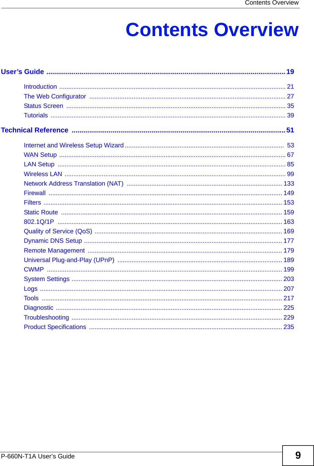
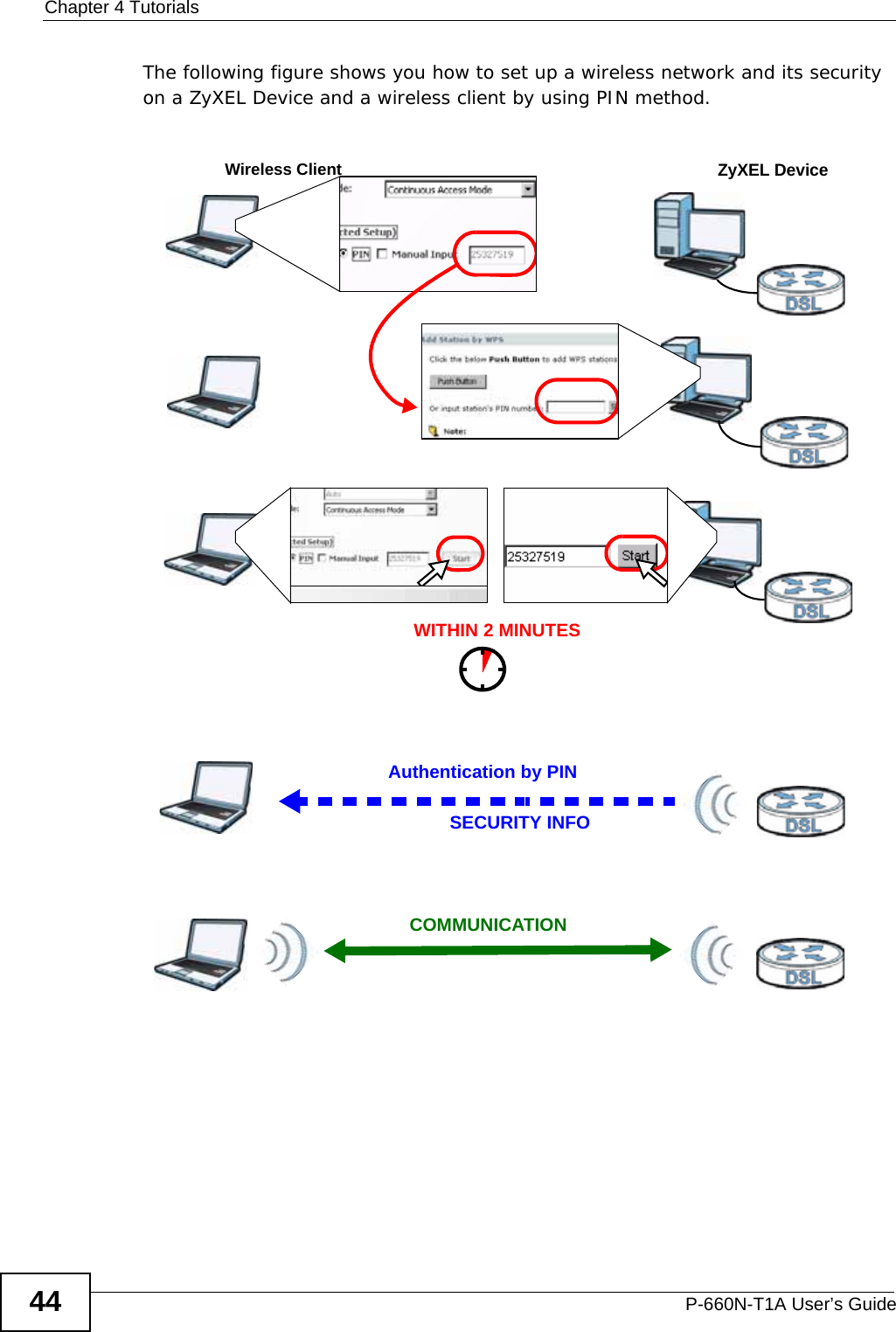
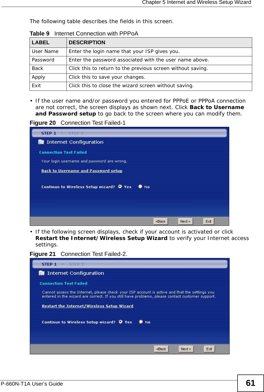
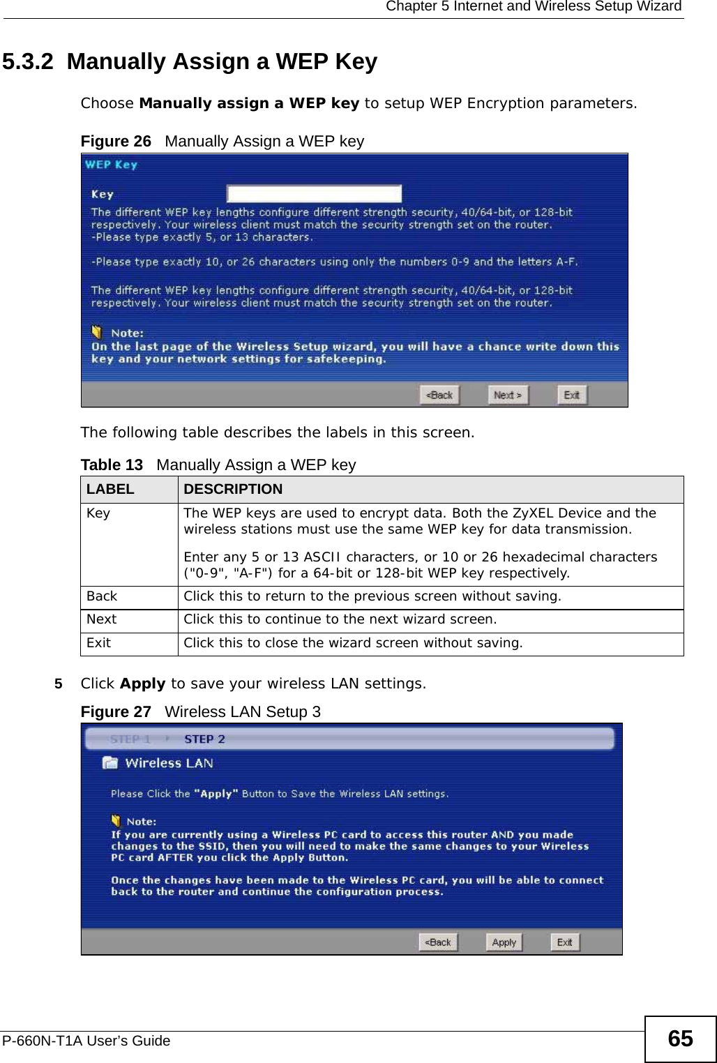
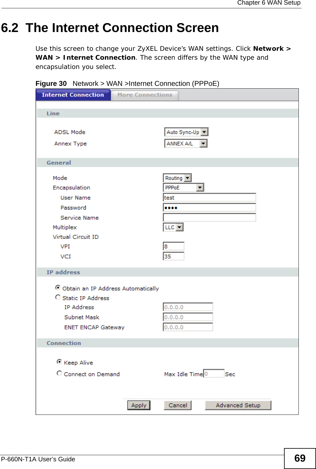
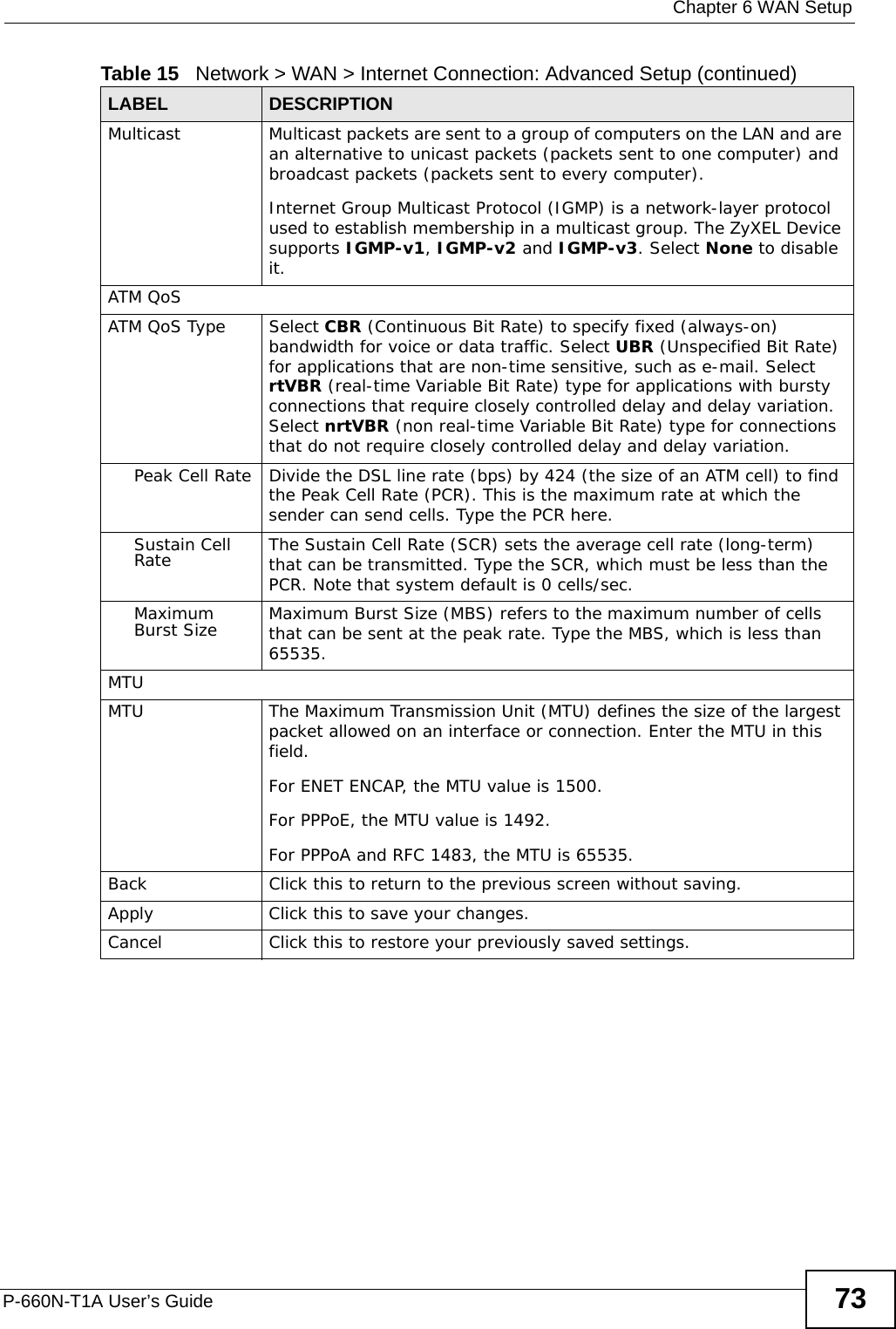
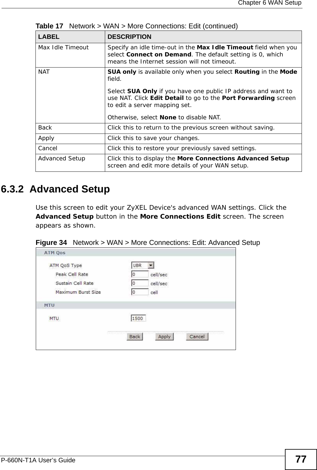
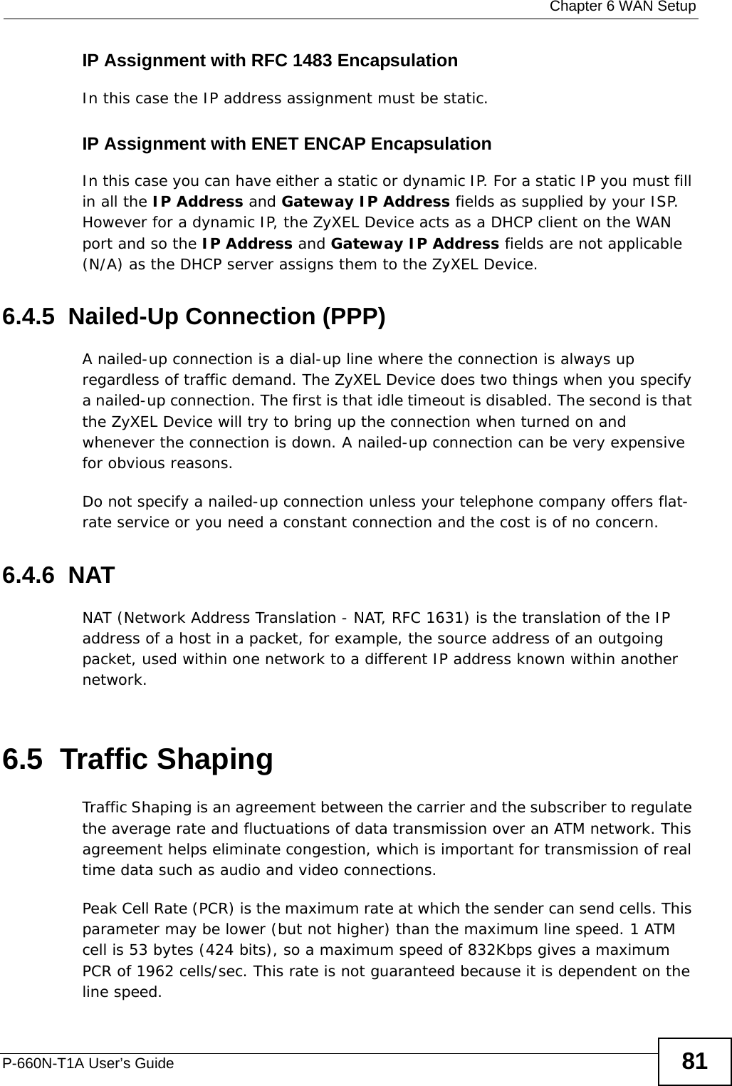
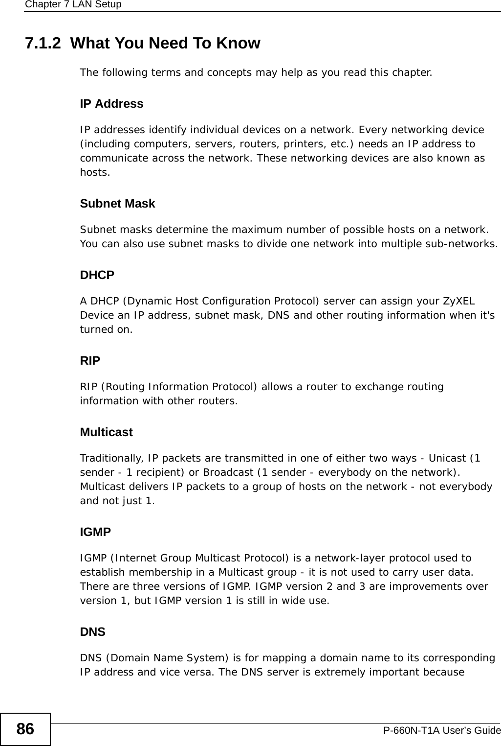
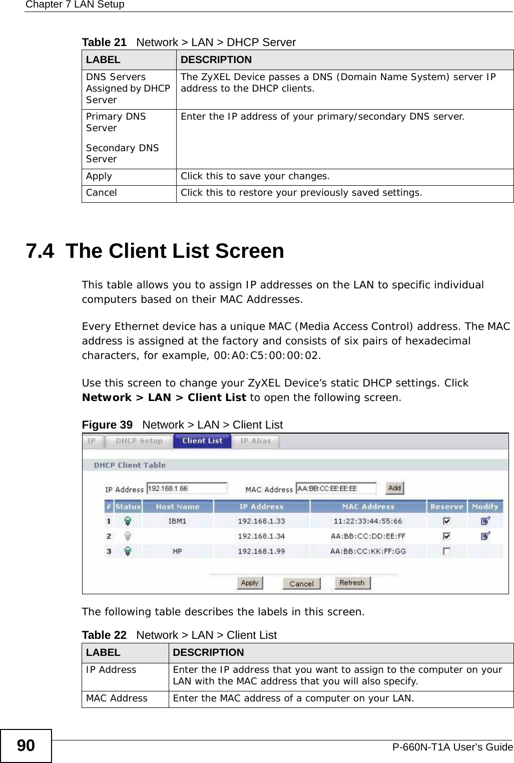
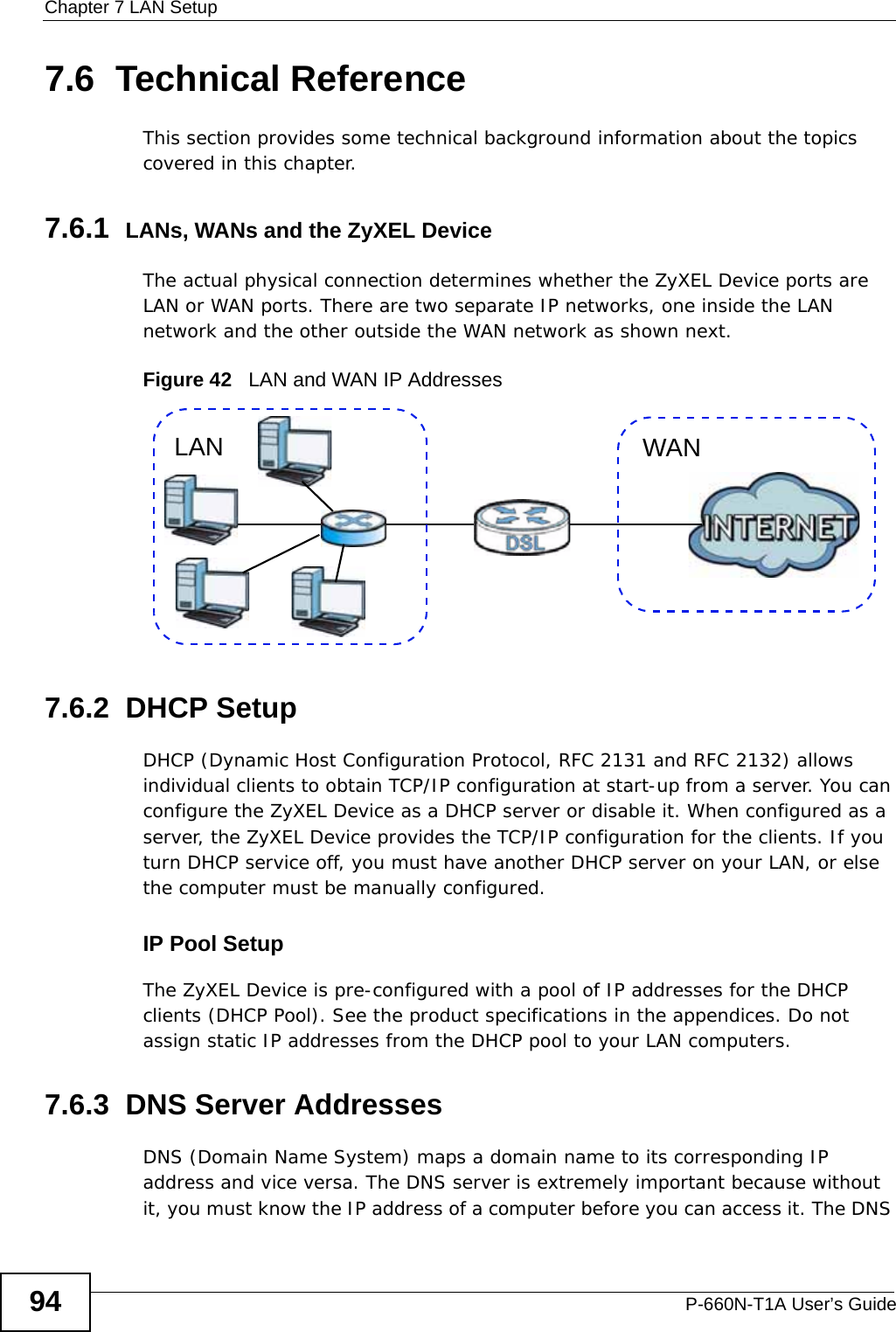
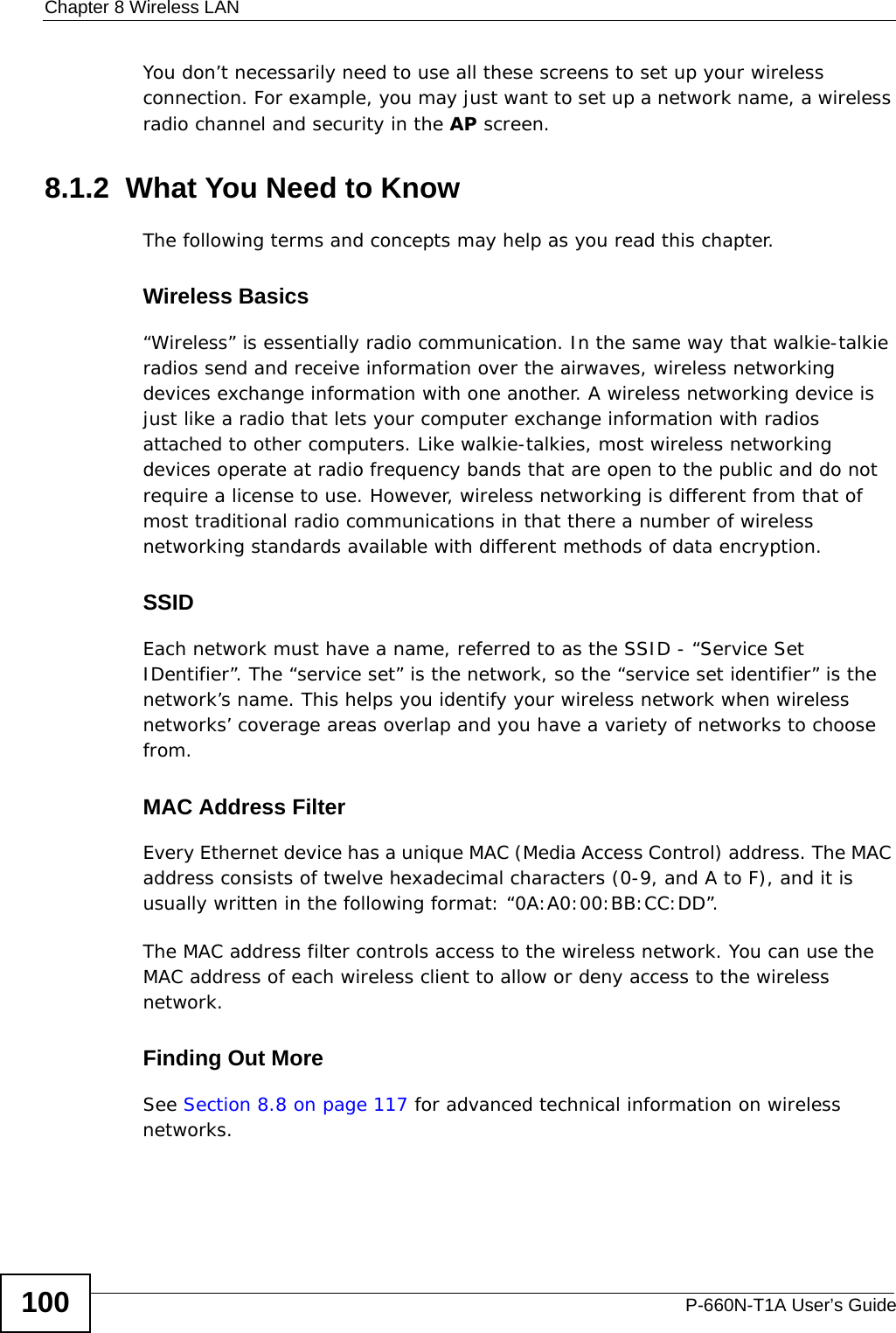
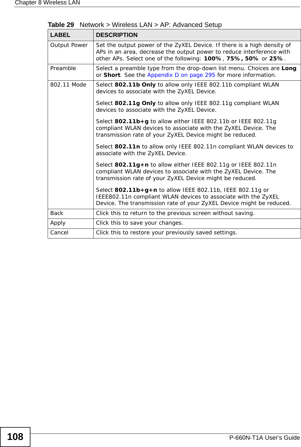
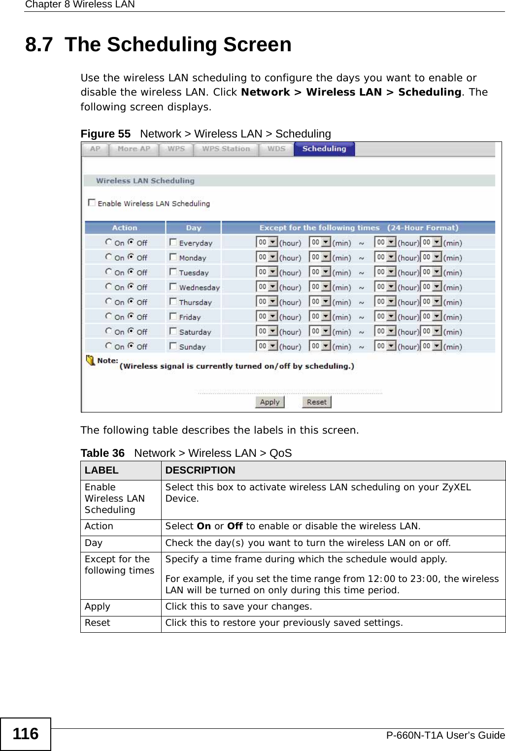
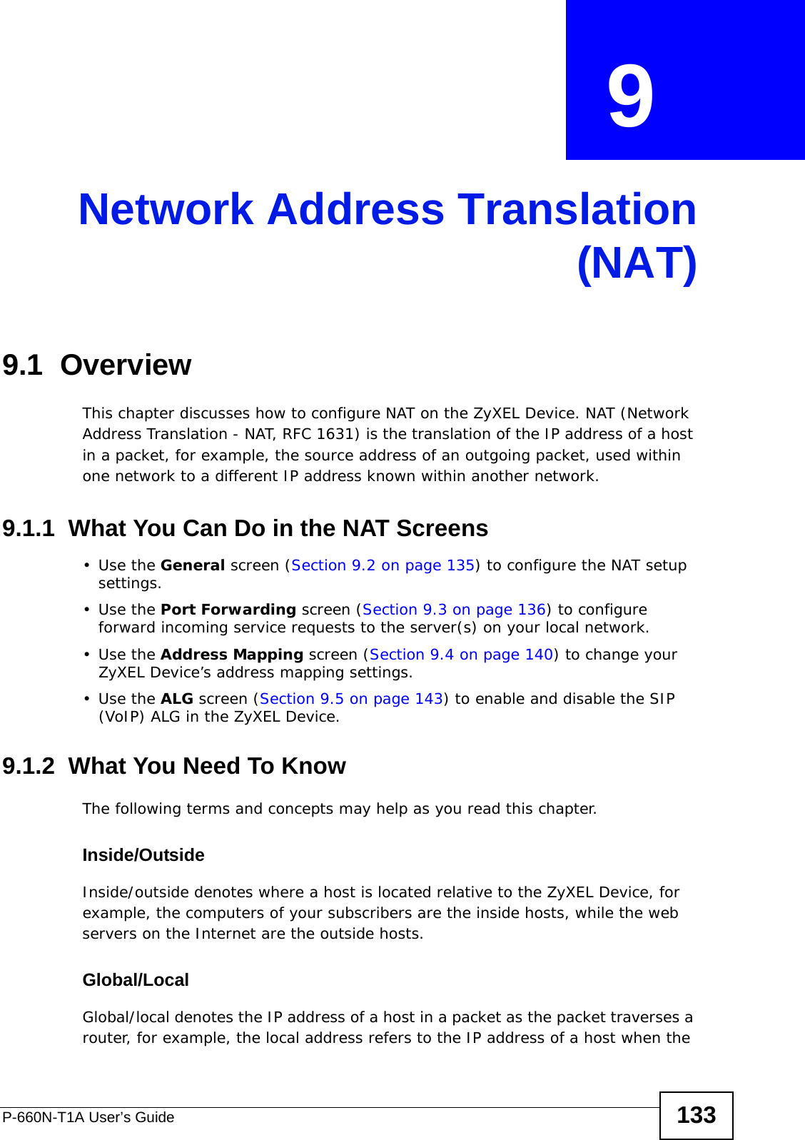
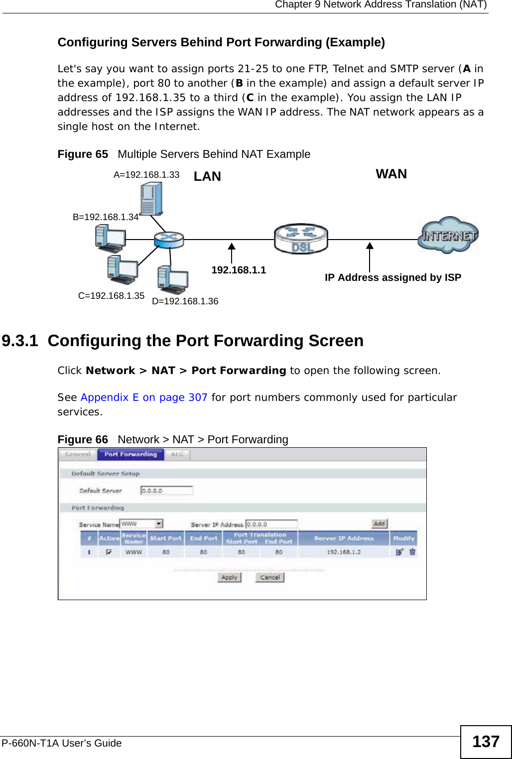
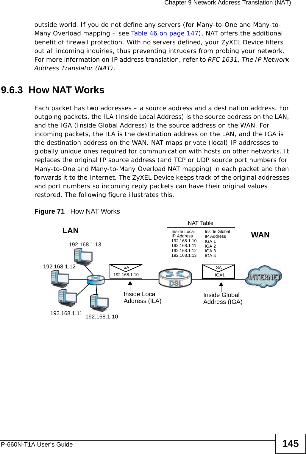
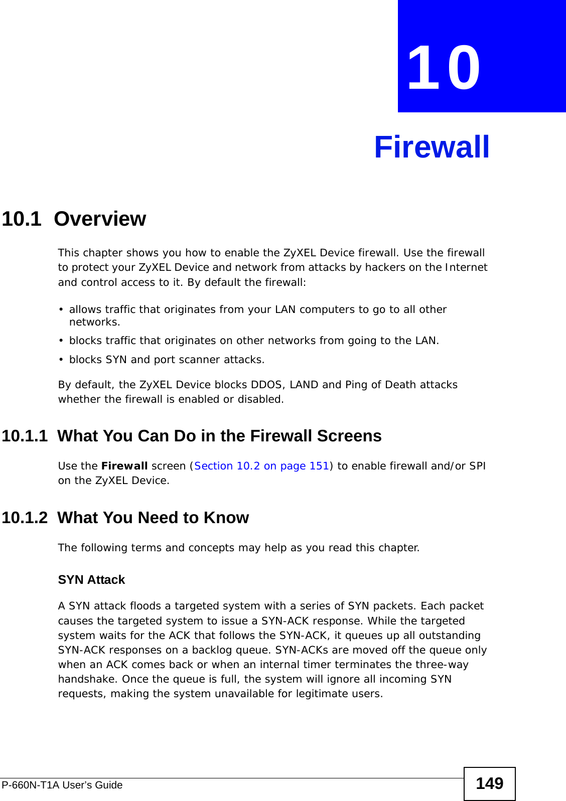
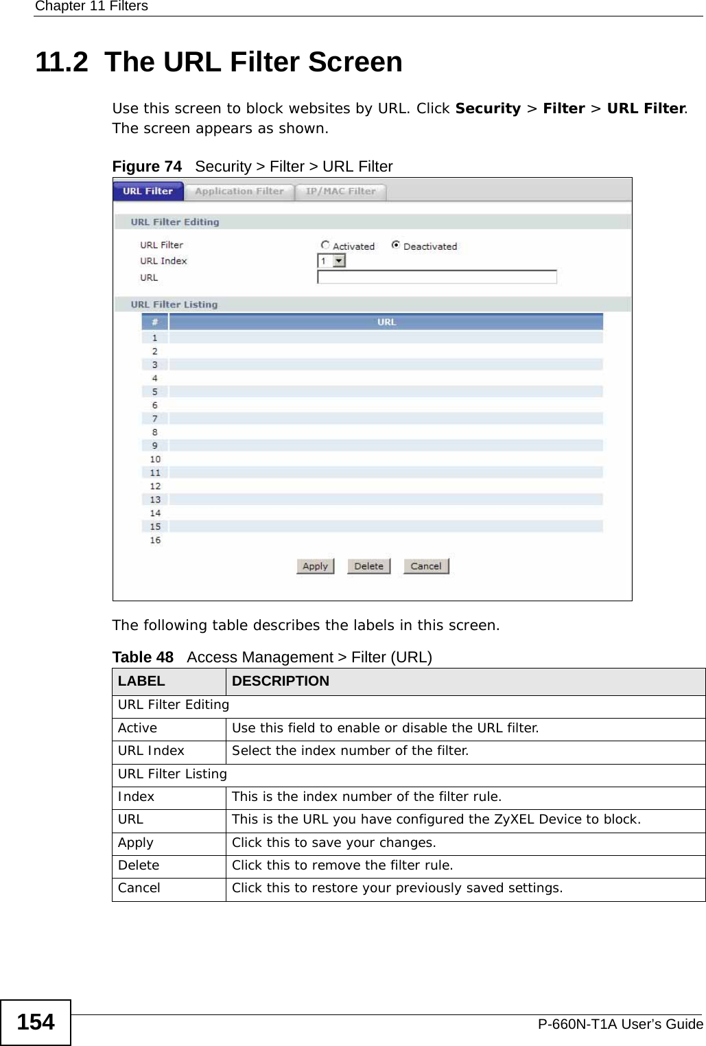
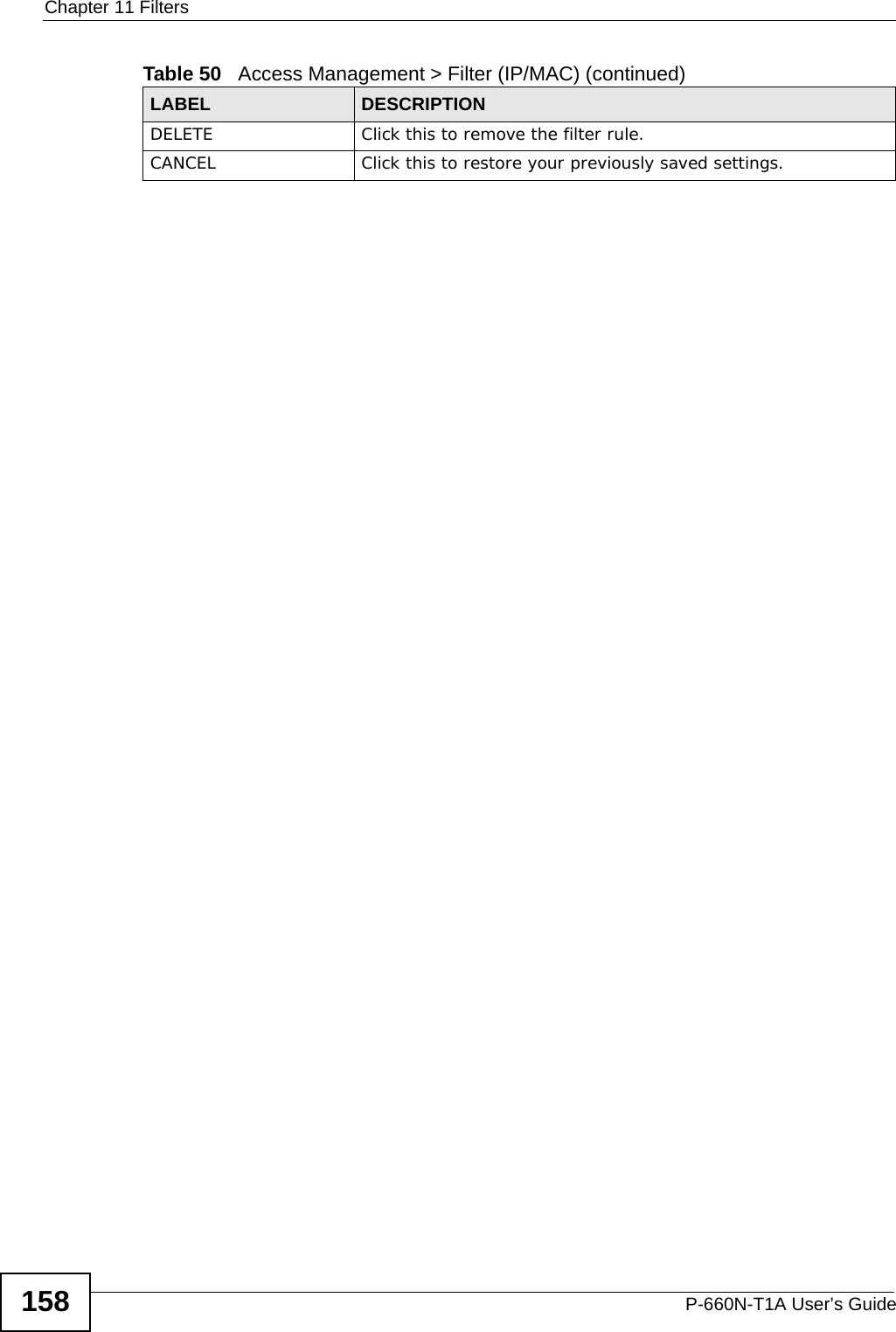
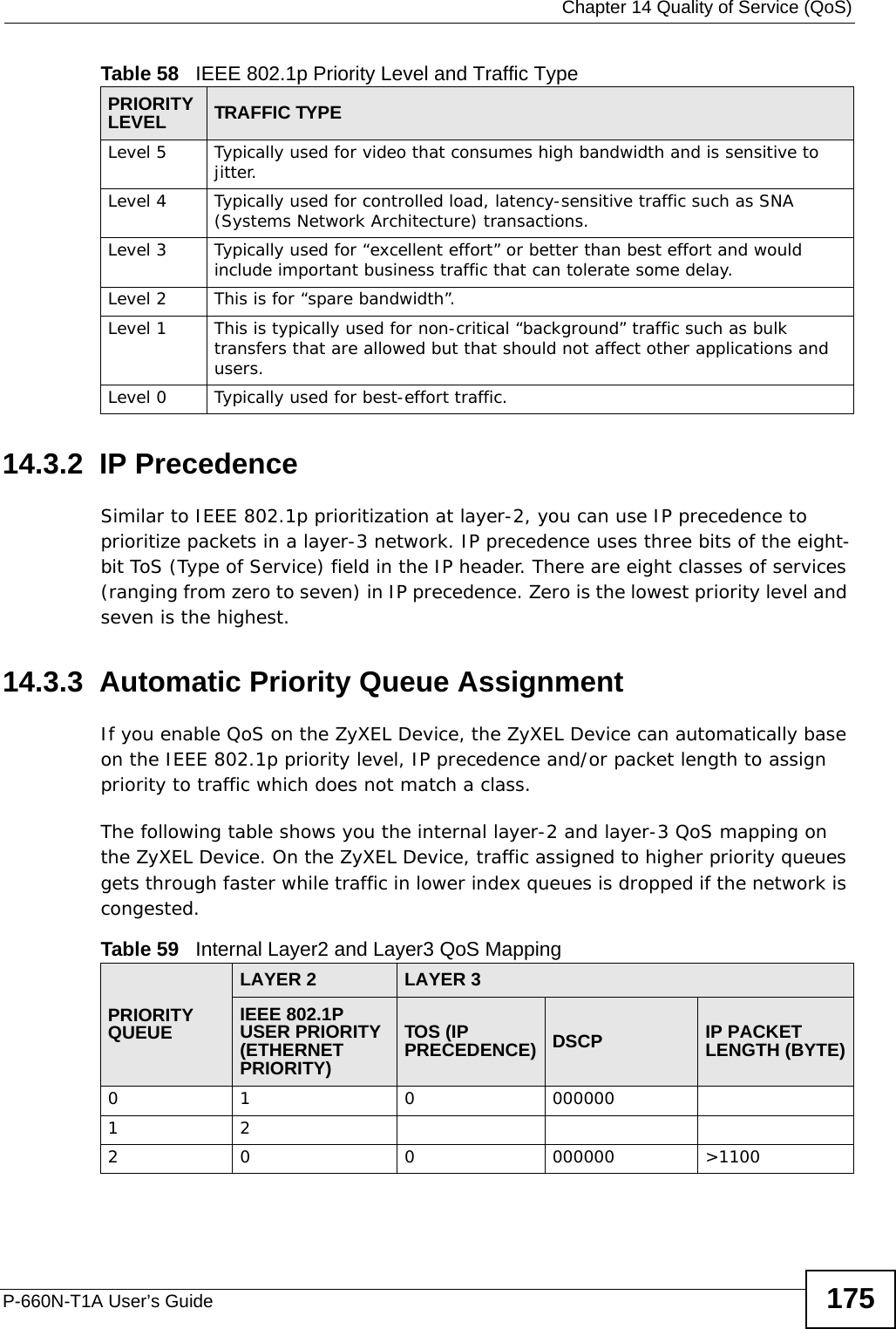
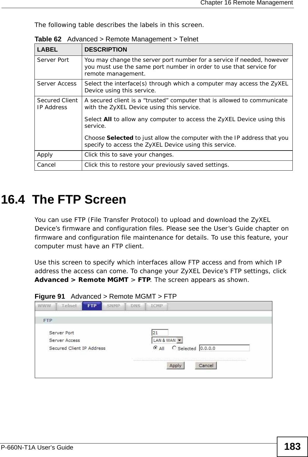
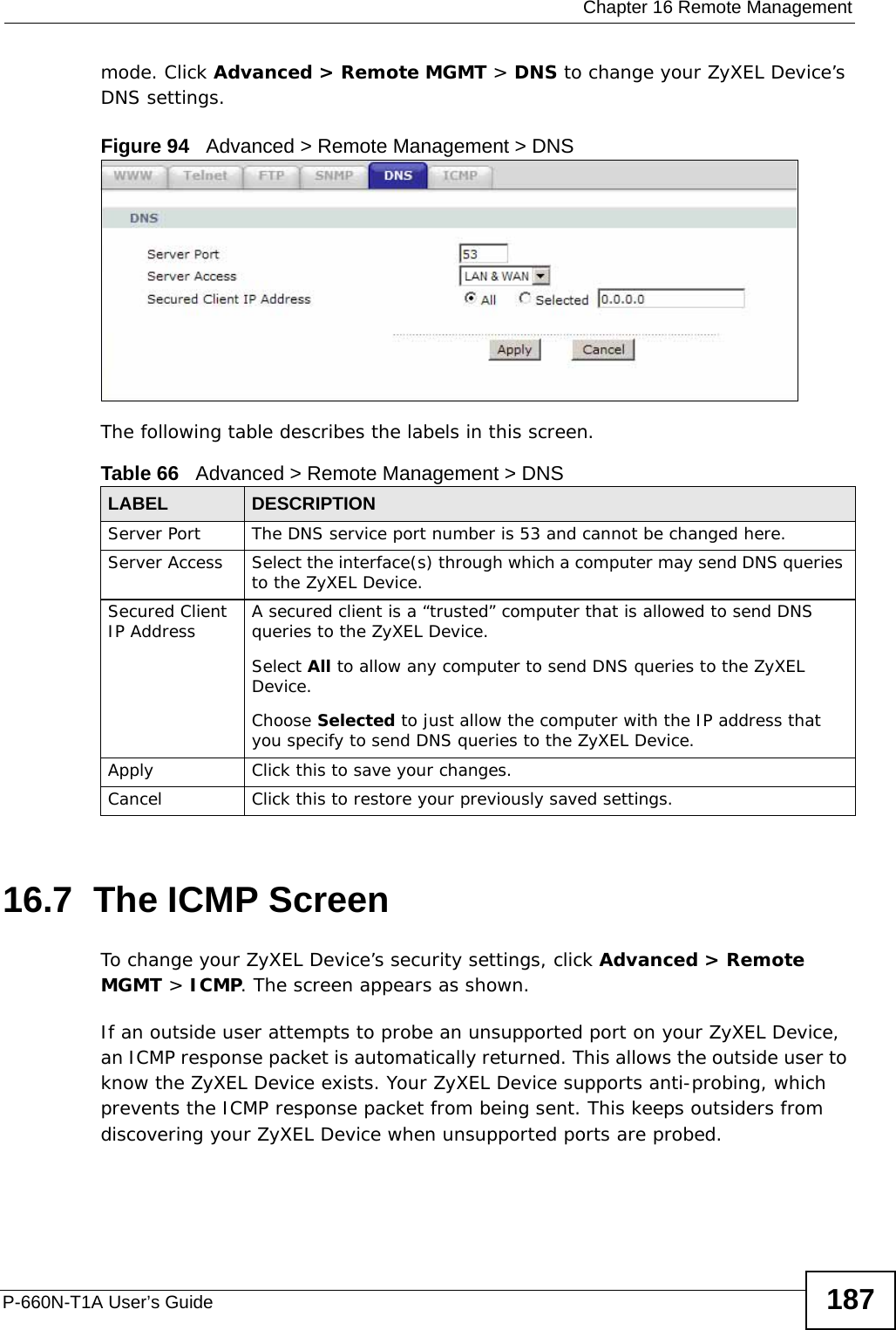
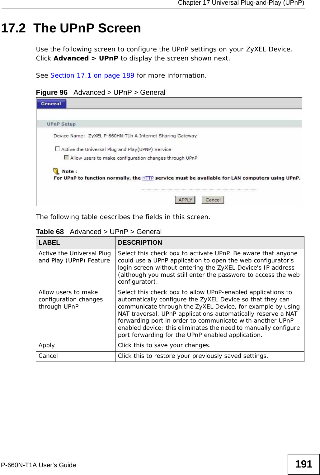
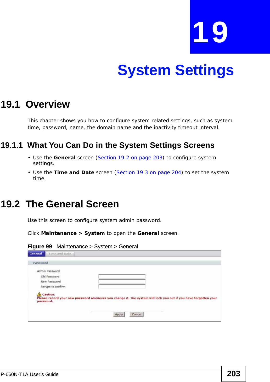
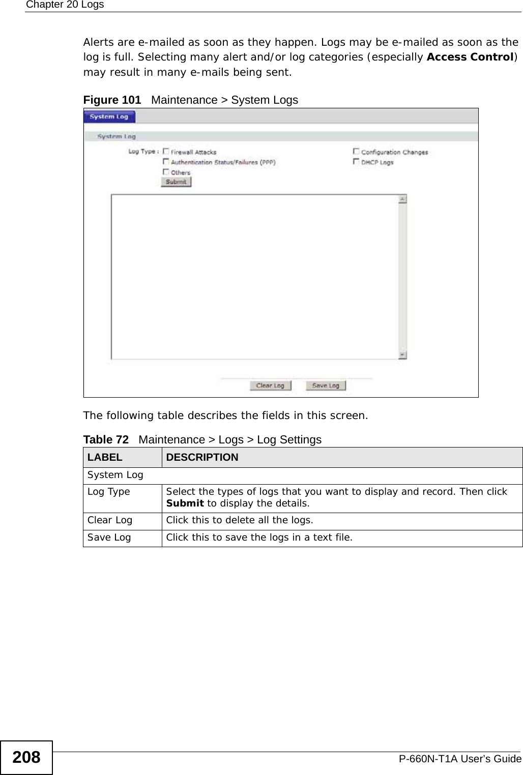
![Document ConventionsP-660N-T1A User’s Guide 5Document ConventionsWarnings and NotesThese are how warnings and notes are shown in this User’s Guide. Warnings tell you about things that could harm you or your device.Note: Notes tell you other important information (for example, other things you may need to configure or helpful tips) or recommendations.Syntax Conventions• The P-660N-T1A may be referred to as the “ZyXEL Device”, the “device”, the “system” or the “product” in this User’s Guide.• Product labels, screen names, field labels and field choices are all in bold font.• A key stroke is denoted by square brackets and uppercase text, for example, [ENTER] means the “enter” or “return” key on your keyboard.• “Enter” means for you to type one or more characters and then press the [ENTER] key. “Select” or “choose” means for you to use one of the predefined choices.• A right angle bracket ( > ) within a screen name denotes a mouse click. For example, Maintenance > Log > Log Setting means you first click Maintenance in the navigation panel, then the Log sub menu and finally the Log Setting tab to get to that screen.• Units of measurement may denote the “metric” value or the “scientific” value. For example, “k” for kilo may denote “1000” or “1024”, “M” for mega may denote “1000000” or “1048576” and so on.• “e.g.,” is a shorthand for “for instance”, and “i.e.,” means “that is” or “in other words”.](https://usermanual.wiki/ZyXEL-Communications/P660NT1A.user-manual-1/User-Guide-1315611-Page-5.png)
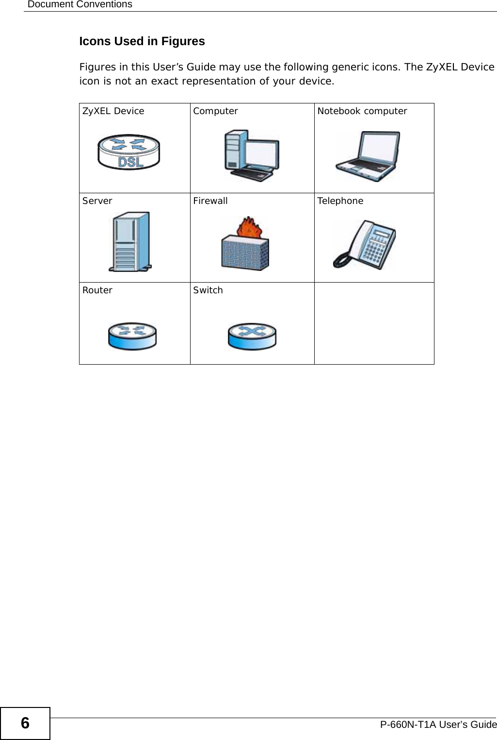

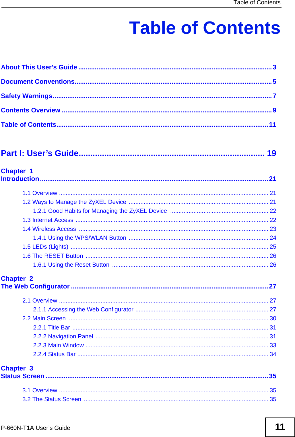
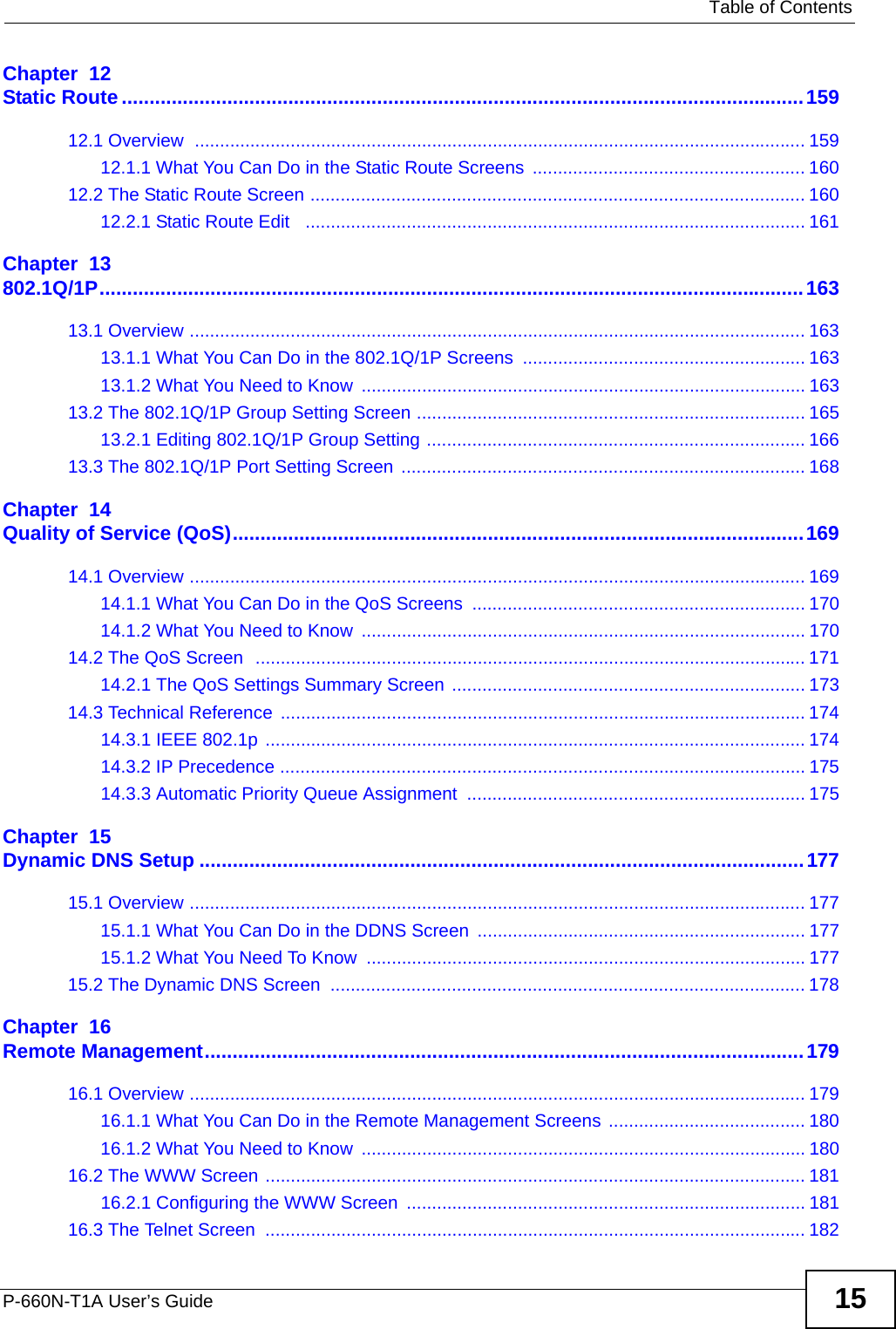


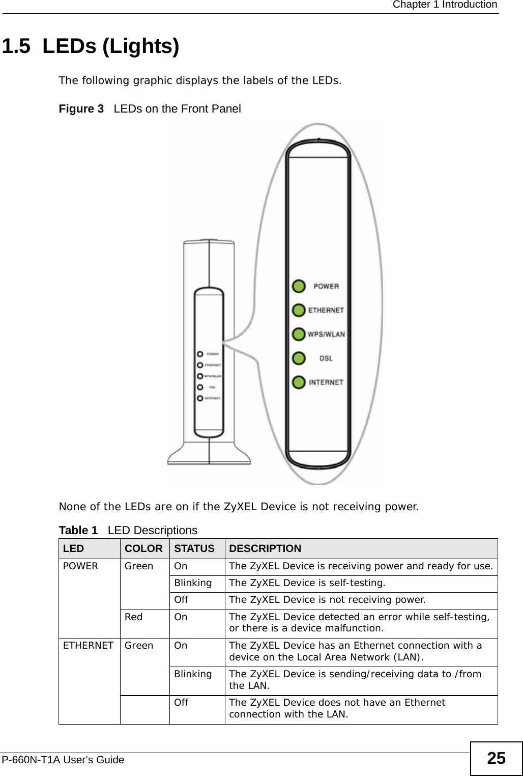
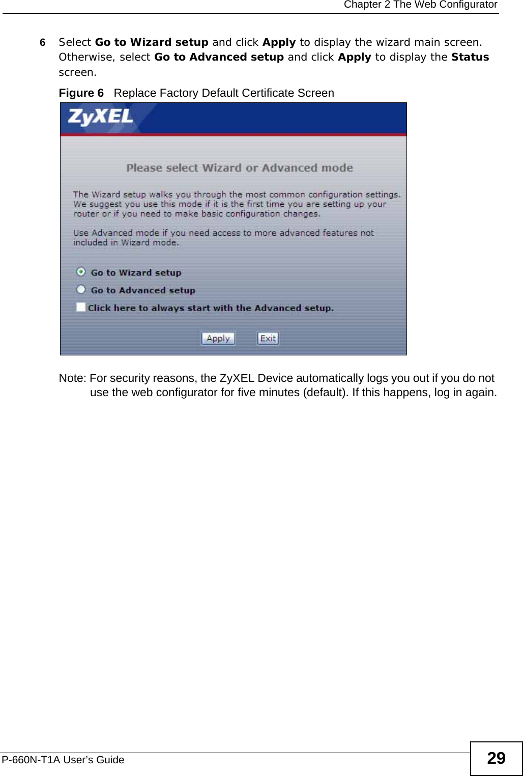
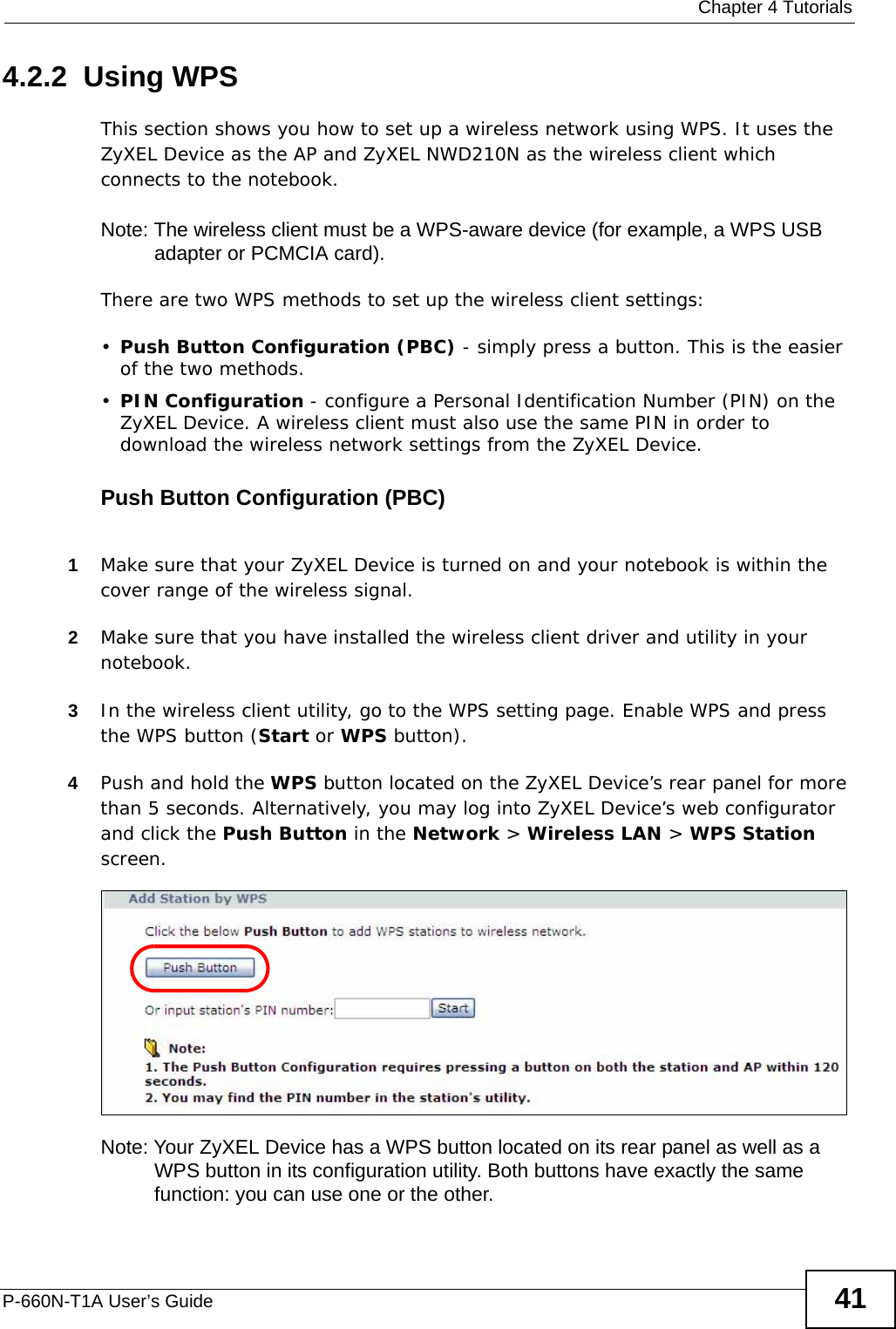
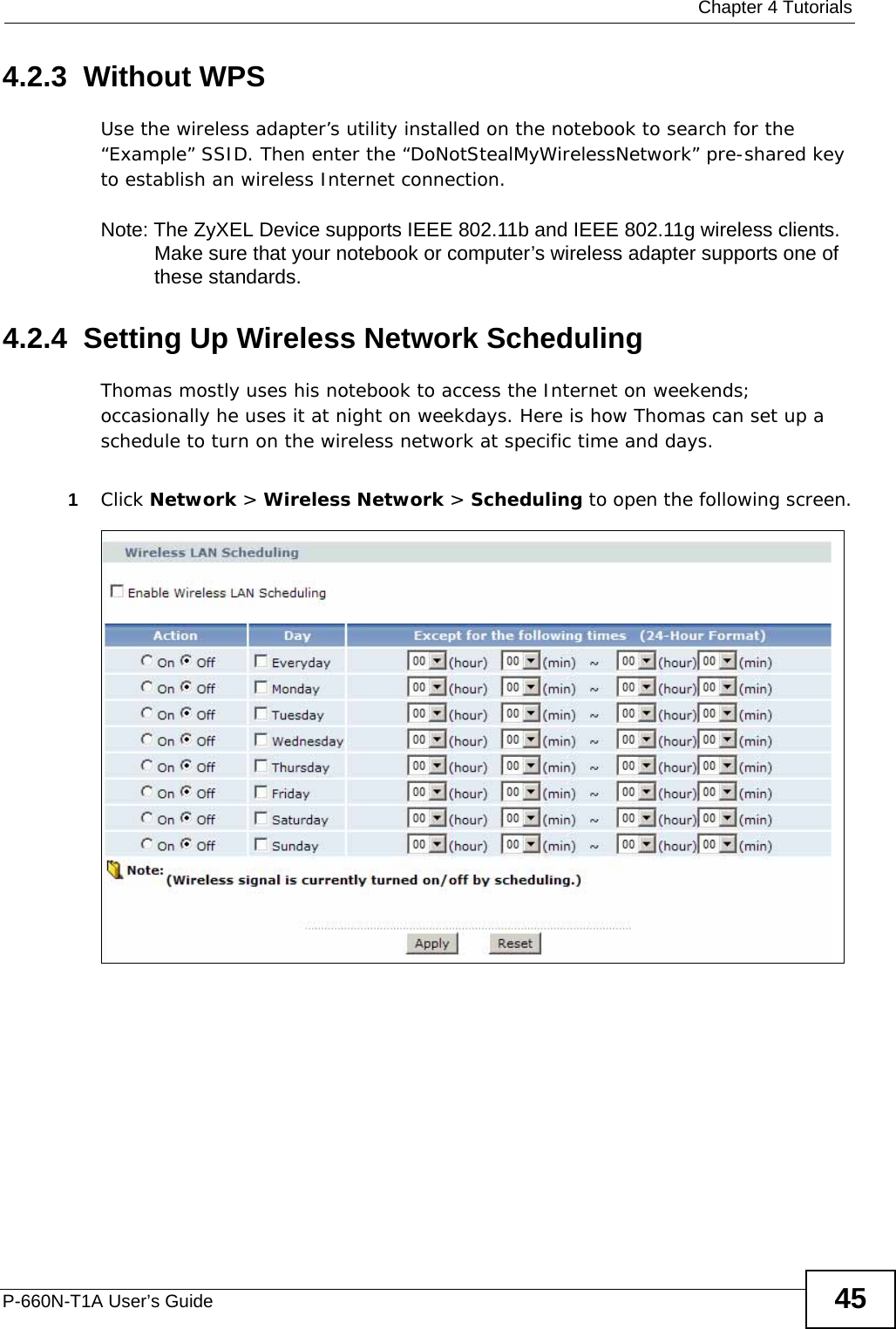

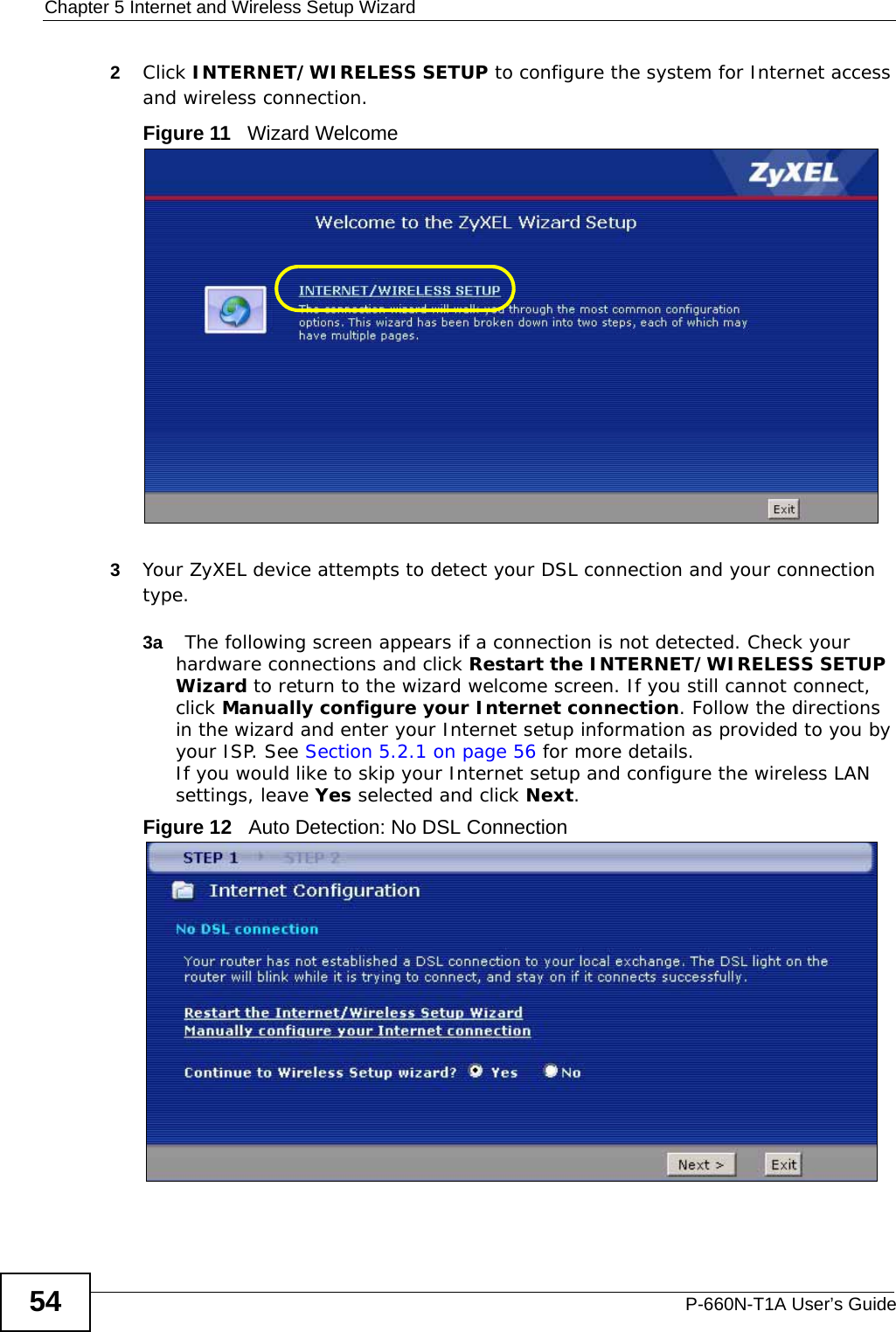
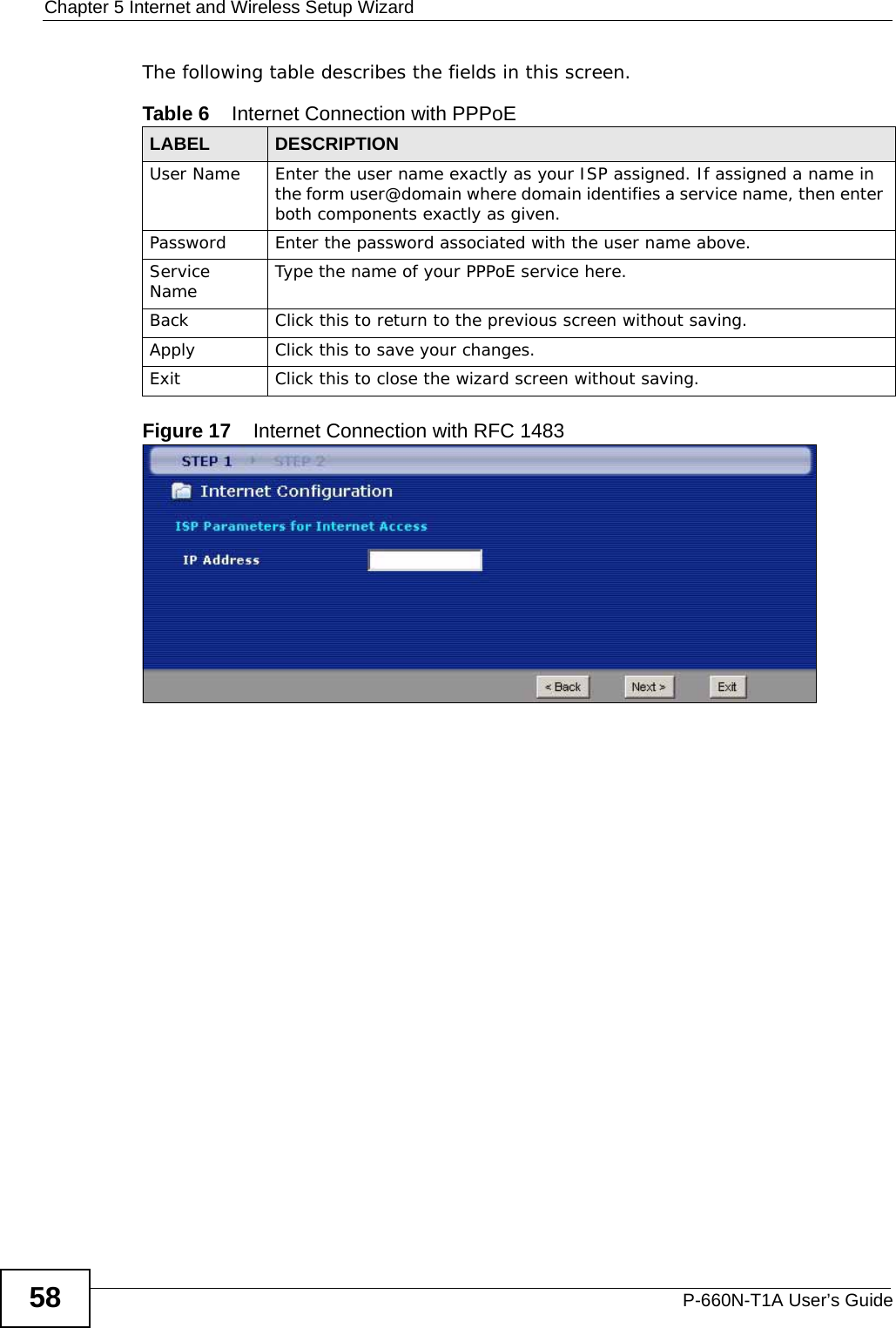
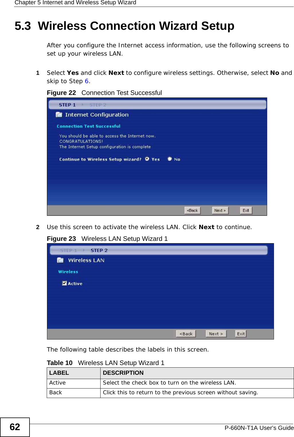
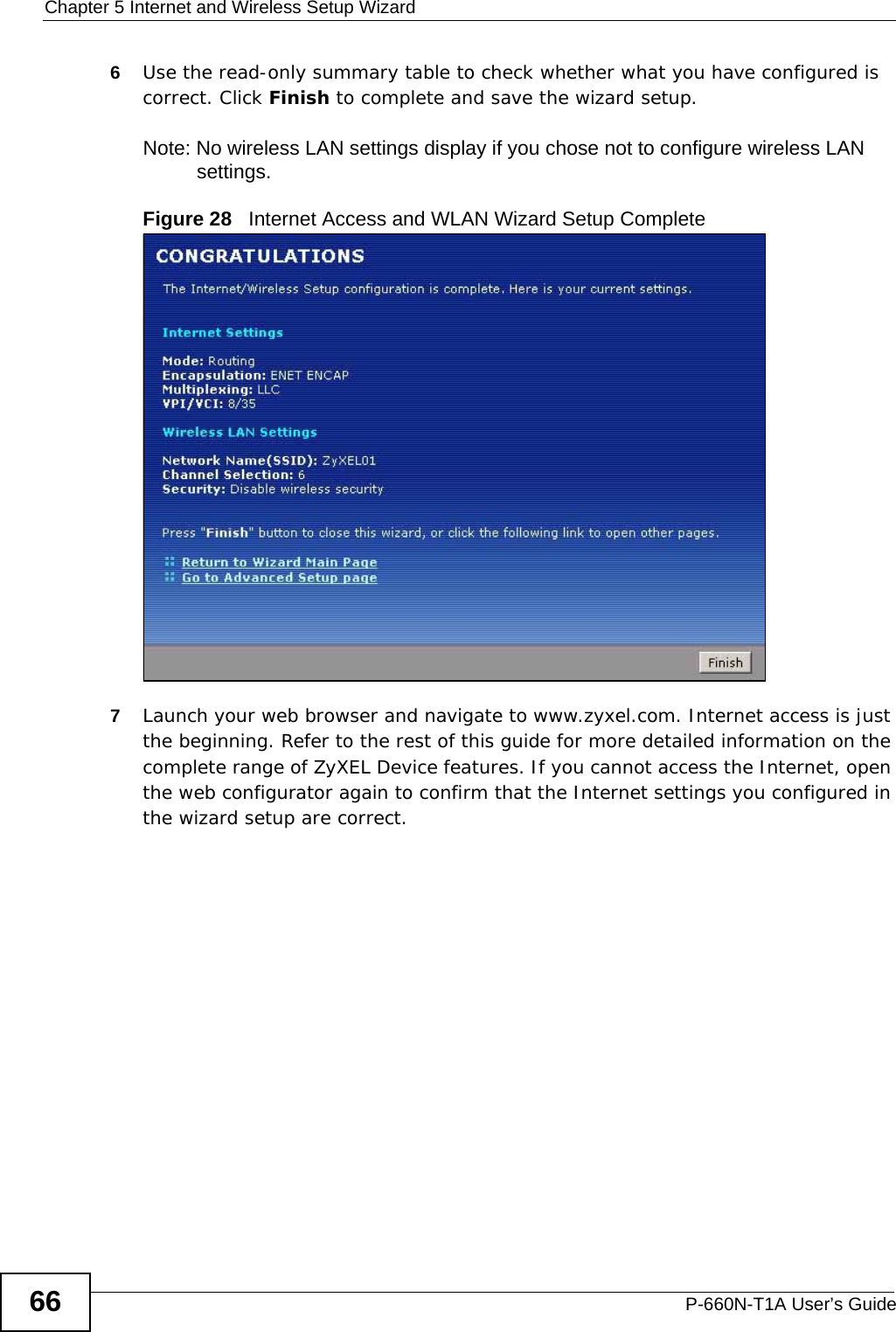
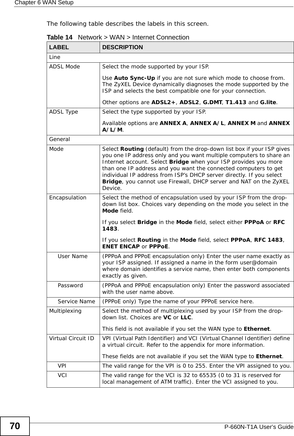
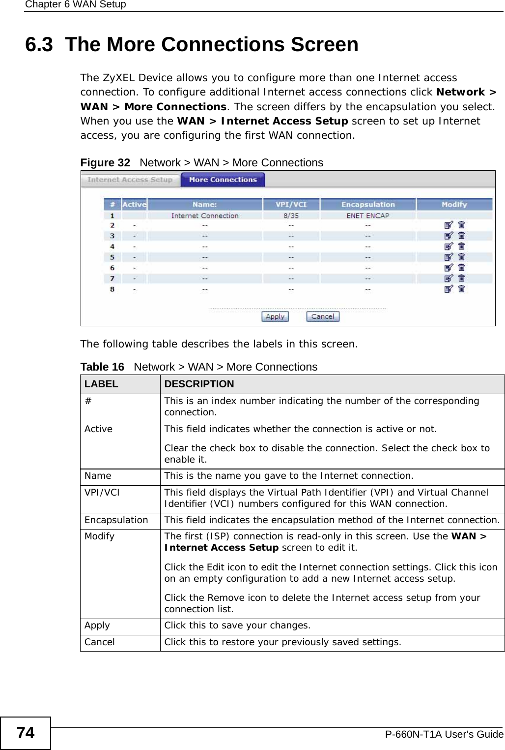
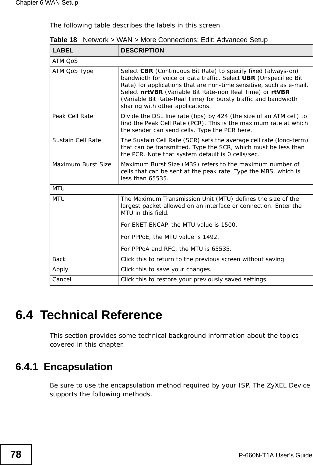
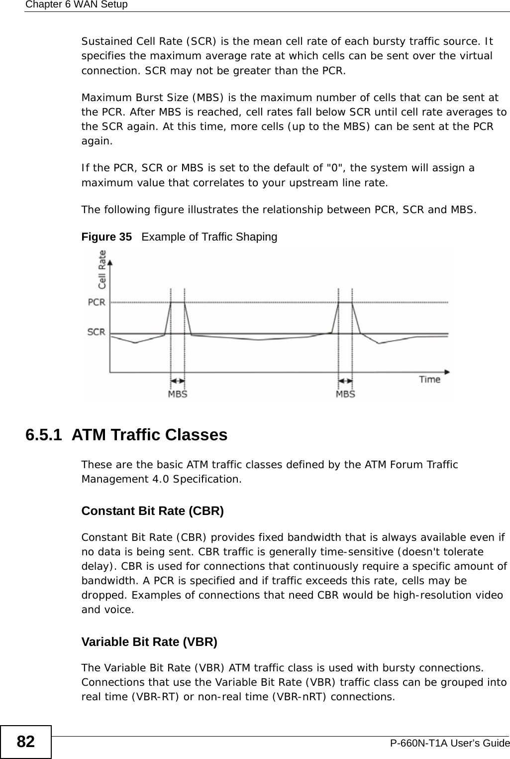

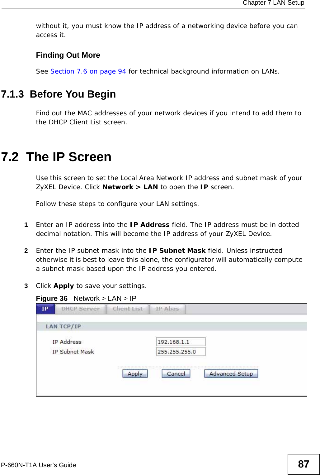
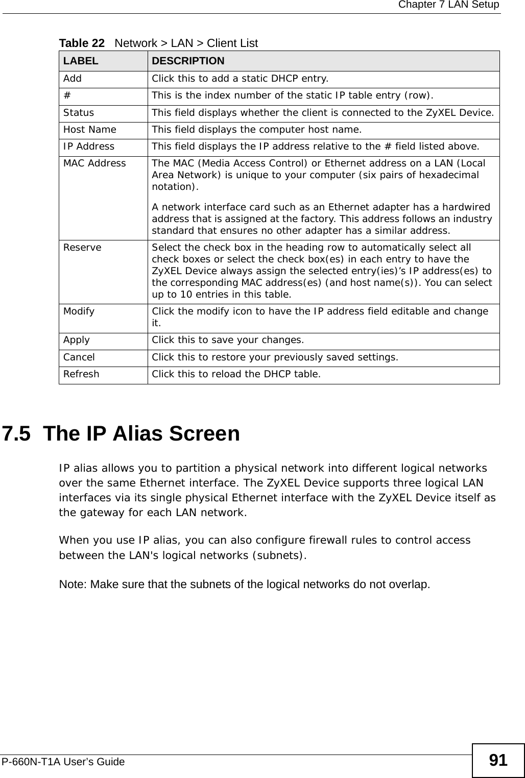
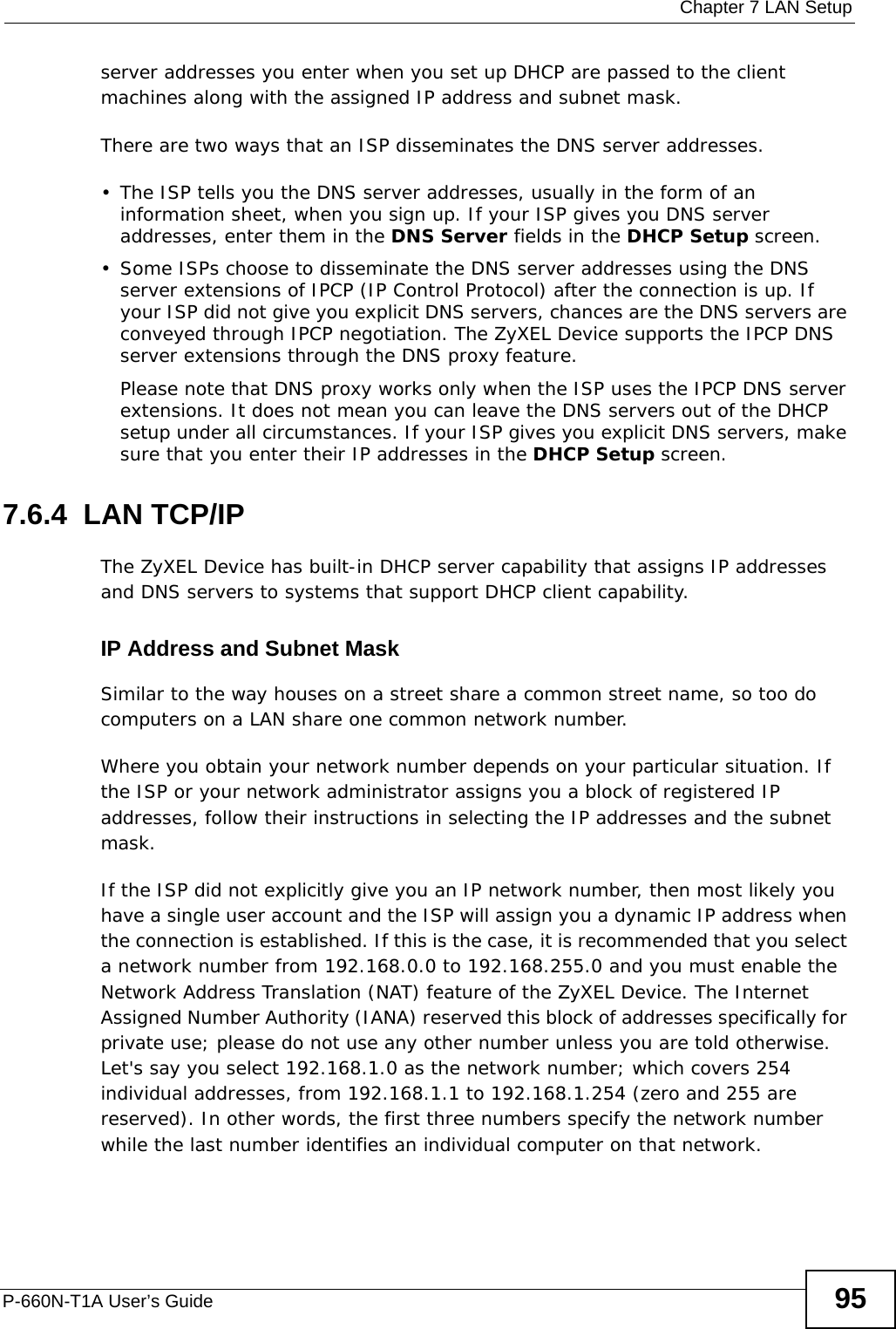


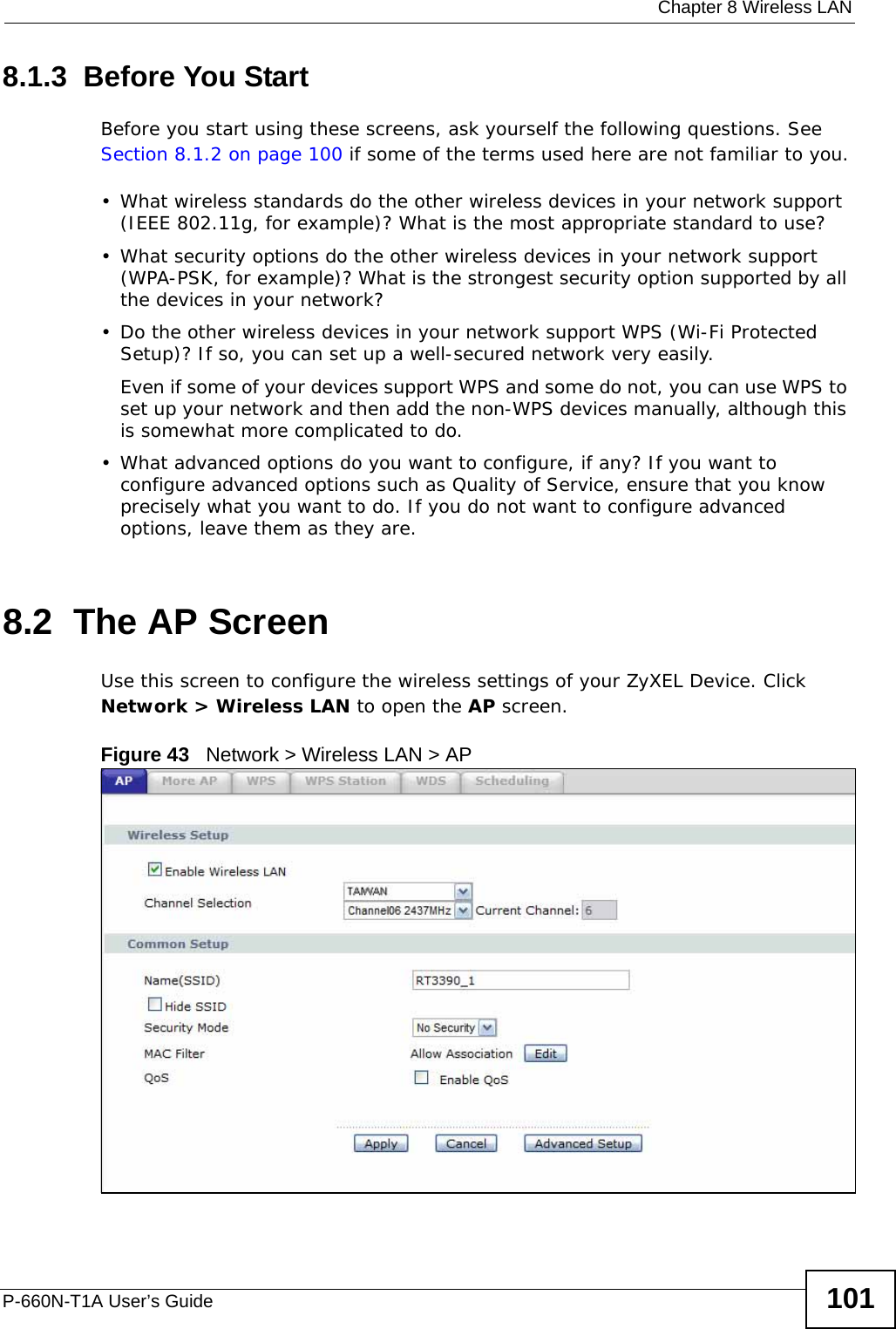
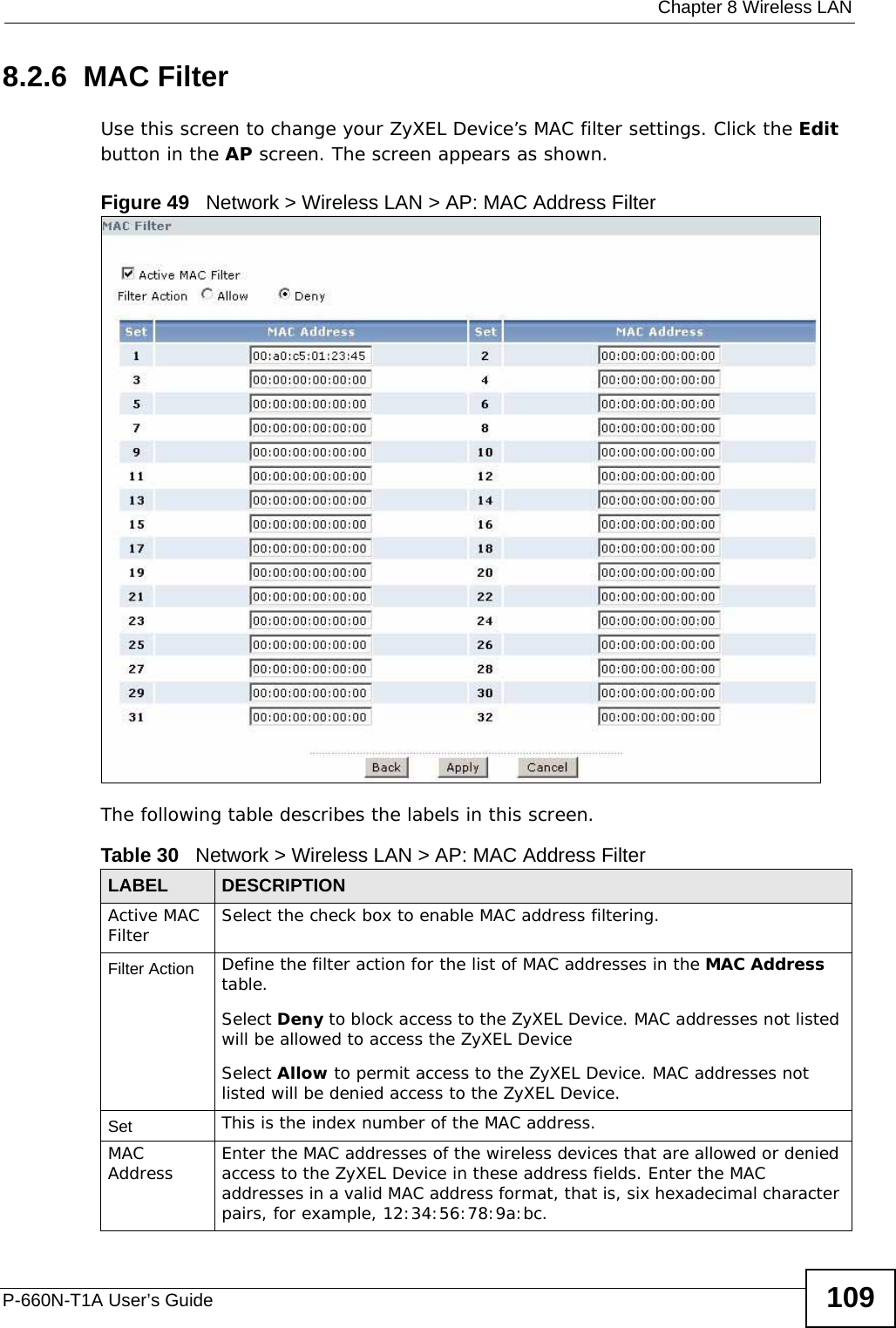
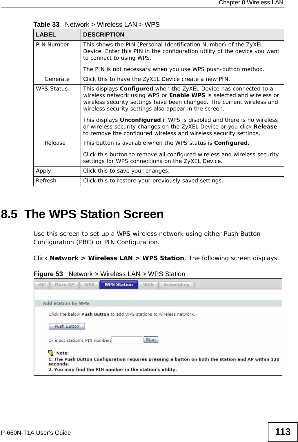
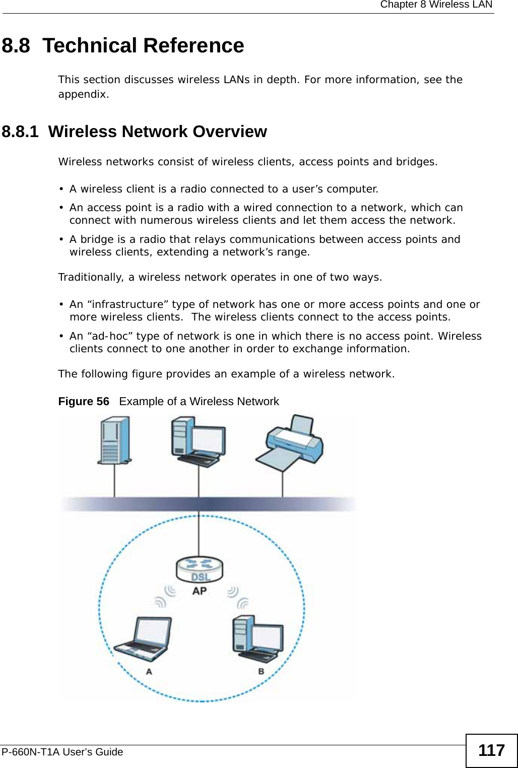

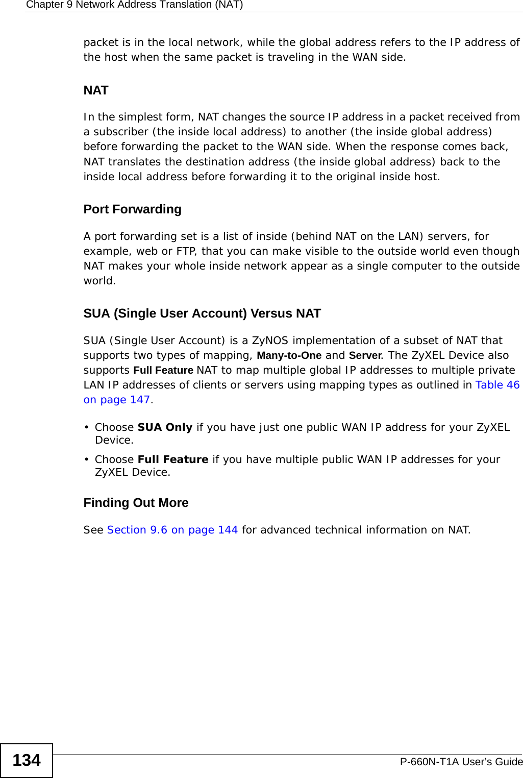
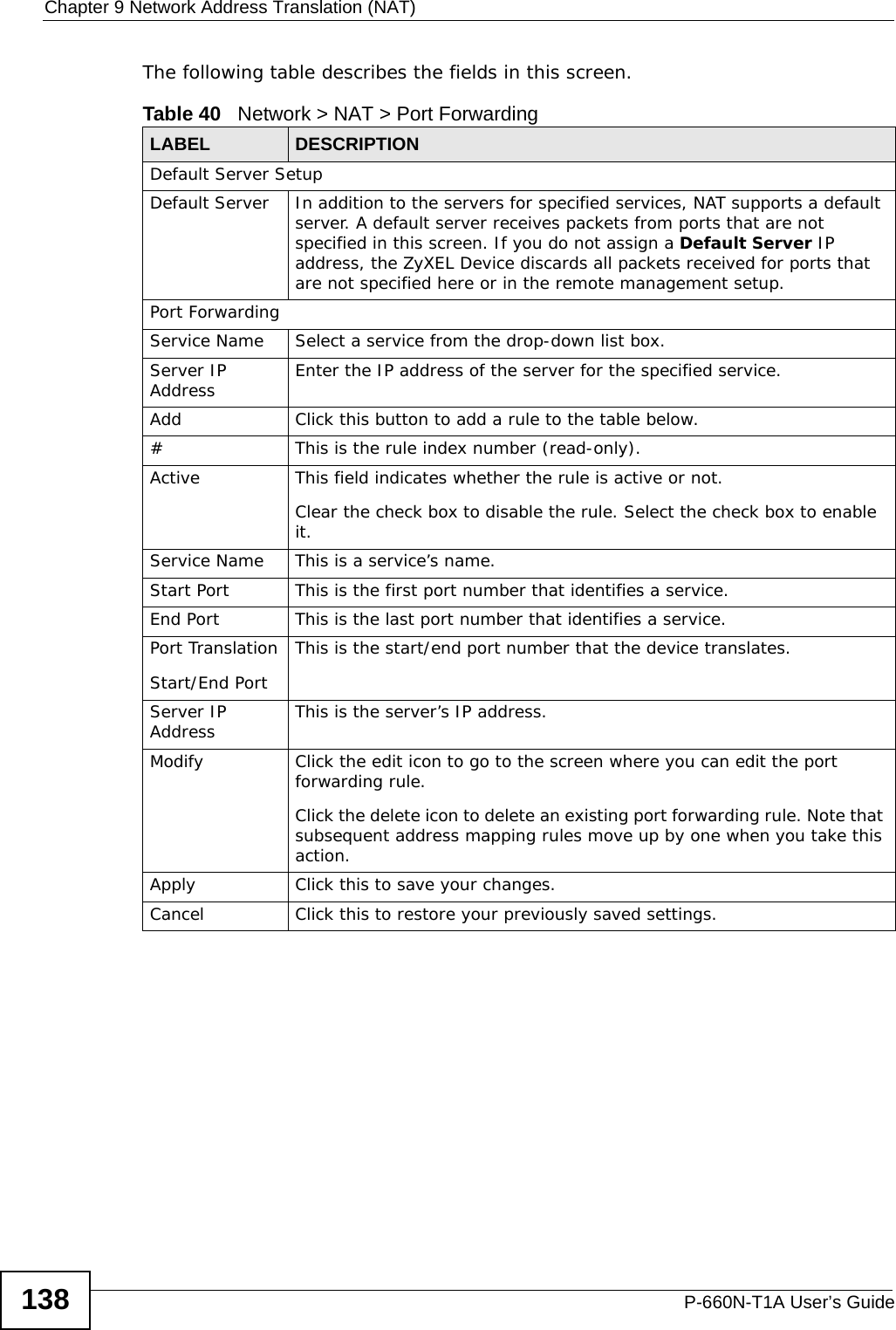
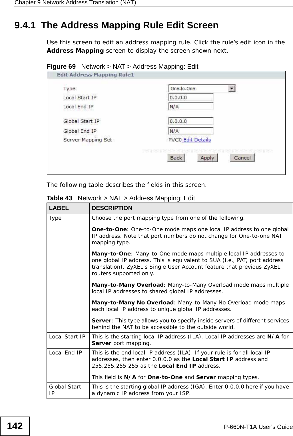
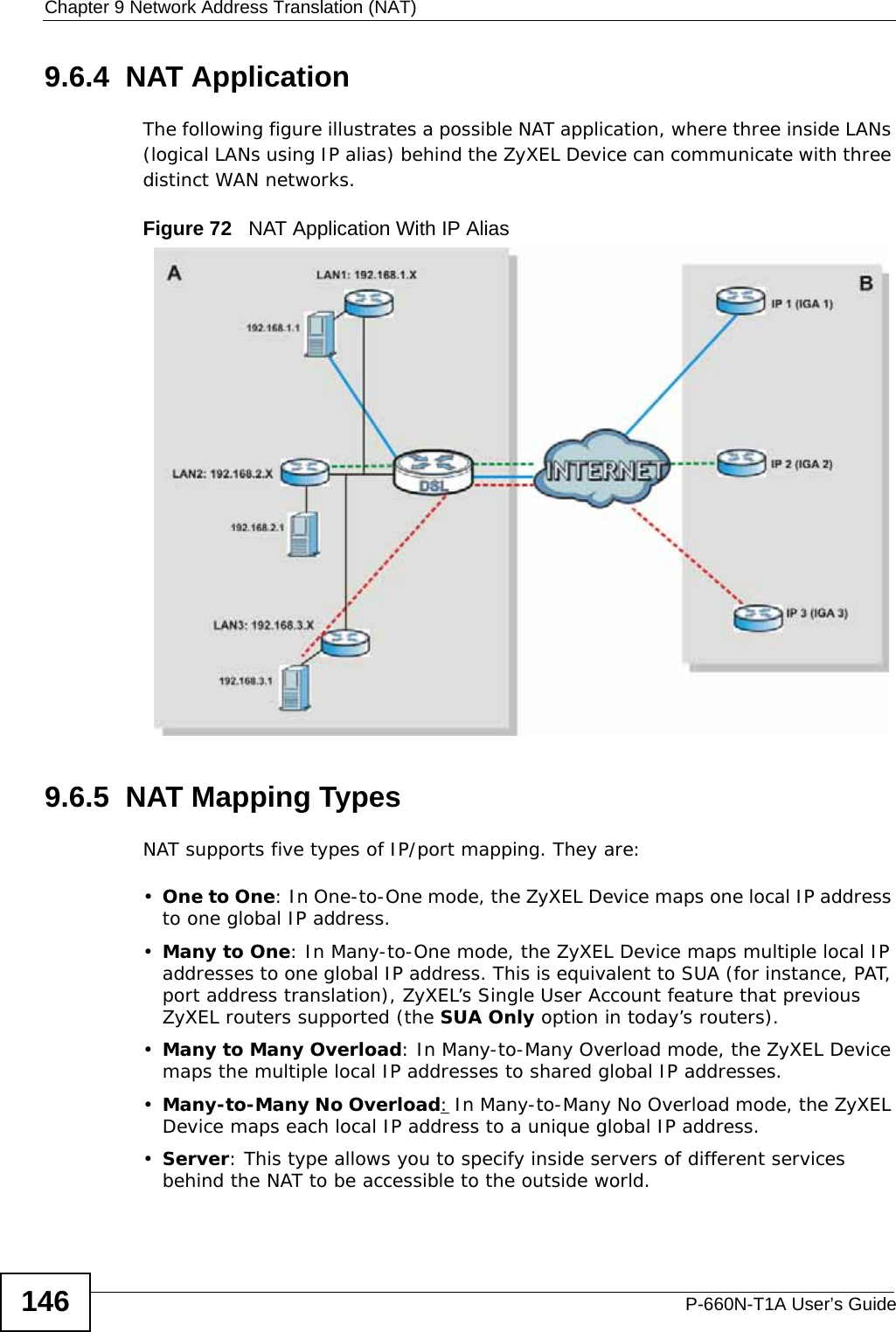
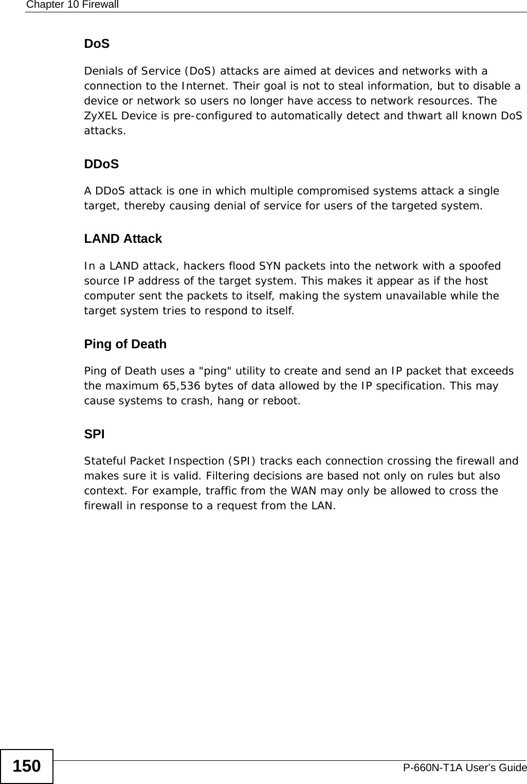

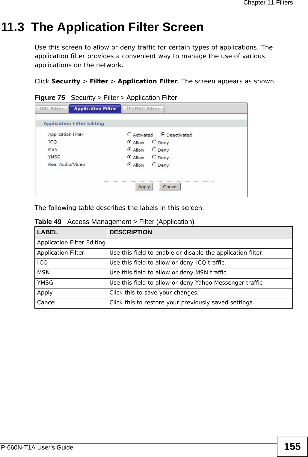
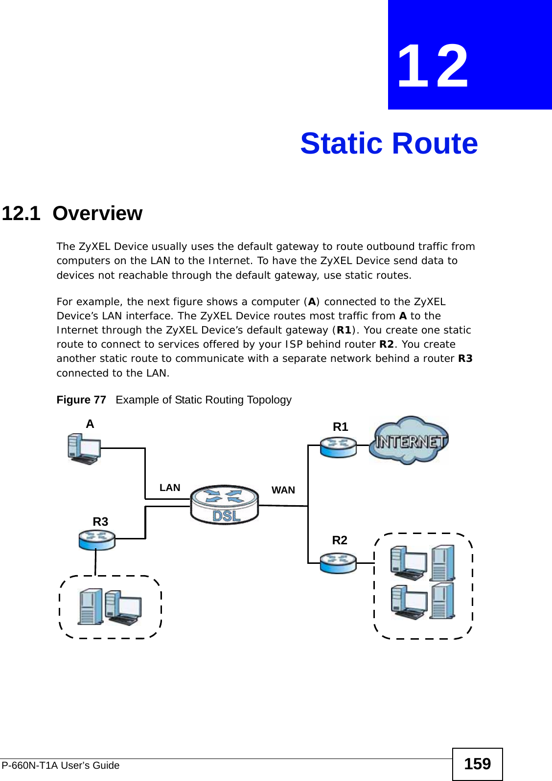

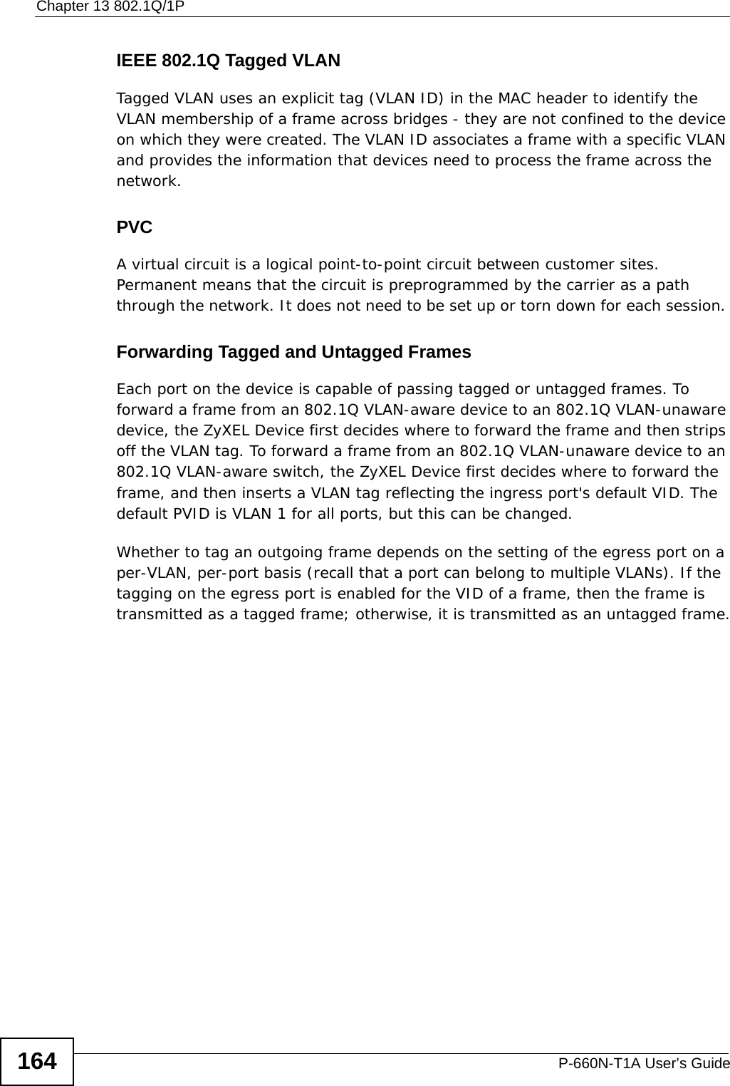
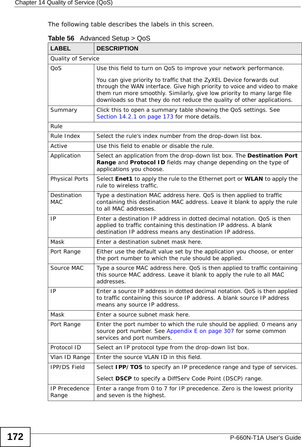
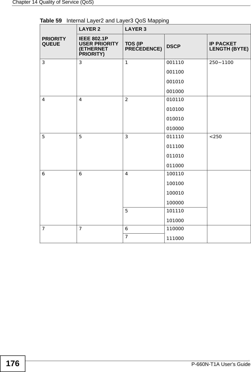
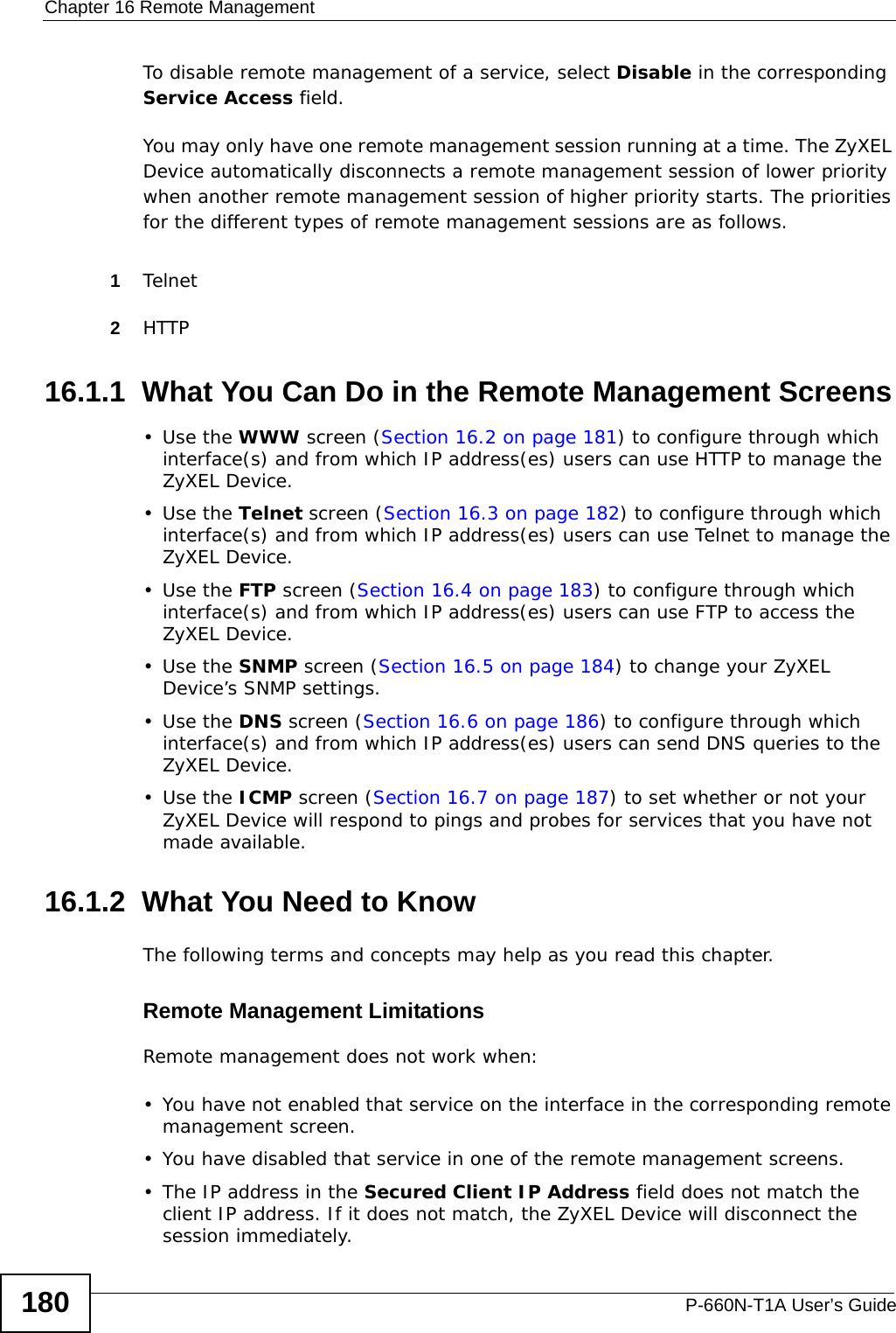
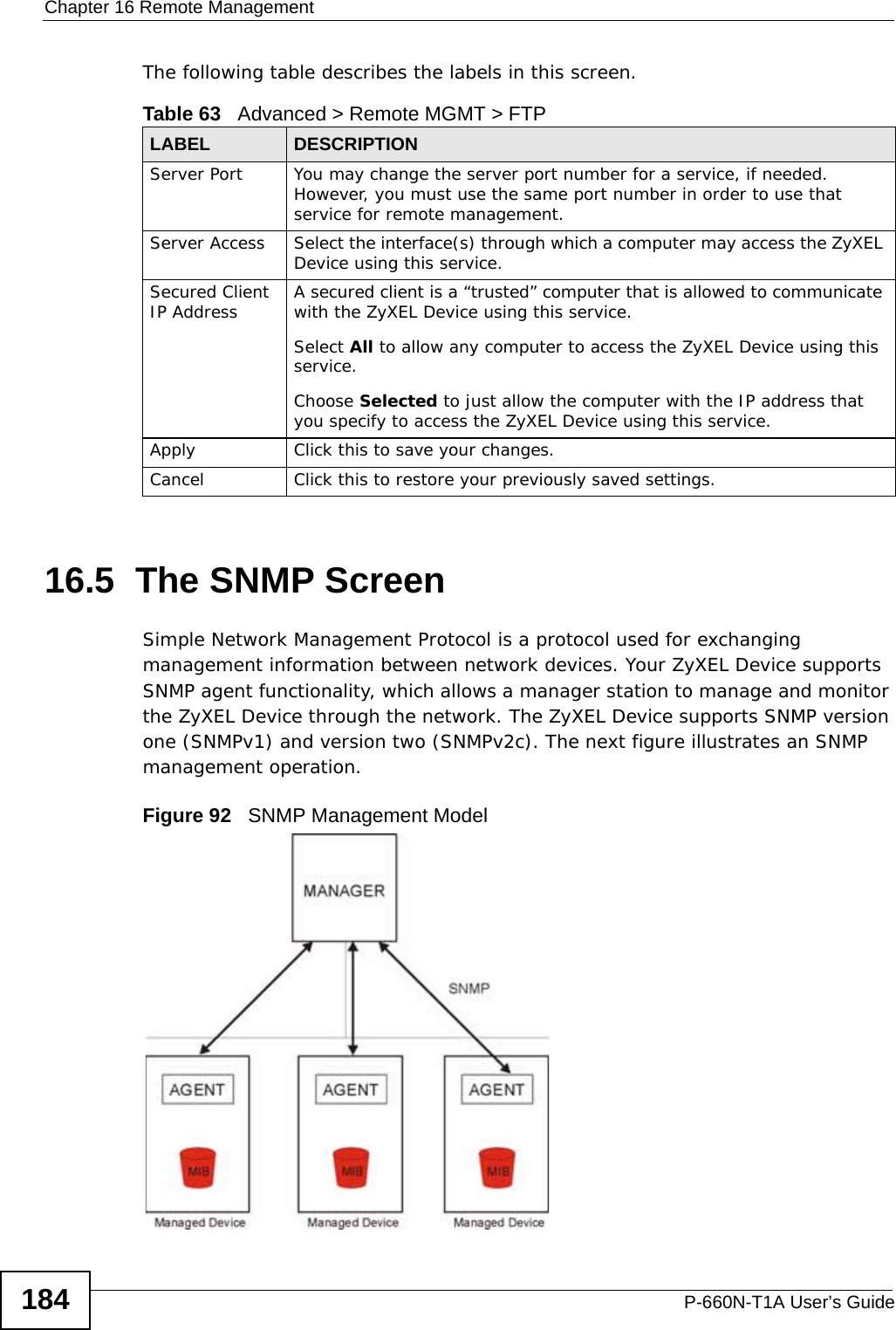
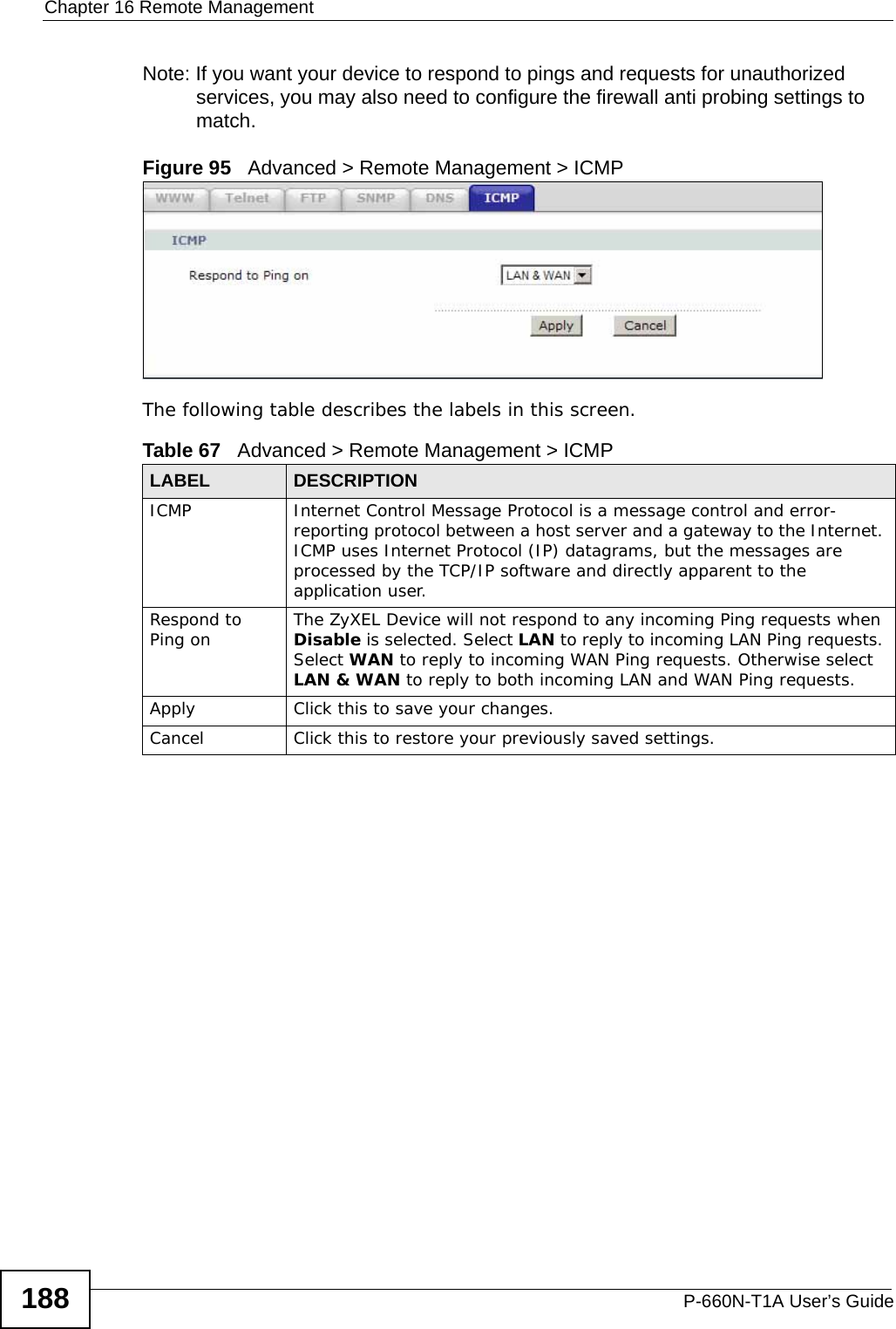
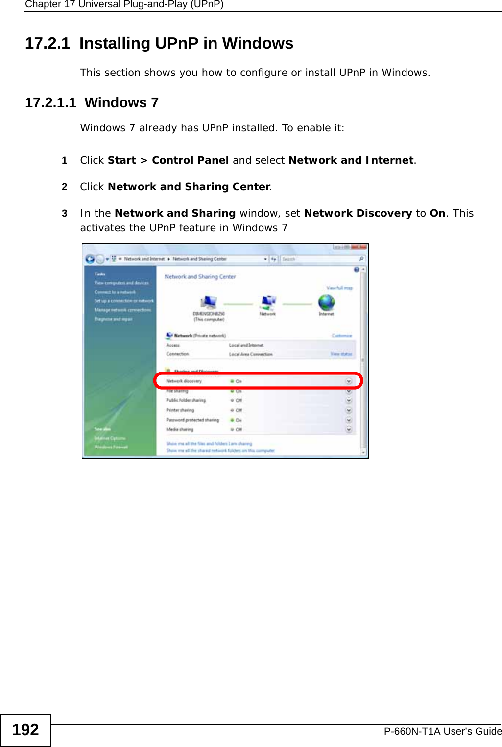

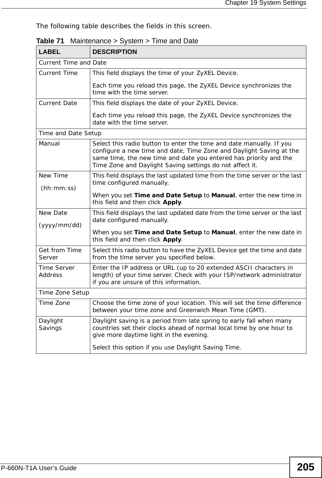
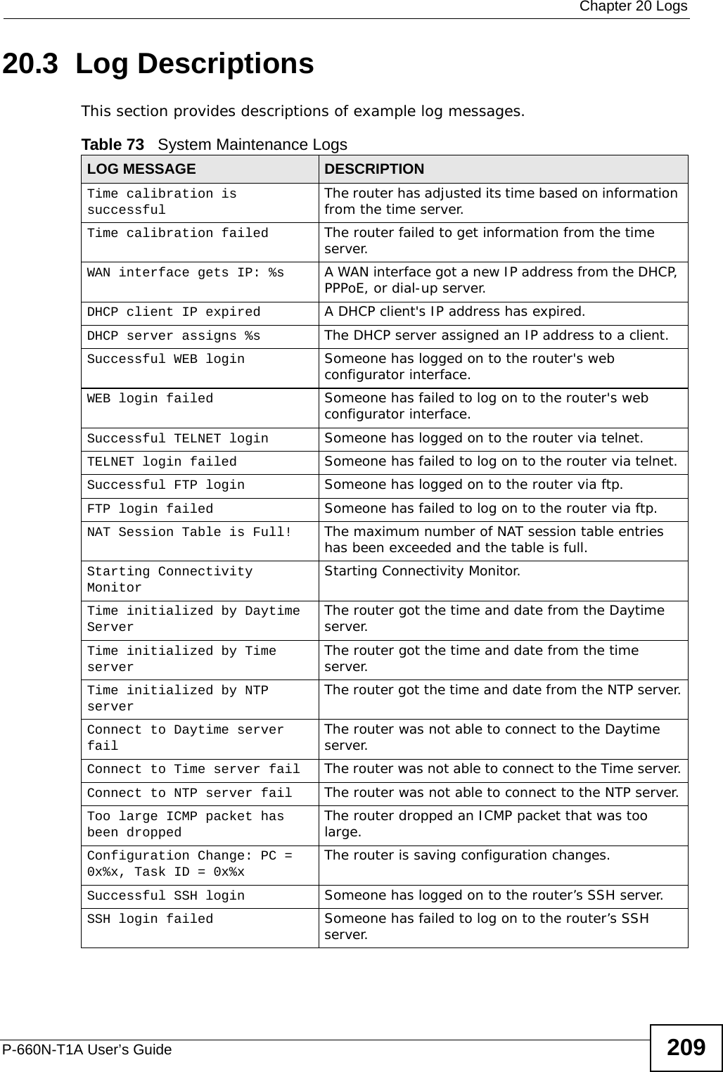
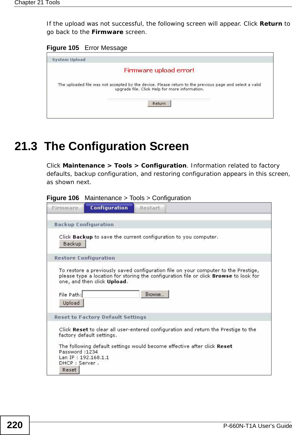
![Chapter 20 LogsP-660N-T1A User’s Guide210 Successful HTTPS login Someone has logged on to the router's web configurator interface using HTTPS protocol.HTTPS login failed Someone has failed to log on to the router's web configurator interface using HTTPS protocol.Table 74 System Error LogsLOG MESSAGE DESCRIPTION%s exceeds the max. number of session per host!This attempt to create a NAT session exceeds the maximum number of NAT session table entries allowed to be created per host.setNetBIOSFilter: calloc error The router failed to allocate memory for the NetBIOS filter settings.readNetBIOSFilter: calloc error The router failed to allocate memory for the NetBIOS filter settings.WAN connection is down. A WAN connection is down. You cannot access the network through this interface.Table 75 Access Control LogsLOG MESSAGE DESCRIPTIONFirewall default policy: [ TCP | UDP | IGMP | ESP | GRE | OSPF ] <Packet Direction>Attempted TCP/UDP/IGMP/ESP/GRE/OSPF access matched the default policy and was blocked or forwarded according to the default policy’s setting.Firewall rule [NOT] match:[ TCP | UDP | IGMP | ESP | GRE | OSPF ] <Packet Direction>, <rule:%d>Attempted TCP/UDP/IGMP/ESP/GRE/OSPF access matched (or did not match) a configured firewall rule (denoted by its number) and was blocked or forwarded according to the rule. Triangle route packet forwarded: [ TCP | UDP | IGMP | ESP | GRE | OSPF ]The firewall allowed a triangle route session to pass through.Packet without a NAT table entry blocked: [ TCP | UDP | IGMP | ESP | GRE | OSPF ]The router blocked a packet that didn't have a corresponding NAT table entry.Router sent blocked web site message: TCP The router sent a message to notify a user that the router blocked access to a web site that the user requested.Table 73 System Maintenance Logs (continued)LOG MESSAGE DESCRIPTION](https://usermanual.wiki/ZyXEL-Communications/P660NT1A.user-manual-1/User-Guide-1315611-Page-210.png)
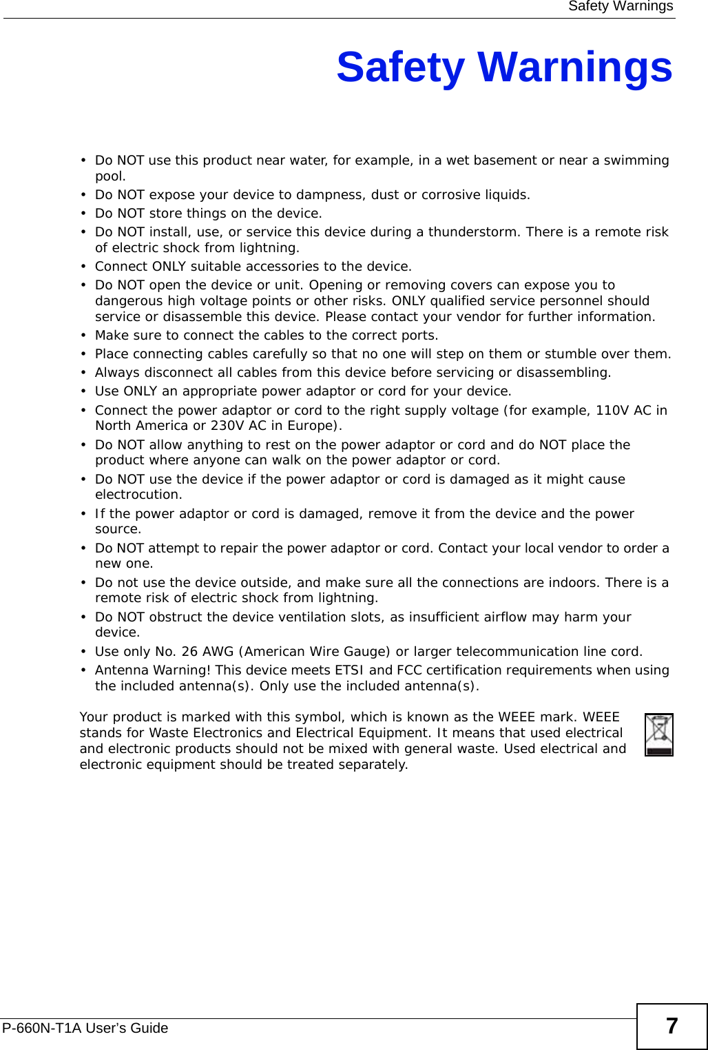
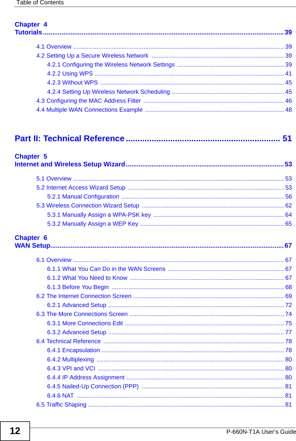
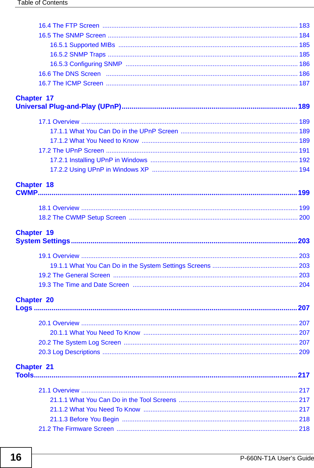
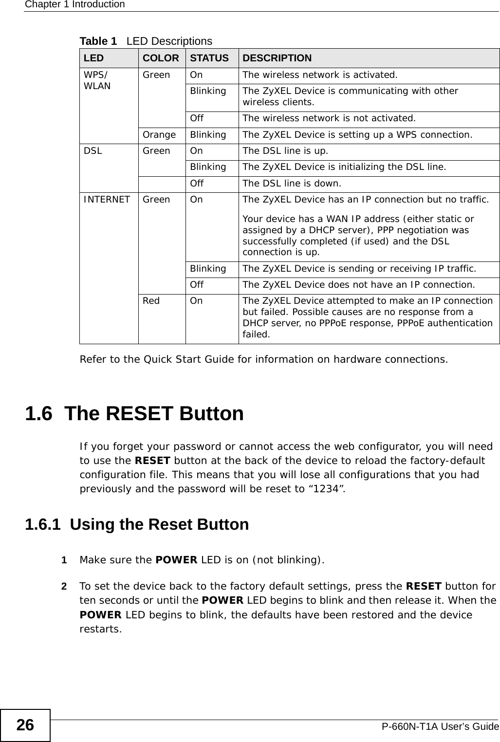
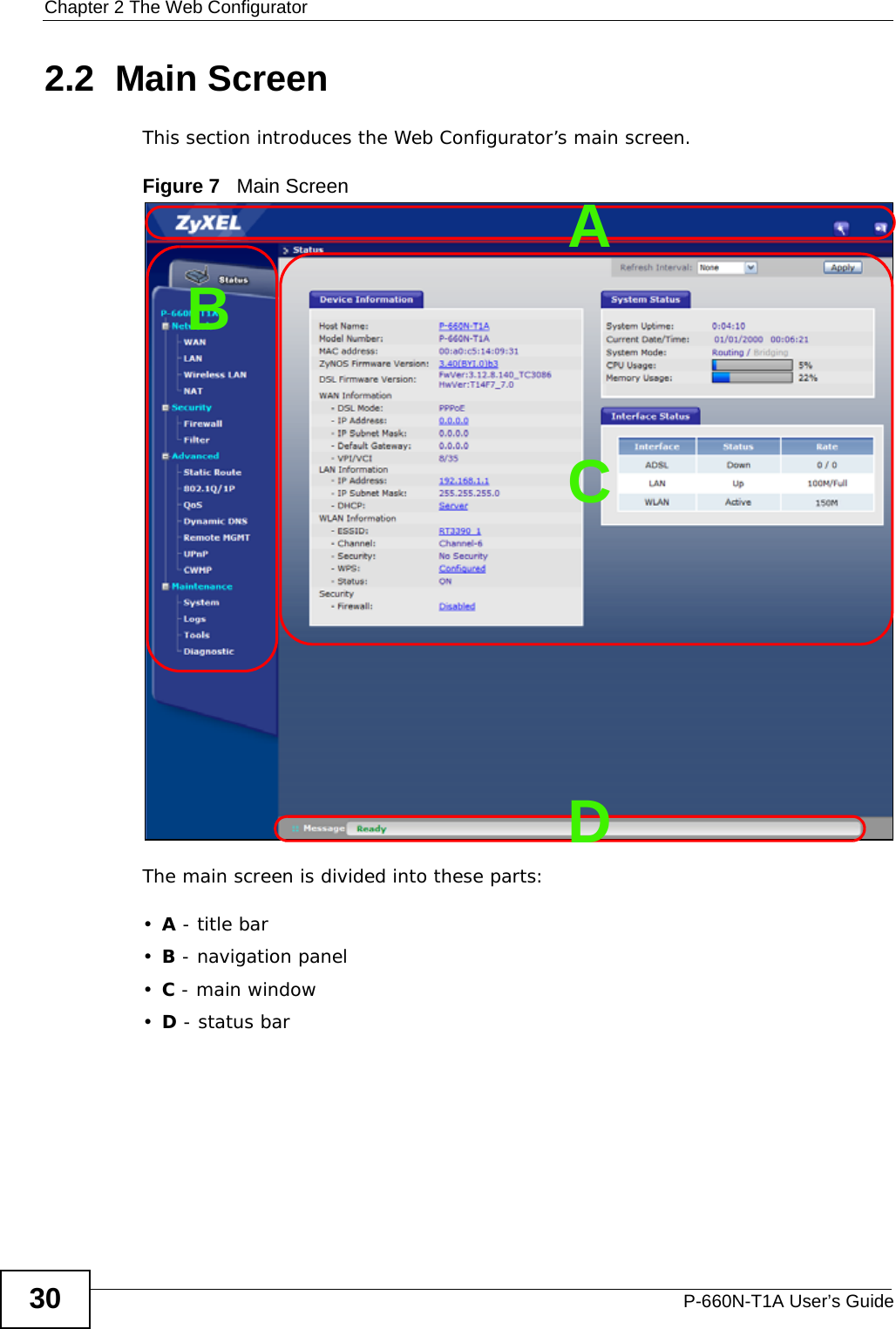
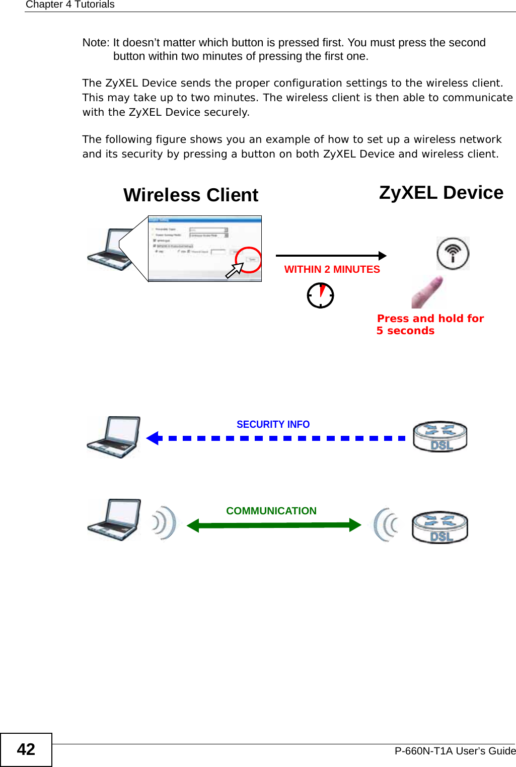
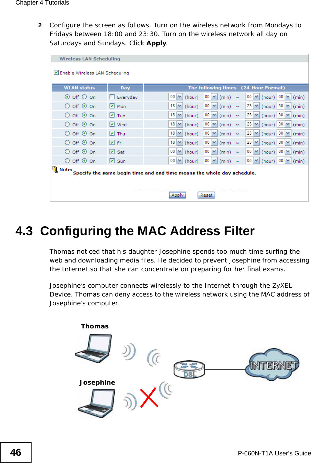
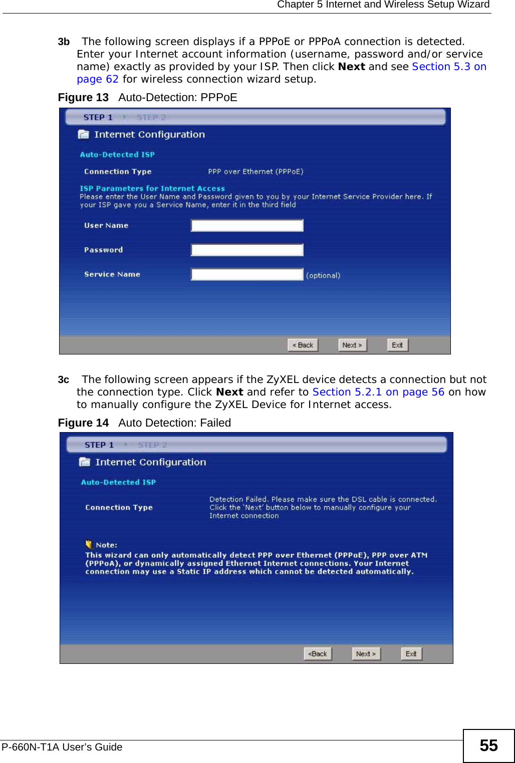
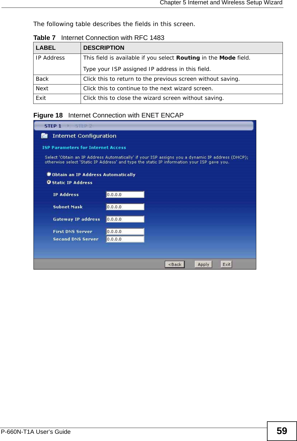
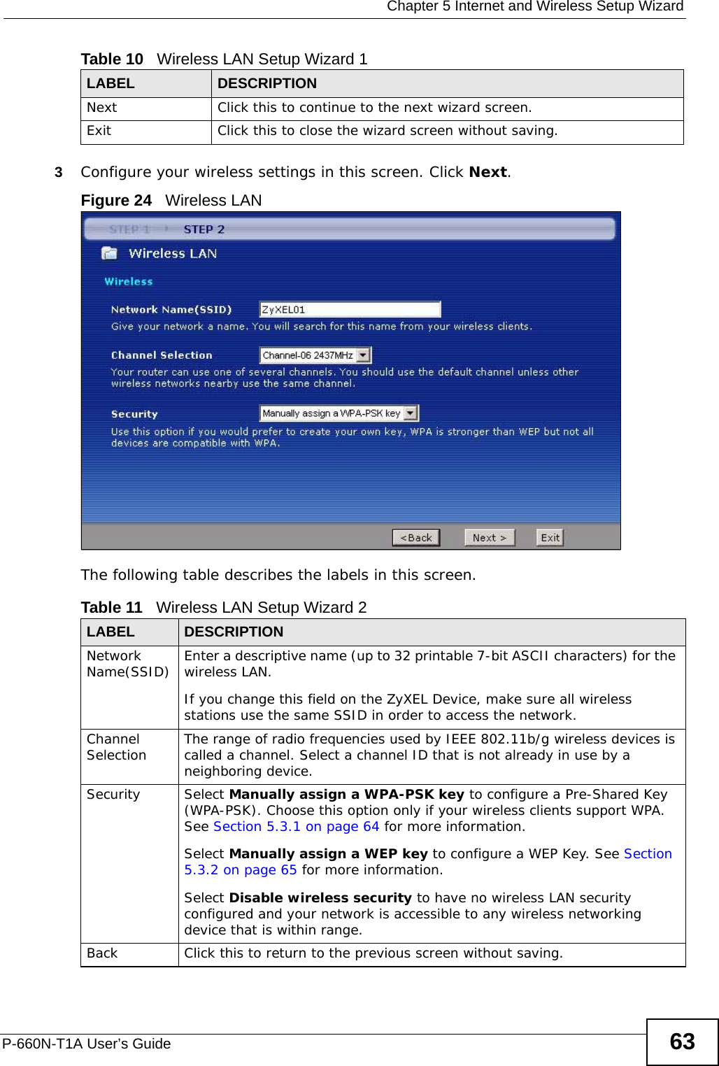
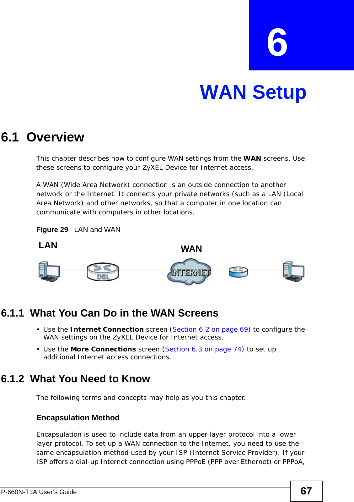
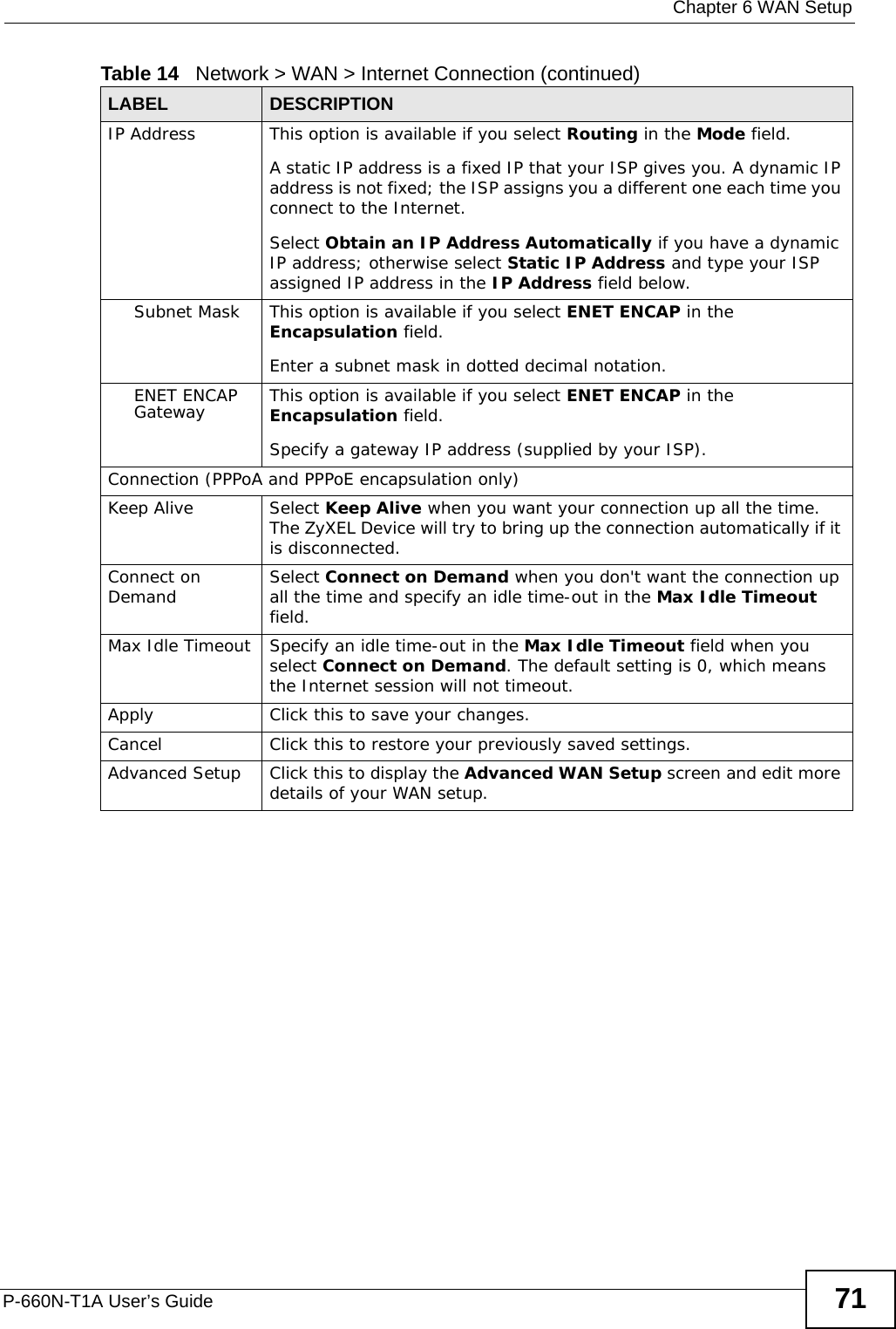
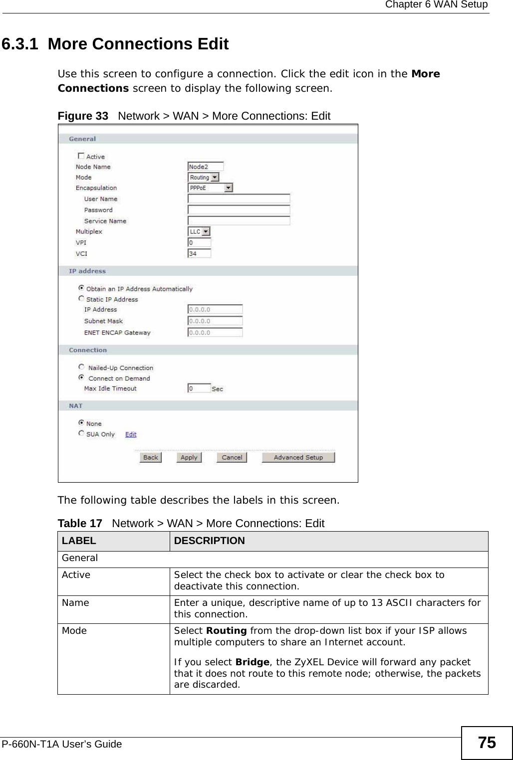
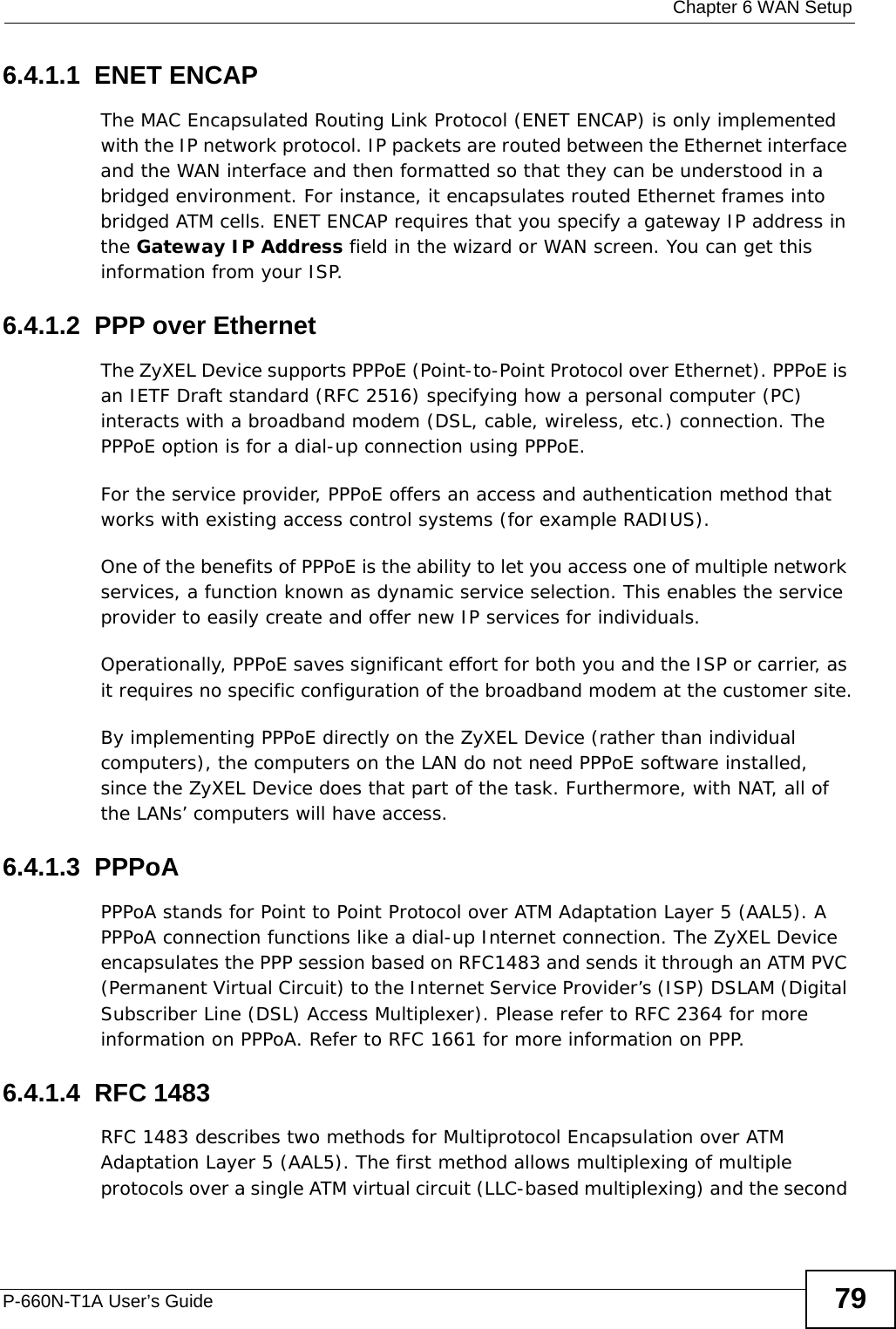
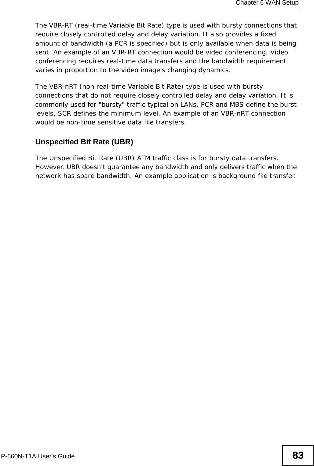
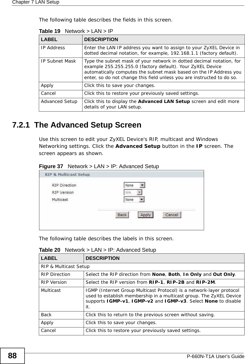
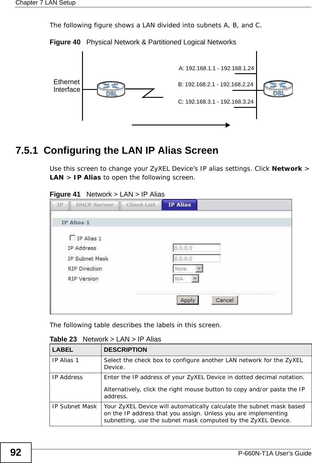
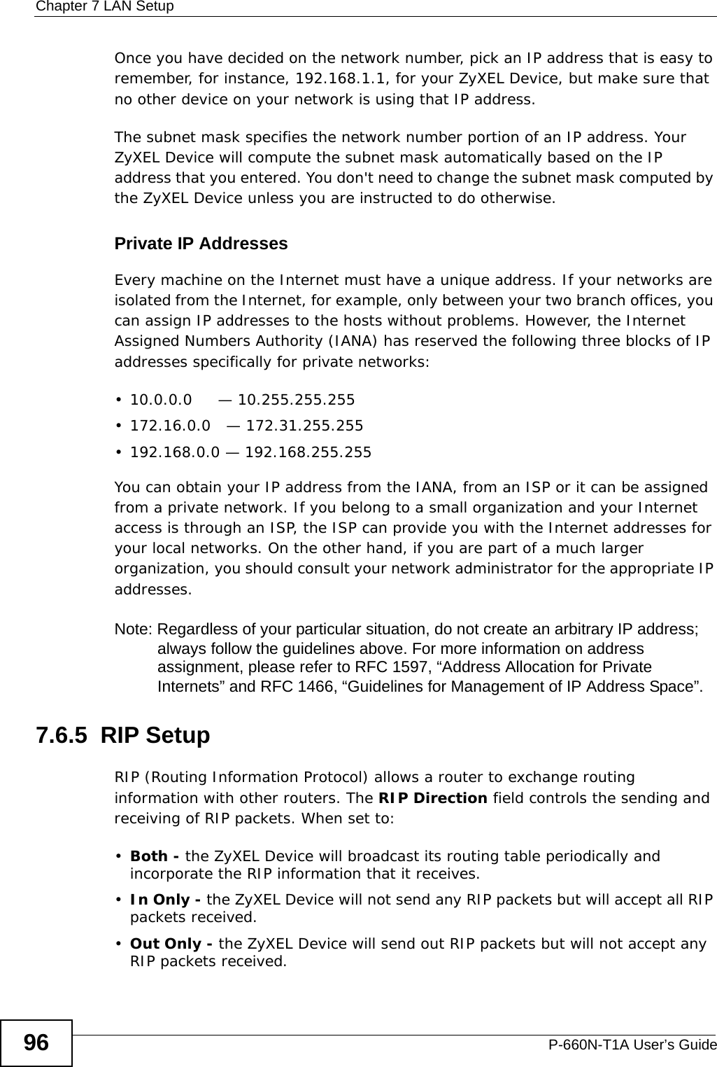
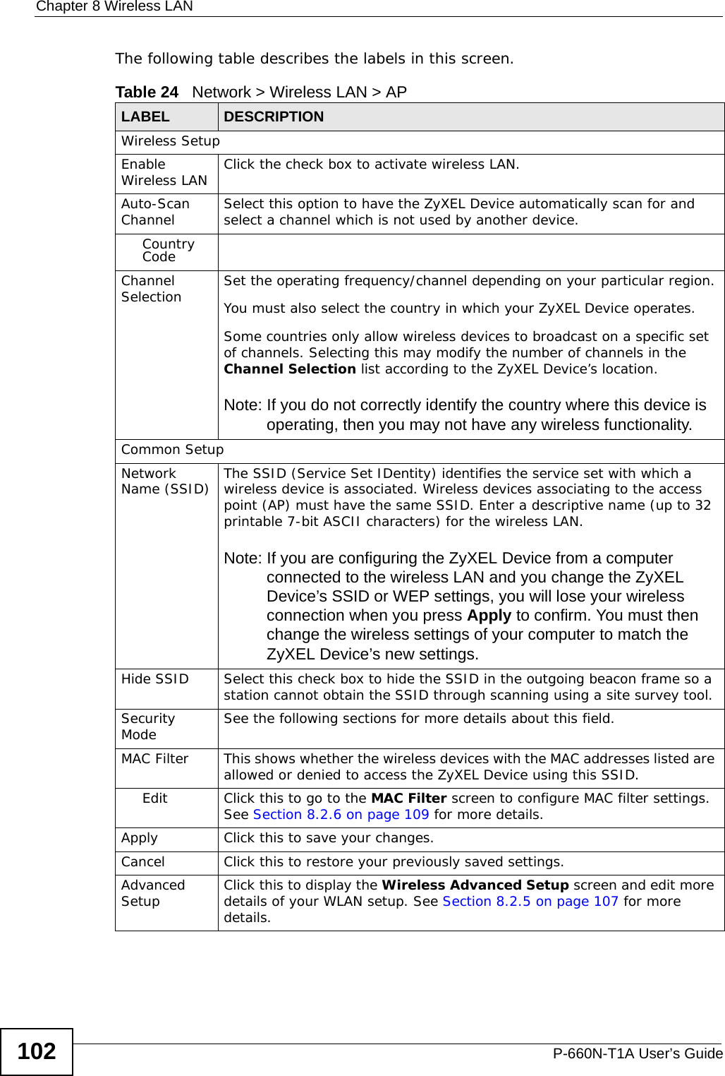
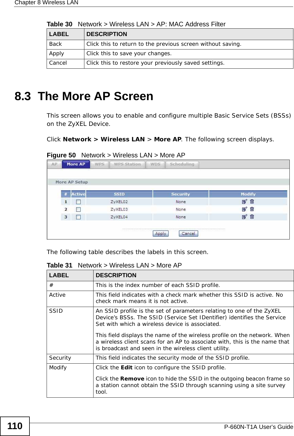
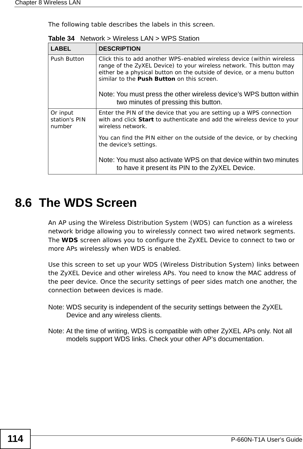
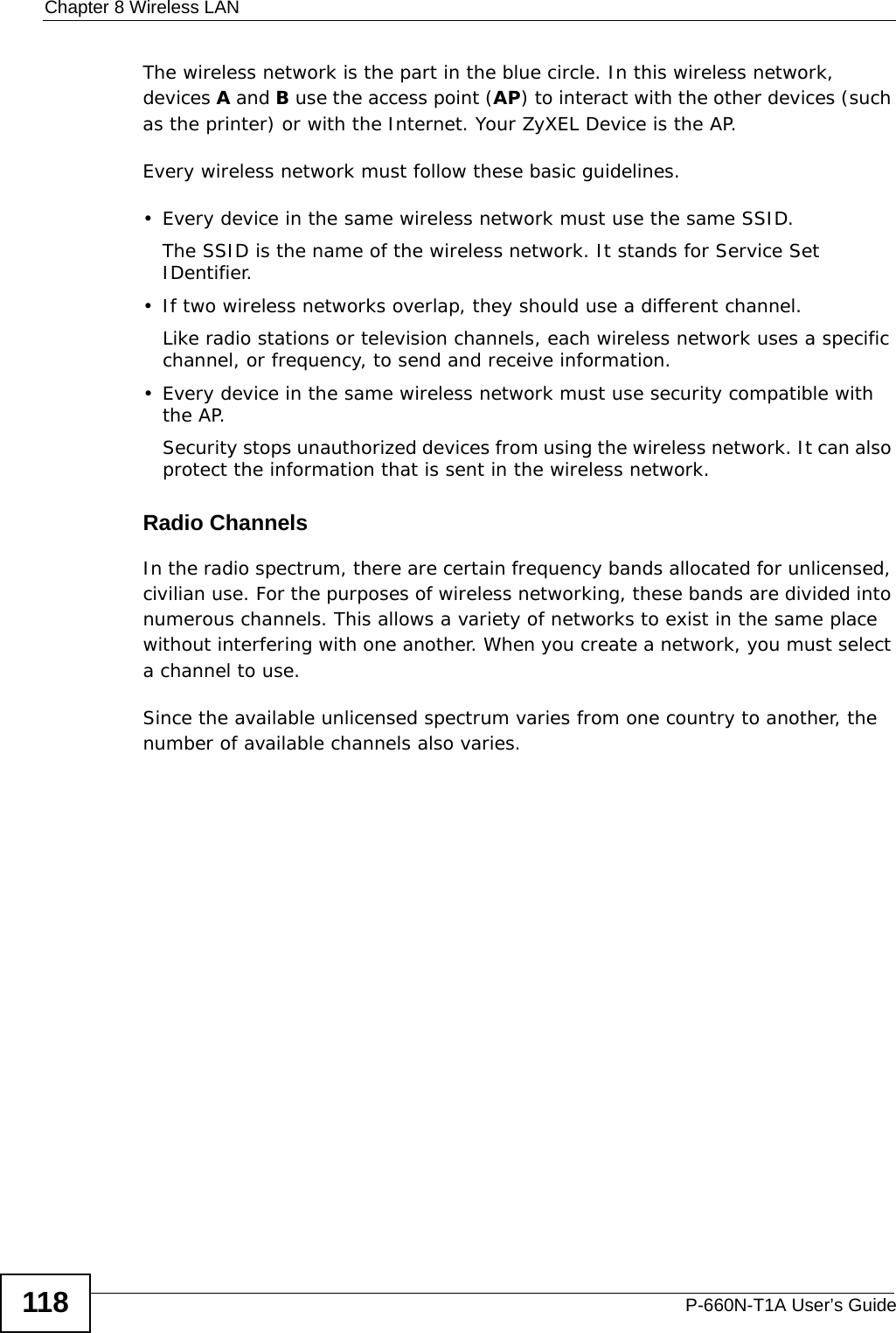
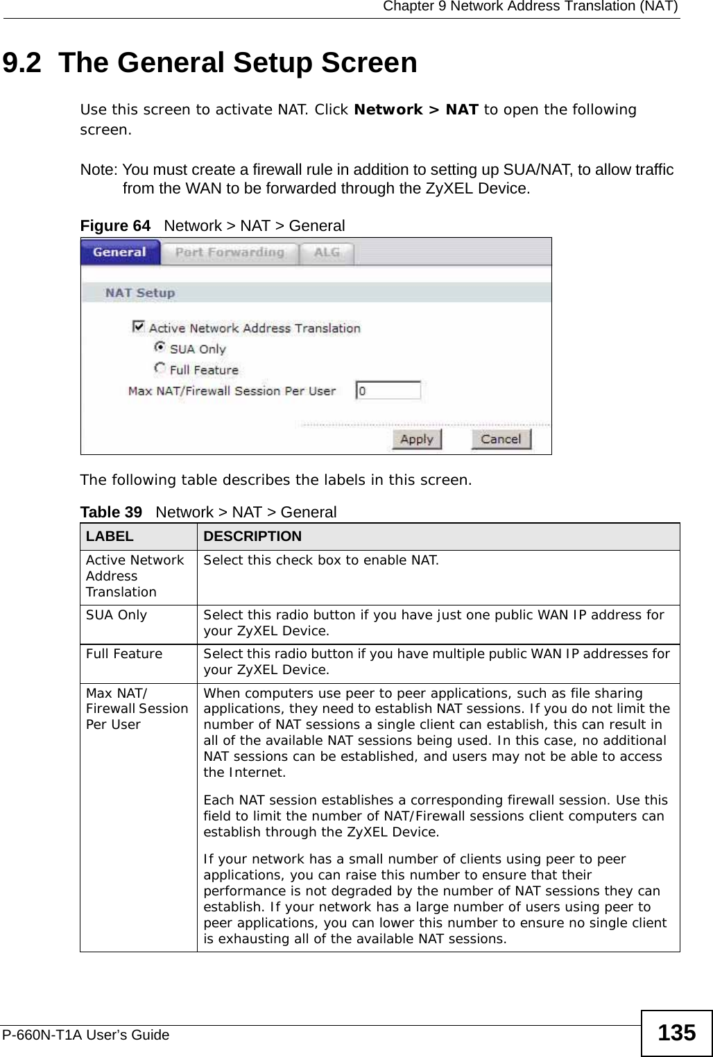
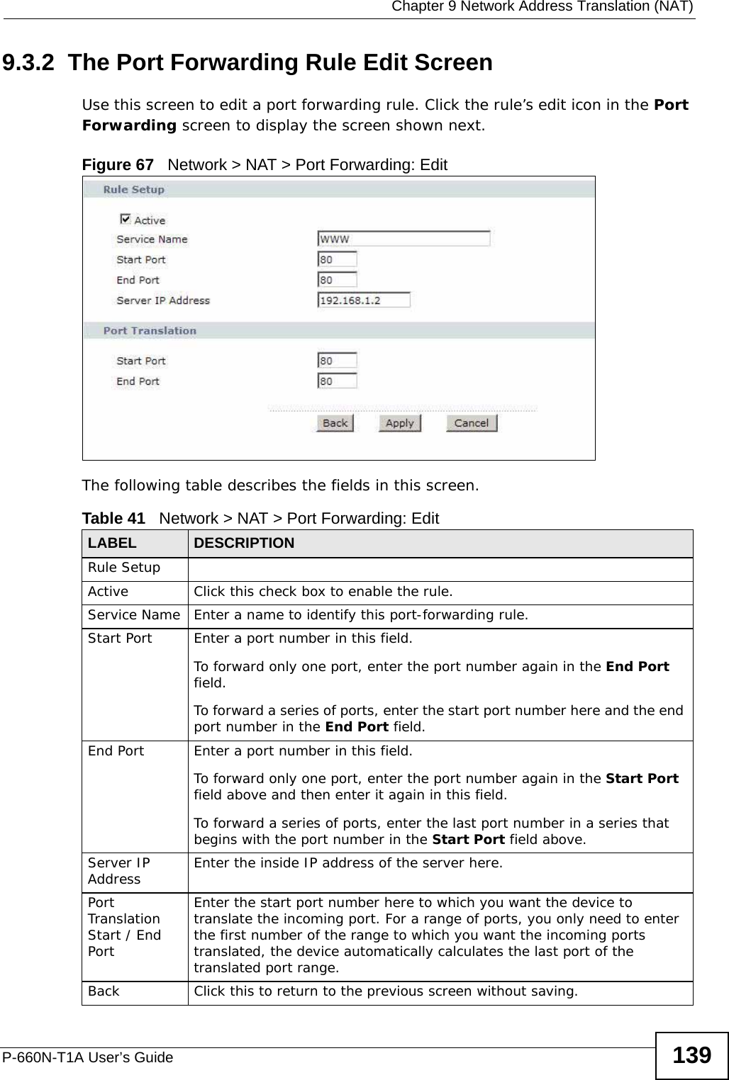
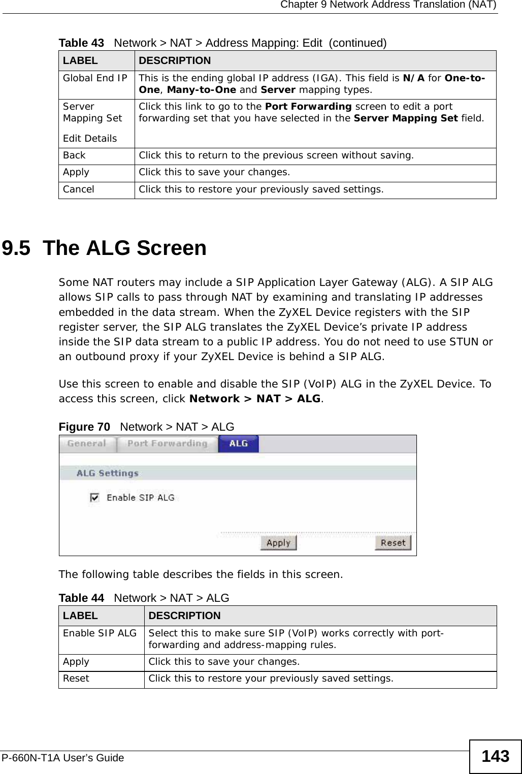
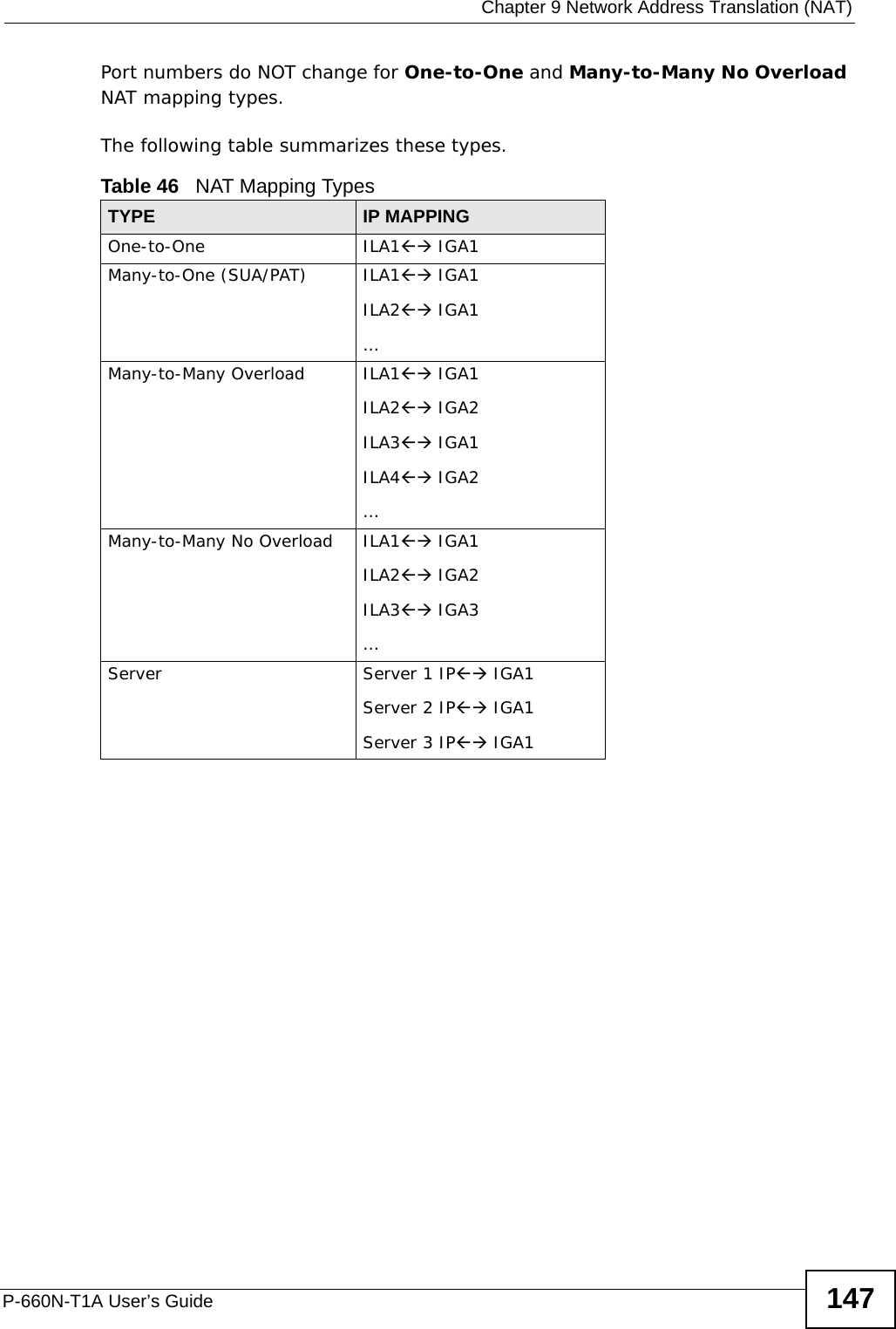
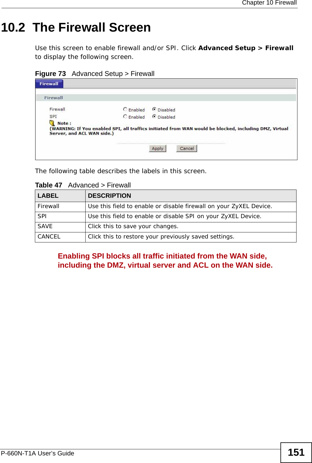
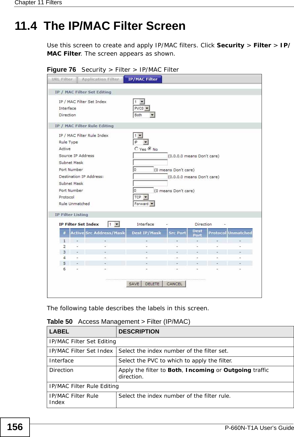
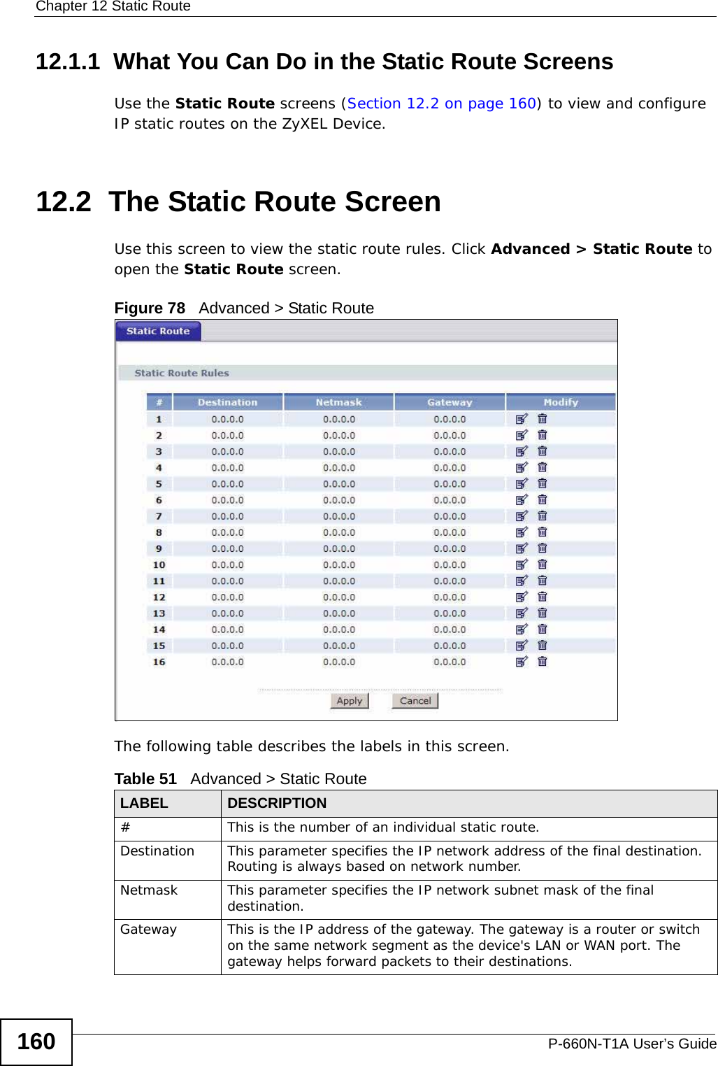
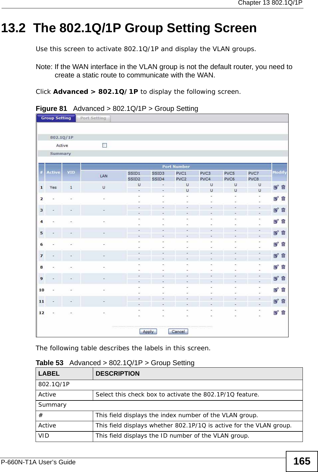
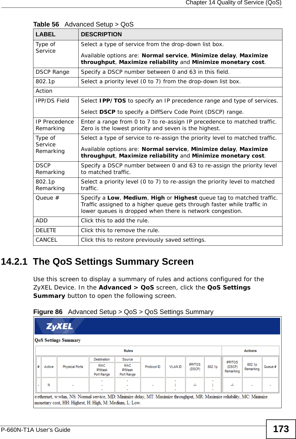
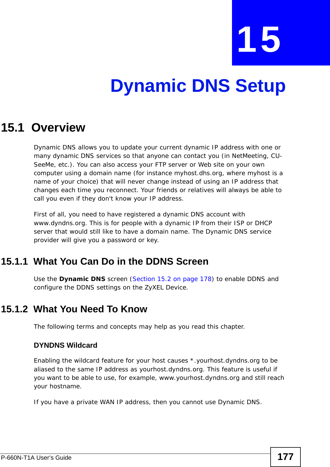
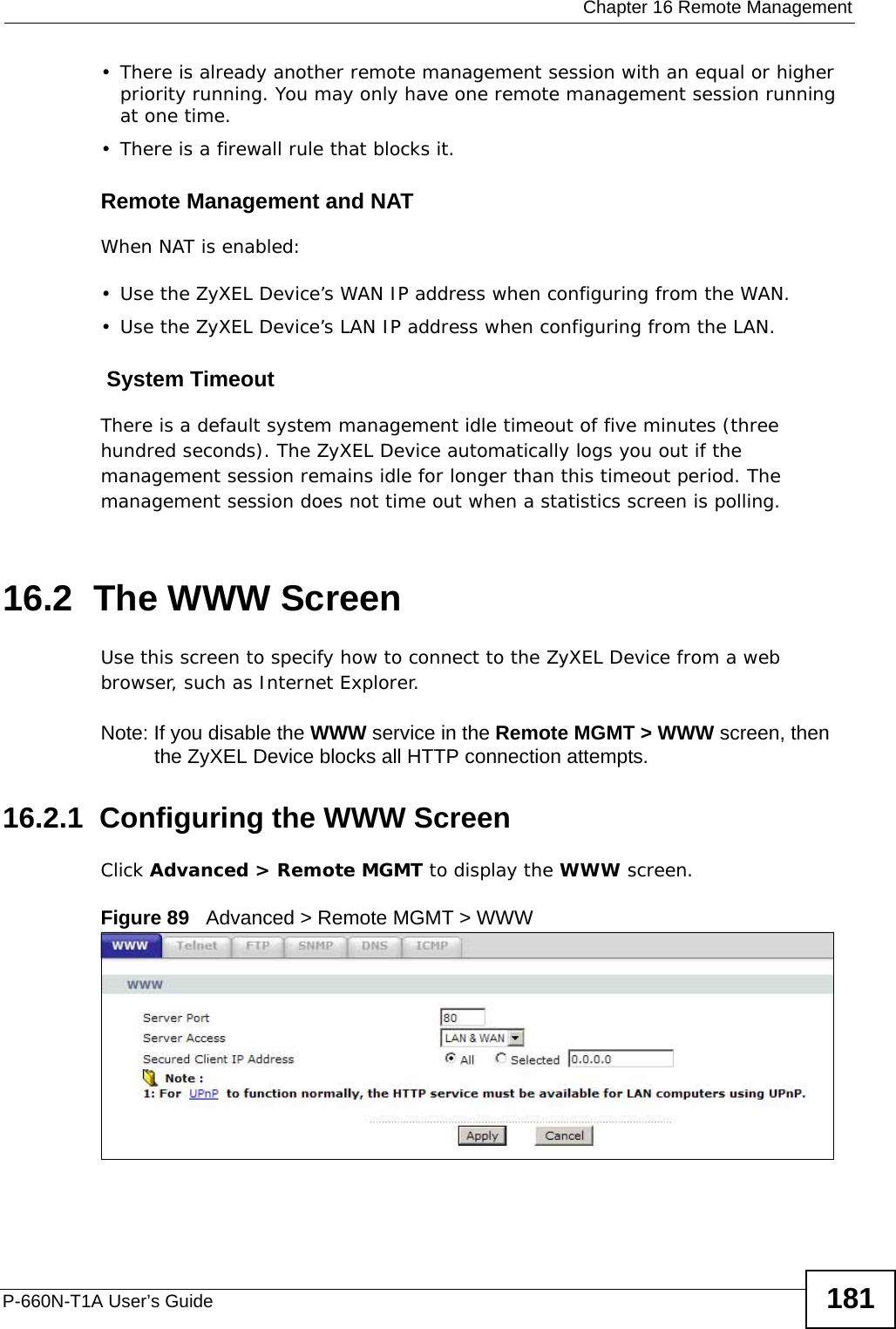
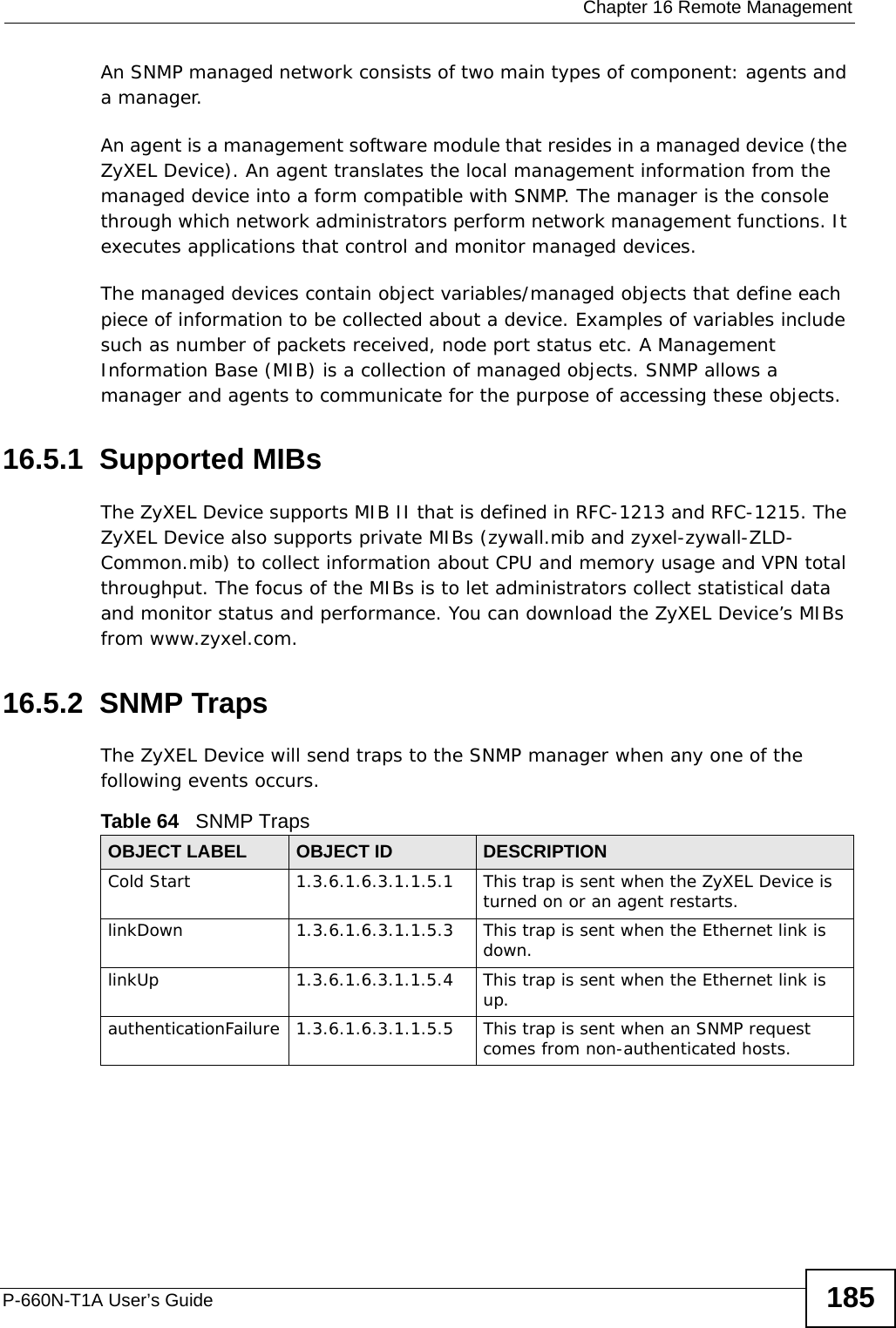
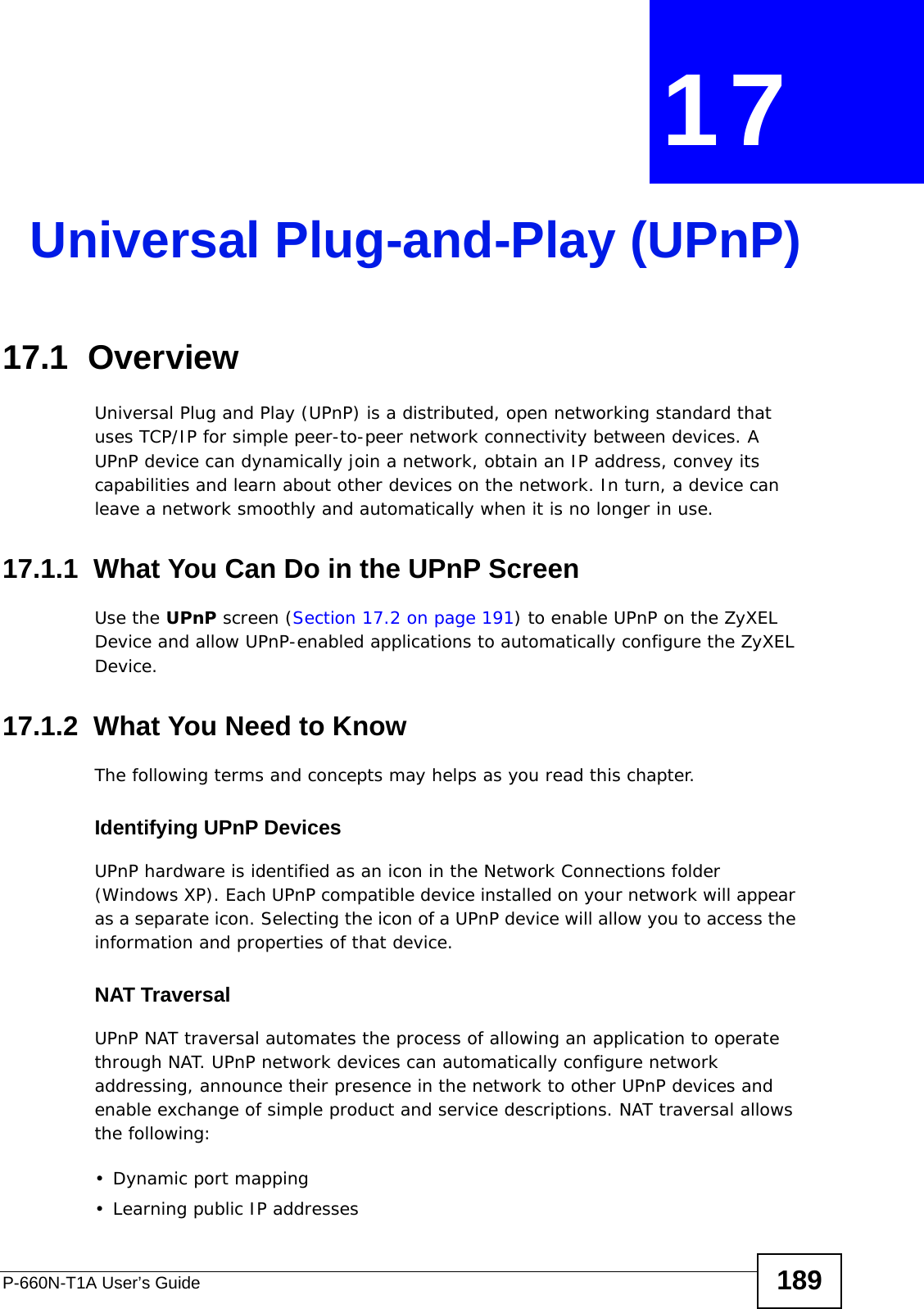
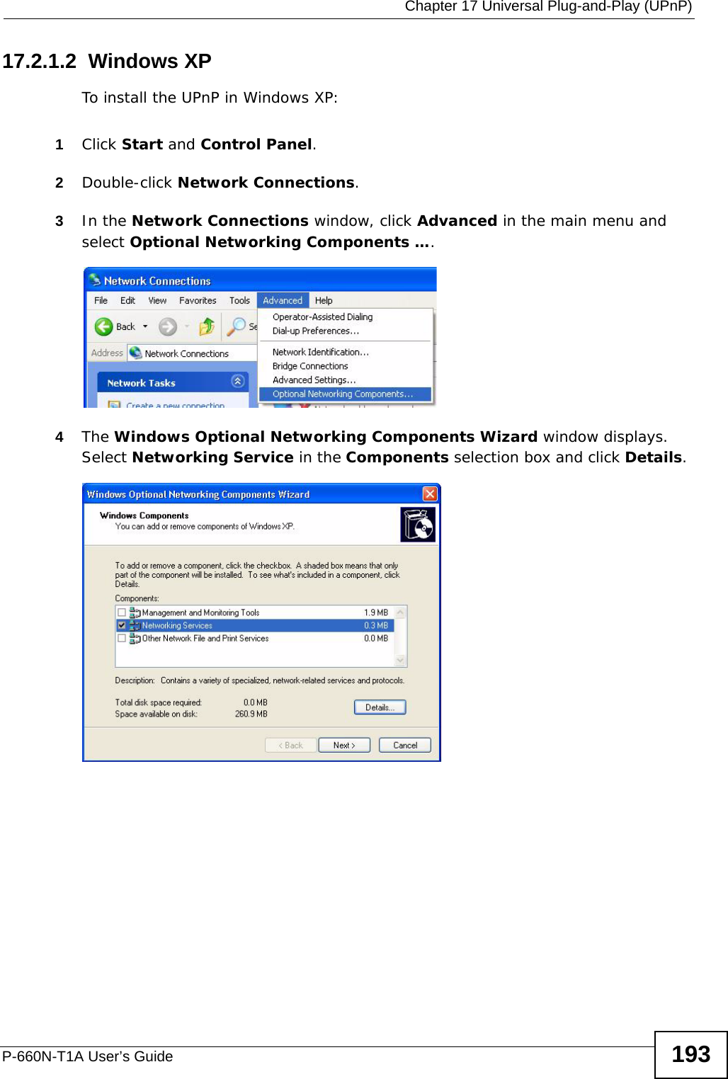
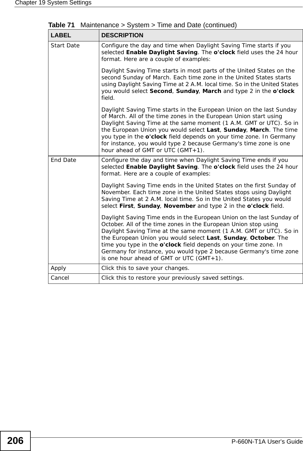
![Chapter 20 LogsP-660N-T1A User’s Guide 211 Table 76 TCP Reset LogsLOG MESSAGE DESCRIPTIONUnder SYN flood attack, sent TCP RST The router sent a TCP reset packet when a host was under a SYN flood attack (the TCP incomplete count is per destination host.) Exceed TCP MAX incomplete, sent TCP RST The router sent a TCP reset packet when the number of TCP incomplete connections exceeded the user configured threshold. (the TCP incomplete count is per destination host.) Note: Refer to TCP Maximum Incomplete in the Firewall Attack Alerts screen. Peer TCP state out of order, sent TCP RST The router sent a TCP reset packet when a TCP connection state was out of order.Note: The firewall refers to RFC793 Figure 6 to check the TCP state.Firewall session time out, sent TCP RST The router sent a TCP reset packet when a dynamic firewall session timed out.Default timeout values:ICMP idle timeout (s): 60UDP idle timeout (s): 60TCP connection (three way handshaking) timeout (s): 30TCP FIN-wait timeout (s): 60TCP idle (established) timeout (s): 3600Exceed MAX incomplete, sent TCP RST The router sent a TCP reset packet when the number of incomplete connections (TCP and UDP) exceeded the user-configured threshold. (Incomplete count is for all TCP and UDP connections through the firewall.)Note: When the number of incomplete connections (TCP + UDP) > “Maximum Incomplete High”, the router sends TCP RST packets for TCP connections and destroys TOS (firewall dynamic sessions) until incomplete connections < “Maximum Incomplete Low”.Access block, sent TCP RST The router sends a TCP RST packet and generates this log if you turn on the firewall TCP reset mechanism (via CI command: "sys firewall tcprst").Table 77 Packet Filter LogsLOG MESSAGE DESCRIPTION[ TCP | UDP | ICMP | IGMP | Generic ] packet filter matched (set: %d, rule: %d)Attempted access matched a configured filter rule (denoted by its set and rule number) and was blocked or forwarded according to the rule.](https://usermanual.wiki/ZyXEL-Communications/P660NT1A.user-manual-1/User-Guide-1315611-Page-211.png)
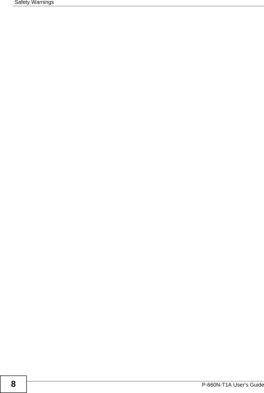
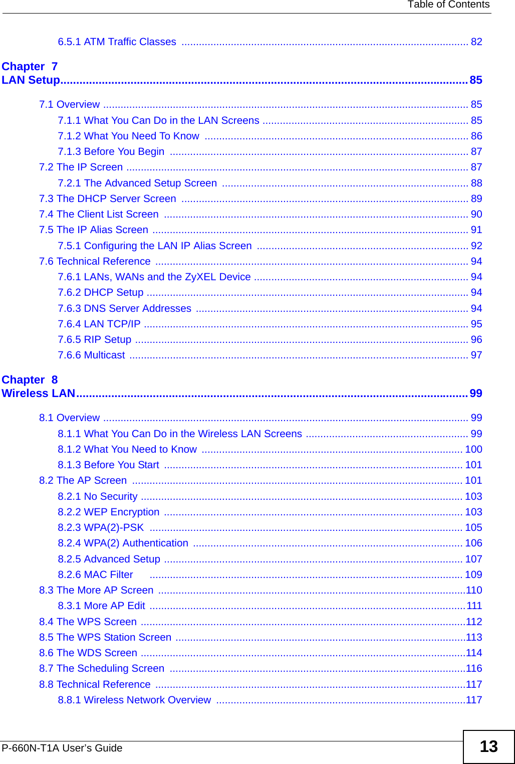
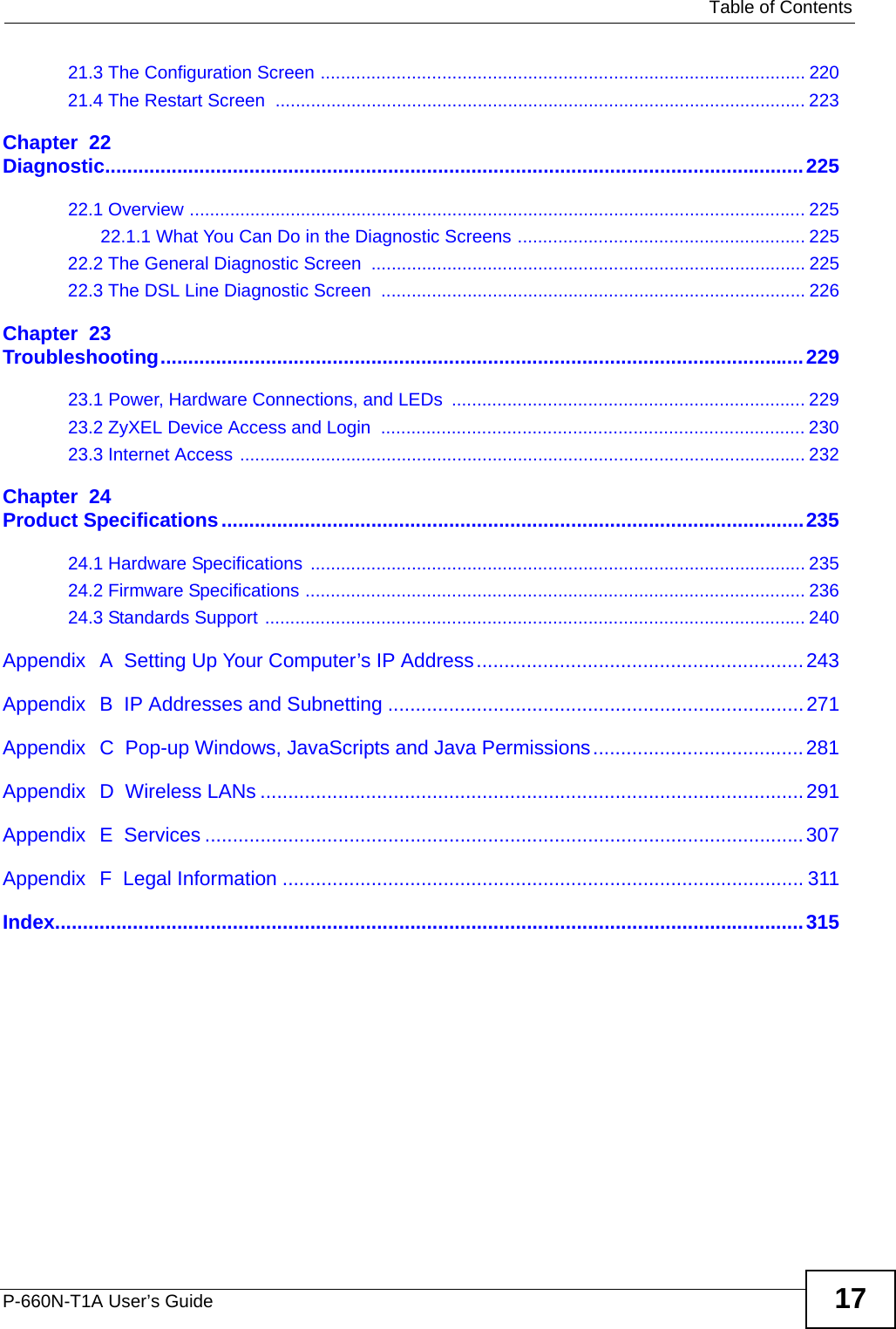
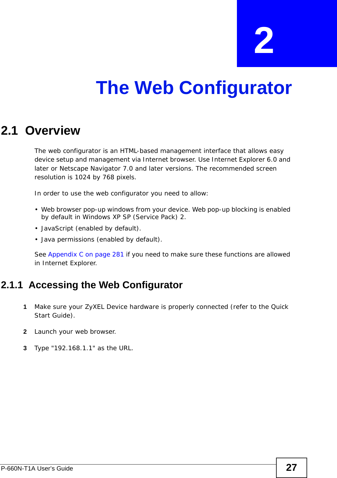
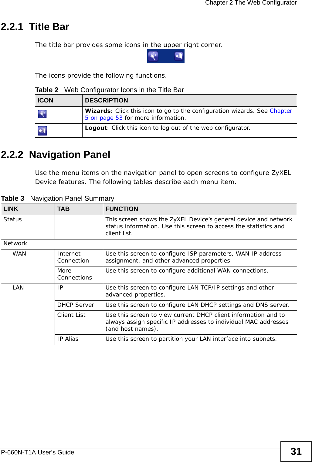
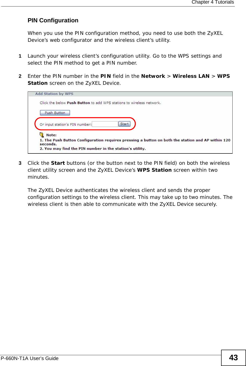
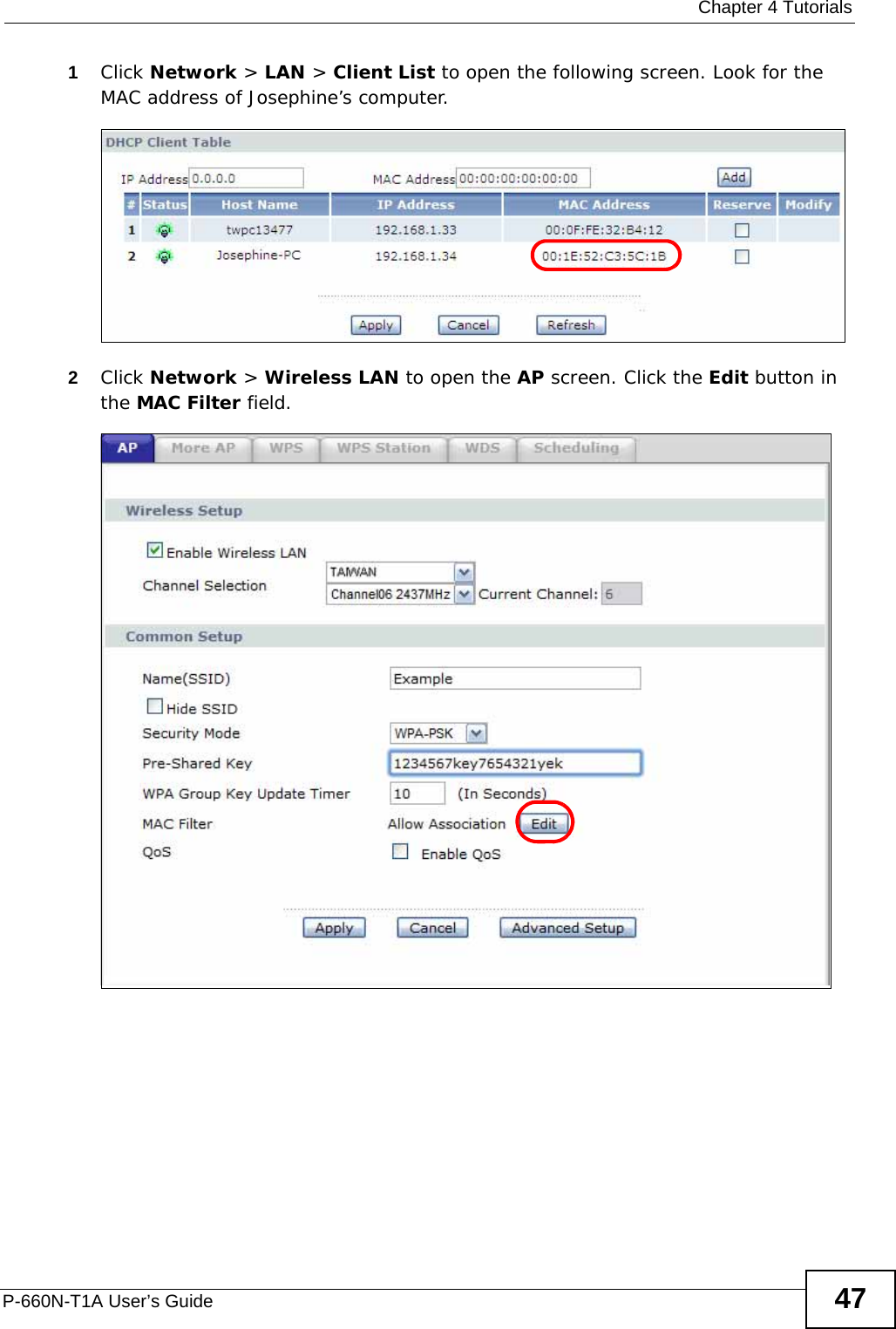
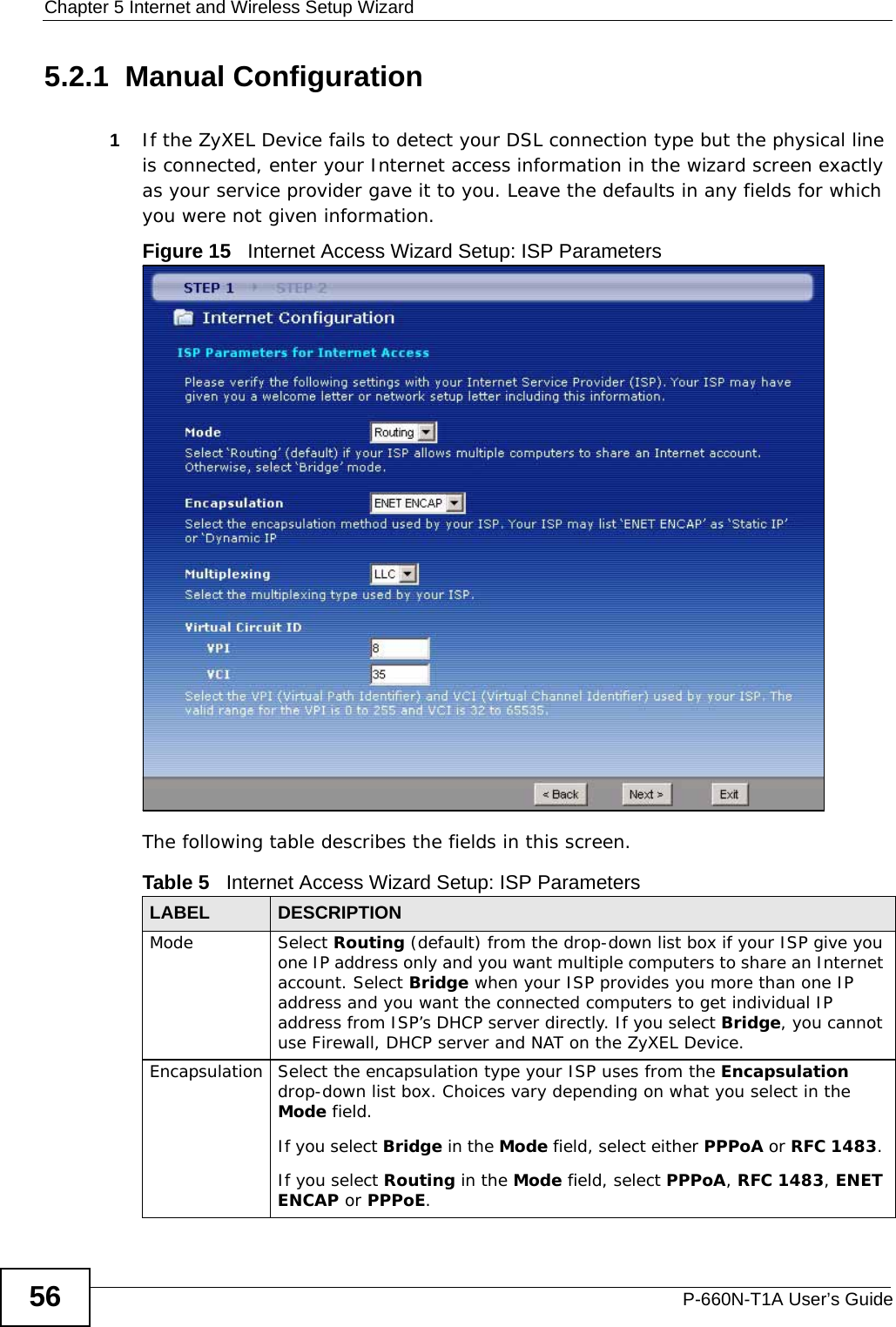
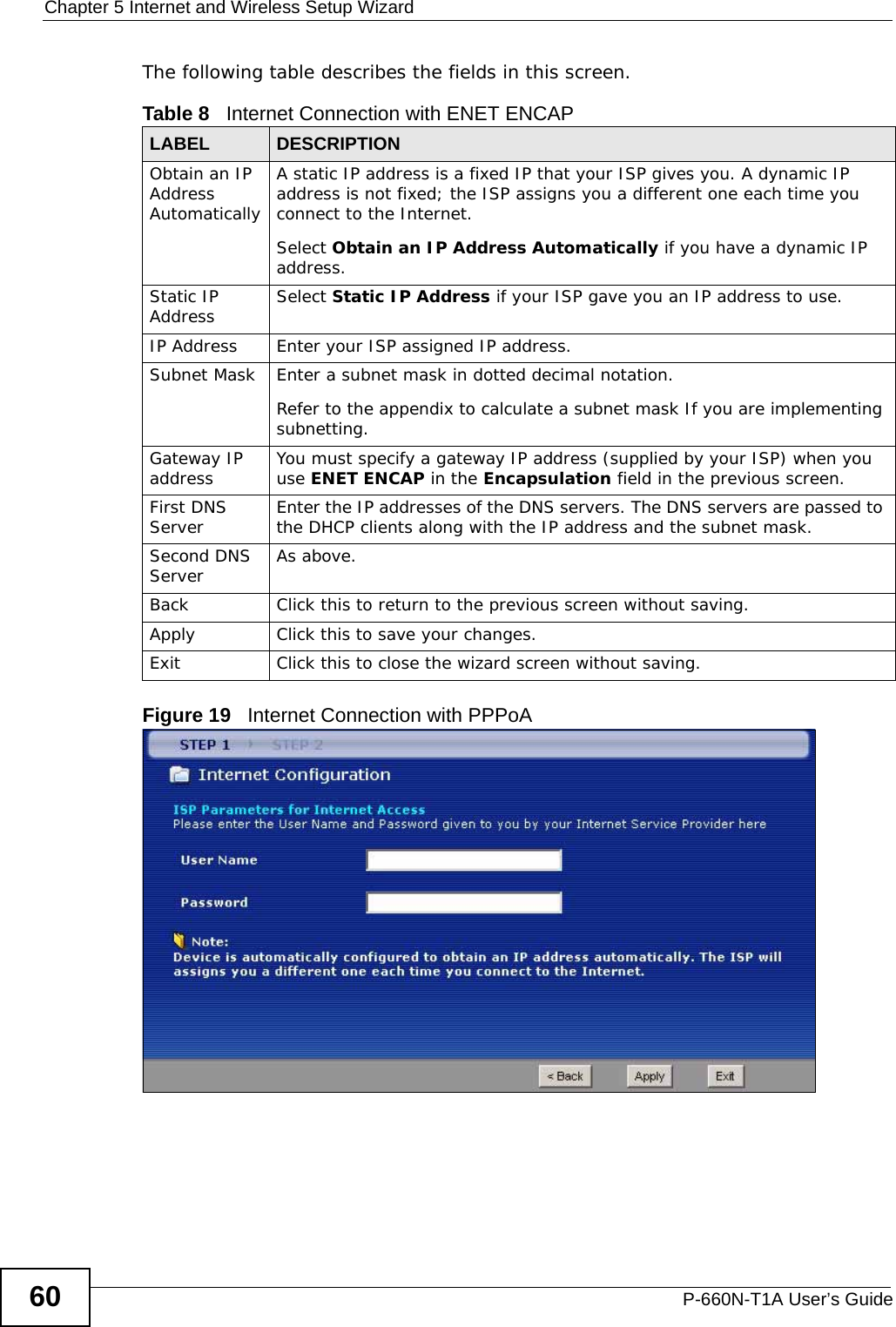
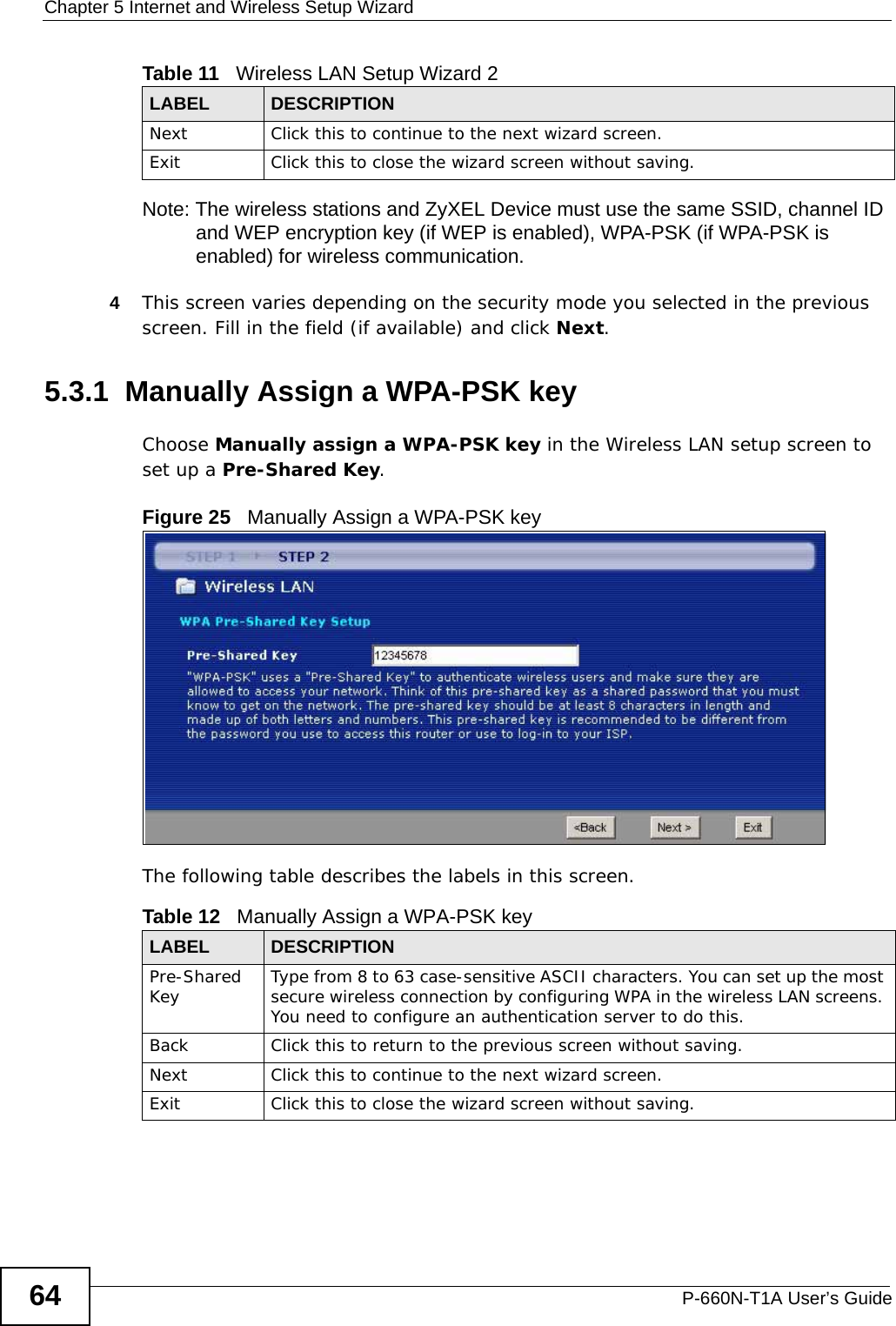
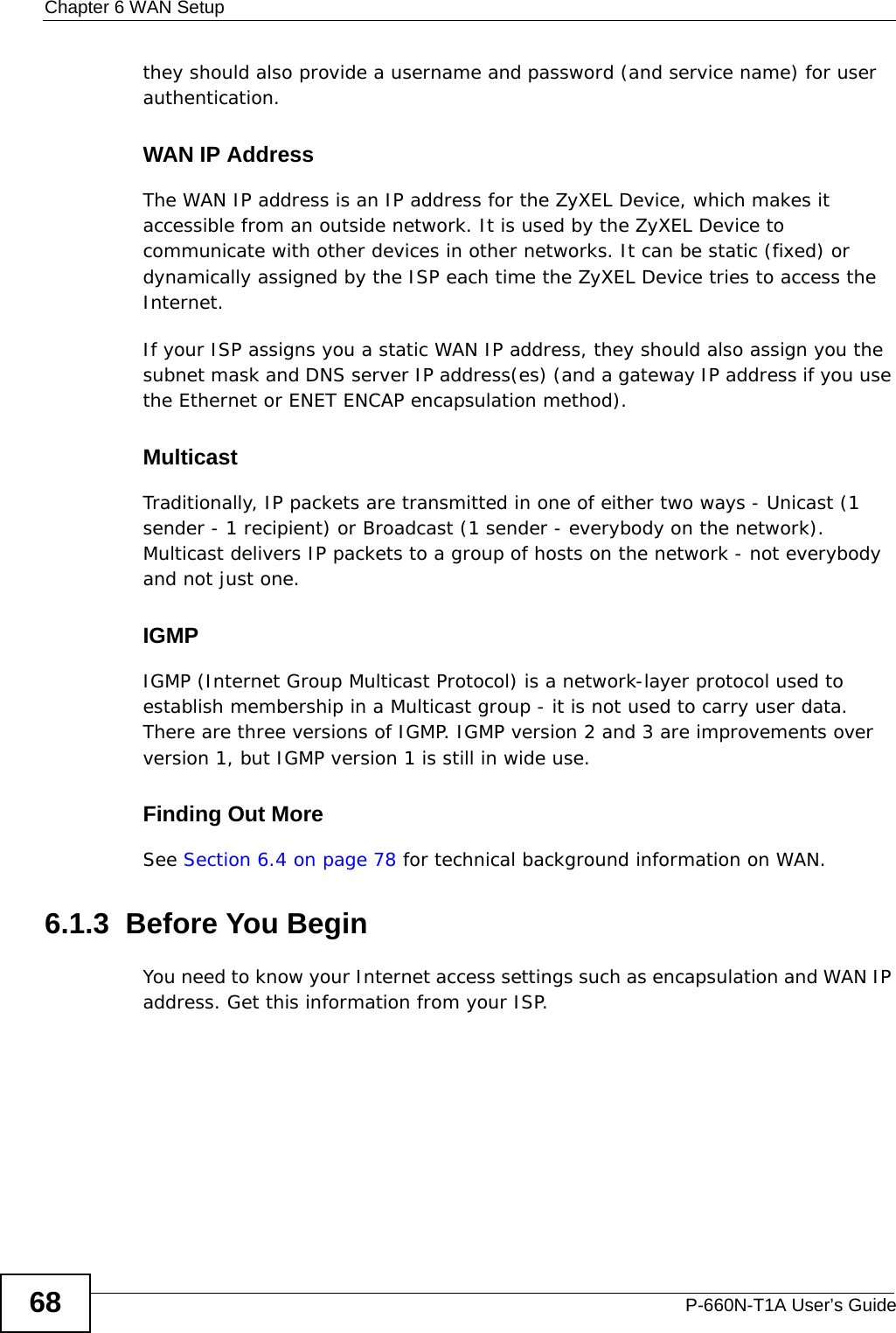
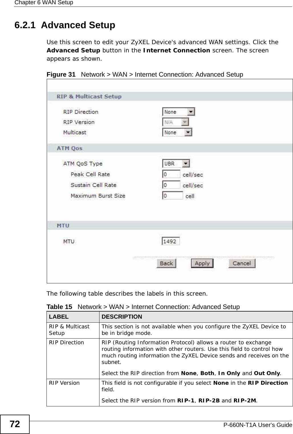
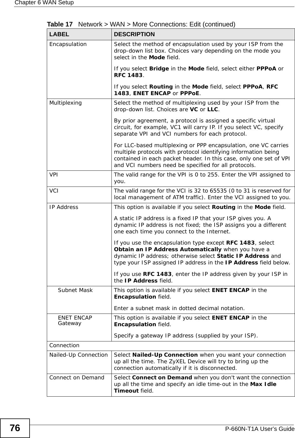
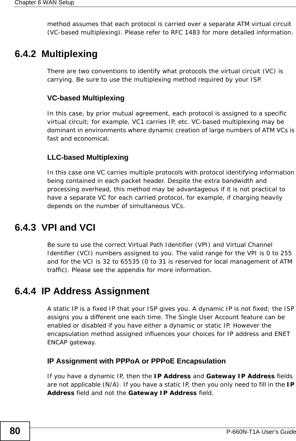
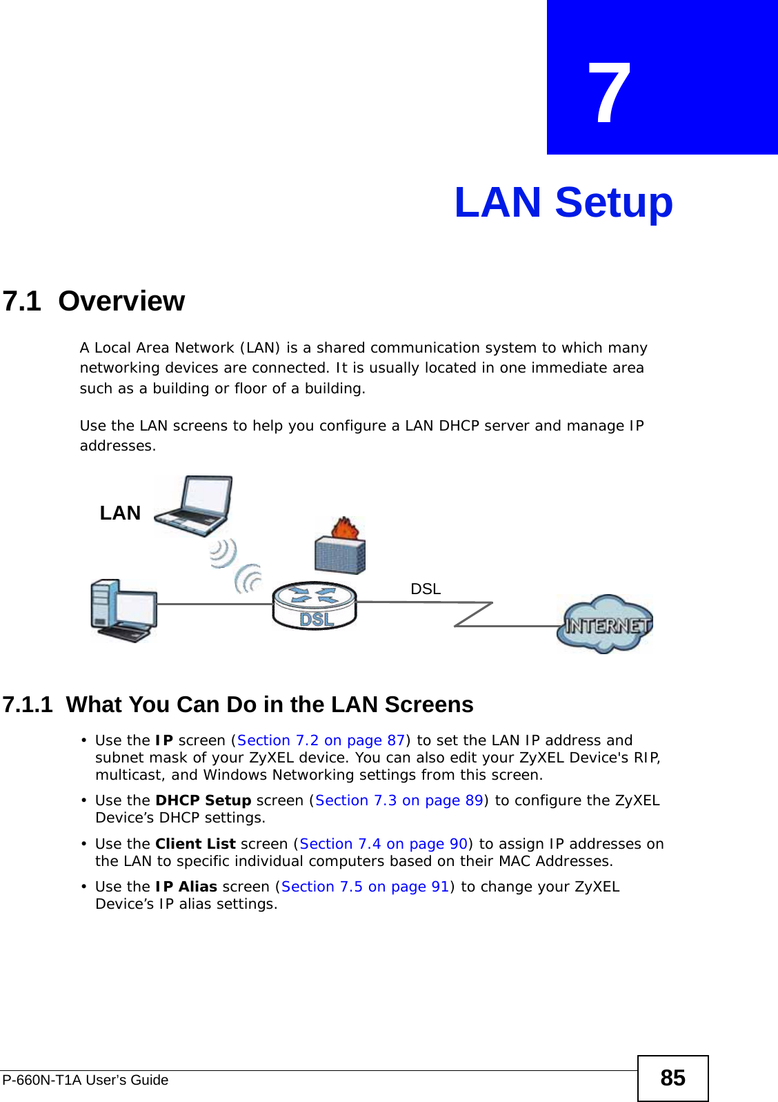
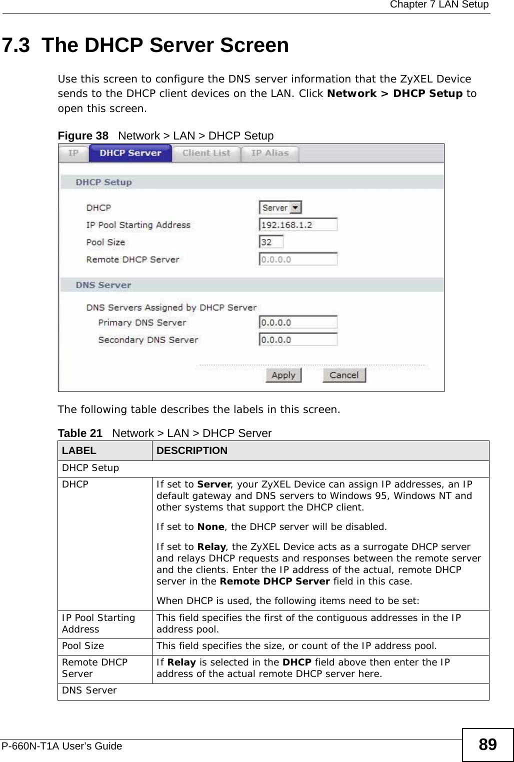
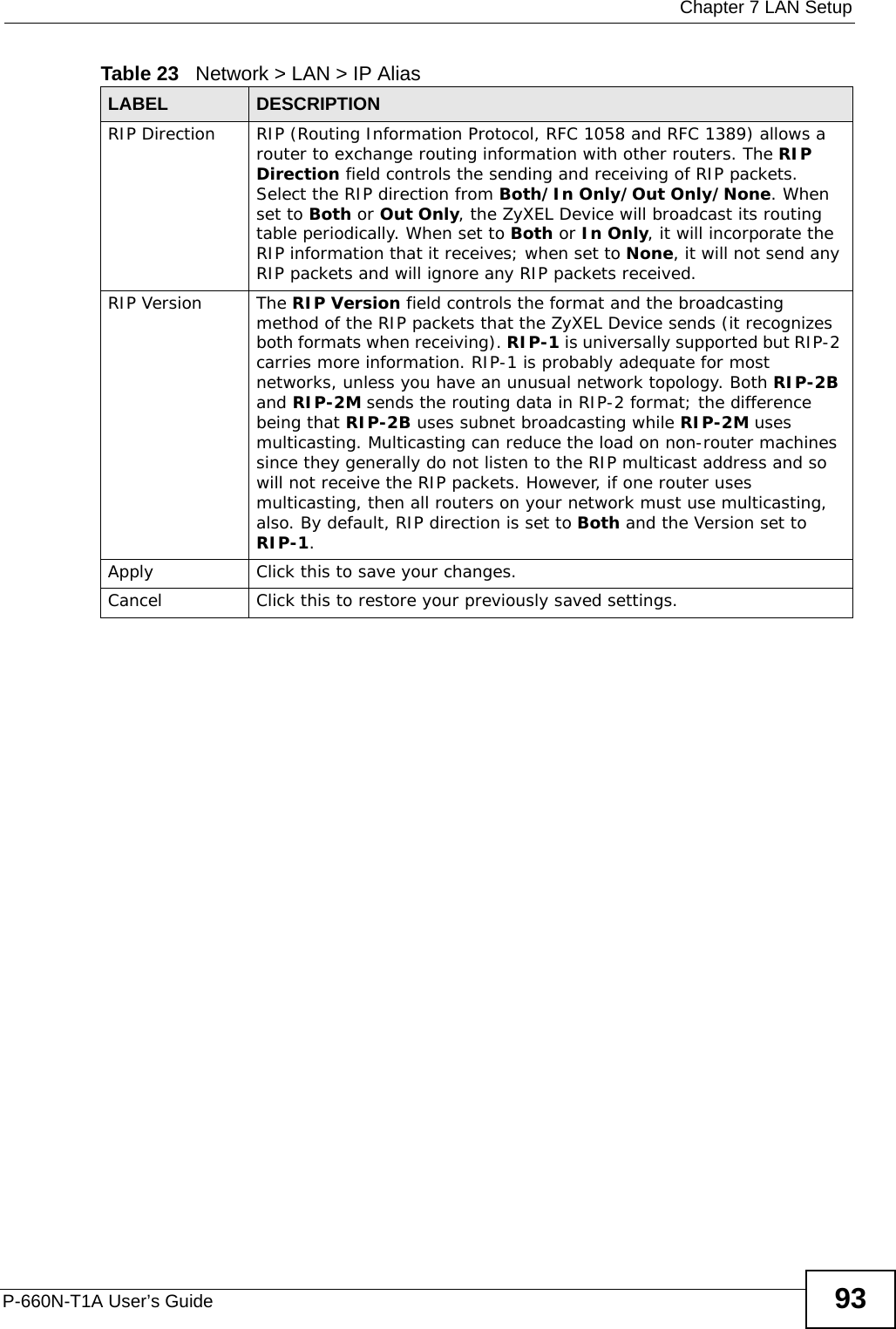
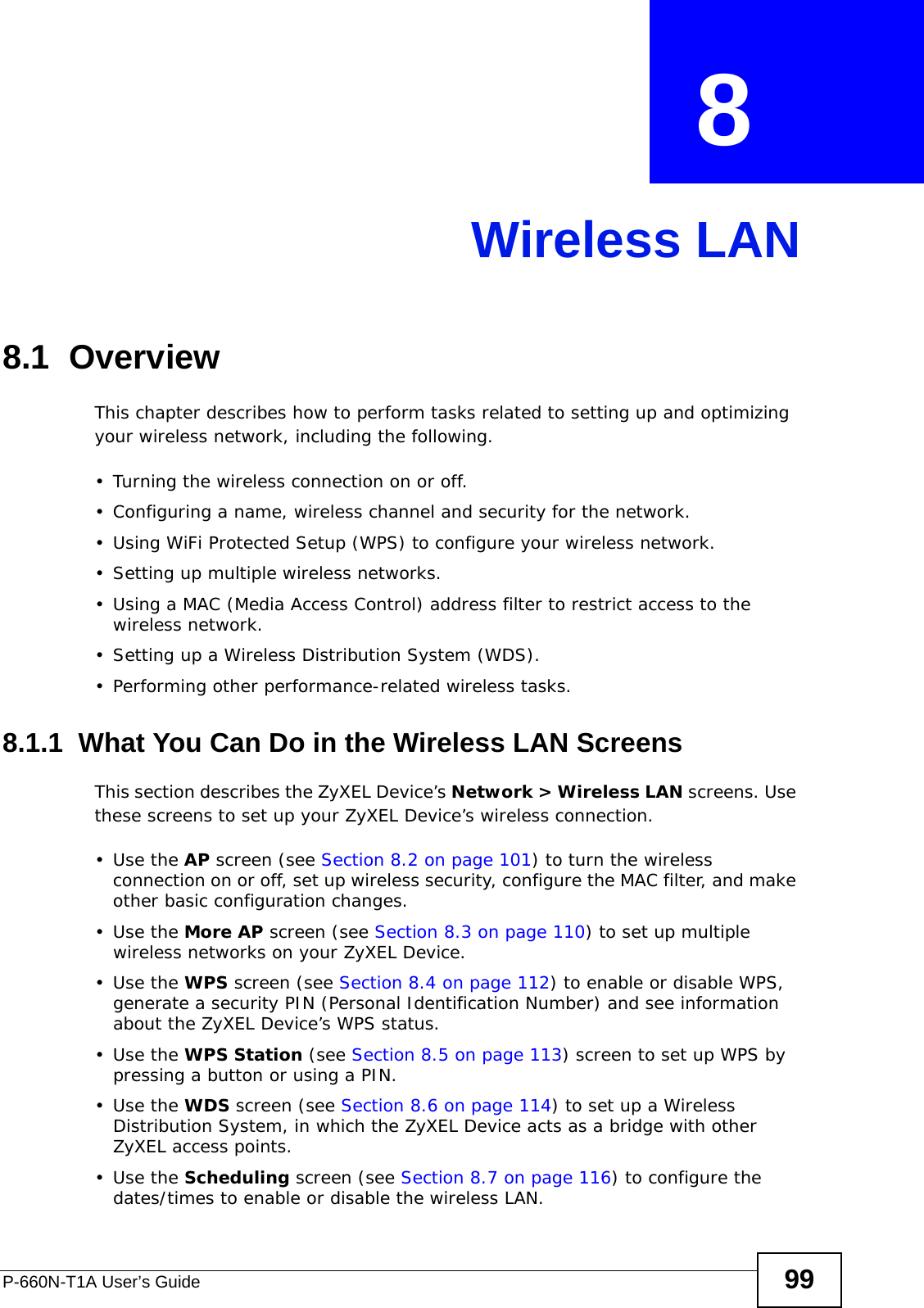
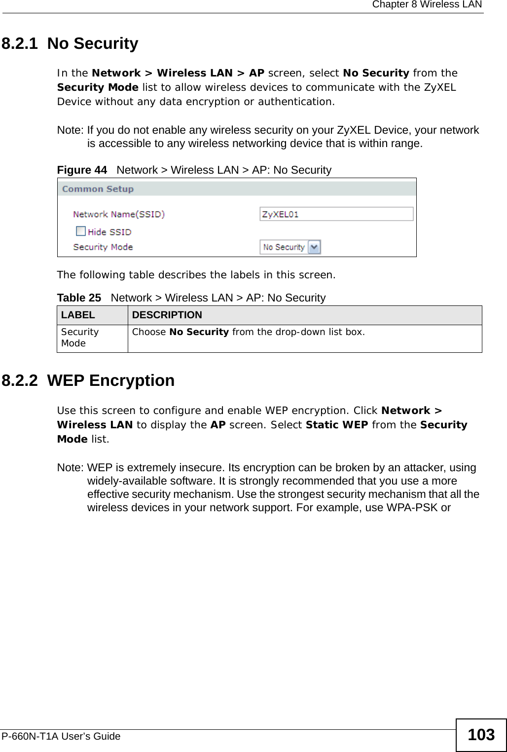
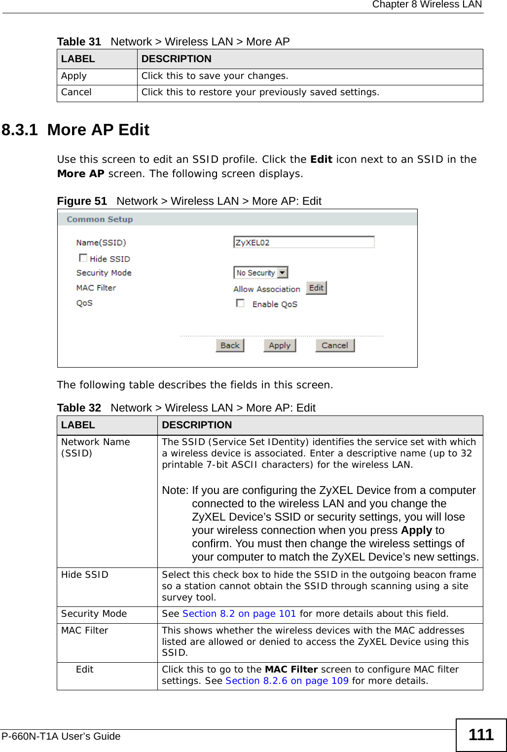
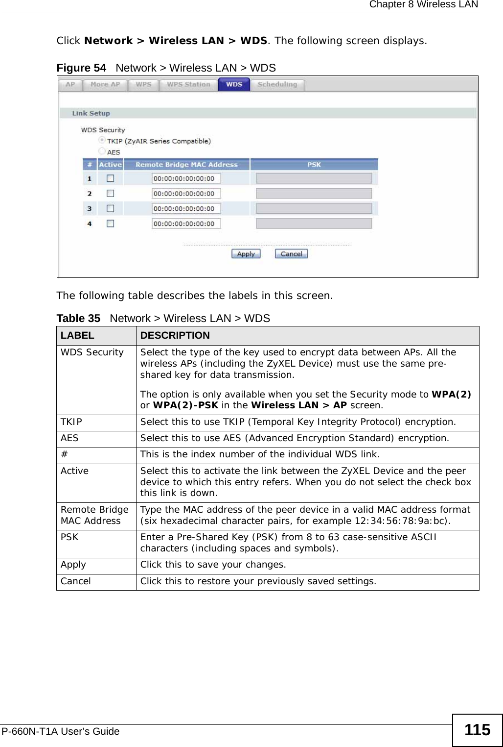
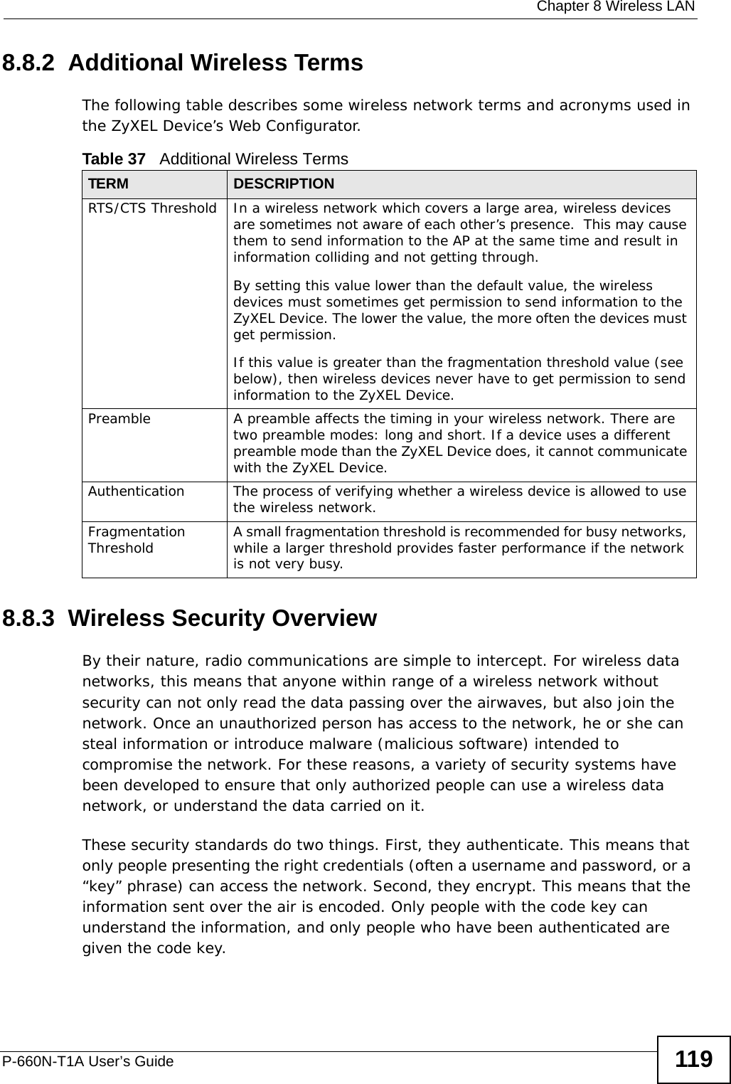
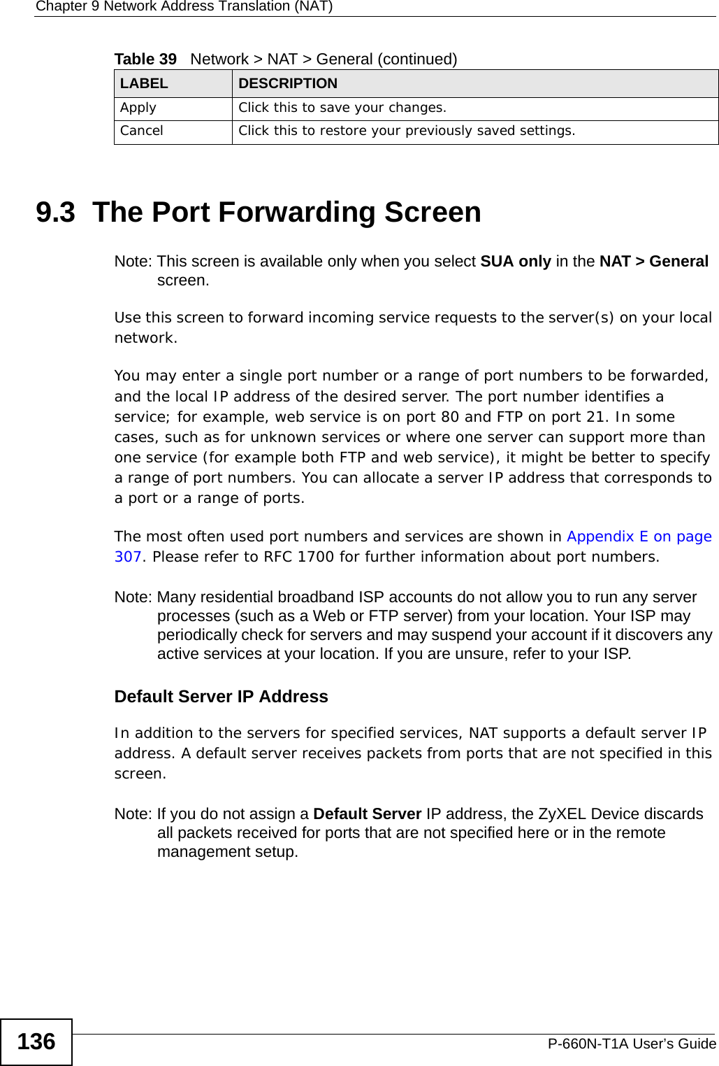
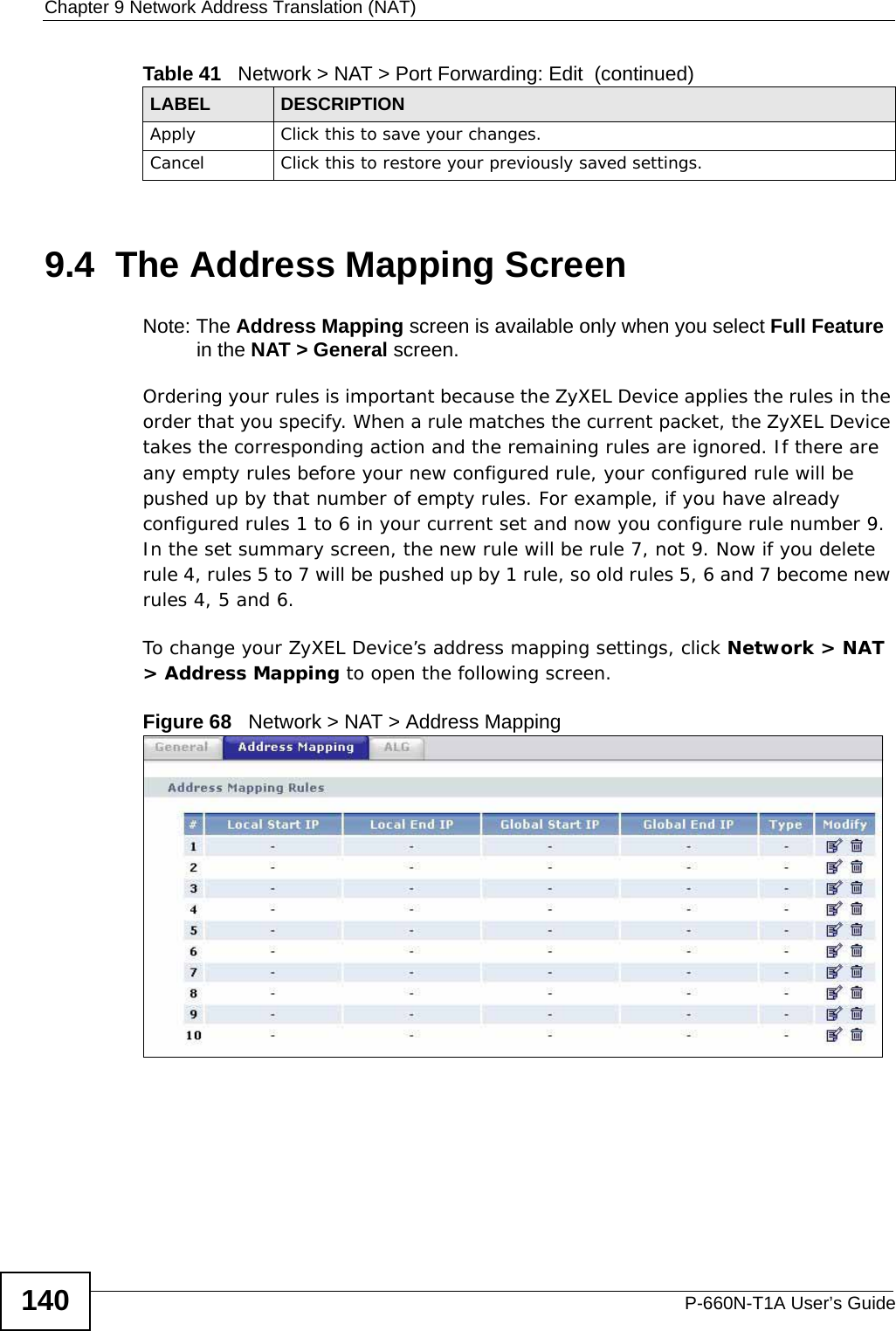
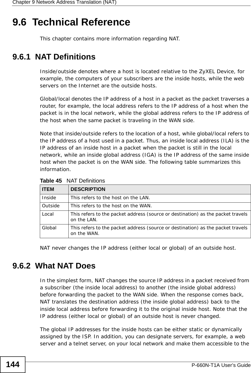
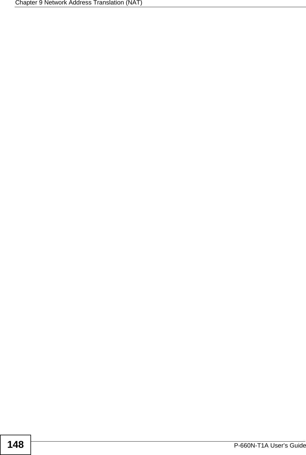
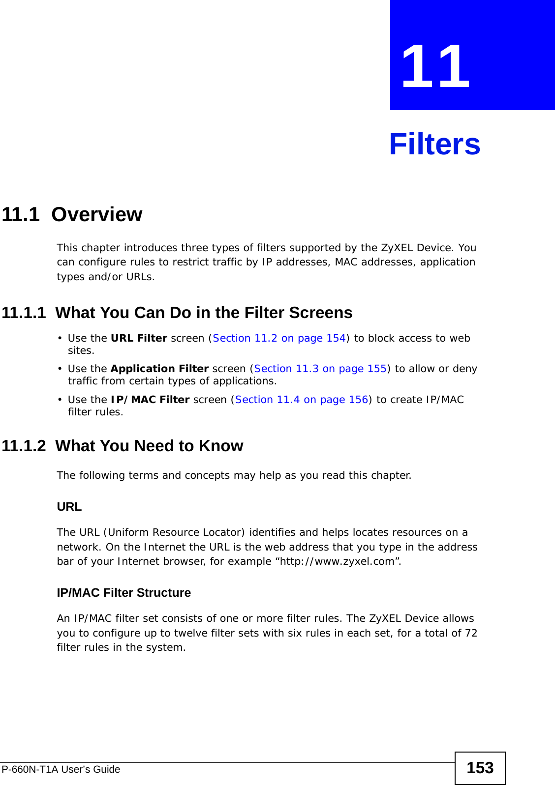
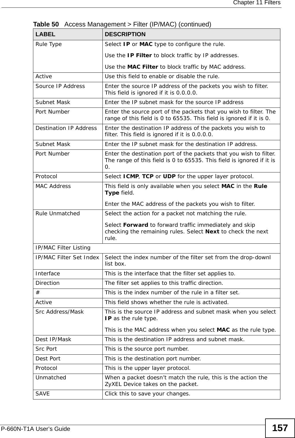
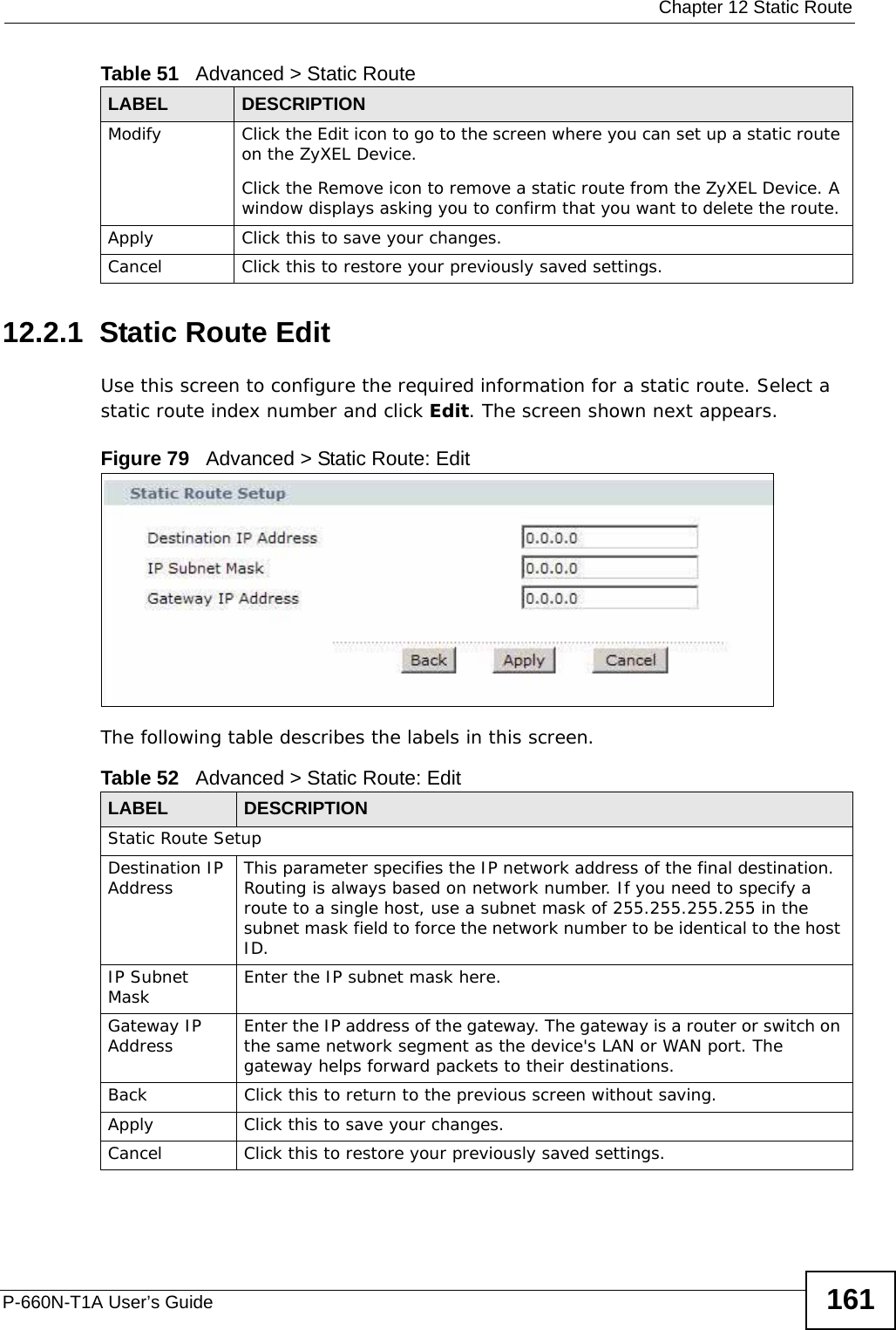
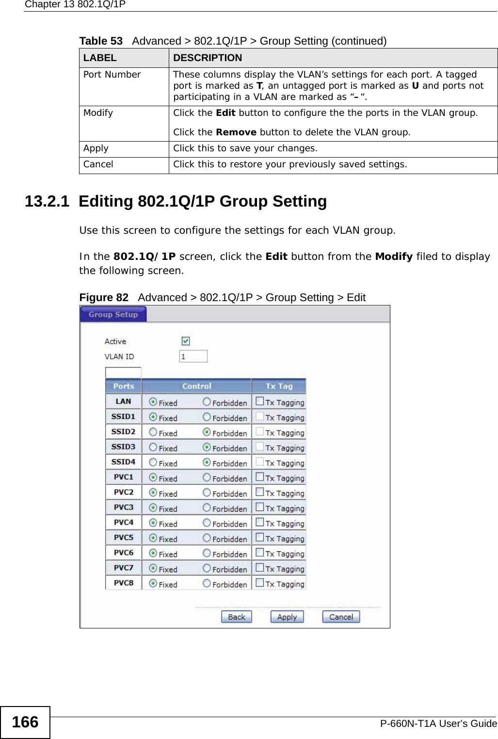
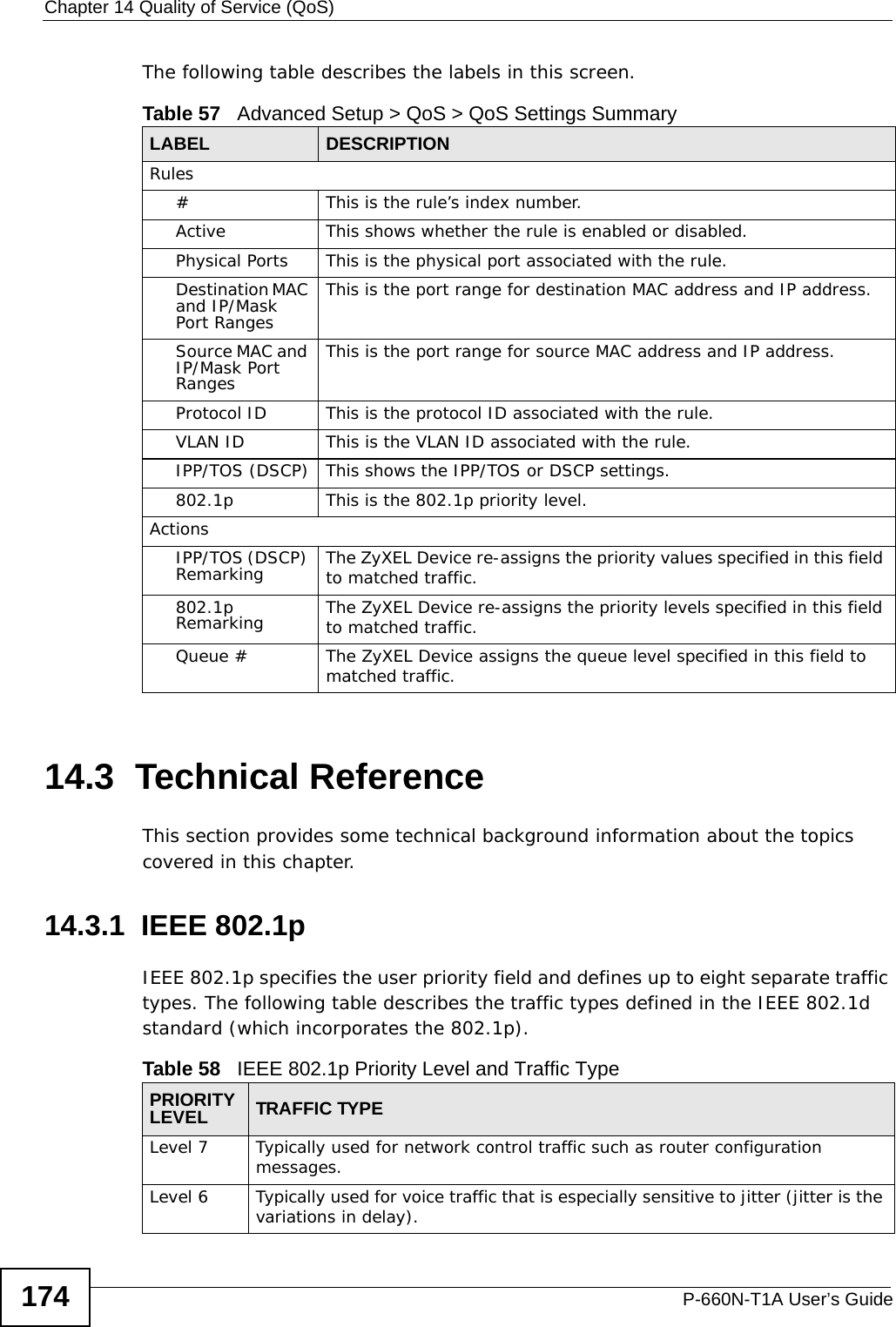
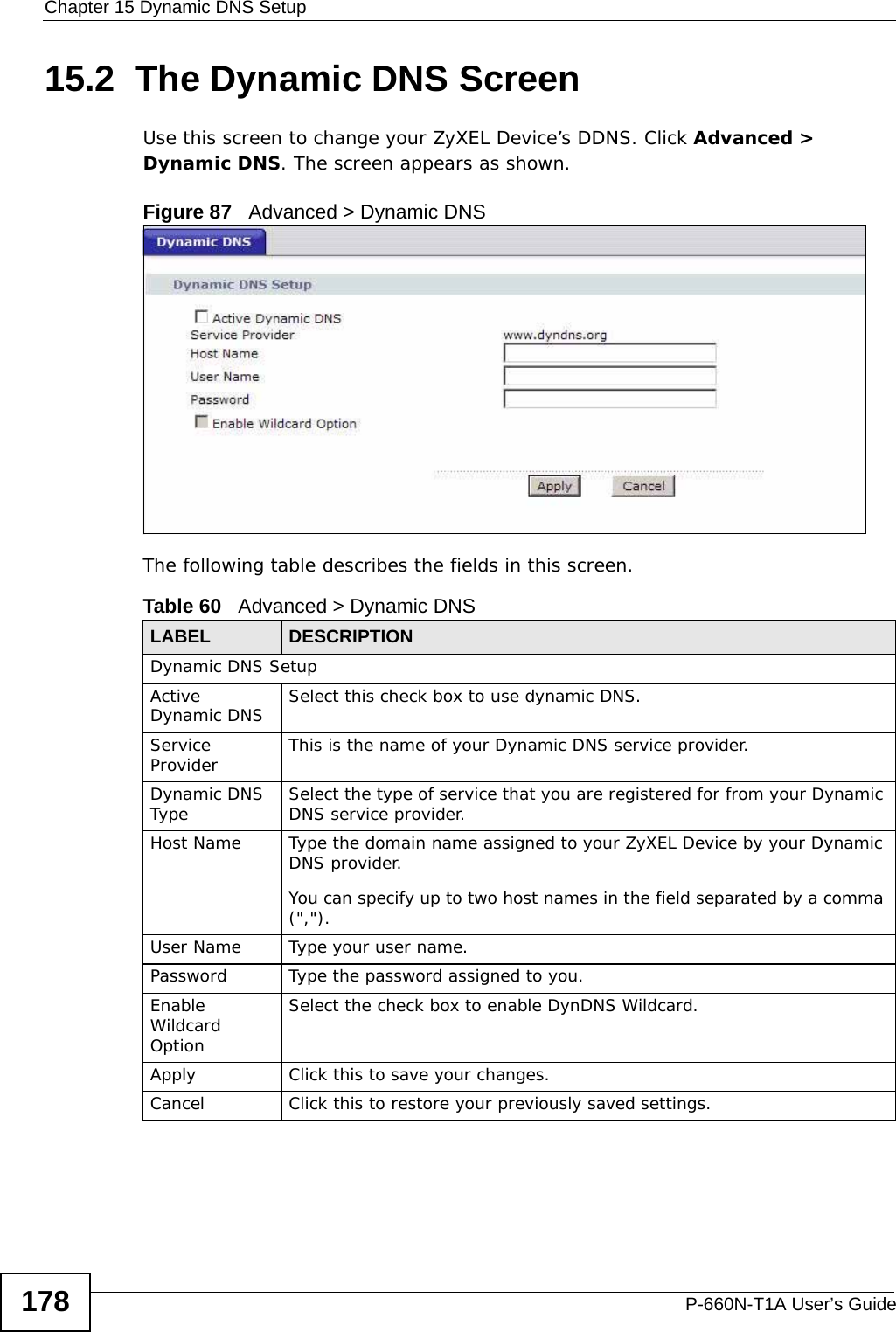
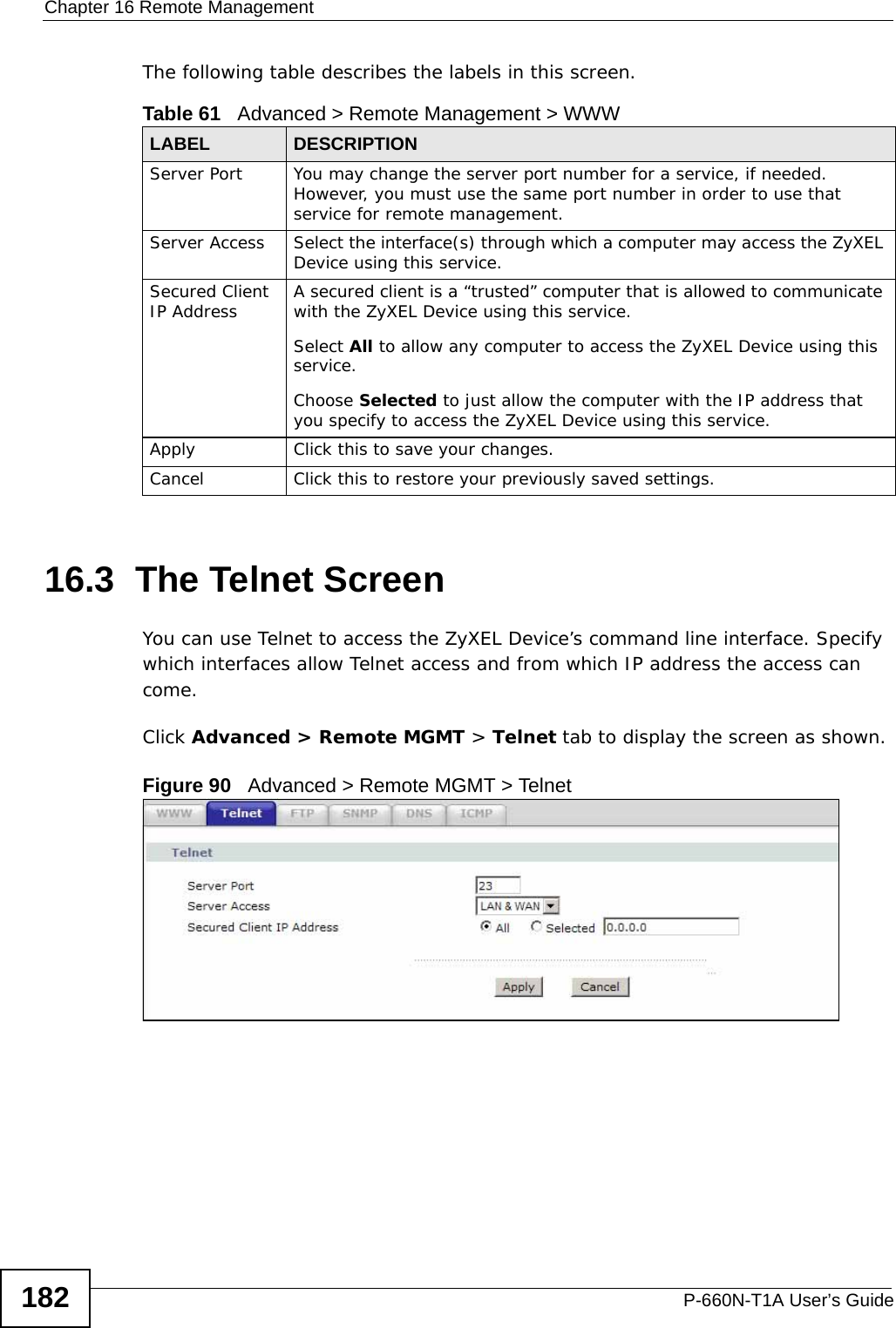
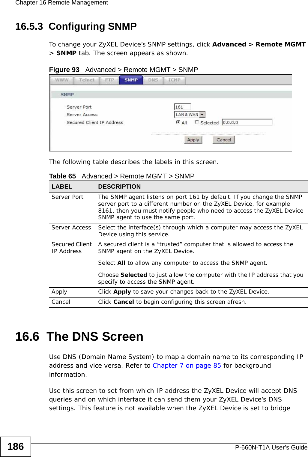
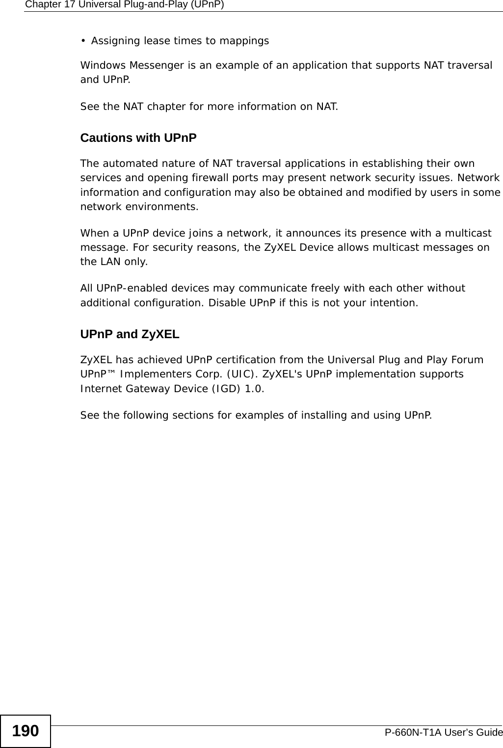
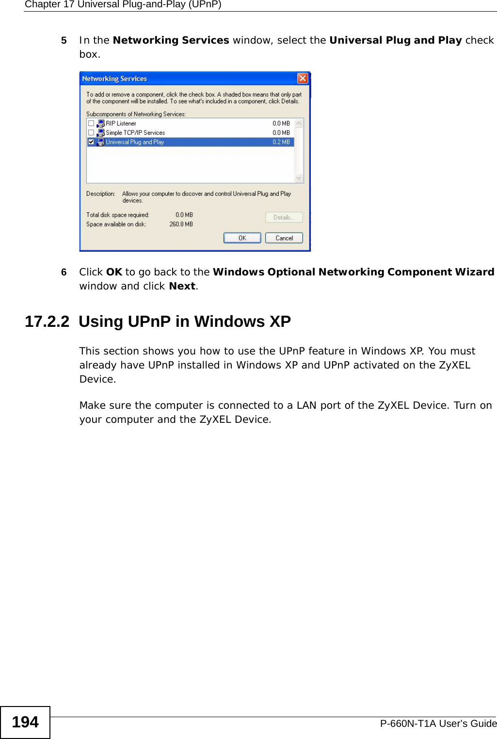
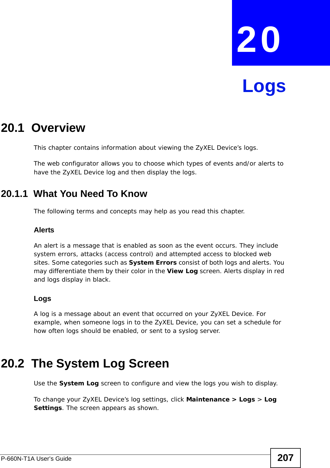
![Chapter 20 LogsP-660N-T1A User’s Guide212For type and code details, see Table 86 on page 215. Table 78 ICMP LogsLOG MESSAGE DESCRIPTIONFirewall default policy: ICMP <Packet Direction>, <type:%d>, <code:%d>ICMP access matched the default policy and was blocked or forwarded according to the user's setting.Firewall rule [NOT] match: ICMP <Packet Direction>, <rule:%d>, <type:%d>, <code:%d>ICMP access matched (or didn’t match) a firewall rule (denoted by its number) and was blocked or forwarded according to the rule. Triangle route packet forwarded: ICMP The firewall allowed a triangle route session to pass through.Packet without a NAT table entry blocked: ICMP The router blocked a packet that didn’t have a corresponding NAT table entry.Unsupported/out-of-order ICMP: ICMP The firewall does not support this kind of ICMP packets or the ICMP packets are out of order.Router reply ICMP packet: ICMP The router sent an ICMP reply packet to the sender.Table 79 CDR LogsLOG MESSAGE DESCRIPTIONboard %d line %d channel %d, call %d, %s C01 Outgoing Call dev=%x ch=%x %sThe router received the setup requirements for a call. “call” is the reference (count) number of the call. “dev” is the device type (3 is for dial-up, 6 is for PPPoE, 10 is for PPTP). "channel" or “ch” is the call channel ID.For example,"board 0 line 0 channel 0, call 3, C01 Outgoing Call dev=6 ch=0 "Means the router has dialed to the PPPoE server 3 times.board %d line %d channel %d, call %d, %s C02 OutCall Connected %d %sThe PPPoE, PPTP or dial-up call is connected.board %d line %d channel %d, call %d, %s C02 Call TerminatedThe PPPoE, PPTP or dial-up call was disconnected.Table 80 PPP LogsLOG MESSAGE DESCRIPTIONppp:LCP Starting The PPP connection’s Link Control Protocol stage has started.ppp:LCP Opening The PPP connection’s Link Control Protocol stage is opening.ppp:CHAP Opening The PPP connection’s Challenge Handshake Authentication Protocol stage is opening.ppp:IPCP Starting The PPP connection’s Internet Protocol Control Protocol stage is starting.ppp:IPCP Opening The PPP connection’s Internet Protocol Control Protocol stage is opening.](https://usermanual.wiki/ZyXEL-Communications/P660NT1A.user-manual-1/User-Guide-1315611-Page-212.png)
![Chapter 20 LogsP-660N-T1A User’s Guide 213 For type and code details, see Table 86 on page 215.ppp:LCP Closing The PPP connection’s Link Control Protocol stage is closing.ppp:IPCP Closing The PPP connection’s Internet Protocol Control Protocol stage is closing.Table 81 UPnP LogsLOG MESSAGE DESCRIPTIONUPnP pass through Firewall UPnP packets can pass through the firewall.Table 82 Content Filtering LogsLOG MESSAGE DESCRIPTION%s: block keyword The content of a requested web page matched a user defined keyword.%s The system forwarded web content.Table 83 Attack LogsLOG MESSAGE DESCRIPTIONattack [ TCP | UDP | IGMP | ESP | GRE | OSPF ] The firewall detected a TCP/UDP/IGMP/ESP/GRE/OSPF attack.attack ICMP (type:%d, code:%d) The firewall detected an ICMP attack.land [ TCP | UDP | IGMP | ESP | GRE | OSPF ] The firewall detected a TCP/UDP/IGMP/ESP/GRE/OSPF land attack.land ICMP (type:%d, code:%d) The firewall detected an ICMP land attack.ip spoofing - WAN [ TCP | UDP | IGMP | ESP | GRE | OSPF ]The firewall detected an IP spoofing attack on the WAN port.ip spoofing - WAN ICMP (type:%d, code:%d) The firewall detected an ICMP IP spoofing attack on the WAN port. icmp echo : ICMP (type:%d, code:%d) The firewall detected an ICMP echo attack. syn flood TCP The firewall detected a TCP syn flood attack.ports scan TCP The firewall detected a TCP port scan attack.teardrop TCP The firewall detected a TCP teardrop attack.teardrop UDP The firewall detected an UDP teardrop attack.teardrop ICMP (type:%d, code:%d) The firewall detected an ICMP teardrop attack. illegal command TCP The firewall detected a TCP illegal command attack.Table 80 PPP Logs (continued)LOG MESSAGE DESCRIPTION](https://usermanual.wiki/ZyXEL-Communications/P660NT1A.user-manual-1/User-Guide-1315611-Page-213.png)
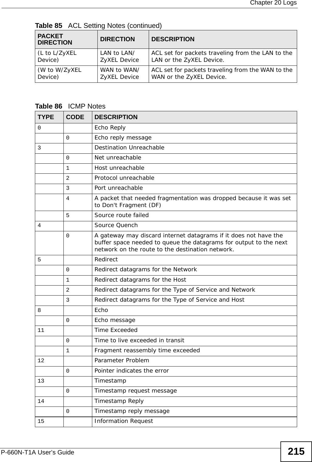
![Chapter 20 LogsP-660N-T1A User’s Guide214 NetBIOS TCP The firewall detected a TCP NetBIOS attack.ip spoofing - no routing entry [ TCP | UDP | IGMP | ESP | GRE | OSPF ]The firewall classified a packet with no source routing entry as an IP spoofing attack.ip spoofing - no routing entry ICMP (type:%d, code:%d)The firewall classified an ICMP packet with no source routing entry as an IP spoofing attack.vulnerability ICMP (type:%d, code:%d) The firewall detected an ICMP vulnerability attack.traceroute ICMP (type:%d, code:%d) The firewall detected an ICMP traceroute attack. Table 84 802.1X LogsLOG MESSAGE DESCRIPTIONRADIUS accepts user. A user was authenticated by the RADIUS Server.RADIUS rejects user. Pls check RADIUS Server. A user was not authenticated by the RADIUS Server. Please check the RADIUS Server.User logout because of session timeout expired. The router logged out a user whose session expired.User logout because of user deassociation. The router logged out a user who ended the session.User logout because of no authentication response from user.The router logged out a user from which there was no authentication response.User logout because of idle timeout expired. The router logged out a user whose idle timeout period expired.User logout because of user request. A user logged out.No response from RADIUS. Pls check RADIUS Server. There is no response message from the RADIUS server, please check the RADIUS server.Use RADIUS to authenticate user. The RADIUS server is operating as the authentication server.No Server to authenticate user. There is no authentication server to authenticate a user.Table 85 ACL Setting NotesPACKET DIRECTION DIRECTION DESCRIPTION(L to W) LAN to WAN ACL set for packets traveling from the LAN to the WAN.(W to L) WAN to LAN ACL set for packets traveling from the WAN to the LAN.Table 83 Attack Logs (continued)LOG MESSAGE DESCRIPTION](https://usermanual.wiki/ZyXEL-Communications/P660NT1A.user-manual-1/User-Guide-1315611-Page-214.png)