ZyXEL Communications P660NT1A 802.11n Wireless ADSL2+ Gateway User Manual SMG 700 User s Guide V1 00 Nov 2004
ZyXEL Communications Corporation 802.11n Wireless ADSL2+ Gateway SMG 700 User s Guide V1 00 Nov 2004
Contents
- 1. user manual 1
- 2. user manual 2
user manual 1

www.zyxel.com
www.zyxel.com
P-660N-T1A
802.11n Wireless ADSL2+ Gateway
Copyright © 2010
ZyXEL Communications Corporation
Firmware Version 3.40
Edition 1, 7/2010
Default Login Details
IP Address http://192.168.1.1
Password 1234
About This User's Guide
P-660N-T1A User’s Guide 3
About This User's Guide
Intended Audience
This manual is intended for people who want to configure the ZyXEL Device using
the web configurator. You should have at least a basic knowledge of TCP/IP
networking concepts and topology.
Related Documentation
•Quick Start Guide
The Quick Start Guide is designed to help you get up and running right away. It
contains information on setting up your network and configuring for Internet
access.
• Support Disc
Refer to the included CD for support documents.
• ZyXEL Web Site
Please refer to www.zyxel.com for additional support documentation and
product certifications.
Documentation Feedback
Send your comments, questions or suggestions to: techwriters@zyxel.com.tw
Thank you!
The Technical Writing Team, ZyXEL Communications Corp.,
6 Innovation Road II, Science-Based Industrial Park, Hsinchu, 30099, Taiwan.
Need More Help?
More help is available at www.zyxel.com.

About This User's Guide
P-660N-T1A User’s Guide
4
• Download Library
Search for the latest product updates and documentation from this link. Read
the Tech Doc Overview to find out how to efficiently use the User Guide, Quick
Start Guide and Command Line Interface Reference Guide in order to better
understand how to use your product.
• Knowledge Base
If you have a specific question about your product, the answer may be here.
This is a collection of answers to previously asked questions about ZyXEL
products.
•Forum
This contains discussions on ZyXEL products. Learn from others who use ZyXEL
products and share your experiences as well.
Customer Support
In the event of problems that cannot be solved by using this manual, you should
contact your vendor. If you cannot contact your vendor, then contact a ZyXEL
office for the region in which you bought the device. See http://www.zyxel.com/
web/contact_us.php for contact information. Please have the following information
ready when you contact an office.
• Product model and serial number.
•Warranty Information.
• Date that you received your device.
• Brief description of the problem and the steps you took to solve it.
Disclaimer
Graphics in this book may differ slightly from the product due to differences in
operating systems, operating system versions, or if you installed updated
firmware/software for your device. Every effort has been made to ensure that the
information in this manual is accurate.

Document Conventions
P-660N-T1A User’s Guide 5
Document Conventions
Warnings and Notes
These are how warnings and notes are shown in this User’s Guide.
Warnings tell you about things that could harm you or your device.
Note: Notes tell you other important information (for example, other things you may
need to configure or helpful tips) or recommendations.
Syntax Conventions
• The P-660N-T1A may be referred to as the “ZyXEL Device”, the “device”, the
“system” or the “product” in this User’s Guide.
• Product labels, screen names, field labels and field choices are all in bold font.
• A key stroke is denoted by square brackets and uppercase text, for example,
[ENTER] means the “enter” or “return” key on your keyboard.
• “Enter” means for you to type one or more characters and then press the
[ENTER] key. “Select” or “choose” means for you to use one of the predefined
choices.
• A right angle bracket ( > ) within a screen name denotes a mouse click. For
example, Maintenance > Log > Log Setting means you first click
Maintenance in the navigation panel, then the Log sub menu and finally the
Log Setting tab to get to that screen.
• Units of measurement may denote the “metric” value or the “scientific” value.
For example, “k” for kilo may denote “1000” or “1024”, “M” for mega may
denote “1000000” or “1048576” and so on.
• “e.g.,” is a shorthand for “for instance”, and “i.e.,” means “that is” or “in other
words”.
Document Conventions
P-660N-T1A User’s Guide
6
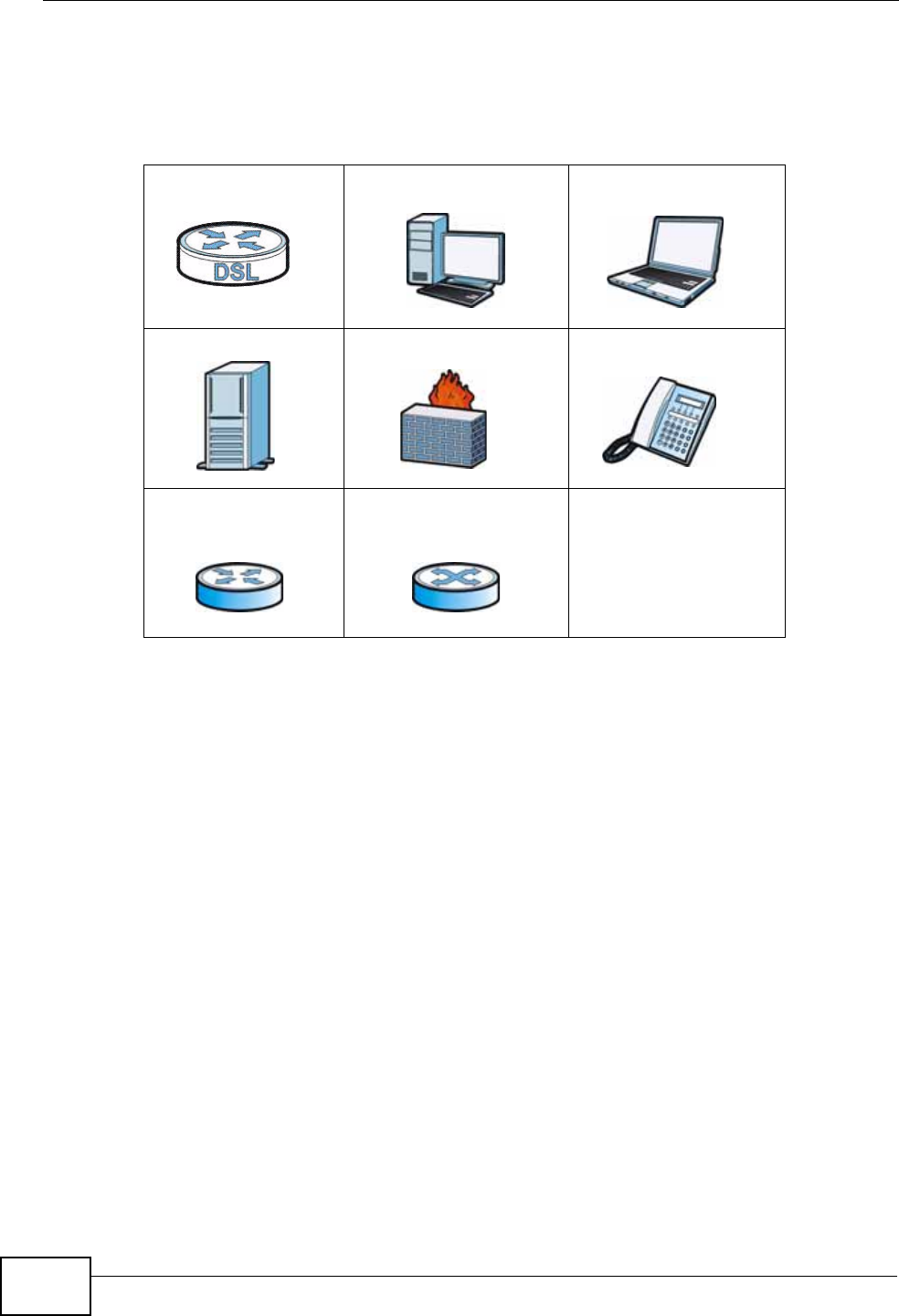
Icons Used in Figures
Figures in this User’s Guide may use the following generic icons. The ZyXEL Device
icon is not an exact representation of your device.
ZyXEL Device Computer Notebook computer
Server Firewall Telephone
Router Switch

Safety Warnings
P-660N-T1A User’s Guide 7
Safety Warnings
• Do NOT use this product near water, for example, in a wet basement or near a swimming
pool.
• Do NOT expose your device to dampness, dust or corrosive liquids.
• Do NOT store things on the device.
• Do NOT install, use, or service this device during a thunderstorm. There is a remote risk
of electric shock from lightning.
• Connect ONLY suitable accessories to the device.
• Do NOT open the device or unit. Opening or removing covers can expose you to
dangerous high voltage points or other risks. ONLY qualified service personnel should
service or disassemble this device. Please contact your vendor for further information.
• Make sure to connect the cables to the correct ports.
• Place connecting cables carefully so that no one will step on them or stumble over them.
• Always disconnect all cables from this device before servicing or disassembling.
• Use ONLY an appropriate power adaptor or cord for your device.
• Connect the power adaptor or cord to the right supply voltage (for example, 110V AC in
North America or 230V AC in Europe).
• Do NOT allow anything to rest on the power adaptor or cord and do NOT place the
product where anyone can walk on the power adaptor or cord.
• Do NOT use the device if the power adaptor or cord is damaged as it might cause
electrocution.
• If the power adaptor or cord is damaged, remove it from the device and the power
source.
• Do NOT attempt to repair the power adaptor or cord. Contact your local vendor to order a
new one.
• Do not use the device outside, and make sure all the connections are indoors. There is a
remote risk of electric shock from lightning.
• Do NOT obstruct the device ventilation slots, as insufficient airflow may harm your
device.
• Use only No. 26 AWG (American Wire Gauge) or larger telecommunication line cord.
• Antenna Warning! This device meets ETSI and FCC certification requirements when using
the included antenna(s). Only use the included antenna(s).
Your product is marked with this symbol, which is known as the WEEE mark. WEEE
stands for Waste Electronics and Electrical Equipment. It means that used electrical
and electronic products should not be mixed with general waste. Used electrical and
electronic equipment should be treated separately.

Safety Warnings
P-660N-T1A User’s Guide
8

Contents Overview
P-660N-T1A User’s Guide 9
Contents Overview
User’s Guide ...........................................................................................................................19
Introduction ................................................................................................................................ 21
The Web Configurator ............................................................................................................... 27
Status Screen ............................................................................................................................ 35
Tutorials ..................................................................................................................................... 39
Technical Reference ..............................................................................................................51
Internet and Wireless Setup Wizard .......................................................................................... 53
WAN Setup ................................................................................................................................ 67
LAN Setup ................................................................................................................................. 85
Wireless LAN ............................................................................................................................. 99
Network Address Translation (NAT) ........................................................................................ 133
Firewall .................................................................................................................................... 149
Filters ....................................................................................................................................... 153
Static Route ............................................................................................................................. 159
802.1Q/1P ............................................................................................................................... 163
Quality of Service (QoS) .......................................................................................................... 169
Dynamic DNS Setup ................................................................................................................ 177
Remote Management ..............................................................................................................179
Universal Plug-and-Play (UPnP) ............................................................................................. 189
CWMP ..................................................................................................................................... 199
System Settings ....................................................................................................................... 203
Logs ......................................................................................................................................... 207
Tools ........................................................................................................................................ 217
Diagnostic ................................................................................................................................ 225
Troubleshooting ....................................................................................................................... 229
Product Specifications ............................................................................................................. 235

Contents Overview
P-660N-T1A User’s Guide
10

Table of Contents
P-660N-T1A User’s Guide 11
Table of Contents
About This User's Guide..........................................................................................................3
Document Conventions............................................................................................................5
Safety Warnings........................................................................................................................7
Contents Overview ...................................................................................................................9
Table of Contents....................................................................................................................11
Part I: User’s Guide................................................................................ 19
Chapter 1
Introduction.............................................................................................................................21
1.1 Overview .............................................................................................................................. 21
1.2 Ways to Manage the ZyXEL Device .................................................................................... 21
1.2.1 Good Habits for Managing the ZyXEL Device ........................................................... 22
1.3 Internet Access .................................................................................................................... 22
1.4 Wireless Access .................................................................................................................. 23
1.4.1 Using the WPS/WLAN Button .................................................................................... 24
1.5 LEDs (Lights) ....................................................................................................................... 25
1.6 The RESET Button .............................................................................................................. 26
1.6.1 Using the Reset Button .............................................................................................. 26
Chapter 2
The Web Configurator ............................................................................................................27
2.1 Overview .............................................................................................................................. 27
2.1.1 Accessing the Web Configurator ................................................................................ 27
2.2 Main Screen ........................................................................................................................ 30
2.2.1 Title Bar ...................................................................................................................... 31
2.2.2 Navigation Panel ........................................................................................................ 31
2.2.3 Main Window ..............................................................................................................33
2.2.4 Status Bar ................................................................................................................... 34
Chapter 3
Status Screen..........................................................................................................................35
3.1 Overview .............................................................................................................................. 35
3.2 The Status Screen ............................................................................................................... 35

Table of Contents
P-660N-T1A User’s Guide
12
Chapter 4
Tutorials...................................................................................................................................39
4.1 Overview .............................................................................................................................. 39
4.2 Setting Up a Secure Wireless Network ............................................................................... 39
4.2.1 Configuring the Wireless Network Settings ................................................................ 39
4.2.2 Using WPS ................................................................................................................. 41
4.2.3 Without WPS ..............................................................................................................45
4.2.4 Setting Up Wireless Network Scheduling ................................................................... 45
4.3 Configuring the MAC Address Filter .................................................................................... 46
4.4 Multiple WAN Connections Example ................................................................................... 48
Part II: Technical Reference.................................................................. 51
Chapter 5
Internet and Wireless Setup Wizard......................................................................................53
5.1 Overview .............................................................................................................................. 53
5.2 Internet Access Wizard Setup ............................................................................................. 53
5.2.1 Manual Configuration ................................................................................................. 56
5.3 Wireless Connection Wizard Setup ..................................................................................... 62
5.3.1 Manually Assign a WPA-PSK key .............................................................................. 64
5.3.2 Manually Assign a WEP Key ...................................................................................... 65
Chapter 6
WAN Setup...............................................................................................................................67
6.1 Overview .............................................................................................................................. 67
6.1.1 What You Can Do in the WAN Screens ..................................................................... 67
6.1.2 What You Need to Know ............................................................................................ 67
6.1.3 Before You Begin ....................................................................................................... 68
6.2 The Internet Connection Screen .......................................................................................... 69
6.2.1 Advanced Setup ......................................................................................................... 72
6.3 The More Connections Screen ............................................................................................ 74
6.3.1 More Connections Edit ............................................................................................... 75
6.3.2 Advanced Setup ......................................................................................................... 77
6.4 Technical Reference ............................................................................................................ 78
6.4.1 Encapsulation ............................................................................................................. 78
6.4.2 Multiplexing ................................................................................................................ 80
6.4.3 VPI and VCI ............................................................................................................... 80
6.4.4 IP Address Assignment .............................................................................................. 80
6.4.5 Nailed-Up Connection (PPP) ..................................................................................... 81
6.4.6 NAT ............................................................................................................................ 81
6.5 Traffic Shaping ..................................................................................................................... 81

Table of Contents
P-660N-T1A User’s Guide 13
6.5.1 ATM Traffic Classes ................................................................................................... 82
Chapter 7
LAN Setup................................................................................................................................85
7.1 Overview .............................................................................................................................. 85
7.1.1 What You Can Do in the LAN Screens ....................................................................... 85
7.1.2 What You Need To Know ........................................................................................... 86
7.1.3 Before You Begin ....................................................................................................... 87
7.2 The IP Screen ...................................................................................................................... 87
7.2.1 The Advanced Setup Screen ..................................................................................... 88
7.3 The DHCP Server Screen ................................................................................................... 89
7.4 The Client List Screen ......................................................................................................... 90
7.5 The IP Alias Screen ............................................................................................................. 91
7.5.1 Configuring the LAN IP Alias Screen ......................................................................... 92
7.6 Technical Reference ............................................................................................................ 94
7.6.1 LANs, WANs and the ZyXEL Device .......................................................................... 94
7.6.2 DHCP Setup ...............................................................................................................94
7.6.3 DNS Server Addresses .............................................................................................. 94
7.6.4 LAN TCP/IP ................................................................................................................ 95
7.6.5 RIP Setup ................................................................................................................... 96
7.6.6 Multicast ..................................................................................................................... 97
Chapter 8
Wireless LAN...........................................................................................................................99
8.1 Overview .............................................................................................................................. 99
8.1.1 What You Can Do in the Wireless LAN Screens ........................................................ 99
8.1.2 What You Need to Know .......................................................................................... 100
8.1.3 Before You Start ....................................................................................................... 101
8.2 The AP Screen .................................................................................................................. 101
8.2.1 No Security ............................................................................................................... 103
8.2.2 WEP Encryption ....................................................................................................... 103
8.2.3 WPA(2)-PSK ............................................................................................................ 105
8.2.4 WPA(2) Authentication ............................................................................................. 106
8.2.5 Advanced Setup ....................................................................................................... 107
8.2.6 MAC Filter ............................................................................................................ 109
8.3 The More AP Screen ..........................................................................................................110
8.3.1 More AP Edit ............................................................................................................. 111
8.4 The WPS Screen ................................................................................................................112
8.5 The WPS Station Screen ....................................................................................................113
8.6 The WDS Screen ................................................................................................................114
8.7 The Scheduling Screen ......................................................................................................116
8.8 Technical Reference ...........................................................................................................117
8.8.1 Wireless Network Overview ......................................................................................117

Table of Contents
P-660N-T1A User’s Guide
14
8.8.2 Additional Wireless Terms .........................................................................................119
8.8.3 Wireless Security Overview ......................................................................................119
8.8.4 Signal Problems ....................................................................................................... 122
8.8.5 BSS .......................................................................................................................... 122
8.8.6 MBSSID ...................................................................................................................123
8.8.7 Wireless Distribution System (WDS) ........................................................................ 124
8.8.8 WiFi Protected Setup (WPS) .................................................................................... 124
Chapter 9
Network Address Translation (NAT)....................................................................................133
9.1 Overview ............................................................................................................................ 133
9.1.1 What You Can Do in the NAT Screens ..................................................................... 133
9.1.2 What You Need To Know ......................................................................................... 133
9.2 The General Setup Screen ................................................................................................ 135
9.3 The Port Forwarding Screen ............................................................................................. 136
9.3.1 Configuring the Port Forwarding Screen .................................................................. 137
9.3.2 The Port Forwarding Rule Edit Screen .................................................................... 139
9.4 The Address Mapping Screen ........................................................................................... 140
9.4.1 The Address Mapping Rule Edit Screen .................................................................. 142
9.5 The ALG Screen ................................................................................................................ 143
9.6 Technical Reference .......................................................................................................... 144
9.6.1 NAT Definitions ........................................................................................................ 144
9.6.2 What NAT Does ....................................................................................................... 144
9.6.3 How NAT Works ....................................................................................................... 145
9.6.4 NAT Application ........................................................................................................ 146
9.6.5 NAT Mapping Types ................................................................................................. 146
Chapter 10
Firewall...................................................................................................................................149
10.1 Overview .......................................................................................................................... 149
10.1.1 What You Can Do in the Firewall Screens ............................................................. 149
10.1.2 What You Need to Know ........................................................................................ 149
10.2 The Firewall Screen ......................................................................................................... 151
Chapter 11
Filters .....................................................................................................................................153
11.1 Overview ......................................................................................................................... 153
11.1.1 What You Can Do in the Filter Screens .................................................................. 153
11.1.2 What You Need to Know ........................................................................................ 153
11.2 The URL Filter Screen ....................................................................................................154
11.3 The Application Filter Screen ........................................................................................... 155
11.4 The IP/MAC Filter Screen ................................................................................................ 156

Table of Contents
P-660N-T1A User’s Guide 15
Chapter 12
Static Route...........................................................................................................................159
12.1 Overview ......................................................................................................................... 159
12.1.1 What You Can Do in the Static Route Screens ...................................................... 160
12.2 The Static Route Screen .................................................................................................. 160
12.2.1 Static Route Edit ................................................................................................... 161
Chapter 13
802.1Q/1P...............................................................................................................................163
13.1 Overview .......................................................................................................................... 163
13.1.1 What You Can Do in the 802.1Q/1P Screens ........................................................ 163
13.1.2 What You Need to Know ........................................................................................ 163
13.2 The 802.1Q/1P Group Setting Screen ............................................................................. 165
13.2.1 Editing 802.1Q/1P Group Setting ........................................................................... 166
13.3 The 802.1Q/1P Port Setting Screen ................................................................................ 168
Chapter 14
Quality of Service (QoS).......................................................................................................169
14.1 Overview .......................................................................................................................... 169
14.1.1 What You Can Do in the QoS Screens .................................................................. 170
14.1.2 What You Need to Know ........................................................................................ 170
14.2 The QoS Screen ............................................................................................................. 171
14.2.1 The QoS Settings Summary Screen ...................................................................... 173
14.3 Technical Reference ........................................................................................................ 174
14.3.1 IEEE 802.1p ........................................................................................................... 174
14.3.2 IP Precedence ........................................................................................................ 175
14.3.3 Automatic Priority Queue Assignment ................................................................... 175
Chapter 15
Dynamic DNS Setup .............................................................................................................177
15.1 Overview .......................................................................................................................... 177
15.1.1 What You Can Do in the DDNS Screen ................................................................. 177
15.1.2 What You Need To Know ....................................................................................... 177
15.2 The Dynamic DNS Screen .............................................................................................. 178
Chapter 16
Remote Management............................................................................................................179
16.1 Overview .......................................................................................................................... 179
16.1.1 What You Can Do in the Remote Management Screens ....................................... 180
16.1.2 What You Need to Know ........................................................................................ 180
16.2 The WWW Screen ........................................................................................................... 181
16.2.1 Configuring the WWW Screen ............................................................................... 181
16.3 The Telnet Screen ........................................................................................................... 182

Table of Contents
P-660N-T1A User’s Guide
16
16.4 The FTP Screen .............................................................................................................. 183
16.5 The SNMP Screen ...........................................................................................................184
16.5.1 Supported MIBs ..................................................................................................... 185
16.5.2 SNMP Traps ........................................................................................................... 185
16.5.3 Configuring SNMP ................................................................................................. 186
16.6 The DNS Screen ............................................................................................................ 186
16.7 The ICMP Screen ............................................................................................................ 187
Chapter 17
Universal Plug-and-Play (UPnP)..........................................................................................189
17.1 Overview .......................................................................................................................... 189
17.1.1 What You Can Do in the UPnP Screen .................................................................. 189
17.1.2 What You Need to Know ........................................................................................ 189
17.2 The UPnP Screen ............................................................................................................ 191
17.2.1 Installing UPnP in Windows ................................................................................... 192
17.2.2 Using UPnP in Windows XP .................................................................................. 194
Chapter 18
CWMP.....................................................................................................................................199
18.1 Overview .......................................................................................................................... 199
18.2 The CWMP Setup Screen ............................................................................................... 200
Chapter 19
System Settings....................................................................................................................203
19.1 Overview .......................................................................................................................... 203
19.1.1 What You Can Do in the System Settings Screens ................................................ 203
19.2 The General Screen ........................................................................................................203
19.3 The Time and Date Screen ............................................................................................. 204
Chapter 20
Logs .......................................................................................................................................207
20.1 Overview .......................................................................................................................... 207
20.1.1 What You Need To Know ....................................................................................... 207
20.2 The System Log Screen .................................................................................................. 207
20.3 Log Descriptions .............................................................................................................. 209
Chapter 21
Tools.......................................................................................................................................217
21.1 Overview .......................................................................................................................... 217
21.1.1 What You Can Do in the Tool Screens ................................................................... 217
21.1.2 What You Need To Know ....................................................................................... 217
21.1.3 Before You Begin ................................................................................................... 218
21.2 The Firmware Screen ...................................................................................................... 218

Table of Contents
P-660N-T1A User’s Guide 17
21.3 The Configuration Screen ................................................................................................ 220
21.4 The Restart Screen ......................................................................................................... 223
Chapter 22
Diagnostic..............................................................................................................................225
22.1 Overview .......................................................................................................................... 225
22.1.1 What You Can Do in the Diagnostic Screens ......................................................... 225
22.2 The General Diagnostic Screen ...................................................................................... 225
22.3 The DSL Line Diagnostic Screen .................................................................................... 226
Chapter 23
Troubleshooting....................................................................................................................229
23.1 Power, Hardware Connections, and LEDs ...................................................................... 229
23.2 ZyXEL Device Access and Login .................................................................................... 230
23.3 Internet Access ................................................................................................................ 232
Chapter 24
Product Specifications.........................................................................................................235
24.1 Hardware Specifications .................................................................................................. 235
24.2 Firmware Specifications ...................................................................................................236
24.3 Standards Support ........................................................................................................... 240
Appendix A Setting Up Your Computer’s IP Address...........................................................243
Appendix B IP Addresses and Subnetting ...........................................................................271
Appendix C Pop-up Windows, JavaScripts and Java Permissions......................................281
Appendix D Wireless LANs ..................................................................................................291
Appendix E Services ............................................................................................................307
Appendix F Legal Information .............................................................................................. 311
Index.......................................................................................................................................315

Table of Contents
P-660N-T1A User’s Guide
18

19
PART I
User’s Guide

20

P-660N-T1A User’s Guide 21
CHAPTER 1
Introduction
1.1 Overview
The P-660N-T1A is an ADSL2+ router. Integrated DSL and NAT, provides ease of
installation and high-speed, shared Internet access. It is also a complete security
solution with a robust firewall and content filtering.
Please refer to the following description of the product name format.
• Models ending in “1”, for example P-660N-T1A, denote a device that works over
the analog telephone system, POTS (Plain Old Telephone Service). Models
ending in “3” denote a device that works over ISDN (Integrated Services Digital
Network) or T-ISDN (UR-2).
Only use firmware for your ZyXEL Device’s specific model. Refer
to the label on the bottom of your ZyXEL Device.
Note: All screens displayed in this user’s guide are from the P-660N-T1A model.
See the product specifications for a full list of features.
1.2 Ways to Manage the ZyXEL Device
Use any of the following methods to manage the ZyXEL Device.
• Web Configurator. This is recommended for everyday management of the ZyXEL
Device using a (supported) web browser.
• Command Line Interface. Line commands are mostly used for troubleshooting
by service engineers.
• FTP for firmware upgrades and configuration backup/restore.
• TR-069. This is an auto-configuration server used to remotely configure your
device.
Chapter 1 Introduction
P-660N-T1A User’s Guide
22
1.2.1 Good Habits for Managing the ZyXEL Device
Do the following things regularly to make the ZyXEL Device more secure and to
manage the ZyXEL Device more effectively.
• Change the password. Use a password that’s not easy to guess and that consists
of different types of characters, such as numbers and letters.
• Write down the password and put it in a safe place.
• Back up the configuration (and make sure you know how to restore it).
Restoring an earlier working configuration may be useful if the device becomes
unstable or even crashes. If you forget your password, you will have to reset the
ZyXEL Device to its factory default settings. If you backed up an earlier
configuration file, you would not have to totally re-configure the ZyXEL Device.
You could simply restore your last configuration.
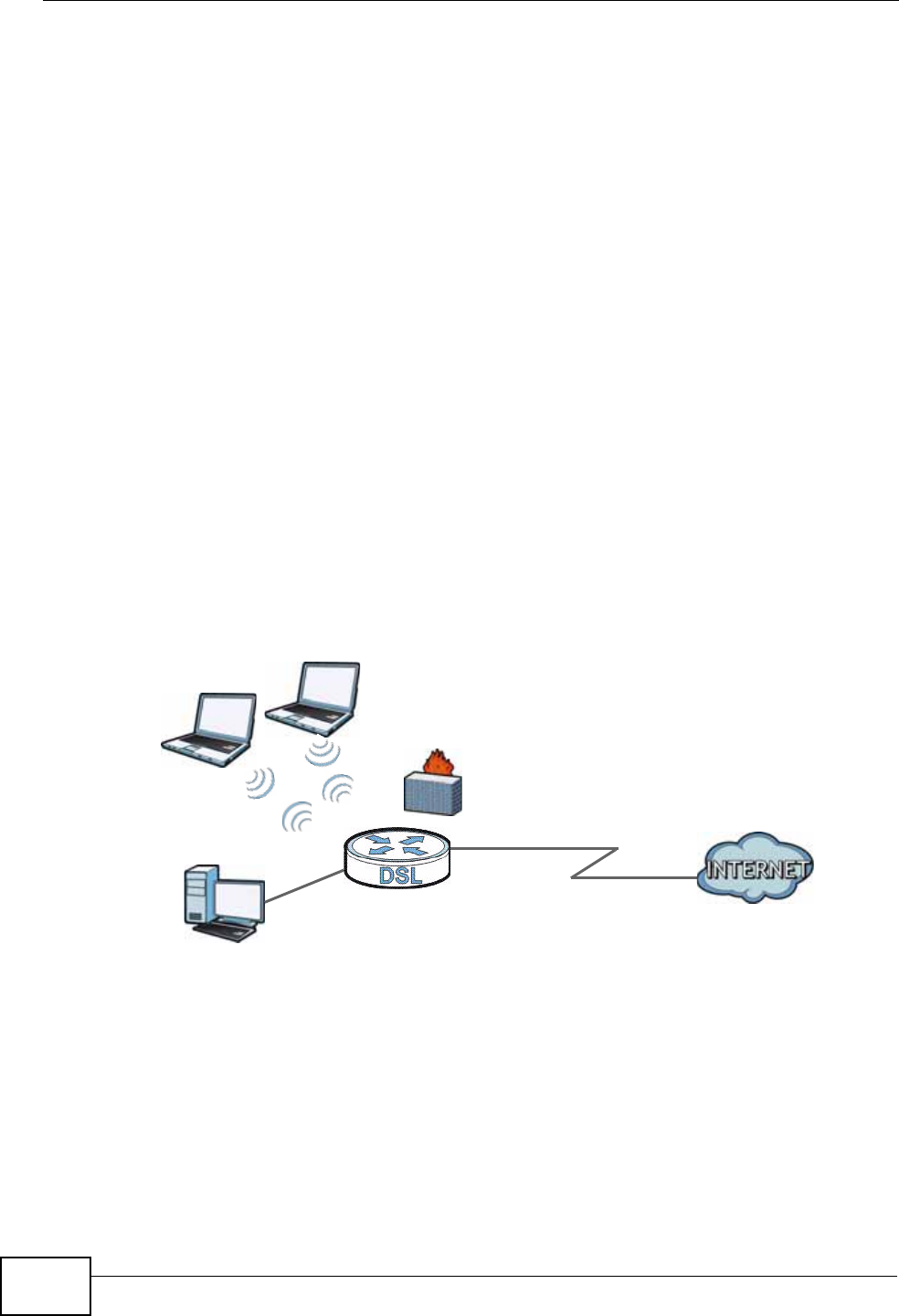
1.3 Internet Access
Your ZyXEL Device provides shared Internet access by connecting the DSL port to
the DSL or MODEM jack on a splitter or your telephone jack. Computers can
connect to the ZyXEL Device’s LAN port or wirelessly.
Figure 1 Internet Access Example
You can also configure firewall and filtering feature on the ZyXEL Device for secure
Internet access. When the firewall is on, all incoming traffic from the Internet to
your network is blocked unless it is initiated from your network. This means that
probes from the outside to your network are not allowed, but you can safely
browse the Internet and download files.
Use the filtering feaure to block access to specific web sites or Internet
applications such as MSN or Yahoo Messanger. You can also configure IP/MAC
filtering rules for incoming or outgoing traffic.
DSL
LAN
Chapter 1 Introduction
P-660N-T1A User’s Guide 23
Use QoS to efficiently manage traffic on your network by giving priority to certain
types of traffic and/or to particular computers. For example, you could make sure
that the ZyXEL Device gives Voice over Internet (VoIP) calls high priority, and/or
limit bandwidth devoted to the boss’s excessive file downloading.
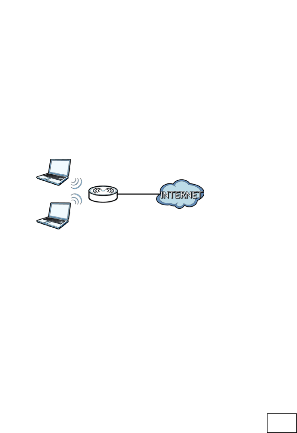
1.4 Wireless Access
The ZyXEL Device is a wireless Access Point (AP) for wireless clients, such as
notebook computers or PDAs and iPads. It allows them to connect to the Internet
without having to rely on inconvenient Ethernet cables.
You can configure your wireless network in either the built-in Web Configurator, or
using the WPS button.
Figure 2 Wireless Access Example
However, before you can use this ZyXEL Device to create a wireless network, you
must set its country code first in the Web Configurator. This is very important.
To set the wireless country code:
1Log into the ZyXEL Device’s built-in Web Configurator. See Chapter 8 on page 99.
2Open the Network > Wireless LAN > AP screen.
3Select your country from the Channel Selection list. See Section 8.2 on page
101 for details.
4Click Apply to save your changes.
5Finally, open the Internet and Wireless Configuration wizards to set up your
network. See Chapter 5 on page 53.
Chapter 1 Introduction
P-660N-T1A User’s Guide
24
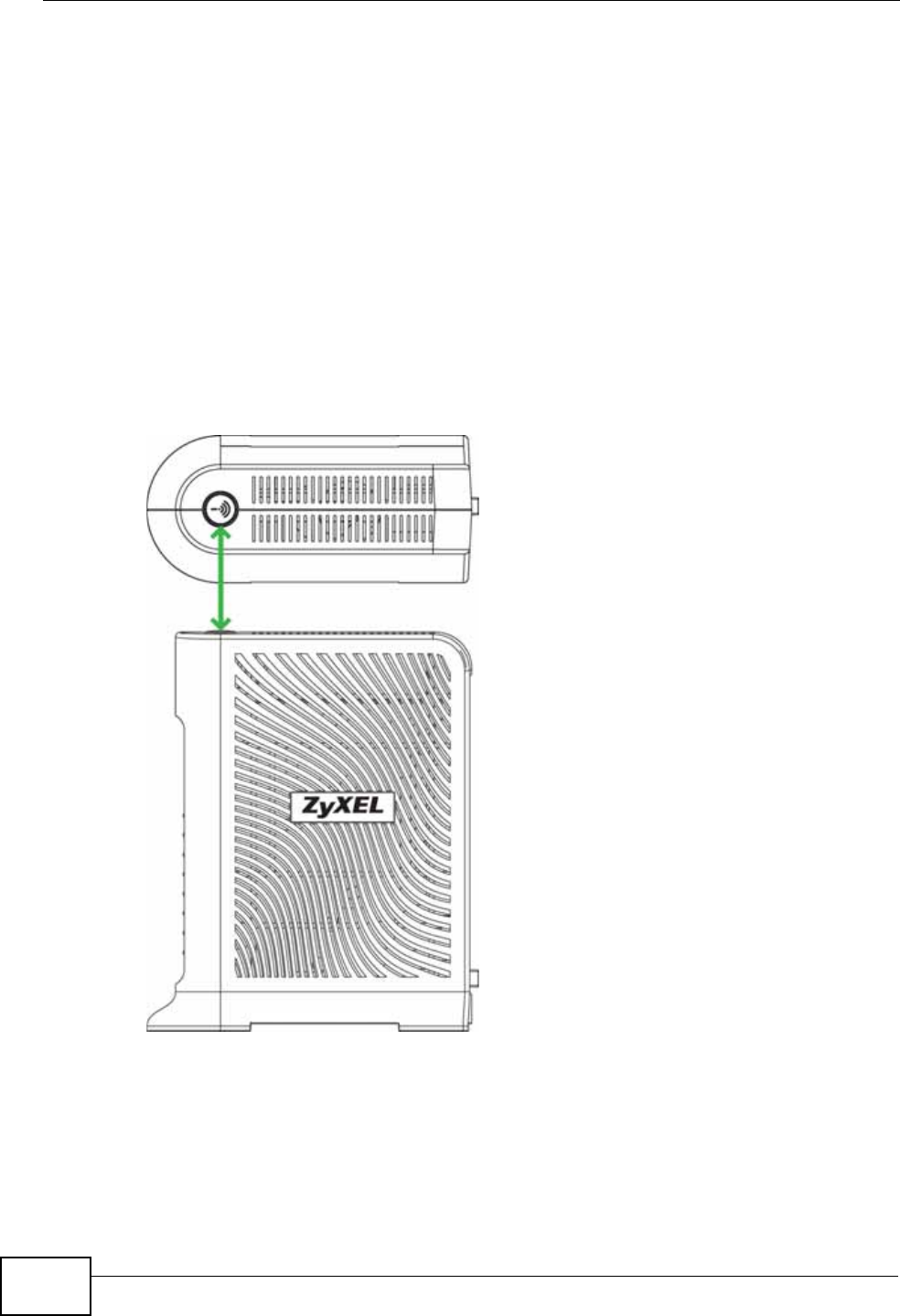
1.4.1 Using the WPS/WLAN Button
By default, the wireless network is turned off on the ZyXEL Device. To turn it on,
simply press the WPS/WLAN button on top of the device for 1 second. Once the
WPS/WLAN LED turns green, the wireless network is active.
You can also use the WPS/WLAN button to quickly set up a secure wireless
connection between the ZyXEL Device and a WPS-compatible client by adding one
device at a time.
To activate WPS:
1Make sure the POWER LED is on and not blinking.
2Press the WPS/WLAN button for five to ten seconds and release it.
3Press the WPS button on another WPS-enabled device within range of the ZyXEL
Device. The WPS/WLAN LED should flash while the ZyXEL Device sets up a WPS
connection with the other wireless device.
4Once the connection is successfully made, the WPS/WLAN LEd shines green.
Chapter 1 Introduction
P-660N-T1A User’s Guide 25
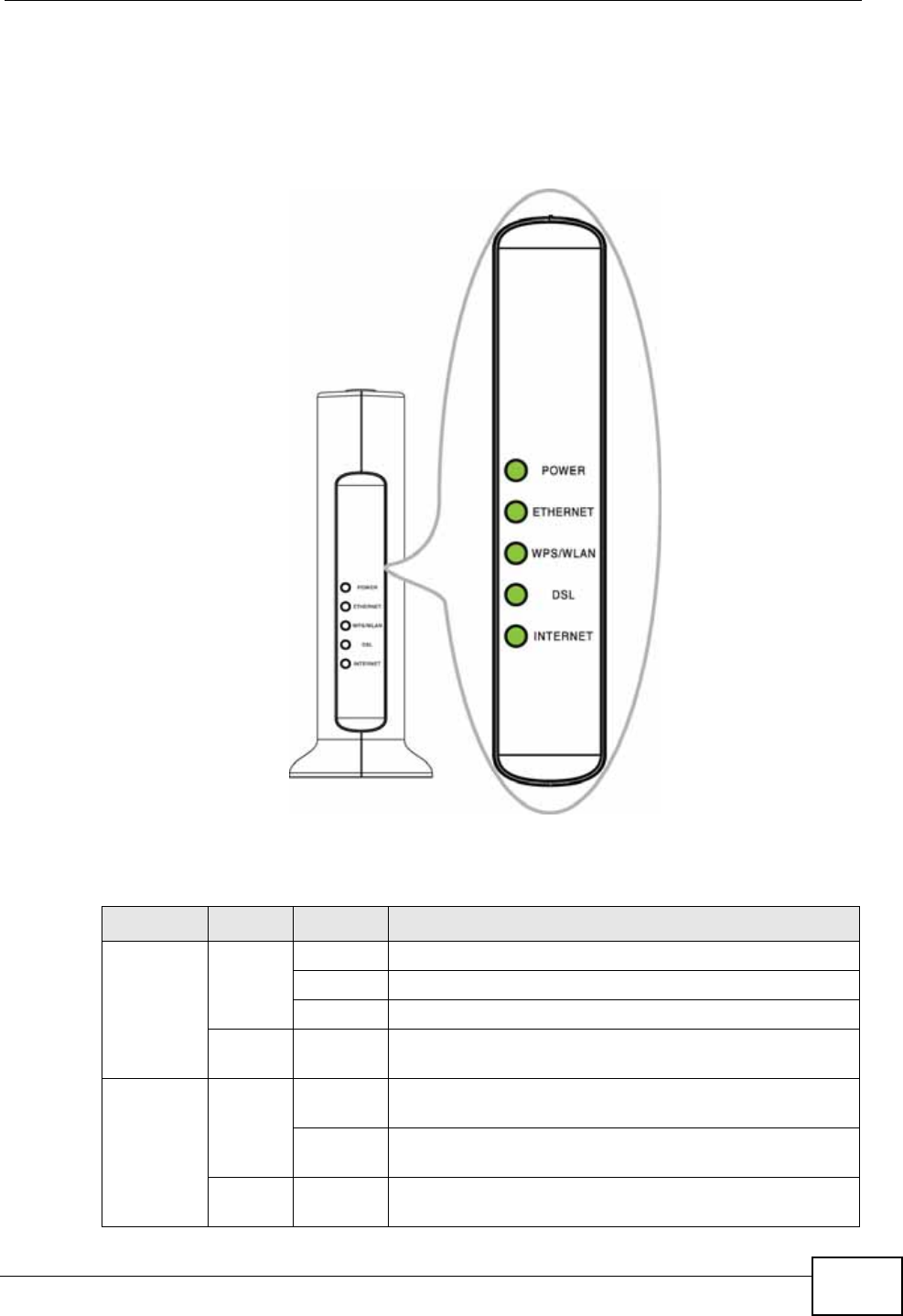
1.5 LEDs (Lights)
The following graphic displays the labels of the LEDs.
Figure 3 LEDs on the Front Panel
None of the LEDs are on if the ZyXEL Device is not receiving power.
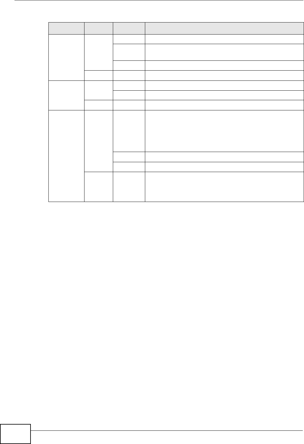
Table 1 LED Descriptions
LED COLOR STATUS DESCRIPTION
POWER Green On The ZyXEL Device is receiving power and ready for use.
Blinking The ZyXEL Device is self-testing.
Off The ZyXEL Device is not receiving power.
Red On The ZyXEL Device detected an error while self-testing,
or there is a device malfunction.
ETHERNET Green On The ZyXEL Device has an Ethernet connection with a
device on the Local Area Network (LAN).
Blinking The ZyXEL Device is sending/receiving data to /from
the LAN.
Off The ZyXEL Device does not have an Ethernet
connection with the LAN.
Chapter 1 Introduction
P-660N-T1A User’s Guide
26
Refer to the Quick Start Guide for information on hardware connections.
1.6 The RESET Button
If you forget your password or cannot access the web configurator, you will need
to use the RESET button at the back of the device to reload the factory-default
configuration file. This means that you will lose all configurations that you had
previously and the password will be reset to “1234”.
1.6.1 Using the Reset Button
1Make sure the POWER LED is on (not blinking).
2To set the device back to the factory default settings, press the RESET button for
ten seconds or until the POWER LED begins to blink and then release it. When the
POWER LED begins to blink, the defaults have been restored and the device
restarts.
WPS/
WLAN Green On The wireless network is activated.
Blinking The ZyXEL Device is communicating with other
wireless clients.
Off The wireless network is not activated.
Orange Blinking The ZyXEL Device is setting up a WPS connection.
DSL Green On The DSL line is up.
Blinking The ZyXEL Device is initializing the DSL line.
Off The DSL line is down.
INTERNET Green On The ZyXEL Device has an IP connection but no traffic.
Your device has a WAN IP address (either static or
assigned by a DHCP server), PPP negotiation was
successfully completed (if used) and the DSL
connection is up.
Blinking The ZyXEL Device is sending or receiving IP traffic.
Off The ZyXEL Device does not have an IP connection.
Red On The ZyXEL Device attempted to make an IP connection
but failed. Possible causes are no response from a
DHCP server, no PPPoE response, PPPoE authentication
failed.
Table 1 LED Descriptions
LED COLOR STATUS DESCRIPTION

P-660N-T1A User’s Guide 27
CHAPTER 2
The Web Configurator
2.1 Overview
The web configurator is an HTML-based management interface that allows easy
device setup and management via Internet browser. Use Internet Explorer 6.0 and
later or Netscape Navigator 7.0 and later versions. The recommended screen
resolution is 1024 by 768 pixels.
In order to use the web configurator you need to allow:
• Web browser pop-up windows from your device. Web pop-up blocking is enabled
by default in Windows XP SP (Service Pack) 2.
• JavaScript (enabled by default).
• Java permissions (enabled by default).
See Appendix C on page 281 if you need to make sure these functions are allowed
in Internet Explorer.
2.1.1 Accessing the Web Configurator
1Make sure your ZyXEL Device hardware is properly connected (refer to the Quick
Start Guide).
2Launch your web browser.
3Type "192.168.1.1" as the URL.
Chapter 2 The Web Configurator
P-660N-T1A User’s Guide
28
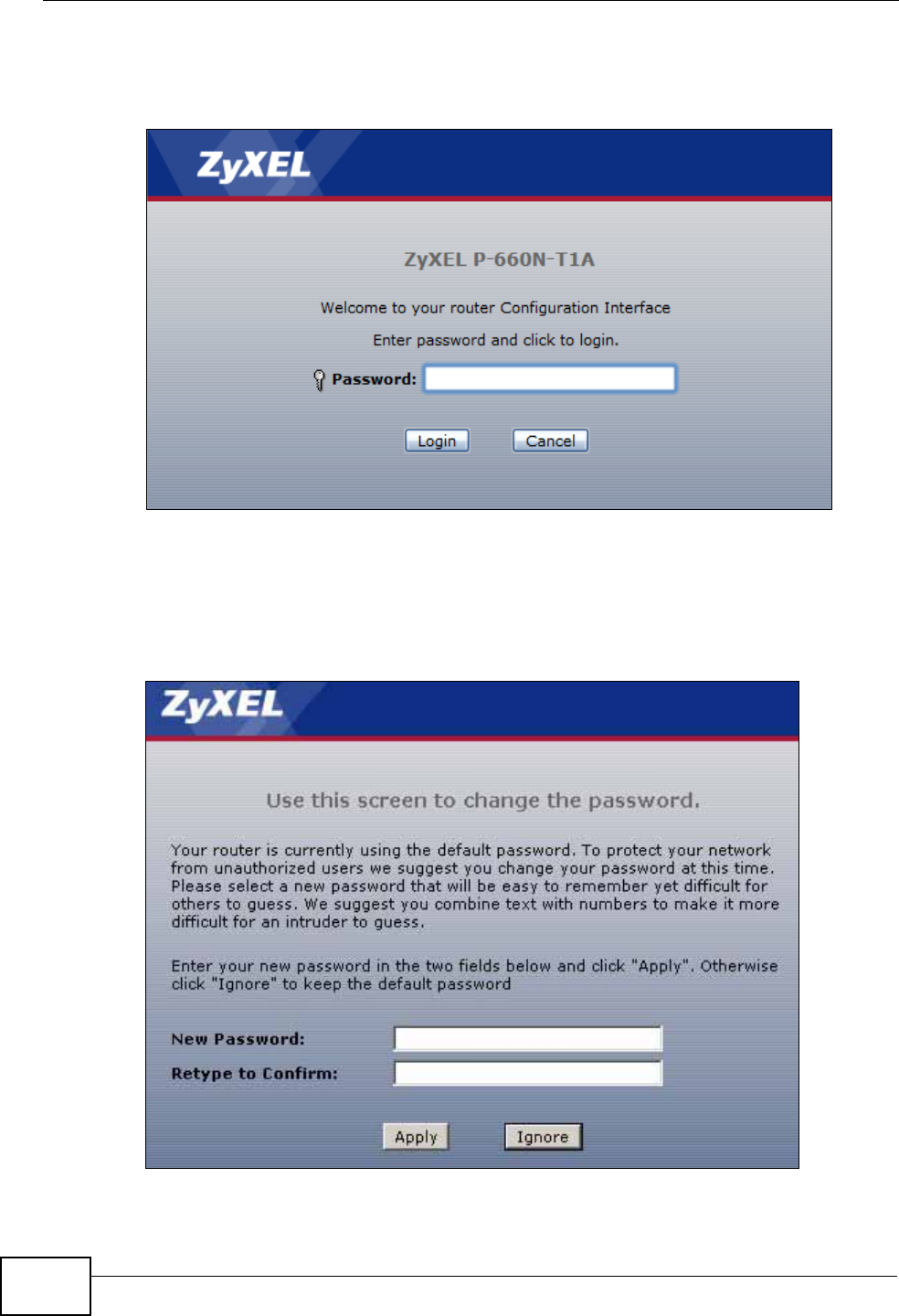
4A password screen displays. Enter the admin password (1234 by default) in the
password screen and click Login.
Figure 4 Password Screen
5The following screen displays if you have not yet changed your password. It is
strongly recommended you change the default password. Enter a new password,
retype it to confirm and click Apply; alternatively click Ignore to proceed to the
main menu if you do not want to change the password now.
Figure 5 Change Password Screen
Chapter 2 The Web Configurator
P-660N-T1A User’s Guide 29
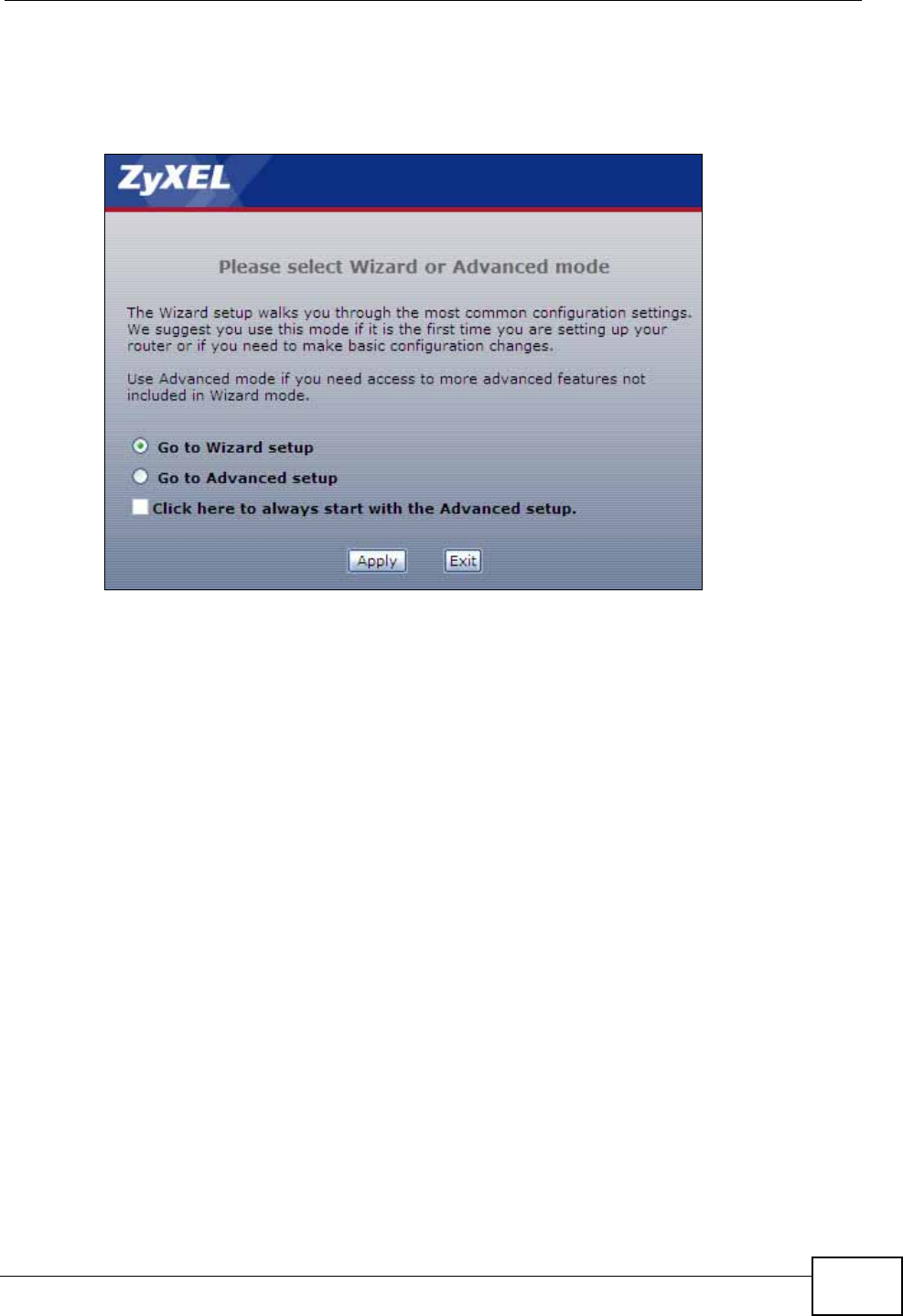
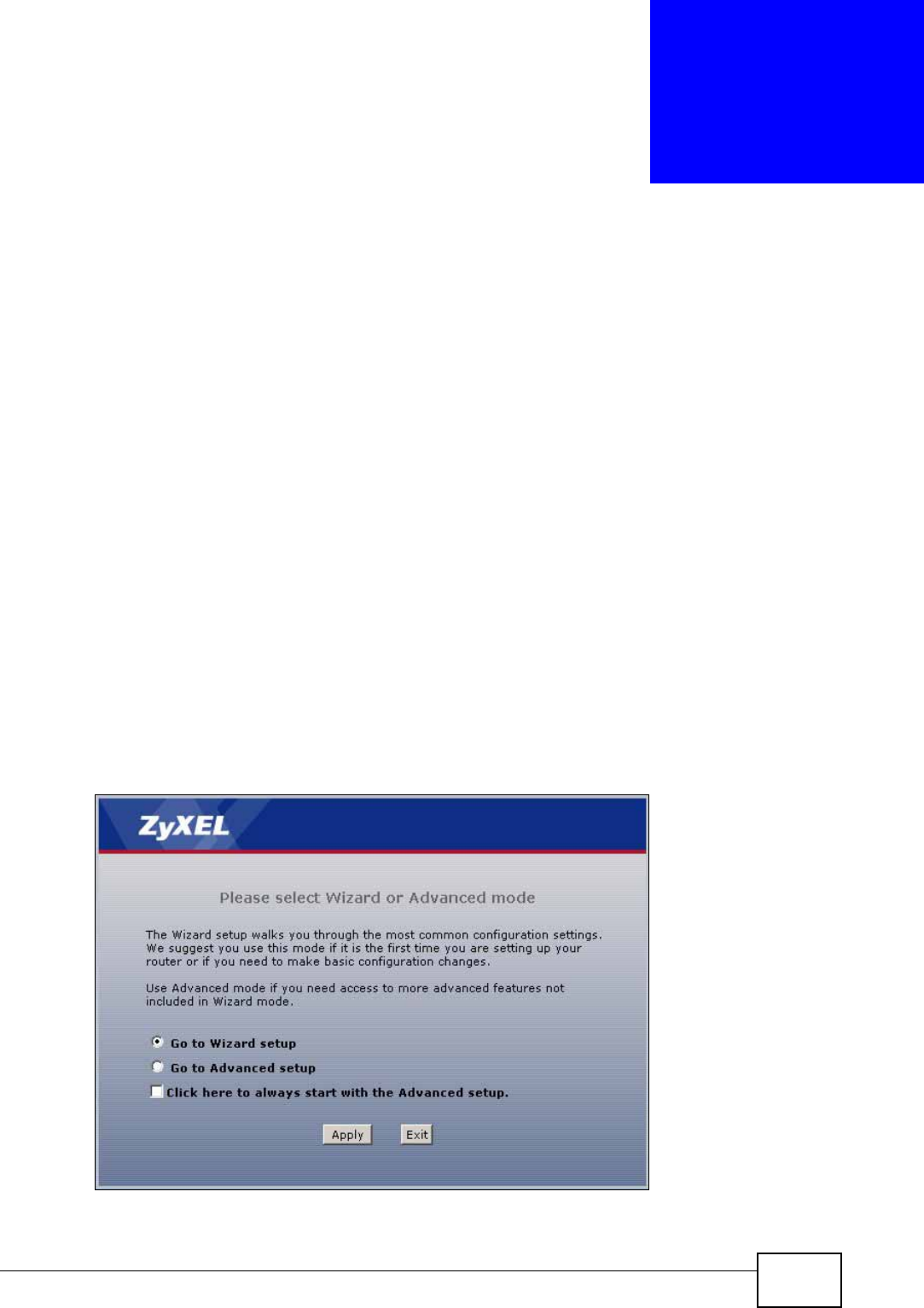
6Select Go to Wizard setup and click Apply to display the wizard main screen.
Otherwise, select Go to Advanced setup and click Apply to display the Status
screen.
Figure 6 Replace Factory Default Certificate Screen
Note: For security reasons, the ZyXEL Device automatically logs you out if you do not
use the web configurator for five minutes (default). If this happens, log in again.
Chapter 2 The Web Configurator
P-660N-T1A User’s Guide
30
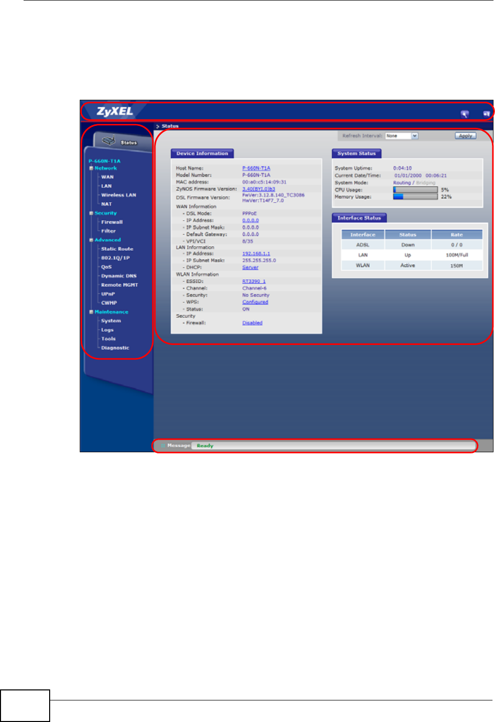
2.2 Main Screen
This section introduces the Web Configurator’s main screen.
Figure 7 Main Screen
The main screen is divided into these parts:
•A - title bar
•B - navigation panel
•C - main window
•D - status bar
B
C
D
A
Chapter 2 The Web Configurator
P-660N-T1A User’s Guide 31
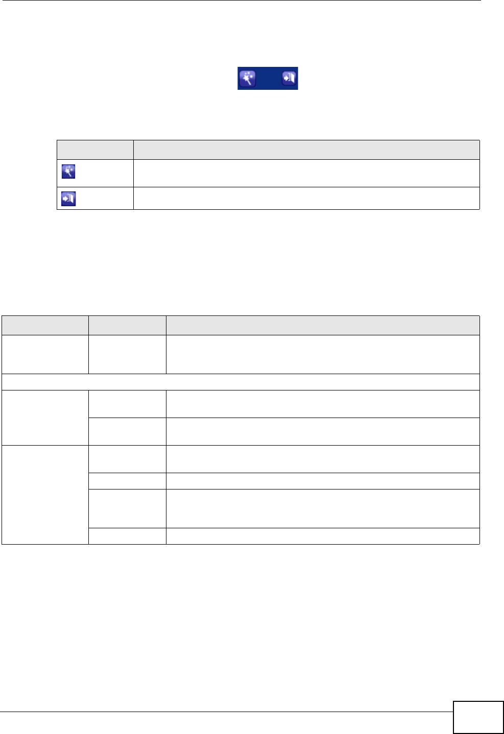
2.2.1 Title Bar
The title bar provides some icons in the upper right corner.
The icons provide the following functions.
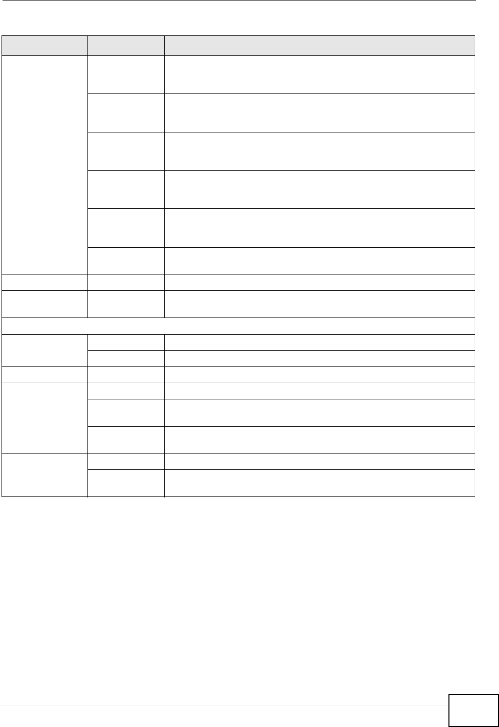
2.2.2 Navigation Panel
Use the menu items on the navigation panel to open screens to configure ZyXEL
Device features. The following tables describe each menu item.
Table 2 Web Configurator Icons in the Title Bar
ICON DESCRIPTION
Wizards: Click this icon to go to the configuration wizards. See Chapter
5 on page 53 for more information.
Logout: Click this icon to log out of the web configurator.
Table 3 Navigation Panel Summary
LINK TAB FUNCTION
Status This screen shows the ZyXEL Device’s general device and network
status information. Use this screen to access the statistics and
client list.
Network
WAN Internet
Connection Use this screen to configure ISP parameters, WAN IP address
assignment, and other advanced properties.
More
Connections Use this screen to configure additional WAN connections.
LAN IP Use this screen to configure LAN TCP/IP settings and other
advanced properties.
DHCP Server Use this screen to configure LAN DHCP settings and DNS server.
Client List Use this screen to view current DHCP client information and to
always assign specific IP addresses to individual MAC addresses
(and host names).
IP Alias Use this screen to partition your LAN interface into subnets.

Chapter 2 The Web Configurator
P-660N-T1A User’s Guide
32
Wireless LAN AP Use this screen to configure the wireless LAN settings and WLAN
authentication/security settings.
More AP Use this screen to configure multiple BSSs on the ZyXEL Device.
WPS Use this screen to configure and view your WPS (Wi-Fi Protected
Setup) settings.
WPS Station Use this screen to set up a WPS wireless network.
WDS Use this screen to set up Wireless Distribution System links to
other access points.
Scheduling Use this screen to configure the dates/times to enable or disable
the wireless LAN.
NAT General Use this screen to enable NAT.
Port
Forwarding Use this screen to make your local servers visible to the outside
world.
ALG Use this screen to enable or disable SIP ALG.
Security
Firewall General Use this screen to activate/deactivate the firewall and SPI
(Security Parameter Index).
Filter URL Use this screen to block access to certain web site URLs.
Application
Filter Use this screen to block or allow traffic from certain applications.
IP/MAC Filter Use this screen to configure IP/MAC filtering rules for incoming or
outgoing traffic.
Advanced
Static Route Use this screen to configure IP static routes to tell your device
about networks beyond the directly connected remote nodes.
802.1Q/1P Group Setting Use this screen to activate 802.1Q/1P, specify the management
VLAN group, display the VLAN groups and configure the settings
for each VLAN group.
Port Setting Use this screen to configure the PVID and assign traffic priority for
each port.
QoS General Use this screen to enable QoS and traffic prioritizing. You can also
configure the QoS rules and actions.
Dynamic DNS This screen allows you to use a static hostname alias for a
dynamic IP address.
Table 3 Navigation Panel Summary
LINK TAB FUNCTION
Chapter 2 The Web Configurator
P-660N-T1A User’s Guide 33
2.2.3 Main Window
The main window displays information and configuration fields. It is discussed in
the rest of this document.
Right after you log in, the Status screen is displayed. See Chapter 3 on page 35
for more information about the Status screen.
Remote
MGMT WWW Use this screen to configure through which interface(s) and from
which IP address(es) users can use HTTP to manage the ZyXEL
Device.
Telnet Use this screen to configure through which interface(s) and from
which IP address(es) users can use Telnet to manage the ZyXEL
Device.
FTP Use this screen to configure through which interface(s) and from
which IP address(es) users can use FTP to access the ZyXEL
Device.
SNMP Use this screen to configure through which interface and from
which IP addresses(es) users can access the SNMP agent on the
ZyXEL Device.
DNS Use this screen to configure through which interface(s) and from
which IP address(es) users can send DNS queries to the ZyXEL
Device.
ICMP Use this screen to set whether or not your device will respond to
pings and probes for services that you have not made available.
UPnP General Use this screen to turn UPnP on or off.
CWMP Use this screen to have a management server manage the ZyXEL
Device.
Maintenance
System General Use this screen to configure your device’s password.
Time and Date Use this screen to change your ZyXEL Device’s time and date.
Logs System Log Use this screen to select which logs your device is to record.
Tools Firmware Use this screen to upload firmware to your device.
Configuration Use this screen to backup and restore your device’s configuration
(settings) or reset the factory default settings.
Restart This screen allows you to reboot the ZyXEL Device without turning
the power off.
Diagnostic General Use this screen to test the connections to other devices.
DSL Line This screen displays information to help you identify problems
with the DSL connection.
Table 3 Navigation Panel Summary
LINK TAB FUNCTION

Chapter 2 The Web Configurator
P-660N-T1A User’s Guide
34
2.2.4 Status Bar
Check the status bar when you click Apply or OK to verify that the configuration
has been updated.
P-660N-T1A User’s Guide 35
CHAPTER 3
Status Screen
3.1 Overview
Use the Status screen to look at the current status of the device, system
resources, and interfaces (LAN and WAN). The Status screen also provides
information from DHCP and statistics from bandwidth management and traffic.
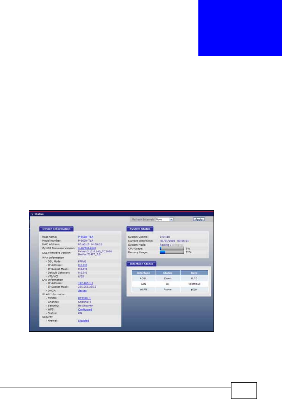
3.2 The Status Screen
Use this screen to view the status of the ZyXEL Device. Click Status to open this
screen.
Figure 8 Status Screen
Chapter 3 Status Screen
P-660N-T1A User’s Guide
36
Each field is described in the following table.
Table 4 Status Screen
LABEL DESCRIPTION
Refresh Interval Select how often you want the ZyXEL Device to update this screen.
Apply Click this to update this screen immediately.
Device Information
Host Name This field displays the ZyXEL Device system name. It is used for
identification.
Model
Number This is the model name of your device.
MAC
Address This is the MAC (Media Access Control) or Ethernet address unique to
your ZyXEL Device.
ZyNOS
Firmware
Version
This is the current version of the firmware inside the device. Click this
to go to the screen where you can change it.
DSL
Firmware
Version
This is the current version of the device’s DSL modem code.
WAN
Information
DSL Mode This is the DSL standard that your ZyXEL Device is using.
IP Address This is the current IP address of the ZyXEL Device in the WAN. Click this
to go to the screen where you can change it.
IP Subnet
Mask This is the current subnet mask in the WAN.
Default
Gateway This is the IP address of the default gateway, if applicable.
VPI/VCI This is the Virtual Path Identifier and Virtual Channel Identifier that you
entered in the wizard or WAN screen.
LAN
Information
IP Address This is the current IP address of the ZyXEL Device in the LAN. Click this
to go to the screen where you can change it.
IP Subnet
Mask This is the current subnet mask in the LAN.
DHCP This field displays what DHCP services the ZyXEL Device is providing to
the LAN. Choices are:
Server - The ZyXEL Device is a DHCP server in the LAN. It assigns IP
addresses to other computers in the LAN.
Relay - The ZyXEL Device acts as a surrogate DHCP server and relays
DHCP requests and responses between the remote server and the
clients.
None - The ZyXEL Device is not providing any DHCP services to the
LAN.
Click this to go to the screen where you can change it.
WLAN
Information

Chapter 3 Status Screen
P-660N-T1A User’s Guide 37
ESSID This is the descriptive name used to identify the ZyXEL Device in a
wireless LAN. Click this to go to the screen where you can change it.
Channel This is the channel number used by the ZyXEL Device now.
Security This displays the type of security mode the ZyXEL Device is using in the
wireless LAN.
WPS This displays whether WPS is activated. Click this to go to the screen
where you can configure the settings.
Status This displays whether WLAN is activated.
Security
Firewall This displays whether or not the ZyXEL Device’s firewall is activated.
Click this to go to the screen where you can change it.
System Status
System
Uptime This field displays how long the ZyXEL Device has been running since it
last started up. The ZyXEL Device starts up when you plug it in, when
you restart it (Maintenance > Tools > Restart), or when you reset it.
Current
Date/Time This field displays the current date and time in the ZyXEL Device. You
can change this in Maintenance > System > Time Setting.
System
Mode This displays whether the ZyXEL Device is functioning as a router or a
bridge.
CPU Usage This field displays what percentage of the ZyXEL Device’s processing
ability is currently used. When this percentage is close to 100%, the
ZyXEL Device is running at full load, and the throughput is not going to
improve anymore. If you want some applications to have more
throughput, you should turn off other applications (for example, using
QoS; see Chapter 14 on page 169).
Memory
Usage This field displays what percentage of the ZyXEL Device’s memory is
currently used. Usually, this percentage should not increase much. If
memory usage does get close to 100%, the ZyXEL Device is probably
becoming unstable, and you should restart the device. See Section 21.4
on page 223, or turn off the device (unplug the power) for a few
seconds.
Interface Status
Interface This column displays each interface the ZyXEL Device has.
Table 4 Status Screen
LABEL DESCRIPTION

Chapter 3 Status Screen
P-660N-T1A User’s Guide
38
Status This field indicates whether or not the ZyXEL Device is using the
interface.
For the DSL interface, this field displays Down (line is down), Up (line
is up or connected) if you're using Ethernet encapsulation and Down
(line is down), Up (line is up or connected), Idle (line (ppp) idle), Dial
(starting to trigger a call) and Drop (dropping a call) if you're using
PPPoE encapsulation.
For the LAN interface, this field displays Up when the ZyXEL Device is
using the interface and Down when the ZyXEL Device is not using the
interface.
For the WLAN interface, it displays Active when WLAN is enabled or
InActive when WLAN is disabled.
Rate For the LAN interface, this displays the port speed and duplex setting.
For the DSL interface, it displays the downstream and upstream
transmission rate.
For the WLAN interface, it displays the maximum transmission rate
when WLAN is enabled or N/A when WLAN is disabled.
Table 4 Status Screen
LABEL DESCRIPTION
P-660N-T1A User’s Guide 39
CHAPTER 4
Tutorials
4.1 Overview
This chapter shows you how to use the ZyXEL Device’s various features.
•Setting Up a Secure Wireless Network, see page 39
•Configuring the MAC Address Filter, see page 46
•Multiple WAN Connections Example, see page 48
4.2 Setting Up a Secure Wireless Network
Thomas wants to set up a wireless network so that he can use his notebook to
access the Internet. In this wireless network, the ZyXEL Device serves as an
access point (AP), and the notebook is the wireless client. The wireless client can
access the Internet through the AP.
Thomas has to configure the wireless network settings on the ZyXEL Device. Then
he can set up a wireless network using WPS (Section 4.2.2 on page 41) or manual
configuration (Section 4.2.3 on page 45).
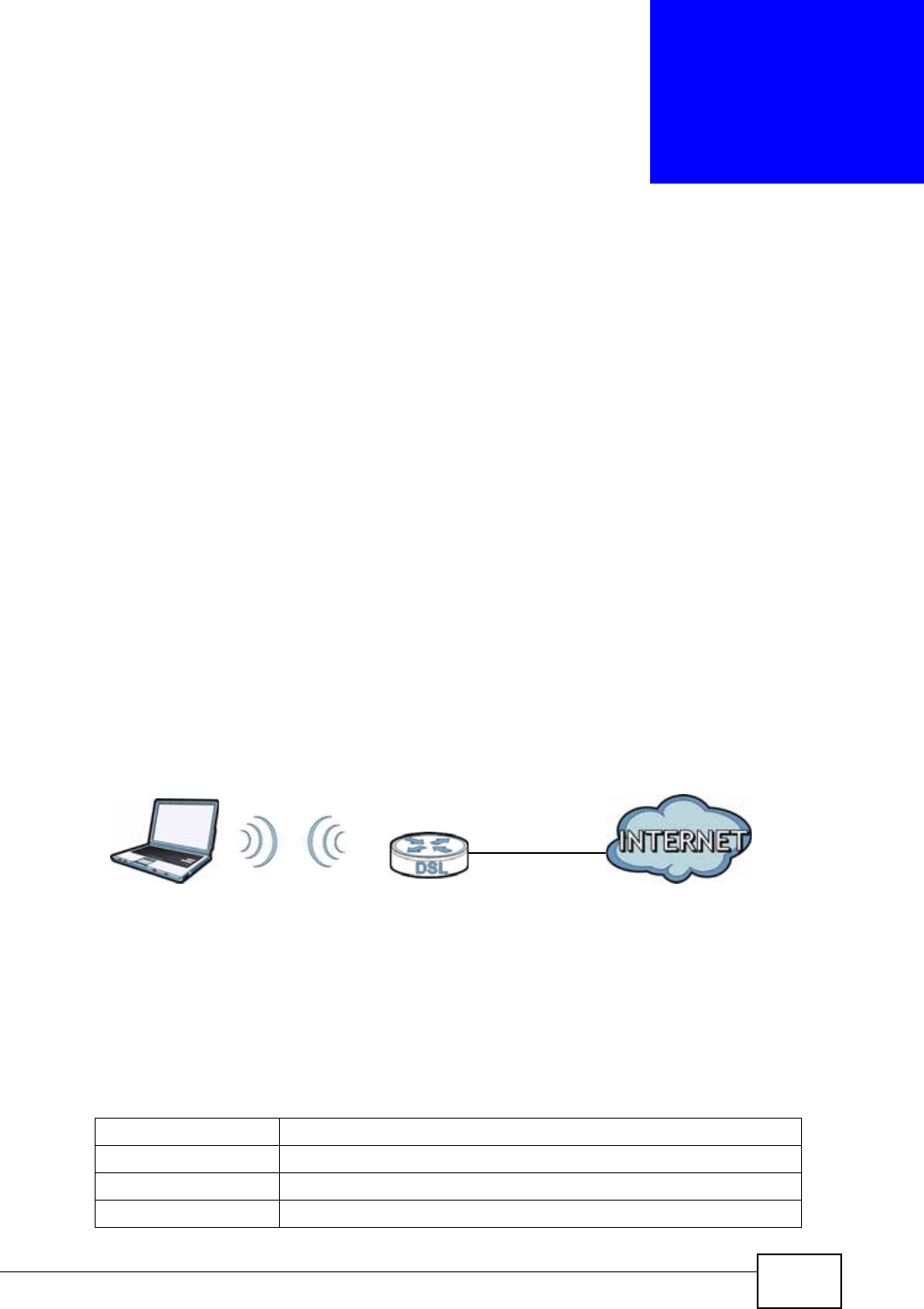
4.2.1 Configuring the Wireless Network Settings
This example uses the following parameters to set up a wireless network.
SSID Example
Security Mode WPA-PSK
Pre-Shared Key 1234567key7654321yek
802.11 Mode 802.11b+g+n
Chapter 4 Tutorials
P-660N-T1A User’s Guide
40
1Click Network > Wireless LAN to open the AP screen. Configure the screen
using the provided parameters (see page 39). Click Apply.
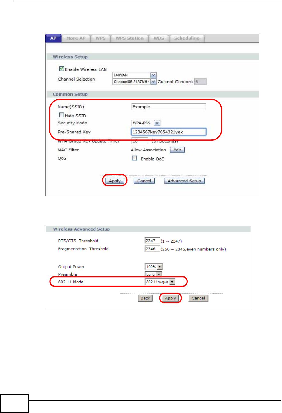
2Click the Advanced Setup button and select 802.11b+g+n in the 802.11 Mode
field. Click Apply.
Thomas can now use the WPS feature to establish a wireless connection between
his notebook and the ZyXEL Device (see Section 4.2.2 on page 41). He can also
use the notebook’s wireless client to search for the ZyXEL Device (see Section
4.2.3 on page 45).
Chapter 4 Tutorials
P-660N-T1A User’s Guide 41
4.2.2 Using WPS
This section shows you how to set up a wireless network using WPS. It uses the
ZyXEL Device as the AP and ZyXEL NWD210N as the wireless client which
connects to the notebook.
Note: The wireless client must be a WPS-aware device (for example, a WPS USB
adapter or PCMCIA card).
There are two WPS methods to set up the wireless client settings:
•Push Button Configuration (PBC) - simply press a button. This is the easier
of the two methods.
•PIN Configuration - configure a Personal Identification Number (PIN) on the
ZyXEL Device. A wireless client must also use the same PIN in order to
download the wireless network settings from the ZyXEL Device.
Push Button Configuration (PBC)
1Make sure that your ZyXEL Device is turned on and your notebook is within the
cover range of the wireless signal.
2Make sure that you have installed the wireless client driver and utility in your
notebook.
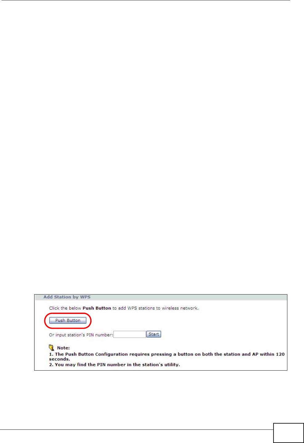
3In the wireless client utility, go to the WPS setting page. Enable WPS and press
the WPS button (Start or WPS button).
4Push and hold the WPS button located on the ZyXEL Device’s rear panel for more
than 5 seconds. Alternatively, you may log into ZyXEL Device’s web configurator
and click the Push Button in the Network > Wireless LAN > WPS Station
screen.
Note: Your ZyXEL Device has a WPS button located on its rear panel as well as a
WPS button in its configuration utility. Both buttons have exactly the same
function: you can use one or the other.
Chapter 4 Tutorials
P-660N-T1A User’s Guide
42
Note: It doesn’t matter which button is pressed first. You must press the second
button within two minutes of pressing the first one.
The ZyXEL Device sends the proper configuration settings to the wireless client.
This may take up to two minutes. The wireless client is then able to communicate
with the ZyXEL Device securely.
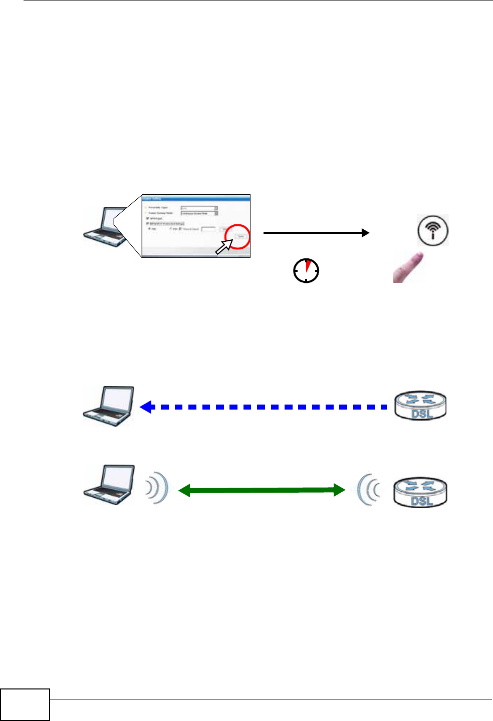
The following figure shows you an example of how to set up a wireless network
and its security by pressing a button on both ZyXEL Device and wireless client.
Example WPS Process: PBC Method
Wireless Client ZyXEL Device
SECURITY INFO
COMMUNICATION
WITHIN 2 MINUTES
Press and hold for
5 seconds
Chapter 4 Tutorials
P-660N-T1A User’s Guide 43
PIN Configuration
When you use the PIN configuration method, you need to use both the ZyXEL
Device’s web configurator and the wireless client’s utility.
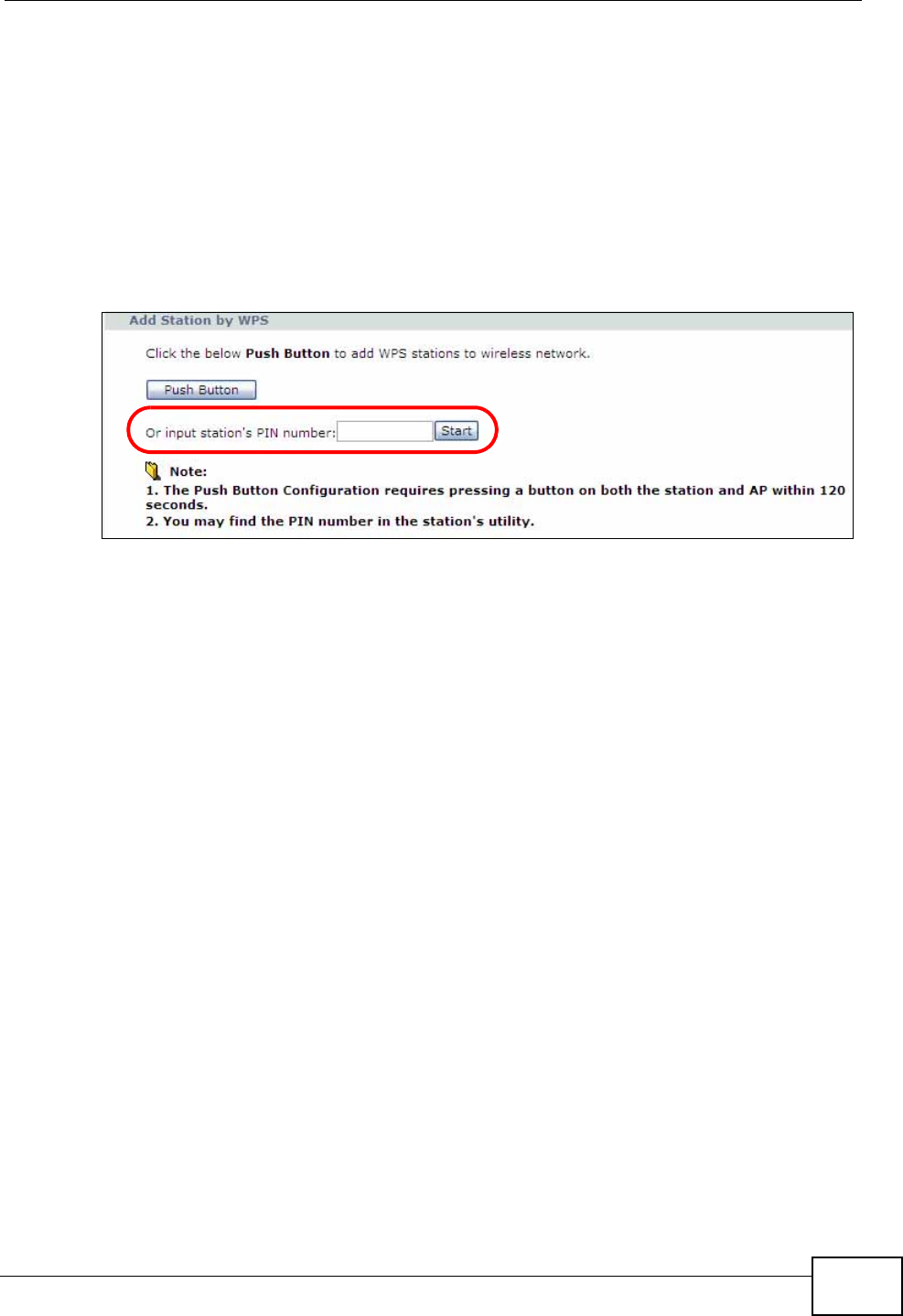
1Launch your wireless client’s configuration utility. Go to the WPS settings and
select the PIN method to get a PIN number.
2Enter the PIN number in the PIN field in the Network > Wireless LAN > WPS
Station screen on the ZyXEL Device.
3Click the Start buttons (or the button next to the PIN field) on both the wireless
client utility screen and the ZyXEL Device’s WPS Station screen within two
minutes.
The ZyXEL Device authenticates the wireless client and sends the proper
configuration settings to the wireless client. This may take up to two minutes. The
wireless client is then able to communicate with the ZyXEL Device securely.
Chapter 4 Tutorials
P-660N-T1A User’s Guide
44
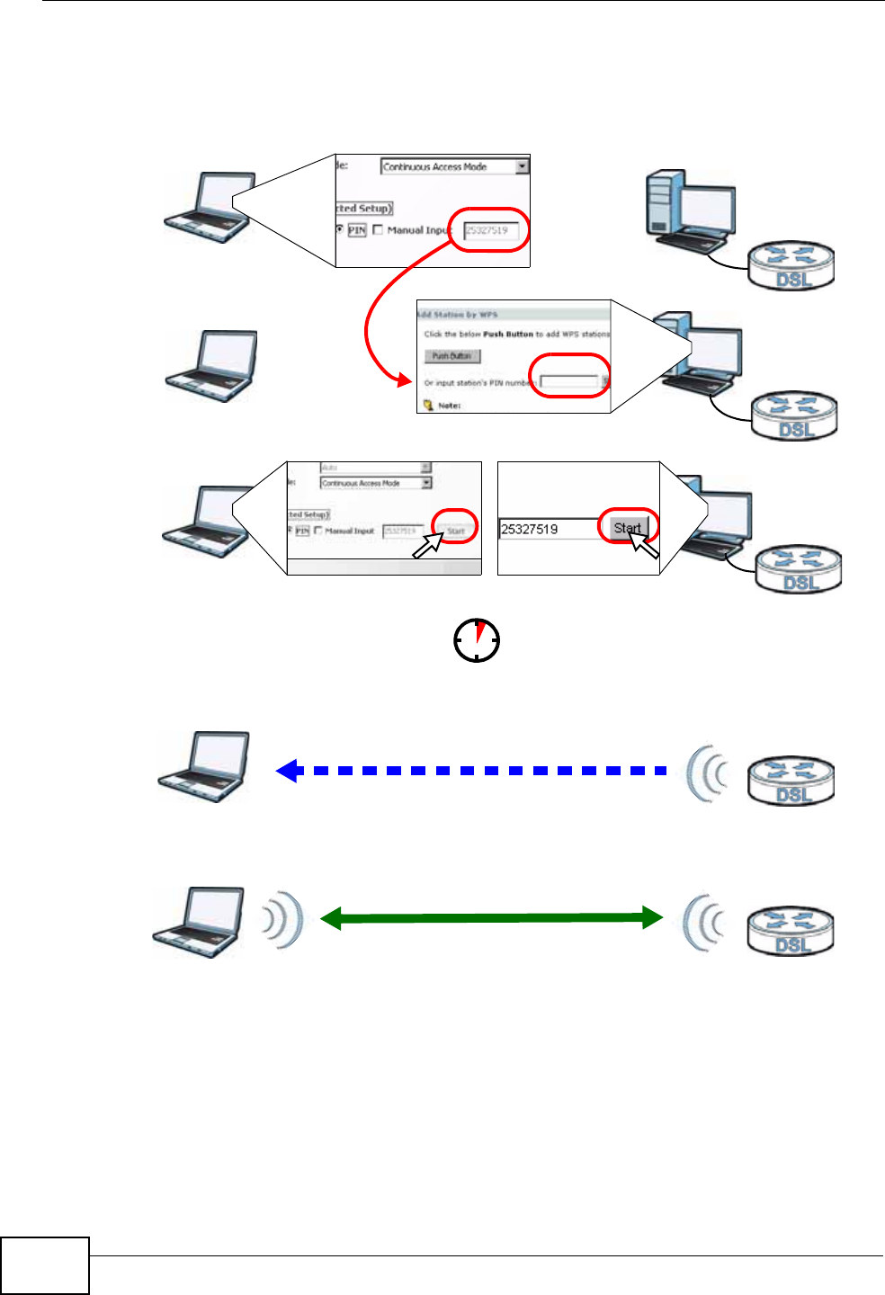
The following figure shows you how to set up a wireless network and its security
on a ZyXEL Device and a wireless client by using PIN method.
Example WPS Process: PIN Method
Authentication by PIN
SECURITY INFO
WITHIN 2 MINUTES
Wireless Client
ZyXEL Device
COMMUNICATION
Chapter 4 Tutorials
P-660N-T1A User’s Guide 45
4.2.3 Without WPS
Use the wireless adapter’s utility installed on the notebook to search for the
“Example” SSID. Then enter the “DoNotStealMyWirelessNetwork” pre-shared key
to establish an wireless Internet connection.
Note: The ZyXEL Device supports IEEE 802.11b and IEEE 802.11g wireless clients.
Make sure that your notebook or computer’s wireless adapter supports one of
these standards.
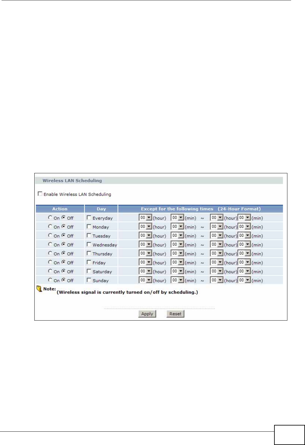
4.2.4 Setting Up Wireless Network Scheduling
Thomas mostly uses his notebook to access the Internet on weekends;
occasionally he uses it at night on weekdays. Here is how Thomas can set up a
schedule to turn on the wireless network at specific time and days.
1Click Network > Wireless Network > Scheduling to open the following screen.
Chapter 4 Tutorials
P-660N-T1A User’s Guide
46
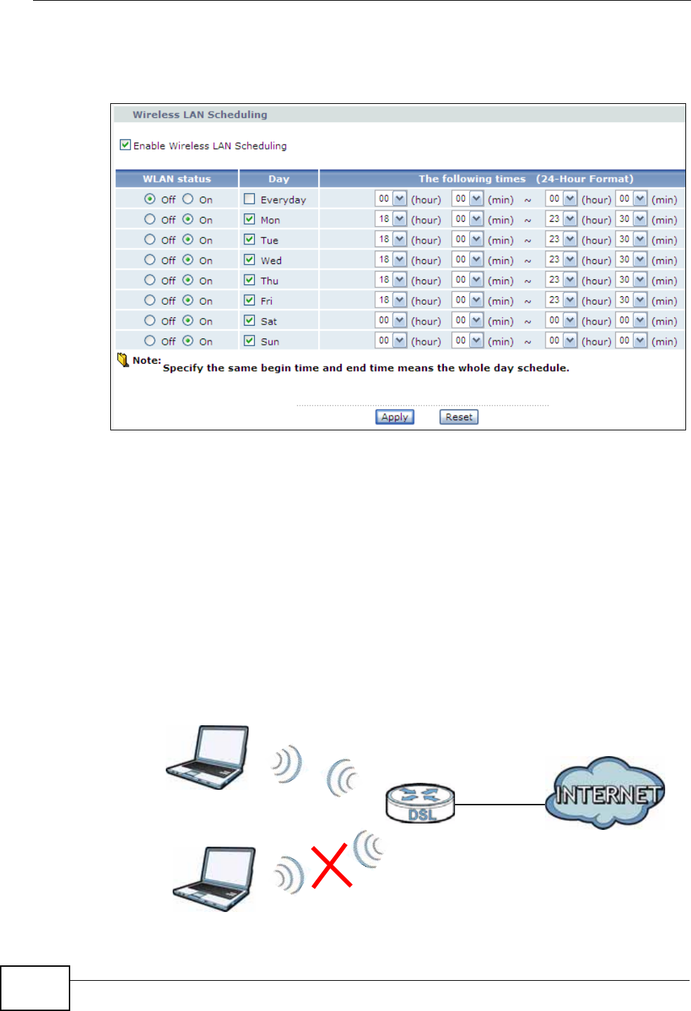
2Configure the screen as follows. Turn on the wireless network from Mondays to
Fridays between 18:00 and 23:30. Turn on the wireless network all day on
Saturdays and Sundays. Click Apply.
4.3 Configuring the MAC Address Filter
Thomas noticed that his daughter Josephine spends too much time surfing the
web and downloading media files. He decided to prevent Josephine from accessing
the Internet so that she can concentrate on preparing for her final exams.
Josephine’s computer connects wirelessly to the Internet through the ZyXEL
Device. Thomas can deny access to the wireless network using the MAC address of
Josephine’s computer.
Thomas
Josephine
Chapter 4 Tutorials
P-660N-T1A User’s Guide 47
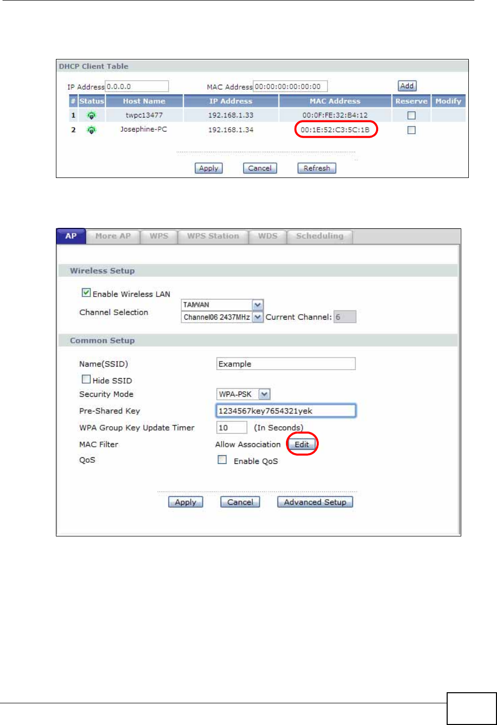
1Click Network > LAN > Client List to open the following screen. Look for the
MAC address of Josephine’s computer.
2Click Network > Wireless LAN to open the AP screen. Click the Edit button in
the MAC Filter field.
Chapter 4 Tutorials
P-660N-T1A User’s Guide
48
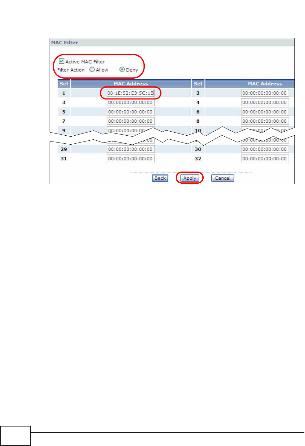
3Select Active MAC Filter and Deny Filter Action. Enter the MAC address you
found in the Client List screen. Click Apply.
Josephine will no longer be able to access the Internet through the ZyXEL Device.
4.4 Multiple WAN Connections Example
This example shows an application for multiple WAN connections.
Your ISP may configure more than one WAN connection on the ZyXEL Device to
record traffic statistics or calculate service charges.
In Figure 9, three WAN connections are configured over the ADSL line:
• The connection with VPI/VCI, 0/33, is dedicated for Media-On-Demand (MOD)
service.
• The connection with VPI/VCI, 0/34, is dedicated for VoIP service.
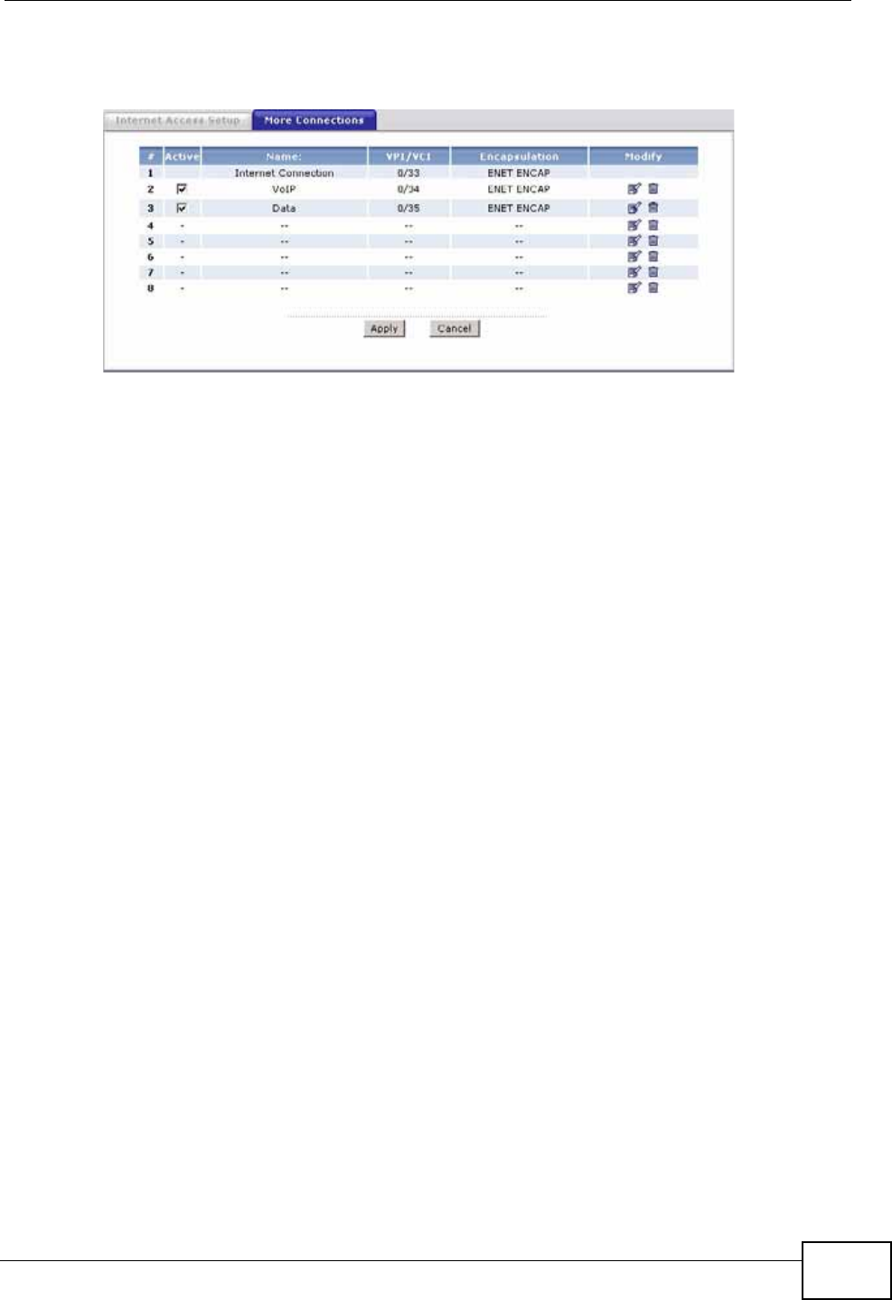
Chapter 4 Tutorials
P-660N-T1A User’s Guide 49
• The connection with VPI/VCI, 0/35, is dedicated for general data transmission.
Figure 9 Example for Multiple WAN Connections

Chapter 4 Tutorials
P-660N-T1A User’s Guide
50

51
PART II
Technical Reference

52
P-660N-T1A User’s Guide 53
CHAPTER 5
Internet and Wireless Setup
Wizard
5.1 Overview
Use the wizard setup screens to configure your system for Internet access with
the information given to you by your ISP.
Note: See the advanced menu chapters for background information on these fields.
5.2 Internet Access Wizard Setup
1After you enter the password to access the web configurator, select Go to Wizard
setup and click Apply. Otherwise, click the wizard icon in the top right corner of
the web configurator to go to the wizards.
Figure 10 Select a Mode
Chapter 5 Internet and Wireless Setup Wizard
P-660N-T1A User’s Guide
54
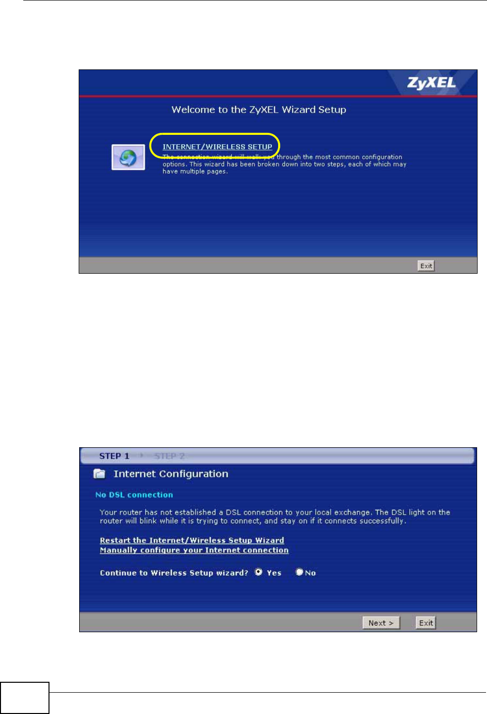
2Click INTERNET/WIRELESS SETUP to configure the system for Internet access
and wireless connection.
Figure 11 Wizard Welcome
3Your ZyXEL device attempts to detect your DSL connection and your connection
type.
3a The following screen appears if a connection is not detected. Check your
hardware connections and click Restart the INTERNET/WIRELESS SETUP
Wizard to return to the wizard welcome screen. If you still cannot connect,
click Manually configure your Internet connection. Follow the directions
in the wizard and enter your Internet setup information as provided to you by
your ISP. See Section 5.2.1 on page 56 for more details.
If you would like to skip your Internet setup and configure the wireless LAN
settings, leave Yes selected and click Next.
Figure 12 Auto Detection: No DSL Connection
Chapter 5 Internet and Wireless Setup Wizard
P-660N-T1A User’s Guide 55
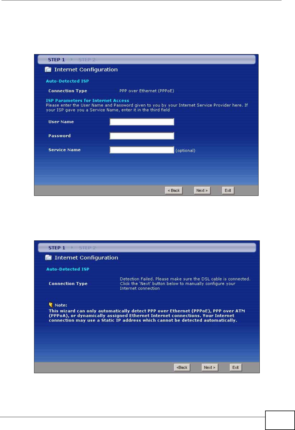
3b The following screen displays if a PPPoE or PPPoA connection is detected.
Enter your Internet account information (username, password and/or service
name) exactly as provided by your ISP. Then click Next and see Section 5.3 on
page 62 for wireless connection wizard setup.
Figure 13 Auto-Detection: PPPoE
3c The following screen appears if the ZyXEL device detects a connection but not
the connection type. Click Next and refer to Section 5.2.1 on page 56 on how
to manually configure the ZyXEL Device for Internet access.
Figure 14 Auto Detection: Failed
Chapter 5 Internet and Wireless Setup Wizard
P-660N-T1A User’s Guide
56
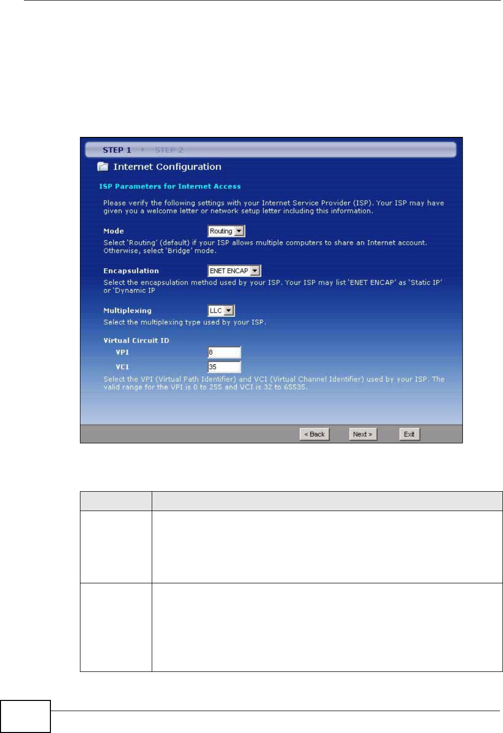
5.2.1 Manual Configuration
1If the ZyXEL Device fails to detect your DSL connection type but the physical line
is connected, enter your Internet access information in the wizard screen exactly
as your service provider gave it to you. Leave the defaults in any fields for which
you were not given information.
Figure 15 Internet Access Wizard Setup: ISP Parameters
The following table describes the fields in this screen.
Table 5 Internet Access Wizard Setup: ISP Parameters
LABEL DESCRIPTION
Mode Select Routing (default) from the drop-down list box if your ISP give you
one IP address only and you want multiple computers to share an Internet
account. Select Bridge when your ISP provides you more than one IP
address and you want the connected computers to get individual IP
address from ISP’s DHCP server directly. If you select Bridge, you cannot
use Firewall, DHCP server and NAT on the ZyXEL Device.
Encapsulation Select the encapsulation type your ISP uses from the Encapsulation
drop-down list box. Choices vary depending on what you select in the
Mode field.
If you select Bridge in the Mode field, select either PPPoA or RFC 1483.
If you select Routing in the Mode field, select PPPoA, RFC 1483, ENET
ENCAP or PPPoE.
Chapter 5 Internet and Wireless Setup Wizard
P-660N-T1A User’s Guide 57
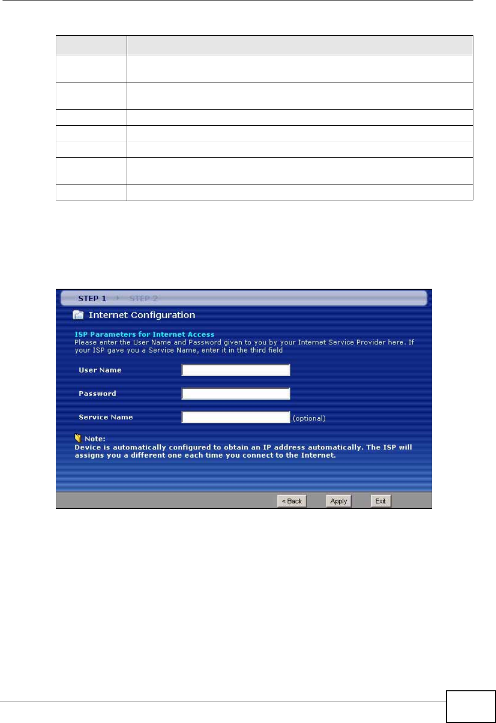
2The next wizard screen varies depending on what mode and encapsulation type
you use. All screens shown are with routing mode. Configure the fields and click
Next to continue. See Section 5.3 on page 62 for wireless connection wizard
setup
Figure 16 Internet Connection with PPPoE
Multiplexing Select the multiplexing method used by your ISP from the Multiplex
drop-down list box either VC-based or LLC-based.
Virtual Circuit
ID VPI (Virtual Path Identifier) and VCI (Virtual Channel Identifier) define a
virtual circuit. Refer to the appendix for more information.
VPI Enter the VPI assigned to you. This field may already be configured.
VCI Enter the VCI assigned to you. This field may already be configured.
Back Click this to return to the previous screen without saving.
Next Click this to continue to the next wizard screen. The next wizard screen
you see depends on what protocol you chose above.
Exit Click this to close the wizard screen without saving.
Table 5 Internet Access Wizard Setup: ISP Parameters
LABEL DESCRIPTION
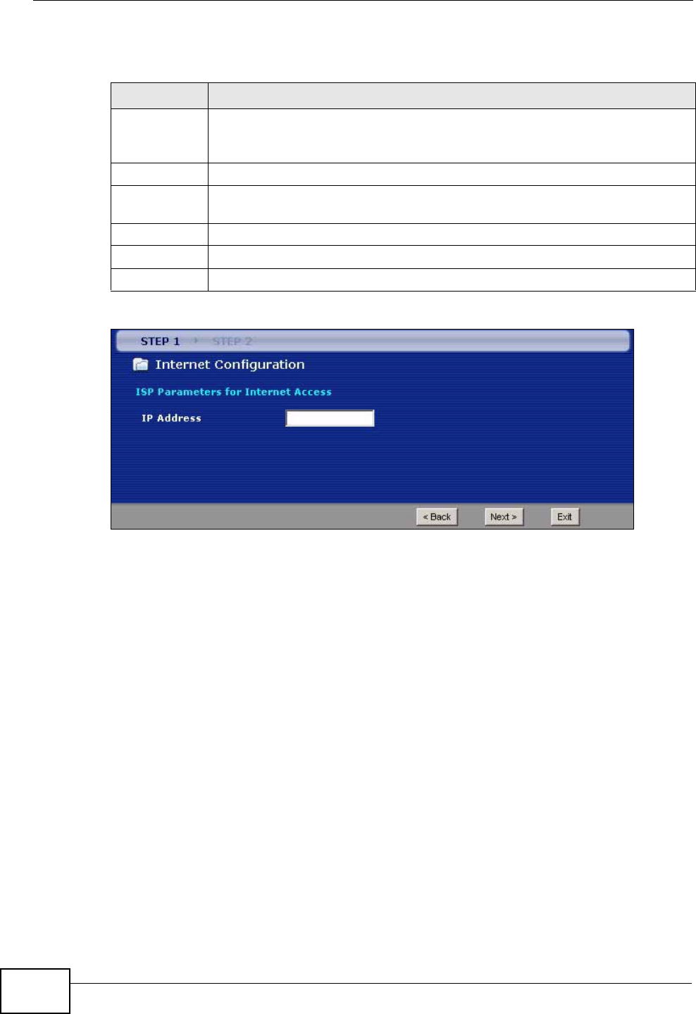
Chapter 5 Internet and Wireless Setup Wizard
P-660N-T1A User’s Guide
58
The following table describes the fields in this screen.
Figure 17 Internet Connection with RFC 1483
Table 6 Internet Connection with PPPoE
LABEL DESCRIPTION
User Name Enter the user name exactly as your ISP assigned. If assigned a name in
the form user@domain where domain identifies a service name, then enter
both components exactly as given.
Password Enter the password associated with the user name above.
Service
Name Type the name of your PPPoE service here.
Back Click this to return to the previous screen without saving.
Apply Click this to save your changes.
Exit Click this to close the wizard screen without saving.
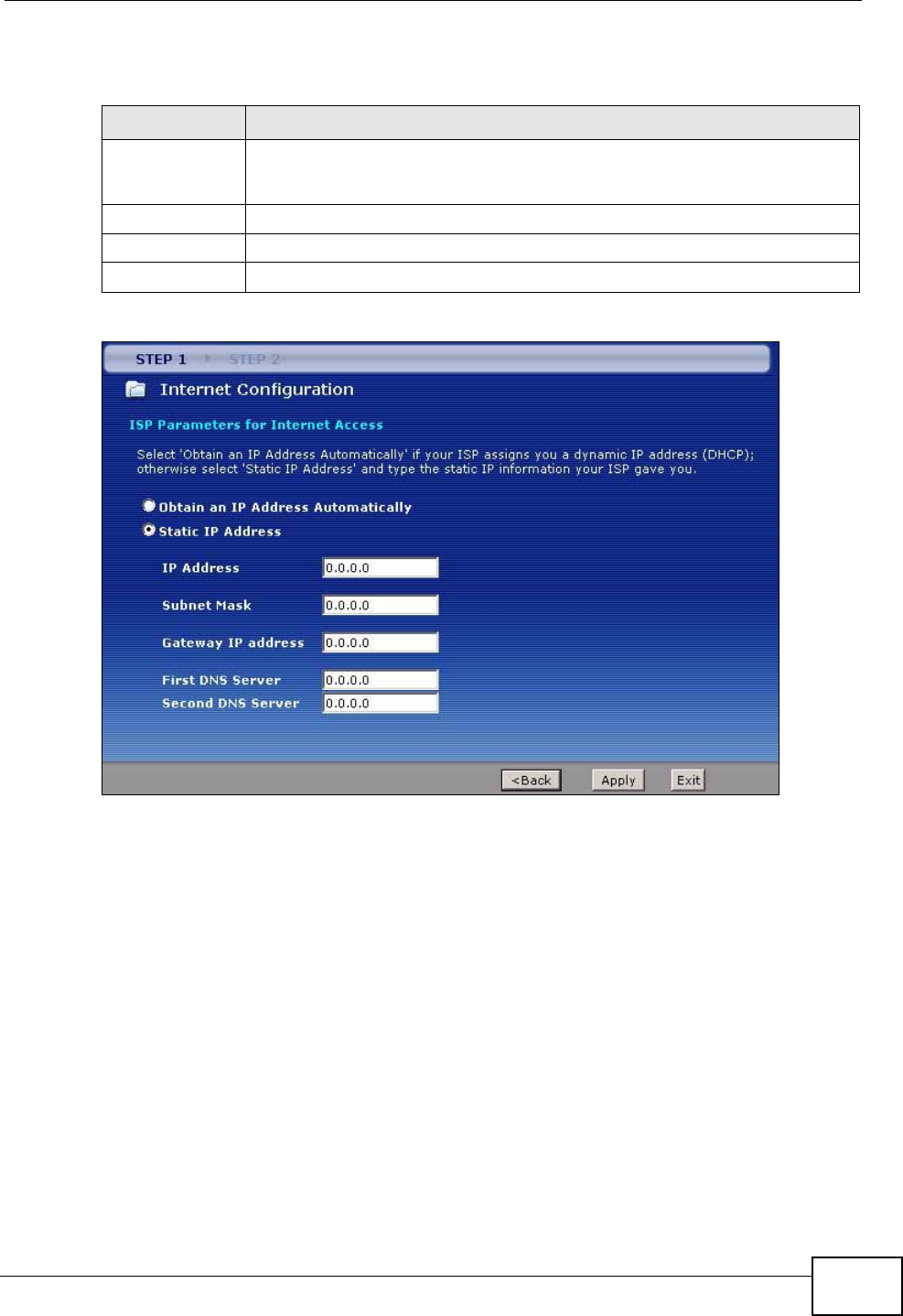
Chapter 5 Internet and Wireless Setup Wizard
P-660N-T1A User’s Guide 59
The following table describes the fields in this screen.
Figure 18 Internet Connection with ENET ENCAP
Table 7 Internet Connection with RFC 1483
LABEL DESCRIPTION
IP Address This field is available if you select Routing in the Mode field.
Type your ISP assigned IP address in this field.
Back Click this to return to the previous screen without saving.
Next Click this to continue to the next wizard screen.
Exit Click this to close the wizard screen without saving.
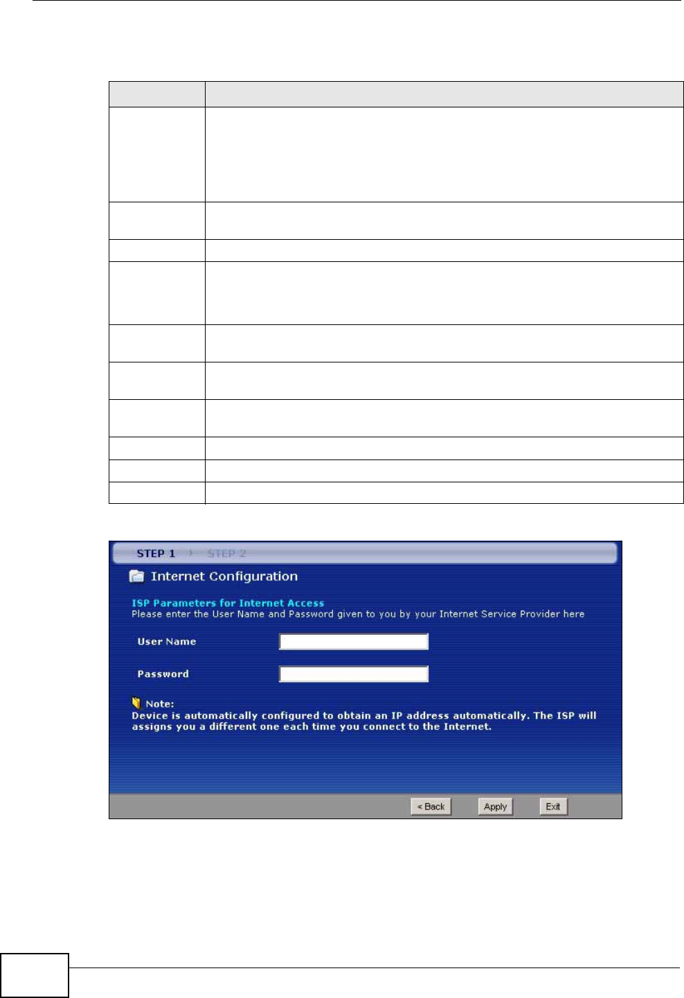
Chapter 5 Internet and Wireless Setup Wizard
P-660N-T1A User’s Guide
60
The following table describes the fields in this screen.
Figure 19 Internet Connection with PPPoA
Table 8 Internet Connection with ENET ENCAP
LABEL DESCRIPTION
Obtain an IP
Address
Automatically
A static IP address is a fixed IP that your ISP gives you. A dynamic IP
address is not fixed; the ISP assigns you a different one each time you
connect to the Internet.
Select Obtain an IP Address Automatically if you have a dynamic IP
address.
Static IP
Address Select Static IP Address if your ISP gave you an IP address to use.
IP Address Enter your ISP assigned IP address.
Subnet Mask Enter a subnet mask in dotted decimal notation.
Refer to the appendix to calculate a subnet mask If you are implementing
subnetting.
Gateway IP
address You must specify a gateway IP address (supplied by your ISP) when you
use ENET ENCAP in the Encapsulation field in the previous screen.
First DNS
Server Enter the IP addresses of the DNS servers. The DNS servers are passed to
the DHCP clients along with the IP address and the subnet mask.
Second DNS
Server As above.
Back Click this to return to the previous screen without saving.
Apply Click this to save your changes.
Exit Click this to close the wizard screen without saving.
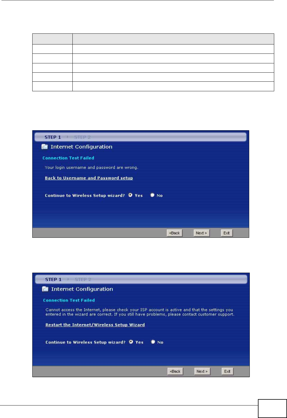
Chapter 5 Internet and Wireless Setup Wizard
P-660N-T1A User’s Guide 61
The following table describes the fields in this screen.
• If the user name and/or password you entered for PPPoE or PPPoA connection
are not correct, the screen displays as shown next. Click Back to Username
and Password setup to go back to the screen where you can modify them.
Figure 20 Connection Test Failed-1
• If the following screen displays, check if your account is activated or click
Restart the Internet/Wireless Setup Wizard to verify your Internet access
settings.
Figure 21 Connection Test Failed-2.
Table 9 Internet Connection with PPPoA
LABEL DESCRIPTION
User Name Enter the login name that your ISP gives you.
Password Enter the password associated with the user name above.
Back Click this to return to the previous screen without saving.
Apply Click this to save your changes.
Exit Click this to close the wizard screen without saving.
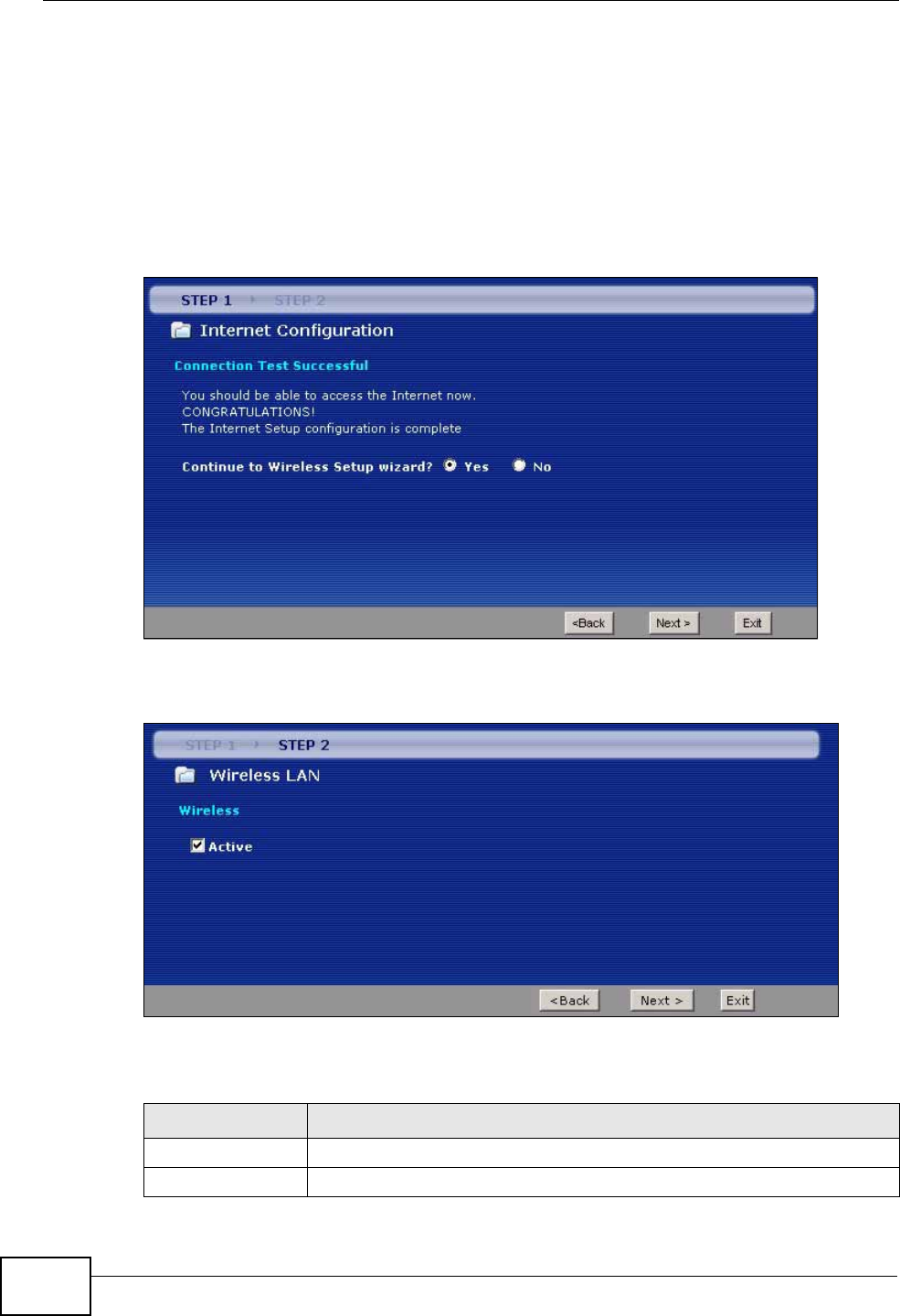
Chapter 5 Internet and Wireless Setup Wizard
P-660N-T1A User’s Guide
62
5.3 Wireless Connection Wizard Setup
After you configure the Internet access information, use the following screens to
set up your wireless LAN.
1Select Yes and click Next to configure wireless settings. Otherwise, select No and
skip to Step 6.
Figure 22 Connection Test Successful
2Use this screen to activate the wireless LAN. Click Next to continue.
Figure 23 Wireless LAN Setup Wizard 1
The following table describes the labels in this screen.
Table 10 Wireless LAN Setup Wizard 1
LABEL DESCRIPTION
Active Select the check box to turn on the wireless LAN.
Back Click this to return to the previous screen without saving.
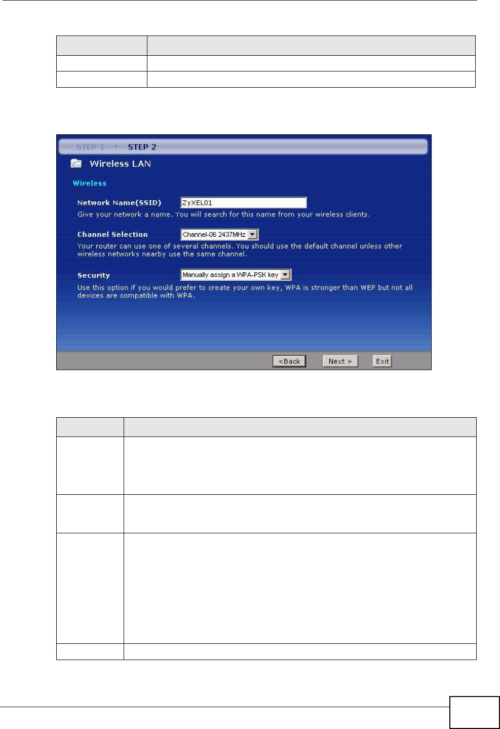
Chapter 5 Internet and Wireless Setup Wizard
P-660N-T1A User’s Guide 63
3Configure your wireless settings in this screen. Click Next.
Figure 24 Wireless LAN
The following table describes the labels in this screen.
Next Click this to continue to the next wizard screen.
Exit Click this to close the wizard screen without saving.
Table 10 Wireless LAN Setup Wizard 1
LABEL DESCRIPTION
Table 11 Wireless LAN Setup Wizard 2
LABEL DESCRIPTION
Network
Name(SSID) Enter a descriptive name (up to 32 printable 7-bit ASCII characters) for the
wireless LAN.
If you change this field on the ZyXEL Device, make sure all wireless
stations use the same SSID in order to access the network.
Channel
Selection The range of radio frequencies used by IEEE 802.11b/g wireless devices is
called a channel. Select a channel ID that is not already in use by a
neighboring device.
Security Select Manually assign a WPA-PSK key to configure a Pre-Shared Key
(WPA-PSK). Choose this option only if your wireless clients support WPA.
See Section 5.3.1 on page 64 for more information.
Select Manually assign a WEP key to configure a WEP Key. See Section
5.3.2 on page 65 for more information.
Select Disable wireless security to have no wireless LAN security
configured and your network is accessible to any wireless networking
device that is within range.
Back Click this to return to the previous screen without saving.
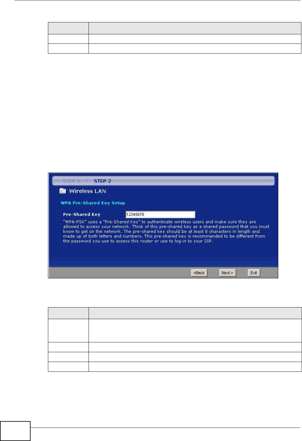
Chapter 5 Internet and Wireless Setup Wizard
P-660N-T1A User’s Guide
64
Note: The wireless stations and ZyXEL Device must use the same SSID, channel ID
and WEP encryption key (if WEP is enabled), WPA-PSK (if WPA-PSK is
enabled) for wireless communication.
4This screen varies depending on the security mode you selected in the previous
screen. Fill in the field (if available) and click Next.
5.3.1 Manually Assign a WPA-PSK key
Choose Manually assign a WPA-PSK key in the Wireless LAN setup screen to
set up a Pre-Shared Key.
Figure 25 Manually Assign a WPA-PSK key
The following table describes the labels in this screen.
Next Click this to continue to the next wizard screen.
Exit Click this to close the wizard screen without saving.
Table 11 Wireless LAN Setup Wizard 2
LABEL DESCRIPTION
Table 12 Manually Assign a WPA-PSK key
LABEL DESCRIPTION
Pre-Shared
Key Type from 8 to 63 case-sensitive ASCII characters. You can set up the most
secure wireless connection by configuring WPA in the wireless LAN screens.
You need to configure an authentication server to do this.
Back Click this to return to the previous screen without saving.
Next Click this to continue to the next wizard screen.
Exit Click this to close the wizard screen without saving.
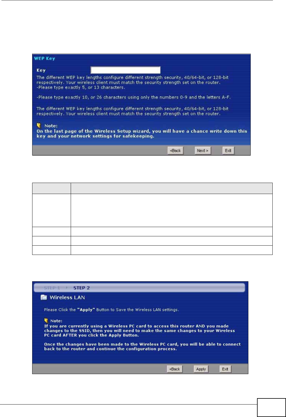
Chapter 5 Internet and Wireless Setup Wizard
P-660N-T1A User’s Guide 65
5.3.2 Manually Assign a WEP Key
Choose Manually assign a WEP key to setup WEP Encryption parameters.
Figure 26 Manually Assign a WEP key
The following table describes the labels in this screen.
5Click Apply to save your wireless LAN settings.
Figure 27 Wireless LAN Setup 3
Table 13 Manually Assign a WEP key
LABEL DESCRIPTION
Key The WEP keys are used to encrypt data. Both the ZyXEL Device and the
wireless stations must use the same WEP key for data transmission.
Enter any 5 or 13 ASCII characters, or 10 or 26 hexadecimal characters
("0-9", "A-F") for a 64-bit or 128-bit WEP key respectively.
Back Click this to return to the previous screen without saving.
Next Click this to continue to the next wizard screen.
Exit Click this to close the wizard screen without saving.
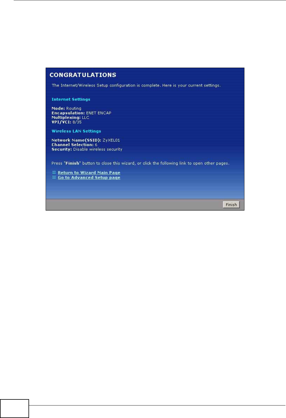
Chapter 5 Internet and Wireless Setup Wizard
P-660N-T1A User’s Guide
66
6Use the read-only summary table to check whether what you have configured is
correct. Click Finish to complete and save the wizard setup.
Note: No wireless LAN settings display if you chose not to configure wireless LAN
settings.
Figure 28 Internet Access and WLAN Wizard Setup Complete
7Launch your web browser and navigate to www.zyxel.com. Internet access is just
the beginning. Refer to the rest of this guide for more detailed information on the
complete range of ZyXEL Device features. If you cannot access the Internet, open
the web configurator again to confirm that the Internet settings you configured in
the wizard setup are correct.
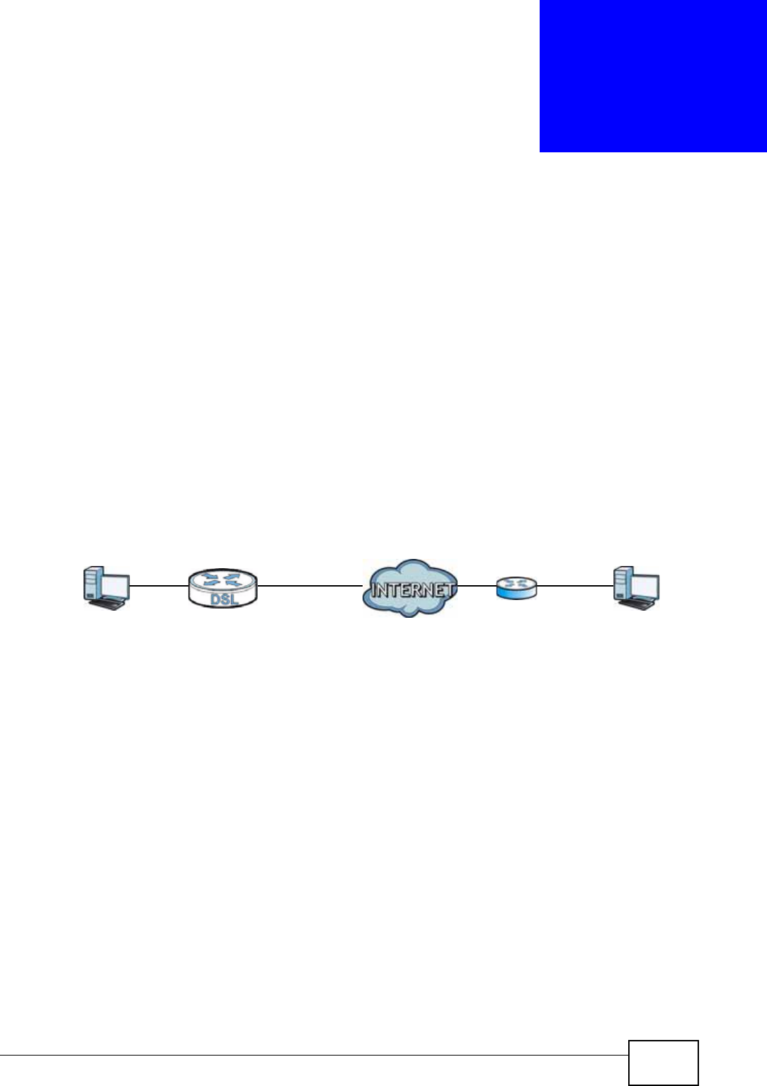
P-660N-T1A User’s Guide 67
CHAPTER 6
WAN Setup
6.1 Overview
This chapter describes how to configure WAN settings from the WAN screens. Use
these screens to configure your ZyXEL Device for Internet access.
A WAN (Wide Area Network) connection is an outside connection to another
network or the Internet. It connects your private networks (such as a LAN (Local
Area Network) and other networks, so that a computer in one location can
communicate with computers in other locations.
Figure 29 LAN and WAN
6.1.1 What You Can Do in the WAN Screens
•Use the Internet Connection screen (Section 6.2 on page 69) to configure the
WAN settings on the ZyXEL Device for Internet access.
•Use the More Connections screen (Section 6.3 on page 74) to set up
additional Internet access connections.
6.1.2 What You Need to Know
The following terms and concepts may help as you this chapter.
Encapsulation Method
Encapsulation is used to include data from an upper layer protocol into a lower
layer protocol. To set up a WAN connection to the Internet, you need to use the
same encapsulation method used by your ISP (Internet Service Provider). If your
ISP offers a dial-up Internet connection using PPPoE (PPP over Ethernet) or PPPoA,
WAN
LAN

Chapter 6 WAN Setup
P-660N-T1A User’s Guide
68
they should also provide a username and password (and service name) for user
authentication.
WAN IP Address
The WAN IP address is an IP address for the ZyXEL Device, which makes it
accessible from an outside network. It is used by the ZyXEL Device to
communicate with other devices in other networks. It can be static (fixed) or
dynamically assigned by the ISP each time the ZyXEL Device tries to access the
Internet.
If your ISP assigns you a static WAN IP address, they should also assign you the
subnet mask and DNS server IP address(es) (and a gateway IP address if you use
the Ethernet or ENET ENCAP encapsulation method).
Multicast
Traditionally, IP packets are transmitted in one of either two ways - Unicast (1
sender - 1 recipient) or Broadcast (1 sender - everybody on the network).
Multicast delivers IP packets to a group of hosts on the network - not everybody
and not just one.
IGMP
IGMP (Internet Group Multicast Protocol) is a network-layer protocol used to
establish membership in a Multicast group - it is not used to carry user data.
There are three versions of IGMP. IGMP version 2 and 3 are improvements over
version 1, but IGMP version 1 is still in wide use.
Finding Out More
See Section 6.4 on page 78 for technical background information on WAN.
6.1.3 Before You Begin
You need to know your Internet access settings such as encapsulation and WAN IP
address. Get this information from your ISP.
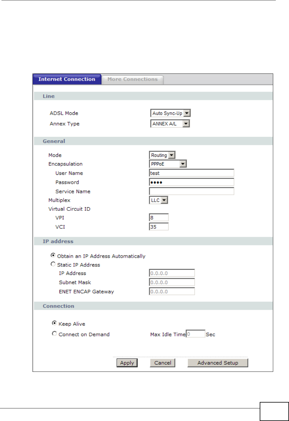
Chapter 6 WAN Setup
P-660N-T1A User’s Guide 69
6.2 The Internet Connection Screen
Use this screen to change your ZyXEL Device’s WAN settings. Click Network >
WAN > Internet Connection. The screen differs by the WAN type and
encapsulation you select.
Figure 30 Network > WAN >Internet Connection (PPPoE)
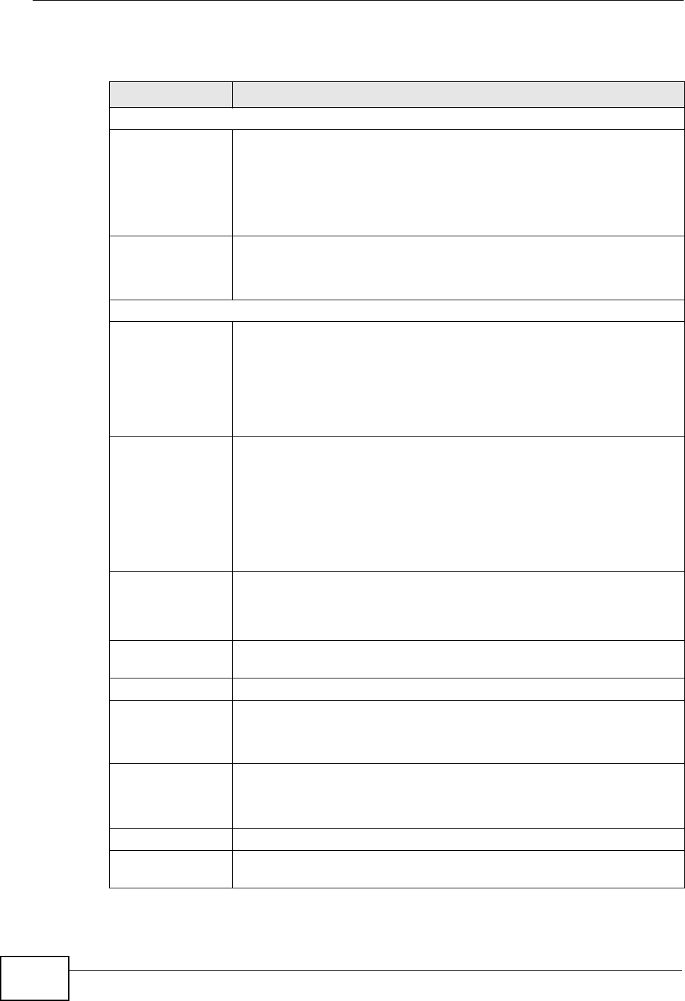
Chapter 6 WAN Setup
P-660N-T1A User’s Guide
70
The following table describes the labels in this screen.
Table 14 Network > WAN > Internet Connection
LABEL DESCRIPTION
Line
ADSL Mode Select the mode supported by your ISP.
Use Auto Sync-Up if you are not sure which mode to choose from.
The ZyXEL Device dynamically diagnoses the mode supported by the
ISP and selects the best compatible one for your connection.
Other options are ADSL2+, ADSL2, G.DMT, T1.413 and G.lite.
ADSL Type Select the type supported by your ISP.
Available options are ANNEX A, ANNEX A/L, ANNEX M and ANNEX
A/L/M.
General
Mode Select Routing (default) from the drop-down list box if your ISP gives
you one IP address only and you want multiple computers to share an
Internet account. Select Bridge when your ISP provides you more
than one IP address and you want the connected computers to get
individual IP address from ISP’s DHCP server directly. If you select
Bridge, you cannot use Firewall, DHCP server and NAT on the ZyXEL
Device.
Encapsulation Select the method of encapsulation used by your ISP from the drop-
down list box. Choices vary depending on the mode you select in the
Mode field.
If you select Bridge in the Mode field, select either PPPoA or RFC
1483.
If you select Routing in the Mode field, select PPPoA, RFC 1483,
ENET ENCAP or PPPoE.
User Name (PPPoA and PPPoE encapsulation only) Enter the user name exactly as
your ISP assigned. If assigned a name in the form user@domain
where domain identifies a service name, then enter both components
exactly as given.
Password (PPPoA and PPPoE encapsulation only) Enter the password associated
with the user name above.
Service Name (PPPoE only) Type the name of your PPPoE service here.
Multiplexing Select the method of multiplexing used by your ISP from the drop-
down list. Choices are VC or LLC.
This field is not available if you set the WAN type to Ethernet.
Virtual Circuit ID VPI (Virtual Path Identifier) and VCI (Virtual Channel Identifier) define
a virtual circuit. Refer to the appendix for more information.
These fields are not available if you set the WAN type to Ethernet.
VPI The valid range for the VPI is 0 to 255. Enter the VPI assigned to you.
VCI The valid range for the VCI is 32 to 65535 (0 to 31 is reserved for
local management of ATM traffic). Enter the VCI assigned to you.

Chapter 6 WAN Setup
P-660N-T1A User’s Guide 71
IP Address This option is available if you select Routing in the Mode field.
A static IP address is a fixed IP that your ISP gives you. A dynamic IP
address is not fixed; the ISP assigns you a different one each time you
connect to the Internet.
Select Obtain an IP Address Automatically if you have a dynamic
IP address; otherwise select Static IP Address and type your ISP
assigned IP address in the IP Address field below.
Subnet Mask This option is available if you select ENET ENCAP in the
Encapsulation field.
Enter a subnet mask in dotted decimal notation.
ENET ENCAP
Gateway This option is available if you select ENET ENCAP in the
Encapsulation field.
Specify a gateway IP address (supplied by your ISP).
Connection (PPPoA and PPPoE encapsulation only)
Keep Alive Select Keep Alive when you want your connection up all the time.
The ZyXEL Device will try to bring up the connection automatically if it
is disconnected.
Connect on
Demand Select Connect on Demand when you don't want the connection up
all the time and specify an idle time-out in the Max Idle Timeout
field.
Max Idle Timeout Specify an idle time-out in the Max Idle Timeout field when you
select Connect on Demand. The default setting is 0, which means
the Internet session will not timeout.
Apply Click this to save your changes.
Cancel Click this to restore your previously saved settings.
Advanced Setup Click this to display the Advanced WAN Setup screen and edit more
details of your WAN setup.
Table 14 Network > WAN > Internet Connection (continued)
LABEL DESCRIPTION
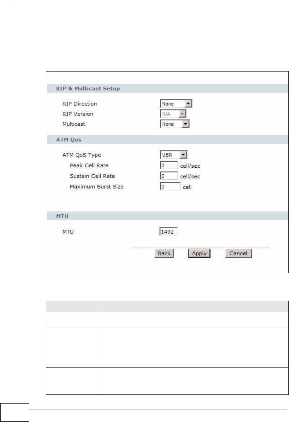
Chapter 6 WAN Setup
P-660N-T1A User’s Guide
72
6.2.1 Advanced Setup
Use this screen to edit your ZyXEL Device's advanced WAN settings. Click the
Advanced Setup button in the Internet Connection screen. The screen
appears as shown.
Figure 31 Network > WAN > Internet Connection: Advanced Setup
The following table describes the labels in this screen.
Table 15 Network > WAN > Internet Connection: Advanced Setup
LABEL DESCRIPTION
RIP & Multicast
Setup This section is not available when you configure the ZyXEL Device to
be in bridge mode.
RIP Direction RIP (Routing Information Protocol) allows a router to exchange
routing information with other routers. Use this field to control how
much routing information the ZyXEL Device sends and receives on the
subnet.
Select the RIP direction from None, Both, In Only and Out Only.
RIP Version This field is not configurable if you select None in the RIP Direction
field.
Select the RIP version from RIP-1, RIP-2B and RIP-2M.

Chapter 6 WAN Setup
P-660N-T1A User’s Guide 73
Multicast Multicast packets are sent to a group of computers on the LAN and are
an alternative to unicast packets (packets sent to one computer) and
broadcast packets (packets sent to every computer).
Internet Group Multicast Protocol (IGMP) is a network-layer protocol
used to establish membership in a multicast group. The ZyXEL Device
supports IGMP-v1, IGMP-v2 and IGMP-v3. Select None to disable
it.
ATM QoS
ATM QoS Type Select CBR (Continuous Bit Rate) to specify fixed (always-on)
bandwidth for voice or data traffic. Select UBR (Unspecified Bit Rate)
for applications that are non-time sensitive, such as e-mail. Select
rtVBR (real-time Variable Bit Rate) type for applications with bursty
connections that require closely controlled delay and delay variation.
Select nrtVBR (non real-time Variable Bit Rate) type for connections
that do not require closely controlled delay and delay variation.
Peak Cell Rate Divide the DSL line rate (bps) by 424 (the size of an ATM cell) to find
the Peak Cell Rate (PCR). This is the maximum rate at which the
sender can send cells. Type the PCR here.
Sustain Cell
Rate The Sustain Cell Rate (SCR) sets the average cell rate (long-term)
that can be transmitted. Type the SCR, which must be less than the
PCR. Note that system default is 0 cells/sec.
Maximum
Burst Size Maximum Burst Size (MBS) refers to the maximum number of cells
that can be sent at the peak rate. Type the MBS, which is less than
65535.
MTU
MTU The Maximum Transmission Unit (MTU) defines the size of the largest
packet allowed on an interface or connection. Enter the MTU in this
field.
For ENET ENCAP, the MTU value is 1500.
For PPPoE, the MTU value is 1492.
For PPPoA and RFC 1483, the MTU is 65535.
Back Click this to return to the previous screen without saving.
Apply Click this to save your changes.
Cancel Click this to restore your previously saved settings.
Table 15 Network > WAN > Internet Connection: Advanced Setup (continued)
LABEL DESCRIPTION
Chapter 6 WAN Setup
P-660N-T1A User’s Guide
74
6.3 The More Connections Screen
The ZyXEL Device allows you to configure more than one Internet access
connection. To configure additional Internet access connections click Network >
WAN > More Connections. The screen differs by the encapsulation you select.
When you use the WAN > Internet Access Setup screen to set up Internet
access, you are configuring the first WAN connection.
Figure 32 Network > WAN > More Connections
The following table describes the labels in this screen.
Table 16 Network > WAN > More Connections
LABEL DESCRIPTION
# This is an index number indicating the number of the corresponding
connection.
Active This field indicates whether the connection is active or not.
Clear the check box to disable the connection. Select the check box to
enable it.
Name This is the name you gave to the Internet connection.
VPI/VCI This field displays the Virtual Path Identifier (VPI) and Virtual Channel
Identifier (VCI) numbers configured for this WAN connection.
Encapsulation This field indicates the encapsulation method of the Internet connection.
Modify The first (ISP) connection is read-only in this screen. Use the WAN >
Internet Access Setup screen to edit it.
Click the Edit icon to edit the Internet connection settings. Click this icon
on an empty configuration to add a new Internet access setup.
Click the Remove icon to delete the Internet access setup from your
connection list.
Apply Click this to save your changes.
Cancel Click this to restore your previously saved settings.
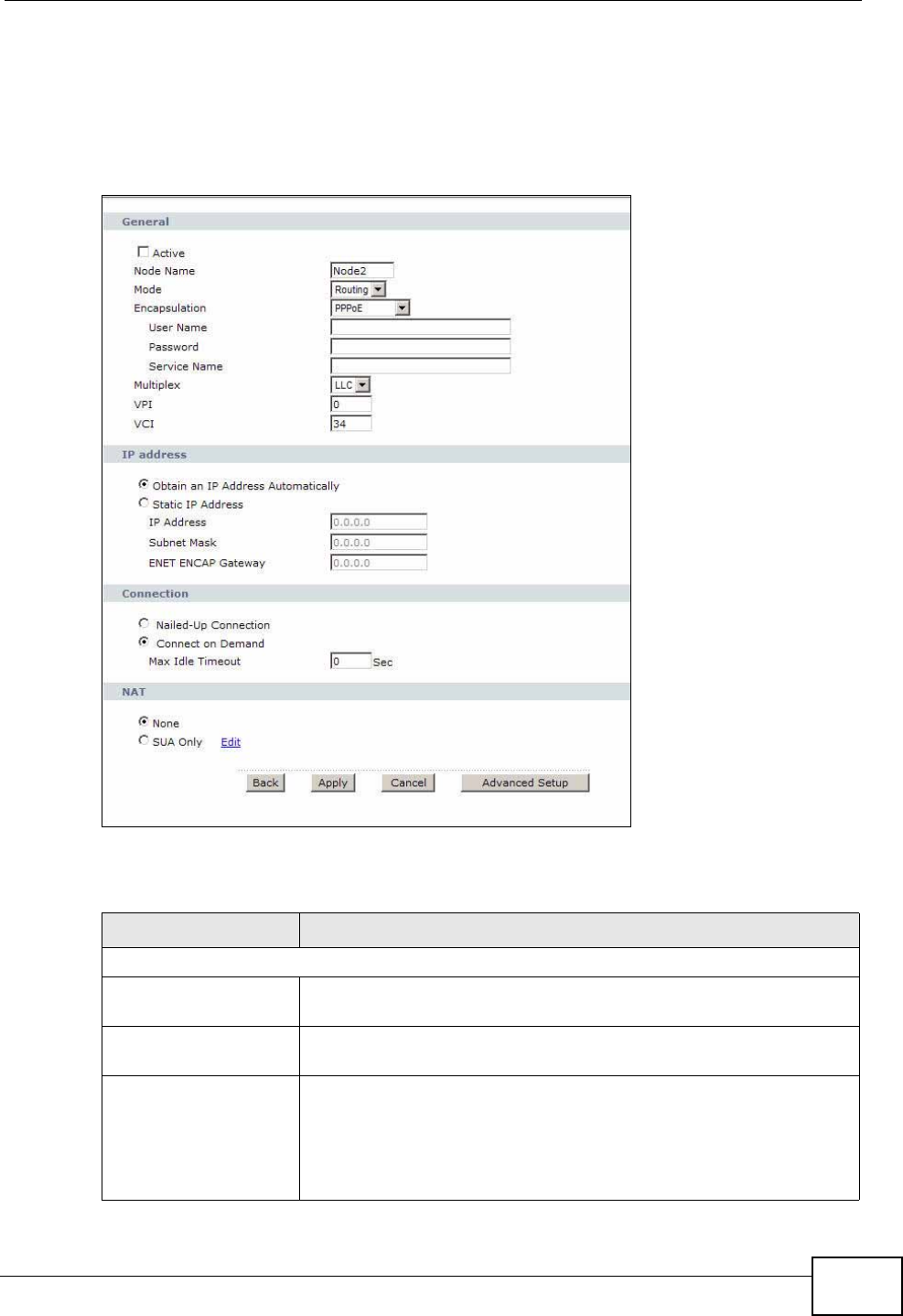
Chapter 6 WAN Setup
P-660N-T1A User’s Guide 75
6.3.1 More Connections Edit
Use this screen to configure a connection. Click the edit icon in the More
Connections screen to display the following screen.
Figure 33 Network > WAN > More Connections: Edit
The following table describes the labels in this screen.
Table 17 Network > WAN > More Connections: Edit
LABEL DESCRIPTION
General
Active Select the check box to activate or clear the check box to
deactivate this connection.
Name Enter a unique, descriptive name of up to 13 ASCII characters for
this connection.
Mode Select Routing from the drop-down list box if your ISP allows
multiple computers to share an Internet account.
If you select Bridge, the ZyXEL Device will forward any packet
that it does not route to this remote node; otherwise, the packets
are discarded.

Chapter 6 WAN Setup
P-660N-T1A User’s Guide
76
Encapsulation Select the method of encapsulation used by your ISP from the
drop-down list box. Choices vary depending on the mode you
select in the Mode field.
If you select Bridge in the Mode field, select either PPPoA or
RFC 1483.
If you select Routing in the Mode field, select PPPoA, RFC
1483, ENET ENCAP or PPPoE.
Multiplexing Select the method of multiplexing used by your ISP from the
drop-down list. Choices are VC or LLC.
By prior agreement, a protocol is assigned a specific virtual
circuit, for example, VC1 will carry IP. If you select VC, specify
separate VPI and VCI numbers for each protocol.
For LLC-based multiplexing or PPP encapsulation, one VC carries
multiple protocols with protocol identifying information being
contained in each packet header. In this case, only one set of VPI
and VCI numbers need be specified for all protocols.
VPI The valid range for the VPI is 0 to 255. Enter the VPI assigned to
you.
VCI The valid range for the VCI is 32 to 65535 (0 to 31 is reserved for
local management of ATM traffic). Enter the VCI assigned to you.
IP Address This option is available if you select Routing in the Mode field.
A static IP address is a fixed IP that your ISP gives you. A
dynamic IP address is not fixed; the ISP assigns you a different
one each time you connect to the Internet.
If you use the encapsulation type except RFC 1483, select
Obtain an IP Address Automatically when you have a
dynamic IP address; otherwise select Static IP Address and
type your ISP assigned IP address in the IP Address field below.
If you use RFC 1483, enter the IP address given by your ISP in
the IP Address field.
Subnet Mask This option is available if you select ENET ENCAP in the
Encapsulation field.
Enter a subnet mask in dotted decimal notation.
ENET ENCAP
Gateway This option is available if you select ENET ENCAP in the
Encapsulation field.
Specify a gateway IP address (supplied by your ISP).
Connection
Nailed-Up Connection Select Nailed-Up Connection when you want your connection
up all the time. The ZyXEL Device will try to bring up the
connection automatically if it is disconnected.
Connect on Demand Select Connect on Demand when you don't want the connection
up all the time and specify an idle time-out in the Max Idle
Timeout field.
Table 17 Network > WAN > More Connections: Edit (continued)
LABEL DESCRIPTION
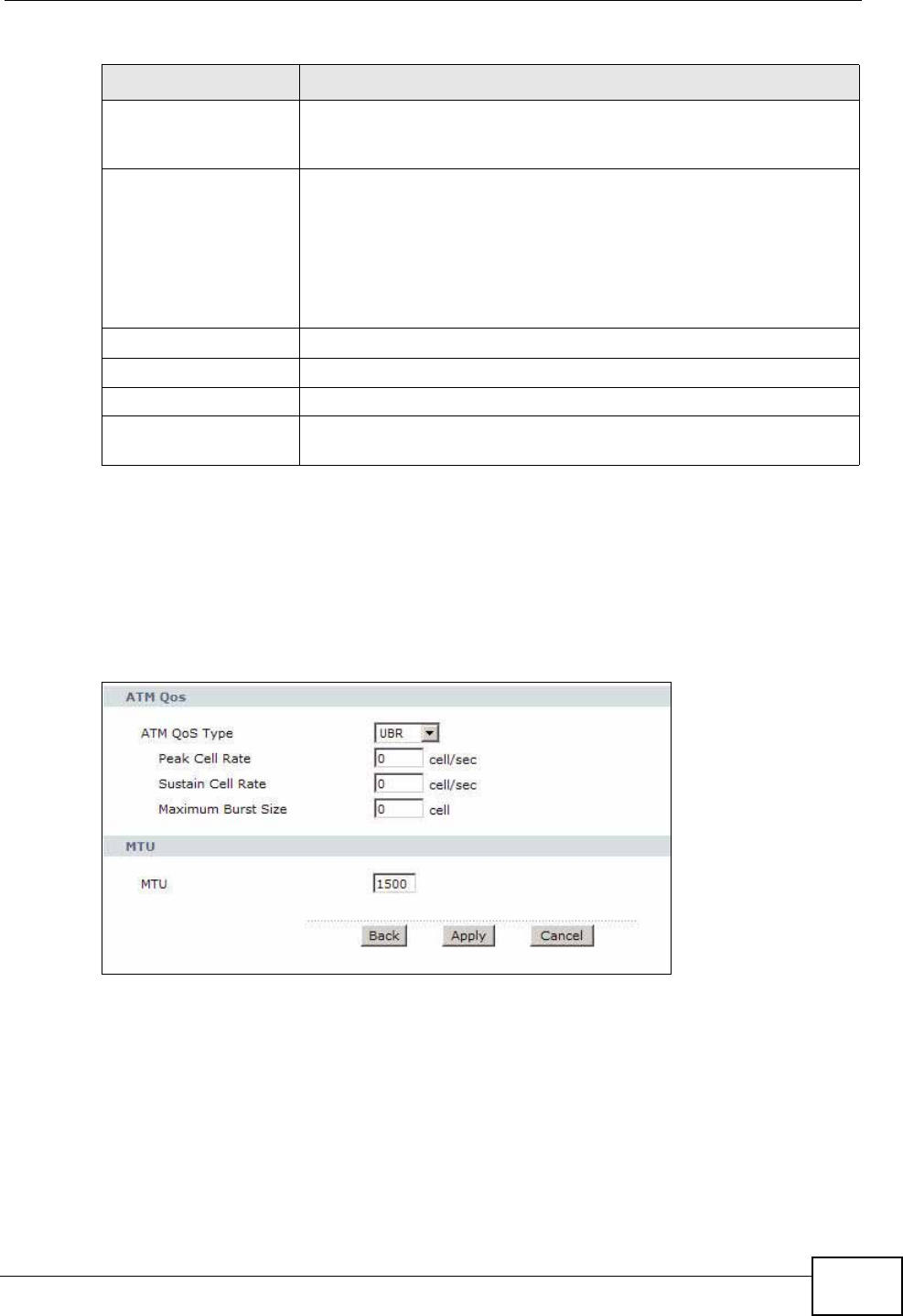
Chapter 6 WAN Setup
P-660N-T1A User’s Guide 77
6.3.2 Advanced Setup
Use this screen to edit your ZyXEL Device's advanced WAN settings. Click the
Advanced Setup button in the More Connections Edit screen. The screen
appears as shown.
Figure 34 Network > WAN > More Connections: Edit: Advanced Setup
Max Idle Timeout Specify an idle time-out in the Max Idle Timeout field when you
select Connect on Demand. The default setting is 0, which
means the Internet session will not timeout.
NAT SUA only is available only when you select Routing in the Mode
field.
Select SUA Only if you have one public IP address and want to
use NAT. Click Edit Detail to go to the Port Forwarding screen
to edit a server mapping set.
Otherwise, select None to disable NAT.
Back Click this to return to the previous screen without saving.
Apply Click this to save your changes.
Cancel Click this to restore your previously saved settings.
Advanced Setup Click this to display the More Connections Advanced Setup
screen and edit more details of your WAN setup.
Table 17 Network > WAN > More Connections: Edit (continued)
LABEL DESCRIPTION
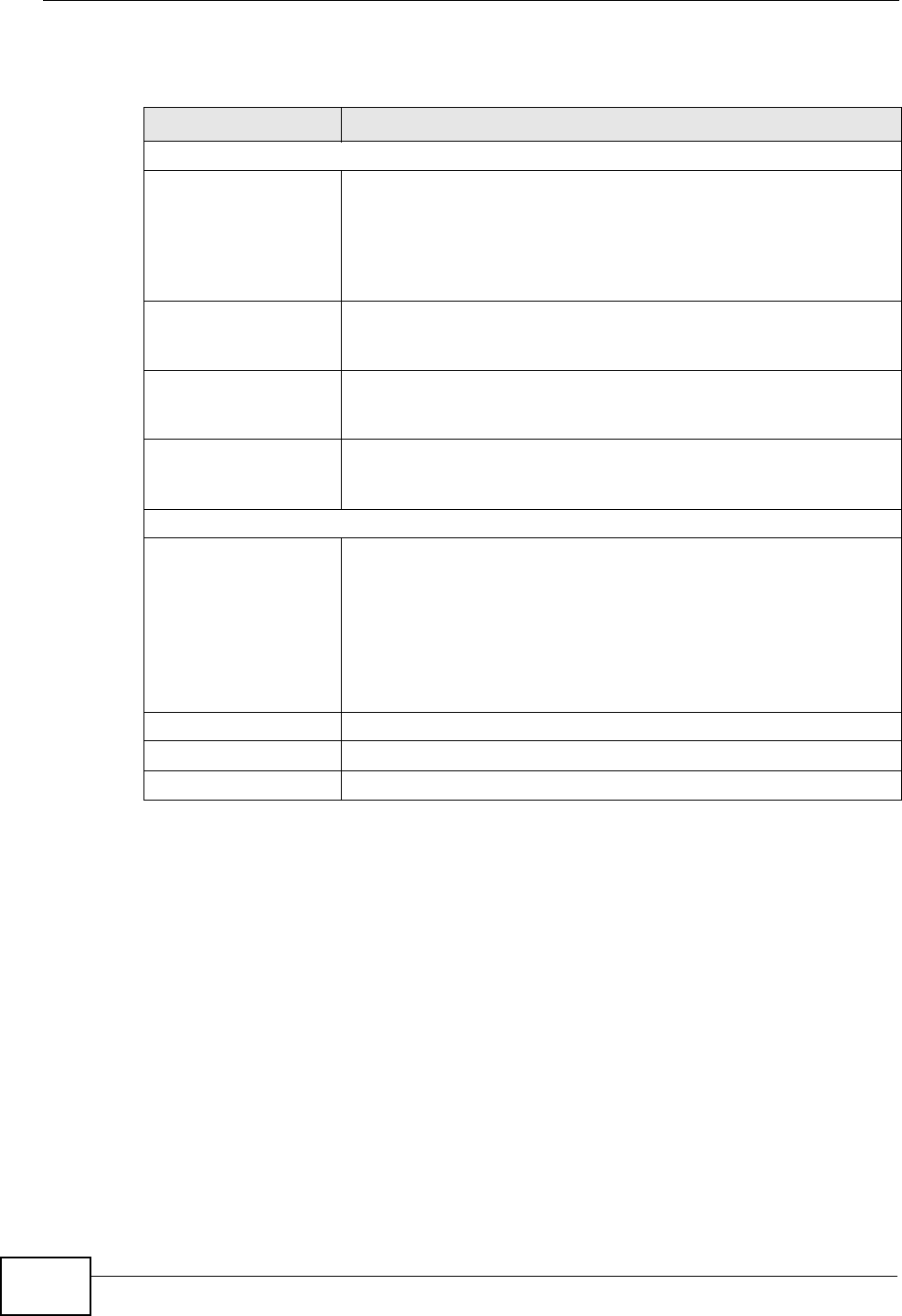
Chapter 6 WAN Setup
P-660N-T1A User’s Guide
78
The following table describes the labels in this screen.
6.4 Technical Reference
This section provides some technical background information about the topics
covered in this chapter.
6.4.1 Encapsulation
Be sure to use the encapsulation method required by your ISP. The ZyXEL Device
supports the following methods.
Table 18 Network > WAN > More Connections: Edit: Advanced Setup
LABEL DESCRIPTION
ATM QoS
ATM QoS Type Select CBR (Continuous Bit Rate) to specify fixed (always-on)
bandwidth for voice or data traffic. Select UBR (Unspecified Bit
Rate) for applications that are non-time sensitive, such as e-mail.
Select nrtVBR (Variable Bit Rate-non Real Time) or rtVBR
(Variable Bit Rate-Real Time) for bursty traffic and bandwidth
sharing with other applications.
Peak Cell Rate Divide the DSL line rate (bps) by 424 (the size of an ATM cell) to
find the Peak Cell Rate (PCR). This is the maximum rate at which
the sender can send cells. Type the PCR here.
Sustain Cell Rate The Sustain Cell Rate (SCR) sets the average cell rate (long-term)
that can be transmitted. Type the SCR, which must be less than
the PCR. Note that system default is 0 cells/sec.
Maximum Burst Size Maximum Burst Size (MBS) refers to the maximum number of
cells that can be sent at the peak rate. Type the MBS, which is
less than 65535.
MTU
MTU The Maximum Transmission Unit (MTU) defines the size of the
largest packet allowed on an interface or connection. Enter the
MTU in this field.
For ENET ENCAP, the MTU value is 1500.
For PPPoE, the MTU value is 1492.
For PPPoA and RFC, the MTU is 65535.
Back Click this to return to the previous screen without saving.
Apply Click this to save your changes.
Cancel Click this to restore your previously saved settings.

Chapter 6 WAN Setup
P-660N-T1A User’s Guide 79
6.4.1.1 ENET ENCAP
The MAC Encapsulated Routing Link Protocol (ENET ENCAP) is only implemented
with the IP network protocol. IP packets are routed between the Ethernet interface
and the WAN interface and then formatted so that they can be understood in a
bridged environment. For instance, it encapsulates routed Ethernet frames into
bridged ATM cells. ENET ENCAP requires that you specify a gateway IP address in
the Gateway IP Address field in the wizard or WAN screen. You can get this
information from your ISP.
6.4.1.2 PPP over Ethernet
The ZyXEL Device supports PPPoE (Point-to-Point Protocol over Ethernet). PPPoE is
an IETF Draft standard (RFC 2516) specifying how a personal computer (PC)
interacts with a broadband modem (DSL, cable, wireless, etc.) connection. The
PPPoE option is for a dial-up connection using PPPoE.
For the service provider, PPPoE offers an access and authentication method that
works with existing access control systems (for example RADIUS).
One of the benefits of PPPoE is the ability to let you access one of multiple network
services, a function known as dynamic service selection. This enables the service
provider to easily create and offer new IP services for individuals.
Operationally, PPPoE saves significant effort for both you and the ISP or carrier, as
it requires no specific configuration of the broadband modem at the customer site.
By implementing PPPoE directly on the ZyXEL Device (rather than individual
computers), the computers on the LAN do not need PPPoE software installed,
since the ZyXEL Device does that part of the task. Furthermore, with NAT, all of
the LANs’ computers will have access.
6.4.1.3 PPPoA
PPPoA stands for Point to Point Protocol over ATM Adaptation Layer 5 (AAL5). A
PPPoA connection functions like a dial-up Internet connection. The ZyXEL Device
encapsulates the PPP session based on RFC1483 and sends it through an ATM PVC
(Permanent Virtual Circuit) to the Internet Service Provider’s (ISP) DSLAM (Digital
Subscriber Line (DSL) Access Multiplexer). Please refer to RFC 2364 for more
information on PPPoA. Refer to RFC 1661 for more information on PPP.
6.4.1.4 RFC 1483
RFC 1483 describes two methods for Multiprotocol Encapsulation over ATM
Adaptation Layer 5 (AAL5). The first method allows multiplexing of multiple
protocols over a single ATM virtual circuit (LLC-based multiplexing) and the second

Chapter 6 WAN Setup
P-660N-T1A User’s Guide
80
method assumes that each protocol is carried over a separate ATM virtual circuit
(VC-based multiplexing). Please refer to RFC 1483 for more detailed information.
6.4.2 Multiplexing
There are two conventions to identify what protocols the virtual circuit (VC) is
carrying. Be sure to use the multiplexing method required by your ISP.
VC-based Multiplexing
In this case, by prior mutual agreement, each protocol is assigned to a specific
virtual circuit; for example, VC1 carries IP, etc. VC-based multiplexing may be
dominant in environments where dynamic creation of large numbers of ATM VCs is
fast and economical.
LLC-based Multiplexing
In this case one VC carries multiple protocols with protocol identifying information
being contained in each packet header. Despite the extra bandwidth and
processing overhead, this method may be advantageous if it is not practical to
have a separate VC for each carried protocol, for example, if charging heavily
depends on the number of simultaneous VCs.
6.4.3 VPI and VCI
Be sure to use the correct Virtual Path Identifier (VPI) and Virtual Channel
Identifier (VCI) numbers assigned to you. The valid range for the VPI is 0 to 255
and for the VCI is 32 to 65535 (0 to 31 is reserved for local management of ATM
traffic). Please see the appendix for more information.
6.4.4 IP Address Assignment
A static IP is a fixed IP that your ISP gives you. A dynamic IP is not fixed; the ISP
assigns you a different one each time. The Single User Account feature can be
enabled or disabled if you have either a dynamic or static IP. However the
encapsulation method assigned influences your choices for IP address and ENET
ENCAP gateway.
IP Assignment with PPPoA or PPPoE Encapsulation
If you have a dynamic IP, then the IP Address and Gateway IP Address fields
are not applicable (N/A). If you have a static IP, then you only need to fill in the IP
Address field and not the Gateway IP Address field.

Chapter 6 WAN Setup
P-660N-T1A User’s Guide 81
IP Assignment with RFC 1483 Encapsulation
In this case the IP address assignment must be static.
IP Assignment with ENET ENCAP Encapsulation
In this case you can have either a static or dynamic IP. For a static IP you must fill
in all the IP Address and Gateway IP Address fields as supplied by your ISP.
However for a dynamic IP, the ZyXEL Device acts as a DHCP client on the WAN
port and so the IP Address and Gateway IP Address fields are not applicable
(N/A) as the DHCP server assigns them to the ZyXEL Device.
6.4.5 Nailed-Up Connection (PPP)
A nailed-up connection is a dial-up line where the connection is always up
regardless of traffic demand. The ZyXEL Device does two things when you specify
a nailed-up connection. The first is that idle timeout is disabled. The second is that
the ZyXEL Device will try to bring up the connection when turned on and
whenever the connection is down. A nailed-up connection can be very expensive
for obvious reasons.
Do not specify a nailed-up connection unless your telephone company offers flat-
rate service or you need a constant connection and the cost is of no concern.
6.4.6 NAT
NAT (Network Address Translation - NAT, RFC 1631) is the translation of the IP
address of a host in a packet, for example, the source address of an outgoing
packet, used within one network to a different IP address known within another
network.
6.5 Traffic Shaping
Traffic Shaping is an agreement between the carrier and the subscriber to regulate
the average rate and fluctuations of data transmission over an ATM network. This
agreement helps eliminate congestion, which is important for transmission of real
time data such as audio and video connections.
Peak Cell Rate (PCR) is the maximum rate at which the sender can send cells. This
parameter may be lower (but not higher) than the maximum line speed. 1 ATM
cell is 53 bytes (424 bits), so a maximum speed of 832Kbps gives a maximum
PCR of 1962 cells/sec. This rate is not guaranteed because it is dependent on the
line speed.
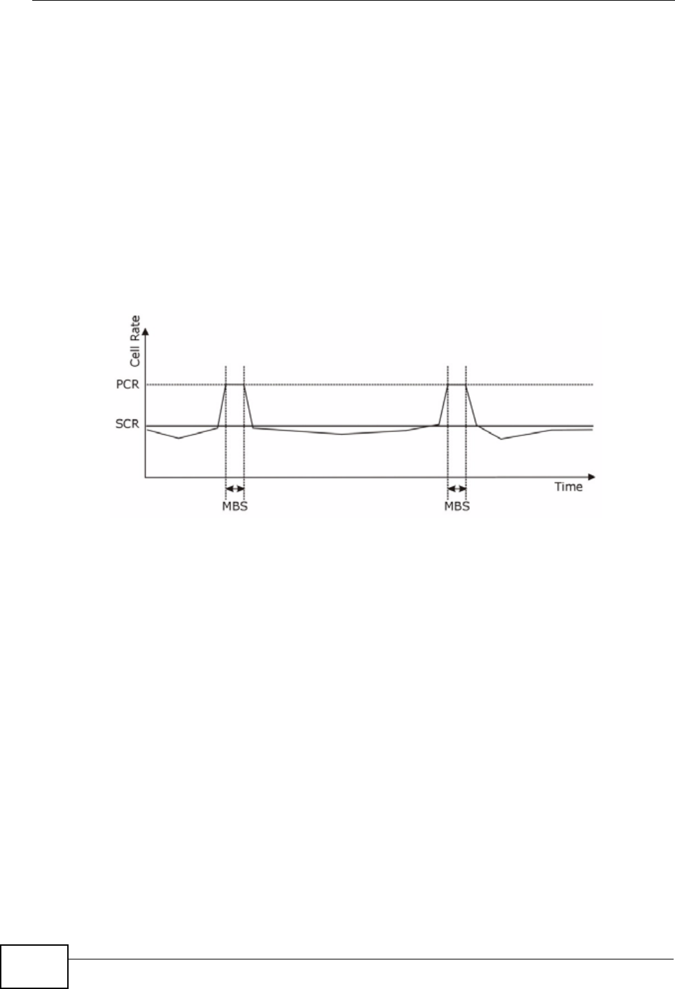
Chapter 6 WAN Setup
P-660N-T1A User’s Guide
82
Sustained Cell Rate (SCR) is the mean cell rate of each bursty traffic source. It
specifies the maximum average rate at which cells can be sent over the virtual
connection. SCR may not be greater than the PCR.
Maximum Burst Size (MBS) is the maximum number of cells that can be sent at
the PCR. After MBS is reached, cell rates fall below SCR until cell rate averages to
the SCR again. At this time, more cells (up to the MBS) can be sent at the PCR
again.
If the PCR, SCR or MBS is set to the default of "0", the system will assign a
maximum value that correlates to your upstream line rate.
The following figure illustrates the relationship between PCR, SCR and MBS.
Figure 35 Example of Traffic Shaping
6.5.1 ATM Traffic Classes
These are the basic ATM traffic classes defined by the ATM Forum Traffic
Management 4.0 Specification.
Constant Bit Rate (CBR)
Constant Bit Rate (CBR) provides fixed bandwidth that is always available even if
no data is being sent. CBR traffic is generally time-sensitive (doesn't tolerate
delay). CBR is used for connections that continuously require a specific amount of
bandwidth. A PCR is specified and if traffic exceeds this rate, cells may be
dropped. Examples of connections that need CBR would be high-resolution video
and voice.
Variable Bit Rate (VBR)
The Variable Bit Rate (VBR) ATM traffic class is used with bursty connections.
Connections that use the Variable Bit Rate (VBR) traffic class can be grouped into
real time (VBR-RT) or non-real time (VBR-nRT) connections.

Chapter 6 WAN Setup
P-660N-T1A User’s Guide 83
The VBR-RT (real-time Variable Bit Rate) type is used with bursty connections that
require closely controlled delay and delay variation. It also provides a fixed
amount of bandwidth (a PCR is specified) but is only available when data is being
sent. An example of an VBR-RT connection would be video conferencing. Video
conferencing requires real-time data transfers and the bandwidth requirement
varies in proportion to the video image's changing dynamics.
The VBR-nRT (non real-time Variable Bit Rate) type is used with bursty
connections that do not require closely controlled delay and delay variation. It is
commonly used for "bursty" traffic typical on LANs. PCR and MBS define the burst
levels, SCR defines the minimum level. An example of an VBR-nRT connection
would be non-time sensitive data file transfers.
Unspecified Bit Rate (UBR)
The Unspecified Bit Rate (UBR) ATM traffic class is for bursty data transfers.
However, UBR doesn't guarantee any bandwidth and only delivers traffic when the
network has spare bandwidth. An example application is background file transfer.

Chapter 6 WAN Setup
P-660N-T1A User’s Guide
84
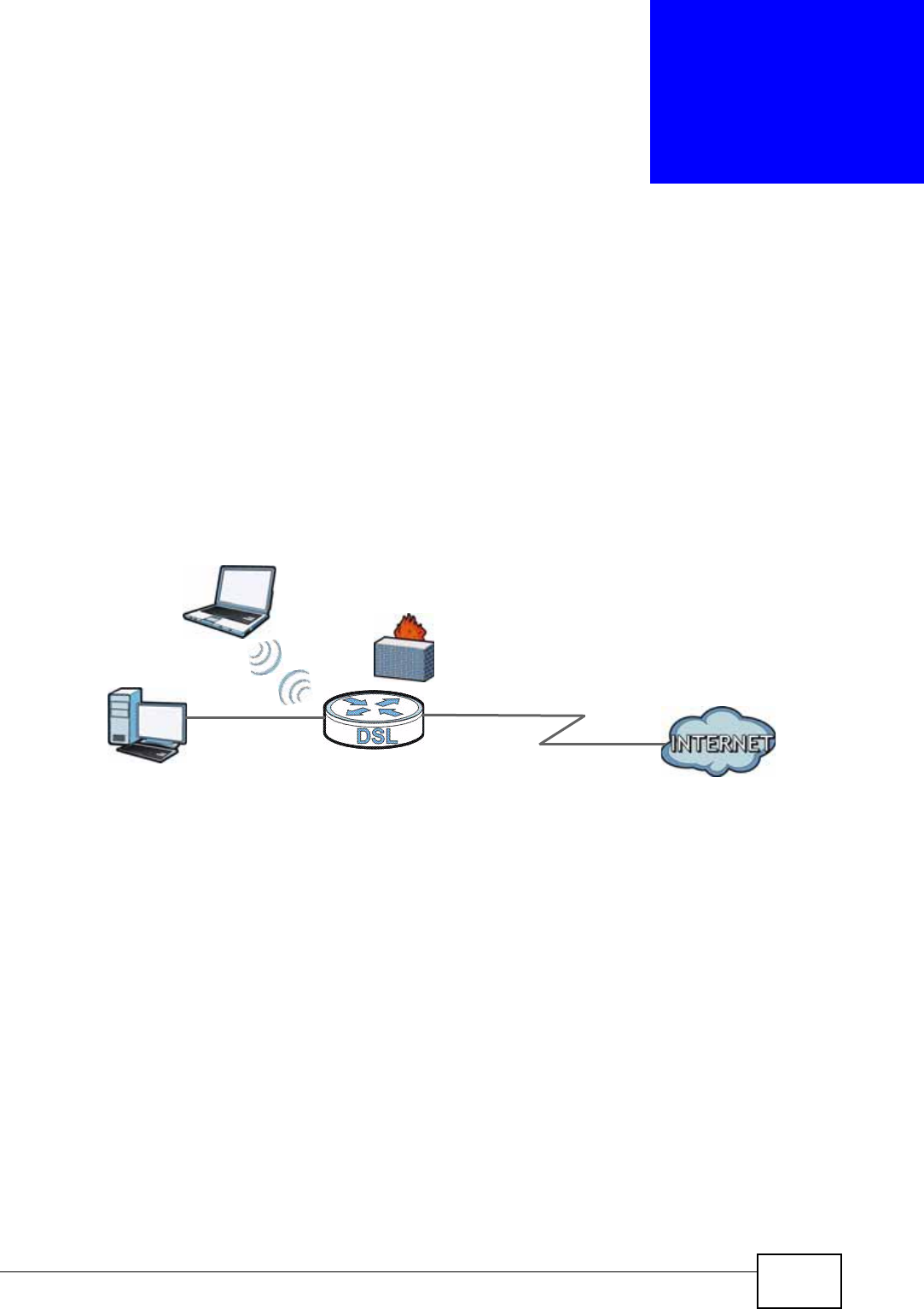
P-660N-T1A User’s Guide 85
CHAPTER 7
LAN Setup
7.1 Overview
A Local Area Network (LAN) is a shared communication system to which many
networking devices are connected. It is usually located in one immediate area
such as a building or floor of a building.
Use the LAN screens to help you configure a LAN DHCP server and manage IP
addresses.
7.1.1 What You Can Do in the LAN Screens
•Use the IP screen (Section 7.2 on page 87) to set the LAN IP address and
subnet mask of your ZyXEL device. You can also edit your ZyXEL Device's RIP,
multicast, and Windows Networking settings from this screen.
•Use the DHCP Setup screen (Section 7.3 on page 89) to configure the ZyXEL
Device’s DHCP settings.
•Use the Client List screen (Section 7.4 on page 90) to assign IP addresses on
the LAN to specific individual computers based on their MAC Addresses.
•Use the IP Alias screen (Section 7.5 on page 91) to change your ZyXEL
Device’s IP alias settings.
DSL
LAN

Chapter 7 LAN Setup
P-660N-T1A User’s Guide
86
7.1.2 What You Need To Know
The following terms and concepts may help as you read this chapter.
IP Address
IP addresses identify individual devices on a network. Every networking device
(including computers, servers, routers, printers, etc.) needs an IP address to
communicate across the network. These networking devices are also known as
hosts.
Subnet Mask
Subnet masks determine the maximum number of possible hosts on a network.
You can also use subnet masks to divide one network into multiple sub-networks.
DHCP
A DHCP (Dynamic Host Configuration Protocol) server can assign your ZyXEL
Device an IP address, subnet mask, DNS and other routing information when it's
turned on.
RIP
RIP (Routing Information Protocol) allows a router to exchange routing
information with other routers.
Multicast
Traditionally, IP packets are transmitted in one of either two ways - Unicast (1
sender - 1 recipient) or Broadcast (1 sender - everybody on the network).
Multicast delivers IP packets to a group of hosts on the network - not everybody
and not just 1.
IGMP
IGMP (Internet Group Multicast Protocol) is a network-layer protocol used to
establish membership in a Multicast group - it is not used to carry user data.
There are three versions of IGMP. IGMP version 2 and 3 are improvements over
version 1, but IGMP version 1 is still in wide use.
DNS
DNS (Domain Name System) is for mapping a domain name to its corresponding
IP address and vice versa. The DNS server is extremely important because
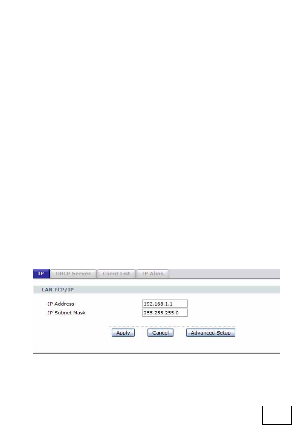
Chapter 7 LAN Setup
P-660N-T1A User’s Guide 87
without it, you must know the IP address of a networking device before you can
access it.
Finding Out More
See Section 7.6 on page 94 for technical background information on LANs.
7.1.3 Before You Begin
Find out the MAC addresses of your network devices if you intend to add them to
the DHCP Client List screen.
7.2 The IP Screen
Use this screen to set the Local Area Network IP address and subnet mask of your
ZyXEL Device. Click Network > LAN to open the IP screen.
Follow these steps to configure your LAN settings.
1Enter an IP address into the IP Address field. The IP address must be in dotted
decimal notation. This will become the IP address of your ZyXEL Device.
2Enter the IP subnet mask into the IP Subnet Mask field. Unless instructed
otherwise it is best to leave this alone, the configurator will automatically compute
a subnet mask based upon the IP address you entered.
3Click Apply to save your settings.
Figure 36 Network > LAN > IP
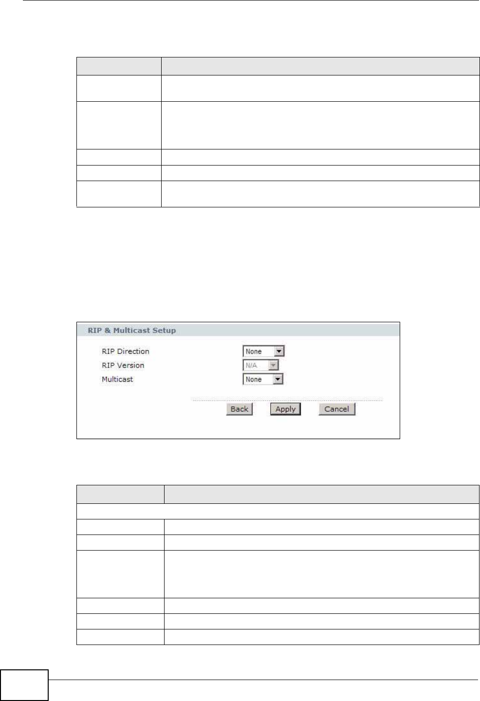
Chapter 7 LAN Setup
P-660N-T1A User’s Guide
88
The following table describes the fields in this screen.
7.2.1 The Advanced Setup Screen
Use this screen to edit your ZyXEL Device's RIP, multicast and Windows
Networking settings. Click the Advanced Setup button in the IP screen. The
screen appears as shown.
Figure 37 Network > LAN > IP: Advanced Setup
The following table describes the labels in this screen.
Table 19 Network > LAN > IP
LABEL DESCRIPTION
IP Address Enter the LAN IP address you want to assign to your ZyXEL Device in
dotted decimal notation, for example, 192.168.1.1 (factory default).
IP Subnet Mask Type the subnet mask of your network in dotted decimal notation, for
example 255.255.255.0 (factory default). Your ZyXEL Device
automatically computes the subnet mask based on the IP Address you
enter, so do not change this field unless you are instructed to do so.
Apply Click this to save your changes.
Cancel Click this to restore your previously saved settings.
Advanced Setup Click this to display the Advanced LAN Setup screen and edit more
details of your LAN setup.
Table 20 Network > LAN > IP: Advanced Setup
LABEL DESCRIPTION
RIP & Multicast Setup
RIP Direction Select the RIP direction from None, Both, In Only and Out Only.
RIP Version Select the RIP version from RIP-1, RIP-2B and RIP-2M.
Multicast IGMP (Internet Group Multicast Protocol) is a network-layer protocol
used to establish membership in a multicast group. The ZyXEL Device
supports IGMP-v1, IGMP-v2 and IGMP-v3. Select None to disable
it.
Back Click this to return to the previous screen without saving.
Apply Click this to save your changes.
Cancel Click this to restore your previously saved settings.
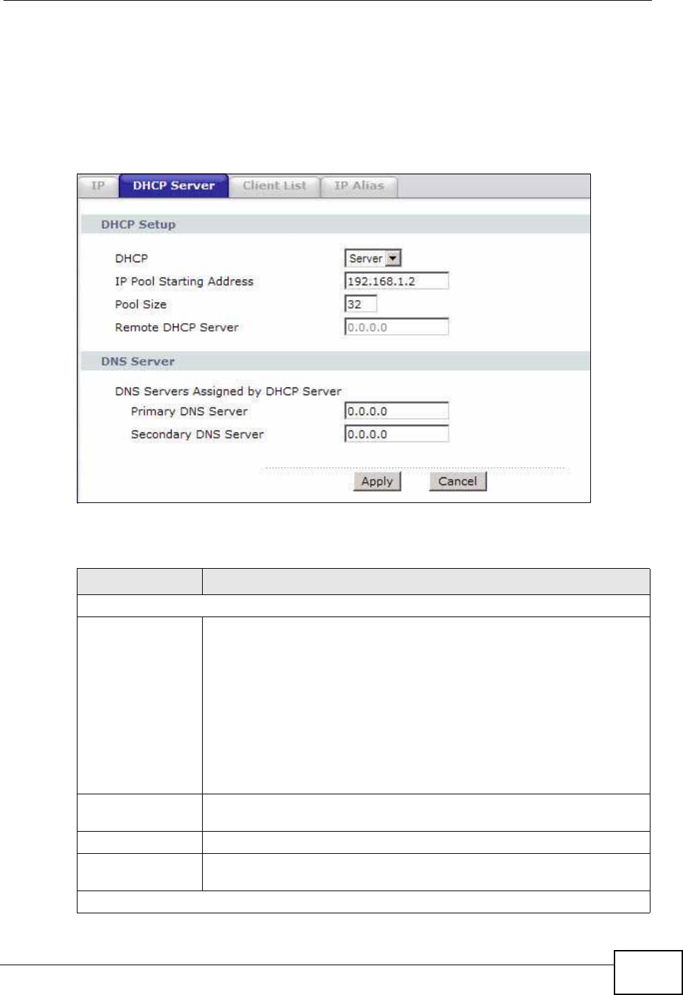
Chapter 7 LAN Setup
P-660N-T1A User’s Guide 89
7.3 The DHCP Server Screen
Use this screen to configure the DNS server information that the ZyXEL Device
sends to the DHCP client devices on the LAN. Click Network > DHCP Setup to
open this screen.
Figure 38 Network > LAN > DHCP Setup
The following table describes the labels in this screen.
Table 21 Network > LAN > DHCP Server
LABEL DESCRIPTION
DHCP Setup
DHCP If set to Server, your ZyXEL Device can assign IP addresses, an IP
default gateway and DNS servers to Windows 95, Windows NT and
other systems that support the DHCP client.
If set to None, the DHCP server will be disabled.
If set to Relay, the ZyXEL Device acts as a surrogate DHCP server
and relays DHCP requests and responses between the remote server
and the clients. Enter the IP address of the actual, remote DHCP
server in the Remote DHCP Server field in this case.
When DHCP is used, the following items need to be set:
IP Pool Starting
Address This field specifies the first of the contiguous addresses in the IP
address pool.
Pool Size This field specifies the size, or count of the IP address pool.
Remote DHCP
Server If Relay is selected in the DHCP field above then enter the IP
address of the actual remote DHCP server here.
DNS Server
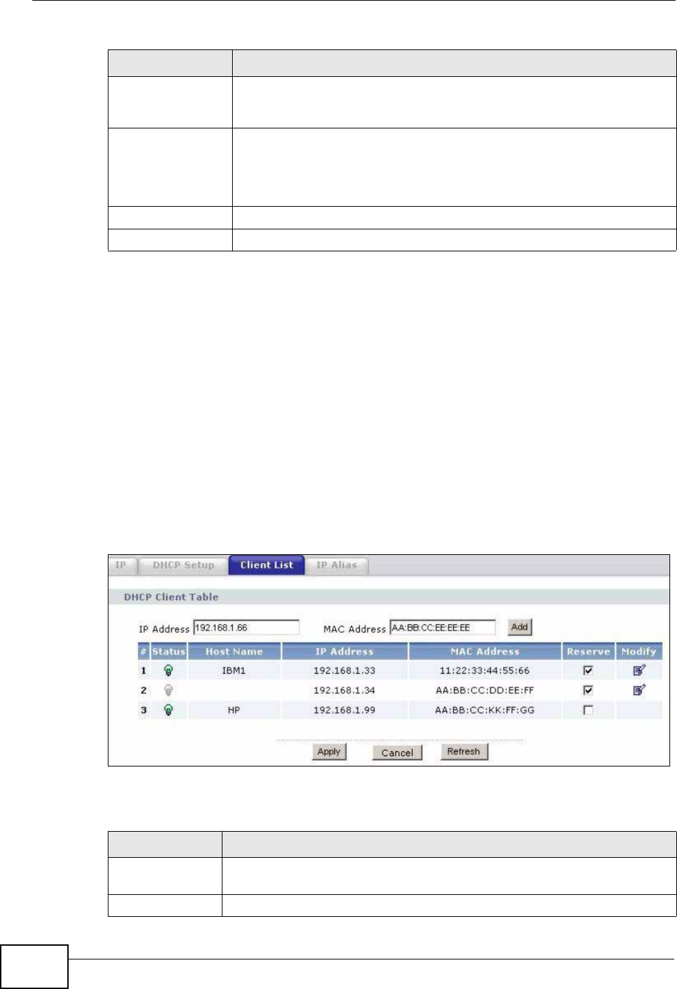
Chapter 7 LAN Setup
P-660N-T1A User’s Guide
90
7.4 The Client List Screen
This table allows you to assign IP addresses on the LAN to specific individual
computers based on their MAC Addresses.
Every Ethernet device has a unique MAC (Media Access Control) address. The MAC
address is assigned at the factory and consists of six pairs of hexadecimal
characters, for example, 00:A0:C5:00:00:02.
Use this screen to change your ZyXEL Device’s static DHCP settings. Click
Network > LAN > Client List to open the following screen.
Figure 39 Network > LAN > Client List
The following table describes the labels in this screen.
DNS Servers
Assigned by DHCP
Server
The ZyXEL Device passes a DNS (Domain Name System) server IP
address to the DHCP clients.
Primary DNS
Server
Secondary DNS
Server
Enter the IP address of your primary/secondary DNS server.
Apply Click this to save your changes.
Cancel Click this to restore your previously saved settings.
Table 21 Network > LAN > DHCP Server
LABEL DESCRIPTION
Table 22 Network > LAN > Client List
LABEL DESCRIPTION
IP Address Enter the IP address that you want to assign to the computer on your
LAN with the MAC address that you will also specify.
MAC Address Enter the MAC address of a computer on your LAN.

Chapter 7 LAN Setup
P-660N-T1A User’s Guide 91
7.5 The IP Alias Screen
IP alias allows you to partition a physical network into different logical networks
over the same Ethernet interface. The ZyXEL Device supports three logical LAN
interfaces via its single physical Ethernet interface with the ZyXEL Device itself as
the gateway for each LAN network.
When you use IP alias, you can also configure firewall rules to control access
between the LAN's logical networks (subnets).
Note: Make sure that the subnets of the logical networks do not overlap.
Add Click this to add a static DHCP entry.
# This is the index number of the static IP table entry (row).
Status This field displays whether the client is connected to the ZyXEL Device.
Host Name This field displays the computer host name.
IP Address This field displays the IP address relative to the # field listed above.
MAC Address The MAC (Media Access Control) or Ethernet address on a LAN (Local
Area Network) is unique to your computer (six pairs of hexadecimal
notation).
A network interface card such as an Ethernet adapter has a hardwired
address that is assigned at the factory. This address follows an industry
standard that ensures no other adapter has a similar address.
Reserve Select the check box in the heading row to automatically select all
check boxes or select the check box(es) in each entry to have the
ZyXEL Device always assign the selected entry(ies)’s IP address(es) to
the corresponding MAC address(es) (and host name(s)). You can select
up to 10 entries in this table.
Modify Click the modify icon to have the IP address field editable and change
it.
Apply Click this to save your changes.
Cancel Click this to restore your previously saved settings.
Refresh Click this to reload the DHCP table.
Table 22 Network > LAN > Client List
LABEL DESCRIPTION
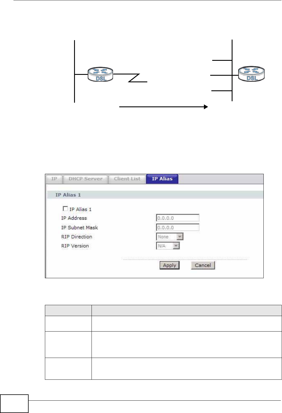
Chapter 7 LAN Setup
P-660N-T1A User’s Guide
92
The following figure shows a LAN divided into subnets A, B, and C.
Figure 40 Physical Network & Partitioned Logical Networks
7.5.1 Configuring the LAN IP Alias Screen
Use this screen to change your ZyXEL Device’s IP alias settings. Click Network >
LAN > IP Alias to open the following screen.
Figure 41 Network > LAN > IP Alias
The following table describes the labels in this screen.
Ethernet
Interface
A: 192.168.1.1 - 192.168.1.24
B: 192.168.2.1 - 192.168.2.24
C: 192.168.3.1 - 192.168.3.24
Table 23 Network > LAN > IP Alias
LABEL DESCRIPTION
IP Alias 1 Select the check box to configure another LAN network for the ZyXEL
Device.
IP Address Enter the IP address of your ZyXEL Device in dotted decimal notation.
Alternatively, click the right mouse button to copy and/or paste the IP
address.
IP Subnet Mask Your ZyXEL Device will automatically calculate the subnet mask based
on the IP address that you assign. Unless you are implementing
subnetting, use the subnet mask computed by the ZyXEL Device.

Chapter 7 LAN Setup
P-660N-T1A User’s Guide 93
RIP Direction RIP (Routing Information Protocol, RFC 1058 and RFC 1389) allows a
router to exchange routing information with other routers. The RIP
Direction field controls the sending and receiving of RIP packets.
Select the RIP direction from Both/In Only/Out Only/None. When
set to Both or Out Only, the ZyXEL Device will broadcast its routing
table periodically. When set to Both or In Only, it will incorporate the
RIP information that it receives; when set to None, it will not send any
RIP packets and will ignore any RIP packets received.
RIP Version The RIP Version field controls the format and the broadcasting
method of the RIP packets that the ZyXEL Device sends (it recognizes
both formats when receiving). RIP-1 is universally supported but RIP-2
carries more information. RIP-1 is probably adequate for most
networks, unless you have an unusual network topology. Both RIP-2B
and RIP-2M sends the routing data in RIP-2 format; the difference
being that RIP-2B uses subnet broadcasting while RIP-2M uses
multicasting. Multicasting can reduce the load on non-router machines
since they generally do not listen to the RIP multicast address and so
will not receive the RIP packets. However, if one router uses
multicasting, then all routers on your network must use multicasting,
also. By default, RIP direction is set to Both and the Version set to
RIP-1.
Apply Click this to save your changes.
Cancel Click this to restore your previously saved settings.
Table 23 Network > LAN > IP Alias
LABEL DESCRIPTION
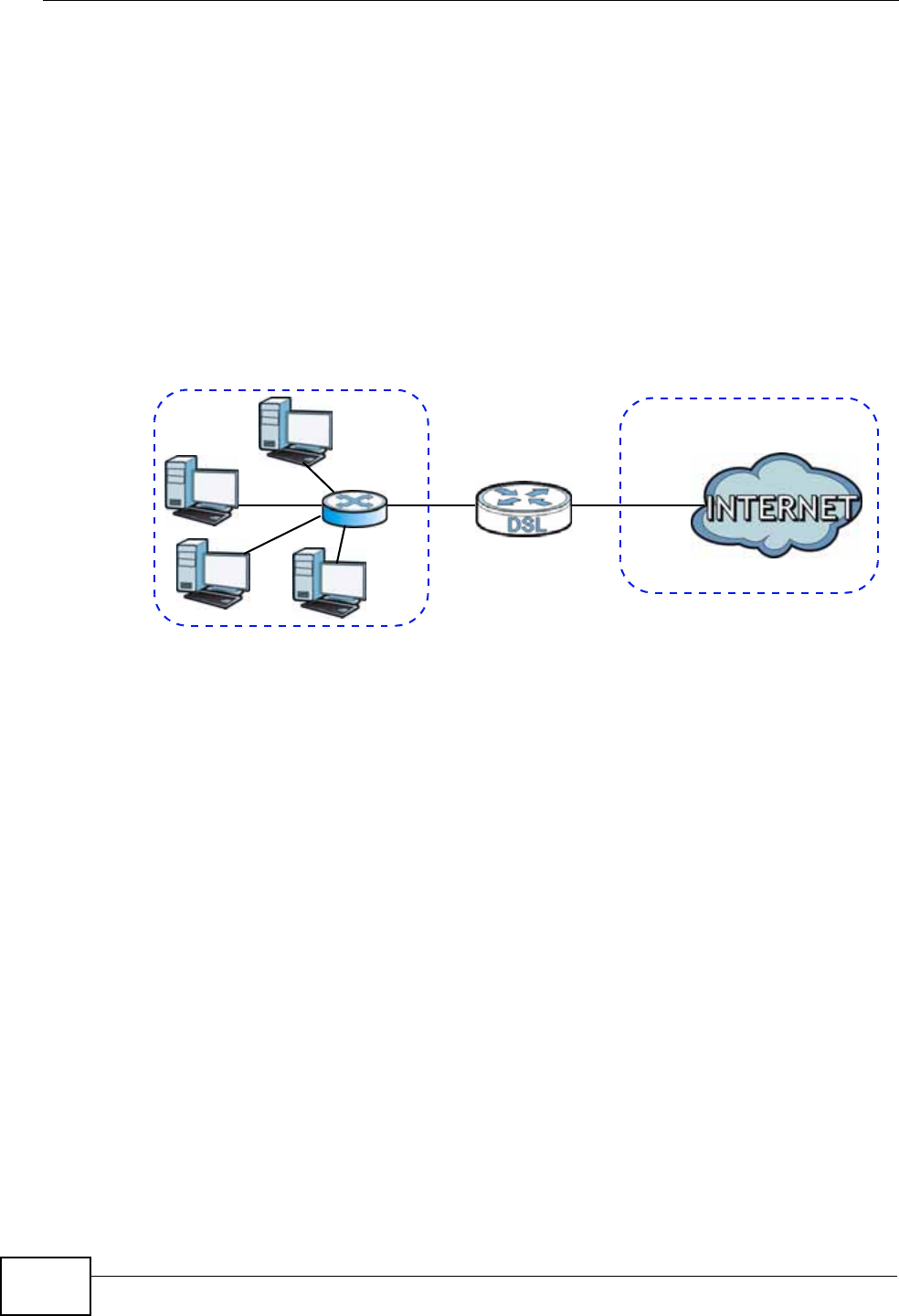
Chapter 7 LAN Setup
P-660N-T1A User’s Guide
94
7.6 Technical Reference
This section provides some technical background information about the topics
covered in this chapter.
7.6.1 LANs, WANs and the ZyXEL Device
The actual physical connection determines whether the ZyXEL Device ports are
LAN or WAN ports. There are two separate IP networks, one inside the LAN
network and the other outside the WAN network as shown next.
Figure 42 LAN and WAN IP Addresses
7.6.2 DHCP Setup
DHCP (Dynamic Host Configuration Protocol, RFC 2131 and RFC 2132) allows
individual clients to obtain TCP/IP configuration at start-up from a server. You can
configure the ZyXEL Device as a DHCP server or disable it. When configured as a
server, the ZyXEL Device provides the TCP/IP configuration for the clients. If you
turn DHCP service off, you must have another DHCP server on your LAN, or else
the computer must be manually configured.
IP Pool Setup
The ZyXEL Device is pre-configured with a pool of IP addresses for the DHCP
clients (DHCP Pool). See the product specifications in the appendices. Do not
assign static IP addresses from the DHCP pool to your LAN computers.
7.6.3 DNS Server Addresses
DNS (Domain Name System) maps a domain name to its corresponding IP
address and vice versa. The DNS server is extremely important because without
it, you must know the IP address of a computer before you can access it. The DNS
WAN
LAN

Chapter 7 LAN Setup
P-660N-T1A User’s Guide 95
server addresses you enter when you set up DHCP are passed to the client
machines along with the assigned IP address and subnet mask.
There are two ways that an ISP disseminates the DNS server addresses.
• The ISP tells you the DNS server addresses, usually in the form of an
information sheet, when you sign up. If your ISP gives you DNS server
addresses, enter them in the DNS Server fields in the DHCP Setup screen.
• Some ISPs choose to disseminate the DNS server addresses using the DNS
server extensions of IPCP (IP Control Protocol) after the connection is up. If
your ISP did not give you explicit DNS servers, chances are the DNS servers are
conveyed through IPCP negotiation. The ZyXEL Device supports the IPCP DNS
server extensions through the DNS proxy feature.
Please note that DNS proxy works only when the ISP uses the IPCP DNS server
extensions. It does not mean you can leave the DNS servers out of the DHCP
setup under all circumstances. If your ISP gives you explicit DNS servers, make
sure that you enter their IP addresses in the DHCP Setup screen.
7.6.4 LAN TCP/IP
The ZyXEL Device has built-in DHCP server capability that assigns IP addresses
and DNS servers to systems that support DHCP client capability.
IP Address and Subnet Mask
Similar to the way houses on a street share a common street name, so too do
computers on a LAN share one common network number.
Where you obtain your network number depends on your particular situation. If
the ISP or your network administrator assigns you a block of registered IP
addresses, follow their instructions in selecting the IP addresses and the subnet
mask.
If the ISP did not explicitly give you an IP network number, then most likely you
have a single user account and the ISP will assign you a dynamic IP address when
the connection is established. If this is the case, it is recommended that you select
a network number from 192.168.0.0 to 192.168.255.0 and you must enable the
Network Address Translation (NAT) feature of the ZyXEL Device. The Internet
Assigned Number Authority (IANA) reserved this block of addresses specifically for
private use; please do not use any other number unless you are told otherwise.
Let's say you select 192.168.1.0 as the network number; which covers 254
individual addresses, from 192.168.1.1 to 192.168.1.254 (zero and 255 are
reserved). In other words, the first three numbers specify the network number
while the last number identifies an individual computer on that network.

Chapter 7 LAN Setup
P-660N-T1A User’s Guide
96
Once you have decided on the network number, pick an IP address that is easy to
remember, for instance, 192.168.1.1, for your ZyXEL Device, but make sure that
no other device on your network is using that IP address.
The subnet mask specifies the network number portion of an IP address. Your
ZyXEL Device will compute the subnet mask automatically based on the IP
address that you entered. You don't need to change the subnet mask computed by
the ZyXEL Device unless you are instructed to do otherwise.
Private IP Addresses
Every machine on the Internet must have a unique address. If your networks are
isolated from the Internet, for example, only between your two branch offices, you
can assign IP addresses to the hosts without problems. However, the Internet
Assigned Numbers Authority (IANA) has reserved the following three blocks of IP
addresses specifically for private networks:
• 10.0.0.0 — 10.255.255.255
• 172.16.0.0 — 172.31.255.255
• 192.168.0.0 — 192.168.255.255
You can obtain your IP address from the IANA, from an ISP or it can be assigned
from a private network. If you belong to a small organization and your Internet
access is through an ISP, the ISP can provide you with the Internet addresses for
your local networks. On the other hand, if you are part of a much larger
organization, you should consult your network administrator for the appropriate IP
addresses.
Note: Regardless of your particular situation, do not create an arbitrary IP address;
always follow the guidelines above. For more information on address
assignment, please refer to RFC 1597, “Address Allocation for Private
Internets” and RFC 1466, “Guidelines for Management of IP Address Space”.
7.6.5 RIP Setup
RIP (Routing Information Protocol) allows a router to exchange routing
information with other routers. The RIP Direction field controls the sending and
receiving of RIP packets. When set to:
•Both - the ZyXEL Device will broadcast its routing table periodically and
incorporate the RIP information that it receives.
•In Only - the ZyXEL Device will not send any RIP packets but will accept all RIP
packets received.
•Out Only - the ZyXEL Device will send out RIP packets but will not accept any
RIP packets received.

Chapter 7 LAN Setup
P-660N-T1A User’s Guide 97
•None - the ZyXEL Device will not send any RIP packets and will ignore any RIP
packets received.
The Version field controls the format and the broadcasting method of the RIP
packets that the ZyXEL Device sends (it recognizes both formats when receiving).
RIP-1 is universally supported; but RIP-2 carries more information. RIP-1 is
probably adequate for most networks, unless you have an unusual network
topology.
Both RIP-2B and RIP-2M sends the routing data in RIP-2 format; the difference
being that RIP-2B uses subnet broadcasting while RIP-2M uses multicasting.
7.6.6 Multicast
Traditionally, IP packets are transmitted in one of either two ways - Unicast (1
sender - 1 recipient) or Broadcast (1 sender - everybody on the network).
Multicast delivers IP packets to a group of hosts on the network - not everybody
and not just 1.
IGMP (Internet Group Multicast Protocol) is a network-layer protocol used to
establish membership in a Multicast group - it is not used to carry user data. IGMP
version 2 (RFC 2236) is an improvement over version 1 (RFC 1112) but IGMP
version 1 is still in wide use. IGMP version 3 supports source filtering, reporting or
ignoring traffic from specific source address to a particular host on the network. If
you would like to read more detailed information about interoperability between
IGMP version 2 and version 1, please see sections 4 and 5 of RFC 2236. The class
D IP address is used to identify host groups and can be in the range 224.0.0.0 to
239.255.255.255. The address 224.0.0.0 is not assigned to any group and is used
by IP multicast computers. The address 224.0.0.1 is used for query messages and
is assigned to the permanent group of all IP hosts (including gateways). All hosts
must join the 224.0.0.1 group in order to participate in IGMP. The address
224.0.0.2 is assigned to the multicast routers group.
The ZyXEL Device supports IGMP version 1 (IGMP-v1), IGMP version 2 (IGMP-
v2) and IGMP version 3 (IGMP-v3). At start up, the ZyXEL Device queries all
directly connected networks to gather group membership. After that, the ZyXEL
Device periodically updates this information. IP multicasting can be enabled/
disabled on the ZyXEL Device LAN and/or WAN interfaces in the web configurator
(LAN; WAN). Select None to disable IP multicasting on these interfaces.

Chapter 7 LAN Setup
P-660N-T1A User’s Guide
98

P-660N-T1A User’s Guide 99
CHAPTER 8
Wireless LAN
8.1 Overview
This chapter describes how to perform tasks related to setting up and optimizing
your wireless network, including the following.
• Turning the wireless connection on or off.
• Configuring a name, wireless channel and security for the network.
• Using WiFi Protected Setup (WPS) to configure your wireless network.
• Setting up multiple wireless networks.
• Using a MAC (Media Access Control) address filter to restrict access to the
wireless network.
• Setting up a Wireless Distribution System (WDS).
• Performing other performance-related wireless tasks.
8.1.1 What You Can Do in the Wireless LAN Screens
This section describes the ZyXEL Device’s Network > Wireless LAN screens. Use
these screens to set up your ZyXEL Device’s wireless connection.
•Use the AP screen (see Section 8.2 on page 101) to turn the wireless
connection on or off, set up wireless security, configure the MAC filter, and make
other basic configuration changes.
•Use the More AP screen (see Section 8.3 on page 110) to set up multiple
wireless networks on your ZyXEL Device.
•Use the WPS screen (see Section 8.4 on page 112) to enable or disable WPS,
generate a security PIN (Personal Identification Number) and see information
about the ZyXEL Device’s WPS status.
•Use the WPS Station (see Section 8.5 on page 113) screen to set up WPS by
pressing a button or using a PIN.
•Use the WDS screen (see Section 8.6 on page 114) to set up a Wireless
Distribution System, in which the ZyXEL Device acts as a bridge with other
ZyXEL access points.
•Use the Scheduling screen (see Section 8.7 on page 116) to configure the
dates/times to enable or disable the wireless LAN.

Chapter 8 Wireless LAN
P-660N-T1A User’s Guide
100
You don’t necessarily need to use all these screens to set up your wireless
connection. For example, you may just want to set up a network name, a wireless
radio channel and security in the AP screen.
8.1.2 What You Need to Know
The following terms and concepts may help as you read this chapter.
Wireless Basics
“Wireless” is essentially radio communication. In the same way that walkie-talkie
radios send and receive information over the airwaves, wireless networking
devices exchange information with one another. A wireless networking device is
just like a radio that lets your computer exchange information with radios
attached to other computers. Like walkie-talkies, most wireless networking
devices operate at radio frequency bands that are open to the public and do not
require a license to use. However, wireless networking is different from that of
most traditional radio communications in that there a number of wireless
networking standards available with different methods of data encryption.
SSID
Each network must have a name, referred to as the SSID - “Service Set
IDentifier”. The “service set” is the network, so the “service set identifier” is the
network’s name. This helps you identify your wireless network when wireless
networks’ coverage areas overlap and you have a variety of networks to choose
from.
MAC Address Filter
Every Ethernet device has a unique MAC (Media Access Control) address. The MAC
address consists of twelve hexadecimal characters (0-9, and A to F), and it is
usually written in the following format: “0A:A0:00:BB:CC:DD”.
The MAC address filter controls access to the wireless network. You can use the
MAC address of each wireless client to allow or deny access to the wireless
network.
Finding Out More
See Section 8.8 on page 117 for advanced technical information on wireless
networks.
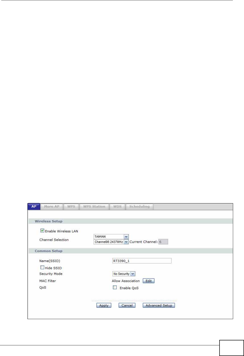
Chapter 8 Wireless LAN
P-660N-T1A User’s Guide 101
8.1.3 Before You Start
Before you start using these screens, ask yourself the following questions. See
Section 8.1.2 on page 100 if some of the terms used here are not familiar to you.
• What wireless standards do the other wireless devices in your network support
(IEEE 802.11g, for example)? What is the most appropriate standard to use?
• What security options do the other wireless devices in your network support
(WPA-PSK, for example)? What is the strongest security option supported by all
the devices in your network?
• Do the other wireless devices in your network support WPS (Wi-Fi Protected
Setup)? If so, you can set up a well-secured network very easily.
Even if some of your devices support WPS and some do not, you can use WPS to
set up your network and then add the non-WPS devices manually, although this
is somewhat more complicated to do.
• What advanced options do you want to configure, if any? If you want to
configure advanced options such as Quality of Service, ensure that you know
precisely what you want to do. If you do not want to configure advanced
options, leave them as they are.
8.2 The AP Screen
Use this screen to configure the wireless settings of your ZyXEL Device. Click
Network > Wireless LAN to open the AP screen.
Figure 43 Network > Wireless LAN > AP
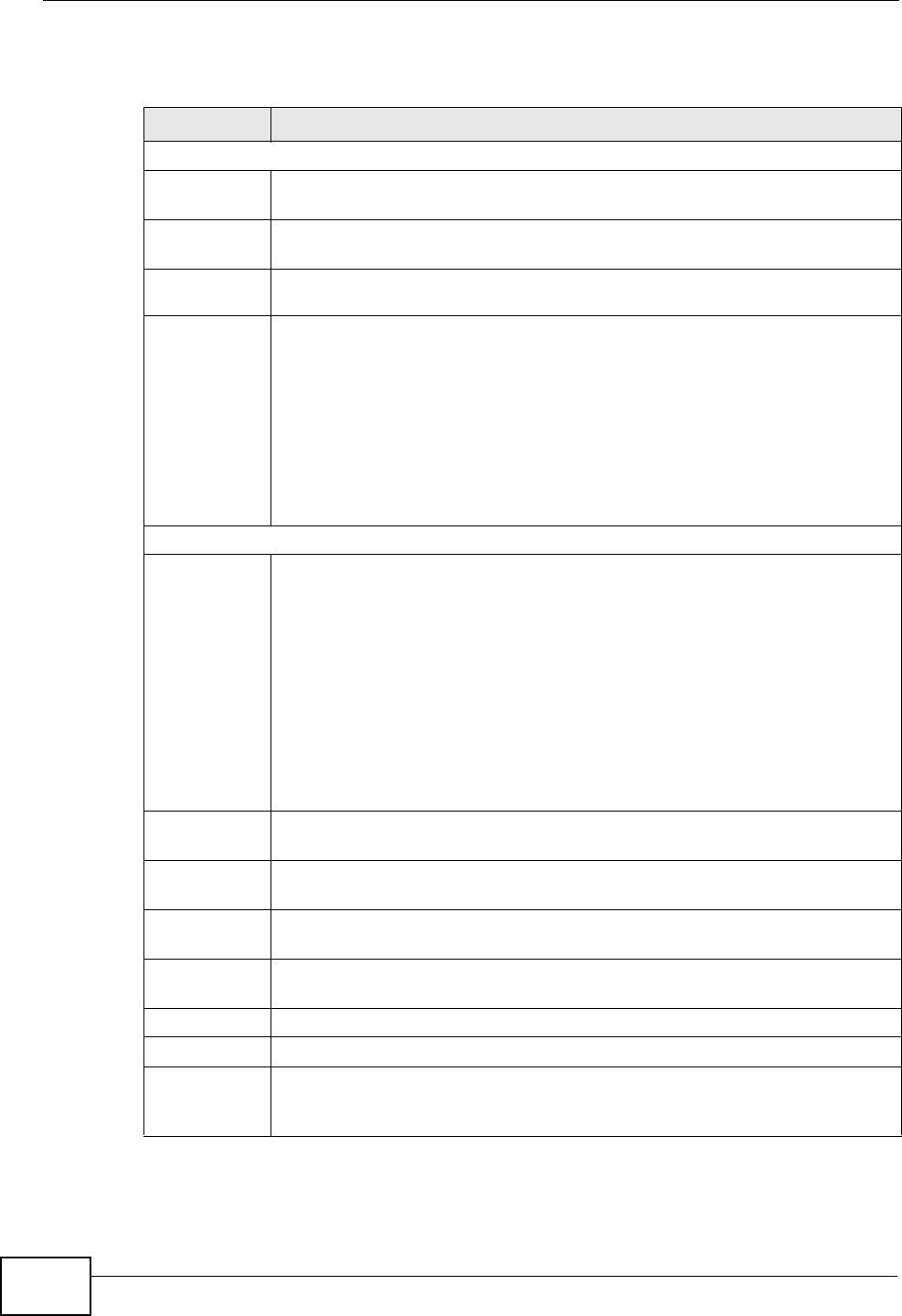
Chapter 8 Wireless LAN
P-660N-T1A User’s Guide
102
The following table describes the labels in this screen.
Table 24 Network > Wireless LAN > AP
LABEL DESCRIPTION
Wireless Setup
Enable
Wireless LAN Click the check box to activate wireless LAN.
Auto-Scan
Channel Select this option to have the ZyXEL Device automatically scan for and
select a channel which is not used by another device.
Country
Code
Channel
Selection Set the operating frequency/channel depending on your particular region.
You must also select the country in which your ZyXEL Device operates.
Some countries only allow wireless devices to broadcast on a specific set
of channels. Selecting this may modify the number of channels in the
Channel Selection list according to the ZyXEL Device’s location.
Note: If you do not correctly identify the country where this device is
operating, then you may not have any wireless functionality.
Common Setup
Network
Name (SSID) The SSID (Service Set IDentity) identifies the service set with which a
wireless device is associated. Wireless devices associating to the access
point (AP) must have the same SSID. Enter a descriptive name (up to 32
printable 7-bit ASCII characters) for the wireless LAN.
Note: If you are configuring the ZyXEL Device from a computer
connected to the wireless LAN and you change the ZyXEL
Device’s SSID or WEP settings, you will lose your wireless
connection when you press Apply to confirm. You must then
change the wireless settings of your computer to match the
ZyXEL Device’s new settings.
Hide SSID Select this check box to hide the SSID in the outgoing beacon frame so a
station cannot obtain the SSID through scanning using a site survey tool.
Security
Mode See the following sections for more details about this field.
MAC Filter This shows whether the wireless devices with the MAC addresses listed are
allowed or denied to access the ZyXEL Device using this SSID.
Edit Click this to go to the MAC Filter screen to configure MAC filter settings.
See Section 8.2.6 on page 109 for more details.
Apply Click this to save your changes.
Cancel Click this to restore your previously saved settings.
Advanced
Setup Click this to display the Wireless Advanced Setup screen and edit more
details of your WLAN setup. See Section 8.2.5 on page 107 for more
details.
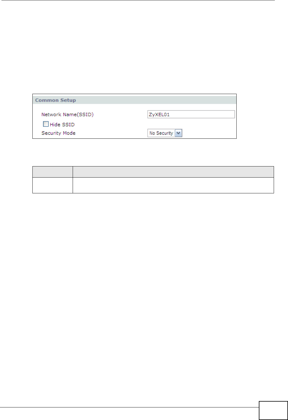
Chapter 8 Wireless LAN
P-660N-T1A User’s Guide 103
8.2.1 No Security
In the Network > Wireless LAN > AP screen, select No Security from the
Security Mode list to allow wireless devices to communicate with the ZyXEL
Device without any data encryption or authentication.
Note: If you do not enable any wireless security on your ZyXEL Device, your network
is accessible to any wireless networking device that is within range.
Figure 44 Network > Wireless LAN > AP: No Security
The following table describes the labels in this screen.
8.2.2 WEP Encryption
Use this screen to configure and enable WEP encryption. Click Network >
Wireless LAN to display the AP screen. Select Static WEP from the Security
Mode list.
Note: WEP is extremely insecure. Its encryption can be broken by an attacker, using
widely-available software. It is strongly recommended that you use a more
effective security mechanism. Use the strongest security mechanism that all the
wireless devices in your network support. For example, use WPA-PSK or
Table 25 Network > Wireless LAN > AP: No Security
LABEL DESCRIPTION
Security
Mode Choose No Security from the drop-down list box.
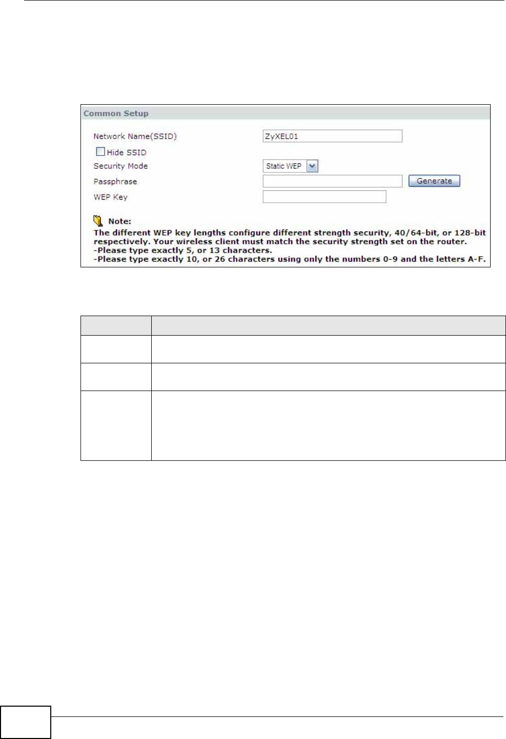
Chapter 8 Wireless LAN
P-660N-T1A User’s Guide
104
WPA2-PSK if all your wireless devices support it, or use WPA or WPA2 if your
wireless devices support it and you have a RADIUS server. If your wireless
devices support nothing stronger than WEP, use the highest encryption level
available.
Figure 45 Network > Wireless LAN > AP: Static WEP
The following table describes the wireless LAN security labels in this screen.
Table 26 Network > Wireless LAN > AP: Static WEP
LABEL DESCRIPTION
Security
Mode Choose Static WEP from the drop-down list box.
Passphrase Enter a passphrase (up to 32 printable characters) and click Generate.
The ZyXEL Device automatically generates a WEP key.
WEP Key The WEP key is used to encrypt data. Both the ZyXEL Device and the
wireless stations must use the same WEP key for data transmission.
If you want to manually set the WEP key, enter any 5 or 13 characters
(ASCII string) or 10 or 26 hexadecimal characters ("0-9", "A-F") for a 64-
bit or 128-bit WEP key respectively.
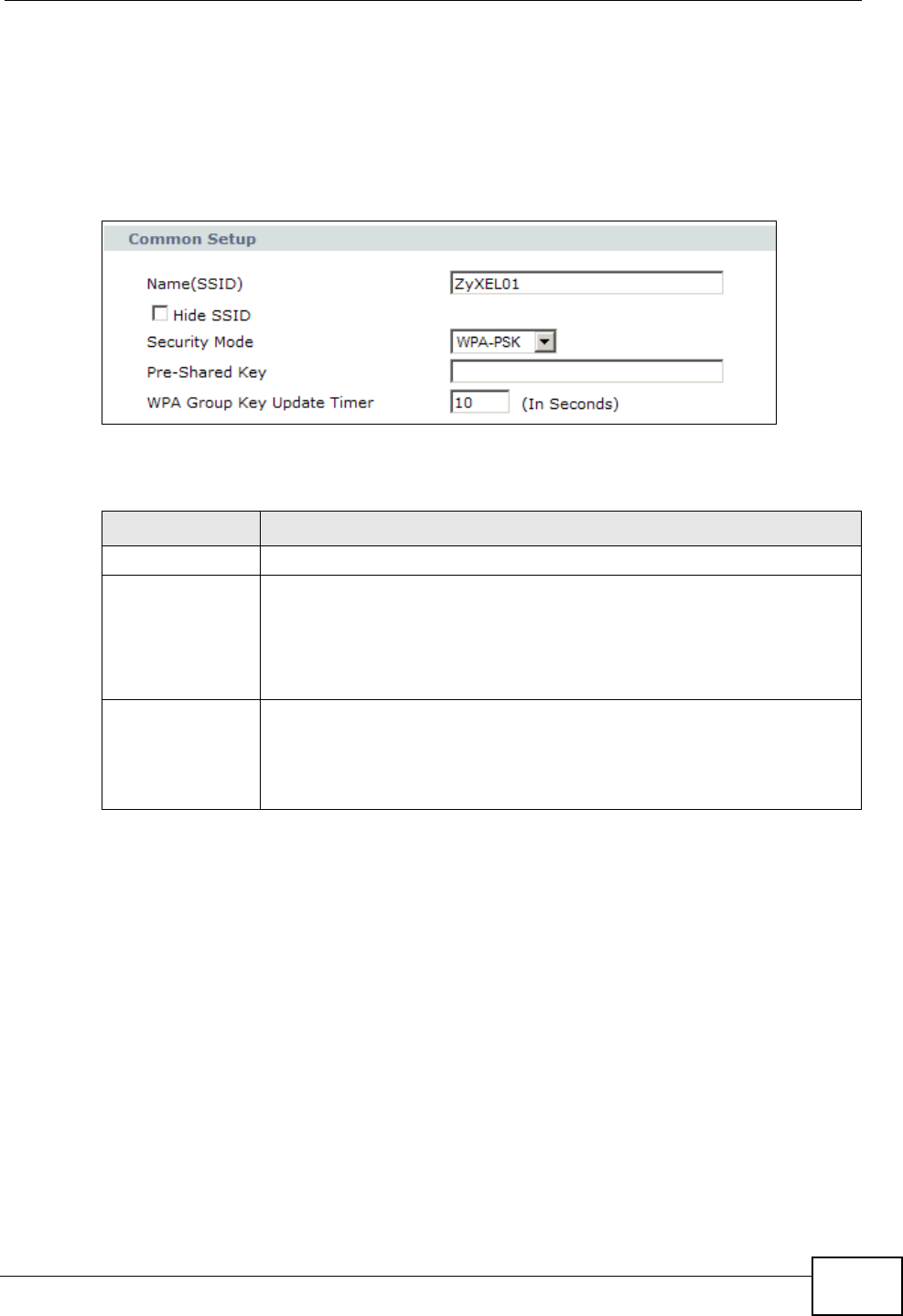
Chapter 8 Wireless LAN
P-660N-T1A User’s Guide 105
8.2.3 WPA(2)-PSK
Use this screen to configure and enable WPA(2)-PSK authentication. Click
Network > Wireless LAN to display the AP screen. Select WPA-PSK or WPA2-
PSK from the Security Mode list.
Figure 46 Network > Wireless LAN > AP: WPA(2)-PSK
The following table describes the wireless LAN security labels in this screen.
Table 27 Network > Wireless LAN > AP: WPA(2)-PSK
LABEL DESCRIPTION
Security Mode Choose WPA-PSK or WPA2-PSK from the drop-down list box.
Pre-Shared Key The encryption mechanisms used for WPA(2) and WPA(2)-PSK are
the same. The only difference between the two is that WPA(2)-PSK
uses a simple common password, instead of user-specific credentials.
Type a pre-shared key from 8 to 63 case-sensitive ASCII characters
(including spaces and symbols).
WPA Group Key
Update Timer The Group Key Update Timer is the rate at which the AP (if using
WPA(2)-PSK key management) or RADIUS server (if using WPA(2)
key management) sends a new group key out to all clients. The re-
keying process is the WPA(2) equivalent of automatically changing the
WEP key for an AP and all stations in a WLAN on a periodic basis.
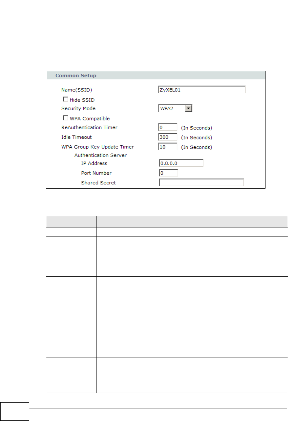
Chapter 8 Wireless LAN
P-660N-T1A User’s Guide
106
8.2.4 WPA(2) Authentication
Use this screen to configure and enable WPA or WPA2 authentication. Click the
Wireless LAN link under Network to display the AP screen. Select WPA, WPA2
or WPAMixed from the Security Mode list.
Figure 47 Network > Wireless LAN > AP: WPA(2)
The following table describes the wireless LAN security labels in this screen.
Table 28 Network > Wireless LAN > AP: WPA(2)
LABEL DESCRIPTION
Security Mode Choose WPA or WPA2 from the drop-down list box.
WPA Compatible This check box is available only when you select WPA2-PSK or WPA2
in the Security Mode field.
Select the check box to have both WPA-PSK and WPA wireless clients
be able to communicate with the ZyXEL Device even when the ZyXEL
Device is using WPA2-PSK or WPA2.
ReAuthentication
Timer Specify how often wireless stations have to resend usernames and
passwords in order to stay connected. Enter a time interval between
10 and 9999 seconds.
Note: If wireless station authentication is done using a RADIUS
server, the reauthentication timer on the RADIUS server has
priority.
Idle Timeout The ZyXEL Device automatically disconnects a wireless station from
the wired network after a period of inactivity. The wireless station
needs to enter the username and password again before access to the
wired network is allowed.
WPA Group Key
Update Timer The Group Key Update Timer is the rate at which the AP (if using
WPA(2)-PSK key management) or RADIUS server (if using WPA(2)
key management) sends a new group key out to all clients. The re-
keying process is the WPA(2) equivalent of automatically changing the
WEP key for an AP and all stations in a WLAN on a periodic basis.
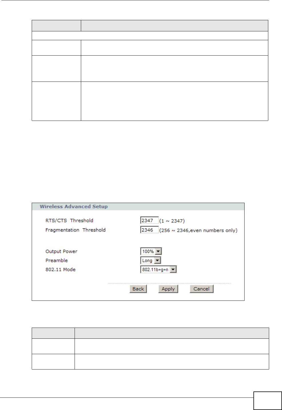
Chapter 8 Wireless LAN
P-660N-T1A User’s Guide 107
8.2.5 Advanced Setup
Use this screen to configure advanced wireless settings. Click the Advanced
Setup button in the AP screen. The screen appears as shown.
See Section 8.8.2 on page 119 for detailed definitions of the terms listed in this
screen.
Figure 48 Network > Wireless LAN > AP: Advanced Setup
The following table describes the labels in this screen.
Authentication Server
IP Address Enter the IP address of the external authentication server in dotted
decimal notation.
Port Number Enter the port number of the external authentication server.
You need not change this value unless your network administrator
instructs you to do so with additional information.
Shared Secret Enter a password (up to 31 alphanumeric characters) as the key to be
shared between the external authentication server and the ZyXEL
Device.
The key must be the same on the external authentication server and
your ZyXEL Device. The key is not sent over the network.
Table 28 Network > Wireless LAN > AP: WPA(2)
LABEL DESCRIPTION
Table 29 Network > Wireless LAN > AP: Advanced Setup
LABEL DESCRIPTION
RTS/CTS
Threshold Enter a value between 0 and 2432.
Fragmentation
Threshold This is the maximum data fragment size that can be sent. Enter a value
between 256 and 2432.
Chapter 8 Wireless LAN
P-660N-T1A User’s Guide
108
Output Power Set the output power of the ZyXEL Device. If there is a high density of
APs in an area, decrease the output power to reduce interference with
other APs. Select one of the following: 100%, 75%, 50% or 25%.
Preamble Select a preamble type from the drop-down list menu. Choices are Long
or Short. See the Appendix D on page 295 for more information.
802.11 Mode Select 802.11b Only to allow only IEEE 802.11b compliant WLAN
devices to associate with the ZyXEL Device.
Select 802.11g Only to allow only IEEE 802.11g compliant WLAN
devices to associate with the ZyXEL Device.
Select 802.11b+g to allow either IEEE 802.11b or IEEE 802.11g
compliant WLAN devices to associate with the ZyXEL Device. The
transmission rate of your ZyXEL Device might be reduced.
Select 802.11n to allow only IEEE 802.11n compliant WLAN devices to
associate with the ZyXEL Device.
Select 802.11g+n to allow either IEEE 802.11g or IEEE 802.11n
compliant WLAN devices to associate with the ZyXEL Device. The
transmission rate of your ZyXEL Device might be reduced.
Select 802.11b+g+n to allow IEEE 802.11b, IEEE 802.11g or
IEEE802.11n compliant WLAN devices to associate with the ZyXEL
Device. The transmission rate of your ZyXEL Device might be reduced.
Back Click this to return to the previous screen without saving.
Apply Click this to save your changes.
Cancel Click this to restore your previously saved settings.
Table 29 Network > Wireless LAN > AP: Advanced Setup
LABEL DESCRIPTION
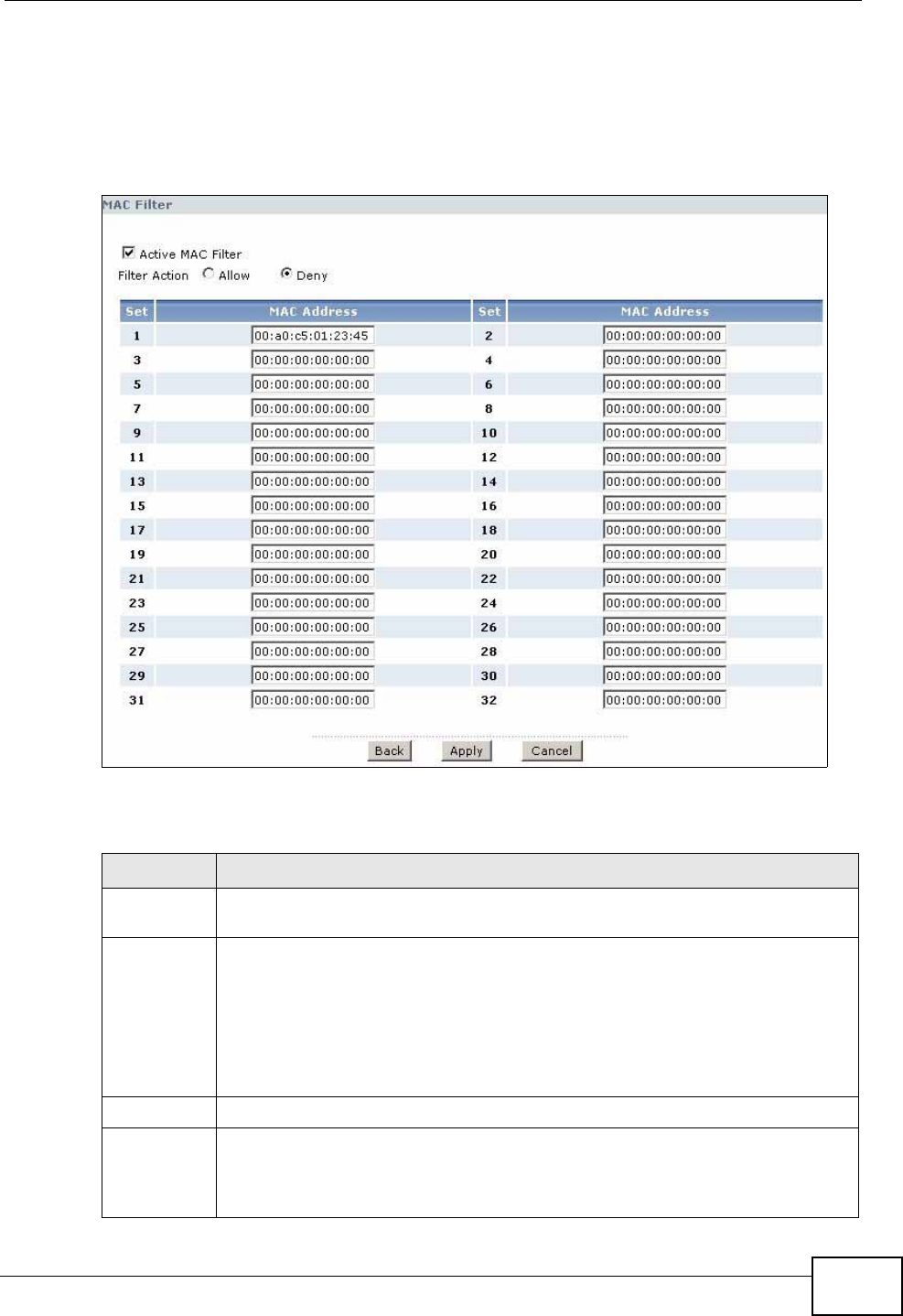
Chapter 8 Wireless LAN
P-660N-T1A User’s Guide 109
8.2.6 MAC Filter
Use this screen to change your ZyXEL Device’s MAC filter settings. Click the Edit
button in the AP screen. The screen appears as shown.
Figure 49 Network > Wireless LAN > AP: MAC Address Filter
The following table describes the labels in this screen.
Table 30 Network > Wireless LAN > AP: MAC Address Filter
LABEL DESCRIPTION
Active MAC
Filter Select the check box to enable MAC address filtering.
Filter Action Define the filter action for the list of MAC addresses in the MAC Address
table.
Select Deny to block access to the ZyXEL Device. MAC addresses not listed
will be allowed to access the ZyXEL Device
Select Allow to permit access to the ZyXEL Device. MAC addresses not
listed will be denied access to the ZyXEL Device.
Set This is the index number of the MAC address.
MAC
Address Enter the MAC addresses of the wireless devices that are allowed or denied
access to the ZyXEL Device in these address fields. Enter the MAC
addresses in a valid MAC address format, that is, six hexadecimal character
pairs, for example, 12:34:56:78:9a:bc.
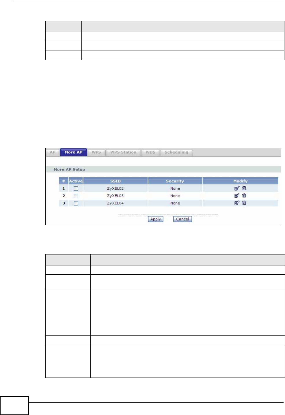
Chapter 8 Wireless LAN
P-660N-T1A User’s Guide
110
8.3 The More AP Screen
This screen allows you to enable and configure multiple Basic Service Sets (BSSs)
on the ZyXEL Device.
Click Network > Wireless LAN > More AP. The following screen displays.
Figure 50 Network > Wireless LAN > More AP
The following table describes the labels in this screen.
Back Click this to return to the previous screen without saving.
Apply Click this to save your changes.
Cancel Click this to restore your previously saved settings.
Table 30 Network > Wireless LAN > AP: MAC Address Filter
LABEL DESCRIPTION
Table 31 Network > Wireless LAN > More AP
LABEL DESCRIPTION
# This is the index number of each SSID profile.
Active This field indicates with a check mark whether this SSID is active. No
check mark means it is not active.
SSID An SSID profile is the set of parameters relating to one of the ZyXEL
Device’s BSSs. The SSID (Service Set IDentifier) identifies the Service
Set with which a wireless device is associated.
This field displays the name of the wireless profile on the network. When
a wireless client scans for an AP to associate with, this is the name that
is broadcast and seen in the wireless client utility.
Security This field indicates the security mode of the SSID profile.
Modify Click the Edit icon to configure the SSID profile.
Click the Remove icon to hide the SSID in the outgoing beacon frame so
a station cannot obtain the SSID through scanning using a site survey
tool.
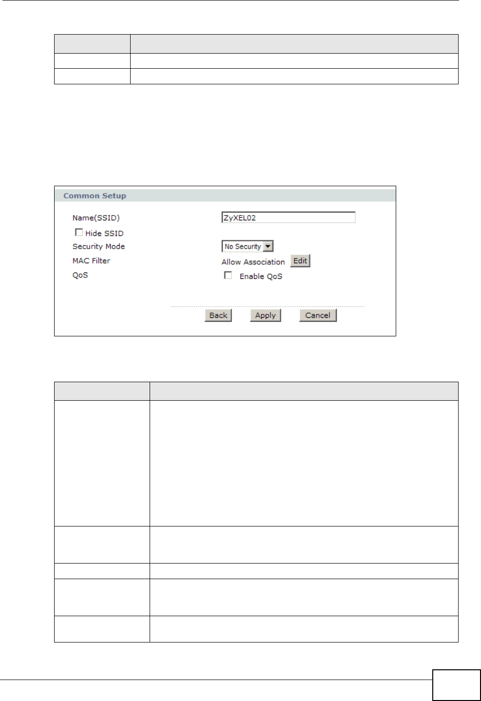
Chapter 8 Wireless LAN
P-660N-T1A User’s Guide 111
8.3.1 More AP Edit
Use this screen to edit an SSID profile. Click the Edit icon next to an SSID in the
More AP screen. The following screen displays.
Figure 51 Network > Wireless LAN > More AP: Edit
The following table describes the fields in this screen.
Apply Click this to save your changes.
Cancel Click this to restore your previously saved settings.
Table 31 Network > Wireless LAN > More AP
LABEL DESCRIPTION
Table 32 Network > Wireless LAN > More AP: Edit
LABEL DESCRIPTION
Network Name
(SSID) The SSID (Service Set IDentity) identifies the service set with which
a wireless device is associated. Enter a descriptive name (up to 32
printable 7-bit ASCII characters) for the wireless LAN.
Note: If you are configuring the ZyXEL Device from a computer
connected to the wireless LAN and you change the
ZyXEL Device’s SSID or security settings, you will lose
your wireless connection when you press Apply to
confirm. You must then change the wireless settings of
your computer to match the ZyXEL Device’s new settings.
Hide SSID Select this check box to hide the SSID in the outgoing beacon frame
so a station cannot obtain the SSID through scanning using a site
survey tool.
Security Mode See Section 8.2 on page 101 for more details about this field.
MAC Filter This shows whether the wireless devices with the MAC addresses
listed are allowed or denied to access the ZyXEL Device using this
SSID.
Edit Click this to go to the MAC Filter screen to configure MAC filter
settings. See Section 8.2.6 on page 109 for more details.
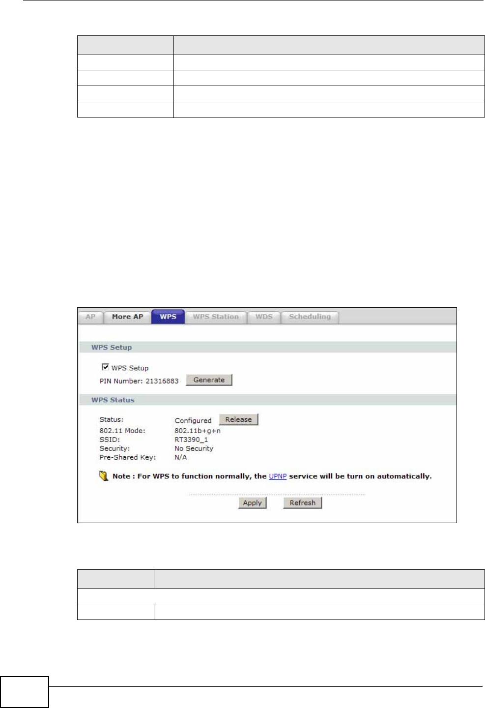
Chapter 8 Wireless LAN
P-660N-T1A User’s Guide
112
8.4 The WPS Screen
Use this screen to configure WiFi Protected Setup (WPS) on your ZyXEL Device.
WPS allows you to quickly set up a wireless network with strong security, without
having to configure security settings manually. Set up each WPS connection
between two devices. Both devices must support WPS.
Click Network > Wireless LAN > WPS. The following screen displays.
Figure 52 Network > Wireless LAN > WPS
The following table describes the labels in this screen.
QoS Select this check box to activate Quality of Service (QoS).
Back Click this to return to the previous screen without saving.
Apply Click this to save your changes.
Cancel Click this to restore your previously saved settings.
Table 32 Network > Wireless LAN > More AP: Edit
LABEL DESCRIPTION
Table 33 Network > Wireless LAN > WPS
LABEL DESCRIPTION
WPS Setup
WPS Setup Select the check box to activate WPS on the ZyXEL Device.
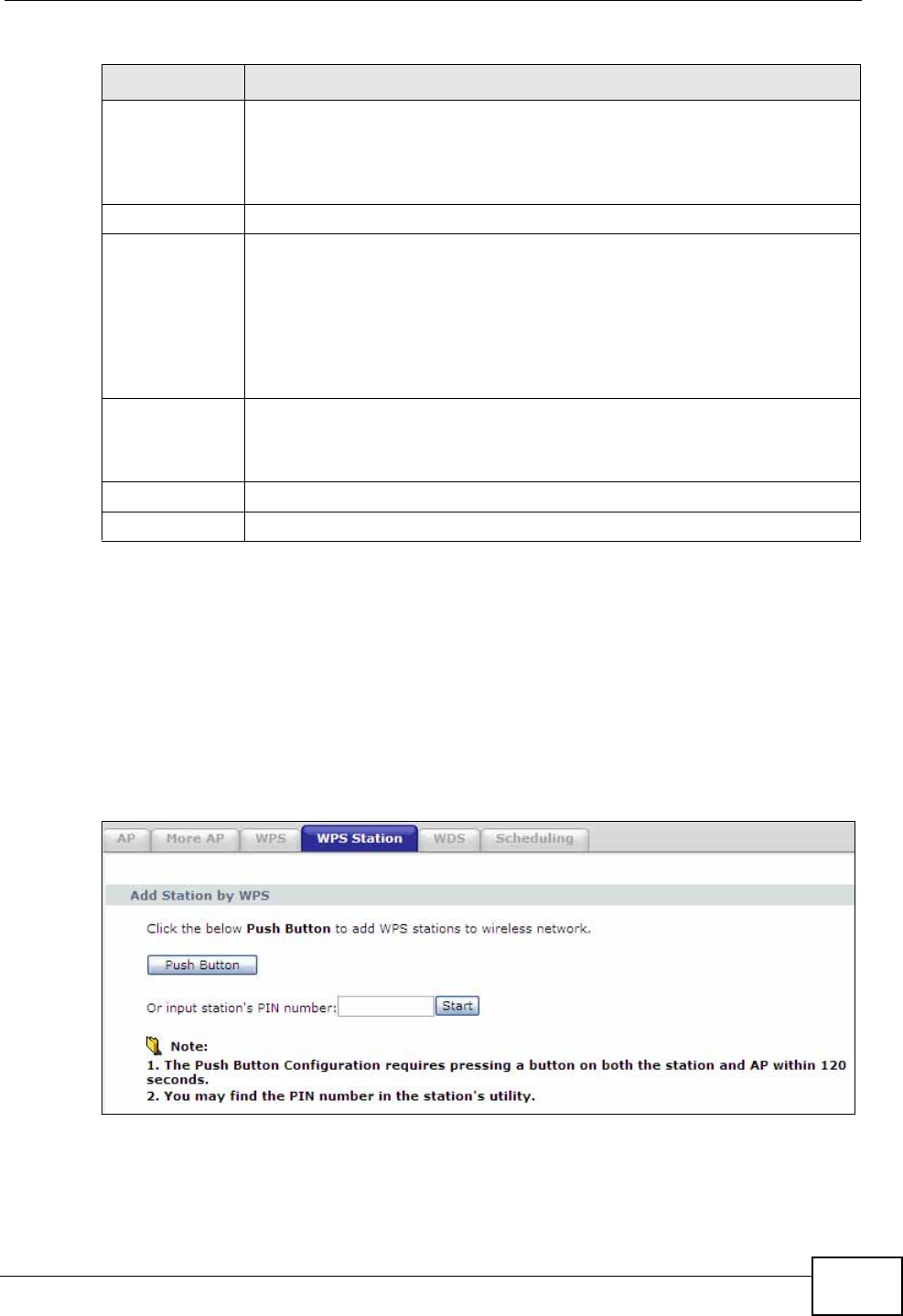
Chapter 8 Wireless LAN
P-660N-T1A User’s Guide 113
8.5 The WPS Station Screen
Use this screen to set up a WPS wireless network using either Push Button
Configuration (PBC) or PIN Configuration.
Click Network > Wireless LAN > WPS Station. The following screen displays.
Figure 53 Network > Wireless LAN > WPS Station
PIN Number This shows the PIN (Personal Identification Number) of the ZyXEL
Device. Enter this PIN in the configuration utility of the device you want
to connect to using WPS.
The PIN is not necessary when you use WPS push-button method.
Generate Click this to have the ZyXEL Device create a new PIN.
WPS Status This displays Configured when the ZyXEL Device has connected to a
wireless network using WPS or Enable WPS is selected and wireless or
wireless security settings have been changed. The current wireless and
wireless security settings also appear in the screen.
This displays Unconfigured if WPS is disabled and there is no wireless
or wireless security changes on the ZyXEL Device or you click Release
to remove the configured wireless and wireless security settings.
Release This button is available when the WPS status is Configured.
Click this button to remove all configured wireless and wireless security
settings for WPS connections on the ZyXEL Device.
Apply Click this to save your changes.
Refresh Click this to restore your previously saved settings.
Table 33 Network > Wireless LAN > WPS
LABEL DESCRIPTION

Chapter 8 Wireless LAN
P-660N-T1A User’s Guide
114
The following table describes the labels in this screen.
8.6 The WDS Screen
An AP using the Wireless Distribution System (WDS) can function as a wireless
network bridge allowing you to wirelessly connect two wired network segments.
The WDS screen allows you to configure the ZyXEL Device to connect to two or
more APs wirelessly when WDS is enabled.
Use this screen to set up your WDS (Wireless Distribution System) links between
the ZyXEL Device and other wireless APs. You need to know the MAC address of
the peer device. Once the security settings of peer sides match one another, the
connection between devices is made.
Note: WDS security is independent of the security settings between the ZyXEL
Device and any wireless clients.
Note: At the time of writing, WDS is compatible with other ZyXEL APs only. Not all
models support WDS links. Check your other AP’s documentation.
Table 34 Network > Wireless LAN > WPS Station
LABEL DESCRIPTION
Push Button Click this to add another WPS-enabled wireless device (within wireless
range of the ZyXEL Device) to your wireless network. This button may
either be a physical button on the outside of device, or a menu button
similar to the Push Button on this screen.
Note: You must press the other wireless device’s WPS button within
two minutes of pressing this button.
Or input
station's PIN
number
Enter the PIN of the device that you are setting up a WPS connection
with and click Start to authenticate and add the wireless device to your
wireless network.
You can find the PIN either on the outside of the device, or by checking
the device’s settings.
Note: You must also activate WPS on that device within two minutes
to have it present its PIN to the ZyXEL Device.
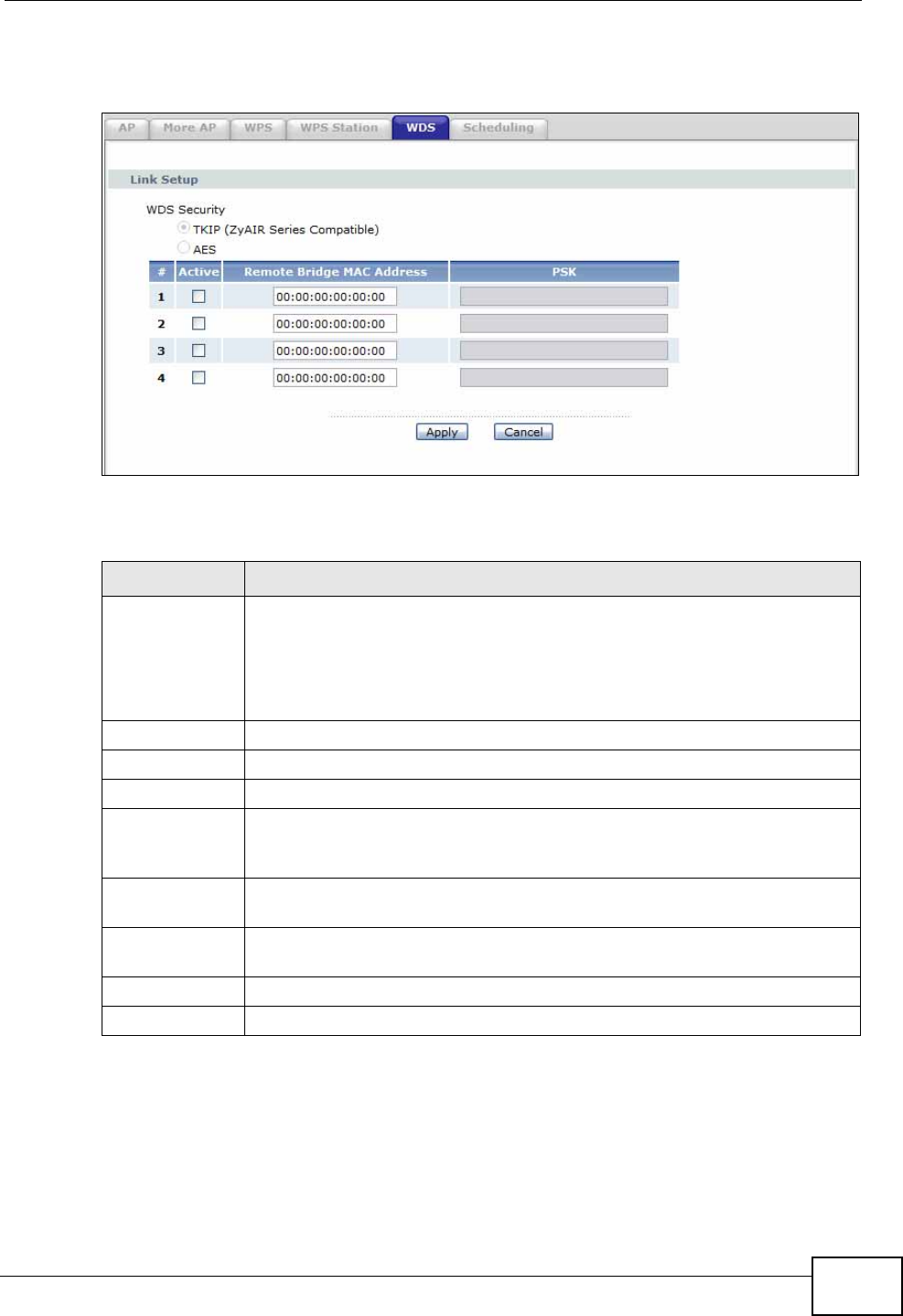
Chapter 8 Wireless LAN
P-660N-T1A User’s Guide 115
Click Network > Wireless LAN > WDS. The following screen displays.
Figure 54 Network > Wireless LAN > WDS
The following table describes the labels in this screen.
Table 35 Network > Wireless LAN > WDS
LABEL DESCRIPTION
WDS Security Select the type of the key used to encrypt data between APs. All the
wireless APs (including the ZyXEL Device) must use the same pre-
shared key for data transmission.
The option is only available when you set the Security mode to WPA(2)
or WPA(2)-PSK in the Wireless LAN > AP screen.
TKIP Select this to use TKIP (Temporal Key Integrity Protocol) encryption.
AES Select this to use AES (Advanced Encryption Standard) encryption.
# This is the index number of the individual WDS link.
Active Select this to activate the link between the ZyXEL Device and the peer
device to which this entry refers. When you do not select the check box
this link is down.
Remote Bridge
MAC Address Type the MAC address of the peer device in a valid MAC address format
(six hexadecimal character pairs, for example 12:34:56:78:9a:bc).
PSK Enter a Pre-Shared Key (PSK) from 8 to 63 case-sensitive ASCII
characters (including spaces and symbols).
Apply Click this to save your changes.
Cancel Click this to restore your previously saved settings.
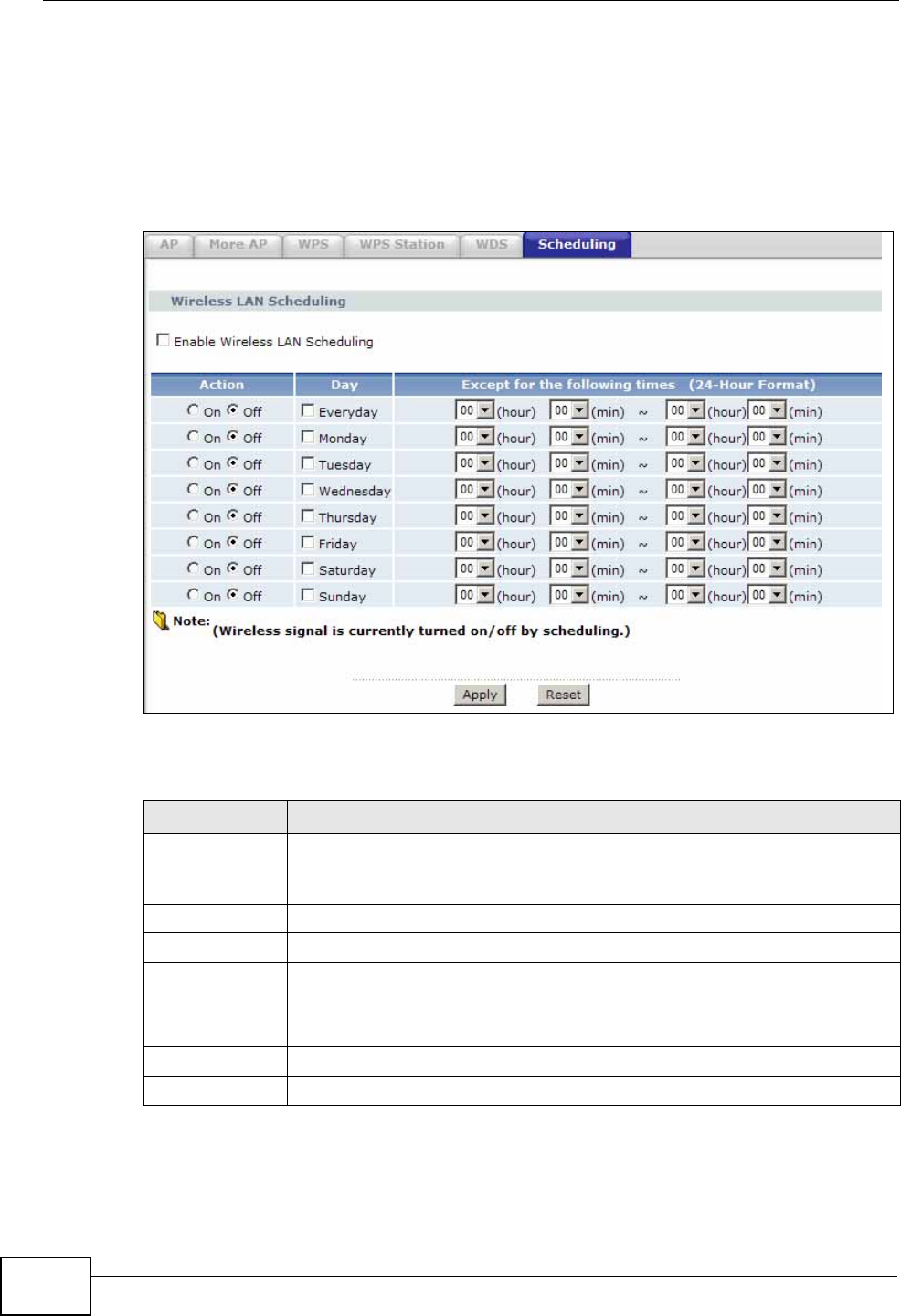
Chapter 8 Wireless LAN
P-660N-T1A User’s Guide
116
8.7 The Scheduling Screen
Use the wireless LAN scheduling to configure the days you want to enable or
disable the wireless LAN. Click Network > Wireless LAN > Scheduling. The
following screen displays.
Figure 55 Network > Wireless LAN > Scheduling
The following table describes the labels in this screen.
Table 36 Network > Wireless LAN > QoS
LABEL DESCRIPTION
Enable
Wireless LAN
Scheduling
Select this box to activate wireless LAN scheduling on your ZyXEL
Device.
Action Select On or Off to enable or disable the wireless LAN.
Day Check the day(s) you want to turn the wireless LAN on or off.
Except for the
following times Specify a time frame during which the schedule would apply.
For example, if you set the time range from 12:00 to 23:00, the wireless
LAN will be turned on only during this time period.
Apply Click this to save your changes.
Reset Click this to restore your previously saved settings.
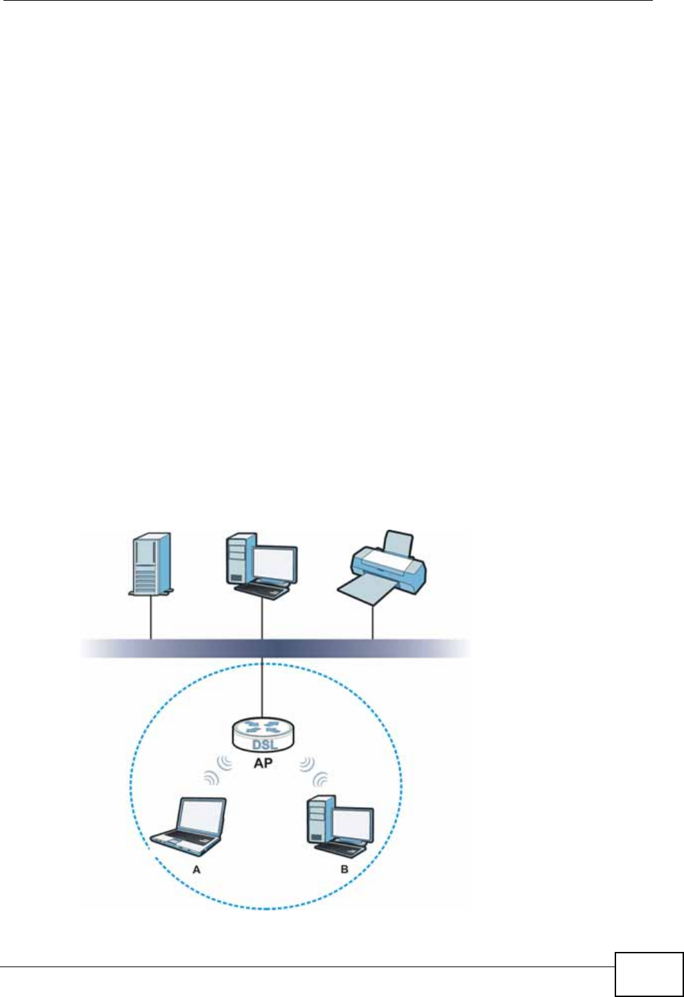
Chapter 8 Wireless LAN
P-660N-T1A User’s Guide 117
8.8 Technical Reference
This section discusses wireless LANs in depth. For more information, see the
appendix.
8.8.1 Wireless Network Overview
Wireless networks consist of wireless clients, access points and bridges.
• A wireless client is a radio connected to a user’s computer.
• An access point is a radio with a wired connection to a network, which can
connect with numerous wireless clients and let them access the network.
• A bridge is a radio that relays communications between access points and
wireless clients, extending a network’s range.
Traditionally, a wireless network operates in one of two ways.
• An “infrastructure” type of network has one or more access points and one or
more wireless clients. The wireless clients connect to the access points.
• An “ad-hoc” type of network is one in which there is no access point. Wireless
clients connect to one another in order to exchange information.
The following figure provides an example of a wireless network.
Figure 56 Example of a Wireless Network

Chapter 8 Wireless LAN
P-660N-T1A User’s Guide
118
The wireless network is the part in the blue circle. In this wireless network,
devices A and B use the access point (AP) to interact with the other devices (such
as the printer) or with the Internet. Your ZyXEL Device is the AP.
Every wireless network must follow these basic guidelines.
• Every device in the same wireless network must use the same SSID.
The SSID is the name of the wireless network. It stands for Service Set
IDentifier.
• If two wireless networks overlap, they should use a different channel.
Like radio stations or television channels, each wireless network uses a specific
channel, or frequency, to send and receive information.
• Every device in the same wireless network must use security compatible with
the AP.
Security stops unauthorized devices from using the wireless network. It can also
protect the information that is sent in the wireless network.
Radio Channels
In the radio spectrum, there are certain frequency bands allocated for unlicensed,
civilian use. For the purposes of wireless networking, these bands are divided into
numerous channels. This allows a variety of networks to exist in the same place
without interfering with one another. When you create a network, you must select
a channel to use.
Since the available unlicensed spectrum varies from one country to another, the
number of available channels also varies.

Chapter 8 Wireless LAN
P-660N-T1A User’s Guide 119
8.8.2 Additional Wireless Terms
The following table describes some wireless network terms and acronyms used in
the ZyXEL Device’s Web Configurator.
8.8.3 Wireless Security Overview
By their nature, radio communications are simple to intercept. For wireless data
networks, this means that anyone within range of a wireless network without
security can not only read the data passing over the airwaves, but also join the
network. Once an unauthorized person has access to the network, he or she can
steal information or introduce malware (malicious software) intended to
compromise the network. For these reasons, a variety of security systems have
been developed to ensure that only authorized people can use a wireless data
network, or understand the data carried on it.
These security standards do two things. First, they authenticate. This means that
only people presenting the right credentials (often a username and password, or a
“key” phrase) can access the network. Second, they encrypt. This means that the
information sent over the air is encoded. Only people with the code key can
understand the information, and only people who have been authenticated are
given the code key.
Table 37 Additional Wireless Terms
TERM DESCRIPTION
RTS/CTS Threshold In a wireless network which covers a large area, wireless devices
are sometimes not aware of each other’s presence. This may cause
them to send information to the AP at the same time and result in
information colliding and not getting through.
By setting this value lower than the default value, the wireless
devices must sometimes get permission to send information to the
ZyXEL Device. The lower the value, the more often the devices must
get permission.
If this value is greater than the fragmentation threshold value (see
below), then wireless devices never have to get permission to send
information to the ZyXEL Device.
Preamble A preamble affects the timing in your wireless network. There are
two preamble modes: long and short. If a device uses a different
preamble mode than the ZyXEL Device does, it cannot communicate
with the ZyXEL Device.
Authentication The process of verifying whether a wireless device is allowed to use
the wireless network.
Fragmentation
Threshold A small fragmentation threshold is recommended for busy networks,
while a larger threshold provides faster performance if the network
is not very busy.

Chapter 8 Wireless LAN
P-660N-T1A User’s Guide
120
These security standards vary in effectiveness. Some can be broken, such as the
old Wired Equivalent Protocol (WEP). Using WEP is better than using no security at
all, but it will not keep a determined attacker out. Other security standards are
secure in themselves but can be broken if a user does not use them properly. For
example, the WPA-PSK security standard is very secure if you use a long key
which is difficult for an attacker’s software to guess - for example, a twenty-letter
long string of apparently random numbers and letters - but it is not very secure if
you use a short key which is very easy to guess - for example, a three-letter word
from the dictionary.
Because of the damage that can be done by a malicious attacker, it’s not just
people who have sensitive information on their network who should use security.
Everybody who uses any wireless network should ensure that effective security is
in place.
A good way to come up with effective security keys, passwords and so on is to use
obscure information that you personally will easily remember, and to enter it in a
way that appears random and does not include real words. For example, if your
mother owns a 1970 Dodge Challenger and her favorite movie is Vanishing Point
(which you know was made in 1971) you could use “70dodchal71vanpoi” as your
security key.
The following sections introduce different types of wireless security you can set up
in the wireless network.
8.8.3.1 SSID
Normally, the ZyXEL Device acts like a beacon and regularly broadcasts the SSID
in the area. You can hide the SSID instead, in which case the ZyXEL Device does
not broadcast the SSID. In addition, you should change the default SSID to
something that is difficult to guess.
This type of security is fairly weak, however, because there are ways for
unauthorized wireless devices to get the SSID. In addition, unauthorized wireless
devices can still see the information that is sent in the wireless network.
8.8.3.2 MAC Address Filter
Every device that can use a wireless network has a unique identification number,
called a MAC address.1 A MAC address is usually written using twelve hexadecimal
characters2; for example, 00A0C5000002 or 00:A0:C5:00:00:02. To get the MAC
address for each device in the wireless network, see the device’s User’s Guide or
other documentation.
1. Some wireless devices, such as scanners, can detect wireless networks but cannot use wireless networks.
These kinds of wireless devices might not have MAC addresses.
2. Hexadecimal characters are 0, 1, 2, 3, 4, 5, 6, 7, 8, 9, A, B, C, D, E, and F.

Chapter 8 Wireless LAN
P-660N-T1A User’s Guide 121
You can use the MAC address filter to tell the ZyXEL Device which devices are
allowed or not allowed to use the wireless network. If a device is allowed to use
the wireless network, it still has to have the correct information (SSID, channel,
and security). If a device is not allowed to use the wireless network, it does not
matter if it has the correct information.
This type of security does not protect the information that is sent in the wireless
network. Furthermore, there are ways for unauthorized wireless devices to get the
MAC address of an authorized device. Then, they can use that MAC address to use
the wireless network.
8.8.3.3 User Authentication
Authentication is the process of verifying whether a wireless device is allowed to
use the wireless network. You can make every user log in to the wireless network
before using it. However, every device in the wireless network has to support IEEE
802.1x to do this.
For wireless networks, you can store the user names and passwords for each user
in a RADIUS server. This is a server used in businesses more than in homes. If you
do not have a RADIUS server, you cannot set up user names and passwords for
your users.
Unauthorized wireless devices can still see the information that is sent in the
wireless network, even if they cannot use the wireless network. Furthermore,
there are ways for unauthorized wireless users to get a valid user name and
password. Then, they can use that user name and password to use the wireless
network.
8.8.3.4 Encryption
Wireless networks can use encryption to protect the information that is sent in the
wireless network. Encryption is like a secret code. If you do not know the secret
code, you cannot understand the message.
The types of encryption you can choose depend on the type of authentication.
(See Section 8.8.3.3 on page 121 for information about this.)
Table 38 Types of Encryption for Each Type of Authentication
NO AUTHENTICATION RADIUS SERVER
Weakest No Security WPA
Static WEP
WPA-PSK
Strongest WPA2-PSK WPA2

Chapter 8 Wireless LAN
P-660N-T1A User’s Guide
122
For example, if the wireless network has a RADIUS server, you can choose WPA
or WPA2. If users do not log in to the wireless network, you can choose no
encryption, Static WEP, WPA-PSK, or WPA2-PSK.
Usually, you should set up the strongest encryption that every device in the
wireless network supports. For example, suppose you have a wireless network
with the ZyXEL Device and you do not have a RADIUS server. Therefore, there is
no authentication. Suppose the wireless network has two devices. Device A only
supports WEP, and device B supports WEP and WPA. Therefore, you should set up
Static WEP in the wireless network.
Note: It is recommended that wireless networks use WPA-PSK, WPA, or stronger
encryption. The other types of encryption are better than none at all, but it is still
possible for unauthorized wireless devices to figure out the original information
pretty quickly.
When you select WPA2 or WPA2-PSK in your ZyXEL Device, you can also select
an option (WPA compatible) to support WPA as well. In this case, if some of the
devices support WPA and some support WPA2, you should set up WPA2-PSK or
WPA2 (depending on the type of wireless network login) and select the WPA
compatible option in the ZyXEL Device.
Many types of encryption use a key to protect the information in the wireless
network. The longer the key, the stronger the encryption. Every device in the
wireless network must have the same key.
8.8.4 Signal Problems
Because wireless networks are radio networks, their signals are subject to
limitations of distance, interference and absorption.
Problems with distance occur when the two radios are too far apart. Problems with
interference occur when other radio waves interrupt the data signal. Interference
may come from other radio transmissions, such as military or air traffic control
communications, or from machines that are coincidental emitters such as electric
motors or microwaves. Problems with absorption occur when physical objects
(such as thick walls) are between the two radios, muffling the signal.
8.8.5 BSS
A Basic Service Set (BSS) exists when all communications between wireless
stations or between a wireless station and a wired network client go through one
access point (AP).
Intra-BSS traffic is traffic between wireless stations in the BSS. When Intra-BSS
traffic blocking is disabled, wireless station A and B can access the wired network
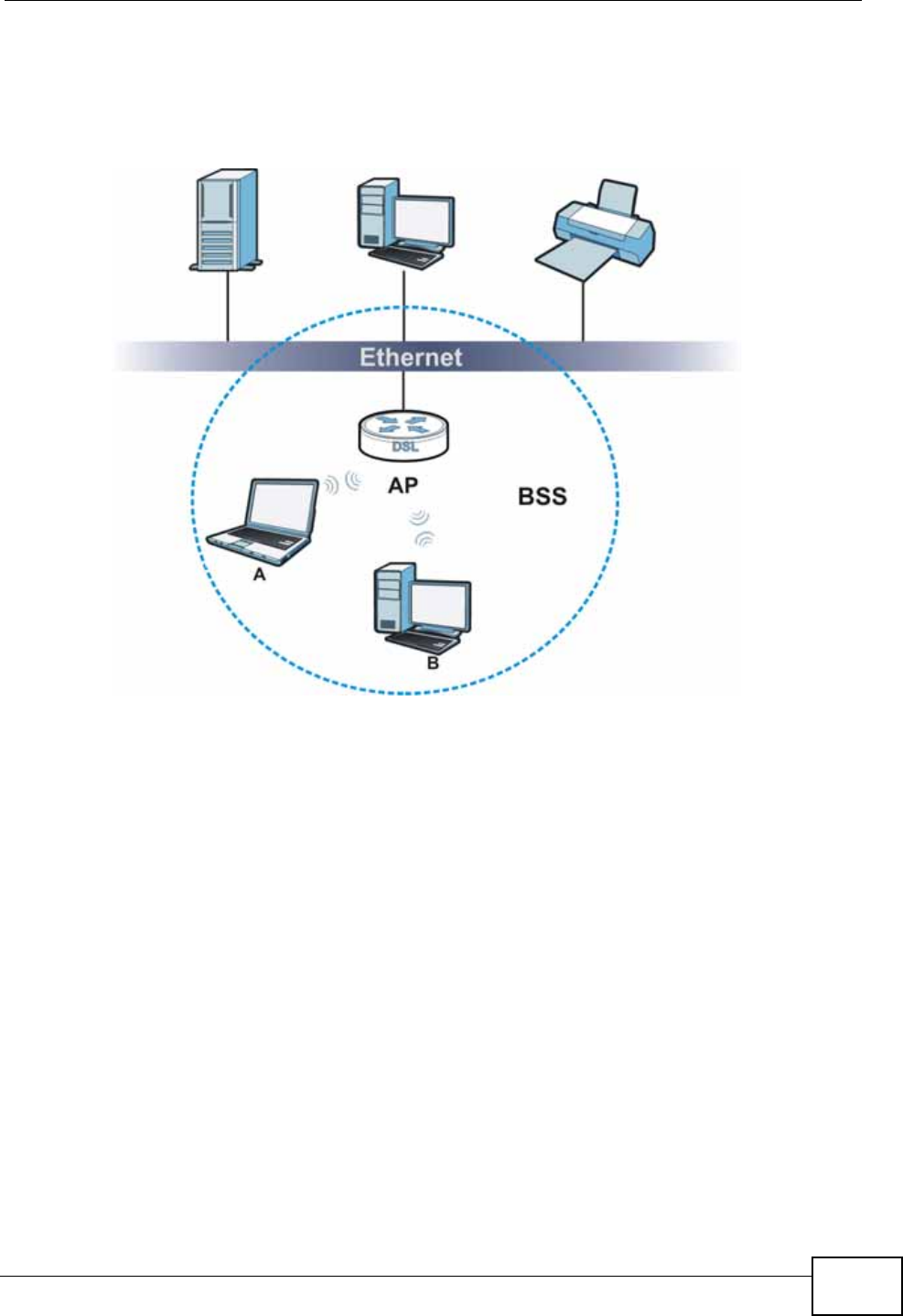
Chapter 8 Wireless LAN
P-660N-T1A User’s Guide 123
and communicate with each other. When Intra-BSS traffic blocking is enabled,
wireless station A and B can still access the wired network but cannot
communicate with each other.
Figure 57 Basic Service set
8.8.6 MBSSID
Traditionally, you need to use different APs to configure different Basic Service
Sets (BSSs). As well as the cost of buying extra APs, there is also the possibility of
channel interference. The ZyXEL Device’s MBSSID (Multiple Basic Service Set
IDentifier) function allows you to use one access point to provide several BSSs
simultaneously. You can then assign varying QoS priorities and/or security modes
to different SSIDs.
Wireless devices can use different BSSIDs to associate with the same AP.
8.8.6.1 Notes on Multiple BSSs
• A maximum of eight BSSs are allowed on one AP simultaneously.
• You must use different keys for different BSSs. If two wireless devices have
different BSSIDs (they are in different BSSs), but have the same keys, they
may hear each other’s communications (but not communicate with each other).
• MBSSID should not replace but rather be used in conjunction with 802.1x
security.

Chapter 8 Wireless LAN
P-660N-T1A User’s Guide
124
8.8.7 Wireless Distribution System (WDS)
The ZyXEL Device can act as a wireless network bridge and establish WDS
(Wireless Distribution System) links with other APs. You need to know the MAC
addresses of the APs you want to link to. Once the security settings of peer sides
match one another, the connection between devices is made.
At the time of writing, WDS security is compatible with other ZyXEL access points
only. Refer to your other access point’s documentation for details.
The following figure illustrates how WDS link works between APs. Notebook
computer A is a wireless client connecting to access point AP 1. AP 1 has no
wired Internet connection, but it can establish a WDS link with access point AP 2,
which has a wired Internet connection. When AP 1 has a WDS link with AP 2, the
notebook computer can access the Internet through AP 2.
Figure 58 WDS Link Example
8.8.8 WiFi Protected Setup (WPS)
Your ZyXEL Device supports WiFi Protected Setup (WPS), which is an easy way to
set up a secure wireless network. WPS is an industry standard specification,
defined by the WiFi Alliance.
WPS allows you to quickly set up a wireless network with strong security, without
having to configure security settings manually. Each WPS connection works
between two devices. Both devices must support WPS (check each device’s
documentation to make sure).
Depending on the devices you have, you can either press a button (on the device
itself, or in its configuration utility) or enter a PIN (a unique Personal Identification
Number that allows one device to authenticate the other) in each of the two
devices. When WPS is activated on a device, it has two minutes to find another
device that also has WPS activated. Then, the two devices connect and set up a
secure network by themselves.
WDS
AP 2
AP 1
A

Chapter 8 Wireless LAN
P-660N-T1A User’s Guide 125
8.8.8.1 Push Button Configuration
WPS Push Button Configuration (PBC) is initiated by pressing a button on each
WPS-enabled device, and allowing them to connect automatically. You do not need
to enter any information.
Not every WPS-enabled device has a physical WPS button. Some may have a WPS
PBC button in their configuration utilities instead of or in addition to the physical
button.
Take the following steps to set up WPS using the button.
1Ensure that the two devices you want to set up are within wireless range of one
another.
2Look for a WPS button on each device. If the device does not have one, log into its
configuration utility and locate the button (see the device’s User’s Guide for how to
do this - for the ZyXEL Device, see Section 8.5 on page 113).
3Press the button on one of the devices (it doesn’t matter which). For the ZyXEL
Device you must press the WPS button for more than three seconds.
4Within two minutes, press the button on the other device. The registrar sends the
network name (SSID) and security key through an secure connection to the
enrollee.
If you need to make sure that WPS worked, check the list of associated wireless
clients in the AP’s configuration utility. If you see the wireless client in the list,
WPS was successful.
8.8.8.2 PIN Configuration
Each WPS-enabled device has its own PIN (Personal Identification Number). This
may either be static (it cannot be changed) or dynamic (in some devices you can
generate a new PIN by clicking on a button in the configuration interface).
Use the PIN method instead of the push-button configuration (PBC) method if you
want to ensure that the connection is established between the devices you specify,
not just the first two devices to activate WPS in range of each other. However, you
need to log into the configuration interfaces of both devices to use the PIN
method.
When you use the PIN method, you must enter the PIN from one device (usually
the wireless client) into the second device (usually the Access Point or wireless
router). Then, when WPS is activated on the first device, it presents its PIN to the
second device. If the PIN matches, one device sends the network and security
information to the other, allowing it to join the network.

Chapter 8 Wireless LAN
P-660N-T1A User’s Guide
126
Take the following steps to set up a WPS connection between an access point or
wireless router (referred to here as the AP) and a client device using the PIN
method.
1Ensure WPS is enabled on both devices.
2Access the WPS section of the AP’s configuration interface. See the device’s User’s
Guide for how to do this.
3Look for the client’s WPS PIN; it will be displayed either on the device, or in the
WPS section of the client’s configuration interface (see the device’s User’s Guide
for how to find the WPS PIN - for the ZyXEL Device, see Section 8.4 on page 112).
4Enter the client’s PIN in the AP’s configuration interface.
5If the client device’s configuration interface has an area for entering another
device’s PIN, you can either enter the client’s PIN in the AP, or enter the AP’s PIN
in the client - it does not matter which.
6Start WPS on both devices within two minutes.
7Use the configuration utility to activate WPS, not the push-button on the device
itself.
8On a computer connected to the wireless client, try to connect to the Internet. If
you can connect, WPS was successful.
If you cannot connect, check the list of associated wireless clients in the AP’s
configuration utility. If you see the wireless client in the list, WPS was successful.
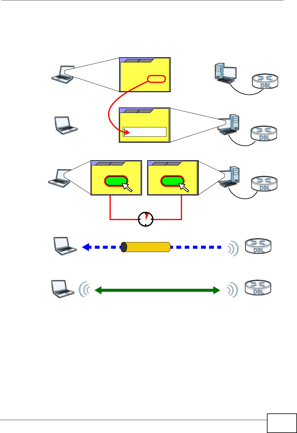
Chapter 8 Wireless LAN
P-660N-T1A User’s Guide 127
The following figure shows a WPS-enabled wireless client (installed in a notebook
computer) connecting to the WPS-enabled AP via the PIN method.
Figure 59 Example WPS Process: PIN Method
8.8.8.3 How WPS Works
When two WPS-enabled devices connect, each device must assume a specific role.
One device acts as the registrar (the device that supplies network and security
settings) and the other device acts as the enrollee (the device that receives
network and security settings. The registrar creates a secure EAP (Extensible
Authentication Protocol) tunnel and sends the network name (SSID) and the WPA-
PSK or WPA2-PSK pre-shared key to the enrollee. Whether WPA-PSK or WPA2-PSK
is used depends on the standards supported by the devices. If the registrar is
already part of a network, it sends the existing information. If not, it generates
the SSID and WPA(2)-PSK randomly.
ENROLLEE
SECURE EAP TUNNEL
SSID
WPA(2)-PSK
WITHIN 2 MINUTES
COMMUNICATION
This device’s
WPS
Enter WPS PIN
WPS
from other device:
WPS PIN: 123456
WPS
START
WPS
START
REGISTRAR
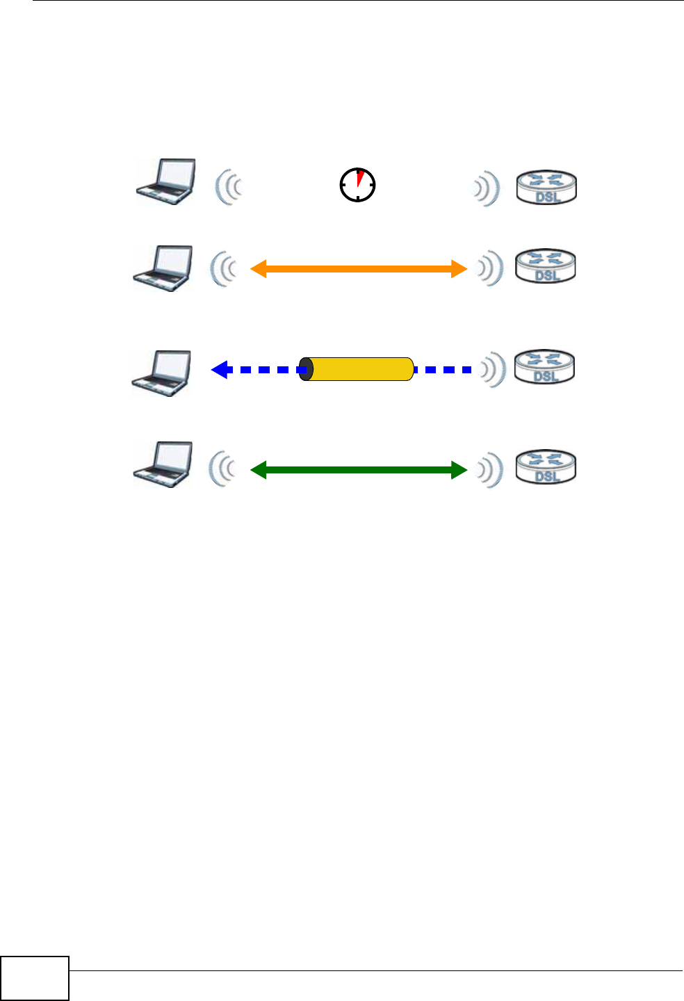
Chapter 8 Wireless LAN
P-660N-T1A User’s Guide
128
The following figure shows a WPS-enabled client (installed in a notebook
computer) connecting to a WPS-enabled access point.
Figure 60 How WPS works
The roles of registrar and enrollee last only as long as the WPS setup process is
active (two minutes). The next time you use WPS, a different device can be the
registrar if necessary.
The WPS connection process is like a handshake; only two devices participate in
each WPS transaction. If you want to add more devices you should repeat the
process with one of the existing networked devices and the new device.
Note that the access point (AP) is not always the registrar, and the wireless client
is not always the enrollee. All WPS-certified APs can be a registrar, and so can
some WPS-enabled wireless clients.
By default, a WPS devices is “unconfigured”. This means that it is not part of an
existing network and can act as either enrollee or registrar (if it supports both
functions). If the registrar is unconfigured, the security settings it transmits to the
enrollee are randomly-generated. Once a WPS-enabled device has connected to
another device using WPS, it becomes “configured”. A configured wireless client
can still act as enrollee or registrar in subsequent WPS connections, but a
configured access point can no longer act as enrollee. It will be the registrar in all
subsequent WPS connections in which it is involved. If you want a configured AP to
act as an enrollee, you must reset it to its factory defaults.
SECURE TUNNEL
SECURITY INFO
WITHIN 2 MINUTES
COMMUNICATION
ACTIVATE
WPS
ACTIVATE
WPS
WPS HANDSHAKE
REGISTRARENROLLEE
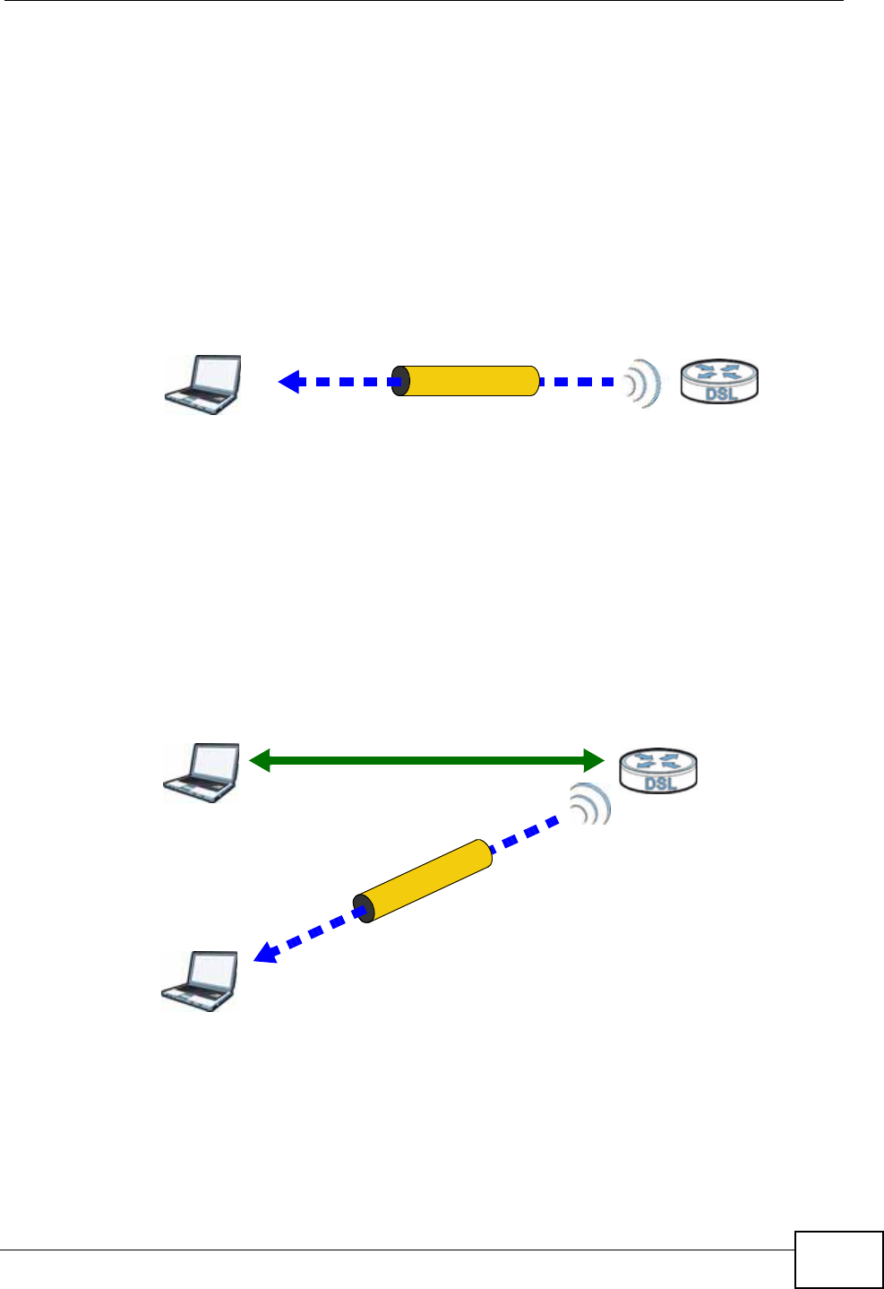
Chapter 8 Wireless LAN
P-660N-T1A User’s Guide 129
8.8.8.4 Example WPS Network Setup
This section shows how security settings are distributed in an example WPS setup.
The following figure shows an example network. In step 1, both AP1 and Client 1
are unconfigured. When WPS is activated on both, they perform the handshake. In
this example, AP1 is the registrar, and Client 1 is the enrollee. The registrar
randomly generates the security information to set up the network, since it is
unconfigured and has no existing information.
Figure 61 WPS: Example Network Step 1
In step 2, you add another wireless client to the network. You know that Client 1
supports registrar mode, but it is better to use AP1 for the WPS handshake with
the new client since you must connect to the access point anyway in order to use
the network. In this case, AP1 must be the registrar, since it is configured (it
already has security information for the network). AP1 supplies the existing
security information to Client 2.
Figure 62 WPS: Example Network Step 2
In step 3, you add another access point (AP2) to your network. AP2 is out of
range of AP1, so you cannot use AP1 for the WPS handshake with the new access
REGISTRARENROLLEE
SECURITY INFO
CLIENT 1 AP1
REGISTRAR
CLIENT 1 AP1
ENROLLEE
CLIENT 2
EXISTING CONNECTION
SECURITY INFO
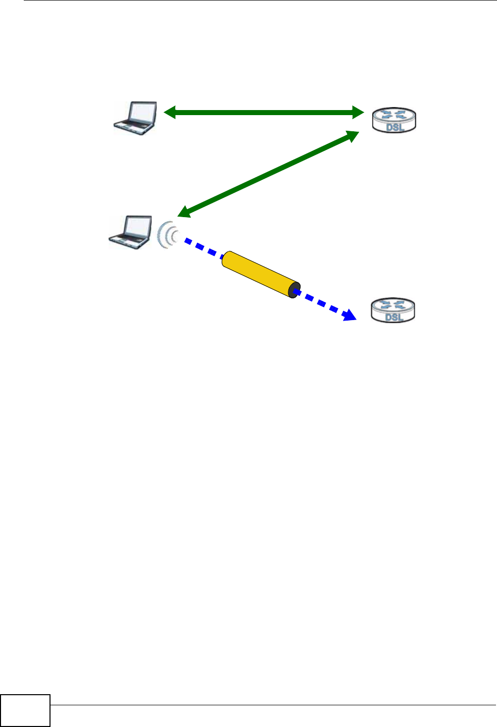
Chapter 8 Wireless LAN
P-660N-T1A User’s Guide
130
point. However, you know that Client 2 supports the registrar function, so you use
it to perform the WPS handshake instead.
Figure 63 WPS: Example Network Step 3
8.8.8.5 Limitations of WPS
WPS has some limitations of which you should be aware.
• WPS works in Infrastructure networks only (where an AP and a wireless client
communicate). It does not work in Ad-Hoc networks (where there is no AP).
• When you use WPS, it works between two devices only. You cannot enroll
multiple devices simultaneously, you must enroll one after the other.
For instance, if you have two enrollees and one registrar you must set up the
first enrollee (by pressing the WPS button on the registrar and the first enrollee,
for example), then check that it successfully enrolled, then set up the second
device in the same way.
• WPS works only with other WPS-enabled devices. However, you can still add
non-WPS devices to a network you already set up using WPS.
WPS works by automatically issuing a randomly-generated WPA-PSK or WPA2-
PSK pre-shared key from the registrar device to the enrollee devices. Whether
the network uses WPA-PSK or WPA2-PSK depends on the device. You can check
the configuration interface of the registrar device to discover the key the
network is using (if the device supports this feature). Then, you can enter the
key into the non-WPS device and join the network as normal (the non-WPS
device must also support WPA-PSK or WPA2-PSK).
CLIENT 1 AP1
REGISTRAR
CLIENT 2
EXISTING CONNECTION
SECURITY INFO
ENROLLEE
AP2
EXISTING CONNECTION

Chapter 8 Wireless LAN
P-660N-T1A User’s Guide 131
• When you use the PBC method, there is a short period (from the moment you
press the button on one device to the moment you press the button on the
other device) when any WPS-enabled device could join the network. This is
because the registrar has no way of identifying the “correct” enrollee, and
cannot differentiate between your enrollee and a rogue device. This is a possible
way for a hacker to gain access to a network.
You can easily check to see if this has happened. WPS works between only two
devices simultaneously, so if another device has enrolled your device will be
unable to enroll, and will not have access to the network. If this happens, open
the access point’s configuration interface and look at the list of associated
clients (usually displayed by MAC address). It does not matter if the access
point is the WPS registrar, the enrollee, or was not involved in the WPS
handshake; a rogue device must still associate with the access point to gain
access to the network. Check the MAC addresses of your wireless clients
(usually printed on a label on the bottom of the device). If there is an unknown
MAC address you can remove it or reset the AP.

Chapter 8 Wireless LAN
P-660N-T1A User’s Guide
132

P-660N-T1A User’s Guide 133
CHAPTER 9
Network Address Translation
(NAT)
9.1 Overview
This chapter discusses how to configure NAT on the ZyXEL Device. NAT (Network
Address Translation - NAT, RFC 1631) is the translation of the IP address of a host
in a packet, for example, the source address of an outgoing packet, used within
one network to a different IP address known within another network.
9.1.1 What You Can Do in the NAT Screens
•Use the General screen (Section 9.2 on page 135) to configure the NAT setup
settings.
•Use the Port Forwarding screen (Section 9.3 on page 136) to configure
forward incoming service requests to the server(s) on your local network.
•Use the Address Mapping screen (Section 9.4 on page 140) to change your
ZyXEL Device’s address mapping settings.
•Use the ALG screen (Section 9.5 on page 143) to enable and disable the SIP
(VoIP) ALG in the ZyXEL Device.
9.1.2 What You Need To Know
The following terms and concepts may help as you read this chapter.
Inside/Outside
Inside/outside denotes where a host is located relative to the ZyXEL Device, for
example, the computers of your subscribers are the inside hosts, while the web
servers on the Internet are the outside hosts.
Global/Local
Global/local denotes the IP address of a host in a packet as the packet traverses a
router, for example, the local address refers to the IP address of a host when the

Chapter 9 Network Address Translation (NAT)
P-660N-T1A User’s Guide
134
packet is in the local network, while the global address refers to the IP address of
the host when the same packet is traveling in the WAN side.
NAT
In the simplest form, NAT changes the source IP address in a packet received from
a subscriber (the inside local address) to another (the inside global address)
before forwarding the packet to the WAN side. When the response comes back,
NAT translates the destination address (the inside global address) back to the
inside local address before forwarding it to the original inside host.
Port Forwarding
A port forwarding set is a list of inside (behind NAT on the LAN) servers, for
example, web or FTP, that you can make visible to the outside world even though
NAT makes your whole inside network appear as a single computer to the outside
world.
SUA (Single User Account) Versus NAT
SUA (Single User Account) is a ZyNOS implementation of a subset of NAT that
supports two types of mapping, Many-to-One and Server. The ZyXEL Device also
supports Full Feature NAT to map multiple global IP addresses to multiple private
LAN IP addresses of clients or servers using mapping types as outlined in Table 46
on page 147.
• Choose SUA Only if you have just one public WAN IP address for your ZyXEL
Device.
• Choose Full Feature if you have multiple public WAN IP addresses for your
ZyXEL Device.
Finding Out More
See Section 9.6 on page 144 for advanced technical information on NAT.
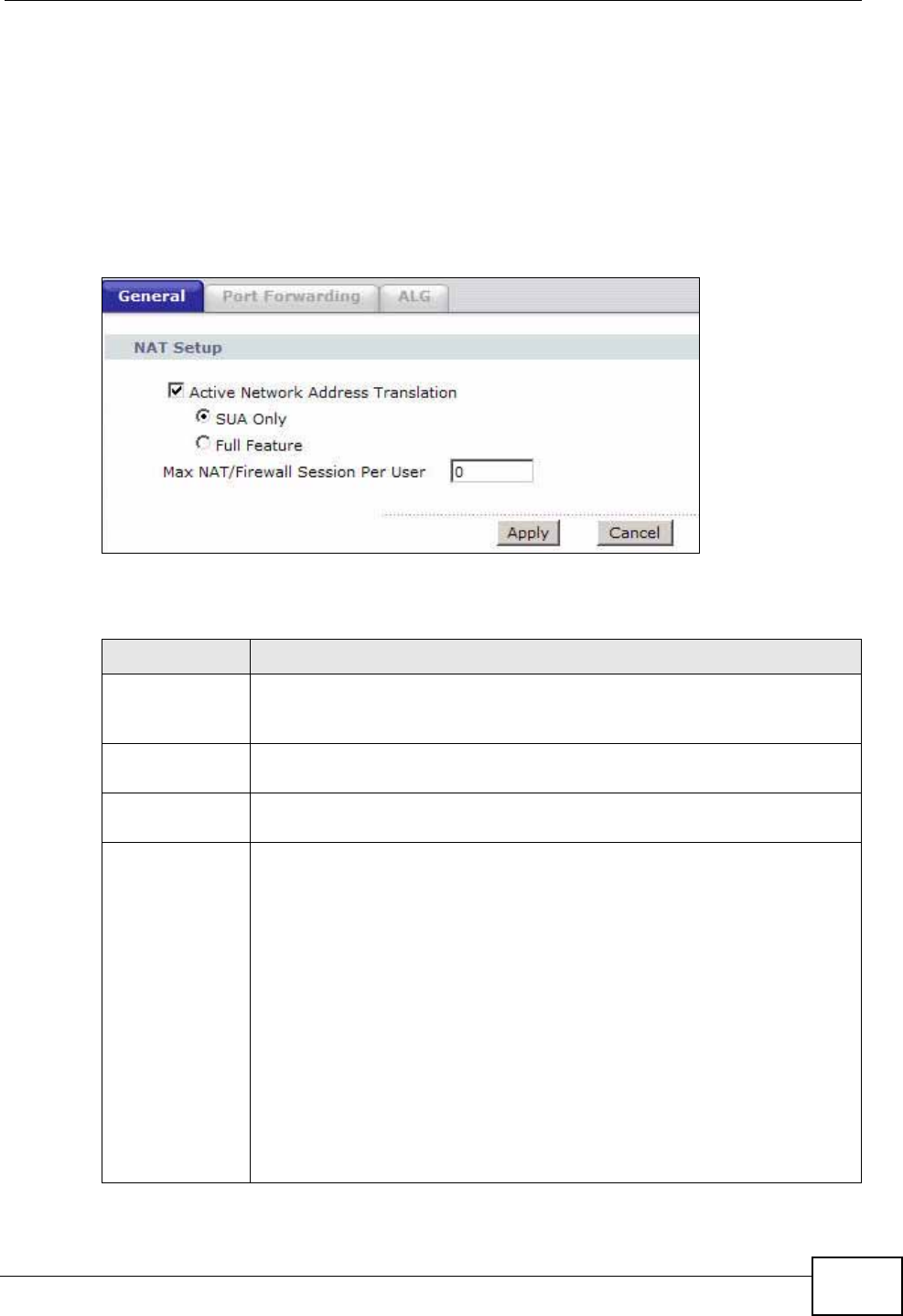
Chapter 9 Network Address Translation (NAT)
P-660N-T1A User’s Guide 135
9.2 The General Setup Screen
Use this screen to activate NAT. Click Network > NAT to open the following
screen.
Note: You must create a firewall rule in addition to setting up SUA/NAT, to allow traffic
from the WAN to be forwarded through the ZyXEL Device.
Figure 64 Network > NAT > General
The following table describes the labels in this screen.
Table 39 Network > NAT > General
LABEL DESCRIPTION
Active Network
Address
Translation
Select this check box to enable NAT.
SUA Only Select this radio button if you have just one public WAN IP address for
your ZyXEL Device.
Full Feature Select this radio button if you have multiple public WAN IP addresses for
your ZyXEL Device.
Max NAT/
Firewall Session
Per User
When computers use peer to peer applications, such as file sharing
applications, they need to establish NAT sessions. If you do not limit the
number of NAT sessions a single client can establish, this can result in
all of the available NAT sessions being used. In this case, no additional
NAT sessions can be established, and users may not be able to access
the Internet.
Each NAT session establishes a corresponding firewall session. Use this
field to limit the number of NAT/Firewall sessions client computers can
establish through the ZyXEL Device.
If your network has a small number of clients using peer to peer
applications, you can raise this number to ensure that their
performance is not degraded by the number of NAT sessions they can
establish. If your network has a large number of users using peer to
peer applications, you can lower this number to ensure no single client
is exhausting all of the available NAT sessions.

Chapter 9 Network Address Translation (NAT)
P-660N-T1A User’s Guide
136
9.3 The Port Forwarding Screen
Note: This screen is available only when you select SUA only in the NAT > General
screen.
Use this screen to forward incoming service requests to the server(s) on your local
network.
You may enter a single port number or a range of port numbers to be forwarded,
and the local IP address of the desired server. The port number identifies a
service; for example, web service is on port 80 and FTP on port 21. In some
cases, such as for unknown services or where one server can support more than
one service (for example both FTP and web service), it might be better to specify
a range of port numbers. You can allocate a server IP address that corresponds to
a port or a range of ports.
The most often used port numbers and services are shown in Appendix E on page
307. Please refer to RFC 1700 for further information about port numbers.
Note: Many residential broadband ISP accounts do not allow you to run any server
processes (such as a Web or FTP server) from your location. Your ISP may
periodically check for servers and may suspend your account if it discovers any
active services at your location. If you are unsure, refer to your ISP.
Default Server IP Address
In addition to the servers for specified services, NAT supports a default server IP
address. A default server receives packets from ports that are not specified in this
screen.
Note: If you do not assign a Default Server IP address, the ZyXEL Device discards
all packets received for ports that are not specified here or in the remote
management setup.
Apply Click this to save your changes.
Cancel Click this to restore your previously saved settings.
Table 39 Network > NAT > General (continued)
LABEL DESCRIPTION
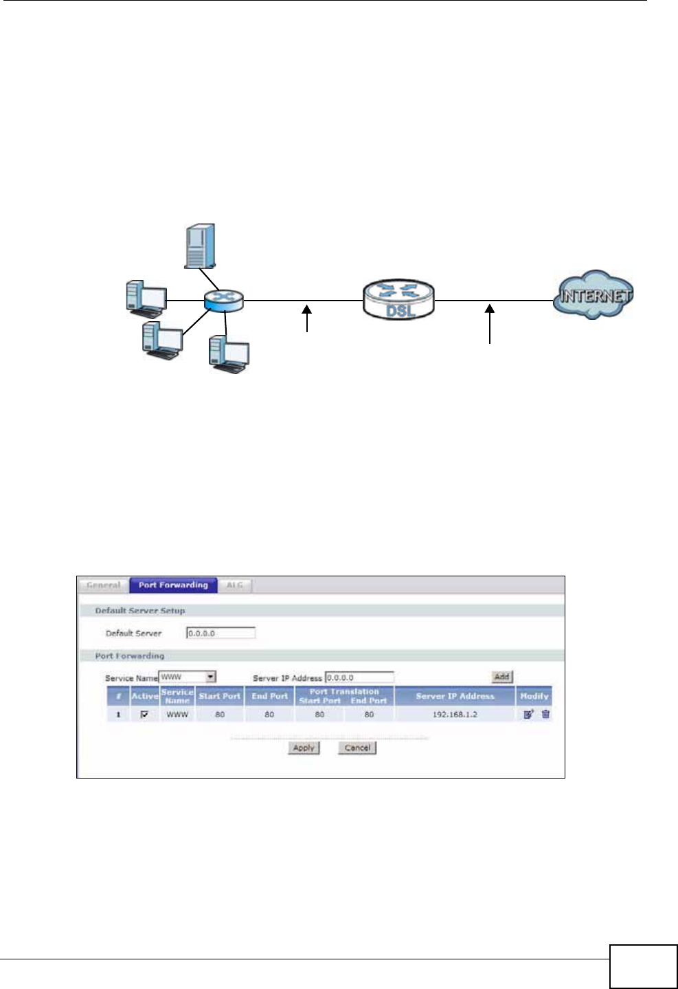
Chapter 9 Network Address Translation (NAT)
P-660N-T1A User’s Guide 137
Configuring Servers Behind Port Forwarding (Example)
Let's say you want to assign ports 21-25 to one FTP, Telnet and SMTP server (A in
the example), port 80 to another (B in the example) and assign a default server IP
address of 192.168.1.35 to a third (C in the example). You assign the LAN IP
addresses and the ISP assigns the WAN IP address. The NAT network appears as a
single host on the Internet.
Figure 65 Multiple Servers Behind NAT Example
9.3.1 Configuring the Port Forwarding Screen
Click Network > NAT > Port Forwarding to open the following screen.
See Appendix E on page 307 for port numbers commonly used for particular
services.
Figure 66 Network > NAT > Port Forwarding
A=192.168.1.33
D=192.168.1.36
C=192.168.1.35
B=192.168.1.34
WAN
LAN
192.168.1.1 IP Address assigned by ISP
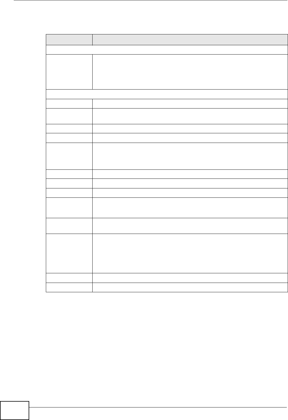
Chapter 9 Network Address Translation (NAT)
P-660N-T1A User’s Guide
138
The following table describes the fields in this screen.
Table 40 Network > NAT > Port Forwarding
LABEL DESCRIPTION
Default Server Setup
Default Server In addition to the servers for specified services, NAT supports a default
server. A default server receives packets from ports that are not
specified in this screen. If you do not assign a Default Server IP
address, the ZyXEL Device discards all packets received for ports that
are not specified here or in the remote management setup.
Port Forwarding
Service Name Select a service from the drop-down list box.
Server IP
Address Enter the IP address of the server for the specified service.
Add Click this button to add a rule to the table below.
#This is the rule index number (read-only).
Active This field indicates whether the rule is active or not.
Clear the check box to disable the rule. Select the check box to enable
it.
Service Name This is a service’s name.
Start Port This is the first port number that identifies a service.
End Port This is the last port number that identifies a service.
Port Translation
Start/End Port
This is the start/end port number that the device translates.
Server IP
Address This is the server’s IP address.
Modify Click the edit icon to go to the screen where you can edit the port
forwarding rule.
Click the delete icon to delete an existing port forwarding rule. Note that
subsequent address mapping rules move up by one when you take this
action.
Apply Click this to save your changes.
Cancel Click this to restore your previously saved settings.
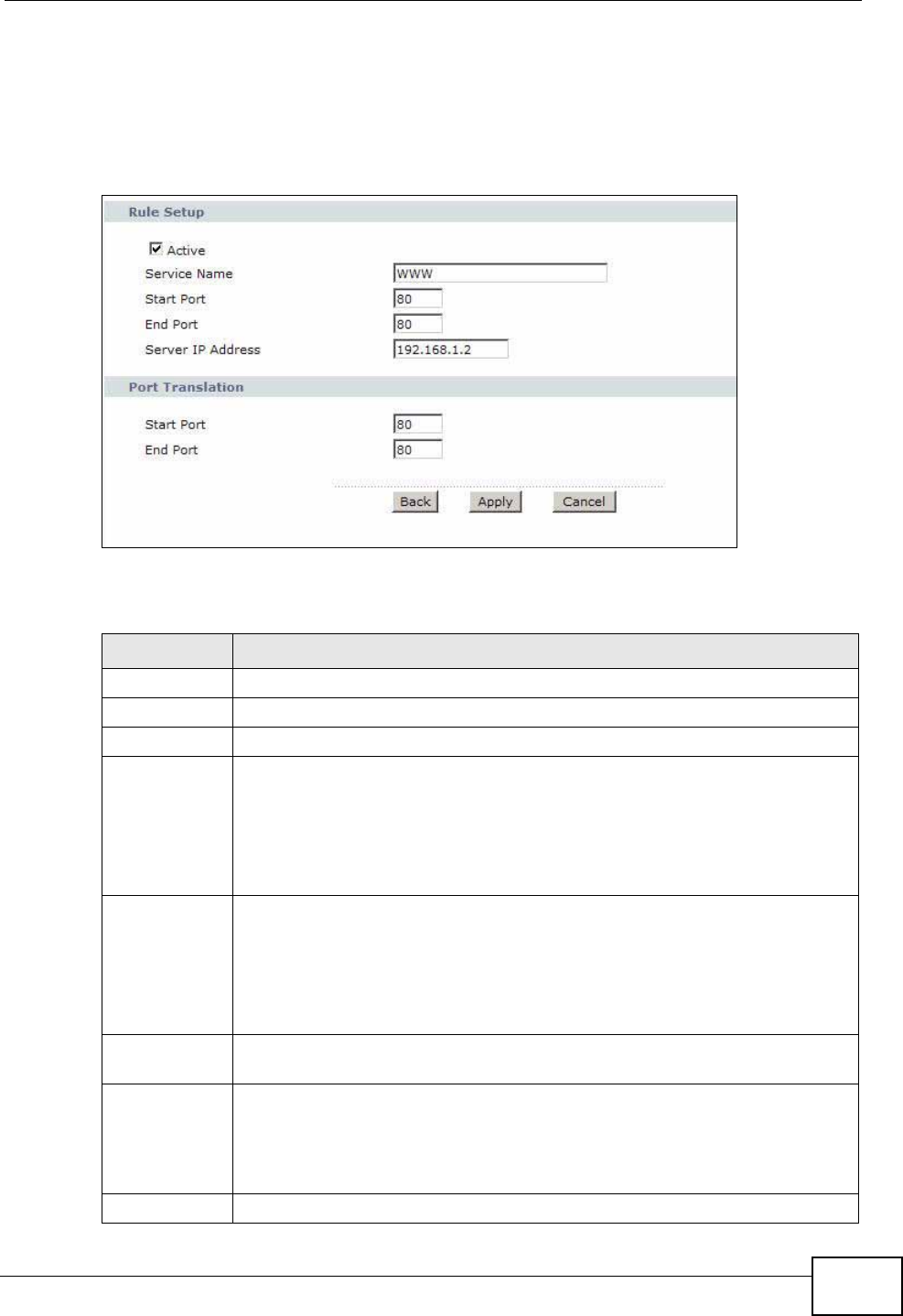
Chapter 9 Network Address Translation (NAT)
P-660N-T1A User’s Guide 139
9.3.2 The Port Forwarding Rule Edit Screen
Use this screen to edit a port forwarding rule. Click the rule’s edit icon in the Port
Forwarding screen to display the screen shown next.
Figure 67 Network > NAT > Port Forwarding: Edit
The following table describes the fields in this screen.
Table 41 Network > NAT > Port Forwarding: Edit
LABEL DESCRIPTION
Rule Setup
Active Click this check box to enable the rule.
Service Name Enter a name to identify this port-forwarding rule.
Start Port Enter a port number in this field.
To forward only one port, enter the port number again in the End Port
field.
To forward a series of ports, enter the start port number here and the end
port number in the End Port field.
End Port Enter a port number in this field.
To forward only one port, enter the port number again in the Start Port
field above and then enter it again in this field.
To forward a series of ports, enter the last port number in a series that
begins with the port number in the Start Port field above.
Server IP
Address Enter the inside IP address of the server here.
Port
Translation
Start / End
Port
Enter the start port number here to which you want the device to
translate the incoming port. For a range of ports, you only need to enter
the first number of the range to which you want the incoming ports
translated, the device automatically calculates the last port of the
translated port range.
Back Click this to return to the previous screen without saving.
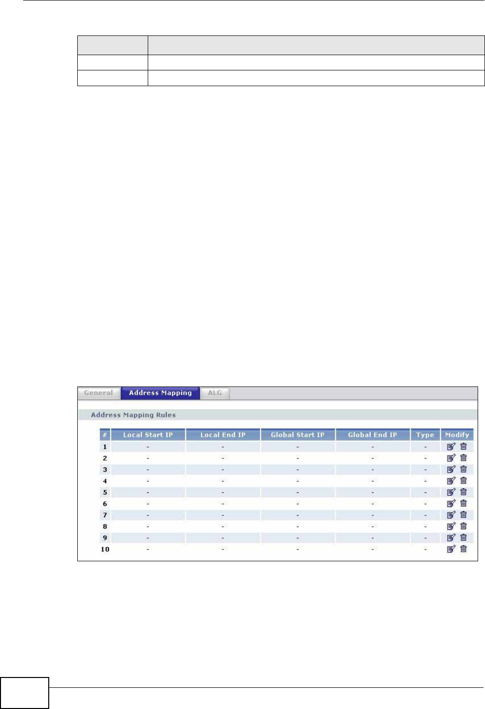
Chapter 9 Network Address Translation (NAT)
P-660N-T1A User’s Guide
140
9.4 The Address Mapping Screen
Note: The Address Mapping screen is available only when you select Full Feature
in the NAT > General screen.
Ordering your rules is important because the ZyXEL Device applies the rules in the
order that you specify. When a rule matches the current packet, the ZyXEL Device
takes the corresponding action and the remaining rules are ignored. If there are
any empty rules before your new configured rule, your configured rule will be
pushed up by that number of empty rules. For example, if you have already
configured rules 1 to 6 in your current set and now you configure rule number 9.
In the set summary screen, the new rule will be rule 7, not 9. Now if you delete
rule 4, rules 5 to 7 will be pushed up by 1 rule, so old rules 5, 6 and 7 become new
rules 4, 5 and 6.
To change your ZyXEL Device’s address mapping settings, click Network > NAT
> Address Mapping to open the following screen.
Figure 68 Network > NAT > Address Mapping
Apply Click this to save your changes.
Cancel Click this to restore your previously saved settings.
Table 41 Network > NAT > Port Forwarding: Edit (continued)
LABEL DESCRIPTION

Chapter 9 Network Address Translation (NAT)
P-660N-T1A User’s Guide 141
The following table describes the fields in this screen.
Table 42 Network > NAT > Address Mapping
LABEL DESCRIPTION
#This is the rule index number.
Local Start IP This is the starting Inside Local IP Address (ILA). Local IP addresses are
N/A for Server port mapping.
Local End IP This is the end Inside Local IP Address (ILA). If the rule is for all local IP
addresses, then this field displays 0.0.0.0 as the Local Start IP address
and 255.255.255.255 as the Local End IP address. This field is N/A for
One-to-one and Server mapping types.
Global Start
IP This is the starting Inside Global IP Address (IGA). Enter 0.0.0.0 here if
you have a dynamic IP address from your ISP. You can only do this for
Many-to-One and Server mapping types.
Global End IP This is the ending Inside Global IP Address (IGA). This field is N/A for
One-to-one, Many-to-One and Server mapping types.
Type 1-1: One-to-one mode maps one local IP address to one global IP
address. Note that port numbers do not change for the One-to-one NAT
mapping type.
M-1: Many-to-One mode maps multiple local IP addresses to one global
IP address. This is equivalent to SUA (i.e., PAT, port address translation),
ZyXEL's Single User Account feature that previous ZyXEL routers
supported only.
M-M Ov (Overload): Many-to-Many Overload mode maps multiple local
IP addresses to shared global IP addresses.
MM No (No Overload): Many-to-Many No Overload mode maps each local
IP address to unique global IP addresses.
Server: This type allows you to specify inside servers of different
services behind the NAT to be accessible to the outside world.
Modify Click the edit icon to go to the screen where you can edit the address
mapping rule.
Click the delete icon to delete an existing address mapping rule. Note that
subsequent address mapping rules move up by one when you take this
action.
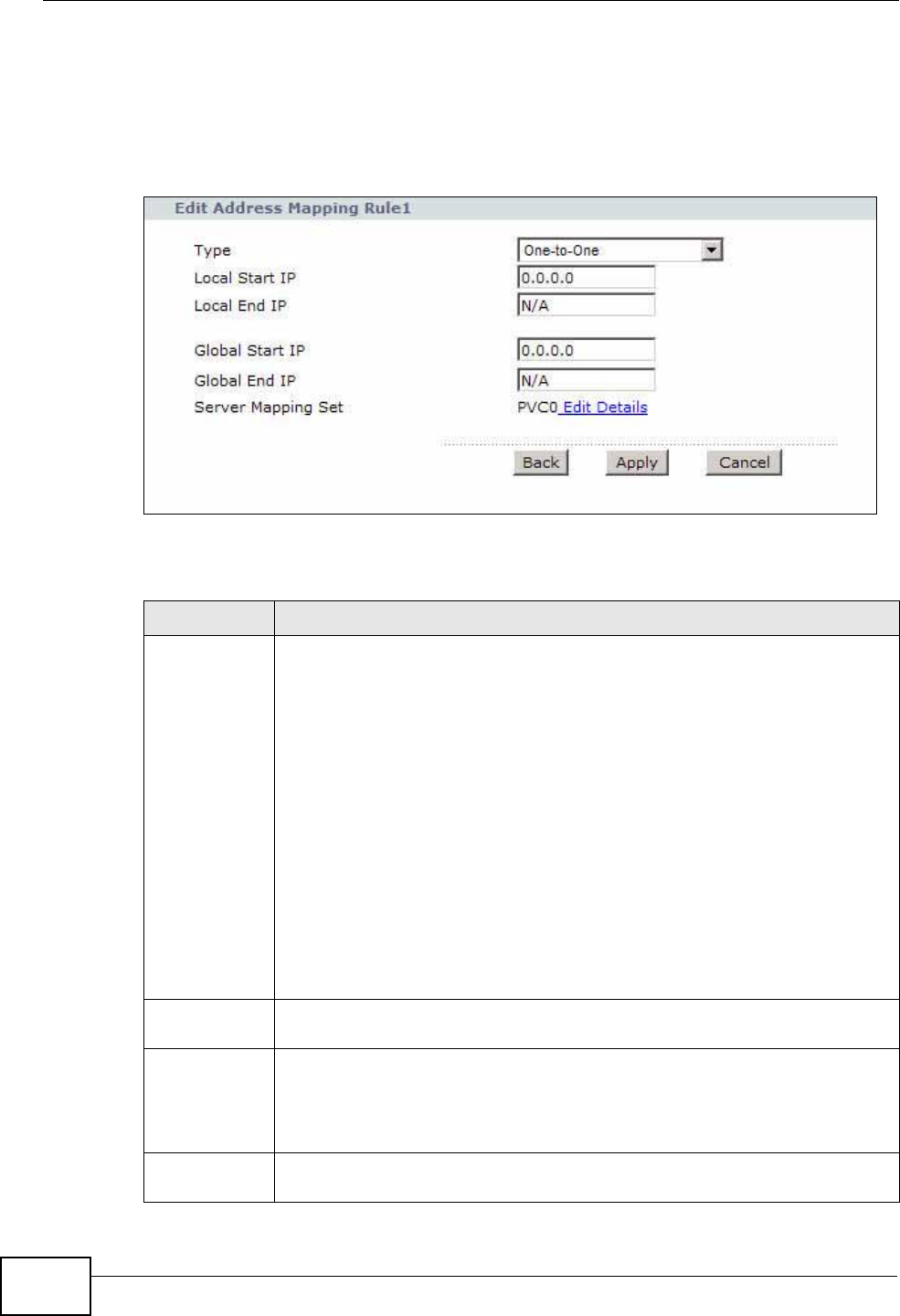
Chapter 9 Network Address Translation (NAT)
P-660N-T1A User’s Guide
142
9.4.1 The Address Mapping Rule Edit Screen
Use this screen to edit an address mapping rule. Click the rule’s edit icon in the
Address Mapping screen to display the screen shown next.
Figure 69 Network > NAT > Address Mapping: Edit
The following table describes the fields in this screen.
Table 43 Network > NAT > Address Mapping: Edit
LABEL DESCRIPTION
Type Choose the port mapping type from one of the following.
One-to-One: One-to-One mode maps one local IP address to one global
IP address. Note that port numbers do not change for One-to-one NAT
mapping type.
Many-to-One: Many-to-One mode maps multiple local IP addresses to
one global IP address. This is equivalent to SUA (i.e., PAT, port address
translation), ZyXEL's Single User Account feature that previous ZyXEL
routers supported only.
Many-to-Many Overload: Many-to-Many Overload mode maps multiple
local IP addresses to shared global IP addresses.
Many-to-Many No Overload: Many-to-Many No Overload mode maps
each local IP address to unique global IP addresses.
Server: This type allows you to specify inside servers of different services
behind the NAT to be accessible to the outside world.
Local Start IP This is the starting local IP address (ILA). Local IP addresses are N/A for
Server port mapping.
Local End IP This is the end local IP address (ILA). If your rule is for all local IP
addresses, then enter 0.0.0.0 as the Local Start IP address and
255.255.255.255 as the Local End IP address.
This field is N/A for One-to-One and Server mapping types.
Global Start
IP This is the starting global IP address (IGA). Enter 0.0.0.0 here if you have
a dynamic IP address from your ISP.
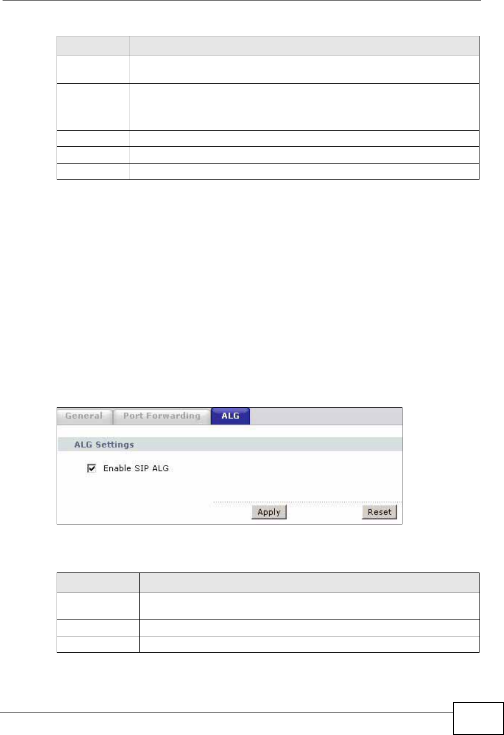
Chapter 9 Network Address Translation (NAT)
P-660N-T1A User’s Guide 143
9.5 The ALG Screen
Some NAT routers may include a SIP Application Layer Gateway (ALG). A SIP ALG
allows SIP calls to pass through NAT by examining and translating IP addresses
embedded in the data stream. When the ZyXEL Device registers with the SIP
register server, the SIP ALG translates the ZyXEL Device’s private IP address
inside the SIP data stream to a public IP address. You do not need to use STUN or
an outbound proxy if your ZyXEL Device is behind a SIP ALG.
Use this screen to enable and disable the SIP (VoIP) ALG in the ZyXEL Device. To
access this screen, click Network > NAT > ALG.
Figure 70 Network > NAT > ALG
The following table describes the fields in this screen.
Global End IP This is the ending global IP address (IGA). This field is N/A for One-to-
One, Many-to-One and Server mapping types.
Server
Mapping Set
Edit Details
Click this link to go to the Port Forwarding screen to edit a port
forwarding set that you have selected in the Server Mapping Set field.
Back Click this to return to the previous screen without saving.
Apply Click this to save your changes.
Cancel Click this to restore your previously saved settings.
Table 43 Network > NAT > Address Mapping: Edit (continued)
LABEL DESCRIPTION
Table 44 Network > NAT > ALG
LABEL DESCRIPTION
Enable SIP ALG Select this to make sure SIP (VoIP) works correctly with port-
forwarding and address-mapping rules.
Apply Click this to save your changes.
Reset Click this to restore your previously saved settings.
Chapter 9 Network Address Translation (NAT)
P-660N-T1A User’s Guide
144
9.6 Technical Reference
This chapter contains more information regarding NAT.
9.6.1 NAT Definitions
Inside/outside denotes where a host is located relative to the ZyXEL Device, for
example, the computers of your subscribers are the inside hosts, while the web
servers on the Internet are the outside hosts.
Global/local denotes the IP address of a host in a packet as the packet traverses a
router, for example, the local address refers to the IP address of a host when the
packet is in the local network, while the global address refers to the IP address of
the host when the same packet is traveling in the WAN side.
Note that inside/outside refers to the location of a host, while global/local refers to
the IP address of a host used in a packet. Thus, an inside local address (ILA) is the
IP address of an inside host in a packet when the packet is still in the local
network, while an inside global address (IGA) is the IP address of the same inside
host when the packet is on the WAN side. The following table summarizes this
information.
NAT never changes the IP address (either local or global) of an outside host.
9.6.2 What NAT Does
In the simplest form, NAT changes the source IP address in a packet received from
a subscriber (the inside local address) to another (the inside global address)
before forwarding the packet to the WAN side. When the response comes back,
NAT translates the destination address (the inside global address) back to the
inside local address before forwarding it to the original inside host. Note that the
IP address (either local or global) of an outside host is never changed.
The global IP addresses for the inside hosts can be either static or dynamically
assigned by the ISP. In addition, you can designate servers, for example, a web
server and a telnet server, on your local network and make them accessible to the
Table 45 NAT Definitions
ITEM DESCRIPTION
Inside This refers to the host on the LAN.
Outside This refers to the host on the WAN.
Local This refers to the packet address (source or destination) as the packet travels
on the LAN.
Global This refers to the packet address (source or destination) as the packet travels
on the WAN.
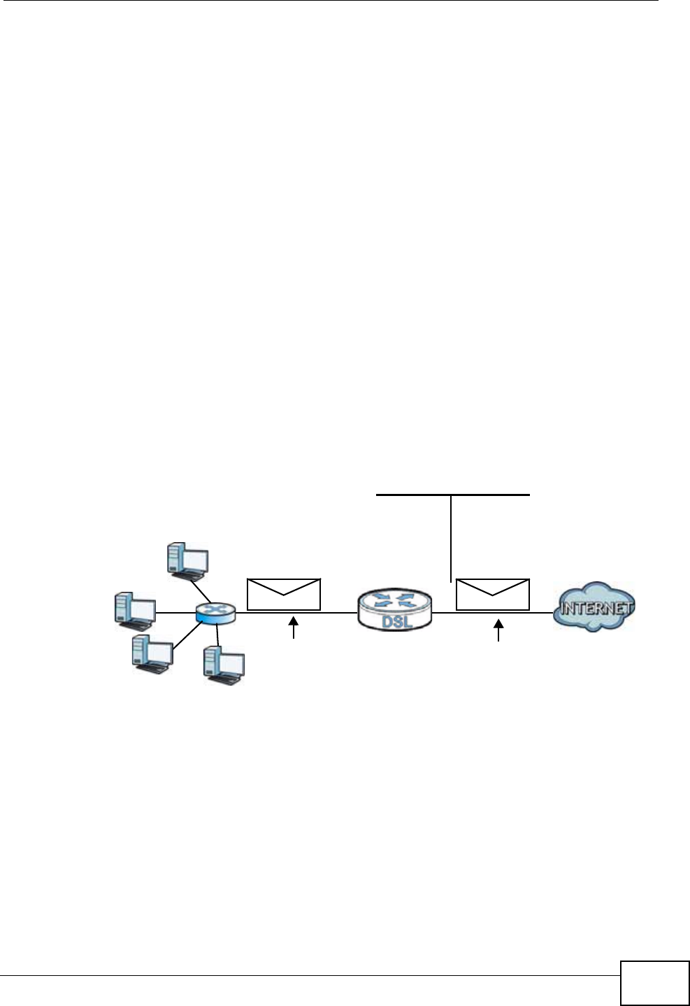
Chapter 9 Network Address Translation (NAT)
P-660N-T1A User’s Guide 145
outside world. If you do not define any servers (for Many-to-One and Many-to-
Many Overload mapping – see Table 46 on page 147), NAT offers the additional
benefit of firewall protection. With no servers defined, your ZyXEL Device filters
out all incoming inquiries, thus preventing intruders from probing your network.
For more information on IP address translation, refer to RFC 1631, The IP Network
Address Translator (NAT).
9.6.3 How NAT Works
Each packet has two addresses – a source address and a destination address. For
outgoing packets, the ILA (Inside Local Address) is the source address on the LAN,
and the IGA (Inside Global Address) is the source address on the WAN. For
incoming packets, the ILA is the destination address on the LAN, and the IGA is
the destination address on the WAN. NAT maps private (local) IP addresses to
globally unique ones required for communication with hosts on other networks. It
replaces the original IP source address (and TCP or UDP source port numbers for
Many-to-One and Many-to-Many Overload NAT mapping) in each packet and then
forwards it to the Internet. The ZyXEL Device keeps track of the original addresses
and port numbers so incoming reply packets can have their original values
restored. The following figure illustrates this.
Figure 71 How NAT Works
192.168.1.13
192.168.1.10
192.168.1.11
192.168.1.12 SA
192.168.1.10
SA
IGA1
Inside Local
IP Address
192.168.1.10
192.168.1.11
192.168.1.12
192.168.1.13
Inside Global
IP Address
IGA 1
IGA 2
IGA 3
IGA 4
NAT Table
WAN
LAN
Inside Local
Address (ILA) Inside Global
Address (IGA)
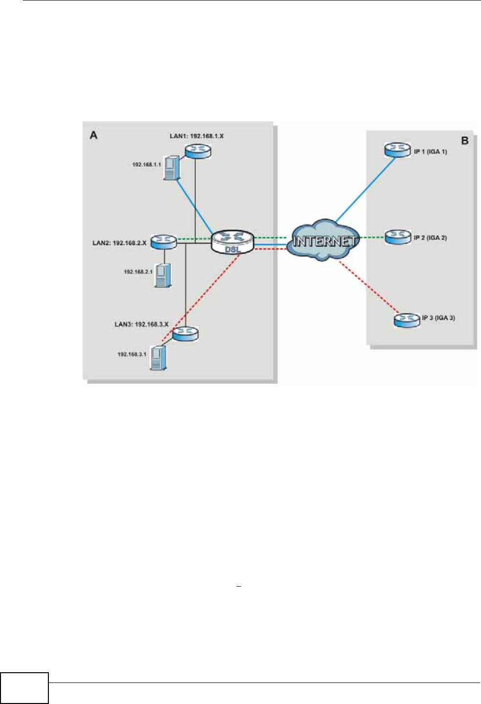
Chapter 9 Network Address Translation (NAT)
P-660N-T1A User’s Guide
146
9.6.4 NAT Application
The following figure illustrates a possible NAT application, where three inside LANs
(logical LANs using IP alias) behind the ZyXEL Device can communicate with three
distinct WAN networks.
Figure 72 NAT Application With IP Alias
9.6.5 NAT Mapping Types
NAT supports five types of IP/port mapping. They are:
•One to One: In One-to-One mode, the ZyXEL Device maps one local IP address
to one global IP address.
•Many to One: In Many-to-One mode, the ZyXEL Device maps multiple local IP
addresses to one global IP address. This is equivalent to SUA (for instance, PAT,
port address translation), ZyXEL’s Single User Account feature that previous
ZyXEL routers supported (the SUA Only option in today’s routers).
•Many to Many Overload: In Many-to-Many Overload mode, the ZyXEL Device
maps the multiple local IP addresses to shared global IP addresses.
•Many-to-Many No Overload: In Many-to-Many No Overload mode, the ZyXEL
Device maps each local IP address to a unique global IP address.
•Server: This type allows you to specify inside servers of different services
behind the NAT to be accessible to the outside world.

Chapter 9 Network Address Translation (NAT)
P-660N-T1A User’s Guide 147
Port numbers do NOT change for One-to-One and Many-to-Many No Overload
NAT mapping types.
The following table summarizes these types.
Table 46 NAT Mapping Types
TYPE IP MAPPING
One-to-One ILA1 IGA1
Many-to-One (SUA/PAT) ILA1 IGA1
ILA2 IGA1
…
Many-to-Many Overload ILA1 IGA1
ILA2 IGA2
ILA3 IGA1
ILA4 IGA2
…
Many-to-Many No Overload ILA1 IGA1
ILA2 IGA2
ILA3 IGA3
…
Server Server 1 IP IGA1
Server 2 IP IGA1
Server 3 IP IGA1

Chapter 9 Network Address Translation (NAT)
P-660N-T1A User’s Guide
148

P-660N-T1A User’s Guide 149
CHAPTER 10
Firewall
10.1 Overview
This chapter shows you how to enable the ZyXEL Device firewall. Use the firewall
to protect your ZyXEL Device and network from attacks by hackers on the Internet
and control access to it. By default the firewall:
• allows traffic that originates from your LAN computers to go to all other
networks.
• blocks traffic that originates on other networks from going to the LAN.
• blocks SYN and port scanner attacks.
By default, the ZyXEL Device blocks DDOS, LAND and Ping of Death attacks
whether the firewall is enabled or disabled.
10.1.1 What You Can Do in the Firewall Screens
Use the Firewall screen (Section 10.2 on page 151) to enable firewall and/or SPI
on the ZyXEL Device.
10.1.2 What You Need to Know
The following terms and concepts may help as you read this chapter.
SYN Attack
A SYN attack floods a targeted system with a series of SYN packets. Each packet
causes the targeted system to issue a SYN-ACK response. While the targeted
system waits for the ACK that follows the SYN-ACK, it queues up all outstanding
SYN-ACK responses on a backlog queue. SYN-ACKs are moved off the queue only
when an ACK comes back or when an internal timer terminates the three-way
handshake. Once the queue is full, the system will ignore all incoming SYN
requests, making the system unavailable for legitimate users.

Chapter 10 Firewall
P-660N-T1A User’s Guide
150
DoS
Denials of Service (DoS) attacks are aimed at devices and networks with a
connection to the Internet. Their goal is not to steal information, but to disable a
device or network so users no longer have access to network resources. The
ZyXEL Device is pre-configured to automatically detect and thwart all known DoS
attacks.
DDoS
A DDoS attack is one in which multiple compromised systems attack a single
target, thereby causing denial of service for users of the targeted system.
LAND Attack
In a LAND attack, hackers flood SYN packets into the network with a spoofed
source IP address of the target system. This makes it appear as if the host
computer sent the packets to itself, making the system unavailable while the
target system tries to respond to itself.
Ping of Death
Ping of Death uses a "ping" utility to create and send an IP packet that exceeds
the maximum 65,536 bytes of data allowed by the IP specification. This may
cause systems to crash, hang or reboot.
SPI
Stateful Packet Inspection (SPI) tracks each connection crossing the firewall and
makes sure it is valid. Filtering decisions are based not only on rules but also
context. For example, traffic from the WAN may only be allowed to cross the
firewall in response to a request from the LAN.
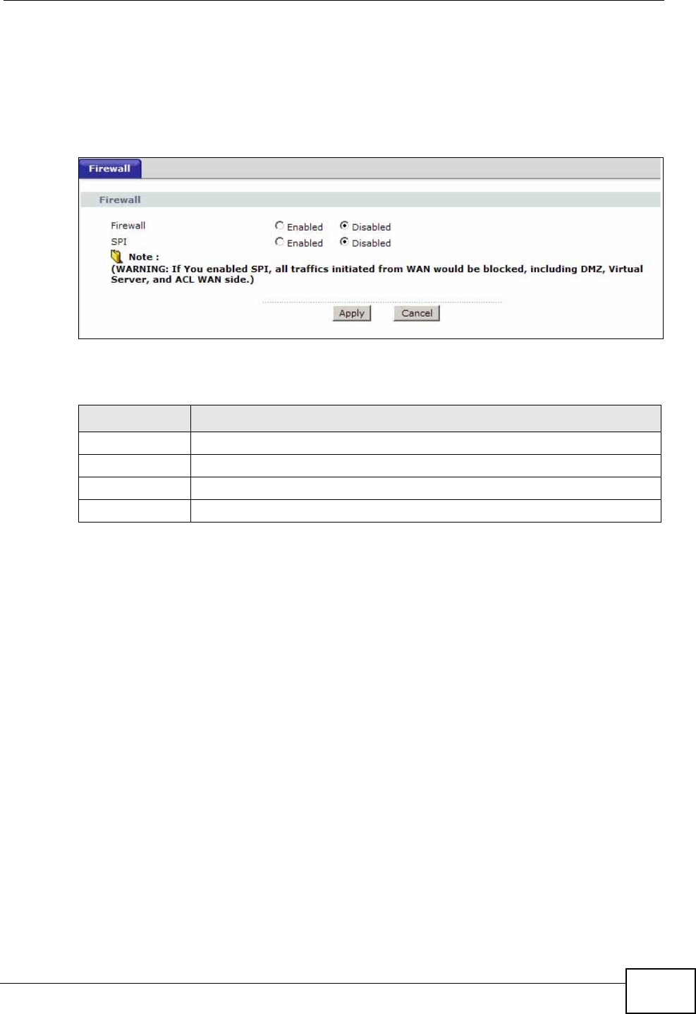
Chapter 10 Firewall
P-660N-T1A User’s Guide 151
10.2 The Firewall Screen
Use this screen to enable firewall and/or SPI. Click Advanced Setup > Firewall
to display the following screen.
Figure 73 Advanced Setup > Firewall
The following table describes the labels in this screen.
Enabling SPI blocks all traffic initiated from the WAN side,
including the DMZ, virtual server and ACL on the WAN side.
Table 47 Advanced > Firewall
LABEL DESCRIPTION
Firewall Use this field to enable or disable firewall on your ZyXEL Device.
SPI Use this field to enable or disable SPI on your ZyXEL Device.
SAVE Click this to save your changes.
CANCEL Click this to restore your previously saved settings.

Chapter 10 Firewall
P-660N-T1A User’s Guide
152

P-660N-T1A User’s Guide 153
CHAPTER 11
Filters
11.1 Overview
This chapter introduces three types of filters supported by the ZyXEL Device. You
can configure rules to restrict traffic by IP addresses, MAC addresses, application
types and/or URLs.
11.1.1 What You Can Do in the Filter Screens
•Use the URL Filter screen (Section 11.2 on page 154) to block access to web
sites.
•Use the Application Filter screen (Section 11.3 on page 155) to allow or deny
traffic from certain types of applications.
•Use the IP/MAC Filter screen (Section 11.4 on page 156) to create IP/MAC
filter rules.
11.1.2 What You Need to Know
The following terms and concepts may help as you read this chapter.
URL
The URL (Uniform Resource Locator) identifies and helps locates resources on a
network. On the Internet the URL is the web address that you type in the address
bar of your Internet browser, for example “http://www.zyxel.com”.
IP/MAC Filter Structure
An IP/MAC filter set consists of one or more filter rules. The ZyXEL Device allows
you to configure up to twelve filter sets with six rules in each set, for a total of 72
filter rules in the system.
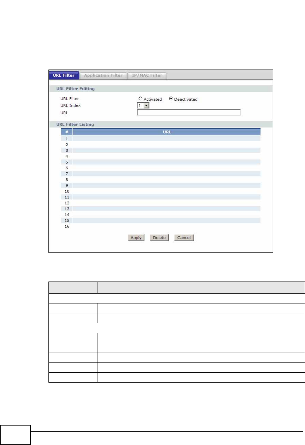
Chapter 11 Filters
P-660N-T1A User’s Guide
154
11.2 The URL Filter Screen
Use this screen to block websites by URL. Click Security > Filter > URL Filter.
The screen appears as shown.
Figure 74 Security > Filter > URL Filter
The following table describes the labels in this screen.
Table 48 Access Management > Filter (URL)
LABEL DESCRIPTION
URL Filter Editing
Active Use this field to enable or disable the URL filter.
URL Index Select the index number of the filter.
URL Filter Listing
Index This is the index number of the filter rule.
URL This is the URL you have configured the ZyXEL Device to block.
Apply Click this to save your changes.
Delete Click this to remove the filter rule.
Cancel Click this to restore your previously saved settings.
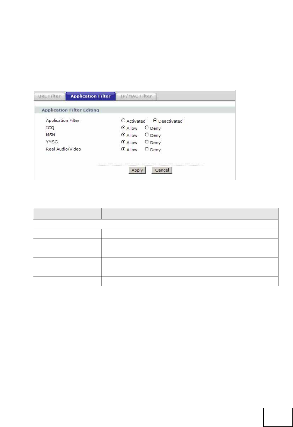
Chapter 11 Filters
P-660N-T1A User’s Guide 155
11.3 The Application Filter Screen
Use this screen to allow or deny traffic for certain types of applications. The
application filter provides a convenient way to manage the use of various
applications on the network.
Click Security > Filter > Application Filter. The screen appears as shown.
Figure 75 Security > Filter > Application Filter
The following table describes the labels in this screen.
Table 49 Access Management > Filter (Application)
LABEL DESCRIPTION
Application Filter Editing
Application Filter Use this field to enable or disable the application filter.
ICQ Use this field to allow or deny ICQ traffic.
MSN Use this field to allow or deny MSN traffic.
YMSG Use this field to allow or deny Yahoo Messenger traffic
Apply Click this to save your changes.
Cancel Click this to restore your previously saved settings.
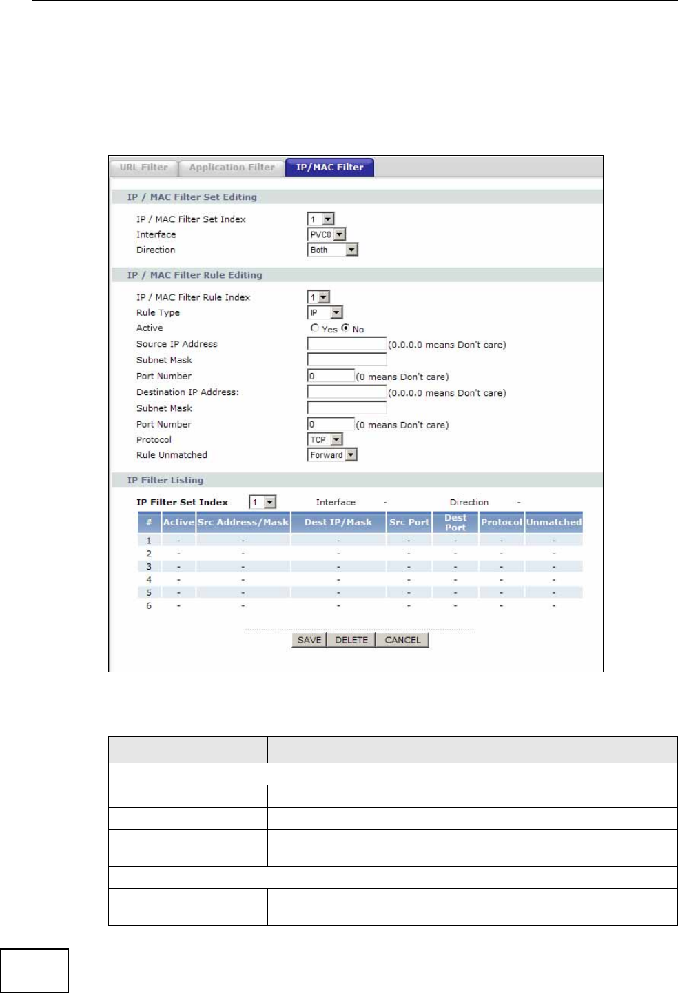
Chapter 11 Filters
P-660N-T1A User’s Guide
156
11.4 The IP/MAC Filter Screen
Use this screen to create and apply IP/MAC filters. Click Security > Filter > IP/
MAC Filter. The screen appears as shown.
Figure 76 Security > Filter > IP/MAC Filter
The following table describes the labels in this screen.
Table 50 Access Management > Filter (IP/MAC)
LABEL DESCRIPTION
IP/MAC Filter Set Editing
IP/MAC Filter Set Index Select the index number of the filter set.
Interface Select the PVC to which to apply the filter.
Direction Apply the filter to Both, Incoming or Outgoing traffic
direction.
IP/MAC Filter Rule Editing
IP/MAC Filter Rule
Index Select the index number of the filter rule.

Chapter 11 Filters
P-660N-T1A User’s Guide 157
Rule Type Select IP or MAC type to configure the rule.
Use the IP Filter to block traffic by IP addresses.
Use the MAC Filter to block traffic by MAC address.
Active Use this field to enable or disable the rule.
Source IP Address Enter the source IP address of the packets you wish to filter.
This field is ignored if it is 0.0.0.0.
Subnet Mask Enter the IP subnet mask for the source IP address
Port Number Enter the source port of the packets that you wish to filter. The
range of this field is 0 to 65535. This field is ignored if it is 0.
Destination IP Address Enter the destination IP address of the packets you wish to
filter. This field is ignored if it is 0.0.0.0.
Subnet Mask Enter the IP subnet mask for the destination IP address.
Port Number Enter the destination port of the packets that you wish to filter.
The range of this field is 0 to 65535. This field is ignored if it is
0.
Protocol Select ICMP, TCP or UDP for the upper layer protocol.
MAC Address This field is only available when you select MAC in the Rule
Type field.
Enter the MAC address of the packets you wish to filter.
Rule Unmatched Select the action for a packet not matching the rule.
Select Forward to forward traffic immediately and skip
checking the remaining rules. Select Next to check the next
rule.
IP/MAC Filter Listing
IP/MAC Filter Set Index Select the index number of the filter set from the drop-downl
list box.
Interface This is the interface that the filter set applies to.
Direction The filter set applies to this traffic direction.
#This is the index number of the rule in a filter set.
Active This field shows whether the rule is activated.
Src Address/Mask This is the source IP address and subnet mask when you select
IP as the rule type.
This is the MAC address when you select MAC as the rule type.
Dest IP/Mask This is the destination IP address and subnet mask.
Src Port This is the source port number.
Dest Port This is the destination port number.
Protocol This is the upper layer protocol.
Unmatched When a packet doesn’t match the rule, this is the action the
ZyXEL Device takes on the packet.
SAVE Click this to save your changes.
Table 50 Access Management > Filter (IP/MAC) (continued)
LABEL DESCRIPTION

Chapter 11 Filters
P-660N-T1A User’s Guide
158
DELETE Click this to remove the filter rule.
CANCEL Click this to restore your previously saved settings.
Table 50 Access Management > Filter (IP/MAC) (continued)
LABEL DESCRIPTION
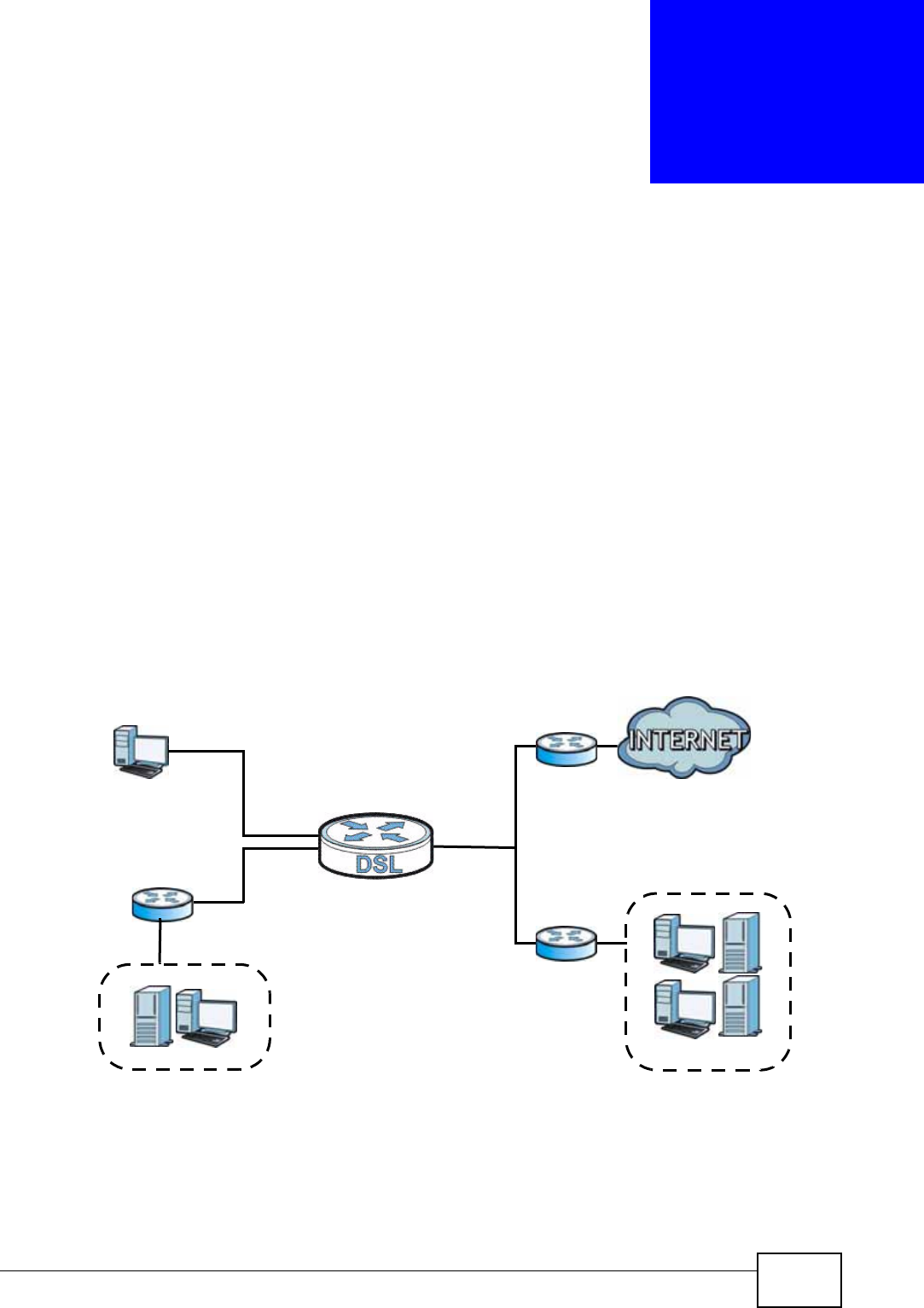
P-660N-T1A User’s Guide 159
CHAPTER 12
Static Route
12.1 Overview
The ZyXEL Device usually uses the default gateway to route outbound traffic from
computers on the LAN to the Internet. To have the ZyXEL Device send data to
devices not reachable through the default gateway, use static routes.
For example, the next figure shows a computer (A) connected to the ZyXEL
Device’s LAN interface. The ZyXEL Device routes most traffic from A to the
Internet through the ZyXEL Device’s default gateway (R1). You create one static
route to connect to services offered by your ISP behind router R2. You create
another static route to communicate with a separate network behind a router R3
connected to the LAN.
Figure 77 Example of Static Routing Topology
WAN
R1
R2
A
R3
LAN
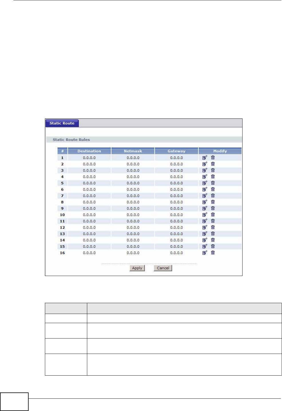
Chapter 12 Static Route
P-660N-T1A User’s Guide
160
12.1.1 What You Can Do in the Static Route Screens
Use the Static Route screens (Section 12.2 on page 160) to view and configure
IP static routes on the ZyXEL Device.
12.2 The Static Route Screen
Use this screen to view the static route rules. Click Advanced > Static Route to
open the Static Route screen.
Figure 78 Advanced > Static Route
The following table describes the labels in this screen.
Table 51 Advanced > Static Route
LABEL DESCRIPTION
#This is the number of an individual static route.
Destination This parameter specifies the IP network address of the final destination.
Routing is always based on network number.
Netmask This parameter specifies the IP network subnet mask of the final
destination.
Gateway This is the IP address of the gateway. The gateway is a router or switch
on the same network segment as the device's LAN or WAN port. The
gateway helps forward packets to their destinations.
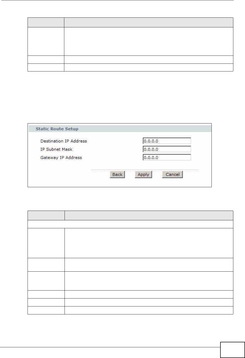
Chapter 12 Static Route
P-660N-T1A User’s Guide 161
12.2.1 Static Route Edit
Use this screen to configure the required information for a static route. Select a
static route index number and click Edit. The screen shown next appears.
Figure 79 Advanced > Static Route: Edit
The following table describes the labels in this screen.
Modify Click the Edit icon to go to the screen where you can set up a static route
on the ZyXEL Device.
Click the Remove icon to remove a static route from the ZyXEL Device. A
window displays asking you to confirm that you want to delete the route.
Apply Click this to save your changes.
Cancel Click this to restore your previously saved settings.
Table 51 Advanced > Static Route
LABEL DESCRIPTION
Table 52 Advanced > Static Route: Edit
LABEL DESCRIPTION
Static Route Setup
Destination IP
Address This parameter specifies the IP network address of the final destination.
Routing is always based on network number. If you need to specify a
route to a single host, use a subnet mask of 255.255.255.255 in the
subnet mask field to force the network number to be identical to the host
ID.
IP Subnet
Mask Enter the IP subnet mask here.
Gateway IP
Address Enter the IP address of the gateway. The gateway is a router or switch on
the same network segment as the device's LAN or WAN port. The
gateway helps forward packets to their destinations.
Back Click this to return to the previous screen without saving.
Apply Click this to save your changes.
Cancel Click this to restore your previously saved settings.

Chapter 12 Static Route
P-660N-T1A User’s Guide
162

P-660N-T1A User’s Guide 163
CHAPTER 13
802.1Q/1P
13.1 Overview
This chapter describes how to configure the 802.1Q/1P settings.
A Virtual Local Area Network (VLAN) allows a physical network to be partitioned
into multiple logical networks. A VLAN group can be treated as an individual
device. Each group can have its own rules about where and how to forward traffic.
You can assign any ports on the ZyXEL Device to a VLAN group and configure the
settings for the group. You may also set the priority level for traffic trasmitted
through the ports.
Figure 80 802.1Q/1P
13.1.1 What You Can Do in the 802.1Q/1P Screens
•Use the Group Setting screen (Section 13.2 on page 165) to activate 802.1Q/
1P, specify the management VLAN group, display the VLAN groups and
configure the settings for each VLAN group.
•Use the Port Setting screen (Section 13.3 on page 168) to configure the PVID
for each port.
13.1.2 What You Need to Know
The following terms and concepts may help as you read this chapter.
IEEE 802.1P Priority
IEEE 802.1P specifies the user priority field and defines up to eight separate traffic
types by inserting a tag into a MAC-layer frame that contains bits to define class of
service.
Ports VLAN Groups Priority Levels
802.1Q 802.1P

Chapter 13 802.1Q/1P
P-660N-T1A User’s Guide
164
IEEE 802.1Q Tagged VLAN
Tagged VLAN uses an explicit tag (VLAN ID) in the MAC header to identify the
VLAN membership of a frame across bridges - they are not confined to the device
on which they were created. The VLAN ID associates a frame with a specific VLAN
and provides the information that devices need to process the frame across the
network.
PVC
A virtual circuit is a logical point-to-point circuit between customer sites.
Permanent means that the circuit is preprogrammed by the carrier as a path
through the network. It does not need to be set up or torn down for each session.
Forwarding Tagged and Untagged Frames
Each port on the device is capable of passing tagged or untagged frames. To
forward a frame from an 802.1Q VLAN-aware device to an 802.1Q VLAN-unaware
device, the ZyXEL Device first decides where to forward the frame and then strips
off the VLAN tag. To forward a frame from an 802.1Q VLAN-unaware device to an
802.1Q VLAN-aware switch, the ZyXEL Device first decides where to forward the
frame, and then inserts a VLAN tag reflecting the ingress port's default VID. The
default PVID is VLAN 1 for all ports, but this can be changed.
Whether to tag an outgoing frame depends on the setting of the egress port on a
per-VLAN, per-port basis (recall that a port can belong to multiple VLANs). If the
tagging on the egress port is enabled for the VID of a frame, then the frame is
transmitted as a tagged frame; otherwise, it is transmitted as an untagged frame.
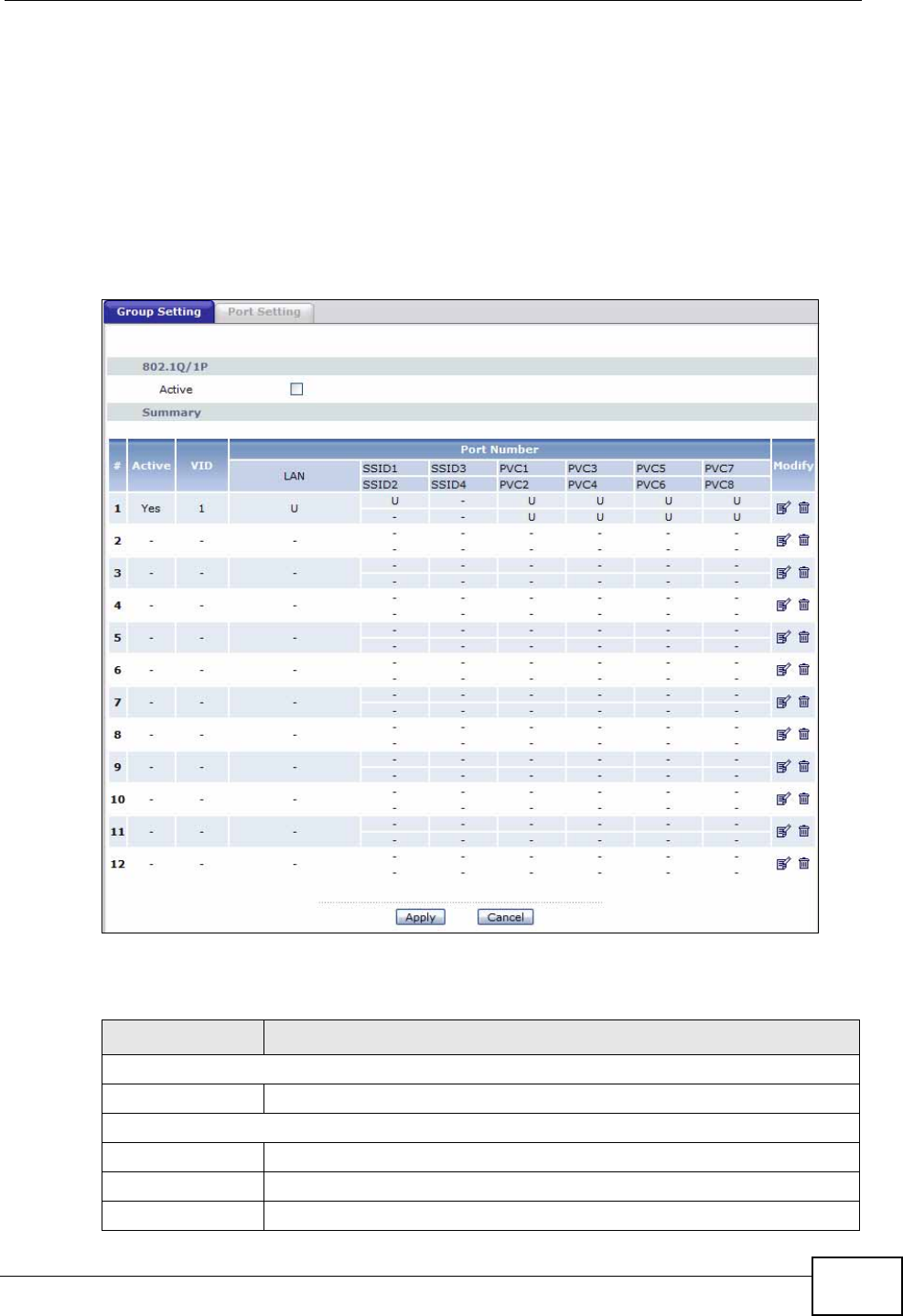
Chapter 13 802.1Q/1P
P-660N-T1A User’s Guide 165
13.2 The 802.1Q/1P Group Setting Screen
Use this screen to activate 802.1Q/1P and display the VLAN groups.
Note: If the WAN interface in the VLAN group is not the default router, you need to
create a static route to communicate with the WAN.
Click Advanced > 802.1Q/1P to display the following screen.
Figure 81 Advanced > 802.1Q/1P > Group Setting
The following table describes the labels in this screen.
Table 53 Advanced > 802.1Q/1P > Group Setting
LABEL DESCRIPTION
802.1Q/1P
Active Select this check box to activate the 802.1P/1Q feature.
Summary
# This field displays the index number of the VLAN group.
Active This field displays whether 802.1P/1Q is active for the VLAN group.
VID This field displays the ID number of the VLAN group.
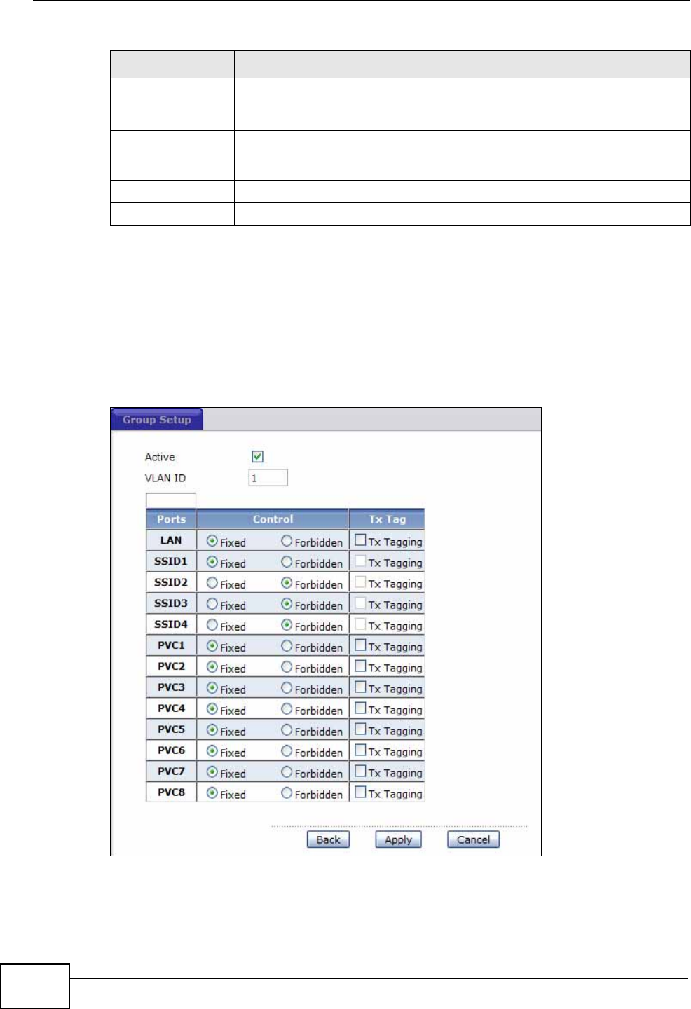
Chapter 13 802.1Q/1P
P-660N-T1A User’s Guide
166
13.2.1 Editing 802.1Q/1P Group Setting
Use this screen to configure the settings for each VLAN group.
In the 802.1Q/1P screen, click the Edit button from the Modify filed to display
the following screen.
Figure 82 Advanced > 802.1Q/1P > Group Setting > Edit
Port Number These columns display the VLAN’s settings for each port. A tagged
port is marked as T, an untagged port is marked as U and ports not
participating in a VLAN are marked as “–“.
Modify Click the Edit button to configure the the ports in the VLAN group.
Click the Remove button to delete the VLAN group.
Apply Click this to save your changes.
Cancel Click this to restore your previously saved settings.
Table 53 Advanced > 802.1Q/1P > Group Setting (continued)
LABEL DESCRIPTION

Chapter 13 802.1Q/1P
P-660N-T1A User’s Guide 167
The following table describes the labels in this screen.
Table 54 Advanced > 802.1Q/1P > Group Setting > Edit
LABEL DESCRIPTION
Active Select this check box to activate the group setting.
VLAN ID Assign a VLAN ID for the VLAN group. The valid VID range is between 1
and 4094.
Default
Gateway Select the default gateway for the VLAN group.
Ports This field displays the types of ports available to join the VLAN group.
Control Select Fixed for the port to be a permanent member of the VLAN group.
Select Forbidden if you want to prohibit the port from joining the VLAN
group.
Tx Tag Select Tx Tagging if you want the port to tag all outgoing traffic
trasmitted through this VLAN. You select this if you want to create VLANs
across different devices and not just the ZyXEL Device.
Back Click this to return to the previous screen without saving.
Apply Click this to save your changes.
Cancel Click this to restore your previously saved settings.
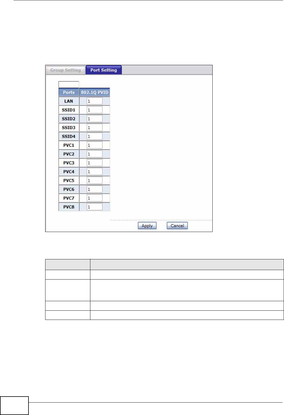
Chapter 13 802.1Q/1P
P-660N-T1A User’s Guide
168
13.3 The 802.1Q/1P Port Setting Screen
Use this screen to configure the PVID for each port. Click Advanced > 802.1Q/
1P > Port Setting to display the following screen.
Figure 83 Advanced > 802.1Q/1P > Port Setting
The following table describes the labels in this screen.
Table 55 Advanced > 802.1Q/1P > Port Setting
LABEL DESCRIPTION
Ports This field displays the types of ports available to join the VLAN group.
802.1Q PVID Assign a VLAN ID for the port. The valid VID range is between 1 and
4094. The ZyXEL Device assigns the PVID to untagged frames or
priority-tagged frames received on this port.
Apply Click this to save your changes.
Cancel Click this to restore your previously saved settings.

P-660N-T1A User’s Guide 169
CHAPTER 14
Quality of Service (QoS)
14.1 Overview
Use the QoS screen to set up your ZyXEL Device to use QoS for traffic
management.
Quality of Service (QoS) refers to both a network’s ability to deliver data with
minimum delay, and the networking methods used to control bandwidth. QoS
allows the ZyXEL Device to group and prioritize application traffic and fine-tune
network performance.
Without QoS, all traffic data are equally likely to be dropped when the network is
congested. This can cause a reduction in network performance and make the
network inadequate for time-critical applications such as video-on-demand.
The ZyXEL Device assigns each packet a priority and then queues the packet
accordingly. Packets assigned with a high priority are processed more quickly than
those with low priorities if there is congestion, allowing time-sensitive applications
to flow more smoothly. Time-sensitive applications include both those that require
a low level of latency (delay) and a low level of jitter (variations in delay) such as
Voice over IP (VoIP) or Internet gaming, and those for which jitter alone is a
problem such as Internet radio or streaming video.
In the following figure, your Internet connection has an upstream transmission
speed of 50 Mbps. You configure a classifier to assign the highest priority queue
(6) to VoIP traffic from the LAN interface, so that voice traffic would not get
delayed when there is network congestion. Traffic from the boss’s IP address
(192.168.1.23 for example) is mapped to queue 5. Traffic that does not match
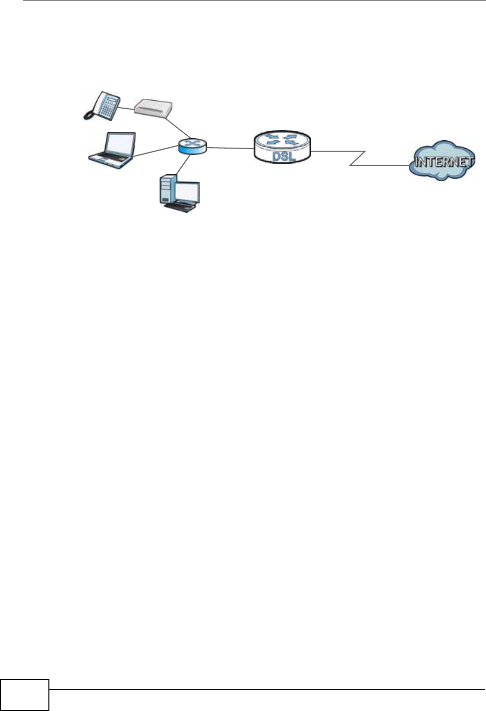
Chapter 14 Quality of Service (QoS)
P-660N-T1A User’s Guide
170
these two classes are assigned priority queue based on the internal QoS mapping
table on the ZyXEL Device.
Figure 84 QoS Example
14.1.1 What You Can Do in the QoS Screens
•Use the QoS screen (Section 14.2 on page 171) to configure QoS settings on
the ZyXEL Device.
•Use the QoS Settings Summary screen (Section 14.2.1 on page 173) to check
the summary of QoS rules and actions you configured for the ZyXEL Device.
14.1.2 What You Need to Know
The following terms and concepts may help as you read this chapter.
802.1p
QoS is used to prioritize source-to-destination traffic flows. All packets in the same
flow are given the same priority. 802.1p is a way of managing traffic in a network
by grouping similar types of traffic together and treating each type as a class. You
can use 802.1p to give different priorities to different packet types.
Tagging and Marking
In a QoS class, you can configure whether to add or change the DiffServ Code
Point (DSCP) value, IEEE 802.1p priority level and VLAN ID number in a matched
packet. When the packet passes through a compatible network, the networking
device, such as a backbone switch, can provide specific treatment or service
based on the tag or marker.
Finding Out More
See Section 14.3 on page 174 for advanced technical information on QoS.
50 Mbps
DSL
VoIP: Queue 6
Boss: Queue 5
IP=192.168.1.23
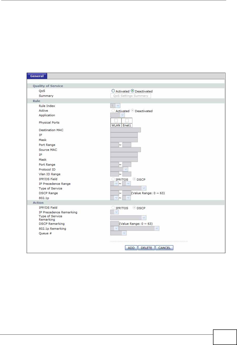
Chapter 14 Quality of Service (QoS)
P-660N-T1A User’s Guide 171
14.2 The QoS Screen
Use this screen to enable or disable QoS and have the ZyXEL Device assign
priority levels to traffic according to the port range, IEEE 802.1p priority level and/
or IP precedence.
Click Advanced Setup > QoS to open the screen as shown next.
Figure 85 Advanced Setup > QoS
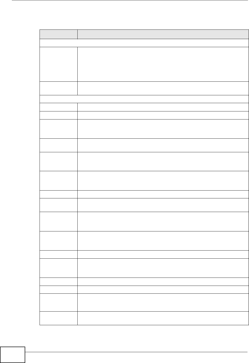
Chapter 14 Quality of Service (QoS)
P-660N-T1A User’s Guide
172
The following table describes the labels in this screen.
Table 56 Advanced Setup > QoS
LABEL DESCRIPTION
Quality of Service
QoS Use this field to turn on QoS to improve your network performance.
You can give priority to traffic that the ZyXEL Device forwards out
through the WAN interface. Give high priority to voice and video to make
them run more smoothly. Similarly, give low priority to many large file
downloads so that they do not reduce the quality of other applications.
Summary Click this to open a summary table showing the QoS settings. See
Section 14.2.1 on page 173 for more details.
Rule
Rule Index Select the rule’s index number from the drop-down list box.
Active Use this field to enable or disable the rule.
Application Select an application from the drop-down list box. The Destination Port
Range and Protocol ID fields may change depending on the type of
applications you choose.
Physical Ports Select Enet1 to apply the rule to the Ethernet port or WLAN to apply the
rule to wireless traffic.
Destination
MAC Type a destination MAC address here. QoS is then applied to traffic
containing this destination MAC address. Leave it blank to apply the rule
to all MAC addresses.
IP Enter a destination IP address in dotted decimal notation. QoS is then
applied to traffic containing this destination IP address. A blank
destination IP address means any destination IP address.
Mask Enter a destination subnet mask here.
Port Range Either use the default value set by the application you choose, or enter
the port number to which the rule should be applied.
Source MAC Type a source MAC address here. QoS is then applied to traffic containing
this source MAC address. Leave it blank to apply the rule to all MAC
addresses.
IP Enter a source IP address in dotted decimal notation. QoS is then applied
to traffic containing this source IP address. A blank source IP address
means any source IP address.
Mask Enter a source subnet mask here.
Port Range Enter the port number to which the rule should be applied. 0 means any
source port number. See Appendix E on page 307 for some common
services and port numbers.
Protocol ID Select an IP protocol type from the drop-down list box.
Vlan ID Range Enter the source VLAN ID in this field.
IPP/DS Field Select IPP/TOS to specify an IP precedence range and type of services.
Select DSCP to specify a DiffServ Code Point (DSCP) range.
IP Precedence
Range Enter a range from 0 to 7 for IP precedence. Zero is the lowest priority
and seven is the highest.
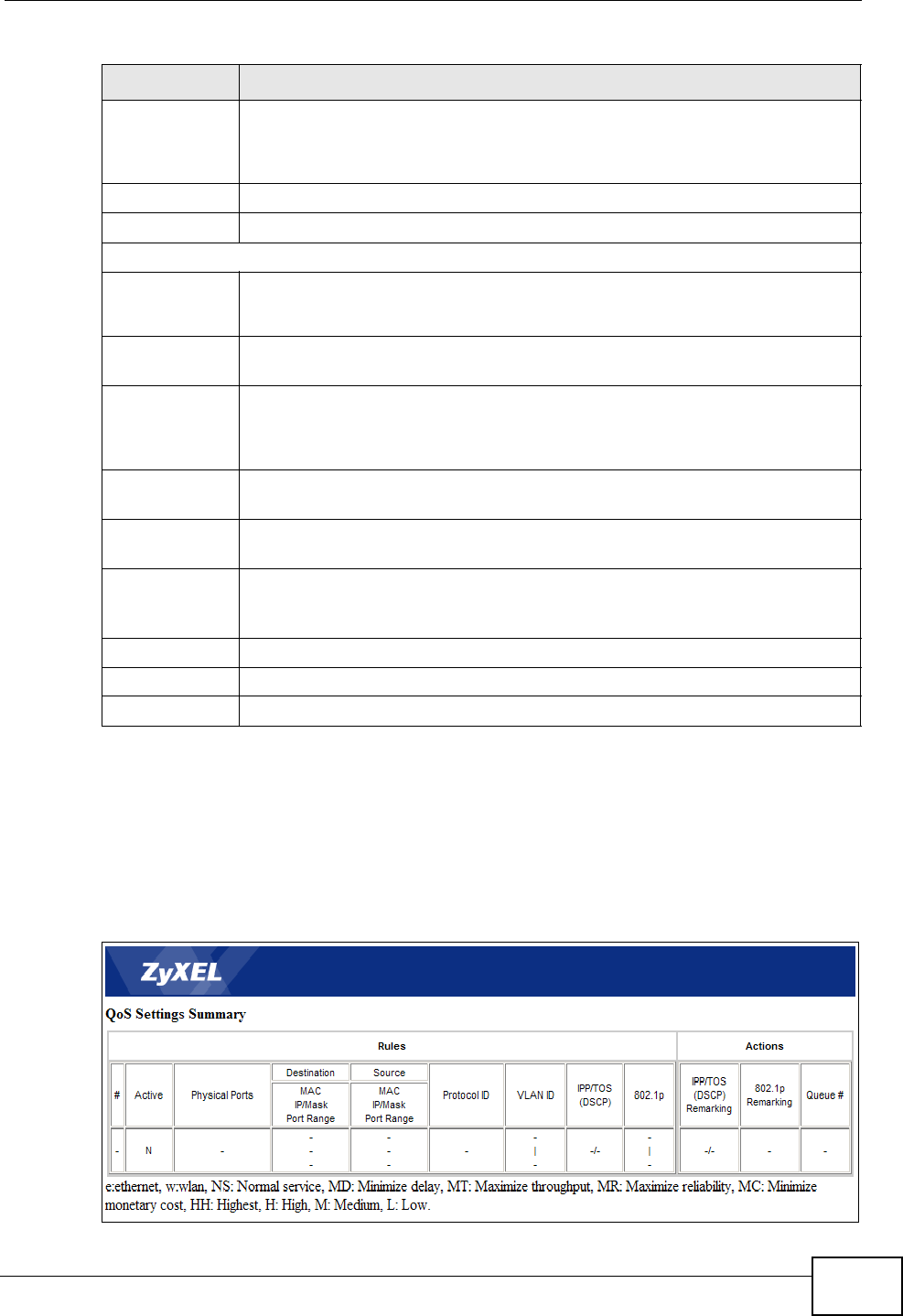
Chapter 14 Quality of Service (QoS)
P-660N-T1A User’s Guide 173
14.2.1 The QoS Settings Summary Screen
Use this screen to display a summary of rules and actions configured for the
ZyXEL Device. In the Advanced > QoS screen, click the QoS Settings
Summary button to open the following screen.
Figure 86 Advanced Setup > QoS > QoS Settings Summary
Type of
Service Select a type of service from the drop-down list box.
Available options are: Normal service, Minimize delay, Maximize
throughput, Maximize reliability and Minimize monetary cost.
DSCP Range Specify a DSCP number between 0 and 63 in this field.
802.1p Select a priority level (0 to 7) from the drop-down list box.
Action
IPP/DS Field Select IPP/TOS to specify an IP precedence range and type of services.
Select DSCP to specify a DiffServ Code Point (DSCP) range.
IP Precedence
Remarking Enter a range from 0 to 7 to re-assign IP precedence to matched traffic.
Zero is the lowest priority and seven is the highest.
Type of
Service
Remarking
Select a type of service to re-assign the priority level to matched traffic.
Available options are: Normal service, Minimize delay, Maximize
throughput, Maximize reliability and Minimize monetary cost.
DSCP
Remarking Specify a DSCP number between 0 and 63 to re-assign the priority level
to matched traffic.
802.1p
Remarking Select a priority level (0 to 7) to re-assign the priority level to matched
traffic.
Queue # Specify a Low, Medium, High or Highest queue tag to matched traffic.
Traffic assigned to a higher queue gets through faster while traffic in
lower queues is dropped when there is network congestion.
ADD Click this to add the rule.
DELETE Click this to remove the rule.
CANCEL Click this to restore previously saved settings.
Table 56 Advanced Setup > QoS
LABEL DESCRIPTION
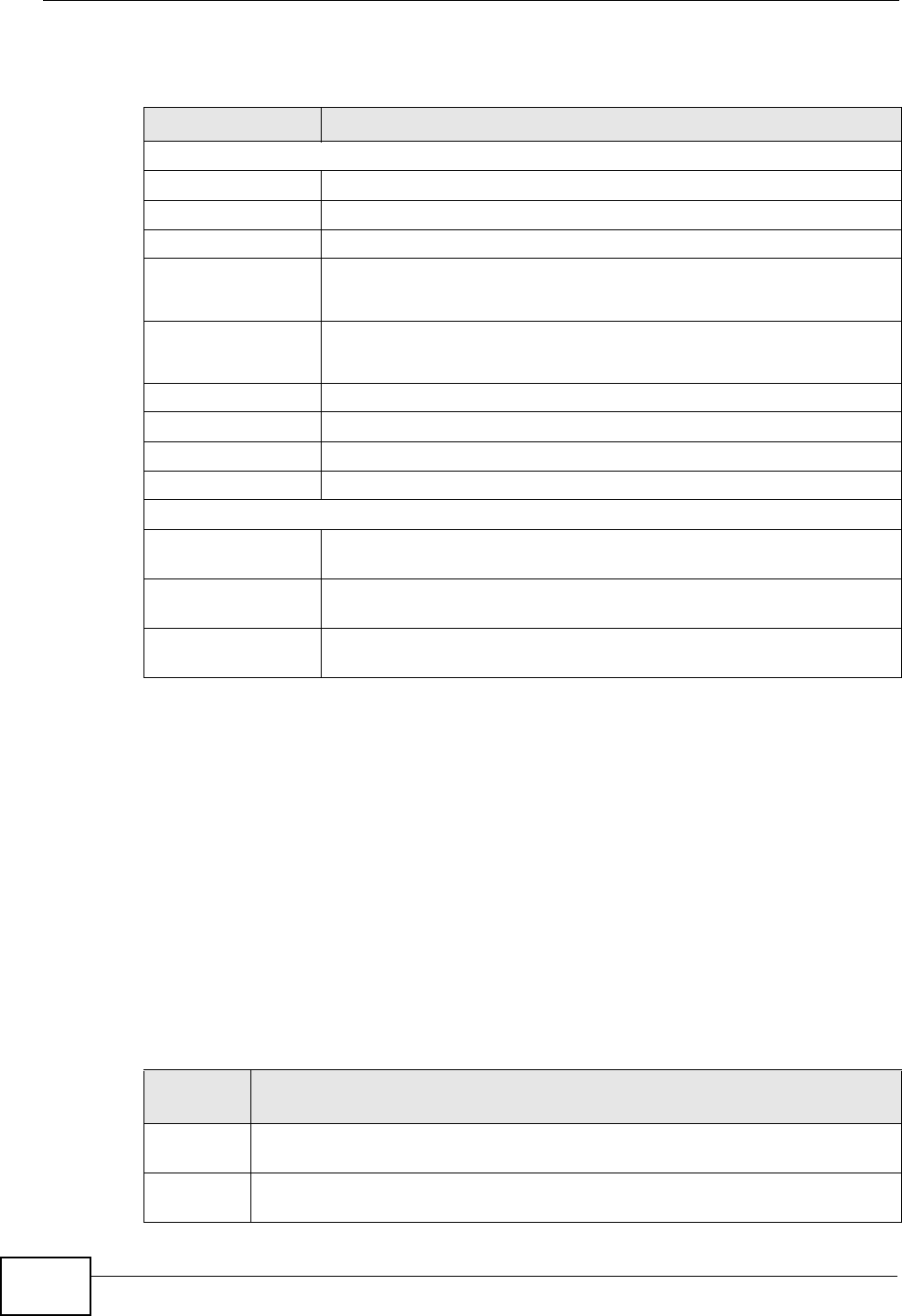
Chapter 14 Quality of Service (QoS)
P-660N-T1A User’s Guide
174
The following table describes the labels in this screen.
14.3 Technical Reference
This section provides some technical background information about the topics
covered in this chapter.
14.3.1 IEEE 802.1p
IEEE 802.1p specifies the user priority field and defines up to eight separate traffic
types. The following table describes the traffic types defined in the IEEE 802.1d
standard (which incorporates the 802.1p).
Table 57 Advanced Setup > QoS > QoS Settings Summary
LABEL DESCRIPTION
Rules
#This is the rule’s index number.
Active This shows whether the rule is enabled or disabled.
Physical Ports This is the physical port associated with the rule.
Destination MAC
and IP/Mask
Port Ranges
This is the port range for destination MAC address and IP address.
Source MAC and
IP/Mask Port
Ranges
This is the port range for source MAC address and IP address.
Protocol ID This is the protocol ID associated with the rule.
VLAN ID This is the VLAN ID associated with the rule.
IPP/TOS (DSCP) This shows the IPP/TOS or DSCP settings.
802.1p This is the 802.1p priority level.
Actions
IPP/TOS (DSCP)
Remarking The ZyXEL Device re-assigns the priority values specified in this field
to matched traffic.
802.1p
Remarking The ZyXEL Device re-assigns the priority levels specified in this field
to matched traffic.
Queue # The ZyXEL Device assigns the queue level specified in this field to
matched traffic.
Table 58 IEEE 802.1p Priority Level and Traffic Type
PRIORITY
LEVEL TRAFFIC TYPE
Level 7 Typically used for network control traffic such as router configuration
messages.
Level 6 Typically used for voice traffic that is especially sensitive to jitter (jitter is the
variations in delay).
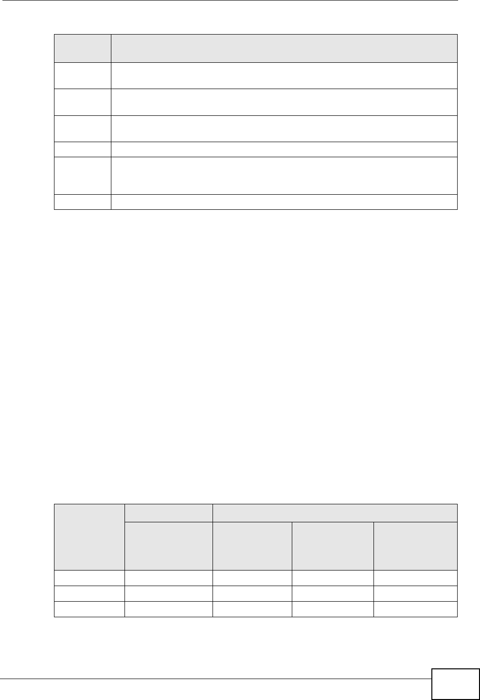
Chapter 14 Quality of Service (QoS)
P-660N-T1A User’s Guide 175
14.3.2 IP Precedence
Similar to IEEE 802.1p prioritization at layer-2, you can use IP precedence to
prioritize packets in a layer-3 network. IP precedence uses three bits of the eight-
bit ToS (Type of Service) field in the IP header. There are eight classes of services
(ranging from zero to seven) in IP precedence. Zero is the lowest priority level and
seven is the highest.
14.3.3 Automatic Priority Queue Assignment
If you enable QoS on the ZyXEL Device, the ZyXEL Device can automatically base
on the IEEE 802.1p priority level, IP precedence and/or packet length to assign
priority to traffic which does not match a class.
The following table shows you the internal layer-2 and layer-3 QoS mapping on
the ZyXEL Device. On the ZyXEL Device, traffic assigned to higher priority queues
gets through faster while traffic in lower index queues is dropped if the network is
congested.
Level 5 Typically used for video that consumes high bandwidth and is sensitive to
jitter.
Level 4 Typically used for controlled load, latency-sensitive traffic such as SNA
(Systems Network Architecture) transactions.
Level 3 Typically used for “excellent effort” or better than best effort and would
include important business traffic that can tolerate some delay.
Level 2 This is for “spare bandwidth”.
Level 1 This is typically used for non-critical “background” traffic such as bulk
transfers that are allowed but that should not affect other applications and
users.
Level 0 Typically used for best-effort traffic.
Table 58 IEEE 802.1p Priority Level and Traffic Type
PRIORITY
LEVEL TRAFFIC TYPE
Table 59 Internal Layer2 and Layer3 QoS Mapping
PRIORITY
QUEUE
LAYER 2 LAYER 3
IEEE 802.1P
USER PRIORITY
(ETHERNET
PRIORITY)
TOS (IP
PRECEDENCE) DSCP IP PACKET
LENGTH (BYTE)
0 1 0 000000
12
2 0 0 000000 >1100

Chapter 14 Quality of Service (QoS)
P-660N-T1A User’s Guide
176
3 3 1 001110
001100
001010
001000
250~1100
4 4 2 010110
010100
010010
010000
5 5 3 011110
011100
011010
011000
<250
6 6 4 100110
100100
100010
100000
5 101110
101000
7 7 6 110000
111000
7
Table 59 Internal Layer2 and Layer3 QoS Mapping
PRIORITY
QUEUE
LAYER 2 LAYER 3
IEEE 802.1P
USER PRIORITY
(ETHERNET
PRIORITY)
TOS (IP
PRECEDENCE) DSCP IP PACKET
LENGTH (BYTE)

P-660N-T1A User’s Guide 177
CHAPTER 15
Dynamic DNS Setup
15.1 Overview
Dynamic DNS allows you to update your current dynamic IP address with one or
many dynamic DNS services so that anyone can contact you (in NetMeeting, CU-
SeeMe, etc.). You can also access your FTP server or Web site on your own
computer using a domain name (for instance myhost.dhs.org, where myhost is a
name of your choice) that will never change instead of using an IP address that
changes each time you reconnect. Your friends or relatives will always be able to
call you even if they don't know your IP address.
First of all, you need to have registered a dynamic DNS account with
www.dyndns.org. This is for people with a dynamic IP from their ISP or DHCP
server that would still like to have a domain name. The Dynamic DNS service
provider will give you a password or key.
15.1.1 What You Can Do in the DDNS Screen
Use the Dynamic DNS screen (Section 15.2 on page 178) to enable DDNS and
configure the DDNS settings on the ZyXEL Device.
15.1.2 What You Need To Know
The following terms and concepts may help as you read this chapter.
DYNDNS Wildcard
Enabling the wildcard feature for your host causes *.yourhost.dyndns.org to be
aliased to the same IP address as yourhost.dyndns.org. This feature is useful if
you want to be able to use, for example, www.yourhost.dyndns.org and still reach
your hostname.
If you have a private WAN IP address, then you cannot use Dynamic DNS.
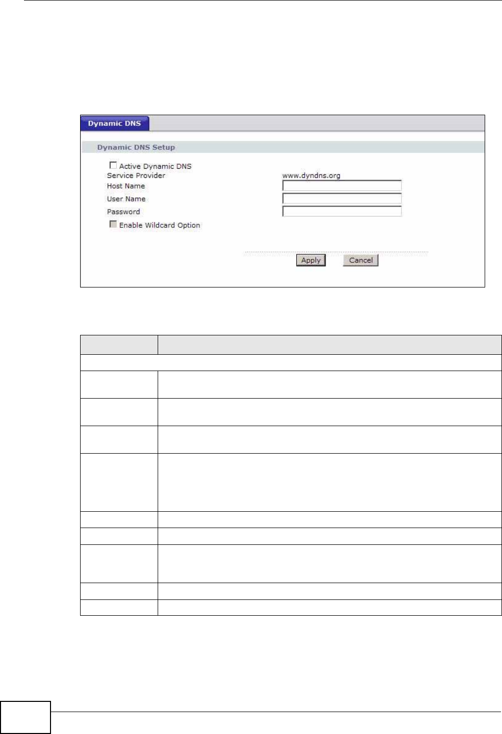
Chapter 15 Dynamic DNS Setup
P-660N-T1A User’s Guide
178
15.2 The Dynamic DNS Screen
Use this screen to change your ZyXEL Device’s DDNS. Click Advanced >
Dynamic DNS. The screen appears as shown.
Figure 87 Advanced > Dynamic DNS
The following table describes the fields in this screen.
Table 60 Advanced > Dynamic DNS
LABEL DESCRIPTION
Dynamic DNS Setup
Active
Dynamic DNS Select this check box to use dynamic DNS.
Service
Provider This is the name of your Dynamic DNS service provider.
Dynamic DNS
Type Select the type of service that you are registered for from your Dynamic
DNS service provider.
Host Name Type the domain name assigned to your ZyXEL Device by your Dynamic
DNS provider.
You can specify up to two host names in the field separated by a comma
(",").
User Name Type your user name.
Password Type the password assigned to you.
Enable
Wildcard
Option
Select the check box to enable DynDNS Wildcard.
Apply Click this to save your changes.
Cancel Click this to restore your previously saved settings.
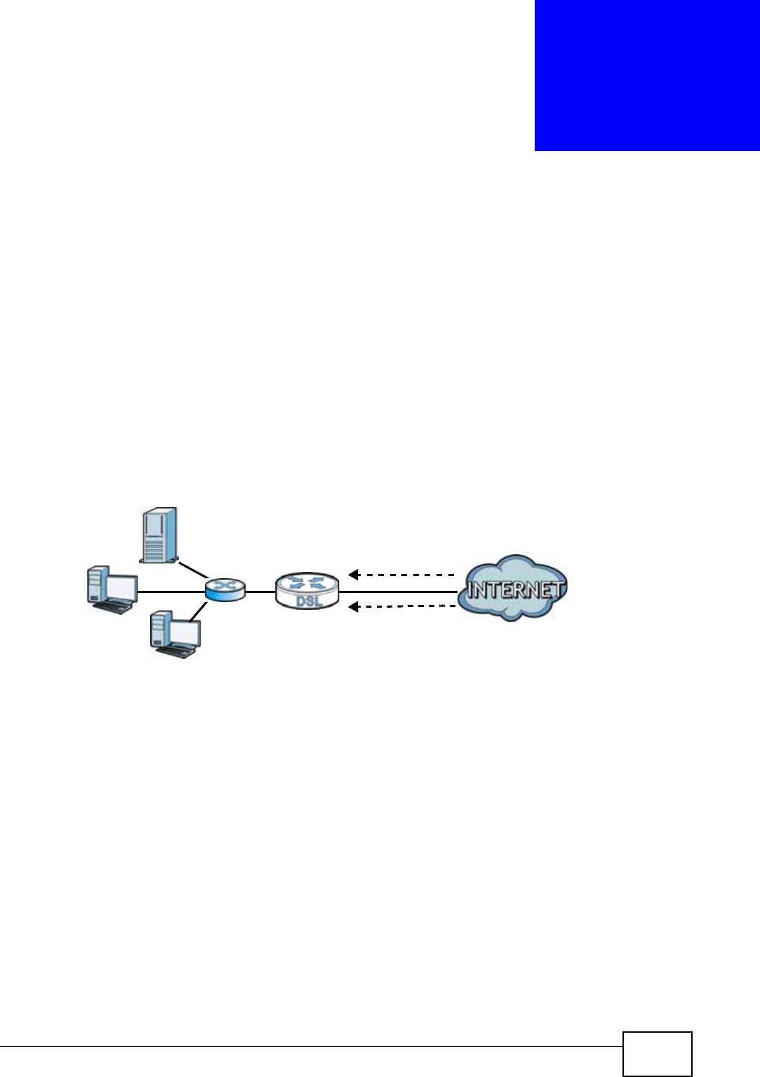
P-660N-T1A User’s Guide 179
CHAPTER 16
Remote Management
16.1 Overview
Remote management allows you to determine which services/protocols can access
which ZyXEL Device interface (if any) from which computers.
The following figure shows remote management of the ZyXEL Device coming in
from the WAN.
Figure 88 Remote Management From the WAN
Note: When you configure remote management to allow management from the WAN,
you still need to configure a firewall rule to allow access.
You may manage your ZyXEL Device from a remote location via:
•Internet (WAN only)
•LAN only
•WLAN only
•LAN and WAN
• LAN and WLAN
•WLAN and WAN
• ALL (WAN, LAN and WLAN)
• None (Disable)
LAN WAN
HTTP
Telnet

Chapter 16 Remote Management
P-660N-T1A User’s Guide
180
To disable remote management of a service, select Disable in the corresponding
Service Access field.
You may only have one remote management session running at a time. The ZyXEL
Device automatically disconnects a remote management session of lower priority
when another remote management session of higher priority starts. The priorities
for the different types of remote management sessions are as follows.
1Telnet
2HTTP
16.1.1 What You Can Do in the Remote Management Screens
•Use the WWW screen (Section 16.2 on page 181) to configure through which
interface(s) and from which IP address(es) users can use HTTP to manage the
ZyXEL Device.
•Use the Telnet screen (Section 16.3 on page 182) to configure through which
interface(s) and from which IP address(es) users can use Telnet to manage the
ZyXEL Device.
•Use the FTP screen (Section 16.4 on page 183) to configure through which
interface(s) and from which IP address(es) users can use FTP to access the
ZyXEL Device.
•Use the SNMP screen (Section 16.5 on page 184) to change your ZyXEL
Device’s SNMP settings.
•Use the DNS screen (Section 16.6 on page 186) to configure through which
interface(s) and from which IP address(es) users can send DNS queries to the
ZyXEL Device.
•Use the ICMP screen (Section 16.7 on page 187) to set whether or not your
ZyXEL Device will respond to pings and probes for services that you have not
made available.
16.1.2 What You Need to Know
The following terms and concepts may help as you read this chapter.
Remote Management Limitations
Remote management does not work when:
• You have not enabled that service on the interface in the corresponding remote
management screen.
• You have disabled that service in one of the remote management screens.
• The IP address in the Secured Client IP Address field does not match the
client IP address. If it does not match, the ZyXEL Device will disconnect the
session immediately.
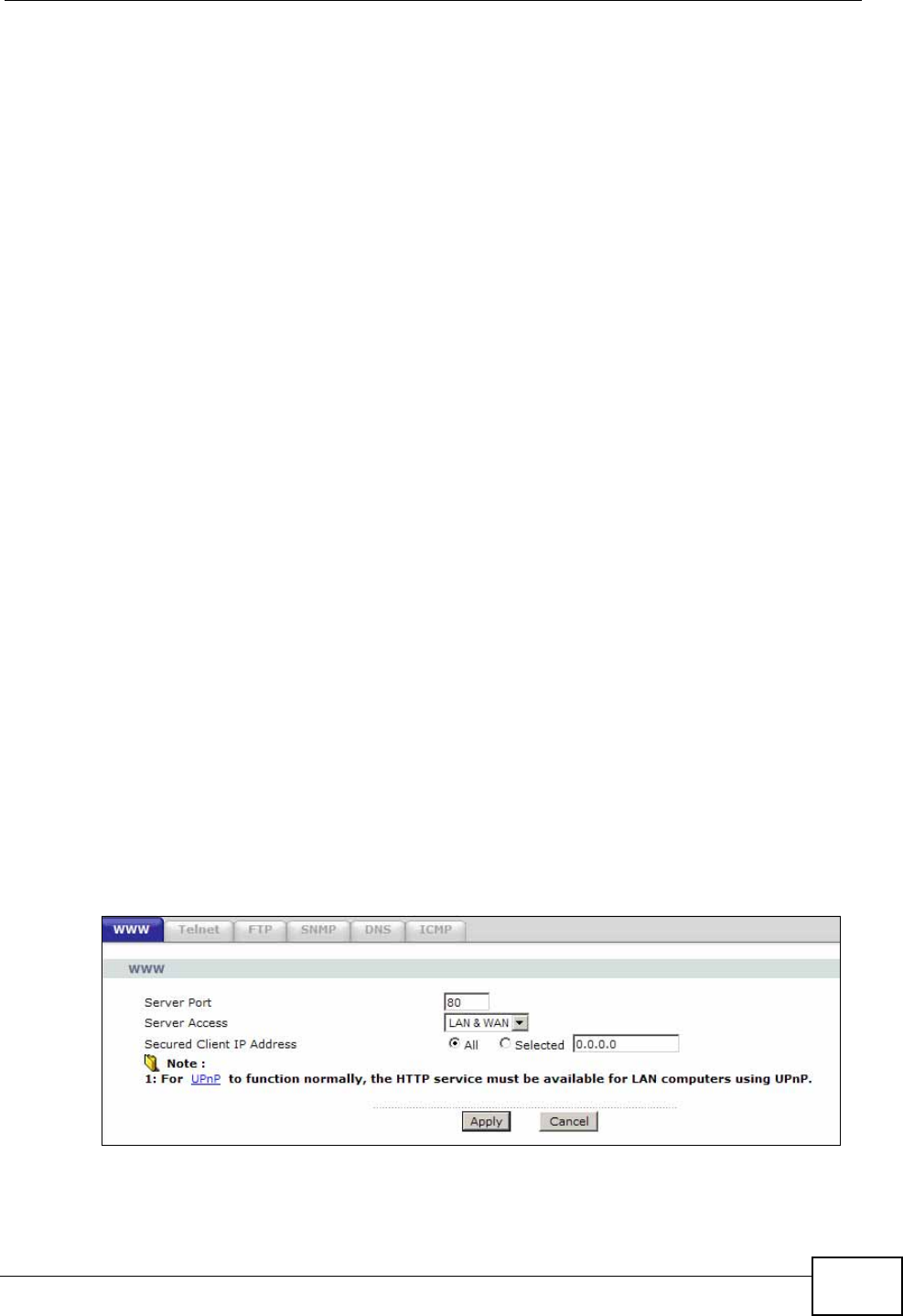
Chapter 16 Remote Management
P-660N-T1A User’s Guide 181
• There is already another remote management session with an equal or higher
priority running. You may only have one remote management session running
at one time.
• There is a firewall rule that blocks it.
Remote Management and NAT
When NAT is enabled:
• Use the ZyXEL Device’s WAN IP address when configuring from the WAN.
• Use the ZyXEL Device’s LAN IP address when configuring from the LAN.
System Timeout
There is a default system management idle timeout of five minutes (three
hundred seconds). The ZyXEL Device automatically logs you out if the
management session remains idle for longer than this timeout period. The
management session does not time out when a statistics screen is polling.
16.2 The WWW Screen
Use this screen to specify how to connect to the ZyXEL Device from a web
browser, such as Internet Explorer.
Note: If you disable the WWW service in the Remote MGMT > WWW screen, then
the ZyXEL Device blocks all HTTP connection attempts.
16.2.1 Configuring the WWW Screen
Click Advanced > Remote MGMT to display the WWW screen.
Figure 89 Advanced > Remote MGMT > WWW
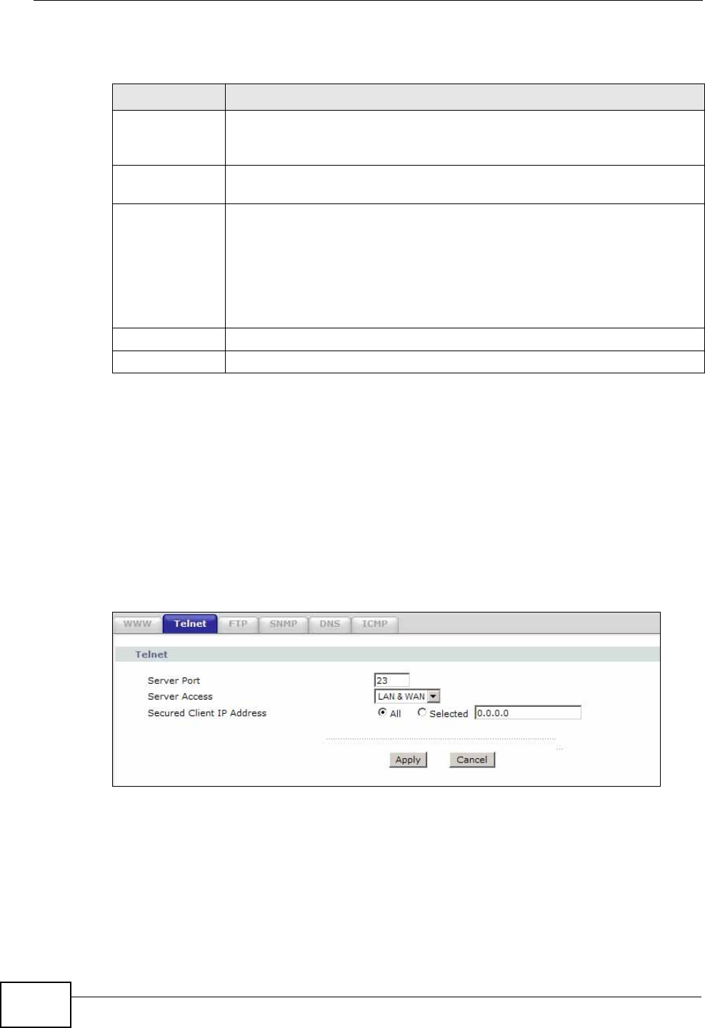
Chapter 16 Remote Management
P-660N-T1A User’s Guide
182
The following table describes the labels in this screen.
16.3 The Telnet Screen
You can use Telnet to access the ZyXEL Device’s command line interface. Specify
which interfaces allow Telnet access and from which IP address the access can
come.
Click Advanced > Remote MGMT > Telnet tab to display the screen as shown.
Figure 90 Advanced > Remote MGMT > Telnet
Table 61 Advanced > Remote Management > WWW
LABEL DESCRIPTION
Server Port You may change the server port number for a service, if needed.
However, you must use the same port number in order to use that
service for remote management.
Server Access Select the interface(s) through which a computer may access the ZyXEL
Device using this service.
Secured Client
IP Address A secured client is a “trusted” computer that is allowed to communicate
with the ZyXEL Device using this service.
Select All to allow any computer to access the ZyXEL Device using this
service.
Choose Selected to just allow the computer with the IP address that
you specify to access the ZyXEL Device using this service.
Apply Click this to save your changes.
Cancel Click this to restore your previously saved settings.
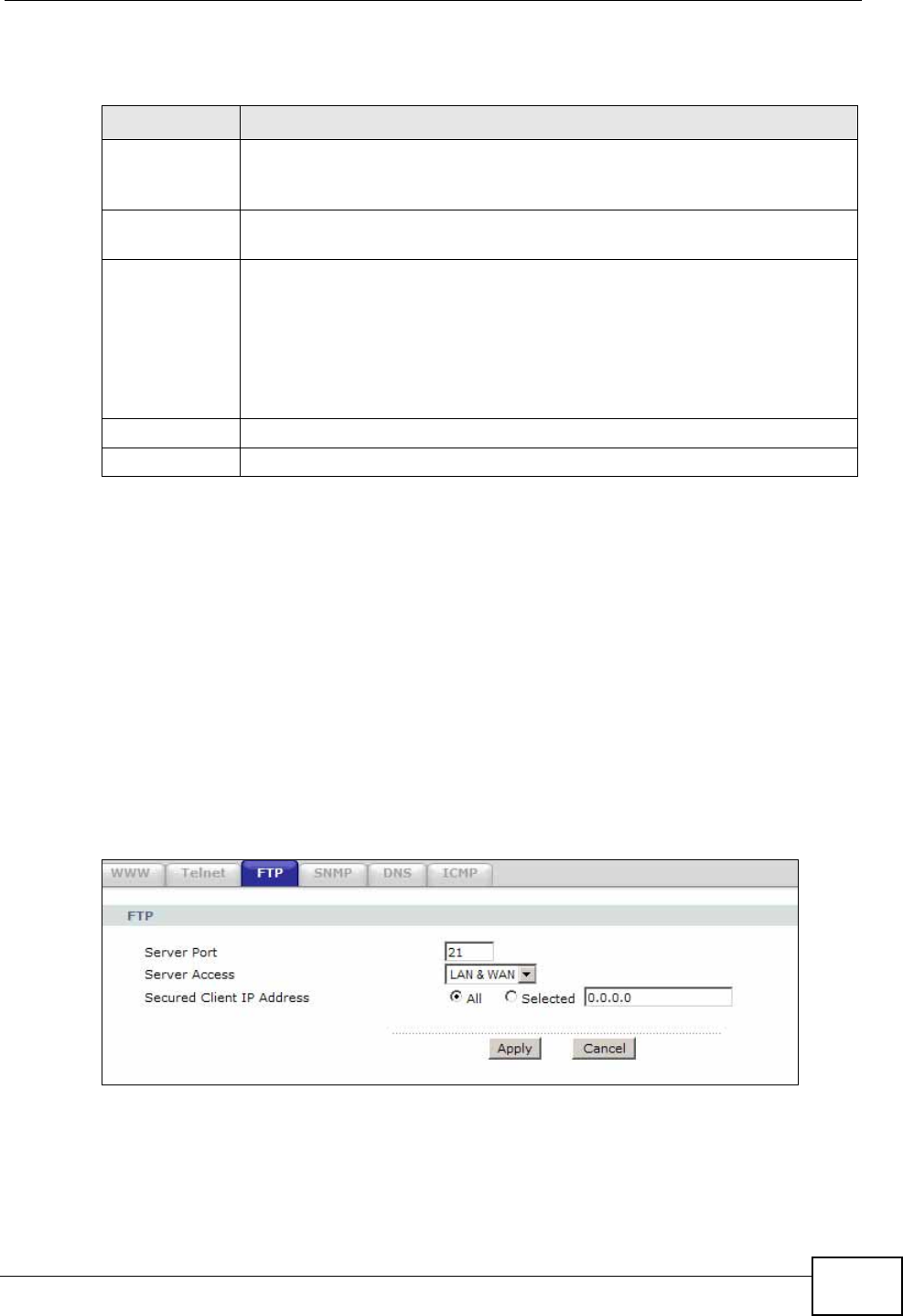
Chapter 16 Remote Management
P-660N-T1A User’s Guide 183
The following table describes the labels in this screen.
16.4 The FTP Screen
You can use FTP (File Transfer Protocol) to upload and download the ZyXEL
Device’s firmware and configuration files. Please see the User’s Guide chapter on
firmware and configuration file maintenance for details. To use this feature, your
computer must have an FTP client.
Use this screen to specify which interfaces allow FTP access and from which IP
address the access can come. To change your ZyXEL Device’s FTP settings, click
Advanced > Remote MGMT > FTP. The screen appears as shown.
Figure 91 Advanced > Remote MGMT > FTP
Table 62 Advanced > Remote Management > Telnet
LABEL DESCRIPTION
Server Port You may change the server port number for a service if needed, however
you must use the same port number in order to use that service for
remote management.
Server Access Select the interface(s) through which a computer may access the ZyXEL
Device using this service.
Secured Client
IP Address A secured client is a “trusted” computer that is allowed to communicate
with the ZyXEL Device using this service.
Select All to allow any computer to access the ZyXEL Device using this
service.
Choose Selected to just allow the computer with the IP address that you
specify to access the ZyXEL Device using this service.
Apply Click this to save your changes.
Cancel Click this to restore your previously saved settings.
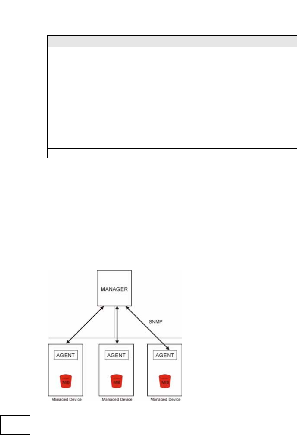
Chapter 16 Remote Management
P-660N-T1A User’s Guide
184
The following table describes the labels in this screen.
16.5 The SNMP Screen
Simple Network Management Protocol is a protocol used for exchanging
management information between network devices. Your ZyXEL Device supports
SNMP agent functionality, which allows a manager station to manage and monitor
the ZyXEL Device through the network. The ZyXEL Device supports SNMP version
one (SNMPv1) and version two (SNMPv2c). The next figure illustrates an SNMP
management operation.
Figure 92 SNMP Management Model
Table 63 Advanced > Remote MGMT > FTP
LABEL DESCRIPTION
Server Port You may change the server port number for a service, if needed.
However, you must use the same port number in order to use that
service for remote management.
Server Access Select the interface(s) through which a computer may access the ZyXEL
Device using this service.
Secured Client
IP Address A secured client is a “trusted” computer that is allowed to communicate
with the ZyXEL Device using this service.
Select All to allow any computer to access the ZyXEL Device using this
service.
Choose Selected to just allow the computer with the IP address that
you specify to access the ZyXEL Device using this service.
Apply Click this to save your changes.
Cancel Click this to restore your previously saved settings.
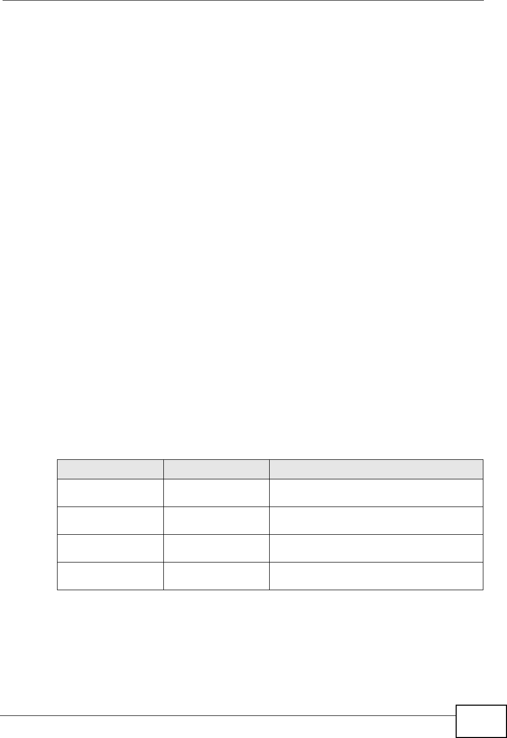
Chapter 16 Remote Management
P-660N-T1A User’s Guide 185
An SNMP managed network consists of two main types of component: agents and
a manager.
An agent is a management software module that resides in a managed device (the
ZyXEL Device). An agent translates the local management information from the
managed device into a form compatible with SNMP. The manager is the console
through which network administrators perform network management functions. It
executes applications that control and monitor managed devices.
The managed devices contain object variables/managed objects that define each
piece of information to be collected about a device. Examples of variables include
such as number of packets received, node port status etc. A Management
Information Base (MIB) is a collection of managed objects. SNMP allows a
manager and agents to communicate for the purpose of accessing these objects.
16.5.1 Supported MIBs
The ZyXEL Device supports MIB II that is defined in RFC-1213 and RFC-1215. The
ZyXEL Device also supports private MIBs (zywall.mib and zyxel-zywall-ZLD-
Common.mib) to collect information about CPU and memory usage and VPN total
throughput. The focus of the MIBs is to let administrators collect statistical data
and monitor status and performance. You can download the ZyXEL Device’s MIBs
from www.zyxel.com.
16.5.2 SNMP Traps
The ZyXEL Device will send traps to the SNMP manager when any one of the
following events occurs.
Table 64 SNMP Traps
OBJECT LABEL OBJECT ID DESCRIPTION
Cold Start 1.3.6.1.6.3.1.1.5.1 This trap is sent when the ZyXEL Device is
turned on or an agent restarts.
linkDown 1.3.6.1.6.3.1.1.5.3 This trap is sent when the Ethernet link is
down.
linkUp 1.3.6.1.6.3.1.1.5.4 This trap is sent when the Ethernet link is
up.
authenticationFailure 1.3.6.1.6.3.1.1.5.5 This trap is sent when an SNMP request
comes from non-authenticated hosts.
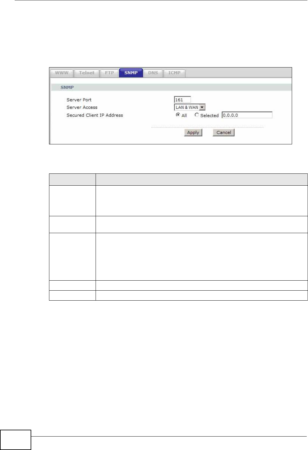
Chapter 16 Remote Management
P-660N-T1A User’s Guide
186
16.5.3 Configuring SNMP
To change your ZyXEL Device’s SNMP settings, click Advanced > Remote MGMT
> SNMP tab. The screen appears as shown.
Figure 93 Advanced > Remote MGMT > SNMP
The following table describes the labels in this screen.
16.6 The DNS Screen
Use DNS (Domain Name System) to map a domain name to its corresponding IP
address and vice versa. Refer to Chapter 7 on page 85 for background
information.
Use this screen to set from which IP address the ZyXEL Device will accept DNS
queries and on which interface it can send them your ZyXEL Device’s DNS
settings. This feature is not available when the ZyXEL Device is set to bridge
Table 65 Advanced > Remote MGMT > SNMP
LABEL DESCRIPTION
Server Port The SNMP agent listens on port 161 by default. If you change the SNMP
server port to a different number on the ZyXEL Device, for example
8161, then you must notify people who need to access the ZyXEL Device
SNMP agent to use the same port.
Server Access Select the interface(s) through which a computer may access the ZyXEL
Device using this service.
Secured Client
IP Address A secured client is a “trusted” computer that is allowed to access the
SNMP agent on the ZyXEL Device.
Select All to allow any computer to access the SNMP agent.
Choose Selected to just allow the computer with the IP address that you
specify to access the SNMP agent.
Apply Click Apply to save your changes back to the ZyXEL Device.
Cancel Click Cancel to begin configuring this screen afresh.
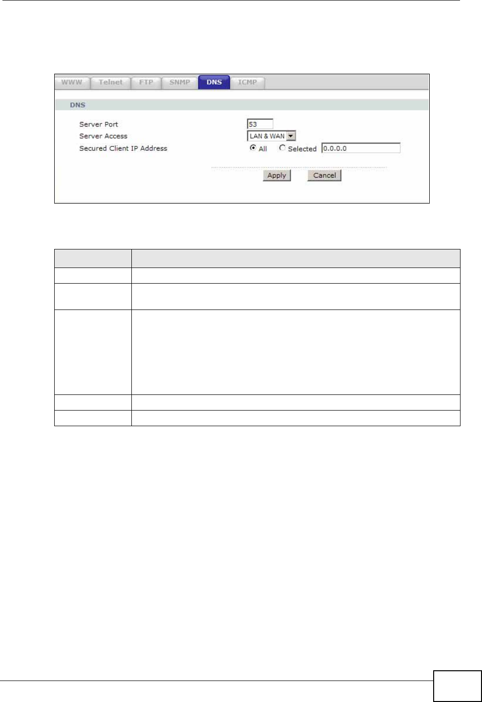
Chapter 16 Remote Management
P-660N-T1A User’s Guide 187
mode. Click Advanced > Remote MGMT > DNS to change your ZyXEL Device’s
DNS settings.
Figure 94 Advanced > Remote Management > DNS
The following table describes the labels in this screen.
16.7 The ICMP Screen
To change your ZyXEL Device’s security settings, click Advanced > Remote
MGMT > ICMP. The screen appears as shown.
If an outside user attempts to probe an unsupported port on your ZyXEL Device,
an ICMP response packet is automatically returned. This allows the outside user to
know the ZyXEL Device exists. Your ZyXEL Device supports anti-probing, which
prevents the ICMP response packet from being sent. This keeps outsiders from
discovering your ZyXEL Device when unsupported ports are probed.
Table 66 Advanced > Remote Management > DNS
LABEL DESCRIPTION
Server Port The DNS service port number is 53 and cannot be changed here.
Server Access Select the interface(s) through which a computer may send DNS queries
to the ZyXEL Device.
Secured Client
IP Address A secured client is a “trusted” computer that is allowed to send DNS
queries to the ZyXEL Device.
Select All to allow any computer to send DNS queries to the ZyXEL
Device.
Choose Selected to just allow the computer with the IP address that
you specify to send DNS queries to the ZyXEL Device.
Apply Click this to save your changes.
Cancel Click this to restore your previously saved settings.
Chapter 16 Remote Management
P-660N-T1A User’s Guide
188
Note: If you want your device to respond to pings and requests for unauthorized
services, you may also need to configure the firewall anti probing settings to
match.
Figure 95 Advanced > Remote Management > ICMP
The following table describes the labels in this screen.
Table 67 Advanced > Remote Management > ICMP
LABEL DESCRIPTION
ICMP Internet Control Message Protocol is a message control and error-
reporting protocol between a host server and a gateway to the Internet.
ICMP uses Internet Protocol (IP) datagrams, but the messages are
processed by the TCP/IP software and directly apparent to the
application user.
Respond to
Ping on The ZyXEL Device will not respond to any incoming Ping requests when
Disable is selected. Select LAN to reply to incoming LAN Ping requests.
Select WAN to reply to incoming WAN Ping requests. Otherwise select
LAN & WAN to reply to both incoming LAN and WAN Ping requests.
Apply Click this to save your changes.
Cancel Click this to restore your previously saved settings.

P-660N-T1A User’s Guide 189
CHAPTER 17
Universal Plug-and-Play (UPnP)
17.1 Overview
Universal Plug and Play (UPnP) is a distributed, open networking standard that
uses TCP/IP for simple peer-to-peer network connectivity between devices. A
UPnP device can dynamically join a network, obtain an IP address, convey its
capabilities and learn about other devices on the network. In turn, a device can
leave a network smoothly and automatically when it is no longer in use.
17.1.1 What You Can Do in the UPnP Screen
Use the UPnP screen (Section 17.2 on page 191) to enable UPnP on the ZyXEL
Device and allow UPnP-enabled applications to automatically configure the ZyXEL
Device.
17.1.2 What You Need to Know
The following terms and concepts may helps as you read this chapter.
Identifying UPnP Devices
UPnP hardware is identified as an icon in the Network Connections folder
(Windows XP). Each UPnP compatible device installed on your network will appear
as a separate icon. Selecting the icon of a UPnP device will allow you to access the
information and properties of that device.
NAT Traversal
UPnP NAT traversal automates the process of allowing an application to operate
through NAT. UPnP network devices can automatically configure network
addressing, announce their presence in the network to other UPnP devices and
enable exchange of simple product and service descriptions. NAT traversal allows
the following:
• Dynamic port mapping
• Learning public IP addresses

Chapter 17 Universal Plug-and-Play (UPnP)
P-660N-T1A User’s Guide
190
• Assigning lease times to mappings
Windows Messenger is an example of an application that supports NAT traversal
and UPnP.
See the NAT chapter for more information on NAT.
Cautions with UPnP
The automated nature of NAT traversal applications in establishing their own
services and opening firewall ports may present network security issues. Network
information and configuration may also be obtained and modified by users in some
network environments.
When a UPnP device joins a network, it announces its presence with a multicast
message. For security reasons, the ZyXEL Device allows multicast messages on
the LAN only.
All UPnP-enabled devices may communicate freely with each other without
additional configuration. Disable UPnP if this is not your intention.
UPnP and ZyXEL
ZyXEL has achieved UPnP certification from the Universal Plug and Play Forum
UPnP™ Implementers Corp. (UIC). ZyXEL's UPnP implementation supports
Internet Gateway Device (IGD) 1.0.
See the following sections for examples of installing and using UPnP.
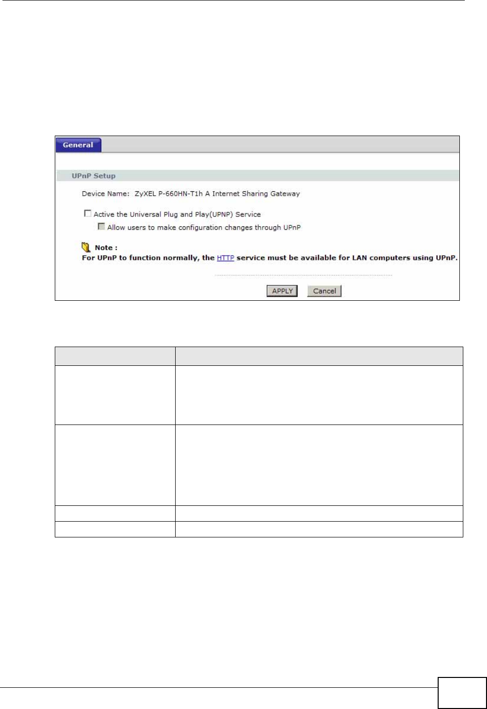
Chapter 17 Universal Plug-and-Play (UPnP)
P-660N-T1A User’s Guide 191
17.2 The UPnP Screen
Use the following screen to configure the UPnP settings on your ZyXEL Device.
Click Advanced > UPnP to display the screen shown next.
See Section 17.1 on page 189 for more information.
Figure 96 Advanced > UPnP > General
The following table describes the fields in this screen.
Table 68 Advanced > UPnP > General
LABEL DESCRIPTION
Active the Universal Plug
and Play (UPnP) Feature Select this check box to activate UPnP. Be aware that anyone
could use a UPnP application to open the web configurator's
login screen without entering the ZyXEL Device's IP address
(although you must still enter the password to access the web
configurator).
Allow users to make
configuration changes
through UPnP
Select this check box to allow UPnP-enabled applications to
automatically configure the ZyXEL Device so that they can
communicate through the ZyXEL Device, for example by using
NAT traversal, UPnP applications automatically reserve a NAT
forwarding port in order to communicate with another UPnP
enabled device; this eliminates the need to manually configure
port forwarding for the UPnP enabled application.
Apply Click this to save your changes.
Cancel Click this to restore your previously saved settings.
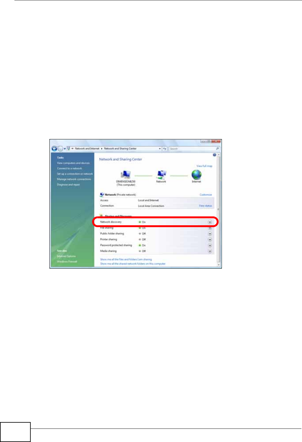
Chapter 17 Universal Plug-and-Play (UPnP)
P-660N-T1A User’s Guide
192
17.2.1 Installing UPnP in Windows
This section shows you how to configure or install UPnP in Windows.
17.2.1.1 Windows 7
Windows 7 already has UPnP installed. To enable it:
1Click Start > Control Panel and select Network and Internet.
2Click Network and Sharing Center.
3In the Network and Sharing window, set Network Discovery to On. This
activates the UPnP feature in Windows 7
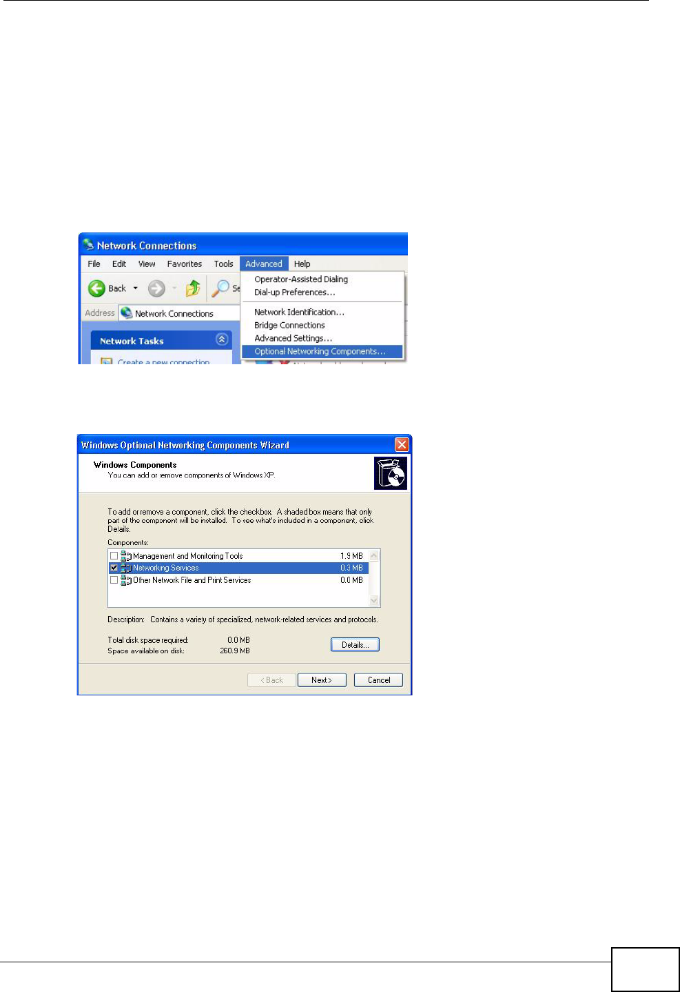
Chapter 17 Universal Plug-and-Play (UPnP)
P-660N-T1A User’s Guide 193
17.2.1.2 Windows XP
To install the UPnP in Windows XP:
1Click Start and Control Panel.
2Double-click Network Connections.
3In the Network Connections window, click Advanced in the main menu and
select Optional Networking Components ….
Network Co nnections
4The Windows Optional Networking Components Wizard window displays.
Select Networking Service in the Components selection box and click Details.
Windows Optional Networking Components Wizard
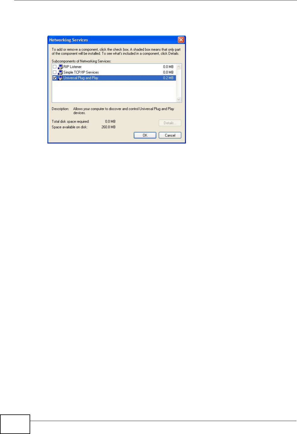
Chapter 17 Universal Plug-and-Play (UPnP)
P-660N-T1A User’s Guide
194
5In the Networking Services window, select the Universal Plug and Play check
box.
Networking Services
6Click OK to go back to the Windows Optional Networking Component Wizard
window and click Next.
17.2.2 Using UPnP in Windows XP
This section shows you how to use the UPnP feature in Windows XP. You must
already have UPnP installed in Windows XP and UPnP activated on the ZyXEL
Device.
Make sure the computer is connected to a LAN port of the ZyXEL Device. Turn on
your computer and the ZyXEL Device.
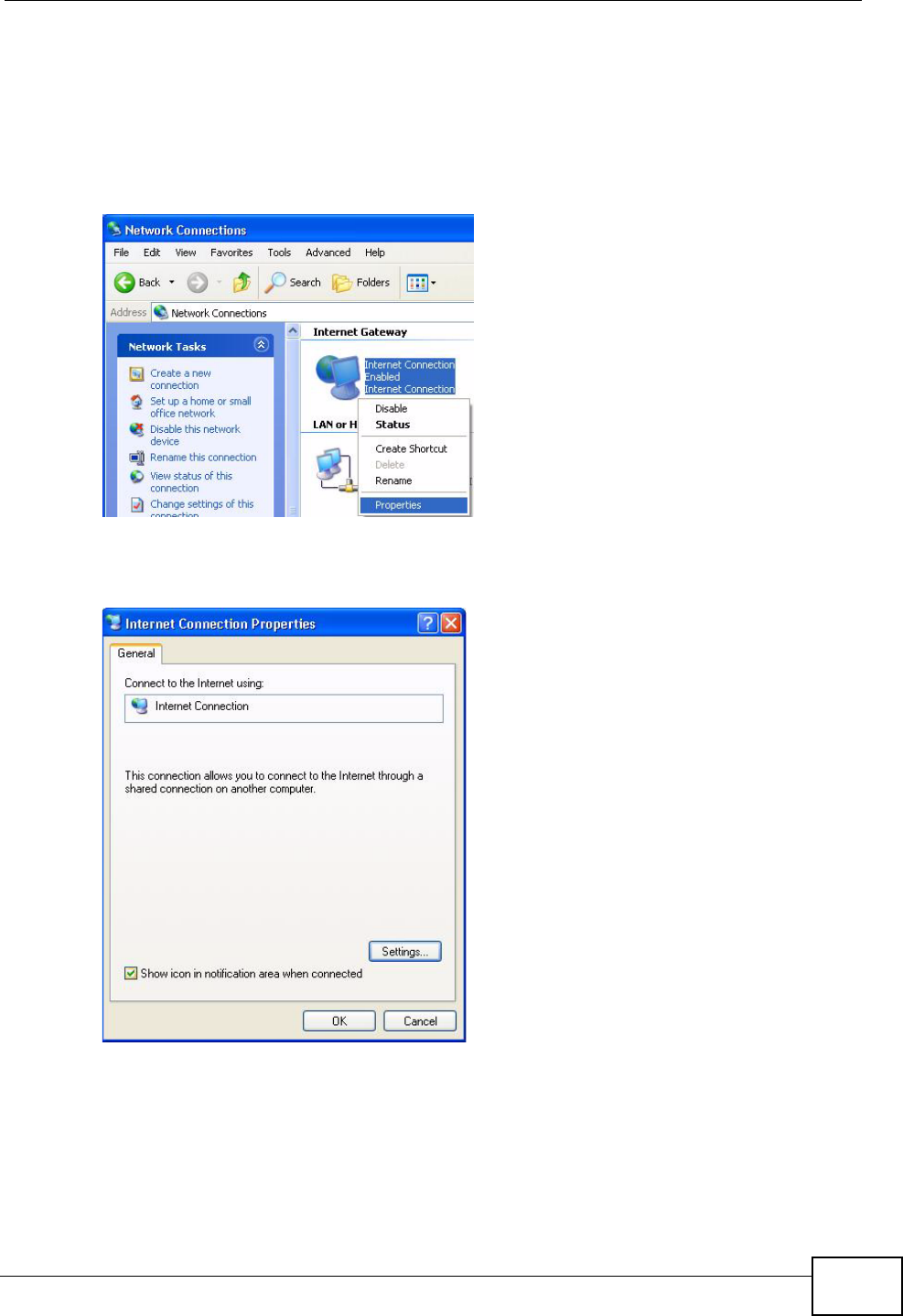
Chapter 17 Universal Plug-and-Play (UPnP)
P-660N-T1A User’s Guide 195
17.2.2.1 Auto-discover Your UPnP-enabled Network Device
1Click Start and Control Panel. Double-click Network Connections. An icon
displays under Internet Gateway.
2Right-click the icon and select Properties.
Network Co nnections
3In the Internet Connection Properties window, click Settings to see the port
mappings there were automatically created.
Internet Connection Properties
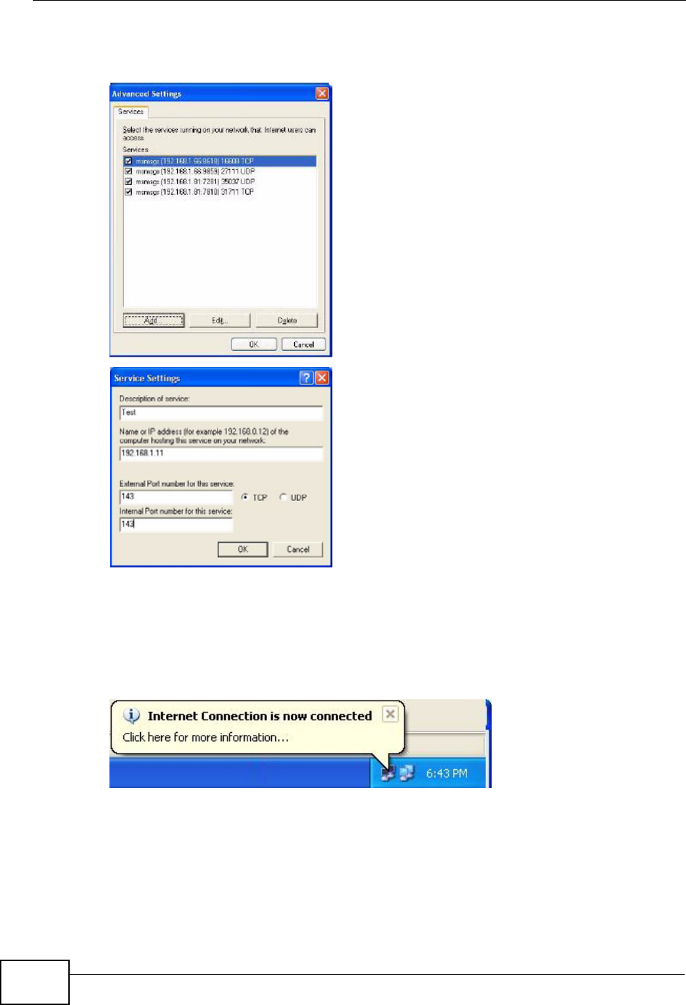
Chapter 17 Universal Plug-and-Play (UPnP)
P-660N-T1A User’s Guide
196
4You may edit or delete the port mappings or click Add to manually add port
mappings.
Internet Connection Properties: Advanced Settin gs
Internet Connection Properties: Advanced Settings: Add
5When the UPnP-enabled device is disconnected from your computer, all port
mappings will be deleted automatically.
6Select Show icon in notification area when connected option and click OK.
An icon displays in the system tray.
System Tray Icon
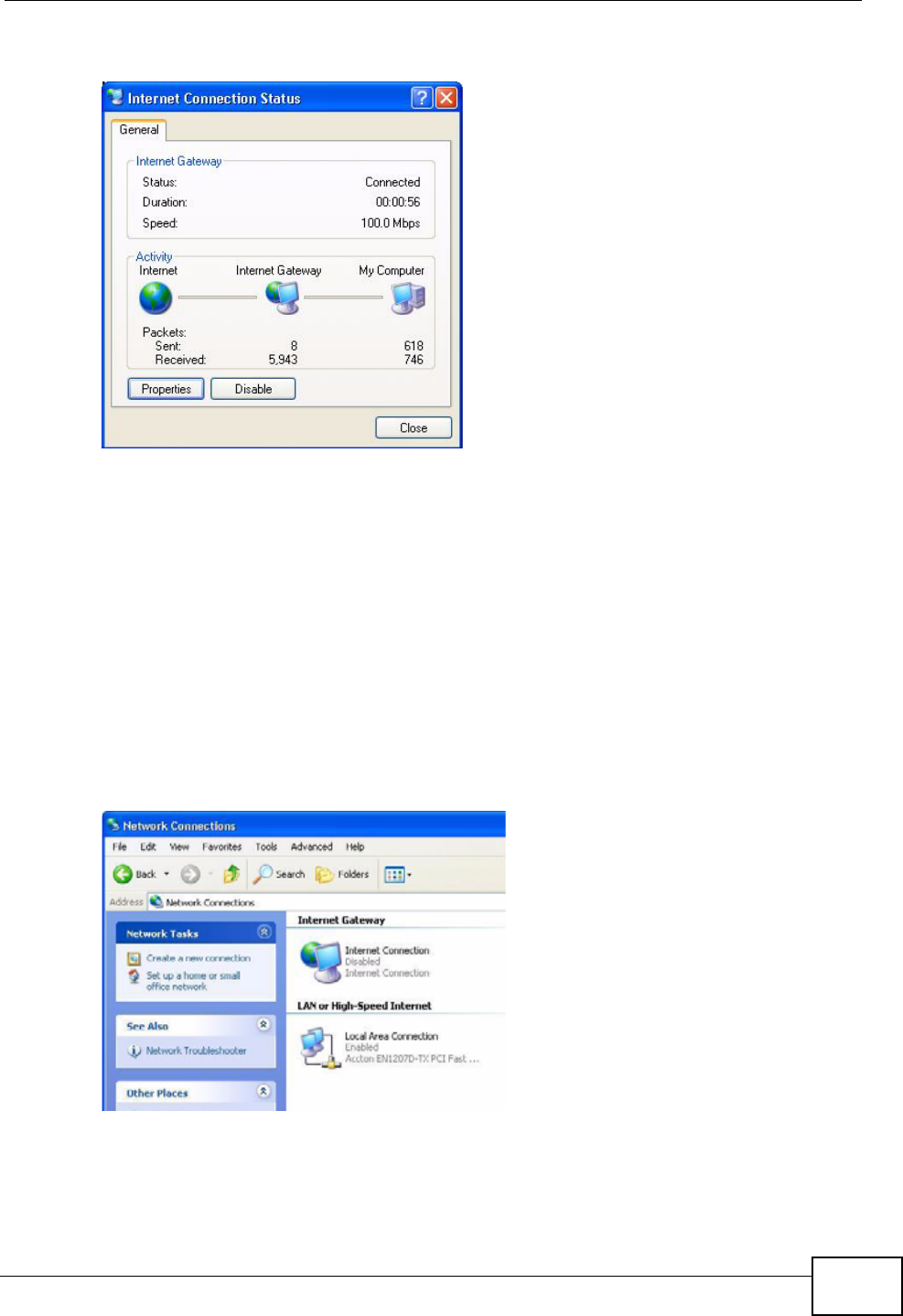
Chapter 17 Universal Plug-and-Play (UPnP)
P-660N-T1A User’s Guide 197
7Double-click on the icon to display your current Internet connection status.
Internet Connection Status
17.2.2.2 Web Configurator Easy Access
With UPnP, you can access the web-based configurator on the ZyXEL Device
without finding out the IP address of the ZyXEL Device first. This comes helpful if
you do not know the IP address of the ZyXEL Device.
Follow the steps below to access the web configurator.
1Click Start and then Control Panel.
2Double-click Network Connections.
3Select My Network Places under Other Places.
Network Co nnections
4An icon with the description for each UPnP-enabled device displays under Local
Network.
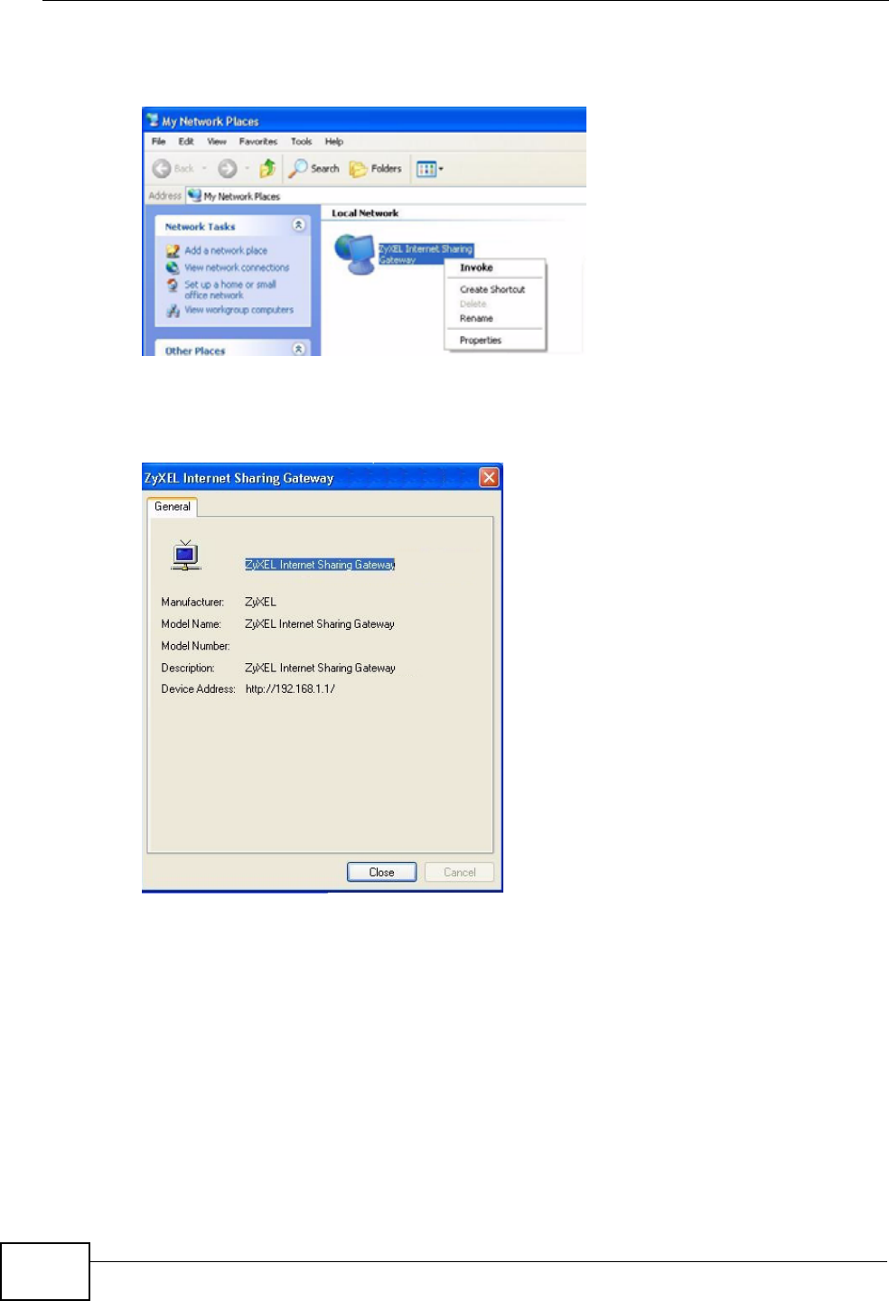
Chapter 17 Universal Plug-and-Play (UPnP)
P-660N-T1A User’s Guide
198
5Right-click on the icon for your ZyXEL Device and select Invoke. The web
configurator login screen displays.
Network Co nnections: My Netw ork Places
6Right-click on the icon for your ZyXEL Device and select Properties. A properties
window displays with basic information about the ZyXEL Device.
Network Co nnections: My Netw ork Places: Proper ties: Example

P-660HN-T1A User’s Guide 199
CHAPTER 18
CWMP
18.1 Overview
The ZyXEL Device supports TR-069 Amendment 1 (CPE WAN Management
Protocol Release 2.0) and TR-069 Amendment 2 (CPE WAN Management Protocol
v1.1, Release 3.0).
TR-069 is a protocol that defines how your ZyXEL Device (ZD) can be managed
via a management server (MS) such as ZyXEL’s Vantage Access.
Figure 97 LAN and WAN
An administrator can use a management server to remotely set up the ZyXEL
device, modify settings, perform firmware upgrades as well as monitor and
diagnose the ZyXEL device.
In order to use CWMP, you need to configure the following steps:
1Activate CWMP
2Specify the URL, username and password.
3Activate periodic inform and specify an interval value.
MSZD
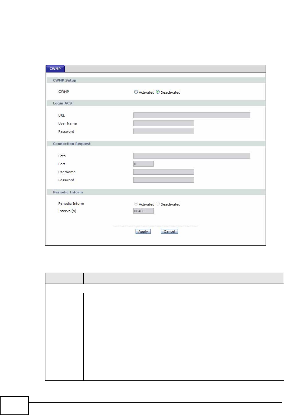
Chapter 18 CWMP
P-660HN-T1A User’s Guide
200
18.2 The CWMP Setup Screen
Use this screen to configure your ZyXEL Device to be managed by a management
server. Click Advanced> CWMP to display the following screen.
Figure 98 Advanced > CWMP
The following table describes the fields in this screen.
Table 69 Advanced > CWMP
LINK DESCRIPTION
CWMP Setup
CWMP Select Activated to allow the ZyXEL Device to be managed by a
management server or select Deactivated to not allow the ZyXEL Device
to be managed by a management server.
Login ACS Configure this part of the screen to log into the management server.
URL Type the IP address or domain name of the management server. If the
ZyXEL Device is behind a NAT router that assigns it a private IP address,
you will have to configure a NAT port forwarding rule on the NAT router.
User Name The user name is used to authenticate the ZyXEL Device when making a
connection to the management server. This user name on the management
server and the ZyXEL Device must be the same. Type a user name of up to
255 printable characters found on an English-language keyboard. Spaces
and characters such as @#$%^&*()_+ are allowed.

Chapter 18 CWMP
P-660HN-T1A User’s Guide 201
Password The password is used to authenticate the ZyXEL Device when making a
connection to the management server. This password on the management
server and the ZyXEL Device must be the same. Type a password of up to
255 printable characters found on an English-language keyboard.
Connection
Request Use this part of the screen to allow the management server to connect to
the ZyXEL Device after a successful login.
Path Type the IP address or domain name of the ZyXEL Device. The
management server uses this path to verify the ZyXEL Device.
Port The default port for access to the ZyXEL Device from the management
server is the HTTP port, port 80. If you change it, make sure it does not
conflict with another port on your network and it is recommended to use a
port number above 1024 (not a commonly used port). The management
server should use this port to connect to the ZyXEL Device. You may need
to alter your NAT port forwarding rules if they were already configured.
UserName The user name is used to authenticate the management server when
connecting to the ZyXEL Device. Type a user name of up to 255 printable
characters found on an English-language keyboard. Spaces and characters
such as @#$%^&*()_+ are allowed.
Password The password is used to authenticate the management server when
connecting to the ZyXEL Device. Type a password of up to 255 printable
characters found on an English-language keyboard. Spaces are not
allowed.
Periodic
Inform Select Activated to have the ZyXEL Device periodically send information to
the management server (recommended if CWMP is enabled) or select
Deactivated to not have the ZyXEL Device periodically send information to
the management server
Interval The interval is the duration in seconds for which the ZyXEL Device must
attempt to connect with the management server to send information and
check for configuration updates. Enter a value between 1 and 86400
seconds.
Apply Click this to save your changes.
Cancel Click this to restore your previously saved settings.
Table 69 Advanced > CWMP (continued)
LINK DESCRIPTION

Chapter 18 CWMP
P-660HN-T1A User’s Guide
202
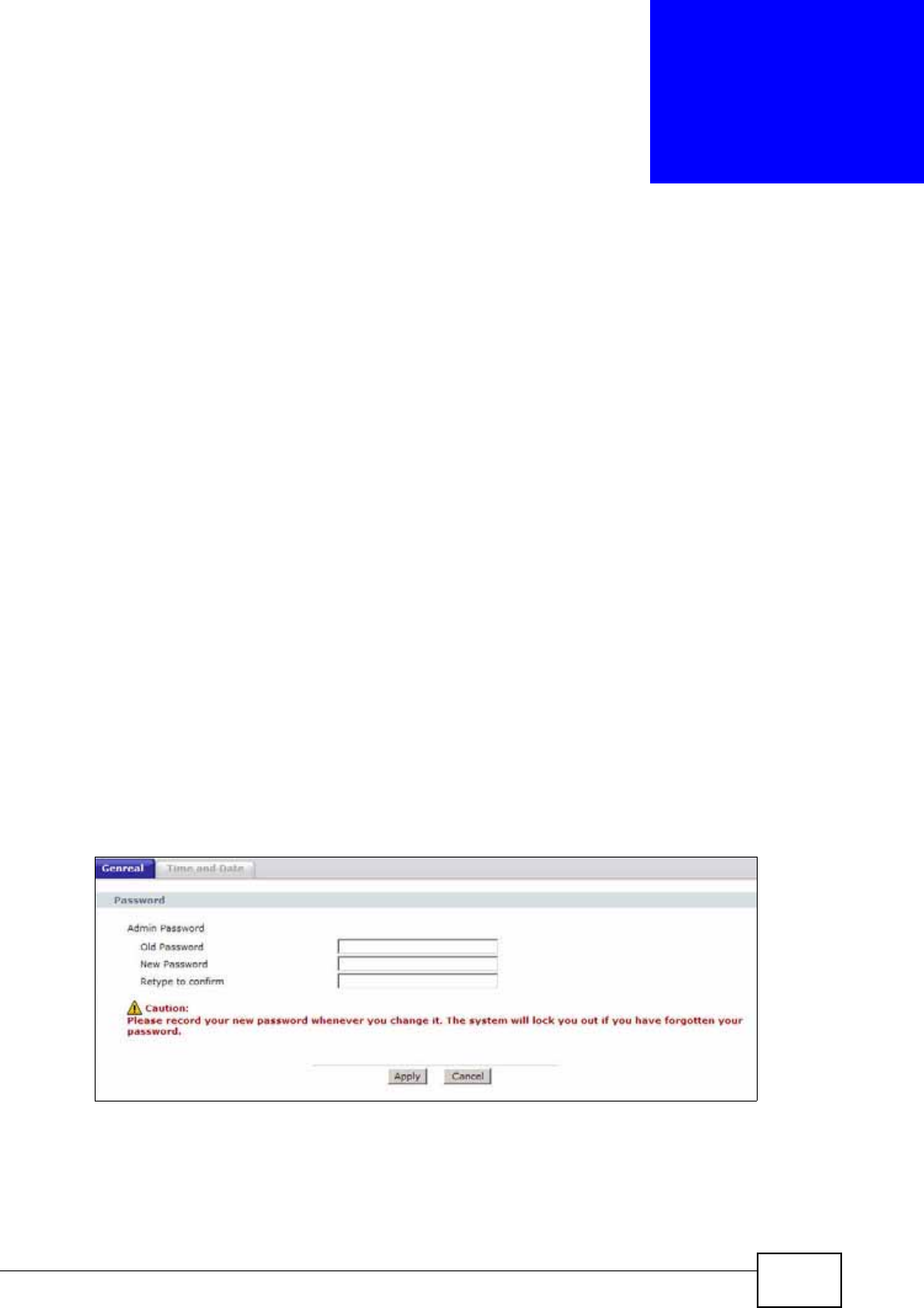
P-660N-T1A User’s Guide 203
CHAPTER 19
System Settings
19.1 Overview
This chapter shows you how to configure system related settings, such as system
time, password, name, the domain name and the inactivity timeout interval.
19.1.1 What You Can Do in the System Settings Screens
•Use the General screen (Section 19.2 on page 203) to configure system
settings.
•Use the Time and Date screen (Section 19.3 on page 204) to set the system
time.
19.2 The General Screen
Use this screen to configure system admin password.
Click Maintenance > System to open the General screen.
Figure 99 Maintenance > System > General
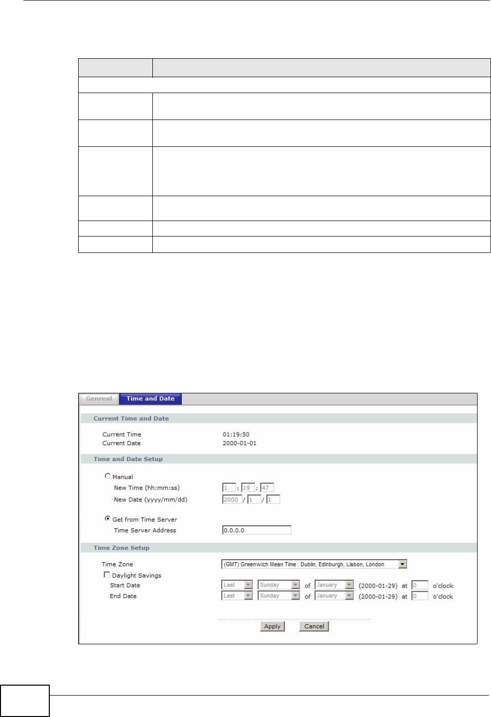
Chapter 19 System Settings
P-660N-T1A User’s Guide
204
The following table describes the labels in this screen.
19.3 The Time and Date Screen
Use this screen to configure the ZyXEL Device’s time based on your local time
zone. To change your ZyXEL Device’s time and date, click Maintenance >
System > Time and Date. The screen appears as shown.
Figure 100 Maintenance > System > Time and Date
Table 70 Maintenance > System > General
LABEL DESCRIPTION
Password
Admin
Password
Old
Password Type the default password or the existing password you use to access the
system in this field.
New
Password Type your new system password (up to 30 characters). Note that as you
type a password, the screen displays a (*) for each character you type.
After you change the password, use the new password to access the
ZyXEL Device.
Retype to
confirm Type the new password again for confirmation.
Apply Click this to save your changes.
Cancel Click this to restore your previously saved settings.

Chapter 19 System Settings
P-660N-T1A User’s Guide 205
The following table describes the fields in this screen.
Table 71 Maintenance > System > Time and Date
LABEL DESCRIPTION
Current Time and Date
Current Time This field displays the time of your ZyXEL Device.
Each time you reload this page, the ZyXEL Device synchronizes the
time with the time server.
Current Date This field displays the date of your ZyXEL Device.
Each time you reload this page, the ZyXEL Device synchronizes the
date with the time server.
Time and Date Setup
Manual Select this radio button to enter the time and date manually. If you
configure a new time and date, Time Zone and Daylight Saving at the
same time, the new time and date you entered has priority and the
Time Zone and Daylight Saving settings do not affect it.
New Time
(hh:mm:ss)
This field displays the last updated time from the time server or the last
time configured manually.
When you set Time and Date Setup to Manual, enter the new time in
this field and then click Apply.
New Date
(yyyy/mm/dd)
This field displays the last updated date from the time server or the last
date configured manually.
When you set Time and Date Setup to Manual, enter the new date in
this field and then click Apply.
Get from Time
Server Select this radio button to have the ZyXEL Device get the time and date
from the time server you specified below.
Time Server
Address Enter the IP address or URL (up to 20 extended ASCII characters in
length) of your time server. Check with your ISP/network administrator
if you are unsure of this information.
Time Zone Setup
Time Zone Choose the time zone of your location. This will set the time difference
between your time zone and Greenwich Mean Time (GMT).
Daylight
Savings Daylight saving is a period from late spring to early fall when many
countries set their clocks ahead of normal local time by one hour to
give more daytime light in the evening.
Select this option if you use Daylight Saving Time.

Chapter 19 System Settings
P-660N-T1A User’s Guide
206
Start Date Configure the day and time when Daylight Saving Time starts if you
selected Enable Daylight Saving. The o'clock field uses the 24 hour
format. Here are a couple of examples:
Daylight Saving Time starts in most parts of the United States on the
second Sunday of March. Each time zone in the United States starts
using Daylight Saving Time at 2 A.M. local time. So in the United States
you would select Second, Sunday, March and type 2 in the o'clock
field.
Daylight Saving Time starts in the European Union on the last Sunday
of March. All of the time zones in the European Union start using
Daylight Saving Time at the same moment (1 A.M. GMT or UTC). So in
the European Union you would select Last, Sunday, March. The time
you type in the o'clock field depends on your time zone. In Germany
for instance, you would type 2 because Germany's time zone is one
hour ahead of GMT or UTC (GMT+1).
End Date Configure the day and time when Daylight Saving Time ends if you
selected Enable Daylight Saving. The o'clock field uses the 24 hour
format. Here are a couple of examples:
Daylight Saving Time ends in the United States on the first Sunday of
November. Each time zone in the United States stops using Daylight
Saving Time at 2 A.M. local time. So in the United States you would
select First, Sunday, November and type 2 in the o'clock field.
Daylight Saving Time ends in the European Union on the last Sunday of
October. All of the time zones in the European Union stop using
Daylight Saving Time at the same moment (1 A.M. GMT or UTC). So in
the European Union you would select Last, Sunday, October. The
time you type in the o'clock field depends on your time zone. In
Germany for instance, you would type 2 because Germany's time zone
is one hour ahead of GMT or UTC (GMT+1).
Apply Click this to save your changes.
Cancel Click this to restore your previously saved settings.
Table 71 Maintenance > System > Time and Date (continued)
LABEL DESCRIPTION

P-660N-T1A User’s Guide 207
CHAPTER 20
Logs
20.1 Overview
This chapter contains information about viewing the ZyXEL Device’s logs.
The web configurator allows you to choose which types of events and/or alerts to
have the ZyXEL Device log and then display the logs.
20.1.1 What You Need To Know
The following terms and concepts may help as you read this chapter.
Alerts
An alert is a message that is enabled as soon as the event occurs. They include
system errors, attacks (access control) and attempted access to blocked web
sites. Some categories such as System Errors consist of both logs and alerts. You
may differentiate them by their color in the View Log screen. Alerts display in red
and logs display in black.
Logs
A log is a message about an event that occurred on your ZyXEL Device. For
example, when someone logs in to the ZyXEL Device, you can set a schedule for
how often logs should be enabled, or sent to a syslog server.
20.2 The System Log Screen
Use the System Log screen to configure and view the logs you wish to display.
To change your ZyXEL Device’s log settings, click Maintenance > Logs > Log
Settings. The screen appears as shown.
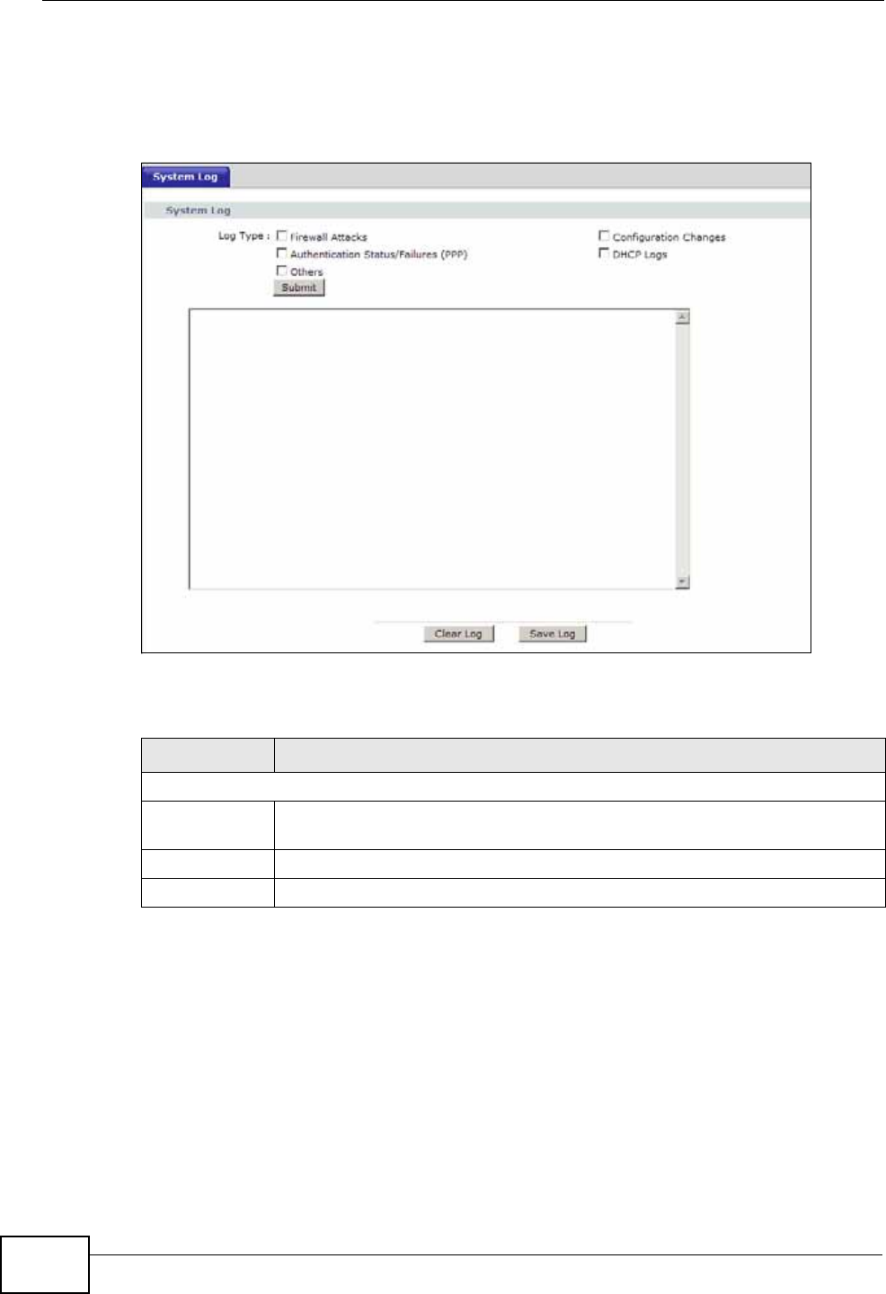
Chapter 20 Logs
P-660N-T1A User’s Guide
208
Alerts are e-mailed as soon as they happen. Logs may be e-mailed as soon as the
log is full. Selecting many alert and/or log categories (especially Access Control)
may result in many e-mails being sent.
Figure 101 Maintenance > System Logs
The following table describes the fields in this screen.
Table 72 Maintenance > Logs > Log Settings
LABEL DESCRIPTION
System Log
Log Type Select the types of logs that you want to display and record. Then click
Submit to display the details.
Clear Log Click this to delete all the logs.
Save Log Click this to save the logs in a text file.

Chapter 20 Logs
P-660N-T1A User’s Guide 209
20.3 Log Descriptions
This section provides descriptions of example log messages.
Table 73 System Maintenance Logs
LOG MESSAGE DESCRIPTION
Time calibration is
successful The router has adjusted its time based on information
from the time server.
Time calibration failed The router failed to get information from the time
server.
WAN interface gets IP: %s A WAN interface got a new IP address from the DHCP,
PPPoE, or dial-up server.
DHCP client IP expired A DHCP client's IP address has expired.
DHCP server assigns %s The DHCP server assigned an IP address to a client.
Successful WEB login Someone has logged on to the router's web
configurator interface.
WEB login failed Someone has failed to log on to the router's web
configurator interface.
Successful TELNET login Someone has logged on to the router via telnet.
TELNET login failed Someone has failed to log on to the router via telnet.
Successful FTP login Someone has logged on to the router via ftp.
FTP login failed Someone has failed to log on to the router via ftp.
NAT Session Table is Full! The maximum number of NAT session table entries
has been exceeded and the table is full.
Starting Connectivity
Monitor Starting Connectivity Monitor.
Time initialized by Daytime
Server The router got the time and date from the Daytime
server.
Time initialized by Time
server The router got the time and date from the time
server.
Time initialized by NTP
server The router got the time and date from the NTP server.
Connect to Daytime server
fail The router was not able to connect to the Daytime
server.
Connect to Time server fail The router was not able to connect to the Time server.
Connect to NTP server fail The router was not able to connect to the NTP server.
Too large ICMP packet has
been dropped The router dropped an ICMP packet that was too
large.
Configuration Change: PC =
0x%x, Task ID = 0x%x The router is saving configuration changes.
Successful SSH login Someone has logged on to the router’s SSH server.
SSH login failed Someone has failed to log on to the router’s SSH
server.
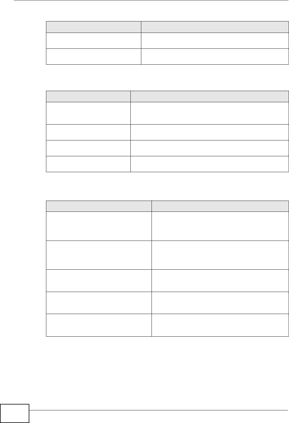
Chapter 20 Logs
P-660N-T1A User’s Guide
210
Successful HTTPS login Someone has logged on to the router's web
configurator interface using HTTPS protocol.
HTTPS login failed Someone has failed to log on to the router's web
configurator interface using HTTPS protocol.
Table 74 System Error Logs
LOG MESSAGE DESCRIPTION
%s exceeds the max.
number of session per
host!
This attempt to create a NAT session exceeds the
maximum number of NAT session table entries allowed to
be created per host.
setNetBIOSFilter: calloc
error The router failed to allocate memory for the NetBIOS
filter settings.
readNetBIOSFilter: calloc
error The router failed to allocate memory for the NetBIOS
filter settings.
WAN connection is down. A WAN connection is down. You cannot access the
network through this interface.
Table 75 Access Control Logs
LOG MESSAGE DESCRIPTION
Firewall default policy: [ TCP |
UDP | IGMP | ESP | GRE | OSPF ]
<Packet Direction>
Attempted TCP/UDP/IGMP/ESP/GRE/OSPF access
matched the default policy and was blocked or
forwarded according to the default policy’s
setting.
Firewall rule [NOT] match:[ TCP
| UDP | IGMP | ESP | GRE | OSPF
] <Packet Direction>, <rule:%d>
Attempted TCP/UDP/IGMP/ESP/GRE/OSPF access
matched (or did not match) a configured firewall
rule (denoted by its number) and was blocked or
forwarded according to the rule.
Triangle route packet forwarded:
[ TCP | UDP | IGMP | ESP | GRE |
OSPF ]
The firewall allowed a triangle route session to
pass through.
Packet without a NAT table entry
blocked: [ TCP | UDP | IGMP |
ESP | GRE | OSPF ]
The router blocked a packet that didn't have a
corresponding NAT table entry.
Router sent blocked web site
message: TCP The router sent a message to notify a user that
the router blocked access to a web site that the
user requested.
Table 73 System Maintenance Logs (continued)
LOG MESSAGE DESCRIPTION
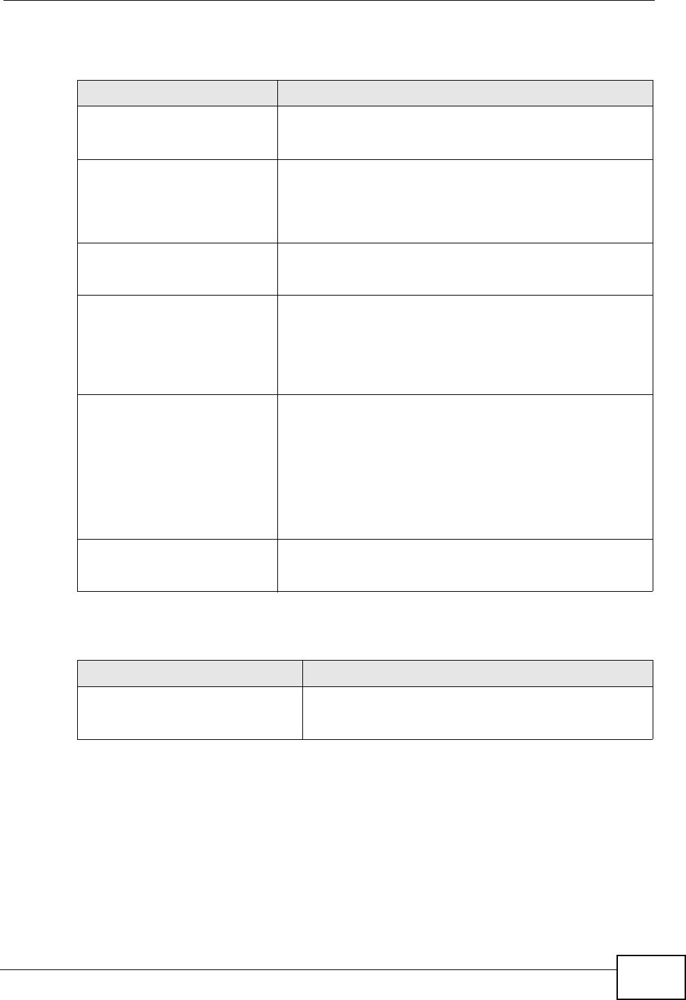
Chapter 20 Logs
P-660N-T1A User’s Guide 211
Table 76 TCP Reset Logs
LOG MESSAGE DESCRIPTION
Under SYN flood attack,
sent TCP RST The router sent a TCP reset packet when a host was
under a SYN flood attack (the TCP incomplete count is per
destination host.)
Exceed TCP MAX
incomplete, sent TCP RST The router sent a TCP reset packet when the number of
TCP incomplete connections exceeded the user configured
threshold. (the TCP incomplete count is per destination
host.) Note: Refer to TCP Maximum Incomplete in the
Firewall Attack Alerts screen.
Peer TCP state out of
order, sent TCP RST The router sent a TCP reset packet when a TCP
connection state was out of order.Note: The firewall refers
to RFC793 Figure 6 to check the TCP state.
Firewall session time
out, sent TCP RST The router sent a TCP reset packet when a dynamic
firewall session timed out.Default timeout values:ICMP
idle timeout (s): 60UDP idle timeout (s): 60TCP
connection (three way handshaking) timeout (s): 30TCP
FIN-wait timeout (s): 60TCP idle (established) timeout
(s): 3600
Exceed MAX incomplete,
sent TCP RST The router sent a TCP reset packet when the number of
incomplete connections (TCP and UDP) exceeded the
user-configured threshold. (Incomplete count is for all
TCP and UDP connections through the firewall.)Note:
When the number of incomplete connections (TCP + UDP)
> “Maximum Incomplete High”, the router sends TCP RST
packets for TCP connections and destroys TOS (firewall
dynamic sessions) until incomplete connections <
“Maximum Incomplete Low”.
Access block, sent TCP
RST The router sends a TCP RST packet and generates this log
if you turn on the firewall TCP reset mechanism (via CI
command: "sys firewall tcprst").
Table 77 Packet Filter Logs
LOG MESSAGE DESCRIPTION
[ TCP | UDP | ICMP | IGMP |
Generic ] packet filter
matched (set: %d, rule: %d)
Attempted access matched a configured filter rule
(denoted by its set and rule number) and was blocked
or forwarded according to the rule.
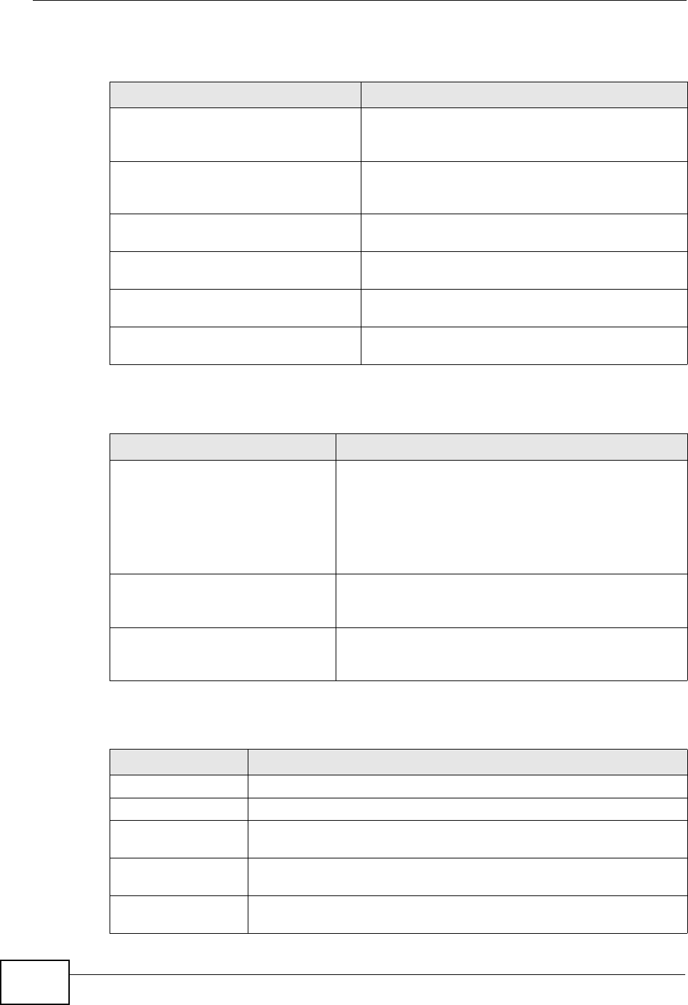
Chapter 20 Logs
P-660N-T1A User’s Guide
212
For type and code details, see Table 86 on page 215.
Table 78 ICMP Logs
LOG MESSAGE DESCRIPTION
Firewall default policy: ICMP
<Packet Direction>, <type:%d>,
<code:%d>
ICMP access matched the default policy and was
blocked or forwarded according to the user's
setting.
Firewall rule [NOT] match: ICMP
<Packet Direction>, <rule:%d>,
<type:%d>, <code:%d>
ICMP access matched (or didn’t match) a firewall
rule (denoted by its number) and was blocked or
forwarded according to the rule.
Triangle route packet forwarded:
ICMP The firewall allowed a triangle route session to
pass through.
Packet without a NAT table entry
blocked: ICMP The router blocked a packet that didn’t have a
corresponding NAT table entry.
Unsupported/out-of-order ICMP:
ICMP The firewall does not support this kind of ICMP
packets or the ICMP packets are out of order.
Router reply ICMP packet: ICMP The router sent an ICMP reply packet to the
sender.
Table 79 CDR Logs
LOG MESSAGE DESCRIPTION
board %d line %d channel %d,
call %d, %s C01 Outgoing Call
dev=%x ch=%x %s
The router received the setup requirements for a call.
“call” is the reference (count) number of the call.
“dev” is the device type (3 is for dial-up, 6 is for
PPPoE, 10 is for PPTP). "channel" or “ch” is the call
channel ID.For example,"board 0 line 0 channel 0, call
3, C01 Outgoing Call dev=6 ch=0 "Means the router
has dialed to the PPPoE server 3 times.
board %d line %d channel %d,
call %d, %s C02 OutCall
Connected %d %s
The PPPoE, PPTP or dial-up call is connected.
board %d line %d channel %d,
call %d, %s C02 Call
Terminated
The PPPoE, PPTP or dial-up call was disconnected.
Table 80 PPP Logs
LOG MESSAGE DESCRIPTION
ppp:LCP Starting The PPP connection’s Link Control Protocol stage has started.
ppp:LCP Opening The PPP connection’s Link Control Protocol stage is opening.
ppp:CHAP Opening The PPP connection’s Challenge Handshake Authentication Protocol
stage is opening.
ppp:IPCP
Starting The PPP connection’s Internet Protocol Control Protocol stage is
starting.
ppp:IPCP Opening The PPP connection’s Internet Protocol Control Protocol stage is
opening.
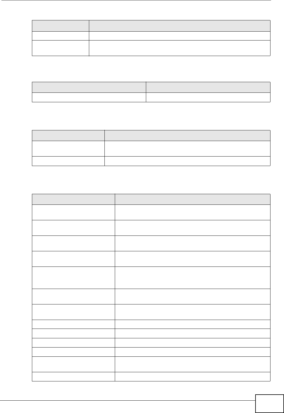
Chapter 20 Logs
P-660N-T1A User’s Guide 213
For type and code details, see Table 86 on page 215.
ppp:LCP Closing The PPP connection’s Link Control Protocol stage is closing.
ppp:IPCP Closing The PPP connection’s Internet Protocol Control Protocol stage is
closing.
Table 81 UPnP Logs
LOG MESSAGE DESCRIPTION
UPnP pass through Firewall UPnP packets can pass through the firewall.
Table 82 Content Filtering Logs
LOG MESSAGE DESCRIPTION
%s: block keyword The content of a requested web page matched a user defined
keyword.
%s The system forwarded web content.
Table 83 Attack Logs
LOG MESSAGE DESCRIPTION
attack [ TCP | UDP | IGMP
| ESP | GRE | OSPF ] The firewall detected a TCP/UDP/IGMP/ESP/GRE/OSPF
attack.
attack ICMP (type:%d,
code:%d) The firewall detected an ICMP attack.
land [ TCP | UDP | IGMP |
ESP | GRE | OSPF ] The firewall detected a TCP/UDP/IGMP/ESP/GRE/OSPF
land attack.
land ICMP (type:%d,
code:%d) The firewall detected an ICMP land attack.
ip spoofing - WAN [ TCP |
UDP | IGMP | ESP | GRE |
OSPF ]
The firewall detected an IP spoofing attack on the WAN
port.
ip spoofing - WAN ICMP
(type:%d, code:%d) The firewall detected an ICMP IP spoofing attack on the
WAN port.
icmp echo : ICMP
(type:%d, code:%d) The firewall detected an ICMP echo attack.
syn flood TCP The firewall detected a TCP syn flood attack.
ports scan TCP The firewall detected a TCP port scan attack.
teardrop TCP The firewall detected a TCP teardrop attack.
teardrop UDP The firewall detected an UDP teardrop attack.
teardrop ICMP (type:%d,
code:%d) The firewall detected an ICMP teardrop attack.
illegal command TCP The firewall detected a TCP illegal command attack.
Table 80 PPP Logs (continued)
LOG MESSAGE DESCRIPTION
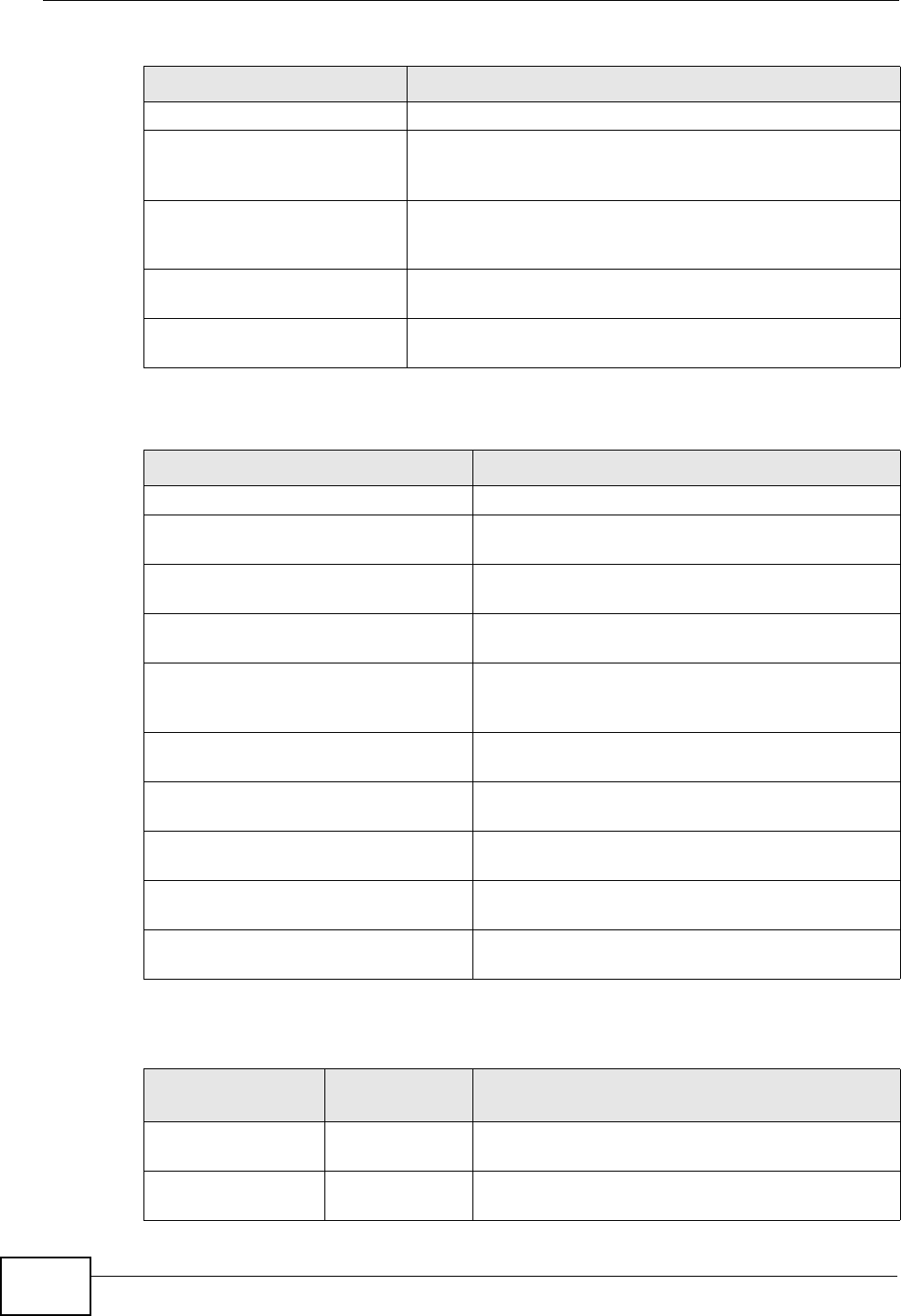
Chapter 20 Logs
P-660N-T1A User’s Guide
214
NetBIOS TCP The firewall detected a TCP NetBIOS attack.
ip spoofing - no routing
entry [ TCP | UDP | IGMP
| ESP | GRE | OSPF ]
The firewall classified a packet with no source routing
entry as an IP spoofing attack.
ip spoofing - no routing
entry ICMP (type:%d,
code:%d)
The firewall classified an ICMP packet with no source
routing entry as an IP spoofing attack.
vulnerability ICMP
(type:%d, code:%d) The firewall detected an ICMP vulnerability attack.
traceroute ICMP (type:%d,
code:%d) The firewall detected an ICMP traceroute attack.
Table 84 802.1X Logs
LOG MESSAGE DESCRIPTION
RADIUS accepts user. A user was authenticated by the RADIUS Server.
RADIUS rejects user. Pls check
RADIUS Server. A user was not authenticated by the RADIUS
Server. Please check the RADIUS Server.
User logout because of session
timeout expired. The router logged out a user whose session
expired.
User logout because of user
deassociation. The router logged out a user who ended the
session.
User logout because of no
authentication response from
user.
The router logged out a user from which there
was no authentication response.
User logout because of idle
timeout expired. The router logged out a user whose idle timeout
period expired.
User logout because of user
request. A user logged out.
No response from RADIUS. Pls
check RADIUS Server. There is no response message from the RADIUS
server, please check the RADIUS server.
Use RADIUS to authenticate user. The RADIUS server is operating as the
authentication server.
No Server to authenticate user. There is no authentication server to authenticate
a user.
Table 85 ACL Setting Notes
PACKET
DIRECTION DIRECTION DESCRIPTION
(L to W) LAN to WAN ACL set for packets traveling from the LAN to the
WAN.
(W to L) WAN to LAN ACL set for packets traveling from the WAN to the
LAN.
Table 83 Attack Logs (continued)
LOG MESSAGE DESCRIPTION
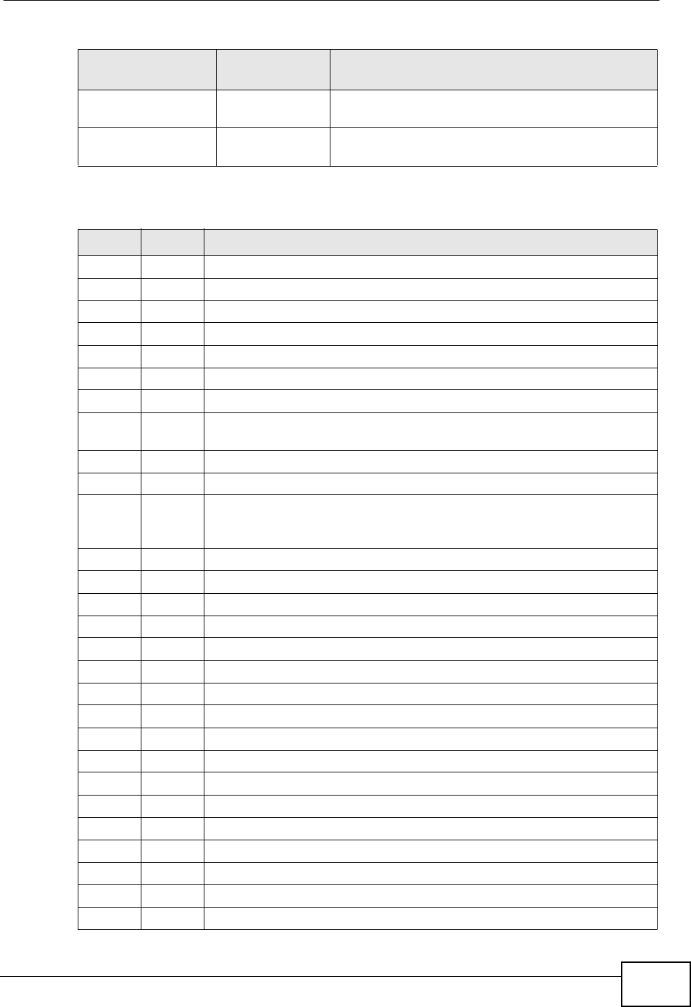
Chapter 20 Logs
P-660N-T1A User’s Guide 215
(L to L/ZyXEL
Device) LAN to LAN/
ZyXEL Device ACL set for packets traveling from the LAN to the
LAN or the ZyXEL Device.
(W to W/ZyXEL
Device) WAN to WAN/
ZyXEL Device ACL set for packets traveling from the WAN to the
WAN or the ZyXEL Device.
Table 86 ICMP Notes
TYPE CODE DESCRIPTION
0Echo Reply
0Echo reply message
3Destination Unreachable
0Net unreachable
1Host unreachable
2Protocol unreachable
3Port unreachable
4A packet that needed fragmentation was dropped because it was set
to Don't Fragment (DF)
5Source route failed
4Source Quench
0A gateway may discard internet datagrams if it does not have the
buffer space needed to queue the datagrams for output to the next
network on the route to the destination network.
5Redirect
0Redirect datagrams for the Network
1Redirect datagrams for the Host
2Redirect datagrams for the Type of Service and Network
3Redirect datagrams for the Type of Service and Host
8Echo
0Echo message
11 Time Exceeded
0Time to live exceeded in transit
1Fragment reassembly time exceeded
12 Parameter Problem
0Pointer indicates the error
13 Timestamp
0Timestamp request message
14 Timestamp Reply
0Timestamp reply message
15 Information Request
Table 85 ACL Setting Notes (continued)
PACKET
DIRECTION DIRECTION DESCRIPTION
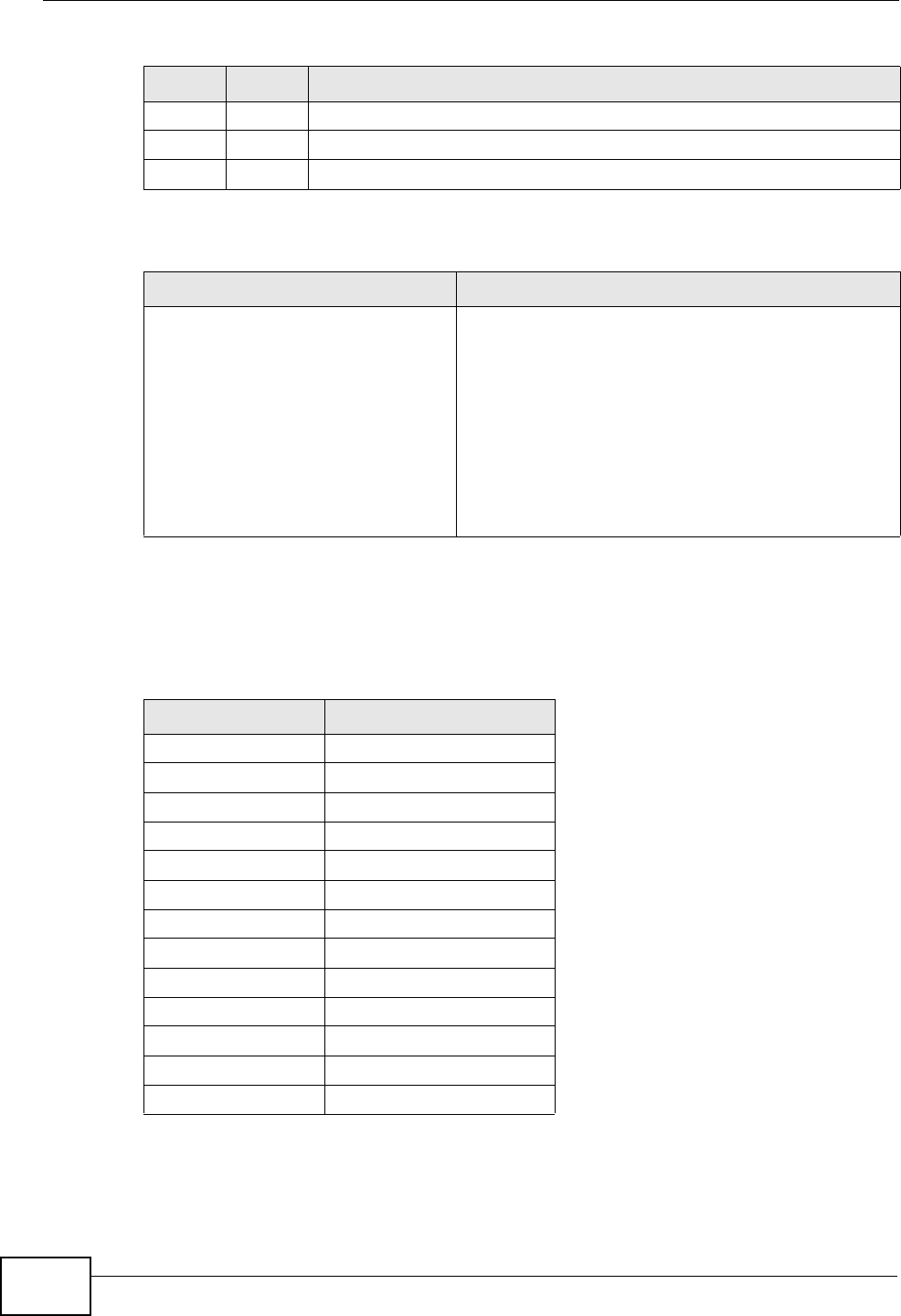
Chapter 20 Logs
P-660N-T1A User’s Guide
216
The following table shows RFC-2408 ISAKMP payload types that the log displays.
Please refer to RFC 2408 for detailed information on each type.
0Information request message
16 Information Reply
0Information reply message
Table 87 Syslog Logs
LOG MESSAGE DESCRIPTION
<Facility*8 + Severity>Mon dd
hr:mm:ss hostname
src="<srcIP:srcPort>"
dst="<dstIP:dstPort>"
msg="<msg>" note="<note>"
devID="<mac address last three
numbers>" cat="<category>
"This message is sent by the system ("RAS"
displays as the system name if you haven’t
configured one) when the router generates a
syslog. The facility is defined in the web MAIN
MENU->LOGS->Log Settings page. The severity is
the log’s syslog class. The definition of messages
and notes are defined in the various log charts
throughout this appendix. The “devID” is the last
three characters of the MAC address of the router’s
LAN port. The “cat” is the same as the category in
the router’s logs.
Table 88 RFC-2408 ISAKMP Payload Types
LOG DISPLAY PAYLOAD TYPE
SA Security Association
PROP Proposal
TRANS Transform
KE Key Exchange
ID Identification
CER Certificate
CER_REQ Certificate Request
HASH Hash
SIG Signature
NONCE Nonce
NOTFY Notification
DEL Delete
VID Vendor ID
Table 86 ICMP Notes (continued)
TYPE CODE DESCRIPTION

P-660N-T1A User’s Guide 217
CHAPTER 21
Tools
21.1 Overview
This chapter explains how to upload new firmware, manage configuration files and
restart your ZyXEL Device.
Use the instructions in this chapter to change the device’s configuration file or
upgrade its firmware. After you configure your device, you can backup the
configuration file to a computer. That way if you later misconfigure the device, you
can upload the backed up configuration file to return to your previous settings.
You can alternately upload the factory default configuration file if you want to
return the device to the original default settings. The firmware determines the
device’s available features and functionality. You can download new firmware
releases from your nearest ZyXEL FTP site (or www.zyxel.com) to use to upgrade
your device’s performance.
Only use firmware for your device’s specific model. Refer to the
label on the bottom of your ZyXEL Device.
21.1.1 What You Can Do in the Tool Screens
•Use the Firmware Upgrade screen (Section 21.2 on page 218) to upload
firmware to your device.
•Use the Configuration screen (Section 21.3 on page 220) to backup and
restore device configurations. You can also reset your device settings back to
the factory default.
•Use the Restart screen (Section 21.4 on page 223) to restart your ZyXEL
device.
21.1.2 What You Need To Know
The following terms and concepts may help as you read this chapter.
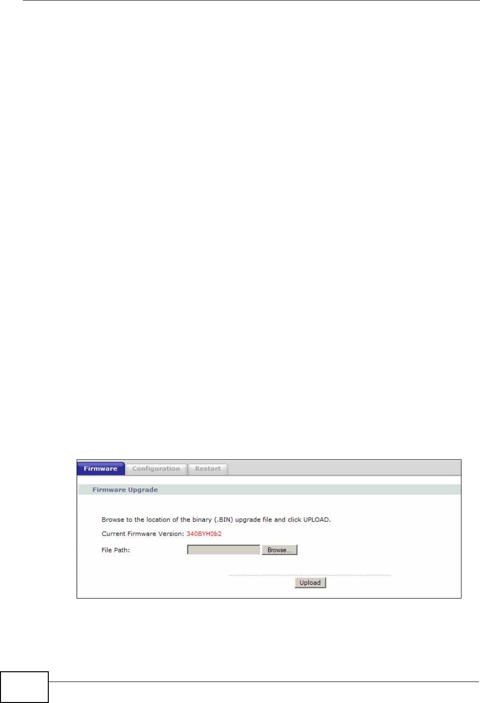
Chapter 21 Tools
P-660N-T1A User’s Guide
218
Filename Conventions
The configuration file (often called the romfile or rom-0) contains the factory
default settings in the menus such as password, DHCP Setup, TCP/IP Setup, etc. It
arrives from ZyXEL with a “rom” filename extension. Once you have customized
the ZyXEL Device's settings, they can be saved back to your computer under a
filename of your choosing.
ZyNOS (ZyXEL Network Operating System sometimes referred to as the “ras” file)
is the system firmware and has a “bin” filename extension. Find this firmware at
www.zyxel.com.
21.1.3 Before You Begin
• Ensure you have either created a firewall rule to allow access from the WAN or
turned the firewall off, otherwise the FTP will not function.
• Make sure the FTP service has not been disabled in the Remote Management
screen.
21.2 The Firmware Screen
Click Maintenance > Tools to open the Firmware screen. Follow the
instructions in this screen to upload firmware to your ZyXEL Device. The upload
process uses HTTP (Hypertext Transfer Protocol) and may take up to two minutes.
After a successful upload, the system will reboot.
Do NOT turn off the ZyXEL Device while firmware upload is in
progress!
Figure 102 Maintenance > Tools > Firmware
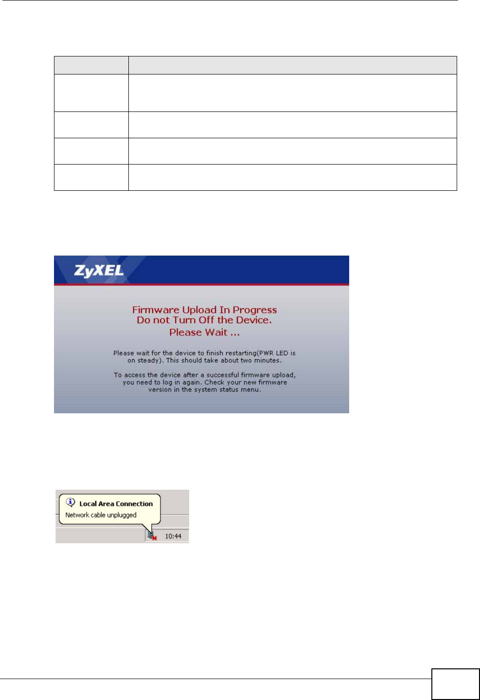
Chapter 21 Tools
P-660N-T1A User’s Guide 219
The following table describes the labels in this screen.
After you see the Firmware Upload in Progress screen, wait two minutes
before logging into the ZyXEL Device again.
Figure 103 Firmware Upload In Progress
The ZyXEL Device automatically restarts in this time causing a temporary network
disconnect. In some operating systems, you may see the following icon on your
desktop.
Figure 104 Network Temporarily Disconnected
After two minutes, log in again and check your new firmware version in the
Status screen.
Table 89 Maintenance > Tools > Firmware
LABEL DESCRIPTION
Current
Firmware
Version
This is the present Firmware version and the date created.
File Path Type in the location of the file you want to upload in this field or click
Browse ... to find it.
Browse... Click this to find the .bin file you want to upload. Remember that you
must decompress compressed (.zip) files before you can upload them.
Upload Click this to begin the upload process. This process may take up to two
minutes.
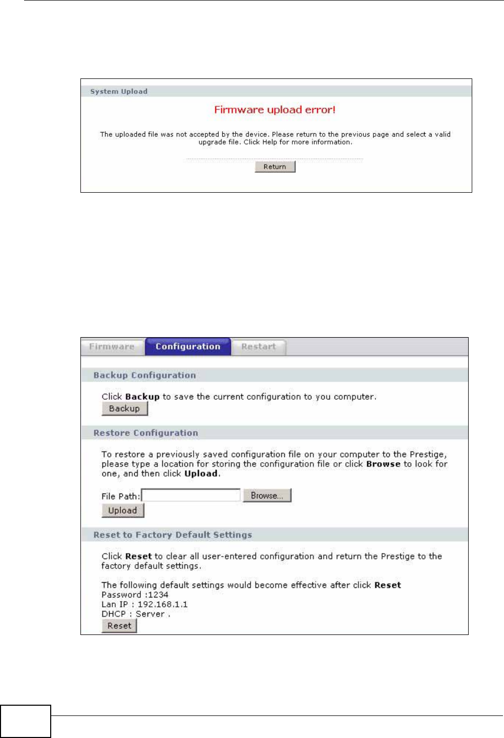
Chapter 21 Tools
P-660N-T1A User’s Guide
220
If the upload was not successful, the following screen will appear. Click Return to
go back to the Firmware screen.
Figure 105 Error Message
21.3 The Configuration Screen
Click Maintenance > Tools > Configuration. Information related to factory
defaults, backup configuration, and restoring configuration appears in this screen,
as shown next.
Figure 106 Maintenance > Tools > Configuration