ZyXEL Communications P660WTXV2 802.11g Wireless ADSL2+ Router User Manual SMG 700 User s Guide V1 00 Nov 2004
ZyXEL Communications Corporation 802.11g Wireless ADSL2+ Router SMG 700 User s Guide V1 00 Nov 2004
Contents
- 1. Users manual1
- 2. Users manual2
- 3. Users manual3
Users manual2
Chapter 8 Network Address Translation (NAT) Screens
P-660W-Tx v2 User’s Guide 101
8.7 Editing an Address Mapping Rule
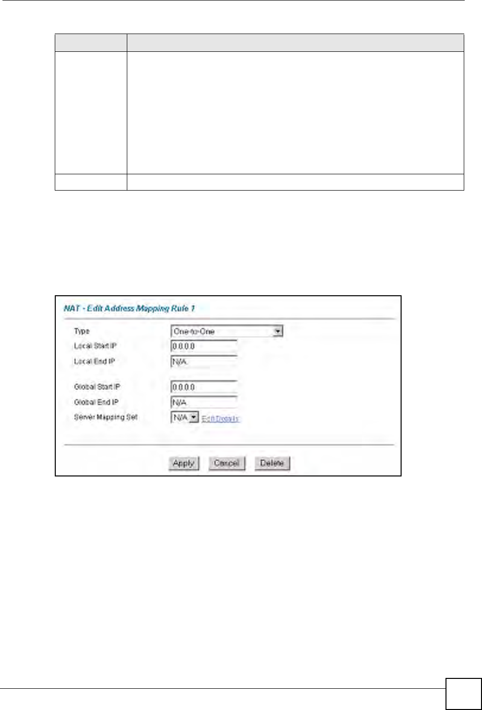
Use this screen to edit an address mapping rule. Click the rule’s link in the NAT Address
Mapping Rules screen to display the screen shown next.
Figure 43 Edit Address Mapping Rule
Type 1-1: One-to-one mode maps one local IP address to one global IP address. Note
that port numbers do not change for the One-to-one NAT mapping type.
M-1: Many-to-One mode maps multiple local IP addresses to one global IP address.
This is equivalent to SUA (i.e., PAT, port address translation), ZyXEL's Single User
Account feature that previous ZyXEL routers supported only.
M-M Ov (Overload): Many-to-Many Overload mode maps multiple local IP
addresses to shared global IP addresses.
MM No (No Overload): Many-to-Many No Overload mode maps each local IP
address to unique global IP addresses.
Server: This type allows you to specify inside servers of different services behind
the NAT to be accessible to the outside world.
Back Click Back to return to the NAT Mode screen.
Table 33 Address Mapping Rules (continued)
LABEL DESCRIPTION
Chapter 8 Network Address Translation (NAT) Screens
P-660W-Tx v2 User’s Guide
102
The following table describes the fields in this screen.
Table 34 Edit Address Mapping Rule
LABEL DESCRIPTION
Type Choose the port mapping type from one of the following.
•One-to-One: One-to-One mode maps one local IP address to one global IP
address. Note that port numbers do not change for One-to-one NAT mapping
type.
•Many-to-One: Many-to-One mode maps multiple local IP addresses to one
global IP address. This is equivalent to SUA (i.e., PAT, port address translation),
ZyXEL's Single User Account feature that previous ZyXEL routers supported
only.
•Many-to-Many Overload: Many-to-Many Overload mode maps multiple local IP
addresses to shared global IP addresses.
•Many-to-Many No Overload: Many-to-Many No Overload mode maps each
local IP address to unique global IP addresses.
•Server: This type allows you to specify inside servers of different services
behind the NAT to be accessible to the outside world.
Local Start IP This is the starting local IP address (ILA). Local IP addresses are N/A for Server
port mapping.
Local End IP This is the end local IP address (ILA). If your rule is for all local IP addresses, then
enter 0.0.0.0 as the Local Start IP address and 255.255.255.255 as the Local End
IP address.
This field is N/A for One-to-One and Server mapping types.
Global Start IP This is the starting global IP address (IGA). Enter 0.0.0.0 here if you have a dynamic
IP address from your ISP.
Global End IP This is the ending global IP address (IGA). This field is N/A for One-to-One, Many-
to-One and Server mapping types.
Server Mapping
Set
Only available when Type is set to Server.
Select a number from the drop-down menu to choose a server set from the NAT -
Address Mapping Rules screen.
Edit Details Click this link to go to the NAT - Edit SUA/NAT Server Set screen to edit a server
set that you have selected in the Server Mapping Set field.
Apply Click Apply to save your changes back to the ZyXEL Device.
Cancel Click Cancel to return to the previously saved settings.
Delete Click Delete to exit this screen without saving.

P-660W-Tx v2 User’s Guide 103
CHAPTER 9
Dynamic DNS Setup
This chapter discusses how to configure your ZyXEL Device to use Dynamic DNS.
9.1 Dynamic DNS Overview
Dynamic DNS allows you to update your current dynamic IP address with one or many
dynamic DNS services so that anyone can contact you (in NetMeeting, CU-SeeMe, etc.). You
can also access your FTP server or Web site on your own computer using a domain name (for
instance myhost.dhs.org, where myhost is a name of your choice) that will never change
instead of using an IP address that changes each time you reconnect. Your friends or relatives
will always be able to call you even if they don't know your IP address.
First of all, you need to have registered a dynamic DNS account with www.dyndns.org. This is
for people with a dynamic IP from their ISP or DHCP server that would still like to have a
domain name. The Dynamic DNS service provider will give you a password or key.
9.1.1 DYNDNS Wildcard
Enabling the wildcard feature for your host causes *.yourhost.dyndns.org to be aliased to the
same IP address as yourhost.dyndns.org. This feature is useful if you want to be able to use,
for example, www.yourhost.dyndns.org and still reach your hostname.
If you have a private WAN IP address, then you cannot use Dynamic DNS.
9.2 Configuring Dynamic DNS
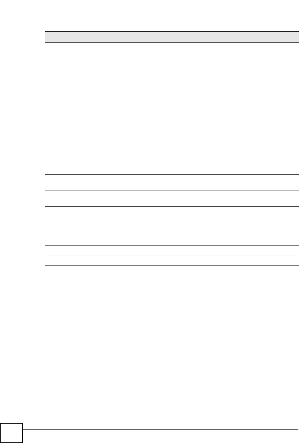
To change your ZyXEL Device’s DDNS, click Dynamic DNS. The screen appears as shown.
Chapter 9 Dynamic DNS Setup
P-660W-Tx v2 User’s Guide
104
Figure 44 Dynamic DNS
The following table describes the fields in this screen.
Table 35 Dynamic DNS
LABEL DESCRIPTION
Active Select this check box to use dynamic DNS.
Service Provider This is the name of your Dynamic DNS service provider.
Host Names Type the domain name assigned to your ZyXEL Device by your Dynamic DNS
provider.
E-mail Address Type your e-mail address.
User Type your user name.
Password Type the password assigned to you.
Enable Wildcard Select the check box to enable DYNDNS Wildcard.
Apply Click Apply to save your changes back to the ZyXEL Device.
Cancel Click Cancel to begin configuring this screen afresh.
P-660W-Tx v2 User’s Guide 105
CHAPTER 10
Time and Date
This screen is not available on all models. Use this screen to configure the ZyXEL Device’s
time and date settings.
10.1 Configuring Time and Date
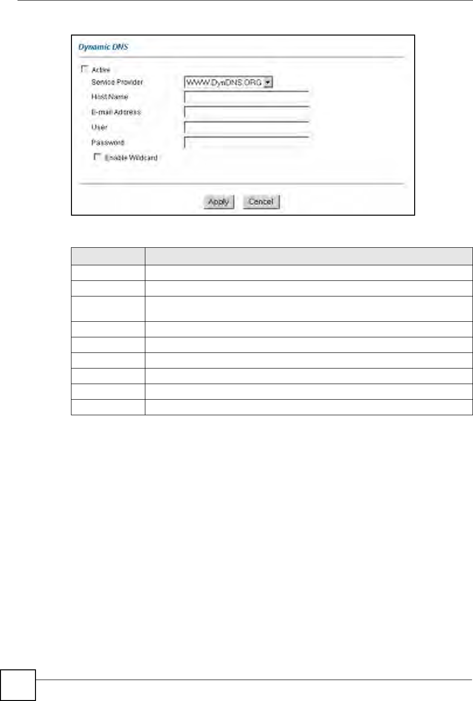
To change your ZyXEL Device’s time and date, click Time And Date. The screen appears as
shown. Use this screen to configure the ZyXEL Device’s time based on your local time zone.
Figure 45 Time and Date
The following table describes the fields in this screen.

Chapter 10 Time and Date
P-660W-Tx v2 User’s Guide
106
Table 36 Time and Date
LABEL DESCRIPTION
Time Server
Use Protocol
when Bootup
Select the time service protocol that your time server sends when you turn on the
ZyXEL Device. Not all time servers support all protocols, so you may have to
check with your ISP/network administrator or use trial and error to find a protocol
that works.
The main difference between them is the format.
Daytime (RFC 867) format is day/month/year/time zone of the server.
Time (RFC 868) format displays a 4-byte integer giving the total number of
seconds since 1970/1/1 at 0:0:0.
NTP (RFC 1305) is similar to Time (RFC 868).
Select None to enter the time and date manually.
IP Address or URL Enter the IP address or URL of your time server. Check with your ISP/network
administrator if you are unsure of this information.
Time and Date Choose the time zone of your location. This will set the time difference between
your time zone and Greenwich Mean Time (GMT).
Daylight Savings Select this option if you use daylight savings time. Daylight saving is a period from
late spring to early fall when many countries set their clocks ahead of normal local
time by one hour to give more daytime light in the evening.
Start Date Enter the month and day that your daylight-savings time starts on if you selected
Daylight Savings.
End Date Enter the month and day that your daylight-savings time ends on if you selected
Daylight Savings.
Synchronize
system clock with
Time Server now.
Select this option to have your ZyXEL Device use the time server (that you
configured above) to set its internal system clock.
Please wait for up to 60 seconds while the ZyXEL Device locates the time server.
If the ZyXEL Device cannot find the time server, please check the time server
protocol and its IP address. If the IP address was entered correctly, try pinging it
for example to test the connection.
Date
Current Date This field displays the date of your ZyXEL Device.
Each time you reload this page, the ZyXEL Device synchronizes the time with the
time server.
New Date (yyyy-
mm-dd)
This field displays the last updated date from the time server.
When you select None in the Use Protocol when Bootup field, enter the new
date in this field and then click Apply.
Time
Current Time This field displays the time of your ZyXEL Device.
Each time you reload this page, the ZyXEL Device synchronizes the time with the
time server.
New Time This field displays the last updated time from the time server.
When you select None in the Use Protocol when Bootup field, enter the new
time in this field and then click Apply.
Apply Click Apply to save your changes back to the ZyXEL Device.
Cancel Click Cancel to begin configuring this screen afresh.

P-660W-Tx v2 User’s Guide 107
CHAPTER 11
Firewalls
This chapter gives some background information on firewalls and introduces the ZyXEL
Device firewall.
11.1 Firewall Overview
Originally, the term firewall referred to a construction technique designed to prevent the
spread of fire from one room to another. The networking term “firewall” is a system or group
of systems that enforces an access-control policy between two networks. It may also be
defined as a mechanism used to protect a trusted network from an untrusted network. Of
course, firewalls cannot solve every security problem. A firewall is one of the mechanisms
used to establish a network security perimeter in support of a network security policy. It
should never be the only mechanism or method employed. For a firewall to guard effectively,
you must design and deploy it appropriately. This requires integrating the firewall into a broad
information-security policy. In addition, specific policies must be implemented within the
firewall itself.
Refer to Section 12.6 on page 122 to configure default firewall settings.
Refer to Section 12.7 on page 123 to view firewall rules.
Refer to Section 12.7.1 on page 125 to configure firewall rules.
Refer to Section 12.8 on page 128 to configure a custom service.
Refer to Section 12.13.3 on page 136 to configure firewall thresholds.
11.2 Types of Firewalls
There are three main types of firewalls:
• Packet Filtering Firewalls
• Application-level Firewalls
• Stateful Inspection Firewalls
11.2.1 Packet Filtering Firewalls
Packet filtering firewalls restrict access based on the source/destination computer network
address of a packet and the type of application.

Chapter 11 Firewalls
P-660W-Tx v2 User’s Guide
108
11.2.2 Application-level Firewalls
Application-level firewalls restrict access by serving as proxies for external servers. Since they
use programs written for specific Internet services, such as HTTP, FTP and telnet, they can
evaluate network packets for valid application-specific data. Application-level gateways have
a number of general advantages over the default mode of permitting application traffic directly
to internal hosts:
Information hiding prevents the names of internal systems from being made known via DNS
to outside systems, since the application gateway is the only host whose name must be made
known to outside systems.
Robust authentication and logging pre-authenticates application traffic before it reaches
internal hosts and causes it to be logged more effectively than if it were logged with standard
host logging. Filtering rules at the packet filtering router can be less complex than they would
be if the router needed to filter application traffic and direct it to a number of specific systems.
The router need only allow application traffic destined for the application gateway and reject
the rest.
11.2.3 Stateful Inspection Firewalls
Stateful inspection firewalls restrict access by screening data packets against defined access
rules. They make access control decisions based on IP address and protocol. They also
"inspect" the session data to assure the integrity of the connection and to adapt to dynamic
protocols. These firewalls generally provide the best speed and transparency, however, they
may lack the granular application level access control or caching that some proxies support.
See Section 11.5 on page 113 for more information on stateful inspection.
Firewalls, of one type or another, have become an integral part of standard security solutions
for enterprises.
11.3 Introduction to ZyXEL’s Firewall
The ZyXEL Device firewall is a stateful inspection firewall and is designed to protect against
Denial of Service attacks when activated (in the web configurator). The ZyXEL Device’s
purpose is to allow a private Local Area Network (LAN) to be securely connected to the
Internet. The ZyXEL Device can be used to prevent theft, destruction and modification of
data, as well as log events, which may be important to the security of your network. The
ZyXEL Device also has packet filtering capabilities.
The ZyXEL Device is installed between the LAN and the Internet. This allows it to act as a
secure gateway for all data passing between the Internet and the LAN.
The ZyXEL Device has one DSL/ISDN port and one Ethernet LAN port, which physically
separate the network into two areas.
• The DSL/ISDN port connects to the Internet.
• The LAN (Local Area Network) port attaches to a network of computers, which needs
security from the outside world. These computers will have access to Internet services
such as e-mail, FTP, and the World Wide Web. However, “inbound access” will not be
allowed unless you configure remote management or create a firewall rule to allow a
remote host to use a specific service.
Chapter 11 Firewalls
P-660W-Tx v2 User’s Guide 109
11.3.1 Denial of Service Attacks
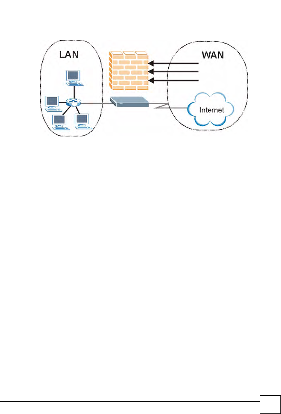
Figure 46 ZyXEL Device Firewall Application
11.4 Denial of Service
Denials of Service (DoS) attacks are aimed at devices and networks with a connection to the
Internet. Their goal is not to steal information, but to disable a device or network so users no
longer have access to network resources. The ZyXEL Device is pre-configured to
automatically detect and thwart all known DoS attacks.
11.4.1 Basics
Computers share information over the Internet using a common language called TCP/IP. TCP/
IP, in turn, is a set of application protocols that perform specific functions. An “extension
number”, called the "TCP port" or "UDP port" identifies these protocols, such as HTTP
(Web), FTP (File Transfer Protocol), POP3 (E-mail), etc. For example, Web traffic by default
uses TCP port 80.
When computers communicate on the Internet, they are using the client/server model, where
the server "listens" on a specific TCP/UDP port for information requests from remote client
computers on the network. For example, a Web server typically listens on port 80. Please note
that while a computer may be intended for use over a single port, such as Web on port 80,
other ports are also active. If the person configuring or managing the computer is not careful, a
hacker could attack it over an unprotected port.
Some of the most common IP ports are:
Chapter 11 Firewalls
P-660W-Tx v2 User’s Guide
110
11.4.2 Types of DoS Attacks
There are four types of DoS attacks:
1Those that exploit bugs in a TCP/IP implementation.
2Those that exploit weaknesses in the TCP/IP specification.
3Brute-force attacks that flood a network with useless data.
4IP Spoofing.
5"Ping of Death" and "Teardrop" attacks exploit bugs in the TCP/IP implementations of
various computer and host systems.
• Ping of Death uses a "ping" utility to create an IP packet that exceeds the maximum
65,536 bytes of data allowed by the IP specification. The oversize packet is then sent to an
unsuspecting system. Systems may crash, hang or reboot.
• Teardrop attack exploits weaknesses in the re-assembly of IP packet fragments. As data is
transmitted through a network, IP packets are often broken up into smaller chunks. Each
fragment looks like the original IP packet except that it contains an offset field that says,
for instance, "This fragment is carrying bytes 200 through 400 of the original (non
fragmented) IP packet." The Teardrop program creates a series of IP fragments with
overlapping offset fields. When these fragments are reassembled at the destination, some
systems will crash, hang, or reboot.
6Weaknesses in the TCP/IP specification leave it open to "SYN Flood" and "LAND"
attacks. These attacks are executed during the handshake that initiates a communication
session between two applications.
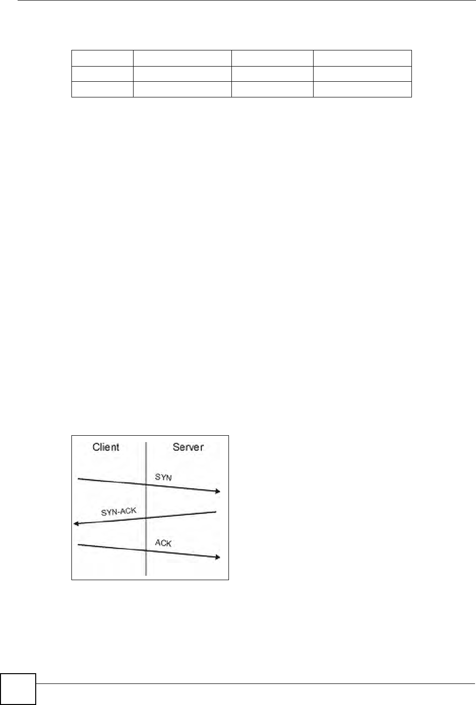
Figure 47 Three-Way Handshake
Under normal circumstances, the application that initiates a session sends a SYN
(synchronize) packet to the receiving server. The receiver sends back an ACK
(acknowledgment) packet and its own SYN, and then the initiator responds with an ACK
(acknowledgment). After this handshake, a connection is established.
Table 37 Common IP Ports
21 FTP 53 DNS
23 Telnet 80 HTTP
25 SMTP 110 POP3
Chapter 11 Firewalls
P-660W-Tx v2 User’s Guide 111
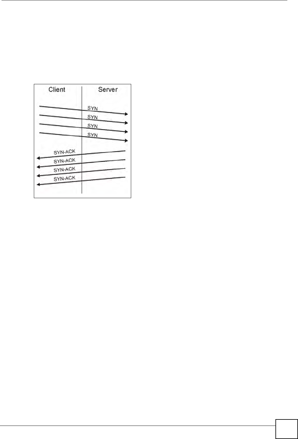
•SYN Attack floods a targeted system with a series of SYN packets. Each packet causes
the targeted system to issue a SYN-ACK response. While the targeted system waits for the
ACK that follows the SYN-ACK, it queues up all outstanding SYN-ACK responses on
what is known as a backlog queue. SYN-ACKs are moved off the queue only when an
ACK comes back or when an internal timer (which is set at relatively long intervals)
terminates the three-way handshake. Once the queue is full, the system will ignore all
incoming SYN requests, making the system unavailable for legitimate users.
Figure 48 SYN Flood
•In a LAND Attack, hackers flood SYN packets into the network with a spoofed source IP
address of the targeted system. This makes it appear as if the host computer sent the
packets to itself, making the system unavailable while the target system tries to respond to
itself.
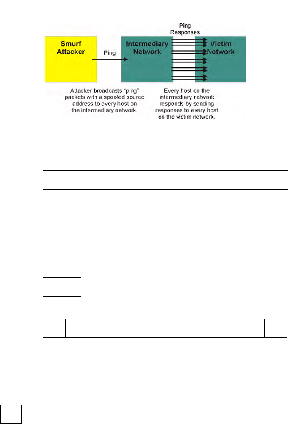
7A brute-force attack, such as a "Smurf" attack, targets a feature in the IP specification
known as directed or subnet broadcasting, to quickly flood the target network with
useless data. A Smurf hacker floods a router with Internet Control Message Protocol
(ICMP) echo request packets (pings). Since the destination IP address of each packet is
the broadcast address of the network, the router will broadcast the ICMP echo request
packet to all hosts on the network. If there are numerous hosts, this will create a large
amount of ICMP echo request and response traffic. If a hacker chooses to spoof the
source IP address of the ICMP echo request packet, the resulting ICMP traffic will not
only clog up the "intermediary" network, but will also congest the network of the
spoofed source IP address, known as the "victim" network. This flood of broadcast
traffic consumes all available bandwidth, making communications impossible.
Chapter 11 Firewalls
P-660W-Tx v2 User’s Guide
112
Figure 49 Smurf Attack
11.4.2.1 ICMP Vulnerability
ICMP is an error-reporting protocol that works in concert with IP. The following ICMP types
trigger an alert:
11.4.2.2 Illegal Commands (NetBIOS and SMTP)
The only legal NetBIOS commands are the following - all others are illegal.
All SMTP commands are illegal except for those displayed in the following tables.
11.4.2.3 Traceroute
Traceroute is a utility used to determine the path a packet takes between two endpoints.
Sometimes when a packet filter firewall is configured incorrectly an attacker can traceroute
the firewall gaining knowledge of the network topology inside the firewall.
Table 38 ICMP Commands That Trigger Alerts
5REDIRECT
13 TIMESTAMP_REQUEST
14 TIMESTAMP_REPLY
17 ADDRESS_MASK_REQUEST
18 ADDRESS_MASK_REPLY
Table 39 Legal NetBIOS Commands
MESSAGE:
REQUEST:
POSITIVE:
VE:
RETARGET:
KEEPALIVE:
Table 40 Legal SMTP Commands
AUTH DATA EHLO ETRN EXPN HELO HELP MAIL NOOP
QUIT RCPT RSET SAML SEND SOML TURN VRFY
Chapter 11 Firewalls
P-660W-Tx v2 User’s Guide 113
Often, many DoS attacks also employ a technique known as "IP Spoofing" as part of their
attack. IP Spoofing may be used to break into systems, to hide the hacker's identity, or to
magnify the effect of the DoS attack. IP Spoofing is a technique used to gain unauthorized
access to computers by tricking a router or firewall into thinking that the communications are
coming from within the trusted network. To engage in IP spoofing, a hacker must modify the
packet headers so that it appears that the packets originate from a trusted host and should be
allowed through the router or firewall. The ZyXEL Device blocks all IP Spoofing attempts.
11.5 Stateful Inspection
With stateful inspection, fields of the packets are compared to packets that are already known
to be trusted. For example, if you access some outside service, the proxy server remembers
things about your original request, like the port number and source and destination addresses.
This “remembering” is called saving the state. When the outside system responds to your
request, the firewall compares the received packets with the saved state to determine if they
are allowed in. The ZyXEL Device uses stateful packet inspection to protect the private LAN
from hackers and vandals on the Internet. By default, the ZyXEL Device’s stateful inspection
allows all communications to the Internet that originate from the LAN, and blocks all traffic to
the LAN that originates from the Internet. In summary, stateful inspection:
• Allows all sessions originating from the LAN (local network) to the WAN (Internet).
• Denies all sessions originating from the WAN to the LAN.
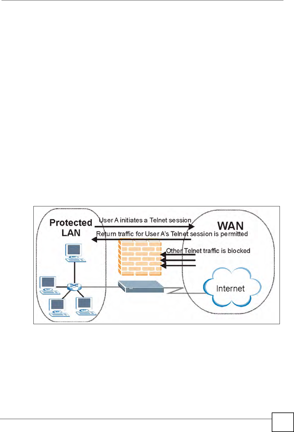
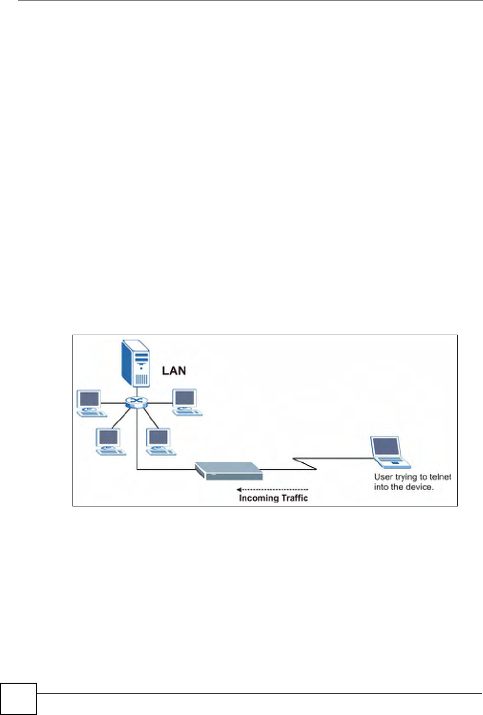
Figure 50 Stateful Inspection
The previous figure shows the ZyXEL Device’s default firewall rules in action as well as
demonstrates how stateful inspection works. User A can initiate a Telnet session from within
the LAN and responses to this request are allowed. However other Telnet traffic initiated from
the WAN is blocked.

Chapter 11 Firewalls
P-660W-Tx v2 User’s Guide
114
11.5.1 Stateful Inspection Process
In this example, the following sequence of events occurs when a TCP packet leaves the LAN
network through the firewall's WAN interface. The TCP packet is the first in a session, and the
packet's application layer protocol is configured for a firewall rule inspection:
1The packet travels from the firewall's LAN to the WAN.
2The packet is evaluated against the interface's existing outbound access list, and the
packet is permitted (a denied packet would simply be dropped at this point).
3The packet is inspected by a firewall rule to determine and record information about the
state of the packet's connection. This information is recorded in a new state table entry
created for the new connection. If there is not a firewall rule for this packet and it is not
an attack, then the settings in the Default Policy screen determine the action for this
packet.
4Based on the obtained state information, a firewall rule creates a temporary access list
entry that is inserted at the beginning of the WAN interface's inbound extended access
list. This temporary access list entry is designed to permit inbound packets of the same
connection as the outbound packet just inspected.
5The outbound packet is forwarded out through the interface.
6Later, an inbound packet reaches the interface. This packet is part of the connection
previously established with the outbound packet. The inbound packet is evaluated
against the inbound access list, and is permitted because of the temporary access list
entry previously created.
7The packet is inspected by a firewall rule, and the connection's state table entry is
updated as necessary. Based on the updated state information, the inbound extended
access list temporary entries might be modified, in order to permit only packets that are
valid for the current state of the connection.
8Any additional inbound or outbound packets that belong to the connection are inspected
to update the state table entry and to modify the temporary inbound access list entries as
required, and are forwarded through the interface.
9When the connection terminates or times out, the connection's state table entry is deleted
and the connection's temporary inbound access list entries are deleted.
11.5.2 Stateful Inspection and the ZyXEL Device
Additional rules may be defined to extend or override the default rules. For example, a rule
may be created which will:
• Block all traffic of a certain type, such as IRC (Internet Relay Chat), from the LAN to the
Internet.
• Allow certain types of traffic from the Internet to specific hosts on the LAN.
• Allow access to a Web server to everyone but competitors.
• Restrict use of certain protocols, such as Telnet, to authorized users on the LAN.
These custom rules work by evaluating the network traffic’s Source IP address, Destination IP
address, IP protocol type, and comparing these to rules set by the administrator.

Chapter 11 Firewalls
P-660W-Tx v2 User’s Guide 115
"The ability to define firewall rules is a very powerful tool. Using custom rules, it
is possible to disable all firewall protection or block all access to the Internet.
Use extreme caution when creating or deleting firewall rules. Test changes
after creating them to make sure they work correctly.
Below is a brief technical description of how these connections are tracked. Connections may
either be defined by the upper protocols (for instance, TCP), or by the ZyXEL Device itself (as
with the "virtual connections" created for UDP and ICMP).
11.5.3 TCP Security
The ZyXEL Device uses state information embedded in TCP packets. The first packet of any
new connection has its SYN flag set and its ACK flag cleared; these are "initiation" packets.
All packets that do not have this flag structure are called "subsequent" packets, since they
represent data that occurs later in the TCP stream.
If an initiation packet originates on the WAN, this means that someone is trying to make a
connection from the Internet into the LAN. Except in a few special cases (see "Upper Layer
Protocols" shown next), these packets are dropped and logged.
If an initiation packet originates on the LAN, this means that someone is trying to make a
connection from the LAN to the Internet. Assuming that this is an acceptable part of the
security policy (as is the case with the default policy), the connection will be allowed. A cache
entry is added which includes connection information such as IP addresses, TCP ports,
sequence numbers, etc.
When the ZyXEL Device receives any subsequent packet (from the Internet or from the LAN),
its connection information is extracted and checked against the cache. A packet is only
allowed to pass through if it corresponds to a valid connection (that is, if it is a response to a
connection which originated on the LAN).
11.5.4 UDP/ICMP Security
UDP and ICMP do not themselves contain any connection information (such as sequence
numbers). However, at the very minimum, they contain an IP address pair (source and
destination). UDP also contains port pairs, and ICMP has type and code information. All of
this data can be analyzed in order to build "virtual connections" in the cache.
For instance, any UDP packet that originates on the LAN will create a cache entry. Its IP
address and port pairs will be stored. For a short period of time, UDP packets from the WAN
that have matching IP and UDP information will be allowed back in through the firewall.
A similar situation exists for ICMP, except that the ZyXEL Device is even more restrictive.
Specifically, only outgoing echoes will allow incoming echo replies, outgoing address mask
requests will allow incoming address mask replies, and outgoing timestamp requests will
allow incoming timestamp replies. No other ICMP packets are allowed in through the firewall,
simply because they are too dangerous and contain too little tracking information. For
instance, ICMP redirect packets are never allowed in, since they could be used to reroute
traffic through attacking machines.

Chapter 11 Firewalls
P-660W-Tx v2 User’s Guide
116
11.5.5 Upper Layer Protocols
Some higher layer protocols (such as FTP and RealAudio) utilize multiple network
connections simultaneously. In general terms, they usually have a "control connection" which
is used for sending commands between endpoints, and then "data connections" which are used
for transmitting bulk information.
Consider the FTP protocol. A user on the LAN opens a control connection to a server on the
Internet and requests a file. At this point, the remote server will open a data connection from
the Internet. For FTP to work properly, this connection must be allowed to pass through even
though a connection from the Internet would normally be rejected.
In order to achieve this, the ZyXEL Device inspects the application-level FTP data.
Specifically, it searches for outgoing "PORT" commands, and when it sees these, it adds a
cache entry for the anticipated data connection. This can be done safely, since the PORT
command contains address and port information, which can be used to uniquely identify the
connection.
Any protocol that operates in this way must be supported on a case-by-case basis. You can use
the web configurator’s Custom Ports feature to do this.
11.6 Guidelines for Enhancing Security with Your Firewall
• Change the default password via the web configurator.
• Limit who can telnet into your router.
• Don't enable any local service (such as SNMP or NTP) that you don't use. Any enabled
service could present a potential security risk. A determined hacker might be able to find
creative ways to misuse the enabled services to access the firewall or the network.
• For local services that are enabled, protect against misuse. Protect by configuring the
services to communicate only with specific peers, and protect by configuring rules to
block packets for the services at specific interfaces.
• Protect against IP spoofing by making sure the firewall is active.
• Keep the firewall in a secured (locked) room.
11.6.1 Security In General
You can never be too careful! Factors outside your firewall, filtering or NAT can cause
security breaches. Below are some generalizations about what you can do to minimize them.
• Encourage your company or organization to develop a comprehensive security plan. Good
network administration takes into account what hackers can do and prepares against
attacks. The best defense against hackers and crackers is information. Educate all
employees about the importance of security and how to minimize risk. Produce lists like
this one!
• DSL or cable modem connections are “always-on” connections and are particularly
vulnerable because they provide more opportunities for hackers to crack your system.
Turn your computer off when not in use.
• Never give out a password or any sensitive information to an unsolicited telephone call or
e-mail.

Chapter 11 Firewalls
P-660W-Tx v2 User’s Guide 117
• Never e-mail sensitive information such as passwords, credit card information, etc.,
without encrypting the information first.
• Never submit sensitive information via a web page unless the web site uses secure
connections. You can identify a secure connection by looking for a small “key” icon on
the bottom of your browser (Internet Explorer 3.02 or better or Netscape 3.0 or better). If a
web site uses a secure connection, it is safe to submit information. Secure web transactions
are quite difficult to crack.
• Never reveal your IP address or other system networking information to people outside
your company. Be careful of files e-mailed to you from strangers. One common way of
getting BackOrifice on a system is to include it as a Trojan horse with other files.
• Change your passwords regularly. Also, use passwords that are not easy to figure out. The
most difficult passwords to crack are those with upper and lower case letters, numbers and
a symbol such as % or #.
• Upgrade your software regularly. Many older versions of software, especially web
browsers, have well known security deficiencies. When you upgrade to the latest versions,
you get the latest patches and fixes.
• If you use “chat rooms” or IRC sessions, be careful with any information you reveal to
strangers.
• If your system starts exhibiting odd behavior, contact your ISP. Some hackers will set off
hacks that cause your system to slowly become unstable or unusable.
• Always shred confidential information, particularly about your computer, before throwing
it away. Some hackers dig through the trash of companies or individuals for information
that might help them in an attack.
11.7 Packet Filtering Vs Firewall
Below are some comparisons between the ZyXEL Device’s filtering and firewall functions.
11.7.1 Packet Filtering:
• The router filters packets as they pass through the router’s interface according to the filter
rules you designed.
• Packet filtering is a powerful tool, yet can be complex to configure and maintain,
especially if you need a chain of rules to filter a service.
• Packet filtering only checks the header portion of an IP packet.
11.7.1.1 When To Use Filtering
• To block/allow LAN packets by their MAC addresses.
• To block/allow special IP packets which are neither TCP nor UDP, nor ICMP packets.
• To block/allow both inbound (WAN to LAN) and outbound (LAN to WAN) traffic
between the specific inside host/network "A" and outside host/network "B". If the filter
blocks the traffic from A to B, it also blocks the traffic from B to A. Filters can not
distinguish traffic originating from an inside host or an outside host by IP address.
• To block/allow IP trace route.

Chapter 11 Firewalls
P-660W-Tx v2 User’s Guide
118
11.7.2 Firewall
• The firewall inspects packet contents as well as their source and destination addresses.
Firewalls of this type employ an inspection module, applicable to all protocols, that
understands data in the packet is intended for other layers, from the network layer (IP
headers) up to the application layer.
• The firewall performs stateful inspection. It takes into account the state of connections it
handles so that, for example, a legitimate incoming packet can be matched with the
outbound request for that packet and allowed in. Conversely, an incoming packet
masquerading as a response to a nonexistent outbound request can be blocked.
• The firewall uses session filtering, i.e., smart rules, that enhance the filtering process and
control the network session rather than control individual packets in a session.
• The firewall provides e-mail service to notify you of routine reports and when alerts occur.
11.7.2.1 When To Use The Firewall
• To prevent DoS attacks and prevent hackers cracking your network.
• A range of source and destination IP addresses as well as port numbers can be specified
within one firewall rule making the firewall a better choice when complex rules are
required.
• To selectively block/allow inbound or outbound traffic between inside host/networks and
outside host/networks. Remember that filters can not distinguish traffic originating from
an inside host or an outside host by IP address.
• The firewall performs better than filtering if you need to check many rules.
• Use the firewall if you need routine e-mail reports about your system or need to be alerted
when attacks occur.
• The firewall can block specific URL traffic that might occur in the future. The URL can be
saved in an Access Control List (ACL) database.

P-660W-Tx v2 User’s Guide 119
CHAPTER 12
Firewall Configuration
This chapter shows you how to enable and configure the ZyXEL Device firewall.
12.1 Access Methods
The web configurator is, by far, the most comprehensive firewall configuration tool your
ZyXEL Device has to offer. For this reason, it is recommended that you configure your
firewall using the web configurator. CLI commands provide limited configuration options and
are only recommended for advanced users.
12.2 Firewall Policies Overview
Firewall rules are grouped based on the direction of travel of packets to which they apply:
"The LAN includes both the LAN port and the WLAN.
By default, the ZyXEL Device’s stateful packet inspection allows packets traveling in the
following directions:
• LAN to LAN/ Router
This allows computers on the LAN to manage the ZyXEL Device and communicate
between networks or subnets connected to the LAN interface.
• LAN to WAN
By default, the ZyXEL Device’s stateful packet inspection blocks packets traveling in the
following directions:
•WAN to LAN
•WAN to WAN/ Router
This prevents computers on the WAN from using the ZyXEL Device as a gateway to
communicate with other computers on the WAN and/or managing the ZyXEL Device.
You may define additional rules and sets or modify existing ones but please exercise
extreme caution in doing so.
• LAN to LAN/ Router • WAN to LAN
• LAN to WAN • WAN to WAN/ Router

Chapter 12 Firewall Configuration
P-660W-Tx v2 User’s Guide
120
"If you configure firewall rules without a good understanding of how they work,
you might inadvertently introduce security risks to the firewall and to the
protected network. Make sure you test your rules after you configure them.
For example, you may create rules to:
• Block certain types of traffic, such as IRC (Internet Relay Chat), from the LAN to the
Internet.
• Allow certain types of traffic, such as Lotus Notes database synchronization, from specific
hosts on the Internet to specific hosts on the LAN.
• Allow everyone except your competitors to access a Web server.
• Restrict use of certain protocols, such as Telnet, to authorized users on the LAN.
These custom rules work by comparing the Source IP address, Destination IP address and IP
protocol type of network traffic to rules set by the administrator. Your customized rules take
precedence and override the ZyXEL Device’s default rules.
12.3 Rule Logic Overview
"Study these points carefully before configuring rules.
12.3.1 Rule Checklist
State the intent of the rule. For example, “This restricts all IRC access from the LAN to the
Internet.” Or, “This allows a remote Lotus Notes server to synchronize over the Internet to an
inside Notes server.”
1Is the intent of the rule to forward or block traffic?
2What direction of traffic does the rule apply to?
3What IP services will be affected?
4What computers on the LAN are to be affected (if any)?
5What computers on the Internet will be affected? The more specific, the better. For
example, if traffic is being allowed from the Internet to the LAN, it is better to allow
only certain machines on the Internet to access the LAN.
12.3.2 Security Ramifications
1Once the logic of the rule has been defined, it is critical to consider the security
ramifications created by the rule:
2Does this rule stop LAN users from accessing critical resources on the Internet? For
example, if IRC is blocked, are there users that require this service?

Chapter 12 Firewall Configuration
P-660W-Tx v2 User’s Guide 121
3Is it possible to modify the rule to be more specific? For example, if IRC is blocked for
all users, will a rule that blocks just certain users be more effective?
4Does a rule that allows Internet users access to resources on the LAN create a security
vulnerability? For example, if FTP ports (TCP 20, 21) are allowed from the Internet to
the LAN, Internet users may be able to connect to computers with running FTP servers.
5Does this rule conflict with any existing rules?
6Once these questions have been answered, adding rules is simply a matter of plugging
the information into the correct fields in the web configurator screens.
12.3.3 Key Fields For Configuring Rules
12.3.3.1 Action
Should the action be to Block or Forward? “Block” means the firewall silently discards the
packet.
12.3.3.2 Service
Select the service from the Service scrolling list box. If the service is not listed, it is necessary
to first define it. See Section 12.11 on page 133 for more information on predefined services.
12.3.3.3 Source Address
What is the connection’s source address; is it on the LAN, WAN? Is it a single IP, a range of
IPs or a subnet?
12.3.3.4 Destination Address
What is the connection’s destination address; is it on the LAN, WAN? Is it a single IP, a range
of IPs or a subnet?
12.4 Connection Direction
This section describes examples for firewall rules for connections going from LAN to WAN
and from WAN to LAN.
LAN to LAN/ Router, WAN to WAN/ Router rules apply to packets coming in on the
associated interface (LAN, WAN respectively). LAN to LAN/ Router means policies for
LAN-to-ZyXEL Device (the policies for managing the ZyXEL Device through the LAN
interface) and policies for LAN-to-LAN (the policies that control routing between two subnets
on the LAN). Similarly, WAN to WAN/ Router polices apply in the same way to the WAN
ports.
12.4.1 LAN to WAN Rules
The default rule for LAN to WAN traffic is that all users on the LAN are allowed non-
restricted access to the WAN. When you configure a LAN to WAN rule, you in essence want
to limit some or all users from accessing certain services on the WAN. WAN to LAN Rules
The default rule for WAN to LAN traffic blocks all incoming connections (WAN to LAN). If
you wish to allow certain WAN users to have access to your LAN, you will need to create
custom rules to allow it.
Chapter 12 Firewall Configuration
P-660W-Tx v2 User’s Guide
122
12.4.2 Alerts
Alerts are reports on events, such as attacks, that you may want to know about right away. You
can choose to generate an alert when an attack is detected in the Edit Rule screen (select the
Send Alert Message to Administrator When Matched check box) or when a rule is matched
in the Edit Rule screen. When an event generates an alert, a message can be immediately sent
to an e-mail account that you specify in the Log Settings screen (see the chapter on logs).
12.5 The Main Firewall Screen
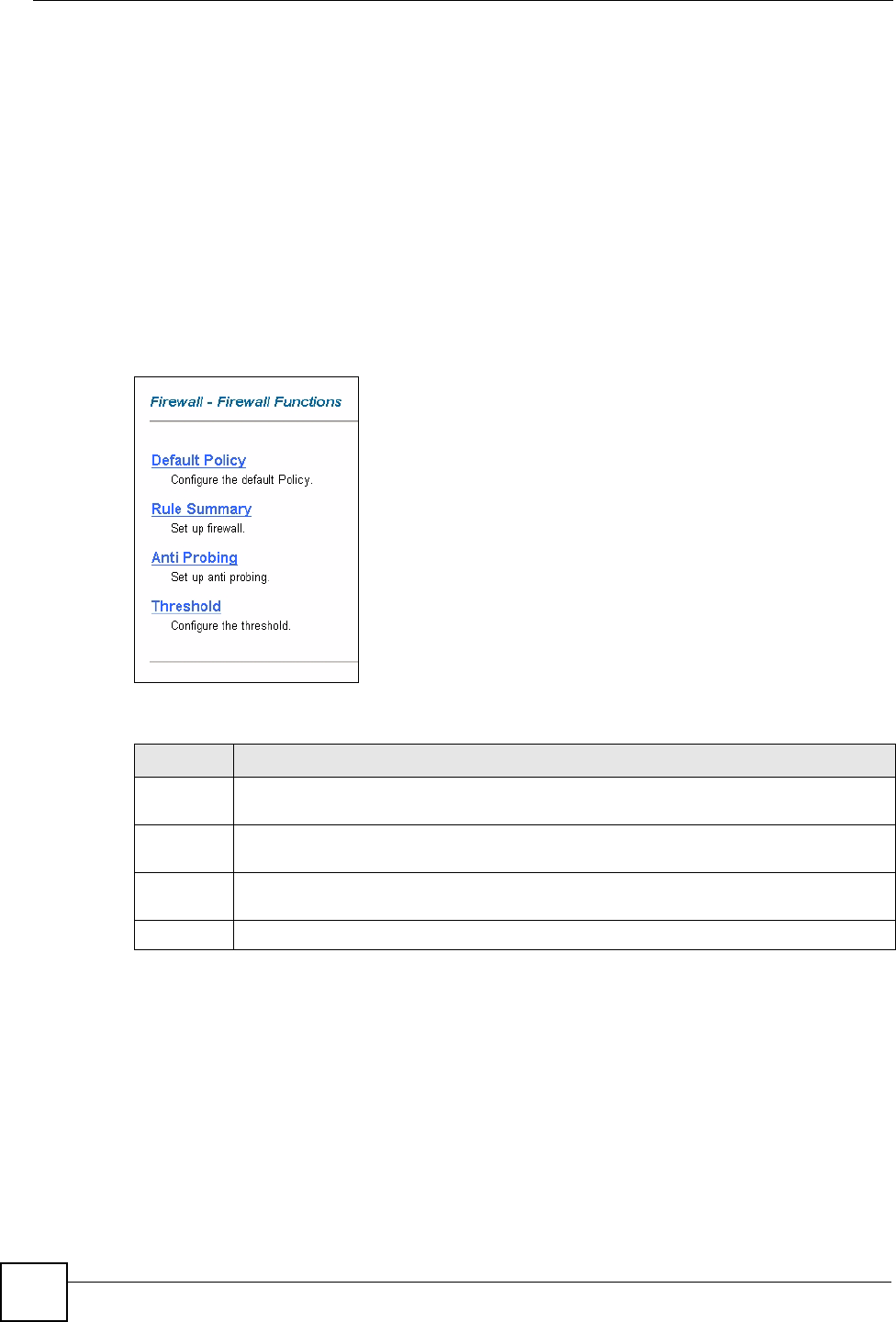
Click Content Filter to display the main Content Filtering screen.
Figure 51 Content Filtering
The following table describes the links in this screen.
12.6 Configuring Default Firewall Policy
Click Firewall and then Default Policy to display the following screen. Activate the firewall
by selecting the Firewall Enabled check box as seen in the following screen.
Refer to Section 11.1 on page 107 for more information.
Table 41 Firewall > Firewall Functions
LINK DESCRIPTION
Default
Policy
Click this link to configure the default firewall policy.
Rule
Summary
Click this link to configure firewall rules.
Anti-
Probing
Click this link to configure anti-probing rules.
Threshold Click this link to configure threshold values used to detect DoS attacks.
Chapter 12 Firewall Configuration
P-660W-Tx v2 User’s Guide 123
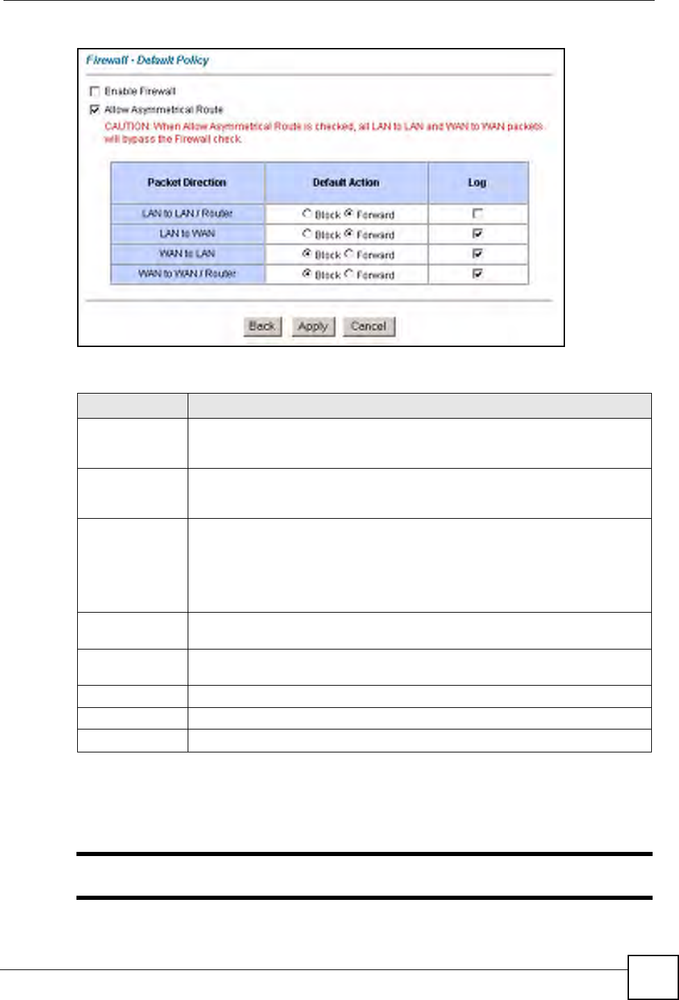
Figure 52 Firewall: Default Policy
The following table describes the labels in this screen.
12.7 Rule Summary
"The ordering of your rules is very important as rules are applied in turn.
Table 42 Firewall: Default Policy
LABEL DESCRIPTION
Firewall Enabled Select this check box to activate the firewall. The ZyXEL Device performs access
control and protects against Denial of Service (DoS) attacks when the firewall is
activated.
Allow
Asymmetrical
Route
Select this check box to have the ZyXEL Device firewall permit the use of triangle
route topology on the network. See the appendix for more on triangle route
topology.
Packet Direction This is the direction of travel of packets (LAN to LAN/Router, LAN to WAN, WAN
to WAN/Router, WAN to LAN).
Firewall rules are grouped based on the direction of travel of packets to which they
apply. For example, LAN to LAN/Router means packets traveling from a
computer/subnet on the LAN to either another computer/subnet on the LAN
interface of the ZyXEL Device or the ZyXEL Device itself.
Default Action Use the radio buttons to select whether to Block (silently discard) or Forward
(allow the passage of) packets that are traveling in the selected direction.
Log Select the check box to create a log (when the above action is taken) for packets
that are traveling in the selected direction and do not match any of the rules below.
Back Click Back to return to the previous screen.
Apply Click Apply to save your changes back to the ZyXEL Device.
Cancel Click Cancel to begin configuring this screen afresh.
Chapter 12 Firewall Configuration
P-660W-Tx v2 User’s Guide
124
Refer to Section 11.1 on page 107 for more information.
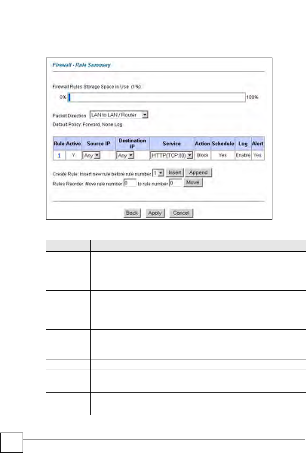
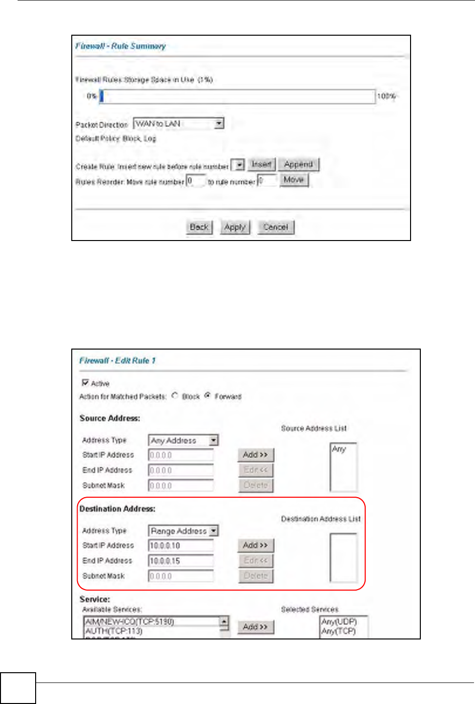
Click on Firewall, then Rule Summary to bring up the following screen. This screen is a
summary of the existing rules. Note the order in which the rules are listed.
Figure 53 Firewall: Rule Summary
The following table describes the labels in this screen.
Table 43 Rule Summary
LABEL DESCRIPTION
Firewall Rules
Storage Space
in Use
This read-only bar shows how much of the ZyXEL Device's memory for recording
firewall rules it is currently using. When you are using 80% or less of the storage
space, the bar is green. When the amount of space used is over 80%, the bar is red.
Packet
Direction
Use the drop-down list box to select a direction of travel of packets for which you
want to configure firewall rules.
Default Policy This field displays the default action and log policy you selected in the Default Rule
screen for the packet direction shown in the field above.
The following read-only fields summarize the rules you have created that apply to
traffic traveling in the selected packet direction. The firewall rules that you configure
(summarized below) take priority over the general firewall action settings above.
Rule This is your firewall rule number. The ordering of your rules is important as rules are
applied in turn.
Click a rule’s number to go to the Firewall Edit Rule screen to configure or edit a
firewall rule.
Active This field displays whether a firewall is turned on (Y) or not (N).
Source IP This drop-down list box displays the source addresses or ranges of addresses to
which this firewall rule applies. Please note that a blank source or destination
address is equivalent to Any.
Destination IP This drop-down list box displays the destination addresses or ranges of addresses to
which this firewall rule applies. Please note that a blank source or destination
address is equivalent to Any.
Chapter 12 Firewall Configuration
P-660W-Tx v2 User’s Guide 125
12.7.1 Configuring Firewall Rules
Refer to Section 11.1 on page 107 for more information.
Follow these directions to create a new rule.
1In the Rule Summary screen, type the index number for where you want to put the rule.
For example, if you type “6”, your new rule becomes number 6 and the previous rule 6
(if there is one) becomes rule 7.
2Click Insert to display this screen and refer to the following table for information on the
labels.
Service This drop-down list box displays the services to which this firewall rule applies.
Please note that a blank service type is equivalent to Any. See Section 12.11 on
page 133 for more information.
Action This is the specified action for that rule, either Block or Forward. Note that Block
means the firewall silently discards the packet.
Schedule This field tells you whether a schedule is specified (Yes) or not (No).
Log This field shows you whether a log is created when packets match this rule
(Enabled) or not (Disable).
Alert This field tells you whether this rule generates an alert (Yes) or not (No) when the
rule is matched.
Insert/Append Type the index number for where you want to put a rule. For example, if you type “6”,
your new rule becomes number 6 and the previous rule 6 (if there is one) becomes
rule 7.
Click Insert to add a new firewall rule before the specified index number.
Click Append to add a new firewall rule after the specified index number.
Move Type a rule’s index number and the number for where you want to put that rule. Click
Move to move the rule to the number that you typed. The ordering of your rules is
important as they are applied in order of their numbering.
Back Click Back to return to the previous screen.
Apply Click Apply to save your changes back to the ZyXEL Device.
Cancel Click Cancel to begin configuring this screen afresh.
Table 43 Rule Summary (continued)
LABEL DESCRIPTION
Chapter 12 Firewall Configuration
P-660W-Tx v2 User’s Guide
126
Figure 54 Firewall: Edit Rule
The following table describes the labels in this screen.

Chapter 12 Firewall Configuration
P-660W-Tx v2 User’s Guide 127
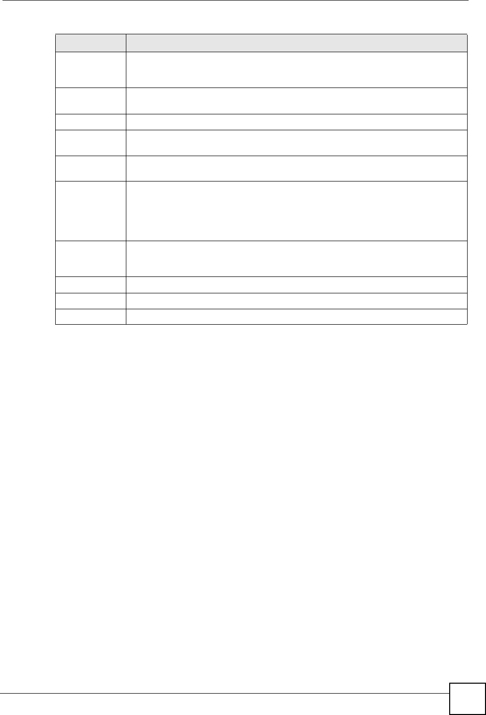
Table 44 Firewall: Edit Rule
LABEL DESCRIPTION
Active Select this option to enable this firewall rule.
Action for Matched
Packet
Use the radio button to select whether to discard (Block) or allow the passage
of (Forward) packets that match this rule.
Source/Destination
Address
Address Type Do you want your rule to apply to packets with a particular (single) IP, a range of
IP addresses (e.g., 192.168.1.10 to 192.169.1.50), a subnet or any IP address?
Select an option from the drop-down list box that includes: Single Address,
Range Address, Subnet Address and Any Address.
Start IP Address Enter the single IP address or the starting IP address in a range here.
End IP Address Enter the ending IP address in a range here.
Subnet Mask Enter the subnet mask here, if applicable.
Add Click Add to add a new address to the Source or Destination Address box.
You can add multiple addresses, ranges of addresses, and/or subnets.
Edit To edit an existing source or destination address, select it from the box and click
Edit.
Delete Highlight an existing source or destination address from the Source or
Destination Address box above and click Delete to remove it.
Services
Available/ Selected
Services
Please see Section 12.11 on page 133 for more information on services
available. Highlight a service from the Available Services box on the left, then
click Add>> to add it to the Selected Services box on the right. To remove a
service, highlight it in the Selected Services box on the right, then click
Remove.
Edit Customized
Service
Click the Edit Customized Services link to bring up the screen that you use to
configure a new custom service that is not in the predefined list of services.
Schedule
Day to Apply Select everyday or the day(s) of the week to apply the rule.
Time of Day to
Apply (24-Hour
Format)
Select All Day or enter the start and end times in the hour-minute format to
apply the rule.
Log
Log Packet Detail
Information
This field determines if a log for packets that match the rule is created (Enable)
or not (Disable). Go to the Log Settings page and select the Access Control
logs category to have the ZyXEL Device record these logs.
Alert
Send Alert
Message to
Administrator When
Matched
Select the check box to have the ZyXEL Device generate an alert when the rule
is matched.
Back Click Back to return to the previous screen.
Apply Click Apply to save your customized settings and exit this screen.
Cancel Click Cancel to exit this screen without saving.
Delete Click Delete to remove this firewall rule and return to the Firewall Rule
Summary screen.
Chapter 12 Firewall Configuration
P-660W-Tx v2 User’s Guide
128
12.8 Customized Services
Configure customized services and port numbers not predefined by the ZyXEL Device. For a
comprehensive list of port numbers and services, visit the IANA (Internet Assigned Number
Authority) website. For further information on these services, please read Section 12.11 on
page 133. Click the Customized Services link while editing a firewall rule to configure a
custom service port. This displays the following screen.
Refer to Section 11.1 on page 107 for more information.
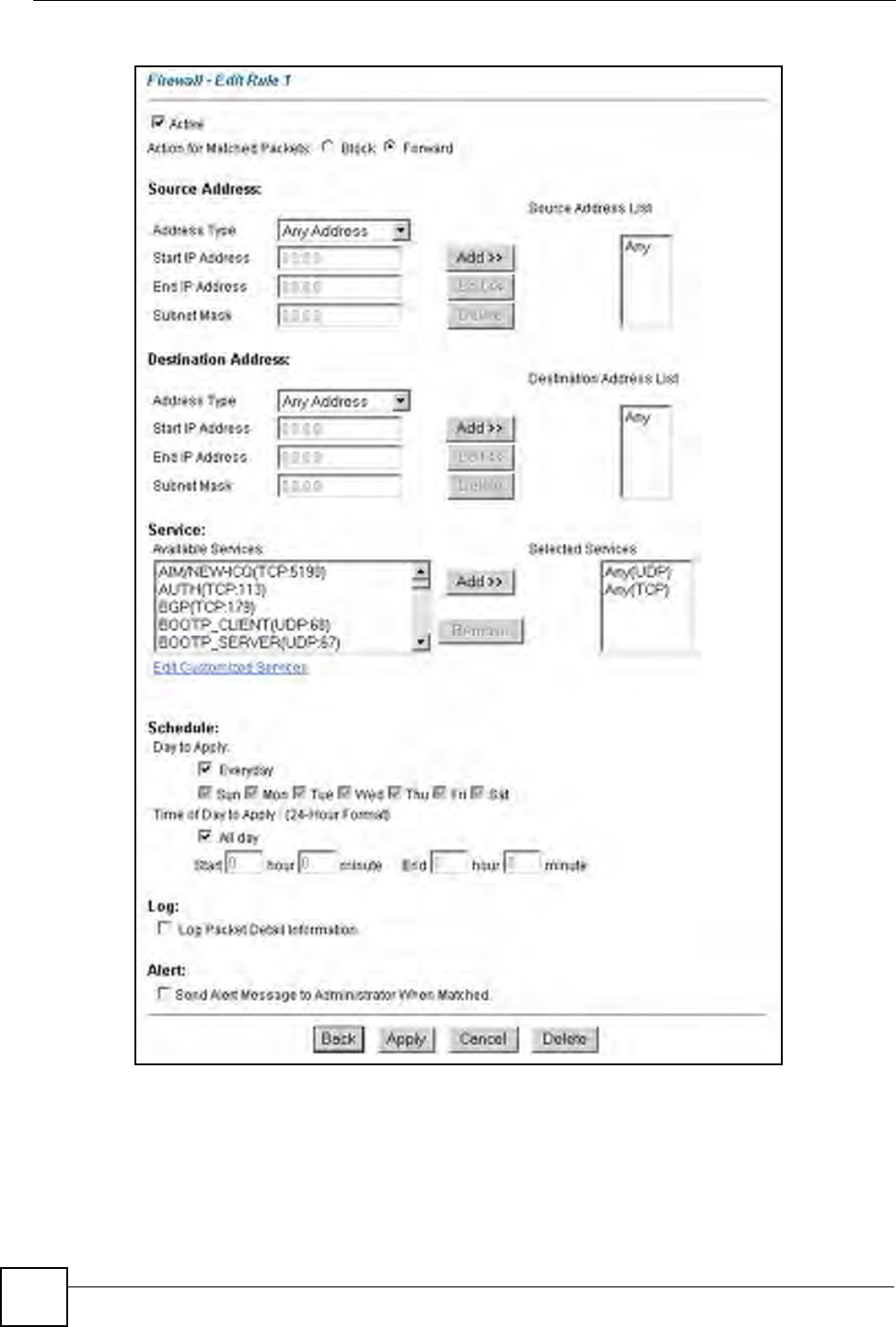
Figure 55 Firewall: Customized Services
The following table describes the labels in this screen.
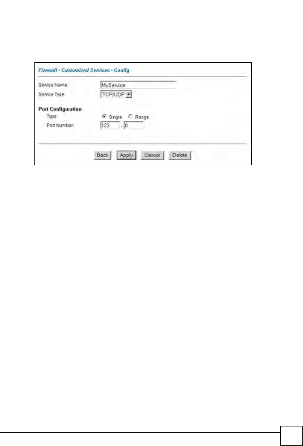
12.9 Configuring A Customized Service
Click a rule number in the Firewall Customized Services screen to create a new custom port
or edit an existing one. This action displays the following screen.
Refer to Section 11.1 on page 107 for more information.
Table 45 Customized Services
LABEL DESCRIPTION
No. This is the number of your customized port. Click a rule’s number of a service to go to the
Firewall Customized Services Config screen to configure or edit a customized service.
Name This is the name of your customized service.
Protocol This shows the IP protocol (TCP, UDP or TCP/UDP) that defines your customized
service.
Port This is the port number or range that defines your customized service.
Back Click Back to return the Firewall Edit Rule screen.
Chapter 12 Firewall Configuration
P-660W-Tx v2 User’s Guide 129
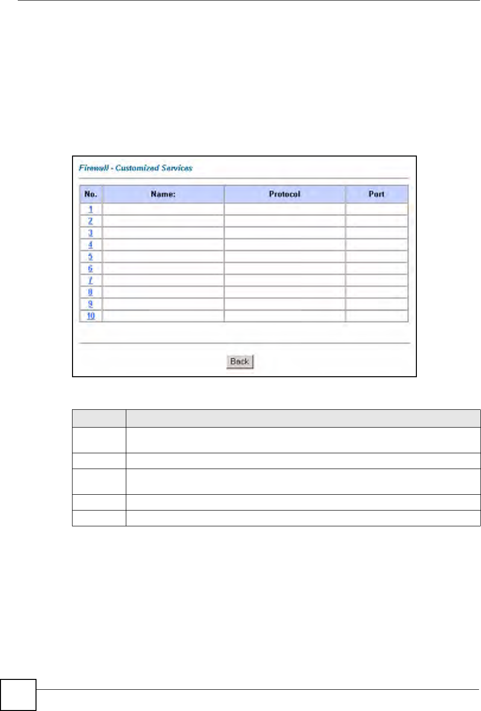
Figure 56 Firewall: Configure Customized Services
The following table describes the labels in this screen.
12.10 Example Firewall Rule
The following Internet firewall rule example allows a hypothetical “My Service” connection
from the Internet.
1Click Firewall in the navigation panel and click Rule Summary.
2Select WAN to LAN in the Packet Direction field.
Table 46 Firewall: Configure Customized Services
LABEL DESCRIPTION
Service Name Type a unique name for your custom port.
Service Type Choose the IP port (TCP, UDP or TCP/UDP) that defines your customized port from
the drop down list box.
Port Configuration
Type Click Single to specify one port only or Range to specify a span of ports that define
your customized service.
Port Number Type a single port number or the range of port numbers that define your customized
service.
Back Click Back to return to the Firewall Customized Services screen.
Apply Click Apply to save your customized settings and exit this screen.
Cancel Click Cancel to return to the previously saved settings.
Delete Click Delete to delete the current rule.
Chapter 12 Firewall Configuration
P-660W-Tx v2 User’s Guide
130
Figure 57 Firewall Example: Rule Summary
3In the Rule Summary screen, type the index number for where you want to put the rule.
For example, if you type “6”, your new rule becomes number 6 and the previous rule 6
(if there is one) becomes rule 7.
4Click Insert to display the firewall rule configuration screen.
5Select Any in the Destination Address box and then click Delete.
6Configure the destination address screen as follows and click Add.
Figure 58 Firewall Example: Edit Rule: Destination Address
Chapter 12 Firewall Configuration
P-660W-Tx v2 User’s Guide 131
7In the Edit Rule screen, click the Customized Services link to open the Customized
Service screen.
8Click an index number to display the Customized Services -Config screen and
configure the screen as follows and click Apply.
Figure 59 Edit Custom Port Example
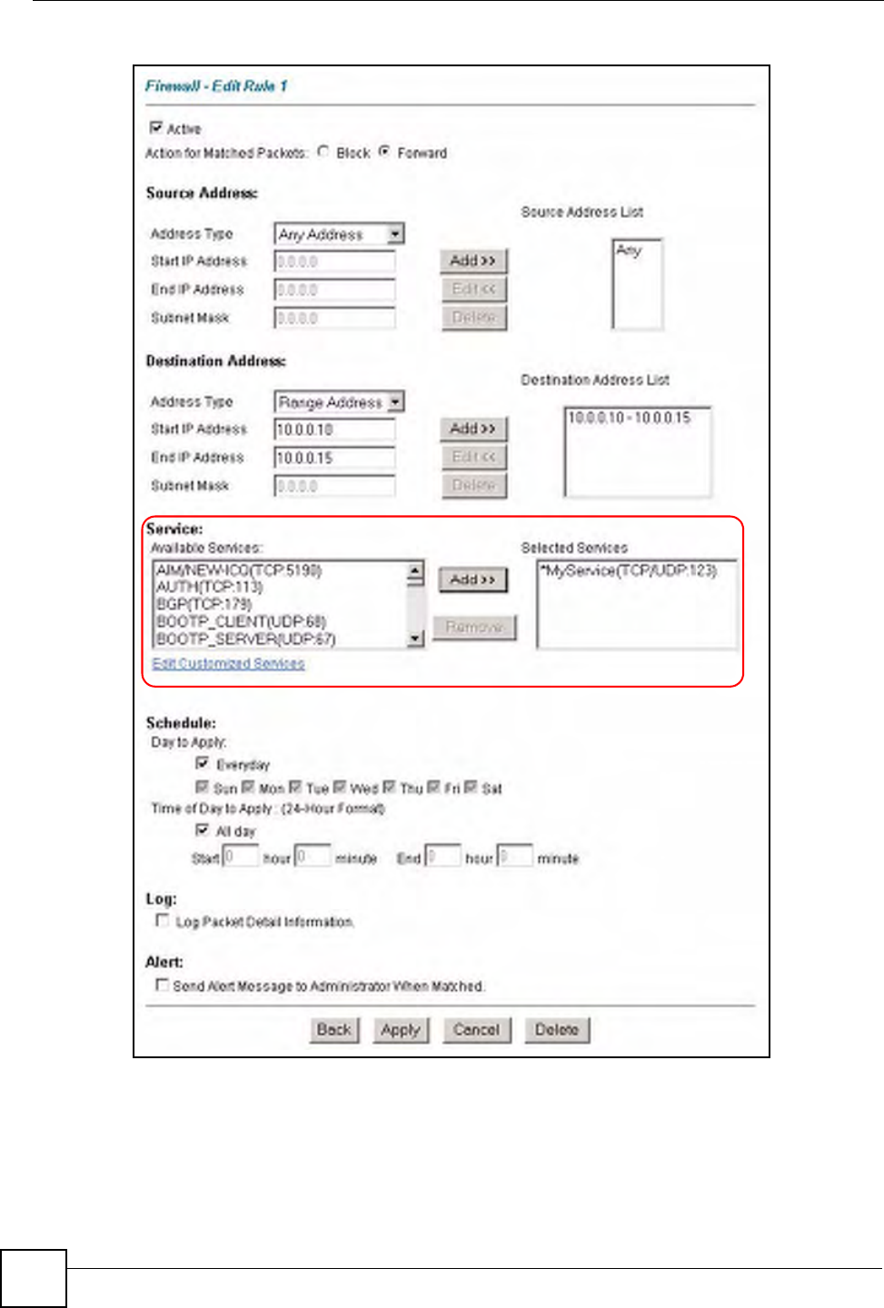
9In the Edit Rule screen, use the Add>> and Remove buttons between Available
Services and Selected Services list boxes to configure it as follows. Click Apply when
you are done.
Chapter 12 Firewall Configuration
P-660W-Tx v2 User’s Guide
132
Figure 60 Firewall Example: Edit Rule: Select Customized Services
Chapter 12 Firewall Configuration
P-660W-Tx v2 User’s Guide 133
"Custom ports show up with an “*” before their names in the Services list box
and the Rule Summary list box. Click Apply after you’ve created your custom
port.
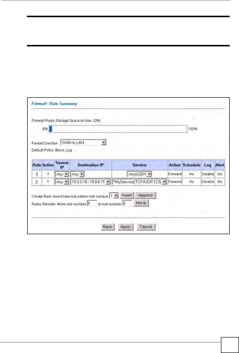
On completing the configuration procedure for this Internet firewall rule, the Rule Summary
screen should look like the following.
Rule 2 allows a “My Service” connection from the WAN to IP addresses 10.0.0.10 through
10.0.0.15 on the LAN.
Figure 61 Firewall Example: Rule Summary: My Service
12.11 Predefined Services
The Available Services list box in the Edit Rule screen (see Section 12.7.1 on page 125)
displays all predefined services that the ZyXEL Device already supports. Next to the name of
the service, two fields appear in brackets. The first field indicates the IP protocol type (TCP,
UDP, or ICMP). The second field indicates the IP port number that defines the service. (Note
that there may be more than one IP protocol type. For example, look at the default
configuration labeled “(DNS)”. (UDP/TCP:53) means UDP port 53 and TCP port 53. Up to 128
entries are supported. Custom service ports may also be configured using the Edit
Customized Services function discussed previously. See Appendix C on page 231 for a list of
common services.
Chapter 12 Firewall Configuration
P-660W-Tx v2 User’s Guide
134
12.12 Anti-Probing
If an outside user attempts to probe an unsupported port on your ZyXEL Device, an ICMP
response packet is automatically returned. This allows the outside user to know the ZyXEL
Device exists. The ZyXEL Device supports anti-probing, which prevents the ICMP response
packet from being sent. This keeps outsiders from discovering your ZyXEL Device when
unsupported ports are probed.
Internet Control Message Protocol (ICMP) is a message control and error-reporting protocol
between a host server and a gateway to the Internet. ICMP uses Internet Protocol (IP)
datagrams, but the messages are processed by the TCP/IP software and directly apparent to the
application user.
Refer to Section 11.1 on page 107 for more information.
Click Firewall in the navigation panel and click Anti Probing to display the screen as shown.
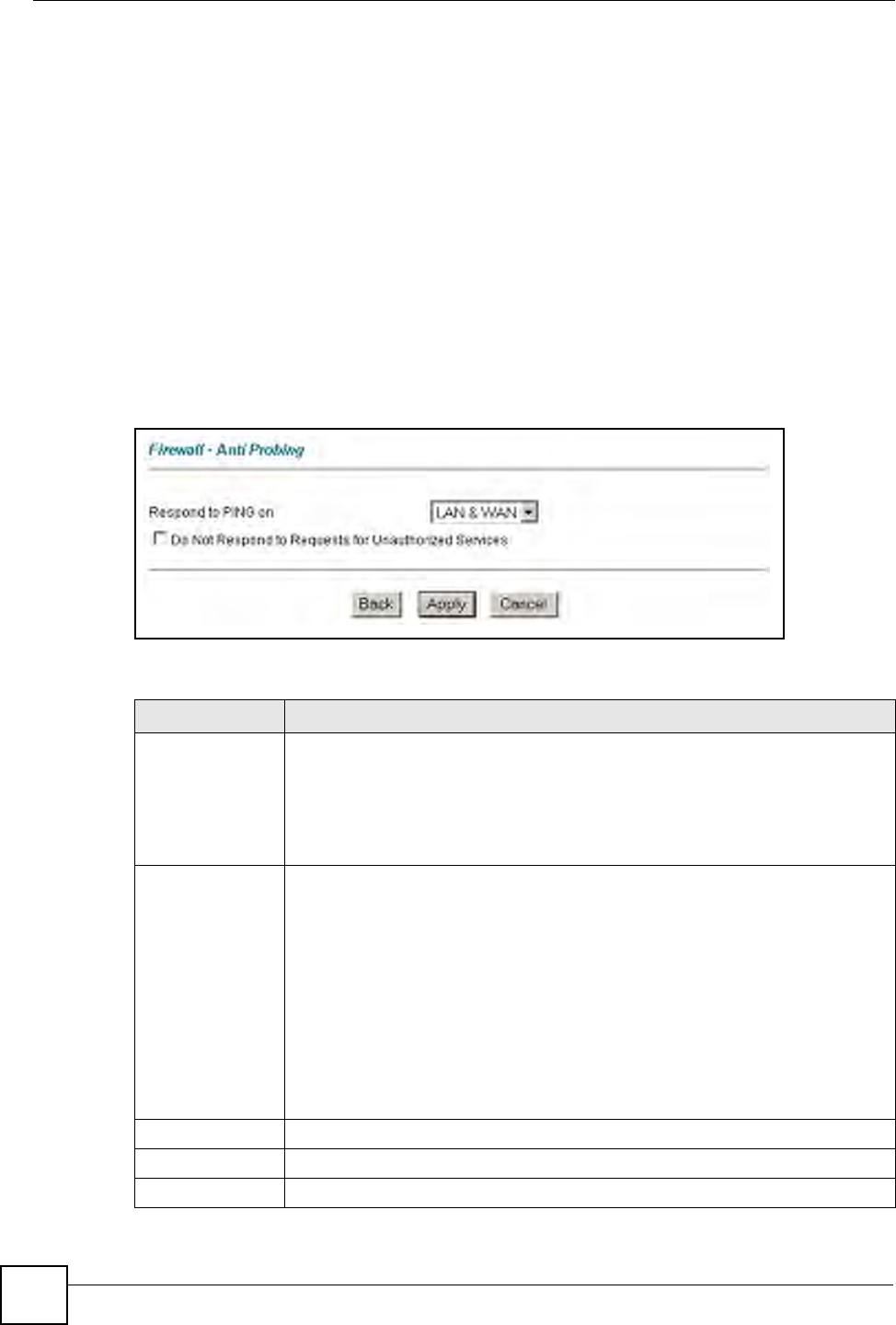
Figure 62 Firewall: Anti Probing
The following table describes the labels in this screen.
Table 47 Firewall: Anti Probing
LABEL DESCRIPTION
Respond to PING
on
The ZyXEL Device does not respond to any incoming Ping requests when
Disable is selected.
Select LAN to reply to incoming LAN Ping requests.
Select WAN to reply to incoming WAN Ping requests.
Otherwise select LAN & WAN to reply to both incoming LAN and WAN Ping
requests.
Do not respond to
requests for
unauthorized
services.
Select this option to prevent hackers from finding the ZyXEL Device by probing for
unused ports. If you select this option, the ZyXEL Device will not respond to port
request(s) for unused ports, thus leaving the unused ports and the ZyXEL Device
unseen. By default this option is not selected and the ZyXEL Device will reply with
an ICMP Port Unreachable packet for a port probe on its unused UDP ports, and a
TCP Reset packet for a port probe on its unused TCP ports.
Note that the probing packets must first traverse the ZyXEL Device 's firewall
mechanism before reaching this anti-probing mechanism. Therefore if the firewall
mechanism blocks a probing packet, the ZyXEL Device reacts based on the
firewall policy, which by default, is to send a TCP reset packet for a blocked TCP
packet. You can use the command "sys firewall tcprst rst [on|off]" to change this
policy. When the firewall mechanism blocks a UDP packet, it drops the packet
without sending a response packet.
Back Click Back to return to the previous screen.
Apply Click Apply to save your changes back to the ZyXEL Device.
Reset Click Reset to begin configuring this screen afresh.

Chapter 12 Firewall Configuration
P-660W-Tx v2 User’s Guide 135
12.13 DoS Thresholds
For DoS attacks, the ZyXEL Device uses thresholds to determine when to drop sessions that
do not become fully established. These thresholds apply globally to all sessions.
You can use the default threshold values, or you can change them to values more suitable to
your security requirements.
Refer to Section 12.13.3 on page 136 to configure thresholds.
12.13.1 Threshold Values
Tune these parameters when something is not working and after you have checked the firewall
counters. These default values should work fine for most small offices. Factors influencing
choices for threshold values are:
• The maximum number of opened sessions.
• The minimum capacity of server backlog in your LAN network.
• The CPU power of servers in your LAN network.
• Network bandwidth.
• Type of traffic for certain servers.
If your network is slower than average for any of these factors (especially if you have servers
that are slow or handle many tasks and are often busy), then the default values should be
reduced.
You should make any changes to the threshold values before you continue configuring
firewall rules.
12.13.2 Half-Open Sessions
An unusually high number of half-open sessions (either an absolute number or measured as
the arrival rate) could indicate that a Denial of Service attack is occurring. For TCP, "half-
open" means that the session has not reached the established state-the TCP three-way
handshake has not yet been completed (see Figure 47 on page 110). For UDP, "half-open"
means that the firewall has detected no return traffic.
The ZyXEL Device measures both the total number of existing half-open sessions and the rate
of session establishment attempts. Both TCP and UDP half-open sessions are counted in the
total number and rate measurements. Measurements are made once a minute.
When the number of existing half-open sessions rises above a threshold (max-incomplete
high), the ZyXEL Device starts deleting half-open sessions as required to accommodate new
connection requests. The ZyXEL Device continues to delete half-open requests as necessary,
until the number of existing half-open sessions drops below another threshold (max-
incomplete low).
When the rate of new connection attempts rises above a threshold (one-minute high), the
ZyXEL Device starts deleting half-open sessions as required to accommodate new connection
requests. The ZyXEL Device continues to delete half-open sessions as necessary, until the rate
of new connection attempts drops below another threshold (one-minute low). The rate is the
number of new attempts detected in the last one-minute sample period.
Chapter 12 Firewall Configuration
P-660W-Tx v2 User’s Guide
136
12.13.2.1 TCP Maximum Incomplete and Blocking Time
An unusually high number of half-open sessions with the same destination host address could
indicate that a Denial of Service attack is being launched against the host.
Whenever the number of half-open sessions with the same destination host address rises above
a threshold (TCP Maximum Incomplete), the ZyXEL Device starts deleting half-open
sessions according to one of the following methods:
• If the Blocking Time timeout is 0 (the default), then the ZyXEL Device deletes the oldest
existing half-open session for the host for every new connection request to the host. This
ensures that the number of half-open sessions to a given host will never exceed the
threshold.
• If the Blocking Time timeout is greater than 0, then the ZyXEL Device blocks all new
connection requests to the host giving the server time to handle the present connections.
The ZyXEL Device continues to block all new connection requests until the Blocking
Time expires.
12.13.3 Configuring Firewall Thresholds
The ZyXEL Device also sends alerts whenever TCP Maximum Incomplete is exceeded. The
global values specified for the threshold and timeout apply to all TCP connections.
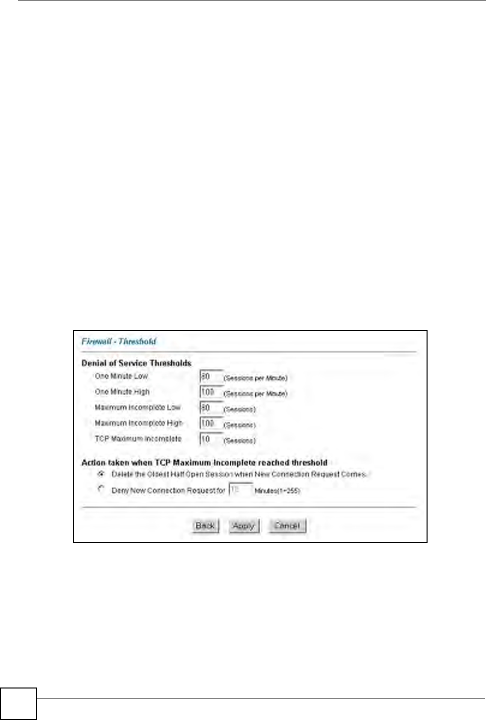
Click Firewall, and Threshold to bring up the next screen.
Figure 63 Firewall: Threshold
The following table describes the labels in this screen.

Chapter 12 Firewall Configuration
P-660W-Tx v2 User’s Guide 137
Table 48 Firewall: Threshold
LABEL DESCRIPTION DEFAULT VALUES
Denial of Service
Thresholds
One Minute Low This is the rate of new half-open sessions
that causes the firewall to stop deleting half-
open sessions. The ZyXEL Device continues
to delete half-open sessions as necessary,
until the rate of new connection attempts
drops below this number.
80 existing half-open sessions.
One Minute High This is the rate of new half-open sessions
that causes the firewall to start deleting half-
open sessions. When the rate of new
connection attempts rises above this number,
the ZyXEL Device deletes half-open sessions
as required to accommodate new connection
attempts.
100 half-open sessions per
minute. The above numbers cause
the ZyXEL Device to start deleting
half-open sessions when more
than 100 session establishment
attempts have been detected in
the last minute, and to stop
deleting half-open sessions when
fewer than 80 session
establishment attempts have been
detected in the last minute.
Maximum
Incomplete Low
This is the number of existing half-open
sessions that causes the firewall to stop
deleting half-open sessions. The ZyXEL
Device continues to delete half-open
requests as necessary, until the number of
existing half-open sessions drops below this
number.
80 existing half-open sessions.
Maximum
Incomplete High
This is the number of existing half-open
sessions that causes the firewall to start
deleting half-open sessions. When the
number of existing half-open sessions rises
above this number, the ZyXEL Device
deletes half-open sessions as required to
accommodate new connection requests. Do
not set Maximum Incomplete High to lower
than the current Maximum Incomplete Low
number.
100 existing half-open sessions.
The above values causes the
ZyXEL Device to start deleting
half-open sessions when the
number of existing half-open
sessions rises above 100, and to
stop deleting half-open sessions
with the number of existing half-
open sessions drops below 80.
TCP Maximum
Incomplete
This is the number of existing half-open TCP
sessions with the same destination host IP
address that causes the firewall to start
dropping half-open sessions to that same
destination host IP address. Enter a number
between 1 and 256. As a general rule, you
should choose a smaller number for a smaller
network, a slower system or limited
bandwidth.
30 existing half-open TCP
sessions.
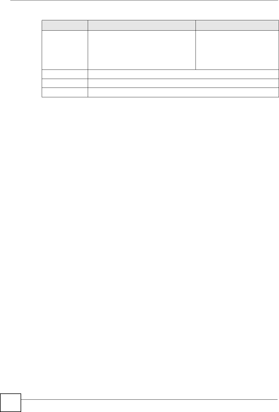
Action taken when the TCP Maximum Incomplete threshold is reached.
Delete the oldest
half open session
when new
connection
request comes
Select this radio button to clear the oldest half
open session when a new connection request
comes.
Chapter 12 Firewall Configuration
P-660W-Tx v2 User’s Guide
138
Deny new
connection
request for
Select this radio button and specify for how
long the ZyXEL Device should block new
connection requests when TCP Maximum
Incomplete is reached.
Enter the length of blocking time in minutes
(between 1 and 256).
Back Click Back to return to the previous screen.
Apply Click Apply to save your changes back to the ZyXEL Device.
Cancel Click Cancel to begin configuring this screen afresh.
Table 48 Firewall: Threshold (continued)
LABEL DESCRIPTION DEFAULT VALUES
P-660W-Tx v2 User’s Guide 139
CHAPTER 13
Content Filtering
This chapter covers how to configure content filtering.
13.1 Content Filtering Overview
Internet content filtering allows you to create and enforce Internet access policies tailored to
your needs. Content filtering gives you the ability to block web sites that contain key words
(that you specify) in the URL. You can set a schedule for when the ZyXEL Device performs
content filtering. You can also specify trusted IP addresses on the LAN for which the ZyXEL
Device will not perform content filtering.
13.2 The Main Content Filter Screen
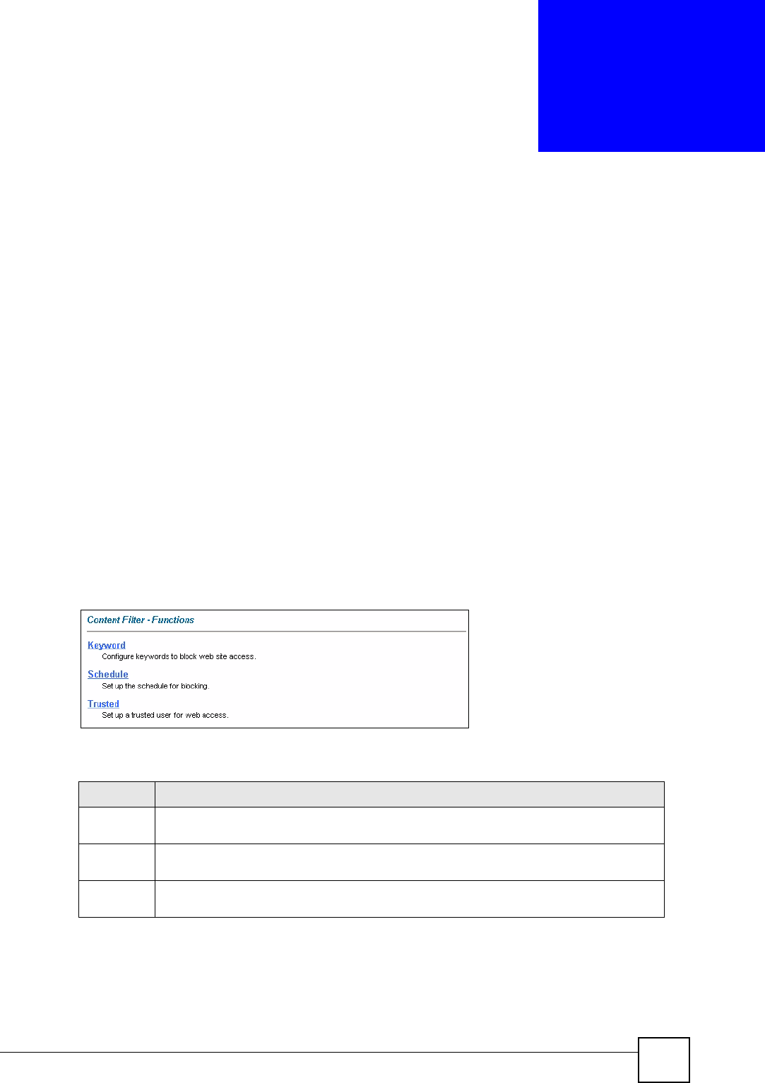
Click Content Filter to display the main Content Filtering screen.
Figure 64 Content Filtering
The following table describes the links in this screen.
Table 49 Content Filter > Functions
LINK DESCRIPTION
Keyword Click this link to display a screen where you can configure your ZyXEL Device to block
Web sites containing keywords in their URLs,
Schedule Click this link to display a screen where you can set the days and times for the ZyXEL
Device to perform content filtering,
Trusted Click this link to display a screen where you can exclude a range of users on the LAN
from content filtering on your ZyXEL Device
Chapter 13 Content Filtering
P-660W-Tx v2 User’s Guide
140
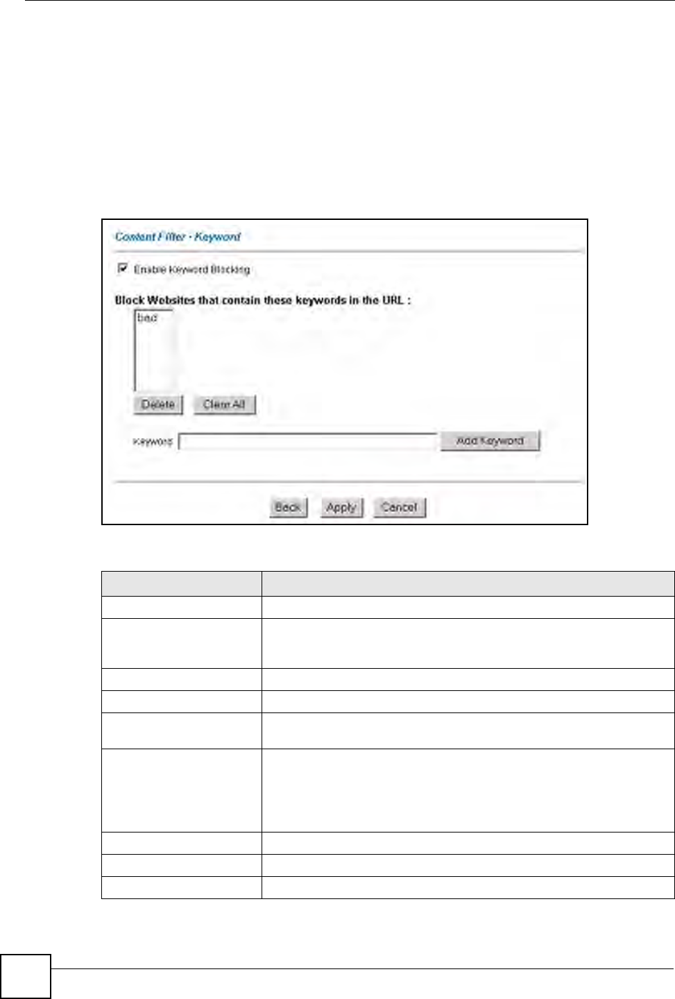
13.3 Configuring Keyword Blocking
Use this screen to block sites containing certain keywords in the URL. For example, if you
enable the keyword "bad", the ZyXEL Device blocks all sites containing this keyword
including the URL http://www.website.com/bad.html, even if it is not included in the Filter
List.
To have your ZyXEL Device block Web sites containing keywords in their URLs, click
Content Filter and Keyword. The screen appears as shown.
Figure 65 Content Filter: Keyword
The following table describes the labels in this screen.
Table 50 Content Filter: Keyword
LABEL DESCRIPTION
Enable Keyword Blocking Select this check box to enable this feature.
Block Websites that
contain these keywords in
the URL:
This box contains the list of all the keywords that you have configured the
ZyXEL Device to block.
Delete Highlight a keyword in the box and click Delete to remove it.
Clear All Click Clear All to remove all of the keywords from the list.
Keyword Type a keyword in this field. You may use any character (up to 127
characters). Wildcards are not allowed.
Add Keyword Click Add Keyword after you have typed a keyword.
Repeat this procedure to add other keywords. Up to 64 keywords are
allowed.
When you try to access a web page containing a keyword, you will get a
message telling you that the content filter is blocking this request.
Back Click Back to return to the previous screen.
Apply Click Apply to save your changes back to the ZyXEL Device.
Cancel Click Cancel to return to the previously saved settings.
Chapter 13 Content Filtering
P-660W-Tx v2 User’s Guide 141
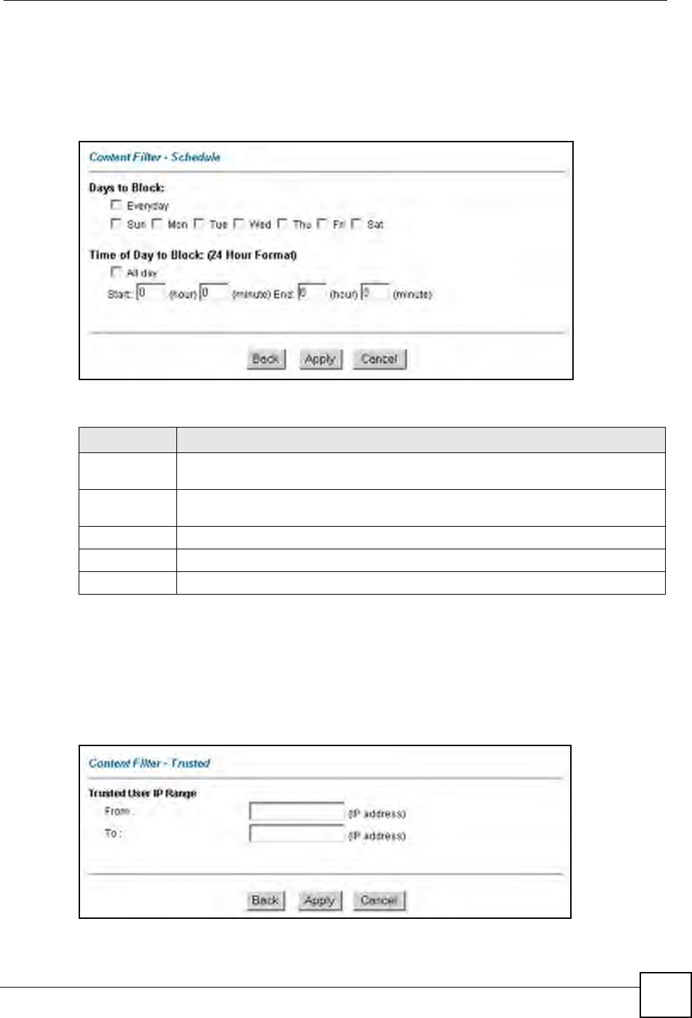
13.4 Configuring the Schedule
To set the days and times for the ZyXEL Device to perform content filtering, click Content
Filter and Schedule. The screen appears as shown.
Figure 66 Content Filter: Schedule
The following table describes the labels in this screen.
13.5 Configuring Trusted Computers
To exclude a range of users on the LAN from content filtering on your ZyXEL Device, click
Content Filter and Trusted. The screen appears as shown.
Figure 67 Content Filter: Trusted
Table 51 Content Filter: Schedule
LABEL DESCRIPTION
Days to Block: Select a check box to configure which days of the week (or everyday) you want the
content filtering to be active.
Time of Day to
Block:
Use the 24 hour format to configure which time of the day (or select the All day check
box) you want the content filtering to be active.
Back Click Back to return to the previous screen.
Apply Click Apply to save your changes.
Cancel Click Cancel to return to the previously saved settings.

Chapter 13 Content Filtering
P-660W-Tx v2 User’s Guide
142
The following table describes the labels in this screen.
Table 52 Content Filter: Trusted
LABEL DESCRIPTION
Trusted User IP Range
From Type the IP address of a computer (or the beginning IP address of a specific
range of computers) on the LAN that you want to exclude from content
filtering.
To Type the ending IP address of a specific range of users on your LAN that
you want to exclude from content filtering. Leave this field blank if you want
to exclude an individual computer.
Back Click Back to return to the previous screen.
Apply Click Apply to save your changes back to the ZyXEL Device.
Cancel Click Cancel to return to the previously saved settings.

P-660W-Tx v2 User’s Guide 143
CHAPTER 14
Remote Management
Configuration
This chapter provides information on configuring remote management.
14.1 Remote Management Overview
Remote management allows you to determine which services/protocols can access which
ZyXEL Device interface (if any) from which computers.
When you configure remote management to allow management from the WAN, you still need
to configure a firewall rule to allow access.
You may manage your ZyXEL Device from a remote location via:
• Internet (WAN only)
• ALL (LAN and WAN)
• LAN only,
• Neither (Disable).
When you Choose WAN o nl y or ALL (LAN & WAN), you still need to configure a firewall
rule to allow access.
To disable remote management of a service, select Disable in the corresponding Server
Access field.
You may only have one remote management session running at a time. The ZyXEL Device
automatically disconnects a remote management session of lower priority when another
remote management session of higher priority starts. The priorities for the different types of
remote management sessions are as follows.
1Telnet
2HTTP
14.1.1 Remote Management Limitations
Remote management over LAN or WAN will not work when:
• You have disabled that service in one of the remote management screens.
• The IP address in the Secured Client IP field does not match the client IP address. If it
does not match, the ZyXEL Device will disconnect the session immediately.
Chapter 14 Remote Management Configuration
P-660W-Tx v2 User’s Guide
144
• There is already another remote management session with an equal or higher priority
running. You may only have one remote management session running at one time.
• There is a firewall rule that blocks it.
14.1.2 Remote Management and NAT
When NAT is enabled:
• Use the ZyXEL Device’s WAN IP address when configuring from the WAN.
• Use the ZyXEL Device’s LAN IP address when configuring from the LAN.
14.1.3 System Timeout
There is a default system management idle timeout of five minutes (three hundred seconds).
The ZyXEL Device automatically logs you out if the management session remains idle for
longer than this timeout period. The management session does not time out when a statistics
screen is polling.
14.2 Telnet
You can configure your ZyXEL Device for remote Telnet access as shown next.
Figure 68 Telnet Configuration on a TCP/IP Network
14.3 FTP
You can upload and download ZyXEL Device firmware and configuration files using FTP. To
use this feature, your computer must have an FTP client.
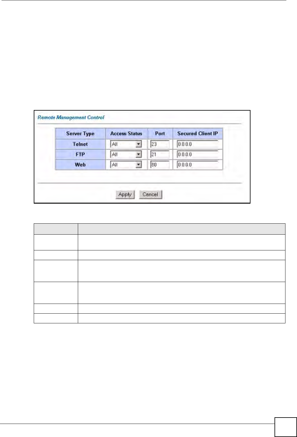
Chapter 14 Remote Management Configuration
P-660W-Tx v2 User’s Guide 145
14.4 Web
You can use the ZyXEL Device’s embedded web configurator for configuration and file
management. See the online help for details.
14.5 Configuring Remote Management
Click Remote Management to open the following screen. See Section 14.1 on page 143 for
more information.
Figure 69 Remote Management
The following table describes the fields in this screen.
Table 53 Remote Management
LABEL DESCRIPTION
Server Type Each of these labels denotes a service that you may use to remotely manage the
ZyXEL Device.
Access Status Select the access interface. Choices are All, LAN Only, WAN Only and Disable.
Port This field shows the port number for the remote management service. You may
change the port number for a service in this field, but you must use the same port
number to use that service for remote management.
Secured Client
IP
The default 0.0.0.0 allows any client to use this service to remotely manage the
ZyXEL Device. Type an IP address to restrict access to a client with a matching IP
address.
Apply Click Apply to save your settings back to the ZyXEL Device.
Cancel Click Cancel to begin configuring this screen afresh.

Chapter 14 Remote Management Configuration
P-660W-Tx v2 User’s Guide
146

P-660W-Tx v2 User’s Guide 147
CHAPTER 15
Universal Plug-and-Play (UPnP)
This chapter introduces the UPnP feature in the web configurator.
15.1 Introducing Universal Plug and Play
Universal Plug and Play (UPnP) is a distributed, open networking standard that uses TCP/IP
for simple peer-to-peer network connectivity between devices. A UPnP device can
dynamically join a network, obtain an IP address, convey its capabilities and learn about other
devices on the network. In turn, a device can leave a network smoothly and automatically
when it is no longer in use.
See Section 15.2.1 on page 148 for configuration instructions.
15.1.1 How do I know if I'm using UPnP?
UPnP hardware is identified as an icon in the Network Connections folder (Windows XP).
Each UPnP compatible device installed on your network will appear as a separate icon.
Selecting the icon of a UPnP device will allow you to access the information and properties of
that device.
15.1.2 NAT Traversal
UPnP NAT traversal automates the process of allowing an application to operate through
NAT. UPnP network devices can automatically configure network addressing, announce their
presence in the network to other UPnP devices and enable exchange of simple product and
service descriptions. NAT traversal allows the following:
• Dynamic port mapping
• Learning public IP addresses
• Assigning lease times to mappings
Windows Messenger is an example of an application that supports NAT traversal and UPnP.
See the NAT chapter for more information on NAT.
15.1.3 Cautions with UPnP
The automated nature of NAT traversal applications in establishing their own services and
opening firewall ports may present network security issues. Network information and
configuration may also be obtained and modified by users in some network environments.
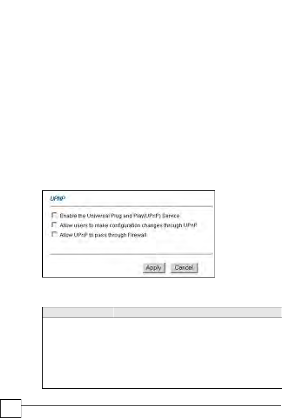
Chapter 15 Universal Plug-and-Play (UPnP)
P-660W-Tx v2 User’s Guide
148
All UPnP-enabled devices may communicate freely with each other without additional
configuration. Disable UPnP if this is not your intention.
15.2 UPnP and ZyXEL
ZyXEL has achieved UPnP certification from the Universal Plug and Play Forum Creates
UPnP™ Implementers Corp. (UIC). ZyXEL's UPnP implementation supports IGD 1.0
(Internet Gateway Device). At the time of writing ZyXEL's UPnP implementation supports
Windows Messenger 4.6 and 4.7 while Windows Messenger 5.0 and Xbox are still being
tested.
UPnP broadcasts are only allowed on the LAN.
See later sections for examples of installing UPnP in Windows XP and Windows Me as well
as an example of using UPnP in Windows.
15.2.1 Configuring UPnP
From the Site Map in the main menu, click UPnP under Advanced Setup to display the
screen shown next.
See Section 15.1 on page 147 for more information.
Figure 70 Configuring UPnP
The following table describes the fields in this screen.
Table 54 Configuring UPnP
LABEL DESCRIPTION
Enable the Universal Plug
and Play (UPnP) Service
Select this check box to activate UPnP. Be aware that anyone could
use a UPnP application to open the web configurator's login screen
without entering the ZyXEL Device's IP address (although you must still
enter the password to access the web configurator).
Allow users to make
configuration changes
through UPnP
Select this check box to allow UPnP-enabled applications to
automatically configure the ZyXEL Device so that they can
communicate through the ZyXEL Device, for example by using NAT
traversal, UPnP applications automatically reserve a NAT forwarding
port in order to communicate with another UPnP enabled device; this
eliminates the need to manually configure port forwarding for the UPnP
enabled application.
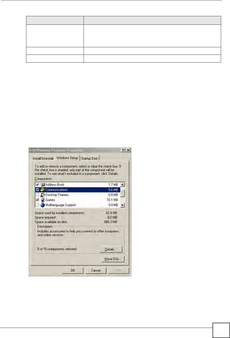
Chapter 15 Universal Plug-and-Play (UPnP)
P-660W-Tx v2 User’s Guide 149
15.3 Installing UPnP in Windows Example
This section shows how to install UPnP in Windows Me and Windows XP.
Installing UPnP in Windows Me
Follow the steps below to install the UPnP in Windows Me.
1Click Start and Control Panel. Double-click Add/Remove Programs.
2Click on the Windows Setup tab and select Communication in the Components
selection box. Click Details.
Figure 71 Add/Remove Programs: Windows Setup: Communication
3In the Communications window, select the Universal Plug and Play check box in the
Components selection box.
Allow UPnP to pass through
Firewall
Select this check box to allow traffic from UPnP-enabled applications to
bypass the firewall.
Clear this check box to have the firewall block all UPnP application
packets (for example, MSN packets).
Apply Click Apply to save the setting to the ZyXEL Device.
Cancel Click Cancel to return to the previously saved settings.
Table 54 Configuring UPnP
LABEL DESCRIPTION
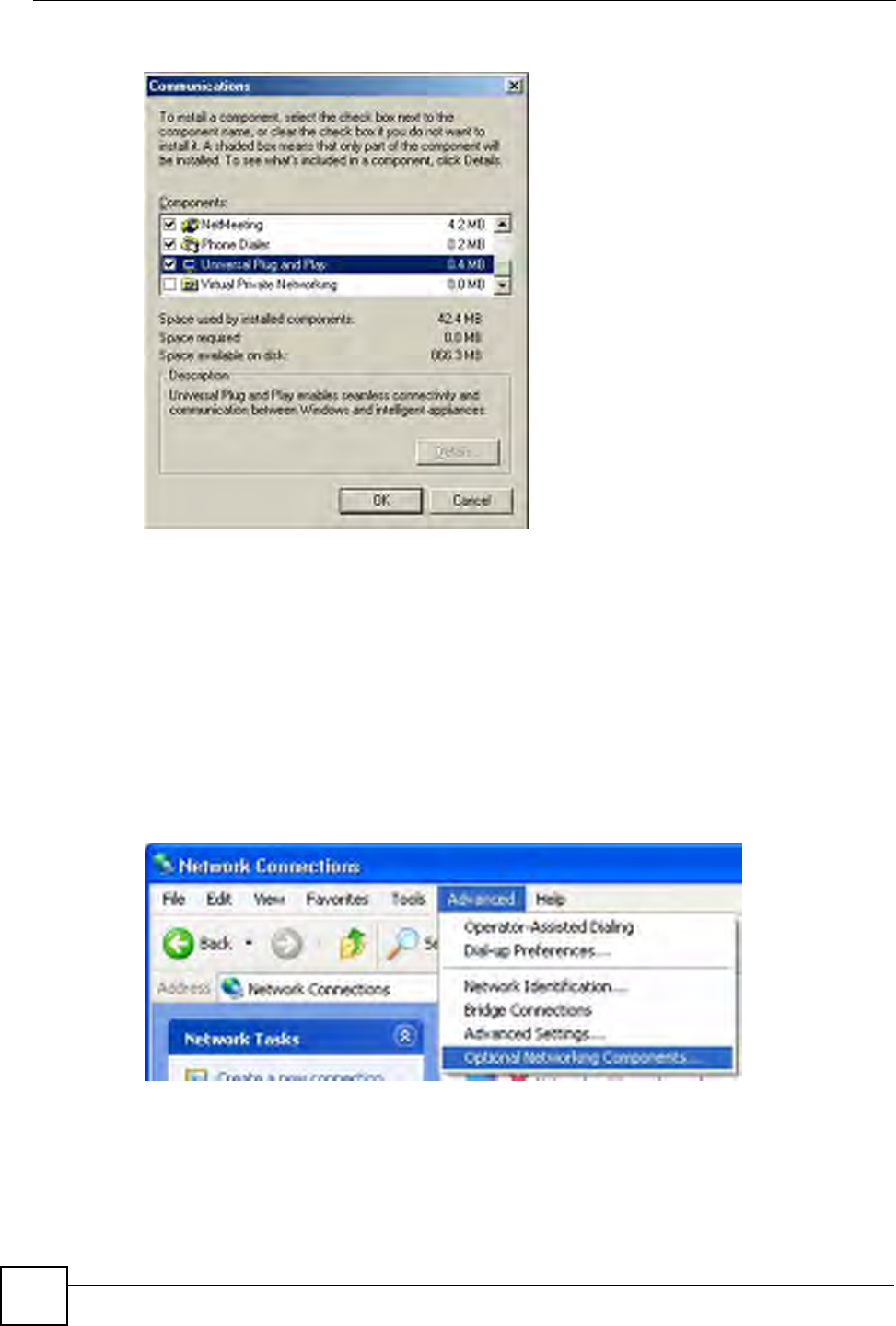
Chapter 15 Universal Plug-and-Play (UPnP)
P-660W-Tx v2 User’s Guide
150
Figure 72 Add/Remove Programs: Windows Setup: Communication: Components
4Click OK to go back to the Add/Remove Programs Properties window and click
Next.
5Restart the computer when prompted.
Installing UPnP in Windows XP
Follow the steps below to install the UPnP in Windows XP.
1Click Start and Control Panel.
2Double-click Network Connections.
3In the Network Connections window, click Advanced in the main menu and select
Optional Networking Components ….
Figure 73 Network Connections
4The Windows Optional Networking Components Wizard window displays. Select
Networking Service in the Components selection box and click Details.
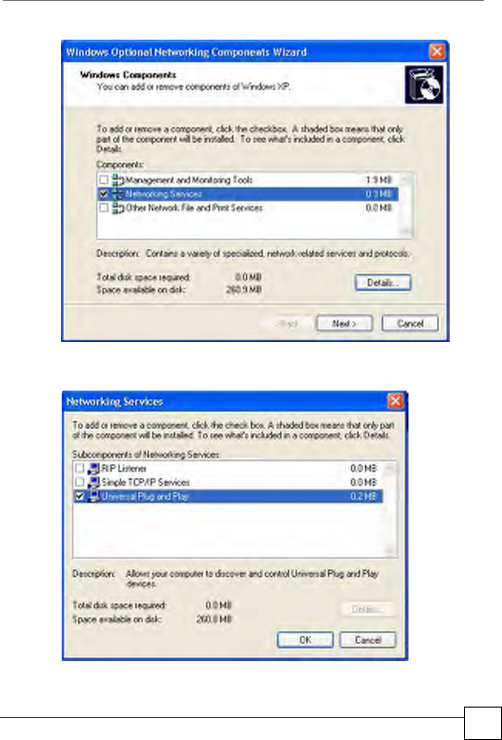
Chapter 15 Universal Plug-and-Play (UPnP)
P-660W-Tx v2 User’s Guide 151
Figure 74 Windows Optional Networking Components Wizard
5In the Networking Services window, select the Universal Plug and Play check box.
Figure 75 Networking Services
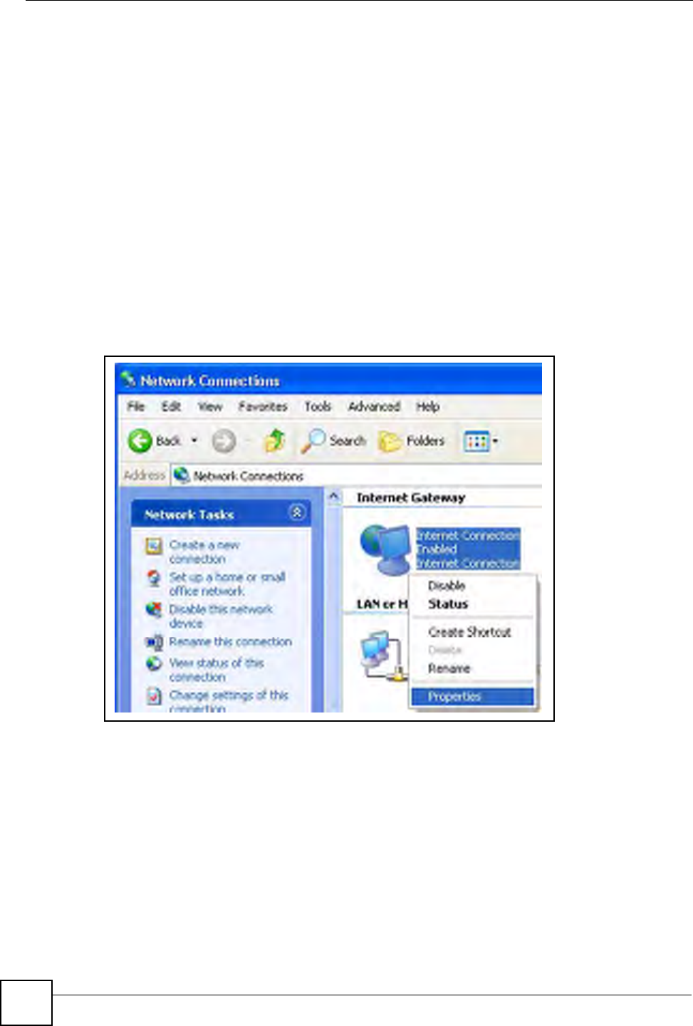
Chapter 15 Universal Plug-and-Play (UPnP)
P-660W-Tx v2 User’s Guide
152
6Click OK to go back to the Windows Optional Networking Component Wizard
window and click Next.
15.4 Using UPnP in Windows XP Example
This section shows you how to use the UPnP feature in Windows XP. You must already have
UPnP installed in Windows XP and UPnP activated on the ZyXEL Device.
Make sure the computer is connected to a LAN port of the ZyXEL Device. Turn on your
computer and the ZyXEL Device.
Auto-discover Your UPnP-enabled Network Device
1Click Start and Control Panel. Double-click Network Connections. An icon displays
under Internet Gateway.
2Right-click the icon and select Properties.
Figure 76 Network Connections
3In the Internet Connection Properties window, click Settings to see the port mappings
there were automatically created.
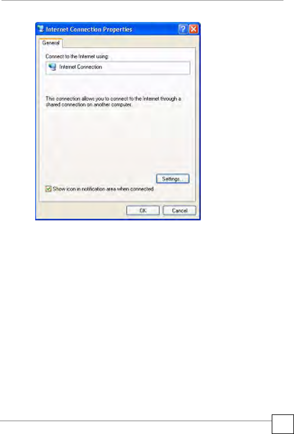
Chapter 15 Universal Plug-and-Play (UPnP)
P-660W-Tx v2 User’s Guide 153
Figure 77 Internet Connection Properties
4You may edit or delete the port mappings or click Add to manually add port mappings.
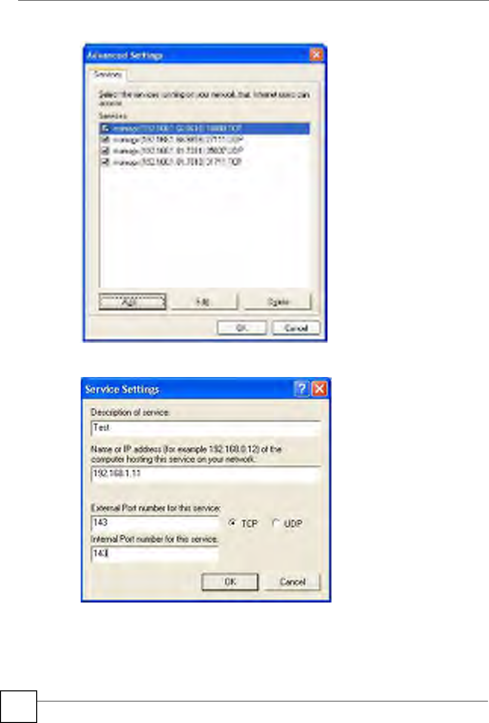
Chapter 15 Universal Plug-and-Play (UPnP)
P-660W-Tx v2 User’s Guide
154
Figure 78 Internet Connection Properties: Advanced Settings
Figure 79 Internet Connection Properties: Advanced Settings: Add
5When the UPnP-enabled device is disconnected from your computer, all port mappings
will be deleted automatically.
6Select Show icon in notification area when connected option and click OK. An icon
displays in the system tray.
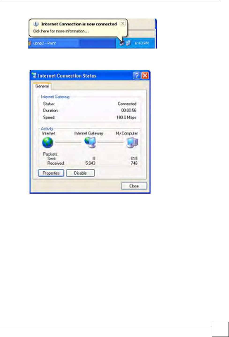
Chapter 15 Universal Plug-and-Play (UPnP)
P-660W-Tx v2 User’s Guide 155
Figure 80 System Tray Icon
7Double-click on the icon to display your current Internet connection status.
Figure 81 Internet Connection Status
Web Configurator Easy Access
With UPnP, you can access the web-based configurator on the ZyXEL Device without finding
out the IP address of the ZyXEL Device first. This comes helpful if you do not know the IP
address of the ZyXEL Device.
Follow the steps below to access the web configurator.
1Click Start and then Control Panel.
2Double-click Network Connections.
3Select My Network Places under Other Places.
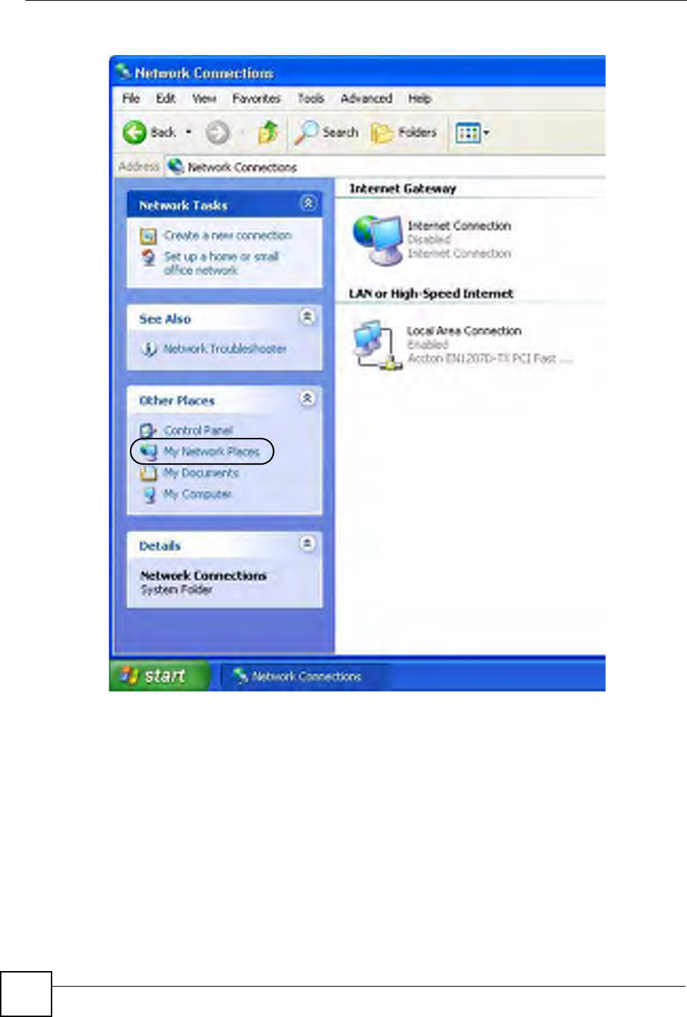
Chapter 15 Universal Plug-and-Play (UPnP)
P-660W-Tx v2 User’s Guide
156
Figure 82 Network Connections
4An icon with the description for each UPnP-enabled device displays under Local
Network.
5Right-click on the icon for your ZyXEL Device and select Invoke. The web configurator
login screen displays.
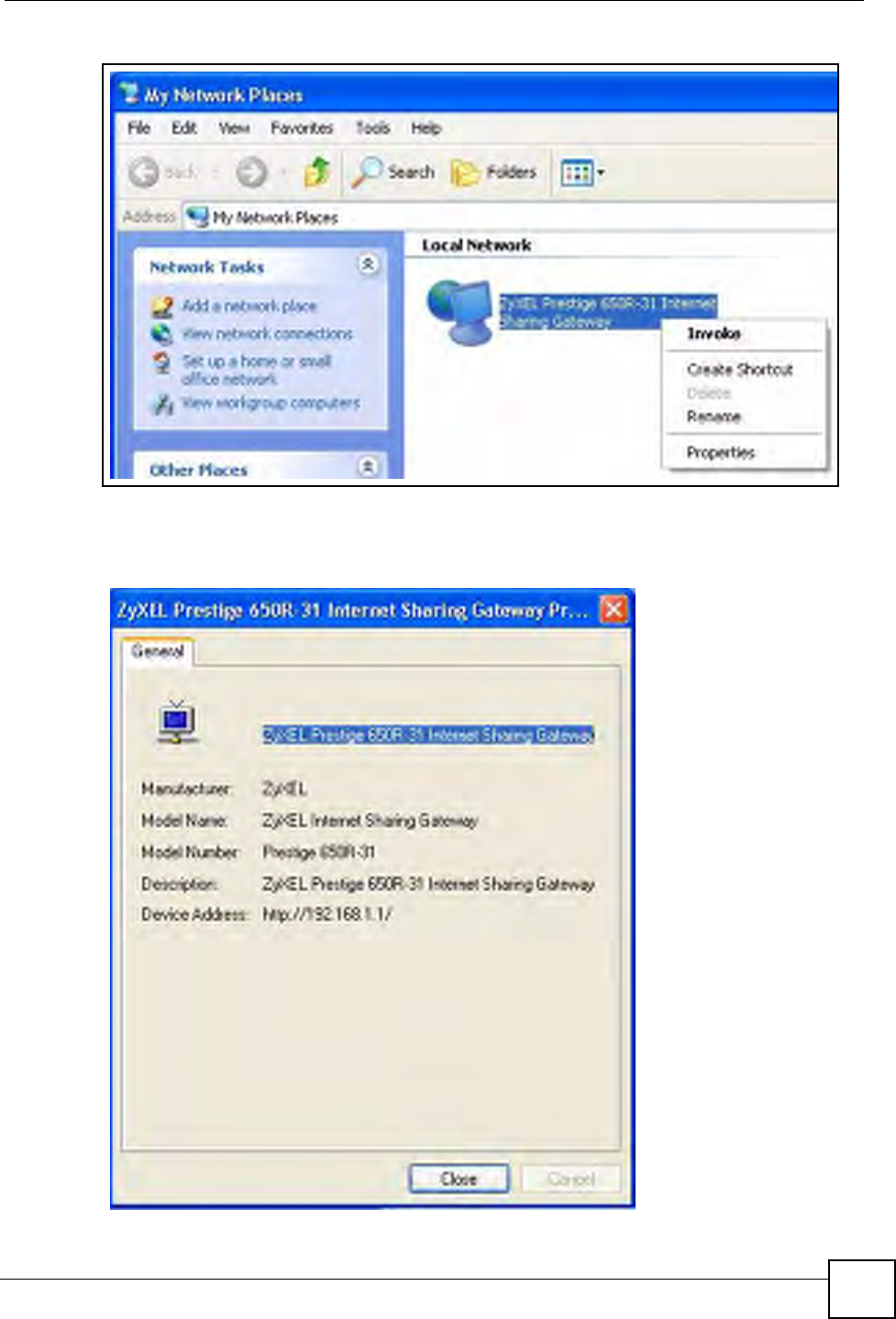
Chapter 15 Universal Plug-and-Play (UPnP)
P-660W-Tx v2 User’s Guide 157
Figure 83 Network Connections: My Network Places
6Right-click on the icon for your ZyXEL Device and select Properties. A properties
window displays with basic information about the ZyXEL Device.
Figure 84 Network Connections: My Network Places: Properties: Example

Chapter 15 Universal Plug-and-Play (UPnP)
P-660W-Tx v2 User’s Guide
158

P-660W-Tx v2 User’s Guide 159
CHAPTER 16
Logs Screens
This chapter contains information about configuring general log settings and viewing the
ZyXEL Device’s logs. Refer to the appendix for example log message explanations.
16.1 Logs Overview
The web configurator allows you to choose which categories of events and/or alerts to have
the ZyXEL Device log and then display the logs or have the ZyXEL Device send them to an
administrator (as e-mail) or to a syslog server.
16.1.1 Alerts and Logs
An alert is a type of log that warrants more serious attention. They include system errors,
attacks (access control) and attempted access to blocked web sites. Some categories such as
System Errors consist of both logs and alerts. You may differentiate them by their color in the
View Log screen. Alerts display in red and logs display in black.
16.2 Configuring Log Settings
Use the Log Settings screen to configure to where the ZyXEL Device is to send logs; the
schedule for when the ZyXEL Device is to send the logs and which logs and/or immediate
alerts the ZyXEL Device is to record. See Section 16.1 on page 159 for more information.
To change your ZyXEL Device’s log settings, click Logs, then the Log Settings. The screen
appears as shown.
Alerts are e-mailed as soon as they happen. Logs may be e-mailed as soon as the log is full.
Selecting many alert and/or log categories (especially Access Control) may result in many e-
mails being sent.
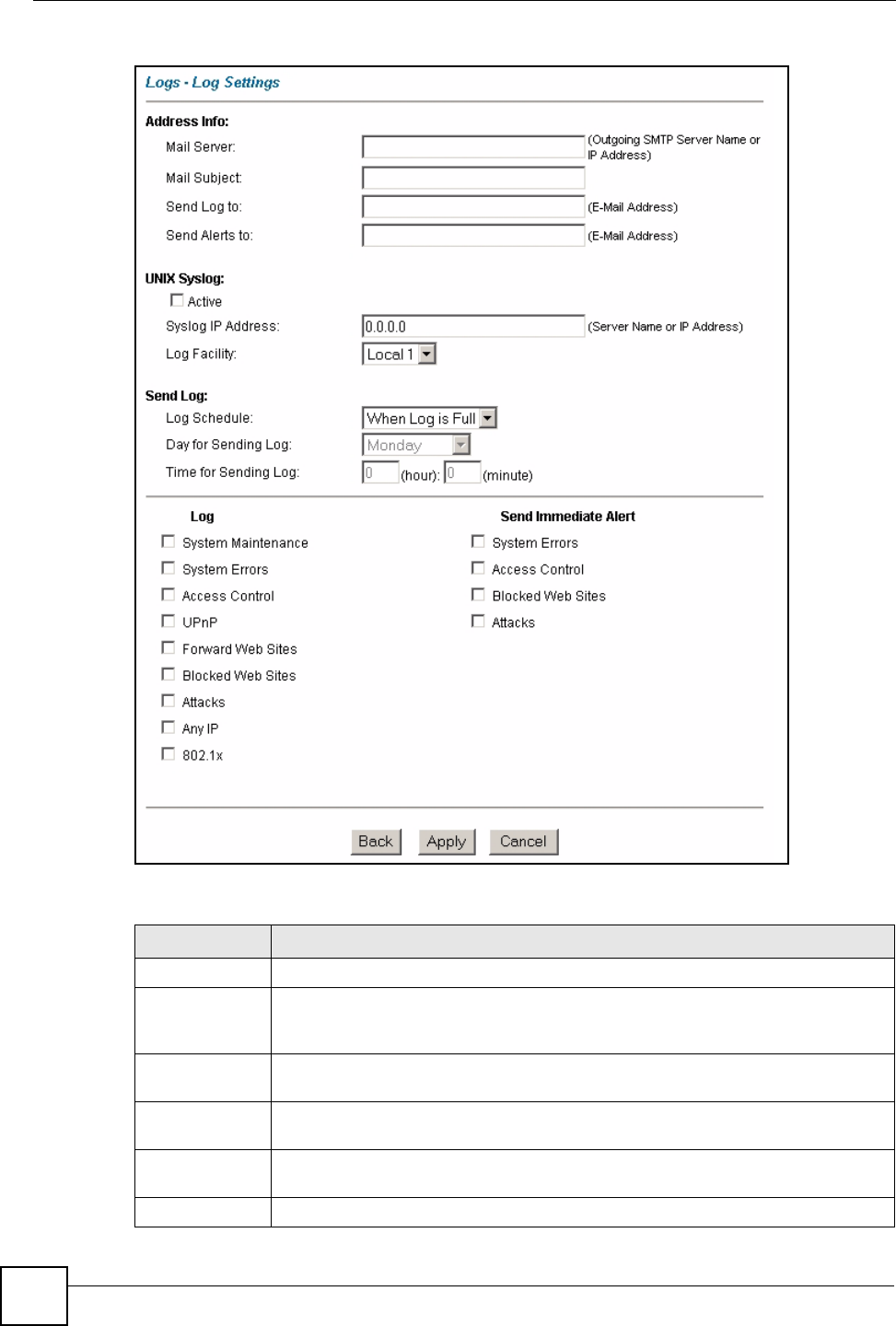
Chapter 16 Logs Screens
P-660W-Tx v2 User’s Guide
160
Figure 85 Log Settings
The following table describes the fields in this screen.
Table 55 Log Settings
LABEL DESCRIPTION
Address Info
Mail Server Enter the server name or the IP address of the mail server for the e-mail addresses
specified below. If this field is left blank, logs and alert messages will not be sent via
e-mail.
Mail Subject Type a title that you want to be in the subject line of the log e-mail message that the
ZyXEL Device sends.
Send log to Logs are sent to the e-mail address specified in this field. If this field is left blank,
logs will not be sent via e-mail.
Send alerts to Alerts are sent to the e-mail address specified in this field. If this field is left blank,
alerts will not be sent via e-mail.
UNIX Syslog Syslog logging sends a log to an external syslog server used to store logs.

Chapter 16 Logs Screens
P-660W-Tx v2 User’s Guide 161
16.3 Displaying the Logs
Click Logs and then View Log to open the View Logs screen. Use the View Logs screen to
see the logs for the categories that you selected in the Log Settings screen (see Section 16.2 on
page 159).
Log entries in red indicate alerts. The log wraps around and deletes the old entries after it fills.
Click a column heading to sort the entries. A triangle indicates ascending or descending sort
order.
Active Click Active to enable syslog logging.
Syslog IP
Address
Enter the server name or IP address of the syslog server that will log the selected
categories of logs.
Log Facility Select a location from the drop down list box. The log facility allows you to log the
messages to different files in the syslog server. Refer to the documentation of your
syslog program for more details.
Send Log
Log Schedule This drop-down menu is used to configure the frequency of log messages being
sent as E-mail:
• Daily
• Weekly
•Hourly
• When Log is Full
• None.
If you select Weekly or Daily, specify a time of day when the E-mail should be sent.
If you select Weekly, then also specify which day of the week the E-mail should be
sent. If you select When Log is Full, an alert is sent when the log fills up. If you
select None, no log messages are sent
Day for Sending
Log
Use the drop down list box to select which day of the week to send the logs.
Time for
Sending Log
Enter the time of the day in 24-hour format (for example 23:00 equals 11:00 pm) to
send the logs.
Log Select the categories of logs that you want to record. Logs include alerts.
Send Immediate
Alert
Select the categories of alerts for which you want the ZyXEL Device to instantly e-
mail alerts to the e-mail address specified in the Send Alerts To field.
Back Click Back to return to the previous screen.
Apply Click Apply to save your customized settings and exit this screen.
Cancel Click Cancel to return to the previously saved settings.
Table 55 Log Settings
LABEL DESCRIPTION
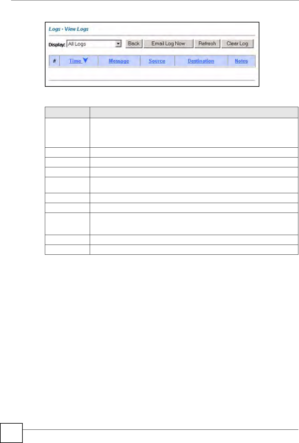
Chapter 16 Logs Screens
P-660W-Tx v2 User’s Guide
162
Figure 86 View Logs
The following table describes the fields in this screen.
16.3.1 Example E-mail Log
An "End of Log" message displays for each mail in which a complete log has been sent. The
following is an example of a log sent by e-mail.
• You may edit the subject title.
• The date format here is Day-Month-Year.
• The date format here is Month-Day-Year. The time format is Hour-Minute-Second.
•"
End of Log" message shows that a complete log has been sent.
Table 56 View Logs
LABEL DESCRIPTION
Display The categories that you select in the Log Settings screen display in the drop-down
list box.
Select a category of logs to view; select All Logs to view logs from all of the log
categories that you selected in the Log Settings page.
Time This field displays the time the log was recorded.
Message This field states the reason for the log.
Source This field lists the source IP address and the port number of the incoming packet.
Destination This field lists the destination IP address and the port number of the incoming
packet.
Notes This field displays additional information about the log entry.
Back Click Back to return to the previous screen
Email Log Now Click Email Log Now to send the log screen to the e-mail address specified in the
Log Settings page (make sure that you have first filled in the Address Info fields in
Log Settings).
Refresh Click Refresh to renew the log screen.
Clear Log Click Clear Log to delete all the logs.

Chapter 16 Logs Screens
P-660W-Tx v2 User’s Guide 163
Figure 87 E-mail Log Example
Subject:
Firewall Alert From ZyXEL Device
Date:
Fri, 07 Apr 2000 10:05:42
From:
user@zyxel.com
To:
user@zyxel.com
1|Apr 7 00 |From:192.168.1.1 To:192.168.1.255 |default policy |forward
| 09:54:03 |UDP src port:00520 dest port:00520 |<1,00> |
2|Apr 7 00 |From:192.168.1.131 To:192.168.1.255 |default policy |forward
| 09:54:17 |UDP src port:00520 dest port:00520 |<1,00> |
3|Apr 7 00 |From:192.168.1.6 To:10.10.10.10 |match |forward
| 09:54:19 |UDP src port:03516 dest port:00053 |<1,01> |
……………………………..{snip}…………………………………..
……………………………..{snip}…………………………………..
126|Apr 7 00 |From:192.168.1.1 To:192.168.1.255 |match |forward
| 10:05:00 |UDP src port:00520 dest port:00520 |<1,02> |
127|Apr 7 00 |From:192.168.1.131 To:192.168.1.255 |match |forward
| 10:05:17 |UDP src port:00520 dest port:00520 |<1,02> |
128|Apr 7 00 |From:192.168.1.1 To:192.168.1.255 |match |forward
| 10:05:30 |UDP src port:00520 dest port:00520 |<1,02> |
End of Firewall Log

Chapter 16 Logs Screens
P-660W-Tx v2 User’s Guide
164

P-660W-Tx v2 User’s Guide 165
CHAPTER 17
Media Bandwidth Management
Advanced Setup
This chapter describes bandwidth management with one level of child class.
17.1 Media Bandwidth Management Overview
Bandwidth management allows you to allocate an interface’s outgoing capacity to specific
types of traffic. It can also help you make sure that the ZyXEL Device forwards certain types
of traffic (especially real-time applications) with minimum delay. With the use of real-time
applications such as Voice-over-IP (VoIP) increasing, the requirement for bandwidth
allocation is also increasing.
Bandwidth management addresses questions such as:
• Who gets how much access to specific applications?
• What priority level should you give to each type of traffic?
• Which traffic must have guaranteed delivery?
• How much bandwidth should be allotted to guarantee delivery?
Bandwidth management also allows you to configure the allowed output for an interface to
match what the network can handle. This helps reduce delays and dropped packets at the next
routing device. For example, you can set the WAN interface speed to 1000kbps if the ADSL
connection has an upstream speed of 1Mbps. All configuration screens display measurements
in kbps (kilobits per second), but this User’s Guide also uses Mbps (megabits per second) for
brevity’s sake.
Refer to Section 17.9 on page 171 to enable and configure bandwidth on the interfaces.
Refer to Section 17.10 on page 172 to configure bandwidth classes.
Refer to Section 17.11 on page 177 to view bandwidth usage information.
17.2 Bandwidth Classes and Filters
Use bandwidth classes and child-classes to allocate specific amounts of bandwidth capacity
(bandwidth budgets). Configure a bandwidth filter to define a bandwidth class (or child-class)
based on a specific application and/or subnet. Use the Class Configuration screen (see
Section 17.10 on page 172) to set up a bandwidth class’s name, bandwidth allotment, and
bandwidth filter. You can configure up to one bandwidth filter per bandwidth class. You can
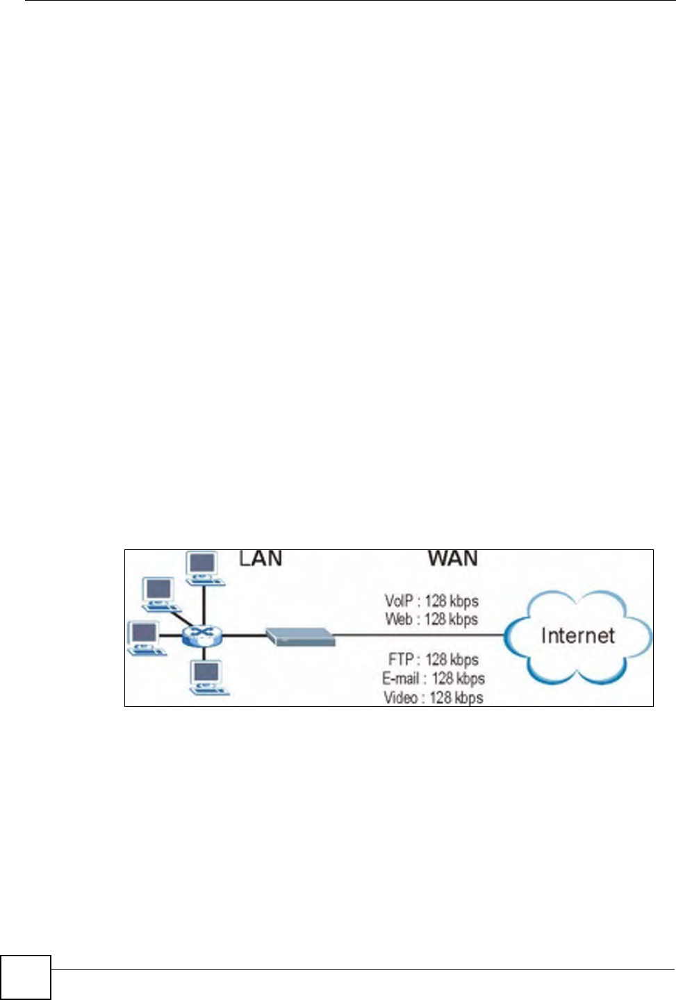
Chapter 17 Media Bandwidth Management Advanced Setup
P-660W-Tx v2 User’s Guide
166
also configure bandwidth classes without bandwidth filters. However, it is recommended that
you configure child-classes with filters for any classes that you configure without filters. The
ZyXEL Device leaves the bandwidth budget allocated and unused for a class that does not
have a filter itself or child-classes with filters. View your configured bandwidth classes and
child-classes in the Class Setup screen (see Section 17.10 on page 172 for details).
The total of the configured bandwidth budgets for child-classes cannot exceed the configured
bandwidth budget speed of the parent class.
17.3 Proportional Bandwidth Allocation
Bandwidth management allows you to define how much bandwidth each class gets; however,
the actual bandwidth allotted to each class decreases or increases in proportion to actual
available bandwidth.
17.4 Bandwidth Management Usage Examples
These examples show bandwidth management allotments on a WAN interface that is
configured for 640Kbps.
17.4.1 Application-based Bandwidth Management Example
The bandwidth classes in the following example are based solely on application. Each
bandwidth class (VoIP, Web, FTP, E-mail and Video) is allotted 128kbps.
Figure 88 Application-based Bandwidth Management Example
17.4.2 Subnet-based Bandwidth Management Example
The following example uses bandwidth classes based solely on LAN subnets. Each bandwidth
class (Subnet A and Subnet B) is allotted 320kbps.
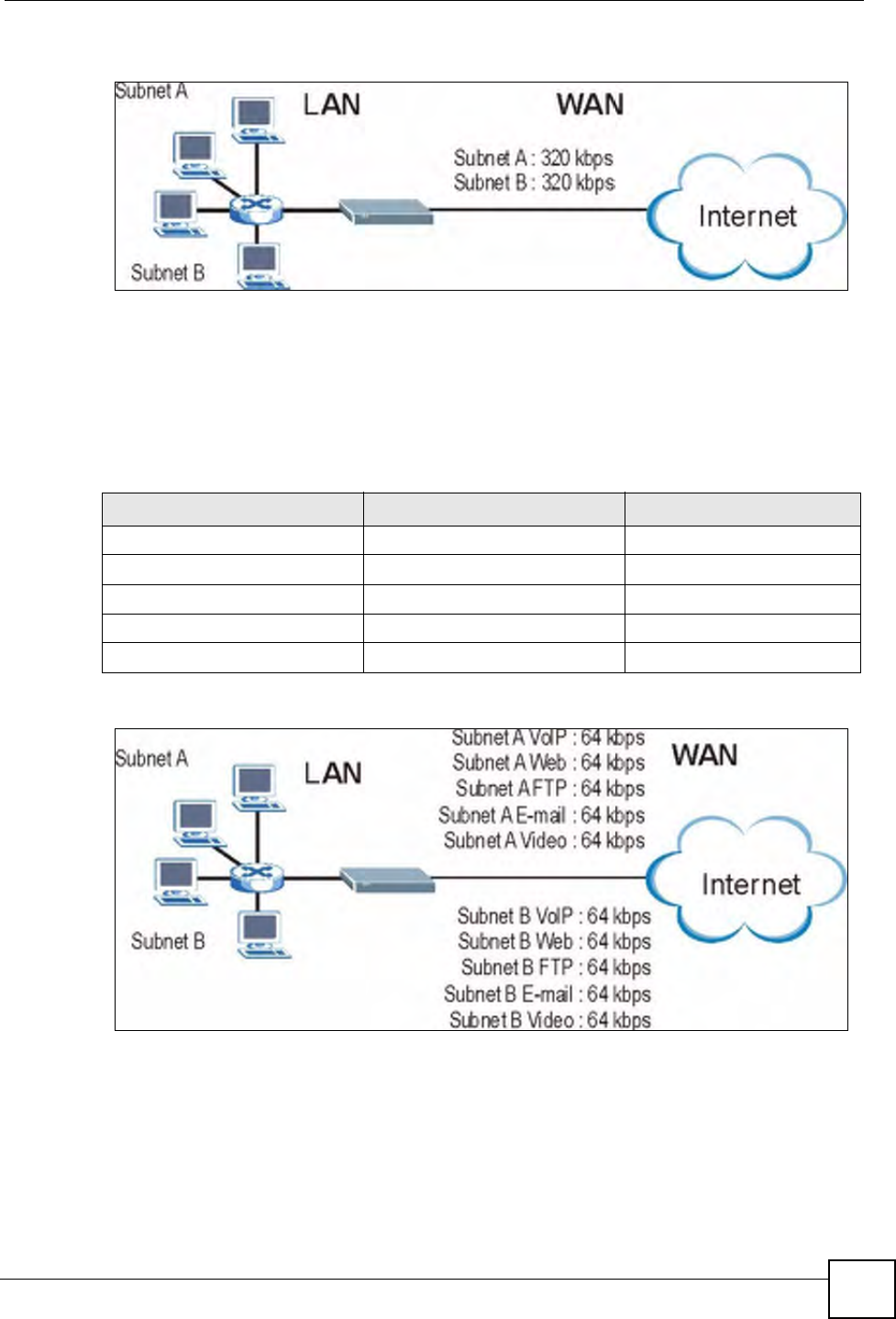
Chapter 17 Media Bandwidth Management Advanced Setup
P-660W-Tx v2 User’s Guide 167
Figure 89 Subnet-based Bandwidth Management Example
17.4.3 Application and Subnet-based Bandwidth Management
Example
The following example uses bandwidth classes based on LAN subnets and applications
(specific applications in each subnet are allotted bandwidth).
Figure 90 Application and Subnet-based Bandwidth Management Example
17.5 Scheduler
The scheduler divides up an interface’s bandwidth among the bandwidth classes. The ZyXEL
Device has two types of scheduler: fairness-based and priority-based.
Table 57 Application and Subnet-based Bandwidth Management Example
TRAFFIC TYPE FROM SUBNET A FROM SUBNET B
VoIP 64 kbps 64 kbps
Web 64 kbps 64 kbps
FTP 64 kbps 64 kbps
E-mail 64 kbps 64 kbps
Video 64 kbps 64 kbps

Chapter 17 Media Bandwidth Management Advanced Setup
P-660W-Tx v2 User’s Guide
168
17.5.1 Priority-based Scheduler
With the priority-based scheduler, the ZyXEL Device forwards traffic from bandwidth classes
according to the priorities that you assign to the bandwidth classes. The larger a bandwidth
class’s priority number is, the higher the priority. Assign real-time applications (like those
using audio or video) a higher priority number to provide smoother operation.
17.5.2 Fairness-based Scheduler
The ZyXEL Device divides bandwidth equally among bandwidth classes when using the
fairness-based scheduler; thus preventing one bandwidth class from using all of the interface’s
bandwidth.
17.6 Maximize Bandwidth Usage
The maximize bandwidth usage option (see Section 17.7.1 on page 170) allows the ZyXEL
Device to divide up any available bandwidth on the interface (including unallocated
bandwidth and any allocated bandwidth that a class is not using) among the bandwidth classes
that require more bandwidth.
When you enable maximize bandwidth usage, the ZyXEL Device first makes sure that each
bandwidth class gets up to its bandwidth allotment. Next, the ZyXEL Device divides up an
interface’s available bandwidth (bandwidth that is unbudgeted or unused by the classes)
depending on how many bandwidth classes require more bandwidth and on their priority
levels. When only one class requires more bandwidth, the ZyXEL Device gives extra
bandwidth to that class.
When multiple classes require more bandwidth, the ZyXEL Device gives the highest priority
classes the available bandwidth first (as much as they require, if there is enough available
bandwidth), and then to lower priority classes if there is still bandwidth available. The ZyXEL
Device distributes the available bandwidth equally among classes with the same priority level.
17.6.1 Reserving Bandwidth for Non-Bandwidth Class Traffic
Do the following three steps to configure the ZyXEL Device to allow bandwidth for traffic
that is not defined in a bandwidth filter.
1Leave some of the interface’s bandwidth unbudgeted.
2Do not enable the interface’s Maximize Bandwidth Usage option.
3Do not enable bandwidth borrowing on the child-classes that have the root class as their
parent (see Section 17.7 on page 170).
17.6.2 Maximize Bandwidth Usage Example
Here is an example of a ZyXEL Device that has maximized bandwidth usage enabled on an
interface. The first figure shows each bandwidth class’s bandwidth budget and priority. The
classes are set up based on subnets. The interface is set to 10 Mbps. Each subnet is allocated 2
Mbps. The unbudgeted 2 Mbps allows traffic not defined in one of the bandwidth filters to go
out when you do not select the maximize bandwidth option.
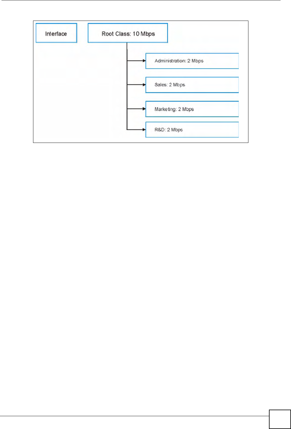
Chapter 17 Media Bandwidth Management Advanced Setup
P-660W-Tx v2 User’s Guide 169
Figure 91 Bandwidth Allotment Example
The following figure shows the bandwidth usage with the maximize bandwidth usage option
enabled. The ZyXEL Device divides up the unbudgeted 2 Mbps among the classes that require
more bandwidth. If the administration department only uses 1 Mbps of the budgeted 2 Mbps,
the ZyXEL Device also divides the remaining 1 Mbps among the classes that require more
bandwidth. Therefore, the ZyXEL Device divides a total of 3 Mbps total of unbudgeted and
unused bandwidth among the classes that require more bandwidth.
In this case, suppose that all of the classes except for the administration class need more
bandwidth.
• Each class gets up to its budgeted bandwidth. The administration class only uses 1 Mbps
of its budgeted 2 Mbps.
• Sales and Marketing are first to get extra bandwidth because they have the highest priority
(6). If they each require 1.5 Mbps or more of extra bandwidth, the ZyXEL Device divides
the total 3 Mbps total of unbudgeted and unused bandwidth equally between the sales and
marketing departments (1.5 Mbps extra to each for a total of 3.5 Mbps for each) because
they both have the highest priority level.
• R&D requires more bandwidth but only gets its budgeted 2 Mbps because all of the
unbudgeted and unused bandwidth goes to the higher priority sales and marketing classes.
• The ZyXEL Device does not send any traffic that is not defined in the bandwidth filters
because all of the unbudgeted bandwidth goes to the classes that need it.
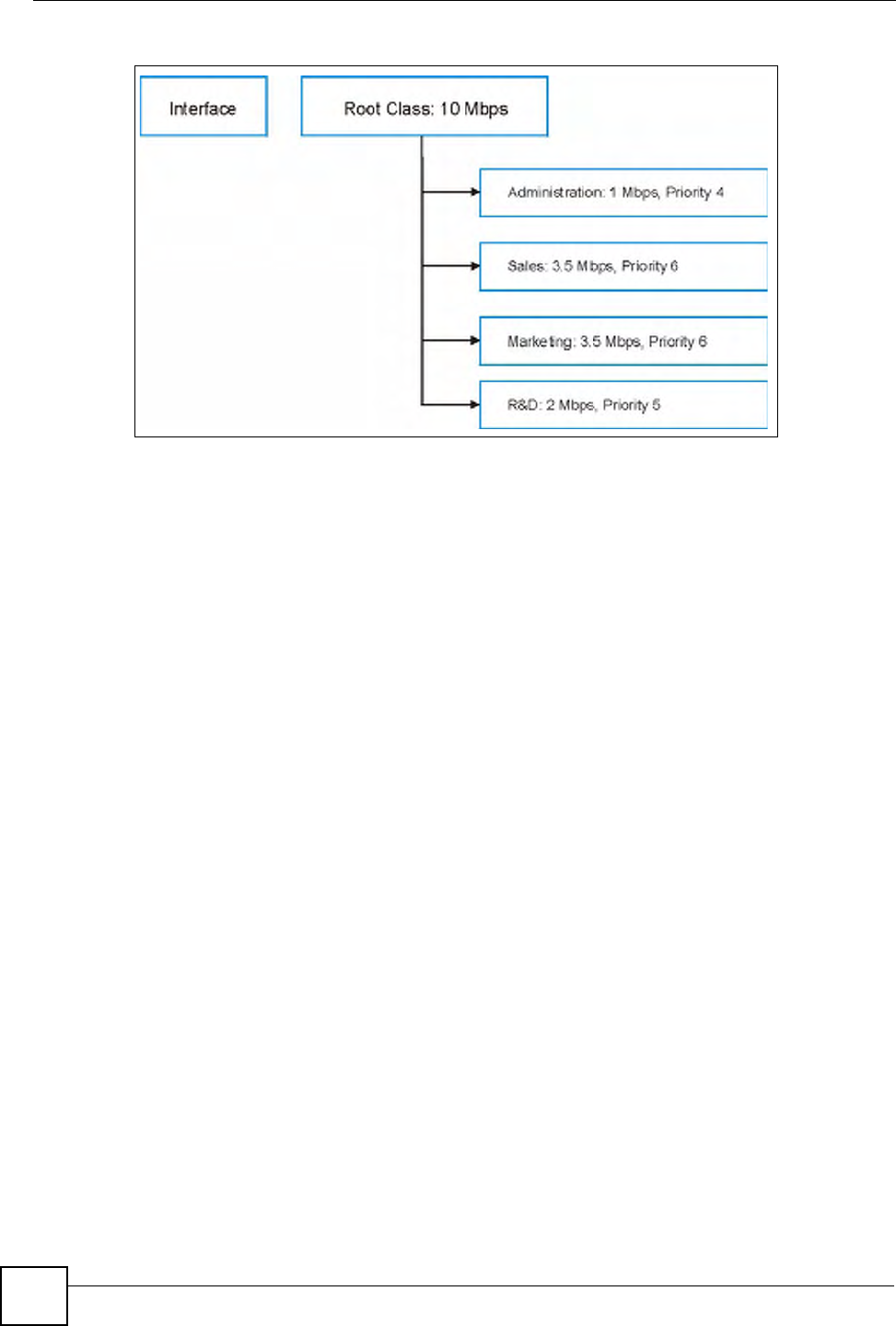
Chapter 17 Media Bandwidth Management Advanced Setup
P-660W-Tx v2 User’s Guide
170
Figure 92 Maximize Bandwidth Usage Example
17.7 Bandwidth Borrowing
Bandwidth borrowing allows a child-class to borrow unused bandwidth from its parent class,
whereas maximize bandwidth usage allows bandwidth classes to borrow any unused or
unbudgeted bandwidth on the whole interface.
Enable bandwidth borrowing on a child-class to allow the child-class to use its parent class’s
unused bandwidth. A parent class’s unused bandwidth is given to the highest-priority child-
class that has bandwidth borrowing configured, first.
The total of the bandwidth allotments for child-classes cannot exceed the bandwidth allotment
of their parent class. The ZyXEL Device uses the scheduler to divide a parent class’s unused
bandwidth among the child-classes.
17.7.1 Maximize Bandwidth Usage With Bandwidth Borrowing
If you configure both maximize bandwidth usage (on the interface) and bandwidth borrowing
(on individual child-classes), the ZyXEL Device functions as follows.
1The ZyXEL Device sends traffic according to each bandwidth class’s bandwidth budget.
2The ZyXEL Device assigns a parent class’s unused bandwidth to its child-classes that
have more traffic than their budgets and have bandwidth borrowing enabled. The
ZyXEL Device gives priority to bandwidth child-classes of higher priority and treats
bandwidth classes of the same priority equally.
3The ZyXEL Device assigns any remaining unused or unbudgeted bandwidth on the
interface to any bandwidth class that requires it. The ZyXEL Device gives priority to
bandwidth classes of higher priority and treats bandwidth classes of the same level
equally.
4The ZyXEL Device assigns any remaining unbudgeted bandwidth to traffic that does not
match any of the bandwidth classes.
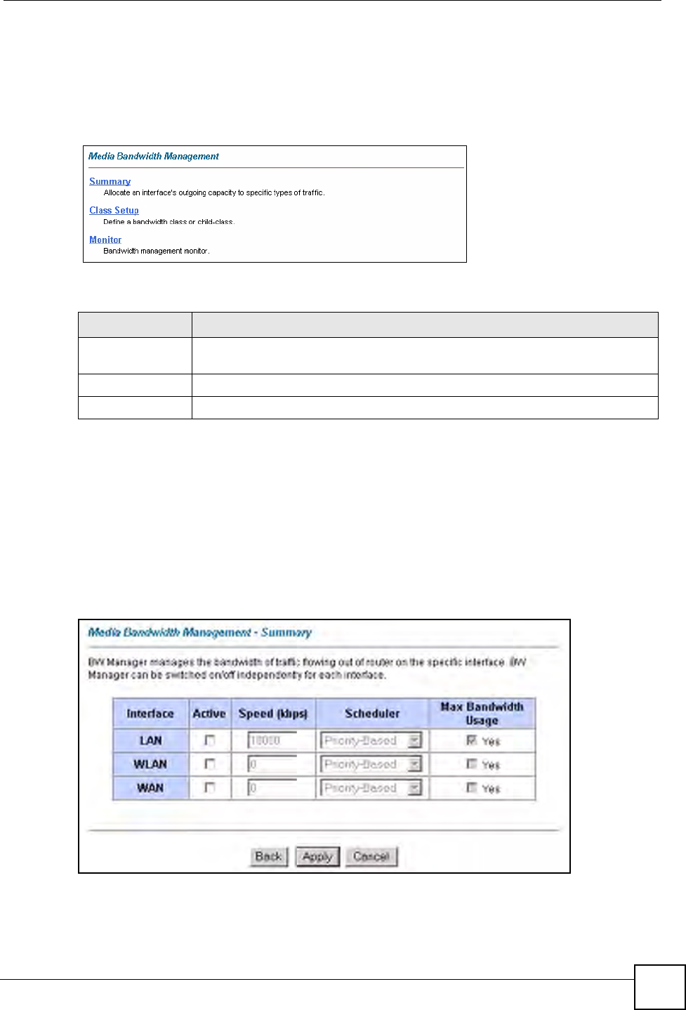
Chapter 17 Media Bandwidth Management Advanced Setup
P-660W-Tx v2 User’s Guide 171
17.8 The Main Media Bandwidth Management Screen
Click Media Bandwidth Mgnt. to display the main Media Bandwidth Management screen
as shown.
Figure 93 Media Bandwidth Mgnt.
The following table describes the links in this screen.
17.9 Configuring Summary
Click Media Bandwidth Management, Summary to open the screen as shown next.
Enable bandwidth management on an interface and set the maximum allowed bandwidth for
that interface.
Refer to Section 17.1 on page 165 for more information.
Figure 94 Media Bandwidth Management: Summary
Table 58 Media Bandwidth Mgnt.
LINK DESCRIPTION
Summary Click this link to display a screen where you can enable bandwidth management
on an interface and set the maximum allowed bandwidth for that interface.
Class Setup Click this link to display a screen where you can configure bandwidth classes.
Monitor Click this link to display a screen where you can view bandwidth usage.
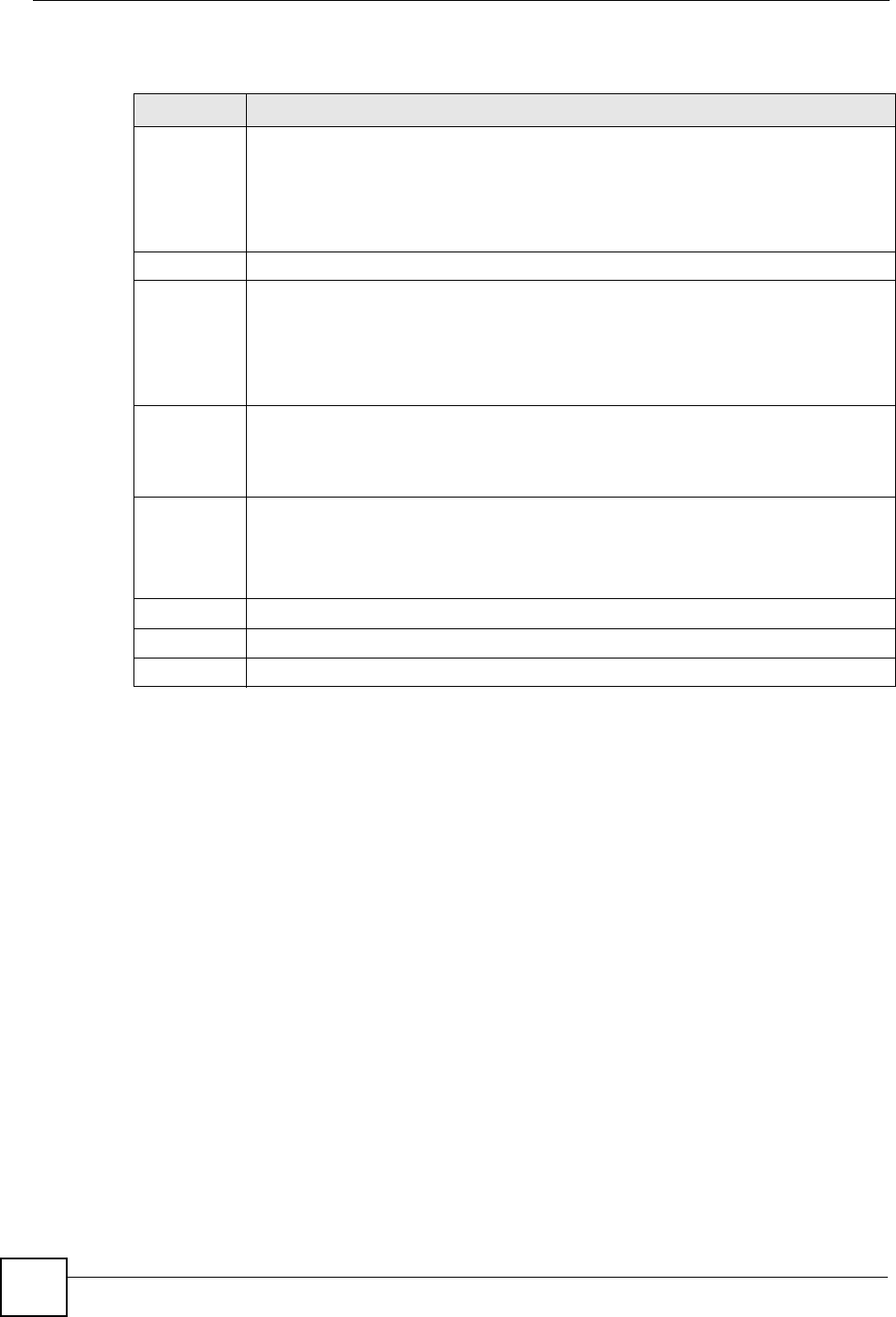
Chapter 17 Media Bandwidth Management Advanced Setup
P-660W-Tx v2 User’s Guide
172
The following table describes the labels in this screen.
17.10 Configuring Class Setup
The class setup screen displays the configured bandwidth classes by individual interface.
Select an interface and click the buttons to perform the actions described next. Click “+” to
expand the class tree or click “-“to collapse the class tree. Each interface has a permanent root
class. The bandwidth budget of the root class is equal to the speed you configured on the
interface (see Section 17.9 on page 171 to configure the speed of the interface). Configure
child-class layers for the root class.
Refer to Section 17.1 on page 165 for more information.
To add or delete child classes on an interface, click Media Bandwidth Management, then
Class Setup. The screen appears as shown (with example classes).
Table 59 Media Bandwidth Management: Summary
LABEL DESCRIPTION
LAN
WLAN
WAN
These read-only labels represent the physical interfaces. Select an interface’s check
box to enable bandwidth management on that interface. Bandwidth management
applies to all traffic flowing out of the router through the interface, regardless of the
traffic’s source.
Traffic redirect or IP alias may cause LAN-to-LAN traffic to pass through the ZyXEL
Device and be managed by bandwidth management.
Active Select an interface’s check box to enable bandwidth management on that interface.
Speed (kbps) Enter the amount of bandwidth for this interface that you want to allocate using
bandwidth management.
This appears as the bandwidth budget of the interface’s root class. The
recommendation is to set this speed to match what the interface’s connection can
handle. For example, set the WAN interface speed to 10000 kbps if the ADSL
connection has an upstream speed of 10Mbps.
Scheduler Select either Priority-Based or Fairness-Based from the drop-down menu to control
the traffic flow.
Select Priority-Based to give preference to bandwidth classes with higher priorities.
Select Fairness-Based to treat all bandwidth classes equally.
Maximize
Bandwidth
Usage
Select this check box to have the ZyXEL Device divide up all of the interface’s
unallocated and/or unused bandwidth among the bandwidth classes that require
bandwidth. Do not select this if you want to reserve bandwidth for traffic that does not
match a bandwidth class or you want to limit the speed of this interface (see the Speed
field description).
Back Click Back to go to the main Media Bandwidth Management screen.
Apply Click Apply to save your settings back to the ZyXEL Device.
Cancel Click Cancel to begin configuring this screen afresh.
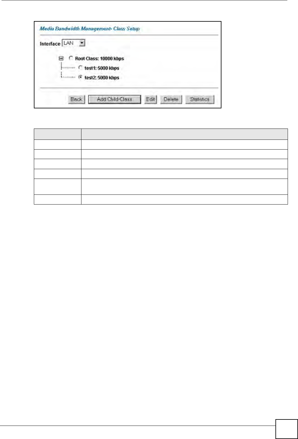
Chapter 17 Media Bandwidth Management Advanced Setup
P-660W-Tx v2 User’s Guide 173
Figure 95 Media Bandwidth Management: Class Setup
The following table describes the labels in this screen.
17.10.1 Media Bandwidth Management Class Configuration
Configure a bandwidth management class in the Class Configuration screen. You must use
the Media Bandwidth Management - Summary screen to enable bandwidth management on
an interface before you can configure classes for that interface.
Refer to Section 17.1 on page 165 for more information.
To add a child class, click Media Bandwidth Management, then Class Setup. Click the Add
Child-Class button to open the following screen.
Table 60 Media Bandwidth Management: Class Setup
LABEL DESCRIPTION
Interface Select an interface from the drop-down list box for which you wish to set up classes.
Back Click Back to go to the main Media Bandwidth Management screen.
Add Child-Class Click Add Child-class to add a sub-class.
Edit Click Edit to configure the selected class. You cannot edit the root class.
Delete Click Delete to delete the class and all its child-classes. You cannot delete the root
class.
Statistics Click Statistics to display the status of the selected class.
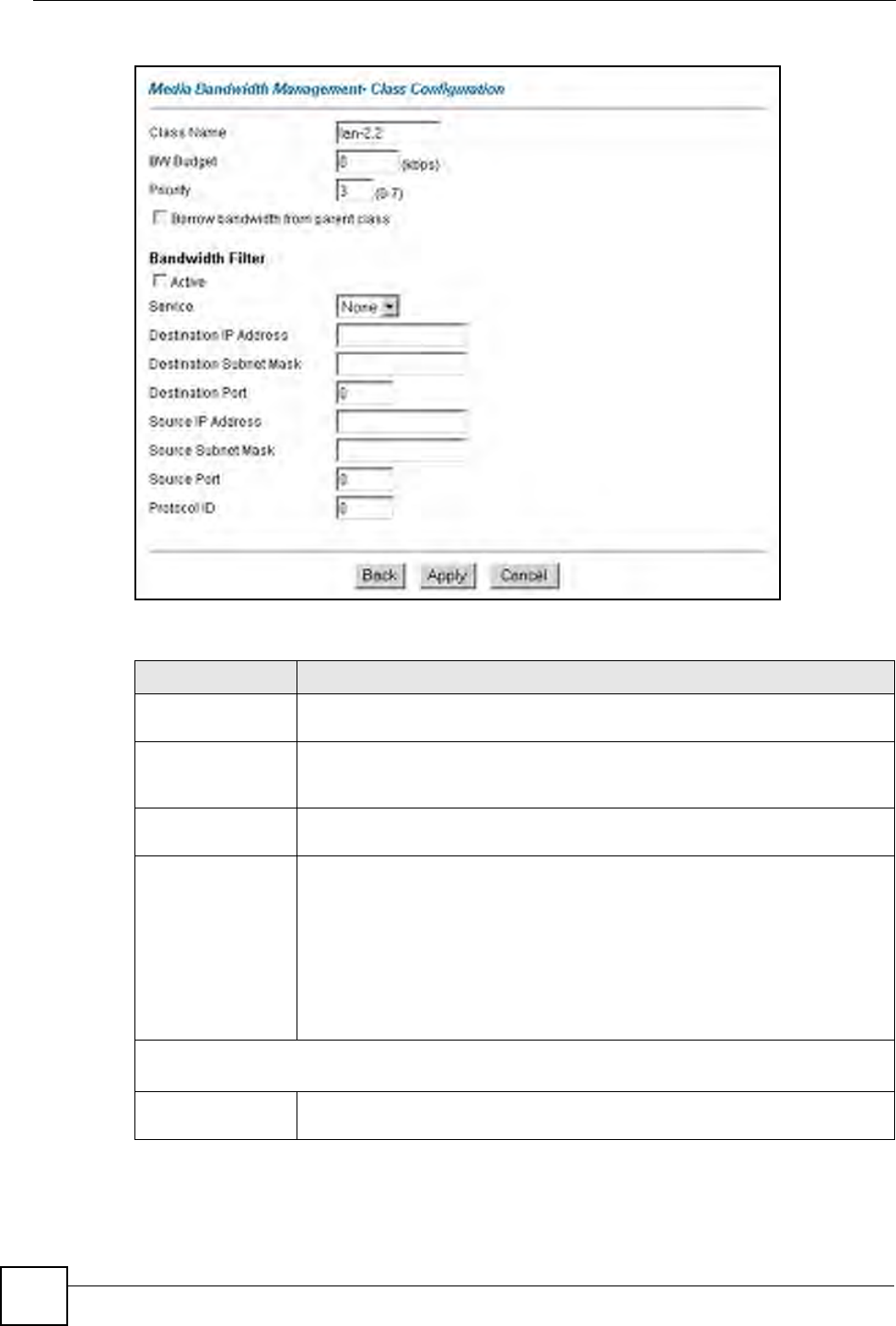
Chapter 17 Media Bandwidth Management Advanced Setup
P-660W-Tx v2 User’s Guide
174
Figure 96 Media Bandwidth Management: Class Configuration
The following table describes the labels in this screen.
Table 61 Media Bandwidth Management: Class Configuration
LABEL DESCRIPTION
Class Name Use the auto-generated name or enter a descriptive name of up to 20
alphanumeric characters, including spaces.
BW Budget (kbps) Specify the maximum bandwidth allowed for the class in kbps. The
recommendation is a setting between 20 kbps and 20000 kbps for an individual
class.
Priority Enter a number between 0 and 7 to set the priority of this class. The higher the
number, the higher the priority. The default setting is 3.
Borrow bandwidth
from parent class
Select this option to allow a child-class to borrow bandwidth from its parent class
if the parent class is not using up its bandwidth budget.
Bandwidth borrowing is governed by the priority of the child-classes. That is, a
child-class with the highest priority (7) is the first to borrow bandwidth from its
parent class.
Do not select this for the classes directly below the root class if you want to
leave bandwidth available for other traffic types or you want to set the interface’s
speed to match what the next device in network can handle (see the Speed field
description in the Summary screen).
Bandwidth Filter
The ZyXEL Device uses a bandwidth filter to identify the traffic that belongs to a bandwidth class.
Active Select the check box to have the ZyXEL Device use this bandwidth filter when it
performs bandwidth management.

Chapter 17 Media Bandwidth Management Advanced Setup
P-660W-Tx v2 User’s Guide 175
Service You can select a predefined service instead of configuring the Destination
Port, Source Port and Protocol ID fields.
SIP (Session Initiation Protocol) is a signaling protocol used in Internet
telephony, instant messaging and other VoIP (Voice over IP) applications.
Select SIP from the drop-down list box to configure this bandwidth filter for traffic
that uses SIP.
File Transfer Protocol (FTP) is an Internet file transfer service that operates on
the Internet and over TCP/IP networks. A system running the FTP server
accepts commands from a system running an FTP client. The service allows
users to send commands to the server for uploading and downloading files.
Select FTP from the drop-down list box to configure this bandwidth filter for FTP
traffic.
H.323 is a standard teleconferencing protocol suite that provides audio, data
and video conferencing. It allows for real-time point-to-point and multipoint
communication between client computers over a packet-based network that
does not provide a guaranteed quality of service. Select H.323 from the drop-
down list box to configure this bandwidth filter for traffic that uses H.323.
When you select None, the bandwidth class applies to all services unless you
specify one by configuring the Destination Port, Source Port and Protocol ID
fields.
Destination IP
Address
Enter the destination IP address in dotted decimal notation. A blank destination
IP address means any destination IP address.
Destination Subnet
Mask
Enter the destination subnet mask. This field is N/A if you do not specify a
Destination IP Address. Refer to the appendix for more information on IP
subnetting.
Destination Port Enter the port number of the destination. A blank destination port means any
destination port.
Source IP Address Enter the source IP address. A blank source IP address means any source IP
address.
Source Subnet
Mask
Enter the source subnet mask. This field is N/A if you do not specify a Source IP
Address. Refer to the appendix for more information on IP subnetting.
Source Port Enter the port number of the source. See the following table for some common
services and port numbers. A blank source port means any source port number.
Protocol ID Enter the protocol ID (service type) number, for example: 1 for ICMP, 6 for TCP
or 17 for UDP. A blank protocol ID means any protocol number.
Back Click Back to go to the main Media Bandwidth Management screen.
Apply Click Apply to save your changes back to the ZyXEL Device.
Cancel Click Cancel to begin configuring this screen afresh.
Table 62 Services and Port Numbers
SERVICES PORT NUMBER
ECHO 7
FTP (File Transfer Protocol) 21
SMTP (Simple Mail Transfer Protocol) 25
DNS (Domain Name System) 53
Finger 79
HTTP (Hyper Text Transfer protocol or WWW, Web) 80
POP3 (Post Office Protocol) 110
Table 61 Media Bandwidth Management: Class Configuration (continued)
LABEL DESCRIPTION
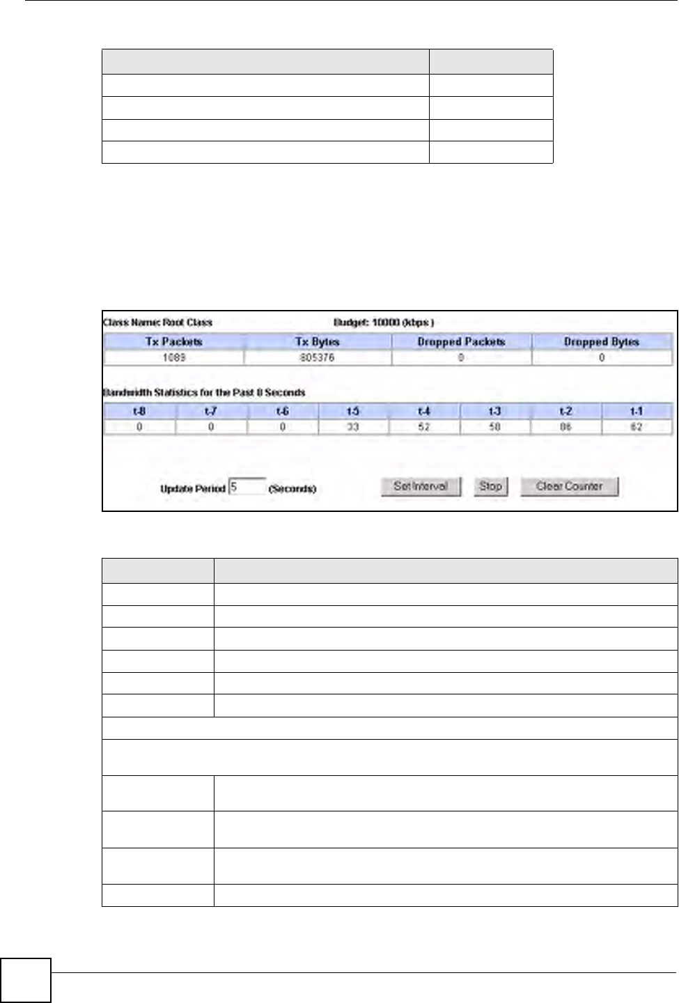
Chapter 17 Media Bandwidth Management Advanced Setup
P-660W-Tx v2 User’s Guide
176
17.10.2 Media Bandwidth Management Statistics
Use the Media Bandwidth Management Statistics screen to view network performance
information. Click the Statistics button in the Class Setup screen to open the Statistics
screen.
Figure 97 Media Bandwidth Management Statistics
The following table describes the labels in this screen.
NNTP (Network News Transport Protocol) 119
SNMP (Simple Network Management Protocol) 161
SNMP trap 162
PPTP (Point-to-Point Tunneling Protocol) 1723
Table 62 Services and Port Numbers
SERVICES PORT NUMBER
Table 63 Media Bandwidth Management Statistics
LABEL DESCRIPTION
Class Name This field displays the name of the class the statistics page is showing.
Budget (kbps) This field displays the amount of bandwidth allocated to the class.
Tx Packets This field displays the total number of packets transmitted.
Tx Bytes This field displays the total number of bytes transmitted.
Dropped Packets This field displays the total number of packets dropped.
Dropped Bytes This field displays the total number of bytes dropped.
Bandwidth Statistics for the Past 8 Seconds (t-8 to t-1)
This field displays the bandwidth statistics (in bps) for the past one to eight seconds. For example, t-1
means one second ago.
Update Period
(seconds)
Enter the time interval in seconds to define how often the information should be
refreshed.
Set Interval Click Set Interval to apply the new update period you entered in the Update
Period field above.
Stop Update Click Stop Update to stop the browser from refreshing bandwidth management
statistics.
Clear Counter Click Clear Counter to clear all of the bandwidth management statistics.
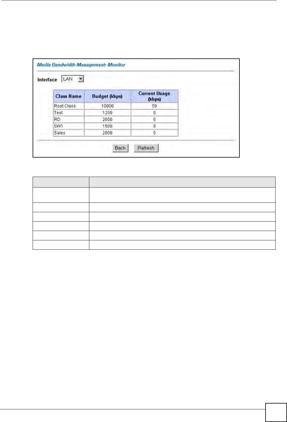
Chapter 17 Media Bandwidth Management Advanced Setup
P-660W-Tx v2 User’s Guide 177
17.11 Bandwidth Monitor
To view the ZyXEL Device’s bandwidth usage and allotments, click Media Bandwidth
Management, then Monitor. The screen appears as shown.
Figure 98 Media Bandwidth Management: Monitor
The following table describes the labels in this screen.
Table 64 Media Bandwidth Management: Monitor
LABEL DESCRIPTION
Interface Select an interface from the drop-down list box to view the bandwidth usage of
its bandwidth classes.
Class Name This field displays the name of the class.
Budget (kbps) This field displays the amount of bandwidth allocated to the class.
Current Usage (kbps) This field displays the amount of bandwidth that each class is using.
Back Click Back to go to the main Media Bandwidth Management screen.
Refresh Click Refresh to update the page.

Chapter 17 Media Bandwidth Management Advanced Setup
P-660W-Tx v2 User’s Guide
178

179
PART IV
Maintenance
Maintenance (181)

180

P-660W-Tx v2 User’s Guide 181
CHAPTER 18
Maintenance
This chapter displays system information such as ZyNOS firmware, port IP addresses and port
traffic statistics.
18.1 Maintenance Overview
The maintenance screens can help you view system information, upload new firmware,
manage configuration and restart your ZyXEL Device.
18.2 System Status Screen
Click System Status under Maintenance to open the following screen, where you can use to
monitor your ZyXEL Device. Note that these fields are READ-ONLY and only for diagnostic
purposes.
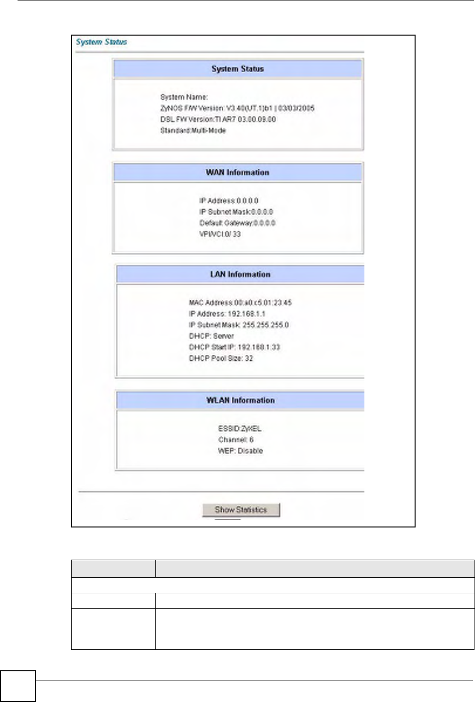
Chapter 18 Maintenance
P-660W-Tx v2 User’s Guide
182
Figure 99 System Status
The following table describes the fields in this screen.
Table 65 System Status
LABEL DESCRIPTION
System Status
System Name This is the name of your ZyXEL Device. It is for identification purposes.
ZyNOS Firmware
Version
This is the ZyNOS firmware version and the date created. ZyNOS is ZyXEL's
proprietary Network Operating System design.
DSL FW Version This is the DSL firmware version associated with your ZyXEL Device.

Chapter 18 Maintenance
P-660W-Tx v2 User’s Guide 183
18.2.1 System Statistics
Click Show Statistics in the System Status screen to open the following screen. Read-only
information here includes port status and packet specific statistics. Also provided are "system
up time" and "poll interval(s)". The Poll Interval(s) field is configurable.
Standard This is the standard that your ZyXEL Device is using.
WAN Information
IP Address This is the WAN port IP address.
IP Subnet Mask This is the WAN port IP subnet mask.
Default Gateway This is the IP address of the default gateway, if applicable.
VPI/VCI This is the Virtual Path Identifier and Virtual Channel Identifier that you entered in
the first Wizard screen.
LAN Information
MAC Address This is the MAC (Media Access Control) or Ethernet address unique to your
ZyXEL Device.
IP Address This is the LAN port IP address.
IP Subnet Mask This is the LAN port IP subnet mask.
DHCP This is the WAN port DHCP role - Server, Relay or None.
DHCP Start IP This is the first of the contiguous addresses in the IP address pool.
DHCP Pool Size This is the number of IP addresses in the IP address pool.
WLAN Information
ESSID This is the descriptive name used to identify the ZyXEL Device in the wireless
LAN.
Channel This is the channel number used by the ZyXEL Device now.
WEP This displays the status of WEP data encryption.
Show Statistics Click Show Statistics to see the performance statistics such as number of
packets sent and number of packets received for each port.
Table 65 System Status (continued)
LABEL DESCRIPTION
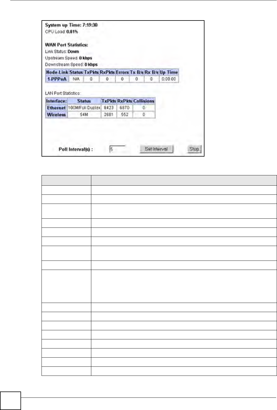
Chapter 18 Maintenance
P-660W-Tx v2 User’s Guide
184
Figure 100 System Status: Show Statistics
The following table describes the fields in this screen.
Table 66 System Status: Show Statistics
LABEL DESCRIPTION
System up Time This is the elapsed time the system has been up.
CPU Load This field specifies the percentage of CPU utilization.
LAN or WAN Port
Statistics
This is the WAN or LAN port.
Link Status This is the status of your WAN link.
Upstream Speed This is the upstream speed of your ZyXEL Device.
Downstream Speed This is the downstream speed of your ZyXEL Device.
Node-Link This field displays the remote node index number and link type. Link types are
PPPoA, ENET, RFC 1483 and PPPoE.
Interface This field displays the type of port.
Status For the WAN port, this displays the port speed and duplex setting if you're using
Ethernet encapsulation and down (line is down), idle (line (ppp) idle), dial
(starting to trigger a call) and drop (dropping a call) if you're using PPPoE
encapsulation.
For a LAN port, this shows the port speed and duplex setting.
TxPkts This field displays the number of packets transmitted on this port.
RxPkts This field displays the number of packets received on this port.
Errors This field displays the number of error packets on this port.
Tx B/s This field displays the number of bytes transmitted in the last second.
Rx B/s This field displays the number of bytes received in the last second.
Up Time This field displays the elapsed time this port has been up.
Collisions This is the number of collisions on this port.
Poll Interval(s) Type the time interval for the browser to refresh system statistics.
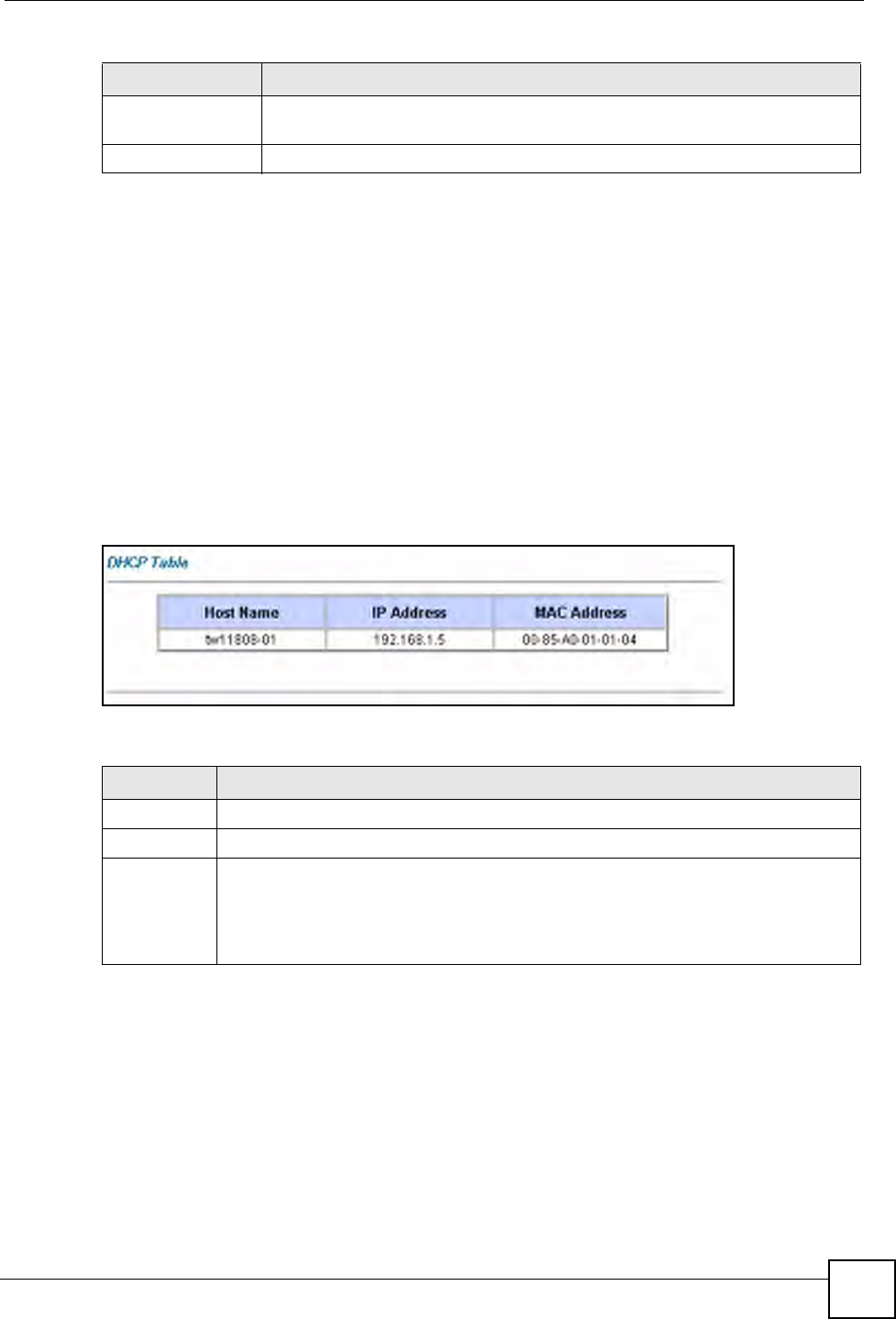
Chapter 18 Maintenance
P-660W-Tx v2 User’s Guide 185
18.3 DHCP Table Screen
DHCP (Dynamic Host Configuration Protocol, RFC 2131 and RFC 2132) allows individual
clients to obtain TCP/IP configuration at start-up from a server. You can configure the ZyXEL
Device as a DHCP server or disable it. When configured as a server, the ZyXEL Device
provides the TCP/IP configuration for the clients. If set to None, DHCP service will be
disabled and you must have another DHCP server on your LAN, or else the computer must be
manually configured.
Click Maintenance, and then the DHCP Table tab. Read-only information here relates to
your DHCP status. The DHCP table shows current DHCP Client information (including IP
Address, Host Name and MAC Address) of all network clients using the DHCP server.
Figure 101 DHCP Table
The following table describes the fields in this screen.
18.4 Any IP Table Screen
Click Maintenance, Any IP. The Any IP table shows current read-only information
(including the IP address and the MAC address) of all network devices that use the Any IP
feature to communicate with the ZyXEL Device.
Set Interval Click this button to apply the new poll interval you entered in the Poll Interval
field above.
Stop Click this button to halt the refreshing of the system statistics.
Table 66 System Status: Show Statistics (continued)
LABEL DESCRIPTION
Table 67 DHCP Table
LABEL DESCRIPTION
Host Name This is the name of the host computer.
IP Address This field displays the IP address relative to the Host Name field.
MAC
Address
This field displays the MAC (Media Access Control) address of the computer with the
displayed host name.
Every Ethernet device has a unique MAC address. The MAC address is assigned at
the factory and consists of six pairs of hexadecimal characters, for example,
00:A0:C5:00:00:02.
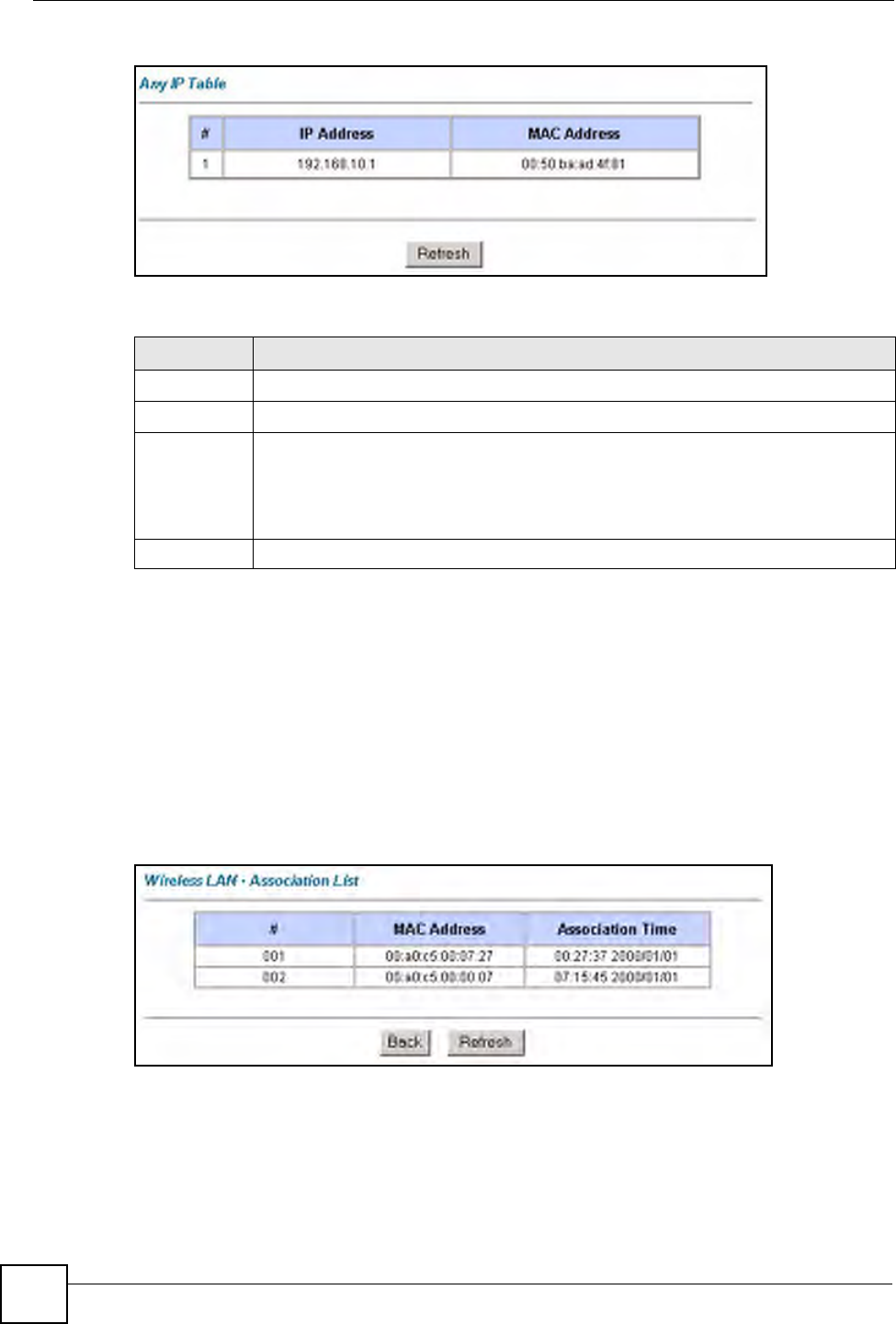
Chapter 18 Maintenance
P-660W-Tx v2 User’s Guide
186
Figure 102 Any IP Table
The following table describes the labels in this screen.
18.5 Wireless Screen
The read-only screen displays information about the ZyXEL Device’s wireless LAN.
18.5.1 Association List
This screen displays the MAC address(es) of the wireless stations that are currently logged in
to the network. Click Wireless LAN and then Association List to open the screen shown next.
Figure 103 Association List
Table 68 Any IP Table
LABEL DESCRIPTION
#This field displays the index number.
IP Address This field displays the IP address of the network device.
MAC Address This field displays the MAC (Media Access Control) address of the computer with the
displayed IP address.
Every Ethernet device has a unique MAC address. The MAC address is assigned at
the factory and consists of six pairs of hexadecimal characters, for example,
00:A0:C5:00:00:02.
Refresh Click Refresh to update this screen.
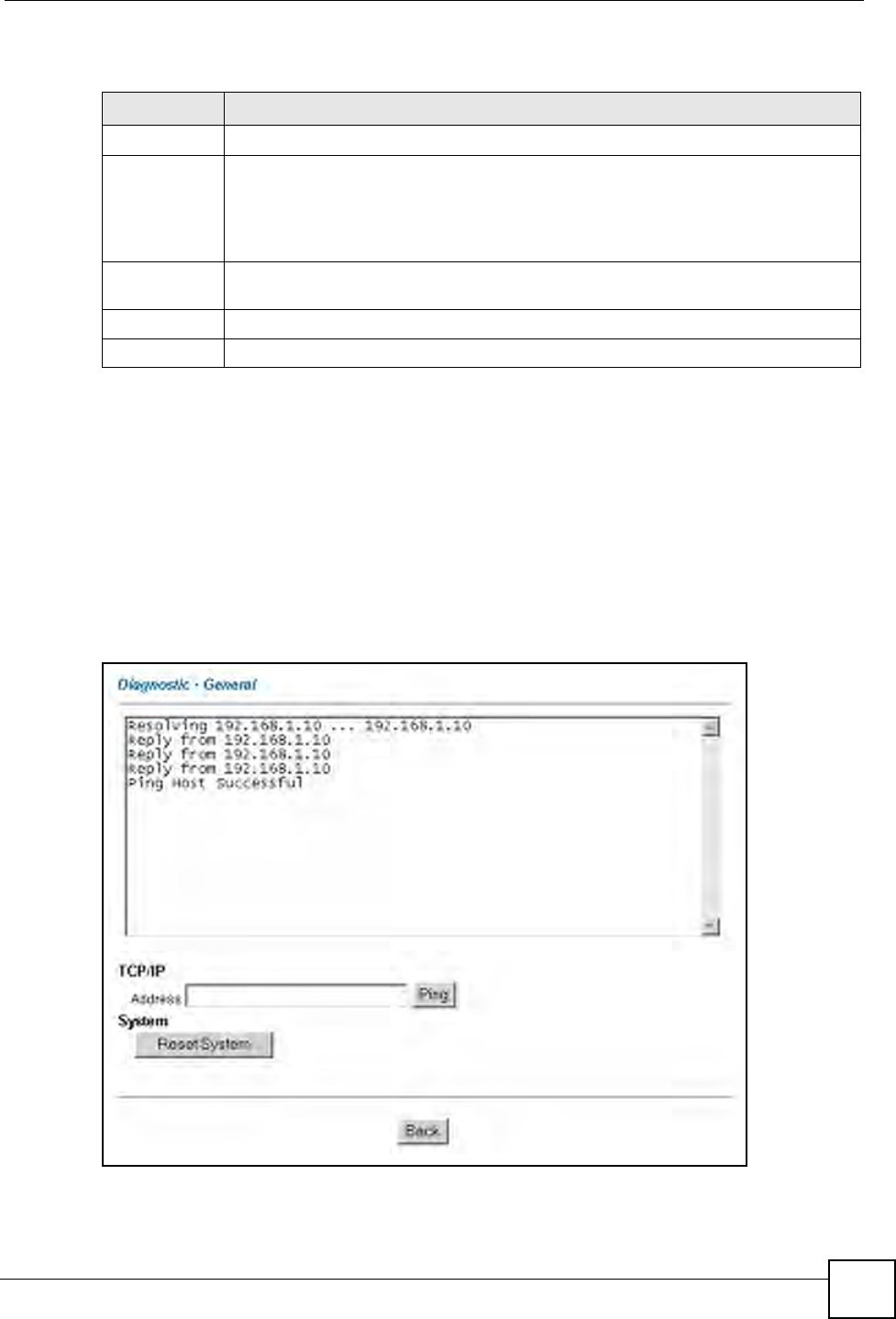
Chapter 18 Maintenance
P-660W-Tx v2 User’s Guide 187
The following table describes the fields in this screen.
18.6 Diagnostic Screens
These read-only screens display information to help you identify problems with the ZyXEL
Device.
18.6.1 General Diagnostic
Click Diagnostic and then General to open the screen shown next.
Figure 104 Diagnostic: General
Table 69 Association List
LABEL DESCRIPTION
#This is the index number of an associated wireless station.
MAC Address This field displays the MAC (Media Access Control) address of an associated wireless
station.
Every Ethernet device has a unique MAC address. The MAC address is assigned at
the factory and consists of six pairs of hexadecimal characters, for example,
00:A0:C5:00:00:02.
Association
Time
This field displays the time a wireless station is associated to the ZyXEL Device.
Back Click Back to return to the previous screen.
Refresh Click Refresh to renew the information in the table.
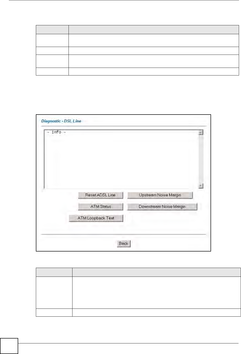
Chapter 18 Maintenance
P-660W-Tx v2 User’s Guide
188
The following table describes the fields in this screen.
18.6.2 DSL Line Diagnostic
Click Diagnostic and then DSL Line to open the screen shown next.
Figure 105 Diagnostic: DSL Line
The following table describes the fields in this screen.
Table 70 Diagnostic: General
LABEL DESCRIPTION
TCP/IP
Address
Type the IP address of a computer that you want to ping in order to test a connection.
Ping Click this button to ping the IP address that you entered.
Reset System Click this button to reboot the ZyXEL Device. A warning dialog box is then displayed
asking you if you're sure you want to reboot the system. Click OK to proceed.
Back Click this button to go back to the main Diagnostic screen.
Table 71 Diagnostic: DSL Line
LABEL DESCRIPTION
Reset ADSL
Line
Click this button to reinitialize the ADSL line. The large text box above then displays
the progress and results of this operation, for example:
"Start to reset ADSL
Loading ADSL modem F/W...
Reset ADSL Line Successfully!"
ATM Status Click this button to view ATM status.
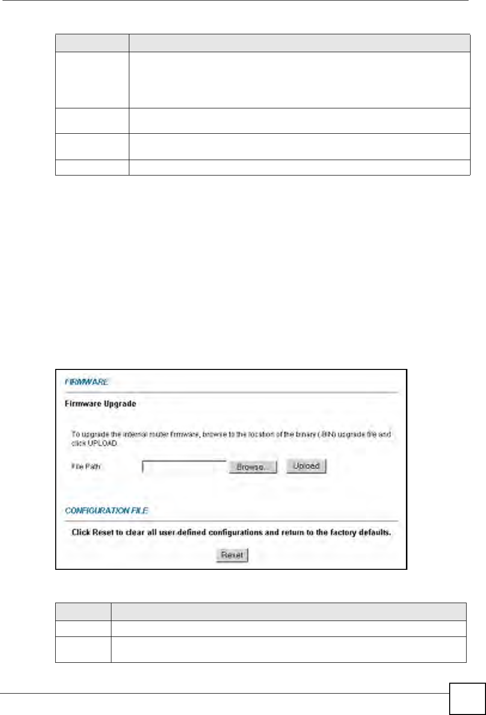
Chapter 18 Maintenance
P-660W-Tx v2 User’s Guide 189
18.7 Firmware Upgrade
Find firmware at www.zyxel.com in a file that (usually) uses the system model name with
a.bin extension, for example, “ZyXEL Device.bin”. The upload process uses HTTP
(Hypertext Transfer Protocol) and may take up to two minutes. After a successful upload, the
system will reboot.
Only use firmware for your device’s specific model. Refer to the label on the bottom of your
device.
Click Firmware to open the following screen. Follow the instructions in this screen to upload
firmware to your ZyXEL Device.
Figure 106 Firmware Upgrade
The following table describes the labels in this screen.
ATM Loopback
Te s t
Click this button to start the ATM loopback test. Make sure you have configured at
least one PVC with proper VPIs/VCIs before you begin this test. The ZyXEL Device
sends an OAM F5 packet to the DSLAM/ATM switch and then returns it (loops it
back) to the ZyXEL Device. The ATM loopback test is useful for troubleshooting
problems with the DSLAM and ATM network.
Upstream Noise
Margin
Click this button to display the upstream noise margin.
Downstream
Noise Margin
Click this button to display the downstream noise margin.
Back Click this button to go back to the main Diagnostic screen.
Table 71 Diagnostic: DSL Line (continued)
LABEL DESCRIPTION
Table 72 Firmware Upgrade
LABEL DESCRIPTION
File Path Type in the location of the file you want to upload in this field or click Browse ... to find it.
Browse... Click Browse... to find the .bin file you want to upload. Remember that you must
decompress compressed (.zip) files before you can upload them.
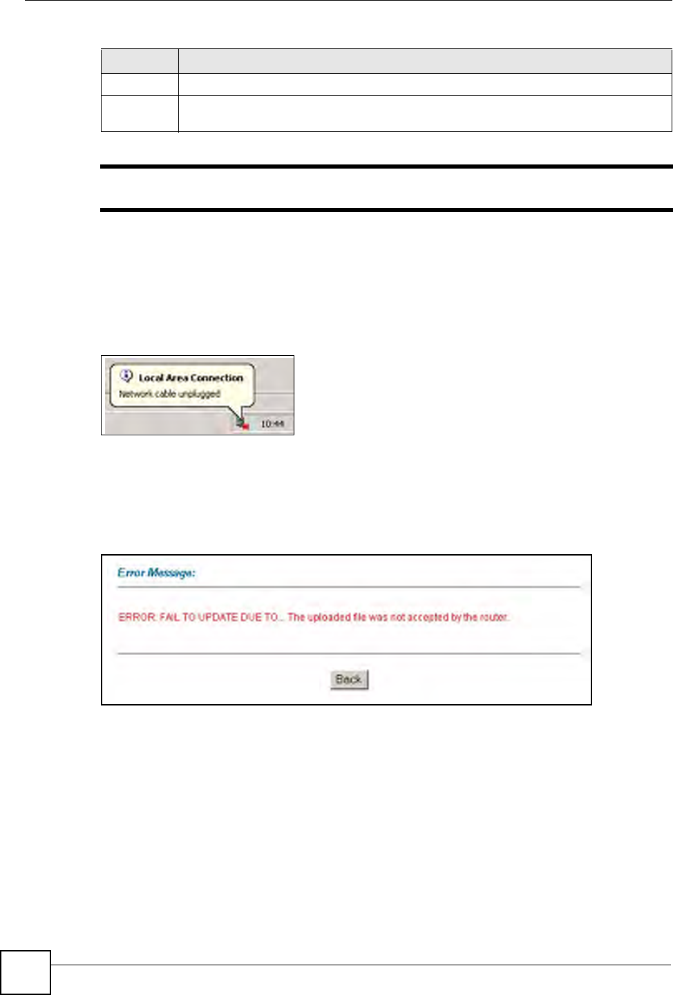
Chapter 18 Maintenance
P-660W-Tx v2 User’s Guide
190
"Do NOT turn off the ZyXEL Device while firmware upload is in progress!
After you see the Firmware Upload in Process screen, wait two minutes before logging into
the ZyXEL Device again.
The ZyXEL Device automatically restarts in this time causing a temporary network
disconnect. In some operating systems, you may see the following icon on your desktop.
Figure 107 Network Temporarily Disconnected
After two minutes, log in again and check your new firmware version in the System Status
screen.
If the upload was not successful, the following screen will appear. Click Back to go back to
the Firmware screen.
Figure 108 Error Message
18.8 FTP Command Line
This section shows some examples of uploading to or downloading files from the ZyXEL
Device using FTP commands. First, understand the filename conventions.
Upload Click Upload to begin the upload process. This process may take up to two minutes.
Reset Click this button to clear all user-entered configuration information and return the ZyXEL
Device to its factory defaults.
Table 72 Firmware Upgrade (continued)
LABEL DESCRIPTION
Chapter 18 Maintenance
P-660W-Tx v2 User’s Guide 191
18.8.1 Filename Conventions
The configuration file (also known as the romfile or ROM) contains the factory default
settings in the screens such as password, ZyXEL Device setup, IP Setup, and so on. Once you
have customized the ZyXEL Device’s settings, they can be saved back to your computer under
a filename of your choosing.
ZyNOS (ZyXEL Network Operating System, sometimes referred to as the “ras” file) is the
system firmware and has a “bin” filename extension.
18.8.1.1 Example FTP Commands
ftp> put firmware.bin ras
This is a sample FTP session showing the transfer of the computer file “firmware.bin” to the
ZyXEL Device.
ftp> get config config.rom
This is a sample FTP session saving the current configuration to a file called “config” on your
computer.
If your (T)FTP client does not allow you to have a destination filename different than the
source, you will need to rename them as the ZyXEL Device only recognizes “config” and
“ras”. Be sure you keep unaltered copies of both files for later use.
1Be sure to upload the correct model firmware as uploading the wrong model
firmware may damage your device.
18.8.2 FTP Command Line Procedure
1Launch the FTP client on your computer.
2Enter open, followed by a space and the IP address of your ZyXEL Device.
3Press [ENTER] when prompted for a username.
4Enter your password as requested (the default is “1234”).
5Enter bin to set transfer mode to binary.
6Use put to transfer files from the computer to the ZyXEL Device, for example, put
firmware.bin ras transfers the firmware on your computer (firmware.bin) to the
ZyXEL Device and renames it to “ras”. Similarly, put config.rom config transfers
the configuration file on your computer (config.cfg) to the ZyXEL Device and renames
Table 73 Filename Conventions
FILE TYPE INTERNAL
NAME
EXTERNAL
NAME DESCRIPTION
Configuration File config *.rom This is the configuration (config) filename on the
ZyXEL Device. Uploading the config file replaces the
specified configuration file system, including your
ZyXEL Device configurations, system-related data
(including the default password), the error log and the
trace log.
Firmware ras *.bin This is the generic name for the ZyNOS firmware on
the ZyXEL Device.
Chapter 18 Maintenance
P-660W-Tx v2 User’s Guide
192
it to “config”. Likewise get config config.rom transfers the configuration file on
the ZyXEL Device to your computer and renames it to “config”. See Table 73 on page
191 for more information on filename conventions.
7Enter quit to exit the ftp prompt.
18.8.3 GUI-based FTP Clients
The following table describes some of the commands that you may see in GUI-based FTP
clients.
18.8.4 FTP Restrictions
FTP will not work when:
• FTP service is disabled in the Service Access Control screen.
• The IP address(es) in the Remote Management screen does not match the client IP
address. If it does not match, the ZyXEL Device will disconnect the FTP session
immediately.
Table 74 General Commands for GUI-based FTP Clients
COMMAND DESCRIPTION
Host Address Enter the address of the host server.
Login Type Anonymous.
This is when a user I.D. and password is automatically supplied to the server
for anonymous access. Anonymous logins will work only if your ISP or service
administrator has enabled this option.
Normal.
The server requires a unique User ID and Password to login.
Transfer Type Transfer files in either ASCII (plain text format) or in binary mode.
Configuration and firmware files should be transferred in binary mode.
Initial Remote
Directory
Specify the default remote directory (path).
Initial Local Directory Specify the default local directory (path).

193
PART V
Troubleshooting
and Specifications
Troubleshooting (195)
Product Specifications (201)

194

P-660W-Tx v2 User’s Guide 195
CHAPTER 19
Troubleshooting
This chapter offers some suggestions to solve problems you might encounter. The potential
problems are divided into the following categories.
•Power, Hardware Connections, and LEDs
•ZyXEL Device Access and Login
•Internet Access
•Reset the ZyXEL Device to Its Factory Defaults
•Wireless Router/AP Troubleshooting
19.1 Power, Hardware Connections, and LEDs
VThe ZyXEL Device does not turn on. None of the LEDs turn on.
1Make sure the ZyXEL Device is turned on.
2Make sure you are using the power adaptor or cord included with the ZyXEL Device.
3Make sure the power adaptor or cord is connected to the ZyXEL Device and plugged in
to an appropriate power source. Make sure the power source is turned on.
4Turn the ZyXEL Device off and on.
5If the problem continues, contact the vendor.
VOne of the LEDs does not behave as expected.
1Make sure you understand the normal behavior of the LED. See Section 19.1 on page
195.
2Check the hardware connections. See the Quick Start Guide and Section 19.1 on page
195.
3Inspect your cables for damage. Contact the vendor to replace any damaged cables.
4Turn the ZyXEL Device off and on.
5If the problem continues, contact the vendor.

Chapter 19 Troubleshooting
P-660W-Tx v2 User’s Guide
196
19.2 ZyXEL Device Access and Login
VI forgot the IP address for the ZyXEL Device.
1The default IP address is 192.168.1.1.
2If you changed the IP address and have forgotten it, you might get the IP address of the
ZyXEL Device by looking up the IP address of the default gateway for your computer.
To do this in most Windows computers, click Start > Run, enter cmd, and then enter
ipconfig. The IP address of the Default Gateway might be the IP address of the ZyXEL
Device (it depends on the network), so enter this IP address in your Internet browser.
3If this does not work, you have to reset the ZyXEL Device to its factory defaults. See
Section 19.1 on page 195.
VI forgot the password.
1The default password is 1234.
2If this does not work, you have to reset the ZyXEL Device to its factory defaults. See
Section 19.1 on page 195.
VI cannot see or access the Login screen in the web configurator.
1Make sure you are using the correct IP address.
• The default IP address is 192.168.1.1.
• If you changed the IP address (Section 19.1 on page 195), use the new IP address.
• If you changed the IP address and have forgotten it, see the troubleshooting
suggestions for I forgot the IP address for the ZyXEL Device.
2Check the hardware connections, and make sure the LEDs are behaving as expected. See
the Quick Start Guide and Section 19.1 on page 195.
3Make sure your Internet browser does not block pop-up windows and has JavaScripts
and Java enabled. See Section 19.1 on page 195.
4Make sure your computer is in the same subnet as the ZyXEL Device. (If you know that
there are routers between your computer and the ZyXEL Device, skip this step.)
• If there is a DHCP server on your network, make sure your computer is using a
dynamic IP address. See Section 19.1 on page 195. Your ZyXEL Device is a DHCP
server by default.
• If there is no DHCP server on your network, make sure your computer’s IP address is
in the same subnet as the ZyXEL Device. See Section 19.1 on page 195.
5Reset the ZyXEL Device to its factory defaults, and try to access the ZyXEL Device
with the default IP address. See Section 19.1 on page 195.

Chapter 19 Troubleshooting
P-660W-Tx v2 User’s Guide 197
6If the problem continues, contact the network administrator or vendor, or try one of the
advanced suggestions.
Advanced Suggestions
• Try to access the ZyXEL Device using another service, such as Telnet. If you can access
the ZyXEL Device, check the remote management settings, and firewall rules to find out
why the ZyXEL Device does not respond to HTTP.
• If your computer is connected to the WA N port or is connected wirelessly, use a computer
that is connected to a LAN/ETHERNET port.
VI can see the Login screen, but I cannot log in to the ZyXEL Device.
1Make sure you have entered the user name and password correctly. The default password
is 1234. These fields are case-sensitive, so make sure [Caps Lock] is not on.
2You cannot log in to the web configurator while someone is using Telnet to access the
ZyXEL Device. Log out of the ZyXEL Device in the other session, or ask the person
who is logged in to log out.
3Turn the ZyXEL Device off and on.
4If this does not work, you have to reset the ZyXEL Device to its factory defaults. See
Section 19.1 on page 195.
VI cannot Telnet to the ZyXEL Device.
See the troubleshooting suggestions for I cannot see or access the Login screen in the web
configurator. Ignore the suggestions about your browser.
VI cannot use FTP to upload / download the configuration file. / I cannot use
FTP to upload new firmware.
See the troubleshooting suggestions for I cannot see or access the Login screen in the web
configurator. Ignore the suggestions about your browser.
19.3 Internet Access
VI cannot access the Internet.

Chapter 19 Troubleshooting
P-660W-Tx v2 User’s Guide
198
1Check the hardware connections, and make sure the LEDs are behaving as expected. See
the Quick Start Guide and Section 19.1 on page 195.
2Make sure you entered your ISP account information correctly in the wizard. These
fields are case-sensitive, so make sure [Caps Lock] is not on.
3If you are trying to access the Internet wirelessly, make sure the wireless settings in the
wireless client are the same as the settings in the AP.
4Disconnect all the cables from your ZyXEL Device, and follow the directions in the
Quick Start Guide again.
5If the problem continues, contact your ISP.
VI cannot access the Internet anymore. I had access to the Internet (with the
ZyXEL Device), but my Internet connection is not available anymore.
1Check the hardware connections, and make sure the LEDs are behaving as expected. See
the Quick Start Guide and Section 19.1 on page 195.
2Turn the ZyXEL Device off and on.
3If the problem continues, contact your ISP.
VThe Internet connection is slow or intermittent.
1There might be a lot of traffic on the network. Look at the LEDs, and check Section 19.1
on page 195. If the ZyXEL Device is sending or receiving a lot of information, try
closing some programs that use the Internet, especially peer-to-peer applications.
2Check the signal strength. If the signal strength is low, try moving the ZyXEL Device
closer to the AP if possible, and look around to see if there are any devices that might be
interfering with the wireless network (for example, microwaves, other wireless
networks, and so on).
3Turn the ZyXEL Device off and on.
4If the problem continues, contact the network administrator or vendor, or try one of the
advanced suggestions.
Advanced Suggestions
• Check the settings for bandwidth management. If it is disabled, you might consider
activating it. If it is enabled, you might consider changing the allocations.
19.4 Reset the ZyXEL Device to Its Factory Defaults
If you reset the ZyXEL Device, you lose all of the changes you have made. The ZyXEL
Device re-loads its default settings, and the password resets to 1234. You have to make all of
your changes again.

Chapter 19 Troubleshooting
P-660W-Tx v2 User’s Guide 199
VYou will lose all of your changes when you push the RESET button.
To reset the ZyXEL Device,
1Make sure the POWER LED is on and not blinking.
2Press and hold the RESET button for five to ten seconds. Release the RESET button
when the POWER LED begins to blink. The default settings have been restored.
If the ZyXEL Device restarts automatically, wait for the ZyXEL Device to finish restarting,
and log in to the web configurator. The password is “1234”.
If the ZyXEL Device does not restart automatically, disconnect and reconnect the ZyXEL
Device’s power. Then, follow the directions above again.
19.5 Wireless Router/AP Troubleshooting
VI cannot access the ZyXEL Device or ping any computer from the WLAN.
1Make sure the wireless LAN is enabled on the ZyXEL Device
2Make sure the wireless adapter on the wireless station is working properly.
3Make sure the wireless adapter (installed on your computer) is IEEE 802.11 compatible
and supports the same wireless standard as the ZyXEL Device.
4Make sure your computer (with a wireless adapter installed) is within the transmission
range of the ZyXEL Device.
5Check that both the ZyXEL Device and your wireless station are using the same wireless
and wireless security settings.
6Make sure traffic between the WLAN and the LAN is not blocked by the firewall on the
ZyXEL Device.
7Make sure you allow the ZyXEL Device to be remotely accessed through the WLAN
interface. Check your remote management settings.

Chapter 19 Troubleshooting
P-660W-Tx v2 User’s Guide
200