ZyXEL Communications P663HN51 802.11n ADSL2+ Bonded 4-port Gateway User Manual SMG 700 User s Guide V1 00 Nov 2004
ZyXEL Communications Corporation 802.11n ADSL2+ Bonded 4-port Gateway SMG 700 User s Guide V1 00 Nov 2004
UserManual.wiki
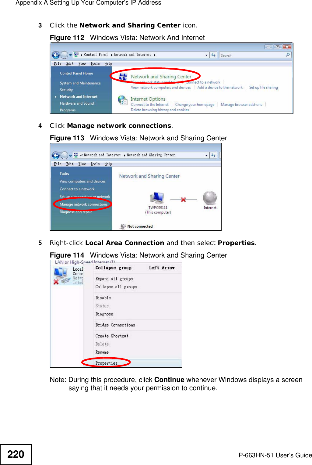
>
ZyXEL Communications
>
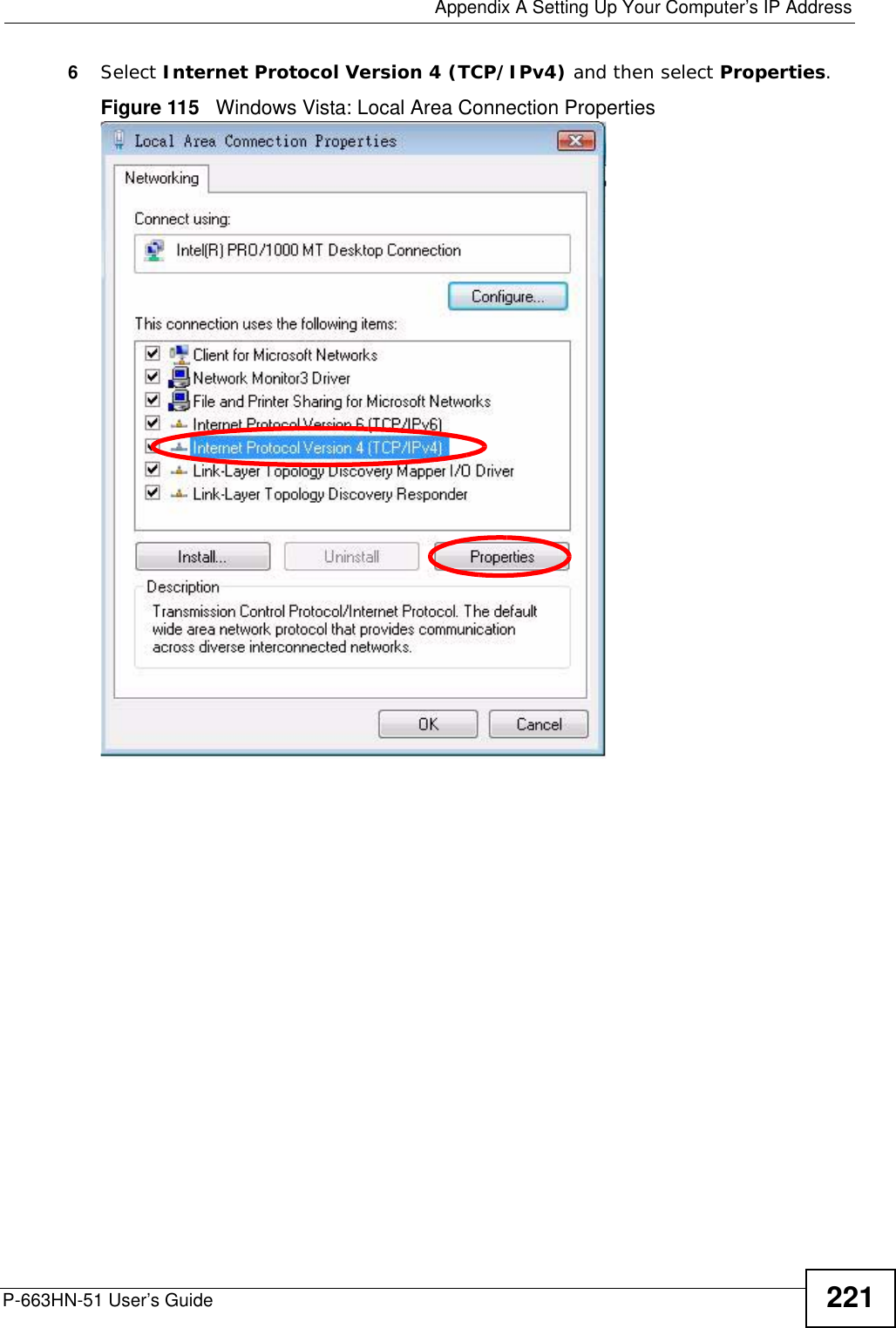
P663HN51 User Manual
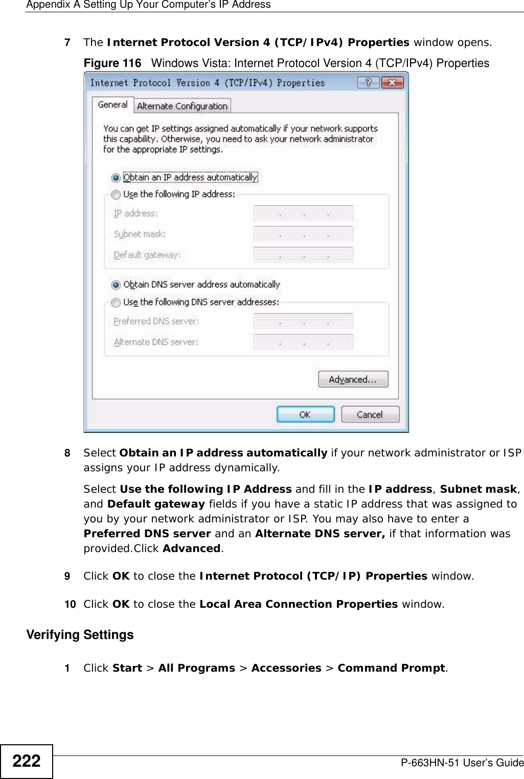
user manual
Navigation menu
Upload a User Manual
Namespaces
Wiki Guide
HTML
PDF
Info
Views
User Manual
Discussion / Help
Navigation
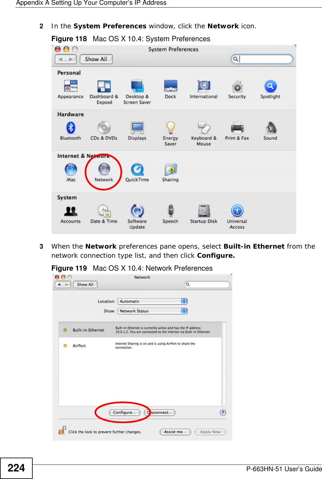
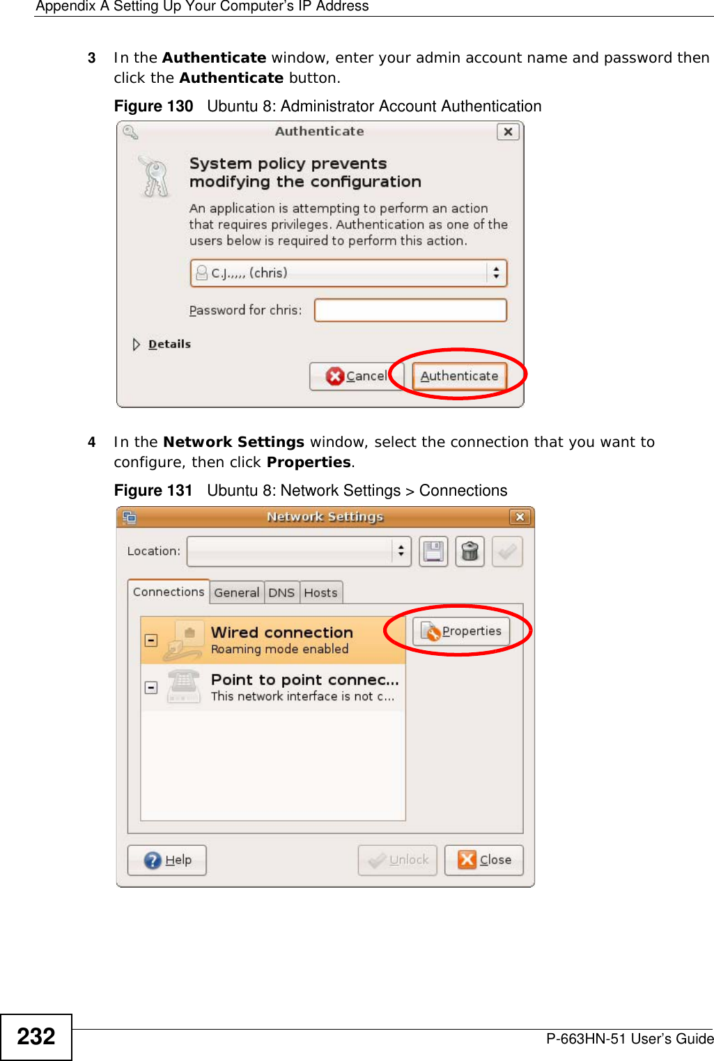
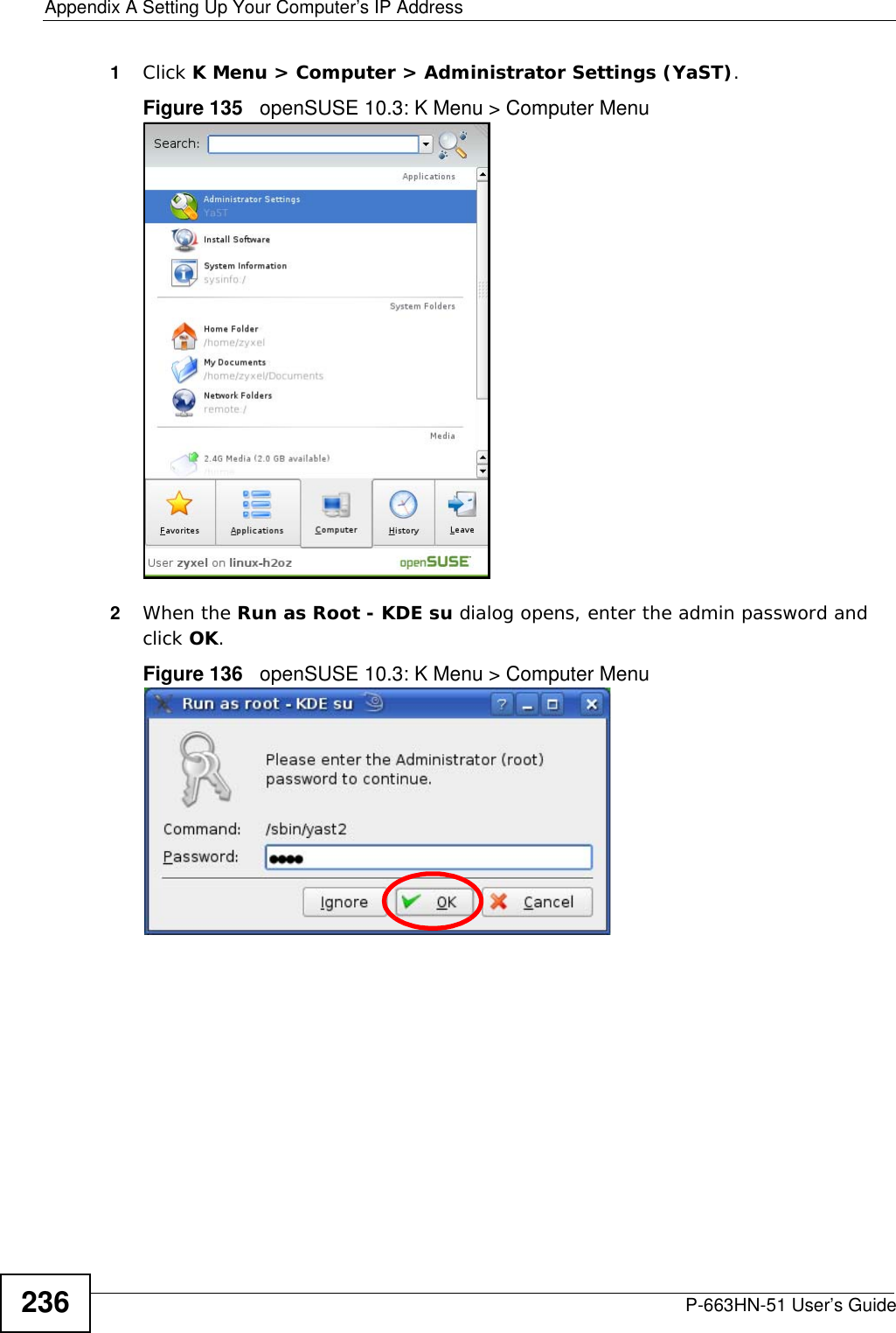
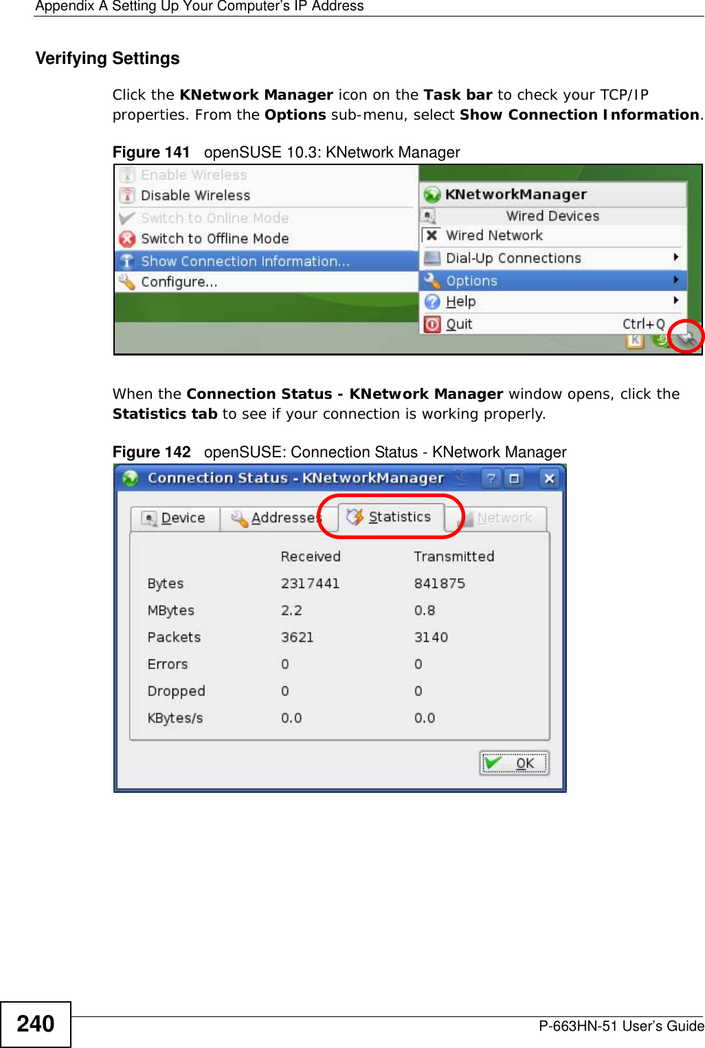
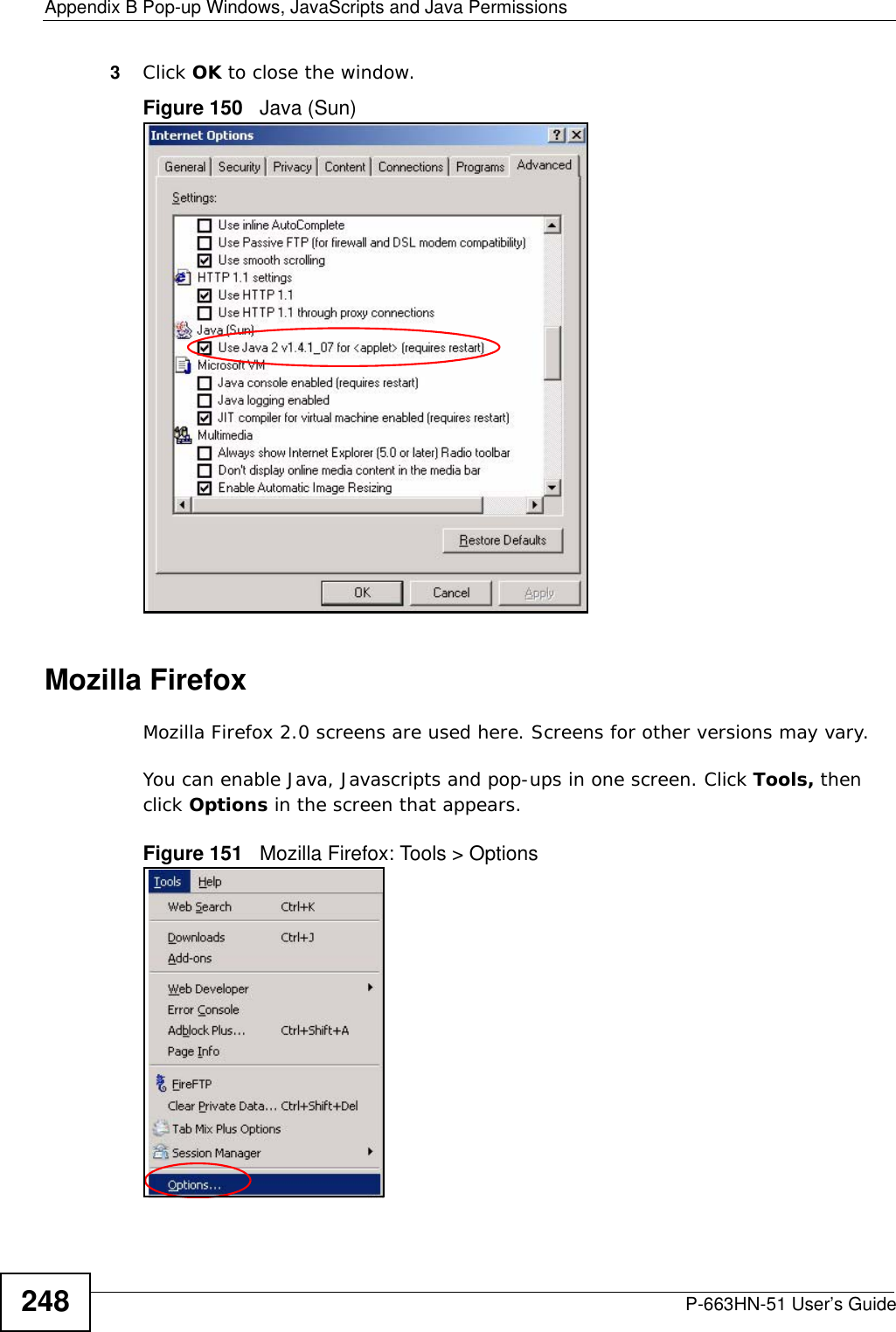
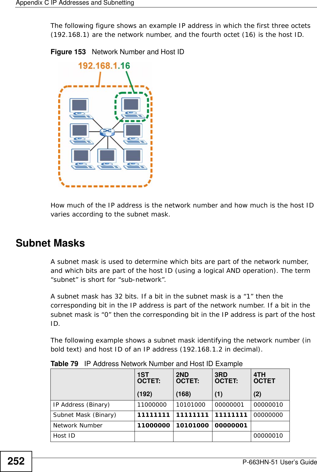
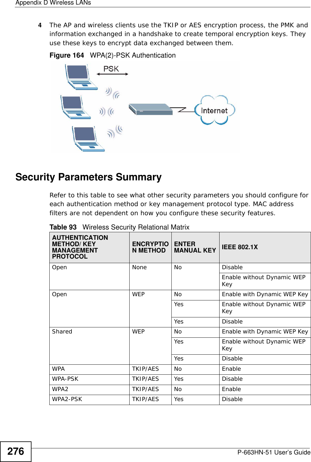
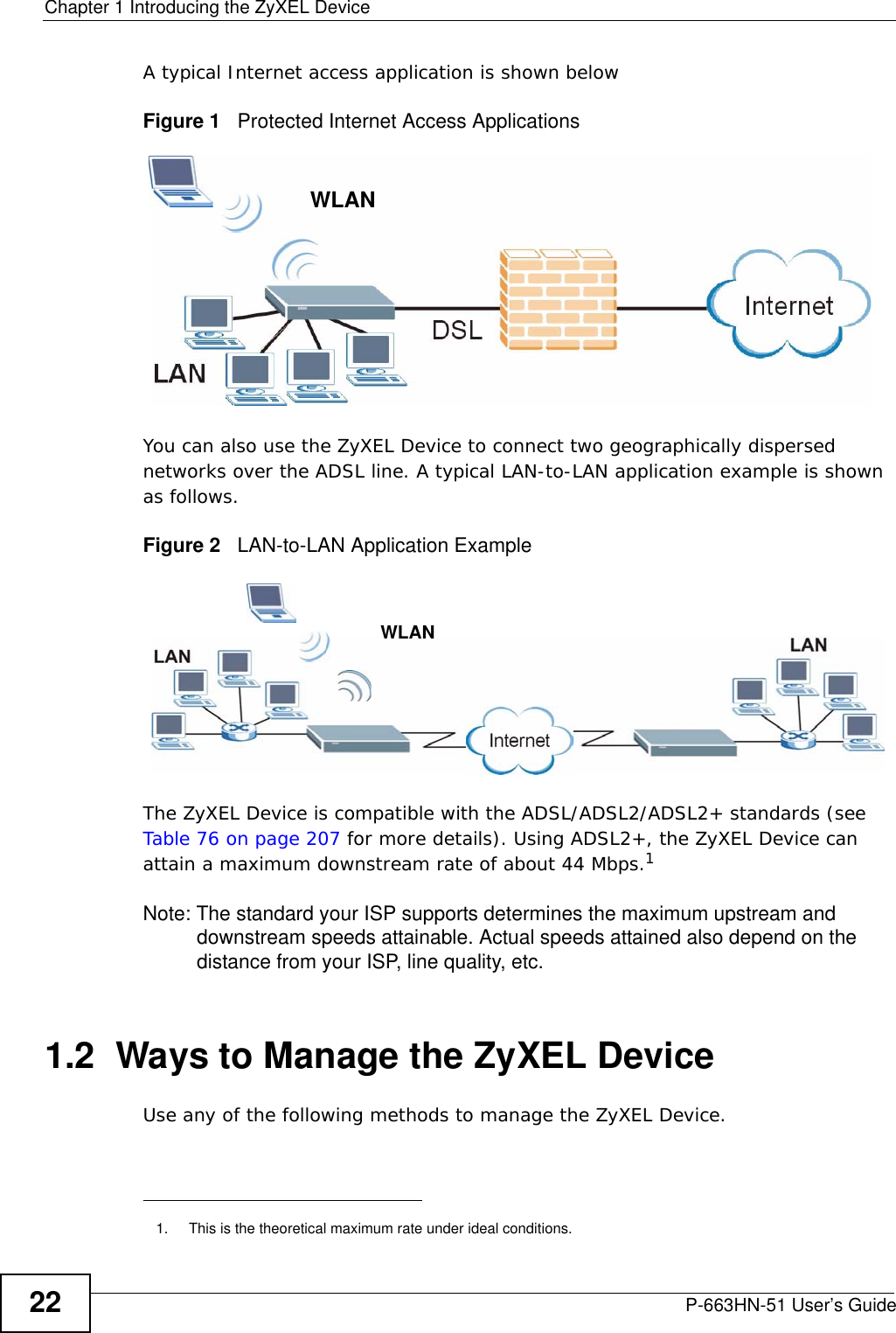
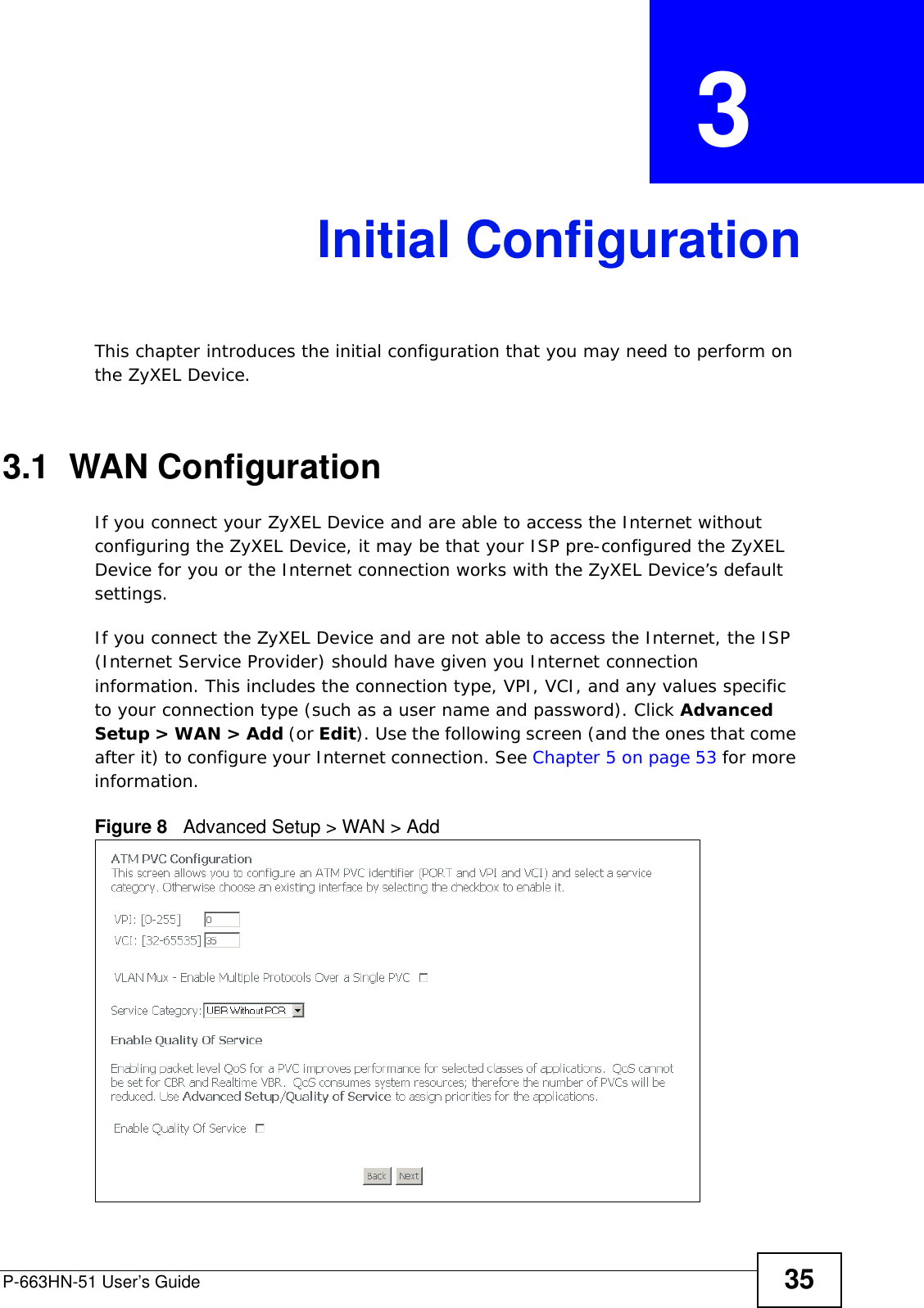
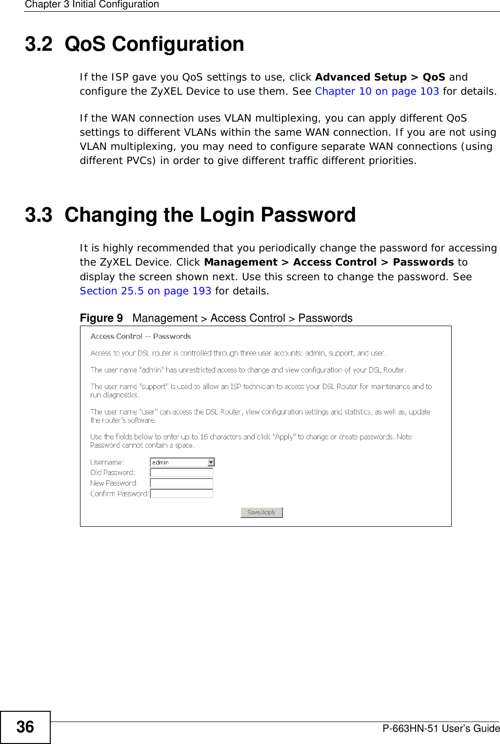
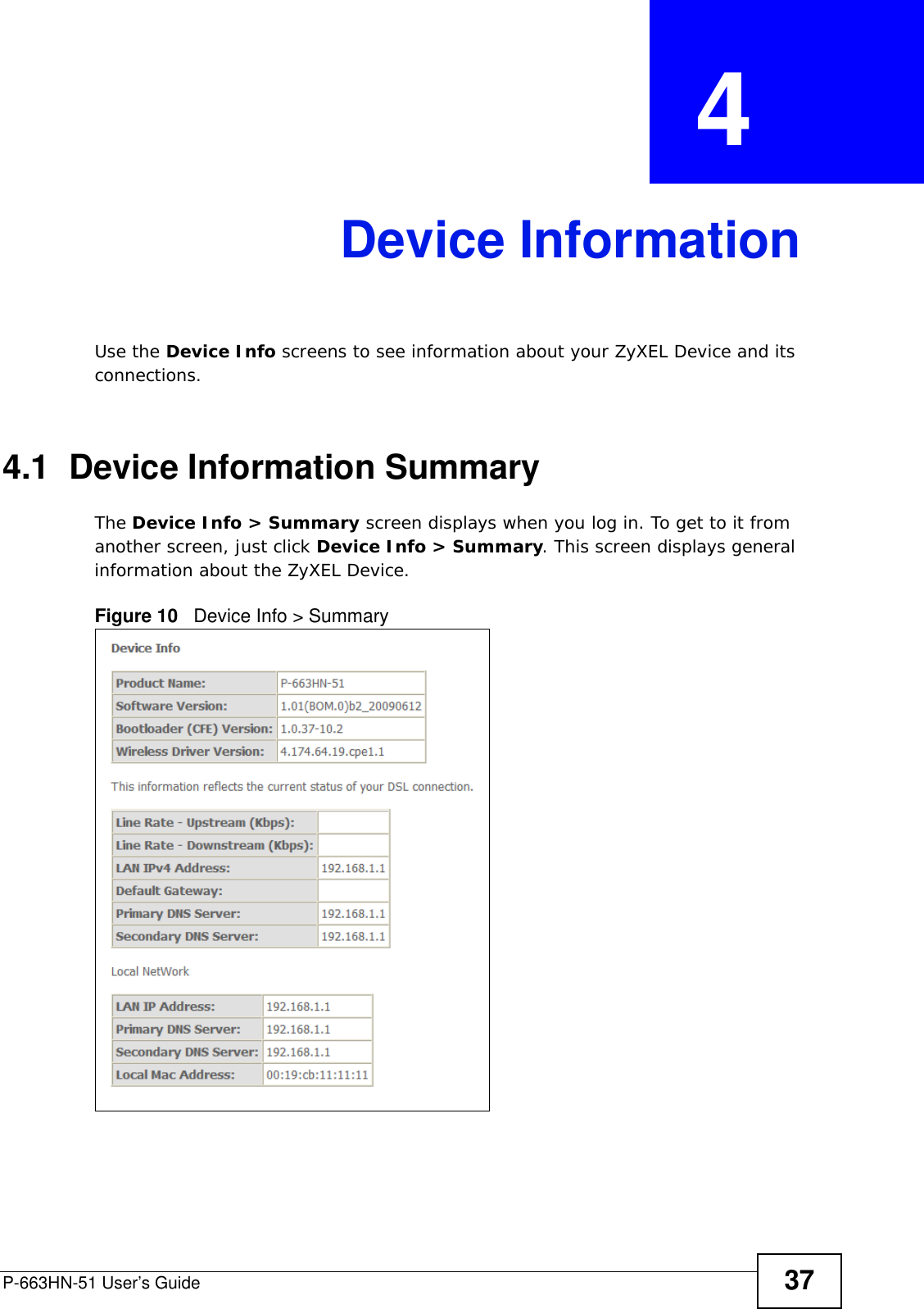
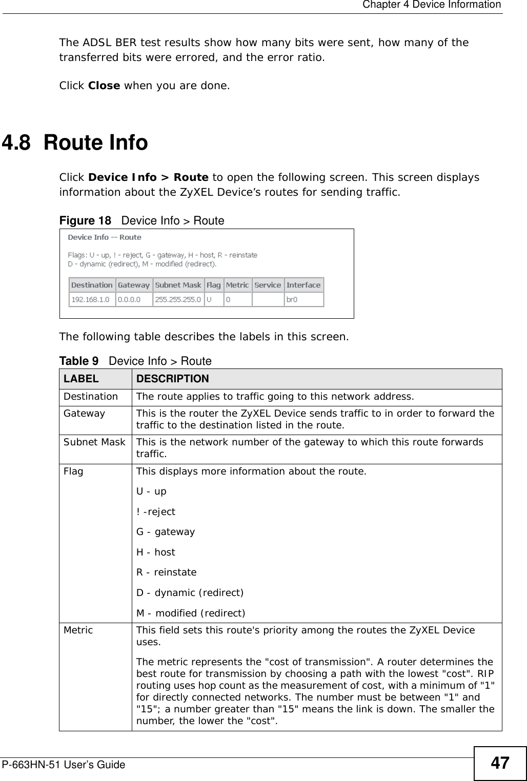
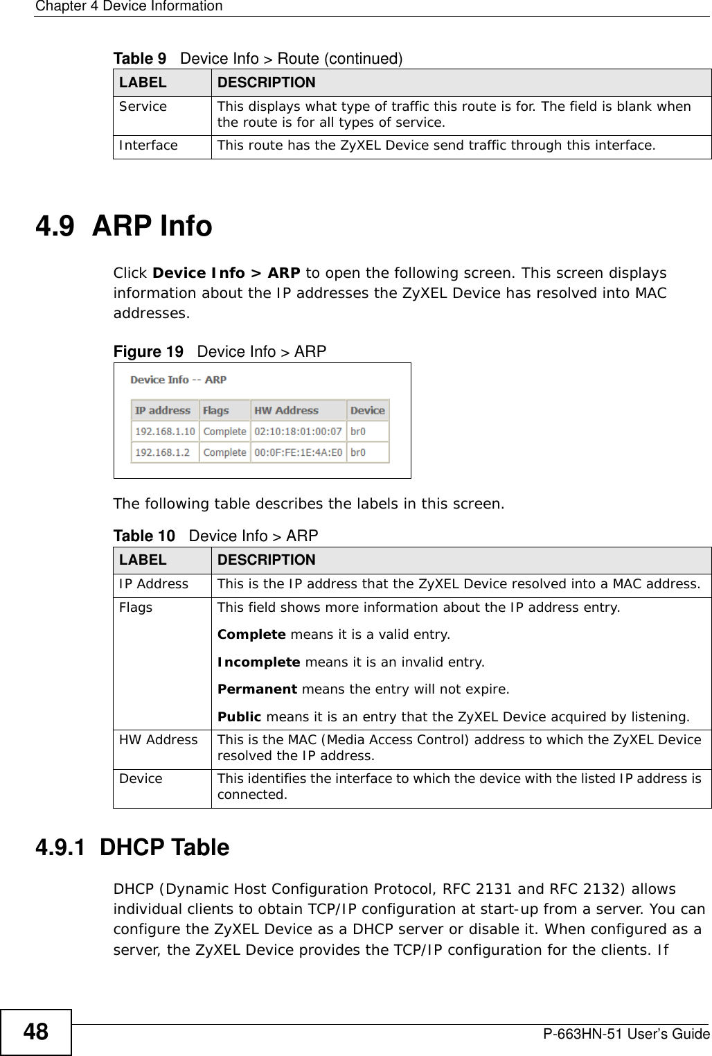
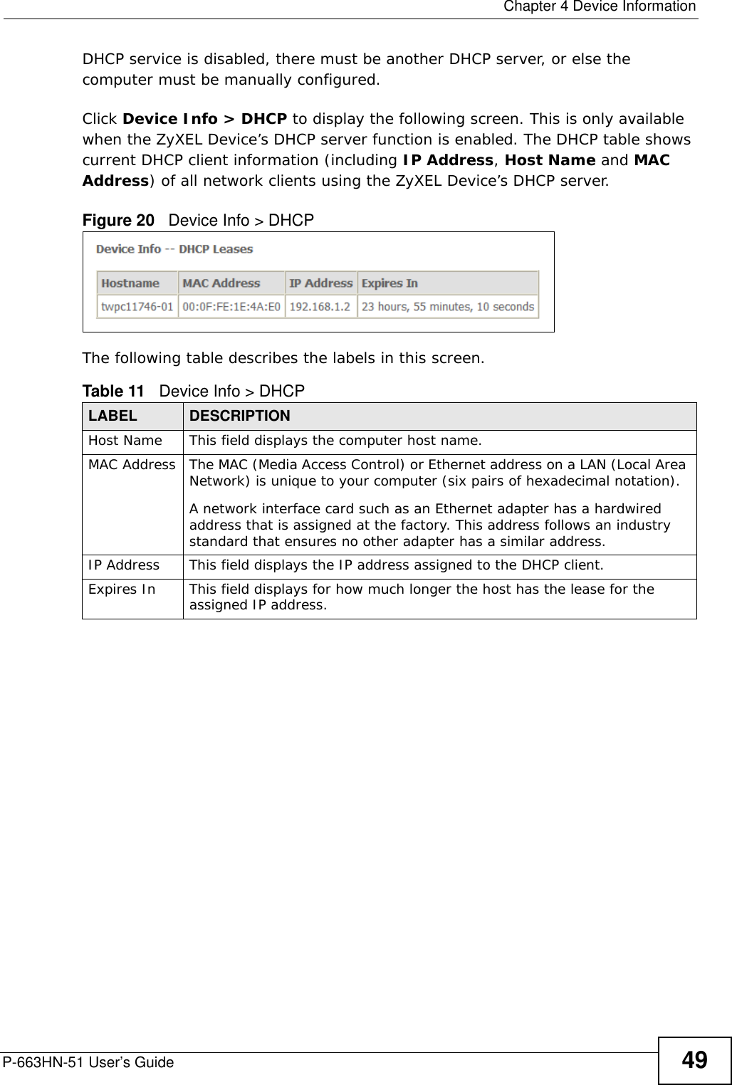
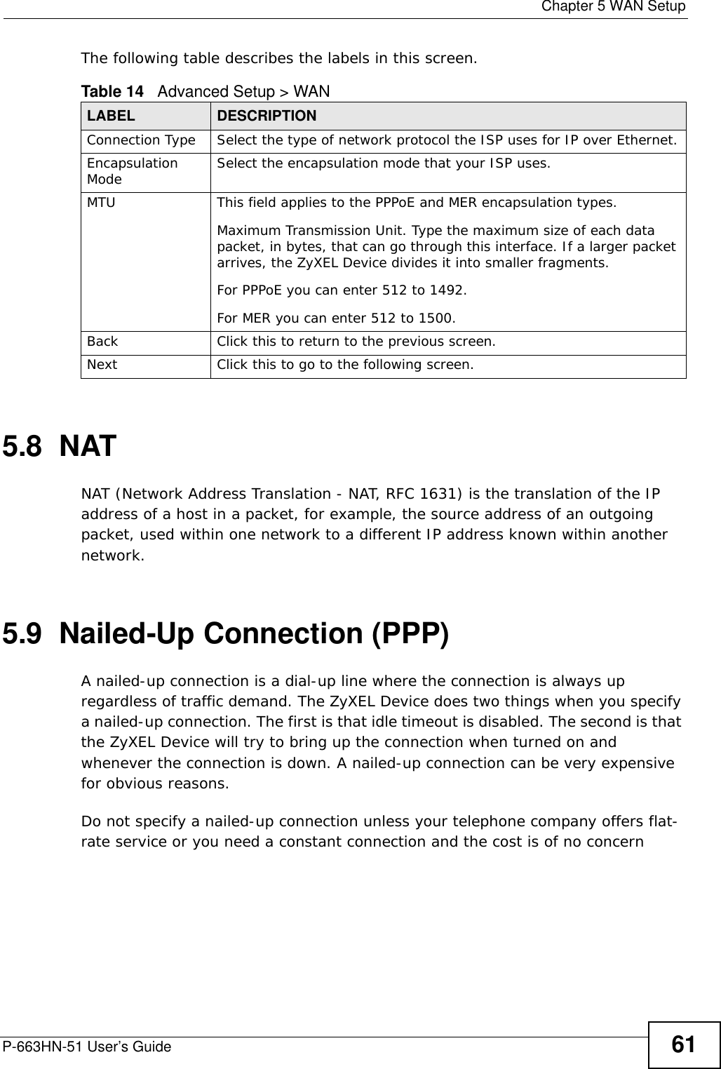
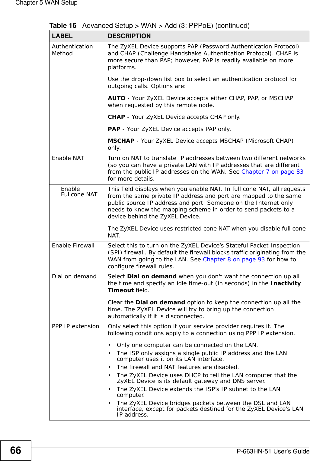
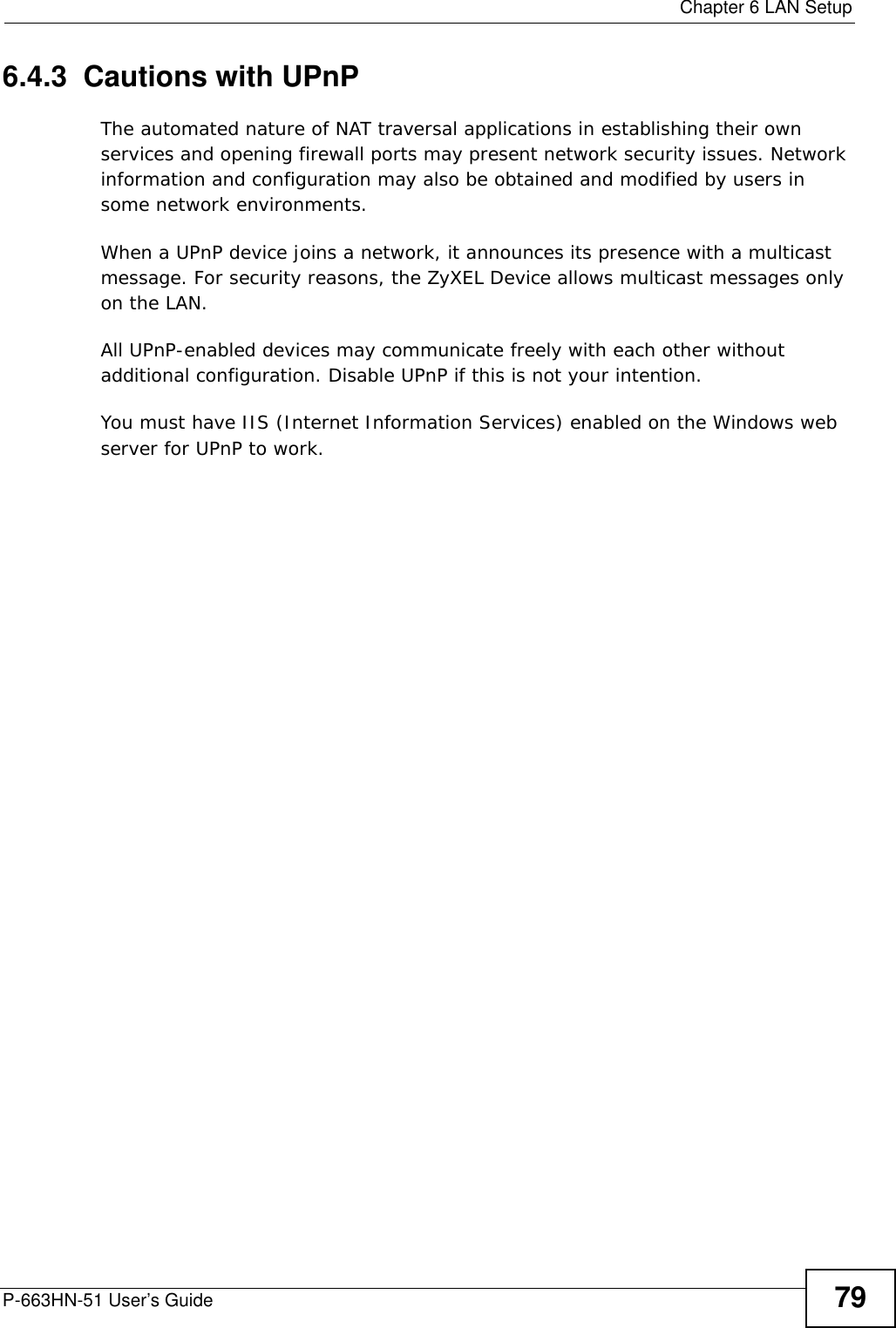
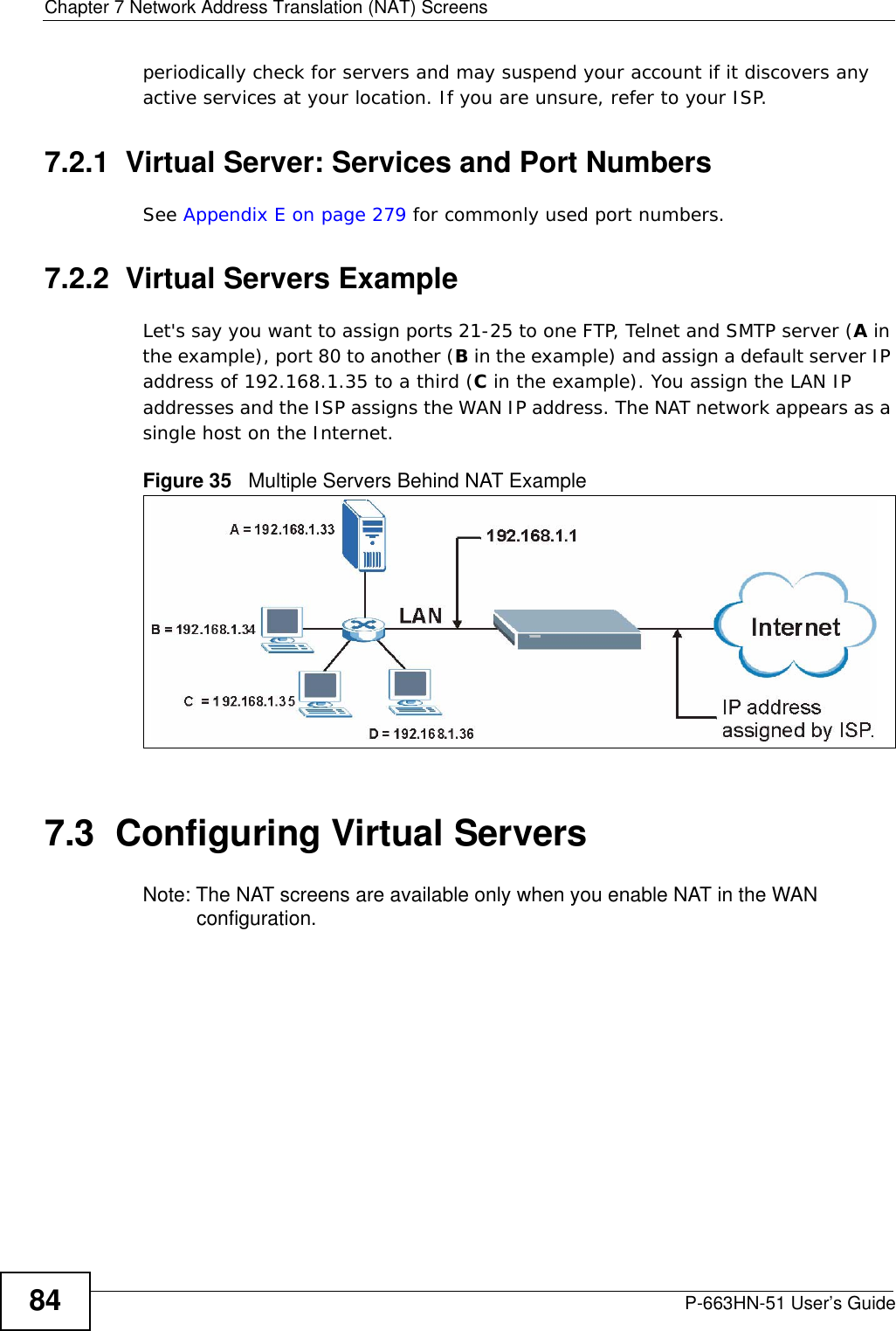
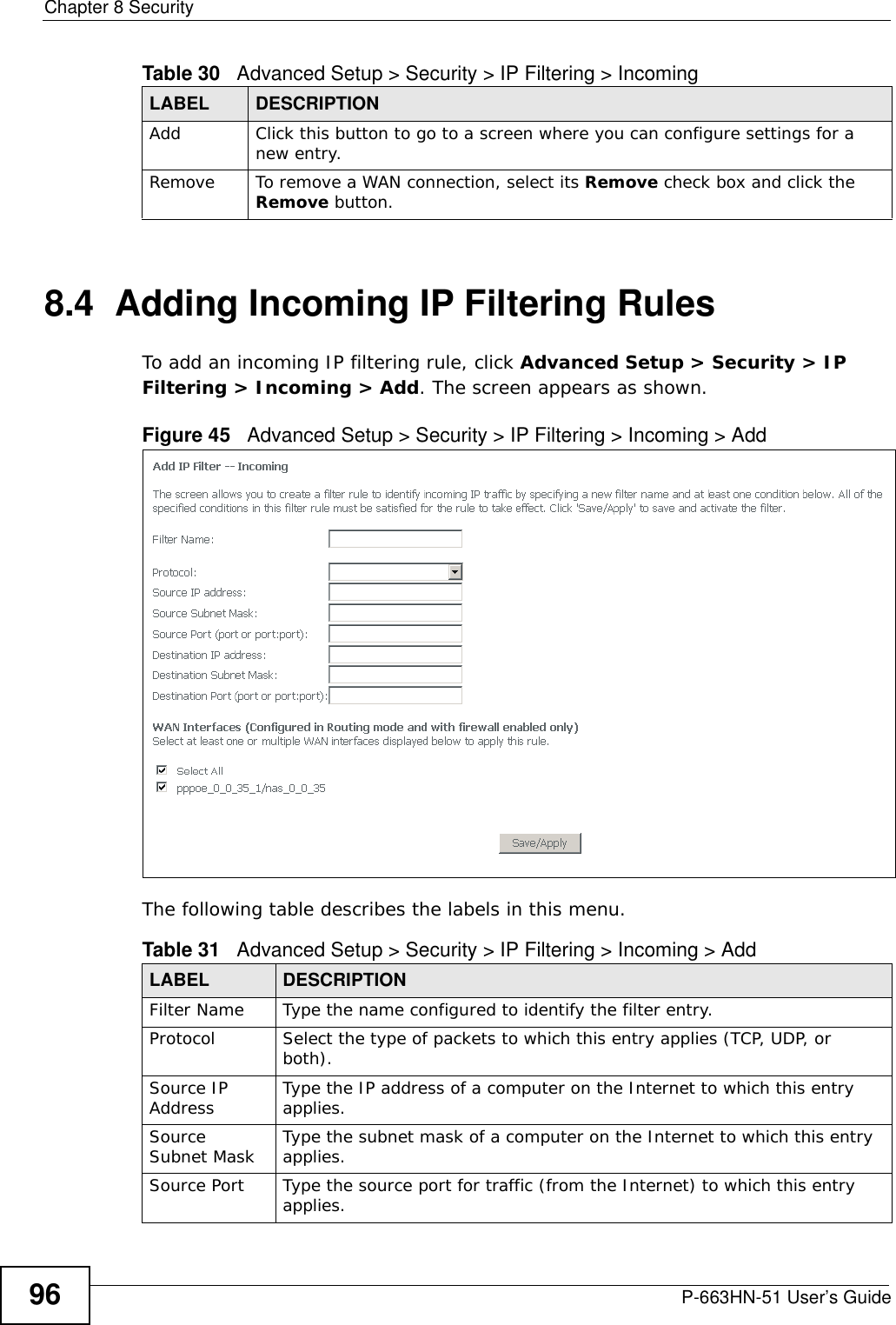
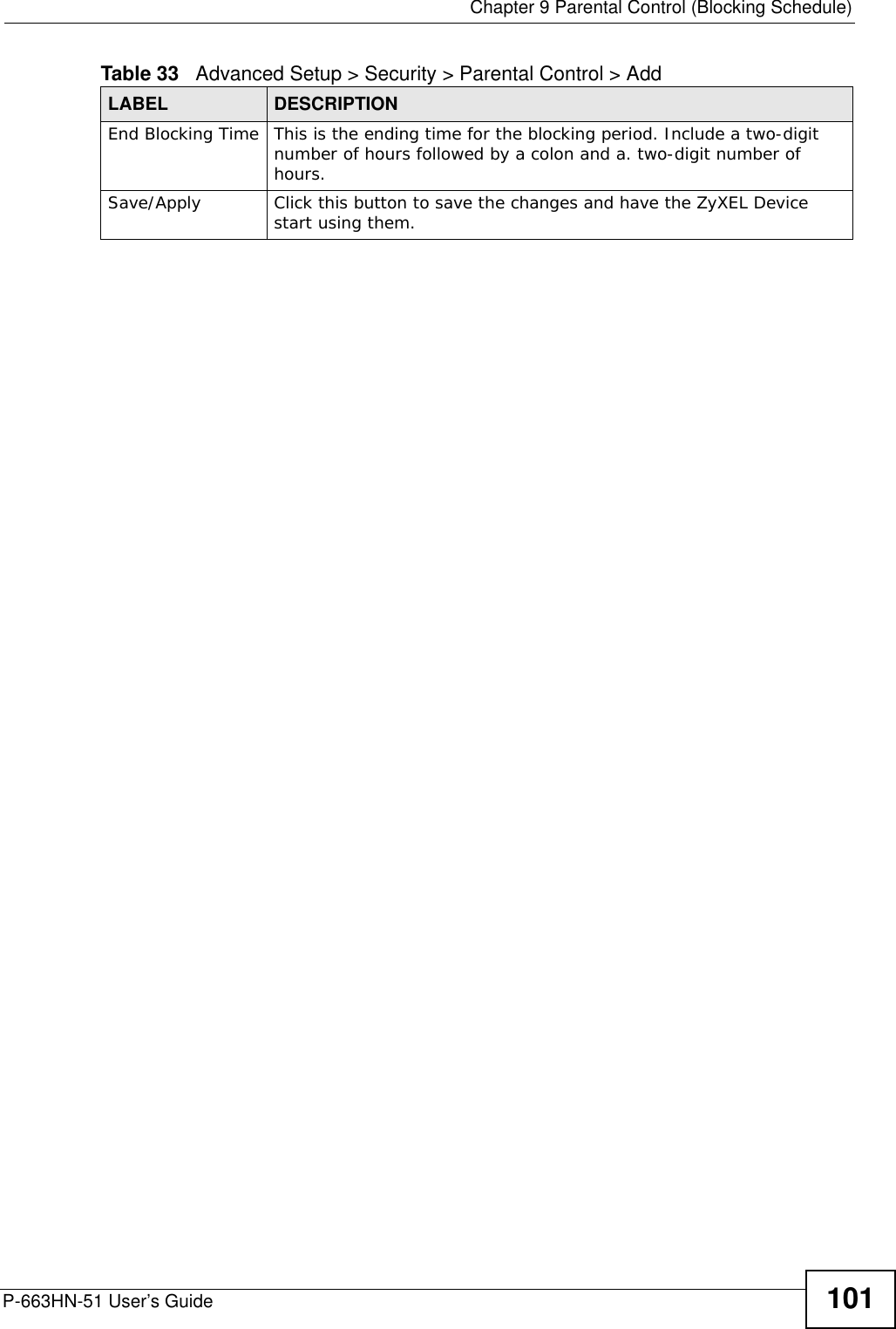
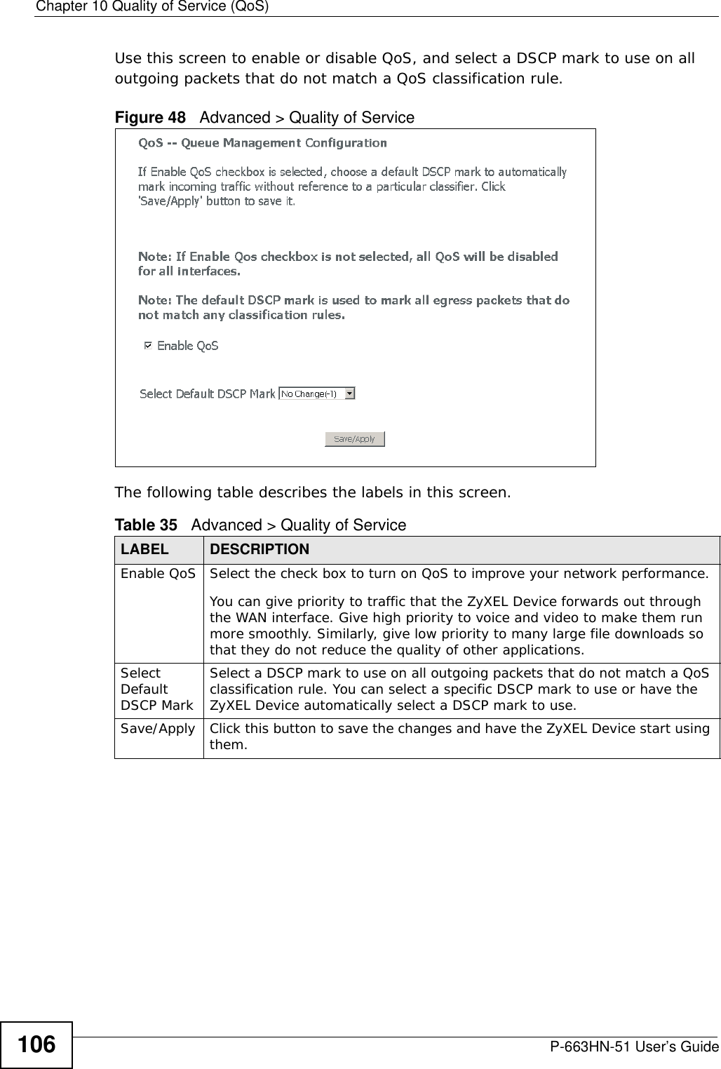
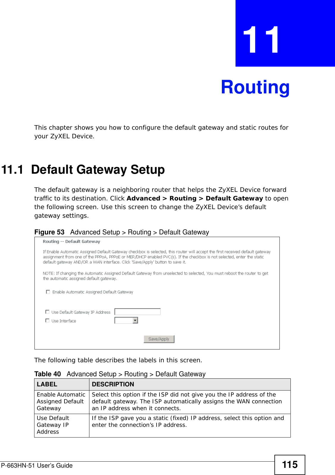
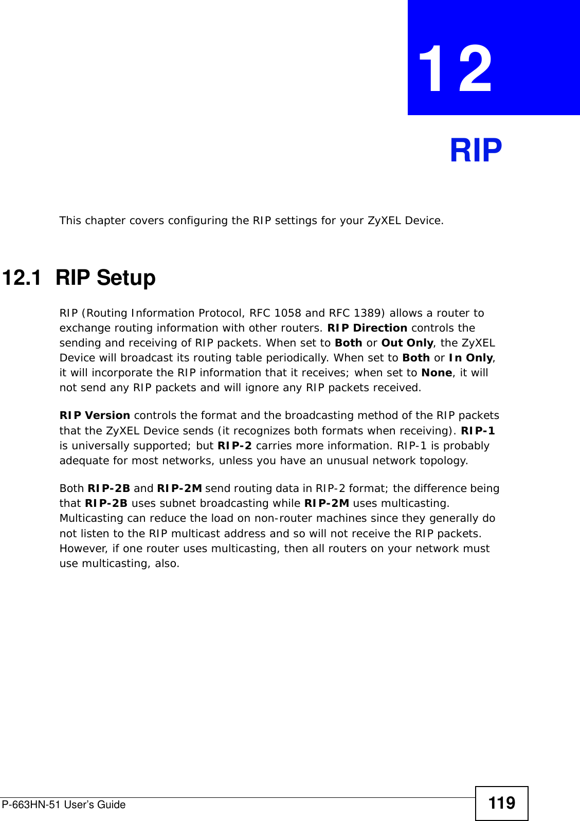
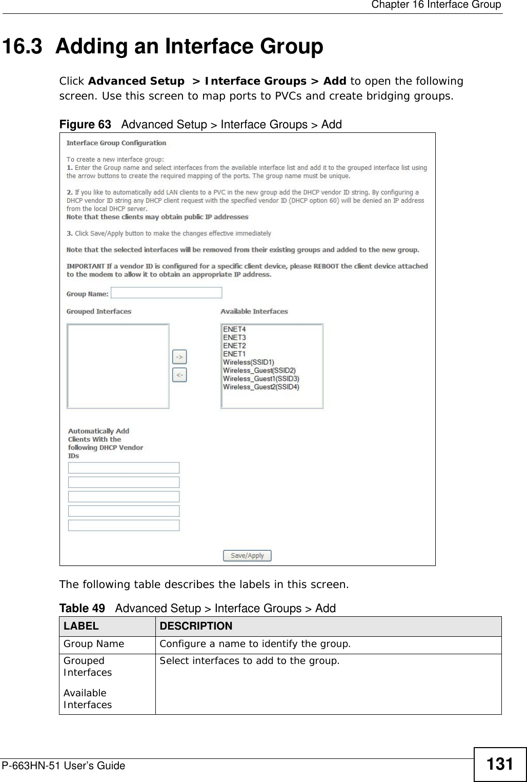
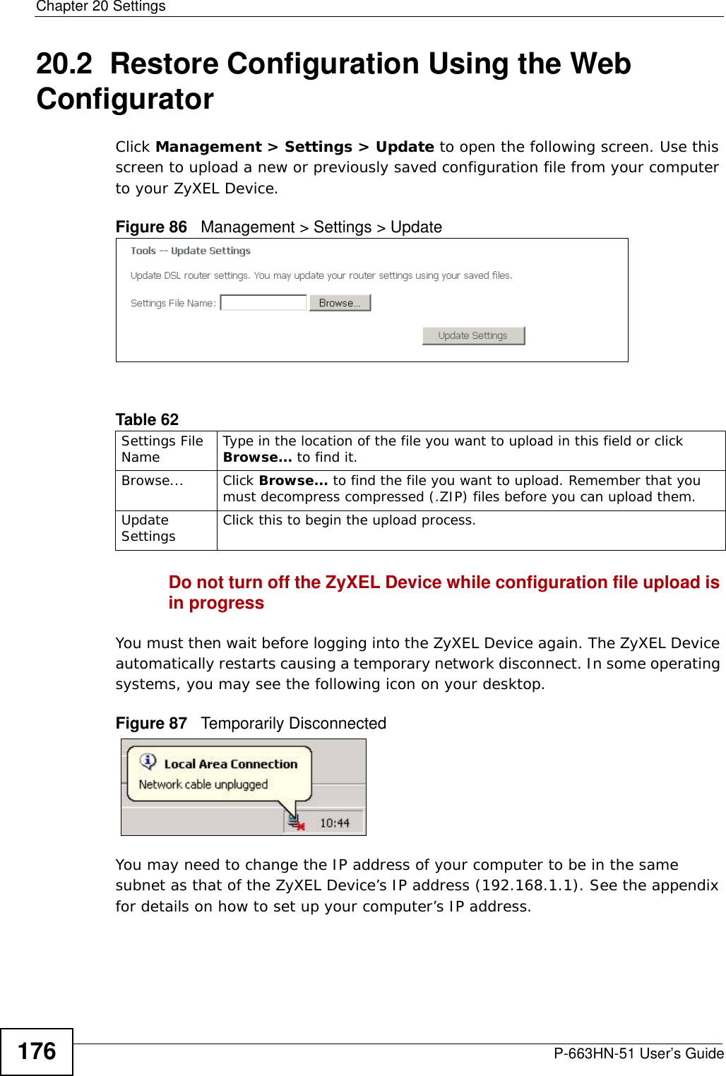
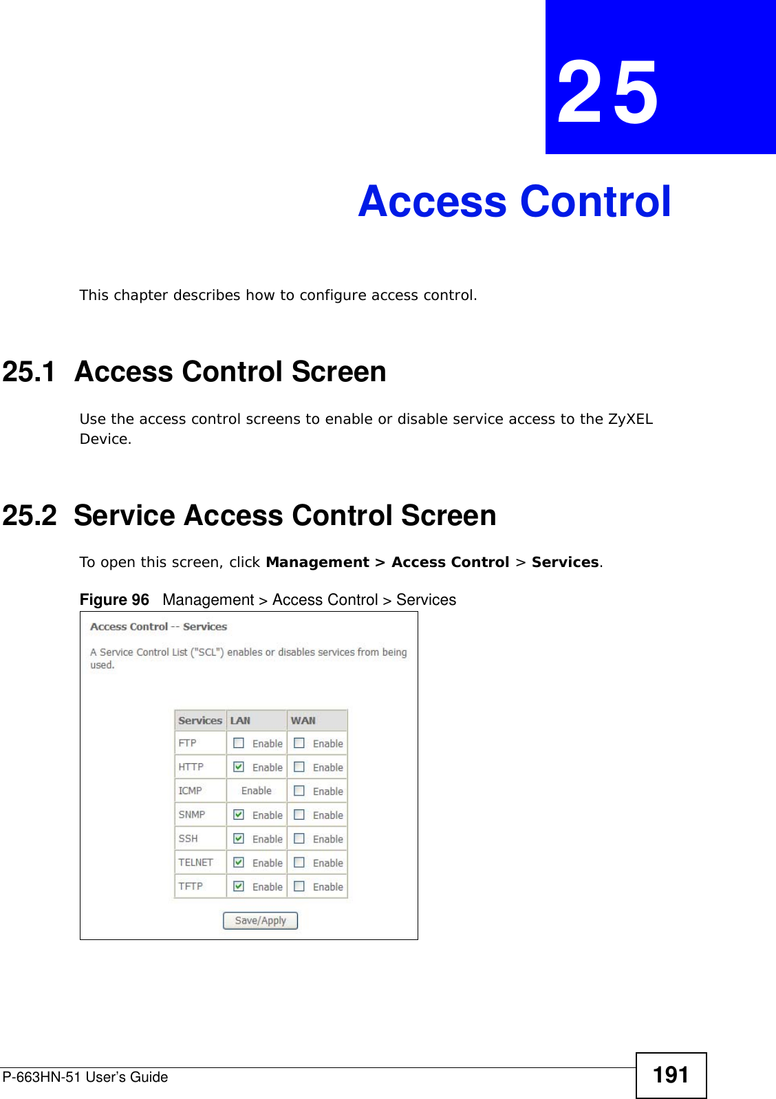
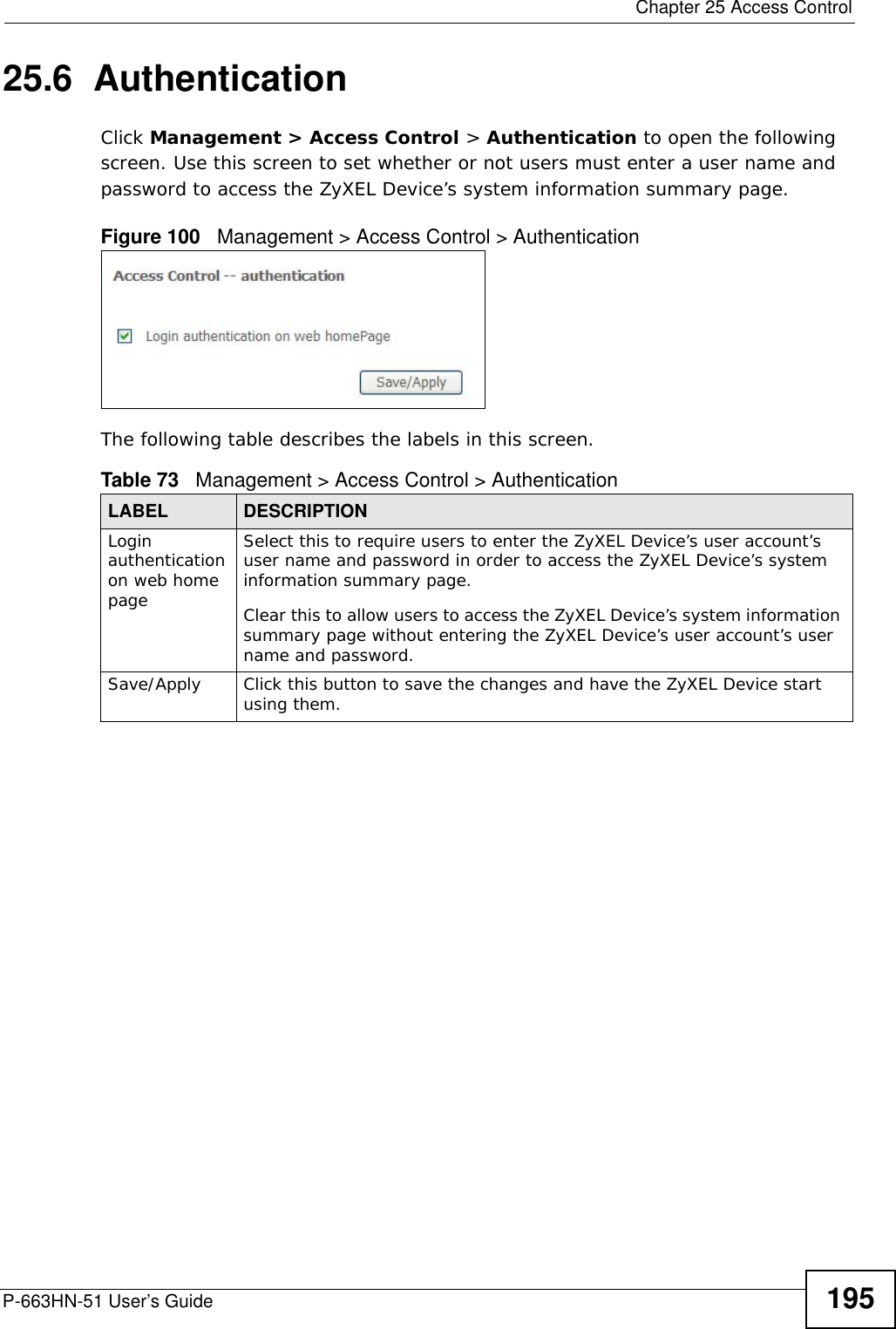
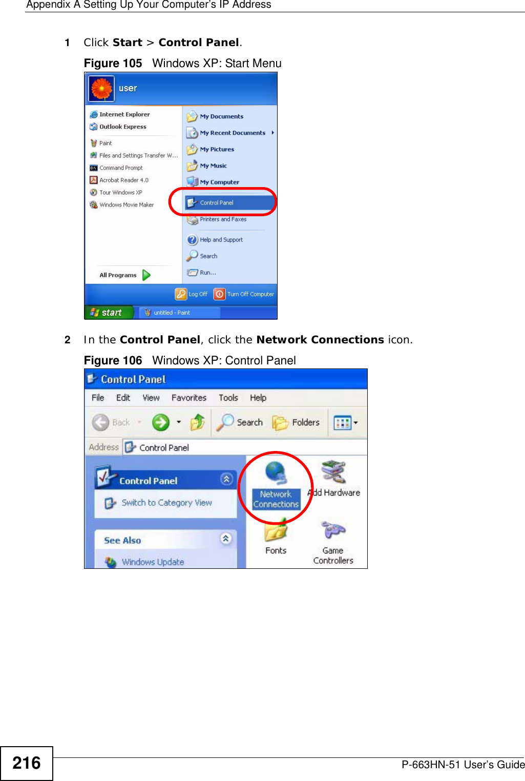
![Document ConventionsP-663HN-51 User’s Guide 5Document ConventionsWarnings and NotesThese are how warnings and notes are shown in this User’s Guide. Warnings tell you about things that could harm you or your device.Note: Notes tell you other important information (for example, other things you may need to configure or helpful tips) or recommendations.Syntax Conventions• The P-663HN-51 may be referred to as the “ZyXEL Device”, the “device” or the “system” in this User’s Guide.• Product labels, screen names, field labels and field choices are all in bold font.• A key stroke is denoted by square brackets and uppercase text, for example, [ENTER] means the “enter” or “return” key on your keyboard.• “Enter” means for you to type one or more characters and then press the [ENTER] key. “Select” or “choose” means for you to use one of the predefined choices.• A right angle bracket ( > ) within a screen name denotes a mouse click. For example, Maintenance > Log > Log Setting means you first click Maintenance in the navigation panel, then the Log sub menu and finally the Log Setting tab to get to that screen.• Units of measurement may denote the “metric” value or the “scientific” value. For example, “k” for kilo may denote “1000” or “1024”, “M” for mega may denote “1000000” or “1048576” and so on.• “e.g.,” is a shorthand for “for instance”, and “i.e.,” means “that is” or “in other words”.](https://usermanual.wiki/ZyXEL-Communications/P663HN51/User-Guide-1165687-Page-5.png)

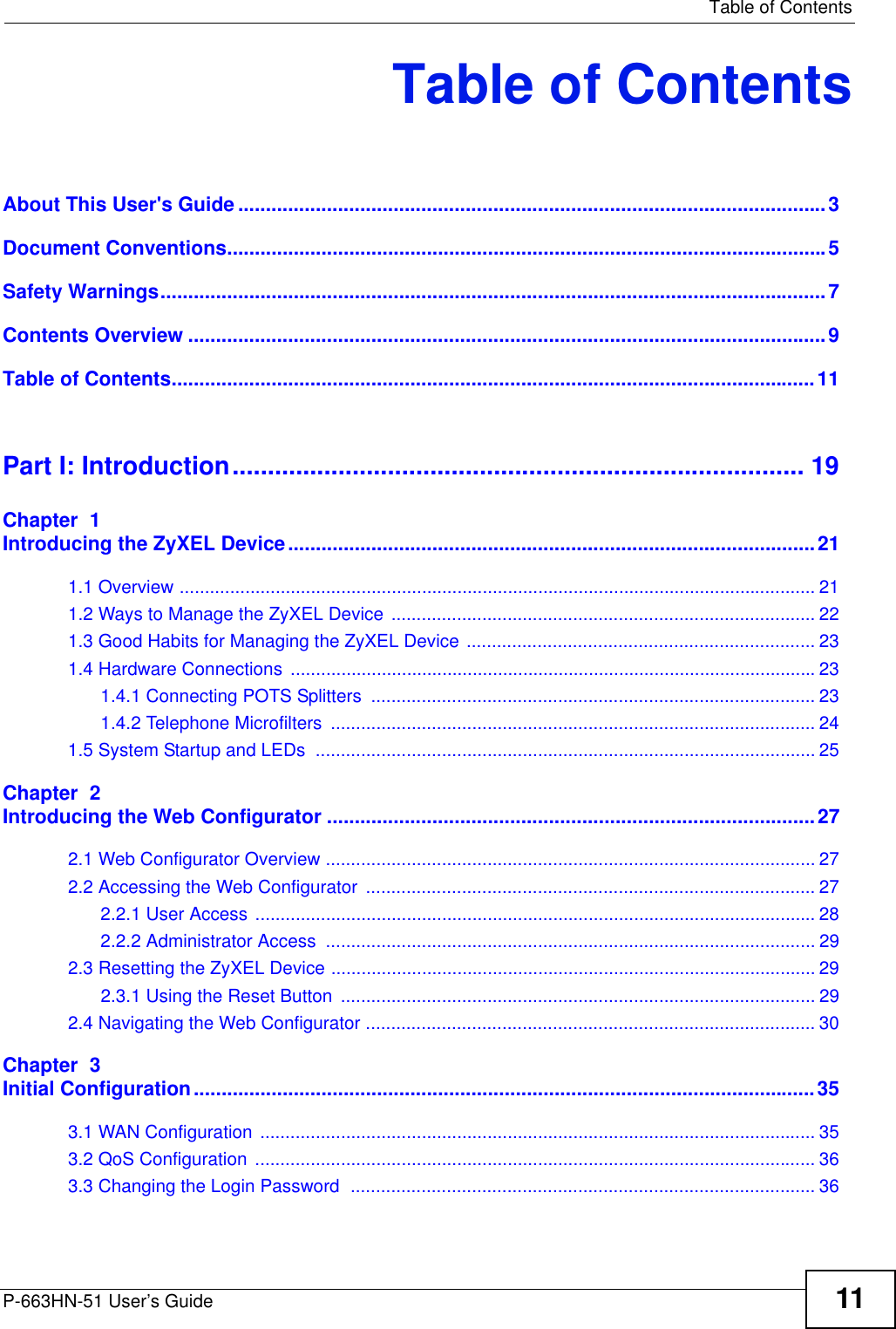
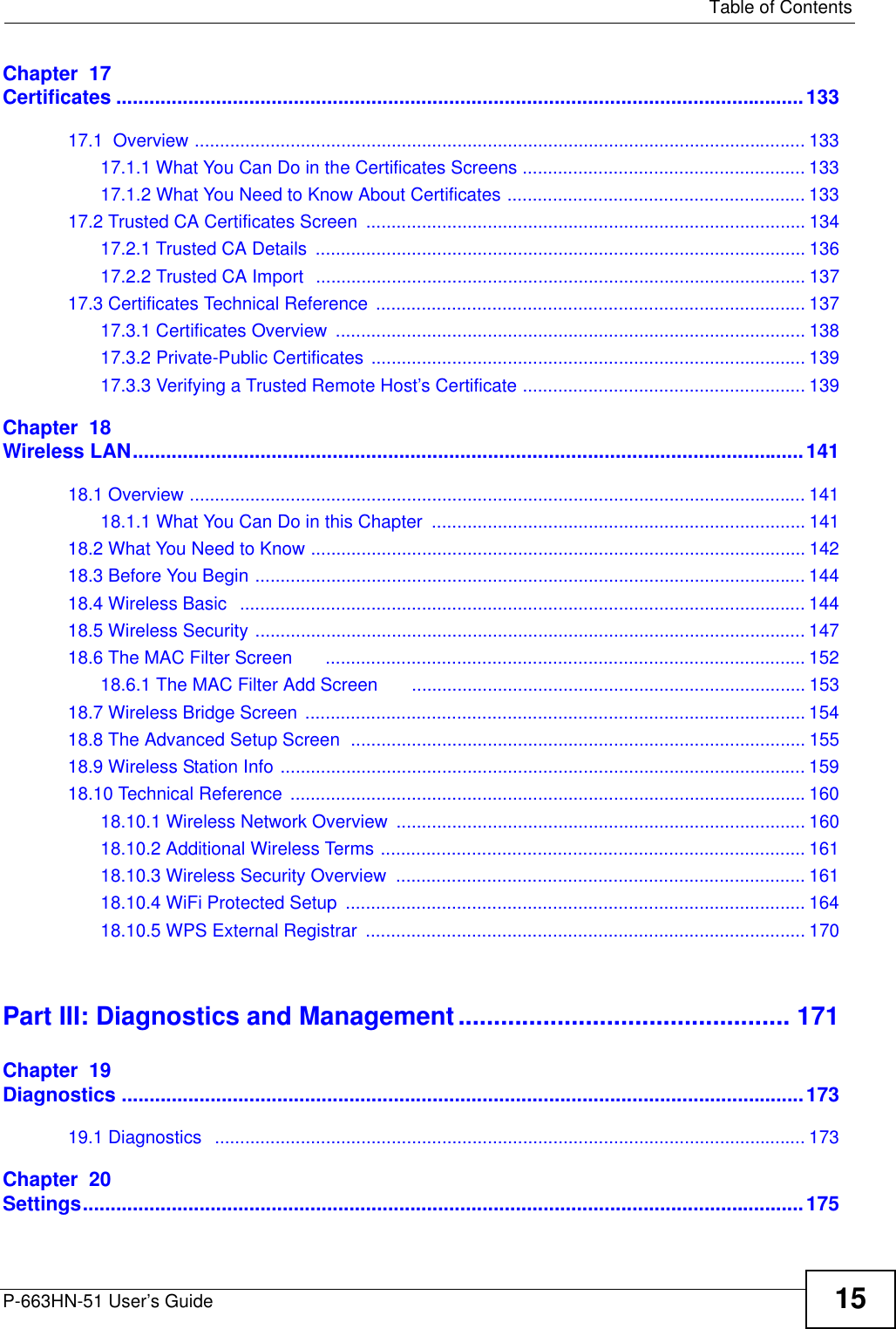


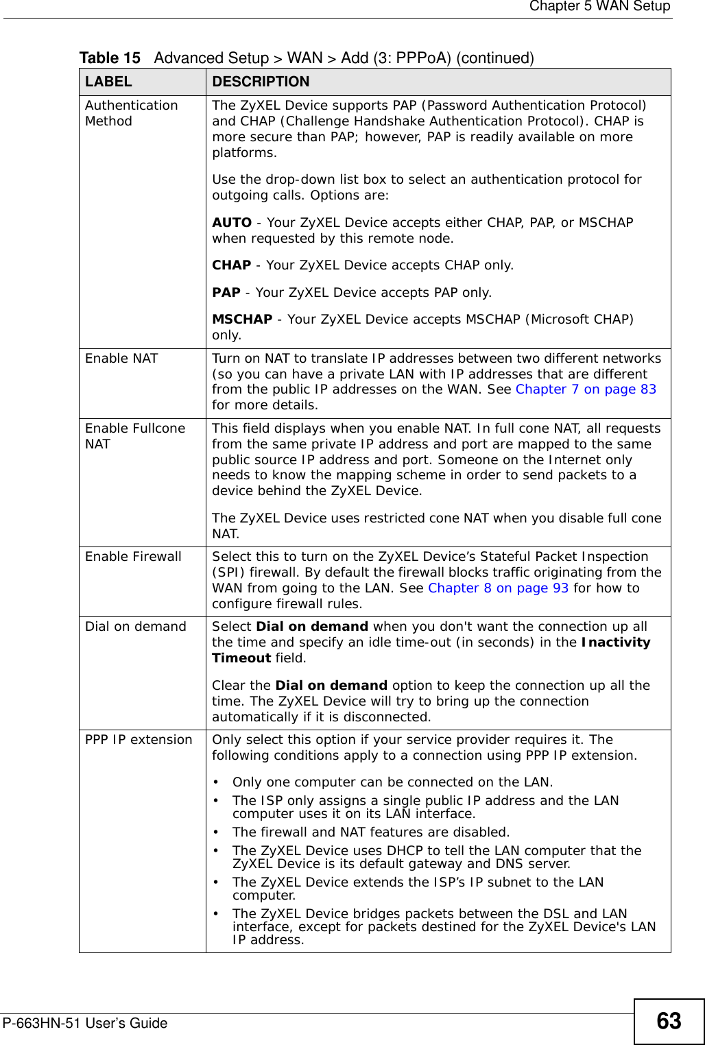
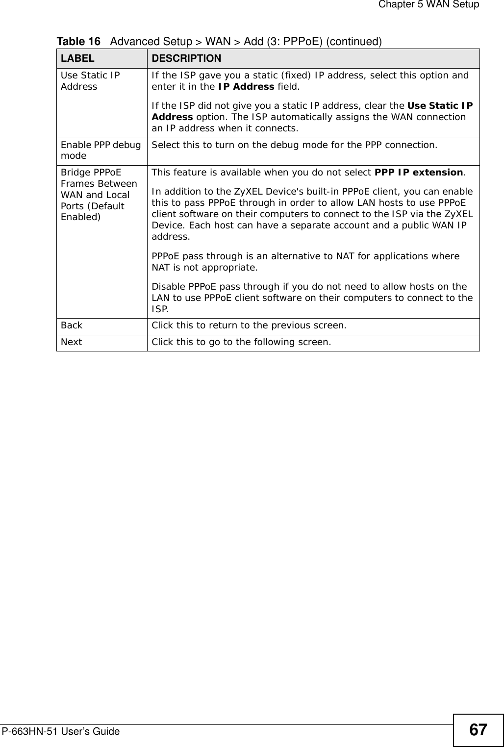

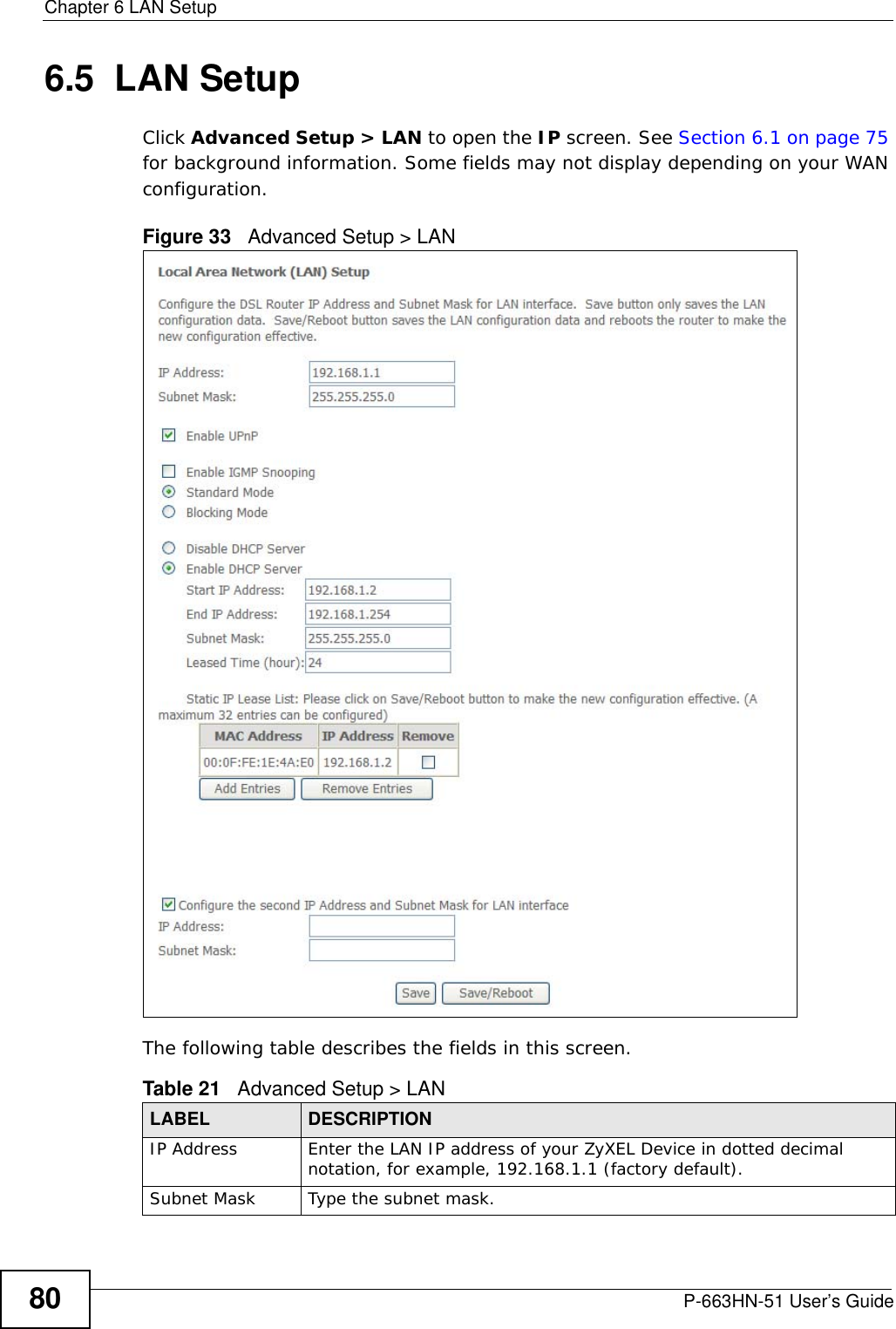

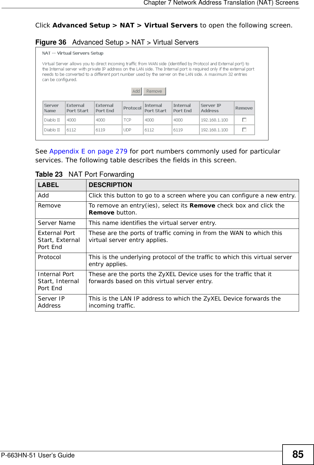
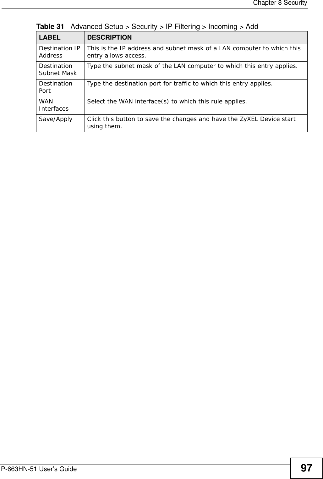


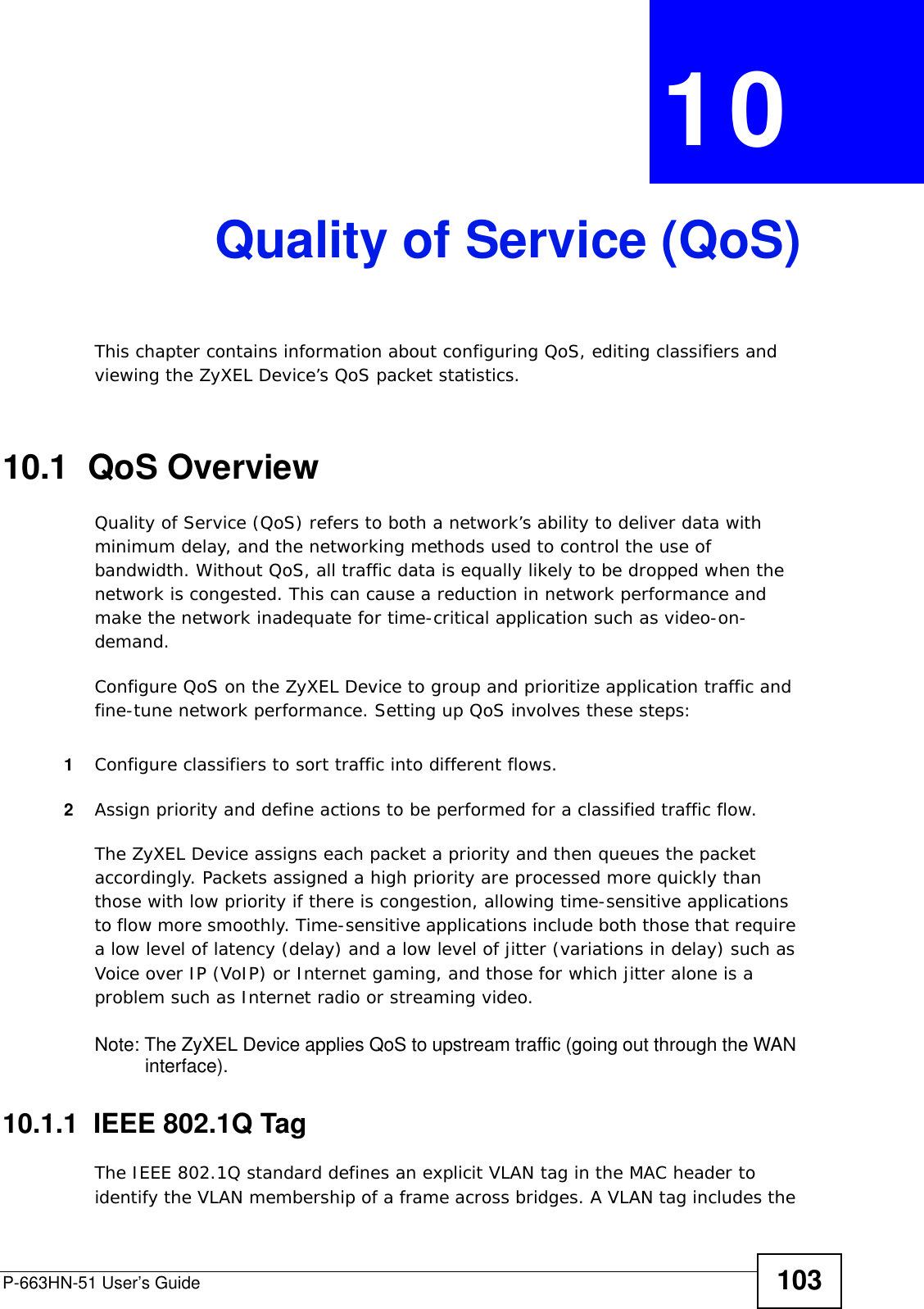
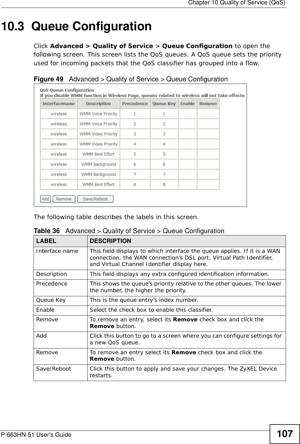

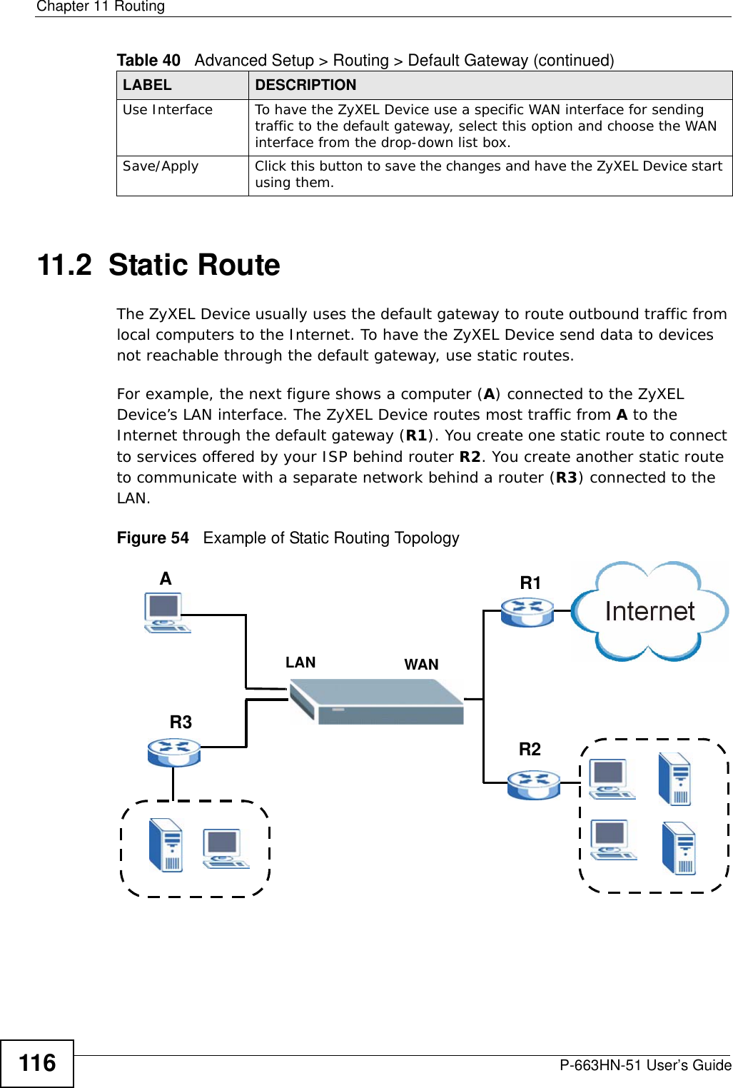
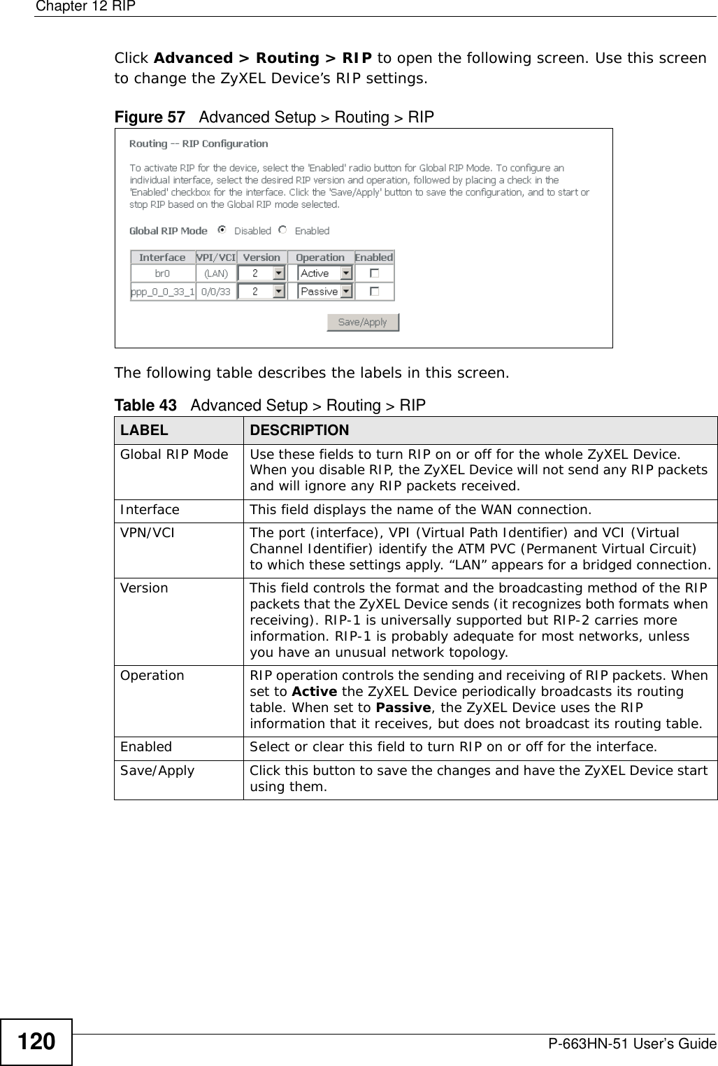
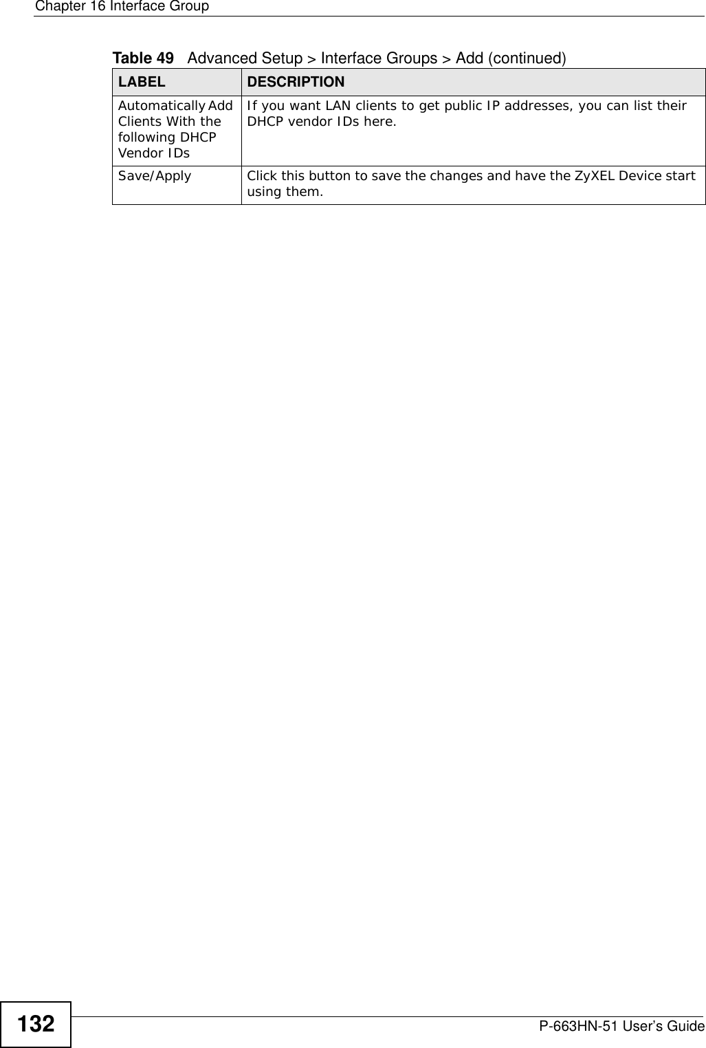

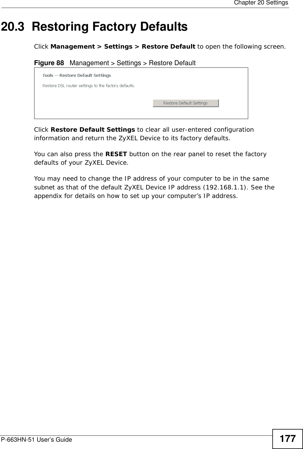


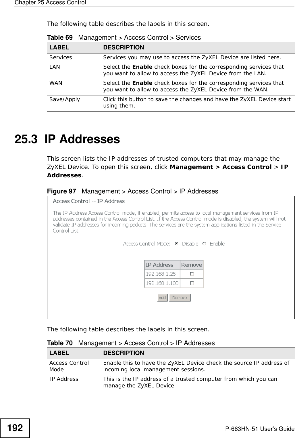

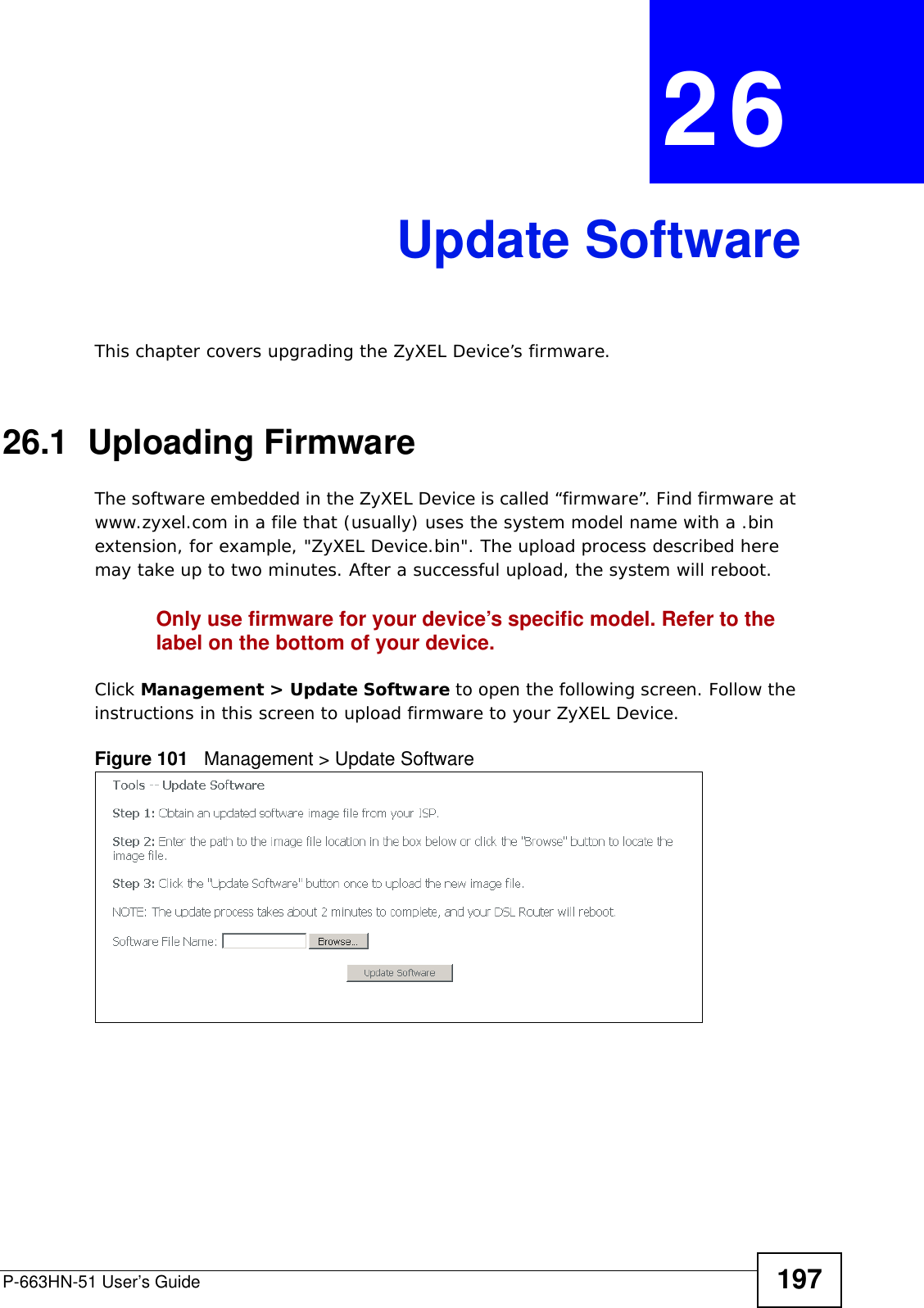
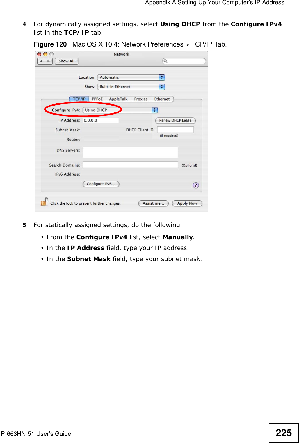
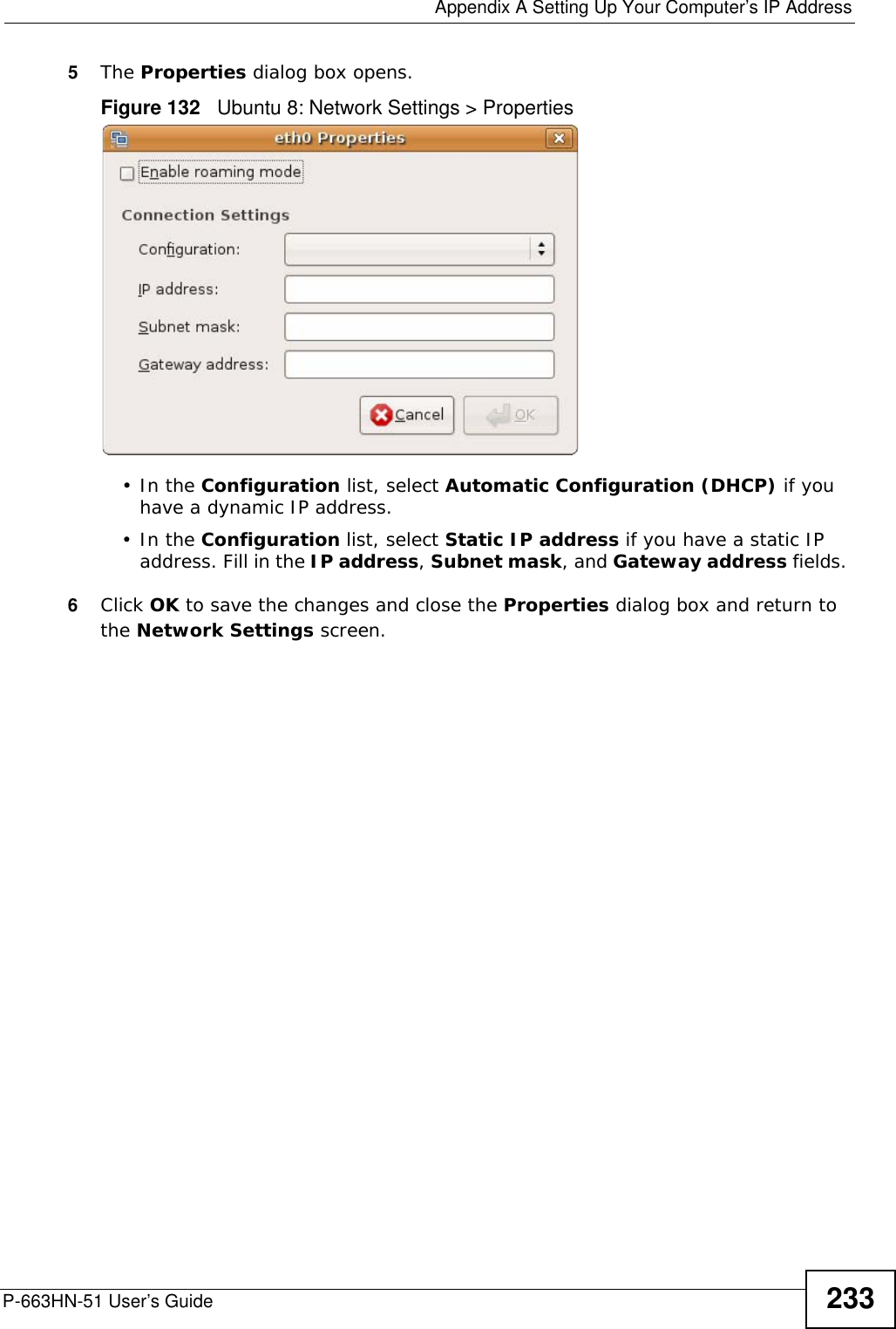
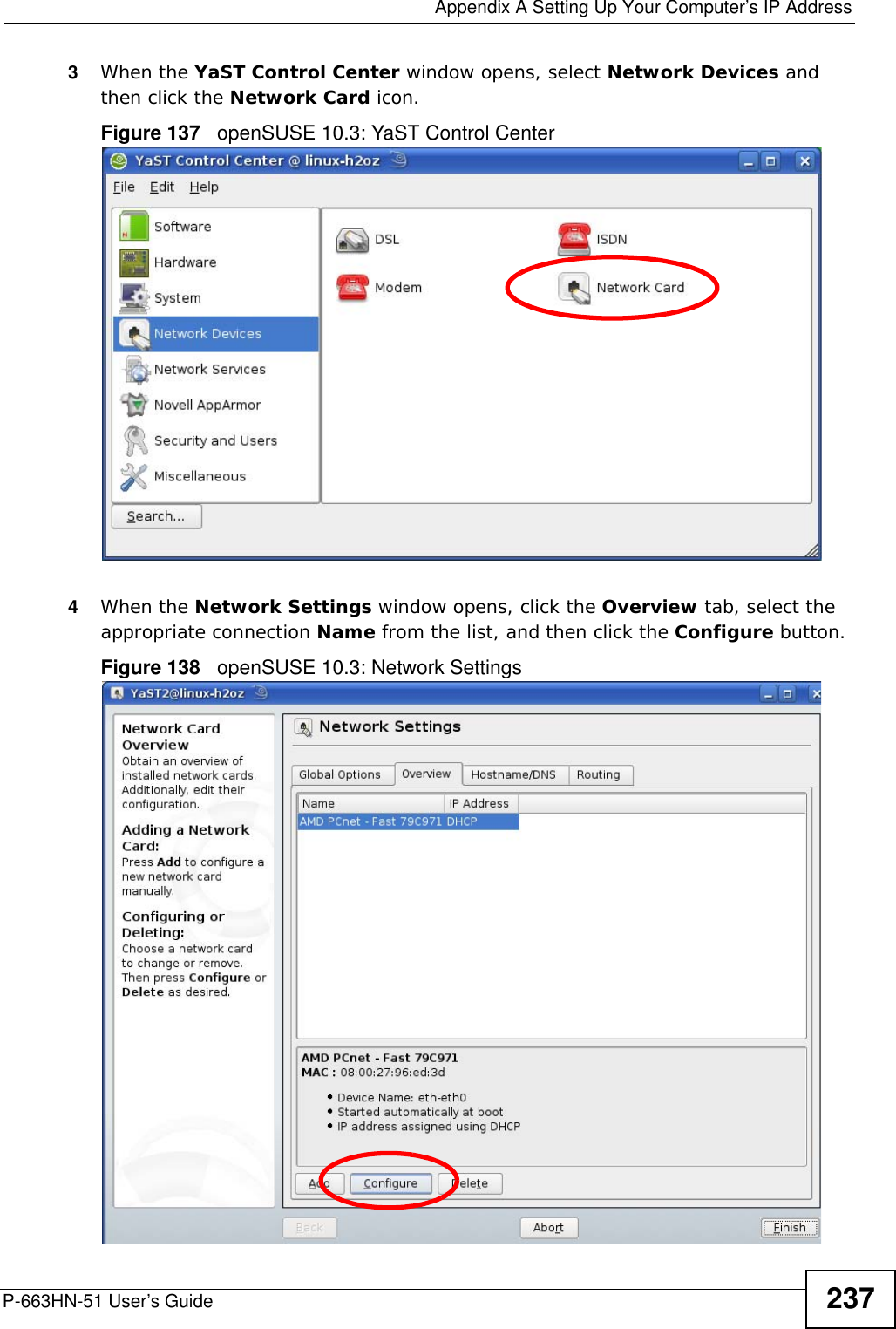
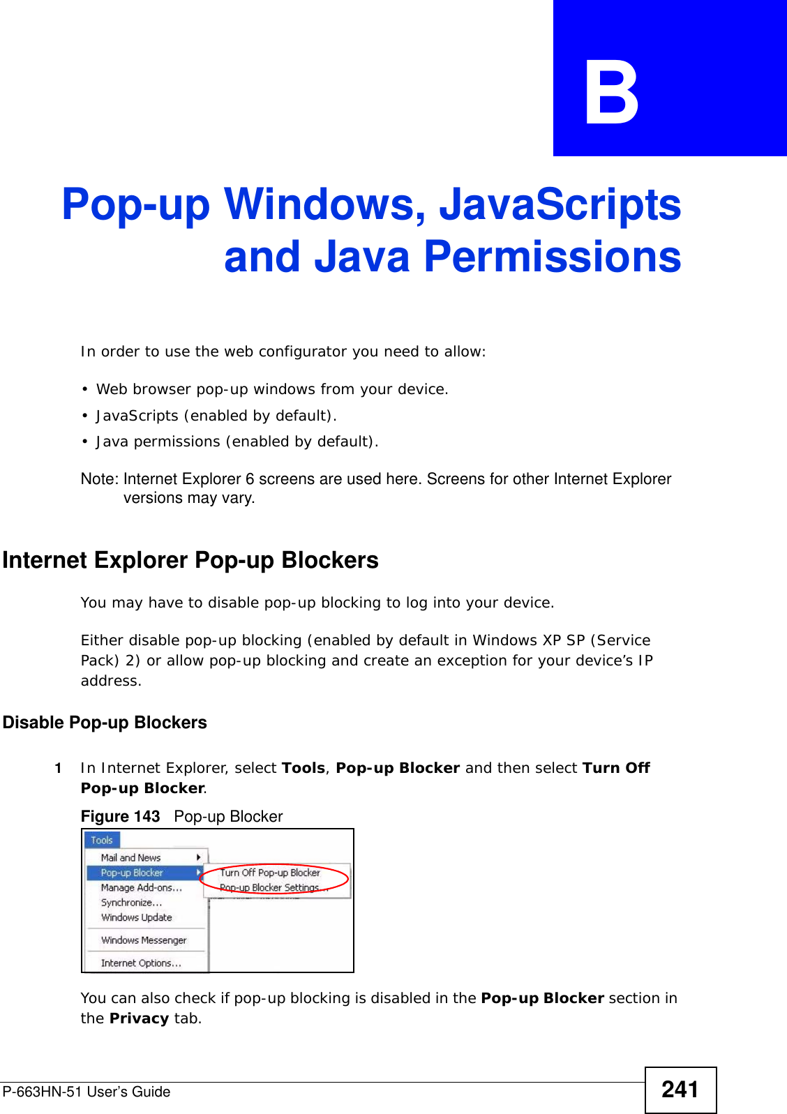
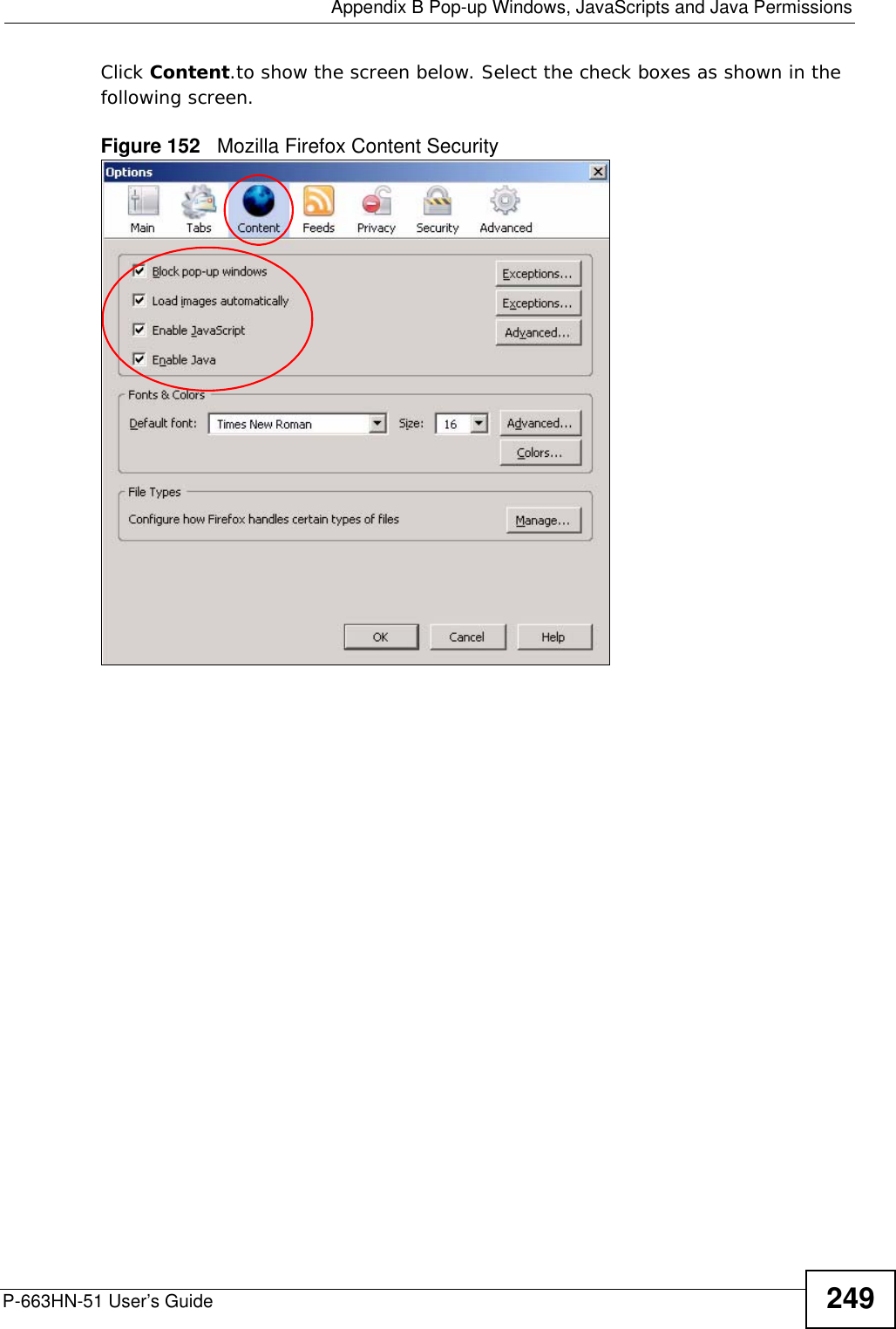
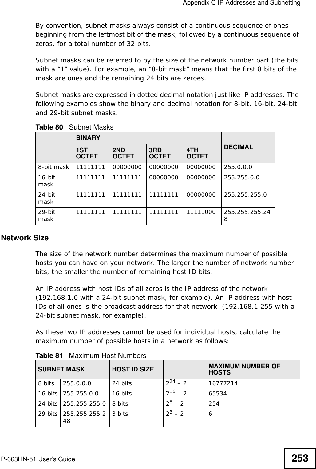
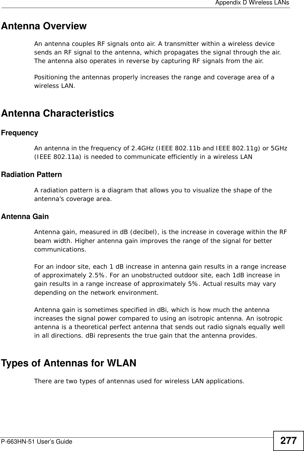
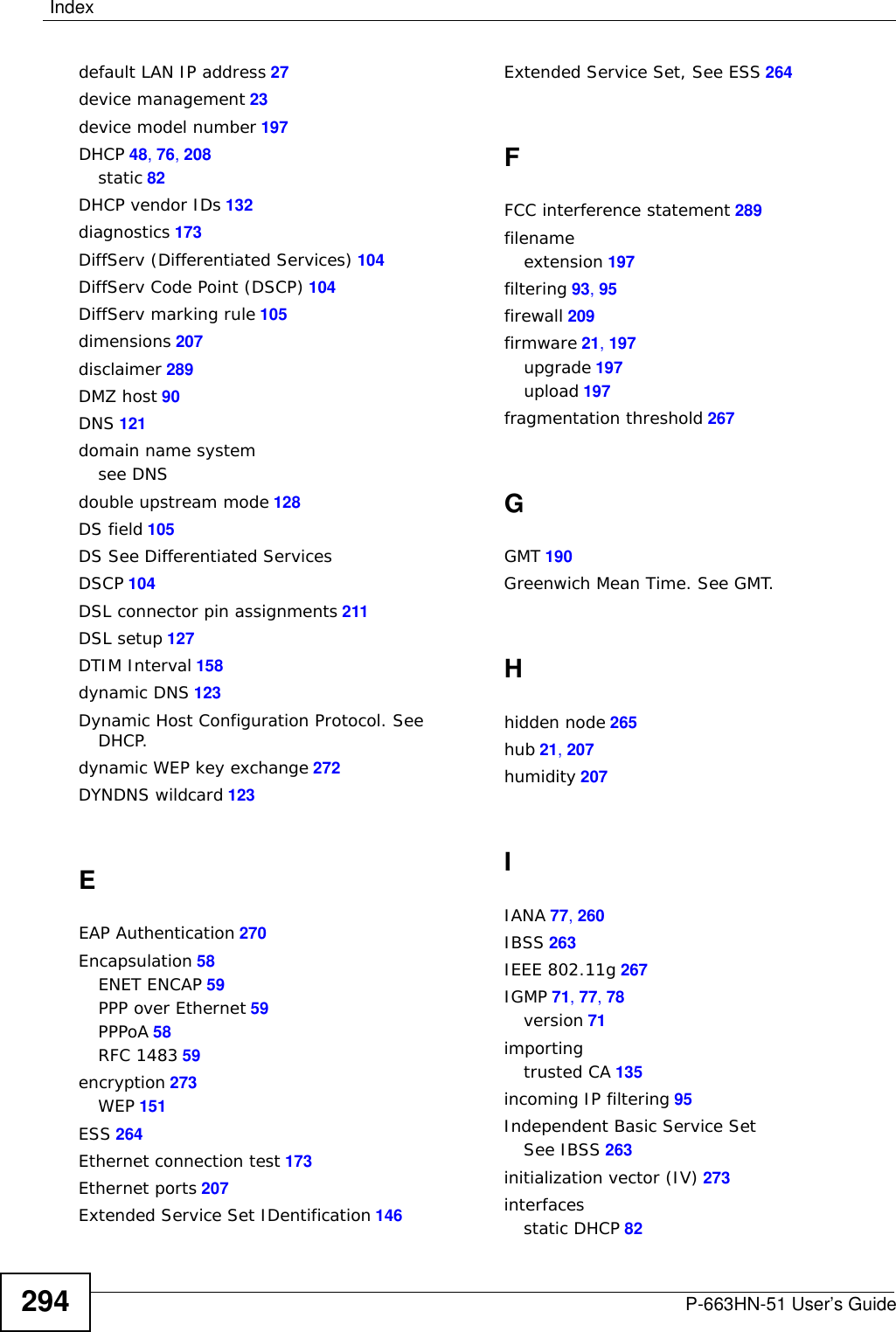
![Chapter 28 TroubleshootingP-663HN-51 User’s Guide 205• If you changed the IP address (Section 6.2.1 on page 76), use the new IP address.• If you changed the IP address and have forgotten it, see the troubleshooting suggestions for I forgot the IP address for the ZyXEL Device.2Check the hardware connections, and make sure the LEDs are behaving as expected. See Section 1.4 on page 23 and Section 1.5 on page 25. 3Make sure your Internet browser does not block pop-up windows. See Appendix C on page 201.4Make sure your computer is in the same subnet as the ZyXEL Device. (If you know that there are routers between your computer and the ZyXEL Device, skip this step.)• If there is a DHCP server on your network, make sure your computer is using a dynamic IP address. See Section 6.2.1 on page 76. Your ZyXEL Device is a DHCP server by default.• If there is no DHCP server on your network, make sure your computer’s IP address is in the same subnet as the ZyXEL Device. See Section 6.2.1 on page 76.5Reset the device to its factory defaults, and try to access the ZyXEL Device with the default IP address. See Section 2.3 on page 29.6If the problem continues, contact the network administrator or vendor, or try one of the advanced suggestions.I can see the Login screen, but I cannot log in to the ZyXEL Device.1Make sure you have entered the user name and password correctly. The default password is 1234. This field is case-sensitive, so make sure [Caps Lock] is not on.2Turn the ZyXEL Device off and on. 3If this does not work, you have to reset the device to its factory defaults. See Section 2.3 on page 29.28.3 Internet AccessI cannot access the Internet.](https://usermanual.wiki/ZyXEL-Communications/P663HN51/User-Guide-1165687-Page-205.png)
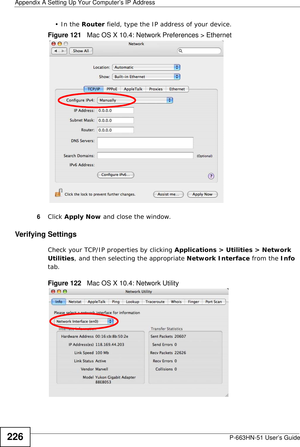
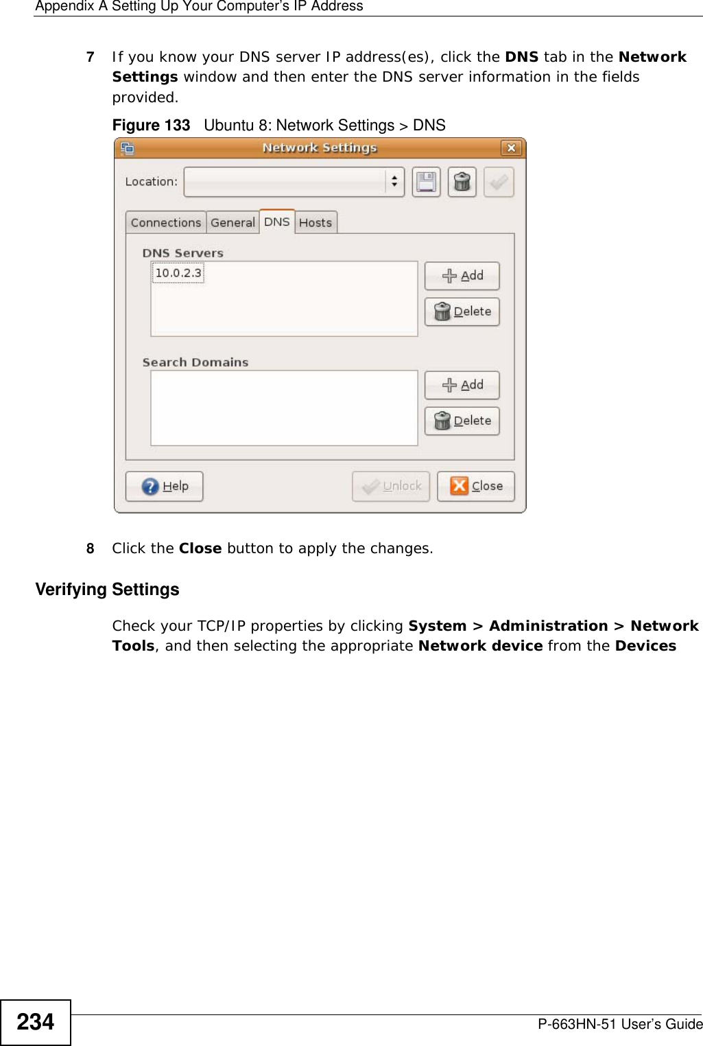
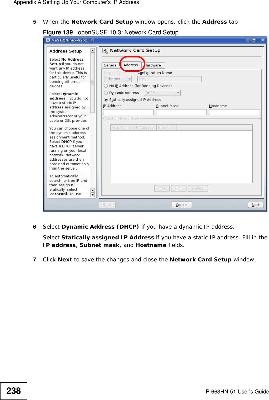
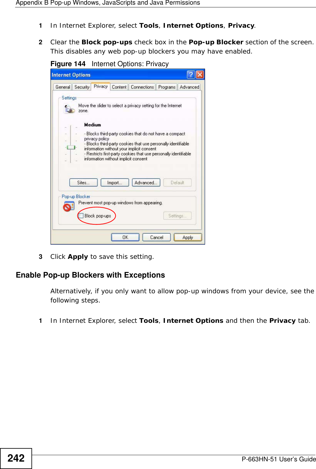
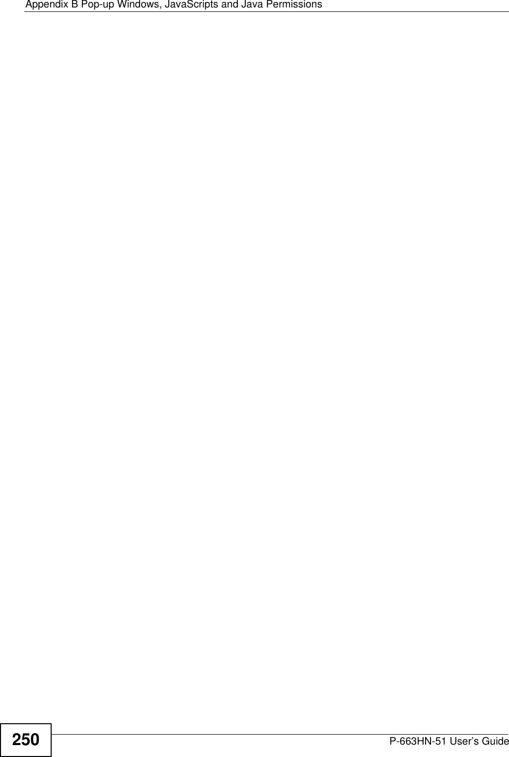
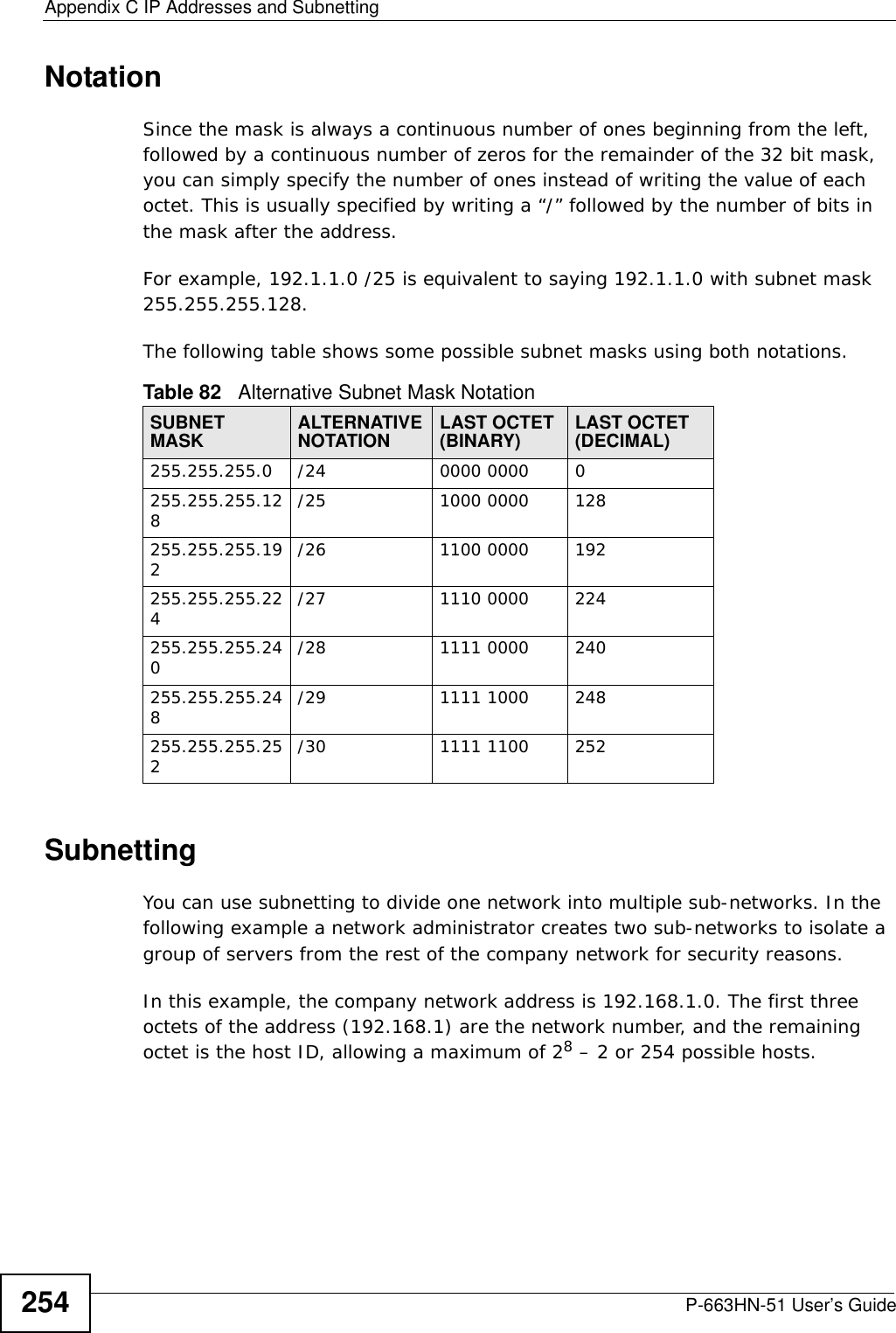
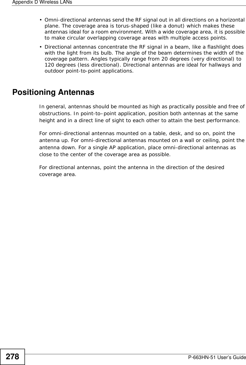
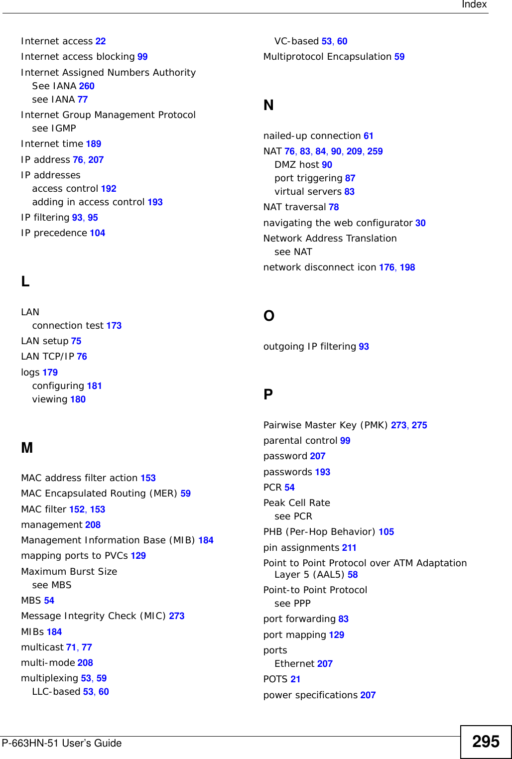
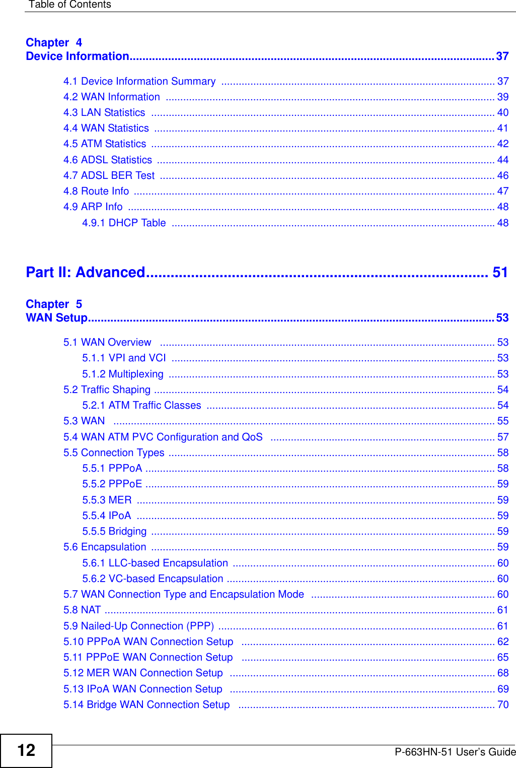
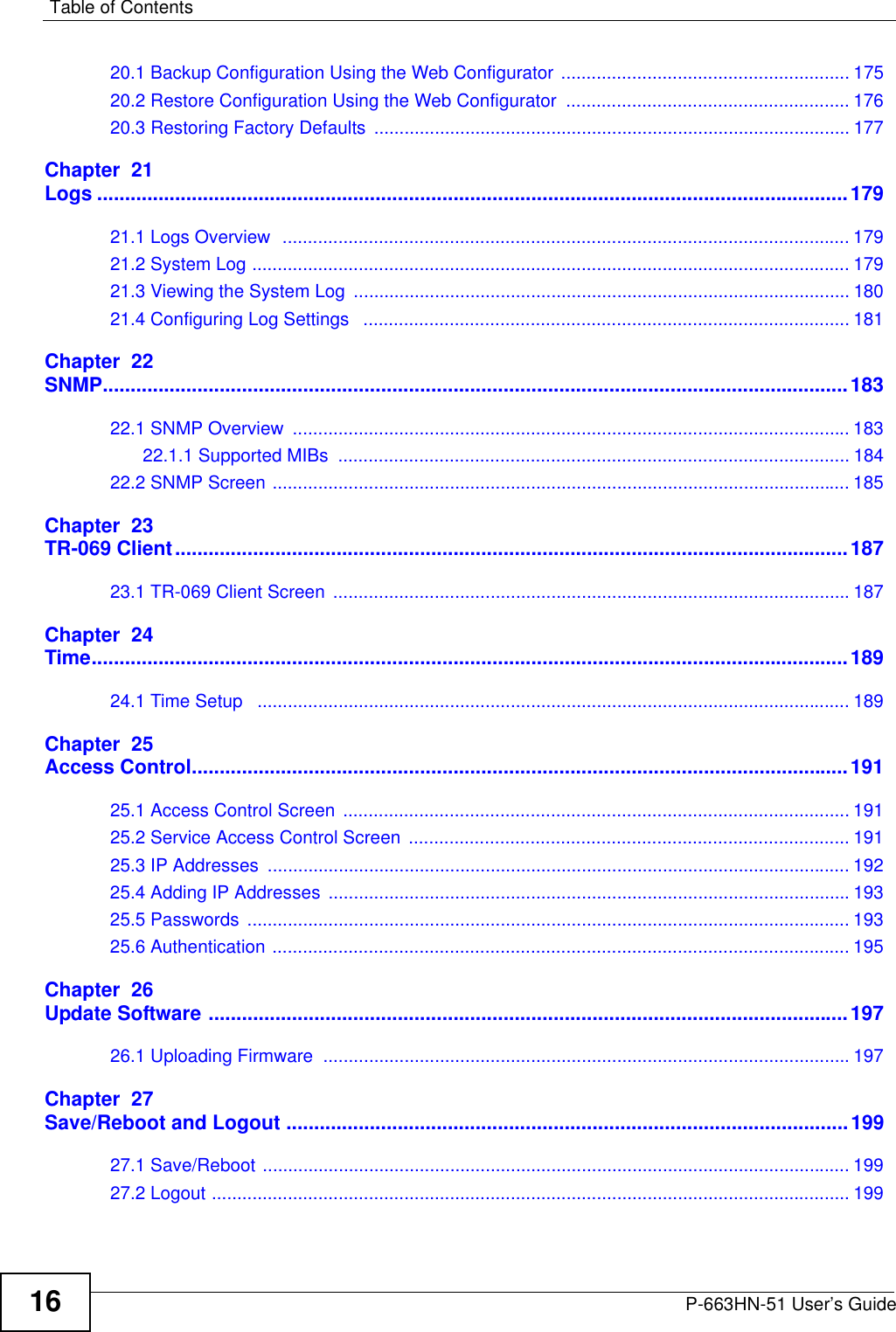
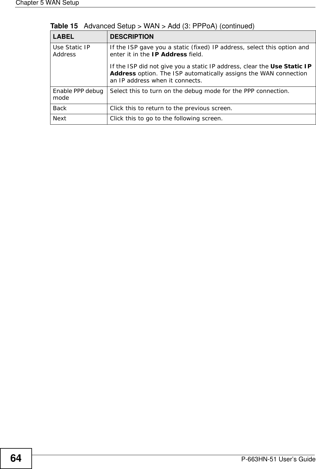
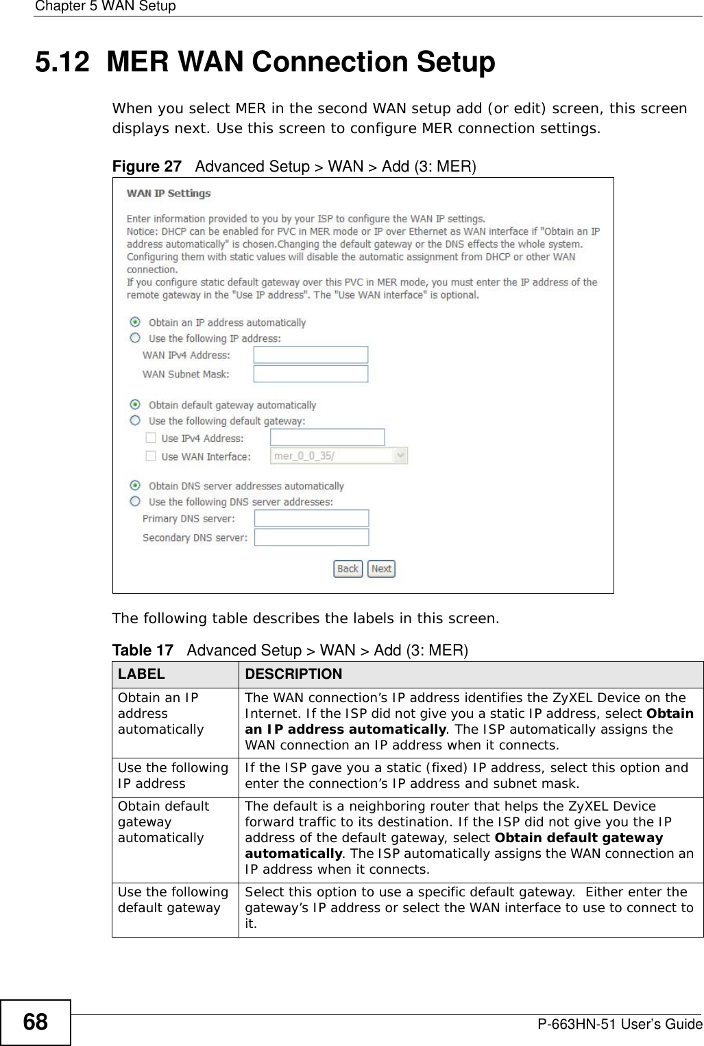
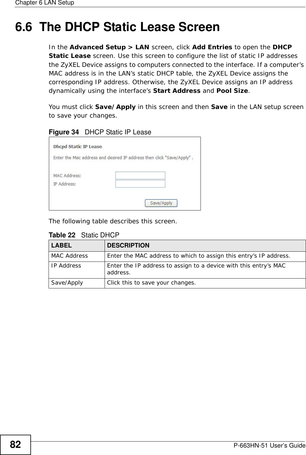
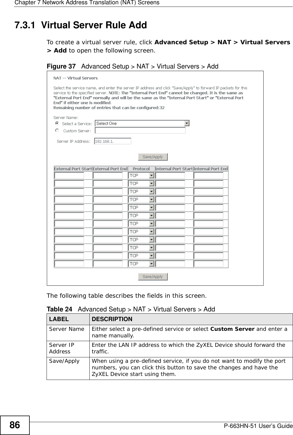
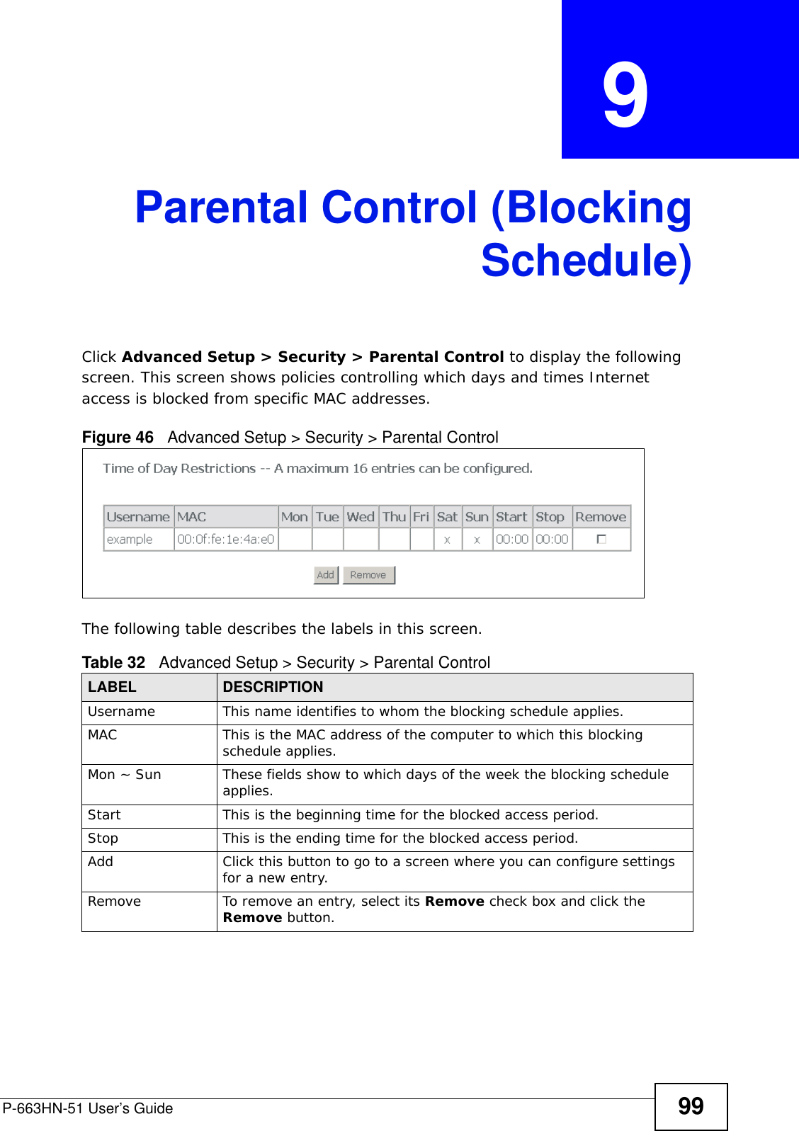
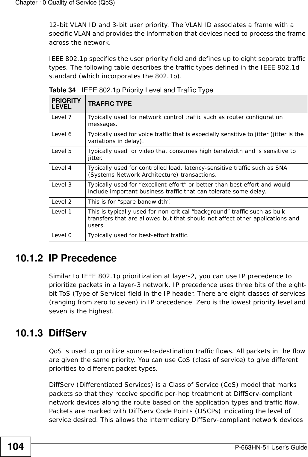
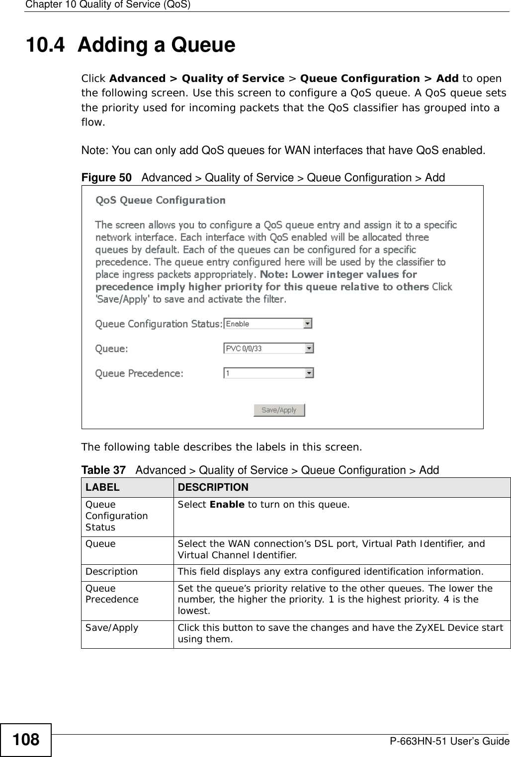
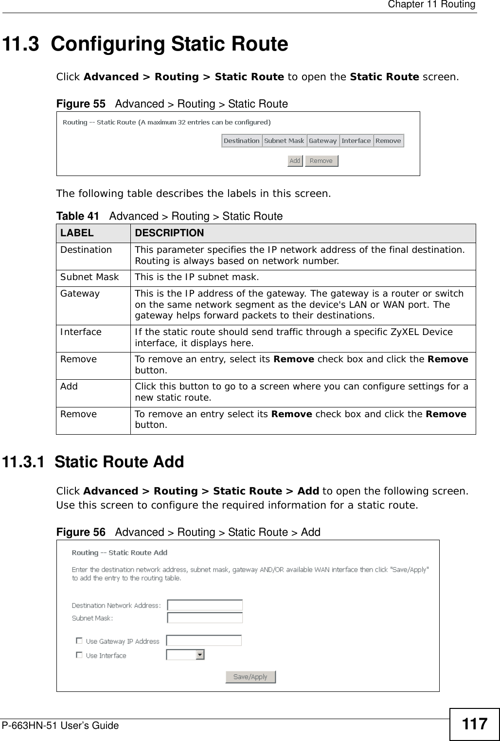
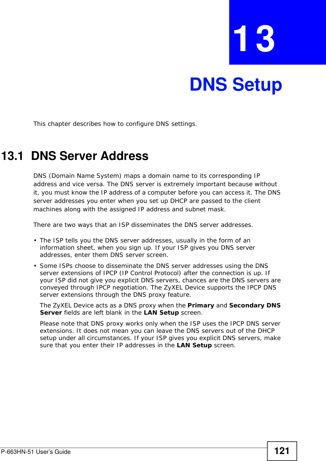
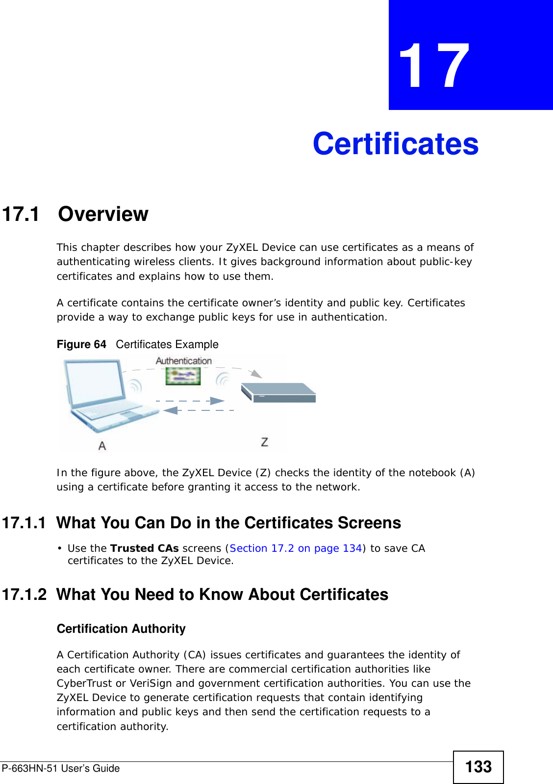
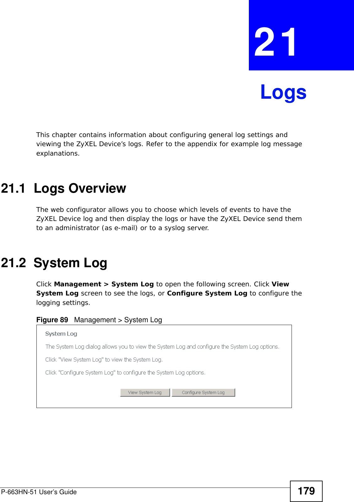
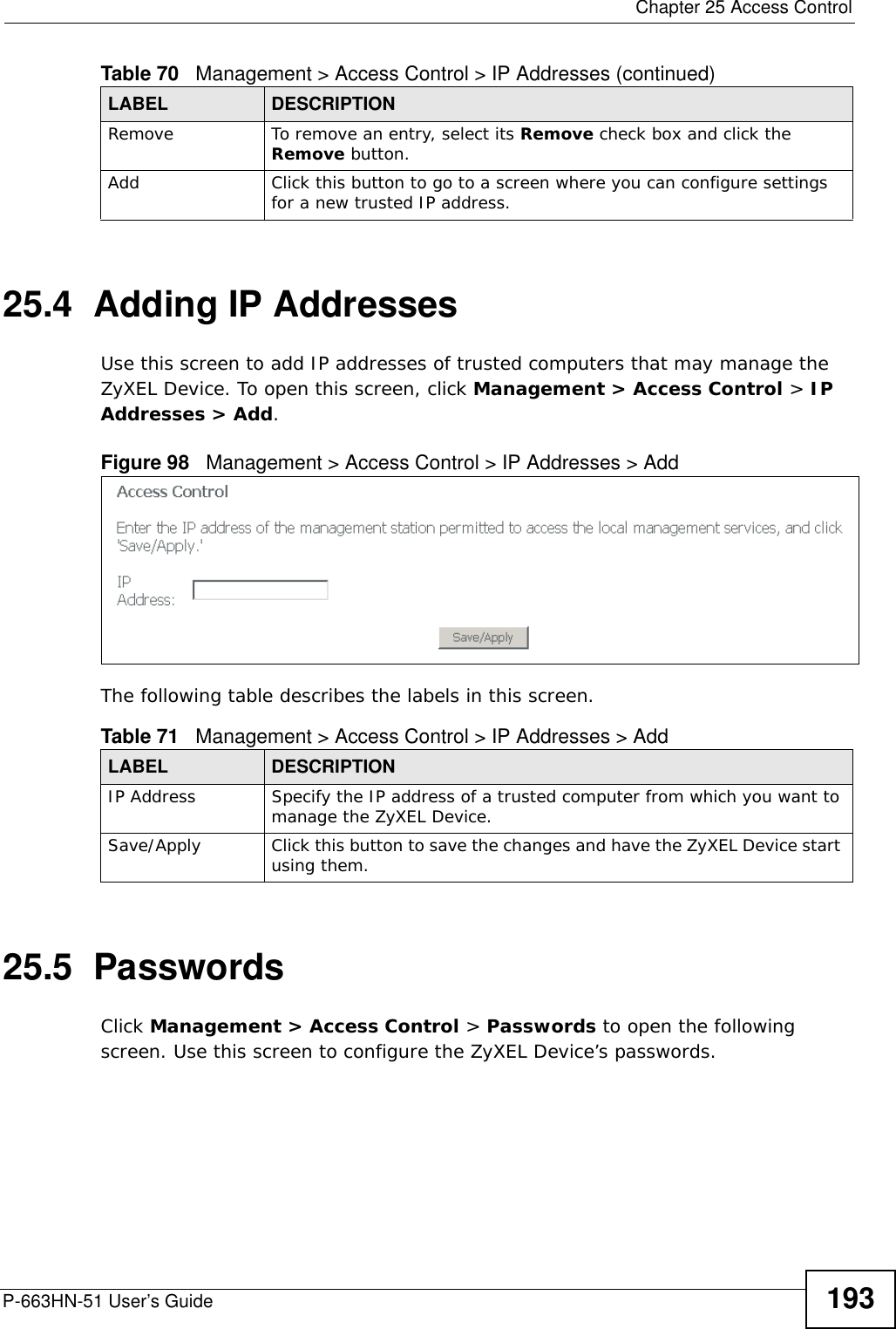
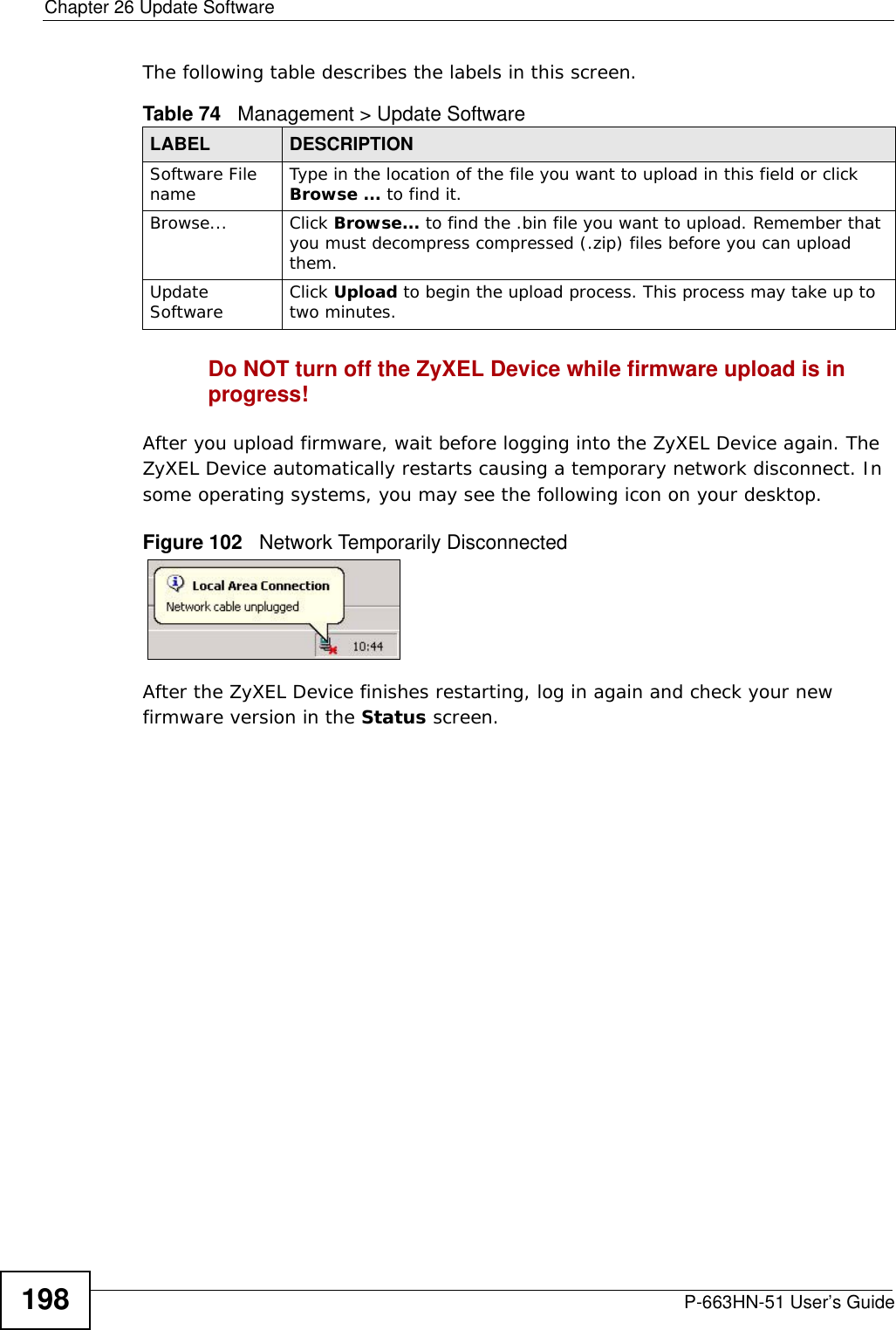
![Chapter 28 TroubleshootingP-663HN-51 User’s Guide2061Check the hardware connections, and make sure the LEDs are behaving as expected. See Section 1.4 on page 23 and Section 1.5 on page 25. 2If your ISP gave you Internet connection information, make sure you entered it correctly in the Network > WAN > Internet Connection screen. These fields are case-sensitive, so make sure [Caps Lock] is not on. 3Disconnect all the cables from your device, and follow the directions in Section 1.4 on page 23 again. 4If the problem continues, contact your ISP. I cannot access the Internet anymore. I had access to the Internet (with the ZyXEL Device), but my Internet connection is not available anymore.1Check the hardware connections, and make sure the LEDs are behaving as expected. See Section 1.4 on page 23 and Section 1.5 on page 25. 2Reboot the ZyXEL Device.3Turn the ZyXEL Device off and on.4If the problem continues, contact your ISP. The Internet connection is slow or intermittent.1There might be a lot of traffic on the network. Look at the LEDs, and check Section 1.5 on page 25. If the ZyXEL Device is sending or receiving a lot of information, try closing some programs that use the Internet, especially peer-to-peer applications.2Reboot the ZyXEL Device. 3Turn the ZyXEL Device off and on. 4If the problem continues, contact the network administrator or vendor, or try one of the advanced suggestions.](https://usermanual.wiki/ZyXEL-Communications/P663HN51/User-Guide-1165687-Page-206.png)

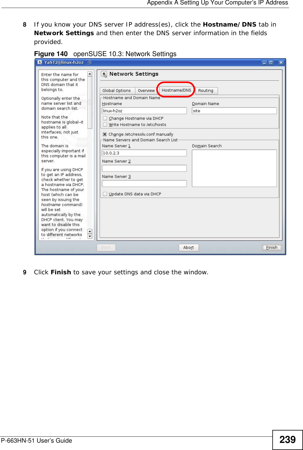
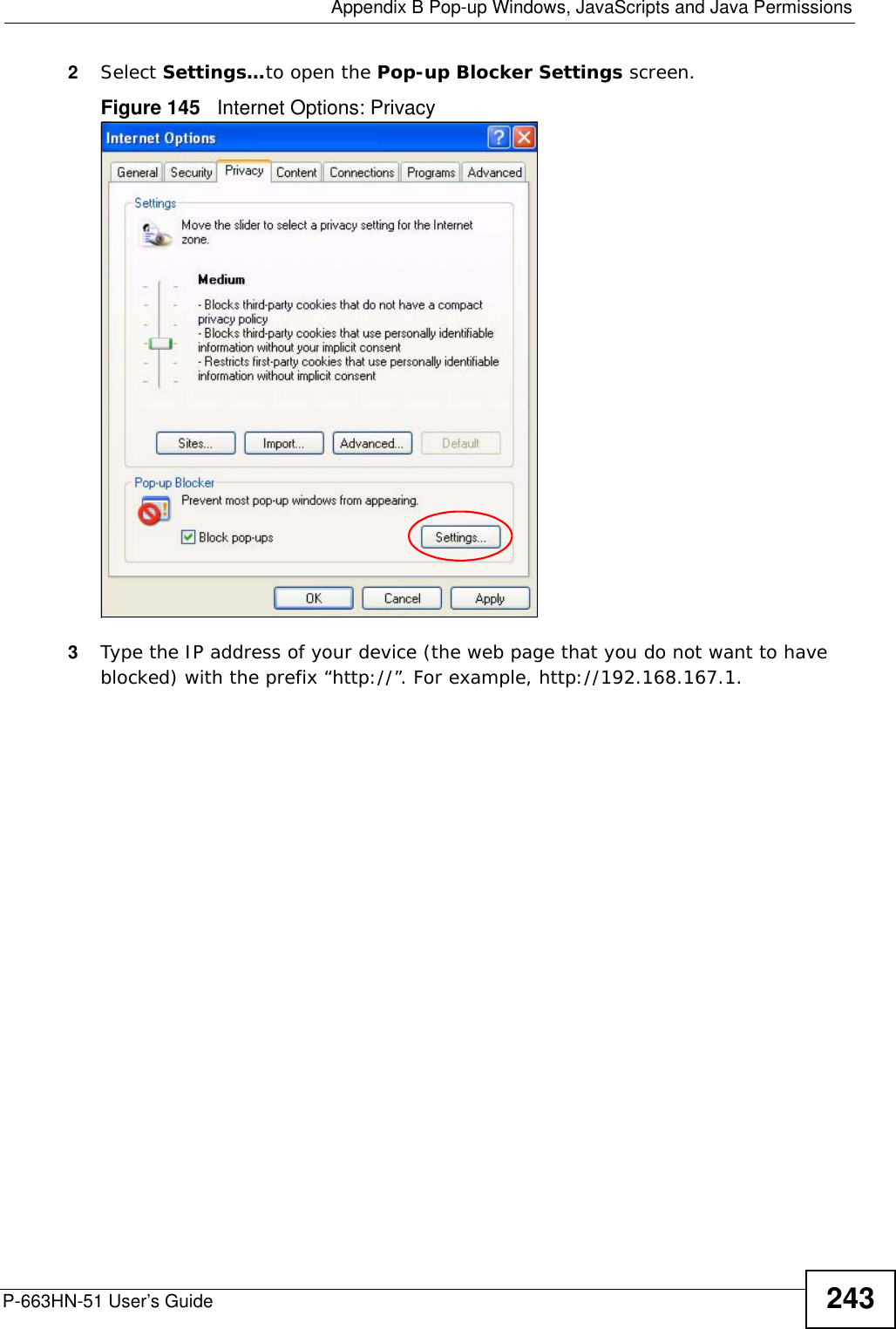
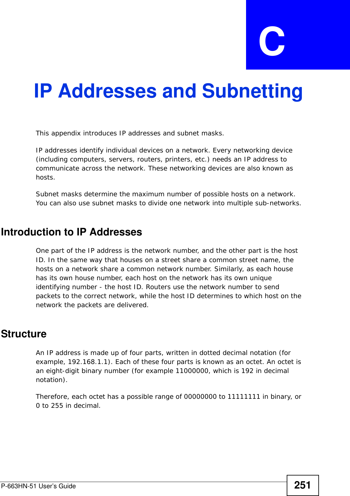
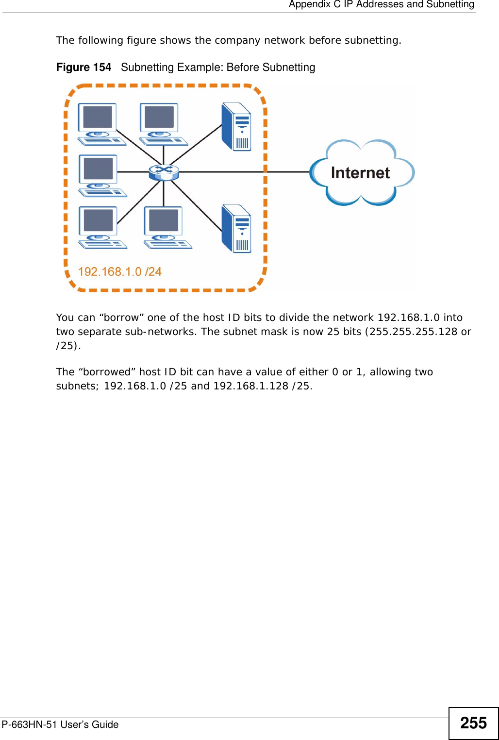
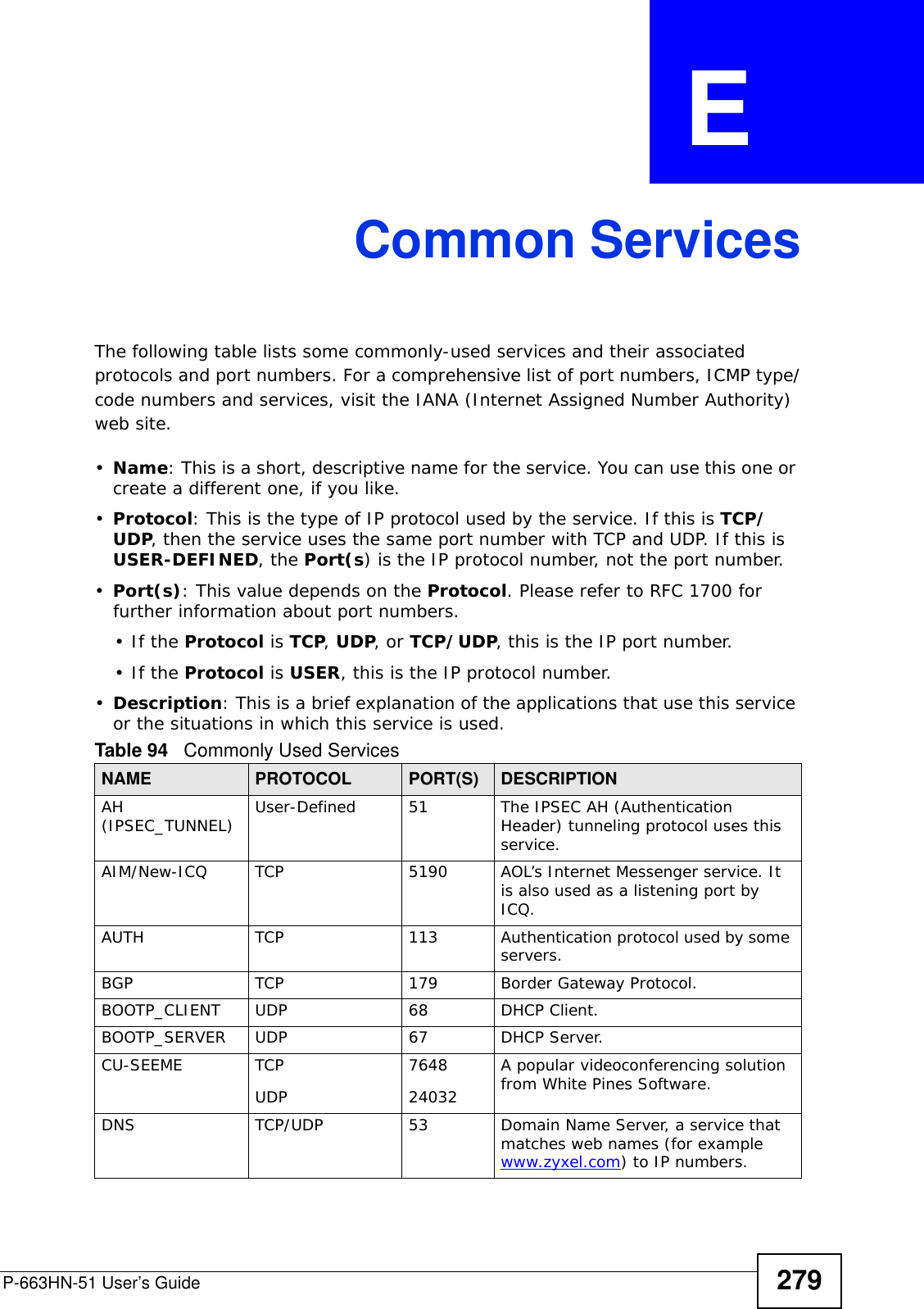
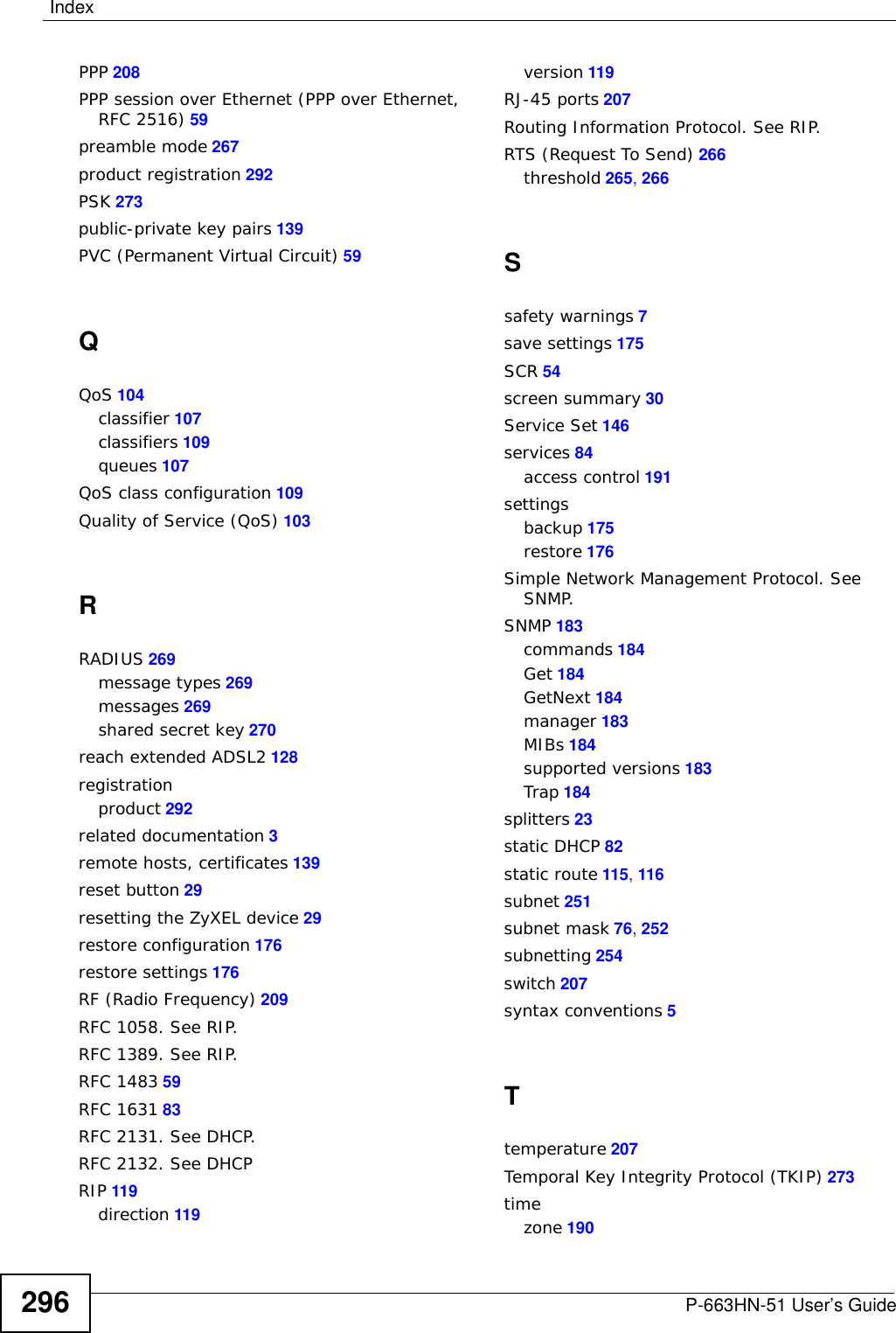
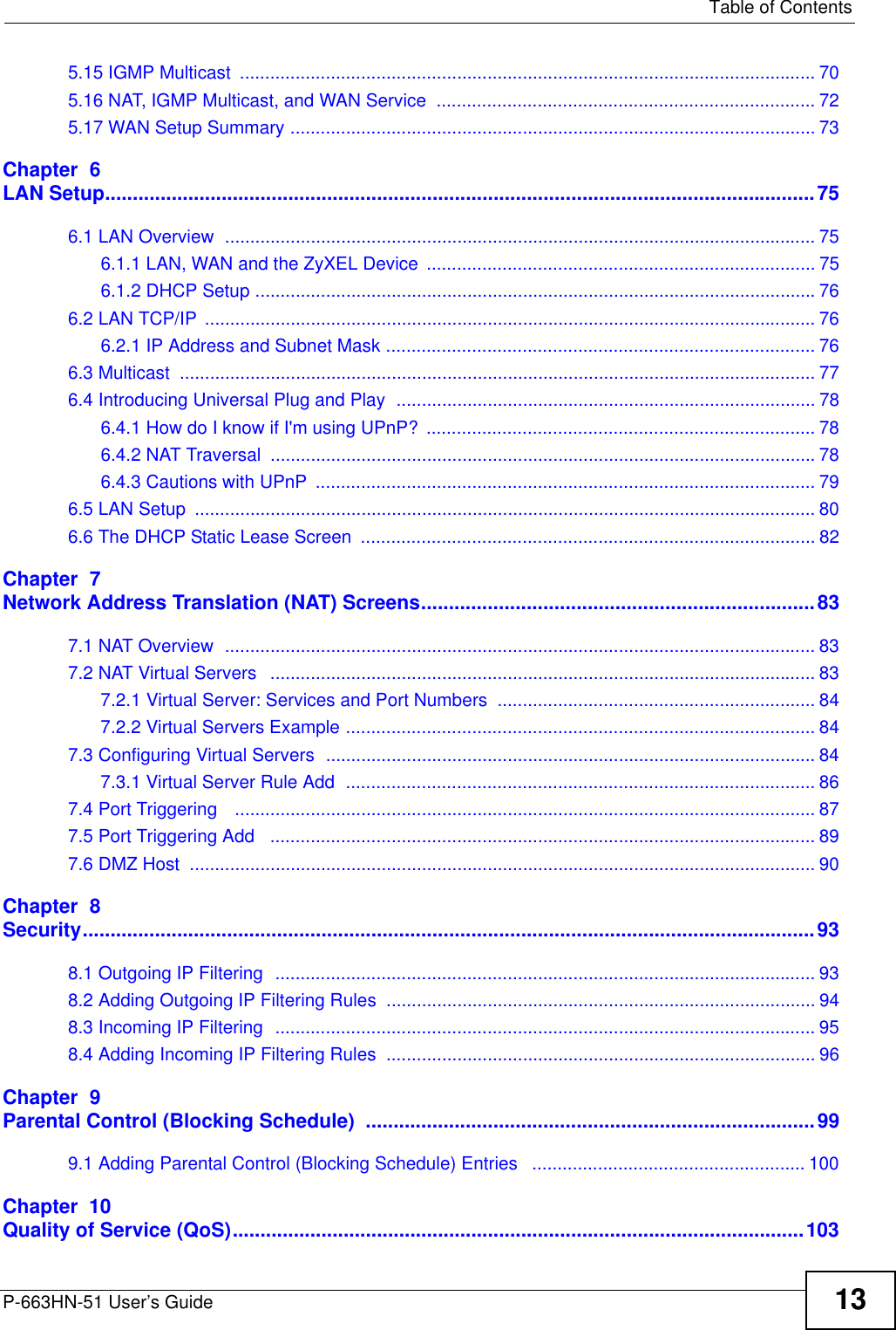
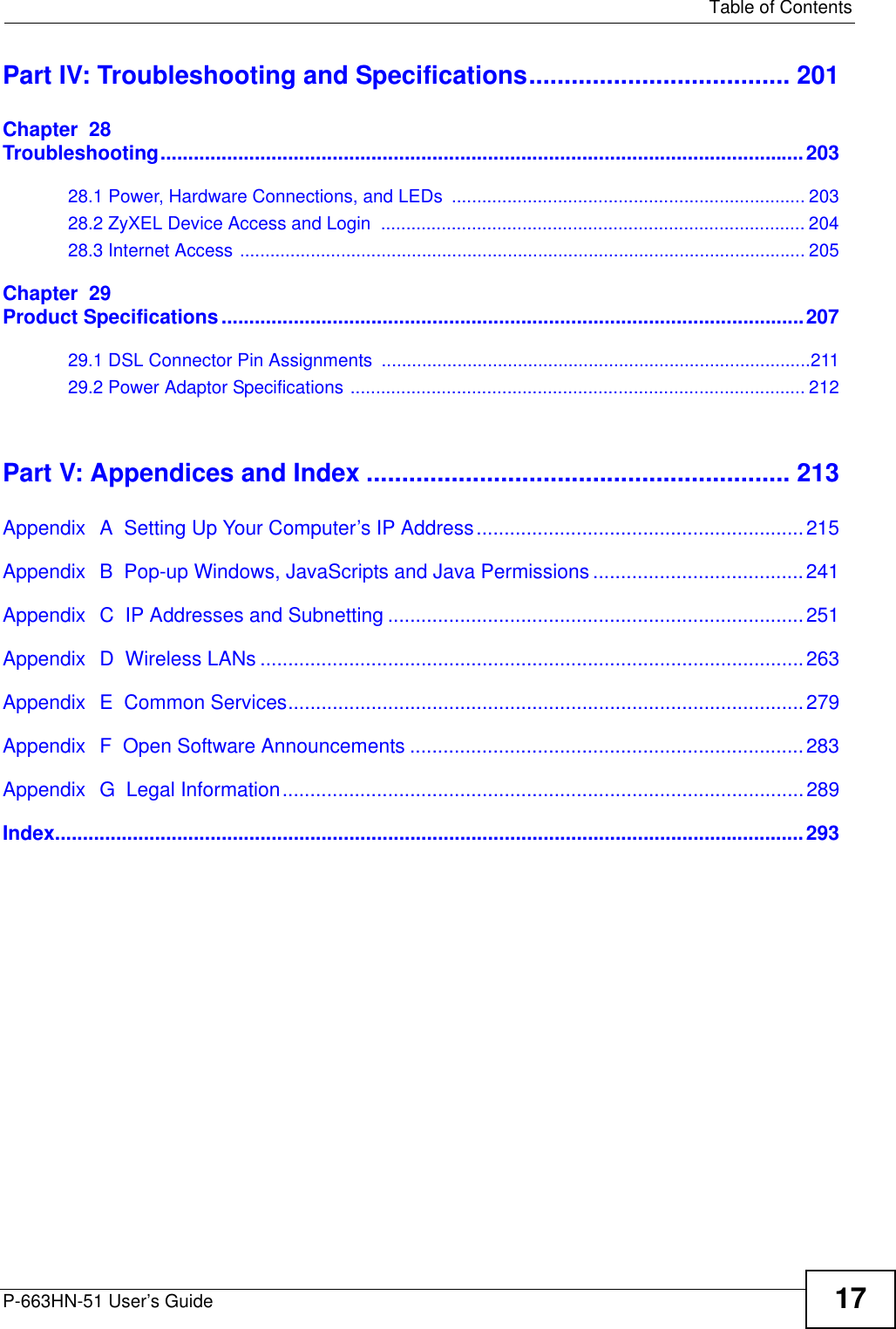
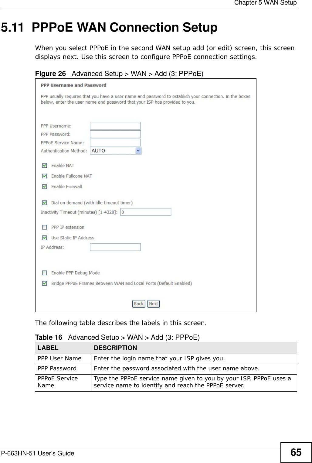
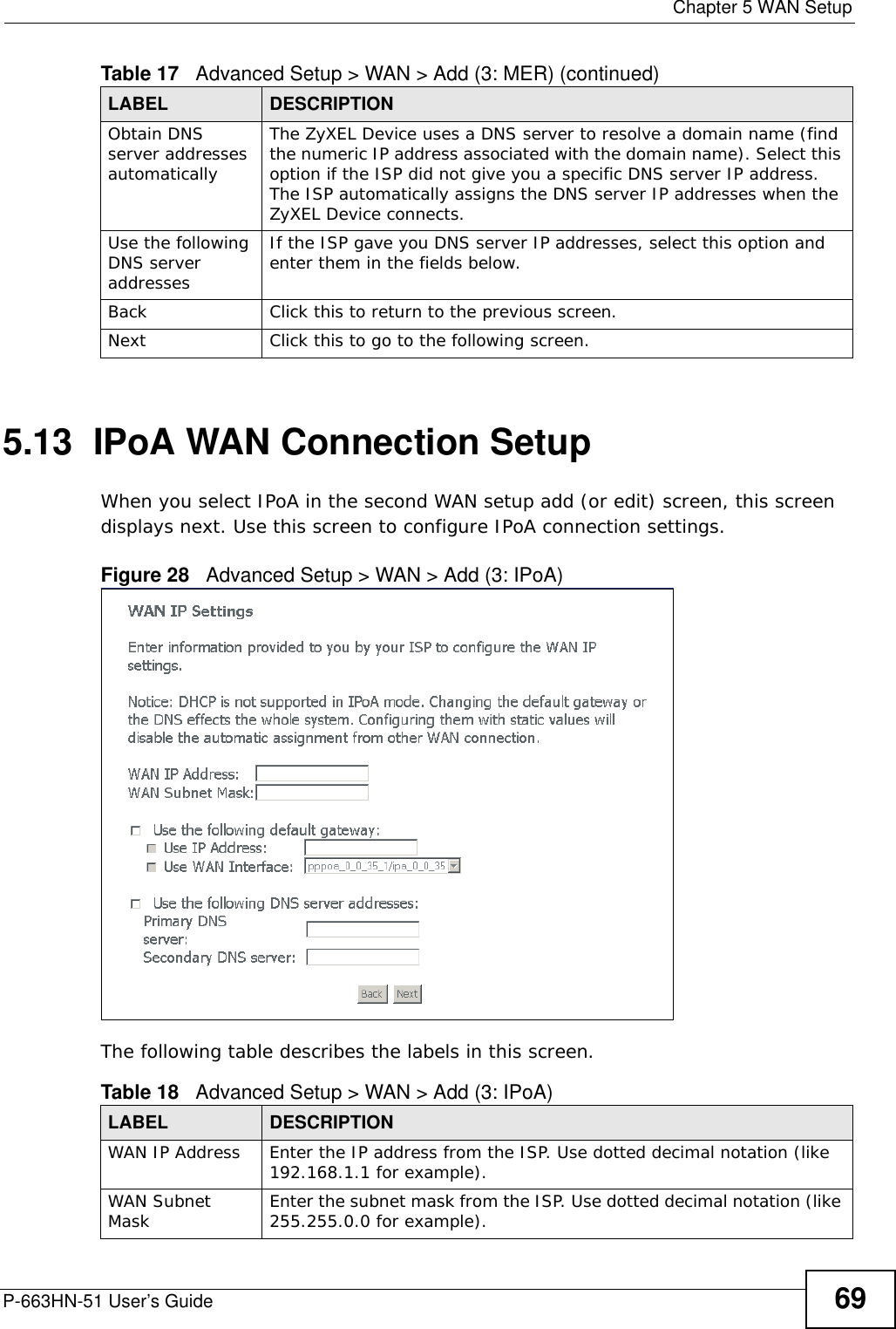
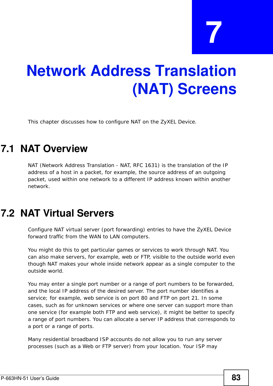
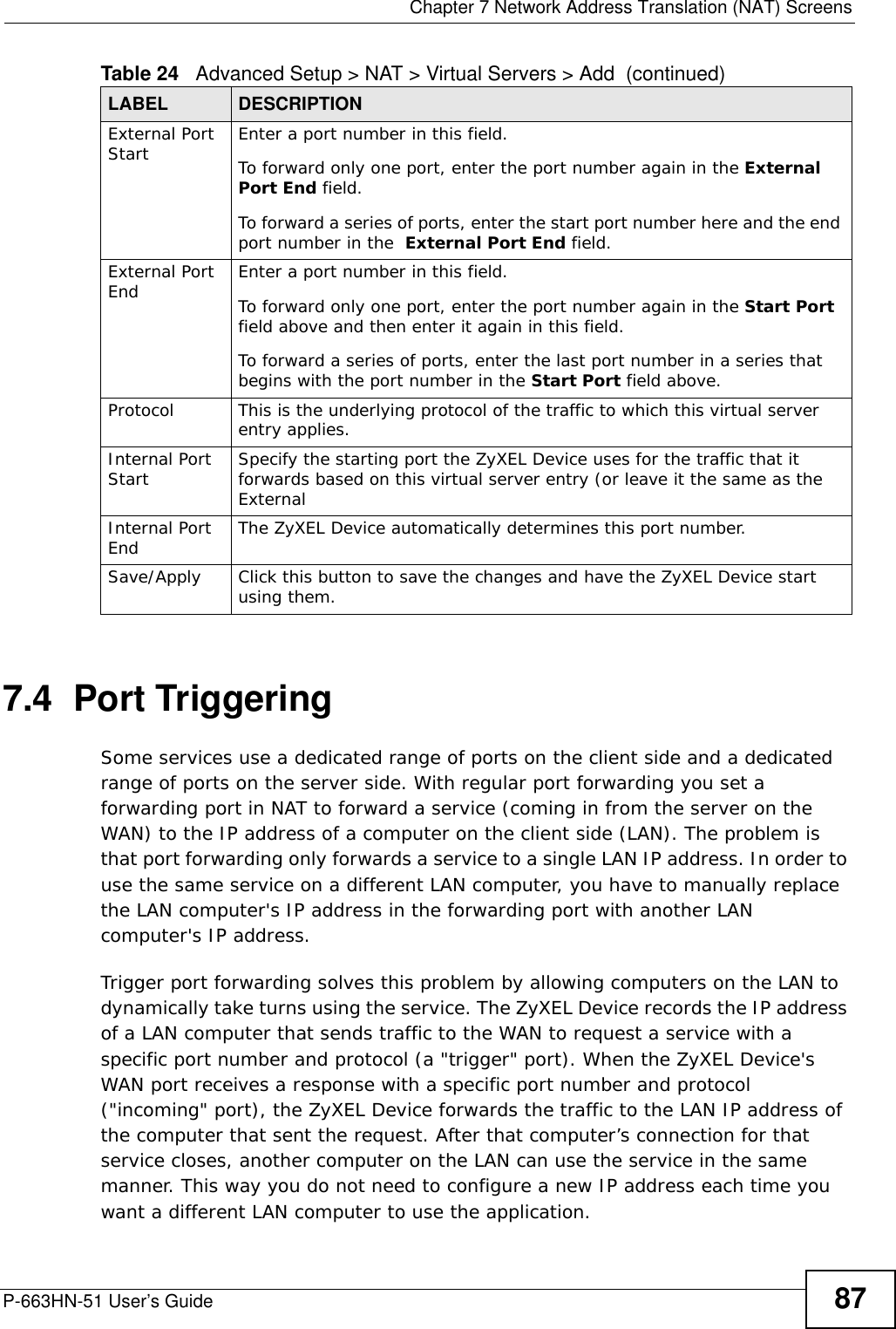
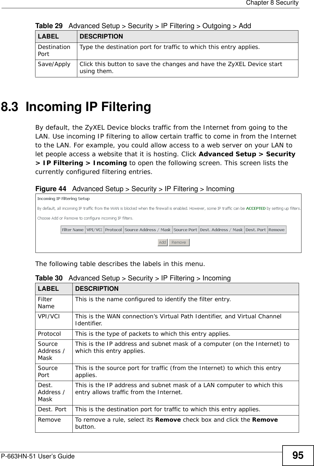
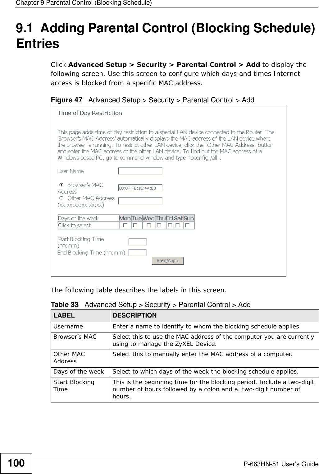
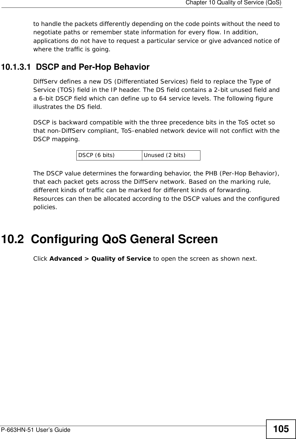
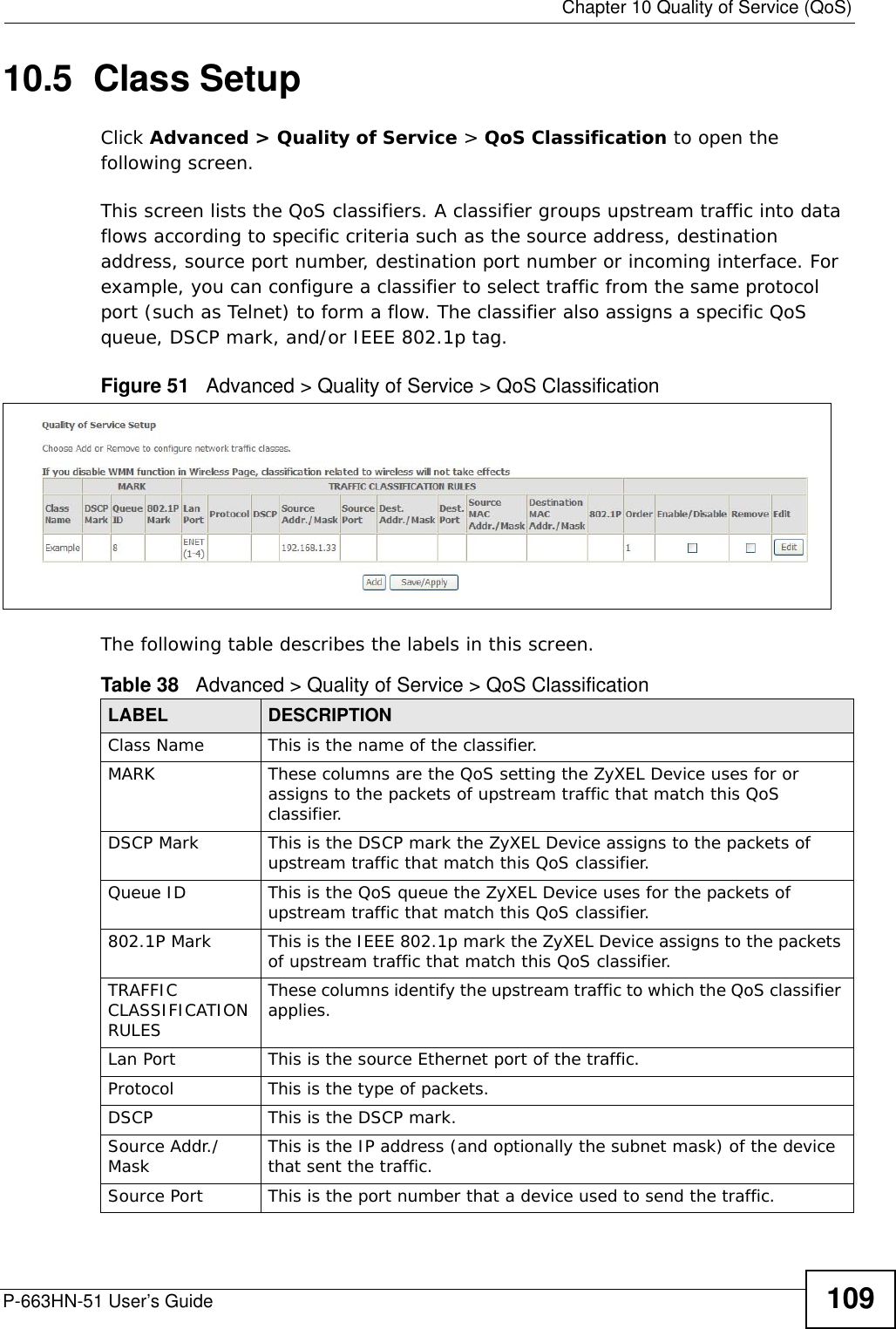
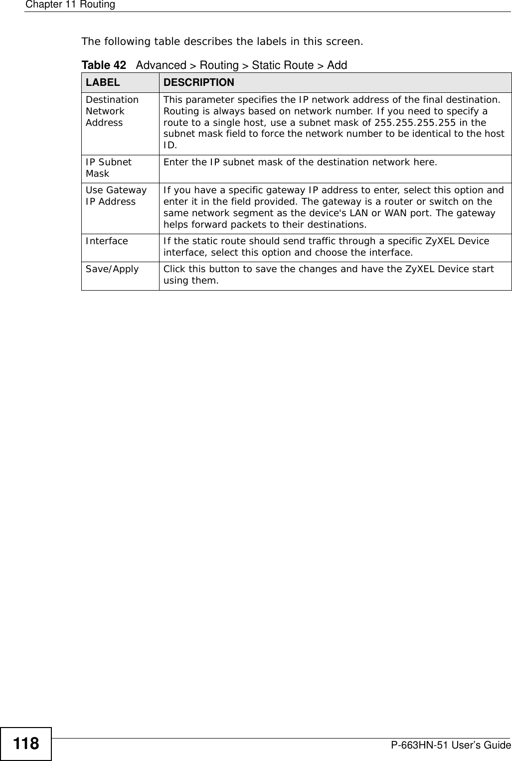
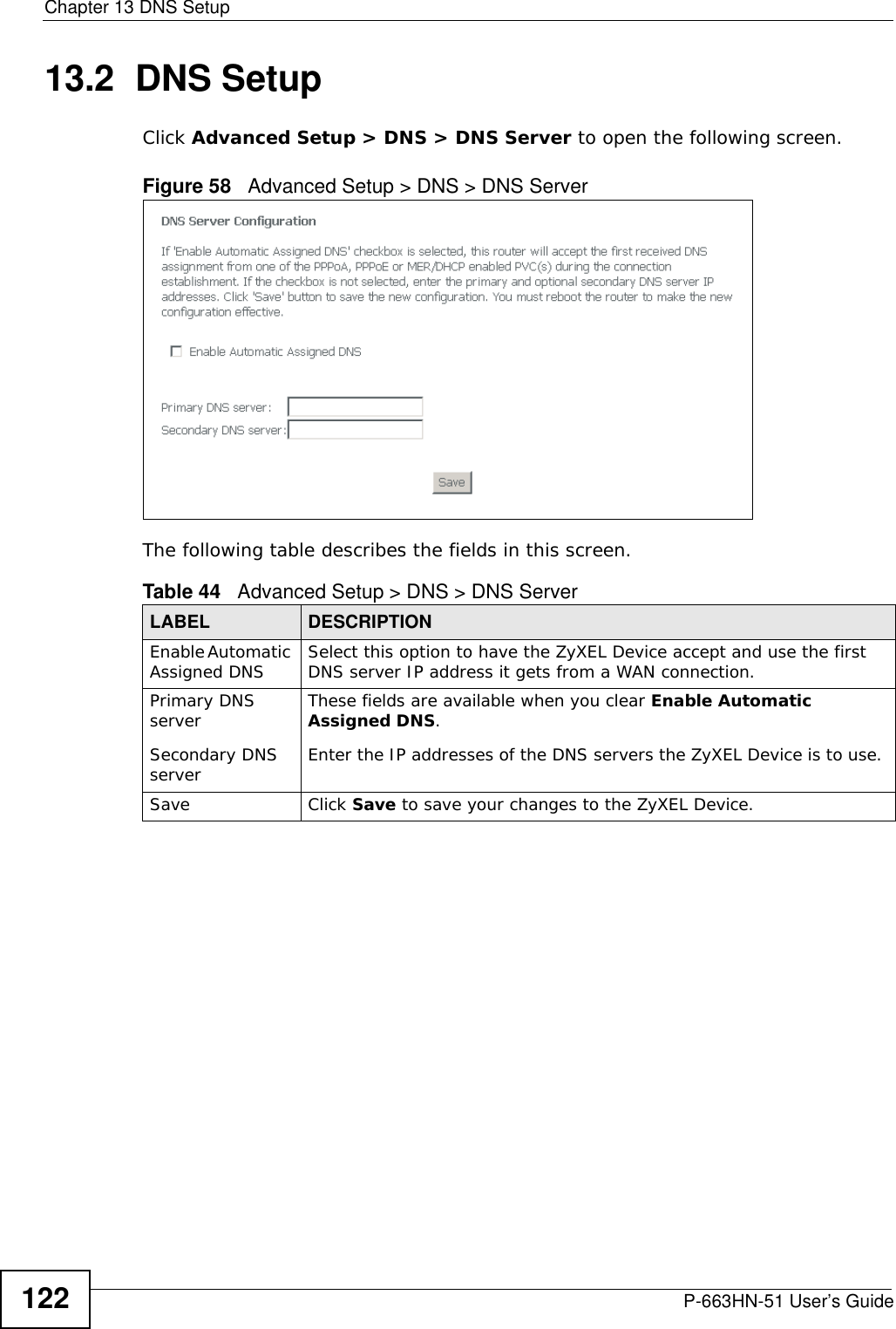
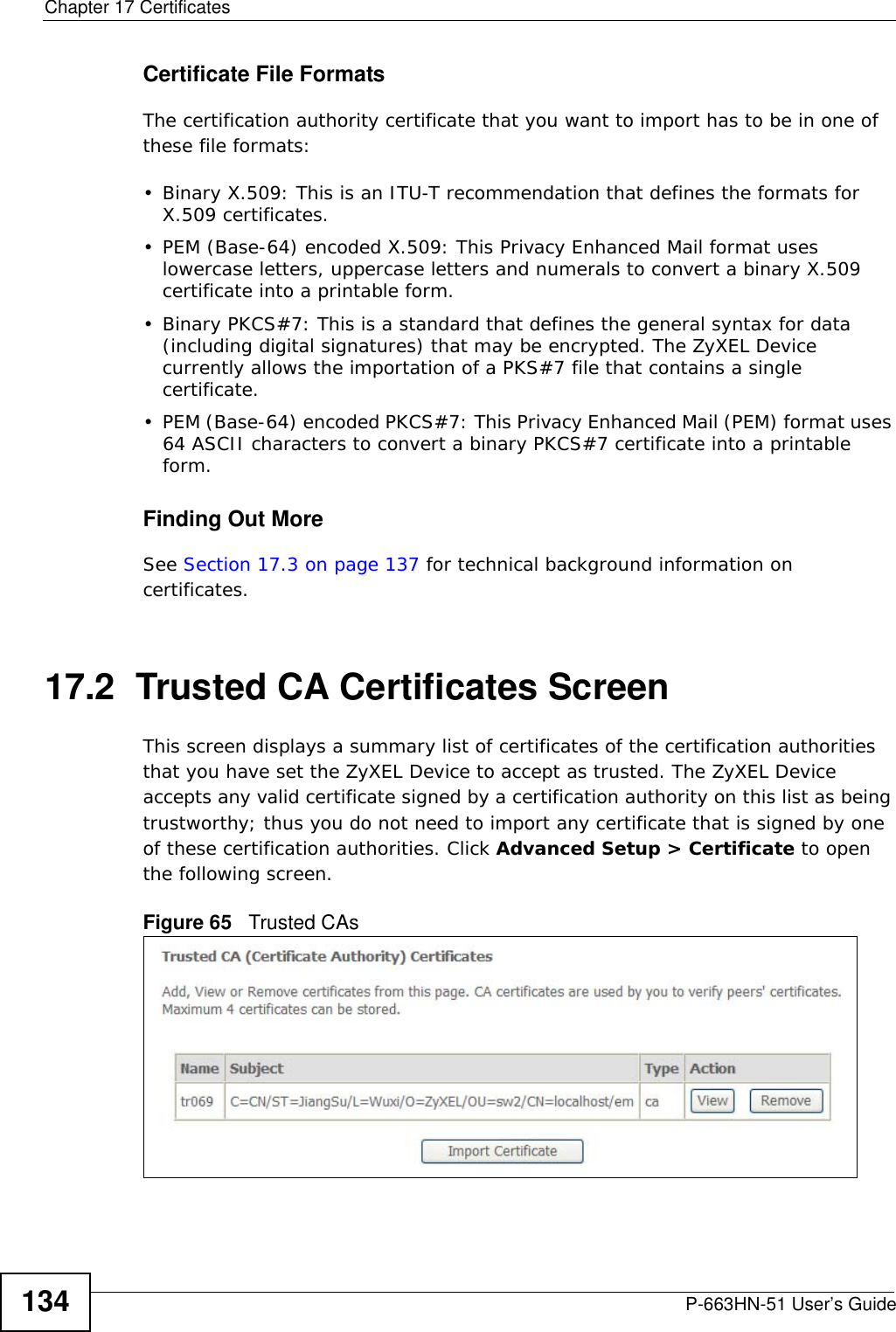
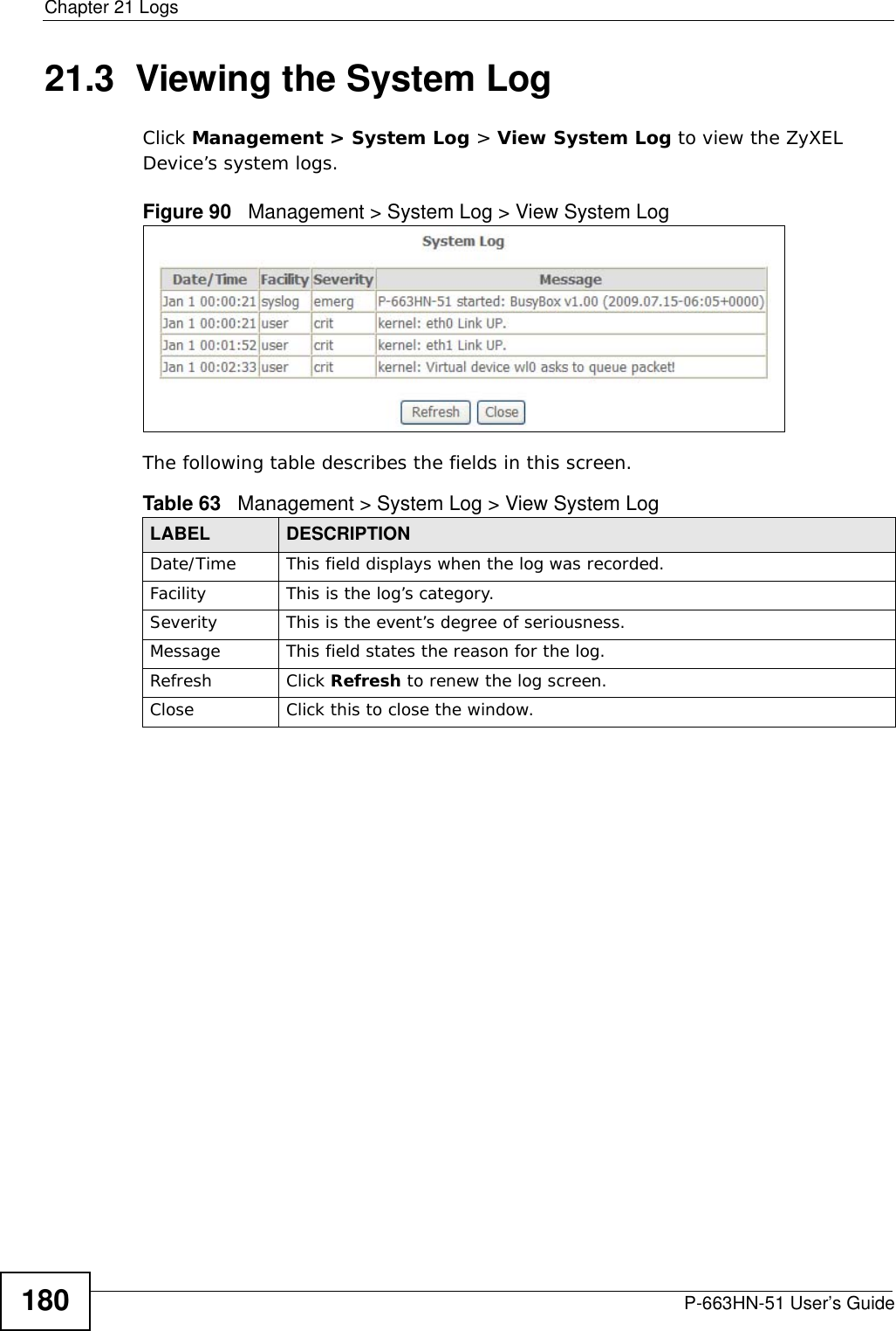
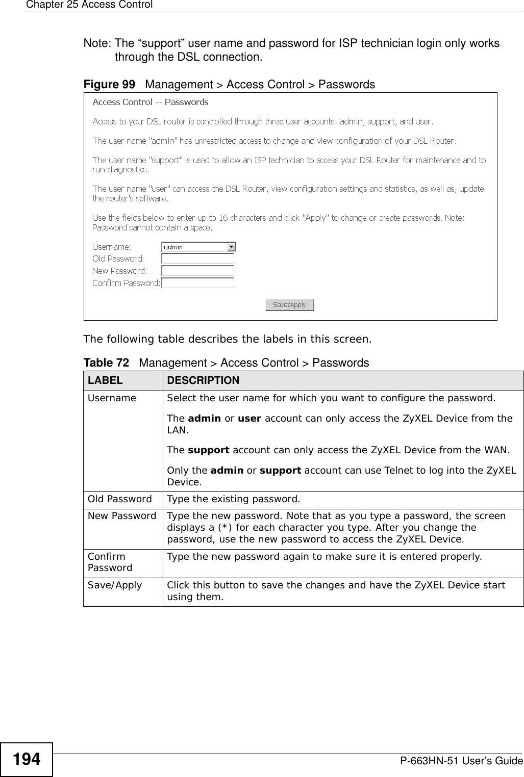
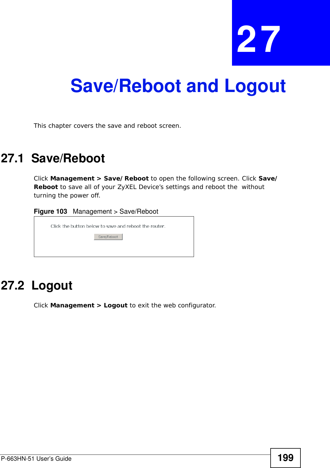
![Appendix A Setting Up Your Computer’s IP AddressP-663HN-51 User’s Guide 2192In the Command Prompt window, type "ipconfig" and then press [ENTER]. You can also go to Start > Control Panel > Network Connections, right-click a network connection, click Status and then click the Support tab to view your IP address and connection information.Windows VistaThis section shows screens from Windows Vista Professional.1Click Start > Control Panel.Figure 110 Windows Vista: Start Menu2In the Control Panel, click the Network and Internet icon.Figure 111 Windows Vista: Control Panel](https://usermanual.wiki/ZyXEL-Communications/P663HN51/User-Guide-1165687-Page-219.png)
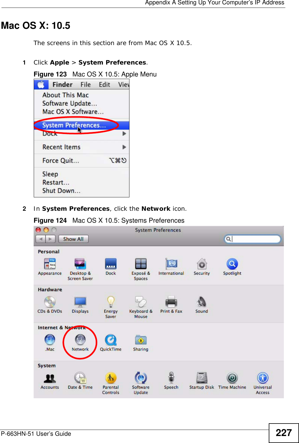
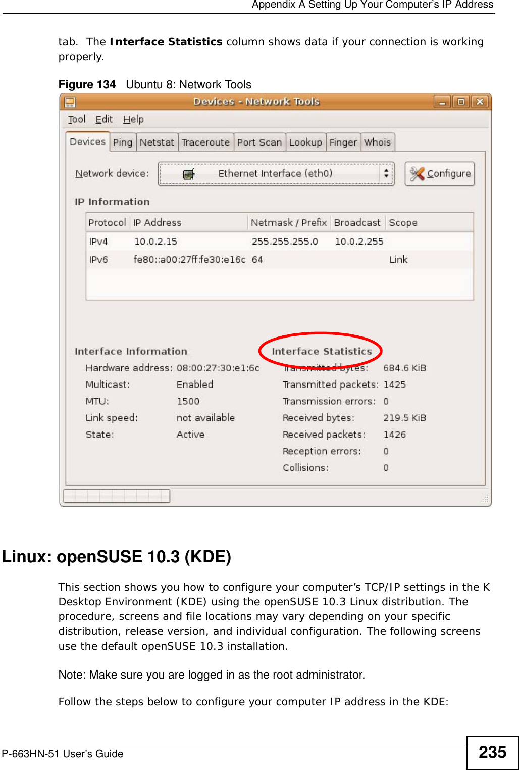
![Appendix A Setting Up Your Computer’s IP AddressP-663HN-51 User’s Guide 2232In the Command Prompt window, type "ipconfig" and then press [ENTER]. You can also go to Start > Control Panel > Network Connections, right-click a network connection, click Status and then click the Support tab to view your IP address and connection information.Mac OS X: 10.3 and 10.4The screens in this section are from Mac OS X 10.4 but can also apply to 10.3.1Click Apple > System Preferences.Figure 117 Mac OS X 10.4: Apple Menu](https://usermanual.wiki/ZyXEL-Communications/P663HN51/User-Guide-1165687-Page-223.png)