ZyXEL Communications P870HN51B 802.11n VDSL2 4-port Gateway User Manual SMG 700 User s Guide V1 00 Nov 2004
ZyXEL Communications Corporation 802.11n VDSL2 4-port Gateway SMG 700 User s Guide V1 00 Nov 2004
Contents
- 1. user manual 1
- 2. user manual 2
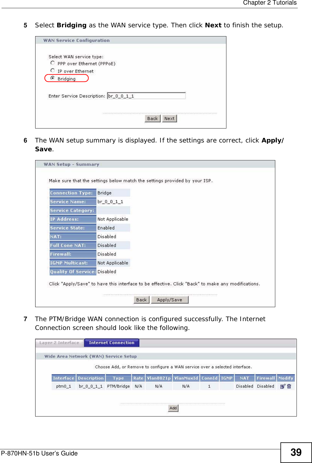
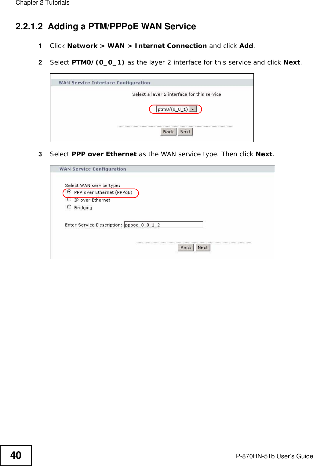
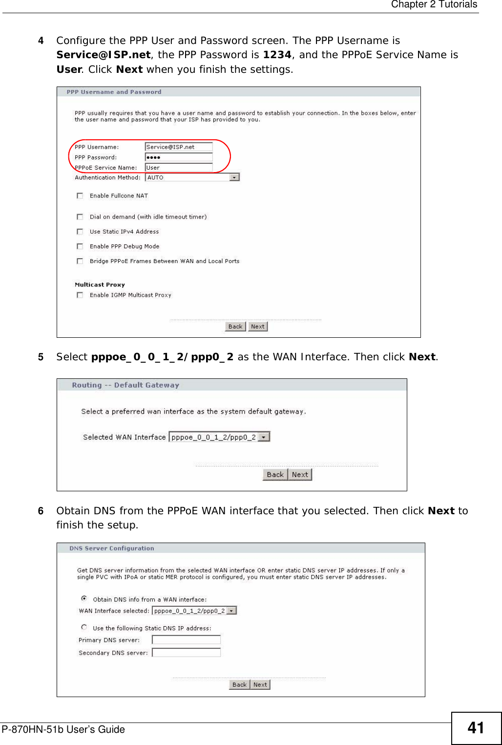
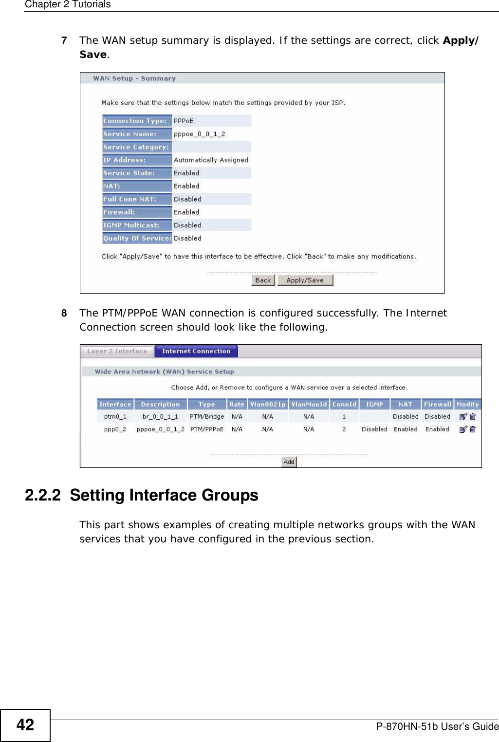
user manual 1
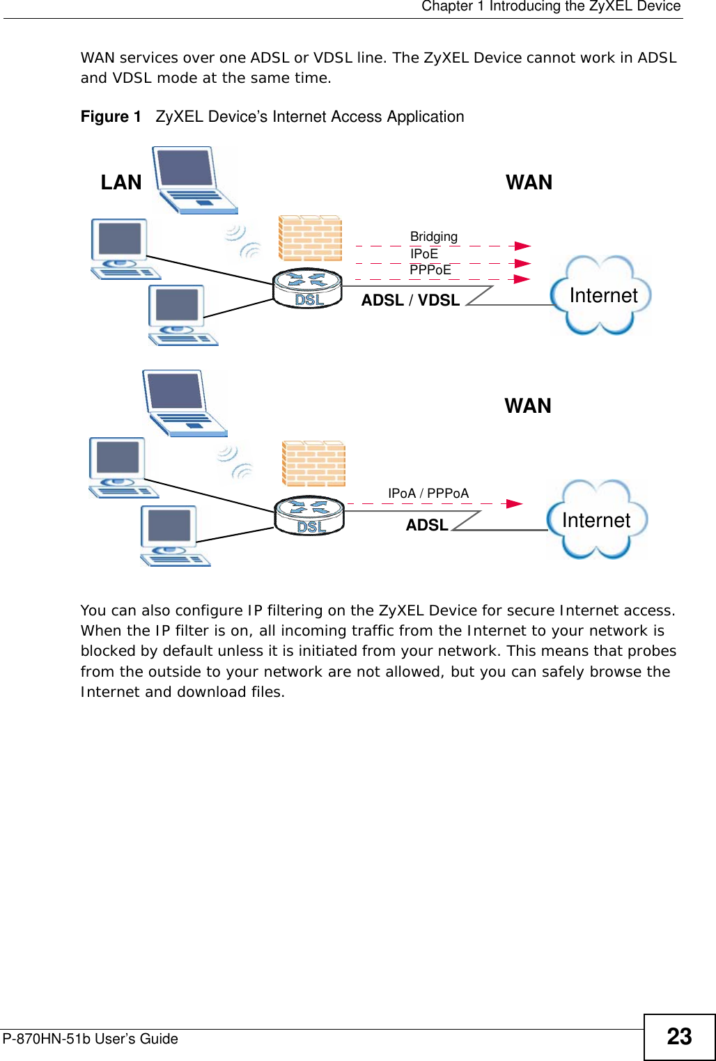
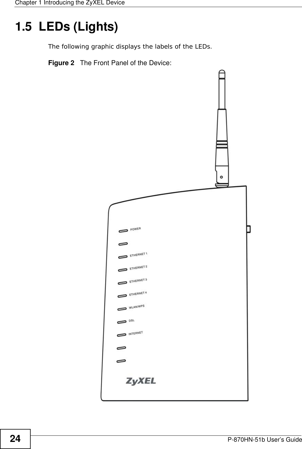
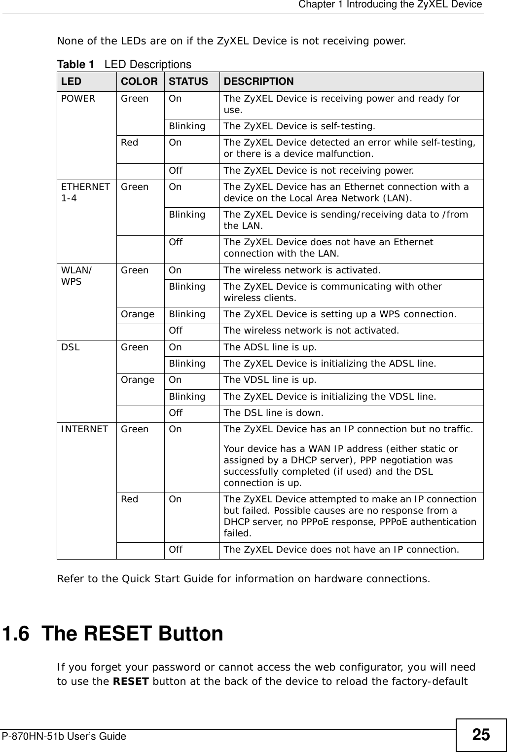
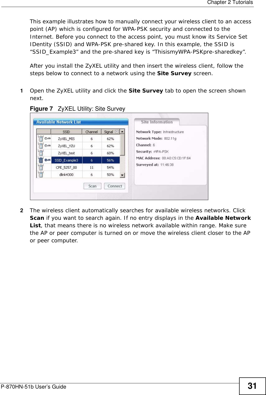
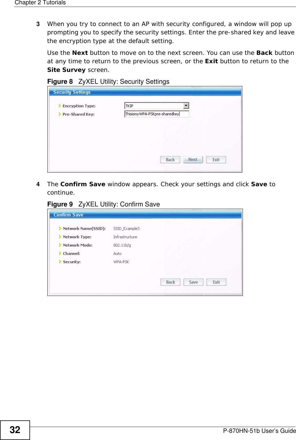
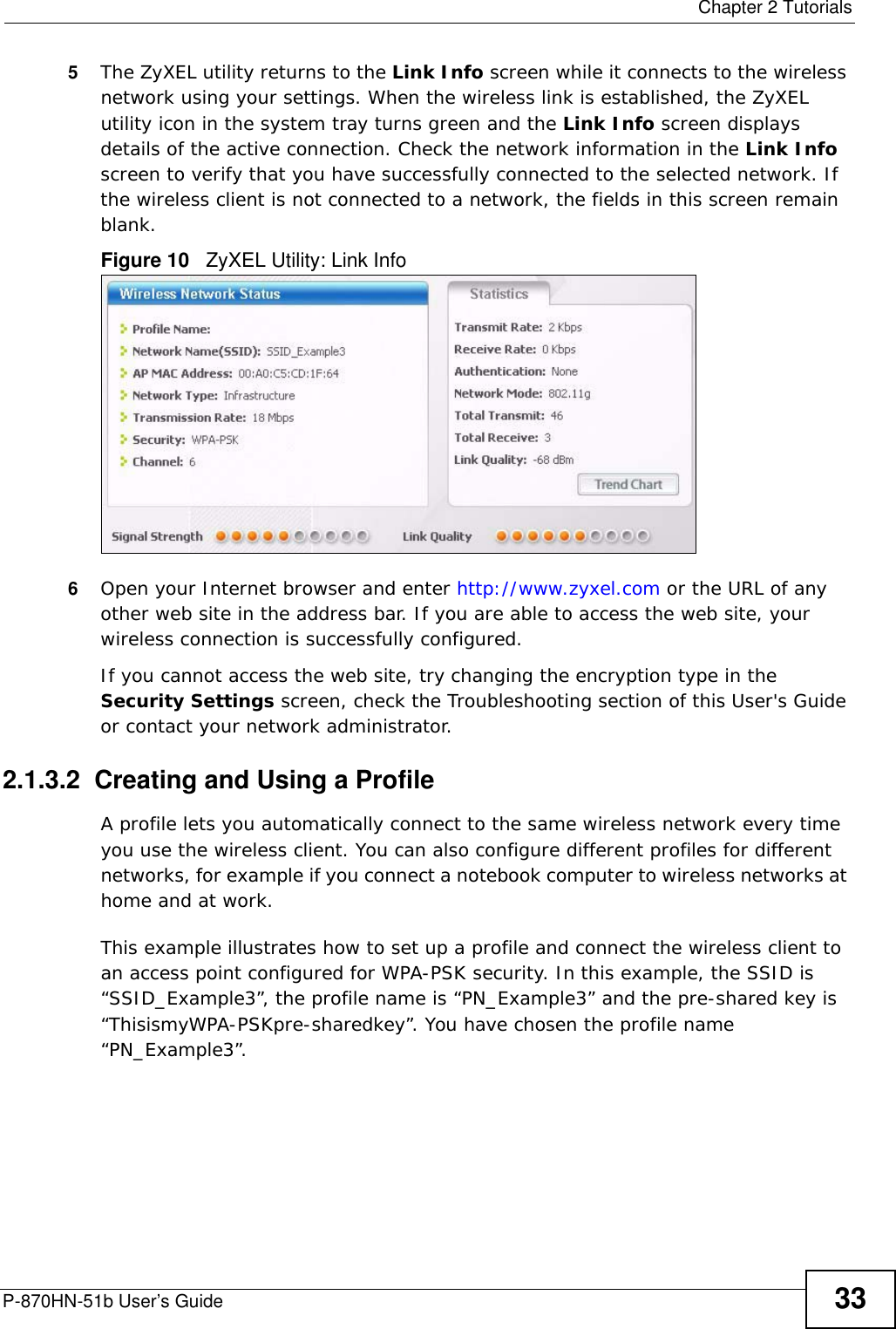
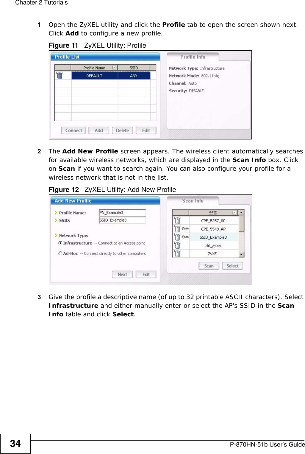
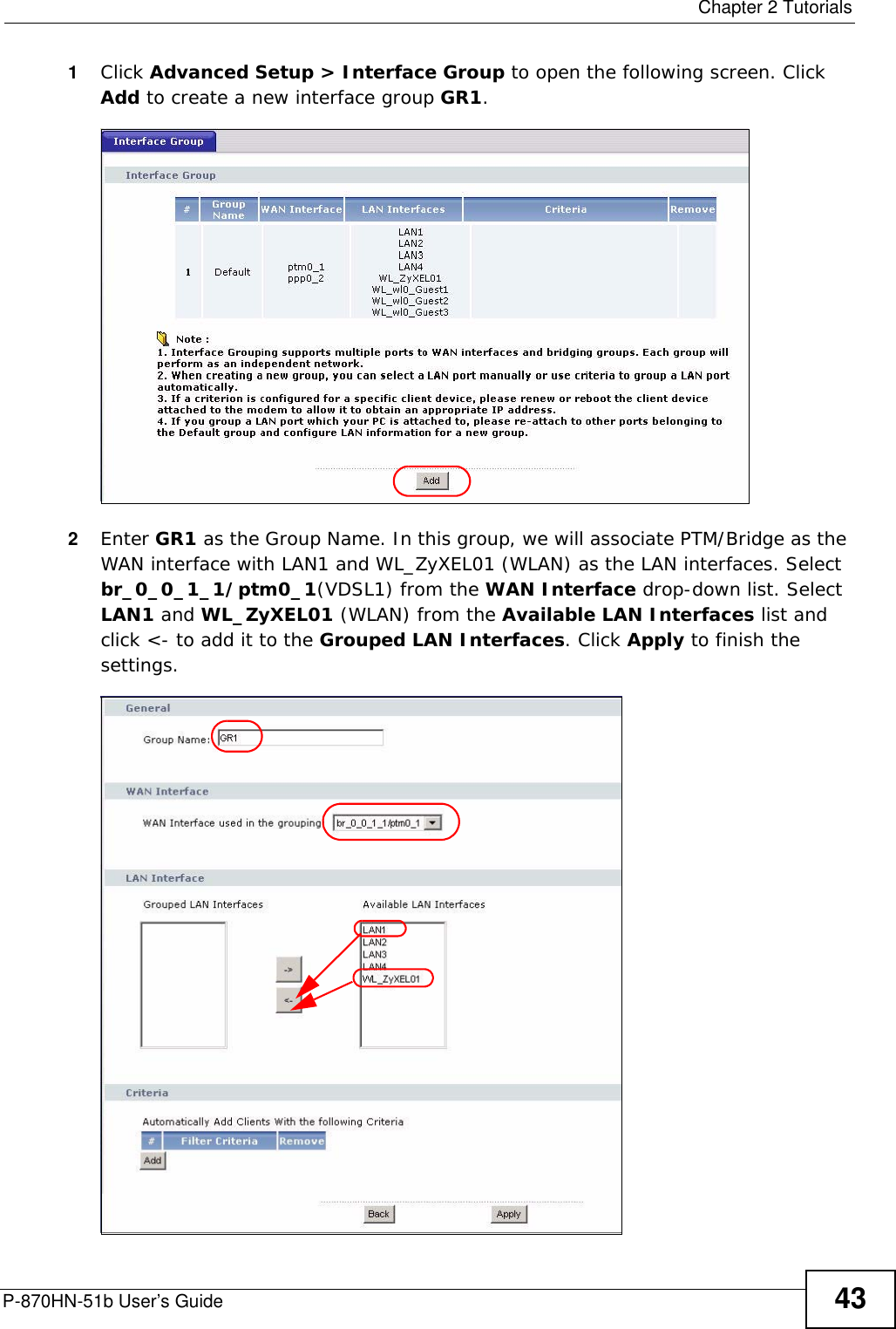
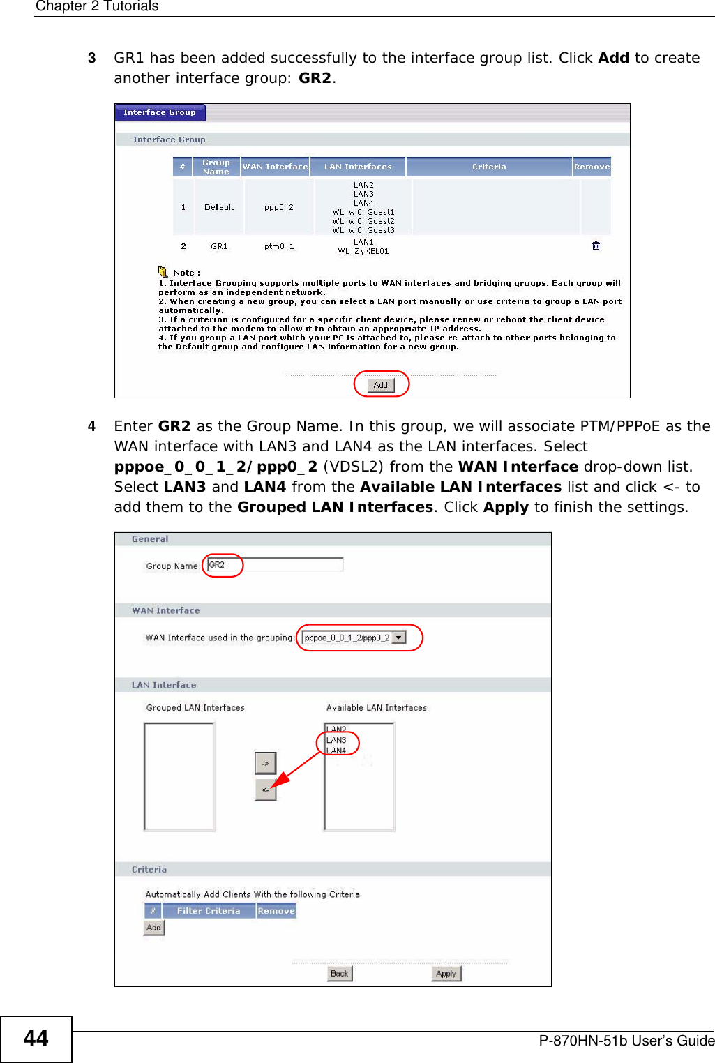
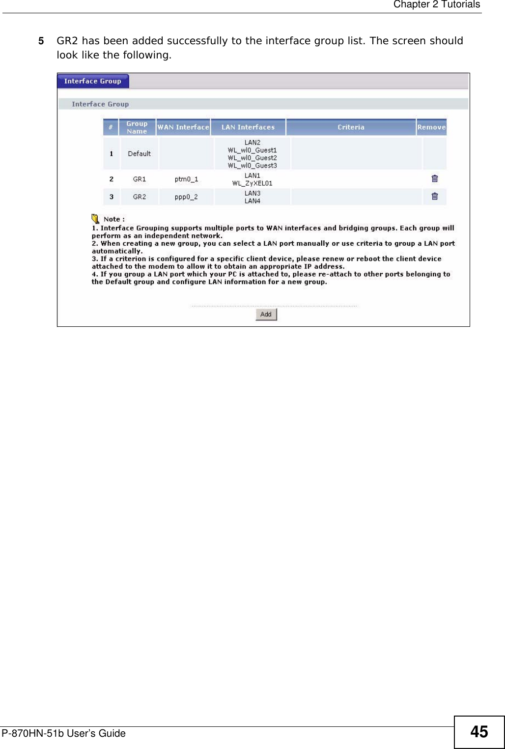
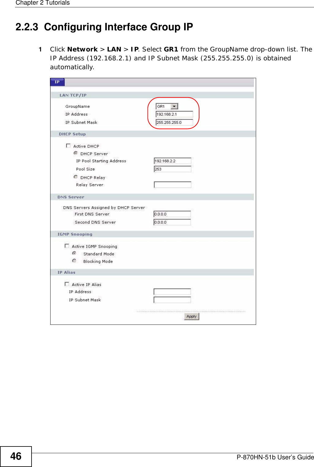
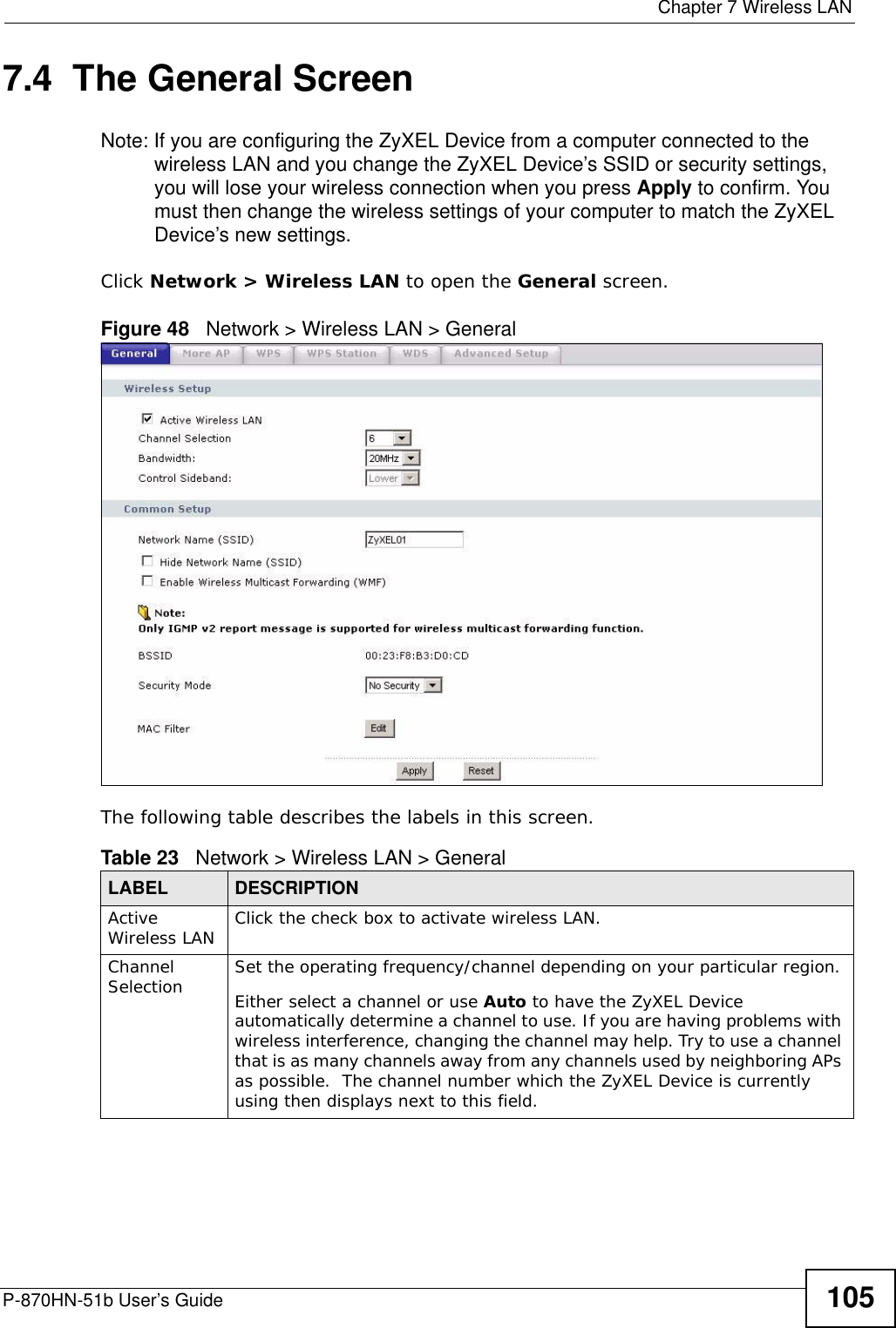
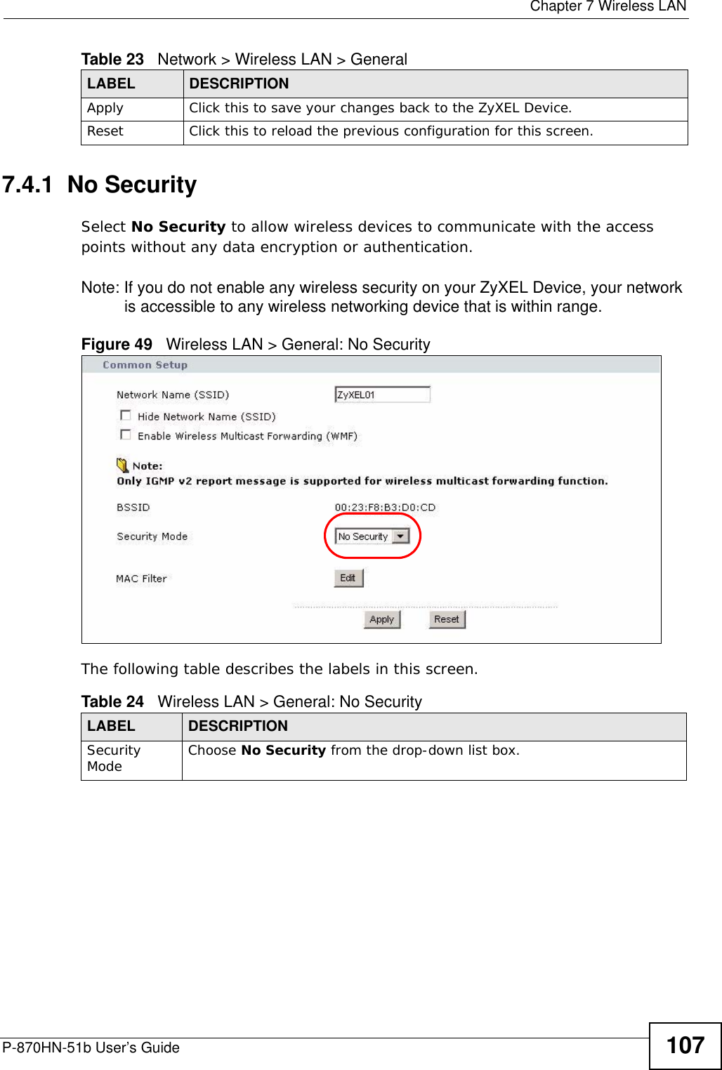
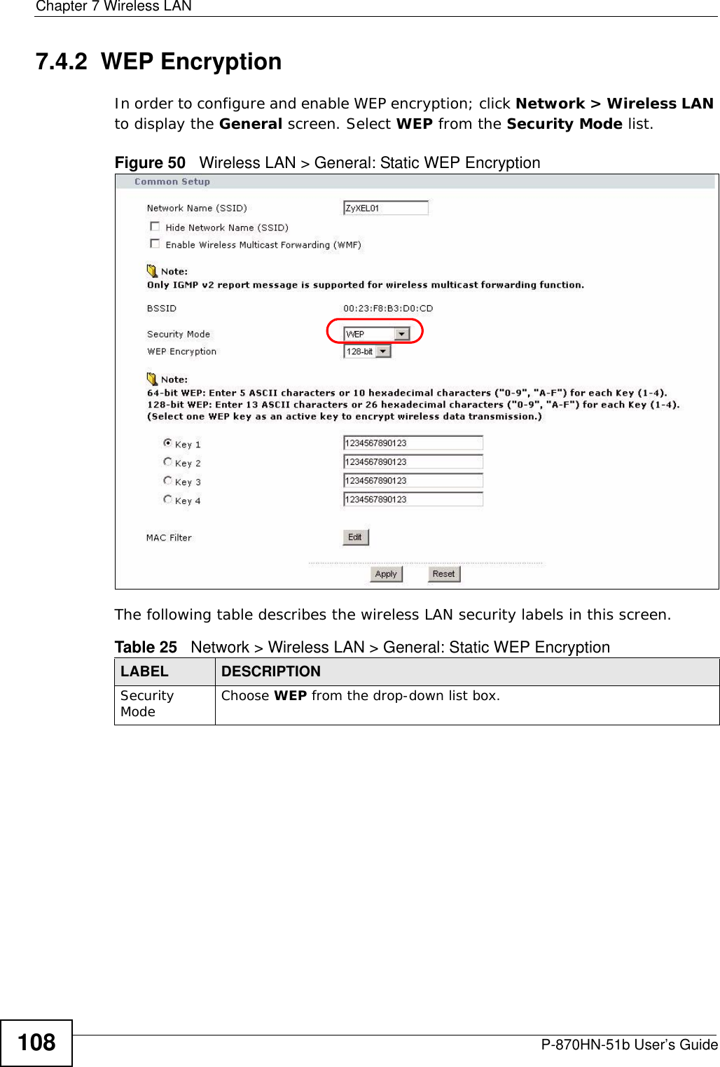
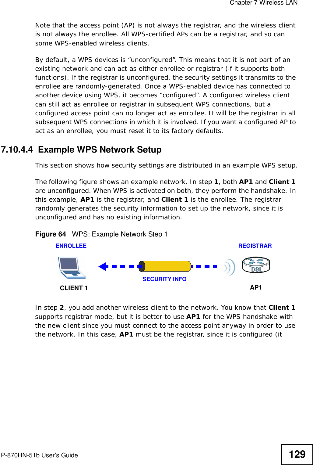
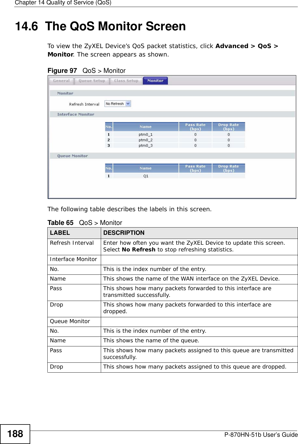
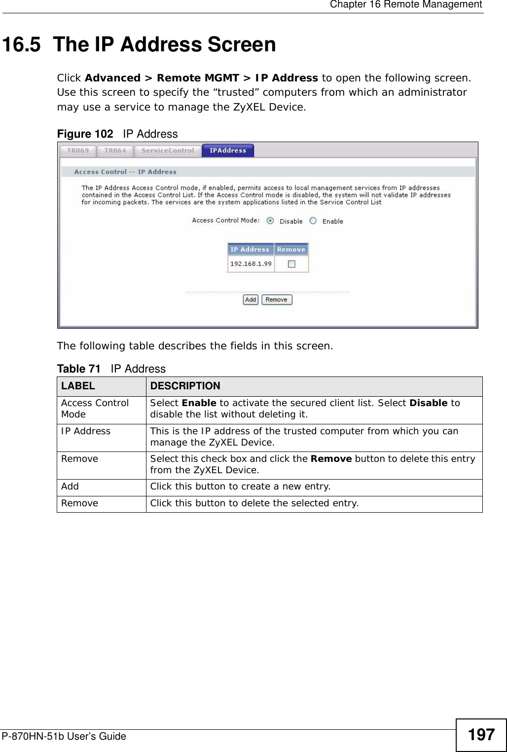
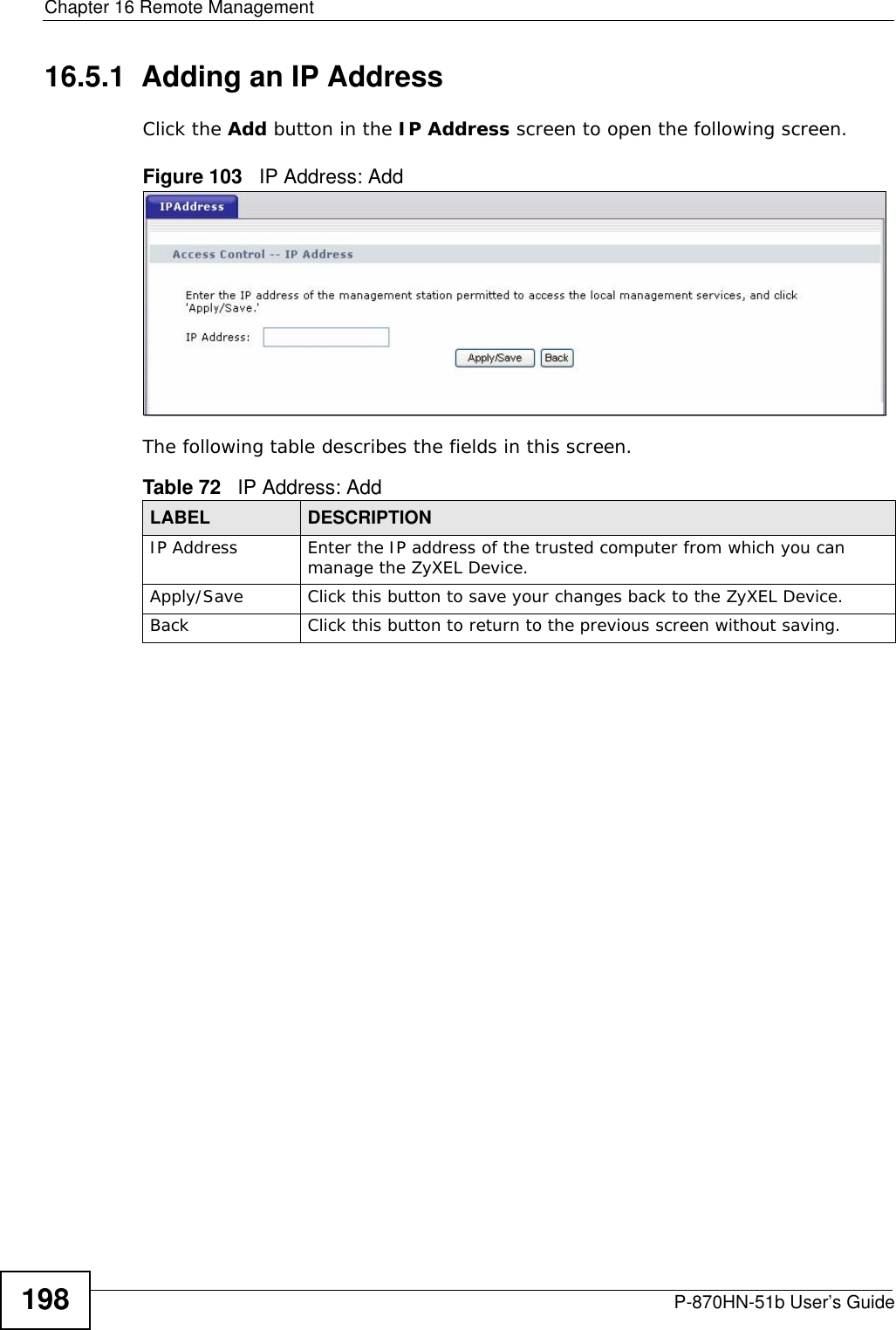
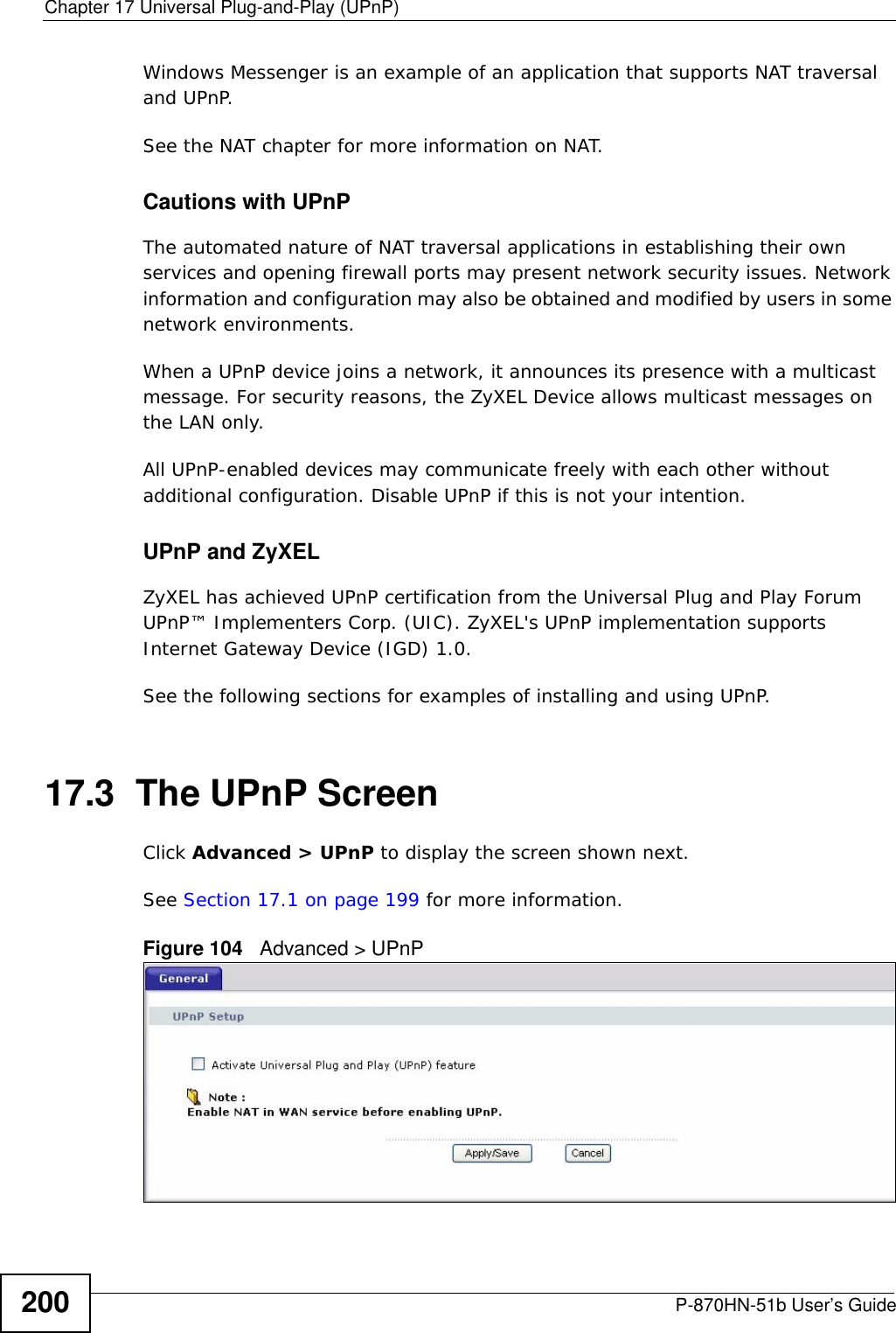
![Document ConventionsP-870HN-51b User’s Guide 5Document ConventionsWarnings and NotesThese are how warnings and notes are shown in this User’s Guide. Warnings tell you about things that could harm you or your device.Note: Notes tell you other important information (for example, other things you may need to configure or helpful tips) or recommendations.Syntax Conventions• The P-870HN-51b may be referred to as the “ZyXEL Device”, the “device”, the “system” or the “product” in this User’s Guide.• Product labels, screen names, field labels and field choices are all in bold font.• A key stroke is denoted by square brackets and uppercase text, for example, [ENTER] means the “enter” or “return” key on your keyboard.• “Enter” means for you to type one or more characters and then press the [ENTER] key. “Select” or “choose” means for you to use one of the predefined choices.• A right angle bracket ( > ) within a screen name denotes a mouse click. For example, Maintenance > Log > Log Setting means you first click Maintenance in the navigation panel, then the Log sub menu and finally the Log Setting tab to get to that screen.• Units of measurement may denote the “metric” value or the “scientific” value. For example, “k” for kilo may denote “1000” or “1024”, “M” for mega may denote “1000000” or “1048576” and so on.• “e.g.,” is a shorthand for “for instance”, and “i.e.,” means “that is” or “in other words”.](https://usermanual.wiki/ZyXEL-Communications/P870HN51B.user-manual-1/User-Guide-1187132-Page-5.png)