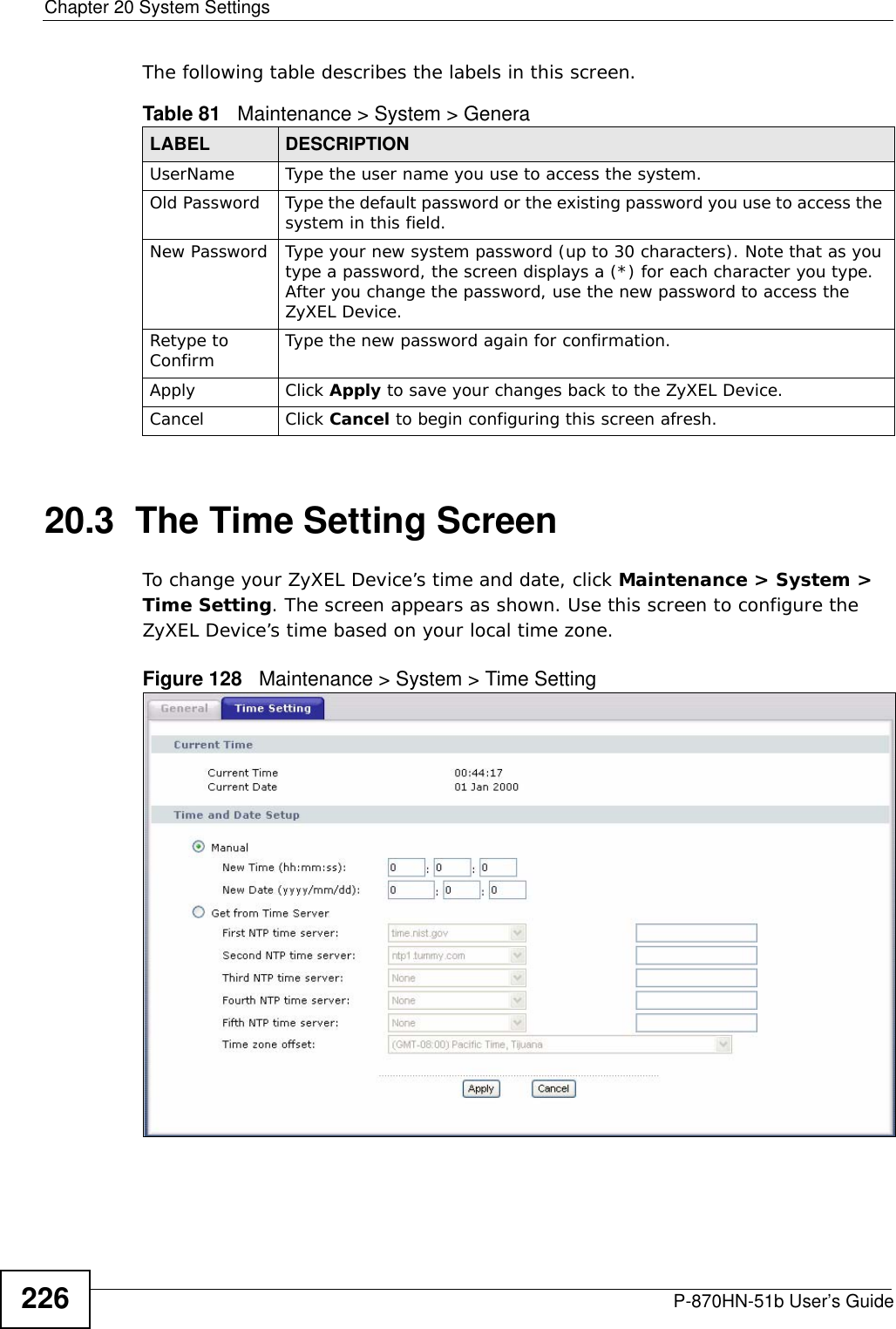
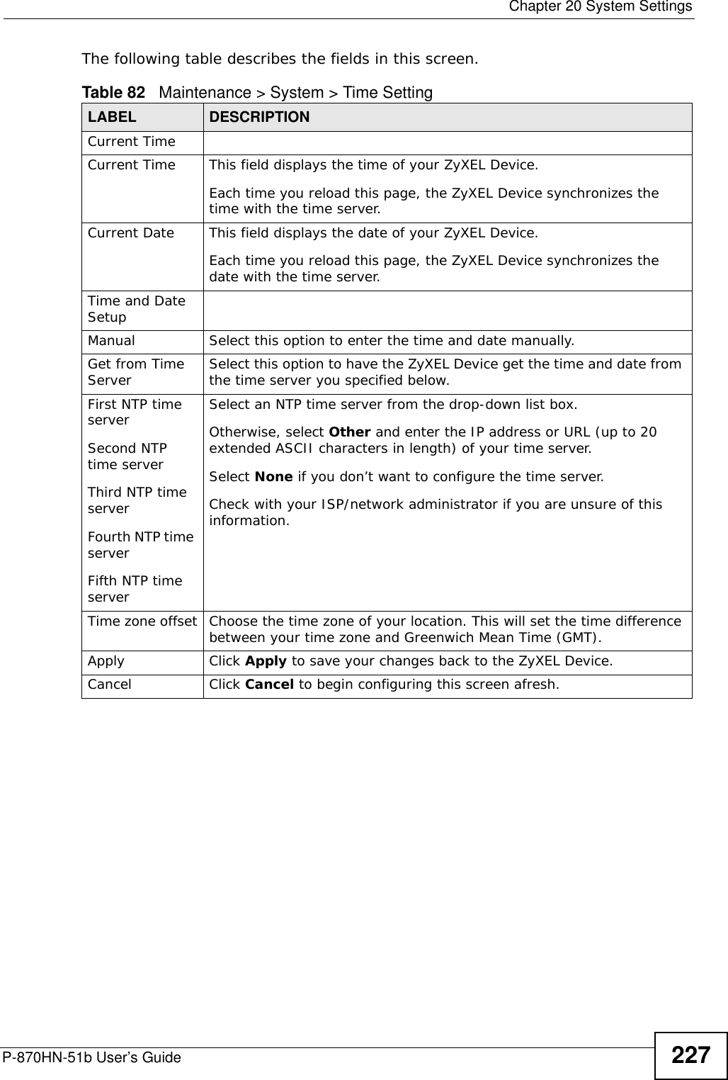
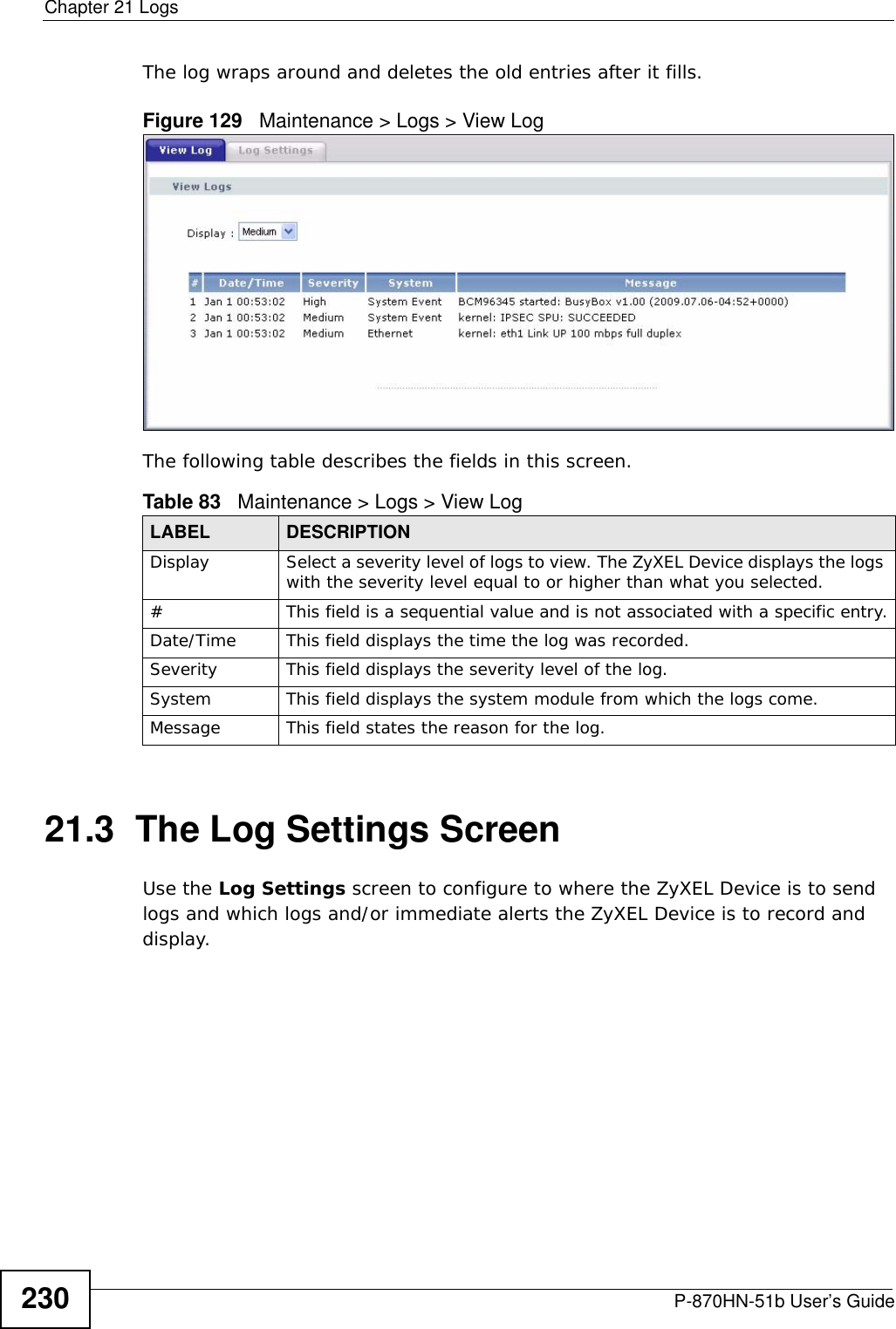
ZyXEL Communications P870HN51B 802.11n VDSL2 4-port Gateway User Manual SMG 700 User s Guide V1 00 Nov 2004
ZyXEL Communications Corporation 802.11n VDSL2 4-port Gateway SMG 700 User s Guide V1 00 Nov 2004
Contents
- 1. user manual 1
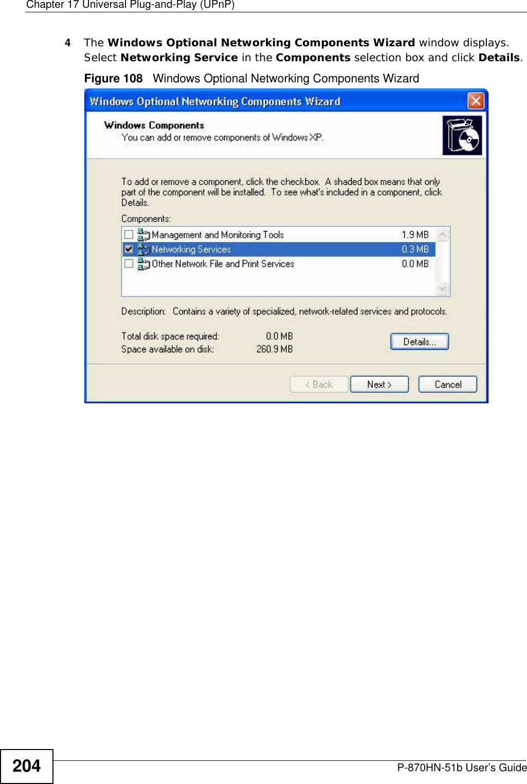
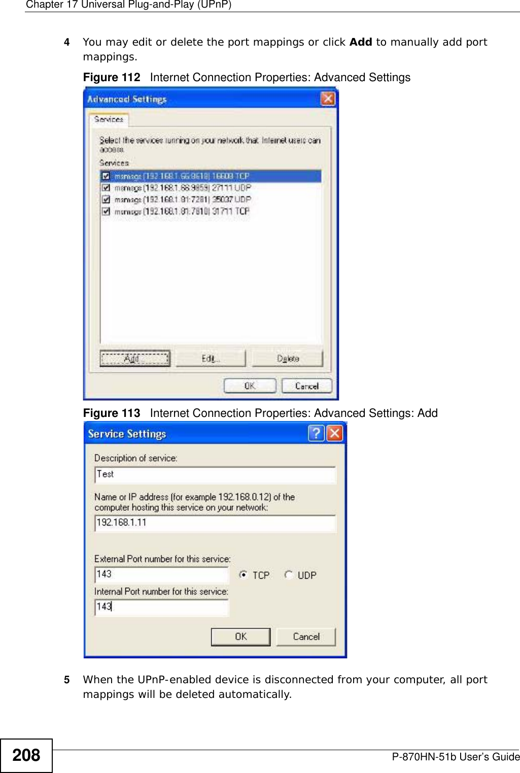
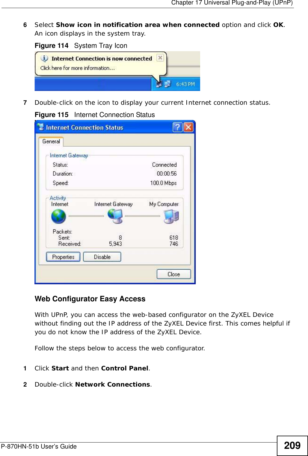
- 2. user manual 2
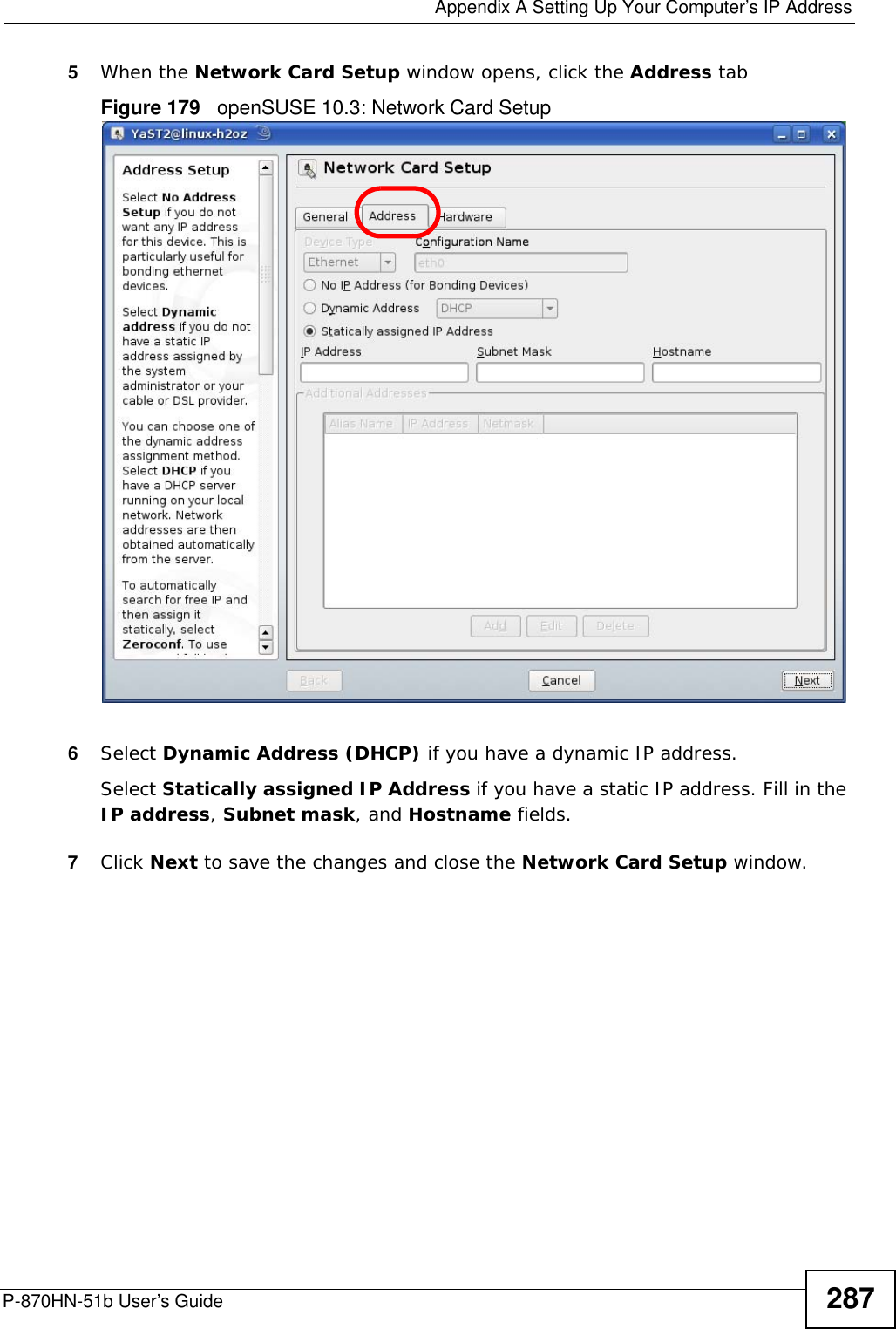
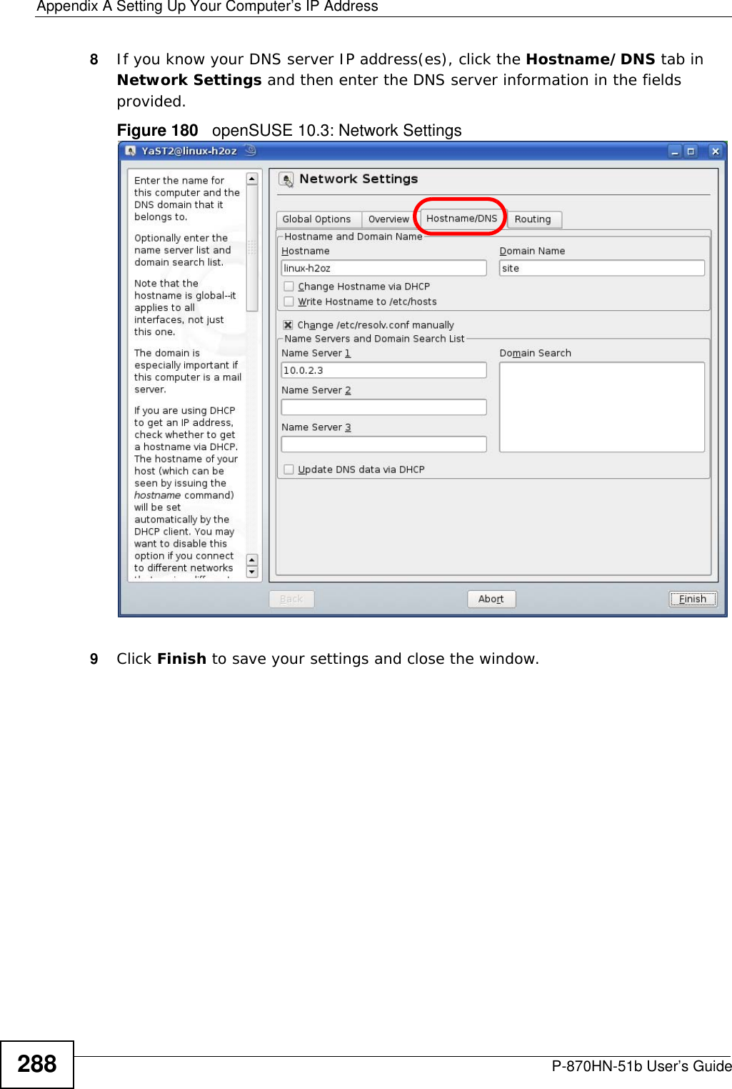
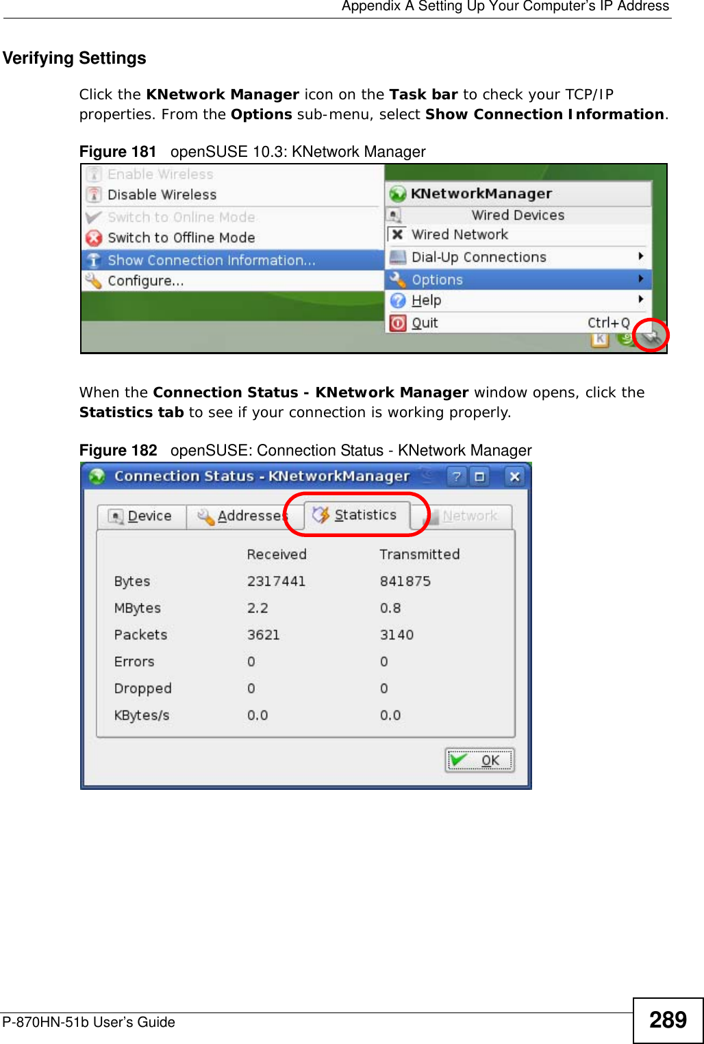
user manual 2
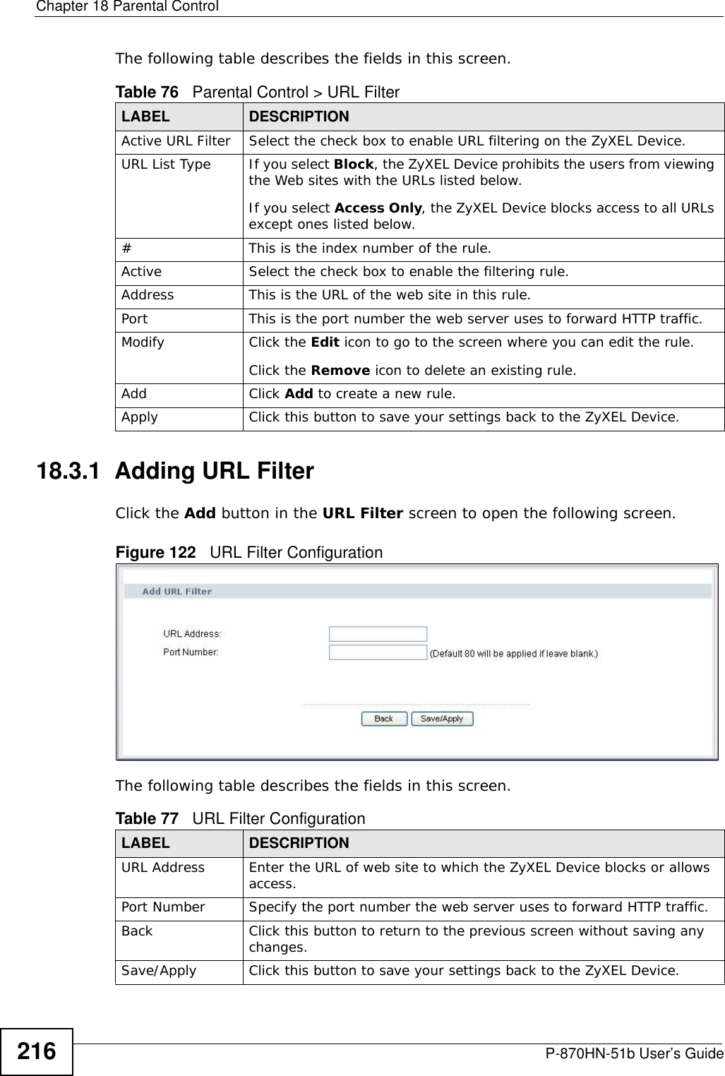

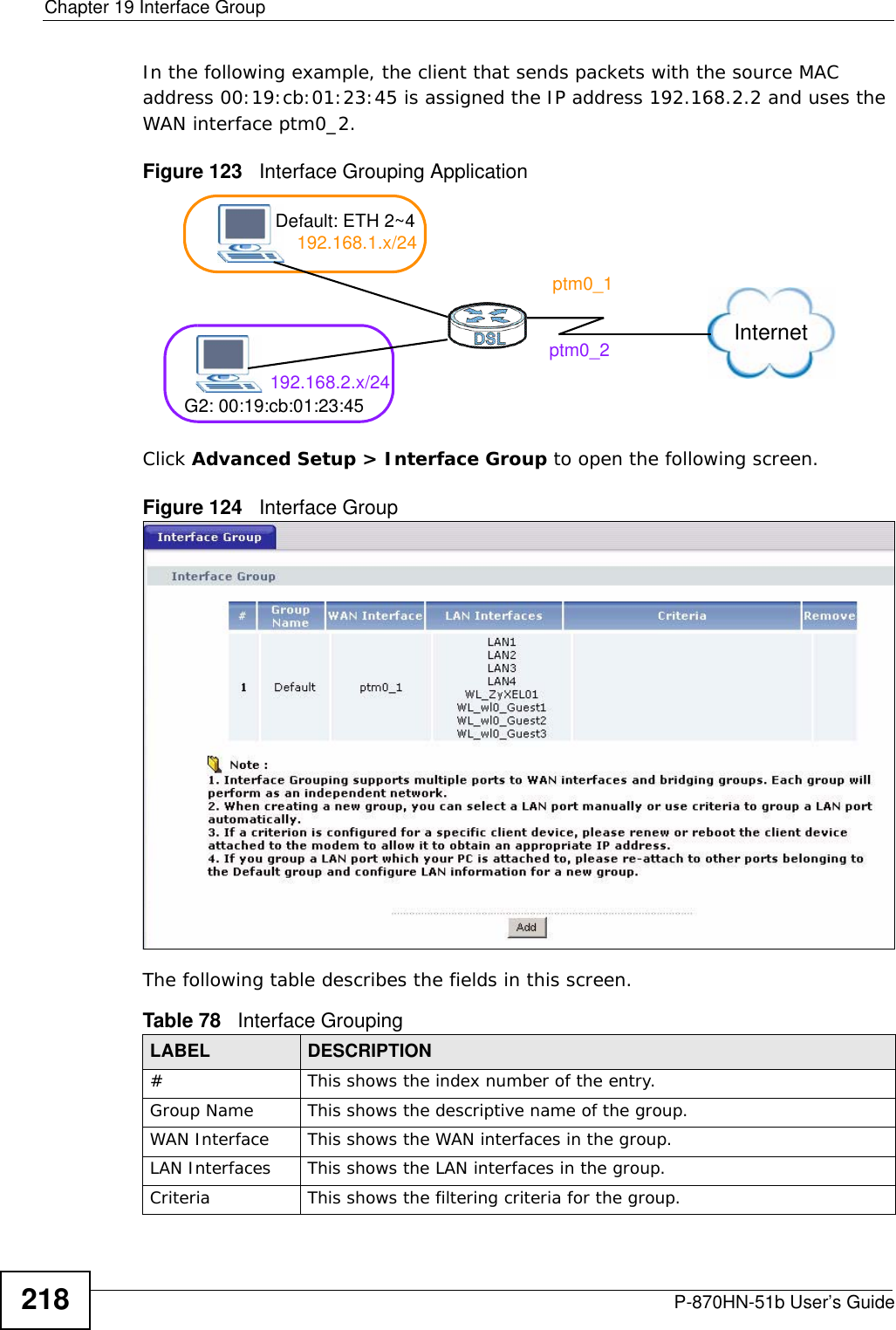
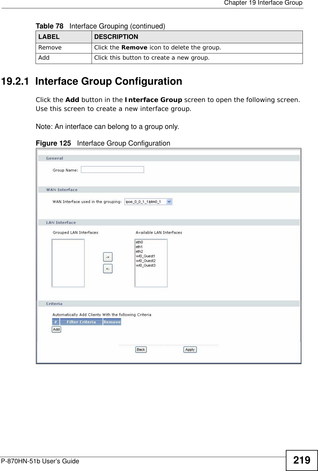
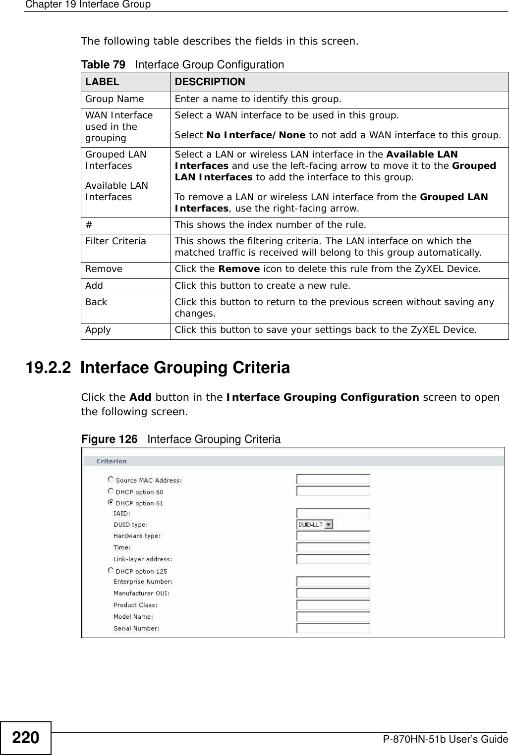


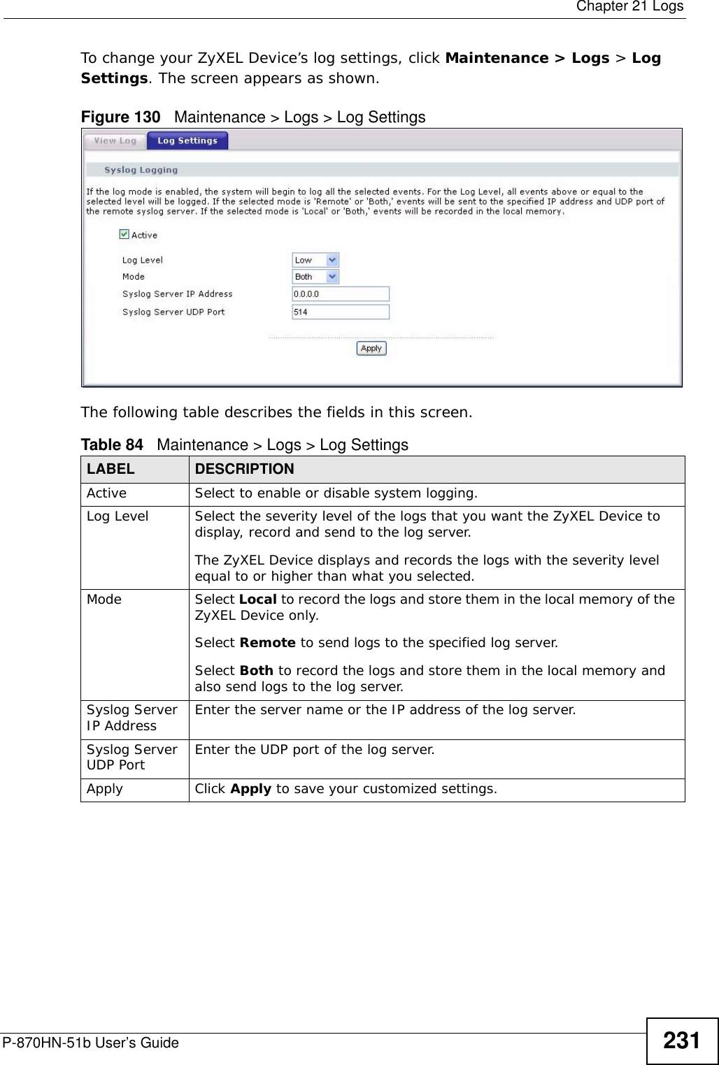


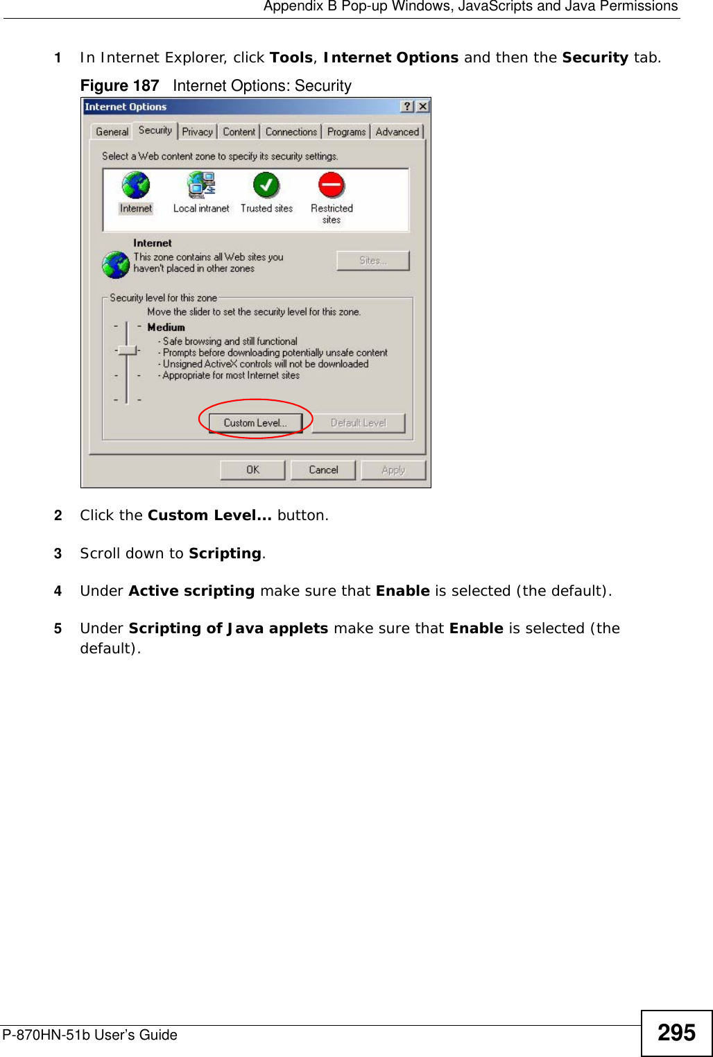
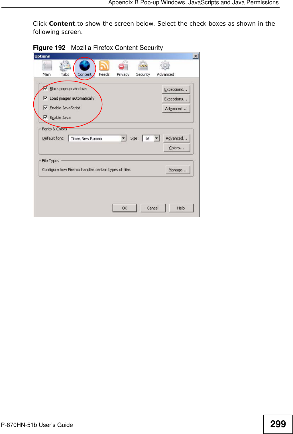
![Chapter 24 TroubleshootingP-870HN-51b User’s Guide 249• If you changed the IP address (Section on page 98), use the new IP address.• If you changed the IP address and have forgotten it, see the troubleshooting suggestions for I forgot the IP address for the ZyXEL Device.2Check the hardware connections, and make sure the LEDs are behaving as expected. See the Quick Start Guide.3Make sure your Internet browser does not block pop-up windows and has JavaScripts and Java enabled. See Appendix B on page 291.4Reset the device to its factory defaults, and try to access the ZyXEL Device with the default IP address. See Section 1.6 on page 25. 5If the problem continues, contact the network administrator or vendor, or try one of the advanced suggestions.Advanced Suggestions• If your computer is connected wirelessly, use a computer that is connected to a ETHERNET port.I can see the Login screen, but I cannot log in to the ZyXEL Device.1Make sure you have entered the user name and password correctly. The default user name is admin and password is 1234. These fields are case-sensitive, so make sure [Caps Lock] is not on. 2Turn the ZyXEL Device off and on. 3If this does not work, you have to reset the device to its factory defaults. See Section 24.1 on page 247.24.3 Internet AccessI cannot access the Internet.1Check the hardware connections, and make sure the LEDs are behaving as expected. See the Quick Start Guide and Section 1.5 on page 24.](https://usermanual.wiki/ZyXEL-Communications/P870HN51B.user-manual-2/User-Guide-1187133-Page-49.png)
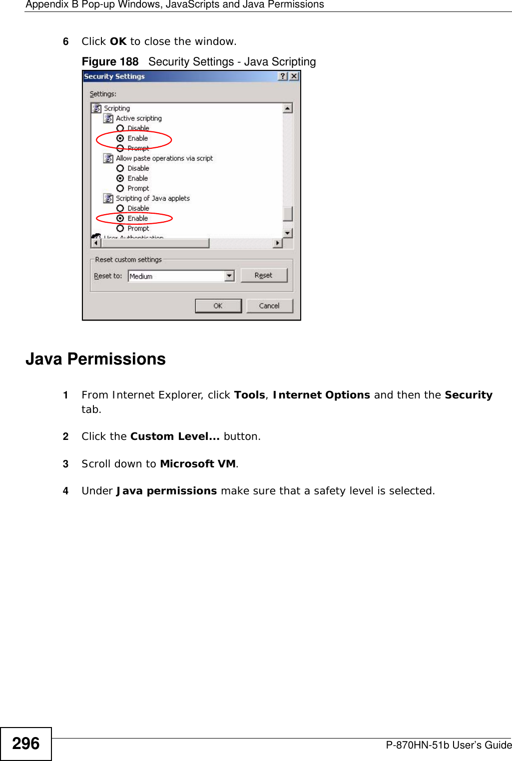
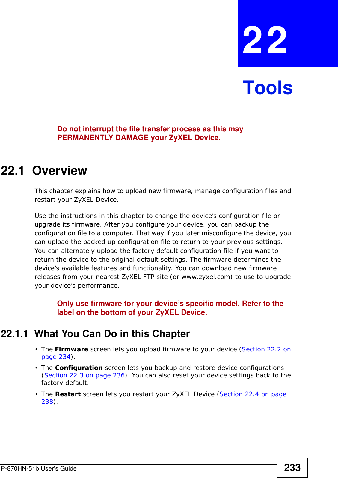
![Chapter 24 TroubleshootingP-870HN-51b User’s Guide2502Make sure you entered your ISP account information correctly in the WAN screens. These fields are case-sensitive, so make sure [Caps Lock] is not on. 3If you are trying to access the Internet wirelessly, make sure the wireless settings in the wireless client are the same as the settings in the AP. 4Disconnect all the cables from your device, and follow the directions in the Quick Start Guide again. 5If the problem continues, contact your ISP. I cannot access the Internet anymore. I had access to the Internet (with the ZyXEL Device), but my Internet connection is not available anymore.1Check the hardware connections, and make sure the LEDs are behaving as expected. See the Quick Start Guide and Section 1.5 on page 24.2Turn the ZyXEL Device off and on. 3If the problem continues, contact your ISP. The Internet connection is slow or intermittent.1There might be a lot of traffic on the network. Look at the LEDs, and check Section 1.5 on page 24. If the ZyXEL Device is sending or receiving a lot of information, try closing some programs that use the Internet, especially peer-to-peer applications. 2Check the signal strength. If the signal strength is low, try moving your computer closer to the ZyXEL Device if possible, and look around to see if there are any devices that might be interfering with the wireless network (for example, microwaves, other wireless networks, and so on).3Turn the ZyXEL Device off and on. 4If the problem continues, contact the network administrator or vendor, or try one of the advanced suggestions.Advanced Suggestions](https://usermanual.wiki/ZyXEL-Communications/P870HN51B.user-manual-2/User-Guide-1187133-Page-50.png)

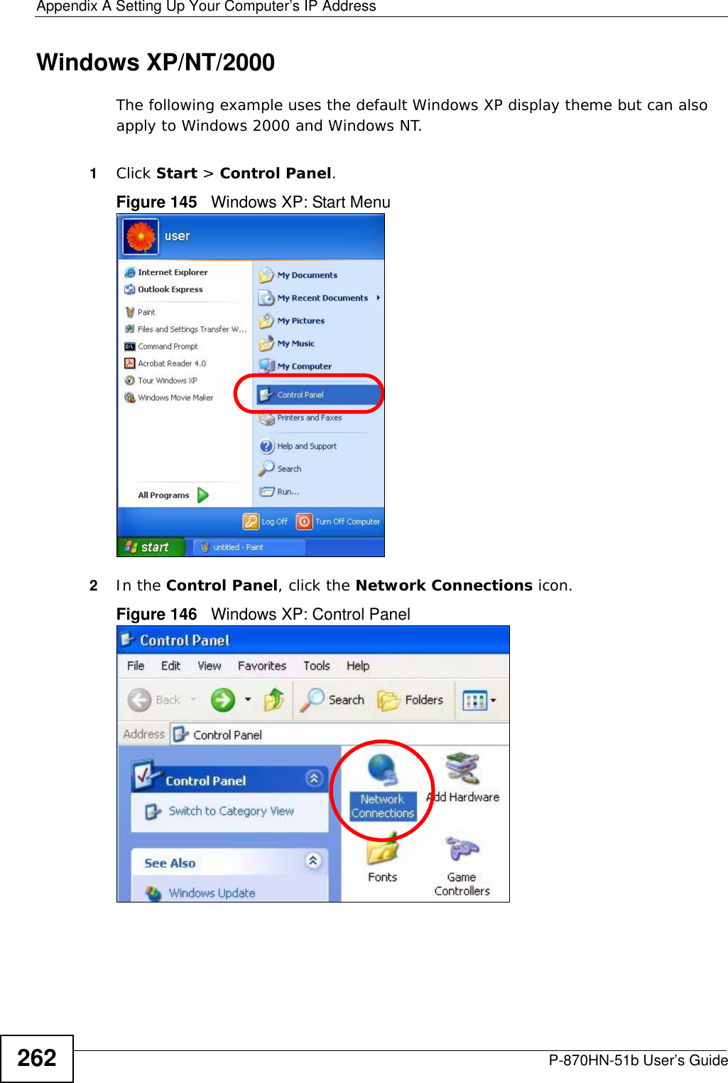
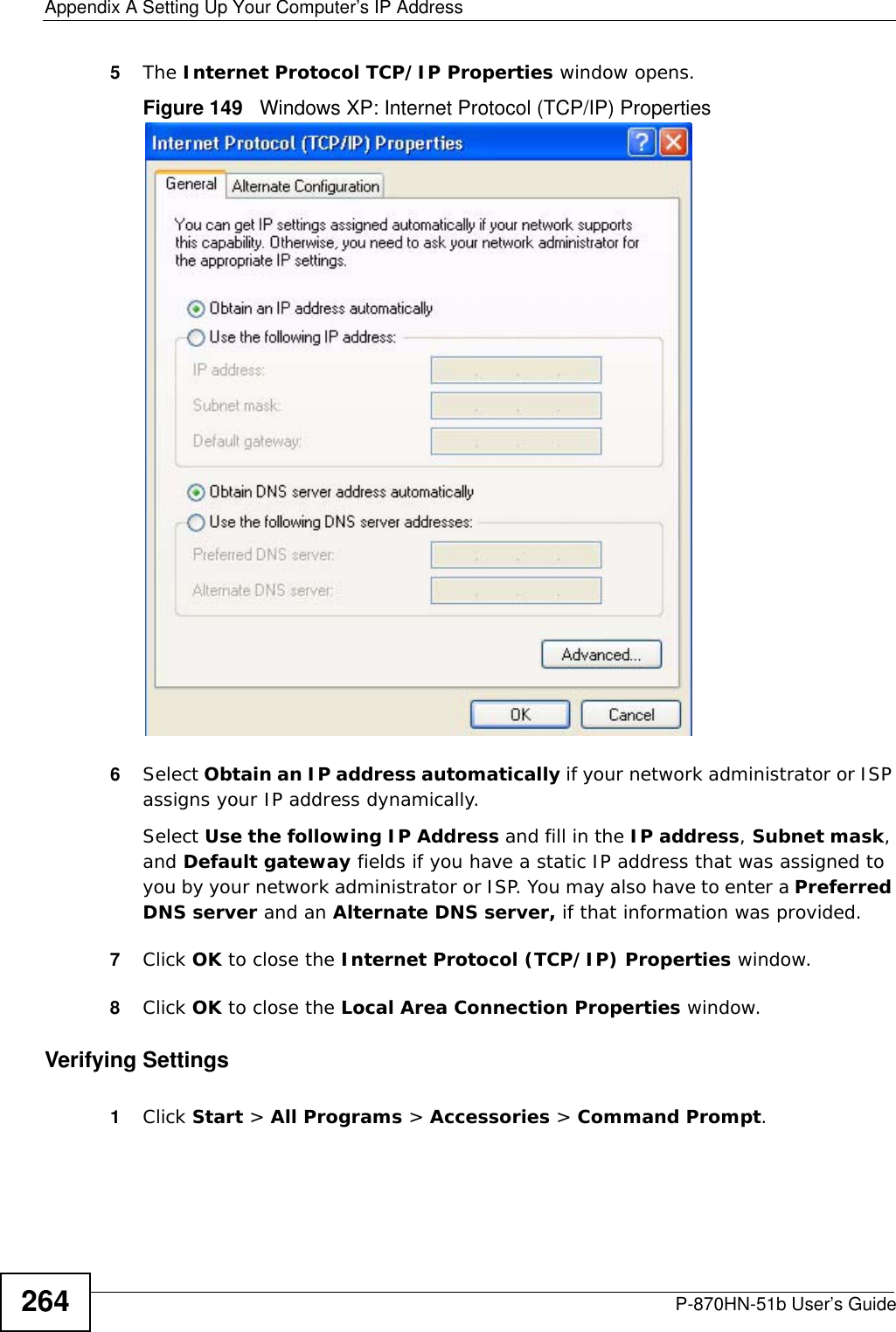
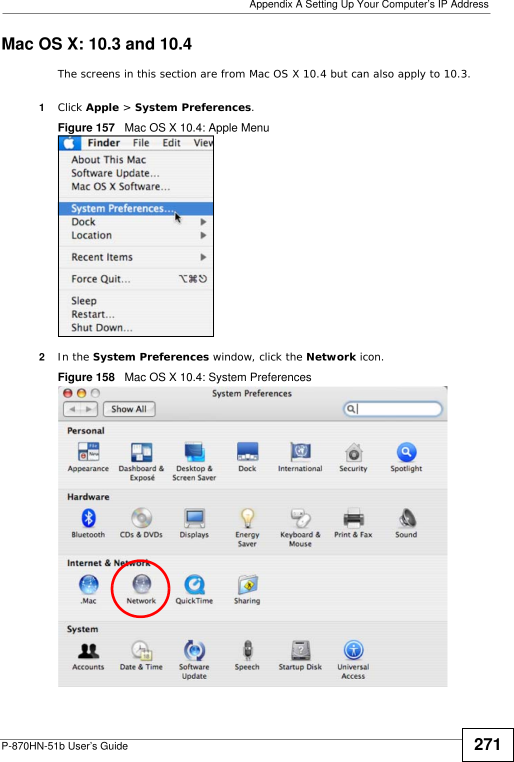
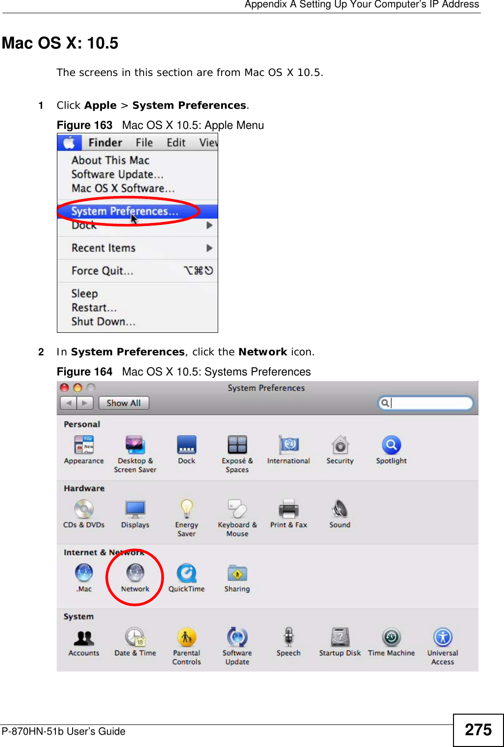
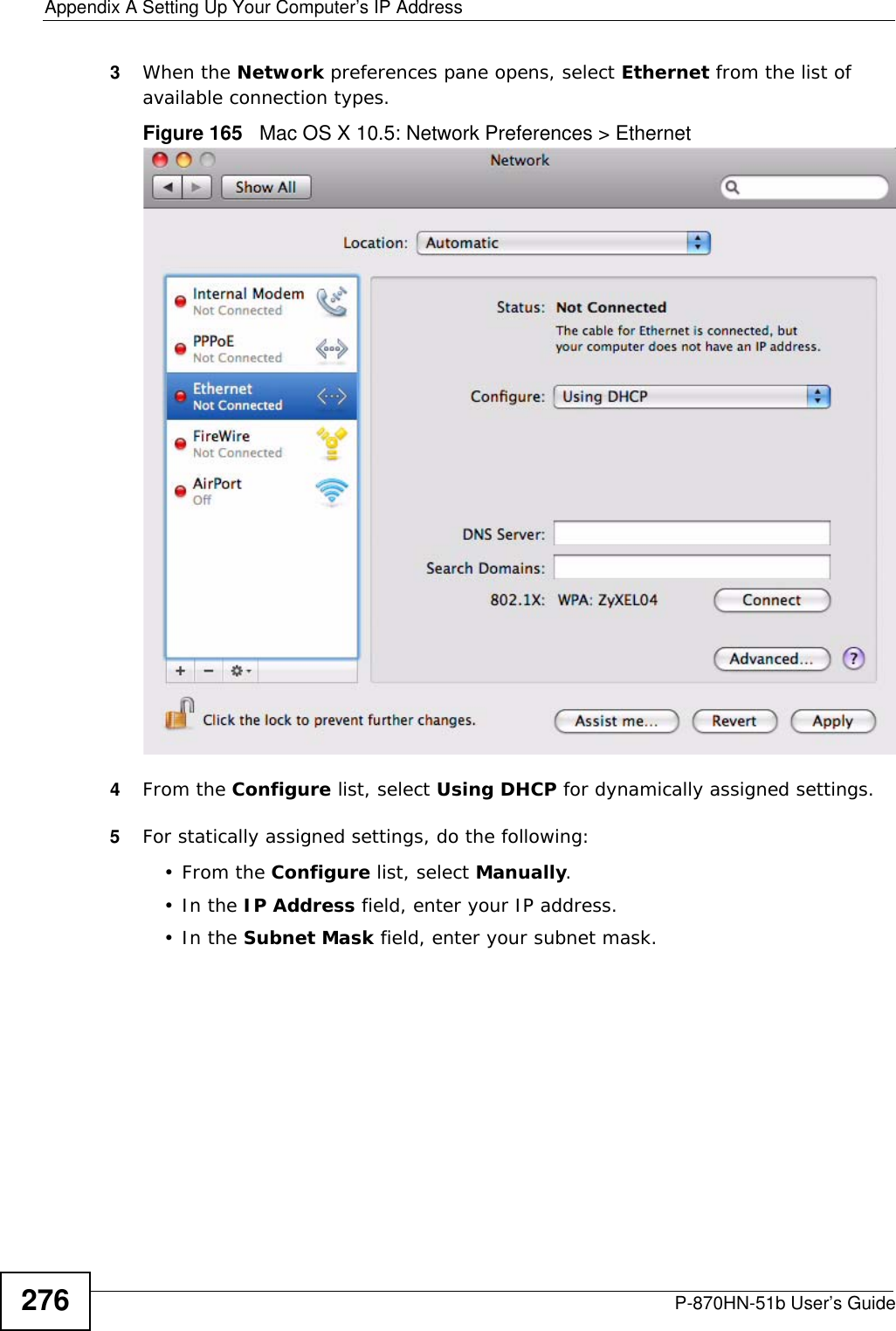
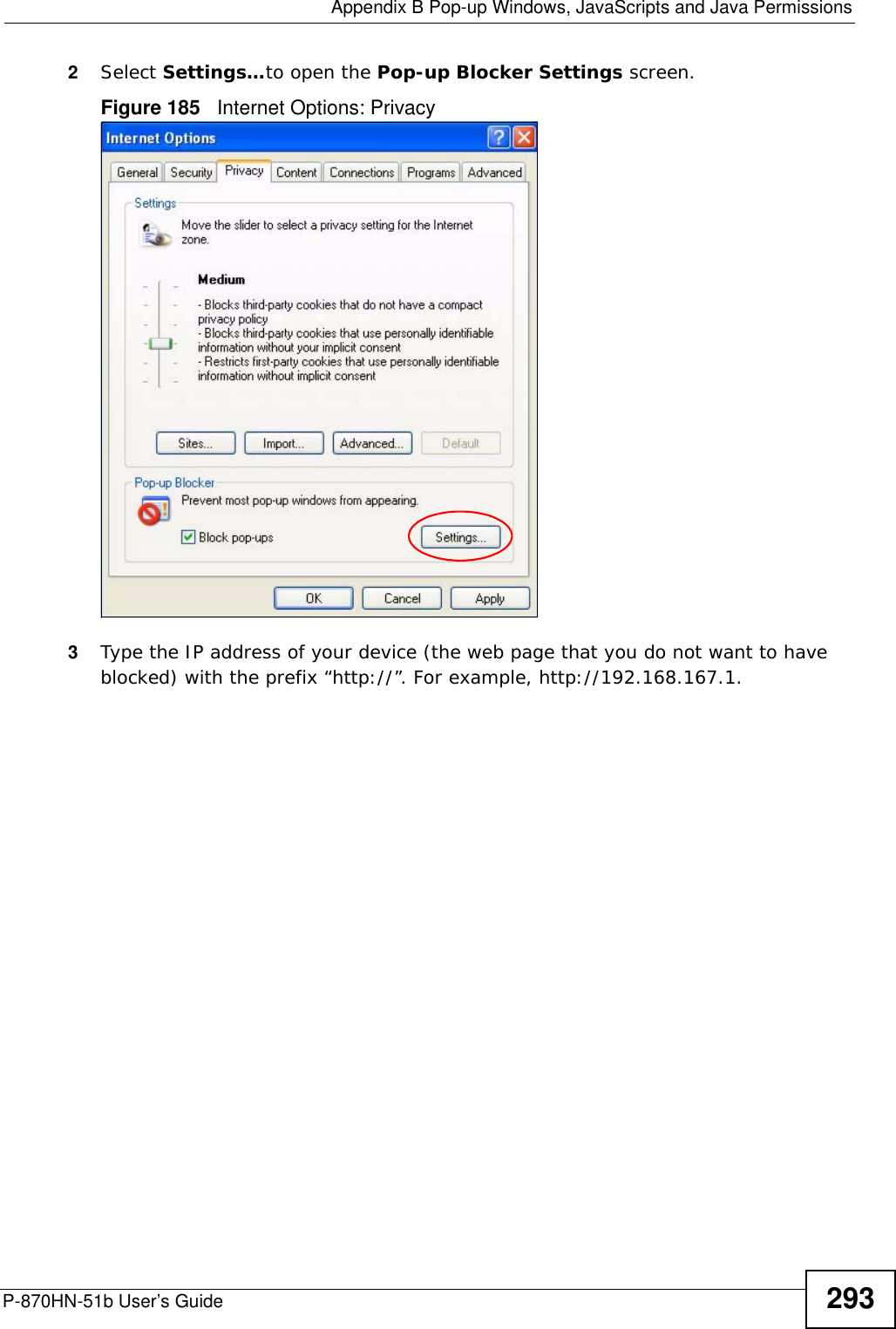
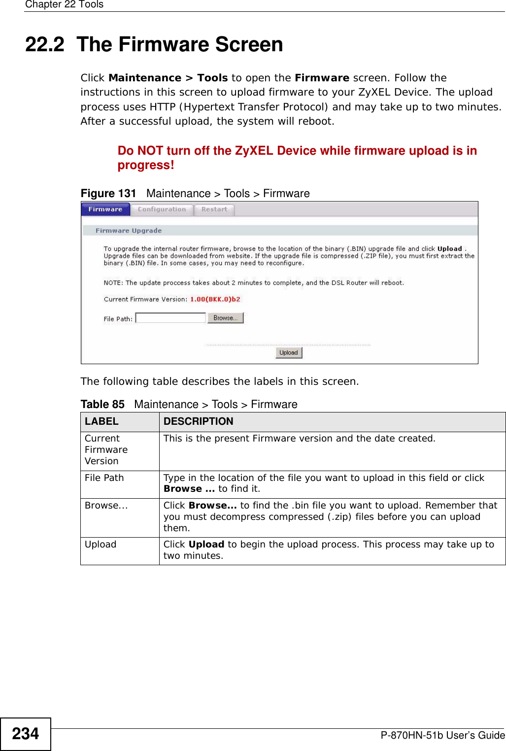
![Appendix A Setting Up Your Computer’s IP AddressP-870HN-51b User’s Guide 2652In the Command Prompt window, type "ipconfig" and then press [ENTER]. You can also go to Start > Control Panel > Network Connections, right-click a network connection, click Status and then click the Support tab to view your IP address and connection information.](https://usermanual.wiki/ZyXEL-Communications/P870HN51B.user-manual-2/User-Guide-1187133-Page-65.png)
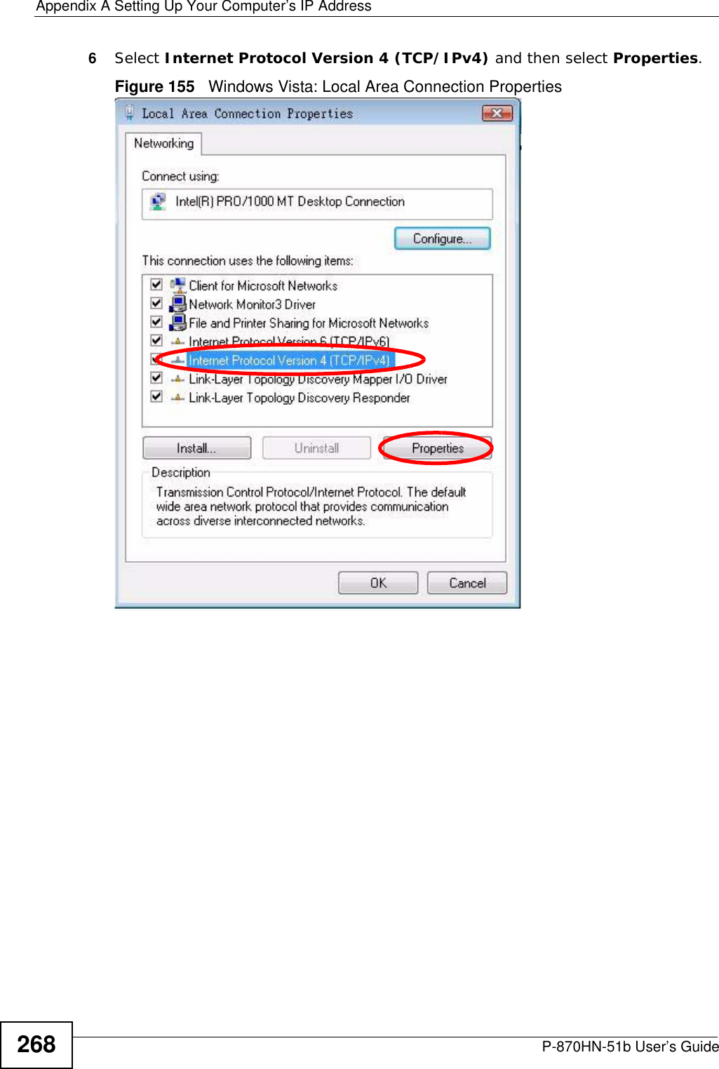
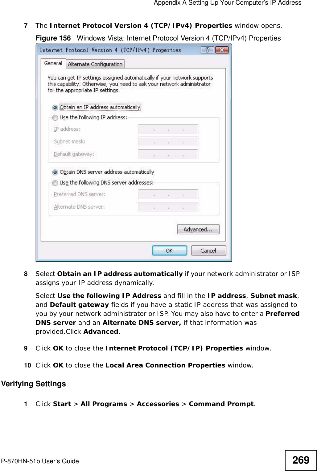
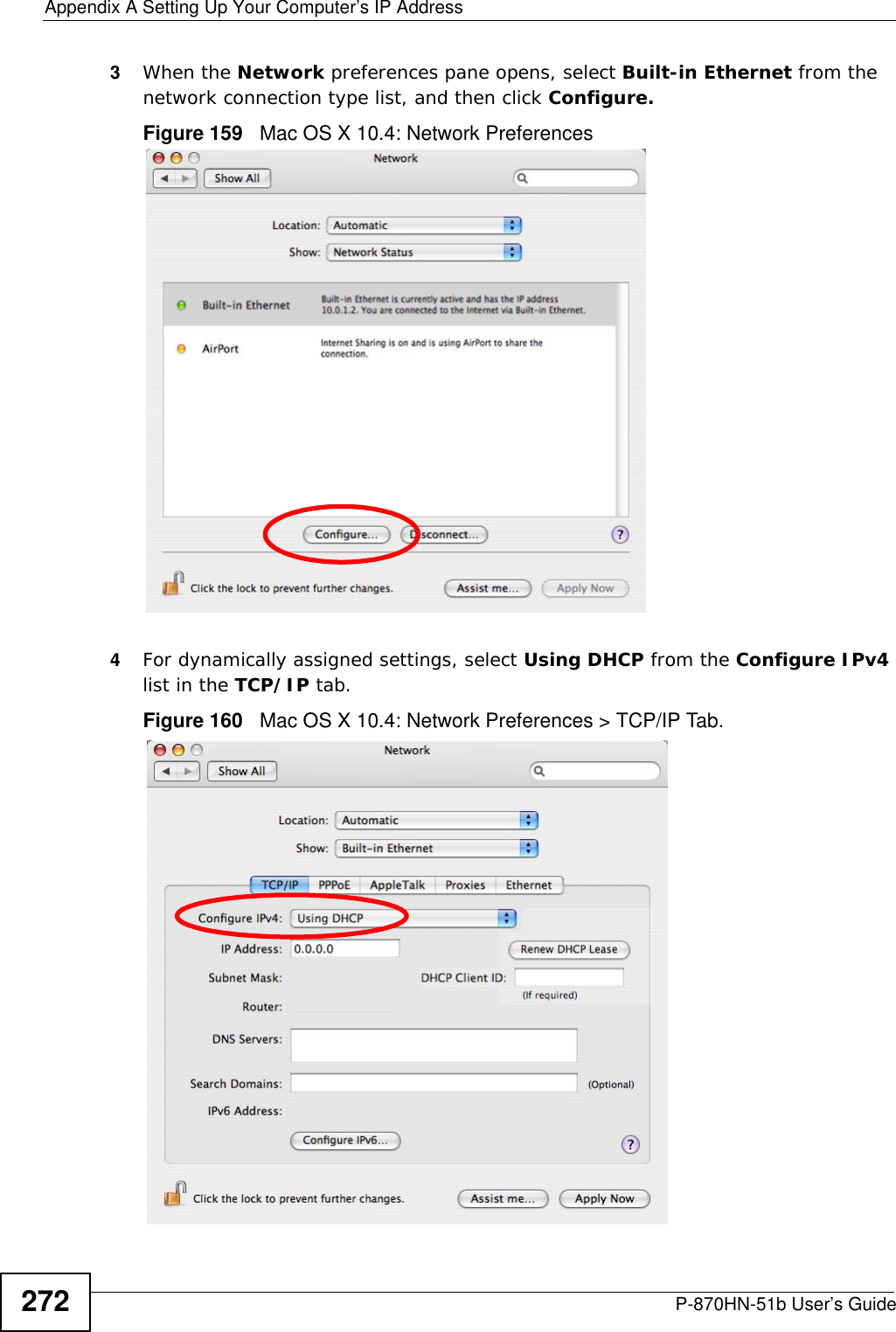
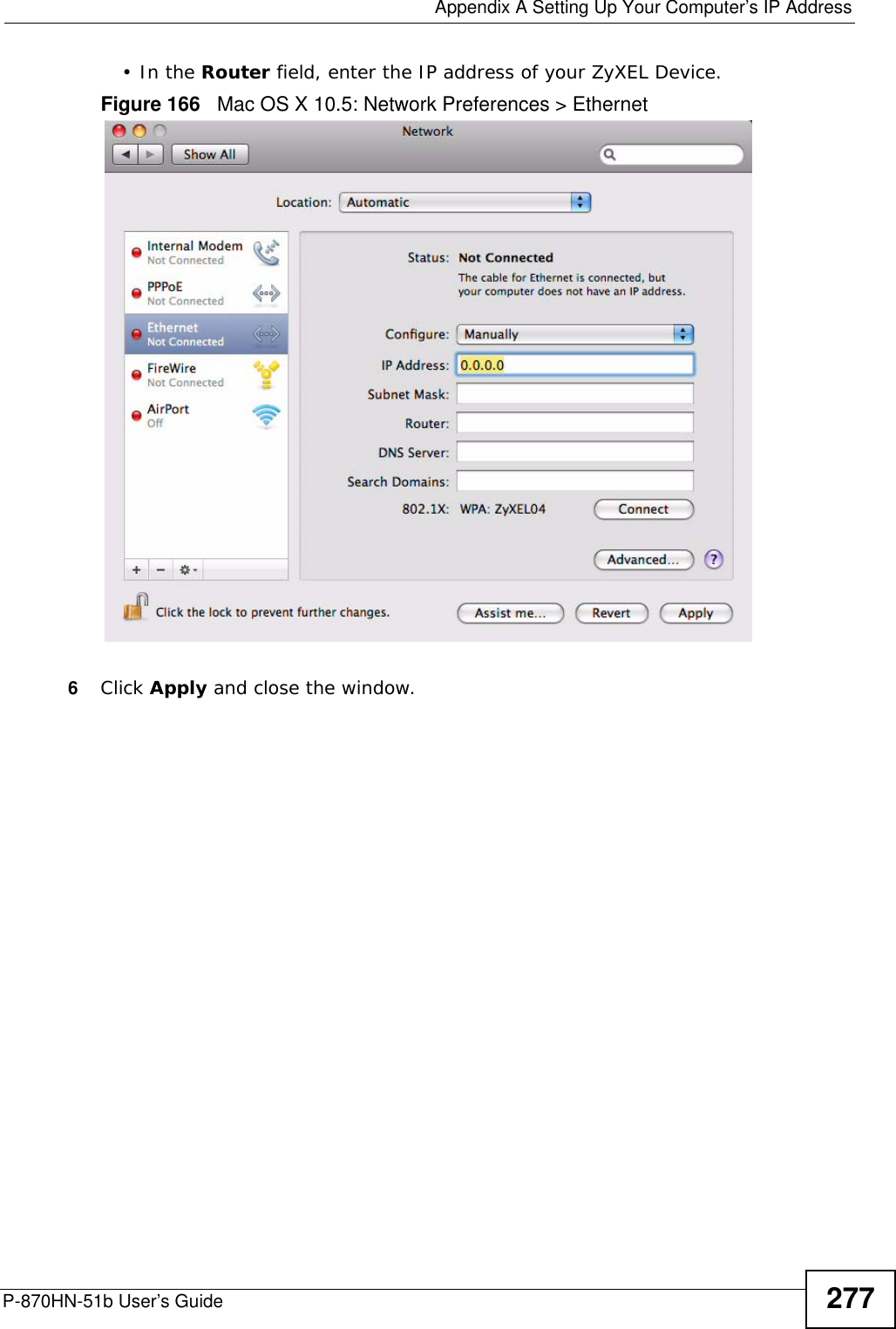
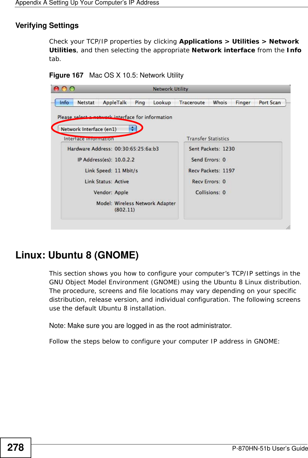
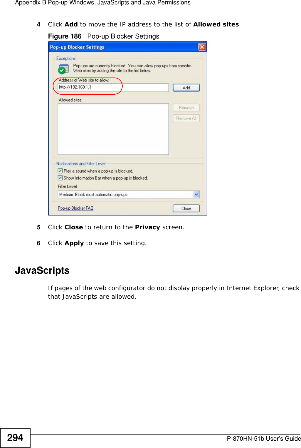
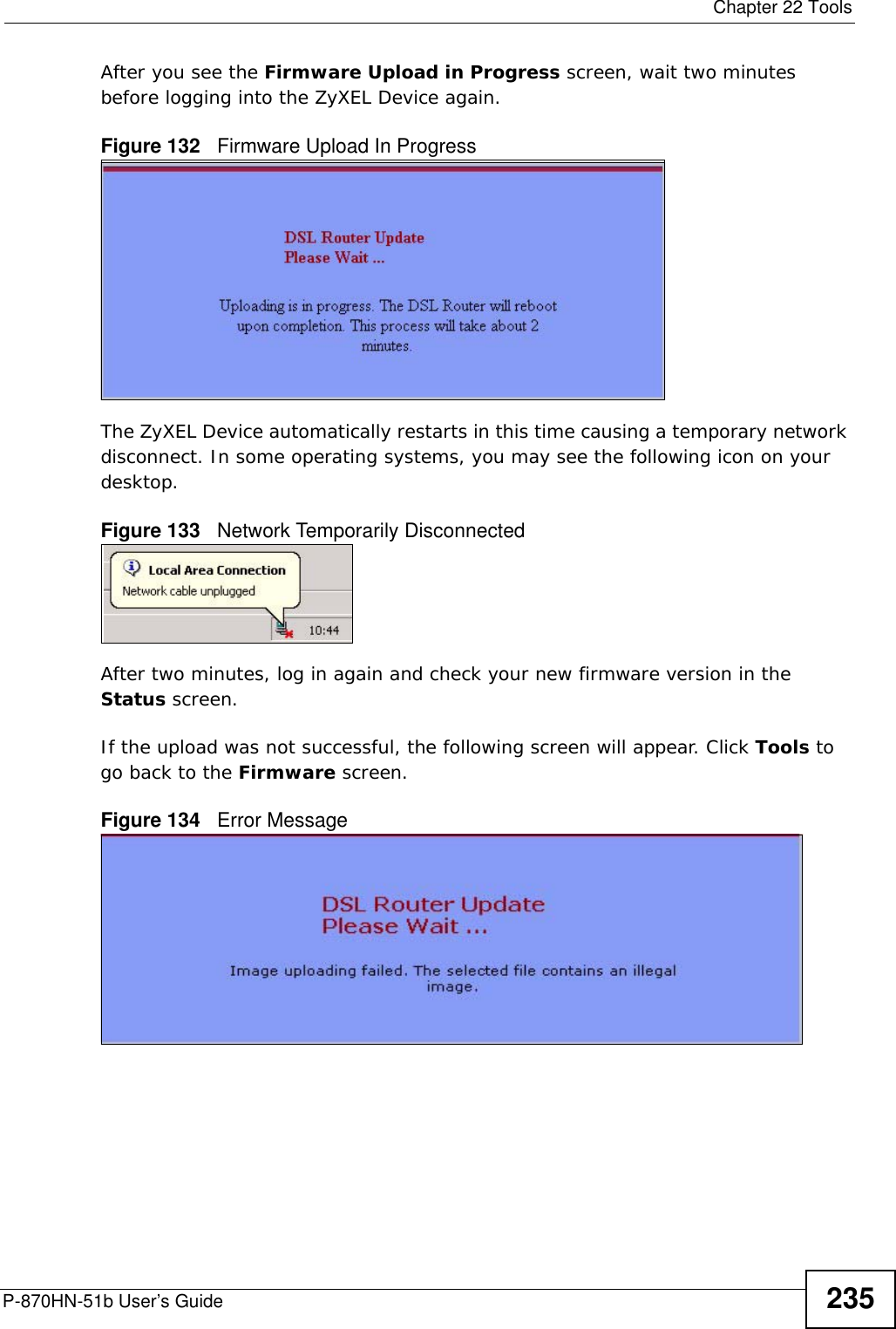
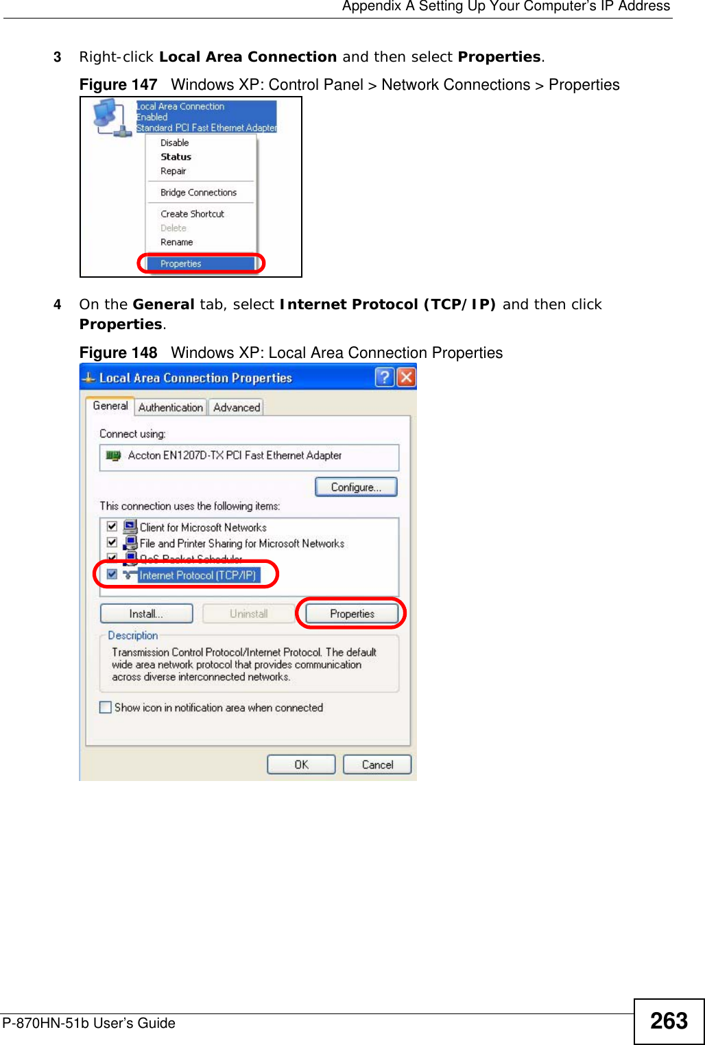
![Appendix A Setting Up Your Computer’s IP AddressP-870HN-51b User’s Guide2702In the Command Prompt window, type "ipconfig" and then press [ENTER]. You can also go to Start > Control Panel > Network Connections, right-click a network connection, click Status and then click the Support tab to view your IP address and connection information.](https://usermanual.wiki/ZyXEL-Communications/P870HN51B.user-manual-2/User-Guide-1187133-Page-70.png)