ZyXEL Communications P870HN51B 802.11n VDSL2 4-port Gateway User Manual SMG 700 User s Guide V1 00 Nov 2004
ZyXEL Communications Corporation 802.11n VDSL2 4-port Gateway SMG 700 User s Guide V1 00 Nov 2004
Contents
- 1. user manual 1
- 2. user manual 2
user manual 2

Chapter 17 Universal Plug-and-Play (UPnP)
P-870HN-51b User’s Guide 201
The following table describes the fields in this screen.
17.4 Installing UPnP in Windows Example
This section shows how to install UPnP in Windows Me and Windows XP.
Installing UPnP in Windows Me
Follow the steps below to install the UPnP in Windows Me.
1Click Start and Control Panel. Double-click Add/Remove Programs.
Table 73 Advanced > UPnP
LABEL DESCRIPTION
Activate Universal Plug
and Play (UPnP) Feature Select this check box to enable UPnP. Be aware that anyone
could use a UPnP application to open the web configurator's
login screen without entering the ZyXEL Device's IP address
(although you must still enter the password to access the web
configurator).
Apply/Save Click this to save the setting to the ZyXEL Device.
Cancel Click this to return to the previously saved settings.
Chapter 17 Universal Plug-and-Play (UPnP)
P-870HN-51b User’s Guide
202
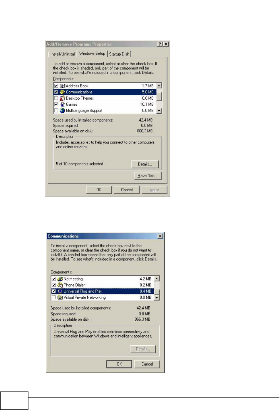
2Click on the Windows Setup tab and select Communication in the
Components selection box. Click Details.
Figure 105 Add/Remove Programs: Windows Setup: Communication
3In the Communications window, select the Universal Plug and Play check box
in the Components selection box.
Figure 106 Add/Remove Programs: Windows Setup: Communication: Components
Chapter 17 Universal Plug-and-Play (UPnP)
P-870HN-51b User’s Guide 203
4Click OK to go back to the Add/Remove Programs Properties window and click
Next.
5Restart the computer when prompted.
Installing UPnP in Windows XP
Follow the steps below to install the UPnP in Windows XP.
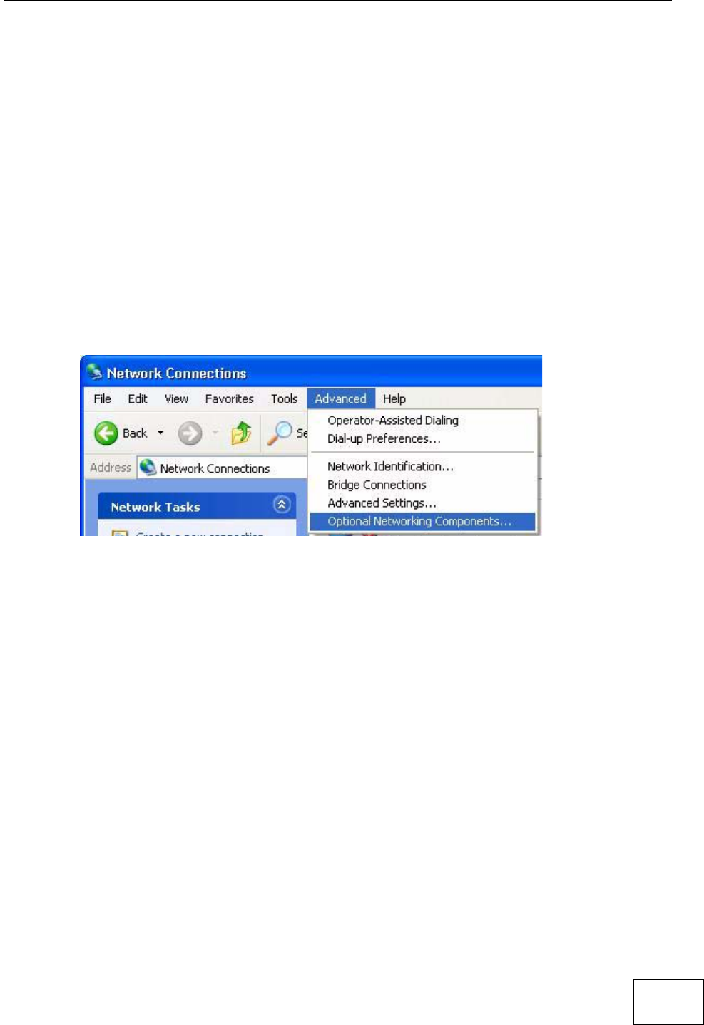
1Click Start and Control Panel.
2Double-click Network Connections.
3In the Network Connections window, click Advanced in the main menu and
select Optional Networking Components ….
Figure 107 Network Connections
Chapter 17 Universal Plug-and-Play (UPnP)
P-870HN-51b User’s Guide
204
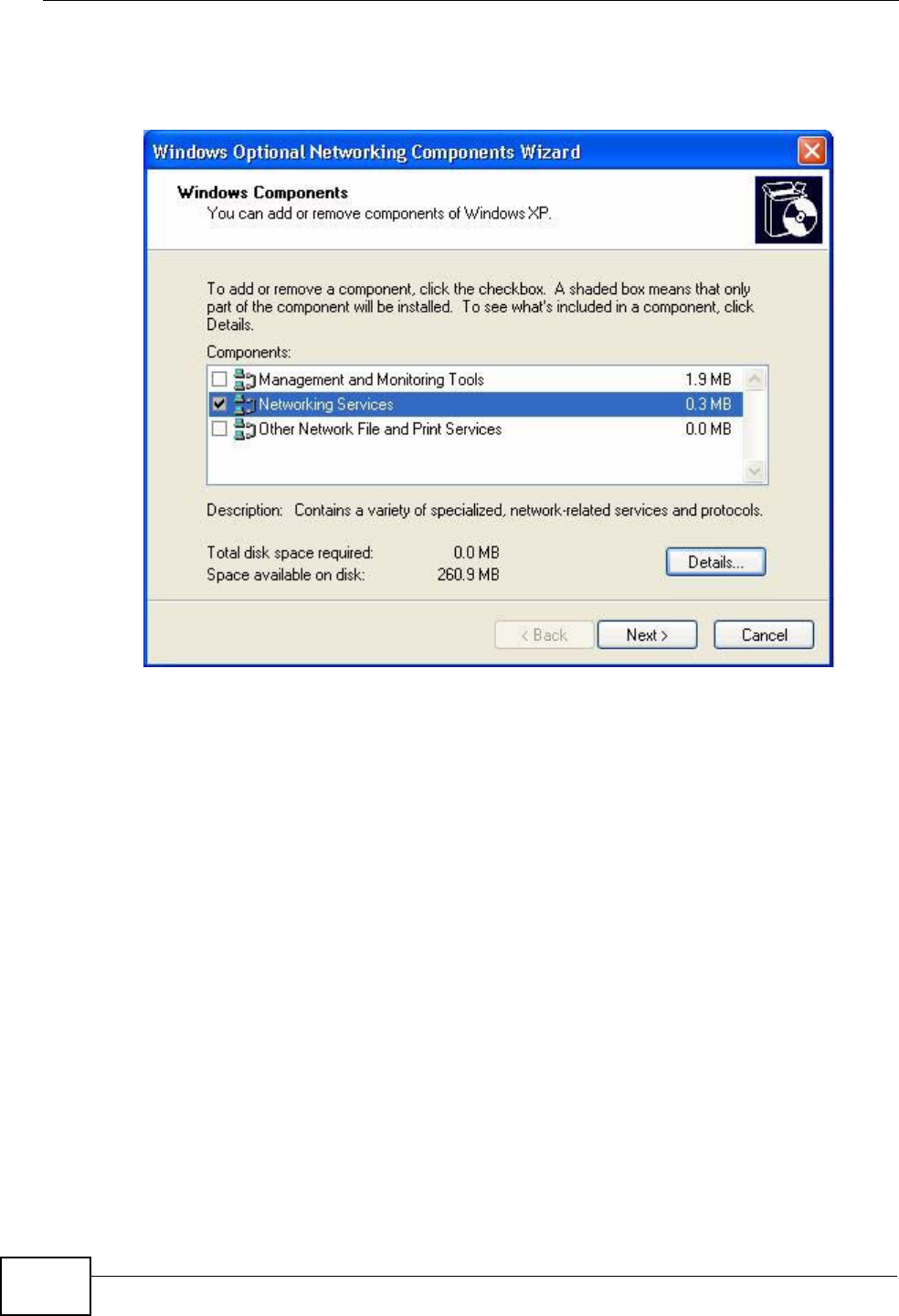
4The Windows Optional Networking Components Wizard window displays.
Select Networking Service in the Components selection box and click Details.
Figure 108 Windows Optional Networking Components Wizard
Chapter 17 Universal Plug-and-Play (UPnP)
P-870HN-51b User’s Guide 205
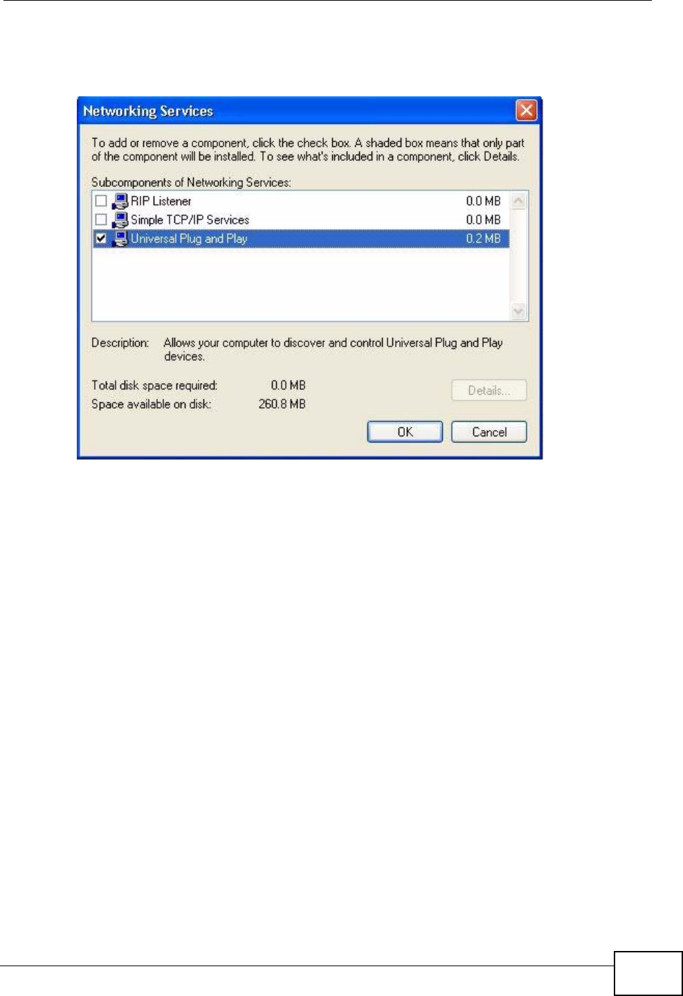
5In the Networking Services window, select the Universal Plug and Play check
box.
Figure 109 Networking Services
6Click OK to go back to the Windows Optional Networking Component Wizard
window and click Next.
17.5 Using UPnP in Windows XP Example
This section shows you how to use the UPnP feature in Windows XP. You must
already have UPnP installed in Windows XP and UPnP activated on the ZyXEL
Device.
Make sure the computer is connected to a LAN port of the ZyXEL Device. Turn on
your computer and the ZyXEL Device.
Auto-discover Your UPnP-enabled Network Device
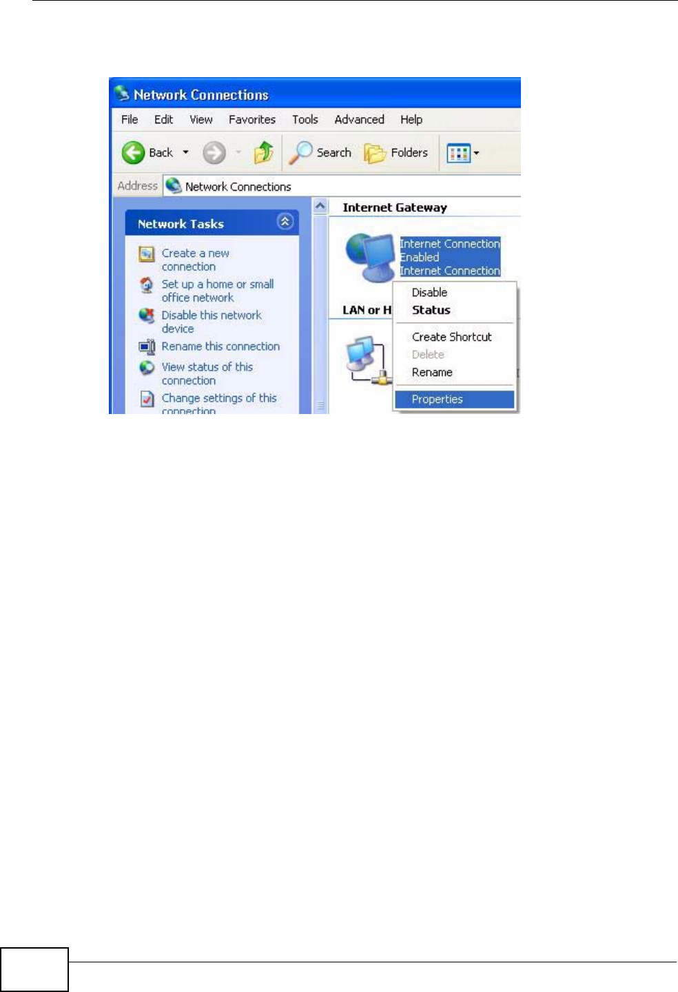
1Click Start and Control Panel. Double-click Network Connections. An icon
displays under Internet Gateway.
Chapter 17 Universal Plug-and-Play (UPnP)
P-870HN-51b User’s Guide
206
2Right-click the icon and select Properties.
Figure 110 Network Connections
Chapter 17 Universal Plug-and-Play (UPnP)
P-870HN-51b User’s Guide 207
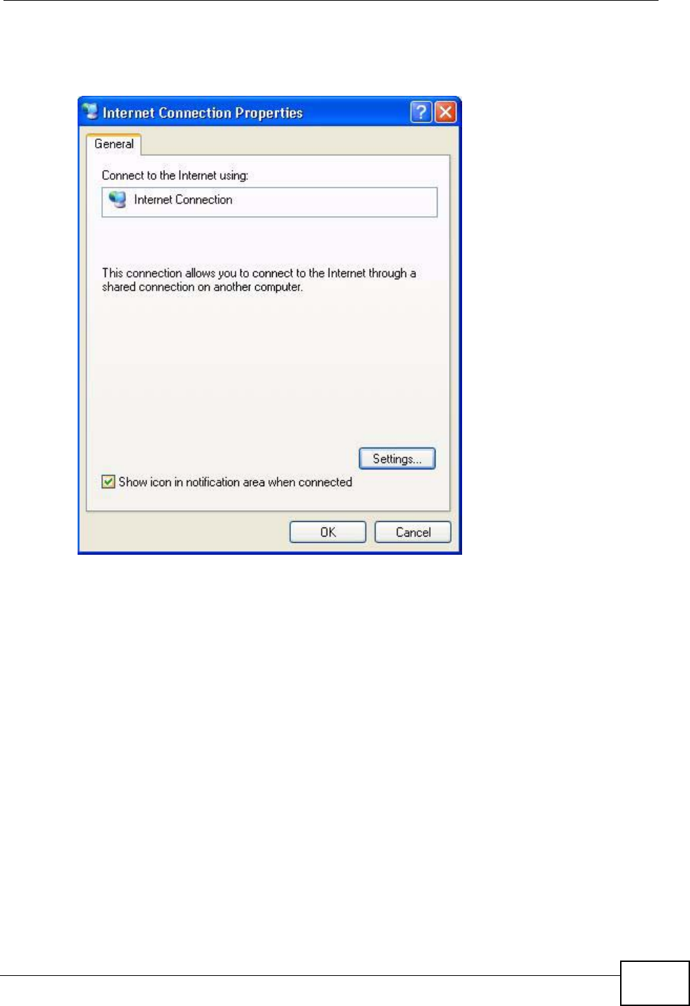
3In the Internet Connection Properties window, click Settings to see the port
mappings there were automatically created.
Figure 111 Internet Connection Properties
Chapter 17 Universal Plug-and-Play (UPnP)
P-870HN-51b User’s Guide
208
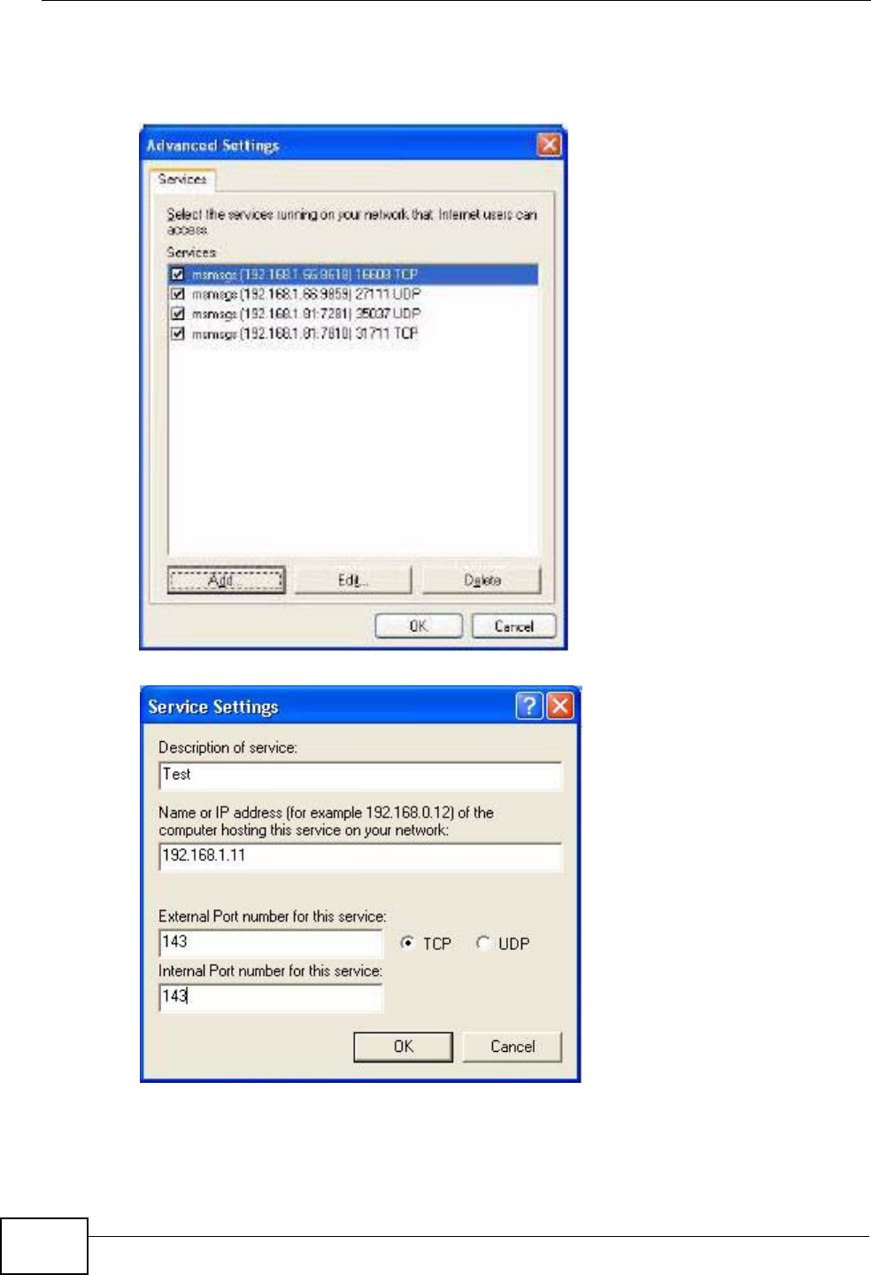
4You may edit or delete the port mappings or click Add to manually add port
mappings.
Figure 112 Internet Connection Properties: Advanced Settings
Figure 113 Internet Connection Properties: Advanced Settings: Add
5When the UPnP-enabled device is disconnected from your computer, all port
mappings will be deleted automatically.
Chapter 17 Universal Plug-and-Play (UPnP)
P-870HN-51b User’s Guide 209
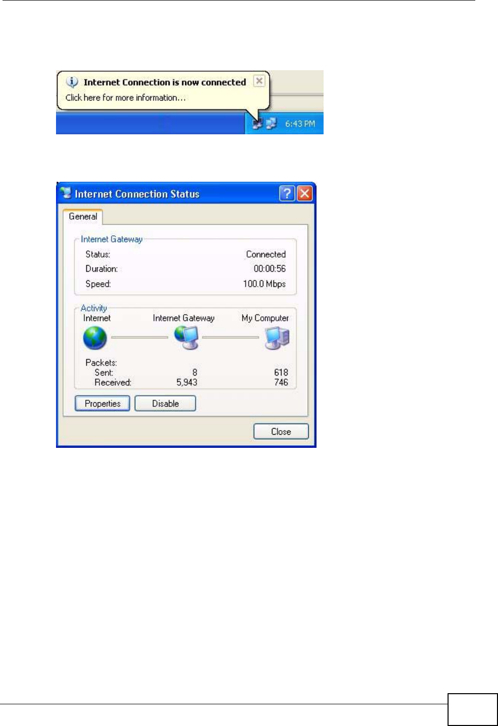
6Select Show icon in notification area when connected option and click OK.
An icon displays in the system tray.
Figure 114 System Tray Icon
7Double-click on the icon to display your current Internet connection status.
Figure 115 Internet Connection Status
Web Configurator Easy Access
With UPnP, you can access the web-based configurator on the ZyXEL Device
without finding out the IP address of the ZyXEL Device first. This comes helpful if
you do not know the IP address of the ZyXEL Device.
Follow the steps below to access the web configurator.
1Click Start and then Control Panel.
2Double-click Network Connections.
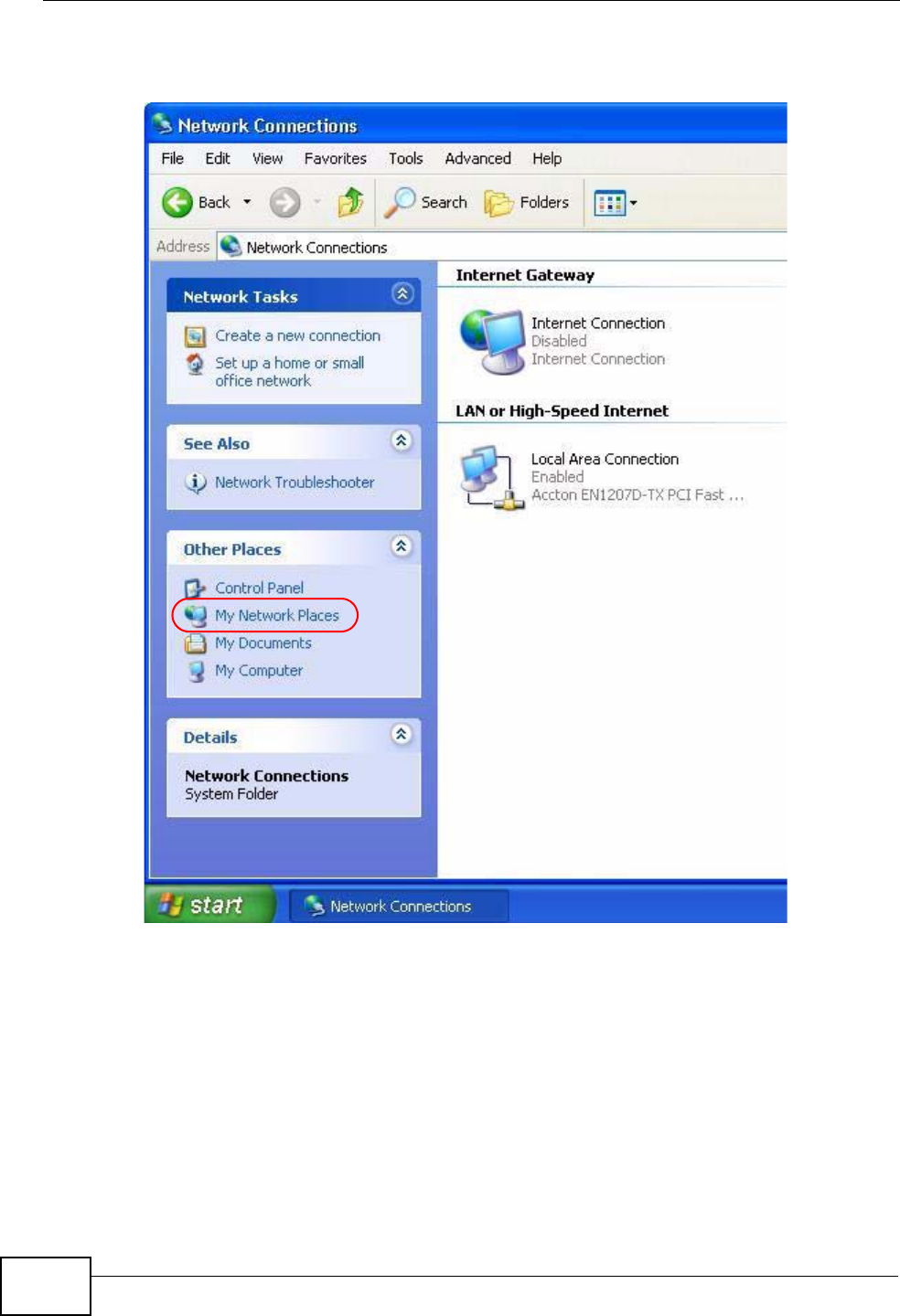
Chapter 17 Universal Plug-and-Play (UPnP)
P-870HN-51b User’s Guide
210
3Select My Network Places under Other Places.
Figure 116 Network Connections
4An icon with the description for each UPnP-enabled device displays under Local
Network.
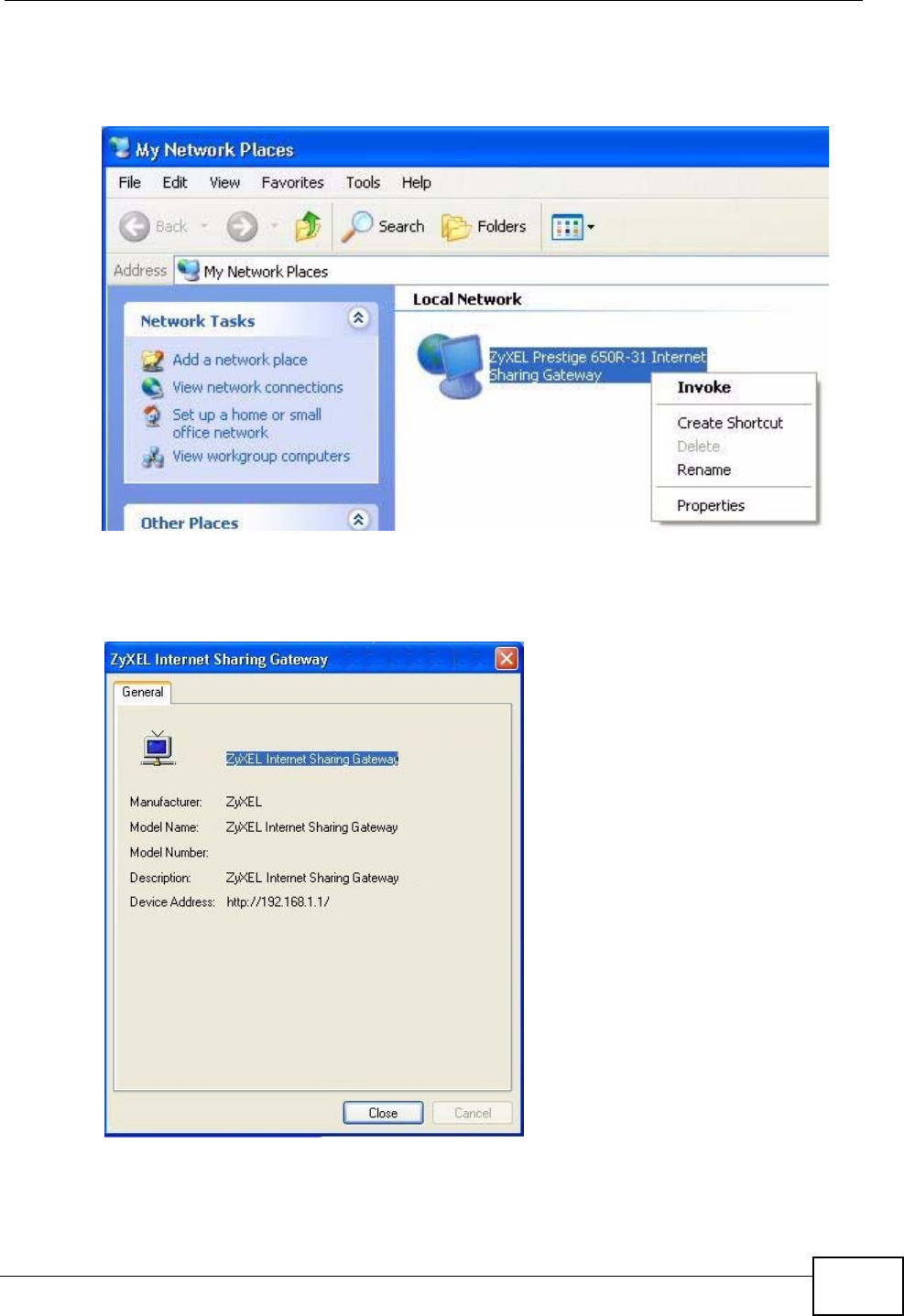
Chapter 17 Universal Plug-and-Play (UPnP)
P-870HN-51b User’s Guide 211
5Right-click on the icon for your ZyXEL Device and select Invoke. The web
configurator login screen displays.
Figure 117 Network Connections: My Network Places
6Right-click on the icon for your ZyXEL Device and select Properties. A properties
window displays with basic information about the ZyXEL Device.
Figure 118 Network Connections: My Network Places: Properties: Example

Chapter 17 Universal Plug-and-Play (UPnP)
P-870HN-51b User’s Guide
212
P-870HN-51b User’s Guide 213
CHAPTER 18
Parental Control
18.1 Overview
Parental control allows you to block web sites with the specific URL. You can also
define time periods and days during which the ZyXEL Device performs parental
control on a specific user.
18.1.1 What You Can Do in this Chapter
•The Time Restriction screen lets you give different time restrictions to each
user of your network (Section 18.2 on page 213).
•The URL Filter screen lets you restrict home network users from viewing
inappropriate websites (Section 18.3 on page 215).
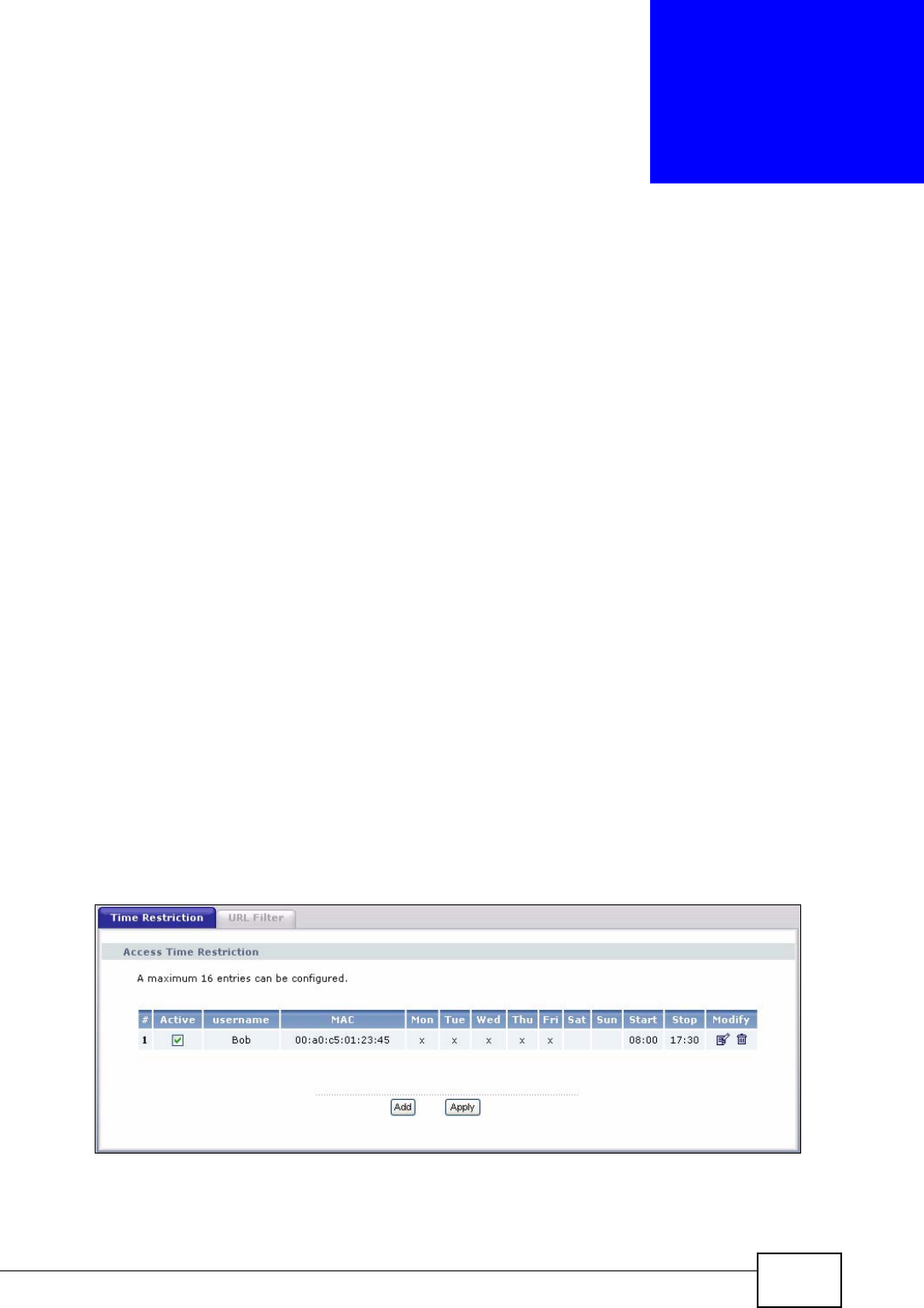
18.2 The Time Restriction Screen
Use this screen to view the schedules and enable parental control on a specific
user during certain periods.
Click Advanced Setup > Parental Control to open the following screen.
Figure 119 Parental Control > Time restriction
Chapter 18 Parental Control
P-870HN-51b User’s Guide
214
The following table describes the fields in this screen.
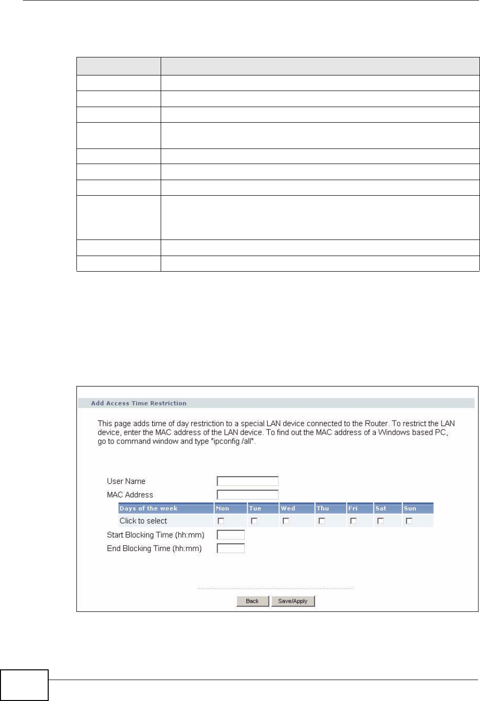
18.2.1 Adding a Schedule
Click the Add button in the Time Restriction screen to open the following
screen. Use this screen to configure a restricted access schedule for a specific user
on your network.
Figure 120 Time Restriction Configuration
Table 74 Parental Control > Time Restriction
LABEL DESCRIPTION
#This shows the index number of the schedule.
Active Select the check box to enable the schedule.
username This shows the name of the user.
MAC This shows the MAC address of the LAN user’s computer to which this
schedule applies.
Mon ~ Sun x indicates the day(s) on which parental control is enabled.
Start This shows the time when the schedule starts.
Stop This shows the time when the schedule ends.
Modify Click the Edit icon to go to the screen where you can edit the
schedule.
Click the Remove icon to delete an existing schedule.
Add Click Add to create a new schedule.
Apply Click Apply to save your changes back to the ZyXEL Device.
Chapter 18 Parental Control
P-870HN-51b User’s Guide 215
The following table describes the fields in this screen.
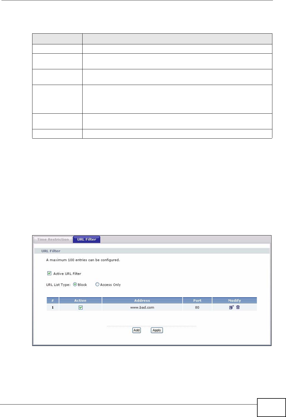
18.3 The URL Filter Screen
Use this screen to configure URL filtering settings to allow or block the users on
your network from accessing certain web sites.
Click Advanced Setup > Parental Control > URL Filter to open the following
screen.
Figure 121 Parental Control > URL Filter
Table 75 Time Restriction Configuration
LABEL DESCRIPTION
User Name Enter the name of the user.
MAC Address Enter the MAC address of the LAN user’s computer to which this
schedule applies.
Days of the week Select check boxes for the days that you want the ZyXEL Device to
perform parental control.
Start Blocking
Time
End Blocking
Time
Enter the time period of each day, in 24-hour format, during which
parental control will be enforced.
Back Click this button to return to the previous screen without saving any
changes.
Save/Apply Click this button to save your settings back to the ZyXEL Device.
Chapter 18 Parental Control
P-870HN-51b User’s Guide
216
The following table describes the fields in this screen.
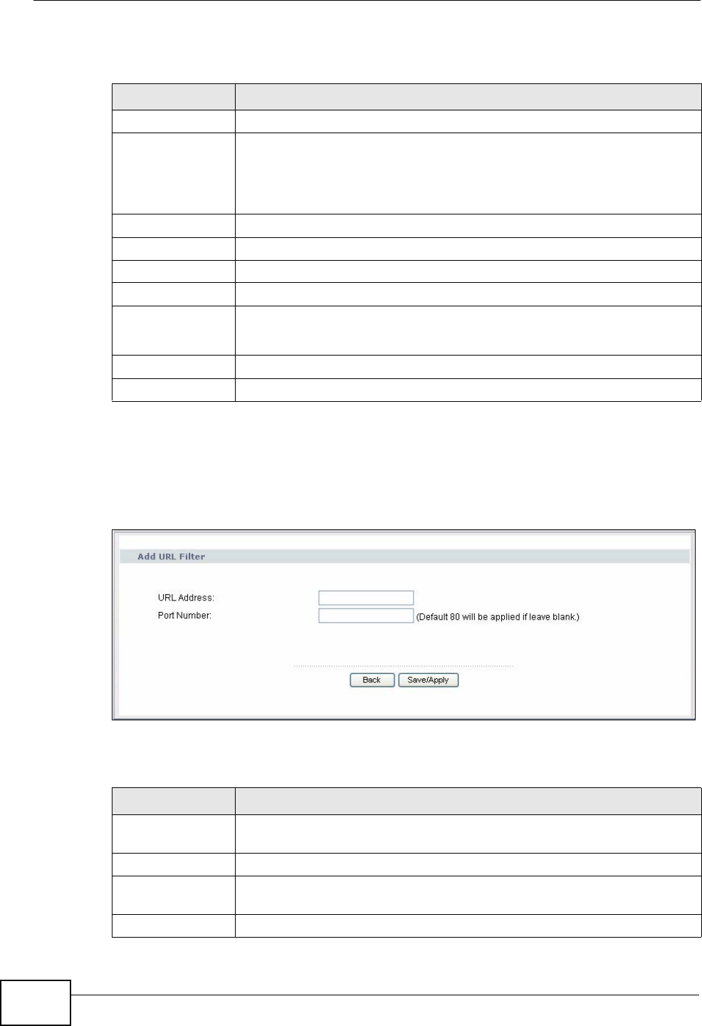
18.3.1 Adding URL Filter
Click the Add button in the URL Filter screen to open the following screen.
Figure 122 URL Filter Configuration
The following table describes the fields in this screen.
Table 76 Parental Control > URL Filter
LABEL DESCRIPTION
Active URL Filter Select the check box to enable URL filtering on the ZyXEL Device.
URL List Type If you select Block, the ZyXEL Device prohibits the users from viewing
the Web sites with the URLs listed below.
If you select Access Only, the ZyXEL Device blocks access to all URLs
except ones listed below.
# This is the index number of the rule.
Active Select the check box to enable the filtering rule.
Address This is the URL of the web site in this rule.
Port This is the port number the web server uses to forward HTTP traffic.
Modify Click the Edit icon to go to the screen where you can edit the rule.
Click the Remove icon to delete an existing rule.
Add Click Add to create a new rule.
Apply Click this button to save your settings back to the ZyXEL Device.
Table 77 URL Filter Configuration
LABEL DESCRIPTION
URL Address Enter the URL of web site to which the ZyXEL Device blocks or allows
access.
Port Number Specify the port number the web server uses to forward HTTP traffic.
Back Click this button to return to the previous screen without saving any
changes.
Save/Apply Click this button to save your settings back to the ZyXEL Device.

P-870HN-51b User’s Guide 217
CHAPTER 19
Interface Group
19.1 Overview
By default, all LAN and WAN interfaces on the ZyXEL Device are in the same group
and can communicate with each other. You can create multiple groups to have the
ZyXEL Device assign the IP addresses in different domains to different groups.
Each group acts as an independent network on the ZyXEL Device.
19.1.1 What You Can Do in this Chapter
The Interface Group screen lets you create multiple networks on the ZyXEL
Device (Section 19.2 on page 217).
19.2 The Interface Group Screen
You can manually add a LAN interface to a new group. Alternatively, you can have
the ZyXEL Device automatically add the incoming traffic and the LAN interface on
which traffic is received to the new group when its source MAC address or DHCP
option information matches the predefined filtering criteria.
Use the LAN screen to configure the private IP addresses the DHCP server on the
ZyXEL Device assigns to the clients in the default and/or user-defined groups. If
you set the ZyXEL Device to assign IP addresses based on the client’s source MAC
address or DHCP option information, you must enable DHCP server and configure
LAN TCP/IP settings for both the default and user-defined groups. See Chapter 6
on page 93 for more information.
Chapter 19 Interface Group
P-870HN-51b User’s Guide
218
In the following example, the client that sends packets with the source MAC
address 00:19:cb:01:23:45 is assigned the IP address 192.168.2.2 and uses the
WAN interface ptm0_2.
Figure 123 Interface Grouping Application
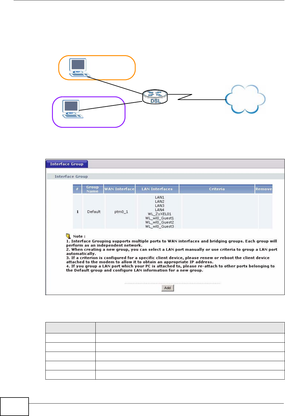
Click Advanced Setup > Interface Group to open the following screen.
Figure 124 Interface Group
The following table describes the fields in this screen.
Table 78 Interface Grouping
LABEL DESCRIPTION
#This shows the index number of the entry.
Group Name This shows the descriptive name of the group.
WAN Interface This shows the WAN interfaces in the group.
LAN Interfaces This shows the LAN interfaces in the group.
Criteria This shows the filtering criteria for the group.
G2: 00:19:cb:01:23:45
Default: ETH 2~4
Internet
192.168.1.x/24
192.168.2.x/24
ptm0_2
ptm0_1
Chapter 19 Interface Group
P-870HN-51b User’s Guide 219
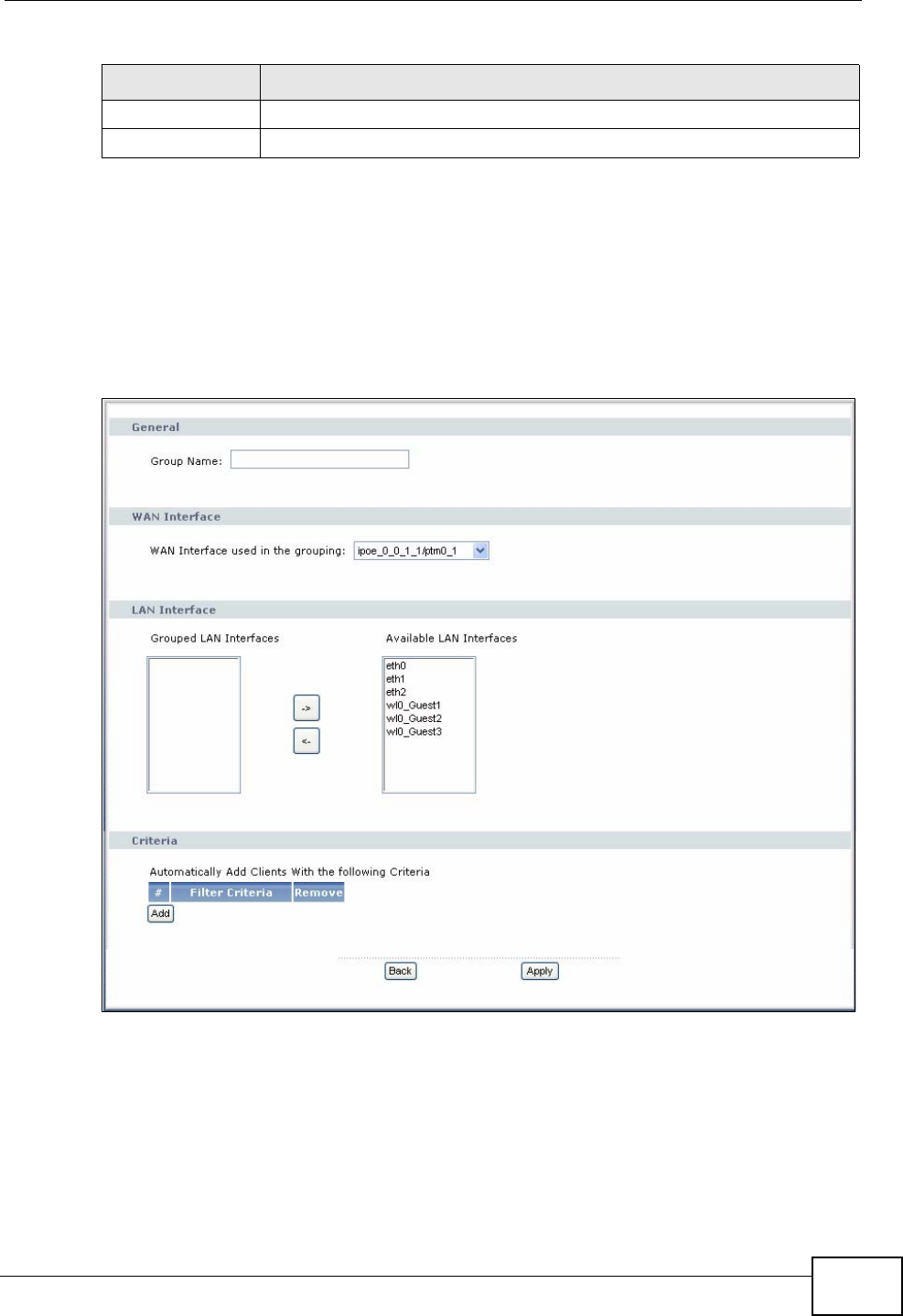
19.2.1 Interface Group Configuration
Click the Add button in the Interface Group screen to open the following screen.
Use this screen to create a new interface group.
Note: An interface can belong to a group only.
Figure 125 Interface Group Configuration
Remove Click the Remove icon to delete the group.
Add Click this button to create a new group.
Table 78 Interface Grouping (continued)
LABEL DESCRIPTION
Chapter 19 Interface Group
P-870HN-51b User’s Guide
220
The following table describes the fields in this screen.
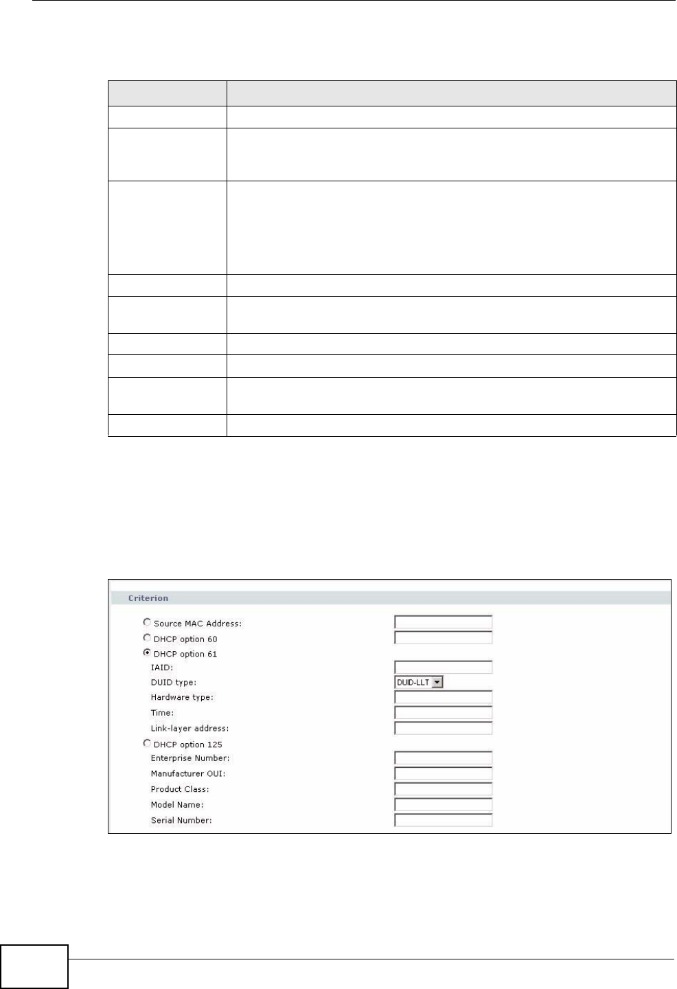
19.2.2 Interface Grouping Criteria
Click the Add button in the Interface Grouping Configuration screen to open
the following screen.
Figure 126 Interface Grouping Criteria
Table 79 Interface Group Configuration
LABEL DESCRIPTION
Group Name Enter a name to identify this group.
WAN Interface
used in the
grouping
Select a WAN interface to be used in this group.
Select No Interface/None to not add a WAN interface to this group.
Grouped LAN
Interfaces
Available LAN
Interfaces
Select a LAN or wireless LAN interface in the Available LAN
Interfaces and use the left-facing arrow to move it to the Grouped
LAN Interfaces to add the interface to this group.
To remove a LAN or wireless LAN interface from the Grouped LAN
Interfaces, use the right-facing arrow.
#This shows the index number of the rule.
Filter Criteria This shows the filtering criteria. The LAN interface on which the
matched traffic is received will belong to this group automatically.
Remove Click the Remove icon to delete this rule from the ZyXEL Device.
Add Click this button to create a new rule.
Back Click this button to return to the previous screen without saving any
changes.
Apply Click this button to save your settings back to the ZyXEL Device.

Chapter 19 Interface Group
P-870HN-51b User’s Guide 221
The following table describes the fields in this screen.
Table 80 Interface Grouping Criteria
LABEL DESCRIPTION
Source MAC
Address Enter the source MAC address of the packet.
DHCP Option 60 Select this option and enter the Vendor Class Identifier (Option 60) of
the matched traffic, such as the type of the hardware or firmware.
DHCP Option 61 Select this and enter the device identity of the matched traffic.
IAID Enter the Identity Association Identifier (IAID) of the device, for
example, the WAN connection index number.
DUID Type Select DUID-LLT (DUID Based on Link-layer Address Plus Time) to
enter the hardware type, a time value and the MAC address of the
device.
Select DUID-EN (DUID Assigned by Vendor Based upon Enterprise
Number) to enter the vendor’s registered enterprise number.
Select DUID-LL (DUID Based on Link-layer Address) to enter the
device’s hardware type and hardware address (MAC address) in the
following fields.
Select Other to enter any string that identifies the device in the DUID
field.
Hardware
type Enter the 16-bit hardware type of the device from which the traffic
comes. For example, Ethernet is 1 and Experimental Ethernet is 2.
Time Enter the time (in seconds since midnight (UTC), January 1, 2000) the
DUID is generated.
Link-layer
address Enter the MAC address of the device.
Enterprise
number Enter the vendor’s 32-bit enterprise number registered with the IANA
(Internet Assigned Numbers Authority).
Identifier Enter a unique identifier assigned by the vendor.
DUID Enter the DHCP Unique Identifier (DUID) of the device.
DHCP Option 125 Select this and enter vendor specific information of the matched
traffic.
Enterprise
number Enter the vendor’s 32-bit enterprise number registered with the IANA
(Internet Assigned Numbers Authority).
Manufacturer
OUI Specify the vendor’s OUI (Organization Unique Identifier). It is usually
the first three bytes of the MAC address.
Product Class Enter the product class of the device.
Model Name Enter the model name of the device.
Serial
Number Enter the serial number of the device.
Back Click this button to return to the previous screen without saving any
changes.
Apply Click this button to save your settings back to the ZyXEL Device.

Chapter 19 Interface Group
P-870HN-51b User’s Guide
222

223
PART V
Maintenance,
Troubleshooting
and Specifications
System Settings (225)
Logs (229)
Tools (233)
Diagnostic (241)
Troubleshooting (247)
Product Specifications (253)

224
P-870HN-51b User’s Guide 225
CHAPTER 20
System Settings
20.1 Overview
This chapter shows you how to configure system related settings, such as system
time, password, name, the domain name and the inactivity timeout interval.
20.1.1 What You Can Do in this Chapter
•The General screen lets you configure system settings (Section 20.2 on page
225).
•The Time Setting screen lets you set the system time (Section 20.3 on page
226).
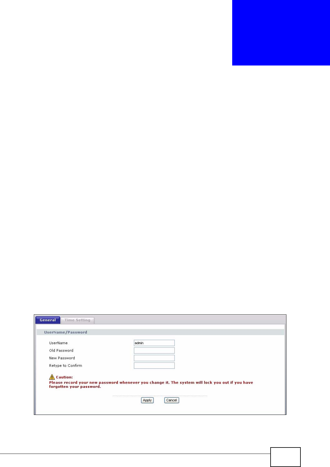
20.2 The General Screen
Use the General screen to configure system settings such as the system
password.
Click Maintenance > System to open the General screen.
Figure 127 Maintenance > System > General
Chapter 20 System Settings
P-870HN-51b User’s Guide
226
The following table describes the labels in this screen.
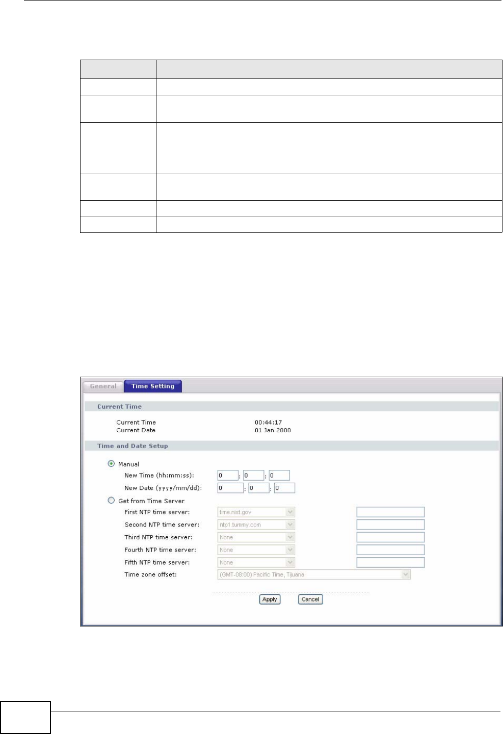
20.3 The Time Setting Screen
To change your ZyXEL Device’s time and date, click Maintenance > System >
Time Setting. The screen appears as shown. Use this screen to configure the
ZyXEL Device’s time based on your local time zone.
Figure 128 Maintenance > System > Time Setting
Table 81 Maintenance > System > Genera
LABEL DESCRIPTION
UserName Type the user name you use to access the system.
Old Password Type the default password or the existing password you use to access the
system in this field.
New Password Type your new system password (up to 30 characters). Note that as you
type a password, the screen displays a (*) for each character you type.
After you change the password, use the new password to access the
ZyXEL Device.
Retype to
Confirm Type the new password again for confirmation.
Apply Click Apply to save your changes back to the ZyXEL Device.
Cancel Click Cancel to begin configuring this screen afresh.

Chapter 20 System Settings
P-870HN-51b User’s Guide 227
The following table describes the fields in this screen.
Table 82 Maintenance > System > Time Setting
LABEL DESCRIPTION
Current Time
Current Time This field displays the time of your ZyXEL Device.
Each time you reload this page, the ZyXEL Device synchronizes the
time with the time server.
Current Date This field displays the date of your ZyXEL Device.
Each time you reload this page, the ZyXEL Device synchronizes the
date with the time server.
Time and Date
Setup
Manual Select this option to enter the time and date manually.
Get from Time
Server Select this option to have the ZyXEL Device get the time and date from
the time server you specified below.
First NTP time
server
Second NTP
time server
Third NTP time
server
Fourth NTP time
server
Fifth NTP time
server
Select an NTP time server from the drop-down list box.
Otherwise, select Other and enter the IP address or URL (up to 20
extended ASCII characters in length) of your time server.
Select None if you don’t want to configure the time server.
Check with your ISP/network administrator if you are unsure of this
information.
Time zone offset Choose the time zone of your location. This will set the time difference
between your time zone and Greenwich Mean Time (GMT).
Apply Click Apply to save your changes back to the ZyXEL Device.
Cancel Click Cancel to begin configuring this screen afresh.

Chapter 20 System Settings
P-870HN-51b User’s Guide
228

P-870HN-51b User’s Guide 229
CHAPTER 21
Logs
21.1 Overview
This chapter contains information about configuring general log settings and
viewing the ZyXEL Device’s logs.
The web configurator allows you to choose which categories of events and/or
alerts to have the ZyXEL Device log and then display the logs or have the ZyXEL
Device send them to a syslog server.
21.1.1 What You Can Do in this Chapter
•The View Log screen lets you see the logs for the categories that you selected
in the Log Settings screen (Section 21.2 on page 229).
•The Log Settings screen lets you configure to where the ZyXEL Device is to
send logs and which logs and/or immediate alerts the ZyXEL Device is to record
(Section 21.3 on page 230).
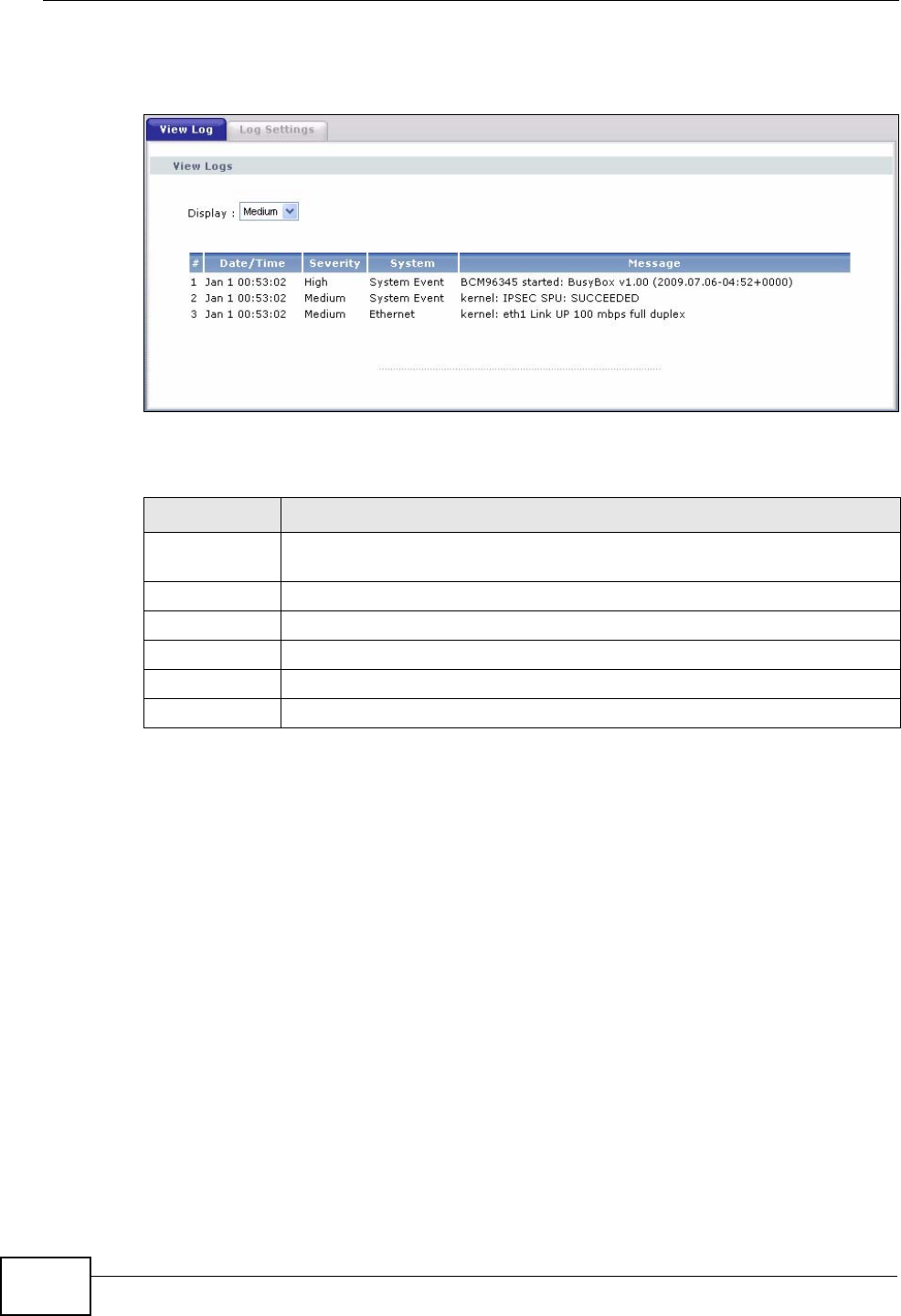
21.2 The View Log Screen
Click Maintenance > Logs to open the View Log screen. Use the View Log
screen to see the logs for the categories that you selected in the Log Settings
screen (see Section 21.3 on page 230).
Chapter 21 Logs
P-870HN-51b User’s Guide
230
The log wraps around and deletes the old entries after it fills.
Figure 129 Maintenance > Logs > View Log
The following table describes the fields in this screen.
21.3 The Log Settings Screen
Use the Log Settings screen to configure to where the ZyXEL Device is to send
logs and which logs and/or immediate alerts the ZyXEL Device is to record and
display.
Table 83 Maintenance > Logs > View Log
LABEL DESCRIPTION
Display Select a severity level of logs to view. The ZyXEL Device displays the logs
with the severity level equal to or higher than what you selected.
#This field is a sequential value and is not associated with a specific entry.
Date/Time This field displays the time the log was recorded.
Severity This field displays the severity level of the log.
System This field displays the system module from which the logs come.
Message This field states the reason for the log.
Chapter 21 Logs
P-870HN-51b User’s Guide 231
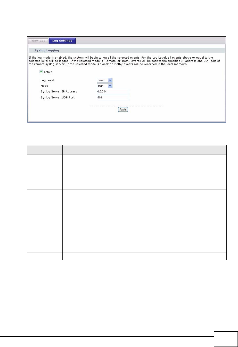
To change your ZyXEL Device’s log settings, click Maintenance > Logs > Log
Settings. The screen appears as shown.
Figure 130 Maintenance > Logs > Log Settings
The following table describes the fields in this screen.
Table 84 Maintenance > Logs > Log Settings
LABEL DESCRIPTION
Active Select to enable or disable system logging.
Log Level Select the severity level of the logs that you want the ZyXEL Device to
display, record and send to the log server.
The ZyXEL Device displays and records the logs with the severity level
equal to or higher than what you selected.
Mode Select Local to record the logs and store them in the local memory of the
ZyXEL Device only.
Select Remote to send logs to the specified log server.
Select Both to record the logs and store them in the local memory and
also send logs to the log server.
Syslog Server
IP Address Enter the server name or the IP address of the log server.
Syslog Server
UDP Port Enter the UDP port of the log server.
Apply Click Apply to save your customized settings.

Chapter 21 Logs
P-870HN-51b User’s Guide
232

P-870HN-51b User’s Guide 233
CHAPTER 22
Tools
Do not interrupt the file transfer process as this may
PERMANENTLY DAMAGE your ZyXEL Device.
22.1 Overview
This chapter explains how to upload new firmware, manage configuration files and
restart your ZyXEL Device.
Use the instructions in this chapter to change the device’s configuration file or
upgrade its firmware. After you configure your device, you can backup the
configuration file to a computer. That way if you later misconfigure the device, you
can upload the backed up configuration file to return to your previous settings.
You can alternately upload the factory default configuration file if you want to
return the device to the original default settings. The firmware determines the
device’s available features and functionality. You can download new firmware
releases from your nearest ZyXEL FTP site (or www.zyxel.com) to use to upgrade
your device’s performance.
Only use firmware for your device’s specific model. Refer to the
label on the bottom of your ZyXEL Device.
22.1.1 What You Can Do in this Chapter
•The Firmware screen lets you upload firmware to your device (Section 22.2 on
page 234).
•The Configuration screen lets you backup and restore device configurations
(Section 22.3 on page 236). You can also reset your device settings back to the
factory default.
•The Restart screen lets you restart your ZyXEL Device (Section 22.4 on page
238).
Chapter 22 Tools
P-870HN-51b User’s Guide
234
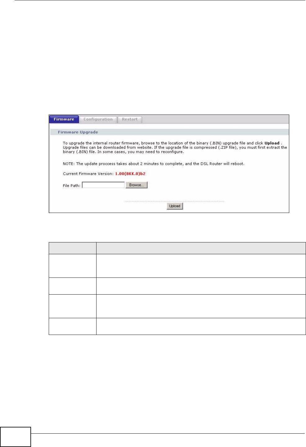
22.2 The Firmware Screen
Click Maintenance > Tools to open the Firmware screen. Follow the
instructions in this screen to upload firmware to your ZyXEL Device. The upload
process uses HTTP (Hypertext Transfer Protocol) and may take up to two minutes.
After a successful upload, the system will reboot.
Do NOT turn off the ZyXEL Device while firmware upload is in
progress!
Figure 131 Maintenance > Tools > Firmware
The following table describes the labels in this screen.
Table 85 Maintenance > Tools > Firmware
LABEL DESCRIPTION
Current
Firmware
Version
This is the present Firmware version and the date created.
File Path Type in the location of the file you want to upload in this field or click
Browse ... to find it.
Browse... Click Browse... to find the .bin file you want to upload. Remember that
you must decompress compressed (.zip) files before you can upload
them.
Upload Click Upload to begin the upload process. This process may take up to
two minutes.
Chapter 22 Tools
P-870HN-51b User’s Guide 235
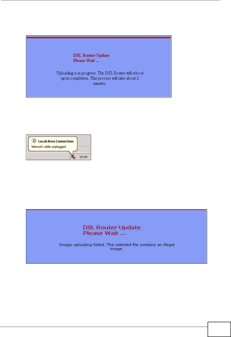
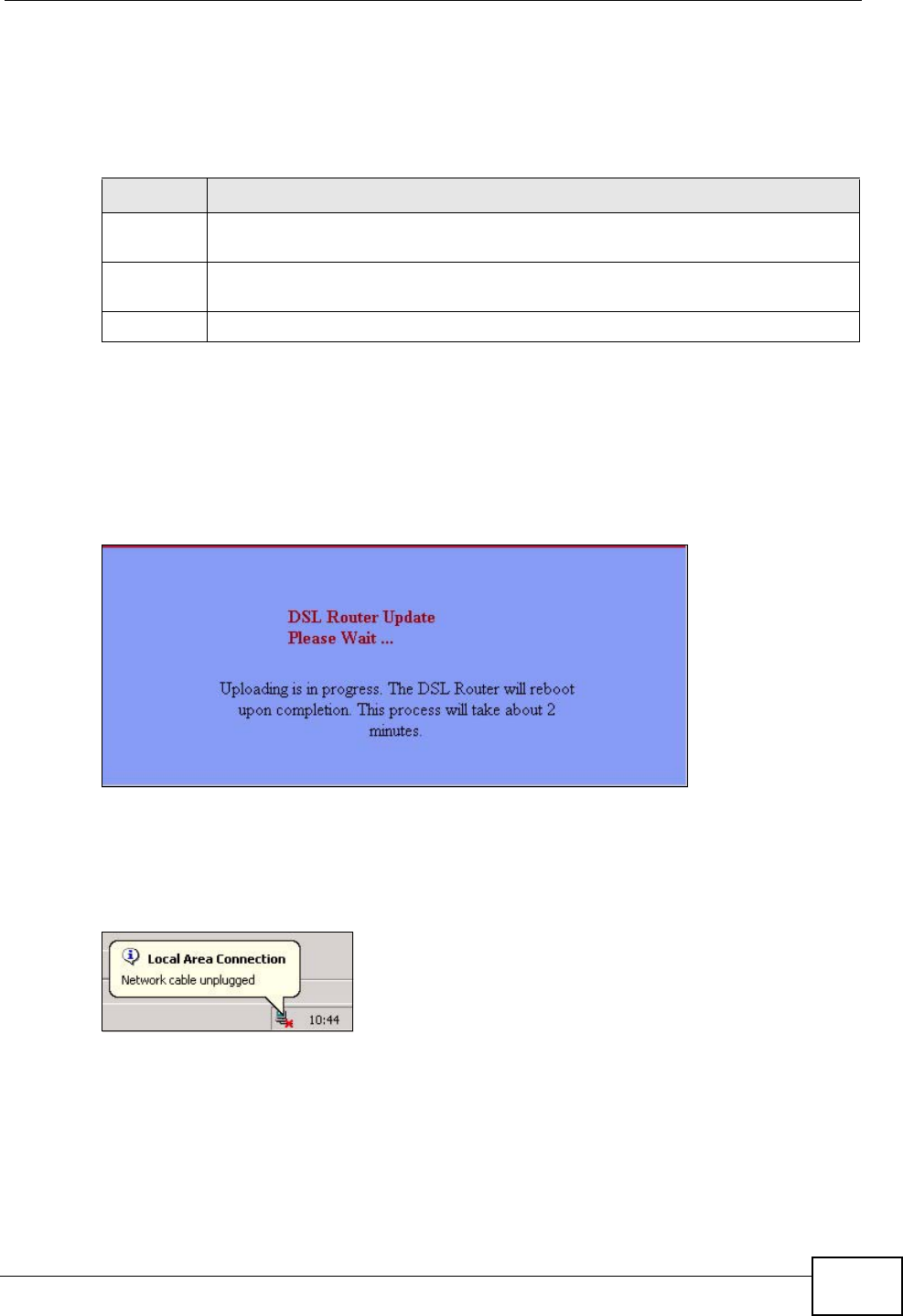
After you see the Firmware Upload in Progress screen, wait two minutes
before logging into the ZyXEL Device again.
Figure 132 Firmware Upload In Progress
The ZyXEL Device automatically restarts in this time causing a temporary network
disconnect. In some operating systems, you may see the following icon on your
desktop.
Figure 133 Network Temporarily Disconnected
After two minutes, log in again and check your new firmware version in the
Status screen.
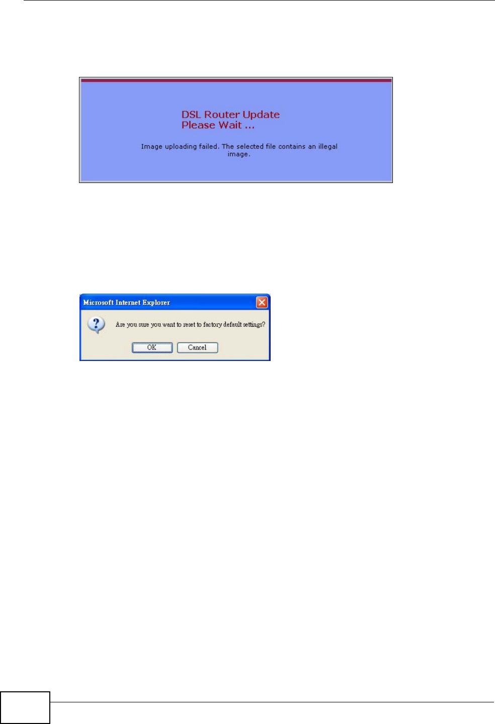
If the upload was not successful, the following screen will appear. Click Tools to
go back to the Firmware screen.
Figure 134 Error Message
Chapter 22 Tools
P-870HN-51b User’s Guide
236
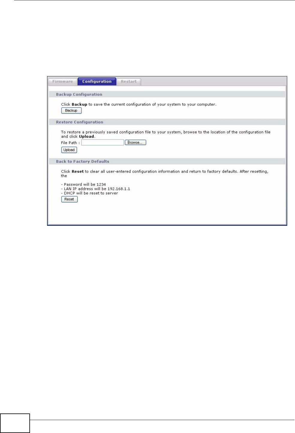
22.3 The Configuration Screen
Click Maintenance > Tools > Configuration. Information related to factory
defaults, backup configuration, and restoring configuration appears in this screen,
as shown next.
Figure 135 Maintenance > Tools > Configuration
Backup Configuration
Backup Configuration allows you to back up (save) the ZyXEL Device’s current
configuration to a file on your computer. Once your ZyXEL Device is configured
and functioning properly, it is highly recommended that you back up your
configuration file before making configuration changes. The backup configuration
file will be useful in case you need to return to your previous settings.
Click Backup to save the ZyXEL Device’s current configuration to your computer.
Chapter 22 Tools
P-870HN-51b User’s Guide 237
Restore Configuration
Restore Configuration allows you to upload a new or previously saved
configuration file from your computer to your ZyXEL Device.
Do not turn off the ZyXEL Device while configuration file upload is
in progress.
After you see a “restore configuration successful” screen, you must then wait one
minute before logging into the ZyXEL Device again.
Figure 136 Configuration Upload Successful
The ZyXEL Device automatically restarts in this time causing a temporary network
disconnect. In some operating systems, you may see the following icon on your
desktop.
Figure 137 Network Temporarily Disconnected
If you uploaded the default configuration file you may need to change the IP
address of your computer to be in the same subnet as that of the default device IP
address (192.168.1.1). See Appendix A on page 261 for details on how to set up
your computer’s IP address.
Table 86 Restore Configuration
LABEL DESCRIPTION
File Path Type in the location of the file you want to upload in this field or click
Browse ... to find it.
Browse... Click Browse... to find the file you want to upload. Remember that you must
decompress compressed (.ZIP) files before you can upload them.
Upload Click Upload to begin the upload process.
Chapter 22 Tools
P-870HN-51b User’s Guide
238
If the upload was not successful, the following screen will appear. Click Tools >
Configuration to go back to the Configuration screen.
Figure 138 Configuration Upload Error
Reset to Factory Defaults
Click the Reset button to clear all user-entered configuration information and
return the ZyXEL Device to its factory defaults. The following warning screen
appears.
Figure 139 Reset Warning Message
You can also press the RESET button on the rear panel to reset the factory
defaults of your ZyXEL Device. Refer to Section 1.6 on page 25 for more
information on the RESET button.
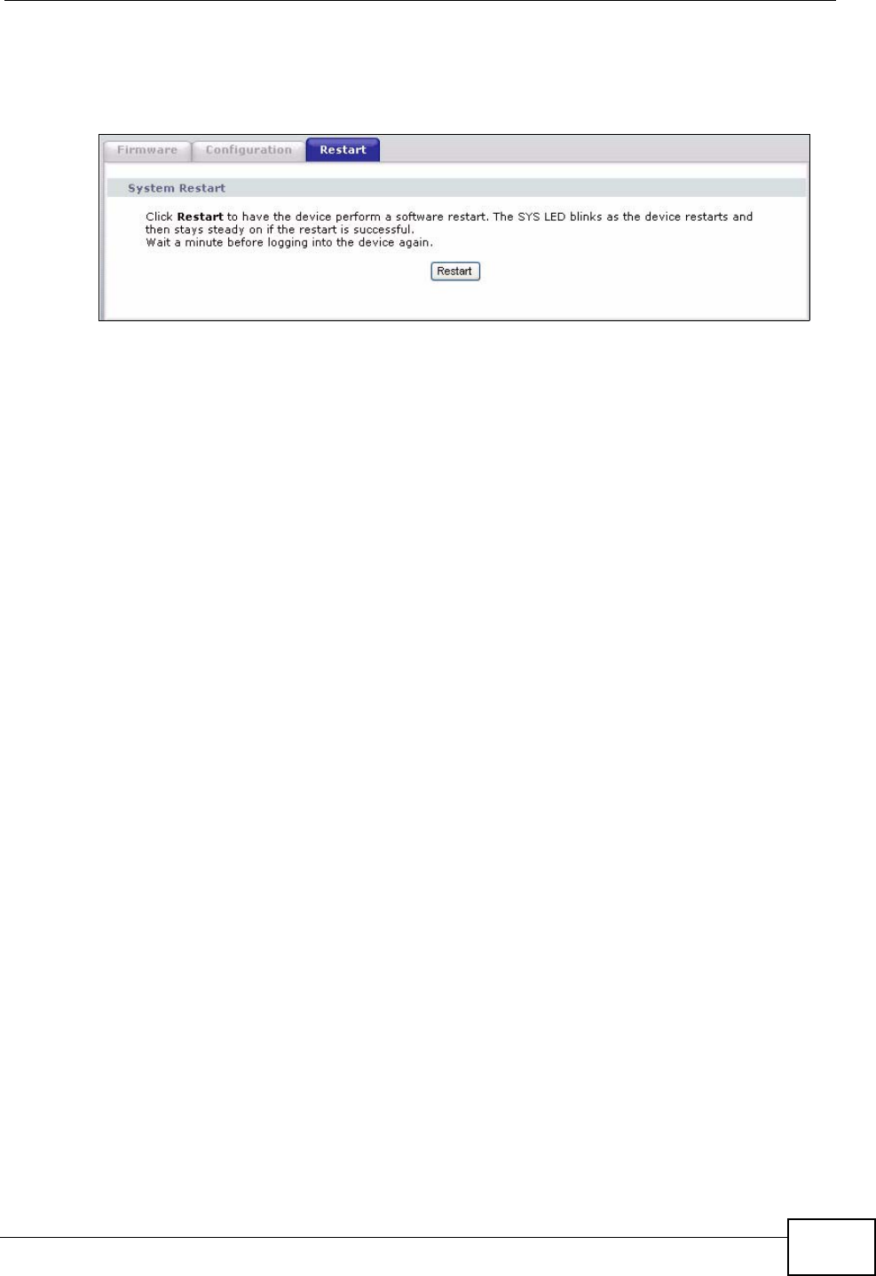
22.4 The Restart Screen
System restart allows you to reboot the ZyXEL Device without turning the power
off.
Chapter 22 Tools
P-870HN-51b User’s Guide 239
Click Maintenance > Tools > Restart. Click Restart to have the ZyXEL Device
reboot. This does not affect the ZyXEL Device's configuration.
Figure 140 Maintenance > Tools >Restart

Chapter 22 Tools
P-870HN-51b User’s Guide
240

P-870HN-51b User’s Guide 241
CHAPTER 23
Diagnostic
23.1 Overview
The Diagnostic screens display information to help you identify problems with the
ZyXEL Device.
The route between a CO VDSL switch and one of its CPE may go through switches
owned by independent organizations. A connectivity fault point generally takes
time to discover and impacts subscriber’s network access. In order to eliminate
the management and maintenance efforts, IEEE 802.1ag is a Connectivity Fault
Management (CFM) specification which allows network administrators to identify
and manage connection faults. Through discovery and verification of the path,
CFM can detect, analyze and isolate connectivity faults in bridged LANs.
23.1.1 What You Can Do in this Chapter
•The General screen lets you ping an IP address or trace the route packets take
to a host (Section 23.4 on page 243).
•The 802.1ag screen lets you perform CFM actions (Section 23.4 on page 243).
•The OAM Ping Test screen lets you send an ATM OAM (Operation,
Administration and Maintenance) packet to verify the connectivity of a specific
PVC. (Section 23.4 on page 243).
23.2 What You Need to Know
The following terms and concepts may help as you read through this chapter.
How CFM Works
A Maintenance Association (MA) defines a VLAN and associated Maintenance End
Point (MEP) ports on the device under a Maintenance Domain (MD) level. An MEP
port has the ability to send Connectivity Check Messages (CCMs) and get other
MEP ports information from neighbor devices’ CCMs within an MA.
CFM provides two tests to discover connectivity faults.
Chapter 23 Diagnostic
P-870HN-51b User’s Guide
242
• Loopback test - checks if the MEP port receives its Loop Back Response (LBR)
from its target after it sends the Loop Back Message (LBM). If no response is
received, there might be a connectivity fault between them.
• Link trace test - provides additional connectivity fault analysis to get more
information on where the fault is. If an MEP port does not respond to the source
MEP, this may indicate a fault. Administrators can take further action to check
and resume services from the fault according to the line connectivity status
report.
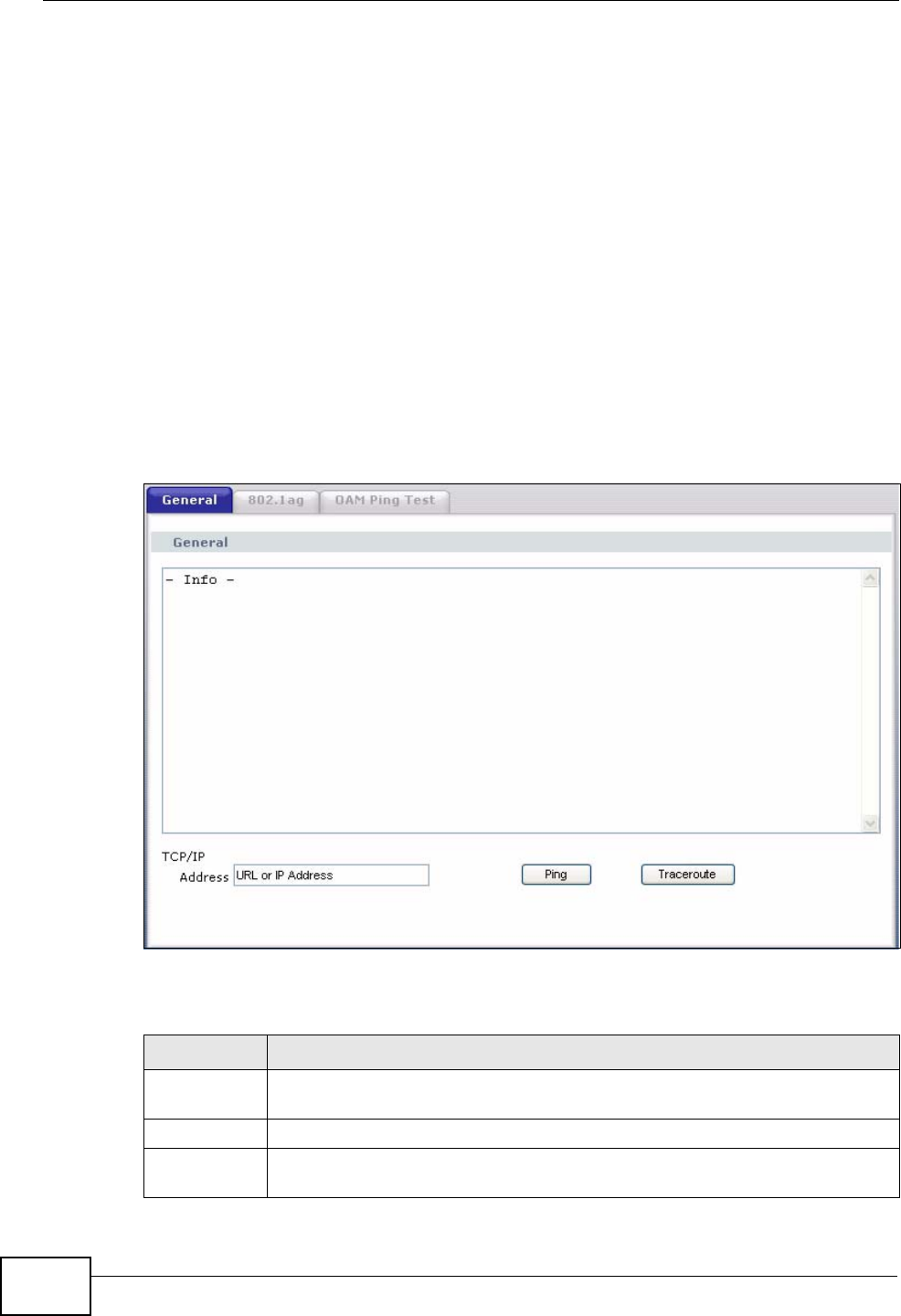
23.3 The General Diagnostic Screen
Click Maintenance > Diagnostic to open the screen shown next. Ping and
traceroute help check availability of remote hosts and also help troubleshoot
network or Internet connections.
Figure 141 Maintenance > Diagnostic > General
The following table describes the fields in this screen.
Table 87 Maintenance > Diagnostic > General
LABEL DESCRIPTION
TCP/IP
Address Type the IP address of a computer that you want to ping in order to test a
connection or trace the route packets take to.
Ping Click this button to ping the IP address that you entered.
Traceoute Click this button to perform the traceroute function. This determines the
path a packet takes to the specified host.
Chapter 23 Diagnostic
P-870HN-51b User’s Guide 243
23.4 The 802.1ag Screen
Click Maintenance > Diagnostic > 8.2.1ag to open the following screen. Use
this screen to perform CFM actions.
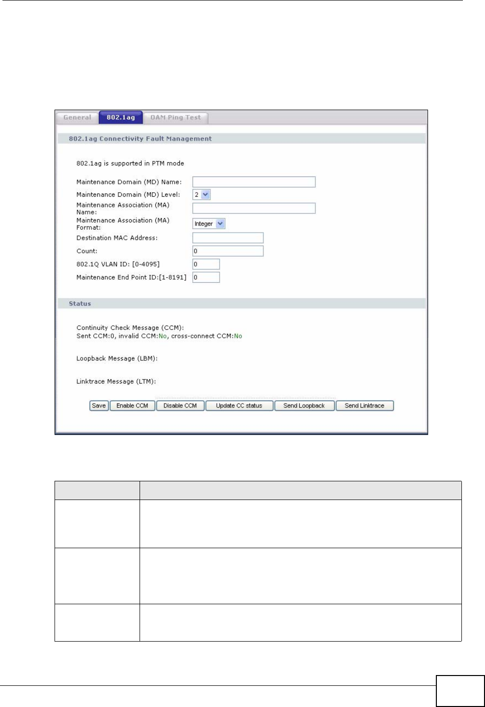
Figure 142 802.1ag
The following table describes the fields in this screen.
Table 88 Maintenance > Diagnostic > 802.1ag
LABEL DESCRIPTION
802.1ag
Connectivity
Fault
Management
Maintenance
Domain (MD)
Name
Type a name of up to 39 printable English keyboard characters for this
MD.
The combined length of the MD Name and MA name must be less or
equal to 44bytes.
Maintenance
Domain (MD)
Level
Select a level (0-7) under which you want to create an MA.

Chapter 23 Diagnostic
P-870HN-51b User’s Guide
244
Maintenance
Association (MA)
Name
Type a name of up to 39 printable English keyboard characters for this
MA.
The combined length of the MD Name and MA name must be less or
equal to 44bytes.
Maintenance
Association (MA)
Format
Select the format which the ZyXEL Device uses to send this MA
information in the domain (MD). Options are VID, String and
Integer.
If you select VID or Integer, the ZyXEL Device adds the VLAN ID you
specified for an MA in the CCM.
If you select String, the ZyXEL Device adds the MA name you
specified above in the CCM.
Note: The MEPs in the same MA should use the same MA format.
Destination MAC
Address Enter the target device’s MAC address to which the ZyXEL Device
performs a CFM loopback test.
Count Set how many times the ZyXEL Device send loopback messages
(LBMs).
802.1Q VLAN ID Type a VLAN ID (0-4095) for this MA.
Maintenance End
Point ID Enter an ID number (1-8191) for this MEP port. Each MEP port needs a
unique ID number within an MD. The MEP ID is to identify an MEP port
used when you perform a CFM action
Status
Continuity Check
Message (CCM) This shows how many Connectivity Check Messages (CCMs) are sent
and if there is any invalid CCM or cross-connect CCM.
Loopback
Message (LBM) This shows how many Loop Back Messages (LBMs) are sent and if
there is any inorder or outorder Loop Back Response (LBR) received
from a remote MEP.
Linktrace
Message (LTM) This shows the destination MAC address in the Link Trace Response
(LTR).
Save Click this to save your changes back to the ZyXEL Device.
Enable CCM Click this button to have the selected MEP send Connectivity Check
Messages (CCMs) to other MEPs.
Disable CCM Click this button to disallow the selected MEP to send Connectivity
Check Messages (CCMs) to other MEPs.
Update CC status Click this button to reload the test result.
Send Loopback Click this button to have the selected MEP send the LBM (Loop Back
Message) to a specified remote end point.
Send Linktrace Click this button to have the selected MEP send the LTMs (Link Trace
Messages) to a specified remote end point.
Table 88 Maintenance > Diagnostic > 802.1ag (continued)
LABEL DESCRIPTION
Chapter 23 Diagnostic
P-870HN-51b User’s Guide 245
23.5 The OAM Ping Test Screen
Click Maintenance > Diagnostic > OAM Ping Test to open the screen shown
next. Use this screen to perform an OAM (Operation, Administration and
Maintenance) F4 or F5 loopback test on a PVC. The ZyXEL Device sends an OAM
F4 or F5 packet to the DSLAM or ATM switch and then returns it to the ZyXEL
Device. The test result then displays in the text box.
ATM sets up virtual circuits over which end systems communicate. The
terminology for virtual circuits is as follows:
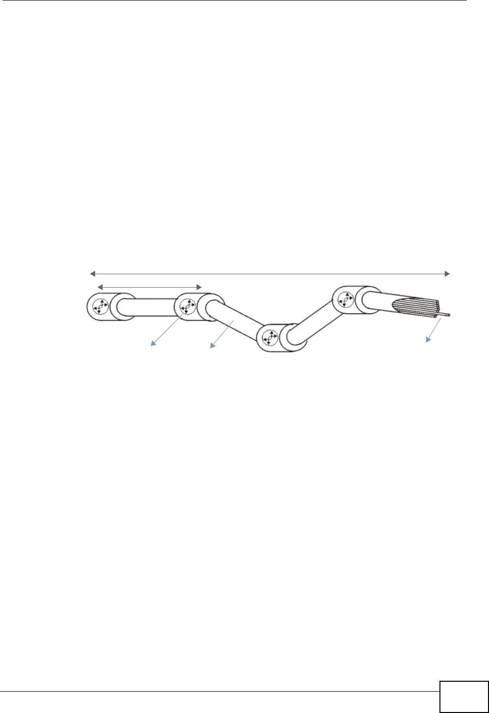
Figure 143 Virtual Circuit Topology
Think of a virtual path as a cable that contains a bundle of wires. The cable
connects two points and wires within the cable provide individual circuits between
the two points. In an ATM cell header, a VPI (Virtual Path Identifier) identifies a
link formed by a virtual path; a VCI (Virtual Channel Identifier) identifies a
channel within a virtual path. A series of virtual paths make up a virtual circuit.
F4 cells operate at the virtual path (VP) level, while F5 cells operate at the virtual
channel (VC) level. F4 cells use the same VPI as the user data cells on VP
connections, but use different predefined VCI values. F5 cells use the same VPI
and VCI as the user data cells on the VC connections, and are distinguished from
data cells by a predefinded Payload Type Identifier (PTI) in the cell header. Both F4
flows and F5 flows are bidirectional and have two types.
• segment F4 flows (VCI=3)
• end-to-end F4 flows (VCI=4)
• segment F5 flows (PTI=100)
• end-to-end F5 flows (PTI=101)
OAM F4 or F5 tests are used to check virtual path or virtual channel availbility
between two DSL devices. Segment flows are terminated at the connecting point
• Virtual Channel (VC) Logical connections between ATM devices
• Virtual Path (VP) A bundle of virtual channels
• Virtual Circuits A series of virtual paths between circuit end points
Virtual Path Virtual Channel
Segment
ATM Switch
Virtual Circuit (End-to-End)
Chapter 23 Diagnostic
P-870HN-51b User’s Guide
246
which terminates a VP or VC segment. End-to-end flows are terminated at the end
point of a VP or VC connection, where an ATM link is terminated. Segment
loopback tests allow you to verify integrity of a PVC to the nearest neighboring
ATM device. End-to-end loopback tests allow you to verify integrity of an end-to-
end PVC.
Note: The DSLAM to which the ZyXEL Device is connected must also support ATM
F4 and/or F5 to use this test.
Note: This screen is available only when you configure an ATM layer-2 interface.
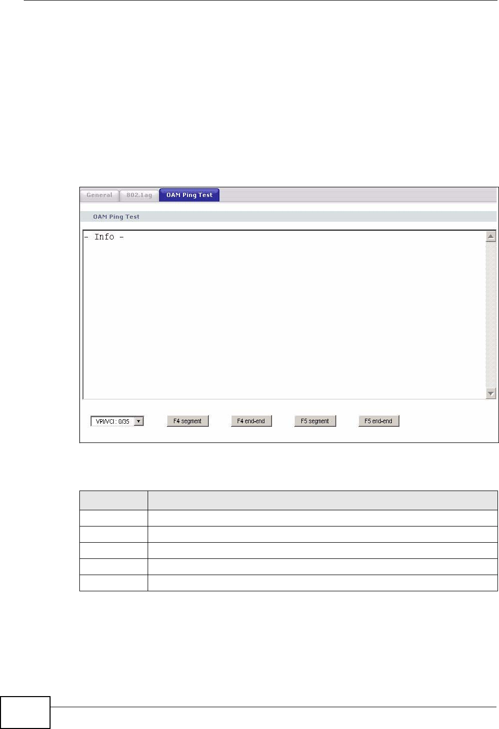
Figure 144 Maintenance > Diagnostic > OAM Ping Test
The following table describes the fields in this screen.
Table 89 Maintenance > Diagnostic > OAM Ping Test
LABEL DESCRIPTION
Select a PVC on which you want to perform the loopback test.
F4 segment Press this to perform an OAM F4 segment loopback test.
F4 end-end Press this to perform an OAM F4 end-to-end loopback test.
F5 segment Press this to perform an OAM F5 segment loopback test.
F5 end-end Press this to perform an OAM F5 end-to-end loopback test.

P-870HN-51b User’s Guide 247
CHAPTER 24
Troubleshooting
This chapter offers some suggestions to solve problems you might encounter. The
potential problems are divided into the following categories.
•Power, Hardware Connections, and LEDs
•ZyXEL Device Access and Login
•Internet Access
24.1 Power, Hardware Connections, and LEDs
The ZyXEL Device does not turn on. None of the LEDs turn on.
1Make sure the ZyXEL Device is turned on.
2Make sure you are using the power adaptor or cord included with the ZyXEL
Device.
3Make sure the power adaptor or cord is connected to the ZyXEL Device and
plugged in to an appropriate power source. Make sure the power source is turned
on.
4Turn the ZyXEL Device off and on.
5If the problem continues, contact the vendor.
One of the LEDs does not behave as expected.
1Make sure you understand the normal behavior of the LED. See Section 1.5 on
page 24.

Chapter 24 Troubleshooting
P-870HN-51b User’s Guide
248
2Check the hardware connections. See the Quick Start Guide.
3Inspect your cables for damage. Contact the vendor to replace any damaged
cables.
4Turn the ZyXEL Device off and on.
5If the problem continues, contact the vendor.
24.2 ZyXEL Device Access and Login
I forgot the IP address for the ZyXEL Device.
1The default IP address is 192.168.1.1.
2If you changed the IP address and have forgotten it, you might get the IP address
of the ZyXEL Device by looking up the IP address of the default gateway for your
computer. To do this in most Windows computers, click Start > Run, enter cmd,
and then enter ipconfig. The IP address of the Default Gateway might be the IP
address of the ZyXEL Device (it depends on the network), so enter this IP address
in your Internet browser.
3If this does not work, you have to reset the device to its factory defaults. See
Section 1.6 on page 25.
I forgot the password.
1The default password is 1234.
2If this does not work, you have to reset the device to its factory defaults. See
Section 1.6 on page 25.
I cannot see or access the Login screen in the web configurator.
1Make sure you are using the correct IP address.
• The default IP address is 192.168.1.1.

Chapter 24 Troubleshooting
P-870HN-51b User’s Guide 249
• If you changed the IP address (Section on page 98), use the new IP address.
• If you changed the IP address and have forgotten it, see the troubleshooting
suggestions for I forgot the IP address for the ZyXEL Device.
2Check the hardware connections, and make sure the LEDs are behaving as
expected. See the Quick Start Guide.
3Make sure your Internet browser does not block pop-up windows and has
JavaScripts and Java enabled. See Appendix B on page 291.
4Reset the device to its factory defaults, and try to access the ZyXEL Device with
the default IP address. See Section 1.6 on page 25.
5If the problem continues, contact the network administrator or vendor, or try one
of the advanced suggestions.
Advanced Suggestions
• If your computer is connected wirelessly, use a computer that is connected to a
ETHERNET port.
I can see the Login screen, but I cannot log in to the ZyXEL Device.
1Make sure you have entered the user name and password correctly. The default
user name is admin and password is 1234. These fields are case-sensitive, so
make sure [Caps Lock] is not on.
2Turn the ZyXEL Device off and on.
3If this does not work, you have to reset the device to its factory defaults. See
Section 24.1 on page 247.
24.3 Internet Access
I cannot access the Internet.
1Check the hardware connections, and make sure the LEDs are behaving as
expected. See the Quick Start Guide and Section 1.5 on page 24.

Chapter 24 Troubleshooting
P-870HN-51b User’s Guide
250
2Make sure you entered your ISP account information correctly in the WAN screens.
These fields are case-sensitive, so make sure [Caps Lock] is not on.
3If you are trying to access the Internet wirelessly, make sure the wireless settings
in the wireless client are the same as the settings in the AP.
4Disconnect all the cables from your device, and follow the directions in the Quick
Start Guide again.
5If the problem continues, contact your ISP.
I cannot access the Internet anymore. I had access to the Internet (with the ZyXEL
Device), but my Internet connection is not available anymore.
1Check the hardware connections, and make sure the LEDs are behaving as
expected. See the Quick Start Guide and Section 1.5 on page 24.
2Turn the ZyXEL Device off and on.
3If the problem continues, contact your ISP.
The Internet connection is slow or intermittent.
1There might be a lot of traffic on the network. Look at the LEDs, and check Section
1.5 on page 24. If the ZyXEL Device is sending or receiving a lot of information,
try closing some programs that use the Internet, especially peer-to-peer
applications.
2Check the signal strength. If the signal strength is low, try moving your computer
closer to the ZyXEL Device if possible, and look around to see if there are any
devices that might be interfering with the wireless network (for example,
microwaves, other wireless networks, and so on).
3Turn the ZyXEL Device off and on.
4If the problem continues, contact the network administrator or vendor, or try one
of the advanced suggestions.
Advanced Suggestions

Chapter 24 Troubleshooting
P-870HN-51b User’s Guide 251
• Check the settings for QoS. If it is disabled, you might consider activating it. If it
is enabled, you might consider raising or lowering the priority for some
applications.

Chapter 24 Troubleshooting
P-870HN-51b User’s Guide
252

P-870HN-51b User’s Guide 253
CHAPTER 25
Product Specifications
The following tables summarize the ZyXEL Device’s hardware and firmware
features.
25.1 Hardware Specifications
25.2 Firmware Specifications
Table 90 Hardware Specifications
Dimensions 231(W) x 147(D) x 57(H) mm
Weight 950g
Power Specification 12 V DC 1A
Built-in Switch Four auto-negotiating, auto MDI/MDI-X 10/100 Mbps RJ-45
Ethernet ports
RESET Button Restores factory defaults
Antenna
(wireless devices
only)
One attached external dipole antenna, one internal antenna,
2*2dBi
WPS Button
(wireless devices
only)
1 second: turn on or off WLAN
5 seconds: enable WPS (Wi-Fi Protected Setup)
Operation
Temperature 0º C ~ 40º C
Storage Temperature -20º ~ 60º C
Operation Humidity 20% ~ 85% RH
Storage Humidity 20% ~ 90% RH
Table 91 Firmware Specifications
Default IP Address 192.168.1.1
Default Subnet Mask 255.255.255.0 (24 bits)

Chapter 25 Product Specifications
P-870HN-51b User’s Guide
254
Default User Name admin
Default Password 1234
DHCP Server IP Pool 192.168.1.33 to 192.168.1.254
Static Routes 16
Device Management Use the web configurator to easily configure the rich range of
features on the ZyXEL Device.
Wireless
Functionality
(wireless devices
only)
Allow the IEEE 802.11b, IEEE 802.11g and/or IEEE 802.11n
wireless clients to connect to the ZyXEL Device wirelessly. Enable
wireless security (WEP, WPA(2), WPA(2)-PSK) and/or MAC filtering
to protect your wireless network.
Firmware Upgrade Download new firmware (when available) from the ZyXEL web site
and use the web configurator to put it on the ZyXEL Device.
Note: Only upload firmware for your specific model!
Configuration Backup
& Restoration Make a copy of the ZyXEL Device’s configuration. You can put it
back on the ZyXEL Device later if you decide to revert back to an
earlier configuration.
Port Forwarding If you have a server (mail or web server for example) on your
network, you can use this feature to let people access it from the
Internet.
DHCP (Dynamic Host
Configuration
Protocol)
Use this feature to have the ZyXEL Device assign IP addresses, an
IP default gateway and DNS servers to computers on your
network. Your device can also act as a surrogate DHCP server
(DHCP Relay) where it relays IP address assignment from the
actual real DHCP server to the clients.
Dynamic DNS
Support With Dynamic DNS (Domain Name System) support, you can use
a fixed URL, www.zyxel.com for example, with a dynamic IP
address. You must register for this service with a Dynamic DNS
service provider.
IP Multicast IP multicast is used to send traffic to a specific group of
computers. The ZyXEL Device supports versions 1 and 2 of IGMP
(Internet Group Management Protocol) used to join multicast
groups (see RFC 2236).
Time and Date Get the current time and date from an external server when you
turn on your ZyXEL Device. You can also set the time manually.
These dates and times are then used in logs.
Logs Use logs for troubleshooting. You can send logs from the ZyXEL
Device to an external syslog server.
Universal Plug and
Play (UPnP) A UPnP-enabled device can dynamically join a network, obtain an
IP address and convey its capabilities to other devices on the
network.
QoS (Quality of
Service) You can efficiently manage traffic on your network by reserving
bandwidth and giving priority to certain types of traffic and/or to
particular computers.
Remote Management This allows you to decide whether a service (HTTP or FTP traffic for
example) from a computer on a network (LAN or WAN for
example) can access the ZyXEL Device.
Table 91 Firmware Specifications (continued)

Chapter 25 Product Specifications
P-870HN-51b User’s Guide 255
PPPoE Support
(RFC2516) PPPoE (Point-to-Point Protocol over Ethernet) emulates a dial-up
connection. It allows your ISP to use their existing network
configuration with newer broadband technologies such as ADSL.
The PPPoE driver on your device is transparent to the computers
on the LAN, which see only Ethernet and are not aware of PPPoE
thus saving you from having to manage PPPoE clients on individual
computers.
Other PPPoE Features PPPoE idle time out
PPPoE dial on demand
IP Alias IP alias allows you to partition a physical network into logical
networks over the same Ethernet interface. Your device supports
three logical LAN interfaces via its single physical Ethernet
interface with the your device itself as the gateway for each LAN
network.
Packet Filters Your device’s packet filtering function allows added network
security and management.
VDSL Standards VDSL line coding: ITU-T G.993.2 DMT modulation
DSL handshake procedure protocol: ITU-T G.994.1
DSL physical layer management protocol: ITU-T G.997.1
VDSL band plan: 997 and 998
Support U0 band
VDSL profiles: 8a, 8b, 8c, 8d, 12a, 12b, 17a
VDSL speed: up to 100/50 Mbps@ 700 feet
Support Annex A, Annex B and 5-band VDSL2
Rate adaptation
OLR: Bit Swapping/ SRA (Seamless Rate Adaption)
Upstream power back-off (UPBO)
VDSL OAM communication channels: Indicator bits (IB) channel,
VDSL embedded operations channel (EOC) and VDSL overhead
control channel (VOC)
PTM Transmission Convergence (PTM-TC)
Dual-latency xDSL framing (fast and interleaved)
Trellis coding
INP capability: At least two symbols protection (INP_MIN = 2), up
to 16 symbols (INP_MIN = 16)
Table 91 Firmware Specifications (continued)

Chapter 25 Product Specifications
P-870HN-51b User’s Guide
256
ADSL Standards Multi-Mode standard (ANSI T1.413,Issue 2; G.dmt(G.992.1);
G.lite(G992.2)).
ADSL2 G.dmt.bis (G.992.3)
ADSL2+ (G.992.5)
Reach-Extended ADSL (RE ADSL)
SRA (Seamless Rate Adaptation)
Auto-negotiating rate adaptation
ADSL physical connection ATM AAL5 (ATM Adaptation Layer type
5)
Multi-protocol over AAL5 (RFC2684/1483)
PPP over ATM AAL5 (RFC 2364)
PPP over Ethernet (RFC 2516)
MAC encapsulated routing (ENET encapsulation)
VC-based and LLC-based multiplexing
Up to 8 PVCs (Permanent Virtual Circuits)
ATM traffic shaping (CBR, VBR-rt/nrt, UBR)
610 F4/F5 OAM
Upstream power backoff (UPBO)
Broadcom PhyR, PHY Level Retransmission Technology
Broadcom Nitro mode, ATM header compression
Other Protocol
Support PPP (Point-to-Point Protocol) link layer protocol
Transparent bridging for unsupported network layer protocols
RIP I/RIP II
ICMP
IP Multicasting IGMP v1 and v2
IGMP Proxy
Management Embedded Web Configurator
Remote Firmware Upgrade
Syslog
TR-069
TR-064
Table 91 Firmware Specifications (continued)

Chapter 25 Product Specifications
P-870HN-51b User’s Guide 257
25.3 Wireless Features
The following list, which is not exhaustive, illustrates the standards supported in
the ZyXEL Device.
Table 92 Wireless Features
External Antenna The ZyXEL Device is equipped with an attached antenna to
provide a clear radio signal between the wireless stations and
the access points.
Wireless LAN MAC Address
Filtering Your device can check the MAC addresses of wireless stations
against a list of allowed or denied MAC addresses.
WEP Encryption WEP (Wired Equivalent Privacy) encrypts data frames before
transmitting over the wireless network to help keep network
communications private.
Wi-Fi Protected Access Wi-Fi Protected Access (WPA) is a subset of the IEEE 802.11i
security standard. Key differences between WPA and WEP
are user authentication and improved data encryption.
WPA2 WPA 2 is a wireless security standard that defines stronger
encryption, authentication and key management than WPA.
Other Wireless Features IEEE 802.11n Compliance
Frequency Range: 2.4 GHz ISM Band
Advanced Orthogonal Frequency Division Multiplexing
(OFDM)
Data Rates: 54Mbps, 11Mbps, 5.5Mbps, 2Mbps, and 1 Mbps
Auto Fallback
WPA2
WMM
IEEE 802.11i
IEEE 802.11e
Wired Equivalent Privacy (WEP) Data Encryption 64/128 bit
WLAN bridge to LAN
Up to 32 MAC Address filters
IEEE 802.1x
Store up to 32 built-in user profiles using EAP-MD5 (Local
User Database)
External RADIUS server using EAP-MD5, TLS, TTLS
Table 93 Standards Supported
STANDARD DESCRIPTION
RFC 1058 RIP-1 (Routing Information Protocol)
RFC 1112 IGMP v1
Chapter 25 Product Specifications
P-870HN-51b User’s Guide
258
RFC 1631 IP Network Address Translator (NAT)
RFC 1661 The Point-to-Point Protocol (PPP)
RFC 1723 RIP-2 (Routing Information Protocol)
RFC 2236 Internet Group Management Protocol, Version 2.
RFC 2516 A Method for Transmitting PPP Over Ethernet (PPPoE)
RFC 2766 Network Address Translation - Protocol
IEEE 802.11 Also known by the brand Wi-Fi, denotes a set of Wireless LAN/
WLAN standards developed by working group 11 of the IEEE
LAN/MAN Standards Committee (IEEE 802).
IEEE 802.11b Uses the 2.4 gigahertz (GHz) band
IEEE 802.11g Uses the 2.4 gigahertz (GHz) band
IEEE 802.11n Uses the 2.4 gigahertz (GHz) band
IEEE 802.11d Standard for Local and Metropolitan Area Networks: Media
Access Control (MAC) Bridges
IEEE 802.11x Port Based Network Access Control.
IEEE 802.11e QoS IEEE 802.11 e Wireless LAN for Quality of Service
ITU-T G.993.2
(VDSL2) ITU standard that defines VDSL2.
TR-069 DSL Forum Standard for CPE Wan Management.
TR-064 DSL Forum LAN-Side DSL CPE Configuration
Table 93 Standards Supported (continued)
STANDARD DESCRIPTION

259
PART VI
Appendices and
Index
Note: The appendices provide general
information. Some details may not
apply to your ZyXEL Device.
Setting Up Your Computer’s IP Address
(261)
Pop-up Windows, JavaScripts and Java
Permissions (291)
IP Addresses and Subnetting (301)
Wireless LANs (313)
Open Software Announcements (333)
Common Services (329)
Legal Information (339)
Index (343)

260

P-870HN-51b User’s Guide 261
APPENDIX A
Setting Up Your Computer’s IP
Address
Note: Your specific ZyXEL device may not support all of the operating systems
described in this appendix. See the product specifications for more information
about which operating systems are supported.
This appendix shows you how to configure the IP settings on your computer in
order for it to be able to communicate with the other devices on your network.
Windows Vista/XP/2000, Mac OS 9/OS X, and all versions of UNIX/LINUX include
the software components you need to use TCP/IP on your computer.
If you manually assign IP information instead of using a dynamic IP, make sure
that your network’s computers have IP addresses that place them in the same
subnet.
In this appendix, you can set up an IP address for:
•Windows XP/NT/2000 on page 262
•Windows Vista on page 266
•Mac OS X: 10.3 and 10.4 on page 271
•Mac OS X: 10.5 on page 275
•Linux: Ubuntu 8 (GNOME) on page 278
•Linux: openSUSE 10.3 (KDE) on page 284
Appendix A Setting Up Your Computer’s IP Address
P-870HN-51b User’s Guide
262
Windows XP/NT/2000
The following example uses the default Windows XP display theme but can also
apply to Windows 2000 and Windows NT.
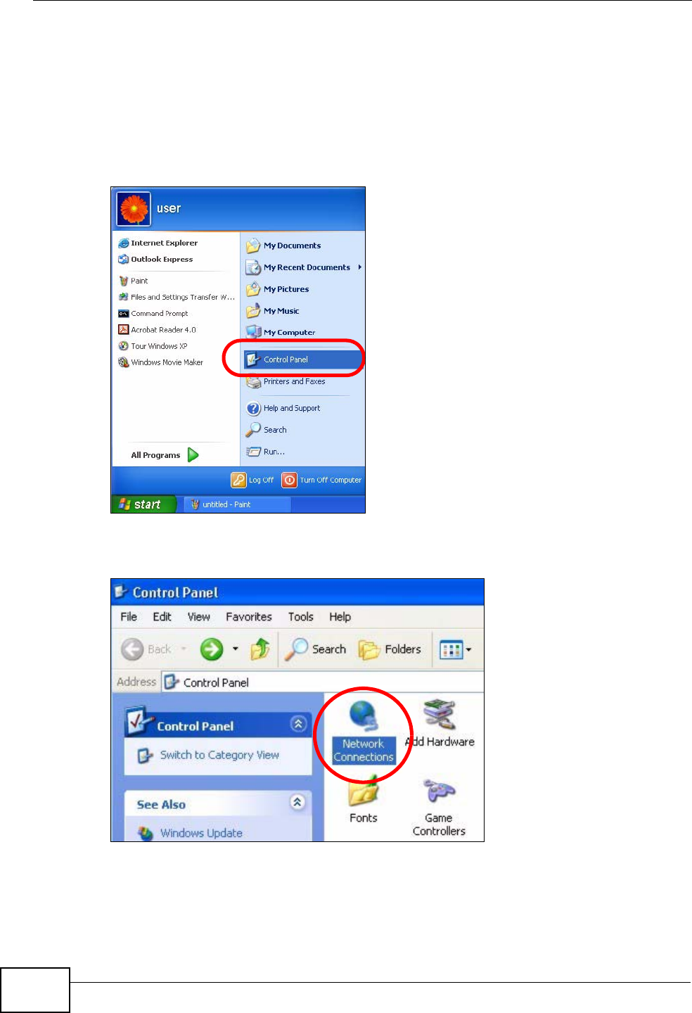
1Click Start > Control Panel.
Figure 145 Windows XP: Start Menu
2In the Control Panel, click the Network Connections icon.
Figure 146 Windows XP: Control Panel
Appendix A Setting Up Your Computer’s IP Address
P-870HN-51b User’s Guide 263
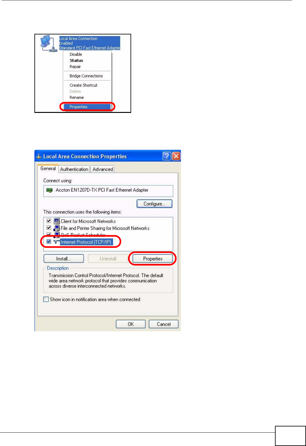
3Right-click Local Area Connection and then select Properties.
Figure 147 Windows XP: Control Panel > Network Connections > Properties
4On the General tab, select Internet Protocol (TCP/IP) and then click
Properties.
Figure 148 Windows XP: Local Area Connection Properties
Appendix A Setting Up Your Computer’s IP Address
P-870HN-51b User’s Guide
264
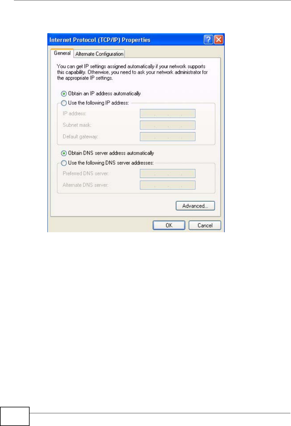
5The Internet Protocol TCP/IP Properties window opens.
Figure 149 Windows XP: Internet Protocol (TCP/IP) Properties
6Select Obtain an IP address automatically if your network administrator or ISP
assigns your IP address dynamically.
Select Use the following IP Address and fill in the IP address, Subnet mask,
and Default gateway fields if you have a static IP address that was assigned to
you by your network administrator or ISP. You may also have to enter a Preferred
DNS server and an Alternate DNS server, if that information was provided.
7Click OK to close the Internet Protocol (TCP/IP) Properties window.
8Click OK to close the Local Area Connection Properties window.
Verifying Settings
1Click Start > All Programs > Accessories > Command Prompt.

Appendix A Setting Up Your Computer’s IP Address
P-870HN-51b User’s Guide 265
2In the Command Prompt window, type "ipconfig" and then press [ENTER].
You can also go to Start > Control Panel > Network Connections, right-click a
network connection, click Status and then click the Support tab to view your IP
address and connection information.
Appendix A Setting Up Your Computer’s IP Address
P-870HN-51b User’s Guide
266
Windows Vista
This section shows screens from Windows Vista Professional.
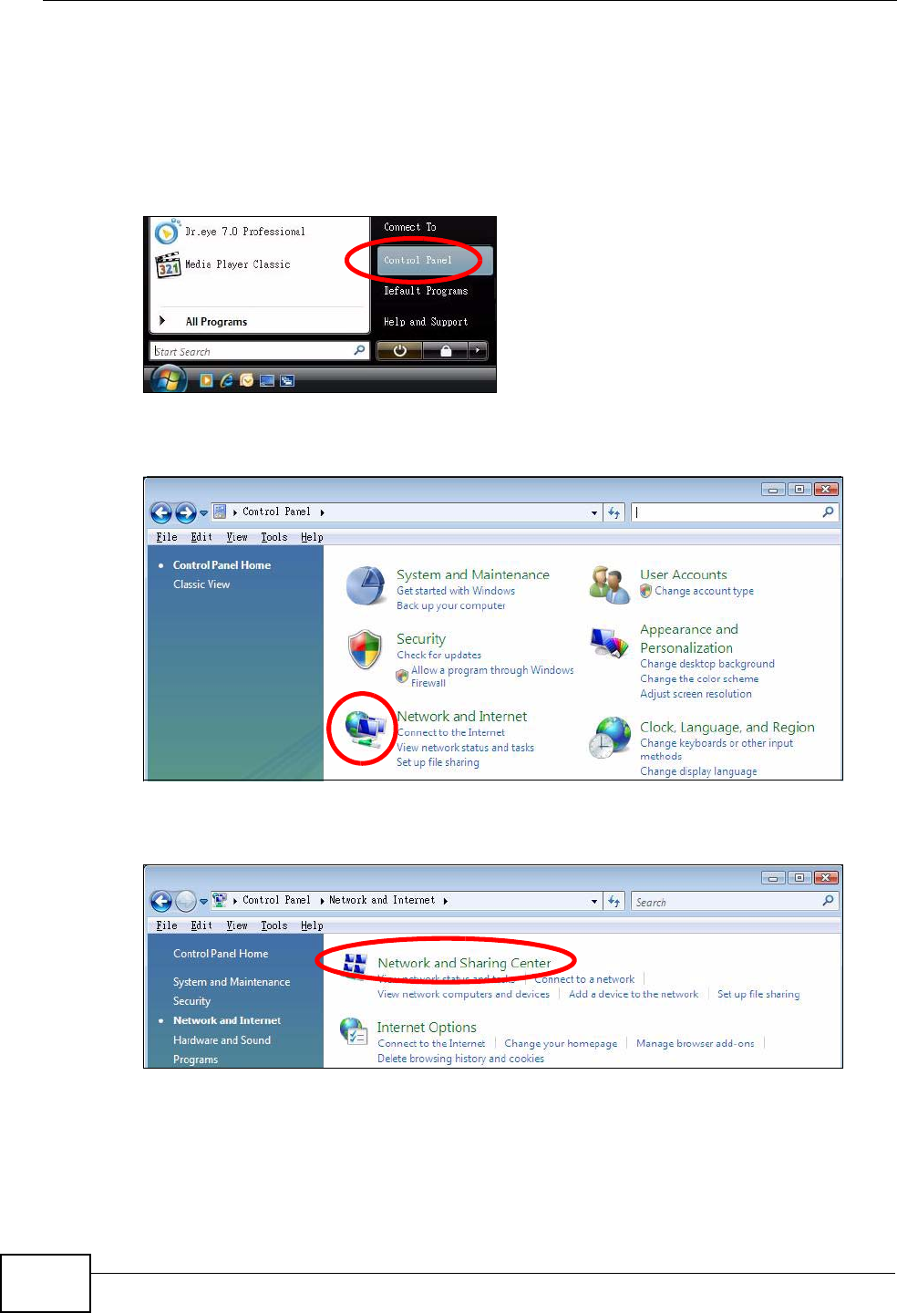
1Click Start > Control Panel.
Figure 150 Windows Vista: Start Menu
2In the Control Panel, click the Network and Internet icon.
Figure 151 Windows Vista: Control Panel
3Click the Network and Sharing Center icon.
Figure 152 Windows Vista: Network And Internet
Appendix A Setting Up Your Computer’s IP Address
P-870HN-51b User’s Guide 267
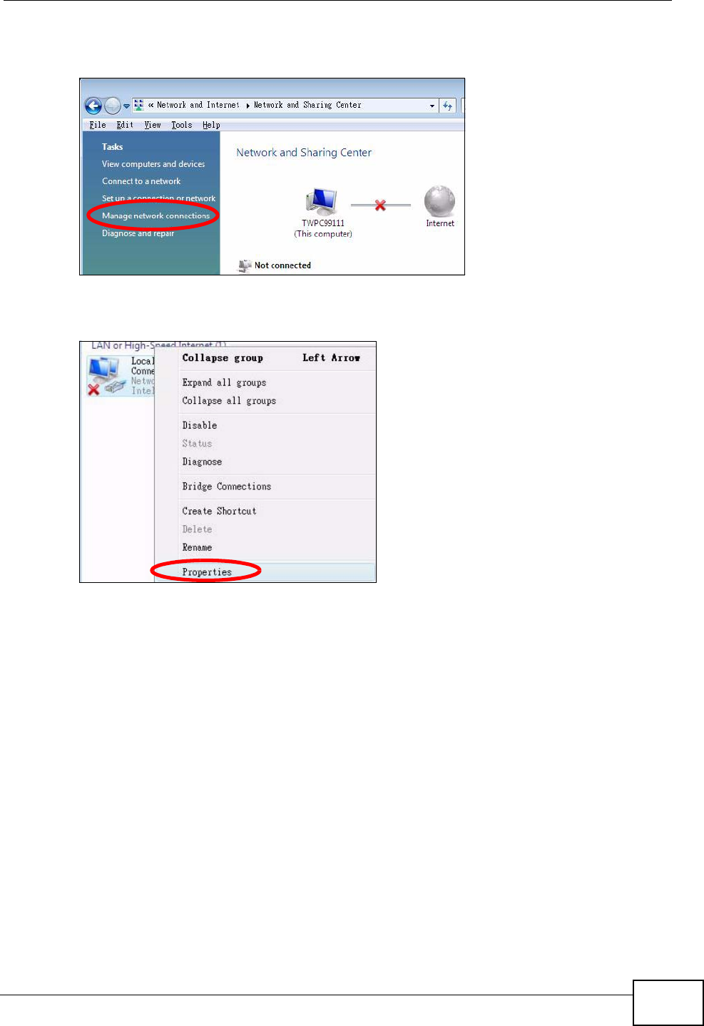
4Click Manage network connections.
Figure 153 Windows Vista: Network and Sharing Center
5Right-click Local Area Connection and then select Properties.
Figure 154 Windows Vista: Network and Sharing Center
Note: During this procedure, click Continue whenever Windows displays a screen
saying that it needs your permission to continue.
Appendix A Setting Up Your Computer’s IP Address
P-870HN-51b User’s Guide
268
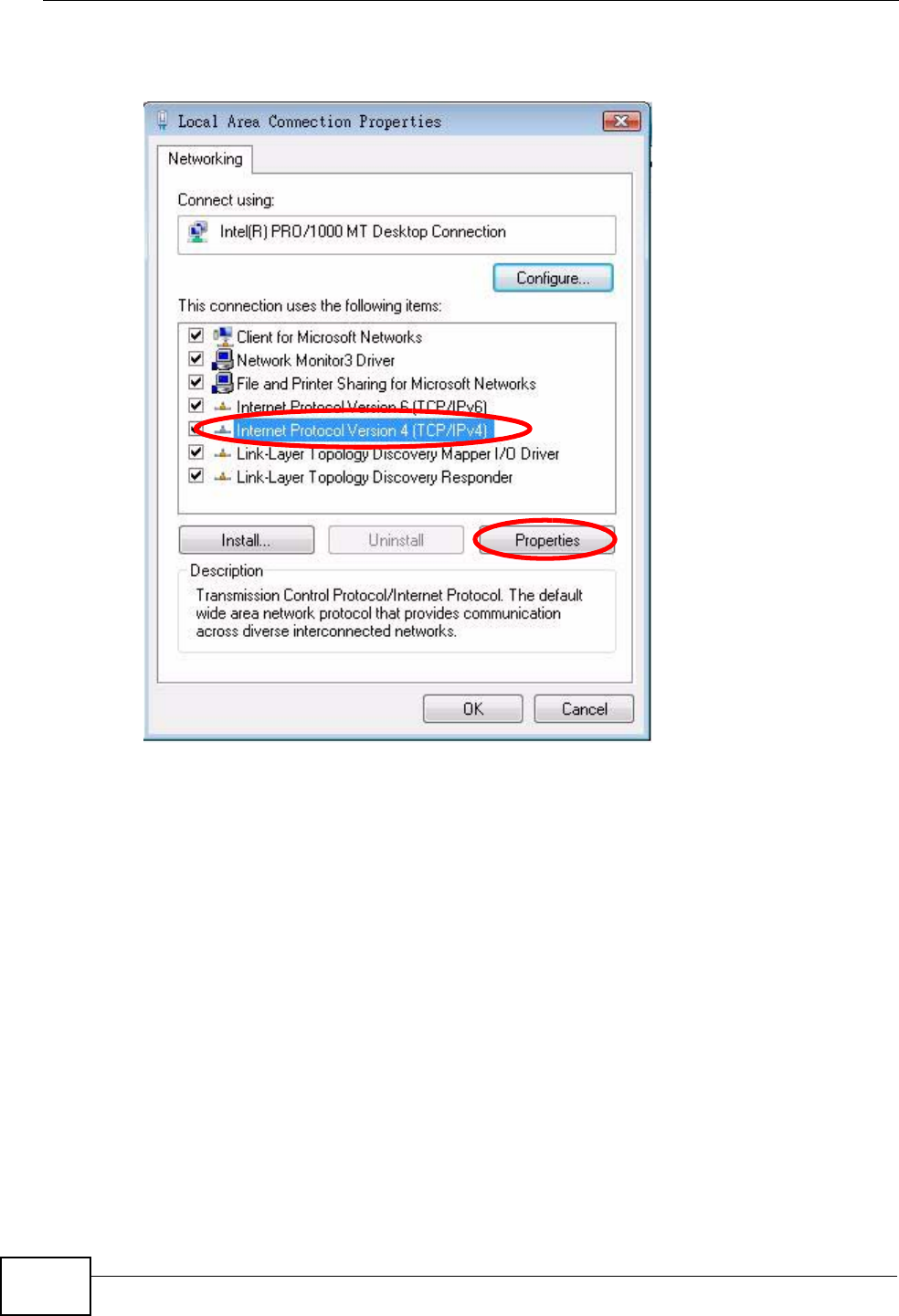
6Select Internet Protocol Version 4 (TCP/IPv4) and then select Properties.
Figure 155 Windows Vista: Local Area Connection Properties
Appendix A Setting Up Your Computer’s IP Address
P-870HN-51b User’s Guide 269
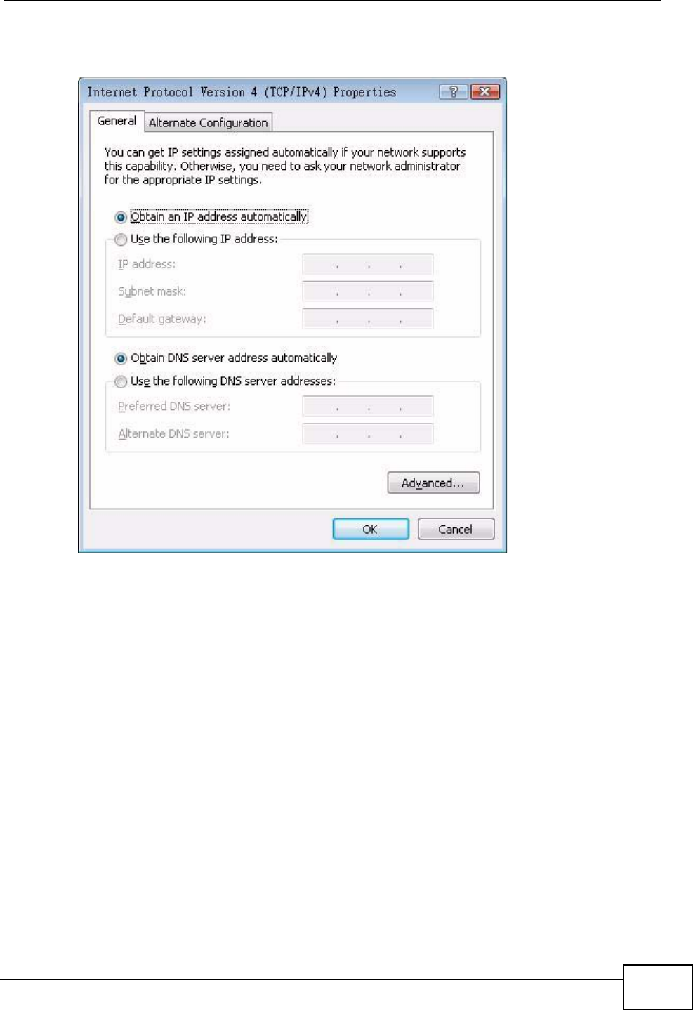
7The Internet Protocol Version 4 (TCP/IPv4) Properties window opens.
Figure 156 Windows Vista: Internet Protocol Version 4 (TCP/IPv4) Properties
8Select Obtain an IP address automatically if your network administrator or ISP
assigns your IP address dynamically.
Select Use the following IP Address and fill in the IP address, Subnet mask,
and Default gateway fields if you have a static IP address that was assigned to
you by your network administrator or ISP. You may also have to enter a Preferred
DNS server and an Alternate DNS server, if that information was
provided.Click Advanced.
9Click OK to close the Internet Protocol (TCP/IP) Properties window.
10 Click OK to close the Local Area Connection Properties window.
Verifying Settings
1Click Start > All Programs > Accessories > Command Prompt.

Appendix A Setting Up Your Computer’s IP Address
P-870HN-51b User’s Guide
270
2In the Command Prompt window, type "ipconfig" and then press [ENTER].
You can also go to Start > Control Panel > Network Connections, right-click a
network connection, click Status and then click the Support tab to view your IP
address and connection information.
Appendix A Setting Up Your Computer’s IP Address
P-870HN-51b User’s Guide 271
Mac OS X: 10.3 and 10.4
The screens in this section are from Mac OS X 10.4 but can also apply to 10.3.
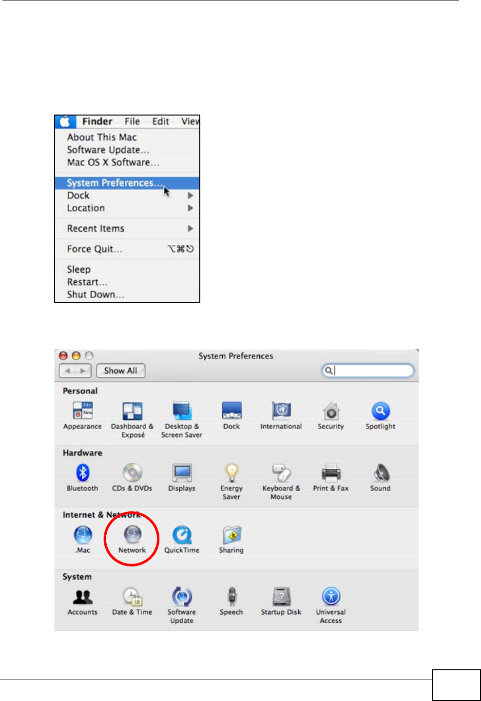
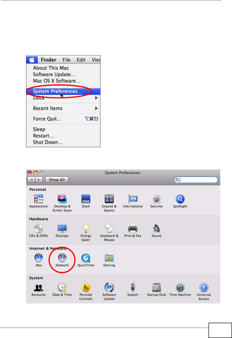
1Click Apple > System Preferences.
Figure 157 Mac OS X 10.4: Apple Menu
2In the System Preferences window, click the Network icon.
Figure 158 Mac OS X 10.4: System Preferences
Appendix A Setting Up Your Computer’s IP Address
P-870HN-51b User’s Guide
272
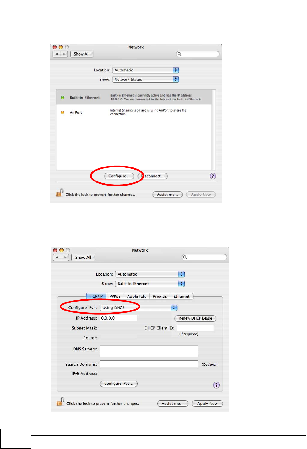
3When the Network preferences pane opens, select Built-in Ethernet from the
network connection type list, and then click Configure.
Figure 159 Mac OS X 10.4: Network Preferences
4For dynamically assigned settings, select Using DHCP from the Configure IPv4
list in the TCP/IP tab.
Figure 160 Mac OS X 10.4: Network Preferences > TCP/IP Tab.
Appendix A Setting Up Your Computer’s IP Address
P-870HN-51b User’s Guide 273
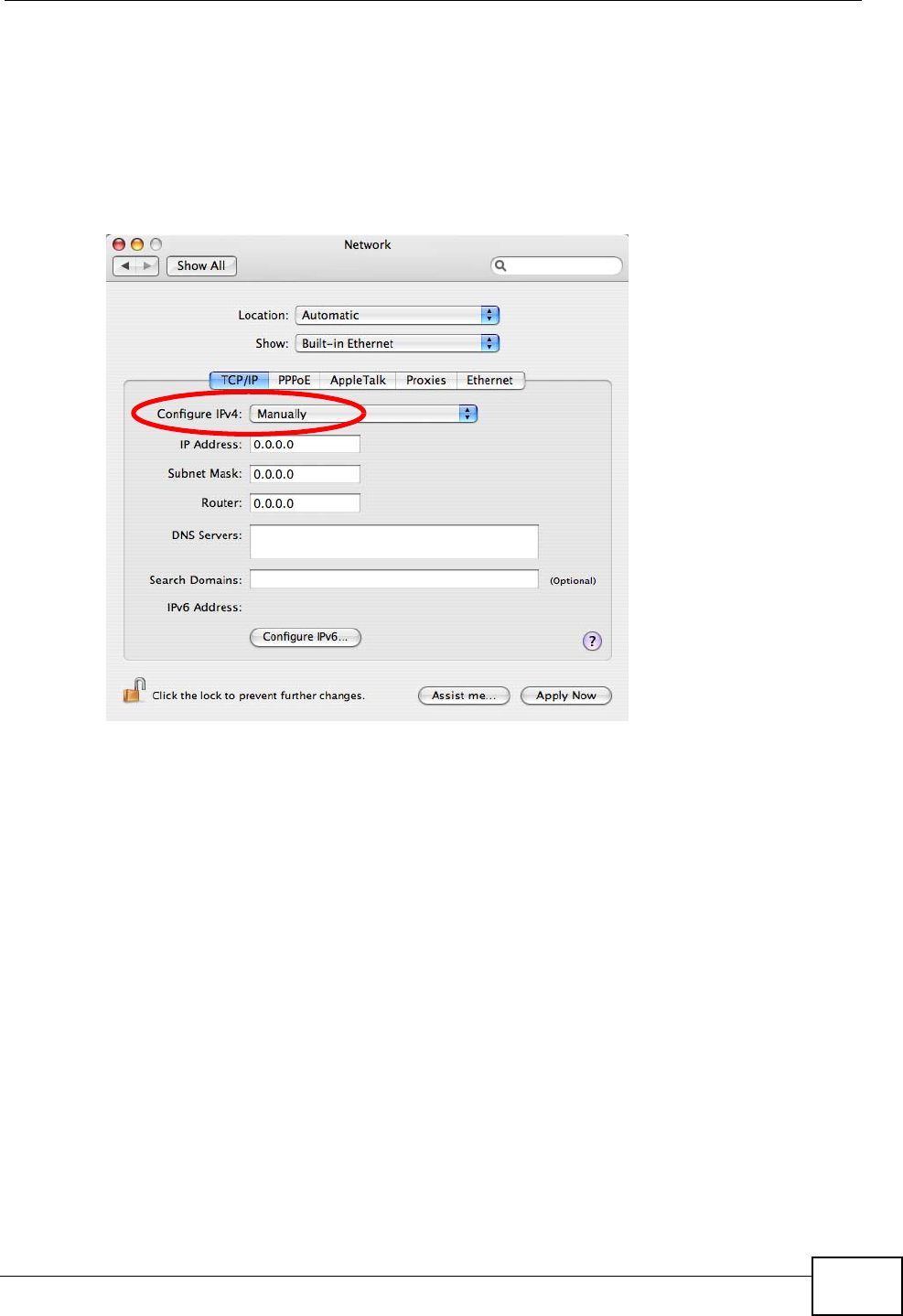
5For statically assigned settings, do the following:
•From the Configure IPv4 list, select Manually.
•In the IP Address field, type your IP address.
•In the Subnet Mask field, type your subnet mask.
•In the Router field, type the IP address of your device.
Figure 161 Mac OS X 10.4: Network Preferences > Ethernet
6Click Apply Now and close the window.
Appendix A Setting Up Your Computer’s IP Address
P-870HN-51b User’s Guide
274
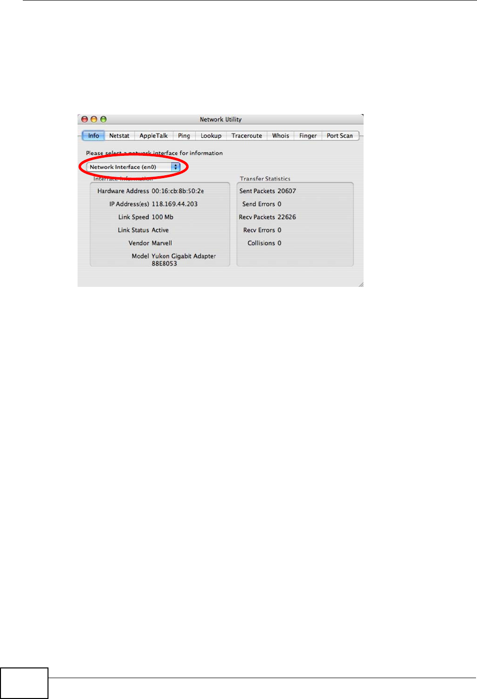
Verifying Settings
Check your TCP/IP properties by clicking Applications > Utilities > Network
Utilities, and then selecting the appropriate Network Interface from the Info
tab.
Figure 162 Mac OS X 10.4: Network Utility
Appendix A Setting Up Your Computer’s IP Address
P-870HN-51b User’s Guide 275
Mac OS X: 10.5
The screens in this section are from Mac OS X 10.5.
1Click Apple > System Preferences.
Figure 163 Mac OS X 10.5: Apple Menu
2In System Preferences, click the Network icon.
Figure 164 Mac OS X 10.5: Systems Preferences
Appendix A Setting Up Your Computer’s IP Address
P-870HN-51b User’s Guide
276
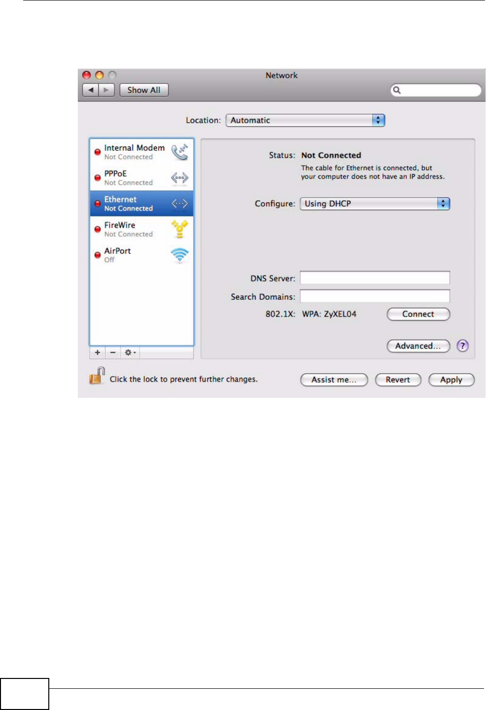
3When the Network preferences pane opens, select Ethernet from the list of
available connection types.
Figure 165 Mac OS X 10.5: Network Preferences > Ethernet
4From the Configure list, select Using DHCP for dynamically assigned settings.
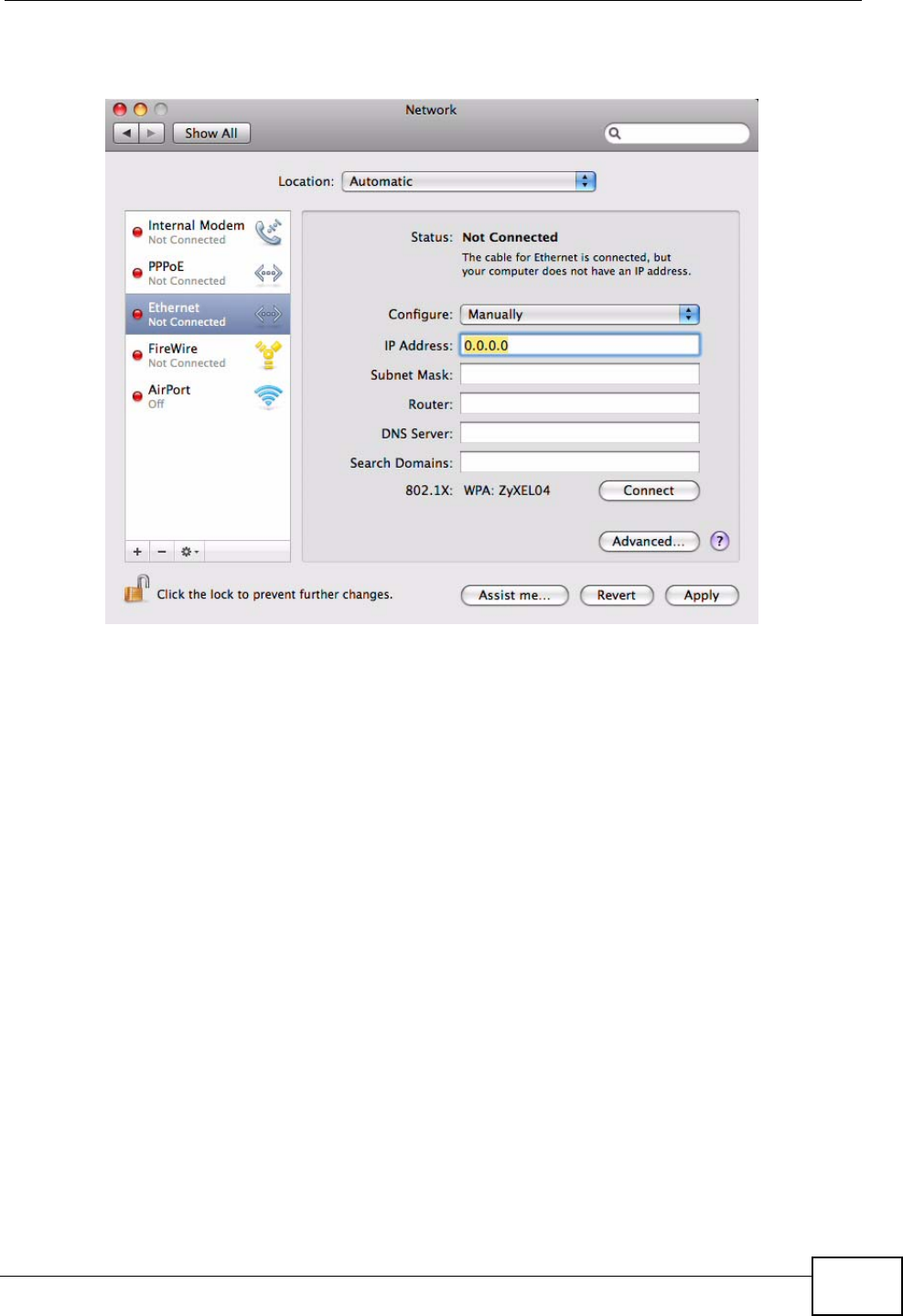
5For statically assigned settings, do the following:
•From the Configure list, select Manually.
•In the IP Address field, enter your IP address.
•In the Subnet Mask field, enter your subnet mask.
Appendix A Setting Up Your Computer’s IP Address
P-870HN-51b User’s Guide 277
•In the Router field, enter the IP address of your ZyXEL Device.
Figure 166 Mac OS X 10.5: Network Preferences > Ethernet
6Click Apply and close the window.
Appendix A Setting Up Your Computer’s IP Address
P-870HN-51b User’s Guide
278
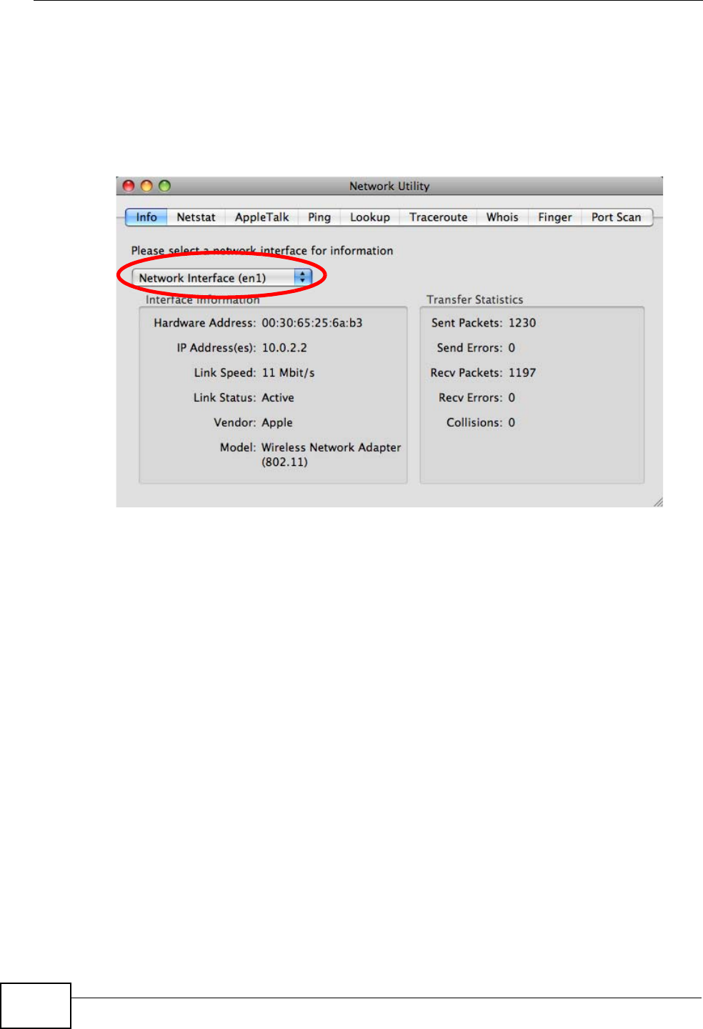
Verifying Settings
Check your TCP/IP properties by clicking Applications > Utilities > Network
Utilities, and then selecting the appropriate Network interface from the Info
tab.
Figure 167 Mac OS X 10.5: Network Utility
Linux: Ubuntu 8 (GNOME)
This section shows you how to configure your computer’s TCP/IP settings in the
GNU Object Model Environment (GNOME) using the Ubuntu 8 Linux distribution.
The procedure, screens and file locations may vary depending on your specific
distribution, release version, and individual configuration. The following screens
use the default Ubuntu 8 installation.
Note: Make sure you are logged in as the root administrator.
Follow the steps below to configure your computer IP address in GNOME:
Appendix A Setting Up Your Computer’s IP Address
P-870HN-51b User’s Guide 279
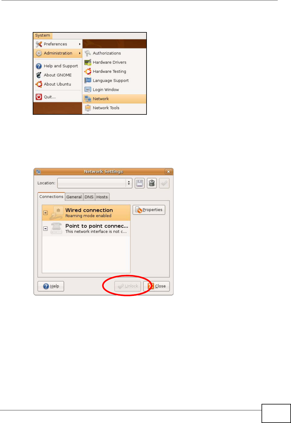
1Click System > Administration > Network.
Figure 168 Ubuntu 8: System > Administration Menu
2When the Network Settings window opens, click Unlock to open the
Authenticate window. (By default, the Unlock button is greyed out until clicked.)
You cannot make changes to your configuration unless you first enter your admin
password.
Figure 169 Ubuntu 8: Network Settings > Connections
Appendix A Setting Up Your Computer’s IP Address
P-870HN-51b User’s Guide
280
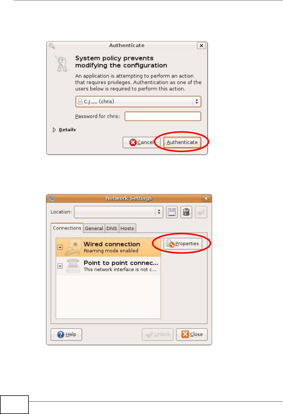
3In the Authenticate window, enter your admin account name and password then
click the Authenticate button.
Figure 170 Ubuntu 8: Administrator Account Authentication
4In the Network Settings window, select the connection that you want to
configure, then click Properties.
Figure 171 Ubuntu 8: Network Settings > Connections
Appendix A Setting Up Your Computer’s IP Address
P-870HN-51b User’s Guide 281
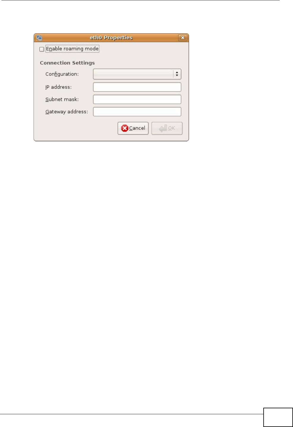
5The Properties dialog box opens.
Figure 172 Ubuntu 8: Network Settings > Properties
•In the Configuration list, select Automatic Configuration (DHCP) if you
have a dynamic IP address.
•In the Configuration list, select Static IP address if you have a static IP
address. Fill in the IP address, Subnet mask, and Gateway address fields.
6Click OK to save the changes and close the Properties dialog box and return to
the Network Settings screen.
Appendix A Setting Up Your Computer’s IP Address
P-870HN-51b User’s Guide
282
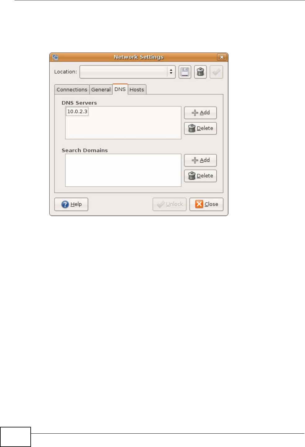
7If you know your DNS server IP address(es), click the DNS tab in the Network
Settings window and then enter the DNS server information in the fields
provided.
Figure 173 Ubuntu 8: Network Settings > DNS
8Click the Close button to apply the changes.
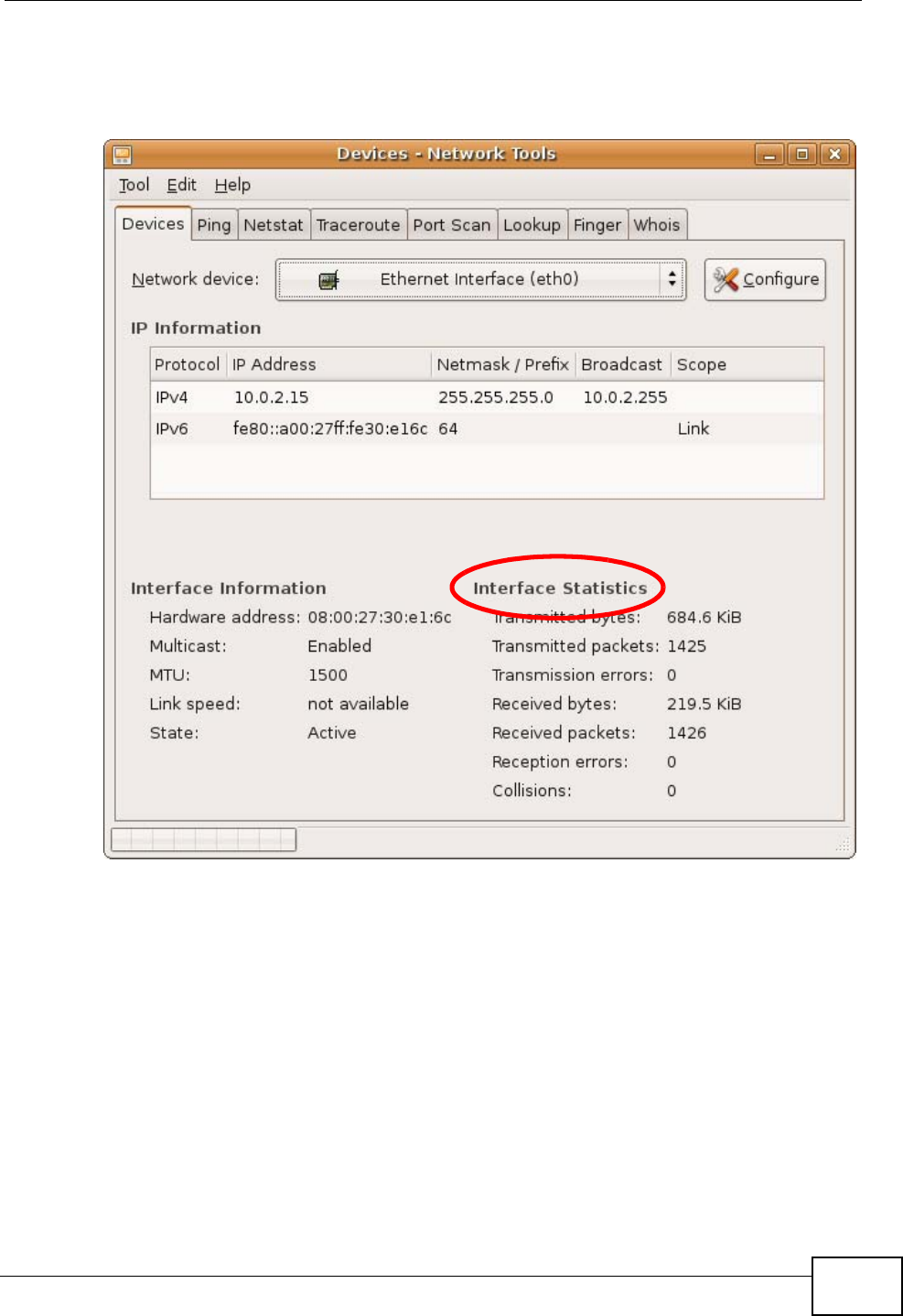
Verifying Settings
Check your TCP/IP properties by clicking System > Administration > Network
Tools, and then selecting the appropriate Network device from the Devices
Appendix A Setting Up Your Computer’s IP Address
P-870HN-51b User’s Guide 283
tab. The Interface Statistics column shows data if your connection is working
properly.
Figure 174 Ubuntu 8: Network Tools
Appendix A Setting Up Your Computer’s IP Address
P-870HN-51b User’s Guide
284
Linux: openSUSE 10.3 (KDE)
This section shows you how to configure your computer’s TCP/IP settings in the K
Desktop Environment (KDE) using the openSUSE 10.3 Linux distribution. The
procedure, screens and file locations may vary depending on your specific
distribution, release version, and individual configuration. The following screens
use the default openSUSE 10.3 installation.
Note: Make sure you are logged in as the root administrator.
Follow the steps below to configure your computer IP address in the KDE:
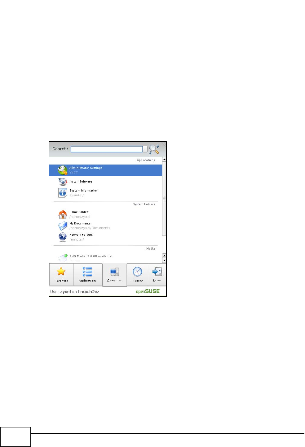
1Click K Menu > Computer > Administrator Settings (YaST).
Figure 175 openSUSE 10.3: K Menu > Computer Menu
Appendix A Setting Up Your Computer’s IP Address
P-870HN-51b User’s Guide 285
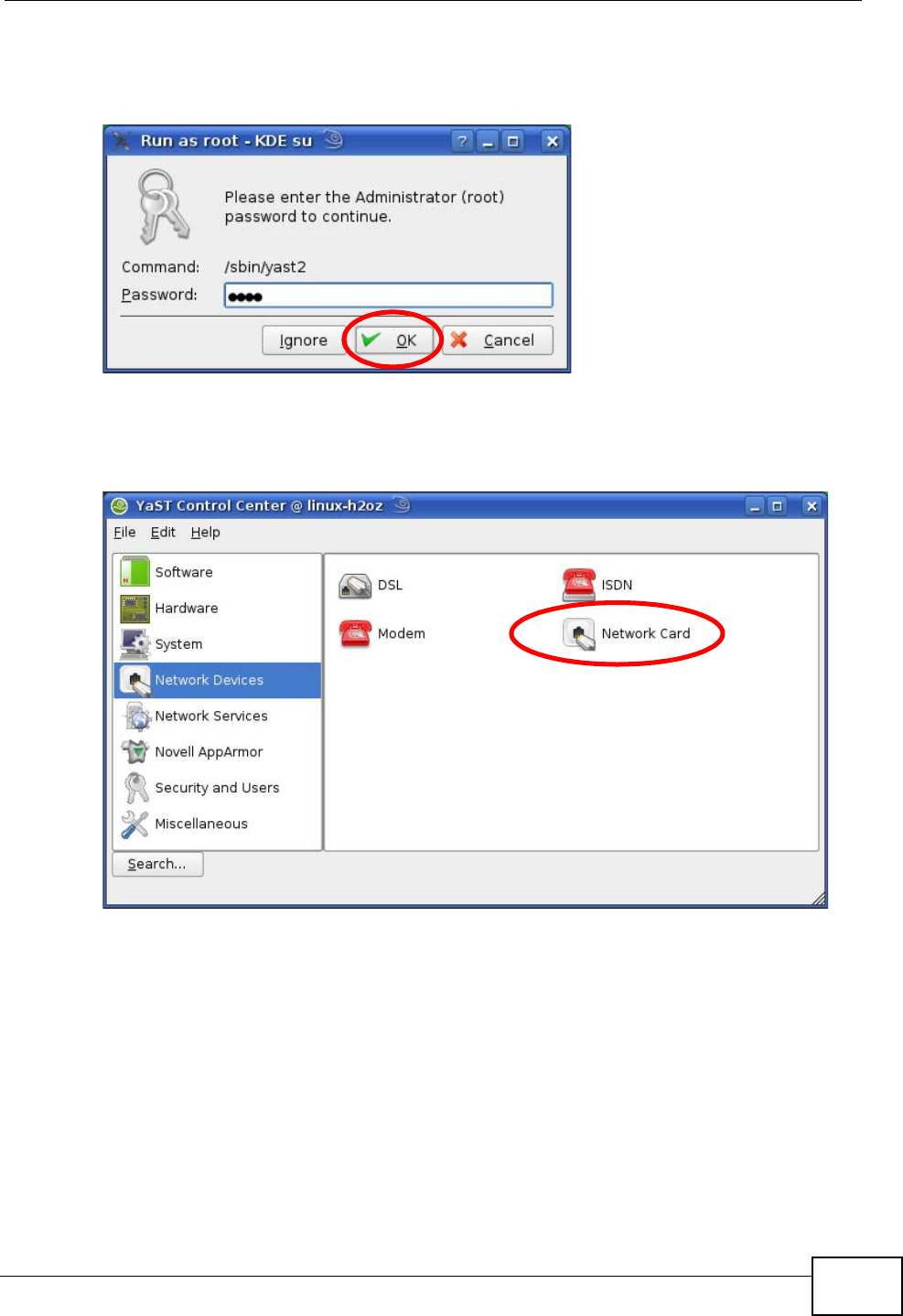
2When the Run as Root - KDE su dialog opens, enter the admin password and
click OK.
Figure 176 openSUSE 10.3: K Menu > Computer Menu
3When the YaST Control Center window opens, select Network Devices and
then click the Network Card icon.
Figure 177 openSUSE 10.3: YaST Control Center
Appendix A Setting Up Your Computer’s IP Address
P-870HN-51b User’s Guide
286
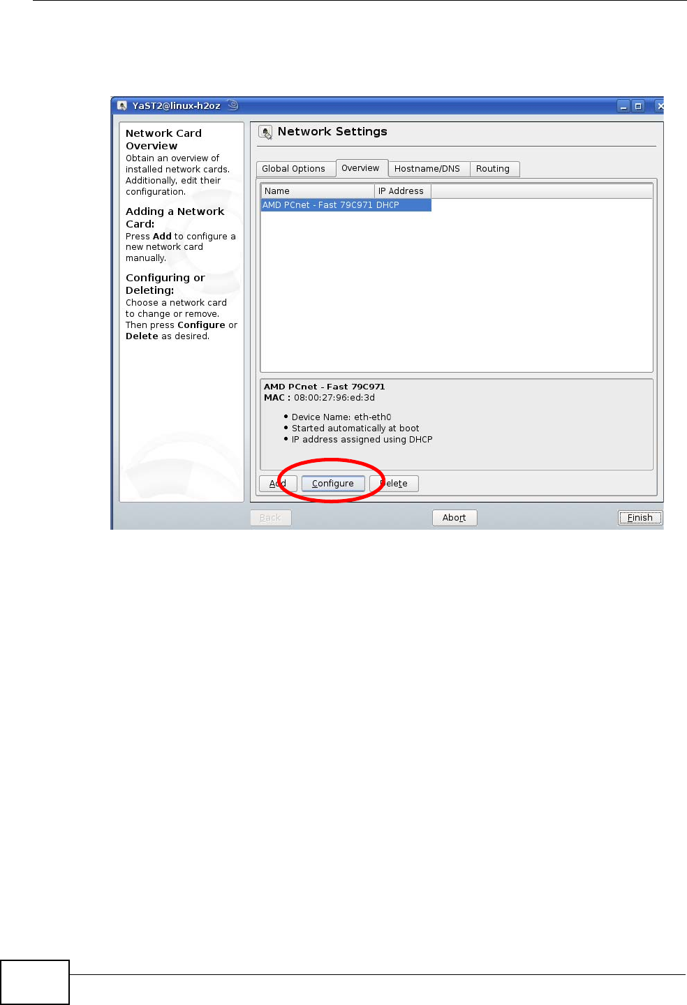
4When the Network Settings window opens, click the Overview tab, select the
appropriate connection Name from the list, and then click the Configure button.
Figure 178 openSUSE 10.3: Network Settings
Appendix A Setting Up Your Computer’s IP Address
P-870HN-51b User’s Guide 287
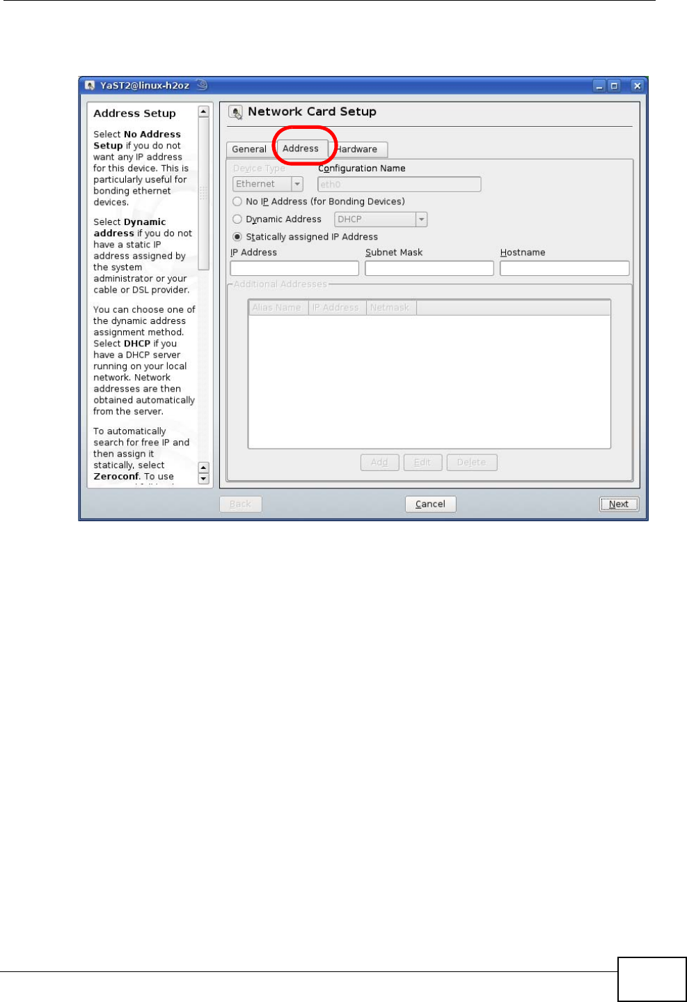
5When the Network Card Setup window opens, click the Address tab
Figure 179 openSUSE 10.3: Network Card Setup
6Select Dynamic Address (DHCP) if you have a dynamic IP address.
Select Statically assigned IP Address if you have a static IP address. Fill in the
IP address, Subnet mask, and Hostname fields.
7Click Next to save the changes and close the Network Card Setup window.
Appendix A Setting Up Your Computer’s IP Address
P-870HN-51b User’s Guide
288
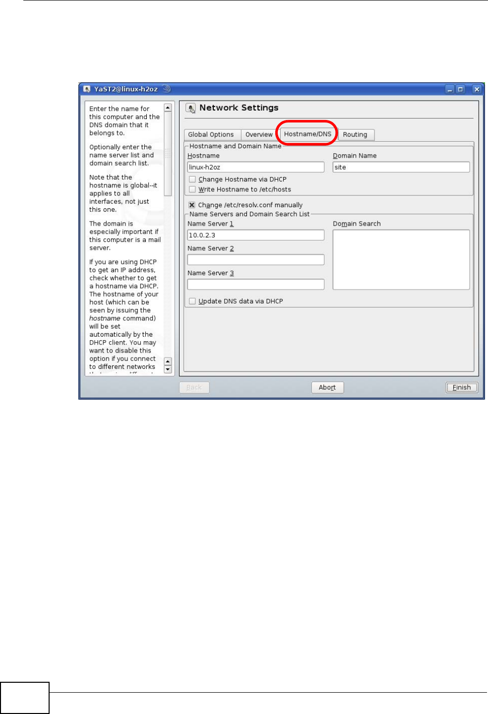
8If you know your DNS server IP address(es), click the Hostname/DNS tab in
Network Settings and then enter the DNS server information in the fields
provided.
Figure 180 openSUSE 10.3: Network Settings
9Click Finish to save your settings and close the window.
Appendix A Setting Up Your Computer’s IP Address
P-870HN-51b User’s Guide 289
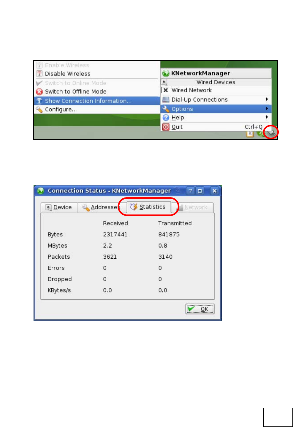
Verifying Settings
Click the KNetwork Manager icon on the Task bar to check your TCP/IP
properties. From the Options sub-menu, select Show Connection Information.
Figure 181 openSUSE 10.3: KNetwork Manager
When the Connection Status - KNetwork Manager window opens, click the
Statistics tab to see if your connection is working properly.
Figure 182 openSUSE: Connection Status - KNetwork Manager

Appendix A Setting Up Your Computer’s IP Address
P-870HN-51b User’s Guide
290

P-870HN-51b User’s Guide 291
APPENDIX B
Pop-up Windows, JavaScripts
and Java Permissions
In order to use the web configurator you need to allow:
• Web browser pop-up windows from your device.
• JavaScripts (enabled by default).
• Java permissions (enabled by default).
Note: Internet Explorer 6 screens are used here. Screens for other Internet Explorer
versions may vary.
Internet Explorer Pop-up Blockers
You may have to disable pop-up blocking to log into your device.
Either disable pop-up blocking (enabled by default in Windows XP SP (Service
Pack) 2) or allow pop-up blocking and create an exception for your device’s IP
address.
Disable Pop-up Blockers
1In Internet Explorer, select Tools, Pop-up Blocker and then select Turn Off
Pop-up Blocker.
Figure 183 Pop-up Blocker
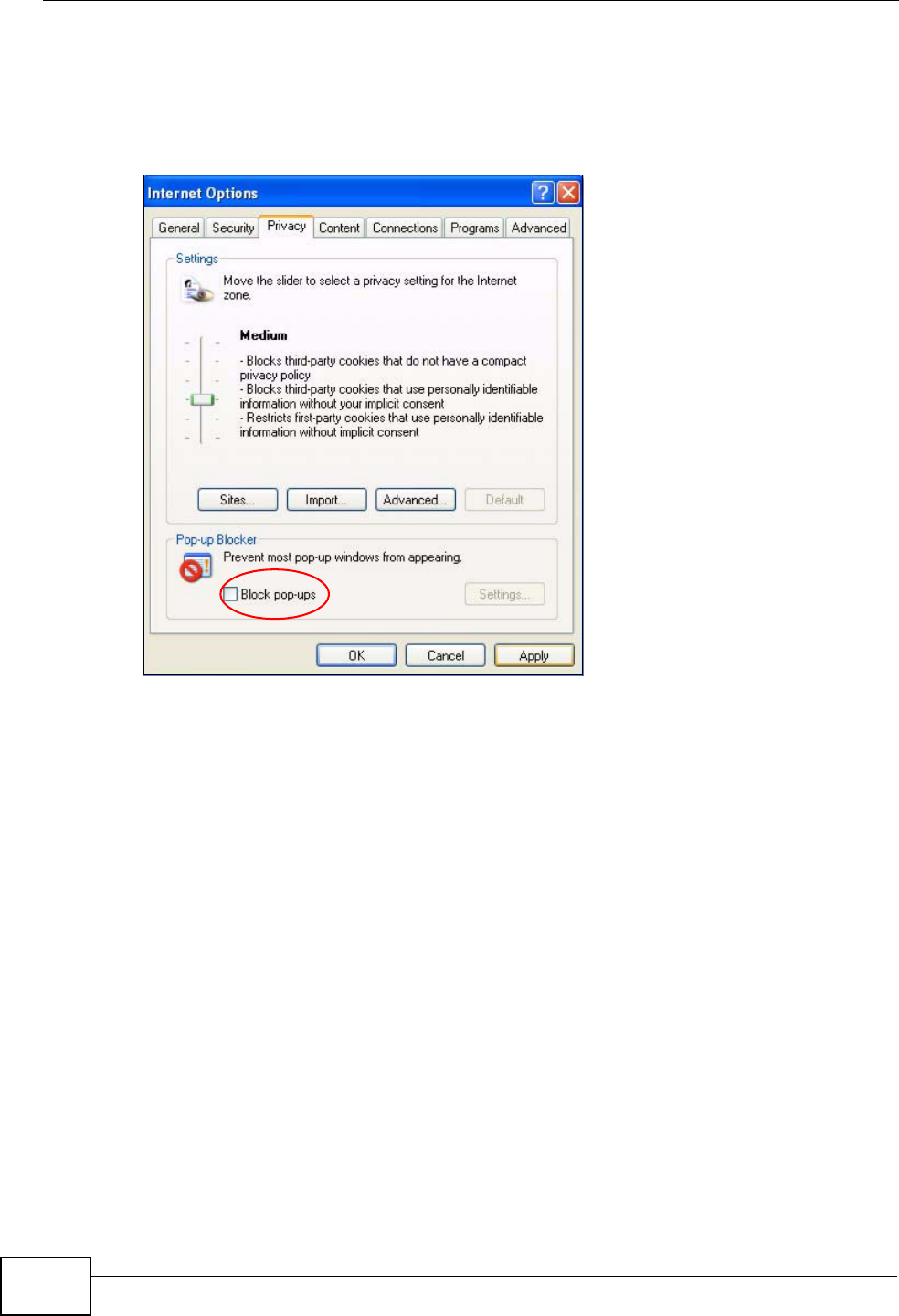
You can also check if pop-up blocking is disabled in the Pop-up Blocker section in
the Privacy tab.
Appendix B Pop-up Windows, JavaScripts and Java Permissions
P-870HN-51b User’s Guide
292
1In Internet Explorer, select Tools, Internet Options, Privacy.
2Clear the Block pop-ups check box in the Pop-up Blocker section of the screen.
This disables any web pop-up blockers you may have enabled.
Figure 184 Internet Options: Privacy
3Click Apply to save this setting.
Enable Pop-up Blockers with Exceptions
Alternatively, if you only want to allow pop-up windows from your device, see the
following steps.
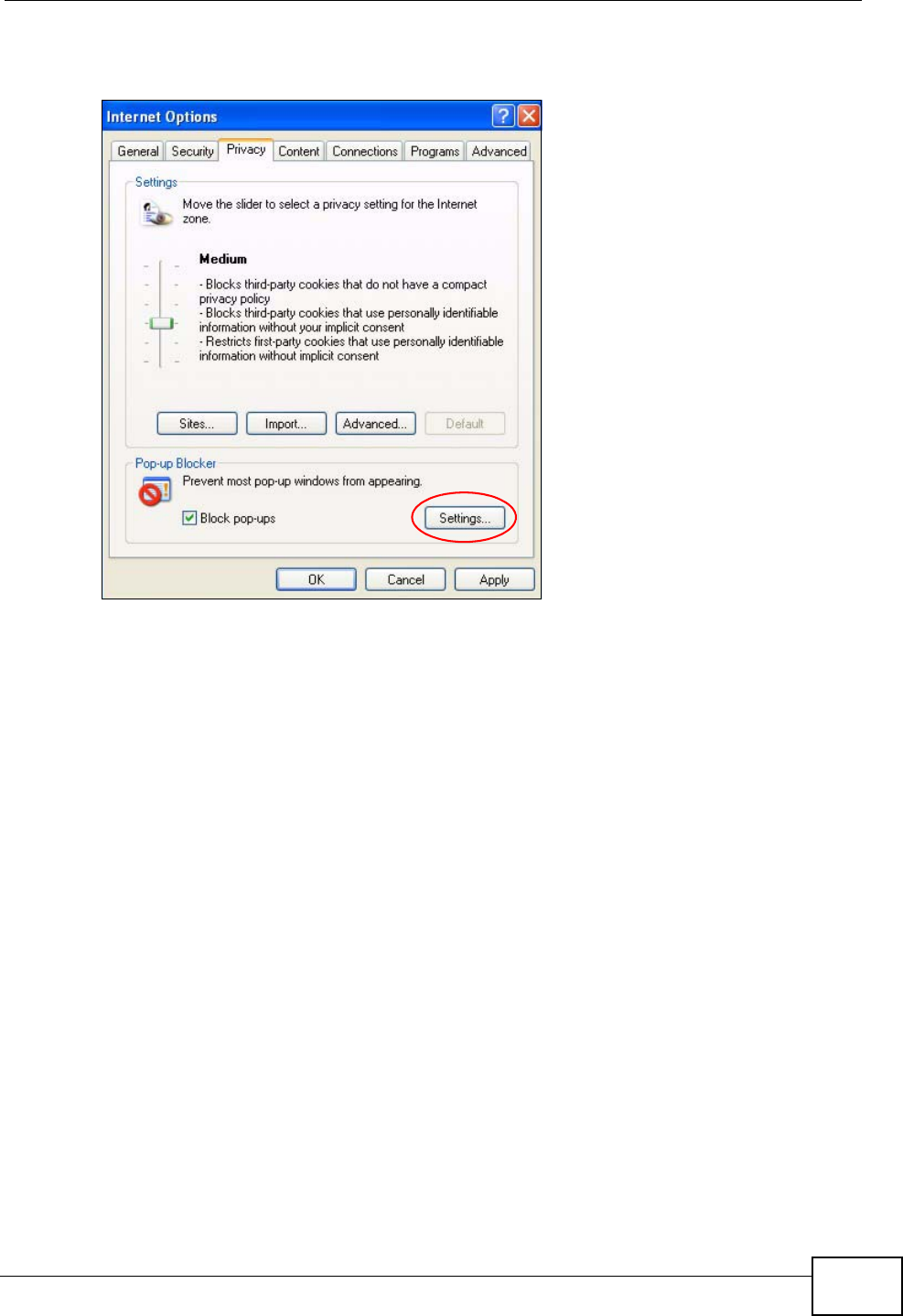
1In Internet Explorer, select Tools, Internet Options and then the Privacy tab.
Appendix B Pop-up Windows, JavaScripts and Java Permissions
P-870HN-51b User’s Guide 293
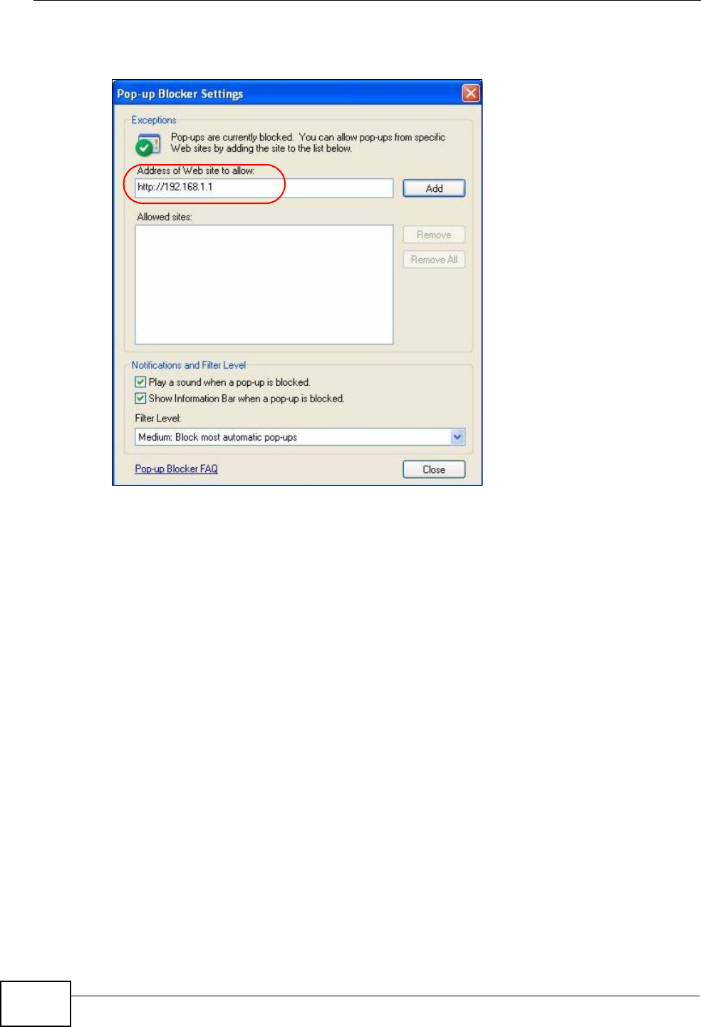
2Select Settings…to open the Pop-up Blocker Settings screen.
Figure 185 Internet Options: Privacy
3Type the IP address of your device (the web page that you do not want to have
blocked) with the prefix “http://”. For example, http://192.168.167.1.
Appendix B Pop-up Windows, JavaScripts and Java Permissions
P-870HN-51b User’s Guide
294
4Click Add to move the IP address to the list of Allowed sites.
Figure 186 Pop-up Blocker Settings
5Click Close to return to the Privacy screen.
6Click Apply to save this setting.
JavaScripts
If pages of the web configurator do not display properly in Internet Explorer, check
that JavaScripts are allowed.
Appendix B Pop-up Windows, JavaScripts and Java Permissions
P-870HN-51b User’s Guide 295
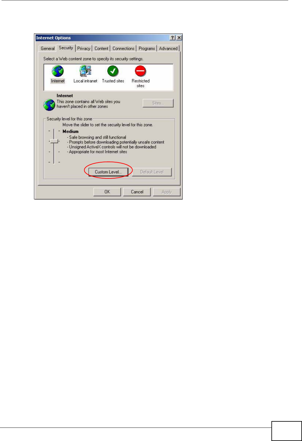
1In Internet Explorer, click Tools, Internet Options and then the Security tab.
Figure 187 Internet Options: Security
2Click the Custom Level... button.
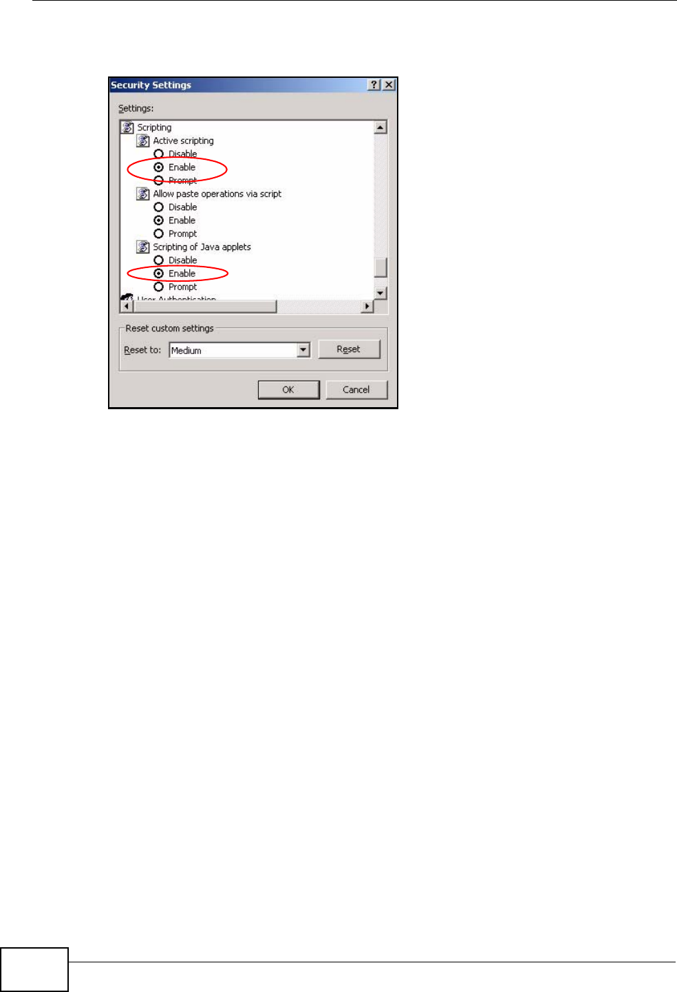
3Scroll down to Scripting.
4Under Active scripting make sure that Enable is selected (the default).
5Under Scripting of Java applets make sure that Enable is selected (the
default).
Appendix B Pop-up Windows, JavaScripts and Java Permissions
P-870HN-51b User’s Guide
296
6Click OK to close the window.
Figure 188 Security Settings - Java Scripting
Java Permissions
1From Internet Explorer, click Tools, Internet Options and then the Security
tab.
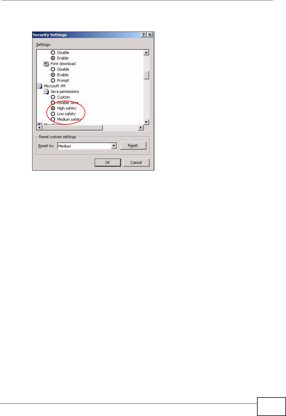
2Click the Custom Level... button.
3Scroll down to Microsoft VM.
4Under Java permissions make sure that a safety level is selected.
Appendix B Pop-up Windows, JavaScripts and Java Permissions
P-870HN-51b User’s Guide 297
5Click OK to close the window.
Figure 189 Security Settings - Java
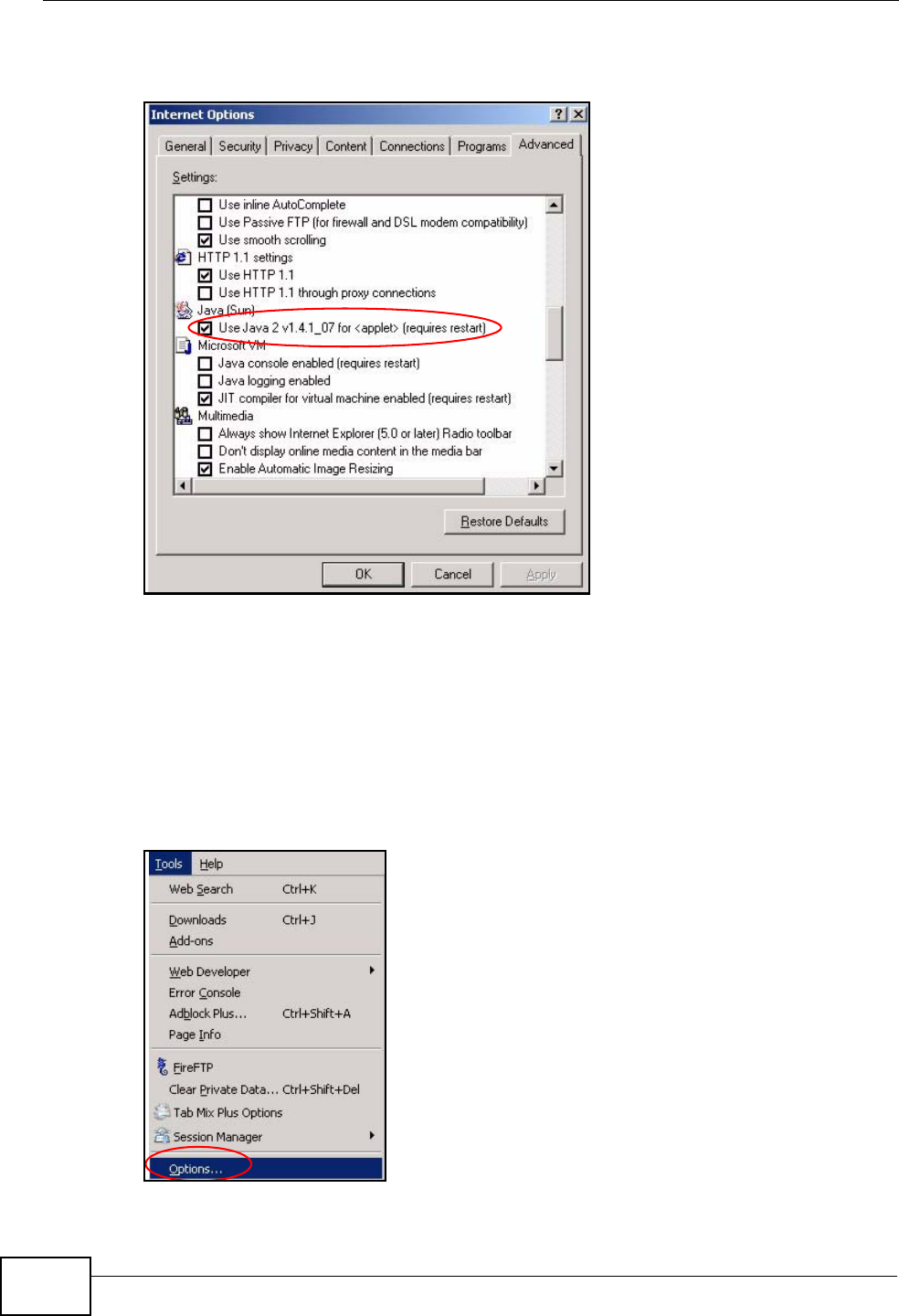
JAVA (Sun)
1From Internet Explorer, click Tools, Internet Options and then the Advanced
tab.
2Make sure that Use Java 2 for <applet> under Java (Sun) is selected.
Appendix B Pop-up Windows, JavaScripts and Java Permissions
P-870HN-51b User’s Guide
298
3Click OK to close the window.
Figure 190 Java (Sun)
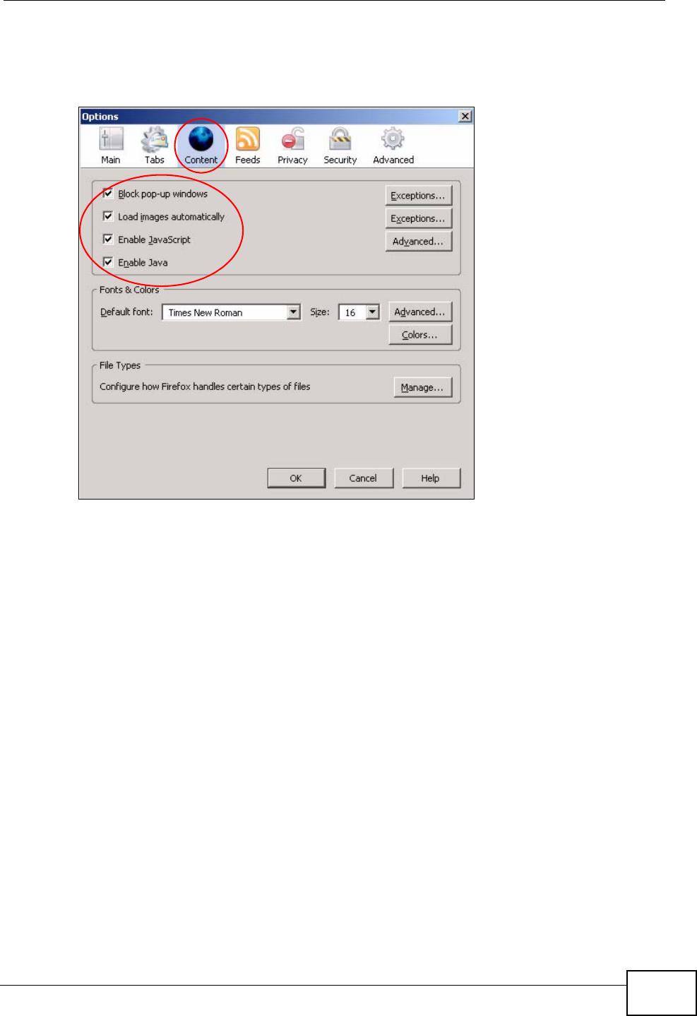
Mozilla Firefox
Mozilla Firefox 2.0 screens are used here. Screens for other versions may vary.
You can enable Java, Javascripts and pop-ups in one screen. Click Tools, then
click Options in the screen that appears.
Figure 191 Mozilla Firefox: Tools > Options
Appendix B Pop-up Windows, JavaScripts and Java Permissions
P-870HN-51b User’s Guide 299
Click Content.to show the screen below. Select the check boxes as shown in the
following screen.
Figure 192 Mozilla Firefox Content Security

Appendix B Pop-up Windows, JavaScripts and Java Permissions
P-870HN-51b User’s Guide
300

P-870HN-51b User’s Guide 301
APPENDIX C
IP Addresses and Subnetting
This appendix introduces IP addresses and subnet masks.
IP addresses identify individual devices on a network. Every networking device
(including computers, servers, routers, printers, etc.) needs an IP address to
communicate across the network. These networking devices are also known as
hosts.
Subnet masks determine the maximum number of possible hosts on a network.
You can also use subnet masks to divide one network into multiple sub-networks.
Introduction to IP Addresses
One part of the IP address is the network number, and the other part is the host
ID. In the same way that houses on a street share a common street name, the
hosts on a network share a common network number. Similarly, as each house
has its own house number, each host on the network has its own unique
identifying number - the host ID. Routers use the network number to send packets
to the correct network, while the host ID determines to which host on the network
the packets are delivered.
Structure
An IP address is made up of four parts, written in dotted decimal notation (for
example, 192.168.1.1). Each of these four parts is known as an octet. An octet is
an eight-digit binary number (for example 11000000, which is 192 in decimal
notation).
Therefore, each octet has a possible range of 00000000 to 11111111 in binary, or
0 to 255 in decimal.
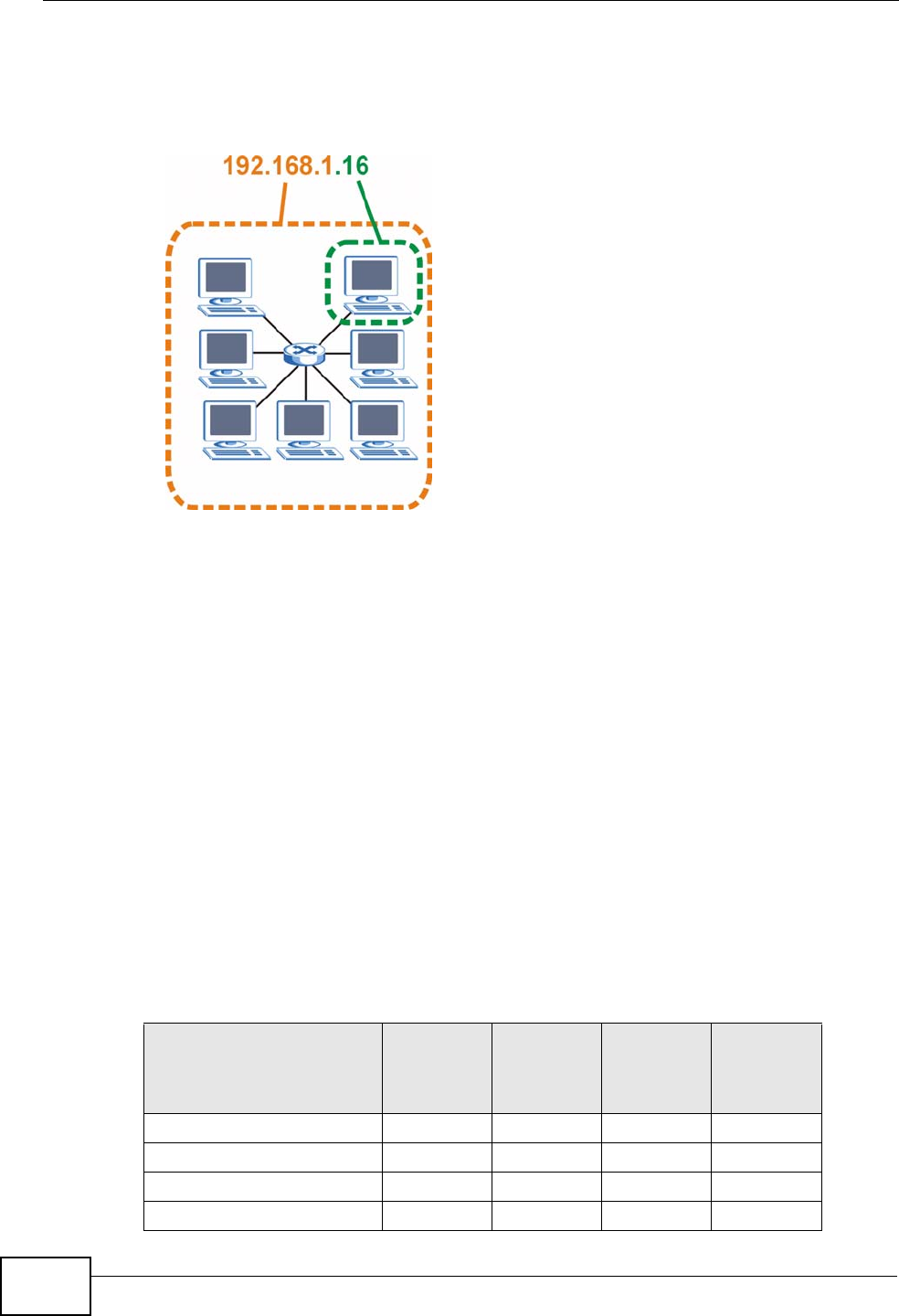
Appendix C IP Addresses and Subnetting
P-870HN-51b User’s Guide
302
The following figure shows an example IP address in which the first three octets
(192.168.1) are the network number, and the fourth octet (16) is the host ID.
Figure 193 Network Number and Host ID
How much of the IP address is the network number and how much is the host ID
varies according to the subnet mask.
Subnet Masks
A subnet mask is used to determine which bits are part of the network number,
and which bits are part of the host ID (using a logical AND operation). The term
“subnet” is short for “sub-network”.
A subnet mask has 32 bits. If a bit in the subnet mask is a “1” then the
corresponding bit in the IP address is part of the network number. If a bit in the
subnet mask is “0” then the corresponding bit in the IP address is part of the host
ID.
The following example shows a subnet mask identifying the network number (in
bold text) and host ID of an IP address (192.168.1.2 in decimal).
Table 94 IP Address Network Number and Host ID Example
1ST
OCTET:
(192)
2ND
OCTET:
(168)
3RD
OCTET:
(1)
4TH
OCTET
(2)
IP Address (Binary) 11000000 10101000 00000001 00000010
Subnet Mask (Binary) 11111111 11111111 11111111 00000000
Network Number 11000000 10101000 00000001
Host ID 00000010

Appendix C IP Addresses and Subnetting
P-870HN-51b User’s Guide 303
By convention, subnet masks always consist of a continuous sequence of ones
beginning from the leftmost bit of the mask, followed by a continuous sequence of
zeros, for a total number of 32 bits.
Subnet masks can be referred to by the size of the network number part (the bits
with a “1” value). For example, an “8-bit mask” means that the first 8 bits of the
mask are ones and the remaining 24 bits are zeroes.
Subnet masks are expressed in dotted decimal notation just like IP addresses. The
following examples show the binary and decimal notation for 8-bit, 16-bit, 24-bit
and 29-bit subnet masks.
Network Size
The size of the network number determines the maximum number of possible
hosts you can have on your network. The larger the number of network number
bits, the smaller the number of remaining host ID bits.
An IP address with host IDs of all zeros is the IP address of the network
(192.168.1.0 with a 24-bit subnet mask, for example). An IP address with host
IDs of all ones is the broadcast address for that network (192.168.1.255 with a
24-bit subnet mask, for example).
As these two IP addresses cannot be used for individual hosts, calculate the
maximum number of possible hosts in a network as follows:
Table 95 Subnet Masks
BINARY
DECIMAL
1ST
OCTET 2ND
OCTET 3RD
OCTET 4TH
OCTET
8-bit mask 11111111 00000000 00000000 00000000 255.0.0.0
16-bit
mask 11111111 11111111 00000000 00000000 255.255.0.0
24-bit
mask 11111111 11111111 11111111 00000000 255.255.255.0
29-bit
mask 11111111 11111111 11111111 11111000 255.255.255.24
8
Table 96 Maximum Host Numbers
SUBNET MASK HOST ID SIZE MAXIMUM NUMBER OF
HOSTS
8 bits 255.0.0.0 24 bits 224 – 2 16777214
16 bits 255.255.0.0 16 bits 216 – 2 65534
24 bits 255.255.255.0 8 bits 28 – 2 254
29 bits 255.255.255.2
48 3 bits 23 – 2 6

Appendix C IP Addresses and Subnetting
P-870HN-51b User’s Guide
304
Notation
Since the mask is always a continuous number of ones beginning from the left,
followed by a continuous number of zeros for the remainder of the 32 bit mask,
you can simply specify the number of ones instead of writing the value of each
octet. This is usually specified by writing a “/” followed by the number of bits in
the mask after the address.
For example, 192.1.1.0 /25 is equivalent to saying 192.1.1.0 with subnet mask
255.255.255.128.
The following table shows some possible subnet masks using both notations.
Subnetting
You can use subnetting to divide one network into multiple sub-networks. In the
following example a network administrator creates two sub-networks to isolate a
group of servers from the rest of the company network for security reasons.
In this example, the company network address is 192.168.1.0. The first three
octets of the address (192.168.1) are the network number, and the remaining
octet is the host ID, allowing a maximum of 28 – 2 or 254 possible hosts.
Table 97 Alternative Subnet Mask Notation
SUBNET
MASK ALTERNATIVE
NOTATION LAST OCTET
(BINARY) LAST OCTET
(DECIMAL)
255.255.255.0 /24 0000 0000 0
255.255.255.12
8/25 1000 0000 128
255.255.255.19
2/26 1100 0000 192
255.255.255.22
4/27 1110 0000 224
255.255.255.24
0/28 1111 0000 240
255.255.255.24
8/29 1111 1000 248
255.255.255.25
2/30 1111 1100 252
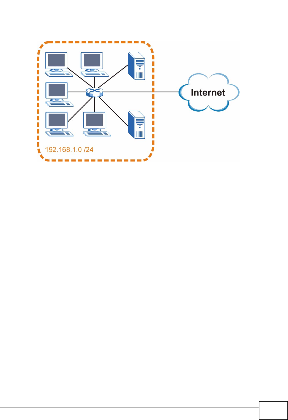
Appendix C IP Addresses and Subnetting
P-870HN-51b User’s Guide 305
The following figure shows the company network before subnetting.
Figure 194 Subnetting Example: Before Subnetting
You can “borrow” one of the host ID bits to divide the network 192.168.1.0 into
two separate sub-networks. The subnet mask is now 25 bits (255.255.255.128 or
/25).
The “borrowed” host ID bit can have a value of either 0 or 1, allowing two
subnets; 192.168.1.0 /25 and 192.168.1.128 /25.
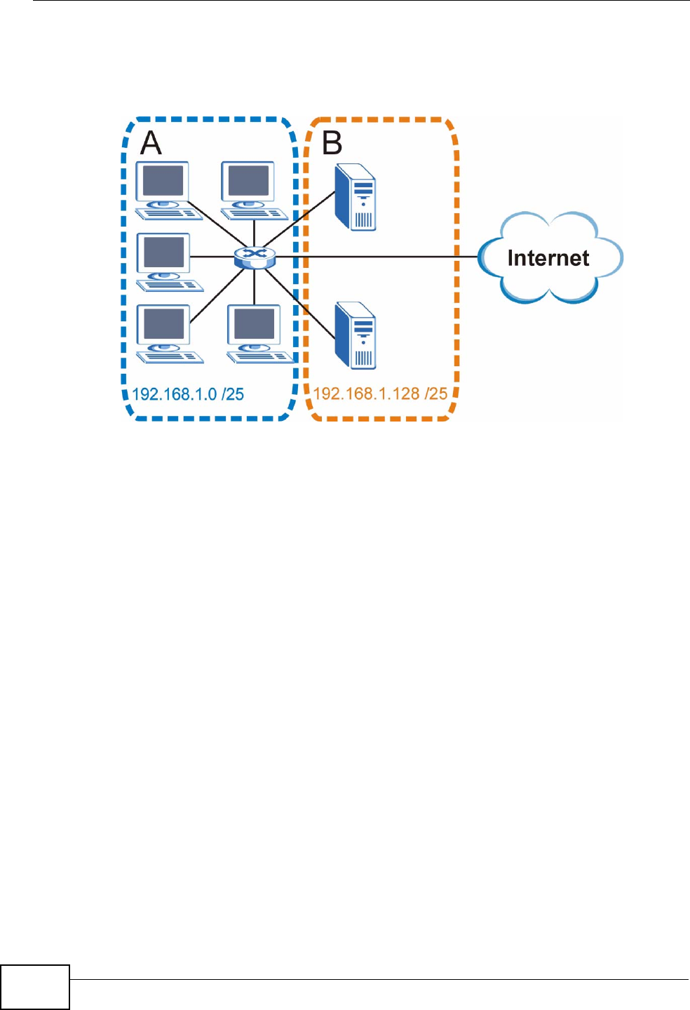
Appendix C IP Addresses and Subnetting
P-870HN-51b User’s Guide
306
The following figure shows the company network after subnetting. There are now
two sub-networks, A and B.
Figure 195 Subnetting Example: After Subnetting
In a 25-bit subnet the host ID has 7 bits, so each sub-network has a maximum of
27 – 2 or 126 possible hosts (a host ID of all zeroes is the subnet’s address itself,
all ones is the subnet’s broadcast address).
192.168.1.0 with mask 255.255.255.128 is subnet A itself, and 192.168.1.127
with mask 255.255.255.128 is its broadcast address. Therefore, the lowest IP
address that can be assigned to an actual host for subnet A is 192.168.1.1 and
the highest is 192.168.1.126.
Similarly, the host ID range for subnet B is 192.168.1.129 to 192.168.1.254.
Example: Four Subnets
The previous example illustrated using a 25-bit subnet mask to divide a 24-bit
address into two subnets. Similarly, to divide a 24-bit address into four subnets,
you need to “borrow” two host ID bits to give four possible combinations (00, 01,
10 and 11). The subnet mask is 26 bits
(11111111.11111111.11111111.11000000) or 255.255.255.192.

Appendix C IP Addresses and Subnetting
P-870HN-51b User’s Guide 307
Each subnet contains 6 host ID bits, giving 26 - 2 or 62 hosts for each subnet (a
host ID of all zeroes is the subnet itself, all ones is the subnet’s broadcast
address).
Table 98 Subnet 1
IP/SUBNET MASK NETWORK NUMBER LAST OCTET BIT
VALUE
IP Address (Decimal) 192.168.1. 0
IP Address (Binary) 11000000.10101000.00000001. 00000000
Subnet Mask (Binary) 11111111.11111111.11111111. 11000000
Subnet Address:
192.168.1.0 Lowest Host ID: 192.168.1.1
Broadcast Address:
192.168.1.63 Highest Host ID: 192.168.1.62
Table 99 Subnet 2
IP/SUBNET MASK NETWORK NUMBER LAST OCTET BIT
VALUE
IP Address 192.168.1. 64
IP Address (Binary) 11000000.10101000.00000001. 01000000
Subnet Mask (Binary) 11111111.11111111.11111111. 11000000
Subnet Address:
192.168.1.64 Lowest Host ID: 192.168.1.65
Broadcast Address:
192.168.1.127 Highest Host ID: 192.168.1.126
Table 100 Subnet 3
IP/SUBNET MASK NETWORK NUMBER LAST OCTET BIT
VALUE
IP Address 192.168.1. 128
IP Address (Binary) 11000000.10101000.00000001. 10000000
Subnet Mask (Binary) 11111111.11111111.11111111. 11000000
Subnet Address:
192.168.1.128 Lowest Host ID: 192.168.1.129
Broadcast Address:
192.168.1.191 Highest Host ID: 192.168.1.190
Table 101 Subnet 4
IP/SUBNET MASK NETWORK NUMBER LAST OCTET BIT
VALUE
IP Address 192.168.1. 192
IP Address (Binary) 11000000.10101000.00000001
. 11000000
Subnet Mask (Binary) 11111111.11111111.11111111
. 11000000
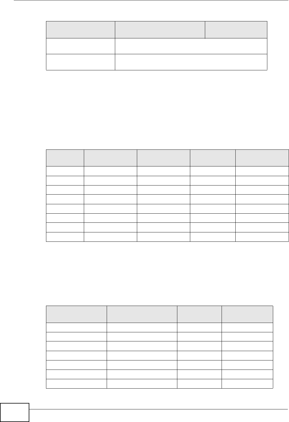
Appendix C IP Addresses and Subnetting
P-870HN-51b User’s Guide
308
Example: Eight Subnets
Similarly, use a 27-bit mask to create eight subnets (000, 001, 010, 011, 100,
101, 110 and 111).
The following table shows IP address last octet values for each subnet.
Subnet Planning
The following table is a summary for subnet planning on a network with a 24-bit
network number.
Subnet Address:
192.168.1.192 Lowest Host ID: 192.168.1.193
Broadcast Address:
192.168.1.255 Highest Host ID: 192.168.1.254
Table 101 Subnet 4 (continued)
IP/SUBNET MASK NETWORK NUMBER LAST OCTET BIT
VALUE
Table 102 Eight Subnets
SUBNET SUBNET
ADDRESS FIRST ADDRESS LAST
ADDRESS BROADCAST
ADDRESS
1 0 1 30 31
232 33 62 63
364 65 94 95
496 97 126 127
5128 129 158 159
6160 161 190 191
7192 193 222 223
8224 225 254 255
Table 103 24-bit Network Number Subnet Planning
NO. “BORROWED”
HOST BITS SUBNET MASK NO. SUBNETS NO. HOSTS PER
SUBNET
1255.255.255.128 (/25) 2126
2255.255.255.192 (/26) 462
3255.255.255.224 (/27) 830
4255.255.255.240 (/28) 16 14
5255.255.255.248 (/29) 32 6
6255.255.255.252 (/30) 64 2
7255.255.255.254 (/31) 128 1

Appendix C IP Addresses and Subnetting
P-870HN-51b User’s Guide 309
The following table is a summary for subnet planning on a network with a 16-bit
network number.
Configuring IP Addresses
Where you obtain your network number depends on your particular situation. If
the ISP or your network administrator assigns you a block of registered IP
addresses, follow their instructions in selecting the IP addresses and the subnet
mask.
If the ISP did not explicitly give you an IP network number, then most likely you
have a single user account and the ISP will assign you a dynamic IP address when
the connection is established. If this is the case, it is recommended that you select
a network number from 192.168.0.0 to 192.168.255.0. The Internet Assigned
Number Authority (IANA) reserved this block of addresses specifically for private
use; please do not use any other number unless you are told otherwise. You must
also enable Network Address Translation (NAT) on the ZyXEL Device.
Once you have decided on the network number, pick an IP address for your ZyXEL
Device that is easy to remember (for instance, 192.168.1.1) but make sure that
no other device on your network is using that IP address.
The subnet mask specifies the network number portion of an IP address. Your
ZyXEL Device will compute the subnet mask automatically based on the IP
Table 104 16-bit Network Number Subnet Planning
NO. “BORROWED”
HOST BITS SUBNET MASK NO. SUBNETS NO. HOSTS PER
SUBNET
1255.255.128.0 (/17) 232766
2255.255.192.0 (/18) 416382
3255.255.224.0 (/19) 88190
4255.255.240.0 (/20) 16 4094
5255.255.248.0 (/21) 32 2046
6255.255.252.0 (/22) 64 1022
7255.255.254.0 (/23) 128 510
8255.255.255.0 (/24) 256 254
9255.255.255.128 (/25) 512 126
10 255.255.255.192 (/26) 1024 62
11 255.255.255.224 (/27) 2048 30
12 255.255.255.240 (/28) 4096 14
13 255.255.255.248 (/29) 8192 6
14 255.255.255.252 (/30) 16384 2
15 255.255.255.254 (/31) 32768 1

Appendix C IP Addresses and Subnetting
P-870HN-51b User’s Guide
310
address that you entered. You don't need to change the subnet mask computed by
the ZyXEL Device unless you are instructed to do otherwise.
Private IP Addresses
Every machine on the Internet must have a unique address. If your networks are
isolated from the Internet (running only between two branch offices, for example)
you can assign any IP addresses to the hosts without problems. However, the
Internet Assigned Numbers Authority (IANA) has reserved the following three
blocks of IP addresses specifically for private networks:
• 10.0.0.0 — 10.255.255.255
• 172.16.0.0 — 172.31.255.255
• 192.168.0.0 — 192.168.255.255
You can obtain your IP address from the IANA, from an ISP, or it can be assigned
from a private network. If you belong to a small organization and your Internet
access is through an ISP, the ISP can provide you with the Internet addresses for
your local networks. On the other hand, if you are part of a much larger
organization, you should consult your network administrator for the appropriate IP
addresses.
Regardless of your particular situation, do not create an arbitrary IP address;
always follow the guidelines above. For more information on address assignment,
please refer to RFC 1597, Address Allocation for Private Internets and RFC 1466,
Guidelines for Management of IP Address Space.
IP Address Conflicts
Each device on a network must have a unique IP address. Devices with duplicate
IP addresses on the same network will not be able to access the Internet or other
resources. The devices may also be unreachable through the network.
Conflicting Computer IP Addresses Example
More than one device can not use the same IP address. In the following example
computer A has a static (or fixed) IP address that is the same as the IP address
that a DHCP server assigns to computer B which is a DHCP client. Neither can
access the Internet. This problem can be solved by assigning a different static IP
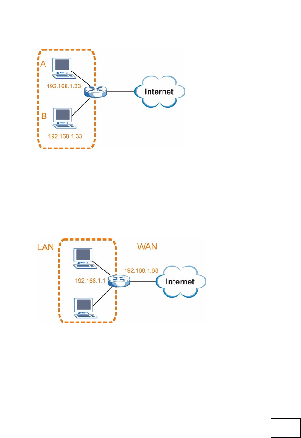
Appendix C IP Addresses and Subnetting
P-870HN-51b User’s Guide 311
address to computer A or setting computer A to obtain an IP address
automatically.
Figure 196 Conflicting Computer IP Addresses Example
Conflicting Router IP Addresses Example
Since a router connects different networks, it must have interfaces using different
network numbers. For example, if a router is set between a LAN and the Internet
(WAN), the router’s LAN and WAN addresses must be on different subnets. In the
following example, the LAN and WAN are on the same subnet. The LAN computers
cannot access the Internet because the router cannot route between networks.
Figure 197 Conflicting Computer IP Addresses Example
Conflicting Computer and Router IP Addresses Example
More than one device can not use the same IP address. In the following example,
the computer and the router’s LAN port both use 192.168.1.1 as the IP address.
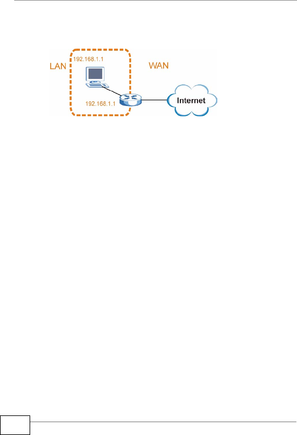
Appendix C IP Addresses and Subnetting
P-870HN-51b User’s Guide
312
The computer cannot access the Internet. This problem can be solved by
assigning a different IP address to the computer or the router’s LAN port.
Figure 198 Conflicting Computer and Router IP Addresses Example
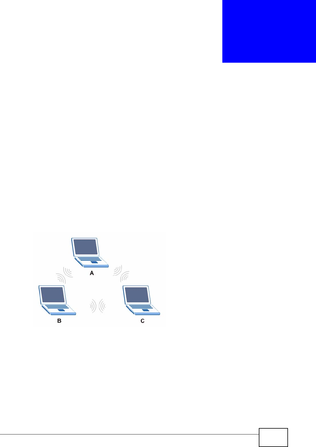
P-870HN-51b User’s Guide 313
APPENDIX D
Wireless LANs
Wireless LAN Topologies
This section discusses ad-hoc and infrastructure wireless LAN topologies.
Ad-hoc Wireless LAN Configuration
The simplest WLAN configuration is an independent (Ad-hoc) WLAN that connects
a set of computers with wireless adapters (A, B, C). Any time two or more wireless
adapters are within range of each other, they can set up an independent network,
which is commonly referred to as an ad-hoc network or Independent Basic Service
Set (IBSS). The following diagram shows an example of notebook computers
using wireless adapters to form an ad-hoc wireless LAN.
Figure 199 Peer-to-Peer Communication in an Ad-hoc Network
BSS
A Basic Service Set (BSS) exists when all communications between wireless
clients or between a wireless client and a wired network client go through one
access point (AP).
Intra-BSS traffic is traffic between wireless clients in the BSS. When Intra-BSS is
enabled, wireless client A and B can access the wired network and communicate
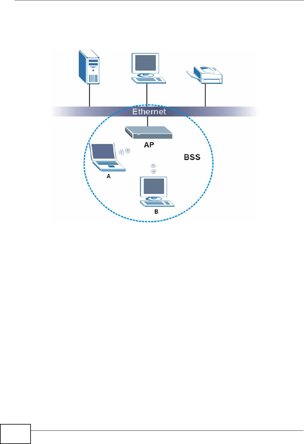
Appendix D Wireless LANs
P-870HN-51b User’s Guide
314
with each other. When Intra-BSS is disabled, wireless client A and B can still
access the wired network but cannot communicate with each other.
Figure 200 Basic Service Set
ESS
An Extended Service Set (ESS) consists of a series of overlapping BSSs, each
containing an access point, with each access point connected together by a wired
network. This wired connection between APs is called a Distribution System (DS).
This type of wireless LAN topology is called an Infrastructure WLAN. The Access
Points not only provide communication with the wired network but also mediate
wireless network traffic in the immediate neighborhood.
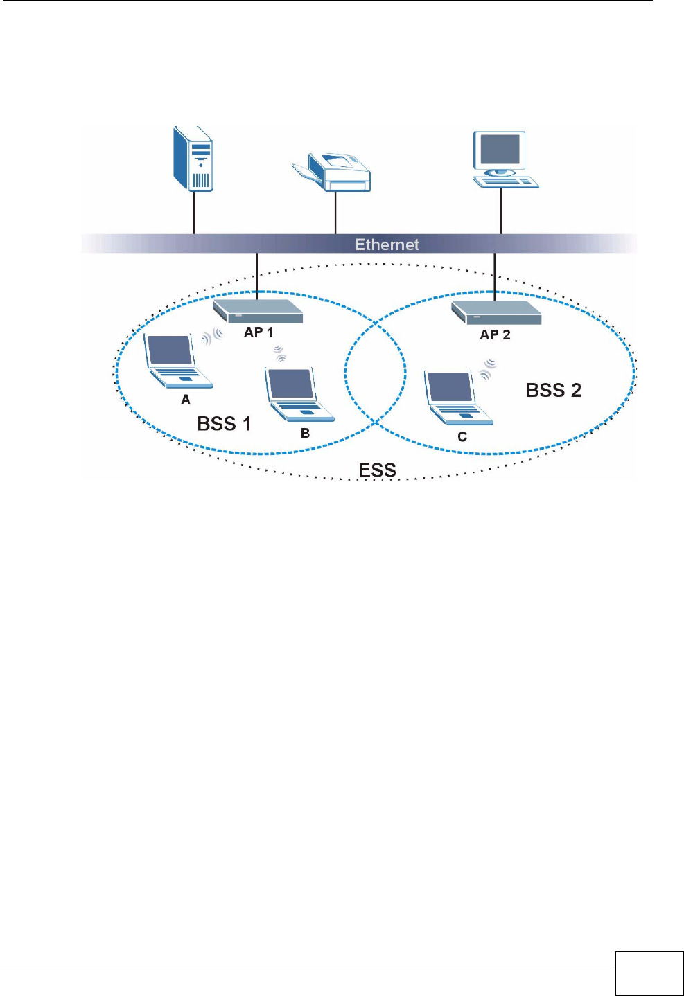
Appendix D Wireless LANs
P-870HN-51b User’s Guide 315
An ESSID (ESS IDentification) uniquely identifies each ESS. All access points and
their associated wireless clients within the same ESS must have the same ESSID
in order to communicate.
Figure 201 Infrastructure WLAN
Channel
A channel is the radio frequency(ies) used by wireless devices to transmit and
receive data. Channels available depend on your geographical area. You may have
a choice of channels (for your region) so you should use a channel different from
an adjacent AP (access point) to reduce interference. Interference occurs when
radio signals from different access points overlap causing interference and
degrading performance.
Adjacent channels partially overlap however. To avoid interference due to overlap,
your AP should be on a channel at least five channels away from a channel that an
adjacent AP is using. For example, if your region has 11 channels and an adjacent
AP is using channel 1, then you need to select a channel between 6 or 11.
RTS/CTS
A hidden node occurs when two stations are within range of the same access
point, but are not within range of each other. The following figure illustrates a
hidden node. Both stations (STA) are within range of the access point (AP) or
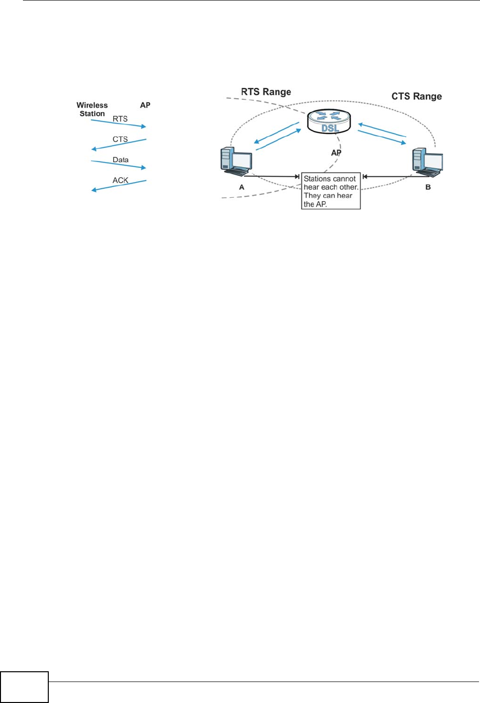
Appendix D Wireless LANs
P-870HN-51b User’s Guide
316
wireless gateway, but out-of-range of each other, so they cannot "hear" each
other, that is they do not know if the channel is currently being used. Therefore,
they are considered hidden from each other.
Figure 202 RTS/CTS
When station A sends data to the AP, it might not know that the station B is
already using the channel. If these two stations send data at the same time,
collisions may occur when both sets of data arrive at the AP at the same time,
resulting in a loss of messages for both stations.
RTS/CTS is designed to prevent collisions due to hidden nodes. An RTS/CTS
defines the biggest size data frame you can send before an RTS (Request To
Send)/CTS (Clear to Send) handshake is invoked.
When a data frame exceeds the RTS/CTS value you set (between 0 to 2432
bytes), the station that wants to transmit this frame must first send an RTS
(Request To Send) message to the AP for permission to send it. The AP then
responds with a CTS (Clear to Send) message to all other stations within its range
to notify them to defer their transmission. It also reserves and confirms with the
requesting station the time frame for the requested transmission.
Stations can send frames smaller than the specified RTS/CTS directly to the AP
without the RTS (Request To Send)/CTS (Clear to Send) handshake.
You should only configure RTS/CTS if the possibility of hidden nodes exists on
your network and the "cost" of resending large frames is more than the extra
network overhead involved in the RTS (Request To Send)/CTS (Clear to Send)
handshake.
If the RTS/CTS value is greater than the Fragmentation Threshold value (see
next), then the RTS (Request To Send)/CTS (Clear to Send) handshake will never
occur as data frames will be fragmented before they reach RTS/CTS size.
Note: Enabling the RTS Threshold causes redundant network overhead that could
negatively affect the throughput performance instead of providing a remedy.

Appendix D Wireless LANs
P-870HN-51b User’s Guide 317
Fragmentation Threshold
A Fragmentation Threshold is the maximum data fragment size (between 256
and 2432 bytes) that can be sent in the wireless network before the AP will
fragment the packet into smaller data frames.
A large Fragmentation Threshold is recommended for networks not prone to
interference while you should set a smaller threshold for busy networks or
networks that are prone to interference.
If the Fragmentation Threshold value is smaller than the RTS/CTS value (see
previously) you set then the RTS (Request To Send)/CTS (Clear to Send)
handshake will never occur as data frames will be fragmented before they reach
RTS/CTS size.
Preamble Type
Preamble is used to signal that data is coming to the receiver. Short and long refer
to the length of the synchronization field in a packet.
Short preamble increases performance as less time sending preamble means
more time for sending data. All IEEE 802.11 compliant wireless adapters support
long preamble, but not all support short preamble.
Use long preamble if you are unsure what preamble mode other wireless devices
on the network support, and to provide more reliable communications in busy
wireless networks.
Use short preamble if you are sure all wireless devices on the network support it,
and to provide more efficient communications.
Use the dynamic setting to automatically use short preamble when all wireless
devices on the network support it, otherwise the ZyXEL Device uses long
preamble.
Note: The wireless devices MUST use the same preamble mode in order to
communicate.
IEEE 802.11g Wireless LAN
IEEE 802.11g is fully compatible with the IEEE 802.11b standard. This means an
IEEE 802.11b adapter can interface directly with an IEEE 802.11g access point
(and vice versa) at 11 Mbps or lower depending on range. IEEE 802.11g has
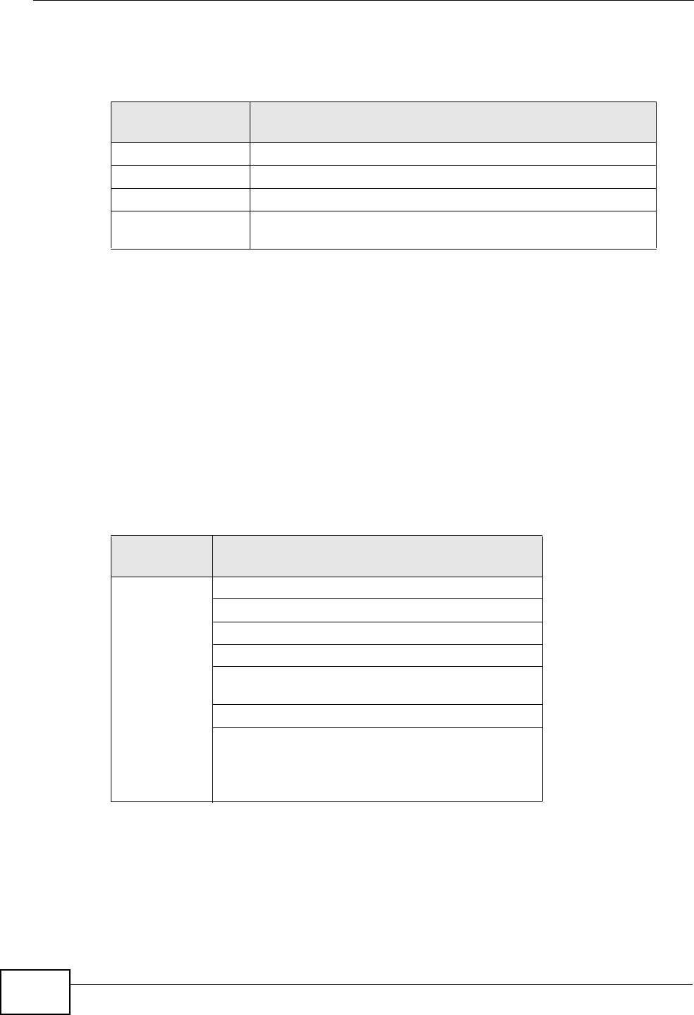
Appendix D Wireless LANs
P-870HN-51b User’s Guide
318
several intermediate rate steps between the maximum and minimum data rates.
The IEEE 802.11g data rate and modulation are as follows:
Wireless Security Overview
Wireless security is vital to your network to protect wireless communication
between wireless clients, access points and the wired network.
Wireless security methods available on the ZyXEL Device are data encryption,
wireless client authentication, restricting access by device MAC address and hiding
the ZyXEL Device identity.
The following figure shows the relative effectiveness of these wireless security
methods available on your ZyXEL Device.
Note: You must enable the same wireless security settings on the ZyXEL Device and
on all wireless clients that you want to associate with it.
Table 105 IEEE 802.11g
DATA RATE
(MBPS) MODULATION
1 DBPSK (Differential Binary Phase Shift Keyed)
2 DQPSK (Differential Quadrature Phase Shift Keying)
5.5 / 11 CCK (Complementary Code Keying)
6/9/12/18/24/36/
48/54 OFDM (Orthogonal Frequency Division Multiplexing)
Table 106 Wireless Security Levels
SECURITY
LEVEL SECURITY TYPE
Least
Secure
Most Secure
Unique SSID (Default)
Unique SSID with Hide SSID Enabled
MAC Address Filtering
WEP Encryption
IEEE802.1x EAP with RADIUS Server
Authentication
Wi-Fi Protected Access (WPA)
WPA2

Appendix D Wireless LANs
P-870HN-51b User’s Guide 319
IEEE 802.1x
In June 2001, the IEEE 802.1x standard was designed to extend the features of
IEEE 802.11 to support extended authentication as well as providing additional
accounting and control features. It is supported by Windows XP and a number of
network devices. Some advantages of IEEE 802.1x are:
• User based identification that allows for roaming.
• Support for RADIUS (Remote Authentication Dial In User Service, RFC 2138,
2139) for centralized user profile and accounting management on a network
RADIUS server.
• Support for EAP (Extensible Authentication Protocol, RFC 2486) that allows
additional authentication methods to be deployed with no changes to the access
point or the wireless clients.
RADIUS
RADIUS is based on a client-server model that supports authentication,
authorization and accounting. The access point is the client and the server is the
RADIUS server. The RADIUS server handles the following tasks:
• Authentication
Determines the identity of the users.
• Authorization
Determines the network services available to authenticated users once they are
connected to the network.
•Accounting
Keeps track of the client’s network activity.
RADIUS is a simple package exchange in which your AP acts as a message relay
between the wireless client and the network RADIUS server.
Types of RADIUS Messages
The following types of RADIUS messages are exchanged between the access point
and the RADIUS server for user authentication:
• Access-Request
Sent by an access point requesting authentication.
• Access-Reject
Sent by a RADIUS server rejecting access.
• Access-Accept
Sent by a RADIUS server allowing access.

Appendix D Wireless LANs
P-870HN-51b User’s Guide
320
• Access-Challenge
Sent by a RADIUS server requesting more information in order to allow access.
The access point sends a proper response from the user and then sends another
Access-Request message.
The following types of RADIUS messages are exchanged between the access point
and the RADIUS server for user accounting:
•Accounting-Request
Sent by the access point requesting accounting.
• Accounting-Response
Sent by the RADIUS server to indicate that it has started or stopped accounting.
In order to ensure network security, the access point and the RADIUS server use a
shared secret key, which is a password, they both know. The key is not sent over
the network. In addition to the shared key, password information exchanged is
also encrypted to protect the network from unauthorized access.
Types of EAP Authentication
This section discusses some popular authentication types: EAP-MD5, EAP-TLS,
EAP-TTLS, PEAP and LEAP. Your wireless LAN device may not support all
authentication types.
EAP (Extensible Authentication Protocol) is an authentication protocol that runs on
top of the IEEE 802.1x transport mechanism in order to support multiple types of
user authentication. By using EAP to interact with an EAP-compatible RADIUS
server, an access point helps a wireless station and a RADIUS server perform
authentication.
The type of authentication you use depends on the RADIUS server and an
intermediary AP(s) that supports IEEE 802.1x. .
For EAP-TLS authentication type, you must first have a wired connection to the
network and obtain the certificate(s) from a certificate authority (CA). A certificate
(also called digital IDs) can be used to authenticate users and a CA issues
certificates and guarantees the identity of each certificate owner.
EAP-MD5 (Message-Digest Algorithm 5)
MD5 authentication is the simplest one-way authentication method. The
authentication server sends a challenge to the wireless client. The wireless client
‘proves’ that it knows the password by encrypting the password with the challenge
and sends back the information. Password is not sent in plain text.

Appendix D Wireless LANs
P-870HN-51b User’s Guide 321
However, MD5 authentication has some weaknesses. Since the authentication
server needs to get the plaintext passwords, the passwords must be stored. Thus
someone other than the authentication server may access the password file. In
addition, it is possible to impersonate an authentication server as MD5
authentication method does not perform mutual authentication. Finally, MD5
authentication method does not support data encryption with dynamic session
key. You must configure WEP encryption keys for data encryption.
EAP-TLS (Transport Layer Security)
With EAP-TLS, digital certifications are needed by both the server and the wireless
clients for mutual authentication. The server presents a certificate to the client.
After validating the identity of the server, the client sends a different certificate to
the server. The exchange of certificates is done in the open before a secured
tunnel is created. This makes user identity vulnerable to passive attacks. A digital
certificate is an electronic ID card that authenticates the sender’s identity.
However, to implement EAP-TLS, you need a Certificate Authority (CA) to handle
certificates, which imposes a management overhead.
EAP-TTLS (Tunneled Transport Layer Service)
EAP-TTLS is an extension of the EAP-TLS authentication that uses certificates for
only the server-side authentications to establish a secure connection. Client
authentication is then done by sending username and password through the
secure connection, thus client identity is protected. For client authentication, EAP-
TTLS supports EAP methods and legacy authentication methods such as PAP,
CHAP, MS-CHAP and MS-CHAP v2.
PEAP (Protected EAP)
Like EAP-TTLS, server-side certificate authentication is used to establish a secure
connection, then use simple username and password methods through the
secured connection to authenticate the clients, thus hiding client identity.
However, PEAP only supports EAP methods, such as EAP-MD5, EAP-MSCHAPv2
and EAP-GTC (EAP-Generic Token Card), for client authentication. EAP-GTC is
implemented only by Cisco.
LEAP
LEAP (Lightweight Extensible Authentication Protocol) is a Cisco implementation of
IEEE 802.1x.
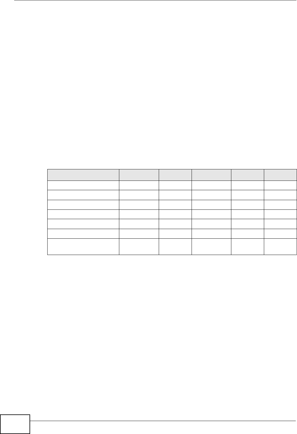
Appendix D Wireless LANs
P-870HN-51b User’s Guide
322
Dynamic WEP Key Exchange
The AP maps a unique key that is generated with the RADIUS server. This key
expires when the wireless connection times out, disconnects or reauthentication
times out. A new WEP key is generated each time reauthentication is performed.
If this feature is enabled, it is not necessary to configure a default encryption key
in the wireless security configuration screen. You may still configure and store
keys, but they will not be used while dynamic WEP is enabled.
Note: EAP-MD5 cannot be used with Dynamic WEP Key Exchange
For added security, certificate-based authentications (EAP-TLS, EAP-TTLS and
PEAP) use dynamic keys for data encryption. They are often deployed in corporate
environments, but for public deployment, a simple user name and password pair
is more practical. The following table is a comparison of the features of
authentication types.
WPA and WPA2
Wi-Fi Protected Access (WPA) is a subset of the IEEE 802.11i standard. WPA2
(IEEE 802.11i) is a wireless security standard that defines stronger encryption,
authentication and key management than WPA.
Key differences between WPA or WPA2 and WEP are improved data encryption and
user authentication.
If both an AP and the wireless clients support WPA2 and you have an external
RADIUS server, use WPA2 for stronger data encryption. If you don't have an
external RADIUS server, you should use WPA2-PSK (WPA2-Pre-Shared Key) that
only requires a single (identical) password entered into each access point, wireless
gateway and wireless client. As long as the passwords match, a wireless client will
be granted access to a WLAN.
Table 107 Comparison of EAP Authentication Types
EAP-MD5 EAP-TLS EAP-TTLS PEAP LEAP
Mutual Authentication No Yes Yes Yes Yes
Certificate – Client No Yes Optional Optional No
Certificate – Server No Yes Yes Yes No
Dynamic Key Exchange No Yes Yes Yes Yes
Credential Integrity None Strong Strong Strong Moderate
Deployment Difficulty Easy Hard Moderate Moderate Moderate
Client Identity
Protection No No Yes Yes No

Appendix D Wireless LANs
P-870HN-51b User’s Guide 323
If the AP or the wireless clients do not support WPA2, just use WPA or WPA-PSK
depending on whether you have an external RADIUS server or not.
Select WEP only when the AP and/or wireless clients do not support WPA or WPA2.
WEP is less secure than WPA or WPA2.
Encryption
WPA improves data encryption by using Temporal Key Integrity Protocol (TKIP),
Message Integrity Check (MIC) and IEEE 802.1x. WPA2 also uses TKIP when
required for compatibility reasons, but offers stronger encryption than TKIP with
Advanced Encryption Standard (AES) in the Counter mode with Cipher block
chaining Message authentication code Protocol (CCMP).
TKIP uses 128-bit keys that are dynamically generated and distributed by the
authentication server. AES (Advanced Encryption Standard) is a block cipher that
uses a 256-bit mathematical algorithm called Rijndael. They both include a per-
packet key mixing function, a Message Integrity Check (MIC) named Michael, an
extended initialization vector (IV) with sequencing rules, and a re-keying
mechanism.
WPA and WPA2 regularly change and rotate the encryption keys so that the same
encryption key is never used twice.
The RADIUS server distributes a Pairwise Master Key (PMK) key to the AP that
then sets up a key hierarchy and management system, using the PMK to
dynamically generate unique data encryption keys to encrypt every data packet
that is wirelessly communicated between the AP and the wireless clients. This all
happens in the background automatically.
The Message Integrity Check (MIC) is designed to prevent an attacker from
capturing data packets, altering them and resending them. The MIC provides a
strong mathematical function in which the receiver and the transmitter each
compute and then compare the MIC. If they do not match, it is assumed that the
data has been tampered with and the packet is dropped.
By generating unique data encryption keys for every data packet and by creating
an integrity checking mechanism (MIC), with TKIP and AES it is more difficult to
decrypt data on a Wi-Fi network than WEP and difficult for an intruder to break
into the network.
The encryption mechanisms used for WPA(2) and WPA(2)-PSK are the same. The
only difference between the two is that WPA(2)-PSK uses a simple common
password, instead of user-specific credentials. The common-password approach
makes WPA(2)-PSK susceptible to brute-force password-guessing attacks but it’s
still an improvement over WEP as it employs a consistent, single, alphanumeric
password to derive a PMK which is used to generate unique temporal encryption

Appendix D Wireless LANs
P-870HN-51b User’s Guide
324
keys. This prevent all wireless devices sharing the same encryption keys. (a
weakness of WEP)
User Authentication
WPA and WPA2 apply IEEE 802.1x and Extensible Authentication Protocol (EAP) to
authenticate wireless clients using an external RADIUS database. WPA2 reduces
the number of key exchange messages from six to four (CCMP 4-way handshake)
and shortens the time required to connect to a network. Other WPA2
authentication features that are different from WPA include key caching and pre-
authentication. These two features are optional and may not be supported in all
wireless devices.
Key caching allows a wireless client to store the PMK it derived through a
successful authentication with an AP. The wireless client uses the PMK when it tries
to connect to the same AP and does not need to go with the authentication
process again.
Pre-authentication enables fast roaming by allowing the wireless client (already
connecting to an AP) to perform IEEE 802.1x authentication with another AP
before connecting to it.
Wireless Client WPA Supplicants
A wireless client supplicant is the software that runs on an operating system
instructing the wireless client how to use WPA. At the time of writing, the most
widely available supplicant is the WPA patch for Windows XP, Funk Software's
Odyssey client.
The Windows XP patch is a free download that adds WPA capability to Windows
XP's built-in "Zero Configuration" wireless client. However, you must run Windows
XP to use it.
WPA(2) with RADIUS Application Example
To set up WPA(2), you need the IP address of the RADIUS server, its port number
(default is 1812), and the RADIUS shared secret. A WPA(2) application example
with an external RADIUS server looks as follows. "A" is the RADIUS server. "DS" is
the distribution system.
1The AP passes the wireless client's authentication request to the RADIUS server.
2The RADIUS server then checks the user's identification against its database and
grants or denies network access accordingly.
3A 256-bit Pairwise Master Key (PMK) is derived from the authentication process by
the RADIUS server and the client.
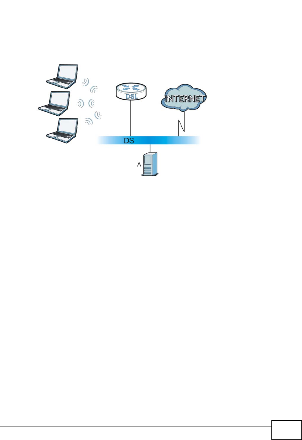
Appendix D Wireless LANs
P-870HN-51b User’s Guide 325
4The RADIUS server distributes the PMK to the AP. The AP then sets up a key
hierarchy and management system, using the PMK to dynamically generate
unique data encryption keys. The keys are used to encrypt every data packet that
is wirelessly communicated between the AP and the wireless clients.
Figure 203 WPA(2) with RADIUS Application Example
WPA(2)-PSK Application Example
A WPA(2)-PSK application looks as follows.
1First enter identical passwords into the AP and all wireless clients. The Pre-Shared
Key (PSK) must consist of between 8 and 63 ASCII characters or 64 hexadecimal
characters (including spaces and symbols).
2The AP checks each wireless client's password and allows it to join the network
only if the password matches.
3The AP and wireless clients generate a common PMK (Pairwise Master Key). The
key itself is not sent over the network, but is derived from the PSK and the SSID.
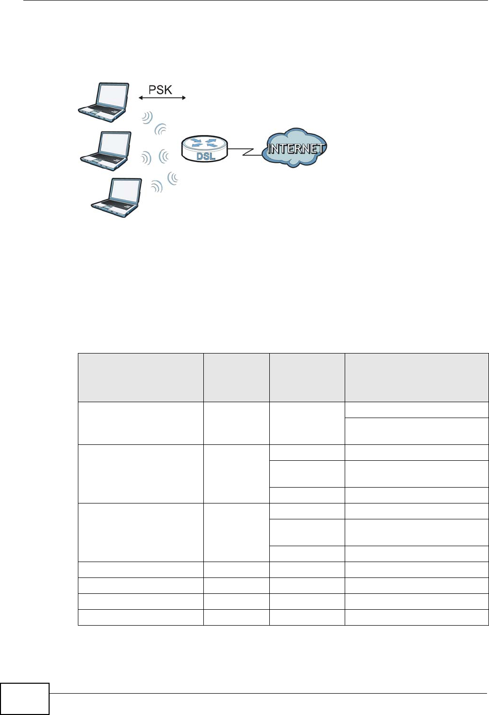
Appendix D Wireless LANs
P-870HN-51b User’s Guide
326
4The AP and wireless clients use the TKIP or AES encryption process, the PMK and
information exchanged in a handshake to create temporal encryption keys. They
use these keys to encrypt data exchanged between them.
Figure 204 WPA(2)-PSK Authentication
Security Parameters Summary
Refer to this table to see what other security parameters you should configure for
each authentication method or key management protocol type. MAC address
filters are not dependent on how you configure these security features.
Table 108 Wireless Security Relational Matrix
AUTHENTICATION
METHOD/ KEY
MANAGEMENT
PROTOCOL
ENCRYPTIO
N METHOD ENTER
MANUAL KEY IEEE 802.1X
Open None No Disable
Enable without Dynamic WEP
Key
Open WEP No Enable with Dynamic WEP Key
Yes Enable without Dynamic WEP
Key
Yes Disable
Shared WEP No Enable with Dynamic WEP Key
Yes Enable without Dynamic WEP
Key
Yes Disable
WPA TKIP/AES No Enable
WPA-PSK TKIP/AES Yes Disable
WPA2 TKIP/AES No Enable
WPA2-PSK TKIP/AES Yes Disable

Appendix D Wireless LANs
P-870HN-51b User’s Guide 327
Antenna Overview
An antenna couples RF signals onto air. A transmitter within a wireless device
sends an RF signal to the antenna, which propagates the signal through the air.
The antenna also operates in reverse by capturing RF signals from the air.
Positioning the antennas properly increases the range and coverage area of a
wireless LAN.
Antenna Characteristics
Frequency
An antenna in the frequency of 2.4GHz (IEEE 802.11b and IEEE 802.11g) or 5GHz
(IEEE 802.11a) is needed to communicate efficiently in a wireless LAN
Radiation Pattern
A radiation pattern is a diagram that allows you to visualize the shape of the
antenna’s coverage area.
Antenna Gain
Antenna gain, measured in dB (decibel), is the increase in coverage within the RF
beam width. Higher antenna gain improves the range of the signal for better
communications.
For an indoor site, each 1 dB increase in antenna gain results in a range increase
of approximately 2.5%. For an unobstructed outdoor site, each 1dB increase in
gain results in a range increase of approximately 5%. Actual results may vary
depending on the network environment.
Antenna gain is sometimes specified in dBi, which is how much the antenna
increases the signal power compared to using an isotropic antenna. An isotropic
antenna is a theoretical perfect antenna that sends out radio signals equally well
in all directions. dBi represents the true gain that the antenna provides.
Types of Antennas for WLAN
There are two types of antennas used for wireless LAN applications.

Appendix D Wireless LANs
P-870HN-51b User’s Guide
328
• Omni-directional antennas send the RF signal out in all directions on a horizontal
plane. The coverage area is torus-shaped (like a donut) which makes these
antennas ideal for a room environment. With a wide coverage area, it is possible
to make circular overlapping coverage areas with multiple access points.
• Directional antennas concentrate the RF signal in a beam, like a flashlight does
with the light from its bulb. The angle of the beam determines the width of the
coverage pattern. Angles typically range from 20 degrees (very directional) to
120 degrees (less directional). Directional antennas are ideal for hallways and
outdoor point-to-point applications.
Positioning Antennas
In general, antennas should be mounted as high as practically possible and free of
obstructions. In point-to–point application, position both antennas at the same
height and in a direct line of sight to each other to attain the best performance.
For omni-directional antennas mounted on a table, desk, and so on, point the
antenna up. For omni-directional antennas mounted on a wall or ceiling, point the
antenna down. For a single AP application, place omni-directional antennas as
close to the center of the coverage area as possible.
For directional antennas, point the antenna in the direction of the desired
coverage area.

P-870HN-51b User’s Guide 329
APPENDIX E
Common Services
The following table lists some commonly-used services and their associated
protocols and port numbers. For a comprehensive list of port numbers, ICMP type/
code numbers and services, visit the IANA (Internet Assigned Number Authority)
web site.
•Name: This is a short, descriptive name for the service. You can use this one or
create a different one, if you like.
•Protocol: This is the type of IP protocol used by the service. If this is TCP/
UDP, then the service uses the same port number with TCP and UDP. If this is
USER-DEFINED, the Port(s) is the IP protocol number, not the port number.
•Port(s): This value depends on the Protocol. Please refer to RFC 1700 for
further information about port numbers.
•If the Protocol is TCP, UDP, or TCP/UDP, this is the IP port number.
•If the Protocol is USER, this is the IP protocol number.
•Description: This is a brief explanation of the applications that use this service
or the situations in which this service is used.
Table 109 Commonly Used Services
NAME PROTOCOL PORT(S) DESCRIPTION
AH
(IPSEC_TUNNEL) User-Defined 51 The IPSEC AH (Authentication
Header) tunneling protocol uses this
service.
AIM/New-ICQ TCP 5190 AOL’s Internet Messenger service. It
is also used as a listening port by
ICQ.
AUTH TCP 113 Authentication protocol used by some
servers.
BGP TCP 179 Border Gateway Protocol.
BOOTP_CLIENT UDP 68 DHCP Client.
BOOTP_SERVER UDP 67 DHCP Server.
CU-SEEME TCP
UDP
7648
24032
A popular videoconferencing solution
from White Pines Software.
DNS TCP/UDP 53 Domain Name Server, a service that
matches web names (for example
www.zyxel.com) to IP numbers.

Appendix E Common Services
P-870HN-51b User’s Guide
330
ESP
(IPSEC_TUNNEL) User-Defined 50 The IPSEC ESP (Encapsulation
Security Protocol) tunneling protocol
uses this service.
FINGER TCP 79 Finger is a UNIX or Internet related
command that can be used to find out
if a user is logged on.
FTP TCP
TCP
20
21
File Transfer Program, a program to
enable fast transfer of files, including
large files that may not be possible by
e-mail.
H.323 TCP 1720 NetMeeting uses this protocol.
HTTP TCP 80 Hyper Text Transfer Protocol - a
client/server protocol for the world
wide web.
HTTPS TCP 443 HTTPS is a secured http session often
used in e-commerce.
ICMP User-Defined 1Internet Control Message Protocol is
often used for diagnostic or routing
purposes.
ICQ UDP 4000 This is a popular Internet chat
program.
IGMP
(MULTICAST) User-Defined 2Internet Group Management Protocol
is used when sending packets to a
specific group of hosts.
IKE UDP 500 The Internet Key Exchange algorithm
is used for key distribution and
management.
IRC TCP/UDP 6667 This is another popular Internet chat
program.
MSN Messenger TCP 1863 Microsoft Networks’ messenger
service uses this protocol.
NEW-ICQ TCP 5190 An Internet chat program.
NEWS TCP 144 A protocol for news groups.
NFS UDP 2049 Network File System - NFS is a client/
server distributed file service that
provides transparent file sharing for
network environments.
NNTP TCP 119 Network News Transport Protocol is
the delivery mechanism for the
USENET newsgroup service.
PING User-Defined 1Packet INternet Groper is a protocol
that sends out ICMP echo requests to
test whether or not a remote host is
reachable.
POP3 TCP 110 Post Office Protocol version 3 lets a
client computer get e-mail from a
POP3 server through a temporary
connection (TCP/IP or other).
Table 109 Commonly Used Services (continued)
NAME PROTOCOL PORT(S) DESCRIPTION

Appendix E Common Services
P-870HN-51b User’s Guide 331
PPTP TCP 1723 Point-to-Point Tunneling Protocol
enables secure transfer of data over
public networks. This is the control
channel.
PPTP_TUNNEL
(GRE) User-Defined 47 PPTP (Point-to-Point Tunneling
Protocol) enables secure transfer of
data over public networks. This is the
data channel.
RCMD TCP 512 Remote Command Service.
REAL_AUDIO TCP 7070 A streaming audio service that
enables real time sound over the web.
REXEC TCP 514 Remote Execution Daemon.
RLOGIN TCP 513 Remote Login.
RTELNET TCP 107 Remote Telnet.
RTSP TCP/UDP 554 The Real Time Streaming (media
control) Protocol (RTSP) is a remote
control for multimedia on the
Internet.
SFTP TCP 115 Simple File Transfer Protocol.
SMTP TCP 25 Simple Mail Transfer Protocol is the
message-exchange standard for the
Internet. SMTP enables you to move
messages from one e-mail server to
another.
SNMP TCP/UDP 161 Simple Network Management
Program.
SNMP-TRAPS TCP/UDP 162 Traps for use with the SNMP
(RFC:1215).
SQL-NET TCP 1521 Structured Query Language is an
interface to access data on many
different types of database systems,
including mainframes, midrange
systems, UNIX systems and network
servers.
SSH TCP/UDP 22 Secure Shell Remote Login Program.
STRM WORKS UDP 1558 Stream Works Protocol.
SYSLOG UDP 514 Syslog allows you to send system logs
to a UNIX server.
TACACS UDP 49 Login Host Protocol used for (Terminal
Access Controller Access Control
System).
TELNET TCP 23 Telnet is the login and terminal
emulation protocol common on the
Internet and in UNIX environments. It
operates over TCP/IP networks. Its
primary function is to allow users to
log into remote host systems.
Table 109 Commonly Used Services (continued)
NAME PROTOCOL PORT(S) DESCRIPTION

Appendix E Common Services
P-870HN-51b User’s Guide
332
TFTP UDP 69 Trivial File Transfer Protocol is an
Internet file transfer protocol similar
to FTP, but uses the UDP (User
Datagram Protocol) rather than TCP
(Transmission Control Protocol).
VDOLIVE TCP 7000 Another videoconferencing solution.
Table 109 Commonly Used Services (continued)
NAME PROTOCOL PORT(S) DESCRIPTION

P-663HN-51 User’s Guide 333
APPENDIX F
Open Software Announcements
End-User License Agreement for "P-870HN-51"
Note: WARNING: ZyXEL Communications Corp. IS WILLING TO LICENSE THE
ENCLOSED SOFTWARE TO YOU ONLY UPON THE CONDITION THAT YOU
ACCEPT ALL OF THE TERMS CONTAINED IN THIS LICENSE AGREEMENT.
PLEASE READ THE TERMS CAREFULLY BEFORE COMPLETING THE
INSTALLATION PROCESS AS INSTALLING THE SOFTWARE WILL
INDICATE YOUR ASSENT TO THEM. IF YOU DO NOT AGREE TO THESE
TERMS, THEN ZyXEL, INC. IS UNWILLING TO LICENSE THE SOFTWARE
TO YOU, IN WHICH EVENT YOU SHOULD RETURN THE UNINSTALLED
SOFTWARE AND PACKAGING TO THE PLACE FROM WHICH IT WAS
ACQUIRED, AND YOUR MONEY WILL BE REFUNDED.
1.Grant of License for Personal Use
ZyXEL Communications Corp. ("ZyXEL") grants you a non-exclusive, non-
sublicense, non-transferable license to use the program with which this license is
distributed (the "Software"), including any documentation files accompanying the
Software ("Documentation"), for internal business use only, for up to the number
of users specified in sales order and invoice. You have the right to make one
backup copy of the Software and Documentation solely for archival, back-up or
disaster recovery purposes. You shall not exceed the scope of the license granted
hereunder. Any rights not expressly granted by ZyXEL to you are reserved by
ZyXEL, and all implied licenses are disclaimed.
2.Ownership
You have no ownership rights in the Software. Rather, you have a license to use
the Software as long as this License Agreement remains in full force and effect.
Ownership of the Software, Documentation and all intellectual property rights
therein shall remain at all times with ZyXEL. Any other use of the Software by any
other entity is strictly forbidden and is a violation of this License Agreement.

Appendix F Open Software Announcements
P-663HN-51 User’s Guide
334
3.Copyright
The Software and Documentation contain material that is protected by United
States Copyright Law and trade secret law, and by international treaty provisions.
All rights not granted to you herein are expressly reserved by ZyXEL. You may not
remove any proprietary notice of ZyXEL or any of its licensors from any copy of
the Software or Documentation.
4.Restrictions
You may not publish, display, disclose, sell, rent, lease, modify, store, loan,
distribute, or create derivative works of the Software, or any part thereof. You
may not assign, sublicense, convey or otherwise transfer, pledge as security or
otherwise encumber the rights and licenses granted hereunder with respect to the
Software. Certain components of the Software, and third party open source
programs included with the Software, have been or may be made available by
ZyXEL listed in the below Table (collectively the “Open-Sourced Components”) You
may modify or replace only these Open-Sourced Components; provided that you
comply with the terms of this License and any applicable licensing terms
governing use of the Open-Sourced Components, which have been provided on
Web Address specified in below Table. ZyXEL is not obligated to provide any
maintenance, technical or other support for the resultant modified Software. You
may not copy, reverse engineer, decompile, reverse compile, translate, adapt, or
disassemble the Software, or any part thereof, nor shall you attempt to create the
source code from the object code for the Software. Except as and only to the
extent expressly permitted in this License, by applicable licensing terms governing
use of the Open-Sourced Components, or by applicable law, you may not market,
co-brand, private label or otherwise permit third parties to link to the Software, or
any part thereof. You may not use the Software, or any part thereof, in the
operation of a service bureau or for the benefit of any other person or entity. You
may not cause, assist or permit any third party to do any of the foregoing.
Portions of the Software utilize or include third party software and other copyright
material. Acknowledgements, licensing terms and disclaimers for such material
are contained in the online electronic documentation for the Software as below,
and your use of such material is governed by their respective terms. ZyXEL has
provided, as part of the Software package, access to certain third party software
as a convenience. To the extent that the Software contains third party software,
ZyXEL has no express or implied obligation to provide any technical or other
support for such software. Please contact the appropriate software vendor or
manufacturer directly for technical support and customer service related to its
software and products.

Appendix F Open Software Announcements
P-663HN-51 User’s Guide 335
5.Confidentiality
You acknowledge that the Software contains proprietary trade secrets of ZyXEL
and you hereby agree to maintain the confidentiality of the Software using at least
as great a degree of care as you use to maintain the confidentiality of your own
most confidential information. You agree to reasonably communicate the terms
and conditions of this License Agreement to those persons employed by you who
come into contact with the Software, and to use reasonable best efforts to ensure
their compliance with such terms and conditions, including, without limitation, not
knowingly permitting such persons to use any portion of the Software for the
purpose of deriving the source code of the Software.
6.No Warranty
THE SOFTWARE IS PROVIDED "AS IS." TO THE MAXIMUM EXTENT PERMITTED BY
LAW, ZyXEL DISCLAIMS ALL WARRANTIES OF ANY KIND, EITHER EXPRESSED OR
IMPLIED, INCLUDING, WITHOUT LIMITATION, IMPLIED WARRANTIES OF
MERCHANTABILITY AND FITNESS FOR A PARTICULAR PURPOSE. ZyXEL DOES NOT
WARRANT THAT THE FUNCTIONS CONTAINED IN THE SOFTWARE WILL MEET ANY
REQUIREMENTS OR NEEDS YOU MAY HAVE, OR THAT THE SOFTWARE WILL
OPERATE ERROR FREE, OR IN AN UNINTERUPTED FASHION, OR THAT ANY
DEFECTS OR ERRORS IN THE SOFTWARE WILL BE CORRECTED, OR THAT THE
SOFTWARE IS COMPATIBLE WITH ANY PARTICULAR PLATFORM. SOME
JURISDICTIONS DO NOT ALLOW THE WAIVER OR EXCLUSION OF IMPLIED
WARRANTIES SO THEY MAY NOT APPLY TO YOU. IF THIS EXCLUSION IS HELD TO
BE UNENFORCEABLE BY A COURT OF COMPETENT JURISDICTION, THEN ALL
EXPRESS AND IMPLIED WARRANTIES SHALL BE LIMITED IN DURATION TO A
PERIOD OF THIRTY (30) DAYS FROM THE DATE OF PURCHASE OF THE SOFTWARE,
AND NO WARRANTIES SHALL APPLY AFTER THAT PERIOD.
7.Limitation of Liability
IN NO EVENT WILL ZyXEL BE LIABLE TO YOU OR ANY THIRD PARTY FOR ANY
INCIDENTAL OR CONSEQUENTIAL DAMAGES (INCLUDING, WITHOUT LIMITATION,
INDIRECT, SPECIAL, PUNITIVE, OR EXEMPLARY DAMAGES FOR LOSS OF
BUSINESS, LOSS OF PROFITS, BUSINESS INTERRUPTION, OR LOSS OF BUSINESS
INFORMATION) ARISING OUT OF THE USE OF OR INABILITY TO USE THE
PROGRAM, OR FOR ANY CLAIM BY ANY OTHER PARTY, EVEN IF ZyXEL HAS BEEN
ADVISED OF THE POSSIBILITY OF SUCH DAMAGES. ZyXEL's AGGREGATE
LIABILITY WITH RESPECT TO ITS OBLIGATIONS UNDER THIS AGREEMENT OR
OTHERWISE WITH RESPECT TO THE SOFTWARE AND DOCUMENTATION OR
OTHERWISE SHALL BE EQUAL TO THE PURCHASE PRICE, BUT SHALL IN NO
EVENT EXCEED THE PRODUCT’S PRICE. BECAUSE SOME STATES/COUNTRIES DO

Appendix F Open Software Announcements
P-663HN-51 User’s Guide
336
NOT ALLOW THE EXCLUSION OR LIMITATION OF LIABILITY FOR CONSEQUENTIAL
OR INCIDENTAL DAMAGES, THE ABOVE LIMITATION MAY NOT APPLY TO YOU.
8.Export Restrictions
THIS LICENSE AGREEMENT IS EXPRESSLY MADE SUBJECT TO ANY APPLICABLE
LAWS, REGULATIONS, ORDERS, OR OTHER RESTRICTIONS ON THE EXPORT OF
THE SOFTWARE OR INFORMATION ABOUT SUCH SOFTWARE WHICH MAY BE
IMPOSED FROM TIME TO TIME. YOU SHALL NOT EXPORT THE SOFTWARE,
DOCUMENTATION OR INFORMATION ABOUT THE SOFTWARE AND
DOCUMENTATION WITHOUT COMPLYING WITH SUCH LAWS, REGULATIONS,
ORDERS, OR OTHER RESTRICTIONS. YOU AGREE TO INDEMNIFY ZyXEL AGAINST
ALL CLAIMS, LOSSES, DAMAGES, LIABILITIES, COSTS AND EXPENSES,
INCLUDING REASONABLE ATTORNEYS' FEES, TO THE EXTENT SUCH CLAIMS
ARISE OUT OF ANY BREACH OF THIS SECTION 8.
9.Audit Rights
ZyXEL SHALL HAVE THE RIGHT, AT ITS OWN EXPENSE, UPON REASONABLE PRIOR
NOTICE, TO PERIODICALLY INSPECT AND AUDIT YOUR RECORDS TO ENSURE
YOUR COMPLIANCE WITH THE TERMS AND CONDITIONS OF THIS LICENSE
AGREEMENT.
10.Termination
This License Agreement is effective until it is terminated. You may terminate this
License Agreement at any time by destroying or returning to ZyXEL all copies of
the Software and Documentation in your possession or under your control. ZyXEL
may terminate this License Agreement for any reason, including, but not limited
to, if ZyXEL finds that you have violated any of the terms of this License
Agreement. Upon notification of termination, you agree to destroy or return to
ZyXEL all copies of the Software and Documentation and to certify in writing that
all known copies, including backup copies, have been destroyed. All provisions
relating to confidentiality, proprietary rights, and non-disclosure shall survive the
termination of this Software License Agreement.
12.General
This License Agreement shall be construed, interpreted and governed by the laws
of Republic of China without regard to conflicts of laws provisions thereof. The

Appendix F Open Software Announcements
P-663HN-51 User’s Guide 337
exclusive forum for any disputes arising out of or relating to this License
Agreement shall be an appropriate court or Commercial Arbitration Association
sitting in ROC, Taiwan. This License Agreement shall constitute the entire
Agreement between the parties hereto. This License Agreement, the rights
granted hereunder, the Software and Documentation shall not be assigned by you
without the prior written consent of ZyXEL. Any waiver or modification of this
License Agreement shall only be effective if it is in writing and signed by both
parties hereto. If any part of this License Agreement is found invalid or
unenforceable by a court of competent jurisdiction, the remainder of this License
Agreement shall be interpreted so as to reasonably effect the intention of the
parties.
Note: Some components of this product incorporate source code covered under the
open source code licenses. To obtain the source code covered under those
Licenses, please check ZyXEL Technical Support to get it.
Appendix F Open Software Announcements
P-663HN-51 User’s Guide
338
End-User License Agreement for "P-870HN-51"
3rd Party Software Version Web Address Of The Software License Term
MIPS Linux kernel 2.6.21.5 http://www.linux-mips.org or http://kernel.org
Bridge-Utils 1.2 http://bridge.sourceforge.net
BusyBox 1.0.0 http://www.busybox.net/
PPP 2.4.1 http://www.roaringpenguin.com/pppoe
udhcp 0.9.6 http://udhcp.busybox.net/
dproxy-nexgen http://dproxy.sourceforge.net
ebtables 2.0.6 http://ebtables.sourceforge.net
bftpd 1.0.24 http://www.bftpd.org/
iproute2 2.4.7 http://www.linuxgrill.com/anonymous/iproute2
iptables 1.3.8 http://www.netfilter.org
zebra 0.93a http://www.zebra.org/
dropbear 0.46 http://matt.ucc.asn.au/dropbear/dropbear.html
openSSL 0.9.7f http://www.openssl.org
Siproxd 0.5.10 http://siproxd.sourceforge.net
Micro_httpd http://www.acme.com/
Reaim 0.8 http://reaim.sourceforge.net
uclibc 0.9.29 http://www.uclibc.org/
net-snmp 5.0.8 http://net-snmp.sourceforge.net/
libosip2 2.0.9 ftp://ftp.gnu.org/gnu/osip

P-870HN-51b User’s Guide 339
APPENDIX G
Legal Information
Copyright
Copyright © 2009 by ZyXEL Communications Corporation.
The contents of this publication may not be reproduced in any part or as a whole,
transcribed, stored in a retrieval system, translated into any language, or
transmitted in any form or by any means, electronic, mechanical, magnetic,
optical, chemical, photocopying, manual, or otherwise, without the prior written
permission of ZyXEL Communications Corporation.
Published by ZyXEL Communications Corporation. All rights reserved.
Disclaimer
ZyXEL does not assume any liability arising out of the application or use of any
products, or software described herein. Neither does it convey any license under
its patent rights nor the patent rights of others. ZyXEL further reserves the right
to make changes in any products described herein without notice. This publication
is subject to change without notice.
Trademarks
ZyNOS (ZyXEL Network Operating System) is a registered trademark of ZyXEL
Communications, Inc. Other trademarks mentioned in this publication are used for
identification purposes only and may be properties of their respective owners.
Certifications
Federal Communications Commission (FCC) Interference Statement
The device complies with Part 15 of FCC rules. Operation is subject to the
following two conditions:
• This device may not cause harmful interference.
Appendix G Legal Information
P-870HN-51b User’s Guide
340
• This device must accept any interference received, including interference that
may cause undesired operations.
This device has been tested and found to comply with the limits for a Class B
digital device pursuant to Part 15 of the FCC Rules. These limits are designed to
provide reasonable protection against harmful interference in a residential
installation. This device generates, uses, and can radiate radio frequency energy,
and if not installed and used in accordance with the instructions, may cause
harmful interference to radio communications. However, there is no guarantee
that interference will not occur in a particular installation.
If this device does cause harmful interference to radio/television reception, which
can be determined by turning the device off and on, the user is encouraged to try
to correct the interference by one or more of the following measures:
1Reorient or relocate the receiving antenna.
2Increase the separation between the equipment and the receiver.
3Connect the equipment into an outlet on a circuit different from that to which the
receiver is connected.
4Consult the dealer or an experienced radio/TV technician for help.
FCC Radiation Exposure Statement
• This transmitter must not be co-located or operating in conjunction with any
other antenna or transmitter.
• IEEE 802.11b or 802.11g operation of this product in the U.S.A. is firmware-
limited to channels 1 through 11.
• To comply with FCC RF exposure compliance requirements, a separation
distance of at least 20 cm must be maintained between the antenna of this
device and all persons.
注意 !
依據 低功率電波輻射性電機管理辦法
第十二條 經型式認證合格之低功率射頻電機,非經許可,公司、商號或使用
者均不得擅自變更頻率、加大功率或變更原設計之特性及功能。
第十四條 低功率射頻電機之使用不得影響飛航安全及干擾合法通信;經發現
有干擾現象時,應立即停用,並改善至無干擾時方得繼續使用。
前項合法通信,指依電信規定作業之無線電信。低功率射頻電機須忍
受合法通信或工業、科學及醫療用電波輻射性電機設備之干擾。

Appendix G Legal Information
P-870HN-51b User’s Guide 341
本機限在不干擾合法電臺與不受被干擾保障條件下於室內使用。
減少電磁波影響,請妥適使用。
Notices
Changes or modifications not expressly approved by the party responsible for
compliance could void the user's authority to operate the equipment.
This device has been designed for the WLAN 2.4 GHz network throughout the EC
region and Switzerland, with restrictions in France.
This Class B digital apparatus complies with Canadian ICES-003.
Cet appareil numérique de la classe B est conforme à la norme NMB-003 du
Canada.
Viewing Certifications
1Go to http://www.zyxel.com.
2Select your product on the ZyXEL home page to go to that product's page.
3Select the certification you wish to view from this page.
ZyXEL Limited Warranty
ZyXEL warrants to the original end user (purchaser) that this product is free from
any defects in materials or workmanship for a period of up to two years from the
date of purchase. During the warranty period, and upon proof of purchase, should
the product have indications of failure due to faulty workmanship and/or
materials, ZyXEL will, at its discretion, repair or replace the defective products or
components without charge for either parts or labor, and to whatever extent it
shall deem necessary to restore the product or components to proper operating
condition. Any replacement will consist of a new or re-manufactured functionally
equivalent product of equal or higher value, and will be solely at the discretion of
ZyXEL. This warranty shall not apply if the product has been modified, misused,
tampered with, damaged by an act of God, or subjected to abnormal working
conditions.
Note
Repair or replacement, as provided under this warranty, is the exclusive remedy of
the purchaser. This warranty is in lieu of all other warranties, express or implied,
including any implied warranty of merchantability or fitness for a particular use or

Appendix G Legal Information
P-870HN-51b User’s Guide
342
purpose. ZyXEL shall in no event be held liable for indirect or consequential
damages of any kind to the purchaser.
To obtain the services of this warranty, contact your vendor. You may also refer to
the warranty policy for the region in which you bought the device at http://
www.zyxel.com/web/support_warranty_info.php.
Registration
Register your product online to receive e-mail notices of firmware upgrades and
information at www.zyxel.com.

Index
P-870HN-51b User’s Guide 343
Index
A
ACS 193
Advanced Encryption Standard
See AES.
AES 323
ALG 142
alternative subnet mask notation 304
antenna 253
directional 328
gain 327
omni-directional 328
AP (access point) 315
Application Layer Gateway 142
applications
Internet access 22
ATM Adaptation Layer 5 (AAL5) 86
Auto Configuration Server, see ACS 193
auto-negotiating 256
B
backup 236
Basic Service Set, See BSS 313
blinking LEDs 25
broadcast 91
BSS 313
C
CA 153, 321
Canonical Format Indicator See CFI
CBR (Continuous Bit Rate) 72
CCMs 241
certificate
details 158
factory default 154
Certificate Authority
See CA.
certificates 153
authentication 153
CA
creating 155
importing 156, 160
public key 153
replacing 154
storage space 154
Certification Authority 153
Certification Authority. see CA
certifications 339
notices 341
viewing 341
CFI 91
CFM 241
CCMs 241
link trace test 242
loopback test 242
MA 241
MD 241
MEP 241
MIP 241
channel 315
interference 315
channel ID 105
configuration 94, 97
Connectivity Check Messages, see CCMs
copyright 339
CoS 189
CoS technologies 178
CPU usage 57
creating certificates 155
CTS (Clear to Send) 316
D
date and time 57
default 238

Index
P-870HN-51b User’s Guide
344
default LAN IP address 49
DHCP 64, 94, 97, 98, 191
DHCP client 64
DHCP client list 64
DHCP relay 254
DHCP server 254
diagnostic 242
Differentiated Services, see DiffServ 189
DiffServ 189
marking rule 190
digital IDs 153
disclaimer 339
DNS 95
DNS server address assignment 91
Domain Name 143
domain name system
see DNS
Domain Name System. See DNS.
DS field 190
DS, dee differentiated services
DSCP 189
DSL interface 68
dynamic DNS 191
Dynamic Host Configuration Protocol. See
DHCP.
dynamic WEP key exchange 322
DYNDNS wildcard 191
E
EAP Authentication 320
EAP-MD5 257
ECHO 143
encapsulated routing link protocol (ENET
ENCAP) 85
Encapsulation 85
MER 85
PPP over Ethernet 85
PPPoA 86
encapsulation
ENET ENCAP 85
RFC 1483 86
encryption 323
WEP 109
ESS 314
ESSID 57
Extended Service Set IDentification 106
Extended Service Set, See ESS 314
external antenna 257
external RADIUS 257
F
FCC interference statement 339
Finger 143
firmware
upload 234
upload error 235
firmware version 56
fragmentation threshold 317
frequency range 257
FTP 134, 143
H
hidden node 315
host 226
host name 56
HTTP 143, 147, 148
HTTP (Hypertext Transfer Protocol) 234
humidity 253
I
IANA 99, 310
IBSS 313
IEEE 802.11g 317
IEEE 802.11g wireless LAN 257
IEEE 802.11i 257
IEEE 802.1Q 90
IGMP 91, 94, 99
version 91
IGMP proxy 256
IGMP v1 256

Index
P-870HN-51b User’s Guide 345
IGMP v2 256
importing certificates 156, 160
Independent Basic Service Set
See IBSS 313
initialization vector (IV) 323
install UPnP 201
Windows Me 201
Windows XP 203
internal routing table 60
Internet access 22
Internet Assigned Numbers Authority
See IANA 310
IP Address 142
IP address 98
IP Address Assignment 88
IP alias 255
IP filter
basics 147
creating or eiding rules 150
introduction 147
policies 148
IP multicasting 256
IP pool 96
IP pool setup 98
L
LAN statistics 63
LAN TCP/IP 98
LAN-Side DSL CPE Configuration 195
LBR 242
link trace 242
Link Trace Message, see LTM
Link Trace Response, see LTR
logs 229
overview 229
settings 230
Loop Back Response, see LBR
loopback 242
LTM 242
LTR 242
M
MA 241
MAC 56
MAC address 56
MAC address filter action 113
MAC filter 112, 113
Maintenance Association, see MA
Maintenance Domain, see MD
Maintenance End Point, see MEP
managing the device
good habits 22
Maximum Burst Size (MBS) 73, 87
MD 241
memory usage 57
MEP 241
Message Integrity Check (MIC) 323
MTU (Multi-Tenant Unit) 90
multicast 91, 94, 99
multi-mode 256
multiplexing 86
LLC-based 86
VC-based 86
multiprotocol encapsulation 86
N
NAT 98, 133, 309
default server 142
DMZ host 142
external port 135
internal port 135
port forwarding 134
port number 134, 143
services 143
Symmetric 89
NAT example 144
NAT traversal 199
Network Address Translation, see NAT
NNTP 143

Index
P-870HN-51b User’s Guide
346
O
OAM Ping Test 245
operation humidity 253
operation temperature 253
P
Packet Transfer Mode 68
Pairwise Master Key (PMK) 323, 325
Peak Cell Rate (PCR) 73, 87
Per-Hop Behavior, see PHB 190
PHB 190
Point to Point Protocol over ATM Adaptation
Layer 5 (AAL5) 86
Point-to-Point Tunneling Protocol 144
POP3 143, 147, 148
ports 25
power adaptor 257
power specifications 253
PPP (Point-to-Point Protocol) Link Layer
Protocol 256
PPPoE 85
Benefits 85
PPPoE (Point-to-Point Protocol over Ethernet)
255
PPTP 144
preamble mode 317
product registration 342
PSK 323
PTM 68
Q
QoS 177, 189
marking 178
setup 177
tagging 178
versus CoS 178
Quality of Service, see QoS
Quick Start Guide 49
R
RADIUS 257, 319
message types 319
messages 319
shared secret key 320
registration
product 342
related documentation 3
remote management
TR-069 193
Remote Procedure Calls, see RPCs 193
resetting your device 26
restore 237
RFC 1058. See RIP.
RFC 1389. See RIP.
RFC 1483 86
RFC 1631 133
RFC 2131. See DHCP.
RFC 2132. See DHCP
RFC 2516 255
RIP 94, 175
Routing Information Protocol
see RIP
route status 61
router features 22
routing information 60
Routing Information Protocol. See RIP
RPPCs 193
RTS (Request To Send) 316
threshold 315, 316
S
safety warnings 7
service access control 196
Service Set 106
Services 143
SIP ALG 142
SIP Application Layer Gateway 142
SMTP 143
SNMP 143
SNMP trap 144

Index
P-870HN-51b User’s Guide 347
static route 167, 171, 175
static VLAN
status indicators 25
storage humidity 253
storage temperature 253
subnet 301
subnet mask 98, 302
subnetting 304
Sustain Cell Rate (SCR) 73
Sustained Cell Rate (SCR) 87
Symmetric NAT 89
Symmetric NAT, Outgoing 90
syntax conventions 5
system name 56
T
Tag Control Information See TCI
Tag Protocol Identifier See TPID
TCI
TCP/IP 147
temperature 253
Temporal Key Integrity Protocol (TKIP) 323
TLS 257
TPID 90
TR-064 195
TR-069 193
ACS setup 193
authentication 194
trademarks 339
traffic shaping 86
transparent bridging 256
TTLS 257
U
unicast 91
Universal Plug and Play 199
application 200
UPnP 199
forum 200
security issues 200
V
VCpermanent virtual circuit
see PVC
VID
Virtual Circuit (VC) 86
Virtual Local Area Network See VLAN
VLAN 90
Introduction 90
number of possible VIDs
priority frame
static
VLAN ID 90
VLAN Identifier See VID
VLAN tag 90
W
WAN (Wide Area Network) 67
WAN interface 59
WAN statistics 59
warranty 341
note 341
Web Configurator 49
WEP (Wired Equivalent Privacy) 257
WEP encryption 110
Wi-Fi Protected Access 322
Wi-Fi Protected Access (WPA) 257
wireless client WPA supplicants 324
wireless LAN MAC address filtering 257
wireless security 318
wireless station list 62
Wireless tutorial 27, 37
WLAN
interference 315
security parameters 326
WLAN button 26
WPA 322
key caching 324
pre-authentication 324
user authentication 324
vs WPA-PSK 323
wireless client supplicant 324

Index
P-870HN-51b User’s Guide
348
with RADIUS application example 324
WPA2 322
user authentication 324
vs WPA2-PSK 323
wireless client supplicant 324
with RADIUS application example 324
WPA2-Pre-Shared Key 322
WPA2-PSK 322, 323
application example 325
WPA-PSK 323
application example 325
WPS
status 57