ZyXEL Communications P870HW51AV2 802.11bg Wireless VDSL2 4-Port Gateway User Manual SMG 700 User s Guide V1 00 Nov 2004
ZyXEL Communications Corporation 802.11bg Wireless VDSL2 4-Port Gateway SMG 700 User s Guide V1 00 Nov 2004
Contents
- 1. Installation guide 1
- 2. Installation guide 2
Installation guide 1

www.zyxel.com
P-870HW-51a v2
802.11bg Wireless VDSL2 4-Port Gateway
User’s Guide
Version 1.00
11/2008
Edition 1

About This User's Guide
P-870HW-51a v2 User’s Guide 3
About This User's Guide
Intended Audience
This manual is intended for people who want to configure the ZyXEL Device using the web
configurator. You should have at least a basic knowledge of TCP/IP networking concepts and
topology.
Related Documentation
• Quick Start Guide
The Quick Start Guide is designed to help you get up and running right away. It contains
information on setting up your network and configuring for Internet access.
• Web Configurator Online Help
Embedded web help for descriptions of individual screens and supplementary
information.
"It is recommended you use the web configurator to configure the ZyXEL
Device.
• Supporting Disk
Refer to the included CD for support documents.
• ZyXEL Web Site
Please refer to www.zyxel.com for additional support documentation and product
certifications.
User Guide Feedback
Help us help you. Send all User Guide-related comments, questions or suggestions for
improvement to the following address, or use e-mail instead. Thank you!
The Technical Writing Team,
ZyXEL Communications Corp.,
6 Innovation Road II,
Science-Based Industrial Park,
Hsinchu, 300, Taiwan.
E-mail: techwriters@zyxel.com.tw

Document Conventions
P-870HW-51a v2 User’s Guide
4
Document Conventions
Warnings and Notes
These are how warnings and notes are shown in this User’s Guide.
1Warnings tell you about things that could harm you or your device.
"Notes tell you other important information (for example, other things you may
need to configure or helpful tips) or recommendations.
Syntax Conventions
•The P-870HW-51a v2 may be referred to as the “ZyXEL Device”, the “device”, the
“system” or the “product” in this User’s Guide.
• Product labels, screen names, field labels and field choices are all in bold font.
• A key stroke is denoted by square brackets and uppercase text, for example, [ENTER]
means the “enter” or “return” key on your keyboard.
• “Enter” means for you to type one or more characters and then press the [ENTER] key.
“Select” or “choose” means for you to use one of the predefined choices.
• A right angle bracket ( > ) within a screen name denotes a mouse click. For example,
Maintenance > Log > Log Setting means you first click Maintenance in the navigation
panel, then the Log sub menu and finally the Log Setting tab to get to that screen.
• Units of measurement may denote the “metric” value or the “scientific” value. For
example, “k” for kilo may denote “1000” or “1024”, “M” for mega may denote “1000000”
or “1048576” and so on.
• “e.g.,” is a shorthand for “for instance”, and “i.e.,” means “that is” or “in other words”.
Document Conventions
P-870HW-51a v2 User’s Guide 5
Icons Used in Figures
Figures in this User’s Guide may use the following generic icons. The ZyXEL Device icon is
not an exact representation of your device.
ZyXEL Device Computer Notebook computer
Server DSLAM Firewall
Telephone Switch Router

Safety Warnings
P-870HW-51a v2 User’s Guide
6
Safety Warnings
1For your safety, be sure to read and follow all warning notices and instructions.
• Do NOT use this product near water, for example, in a wet basement or near a swimming
pool.
• Do NOT expose your device to dampness, dust or corrosive liquids.
• Do NOT store things on the device.
• Do NOT install, use, or service this device during a thunderstorm. There is a remote risk
of electric shock from lightning.
• Connect ONLY suitable accessories to the device.
• Do NOT open the device or unit. Opening or removing covers can expose you to
dangerous high voltage points or other risks. ONLY qualified service personnel should
service or disassemble this device. Please contact your vendor for further information.
• Make sure to connect the cables to the correct ports.
• Place connecting cables carefully so that no one will step on them or stumble over them.
• Always disconnect all cables from this device before servicing or disassembling.
• Use ONLY an appropriate power adaptor or cord for your device.
• Connect the power adaptor or cord to the right supply voltage (for example, 110V AC in
North America or 230V AC in Europe).
• Do NOT allow anything to rest on the power adaptor or cord and do NOT place the
product where anyone can walk on the power adaptor or cord.
• Do NOT use the device if the power adaptor or cord is damaged as it might cause
electrocution.
• If the power adaptor or cord is damaged, remove it from the device and the power source.
• Do NOT attempt to repair the power adaptor or cord. Contact your local vendor to order a
new one.
• Do not use the device outside, and make sure all the connections are indoors. There is a
remote risk of electric shock from lightning.
• Do NOT obstruct the device ventilation slots, as insufficient airflow may harm your
device.
• Use only No. 26 AWG (American Wire Gauge) or larger telecommunication line cord.
• Antenna Warning! This device meets ETSI and FCC certification requirements when
using the included antenna(s). Only use the included antenna(s).
• If you wall mount your device, make sure that no electrical lines, gas or water pipes will
be damaged.

Safety Warnings
P-870HW-51a v2 User’s Guide 7
This product is recyclable. Dispose of it properly.

Safety Warnings
P-870HW-51a v2 User’s Guide
8

Contents Overview
P-870HW-51a v2 User’s Guide 9
Contents Overview
Introduction ............................................................................................................................23
Introducing the ZyXEL Device ...................................................................................................25
Tutorials ..................................................................................................................................... 31
Introducing the Web Configurator .............................................................................................. 39
Status Screens .......................................................................................................................... 43
Network ...................................................................................................................................51
WAN Setup ................................................................................................................................ 53
LAN Setup ................................................................................................................................. 67
Wireless LAN ............................................................................................................................. 75
Network Address Translation (NAT) .......................................................................................... 99
Security .................................................................................................................................105
IP Filter .................................................................................................................................... 107
Advanced .............................................................................................................................. 111
Static Route ..............................................................................................................................113
Quality of Service (QoS) ...........................................................................................................117
Dynamic DNS Setup ................................................................................................................ 127
Remote Management ..............................................................................................................129
Universal Plug-and-Play (UPnP) ............................................................................................. 131
Maintenance, Troubleshooting and Specifications ..........................................................141
System Settings ....................................................................................................................... 143
Logs ........................................................................................................................................ 147
Tools ........................................................................................................................................ 149
Diagnostic ................................................................................................................................ 155
Troubleshooting ....................................................................................................................... 159
Product Specifications ............................................................................................................. 165
Appendices and Index .........................................................................................................171

Contents Overview
P-870HW-51a v2 User’s Guide
10

Table of Contents
P-870HW-51a v2 User’s Guide 11
Table of Contents
About This User's Guide..........................................................................................................3
Document Conventions............................................................................................................4
Safety Warnings........................................................................................................................6
Contents Overview ...................................................................................................................9
Table of Contents....................................................................................................................11
List of Figures .........................................................................................................................17
List of Tables...........................................................................................................................21
Part I: Introduction................................................................................. 23
Chapter 1
Introducing the ZyXEL Device...............................................................................................25
1.1 Overview .............................................................................................................................. 25
1.2 Ways to Manage the ZyXEL Device .................................................................................... 25
1.3 Good Habits for Managing the ZyXEL Device ..................................................................... 25
1.4 Applications for the ZyXEL Device ...................................................................................... 26
1.4.1 Internet Access ..........................................................................................................26
1.5 LEDs (Lights) ....................................................................................................................... 26
1.6 The RESET Button .............................................................................................................. 28
1.6.1 Using the Reset Button .............................................................................................. 28
1.7 The WPS WLAN Button ...................................................................................................... 28
1.7.1 Turn the Wireless LAN Off or On ............................................................................... 28
1.7.2 Activate WPS .............................................................................................................28
Chapter 2
Tutorials...................................................................................................................................31
2.1 How to Set up a Wireless Network ...................................................................................... 31
2.1.1 Example Parameters .................................................................................................. 31
2.1.2 Configuring the AP ..................................................................................................... 31
2.1.3 Configuring the Wireless Client .................................................................................. 33
Chapter 3
Introducing the Web Configurator ........................................................................................39

Table of Contents
P-870HW-51a v2 User’s Guide
12
3.1 Web Configurator Overview ................................................................................................. 39
3.1.1 Accessing the Web Configurator ................................................................................ 39
3.2 Web Configurator Main Screen ........................................................................................... 40
3.2.1 Title Bar ...................................................................................................................... 40
3.2.2 Navigation Panel ........................................................................................................ 41
3.2.3 Main Window ..............................................................................................................42
3.2.4 Status Bar ................................................................................................................... 42
Chapter 4
Status Screens........................................................................................................................43
4.1 Status Screen ...................................................................................................................... 43
4.1.1 WAN Service Statistics ............................................................................................... 46
4.1.2 Route Info ................................................................................................................... 47
4.1.3 WLAN Station List ...................................................................................................... 47
4.1.4 LAN Statistics ............................................................................................................. 48
4.1.5 Client List ................................................................................................................... 50
Part II: Network....................................................................................... 51
Chapter 5
WAN Setup...............................................................................................................................53
5.1 Overview .............................................................................................................................. 53
5.1.1 What You Can Do in this Chapter .............................................................................. 53
5.2 What You Need to Know ......................................................................................................54
5.3 Before You Begin ................................................................................................................. 54
5.4 The Internet Connection Screen .......................................................................................... 54
5.4.1 Advanced Internet Connection Setup ........................................................................ 56
5.5 The More Connections Screen ........................................................................................... 58
5.5.1 More Connections Edit .............................................................................................. 59
5.5.2 Configuring More Connections Advanced Setup ....................................................... 61
5.6 Technical Reference ............................................................................................................ 62
Chapter 6
LAN Setup................................................................................................................................67
6.1 Overview .............................................................................................................................. 67
6.1.1 What You Can Do in this Chapter .............................................................................. 67
6.2 What You Need To Know ..................................................................................................... 67
6.3 Before You Begin ................................................................................................................. 68
6.4 The LAN IP Screen .............................................................................................................. 68
6.5 The Client List Screen ......................................................................................................... 70
6.6 The IP Alias Screen ............................................................................................................. 70

Table of Contents
P-870HW-51a v2 User’s Guide 13
6.6.1 Configuring the LAN IP Alias Screen ......................................................................... 71
6.7 Technical Reference ............................................................................................................ 72
Chapter 7
Wireless LAN...........................................................................................................................75
7.1 Overview .............................................................................................................................. 75
7.1.1 What You Can Do in this Chapter .............................................................................. 75
7.2 What You Need to Know ......................................................................................................76
7.3 Before You Begin ................................................................................................................. 77
7.4 The General Screen ........................................................................................................... 78
7.4.1 No Security ................................................................................................................. 79
7.4.2 WEP Encryption ......................................................................................................... 80
7.4.3 WPA(2)-PSK .............................................................................................................. 81
7.4.4 WPA(2) Authentication ............................................................................................... 82
7.5 The WPS Screen ................................................................................................................ 84
7.6 The WPS Station Screen ....................................................................................................85
7.7 The MAC Filter Screen ................................................................................................... 86
7.8 The Advanced Setup Screen .............................................................................................. 87
7.9 Technical Reference ............................................................................................................ 88
7.9.1 Wireless Network Overview ....................................................................................... 88
7.9.2 Additional Wireless Terms .......................................................................................... 90
7.9.3 Wireless Security Overview ....................................................................................... 90
7.9.4 WiFi Protected Setup ................................................................................................. 92
Chapter 8
Network Address Translation (NAT)......................................................................................99
8.1 Overview ............................................................................................................................. 99
8.1.1 What You Can Do in this Chapter .............................................................................. 99
8.2 What You Need to Know ......................................................................................................99
8.3 The Port Forwarding Screen ............................................................................................... 99
8.3.1 The Port Forwarding Edit Screen ............................................................................ 101
8.4 Technical Reference .......................................................................................................... 103
Part III: Security.................................................................................... 105
Chapter 9
IP Filter...................................................................................................................................107
9.1 Overview ........................................................................................................................... 107
9.1.1 What You Can Do in this Chapter ............................................................................ 107
9.2 What You Need to Know .................................................................................................... 107
9.3 The Incoming IP Filtering Screen ...................................................................................... 108

Table of Contents
P-870HW-51a v2 User’s Guide
14
9.3.1 Creating Incoming Filtering Rules .......................................................................... 109
Part IV: Advanced .................................................................................111
Chapter 10
Static Route........................................................................................................................... 113
10.1 Overview ........................................................................................................................113
10.1.1 What You Can Do in this Chapter ...........................................................................113
10.2 The Static Route Screen ...................................................................................................114
10.2.1 Static Route Edit ....................................................................................................114
Chapter 11
Quality of Service (QoS)....................................................................................................... 117
11.1 Overview ..........................................................................................................................117
11.1.1 What You Can Do in this Chapter ............................................................................117
11.2 What You Need to Know ...................................................................................................118
11.3 The Quality of Service Screen .........................................................................................118
11.4 The Queue Setup Screen .................................................................................................119
11.4.1 Adding a QoS Queue ............................................................................................ 120
11.5 The Class Setup Screen ................................................................................................ 120
11.5.1 QoS Class Edit ...................................................................................................... 122
11.6 Technical Reference ........................................................................................................ 124
Chapter 12
Dynamic DNS Setup .............................................................................................................127
12.1 Overview ......................................................................................................................... 127
12.1.1 What You Can Do in this Chapter .......................................................................... 127
12.2 What You Need To Know ................................................................................................. 127
12.3 The Dynamic DNS Screen .............................................................................................. 127
Chapter 13
Remote Management............................................................................................................129
13.1 Overview .......................................................................................................................... 129
13.1.1 What You Can Do in this Chapter .......................................................................... 129
13.2 The TR-069 Screen .........................................................................................................129
Chapter 14
Universal Plug-and-Play (UPnP)..........................................................................................131
14.1 Overview ......................................................................................................................... 131
14.1.1 What You Can Do in this Chapter .......................................................................... 131
14.2 What You Need to Know .................................................................................................. 131

Table of Contents
P-870HW-51a v2 User’s Guide 15
14.3 The UPnP Screen ............................................................................................................ 132
14.4 Installing UPnP in Windows Example .............................................................................. 132
14.5 Using UPnP in Windows XP Example ............................................................................. 135
Part V: Maintenance, Troubleshooting and Specifications.............. 141
Chapter 15
System Settings....................................................................................................................143
15.1 Overview .......................................................................................................................... 143
15.1.1 What You Can Do in this Chapter .......................................................................... 143
15.1.2 What You Need to Know ........................................................................................ 143
15.2 The General Screen ........................................................................................................143
15.3 The Time Setting Screen ................................................................................................ 144
Chapter 16
Logs ......................................................................................................................................147
16.1 Overview ......................................................................................................................... 147
16.1.1 What You Can Do in this Chapter .......................................................................... 147
16.2 The View Log Screen ...................................................................................................... 147
16.3 The Log Settings Screen ................................................................................................. 148
Chapter 17
Tools.......................................................................................................................................149
17.1 Overview .......................................................................................................................... 149
17.1.1 What You Can Do in this Chapter .......................................................................... 149
17.2 The Firmware Upgrade Screen ....................................................................................... 150
17.3 The Configuration Screen ................................................................................................ 151
17.4 The Restart Screen ......................................................................................................... 154
Chapter 18
Diagnostic..............................................................................................................................155
18.1 Overview .......................................................................................................................... 155
18.1.1 What You Can Do in this Chapter .......................................................................... 155
18.2 What You Need to Know .................................................................................................. 155
18.3 The 802.1ag Screen ........................................................................................................156
Chapter 19
Troubleshooting....................................................................................................................159
19.1 Power, Hardware Connections, and LEDs ...................................................................... 159
19.2 ZyXEL Device Access and Login .................................................................................... 160
19.3 Internet Access ................................................................................................................ 161

Table of Contents
P-870HW-51a v2 User’s Guide
16
Chapter 20
Product Specifications.........................................................................................................165
20.1 Hardware Specifications .................................................................................................. 165
20.2 Firmware Specifications ...................................................................................................165
20.3 Wireless Features ............................................................................................................ 167
Part VI: Appendices and Index ........................................................... 171
Appendix A Setting Up Your Computer’s IP Address...........................................................173
Appendix B Pop-up Windows, JavaScripts and Java Permissions......................................197
Appendix C IP Addresses and Subnetting ...........................................................................205
Appendix D Wireless LANs ..................................................................................................215
Appendix E Common Services.............................................................................................229
Appendix F Legal Information ..............................................................................................233
Appendix G Customer Support ............................................................................................237
Index.......................................................................................................................................243

List of Figures
P-870HW-51a v2 User’s Guide 17
List of Figures
Figure 1 ZyXEL Device’s Router Features ............................................................................................. 26
Figure 2 LEDs on the Top of the Device ................................................................................................. 27
Figure 3 AP: Wireless LAN .................................................................................................................... 32
Figure 4 AP: Wireless LAN > Advanced Setup ...................................................................................... 32
Figure 5 AP: Status ................................................................................................................................. 33
Figure 6 AP: Status: WLAN Station List ................................................................................................. 33
Figure 7 ZyXEL Utility: Site Survey ....................................................................................................... 34
Figure 8 ZyXEL Utility: Security Settings ............................................................................................... 35
Figure 9 ZyXEL Utility: Confirm Save ..................................................................................................... 35
Figure 10 ZyXEL Utility: Link Info .......................................................................................................... 35
Figure 11 ZyXEL Utility: Profile ............................................................................................................... 36
Figure 12 ZyXEL Utility: Add New Profile ............................................................................................... 36
Figure 13 ZyXEL Utility: Profile Security ................................................................................................. 37
Figure 14 ZyXEL Utility: Profile Encryption ............................................................................................. 37
Figure 15 Profile: Wireless Protocol Settings. ........................................................................................ 37
Figure 16 Profile: Confirm Save ............................................................................................................. 38
Figure 17 Profile: Activate ...................................................................................................................... 38
Figure 18 Password Screen ................................................................................................................... 40
Figure 19 Main Screen ........................................................................................................................... 40
Figure 20 Status Screen ......................................................................................................................... 43
Figure 21 Status > WAN Service Statistics ............................................................................................ 46
Figure 22 Status > Route Info ................................................................................................................ 47
Figure 23 Status > WLAN Station List .................................................................................................... 48
Figure 24 Status > LAN Statistics .......................................................................................................... 49
Figure 25 Status > Client List .................................................................................................................. 50
Figure 26 LAN and WAN ........................................................................................................................ 53
Figure 27 WAN > Internet Connection (PPPoE) ..................................................................................... 55
Figure 28 WAN > Internet Connection: Advanced Setup ....................................................................... 57
Figure 29 WAN > More Connections ...................................................................................................... 58
Figure 30 WAN > More Connections: Edit .............................................................................................. 59
Figure 31 WAN > More Connections: Edit: Advanced Setup ................................................................. 61
Figure 32 Full Cone NAT Example ......................................................................................................... 64
Figure 33 Symmetric NAT ...................................................................................................................... 64
Figure 34 LAN > IP ................................................................................................................................. 69
Figure 35 LAN > Client List .................................................................................................................... 70
Figure 36 Physical Network & Partitioned Logical Networks .................................................................. 71
Figure 37 Network > LAN > IP Alias ....................................................................................................... 71
Figure 38 LAN and WAN IP Addresses .................................................................................................. 72

List of Figures
P-870HW-51a v2 User’s Guide
18
Figure 39 Network > Wireless LAN > General ...................................................................................... 78
Figure 40 Wireless LAN > General: No Security .................................................................................... 80
Figure 41 Wireless LAN > General: Static WEP Encryption ................................................................... 81
Figure 42 Wireless LAN > General: WPA(2)-PSK .................................................................................. 82
Figure 43 Wireless LAN > General: WPA(2) .......................................................................................... 83
Figure 44 Network > Wireless LAN > WPS ............................................................................................ 84
Figure 45 Network > Wireless LAN > WPS Station ................................................................................ 85
Figure 46 Wireless LAN > MAC Filter ..................................................................................................... 86
Figure 47 Wireless LAN > Advanced Setup ........................................................................................... 87
Figure 48 Example of a Wireless Network ............................................................................................. 89
Figure 49 Example WPS Process: PIN Method ..................................................................................... 94
Figure 50 How WPS works ..................................................................................................................... 95
Figure 51 WPS: Example Network Step 1 .............................................................................................. 96
Figure 52 WPS: Example Network Step 2 .............................................................................................. 96
Figure 53 WPS: Example Network Step 3 .............................................................................................. 97
Figure 54 NAT Port Forwarding ........................................................................................................... 100
Figure 55 Port Forwarding Edit ............................................................................................................ 102
Figure 56 Multiple Servers Behind NAT Example ................................................................................ 103
Figure 57 Incoming IP Filter ................................................................................................................. 108
Figure 58 Incoming IP Filtering: Add .................................................................................................... 109
Figure 59 Example of Static Routing Topology ......................................................................................113
Figure 60 Advanced > Static Route .......................................................................................................114
Figure 61 Static Route: Add ..................................................................................................................115
Figure 62 QoS ......................................................................................................................................118
Figure 63 QoS Queue Setup ................................................................................................................119
Figure 64 QoS Queue Setup: Add ....................................................................................................... 120
Figure 65 QoS Class Setup ................................................................................................................. 121
Figure 66 QoS Class Setup: Add ......................................................................................................... 122
Figure 67 Advanced > Dynamic DNS ................................................................................................... 128
Figure 68 TR-069 ................................................................................................................................ 130
Figure 69 Advanced > UPnP ............................................................................................................... 132
Figure 70 Add/Remove Programs: Windows Setup: Communication .................................................. 133
Figure 71 Add/Remove Programs: Windows Setup: Communication: Components ............................ 133
Figure 72 Network Connections ........................................................................................................... 134
Figure 73 Windows Optional Networking Components Wizard ............................................................ 134
Figure 74 Networking Services ............................................................................................................. 135
Figure 75 Network Connections ........................................................................................................... 136
Figure 76 Internet Connection Properties ............................................................................................ 136
Figure 77 Internet Connection Properties: Advanced Settings ............................................................. 137
Figure 78 Internet Connection Properties: Advanced Settings: Add .................................................... 137
Figure 79 System Tray Icon .................................................................................................................. 138
Figure 80 Internet Connection Status ................................................................................................... 138
Figure 81 Network Connections ........................................................................................................... 139

List of Figures
P-870HW-51a v2 User’s Guide 19
Figure 82 Network Connections: My Network Places .......................................................................... 140
Figure 83 Network Connections: My Network Places: Properties: Example ........................................ 140
Figure 84 Maintenance > System > General ........................................................................................ 144
Figure 85 Maintenance > System > Time Setting ................................................................................. 145
Figure 86 Maintenance > Logs > View Log .......................................................................................... 147
Figure 87 Maintenance > Logs > Log Settings ..................................................................................... 148
Figure 88 Maintenance > Tools > Firmware ......................................................................................... 150
Figure 89 Firmware Upload In Progress ............................................................................................... 151
Figure 90 Network Temporarily Disconnected ...................................................................................... 151
Figure 91 Error Message ...................................................................................................................... 151
Figure 92 Maintenance > Tools > Configuration ................................................................................... 152
Figure 93 Configuration Upload Successful ......................................................................................... 153
Figure 94 Network Temporarily Disconnected ...................................................................................... 153
Figure 95 Configuration Upload Error ................................................................................................... 153
Figure 96 Reset Warning Message ...................................................................................................... 153
Figure 97 Maintenance > Tools >Restart ............................................................................................. 154
Figure 98 802.1ag ............................................................................................................................... 156
Figure 99 Windows XP: Start Menu ...................................................................................................... 174
Figure 100 Windows XP: Control Panel ............................................................................................... 174
Figure 101 Windows XP: Control Panel > Network Connections > Properties .................................... 175
Figure 102 Windows XP: Local Area Connection Properties ............................................................... 175
Figure 103 Windows XP: Internet Protocol (TCP/IP) Properties .......................................................... 176
Figure 104 Windows Vista: Start Menu ................................................................................................. 177
Figure 105 Windows Vista: Control Panel ............................................................................................ 177
Figure 106 Windows Vista: Network And Internet ................................................................................ 177
Figure 107 Windows Vista: Network and Sharing Center ..................................................................... 178
Figure 108 Windows Vista: Network and Sharing Center ..................................................................... 178
Figure 109 Windows Vista: Local Area Connection Properties ............................................................ 179
Figure 110 Windows Vista: Internet Protocol Version 4 (TCP/IPv4) Properties .................................... 180
Figure 111 Mac OS X 10.4: Apple Menu .............................................................................................. 181
Figure 112 Mac OS X 10.4: System Preferences ................................................................................. 181
Figure 113 Mac OS X 10.4: Network Preferences ................................................................................ 182
Figure 114 Mac OS X 10.4: Network Preferences > TCP/IP Tab. ........................................................ 182
Figure 115 Mac OS X 10.4: Network Preferences > Ethernet .............................................................. 183
Figure 116 Mac OS X 10.4: Network Utility .......................................................................................... 183
Figure 117 Mac OS X 10.5: Apple Menu .............................................................................................. 184
Figure 118 Mac OS X 10.5: Systems Preferences ............................................................................... 184
Figure 119 Mac OS X 10.5: Network Preferences > Ethernet .............................................................. 185
Figure 120 Mac OS X 10.5: Network Preferences > Ethernet .............................................................. 186
Figure 121 Mac OS X 10.5: Network Utility .......................................................................................... 186
Figure 122 Ubuntu 8: System > Administration Menu .......................................................................... 187
Figure 123 Ubuntu 8: Network Settings > Connections ........................................................................ 187
Figure 124 Ubuntu 8: Administrator Account Authentication ................................................................ 188

List of Figures
P-870HW-51a v2 User’s Guide
20
Figure 125 Ubuntu 8: Network Settings > Connections ........................................................................ 188
Figure 126 Ubuntu 8: Network Settings > Properties ........................................................................... 189
Figure 127 Ubuntu 8: Network Settings > DNS ...................................................................................189
Figure 128 Ubuntu 8: Network Tools .................................................................................................... 190
Figure 129 openSUSE 10.3: K Menu > Computer Menu ..................................................................... 191
Figure 130 openSUSE 10.3: K Menu > Computer Menu ..................................................................... 191
Figure 131 openSUSE 10.3: YaST Control Center .............................................................................. 192
Figure 132 openSUSE 10.3: Network Settings .................................................................................... 192
Figure 133 openSUSE 10.3: Network Card Setup ............................................................................... 193
Figure 134 openSUSE 10.3: Network Settings .................................................................................... 194
Figure 135 openSUSE 10.3: KNetwork Manager ................................................................................. 195
Figure 136 openSUSE: Connection Status - KNetwork Manager ........................................................ 195
Figure 137 Pop-up Blocker ................................................................................................................... 197
Figure 138 Internet Options: Privacy .................................................................................................... 198
Figure 139 Internet Options: Privacy .................................................................................................... 199
Figure 140 Pop-up Blocker Settings ..................................................................................................... 199
Figure 141 Internet Options: Security ................................................................................................... 200
Figure 142 Security Settings - Java Scripting ....................................................................................... 201
Figure 143 Security Settings - Java ...................................................................................................... 201
Figure 144 Java (Sun) .......................................................................................................................... 202
Figure 145 Mozilla Firefox: Tools > Options ......................................................................................... 203
Figure 146 Mozilla Firefox Content Security ......................................................................................... 203
Figure 147 Network Number and Host ID ............................................................................................ 206
Figure 148 Subnetting Example: Before Subnetting ............................................................................ 208
Figure 149 Subnetting Example: After Subnetting ............................................................................... 209
Figure 150 Conflicting Computer IP Addresses Example .................................................................... 213
Figure 151 Conflicting Computer IP Addresses Example .................................................................... 213
Figure 152 Conflicting Computer and Router IP Addresses Example .................................................. 214
Figure 153 Peer-to-Peer Communication in an Ad-hoc Network ......................................................... 215
Figure 154 Basic Service Set ............................................................................................................... 216
Figure 155 Infrastructure WLAN ........................................................................................................... 217
Figure 156 RTS/CTS ........................................................................................................................... 218
Figure 157 WPA(2) with RADIUS Application Example ....................................................................... 225
Figure 158 WPA(2)-PSK Authentication ............................................................................................... 226

List of Tables
P-870HW-51a v2 User’s Guide 21
List of Tables
Table 1 LED Descriptions ...................................................................................................................... 27
Table 2 Web Configurator Icon in the Title Bar ...................................................................................... 41
Table 3 Navigation Panel Summary ...................................................................................................... 41
Table 4 Status Screen ............................................................................................................................ 43
Table 5 Status > WAN Service Statistics ............................................................................................... 46
Table 6 Status > Route Info ................................................................................................................... 47
Table 7 Status > WLAN Station List ....................................................................................................... 48
Table 8 Status > LAN Statistics .............................................................................................................. 49
Table 9 Status > Client List .................................................................................................................... 50
Table 10 WAN > Internet Connection .................................................................................................... 55
Table 11 WAN > Internet Connection: Advanced Setup ........................................................................ 57
Table 12 WAN > More Connections ...................................................................................................... 58
Table 13 WAN > More Connections: Edit .............................................................................................. 59
Table 14 WAN > More Connections: Edit: Advanced Setup .................................................................. 61
Table 15 LAN > IP ................................................................................................................................. 69
Table 16 LAN > Client List ..................................................................................................................... 70
Table 17 Network > LAN > IP Alias ....................................................................................................... 71
Table 18 Network > Wireless LAN > General ........................................................................................ 79
Table 19 Wireless LAN > General: No Security ..................................................................................... 80
Table 20 Network > Wireless LAN > General: Static WEP Encryption .................................................. 81
Table 21 Wireless LAN > General: WPA(2)-PSK ...................................................................................82
Table 22 Wireless LAN > General: WPA(2) ........................................................................................... 83
Table 23 Network > Wireless LAN > WPS ............................................................................................. 85
Table 24 Network > Wireless LAN > WPS Station .................................................................................86
Table 25 Wireless LAN > MAC Filter ..................................................................................................... 87
Table 26 Wireless LAN > Advanced Setup ............................................................................................ 88
Table 27 Additional Wireless Terms ....................................................................................................... 90
Table 28 Types of Encryption for Each Type of Authentication ............................................................. 91
Table 29 NAT Port Forwarding ............................................................................................................ 100
Table 30 Port Forwarding Edit ............................................................................................................. 102
Table 31 Services and Port Numbers .................................................................................................. 103
Table 32 Common IP Ports .................................................................................................................. 107
Table 33 Incoming IP Filtering ............................................................................................................. 108
Table 34 Incoming IP Filtering: Add ..................................................................................................... 109
Table 35 Advanced > Static Route ........................................................................................................114
Table 36 Static Route: Add ...................................................................................................................115
Table 37 QoS ........................................................................................................................................118
Table 38 QoS Queue Setup ..................................................................................................................119

List of Tables
P-870HW-51a v2 User’s Guide
22
Table 39 QoS Queue Setup: Add ........................................................................................................ 120
Table 40 QoS Class Setup .................................................................................................................. 121
Table 41 QoS Class Configuration ...................................................................................................... 123
Table 42 IEEE 802.1p Priority Level and Traffic Type ......................................................................... 124
Table 43 Advanced > Dynamic DNS ................................................................................................... 128
Table 44 TR-069 Client ........................................................................................................................ 130
Table 45 Advanced > UPnP ................................................................................................................ 132
Table 46 Maintenance > System > Genera ......................................................................................... 144
Table 47 Maintenance > System > Time Setting ................................................................................. 145
Table 48 Maintenance > Logs > View Log ........................................................................................... 148
Table 49 Maintenance > Logs > Log Settings ..................................................................................... 148
Table 50 Maintenance > Tools > Firmware .......................................................................................... 150
Table 51 Restore Configuration ........................................................................................................... 152
Table 52 802.1ag ................................................................................................................................. 156
Table 53 Hardware Specifications ....................................................................................................... 165
Table 54 Firmware Specifications ........................................................................................................ 165
Table 55 Wireless Features ................................................................................................................. 167
Table 56 Standards Supported ............................................................................................................ 168
Table 57 IP Address Network Number and Host ID Example ............................................................. 206
Table 58 Subnet Masks ....................................................................................................................... 207
Table 59 Maximum Host Numbers ...................................................................................................... 207
Table 60 Alternative Subnet Mask Notation ......................................................................................... 207
Table 61 Subnet 1 ................................................................................................................................ 209
Table 62 Subnet 2 ................................................................................................................................ 210
Table 63 Subnet 3 ................................................................................................................................ 210
Table 64 Subnet 4 ................................................................................................................................ 210
Table 65 Eight Subnets ........................................................................................................................ 210
Table 66 24-bit Network Number Subnet Planning ...............................................................................211
Table 67 16-bit Network Number Subnet Planning ...............................................................................211
Table 68 IEEE 802.11g ........................................................................................................................ 219
Table 69 Wireless Security Levels ....................................................................................................... 220
Table 70 Comparison of EAP Authentication Types ............................................................................ 223
Table 71 Wireless Security Relational Matrix ...................................................................................... 226
Table 72 Commonly Used Services ..................................................................................................... 229

23
PART I
Introduction
Introducing the ZyXEL Device (25)
Tutorials (31)
Introducing the Web Configurator (39)
Status Screens (43)

24

P-870HW-51a v2 User’s Guide 25
CHAPTER 1
Introducing the ZyXEL Device
This chapter introduces the main applications and features of the ZyXEL Device. It also
introduces the ways you can manage the ZyXEL Device.
1.1 Overview
The P-870HW-51a v2 is a VDSL2 gateway that allows super-fast, secure Internet access over
analog (POTS) telephone lines.
you can use Quality of Service (QoS) to efficiently manage traffic on your network by giving
priority to certain types of traffic and/or to particular computers.
Please refer to the following description of the product name format.
• “H” denotes an integrated 4-port hub (switch).
• “W” denotes wireless functionality. There is an embedded mini-PCI module for IEEE
802.11g wireless LAN connectivity.
1Only use firmware for your ZyXEL Device’s specific model. Refer to the label
on the bottom of your ZyXEL Device.
See Chapter 20 on page 165 for a full list of features.
1.2 Ways to Manage the ZyXEL Device
Use any of the following methods to manage the ZyXEL Device.
• Web Configurator. This is recommended for everyday management of the ZyXEL Device
using a (supported) web browser.
• TR-069. This is an auto-configuration server used to remotely configure your device.
1.3 Good Habits for Managing the ZyXEL Device
Do the following things regularly to make the ZyXEL Device more secure and to manage the
ZyXEL Device more effectively.
Chapter 1 Introducing the ZyXEL Device
P-870HW-51a v2 User’s Guide
26
• Change the password. Use a password that’s not easy to guess and that consists of
different types of characters, such as numbers and letters.
• Write down the password and put it in a safe place.
• Back up the configuration (and make sure you know how to restore it). Restoring an
earlier working configuration may be useful if the device becomes unstable or even
crashes. If you forget your password, you will have to reset the ZyXEL Device to its
factory default settings. If you backed up an earlier configuration file, you would not have
to totally re-configure the ZyXEL Device. You could simply restore your last
configuration.
1.4 Applications for the ZyXEL Device
Here are some example uses for which the ZyXEL Device is well suited.
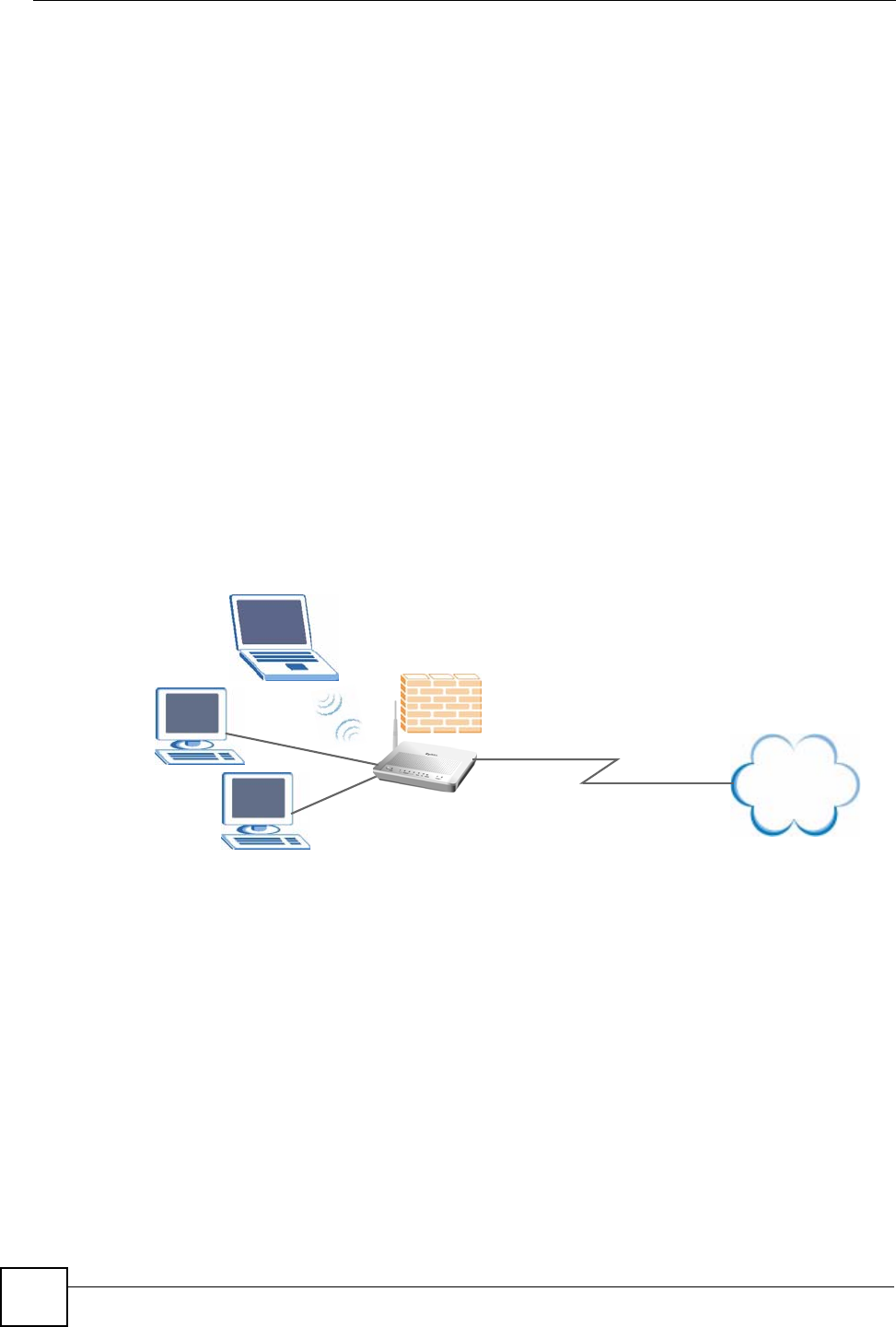
1.4.1 Internet Access
Your ZyXEL Device provides shared Internet access by connecting the DSL port to the DSL
or MODEM jack on a splitter or your telephone jack. Computers can connect to the ZyXEL
Device’s LAN ports (or wirelessly).
Figure 1 ZyXEL Device’s Router Features
You can also configure IP filtering on the ZyXEL Device for secure Internet access. When the
IP filter is on, all incoming traffic from the Internet to your network is blocked by default
unless it is initiated from your network. This means that probes from the outside to your
network are not allowed, but you can safely browse the Internet and download files.
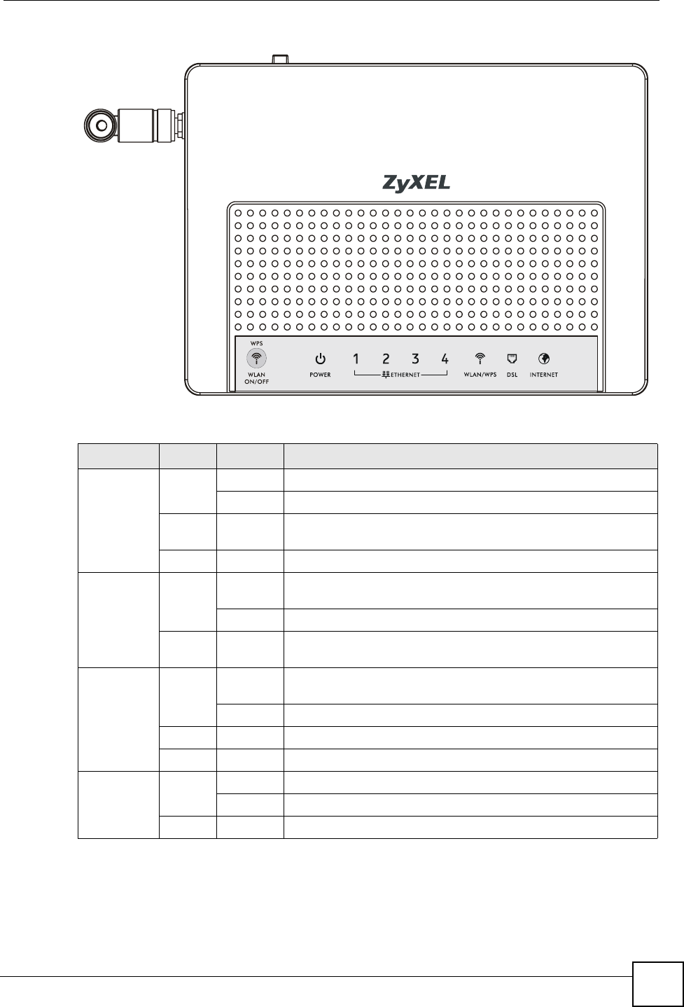
1.5 LEDs (Lights)
The following graphic displays the labels of the LEDs.
Internet
DSL
LAN
Chapter 1 Introducing the ZyXEL Device
P-870HW-51a v2 User’s Guide 27
Figure 2 LEDs on the Top of the Device
None of the LEDs are on if the ZyXEL Device is not receiving power.
Table 1 LED Descriptions
LED COLOR STATUS DESCRIPTION
POWER Green On The ZyXEL Device is receiving power and ready for use.
Blinking The ZyXEL Device is self-testing.
Red On The ZyXEL Device detected an error while self-testing, or there is
a device malfunction.
Off The ZyXEL Device is not receiving power.
ETHERNET
1-4 Green On The ZyXEL Device has an Ethernet connection with a device on
the Local Area Network (LAN).
Blinking The ZyXEL Device is sending/receiving data to /from the LAN.
Off The ZyXEL Device does not have an Ethernet connection with
the LAN.
WLAN/WPS Green On The wireless network is activated and is operating in IEEE
802.11b/g mode.
Blinking The ZyXEL Device is communicating with other wireless clients.
Orange Blinking The ZyXEL Device is setting up a WPS connection.
Off The wireless network is not activated.
DSL Green On The DSL line is up.
Blinking The ZyXEL Device is initializing the DSL line.
Off The DSL line is down.

Chapter 1 Introducing the ZyXEL Device
P-870HW-51a v2 User’s Guide
28
Refer to the Quick Start Guide for information on hardware connections.
1.6 The RESET Button
If you forget your password or cannot access the web configurator, you will need to use the
RESET button at the back of the device to reload the factory-default configuration file. This
means that you will lose all configurations that you had previously and the password will be
reset to “1234”. You can also use the
1.6.1 Using the Reset Button
1Make sure the POWER LED is on (not blinking).
2To set the device back to the factory default settings, press the RESET button for ten
seconds or until the POWER LED begins to blink and then release it. When the
POWER LED begins to blink, the defaults have been restored and the device restarts.
1.7 The WPS WLAN Button
You can use the WPS WLAN ON/OFF button ( ) on the top of the device to turn the
wireless LAN off or on. You can also use it to activate WPS in order to quickly set up a
wireless network with strong security.
1.7.1 Turn the Wireless LAN Off or On
1Make sure the POWER LED is on (not blinking).
2Press the WPS WLAN ON/OFF button for one second and release it. The WLAN/
WPS LED should change from on to off or vice versa.
1.7.2 Activate WPS
1Make sure the POWER LED is on (not blinking).
2Press the WPS WLAN ON/OFF button for more than five seconds and release it. Press
the WPS button on another WPS -enabled device within range of the ZyXEL Device.
INTERNET Green On The ZyXEL Device has an IP connection but no traffic.
Your device has a WAN IP address (either static or assigned by a
DHCP server), PPP negotiation was successfully completed (if
used) and the DSL connection is up.
Blinking The ZyXEL Device is sending or receiving IP traffic.
Red On The ZyXEL Device attempted to make an IP connection but
failed. Possible causes are no response from a DHCP server, no
PPPoE response, PPPoE authentication failed.
Off The ZyXEL Device does not have an IP connection.
Table 1 LED Descriptions
LED COLOR STATUS DESCRIPTION

Chapter 1 Introducing the ZyXEL Device
P-870HW-51a v2 User’s Guide 29
The WLAN/WPS LED should flash while the ZyXEL Device sets up a WPS connection
with the wireless device.
"You must activate WPS in the ZyXEL Device and in another wireless device
within two minutes of each other. See Section 7.9.4 on page 92 for more
information.

Chapter 1 Introducing the ZyXEL Device
P-870HW-51a v2 User’s Guide
30

P-870HW-51a v2 User’s Guide 31
CHAPTER 2
Tutorials
This chapter describes how to set up a wireless network.
2.1 How to Set up a Wireless Network
This tutorial gives you examples of how to set up an access point and wireless client for
wireless communication using the following parameters. The wireless clients can access the
Internet through an AP wirelessly.
2.1.1 Example Parameters
An access point (AP) or wireless router is referred to as “AP” and a computer with a wireless
network card or USB/PCI adapter is referred to as “wireless client” here.
We use the ZyXEL Device web screens and M-302 utility screens as an example. The screens
may vary slightly for different models.
2.1.2 Configuring the AP
Follow the steps below to configure the wireless settings on your AP.
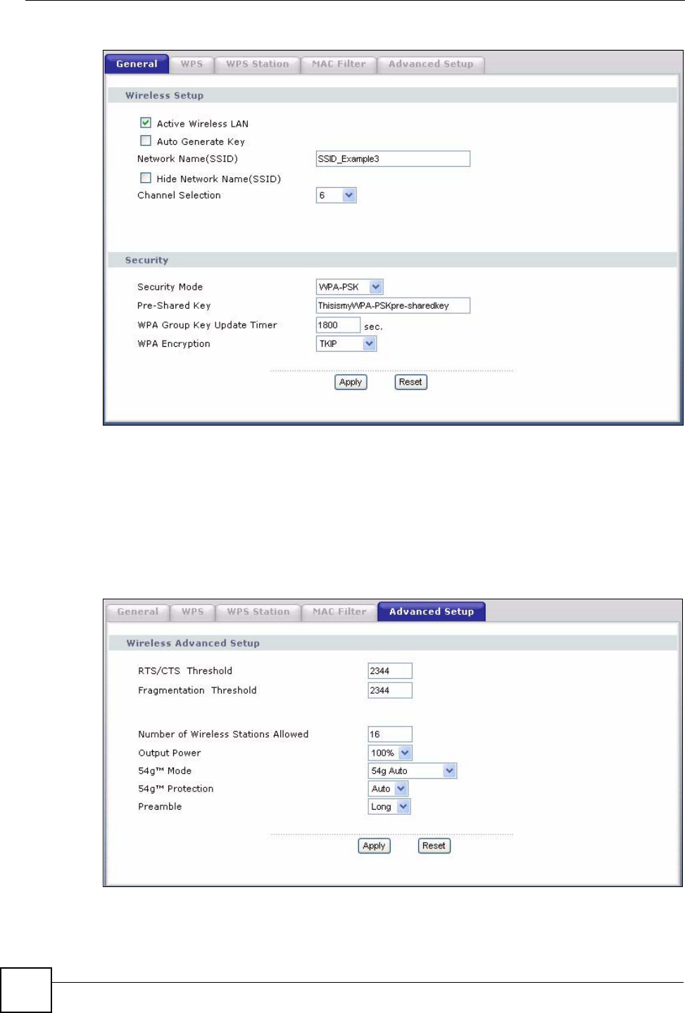
1Open the Network > Wireless LAN screen in the AP’s web configurator.
SSID SSID_Example3
Security WPA-PSK
(Pre-Shared Key: ThisismyWPA-PSKpre-sharedkey)
802.11 mode IEEE 802.11b/g
Chapter 2 Tutorials
P-870HW-51a v2 User’s Guide
32
Figure 3 AP: Wireless LAN
2Make sure the Active Wireless LAN check box is selected.
3Enter “SSID_Example3” as the SSID and select a channel which is not used by another
AP.
4Set security mode to WPA-PSK and enter “ThisismyWPA-PSKpre-sharedkey” in the
Pre-Shared Key field. Click Apply.
5Click the Advanced Setup tab and select 54g Auto in the 54gTM Mode field. Click
Apply.
Figure 4 AP: Wireless LAN > Advanced Setup
6Open the Status screen.Verify your wireless and wireless security settings under Device
Information and check if the WLAN connection is up under Interface Status.
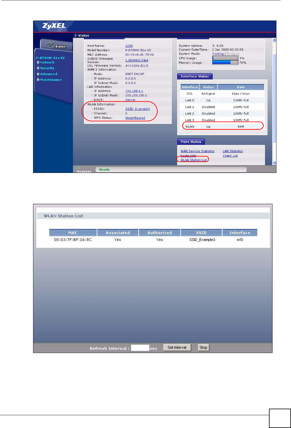
Chapter 2 Tutorials
P-870HW-51a v2 User’s Guide 33
Figure 5 AP: Status
7Click the WLAN Station List hyperlink in the AP’s Status screen. You can see if any
wireless client has connected to the AP.
Figure 6 AP: Status: WLAN Station List
2.1.3 Configuring the Wireless Client
This section describes how to connect the wireless client to a network.
Chapter 2 Tutorials
P-870HW-51a v2 User’s Guide
34
2.1.3.1 Connecting to a Wireless LAN
The following sections show you how to join a wireless network using the ZyXEL utility, as in
the following diagram. The wireless client is labeled C and the access point is labeled AP.
There are three ways to connect the client to an access point.
• Configure nothing and leave the wireless client to automatically scan for and connect to
any available network that has no wireless security configured.
• Manually connect to a network.
• Configure a profile to have the wireless client automatically connect to a specific network
or peer computer.
This example illustrates how to manually connect your wireless client to an access point (AP)
which is configured for WPA-PSK security and connected to the Internet. Before you connect
to the access point, you must know its Service Set IDentity (SSID) and WPA-PSK pre-shared
key. In this example, the SSID is “SSID_Example3” and the pre-shared key is
“ThisismyWPA-PSKpre-sharedkey”.
After you install the ZyXEL utility and then insert the wireless client, follow the steps below
to connect to a network using the Site Survey screen.
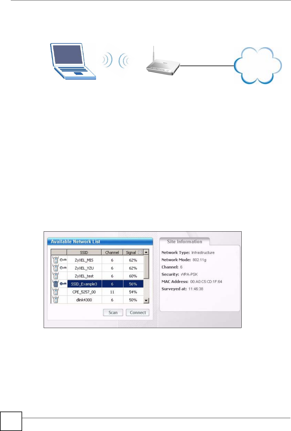
1Open the ZyXEL utility and click the Site Survey tab to open the screen shown next.
Figure 7 ZyXEL Utility: Site Survey
2The wireless client automatically searches for available wireless networks. Click Scan if
you want to search again. If no entry displays in the Available Network List, that means
there is no wireless network available within range. Make sure the AP or peer computer
is turned on or move the wireless client closer to the AP or peer computer.
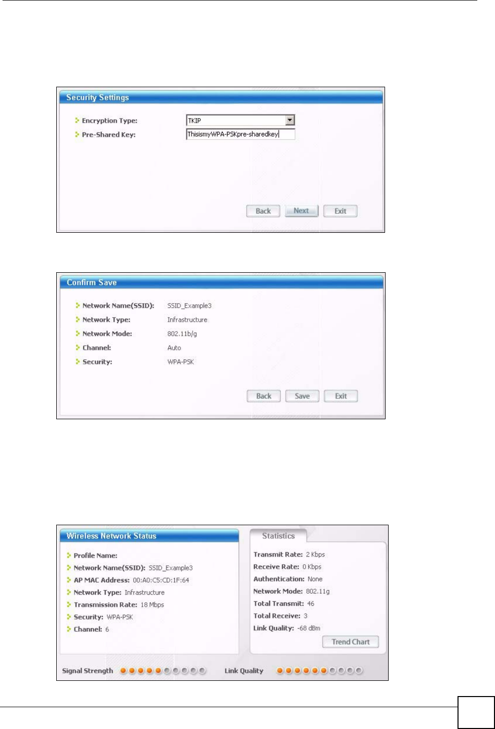
3When you try to connect to an AP with security configured, a window will pop up
prompting you to specify the security settings. Enter the pre-shared key and leave the
encryption type at the default setting.
CAP
Internet
Chapter 2 Tutorials
P-870HW-51a v2 User’s Guide 35
Use the Next button to move on to the next screen. You can use the Back button at any
time to return to the previous screen, or the Exit button to return to the Site Survey
screen.
Figure 8 ZyXEL Utility: Security Settings
4The Confirm Save window appears. Check your settings and click Save to continue.
Figure 9 ZyXEL Utility: Confirm Save
5The ZyXEL utility returns to the Link Info screen while it connects to the wireless
network using your settings. When the wireless link is established, the ZyXEL utility
icon in the system tray turns green and the Link Info screen displays details of the active
connection. Check the network information in the Link Info screen to verify that you
have successfully connected to the selected network. If the wireless client is not
connected to a network, the fields in this screen remain blank.
Figure 10 ZyXEL Utility: Link Info
Chapter 2 Tutorials
P-870HW-51a v2 User’s Guide
36
6Open your Internet browser and enter http://www.zyxel.com or the URL of any other
web site in the address bar. If you are able to access the web site, your wireless
connection is successfully configured.
If you cannot access the web site, try changing the encryption type in the Security
Settings screen, check the Troubleshooting section of this User's Guide or contact your
network administrator.
2.1.3.2 Creating and Using a Profile
A profile lets you automatically connect to the same wireless network every time you use the
wireless client. You can also configure different profiles for different networks, for example if
you connect a notebook computer to wireless networks at home and at work.
This example illustrates how to set up a profile and connect the wireless client to an access
point configured for WPA-PSK security. In this example, the SSID is “SSID_Example3”, the
profile name is “PN_Example3” and the pre-shared key is “ThisismyWPA-PSKpre-
sharedkey”. You have chosen the profile name “PN_Example3”.
1Open the ZyXEL utility and click the Profile tab to open the screen shown next. Click
Add to configure a new profile.
Figure 11 ZyXEL Utility: Profile
2The Add New Profile screen appears. The wireless client automatically searches for
available wireless networks, which are displayed in the Scan Info box. Click on Scan if
you want to search again. You can also configure your profile for a wireless network that
is not in the list.
Figure 12 ZyXEL Utility: Add New Profile
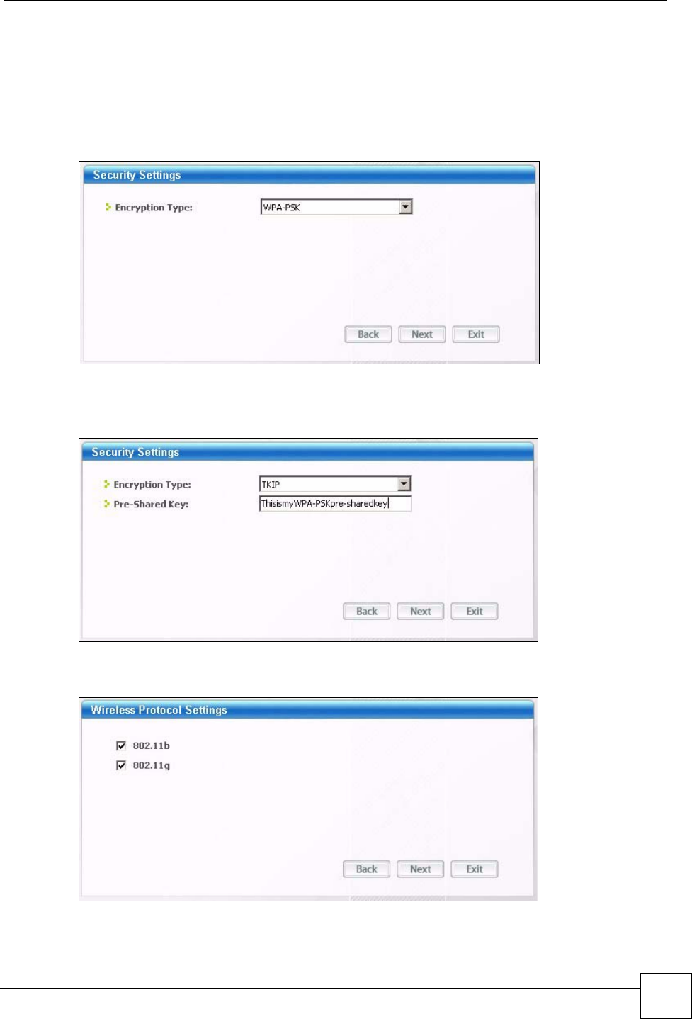
Chapter 2 Tutorials
P-870HW-51a v2 User’s Guide 37
3Give the profile a descriptive name (of up to 32 printable ASCII characters). Select
Infrastructure and either manually enter or select the AP's SSID in the Scan Info table
and click Select.
4Choose the same encryption method as the AP to which you want to connect (In this
example, WPA-PSK).
Figure 13 ZyXEL Utility: Profile Security
5This screen varies depending on the encryption method you selected in the previous
screen. Enter the pre-shared key and leave the encryption type at the default setting.
Figure 14 ZyXEL Utility: Profile Encryption
6In the next screen, leave both boxes checked.
Figure 15 Profile: Wireless Protocol Settings.
7Verify the profile settings in the read-only screen. Click Save to save and go to the next
screen.
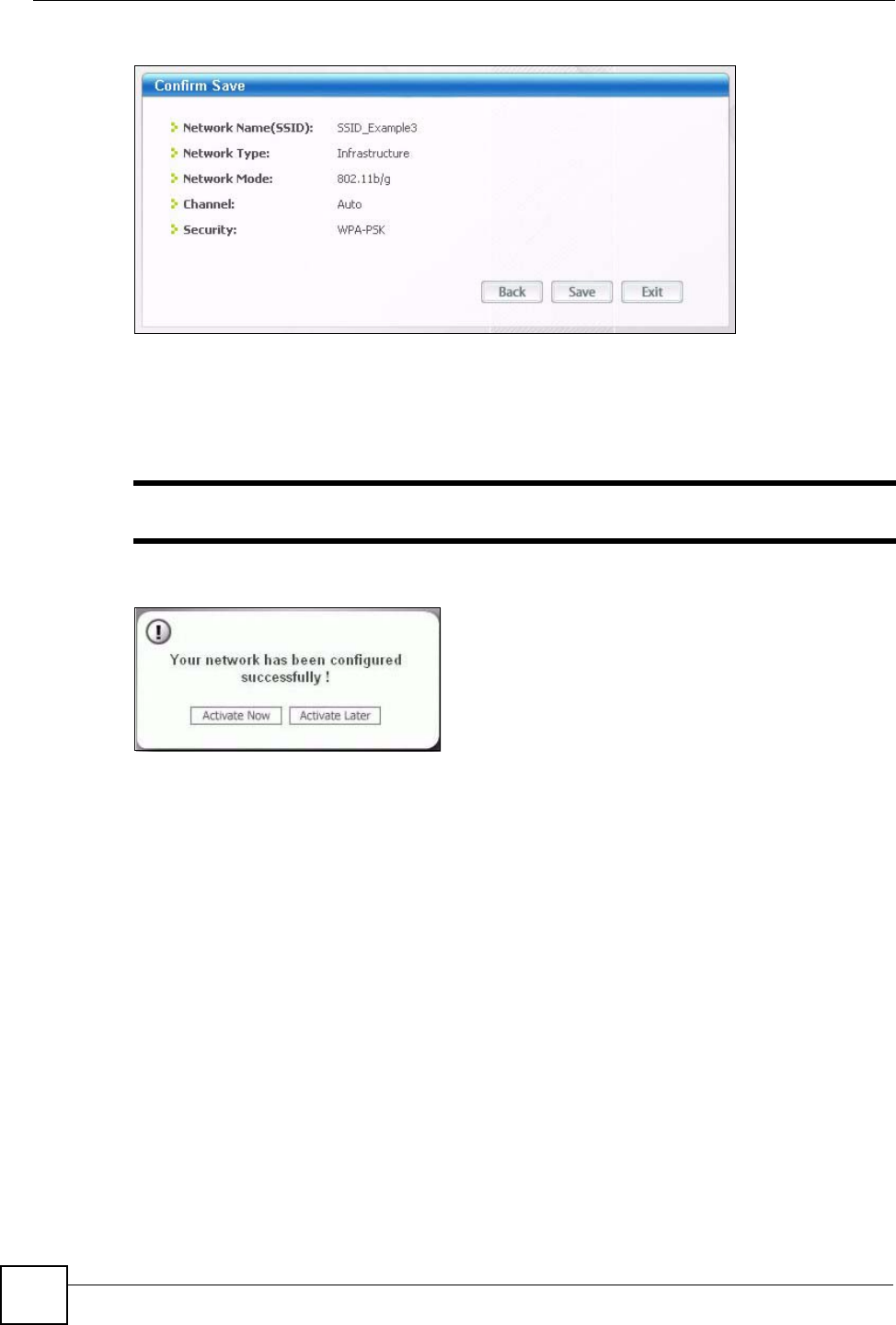
Chapter 2 Tutorials
P-870HW-51a v2 User’s Guide
38
Figure 16 Profile: Confirm Save
8Click Activate Now to use the new profile immediately. Otherwise, click the Activate
Later button.
If you clicked Activate Later, you can select the profile from the list in the Profile
screen and click Connect to activate it.
"Only one profile can be activated and used at any given time.
Figure 17 Profile: Activate
9When you activate the new profile, the ZyXEL utility returns to the Link Info screen
while it connects to the AP using your settings. When the wireless link is established, the
ZyXEL utility icon in the system tray turns green and the Link Info screen displays
details of the active connection.
10 Open your Internet browser, enter http://www.zyxel.com or the URL of any other web
site in the address bar and press ENTER. If you are able to access the web site, your new
profile is successfully configured.
11 If you cannot access the Internet go back to the Profile screen, select the profile you are
using and click Edit. Check the details you entered previously. Also, refer to the
Troubleshooting section of this User's Guide or contact your network administrator if
necessary.

P-870HW-51a v2 User’s Guide 39
CHAPTER 3
Introducing the Web
Configurator
This chapter describes how to access and navigate the web configurator.
3.1 Web Configurator Overview
The web configurator is an HTML-based management interface that allows easy device setup
and management via Internet browser. Use Internet Explorer 6.0 and later or Netscape
Navigator 7.0 and later versions. The recommended screen resolution is 1024 by 768 pixels.
In order to use the web configurator you need to allow:
• Web browser pop-up windows from your device. Web pop-up blocking is enabled by
default in Windows XP SP (Service Pack) 2.
• JavaScripts (enabled by default).
• Java permissions (enabled by default).
See Appendix B on page 197 if you need to make sure these functions are allowed in Internet
Explorer.
3.1.1 Accessing the Web Configurator
1Make sure your ZyXEL Device hardware is properly connected (refer to the Quick Start
Guide).
2Launch your web browser.
3Type "192.168.1.1" as the URL.
4A password screen displays. Enter the default user name 1234 and default password
1234.The password displays in non-readable characters. If you have changed the
password, enter your password and click Login. Click Cancel to revert to the default
password in the password field.
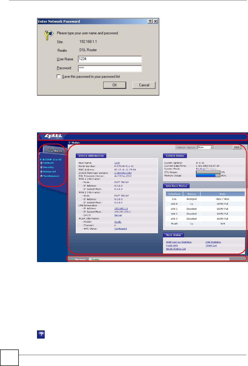
Chapter 3 Introducing the Web Configurator
P-870HW-51a v2 User’s Guide
40
Figure 18 Password Screen
3.2 Web Configurator Main Screen
Figure 19 Main Screen
As illustrated above, the main screen is divided into these parts:
•A - title bar
•B - navigation panel
•C - main window
•D - status bar
3.2.1 Title Bar
The title bar allows you to change the language and provides an icon in the upper right corner.
A
BC
D
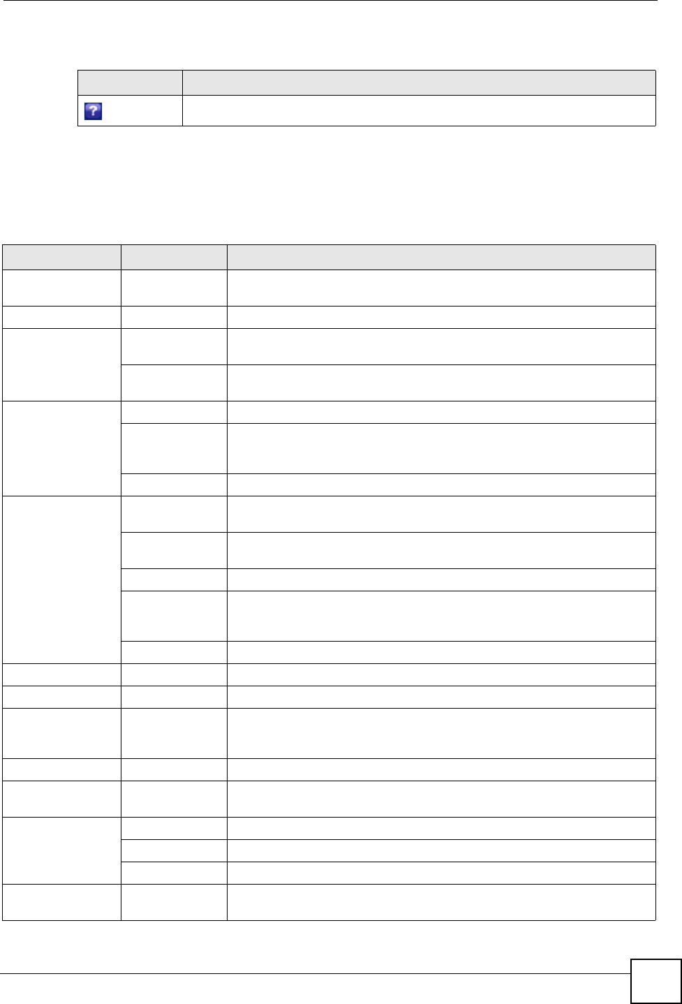
Chapter 3 Introducing the Web Configurator
P-870HW-51a v2 User’s Guide 41
The icon provides the following function.
3.2.2 Navigation Panel
Use the menu items on the navigation panel to open screens to configure ZyXEL Device
features. The following tables describe each menu item.
Table 2 Web Configurator Icon in the Title Bar
ICON DESCRIPTION
Help: Click this icon to open up help screens.
Table 3 Navigation Panel Summary
LINK TAB FUNCTION
Status This screen shows the ZyXEL Device’s general device and network status
information. Use this screen to access the statistics and client list.
Network
WAN Internet
Connection Use this screen to configure ISP parameters, WAN IP address assignment,
DNS servers and other advanced properties.
More
Connections Use this screen to configure additional WAN connections.
LAN IP Use this screen to configure LAN TCP/IP DHCP settings.
Client List Use this screen to view current DHCP client information and to always
assign specific IP addresses to individual MAC addresses (and host
names).
IP Alias Use this screen to partition your LAN interface into subnets.
Wireless LAN General Use this screen to configure the wireless LAN settings and WLAN
authentication/security settings.
WPS Use this screen to enable WPS (Wi-Fi Protected Setup) and view the WPS
status.
WPS Station Use this screen to use WPS to set up your wireless network.
MAC Filter Use this screen to configure the ZyXEL Device to give exclusive access to
specific wireless clients or exclude specific wireless clients from accessing
the ZyXEL Device.
Advanced Setup Use this screen to configure the advanced wireless LAN settings.
NAT Port Forwarding Use this screen to make your local servers visible to the outside world.
Security
IP Filter Incoming This screen shows a summary of the IP filtering rules, and allows you to
add or remove an incoming IP filtering rule that allows incoming traffic from
the WAN.
Advanced
Static Route IP Static Route Use this screen to configure IP static routes to tell your device about
networks beyond the directly connected remote nodes.
QoS General Use this screen to enable QoS.
Queue Setup Use this screen to configure QoS queues.
Class Setup Use this screen to define a classifier.
Dynamic DNS This screen allows you to use a static hostname alias for a dynamic IP
address.

Chapter 3 Introducing the Web Configurator
P-870HW-51a v2 User’s Guide
42
3.2.3 Main Window
The main window displays information and configuration fields. It is discussed in the rest of
this document.
Right after you log in, the Status screen is displayed. See Chapter 4 on page 43 for more
information about the Status screen.
3.2.4 Status Bar
Check the status bar when you click Apply or OK to verify that the configuration has been
updated.
Remote MGMT TR069 Use this screen to configure the ZyXEL Device to be managed by an ACS
(Auto Configuration Server).
UPnP General Use this screen to turn UPnP on or off.
Maintenance
System General Use this screen to configure your device’s name, domain name,
management inactivity timeout and password.
Time Setting Use this screen to change your ZyXEL Device’s time and date.
Logs View Log Use this screen to view the logs for the level that you selected.
Log Settings Use this screen to change your ZyXEL Device’s log settings.
Tools Firmware Use this screen to upload firmware to your device.
Configuration Use this screen to backup and restore your device’s configuration (settings)
or reset the factory default settings.
Restart This screen allows you to reboot the ZyXEL Device without turning the
power off.
Diagnostic 802.1ag Use this screen to configure CFM (Connectivity Fault Management) and
perform connectivity tests and view test reports.
Table 3 Navigation Panel Summary
LINK TAB FUNCTION
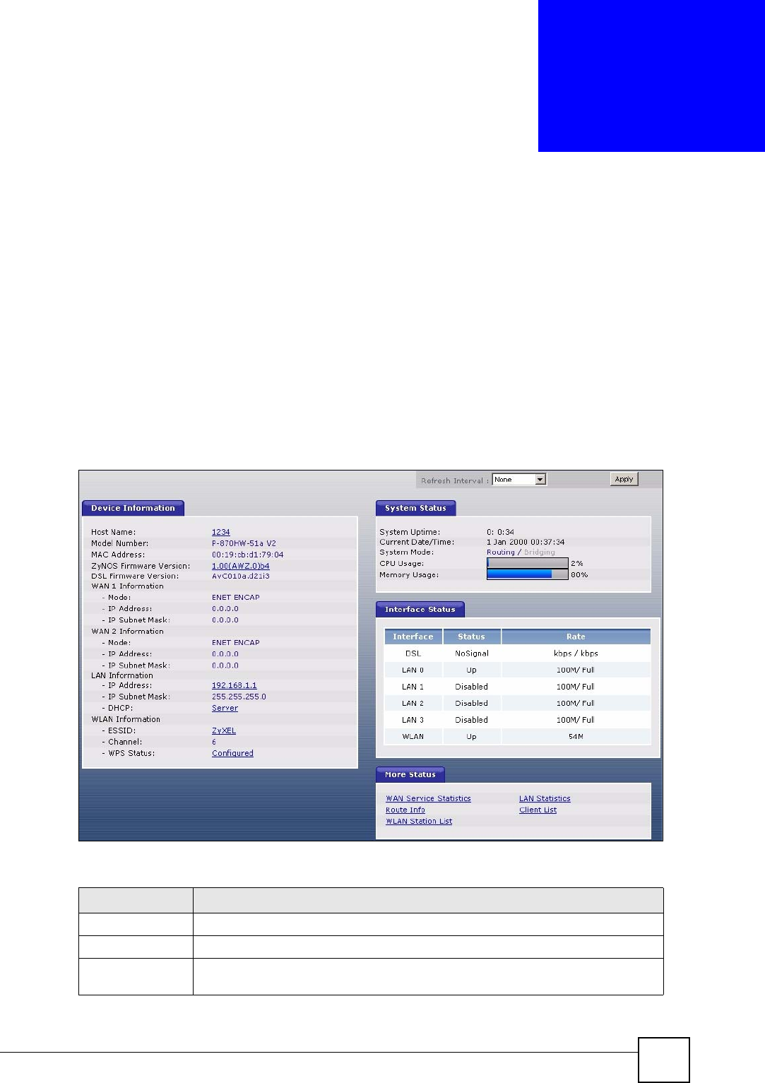
P-870HW-51a v2 User’s Guide 43
CHAPTER 4
Status Screens
Use the Status screens to look at the current status of the device, system resources and
interfaces (LAN and WAN). The Status screen also provides detailed information from DHCP
and statistics from traffic.
4.1 Status Screen
Click Status to open this screen.
Figure 20 Status Screen
Each field is described in the following table.
Table 4 Status Screen
LABEL DESCRIPTION
Refresh Interval Enter how often you want the ZyXEL Device to update this screen.
Apply Click this to update this screen immediately.
Device
Information

Chapter 4 Status Screens
P-870HW-51a v2 User’s Guide
44
Host Name This field displays the ZyXEL Device system name. It is used for identification.
Click this to go to the screen where you can change it.
Model
Number This is the model name of your device.
MAC Address This is the MAC (Media Access Control) or Ethernet address unique to your
ZyXEL Device.
ZyNOS
Firmware
Version
This field displays the current version of the firmware inside the device. It also
shows the date the firmware version was created. Click this to go to the screen
where you can change it.
DSL Firmware
Version This field displays the current version of the device’s DSL modem code.
WAN Information
Mode This is the method of encapsulation used by your ISP.
IP Address This field displays the current IP address of the ZyXEL Device in the WAN. Click
this to go to the screen where you can change it.
IP Subnet
Mask This field displays the current subnet mask in the WAN.
LAN Information
IP Address This field displays the current IP address of the ZyXEL Device in the LAN. Click
this to go to the screen where you can change it.
IP Subnet
Mask This field displays the current subnet mask in the LAN.
DHCP This field displays what DHCP services the ZyXEL Device is providing to the LAN.
Choices are:
Server - The ZyXEL Device is a DHCP server in the LAN. It assigns IP addresses
to other computers in the LAN.
None - The ZyXEL Device is not providing any DHCP services to the LAN.
Click this to go to the screen where you can change it.
WLAN
Information
ESSID This is the descriptive name used to identify the ZyXEL Device in the wireless
LAN. Click this to go to the screen where you can change it.
Channel This is the channel number used by the ZyXEL Device now.
WPS This field displays the status of WPS (Wi-Fi Protected Setup). Click this to go to
the screen where you can change it.
System Status
System
Uptime This field displays how long the ZyXEL Device has been running since it last
started up. The ZyXEL Device starts up when you plug it in, when you restart it
(Maintenance > Tools > Restart), or when you reset it (see Section 1.6 on page
28).
Current Date/
Time This field displays the current date and time in the ZyXEL Device. You can change
this in Maintenance > System > Time Setting.
System Mode This displays whether the ZyXEL Device is functioning as a router or a bridge.
CPU Usage This field displays what percentage of the ZyXEL Device’s processing ability is
currently used. When this percentage is close to 100%, the ZyXEL Device is
running at full load, and the throughput is not going to improve anymore. If you
want some applications to have more throughput, you should turn off other
applications (for example, using QoS; see Chapter 11 on page 117).
Table 4 Status Screen
LABEL DESCRIPTION

Chapter 4 Status Screens
P-870HW-51a v2 User’s Guide 45
Memory
Usage This field displays what percentage of the ZyXEL Device’s memory is currently
used. Usually, this percentage should not increase much. If memory usage does
get close to 100%, the ZyXEL Device is probably becoming unstable, and you
should restart the device. See Section 17.4 on page 154, or turn off the device
(unplug the power) for a few seconds.
Interface Status
Interface This column displays each interface the ZyXEL Device has.
Status This field indicates whether or not the ZyXEL Device is using the interface.
For the DSL interface, this field displays NoSignal (line is down) or Up (line is up
or connected).
For the LAN interface, this field displays Up when the ZyXEL Device is using the
interface and Disabled when the ZyXEL Device is not using the interface.
For the WLAN interface, it displays Up when WLAN is enabled or Disabled when
WLAN is not active.
Rate For the LAN interface, this displays the port speed and duplex setting.
For the DSL interface, it displays the downstream and upstream transmission rate.
For the WLAN interface, it displays the maximum transmission rate.
More Status
WAN Service
Statistics Click this link to view packet specific statistics of the WAN connection(s). See
Section 4.1.1 on page 46.
Route Info Click this link to view the internal routing table on the ZyXEL Device. See Section
4.1.2 on page 47.
WLAN Station
List Click this link to display the MAC address(es) of the wireless stations that are
currently associating with the ZyXEL Device. See Section 4.1.3 on page 47.
LAN Statistics Click this link to view packet specific statistics on the LAN and WLAN interfaces.
See Section 4.1.4 on page 48.
Client List Click this link to view current DHCP client information. See Section 4.1.5 on page
50.
Table 4 Status Screen
LABEL DESCRIPTION
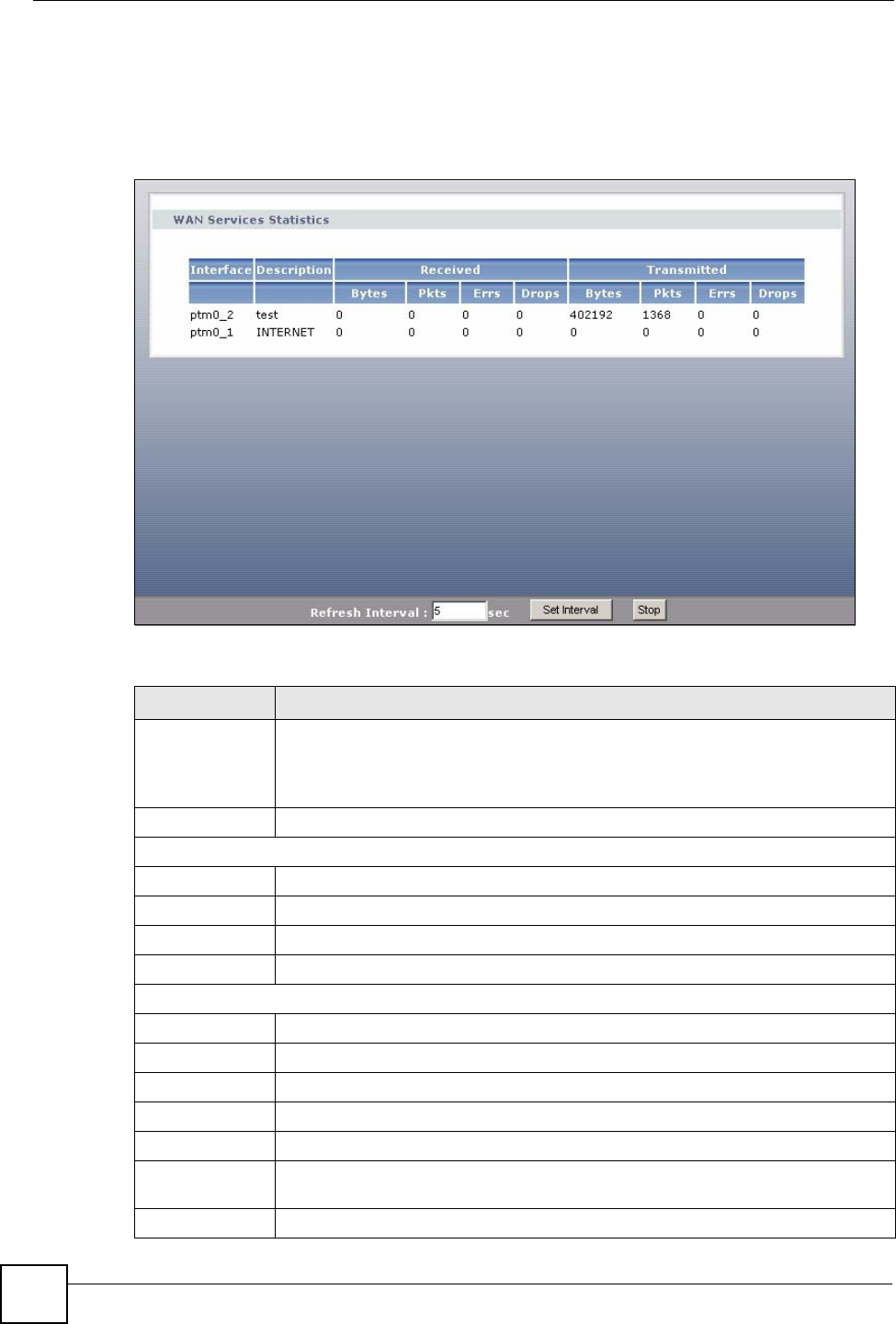
Chapter 4 Status Screens
P-870HW-51a v2 User’s Guide
46
4.1.1 WAN Service Statistics
Click Status > WLAN Service Statistics to access this screen. Use this screen to view the
WAN statistics.
Figure 21 Status > WAN Service Statistics
The following table describes the labels in this screen.
Table 5 Status > WAN Service Statistics
LABEL DESCRIPTION
Interface This shows the name of the WAN interface used by this connection.
The default name ptm0 indicates the DSL port. The last number represents the
index number of connections over the same PVC or the VLAN ID number assigned
to traffic sent through this connection.
Description This shows the descriptive name of this connection.
Received
Bytes This indicates the number of bytes received on this interface.
Pkts This indicates the number of transmitted packets on this interface.
Errs This indicates the number of frames with errors received on this interface.
Drops This indicates the number of received packets dropped on this interface.
Transmitted
Bytes This indicates the number of bytes transmitted on this interface.
Pkts This indicates the number of transmitted packets on this interface.
Errs This indicates the number of frames with errors transmitted on this interface.
Drops This indicates the number of outgoing packets dropped on this interface.
Refresh Interval Enter the time interval for refreshing statistics in this field.
Set Interval Click this button to apply the new poll interval you entered in the Refresh Interval
field.
Stop Click Stop to stop refreshing statistics.
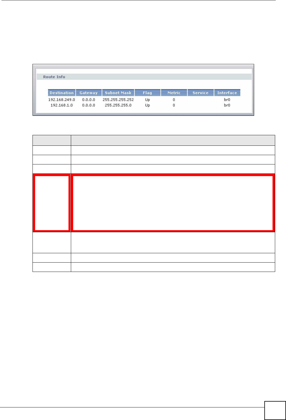
Chapter 4 Status Screens
P-870HW-51a v2 User’s Guide 47
4.1.2 Route Info
Routing is based on the destination address only and the ZyXEL Device takes the shortest path
to forward a packet. Click Status > Route Info to access this screen. Use this screen to view
the internal routing table on the ZyXEL Device.
Figure 22 Status > Route Info
The following table describes the labels in this screen.
4.1.3 WLAN Station List
Click Status > WLAN Station List to access this screen. Use this screen to view the wireless
stations that are currently associated to the ZyXEL Device.
Table 6 Status > Route Info
LABEL DESCRIPTION
Destination This indicates the destination IP address of this route.
Gateway This indicates the IP address of the gateway that helps forward this route’s traffic.
Subnet Mask This indicates the destination subnet mask of this route.
Flag This indicates the route status.
Up: The route is up.
Reject: The route is blocked and will force a route lookup to fail.
Gateway: The route uses a gateway to forward traffic.
Host: The target of the route is a host.
Reinstate: The route is reinstated for dynamic routing.
Dynamic (redirect): The route is dynamically installed by a routing daemon or redirect
Modified (redirect): The route is modified from a routing daemon or rederict.
Metric The metric represents the "cost of transmission". A router determines the best route
for transmission by choosing a path with the lowest "cost". The smaller the number,
the lower the "cost".
Service This indicates the name of the service used to forward the route.
Interface This indicates the name of the interface through which the route is forwarded.
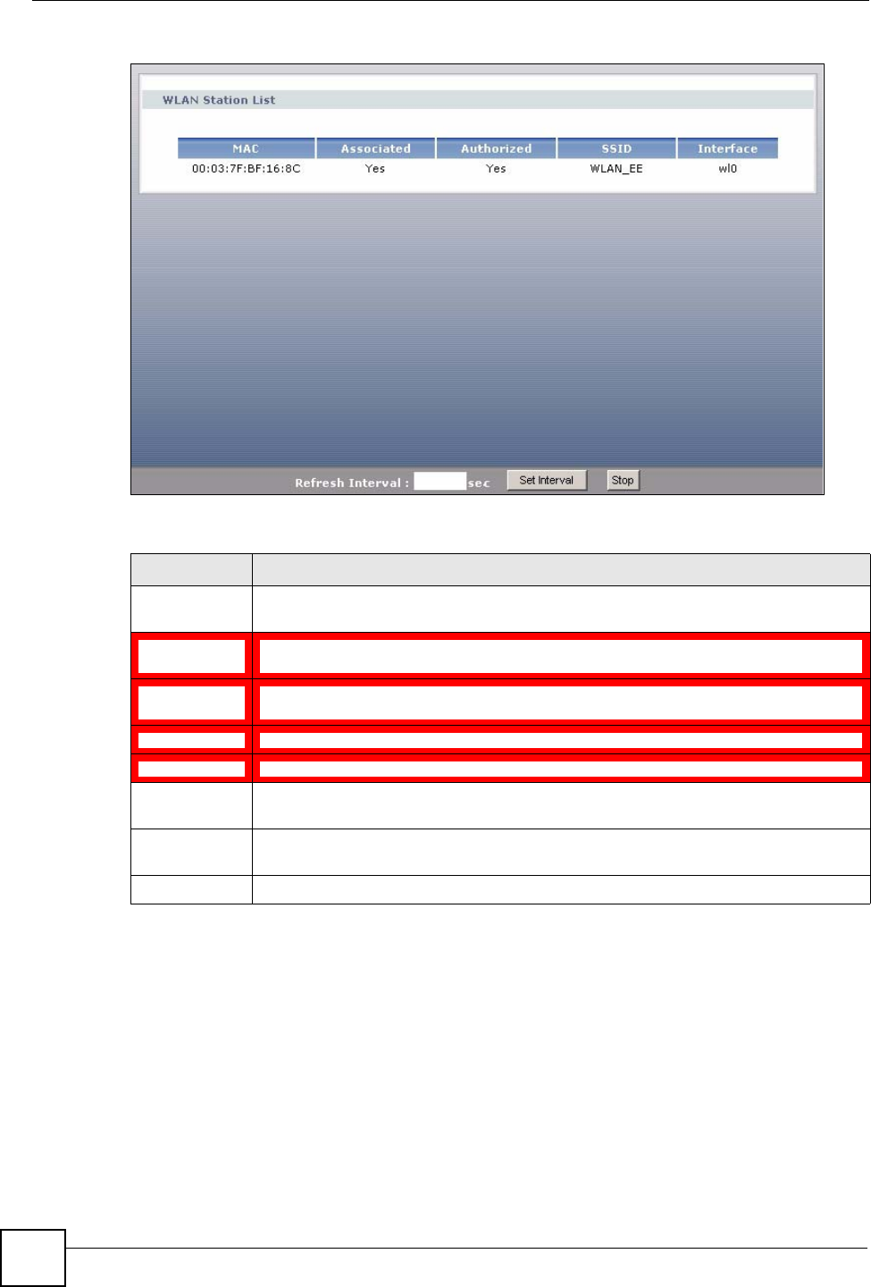
Chapter 4 Status Screens
P-870HW-51a v2 User’s Guide
48
Figure 23 Status > WLAN Station List
The following table describes the labels in this screen.
4.1.4 LAN Statistics
Click Status > LAN Statistics to access this screen. Use this screen to view the LAN statistics.
Table 7 Status > WLAN Station List
LABEL DESCRIPTION
MAC Address This field shows the MAC (Media Access Control) address of an associated wireless
station.
Associated This field shows whether the wireless station is currently associated to the ZyXEL
Device (Yes) or not (No).
Authorized This field shows whether the wireless station is allowed to access network resources
behind the ZyXEL Device (Yes) or not (No).
SSID This field shows the SSID to which the wireless station is connected.
Interface This field shows the wireless interface to which the wireless station is connected.
Refresh
Interval Enter the time interval for refreshing statistics in this field.
Set Interval Click this button to apply the new poll interval you entered in the Refresh Interval
field.
Stop Click Stop to stop refreshing statistics.
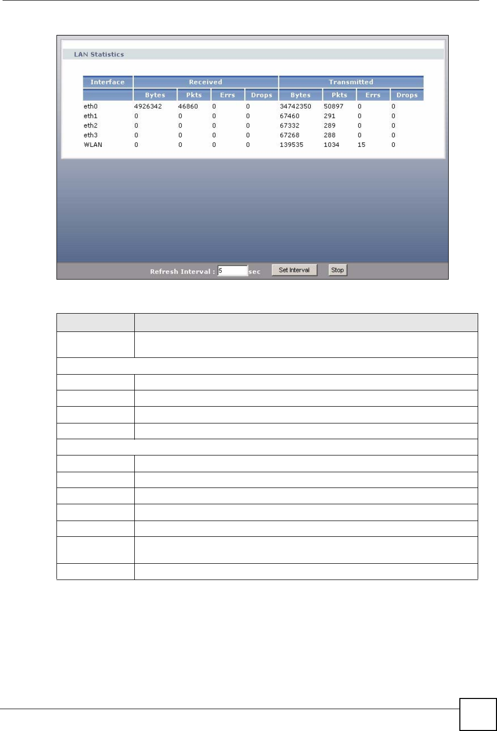
Chapter 4 Status Screens
P-870HW-51a v2 User’s Guide 49
Figure 24 Status > LAN Statistics
The following table describes the labels in this screen.
Table 8 Status > LAN Statistics
LABEL DESCRIPTION
Interface This shows the LAN or WLAN interface. eth0~3 represent the physical Ethernet
ports 1~ 4.
Received
Bytes This indicates the number of bytes received on this interface.
Pkts This indicates the number of transmitted packets on this interface.
Errs This indicates the number of frames with errors received on this interface.
Drops This indicates the number of received packets dropped on this interface.
Transmitted
Bytes This indicates the number of bytes transmitted on this interface.
Pkts This indicates the number of transmitted packets on this interface.
Errs This indicates the number of frames with errors transmitted on this interface.
Drops This indicates the number of outgoing packets dropped on this interface.
Refresh Interval Enter the time interval for refreshing statistics in this field.
Set Interval Click this button to apply the new poll interval you entered in the Refresh Interval
field.
Stop Click Stop to stop refreshing statistics.
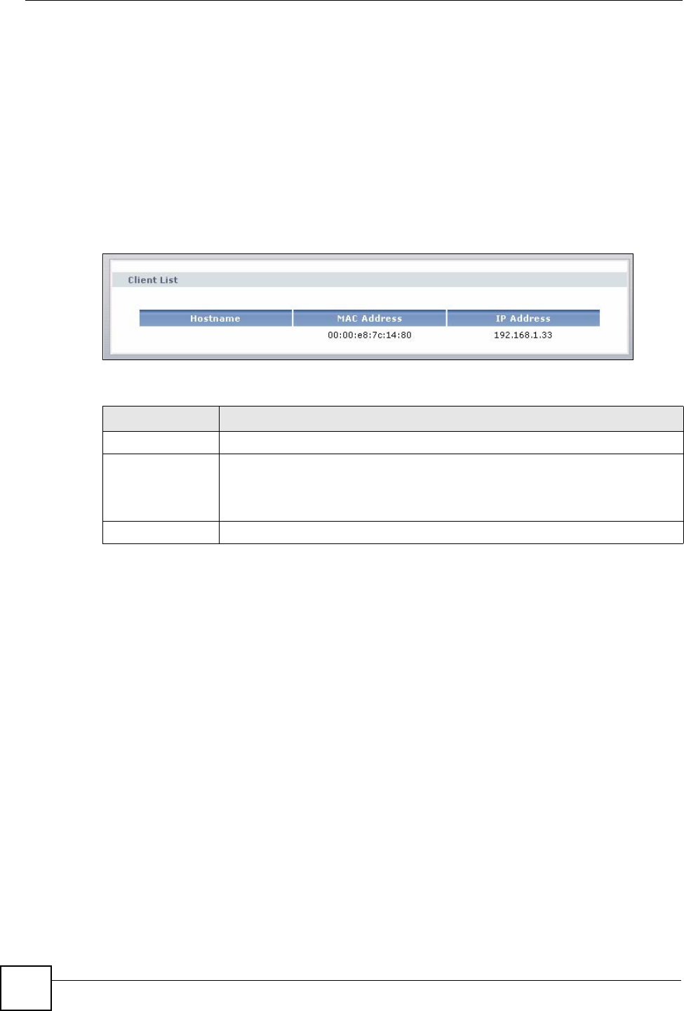
Chapter 4 Status Screens
P-870HW-51a v2 User’s Guide
50
4.1.5 Client List
DHCP (Dynamic Host Configuration Protocol, RFC 2131 and RFC 2132) allows individual
clients to obtain TCP/IP configuration at start-up from a server. You can configure the ZyXEL
Device as a DHCP server or disable it. When configured as a server, the ZyXEL Device
provides the TCP/IP configuration for the clients. If DHCP service is disabled, you must have
another DHCP server on your LAN, or else the computer must be manually configured.
Click Status > Client List to open the following screen. The read-only DHCP table shows
current DHCP client information (including IP Address, Host Name and MAC Address) of
all network clients using the ZyXEL Device’s DHCP server.
Figure 25 Status > Client List
The following table describes the labels in this screen.
Table 9 Status > Client List
LABEL DESCRIPTION
Host Name This indicates the computer host name.
MAC Address Every Ethernet device has a unique MAC (Media Access Control) address. The
MAC address is assigned at the factory and consists of six pairs of hexadecimal
characters, for example, 00:A0:C5:00:00:02.
This indicates the MAC address of the client computer.
IP Address This indicates the IP address assigned to this client computer.

51
PART II
Network
WAN Setup (53)
LAN Setup (67)
Wireless LAN (75)
Network Address Translation (NAT) (99)

52
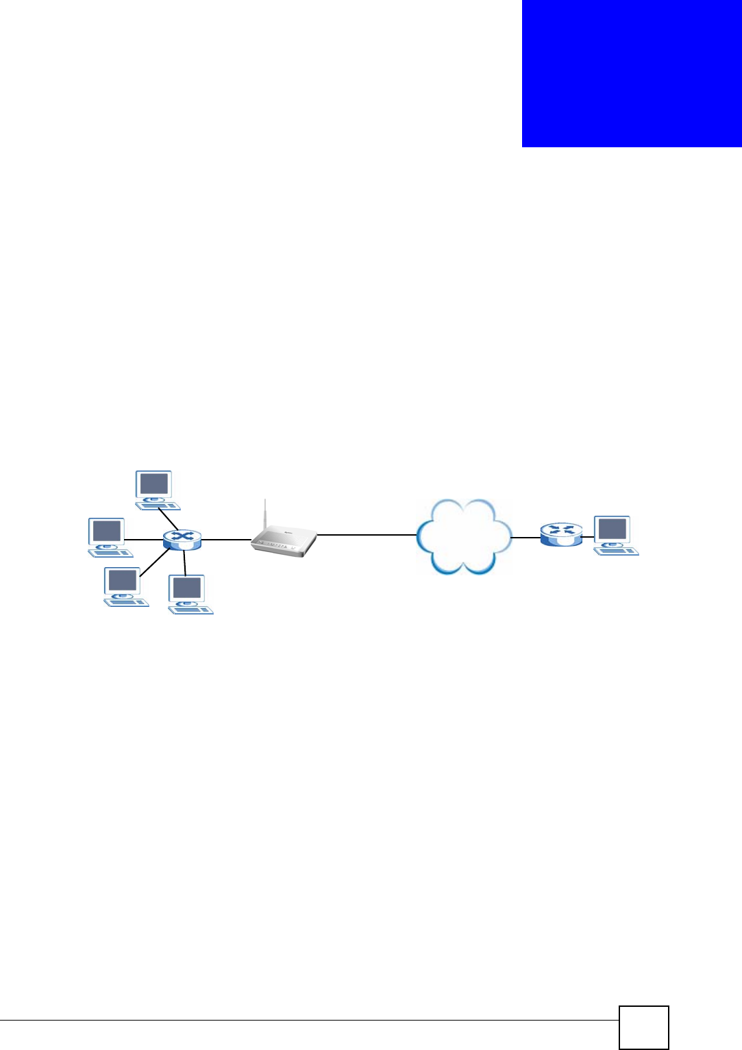
P-870HW-51a v2 User’s Guide 53
CHAPTER 5
WAN Setup
5.1 Overview
This chapter discusses the ZyXEL Device’s WAN screens. Use these screens to configure your
ZyXEL Device for Internet access.
A WAN (Wide Area Network) connection is an outside connection to another network or the
Internet. It connects your private networks (such as a LAN (Local Area Network) and other
networks, so that a computer in one location can communicate with computers in other
locations.
Figure 26 LAN and WAN
• See Section 5.6 on page 62 for advanced technical information on WAN.
• See Chapter 2 on page 31 for WAN tutorials.
5.1.1 What You Can Do in this Chapter
•The Internet Connection screen lets you configure the WAN settings on the ZyXEL
Device for Internet access (Section 5.4 on page 54).
•The More Connections screen lets you set up additional Internet access connections
(Section 5.5 on page 58).
Internet
WAN
LAN

Chapter 5 WAN Setup
P-870HW-51a v2 User’s Guide
54
5.2 What You Need to Know
Encapsulation Method
Encapsulation is used to include data from an upper layer protocol into a lower layer protocol.
To set up a WAN connection to the Internet, you need to use the same encapsulation method
used by your ISP (Internet Service Provider). If your ISP offers a dial-up Internet connection
using PPPoE (PPP over Ethernet) or PPPoA, they should also provide a username and
password (and service name) for user authentication.
WAN IP Address
The WAN IP address is an IP address for the ZyXEL Device, which makes it accessible from
an outside network. It is used by the ZyXEL Device to communicate with other devices in
other networks. It can be static (fixed) or dynamically assigned by the ISP each time the
ZyXEL Device tries to access the Internet.
If your ISP assigns you a static WAN IP address, they should also assign you the subnet mask
and DNS server IP address(es) (and a gateway IP address if you use the Ethernet or ENET
ENCAP encapsulation method).
PTM
Packet Transfer Mode (PTM) is packet-oriented and supported by the VDSL2 standard. In
PTM, packets are encapsulated directly in the High-level Data Link Control (HDLC) frames.
It is designed to provide a low-overhead, transparent way of transporting packets over DSL
links, as an alternative to ATM.
5.3 Before You Begin
You need to know your Internet access settings such as encapsulation and WAN IP address.
Get this information from your ISP.
5.4 The Internet Connection Screen
Use this screen to change your ZyXEL Device’s WAN settings. Click Network > WAN >
Internet Connection. The screen differs by the mode you select.
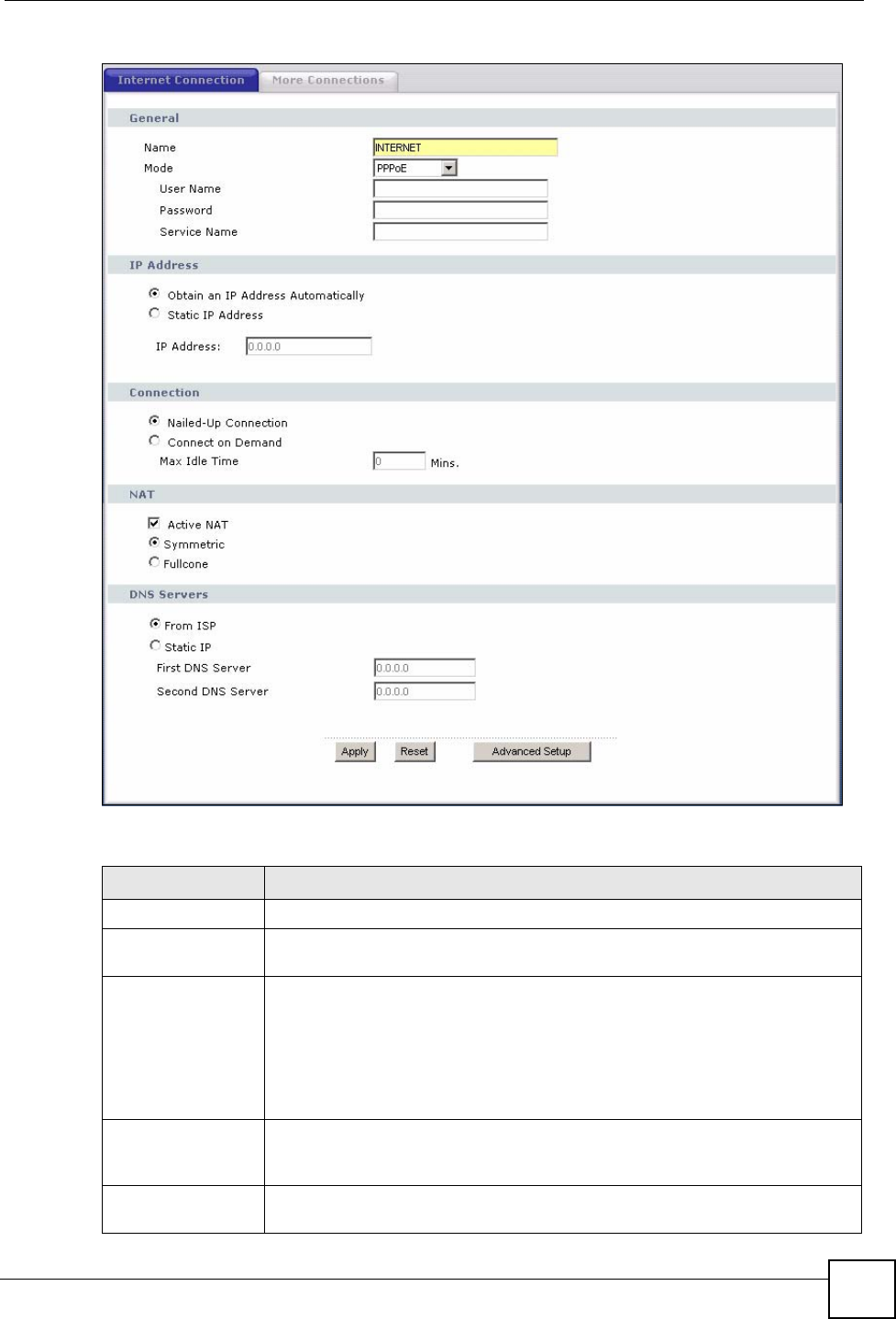
Chapter 5 WAN Setup
P-870HW-51a v2 User’s Guide 55
Figure 27 WAN > Internet Connection (PPPoE)
The following table describes the labels in this screen.
Table 10 WAN > Internet Connection
LABEL DESCRIPTION
General
Name Specify a name for this connection. You can use up to 32 letters, numerals and
any printable character found on a typical English language keyboard.
Mode The ZyXEL Device is in routing mode by default. This allows multiple computers
to share an Internet account. Select the method of encapsulation (ENET
ENCAP or PPPoE) used by your ISP from the drop-down list box.
Otherwise, select Bridge when your ISP provides you more than one IP address
and you want the connected computers to get individual IP address from ISP’s
DHCP server directly. If you select Bridge, you cannot use IP filter, DHCP
server and NAT on the ZyXEL Device.
User Name (PPPoE encapsulation only) Enter the user name exactly as your ISP assigned.
If assigned a name in the form user@domain where domain identifies a service
name, then enter both components exactly as given.
Password (PPPoE encapsulation only) Enter the password associated with the user name
above.

Chapter 5 WAN Setup
P-870HW-51a v2 User’s Guide
56
5.4.1 Advanced Internet Connection Setup
Use this screen to edit your ZyXEL Device's advanced WAN settings. Click the Advanced
Setup button in the Internet Connection screen. The screen appears as shown.
Service Name (PPPoE encapsulation only) Type the name of your PPPoE service here.
IP Address A static IP address is a fixed IP that your ISP gives you. A dynamic IP address is
not fixed; the ISP assigns you a different one each time you connect to the
Internet.
Select Obtain an IP Address Automatically if you have a dynamic IP address;
otherwise select Static IP Address and type your ISP assigned IP address in
the IP Address field below.
IP Address Enter the IP address assigned by your ISP if you select Static IP Address.
Subnet Mask Enter a subnet mask in dotted decimal notation when you select ENET ENCAP
in the Mode field.
Gateway IP
address You must specify a gateway IP address (supplied by your ISP) when you select
ENET ENCAP in the Mode field.
Connection
(PPPoE only)
Nailed-Up
Connection Select Nailed-Up Connection when you want your connection up all the time.
The ZyXEL Device will try to bring up the connection automatically if it is
disconnected.
Connect on
Demand Select Connect on Demand when you don't want the connection up all the time
and specify an idle time-out in the Max Idle Time field.
Max Idle Time Specify an idle time-out in the Max Idle Time field when you select Connect on
Demand. The default setting is 0, which means the Internet session will not
timeout.
NAT
Active NAT Select this check box to enable NAT on this connection.
Symmetric Select this option to enable symmetric NAT on this connection.
This field is available only when you select Active NAT.
Fullcone Select this option to enable full cone NAT on this connection.
This field is available only when you select Active NAT.
DNS Servers Select From ISP if your ISP dynamically assigns DNS server information (and
the ZyXEL Device's WAN IP address).
Select Static IP if you have the IP address of a DNS server.
First DNS Server
Second DNS Server
If you select Static IP, enter the DNS server's IP address in the field to the right.
Apply Click this to save the changes.
Reset Click this to begin configuring this screen afresh.
Advanced Setup Click this button to display the Advanced WAN Setup screen and edit more
details of your WAN setup.
Table 10 WAN > Internet Connection (continued)
LABEL DESCRIPTION
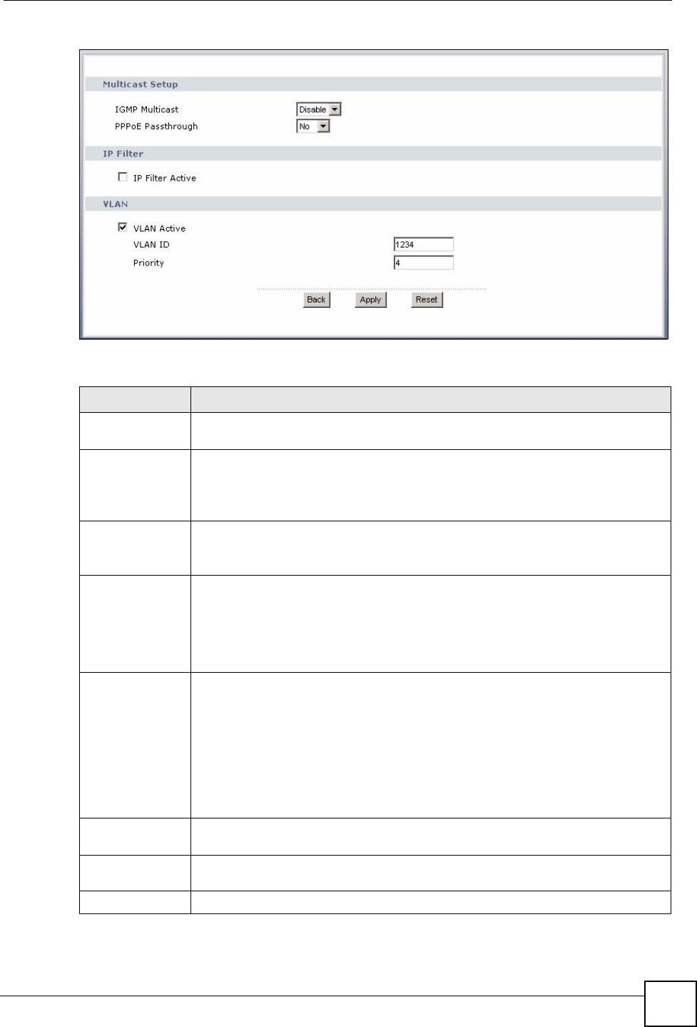
Chapter 5 WAN Setup
P-870HW-51a v2 User’s Guide 57
Figure 28 WAN > Internet Connection: Advanced Setup
The following table describes the labels in this screen.
Table 11 WAN > Internet Connection: Advanced Setup
LABEL DESCRIPTION
RIP & Multicast
Setup This section is not available when you configure the ZyXEL Device to be in bridge
mode.
RIP Version RIP (Routing Information Protocol) allows a router to exchange routing information
with other routers.
This field is available only when you select ENET ENCAP.
This shows the RIP version used for this WAN connection.
RIP
Operation This field is available only when you select ENET ENCAP.
This shows whether RIP is enabled (Active) or not (Disable) on this WAN
connection.
IGMP
Multicast Multicast packets are sent to a group of computers on the LAN and are an
alternative to unicast packets (packets sent to one computer) and broadcast
packets (packets sent to every computer).
IGMP (Internet Group Multicast Protocol) is a network-layer protocol used to
establish membership in a multicast group. The ZyXEL Device supports both IGMP
version 1 and version 2. Select Enable to turn on IGMP. Otherwise, select Disable.
PPPoE
Passthrough
(PPPoE
encapsulation
only)
This field is available when you select PPPoE encapsulation.
In addition to the ZyXEL Device's built-in PPPoE client, you can enable PPPoE
pass through to allow up to ten hosts on the LAN to use PPPoE client software on
their computers to connect to the ISP via the ZyXEL Device. Each host can have a
separate account and a public WAN IP address.
PPPoE pass through is an alternative to NAT for application where NAT is not
appropriate.
Disable PPPoE pass through if you do not need to allow hosts on the LAN to use
PPPoE client software on their computers to connect to the ISP.
IP Filter This section is not available when you configure the ZyXEL Device to be in bridge
mode.
IP Filter
Active Select this option to enable IP filtering on this connection.
VLAN
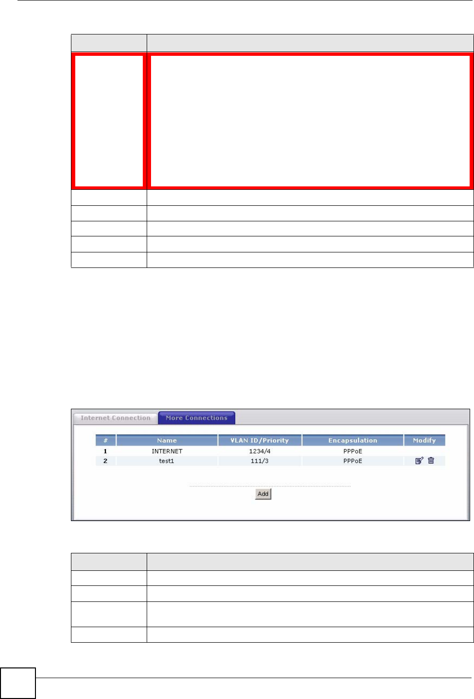
Chapter 5 WAN Setup
P-870HW-51a v2 User’s Guide
58
5.5 The More Connections Screen
The ZyXEL Device allows you to configure more than one Internet access connection. To
configure additional Internet access connections click Network > WAN > More
Connections. The screen differs by the encapsulation you select. When you use the WAN >
Internet Connection screen to set up Internet access, you are configuring the first WAN
connection.
Figure 29 WAN > More Connections
The following table describes the labels in this screen.
VLAN Active Select this option to enable VLAN multiplexing of multiple protocols over a single
virtual circuit. You need to assign a VLAN ID and priority level to traffic through
each WAN connection. All WAN connections share one MAC address. This allows
the backbone switch to classify and service traffic based on the VLAN tag, instead
of the MAC address.
Otherwise, disable VLAN multiplexing and each WAN connection has its own MAC
address.
Note: This field is only configurable for the first WAN connection.
When you change the setting here, all existing WAN
connections will be removed except for the first WAN
connection.
VLAN ID Enter a VLAN ID number for traffic that goes through this connection.
Priority Enter a priority level for traffic that goes through this connection.
Back Click this to return to the previous screen.
Apply Click this to save the changes.
Reset Click this to restore your last-saved settings.
Table 11 WAN > Internet Connection: Advanced Setup (continued)
LABEL DESCRIPTION
Table 12 WAN > More Connections
LABEL DESCRIPTION
# This is an index number indicating the number of the corresponding connection.
Name This is the name you gave to the Internet connection.
VLAN ID/Priority This field shows the VLAN ID number and priority configured for this WAN
connection when VLAN multiplexing is enabled. Otherwise, it shows disable.
Encapsulation This field indicates the encapsulation method of the Internet connection.
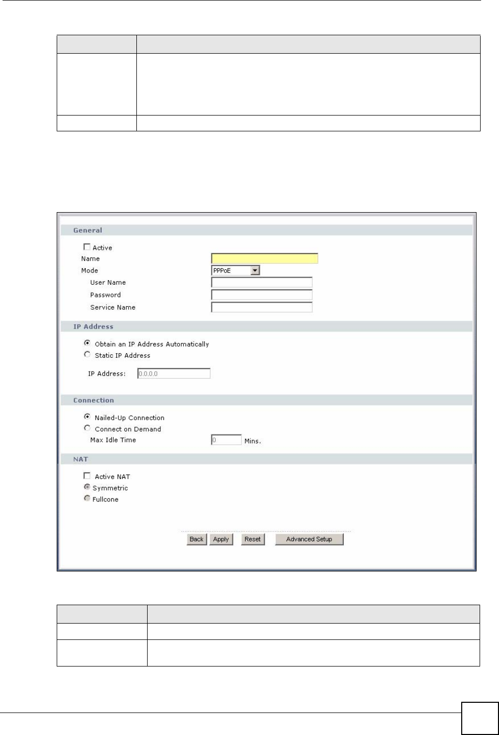
Chapter 5 WAN Setup
P-870HW-51a v2 User’s Guide 59
5.5.1 More Connections Edit
Click the edit icon or Add button in the More Connections screen to configure a connection.
Figure 30 WAN > More Connections: Edit
The following table describes the labels in this screen.
Modify The first (ISP) connection is read-only in this screen. Use the WAN > Internet
Connection screen to edit it.
Click the edit icon to edit the Internet connection settings. Click this icon on an
empty configuration to add a new Internet access setup.
Click the remove icon to delete the Internet access setup from your connection list.
Add Click this to add a new connection.
Table 12 WAN > More Connections (continued)
LABEL DESCRIPTION
Table 13 WAN > More Connections: Edit
LABEL DESCRIPTION
General
Active Select the check box to activate or clear the check box to deactivate this
connection.

Chapter 5 WAN Setup
P-870HW-51a v2 User’s Guide
60
Name Specify a name for this connection. You can use up to 32 letters, numerals and
any printable character found on a typical English language keyboard.
Mode The ZyXEL Device is in routing mode by default. This allows multiple computers
to share an Internet account. Select the method of encapsulation (ENET
ENCAP or PPPoE) used by your ISP from the drop-down list box.
Otherwise, select Bridge when your ISP provides you more than one IP address
and you want the connected computers to get individual IP address from ISP’s
DHCP server directly. If you select Bridge, you cannot use IP filter, DHCP
server and NAT on the ZyXEL Device.
User Name (PPPoE encapsulation only) Enter the user name exactly as your ISP assigned.
If assigned a name in the form user@domain where domain identifies a service
name, then enter both components exactly as given.
Password (PPPoE encapsulation only) Enter the password associated with the user name
above.
Service Name (PPPoE encapsulation only) Type the name of your PPPoE service here.
IP Address A static IP address is a fixed IP that your ISP gives you. A dynamic IP address is
not fixed; the ISP assigns you a different one each time you connect to the
Internet.
Select Obtain an IP Address Automatically if you have a dynamic IP address;
otherwise select Static IP Address and type your ISP assigned IP address in
the IP Address field below.
IP Address Enter the IP address assigned by your ISP if you select Static IP Address.
Subnet Mask Enter a subnet mask in dotted decimal notation when you select ENET ENCAP
in the Mode field.
Gateway IP
address You must specify a gateway IP address (supplied by your ISP) when you select
ENET ENCAP in the Mode field.
Connection
(PPPoE only)
Nailed-Up
Connection Select Nailed-Up Connection when you want your connection up all the time.
The ZyXEL Device will try to bring up the connection automatically if it is
disconnected.
Connect on
Demand Select Connect on Demand when you don't want the connection up all the time
and specify an idle time-out in the Max Idle Time field.
Max Idle Time Specify an idle time-out in the Max Idle Time field when you select Connect on
Demand. The default setting is 0, which means the Internet session will not
timeout.
NAT
Active NAT Select this check box to enable NAT on this connection.
Symmetric Select this option to enable symmetric NAT on this connection.
This field is available only when you select Active NAT.
Fullcone Select this option to enable full cone NAT on this connection.
This field is available only when you select Active NAT.
DNS Servers Select From ISP if your ISP dynamically assigns DNS server information (and
the ZyXEL Device's WAN IP address).
Select Static IP if you have the IP address of a DNS server.
First DNS Server
Second DNS Server
If you select Static IP, enter the DNS server's IP address in the field to the right.
Back Click this to return to the More Connections screen with saving your changes.
Table 13 WAN > More Connections: Edit (continued)
LABEL DESCRIPTION
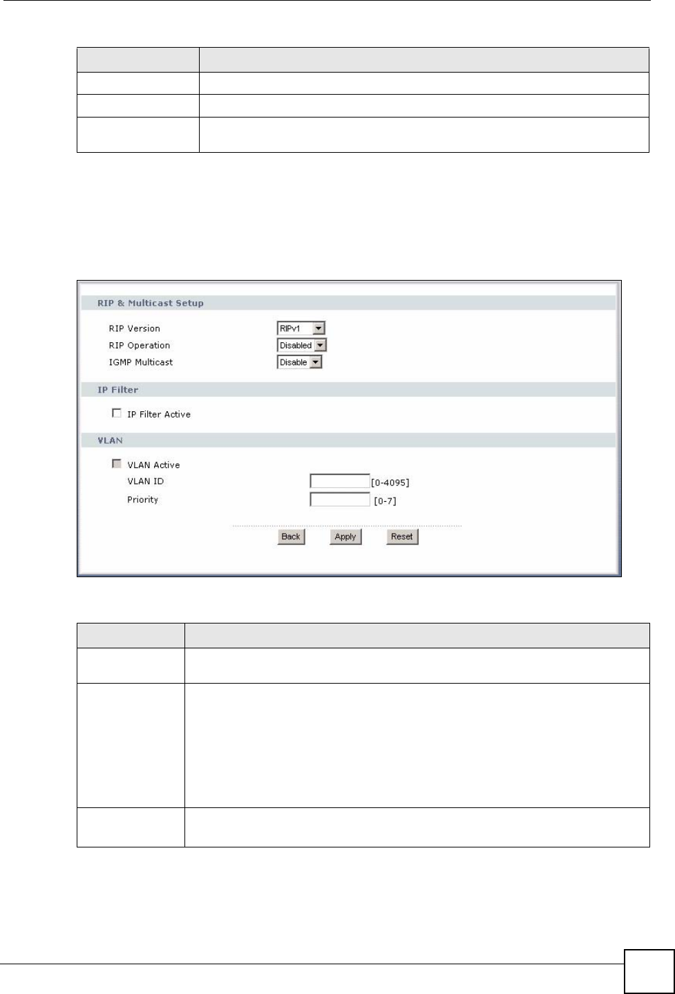
Chapter 5 WAN Setup
P-870HW-51a v2 User’s Guide 61
5.5.2 Configuring More Connections Advanced Setup
To edit your ZyXEL Device's advanced WAN settings, click the Advanced Setup button in
the More Connections Edit screen. The screen appears as shown.
Figure 31 WAN > More Connections: Edit: Advanced Setup
The following table describes the labels in this screen.
Apply Click this to save the changes.
Reset Click this to begin configuring this screen afresh.
Advanced Setup Click this button to display the More Connections Advanced Setup screen and
edit more details of your WAN setup.
Table 13 WAN > More Connections: Edit (continued)
LABEL DESCRIPTION
Table 14 WAN > More Connections: Edit: Advanced Setup
LABEL DESCRIPTION
RIP & Multicast
Setup This section is not available when you configure the ZyXEL Device to be in bridge
mode.
RIP Version RIP (Routing Information Protocol) allows a router to exchange routing information
with other routers. The version field controls the format and the broadcasting
method of the RIP packets that the ZyXEL Device sends (it recognizes both
formats when receiving). RIP-1 is universally supported; but RIP-2 carries more
information. RIP-1 is probably adequate for most networks, unless you have an
unusual network topology
This field is available only when you select ENET ENCAP.
Select the RIP version from RIPv1, RIPv2 and RIPv1v2.
RIP
Operation This field is available only when you select ENET ENCAP.
Select Active to enable RIP. Otherwise, select Disable.
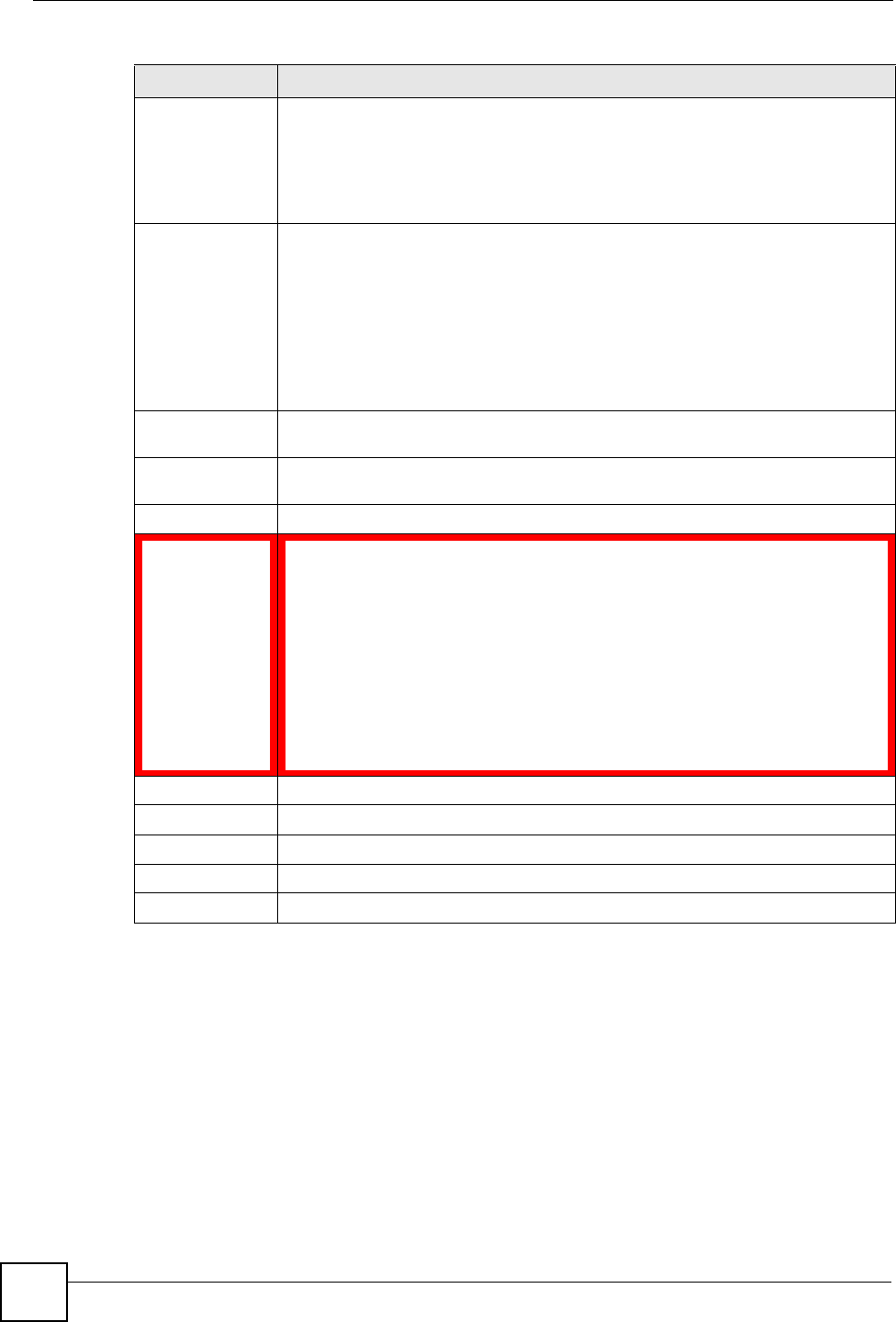
Chapter 5 WAN Setup
P-870HW-51a v2 User’s Guide
62
5.6 Technical Reference
The following section contains additional technical information about the ZyXEL Device
features described in this chapter.
Encapsulation
Be sure to use the encapsulation method required by your ISP. The ZyXEL Device can work in
bridge mode or routing mode. When the ZyXEL Device is in routing mode, it supports the
following methods.
IGMP
Multicast Multicast packets are sent to a group of computers on the LAN and are an
alternative to unicast packets (packets sent to one computer) and broadcast
packets (packets sent to every computer).
IGMP (Internet Group Multicast Protocol) is a network-layer protocol used to
establish membership in a multicast group. The ZyXEL Device supports both IGMP
version 1 and version 2. Select Enable to turn on IGMP. Otherwise, select Disable.
PPPoE
Passthrough
(PPPoE
encapsulation
only)
This field is available when you select PPPoE encapsulation.
In addition to the ZyXEL Device's built-in PPPoE client, you can enable PPPoE
pass through to allow up to ten hosts on the LAN to use PPPoE client software on
their computers to connect to the ISP via the ZyXEL Device. Each host can have a
separate account and a public WAN IP address.
PPPoE pass through is an alternative to NAT for application where NAT is not
appropriate.
Disable PPPoE pass through if you do not need to allow hosts on the LAN to use
PPPoE client software on their computers to connect to the ISP.
IP Filter This section is not available when you configure the ZyXEL Device to be in bridge
mode.
IP Filter
Active Select this option to enable IP filtering on this connection.
VLAN
VLAN Active Select this option to enable VLAN multiplexing of multiple protocols over a single
virtual circuit. You need to assign a VLAN ID and priority level to traffic through
each WAN connection. All WAN connections share one MAC address. This allows
the backbone switch to classify and service traffic based on the VLAN tag.
Otherwise, disable VLAN multiplexing and each WAN connection has its own MAC
address.
Note: This field is only configurable for the first WAN connection.
When you change the setting here, all existing WAN
connections will be removed except for the first WAN
connection.
VLAN ID Enter a VLAN ID number for traffic that goes through this connection.
Priority Enter a priority level for traffic that goes through this connection.
Back Click this to return to the previous screen.
Apply Click this to save the changes.
Reset Click this to restore your last-saved settings.
Table 14 WAN > More Connections: Edit: Advanced Setup (continued)
LABEL DESCRIPTION

Chapter 5 WAN Setup
P-870HW-51a v2 User’s Guide 63
ENET ENCAP
The MAC Encapsulated Routing Link Protocol (ENET ENCAP) is only implemented with the
IP network protocol. IP packets are routed between the Ethernet interface and the WAN
interface and then formatted so that they can be understood in a bridged environment. For
instance, it encapsulates routed Ethernet frames into bridged ATM cells.
PPP over Ethernet
Point-to-Point Protocol over Ethernet (PPPoE) provides access control and billing
functionality in a manner similar to dial-up services using PPP. PPPoE is an IETF standard
(RFC 2516) specifying how a personal computer (PC) interacts with a broadband modem
(DSL, cable, wireless, etc.) connection.
For the service provider, PPPoE offers an access and authentication method that works with
existing access control systems (for example RADIUS).
One of the benefits of PPPoE is the ability to let you access one of multiple network services,
a function known as dynamic service selection. This enables the service provider to easily
create and offer new IP services for individuals.
Operationally, PPPoE saves significant effort for both you and the ISP or carrier, as it requires
no specific configuration of the broadband modem at the customer site.
By implementing PPPoE directly on the ZyXEL Device (rather than individual computers),
the computers on the LAN do not need PPPoE software installed, since the ZyXEL Device
does that part of the task. Furthermore, with NAT, all of the LANs’ computers will have
access.
IP Address Assignment
A static IP is a fixed IP that your ISP gives you. A dynamic IP is not fixed; the ISP assigns you
a different one each time. The Single User Account feature can be enabled or disabled if you
have either a dynamic or static IP. However the encapsulation method assigned influences
your choices for IP address and default gateway.
Full Cone NAT
In full cone NAT, the NAT router maps all outgoing packets from an internal IP address and
port to a single IP address and port on the external network. The NAT router also maps packets
coming to that external IP address and port to the internal IP address and port.
In the following example, the ZyXEL Device maps the source address of all packets sent from
the internal IP address 1 and port A to IP address 2 and port B on the external network. The
ZyXEL Device also performs NAT on all incoming packets sent to IP address 2 and port B and
forwards them to IP address 1, port A.
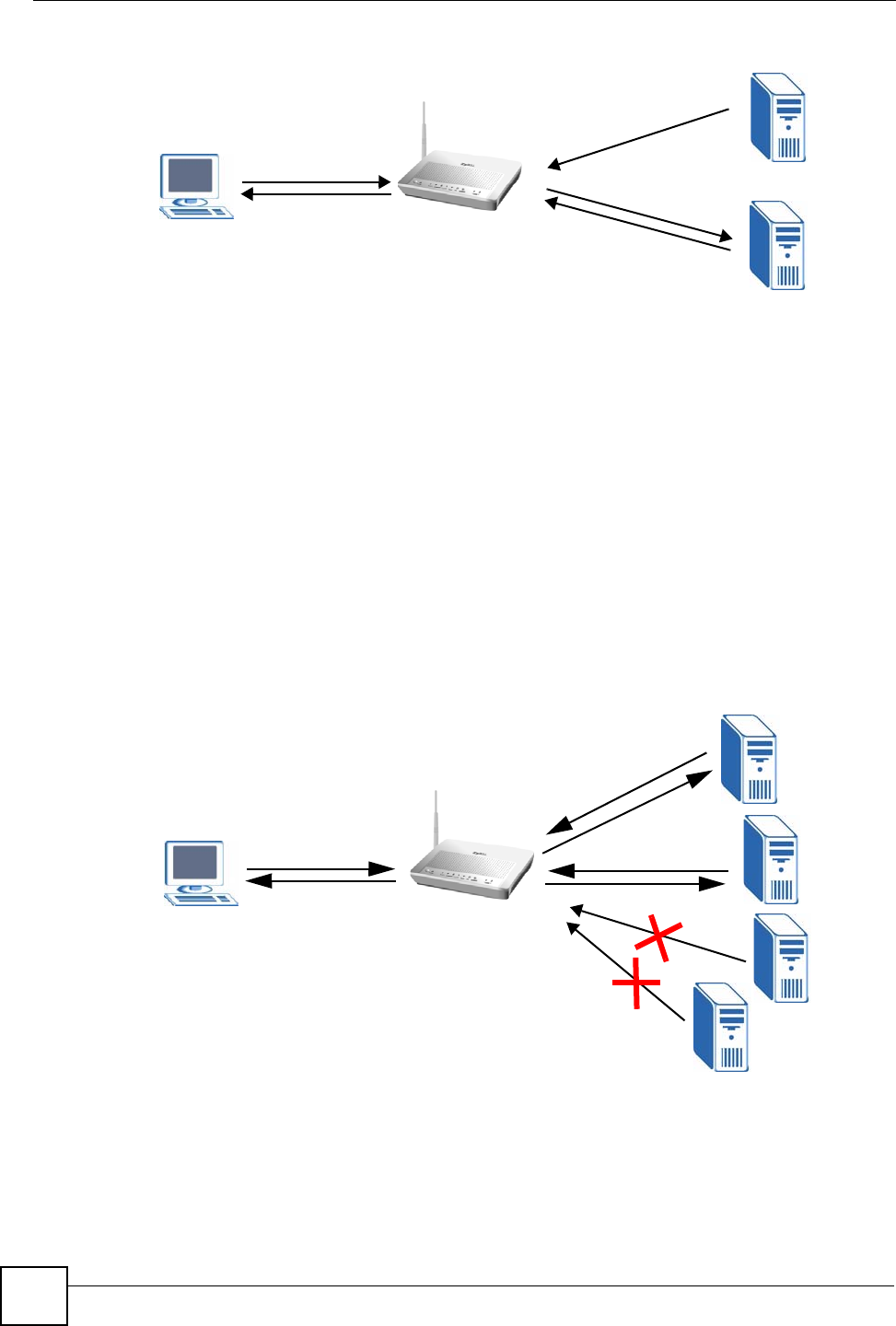
Chapter 5 WAN Setup
P-870HW-51a v2 User’s Guide
64
Figure 32 Full Cone NAT Example
Symmetric NAT
The full, restricted and port restricted cone NAT types use the same mapping for an outgoing
packet’s source address regardless of the destination IP address and port. In symmetric NAT,
the mapping of an outgoing packet’s source address to a source address in another network is
different for each different destination IP address and port.
In the following example, the ZyXEL Device maps the source address IP address 1 and port A
to IP address 2 and port B on the external network for packets sent to IP address 3 and port C.
The ZyXEL Device uses a different mapping (IP address 2 and port M) for packets sent to IP
address 4 and port D.
A host on the external network (IP address 3 and port C for example) can only send packets to
the internal host via the external IP address and port that the NAT router used in sending a
packet to the external host’s IP address and port. So in the example, only 3, C is allowed to
send packets to 2, B and only 4, D is allowed to send packets to 2, M.
Figure 33 Symmetric NAT
Introduction to VLANs
A Virtual Local Area Network (VLAN) allows a physical network to be partitioned into
multiple logical networks. Devices on a logical network belong to one group. A device can
belong to more than one group. With VLAN, a device cannot directly talk to or hear from
devices that are not in the same group(s); the traffic must first go through a router.
2, B
1, A
1, A 2, M
2, B
4, D
4, E
3, C
5, B

Chapter 5 WAN Setup
P-870HW-51a v2 User’s Guide 65
In Multi-Tenant Unit (MTU) applications, VLAN is vital in providing isolation and security
among the subscribers. When properly configured, VLAN prevents one subscriber from
accessing the network resources of another on the same LAN, thus a user will not see the
printers and hard disks of another user in the same building.
VLAN also increases network performance by limiting broadcasts to a smaller and more
manageable logical broadcast domain. In traditional switched environments, all broadcast
packets go to each and every individual port. With VLAN, all broadcasts are confined to a
specific broadcast domain.
Introduction to IEEE 802.1Q Tagged VLAN
A tagged VLAN uses an explicit tag (VLAN ID) in the MAC header to identify the VLAN
membership of a frame across bridges - they are not confined to the switch on which they were
created. The VLANs can be created statically by hand or dynamically through GVRP. The
VLAN ID associates a frame with a specific VLAN and provides the information that switches
need to process the frame across the network. A tagged frame is four bytes longer than an
untagged frame and contains two bytes of TPID (Tag Protocol Identifier), residing within the
type/length field of the Ethernet frame) and two bytes of TCI (Tag Control Information), starts
after the source address field of the Ethernet frame).
The CFI (Canonical Format Indicator) is a single-bit flag, always set to zero for Ethernet
switches. If a frame received at an Ethernet port has a CFI set to 1, then that frame should not
be forwarded as it is to an untagged port. The remaining twelve bits define the VLAN ID,
giving a possible maximum number of 4,096 VLANs. Note that user priority and VLAN ID
are independent of each other. A frame with VID (VLAN Identifier) of null (0) is called a
priority frame, meaning that only the priority level is significant and the default VID of the
ingress port is given as the VID of the frame. Of the 4096 possible VIDs, a VID of 0 is used to
identify priority frames and value 4095 (FFF) is reserved, so the maximum possible VLAN
configurations are 4,094.
Multicast
IP packets are transmitted in either one of two ways - Unicast (1 sender - 1 recipient) or
Broadcast (1 sender - everybody on the network). Multicast delivers IP packets to a group of
hosts on the network - not everybody and not just 1.
Internet Group Multicast Protocol (IGMP) is a network-layer protocol used to establish
membership in a Multicast group - it is not used to carry user data. IGMP version 2 (RFC
2236) is an improvement over version 1 (RFC 1112) but IGMP version 1 is still in wide use. If
you would like to read more detailed information about interoperability between IGMP
version 2 and version 1, please see sections 4 and 5 of RFC 2236. The class D IP address is
used to identify host groups and can be in the range 224.0.0.0 to 239.255.255.255. The address
224.0.0.0 is not assigned to any group and is used by IP multicast computers. The address
224.0.0.1 is used for query messages and is assigned to the permanent group of all IP hosts
(including gateways). All hosts must join the 224.0.0.1 group in order to participate in IGMP.
The address 224.0.0.2 is assigned to the multicast routers group.
At start up, the ZyXEL Device queries all directly connected networks to gather group
membership. After that, the ZyXEL Device periodically updates this information.
TPID
2 Bytes
User Priority
3 Bits
CFI
1 Bit
VLAN ID
12 Bits

Chapter 5 WAN Setup
P-870HW-51a v2 User’s Guide
66
DNS Server Address Assignment
Use Domain Name System (DNS) to map a domain name to its corresponding IP address and
vice versa, for instance, the IP address of www.zyxel.com is 204.217.0.2. The DNS server is
extremely important because without it, you must know the IP address of a computer before
you can access it.
The ZyXEL Device can get the DNS server addresses in the following ways.
1The ISP tells you the DNS server addresses, usually in the form of an information sheet,
when you sign up. If your ISP gives you DNS server addresses, manually enter them in
the DNS server fields.
2If your ISP dynamically assigns the DNS server IP addresses (along with the ZyXEL
Device’s WAN IP address), set the DNS server fields to get the DNS server address from
the ISP.
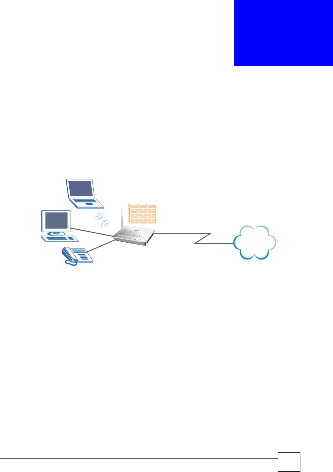
P-870HW-51a v2 User’s Guide 67
CHAPTER 6
LAN Setup
6.1 Overview
A Local Area Network (LAN) is a shared communication system to which many computers
are attached. A LAN is usually located in one immediate area such as a building or floor of a
building.
The LAN screens can help you configure a LAN DHCP server and manage IP addresses.
• See Section 6.7 on page 72 for more information on LANs.
• See Appendix D on page 215 for more information on IP addresses and subnetting.
6.1.1 What You Can Do in this Chapter
•The LAN IP screen lets you set the LAN IP address and subnet mask of your ZyXEL
device and configure the ZyXEL Device’s DHCP settings (Section 6.4 on page 68).
•The Client List screen lets you assign IP addresses on the LAN to specific individual
computers based on their MAC Addresses (Section 6.5 on page 70).
•The IP Alias screen lets you change your ZyXEL Device’s IP alias settings (Section 6.6
on page 70).
6.2 What You Need To Know
IP Address
Similar to the way houses on a street share a common street name, so too do computers on a
LAN share one common network number. This is known as an Internet Protocol address.
Internet
DSL
LAN

Chapter 6 LAN Setup
P-870HW-51a v2 User’s Guide
68
Subnet Mask
The subnet mask specifies the network number portion of an IP address. Your ZyXEL Device
will compute the subnet mask automatically based on the IP address that you entered. You
don't need to change the subnet mask computed by the ZyXEL Device unless you are
instructed to do otherwise.
DHCP
DHCP (Dynamic Host Configuration Protocol) allows clients to obtain TCP/IP configuration
at start-up from a server. This ZyXEL Device has a built-in DHCP server capability that
assigns IP addresses and DNS servers to systems that support DHCP client capability.
RIP
RIP (Routing Information Protocol) allows a router to exchange routing information with
other routers.
Multicast and IGMP
Traditionally, IP packets are transmitted in one of either two ways - Unicast (1 sender - 1
recipient) or Broadcast (1 sender - everybody on the network). Multicast delivers IP packets to
a group of hosts on the network - not everybody and not just 1.
IGMP (Internet Group Multicast Protocol) is a network-layer protocol used to establish
membership in a Multicast group - it is not used to carry user data. There are two versions 1
and 2. IGMP version 2 is an improvement over version 1 but IGMP version 1 is still in wide
use.
DNS
DNS (Domain Name System) maps a domain name to its corresponding IP address and vice
versa. The DNS server is extremely important because without it, you must know the IP
address of a computer before you can access it. The DNS server addresses you enter when you
set up DHCP are passed to the client machines along with the assigned IP address and subnet
mask.
6.3 Before You Begin
Find out the MAC addresses of your network devices if you intend to add them to the DHCP
Client List screen.
6.4 The LAN IP Screen
Click Network > LAN to open the IP screen. See Section 6.7 on page 72 for background
information. Use this screen to set the Local Area Network IP address and subnet mask of your
ZyXEL Device.
Follow these steps to configure your LAN settings.
1Enter an IP address into the IP Address field. The IP address must be in dotted decimal
notation. This will become the IP address of your ZyXEL Device.
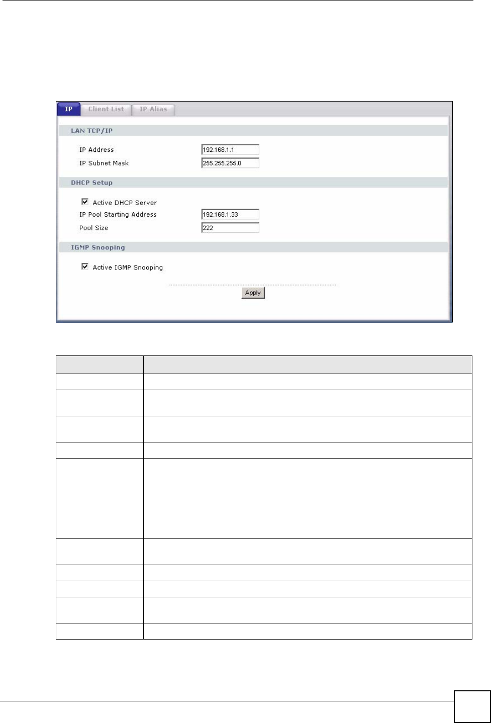
Chapter 6 LAN Setup
P-870HW-51a v2 User’s Guide 69
2Enter the IP subnet mask into the IP Subnet Mask field. Unless instructed otherwise it
is best to leave this alone, the configurator will automatically compute a subnet mask
based upon the IP address you entered.
3Click Apply to save your settings.
Figure 34 LAN > IP
The following table describes the fields in this screen.
Table 15 LAN > IP
LABEL DESCRIPTION
LAN TCP/IP
IP Address Enter the LAN IP address you want to assign to your ZyXEL Device in dotted
decimal notation, for example, 192.168.1.1 (factory default).
IP Subnet Mask Type the subnet mask of your network in dotted decimal notation, for example
255.255.255.0 (factory default).
DHCP Setup
Active DHCP
Server Select this option to have the ZyXEL Device assign IP addresses and provide
subnet mask, gateway, and DNS server information to the network. The ZyXEL
Device is the DHCP server for the network.
Otherwise, deselect this to not have the ZyXEL Device provide any DHCP
services. The DHCP server will be disabled.
When the ZyXEL Device acts as a DHCP server, the following items need to be
set:
IP Pool Starting
Address This field specifies the first of the contiguous addresses in the IP address pool.
Pool Size This field specifies the size, or count of the IP address pool.
IGMP Snooping
Active IGMP
Snooping Select this option to enable IGMP snooping. This allows the ZyXEL Device to
passively learn multicast group.
Apply Click Apply to save your changes back to the ZyXEL Device.
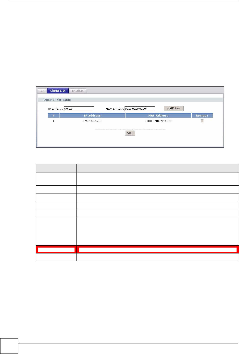
Chapter 6 LAN Setup
P-870HW-51a v2 User’s Guide
70
6.5 The Client List Screen
This table allows you to assign IP addresses on the LAN to specific individual computers
based on their MAC Addresses.
Every Ethernet device has a unique MAC (Media Access Control) address. The MAC address
is assigned at the factory and consists of six pairs of hexadecimal characters, for example,
00:A0:C5:00:00:02.
Click Network > LAN > Client List to open the following screen. Use this screen to change
your ZyXEL Device’s static DHCP settings.
Figure 35 LAN > Client List
The following table describes the labels in this screen.
6.6 The IP Alias Screen
IP alias allows you to partition a physical network into different logical networks over the
same Ethernet interface. The ZyXEL Device supports three logical LAN interfaces via its
single physical Ethernet interface with the ZyXEL Device itself as the gateway for each LAN
network.
When you use IP alias, you can also configure firewall rules to control access between the
LAN's logical networks (subnets).
Table 16 LAN > Client List
LABEL DESCRIPTION
IP Address Enter the IP address that you want to assign to the computer on your LAN with
the MAC address that you will also specify.
MAC Address Enter the MAC address of a computer on your LAN.
Add Entries Click this to add a static DHCP entry.
# This is the index number of the static IP table entry (row).
IP Address This field displays the IP address relative to the # field listed above.
MAC Address The MAC (Media Access Control) or Ethernet address on a LAN (Local Area
Network) is unique to your computer (six pairs of hexadecimal notation).
A network interface card such as an Ethernet adapter has a hardwired address
that is assigned at the factory. This address follows an industry standard that
ensures no other adapter has a similar address.
Remove Click this to delete a static DHCP entry. You cannot delete a dynamic DHCP entry.
Apply Click this to save your changes back to the ZyXEL Device.
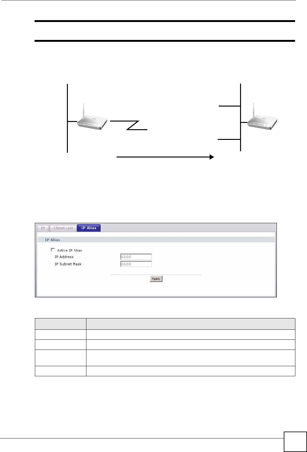
Chapter 6 LAN Setup
P-870HW-51a v2 User’s Guide 71
"Make sure that the subnets of the logical networks do not overlap.
The following figure shows a LAN divided into subnets A and B.
Figure 36 Physical Network & Partitioned Logical Networks
6.6.1 Configuring the LAN IP Alias Screen
Click Network > LAN > IP Alias to open the following screen. Use this screen to change
your ZyXEL Device’s IP alias settings.
Figure 37 Network > LAN > IP Alias
The following table describes the labels in this screen.
Ethernet
Interface
A: 192.168.1.1 - 192.168.1.24
B: 192.168.2.1 - 192.168.2.24
Table 17 Network > LAN > IP Alias
LABEL DESCRIPTION
Active IP Alias Select the check box to configure another LAN network for the ZyXEL Device.
IP Address Enter the IP address of your ZyXEL Device in dotted decimal notation.
IP Subnet Mask Type the subnet mask of your network in dotted decimal notation, for example
255.255.255.0 (factory default).
Apply Click this to save your changes back to the ZyXEL Device.
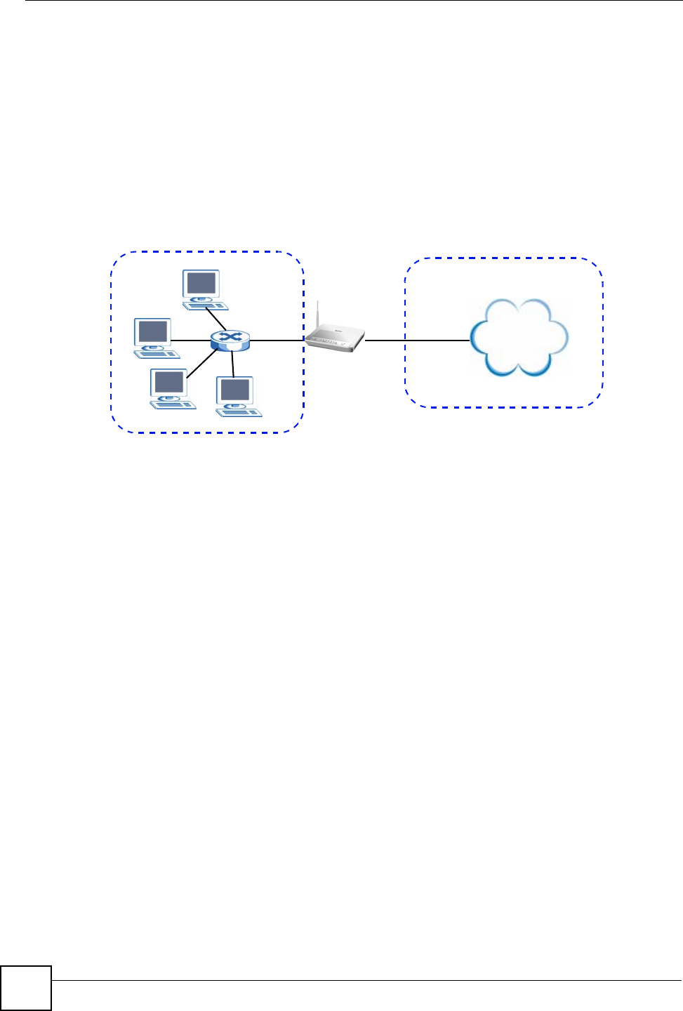
Chapter 6 LAN Setup
P-870HW-51a v2 User’s Guide
72
6.7 Technical Reference
The following section contains additional technical information about the ZyXEL Device
features described in this chapter.
LANs, WANs and the ZyXEL Device
The actual physical connection determines whether the ZyXEL Device ports are LAN or
WAN ports. There are two separate IP networks, one inside the LAN network and the other
outside the WAN network as shown next.
Figure 38 LAN and WAN IP Addresses
DHCP Setup
DHCP (Dynamic Host Configuration Protocol, RFC 2131 and RFC 2132) allows individual
clients to obtain TCP/IP configuration at start-up from a server. You can configure the ZyXEL
Device as a DHCP server or disable it. When configured as a server, the ZyXEL Device
provides the TCP/IP configuration for the clients. If you turn DHCP service off, you must
have another DHCP server on your LAN, or else the computer must be manually configured.
IP Pool Setup
The ZyXEL Device is pre-configured with a pool of IP addresses for the DHCP clients (DHCP
Pool). See the product specifications in the appendices. Do not assign static IP addresses from
the DHCP pool to your LAN computers.
LAN TCP/IP
The ZyXEL Device has built-in DHCP server capability that assigns IP addresses and DNS
servers to systems that support DHCP client capability.
IP Address and Subnet Mask
Similar to the way houses on a street share a common street name, so too do computers on a
LAN share one common network number.
Where you obtain your network number depends on your particular situation. If the ISP or
your network administrator assigns you a block of registered IP addresses, follow their
instructions in selecting the IP addresses and the subnet mask.
Internet
WAN
LAN

Chapter 6 LAN Setup
P-870HW-51a v2 User’s Guide 73
If the ISP did not explicitly give you an IP network number, then most likely you have a single
user account and the ISP will assign you a dynamic IP address when the connection is
established. If this is the case, it is recommended that you select a network number from
192.168.0.0 to 192.168.255.0 and you must enable the Network Address Translation (NAT)
feature of the ZyXEL Device. The Internet Assigned Number Authority (IANA) reserved this
block of addresses specifically for private use; please do not use any other number unless you
are told otherwise. Let's say you select 192.168.1.0 as the network number; which covers 254
individual addresses, from 192.168.1.1 to 192.168.1.254 (zero and 255 are reserved). In other
words, the first three numbers specify the network number while the last number identifies an
individual computer on that network.
Once you have decided on the network number, pick an IP address that is easy to remember,
for instance, 192.168.1.1, for your ZyXEL Device, but make sure that no other device on your
network is using that IP address.
The subnet mask specifies the network number portion of an IP address. Your ZyXEL Device
will compute the subnet mask automatically based on the IP address that you entered. You
don't need to change the subnet mask computed by the ZyXEL Device unless you are
instructed to do otherwise.
Private IP Addresses
Every machine on the Internet must have a unique address. If your networks are isolated from
the Internet, for example, only between your two branch offices, you can assign any IP
addresses to the hosts without problems. However, the Internet Assigned Numbers Authority
(IANA) has reserved the following three blocks of IP addresses specifically for private
networks:
• 10.0.0.0 — 10.255.255.255
• 172.16.0.0 — 172.31.255.255
• 192.168.0.0 — 192.168.255.255
You can obtain your IP address from the IANA, from an ISP or it can be assigned from a
private network. If you belong to a small organization and your Internet access is through an
ISP, the ISP can provide you with the Internet addresses for your local networks. On the other
hand, if you are part of a much larger organization, you should consult your network
administrator for the appropriate IP addresses.
" Regardless of your particular situation, do not create an arbitrary IP address;
always follow the guidelines above. For more information on address
assignment, please refer to RFC 1597, “Address Allocation for Private
Internets” and RFC 1466, “Guidelines for Management of IP Address Space”.
Multicast
Traditionally, IP packets are transmitted in one of either two ways - Unicast (1 sender - 1
recipient) or Broadcast (1 sender - everybody on the network). Multicast delivers IP packets to
a group of hosts on the network - not everybody and not just 1.

Chapter 6 LAN Setup
P-870HW-51a v2 User’s Guide
74
IGMP (Internet Group Multicast Protocol) is a network-layer protocol used to establish
membership in a Multicast group - it is not used to carry user data. IGMP version 2 (RFC
2236) is an improvement over version 1 (RFC 1112) but IGMP version 1 is still in wide use. If
you would like to read more detailed information about interoperability between IGMP
version 2 and version 1, please see sections 4 and 5 of RFC 2236. The class D IP address is
used to identify host groups and can be in the range 224.0.0.0 to 239.255.255.255. The address
224.0.0.0 is not assigned to any group and is used by IP multicast computers. The address
224.0.0.1 is used for query messages and is assigned to the permanent group of all IP hosts
(including gateways). All hosts must join the 224.0.0.1 group in order to participate in IGMP.
The address 224.0.0.2 is assigned to the multicast routers group.
The ZyXEL Device supports both IGMP version 1 (IGMP-v1) and IGMP version 2 (IGMP-
v2). At start up, the ZyXEL Device queries all directly connected networks to gather group
membership. After that, the ZyXEL Device periodically updates this information. IP
multicasting can be enabled/disabled on the ZyXEL Device LAN and/or WAN interfaces in
the web configurator (LAN; WAN). Select None to disable IP multicasting on these
interfaces.

P-870HW-51a v2 User’s Guide 75
CHAPTER 7
Wireless LAN
7.1 Overview
This chapter describes how to perform tasks related to setting up and optimizing your wireless
network, including the following.
• Turning the wireless connection on or off.
• Configuring a name, wireless channel and security for the network.
• Using WiFi Protected Setup (WPS) to configure your wireless network.
• Using a MAC (Media Access Control) address filter to restrict access to the wireless
network.
See Chapter 2 on page 31 for a tutorial showing how to set up your wireless connection in an
example scenario.
See Section 7.9 on page 88 for advanced technical information on wireless networks.
7.1.1 What You Can Do in this Chapter
This chapter describes the ZyXEL Device’s Network > Wireless LAN screens. Use these
screens to set up your ZyXEL Device’s wireless connection.
•The General screen lets you turn the wireless connection on or off, set up wireless
security and make other basic configuration changes (Section 7.4 on page 78).
• Use the WPS screen and the WPS Station screen to use WiFi Protected Setup (WPS).
WPS lets you set up a secure network quickly, when connecting to other WPS-enabled
devices.
Use the WPS screen (see Section 7.5 on page 84) to enable or disable WPS, generate a
security PIN (Personal Identification Number) and see information about the ZyXEL
Device’s WPS status.
Use the WPS Station (see Section 7.6 on page 85) screen to set up WPS by pressing a
button or using a PIN.
•The MAC Filter screen lets you configure the MAC filter to allow or block access to the
ZyXEL Device based on the MAC addresses of the wireless stations (Section 7.7 on page
86).
•The Advanced Setup screen lets you change the wireless mode, and make other advanced
wireless configuration changes (Section 7.8 on page 87).
You don’t necessarily need to use all these screens to set up your wireless connection. For
example, you may just want to set up a network name, a wireless radio channel and some
security in the General screen.

Chapter 7 Wireless LAN
P-870HW-51a v2 User’s Guide
76
7.2 What You Need to Know
Wireless Basics
“Wireless” is essentially radio communication. In the same way that walkie-talkie radios send
and receive information over the airwaves, wireless networking devices exchange information
with one another. A wireless networking device is just like a radio that lets your computer
exchange information with radios attached to other computers. Like walkie-talkies, most
wireless networking devices operate at radio frequency bands that are open to the public and
do not require a license to use. However, wireless networking is different from that of most
traditional radio communications in that there a number of wireless networking standards
available with different methods of data encryption.
Wireless Network Construction
Wireless networks consist of wireless clients, access points and bridges.
• A wireless client is a radio connected to a user’s computer.
• An access point is a radio with a wired connection to a network, which can connect with
numerous wireless clients and let them access the network.
• A bridge is a radio that relays communications between access points and wireless clients,
extending a network’s range.
Traditionally, a wireless network operates in one of two ways.
• An “infrastructure” type of network has one or more access points and one or more
wireless clients. The wireless clients connect to the access points.
• An “ad-hoc” type of network is one in which there is no access point. Wireless clients
connect to one another in order to exchange information.
Network Names
Each network must have a name, referred to as the SSID - “Service Set IDentifier”. The
“service set” is the network, so the “service set identifier” is the network’s name. This helps
you identify your wireless network when wireless networks’ coverage areas overlap and you
have a variety of networks to choose from.
Radio Channels
In the radio spectrum, there are certain frequency bands allocated for unlicensed, civilian use.
For the purposes of wireless networking, these bands are divided into numerous channels. This
allows a variety of networks to exist in the same place without interfering with one another.
When you create a network, you must select a channel to use.
Since the available unlicensed spectrum varies from one country to another, the number of
available channels also varies.

Chapter 7 Wireless LAN
P-870HW-51a v2 User’s Guide 77
Wireless Security
By their nature, radio communications are simple to intercept. For wireless data networks, this
means that anyone within range of a wireless network without security can not only read the
data passing over the airwaves, but also join the network. Once an unauthorized person has
access to the network s/he can either steal information or introduce malware (malicious
software) intended to compromise the network. For these reasons, a variety of security
systems have been developed to ensure that only authorized people can use a wireless data
network, or understand the data carried on it.
These security standards do two things. First, they authenticate. This means that only people
presenting the right credentials (often a username and password, or a “key” phrase) can access
the network. Second, they encrypt. This means that the information sent over the air is
encoded. Only people with the code key can understand the information, and only people who
have been authenticated are given the code key.
These security standards vary in effectiveness. Some can be broken, such as the old Wired
Equivalent Protocol (WEP). Using WEP is better than using no security at all, but it will not
keep a determined attacker out. Other security standards are secure in themselves but can be
broken if a user does not use them properly. For example, the WPA-PSK security standard is
perfectly secure if you use a long key which is difficult for an attacker’s software to guess - for
example, a twenty-letter long string of apparently random numbers and letters - but it is not
very secure if you use a short key which is very easy to guess - for example, a three-letter word
from the dictionary.
Because of the damage that can be done by a malicious attacker, it’s not just people who have
sensitive information on their network who should use security. Everybody who uses any
wireless network should ensure that effective security is in place.
A good way to come up with effective security keys, passwords and so on is to use obscure
information that you personally will easily remember, and to enter it in a way that appears
random and does not include real words. For example, if your mother owns a 1970 Dodge
Challenger and her favorite movie is Vanishing Point (which you know was made in 1971)
you could use “70dodchal71vanpoi” as your security key.
Signal Problems
Because wireless networks are radio networks, their signals are subject to limitations of
distance, interference and absorption.
Problems with distance occur when the two radios are too far apart. Problems with
interference occur when other radio waves interrupt the data signal. Interference may come
from other radio transmissions, such as military or air traffic control communications, or from
machines that are coincidental emitters such as electric motors or microwaves. Problems with
absorption occur when physical objects (such as thick walls) are between the two radios,
muffling the signal.
7.3 Before You Begin
Before you start using these screens, ask yourself the following questions. See Section 7.2 on
page 76 if some of the terms used here do not make sense to you.
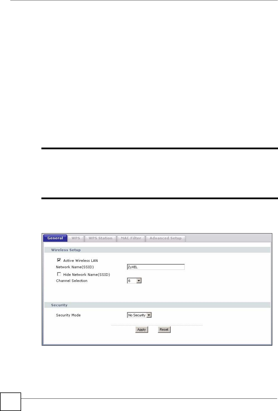
Chapter 7 Wireless LAN
P-870HW-51a v2 User’s Guide
78
• What wireless standards do the other wireless devices support (IEEE 802.11g, for
example)? What is the most appropriate standard to use?
• What security options do the other wireless devices support (WPA-PSK, for example)?
What is the best one to use?
• Do the other wireless devices support WPS (Wi-Fi Protected Setup)? If so, you can set up
a well-secured network very easily.
Even if some of your devices support WPS and some do not, you can use WPS to set up
your network and then add the non-WPS devices manually, although this is somewhat
more complicated to do.
• What advanced options do you want to configure, if any? If you want to configure
advanced options, ensure that you know precisely what you want to do. If you do not want
to configure advanced options, leave them alone.
7.4 The General Screen
"If you are configuring the ZyXEL Device from a computer connected to the
wireless LAN and you change the ZyXEL Device’s SSID or security settings,
you will lose your wireless connection when you press Apply to confirm. You
must then change the wireless settings of your computer to match the ZyXEL
Device’s new settings.
Click Network > Wireless LAN to open the General screen.
Figure 39 Network > Wireless LAN > General

Chapter 7 Wireless LAN
P-870HW-51a v2 User’s Guide 79
The following table describes the labels in this screen.
7.4.1 No Security
Select No Security to allow wireless devices to communicate with the access points without
any data encryption or authentication.
"If you do not enable any wireless security on your ZyXEL Device, your network
is accessible to any wireless networking device that is within range.
Table 18 Network > Wireless LAN > General
LABEL DESCRIPTION
Active Wireless
LAN Click the check box to activate wireless LAN.
Network Name
(SSID) The SSID (Service Set IDentity) identifies the service set with which a wireless device
is associated. Wireless devices associating to the access point (AP) must have the
same SSID. Enter a descriptive name (up to 32 printable 7-bit ASCII characters) for
the wireless LAN.
Note: If you are configuring the ZyXEL Device from a computer
connected to the wireless LAN and you change the ZyXEL
Device’s SSID or WEP settings, you will lose your wireless
connection when you press Apply to confirm. You must then
change the wireless settings of your computer to match the
ZyXEL Device’s new settings.
Hide Network
Name (SSID) Select this check box to hide the SSID in the outgoing beacon frame so a station
cannot obtain the SSID through scanning using a site survey tool.
Channel
Selection Set the operating frequency/channel depending on your particular region.
Select a channel from the drop-down list box.
Security Mode See the following sections for more details about this field.
Apply Click this to save your changes back to the ZyXEL Device.
Reset Click this to reload the previous configuration for this screen.
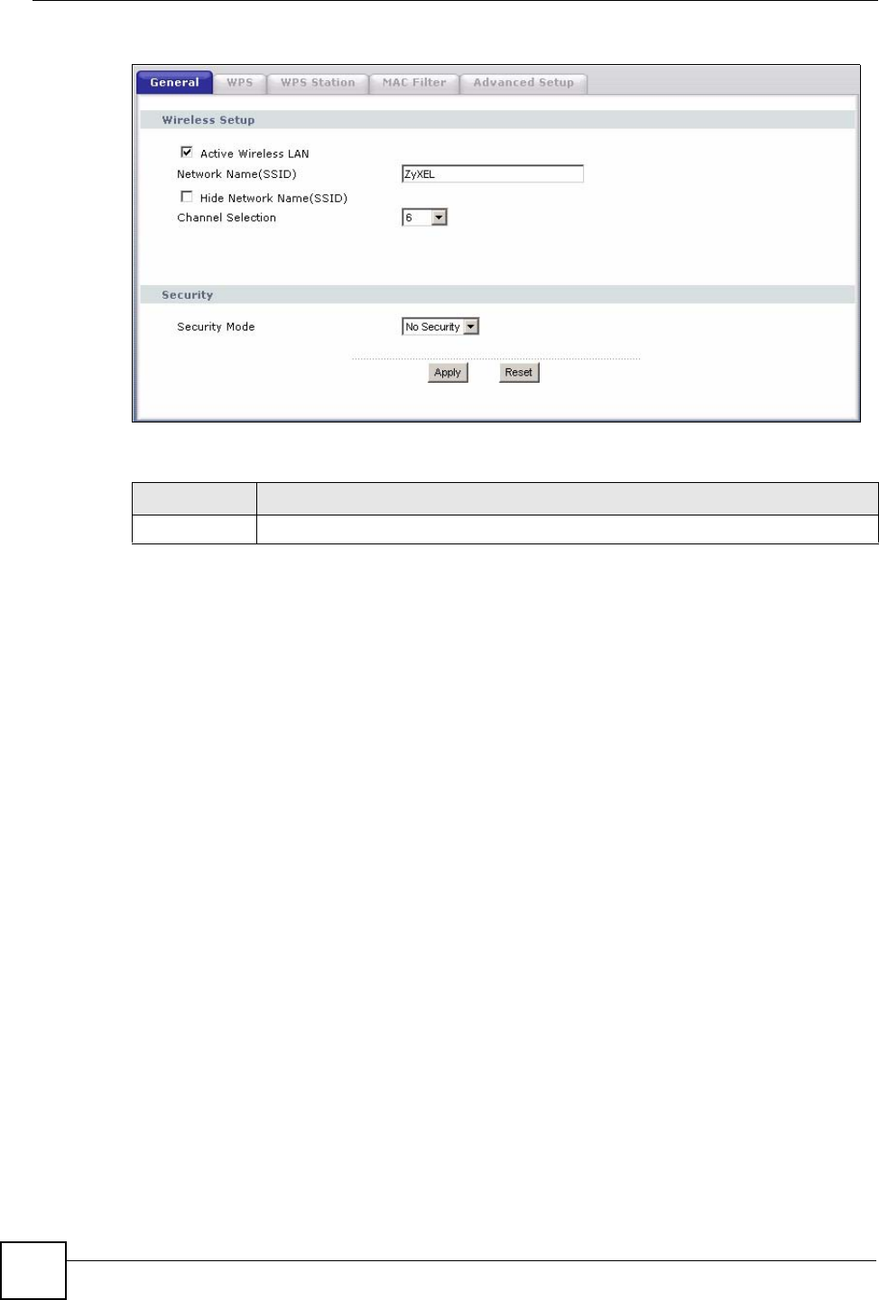
Chapter 7 Wireless LAN
P-870HW-51a v2 User’s Guide
80
Figure 40 Wireless LAN > General: No Security
The following table describes the labels in this screen.
7.4.2 WEP Encryption
In order to configure and enable WEP encryption; click Network > Wireless LAN to display
the General screen. Select WEP from the Security Mode list.
Table 19 Wireless LAN > General: No Security
LABEL DESCRIPTION
Security Mode Choose No Security from the drop-down list box.
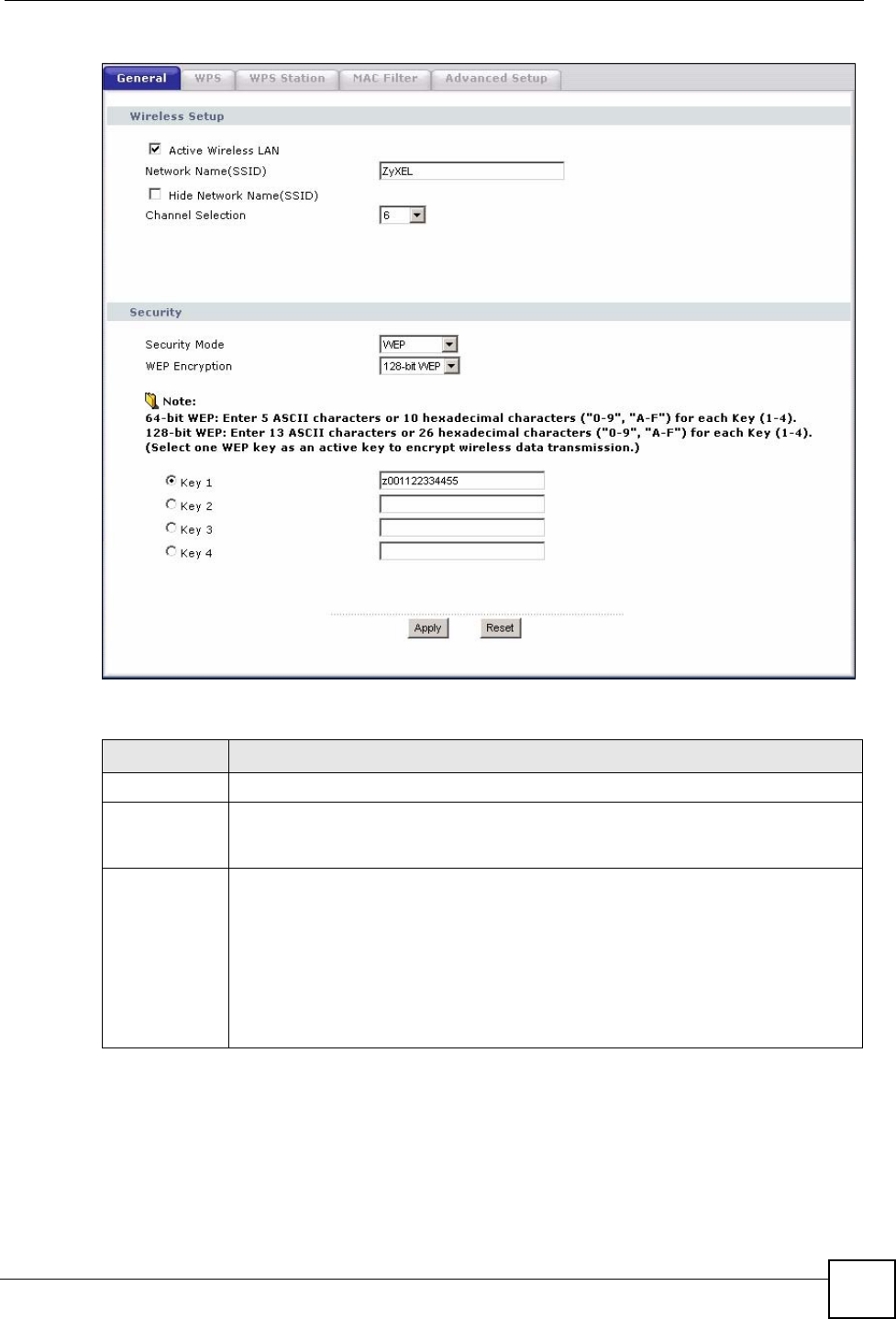
Chapter 7 Wireless LAN
P-870HW-51a v2 User’s Guide 81
Figure 41 Wireless LAN > General: Static WEP Encryption
The following table describes the wireless LAN security labels in this screen.
7.4.3 WPA(2)-PSK
In order to configure and enable WPA(2)-PSK authentication; click Network > Wireless
LAN to display the General screen. Select WPA-PSK or WPA2-PSK from the Security
Mode list.
Table 20 Network > Wireless LAN > General: Static WEP Encryption
LABEL DESCRIPTION
Security Mode Choose Static WEP from the drop-down list box.
WEP
Encryption WEP (Wired Equivalent Privacy) provides data encryption to prevent unauthorized
wireless stations from accessing data transmitted over the wireless network.
Select 64-bit WEP or 128-bit WEP to enable data encryption.
Key 1 to Key 4 If you chose 64-bit WEP in the WEP Encryption field, then enter any 5 characters
(ASCII string) or 10 hexadecimal characters ("0-9", "A-F") preceded by 0x for each
key.
If you chose 128-bit WEP in the WEP Encryption field, then enter 13 characters
(ASCII string) or 26 hexadecimal characters ("0-9", "A-F") preceded by 0x for each
key.
There are four data encryption keys to secure your data from eavesdropping by
unauthorized wireless users. Both the ZyXEL Device and the wireless stations must
use the same WEP key for data transmission.
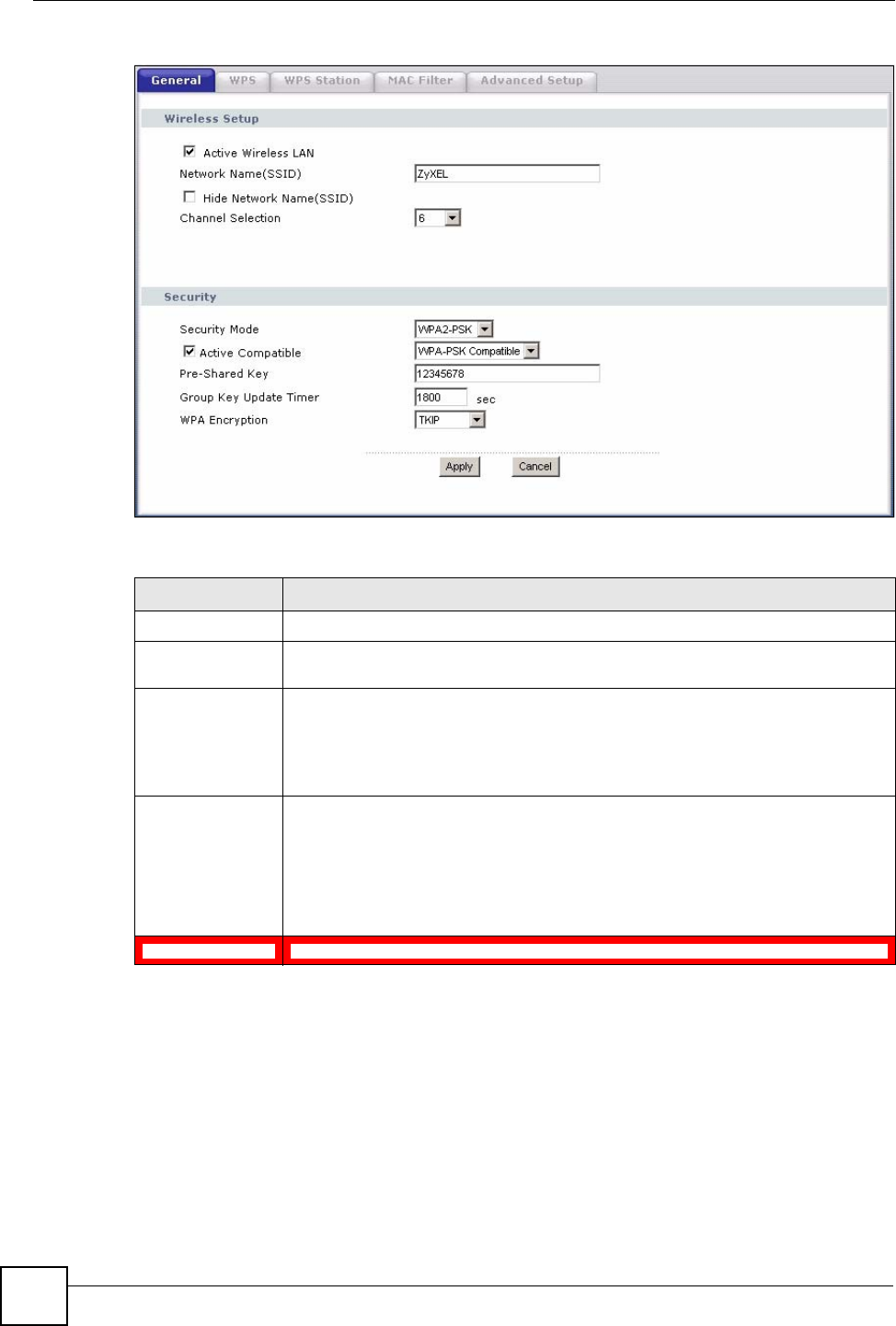
Chapter 7 Wireless LAN
P-870HW-51a v2 User’s Guide
82
Figure 42 Wireless LAN > General: WPA(2)-PSK
The following table describes the wireless LAN security labels in this screen.
7.4.4 WPA(2) Authentication
Use this screen to configure and enable WPA or WPA2 authentication; click the Wireless
LAN link under Network to display the General screen. Select WPA or WPA2 from the
Security Mode list.
Table 21 Wireless LAN > General: WPA(2)-PSK
LABEL DESCRIPTION
Security Mode Choose WPA-PSK or WPA2-PSK from the drop-down list box.
Active Compatible This field is only available for WPA2-PSK. Select this if you want the ZyXEL
Device to support WPA-PSK and WPA2-PSK simultaneously.
Pre-Shared Key The encryption mechanisms used for WPA(2) and WPA(2)-PSK are the same.
The only difference between the two is that WPA(2)-PSK uses a simple common
password, instead of user-specific credentials.
Type a pre-shared key from 8 to 63 case-sensitive ASCII characters (including
spaces and symbols).
(WPA) Group Key
Update Timer The (WPA) Group Key Update Timer is the rate at which the AP (if using
WPA(2)-PSK key management) or RADIUS server (if using WPAWPA(2) key
management) sends a new group key out to all clients. The re-keying process is
the WPA(2) equivalent of automatically changing the WEP key for an AP and all
stations in a WLAN on a periodic basis. Setting of the (WPA) Group Key Update
Timer is also supported in WPA(2)-PSK mode. The ZyXEL Device default is 1800
seconds (30 minutes).
WPA Encryption Select the encryption type (TKIP or AES) for data encryption.
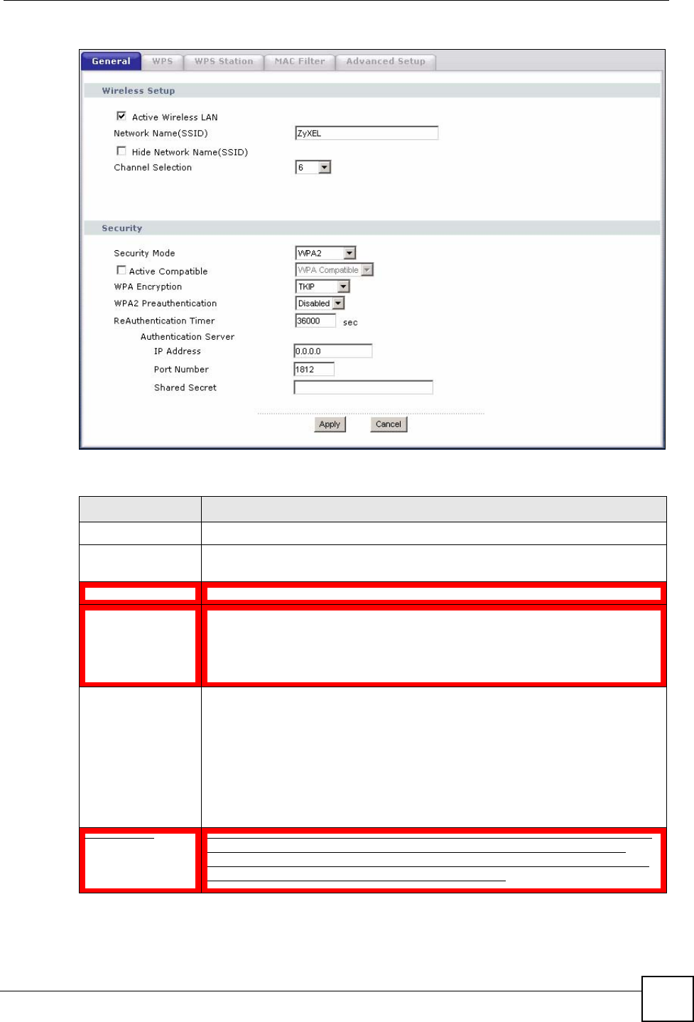
Chapter 7 Wireless LAN
P-870HW-51a v2 User’s Guide 83
Figure 43 Wireless LAN > General: WPA(2)
The following table describes the wireless LAN security labels in this screen.
Table 22 Wireless LAN > General: WPA(2)
LABEL DESCRIPTION
Security Mode Choose WPA or WPA2 from the drop-down list box.
Active Compatible This field is only available for WPA2. Select this if you want the ZyXEL Device to
support WPA and WPA2 simultaneously.
WPA Encryption Select the encryption type (TKIP or AES) for data encryption.
WPA2
Preauthentication This field is available only when you select WPA2.
Pre-authentication enables fast roaming by allowing the wireless client (already
connecting to an AP) to perform IEEE 802.1x authentication with another AP
before connecting to it. Select Enabled to turn on preauthentication in WAP2.
Otherwise, select Disabled.
ReAuthentication
Timer This field is available only when you select WPA2.
Specify how often wireless stations have to resend usernames and passwords in
order to stay connected. Enter a time interval between 10 and 9999 seconds.
The default time interval is 1800 seconds (30 minutes).
Note: If wireless station authentication is done using a RADIUS
server, the reauthentication timer on the RADIUS server
has priority.
Idle Timeout The ZyXEL Device automatically disconnects a wireless station from the wired
network after a period of inactivity. The wireless station needs to enter the
username and password again before access to the wired network is allowed.
The default time interval is 3600 seconds (or 1 hour).
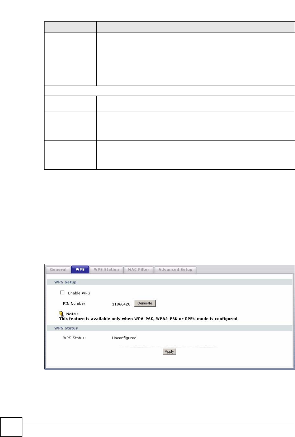
Chapter 7 Wireless LAN
P-870HW-51a v2 User’s Guide
84
7.5 The WPS Screen
Use this screen to configure WiFi Protected Setup (WPS) on your ZyXEL Device.
WPS allows you to quickly set up a wireless network with strong security, without having to
configure security settings manually. Set up each WPS connection between two devices. Both
devices must support WPS.
Click Network > Wireless LAN >WPS. The following screen displays.
Figure 44 Network > Wireless LAN > WPS
Group Key Update
Timer This field is available only when you select WPA.
The Group Key Update Timer is the rate at which the AP (if using WPA(2)-PSK
key management) or RADIUS server (if using WPA(2) key management) sends
a new group key out to all clients. The re-keying process is the WPA(2)
equivalent of automatically changing the WEP key for an AP and all stations in a
WLAN on a periodic basis. Setting of the Group Key Update Timer is also
supported in WPA(2)-PSK mode. The ZyXEL Device default is 1800 seconds (30
minutes).
Authentication Server
IP Address Enter the IP address of the external authentication server in dotted decimal
notation.
Port Number Enter the port number of the external authentication server. The default port
number is 1812.
You need not change this value unless your network administrator instructs you
to do so with additional information.
Shared Secret Enter a password (up to 31 alphanumeric characters) as the key to be shared
between the external authentication server and the ZyXEL Device.
The key must be the same on the external authentication server and your ZyXEL
Device. The key is not sent over the network.
Table 22 Wireless LAN > General: WPA(2)
LABEL DESCRIPTION
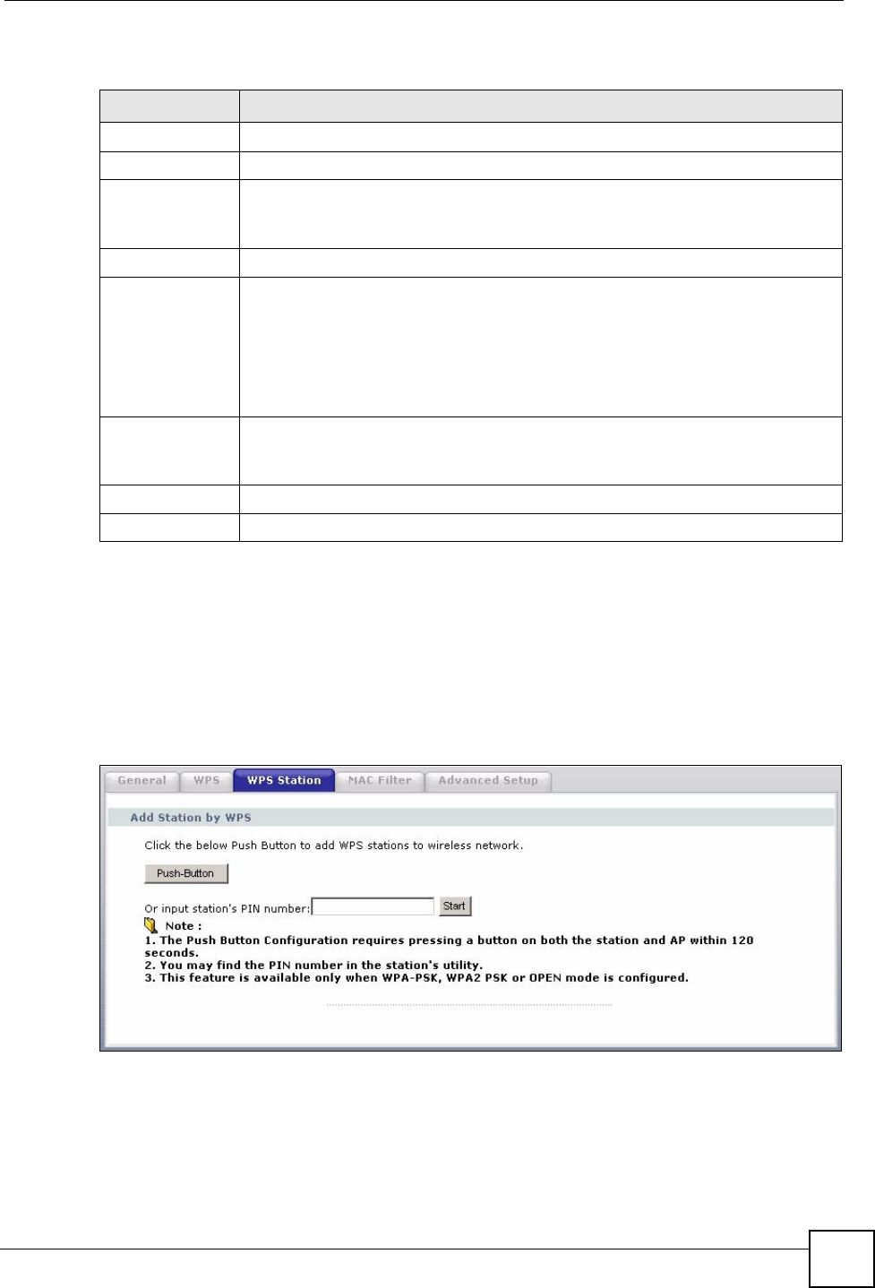
Chapter 7 Wireless LAN
P-870HW-51a v2 User’s Guide 85
The following table describes the labels in this screen.
7.6 The WPS Station Screen
Use this screen to set up a WPS wireless network using either Push Button Configuration
(PBC) or PIN Configuration.
Click Network > Wireless LAN > WPS Station. The following screen displays.
Figure 45 Network > Wireless LAN > WPS Station
Table 23 Network > Wireless LAN > WPS
LABEL DESCRIPTION
WPS Setup
Enable WPS Select the check box to activate WPS on the ZyXEL Device.
PIN Number This shows the PIN (Personal Identification Number) of the ZyXEL Device. Enter
this PIN in the configuration utility of the device you want to connect to using WPS.
The PIN is not necessary when you use WPS push-button method.
Generate Click this button to have the ZyXEL Device create a new PIN.
WPS Status This displays Configured when the ZyXEL Device has connected to a wireless
network using WPS or Enable WPS is selected and wireless or wireless security
settings have been changed. The current wireless and wireless security settings
also appear in the screen.
This displays Unconfigured if WPS is disabled and there is no wireless or wireless
security changes on the ZyXEL Device or you click Release_Configuration to
remove the configured wireless and wireless security settings.
Release_Con
figuration This button is available when the WPS status is Configured.
Click this button to remove all configured wireless and wireless security settings for
WPS connections on the ZyXEL Device.
Apply Click Apply to save your changes back to the ZyXEL Device.
Refresh Click Refresh to reload the previous configuration for this screen.
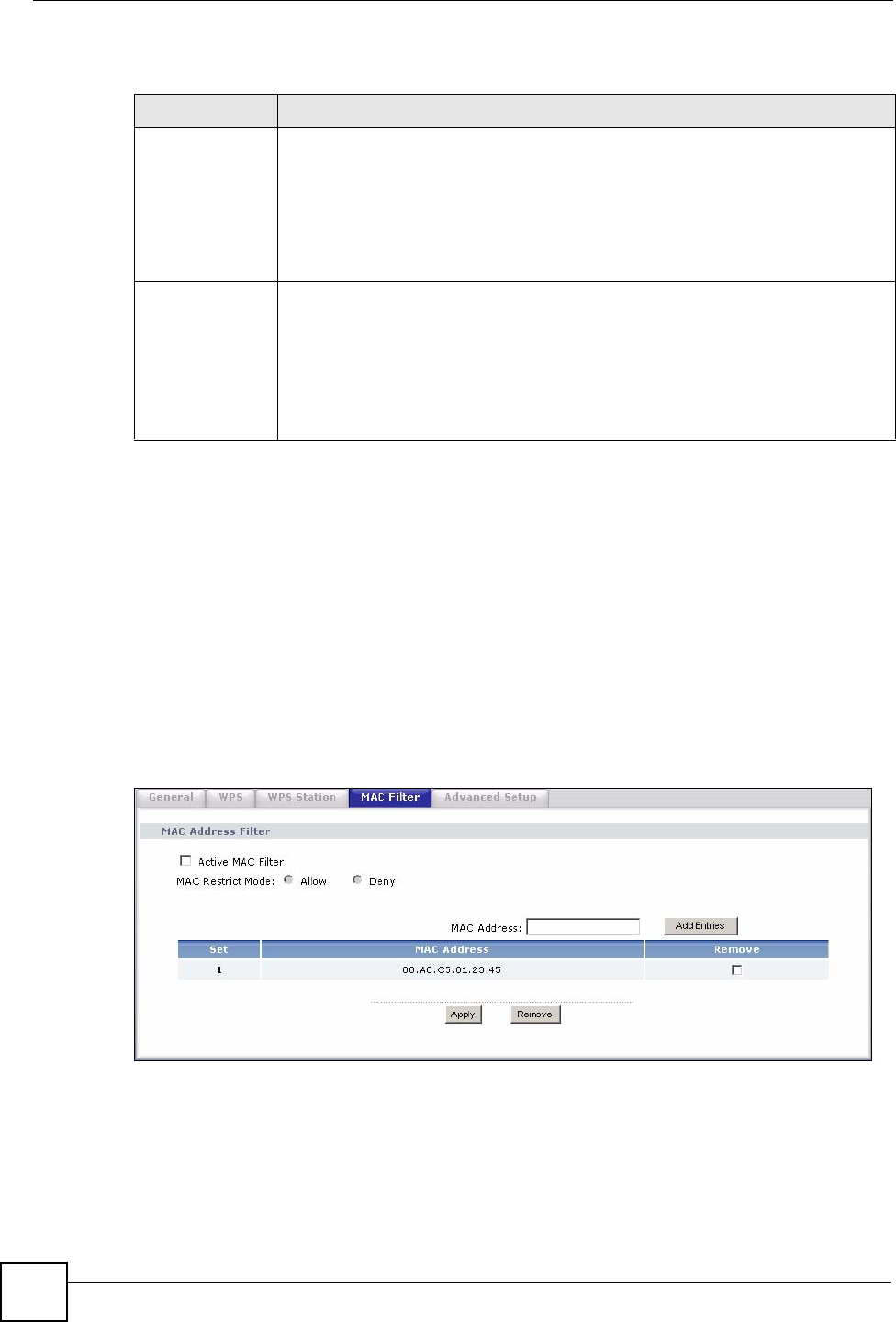
Chapter 7 Wireless LAN
P-870HW-51a v2 User’s Guide
86
The following table describes the labels in this screen.
7.7 The MAC Filter Screen
This screen allows you to configure the ZyXEL Device to give exclusive access to specific
devices (Allow) or exclude specific devices from accessing the ZyXEL Device (Deny). Every
Ethernet device has a unique MAC (Media Access Control) address. The MAC address is
assigned at the factory and consists of six pairs of hexadecimal characters, for example,
00:A0:C5:00:00:02. You need to know the MAC addresses of the devices to configure this
screen.
Use this screen to change your ZyXEL Device’s MAC filter settings.Click Network >
Wireless LAN > MAC Filter. The following screen displays.
Figure 46 Wireless LAN > MAC Filter
Table 24 Network > Wireless LAN > WPS Station
LABEL DESCRIPTION
Push Button Click this button to add another WPS-enabled wireless device (within wireless
range of the ZyXEL Device) to your wireless network. This button may either be a
physical button on the outside of device, or a menu button similar to the Push
Button on this screen.
Note: You must press the other wireless device’s WPS button within
two minutes of pressing this button.
Or input station's
PIN number Enter the PIN of the device that you are setting up a WPS connection with and click
Start to authenticate and add the wireless device to your wireless network.
You can find the PIN either on the outside of the device, or by checking the device’s
settings.
Note: You must also activate WPS on that device within two minutes
to have it present its PIN to the ZyXEL Device.
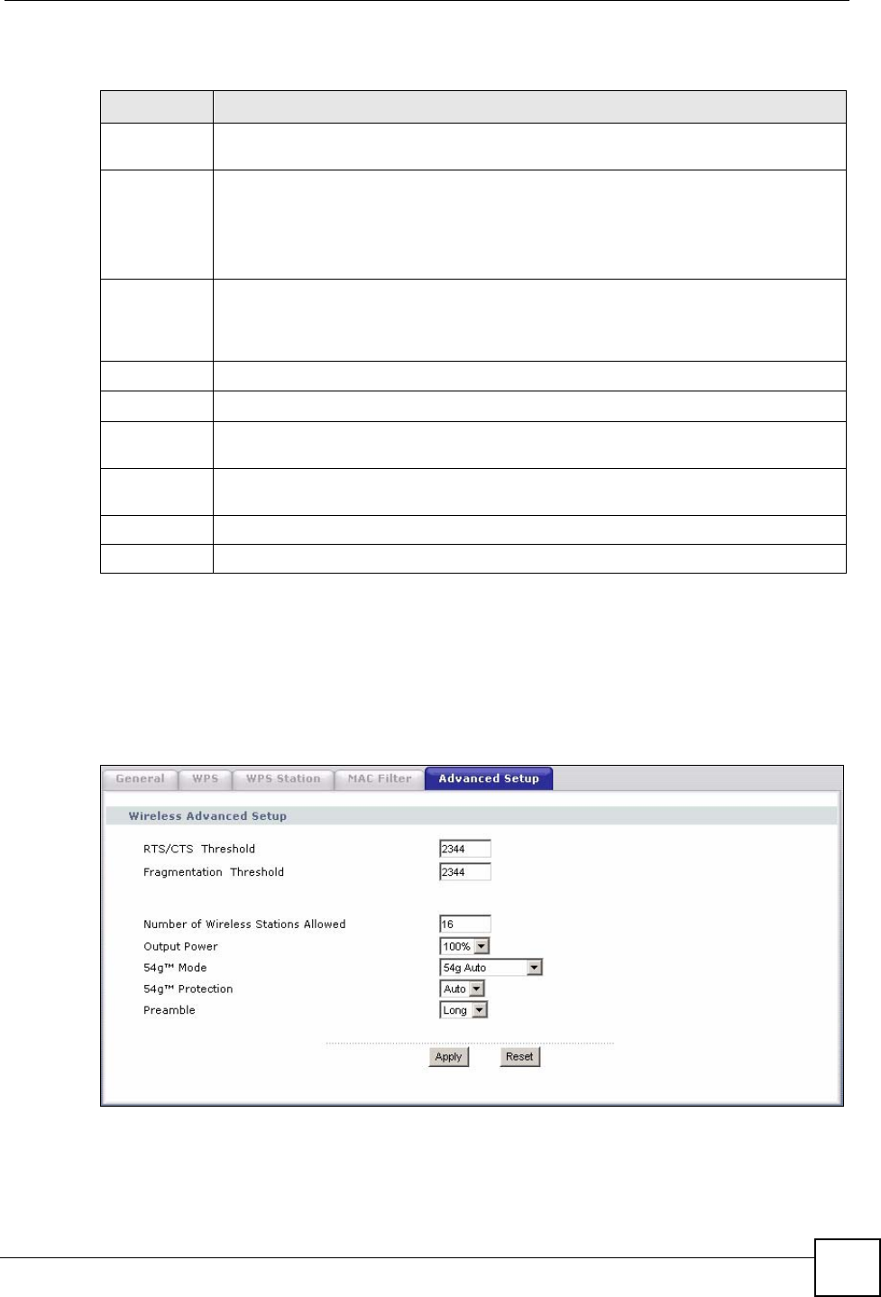
Chapter 7 Wireless LAN
P-870HW-51a v2 User’s Guide 87
The following table describes the labels in this screen.
7.8 The Advanced Setup Screen
To configure advanced wireless settings, click Network > Wireless LAN > Advanced Setup.
The screen appears as shown.
Figure 47 Wireless LAN > Advanced Setup
Table 25 Wireless LAN > MAC Filter
LABEL DESCRIPTION
Active MAC
Filter Select the check box to enable MAC address filtering.
MAC Restrict
Mode
Define the filter action for the list of MAC addresses in the table below.
Select Allow to permit access to the ZyXEL Device, MAC addresses not listed will be
denied access to the ZyXEL Device.
Select Deny to block access to the ZyXEL Device, MAC addresses not listed will be
allowed to access the ZyXEL Device
MAC
Address Enter the MAC addresses of the wireless devices that are allowed or denied access to
the ZyXEL Device in these address fields. Enter the MAC addresses in a valid MAC
address format, that is, six hexadecimal character pairs, for example,
12:34:56:78:9a:bc.
Add Entries Click this to save and insert the entry to the table below.
Set This is the index number of the MAC address.
MAC
Address This is the MAC addresses of the wireless devices that are allowed or denied access to
the ZyXEL Device.
Remove Select the entry(ies) that you want to delete in the Remove column, then click the
Remove button.
Apply Click this to save your changes back to the ZyXEL Device.
Remove Click this to delete the selected entry(ies).
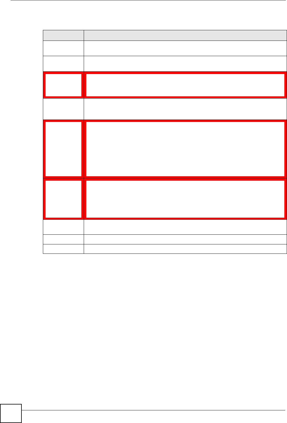
Chapter 7 Wireless LAN
P-870HW-51a v2 User’s Guide
88
The following table describes the labels in this screen.
7.9 Technical Reference
This section discusses wireless LANs in depth. For more information, see the appendix.
7.9.1 Wireless Network Overview
The following figure provides an example of a wireless network.
Table 26 Wireless LAN > Advanced Setup
LABEL DESCRIPTION
RTS/CTS
Threshold Enter a value between 0 and 2432.
Fragmentation
Threshold This is the maximum data fragment size that can be sent. Enter a value between 256
and 2432.
Number of
Wireless
Stations
Allowed
Specify the maximum number of the wireless stations that may connect to the ZyXEL
Device.
Output Power Set the output power of the ZyXEL Device. If there is a high density of APs in an area,
decrease the output power to reduce interference with other APs. Select one of the
following 20%, 40%, 60%, 80% or 100%.
54gTM Mode Select 54g Auto to allow either IEEE 802.11b or IEEE 802.11g compliant WLAN
devices to associate with the ZyXEL Device. The ZyXEL Device adjusts the
transmission rate automatically according to the wireless standard supported by the
wireless devices.
Select 54g Performance to allow only IEEE 802.11b compliant WLAN devices to
associate with the ZyXEL Device.
Select 802.11b Only to allow either IEEE 802.11b or IEEE 802.11g compliant WLAN
devices to associate with the ZyXEL Device. In this mode, all wireless devices can
only transmit at the data rates supported by IEEE 802.11b.
54gTM
Protection Enabling this feature can help prevent collisions in mixed-mode networks (networks
with both IEEE 802.11b and IEEE 802.11g traffic).
Select Auto to have the wireless devices transmit data after a RTS/CTS handshake.
This helps improve IEEE 802.11g performance.
Select Off to disable 54g protection. The transmission rate of your ZyXEL Device
might be reduced in a mixed-mode network.
Preamble Select a preamble type from the drop-down list menu. Choices are Long or Short.
The default setting is Long. See the appendix for more information.
Apply Click this to save your changes back to the ZyXEL Device.
Reset Click this to reload the previous configuration for this screen.
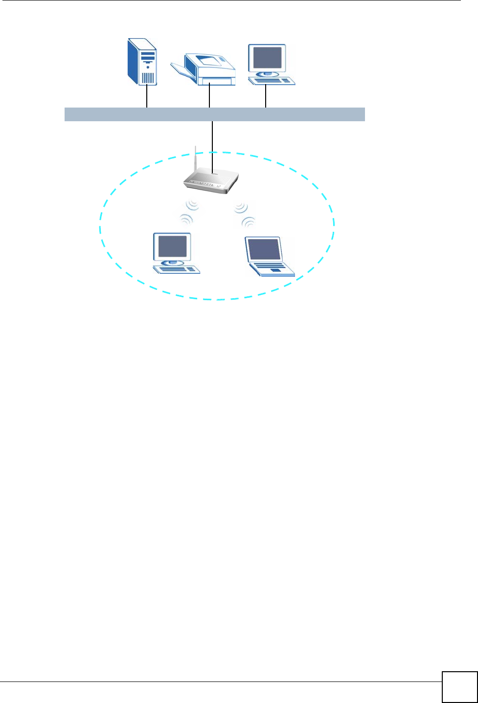
Chapter 7 Wireless LAN
P-870HW-51a v2 User’s Guide 89
Figure 48 Example of a Wireless Network
The wireless network is the part in the blue circle. In this wireless network, devices A and B
use the access point (AP) to interact with the other devices (such as the printer) or with the
Internet. Your ZyXEL Device is the AP.
Every wireless network must follow these basic guidelines.
• Every device in the same wireless network must use the same SSID.
The SSID is the name of the wireless network. It stands for Service Set IDentity.
• If two wireless networks overlap, they should use a different channel.
Like radio stations or television channels, each wireless network uses a specific channel,
or frequency, to send and receive information.
• Every device in the same wireless network must use security compatible with the AP.
Security stops unauthorized devices from using the wireless network. It can also protect
the information that is sent in the wireless network.
AB
AP
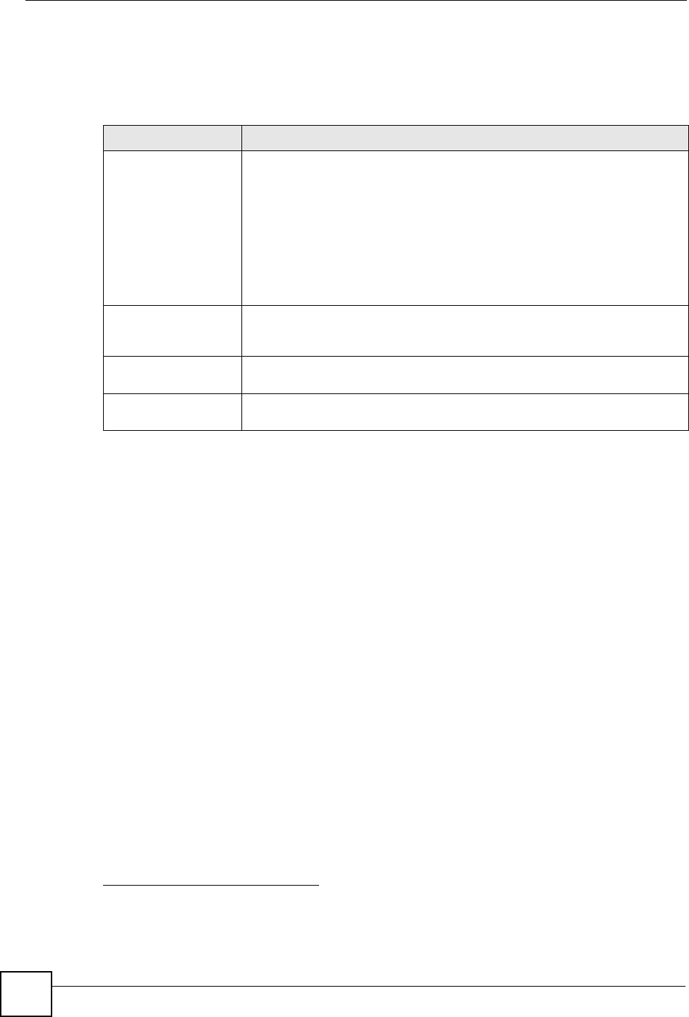
Chapter 7 Wireless LAN
P-870HW-51a v2 User’s Guide
90
7.9.2 Additional Wireless Terms
The following table describes some wireless network terms and acronyms used in the ZyXEL
Device’s Web Configurator.
7.9.3 Wireless Security Overview
The following sections introduce different types of wireless security you can set up in the
wireless network.
7.9.3.1 SSID
Normally, the ZyXEL Device acts like a beacon and regularly broadcasts the SSID in the area.
You can hide the SSID instead, in which case the ZyXEL Device does not broadcast the SSID.
In addition, you should change the default SSID to something that is difficult to guess.
This type of security is fairly weak, however, because there are ways for unauthorized wireless
devices to get the SSID. In addition, unauthorized wireless devices can still see the
information that is sent in the wireless network.
7.9.3.2 MAC Address Filter
Every device that can use a wireless network has a unique identification number, called a
MAC address.1 A MAC address is usually written using twelve hexadecimal characters2; for
example, 00A0C5000002 or 00:A0:C5:00:00:02. To get the MAC address for each device in
the wireless network, see the device’s User’s Guide or other documentation.
You can use the MAC address filter to tell the ZyXEL Device which devices are allowed or
not allowed to use the wireless network. If a device is allowed to use the wireless network, it
still has to have the correct information (SSID, channel, and security). If a device is not
allowed to use the wireless network, it does not matter if it has the correct information.
Table 27 Additional Wireless Terms
TERM DESCRIPTION
RTS/CTS Threshold In a wireless network which covers a large area, wireless devices are
sometimes not aware of each other’s presence. This may cause them to send
information to the AP at the same time and result in information colliding and
not getting through.
By setting this value lower than the default value, the wireless devices must
sometimes get permission to send information to the ZyXEL Device. The
lower the value, the more often the devices must get permission.
If this value is greater than the fragmentation threshold value (see below),
then wireless devices never have to get permission to send information to the
ZyXEL Device.
Preamble A preamble affects the timing in your wireless network. There are two
preamble modes: long and short. If a device uses a different preamble mode
than the ZyXEL Device does, it cannot communicate with the ZyXEL Device.
Authentication The process of verifying whether a wireless device is allowed to use the
wireless network.
Fragmentation
Threshold A small fragmentation threshold is recommended for busy networks, while a
larger threshold provides faster performance if the network is not very busy.
1. Some wireless devices, such as scanners, can detect wireless networks but cannot use wireless networks.
These kinds of wireless devices might not have MAC addresses.
2. Hexadecimal characters are 0, 1, 2, 3, 4, 5, 6, 7, 8, 9, A, B, C, D, E, and F.
Chapter 7 Wireless LAN
P-870HW-51a v2 User’s Guide 91
This type of security does not protect the information that is sent in the wireless network.
Furthermore, there are ways for unauthorized wireless devices to get the MAC address of an
authorized device. Then, they can use that MAC address to use the wireless network.
7.9.3.3 User Authentication
Authentication is the process of verifying whether a wireless device is allowed to use the
wireless network. You can make every user log in to the wireless network before they can use
it. However, every device in the wireless network has to support IEEE 802.1x to do this.
For wireless networks, you can store the user names and passwords for each user in a RADIUS
server. This is a server used in businesses more than in homes. If you do not have a RADIUS
server, you cannot set up user names and passwords for your users.
Unauthorized wireless devices can still see the information that is sent in the wireless network,
even if they cannot use the wireless network. Furthermore, there are ways for unauthorized
wireless users to get a valid user name and password. Then, they can use that user name and
password to use the wireless network.
7.9.3.4 Encryption
Wireless networks can use encryption to protect the information that is sent in the wireless
network. Encryption is like a secret code. If you do not know the secret code, you cannot
understand the message.
The types of encryption you can choose depend on the type of authentication. (See Section
7.9.3.3 on page 91 for information about this.)
For example, if the wireless network has a RADIUS server, you can choose WPA or WPA2. If
users do not log in to the wireless network, you can choose no encryption, Static WEP, WPA-
PSK, or WPA2-PSK.
Usually, you should set up the strongest encryption that every device in the wireless network
supports. For example, suppose you have a wireless network with the ZyXEL Device and you
do not have a RADIUS server. Therefore, there is no authentication. Suppose the wireless
network has two devices. Device A only supports WEP, and device B supports WEP and
WPA. Therefore, you should set up Static WEP in the wireless network.
"It is recommended that wireless networks use WPA-PSK, WPA, or stronger
encryption. The other types of encryption are better than none at all, but it is
still possible for unauthorized wireless devices to figure out the original
information pretty quickly.
Table 28 Types of Encryption for Each Type of Authentication
NO AUTHENTICATION RADIUS SERVER
Weakest No Security
WPA
Static WEP
WPA-PSK
Strongest WPA2-PSK WPA2

Chapter 7 Wireless LAN
P-870HW-51a v2 User’s Guide
92
When you select WPA2 or WPA2-PSK in your ZyXEL Device, you can also select an option
(WPA compatible) to support WPA as well. In this case, if some of the devices support WPA
and some support WPA2, you should set up WPA2-PSK or WPA2 (depending on the type of
wireless network login) and select the WPA compatible option in the ZyXEL Device.
Many types of encryption use a key to protect the information in the wireless network. The
longer the key, the stronger the encryption. Every device in the wireless network must have the
same key.
7.9.4 WiFi Protected Setup
Your ZyXEL Device supports WiFi Protected Setup (WPS), which is an easy way to set up a
secure wireless network. WPS is an industry standard specification, defined by the WiFi
Alliance.
WPS allows you to quickly set up a wireless network with strong security, without having to
configure security settings manually. Each WPS connection works between two devices. Both
devices must support WPS (check each device’s documentation to make sure).
Depending on the devices you have, you can either press a button (on the device itself, or in its
configuration utility) or enter a PIN (a unique Personal Identification Number that allows one
device to authenticate the other) in each of the two devices. When WPS is activated on a
device, it has two minutes to find another device that also has WPS activated. Then, the two
devices connect and set up a secure network by themselves.
7.9.4.1 Push Button Configuration
WPS Push Button Configuration (PBC) is initiated by pressing a button on each WPS-enabled
device, and allowing them to connect automatically. You do not need to enter any information.
Not every WPS-enabled device has a physical WPS button. Some may have a WPS PBC
button in their configuration utilities instead of or in addition to the physical button.
Take the following steps to set up WPS using the button.
1Ensure that the two devices you want to set up are within wireless range of one another.
2Look for a WPS button on each device. If the device does not have one, log into its
configuration utility and locate the button (see the device’s User’s Guide for how to do
this - for the ZyXEL Device, see Section 7.6 on page 85).
3Press the button on one of the devices (it doesn’t matter which). For the ZyXEL Device
you must press the WPS button for more than three seconds.
4Within two minutes, press the button on the other device. The registrar sends the network
name (SSID) and security key through an secure connection to the enrollee.
If you need to make sure that WPS worked, check the list of associated wireless clients in the
AP’s configuration utility. If you see the wireless client in the list, WPS was successful.
7.9.4.2 PIN Configuration
Each WPS-enabled device has its own PIN (Personal Identification Number). This may either
be static (it cannot be changed) or dynamic (in some devices you can generate a new PIN by
clicking on a button in the configuration interface).

Chapter 7 Wireless LAN
P-870HW-51a v2 User’s Guide 93
Use the PIN method instead of the push-button configuration (PBC) method if you want to
ensure that the connection is established between the devices you specify, not just the first two
devices to activate WPS in range of each other. However, you need to log into the
configuration interfaces of both devices to use the PIN method.
When you use the PIN method, you must enter the PIN from one device (usually the wireless
client) into the second device (usually the Access Point or wireless router). Then, when WPS
is activated on the first device, it presents its PIN to the second device. If the PIN matches, one
device sends the network and security information to the other, allowing it to join the network.
Take the following steps to set up a WPS connection between an access point or wireless
router (referred to here as the AP) and a client device using the PIN method.
1Ensure WPS is enabled on both devices.
2Access the WPS section of the AP’s configuration interface. See the device’s User’s
Guide for how to do this.
3Look for the client’s WPS PIN; it will be displayed either on the device, or in the WPS
section of the client’s configuration interface (see the device’s User’s Guide for how to
find the WPS PIN - for the ZyXEL Device, see Section 7.5 on page 84).
4Enter the client’s PIN in the AP’s configuration interface.
"If the client device’s configuration interface has an area for entering another
device’s PIN, you can either enter the client’s PIN in the AP, or enter the AP’s
PIN in the client - it does not matter which.
5Start WPS on both devices within two minutes.
"Use the configuration utility to activate WPS, not the push-button on the device
itself.
6On a computer connected to the wireless client, try to connect to the Internet. If you can
connect, WPS was successful.
If you cannot connect, check the list of associated wireless clients in the AP’s
configuration utility. If you see the wireless client in the list, WPS was successful.
The following figure shows a WPS-enabled wireless client (installed in a notebook computer)
connecting to the WPS-enabled AP via the PIN method.
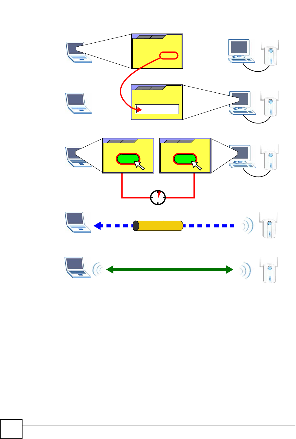
Chapter 7 Wireless LAN
P-870HW-51a v2 User’s Guide
94
Figure 49 Example WPS Process: PIN Method
7.9.4.3 How WPS Works
When two WPS-enabled devices connect, each device must assume a specific role. One device
acts as the registrar (the device that supplies network and security settings) and the other
device acts as the enrollee (the device that receives network and security settings. The registrar
creates a secure EAP (Extensible Authentication Protocol) tunnel and sends the network name
(SSID) and the WPA-PSK or WPA2-PSK pre-shared key to the enrollee. Whether WPA-PSK
or WPA2-PSK is used depends on the standards supported by the devices. If the registrar is
already part of a network, it sends the existing information. If not, it generates the SSID and
WPA(2)-PSK randomly.
The following figure shows a WPS-enabled client (installed in a notebook computer)
connecting to a WPS-enabled access point.
ENROLLEE
SECURE EAP TUNNEL
SSID
WPA(2)-PSK
WITHIN 2 MINUTES
COMMUNICATION
This device’s
WPS
Enter WPS PIN
WPS
from other device:
WPS PIN: 123456
WPS
START
WPS
START
REGISTRAR
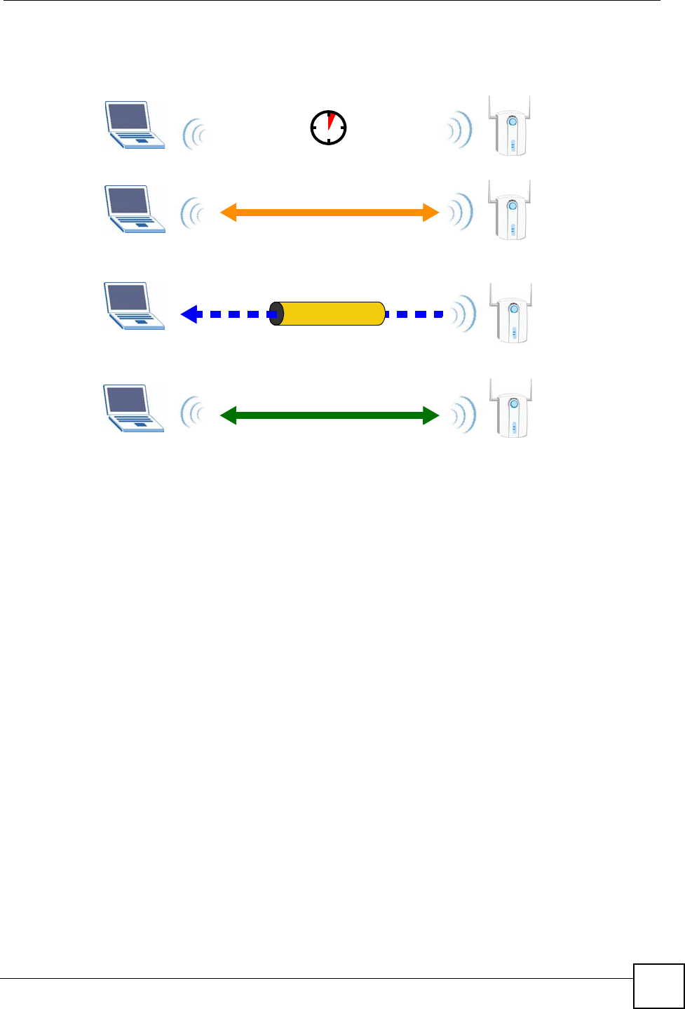
Chapter 7 Wireless LAN
P-870HW-51a v2 User’s Guide 95
Figure 50 How WPS works
The roles of registrar and enrollee last only as long as the WPS setup process is active (two
minutes). The next time you use WPS, a different device can be the registrar if necessary.
The WPS connection process is like a handshake; only two devices participate in each WPS
transaction. If you want to add more devices you should repeat the process with one of the
existing networked devices and the new device.
Note that the access point (AP) is not always the registrar, and the wireless client is not always
the enrollee. All WPS-certified APs can be a registrar, and so can some WPS-enabled wireless
clients.
By default, a WPS devices is “unconfigured”. This means that it is not part of an existing
network and can act as either enrollee or registrar (if it supports both functions). If the registrar
is unconfigured, the security settings it transmits to the enrollee are randomly-generated. Once
a WPS-enabled device has connected to another device using WPS, it becomes “configured”.
A configured wireless client can still act as enrollee or registrar in subsequent WPS
connections, but a configured access point can no longer act as enrollee. It will be the registrar
in all subsequent WPS connections in which it is involved. If you want a configured AP to act
as an enrollee, you must reset it to its factory defaults.
7.9.4.4 Example WPS Network Setup
This section shows how security settings are distributed in an example WPS setup.
The following figure shows an example network. In step 1, both AP1 and Client 1 are
unconfigured. When WPS is activated on both, they perform the handshake. In this example,
AP1 is the registrar, and Client 1 is the enrollee. The registrar randomly generates the security
information to set up the network, since it is unconfigured and has no existing information.
SECURE TUNNEL
SECURITY INFO
WITHIN 2 MINUTES
COMMUNICATION
ACTIVATE
WPS
ACTIVATE
WPS
WPS HANDSHAKE
REGISTRARENROLLEE
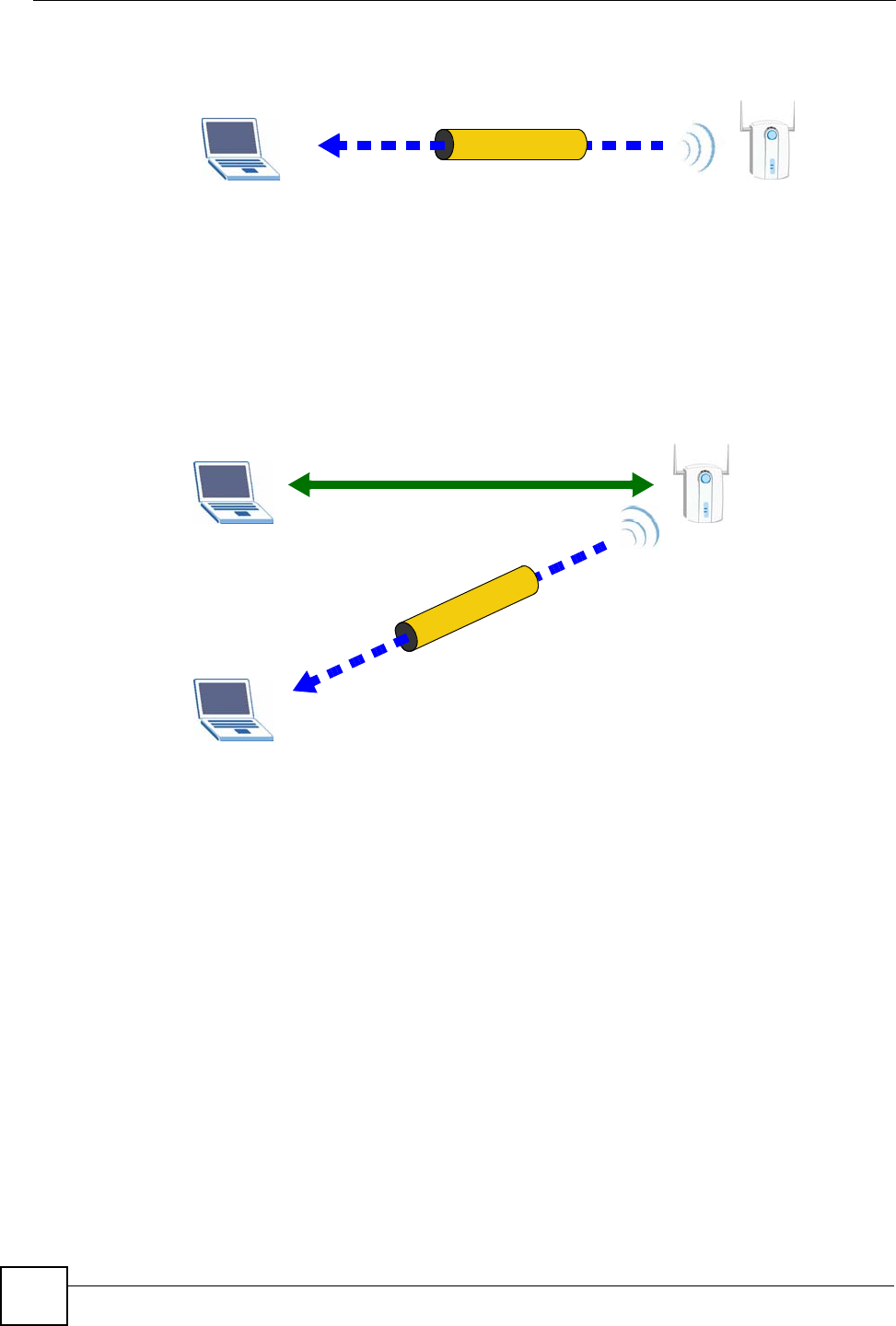
Chapter 7 Wireless LAN
P-870HW-51a v2 User’s Guide
96
Figure 51 WPS: Example Network Step 1
In step 2, you add another wireless client to the network. You know that Client 1 supports
registrar mode, but it is better to use AP1 for the WPS handshake with the new client since
you must connect to the access point anyway in order to use the network. In this case, AP1
must be the registrar, since it is configured (it already has security information for the
network). AP1 supplies the existing security information to Client 2.
Figure 52 WPS: Example Network Step 2
In step 3, you add another access point (AP2) to your network. AP2 is out of range of AP1, so
you cannot use AP1 for the WPS handshake with the new access point. However, you know
that Client 2 supports the registrar function, so you use it to perform the WPS handshake
instead.
REGISTRARENROLLEE
SECURITY INFO
CLIENT 1 AP1
REGISTRAR
CLIENT 1 AP1
ENROLLEE
CLIENT 2
EXISTING CONNECTION
SECURITY INFO
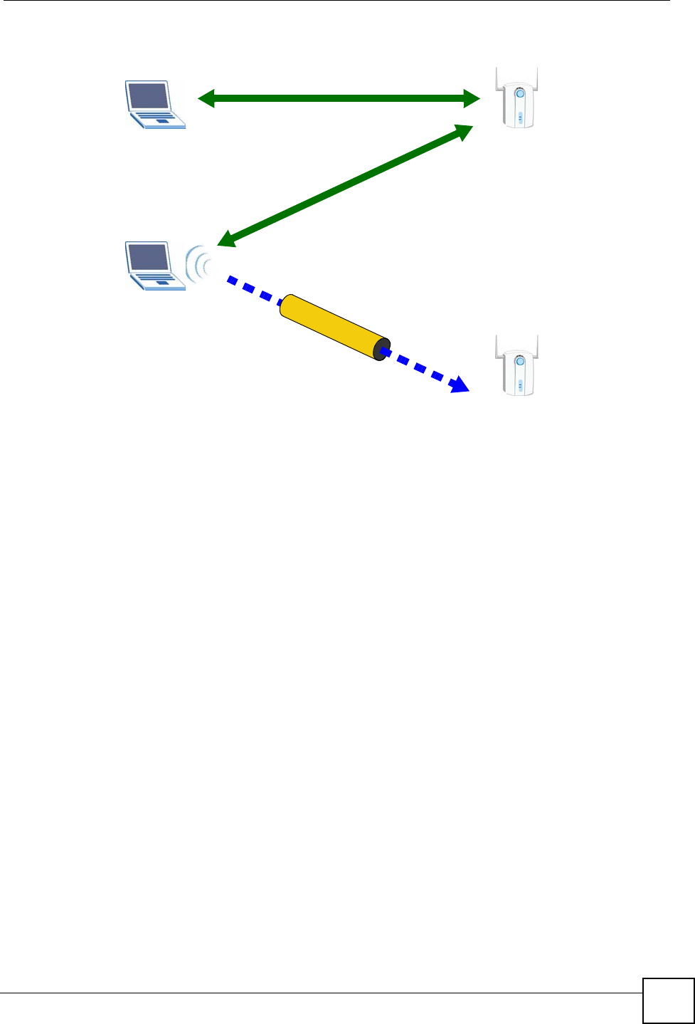
Chapter 7 Wireless LAN
P-870HW-51a v2 User’s Guide 97
Figure 53 WPS: Example Network Step 3
7.9.4.5 Limitations of WPS
WPS has some limitations of which you should be aware.
• WPS works in Infrastructure networks only (where an AP and a wireless client
communicate). It does not work in Ad-Hoc networks (where there is no AP).
• When you use WPS, it works between two devices only. You cannot enroll multiple
devices simultaneously, you must enroll one after the other.
For instance, if you have two enrollees and one registrar you must set up the first enrollee
(by pressing the WPS button on the registrar and the first enrollee, for example), then
check that it successfully enrolled, then set up the second device in the same way.
• WPS works only with other WPS-enabled devices. However, you can still add non-WPS
devices to a network you already set up using WPS.
WPS works by automatically issuing a randomly-generated WPA-PSK or WPA2-PSK
pre-shared key from the registrar device to the enrollee devices. Whether the network uses
WPA-PSK or WPA2-PSK depends on the device. You can check the configuration
interface of the registrar device to discover the key the network is using (if the device
supports this feature). Then, you can enter the key into the non-WPS device and join the
network as normal (the non-WPS device must also support WPA-PSK or WPA2-PSK).
• When you use the PBC method, there is a short period (from the moment you press the
button on one device to the moment you press the button on the other device) when any
WPS-enabled device could join the network. This is because the registrar has no way of
identifying the “correct” enrollee, and cannot differentiate between your enrollee and a
rogue device. This is a possible way for a hacker to gain access to a network.
CLIENT 1 AP1
REGISTRAR
CLIENT 2
EXISTING CONNECTION
SECURITY INFO
ENROLLEE
AP2
EXISTING CONNECTION

Chapter 7 Wireless LAN
P-870HW-51a v2 User’s Guide
98
You can easily check to see if this has happened. WPS works between only two devices
simultaneously, so if another device has enrolled your device will be unable to enroll, and
will not have access to the network. If this happens, open the access point’s configuration
interface and look at the list of associated clients (usually displayed by MAC address). It
does not matter if the access point is the WPS registrar, the enrollee, or was not involved
in the WPS handshake; a rogue device must still associate with the access point to gain
access to the network. Check the MAC addresses of your wireless clients (usually printed
on a label on the bottom of the device). If there is an unknown MAC address you can
remove it or reset the AP.

P-870HW-51a v2 User’s Guide 99
CHAPTER 8
Network Address Translation
(NAT)
8.1 Overview
This chapter discusses how to configure NAT on the ZyXEL Device.
Network Address Translation (NAT, RFC 1631) is the translation of the IP address of a host in
a packet, for example, the source address of an outgoing packet, used within one network to a
different IP address known within another network.
8.1.1 What You Can Do in this Chapter
The Port Forwarding screen lets you configure forward incoming service requests to the
server(s) on your local network (Section 8.3 on page 99).
8.2 What You Need to Know
The following terms and concepts may help as you read through this chapter.
NAT
In the simplest form, NAT changes the source IP address in a packet received from a
subscriber (the inside local address) to another (the inside global address) before forwarding
the packet to the WAN side. When the response comes back, NAT translates the destination
address (the inside global address) back to the inside local address before forwarding it to the
original inside host.
Port Forwarding
A port forwarding set is a list of inside (behind NAT on the LAN) servers, for example, web or
FTP, that you can make visible to the outside world even though NAT makes your whole
inside network appear as a single computer to the outside world.
8.3 The Port Forwarding Screen
This summary screen provides a summary of all port forwarding rules and their configuration.
In addition, this screen allows you to create new port forwarding rules and delete existing
rules.
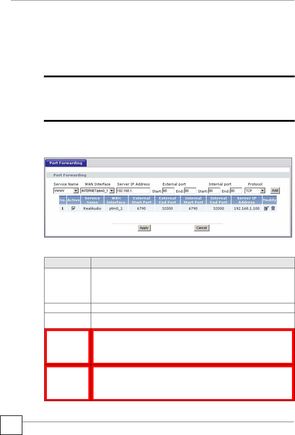
Chapter 8 Network Address Translation (NAT)
P-870HW-51a v2 User’s Guide
100
You may enter a single port number or a range of port numbers to be forwarded, and the local
IP address of the desired server. The port number identifies a service; for example, web service
is on port 80 and FTP on port 21. In some cases, such as for unknown services or where one
server can support more than one service (for example both FTP and web service), it might be
better to specify a range of port numbers. You can allocate a server IP address that corresponds
to a port or a range of ports.
"Many residential broadband ISP accounts do not allow you to run any server
processes (such as a Web or FTP server) from your location. Your ISP may
periodically check for servers and may suspend your account if it discovers
any active services at your location. If you are unsure, refer to your ISP.
To access this screen, click Network > NAT. The following screen appears.
Figure 54 NAT Port Forwarding
The following table describes the labels in this screen.
Table 29 NAT Port Forwarding
LABEL DESCRIPTION
Service Name Select a pre-defined service from the drop-down list box. The pre-defined service
port number(s) and protocol will display in the External port, Internal port and
Protocol fields.
Otherwise, select User Define to open the Rule Setup screen where you can
manually enter the port number(s) and select the IP protocol.
WAN Interface Select the WAN interface through which the service is forwarded.
Server IP
Address Enter the IP address of the server for the specified service.
External Port
Start Enter the original destination port for the packets.
To forward only one port, enter the port number again in the External Port End
field.
To forward a series of ports, enter the start port number here and the end port
number in the External Port End field.
External Port
End Enter the last port of the original destination port range.
To forward only one port, enter the port number in the External Port Start field
above and then enter it again in this field.
To forward a series of ports, enter the last port number in a series that begins with
the port number in the External Port Start field above.

Chapter 8 Network Address Translation (NAT)
P-870HW-51a v2 User’s Guide 101
8.3.1 The Port Forwarding Edit Screen
This screen lets you create or edit a port forwarding rule. Select User Define in the Service
Name field or click the rule’s edit icon in the Port Forwarding screen to open the following
screen.
Protocol This is the IP protocol.
Internal Port
Start Enter the port number to which you want the ZyXEL Device to translate the
incoming port.
To forward only one port, enter the port number again in the Internal Port End
field.
For a range of ports, enter the first number of the range to which you want the
incoming ports translated.
Internal Port End Enter the last port of the translated port range.
Add Click this button to add a rule to the table below.
No. This is the rule index number (read-only).
Active This field indicates whether the rule is active or not.
Clear the check box to disable the rule. Select the check box to enable it.
Server Name This field displays the name of the service used by the packets for this virtual
server.
WAN Interface This field shows the WAN interface through which the service is forwarded.
External Port
Start This is the first external port number that identifies a service.
External Port
End This is the last external port number that identifies a service.
Internal Port
Start This is the first internal port number that identifies a service.
Internal Port End This is the last internal port number that identifies a service.
Server IP
Address This field displays the destination IP address for the packet.
Modify Click the edit icon to go to the screen where you can edit the port forwarding rule.
Click the remove icon to delete an existing port forwarding rule. Note that
subsequent rules move up by one when you take this action.
Apply Click Apply to save your changes back to the ZyXEL Device.
Cancel Click Cancel to return to the previous configuration.
Table 29 NAT Port Forwarding (continued)
LABEL DESCRIPTION
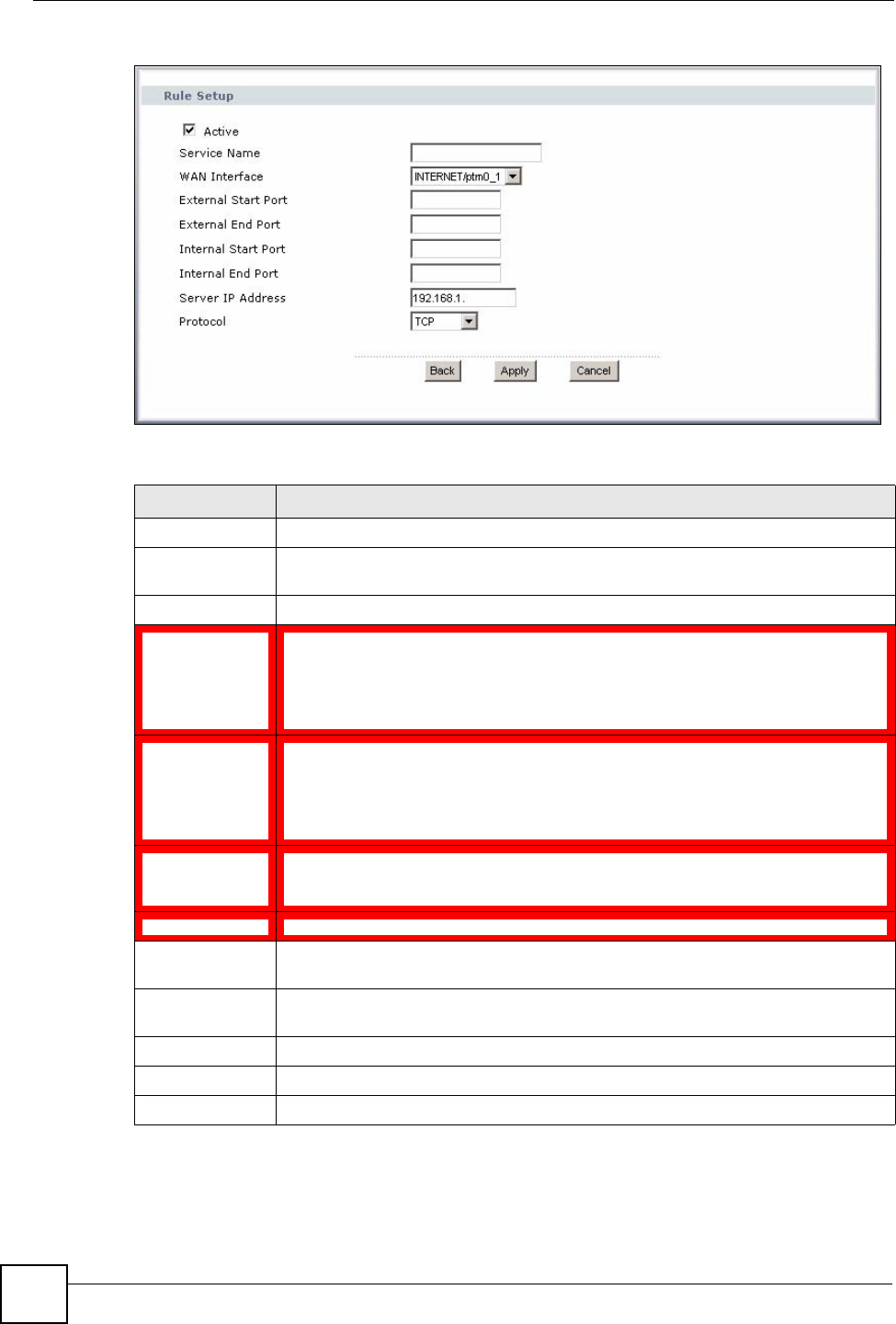
Chapter 8 Network Address Translation (NAT)
P-870HW-51a v2 User’s Guide
102
Figure 55 Port Forwarding Edit
The following table describes the labels in this screen.
Table 30 Port Forwarding Edit
LABEL DESCRIPTION
Active Clear the check box to disable the rule. Select the check box to enable it.
Service Name Enter a name to identify this rule. This field is read-only if you click the edit icon in
the Port Forwarding screen.
WAN Interface Select a WAN interface for which you want to configure port forwarding rules.
External Start
Port Enter the original destination port for the packets.
To forward only one port, enter the port number again in the External End Port
field.
To forward a series of ports, enter the start port number here and the end port
number in the External End Port field.
External End
Port Enter the last port of the original destination port range.
To forward only one port, enter the port number in the External Start Port field
above and then enter it again in this field.
To forward a series of ports, enter the last port number in a series that begins with
the port number in the External Start Port field above.
Internal Start
Port Enter the port number here to which you want the ZyXEL Device to translate the
incoming port. For a range of ports, enter the first number of the range to which you
want the incoming ports translated.
Internal End Port Enter the last port of the translated port range.
Server IP
Address Enter the inside IP address of the virtual server here.
Protocol Select the protocol supported by this virtual server. Choices are TCP, UDP, or TCP/
UDP.
Back Click Back to return to the previous screen.
Apply Click Apply to save your changes back to the ZyXEL Device.
Cancel Click Cancel to begin configuring this screen afresh.
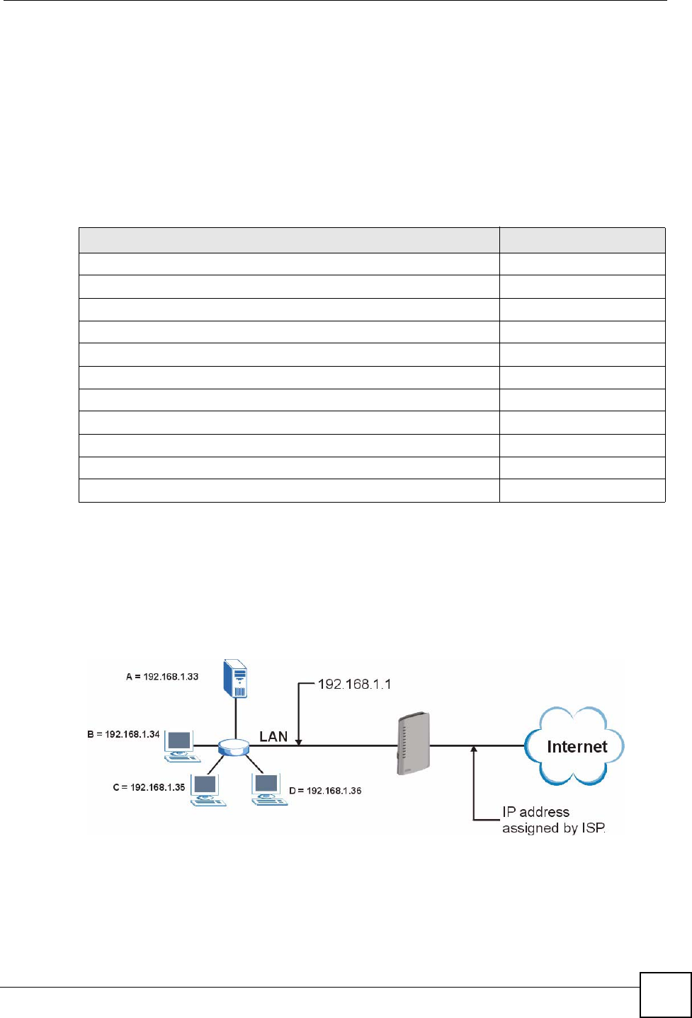
Chapter 8 Network Address Translation (NAT)
P-870HW-51a v2 User’s Guide 103
8.4 Technical Reference
The following section contains additional technical information about the ZyXEL Device
features described in this chapter.
Port Forwarding: Services and Port Numbers
The most often used port numbers are shown in the following table. Please refer to RFC 1700
for further information about port numbers. Please also refer to the Supporting CD for more
examples and details on port forwarding and NAT.
Port Forwarding Example
Let's say you want to assign ports 21-25 to one FTP, Telnet and SMTP server (A in the
example), port 80 to another (B in the example) and assign a default server IP address of
192.168.1.35 to a third (C in the example). You assign the LAN IP addresses and the ISP
assigns the WAN IP address. The NAT network appears as a single host on the Internet.
Figure 56 Multiple Servers Behind NAT Example
Table 31 Services and Port Numbers
SERVICES PORT NUMBER
ECHO 7
FTP (File Transfer Protocol) 21
SMTP (Simple Mail Transfer Protocol) 25
DNS (Domain Name System) 53
Finger 79
HTTP (Hyper Text Transfer protocol or WWW, Web) 80
POP3 (Post Office Protocol) 110
NNTP (Network News Transport Protocol) 119
SNMP (Simple Network Management Protocol) 161
SNMP trap 162
PPTP (Point-to-Point Tunneling Protocol) 1723

Chapter 8 Network Address Translation (NAT)
P-870HW-51a v2 User’s Guide
104

105
PART III
Security
IP Filter (107)

106

P-870HW-51a v2 User’s Guide 107
CHAPTER 9
IP Filter
9.1 Overview
This chapter shows you how to enable and configure the ZyXEL Device IP filtering settings.
The ZyXEL Device firewall is a packet filtering firewall and restricts access based on the
source/destination computer network address of a packet and the type of application.
9.1.1 What You Can Do in this Chapter
The IP Filtering Incoming screen lets you view and configure incoming IP filtering rules
(Section 9.3 on page 108).
9.2 What You Need to Know
The following terms and concepts may help as you read through this chapter.
Basics
Computers share information over the Internet using a common language called TCP/IP. TCP/
IP, in turn, is a set of application protocols that perform specific functions. An “extension
number”, called the "TCP port" or "UDP port" identifies these protocols, such as HTTP (Web),
FTP (File Transfer Protocol), POP3 (E-mail), etc. For example, Web traffic by default uses
TCP port 80.
When computers communicate on the Internet, they are using the client/server model, where
the server "listens" on a specific TCP/UDP port for information requests from remote client
computers on the network. For example, a Web server typically listens on port 80. Please note
that while a computer may be intended for use over a single port, such as Web on port 80,
other ports are also active. If the person configuring or managing the computer is not careful, a
hacker could attack it over an unprotected port.
Some of the most common IP ports are:
Default Filtering Policies
Filtering rules are grouped based on the direction of travel of packets to which they apply.
Table 32 Common IP Ports
21 FTP 53 DNS
23 Telnet 80 HTTP
25 SMTP 110 POP3
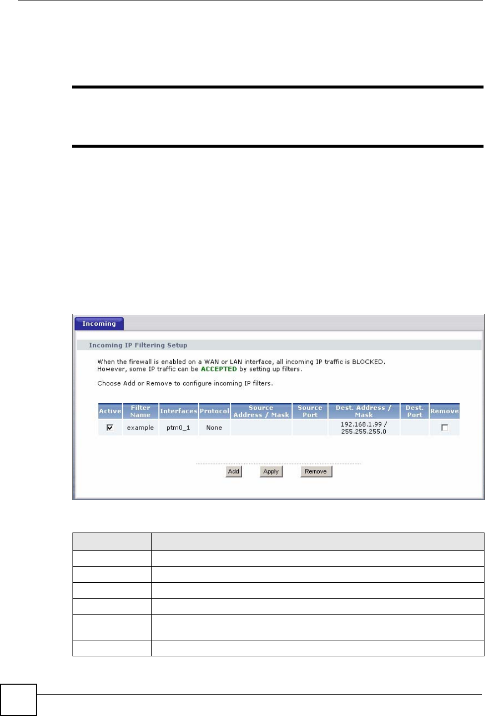
Chapter 9 IP Filter
P-870HW-51a v2 User’s Guide
108
The default rule for incoming traffic blocks all incoming connections from the WAN to the
LAN. If you wish to allow certain WAN users to have access to your LAN, you will need to
create custom rules to allow it.
"If you configure filtering rules without a good understanding of how they work,
you might inadvertently introduce security risks to the firewall and to the
protected network. Make sure you test your rules after you configure them.
These custom rules work by comparing the Source IP address, Destination IP address and IP
protocol type of network traffic to rules set by the administrator. Your customized rules take
precedence and override the ZyXEL Device’s default rules.
9.3 The Incoming IP Filtering Screen
Click Security > IP Filter > Incoming to display the following screen. This screen displays a
list of the configured incoming filtering rules.
Figure 57 Incoming IP Filter
The following table describes the labels in this screen.
Table 33 Incoming IP Filtering
LABEL DESCRIPTION
Active Select this check box to enable the rule.
Filter Name This displays the name of the rule.
Interfaces This displays the WAN interface to which this rule is applied.
Protocol This displays the IP protocol that defines the service to which this rule applies.
Source Address /
Mask This displays the source IP addresses and subnet mask to which this rule applies.
Please note that a blank source address is equivalent to Any.
Source Port This is the source port number.
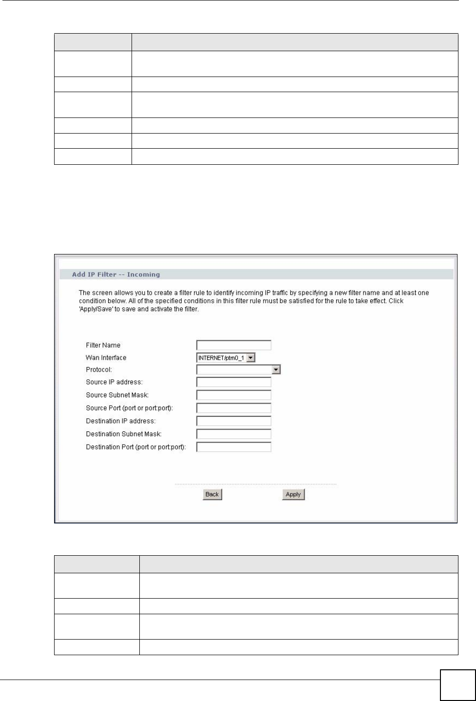
Chapter 9 IP Filter
P-870HW-51a v2 User’s Guide 109
9.3.1 Creating Incoming Filtering Rules
In the Incoming screen, click Add to display this screen and refer to the following table for
information on the labels.
Figure 58 Incoming IP Filtering: Add
The following table describes the labels in this screen.
Dest. Address /
Mask This displays the destination IP addresses and subnet mask to which this rule
applies. Please note that a blank destination address is equivalent to Any.
Dest. Port This is the destination port number.
Remove Select the rule(s) you want to delete in the Remove column and then click the
Remove button.
Add Click Add to create a new rule.
Apply Click Apply to save your changes back to the ZyXEL Device.
Remove Click Remove to delete the selected rule(s).
Table 33 Incoming IP Filtering (continued)
LABEL DESCRIPTION
Table 34 Incoming IP Filtering: Add
LABEL DESCRIPTION
Filter Name Enter a descriptive name of up to 16 printable English keyboard characters,
including spaces.
WAN Interfaces Select the WAN interface to which this rule applies.
Protocol Select the IP protocol (TCP/UDP, TCP, UDP or ICMP) and enter the protocol
(service type) number in the port field.
Source IP Address Enter the source IP address in dotted decimal notation.

Chapter 9 IP Filter
P-870HW-51a v2 User’s Guide
110
Source Subnet
Mask Enter the source subnet mask.
Source Port Enter a single port number or the range of port numbers of the source.
Destination IP
Address Enter the destination IP address in dotted decimal notation.
Destination Subnet
Mask Enter the destination subnet mask.
Destination Port Enter the port number of the destination.
Back Click Back to return to the previous screen.
Apply Click Apply to save your customized settings and exit this screen.
Table 34 Incoming IP Filtering: Add (continued)
LABEL DESCRIPTION

111
PART IV
Advanced
Static Route (113)
Quality of Service (QoS) (117)
Dynamic DNS Setup (127)
Remote Management (129)
Universal Plug-and-Play (UPnP) (131)

112
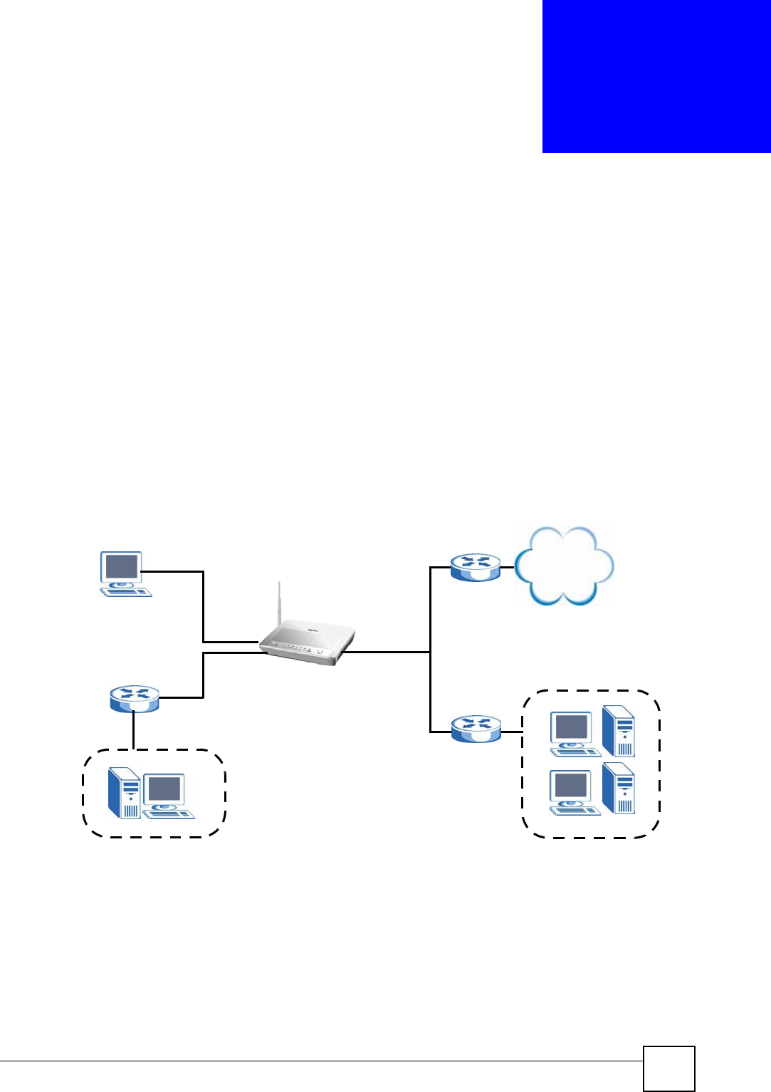
P-870HW-51a v2 User’s Guide 113
CHAPTER 10
Static Route
10.1 Overview
The ZyXEL Device usually uses the default gateway to route outbound traffic from computers
on the LAN to the Internet. To have the ZyXEL Device send data to devices not reachable
through the default gateway, use static routes.
For example, the next figure shows a computer (A) connected to the ZyXEL Device’s LAN
interface. The ZyXEL Device routes most traffic from A to the Internet through the ZyXEL
Device’s default gateway (R1). You create one static route to connect to services offered by
your ISP behind router R2. You create another static route to communicate with a separate
network behind a router R3 connected to the LAN.
Figure 59 Example of Static Routing Topology
10.1.1 What You Can Do in this Chapter
The Static Route screens let you view and configure IP static routes on the ZyXEL Device
(Section 10.2 on page 114).
WAN
R1
R2
A
R3
LAN
Internet
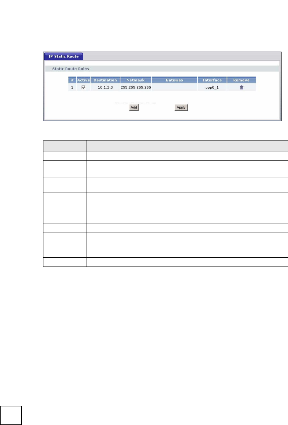
Chapter 10 Static Route
P-870HW-51a v2 User’s Guide
114
10.2 The Static Route Screen
Click Advanced > Static Route to open the Static Route screen.
Figure 60 Advanced > Static Route
The following table describes the labels in this screen.
10.2.1 Static Route Edit
Click the Add button in the Static Route screen. Use this screen to configure the required
information for a static route.
Table 35 Advanced > Static Route
LABEL DESCRIPTION
#This is the number of an individual static route.
Active This field indicates whether the rule is active or not.
Clear the check box to disable the rule. Select the check box to enable it.
Destination This parameter specifies the IP network address of the final destination. Routing is
always based on network number.
Netmask This parameter specifies the IP network subnet mask of the final destination.
Gateway This is the IP address of the gateway. The gateway is a router or switch on the same
network segment as the device's LAN or WAN port. The gateway helps forward
packets to their destinations.
Interface This is the WAN interface through which the traffic is routed.
Remove Click the icon to remove a static route from the ZyXEL Device. A window displays
asking you to confirm that you want to delete the route.
Add Click this to create a new rule.
Apply Click this to apply your changes to the ZyXEL Device.
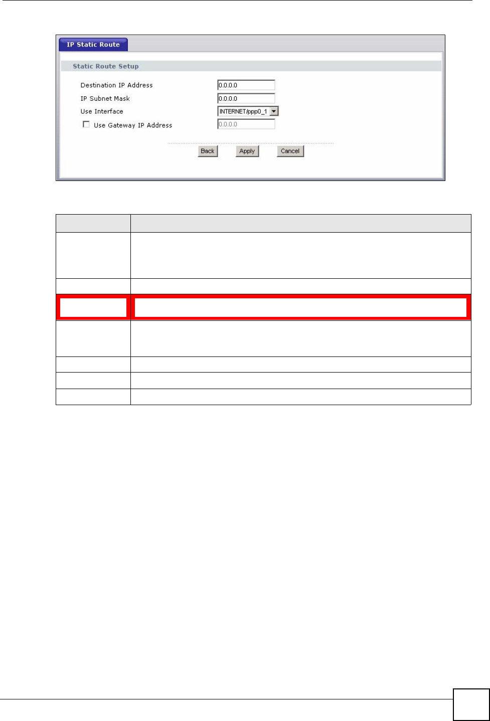
Chapter 10 Static Route
P-870HW-51a v2 User’s Guide 115
Figure 61 Static Route: Add
The following table describes the labels in this screen.
Table 36 Static Route: Add
LABEL DESCRIPTION
Destination IP
Address This parameter specifies the IP network address of the final destination. Routing is
always based on network number. If you need to specify a route to a single host,
use a subnet mask of 255.255.255.255 in the subnet mask field to force the network
number to be identical to the host ID.
IP Subnet Mask Enter the IP subnet mask here.
Use Interface Select a predefined interface through which the traffic is sent. If you select a WAN
interface using PPPoE you must specify the gateway IP address.
Use Gateway IP
Address Select this option and enter the IP address of the next-hop gateway. The gateway is
a router or switch on the same segment as your ZyXEL Device's interface(s). The
gateway helps forward packets to their destinations.
Back Click Back to return to the previous screen without saving.
Apply Click Apply to save your changes back to the ZyXEL Device.
Cancel Click Cancel to begin configuring this screen afresh.

Chapter 10 Static Route
P-870HW-51a v2 User’s Guide
116

P-870HW-51a v2 User’s Guide 117
CHAPTER 11
Quality of Service (QoS)
11.1 Overview
Quality of Service (QoS) refers to both a network’s ability to deliver data with minimum delay,
and the networking methods used to control the use of bandwidth. Without QoS, all traffic data
is equally likely to be dropped when the network is congested. This can cause a reduction in
network performance and make the network inadequate for time-critical application such as
video-on-demand.
Configure QoS on the ZyXEL Device to group and prioritize application traffic and fine-tune
network performance. Setting up QoS involves these steps:
1Configure classifiers to sort traffic into different flows.
2Assign priority and define actions to be performed for a classified traffic flow.
The ZyXEL Device assigns each packet a priority and then queues the packet accordingly.
Packets assigned a high priority are processed more quickly than those with low priority if
there is congestion, allowing time-sensitive applications to flow more smoothly. Time-
sensitive applications include both those that require a low level of latency (delay) and a low
level of jitter (variations in delay) such as Voice over IP (VoIP) or Internet gaming, and those
for which jitter alone is a problem such as Internet radio or streaming video.
This chapter contains information about configuring QoS and editing classifiers.
11.1.1 What You Can Do in this Chapter
•The General screen lets you lets you enable or disable QoS and set the default DSCP
value for incoming traffic does not match a class (Section 11.3 on page 118).
•The Queue Setup screen lets you lets you configure QoS queue assignment (Section 11.4
on page 119).
•The Class Setup screen lets you add, edit or delete QoS classifiers (Section 11.5 on page
120).
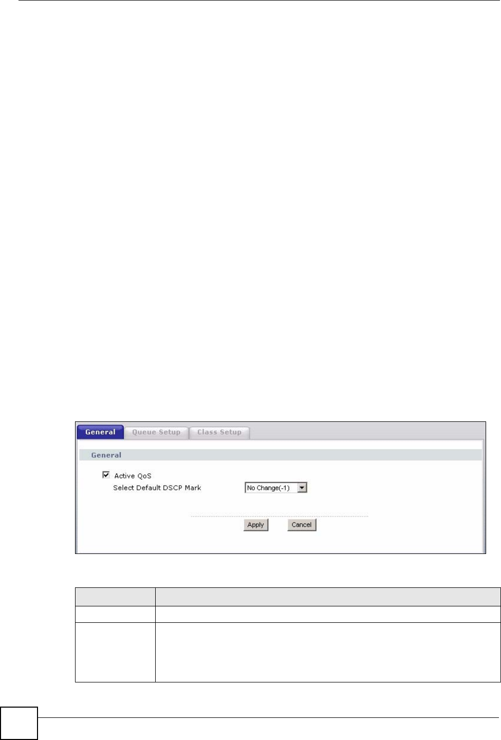
Chapter 11 Quality of Service (QoS)
P-870HW-51a v2 User’s Guide
118
11.2 What You Need to Know
The following terms and concepts may help as you read through this chapter.
QoS versus Cos
QoS is used to prioritize source-to-destination traffic flows. All packets in the same flow are
given the same priority. CoS (class of service) is a way of managing traffic in a network by
grouping similar types of traffic together and treating each type as a class. You can use CoS to
give different priorities to different packet types.
CoS technologies include IEEE 802.1p layer 2 tagging and DiffServ (Differentiated Services
or DS). IEEE 802.1p tagging makes use of three bits in the packet header, while DiffServ is a
new protocol and defines a new DS field, which replaces the eight-bit ToS (Type of Service)
field in the IP header.
Tagging and Marking
In a QoS class, you can configure whether to add or change the DSCP (DiffServ Code Point)
value, IEEE 802.1p priority level and VLAN ID number in a matched packet. When the packet
passes through a compatible network, the networking device, such as a backbone switch, can
provide specific treatment or service based on the tag or marker.
11.3 The Quality of Service Screen
Click Advanced Setup > Quality of Service to open the screen as shown next.
Use this screen to enable or disable QoS and set the default DSCP value for incoming traffic
does not match a class. See Section 11.1 on page 117 for more information.
Figure 62 QoS
The following table describes the labels in this screen.
Table 37 QoS
LABEL DESCRIPTION
Active QoS Select the check box to turn on QoS to improve your network performance.
Select Default
DSCP Mark This field is available only when you select Enable QoS.
If you enable QoS and incoming traffic does not match a class configured in the
Class Setup screen, the ZyXEL Device sets the DSCP field in the packets with the
value you select here. If you select No Change, the ZyXEL Device keeps the
DSCP fields in the packets.
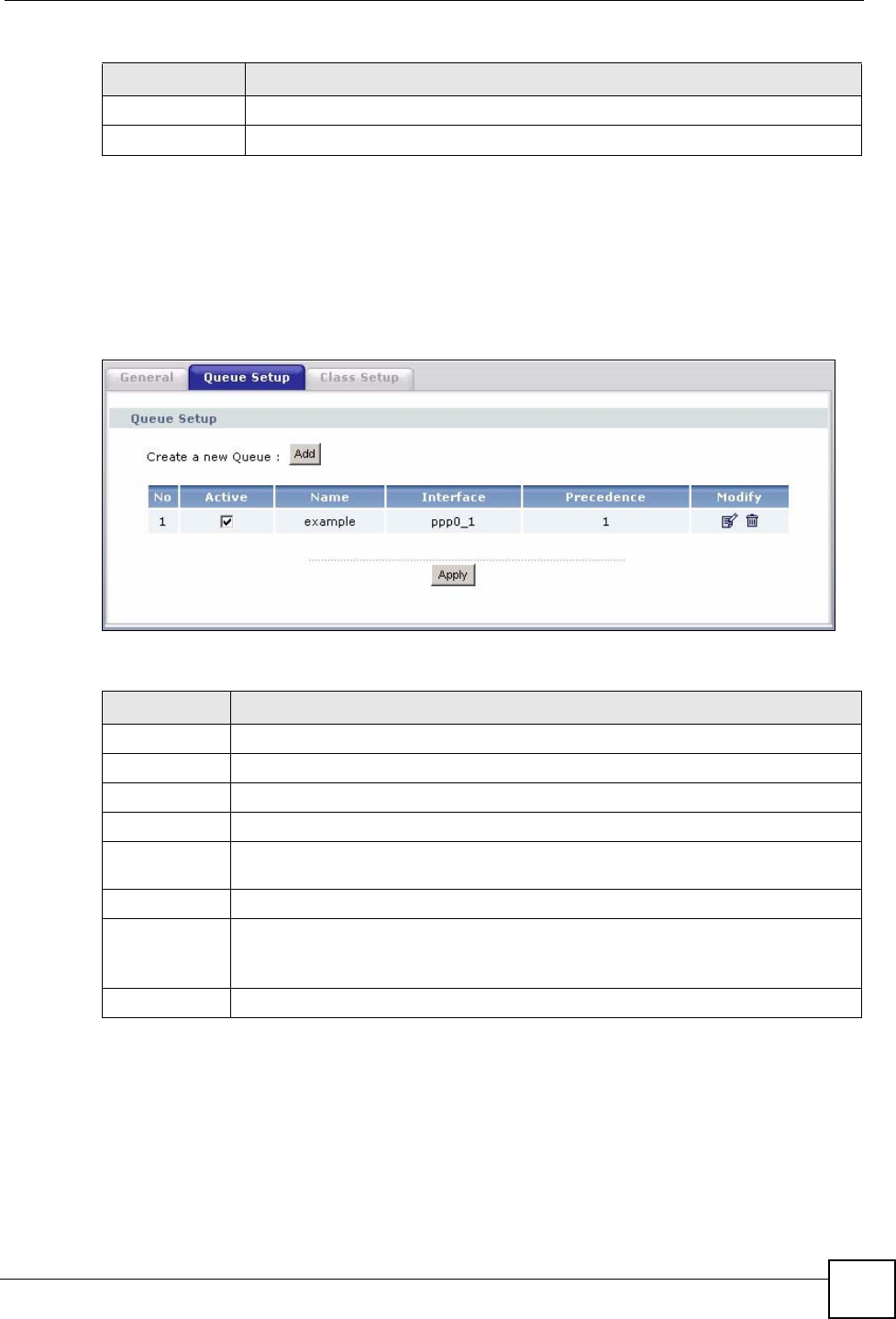
Chapter 11 Quality of Service (QoS)
P-870HW-51a v2 User’s Guide 119
11.4 The Queue Setup Screen
Click QoS > Queue Setup to open the screen as shown next.
Use this screen to configure QoS queue assignment.
Figure 63 QoS Queue Setup
The following table describes the labels in this screen.
Apply Click Apply to save your changes back to the ZyXEL Device.
Cancel Click Cancel to begin configuring this screen afresh.
Table 37 QoS
LABEL DESCRIPTION
Table 38 QoS Queue Setup
LABEL DESCRIPTION
Add Click this button to create a new entry.
No This is the index number of this entry.
Active Select the check box to enable the queue.
Name This shows the descriptive name of this entry.
Interface This shows the name of the ZyXEL Device’s interface through which traffic in this
queue passes.
Precedence This shows the priority queue of this entry.
Modify Click the edit icon to go to the screen where you can edit the queue.
Click the remove icon to delete an existing queue. Note that subsequent rules move
up by one when you take this action.
Apply Click Apply to save your changes back to the ZyXEL Device.
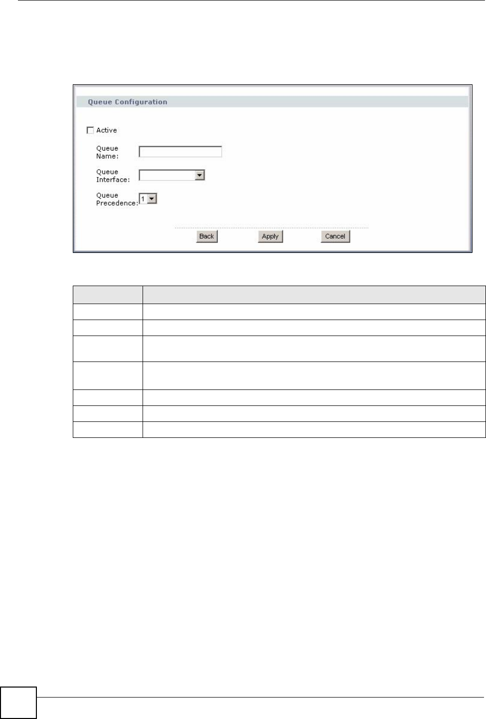
Chapter 11 Quality of Service (QoS)
P-870HW-51a v2 User’s Guide
120
11.4.1 Adding a QoS Queue
Click the Add button or the edit icon in the Queue Setup screen to configure a queue.
Figure 64 QoS Queue Setup: Add
The following table describes the labels in this screen.
11.5 The Class Setup Screen
Use this screen to add, edit or delete QoS classifiers. A classifier groups traffic into data flows
according to specific criteria such as the source address, destination address, source port
number, destination port number or incoming interface. For example, you can configure a
classifier to select traffic from the same protocol port (such as Telnet) to form a flow.
You can give different priorities to traffic that the ZyXEL Device forwards out through the
WAN interface. Give high priority to voice and video to make them run more smoothly.
Similarly, give low priority to many large file downloads so that they do not reduce the quality
of other applications.
Click QoS > Class Setup to open the following screen.
Table 39 QoS Queue Setup: Add
LABEL DESCRIPTION
Active Select to enable or disable this rule.
Queue Name Enter the descriptive name of this rule.
Queue
Interface Select the interface to which this rule is applied.
Queue
Precedence Select the priority queue of this rule.
The smaller the number, the higher the priority level.
Back Click Back to return to the previous screen without saving.
Apply Click Apply to save your changes back to the ZyXEL Device.
Cancel Click Cancel to begin configuring this screen afresh.
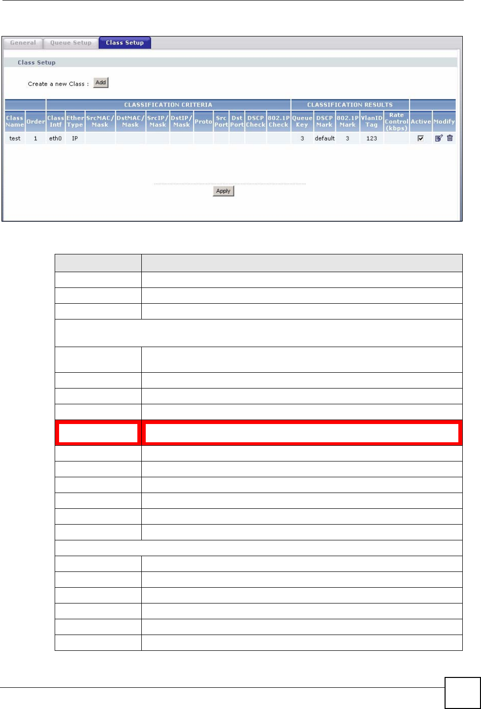
Chapter 11 Quality of Service (QoS)
P-870HW-51a v2 User’s Guide 121
Figure 65 QoS Class Setup
The following table describes the labels in this screen.
Table 40 QoS Class Setup
LABEL DESCRIPTION
Add Click this button to create a new classifier.
Class Name This is the name of the classifier.
Order This field displays the index number of the classifier.
CLASSIFICATION CRITERIA
This section shows criteria specified in this classifier.
Class Intf This shows the interface through which traffic that matches this classifier is
forwarded out.
Ether Type This is the service type.
SrcMAC /Mask This shows the source MAC address and the mask of traffic of this class.
DstMAC /Mask This shows the destination MAC address and the mask of traffic of this class.
SrcIP/Mask This shows the source IP address, the source subnet mask and DHCP option 60
or DHCP option 77.
DstIP/Mask This shows the destination IP address and the destination subnet mask.
Proto This shows the protocol type.
Src Port This shows the source port number.
Dst Port This shows the destination port number.
DSCP Check This is the DSCP value of traffic of this class.
802.1P Check This shows the 802.1P priority level.
CLASSIFICATION RESULTS
Queue Key This is the index number of a queue you configured in the Queue Setup screen.
DSCP Mark This is the DSCP number added to traffic of this classifier.
802.1P Mark This is the IEEE 802.1p priority level assigned to traffic of this classifier.
VlanID Tag This is the VLAN ID number assigned to traffic of this classifier.
Rate Control
Active Select the check box to enable this classifier.
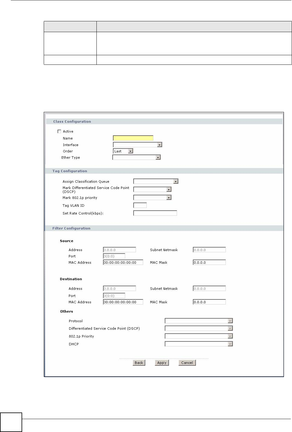
Chapter 11 Quality of Service (QoS)
P-870HW-51a v2 User’s Guide
122
11.5.1 QoS Class Edit
Click the Add button or the edit icon in the Class Setup screen to configure a classifier.
Figure 66 QoS Class Setup: Add
Modify Click the edit icon to go to the screen where you can edit the rule.
Click the remove icon to delete an existing rule. Note that subsequent rules
move up by one when you take this action.
Apply Click Apply to save your changes back to the ZyXEL Device.
Table 40 QoS Class Setup (continued)
LABEL DESCRIPTION
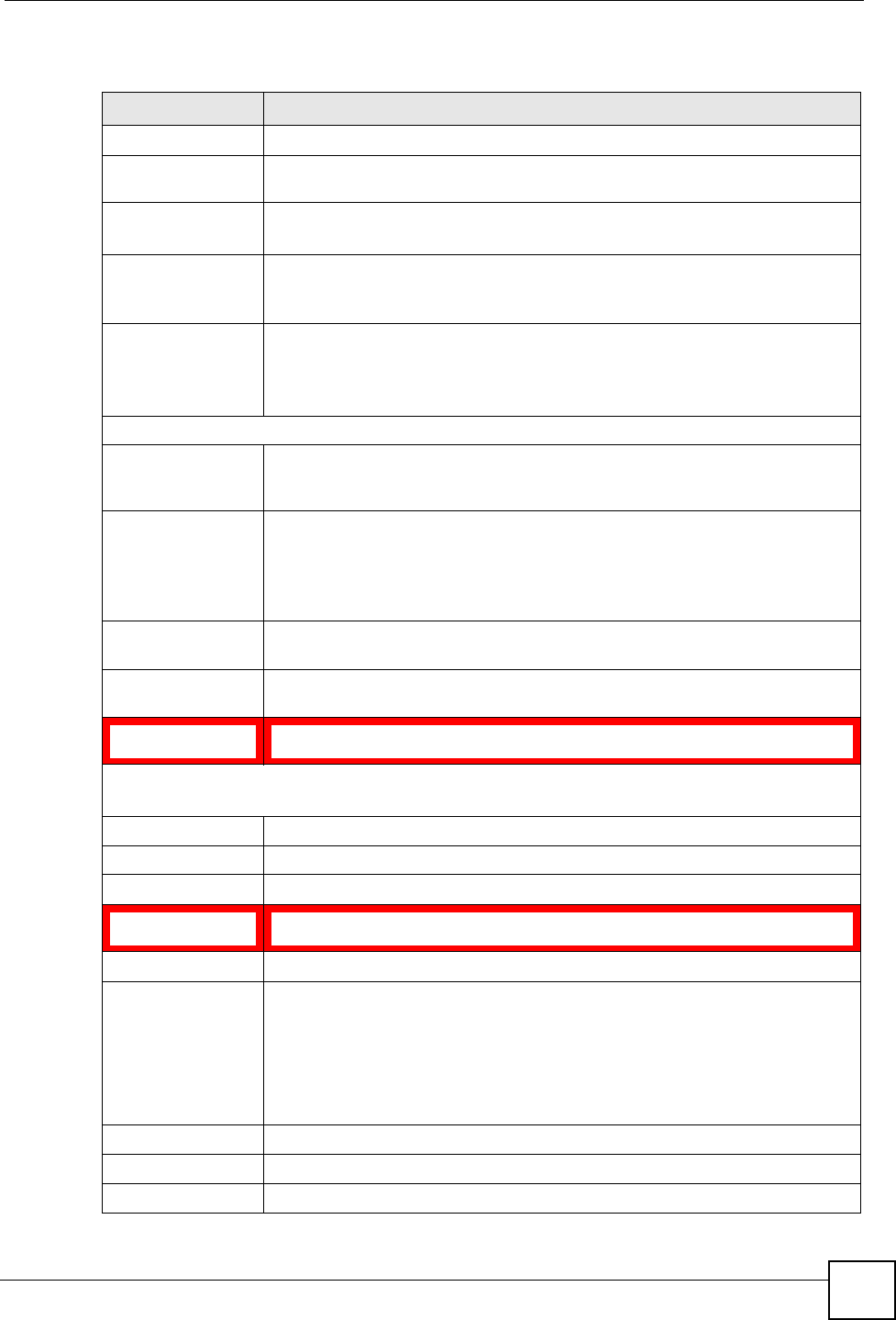
Chapter 11 Quality of Service (QoS)
P-870HW-51a v2 User’s Guide 123
The following table describes the labels in this screen.
Table 41 QoS Class Configuration
LABEL DESCRIPTION
Active Select to enable or disable this classifier.
Name Enter a descriptive name of up to 20 printable English keyboard characters,
including spaces.
Interface Select from which Ethernet port traffic of this class should come.
Select Local for any traffic from the LAN.
Order Select an existing number for where you want to put this classifier to move the
classifier to the number you selected after clicking Apply.
Select Last to put this rule in the back of the classifier list.
Ether Type Select a predefined application to configure a class for the matched traffic.
If you select IP, you also need to configure source or destination MAC address,
IP address, DHCP options, DSCP value or the protocol type.
If you select 8021Q, you can only configure a 802.1p priority level.
Tag Configuration
Assign
Classification
Queue
Select a queue that applies to this class.
You should have configured a queue in the Queue Setup screen already.
Mark Differentiated
Services Code
Point (DSCP)
Select a DSCP value with which the ZyXEL Device replaces the DSCP field in
the packets.
Select Auto Marking and the ZyXEL Device will change the DSCP value to an
IP ToS value when there is a 802.1p priority field in the matched packets.
Select default to set the DSCP value in the matched packets to 0.
Mark 802.1p priority Select a priority level with which the ZyXEL Device replaces the IEEE 802.1
priority field in the packets.
Tag VLAN ID Select a VLAN ID number (between 0 and 4095) with which the ZyXEL Device
replaces the VLAN ID of the frames.
Set Rate
Control(kbps) Enter the transmission rate (in Kbps) for traffic that matches this QoS class
Filter Configuration
Use the following fields to configure the criteria for traffic classification.
Source
Address Enter the source IP address in dotted decimal notation.
Subnet Mask Enter the source subnet mask.
Port If you select a protocol type, enter the port number(s) of the source. 0 means
any source port number.
MAC Address Enter the source MAC address of the packet.
MAC Mask Type the mask for the specified MAC address to determine which bits a packet’s
MAC address should match.
Enter “f” for each bit of the specified source MAC address that the traffic’s MAC
address should match. Enter “0“ for the bit(s) of the matched traffic’s MAC
address, which can be of any hexadecimal character(s). For example, if you set
the MAC address to 00:13:49:00:00:00 and the mask to ff:ff:ff:00:00:00, a packet
with a MAC address of 00:13:49:12:34:56 matches this criteria.
Destination
Address Enter the destination IP address in dotted decimal notation.
Subnet Mask Enter the destination subnet mask.
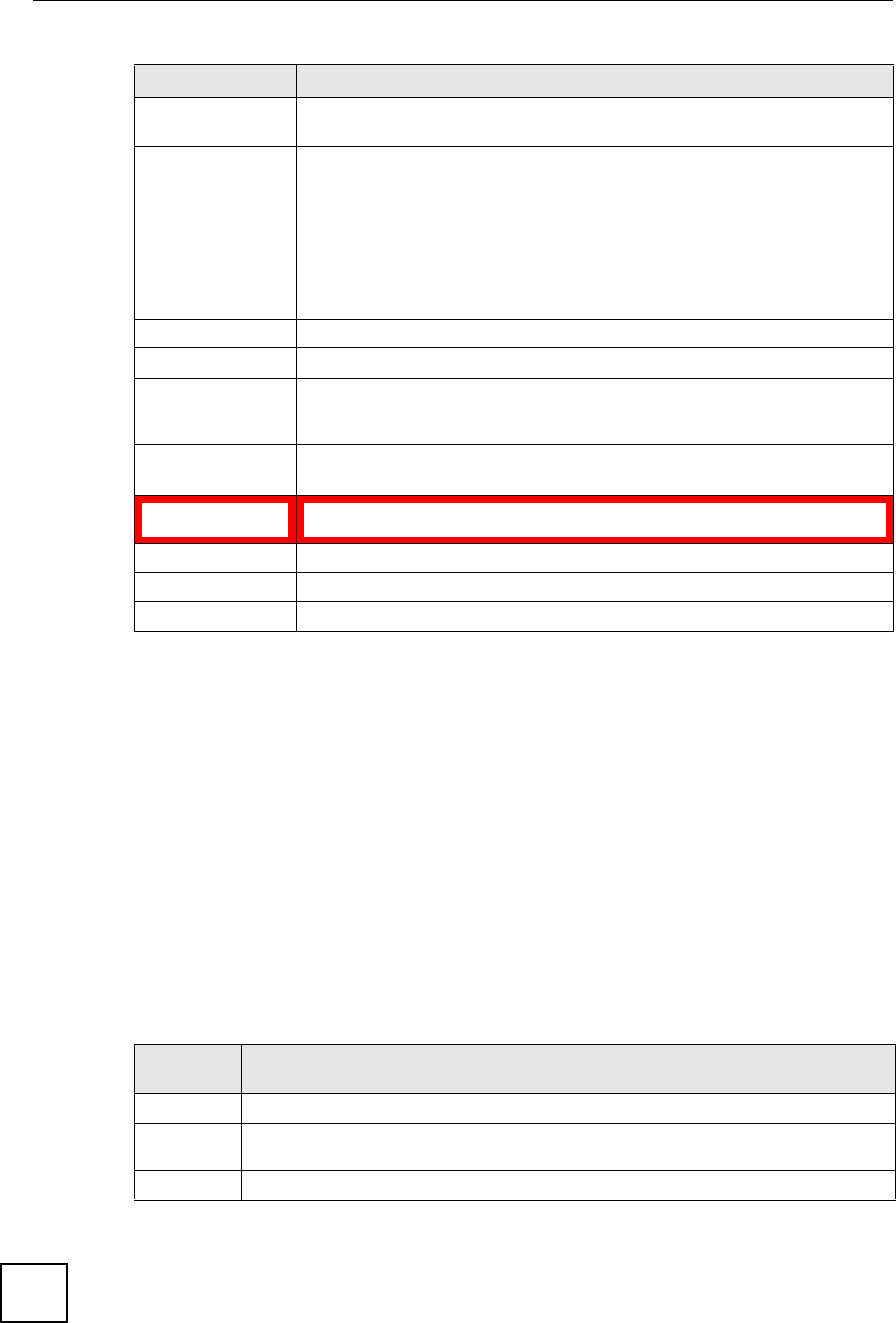
Chapter 11 Quality of Service (QoS)
P-870HW-51a v2 User’s Guide
124
11.6 Technical Reference
The following section contains additional technical information about the ZyXEL Device
features described in this chapter.
IEEE 802.1Q Tag
The IEEE 802.1Q standard defines an explicit VLAN tag in the MAC header to identify the
VLAN membership of a frame across bridges. A VLAN tag includes the 12-bit VLAN ID and
3-bit user priority. The VLAN ID associates a frame with a specific VLAN and provides the
information that devices need to process the frame across the network.
IEEE 802.1p specifies the user priority field and defines up to eight separate traffic types. The
following table describes the traffic types defined in the IEEE 802.1d standard (which
incorporates the 802.1p).
Port If you select a protocol type, enter the port number(s) of the destination. 0
means any destination port number.
MAC Address Enter the destination MAC address of the packet.
MAC Mask Type the mask for the specified MAC address to determine which bits a packet’s
MAC address should match.
Enter “f” for each bit of the specified destination MAC address that the traffic’s
MAC address should match. Enter “0“ for the bit(s) of the matched traffic’s MAC
address, which can be of any hexadecimal character(s). For example, if you set
the MAC address to 00:13:49:00:00:00 and the mask to ff:ff:ff:00:00:00, a packet
with a MAC address of 00:13:49:12:34:56 matches this criteria.
Others
Protocol Select the protocol (service type) from TCP, UDP, ICMP or IGMP.
Differentiated
Services Code
Point (DSCP)
Select a DSCP value from the drop-down list box.
default represents the default DSCP value 000000 or 0x00.
802.1p Priority Select a priority level (between 0 and 7) from the drop down list box.
"0" is the lowest priority level and "7" is the highest.
DHCP Select Vendor Class ID (DHCP Option 60) or User Class ID (DHCP Option
77) for the matched traffic.
Back Click Back to return to the previous screen without saving.
Apply Click Apply to save your changes back to the ZyXEL Device.
Cancel Click Cancel to begin configuring this screen afresh.
Table 41 QoS Class Configuration (continued)
LABEL DESCRIPTION
Table 42 IEEE 802.1p Priority Level and Traffic Type
PRIORITY
LEVEL TRAFFIC TYPE
Level 7 Typically used for network control traffic such as router configuration messages.
Level 6 Typically used for voice traffic that is especially sensitive to jitter (jitter is the variations in
delay).
Level 5 Typically used for video that consumes high bandwidth and is sensitive to jitter.
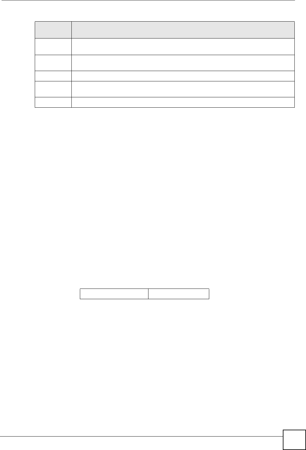
Chapter 11 Quality of Service (QoS)
P-870HW-51a v2 User’s Guide 125
DiffServ
QoS is used to prioritize source-to-destination traffic flows. All packets in the flow are given
the same priority. You can use CoS (class of service) to give different priorities to different
packet types.
DiffServ (Differentiated Services) is a class of service (CoS) model that marks packets so that
they receive specific per-hop treatment at DiffServ-compliant network devices along the route
based on the application types and traffic flow. Packets are marked with DiffServ Code Points
(DSCPs) indicating the level of service desired. This allows the intermediary DiffServ-
compliant network devices to handle the packets differently depending on the code points
without the need to negotiate paths or remember state information for every flow. In addition,
applications do not have to request a particular service or give advanced notice of where the
traffic is going.
DSCP and Per-Hop Behavior
DiffServ defines a new Differentiated Services (DS) field to replace the Type of Service (TOS)
field in the IP header. The DS field contains a 2-bit unused field and a 6-bit DSCP field which
can define up to 64 service levels. The following figure illustrates the DS field.
DSCP is backward compatible with the three precedence bits in the ToS octet so that non-
DiffServ compliant, ToS-enabled network device will not conflict with the DSCP mapping.
The DSCP value determines the forwarding behavior, the PHB (Per-Hop Behavior), that each
packet gets across the DiffServ network. Based on the marking rule, different kinds of traffic
can be marked for different kinds of forwarding. Resources can then be allocated according to
the DSCP values and the configured policies.
Level 4 Typically used for controlled load, latency-sensitive traffic such as SNA (Systems
Network Architecture) transactions.
Level 3 Typically used for “excellent effort” or better than best effort and would include important
business traffic that can tolerate some delay.
Level 2 This is for “spare bandwidth”.
Level 1 This is typically used for non-critical “background” traffic such as bulk transfers that are
allowed but that should not affect other applications and users.
Level 0 Typically used for best-effort traffic.
Table 42 IEEE 802.1p Priority Level and Traffic Type
PRIORITY
LEVEL TRAFFIC TYPE
DSCP (6 bits) Unused (2 bits)

Chapter 11 Quality of Service (QoS)
P-870HW-51a v2 User’s Guide
126

P-870HW-51a v2 User’s Guide 127
CHAPTER 12
Dynamic DNS Setup
12.1 Overview
Dynamic DNS allows you to update your current dynamic IP address with one or many
dynamic DNS services so that anyone can contact you (in NetMeeting, CU-SeeMe, etc.). You
can also access your FTP server or Web site on your own computer using a domain name (for
instance myhost.dhs.org, where myhost is a name of your choice) that will never change
instead of using an IP address that changes each time you reconnect. Your friends or relatives
will always be able to call you even if they don't know your IP address.
First of all, you need to have registered a dynamic DNS account with www.dyndns.org. This is
for people with a dynamic IP from their ISP or DHCP server that would still like to have a
domain name. The Dynamic DNS service provider will give you a password or key.
12.1.1 What You Can Do in this Chapter
Use the Dynamic DNS screen (Section 12.3 on page 127) to enable DDNS and configure the
DDNS settings on the ZyXEL Device.
12.2 What You Need To Know
DYNDNS Wildcard
Enabling the wildcard feature for your host causes *.yourhost.dyndns.org to be aliased to the
same IP address as yourhost.dyndns.org. This feature is useful if you want to be able to use,
for example, www.yourhost.dyndns.org and still reach your hostname.
If you have a private WAN IP address, then you cannot use Dynamic DNS.
12.3 The Dynamic DNS Screen
To change your ZyXEL Device’s DDNS, click Advanced > Dynamic DNS. The screen
appears as shown.
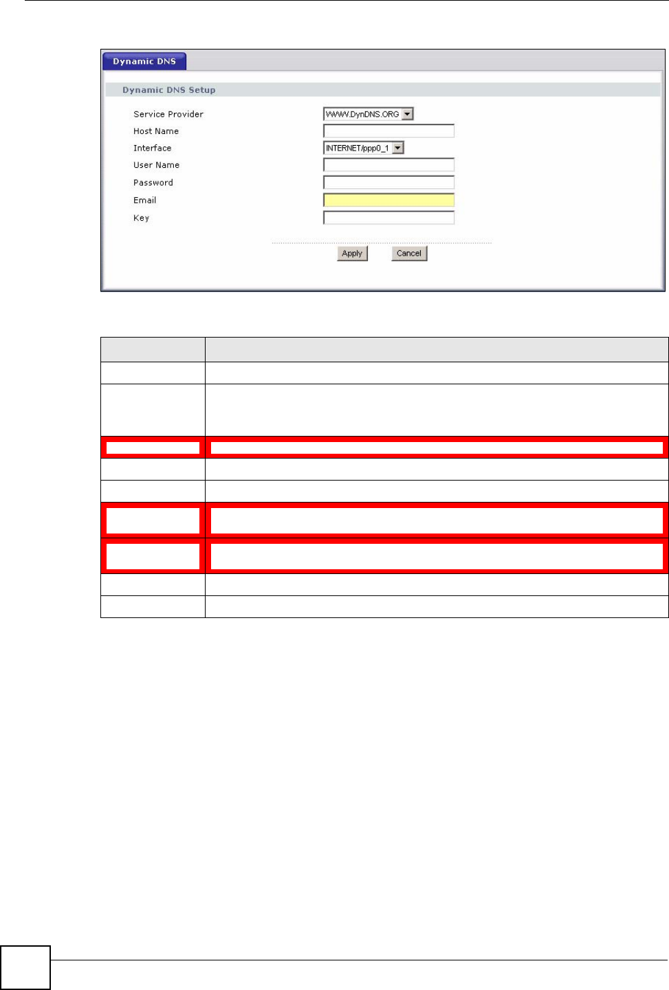
Chapter 12 Dynamic DNS Setup
P-870HW-51a v2 User’s Guide
128
Figure 67 Advanced > Dynamic DNS
The following table describes the fields in this screen.
Table 43 Advanced > Dynamic DNS
LABEL DESCRIPTION
Service Provider Select the name of your Dynamic DNS service provider.
Host Name Type the domain name assigned to your ZyXEL Device by your Dynamic DNS
provider.
You can specify up to two host names in the field separated by a comma (",").
Interface Select the WAN interface to use for updating the IP address of the domain name.
User Name Type your user name.
Password Type the password assigned to you.
Email If you select TZO in the Service Provider field, enter the user name you used to
register for this service.
Key If you select TZO in the Service Provider field, enter the password you used to
register for this service.
Apply Click Apply to save your changes back to the ZyXEL Device.
Cancel Click Cancel to begin configuring this screen afresh.

P-870HW-51a v2 User’s Guide 129
CHAPTER 13
Remote Management
13.1 Overview
This chapter explains how to configure the TR-069 settings on the ZyXEL Device.
13.1.1 What You Can Do in this Chapter
The TR-069 Client screen lets you configure the ZyXEL Device’s TR-069 auto-configuration
settings (Section 13.2 on page 129).
13.2 The TR-069 Screen
TR-069 defines how Customer Premise Equipment (CPE), for example your ZyXEL Device,
can be managed over the WAN by an Auto Configuration Server (ACS). TR-069 is based on
sending Remote Procedure Calls (RPCs) between an ACS and a client device. RPCs are sent
in Extensible Markup Language (XML) format over HTTP or HTTPS.
An administrator can use an ACS to remotely set up the ZyXEL Device, modify settings,
perform firmware upgrades as well as monitor and diagnose the ZyXEL Device. You have
enable the device to be managed by the ACS and specify the ACS IP address or domain name
and username and password.
Click Advanced > Remote MGMT to open the following screen. Use this screen to configure
your P-870HA to be managed by an ACS.
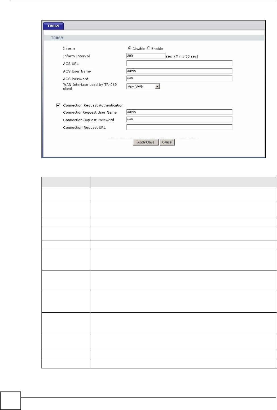
Chapter 13 Remote Management
P-870HW-51a v2 User’s Guide
130
Figure 68 TR-069
The following table describes the fields in this screen.
Table 44 TR-069 Client
LABEL DESCRIPTION
Inform Select Enable to activate remote management via TR-069 on the WAN.
Otherwise, select Disable.
Inform Interval Enter the time interval (in seconds) at which the ZyXEL Device sends information
to the auto-configuration server.
ACS URL Enter the URL or IP address of the auto-configuration server.
ACS User Name Enter the TR-069 user name for authentication with the auto-configuration
server.
ACS Password Enter the TR-069 password for authentication with the auto-configuration server.
WAN Interface
used by TR-069
client
Select a WAN interface through which the TR-069 traffic passes.
Connection
Request
Authentication
Select this option to enable authentication when there is a connection request
from the ACS.
Connection
Request User
Name
Enter the connection request user name.
When the ACS makes a connection request to the ZyXEL Device, this user
name is used to authenticate the ACS.
Connection
Request Password Enter the connection request password.
When the ACS makes a connection request to the ZyXEL Device, this password
is used to authenticate the ACS.
Connection
Request URL This shows the connection request URL.
The ACS can use this URL to make a connection request to the ZyXEL Device.
Apply/Save Click this button to save your changes back to the ZyXEL Device.
Cancel Click Cancel to begin configuring this screen afresh.

P-870HW-51a v2 User’s Guide 131
CHAPTER 14
Universal Plug-and-Play (UPnP)
14.1 Overview
Universal Plug and Play (UPnP) is a distributed, open networking standard that uses TCP/IP
for simple peer-to-peer network connectivity between devices. A UPnP device can
dynamically join a network, obtain an IP address, convey its capabilities and learn about other
devices on the network. In turn, a device can leave a network smoothly and automatically
when it is no longer in use.
14.1.1 What You Can Do in this Chapter
The UPnP screen lets you enable UPnP on the ZyXEL Device (Section 14.3 on page 132).
14.2 What You Need to Know
How do I know if I'm using UPnP?
UPnP hardware is identified as an icon in the Network Connections folder (Windows XP).
Each UPnP compatible device installed on your network will appear as a separate icon.
Selecting the icon of a UPnP device will allow you to access the information and properties of
that device.
NAT Traversal
UPnP NAT traversal automates the process of allowing an application to operate through NAT.
UPnP network devices can automatically configure network addressing, announce their
presence in the network to other UPnP devices and enable exchange of simple product and
service descriptions. NAT traversal allows the following:
• Dynamic port mapping
• Learning public IP addresses
• Assigning lease times to mappings
Windows Messenger is an example of an application that supports NAT traversal and UPnP.
See the NAT chapter for more information on NAT.
Cautions with UPnP
The automated nature of NAT traversal applications in establishing their own services and
opening firewall ports may present network security issues. Network information and
configuration may also be obtained and modified by users in some network environments.
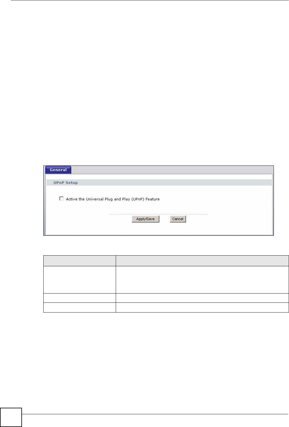
Chapter 14 Universal Plug-and-Play (UPnP)
P-870HW-51a v2 User’s Guide
132
When a UPnP device joins a network, it announces its presence with a multicast message. For
security reasons, the ZyXEL Device allows multicast messages on the LAN only.
All UPnP-enabled devices may communicate freely with each other without additional
configuration. Disable UPnP if this is not your intention.
UPnP and ZyXEL
ZyXEL has achieved UPnP certification from the Universal Plug and Play Forum UPnP™
Implementers Corp. (UIC). ZyXEL's UPnP implementation supports Internet Gateway Device
(IGD) 1.0.
See the following sections for examples of installing and using UPnP.
14.3 The UPnP Screen
Click Advanced > UPnP to display the screen shown next.
See Section 14.1 on page 131 for more information.
Figure 69 Advanced > UPnP
The following table describes the fields in this screen.
14.4 Installing UPnP in Windows Example
This section shows how to install UPnP in Windows Me and Windows XP.
Installing UPnP in Windows Me
Follow the steps below to install the UPnP in Windows Me.
1Click Start and Control Panel. Double-click Add/Remove Programs.
Table 45 Advanced > UPnP
LABEL DESCRIPTION
Active the Universal Plug
and Play (UPnP) Feature Select this check box to activate UPnP. Be aware that anyone could use
a UPnP application to open the web configurator's login screen without
entering the ZyXEL Device's IP address (although you must still enter
the password to access the web configurator).
Apply/Save Click this to save the setting to the ZyXEL Device.
Cancel Click this to return to the previously saved settings.
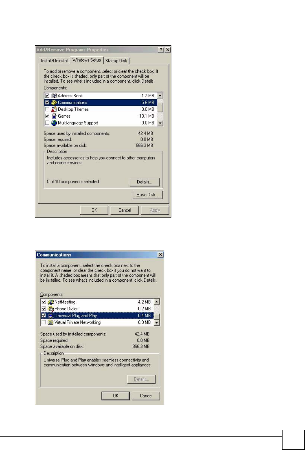
Chapter 14 Universal Plug-and-Play (UPnP)
P-870HW-51a v2 User’s Guide 133
2Click on the Windows Setup tab and select Communication in the Components
selection box. Click Details.
Figure 70 Add/Remove Programs: Windows Setup: Communication
3In the Communications window, select the Universal Plug and Play check box in the
Components selection box.
Figure 71 Add/Remove Programs: Windows Setup: Communication: Components
4Click OK to go back to the Add/Remove Programs Properties window and click Next.
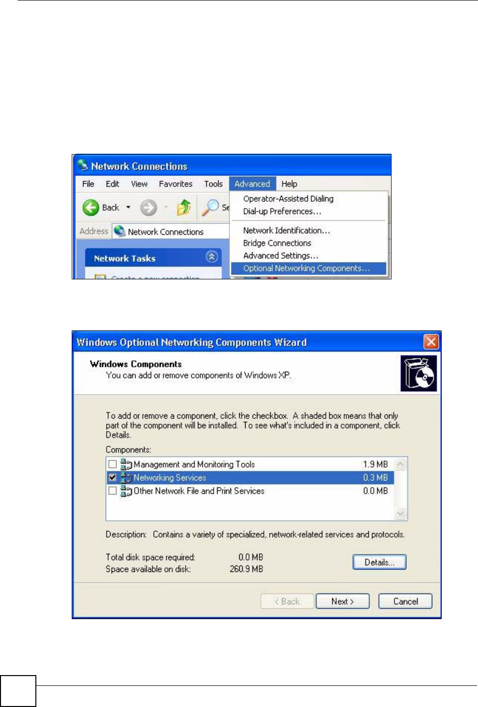
Chapter 14 Universal Plug-and-Play (UPnP)
P-870HW-51a v2 User’s Guide
134
5Restart the computer when prompted.
Installing UPnP in Windows XP
Follow the steps below to install the UPnP in Windows XP.
1Click Start and Control Panel.
2Double-click Network Connections.
3In the Network Connections window, click Advanced in the main menu and select
Optional Networking Components ….
Figure 72 Network Connections
4The Windows Optional Networking Components Wizard window displays. Select
Networking Service in the Components selection box and click Details.
Figure 73 Windows Optional Networking Components Wizard
5In the Networking Services window, select the Universal Plug and Play check box.
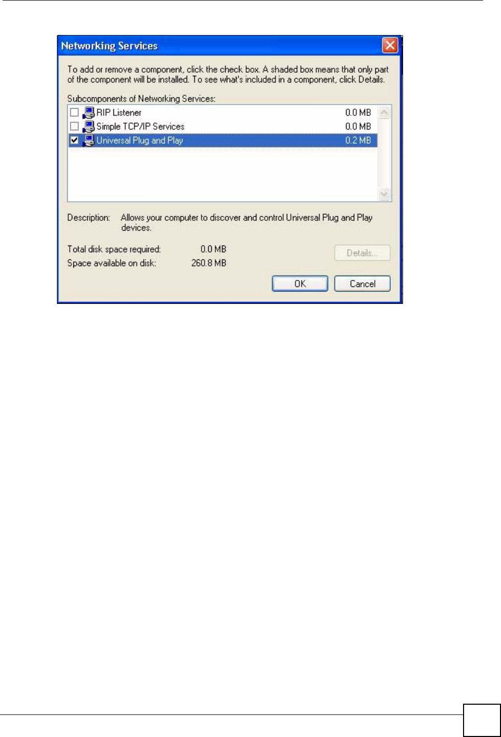
Chapter 14 Universal Plug-and-Play (UPnP)
P-870HW-51a v2 User’s Guide 135
Figure 74 Networking Services
6Click OK to go back to the Windows Optional Networking Component Wizard
window and click Next.
14.5 Using UPnP in Windows XP Example
This section shows you how to use the UPnP feature in Windows XP. You must already have
UPnP installed in Windows XP and UPnP activated on the ZyXEL Device.
Make sure the computer is connected to a LAN port of the ZyXEL Device. Turn on your
computer and the ZyXEL Device.
Auto-discover Your UPnP-enabled Network Device
1Click Start and Control Panel. Double-click Network Connections. An icon displays
under Internet Gateway.
2Right-click the icon and select Properties.
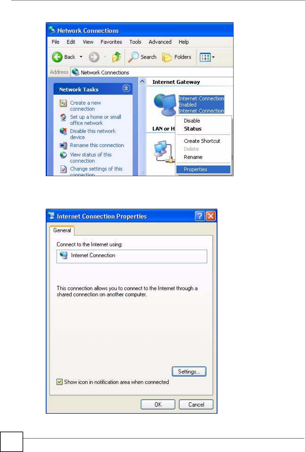
Chapter 14 Universal Plug-and-Play (UPnP)
P-870HW-51a v2 User’s Guide
136
Figure 75 Network Connections
3In the Internet Connection Properties window, click Settings to see the port mappings
there were automatically created.
Figure 76 Internet Connection Properties
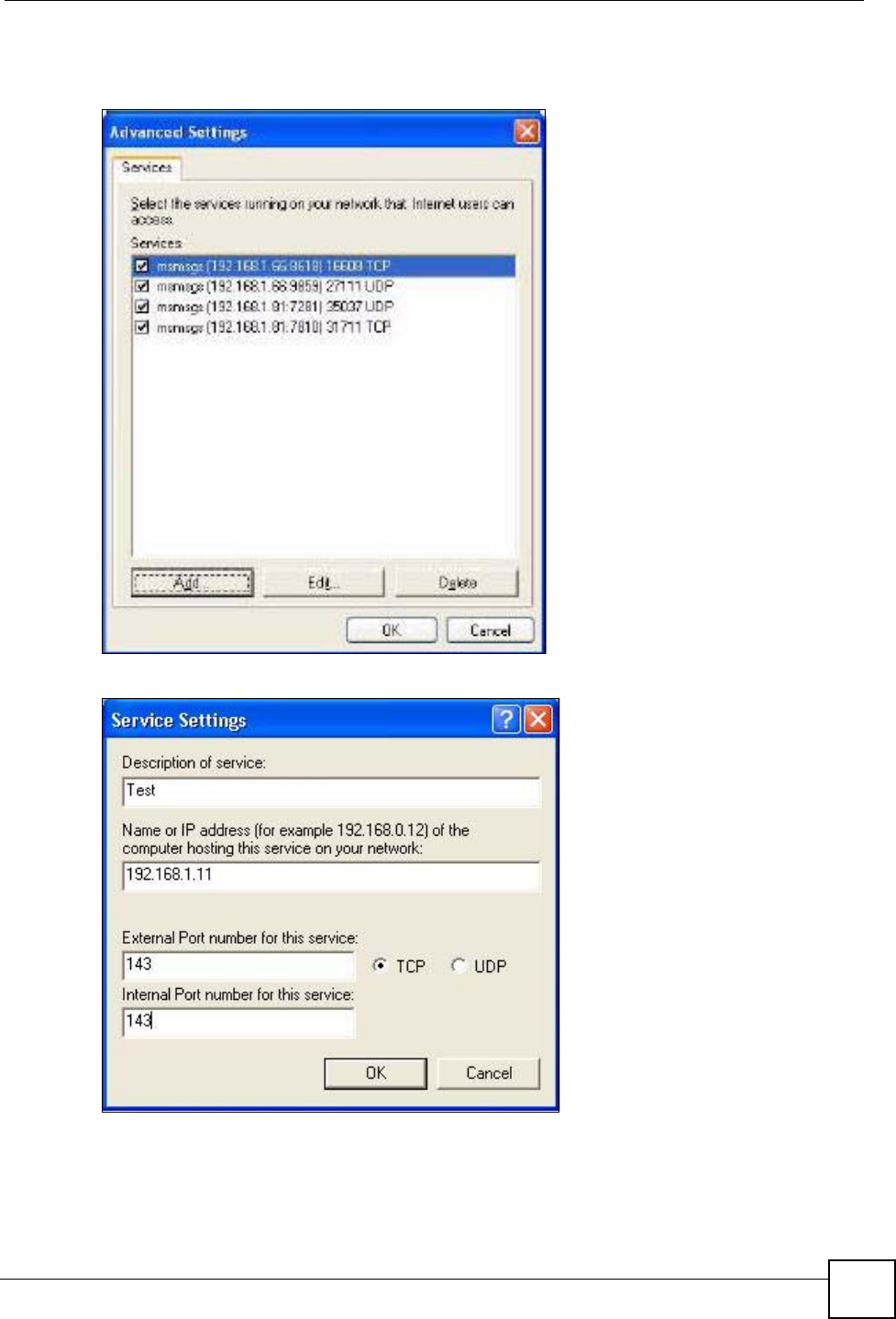
Chapter 14 Universal Plug-and-Play (UPnP)
P-870HW-51a v2 User’s Guide 137
4You may edit or delete the port mappings or click Add to manually add port mappings.
Figure 77 Internet Connection Properties: Advanced Settings
Figure 78 Internet Connection Properties: Advanced Settings: Add
5When the UPnP-enabled device is disconnected from your computer, all port mappings
will be deleted automatically.
6Select Show icon in notification area when connected option and click OK. An icon
displays in the system tray.
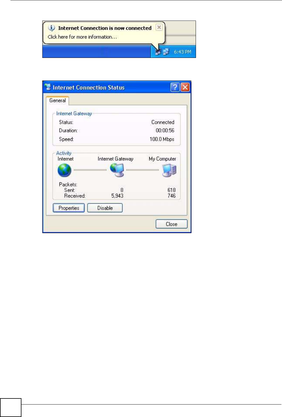
Chapter 14 Universal Plug-and-Play (UPnP)
P-870HW-51a v2 User’s Guide
138
Figure 79 System Tray Icon
7Double-click on the icon to display your current Internet connection status.
Figure 80 Internet Connection Status
Web Configurator Easy Access
With UPnP, you can access the web-based configurator on the ZyXEL Device without finding
out the IP address of the ZyXEL Device first. This comes helpful if you do not know the IP
address of the ZyXEL Device.
Follow the steps below to access the web configurator.
1Click Start and then Control Panel.
2Double-click Network Connections.
3Select My Network Places under Other Places.
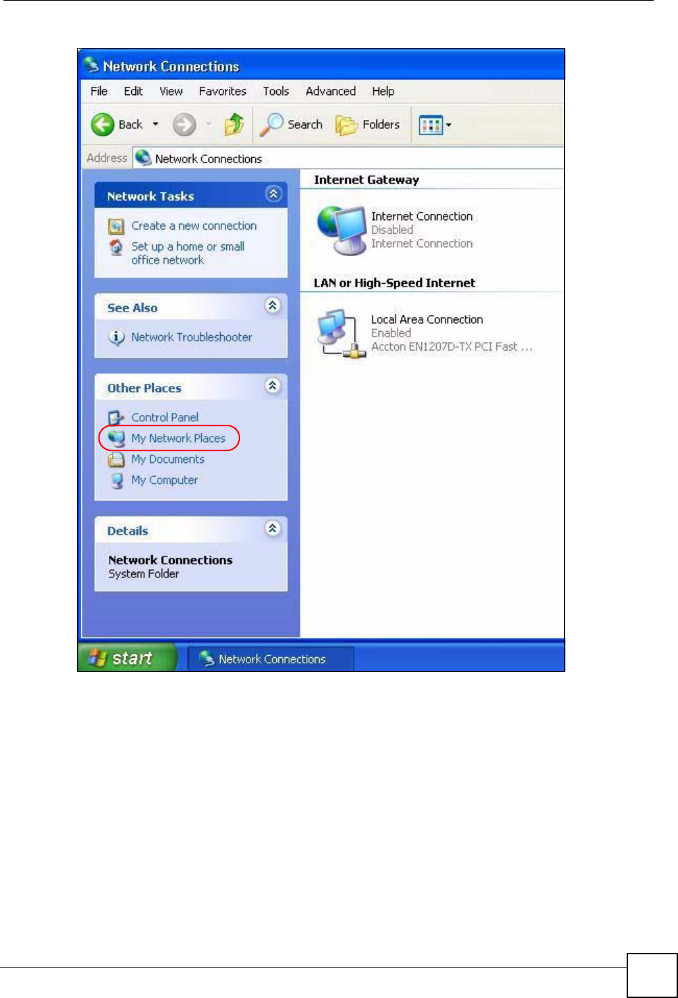
Chapter 14 Universal Plug-and-Play (UPnP)
P-870HW-51a v2 User’s Guide 139
Figure 81 Network Connections
4An icon with the description for each UPnP-enabled device displays under Local
Network.
5Right-click on the icon for your ZyXEL Device and select Invoke. The web configurator
login screen displays.
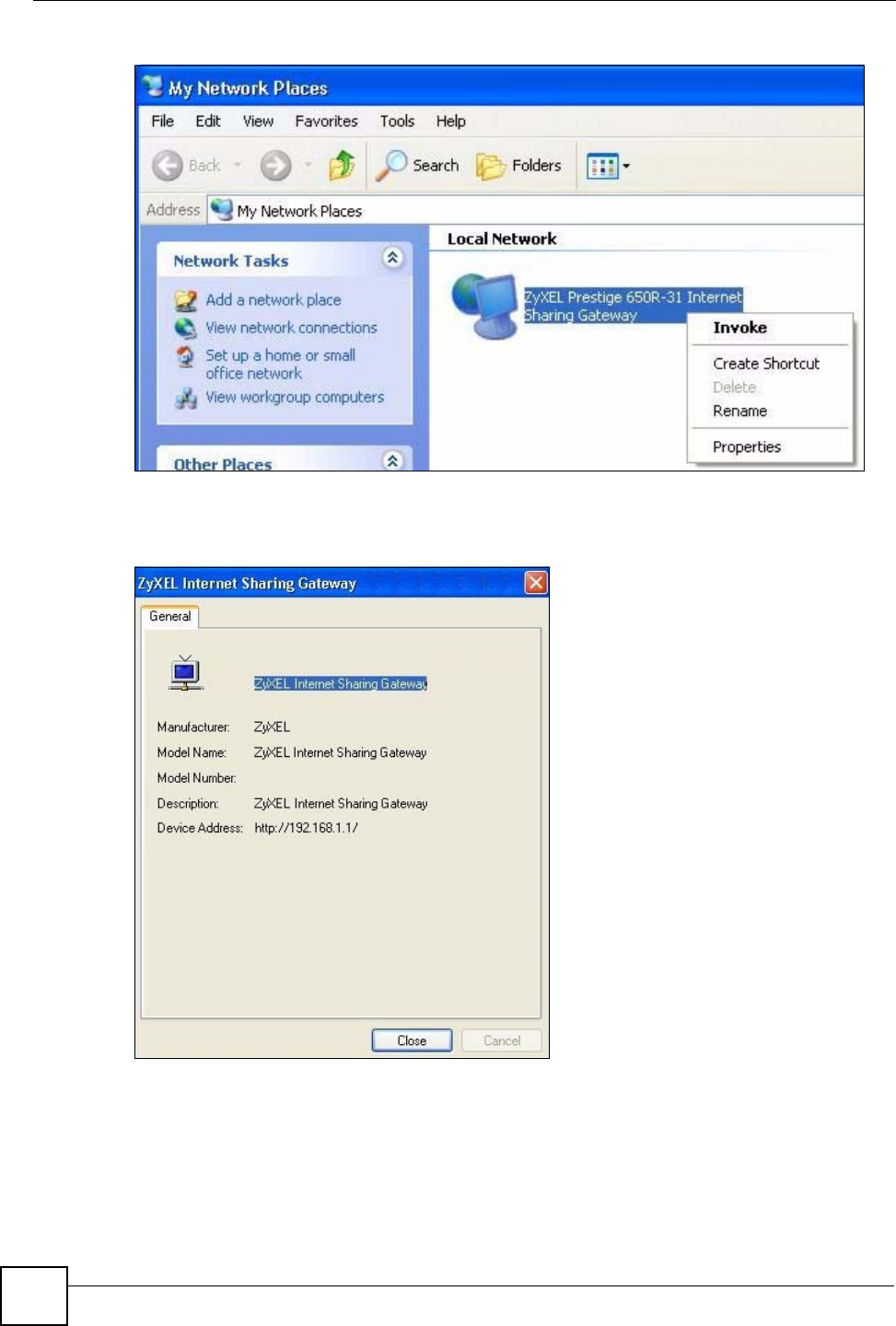
Chapter 14 Universal Plug-and-Play (UPnP)
P-870HW-51a v2 User’s Guide
140
Figure 82 Network Connections: My Network Places
6Right-click on the icon for your ZyXEL Device and select Properties. A properties
window displays with basic information about the ZyXEL Device.
Figure 83 Network Connections: My Network Places: Properties: Example

141
PART V
Maintenance,
Troubleshooting
and Specifications
System Settings (143)
Logs (147)
Tools (149)
Diagnostic (155)
Product Specifications (165)
Troubleshooting (159)

142

P-870HW-51a v2 User’s Guide 143
CHAPTER 15
System Settings
15.1 Overview
This chapter shows you how to configure system related settings, such as system time,
password, name, the domain name and the inactivity timeout interval.
15.1.1 What You Can Do in this Chapter
•The General screen lets you configure system settings (Section 15.2 on page 143).
•The Time Setting screen lets you set the system time (Section 15.3 on page 144).
15.1.2 What You Need to Know
Domain Name
This is a network address that identifies the owner of a network connection. For example, in
the network address “www.zyxel.com/support/files”, the domain name is “www.zyxel.com”.
DHCP
DHCP (Dynamic Host Configuration Protocol) is a method of allocating IP addresses to
devices on a network from a DHCP Server. Often your ISP or a router on your network
performs this function.
LAN
A LAN (local area network) is typically a network which covers a small area, made up of
computers and other devices which share resources such as Internet access, printers etc.
15.2 The General Screen
Use the General screen to configure system settings such as the system password.
Click Maintenance > System to open the General screen.
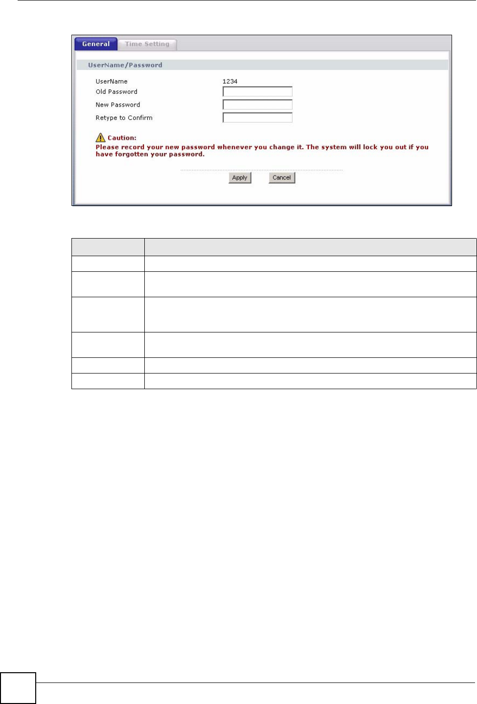
Chapter 15 System Settings
P-870HW-51a v2 User’s Guide
144
Figure 84 Maintenance > System > General
The following table describes the labels in this screen.
15.3 The Time Setting Screen
To change your ZyXEL Device’s time and date, click Maintenance > System > Time
Setting. The screen appears as shown. Use this screen to configure the ZyXEL Device’s time
based on your local time zone.
Table 46 Maintenance > System > Genera
LABEL DESCRIPTION
UserName This shows the user name you use to access the system.
Old Password Type the default password or the existing password you use to access the system in
this field.
New Password Type your new system password (up to 30 characters). Note that as you type a
password, the screen displays a (*) for each character you type. After you change
the password, use the new password to access the ZyXEL Device.
Retype to
Confirm Type the new password again for confirmation.
Apply Click Apply to save your changes back to the ZyXEL Device.
Cancel Click Cancel to begin configuring this screen afresh.
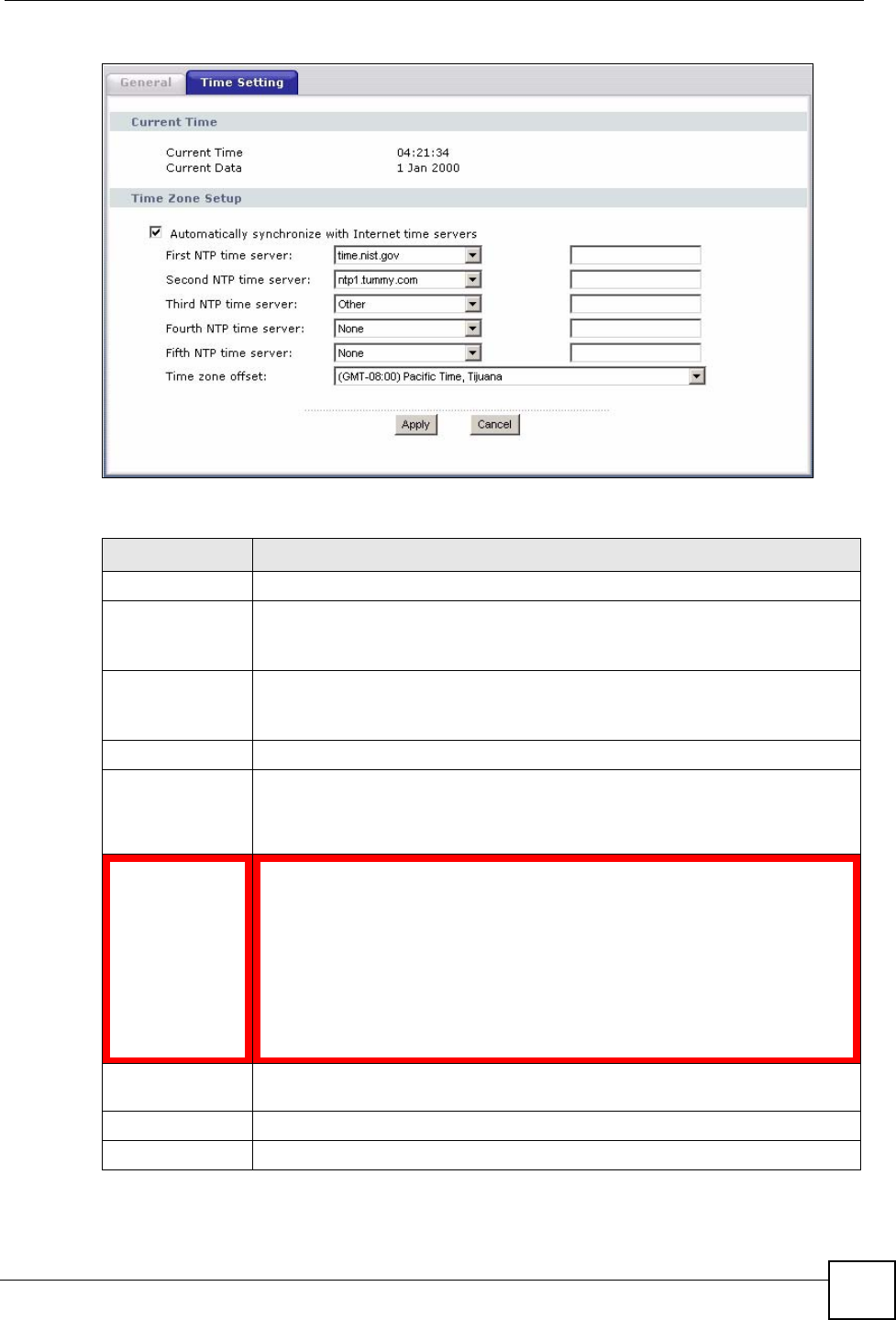
Chapter 15 System Settings
P-870HW-51a v2 User’s Guide 145
Figure 85 Maintenance > System > Time Setting
The following table describes the fields in this screen.
Table 47 Maintenance > System > Time Setting
LABEL DESCRIPTION
Current Time
Current Time This field displays the time of your ZyXEL Device.
Each time you reload this page, the ZyXEL Device synchronizes the time with the
time server.
Current Date This field displays the date of your ZyXEL Device.
Each time you reload this page, the ZyXEL Device synchronizes the date with the
time server.
Time Zone Setup
Automatically
synchronize with
Internet time
servers
Select this radio button to have the ZyXEL Device get the time and date from the
time server you specified below.
First NTP time
server
Second NTP time
server
Third NTP time
server
Fourth NTP time
server
Fifth NTP time
server
Select an NTP time server from the drop-down list box.
Otherwise, select Other and enter the IP address or URL (up to 20 extended
ASCII characters in length) of your time server.
Select None if you don’t want to configure the time server.
Check with your ISP/network administrator if you are unsure of this information.
Time zone offset Choose the time zone of your location. This will set the time difference between
your time zone and Greenwich Mean Time (GMT).
Apply Click Apply to save your changes back to the ZyXEL Device.
Cancel Click Cancel to begin configuring this screen afresh.

Chapter 15 System Settings
P-870HW-51a v2 User’s Guide
146
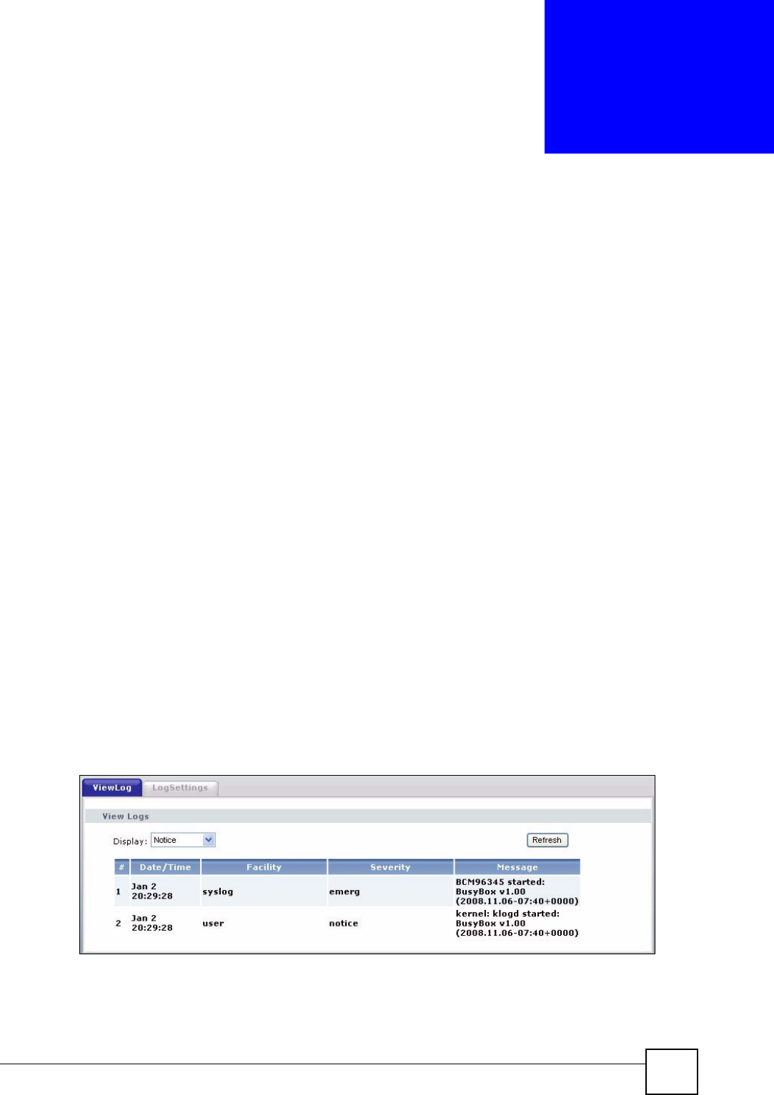
P-870HW-51a v2 User’s Guide 147
CHAPTER 16
Logs
16.1 Overview
This chapter contains information about configuring general log settings and viewing the
ZyXEL Device’s logs.
The web configurator allows you to choose which categories of events and/or alerts to have
the ZyXEL Device log and then display the logs or have the ZyXEL Device send them to a
syslog server.
16.1.1 What You Can Do in this Chapter
•The View Log screen lets you see the logs for the categories that you selected in the Log
Settings screen (Section 16.2 on page 147).
•The Log Settings screen lets you configure to where the ZyXEL Device is to send logs
and which logs and/or immediate alerts the ZyXEL Device is to record (Section 16.3 on
page 148).
16.2 The View Log Screen
Click Maintenance > Logs to open the View Log screen. Use the View Log screen to see the
logs for the categories that you selected in the Log Settings screen (see Section 16.3 on page
148).
The log wraps around and deletes the old entries after it fills.
Figure 86 Maintenance > Logs > View Log
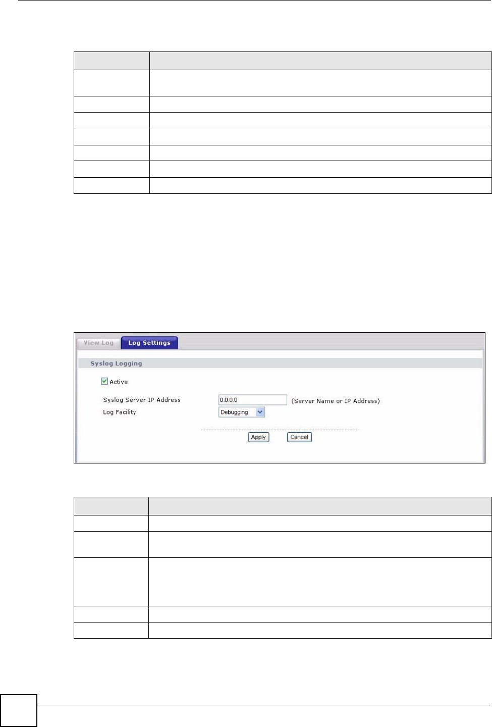
Chapter 16 Logs
P-870HW-51a v2 User’s Guide
148
The following table describes the fields in this screen.
16.3 The Log Settings Screen
Use the Log Settings screen to configure to where the ZyXEL Device is to send logs and
which logs and/or immediate alerts the ZyXEL Device is to record and display.
To change your ZyXEL Device’s log settings, click Maintenance > Logs > Log Settings. The
screen appears as shown.
Figure 87 Maintenance > Logs > Log Settings
The following table describes the fields in this screen.
Table 48 Maintenance > Logs > View Log
LABEL DESCRIPTION
Display Select a category of logs to view. The ZyXEL Device displays the logs with the
severity level equal to or higher than what you selected.
Refresh Click this button to renew the log screen.
#This field is a sequential value and is not associated with a specific entry.
Date/Time This field displays the time the log was recorded.
Facility This field displays the log facility in the log server or the local memory.
Severity This field displays the severity type of the log.
Message This field states the reason for the log.
Table 49 Maintenance > Logs > Log Settings
LABEL DESCRIPTION
Active Select to enable or disable system logging.
Syslog Server
IP Address Enter the server name or the IP address of the log server.
Log Facility Select the severity level of the logs that you want the ZyXEL Device to record and
send to the log serve.
The ZyXEL Device records the logs with the severity level equal to or higher than
what you selected.
Apply Click Apply to save your customized settings and exit this screen.
Cancel Click Cancel to return to the previously saved settings.

P-870HW-51a v2 User’s Guide 149
CHAPTER 17
Tools
1Do not interrupt the file transfer process as this may PERMANENTLY
DAMAGE your ZyXEL Device.
17.1 Overview
This chapter explains how to upload new firmware, manage configuration files and restart
your ZyXEL Device.
Use the instructions in this chapter to change the device’s configuration file or upgrade its
firmware. After you configure your device, you can backup the configuration file to a
computer. That way if you later misconfigure the device, you can upload the backed up
configuration file to return to your previous settings. You can alternately upload the factory
default configuration file if you want to return the device to the original default settings. The
firmware determines the device’s available features and functionality. You can download new
firmware releases from your nearest ZyXEL FTP site (or www.zyxel.com) to use to upgrade
your device’s performance.
1Only use firmware for your device’s specific model. Refer to the label on the
bottom of your ZyXEL Device.
17.1.1 What You Can Do in this Chapter
•The Firmware Upgrade screen lets you upload firmware to your device (Section 17.2 on
page 150).
•The Configuration screen lets you backup and restore device configurations (Section
17.3 on page 151). You can also reset your device settings back to the factory default.
•The Restart screen lets you restart your ZyXEL Device (Section 17.4 on page 154).
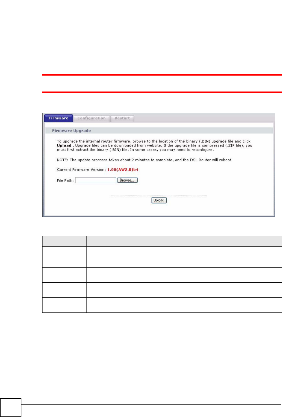
Chapter 17 Tools
P-870HW-51a v2 User’s Guide
150
17.2 The Firmware Upgrade Screen
Click Maintenance > Tools to open the Firmware screen. Follow the instructions in this
screen to upload firmware to your ZyXEL Device. The upload process uses HTTP (Hypertext
Transfer Protocol) and may take up to two minutes. After a successful upload, the system will
reboot.
1Do NOT turn off the ZyXEL Device while firmware upload is in progress!
Figure 88 Maintenance > Tools > Firmware
The following table describes the labels in this screen.
After you see the Firmware Upload in Progress screen, wait two minutes before logging into
the ZyXEL Device again.
Table 50 Maintenance > Tools > Firmware
LABEL DESCRIPTION
Current
Firmware
Version
This is the present Firmware version and the date created.
File Path Type in the location of the file you want to upload in this field or click Browse ... to
find it.
Browse... Click Browse... to find the .bin file you want to upload. Remember that you must
decompress compressed (.zip) files before you can upload them.
Upload Click Upload to begin the upload process. This process may take up to two
minutes.