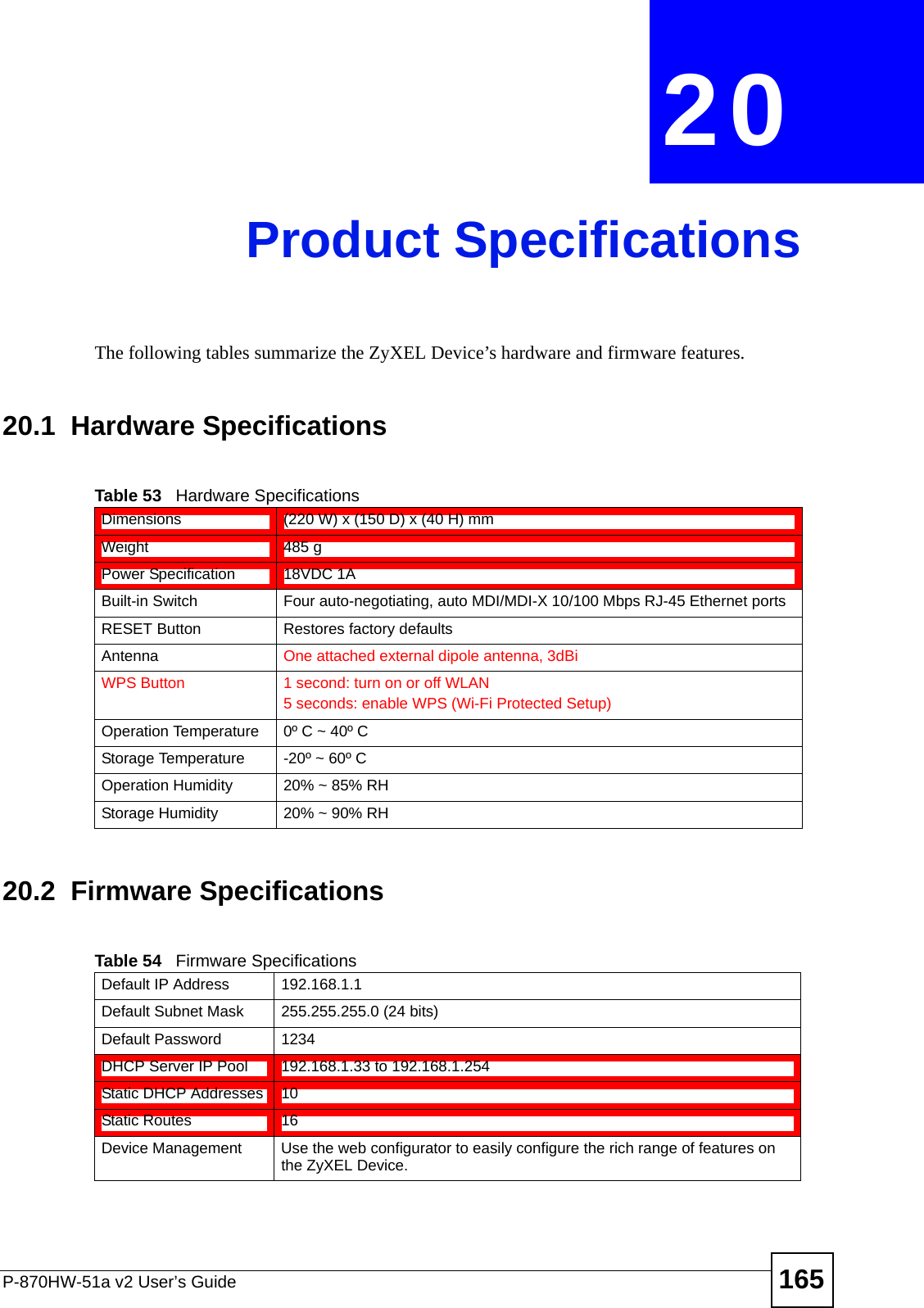
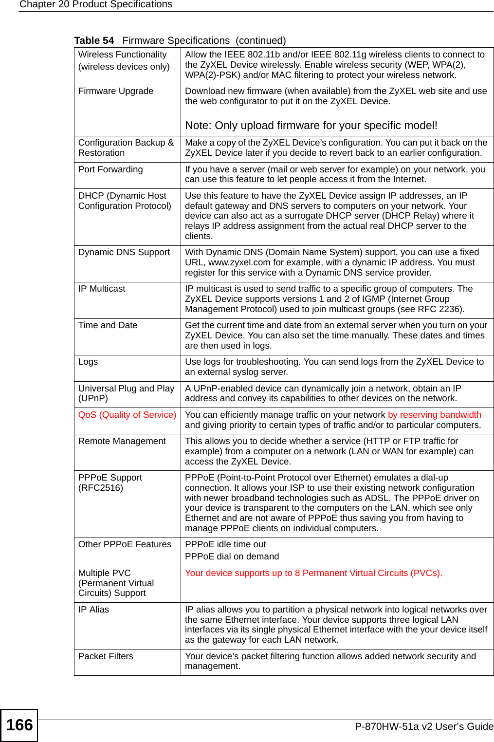
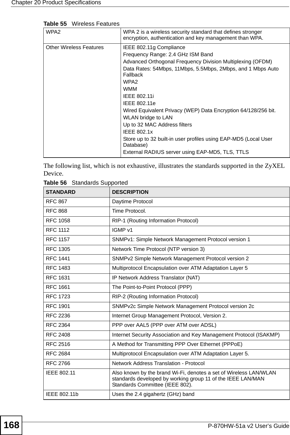
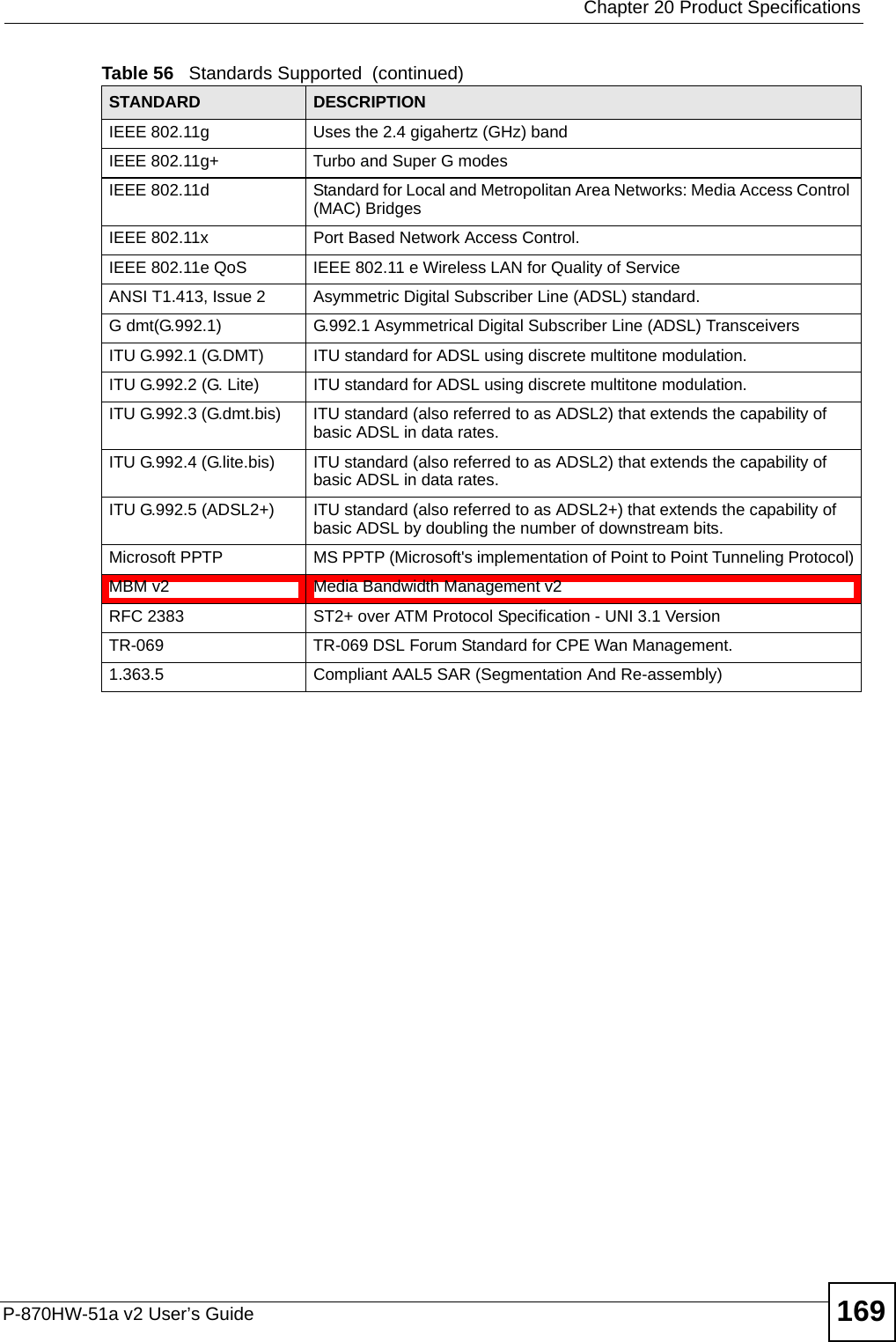
ZyXEL Communications P870HW51AV2 802.11bg Wireless VDSL2 4-Port Gateway User Manual SMG 700 User s Guide V1 00 Nov 2004
ZyXEL Communications Corporation 802.11bg Wireless VDSL2 4-Port Gateway SMG 700 User s Guide V1 00 Nov 2004
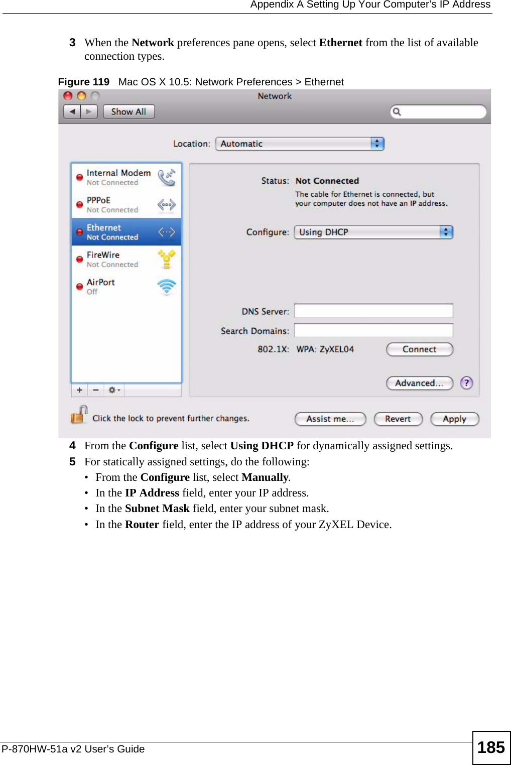
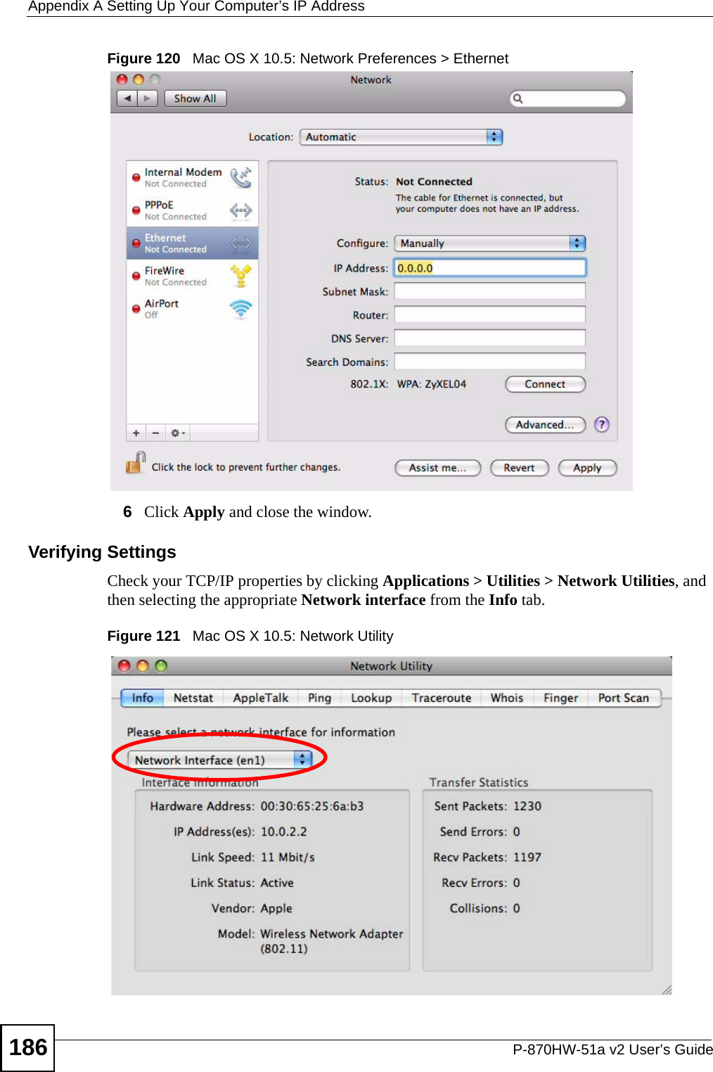
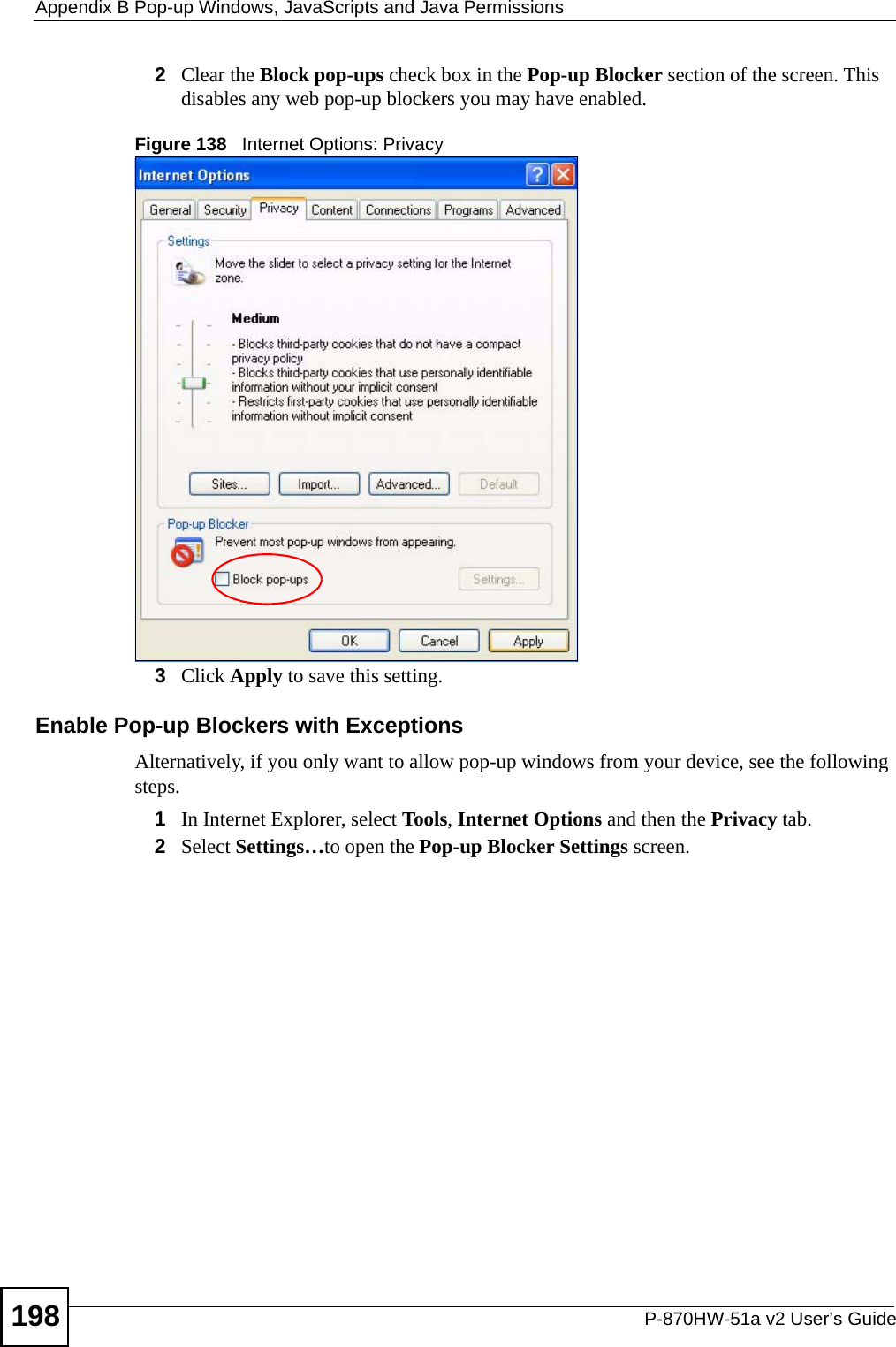
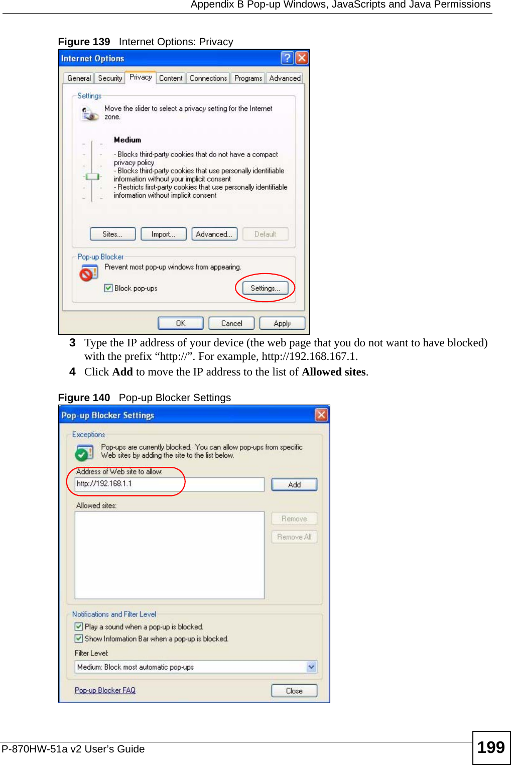
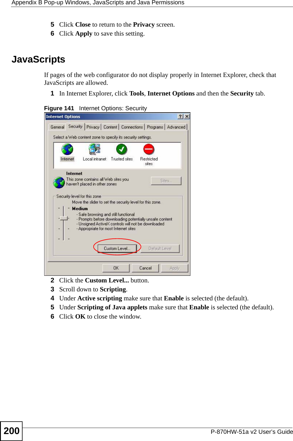
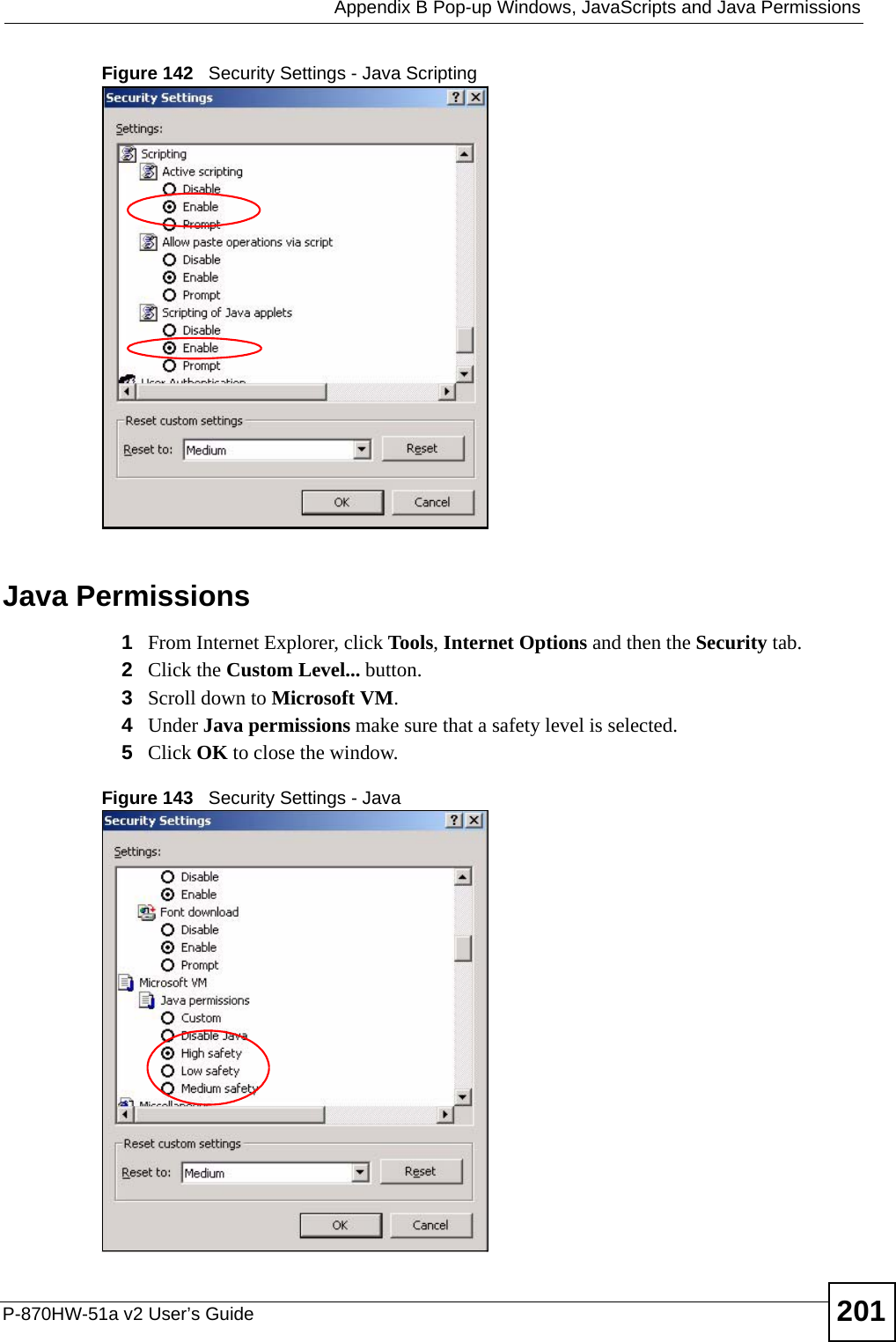
Contents
- 1. Installation guide 1
- 2. Installation guide 2
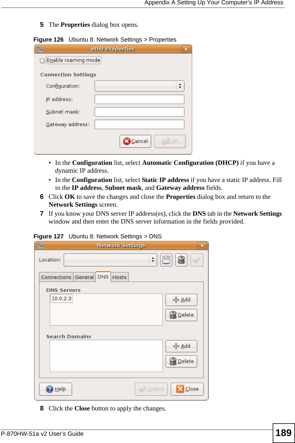
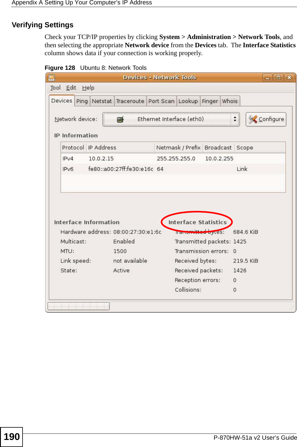
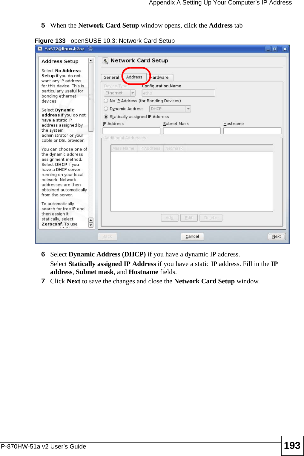
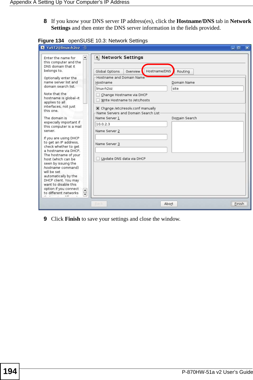
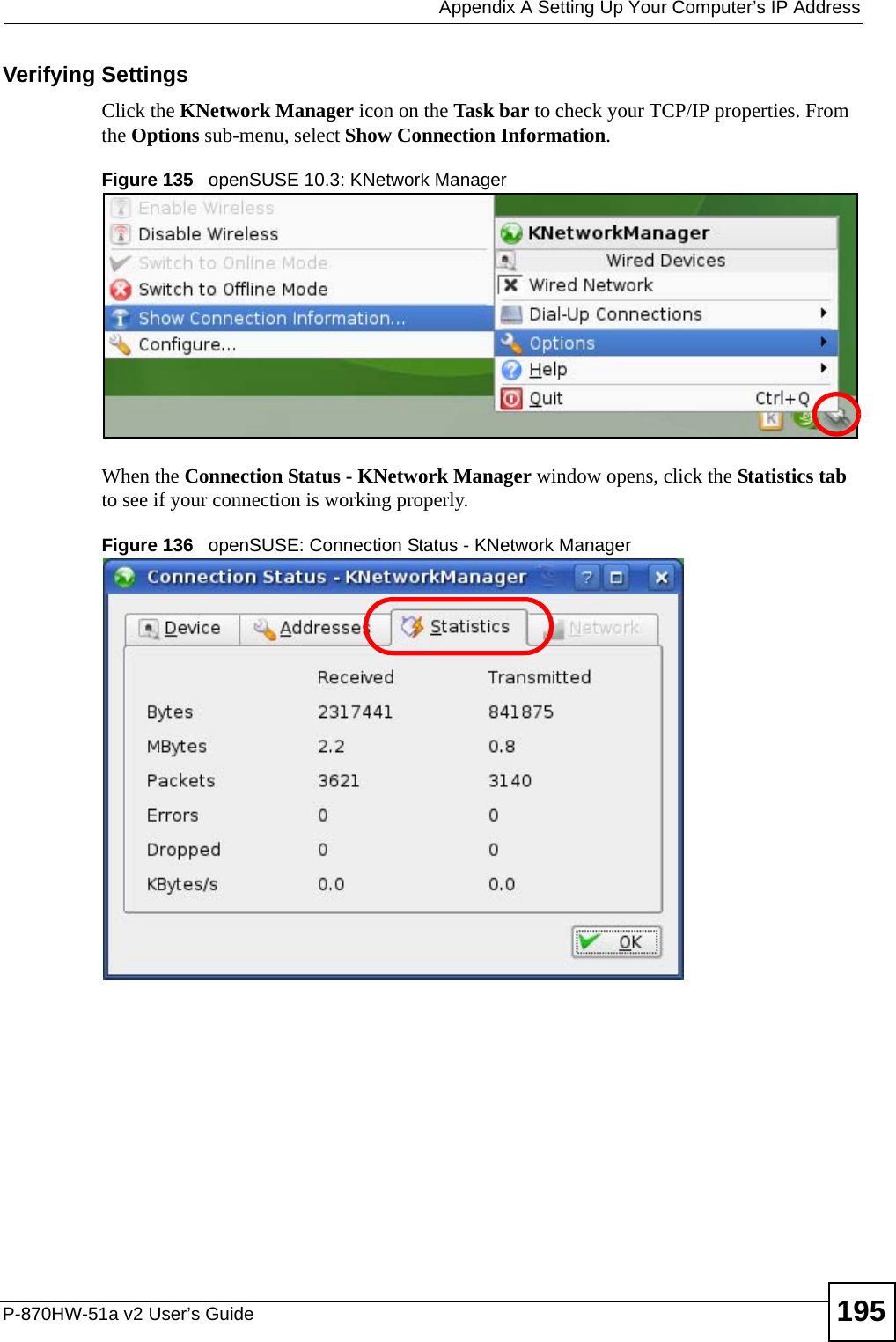
Installation guide 2

![Chapter 19 TroubleshootingP-870HW-51a v2 User’s Guide 161VI can see the Login screen, but I cannot log in to the ZyXEL Device.1Make sure you have entered the user name and password correctly. The default password is 1234. These fields are case-sensitive, so make sure [Caps Lock] is not on. 2Turn the ZyXEL Device off and on. 3If this does not work, you have to reset the device to its factory defaults. See Section 19.1 on page 159.19.3 Internet AccessVI cannot access the Internet.1Check the hardware connections, and make sure the LEDs are behaving as expected. See the Quick Start Guide and Section 1.5 on page 26. 2Make sure you entered your ISP account information correctly in the WAN screens. These fields are case-sensitive, so make sure [Caps Lock] is not on. 3If you are trying to access the Internet wirelessly, make sure the wireless settings in the wireless client are the same as the settings in the AP. 4Disconnect all the cables from your device, and follow the directions in the Quick Start Guide again. 5If the problem continues, contact your ISP. VI cannot access the Internet anymore. I had access to the Internet (with the ZyXEL Device), but my Internet connection is not available anymore.1Check the hardware connections, and make sure the LEDs are behaving as expected. See the Quick Start Guide and Section 1.5 on page 26.2Turn the ZyXEL Device off and on. 3If the problem continues, contact your ISP. VThe Internet connection is slow or intermittent.1There might be a lot of traffic on the network. Look at the LEDs, and check Section 1.5 on page 26. If the ZyXEL Device is sending or receiving a lot of information, try closing some programs that use the Internet, especially peer-to-peer applications.](https://usermanual.wiki/ZyXEL-Communications/P870HW51AV2.Installation-guide-2/User-Guide-1050501-Page-11.png)


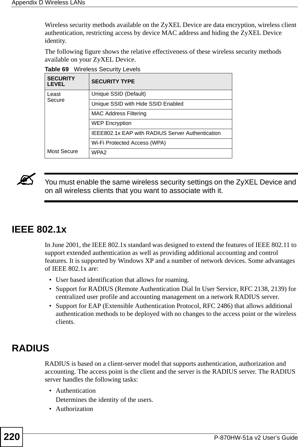
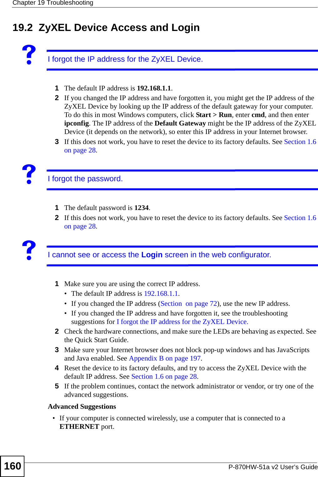
![Appendix A Setting Up Your Computer’s IP AddressP-870HW-51a v2 User’s Guide1765The Internet Protocol TCP/IP Properties window opens.Figure 103 Windows XP: Internet Protocol (TCP/IP) Properties6Select Obtain an IP address automatically if your network administrator or ISP assigns your IP address dynamically.Select Use the following IP Address and fill in the IP address, Subnet mask, and Default gateway fields if you have a static IP address that was assigned to you by your network administrator or ISP. You may also have to enter a Preferred DNS server and an Alternate DNS server, if that information was provided.7Click OK to close the Internet Protocol (TCP/IP) Properties window.8Click OK to close the Local Area Connection Properties window.Verifying Settings1Click Start > All Programs > Accessories > Command Prompt.2In the Command Prompt window, type "ipconfig" and then press [ENTER]. You can also go to Start > Control Panel > Network Connections, right-click a network connection, click Status and then click the Support tab to view your IP address and connection information.](https://usermanual.wiki/ZyXEL-Communications/P870HW51AV2.Installation-guide-2/User-Guide-1050501-Page-26.png)
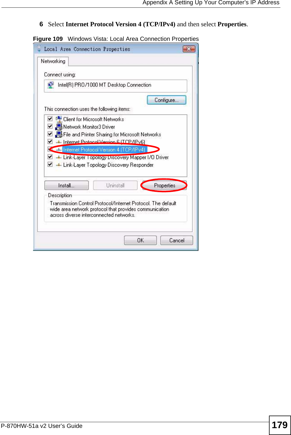
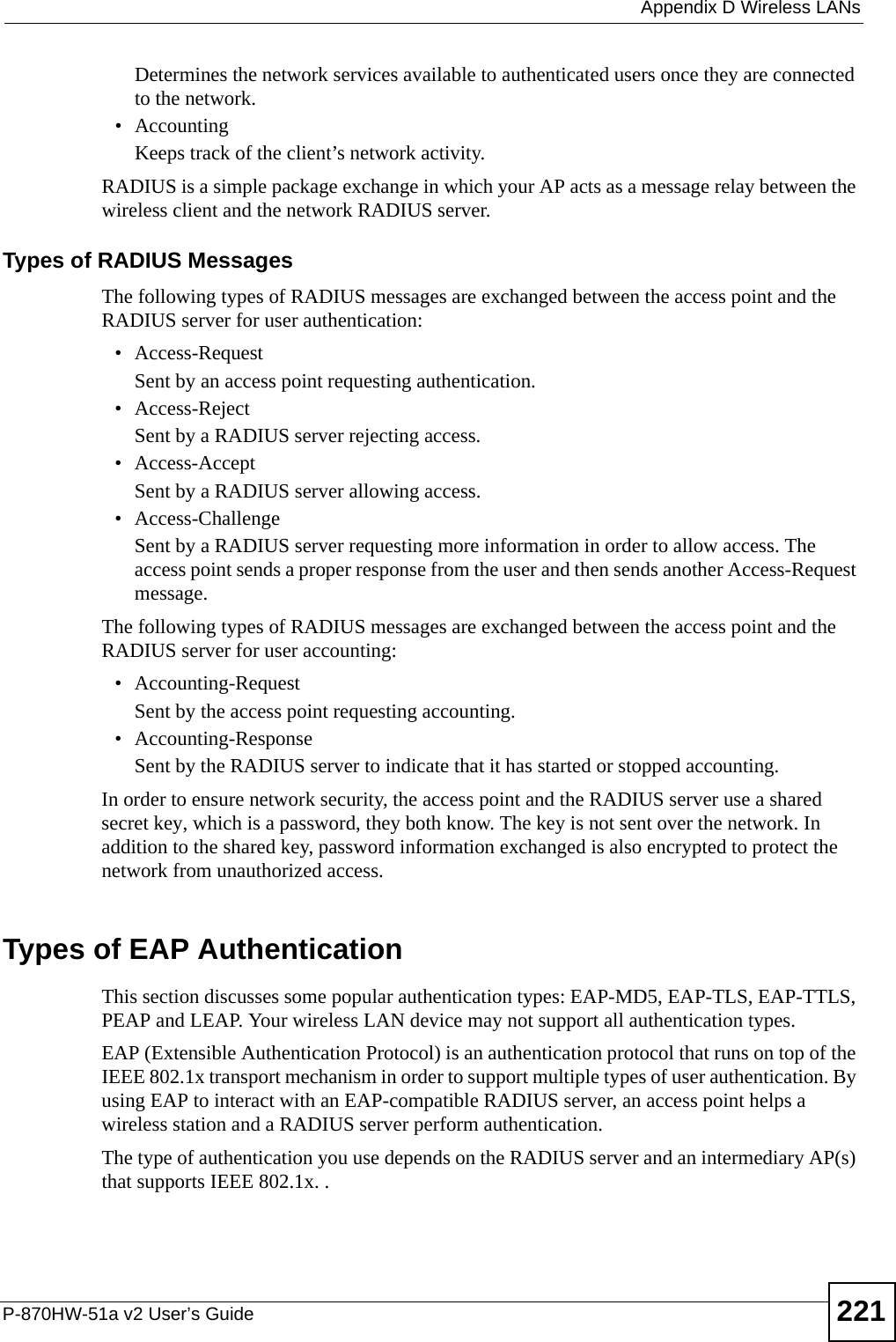
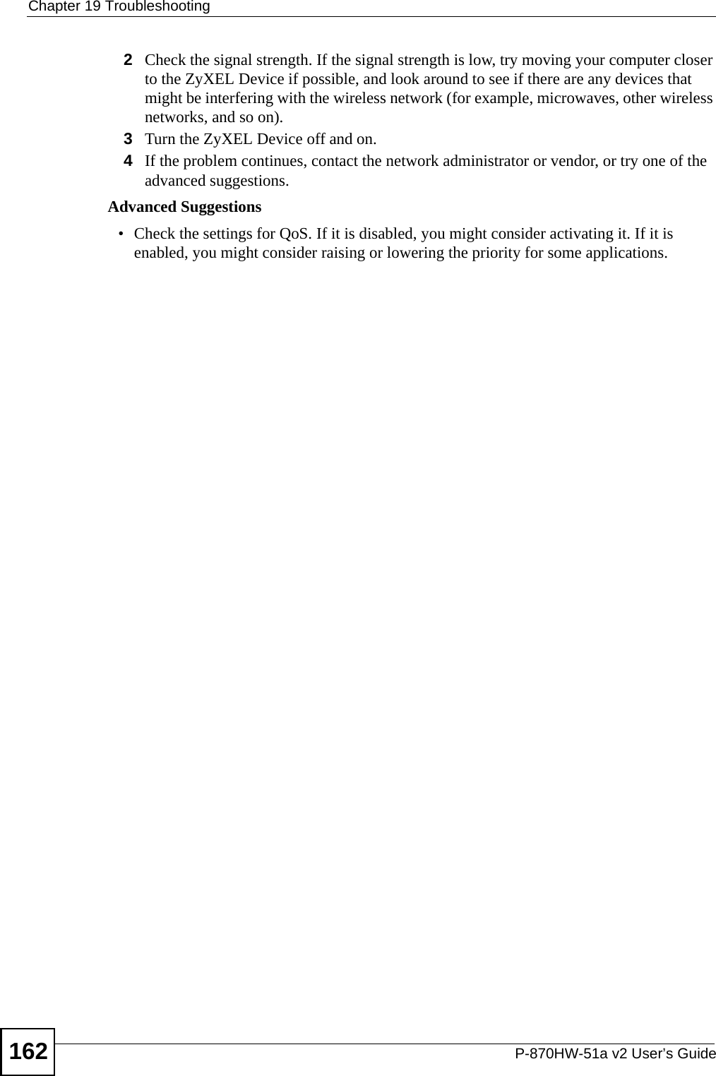
![Appendix A Setting Up Your Computer’s IP AddressP-870HW-51a v2 User’s Guide1807The Internet Protocol Version 4 (TCP/IPv4) Properties window opens.Figure 110 Windows Vista: Internet Protocol Version 4 (TCP/IPv4) Properties8Select Obtain an IP address automatically if your network administrator or ISP assigns your IP address dynamically.Select Use the following IP Address and fill in the IP address, Subnet mask, and Default gateway fields if you have a static IP address that was assigned to you by your network administrator or ISP. You may also have to enter a Preferred DNS server and an Alternate DNS server, if that information was provided.Click Advanced.9Click OK to close the Internet Protocol (TCP/IP) Properties window.10 Click OK to close the Local Area Connection Properties window.Verifying Settings1Click Start > All Programs > Accessories > Command Prompt.2In the Command Prompt window, type "ipconfig" and then press [ENTER]. You can also go to Start > Control Panel > Network Connections, right-click a network connection, click Status and then click the Support tab to view your IP address and connection information.](https://usermanual.wiki/ZyXEL-Communications/P870HW51AV2.Installation-guide-2/User-Guide-1050501-Page-30.png)