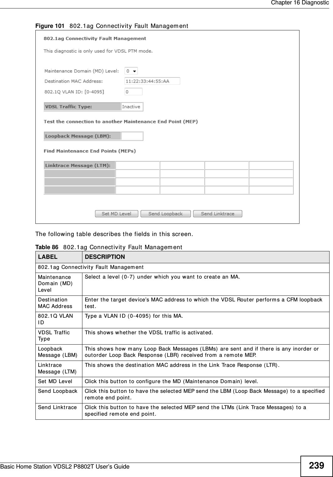
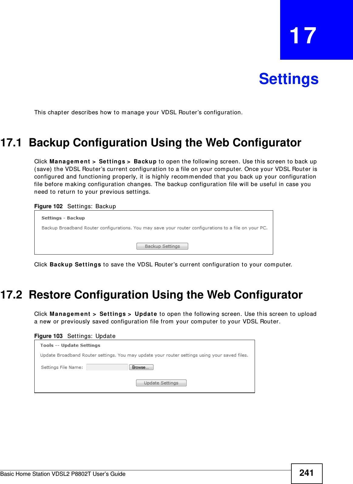
ZyXEL Communications P8802T Wireless N VDSL2 VoIP IAD With USB User Manual Book
ZyXEL Communications Corporation Wireless N VDSL2 VoIP IAD With USB Book
UserManual.wiki
>
ZyXEL Communications
>
P8802T User Manual
User Manual
Navigation menu
Upload a User Manual
Namespaces
Wiki Guide
HTML
PDF
Info
Views
User Manual
Discussion / Help
Navigation
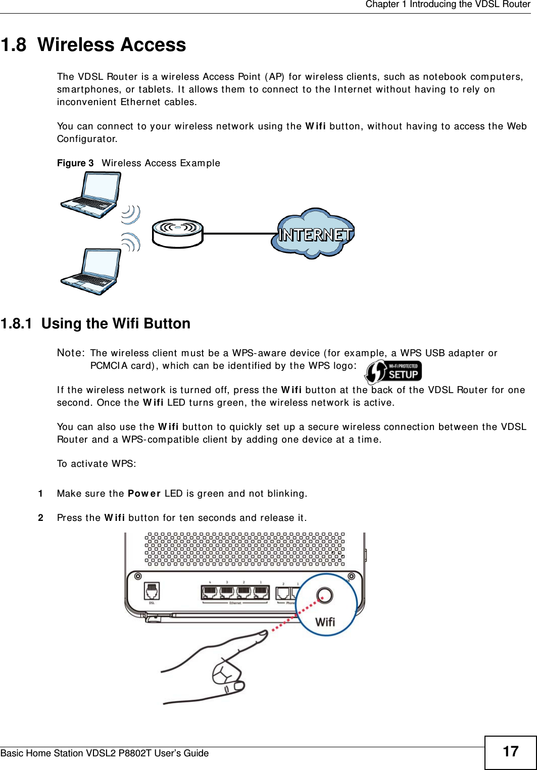
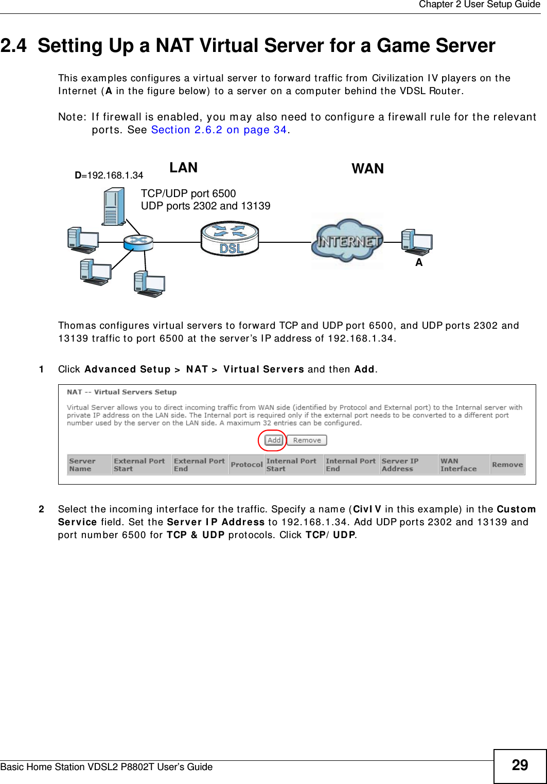

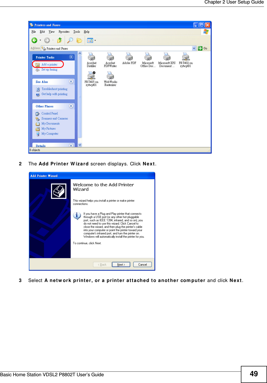
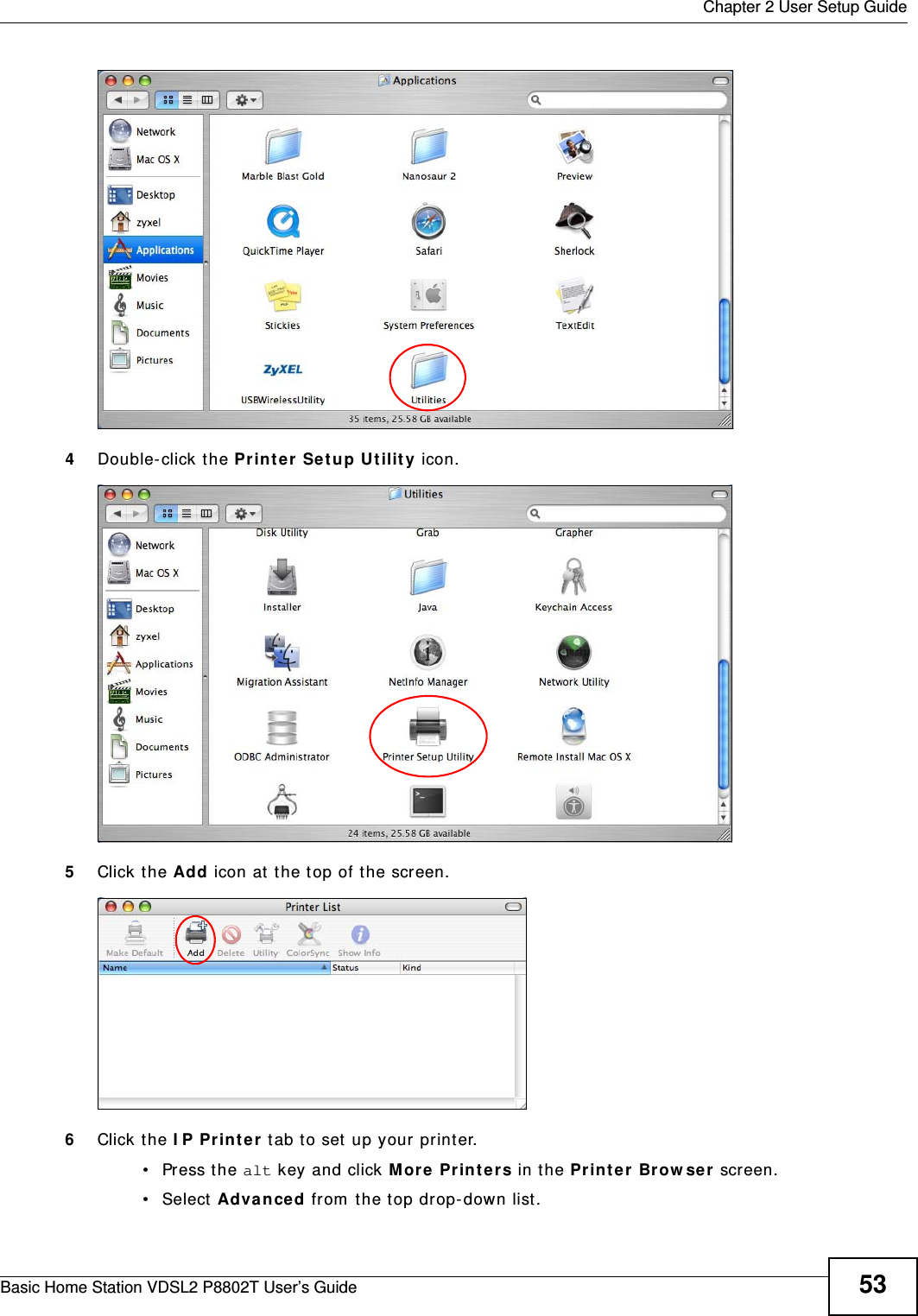
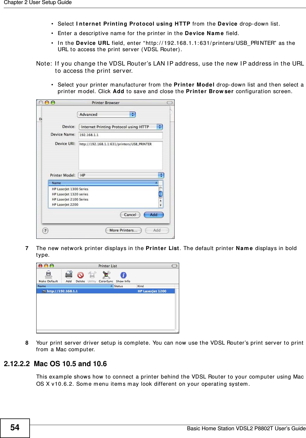
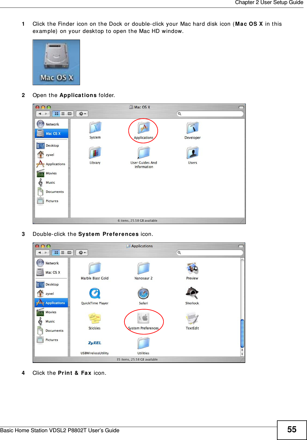
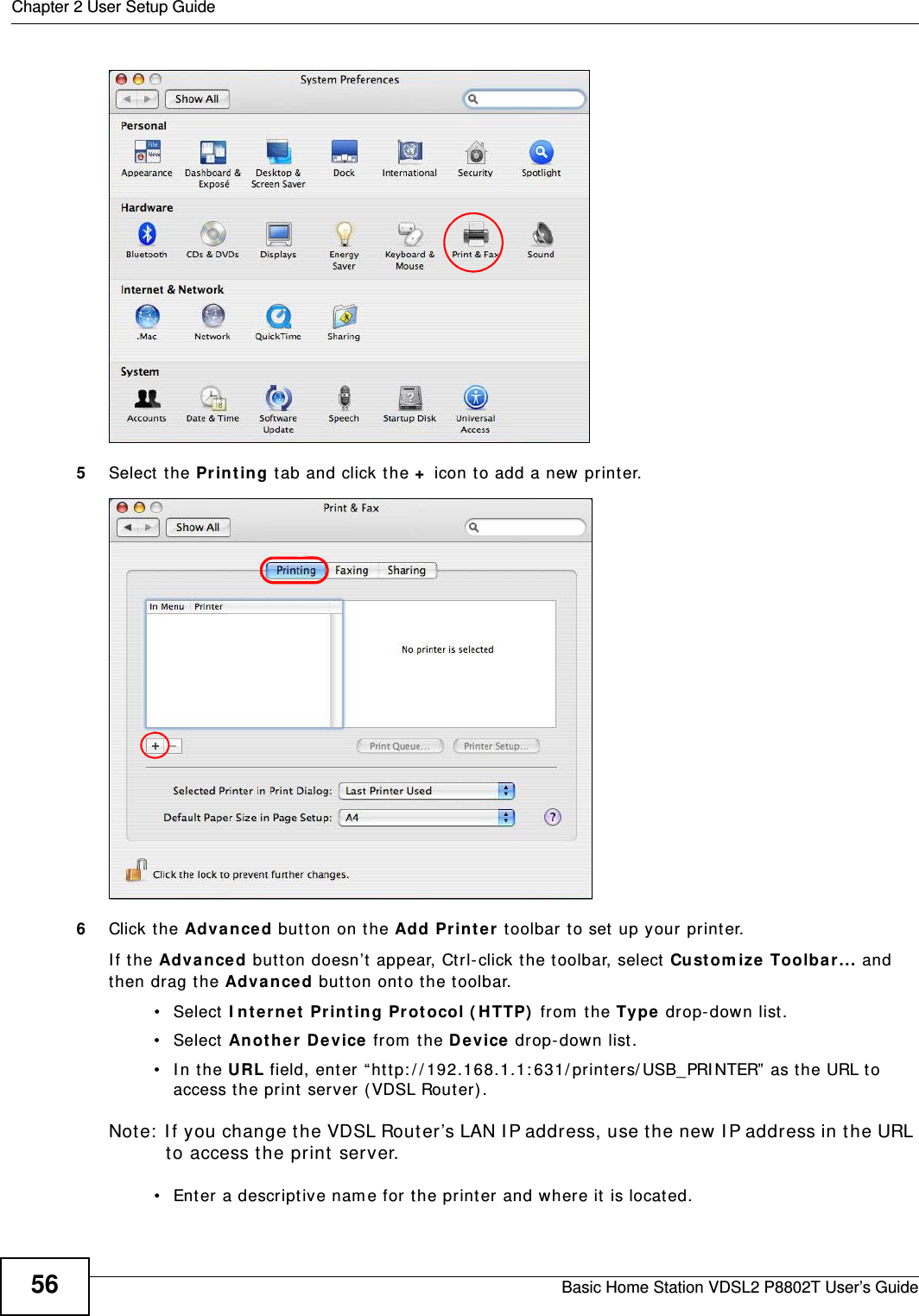
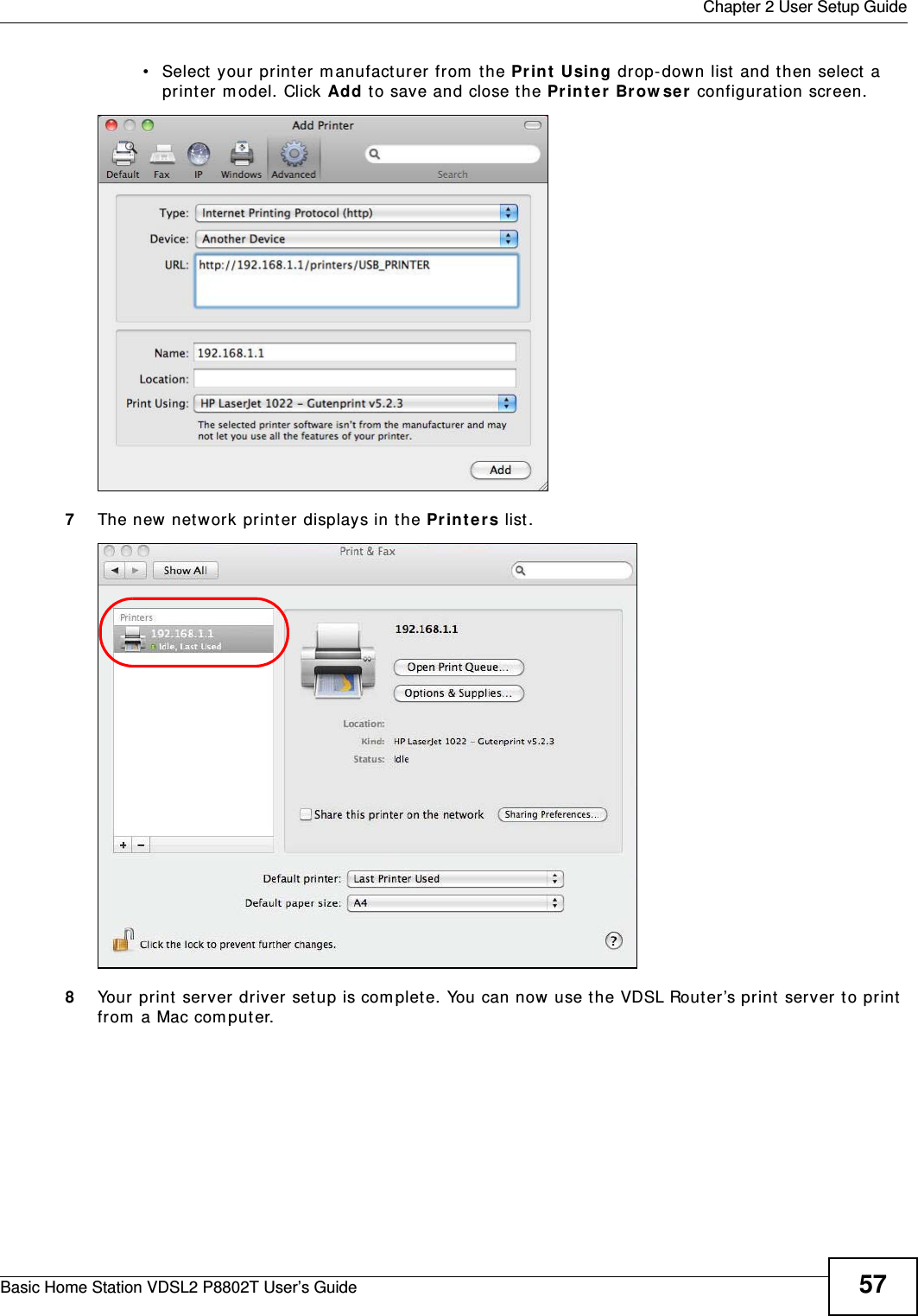
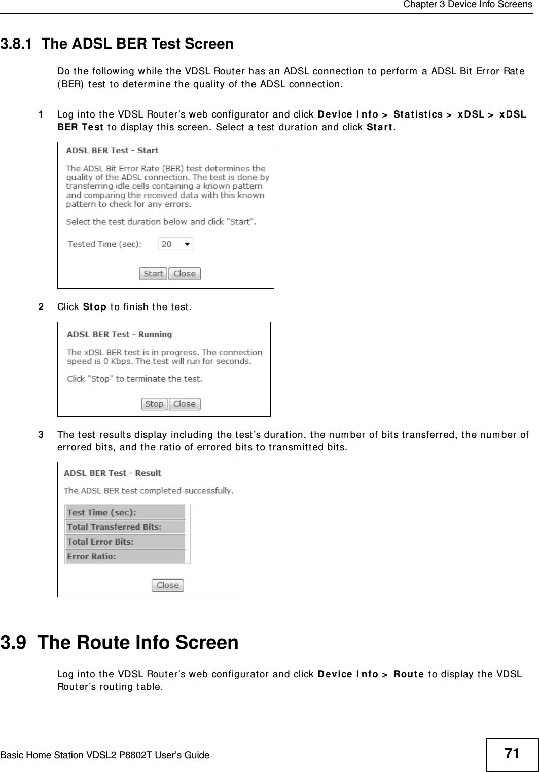
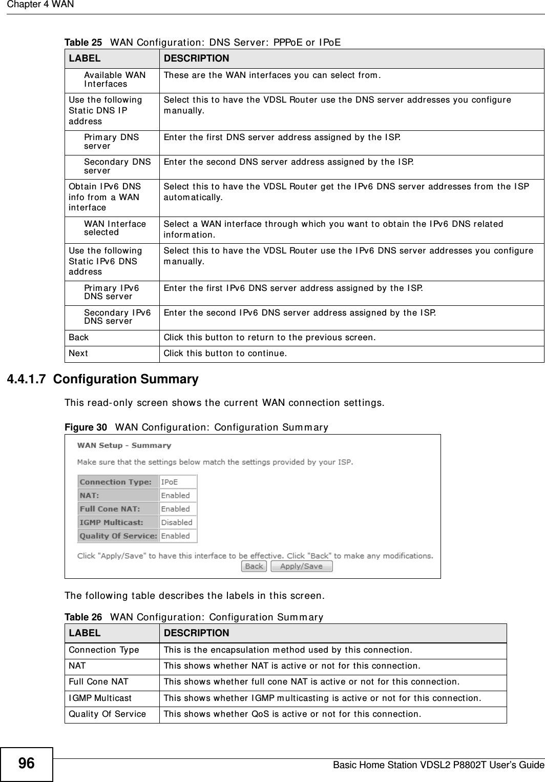
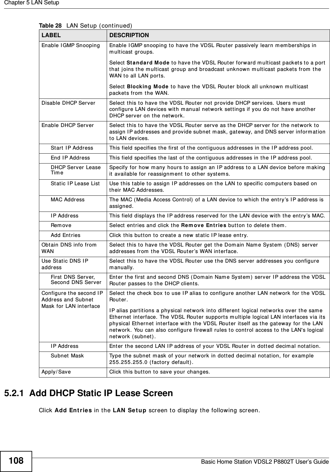
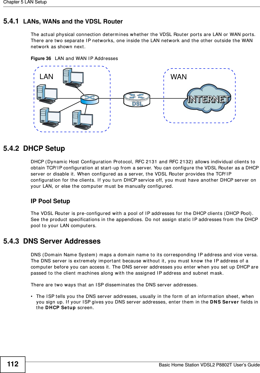
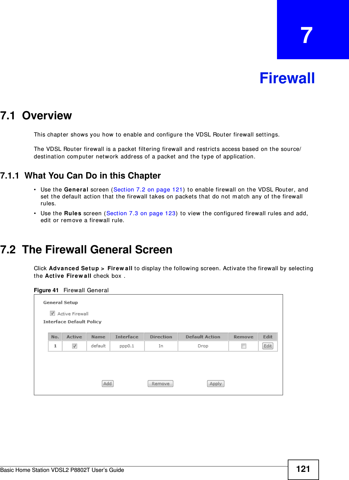
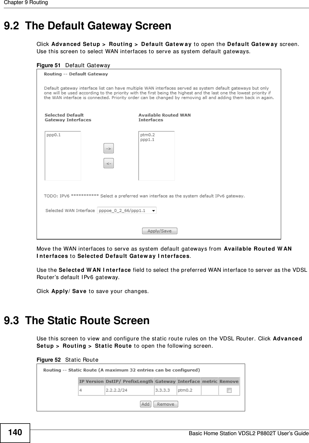
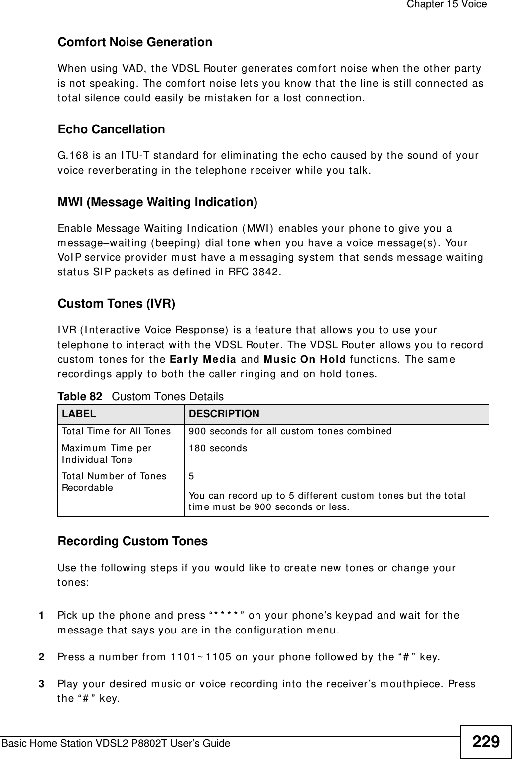
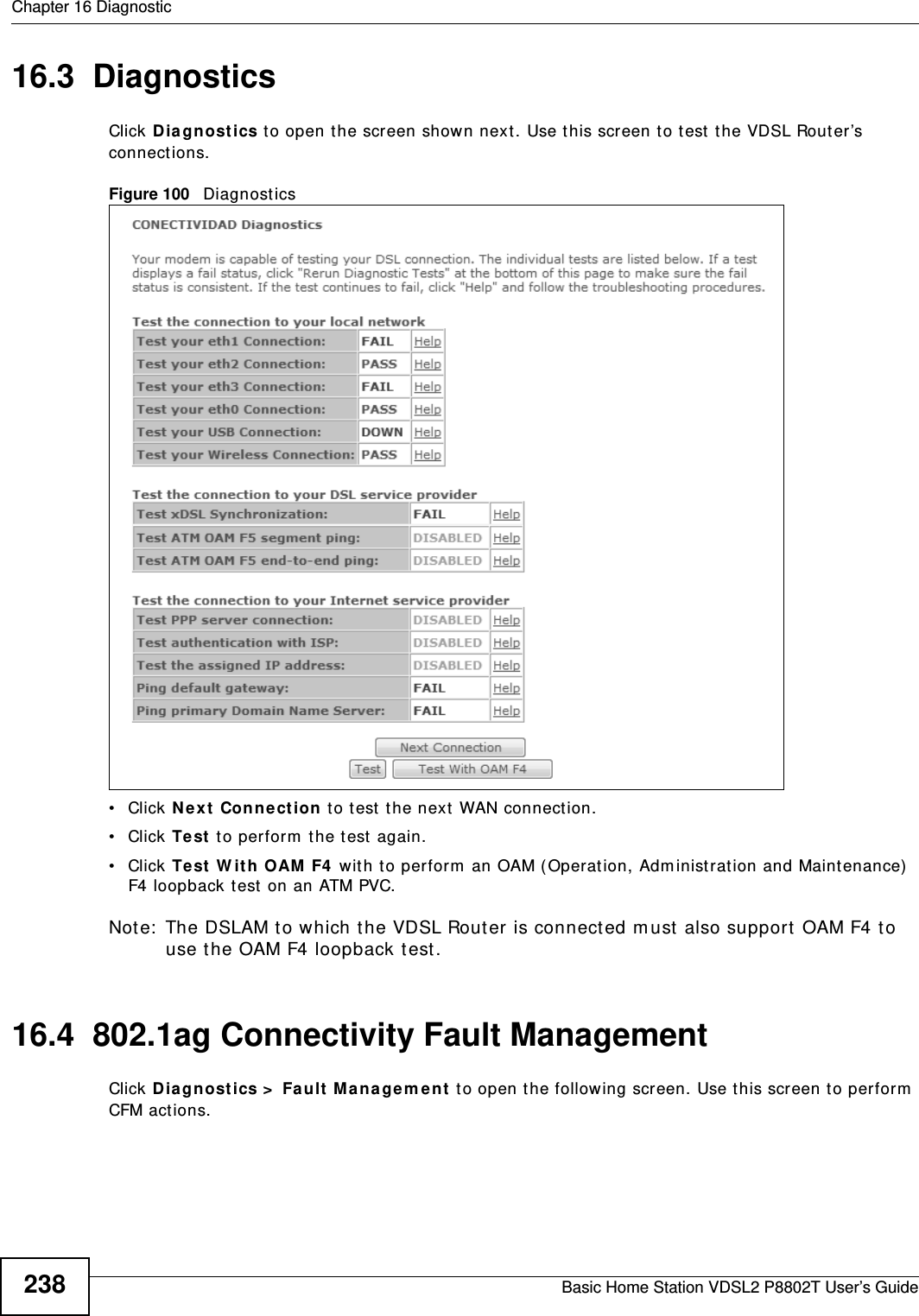
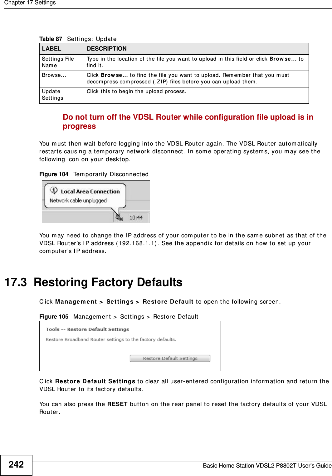
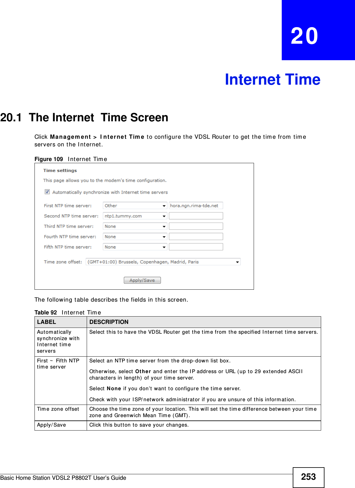
![Chapter 2 User Setup GuideBasic Home Station VDSL2 P8802T User’s Guide322.5.3 Configuring Port Forwarding on your VDSL RouterConfigure t he following set t ings in t he Adva nce d Se tup > N AT > Virtua l Ser ve rs > Add screen.• Leave t he inter face set to the default unless you have configured another interface t o use.• Select Cust om Service and type RD in the field.• Type the LAN I P address of your com puter in the Ser ver I P Addr e ss f ield. To ch eck t his on y our hom e computer, click St ar t , All Pr ogram s, Acce ssor ies and t hen Com m and Prom pt. I n the Com m a nd Pr om pt window, type " ipconfig" and t hen press [ ENTER] . This exam ple uses 1 9 2 .1 6 8 .1 .6 4 . See Configuring St at ic DHCP to configure a Stat ic DHCP rule for t his I P address. • Type 3 3 8 9 in the Exter na l/ I nt ern al St a rt/ End Por t fields. This is t he listening port for Windows rem ot e desktop.• Select the TCP in t he Pro t ocol field.](https://usermanual.wiki/ZyXEL-Communications/P8802T/User-Guide-1781920-Page-32.png)
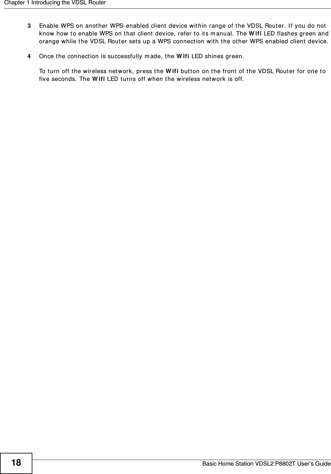
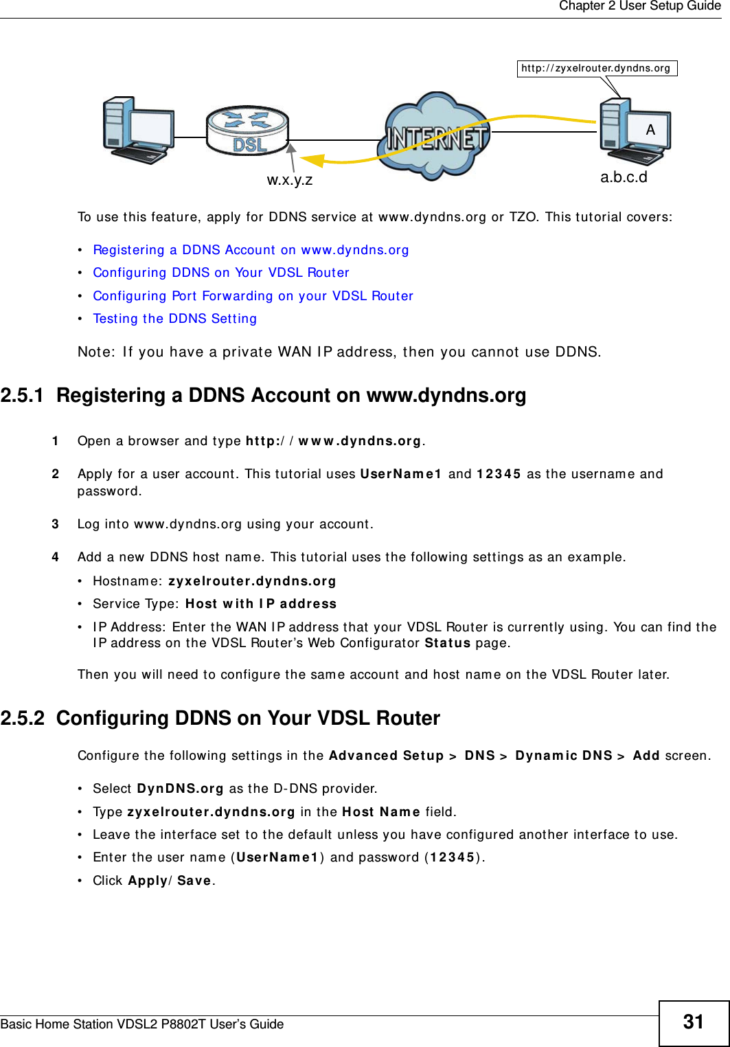
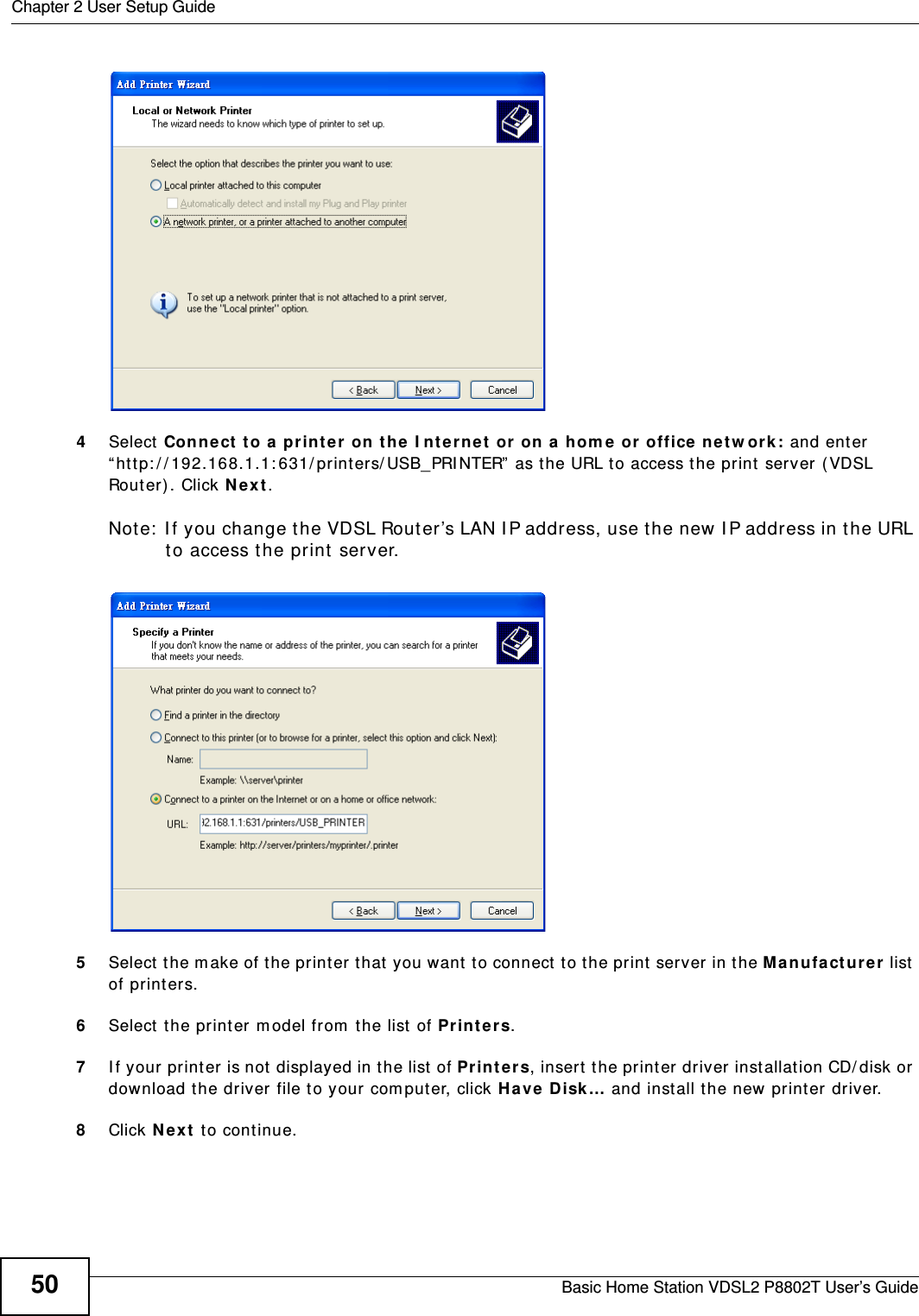
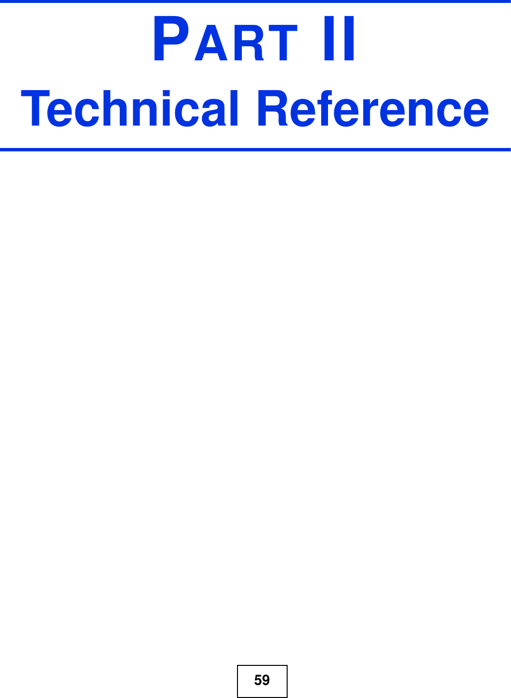
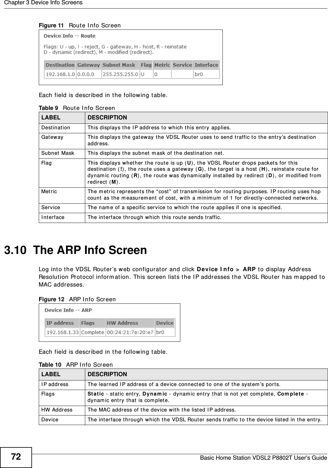
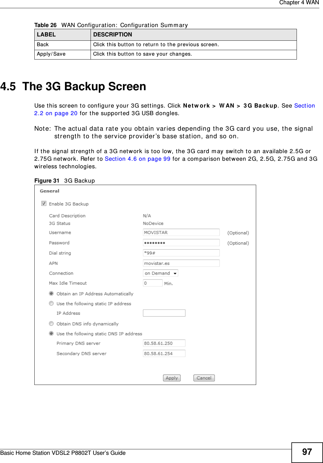
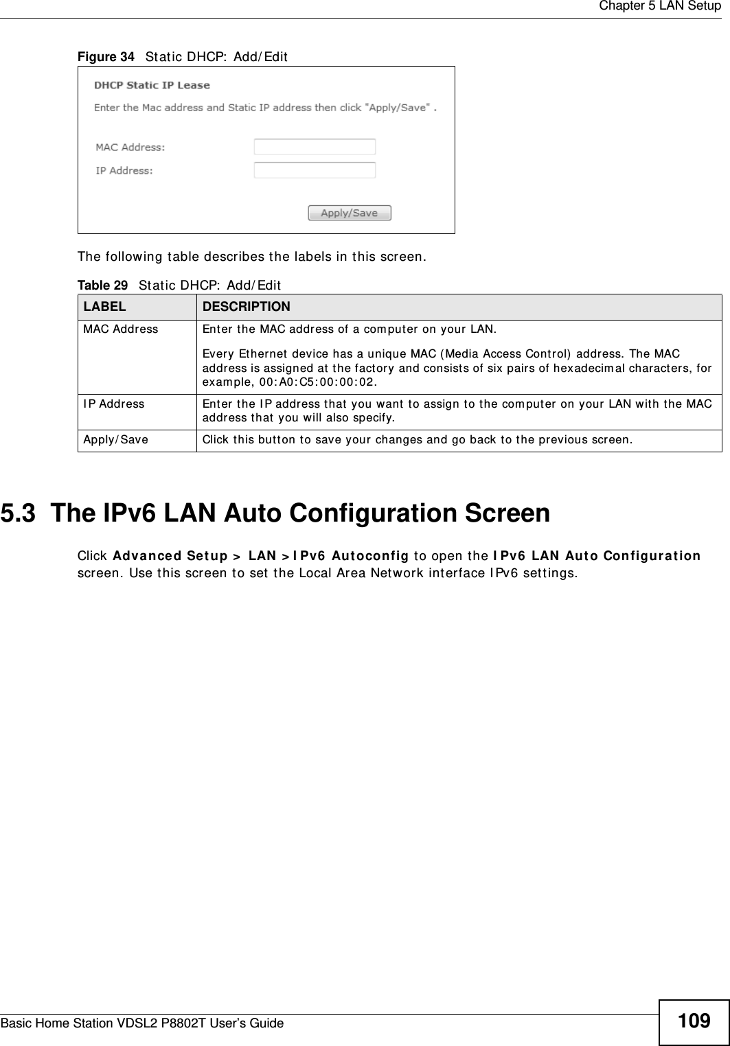
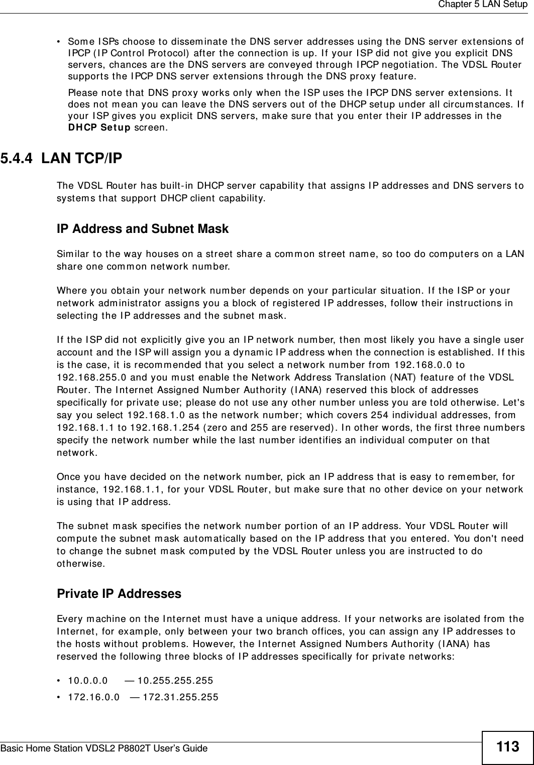
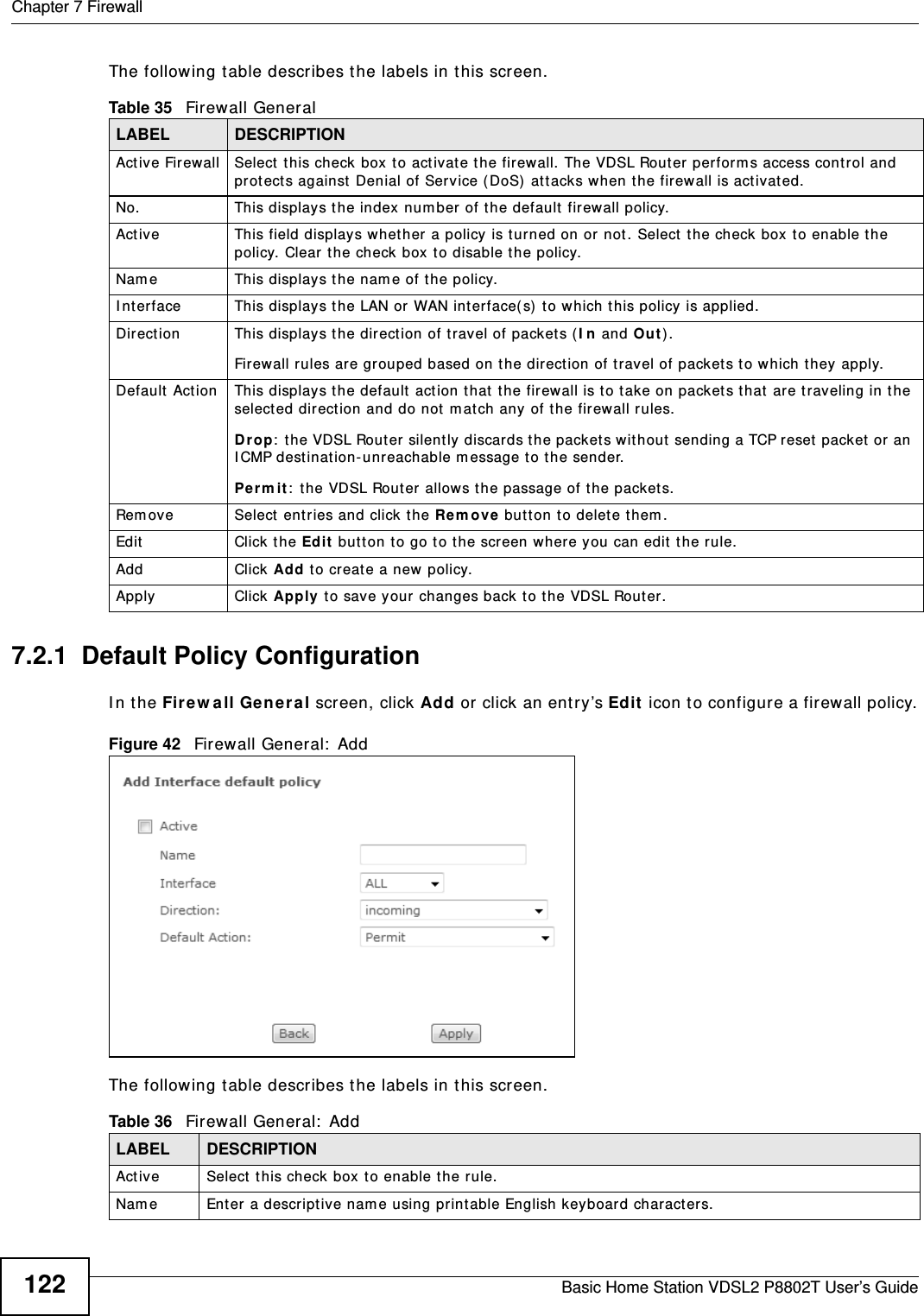
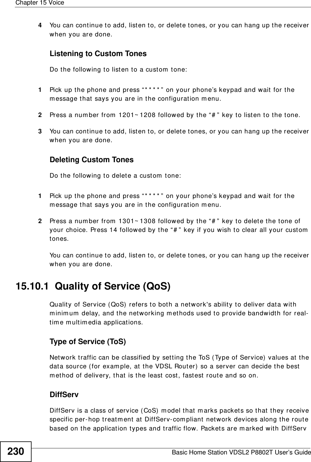
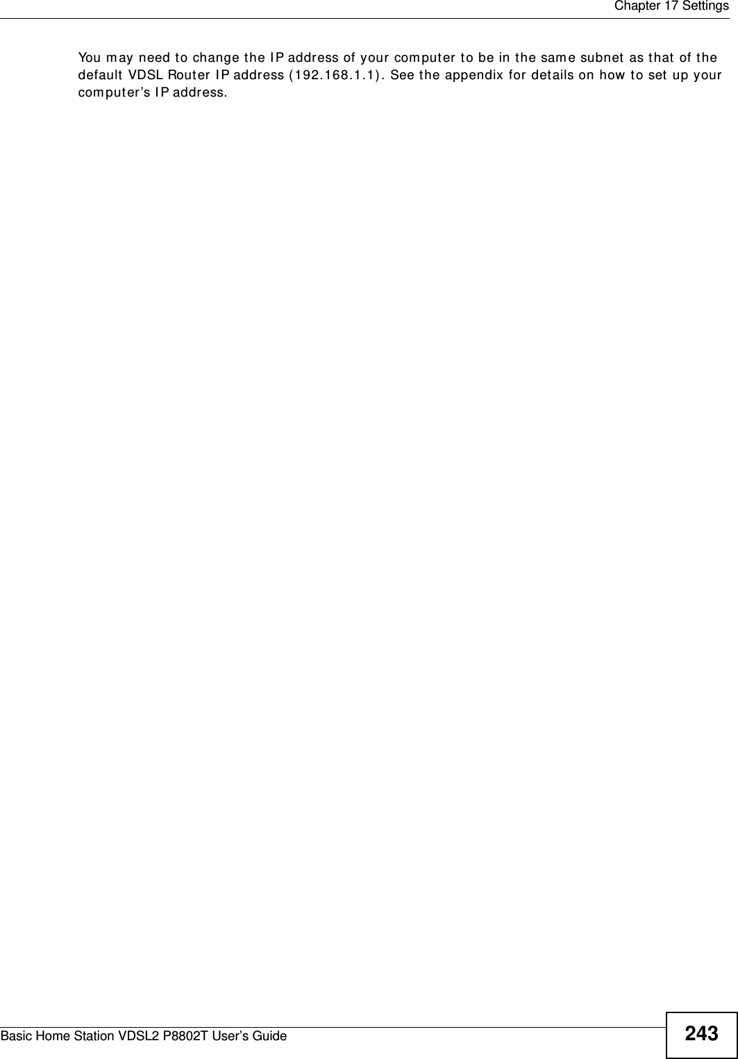
![Chapter 2 User Setup GuideBasic Home Station VDSL2 P8802T User’s Guide 33Click Apply / Sa ve .2.5.4 Testing the DDNS SettingTest your access t o your com puter from the I nt ernet . 1Open the remot e deskt op client application on t he rem ot e comput er (using t he I P address a .b.c.d) that is connect ed to t he I nt ernet .2Ty p e ht t p:/ / z y xe lrou t er .dy ndn s. or g and press [ Ent er] .3Your com puter’s rem ote deskt op login page should appear.](https://usermanual.wiki/ZyXEL-Communications/P8802T/User-Guide-1781920-Page-33.png)
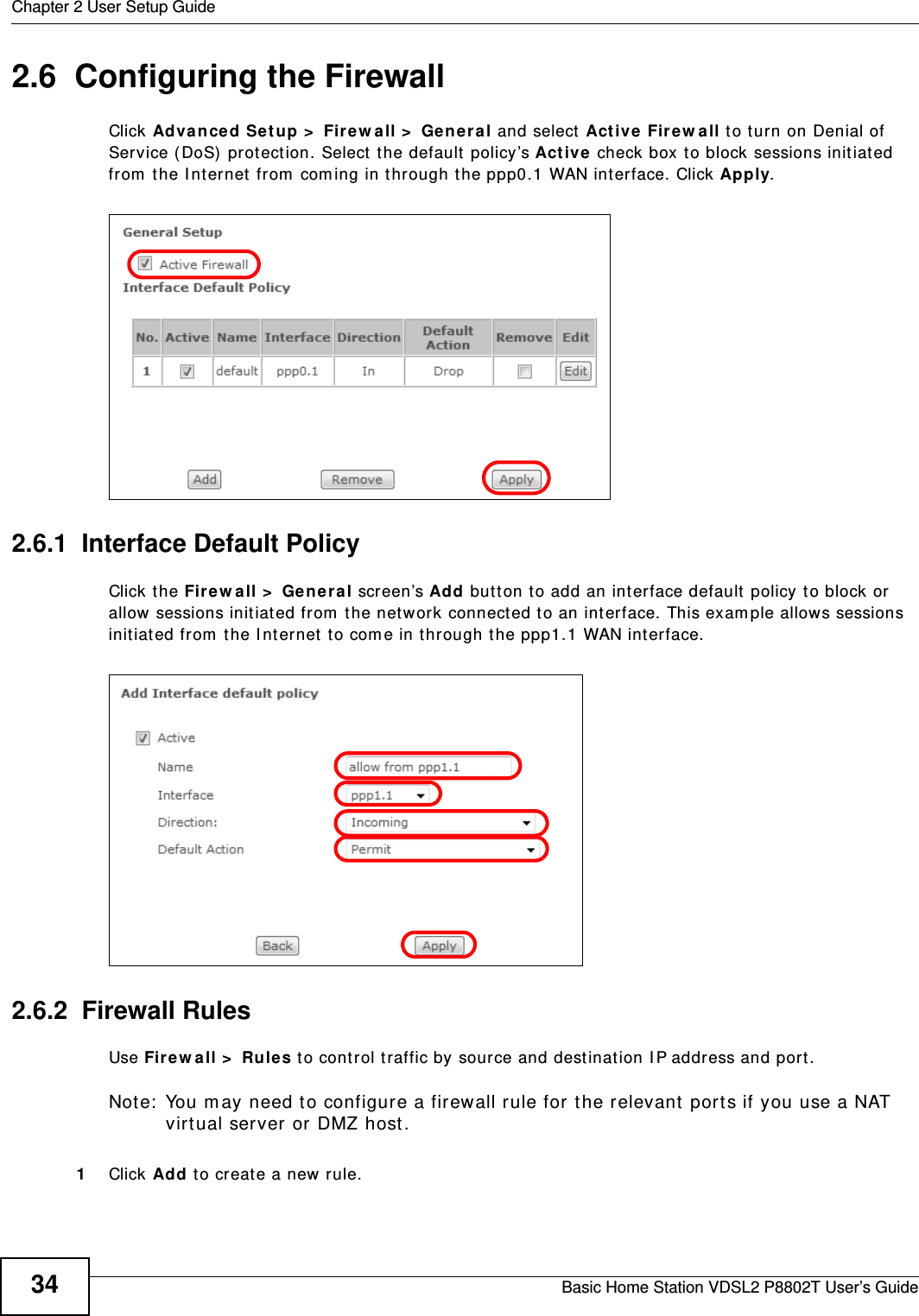
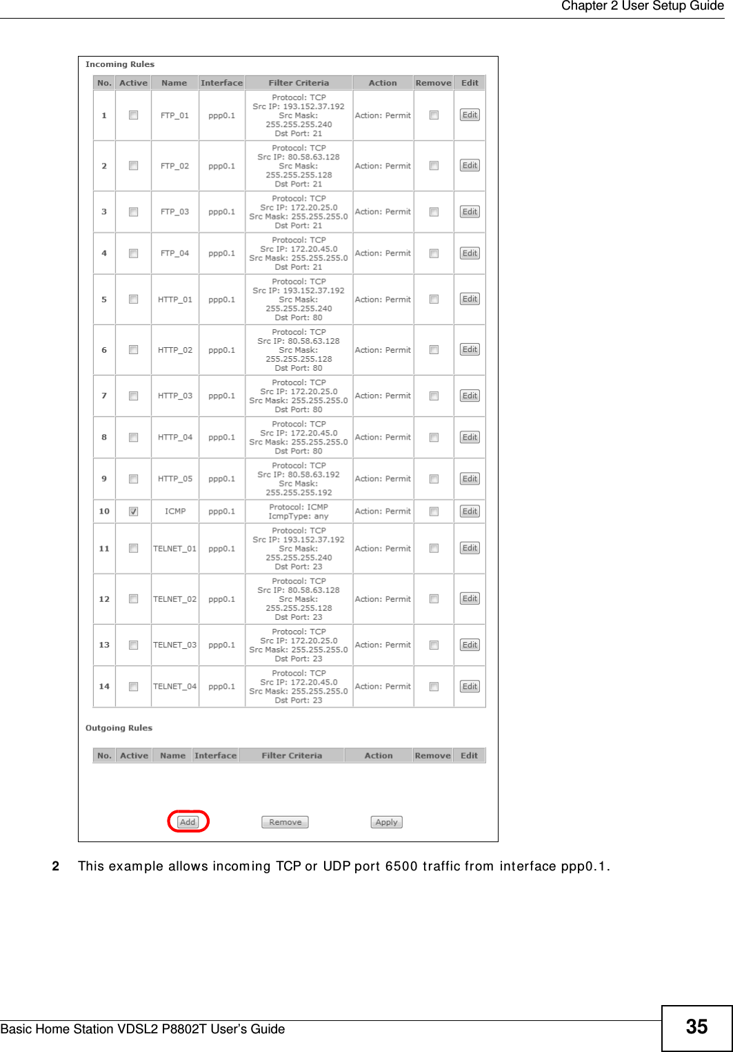
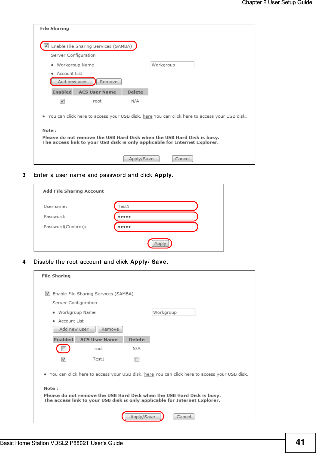
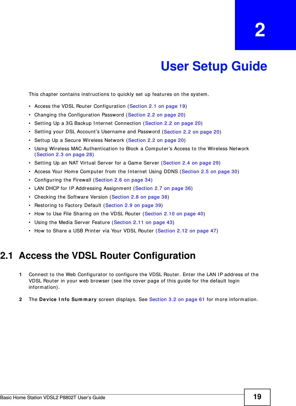
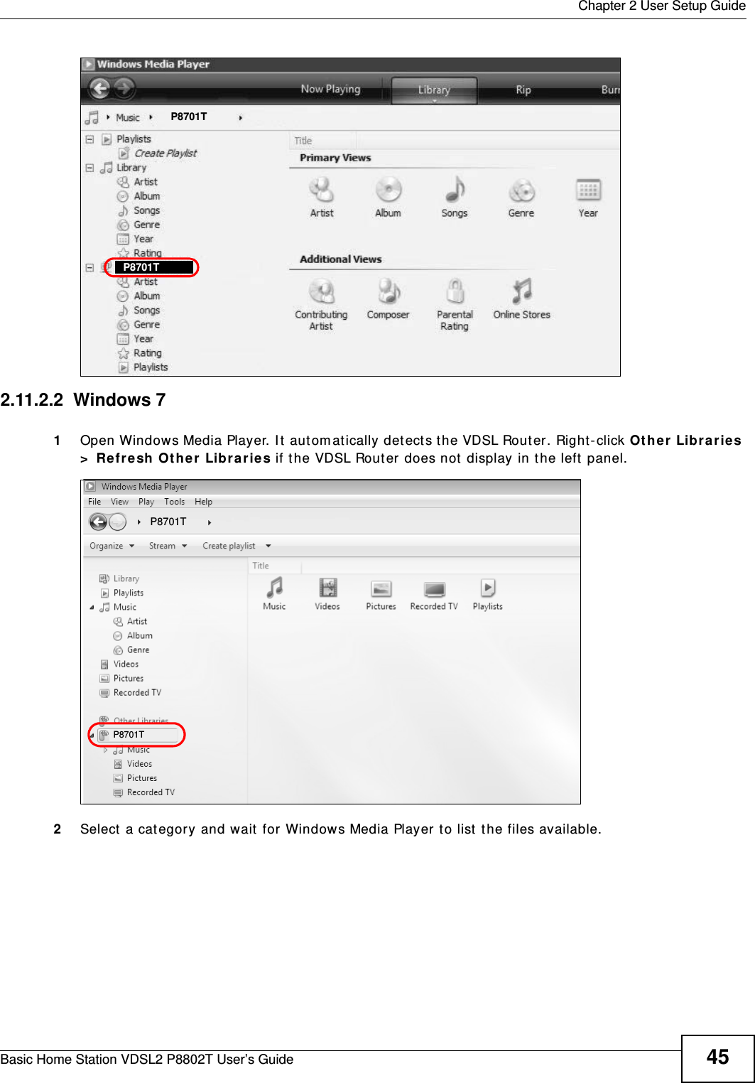
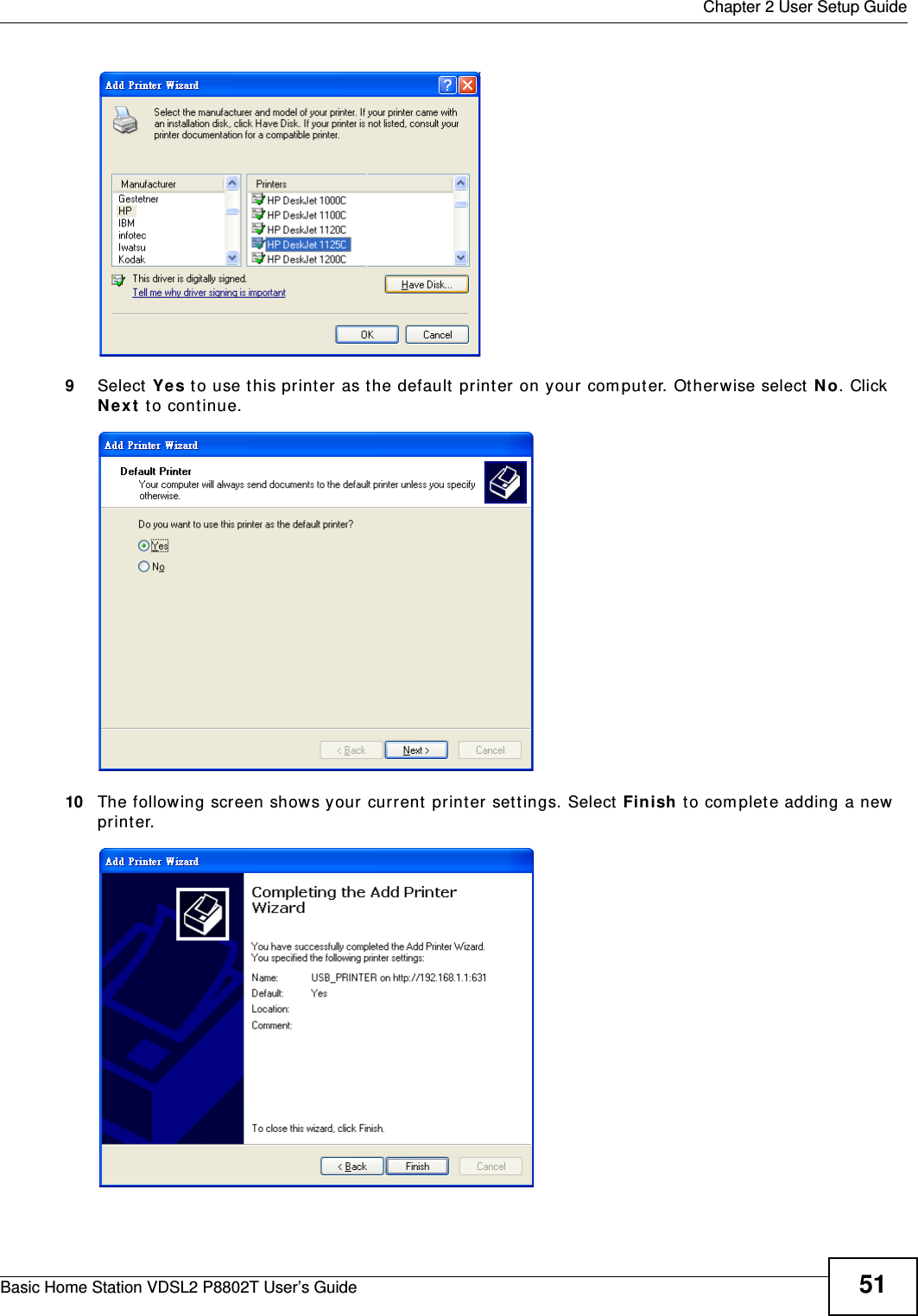
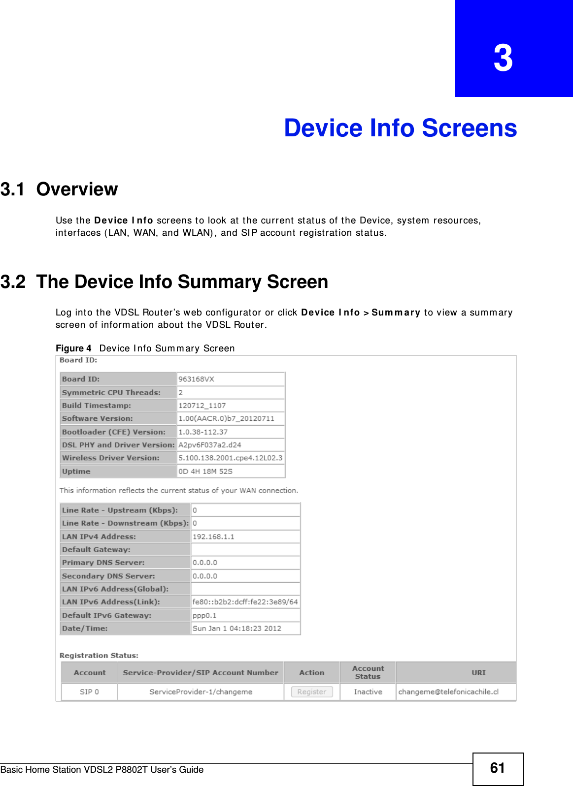
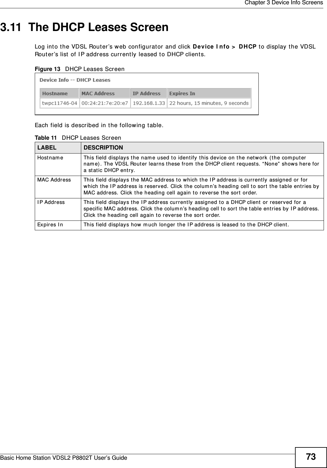
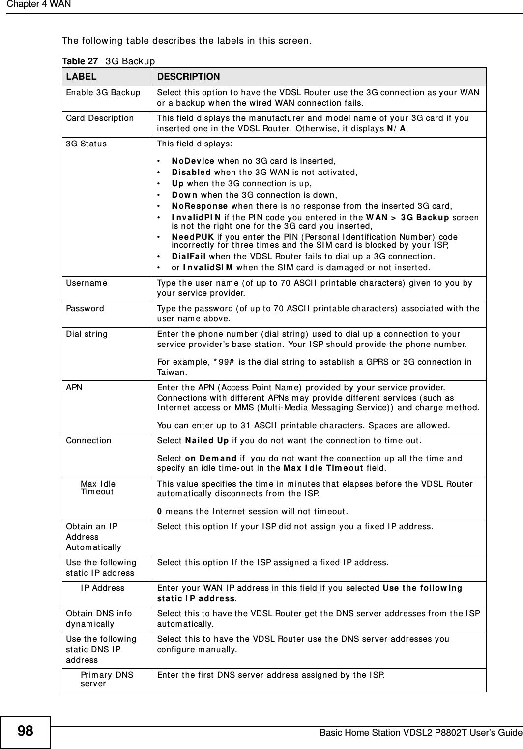
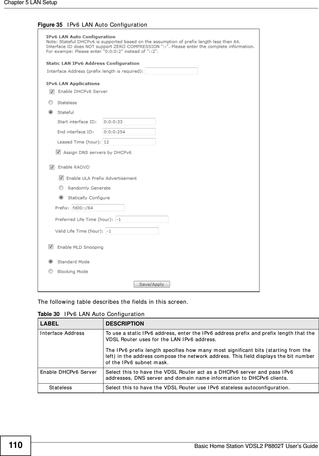
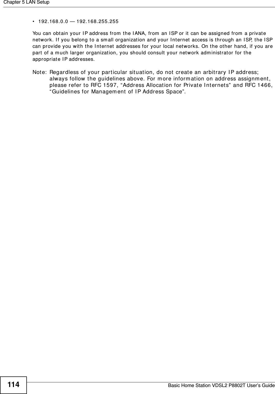
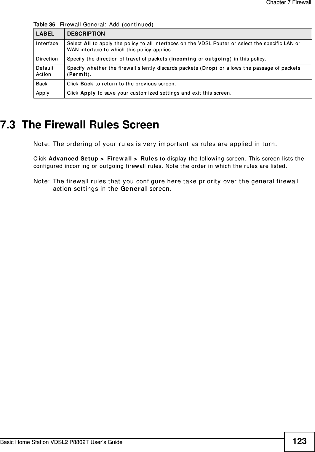
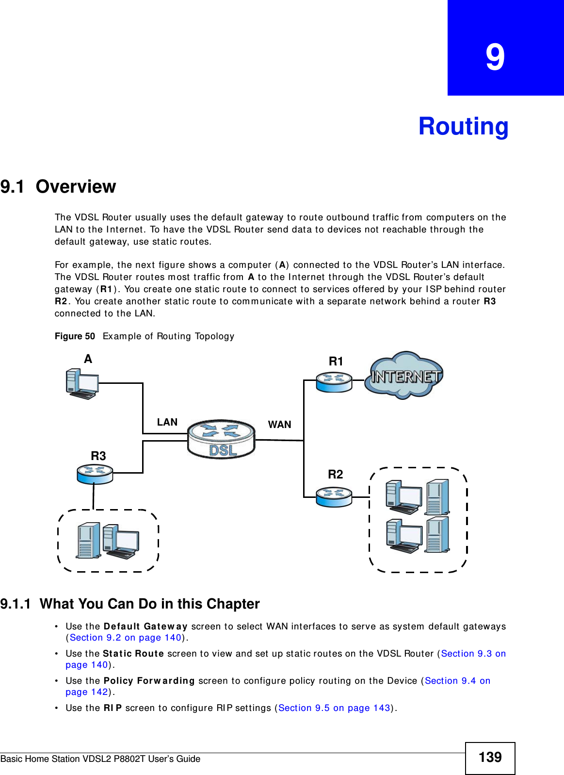
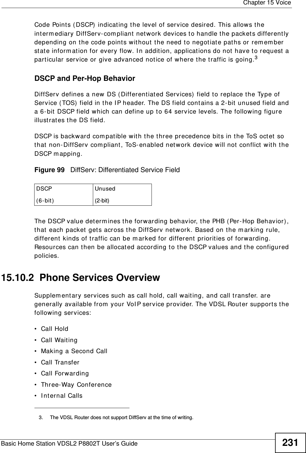
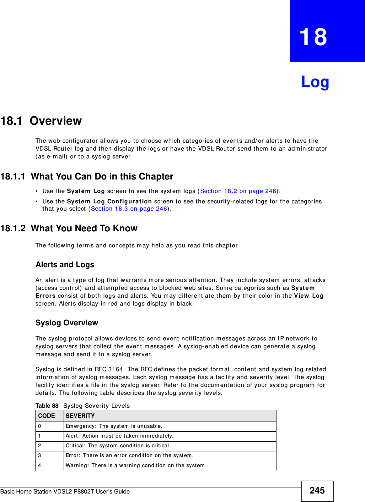
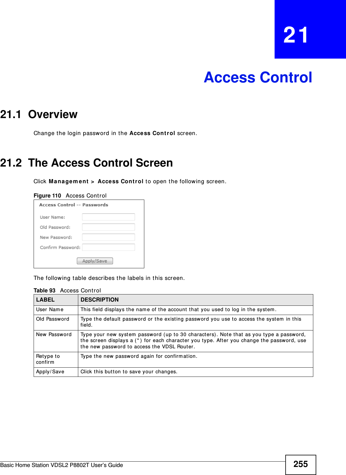
![Chapter 2 User Setup GuideBasic Home Station VDSL2 P8802T User’s Guide422.10.2 Access Your Shared Files From a ComputerNote: This exam ple uses Microsoft ’s Windows 7 t o browse your shared files. 1Open Windows Explorer and in the address bar t ype a double backslash “ \ \ ” followed by the VDSL Router’s LAN I P address and press [ ENTER] . 2A login scr een displays. Type the user nam e and password you set up for file sharing and click OK. Note: Once you log into the file share via your VDSL Router, you do not have t o log in again unless you rest art your com put er or t he VDSL Router.3Double- click the usbshare folder and browser it s cont ent s.](https://usermanual.wiki/ZyXEL-Communications/P8802T/User-Guide-1781920-Page-42.png)


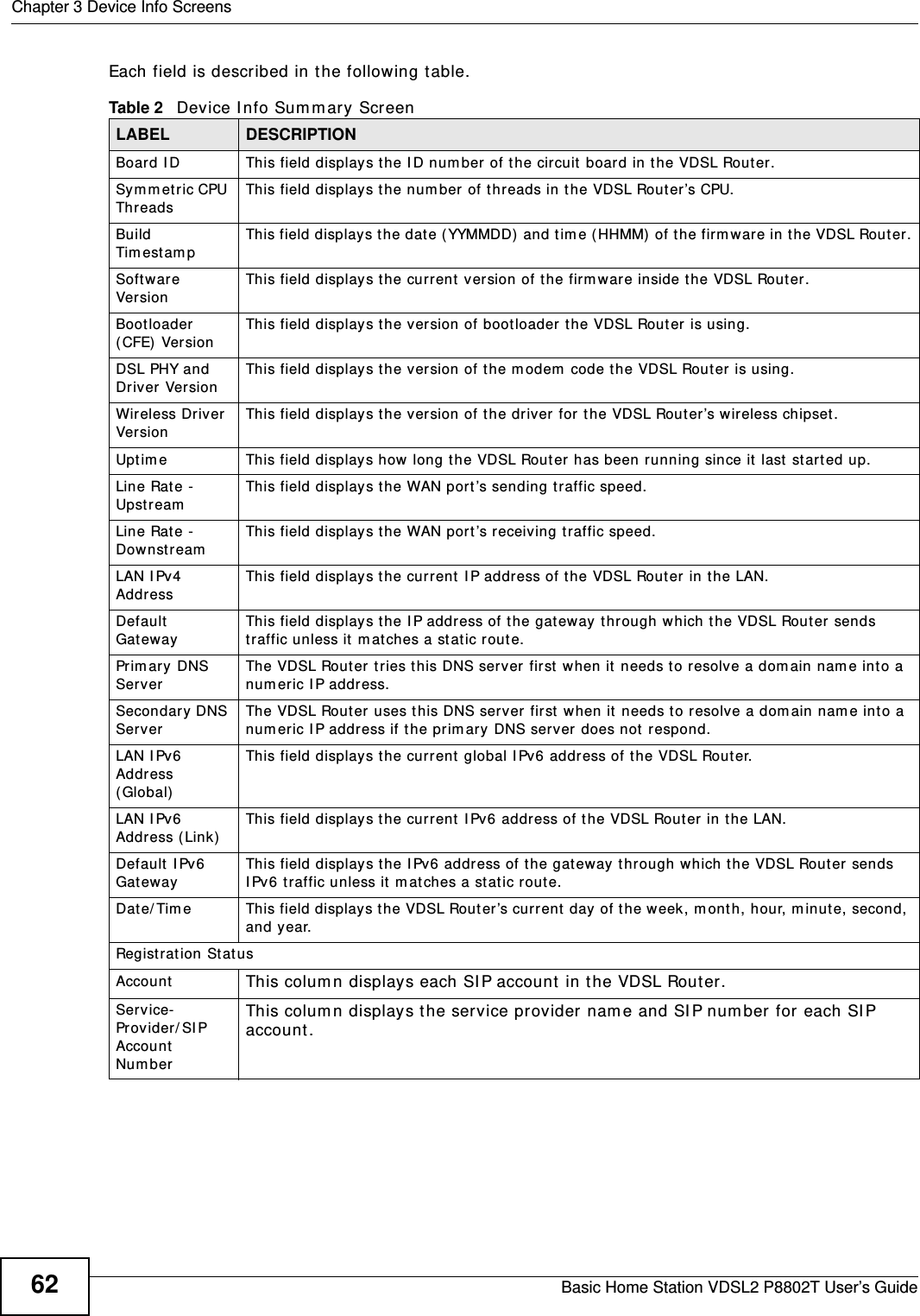
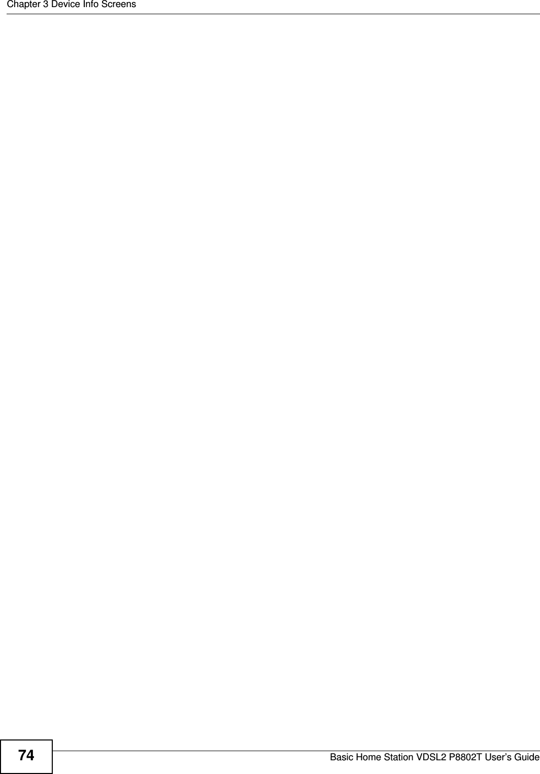

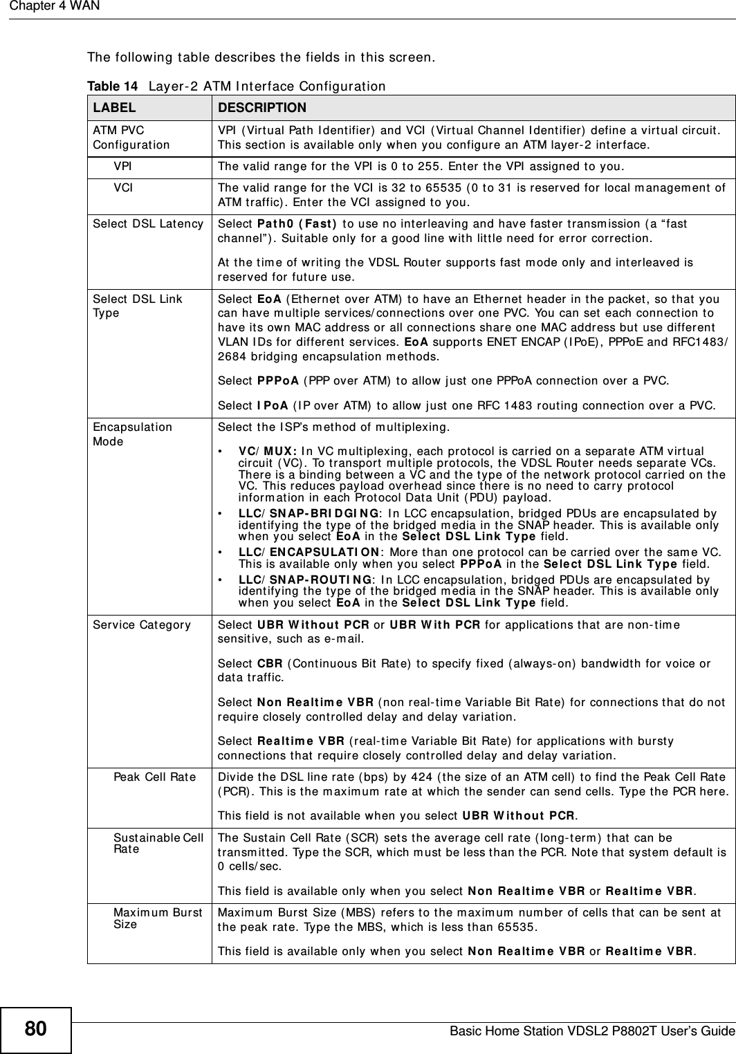
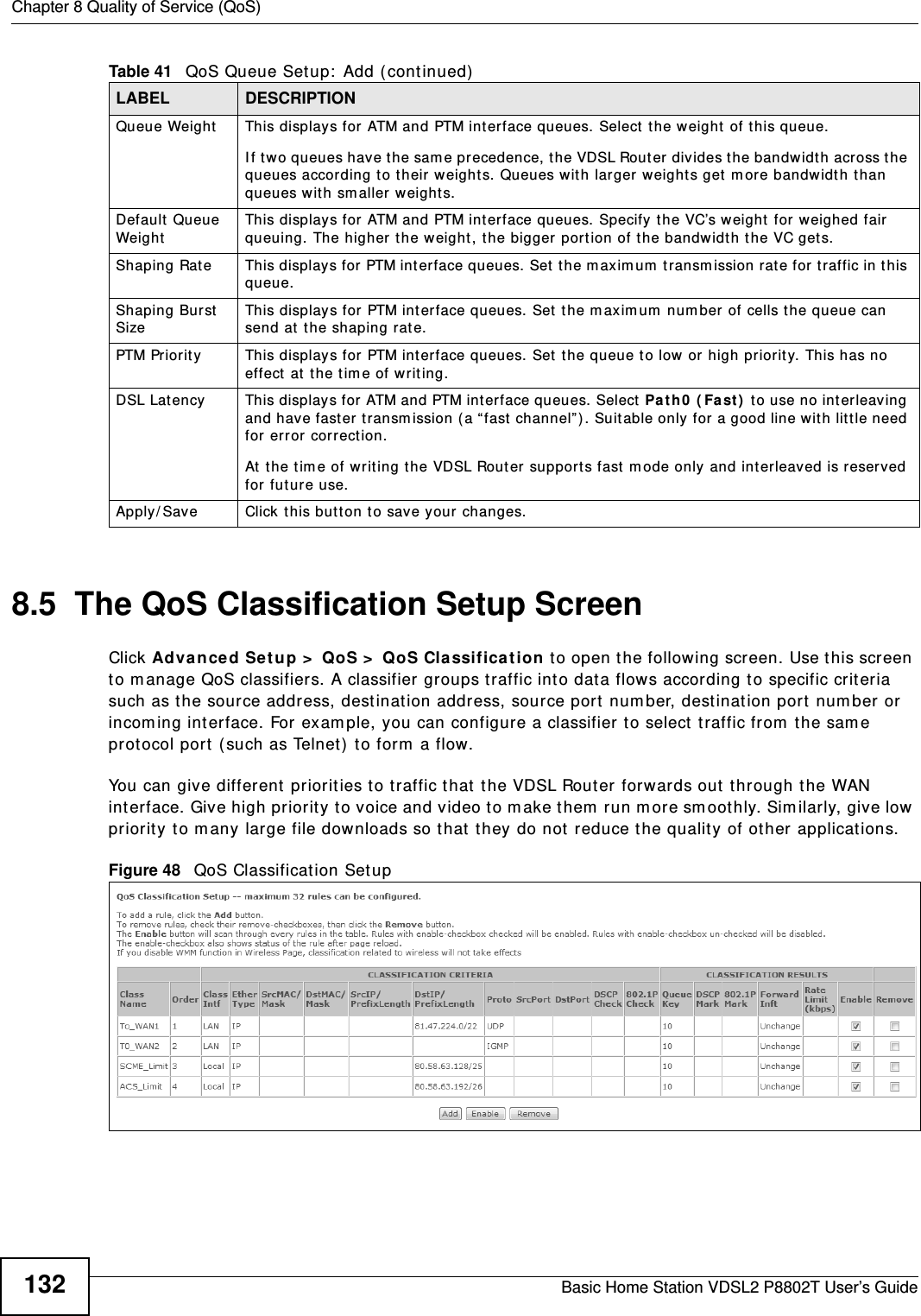
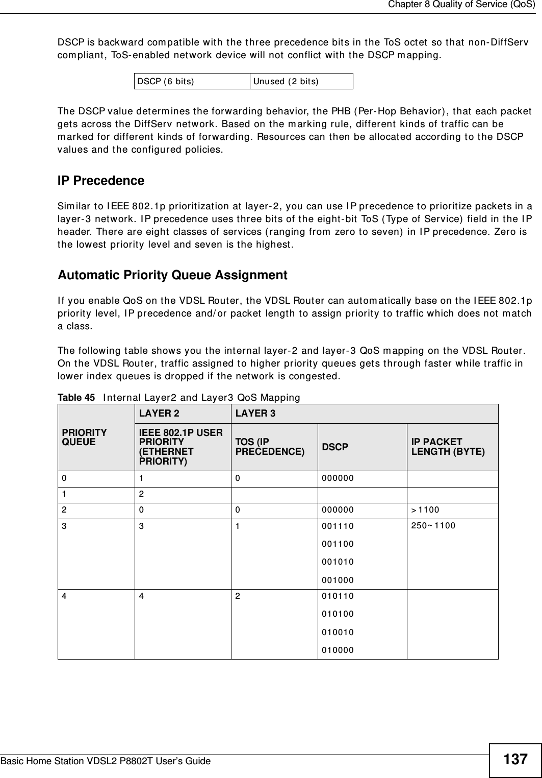
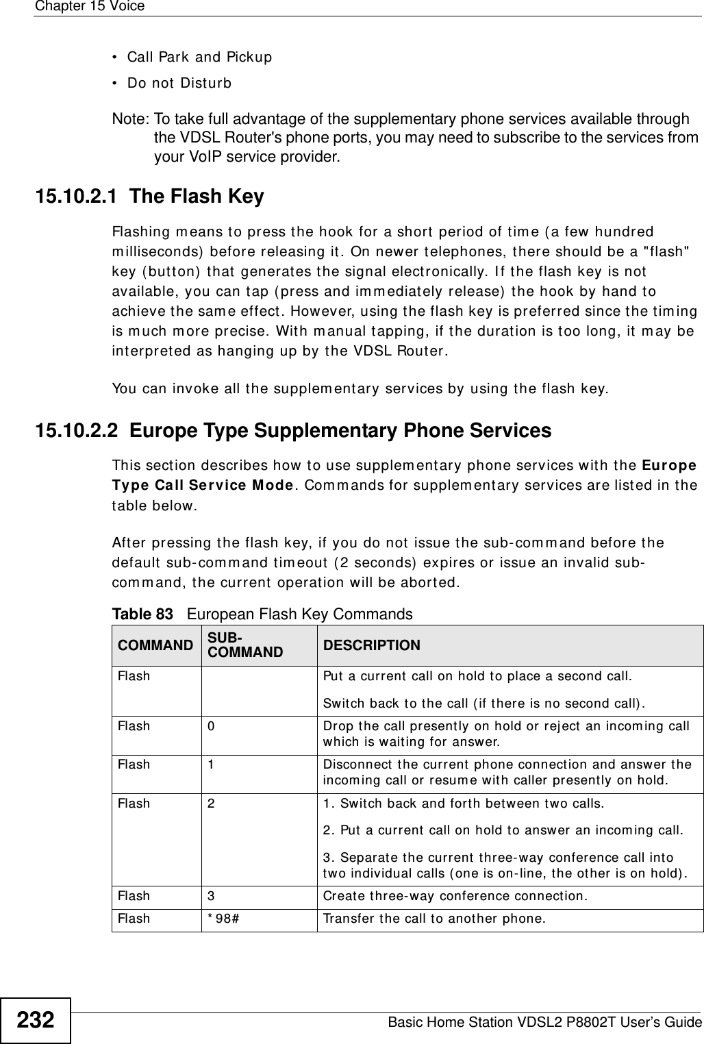
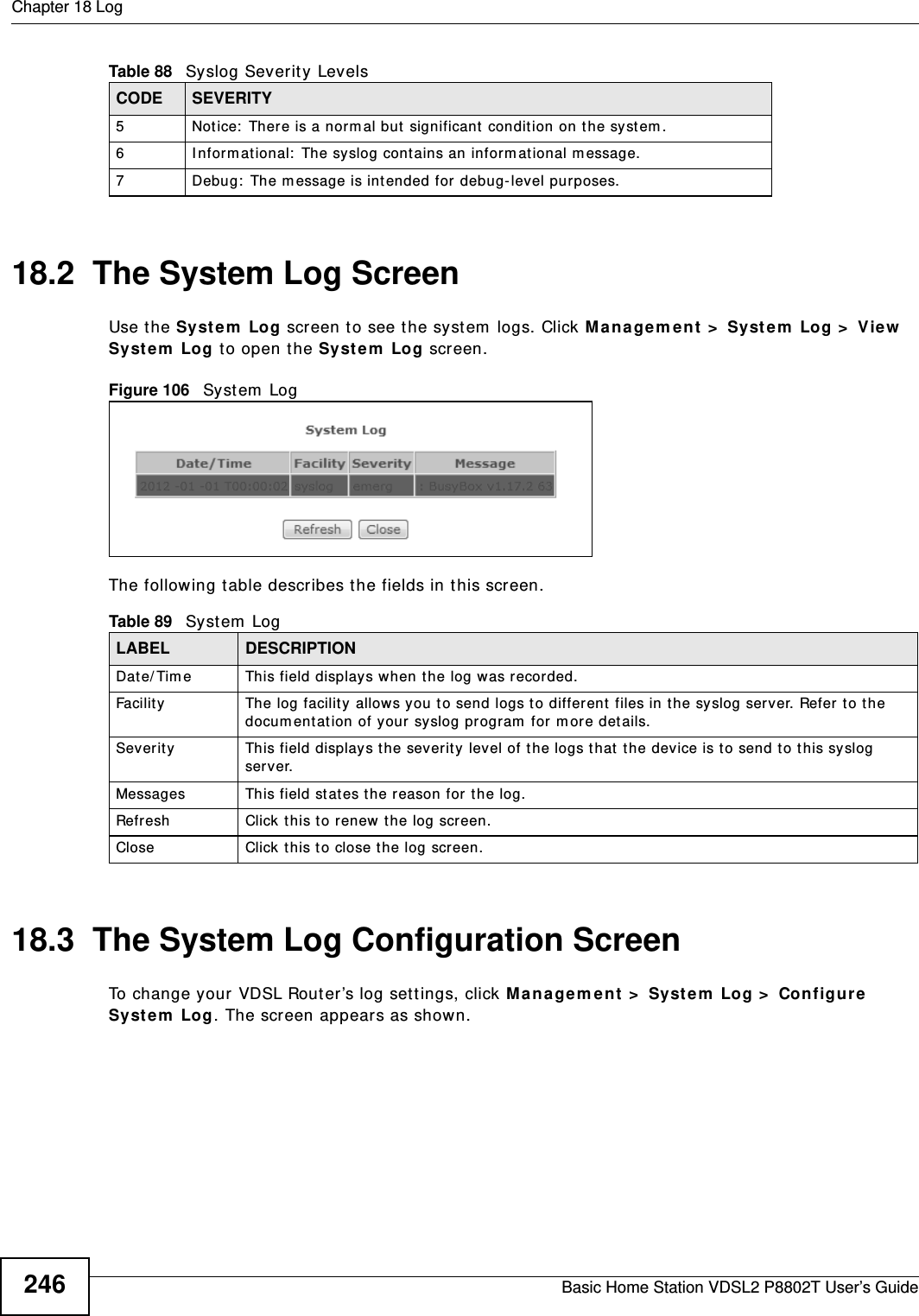
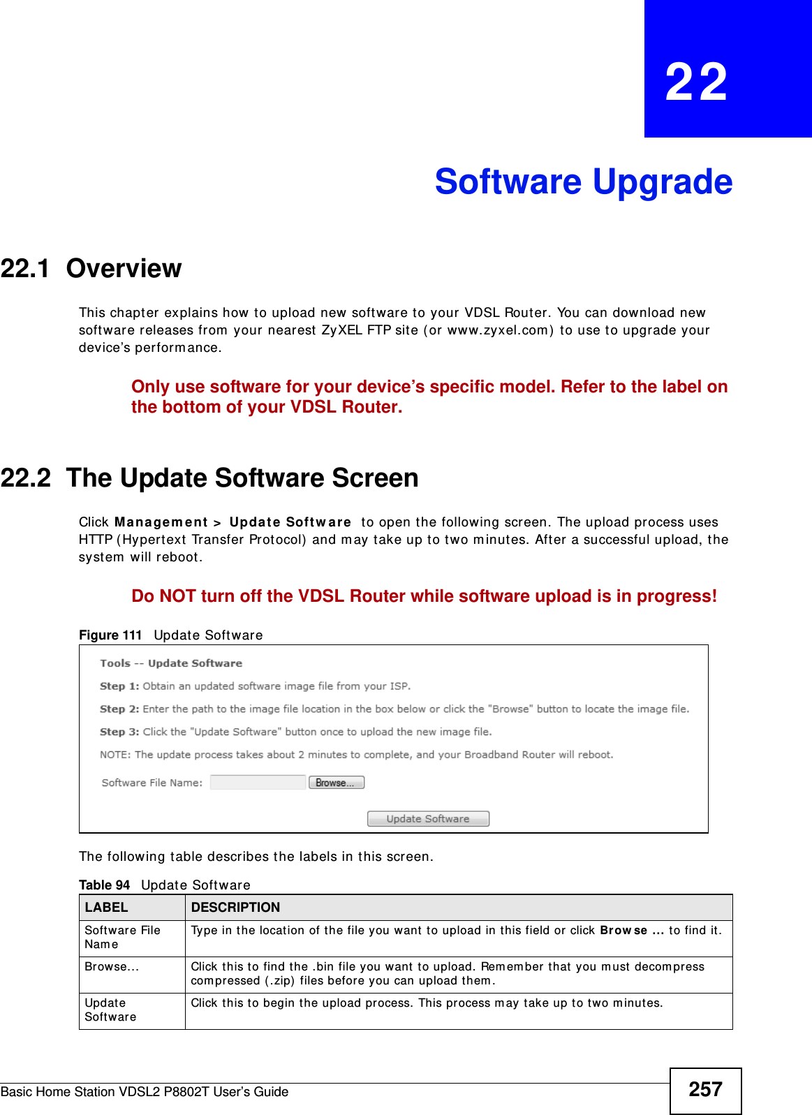
![Chapter 8 Quality of Service (QoS)Basic Home Station VDSL2 P8802T User’s Guide 135Source MAC MaskType t he m ask for t he specified MAC address t o determ ine which bits a packet ’s MAC addr ess should m at ch. Enter “ f” for each bit of the specified source MAC address that the traffic’s MAC address should m at ch. Ent er “ 0” for the bit (s) of t he m at ched traffic’s MAC address, which can be of any hexadecim al character(s) . For exam ple, if you set the MAC address to 00: 13: 49: 00: 00: 00 and t he m ask t o ff: ff: ff: 00: 00: 00, a packet with a MAC address of 00: 13: 49: 12: 34: 56 m at ches this cr it eria.Dest inat ion MAC AddressEnter a MAC address to apply the classifier to packets destined for that MAC address.Dest inat ion MAC MaskType t he m ask for t he specified MAC address t o determ ine which bits a packet ’s MAC addr ess should m at ch. Enter “ f” for each bit of the specified source MAC address that the traffic’s MAC address should m at ch. Ent er “ 0” for the bit (s) of t he m at ched traffic’s MAC address, which can be of any hexadecim al character(s) . For exam ple, if you set the MAC address to 00: 13: 49: 00: 00: 00 and t he m ask t o ff: ff: ff: 00: 00: 00, a packet with a MAC address of 00: 13: 49: 12: 34: 56 m at ches this cr it eria.Source I P Address[ / Mask]Select this and ent er an I P address t o apply t he classifier t o packets from t hat I P address. You can also include a source subnet m ask.Ven do r Cl ass I D ( DHCP Option 60)Select this and ent er t he Vendor Class I dent ifier ( Option 60) of the m atched traffic, such as the t ype of the hardware or firm ware.User Class I D DHCP option 77Select this and ent er a str ing that identifies the user ’s cat egor y or applicat ion ty pe in the m at ched DHCP packet s.Dest inat ion I P Address[ / Mask]Enter an I P address to apply the classifier t o packet s destined for t hat I P address. You can also include a dest inat ion subnet m ask.Different iat ed Ser vice Code Point ( DSCP) CheckSelect a DSCP m ar k of t raffic to w hich to apply the classifier.802.1p Priorit y CheckThis field is available only when you set the Et her Type field to 8 0 2 1 Q.Select t he I EEE 802.1p priority level ( bet ween 0 and 7) of traffic t o which to apply the classifier. "0" is the lowest priority level and " 7" is the highest .Specify Classification Result sConfigure these fields t o change t raffic that m atches the classifier. The fields available vary depending on the select ed interface, Ether type, and som et im es on the select ed class queue. Leave a field blank to not apply that type of change. Specify Class Queue Select the queue to which to add traffic that m atches this classifier.Forward To I nter face Select a WAN interface through w hich to forward traffic of this class. Select Uncha nge to forward traffic of this class according to t he default routing table.Mark Different iat ed Ser vice Code Point ( DSCP):Select the DSCP m ar k t o add t o traffic t hat m atches this classifier. Use Au to m arking to autom atically apply a DSCP m ark according t o t he t ype of traffic. Use defa ult to leave the DSCP m ar k unchanged.Protocol Select a service t ype ( TCP, UDP, I CMP or I GM P) of traffic to w hich to apply the classifier.Mark 802.1p priorit y Select the I EEE 802.1p priorit y level t o assign to t raffic t hat m at ches this classifier.Set Rat e Lim it Set the rat e lim it to apply t o traffic that m at ches this classifier. Apply/ Save Click this but ton t o save your changes.Table 43 QoS Classification Setup: Add (continued)LABEL DESCRIPTION](https://usermanual.wiki/ZyXEL-Communications/P8802T/User-Guide-1781920-Page-135.png)
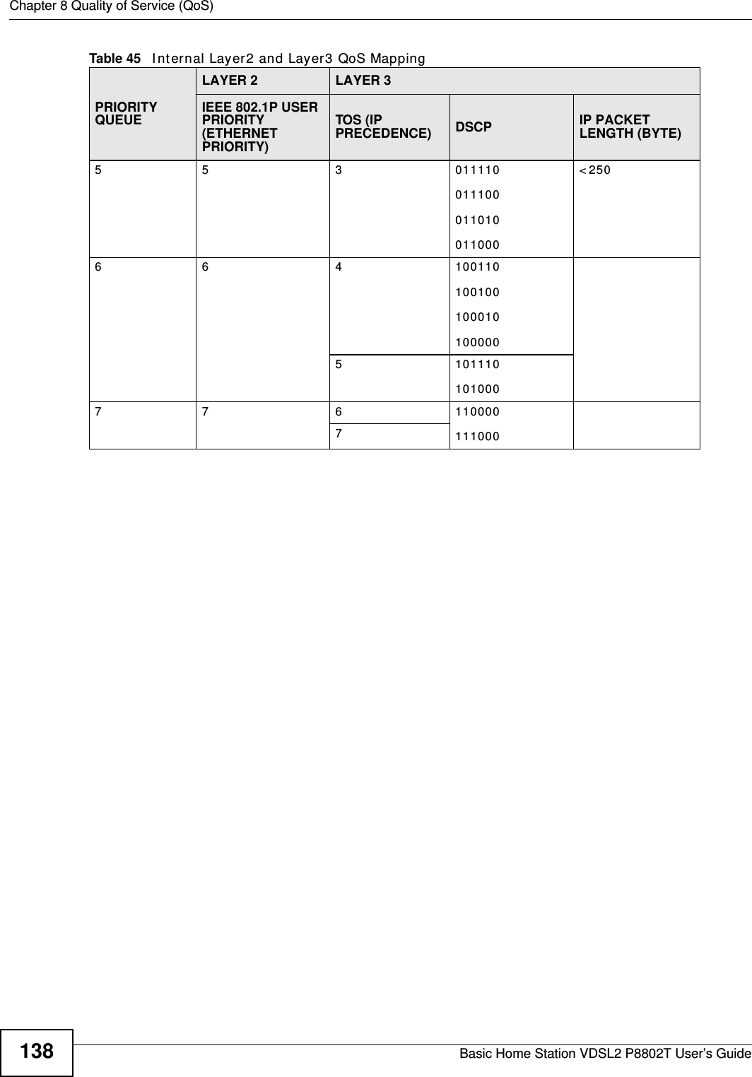


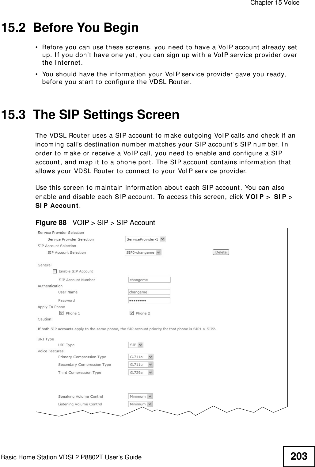
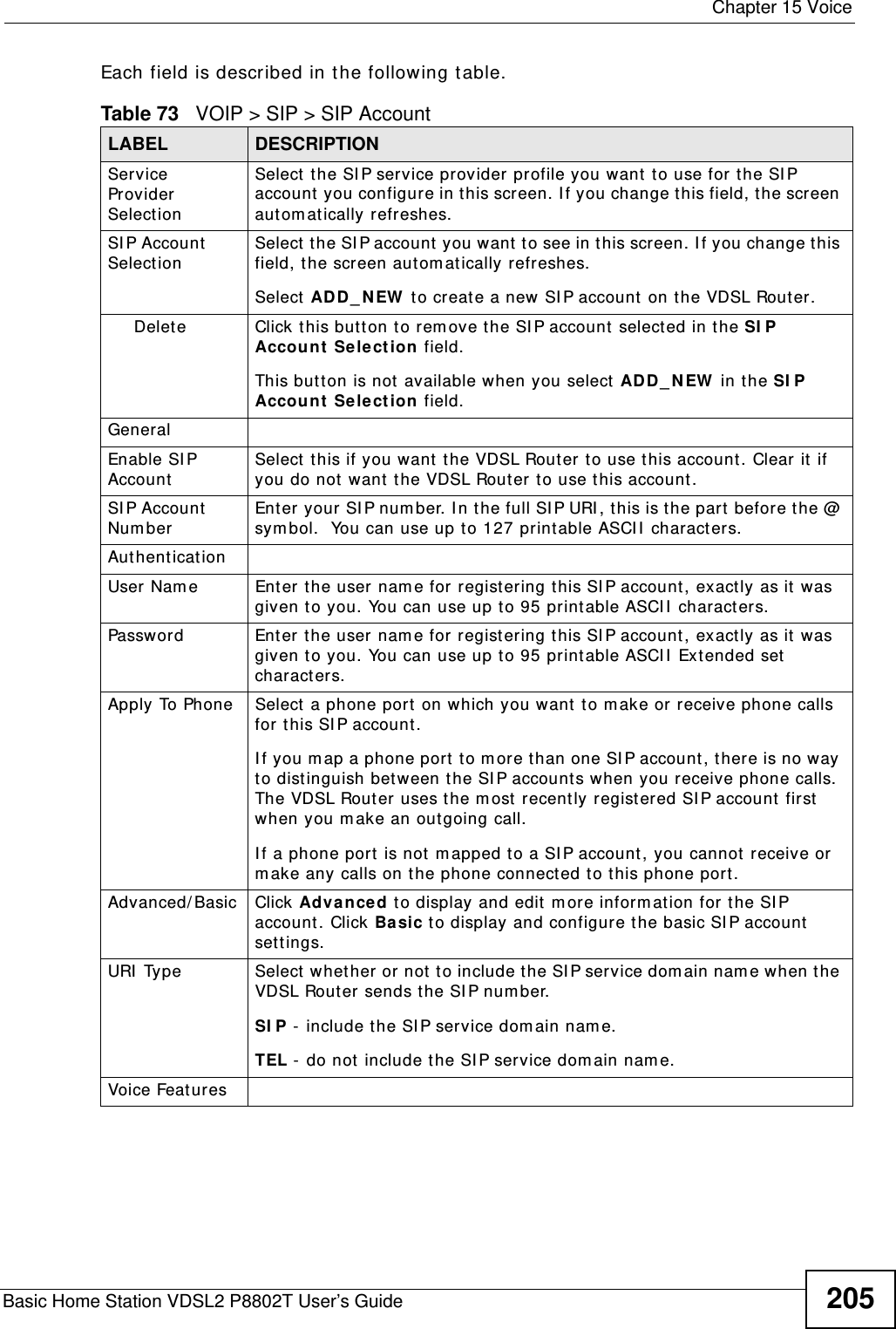
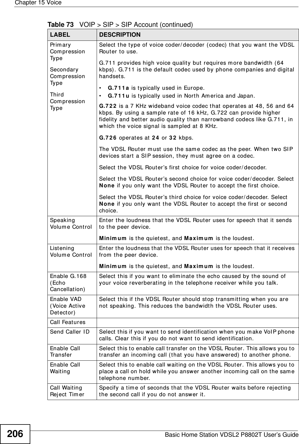
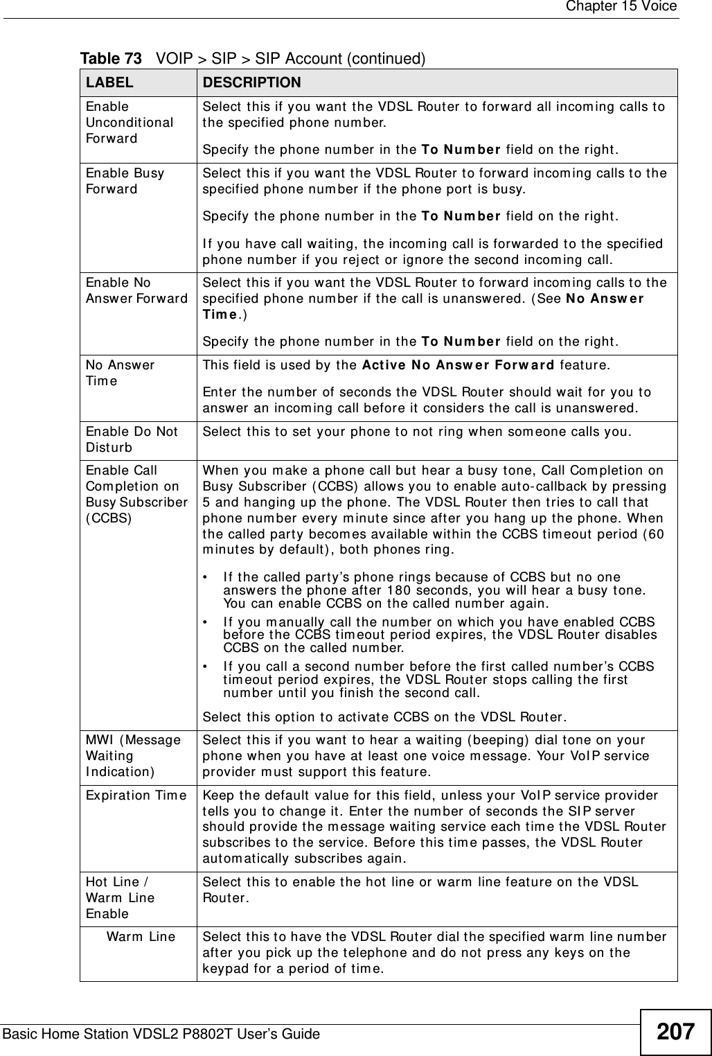
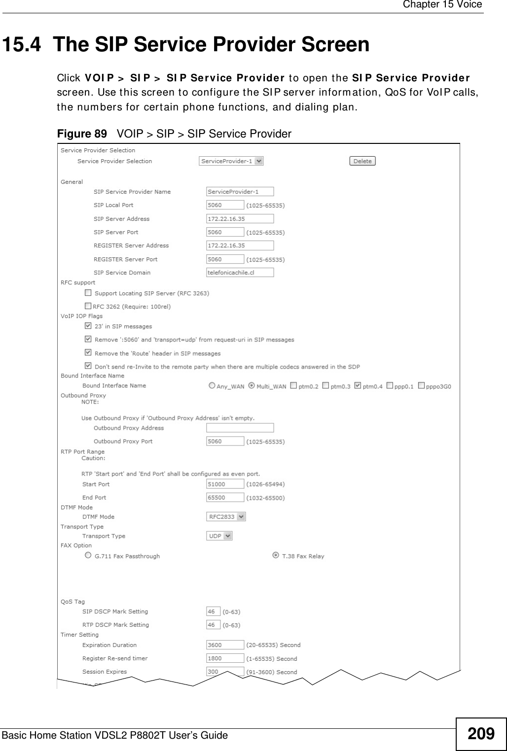
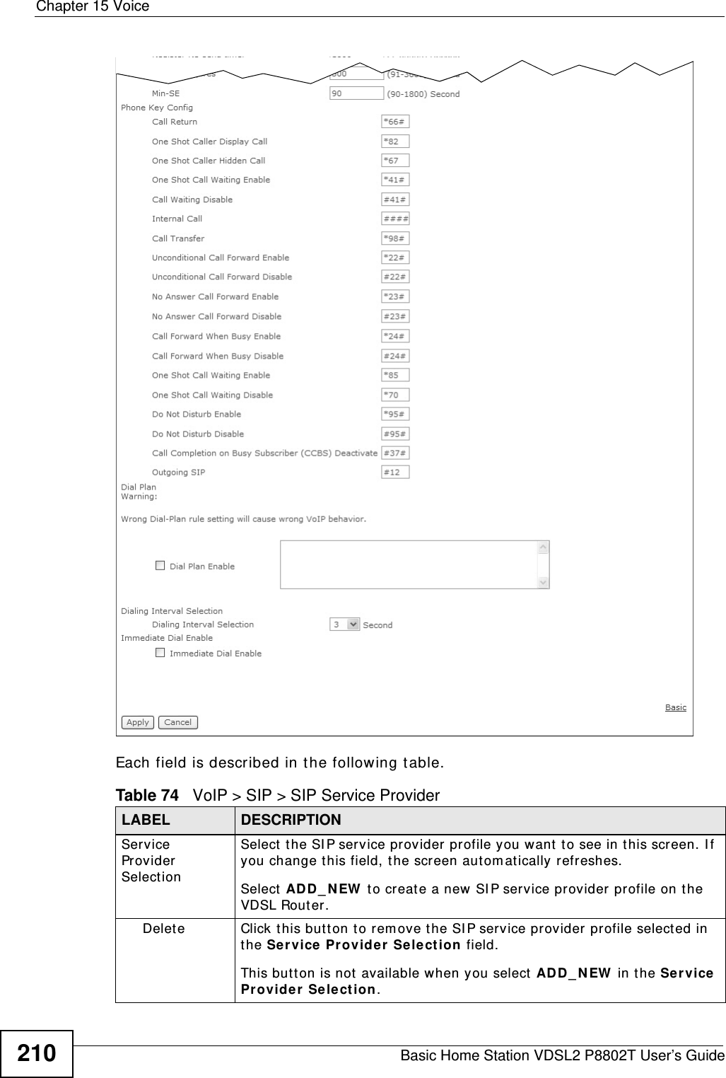
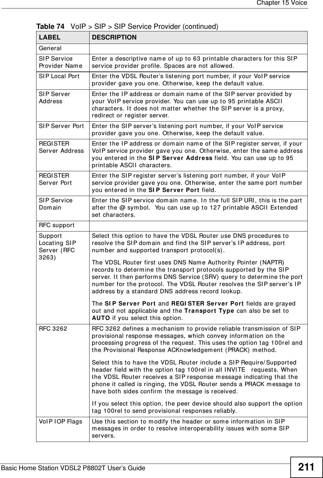
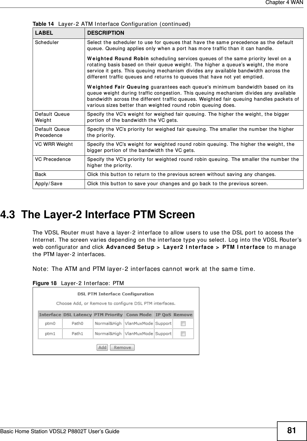
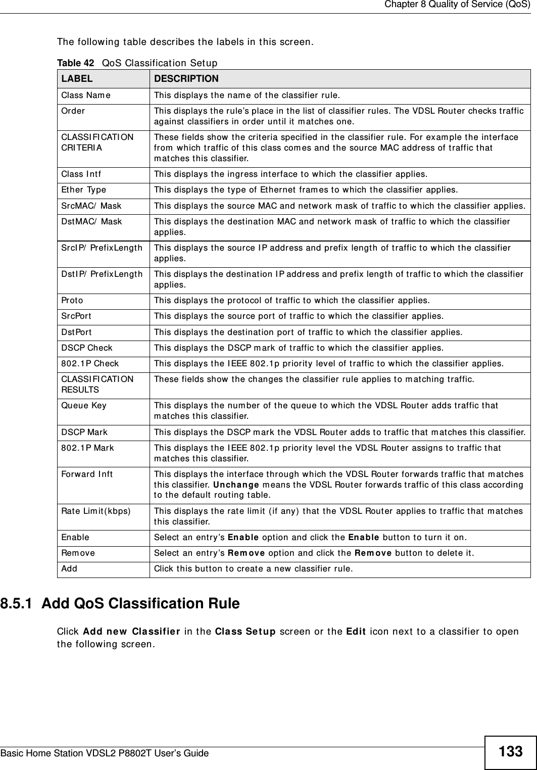
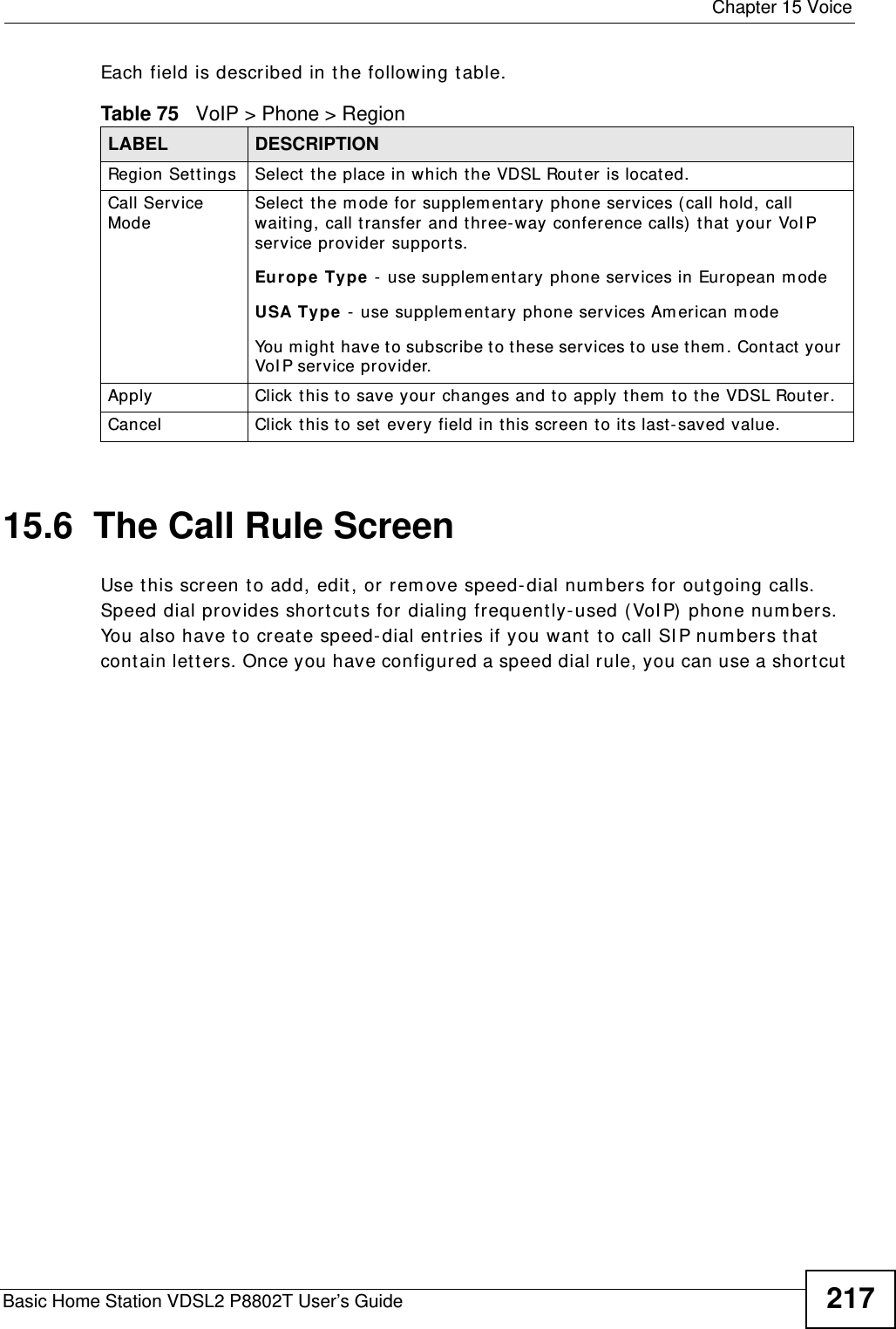
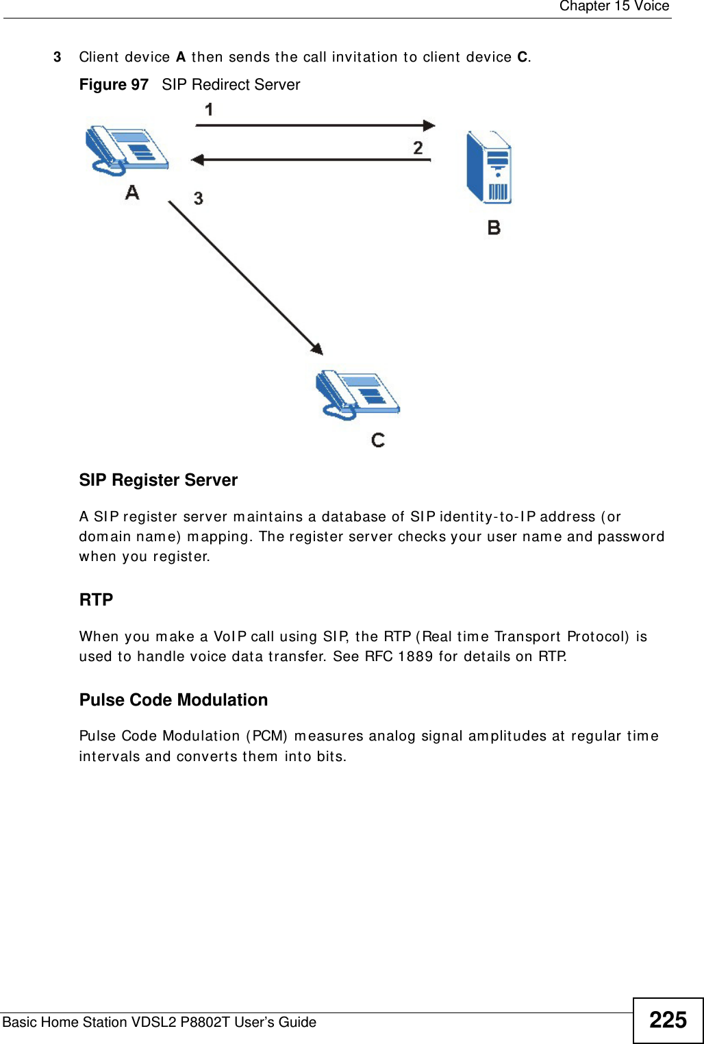
![Chapter 15 VoiceBasic Home Station VDSL2 P8802T User’s Guide 21515.4.1 Dial Plan RulesA dial plan defines the dialing patterns, such as the length and range of t he digit s for a telephone num ber. I t also includes country codes, access codes, area codes, local num bers, long dist ance num bers or int ernat ional call prefixes. For exam ple, the dial plan ([ 2- 9] xxxxxx) does not allow a local num ber which begins wit h 1 or 0.Without a dial plan, users have to m anually ent er the whole callee’s num ber and wait for t he specified dialing int erval t o tim e out or press a term inat or key (usually the pound key on the phone keypad) before t he VDSL Router m akes t he call.The VDSL Router init ializes a call when t he dialed num ber m at ches any one of t he rules in the dial plan. Dial plan rules follow these convent ions:• The collect ion of rules is in parent heses ( ) .• Rules are separat ed by the | ( bar) sym bol.Out going SI P Specify the key com binat ions that you can ent er to select the SI P account that you use t o make outgoing calls. I f you ent er # 12(by default) < SI P account index num ber> # < the phone num ber you want to call> , # 1201# 12345678 for exam ple, the VDSL Router uses t he first SI P account t o call 12345678.Dial PlanDial Plan Enable Select this to act ivate the dial plan rules you specify in the t ext box provided. See Section 15.4.1 on page 215 for how to set up a rule.Dialing I nt erval Select ionDialing I nt erval Select ionEnt er the num ber of seconds the VDSL Rout er should wait aft er you st op dialing num bers before it m akes t he phone call. The value depends on how quickly you dial phone num bers.I f you select I m m ediat e Dial En able, you can press t he pound key ( # ) t o t ell t he VDSL Router to m ake t he phone call im m ediately, regardless of t his sett ing.I m m ediat e Dial EnableI m m ediat e Dial EnableSelect this if you want to use the pound key (# ) to tell t he VDSL Router to m ake t he phone call im m ediat ely, inst ead of waiting the num ber of seconds you selected in the Dia ling I nt er val Sele ct ion field.I f you select t his, dial the phone num ber, and then press t he pound key. The VDSL Rout er m akes t he call im m ediately, inst ead of wait ing. You can still wait, if you want.Apply Click this to save your changes and to apply them to the VDSL Router.Cancel Click t his to set every field in this screen to it s last-saved value.Table 74 VoIP > SIP > SIP Service Provider (continued)LABEL DESCRIPTION](https://usermanual.wiki/ZyXEL-Communications/P8802T/User-Guide-1781920-Page-215.png)
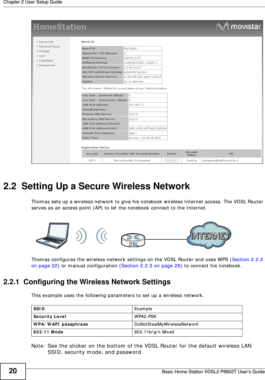
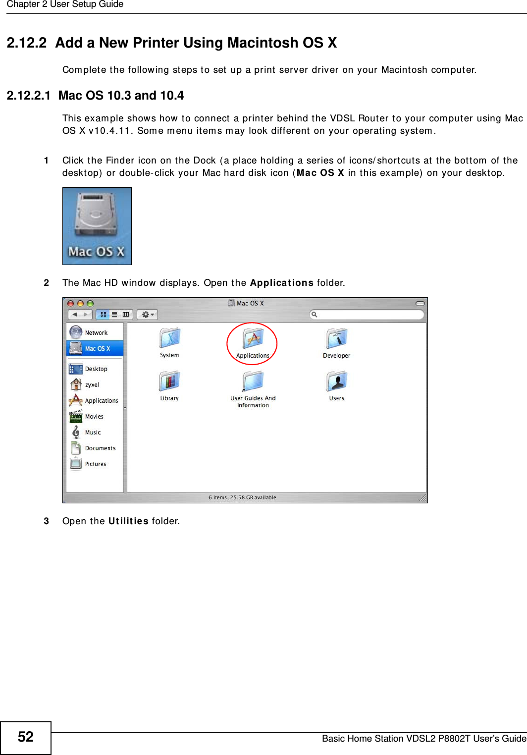
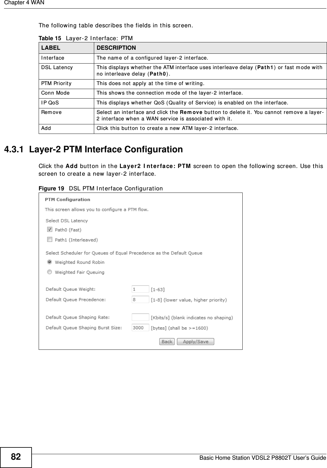
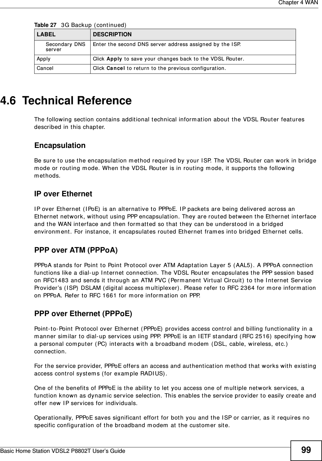
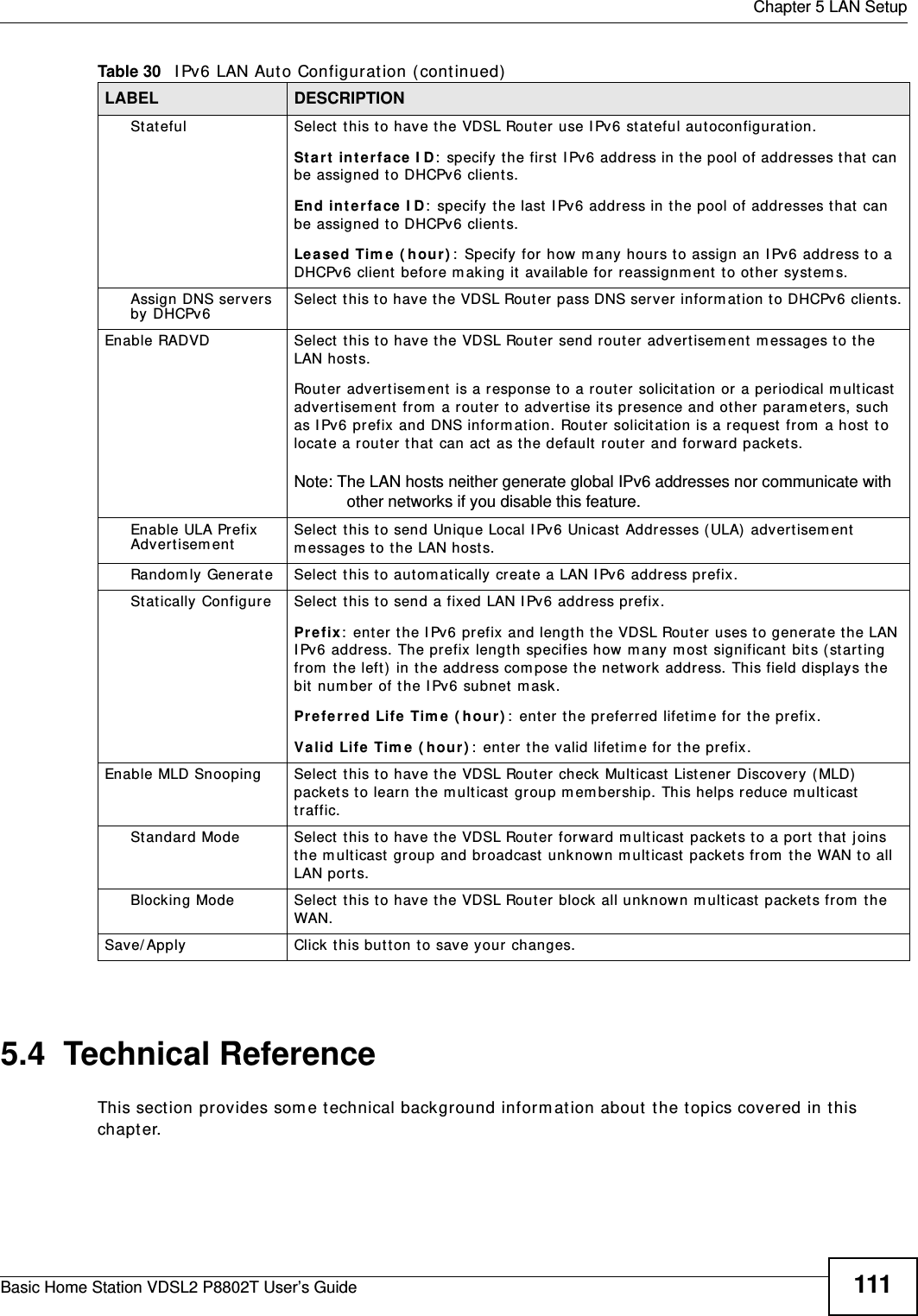
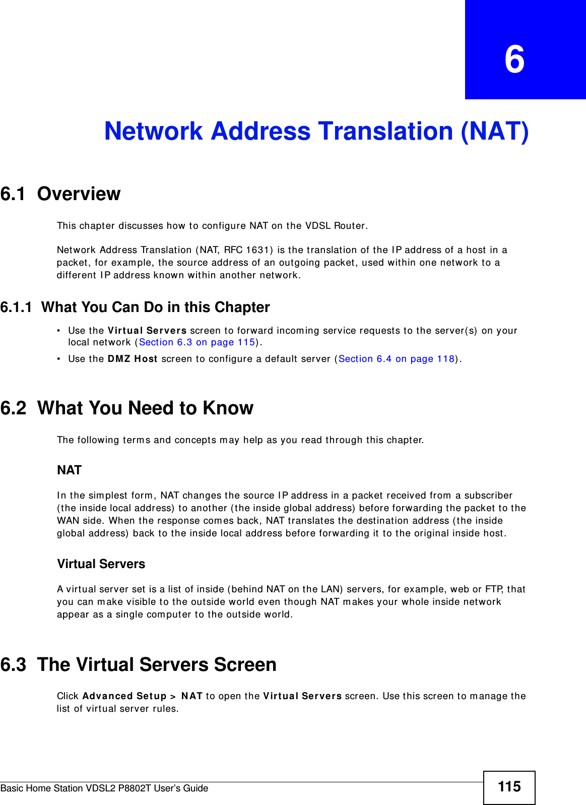
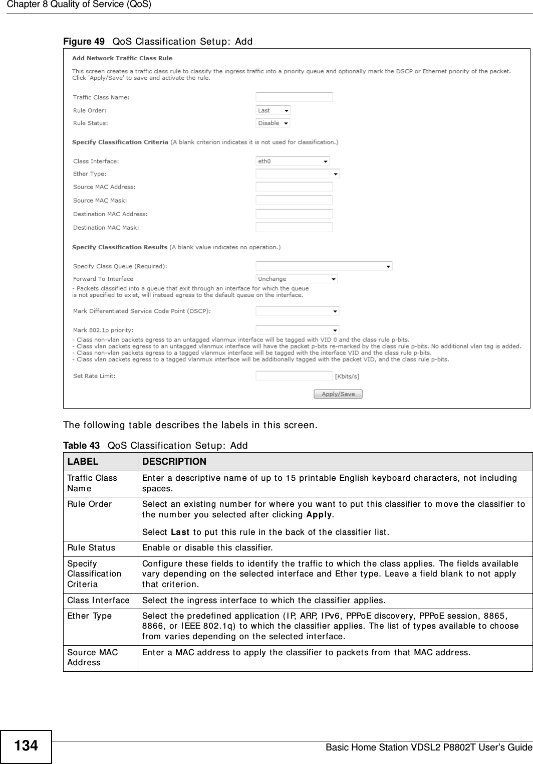
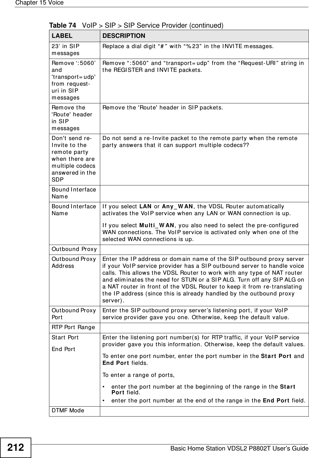
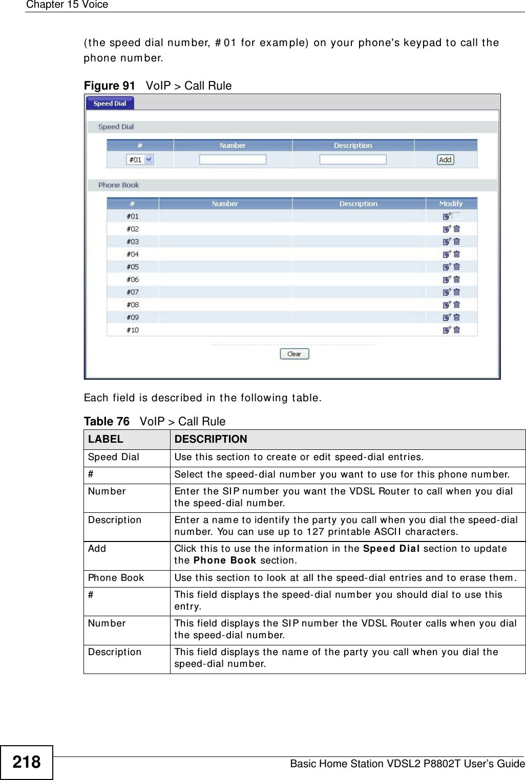
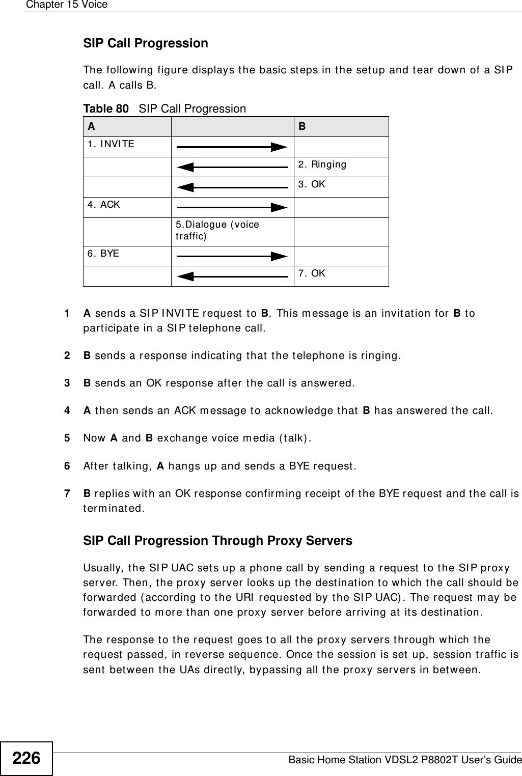
![Chapter 15 VoiceBasic Home Station VDSL2 P8802T User’s Guide216• “ x” stands for a wildcard and can be any digit from 0 to 9.• A subset of keys is in a square bracket [ ] . Ranges are allowed.For exam ple, [ 359] m eans a num ber m at ching this rule can be 3, 5 or 9. [ 26-8* ] m eans a num ber m atching this rule can be 2, 6, 7, 8 or * .• The dot “ .” appended t o a digit allows the digit t o be ignored or repeat ed m ult iple tim es. Any digit ( 0~ 9, * , # ) aft er the dot will be ignored.For exam ple, (01.) m eans a num ber m at ching this rule can be 0, 01, 0111, 01111, and so on.• < dialed- n um ber : t ran slat ed- num ber> indicat es t he num ber after the colon replaces t he num ber before the colon in an angle bracket < > . For exam ple, (< : 1212> xxxxxxx) m eans t he VDSL Router aut om atically prefixes t he translated- num ber “ 1212” to t he num ber you dialed before m aking the call. This can be used for local calls in the US.(< 9: > xxx xxxxxxx) m eans t he VDSL Router autom at ically rem oves the specified prefix “9” from t he num ber you dialed before m aking the call. This is always used for m aking out side calls from an office. (xx< 123: 456> xxxx) m eans t he VDSL Router aut om atically translates “ 123” t o “ 456” in the num ber you dialed before m aking t he call.• Calls wit h a num ber followed by the exclam at ion m ark “ !” will be dropped.• Calls wit h a num ber followed by the t erm ination charact er “ @” will be m ade im m ediat ely. Any digit (0~ 9, * , # ) after the @ charact er will be ignored.I n this exam ple dial plan ( 0 | [ 49] 11 | 1 [ 2- 9] xx xxxxxxx | 1 947 xxxxxxx ! ) , you can dial “ 0” t o call the local operator, call 411 or 911, or m ake a long distance call with an area code st arting from 2 to 9 in the US. The calls wit h t he area code 947 will be dropped.15.5 The Phone Region Screen Use t his screen to m aint ain settings t hat depend on which region of the world the VDSL Rout er is in. To access t his screen, click VoI P > Phon e > Region.Figure 90 VoIP > Phone > Region](https://usermanual.wiki/ZyXEL-Communications/P8802T/User-Guide-1781920-Page-216.png)


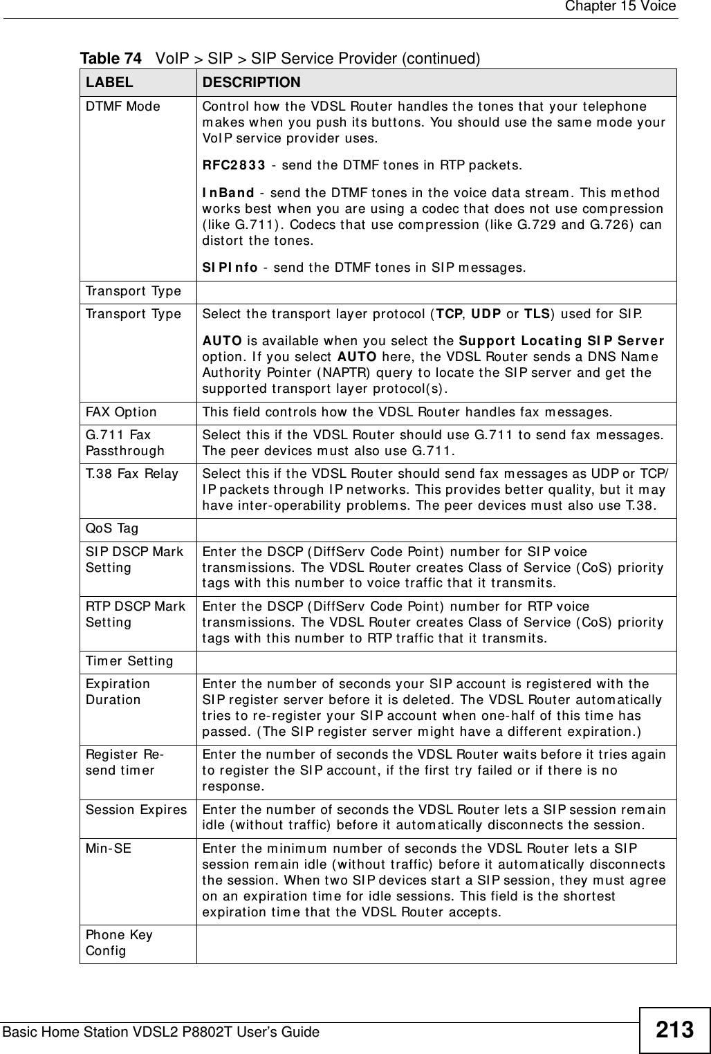
![Chapter 24 TroubleshootingBasic Home Station VDSL2 P8802T User’s Guide 2635Reset the device t o its fact ory defaults, and t ry t o access the VDSL Router with t he default I P address. See Section 1.7 on page 16.6I f the problem continues, contact the netw ork adm inist rator or vendor, or try one of t he advanced suggest ions.Advance d Suggestions• Make sure you have logged out of any earlier m anagem ent sessions using t he sam e user account even if they were through a different interface or using a different browser.• Try to access the VDSL Rout er using another service, such as Telnet . I f you can access the VDSL Router, check the rem ote m anagem ent set t ings and firewall rules to find out why the VDSL Router does not respond t o HTTP. I can see t he Login screen, but I cannot log in to the VDSL Router.1Make sure you have entered the password correct ly. The field is case- sensitive, so m ake sure [ Caps Lock] is not on. 2You cannot log in to t he web configurat or while som eone is using Telnet t o access t he VDSL Router. Log out of t he VDSL Router in the other session, or ask t he person who is logged in to log out. 3Turn t he VDSL Router off and on. 4I f this does not work, you have t o reset the device t o its fact ory defaults. See Section 24.1 on page 261.I cannot Telnet to t he VDSL Router.See t he t roubleshooting suggest ions for I cannot see or access t he Login screen in the web configurator. I gnore the suggestions about your browser.I cannot use FTP to upload / download t he configuration file. / I cannot use FTP to upload new software.See t he t roubleshooting suggest ions for I cannot see or access t he Login screen in the web configurator. I gnore the suggestions about your browser.](https://usermanual.wiki/ZyXEL-Communications/P8802T/User-Guide-1781920-Page-263.png)
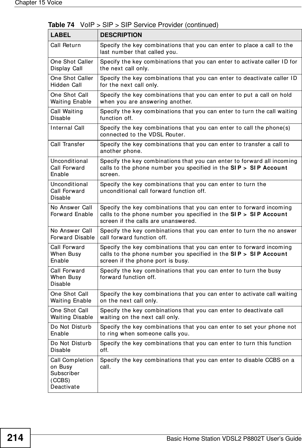
![Chapter 24 TroubleshootingBasic Home Station VDSL2 P8802T User’s Guide26424.3 Internet AccessI cannot access t he I nternet .1Check the hardware connections, and m ake sure t he LEDs ar e behaving as expect ed. See the Quick St a rt Guide and Sect ion 1.5 on page 14.2Make sure you ent ered your I SP account inform ation correct ly in the Net w ork Settin g > Broadband screen. These fields are case- sensitive, so m ake sure [ Caps Lock] is not on. 3I f you are t rying to access t he I nt ernet wirelessly, m ake sure t hat you enabled the wireless LAN in the VDSL Router and your wireless client and t hat the wir eless set t ings in t he wireless client are t he sam e as t he sett ings in t he VDSL Router.4Disconnect all the cables from your device and reconnect them . 5I f the problem continues, contact your I SP. I cannot access t he I nternet t hrough a DSL connect ion.1Make sure you have the D SL W AN port connect ed to a t elephone j ack (or t he DSL or m odem jack on a split ter if you have one).2Make sure you configured a proper DSL WAN int erface (N et w ork Settin g > Br oadband scr een) with t he I nt ernet account inform ation prov ided by your I SP and that it is enabled.3Check t hat t he LAN inter face you are connected to is in t he sam e interface group as the DSL connect ion ( N et w ork Se t t ing > I nt erfa ce Gr oup) .4I f you set up a WAN connect ion using bridging service, make sure you turn off the DHCP feat ure in the LAN screen to have the client s get WAN I P addresses direct ly from your I SP’s DHCP server.I cannot connect t o the I nternet using a second DSL connect ion.ADSL and VDSL connect ions cannot work at t he sam e t im e. You can only use one type of DSL connect ion, either ADSL or VDSL connect ion at one t ime.I cannot access t he I nt ernet anym ore. I had access t o the I nt ernet (with t he VDSL Router), but m y I nternet connection is not available anym ore.1Your session with t he VDSL Router m ay have expired. Try logging into the VDSL Router again.](https://usermanual.wiki/ZyXEL-Communications/P8802T/User-Guide-1781920-Page-264.png)