ZyXEL Communications P8802T Wireless N VDSL2 VoIP IAD With USB User Manual Book
ZyXEL Communications Corporation Wireless N VDSL2 VoIP IAD With USB Book
User Manual

www.zyxel.com
www.zyxel.com
Basic Home Station VDSL2
P8802T
Wireless N VDSL2 GW with USB
Copyright © 2012
ZyXEL Communications Corporation
Version 1.00
Edit ion 1, 7/ 2012
Default Login Details
LAN I P Address ht tp: / / 192.168.1.1: 8000
Trusted I P
Address for t he
Device Access
192.168.1.252
User Nam e Adm inistrat or
Password Te1ef6n1c4

Basic Home Station VDSL2 P8802T User’s Guide2
IMPORTANT!
READ CAREFULLY BEFORE USE.
KEEP THIS GUIDE FOR FUTURE REFERENCE.
Note: This guide is a reference for a series of product s. Ther efore som e features or
opt ions in this guide m ay not be available in your product .
Graphics in t his book m ay differ slightly from t he product due to differences in operating syst em s,
operating syst em versions, or if you inst alled updat ed software for your device. Every effor t has
been m ade to ensure that t he inform ation in this m anual is accurat e.
Related Documentation
• Quick Start Guide
The Quick St art Guide helps you get up and running right away. I t contains inform at ion on sett ing
up your network and configuring for I nt ernet access.

Table of Contents
Basic Home Station VDSL2 P8802T User’s Guide 3
Table of Contents
Part I: User’s Guide ......................................................................................... 11
Chapter 1
Introducing the VDSL Router ............................................................................................................13
1.1 Overview ...........................................................................................................................................13
1.2 How to Manage the VDSL Router .....................................................................................................13
1.3 Good Habits for Managing the VDSL Router ....................................................................................13
1.4 Power On/Off the VDSL Router ........................................................................................................14
1.5 LEDs (Lights) ....................................................................................................................................14
1.6 3G WAN ............................................................................................................................................16
1.7 The RESET Button ............................................................................................................................16
1.8 Wireless Access ................................................................................................................................17
1.8.1 Using the Wifi Button ...............................................................................................................17
Chapter 2
User Setup Guide................................................................................................................................19
2.1 Access the VDSL Router Configuration ............................................................................................19
2.2 Setting Up a Secure Wireless Network .............................................................................................20
2.2.1 Configuring the Wireless Network Settings .............................................................................20
2.2.2 Using WPS ..............................................................................................................................22
2.2.3 Without WPS ...........................................................................................................................26
2.3 Using Wireless MAC Authentication to Block a Computer’s Access to the Wireless Network ..........28
2.4 Setting Up a NAT Virtual Server for a Game Server .........................................................................29
2.5 Access Your Home Computer from the Internet Using DDNS ..........................................................30
2.5.1 Registering a DDNS Account on www.dyndns.org ..................................................................31
2.5.2 Configuring DDNS on Your VDSL Router ................................................................................31
2.5.3 Configuring Port Forwarding on your VDSL Router ................................................................32
2.5.4 Testing the DDNS Setting ........................................................................................................33
2.6 Configuring the Firewall ....................................................................................................................34
2.6.1 Interface Default Policy ............................................................................................................34
2.6.2 Firewall Rules ..........................................................................................................................34
2.7 LAN DHCP for IP Addressing Assignment ........................................................................................36
2.7.1 Configuring Static DHCP .........................................................................................................37
2.8 Checking the Software Version .........................................................................................................38
2.9 Restoring to Factory Default .............................................................................................................39
2.10 How to Use File Sharing on the VDSL Router ................................................................................40
2.10.1 Set Up File Sharing ...............................................................................................................40
2.10.2 Access Your Shared Files From a Computer ........................................................................42

Table of Contents
Basic Home Station VDSL2 P8802T User’s Guide
4
2.11 Using the Media Server Feature ....................................................................................................43
2.11.1 Configuring the VDSL Router ................................................................................................43
2.11.2 Using Windows Media Player ................................................................................................43
2.11.3 Using a Digital Media Adapter ...............................................................................................46
2.12 How to Share a USB Printer via Your VDSL Router .......................................................................47
2.12.1 Add a New Printer Using Windows ........................................................................................48
2.12.2 Add a New Printer Using Macintosh OS X ............................................................................52
Part II: Technical Reference............................................................................ 59
Chapter 3
Device Info Screens............................................................................................................................61
3.1 Overview ...........................................................................................................................................61
3.2 The Device Info Summary Screen ....................................................................................................61
3.3 The WAN Info Screen .......................................................................................................................63
3.4 The 3G Status Screen .......................................................................................................................64
3.5 The LAN Statistics Screen ................................................................................................................65
3.6 The WAN Statistics Screen ...............................................................................................................66
3.7 The xTM Statistics Screen ................................................................................................................67
3.8 The xDSL Statistics Screen ...............................................................................................................68
3.8.1 The ADSL BER Test Screen ....................................................................................................71
3.9 The Route Info Screen ......................................................................................................................71
3.10 The ARP Info Screen ......................................................................................................................72
3.11 The DHCP Leases Screen ..............................................................................................................73
Chapter 4
WAN .....................................................................................................................................................75
4.1 Overview ...........................................................................................................................................75
4.1.1 What You Can Do in this Chapter ............................................................................................75
4.1.2 What You Need to Know ..........................................................................................................76
4.1.3 Before You Begin .....................................................................................................................78
4.2 The Layer-2 Interface ATM Screen ...................................................................................................78
4.2.1 Layer-2 ATM Interface Configuration .......................................................................................79
4.3 The Layer-2 Interface PTM Screen ...................................................................................................81
4.3.1 Layer-2 PTM Interface Configuration ......................................................................................82
4.4 The WAN Service Screen .................................................................................................................83
4.4.1 WAN Connection Configuration ...............................................................................................85
4.5 The 3G Backup Screen .....................................................................................................................97
4.6 Technical Reference ..........................................................................................................................99
Chapter 5
LAN Setup .........................................................................................................................................105

Table of Contents
Basic Home Station VDSL2 P8802T User’s Guide 5
5.1 Overview .........................................................................................................................................105
5.1.1 What You Can Do in this Chapter ..........................................................................................105
5.1.2 What You Need To Know .......................................................................................................106
5.1.3 Before You Begin ...................................................................................................................106
5.2 The LAN Setup Screen ...................................................................................................................106
5.2.1 Add DHCP Static IP Lease Screen ........................................................................................108
5.3 The IPv6 LAN Auto Configuration Screen .......................................................................................109
5.4 Technical Reference ........................................................................................................................ 111
5.4.1 LANs, WANs and the VDSL Router ....................................................................................... 112
5.4.2 DHCP Setup .......................................................................................................................... 112
5.4.3 DNS Server Addresses ......................................................................................................... 112
5.4.4 LAN TCP/IP ........................................................................................................................... 113
Chapter 6
Network Address Translation (NAT)................................................................................................ 115
6.1 Overview ........................................................................................................................................ 115
6.1.1 What You Can Do in this Chapter ..........................................................................................115
6.2 What You Need to Know ................................................................................................................. 115
6.3 The Virtual Servers Screen ............................................................................................................. 115
6.3.1 The Virtual Servers Add Screen ........................................................................................... 116
6.4 The DMZ Host Screen .................................................................................................................... 118
6.5 Technical Reference ........................................................................................................................ 119
Chapter 7
Firewall ..............................................................................................................................................121
7.1 Overview ........................................................................................................................................121
7.1.1 What You Can Do in this Chapter ..........................................................................................121
7.2 The Firewall General Screen .........................................................................................................121
7.2.1 Default Policy Configuration ..................................................................................................122
7.3 The Firewall Rules Screen ..............................................................................................................123
7.3.1 Firewall Rules Configuration ................................................................................................125
Chapter 8
Quality of Service (QoS)...................................................................................................................127
8.1 Overview ........................................................................................................................................127
8.1.1 What You Can Do in this Chapter ..........................................................................................127
8.2 What You Need to Know .................................................................................................................127
8.3 The QoS Screen ............................................................................................................................129
8.4 The QoS Queue Setup Screen .......................................................................................................129
8.4.1 Adding a QoS Queue ...........................................................................................................131
8.5 The QoS Classification Setup Screen .............................................................................................132
8.5.1 Add QoS Classification Rule ................................................................................................133
8.6 Technical Reference ........................................................................................................................136

Table of Contents
Basic Home Station VDSL2 P8802T User’s Guide
6
Chapter 9
Routing ..............................................................................................................................................139
9.1 Overview ........................................................................................................................................139
9.1.1 What You Can Do in this Chapter ..........................................................................................139
9.2 The Default Gateway Screen ..........................................................................................................140
9.3 The Static Route Screen .................................................................................................................140
9.3.1 Add Static Route ....................................................................................................................141
9.4 The Policy Routing Screen ..............................................................................................................142
9.4.1 Add Policy Routing ................................................................................................................142
9.5 The RIP Screen ...............................................................................................................................143
Chapter 10
DNS Setup .........................................................................................................................................145
10.1 Overview .......................................................................................................................................145
10.1.1 What You Can Do in this Chapter ........................................................................................145
10.1.2 What You Need To Know .....................................................................................................146
10.2 The DNS Server Screen ...............................................................................................................146
10.3 The Dynamic DNS Screen ............................................................................................................147
10.3.1 The Dynamic DNS Add Screen ...........................................................................................148
Chapter 11
UPnP ..................................................................................................................................................151
11.1 Overview .......................................................................................................................................151
11.1.1 What You Can Do in this Chapter ........................................................................................151
11.1.2 What You Need To Know .....................................................................................................151
11.2 The UPnP Screen .........................................................................................................................152
11.3 Installing UPnP in Windows XP Example ......................................................................................152
11.4 Using UPnP in Windows XP Example ...........................................................................................154
Chapter 12
USB Services ....................................................................................................................................161
12.1 Overview .......................................................................................................................................161
12.1.1 What You Can Do in this Chapter ........................................................................................161
12.1.2 What You Need To Know .....................................................................................................161
12.2 The File Sharing Screen ...............................................................................................................162
12.2.1 Before You Begin .................................................................................................................163
12.2.2 Add New File Sharing User .................................................................................................164
12.3 The Printer Server Screen ............................................................................................................165
12.3.1 Before You Begin .................................................................................................................165
12.4 The Media Server Screen .............................................................................................................166
Chapter 13
Certificates ........................................................................................................................................169

Table of Contents
Basic Home Station VDSL2 P8802T User’s Guide 7
13.1 Overview .......................................................................................................................................169
13.1.1 What You Can Do in this Chapter ........................................................................................169
13.2 What You Need to Know ...............................................................................................................169
13.3 The Local Certificates Screen .......................................................................................................169
13.3.1 Create Certificate Request .................................................................................................170
13.3.2 Load Signed Certificate ......................................................................................................172
13.4 The Trusted CA Screen ................................................................................................................173
13.4.1 View Trusted CA Certificate .................................................................................................174
13.4.2 Import Trusted CA Certificate ..............................................................................................175
Chapter 14
Wireless .............................................................................................................................................177
14.1 Overview .......................................................................................................................................177
14.1.1 What You Can Do in this Chapter ........................................................................................177
14.1.2 What You Need to Know ......................................................................................................178
14.2 The Basic Screen .........................................................................................................................178
14.3 Wireless Security ..........................................................................................................................179
14.4 MAC Filter .....................................................................................................................................183
14.4.1 The MAC Filter Add Screen ............................................................................................184
14.5 The Advanced Screen ...................................................................................................................184
14.6 Wireless Station Info .....................................................................................................................186
14.7 Technical Reference ......................................................................................................................186
14.7.1 Wireless Network Overview .................................................................................................186
14.7.2 Additional Wireless Terms ...................................................................................................188
14.7.3 Wireless Security Overview .................................................................................................188
14.7.4 Signal Problems ..................................................................................................................191
14.7.5 BSS .....................................................................................................................................191
14.7.6 Preamble Type ....................................................................................................................192
14.7.7 WiFi Protected Setup (WPS) ...............................................................................................192
14.7.8 Vista as a WPS External Registrar ......................................................................................198
Chapter 15
Voice ..................................................................................................................................................201
15.1 Overview .......................................................................................................................................201
15.1.1 What You Can Do in this Chapter ........................................................................................201
15.1.2 What You Need to Know About VoIP ...................................................................................202
15.2 Before You Begin ..........................................................................................................................203
15.3 The SIP Settings Screen ..............................................................................................................203
15.4 The SIP Service Provider Screen ................................................................................................209
15.4.1 Dial Plan Rules ....................................................................................................................215
15.5 The Phone Region Screen ...........................................................................................................216
15.6 The Call Rule Screen ....................................................................................................................217
15.7 Call History Summary Screen .......................................................................................................219

Table of Contents
Basic Home Station VDSL2 P8802T User’s Guide
8
15.8 Outgoing Calls Screen ..................................................................................................................219
15.9 Incoming Calls Screen ..................................................................................................................220
15.10 Technical Reference ....................................................................................................................221
15.10.1 Quality of Service (QoS) ....................................................................................................230
15.10.2 Phone Services Overview .................................................................................................231
Chapter 16
Diagnostic .........................................................................................................................................237
16.1 Overview .......................................................................................................................................237
16.1.1 What You Can Do in this Chapter ........................................................................................237
16.2 What You Need to Know ...............................................................................................................237
16.3 Diagnostics ...................................................................................................................................238
16.4 802.1ag Connectivity Fault Management ......................................................................................238
Chapter 17
Settings..............................................................................................................................................241
17.1 Backup Configuration Using the Web Configurator ......................................................................241
17.2 Restore Configuration Using the Web Configurator ......................................................................241
17.3 Restoring Factory Defaults ............................................................................................................242
Chapter 18
Log ....................................................................................................................................................245
18.1 Overview .......................................................................................................................................245
18.1.1 What You Can Do in this Chapter ........................................................................................245
18.1.2 What You Need To Know .....................................................................................................245
18.2 The System Log Screen ................................................................................................................246
18.3 The System Log Configuration Screen .........................................................................................246
Chapter 19
TR-069 Client.....................................................................................................................................249
19.1 Overview .......................................................................................................................................249
19.2 The TR-069 Client Screen ............................................................................................................249
Chapter 20
Internet Time .....................................................................................................................................253
20.1 The Internet Time Screen ...........................................................................................................253
Chapter 21
Access Control .................................................................................................................................255
21.1 Overview ......................................................................................................................................255
21.2 The Access Control Screen ..........................................................................................................255
Chapter 22
Software Upgrade .............................................................................................................................257

Table of Contents
Basic Home Station VDSL2 P8802T User’s Guide 9
22.1 Overview .......................................................................................................................................257
22.2 The Update Software Screen ........................................................................................................257
Chapter 23
Reboot ...............................................................................................................................................259
23.1 Restart Using the Web Configurator .............................................................................................259
Chapter 24
Troubleshooting................................................................................................................................261
24.1 Power, Hardware Connections, and LEDs ....................................................................................261
24.2 VDSL Router Access and Login ....................................................................................................262
24.3 Internet Access .............................................................................................................................264
24.4 Wireless Internet Access ...............................................................................................................265
24.5 USB Device Connection ................................................................................................................266
24.6 UPnP .............................................................................................................................................266
Appendix A Legal Information..........................................................................................................269
Index ..................................................................................................................................................273

Table of Contents
Basic Home Station VDSL2 P8802T User’s Guide
10

11
PART I
User’s Guide

12

Basic Home Station VDSL2 P8802T User’s Guide 13
CHAPTER 1
Introducing the VDSL Router
1.1 Overview
The P8802T is a VDSL2 router and 100/ 10 Mb Et hernet gat eway wit h a four-port built-in Et hernet
swit ch and I EEE 802.11n wireless. The VDSL Rout er allows wired and wireless client s to safely
access the I nternet. The built-in firewall blocks unaut horized access to your network.
Only use firmware for your VDSL Router’s specific model. Refer to the
label on the bottom of your VDSL Router.
The VDSL Rout er has a USB port for sharing files via a USB st orage device, sharing a USB print er, or
a 3G dongle for a backup connect ion.
1.2 How to Manage the VDSL Router
Use t he Web Configurat or to m anage t he VDSL Router using a (supported) web browser.
1.3 Good Habits for Managing the VDSL Router
Do the following things regularly to m ake t he VDSL Router m ore secure and t o m anage t he VDSL
Router m ore effect ively.
• Change t he password. Use a password t hat ’s not easy t o guess and that consist s of different
types of charact ers, such as num bers and lett ers.
• Writ e down the password and put it in a safe place.
Chapter 1 Introducing the VDSL Router
Basic Home Station VDSL2 P8802T User’s Guide
14
1.4 Power On/Off the VDSL Router
Use t he Pow e r On/ Off butt on at t he left side of
the device when you face t o t he front panel to t urn
the VDSL Router on or off.
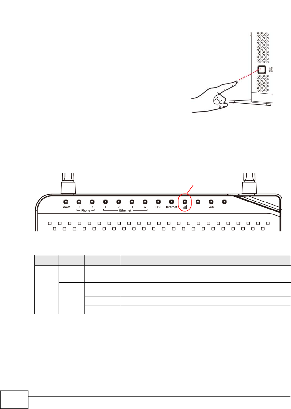
1.5 LEDs (Lights)
The following graphic displays t he labels of t he LEDs.
Figure 1 LEDs on t he Device
None of t he LEDs are on if t he VDSL Router is not receiving power.
Table 1 LED Descriptions
LED COLOR STATUS DESCRIPTION
Power Green On The VDSL Rout er is receiving power and ready for use.
Blinking The VDSL Router is self- test ing.
Red On The VDSL Router det ected an err or while self-t est ing, or t here is a
device m alfunct ion.
Off The VDSL Rout er is not receiving power.
Blinking Fir m ware upgrade is in progr ess.
3 G

Chapter 1 Introducing the VDSL Router
Basic Home Station VDSL2 P8802T User’s Guide 15
Phone
1/ 2
Green On A SI P account is regist ered for the phone port .
Blinking A t elephone connect ed to the phone port has its receiver off of
the hook or there is an incom ing call.
Orange On A SI P account is regist ered for the phone port and t here is a
voice message in the corresponding SI P account .
Blinking A t elephone connect ed to the phone port has its receiver off of
the hook and there is a voice m essage in the corresponding SI P
account .
Off The phone port does not have a SI P account regist ered.
Ethernet
1- 4
Green On The VDSL Rout er has a successful 100 Mbps Et hernet connection wit h a
device on t he Local Area Net wor k ( LAN) .
Blinking The VDSL Router is sending or r eceiving data to/ from t he LAN at 100
Mbps.
Off The VDSL Router does not have an Ethernet connect ion with the LAN.
DSL Green On The DSL line is up.
Blinking The VDSL Rout er is initializing t he DSL line.
Off The DSL line is down.
I nternet Green On The VDSL Router has an I P connect ion but no t raffic.
Your device has a WAN I P address (eit her st atic or assigned by a DHCP
server) , PPP negot iation was successfully com plet ed (if used) and the
DSL connect ion is up.
Blinking The VDSL Router is sending or receiving I P traffic.
Off There is no I nternet connect ion or the gat eway is in bridged mode.
Red On The VDSL Rout er at tem pted to m ake an I P connect ion but failed.
Possible causes are no response from a DHCP server, no PPPoE
response, PPPoE aut henticat ion failed.
3G Green On The 3G backup connect ion t hr ough a 3G USB dongle is connect ed.
Blinking The VDSL Router is negotiat ing a backup connect ion t hr ough a 3G
dongle or sending or r eceiving traffic through t he backup connection.
Fast Blinking The VDSL Rout er is sending or receiving traffic through t he backup
connection.
Red On Aut henticat ion of t he 3G backup connect ion t hrough a 3G USB dongle
failed.
Off The VDSL Router is using t he broadband interface.
Wifi Green On The wireless net work is act ivat ed.
Blinking The VDSL Rout er is com m unicat ing w it h ot her wireless client s.
Orange Blinking The VDSL Router is set ting up a WPS connect ion.
Off The wireless net work is not act ivated.
Table 1 LED Descriptions ( continued)
LED COLOR STATUS DESCRIPTION
Chapter 1 Introducing the VDSL Router
Basic Home Station VDSL2 P8802T User’s Guide
16
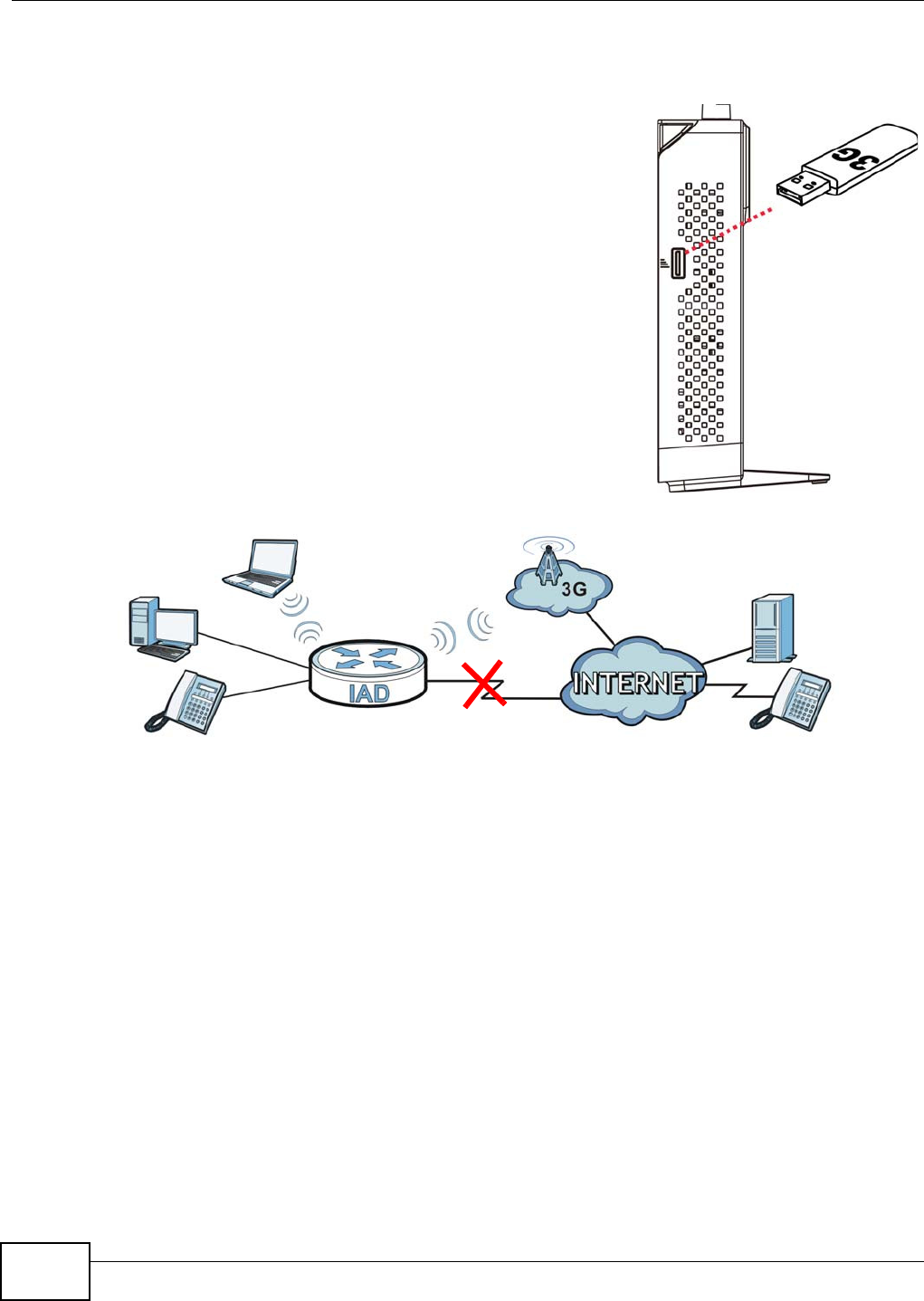
1.6 3G WAN
The USB port ( at the right side of the device when you
face to the front panel) allows you to wirelessly
connect to a 3G netowk t o get I nt ernet access by
at taching a 3G dongle. You m ust leave the VDSL
Router DSL or Ethernet WAN port unconnect ed and
at t ached a 3G dongle to use 3G as your WAN. You can
also heve t he VDSL Router use t he 3G WAN
connection as a backup. That m eans t he VDSL Router
switches t o the 3G wireless WAN connection after the
wired DSL or Ethernet WAN connect ion fails. The
VDSL Rout er autom at ically changes back to use t he
wired DSL or Ethernet WAN connect ion when it is
available.
Figure 2 Internet Access Application: 3G WAN
1.7 The RESET Button
I f you forget your passw ord or cannot access the web configurat or, you will need to use t he RESET
butt on at t he back of the device to reload t he fact ory- default configurat ion file. This deletes all your
and the passwor d w ill be reset t o “ 1234”.
1Make sure t he Pow e r LED is green and on ( not blinking and not red or flashing r ed).
2To set t he device back to the factory default sett ings, press t he RESET but t on for ten seconds or
until t he Pow e r LED begins t o blink and t hen release it. When the Pow er LED begins to blink, t he
defaults have been rest ored and the device rest arts.
Note: The default usernam e and password are on the label on the bottom of the Device.
Chapter 1 Introducing the VDSL Router
Basic Home Station VDSL2 P8802T User’s Guide 17
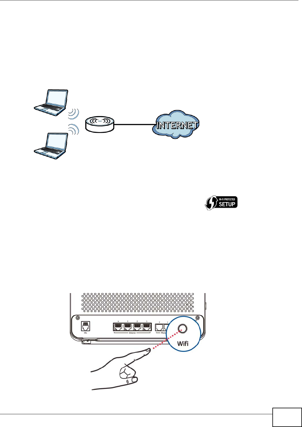
1.8 Wireless Access
The VDSL Router is a wireless Access Point ( AP) for wireless clients, such as not ebook com put ers,
sm artphones, or t ablet s. I t allows them t o connect to the I nt er net without having to rely on
inconvenient Ethernet cables.
You can connect to your wireless net work using the W ifi but t on, wit hout having to access the Web
Configurat or.
Figure 3 Wireless Access Exam ple
1.8.1 Using the Wifi Button
Note: The wireless client m ust be a WPS- aware device (for exam ple, a WPS USB adapt er or
PCMCI A card), which can be ident ified by t he WPS logo:
I f the wireless net work is t urned off, press the W ifi but t on at t he back of t he VDSL Router for one
second. Once t he W ifi LED turns green, t he wireless net work is act ive.
You can also use the W ifi but t on t o quickly set up a secure w ireless connect ion bet ween t he VDSL
Router and a WPS- com pat ible client by adding one device at a t im e.
To act ivate WPS:
1Make sure t he Pow e r LED is green and not blinking.
2Press t he W ifi but t on for ten seconds and release it.

Chapter 1 Introducing the VDSL Router
Basic Home Station VDSL2 P8802T User’s Guide
18
3Enable WPS on anot her WPS- enabled client device within range of t he VDSL Router. I f you do not
know how to enable WPS on t hat client device, refer t o its m anual. The W ifi LED flashes green and
orange while t he VDSL Router set s up a WPS connection w it h t he ot her WPS enabled client device.
4Once t he connect ion is successfully m ade, t he W ifi LED shines green.
To t urn off the wireless net work, press t he W ifi but t on on t he front of the VDSL Router for one t o
five seconds. The W ifi LED t urns off when t he wireless network is off.

Basic Home Station VDSL2 P8802T User’s Guide 19
CHAPTER 2
User Setup Guide
This chapt er cont ains instruct ions to quickly set up feat ures on t he syst em .
• Access the VDSL Router Configuration (Sect ion 2.1 on page 19)
• Changing t he Configuration Passw ord ( Sect ion 2.2 on page 20)
• Set t ing Up a 3G Backup I nt ernet Connect ion (Sect ion 2.2 on page 20)
• Set t ing your DSL Account’s Usernam e and Passw ord ( Sect ion 2.2 on page 20)
• Sett up Up a Secure Wireless Net work (Sect ion 2.2 on page 20)
• Using Wireless MAC Aut henticat ion to Block a Com put er ’s Access t o t he Wireless Network
(Sect ion 2.3 on page 28)
• Sett ing Up an NAT Virtual Server for a Gam e Server (Sect ion 2.4 on page 29)
• Access Your Hom e Com put er from t he I nt ernet Using DDNS ( Sect ion 2.5 on page 30)
• Configuring the Firewall (Sect ion 2.6 on page 34)
• LAN DHCP for I P Addressing Assignm ent (Sect ion 2.7 on page 36)
• Checking t he Software Version (Sect ion 2.8 on page 38)
• Rest oring t o Fact ory Default ( Section 2.9 on page 39)
• How t o Use File Sharing on t he VDSL Router (Sect ion 2.10 on page 40)
• Using the Media Server Feat ure ( Sect ion 2.11 on page 43)
• How t o Share a USB Printer via Your VDSL Rout er ( Sect ion 2.12 on page 47)
2.1 Access the VDSL Router Configuration
1Connect to t he Web Configurator t o configure the VDSL Rout er. Ent er the LAN I P address of t he
VDSL Router in your web browser (see t he cover page of this guide for the default login
in form at ion) .
2The D evice I nfo Sum m a ry screen displays. See Sect ion 3.2 on page 61 for m ore inform ation.
Chapter 2 User Setup Guide
Basic Home Station VDSL2 P8802T User’s Guide
20
2.2 Setting Up a Secure Wireless Network
Thom as set s up a wireless net work t o give his not ebook wireless I nt ernet access. The VDSL Router
serves as an access point ( AP) to let t he not ebook connect to the I nt ernet.
Thom as configures t he wireless net work set t ings on t he VDSL Router and uses WPS ( Section 2.2.2
on page 22) or m anual configurat ion (Sect ion 2.2.3 on page 26) to connect his notebook.
2.2.1 Configuring the Wireless Network Settings
This exam ple uses t he following paramet ers to set up a wireless net work.
Note: See t he sticker on the bottom of the VDSL Router for the default wireless LAN
SSI D, securit y m ode, and password.
SSI D Exam ple
Secu rity Leve l WPA2 - PSK
W PA/ W API pa ssph rase DoNot StealMyWirelessNetwor k
8 0 2 .1 1 M ode 802.11b/ g/ n Mixed
Chapter 2 User Setup Guide
Basic Home Station VDSL2 P8802T User’s Guide 21
1Click W irele ss t o display the w ireless sett ings. Make sure Enable W ireless is select ed. Type
Ex am ple in t he SSI D field.
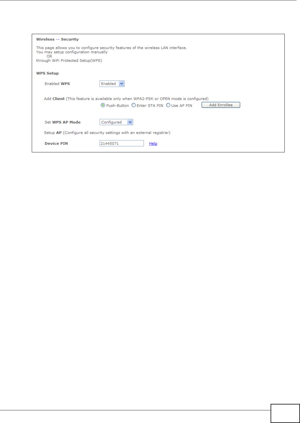
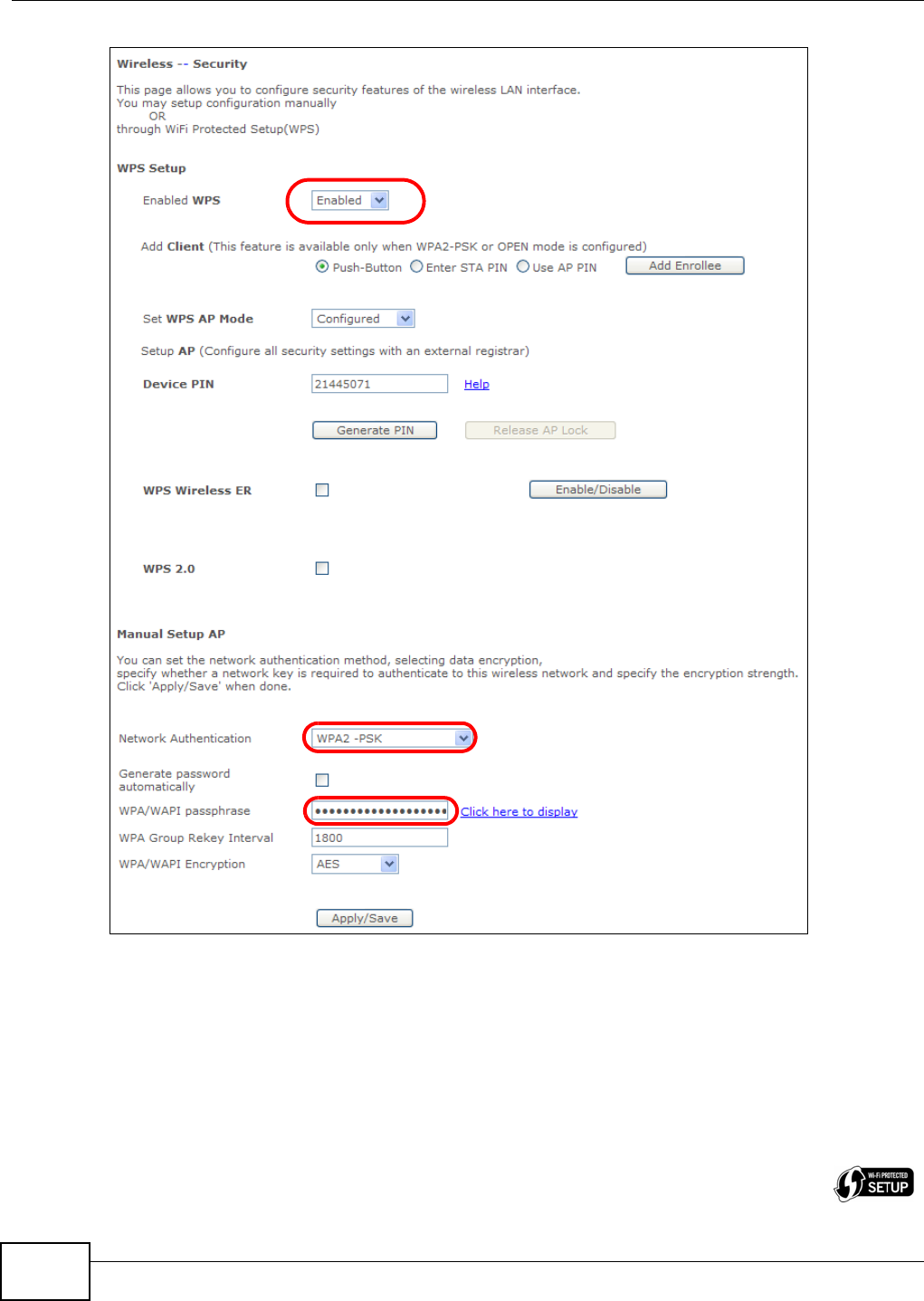
2Click W ir ele ss > Se cu rit y, m ake sure Ena bled W PS is set t o Ena bled. Select W PA2 - PSK in t he
N etw ork Au t he nt ica t ion field. Ent er t he W PA/ W API passph ra se . Click Apply/ Save.
Chapter 2 User Setup Guide
Basic Home Station VDSL2 P8802T User’s Guide
22
Use WPS to wirelessly connect t he not ebook t o the VDSL Router (see Sect ion 2.2.2 on page 22) or
use t he notebook’s wireless client to search for the VDSL Router (see Sect ion 2.2.3 on page 26) .
2.2.2 Using WPS
This exam ple uses WPS to connect a ZyXEL NWD210N wireless client t o t he VDSL Router’s wireless
net work.
Note: One way to see if the wireless client ( a notebook, sm artphone, tablet, wireless USB adapter,
or wir eless PCMCIA card for exam ple) supports WPS is t o look for t he WPS logo:

Chapter 2 User Setup Guide
Basic Home Station VDSL2 P8802T User’s Guide 23
I t covers t wo WPS m ethods to set up the w ireless client set t ings:
•Push But t on Configu ra t ion ( PBC) - simply press a but ton. This is the easier m ethod.
•PI N Configurat ion - ent er a wireless client ’s Personal I dentificat ion Num ber (PI N) in t he VDSL
Rou t er .
Push Button Configuration (PBC)
1Make sure t hat your VDSL Router is on and your notebook is wit hin range of the wireless signal.
2Make sure that you have inst alled t he wireless client driver and utilit y in your notebook.
3I n the wireless client utility, go to the WPS sett ing page. Enable WPS and press the W ifi but t on
(St a r t or W ifi button) .
4Push and hold t he W ifi but t on locat ed on t he VDSL Rout er’s rear panel for 10 seconds.
Note: I t doesn’t m at t er which device’s but t on you press first. You m ust press the second
button within two m inut es of pressing the first one.
Note: The WPS but t on in the Web Configurator screens also has the same funct ion as the
one on t he VDSL Router rear panel: use either.
The VDSL Router sends the wireless net work set t ings to the wireless client . This m ay take up to two
m inutes. After wards t he wireless client can comm unicate wit h the VDSL Rout er securely.
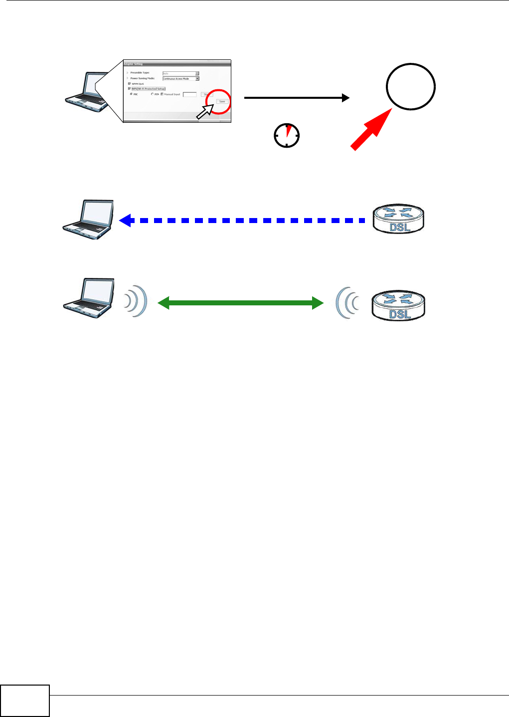
The following figure shows an exam ple of how t o set up a wireless net work and it s security by
pressing a button on bot h VDSL Router and wir eless client .
Chapter 2 User Setup Guide
Basic Home Station VDSL2 P8802T User’s Guide
24
Example WPS Process: PBC Method
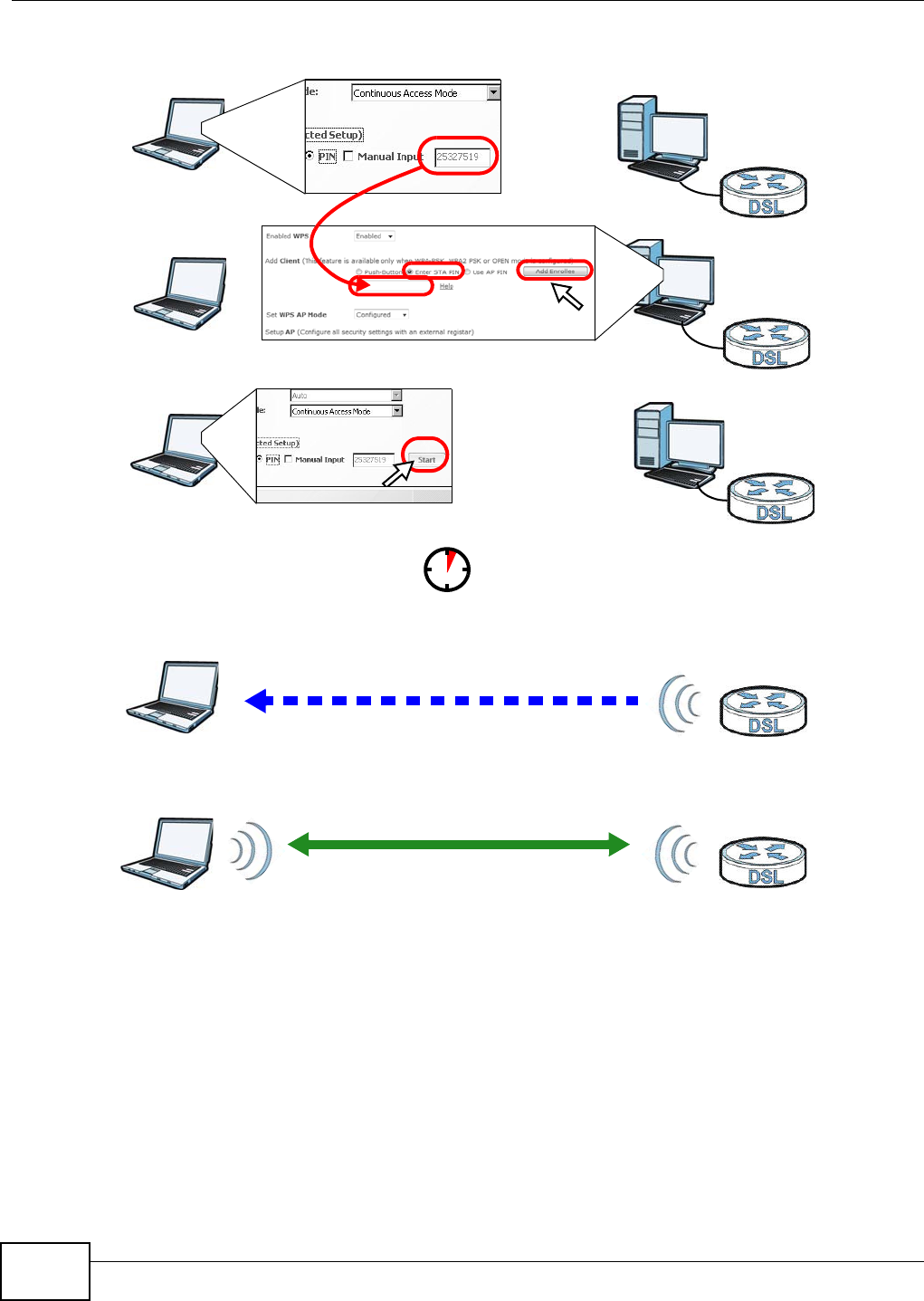
PIN Configuration
When you use t he PI N configurat ion m ethod, you need t o use both t he VDSL Rout er’s web
configurat or and the wireless client ’s utilit y.
1Launch your wireless client’s configurat ion utility. Go to t he WPS set t ings and select t he PI N m et hod
to get a PI N num ber.
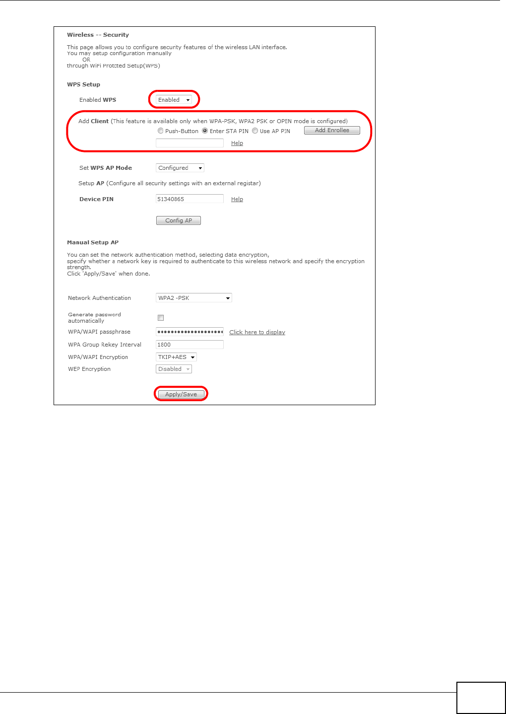
2Log int o the VDSL Router’s web configurat or and click W ire less > Se cur ity. Enable t he WPS
funct ion and select En ter STA PI N. Ent er the PI N num ber of the w ireless client and click the Add
Enrollee butt on. Click Apply / Sa ve .
Wireless Client VDSL Router
SECURITY INFO
COMMUNICATION
WITHIN 2 MINUTES
Press an d hold for
1 0 se conds
W ifi
Chapter 2 User Setup Guide
Basic Home Station VDSL2 P8802T User’s Guide 25
3Act ivate WPS on t he wireless client ut ilit y screen wit hin t wo m inutes.
The VDSL Router authent icat es t he wireless client and sends it t he proper configuration set t ings.
This m ay take up to t wo minut es. The wireless client can then com m unicat e wit h the VDSL Router
securely.
The following figure shows how to set up a wireless net work and its security on a VDSL Router and
a wireless client by using PI N m et hod.
Chapter 2 User Setup Guide
Basic Home Station VDSL2 P8802T User’s Guide
26
Example WPS Process: PIN Method
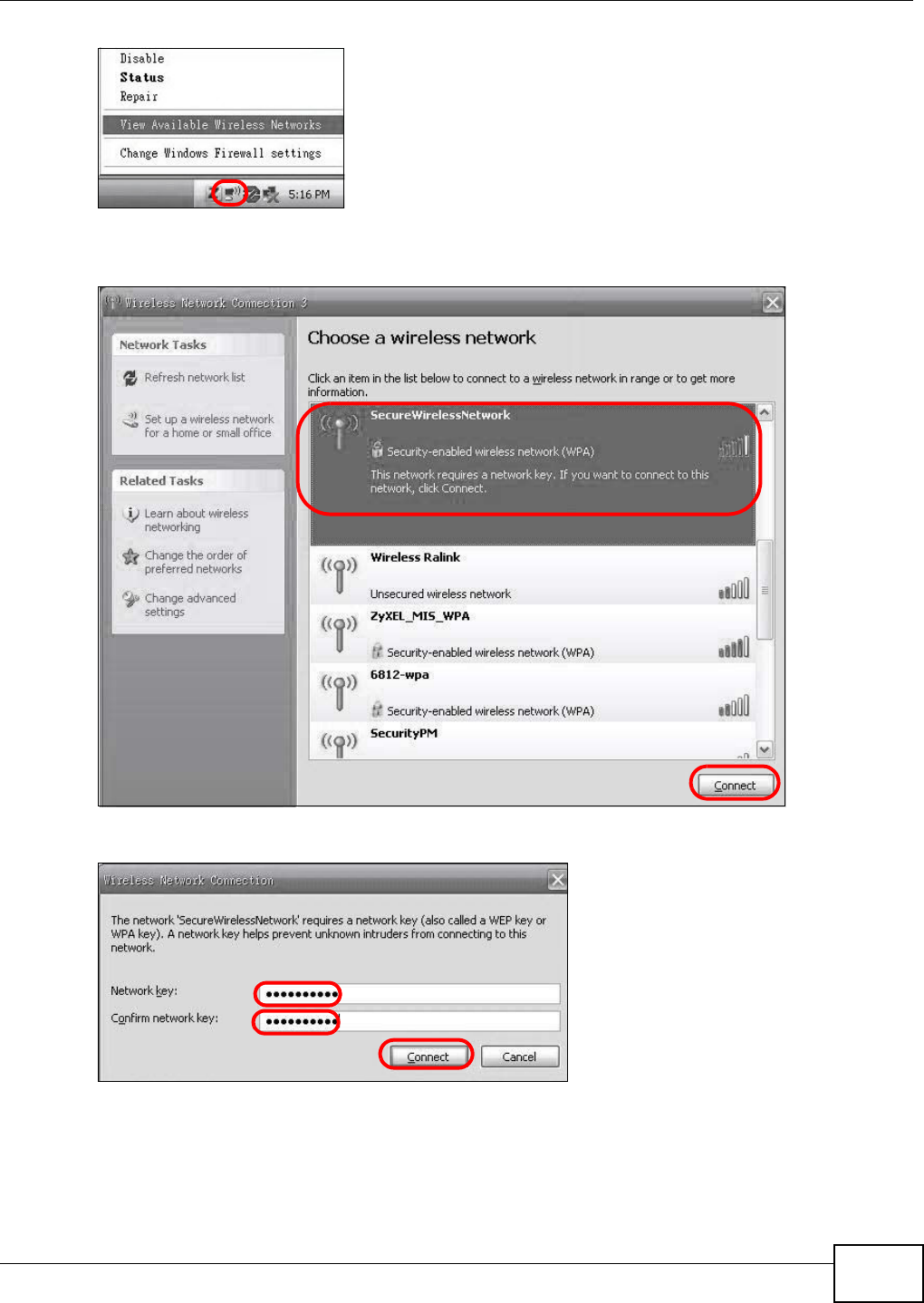
2.2.3 Without WPS
This exam ple uses Windows XP t o connect wirelessly to your VDSL Router.
1Right- click t he wireless adapter icon at the bott om right of your com puter m onit or. Click Vie w
Available W ire less N etw orks.
Authentication by PIN
SECURITY INFO
WITHIN 2 MINUTES
Wireless Client
VDSL Router
COMMUNICATION
Chapter 2 User Setup Guide
Basic Home Station VDSL2 P8802T User’s Guide 27
2Select the VDSL Router’s SSI D nam e ( “ SecureWir elessNet work” in this exam ple) and click
Con ne ct ( A) .
3Enter t he passw ord when prom pted and click Conne ct .
4You m ay have t o wait several m inutes while your com puter connect s t o t he wireless net work.
5Congratulat ions! Browse t o your favorite websites. I f you cannot, check that you connected to the
correct AP, and the signal st rengt h is OK. Click your wireless adapt er’s icon and click Enable. Som e
not ebooks also have a physical butt on t hat enables or disables the wireless adaptor.
A
Chapter 2 User Setup Guide
Basic Home Station VDSL2 P8802T User’s Guide
28
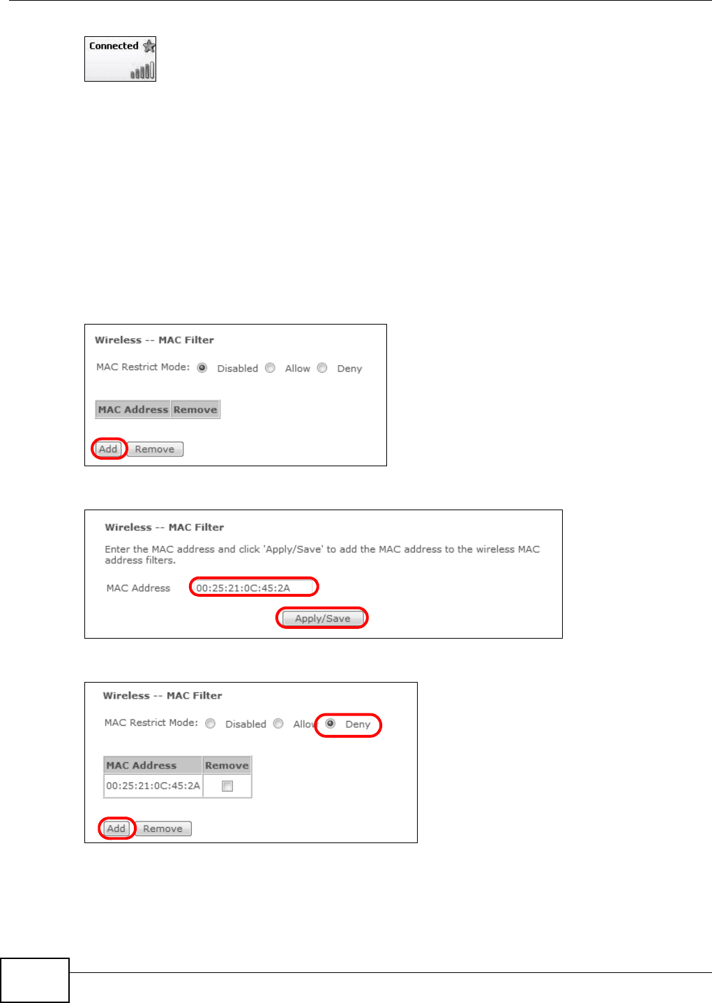
2.3 Using Wireless MAC Authentication to Block a
Computer’s Access to the Wireless Network
Use M AC Aut hent ication to block a com puter from accessing t he wireless net work based on t he
com puter ’s MAC address.
Note: MAC Aut hent ication offers lim ited security.
1Click W ireless > MAC Filt er. I n the M AC Filt er screen, click Add.
2I n t he M AC Address field, enter the MAC address of the computer to block and click Apply/ Save .
3The MAC address appears in t he M AC List . Set t he M AC Restr ict M ode to Deny and click Add.
Chapter 2 User Setup Guide
Basic Home Station VDSL2 P8802T User’s Guide 29
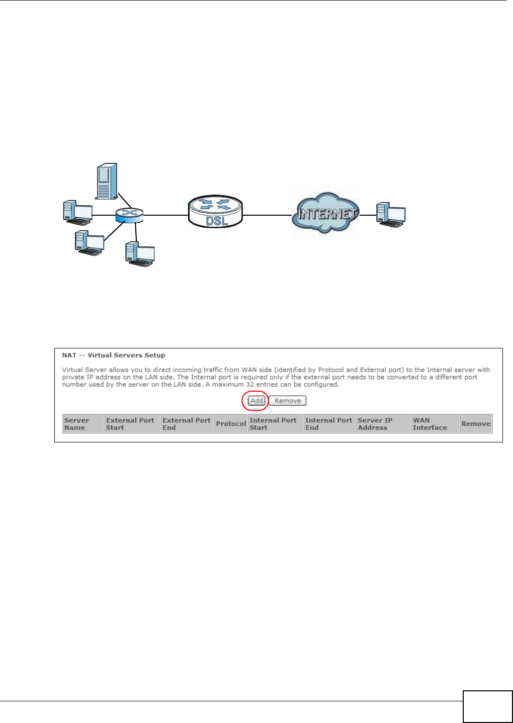
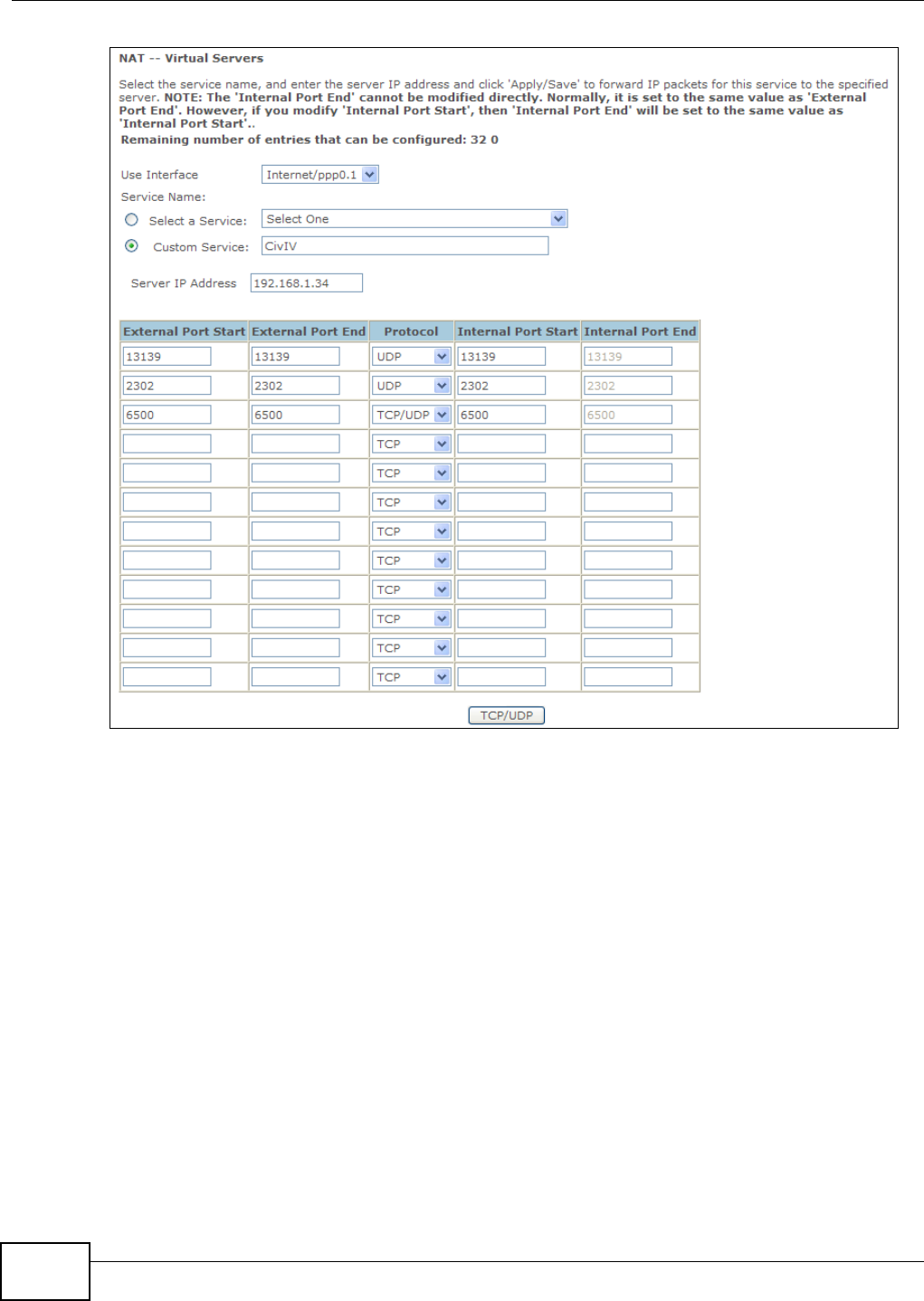
2.4 Setting Up a NAT Virtual Server for a Game Server
This exam ples configures a virtual server t o forward t raffic from Civilizat ion I V player s on t he
I nt ernet ( A in t he figure below) t o a server on a com put er behind the VDSL Router.
Not e: I f fir ewall is enabled, you m ay also need t o configu r e a fir ewall rule f or t he relevant
ports. See Sect ion 2.6.2 on page 34.
Tutorial: NAT Port Forwarding Setup
Thom as configures virtual servers t o forwar d TCP and UDP port 6500, and UDP por ts 2302 and
13139 t raffic t o port 6500 at the server’s I P address of 192.168.1.34.
1Click Advance d Setup > NAT > Virt ua l Se rver s and then Add.
2Select the incom ing int er face for the traffic. Specify a nam e ( CivI V in this exam ple) in the Cu st om
Se rvice field. Set the Ser ve r I P Address to 192.168.1.34. Add UDP ports 2302 and 13139 and
port num ber 6500 for TCP & UDP prot ocols. Click TCP/ UD P.
D=192.168.1.34 WAN
LAN
TCP/UDP port 6500
A
UDP ports 2302 and 13139
Chapter 2 User Setup Guide
Basic Home Station VDSL2 P8802T User’s Guide
30
Players on t he I nt ernet then can access Thom as’ server.
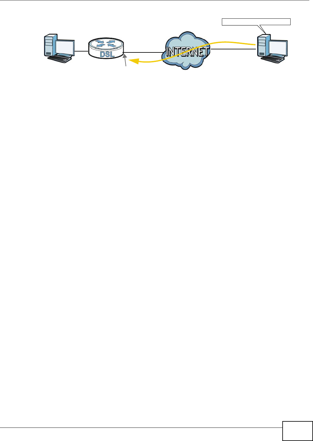
2.5 Access Your Home Computer from the Internet Using
DDNS
I t is inconvenient for you to access your hom e com put er from the I nternet if your VDSL Router uses
a dynam ic WAN I P address since it changes dynam ically. Dynam ic DNS ( DDNS) allows you to
access your hom e com puter using a dom ain nam e.
Note: Enable rem ote desktop server service on your hom e com puter. The rem ote desktop
server feat ure covered here is included in Windows Professional, Business, and
Ultim at e versions.
Not e: I f fir ewall is enabled, you m ay also need t o configu r e a fir ewall rule f or t he relevant
ports. See Sect ion 2.6.2 on page 34.
Chapter 2 User Setup Guide
Basic Home Station VDSL2 P8802T User’s Guide 31
To use t his feat ure, apply for DDNS service at www.dyndns.org or TZO. This t ut orial covers:
•Regist ering a DDNS Account on www.dyndns.org
•Configuring DDNS on Your VDSL Rout er
•Configuring Port Forwarding on your VDSL Router
•Test ing t he DDNS Sett ing
Note: I f you have a private WAN I P address, then you cannot use DDNS.
2.5.1 Registering a DDNS Account on www.dyndns.org
1Open a browser and type h t t p:/ / w w w .dyn dn s.or g.
2Apply for a user account. This t ut orial uses Use r N am e 1 and 1 2 3 4 5 as t he usernam e and
password.
3Log int o www.dyndns.org using your account .
4Add a new DDNS host nam e. This t ut orial uses the following sett ings as an exam ple.
• Hostname: zy x elr out e r .dyn dns. org
• Service Type: Host w ith I P addre ss
• I P Address: Enter the WAN I P address t hat your VDSL Router is current ly using. You can find t he
I P address on the VDSL Router ’s Web Configurat or Stat us page.
Then you w ill need t o configure t he sam e account and host nam e on the VDSL Router later.
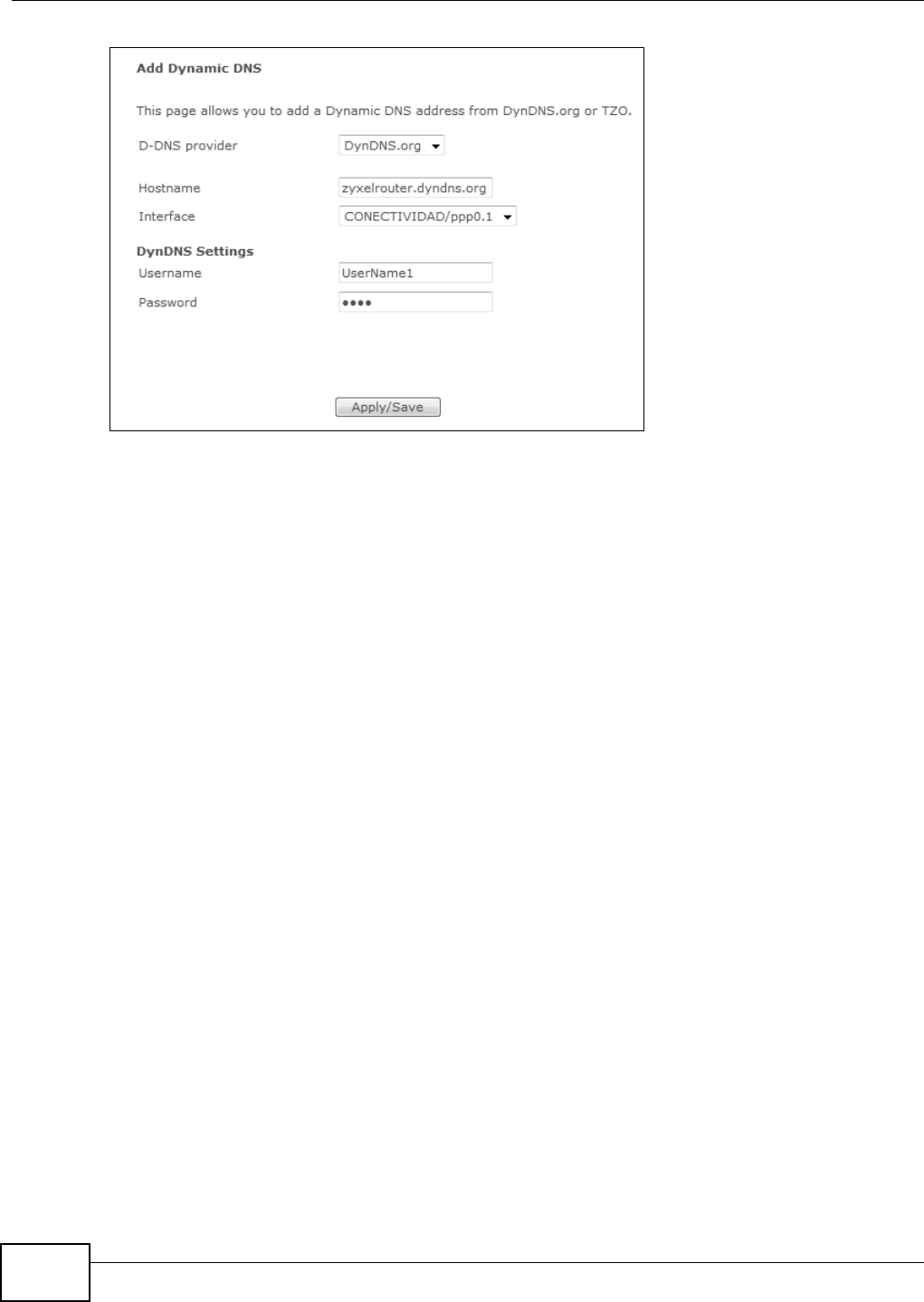
2.5.2 Configuring DDNS on Your VDSL Router
Configure t he following sett ings in t he Adva nced Se t up > DNS > Dyna m ic DNS > Add screen.
• Select D yn D N S.or g as t he D- DNS provider.
• Type zy xe lr ou t er .dynd ns.or g in the H ost Nam e field.
• Leave t he inter face set to the default unless you have configured another interface t o use.
• Ent er t he user nam e ( U se r N am e 1 ) and password ( 1 2 3 4 5 ) .
• Click Apply/ Sa ve .
w.x.y.z a.b.c.d
http: / / zyxelrout er.dyndns.org
A
Chapter 2 User Setup Guide
Basic Home Station VDSL2 P8802T User’s Guide
32
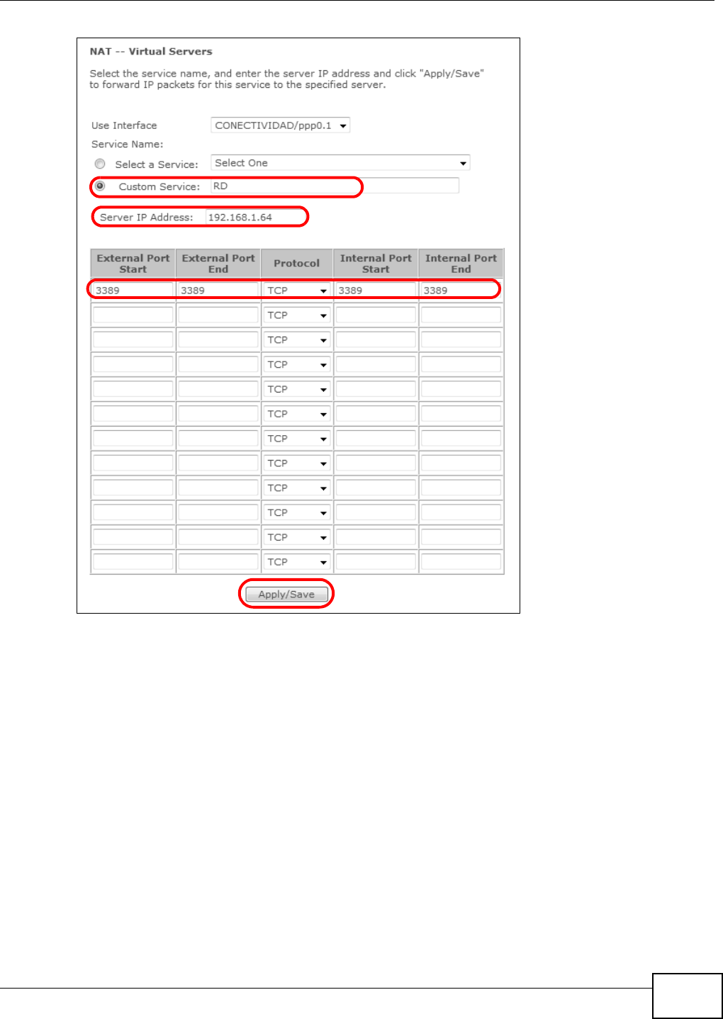
2.5.3 Configuring Port Forwarding on your VDSL Router
Configure t he following set t ings in t he Adva nce d Se tup > N AT > Virtua l Ser ve rs > Add screen.
• Leave t he inter face set to the default unless you have configured another interface t o use.
• Select Cust om Service and type RD in the field.
• Type the LAN I P address of your com puter in the Ser ver I P Addr e ss f ield. To ch eck t his on y our
hom e computer, click St ar t , All Pr ogram s, Acce ssor ies and t hen Com m and Prom pt. I n the
Com m a nd Pr om pt window, type " ipconfig" and t hen press [ ENTER] . This exam ple uses
1 9 2 .1 6 8 .1 .6 4 . See Configuring St at ic DHCP to configure a Stat ic DHCP rule for t his I P address.
• Type 3 3 8 9 in the Exter na l/ I nt ern al St a rt/ End Por t fields. This is t he listening port for
Windows rem ot e desktop.
• Select the TCP in t he Pro t ocol field.
Chapter 2 User Setup Guide
Basic Home Station VDSL2 P8802T User’s Guide 33
Click Apply / Sa ve .
2.5.4 Testing the DDNS Setting
Test your access t o your com puter from the I nt ernet .
1Open the remot e deskt op client application on t he rem ot e comput er (using t he I P address a .b.c.d)
that is connect ed to t he I nt ernet .
2Ty p e ht t p:/ / z y xe lrou t er .dy ndn s. or g and press [ Ent er] .
3Your com puter’s rem ote deskt op login page should appear.
Chapter 2 User Setup Guide
Basic Home Station VDSL2 P8802T User’s Guide
34
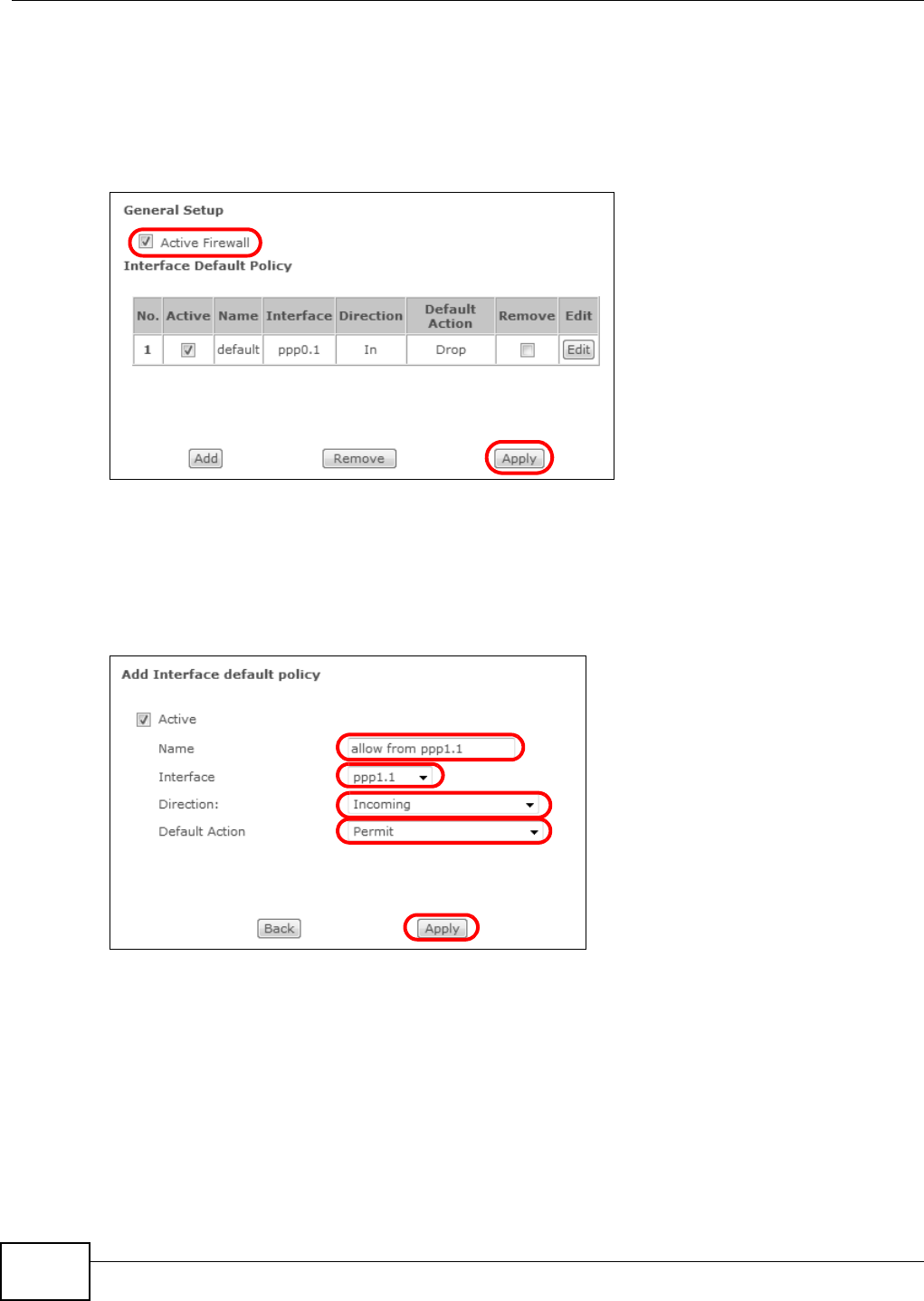
2.6 Configuring the Firewall
Click Advan ce d Setup > Firew all > Ge ne ral and select Act ive Fire w a ll to turn on Denial of
Service ( DoS) protect ion. Select t he default policy’s Act iv e check box t o block sessions initiated
from the I nternet from com ing in through the ppp0.1 WAN interface. Click Apply.
Firewall Ex ample: Edit Rul e: Destina tion Address
2.6.1 Interface Default Policy
Click the Firew all > Ge ne ral screen’s Add butt on t o add an interface default policy t o block or
allow sessions init iated from the net work connected to an int er face. This exam ple allows sessions
initiat ed from the I nternet to com e in t hrough t he ppp1.1 WAN interface.
Firewall Ex ample: Edit Rul e: Destina tion Address
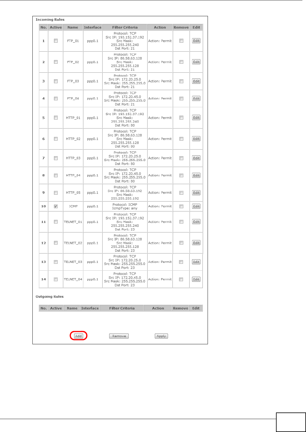
2.6.2 Firewall Rules
Use Fir ew all > Ru les t o control traffic by source and dest inat ion I P address and port .
Note: You m ay need t o configure a firewall rule for t he relevant ports if you use a NAT
virt ual server or DMZ host .
1Click Add to creat e a new rule.
Chapter 2 User Setup Guide
Basic Home Station VDSL2 P8802T User’s Guide 35
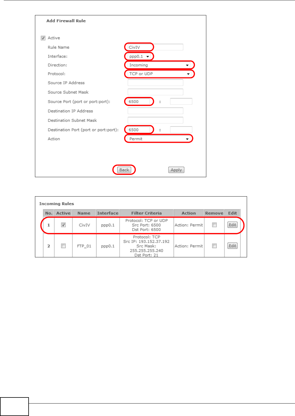
Firewall Ex ample: Edit Rul e: Destina tion Address
2This exam ple allows incom ing TCP or UDP port 6500 t raffic from int erface ppp0.1.
Chapter 2 User Setup Guide
Basic Home Station VDSL2 P8802T User’s Guide
36
Firewall Ex ample: Edit Rul e: Destina tion Address
Firewall Example: Ed it Rule: Select Cus tomized Services
3Your new rule displays in t he list.
Firewall Ex ample: Edit Rul e: Destina tion Address
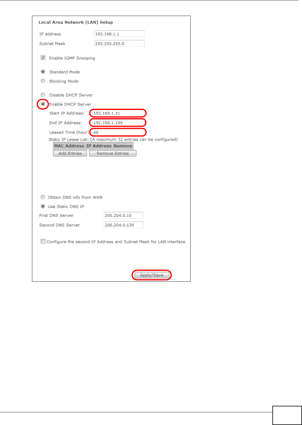
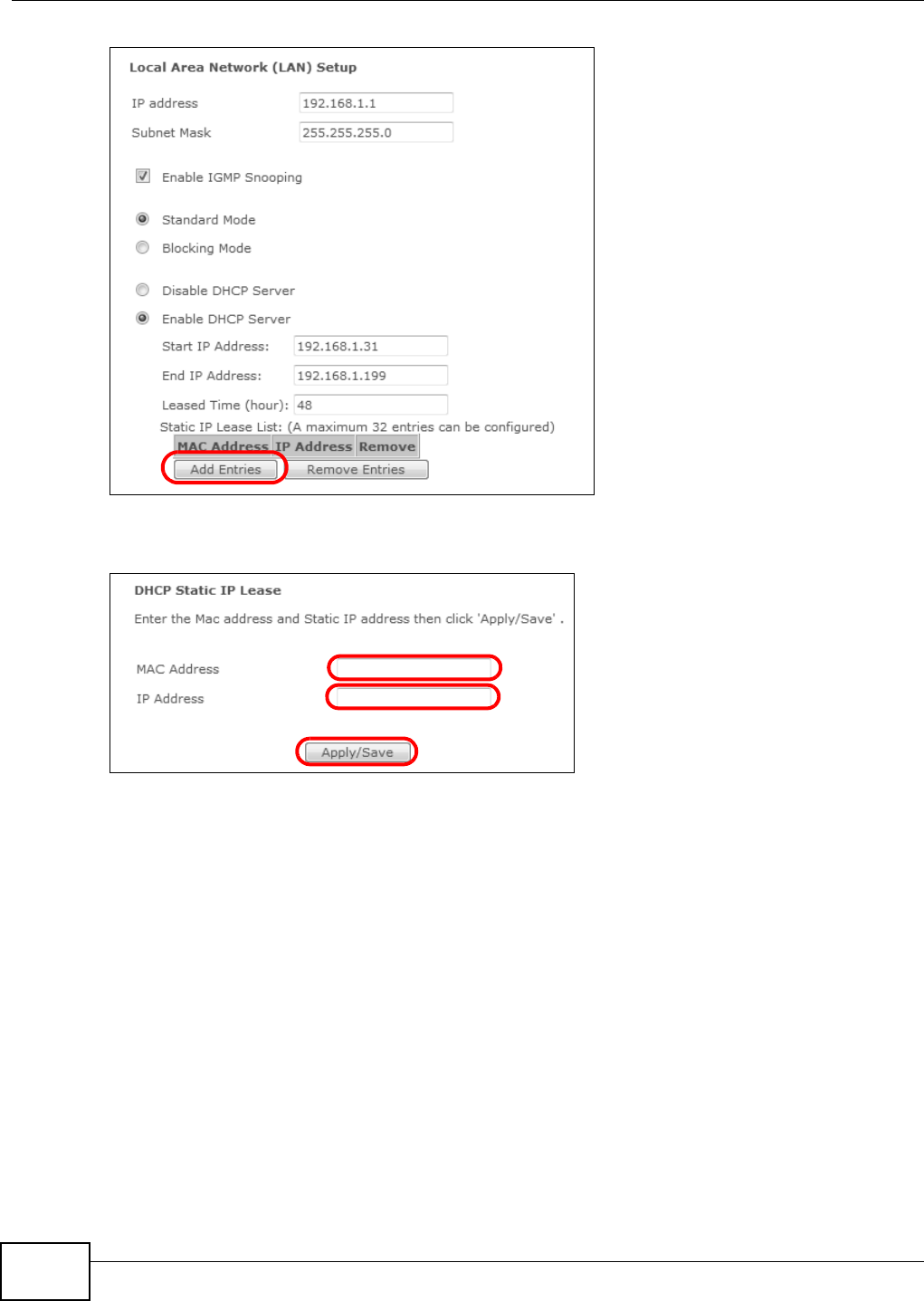
2.7 LAN DHCP for IP Addressing Assignment
The following exam ple shows how to configure LAN DHCP set t ings.
Click Adva nce d Se tup > LAN to display the LAN set t ings. Under the Ena ble DH CP Ser ve r option
change the DHCP server I P address range. Set Leased Tim e to specify how long to lease an IP
address t o a LAN com puter. Click Apply/ Save.
Chapter 2 User Setup Guide
Basic Home Station VDSL2 P8802T User’s Guide 37
Firewall Ex ample: Edit Rul e: Destina tion Address
2.7.1 Configuring Static DHCP
Use stat ic DHCP t o have t he VDSL Router always give t he same I P address t o a specific com puter.
1Click Advance d Setup > LAN t o display the LAN sett ings. Under the Sta t ic I P Lease List , click
Add Ent r ies.
Chapter 2 User Setup Guide
Basic Home Station VDSL2 P8802T User’s Guide
38
Firewall Ex ample: Edit Rul e: Destina tion Address
2Enter t he com put er ’s MAC address and t he LAN I P address t o give t he com puter and click Apply/
Sa ve .
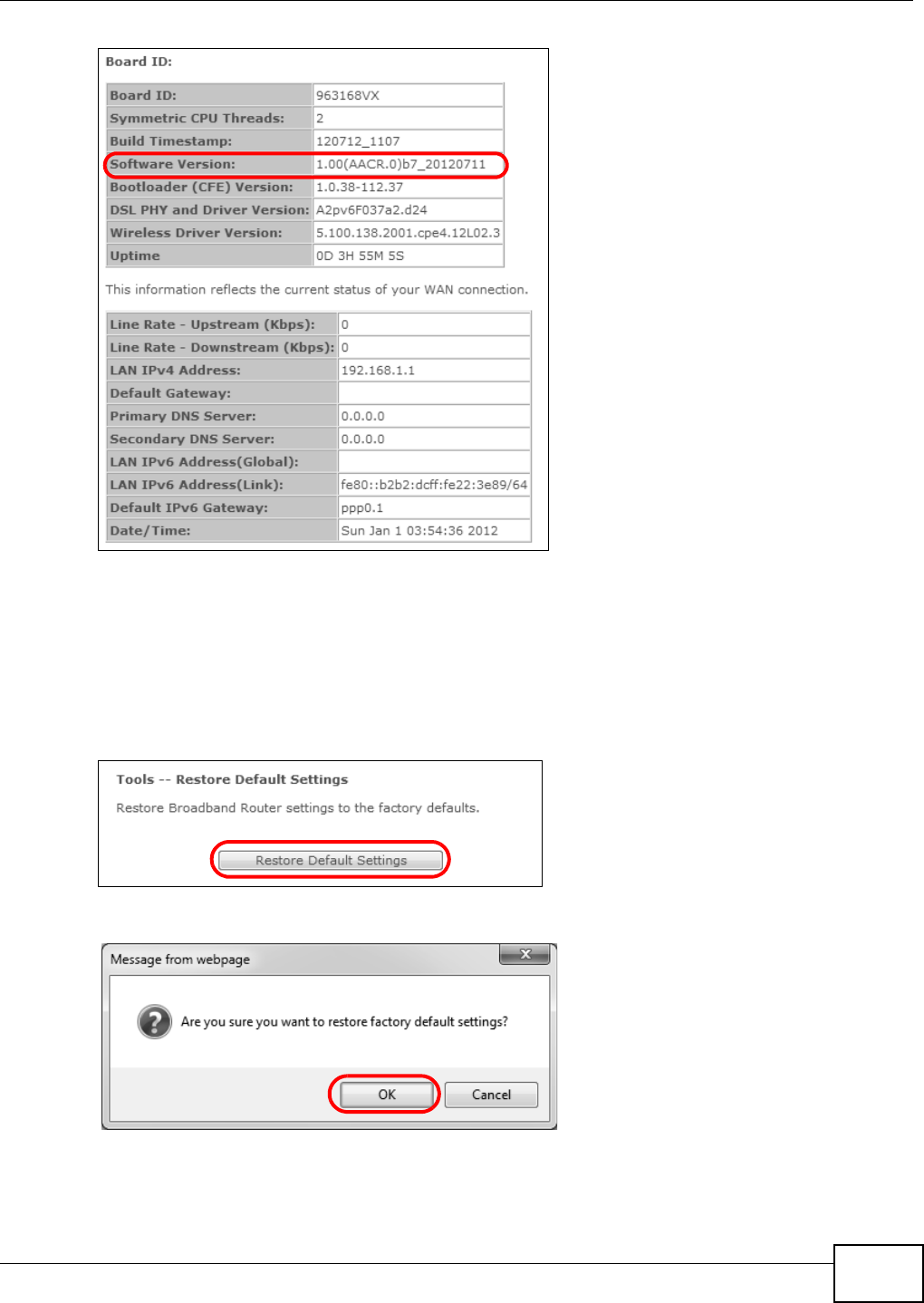
2.8 Checking the Software Version
Click . The Device I nfo. The screen displays t he version of t he soft ware inst alled on the VDSL
Rou t er .
Chapter 2 User Setup Guide
Basic Home Station VDSL2 P8802T User’s Guide 39
Firewall Ex ample: Edit Rul e: Destina tion Address
2.9 Restoring to Factory Default
This procedure rest ores the fact ory default set t ings t o the VDSL Router.
1Click Manage m ent > Re st ore De fa ult > Re st ore D efault Set t ings.
Firewall Ex ample: Edit Rul e: Destina tion Address
2Click OK.
Firewall Ex ample: Edit Rul e: Destina tion Address
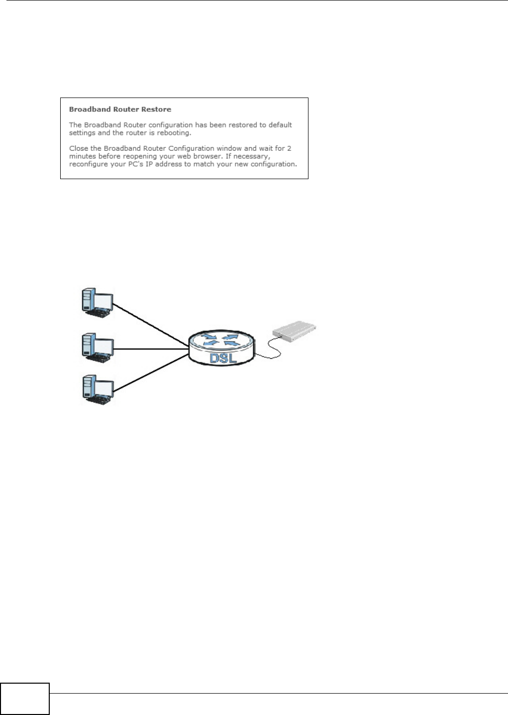
3The rest ore screen displays.
Chapter 2 User Setup Guide
Basic Home Station VDSL2 P8802T User’s Guide
40
Note: The Power LED flashes and stays on green when ready t o reconfigure. Follow the
inst ruct ions provided by your I SP t o reprogram your m odem .
Note: The VDSL Router’s back st icker displays t he default LAN I P address, usernam e, and
password.
Firewall Ex ample: Edit Rul e: Destina tion Address
2.10 How to Use File Sharing on the VDSL Router
These sect ions cover how t o use file sharing t o allow LAN users t o access a USB st orage device
connect ed t o t he VDSL Router as if it was direct ly connected to their com puters.
Note: Rem em ber to control physical access t o the USB drive so som eone doesn’t access
files by sim ply connect ing it to a com put er.
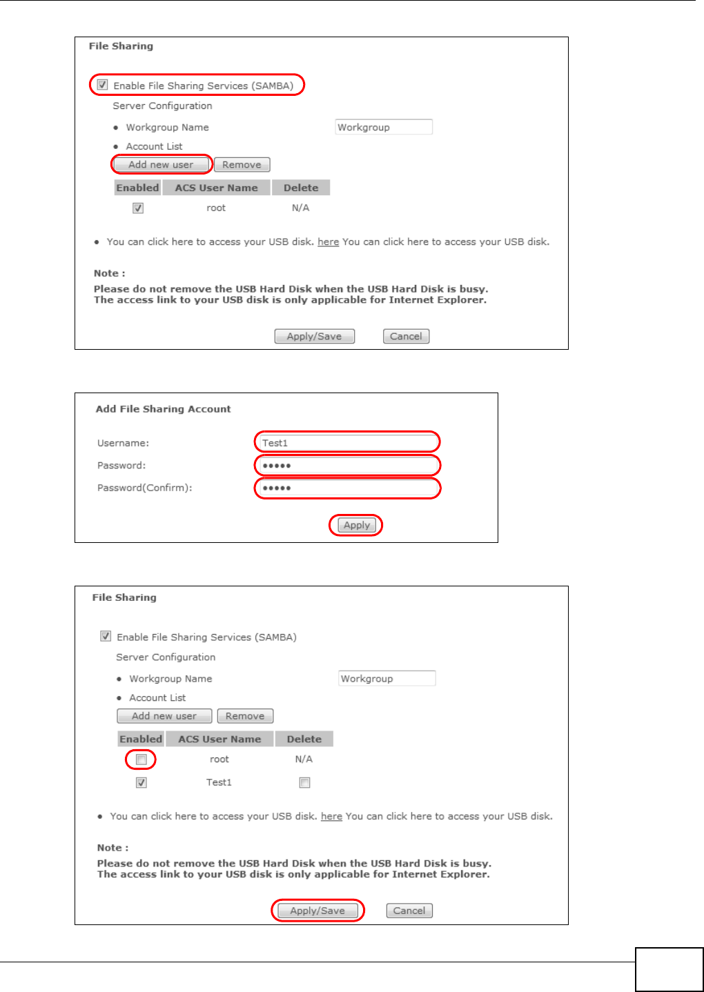
2.10.1 Set Up File Sharing
1Connect your USB device t o t he USB port at t he back panel of t he VDSL Router.
2Click Advanced Setup > USB Services > File Shar ing and enable file sharing. Click Add ne w
user to set up a new file sharing user account.
Chapter 2 User Setup Guide
Basic Home Station VDSL2 P8802T User’s Guide 41
3Ent er a user nam e and password and click Apply.
4Disable the root account and click Apply/ Sa ve .
Chapter 2 User Setup Guide
Basic Home Station VDSL2 P8802T User’s Guide
42
2.10.2 Access Your Shared Files From a Computer
Note: This exam ple uses Microsoft ’s Windows 7 t o browse your shared files.
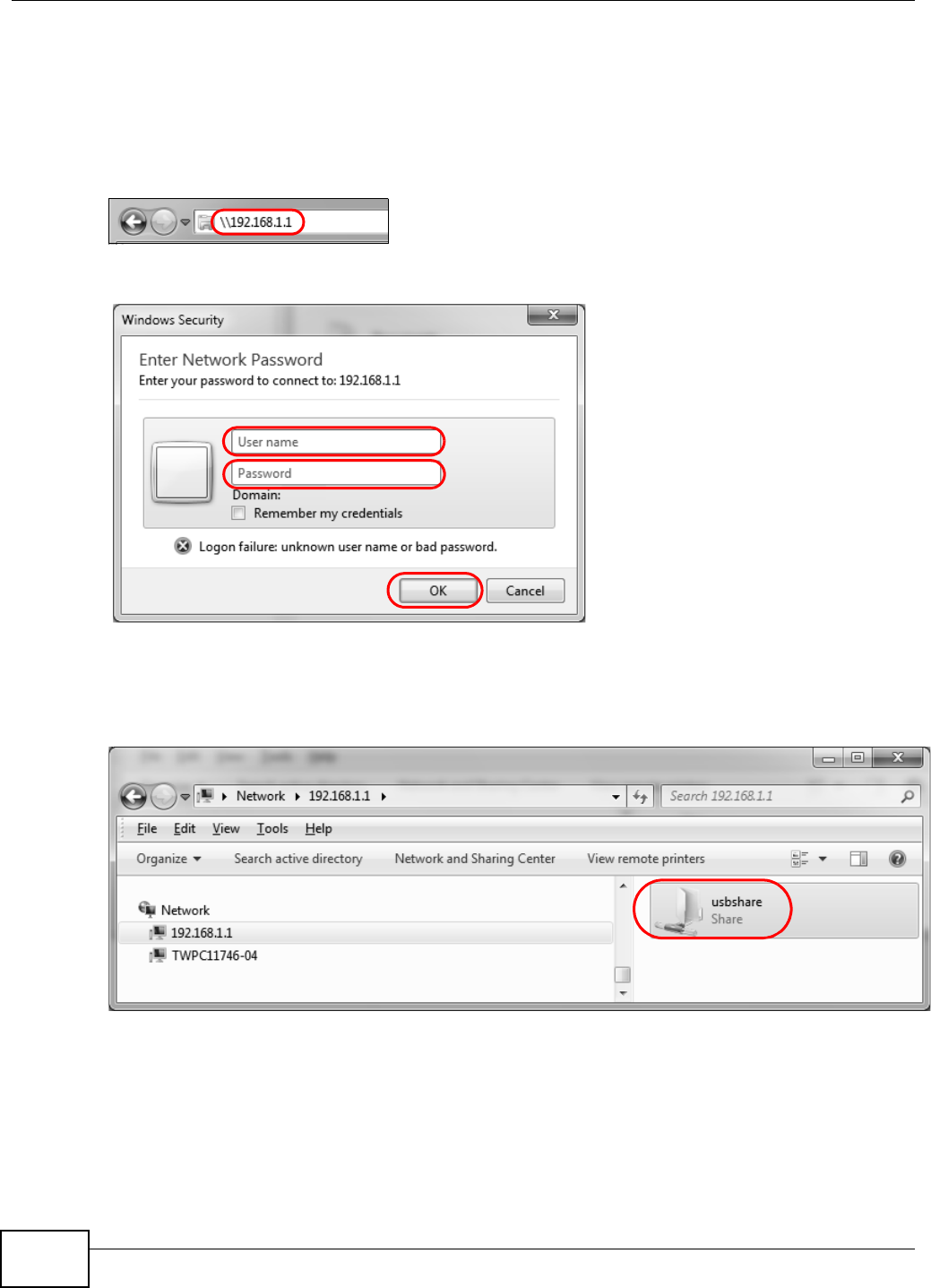
1Open Windows Explorer and in the address bar t ype a double backslash “ \ \ ” followed by the VDSL
Router’s LAN I P address and press [ ENTER] .
2A login scr een displays. Type the user nam e and password you set up for file sharing and click OK.
Note: Once you log into the file share via your VDSL Router, you do not have t o log in
again unless you rest art your com put er or t he VDSL Router.
3Double- click the usbshare folder and browser it s cont ent s.
Chapter 2 User Setup Guide
Basic Home Station VDSL2 P8802T User’s Guide 43
2.11 Using the Media Server Feature
The m edia server st ream s video, m usic, and phot o files from a USB st orage device t o DLNA-
com pliant m edia client s on your network. Connect t he USB st orage device to the VDSL Router’s
USB port. This sect ion gives examples of using t he m edia server with the following media client s:
• Microsoft ( MS) Windows Media Player
• ZyXEL DMA- 2500, a digital m edia adapt er - see t he DMA-2500 Quick St art Guide to set up the
DMA-2500 to work with your television ( TV) before using t he inst ruct ions here.
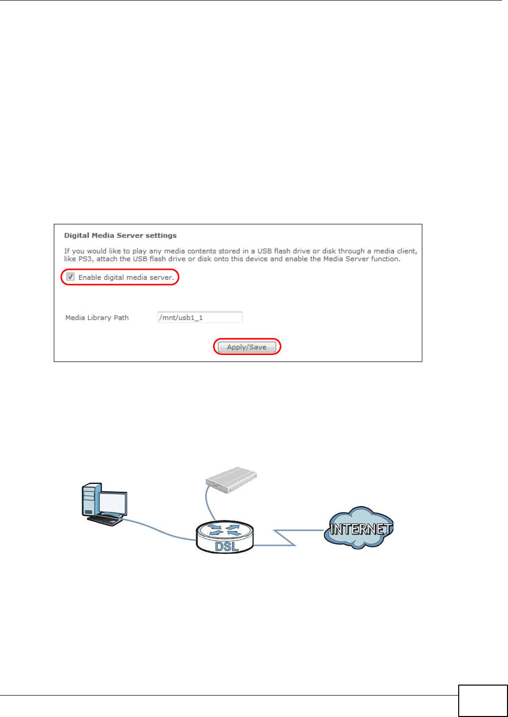
2.11.1 Configuring the VDSL Router
Click Advan ce d Setup > USB Se rvices > Media Se rver. The digit al m edia server set tings
display. Enable t he digital m edia server and click Apply/ Save.
Tutorial: USB Services > Media Server
2.11.2 Using Windows Media Player
This sect ion shows you how t o play the media files on t he USB st orage device connect ed t o your
VDSL Router using Windows Media Player.
Tutorial: Media Server Setup (Using Windows Media Player)
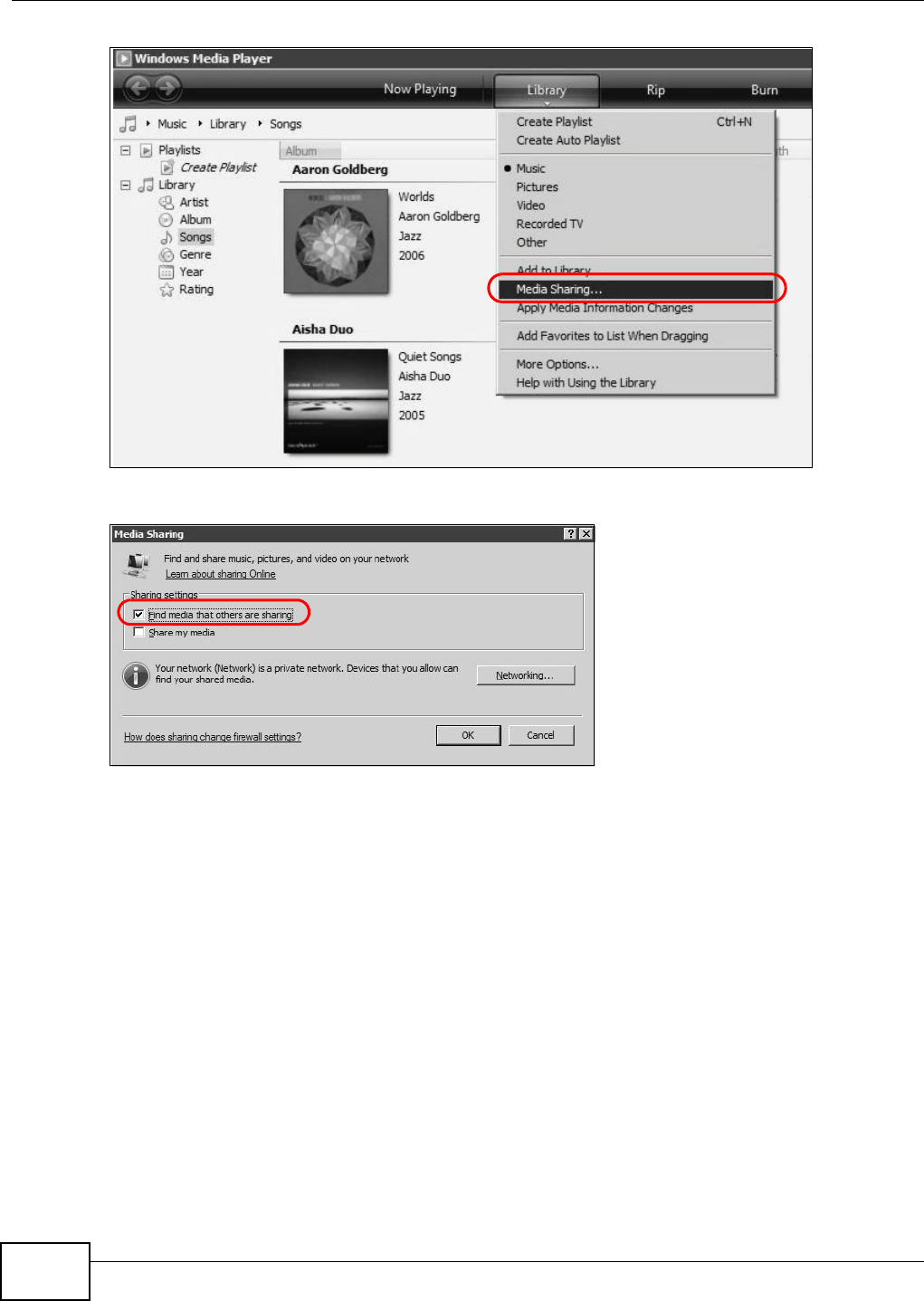
2.11.2.1 Windows Vista
1Open Windows Media Player and click Libr ary > Me dia Sh aring as follows.
Computer with
VDSL Router
USB Storage Device
Windows Media Player
Chapter 2 User Setup Guide
Basic Home Station VDSL2 P8802T User’s Guide
44
Tutorial: Media Sharing using Windows Vista
2Select Find m edia t ha t othe rs a re sh aring in the following screen and click OK.
Tutorial: Media Sharing using Windows Vista (2)
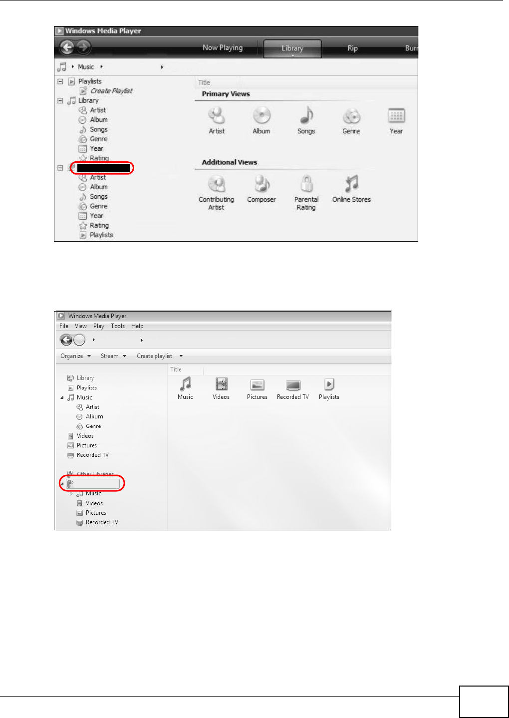
3The VDSL Rout er displays as a playlist in the Libr ary screen’s left panel. Click the category icons in
the right panel t o display the m edia files in the USB storage device at t ached t o your VDSL Router.
Chapter 2 User Setup Guide
Basic Home Station VDSL2 P8802T User’s Guide 45
Tutorial: Media Sharing using Windows Vista (3)
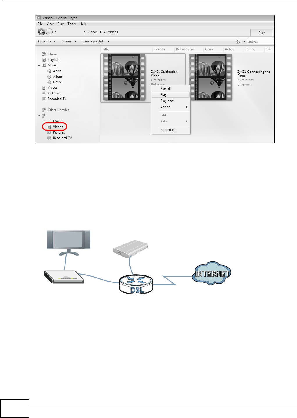
2.11.2.2 Windows 7
1Open Windows Media Player. I t aut om at ically detects t he VDSL Router . Right-click Ot her Libr aries
> Re fr esh Ot her Librar ies if t he VDSL Rout er does not display in the left panel.
Tutorial: Media Sharing using Windows 7 (1)
2Select a category and wait for Windows Media Player to list the files available.
P8701T
P8701T
P8701T
P8701T
Chapter 2 User Setup Guide
Basic Home Station VDSL2 P8802T User’s Guide
46
Tutorial: Media Sharing using Windows 7 (2)
2.11.3 Using a Digital Media Adapter
This sect ion shows you how t o use a ZyXEL DMA-2500 to play m edia files in a USB st orage device
connect ed to t he VDSL Router.
Note: Set up your DMA-2500 with the TV according t o the inst ruct ions in the DMA- 2500
Quick St art Guide before using this tut orial.
1Connect the DMA- 2500 t o an available LAN port on your VDSL Router.
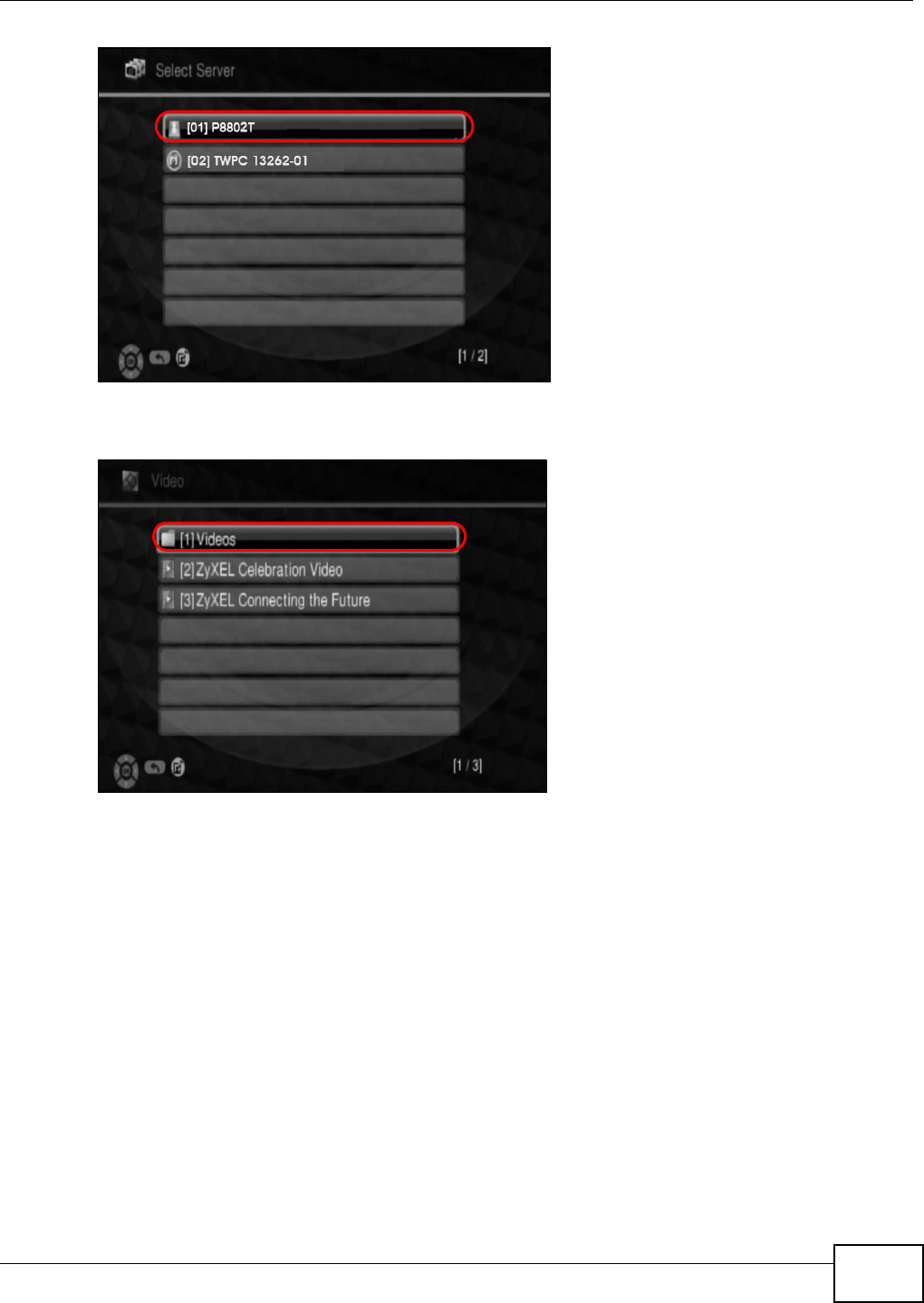
Tutorial: Media Server Setup (Using DMA)
2Turn on the TV and wait for the DMA- 2500 Hom e screen t o appear. Using t he remot e control, go t o
MyM edia to open t he following screen. Select the VDSL Router as your m edia server.
P8701T
P8701T
DMA-2500
VDSL Router
USB Storage Device
Chapter 2 User Setup Guide
Basic Home Station VDSL2 P8802T User’s Guide 47
Tutorial: Media Sharing using DMA-2500
3The screen list s available m edia files in the USB st orage device. Select a file and push t he Play
butt on in the rem ote control t o open it .
Tutorial: Media Sharing using DMA-2500 (2)
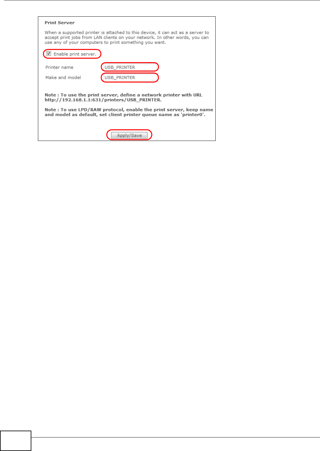
2.12 How to Share a USB Printer via Your VDSL Router
Your VDSL Rout er can act as a print ser ver and let t he com puters on your net work use the USB
print er connect ed to the VDSL Router ’s USB port .
1Go t o Advance d Se t up > USB Se r vices > to enable t he print server function on the VDSL Rout er .
Enter t he printer’s name and m anufact urer and m odel num ber. Click Apply/ Save to save your
sett ings.
Chapter 2 User Setup Guide
Basic Home Station VDSL2 P8802T User’s Guide
48
2Connect the USB printer to the VDSL Router if you have not done so already.
3See Sect ion 2.12.1 on page 48 and/ or Sect ion 2.12.2 on page 52 for exam ples of how to set up a
print er on your com puter. The com put er s on your net work m ust have t he printer software already
inst alled befor e they can use t he print er.
Note: Your print er ’s inst allat ion instructions m ay ask that you connect t he printer to your
com put er. Connect t he printer to t he VDSL Router inst ead.
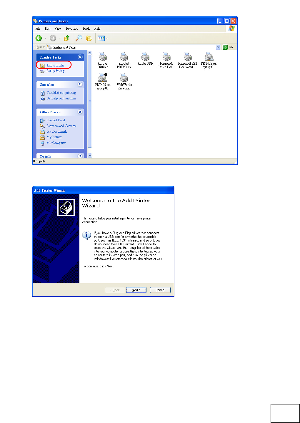
2.12.1 Add a New Printer Using Windows
This exam ple shows how to connect a printer behind t he VDSL Router to a comput er using the
Windows XP Professional. Som e m enu item s m ay look different on your operat ing syst em .
1Click St art > Control Pa ne l > Print ers a nd Fa xes t o open t he Prin t ers a nd Fa xes screen. Click
Add a Print e r.
Chapter 2 User Setup Guide
Basic Home Station VDSL2 P8802T User’s Guide 49
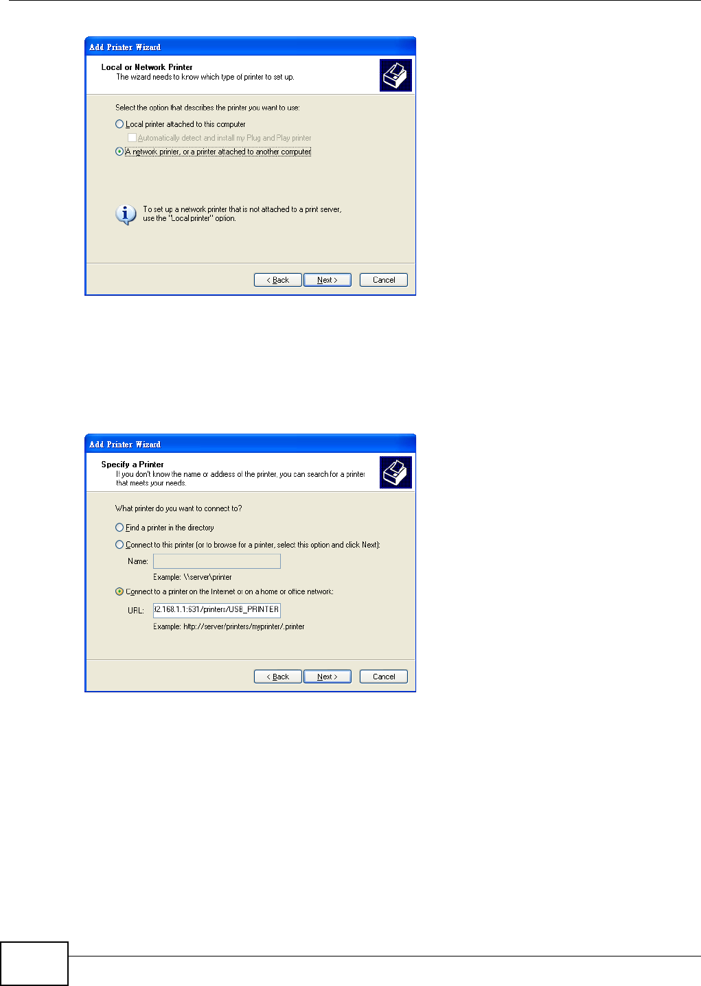
2The Add Print er W iza rd screen displays. Click N e x t .
3Select A net w or k printer , or a printer at t a che d t o an ot he r com puter and click N e x t .
Chapter 2 User Setup Guide
Basic Home Station VDSL2 P8802T User’s Guide
50
4Select Connect to a print er on t he I nter net or on a hom e or office net w ork : and enter
“ http: / / 192.168.1.1: 631/ printers/ USB_PRI NTER” as t he URL to access the print server ( VDSL
Router). Click N ex t .
Note: I f you change t he VDSL Rout er’s LAN I P address, use the new I P address in the URL
to access t he print server.
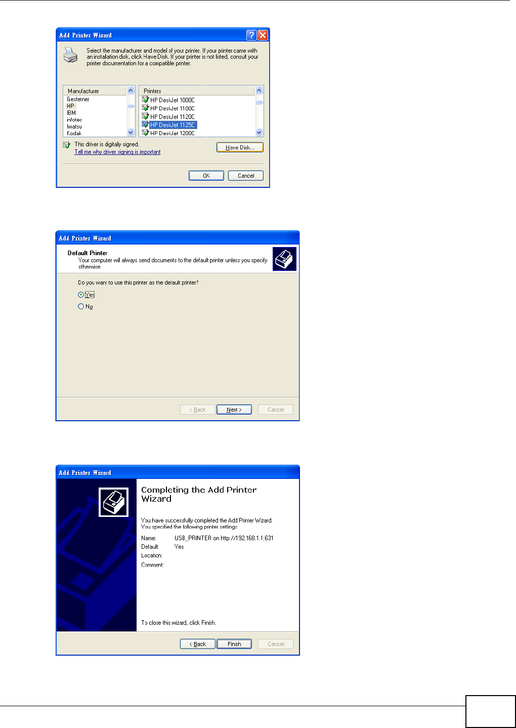
5Select the m ake of the printer t hat you want to connect to the print server in the M a n ufa ct u r er list
of printer s.
6Select the printer m odel from the list of Pr in t e rs.
7I f your pr int er is not displayed in t he list of Pr in t e rs, insert the printer dr iver inst allat ion CD/ disk or
download t he driver file t o your com put er, click Ha ve Disk… and install the new printer driver.
8Click N e xt t o cont inue.
Chapter 2 User Setup Guide
Basic Home Station VDSL2 P8802T User’s Guide 51
9Select Yes t o use t his print er as the default print er on your com put er. Otherwise select N o. Click
N e xt t o cont inue.
10 The following screen show s your current print er set t ings. Select Finish to com plet e adding a new
print er.
Chapter 2 User Setup Guide
Basic Home Station VDSL2 P8802T User’s Guide
52
2.12.2 Add a New Printer Using Macintosh OS X
Com plet e t he following st eps t o set up a print server driver on your Macintosh com puter.
2.12.2.1 Mac OS 10.3 and 10.4
This exam ple shows how to connect a printer behind the VDSL Router to your com put er using Mac
OS X v10.4.11. Som e m enu it em s m ay look different on your operat ing syst em .
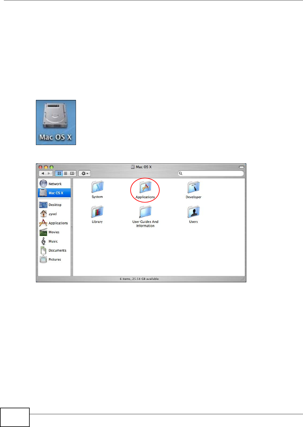
1Click the Finder icon on the Dock ( a place holding a ser ies of icons/ shortcut s at the bot tom of the
desktop) or double-click your Mac hard disk icon ( Mac OS X in t his exam ple) on your desktop.
2The Mac HD window displays. Open t he Applica t ions folder.
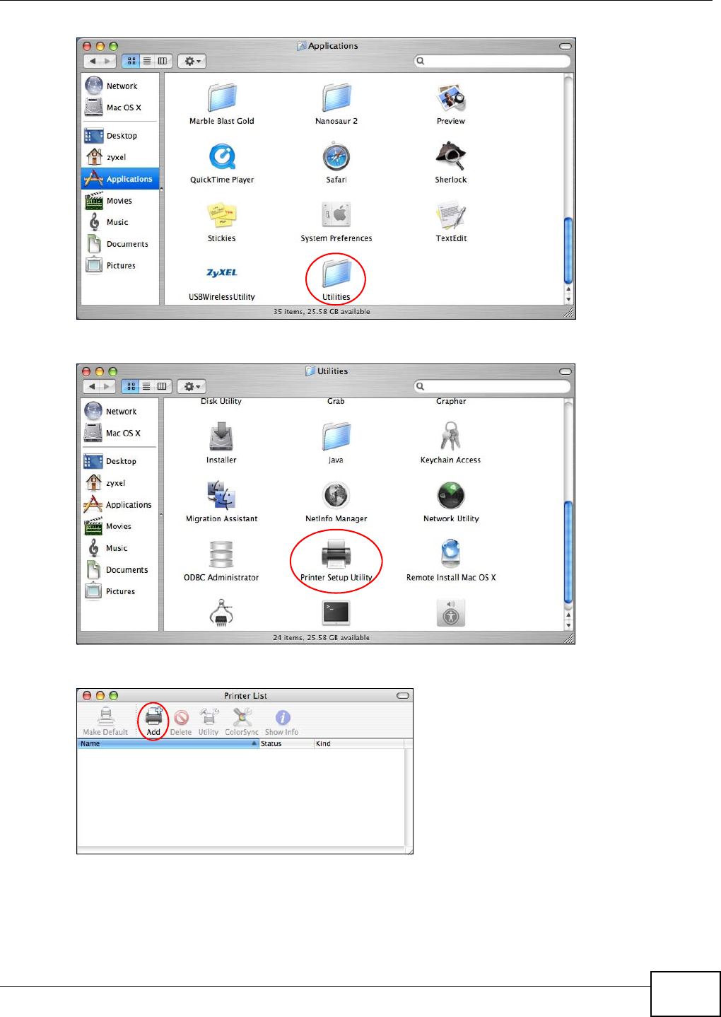
3Open the Ut ilit ie s folder.
Chapter 2 User Setup Guide
Basic Home Station VDSL2 P8802T User’s Guide 53
4Double- click the Pr inter Se tup Ut ility icon.
5Click the Add icon at t he t op of t he screen.
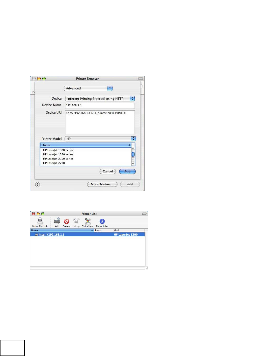
6Click the I P Pr int er tab t o set up your printer.
• Press the alt key and click M ore Print e rs in t he Print e r Brow se r screen.
• Select Advance d from t he top drop- down list .
Chapter 2 User Setup Guide
Basic Home Station VDSL2 P8802T User’s Guide
54
• Select I nt e rnet Pr int ing Protocol using H TTP from t he Device drop- down list .
• Enter a descriptive nam e for the printer in the Device N am e field.
• In the D evice URL field, ent er “ht t p: / / 192.168.1.1: 631/ printers/ USB_PRI NTER” as t he
URL to access t he print server ( VDSL Router) .
Note: I f you change t he VDSL Rout er’s LAN I P address, use the new I P address in the URL
to access t he print server.
• Select your print er m anufact urer from the Printer Model drop- down list and t hen select a
print er m odel. Click Add t o save and close t he Printer Br ow se r configuration screen.
7The new network printer displays in the Pr int er List . The default print er N am e displays in bold
type.
8Your print server driver set up is com plete. You can now use t he VDSL Router’s print server to print
from a Mac com put er.
2.12.2.2 Mac OS 10.5 and 10.6
This exam ple shows how to connect a printer behind the VDSL Router to your com put er using Mac
OS X v10.6.2. Som e m enu item s m ay look different on your operating syst em .
Chapter 2 User Setup Guide
Basic Home Station VDSL2 P8802T User’s Guide 55
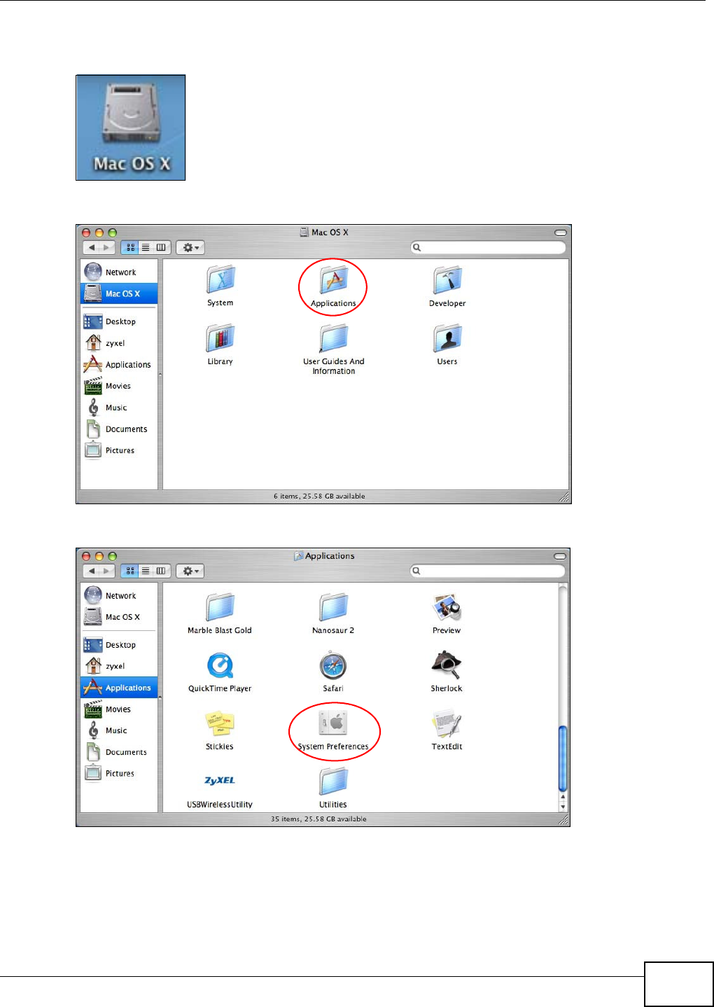
1Click the Finder icon on the Dock or double-click your Mac hard disk icon (M ac OS X in this
exam ple) on your deskt op t o open t he Mac HD window.
2Open the Ap plica t ion s folder.
3Double- click the Syst e m Pr efe rence s icon.
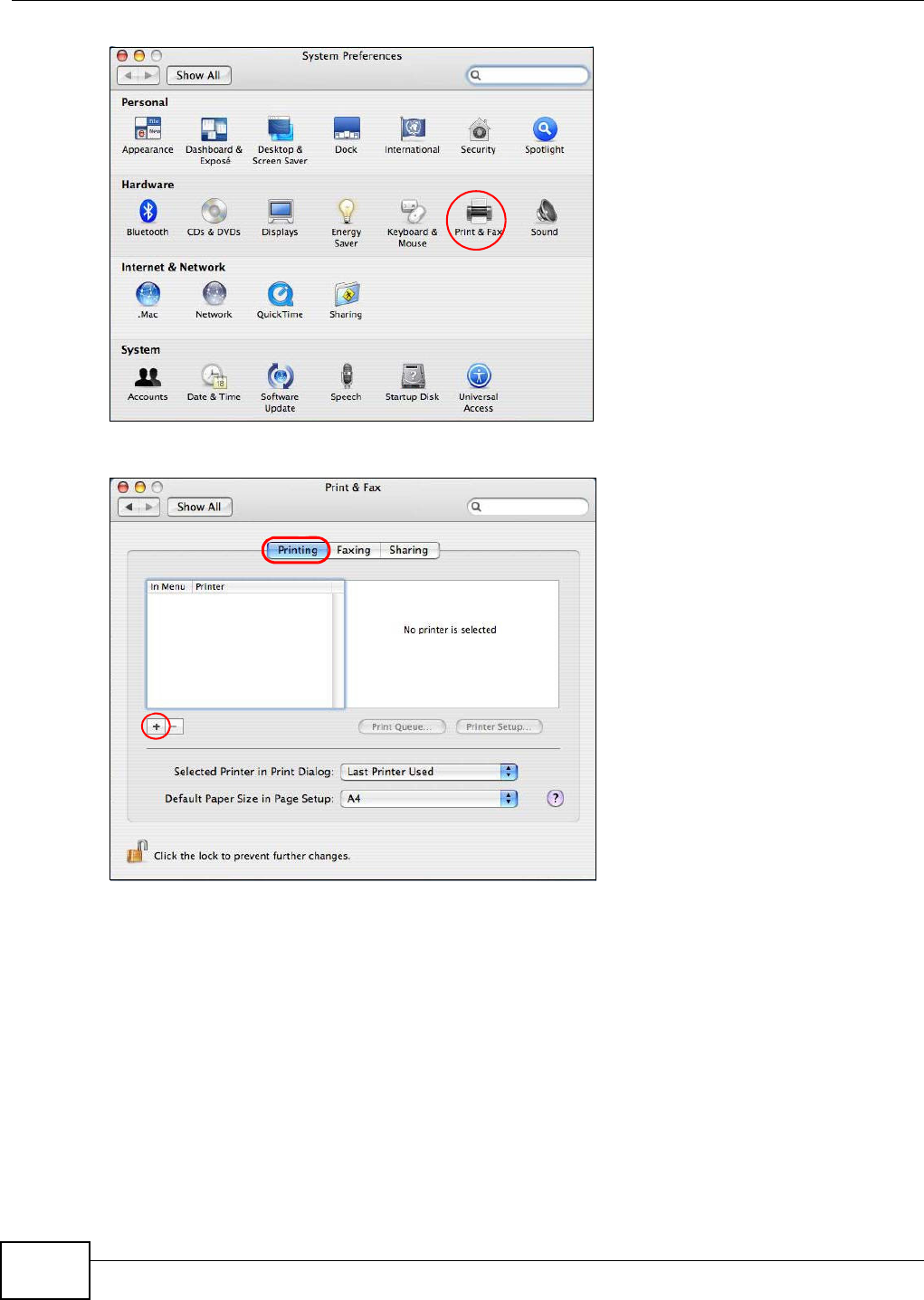
4Click the Pr int & Fa x icon.
Chapter 2 User Setup Guide
Basic Home Station VDSL2 P8802T User’s Guide
56
5Select the Pr int in g tab and click t he + icon to add a new pr int er.
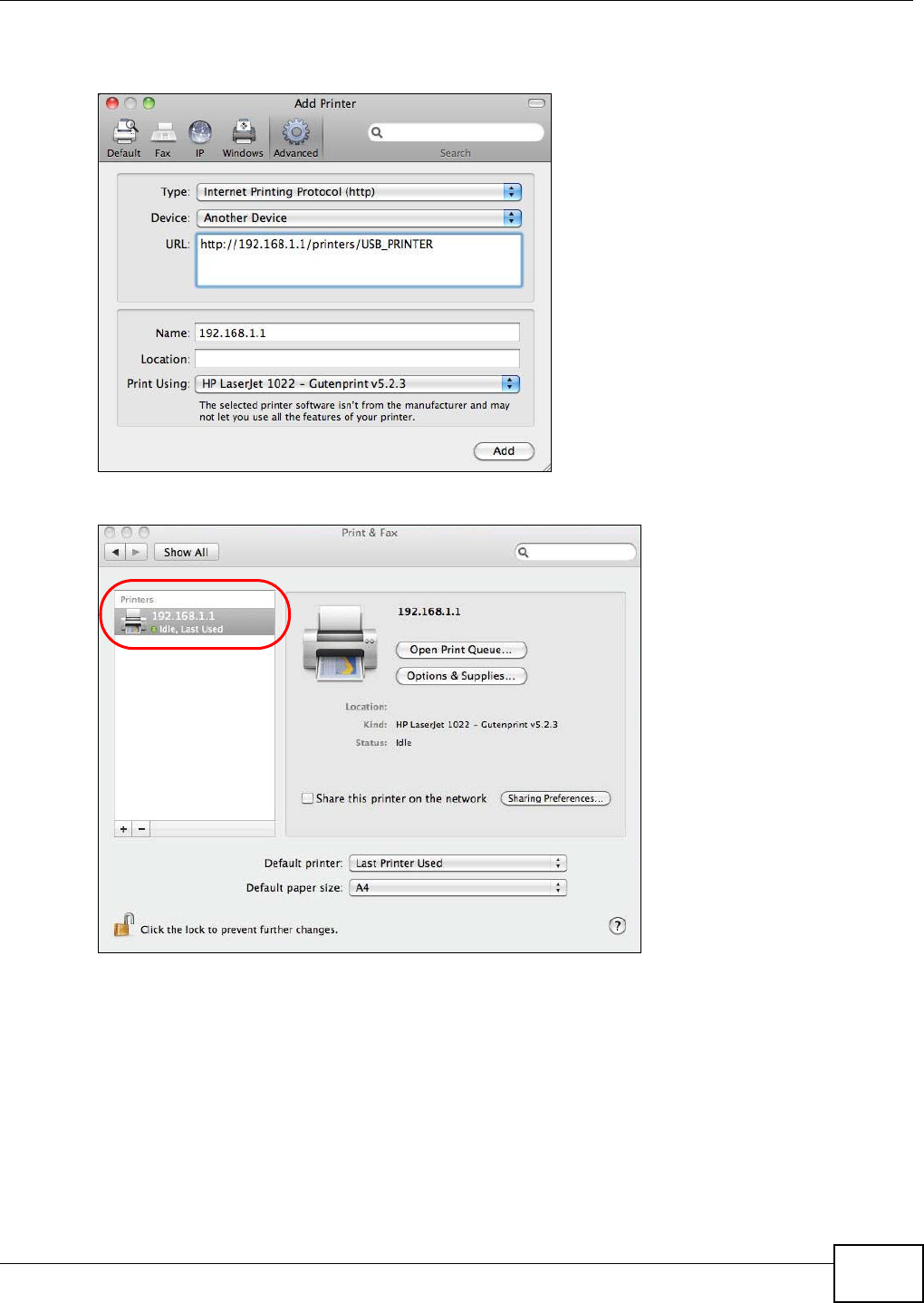
6Click the Advance d butt on on the Add Pr inter toolbar t o set up your print er.
I f t he Adva nced but t on doesn’t appear, Ctrl- click the t oolbar, select Cu st om ize Toolbar ... and
then drag t he Adva nce d button ont o t he t oolbar.
• Select I nt e rnet Pr int ing Protocol ( H TTP) from the Type drop-down list .
• Select Anot he r Device from t he D evice drop- down list.
• In the URL field, ent er “ht t p: / / 192.168.1.1: 631/ printer s/ USB_PRI NTER” as t he URL to
access the print server ( VDSL Router) .
Note: I f you change t he VDSL Rout er’s LAN I P address, use the new I P address in the URL
to access t he print server.
• Ent er a descriptive nam e for the print er and where it is located.
Chapter 2 User Setup Guide
Basic Home Station VDSL2 P8802T User’s Guide 57
• Select your printer m anufact urer from the Prin t Using dr op- down list and then select a
print er m odel. Click Add t o save and close t he Printer Br ow se r configuration screen.
7The new network printer displays in the Pr int e r s list.
8Your print server driver set up is com plete. You can now use t he VDSL Router’s print server to print
from a Mac com put er.

Chapter 2 User Setup Guide
Basic Home Station VDSL2 P8802T User’s Guide
58

59
PART II
Technical Reference

60
Basic Home Station VDSL2 P8802T User’s Guide 61
CHAPTER 3
Device Info Screens
3.1 Overview
Use t he D evice I nfo screens to look at the current st at us of t he Device, syst em resources,
int erfaces ( LAN, WAN, and WLAN) , and SI P account regist rat ion st at us.
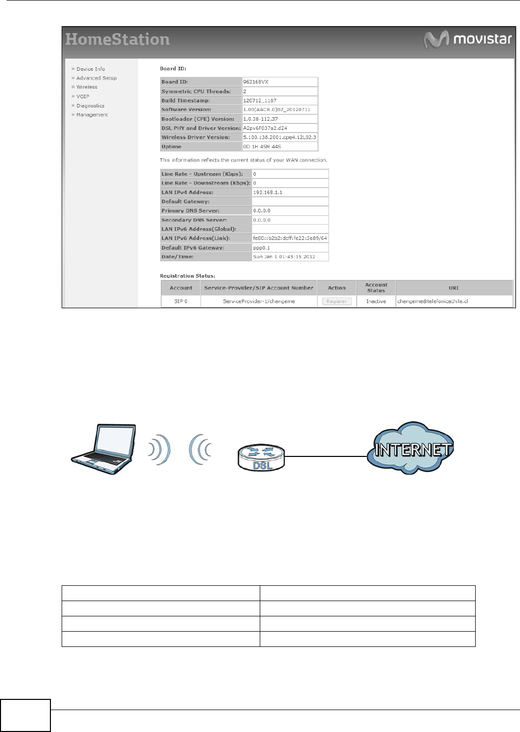
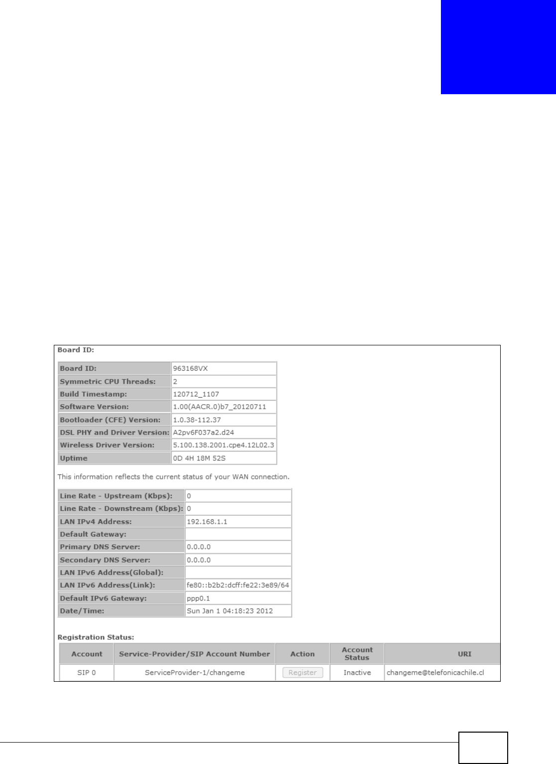
3.2 The Device Info Summary Screen
Log int o the VDSL Router’s web configurat or or click Device I nfo > Sum m a ry to view a sum m ary
screen of inform at ion about t he VDSL Rout er .
Figure 4 Device I nfo Sum m ary Screen

Chapter 3 Device Info Screens
Basic Home Station VDSL2 P8802T User’s Guide
62
Each field is described in the following table.
Table 2 Device I nfo Sum m ary Screen
LABEL DESCRIPTION
Board I D This field displays the I D number of the circuit board in t he VDSL Rout er.
Sym m et ric CPU
Threads
This field displays t he num ber of threads in t he VDSL Rout er’s CPU.
Build
Tim est am p
This field display s t h e dat e ( YYMMDD) and t im e ( HHMM) of t h e fir m w are in th e VDSL Rout er .
Software
Ve r si on
This field display s t he current version of t he firm ware inside t he VDSL Rout er.
Bootloader
( CFE) Version
This field displays t he version of boot loader t he VDSL Router is using.
DSL PHY and
Driver Version
This field displays t he version of the m odem code the VDSL Rout er is using.
Wireless Driver
Ve r si on
This field displays t he version of the driver for t he VDSL Router’s wireless chipset.
Uptim e This field displays how long t he VDSL Router has been running since it last st art ed up.
Line Rate -
Upst ream
This field displays the WAN port ’s sending t raffic speed.
Line Rate -
Downstream
This field displays the WAN port ’s receiving traffic speed.
LAN I Pv4
Address
This field displays the current I P address of the VDSL Rout er in t he LAN.
Default
Gateway
This field display s t he I P address of the gateway t hrough which t he VDSL Router sends
traffic unless it m at ches a st atic rout e.
Prim ary DNS
Server
The VDSL Rout er t ries this DNS server first when it needs to r esolve a dom ain nam e int o a
num eric I P address.
Secondary DNS
Server
The VDSL Rout er uses t his DNS server first when it needs to resolve a dom ain nam e int o a
numeric I P address if the prim ary DNS server does not respond.
LAN I Pv6
Address
( Global)
This field displays the current global I Pv6 address of the VDSL Rout er.
LAN I Pv6
Address (Link)
This field displays the current I Pv6 addr ess of t he VDSL Rout er in t he LAN.
Default I Pv6
Gateway
This field display s t he I Pv6 address of the gat eway t hrough which the VDSL Router sends
I Pv6 traffic unless it m atches a st at ic rout e.
Date/ Tim e This field displays t he VDSL Rout er’s current day of t he week, m ont h, hour, m inut e, second,
and year.
Regist rat ion Stat us
Account This colum n displays each SI P account in the VDSL Router.
Service-
Provider/ SI P
Account
Nu m ber
This colum n displays t he service provider nam e and SI P num ber for each SI P
account .
Chapter 3 Device Info Screens
Basic Home Station VDSL2 P8802T User’s Guide 63
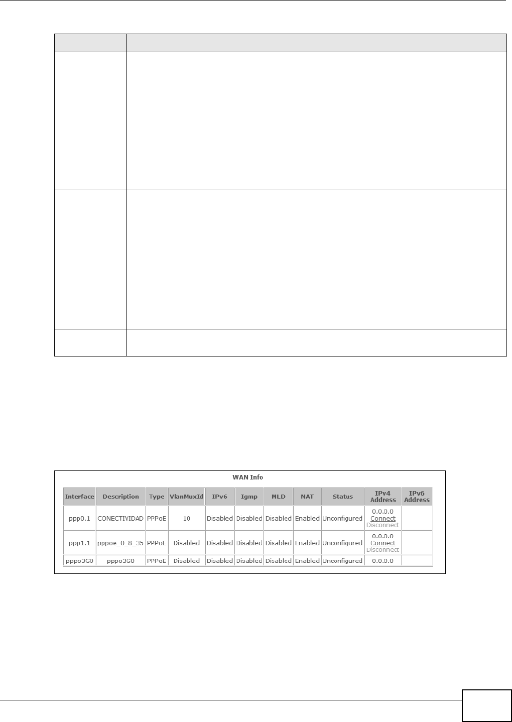
3.3 The WAN Info Screen
Log int o the VDSL Router’s web configurat or and click Device I nfo > W AN t o view a sum mary
screen of inform at ion about t he VDSL Rout er’s WAN connections.
Figure 5 WAN I nfo Screen
Act ion I f t he SI P account is already regist ered wit h the SI P server, the Accou nt St a t us
field displays Re gist e r ed .
• Click Un r egist e r to delet e t he SI P account ’s regist rat ion in t he SI P server. This
does not cancel your SI P account, but it delet es the m apping between your SI P
ident ity and your I P address or dom ain nam e.
I f t he SI P account is not regist ered w it h t he SI P ser ver, t he Account St atus field
displays N ot Re gist e r ed .
• Click Re gist e r t o have the VDSL Rout er at tem pt to regist er the SI P account
with t he SI P server.
The button is grayed out if the SI P account is disabled.
Account St at us This field displays t he current regist rat ion st at us of t he SI P account. You have to
regist er SI P accounts with a SI P server t o use VoI P.
I n act ive - The SI P account is not act ive. You can act ivate it in VoI P > SI P > SI P
Accou nt .
N ot Registered - The last tim e t he VDSL Router tried t o regist er t he SI P account
with t he SI P server, the att em pt failed. Use t he Regist er button to regist er the
account again. The VDSL Router aut om at ically tries t o regist er t he SI P account
when you turn on the VDSL Router or when you act ivat e it.
Regist e r ed - The SI P account is already regist ered with t he SI P server. You can
use it to m ake a VoI P call.
URI This field displays t he account num ber and service dom ain of the SI P account. You
can change t hese in t he VoI P > SI P screens.
Table 2 Device I nfo Sum m ary Screen ( continued)
LABEL DESCRIPTION

Chapter 3 Device Info Screens
Basic Home Station VDSL2 P8802T User’s Guide
64
Each field is described in the following table.
3.4 The 3G Status Screen
Log into the VDSL Router’s web configurat or and click Device I nfo > 3 G t o view a sum m ary screen
of inform at ion about t he VDSL Rout er’s 3G connect ion.
Table 3 WAN I nfo Scr een
LABEL DESCRIPTION
I nterface This show s the nam e of the int erface used by t his connect ion.
A default nam e ipoa * , pppoa* , at m * or pt m * indicates DSL port . The ppp * indicates a
PPP connection via any one of the WAN int er face.
The num ber aft er t he dot (.) represent s the VLAN I D num ber assigned to t raffic sent
through this connect ion. The num ber aft er the underscor e ( _) represent s the index num ber
of connect ions through the sam e int erface.
( null) m eans the ent ry is not valid.
Description This is t he se rvice nam e of th is conne ct ion.
0 and 3 5 or 0 and 1 are t he default VPI and VCI num bers. The last num ber represent s the
index num ber of connect ions over t he sam e PVC or the VLAN I D num ber assigned to t raffic
sent through this connection.
( null) m eans the ent ry is not valid.
Type This shows the m et hod of encapsulat ion used by t his connection.
VlanMuxI D This indicates t he VLAN I D num ber assigned t o traffic sent through t his connect ion. This
displays N / A w hen t here is no VLAN I D num ber assigned.
I Pv6 This displays whet her or not IPv6 is enabled on the int erface.
I gm p This show s whether I GMP ( I nternet Group Mult icast Pr otocol) is act ivat ed or not for t his
connection. I GMP is not available when the connect ion uses t he bridging service.
MLD This show s whether Mult icast Listener Discovery ( MLD) is act ivated or not for t his
connection. MLD is not available when the connect ion uses the bridging service.
NAT This show s whet her NAT is act ivat ed or not for t his int erface. NAT is not available when the
connect ion uses the bridging serv ice.
St at us This displays t he connection st at e or Un configured if t he interface has not yet been
configured.
I Pv4 Address This display s t he int erface’s current I Pv4 address if it has one. Click co nne ct t o initiate the
WAN int erface’s connect ion.
I Pv6 Address This display s t he int erface’s current I Pv6 address if it has one. Click co nne ct t o initiate the
WAN int erface’s connect ion.
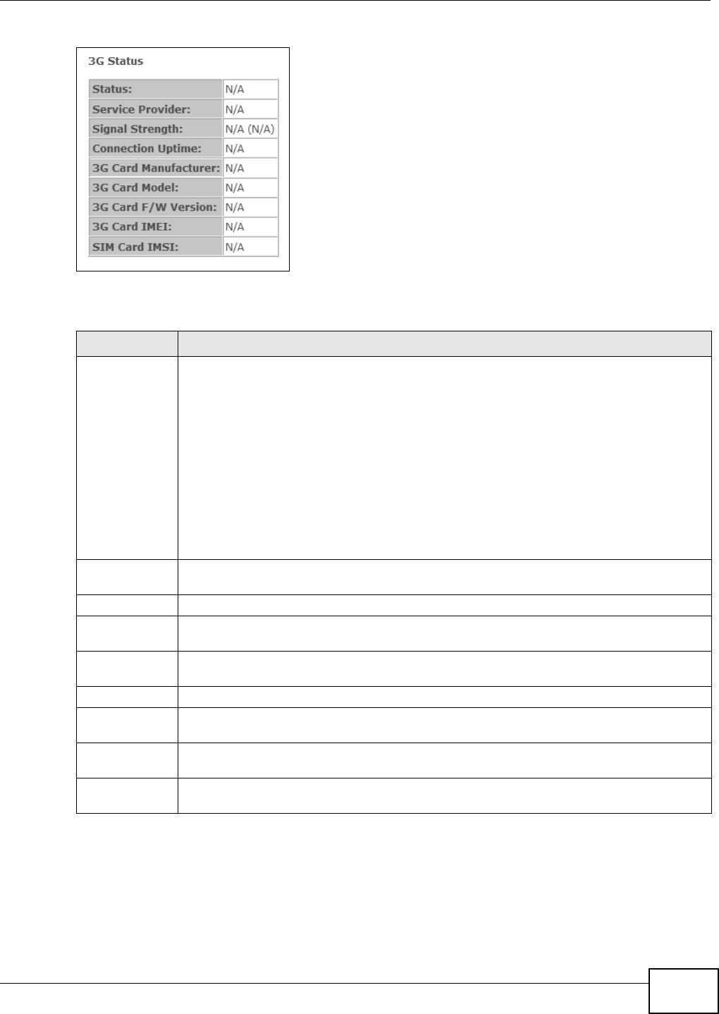
Chapter 3 Device Info Screens
Basic Home Station VDSL2 P8802T User’s Guide 65
Figure 6 3G St atus Screen
Each field is described in the following table.
3.5 The LAN Statistics Screen
Log int o the VDSL Router’s web configurat or and click Device I nfo > St a t ist ics > LAN to view a
sum mary screen of inform ation about t he VDSL Router’s LAN connect ions.
Table 4 3G Stat us Screen
LABEL DESCRIPTION
St at us • N oD e vice when no 3G car d is insert ed,
•Disabled when the 3G WAN is not act ivat ed,
•Up when the 3G connect ion is up,
•Dow n when the 3G connect ion is dow n,
•N oRe sponse when ther e is no response from the insert ed 3G card,
•I n va lidPI N if the PI N code you ent ered in the W AN > 3 G Ba ck up scr een is not t he
right one for t he 3G card you insert ed,
•N e edPU K if you ent er t he PI N ( Personal I dent ification Num ber) code incorr ect ly for
three tim es and t he SI M car d is blocked by your I SP,
•DialFa il w hen t he VDSL Rout er fails to dial up a 3G connect ion.
• or I n validSI M when the SI M card is damaged or not insert ed.
I f a link displays in this field, click the link to view m or e st atus infor m at ion or ent er t he
correct PI N or PUK (Personal Unblocking Key) code.
Service
Provider
This displays the nam e of your 3G net work service pr ovider.
Signal Str ength This displays the 3G connect ion’s signal qualit y.
Connection
Uptim e
This displays how long the 3G connect ion has been connect ed since it last cam e up.
3G Card
Manu fact urer
This displays t he nam e of the com pany t hat produced t he 3G USB dongle.
3G Card Model This displays the m odel nam e of the 3G USB dongle.
3G Card F/ W
Ve r si on
This displays the soft war e version of the 3G USB dongle.
3G Car d I MEI I MEI (I nt ernational Mobile Equipm ent I dentity) is a 15-digit code in decim al form at that
ident ifies the 3G device.
SI M Card I MSI I MSI ( I nternational Mobile Subscriber I dent ity) is a 15- digit code that identifies the SI M
card.
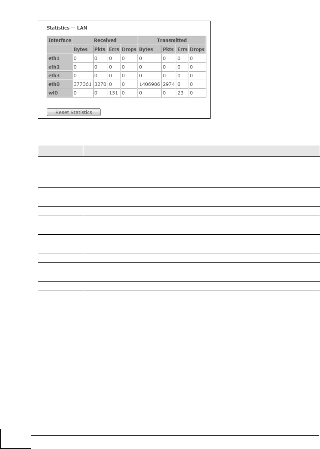
Chapter 3 Device Info Screens
Basic Home Station VDSL2 P8802T User’s Guide
66
Figure 7 LAN St at istics Screen
Each field is described in the following table.
3.6 The WAN Statistics Screen
Log int o the VDSL Router’s web configurat or and click Device I nfo > St a t ist ics > W AN Se rv ice
to view a sum m ary screen of inform at ion about the VDSL Router’s WAN connections.
Table 5 LAN St atist ics Screen
LABEL DESCRIPTION
I nter face These fields identify the LAN int erfaces. e t h0 ~ eth 3 represent the ethernet LAN ports 1 ~
4. w lo represent s t he wireless LAN interface.
Received /
Tr a n s m i t t e d
These fields display t he num ber of bytes, packet s, error packets, and dropped packet s for
each inter face.
Received
By tes This indicat es the num ber of bytes received on this interface.
Pkt s This indicates the num ber of packet s received on this int erface.
Errs This indicates the num ber of fram es wit h errors received on this interface.
Drops This indicates t he num ber of received packet s dropped on this inter face.
Tr a n s m i t t e d
Byt es This indicates t he num ber of byt es t ransm it ted on t his int erface.
Pkt s This indicat es t he num ber of transm itted packets on this int erface.
Errs This indicates the num ber of fram es wit h errors transm it ted on this int er face.
Drops This indicates the num ber of outgoing packet s dropped on this int erface.
Reset Statistics Click this to clear t he screen’s statist ics counter s.
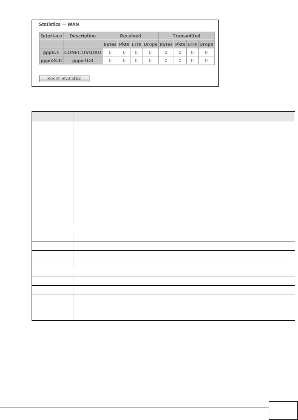
Chapter 3 Device Info Screens
Basic Home Station VDSL2 P8802T User’s Guide 67
Figure 8 WAN St at istics Screen
Each field is described in the following table.
3.7 The xTM Statistics Screen
Log int o the VDSL Router’s web configurat or and click Device I nfo > St a t ist ics > xTM to display
ATM or PTM connect ion inform at ion.
Table 6 WAN St at ist ics Screen
LABEL DESCRIPTION
I nterface This show s the nam e of the WAN interface used by this connect ion.
The default nam e ipoa* , p ppoa * , at m * or ptm * indicat es the DSL port. ppp* indicates a
PPP connection via any one of the WAN int er faces. ppp3 G0 indicates a PPP connect ion
through t he 3G int erface.
The num ber aft er t he dot (.) represent s the VLAN I D num ber assigned to t raffic sent
through this connect ion. The num ber aft er the underscor e ( _) represent s the index num ber
of connect ions through the sam e int erface.
( null) m eans the ent ry is not valid.
Descr iption This show s the descript ive name of t his connect ion.
ATM int er faces include t he VPI and VCI . 0 and 3 5 or 0 and 1 ar e the default VPI and VCI
num ber s. The last num ber represents t he index num ber of connect ions over t he sam e PVC
or the VLAN I D num ber assigned to t raffic sent through t his connect ion.
( null) m eans the ent ry is not valid.
Received
By tes This indicates t he num ber of byt es received on this int erface.
Pkt s This indicates the num ber of packet s received on this int erface.
Errs This indicates the num ber of fram es wit h errors received on this interface.
Drops This indicates t he num ber of received packet s dropped on this inter face.
Tr a n s m i t t e d
Byt es This indicates t he num ber of byt es t ransm it ted on t his int erface.
Pkt s This indicat es t he num ber of transm itted packets on this int erface.
Errs This indicates the num ber of fram es wit h errors transm it ted on this int er face.
Drops This indicates the num ber of outgoing packet s dropped on this int erface.
Reset Statistics Click this to clear t he screen’s statist ics counter s.
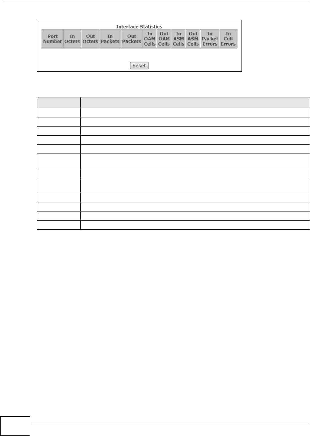
Chapter 3 Device Info Screens
Basic Home Station VDSL2 P8802T User’s Guide
68
Figure 9 xTM St atist ics Screen
Each field is described in the following table.
3.8 The xDSL Statistics Screen
Log into the VDSL Router’s web configurat or and click Device I nfo > St atistics > x DSL t o display
inform ation about the VDSL Router’s VDSL or ADSL connect ions.
Table 7 xTM St at ist ics Screen
LABEL DESCRIPTION
Port Num ber This ident ifies the ATM or PTM port.
I n Oct et s This displays the num ber of 8- bit binary digit s ( byt es) received through t he port .
Out Oct et s This displays the num ber of 8-bit binary digits (bytes) sent through t he por t.
I n Packet s This displays the num ber of packet s received t hrough t he port .
Out Packet s This displays the num ber of packet s sent through the port.
I n OAM Cells This displays t he num ber of OAM ( Operat ional, Adm inist ration and Maint enance) cells
received through t he port.
Out OAM Cells This display s t he num ber of OAM cells sent t hrough t he port .
I n ASM Cells This displays the num ber of ASM ( Autonom ous St at us Message) cells received through t he
por t.
Out ASM Cells This displays the number of ASM cells sent t hr ough the port.
I n Packet Errors This displays the num ber of errored packet s received on the port.
I n Cell Errors This displays t he number of err ored cells received on the port .
Reset Click this t o clear t he screen’s statist ics counters.
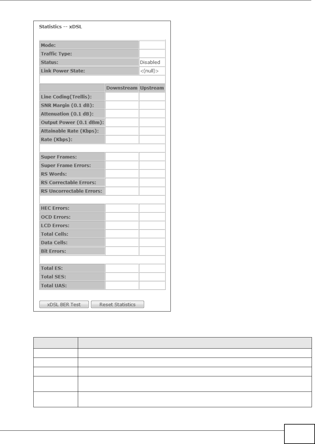
Chapter 3 Device Info Screens
Basic Home Station VDSL2 P8802T User’s Guide 69
Figure 10 xDSL St at istics Screen
Each field is described in the following table.
Table 8 xDSL St at ist ics Screen
LABEL DESCRIPTION
Mode This field identifies the DSL m ode of the DSL connection.
Traffic Type This displays the t ype of t raffic the DSL port is sending and receiving.
St at us This displays t he current st at e of set ting up the DSL connect ion.
Link Power
St at e
This displays the DSL connect ion’s current power usage or pow er saving m ode. null displays
when there is no DSL connect ion.
D o w n s t r e a m T h e s e a r e t h e st at ist ics for t he t raffic direct ion com ing int o t he port from the service
provider.

Chapter 3 Device Info Screens
Basic Home Station VDSL2 P8802T User’s Guide
70
Upst ream These ar e t he st atist ics for the traffic direct ion going out from the port t o t he service
provider.
Line Coding
( Tr ellis)
This display s whet her or not the por t is using Trellis coding for traffic. Tr ellis coding helps t o
reduce t he noise in ADSL transm issions. Trellis m ay reduce t hroughput but it m akes the
connection m ore st able.
SNR Mar gin
( 0.1 dB)
This displays the Signal-t o- Noise Ratio m argin ( in 0.1 dB) . A DMT sub- carrier’s SNR is the
rat io between the received signal power and the received noise pow er. The signal-t o- noise
rat io m ar gin is the m axim um t hat the received noise power could increase with t he syst em
st ill being able t o m eet it s transm ission t ar gets.
At tenuation
( 0.1 dB)
This displays the line attenuat ion, m easured in tenths of a decibel ( 0.1 dB) . This at tenuation
is the differ ence bet ween the power transm itt ed at the near- end and the power received at
the far- end. Att enuat ion is affected by t he channel charact erist ics (wire gauge, qualit y,
condit ion and length of the physical line).
Output Power
( 0.1 dBm )
This displays the far end act ual aggregat e transm it power ( in dBm ) . Dow nst ream is how
m uch por t the ser vice provider is using to transm it t o the port. Upst ream is how m uch
pow er t he por t is using t o t ransm it to the ser vice provider.
At tainable Rate
( Kb ps) :
These are the highest theoret ically possible transfer rat es at w hich t he port could send and
receive dat a.
Rate ( Kbps) This displays the dat a transfer rat es at which the port is receiving and sending.
Super Frames This displays t he number of ADSL superfram es t he DSL connect ion received and
transm itted. Each superfram e cont ains 68 ADSL dat a frames and a one- fram e synch sym bol
for a t ot al num ber of 69 fram es.
Super Fram e
Error s
This displays the number of errored ADSL superfram es the DSL connect ion received and
t ransm it t ed.
RS Words This displays the num ber of Reed Solom on error correction words for received and
transm itt ed traffic.
RS Correct able
Error s
This displays the num ber of error ed packets correct ed by Reed Solom on error correct ion for
received and t ransm it ted traffic.
RS
Uncorrect able
Error s
This displays the number of errored packet s that Reed Solom on er ror correct ion could not
correct for received and t ransm it ted traffic.
HEC Errors Header Error Cont rol ( HEC) check s for errors in packet headers.
OCD Er rors The num ber of Out of Cell Delineat ion errors for received and t ransm it ted traffic. An OCD
error m eans seven consecut ive ATM cells had Header Error Cont rol ( HEC) violations.
LCD Errors The number of Loss of Cell Delineat ion error s for r eceived and t ransm it ted traffic. An LCD
st at e m eans an OCD condit ion per sist ed for 4 m illiseconds.
Total Cells This display s the t ot al num ber of DSL cells including headers.
Dat a Cells This displays the num ber of data payload DSL cells, excluding headers.
Bit Er rors This displays t he num ber of err or ed bit s.
Total ES This displays the num ber of Error ed Seconds m eaning t he num ber of seconds containing at
least one er rored block or at least one defect.
Total SES This display s the num ber of Severely Errored Seconds m eaning the number of seconds
cont aining 30% or m ore errored blocks or at least one defect . This is a subset of ES.
Total UAS This displays the num ber of UnAvailable Seconds.
xDSL BER Test Click this to open a screen where you can perform a ADSL Bit Error Rat e (BER) test t o
det erm ine t he qualit y of t he ADSL connection.
Reset Statistics Click this to clear t he screen’s statist ics counter s.
Table 8 xDSL St at ist ics Screen ( continued)
LABEL DESCRIPTION
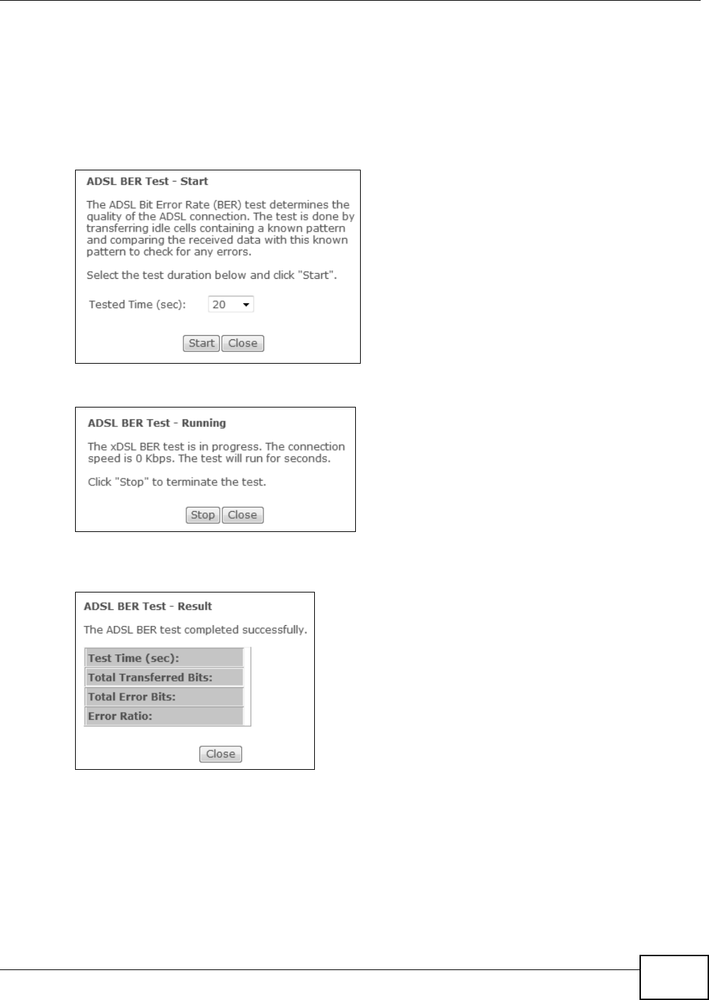
Chapter 3 Device Info Screens
Basic Home Station VDSL2 P8802T User’s Guide 71
3.8.1 The ADSL BER Test Screen
Do the following while the VDSL Router has an ADSL connection t o perform a ADSL Bit Error Rat e
( BER) t est to determ ine the qualit y of t he ADSL connection.
1Log int o the VDSL Router’s web configurat or and click Device I nfo > St a t ist ics > x DSL > xD SL
BER Test to display this screen. Select a t est durat ion and click St a rt .
2Click St op t o finish the t est .
3The t est results display including the t est ’s duration, the num ber of bit s transfer red, t he num ber of
err ored bit s, and t he rat io of errored bits t o t ransm itted bit s.
3.9 The Route Info Screen
Log int o the VDSL Router’s web configurat or and click Device I nfo > Rou t e to display the VDSL
Rou t er ’s rout ing t able.
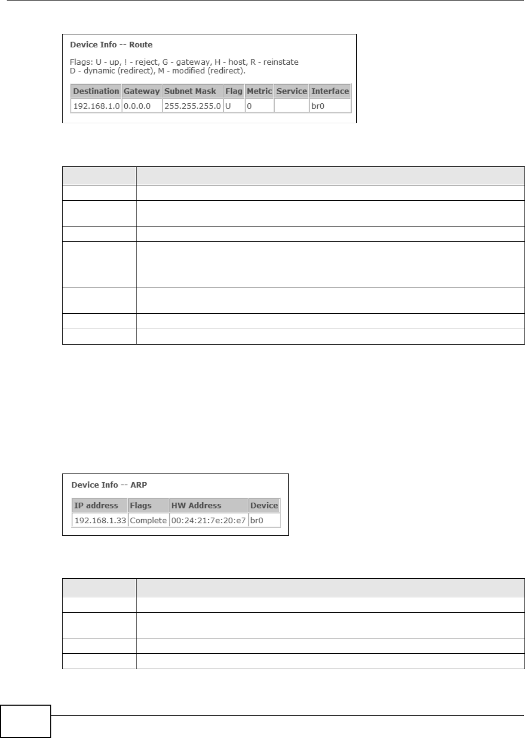
Chapter 3 Device Info Screens
Basic Home Station VDSL2 P8802T User’s Guide
72
Figure 11 Route I nfo Screen
Each field is described in the following table.
3.10 The ARP Info Screen
Log int o the VDSL Router’s web configurat or and click Device I nfo > ARP to display Address
Resolution Prot ocol inform ation. This screen lists t he I P addresses the VDSL Router has m apped to
MAC addresses.
Figure 12 ARP I nfo Screen
Each field is described in the following table.
Table 9 Rout e I nfo Screen
LABEL DESCRIPTION
Dest inat ion This displays the I P address to which this entr y applies.
Gat eway This displays the gat ew ay t he VDSL Router uses to send t raffic to t he ent ry’s destinat ion
addr ess.
Subnet Mask This displays t he subnet m ask of the dest inat ion net .
Flag This displays whet her t he rout e is up ( U), t he VDSL Rout er drops packet s for t his
dest ination (!) , the rout e uses a gateway ( G), the target is a host ( H), reinst at e route for
dynam ic rout ing ( R), t he rout e was dynam ically inst alled by redirect ( D), or m odified from
redirect ( M) .
Met ric The m et r ic represent s the “ cost ” of t ransm ission for rout ing purposes. I P rout ing uses hop
count as t he m easurem ent of cost , w it h a m inim um of 1 for directly- connect ed networks.
Service The nam e of a specific serv ice t o which the rout e applies if one is specified.
I nter face The int erface t hrough which this rout e sends t raffic.
Table 10 ARP I nfo Screen
LABEL DESCRIPTION
I P addr ess The learned I P address of a device connect ed t o one of t he syst em ’s ports.
Flags St at ic - st at ic ent ry, Dyna m ic - dynam ic entry t hat is not yet com plet e, Com p let e -
dynamic entr y t hat is com plet e.
HW Addr ess The MAC address of the device wit h t he listed I P address.
Device The interface through which the VDSL Router sends traffic to t he device listed in the entry.
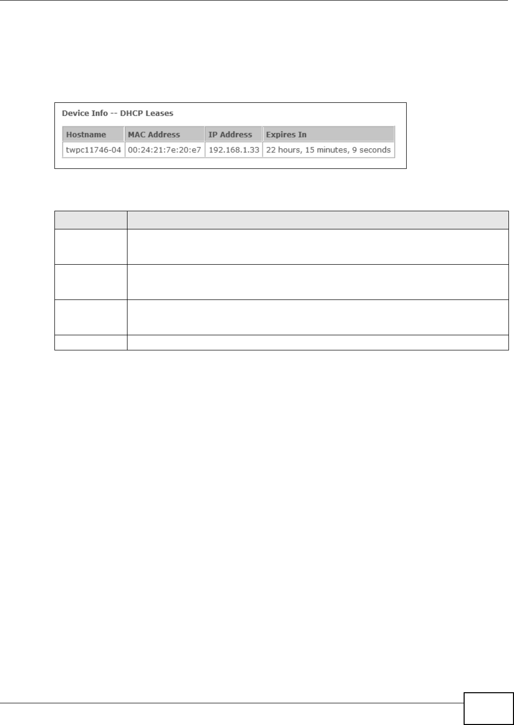
Chapter 3 Device Info Screens
Basic Home Station VDSL2 P8802T User’s Guide 73
3.11 The DHCP Leases Screen
Log int o the VDSL Router’s web configurat or and click Device I nfo > DH CP to display the VDSL
Router’s list of I P address curr ent ly leased t o DHCP client s.
Figure 13 DHCP Leases Screen
Each field is described in the following table.
Table 11 DHCP Leases Screen
LABEL DESCRIPTION
Host nam e This field displays t he nam e used to ident ify this dev ice on t he net wor k ( t he com put er
nam e) . The VDSL Router learns these from the DHCP client request s. “ None” shows here for
a st at ic DHCP entry.
MAC Address This field displays the MAC address to which the I P address is current ly assigned or for
which the I P address is reserved. Click the column’s heading cell t o sort the table ent ries by
MAC address. Click the heading cell again t o reverse t he sort order.
I P Address This field displays the I P addr ess currently assigned to a DHCP client or reserved for a
specific MAC address. Click the column’s heading cell t o sor t the t able entr ies by I P address.
Click the heading cell again t o reverse t he sort or der.
Expires I n This field displays how m uch longer t he I P addr ess is leased to t he DHCP client .

Chapter 3 Device Info Screens
Basic Home Station VDSL2 P8802T User’s Guide
74
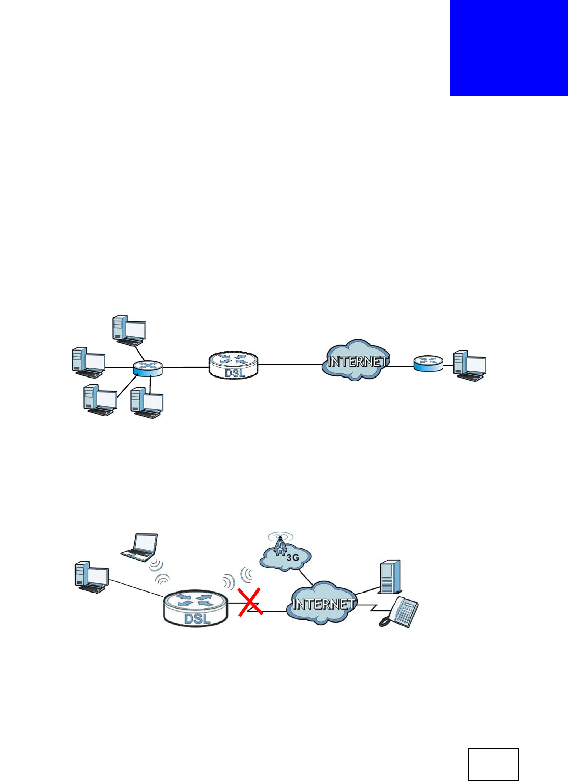
Basic Home Station VDSL2 P8802T User’s Guide 75
CHAPTER 4
WAN
4.1 Overview
This chapt er discusses t he VDSL Rout er’s W AN screens. Use these screens t o configure your VDSL
Router for I nternet access.
A WAN ( Wide Area Network) connection is an outside connect ion to another networ k or the
I nt ernet . I t connect s your pr ivate networks, such as a LAN ( Local Area Net work) and ot her
net works, so that a com puter in one locat ion can com m unicate wit h com puters in ot her locations.
Figure 14 LAN and WAN
3G (third generat ion) st andar ds for the sending and receiving of voice, video, and dat a in a m obile
environm ent .
You can at t ach a 3G wireless adapter to the USB port and set t he VDSL Router to use t his 3G
connect ion as your WAN or a backup when t he wired WAN connect ion fails.
Figure 15 3G WAN Connect ion
4.1.1 What You Can Do in this Chapter
• Use the La ye r 2 I nterface screens t o view, rem ove or add layer-2 WAN interfaces ( Sect ion 4.2
on page 78 and Sect ion 4.3 on page 81) .
WAN

Chapter 4 WAN
Basic Home Station VDSL2 P8802T User’s Guide
76
• Use the W AN Se rvice screens to view, rem ove or add a WAN int erface. You can also configure
the WAN sett ings on t he VDSL Router for I nternet access ( Sect ion 4.4 on page 83) .
• Use the 3 G Ba ck up screen t o configure 3G WAN connect ion (Sect ion 4.5 on page 97) .
4.1.2 What You Need to Know
The following t erm s and concept s m ay help as you r ead t his chapter.
Encapsulation Method
Encapsulat ion is used t o include data from an upper layer pr ot ocol into a lower layer prot ocol. To set
up a WAN connect ion to t he I nt ernet , you need t o use t he same encapsulation m et hod used by your
I SP (I nt ernet Service Provider). I f your I SP offers a dial- up I nt ernet connect ion using PPPoE ( PPP
over Ether net ), they should also provide a usernam e and password ( and service nam e) for user
aut hent icat ion.
WAN IP Address
The WAN I P address is an I P address for t he VDSL Router, which m akes it accessible from an
out side net work. I t is used by the VDSL Router to comm unicate wit h ot her devices in other
net works. I t can be st atic ( fixed) or dynam ically assigned by t he I SP each t im e t he VDSL Rout er
tries t o access t he I nter net .
I f your I SP assigns you a st at ic WAN I P address, t hey should also assign you the subnet m ask and
DNS server I P address( es) .
ATM
Asynchronous Transfer Mode ( ATM) is a WAN net working t echnology t hat prov ides high- speed dat a
transfer. ATM uses fixed- size packets of inform at ion called cells. With ATM, a high QoS ( Qualit y of
Table 12 WAN Set up Overview
LAYER-2 INTERFACE INTERNET CONNECTION
CONNECTION DSL LINK
TYPE MODE ENCAPSULATION CONNECTION SETTINGS
ADSL/ VDSL
over PTM
N/ A Routing PPPoE PPP inform at ion, I Pv4/ IPv6 I P
addr ess, rout ing feat ure, DNS
server, VLAN, QoS, and MTU
I PoE I Pv4/ I Pv6 I P address, rout ing
feature, DNS server, VLAN, QoS,
and MTU
Bridge N/ A VLAN and QoS
ADSL over ATM EoA Routing PPPoE/ PPP0A ATM PCV configurat ion, PPP
inform at ion, I Pv4/ I Pv6 IP address,
rout ing feat ure, DNS server, VLAN,
QoS, and MTU
I PoE/ I PoA ATM PCV configurat ion, I Pv4/ I Pv6
I P address, rout ing feat ure, DNS
server, VLAN, QoS, and MTU
Bridge N/ A ATM PCV configurat ion, and QoS

Chapter 4 WAN
Basic Home Station VDSL2 P8802T User’s Guide 77
Service) can be guarant eed. ATM uses a connect ion- orient ed m odel and est ablishes a virt ual circuit
( VC) bet ween Finding Out More
PTM
Packet Transfer Mode ( PTM) is packet-orient ed and support ed by the VDSL2 st andard. I n PTM,
packets are encapsulated direct ly in t he High- level Dat a Link Cont rol ( HDLC) fram es. I t is designed
to provide a low- overhead, t ransparent way of transporting packets over DSL links, as an
alternat ive t o ATM.
3G
3G (Third Generat ion) is a digital, packet-switched wireless t echnology. Bandwidth usage is
opt im ized as m ultiple users share the sam e channel and bandwidt h is only allocat ed t o users when
t h ey send dat a. I t allows fast t ransfer of voice and non-voice dat a and provides broadband I nternet
access to m obile devices.
IPv6 Introduction
I Pv6 (I nternet Protocol version 6), is designed t o enhance I P address size and features. The
increase in I Pv6 address size t o 128 bits ( from the 32-bit I Pv4 address) allows up t o 3.4 x 1038 I P
addresses. The VDSL Router can use I Pv4/ I Pv6 dual st ack to connect t o I Pv4 and I Pv6 net works,
and supports I Pv6 rapid deploym ent ( 6RD) .
IPv6 Addressing
The 128- bit I Pv6 address is writ ten as eight 16- bit hexadecimal blocks separat ed by colons ( : ) . This
is an exam ple I Pv6 address 2001:0db8:1a2b:0015:0000:0000:1a2f:0000.
I Pv6 addr esses can be abbreviated in tw o ways:
• Leading zeros in a block can be om it t ed. So 2001:0db8:1a2b:0015:0000:0000:1a2f:0000 can
be written as 2001:db8:1a2b:15:0:0:1a2f:0.
• Any num ber of consecutive blocks of zeros can be replaced by a double colon. A double colon can
only appear once in an I Pv6 address. So 2001:0db8:0000:0000:1a2f:0000:0000:0015 can be
writ ten as 2001:0db8::1a2f:0000:0000:0015, 2001:0db8:0000:0000:1a2f::0015,
2001:db8::1a2f:0:0:15 or 2001:db8:0:0:1a2f::15.
IPv6 Prefix and Prefix Length
Sim ilar to an I Pv4 subnet m ask, I Pv6 uses an address prefix to represent t he net work address. An
I Pv6 prefix lengt h specifies how m any m ost significant bit s ( st art from t he left) in the address
com pose t he net work address. The prefix lengt h is writt en as “ / x” where x is a num ber. For
exam ple,
2001:db8:1a2b:15::1a2f:0/32
m eans that the first 32 bit s ( 2001:db8) is t he subnet prefix.
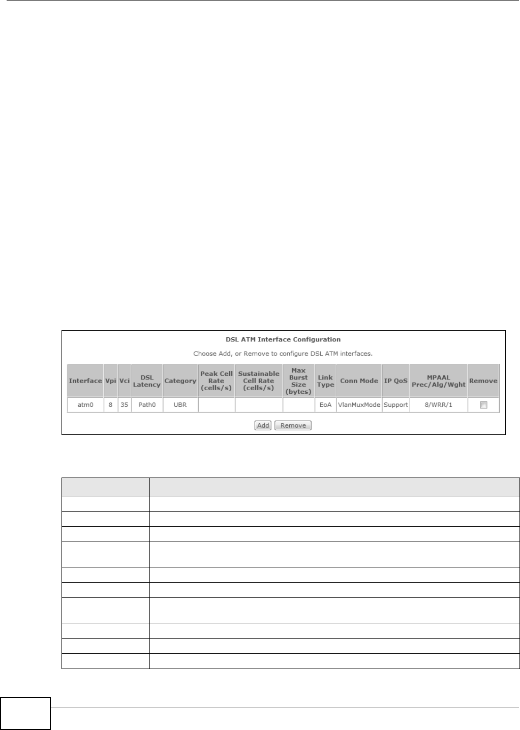
Chapter 4 WAN
Basic Home Station VDSL2 P8802T User’s Guide
78
IPv6 Subnet Masking
Both an I Pv6 address and I Pv6 subnet m ask com pose of 128-bit binary digit s, which ar e divided
int o eight 16-bit blocks and writ t en in hexadecim al notation. Hexadecim al uses four bit s for each
charact er (1 ~ 10, A ~ F) . Each block’s 16 bits ar e then represent ed by four hexadecim al
charact ers. For exam ple, FFFF: FFFF: FFFF: FFFF: FC00: 0000: 0000: 0000.
4.1.3 Before You Begin
You need t o know your I nt ernet access sett ings such as encapsulation and WAN I P address. Get t his
inform ation from your I SP.
4.2 The Layer-2 Interface ATM Screen
The VDSL Rout er m ust have a layer -2 int erface t o allow users t o use t he DSL port t o access the
I nt ernet . The scr een varies depending on t he interface type you select . Log into the VDSL Router’s
web configurat or and click Advance d Setup > La ye r2 I nt erface > ATM I nter fa ce to m anage
the ATM layer- 2 int erfaces.
Note: The ATM and PTM layer- 2 int erfaces cannot work at t he sam e tim e.
Figure 16 Layer- 2 I nt erface: ATM
The following t able describes t he fields in this screen.
Table 13 Layer-2 I nter face: ATM
LABEL DESCRIPTION
I nterface The nam e of a configured layer- 2 interface.
Vpi This displays the Virtual Pat h I dent ifier ( VPI ) .
Vci This displays t he Virtual Channel I dent ifier ( VCI ).
DSL Latency This displays whet her the ATM int erface uses int er leav e delay ( Pa t h1 ) or fast m ode wit h
no interleave delay (Pa t h 0 ) .
Cat egory This displays the ATM traffic class.
Peak Cell Rate This displays the m axim um rate at which the sender can send cells.
Sustainable Cell
Rat e
This display s the average cell rate ( long-t erm ) at which the sender can send cells.
Max Burst Size This displays the m axim um num ber of cells that can be sent at t he peak rat e.
Link Type This is the DSL link type of t he ATM layer- 2 int erface.
Conn Mode This show s the connect ion m ode of the layer-2 int erface.
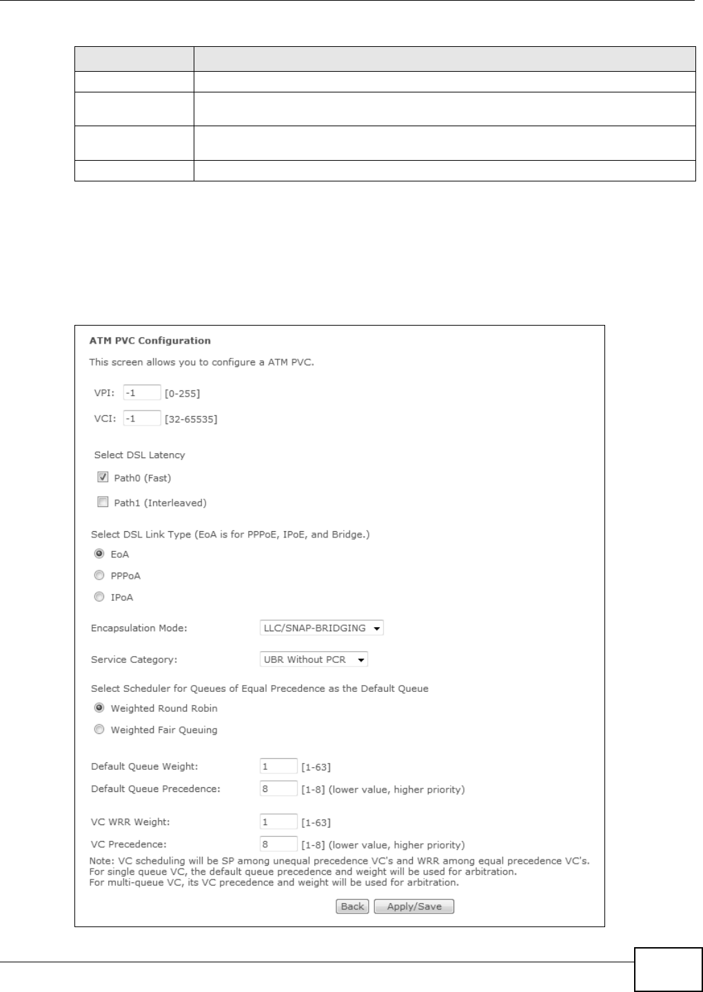
Chapter 4 WAN
Basic Home Station VDSL2 P8802T User’s Guide 79
4.2.1 Layer-2 ATM Interface Configuration
Click the Add button in the La yer2 I nterface : ATM screen t o open t he following screen. Use t his
screen t o creat e a new layer-2 int erface. You can have m ultiple ATM layer-2 interfaces using
different VPI and/ or VCI values. The screen var ies depending on t he int er face t ype you select .
Figure 17 DSL ATM I nt erface Configurat ion
I P QoS This displays whet her QoS (Qualit y of Service) is enabled on the int erface.
MPAAL
Prec/ Alg/ Wght
This displays the int erface’s default queue precedence, queuing algorit hm , and w eight ed
round r obin w eight .
Rem ove Select an int erface and click t he Re m ove butt on to delet e it . You cannot rem ove a layer-
2 interface when a WAN service is associat ed with it .
Add Click this but ton t o creat e a new ATM layer- 2 inter face.
Table 13 Layer-2 I nter face: ATM (continued)
LABEL DESCRIPTION

Chapter 4 WAN
Basic Home Station VDSL2 P8802T User’s Guide
80
The following t able describes t he fields in this screen.
Table 14 Layer-2 ATM I nterface Configurat ion
LABEL DESCRIPTION
ATM PVC
Configuration
VPI (Virt ual Pat h I dent ifier ) and VCI ( Virtual Channel I dentifier) define a vir tual cir cuit .
This sect ion is available only when you configur e an ATM layer- 2 int erface.
VPI The valid range for t he VPI is 0 t o 255. Ent er the VPI assigned to you.
VCI The valid range for t he VCI is 32 to 65535 ( 0 t o 31 is reserved for local m anagem ent of
ATM traffic) . Ent er the VCI assigned t o you.
Select DSL Lat ency Select Pat h0 ( Fa st ) to use no int er leaving and have fast er t ransm ission ( a “fast
channel” ) . Suit able only for a good line wit h lit tle need for er ror correct ion.
At t he tim e of writ ing t he VDSL Rout er supports fast m ode only and interleaved is
reserved for fut ur e use.
Select DSL Link
Ty p e
Select EoA (Ethernet over ATM) t o have an Et hernet header in t he packet , so that you
can have m ult iple services/ connect ions over one PVC. You can set each connection to
have its own MAC address or all connect ions shar e one MAC address but use different
VLAN I Ds for different services. EoA supports ENET ENCAP ( I PoE), PPPoE and RFC1483/
2684 bridging encapsulat ion m et hods.
Select PPPoA (PPP over ATM) to allow j ust one PPPoA connect ion over a PVC.
Select I PoA (I P over ATM) to allow just one RFC 1483 r out ing connect ion over a PVC.
Encapsulat ion
Mode
Select t he I SP’s m et hod of m ultiplexing.
•VC/ M UX: I n VC m ultiplexing, each protocol is carried on a separat e ATM virt ual
circuit ( VC). To transport multiple prot ocols, the VDSL Rout er needs separat e VCs.
There is a binding bet ween a VC and the type of the net work prot ocol carried on t he
VC. This reduces pay load overhead since there is no need to car ry prot ocol
inform at ion in each Prot ocol Dat a Unit (PDU) payload.
•LLC/ SN AP- BRI DGI N G: I n LCC encapsulation, bridged PDUs are encapsulated by
identifying t he type of the bridged m edia in the SNAP header. This is available only
when you select EoA in the Se lect D SL Link Type field.
•LLC/ EN CAPSU LATI ON : More t han one prot ocol can be car ried over the same VC.
This is available only when you select PPPoA in t he Se le ct DSL Link Type field.
•LLC/ SN AP- RO UTI N G: I n LCC encapsulation, bridged PDUs are encapsulated by
identifying t he type of the bridged m edia in the SNAP header. This is available only
when you select EoA in the Se lect D SL Link Type field.
Ser vice Cat egory Select UBR W it hout PCR or UBR W it h PCR for applicat ions that are non- tim e
sensitive, such as e- m ail.
Select CBR (Cont inuous Bit Rat e) t o specify fixed (always- on) bandwidth for voice or
dat a traffic.
Select N on Rea ltim e V BR ( non r eal- time Var iable Bit Rat e) for connect ions that do not
require closely cont rolled delay and delay variat ion.
Select Realtim e VBR (real- time Var iable Bit Rate) for applicat ions wit h burst y
connect ions that require closely cont rolled delay and delay variat ion.
Peak Cell Rat e Divide t he DSL line rat e ( bps) by 424 ( t he size of an ATM cell) t o find t he Peak Cell Rat e
( PCR). This is the m axim um rate at which the sender can send cells. Type t he PCR here.
This field is not available when you select UBR W it hou t PCR.
Su st ainable Cell
Rat e
The Sust ain Cell Rat e (SCR) set s the average cell rate ( long- term ) t hat can be
transm itted. Type t he SCR, which must be less than the PCR. Note t hat syst em default is
0 cells/ sec.
This field is available only when you select N on Rea lt im e VBR or Rea lt im e VBR.
Maximum Burst
Size
Maxim um Burst Size ( MBS) refers to t he m axim um num ber of cells that can be sent at
the peak rat e. Type the MBS, which is less than 65535.
This field is available only when you select N on Rea lt im e VBR or Rea lt im e VBR.
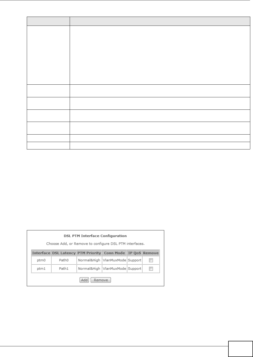
Chapter 4 WAN
Basic Home Station VDSL2 P8802T User’s Guide 81
4.3 The Layer-2 Interface PTM Screen
The VDSL Rout er m ust have a layer -2 int erface t o allow users t o use t he DSL port t o access the
I nt ernet . The scr een varies depending on t he interface type you select . Log into the VDSL Router’s
web configurat or and click Advance d Setup > La yer 2 I nt e rface > PTM I nt e rface to m anage
the PTM layer-2 interfaces.
Note: The ATM and PTM layer- 2 int erfaces cannot work at t he sam e tim e.
Figure 18 Layer- 2 I nt erface: PTM
Scheduler Select t he scheduler t o use for queues that have t he sam e precedence as the default
queue. Queuing applies only when a port has m ore traffic than it can handle.
W eight ed Rou nd Robin scheduling services queues of t he sam e priority level on a
rot at ing basis based on their queue weight. The higher a queue’s weight , the m ore
service it gets. This queuing m echanism divides any available bandwidth across t he
different t raffic queues and ret urns to queues that have not yet em ptied.
W eight ed Fa ir Queuing guarant ees each queue's m inim um bandwidt h based on it s
queue weight during t raffic congest ion. This queuing m echanism divides any available
bandwidth across the differ ent t raffic queues. Weight ed fair queuing handles packet s of
var ious sizes bett er than weight ed round robin queuing does.
Default Queue
Weig ht
Specify t he VC’s weight for weighed fair queuing. The higher the weight , t he bigger
por tion of t he bandwidth the VC get s.
Default Queue
Precedence
Specify t he VC’s priority for weighed fair queuing. The sm aller t he num ber t he higher
the priority.
VC WRR Weight Specify the VC’s weight for w eighted round robin queuing. The higher the weight , t he
bigger port ion of the bandwidth the VC get s.
VC Precedence Specify t he VC’s priority for weighted round robin queuing. The sm aller the number t he
higher t he priority.
Back Click this but ton t o ret urn t o t he previous screen wit hout saving any changes.
Apply/ Save Click t his but t on to sav e your changes and go back to the previous screen.
Table 14 Layer-2 ATM I nterface Configurat ion ( continued)
LABEL DESCRIPTION
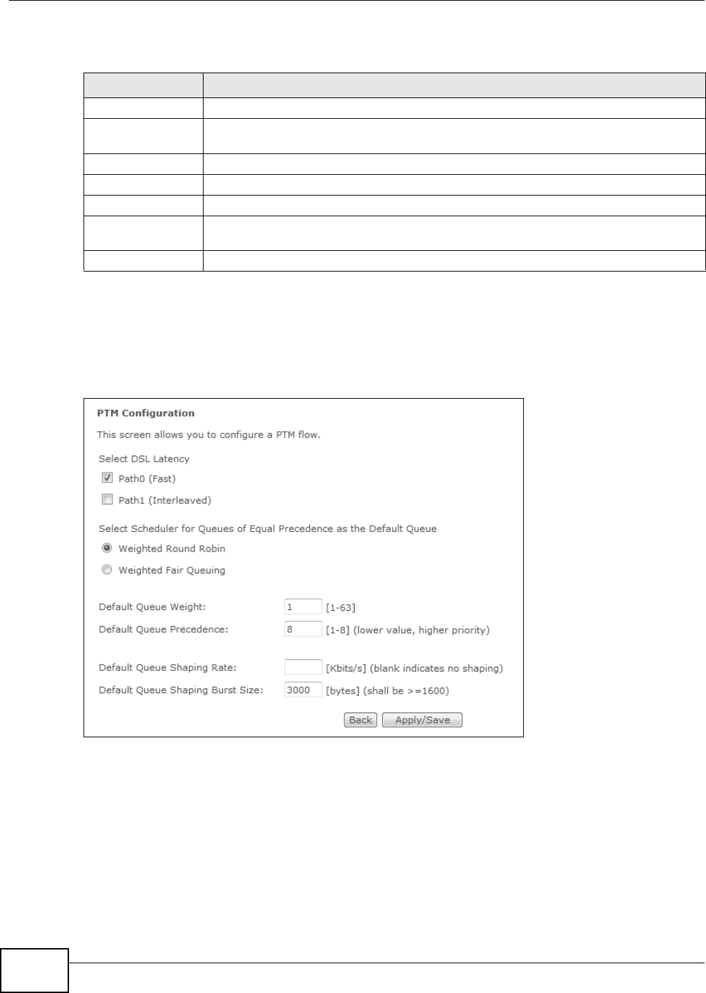
Chapter 4 WAN
Basic Home Station VDSL2 P8802T User’s Guide
82
The following t able describes t he fields in this screen.
4.3.1 Layer-2 PTM Interface Configuration
Click the Add button in the La ye r2 I nterface : PTM screen t o open the following screen. Use t his
screen t o creat e a new layer-2 interface.
Figure 19 DSL PTM I nt erface Configuration
Table 15 Layer-2 I nter face: PTM
LABEL DESCRIPTION
I nterface The nam e of a configured layer- 2 interface.
DSL Latency This displays whet her t he ATM int erface uses interleave delay (Pat h1 ) or fast m ode with
no interleave delay (Pa t h 0 ) .
PTM Priority This does not apply at t he tim e of writ ing.
Conn Mode This show s the connect ion m ode of the layer-2 int erface.
I P QoS This displays whet her QoS (Qualit y of Service) is enabled on the int erface.
Rem ove Select an int erface and click t he Re m ove butt on t o delete it. You cannot rem ove a layer -
2 interface when a WAN service is associat ed with it .
Add Click this but ton t o creat e a new ATM layer- 2 inter face.

Chapter 4 WAN
Basic Home Station VDSL2 P8802T User’s Guide 83
The following t able describes t he fields in this screen.
4.4 The WAN Service Screen
Use t his screen t o change your VDSL Router’s WAN sett ings. Click Advance d Setup > W AN
Se rvice. The sum m ary table shows you the configured WAN services (connect ions) on t he VDSL
Rou t er .
To use NAT, firewall or I GMP proxy in the VDSL Router, you need t o configure a WAN connect ion
with PPPoE or I PoE.
Note: When a layer- 2 interface is in VLAN MUX Mode, you can configure up t o five WAN
services on the VDSL Rout er.
Table 16 Layer-2 PTM I nt erface Configurat ion
LABEL DESCRIPTION
Select DSL Lat ency Select Pat h0 ( Fa st ) to use no int er leaving and have fast er t ransm ission ( a “fast
channel” ) . Suit able only for a good line wit h lit tle need for er ror correct ion.
At t he tim e of writ ing t he VDSL Rout er supports fast m ode only and interleaved is
reserved for fut ur e use.
Scheduler Select t he scheduler t o use for queues that have t he sam e precedence as the default
queue.
W eight ed Rou nd Robin scheduling services queues of t he sam e priority level on a
rot at ing basis based on their queue weight. The higher a queue’s weight , the m ore
service it gets. This queuing m echanism divides any available bandwidth across t he
different t raffic queues and ret urns to queues that have not yet em ptied.
During traffic congest ion W eighte d Fa ir Queu ing guarant ees each queue's m inim um
bandwidth based on it s default queue weight. This queuing m echanism divides any
available bandwidth across the different t raffic queues. Weighted fair queuing applies
only when a port has m ore t raffic than it can handle.
Default Queue
Weig ht
Specify t he PTM int erface’s weight for weighed fair queuing. The higher t he weight , t he
bigger port ion of the bandwidth the PTM interface gets.
Default Queue
Precedence
Specify t he PTM int erface’s prior ity for weighed fair queuing. The sm aller the num ber
t he higher the priorit y.
Default Queue
Shaping Rat e
Specify the m axim um transm ission rat e allowed for traffic on this queue.
Default Queue
Shaping Burst Size
Specify the m aximum num ber of cells that can be sent at the default queue shaping
rate.
Back Click this but ton t o ret urn t o t he previous screen wit hout saving any changes.
Apply/ Save Click t his but t on to sav e your changes and go back to the previous screen.
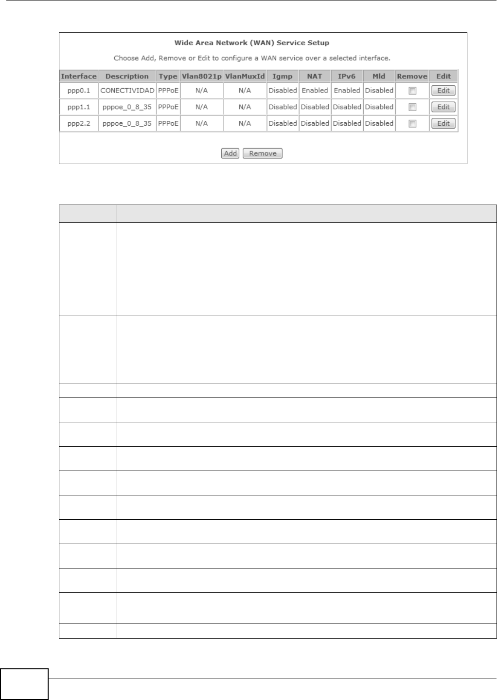
Chapter 4 WAN
Basic Home Station VDSL2 P8802T User’s Guide
84
Figure 20 WAN Ser vice
The following t able describes t he labels in t his screen.
Table 17 WAN Service
LABEL DESCRIPTION
I nter face This shows the nam e of t he int erface used by t his connect ion.
A default nam e ipoa * , pppoa * , a t m * or pt m * indicates the DSL port. ppp* indicates a PPP
connect ion through any one of the WAN int erfaces.
The num ber after t he dot (.) r epresents the VLAN I D num ber assigned t o t raffic sent through
this connection. The number after t he underscore (_) represent s t he index num ber of
connect ions through t he same int erface.
( null) m eans the ent ry is not valid.
Description This is t he se rvice na m e of t his conne ct ion .
0 and 3 5 or 0 and 1 are the default VPI and VCI num bers. The last num ber represent s the
index num ber of connect ions over t he sam e PVC or the VLAN I D num ber assigned to t raffic
sent through this connection.
( null) m eans the ent ry is not valid.
Type This shows the m et hod of encapsulat ion used by t his connect ion.
Vlan8021p This indicat es the 802.1P pr iority level assigned t o traffic sent through this connect ion. This
displays N / A w hen t here is no priority level assigned.
VlanMuxI d This indicat es t he VLAN I D num ber assigned t o traffic sent through t his connect ion. This
displays N / A w hen t here is no VLAN I D num ber assigned.
ConnI d This shows the index num ber of each connect ion. This displays N / A when the interface used
by t he connect ion is in Defa ult Mode.
I gm p This shows whet her I GMP (I nt er net Group Multicast Prot ocol) is act ivat ed or not for this
connection. I GMP is not available w hen the connect ion uses the bridging service.
NAT This shows whet her NAT is act ivat ed or not for t his int erface. NAT is not available when the
connect ion uses the bridging ser vice.
I Pv6 This shows whet her I Pv6 is act ivat ed or not for this connection. I Pv6 is not available when the
connect ion uses the bridging ser vice.
Mld This shows whet her Mult icast Listener Discovery (MLD) is act ivat ed or not for t his connect ion.
MLD is not available when the connection uses t he bridging service.
Rem ove Select an int erface and click the Rem ove but ton t o delet e it . You cannot rem ove a layer- 2
int erface when a WAN service is associated wit h it .
Modify Click the Edit icon to configure the WAN connect ion.
Click the Re m ove icon t o delet e the WAN connect ion.
Add Click Add to creat e a new connect ion.
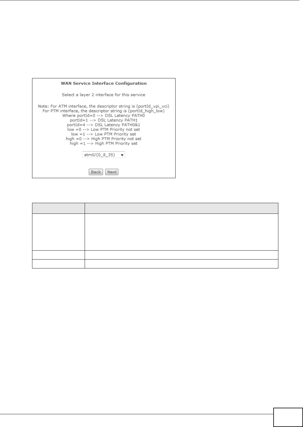
Chapter 4 WAN
Basic Home Station VDSL2 P8802T User’s Guide 85
4.4.1 WAN Connection Configuration
Click the Edit or Add butt on in the W AN Service screen t o configure a WAN connect ion.
4.4.1.1 WAN Interface
This screen displays when you add a new WAN connect ion.
Figure 21 WAN Configurat ion: WAN I nterface
The following t able describes t he labels in t his screen.
4.4.1.2 Service Type
I f you set t he DSL link t ype to PPPoA or I PoA for the ATM int erface and configur e a WAN
connect ion using t he ATM interface, you only need t o configure the Ent e r Se rvice Description
field in this screen.
Table 18 WAN Configuration: WAN I nt erface
LABEL DESCRIPTION
Select a layer 2
int erface for this
serv ice
Select pt m x to use the DSL port as the WAN port and use the VDSL
technology for data t ransm ission.
Select at m x or ipoa x (w here x st art s from 0 and is the index number of ATM
layer- 2 interfaces using different VPI and/ or VCI values) t o use the DSL port as
the WAN por t and use t he ADSL technology for data t ransm ission.
Back Click t his butt on to return to t he previous screen.
Next Click this butt on to cont inue.
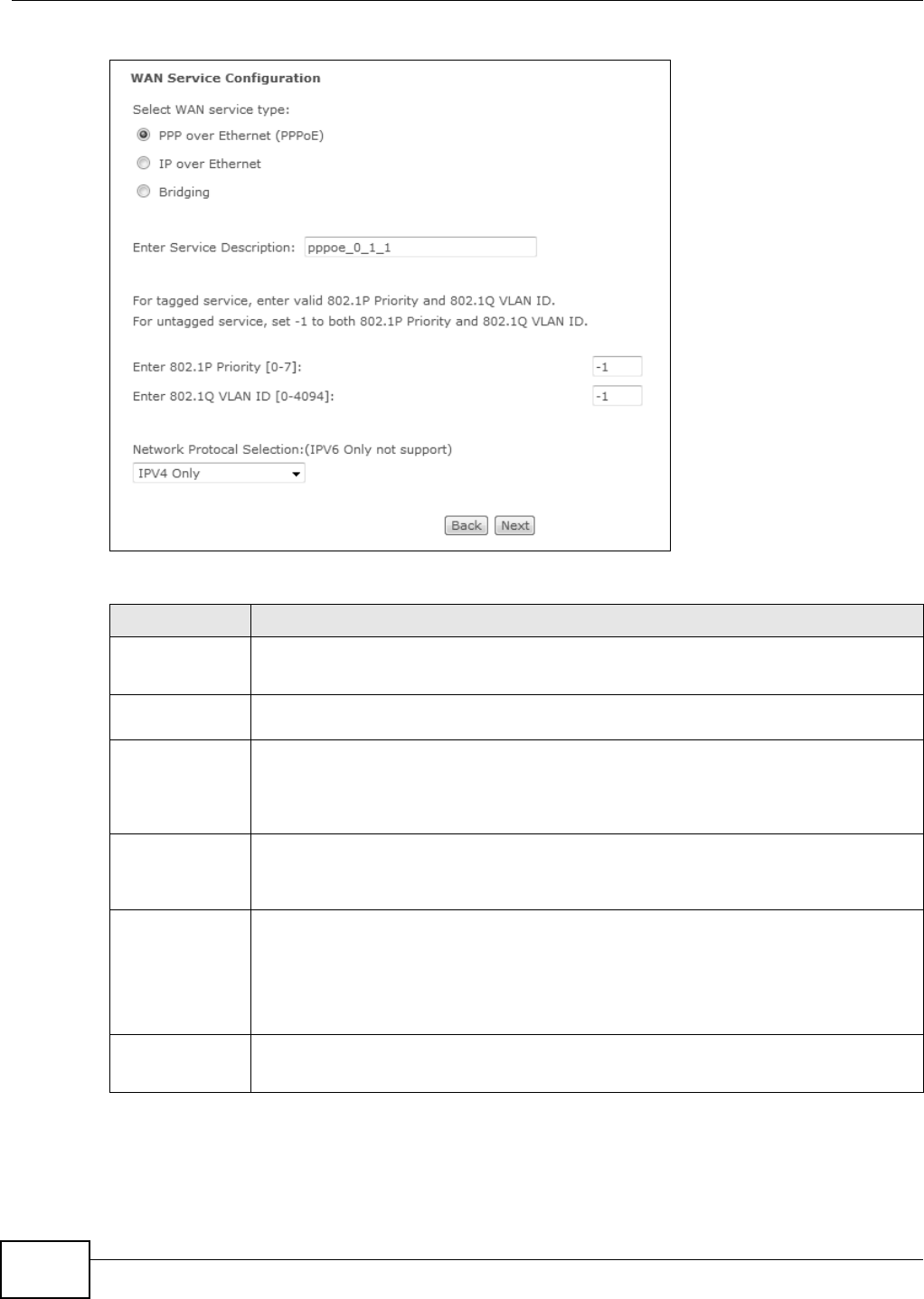
Chapter 4 WAN
Basic Home Station VDSL2 P8802T User’s Guide
86
Figure 22 WAN Configurat ion: Service Type
Figure 23 The following table describes the labels in t his screen.
Table 19 WAN Configuration: Service Type
LABEL DESCRIPTION
Select WAN
serv ice type
Select t he m et hod of encapsulat ion used by your I SP.
Choices are PPP over Et he rnet ( PPPoE) , I P over Et her net and Br idging.
Enter Service
Description
Specify a nam e for t his connect ion or use t he aut om at ically generat ed one.
Rate Lim it Enter the m axim um transm ission rat e in Kbps for traffic sent t hrough t he WAN connect ion.
Ot herwise, leave t his field blank t o disable t he rat e lim it .
This field is not available for an ATM connect ion if QoS is disabled in the DSL ATM I nterface
Configurat ion.
Tag VLAN I D for
egress packet s
Select t his option t o add t he VLAN tag (specified below) t o t he out going traffic through t his
connection.
This field is available when the layer- 2 interface is in VLAN M UX m ode.
Enter 802.1P
Prior ity
I EEE 802.1p defines up t o 8 separat e t raffic types by insert ing a t ag into a MAC-layer
fram e that cont ains bits t o define class of service.
Type t he I EEE 802.1p priorit y level ( from 0 t o 7) t o add to t raffic through t his connection.
The gr eater t he num ber, t he higher the priorit y level.
This field is available when the layer- 2 interface is in VLAN M UX m ode.
Enter 802.1Q
VLAN I D
Ty pe t he VLAN I D number ( from 1 to 4094) for t raffic through t his connect ion.
This field is available when the PTM int er face is in VLAN MU X m ode.

Chapter 4 WAN
Basic Home Station VDSL2 P8802T User’s Guide 87
4.4.1.3 WAN IP Address and DNS Server
The screen differs by the encapsulat ion you select ed in t he previous screen. See Sect ion 4.6 on
page 99 for m ore inform at ion.
PPPoE or PPPoA
This screen displays when you select PPP ove r Et her ne t ( PPPoE) in the W AN Service
Con fig ur a t io n scr een or set t he DSL link t ype t o PPPoA for the ATM inter face and configure a
WAN connect ion using t he ATM interface.
Network Pr ot ocol
Select ion
Select I Pv4 Only to have t he VDSL Router use only I Pv4.
Select I Pv4 & I Pv 6 ( Dua l St ack ) t o let the VDSL Rout er connect to I Pv4 and I Pv6
net wor ks an choose t he prot ocol for applicat ions accor ding to t he address type. This let s
t he VDSL Router use an I Pv6 addr ess when sending t raffic through this connect ion. You
can only select this for a WAN service that uses the PPPoE or I PoE encapsulat ion m ethod
over t he ATM or PTM int erface.
Back Click this but ton to ret urn t o the previous screen.
Next Click this but ton to cont inue.
Table 19 WAN Configuration: Service Type
LABEL DESCRIPTION
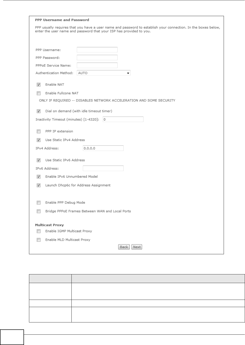
Chapter 4 WAN
Basic Home Station VDSL2 P8802T User’s Guide
88
Figure 24 WAN Configurat ion: PPPoE
The following t able describes t he labels in t his screen.
Table 20 WAN Configuration: PPPoE or PPPoA
LABEL DESCRIPTION
PPP Username Enter t he user nam e exactly as your I SP assigned. I f assigned a nam e in the form
user @dom ain w here dom ain ident ifies a ser v ice nam e, t hen ent er both com ponent s
exact ly as given.
PPP Password Enter t he password associat ed wit h t he user name above.
PPPoE Service
Nam e
Type t he nam e of your PPPoE service here.
This field is not available for a PPPoA connect ion.

Chapter 4 WAN
Basic Home Station VDSL2 P8802T User’s Guide 89
Aut hent icat ion
Met hod
The VDSL Rout er supports PAP (Password Aut hent ication Protocol) and CHAP ( Challenge
Handshake Aut hent ication Pr otocol). CHAP is m ore secure than PAP; however, PAP is
readily available on m ore plat form s.
Use the drop-down list box t o select an aut hent icat ion protocol for out going calls.
Options are:
AUTO - Your VDSL Router accept s eit her CHAP or PAP when requested by t his rem ot e
node.
PAP - Your VDSL Rout er accept s PAP only.
CH AP - Your VDSL Rout er accept s CHAP only.
M SCH AP - Your VDSL Rout er accepts MSCHAP only. MS-CHAP is the Microsoft version
of t he CHAP.
Enable NAT Select t his check box t o act ivat e NAT on t his connect ion.
Enable Fullcone NAT This field is available only w hen you select Ena ble N AT. Select t his check box t o
act ivat e full cone NAT on t his connect ion.
Dial on Dem and Select this check box t o not keep t he connect ion up all t he t im e. Specify an idle t im e-
out in the I nact ivit y Tim eout field.
I nact ivity
Tim eout
Specify an idle t im e- out when you select Dial on De m a nd. The default set ting is 0,
which m eans the I nternet session will not t im eout .
PPP I P ext ension Select t his only if your service provider r equires it. PPP I P ext ension ext ends the service
provider ’s I P subnet to a single LAN com puter.
• I t let s only one com puter on the LAN connect t o the WAN.
• The public I P address fr om t he I SP is forwarded through DHCP to t he LAN com put er
inst ead of being used on the WAN PPP int erface.
• I t disables NAT and the fir ewall.
• DHCP tells the LAN com put er to use t he gat eway as the default gateway and DNS
ser ver.
• The VDSL Rout er bridges I P packet s bet ween t he WAN and LAN port s except
packet s dest ined for the VDSL Router’s LAN I P addr ess.
Use Static I Pv4
Address
Select this option if you have a fixed I Pv4 address assigned by your I SP.
I Pv4 Addr ess Enter t he I Pv4 address assigned by your I SP.
Use Static I Pv6
Address
Select this option if you have a fixed I Pv6 address assigned by your I SP.
I Pv6 Addr ess Enter t he I Pv6 address assigned by your I SP.
Enable I Pv6
Unnum bered Model
Select th is t o enable I Pv6 pr ocessing on t h e int erface wit hout assigning an explicit I Pv6
addr ess to t he int erface.
Launch Dhcp6c for
Address
Assignm ent
Select t his check box to obt ain an I Pv6 address from a DHCPv6 server.
The I P address assigned by a DHCPv6 server has prior ity over t he I P address
automatically generated by t he VDSL Router using the I Pv6 prefix from an RA.
Enable PPP Debug
Mode
Select t his option to display PPP debugging messages on the console.
Table 20 WAN Configuration: PPPoE or PPPoA
LABEL DESCRIPTION

Chapter 4 WAN
Basic Home Station VDSL2 P8802T User’s Guide
90
IPoE
This screen displays when you select I P over Ethernet in t he W AN Ser vice Con figur at ion
screen.
Br idge PPPoE
Frames Bet ween
WAN and Local
Port s
Select this option t o forward PPPoE packet s from the WAN port to t he LAN port s and
from the LAN ports to the WAN port.
I n addit ion t o the VDSL Rout er's built- in PPPoE client , you can select this to allow up t o
ten host s on the LAN t o use PPPoE client soft ware on t heir com puter s to connect t o the
I SP via the VDSL Router. Each host can have a separat e account and a public WAN I P
addr ess.
This is an alternat ive to NAT for applicat ion where NAT is not appropriat e.
Clear t his if you do not need to allow host s on t he LAN t o use PPPoE client soft ware on
their com puters to connect t o the I SP.
This field is not available for a PPPoA connect ion.
Enable I GMP
Mult icast Proxy
Select t h is ch eck box t o h av e t he VDSL Rout er act as an I GMP pr ox y on t his con nect ion.
This allow s the VDSL Router to get subscribing infor m ation and m aintain a j oined
m em ber list for each m ult icast group. I t can reduce m ult icast traffic significant ly.
Enable MLD
Mult icast Proxy
Select Enable to have t he VDSL Rout er act as an MLD proxy on t his connect ion. This
allows the VDSL Rout er t o get subscript ion inform at ion and m aint ain a joined m em ber
list for each m ulticast group. I t can reduce m ult icast t raffic significant ly.
Back Click this but ton t o ret urn to t he previous screen.
Next Click this butt on to cont inue.
Table 20 WAN Configuration: PPPoE or PPPoA
LABEL DESCRIPTION
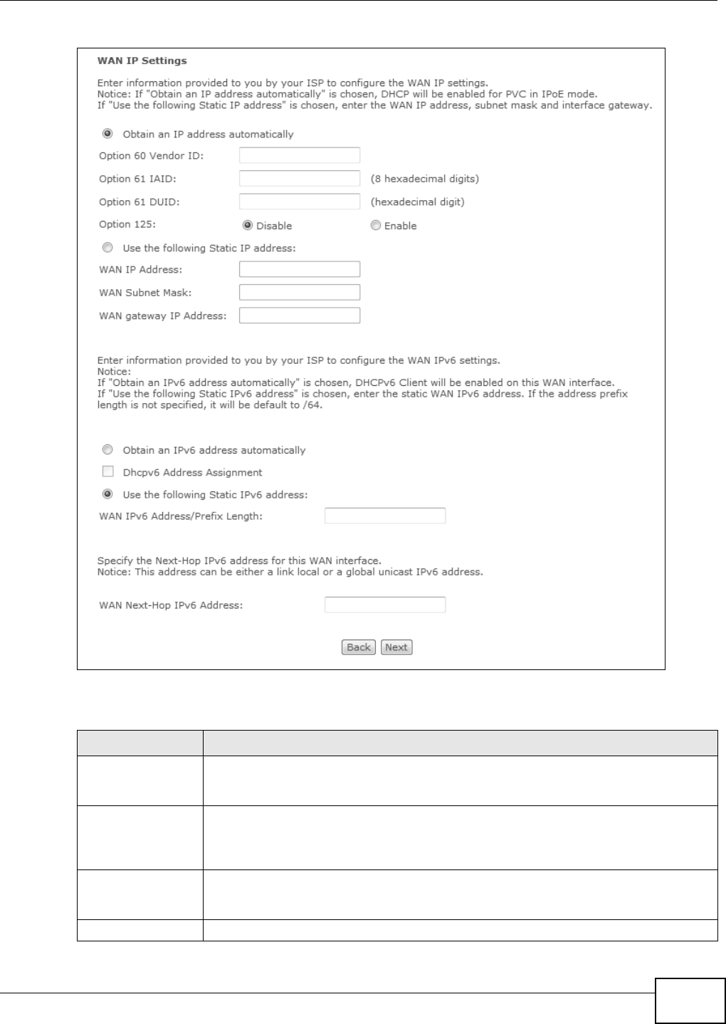
Chapter 4 WAN
Basic Home Station VDSL2 P8802T User’s Guide 91
Figure 25 WAN Configurat ion: I PoE
The following t able describes t he labels in t his screen.
Table 21 WAN Configuration: I PoE
LABEL DESCRIPTION
Obtain an I P
address
autom atically
A st at ic I P address is a fixed I P that your I SP gives you. A dynam ic I P address is not
fixed; t he I SP assigns you a different one each tim e you connect t o the I nt ernet . Select
this if you have a dy nam ic I P address.
Option 60 Vendor
I D
DHCP Option 60 ident ifies t he vendor and funct ionality of the VDSL Rout er in DHCP
request s that t he VDSL Rout er sends to a DHCP server when get ting a WAN I P addr ess.
Enter t he Vendor Class I dent ifier ( Option 60) , such as the type of the hardware or
firm war e.
Option 61 I AI D DHCP Option 61 ident ifies the VDSL Router in DHCP request s t he VDSL Rout er sends t o
a DHCP ser ver when get ting a WAN I P address. Enter t he I dentity Association I dent ifier
( I AI D) of the VDSL Rout er . For exam ple, t he WAN connect ion index num ber.
Option 61 DUI D Enter t he DHCP Unique I dent ifier ( DUI D) of the VDSL Rout er.
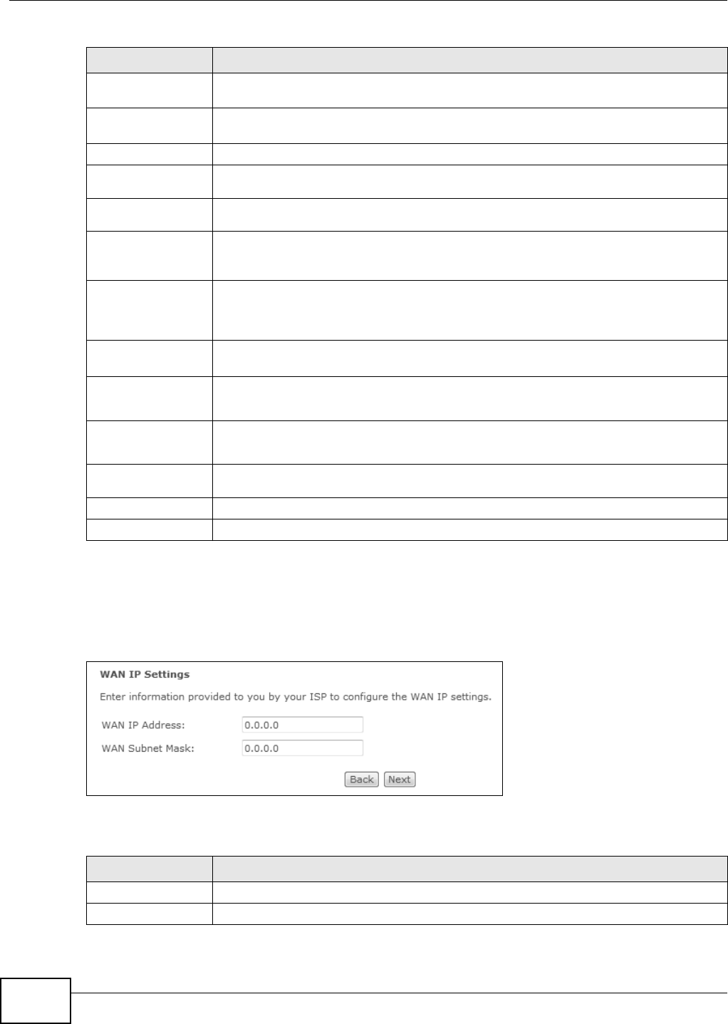
Chapter 4 WAN
Basic Home Station VDSL2 P8802T User’s Guide
92
IPoA
This screen displays only when you set t he DSL link t ype to I PoA for t he ATM interface and
configure a WAN connect ion using the ATM int erface.
Figure 26 WAN Configurat ion: I PoA
The following t able describes t he labels in t his screen.
Option 125 Enable this t o add vendor specific inform at ion to DHCP request s that the VDSL Router
sends t o a DHCP server when get ting a WAN I P address.
Use t he follow ing
St at ic I P address
Select this if you have a static I P address.
WAN I P Address Ent er t he static I P address pr ov ided by your I SP.
WAN Su bnet
Mask
Enter t he subnet m ask prov ided by your I SP.
WAN gat eway I P
Addr ess
Enter t he gateway I P address provided by your I SP.
Obtain an I Pv6
address
autom atically
Select this option to have t he VDSL Rout er use t he I Pv 6 prefix from the connect ed
router ’s Rout er Advertisem ent ( RA) t o generat e an I Pv6 address.
Dhcpv6 Address
Assignm ent
Select t his check box to obt ain an I Pv6 address from a DHCPv6 server.
The I P address assigned by a DHCPv6 server has prior ity over t he I P address
automatically generated by t he VDSL Router using the I Pv6 prefix from an RA.
Use t he follow ing
St at ic I Pv6 addr ess
Select this option if you have a fixed I Pv6 address assigned by your I SP.
WAN I Pv 6
Addr ess/ Prefix
Length
Enter t he static I Pv6 address and bit num ber of the I Pv6 subnet m ask provided by your
I SP.
WAN I Pv 6
Subnet Prefix
Length
Enter t he bit num ber of the I Pv6 subnet m ask provided by your I SP.
WAN Next- Hop
I Pv6 Address
Enter t he gateway I Pv6 address provided by your I SP.
Back Click this but ton t o ret urn to t he previous screen.
Next Click this butt on to cont inue.
Table 22 WAN Configuration: I PoA
LABEL DESCRIPTION
WAN I P Addr ess Enter t he st at ic I P address pr ovided by your I SP.
WAN Subnet Mask Enter t he subnet m ask prov ided by your I SP.
Table 21 WAN Configuration: I PoE
LABEL DESCRIPTION
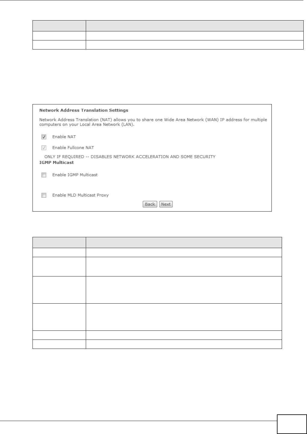
Chapter 4 WAN
Basic Home Station VDSL2 P8802T User’s Guide 93
4.4.1.4 NAT, IGMP Multicast and Firewall Activation
The screen is available only when you select I P ove r Et he rnet in the W AN Service
Con fig ur a t io n scr een or set t he DSL link t ype t o I PoA for the ATM interface and configure a WAN
connect ion using t he ATM interface.
Figure 27 WAN Configurat ion: NAT, I GMP Multicast and Firewall Activat ion: I PoE/ I PoA
The following t able describes t he labels in t his screen.
4.4.1.5 Default Gateway
The screen is not available when you select Bridging in t he W AN Ser vice Configur a tion screen.
Back Click this but ton t o ret urn to t he previous screen.
Next Click this butt on to cont inue.
Table 22 WAN Configuration: I PoA
LABEL DESCRIPTION
Table 23 WAN Configuration: NAT, I GMP Multicast and Firewall Act ivation: I PoE
LABEL DESCRIPTION
Enable NAT Select t his check box t o act ivat e NAT on t his connect ion.
Enable Fullcone NAT Select t his check box t o act ivat e full cone NAT on t his connect ion.
This field is available only w hen you select Ena ble N AT.
Enable I GMP
Mult icast Proxy
Select this check box to have the VDSL Rout er act as an I GMP proxy on this
connect ion. This allows t he VDSL Rout er t o get subscribing inform ation and
m aint ain a j oined m em ber list for each m ult icast group. I t can reduce m ulticast
traffic significantly.
Enable MLD
Mult icast Proxy
Select Enable to have t he VDSL Rout er act as an MLD pr oxy on t his
connect ion. This allows the VDSL Rout er to get subscr iption infor m at ion and
m aint ain a joined m ember list for each m ulticast group. I t can reduce
m ult icast traffic significant ly.
Back Click this but ton t o ret urn to t he previous screen.
Next Click this butt on to cont inue.
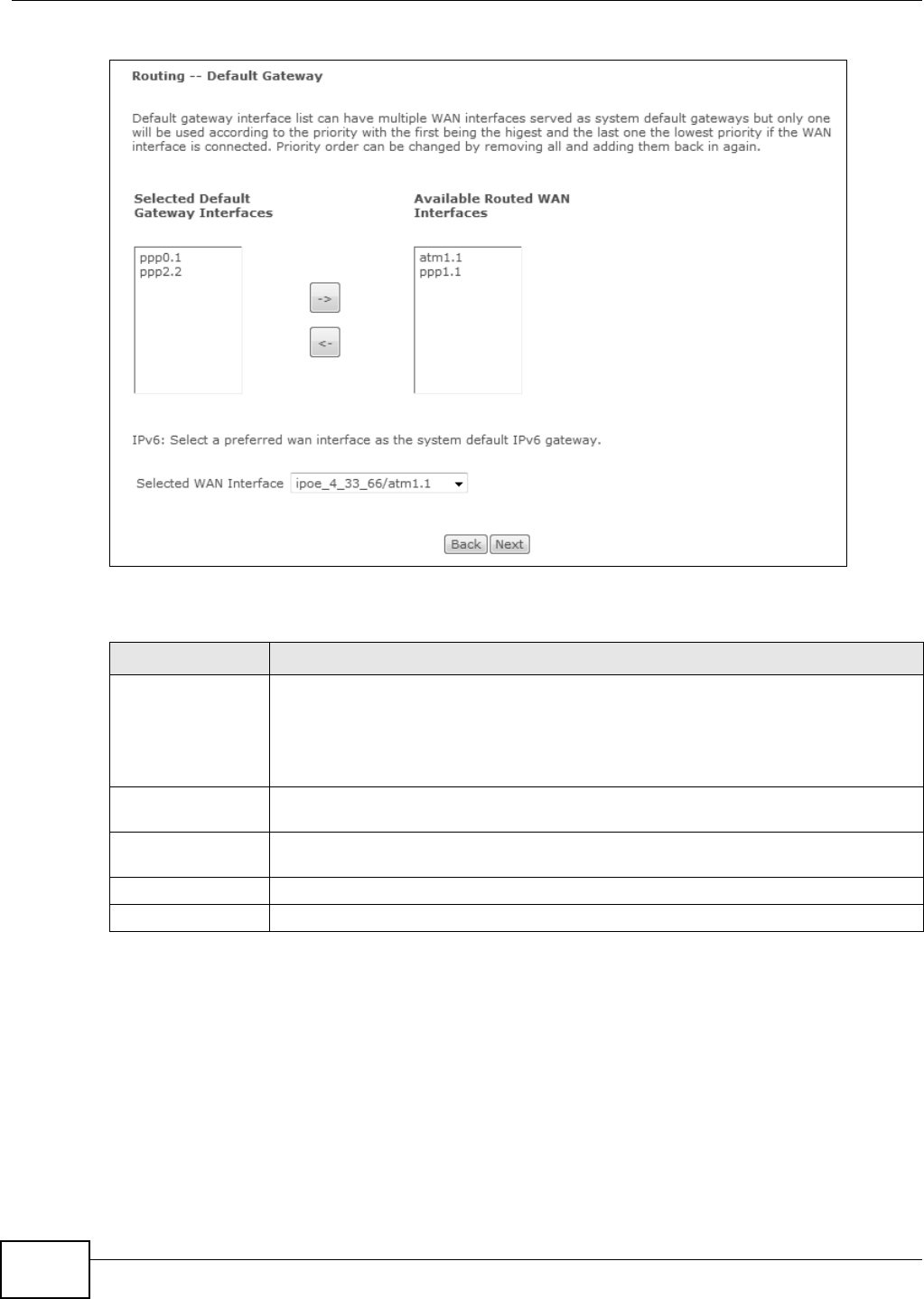
Chapter 4 WAN
Basic Home Station VDSL2 P8802T User’s Guide
94
Figure 28 WAN Configuration: Default Gat eway: PPPoE, PPPoA, I PoE or I PoA
The following t able describes t he labels in t his screen.
4.4.1.6 DNS Server
The screen is not available when you select Bridging in t he W AN Ser vice Configur a tion screen.
Note: I f you configure only one I PoA or I PoE connect ion using the ATM interface on t he
VDSL Router, you m ust enter the st atic DNS server address.
Table 24 WAN Configuration: Default Gateway: PPPoE or I PoE
LABEL DESCRIPTION
Select ed Default
Gat eway I nt er faces
Select a WAN interface through which you want t o forwar d the t raffic.
You can select m ult iple WAN inter faces for the dev ice t o t r y. The VDSL Router t ries the
WAN int erfaces in the order list ed and uses only t he default gat eway of t he first WAN
interface that connect s; there is no backup WAN funct ion. To change t he priority order
rem ove t hem all and add t hem back in again.
Av ailable Rout ed
WAN I nterfaces
These are t he WAN int er faces you can select from .
Select ed WAN
I nterface
Select a WAN interface through which t o forward I Pv6 t raffic.
Back Click this but ton t o ret urn to t he previous screen.
Next Click this butt on to cont inue.
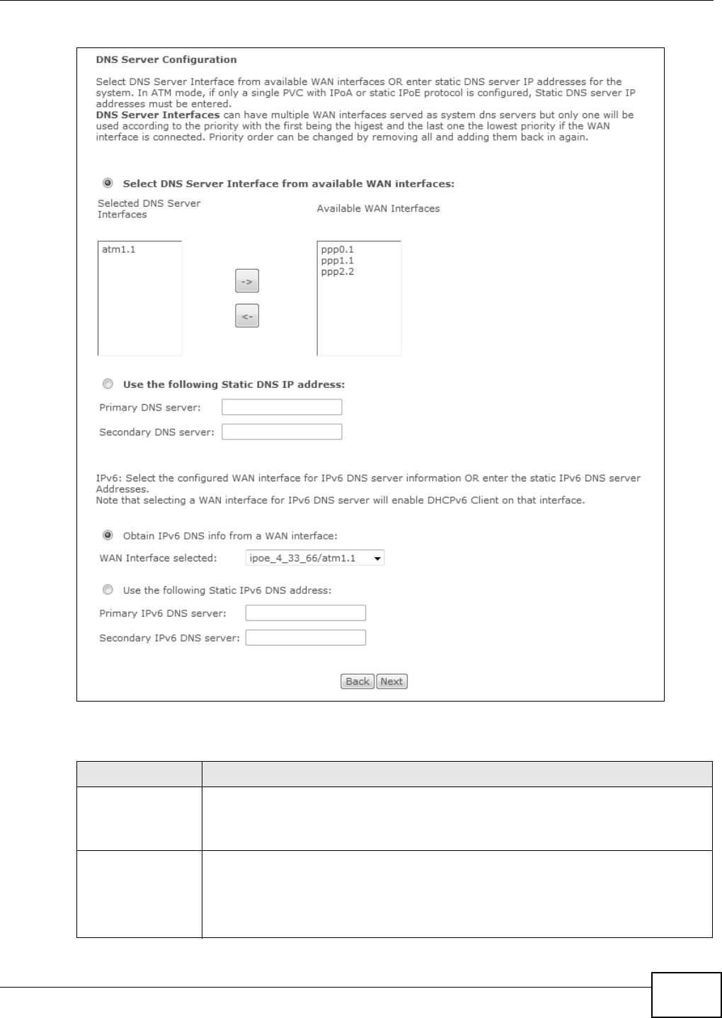
Chapter 4 WAN
Basic Home Station VDSL2 P8802T User’s Guide 95
Figure 29 WAN Configuration: DNS Ser ver: PPPoE, PPPoA, I PoE or I PoA
The following t able describes t he labels in t his screen.
Table 25 WAN Configuration: DNS Server: PPPoE or I PoE
LABEL DESCRIPTION
Select DNS Server
I nter face fr om
available WAN
int erfaces
Select this to have the VDSL Rout er get t he DNS server addresses from one of the
VDSL Router’s WAN interfaces.
Select ed DNS
Server
I nter faces
Select a WAN interface through which t o get DNS ser ver addresses.
You can select m ult iple WAN inter faces for the dev ice t o t ry. The VDSL Router t ries t he
WAN int er faces in the or der list ed and uses only the DNS server information of the first
WAN int er face that connect s; there is no backup WAN funct ion. To change the prior ity
order rem ove t hem all and add t hem back in again.
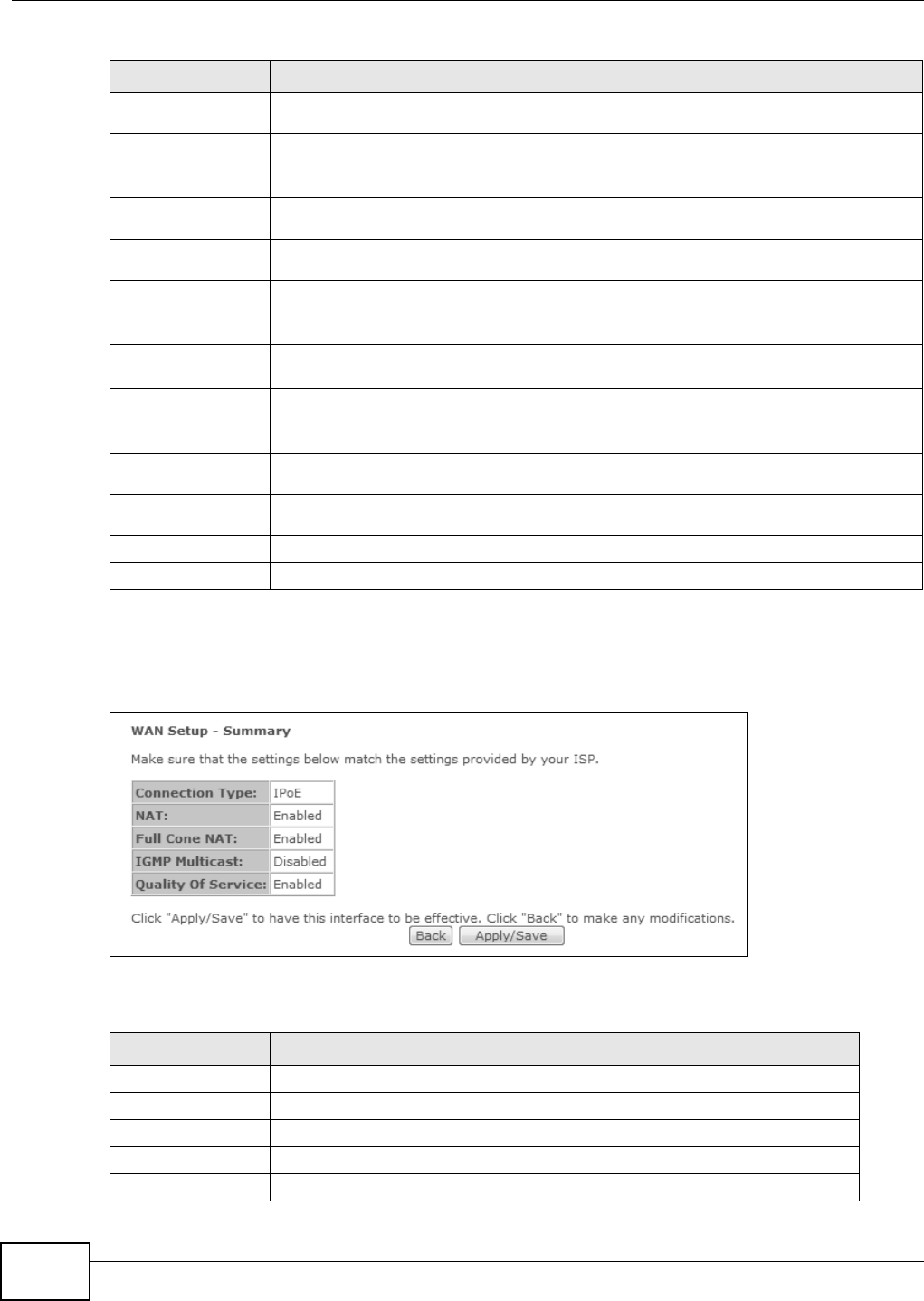
Chapter 4 WAN
Basic Home Station VDSL2 P8802T User’s Guide
96
4.4.1.7 Configuration Summary
This read-only screen show s t he current WAN connect ion set t ings.
Figure 30 WAN Configurat ion: Configurat ion Sum m ary
The following t able describes t he labels in t his screen.
Av ailable WAN
I nter faces
These are t he WAN int er faces you can select from .
Use t he follow ing
St at ic DNS I P
address
Select this to have the VDSL Rout er use t he DNS server addresses you configure
m anually.
Prim ar y DNS
ser ver
Enter t he first DNS server address assigned by the I SP.
Secondary DNS
ser ver
Enter t he second DNS server address assigned by the I SP.
Obtain I Pv6 DNS
info from a WAN
int erface
Select this to have the VDSL Rout er get t he I Pv6 DNS server addresses from t he I SP
aut om at ically.
WAN I nterface
selected
Select a WAN interface through which you want t o obtain t he I Pv6 DNS related
inform at ion.
Use t he follow ing
St at ic I Pv6 DNS
address
Select this to have the VDSL Rout er use the I Pv6 DNS server addresses you configure
m anually.
Primary I Pv6
DNS ser ver
Enter t he first I Pv6 DNS server address assigned by the I SP.
Secondary I Pv6
DNS ser ver
Enter t he second I Pv6 DNS server address assigned by the I SP.
Back Click this but ton t o ret urn to t he previous screen.
Next Click this butt on to cont inue.
Table 25 WAN Configuration: DNS Server: PPPoE or I PoE
LABEL DESCRIPTION
Table 26 WAN Configuration: Configuration Sum m ary
LABEL DESCRIPTION
Connect ion Type This is the encapsulat ion m et hod used by t his connect ion.
NAT This show s whet her NAT is act ive or not for t his connect ion.
Full Cone NAT This shows whet her full cone NAT is act ive or not for t his connect ion.
I GMP Mult icast This show s whet her I GMP m ult icasting is act ive or not for t his connect ion.
Quality Of Service This shows whether QoS is act ive or not for t his connect ion.
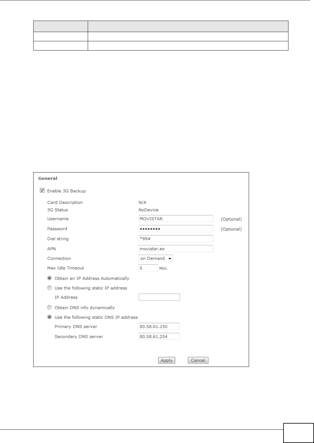
Chapter 4 WAN
Basic Home Station VDSL2 P8802T User’s Guide 97
4.5 The 3G Backup Screen
Use t his screen to configur e your 3G sett ings. Click Net w ork > W AN > 3 G Back up. See Section
2.2 on page 20 for the supported 3G USB dongles.
Note: The actual dat a rat e you obtain varies depending t he 3G card you use, the signal
st rengt h to t he service provider’s base st ation, and so on.
I f t he signal st rengt h of a 3G netw ork is t oo low, the 3G card m ay switch to an available 2.5G or
2.75G net work. Refer to Sect ion 4.6 on page 99 for a com parison bet ween 2G, 2.5G, 2.75G and 3G
wireless t echnologies.
Figure 31 3G Backup
Back Click this but ton t o ret urn to t he previous screen.
Apply/ Save Click this but ton t o save your changes.
Table 26 WAN Configuration: Configuration Sum m ary
LABEL DESCRIPTION

Chapter 4 WAN
Basic Home Station VDSL2 P8802T User’s Guide
98
The following t able describes t he labels in t his screen.
Table 27 3G Backup
LABEL DESCRIPTION
Enable 3G Backup Select this option t o have t he VDSL Router use t he 3G connect ion as your WAN
or a backup when the wired WAN connect ion fails.
Car d Descr iption This field displays the m anufacturer and m odel nam e of your 3G card if you
insert ed one in t he VDSL Router. Ot herwise, it displays N / A.
3G St at us This field displays:
•N oD e vice when no 3G card is insert ed,
•Disabled when the 3G WAN is not act ivat ed,
•Up when the 3G connect ion is up,
•Dow n when the 3G connect ion is down,
•NoResponse when t here is no response from the inserted 3G card,
•I n va lidPI N if t he PI N code you entered in t he W AN > 3 G Ba cku p screen
is not the right one for the 3G card you inser ted,
•N e e dPU K if you enter t he PI N (Personal I dentificat ion Num ber) code
incorrect ly for three t im es and t he SI M card is blocked by your I SP,
•DialFa il when the VDSL Rout er fails t o dial up a 3G connect ion.
• or I n validSI M when the SI M card is dam aged or not inser ted.
Usernam e Type the user nam e ( of up to 70 ASCI I print able charact er s) given to you by
your serv ice provider.
Password Type the passw or d ( of up to 70 ASCI I print able characters) associated w it h t he
user nam e abov e.
Dial st ring Enter t he phone num ber ( dial str ing) used to dial up a connect ion to your
ser vice provider ’s base st at ion. Your I SP should provide the phone num ber.
For ex am ple, * 99# is the dial st ring t o est ablish a GPRS or 3G connect ion in
Ta i w a n .
APN Ent er the APN (Access Point Nam e) provided by your ser vice provider.
Connect ions wit h different APNs m ay provide different ser vices (such as
I nternet access or MMS ( Mult i- Media Messaging Service) ) and charge m et hod.
You can ent er up to 31 ASCI I pr intable charact ers. Spaces are allowed.
Connection Select N aile d Up if you do not want the connect ion t o tim e out .
Select on D em a nd if you do not want the connect ion up all t he time and
specify an idle time-out in t he Ma x I dle Tim eout field.
Max I dle
Tim eout
This value specifies the tim e in m inutes that elapses before t he VDSL Router
automatically disconnect s from the I SP.
0 m eans the I nternet session will not tim eout.
Obtain an I P
Address
Aut om at ically
Select this opt ion I f your I SP did not assign you a fixed I P address.
Use t he follow ing
st at ic I P address
Select this opt ion I f the I SP assigned a fixed I P address.
I P Addr ess Enter your WAN I P address in this field if you selected Use t he follow ing
st at ic I P addr ess.
Obtain DNS info
dynam ically
Select this to have the VDSL Rout er get the DNS server addresses from the I SP
automatically.
Use t he follow ing
st atic DNS I P
address
Select this to have the VDSL Rout er use t he DNS server addresses you
configure m anually.
Prim ar y DNS
ser ver
Enter t he first DNS server address assigned by the I SP.

Chapter 4 WAN
Basic Home Station VDSL2 P8802T User’s Guide 99
4.6 Technical Reference
The following sect ion contains addit ional t echnical inform at ion about the VDSL Router features
described in t his chapt er.
Encapsulation
Be sure t o use t he encapsulat ion met hod required by you r I SP. The VDSL Rout er can wor k in bridge
m ode or routing m ode. When t he VDSL Router is in routing m ode, it support s the following
m et hods.
IP over Ethernet
I P over Et hernet ( I PoE) is an alt ernative t o PPPoE. I P packets are being delivered across an
Et hernet net work, wit hout using PPP encapsulat ion. They are rout ed bet ween t he Ethernet int erface
and the WAN int erface and t hen form atted so that t hey can be underst ood in a bridged
environm ent . For inst ance, it encapsulat es routed Et hernet fram es int o bridged Et hernet cells.
PPP over ATM (PPPoA)
PPPoA st ands for Point to Point Protocol over ATM Adapt at ion Layer 5 (AAL5) . A PPPoA connect ion
funct ions like a dial- up I nt ernet connect ion. The VDSL Router encapsulates the PPP session based
on RFC1483 and sends it t hrough an ATM PVC (Perm anent Virt ual Circuit) t o the I nternet Service
Provider ’s ( I SP) DSLAM ( digital access m ultiplexer). Please refer to RFC 2364 for m ore inform at ion
on PPPoA. Refer to RFC 1661 for m or e inform ation on PPP.
PPP over Ethernet (PPPoE)
Point-t o-Point Protocol over Et hernet (PPPoE) provides access contr ol and billing functionality in a
m anner sim ilar to dial-up services using PPP. PPPoE is an I ETF st andard ( RFC 2516) specifying how
a personal com puter (PC) interact s with a broadband m odem (DSL, cable, wireless, et c.)
connect ion.
For the service provider, PPPoE offers an access and authentication m et hod t hat works with exist ing
access control syst em s (for exam ple RADI US) .
One of t he benefits of PPPoE is t he ability to let you access one of m ultiple net work services, a
funct ion known as dynam ic service select ion. This enables t he service provider to easily create and
offer new I P services for individuals.
Operationally, PPPoE saves significant effort for bot h you and t he I SP or carrier, as it requires no
specific configurat ion of the broadband m odem at t he custom er sit e.
Secondary DNS
ser ver
Enter t he second DNS server address assigned by the I SP.
Apply Click Apply to save your changes back t o the VDSL Rout er.
Cancel Click Ca nce l t o ret ur n t o the previous configuration.
Table 27 3G Backup ( continued)
LABEL DESCRIPTION

Chapter 4 WAN
Basic Home Station VDSL2 P8802T User’s Guide
100
By im plem ent ing PPPoE direct ly on the VDSL Rout er ( rather than individual com puters) , t he
com puters on t he LAN do not need PPPoE soft ware installed, since t he VDSL Router does t hat part
of t he t ask. Furt herm ore, with NAT, all of the LANs’ com puters will have access.
RFC 1483
RFC 1483 describes t wo m et hods for Mult iprot ocol Encapsulat ion over ATM Adapt at ion Layer 5
( AAL5) . The first m et hod allows m ultiplexing of m ult iple protocols over a single ATM virt ual circuit
( LLC- based m ultiplexing) and the second m ethod assum es that each protocol is carried over a
separat e ATM virt ual circuit ( VC- based m ultiplexing). Please refer t o RFC 1483 for m or e det ailed
inform at ion.
Multiplexing
There are t wo conventions to identify what protocols the virtual circuit ( VC) is carrying. Be sure to
use t he m ultiplexing m et hod required by your I SP.
VC- based Mult iplexing
I n this case, by prior m ut ual agreem ent , each prot ocol is assigned to a specific virtual circuit; for
exam ple, VC1 car ries I P, etc. VC- based m ultiplexing m ay be dom inant in environm ent s where
dynam ic creat ion of large num bers of ATM VCs is fast and econom ical.
LLC- based Multiplexing
I n t his case one VC carries m ultiple prot ocols with prot ocol identifying inform at ion being cont ained
in each packet header. Despite t he extra bandw idt h and processing overhead, t his m et hod m ay be
advant ageous if it is not pract ical to have a separat e VC for each carried protocol, for exam ple, if
charging heavily depends on t he num ber of sim ult aneous VCs.
Traffic Shaping
Traffic Shaping is an agreem ent bet ween t he carrier and t he subscriber to regulate the average rat e
and fluct uat ions of data t ransm ission over an ATM net work. This agreem ent helps elim inat e
congest ion, which is im port ant for transm ission of real tim e dat a such as audio and video
connect ions.
Peak Cell Rate ( PCR) is t he m axim um rate at which t he sender can send cells. This param et er m ay
be lower (but not higher) than t he m axim um line speed. 1 ATM cell is 53 bytes ( 424 bit s) , so a
m axim um speed of 832Kbps gives a m aximum PCR of 1962 cells/ sec. This rat e is not guarant eed
because it is dependent on t he line speed.
Sust ained Cell Rat e ( SCR) is the m ean cell rate of each burst y traffic source. I t specifies the
m axim um average rat e at which cells can be sent over t he virtual connect ion. SCR m ay not be
greater than t he PCR.
Maxim um Burst Size ( MBS) is t he m axim um num ber of cells t hat can be sent at t he PCR. After MBS
is reached, cell rat es fall below SCR unt il cell rate averages to t he SCR again. At this t im e, more
cells (up t o the MBS) can be sent at the PCR again.
I f the PCR, SCR or MBS is set t o t he default of "0", the syst em will assign a m axim um value that
correlat es t o your upst ream line rate.
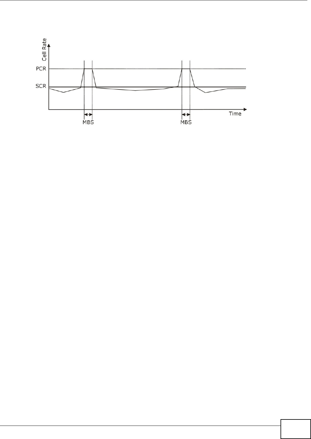
Chapter 4 WAN
Basic Home Station VDSL2 P8802T User’s Guide 101
The following figure illust rat es the relat ionship bet ween PCR, SCR and MBS.
Figure 32 Exam ple of Traffic Shaping
ATM Traffic Classes
These are the basic ATM t raffic classes defined by t he ATM Forum Traffic Managem ent 4.0
Specification.
Constant Bit Rate ( CBR)
Const ant Bit Rate ( CBR) provides fixed bandwidt h t hat is always available even if no dat a is being
sent. CBR traffic is generally tim e- sensitive ( doesn't t olerate delay) . CBR is used for connect ions
that cont inuously require a specific am ount of bandwidt h. A PCR is specified and if traffic exceeds
this rat e, cells m ay be dropped. Examples of connect ions t hat need CBR would be high- resolut ion
video and voice.
Variable Bit Rat e ( VBR)
The Variable Bit Rat e ( VBR) ATM t raffic class is used with burst y connections. Connections that use
the Variable Bit Rat e ( VBR) traffic class can be grouped int o real tim e (VBR-RT) or non-real tim e
( VBR-nRT) connect ions.
The VBR- RT ( real-t im e Variable Bit Rat e) t ype is used wit h burst y connect ions that require closely
controlled delay and delay variat ion. I t also provides a fixed am ount of bandwidth ( a PCR is
specified) but is only available when data is being sent . An exam ple of an VBR-RT connect ion would
be video conferencing. Video conferencing requires real- t im e dat a t ransfers and t he bandwidth
requirem ent varies in proport ion to the video im age's changing dynam ics.
The VBR- nRT ( non real-tim e Variable Bit Rate) t ype is used with bursty connect ions t hat do not
require closely controlled delay and delay variat ion. I t is com m only used for "burst y" t raffic typical
on LANs. PCR and MBS define t he burst levels, SCR defines the m inim um level. An exam ple of an
VBR- nRT connect ion would be non-t im e sensitive dat a file t ransfers.
Unspecified Bit Rat e ( UBR)
The Unspecified Bit Rat e ( UBR) ATM t raffic class is for bursty dat a t ransfers. However, UBR doesn't
guarant ee any bandwidt h and only delivers traffic when t he net work has spare bandwidt h. An
exam ple applicat ion is background file t ransfer.

Chapter 4 WAN
Basic Home Station VDSL2 P8802T User’s Guide
102
IP Address Assignment
A st at ic I P is a fixed I P t hat your I SP gives you. A dynam ic I P is not fixed; t he I SP assigns you a
different one each t im e. The Single User Account feat ure can be enabled or disabled if you have
either a dynam ic or st atic I P. However the encapsulat ion m et hod assigned influences your choices
for I P address and default gat eway.
Introduction to VLANs
A Virtual Local Area Network (VLAN) allows a physical network t o be part itioned int o m ult iple logical
net works. Devices on a logical net work belong to one gr oup. A device can belong to m ore t han one
group. With VLAN, a device cannot direct ly talk to or hear from devices t hat are not in the sam e
group( s) ; the traffic m ust first go through a router.
I n Multi-Tenant Unit ( MTU) applications, VLAN is vital in providing isolat ion and security am ong t he
subscribers. When properly configured, VLAN prevent s one subscriber from accessing t he net work
resources of another on the same LAN, t hus a user will not see t he printers and hard disks of
another user in the sam e building.
VLAN also increases net work perform ance by lim iting broadcast s t o a sm aller and m ore
m anageable logical broadcast dom ain. I n t raditional sw it ched environm ent s, all broadcast packet s
go t o each and every individual port. With VLAN, all broadcast s are confined t o a specific broadcast
dom ain.
Introduction to IEEE 802.1Q Tagged VLAN
A t agged VLAN uses an explicit t ag ( VLAN I D) in t he MAC header to ident ify the VLAN m em bership
of a fram e across bridges - they are not confined to the switch on which they were created. The
VLANs can be creat ed st at ically by hand or dynam ically through GVRP. The VLAN I D associat es a
fram e wit h a specific VLAN and provides t he inform at ion t hat switches need t o process t he fram e
across t he net work. A t agged fram e is four bytes longer than an unt agged fram e and contains two
bytes of TPI D ( Tag Prot ocol I dent ifier ), residing within the t ype/ lengt h field of t he Ethernet fram e)
and two byt es of TCI (Tag Cont rol I nform at ion) , st arts aft er t he source address field of the Ethernet
fram e).
The CFI ( Canonical Form at I ndicat or) is a single- bit flag, always set t o zero for Et hernet sw it ches. I f
a fram e received at an Et hernet port has a CFI set to 1, t hen that fram e should not be forwarded as
it is t o an unt agged port. The rem aining t welve bits define the VLAN I D, giving a possible m axim um
num ber of 4,096 VLANs. Note t hat user priorit y and VLAN I D are independent of each ot her. A
fram e wit h VI D (VLAN I dentifier) of null (0) is called a priority fram e, m eaning t hat only t he priority
level is significant and the default VI D of the ingress port is given as t he VI D of the fram e. Of the
4096 possible VI Ds, a VI D of 0 is used t o ident ify priorit y fram es and value 4095 ( FFF) is reserved,
so the m axim um possible VLAN configurat ions are 4,094.
TPI D
2 Bytes
User Priority
3 Bit s
CFI
1 Bit
VLAN I D
12 Bit s

Chapter 4 WAN
Basic Home Station VDSL2 P8802T User’s Guide 103
Multicast
I P packet s are transm it t ed in either one of t wo ways - Unicast (1 sender - 1 recipient) or Broadcast
( 1 sender - everybody on t he net work) . Mult icast delivers I P packets to a group of host s on t he
net work - not everybody and not j ust 1.
I nt ernet Group Multicast Protocol ( I GMP) is a network-layer prot ocol used t o establish m em bership
in a Mult icast group - it is not used to carry user data. I GMP version 2 (RFC 2236) is an
im provem ent over version 1 (RFC 1112) but I GMP version 1 is st ill in wide use. I f you would like t o
read m ore detailed inform ation about int eroperability bet ween I GMP version 2 and ver sion 1, please
see sections 4 and 5 of RFC 2236. The class D I P address is used t o ident ify host groups and can be
in t he range 224.0.0.0 t o 239.255.255.255. The address 224.0.0.0 is not assigned t o any group
and is used by I P m ulticast com puters. The address 224.0.0.1 is used for query m essages and is
assigned t o t he perm anent group of all I P host s ( including gat eways) . All host s m ust j oin the
224.0.0.1 gr oup in order t o participat e in I GMP. The address 224.0.0.2 is assigned t o t he m ulticast
routers group.
At st art up, the VDSL Rout er queries all direct ly connected net works to gat her group m em bership.
Aft er that, t he VDSL Router periodically updates this inform ation.
DNS Server Address Assignment
Use Dom ain Nam e Syst em ( DNS) to m ap a dom ain name to its corresponding I P address and vice
versa, for inst ance, t he I P address of www.zyxel.com is 204.217.0.2. The DNS server is extrem ely
im port ant because without it , you m ust know the I P address of a com puter before you can access
it .
The VDSL Rout er can get the DNS server addresses in t he following ways.
1The I SP t ells you t he DNS server addresses, usually in the form of an inform at ion sheet, when you
sign up. I f your I SP gives you DNS server addresses, m anually enter t hem in the DNS server fields.
2I f your I SP dynam ically assigns t he DNS server I P addresses ( along with t he VDSL Router’s WAN I P
address) , set the DNS server fields to get the DNS server address from the I SP.
IPv6 Addressing
The 128- bit I Pv6 address is writ ten as eight 16- bit hexadecimal blocks separat ed by colons ( : ) . This
is an exam ple I Pv6 address 2001:0db8:1a2b:0015:0000:0000:1a2f:0000.
I Pv6 addr esses can be abbreviated in tw o ways:
• Leading zeros in a block can be om it t ed. So 2001:0db8:1a2b:0015:0000:0000:1a2f:0000 can
be written as 2001:db8:1a2b:15:0:0:1a2f:0.
• Any num ber of consecutive blocks of zeros can be replaced by a double colon. A double colon can
only appear once in an I Pv6 address. So 2001:0db8:0000:0000:1a2f:0000:0000:0015 can be
writ ten as 2001:0db8::1a2f:0000:0000:0015, 2001:0db8:0000:0000:1a2f::0015,
2001:db8::1a2f:0:0:15 or 2001:db8:0:0:1a2f::15.
IPv6 Prefix and Prefix Length
Sim ilar to an I Pv4 subnet m ask, I Pv6 uses an address prefix to represent t he net work address. An
I Pv6 prefix lengt h specifies how m any m ost significant bit s ( st art from t he left) in the address

Chapter 4 WAN
Basic Home Station VDSL2 P8802T User’s Guide
104
com pose t he net work address. The prefix lengt h is writt en as “ / x” where x is a num ber. For
exam ple,
2001:db8:1a2b:15::1a2f:0/32
m eans that the first 32 bit s ( 2001:db8) is t he subnet prefix.
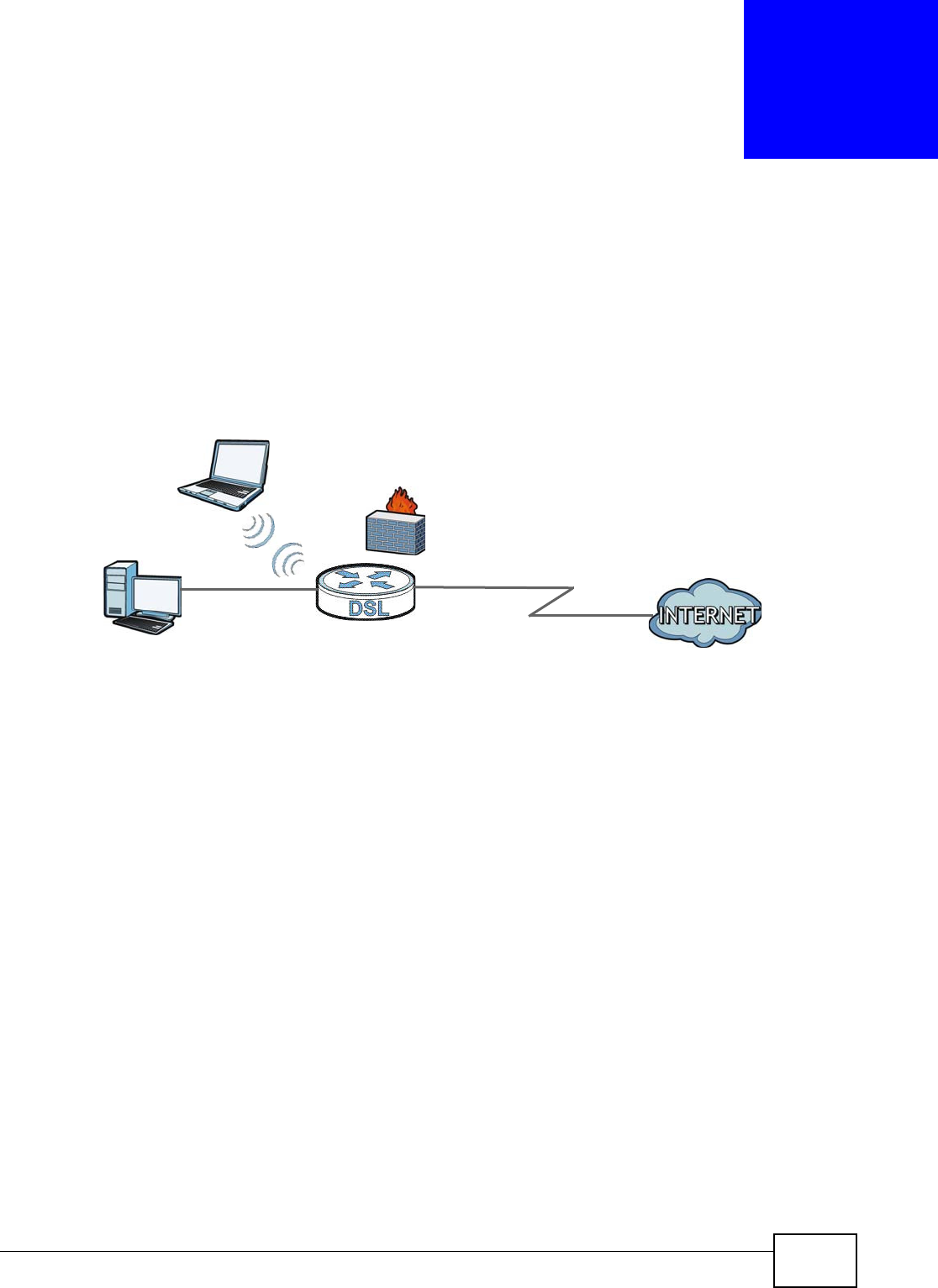
Basic Home Station VDSL2 P8802T User’s Guide 105
CHAPTER 5
LAN Setup
5.1 Overview
A Local Area Network (LAN) is a shared com m unication syst em t o which m any networking devices
are connect ed. I t is usually locat ed in one im m ediat e area such as a building or floor of a building.
Use t he LAN screens to help you configure a LAN DHCP server and m anage I P addresses.
5.1.1 What You Can Do in this Chapter
• Use the LAN Set up scr een t o set t he LAN I P address, subnet m ask, and DHCP sett ings of your
VDSL Rout er ( Sect ion 5.2 on page 106) .
• Use the St a t ic DHCP screen t o assign I P addresses on t he LAN t o specific individual com puters
based on their MAC Addresses (Sect ion 5.2.1 on page 108).
• Use the I Pv6 Aut oconfig screen t o set t he Local Area Network int erface I Pv6 sett ings (Section
5.3 on page 109) .
DSL
LAN

Chapter 5 LAN Setup
Basic Home Station VDSL2 P8802T User’s Guide
106
5.1.2 What You Need To Know
IP Address
I P addresses ident ify individual devices on a net work. Every net working device (including
com puters, servers, rout ers, print ers, etc.) needs an I P address to com m unicate across t he
net work. These net working devices are also known as hosts.
Subnet Mask
Subnet m asks det erm ine t he m axim um number of possible hosts on a netw ork. You can also use
subnet m asks t o divide one net work int o m ultiple sub-networks.
DHCP
A DHCP ( Dynam ic Host Configurat ion Prot ocol) server can assign your VDSL Router an I P address,
subnet m ask, DNS and ot her rout ing infor m at ion when it's turned on.
DNS
DNS ( Dom ain Nam e Syst em ) is for m apping a dom ain nam e t o its corresponding I P address and
vice ver sa. The DNS server is extrem ely im port ant because w it hout it, you m ust know t he I P
address of a networking device before you can access it .
RADVD (Router Advertisement Daemon)
When an I Pv6 host sends a Router Solicitation ( RS) request to discover the available rout ers,
RADVD wit h Router Advert isem ent ( RA) m essages in response t o the request . I t specifies t he
m inim um and m axim um int ervals of RA broadcast s. RA m essages cont aining t he address prefix.
I Pv6 host s can be generated wit h the I Pv6 prefix an I Pv6 address.
Finding Out More
See Sect ion 5.4 on page 111 for technical background infor m at ion on LANs.
5.1.3 Before You Begin
Find out t he MAC addresses of your net work devices if you intend to add t hem to the DHCP Client
List screen.
5.2 The LAN Setup Screen
Click Adva nce d Se tup > LAN to open the LAN Se t up screen. Use t his screen to set t he Local Area
Network int erface sett ings.
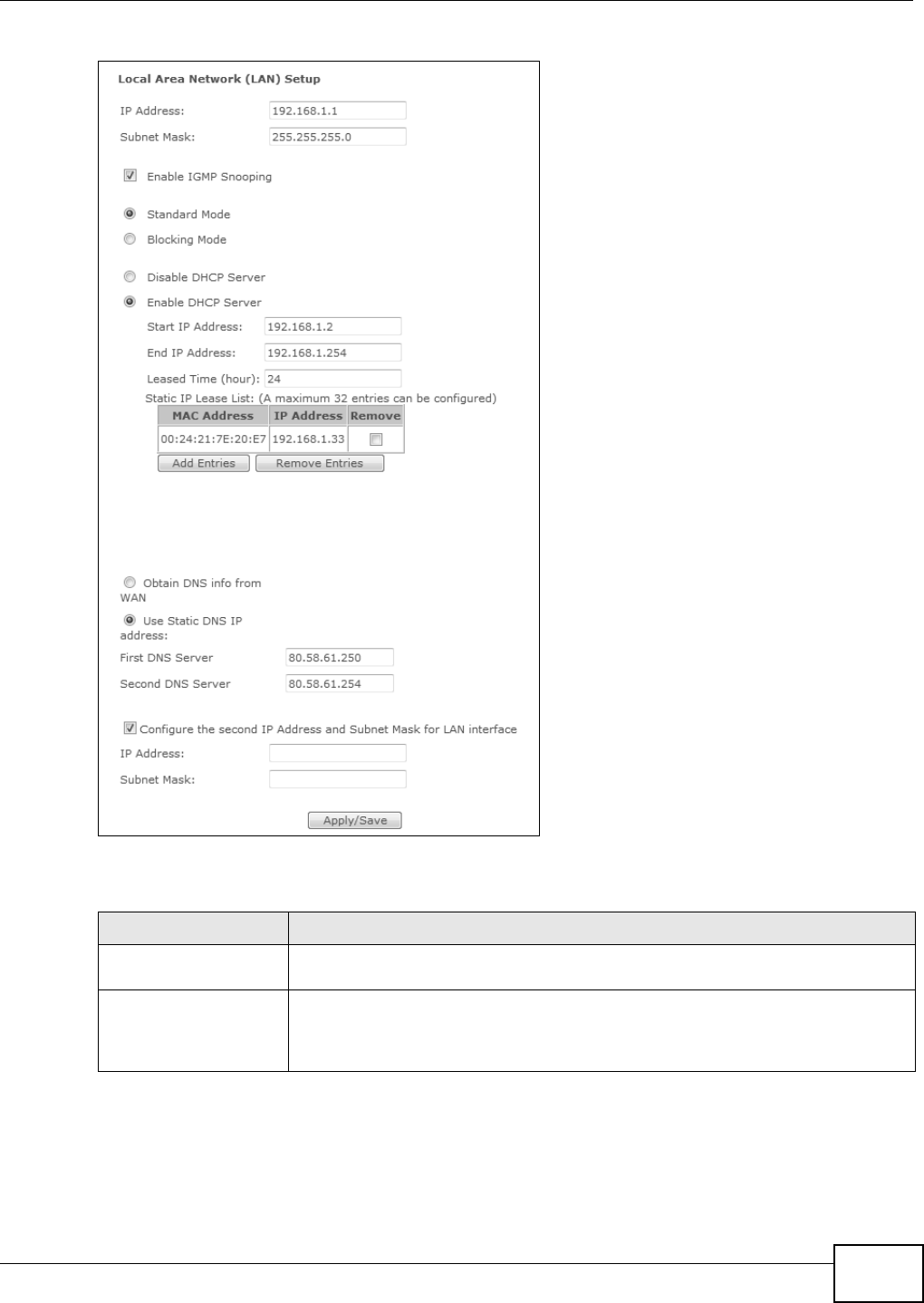
Chapter 5 LAN Setup
Basic Home Station VDSL2 P8802T User’s Guide 107
Figure 33 LAN Setup
The following t able describes t he fields in this screen.
Table 28 LAN Set up
LABEL DESCRIPTION
I P Address Enter t he LAN I P address t o assign t o your VDSL Rout er in dot t ed decim al not ation,
for exam ple, 192.168.1.1 (fact ory default) .
Subnet Mask Type t he subnet m ask of your net work in dotted decim al notation, for exam ple
255.255.255.0 (fact ory default ). Your VDSL Router autom at ically com putes t he
subnet mask based on the I P Address you ent er, so do not change t his field unless
you are inst ructed to do so.

Chapter 5 LAN Setup
Basic Home Station VDSL2 P8802T User’s Guide
108
5.2.1 Add DHCP Static IP Lease Screen
Click Add Entries in t he LAN Se t up scr een t o display the following screen.
Enable I GMP Snooping Enable I GMP snooping to have t he VDSL Router passively learn m em berships in
m ult icast groups.
Select St an dard Mode t o have t he VDSL Rout er forwar d m ult icast packet s t o a port
that joins t he m ult icast group and broadcast unknow n m ult icast packet s from the
WAN to all LAN ports.
Select Block in g M ode t o have the VDSL Rout er block all unknown m ult icast
packet s from t he WAN.
Disable DHCP Server Select this to have the VDSL Router not provide DHCP services. Users m ust
configure LAN devices wit h m anual net wor k set tings if you do not have anot her
DHCP server on the net work.
Enable DHCP Server Select t his to have t he VDSL Rout er serve as the DHCP server for t he net work to
assign I P addresses and provide subnet m ask, gat eway, and DNS server inform at ion
to LAN devices.
St art I P Address This field specifies t he first of the contiguous addresses in the I P address pool.
End I P Address This field specifies t he last of t he contiguous addresses in the I P address pool.
DHCP Server Lease
Tim e
Specify for how m any hours to assign an I P address to a LAN dev ice before m aking
it available for reassignm ent t o ot her system s.
St at ic I P Lease List Use this table t o assign I P addresses on the LAN to specific com puters based on
their MAC Addresses.
MAC Address The MAC ( Media Access Cont rol) of a LAN device to w hich the ent ry’s I P address is
assigned.
I P Addr ess This field displays the I P address reserved for t he LAN device with the entr y ’s MAC.
Rem ove Select entr ies and click the Re m ove Ent r ie s button t o delet e t hem.
Add Ent ries Click this butt on to creat e a new st atic I P lease entry.
Obtain DNS info from
WAN
Select t his to have the VDSL Rout er get the Dom ain Nam e Syst em (DNS) server
addr esses fr om t he VDSL Rout er’s WAN inter face.
Use Static DNS I P
address
Select this to have the VDSL Rout er use the DNS server addresses you configure
m anually.
Fir st DNS Server,
Second DNS Ser ver
Enter t he first and second DNS (Dom ain Nam e Syst em ) server I P address t he VDSL
Router passes to t he DHCP client s.
Configure the second I P
Address and Subnet
Mask for LAN int erface
Select t he check box t o use I P alias t o configure anot her LAN net wor k for t he VDSL
Rou t er .
I P alias partitions a physical net work int o different logical net works over t he sam e
Et hernet interface. The VDSL Rout er suppor t s m ult iple logical LAN interfaces via it s
physical Ethernet int er face wit h t he VDSL Rout er it self as the gat eway for the LAN
net work. You can also configure firewall rules to cont rol access to t he LAN's logical
net work ( subnet ).
I P Addr ess Ent er t he second LAN I P address of your VDSL Rout er in dot t ed decim al not at ion.
Subnet Mask Ty pe t he subnet mask of your net wor k in dot ted decim al notation, for exam ple
255.255.255.0 ( fact ory default ).
Apply/ Save Click this but ton t o save your changes.
Table 28 LAN Set up (cont inued)
LABEL DESCRIPTION
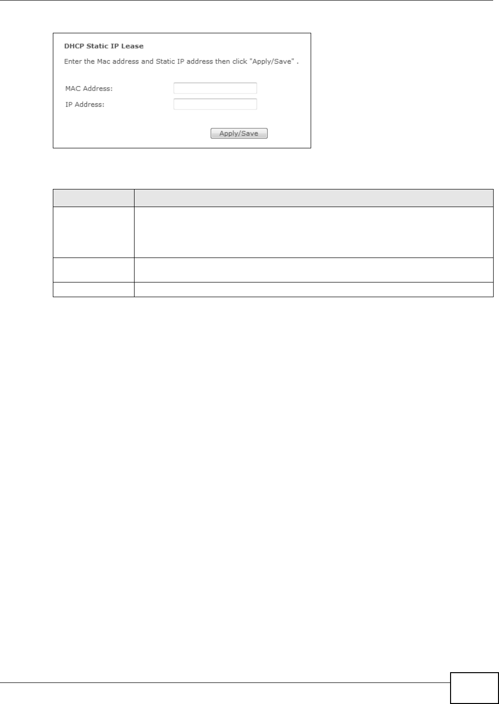
Chapter 5 LAN Setup
Basic Home Station VDSL2 P8802T User’s Guide 109
Figure 34 Stat ic DHCP: Add/ Edit
The following t able describes t he labels in t his screen.
5.3 The IPv6 LAN Auto Configuration Screen
Click Advanced Se t up > LAN > I Pv6 Autoconfig to open the I Pv6 LAN Aut o Con figurat ion
screen. Use t his screen to set the Local Area Network int erface I Pv6 set t ings.
Table 29 St at ic DHCP: Add/ Edit
LABEL DESCRIPTION
MAC Address Enter t he MAC address of a com puter on your LAN.
Every Ethernet device has a unique MAC (Media Access Cont rol) address. The MAC
address is assigned at t he fact ory and consist s of six pairs of hexadecim al charact ers, for
exam ple, 00: A0: C5: 00: 00: 02.
I P Address Enter t he I P address t hat you want to assign t o the com puter on your LAN wit h t he MAC
address t hat you w ill also specify.
Apply/ Save Click t his butt on to save your changes and go back t o the previous screen.
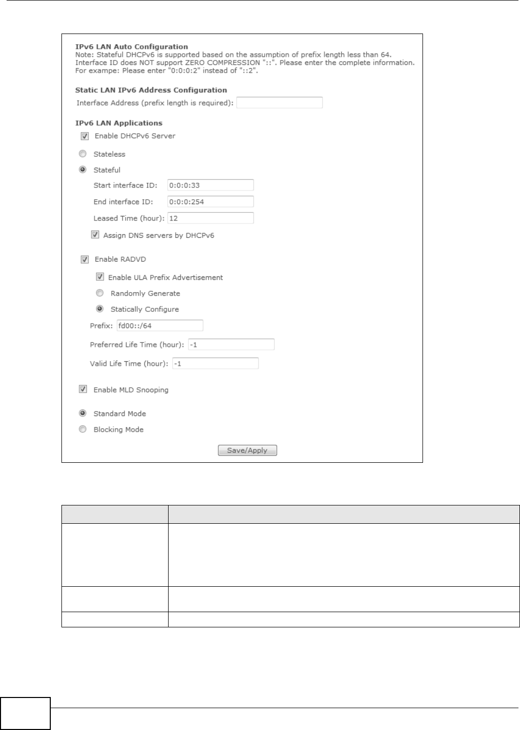
Chapter 5 LAN Setup
Basic Home Station VDSL2 P8802T User’s Guide
110
Figure 35 I Pv6 LAN Aut o Configurat ion
The following t able describes t he fields in this screen.
Table 30 I Pv6 LAN Aut o Configurat ion
LABEL DESCRIPTION
I nter face Address To use a st at ic I Pv6 address, ent er t he I Pv6 addr ess prefix and prefix length that the
VDSL Rout er uses for the LAN I Pv6 address.
The I Pv6 prefix length specifies how many m ost significant bit s (st art ing from the
left ) in t he address com pose the net work addr ess. This field displays the bit num ber
of the I Pv6 subnet m ask.
Enable DHCPv6 Server Select t his to have t he VDSL Rout er act as a DHCPv6 ser ver and pass I Pv6
addr esses, DNS ser ver and dom ain nam e inform ation t o DHCPv6 client s.
St at eless Select this t o have t he VDSL Router use I Pv6 st at eless aut oconfigurat ion.

Chapter 5 LAN Setup
Basic Home Station VDSL2 P8802T User’s Guide 111
Network Co nnections: My Netw ork Places: Proper ties: Example
5.4 Technical Reference
This sect ion provides some technical background inform at ion about the topics covered in this
chapt er.
St at eful Select t his t o have t he VDSL Rout er use I Pv6 stat eful autoconfiguration.
St art int er face I D: specify the first I Pv6 addr ess in the pool of addr esses that can
be assigned to DHCPv6 clients.
End inte rface I D: specify the last I Pv6 address in the pool of addresses t hat can
be assigned to DHCPv6 clients.
Le ase d Tim e ( hour ) : Specify for how many hours t o assign an I Pv6 address to a
DHCPv6 client before m ak ing it available for reassignm ent t o ot her syst em s.
Assign DNS servers
by DHCPv6
Select this to have t he VDSL Rout er pass DNS server inform ation t o DHCPv6 client s.
Enable RADVD Select t his to have t he VDSL Rout er send r out er advertisem ent m essages t o t he
LAN host s.
Router advert isem ent is a response t o a rout er solicitat ion or a periodical m ult icast
advert isem ent from a rout er to advert ise it s presence and other param et ers, such
as I Pv6 prefix and DNS inform at ion. Router solicit at ion is a request from a host to
locat e a rout er that can act as the default rout er and forward packets.
Note: The LAN hosts neither generate global IPv6 addresses nor communicate with
other networks if you disable this feature.
Enable ULA Prefix
Advertisem ent
Select this to send Unique Local I Pv6 Unicast Addresses ( ULA) advert isem ent
m essages t o the LAN host s.
Random ly Generat e Select t his to aut om atically cr eate a LAN I Pv6 address prefix.
St at ically Configure Select this to send a fixed LAN I Pv6 address prefix.
Prefix : enter t he I Pv6 prefix and length the VDSL Rout er uses to generate t he LAN
I Pv6 address. The prefix lengt h specifies how m any most significant bit s (st arting
from the left) in the address com pose t he netw ork address. This field displays the
bit num ber of the I Pv6 subnet m ask.
Prefe rre d Life Tim e ( h our) : enter t he preferr ed lifet im e for the prefix.
Valid Life Tim e ( h ou r) : ent er t he valid lifet im e for the prefix.
Enable MLD Snooping Select t his to have t he VDSL Router check Multicast List ener Discovery ( MLD)
packet s t o learn t he m ult icast group m em bership. This helps reduce m ult icast
traffic.
St andard Mode Select t his to have t he VDSL Rout er forward m ult icast packet s t o a port t hat j oins
the m ult icast group and broadcast unknown m ult icast packet s from t he WAN to all
LAN port s.
Block ing Mode Select this to have the VDSL Rout er block all unknown m ult icast packet s from the
WAN.
Save/ Apply Click this but ton to save your changes.
Table 30 I Pv6 LAN Aut o Configurat ion ( continued)
LABEL DESCRIPTION
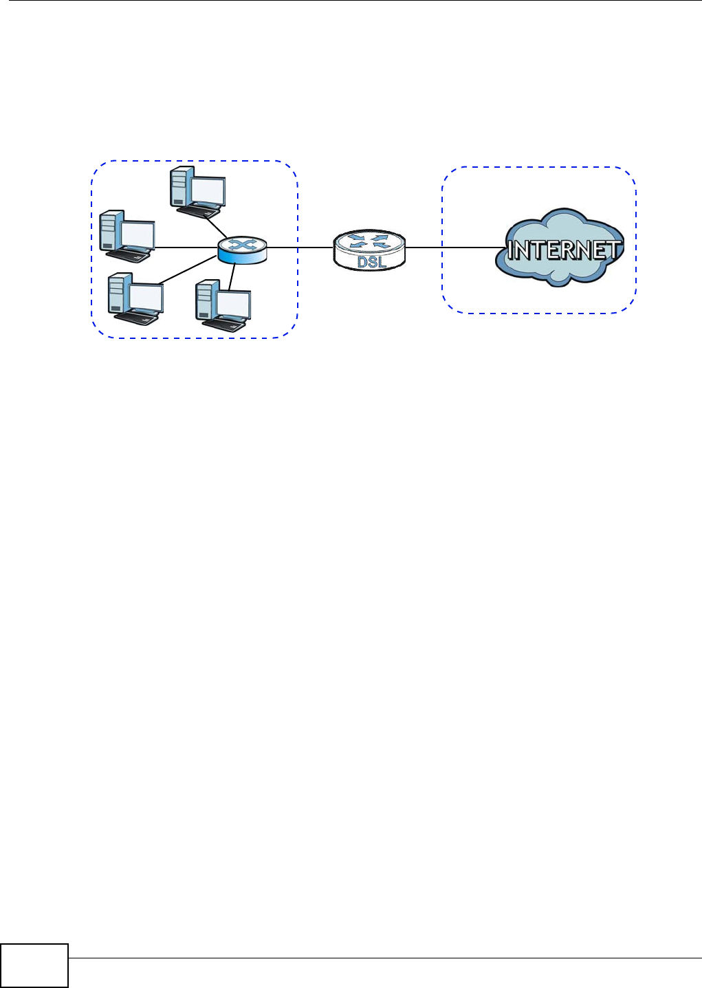
Chapter 5 LAN Setup
Basic Home Station VDSL2 P8802T User’s Guide
112
5.4.1 LANs, WANs and the VDSL Router
The act ual physical connect ion determ ines whether the VDSL Router port s are LAN or WAN ports.
There are t wo separate I P networks, one inside the LAN net work and the ot her outside the WAN
net work as shown next.
Figure 36 LAN and WAN I P Addresses
5.4.2 DHCP Setup
DHCP (Dynam ic Host Configuration Protocol, RFC 2131 and RFC 2132) allows individual clients to
obt ain TCP/ I P configuration at start -up from a server. You can configure t he VDSL Router as a DHCP
server or disable it . When configured as a server, the VDSL Router pr ovides the TCP/ I P
configuration for the client s. I f you t urn DHCP service off, you m ust have another DHCP server on
your LAN, or else t he computer m ust be m anually configured.
IP Pool Setup
The VDSL Rout er is pre- configured with a pool of I P addresses for t he DHCP clients ( DHCP Pool) .
See t he product specificat ions in the appendices. Do not assign st at ic I P addresses from t he DHCP
pool to your LAN com puters.
5.4.3 DNS Server Addresses
DNS ( Dom ain Nam e Syst em ) m aps a dom ain nam e t o its corresponding I P address and vice versa.
The DNS ser ver is extrem ely im portant because wit hout it, you m ust know the I P address of a
com puter before you can access it. The DNS server addresses you enter when you set up DHCP are
passed t o t he client m achines along with the assigned I P address and subnet m ask.
There are t wo ways t hat an I SP dissem inat es t he DNS server addresses.
• The I SP t ells you t he DNS server addresses, usually in the form of an inform at ion sheet , when
you sign up. I f your I SP gives you DNS server addresses, enter them in t he DN S Ser ve r fields in
the DHCP Se t up screen.
WAN
LAN

Chapter 5 LAN Setup
Basic Home Station VDSL2 P8802T User’s Guide 113
• Som e I SPs choose t o dissem inat e t he DNS server addresses using t he DNS server extensions of
I PCP (I P Cont rol Protocol) aft er the connection is up. I f your I SP did not give you explicit DNS
servers, chances are the DNS servers ar e conveyed through I PCP negot iat ion. The VDSL Router
supports t he I PCP DNS server extensions t hrough t he DNS proxy feat ure.
Please note t hat DNS proxy w orks only when t he I SP uses t he I PCP DNS server extensions. I t
does not m ean you can leave t he DNS servers out of t he DHCP set up under all circum st ances. I f
your I SP gives you explicit DNS server s, m ake sure t hat you ent er their I P addresses in t he
DHCP Se t up scr een.
5.4.4 LAN TCP/IP
The VDSL Router has built- in DHCP server capability that assigns I P addresses and DNS servers to
syst em s t hat support DHCP client capability.
IP Address and Subnet Mask
Sim ilar to the way houses on a st reet share a com mon street name, so too do com put ers on a LAN
share one comm on network num ber.
Wher e you obtain your net work num ber depends on your particular situation. I f t he I SP or your
net work adm inist rat or assigns you a block of registered I P addresses, follow their inst ructions in
select ing t he I P addresses and t he subnet m ask.
I f t he I SP did not explicitly give you an I P network number, t hen m ost likely you have a single user
account and t he I SP will assign you a dynam ic I P address when t he connect ion is est ablished. I f t his
is t he case, it is recom m ended that you select a net work num ber from 192.168.0.0 t o
192.168.255.0 and you m ust enable the Netw ork Addr ess Translat ion (NAT) feat ure of the VDSL
Router. The I nt ernet Assigned Num ber Authority (I ANA) reserved this block of addresses
specifically for private use; please do not use any ot her num ber unless you are told otherwise. Let 's
say you select 192.168.1.0 as t he net work num ber; w hich covers 254 individual addresses, from
192.168.1.1 to 192.168.1.254 ( zero and 255 are reserved). I n ot her words, t he first t hree number s
specify the network num ber while t he last num ber identifies an individual com put er on that
net work.
Once you have decided on t he net work num ber, pick an I P address t hat is easy t o rem em ber, for
inst ance, 192.168.1.1, for your VDSL Router, but m ake sure that no other device on your net work
is using t hat I P address.
The subnet m ask specifies the net work num ber portion of an I P address. Your VDSL Router will
com pute t he subnet m ask autom at ically based on t he I P address that you entered. You don't need
to change the subnet m ask com puted by t he VDSL Router unless you are inst ruct ed t o do
ot herwise.
Private IP Addresses
Ever y m achine on the I nternet m ust have a unique address. I f your net works are isolated from the
I nt ernet , for exam ple, only between your two branch offices, you can assign any I P addr esses to
the host s without problem s. However, the I nt ernet Assigned Num bers Aut horit y ( I ANA) has
reserved the following t hree blocks of I P addresses specifically for private net works:
• 10.0.0.0 — 10.255.255.255
• 172.16.0.0 — 172.31.255.255

Chapter 5 LAN Setup
Basic Home Station VDSL2 P8802T User’s Guide
114
• 192.168.0.0 — 192.168.255.255
You can obtain your I P address from the I ANA, from an I SP or it can be assigned from a privat e
net work. I f you belong t o a sm all organizat ion and your I nternet access is through an I SP, the I SP
can provide you with the I nternet addresses for your local networks. On t he ot her hand, if you are
part of a m uch larger organization, you should consult your net work adm inist rat or for t he
appropriate I P addresses.
Note: Regardless of your particular situat ion, do not create an arbit rary I P address;
always follow t he guidelines above. For m ore inform at ion on address assignm ent,
please refer to RFC 1597, “Address Allocation for Privat e I nternet s” and RFC 1466,
“ Guidelines for Managem ent of I P Address Space”.

Basic Home Station VDSL2 P8802T User’s Guide 115
CHAPTER 6
Network Address Translation (NAT)
6.1 Overview
This chapt er discusses how t o configure NAT on the VDSL Router.
Network Address Translation ( NAT, RFC 1631) is t he t ranslation of the I P address of a host in a
packet, for exam ple, t he source address of an outgoing packet, used within one net work t o a
different I P address known within another network.
6.1.1 What You Can Do in this Chapter
• Use the Vir t ua l Servers screen t o forward incom ing service requests t o t he server(s) on your
local net work ( Sect ion 6.3 on page 115) .
• Use the D MZ H ost screen t o configure a default server (Sect ion 6.4 on page 118) .
6.2 What You Need to Know
The following t erm s and concept s m ay help as you read t hrough this chapt er.
NAT
I n the sim plest form , NAT changes the source I P address in a packet received from a subscriber
( the inside local address) t o anot her ( t he inside global address) befor e forwarding t he packet t o t he
WAN side. When t he response com es back, NAT translates t he dest inat ion address ( t he inside
global address) back to the inside local address before forwarding it to the original inside host .
Virtual Servers
A virt ual server set is a list of inside (behind NAT on the LAN) servers, for exam ple, web or FTP, that
you can m ake visible to the out side world even though NAT m akes your whole inside netw ork
appear as a single com puter to the outside world.
6.3 The Virtual Servers Screen
Click Advance d Setup > N AT t o open the Virt ua l Se rver s screen. Use t his screen t o m anage the
list of virt ual ser ver rules.
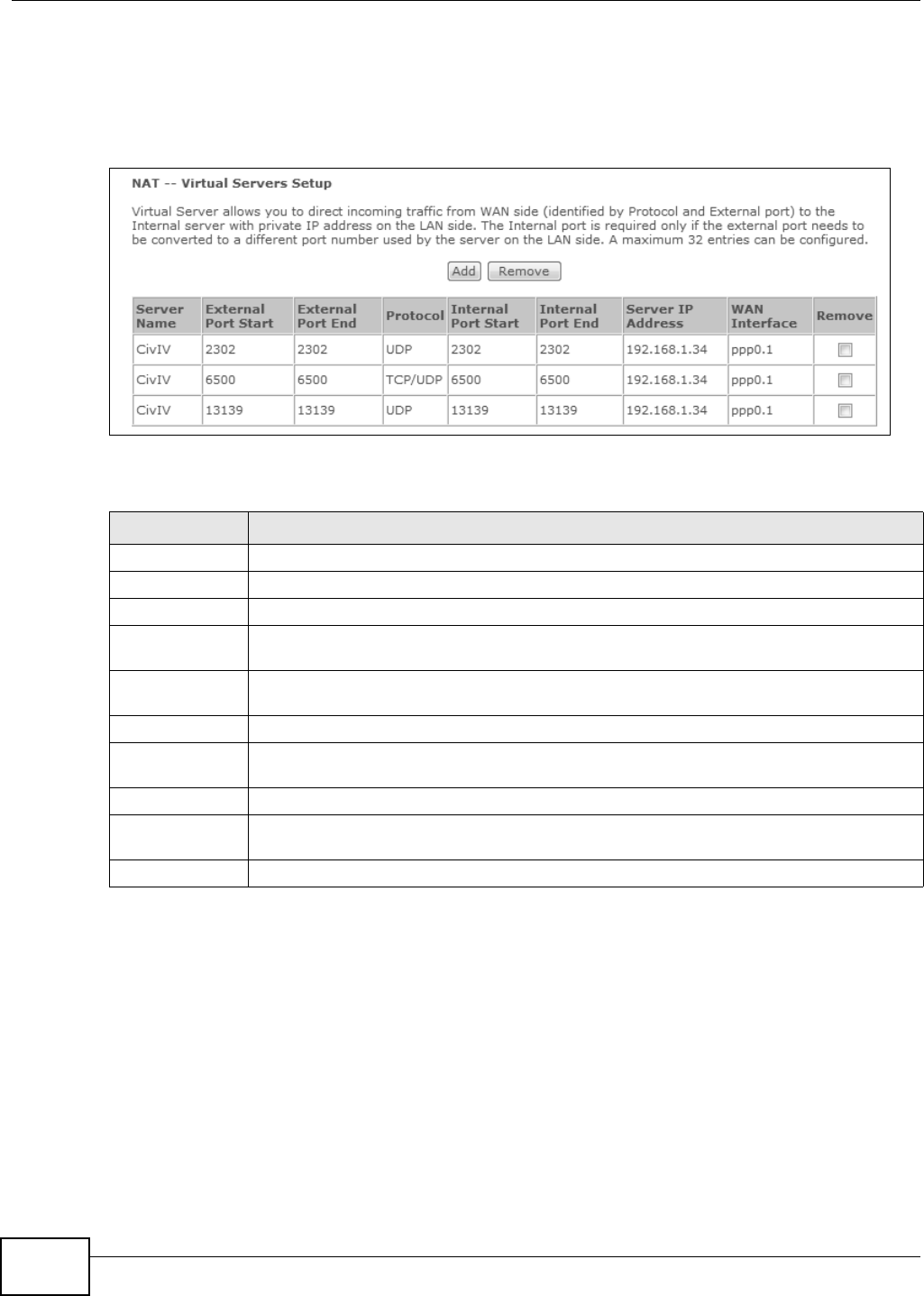
Chapter 6 Network Address Translation (NAT)
Basic Home Station VDSL2 P8802T User’s Guide
116
Note: Many residential broadband I SP account s do not allow you t o run any server
processes ( such as a Web or FTP server) from your location. Your I SP m ay
periodically check for servers and m ay suspend your account if it discovers any
act ive services at your location. I f you are unsure, refer to your I SP.
Figure 37 NAT Virt ual Servers
The following t able describes t he labels in t his screen.
6.3.1 The Virtual Servers Add Screen
This screen let s you create or edit a virtual server rule. Click Add in the V irt ual Server s screen t o
open t he following screen.
You m ay ent er a single port num ber or a range of port num bers t o be forwarded, and t he local I P
address of t he desired server. The por t number identifies a service; for exam ple, web service is on
port 80 and FTP on port 21. I n som e cases, such as for unknown services or where one server can
support m ore t han one service ( for exam ple bot h FTP and web service), it m ight be bet t er to
specify a range of port num bers. You can allocat e a server I P address t hat corresponds t o a port or
a range of ports.
Table 31 NAT Virtual Servers
LABEL DESCRIPTION
Add Click this but ton t o cr eate a new entr y.
Rem ove Select ent ries and click the Re m ove butt on to delet e them .
Ser ver Nam e This field displays the nam e of the ser vice used by the packet s for this virt ual server.
Ext ernal Por t
St art
This is t he first ext ernal port num ber t hat identifies a service.
Ext ernal Por t
End
This is t he last ext ernal port num ber t hat ident ifies a serv ice.
Protocol This show w het her t he virtual server applies t o TCP traffic, UDP t raffic, or both.
I nter nal Port
St art
This is t he first inter nal port number that ident ifies a service.
I nt er nal Port En d This is t he last int ernal port num ber that identifies a ser vice.
Ser ver I P
Address
This field displays the inside I P addr ess of t he server.
WAN I nterface This field displays the WAN int erface through which the serv ice is forwarded.
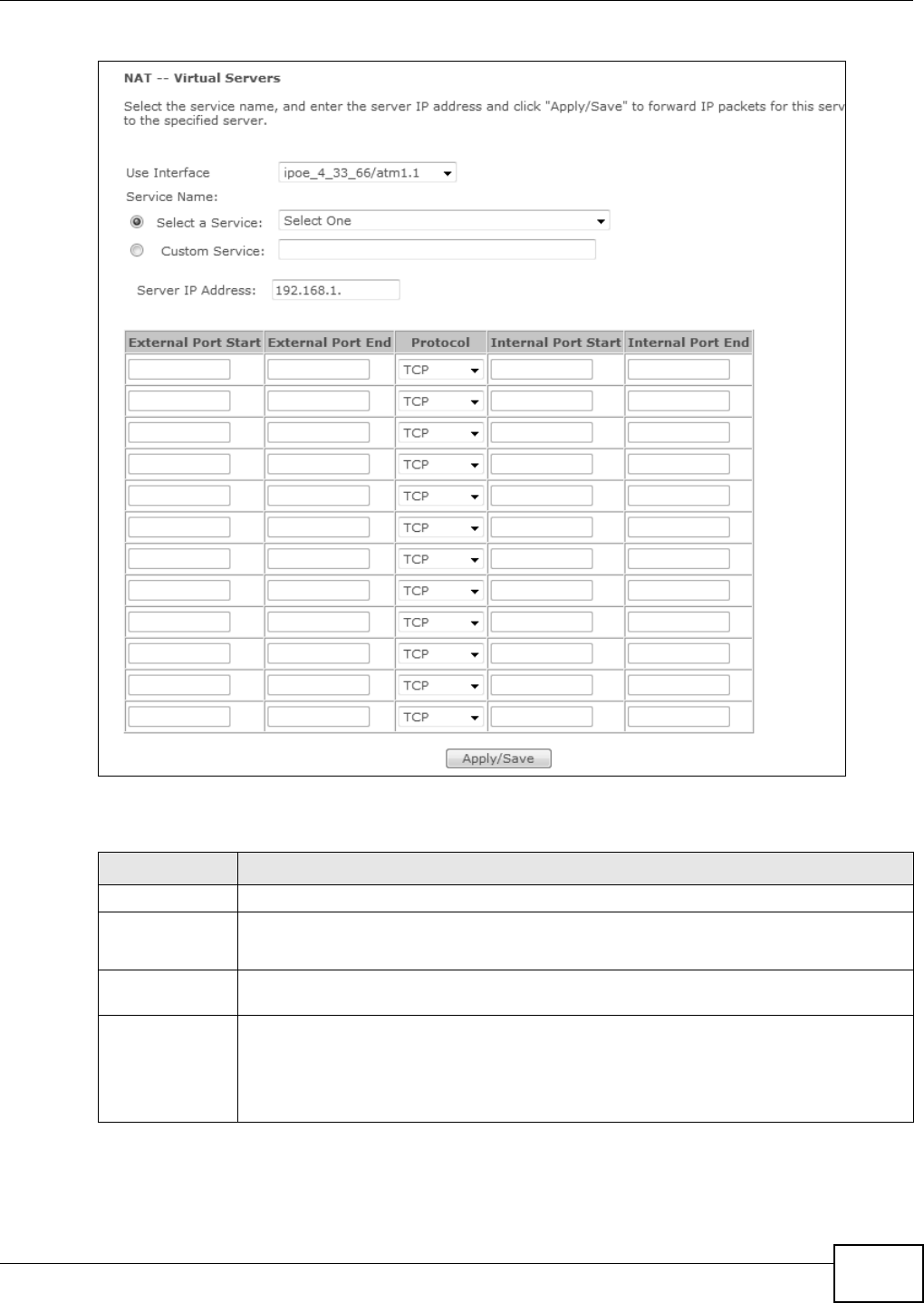
Chapter 6 Network Address Translation (NAT)
Basic Home Station VDSL2 P8802T User’s Guide 117
Figure 38 Virtual Ser vers Add
The following t able describes t he labels in t his screen.
Table 32 Virtual Servers Add
LABEL DESCRIPTION
Use I nt er face Select a WAN int erface for which you want to configure a virtual server rules.
Service Name Select a Service: use the drop- down list to select a service.
Cust om Service: t ype a nam e to specify a different service.
Ser ver I P
Address
Enter t he inside I P address of the LAN device to w hich the virt ual server for wards traffic.
Ext ernal Por t
St art
Enter t he original dest ination port for the packet s.
To forward only one port , ent er the por t num ber again in t he Ex te rna l En d Por t field.
To forward a ser ies of port s, enter t he st art port num ber here and t he end port num ber in
the Ext er nal End Por t field.
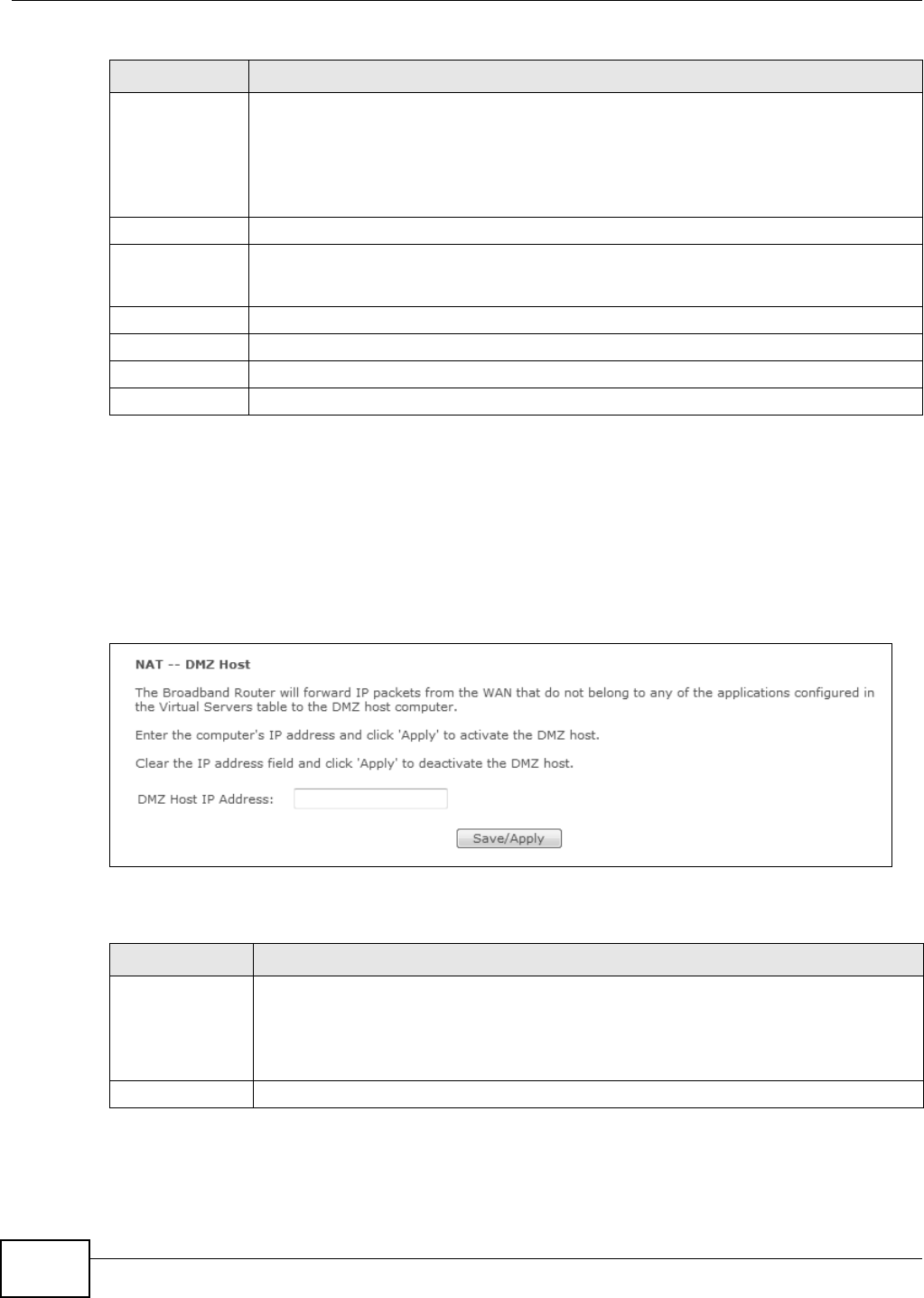
Chapter 6 Network Address Translation (NAT)
Basic Home Station VDSL2 P8802T User’s Guide
118
6.4 The DMZ Host Screen
Click Advanced Se t up > N AT > DMZ H ost to open t he D MZ H ost screen. Use t his screen t o
specify the I P address of a default server t o receive packet s from ports not specified in t he Vir tua l
Se rvers screen.
Figure 39 DMZ Host
The following t able describes t he fields in this screen.
Ext ernal Por t
End
Enter t he last port of t he original dest inat ion port range.
To forward only one port , ent er the port num ber in the Ex te rna l St ar t Port field above
and t hen enter it again in this field.
To forward a series of ports, enter t he last port num ber in a series that begins wit h t he port
num ber in t he Ex te rna l St art Port field above.
Protocol Select the prot ocol suppor ted by this virt ual server. Choices ar e TCP, UDP, or TCP/ UD P.
I nter nal Port
St art
Enter t he port num ber here t o which you want t he VDSL Rout er t o t ranslat e t he incom ing
port . For a range of port s, ent er t he first num ber of the range t o which you want t he
incoming ports translat ed.
I nt er nal Port En d Enter t he last por t of t he translat ed por t range.
Back Click Ba ck to ret urn t o the previous screen.
Apply Click Apply to save your changes back t o the VDSL Rout er.
Cancel Click Ca nce l t o begin configuring t his screen afresh.
Table 32 Virtual Servers Add ( continued)
LABEL DESCRIPTION
Table 33 DMZ Host
LABEL DESCRIPTION
DMZ Host I P
Address
Enter t he I P address of the default server which receives packet s from ports that are not
specified in the Virt ual Se rve rs screen.
Note: If you do not assign a default server, the VDSL Router discards all packets received
for ports not specified in the virtual server configuration.
Save/ Apply Click t his to save your changes back to t he VDSL Rout er.
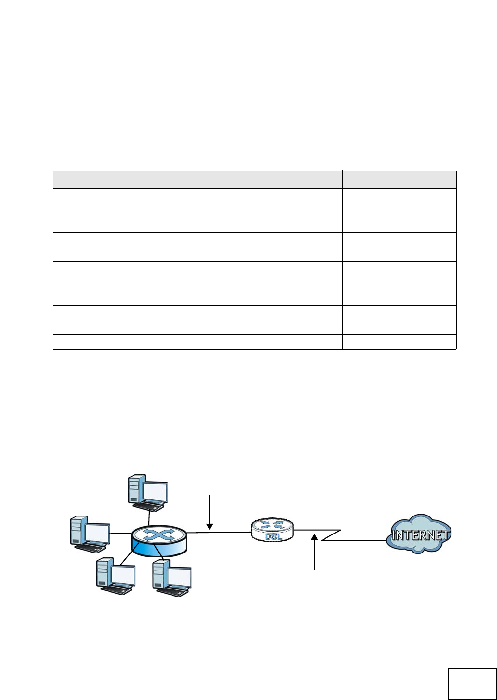
Chapter 6 Network Address Translation (NAT)
Basic Home Station VDSL2 P8802T User’s Guide 119
6.5 Technical Reference
The following sect ion contains addit ional t echnical inform at ion about the VDSL Router features
described in t his chapt er.
Virtual Server: Services and Port Numbers
The m ost oft en used port num bers are shown in t he following t able. Please refer t o RFC 1700 for
further inform ation about port num bers. Please also refer t o t he Support ing CD for m ore exam ples
and det ails on port forwarding and NAT.
Virtual Server Example
Let 's say you want to assign ports 21- 25 t o one FTP, Telnet and SMTP server (A in t he exam ple) ,
port 80 t o another ( B in t he exam ple) and assign a default server I P address of 192.168.1.35 t o a
third ( C in t he exam ple) . You assign t he LAN I P addresses and the I SP assigns the WAN I P address.
The NAT net work appears as a single host on t he I nt ernet .
Figure 40 Multiple Server s Behind NAT Exam ple
Table 34 Services and Port Num bers
SERVICES PORT NUMBER
ECHO 7
FTP ( File Transfer Prot ocol) 21
SMTP ( Sim ple Mail Transfer Protocol) 25
DNS ( Dom ain Nam e Syst em ) 53
Finger 79
HTTP ( Hy per Text Transfer prot ocol or WWW, Web) 80
POP3 (Post Office Prot ocol) 110
NNTP (Net work News Transpor t Prot ocol) 119
SNMP (Sim ple Network Managem ent Protocol) 161
SNMP trap 162
PPTP (Point-t o- Point Tunneling Prot ocol) 1723
D=192.168.1.36
192.168.1.1
IP address assigned by ISP
A=192.168.1.33
B=192.168.1.34
C=192.168.1.35

Chapter 6 Network Address Translation (NAT)
Basic Home Station VDSL2 P8802T User’s Guide
120
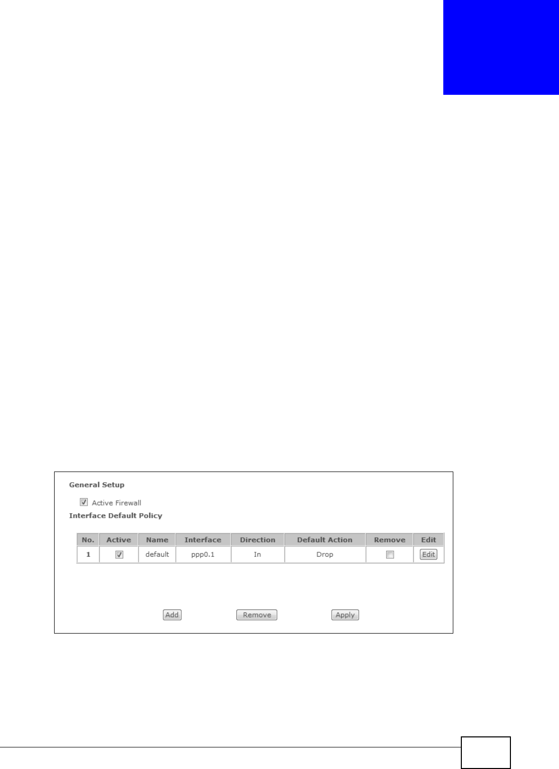
Basic Home Station VDSL2 P8802T User’s Guide 121
CHAPTER 7
Firewall
7.1 Overview
This chapt er shows you how t o enable and configure t he VDSL Rout er firewall set t ings.
The VDSL Router firewall is a packet filt ering firewall and restricts access based on t he source/
dest ination com put er net work address of a packet and t he t ype of application.
7.1.1 What You Can Do in this Chapter
• Use the Genera l screen (Sect ion 7.2 on page 121) t o enable firewall on t he VDSL Rout er, and
set t he default act ion that t he firewall t akes on packets t hat do not m atch any of t he firewall
rules.
• Use the Rules screen ( Sect ion 7.3 on page 123) to view t he configur ed firewall rules and add,
edit or rem ove a firewall r ule.
7.2 The Firewall General Screen
Click Adva nced Se tup > Firew all t o display the following screen. Activate t he firewall by select ing
the Active Fire w a ll check box .
Figure 41 Firewall General
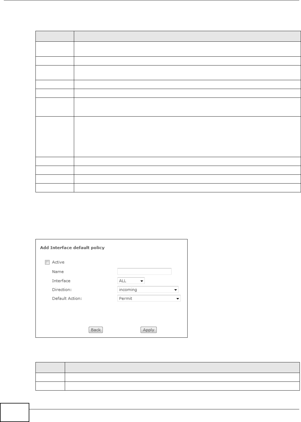
Chapter 7 Firewall
Basic Home Station VDSL2 P8802T User’s Guide
122
The following t able describes t he labels in t his screen.
7.2.1 Default Policy Configuration
I n t he Fire w a ll Ge nera l screen, click Add or click an ent ry’s Edit icon to configure a firewall policy.
Figure 42 Firewall General: Add
The following t able describes t he labels in t his screen.
Table 35 Firewall General
LABEL DESCRIPTION
Active Firewall Select this check box t o act ivat e the firewall. The VDSL Router perfor m s access cont rol and
prot ect s against Denial of Service ( DoS) att acks when the firewall is act ivat ed.
No. This displays the index num ber of t he default fir ewall policy.
Act ive This field displays whet her a policy is turned on or not . Select t he check box to enable t he
policy. Clear t he check box t o disable t he policy.
Nam e This displays t he nam e of the policy.
I nterface This displays the LAN or WAN int erface(s) to which this policy is applied.
Direction This displays t he dir ect ion of t ravel of packets (I n and Ou t ) .
Firewall rules ar e grouped based on the direct ion of t ravel of packet s to which they apply.
Default Act ion This displays the default act ion that the firewall is to t ake on packet s t hat are t raveling in the
select ed dir ection and do not m at ch any of the fir ewall r ules.
Dr op: the VDSL Router silently discards t he packets without sending a TCP reset packet or an
I CMP dest ination-unreachable m essage to t he sender.
Per m it : t he VDSL Rout er allows t he passage of the packet s.
Rem ove Select ent ries and click t he Rem ove butt on to delete t hem .
Edit Click the Edit but ton t o go t o the screen wher e you can edit the rule.
Add Click Add to create a new policy.
Apply Click Apply to save your changes back t o t he VDSL Rout er.
Table 36 Firewall General: Add
LABEL DESCRIPTION
Act ive Select t his check box t o enable the rule.
Nam e Ent er a descript ive nam e using printable English keyboar d charact er s.

Chapter 7 Firewall
Basic Home Station VDSL2 P8802T User’s Guide 123
7.3 The Firewall Rules Screen
Note: The ordering of your rules is very im port ant as rules are applied in turn.
Click Advan ce d Setup > Firew all > Rules t o display the following screen. This screen list s the
configured incom ing or out going firewall rules. Note the order in which t he rules are list ed.
Note: The firewall rules t hat you configure here take priority over the general firewall
act ion settings in the Ge neral screen.
I nterface Select All to apply the policy to all interfaces on the VDSL Rout er or select the specific LAN or
WAN int er face to which this policy applies.
Direction Specify the direct ion of travel of packet s ( in com ing or out going) in this policy.
Default
Act ion
Specify whet her t he firewall silently discards packet s (D rop) or allows the passage of packet s
(Per m i t ) .
Back Click Ba ck to ret urn t o the previous screen.
Apply Click Apply to save your cust om ized sett ings and exit this screen.
Table 36 Firewall General: Add ( continued)
LABEL DESCRIPTION
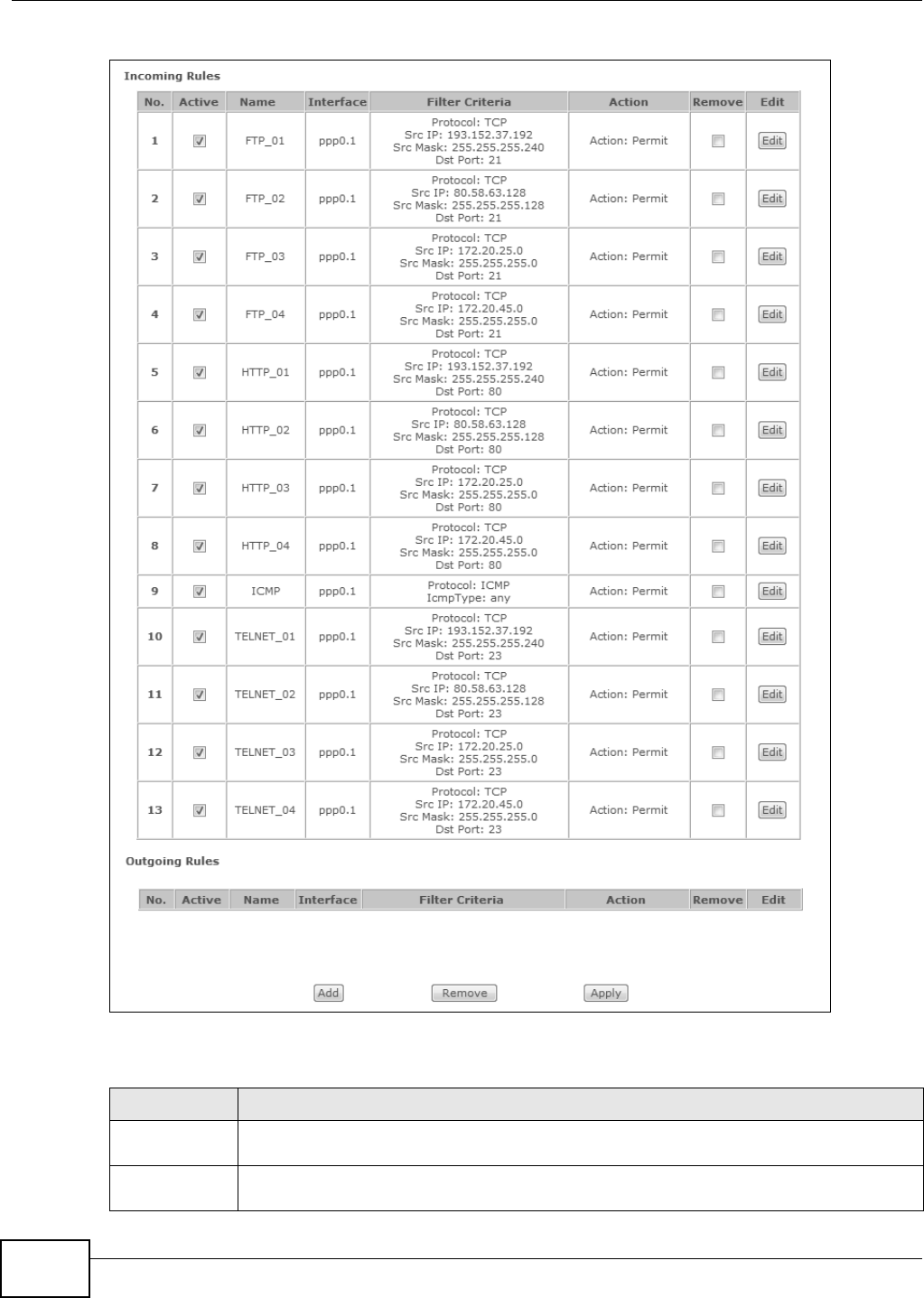
Chapter 7 Firewall
Basic Home Station VDSL2 P8802T User’s Guide
124
Figure 43 Firewall Rules
The following t able describes t he labels in t his screen.
Table 37 Firewall Rules
LABEL DESCRIPTION
I ncom ing/
Outgoing Rules
The following fields sum m ar ize t he rules you have cr eated that apply t o t raffic traveling in
the selected packet direction.
No. This is y our f irewall rule num ber. Th e or dering of your rules is im por tant as rules are applied
in turn.
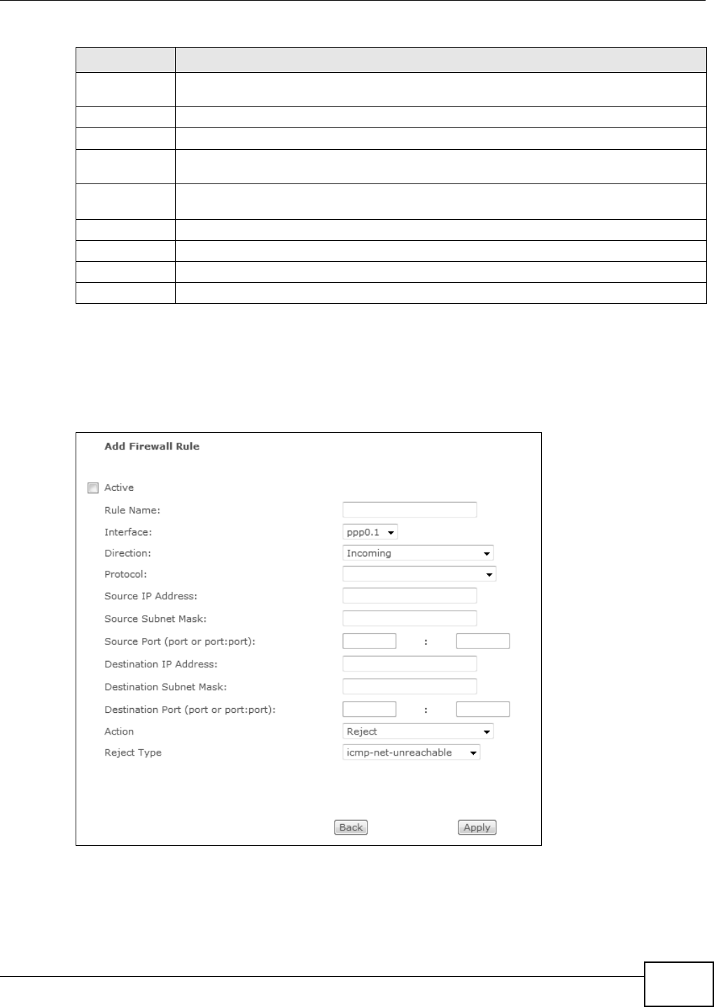
Chapter 7 Firewall
Basic Home Station VDSL2 P8802T User’s Guide 125
7.3.1 Firewall Rules Configuration
I n t he Fire w all Rule s screen, click Add or click a r ule’s Edit but t on t o display this scr een and refer
to t he following t able for inform at ion on the labels.
Figure 44 Firewall Rules: Add
Act ive This field displays whet her a firew all rule is t urn ed on or not. Select t he check box t o en able
t he rule. Clear t he check box to disable t he rule.
Nam e This displays t he nam e of the rule.
I nter face This displays the LAN or WAN interface( s) to which this rule is applied.
Filter Crit eria This displays the filtering criter ia, such as t he source or dest inat ion I P addr esses and subnet
m ask t o which this rule applies.
Act ion This displays whether the firewall silent ly discards packet s ( D rop), discar ds packet s and
sends an I CMP m essage t o the sender ( Re j e ct ) or allows the passage of packet s (P er m it ) .
Rem ove Select ent ries and click t he Re m ove button t o delet e them .
Edit Click the Edit butt on to go to t he screen where you can edit the rule.
Add Click Add to creat e a new rule.
Apply Click Apply to save your changes back t o the VDSL Rout er.
Table 37 Firewall Rules ( continued)
LABEL DESCRIPTION

Chapter 7 Firewall
Basic Home Station VDSL2 P8802T User’s Guide
126
The following t able describes t he labels in t his screen.
Table 38 Firewall Rules: Add
LABEL DESCRIPTION
Act ive Select t his check box t o enable t he rule.
Rule Name Enter a descript ive nam e of up to 16 printable English keyboard charact ers, including
spaces.
To add a firewall rule, you need to configure at least one of the following fields (except
the I n t e r fa ce field) .
I nterface Select an int erface on t he VDSL Router t o which this rule applies.
Direction Select a direct ion of t ravel of packet s for which you want t o configure the firewall rule.
Protocol Select t he I P prot ocol (TCP, UDP or I CM P) and ent er the prot ocol (service t ype)
number in the port field.
Source I P Address Ent er t he source I P address in dott ed decim al notation.
Source Subnet
Mask
Enter the source subnet mask.
Source Port Enter t he single port num ber or the range of port num bers of t he source.
Dest inat ion I P
Address
Enter t he dest inat ion I P address in dott ed decim al not at ion.
Dest inat ion Subnet
Mask
Enter t he destinat ion subnet m ask.
Dest inat ion Port Ent er t he single port num ber or t he range of port num bers of t he dest inat ion.
Act ion Use t he drop-down list box t o select whet her t o discard ( Drop), deny and send an I CMP
m essage to t he sender of (Re j ect ) or allow t he passage of (Pe rm i t ) packet s t hat m at ch
this rule.
Rej ect Type I f you select Re j e ct , specify the type of I CMP m essage to send t o t he sender.
Back Click Ba ck to ret urn t o the previous screen.
Apply Click Apply to save your cust om ized sett ings and exit this screen.

Basic Home Station VDSL2 P8802T User’s Guide 127
CHAPTER 8
Quality of Service (QoS)
8.1 Overview
Qualit y of Service ( QoS) refers t o both a network’s ability t o deliver data wit h m inim um delay, and
the net working m et hods used t o control the use of bandwidt h. Without QoS, all t raffic data is
equally likely t o be dropped w hen the net work is congest ed. This can cause a reduct ion in net work
perform ance and m ake t he net work inadequat e for tim e- crit ical applicat ion such as video-on-
dem and.
Configure QoS on t he VDSL Router to group and pr ioritize applicat ion traffic and fine- t une net work
perform ance. Set t ing up QoS involves these st eps:
1Configure classifiers t o sort traffic into different flows.
2Assign priority and define act ions t o be perform ed for a classified t raffic flow.
The VDSL Router assigns each packet a priorit y and then queues the packet accor dingly. Packet s
assigned a high priorit y are processed m ore quickly t han t hose wit h low priority if t here is
congest ion, allowing tim e- sensitive applications to flow m ore sm oot hly. Tim e- sensitive applicat ions
include both t hose t hat require a low level of lat ency ( delay) and a low level of jit ter (variat ions in
delay ) such as Voi ce ov er I P ( VoI P) o r I nt er n et gam ing, and those for which jit t er alone is a problem
such as I nt ernet radio or st ream ing video.
This chapt er cont ains inform ation about configuring QoS and editing classifiers.
8.1.1 What You Can Do in this Chapter
• The QoS screen lets you enable or disable QoS and set t he default DSCP m ark (Section 8.3 on
page 129) .
• The QoS Qu eu e Set u p screen let s you configure QoS queue assignm ent (Sect ion 8.4 on page
129) .
• The QoS Classifica t ion Setup screen let s you add, edit or delete QoS classifiers ( Sect ion 8.5 on
page 132) .
8.2 What You Need to Know
The following t erm s and concept s m ay help as you read t hrough this chapt er.
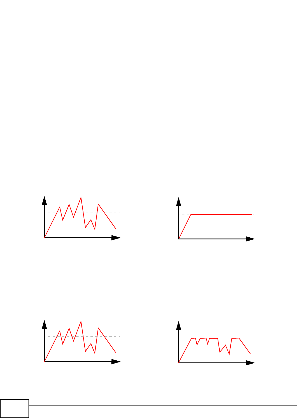
Chapter 8 Quality of Service (QoS)
Basic Home Station VDSL2 P8802T User’s Guide
128
QoS versus Cos
QoS is used t o priorit ize source-t o-dest inat ion t raffic flows. All packets in t he sam e flow are given
the sam e priority. CoS ( class of service) is a way of m anaging traffic in a net work by grouping
sim ilar types of t raffic toget her and t reat ing each t ype as a class. You can use CoS to give different
priorities to different packet types.
CoS t echnologies include I EEE 802.1p layer 2 t agging and DiffServ ( Different iated Ser vices or DS) .
I EEE 802.1p tagging m akes use of three bit s in t he packet header, while DiffServ is a new protocol
and defines a new DS field, which replaces the eight -bit ToS ( Type of Service) field in t he I P header.
Tagging and Marking
I n a QoS class, you can configure whether to add or change the DSCP (DiffServ Code Point) value,
I EEE 802.1p priorit y level and VLAN I D num ber in a m at ched packet. When the packet passes
through a com patible network, the networking device, such as a backbone switch, can provide
specific treatm ent or service based on t he t ag or marker.
Traffic Shaping
Burst y t raffic m ay cause net work congestion. Traffic shaping regulat es packet s t o be transm it t ed
with a pr e- configured dat a t ransm ission rat e using buffers ( or queues) . Your VDSL Router uses t he
Token Bucket algorit hm t o allow a certain am ount of large burst s while keeping a lim it at the
average rat e.
Traffic Policing
Traffic policing is the lim iting of the input or out put t ransm ission rat e of a class of t raffic on t he
basis of user-defined criteria. Traffic policing m et hods m easure t raffic flows against user-defined
crit eria and ident ify it as either conform ing, exceeding or violat ing the crit eria.
Tr a f f i c
Tim e
Traffic Rate
Tr a f f i c
Tim e
Traffic Rate
( Before Traffic Shaping) (Aft er Traffic Shaping)
Tr a f f i c
Tim e
Traffic Rate
Traffic
Tim e
Traffic Rate
( Before Traffic Policing) ( After Traffic Policing)
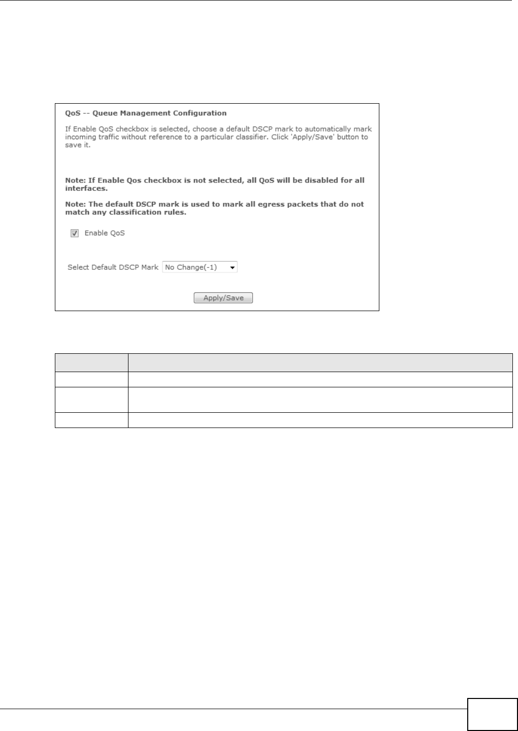
Chapter 8 Quality of Service (QoS)
Basic Home Station VDSL2 P8802T User’s Guide 129
8.3 The QoS Screen
Click Advance d Setup > QoS t o open the screen show n next . Use t his screen to enable or disable
QoS and set t he default DSCP m ar k for outgoing packet s t hat do not m atch any classification rules.
Figure 45 QoS
The following t able describes t he labels in t his screen.
8.4 The QoS Queue Setup Screen
Click Advance d Setup > QoS > QoS Queue t o open the screen shown next. Use this screen t o
configure QoS queue assignm ent.
Table 39 QoS
LABEL DESCRIPTION
QoS Select the Ena ble check box to t urn on QoS to im prove your net wor k perform ance.
Select Default
DSCP Mar k
Set the default DSCP ( DiffServ Code Point ) value for outgoing packet s t hat do not m at ch
any classification rules.
Apply/ Save Click this to save your changes.
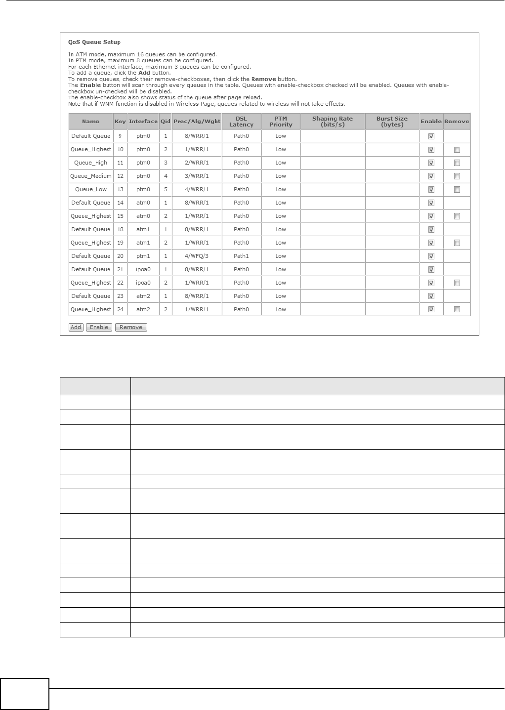
Chapter 8 Quality of Service (QoS)
Basic Home Station VDSL2 P8802T User’s Guide
130
Figure 46 QoS Queue Set up
The following t able describes t he labels in t his screen.
Table 40 QoS Queue Setup
LABEL DESCRIPTION
Nam e This shows t he descr iptive nam e of this queue.
Key This is the queue’s index num ber.
St at us This field displays whet her t he queue is act ive or not . A yellow bulb signifies t hat t his queue
is act ive. A gray bulb signifies that this queue is not act ive.
I nterface This show s the name of the VDSL Router’s interface t hrough which traffic in this queue
passes.
Qid This shows the pr iority of this queue for the interface.
Prec/ Alg/ Wght This displays t he queue’s default precedence, queue m anagem ent algorit hm , and weight ed
round robin weight .
DSL Latency This displays whet her the ATM int erface uses int erleave delay (Pat h1 ) or fast m od e w it h no
int erleave delay ( Pa th0 ) .
PTM Priority This displays the queue’s PTM priority (H igh or Low ) . This has no effect at the time of
w rit in g.
Shaping Rat e This displays the m axim um transm ission rate for t raffic in this queue.
Burst Size This displays the m axim um num ber of cells the queue can send at the shaping rat e.
Enable Select an ent ry’s En able opt ion and click the Ena ble butt on to turn it on.
Rem ove Select an entry ’s Rem ove opt ion and click the Rem ove but t on to delete it .
Add Click this button t o creat e a new queue entry.
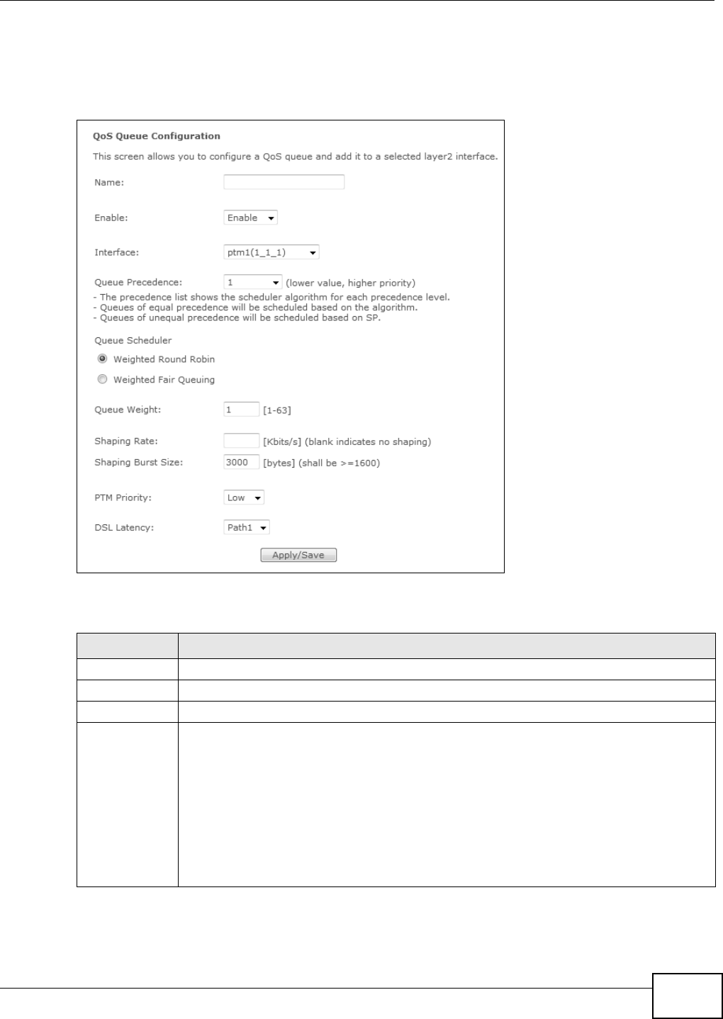
Chapter 8 Quality of Service (QoS)
Basic Home Station VDSL2 P8802T User’s Guide 131
8.4.1 Adding a QoS Queue
Click the QoS Queue Se t up screen’s Add butt on t o configure a new queue.
Figure 47 QoS Queue Set up: Add
The following t able describes t he labels in t his screen.
Table 41 QoS Queue Setup: Add
LABEL DESCRIPTION
Nam e Enter t he descr ipt ive nam e of this queue.
Enable Enable or disable t his queue.
I nterface Select t he interface t o which this queue is applied.
Queue
Precedence
Select the precedence lev el (from 1 to 8) of this queue. The sm aller t he num ber, the higher
the priority level. Traffic assigned t o higher prior ity queues get s through faster while t raffic
in lower priorit y queues is dr opped if the net work is congest ed.
The precedence list shows the scheduler algorit hm for each precedence level. The scheduler
algorithm depends on the int er face. Ethernet inter faces use st rict priority ( SP) . ATM and
PTM int er faces use t he scheduler algor ithm configured for t he int er face (w eight ed round
robin or weighted fair queuing).
The VDSL Rout er uses the algorit hm t o service queues wit h the sam e precedence.
The VDSL Rout er uses st rict priorit y t o ser vice queues with different precedences.
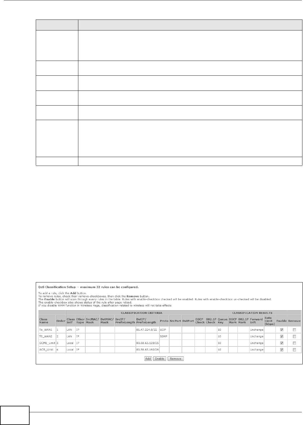
Chapter 8 Quality of Service (QoS)
Basic Home Station VDSL2 P8802T User’s Guide
132
8.5 The QoS Classification Setup Screen
Click Advance d Set u p > QoS > QoS Classification to open the following screen. Use t his screen
to m anage QoS classifiers. A classifier groups traffic into data flow s according to specific crit eria
such as the source address, dest ination address, source port num ber, destination port num ber or
incom ing int erface. For exam ple, you can configure a classifier t o select t raffic from the sam e
prot ocol port ( such as Telnet) to form a flow.
You can give different priorit ies t o t raffic t hat the VDSL Router forwards out through the WAN
int erface. Give high priorit y t o voice and video t o m ake them run m ore sm oothly. Similarly, give low
priority to many large file dow nloads so t hat t hey do not reduce t he quality of ot her applicat ions.
Figure 48 QoS Classificat ion Setup
Queue Weight This displays for ATM and PTM interface queues. Select t he weight of this queue.
I f t wo queues have the same precedence, the VDSL Router divides the bandwidth across t he
queues according t o their weights. Queues wit h larger w eight s get m ore bandwidth than
queues wit h sm aller w eights.
Default Queue
Weig ht
This displays for ATM and PTM interface queues. Specify the VC’s weight for weighed fair
queuing. The higher t he weight , t he bigger por tion of t he bandwidth the VC get s.
Shaping Rate This displays for PTM interface queues. Set the m axim um t ransm ission rate for traffic in this
queue.
Shaping Burst
Size
This displays for PTM interface queues. Set the m aximum num ber of cells the queue can
send at t he shaping rat e.
PTM Priorit y This displays for PTM int er face queues. Set the queue t o low or high pr iority. This has no
effect at the time of writing.
DSL Latency This displays for ATM and PTM int er face queues. Select Pa t h0 ( Fa st ) to use no int erleaving
and have fast er transm ission (a “ fast channel”) . Suit able only for a good line with litt le need
for error corr ect ion.
At t he t im e of writing the VDSL Router supports fast m ode only and interleaved is reserved
for fut ure use.
Apply/ Save Click this butt on to save your changes.
Table 41 QoS Queue Setup: Add (continued)
LABEL DESCRIPTION

Chapter 8 Quality of Service (QoS)
Basic Home Station VDSL2 P8802T User’s Guide 133
The following t able describes t he labels in t his screen.
8.5.1 Add QoS Classification Rule
Click Add n ew Cla ssifier in the Cla ss Se t up screen or the Edit icon next t o a classifier to open
the following screen.
Table 42 QoS Classification Setup
LABEL DESCRIPTION
Class Nam e This displays the nam e of the classifier rule.
Order This displays the rule’s place in t he list of classifier rules. The VDSL Router checks traffic
against classifier s in order unt il it m at ches one.
CLASSI FI CATI ON
CRI TERI A
These fields show t he criteria specified in the classifier rule. For exam ple t he int erface
from which traffic of this class com es and t he source MAC address of traffic t hat
m atches this classifier.
Class I ntf This displays the ingress int erface t o which t he classifier applies.
Ether Type This displays the t ype of Et her net frames t o which the classifier applies.
SrcMAC/ Mask This display s the source MAC and net work m ask of traffic t o which the classifier applies.
DstMAC/ Mask This displays the destinat ion MAC and net work m ask of traffic t o which the classifier
applies.
Sr cI P/ PrefixLengt h This displays the source I P address and prefix length of t raffic t o which the classifier
applies.
Dst I P/ Prefix Length This displays the destination I P address and prefix length of t raffic to which the classifier
applies.
Proto This display s the protocol of t raffic to w hich the classifier applies.
SrcPort This display s the source por t of traffic to which the classifier applies.
DstPor t This displays the dest inat ion port of traffic t o which the classifier applies.
DSCP Check This displays the DSCP m ar k of t raffic to w hich the classifier applies.
802.1P Check This displays the I EEE 802.1p priorit y level of traffic to which t he classifier applies.
CLASSI FI CATI ON
RESULTS
These fields show t he changes the classifier rule applies to m at ching traffic.
Queue Key This displays the num ber of the queue t o which the VDSL Rout er adds traffic that
m atches this classifier.
DSCP Mar k Th is display s t he DSCP m ark t h e VDSL Rou ter adds t o tr af fic t hat m at ch es t his classifier.
802.1P Mark This displays the I EEE 802.1p priority level t he VDSL Rout er assigns t o traffic t hat
m atches this classifier.
Forward I nft This displays the int er face t hrough w hich the VDSL Rout er forwards t raffic t hat m at ches
this classifier. Un cha nge m eans t he VDSL Rout er for wards t raffic of this class according
to t he default rout ing t able.
Rate Lim it( kbps) This displays the rat e lim it (if any) t hat the VDSL Rout er applies to traffic t hat m atches
this classifier.
Enable Select an ent ry’s Ena ble opt ion and click the Ena ble but ton t o t ur n it on.
Rem ove Select an entry’s Rem ove option and click the Re m ove butt on to delet e it.
Add Click this but ton t o cr eate a new classifier rule.
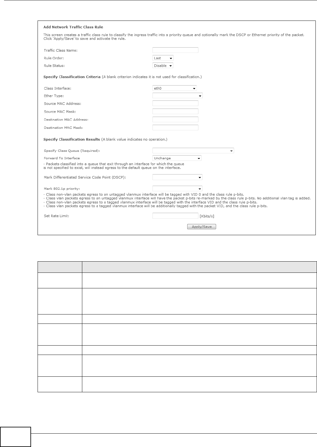
Chapter 8 Quality of Service (QoS)
Basic Home Station VDSL2 P8802T User’s Guide
134
Figure 49 QoS Classificat ion Setup: Add
The following t able describes t he labels in t his screen.
Table 43 QoS Classification Setup: Add
LABEL DESCRIPTION
Traffic Class
Nam e
Enter a descript ive nam e of up to 15 pr int able English keyboard charact ers, not including
spaces.
Rule Or der Select an ex ist ing num ber for where you want to put t his classifier t o m ove t he classifier t o
the num ber you selected after clicking Apply.
Select La st t o put this rule in the back of the classifier list .
Rule St at us Enable or disable t his classifier.
Specify
Classification
Criteria
Configure these fields t o ident ify the traffic to which the class applies. The fields available
var y depending on t he selected int erface and Ether type. Leave a field blank t o not apply
that criter ion.
Class I nterface Select t he ingress int erface t o which the classifier applies.
Ether Type Select t he predefined applicat ion ( I P, ARP, I Pv6, PPPoE discovery, PPPoE session, 8865,
8866, or I EEE 802.1q) to w hich t he classifier applies. The list of ty pes available to choose
from varies depending on the select ed interface.
Source MAC
Address
Enter a MAC address to apply the classifier t o packets from that MAC address.

Chapter 8 Quality of Service (QoS)
Basic Home Station VDSL2 P8802T User’s Guide 135
Source MAC
Mask
Type t he m ask for t he specified MAC address t o determ ine which bits a packet ’s MAC
addr ess should m at ch.
Enter “ f” for each bit of the specified source MAC address that the traffic’s MAC address
should m at ch. Ent er “ 0” for the bit (s) of t he m at ched traffic’s MAC address, which can be of
any hexadecim al character(s) . For exam ple, if you set the MAC address to
00: 13: 49: 00: 00: 00 and t he m ask t o ff: ff: ff: 00: 00: 00, a packet with a MAC address of
00: 13: 49: 12: 34: 56 m at ches this cr it eria.
Dest inat ion
MAC Address
Enter a MAC address to apply the classifier to packets destined for that MAC address.
Dest inat ion
MAC Mask
Type t he m ask for t he specified MAC address t o determ ine which bits a packet ’s MAC
addr ess should m at ch.
Enter “ f” for each bit of the specified source MAC address that the traffic’s MAC address
should m at ch. Ent er “ 0” for the bit (s) of t he m at ched traffic’s MAC address, which can be of
any hexadecim al character(s) . For exam ple, if you set the MAC address to
00: 13: 49: 00: 00: 00 and t he m ask t o ff: ff: ff: 00: 00: 00, a packet with a MAC address of
00: 13: 49: 12: 34: 56 m at ches this cr it eria.
Source I P
Address[ / Mask]
Select this and ent er an I P address t o apply t he classifier t o packets from t hat I P address.
You can also include a source subnet m ask.
Ven do r Cl ass I D
( DHCP Option
60)
Select this and ent er t he Vendor Class I dent ifier ( Option 60) of the m atched traffic, such as
the t ype of the hardware or firm ware.
User Class I D
DHCP option 77
Select this and ent er a str ing that identifies the user ’s cat egor y or applicat ion ty pe in the
m at ched DHCP packet s.
Dest inat ion I P
Address[ / Mask]
Enter an I P address to apply the classifier t o packet s destined for t hat I P address. You can
also include a dest inat ion subnet m ask.
Different iat ed
Ser vice Code
Point ( DSCP)
Check
Select a DSCP m ar k of t raffic to w hich to apply the classifier.
802.1p Priorit y
Check
This field is available only when you set the Et her Type field to 8 0 2 1 Q.
Select t he I EEE 802.1p priority level ( bet ween 0 and 7) of traffic t o which to apply the
classifier. "0" is the lowest priority level and " 7" is the highest .
Specify
Classification
Result s
Configure these fields t o change t raffic that m atches the classifier. The fields available vary
depending on the select ed interface, Ether type, and som et im es on the select ed class
queue. Leave a field blank to not apply that type of change.
Specify Class
Queue
Select the queue to which to add traffic that m atches this classifier.
Forward To
I nter face
Select a WAN interface through w hich to forward traffic of this class. Select Uncha nge to
forward traffic of this class according to t he default routing table.
Mark
Different iat ed
Ser vice Code
Point ( DSCP):
Select the DSCP m ar k t o add t o traffic t hat m atches this classifier. Use Au to m arking to
autom atically apply a DSCP m ark according t o t he t ype of traffic. Use defa ult to leave the
DSCP m ar k unchanged.
Protocol Select a service t ype ( TCP, UDP, I CMP or I GM P) of traffic to w hich to apply the classifier.
Mark 802.1p
priorit y
Select the I EEE 802.1p priorit y level t o assign to t raffic t hat m at ches this classifier.
Set Rat e Lim it Set the rat e lim it to apply t o traffic that m at ches this classifier.
Apply/ Save Click this but ton t o save your changes.
Table 43 QoS Classification Setup: Add (continued)
LABEL DESCRIPTION
Chapter 8 Quality of Service (QoS)
Basic Home Station VDSL2 P8802T User’s Guide
136
8.6 Technical Reference
The following sect ion contains addit ional t echnical inform at ion about the VDSL Router features
described in t his chapt er.
IEEE 802.1Q Tag
The I EEE 802.1Q st andard defines an explicit VLAN tag in t he MAC header to ident ify the VLAN
m em bership of a fram e across bridges. A VLAN t ag includes t he 12- bit VLAN I D and 3- bit user
priority. The VLAN I D associat es a fram e with a specific VLAN and provides t he inform ation t hat
devices need t o process t he fram e across t he net work.
I EEE 802.1p specifies t he user priority field and defines up to eight separate traffic t ypes. The
following t able describes t he t raffic types defined in t he I EEE 802.1d standard ( which incorporat es
the 802.1p) .
DiffServ
QoS is used to prioritize source-t o-destination t raffic flows. All packets in t he flow are given t he
sam e priority. You can use CoS ( class of service) t o give different priorit ies t o different packet
types.
DiffServ ( Differentiated Services) is a class of service (CoS) m odel that m arks packets so that t hey
receive specific per- hop t reat m ent at DiffServ-com pliant net work devices along t he route based on
the application types and traffic flow. Packets are m arked with DiffServ Code Points ( DSCPs)
indicat ing t he level of service desired. This allows the interm ediary DiffServ-com pliant network
devices t o handle the packets different ly depending on the code point s wit hout t he need t o
negot iate pat hs or rem em ber st at e inform at ion for ever y flow. I n addit ion, applicat ions do not have
to request a part icular service or give advanced not ice of where t he t raffic is going.
DSCP and Per-Hop Behavior
DiffServ defines a new Different iated Services ( DS) field t o r eplace t he Ty pe of Service ( TOS) field
in t he I P header. The DS field contains a 2- bit unused field and a 6- bit DSCP field which can define
up to 64 service levels. The following figure illust rat es the DS field.
Table 44 I EEE 802.1p Priorit y Level and Traffic Type
PRIORITY
LEVEL TRAFFIC TYPE
Level 7 Typically used for netw or k cont rol t raffic such as rout er configuration m essages.
Level 6 Typically used for voice t raffic that is especially sensitive t o j it ter ( j it ter is t he
variations in delay ).
Level 5 Typically used for video t hat consum es high bandw idth and is sensitive to j it t er.
Level 4 Typically used for controlled load, lat ency-sensitive traffic such as SNA (System s
Network Architect ure) transact ions.
Level 3 Typically used for “ excellent effor t” or better t han best effor t and would include
im port ant business traffic that can tolerat e som e delay.
Level 2 This is for “ spare bandw idt h”.
Level 1 This is t ypically used for non- critical “ background” traffic such as bulk transfers that
are allow ed but t hat should not affect other applicat ions and users.
Level 0 Typically used for best- effort t raffic.
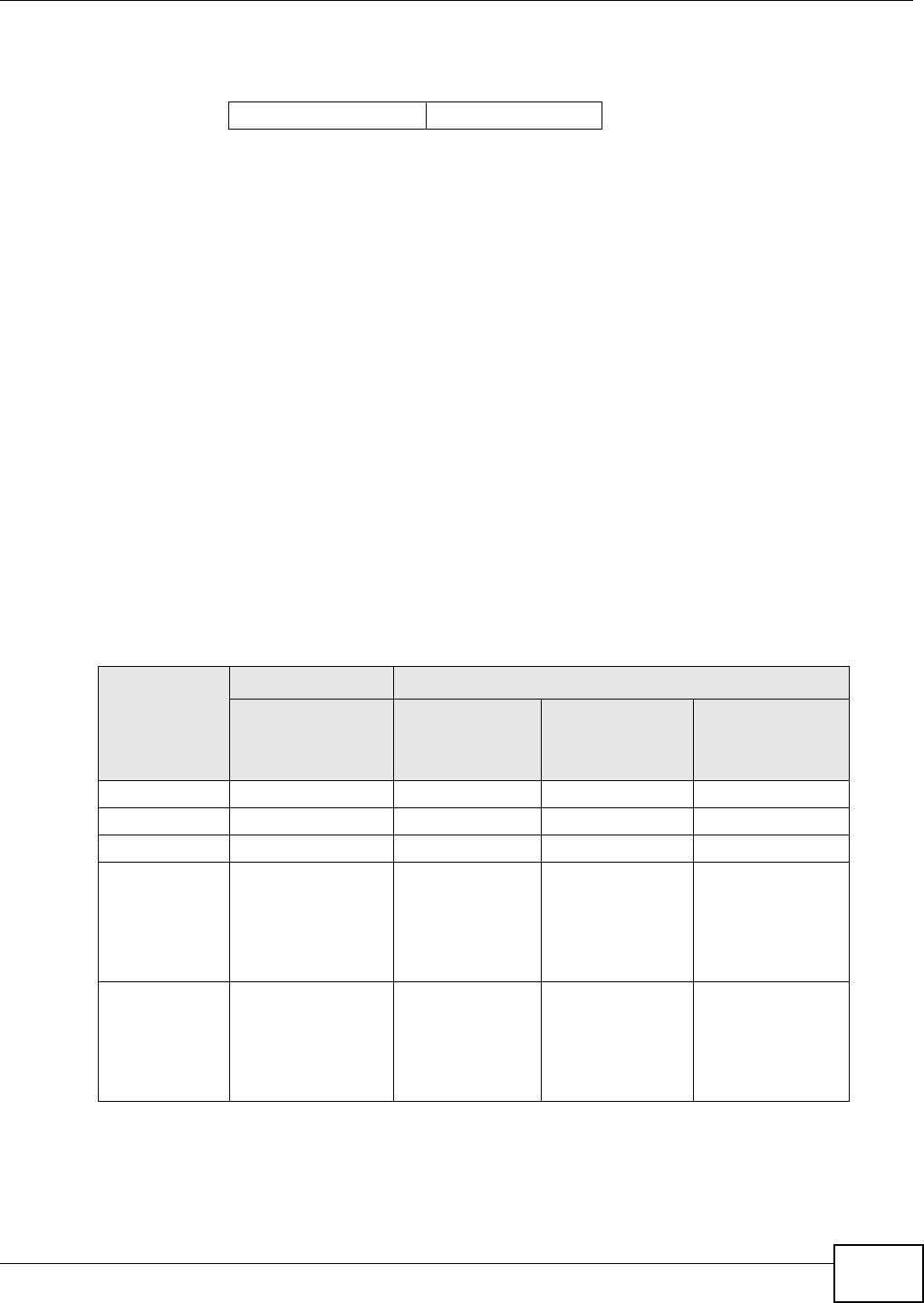
Chapter 8 Quality of Service (QoS)
Basic Home Station VDSL2 P8802T User’s Guide 137
DSCP is backward compat ible wit h the t hree precedence bit s in the ToS oct et so that non- DiffServ
com pliant , ToS-enabled net work device will not conflict with t he DSCP m apping.
The DSCP value determ ines t he forwarding behavior, t he PHB ( Per-Hop Behavior) , t hat each packet
gets across t he DiffServ net work. Based on t he m arking rule, differ ent kinds of t raffic can be
m arked for different kinds of forwar ding. Resources can then be allocated according to the DSCP
values and t he configured policies.
IP Precedence
Sim ilar to I EEE 802.1p priorit izat ion at layer-2, you can use I P precedence t o priorit ize packets in a
layer- 3 net work. I P precedence uses three bits of the eight- bit ToS ( Type of Service) field in the I P
header. There are eight classes of services ( ranging from zero t o seven) in I P precedence. Zero is
the lowest priority level and seven is t he highest.
Automatic Priority Queue Assignment
I f you enable QoS on the VDSL Router, the VDSL Rout er can autom at ically base on t he I EEE 802.1p
priority level, I P precedence and/ or packet lengt h t o assign priorit y t o t raffic which does not m atch
a class.
The following t able shows you the internal layer-2 and layer- 3 QoS m apping on the VDSL Router.
On the VDSL Rout er, traffic assigned t o higher priorit y queues get s t hrough fast er while t raffic in
lower index queues is dropped if the network is congest ed.
DSCP (6 bits) Unused (2 bits)
Table 45 I nternal Layer2 and Layer 3 QoS Mapping
PRIORITY
QUEUE
LAYER 2 LAYER 3
IEEE 802.1P USER
PRIORITY
(ETHERNET
PRIORITY)
TOS (IP
PRECEDENCE) DSCP IP PACKET
LENGTH (BYTE)
0 1 0 000000
12
2 0 0 000000 > 1100
3 3 1 001110
001100
001010
001000
250~ 1100
4 4 2 010110
010100
010010
010000

Chapter 8 Quality of Service (QoS)
Basic Home Station VDSL2 P8802T User’s Guide
138
5 5 3 011110
011100
011010
011000
< 250
6 6 4 100110
100100
100010
100000
5 101110
101000
7 7 6 110000
111000
7
Table 45 I nternal Layer2 and Layer 3 QoS Mapping
PRIORITY
QUEUE
LAYER 2 LAYER 3
IEEE 802.1P USER
PRIORITY
(ETHERNET
PRIORITY)
TOS (IP
PRECEDENCE) DSCP IP PACKET
LENGTH (BYTE)
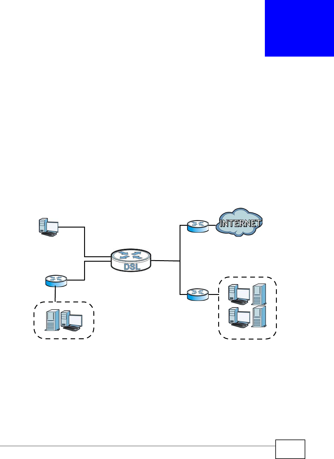
Basic Home Station VDSL2 P8802T User’s Guide 139
CHAPTER 9
Routing
9.1 Overview
The VDSL Rout er usually uses t he default gat ew ay t o rout e out bound t raffic from com put ers on the
LAN t o t he I nternet . To have t he VDSL Router send dat a t o devices not reachable t hrough t he
default gat eway, use st at ic routes.
For exam ple, t he next figure shows a computer (A) connected to the VDSL Rout er’s LAN int erface.
The VDSL Router routes m ost traffic from A to the I nt ernet t hrough the VDSL Router’s default
gat eway (R1 ) . You creat e one st atic route to connect t o services offered by your I SP behind rout er
R2 . You creat e anot her st at ic route t o com m unicate with a separate net work behind a rout er R3
connect ed to t he LAN.
Figure 50 Exam ple of Routing Topology
9.1.1 What You Can Do in this Chapter
• Use the D efault Ga tew ay screen to select WAN int erfaces t o serve as syst em default gateways
(Sect ion 9.2 on page 140) .
• Use the Stat ic Rou t e screen t o view and set up st at ic routes on t he VDSL Router (Sect ion 9.3 on
page 140) .
• Use the Policy For w a rding screen to configure policy rout ing on the Device ( Sect ion 9.4 on
page 142) .
• Use the RI P screen t o configure RI P sett ings ( Section 9.5 on page 143) .
WAN
R1
R2
A
R3
LAN
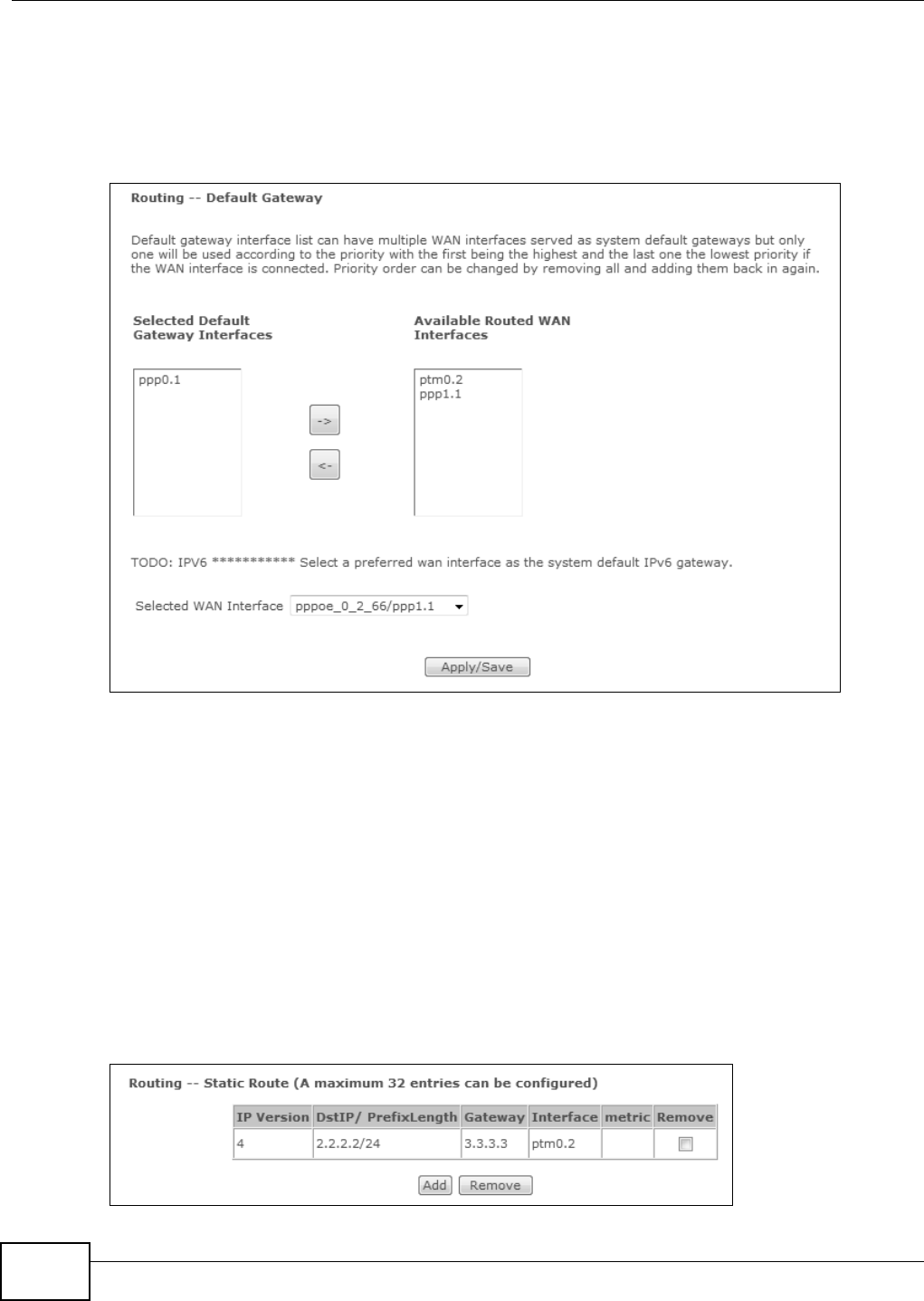
Chapter 9 Routing
Basic Home Station VDSL2 P8802T User’s Guide
140
9.2 The Default Gateway Screen
Click Advanced Se t up > Rout ing > Defau lt Gatew ay t o open the De fa ult Gatew ay screen.
Use t his scr een t o select WAN interfaces t o serve as syst em default gat ew ays.
Figure 51 Default Gat eway
Move t he WAN interfaces to serve as syst em default gateways from Ava ilable Rou t ed W AN
I n t er fa ce s t o Select e d De fa ult Ga t ew a y I nt erface s.
Use t he Select ed W AN I nter face field to select the preferred WAN interface t o server as the VDSL
Rou t er ’s defau lt I Pv 6 gat eway.
Click Apply / Sa ve to save your changes.
9.3 The Static Route Screen
Use t his screen to view and configure t he st atic route rules on t he VDSL Rout er. Click Advance d
Se t up > Rou t ing > St a t ic Route to open t he following screen.
Figure 52 Stat ic Rout e
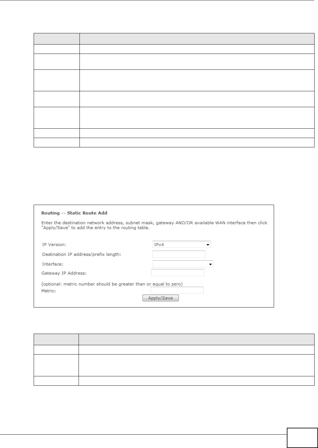
Chapter 9 Routing
Basic Home Station VDSL2 P8802T User’s Guide 141
The following t able describes t he labels in t his screen.
9.3.1 Add Static Route
Use t his screen t o add a stat ic route. Click Add in the Sta t ic Rout e screen t o display the following
screen.
Figure 53 Stat ic Rout e: Add
The following t able describes t he labels in t his screen.
Table 46 St at ic Route
LABEL DESCRIPTION
I P Version This displays whet her t he entry uses I Pv4 or I Pv6.
DstI P/
PrefixLength
This specifies the I P network address and prefix lengt h of the final dest inat ion. Rout ing is
alway s based on net work num ber.
Gateway This is the I P address of the gatew ay. The gateway is a rout er or switch on t he sam e
net work segm ent as the device's LAN or WAN port. The gat eway helps forward packet s to
their destinations.
I nterface This is the int erface t his st at ic rout e uses to forward t raffic for t he listed dest ination
addr ess.
Met ric The m et ric represent s the " cost of transm ission" . A rout er determ ines the best rout e for
transm ission by choosing a pat h w it h t he lowest "cost ". The sm aller t he num ber, t he lower
the "cost ".
Rem ove Select ent ries and click the Re m ove but ton t o delet e them .
Add Click t his to configure a new st atic route.
Table 47 St at ic Route: Add (Sheet 1 of 2)
LABEL DESCRIPTION
I P Version Select whether your I P type is I Pv4 or I Pv6 .
Dest inat ion I P
address/ prefix
length
Ent er the I Pv4 or I Pv6 address and net work lengt h of the final dest inat ion.
I nterface Select the inter face through w hich this st at ic rout e sends t raffic.
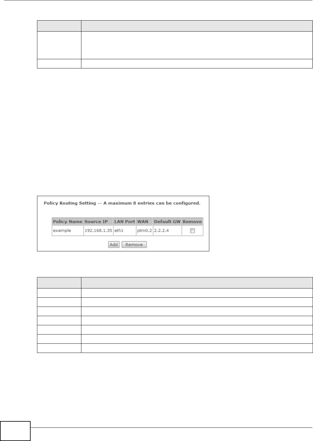
Chapter 9 Routing
Basic Home Station VDSL2 P8802T User’s Guide
142
9.4 The Policy Routing Screen
Traditionally, rout ing is based on t he dest inat ion address only and the VDSL Router takes the
short est path t o forward a packet. Policy rout ing allows the VDSL Router to override t he default
routing behavior and alter the packet routing based on t he policy defined by the net work
adm inist rat or. Policy- based routing is applied t o out going packet s, prior to the norm al routing.
You can use source-based policy rout ing t o direct t raffic from different users t hrough different
connect ions or distribut e t raffic am ong m ultiple paths for load sharing.
Use t he Policy Routin g screen to view and configure routing policies on the VDSL Router . Click
Advance d Setup > Rou t ing > Policy Routin g to open t he following screen.
Figure 54 Policy Rout ing
The following t able describes t he labels in t his screen.
9.4.1 Add Policy Routing
Click Add in t he Policy Routin g screen to open the following screen. Use t his screen to configure
the required inform at ion for a policy rout e.
Gateway I P
Address
Enter t he I P address of t he gat eway when you configure a st at ic rout e that uses an I P- based
int erface ( such as I PoE, I PoA, or LAN) . The gat eway is a rout er or switch on the same
net work segm ent as the dev ice's LAN or WAN por t. The gateway helps forwar d packet s to
their dest inat ions.
Apply/ Save Click this but ton t o save your changes.
Table 47 St at ic Route: Add (Sheet 2 of 2)
LABEL DESCRIPTION
Table 48 Policy Routing
LABEL DESCRIPTION
Policy Nam e This displays the nam e of t he rule.
Source I P This displays t he source I P address.
LAN Port This displays the sour ce LAN port num ber.
WAN This displays t he WAN int erface through w hich the traffic is rout ed.
Default GW This displays the default gat eway I P addr ess the route uses.
Rem ove Select ent ries and click t he Re m ove butt on t o delete t hem .
Add Click t his t o creat e a new policy rout ing r ule.
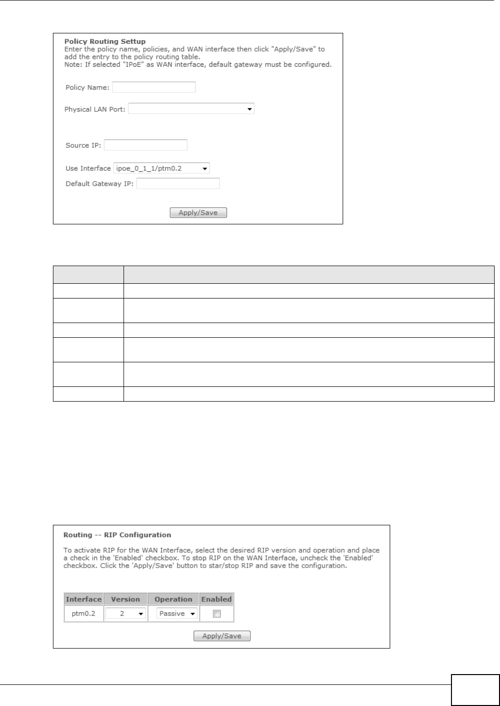
Chapter 9 Routing
Basic Home Station VDSL2 P8802T User’s Guide 143
Figure 55 Policy Rout ing: Add
The following t able describes t he labels in t his screen.
9.5 The RIP Screen
Click Adva nce d Se tup > Rout ing > RI P to open t he RI P screen. Use t his screen to configure RI P
sett ings. Rout ing I nform ation Pr ot ocol (RI P, RFC 1058 and RFC 1389) allow s a device t o exchange
routing inform ation wit h other routers.
Figure 56 RI P
Table 49 Policy Rout ing: Add
LABEL DESCRIPTION
Policy Nam e Enter a descr iptive nam e of print able English keyboard characters, not including spaces.
Physical LAN
Port
Select t he source LAN Et her net port num ber.
Source I P Ent er t he source I P address.
Use I nt er face Select a WAN int er face through which the t raffic is sent . You m ust have t he WAN
int erface( s) already configured in t he Br oa dband screens.
Default
Gateway I P
Ent er the default gat eway I P address the rout e uses.
Apply/ Save Click this but ton t o save your changes.

Chapter 9 Routing
Basic Home Station VDSL2 P8802T User’s Guide
144
The following t able describes t he labels in t his screen.
Table 50 RI P
LABEL DESCRIPTION
I nterface This is the nam e of the int erface in which the RI P set ting is used.
Ve r si on The RIP ver sion contr ols the form at and the broadcasting m ethod of the RI P packets that
the VDSL Router sends (it recognizes bot h for m at s when receiving) . RI P version 1 is
universally supported but RIP ver sion 2 carries m ore inform ation. RI P version 1 is probably
adequat e for m ost networks, unless you hav e an unusual net wor k t opology.
Operat ion Select Passive t o h av e t he VDSL Rout er updat e t he rout ing table based on t he RIP packet s
received from neighbors but not advert ise its rout e inform at ion t o ot her r out er s in this
int erface.
Select Act ive t o have t he VDSL Router adver t ise it s rout e infor m ation and also list en for
rout ing updates fr om neighboring rout ers.
Enabled Select the check box t o act ivate t he set tings.
Apply/ Save Click this but ton t o save your changes.

Basic Home Station VDSL2 P8802T User’s Guide 145
CHAPTER 10
DNS Setup
10.1 Overview
DNS
DNS ( Dom ain Nam e Syst em ) is for m apping a dom ain nam e t o its corresponding I P address and
vice ver sa. The DNS server is extrem ely im port ant because w it hout it, you m ust know t he I P
address of a m achine before you can access it .
I n addit ion to the syst em DNS server( s) , each WAN int erface (service) is set to have its own st at ic
or dynam ic DNS server list. You can configure a DNS st atic rout e t o forward DNS queries for certain
dom ain nam es t hrough a specific WAN interface to it s DNS server( s) . The VDSL Router uses a
syst em DNS ser ver (in the order you specify in the Br oadband scr een) t o resolve dom ain nam es
that do not m at ch any DNS rout ing entry. Aft er the VDSL Router receives a DNS reply from a DNS
server, it creat es a new ent ry for t he resolved I P address in t he routing table.
Dynamic DNS
Dynam ic DNS allows you to update your current dynam ic I P address with one or m any dynam ic
DNS services so that anyone can cont act you ( in Net Meet ing, CU-SeeMe, etc.) . You can also access
your FTP server or Web site on your own com puter using a domain nam e ( for inst ance
m yhost .dhs.org, where m yhost is a nam e of your choice) t hat will never change instead of using an
I P address t hat changes each tim e you reconnect . Your friends or relatives will always be able to
call you even if t hey don't know your I P address.
First of all, you need t o have regist ered a dynam ic DNS account with www.dyndns.org. This is for
people wit h a dynam ic I P from t heir I SP or DHCP server that would st ill like to have a dom ain nam e.
The Dynam ic DNS service provider will give you a password or key.
10.1.1 What You Can Do in this Chapter
• Use the D NS Ser ve r screen t o configure DNS ser ver sett ings ( Sect ion 10.2 on page 146) .
• Use the D ynam ic DNS screen t o configure DDNS sett ings on the VDSL Router (Sect ion 10.3 on
page 147) .
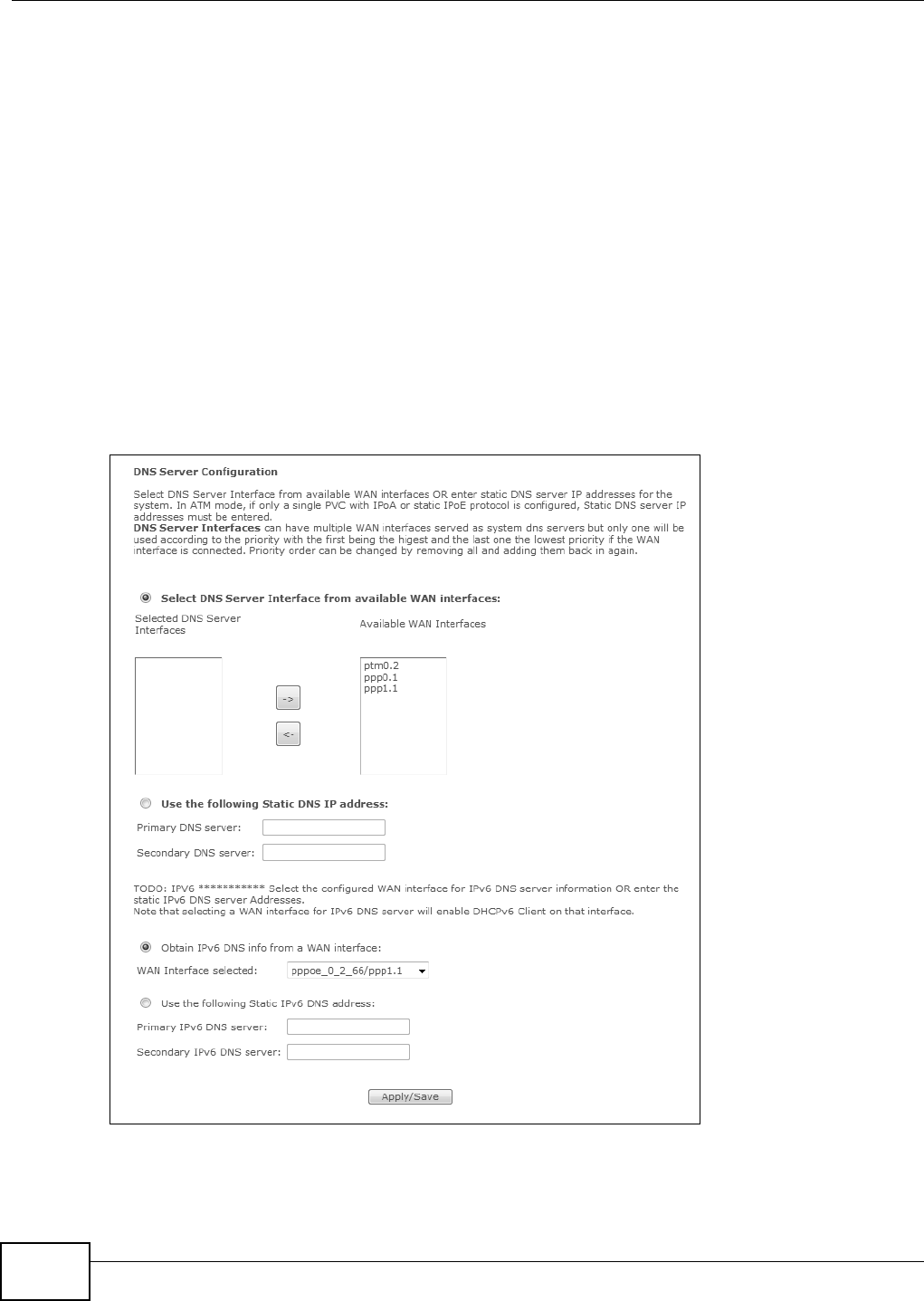
Chapter 10 DNS Setup
Basic Home Station VDSL2 P8802T User’s Guide
146
10.1.2 What You Need To Know
DYNDNS Wildcard
Enabling t he wildcard feature for your host causes * .yourhost .dyndns.org to be aliased to t he sam e
I P address as yourhost.dyndns.org. This feature is useful if you want to be able t o use, for exam ple,
www.yourhost .dyndns.org and st ill reach your host nam e.
I f you have a privat e WAN I P address, then you cannot use Dynam ic DNS.
10.2 The DNS Server Screen
Use t his screen to view and configur e DNS routes on t he VDSL Router. Click W ire less ne t w or k >
Classic con figura t ion > Adva nced Se t up > DN S > DN S Ser ver t o open t his screen.
Figure 57 DNS Server

Chapter 10 DNS Setup
Basic Home Station VDSL2 P8802T User’s Guide 147
The following t able describes t he fields in this screen.
10.3 The Dynamic DNS Screen
Use t his screen t o creat e m anage DDNS ent ries. Click Advance d Se t up > DNS > D yn am ic DNS
to display the following screen.
Table 51 DNS Server
LABEL DESCRIPTION
Select DNS
Server
I nter face fr om
available WAN
int erfaces
Select t his to have t he VDSL Rout er get the DNS server addresses from one of the VDSL
Rout er’s WAN interfaces.
Select ed
DNS Server
I nter faces
Select a WAN int erface t hrough which to get DNS server addresses.
You can select multiple WAN int erfaces for t he device t o t ry. The VDSL Rout er t ries t he WAN
int erfaces in the order listed and uses only t he DNS server inform at ion of the first WAN
int erface t hat connect s; there is no backup WAN funct ion. To change the pr iorit y order
rem ove t hem all and add t hem back in again.
Av ailable
WAN
I nter faces
These are t he WAN int er faces you can select from .
Use t he
following Stat ic
DNS I P address
Select this to have t he VDSL Rout er use the DNS server addresses you configure m anually.
Prim ar y
DNS ser ver
Enter t he first DNS server address assigned by the I SP.
Secondary
DNS ser ver
Enter t he second DNS server address assigned by the I SP.
Obtain I Pv6
DNS info from
a WAN
int erface
Select this to have the VDSL Rout er get t he I Pv6 DNS server addresses from t he I SP
aut om atically.
WAN
I nterface
selected
Select a WAN int erface through w hich you want to obtain the I Pv6 DNS related inform at ion.
Use t he
following Stat ic
I Pv6 DNS
address
Select this to have t he VDSL Router use the I Pv 6 DNS server addresses you configure
m anually.
Prim ar y
I Pv6 DNS
ser ver
Enter t he first I Pv 6 DNS server address assigned by the I SP.
Secondary
I Pv6 DNS
ser ver
Enter t he second IPv 6 DNS server address assigned by the I SP.
Apply/ Save Click this but t on to save your changes.
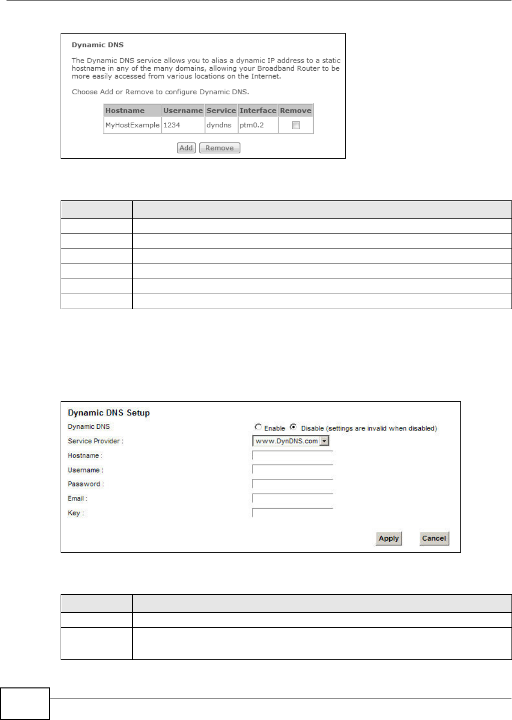
Chapter 10 DNS Setup
Basic Home Station VDSL2 P8802T User’s Guide
148
Figure 58 Dynam ic DNS
The following t able describes t he fields in this screen.
10.3.1 The Dynamic DNS Add Screen
Use t his screen t o create a DDNS ent ry. Click t he D ynam ic DNS screen’s Add butt on t o display t he
following screen.
Figure 59 Dynam ic DNS Add
The following t able describes t he fields in this screen.
Table 52 Dynamic DNS
LABEL DESCRIPTION
Hostnam e This displays the ent ry’s dom ain nam e.
Usernam e This displays the entry’s user nam e.
Service This displays the ent ry’s Dynam ic DNS service pr ovider.
I nterface This displays t he int erface the DDNS ent ry uses.
Rem ove Select entries and click the Re m ove butt on to delet e t hem .
Add Click this to creat e a new DDNS entr y.
Table 53 Dynamic DNS Add
LABEL DESCRIPTION
D- DNS pr ov id er Select your Dynam ic DNS serv ice provider from the dr op-down list box.
Hostnam e Type t he dom ain nam e assigned to your VDSL Rout er by your Dynam ic DNS provider.
You can specify up to two host nam es in the field separat ed by a com ma ( ",") .

Chapter 10 DNS Setup
Basic Home Station VDSL2 P8802T User’s Guide 149
I nterface Select t he int erface the DDNS ent ry uses.
Usernam e Type your user nam e.
Password Type the password assigned to you.
Apply/ Save Click this but t on to save your changes.
Table 53 Dynam ic DNS Add (continued)
LABEL DESCRIPTION

Chapter 10 DNS Setup
Basic Home Station VDSL2 P8802T User’s Guide
150

Basic Home Station VDSL2 P8802T User’s Guide 151
CHAPTER 11
UPnP
11.1 Overview
Universal Plug and Play (UPnP) is a dist ributed, open net working standard t hat uses TCP/ I P for
sim ple peer-to-peer net work connectivity between devices. A UPnP device can dynam ically join a
net work, obt ain an I P address, convey it s capabilities and learn about other devices on t he net work.
I n t urn, a device can leave a net work sm oot hly and aut om at ically when it is no longer in use.
11.1.1 What You Can Do in this Chapter
Use t he UPnP screen to enable UPnP on the VDSL Router (Sect ion 11.2 on page 152) .
11.1.2 What You Need To Know
Identifying UPnP Devices
UPnP hardware is ident ified as an icon in the Net work Connections folder (Windows XP) . Each UPnP
com pat ible device installed on your net work will appear as a separate icon. Selecting the icon of a
UPnP device will allow you t o access the inform at ion and properties of t hat device.
NAT Traversal
UPnP NAT traversal aut omat es the process of allowing an applicat ion to operate through NAT. UPnP
net work devices can autom atically configure net work addressing, announce t heir presence in the
net work t o other UPnP devices and enable exchange of sim ple product and service descript ions.
NAT traversal allows t he following:
• Dynam ic port m apping
• Lear ning public I P addresses
• Assigning lease t im es to m appings
Windows Messenger is an exam ple of an application t hat supports NAT traversal and UPnP.
See t he Chapter 6 on page 115 for m or e inform ation on NAT.
Cautions with UPnP
The aut om at ed nat ure of NAT traversal applications in est ablishing t heir own services and opening
firewall port s m ay present net work security issues. Net work inform at ion and configuration m ay also
be obt ained and m odified by users in some net work environm ents.
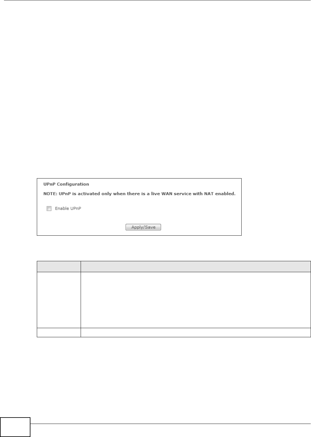
Chapter 11 UPnP
Basic Home Station VDSL2 P8802T User’s Guide
152
When a UPnP device j oins a net work, it announces it s presence with a m ulticast m essage. For
security reasons, t he VDSL Router allows m ulticast m essages on t he LAN only.
All UPnP- enabled devices m ay com m unicat e freely with each ot her wit hout additional configuration.
Disable UPnP if t his is not your int ent ion.
UPnP and ZyXEL
ZyXEL has achieved UPnP certification from the Universal Plug and Play Forum UPnP™
I m plem ent ers Corp. ( UI C) . ZyXEL's UPnP im plem ent at ion support s I nt ernet Gateway Device ( I GD)
1.0.
See Sect ion 11.3 on page 152 for exam ples of installing and using UPnP.
11.2 The UPnP Screen
Use t he following screen t o enable or disable UPnP on your VDSL Router. Click Advanced Setup >
UPnP t o display the screen show n next .
Figure 60 Net work Set ting > Hom e Net working > UPnP
The following t able describes t he labels in t his screen.
11.3 Installing UPnP in Windows XP Example
This sect ion shows how to install UPnP in Window s Windows XP.
1Click St a r t and Cont r ol Pa ne l.
Table 54 Net work Set t ing > Home Net working > UPnP
LABEL DESCRIPTION
Enable UPnP Select t his to allow UPnP- enabled applications to aut om at ically configure the VDSL Rout er
so t hat t hey can com m unicate t hrough t he VDSL Rout er by using NAT traver sal. UPnP
applications aut om at ically reserve a NAT forwarding port in order t o comm unicat e wit h
anot her UPnP enabled dev ice; t his elim inates the need to m anually configure port
forwarding for t he UPnP enabled applicat ion.
Be awar e t hat anyone could use a UPnP applicat ion t o open the web configurat or's login
screen without ent ering the VDSL Router's I P address ( although you m ust still ent er the
passwor d to access t he web configurator).
Apply/ Save Click t his to save your changes.
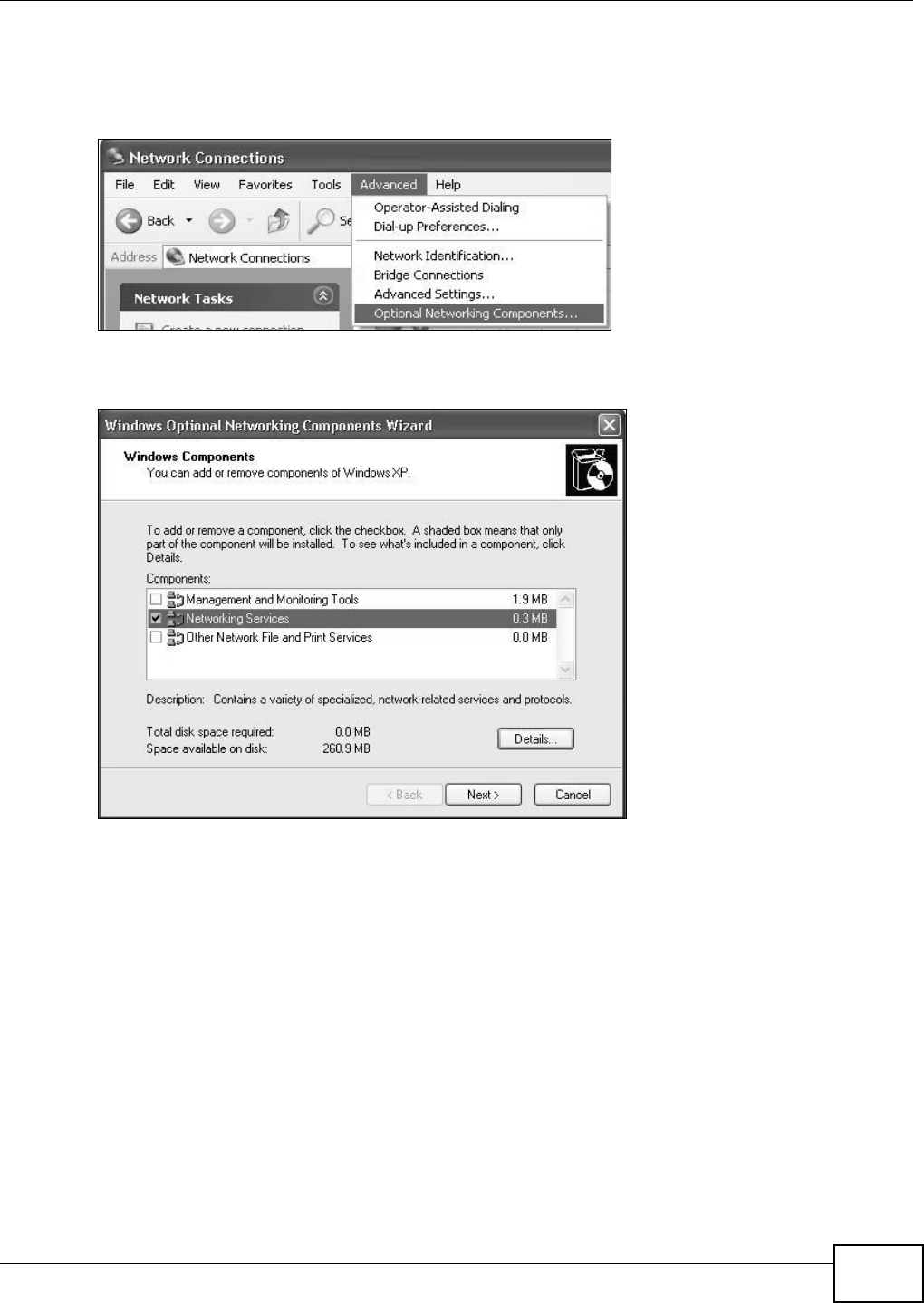
Chapter 11 UPnP
Basic Home Station VDSL2 P8802T User’s Guide 153
2Double- click Ne t w ork Conne ct ions.
3I n t he N e tw or k Con ne ct ions window, click Adva nced in t he m ain m enu and select Opt ional
N etw ork ing Com ponents ….
Network Co nnections
4The W indow s Opt iona l N e t w or kin g Com ponent s W izard window displays. Select Net w ork ing
Se rvice in the Com ponent s select ion box and click D e t a ils.
Windows Optional Networking Components Wizard
5I n t he N e tw orking Se rvice s window, select the Unive rsa l Plug a nd Play check box.
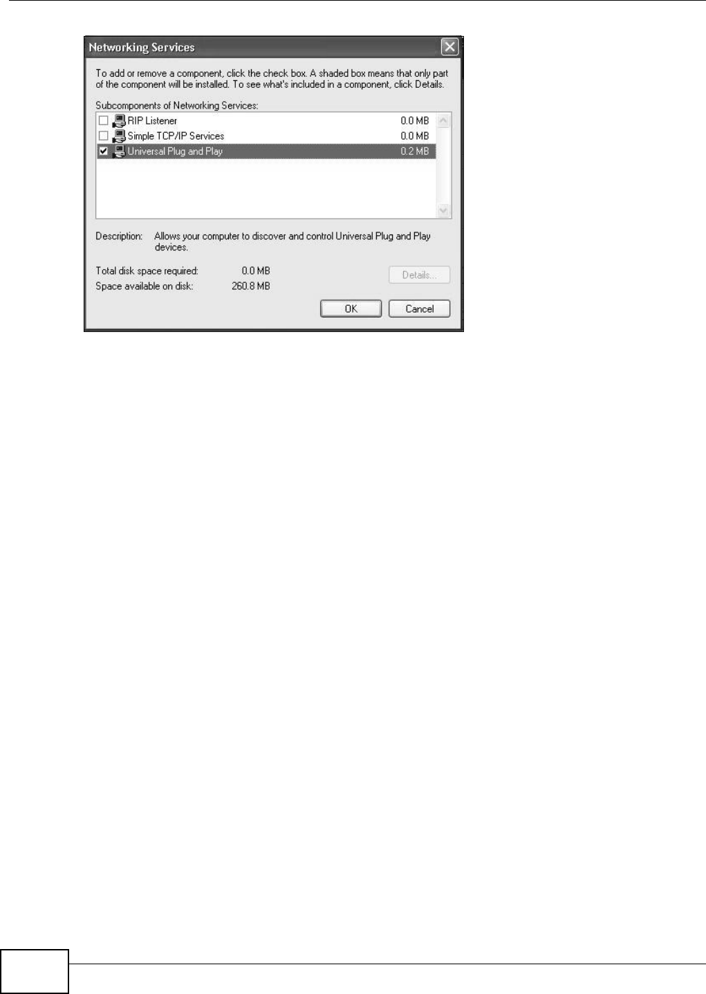
Chapter 11 UPnP
Basic Home Station VDSL2 P8802T User’s Guide
154
Networking Services
6Click OK to go back t o the W indow s Opt ional N etw ork ing Com pon en t W iz ard window and
click N e x t .
11.4 Using UPnP in Windows XP Example
This sect ion shows you how t o use the UPnP feature in Windows XP. You m ust already have UPnP
inst alled in Windows XP and UPnP act ivated on the VDSL Router.
Make sure t he computer is connected to a LAN port of the VDSL Router. Turn on your com puter and
the VDSL Router.
Auto-discover Your UPnP-enabled Network Device
1Click St a r t and Cont r ol Pa ne l. Double- click N e t w or k Connect ions. An icon displays under
I nt ernet Gat eway.
2Right-click t he icon and select Pr ope r t ie s.
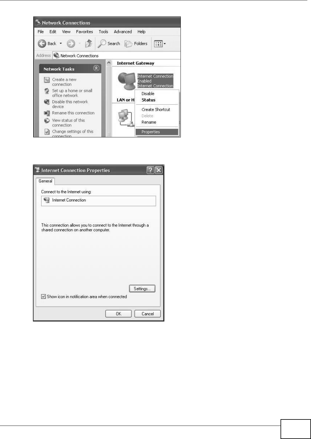
Chapter 11 UPnP
Basic Home Station VDSL2 P8802T User’s Guide 155
Network Co nnections
3I n t he I nt e rnet Con ne ct ion Pr opert ies window, click Set t ings t o see t he port m appings t here
were aut om at ically created.
Internet Connec tion Propertie s
4You m ay edit or delete t he por t m appings or click Add to manually add port mappings.
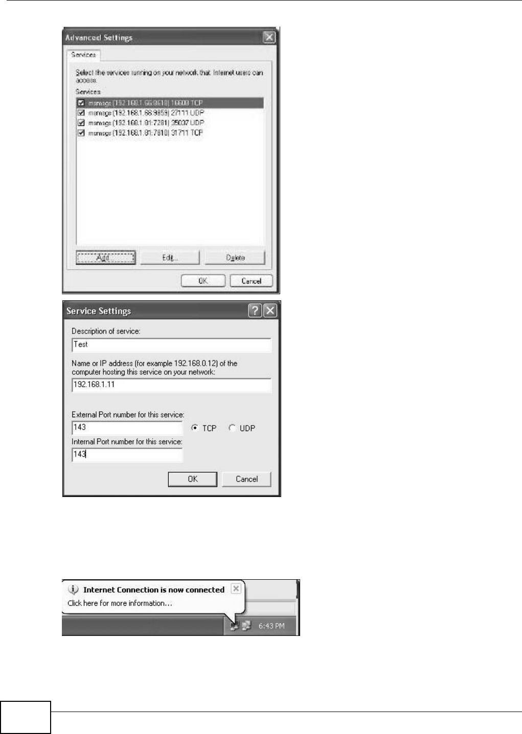
Chapter 11 UPnP
Basic Home Station VDSL2 P8802T User’s Guide
156
Internet Connection Properties: Advanced Settings
Internet Connec tion Propertie s: Advanced Set tings: Add
5When t he UPnP-enabled device is disconnected from your com puter, all port m appings will be
deleted autom at ically.
6Select Show icon in not ifica t ion ar ea w hen conne ct ed opt ion and click OK. An icon displays in
the syst em t ray.
System Tray Icon
7Double- click on the icon to display your curr ent I nt ernet connect ion st at us.
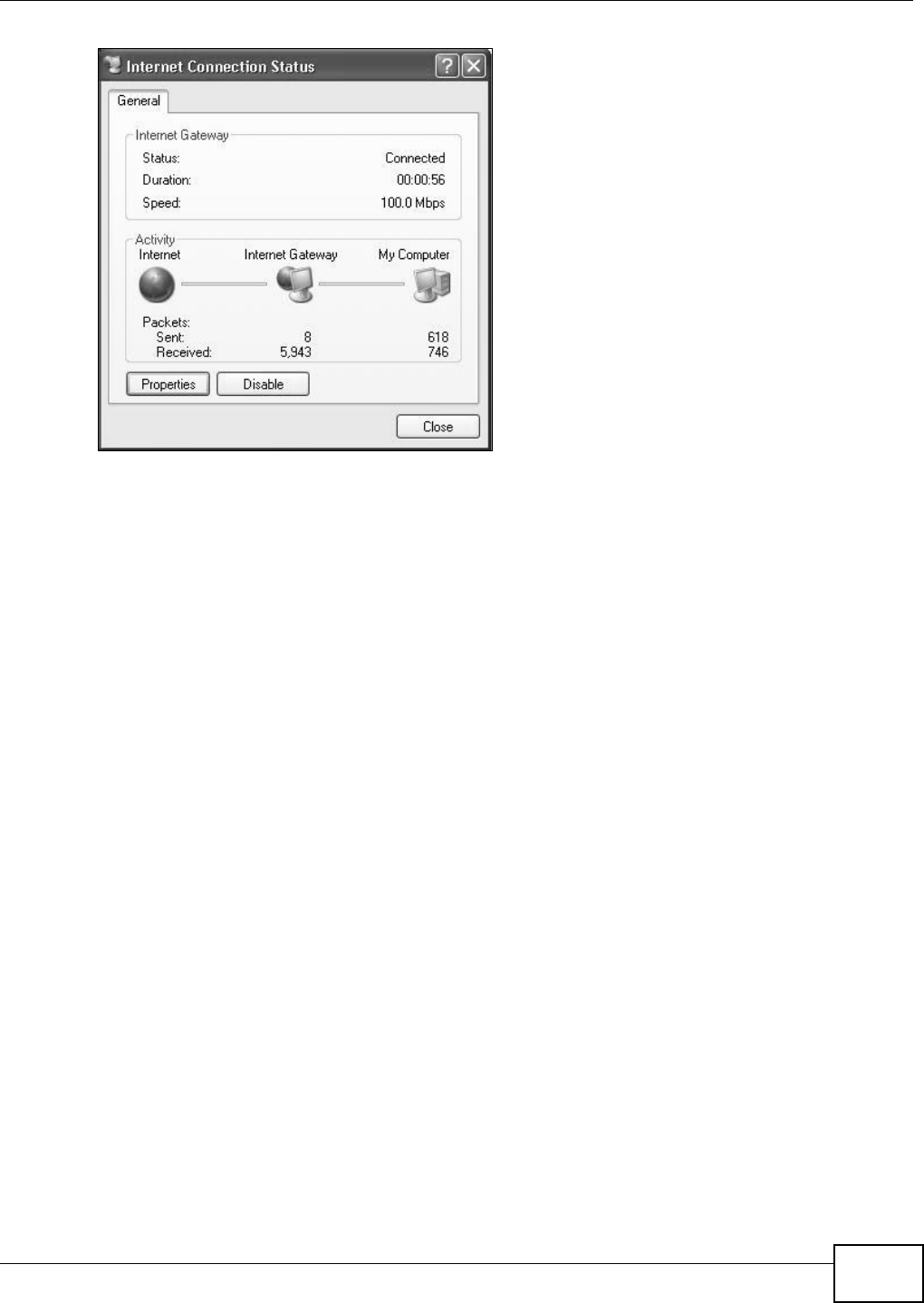
Chapter 11 UPnP
Basic Home Station VDSL2 P8802T User’s Guide 157
Internet Conn ection Status
Web Configurator Easy Access
With UPnP, you can access the web-based configurat or on t he VDSL Rout er wit hout finding out t he
I P address of the VDSL Rout er first . This com es helpful if you do not know the I P address of t he
VDSL Rout er .
Follow t he st eps below to access t he web configurator.
1Click St a r t and t hen Cont r ol Pa ne l.
2Double- click Ne t w ork Conne ct ions.
3Select My Net w ork Pla ces under Other Pla ce s.
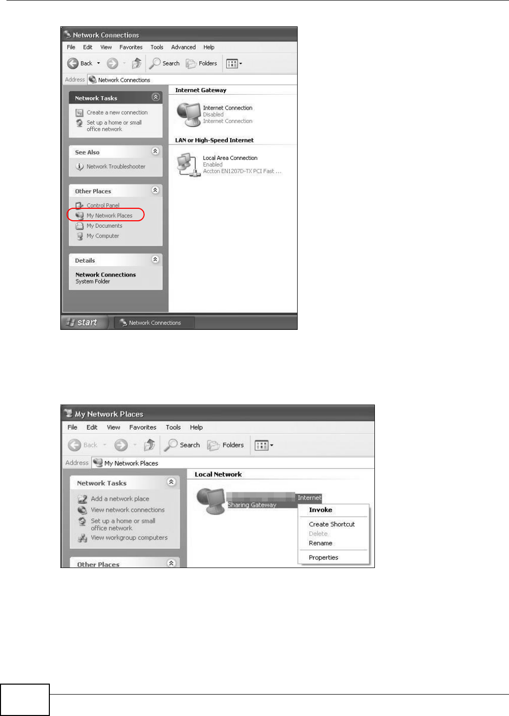
Chapter 11 UPnP
Basic Home Station VDSL2 P8802T User’s Guide
158
Network Co nnections
4An icon wit h the description for each UPnP- enabled device displays under Local N etw ork.
5Right-click on the icon for your VDSL Router and select I nvoke . The web configurator login screen
displays.
Network Co nnections: My Netw ork Places
6Right-click on the icon for your VDSL Rout er and select Prope r t ie s. A properties window displays
with basic inform ation about t he VDSL Router.
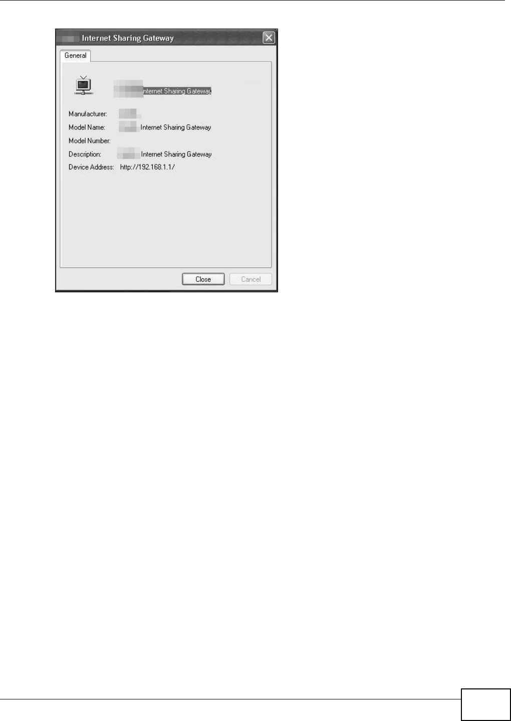
Chapter 11 UPnP
Basic Home Station VDSL2 P8802T User’s Guide 159
Network Co nnections: My Netw ork Places: Proper ties: Example

Chapter 11 UPnP
Basic Home Station VDSL2 P8802T User’s Guide
160

Basic Home Station VDSL2 P8802T User’s Guide 161
CHAPTER 12
USB Services
12.1 Overview
The VDSL Rout er has a USB port used t o share files via a USB m emory st ick or a USB hard drive. I n
the USB Se rvice screens, you can enable file- sharing server, m edia server, and print er server.
12.1.1 What You Can Do in this Chapter
• Use the File Sh aring screen t o configure a file- sharing server ( Sect ion 12.2 on page 162) .
• Use the Printer Server screen t o enable t he print server (Sect ion 12.3 on page 165) .
• Use the M edia Server screen to enable or disable the sharing of m edia files (Sect ion 12.4 on
page 166) .
12.1.2 What You Need To Know
The following t erm s and concept s m ay help as you r ead t his chapter.
12.1.2.1 About File Sharing
Workgroup name
This is the nam e given t o a set of com puters t hat are connect ed on a network and share resources
such as a printer or files. Windows aut om atically assigns t he workgroup nam e when you set up a
net work.
Shares
When set t ings are set t o default, each USB device connect ed to t he VDSL Router is given a folder,
called a “ share”. I f a USB hard drive connect ed to t he VDSL Router has m ore t han one part ition,
then each part ition will be allocated a share. You can also configure a “ share” to be a sub- folder or
file on t he USB device.
File Systems
A file syst em is a way of st oring and organizing files on your hard drive and storage device. Often
different operat ing syst em s such as Windows or Linux have different file syst em s. The file sharing
feat ure on your VDSL Router support s File Allocation Table ( FAT) and FAT32.
Common Internet File System
The VDSL Router uses Com m on I nt ernet File Syst em ( CI FS) protocol for its file sharing funct ions.
CIFS com patible comput ers can access the USB file st orage devices connected to t he VDSL Router.

Chapter 12 USB Services
Basic Home Station VDSL2 P8802T User’s Guide
162
CIFS protocol is support ed on Microsoft Windows, Linux Sam ba and ot her operat ing syst em s (refer
to your syst em s specifications for CI FS com pat ibility).
12.1.2.2 About Printer Server
Print Server
This is a com put er or other device which m anages one or m ore print ers, and which sends print j obs
to each printer from the com put er it self or ot her devices.
Operating System
An operating syst em ( OS) is t he int er face which helps you m anage a com puter. Com m on exam ples
are Microsoft Windows, Mac OS or Linux.
TCP/IP
TCP/ I P ( Transm ission Control Prot ocol/ I nt ernet Prot ocol) is a set of comm unications prot ocols t hat
m ost of the I nt ernet runs on.
Port
A port maps a network service such as ht tp t o a pr ocess running on your computer, such as a
process run by your web browser. When t raffic from t he I nt ernet is received on your com puter, t he
port num ber is used to ident ify which process running on your com put er it is int ended for.
Supported OSs
Your operating syst em m ust support TCP/ IP port s for printing and be com pat ible with the RAW ( port
9100) prot ocol.
The following OSs support VDSL Rout er’s printer sharing feat ure.
• Microsoft Windows 95, Windows 98 SE ( Second Edit ion), Windows Me, Windows NT 4.0, Windows
2000, Window s XP or Macint osh OS X.
12.2 The File Sharing Screen
You can share files on a USB m emory stick or hard drive connect ed to your VDSL Router with users
on your net work.
The following figure is an overview of the VDSL Router’s file server feature. Com put ers A and B can
access files on a USB device ( C) which is connect ed to t he VDSL Router.
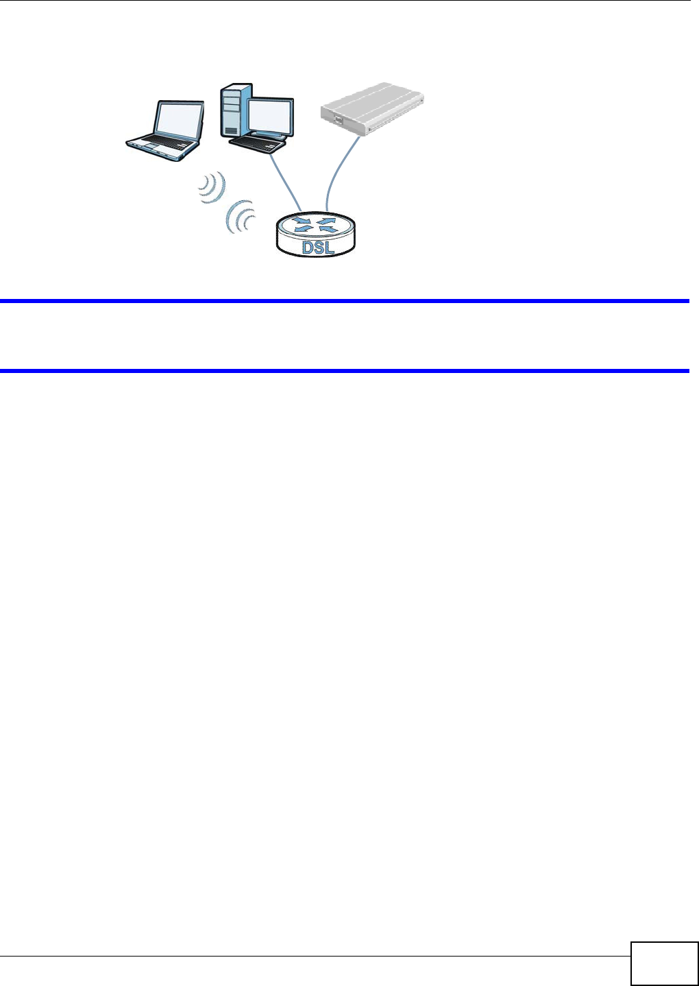
Chapter 12 USB Services
Basic Home Station VDSL2 P8802T User’s Guide 163
Figure 61 File Sharing Overview
The VDSL Router will not be able t o join t he workgroup if your local area net work has
rest rict ions set up that do not allow devices to j oin a workgroup. I n t his case, cont act your
netw ork adm inist rator.
12.2.1 Before You Begin
Make sure the VDSL Rout er is connect ed t o your net work and turned on.
1Connect the USB device t o one of t he VDSL Router’s USB port . Make sure the VDSL Rout er is
connect ed to your network.
2The VDSL Router detect s t he USB device and m akes it s contents available for browsing. I f you are
connect ing a USB hard drive t hat com es wit h an ext ernal power supply, m ake sure it is connect ed
to an appropriate power source t hat is on.
Note: I f your USB device cannot be det ect ed by t he VDSL Router, see the t roubleshoot ing
for suggest ions.
Use t his screen t o set up file sharing using t he VDSL Router. To access t his screen, Click Adva nced
Se t up > USB Se rvices > File Sha r ing.
A
BC
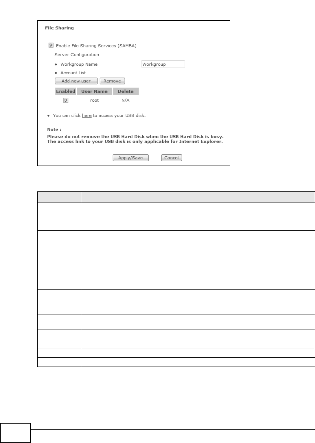
Chapter 12 USB Services
Basic Home Station VDSL2 P8802T User’s Guide
164
Figure 62 Net work Set t ing > USB Service > File Sharing
Each field is described in the following table.
12.2.2 Add New File Sharing User
Click the File Shar ing screen’s Add ne w user butt on t o set up a new file sharing user on the VDSL
Rou t er .
Table 55 Net work Set t ing > Home Net working > File Sharing
LABEL DESCRIPTION
Enable File
Sharing
Services
( SAMBA)
Select this t o act ivate file shar ing t hrough t he VDSL Router.
Workgroup
Nam e
You can add the VDSL Router t o an ex ist ing or a new workgroup on your netw ork. Enter t he
nam e of the work group which your VDSL Rout er aut om at ically j oins.
You can set the VDSL Rout er’s workgroup nam e to be exactly t he sam e as the workgroup
nam e to w hich your com put er belongs.
Note: The VDSL Router will not be able to join the workgroup if your local area network has
restrictions set up that do not allow devices to join a workgroup. In this case, contact
your network administrator.
Add new user Click t his t o set up a file-sharing account . Before you can shar e files you need a user
account .
Rem ove Click this to delet e the user account ( s) who’s D ele t e check box is select ed.
Enabled This field displays whether a user account is act ivated or not . Select the check box to enable
the account. Clear t he check box t o disable the account.
User Nam e This display s the user nam e t hat has been configured on the VDSL Rout er for file sharing.
Delet e Select t he check box of the user account that you want t o rem ove from the list .
Apply/ Save Click this to save your changes t o the VDSL Rout er.
Cancel Click this to set every field in t his scr een to its last- saved value.
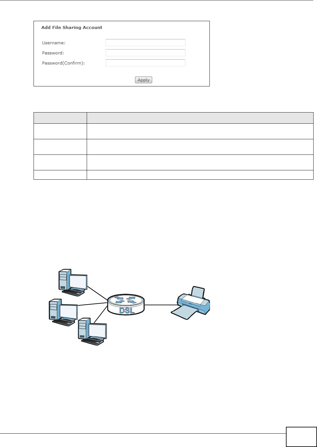
Chapter 12 USB Services
Basic Home Station VDSL2 P8802T User’s Guide 165
Figure 63 File Sharing: Add new user
Each field is described in the following table.
12.3 The Printer Server Screen
The VDSL Router allows you t o share a USB print er on your LAN. You can do t his by connect ing a
USB printer to one of the USB ports on t he VDSL Router and then configuring a TCP/ I P port on t he
com puters connect ed t o your net work.
Figure 64 Sharing a USB Printer
12.3.1 Before You Begin
To configure the print server you need the follow ing:
• Your VDSL Router m ust be connect ed to your com put er and any ot her devices on your net work.
The USB print er m ust be connect ed t o your VDSL Router.
• A USB print er with t he driver already inst alled on your com put er.
Table 56 File Sharing: Add new user
LABEL DESCRIPTION
Usernam e Enter a user nam e that will be allowed to access shares. You can enter up t o 16
charact er s. Only let t ers and num bers allowed.
Password Enter t he password used t o access the share. You can enter up to 16 charact er s. Only
lett er s and num bers are allowed. The passw ord is case sensitive.
Password
( Con firm )
Retype the password t hat you ent ered above.
Apply Click this to save your changes t o the VDSL Rout er.
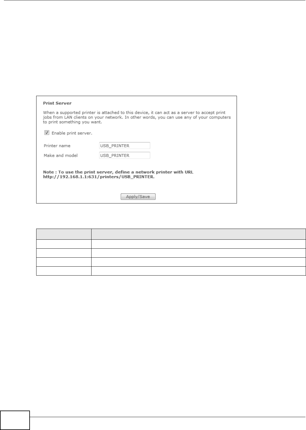
Chapter 12 USB Services
Basic Home Station VDSL2 P8802T User’s Guide
166
• The com put ers on your net work m ust have t he printer soft ware already installed before t hey can
creat e a TCP/ I P port for printing via t he net work. Follow your printer m anufact urers instruct ions
on how to install the print er software on your com puter.
Note: Your print er ’s inst allat ion instructions m ay ask that you connect t he printer to your
com put er. Connect your print er t o the VDSL Router inst ead.
Use t his screen t o enable or disable sharing of a USB print er via your VDSL Rout er.
To access this screen, click Advan ced Set up > USB Se rvices > Print Serve r.
Figure 65 Print Server
The following t able describes t he labels in t his m enu.
12.4 The Media Server Screen
The m edia server st ream s video, m usic, and phot o files from USB st orage to DLNA- com pliant m edia
clients on your network. Connect the USB st orage device t o t he VDSL Router’s USB port. See
Sect ion 2.11 on page 43 for exam ples of using t he m edia server wit h following m edia client s.
Note: Anyone on your network can play t he m edia files in t he published shares. The
m edia server does not use user nam e and password or ot her form s of security.
Click Advan ce d Setup > USB Se rvices > Media Se rver t o open t his screen and change your
VDSL Router’s m edia server set t ings.
Table 57 Net work Set ting > USB Service > Print Server
LABEL DESCRIPTION
Enable print server Select this to have the VDSL Rout er share a USB print er.
Printer name Enter t he nam e of the printer.
Make and m odel Enter t he m anufact urer and m odel num ber of the print er.
Apply/ Save Click t his to save your changes to the VDSL Rout er.
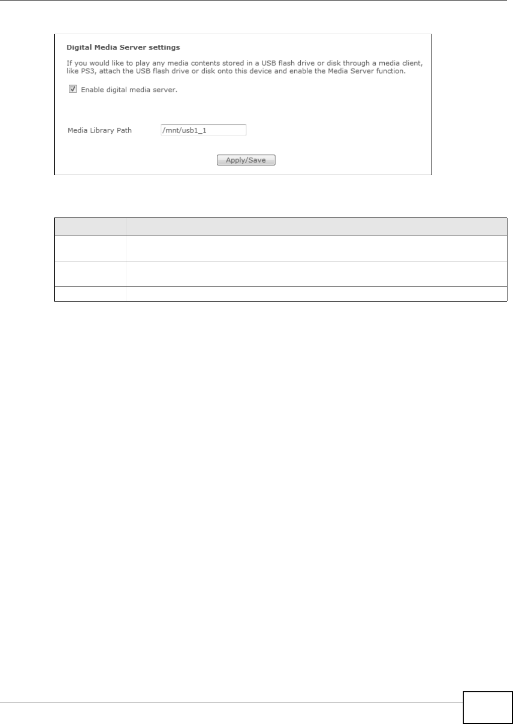
Chapter 12 USB Services
Basic Home Station VDSL2 P8802T User’s Guide 167
Figure 66 Media Server
The following t able describes t he labels in t his m enu.
Table 58 Media Server
LABEL DESCRIPTION
Enable digit al
m edia server
Select this to have t he VDSL Rout er function as a DLNA-compliant media server so DLNA-
compliant m edia clients on your net work can play m edia files locat ed in t he shar es.
Media Library
Pat h
Enter t he path client s use to access t he m edia files on a USB st orage device connected to
the VDSL Rout er.
Apply/ Save Click this to save your changes to t he VDSL Rout er.

Chapter 12 USB Services
Basic Home Station VDSL2 P8802T User’s Guide
168

Basic Home Station VDSL2 P8802T User’s Guide 169
CHAPTER 13
Certificates
13.1 Overview
The VDSL Router can use cert ificat es ( also called digit al I Ds) t o authent icat e user s. Cert ificates are
based on public- privat e key pairs. A certificate cont ains t he certificat e owner ’s ident ity and public
key. Cert ificates provide a way to exchange public keys for use in aut hent icat ion.
13.1.1 What You Can Do in this Chapter
• Use the Loca l Ce rtifica t es screens t o generat e cer tificat ion request s and im port the VDSL
Router's CA-signed certificates (Sect ion 13.4 on page 173) .
• Use the Tru st ed CA screen to save the certificates of t rust ed CAs to t he VDSL Router (Sect ion
13.4 on page 173) .
13.2 What You Need to Know
The following t erm s and concept s m ay help as you read t hrough this chapt er.
Certification Authority
A Cert ification Aut horit y ( CA) issues certificates and guarantees the ident ity of each certificat e
owner. There are com m ercial certification aut horit ies like CyberTrust or VeriSign and governm ent
certificat ion aut horit ies. The cert ificat ion aut horit y uses it s private key to sign cert ificates. Anyone
can t hen use t he certificat ion aut horit y's public key t o verify the cer tificat es. You can use t he VDSL
Router to generat e certificat ion request s t hat contain ident ifying inform ation and public keys and
then send t he certificat ion request s t o a certification aut horit y.
13.3 The Local Certificates Screen
Click Advance d Setup > Certifica t e to open the Loca l Ce rt ificate s screen. This screen displays
the VDSL Router ’s list of certificat es and certification request s.
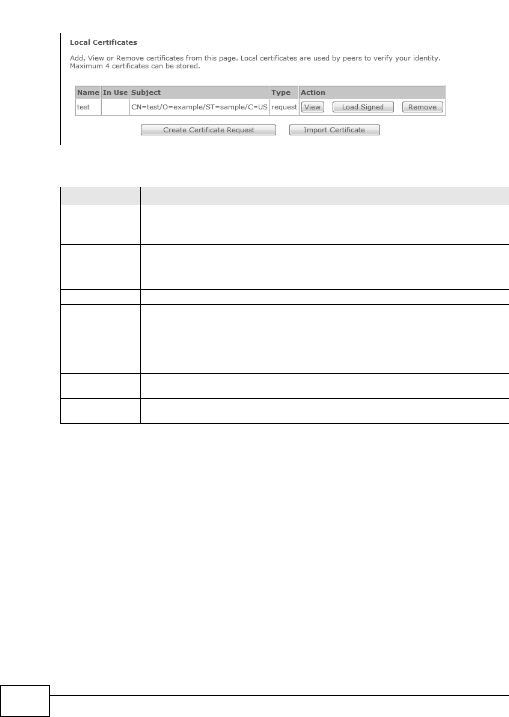
Chapter 13 Certificates
Basic Home Station VDSL2 P8802T User’s Guide
170
Figure 67 Local Certificat es
The following t able describes t he labels in t his screen.
13.3.1 Create Certificate Request
Click the Local Ce rt ifica t es screen’s Cr eat e Cer t ificate Requ est button to open the following
screen. Use t his screen to have the VDSL Router generat e a certificat ion request .
Table 59 Local Certificat es
LABEL DESCRIPTION
Nam e This field displays the nam e used to identify t his certificat e. I t is recom m ended that you
give each cert ificate a unique nam e.
I n Use This field show s whet her or not t he VDSL Rout er currently uses the cert ificat e.
Subject This field displays ident ifying inform at ion about t he cert ificat e’s owner, such as CN
( Com m on Nam e) , OU (Organizat ional Unit or depart m ent ), O (Or ganizat ion or com pany)
and C (Country) . I t is recom m ended t hat each cert ificate have unique subject
inform at ion.
Type This field displays whet her t he entry is for a cert ificat e or a cert ificat e request .
Action Click the View but ton t o open a screen wit h an in- dept h list of inform at ion about t he
cert ificat e ( or cert ification request) .
For a cert ificat ion request , click Load Signed to im port the signed cert ificate.
Click the Re m ove butt on t o delet e t he cert ificat e ( or cert ificat ion request) . You cannot
delet e a cert ificat e that one or m ore features is configured to use.
Creat e Cert ificate
Requ est
Click this but ton t o go to t he scr een where you can hav e t he VDSL Rout er generate a
cer tificat ion request .
I m por t Cert ificat e Click this but ton t o save the cer tificate that you have enrolled from a certificat ion
authority from your com puter t o t he VDSL Rout er.
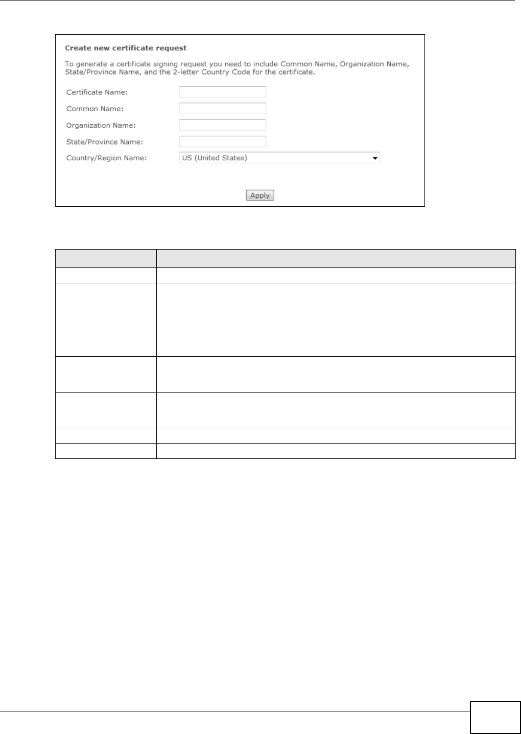
Chapter 13 Certificates
Basic Home Station VDSL2 P8802T User’s Guide 171
Figure 68 Creat e Certificate Request
The following t able describes t he labels in t his screen.
Aft er you click Apply, the following scr een displays to not ify you t hat you need t o get t he certificat e
request signed by a Certificate Authority. I f you already have, click Load_ Signed to im port the
signed certificate into the VDSL Router. Otherwise click Ba ck to return t o t he Loca l Ce rt ifica t es
screen.
Table 60 Create Cert ificate Request
LABEL DESCRIPTION
Cert ificat e Nam e Type up t o 63 ASCI I charact ers ( not including spaces) t o identify this certificat e.
Com m on Nam e Select Auto to have t he VDSL Router configure this field autom atically. Or select
Cu st o m iz e t o ent er it m anually.
Type t he I P addr ess ( in dott ed decim al not ation) , dom ain nam e or e-m ail address in
the field provided. The dom ain nam e or e-m ail address can be up t o 63 ASCI I
charact ers. The dom ain nam e or e- m ail address is for ident ificat ion purposes only
and can be any str ing.
Organizat ion Nam e Type up t o 63 charact ers to ident ify the com pany or group t o which the cert ificat e
owner belongs. You m ay use any charact er, including spaces, but the VDSL Router
drops trailing spaces.
St at e/ Province Nam e Type up t o 32 charact ers to ident ify the st at e or province wher e t he cer tificat e owner
is locat ed. You m ay use any charact er, including spaces, but the VDSL Rout er drops
trailing spaces.
Country/ Region Nam e Select a country to identify the nat ion wher e t he certificat e owner is located.
Apply Click Ap ply t o save your changes.
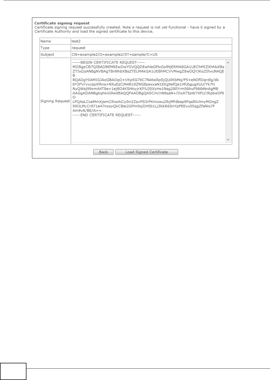
Chapter 13 Certificates
Basic Home Station VDSL2 P8802T User’s Guide
172
Figure 69 Cert ificate Request Created
13.3.2 Load Signed Certificate
Aft er you create a cert ificat e request and have it signed by a Cert ificate Authority, in t he Loca l
Ce r t if ica t e s screen click t he certificate request ’s Load Sign ed butt on t o im port the signed
certificat e into the VDSL Router.
Note: You m ust rem ove any spaces from t he cert ificate’s filenam e before you can im port
it .
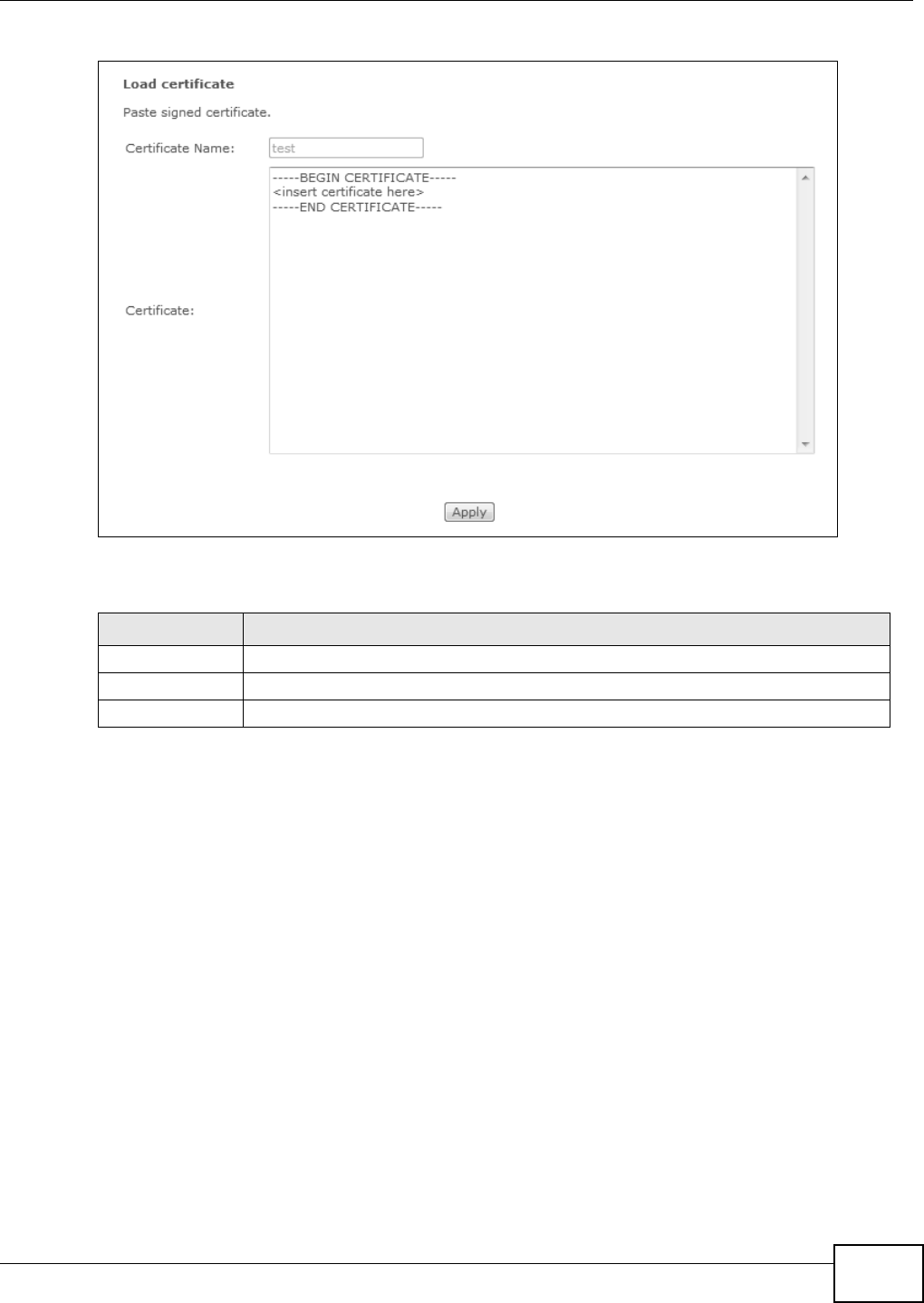
Chapter 13 Certificates
Basic Home Station VDSL2 P8802T User’s Guide 173
Figure 70 Load Signed Certificate
The following t able describes t he labels in t his screen.
13.4 The Trusted CA Screen
Click Advance d Setup > Cer tifica t e > Trust e d CA t o open t he following screen. This screen
displays a sum m ary list of certificat es of t he certificat ion aut horit ies t hat you have set the VDSL
Router to accept as t rust ed. The VDSL Router accepts any valid certificat e signed by a certificat ion
aut horit y on t his list as being trust wort hy; thus you do not need to im port any certificat e t hat is
signed by one of these certification aut horit ies.
Table 61 Load Signed Certificate
LABEL DESCRIPTION
Cert ificate Nam e This is t he nam e of the signed cert ificat e.
Cert ificat e Copy and past e the signed cert ificat e int o the text box t o st ore it on the VDSL Rout er.
Apply Click Apply to save your changes.
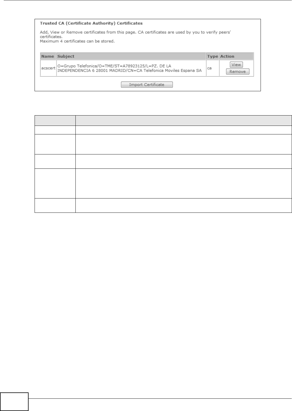
Chapter 13 Certificates
Basic Home Station VDSL2 P8802T User’s Guide
174
Figure 71 Tr u st e d CA
The following t able describes t he fields in this screen.
13.4.1 View Trusted CA Certificate
Click the View icon in the Tr ust e d CA screen t o open t he following screen. Use t his screen t o view
in- dept h inform at ion about t he certificat ion aut horit y’s certificat e.
Table 62 Tr u st e d CA
LABEL DESCRIPTION
Nam e This field displays the nam e used to ident ify this certificat e.
Subject This field displays infor m at ion t hat ident ifies the ow ner of t he cert ificat e, such as Com m on
Name ( CN) , OU ( Organizat ional Unit or depart m ent) , Organizat ion ( O) , St at e (ST) and
Countr y ( C). I t is recom m ended t hat each cert ificat e have unique subj ect inform at ion.
Type This field displays general inform ation about the cer tificat e. ca m eans that a Cert ificat ion
Aut hority signed the certificat e.
Act ion Click the View icon t o open a screen with an in-depth list of inform ation about the
cer tificate (or cert ificat ion request) .
Click the Re m ove but ton to delet e the certificat e (or cert ificat ion request ). You cannot
delet e a cert ificat e that one or m ore feat ures is configured to use.
I m port
Certificate
Click this but ton t o open a scr een where you can save the cert ificat e of a cert ificat ion
authority that you t r ust t o the VDSL Router.
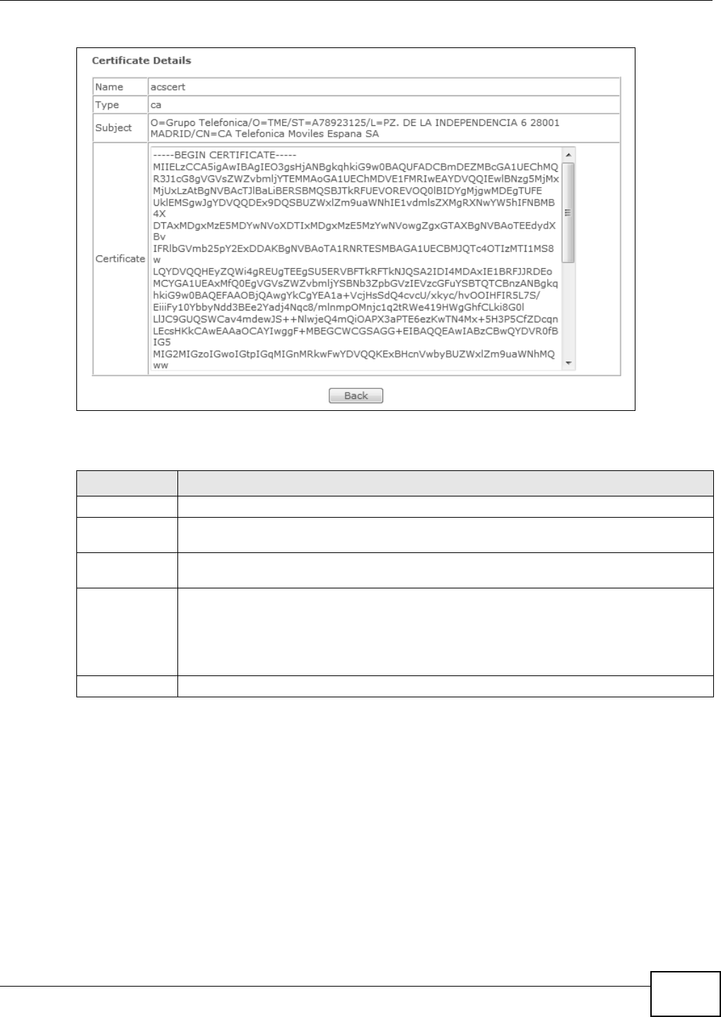
Chapter 13 Certificates
Basic Home Station VDSL2 P8802T User’s Guide 175
Figure 72 Tr u st e d CA : V i e w
The following t able describes t he fields in this screen.
13.4.2 Import Trusted CA Certificate
Click the Tr uste d CA screen’s I m port Cer t ificat e but ton t o open t he following screen. The VDSL
Router tr ust s any valid certificat e signed by any of t he im port ed t rust ed CA certificates.
Table 63 Tr u st e d CA: V i e w
LABEL DESCRIPTION
Nam e This field displays the identifying nam e of this certificat e.
Type This field displays general inform ation about the cer tificat e. ca m eans that a Cert ificat ion
Aut hority signed the certificat e.
Subject This field displays infor m at ion t hat ident ifies the ow ner of t he cert ificat e, such as Com m on
Name ( CN) , Organizational Unit (OU) , Organization ( O) and Country ( C).
Cert ificat e This read- only text box displays t he cert ificat e in Privacy Enhanced Mail (PEM) form at . PEM
uses base 64 t o convert t he binary cert ificate int o a printable form .
You can copy and past e t he cert ificate into an e- m ail t o send t o friends or colleagues or you
can copy and past e the cert ificat e into a t ext edit or and save t he file on a m anagem ent
com put er for lat er dist ribution ( via floppy disk for exam ple) .
Back Click Ba ck to return t o t he previous screen.
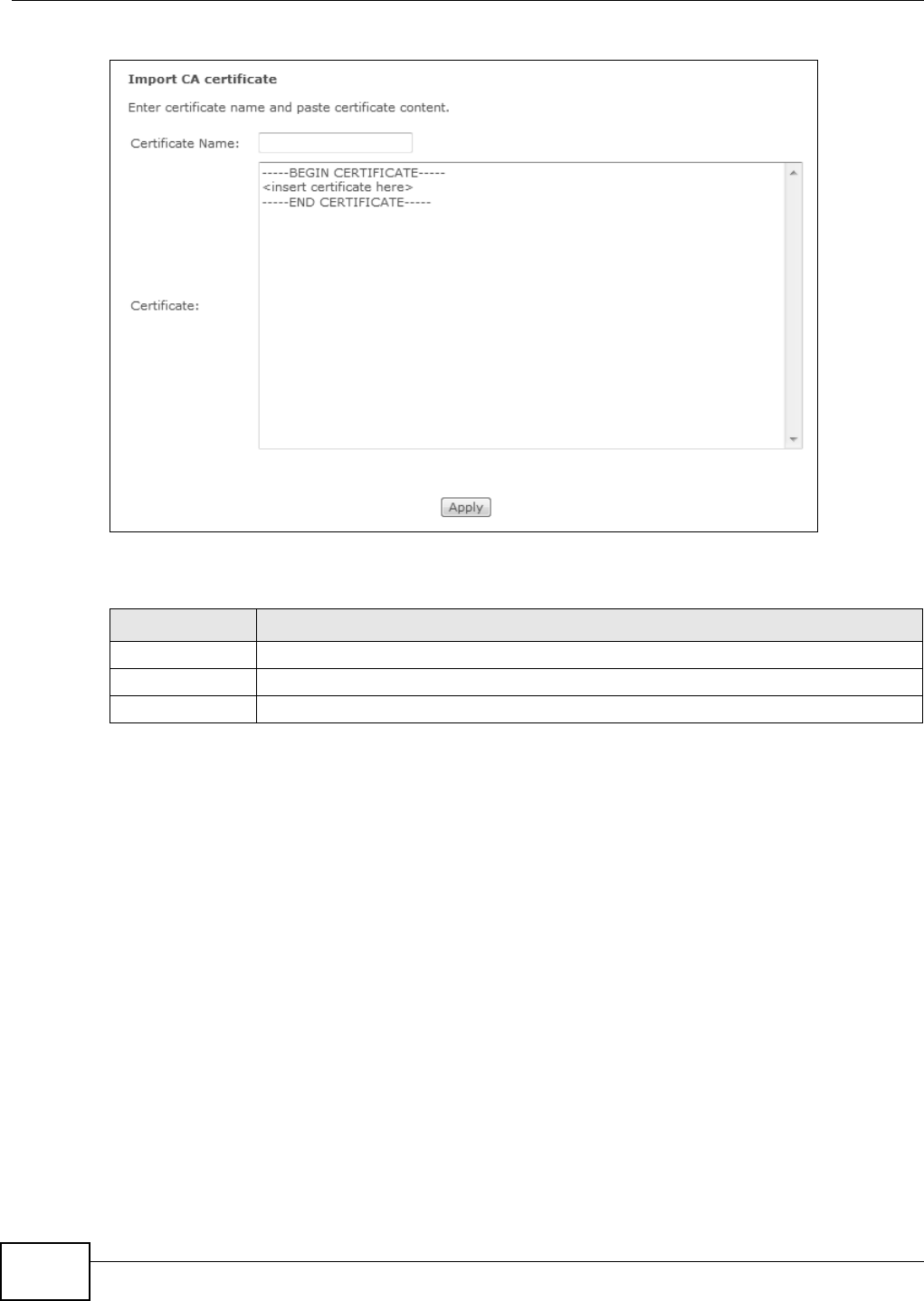
Chapter 13 Certificates
Basic Home Station VDSL2 P8802T User’s Guide
176
Figure 73 Tr ust ed CA: Im port Cert ificate
The following t able describes t he fields in this screen.
Table 64 Trust ed CA: I m port Cert ificate
LABEL DESCRIPTION
Cer tificat e Nam e Type a nam e for t he signed cert ificat e.
Cert ificate Copy and past e the certificat e into t he t ext box t o st ore it on the VDSL Router .
Apply Click t his to save your changes.

Basic Home Station VDSL2 P8802T User’s Guide 177
CHAPTER 14
Wireless
14.1 Overview
This chapt er describes t he VDSL Router’s N e t w or k Set t ing > W ire less screens. Use t hese
screens to set up your VDSL Router’s wireless connection.
14.1.1 What You Can Do in this Chapter
This sect ion describes t he VDSL Router’s W ir ele ss scr eens. Use t hese screens t o set up your VDSL
Router’s wireless connect ion.
• Use the Ba sic screen t o enable the Wireless LAN, enter the SSI D and configure basic sett ings
(Sect ion 14.2 on page 178) .
• Use the Se curity screen to configure wireless security set tings m anually or t hrough WPS
(Sect ion 14.3 on page 179) .
• Use the M AC Filt er screen t o allow or deny wireless client s based on t heir MAC addresses from
connect ing t o t he VDSL Router (Sect ion 14.4 on page 183) .
• Use the Advanced screen t o configure wireless advanced feat ures, such as t he RTS/ CTS
Threshold ( Section 14.5 on page 184) .
• Use the Stat ion I n fo screen t o display a list of connect ed wireless client s (Sect ion 14.6 on page
186) .
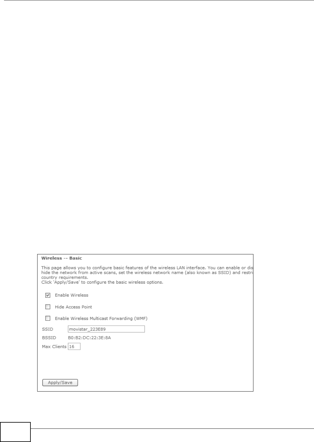
Chapter 14 Wireless
Basic Home Station VDSL2 P8802T User’s Guide
178
14.1.2 What You Need to Know
Wireless Basics
“ Wireless” is essentially radio com m unicat ion. I n t he sam e way that walkie- t alkie radios send and
receive inform at ion over the airwaves, w ireless net working devices exchange inform at ion with one
another. A wireless net working device is j ust like a radio t hat let s your com puter exchange
inform ation with radios at tached to other com puters. Like walkie- talkies, m ost wireless net working
devices operat e at radio frequency bands t hat are open t o t he public and do not require a license t o
use. However, w ireless net working is different from that of m ost t radit ional radio comm unicat ions in
that there a num ber of wireless networking st andards available with different m et hods of dat a
encrypt ion.
Finding Out More
See Sect ion 14.7 on page 186 for advanced technical inform ation on wireless net works.
14.2 The Basic Screen
Use t his screen t o enable t he Wireless LAN, ent er the SSI D and select t he wireless security mode.
Note: I f you configure t he VDSL Router from a com put er connected t o the wireless LAN
and you change t he VDSL Router’s SSI D, channel or securit y settings, you lose
your w ireless connect ion when you click Apply/ Save . Change the com put er’s
wireless set t ings t o m atch the VDSL Router’s new settings.
Click W ireless t o open the Ba sic screen.
Figure 74 Wireless: Basic
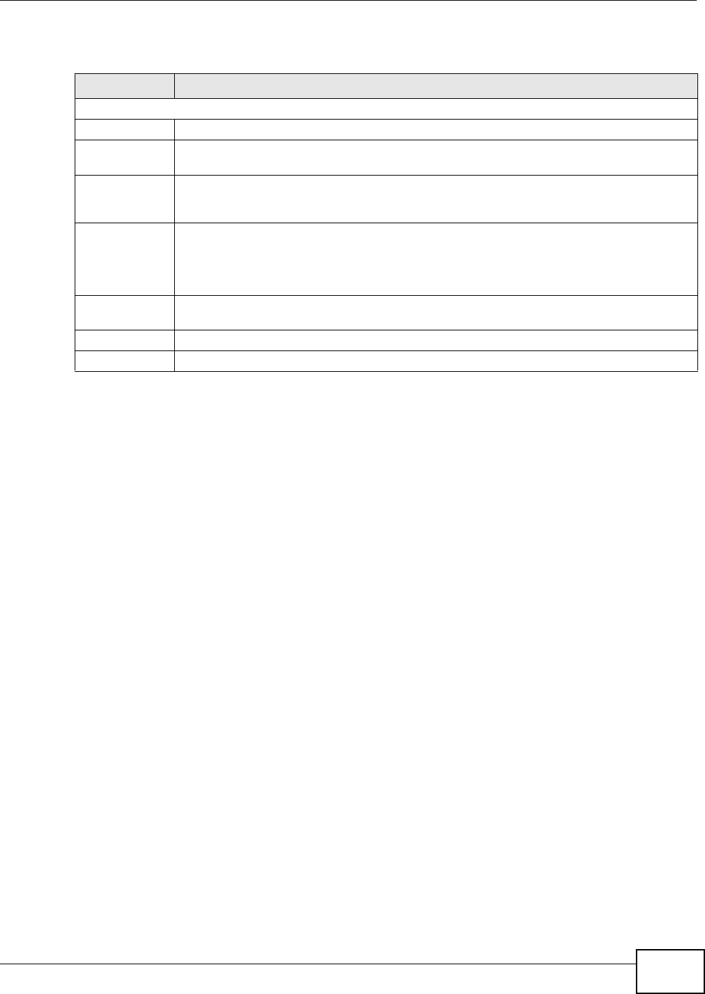
Chapter 14 Wireless
Basic Home Station VDSL2 P8802T User’s Guide 179
The following table describes t he general wireless LAN labels in t his scr een.
14.3 Wireless Security
Click W ireless > Securit y t o open the Securit y screen. Set N et w ork Aut he nt ication t o Ope n
and W EP Encr yption to D isabled t o allow wireless st ations to com m unicate wit h the VDSL Router
without any dat a encrypt ion or authenticat ion.
Note: I f you do not enable any wireless securit y on your VDSL Router, your network is
accessible to any wireless net working device t hat is wit hin range.
Table 65 Wireless: Basic
LABEL DESCRIPTION
Wireless Network Setup
Enable Wir eless Turn the wireless LAN on or off.
Hide Access
Point
Select this check box t o hide t he SSI D in t he out going beacon fram e so a st at ion cannot
obtain the SSI D t hr ough scanning using a sit e survey tool.
Enable Wireless
Mult icast
Forwarding
Select t his check box t o convert wireless m ult icast traffic into wir eless unicast t raffic.
SSI D The SSI D ( Service Set IDent it y) identifies the service set wit h which a wireless device is
associated and serves as a nam e for the wireless net work. Wireless devices associat ing to
t he access point ( AP) m ust have t he sam e SSI D.
Enter a descript ive nam e ( up to 32 English keyboard characters) for t he wireless LAN.
BSSI D This show s the MAC address of the wireless int erface on the VDSL Rout er when wireless LAN
is enabled.
Max Clients Set a lim it for how m any wireless client s can connect to the VDSL Rout er at a t im e.
Apply/ Save Click t his but t on to save your changes.
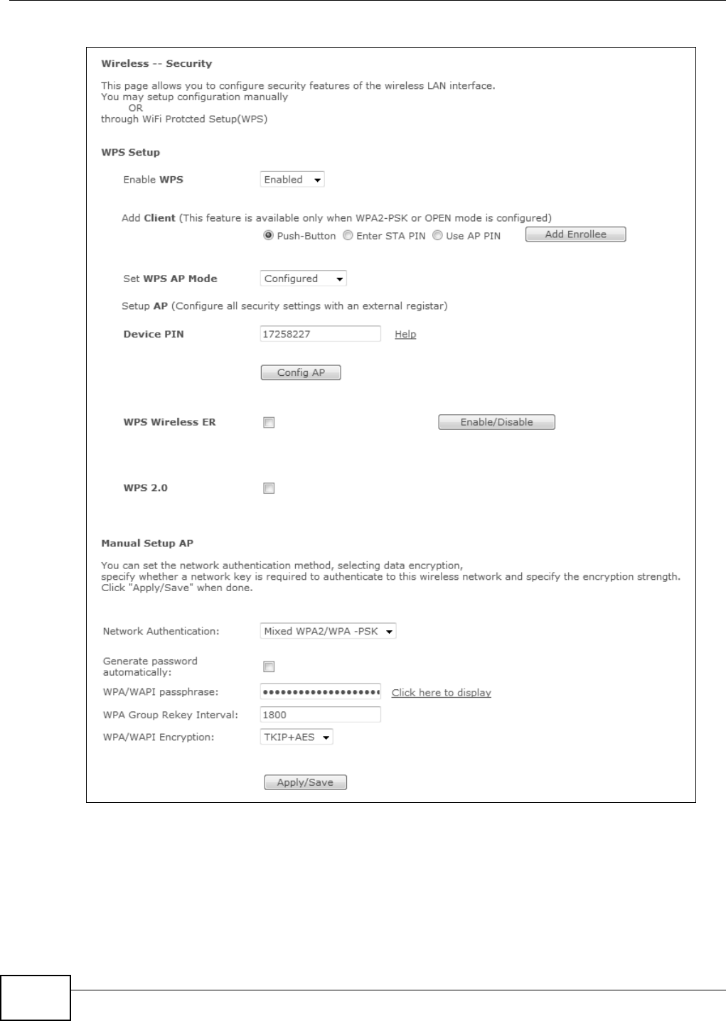
Chapter 14 Wireless
Basic Home Station VDSL2 P8802T User’s Guide
180
Figure 75 Wireless: Security

Chapter 14 Wireless
Basic Home Station VDSL2 P8802T User’s Guide 181
The following t able describes t he labels in t his screen.
Table 66 Wireless: Securit y
LABEL DESCRIPTION
Enable WPS Use WiFi Protected Set up (WPS) to quickly set up a wireless net wor k w it hout having to
m anually configure set tings. Set up each WPS connect ion bet ween t wo dev ices at a tim e.
WPS is not available when using WPA or WPA 2.
Add Client Use t his sect ion to add a wireless client t o the wireless net w ork.
Select Push - Bu t t on to add a client by pressing a but ton on the VDSL Rout er and t he
wireless client . This is the easiest m ethod.
Select En te r STA PI N t o add a client by enter ing t he client ’s Personal Identification
Num ber ( PI N) in the field that displays when you select t his option.
Select Use AP PI N to add a client by ent er ing t he AP’s PI N from the De vice PI N field in
the client ’s WPS configuration.
Add Enrollee Click this to use WPS t o add a w ireless client t o your wireless net work.
Note: You must also activate WPS on the client within two minutes.
Set WPS AP Mode Configured uses t he VDSL Rout er’s current wireless securit y set tings for WPS.
Unconfigure d has the VDSL Rout er change it s wireless security set t ings when you do
one of the following:
• Add a wireless enrollee. The VDSL Router autom atically uses WPA2- PSK and a random
key. The W PS AP Mode aut om at ically changes to Configure d.
• Use Se tu p AP to have an ext er nal regist rar ( like Window s Vist a) configure the VDSL
Router’s wireless securit y set tings. The W PS AP Mode automatically changes t o
Configured .
• Manually configure t he VDSL Rout er’s wireless securit y set tings. Then you can
m anually set the W PS AP Mode t o Configure d.
Device PI N This shows the VDSL Router’s PI N. Ent er this PI N in the ext ernal registrar within two
m inut es of click ing Config AP.
Enter t his PI N in the client’s WPS configuration if you select ed Use AP PI N .
Config AP Click Con fig AP t o have an ext ernal regist rar configure t he VDSL Router’s wireless
securit y set tings. See Section 14.7.8 on page 198 for how to use Windows Vist a as an
ext ernal regist rar. Pu sh But t on and PI N are reserved for future use and have no effect
at t he t im e of w rit ing.
Note: After you click Config AP you must enter the VDSL Router’s PIN in the external
registrar within two minutes.
WPS Wireless ER This is available when you set t he W PS AP Mode t o Configure d. Click En able/ Disa ble
to have an ext ernal r egist rar such as an I ntel wireless st ation use WPS t o add wireless
client s and t hen authenticat e t hem whenever they connect to t he wireless net work.
I f you used a Windows Vista com puter to configure the VDSL Router’s wireless set tings,
you can also use the Window s Vista computer to add and authenticat e wireless clients
without using W PS W ire le ss ER. See Sect ion 14.7.8 on page 198 for details.
Note: After you click Enable/Disable you must enter the VDSL Router’s PIN in the external
registrar within two minutes.
Then click Ena ble / Disa ble again.
WPS 2.0 Select t his t o support WPS 2.0.

Chapter 14 Wireless
Basic Home Station VDSL2 P8802T User’s Guide
182
Network
Au t hent ication
Use t he strongest aut hent ication m et hod t hat the wireless clients all support .
W PA2 or W PA uses an ext ernal RADI US ser ver t o aut hent icat e a separat e user nam e
and password for each user. While WPA2 offers t he st rongest securit y, m ore wireless
client s support WPA.
Mixe d W PA2 / W PA supports WPA and WPA2 sim ultaneously.
W PA2 - PSK or W PA- PSK uses a com m on password for all client s. While WPA2- PSK offers
st ronger securit y, m ore wireless client s support WPA- PSK.
Mixe d W PA2 / W PA - PSK suppor ts WPA2- PSK and WPA- PSK sim ult aneously.
Choose Open t o allow all w ir eless connections wit hout authent ication.
WPA2
Pr eau t hent icat ion
This field displays when you select W PA2 or Mixe d W PA2 / W PA.
Enable pre- aut hent ication for fast roam ing by allow ing a wireless client alr eady connect ed
to an AP to perform I EEE 802.1x authenticat ion wit h another AP before connect ing t o it .
Network Re- auth
I nterval
This field displays when you select W PA2 or Mixe d W PA2 / W PA.
Specify how oft en wireless stations have t o resend user nam es and passwords in order to
st ay connected. I f wireless st at ion aut hent icat ion is done using a RADI US server, t he
reaut henticat ion t im er on t he RADI US server has priorit y.
WPA Group Rekey
I nterval
Set the rat e at which the AP ( if using WPA( 2)- PSK key m anagem ent ) or RADI US server (if
using WPA( 2) key m anagem ent ) sends a new group key out to all client s. The re- keying
process is the WPA( 2) equivalent of aut om atically changing t he WEP key for an AP and all
st at ions in a WLAN on a periodic basis.
RADI US Server I P
Address
Enter t he I P address of the ext er nal aut hent icat ion server in dott ed decim al not ation.
RADI US Port Ent er the por t num ber of the external authent ication server. The default port number is
1 8 1 2 . You need not change this value unless your net work adm inist rator inst ruct s you to
do so with addit ional infor m at ion.
RADI US Key Ent er a passwor d ( up to 31 alphanum eric charact er s) as the key t o be shared bet ween
the ext er nal RADI US ser ver and t he VDSL Router. The key m ust be the sam e on the
RADI US server and your VDSL Rout er. The key is not sent over t he net work.
WPA/ WAPI
Encryption
Select t he encryption type (AES or TKI P+ AES) for dat a encryption.
Select AES if your wireless clients can all use AES.
Select TKI P+ AES to allow the wireless client s to use eit her TKI P or AES.
Generate
password
autom atically
This field displays when you select WPA( 2)- PSK.
Select this option to have t he VDSL Rout er aut om at ically generat e a passwor d. The
passwor d field becom es read- only.
WPA/ WAPI
passphrase
This field displays when you select WPA( 2)- PSK.
Enter 16 to 63 alphanumeric charact ers (0- 9, A-Z, wit h no spaces) . I t m ust contain bot h
let ters and num ber s and is case- sensitive. Click the link to display the password.
WEP Encryption This field displays when you set Ne tw ork Auth ent ica t ion to Open . Enable WEP
encry pt ion t o scram ble t he wireless dat a transm issions bet ween the wireless st at ions and
the access point s (AP) to keep netw ork com m unicat ions privat e. Bot h the wireless
st at ions and t he access point s m ust use the sam e WEP key.
Note: WEP is extremely insecure. Attackers can break it using widely-available software. It
is strongly recommended that you use a more effective security mechanism.
Encryption
St rengt h
I f y ou are using WEP encry pt ion, select 6 4 - bit or 1 2 8 - bit to set the lengt h of t he
encry pt ion key.
Table 66 Wireless: Securit y
LABEL DESCRIPTION
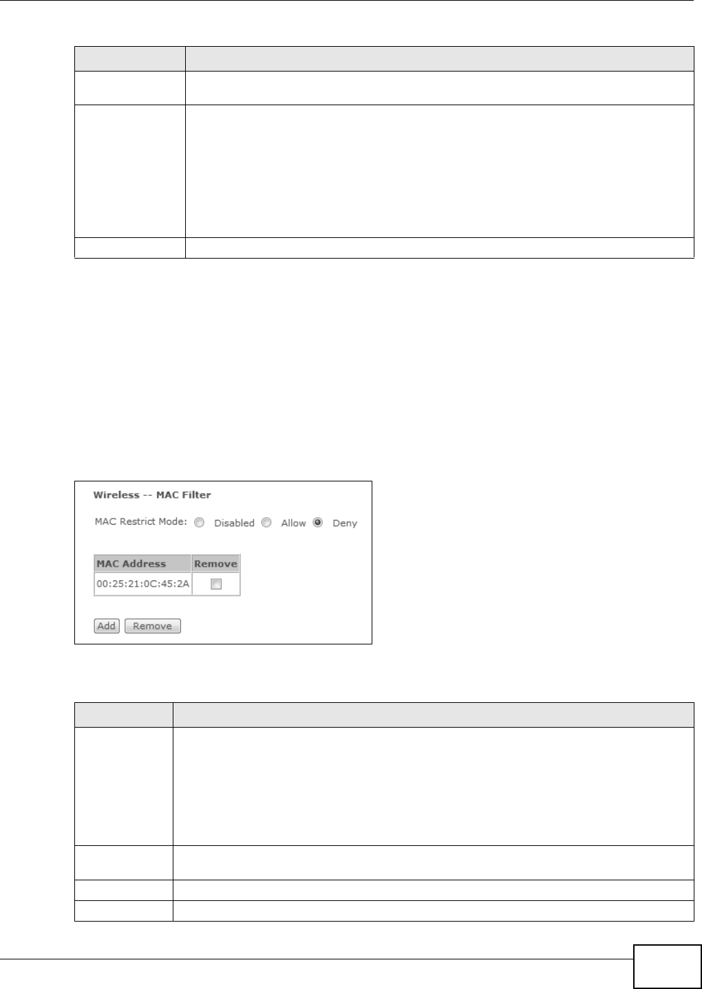
Chapter 14 Wireless
Basic Home Station VDSL2 P8802T User’s Guide 183
14.4 MAC Filter
Click W ireless > MAC Filt er to open t he M AC Filt er screen. This screen allows you t o configure
the VDSL Router to give exclusive access t o specific devices ( Allow ) or exclude specific devices
from accessing t he VDSL Router ( De ny) . Every Ether net device has a unique MAC (Media Access
Cont rol) address assigned at t he fact ory. I t consist s of six pairs of hexadecim al charact ers, for
exam ple, 00: A0: C5: 00: 00: 02. You need to know t he MAC addresses of t he devices to configure this
screen.
Figure 76 Wireless > MAC Authent icat ion
The following t able describes t he labels in t his screen.
Cur rent Networ k
Key
This field displays when you enable WEP encryption. Configure up t o four 64-bit or 128-bit
WEP keys. Use this field t o select w hich one the net work uses.
Network Key 1~ 4 These fields display when you enable WEP encryption. WEP uses a net work key t o encrypt
dat a. The VDSL Rout er and wireless client s m ust use the sam e net work key ( password) .
I f you chose 6 4 - bit WEP, t hen ent er any 5 ASCI I charact ers or 10 hexadecim al charact er s
( "0-9", "A- F") .
I f you chose 1 2 8- bit WEP, t hen enter 13 ASCI I charact er s or 26 hexadecim al charact er s
( "0-9", "A- F") .
You m ust configure at least one password.
Apply/ Save Click this but ton to save your changes.
Table 66 Wireless: Securit y
LABEL DESCRIPTION
Table 67 Wireless > MAC Aut hent ication
LABEL DESCRIPTION
MAC Restrict
Mode
Define t he filter act ion for t he list of MAC addresses in the M AC Addr ess t able.
Select D isabled to t urn off MAC filt ering.
Select Allow to perm it access t o the VDSL Router. MAC addresses not listed will be denied
access to t he VDSL Router.
Select De ny t o block access t o the VDSL Rout er. MAC addresses not list ed w ill be allowed to
access the VDSL Rout er.
MAC Address This displays the MAC addresses of the wir eless devices that are allowed or denied access to
the VDSL Rout er.
Rem ove Select ent ries and click t he Rem ove button t o delet e them .
Add Click this to add a new MAC address ent ry to the t able.
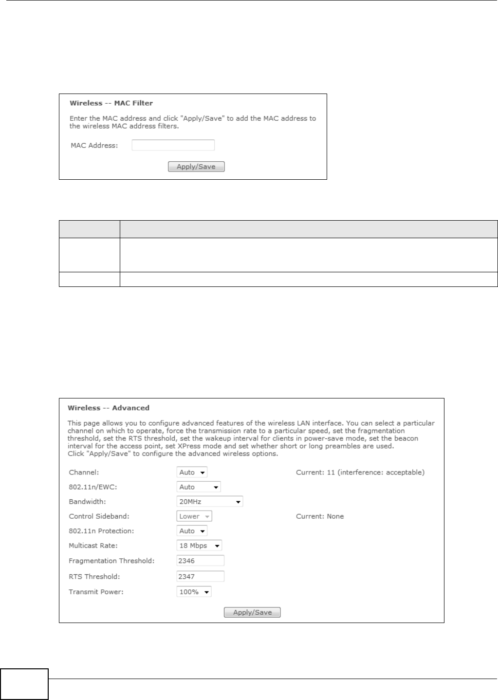
Chapter 14 Wireless
Basic Home Station VDSL2 P8802T User’s Guide
184
14.4.1 The MAC Filter Add Screen
Use t his screen t o add MAC address entries. Click W ir ele ss > MAC Filt er > Add to open t he
following screen.
Figure 77 Wireless > MAC Filt er > Add
The following t able describes t he labels in t his screen.
14.5 The Advanced Screen
Click W ire less > Advan ced t o configure advanced wireless set t ings. See Section 14.7.2 on page
188 for det ailed definit ions of t he t erm s list ed in t his screen.
Figure 78 Wireless: Advanced
Table 68 Wireless > MAC Filter > Add
LABEL DESCRIPTION
MAC Address Enter t he MAC address of the wireless device that is t o be allow ed or denied access t o the
VDSL Rout er . Ent er the MAC addresses in a valid MAC address form at , that is, six hexadecim al
charact er pairs, for exam ple, 12: 34: 56: 78: 9a: bc.
Save/ Apply Click t his butt on to save t he changes and have t he VDSL Router st art using them .

Chapter 14 Wireless
Basic Home Station VDSL2 P8802T User’s Guide 185
The following t able describes t he labels in t his screen.
Table 69 Wireless: Advanced
LABEL DESCRIPTION
Channel Set the channel depending on your par ticular region.
Select a channel or use Aut o t o have t he VDSL Rout er aut om at ically det erm ine a channel
t o use. Changing the channel m ay help resolve wireless inter fer ence issues. Use a channel
as m any channels away from any channels used by neighboring APs as possible. The VDSL
Rout er ’s current channel num ber displays next to t his field.
802.11n/ EWC Select Auto t o have t he VDSL Router aut om at ically use I EEE 802.11n t o connect I EEE
802. 11n client s. Disable this to not use I EEE 802.11n.
Bandwidth This displays when you set 8 0 2 .1 1 n/ EW C to Aut o.
Select whet her t he VDSL Rout er uses a wireless channel width of 2 0 M H z or 4 0 MHz.
A st andard 20MHz channel offers transfer speeds of up to 150Mbps wher eas a 40MHz
channel uses two standard channels and offers speeds of up to 300 Mbps.
40MHz (channel bonding or dual channel) bonds two adj acent radio channels to increase
t hr oughput. The wireless clients m ust also support 40 MHz. I t is oft en bet t er t o use t he 20
MHz set ting in a locat ion where t he environm ent hinders the wireless signal.
Select 2 0 M Hz if you want t o lessen radio int erference wit h other wireless devices in your
neighborhood or the wireless client s do not support channel bonding.
Control
Sideband
This displays when you set 8 0 2 .1 1 n/ EW C to Aut o.
This is available for some regions when you select a specific channel and set the Bandwidth
field to 4 0 M Hz. Set whet her t he cont rol channel ( set in the Cha nnel field) should be in the
Low e r or Upper range of channel bands.
802.11n
Protect ion
This displays when you set 8 0 2 .1 1 n/ EW C to Aut o. Select Aut o t o have the wireless
devices transm it dat a after a RTS/ CTS handshake to help prevent collisions in m ixed-m ode
netw orks (net works wit h both I EEE 802.11n and I EEE 802.11g or I EEE 802.11b traffic) .
Select Off to disable 802.11n prot ection. This can increase throughput in an I EEE 802.11n-
only environm ent alt hough it m ay reduce t ransm ission rates if your network also has I EEE
802.11G and I EEE 802.11B client s.
Mult icast Rate Select a t ransm ission speed for wireless m ult icast t raffic.
Fragm ent ation
Threshold
This is t he m aximum dat a fragm ent size t hat can be sent . Enter a value bet ween 256 and
2346.
RTS Thr eshold Data wit h its fram e size larger t han this value will perform t he RTS ( Request To Send)/ CTS
( Clear To Send) handshake.
Enter a value bet ween 0 and 2347.
54g™ Mode This displays when you set 8 0 2 .1 1 n/ EW C to Disabled.
Select 5 4 g Auto to allow bot h I EEE 802.11G and I EEE 802.11B client s t o connect .
Select 5 4 G Pe rform ance for the best perform ance with I EEE 802.11G-certified clients.
Select 5 4 G LRS (Lim it ed Rat e Support) t o allow older I EEE 802.11B client s wit h 3-Bit
m essage headers to connect. Only use t his if none of the ot her m odes work.
Select 8 0 2 .1 1 b On ly if all your wir eless clients only support I EEE 802.11B.
54g™ Prot ect ion This displays when you set 8 0 2 .1 1 n/ EW C to D isa bled . Select Au to to have the wir eless
devices transm it dat a after a RTS/ CTS handshake to help prevent collisions in m ixed-m ode
net wor ks (net works wit h both IEEE 802.11g and I EEE 802.11b traffic) .
Select Off to disable 802.11g prot ect ion. Only select this if you only connect I EEE 802.11G
client s.
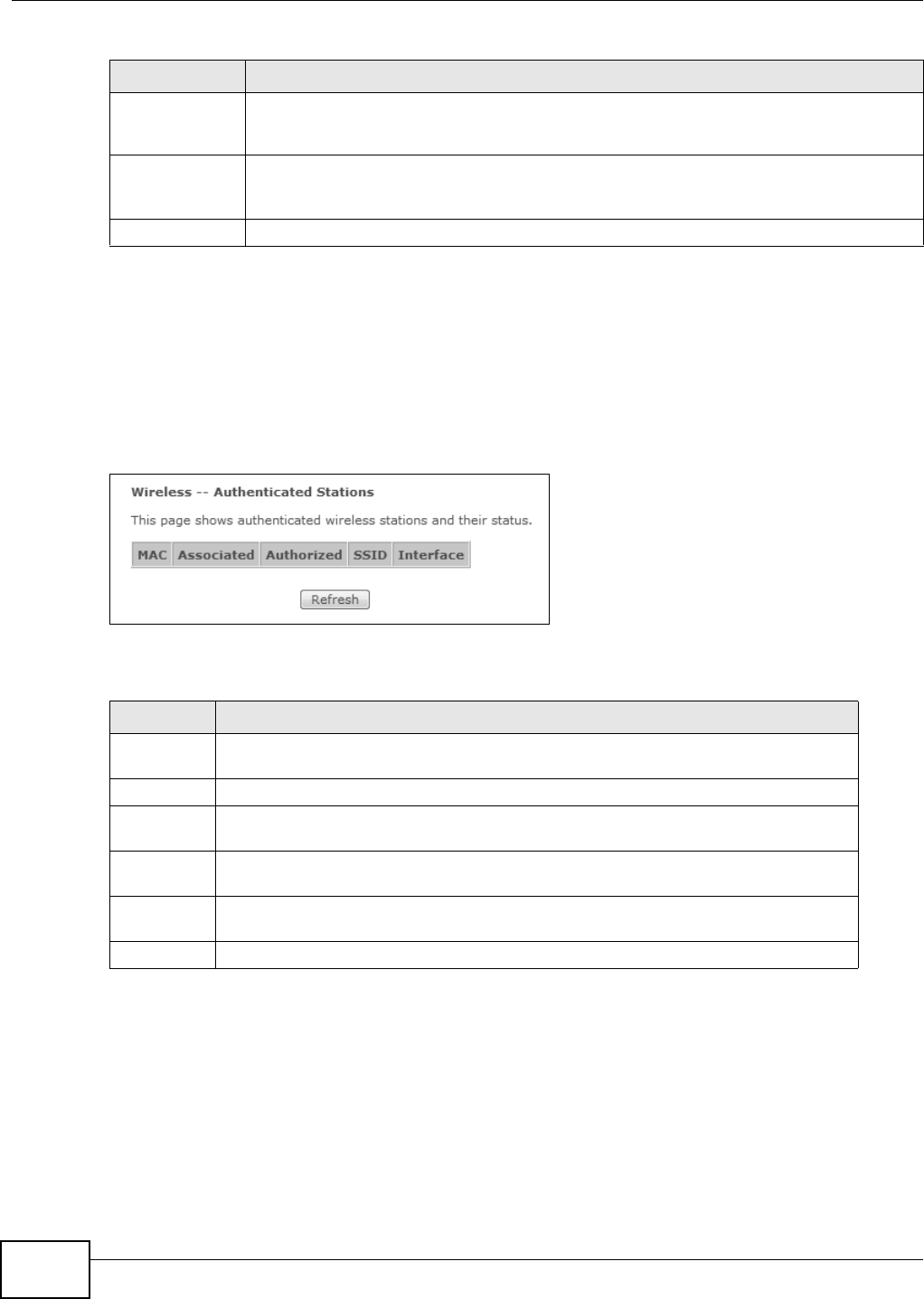
Chapter 14 Wireless
Basic Home Station VDSL2 P8802T User’s Guide
186
14.6 Wireless Station Info
The st at ion m onitor displays the connect ion st atus of t he wireless client s connect ed t o ( or t rying to
connect to) the VDSL Router . To open t he st at ion m onitor, click W ir ele ss > Stat ion I nfo. The
screen appear s as shown.
Figure 79 Wireless > St at ion I nfo
The following t able describes t he labels in t his m enu.
14.7 Technical Reference
This sect ion discusses wireless LANs in m ore dept h.
14.7.1 Wireless Network Overview
Wireless net works consist of wireless client s, access points and bridges.
Preamble Type This displays when you set 8 0 2 .1 1 n/ EW C to D isa ble d and 5 4 g™ M ode to 5 4 g Aut o or
8 0 2 .1 1 b Only. Select a pream ble ty pe from the drop-down list box. Choices ar e Long or
Sh or t . See Sect ion 14.7.6 on page 192 for m ore inform at ion.
Transm it Power Set the output power of the VDSL Rout er. I f t here is a high density of APs in an area,
decrease the out put power t o reduce int er ference with ot her APs. Select one of the
follow ing: 2 0 % , 4 0 % , 6 0 % , 8 0 % or 1 0 0 % .
Apply/ Save Click t his to save your changes to the VDSL Router.
Table 69 Wireless: Advanced ( continued)
LABEL DESCRIPTION
Table 70 Wireless > St at ion I nfo
LABEL DESCRIPTION
MAC This displays the MAC address (in XX: XX: XX: XX: XX: XX for m at ) of a connect ed
wireless station.
Associat ed This is the t im e t hat the wir eless client associat ed with the VDSL Rout er .
Aut horized This is the t im e t hat t he wir eless client ’s connect ion t o t he VDSL Rout er was
authorized.
SSI D This is t he nam e of the wireless netw ork on the VDSL Rout er t o which the wireless
client is connect ed.
I nter face This is t he nam e of the wireless LAN inter face on the VDSL Rout er t o which the
wireless client is connected.
Refresh Click this but ton to updat e the inform at ion in the screen.
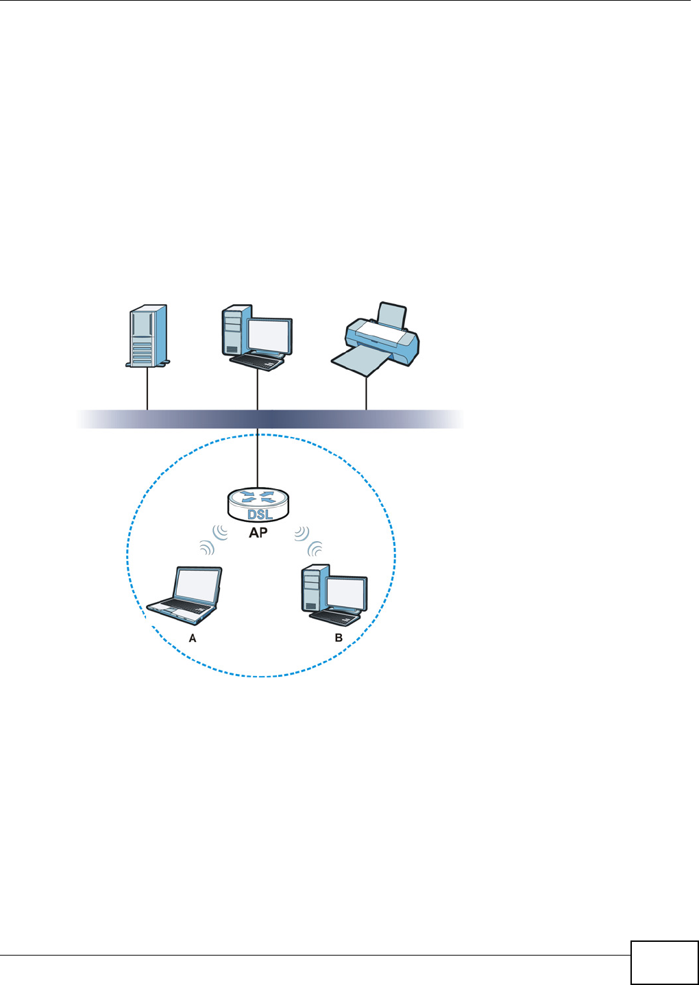
Chapter 14 Wireless
Basic Home Station VDSL2 P8802T User’s Guide 187
• A wireless client is a radio connect ed t o a user’s computer.
• An access point is a radio wit h a wired connect ion to a net work, which can connect with
num erous wireless client s and let t hem access the network.
• A bridge is a radio t hat relays comm unications bet ween access point s and wireless client s,
ext ending a net work’s range.
Traditionally, a wireless network operat es in one of t wo ways.
• An “ infrast ruct ure” t ype of network has one or m ore access points and one or m or e wireless
clients. The wireless client s connect to t he access points.
• An “ ad- hoc” type of net work is one in which there is no access point. Wireless clients connect to
one another in order to exchange inform at ion.
The following figure provides an exam ple of a wireless net work.
Figure 80 Exam ple of a Wireless Net work
The wireless network is t he part in the blue circle. I n t his wireless net work, devices A and B use the
access point ( AP) t o interact with t he other devices (such as t he printer) or wit h the I nt ernet. Your
VDSL Rout er is t he AP.
Ever y wireless net work m ust follow these basic guidelines.
• Every device in the sam e wireless net work m ust use t he same SSI D.
The SSI D is the nam e of t he wireless net work. I t st ands for Service Set I Dentifier.
• I f two w ireless net works overlap, t hey should use a different channel.
Like radio stat ions or television channels, each wireless network uses a specific channel, or
frequency, t o send and receive inform ation.

Chapter 14 Wireless
Basic Home Station VDSL2 P8802T User’s Guide
188
• Every device in t he sam e wireless net work m ust use security com patible wit h the AP.
Security st ops unauthorized devices from using the wireless net work. I t can also prot ect the
inform ation t hat is sent in t he wireless net work.
Radio Channels
I n the radio spect rum , there are certain frequency bands allocated for unlicensed, civilian use. For
the purposes of wireless net working, t hese bands are divided int o num er ous channels. This allows a
variet y of net works t o exist in the sam e place wit hout int erfer ing with one anot her. When you
creat e a netw ork, you m ust select a channel to use.
Since t he available unlicensed spectrum varies from one count ry to anot her, the num ber of
available channels also varies.
14.7.2 Additional Wireless Terms
The following t able describes som e wireless net work term s and acronym s used in t he VDSL Router’s
Web Configurator.
14.7.3 Wireless Security Overview
By their nat ure, radio comm unicat ions are sim ple t o intercept . For wireless dat a net works, t his
m eans that anyone wit hin range of a wireless net work without security can not only read t he dat a
passing over t he airwaves, but also j oin t he net work. Once an unaut horized person has access t o
the net work, he or she can steal inform ation or int roduce m alware ( m alicious software) intended t o
com prom ise t he net work. For t hese reasons, a variety of security syst em s have been developed t o
ensure t hat only aut horized people can use a wireless dat a net work, or underst and the data carried
on it.
These security st andards do two things. First, they authenticat e. This m eans t hat only people
present ing t he right credentials ( oft en a usernam e and password, or a “ key” phrase) can access the
net work. Second, t hey encrypt . This m eans t hat the inform ation sent over the air is encoded. Only
Table 71 Addit ional Wireless Term s
TERM DESCRIPTION
RTS/ CTS Threshold I n a wireless net work which covers a large area, wireless dev ices are som et im es not
aware of each ot her ’s pr esence. This m ay cause t hem t o send inform ation t o t he AP
at t he sam e t im e and result in inform at ion colliding and not get ting through.
By set ting this value lower than the default value, t he w ireless dev ices m ust
sometim es get per m ission t o send inform at ion t o t he VDSL Router. The lower the
value, the m ore oft en the devices m ust get perm ission.
I f t his value is greater t han t he fragm entat ion threshold value (see below), then
wir eless devices never have to get per m ission t o send infor m at ion t o the VDSL
Rou t er .
Pream ble A pr eamble affects the t im ing in your wireless net work. There are tw o pream ble
m odes: long and short . I f a dev ice uses a different preamble m ode than t he VDSL
Rout er does, it cannot com m unicate with the VDSL Router.
Aut hentication The process of verifying whet her a wireless device is allow ed to use t he w ireless
netw ork.
Fragm ent ation
Threshold
A sm all fragm entation t hreshold is recom m ended for busy net works, while a larger
threshold prov ides fast er perform ance if the netw ork is not very busy.

Chapter 14 Wireless
Basic Home Station VDSL2 P8802T User’s Guide 189
people wit h the code key can underst and the inform at ion, and only people who have been
aut hent icat ed are given the code key.
These security st andar ds vary in effectiveness. Some can be broken, such as t he old Wir ed
Equivalent Prot ocol (WEP) . Using WEP is bet t er t han using no securit y at all, but it will not keep a
determ ined at t acker out . Ot her security st andards are secure in themselves but can be broken if a
user does not use t hem properly. For exam ple, the WPA-PSK security st andard is very secure if you
use a long key which is difficult for an at tacker ’s soft ware t o guess - for exam ple, a t wenty- let t er
long string of appar ent ly random num bers and let t ers - but it is not very secure if you use a short
key which is very easy t o guess - for exam ple, a t hree- letter word from t he dict ionary.
Because of t he dam age that can be done by a m alicious at t acker, it ’s not j ust people who have
sensit ive inform at ion on t heir net work who should use security. Everybody who uses any wireless
net work should ensure that effect ive security is in place.
A good way to com e up with effective security keys, passwords and so on is t o use obscure
inform ation that you personally will easily rem em ber, and to ent er it in a way that appears random
and does not include real words. For exam ple, if your m other owns a 1970 Dodge Challenger and
her favorite m ovie is Vanishing Point ( which you know was m ade in 1971) you could use
“ 70dodchal71vanpoi” as your security key.
The following sect ions introduce different types of wireless security you can set up in the wireless
net work.
14.7.3.1 SSID
Norm ally, the VDSL Router acts like a beacon and regularly broadcast s the SSI D in t he area. You
can hide t he SSI D inst ead, in which case t he VDSL Router does not broadcast the SSI D. I n addition,
you should change t he default SSI D t o som et hing t hat is difficult t o guess.
This t ype of security is fairly w eak, however, because t here are ways for unaut horized wireless
devices t o get t he SSI D. I n addition, unaut horized wireless devices can st ill see the inform at ion that
is sent in t he wireless net work.
14.7.3.2 MAC Address Filter
Ever y device t hat can use a wireless network has a unique identificat ion num ber, called a MAC
address.1 A MAC address is usually written using t welve hexadecim al charact ers2; for exam ple,
00A0C5000002 or 00: A0: C5: 00: 00: 02. To get the MAC address for each device in the w ireless
net work, see t he device’s User’s Guide or ot her docum ent at ion.
You can use the MAC address filt er to t ell t he VDSL Rout er which devices are allowed or not allowed
to use t he wireless network. I f a device is allowed to use t he wireless net work, it still has t o have
the correct inform at ion (SSI D, channel, and security). I f a device is not allowed to use the wireless
net work, it does not m atter if it has the correct inform ation.
This t ype of security does not prot ect the inform at ion t hat is sent in t he wireless network.
Furt herm ore, there are ways for unauthorized wireless devices to get the MAC address of an
aut hor ized device. Then, t hey can use t hat MAC address t o use t he wireless net work.
1. Some wireless devices, such as scanners, can detect wireless networks but cannot use wireless networks. These kinds
of wireless devices might not have MAC addresses.
2. Hexadecimal characters are 0, 1, 2, 3, 4, 5, 6, 7, 8, 9, A, B, C, D, E, and F.
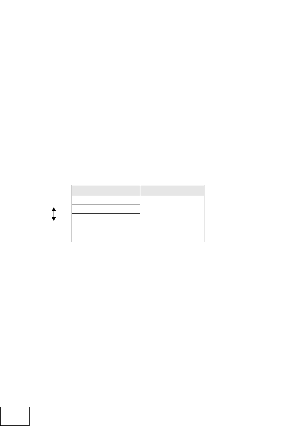
Chapter 14 Wireless
Basic Home Station VDSL2 P8802T User’s Guide
190
14.7.3.3 User Authentication
Aut hent ication is the process of ver ifying whet her a wireless device is allowed t o use t he wireless
net work. You can m ake every user log in to the wireless net work before using it. However, every
device in the wireless net work has t o support I EEE 802.1x to do this.
For wireless net works, you can st ore the user nam es and passwords for each user in a RADI US
server. This is a server used in businesses m ore than in homes. I f you do not have a RADI US server,
you cannot set up user nam es and passwords for your users.
Unaut horized wireless devices can st ill see the inform at ion that is sent in the wireless net work,
even if they cannot use t he wireless net work. Furtherm ore, there are ways for unauthorized
wireless users t o get a valid user nam e and password. Then, they can use that user nam e and
password t o use t he wireless net work.
14.7.3.4 Encryption
Wireless net works can use encryption t o protect the inform at ion that is sent in t he wireless
net work. Encryption is like a secret code. I f you do not know the secret code, you cannot
underst and the m essage.
The types of encryption you can choose depend on t he type of aut hent icat ion. ( See Sect ion
14.7.3.3 on page 190 for inform at ion about t his.)
For exam ple, if the wireless net work has a RADI US server, you can choose W PA or W PA2 . I f users
do not log in to the wireless net work, you can choose no encryption, St a t ic W EP, W PA- PSK, or
W PA2 - PSK.
Usually, you should set up the st rongest encr yption t hat every device in the wireless net work
supports. For exam ple, suppose you have a wireless network wit h t he VDSL Router and you do not
have a RADI US server. Therefore, t here is no aut hentication. Suppose t he wireless net work has t wo
devices. Device A only supports WEP, and device B suppor ts WEP and WPA. Therefore, you should
set up St at ic W EP in t he wireless net work.
Note: I t is recom m ended t hat wireless networks use W PA- PSK, W PA, or st ronger
encrypt ion. The ot her t ypes of encryption are better than none at all, but it is st ill
possible for unaut horized wireless devices t o figure out t he original inform at ion
pretty quickly.
When you select W PA2 or W PA2 - PSK in your VDSL Rout er , you can also select an opt ion (W PA
com pa tible) t o support WPA as well. I n t his case, if som e of t he devices support WPA and som e
support WPA2, you should set up W PA2 - PSK or W PA2 ( depending on the t ype of w ireless net work
login) and select the W PA com pa t ible opt ion in t he VDSL Rout er.
Table 72 Types of Encryption for Each Type of Aut hentication
NO AUTHENTICATION RADIUS SERVER
W eak est No Securit y WPA
St at ic WEP
WPA- PSK
St r onge st WPA2- PSK WPA2
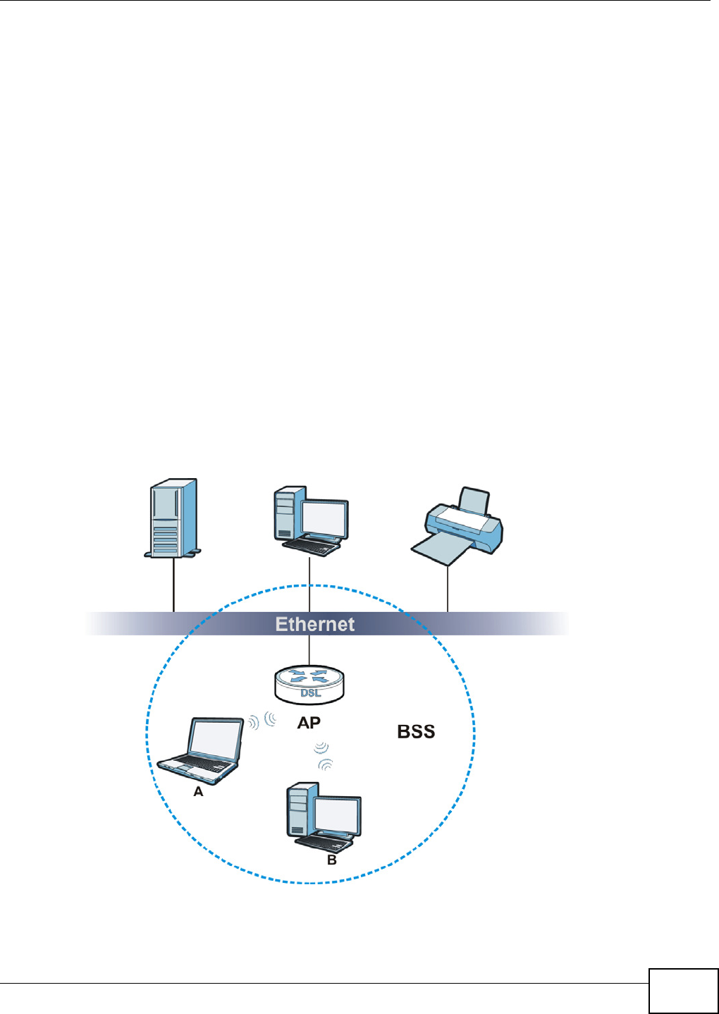
Chapter 14 Wireless
Basic Home Station VDSL2 P8802T User’s Guide 191
Many t ypes of encrypt ion use a key to prot ect the inform at ion in t he wireless net work. The longer
the key, t he st ronger the encrypt ion. Every device in t he wireless network m ust have t he sam e key.
14.7.4 Signal Problems
Because wireless net works are radio networks, t heir signals are subject t o lim itat ions of dist ance,
int erference and absorption.
Problem s with dist ance occur when t he t wo radios are too far apart. Pr oblem s with interference
occur when ot her radio waves interrupt the data signal. I nt erference m ay come from ot her radio
transm issions, such as m ilitary or air traffic cont rol com m unicat ions, or from m achines t hat are
coincidental em itters such as elect ric m otors or m icrowaves. Problem s with absorption occur when
physical obj ect s ( such as t hick walls) are between t he t wo radios, m uffling the signal.
14.7.5 BSS
A Basic Service Set ( BSS) exist s when all com m unications between wireless st at ions or between a
wireless st at ion and a wired net work client go t hrough one access point ( AP) .
I nt ra- BSS traffic is t raffic bet ween wireless st at ions in t he BSS. When I ntra-BSS traffic blocking is
disabled, wireless stat ion A and B can access the wired net work and comm unicate wit h each other.
When I ntra-BSS traffic blocking is enabled, wireless st at ion A and B can st ill access t he wired
net work but cannot com m unicate wit h each ot her.
Figure 81 Basic Service set

Chapter 14 Wireless
Basic Home Station VDSL2 P8802T User’s Guide
192
14.7.6 Preamble Type
Pream ble is used t o signal that data is com ing t o the receiver. Short and long refer t o the length of
the synchronization field in a packet .
Short pr eam ble increases perform ance as less tim e sending pream ble m eans m ore tim e for sending
dat a. All I EEE 802.11 com pliant wir eless adapt ers support long pream ble, but not all support short
pream ble.
Use long pream ble if you are unsure what pream ble m ode other wireless devices on t he net work
support, and t o provide m ore reliable com m unicat ions in busy wireless net works.
Use short pream ble if you are sure all wireless devices on t he net work support it , and t o provide
m ore efficient com m unicat ions.
Use t he dynam ic set t ing t o autom at ically use shor t pream ble when all wireless devices on t he
net work support it , other wise t he VDSL Router uses long pream ble.
Note: The wireless devices MUST use t he sam e pream ble m ode in order to com municate.
14.7.7 WiFi Protected Setup (WPS)
Your VDSL Router support s WiFi Protected Set up (WPS) , which is an easy way to set up a secure
wireless net work. WPS is an indust ry standard specification, defined by the WiFi Alliance.
WPS allows you to quickly set up a wireless net work with st rong security, wit hout having to
configure security set t ings m anually. Each WPS connect ion works bet ween two devices. Both
devices m ust support WPS ( check each device’s docum entation t o m ake sure).
Depending on the devices you have, you can either press a butt on (on the device it self, or in its
configurat ion utility) or ent er a PI N ( a unique Personal I dentificat ion Num ber that allow s one device
to aut hent icat e t he other) in each of t he t wo devices. When WPS is act ivated on a device, it has t wo
m inutes to find another device t hat also has WPS act ivated. Then, the t wo devices connect and set
up a secure network by them selves.
14.7.7.1 Push Button Configuration
WPS Push But ton Configurat ion (PBC) is init iated by pressing a but ton on each WPS- enabled
device, and allowing t hem to connect autom at ically. You do not need t o ent er any inform at ion.
Not every WPS- enabled device has a physical WPS butt on. Som e m ay have a WPS PBC button in
their configuration utilities inst ead of or in addition t o the physical butt on.
Take t he following steps t o set up WPS using the butt on.
1Ensure t hat t he t wo devices you want to set up are within wireless range of one another.
2Look for a WPS but t on on each device. I f the device does not have one, log int o its configuration
utility and locate the but ton ( see t he device’s User ’s Guide for how to do this - for the VDSL Router ,
see Sect ion 14.5 on page 184) .
3Press t he button on one of the devices ( it doesn’t m at t er which) . For the VDSL Router you m ust
press the W ifi butt on for 10 seconds.

Chapter 14 Wireless
Basic Home Station VDSL2 P8802T User’s Guide 193
4Within two m inutes, press the butt on on the other device. The regist rar sends the net work nam e
( SSI D) and security key t hrough an secure connect ion to the enrollee.
I f you need t o m ake sure t hat WPS worked, check the list of associated wireless client s in the AP’s
configurat ion utility. I f you see the wireless client in t he list, WPS was successful.
14.7.7.2 PIN Configuration
Each WPS- enabled device has its own PI N ( Personal I dentificat ion Num ber). This m ay either be
st atic ( it cannot be changed) or dynam ic (in som e devices you can generate a new PI N by clicking
on a but ton in t he configuration interface) .
Use t he PI N m ethod inst ead of t he push- but ton configurat ion (PBC) met hod if you want to ensure
that the connect ion is est ablished bet ween t he devices you specify, not just the first t wo devices t o
act ivate WPS in range of each ot her. How ever, you need t o log int o the configuration interfaces of
bot h devices t o use t he PI N m ethod.
When you use t he PI N m et hod, you m ust enter t he PI N from one device ( usually t he wireless client)
int o t he second device ( usually t he Access Point or wireless router). Then, when WPS is act ivated
on t he first device, it presents its PI N t o t he second device. I f t he PI N m atches, one device sends
the net work and security inform at ion to the other, allowing it t o j oin t he net work.
Take t he following steps t o set up a WPS connection between an access point or wir eless router
( referred to here as the AP) and a client device using t he PI N m et hod.
1Ensure WPS is enabled on bot h devices.
2Access the WPS sect ion of t he AP’s configurat ion int erface. See the device’s User’s Guide for how to
do t his.
3Look for the client’s WPS PI N; it will be displayed either on t he device, or in the WPS sect ion of the
client’s configurat ion int erface (see the device’s User’s Guide for how to find the WPS PI N - for the
VDSL Rout er , see Sect ion 14.3 on page 179) .
4Enter t he client ’s PI N in t he AP’s configuration interface.
5I f the client device’s configurat ion int erface has an area for entering anot her device’s PI N, you can
either ent er t he client ’s PI N in the AP, or enter t he AP’s PI N in the client - it does not m att er which.
6St art WPS on bot h devices wit hin t wo m inutes.
7Use t he configuration ut ility t o act ivate WPS, not the push- butt on on the device itself.
8On a com put er connect ed to the wireless client , t ry t o connect to t he I nt ernet. I f you can connect ,
WPS was successful.
I f you cannot connect, check the list of associat ed wireless client s in the AP’s configuration ut ility. I f
you see the wireless client in t he list , WPS was successful.
The following figure shows a WPS- enabled wireless client ( inst alled in a not ebook com puter)
connect ing t o t he WPS- enabled AP via t he PI N m ethod.
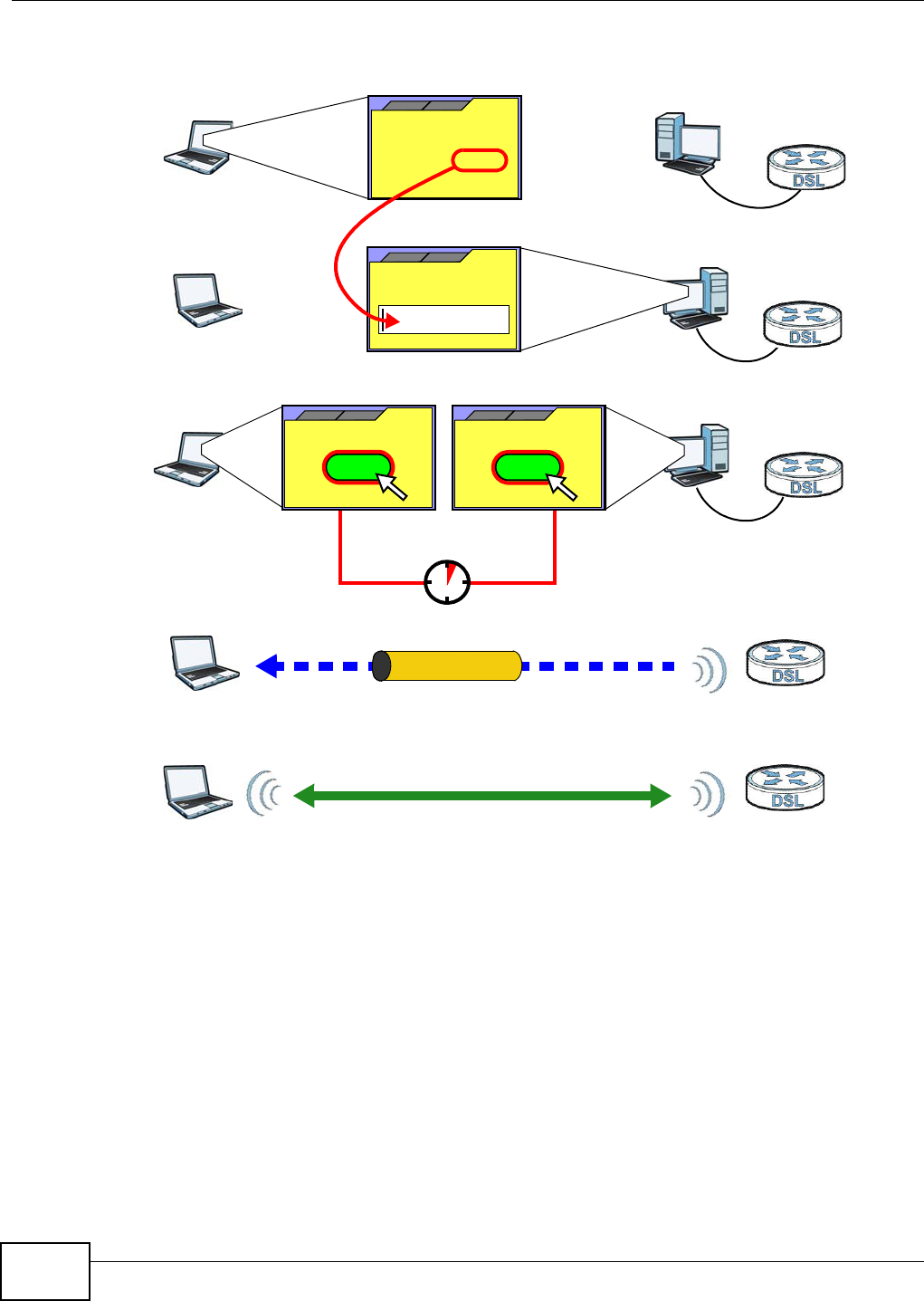
Chapter 14 Wireless
Basic Home Station VDSL2 P8802T User’s Guide
194
Figure 82 Exam ple WPS Process: PI N Met hod
14.7.7.3 How WPS Works
When t wo WPS- enabled devices connect , each device m ust assum e a specific role. One device acts
as t he regist rar ( t he device t hat supplies net work and security set t ings) and the other device acts
as the enrollee ( the device t hat receives net work and security set t ings. The regist rar creates a
secure EAP ( Extensible Aut hent ication Protocol) tunnel and sends t he net work nam e ( SSI D) and the
WPA-PSK or WPA2- PSK pre- shared key t o t he enrollee. Whet her WPA- PSK or WPA2- PSK is used
depends on t he st andards supported by the devices. I f t he regist rar is already part of a network, it
sends t he exist ing inform at ion. I f not, it generates t he SSI D and WPA( 2) - PSK random ly.
The following figure shows a WPS- enabled client ( inst alled in a not ebook com puter) connect ing to a
WPS- enabled access point.
ENROLLEE
SECURE EAP TUNNEL
SSID
WPA(2)-PSK
WITHIN 2 MINUTES
COMMUNICATION
This device’s
WPS
Enter WPS PIN
WPS
from other device:
WPS PIN: 123456
WPS
START
WPS
START
REGISTRAR
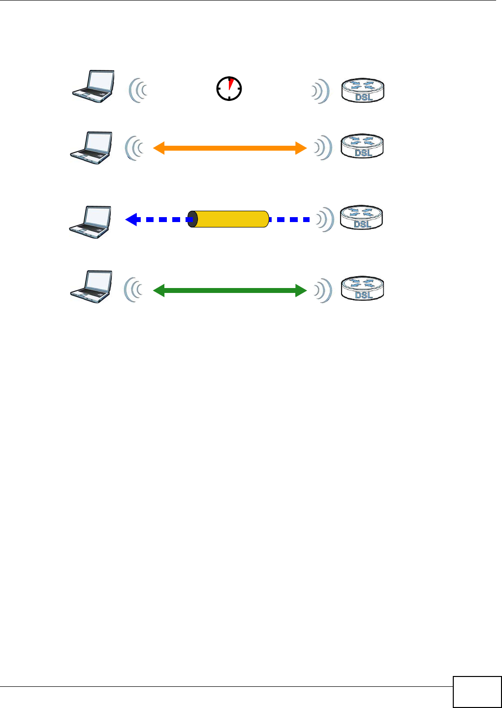
Chapter 14 Wireless
Basic Home Station VDSL2 P8802T User’s Guide 195
Figure 83 How WPS w orks
The roles of regist rar and enrollee last only as long as t he WPS setup process is act ive ( t wo
m inutes) . The next t im e you use WPS, a different device can be t he regist rar if necessary.
The WPS connect ion process is like a handshake; only t wo devices part icipate in each WPS
transact ion. I f you want to add m ore devices you should repeat t he process with one of t he exist ing
net worked devices and the new device.
Note that the access point ( AP) is not always the registrar, and t he wireless client is not always t he
enrollee. All WPS- certified APs can be a regist rar, and so can som e WPS- enabled wireless clients.
By default , a WPS devices is “ unconfigured”. This m eans t hat it is not part of an exist ing net work
and can act as either enrollee or regist rar (if it support s bot h funct ions) . I f t he regist rar is
unconfigured, the security set t ings it transm its t o t he enrollee are random ly-generated. Once a
WPS- enabled device has connect ed t o anot her device using WPS, it becom es “ configured”. A
configured wireless client can st ill act as enrollee or regist rar in subsequent WPS connections, but a
configured access point can no longer act as enrollee. I t will be t he regist rar in all subsequent WPS
connect ions in which it is involved. If you want a configured AP t o act as an enrollee, you m ust reset
it t o its fact ory defaults.
14.7.7.4 Example WPS Network Setup
This sect ion shows how security sett ings are dist ribut ed in an exam ple WPS setup.
The following figure shows an exam ple network. I n st ep 1, both AP1 and Client 1 are
unconfigured. When WPS is act ivat ed on both, they perform t he handshake. In this exam ple, AP1
is t he regist rar, and Clie nt 1 is t he enrollee. The regist rar random ly generates the security
inform ation t o set up the network, since it is unconfigured and has no exist ing inform ation.
SECURE TUNNEL
SECURITY INFO
WITHIN 2 MINUTES
COMMUNICATION
ACTIVATE
WPS
ACTIVATE
WPS
WPS HANDSHAKE
REGISTRARENROLLEE
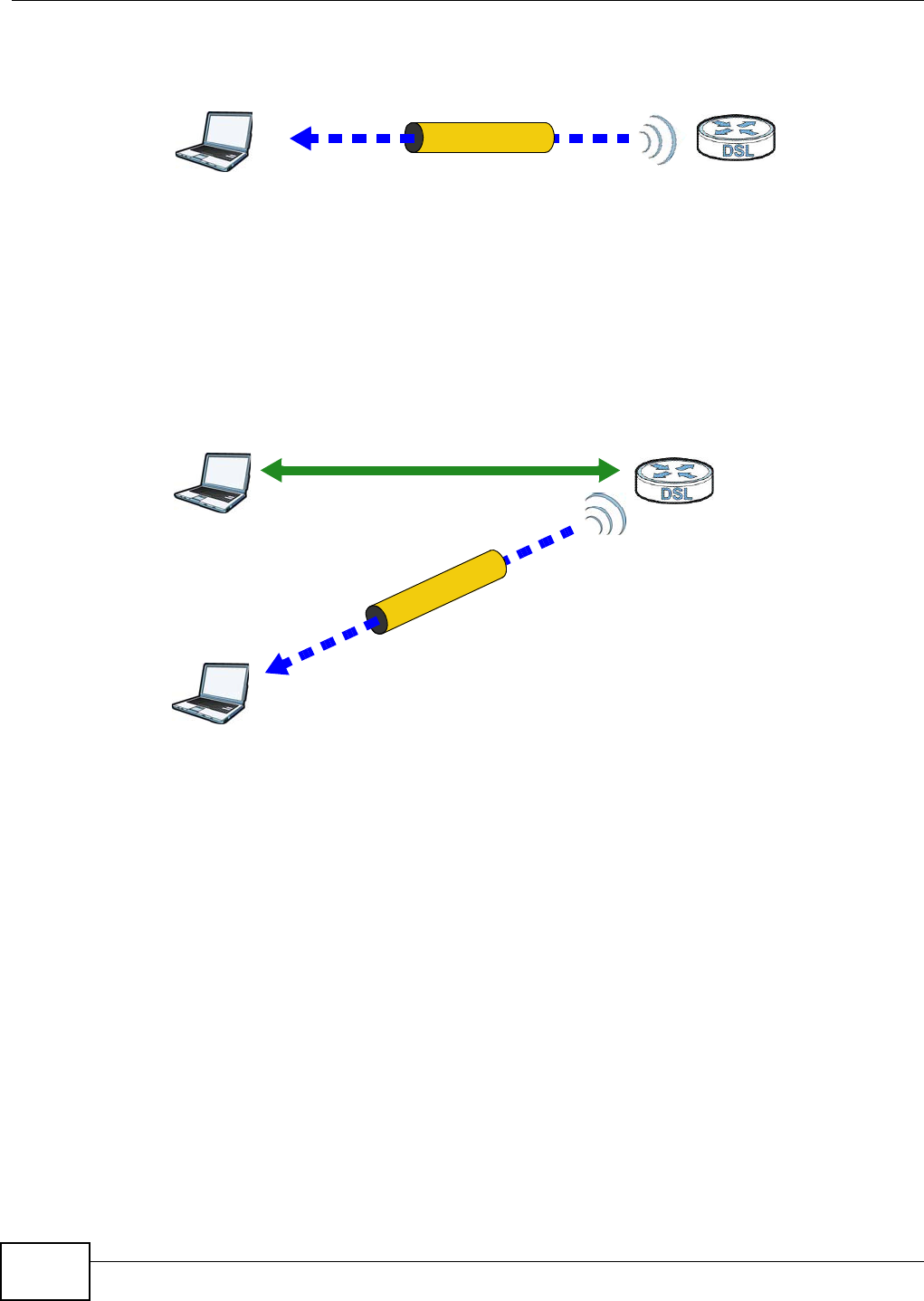
Chapter 14 Wireless
Basic Home Station VDSL2 P8802T User’s Guide
196
Figure 84 WPS: Exam ple Net work St ep 1
I n step 2 , you add another wireless client t o t he net work. You know that Client 1 support s regist rar
m ode, but it is bet t er to use AP1 for the WPS handshake wit h the new client since you m ust
connect to t he access point anyway in order to use the network. I n t his case, AP1 m ust be t he
regist rar, since it is configured (it already has security inform at ion for the network). AP1 supplies
the exist ing security infor m ation to Clie nt 2 .
Figure 85 WPS: Exam ple Net work St ep 2
I n step 3, you add another access point (AP2 ) to your network. AP2 is out of range of AP1 , so you
cannot use AP1 for t he WPS handshake wit h t he new access point. However, you know that Client
2 support s the regist rar funct ion, so you use it t o perform t he WPS handshake inst ead.
REGISTRARENROLLEE
SECURITY INFO
CLIENT 1 AP1
REGISTRAR
CLIENT 1 AP1
ENROLLEE
CLIENT 2
EXISTING CONNECTION
SECURITY INFO
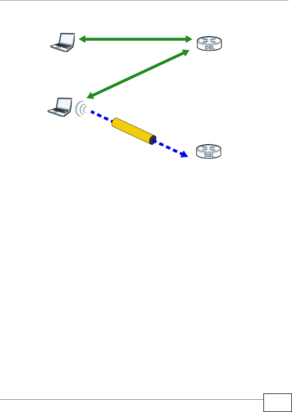
Chapter 14 Wireless
Basic Home Station VDSL2 P8802T User’s Guide 197
Figure 86 WPS: Exam ple Net work St ep 3
14.7.7.5 Limitations of WPS
WPS has som e lim itat ions of which you should be aware.
• WPS works in I nfrastruct ure net works only ( where an AP and a wireless client com m unicat e). I t
does not work in Ad- Hoc net works ( wher e there is no AP) .
• When you use WPS, it works bet ween two devices only. You cannot enroll m ultiple devices
sim ult aneously, you m ust enroll one aft er t he ot her.
For inst ance, if you have two enrollees and one regist rar you m ust set up the first enrollee ( by
pressing the WPS butt on on the r egist rar and t he first enrollee, for exam ple) , then check t hat it
successfully enrolled, then set up the second device in the sam e way.
• WPS works only wit h ot her WPS- enabled devices. However, you can st ill add non-WPS devices t o
a net work you already set up using WPS.
WPS works by aut om atically issuing a random ly-generated WPA- PSK or WPA2- PSK pre- shared
key from t he regist rar device t o t he enrollee devices. Whether t he net work uses WPA-PSK or
WPA2- PSK depends on t he device. You can check t he configurat ion int erface of the regist rar
device t o discover the key the network is using (if t he device supports t his feature) . Then, you
can ent er the key int o the non-WPS device and j oin the net work as norm al (t he non-WPS device
m ust also support WPA-PSK or WPA2- PSK) .
• When you use the PBC m et hod, t here is a short period ( from t he m om ent you press t he butt on
on one device t o the mom ent you press the butt on on the other device) when any WPS- enabled
device could join t he net work. This is because t he regist rar has no way of ident ifying t he
“ correct ” enrollee, and cannot different iate between your enrollee and a rogue device. This is a
possible way for a hacker to gain access t o a network.
You can easily check t o see if this has happened. WPS works bet ween only two devices
sim ultaneously, so if another device has enrolled your device w ill be unable t o enroll, and will not
have access t o the network. I f this happens, open t he access point’s configuration interface and
look at t he list of associat ed client s ( usually displayed by MAC address) . I t does not m att er if the
CLIENT 1 AP1
REGISTRAR
CLIENT 2
EXISTING CONNECTION
SECURITY INFO
ENROLLEE
AP2
EXISTING CONNECTION
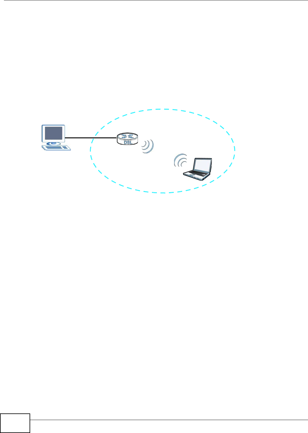
Chapter 14 Wireless
Basic Home Station VDSL2 P8802T User’s Guide
198
access point is the WPS regist rar, the enrollee, or was not involved in t he WPS handshake; a
rogue device m ust st ill associate wit h the access point to gain access to the net work. Check the
MAC addresses of your wireless clients ( usually print ed on a label on t he bott om of t he device) . I f
there is an unknown MAC address you can rem ove it or reset t he AP.
14.7.8 Vista as a WPS External Registrar
Use an Ethernet cable to connect a Windows Vist a com puter directly t o one of t he VDSL Router’s
Et hernet ports t o let the com put er give wireless set t ings t o the VDSL Router and then lat er to
wireless client s using t he WPS PI N m ethod.
Figure 87 Windows Vista Com put er Connect ed to a VDSL Rout er Et hernet Port
14.7.8.1 Vista Configuring the VDSL Router’s Wireless Settings
1Go t o t he VDSL Router’s W ire less > Secu rit y scr een and copy the VDSL Router’s ident ification
PI N.
2I n Windows Vist a, go to your network connections and double-click t he ZyXEL AP icon t o open t he
Windows Connect Now (WCN) screens.
3Enter t he VDSL Router’s ident ification PI N and click N e x t . The com puter tells t he VDSL Router what
wireless net work set t ings to use.
14.7.8.2 Vista Adding and Authenticating Wireless Clients
Aft er a Windows Vist a com put er configures the VDSL Rout er’s wireless set t ings, the sam e com puter
can use WPS to add wireless client s t o t he network. The com puter also authenticat es them when
they connect t o t he wireless net work.
1I n the wireless client ’s configurat ion utility, select t he opt ion to use its PI N t o add it t o t he wireless
net work.
Note: Aft er t he wireless client st arts WPS configurat ion, you have t wo m inutes t o ent er
the PI N in t he Windows Vist a com puter.
2I n the Windows Vista net work connect ions, an icon for the wireless client displays. Double- click it,
ent er t he wireless client ’s PI N, and click N e x t .

Chapter 14 Wireless
Basic Home Station VDSL2 P8802T User’s Guide 199
3The Windows Vist a com puter uses WPS t o give t he wireless client t he wireless net work’s settings.
Aft er the wireless client ’s wireless set t ings are configured, the Windows Vist a computer
aut hent icat es t hem whenever they connect to the wireless net work.
4Aft er the WPS process finishes (the enrollee is able to access the VDSL Router) you can repeat
these steps to add m ore wireless client s one at a t im e.

Chapter 14 Wireless
Basic Home Station VDSL2 P8802T User’s Guide
200

Basic Home Station VDSL2 P8802T User’s Guide 201
CHAPTER 15
Voice
15.1 Overview
Use t his chapter t o:
• Connect an analog phone t o the VDSL Router.
• Make phone calls over the I nt ernet, as well as the regular phone net work.
• Configure set t ings such as speed dial.
• Configure network settings t o opt im ize t he voice qualit y of your phone calls.
15.1.1 What You Can Do in this Chapter
These screens allow you t o configure your VDSL Router to m ake phone calls over
the I nt ernet and your regular phone line, and to set up t he phones you connect t o
the VDSL Router.
• Use the SI P Account screen (Sect ion 15.3 on page 203) t o set up inform at ion
about your SI P account, cont rol which SI P accounts t he phones connected t o
the VDSL Router use and configure audio settings such as volum e levels for t he
phones connect ed to t he ZyXEL Device.
• Use the SI P Se rvice Provide r screen ( Sect ion 15.4 on page 209) t o configure
the SI P server inform at ion, QoS for VoI P calls, the num ber s for certain phone
funct ions, and dialing plan.
• Use the Region screen (Sect ion 15.5 on page 216) to change set t ings that
depend on t he country you are in.
• Use the Ca ll Rule screen (Section 15.6 on page 217) t o set up short cuts for
dialing frequently-used ( VoI P) phone num bers.
• Use the Su m m a ry screen ( Sect ion 15.7 on page 219) t o view t he sum m ary list
of received, dialed and m issed calls.
• Use the Ou t going screen ( Sect ion 15.8 on page 219) t o view detailed
inform at ion for each outgoing call you m ade.
• Use the I ncom ing screen (Sect ion 15.9 on page 220) to view det ailed
inform ation for each incom ing call from som eone calling you.

Chapter 15 Voice
Basic Home Station VDSL2 P8802T User’s Guide
202
You don’t necessarily need to use all t hese screens t o set up your account. I n fact ,
if your service provider did not supply inform ation on a part icular field in a screen,
it is usually best to leave it at it s default setting.
15.1.2 What You Need to Know About VoIP
VoIP
VoI P st ands for Voice over I P. I P is t he I nternet Protocol, which is t he m essage-
carrying st andard t he I nternet runs on. So, Voice over I P is t he sending of voice
signals ( speech) over t he I nt ernet (or anot her network t hat uses t he I nternet
Prot ocol) .
SIP
SI P st ands for Session I nit iat ion Protocol. SI P is a signalling standard t hat let s one
netw ork device (like a com put er or t he VDSL Rout er) send m essages t o another.
I n VoI P, these m essages are about phone calls over the network. For exam ple,
when you dial a num ber on your VDSL Rout er, it sends a SI P m essage over t he
netw ork asking the other device ( the num ber you dialed) to take part in the call.
SIP Accounts
A SI P account is a type of VoI P account . I t is an arrangem ent with a service
provider t hat lets you m ake phone calls over the I nternet . When you set the VDSL
Router to use your SI P account t o m ake calls, t he VDSL Router is able to send all
the inform at ion about t he phone call to your service provider on the I nt ernet.
St rict ly speaking, you don’t need a SI P account. I t is possible for one SI P device
( like the VDSL Router) t o call another wit hout involving a SI P service provider.
However, the networking difficulties involved in doing t his m ake it t rem endously
im pract ical under norm al circum st ances. Your SI P account provider rem oves t hese
difficulties by taking care of t he call routing and setup - figuring out how to get
your call to the right place in a way t hat you and the other person can talk t o one
anot her.
How to Find Out More
See Chapt er 2 on page 19 for a t ut orial showing how to set up t hese screens in an
exam ple scenario.
See Sect ion 15.10 on page 221 for advanced technical inform at ion on SI P.
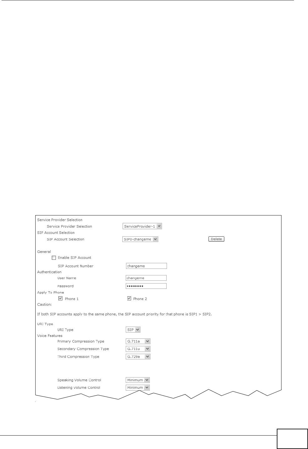
Chapter 15 Voice
Basic Home Station VDSL2 P8802T User’s Guide 203
15.2 Before You Begin
• Before you can use t hese screens, you need to have a VoI P account already set
up. I f you don’t have one yet, you can sign up with a VoI P service pr ovider over
the I nt ernet.
• You should have the inform at ion your VoI P service provider gave you ready,
before you start t o configure t he VDSL Rout er.
15.3 The SIP Settings Screen
The VDSL Rout er uses a SI P account to m ake out going VoI P calls and check if an
incom ing call’s dest inat ion num ber m at ches your SI P account ’s SI P num ber. I n
order to m ake or receive a VoI P call, you need t o enable and configure a SI P
account , and m ap it to a phone port. The SI P account contains inform at ion that
allows your VDSL Router to connect to your VoI P service provider.
Use t his screen to m aint ain inform ation about each SI P account . You can also
enable and disable each SI P account. To access t his screen, click VOI P > SI P >
SI P Account.
Figure 88 VOIP > SIP > SIP Account
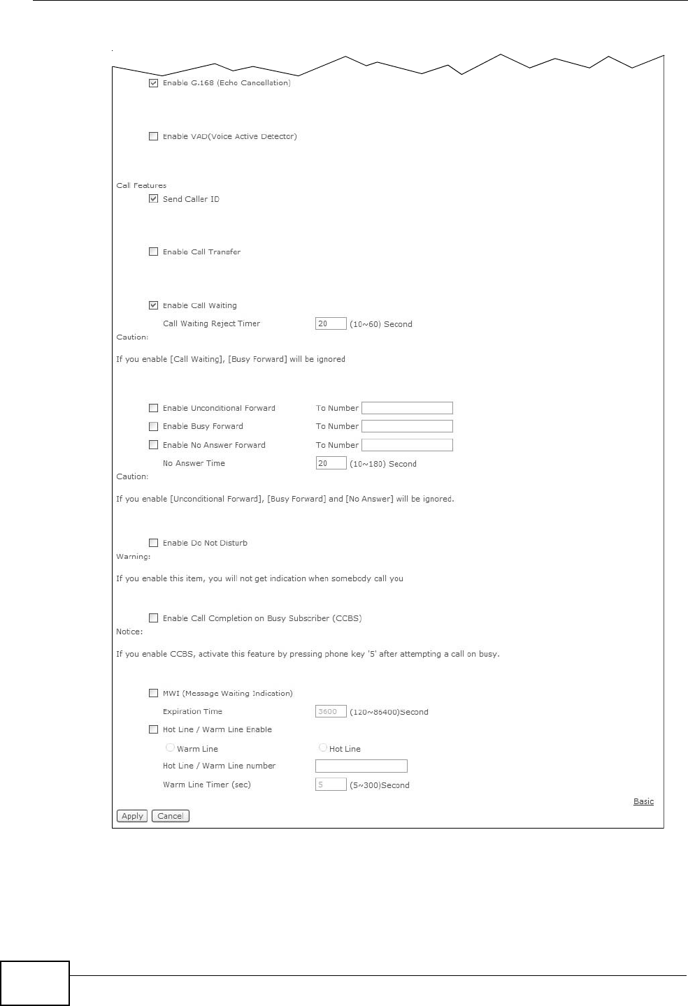
Chapter 15 Voice
Basic Home Station VDSL2 P8802T User’s Guide
204

Chapter 15 Voice
Basic Home Station VDSL2 P8802T User’s Guide 205
Each field is described in t he following table.
Table 73 VOIP > SIP > SIP Account
LABEL DESCRIPTION
Service
Provider
Select ion
Select the SI P service provider profile you want to use for the SI P
account you configure in t his screen. I f you change t his field, the screen
aut om at ically refreshes.
SI P Account
Select ion
Select the SI P account you want to see in t his screen. I f you change t his
field, the screen autom atically refreshes.
Select AD D _ N EW t o creat e a new SI P account on t he VDSL Router.
Delet e Click t his but t on t o rem ove t he SI P account select ed in the SI P
Account Sele ct ion field.
This button is not available when you select AD D _ N EW in t he SI P
Account Sele ct ion field.
General
Enable SI P
Account
Select this if you want the VDSL Router to use t his account. Clear it if
you do not want t he VDSL Rout er to use t his account.
SI P Account
Num ber
Enter your SI P num ber. I n t he full SI P URI, this is the part before t he @
sym bol. You can use up to 127 printable ASCI I charact ers.
Aut hent ication
User Nam e Enter the user nam e for registering t his SI P account, exact ly as it was
given t o you. You can use up to 95 print able ASCII charact er s.
Passw ord Ent er the user nam e for regist ering this SI P account , exactly as it was
given t o you. You can use up to 95 print able ASCII Ext ended set
charact ers.
Apply To Phone Select a phone port on which you want to m ake or receive phone calls
for this SI P account.
I f you m ap a phone port to m ore than one SI P account, there is no way
to dist inguish bet ween t he SI P accounts when you receive phone calls.
The VDSL Rout er uses t he m ost recent ly registered SI P account fir st
when you m ake an outgoing call.
I f a phone port is not m apped t o a SI P account , you cannot receive or
m ake any calls on t he phone connect ed t o t his phone port.
Advanced/ Basic Click Advance d t o display and edit m ore inform at ion for the SI P
account . Click Ba sic to display and configure t he basic SI P account
sett ings.
URI Type Select whet her or not t o include t he SI P service dom ain nam e when t he
VDSL Router sends t he SI P num ber.
SI P - include t he SI P service dom ain nam e.
TEL - do not include t he SI P service dom ain nam e.
Voice Feat u r e s

Chapter 15 Voice
Basic Home Station VDSL2 P8802T User’s Guide
206
Prim ary
Com pression
Ty p e
Secondary
Com pression
Ty p e
Thir d
Com pression
Ty p e
Select the t ype of voice coder/ decoder (codec) that you want the VDSL
Router to use.
G.711 provides high voice qualit y but requires m ore bandwidth (64
kbps) . G.711 is t he default codec used by phone com panies and digit al
han dset s.
•G.7 1 1 a is t ypically used in Europe.
•G.7 1 1 u is typically used in Nort h Am erica and Japan.
G.7 2 2 is a 7 KHz wideband voice codec t hat operates at 48, 56 and 64
kbps. By using a sam ple rat e of 16 kHz, G.722 can provide higher
fidelit y and bet t er audio quality than narrowband codecs like G.711, in
which the voice signal is sam pled at 8 KHz.
G.7 2 6 operates at 2 4 or 3 2 kbps.
The VDSL Rout er m ust use t he same codec as t he peer. When two SI P
devices start a SI P session, t hey m ust agree on a codec.
Select the VDSL Router’s first choice for voice coder/ decoder.
Select the VDSL Router’s second choice for voice coder/ decoder. Select
N on e if you only want the VDSL Rout er to accept t he first choice.
Select the VDSL Router’s t hird choice for voice coder/ decoder. Select
N on e if you only want the VDSL Router to accept the first or second
choice.
Speaking
Volum e Cont rol
Enter t he loudness t hat the VDSL Router uses for speech that it sends
to the peer device.
Min im um is the quiet est , and M axim um is the loudest .
List ening
Volum e Cont rol
Enter t he loudness t hat the VDSL Router uses for speech t hat it receives
from the peer device.
Min im um is the quiet est , and M axim um is the loudest .
Enable G.168
( Echo
Cancellation)
Select this if you want to elim inat e t he echo caused by the sound of
your voice reverberat ing in t he t elephone receiver while you t alk.
Enable VAD
( Voice Act ive
Detect or)
Select this if the VDSL Router should stop transm it t ing when you are
not speaking. This reduces the bandwidth t he VDSL Router uses.
Call Features
Send Caller I D Select this if you want to send ident ification when you m ake VoI P phone
calls. Clear this if you do not want to send ident ification.
Enable Call
Tr a n s f e r
Select this to enable call transfer on the VDSL Router. This allows you to
transfer an incom ing call ( t hat you have answered) to another phone.
Enable Call
Waiting
Select this t o enable call wait ing on the VDSL Router. This allows you to
place a call on hold w hile you answer another incom ing call on t he sam e
telephone num ber.
Call Waiting
Rej ect Tim er
Specify a tim e of seconds that the VDSL Router waits befor e reject ing
the second call if you do not answer it .
Table 73 VOIP > SIP > SIP Account (continued)
LABEL DESCRIPTION

Chapter 15 Voice
Basic Home Station VDSL2 P8802T User’s Guide 207
Enable
Unconditional
For w ar d
Select this if you want the VDSL Rout er to forward all incom ing calls to
the specified phone num ber.
Specify the phone num ber in the To Num ber field on t he right.
Enable Busy
For w ar d
Select this if you want t he VDSL Rout er to forward incoming calls t o t he
specified phone num ber if the phone port is busy.
Specify the phone num ber in the To Num ber field on t he right.
I f you have call wait ing, t he incom ing call is forwarded t o t he specified
phone num ber if you reject or ignore the second incom ing call.
Enable No
Answ er For war d
Select this if you want t he VDSL Rout er to forward incoming calls t o t he
specified phone num ber if t he call is unanswered. (See N o Answ er
Tim e.)
Specify the phone num ber in the To Num ber field on t he right.
No Answer
Tim e
This field is used by t he Act ive N o Answ er Forw ard feature.
Ent er the num ber of seconds the VDSL Rout er should wait for you to
answer an incom ing call before it considers t he call is unanswered.
Enable Do Not
Dist urb
Select this t o set your phone to not ring w hen som eone calls you.
Enable Call
Com plet ion on
Bu sy Su bscr ib er
( CCBS)
When you m ake a phone call but hear a busy tone, Call Com plet ion on
Busy Subscriber (CCBS) allows you to enable aut o-callback by pressing
5 and hanging up the phone. The VDSL Router then t ries to call t hat
phone num ber every m inute since after you hang up the phone. When
the called part y becom es available w it hin t he CCBS tim eout period ( 60
m inutes by default ), both phones ring.
• I f t he called part y’s phone rings because of CCBS but no one
answers t he phone after 180 seconds, you will hear a busy t one.
You can enable CCBS on t he called num ber again.
• I f you m anually call t he num ber on which you have enabled CCBS
before t he CCBS t im eout period expires, t he VDSL Router disables
CCBS on the called num ber.
• I f you call a second num ber before t he first called num ber ’s CCBS
tim eout period expires, the VDSL Router st ops calling the first
num ber unt il you finish the second call.
Select this opt ion to act ivate CCBS on t he VDSL Router.
MWI (Message
Waiting
I ndication)
Select this if you want to hear a waiting ( beeping) dial t one on your
phone when you have at least one voice m essage. Your VoI P service
provider m ust support t his feature.
Expiration Tim e Keep the default value for this field, unless your VoI P service provider
tells you to change it . Enter the num ber of seconds the SI P server
should provide t he m essage wait ing service each tim e the VDSL Router
subscribes to t he service. Before this tim e passes, t he VDSL Router
aut om at ically subscribes again.
Hot Line /
War m Line
Enable
Select this t o enable the hot line or warm line feature on t he VDSL
Rou t er .
Warm Line Select this t o have the VDSL Router dial the specified warm line num ber
aft er you pick up the t elephone and do not press any keys on t he
keypad for a period of tim e.
Table 73 VOIP > SIP > SIP Account (continued)
LABEL DESCRIPTION

Chapter 15 Voice
Basic Home Station VDSL2 P8802T User’s Guide
208
Hot Line Select this to have the VDSL Rout er dial the specified hot line num ber
im m ediately when you pick up t he t elephone.
Hot Line /
War m Line
num ber
Enter t he num ber of the hot line or warm line that you want the VDSL
Rou t er t o dial.
War m Line
Timer
Enter a num ber of seconds that the VDSL Router waits before dialing
the warm line num ber if you pick up the t elephone and do not press any
keys on the keypad.
Apply Click this to save your changes and to apply them to the VDSL Router.
Cancel Click t his to set every field in this screen to it s last-saved value.
Table 73 VOIP > SIP > SIP Account (continued)
LABEL DESCRIPTION
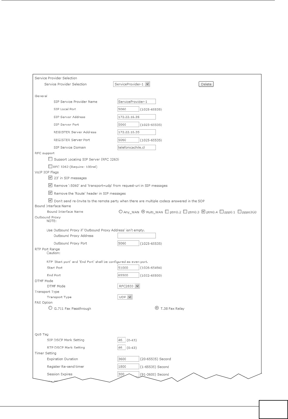
Chapter 15 Voice
Basic Home Station VDSL2 P8802T User’s Guide 209
15.4 The SIP Service Provider Screen
Click V OI P > SI P > SI P Se rvice Provider t o open the SI P Ser vice Provider
screen. Use this screen to configure t he SI P server inform at ion, QoS for VoI P calls,
the num bers for certain phone funct ions, and dialing plan.
Figure 89 VOIP > SIP > SIP Service Provider
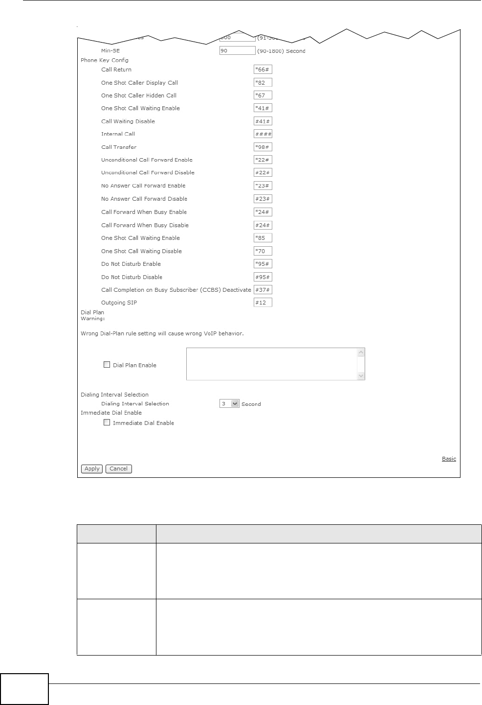
Chapter 15 Voice
Basic Home Station VDSL2 P8802T User’s Guide
210
Each field is described in t he following table.
Table 74 VoIP > SIP > SIP Service Provider
LABEL DESCRIPTION
Service
Provider
Select ion
Select the SI P ser vice provider profile you want to see in this screen. I f
you change t his field, the screen aut om at ically refreshes.
Select AD D _ N EW t o creat e a new SI P ser vice provider profile on t he
VDSL Rout er.
Delet e Click t his but t on t o rem ove t he SI P service provider profile selected in
the Se rvice Pr ovide r Select ion field.
This button is not available when you select AD D _ N EW in t he Ser vice
Provide r Se lect ion.

Chapter 15 Voice
Basic Home Station VDSL2 P8802T User’s Guide 211
General
SI P Service
Provider Nam e
Enter a descriptive nam e of up t o 63 printable characters for this SI P
service provider profile. Spaces are not allowed.
SI P Local Port Enter t he VDSL Router’s list ening port num ber, if your VoI P service
provider gave you one. Otherwise, keep t he default value.
SI P Ser ver
Address
Enter t he I P address or dom ain nam e of the SI P server provided by
your VoI P service provider. You can use up t o 95 printable ASCI I
charact ers. I t does not m att er whet her t he SI P server is a proxy,
redirect or regist er server.
SI P Server Port Ent er the SI P server ’s list ening port num ber, if your VoI P service
provider gave you one. Otherwise, keep t he default value.
REGI STER
Server Address
Enter t he I P address or dom ain nam e of the SI P regist er server, if your
VoI P service provider gave you one. Ot herwise, ent er the sam e address
you ent ered in t he SI P Ser ve r Addr ess field. You can use up to 95
print able ASCI I characters.
REGI STER
Server Port
Ent er the SI P regist er server’s list ening port num ber, if your VoI P
service provider gave you one. Otherwise, ent er the sam e port num ber
you ent ered in t he SI P Ser ve r Port field.
SI P Service
Dom ain
Enter t he SI P service dom ain nam e. I n the full SI P URI , t his is t he part
aft er the @ sym bol. You can use up to 127 printable ASCI I Extended
set charact ers.
RFC support
Support
Locating SI P
Server (RFC
3263)
Select this opt ion to have the VDSL Router use DNS procedures t o
resolve t he SI P dom ain and find t he SI P server ’s I P address, port
num ber and support ed transport prot ocol( s) .
The VDSL Rout er first uses DNS Nam e Aut horit y Pointer ( NAPTR)
records t o det erm ine the t ransport prot ocols supported by t he SI P
server. I t then perform s DNS Service ( SRV) query to det erm ine t he port
num ber for t he prot ocol. The VDSL Router resolves t he SI P server ’s I P
address by a st andard DNS address record lookup.
The SI P Server Port and REGI STER Server Port fields are grayed
out and not applicable and t he Tra nsport Type can also be set t o
AUTO if you select this opt ion.
RFC 3262 RFC 3262 defines a m echanism t o provide reliable t ransm ission of SI P
provisional response m essages, which convey inform ation on t he
processing progress of t he request. This uses the option t ag 100rel and
the Provisional Response ACKnowledgem ent (PRACK) m ethod.
Select this t o have the VDSL Router include a SI P Require/ Support ed
header field wit h the option t ag 100rel in all I NVI TE requests. When
the VDSL Rout er receives a SI P response m essage indicating that t he
phone it called is ringing, the VDSL Router sends a PRACK m essage t o
have both sides confirm t he m essage is received.
I f you select this opt ion, t he peer device should also support t he opt ion
tag 100rel to send provisional responses reliably.
VoI P I OP Flags Use t his sect ion to m odify the header or som e inform ation in SI P
m essages in order t o resolve int eroperability issues with som e SI P
servers.
Table 74 VoIP > SIP > SIP Service Provider (continued)
LABEL DESCRIPTION

Chapter 15 Voice
Basic Home Station VDSL2 P8802T User’s Guide
212
23’ in SI P
m essages
Replace a dial digit “ # ” wit h “ % 23” in the I NVI TE m essages.
Rem ove ‘: 5060’
and
'transport= udp'
from request-
uri in SI P
m essages
Rem ove “ : 5060” and “ t ransport= udp” from the “ Request- URI ” st ring in
the REGI STER and I NVI TE packets.
Rem ove t he
'Route' header
in SI P
m essages
Rem ove t he 'Route' header in SI P packets.
Don't send re-
I nvite to the
rem ote party
when t here are
m ultiple codecs
answered in t he
SDP
Do not send a re-I nvite packet t o t he rem ote party when the remot e
part y answers t hat it can support mult iple codecs??
Bound I nter face
Nam e
Bound I nter face
Nam e
I f you select LAN or An y_ W AN , the VDSL Router aut om atically
act ivates t he VoI P service w hen any LAN or WAN connect ion is up.
I f you select M ult i_ W AN , you also need to select the pre- configured
WAN connect ions. The VoI P service is act ivat ed only when one of t he
select ed WAN connect ions is up.
Outbound Proxy
Out bound Pr ox y
Address
Enter t he I P address or dom ain nam e of the SI P outbound proxy server
if your VoI P service provider has a SI P out bound server t o handle voice
calls. This allows t he VDSL Router to work with any type of NAT rout er
and elim inates t he need for STUN or a SI P ALG. Turn off any SI P ALG on
a NAT router in front of t he VDSL Router to keep it from re- t ranslat ing
the I P address ( since this is already handled by the out bound proxy
server) .
Out bound Pr ox y
Por t
Ent er the SI P outbound proxy server’s list ening port , if your VoI P
service provider gave you one. Ot herwise, keep t he default value.
RTP Por t Range
St art Port
End Port
Ent er the list ening port number(s) for RTP t raffic, if your VoI P service
provider gave you this inform ation. Ot her wise, keep the default values.
To enter one port num ber, ent er the port num ber in t he St a rt Port and
End Por t fields.
To enter a range of ports,
• ent er t he port num ber at the beginning of t he range in the St a rt
Por t field.
• ent er t he port num ber at the end of t he range in the End Port field.
DTMF Mode
Table 74 VoIP > SIP > SIP Service Provider (continued)
LABEL DESCRIPTION

Chapter 15 Voice
Basic Home Station VDSL2 P8802T User’s Guide 213
DTMF Mode Control how the VDSL Router handles t he t ones t hat your telephone
m akes when you push its buttons. You should use t he sam e m ode your
VoI P ser vice provider uses.
RFC2 8 3 3 - send the DTMF tones in RTP packet s.
I nBan d - send the DTMF t ones in t he voice dat a st ream . This m et hod
works best when you are using a codec t hat does not use com pression
( like G.711) . Codecs that use compression ( like G.729 and G.726) can
dist ort t he tones.
SI PI nfo - send t he DTMF t ones in SI P m essages.
Tr a n s p o r t Ty p e
Tr a n s p o r t Ty p e Select t he transport layer prot ocol ( TCP, UDP or TLS) used for SI P.
AUTO is available w hen you select t he Support Locat ing SI P Se rver
opt ion. I f you select AUTO here, the VDSL Router sends a DNS Name
Aut hority Point er (NAPTR) query to locate t he SI P ser ver and get t he
support ed t ransport layer prot ocol( s) .
FAX Option This field cont rols how the VDSL Router handles fax m essages.
G.711 Fax
Passt hrough
Select this if the VDSL Rout er should use G.711 t o send fax m essages.
The peer devices m ust also use G.711.
T.38 Fax Relay Select this if t he VDSL Router should send fax m essages as UDP or TCP/
I P packet s t hrough I P networks. This prov ides bet ter qualit y, but it m ay
have inter- operability problem s. The peer devices m ust also use T.38.
QoS Tag
SI P DSCP Mark
Sett ing
Enter t he DSCP (DiffServ Code Point ) num ber for SI P voice
transm issions. The VDSL Rout er creat es Class of Service ( CoS) priority
tags wit h this num ber to voice t raffic that it transm its.
RTP DSCP Mar k
Sett ing
Enter t he DSCP (DiffServ Code Point ) num ber for RTP voice
transm issions. The VDSL Rout er creat es Class of Service ( CoS) priority
tags wit h this num ber to RTP traffic t hat it transm it s.
Timer Set t ing
Expirat ion
Duration
Enter t he num ber of seconds your SI P account is regist ered with t he
SI P regist er server before it is delet ed. The VDSL Rout er autom atically
tries t o re-r egist er your SI P account when one- half of this tim e has
passed. (The SI P regist er server m ight have a different expirat ion.)
Regist er Re-
send t imer
Enter t he num ber of seconds t he VDSL Rout er waits before it t ries again
to regist er the SI P account, if the first try failed or if there is no
response.
Session Expires Ent er the num ber of seconds the VDSL Router let s a SI P session rem ain
idle ( wit hout traffic) before it aut om at ically disconnect s t he session.
Min-SE Enter t he m inim um num ber of seconds the VDSL Rout er let s a SI P
session rem ain idle ( without traffic) before it autom at ically disconnects
the session. When two SI P devices start a SI P session, t hey m ust agree
on an expirat ion tim e for idle sessions. This field is t he shortest
expirat ion t im e t hat the VDSL Router accept s.
Phone Key
Config
Table 74 VoIP > SIP > SIP Service Provider (continued)
LABEL DESCRIPTION

Chapter 15 Voice
Basic Home Station VDSL2 P8802T User’s Guide
214
Call Return Specify the key combinat ions t hat you can ent er to place a call t o t he
last num ber t hat called you.
One Shot Caller
Display Call
Specify the key com binat ions t hat you can enter to act ivate caller I D for
the next call only.
One Shot Caller
Hidden Call
Specify the key com binat ions t hat you can ent er t o deact ivat e caller I D
for the next call only.
One Shot Call
Waiting Enable
Specify the key com binat ions that you can ent er to put a call on hold
when you are answering another.
Call Waiting
Disable
Specify the key com binations that you can ent er to turn the call wait ing
funct ion off.
I nt ernal Call Specify the key com binat ions t hat you can enter to call t he phone(s)
connect ed t o t he VDSL Rout er.
Call Transfer Specify the key com binat ions t hat you can ent er to transfer a call t o
another phone.
Unconditional
Call Forward
Enable
Specify the key com binat ions t hat you can enter to forward all incom ing
calls to the phone num ber you specified in t he SI P > SI P Account
screen.
Unconditional
Call Forward
Disable
Specify the key com binat ions t hat you can ent er to turn the
unconditional call forwar d funct ion off.
No Answer Call
For ward Enable
Specify the key com binat ions t hat you can ent er to forward incoming
calls to the phone num ber you specified in t he SI P > SI P Account
screen if the calls are unanswered.
No Answer Call
Forward Disable
Specify the key com binat ions t hat you can ent er to turn the no answer
call forwar d funct ion off.
Call Forward
When Busy
Enable
Specify the key com binat ions t hat you can ent er to forward incoming
calls to the phone num ber you specified in t he SI P > SI P Account
screen if the phone port is busy.
Call Forward
When Busy
Disable
Specify the key com binat ions t hat you can ent er to turn the busy
forward funct ion off.
One Shot Call
Waiting Enable
Specify the key com binat ions that you can ent er to act ivate call wait ing
on t he nex t call only.
One Shot Call
Waiting Disable
Specify the key com binat ions t hat you can ent er to deact ivat e call
waiting on t he next call only.
Do Not Disturb
Enable
Specify the key com binat ions that you can ent er t o set your phone not
to ring when som eone calls you.
Do Not Disturb
Disable
Specify the key com binat ions t hat you can ent er to turn this funct ion
off.
Call Com plet ion
on Busy
Subscriber
( CCBS)
Deact ivat e
Specify the key com binat ions that you can ent er to disable CCBS on a
call.
Table 74 VoIP > SIP > SIP Service Provider (continued)
LABEL DESCRIPTION

Chapter 15 Voice
Basic Home Station VDSL2 P8802T User’s Guide 215
15.4.1 Dial Plan Rules
A dial plan defines the dialing patterns, such as the length and range of t he digit s
for a telephone num ber. I t also includes country codes, access codes, area codes,
local num bers, long dist ance num bers or int ernat ional call prefixes. For exam ple,
the dial plan ([ 2- 9] xxxxxx) does not allow a local num ber which begins wit h 1 or
0.
Without a dial plan, users have to m anually ent er the whole callee’s num ber and
wait for t he specified dialing int erval t o tim e out or press a term inat or key (usually
the pound key on the phone keypad) before t he VDSL Router m akes t he call.
The VDSL Router init ializes a call when t he dialed num ber m at ches any one of t he
rules in the dial plan. Dial plan rules follow these convent ions:
• The collect ion of rules is in parent heses ( ) .
• Rules are separat ed by the | ( bar) sym bol.
Out going SI P Specify the key com binat ions that you can ent er to select the SI P
account that you use t o make outgoing calls.
I f you ent er # 12(by default) < SI P account index num ber> # < the phone
num ber you want to call> , # 1201# 12345678 for exam ple, the VDSL
Router uses t he first SI P account t o call 12345678.
Dial Plan
Dial Plan Enable Select this to act ivate the dial plan rules you specify in the t ext box
provided. See Section 15.4.1 on page 215 for how to set up a rule.
Dialing I nt erval
Select ion
Dialing I nt erval
Select ion
Ent er the num ber of seconds the VDSL Rout er should wait aft er you
st op dialing num bers before it m akes t he phone call. The value depends
on how quickly you dial phone num bers.
I f you select I m m ediat e Dial En able, you can press t he pound key
( # ) t o t ell t he VDSL Router to m ake t he phone call im m ediately,
regardless of t his sett ing.
I m m ediat e Dial
Enable
I m m ediat e Dial
Enable
Select this if you want to use the pound key (# ) to tell t he VDSL Router
to m ake t he phone call im m ediat ely, inst ead of waiting the num ber of
seconds you selected in the Dia ling I nt er val Sele ct ion field.
I f you select t his, dial the phone num ber, and then press t he pound key.
The VDSL Rout er m akes t he call im m ediately, inst ead of wait ing. You
can still wait, if you want.
Apply Click this to save your changes and to apply them to the VDSL Router.
Cancel Click t his to set every field in this screen to it s last-saved value.
Table 74 VoIP > SIP > SIP Service Provider (continued)
LABEL DESCRIPTION

Chapter 15 Voice
Basic Home Station VDSL2 P8802T User’s Guide
216
• “ x” stands for a wildcard and can be any digit from 0 to 9.
• A subset of keys is in a square bracket [ ] . Ranges are allowed.
For exam ple, [ 359] m eans a num ber m at ching this rule can be 3, 5 or 9. [ 26-
8* ] m eans a num ber m atching this rule can be 2, 6, 7, 8 or * .
• The dot “ .” appended t o a digit allows the digit t o be ignored or repeat ed
m ult iple tim es. Any digit ( 0~ 9, * , # ) aft er the dot will be ignored.
For exam ple, (01.) m eans a num ber m at ching this rule can be 0, 01, 0111,
01111, and so on.
• < dialed- n um ber : t ran slat ed- num ber> indicat es t he num ber after the colon
replaces t he num ber before the colon in an angle bracket < > . For exam ple,
(< : 1212> xxxxxxx) m eans t he VDSL Router aut om atically prefixes t he
translated- num ber “ 1212” to t he num ber you dialed before m aking the call. This
can be used for local calls in the US.
(< 9: > xxx xxxxxxx) m eans t he VDSL Router autom at ically rem oves the
specified prefix “9” from t he num ber you dialed before m aking the call. This is
always used for m aking out side calls from an office.
(xx< 123: 456> xxxx) m eans t he VDSL Router aut om atically translates “ 123” t o
“ 456” in the num ber you dialed before m aking t he call.
• Calls wit h a num ber followed by the exclam at ion m ark “ !” will be dropped.
• Calls wit h a num ber followed by the t erm ination charact er “ @” will be m ade
im m ediat ely. Any digit (0~ 9, * , # ) after the @ charact er will be ignored.
I n this exam ple dial plan ( 0 | [ 49] 11 | 1 [ 2- 9] xx xxxxxxx | 1 947 xxxxxxx ! ) , you
can dial “ 0” t o call the local operator, call 411 or 911, or m ake a long distance call
with an area code st arting from 2 to 9 in the US. The calls wit h t he area code 947
will be dropped.
15.5 The Phone Region Screen
Use t his screen to m aint ain settings t hat depend on which region of the world the
VDSL Rout er is in. To access t his screen, click VoI P > Phon e > Region.
Figure 90 VoIP > Phone > Region

Chapter 15 Voice
Basic Home Station VDSL2 P8802T User’s Guide 217
Each field is described in t he following table.
15.6 The Call Rule Screen
Use t his screen to add, edit , or rem ove speed-dial num bers for out going calls.
Speed dial provides short cut s for dialing frequently- used ( VoI P) phone num bers.
You also have to creat e speed- dial ent ries if you want to call SI P num bers that
contain let t ers. Once you have configured a speed dial rule, you can use a short cut
Table 75 VoIP > Phone > Region
LABEL DESCRIPTION
Region Set t ings Select the place in which the VDSL Router is located.
Call Service
Mode
Select the m ode for supplem ent ary phone services (call hold, call
waiting, call transfer and three- way conference calls) that your VoI P
service provider support s.
Europe Type - use supplem entary phone services in European m ode
USA Type - use supplem ent ary phone ser vices Am erican m ode
You m ight have to subscribe t o these services to use them. Contact your
VoI P ser vice provider.
Apply Click this to save your changes and to apply them to the VDSL Router.
Cancel Click t his to set every field in this screen to it s last-saved value.
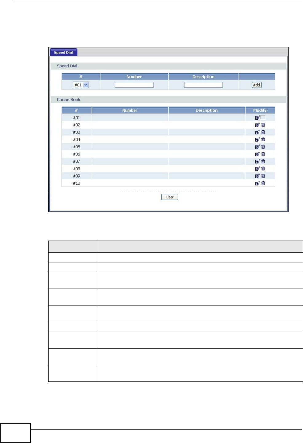
Chapter 15 Voice
Basic Home Station VDSL2 P8802T User’s Guide
218
(the speed dial num ber, # 01 for exam ple) on your phone's keypad t o call the
phone num ber.
Figure 91 VoIP > Call Rule
Each field is described in t he following table.
Table 76 VoIP > Call Rule
LABEL DESCRIPTION
Speed Dial Use t his sect ion to creat e or edit speed- dial ent ries.
#Select the speed- dial num ber you want t o use for this phone num ber.
Num ber Ent er the SI P num ber you want the VDSL Rout er t o call when you dial
the speed- dial num ber.
Descript ion Enter a nam e t o identify t he party you call when you dial the speed-dial
num ber. You can use up t o 127 print able ASCI I charact ers.
Add Click this t o use t he inform at ion in t he Spee d Dia l sect ion to updat e
the Phone Book sect ion.
Phone Book Use this sect ion to look at all the speed- dial ent ries and t o erase t hem .
# This field displays t he speed- dial num ber you should dial to use t his
ent ry.
Num ber This field displays t he SI P number the VDSL Router calls when you dial
the speed- dial num ber.
Descript ion This field displays t he nam e of t he party you call when you dial the
speed- dial num ber.
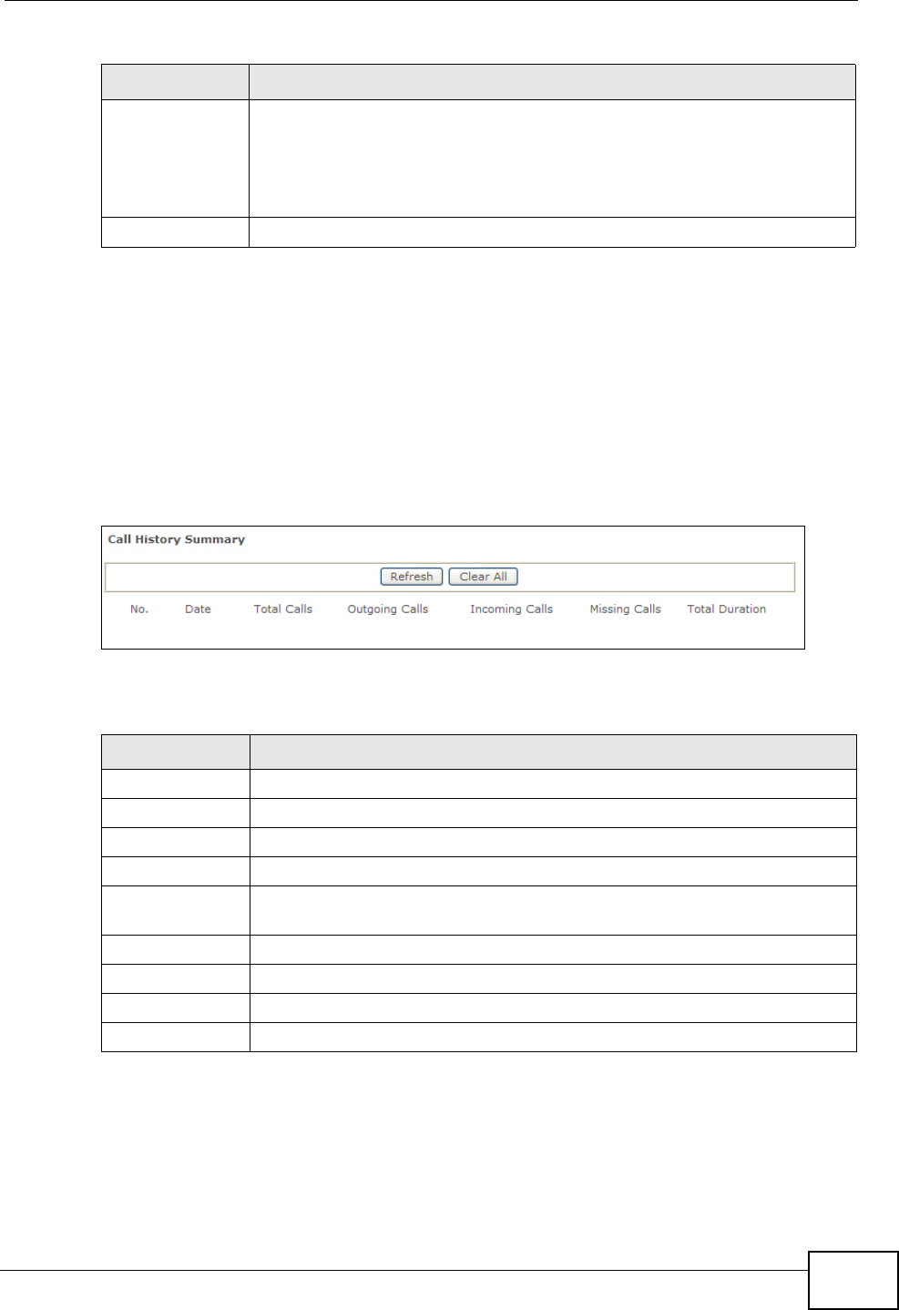
Chapter 15 Voice
Basic Home Station VDSL2 P8802T User’s Guide 219
15.7 Call History Summary Screen
Th e VDSL Rou t er log s calls fr om or t o you r SI P num ber s. Th is scr een allow s y ou t o
view the sum m ary of received, dialed and m issed calls.
Click V OI P > Call History > Sum m a r y. The following screen displays.
Figure 92 VOIP > Call History > Summary
Each field is described in t he following table.
15.8 Outgoing Calls Screen
Use t his screen t o see det ailed informat ion for each outgoing call you m ade.
Modify Use t his field to edit or erase t he speed- dial ent ry.
Click the Ed it icon to copy the inform at ion for this speed- dial entry into
the Spe ed Dial sect ion, where you can change it.
Click the D e let e icon t o erase t his speed- dial ent ry.
Clear Click t his to erase all t he speed- dial ent ries.
Table 76 VoIP > Call Rule
LABEL DESCRIPTION
Table 77 VOIP > Call History > Call History Summary
LABEL DESCRIPTION
Ref r esh Click this butt on t o renew the call hist ory list .
Clear All Click this but ton to rem ove all ent ries from the call hist ory list .
No. This is a read- only index num ber.
Date This is the date when t he calls were m ade.
Total Calls This displays t he t otal num ber of calls from or to your SI P num bers t hat
day.
Outgoing Calls This displays how m any calls originated from you t hat day.
I ncom ing Calls This displays how m any calls you received that day.
Missing Calls This displays how m any incom ing calls were not answered that day.
Total Duration This displays how long all calls last ed that day.
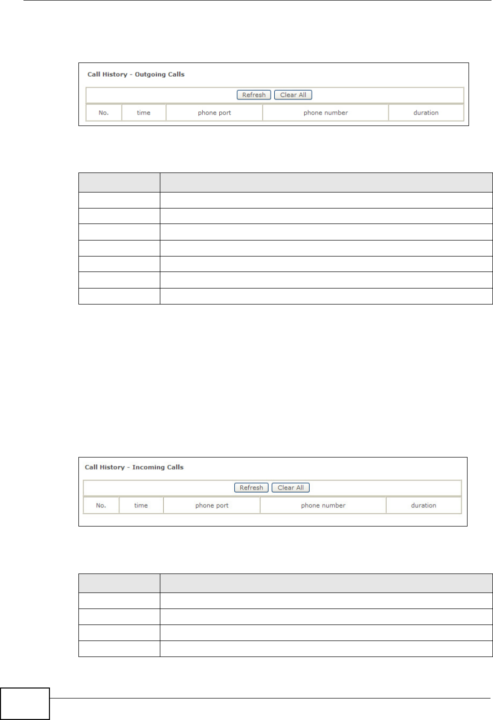
Chapter 15 Voice
Basic Home Station VDSL2 P8802T User’s Guide
220
Click V OI P > Call H ist ory > Out going. The following screen displays.
Figure 93 VOIP > Call History > Outgoing
Each field is described in t he following table.
15.9 Incoming Calls Screen
Use t his screen t o see det ailed inform ation for each incom ing call from som eone
calling you.
Click V OI P > Call H ist ory > I ncom in g Calls. The following screen displays.
Figure 94 VOIP > Call History > Incoming Calls
Each field is described in t he following table.
Table 78 VOIP > Call History > Outgoing
LABEL DESCRIPTION
Ref r esh Click this butt on t o renew the dialed call list .
Clear All Click this button to rem ove all ent ries from t he dialed call list .
No. This is a read- only index num ber.
t im e This is the dat e and tim e when the call was m ade.
phone port This is the phone port on which you m ade t he call.
phone num ber This is the SI P num ber you called.
durat ion This displays how long t he call lasted.
Table 79 VOIP > Call History > Incoming
LABEL DESCRIPTION
Ref r esh Click this butt on t o renew the received call list .
Clear All Click this but ton to rem ove all ent ries from the received call list .
No. This is a read- only index num ber.
t im e This is the dat e and tim e when the call was m ade.

Chapter 15 Voice
Basic Home Station VDSL2 P8802T User’s Guide 221
15.10 Technical Reference
This sect ion contains background m at erial relevant to the VoI P screens.
VoIP
VoI P is t he sending of voice signals over I nt ernet Prot ocol. This allow s you to
m ake phone calls and send faxes over the I nternet at a fract ion of t he cost of
using the t radit ional circuit- switched telephone net work. You can also use servers
to run t elephone service applications like PBX services and voice m ail. I nt ernet
Telephony Service Provider ( I TSP) com panies provide VoI P service.
Circuit-sw itched t elephone net works require 64 kilobit s per second (Kbps) in each
direction t o handle a telephone call. VoI P can use advanced voice coding
techniques wit h com pression t o reduce t he required bandwidth.
SIP
The Session I nit iat ion Protocol ( SI P) is an application-layer control (signaling)
protocol t hat handles t he set t ing up, altering and tearing down of voice and
m ult im edia sessions over the I nternet.
SI P signaling is separat e from t he m edia for w hich it handles sessions. The m edia
that is exchanged during t he session can use a different pat h from that of the
signaling. SI P handles t elephone calls and can int erface wit h traditional circuit-
switched t elephone net works.
SIP Identities
A SI P account uses an identit y (som et im es referred to as a SI P address) . A
com plet e SI P ident ity is called a SI P URI ( Uniform Resource I dentifier). A SI P
account's URI ident ifies t he SI P account in a way sim ilar t o the way an e-m ail
address ident ifies an e- m ail account . The form at of a SI P ident ity is SI P-
Num ber@SI P- Service-Dom ain.
phone port This is the phone port on which you received t he call.
Misse d m eans the call was unanswered.
phone num ber This is the SI P num ber that called you.
durat ion This displays how long t he call lasted.
Table 79 VOIP > Call History > Incoming
LABEL DESCRIPTION

Chapter 15 Voice
Basic Home Station VDSL2 P8802T User’s Guide
222
SIP Number
The SI P num ber is t he part of the SI P URI t hat com es before the “ @” sym bol. A
SI P num ber can use letters like in an e- m ail address ( johndoe@your-I TSP.com for
exam ple) or num bers like a t elephone num ber ( 1122334455@VoI P- provider.com
for exam ple) .
SIP Service Domain
The SI P service dom ain of the VoI P service provider is t he dom ain nam e in a SI P
URI . For exam ple, if the SI P address is 1122334455@VoI P-provider.com , then
“ VoI P-provider.com ” is t he SI P service dom ain.
SIP Registration
Each VDSL Rou t er is an in di v id u al SI P User Agent (UA) . To provide voice service, it
has a public I P address for SI P and RTP protocols to com m unicat e with ot her
servers.
A SI P user agent has to regist er with the SI P regist rar and m ust provide
inform at ion about t he users it represents, as well as its current I P address ( for the
routing of incom ing SI P requests) . Aft er successful regist ration, the SI P server
knows t hat t he users (identified by their dedicated SI P URI s) are represented by
the UA, and knows the I P address t o which the SI P request s and responses should
be sent.
Regist ration is init iat ed by the User Agent Client (UAC) running in t he VoI P
gat eway (the VDSL Router) . The gateway m ust be configured wit h inform at ion
letting it know where t o send the REGI STER m essage, as well as t he relevant user
and aut horization dat a.
A SI P regist ration has a lim it ed lifespan. The User Agent Client m ust renew its
regist rat ion within t his lifespan. I f it does not do so, the registration dat a will be
deleted from the SI P regist rar's dat abase and the connect ion broken.
The VDSL Router att em pts t o regist er all enabled subscriber port s when it is
switched on. When you enable a subscriber port t hat was previously disabled, t he
VDSL Router at t em pt s t o regist er the port im m ediately.
Authorization Requirements
SI P registrations ( and subsequent SI P request s) require a usernam e and
password for authorization. These credent ials are validated via a challenge /
response system using t he HTTP digest m echanism (as det ailed in RFC3261, " SI P:
Session I nitiation Prot ocol" ) .
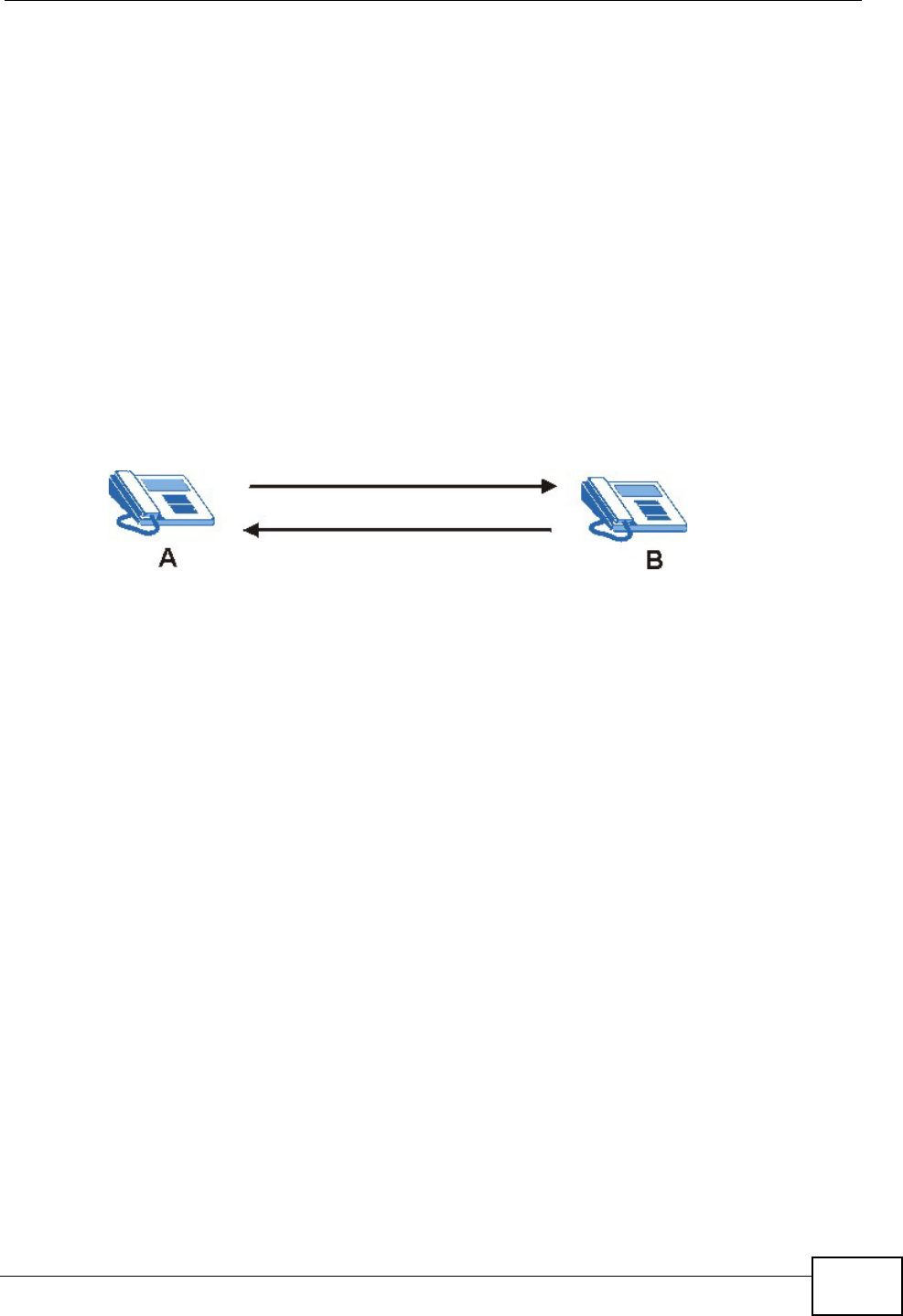
Chapter 15 Voice
Basic Home Station VDSL2 P8802T User’s Guide 223
SIP Servers
SI P is a client- server protocol. A SI P client is an application program or device t hat
sends SI P request s. A SI P server responds t o the SI P request s.
When you use SI P t o m ake a VoI P call, it originates at a client and t erm inates at a
server. A SI P client could be a com put er or a SI P phone. One device can act as
bot h a SI P client and a SI P server.
SIP User Agent
A SI P user agent can m ake and receive VoI P t elephone calls. This m eans t hat SI P
can be used for peer-to-peer com munications even t hough it is a client- server
protocol. I n t he following figure, eit her A or B can act as a SI P user agent client to
init iat e a call. A and B can also bot h act as a SI P user agent t o receive t he call.
Figure 95 SIP User Agent
SIP Proxy Server
A SI P proxy server receives requests from clients and forwards t hem to another
server.
I n the following exam ple, you want t o use client device A to call som eone who is
using client device C.
1The client device ( A in t he figure) sends a call invitat ion t o the SI P proxy server
(B) .
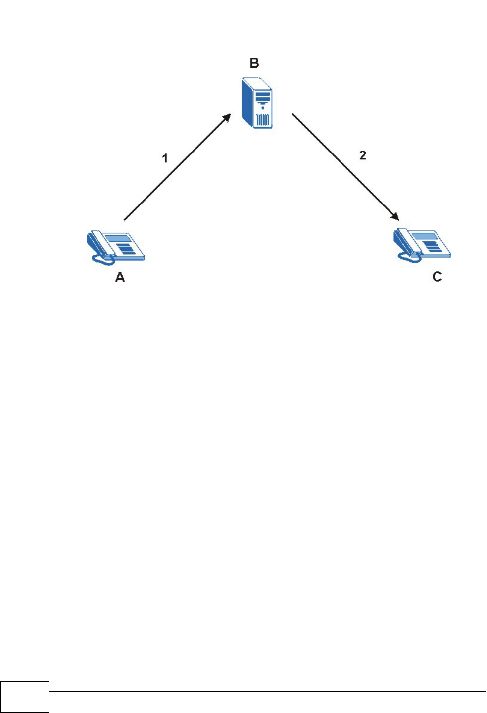
Chapter 15 Voice
Basic Home Station VDSL2 P8802T User’s Guide
224
2The SI P proxy server forwards the call invitat ion to C.
Figure 96 SIP Proxy Server
SIP Redirect Server
A SI P redirect server accept s SI P requests, t ranslat es the dest inat ion address to
an I P address and sends t he translat ed I P address back to the device t hat sent the
request. Then the client device that originally sent the request can send requests
to the I P address that it received back from t he redirect server. Redirect servers
do not initiate SI P request s.
I n the following exam ple, you want t o use client device A to call som eone who is
using client device C.
1Client device A sends a call invit ation for C to t he SI P redirect server (B) .
2The SI P redirect server sends t he invit ation back to A with C’s I P addr ess ( or
dom ain nam e).
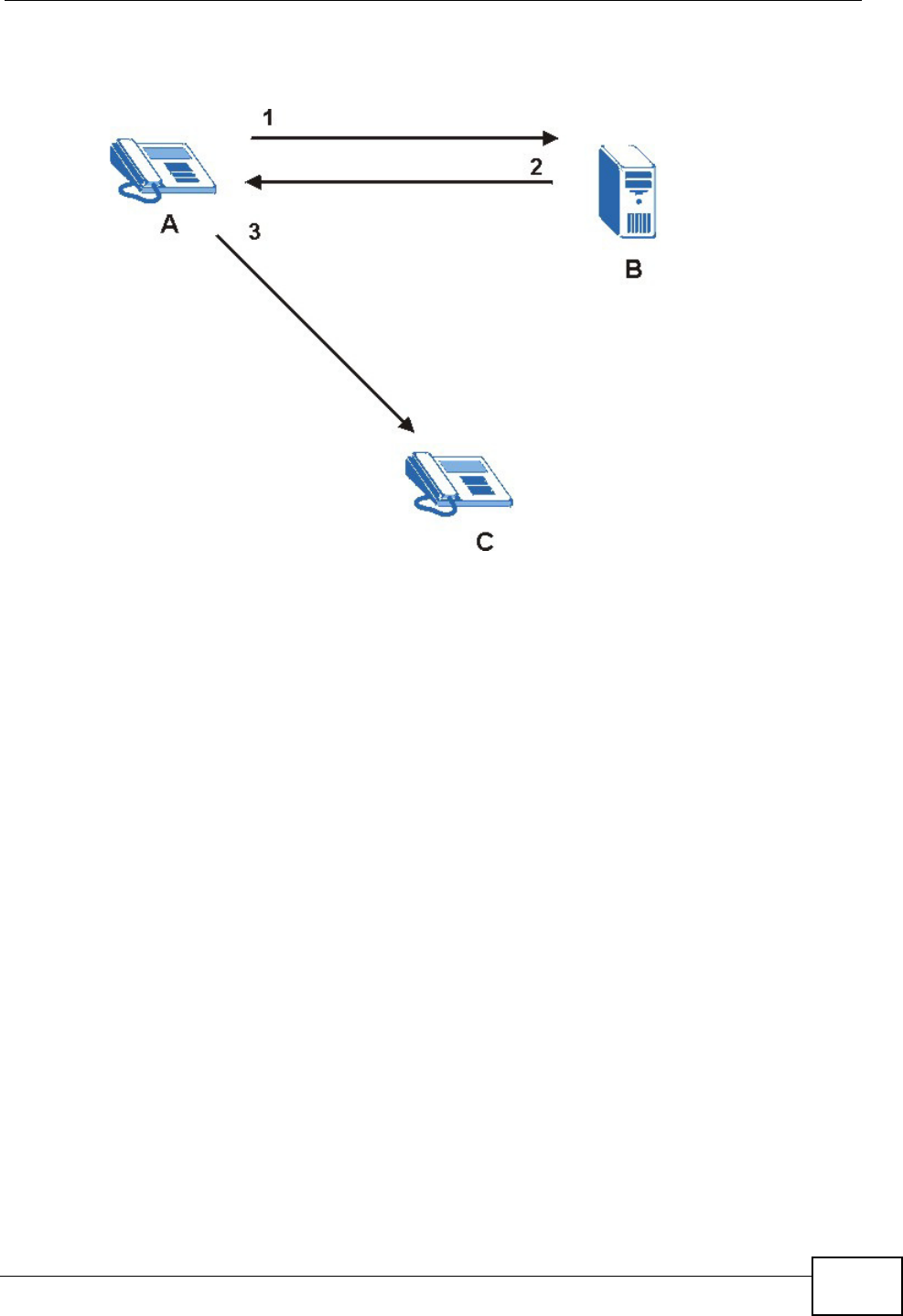
Chapter 15 Voice
Basic Home Station VDSL2 P8802T User’s Guide 225
3Client device A then sends the call invitat ion to client device C.
Figure 97 SIP Redirect Server
SIP Register Server
A SI P regist er server m aintains a database of SI P identity-to-I P address ( or
dom ain nam e) m apping. The regist er server ch eck s y our user nam e and passw or d
when you register.
RTP
When you m ake a VoI P call using SI P, the RTP (Real tim e Transport Prot ocol) is
used t o handle voice dat a transfer. See RFC 1889 for det ails on RTP.
Pulse Code Modulation
Pulse Code Modulation (PCM) m easures analog signal am plitudes at regular tim e
intervals and converts t hem int o bit s.
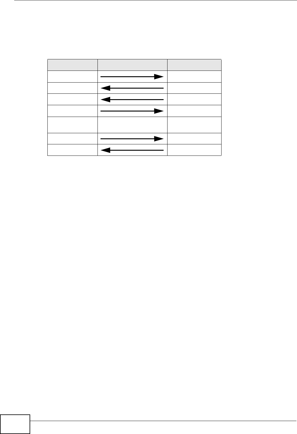
Chapter 15 Voice
Basic Home Station VDSL2 P8802T User’s Guide
226
SIP Call Progression
The following figure displays t he basic steps in the set up and tear down of a SI P
call. A calls B.
1 A sends a SI P I NVI TE request to B. This m essage is an invit ation for B to
participat e in a SI P telephone call.
2 B sends a response indicating t hat the t elephone is ringing.
3 B sends an OK response after the call is answered.
4 A then sends an ACK m essage to acknowledge t hat B has answered t he call.
5Now A and B exchange voice m edia ( t alk) .
6Aft er t alking, A hangs up and sends a BYE request .
7 B replies wit h an OK response confirm ing receipt of the BYE request and the call is
ter m inated.
SIP Call Progression Through Proxy Servers
Usually, the SI P UAC sets up a phone call by sending a request t o the SI P proxy
server. Then, t he proxy server looks up t he destinat ion t o which t he call should be
forwarded ( according to t he URI request ed by the SI P UAC). The request m ay be
forwarded t o m ore t han one proxy server before arriving at it s dest inat ion.
The response to t he request goes to all the proxy servers t hrough which t he
request passed, in reverse sequence. Once the session is set up, session traffic is
sent between the UAs directly, bypassing all the proxy servers in bet ween.
Table 80 SIP Call Progression
A B
1. I NVI TE
2. Ringing
3. OK
4. ACK
5.Dialogue ( voice
traffic)
6. BYE
7. OK
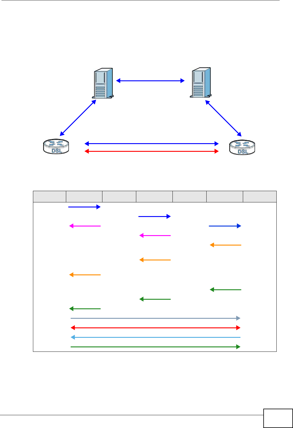
Chapter 15 Voice
Basic Home Station VDSL2 P8802T User’s Guide 227
The following figure shows t he SI P and session t raffic flow between the user
agents ( UA 1 and UA 2 ) and the proxy servers ( t his exam ple shows t wo proxy
servers, PROXY 1 and PROX Y 2 ) .
Figure 98 SIP Call Through Proxy Servers
The following table shows t he SI P call progression.
1User Agent 1 sends a SI P I NVI TE request to Pr ox y 1 . This m essage is an
invitat ion to Use r Agent 2 to participate in a SI P telephone call. Proxy 1 sends a
response indicating t hat it is t rying to com plet e the request .
Table 81 SIP Call Progression
UA 1 PROXY 1 PROXY 2 UA 2
I nvit e
I nvit e
100 Trying I nvite
100 Trying
180
Ringing
180
Ringing
180
Ringing
200 OK
200 OK
200 OK
ACK
RTP RTP
BYE
200 OK
UA 1 UA 2
PROXY 1 PROXY 2
SIP
SIP
SIP
SIP & RTP

Chapter 15 Voice
Basic Home Station VDSL2 P8802T User’s Guide
228
2Proxy 1 sends a SI P I NVI TE request t o Proxy 2 . Proxy 2 sends a response
indicating t hat it is t rying t o com plet e t he request.
3Proxy 2 sends a SI P I NVI TE request t o User Agent 2 .
4User Agent 2 sends a response back to Prox y 2 indicating that the phone is
ringing. The response is relayed back t o User Agent 1 via Proxy 1 .
5User Agent 2 sends an OK response to Proxy 2 after the call is answered. This is
also relayed back to Use r Agent 1 via Proxy 1 .
6User Agent 1 and User Agent 2 exchange RTP packets containing voice data
directly, without involving the proxies.
7When User Agent 2 hangs up, he sends a BYE request .
8User Agent 1 replies with an OK response confirm ing receipt of t he BYE request,
and the call is t erm inat ed.
Voice Coding
A codec ( coder/ decoder) codes analog voice signals into digit al signals and
decodes t he digital signals back into analog voice signals. The VDSL Router
support s the following codecs.
• G.711 is a Pulse Code Modulation ( PCM) waveform codec. PCM m easur es analog
signal am plitudes at regular tim e intervals and converts t hem into digit al
sam ples. G.711 provides very good sound quality but requires 64 kbps of
bandwidt h.
• G.726 is an Adaptive Different ial PCM ( ADPCM) waveform codec that uses a
lower bitrate than st andard PCM conversion. ADPCM converts analog audio into
digital signals based on the difference bet ween each audio sam ple and a
predict ion based on previous sam ples. The m ore sim ilar t he audio sam ple is t o
the predict ion, the less space needed t o describe it . G.726 operates at 16, 24,
32 or 40 kbps.
• G.729 is an Analysis- by- Synthesis ( AbS) hybrid waveform codec t hat uses a
filter based on inform at ion about how the hum an vocal t ract produces sounds.
G.729 provides good sound quality and reduces t he required bandwidth to 8
kbps.
Voice Activity Detection/Silence Suppression
Voice Act ivit y Det ect ion ( VAD) det ect s whet her or not speech is present. This lets
the VDSL Rout er reduce t he bandwidth that a call uses by not t ransm it t ing “ silent
packets” w hen you are not speaking.
Chapter 15 Voice
Basic Home Station VDSL2 P8802T User’s Guide 229
Comfort Noise Generation
When using VAD, the VDSL Rout er generat es com fort noise when the other party
is not speaking. The com fort noise lets you know that the line is st ill connect ed as
total silence could easily be m ist aken for a lost connection.
Echo Cancellation
G.168 is an I TU-T standard for elim inating t he echo caused by the sound of your
voice reverberat ing in the t elephone receiver while you talk.
MWI (Message Waiting Indication)
Enable Message Waiting I ndication ( MWI ) enables your phone t o give you a
m essage–wait ing (beeping) dial tone when you have a voice m essage( s) . Your
VoI P service provider m ust have a m essaging system that sends m essage waiting
st atus SI P packets as defined in RFC 3842.
Custom Tones (IVR)
I VR ( I nteractive Voice Response) is a feat ure t hat allows you t o use your
telephone to int eract with t he VDSL Router. The VDSL Router allows you to record
custom t ones for the Early M edia and Music On Hold funct ions. The sam e
recordings apply t o bot h the caller ringing and on hold tones.
Recording Custom Tones
Use t he following steps if you would like to creat e new tones or change your
tones:
1Pick up the phone and press “ * * * * ” on your phone’s keypad and wait for the
m essage that says you are in the configuration m enu.
2Press a num ber from 1101~ 1105 on your phone followed by the “ # ” key.
3Play your desired m usic or voice recording int o the receiver’s m outhpiece. Press
the “# ” key.
Table 82 Custom Tones Details
LABEL DESCRIPTION
Total Time for All Tones 900 seconds for all cust om tones combined
Maxim um Tim e per
I ndividual Tone
180 seconds
To t a l N u m b e r o f To n e s
Recor dable
5
You can record up to 5 different custom t ones but t he t ot al
tim e m ust be 900 seconds or less.

Chapter 15 Voice
Basic Home Station VDSL2 P8802T User’s Guide
230
4You can continue t o add, list en to, or delet e tones, or you can hang up the receiver
when you are done.
Listening to Custom Tones
Do t he following to listen t o a custom t one:
1Pick up the phone and press “ * * * * ” on your phone’s keypad and wait for the
m essage that says you are in the configuration m enu.
2Press a num ber from 1201~ 1208 followed by t he “# ” key to list en to t he tone.
3You can continue t o add, list en to, or delet e tones, or you can hang up the receiver
when you are done.
Deleting Custom Tones
Do t he following to delete a custom t one:
1Pick up the phone and press “ * * * * ” on your phone’s keypad and wait for the
m essage that says you are in the configuration m enu.
2Press a num ber from 1301~ 1308 followed by t he “# ” key to delet e the t one of
your choice. Press 14 followed by the “ # ” key if you wish t o clear all your custom
tones.
You can continue t o add, list en to, or delet e tones, or you can hang up the receiver
when you are done.
15.10.1 Quality of Service (QoS)
Quality of Service ( QoS) refers t o both a netw ork's abilit y to deliver dat a with
m inim um delay, and the networking m ethods used t o provide bandwidt h for real-
tim e m ult im edia applications.
Type of Service (ToS)
Net work traffic can be classified by setting t he ToS ( Type of Service) values at t he
dat a source ( for exam ple, at t he VDSL Rout er) so a server can decide the best
m et hod of delivery, that is t he least cost , fast est rout e and so on.
DiffServ
DiffServ is a class of service ( CoS) m odel t hat m arks packets so that they receive
specific per-hop t reatm ent at DiffServ-com pliant network devices along the rout e
based on t he application t ypes and t raffic flow. Packet s are m arked wit h DiffServ

Chapter 15 Voice
Basic Home Station VDSL2 P8802T User’s Guide 231
Code Points ( DSCP) indicat ing the level of service desired. This allows the
interm ediary DiffServ- com pliant network devices t o handle the packets differently
depending on the code point s wit hout t he need to negot iat e pat hs or rem em ber
st ate inform ation for every flow. I n addit ion, applications do not have to request a
particular service or give advanced notice of where the t raffic is going.3
DSCP and Per-Hop Behavior
DiffServ defines a new DS ( Differentiated Services) field to replace the Type of
Service ( TOS) field in the I P header. The DS field cont ains a 2-bit unused field and
a 6-bit DSCP field which can define up to 64 service levels. The following figure
illust rates the DS field.
DSCP is backward com patible with the three precedence bit s in t he ToS oct et so
that non-DiffServ com pliant , ToS- enabled netw ork device will not conflict with the
DSCP m apping.
Figure 99 DiffServ: Differentiated Service Field
The DSCP value determ ines t he for warding behavior, the PHB (Per-Hop Behavior),
that each packet get s across the DiffServ net work. Based on t he m arking rule,
different kinds of traffic can be m arked for different priorities of forwarding.
Resources can then be allocat ed according to t he DSCP values and the configured
policies.
15.10.2 Phone Services Overview
Supplem entary services such as call hold, call wait ing, and call transfer. are
generally available from your VoI P service provider. The VDSL Router supports t he
following services:
• Call Hold
• Call Waiting
• Making a Second Call
• Call Transfer
• Call Forwarding
• Three-Way Conference
• Internal Calls
3. The VDSL Router does not support DiffServ at the time of writing.
DSCP
( 6- bit )
Unused
(2-bit)
Chapter 15 Voice
Basic Home Station VDSL2 P8802T User’s Guide
232
• Call Park and Pickup
• Do not Disturb
Note: To take full advantage of the supplementary phone services available through
the VDSL Router's phone ports, you may need to subscribe to the services from
your VoIP service provider.
15.10.2.1 The Flash Key
Flashing m eans t o press t he hook for a short period of tim e ( a few hundred
m illiseconds) before releasing it . On newer telephones, t here should be a "flash"
key (but t on) that generates t he signal elect ronically. I f the flash key is not
available, you can tap ( press and im m ediately release) the hook by hand t o
achieve t he sam e effect . However, using the flash key is preferred since the t im ing
is m uch m ore precise. With m anual t apping, if the duration is too long, it m ay be
interpret ed as hanging up by the VDSL Rout er.
You can invoke all t he supplem entary services by using the flash key.
15.10.2.2 Europe Type Supplementary Phone Services
This sect ion describes how to use supplem entary phone services wit h the Eu rope
Type Ca ll Service M ode. Com mands for supplem entary services are listed in the
table below.
Aft er pressing t he flash key, if you do not issue t he sub- com m and before the
default sub- com m and tim eout ( 2 seconds) expires or issue an invalid sub-
com mand, the current operat ion w ill be aborted.
Table 83 European Flash Key Commands
COMMAND SUB-
COMMAND DESCRIPTION
Flash Put a curr ent call on hold t o place a second call.
Switch back to the call ( if there is no second call).
Flash 0 Drop the call present ly on hold or rej ect an incoming call
which is waiting for answer.
Flash 1 Disconnect the current phone connect ion and answer the
incom ing call or resum e wit h caller presently on hold.
Flash 2 1. Swit ch back and forth between t wo calls.
2. Put a current call on hold t o answer an incoming call.
3. Separat e t he current three- way conference call into
two individual calls (one is on- line, t he other is on hold).
Flash 3 Create t hree-way conference connect ion.
Flash * 98# Transfer the call t o another phone.

Chapter 15 Voice
Basic Home Station VDSL2 P8802T User’s Guide 233
European Call Hold
Call hold allows you to put a call ( A) on hold by pressing t he flash key.
I f you have anot her call, press the flash key and t hen “2” t o swit ch back and forth
bet ween caller A and B by putting eit her one on hold.
Press the flash key and then “ 0” t o disconnect t he call presently on hold and keep
the current call on line.
Press the flash key and then “ 1” to disconnect t he current call and resum e t he call
on hold.
I f you hang up t he phone but a caller is still on hold, there will be a rem ind ring.
European Call Waiting
This allows you t o place a call on hold while you answer anot her incom ing call on
the sam e telephone (direct ory) num ber.
I f there is a second call to a t elephone num ber, you will hear a call wait ing tone.
Take one of t he follow ing act ions.
• Reject t he second call.
Press the flash key and then press “ 0”.
• Disconnect t he first call and answer the second call.
Either press the flash key and press “ 1”, or j ust hang up the phone and t hen
answer the phone after it rings.
• Put the first call on hold and answer the second call.
Press t he flash key and then “ 2”.
European Call Transfer
Do t he following to transfer an incom ing call (that you have answered) to another
phone.
1Press the flash key to put the caller on hold.
2When you hear t he dial tone, dial “ * 98# ” followed by the num ber to which you
want to transfer t he call.
3Aft er you hear t he ring signal or the second party answers it, hang up the phone.
European Three-Way Conference
Use t he following steps t o m ake three-way conference calls.

Chapter 15 Voice
Basic Home Station VDSL2 P8802T User’s Guide
234
1When you are on the phone talking to som eone, press the flash key to put t he
caller on hold and get a dial tone.
2Dial a phone num ber directly t o m ake another call.
3When the second call is answered, press t he flash key and press “ 3” t o create a
three- way conversation.
4Hang up the phone t o drop the connect ion.
5I f you want to separat e the act ivat ed three-way conference into t w o individual
connections ( one is on-line, the ot her is on hold) , press t he flash key and press
“ 2”.
15.10.2.3 USA Type Supplementary Services
This sect ion describes how t o use supplem ent ary phone services wit h the USA
Type Ca ll Service M ode. Com mands for supplem entary services are listed in the
table below.
Aft er pressing t he flash key, if you do not issue t he sub- com m and before the
default sub- com m and tim eout ( 2 seconds) expires or issue an invalid sub-
com mand, the current operat ion w ill be aborted.
USA Call Hold
Call hold allows you to put a call ( A) on hold by pressing t he flash key.
I f you have another call, press the flash key to swit ch back and forth bet ween
caller A and B by put t ing eit her one on hold.
I f you hang up t he phone but a caller is still on hold, there will be a rem ind ring.
USA Call Waiting
This allows you t o place a call on hold while you answer anot her incom ing call on
the sam e telephone (direct ory) num ber.
Table 84 USA Flash Key Commands
COMMAND SUB-
COMMAND DESCRIPTION
Flash Put a current call on hold t o place a second call. After the
second call is successful, press t he flash key again to
have a three-way conference call.
Put a curr ent call on hold t o answer an incom ing call.
Flash * 98# Transfer the call t o another phone.

Chapter 15 Voice
Basic Home Station VDSL2 P8802T User’s Guide 235
I f t here is a second call to your t elephone num ber, you will hear a call waiting
tone.
Press the flash key to put the first call on hold and answer the second call.
USA Call Transfer
Do t he following to transfer an incom ing call (that you have answered) to another
phone.
1Press the flash key to put the caller on hold.
2When you hear t he dial tone, dial “ * 98# ” followed by the num ber to which you
want to transfer t he call.
3Aft er you hear t he ring signal or the second party answers it, hang up the phone.
USA Three-Way Conference
Use t he following steps t o m ake three-way conference calls.
1When you are on the phone talking to som eone ( part y A) , press t he flash key to
put t he caller on hold and get a dial t one.
2Dial a phone num ber directly t o m ake anot her call (to part y B) .
3When part y B answers t he second call, press t he flash key t o creat e a t hree-way
conversation.
4Hang up the phone t o drop the connect ion.
5I f you want to separat e the act ivat ed three-way conference into t w o individual
connections ( with party A on- line and party B on hold) , press t he flash key.
6I f you want t o go back to t he three-way conversation, press the flash key again.
7I f you want to separat e the act ivat ed three-way conference into t w o individual
connections again, press the flash key. This t im e the party B is on-line and party A
is on hold.

Chapter 15 Voice
Basic Home Station VDSL2 P8802T User’s Guide
236
15.10.2.4 Phone Functions Summary
The following table shows t he key com binat ions you can ent er on your phone’s
keypad to use certain features.
Table 85 Phone Functions Summary
ACTION FUNCTION DESCRIPTION
* 98# Call t ransfer Transfer a call t o anot her phone. See Sect ion
15.10.2.2 on page 232 (Europe t ype) and Sect ion
15.10.2.3 on page 234 (USA type) .
* 66# Call return Place a call t o t he last person who called you.
* 95# Enable Do Not Dist urb Use t hese t o set your phone not to ring when
som eone calls you, or to t urn this funct ion off.
# 95# Disable Do Not Dist urb
* 41# Enable Call Waiting Use t hese t o allow you to put a call on hold when
you are answering anot her, or t o t urn t his funct ion
off.
# 41# Disable Call Waiting
* * * * I VR Use t hese t o set up I nt eractive Voice Response
( I VR). I VR allows you t o record cust om caller ringing
tones ( t he sound a caller hears before you pick up
the phone) and on hold tones (the sound som eone
hear s when you put t heir call on hold) .
# # # # I nt ernal Call Call the phone(s) connect ed t o t he VDSL Router.
* 82 One Shot Caller Display
Call
Act ivate or deact ivate caller I D for the next call only.
* 67 One Shot Caller Hidden
Call

Basic Home Station VDSL2 P8802T User’s Guide 237
CHAPTER 16
Diagnostic
16.1 Overview
The D ia gnost ic screens display inform at ion to help you ident ify problem s with t he VDSL Router.
The route bet ween a CO VDSL sw it ch and one of it s CPE m ay go t hrough swit ches owned by
independent or ganizations. A connect ivit y fault point generally takes t im e t o discover and im pact s
subscriber ’s net work access. I n order t o elim inat e t he m anagem ent and m aintenance efforts, I EEE
802.1ag is a Connect ivit y Fault Managem ent ( CFM) specificat ion which allows network
adm inist rat ors t o identify and m anage connect ion fault s. Through discovery and verificat ion of t he
pat h, CFM can det ect , analyze and isolate connect ivit y faults in bridged LANs.
16.1.1 What You Can Do in this Chapter
• The D ia gn ost ics screen lets you test the VDSL Rout er’s connect ions ( Section 16.3 on page 238) .
• The Fa ult Man agem ent screen let s you perform CFM actions ( Section 16.4 on page 238) .
16.2 What You Need to Know
The following t erm s and concept s m ay help as you read t hrough this chapt er.
How CFM Works
A Maintenance Associat ion ( MA) defines a VLAN and associat ed Maintenance End Point ( MEP) ports
on t he device under a Maintenance Dom ain (MD) level. An MEP port has t he ability t o send
Connect ivity Check Messages ( CCMs) and get ot her MEP ports inform ation from neighbor devices’
CCMs wit hin an MA.
CFM provides t wo tests t o discover connectivity faults.
• Loopback t est - checks if t he MEP port receives its Loop Back Response ( LBR) from its tar get
aft er it sends t he Loop Back Message (LBM) . I f no response is received, there m ight be a
connect ivit y fault bet ween t hem .
• Link trace t est - provides addit ional connect ivit y fault analysis to get m ore inform ation on where
the fault is. I f an MEP port does not respond t o t he source MEP, this m ay indicate a fault .
Adm inistrat ors can take furt her act ion to check and resum e services from the fault according to
the line connect ivit y stat us report .
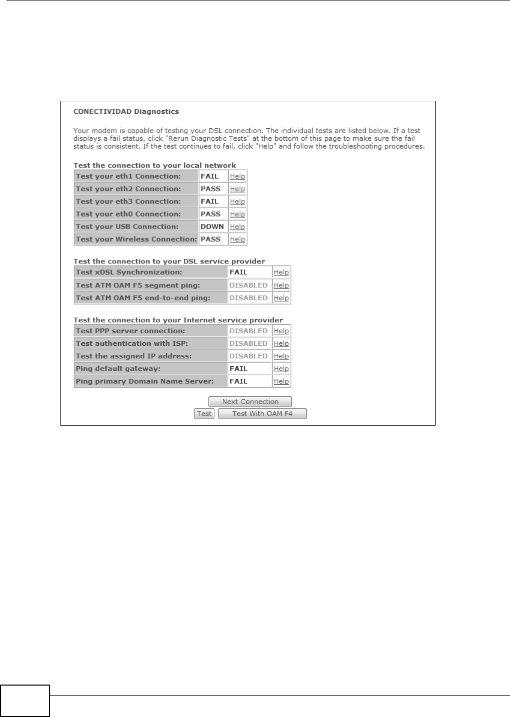
Chapter 16 Diagnostic
Basic Home Station VDSL2 P8802T User’s Guide
238
16.3 Diagnostics
Click D ia gn ost ics t o open the screen shown next. Use t his screen t o t est the VDSL Router’s
connect ions.
Figure 100 Diagnost ics
• Click Nex t Connect ion t o t est t he next WAN connection.
• Click Test t o perform the t est again.
• Click Test W it h OAM F4 wit h t o perform an OAM ( Operation, Adm inist rat ion and Maintenance)
F4 loopback t est on an ATM PVC.
Note: The DSLAM t o which t he VDSL Router is connect ed m ust also support OAM F4 to
use t he OAM F4 loopback test.
16.4 802.1ag Connectivity Fault Management
Click Diagnostics > Fault Ma na gem e nt t o open the following screen. Use this screen t o perform
CFM act ions.
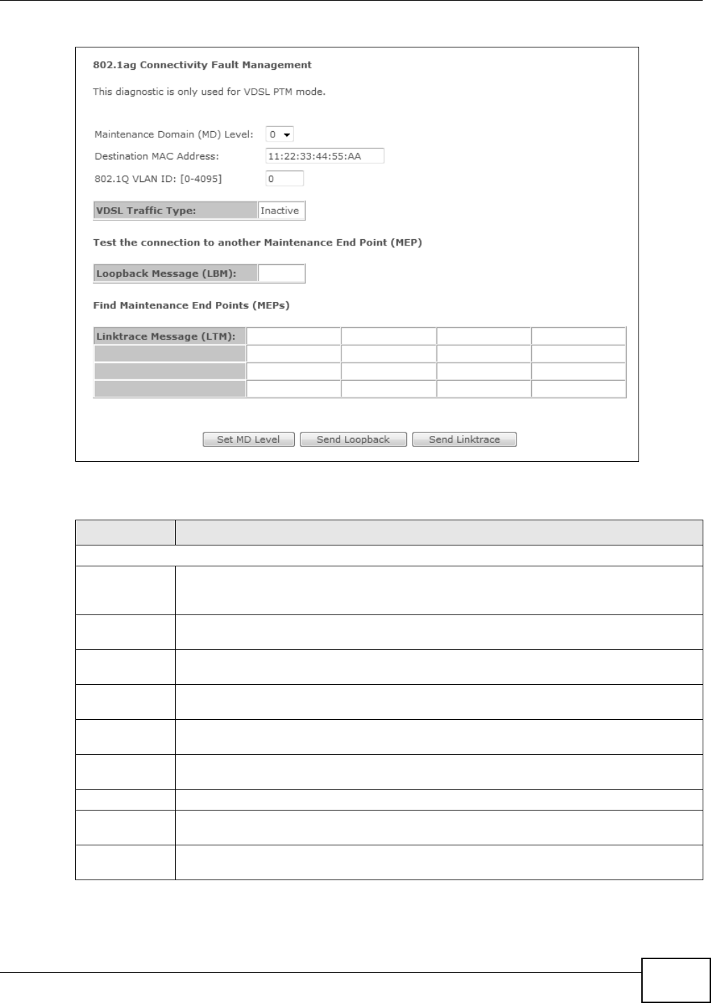
Chapter 16 Diagnostic
Basic Home Station VDSL2 P8802T User’s Guide 239
Figure 101 802.1ag Connect ivit y Fault Managem ent
The following t able describes t he fields in this screen.
Table 86 802.1ag Connect ivit y Fault Management
LABEL DESCRIPTION
802.1ag Connect ivity Fault Managem ent
Maint enance
Domain (MD)
Level
Select a level (0- 7) under which you want t o create an MA.
Dest inat ion
MAC Address
Enter t he t arget device’s MAC address to which t he VDSL Rout er perfor m s a CFM loopback
test .
802.1Q VLAN
I D
Ty pe a VLAN I D (0- 4095) for t his MA.
VDSL Traffic
Ty p e
This shows whether t he VDSL traffic is act ivated.
Loopback
Message (LBM)
This shows how m any Loop Back Messages (LBMs) are sent and if t here is any inorder or
out order Loop Back Response ( LBR) received from a rem ot e MEP.
Linktrace
Message (LTM)
This show s t he dest inat ion MAC address in t he Link Trace Response ( LTR).
Set MD Level Click this but ton to configure the MD (Maint enance Dom ain) level.
Send Loopback Click this but ton to have the select ed MEP send t he LBM (Loop Back Message) t o a specified
rem ote end point.
Send Linkt race Click this but ton to have the selected MEP send t he LTMs (Link Trace Messages) t o a
specified rem ot e end point .

Chapter 16 Diagnostic
Basic Home Station VDSL2 P8802T User’s Guide
240
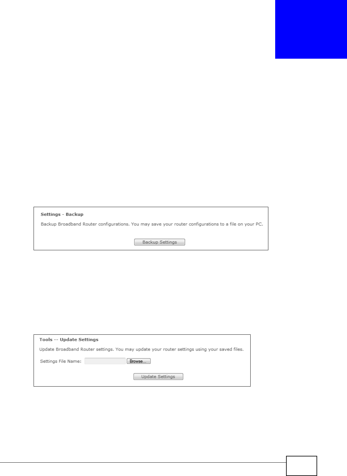
Basic Home Station VDSL2 P8802T User’s Guide 241
CHAPTER 17
Settings
This chapt er describes how to m anage your VDSL Router’s configuration.
17.1 Backup Configuration Using the Web Configurator
Click Man agem ent > Settings > Back u p to open the following screen. Use t his screen to back up
( save) t he VDSL Router’s current configurat ion to a file on your com put er. Once your VDSL Router is
configured and functioning pr operly, it is highly recomm ended that you back up your configuration
file before m aking configuration changes. The backup configurat ion file will be useful in case you
need to return to your previous sett ings.
Figure 102 Sett ings: Backup
Click Back up Se t t ings to save t he VDSL Rout er’s current configuration t o your com puter.
17.2 Restore Configuration Using the Web Configurator
Click Managem e nt > Se t t ings > Upda t e to open t he following screen. Use t his screen t o upload
a new or previously saved configuration file from your computer to your VDSL Router.
Figure 103 Sett ings: Updat e
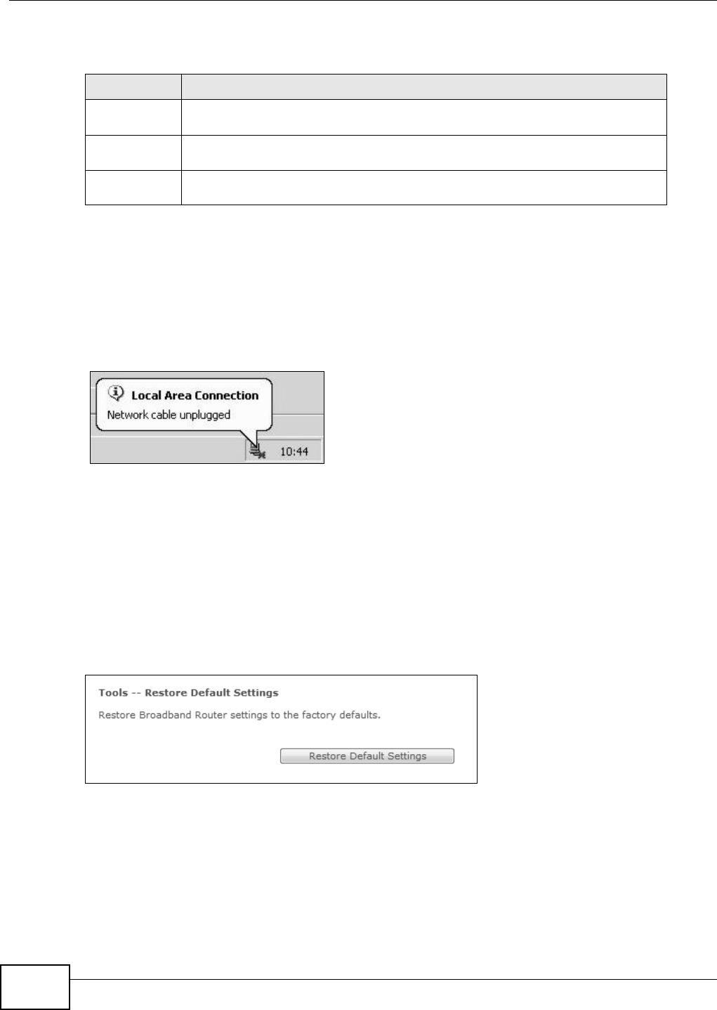
Chapter 17 Settings
Basic Home Station VDSL2 P8802T User’s Guide
242
Do not turn off the VDSL Router while configuration file upload is in
progress
You m ust then wait before logging int o t he VDSL Router again. The VDSL Rout er autom atically
rest ar ts causing a t emporary net work disconnect. I n som e operating syst em s, you m ay see t he
follow ing icon on your desktop.
Figure 104 Temporarily Disconnect ed
You m ay need to change t he I P address of your com puter t o be in the sam e subnet as that of the
VDSL Router’s I P address ( 192.168.1.1) . See t he appendix for det ails on how to set up your
com puter ’s I P address.
17.3 Restoring Factory Defaults
Click Managem ent > Settin gs > Rest ore Default t o open t he following screen.
Figure 105 Managem ent > Set t ings > Rest ore Default
Click Re st or e D efau lt Set t ings to clear all user-entered configurat ion inform ation and ret urn t he
VDSL Router to its fact ory defaults.
You can also press t he RESET butt on on the rear panel t o reset t he fact ory defaults of your VDSL
Rou t er .
Table 87 Set t ings: Updat e
LABEL DESCRIPTION
Set tings File
Nam e
Ty pe in the locat ion of the file you want to upload in t his field or click Brow se... to
find it .
Br owse... Click Br ow se ... to find the file you want to upload. Rem em ber that you m ust
decom press com pressed (.ZI P) files before you can upload t hem .
Update
Set tings
Click this to begin the upload process.

Chapter 17 Settings
Basic Home Station VDSL2 P8802T User’s Guide 243
You m ay need to change t he I P address of your com puter t o be in the sam e subnet as that of the
default VDSL Router I P address ( 192.168.1.1) . See the appendix for det ails on how t o set up your
com puter ’s I P address.

Chapter 17 Settings
Basic Home Station VDSL2 P8802T User’s Guide
244

Basic Home Station VDSL2 P8802T User’s Guide 245
CHAPTER 18
Log
18.1 Overview
The web configurat or allow s you to choose which categories of event s and/ or alerts t o have t he
VDSL Router log and then display the logs or have t he VDSL Router send t hem to an adm inist rat or
( as e- m ail) or t o a syslog server.
18.1.1 What You Can Do in this Chapter
• Use the System Log screen t o see the syst em logs ( Sect ion 18.2 on page 246) .
• Use the Syst em Log Configura t ion screen t o see t he security-relat ed logs for the cat egories
that you select (Sect ion 18.3 on page 246) .
18.1.2 What You Need To Know
The following t erm s and concept s m ay help as you r ead t his chapter.
Alerts and Logs
An alert is a t ype of log that warrants m ore serious att ent ion. They include syst em errors, att acks
( access control) and at tem pt ed access to blocked web sites. Som e categories such as Syst em
Er rors consist of bot h logs and alerts. You m ay different iat e them by their color in the V iew Log
screen. Alerts display in red and logs display in black.
Syslog Overview
The syslog pr ot ocol allows devices to send event not ification m essages across an I P network to
syslog servers t hat collect t he event m essages. A syslog-enabled device can generat e a syslog
m essage and send it t o a syslog server.
Syslog is defined in RFC 3164. The RFC defines the packet form at , cont ent and syst em log relat ed
inform ation of syslog m essages. Each syslog m essage has a facility and severit y level. The syslog
facilit y identifies a file in the syslog server. Refer t o the docum ent ation of your syslog program for
details. The following t able describes the syslog severit y levels.
Table 88 Syslog Severit y Levels
CODE SEVERITY
0 Em ergency: The syst em is unusable.
1 Aler t : Act ion m ust be t aken im m ediately.
2 Crit ical: The sy st em condit ion is critical.
3 Error : There is an error condit ion on t he syst em .
4 Warning: There is a warning condition on the syst em .
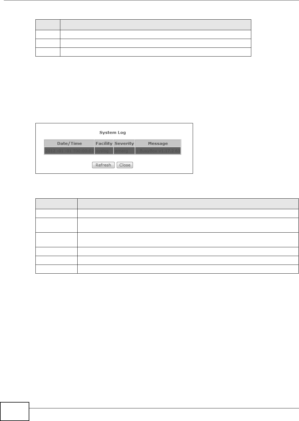
Chapter 18 Log
Basic Home Station VDSL2 P8802T User’s Guide
246
18.2 The System Log Screen
Use t he Syst e m Log screen t o see t he syst em logs. Click M anagem ent > Syst e m Log > View
Syst e m Log t o open t he Syst e m Log screen.
Figure 106 Sy st em Log
The following t able describes t he fields in t his screen.
18.3 The System Log Configuration Screen
To change your VDSL Router’s log set t ings, click M a na ge m ent > Syst e m Log > Configur e
Syst e m Log. The screen appears as shown.
5 Not ice: There is a nor m al but significant condition on the syst em .
6 I nform ational: The syslog cont ains an inform at ional m essage.
7 Debug: The m essage is intended for debug- level purposes.
Table 88 Syslog Severit y Levels
CODE SEVERITY
Table 89 System Log
LABEL DESCRIPTION
Dat e/ Tim e This field displays when the log was recorded.
Facility The log facility allows you t o send logs t o different files in the syslog server. Refer to the
docum entation of your syslog program for m ore det ails.
Sever ity This field displays t he severit y level of the logs t hat the device is to send t o this syslog
server.
Messages This field st at es the reason for the log.
Refresh Click this t o renew t he log scr een.
Close Click this to close the log screen.
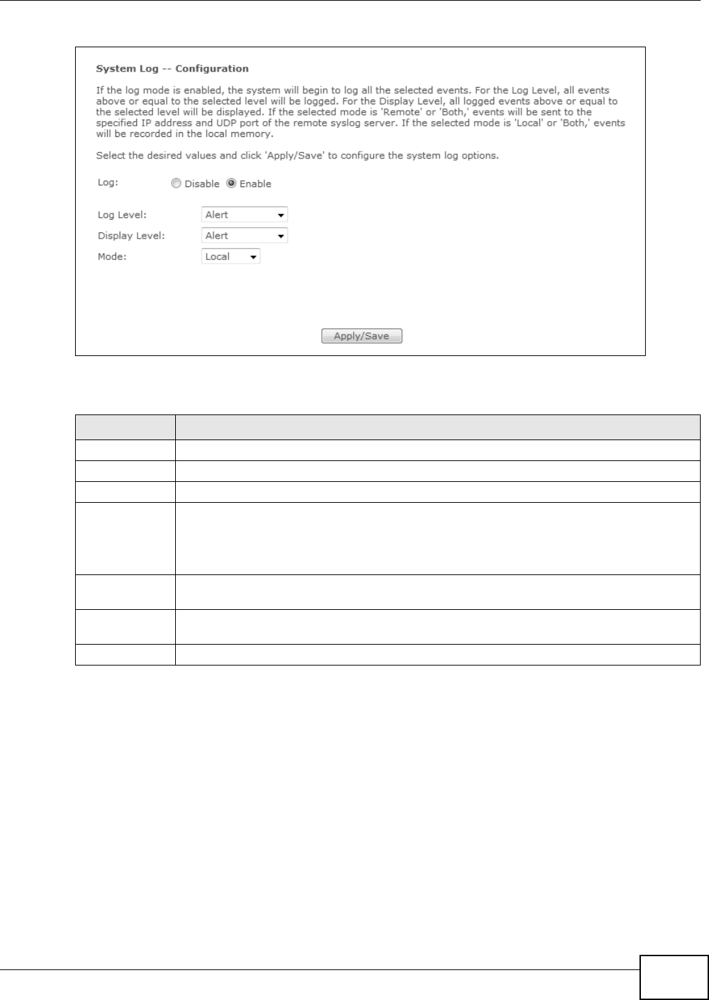
Chapter 18 Log
Basic Home Station VDSL2 P8802T User’s Guide 247
Figure 107 Syst em Log Configuration
The following t able describes t he fields in this screen.
Table 90 Syst em Log Configurat ion
LABEL DESCRIPTION
Log Select Enable t o have t he VDSL Router log event s.
Log Level Select t he severity level of events to log.
Display Level Select t he sever it y level of events to display in the log.
Mode Select the syslog destinat ion from the dr op-down list box.
Select Re m o t e, t he log( s) t o send logs on ly t o a r em ot e sy slog serv er. Select Local to save
t he logs in a local file. To send the log( s) to a rem ote syslog server and sav e it in a local file,
select Bot h .
Ser ver I P
Address
Enter t he I P address of t he syslog server t hat will log the select ed cat egories of logs.
Ser ver UDP
Port
Enter t he port num ber used by the syslog server.
Apply/ Save Click t his butt on to save your changes.

Chapter 18 Log
Basic Home Station VDSL2 P8802T User’s Guide
248

Basic Home Station VDSL2 P8802T User’s Guide 249
CHAPTER 19
TR-069 Client
19.1 Overview
This chapt er explains how to configur e the VDSL Rout er’s TR- 069 aut o-configuration settings.
19.2 The TR-069 Client Screen
TR-069 defines how Cust omer Prem ise Equipm ent ( CPE), for exam ple your VDSL Router , can be
m anaged over t he WAN by an Auto Configurat ion Server (ACS) . TR- 069 is based on sending
Remot e Procedure Calls ( RPCs) bet ween an ACS and a client device. RPCs are sent in Ext ensible
Mar kup Language (XML) form at over HTTP or HTTPS.
An adm inist rat or can use an ACS to rem ot ely set up t he VDSL Router, m odify set t ings, perform
firm ware upgrades as well as m onitor and diagnose t he VDSL Router. You have t o enable t he device
to be m anaged by the ACS and specify the ACS I P address or dom ain name and usernam e and
password.
Click Managem ent > TR- 0 6 9 Clie nt t o open the following screen. Use t his screen to configure
your VDSL Router to be m anaged by an ACS.
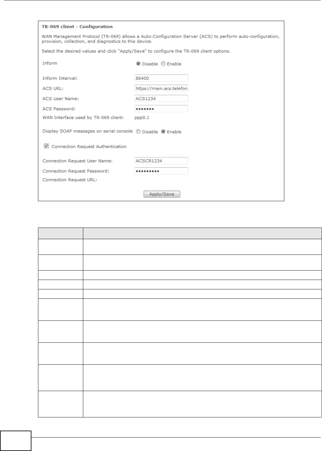
Chapter 19 TR-069 Client
Basic Home Station VDSL2 P8802T User’s Guide
250
Figure 108 TR- 069 Client
The following t able describes t he fields in this screen.
Table 91 TR- 069 Client
LABEL DESCRIPTION
I nfor m Select En able for t he VDSL Rout er to send periodic inform via TR- 069 on the WAN.
Ot herwise, select Disa ble .
I nfor m I nt er val Ent er t he t im e int erval ( in seconds) at which the VDSL Router sends inform at ion t o the aut o-
configurat ion server.
ACS URL Enter t he URL or I P address of the aut o- configurat ion serv er.
ACS User Nam e Enter t he TR- 069 user nam e for aut hent ication with the aut o- configurat ion server.
ACS Passw or d Ent er the TR- 069 password for aut hent icat ion wit h the aut o-configurat ion server.
WAN I nterface
used by TR- 069
client
Select a WAN int er face t hr ough which the TR- 069 traffic passes.
I f y ou select Any_ W AN , you should also select t he pre- configured WAN connection(s) .
Display SOAP
m essages on
serial console
Select Ena ble t o show t he SOAP m essages on the console.
Connection
Requ est
Au t hent ication
Select t his option to enable aut henticat ion w hen t here is a connect ion request fr om the ACS.
Connection
Request User
Nam e
Enter the connect ion request user nam e.
When the ACS m akes a connection request to the VDSL Rout er, this user nam e is used to
authenticat e the ACS.
Connection
Requ est
Password
Enter t he connect ion request passw ord.
When the ACS m akes a connection request to the VDSL Rout er, this passwor d is used t o
authenticat e the ACS.

Chapter 19 TR-069 Client
Basic Home Station VDSL2 P8802T User’s Guide 251
Connection
Requ est URL
This shows the connect ion request URL.
The ACS can use this URL t o m ake a connect ion request to t he VDSL Router.
Apply/ Save Click t his but ton to save your changes.
Table 91 TR- 069 Client ( cont inued)
LABEL DESCRIPTION

Chapter 19 TR-069 Client
Basic Home Station VDSL2 P8802T User’s Guide
252
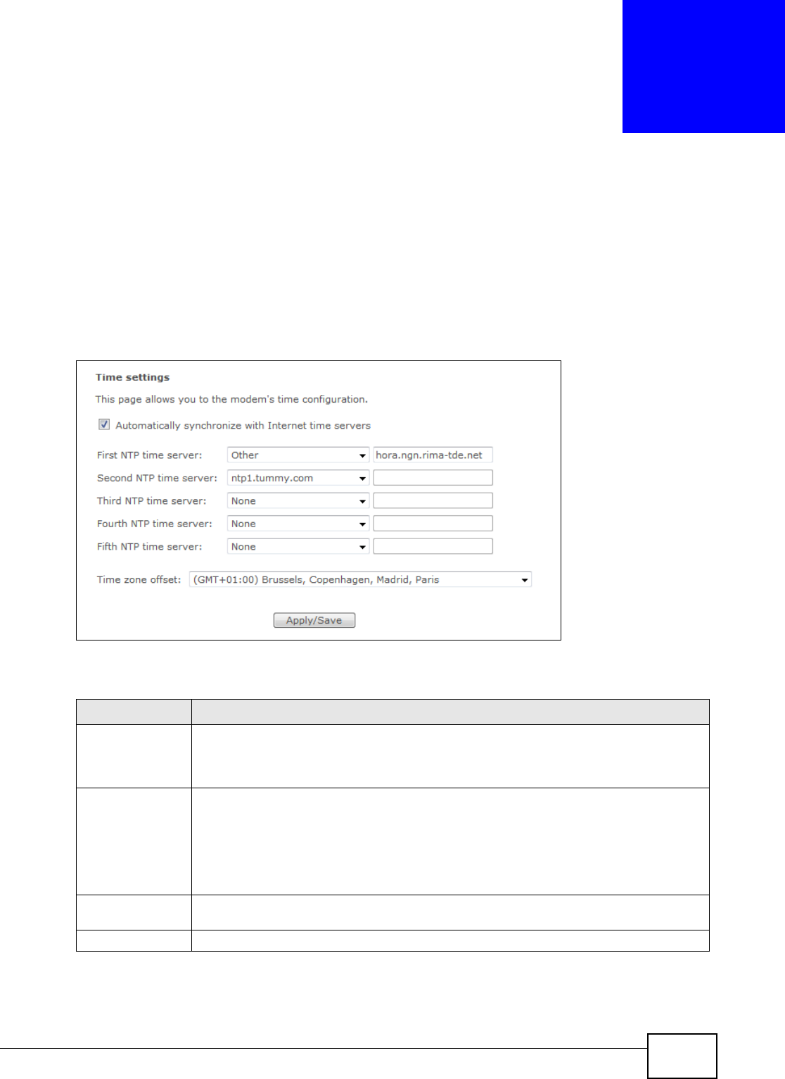
Basic Home Station VDSL2 P8802T User’s Guide 253
CHAPTER 20
Internet Time
20.1 The Internet Time Screen
Click Man agem e nt > I n t er net Tim e t o configure t he VDSL Router to get t he tim e from tim e
servers on t he I nt ernet.
Figure 109 I nt ernet Tim e
The following t able describes t he fields in this screen.
Table 92 I nternet Tim e
LABEL DESCRIPTION
Autom at ically
sy nchronize wit h
I nternet tim e
servers
Select t his t o have t he VDSL Rout er get t he tim e from t he specified I nt ernet tim e serv ers.
Fir st ~ Fifth NTP
tim e server
Select an NTP t im e ser ver from the drop-down list box.
Ot herwise, select Ot h e r and ent er t he I P address or URL (up t o 29 extended ASCI I
charact ers in length) of your t im e server.
Select N o ne if you don’t want t o configure the tim e server.
Check with your I SP/ network adm inist rator if you are unsure of this inform at ion.
Tim e zone offset Choose t he t im e zone of your location. This will set t he t im e difference betw een your t im e
zone and Greenwich Mean Tim e ( GMT) .
Apply/ Save Click t his but ton to save your changes.

Chapter 20 Internet Time
Basic Home Station VDSL2 P8802T User’s Guide
254
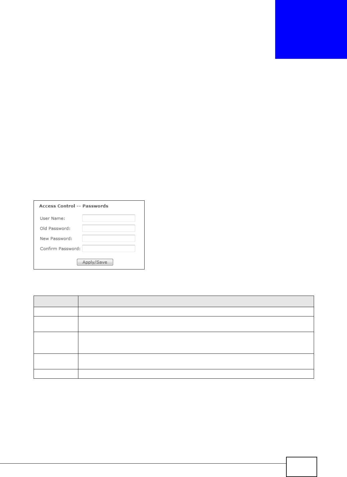
Basic Home Station VDSL2 P8802T User’s Guide 255
CHAPTER 21
Access Control
21.1 Overview
Change t he login password in t he Access Cont r ol screen.
21.2 The Access Control Screen
Click Managem ent > Acce ss Cont r ol t o open the following screen.
Figure 110 Access Control
The following t able describes t he labels in t his screen.
Table 93 Access Cont rol
LABEL DESCRIPTION
User Nam e This field displays the nam e of the account t hat you used to log in the syst em .
Old Passw or d Type t he default password or t he exist ing password you use to access the syst em in this
field.
New Password Type your new syst em password (up to 30 charact ers) . Note that as you type a password,
the screen displays a (* ) for each charact er you type. After you change the passwor d, use
the new password to access the VDSL Rout er.
Ret y pe t o
confir m
Ty pe t he new password again for confirm at ion.
Apply/ Save Click this but ton t o save your changes.

Chapter 21 Access Control
Basic Home Station VDSL2 P8802T User’s Guide
256
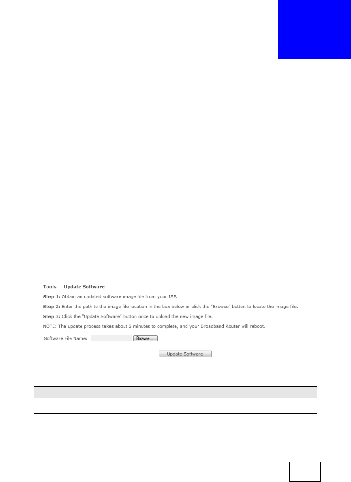
Basic Home Station VDSL2 P8802T User’s Guide 257
CHAPTER 22
Software Upgrade
22.1 Overview
This chapt er explains how to upload new software to your VDSL Rout er. You can download new
software releases from your nearest ZyXEL FTP sit e ( or www.zyxel.com ) to use to upgrade your
device’s perform ance.
Only use software for your device’s specific model. Refer to the label on
the bottom of your VDSL Router.
22.2 The Update Software Screen
Click Managem ent > Upda t e Softw a re to open t he following screen. The upload process uses
HTTP (Hyper text Transfer Prot ocol) and m ay take up to two m inutes. After a successful upload, t he
syst em will reboot .
Do NOT turn off the VDSL Router while software upload is in progress!
Figure 111 Updat e Software
The following t able describes t he labels in t his screen.
Table 94 Update Soft ware
LABEL DESCRIPTION
Soft ware File
Nam e
Type in t he location of the file you want t o upload in t his field or click Brow se ... to find it.
Br owse... Click this to find the .bin file you want t o upload. Rem em ber that you m ust decom press
com pressed (.zip) files before you can upload t hem .
Update
Software
Click this to begin the upload process. This process m ay t ake up to t wo m inut es.

Chapter 22 Software Upgrade
Basic Home Station VDSL2 P8802T User’s Guide
258
Aft er you see t he soft ware updat ing screen, wait tw o m inutes before logging int o t he VDSL Rout er
again.
The VDSL Router autom atically rest ar ts in t his tim e causing a t em porary netw ork disconnect . I n
som e operat ing syst em s, you m ay see t he following icon on your desktop.
Figure 112 Network Tem porarily Disconnect ed
Aft er two m inutes, log in again and check your new soft ware version in t he D e vice I nfo screen.

Basic Home Station VDSL2 P8802T User’s Guide 259
CHAPTER 23
Reboot
23.1 Restart Using the Web Configurator
Click Man agem e nt > Re boot t o open t he following screen. Use t his screen t o rest art the .
Figure 113 Reboot

Chapter 23 Reboot
Basic Home Station VDSL2 P8802T User’s Guide
260

Basic Home Station VDSL2 P8802T User’s Guide 261
CHAPTER 24
Troubleshooting
This chapt er offers som e suggest ions t o solve problem s you m ight encounter. The pot ent ial
problem s are divided into t he following categories.
•Power, Hardware Connect ions, and LEDs
•VDSL Rout er Access and Login
•I nt ernet Access
•Wireless I nt ernet Access
•USB Device Connect ion
•UPnP
24.1 Power, Hardware Connections, and LEDs
The VDSL Rout er does not t urn on. None of t he LEDs t urn on.
1Make sure t he VDSL Rout er is turned on.
2Make sure you are using t he power adapt or or cord included wit h the VDSL Rout er.
3Make sure the power adaptor or cor d is connect ed to the VDSL Router and plugged in t o an
appropriate power source. Make sure the power source is t urned on.
4Turn t he VDSL Router off and on.
5I f the problem continues, contact the vendor.
One of the LEDs does not behave as expected.
1Make sure you underst and the norm al behavior of t he LED. See Sect ion 1.5 on page 14.
2Check the hardware connections.
3I nspect your cables for dam age. Contact the vendor to replace any dam aged cables.
4Turn t he VDSL Router off and on.

Chapter 24 Troubleshooting
Basic Home Station VDSL2 P8802T User’s Guide
262
5I f the problem continues, contact the vendor.
24.2 VDSL Router Access and Login
I forgot t he I P address for t he VDSL Router.
1See t he cover page of t his guide for the default LAN I P address.
2I f you changed the I P address and have forgot ten it , you might get t he I P address of t he VDSL
Router by looking up the I P address of t he default gat eway for your com puter. To do this in m ost
Windows com puters, click St a rt > Run, enter cm d, and then enter ipconfig. The I P address of the
Defa ult Gatew ay m ight be t he I P address of the VDSL Router (it depends on t he net work), so
ent er t his I P address in your I nt er net browser.
3I f this does not work, you have t o reset the device t o its fact ory default s. See Sect ion 1.7 on page
16.
I forgot t he passw ord.
1See t he back st icker for the default adm in password.
2I f this does not work, you have t o reset the device t o its fact ory default s. See Sect ion 1.7 on page
16.
I cannot see or access t he Login screen in t he web configurat or.
1Make sure you are using t he correct I P address.
• See the cover page of t his guide for t he default I P address.
• I f you changed the I P address (Sect ion 5.2 on page 106), use t he new I P address.
• I f you changed t he I P address and have forgot ten it , see the troubleshooting suggest ions for I
forgot t he I P address for the VDSL Rout er.
2Check the hardware connections, and m ake sure t he LEDs ar e behaving as expect ed. See Sect ion
1.5 on page 14.
3Make sure your I nt ernet browser does not block pop- up windows and has JavaScr ipt s and Java
enabled.
4I f it is possible t o log in from another int erface, check the ser vice cont rol set t ings for HTTP and
HTTPS ( M ain t en ance > Rem ot e MGMT) .

Chapter 24 Troubleshooting
Basic Home Station VDSL2 P8802T User’s Guide 263
5Reset the device t o its fact ory defaults, and t ry t o access the VDSL Router with t he default I P
address. See Section 1.7 on page 16.
6I f the problem continues, contact the netw ork adm inist rator or vendor, or try one of t he advanced
suggest ions.
Advance d Suggestions
• Make sure you have logged out of any earlier m anagem ent sessions using t he sam e user account
even if they were through a different interface or using a different browser.
• Try to access the VDSL Rout er using another service, such as Telnet . I f you can access the VDSL
Router, check the rem ote m anagem ent set t ings and firewall rules to find out why the VDSL
Router does not respond t o HTTP.
I can see t he Login screen, but I cannot log in to the VDSL Router.
1Make sure you have entered the password correct ly. The field is case- sensitive, so m ake sure [ Caps
Lock] is not on.
2You cannot log in to t he web configurat or while som eone is using Telnet t o access t he VDSL Router.
Log out of t he VDSL Router in the other session, or ask t he person who is logged in to log out.
3Turn t he VDSL Router off and on.
4I f this does not work, you have t o reset the device t o its fact ory defaults. See Section 24.1 on page
261.
I cannot Telnet to t he VDSL Router.
See t he t roubleshooting suggest ions for I cannot see or access t he Login screen in the web
configurator. I gnore the suggestions about your browser.
I cannot use FTP to upload / download t he configuration file. / I cannot use FTP to upload
new software.
See t he t roubleshooting suggest ions for I cannot see or access t he Login screen in the web
configurator. I gnore the suggestions about your browser.

Chapter 24 Troubleshooting
Basic Home Station VDSL2 P8802T User’s Guide
264
24.3 Internet Access
I cannot access t he I nternet .
1Check the hardware connections, and m ake sure t he LEDs ar e behaving as expect ed. See the
Quick St a rt Guide and Sect ion 1.5 on page 14.
2Make sure you ent ered your I SP account inform ation correct ly in the Net w ork Settin g >
Broadband screen. These fields are case- sensitive, so m ake sure [ Caps Lock] is not on.
3I f you are t rying to access t he I nt ernet wirelessly, m ake sure t hat you enabled the wireless LAN in
the VDSL Router and your wireless client and t hat the wir eless set t ings in t he wireless client are t he
sam e as t he sett ings in t he VDSL Router.
4Disconnect all the cables from your device and reconnect them .
5I f the problem continues, contact your I SP.
I cannot access t he I nternet t hrough a DSL connect ion.
1Make sure you have the D SL W AN port connect ed to a t elephone j ack (or t he DSL or m odem jack
on a split ter if you have one).
2Make sure you configured a proper DSL WAN int erface (N et w ork Settin g > Br oadband scr een)
with t he I nt ernet account inform ation prov ided by your I SP and that it is enabled.
3Check t hat t he LAN inter face you are connected to is in t he sam e interface group as the DSL
connect ion ( N et w ork Se t t ing > I nt erfa ce Gr oup) .
4I f you set up a WAN connect ion using bridging service, make sure you turn off the DHCP feat ure in
the LAN screen to have the client s get WAN I P addresses direct ly from your I SP’s DHCP server.
I cannot connect t o the I nternet using a second DSL connect ion.
ADSL and VDSL connect ions cannot work at t he sam e t im e. You can only use one type of DSL
connect ion, either ADSL or VDSL connect ion at one t ime.
I cannot access t he I nt ernet anym ore. I had access t o the I nt ernet (with t he VDSL Router),
but m y I nternet connection is not available anym ore.
1Your session with t he VDSL Router m ay have expired. Try logging into the VDSL Router again.

Chapter 24 Troubleshooting
Basic Home Station VDSL2 P8802T User’s Guide 265
2Check the hardware connections, and m ake sure t he LEDs ar e behaving as expect ed. See the
Quick St a rt Guide and Sect ion 1.5 on page 14.
3Turn t he VDSL Router off and on.
4I f the problem continues, contact your I SP.
24.4 Wireless Internet Access
What fact ors m ay cause interm it t ent or unst abled wireless connection? How can I solve t his
problem ?
The following factors m ay cause interference:
• Obst acles: walls, ceilings, furnit ure, and so on.
• Building Materials: m et al doors, alum inum st uds.
• Elect rical devices: m icrowaves, m onit ors, electric m otors, cor dless phones, and ot her wireless
devices.
To optim ize the speed and quality of your wireless connect ion, you can:
• Move your wireless device closer to the AP if t he signal st rengt h is low.
• Reduce wireless inter ference t hat m ay be caused by ot her wireless net works or surrounding
wireless elect ronics such as cordless phones.
• Place t he AP where there are m inim um obst acles ( such as walls and ceilings) bet ween t he AP and
the wireless client .
• Reduce t he num ber of wireless client s connect ing t o t he sam e AP sim ultaneously, or add
addit ional APs if necessary.
• Try closing som e program s t hat use t he I nter net, especially peer-to- peer applications. I f t he
wireless client is sending or receiving a lot of inform ation, it may have t oo m any program s open
that use t he I nternet.
What is a Server Set I D (SSI D) ?
An SSI D is a nam e t hat uniquely ident ifies a wireless net work. The AP and all the client s within a
wireless net work m ust use the sam e SSI D.
What wireless security m odes does m y VDSL Router support ?
Wireless security is vital t o your net work. I t protect s com m unications bet ween wireless st ations,
access points and the wired net work. Your VDSL Rout er provides t he following wireless securit y
m odes:

Chapter 24 Troubleshooting
Basic Home Station VDSL2 P8802T User’s Guide
266
•W PA: Wi-Fi Prot ect ed Access ( WPA) is a subset of the I EEE 802.11i st andar d. I t requires t he use
of a RADI US server and is m ost ly used in business net works.
•W PA- PSK: This has the device use either WPA- PSK or WPA2- PSK depending on which security
m ode the wireless client uses.
•W PA2 : WPA2 ( I EEE 802.11i) is a wireless security standard t hat defines stronger encryption,
aut hent icat ion and key m anagem ent than WPA. I t requires the use of a RADI US server and is
m ost ly used in business net works.
•W PA2 - PSK: This uses a pre- shar ed key wit h the WPA2 st andard.
•Mix e d W PA2 / W PA: This allows users t o connect using either WPA2 or WPA.
•Mix e d W PA2 / W PA - PSK: This allows users t o connect using eit her WPA2- PSK or WPA- PSK.
•W EP: Wir ed Equivalent Privacy ( WEP) encrypt ion scram bles the dat a t ransm itted bet ween t he
wireless st at ions and the access point s to keep net work comm unicat ions private.
24.5 USB Device Connection
The VDSL Router fails to detect m y USB device.
1Disconnect the USB device.
2Reboot the VDSL Router.
3I f you are connect ing a USB hard drive that com es with an external power supply, m ake sure it is
connect ed to an appropriate power source that is on.
4Re-connect your USB device t o t he VDSL Router.
24.6 UPnP
When using UPnP and t he VDSL Router reboots, m y com put er cannot detect UPnP and
refresh M y N et w ork Places > Loca l N e t w or k .
1Disconnect the Ethernet cable from the VDSL Router’s LAN port or from your com put er.
2Re-connect the Et her net cable.
The Local Area Connect ion icon for UPnP disappears in the screen.
Restart your com puter.

Chapter 24 Troubleshooting
Basic Home Station VDSL2 P8802T User’s Guide 267
I cannot open special applications such as white board, file t ransfer and video when I use the
MSN m essenger.
1Wait m ore t han t hree m inutes.
2Restart t he applications.

Chapter 24 Troubleshooting
Basic Home Station VDSL2 P8802T User’s Guide
268

Basic Home Station VDSL2 P8802T User’s Guide 269
APPENDIX A
Legal Information
Copyright
Copyright © 2012 by Zy XEL Com m unications Corporat ion.
The cont ent s of t his publicat ion m ay not be reproduced in any part or as a whole, transcribed,
st ored in a ret rieval syst em , translat ed int o any language, or t ransm itt ed in any form or by any
m eans, electronic, m echanical, m agnet ic, opt ical, chem ical, photocopying, manual, or otherwise,
without the prior writt en perm ission of ZyXEL Com m unicat ions Corporat ion.
Published by ZyXEL Com m unications Corporat ion. All rights reserved.
Disclaimer
ZyXEL does not assum e any liabilit y arising out of t he application or use of any product s, or
software described herein. Neither does it convey any license under it s pat ent rights nor the patent
right s of others. ZyXEL furt her reserves t he right to m ake changes in any product s described herein
without not ice. This publication is subj ect to change wit hout not ice.
Certifications
Federal Communications Commission (FCC) Interference Statement
The device com plies with Part 15 of FCC rules. Operation is subject t o t he following t wo condit ions:
• This device m ay not cause harm ful interference.
• This device m ust accept any int erference r eceived, including interference t hat m ay cause
undesired operat ions.
This device has been t est ed and found to comply wit h the lim its for a Class B digital device pursuant
to Part 15 of the FCC Rules. These lim its ar e designed t o provide reasonable prot ect ion against
harm ful interference in a residential inst allation. This device generates, uses, and can radiat e radio
frequency energy, and if not inst alled and used in accordance wit h t he inst ruct ions, m ay cause
harm ful interference to radio com m unications. However, t here is no guarantee that int erfer ence will
not occur in a part icular inst allat ion.
I f this device does cause harm ful inter ference t o radio/ t elevision reception, which can be
determ ined by turning t he device off and on, the user is encouraged to try t o correct the
int erference by one or m ore of t he following m easures:
1Reorient or relocate the receiving antenna.
2I ncrease the separat ion between t he equipm ent and t he receiver.

Appendix A Legal Information
Basic Home Station VDSL2 P8802T User’s Guide
270
3Connect the equipm ent int o an outlet on a circuit differ ent from t hat t o which the receiver is
connect ed.
4Consult t he dealer or an experienced radio/ TV t echnician for help.
FCC Radiation Exposure Statement
• This t ransm itter m ust not be co-located or operating in conj unct ion wit h any other ant enna or
transm it ter.
• I EEE 802.11b or 802.11g operation of this product in t he U.S.A. is software-lim ited to channels 1
through 11.
• To com ply with FCC RF exposure com pliance requirem ents, a separation dist ance of at least 20
cm m ust be maintained between t he antenna of this device and all persons.
注意 !
依據 低率電波輻射性電機管理辦法
第十二條 經型式認證合格之低率射頻電機,非經許可,公司商號或使用
者均不得擅自變更頻率大率或變更原設計之特性及能
第十四條 低率射頻電機之使用不得影響飛航安及干擾合法通信;經發現
有干擾現象時,應立即停用,並改善至無干擾時方得繼續使用
前項合法通信,指依電信規定作業之無線電信低率射頻電機須忍
受合法通信或工業科學及醫療用電波輻射性電機設備之干擾
本機限在不干擾合法電臺與不受被干擾保障條件下於室使用
減少電磁波影響,請妥適使用
Notices
Changes or m odificat ions not expressly approved by the part y responsible for com pliance could
void the user 's aut horit y to operat e t he equipment .
This device has been designed for the WLAN 2.4 GHz net work t hroughout t he EC region and
Switzerland, with rest rictions in France.
Ce produit est conçu pour les bandes de fréquences 2,4 GHz et/ ou 5 GHz conform ém ent à la
législat ion Européenne. En France m ét ropolitaine, suivant les décisions n° 03- 908 et 03- 909 de
l’ARCEP, la puissance d’ém ission ne devra pas dépasser 10 mW ( 10 dB) dans le cadre d’une
inst allation WiFi en extérieur pour les fréquences com prises ent re 2454 MHz et 2483,5 MHz.
This Class B digit al apparat us com plies with Canadian I CES- 003.
Cet appareil num érique de la classe B est conform e à la norm e NMB- 003 du Canada.

Appendix A Legal Information
Basic Home Station VDSL2 P8802T User’s Guide 271
ZyXEL Limited Warranty
ZyXEL warrant s t o t he original end user (purchaser) that t his product is free from any defect s in
m aterial or workm anship for a specific period ( t he Warranty Period) from the dat e of purchase. The
Warrant y Period varies by region. Check wit h your vendor and/ or t he authorized ZyXEL local
dist ribut or for det ails about t he Warranty Period of t his product . During the war ranty per iod, and
upon proof of pur chase, should the product have indications of failure due t o faulty workm anship
and/ or m at erials, ZyXEL will, at it s discretion, repair or replace t he defect ive products or
com ponent s without charge for either part s or labor, and to what ever extent it shall deem
necessary to rest ore the product or com ponents t o proper operating condition. Any replacem ent
will consist of a new or re- m anufact ured funct ionally equivalent product of equal or higher value,
and will be solely at t he discretion of ZyXEL. This warranty shall not apply if the product has been
m odified, m isused, t am pered wit h, dam aged by an act of God, or subj ect ed to abnorm al working
conditions.
Note
Repair or replacem ent , as provided under this warranty, is t he exclusive rem edy of the purchaser.
This warrant y is in lieu of all ot her warranties, express or im plied, including any im plied warrant y of
m er chantability or fitness for a part icular use or pur pose. Zy XEL shall in no event be held liable for
indirect or consequent ial dam ages of any kind to t he purchaser.
To obtain t he ser vices of t his warrant y, cont act your vendor. You may also refer to the warrant y
policy for the region in which you bought the device at htt p: / / www.zyxel.com/ web/
support_warrant y_info.php.
Registration
Regist er your product online t o r eceive e- m ail not ices of firm ware upgrades and inform at ion at
www.zyxel.com for global product s, or at www.us.zyxel.com for Nor th Am erican product s.
Safety Warnings
• Do NOT use this pr oduct near wat er, for exam ple, in a wet basem ent or near a swim ming pool.
• Do NOT ex pose your dev ice to dam pness, dust or cor rosive liquids.
• Do NOT st ore t hings on t he device.
• Avoid using this product (ot her t han a cordless type) during an electrical st or m . There may be a rem ot e risk of electric shock from
lightnin g.
• Do NOT inst all, use, or service this dev ice du ring a t hunderst or m . There is a rem ote risk of elect r ic shock from lightning.
• Connect ONLY suit able accessor ies to the dev ice.
• Do NOT open t he dev ice or unit . Opening or r em ov ing covers can expose you t o dangerous high volt age points or other r isk s. ONLY
qualified service personnel should ser vice or disassem ble this device. Please contact your vendor for further infor m at ion.
• Make sure to connect t he cables t o the correct port s.
• Place con necting cables car efully so that no one will st ep on them or st um ble over them.
• Alway s disconnect all t elephone lines from t he wall outlet before ser vicing or disassem bling this equipm ent.
• Use ONLY an appropr iate power adaptor or cord for your device.
• Connect t he pow er adaptor or cor d t o the right supply volt age (for exam ple, 110V AC in North Am er ica or 230V AC in Eur ope) .
• Do NOT allow anyt hing to rest on t he power adapt or or cord and do NOT place the product where anyone can walk on t he pow er
adapt or or cord.
• Do NOT use the device if t he power adaptor or cord is dam aged as it m igh t cause electrocution .
• I f the pow er adaptor or cor d is dam aged, rem ove it fr om t he device and the power source.
• Do NOT attem pt t o repair t he power adaptor or cord. Contact your local vendor to order a new one.
• Do not use the device outside, and make sur e all the connect ions are indoors. Ther e may be a rem ote risk of electric shock from
lightnin g.
• Do NOT obst r uct the dev ice ventilation slot s, as insufficient airflow m ay harm your device.
• To redu ce the risk of fire, use only No. 26 AWG ( Am er ican Wir e Gauge) or lar ger telecom m unicat ion line cor d.
• The RJ- 45 jacks are not used for telephone line connection.
• Antenna Warning! This device meet s ETSI and FCC certification r equirem ents when using t he included antenna( s) . Only use the
included ant enna(s) .
Your produ ct is m ar ked w it h this symbol, which is know n as the WEEE mark. WEEE st ands for Wast e Elect r onics and Elect r ical
Equipm ent. I t m eans t hat used elect r ical and elect r onic pr oduct s should not be mixed wit h general wast e. Used elect r ical and
elect ronic equipm ent should be treat ed separat ely.

Appendix A Legal Information
Basic Home Station VDSL2 P8802T User’s Guide
272

Index
Basic Home Station VDSL2 P8802T User’s Guide 273
Index
A
ACK m essage 226
ACS 249
act ivation
m edia server 167
adding a print er example 48
applications
m edia server 166
act ivation 167
iTunes server 166
aut hent ication 188, 190
RADI US server 190
Aut o Configuration Server, see ACS 249
B
backing up configurat ion 241
backup sett ings 241
Basic Service Set, see BSS
blinking LEDs 14
broadcast 103
BSS 191
exam ple 191
BYE request 226
C
CA 169
call hist ory 219
incom ing calls 220
out going calls 219
call hold 233, 234
call service m ode 232, 234
call transfer 233, 235
call wait ing 233, 234
Canonical Form at I ndicat or See CFI
CBR ( Cont inuous Bit Rat e) 80
CCMs 237
certificat e
fact ory default 170
certificat es 169
aut hent icat ion 169
CA
creat ing 170
public key 169
replacing 170
st orage space 170
Certificat ion Aut horit y 169
Certificat ion Aut horit y. see CA
certificat ions 269
not ices 270
CFI 102
CFM 237
CCMs 237
link trace t est 237
loopback t est 237
MA 237
MD 237
MEP 237
MI P 237
channel, wireless LAN 188
Class of Service 230
Class of Service, see CoS
client-server protocol 223
com fort noise generat ion 229
configurat ion
backup 241
rest ore 241
st atic route 141
configurat ion backup 241
Connectivity Check Messages, see CCMs
copyright 269
CoS 136, 230
CoS t echnologies 128
creat ing certificates 170
CTS t hreshold 185, 188

Index
Basic Home Station VDSL2 P8802T User’s Guide274
D
dat a fragm ent t hreshold 185, 188
default 242
DHCP 106, 112
different iated services 231
Differentiated Services, see DiffServ 136
DiffServ 136
m arking rule 137
DiffServ ( Differentiat ed Services) 230
code points 230
m arking rule 231
digital I Ds 169
disclaim er 269
DLNA 166
DNS 106, 112
DNS server address assignm ent 103
docum ent at ion
relat ed 2
Dom ain Nam e 119
Dom ain Nam e Syst em , see DNS
Dom ain Name Syst em . See DNS.
DS field 136, 231
DS, dee differentiated services
DSCP 136, 231
dynam ic DNS 145
wildcard 146
Dynam ic Host Configuration Prot ocol, see DHCP
DYNDNS wildcard 146
E
ECHO 119
echo cancellation 229
Encapsulat ion 99
MER 99
PPP over Et hernet 99
encapsulation 76
RFC 1483 100
encrypt ion 190
Europe type call service m ode 232
Ext ended Ser vice Set I Dentificat ion 179
F
FCC interference stat em ent 269
File Sharing 162
filters
MAC addr ess 183, 189
Finger 119
firewall
enabling 121
fir m ware 257
version 62
flash key 232
flashing 232
fragm ent at ion t hreshold 185, 188
FTP 116, 119
G
G.168 229
General wireless LAN screen 178
H
HTTP 119
I
I EEE 802.1Q 102
I GMP 103
version 103
I nt ernet Prot ocol version 6 77
I nt ernet Service Provider, see I SP
I P Address 118
I P address 106, 113
private 113
WAN 76
I P Address Assignm ent 102
I P filt er
creat ing or edit ing rules 125
int roduct ion 121
I Pv6 77

Index
Basic Home Station VDSL2 P8802T User’s Guide 275
addressing 77, 103
prefix 77, 103
prefix delegat ion 78
prefix lengt h 77, 103
I SP 76
iTunes server 166
I TU-T 229
K
key com binat ions 236
keypad 236
L
LAN 105
and USB print er 166
DHCP 106, 112
DNS 106, 112
I P address 106, 109, 113
MAC address 108
subnet m ask 106, 113
LBR 237
lim it at ions
wireless LAN 191
WPS 197
link trace 237
Link Trace Message, see LTM
Link Trace Response, see LTR
list ening port 212
logs 245
Loop Back Response, see LBR
loopback 237
LTM 237
LTR 237
M
MA 237
MAC address 108, 183
filter 183, 189
MAC aut hent ication 183
MAC filter 184
Maintenance Associat ion, see MA
Maintenance Dom ain, see MD
Maintenance End Point, see MEP
m anaging t he device
good habits 13
Maxim um Burst Size ( MBS) 80, 100
MD 237
m edia server 166
act ivation 167
iTunes server 166
MEP 237
MTU ( Multi-Tenant Unit) 102
m ult icast 103
m ult im edia 221
m ult iplex ing 100
LLC- based 100
VC- based 100
m ultiprot ocol encapsulation 100
N
NAT 115
default server 118
DMZ host 118
port num ber 116, 119
services 119
virtual servers 115
NAT exam ple 119
Network Address Translat ion, see NAT
net work disconnect icon 242
Network Map 61
NNTP 119
non- proxy calls 217
O
OK response 226, 228
ot her docum ent at ion 2

Index
Basic Home Station VDSL2 P8802T User’s Guide276
P
PBC 192
Peak Cell Rat e ( PCR) 80, 100
peer- t o-peer calls 217
Per- Hop Behavior, see PHB 137
PHB 137, 231
phone book
speed dial 217
phone funct ions 236
PI N, WPS 193
exam ple 194
Point-t o-Point Tunneling Prot ocol 119
POP3 119
port s 14
PPP over Et hernet , see PPPoE
PPPoE 76, 99
Benefits 99
PPTP 119
pream ble 186, 188
pream ble m ode 192
prefix delegat ion 78
Printer Server 165
print er shar ing
and LAN 166
requirem ent s 165
private I P address 113
product registration 271
prot ocol 76
push butt on 17
Push Button Configuration, see PBC
push butt on, WPS 192
Q
QoS 127, 136, 230
m arking 128
setup 127
tagging 128
versus CoS 128
Qualit y of Service, see QoS
R
RADI US server 190
Real tim e Transport Prot ocol, see RTP
regist rat ion
product 271
relat ed docum entation 2
rem ot e m anagem ent
TR- 069 249
Rem ot e Procedure Calls, see RPCs 249
reset 16
rest ore configurat ion 241
rest ore settings 241
RFC 1058. See RI P.
RFC 1389. See RI P.
RFC 1483 100
RFC 1631 115
RFC 1889 225
RFC 3164 245
RI P 143
Routing I nform ation Prot ocol. See RI P
RPCs 249
RTP 225
RTS t hr eshold 185, 188
S
safet y warnings 271
save set t ings 241
security
wireless LAN 188
Service Set 179
Services 119
Session I nitiation Prot ocol, see SI P
sett ings
backup 241
rest ore 241
setup
st atic route 141
silence suppr ession 228
SI P 221
account 221
call progression 226

Index
Basic Home Station VDSL2 P8802T User’s Guide 277
client 223
ident ities 221
I NVI TE request 226, 227
num ber 222
OK response 228
proxy server 223
redirect ser ver 224
regist er server 225
servers 223
service dom ain 222
URI 221
user agent 223
SI P ALG 119
SMTP 119
SNMP 119
SNMP trap 119
speed dial 217
SSI D 189
st atic route 139
configuration 141
exam ple 139
st atic VLAN
st atus
firm ware version 62
st atus indicat ors 14
subnet m ask 106, 113
supplementary services 231
Sust ain Cell Rate ( SCR) 80
Sust ained Cell Rat e ( SCR) 100
syslog
prot ocol 245
severit y levels 245
syst em
fir m ware 257
version 62
reset 16
t im e 253
T
Tag Control I nform ation See TCI
Tag Protocol I dentifier See TPI D
TCI
The 76
three- way conference 233, 235
thresholds
dat a fragm ent 185, 188
RTS/ CTS 185, 188
t im e 253
To S 230
TPI D 102
TR- 069 249
ACS set up 249
aut hent icat ion 250
traffic shaping 100
Type of Service, see ToS
U
unicast 103
Uniform Resource I dentifier 221
Universal Plug and Play, see UPnP
upgrading firm ware 257
UPnP 151
cautions 151
exam ple 152
inst allation 152
NAT traversal 151
USA type call service m ode 234
V
VAD 228
VI D
Virt ual Circuit ( VC) 100
Virt ual Local Area Network See VLAN
VLAN 102
I ntroduct ion 102
num ber of possible VI Ds
priority fram e
st atic
VLAN I D 102
VLAN I dentifier See VI D
VLAN t ag 102
voice act ivit y det ect ion 228
voice coding 228
VoI P 221
peer- t o-peer calls 217

Index
Basic Home Station VDSL2 P8802T User’s Guide278
W
WAN
Wide Area Network, see WAN 75
WAN int erface 67
warranty 271
not e 271
WEP 190
wireless LAN 177, 186
aut hent ication 188, 190
BSS 191
exam ple 191
channel 188
encrypt ion 190
exam ple 187
fragm ent at ion t hreshold 185, 188
lim it at ions 191
MAC address filter 183, 189
pream ble 186, 188
RADI US server 190
RTS/ CTS t hr eshold 185, 188
security 188
SSI D 189
WEP 190
WPA 190
WPA- PSK 190
WPS 192, 194
exam ple 195
lim it at ions 197
PI N 193
push butt on 17, 192
Wireless t utorial 22
WPA 190
WPA- PSK 190
WPS 192, 194
exam ple 195
lim it at ions 197
PI N 193
exam ple 194
push butt on 17, 192