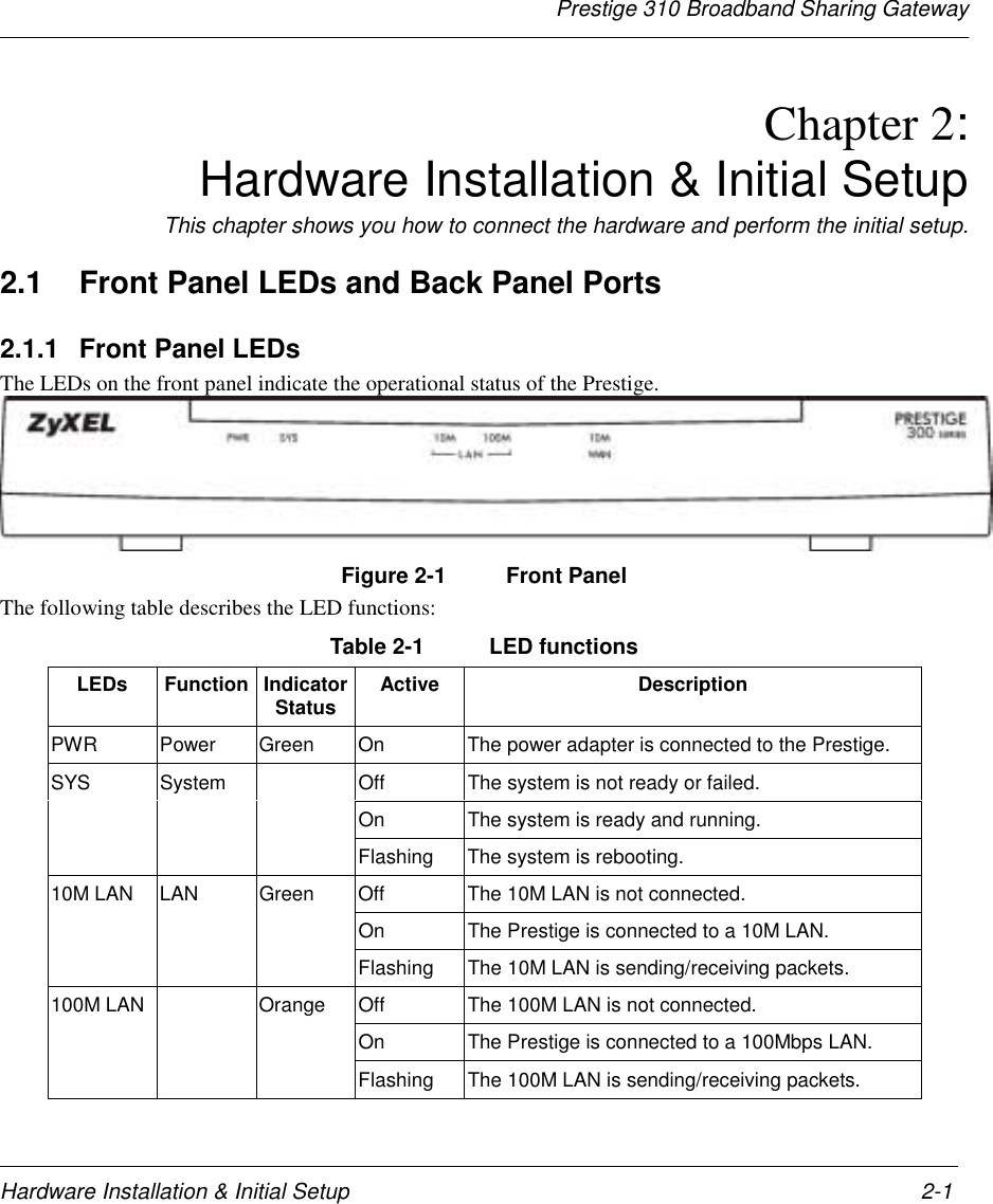
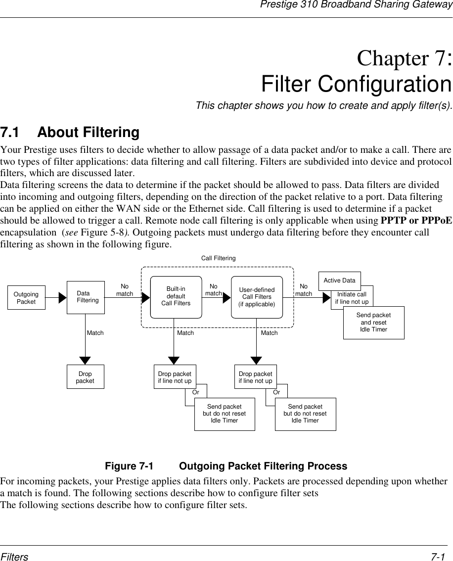
ZyXEL Communications PRESTIGE310S LAN/ Gateway Router User Manual Prestige 310
ZyXEL Communications Corporation LAN/ Gateway Router Prestige 310
UserManual.wiki
>
ZyXEL Communications
>
PRESTIGE310S User Manual
users manual
Navigation menu
Upload a User Manual
Namespaces
Wiki Guide
HTML
PDF
Info
Views
User Manual
Discussion / Help
Navigation
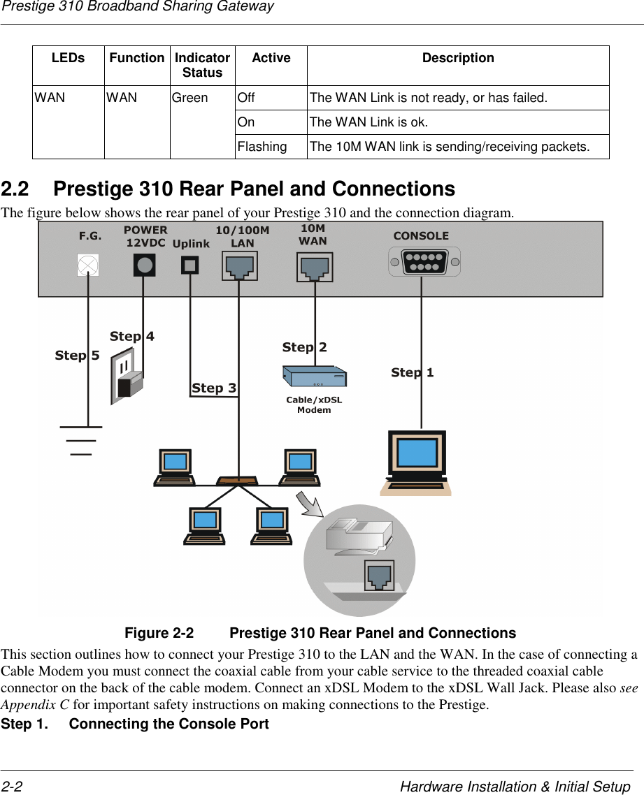
![Prestige 310 Broadband Sharing Gatewayxxiv PrefaceSupport Notes (that include a General FAQ, an Advanced FAQ, Applications Notes, Troubleshooting,Reference CI Commands) and bundled software." Read Me FirstOur Read Me First is designed to help you get your Prestige up and running right away. It contains a detailedeasy to follow connection diagram, Prestige default settings, handy checklists and information on setting upyour PC." Packing List CardFinally, you should have a Packing List Card that lists all items that should have come with your Prestige.." ZyXEL Web Page and FTP Server SiteYou can access release notes for firmware upgrades and other information at ZyXEL web pages and FTPserver sites. Refer to the Customer Support page in this User’s Guide for more information.Syntax Conventions• “Enter” means for you to type one or more characters and press the carriage return. “Select” or“Choose” means for you to select one from the predefined choices.• The SMT menu titles and labels are in Bold Times font. The choices of a menu item are in Bold Arialfont. A single keystroke is in Arial font and enclosed in square brackets, for instance, [ENTER] meansthe Enter, or carriage return, key; [ESC] means the Escape Key.• For brevity’s sake, we will use “e.g.” as a shorthand for “for instance” and “i.e.” for “that is” or “in otherwords” throughout this manual.](https://usermanual.wiki/ZyXEL-Communications/PRESTIGE310S/User-Guide-133477-Page-24.png)
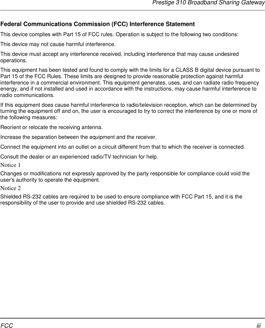
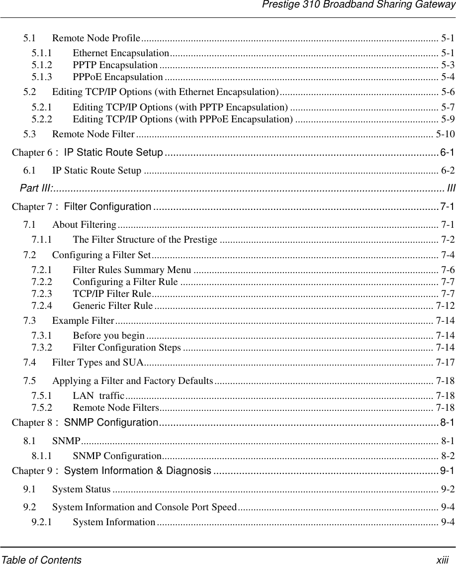
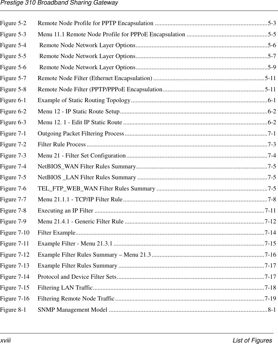
![Prestige 310 Broadband Sharing GatewayHardware Installation & Initial Setup2-4♦ No parity, 8 Data bits, 1 Stop bit, Flow Control set to None.3. A cable/xDSL modem and an ISP account.The following table lists some common names for the communications software, based on the type ofcomputer you are using.Table 2-2 Terminal Emulation SoftwareOperating System SoftwareWindows 95/98 or Windows NT HyperTerminal (bundled with Windows software)Windows 3.1 Terminal (bundled with Windows software)Macintosh ProComm, VersaTerm (supplied separately)After the Prestige is properly set up, you can make future changes to the configuration through telnetconnections.2.4 Power Up Your PrestigeAt this point, you should have connected the console port, the LAN port, the WAN port and the power port tothe appropriate devices or lines. Plug the power adapter into a wall outlet. The Power LED should be on. TheSYS LED will come on after the system tests are complete. The WAN LED and one of the LAN LEDs comeon immediately after the SYS LED comes on, if connections have been made to the LAN and WAN ports.Initial ScreenWhen you power on your Prestige, it performs several internal tests as well as line initialization.After the tests, the Prestige asks you to press [Enter] to continue, as shown.Figure 2-3 Initial ScreenEntering PasswordThe login screen appears after you press [Enter], prompting you to enter the password, as shown below.For your first login, enter the default password 1234. As you type the password, the screen displays an (X)for each character you type.Please note that if there is no activity for longer than 5 minutes after you log in, your Prestige willautomatically log you out and will display a blank screen. If you see a blank screen, press [Enter] to bring upthe login screen again.Copyright (c) 1994 - 2000 ZyXEL Communications Corp.initialize ch =0, ethernet address: 00:a0:c5:41:51:61initialize ch =1, ethernet address: 00:a0:c5:41:51:62Press ENTER to continue...](https://usermanual.wiki/ZyXEL-Communications/PRESTIGE310S/User-Guide-133477-Page-34.png)
![Prestige 310 Broadband Sharing GatewayHardware Installation & Initial Setup 2-5Figure 2-4 Password Screen2.5 Navigating the SMT InterfaceThe SMT (System Management Terminal) is the interface that you use to configure your Prestige.Several operations that you should be familiar with before you attempt to modify the configuration are listedin the table below.Table 2-3 Main Menu CommandsOperation Keystroke DescriptionMove down toanother menu [ENTER] To move forward to a submenu, type in the number of the desiredsubmenu and press [ENTER].Move up to aprevious menu [Esc] Press the [Esc] key to move back to the previous menu.Move to a “hidden”menu Press the [SPACEBAR] to change Noto Yes then press[ENTER].Fields beginning with “Edit” lead to hidden menus and have adefault setting of No. Press the [SPACE BAR] to change No toYes, then press [ENTER] to go to a “hidden” menu.Move the cursor [ENTER] or[Up]/[Down] arrowkeysWithin a menu, press [ENTER] to move to the next field. You canalso use the [Up]/[Down] arrow keys to move to the previous andthe next field, respectively.Enter information Fill in, orPress the [SPACEBAR] to toggleYou need to fill in two types of fields. The first requires you to typein the appropriate information. The second allows you to cyclethrough the available choices by pressing the [Space] bar.Required fields <? > All fields with the symbol <?> must be filled in order be able tosave the new configuration.N/A fields <N/A> Some of the fields in the SMT will show a <N/A>. This symbolrefers to an option that is Not Applicable.Save yourconfiguration [ENTER] Save your configuration by pressing [ENTER] at the message[Press ENTER to confirm or ESC to cancel]. Saving the data onthe screen will take you, in most cases to the previous menu.Enter Password : XXXX](https://usermanual.wiki/ZyXEL-Communications/PRESTIGE310S/User-Guide-133477-Page-35.png)
![Prestige 310 Broadband Sharing GatewayHardware Installation & Initial Setup2-6Operation Keystroke DescriptionExit the SMT Type 99, thenpress [ENTER].Type 99 at the Main Menu prompt and press [ENTER] to exit theSMT interface.2.5.1 Main MenuAfter you enter the password, the SMT displays the Prestige 310 Main Menu, as shown next.Figure 2-5 Prestige 310 Main Menu2.5.2 System Management Terminal Interface SummaryTable 2-4 Main Menu Summary# Menu Title Description1 General Setup Use this menu to setup general information.2 WAN Setup Use this menu to setup the WAN.3 LAN Setup Use this menu to setup the LAN.4 Internet Access Setup A quick and easy way to setup Internet connection.11 Remote Node Setup Use this menu to setup the remote node for LAN-to-LAN connection,including Internet connection.12 Static Routing Setup Use this menu to setup static route.15 SUA Setup Use this menu to specify inside servers when SUA is enabled. Copyright (c) 1994 - 2000 ZyXEL Communications Corp. Prestige 310 Main Menu Getting Started Advanced Management 1. General Setup 2. WAN Setup 3. LAN Setup 4. Internet Access Setup Advanced Applications 11. Remote Node Setup 12. Static Routing Setup 15. SUA Server Setup 21. Filter Set Configuration 22. SNMP Configuration 23. System Password 24. System Maintenance 26. Schedule Setup99. Exit Enter Menu Selection Number:](https://usermanual.wiki/ZyXEL-Communications/PRESTIGE310S/User-Guide-133477-Page-36.png)
![Prestige 310 Broadband Sharing GatewayHardware Installation & Initial Setup 2-7# Menu Title Description21 Filter Set Configuration Use this menu to setup filters to provide security.22 SNMP Configuration Use this menu to setup SNMP related parameters23 System Password Use this menu to setup a new password.24 System Maintenance This menu provides system status, diagnostics, firmware upload, etc.26 Schedule Setup Use this menu to schedule outgoing calls.99 Exit To exit from SMT and return to the blank screen.2.6 Changing the System PasswordThe first thing your should do before anything else is to change the default system password by following thesteps below.Step 1. Enter 23 in the Main Menu to open Menu 23 - System Password as shown below.Figure 2-6 Menu 23 - System SecurityStep 2. Enter your existing password and press [Enter].Step 3. Enter your new system password and press [Enter].Step 4. Re-type your new system password for confirmation and press [Enter].Note that as you type a password, the screen displays a (X) for each character you type.2.6.1 Resetting the PrestigeIf you have forgotten your password or for some reason cannot access the SMT menu you will need toreinstall the configuration file. Uploading the configuration file replaces the current configuration file withthe default configuration file, you will lose all configurations that you had before and the speed of theMenu 23 - System PasswordOld Password= ?New Password= ?Retype to confirm= ?Enter here to CONFIRM or ESC to CANCEL:](https://usermanual.wiki/ZyXEL-Communications/PRESTIGE310S/User-Guide-133477-Page-37.png)
![Prestige 310 Broadband Sharing GatewayHardware Installation & Initial Setup 2-9Figure 2-7 Menu 1 – General SetupTable 2-5 General Setup Menu FieldField Description ExampleSystem Name Choose a descriptive name for identification purposes. It isrecommended you enter your computer’s “Computer name” in thisfield. This name can be up to 30 alphanumeric characters long.Spaces are not allowed, but dashes “-” and underscores "_" areaccepted.P310Domain Name Enter the domain name (if you know it) here. If you leave this fieldblank, the ISP may assign a domain name via DHCP. You can go toMenu 24.8 and type "sys domainname" to see the current domainname used by your gateway.If you want to clear this field just press the [SPACE BAR]. Thedomain name entered by you is given priority over the ISP assigneddomain name.zyxel.com.twEdit DynamicDNS Press the [SPACE BAR] to select Yes or No (default). Select Yes toconfigure Menu 1.1 – Configure Dynamic DNS discussed next.2.7.2 Configuring Dynamic DNSTo configure Dynamic DNS, go to Menu 1 – General Setup and press select Yes in the Edit DynamicDNS field.Pressing [ENTER] takes you to Menu 1.1– Configure Dynamic DNS as shown next.Menu 1 - General SetupSystem Name= xxxDomain Name=zyxel.com.twEdit Dynamic DNS= NoPress ENTER to Confirm or ESC to Cancel:](https://usermanual.wiki/ZyXEL-Communications/PRESTIGE310S/User-Guide-133477-Page-39.png)
![Prestige 310 Broadband Sharing GatewayHardware Installation & Initial Setup2-10Figure 2-8 Configure Dynamic DNSFollow the instructions in the next table to configure Dynamic DNS parameters.Table 2-6 Configure Dynamic DNS Menu FieldsField Description ExampleServiceProvider Enter the name of your Dynamic DNS client. www.ddns.orgActive Press [SPACE BAR] to toggle between Yes or No. YesHost Enter the domain name assigned to your Prestige by yourDynamic DNS provider. me.ddns.orgEMAIL Enter your e-mail address. mail@mailserverUser Enter your user name.Password Enter the password assigned to you.EnableWildcard Your Prestige supports DYNDNS Wildcard. Press [SPACEBAR] to toggle between Yes or No This field is N/A when youchoose DDNS client as your service provider.YesThe IP address will be updated when you reconfigure Menu 1 or perform DHCP client renewal.Please note that:♦ The Prestige supports basic DDNS, i.e., insecure login and password.♦ If you have a private WAN IP address, then you can not use this service.2.8 WAN SetupThis section describes how to configure the WAN using Menu 2 – WAN (10Mbps Ethernet) Setup. Fromthe Main Menu, enter 2 to open Menu 2.Menu 1.1 - Configure Dynamic DNSService Provider = WWW.DynDNS.ORGActive= YesHost= me.ddns.orgEMAIL= mail@mailserverUser= usernamePassword= ******Enable Wildcard= NoPress ENTER to confirm or ESC to cancel:](https://usermanual.wiki/ZyXEL-Communications/PRESTIGE310S/User-Guide-133477-Page-40.png)
![Prestige 310 Broadband Sharing GatewayHardware Installation & Initial Setup 2-11You only need to configure this menu if your WAN connection is a cable modem.Figure 2-9 Menu 2 – WAN SetupThe MAC address field allows users to configure the WAN port's MAC Address by either using the factorydefault or cloning the MAC address from a workstation on your LAN. Once it is successfully configured, theaddress will be copied to the rom file (ZyNOS configuration file). It will not change unless you change thesetting in Menu 2 or upload a different rom file.The following table contains instructions on how to configure your WAN setup.Table 2-7 WAN Setup Menu FieldsField Description ExamplesMAC AddressAssigned By Press the [SPACEBAR] to choose either of the two methods ofassigning a MAC Address. Choose Factory Default to select thefactory assigned default MAC Address. Choose IP Address attachedon LAN to use the MAC Address of that workstation whose IP yougive in the following field.Factory DefaultIP Address This field is applicable only if you choose IP Address attached on LANmethod. Enter the IP address of the workstation on the LAN whoseMAC you are cloning.Note: Your Prestige WAN Port is always set at half-duplex mode as most cable modemsonly support half-duplex mode. If your cable modem supports full-duplex mode, thenyou will be able to manually set it at half-duplex mode.If the Prestige was set at half-duplex and the cable modem was set at full-duplex thenthe WAN port would not function properly.2.9 LAN SetupThis section describes how to configure the LAN using Menu 3 – LAN Setup (10/100Mbps Ethernet).From the Main Menu, enter 3 to open Menu 3.Menu 2 - WAN Setup MAC Address: Assigned By=IP address attached on LAN IP Address= 192.168.1.12Press ENTER to Confirm or ESC to Cancel:Press Space Bar to Toggle](https://usermanual.wiki/ZyXEL-Communications/PRESTIGE310S/User-Guide-133477-Page-41.png)
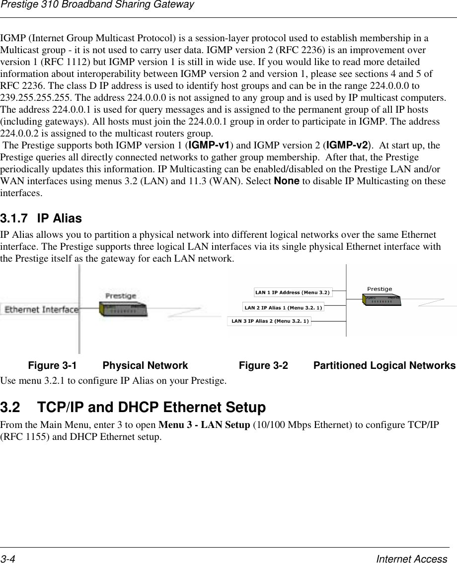
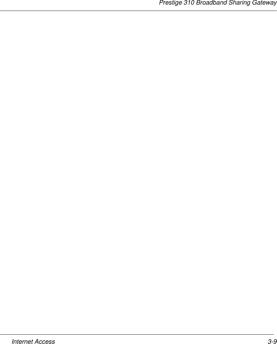
![Prestige 310 Broadband Sharing GatewayInternet Access3-6Follow the instructions in the following table on how to configure the DHCP fields.Table 3-1 LAN DHCP Setup Menu FieldsField Description ExampleDHCP= This field enables/disables the DHCP server. If it is set to Server,your Prestige will act as a DHCP server. If set to None, DHCPservice will be disabled and you must have another DHCP severon your LAN, or else the workstation must be manually configured.When DHCP is set to Server, the following four items need to beset. The Prestige can now also act as a surrogate DHCP server(Relay) where it relays IP address assignment from the actual realDHCP server to the clients.NoneRelayServer (default)Client IP Pool StartingAddress This field specifies the first of the contiguous addresses in the IPaddress pool. 192.168.1.33Size of Client IP Pool This field specifies the size, or count, of the IP address pool. 32Primary DNS ServerSecondary DNSServerEnter the IP addresses of the DNS servers. The DNS servers arepassed to the DHCP clients along with the IP address and thesubnet mask. Leave these entries at 0.0.0.0 if they are provided bya WAN DHCP server.Follow the instructions in the following table to configure TCP/IP parameters for the LAN port.Table 3-2 LAN TCP/IP Setup Menu FieldsField Description ExampleTCP/IP SetupIP Address Enter the IP address of your Prestige in dotted decimal notation 192.168.1.1(default)IP Subnet Mask Your Prestige will automatically calculate the subnet mask based onthe IP address that you assign. Unless you are implementingsubnetting, use the subnet mask computed by the Prestige255.255.255.0RIP Direction Press the [SPACE BAR] to select the RIP direction from Both/InOnly/Out Only/None.Both(default)Version Press the [SPACE BAR] to select the RIP version from RIP-1/RIP-2B/RIP-2M.RIP-1(default)Multicast IGMP (Internet Group Multicast Protocol) is a session-layer protocolused to establish membership in a Multicast group. The Prestigesupports both IGMP version 1 (IGMP-v1) and IGMP-v2. Press theNone](https://usermanual.wiki/ZyXEL-Communications/PRESTIGE310S/User-Guide-133477-Page-48.png)
![Prestige 310 Broadband Sharing GatewayInternet Access 3-7Field Description Examplespace bar to enable IP Multicasting or select None (default) todisable it.Edit IP Alias The Prestige supports three logical LAN interfaces via its singlephysical Ethernet interface with the Prestige itself as the gateway foreach LAN network. Press the space bar to toggle No to Yes, thenpress [ENTER] to bring you to menu 3.2.1YesNo (default)When you have completed this menu, press [Enter] at the prompt [Press ENTER to Confirm…] to save yourconfiguration, or press [Esc] at any time to cancel.3.2.1 IP Alias SetupYou must use Menu 3.2 to configure the first network and move the cursor to the Edit IP Alias field andpress [SPACE BAR] to choose Yes and press [ENTER] to configure the second and third network.Pressing [Enter] opens Menu 3.2.1 - IP Alias Setup, as shown next.Figure 3-5 Menu 3.2.1 - IP Alias SetupFollow the instructions in the following table to configure IP Alias parameters.Table 3-3 IP Alias Setup Menu FieldsField Description ExampleIP Alias Choose Yes to configure the LAN network for the Prestige. YesIP Address Enter the IP address of your Prestige in dotted decimal notation 192.168.2.1IP Subnet Mask Your Prestige will automatically calculate the subnet mask based onthe IP address that you assign. Unless you are implementing 255.255.255.0Menu 3.2.1 - IP Alias Setup IP Alias 1= No IP Address= N/A IP Subnet Mask= N/A RIP Direction= N/A Version= N/A Incoming protocol filters= N/A Outgoing protocol filters= N/A IP Alias 2= No IP Address= N/A IP Subnet Mask= N/A RIP Direction= N/A Version= N/A Incoming protocol filters= N/A Outgoing protocol filters= N/A Enter here to CONFIRM or ESC to CANCEL:Press Space Bar to Toggle.](https://usermanual.wiki/ZyXEL-Communications/PRESTIGE310S/User-Guide-133477-Page-49.png)
![Prestige 310 Broadband Sharing GatewayInternet Access3-8subnetting, use the subnet mask computed by the PrestigeRIP Direction Press the space bar to select the RIP direction from None, Both/InOnly/Out Only. NoneVersion Press the space bar to select the RIP version from RIP-1/RIP-2B/RIP-2M. RIP-1IncomingProtocol Filters Enter the filter set(s) you wish to apply to the incoming trafficbetween this node and the Prestige.OutgoingProtocol Filters Enter the filter set(s) you wish to apply to the outgoing traffic betweenthis node and the Prestige.When you have completed this menu, press [Enter] at the prompt [Press ENTER to Confirm…] to saveyour configuration, or press [Esc] at any time to cancel.3.3 Internet Access SetupYou will see three different Menu 4 screens depending on whether you chose Ethernet, PPTP or PPPoEEncapsulation.3.3.1 Ethernet EncapsulationStep 1. You must choose the Ethernet option when the WAN port is used as a regular Ethernet. ThePPPoE choice is for a dial-up connection using PPPoE. If you choose Ethernet in Menu 4 you will see thenext screen.Figure 3-6 Internet Access Setup (Ethernet)Menu 4 - Internet Access SetupISP's Name= ChangeMeEncapsulation= Ethernet Service Type= Standard My Login= N/A My Password= N/A Login Server IP= N/AIP Address Assignment= Dynamic IP Address= N/A IP Subnet Mask= N/A Gateway IP Address= N/ASingle User Account= YesPress ENTER to Confirm or ESC to Cancel:](https://usermanual.wiki/ZyXEL-Communications/PRESTIGE310S/User-Guide-133477-Page-50.png)
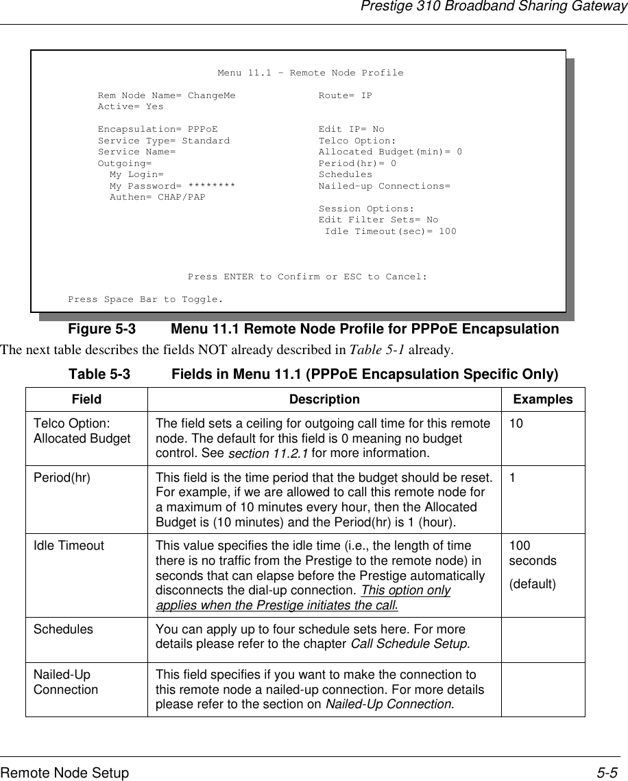
![Prestige 310 Broadband Sharing GatewayInternet Access3-10The following table describes this screen.Table 3-4 Internet Access Setup Menu FieldsField DescriptionISP’s Name Enter the name of your Internet Service Provider, e.g., myISP. Thisinformation is for identification purposes only.Encapsulation Press the [SPACE BAR] and the press [ENTER] to choose Ethernet. Theencapsulation method influences your choices for IP Address.Service Type This is applicable only when you choose Ethernet as your encapsulationmethod. Press the [SPACE BAR] to select Standard, RR-Toshiba(RoadRunner Toshiba authentication method) or RR-Manager (RoadRunnerManager authentication method). Choose a RoadRunner flavor if your ISP isTime Warner's RoadRunner; otherwise choose Standard.Note: xDSL users must choose the Standard option only. The Server IP, My Login IP and My Passwordfields are not applicable in this case.My Login Name Enter the login name given to you by your ISP.My Password Enter the password associated with the login name above.Login Server IP The Prestige will find the RoadRunner Server IP if this field is left blank. If itdoes not, then you must enter the authentication server IP address.IP Address Assignment If your ISP did not assign you a fixed IP address, select Dynamic, otherwiseselect Static and enter the IP address & subnet mask in the following fields.IP Address Enter the (fixed) IP address assigned to you by your ISP (Static IP AddressAssignment is selected in the previous field).IP Subnet Mask Enter the subnet mask associated with your static IP.Gateway IP Address Enter the gateway IP address associated with your static IP.Single User Account Please see the following chapter for a more detailed discussion on the SingleUser Account. The default is Yes.3.3.2 PPTP EncapsulationPoint-to-Point Tunneling Protocol (PPTP) is a network protocol that enables secure transfer of data from aremote client to a private server, creating a Virtual Private Network (VPN) using TCP/IP-based networksPPTP supports on-demand, multi-protocol, and virtual private networking over public networks, such as theInternet.The P310 supports only one PPTP server connection at any given time.](https://usermanual.wiki/ZyXEL-Communications/PRESTIGE310S/User-Guide-133477-Page-52.png)
![Prestige 310 Broadband Sharing GatewayInternet Access 3-113.3.3 Configure PPTP ClientTo configure a PPTP client, you must configure My Login and Password fields for PPP connection andPPTP parameters for PPTP connection.After configuring the User Name and Password for PPP connection, toggle the space bar in theEncapsulation field in Menu 4 -Internet Access Setup to choose PPTP as your encapsulation option.If you choose PPTP in Menu 4 you will see the next screen.Figure 3-7 Internet Access Setup (PPTP)The following table contains instructions about the new fields when you choose PPTP in the Encapsulationfield in Menu 4.Table 3-5 New Fields in Menu 4 (PPTP) screenField Description ExamplesEncapsulation Press the [SPACE BAR] and then press [ENTER] to choosePPTP. The encapsulation method influences your choices forIP Address.PPTPIdle Timeout This value specifies the time in seconds that elapses beforethe Prestige automatically disconnects from the PPTP server. 100(default)3.3.4 PPPoE EncapsulationThe Prestige supports PPPoE (Point-to-Point Protocol over Ethernet). You can use PPPoE encapsulation onlywhen you’re using the Prestige with an xDSL modem as the WAN device.PPPoE is an IETF Draft standard specifying how a host personal computer (PC) interacts with a broadbandmodem (i.e. xDSL, cable, wireless, etc.) to achieve access to high-speed data networks. It preserves theexisting Microsoft Dial-Up Networking experience and requires no new learning or procedures.Menu 4 - Internet Access Setup ISP's Name= ChangeMe Encapsulation= PPTP Service Type= N/A My Login= username My Password= ****** Idle Timeout= 100 IP Address Assignment= Dynamic IP Address= N/A IP Subnet Mask= N/A Gateway IP Address=N/A Single User Account= Yes Press ENTER to Confirm or ESC to Cancel:](https://usermanual.wiki/ZyXEL-Communications/PRESTIGE310S/User-Guide-133477-Page-53.png)
![Prestige 310 Broadband Sharing GatewayInternet Access3-12Operationally, PPPoE saves significant effort for both the end user and ISP/carrier, as it requires noconfiguration of the modem at the customer site.PPPoE uses industry-standard, low-cost Ethernet NICs to connect your PCs to the broadband modem. Inaddition, PPPoE allows multiple PCs to share a single broadband connection, making it the best solution forsmall offices and homes that have more than one PC needing high-speed network access. For the serviceprovider, one of the benefits of PPPoE is the ability to let end users access multiple network services, afunction known as dynamic service selection. This enables the service provider to easily create and offer newIP services.If you choose PPPoE in Menu 4, you will see the next screen. For extra information on PPPoE, please seethe appendix.Figure 3-8 Internet Access (PPPoE)Table 3-6 New Fields in Menu 4 (PPPoE) screenField Description ExamplesEncapsulation Press the [SPACE BAR] and then press [ENTER] to choosePPPoE. The encapsulation method influences your choicesfor IP Address.PPPoEIdle Timeout This value specifies the time in seconds that elapses beforethe Prestige automatically disconnects from the PPPoEserver.100(default)Menu 4 - Internet Access SetupISP's Name= ChangeMeEncapsulation= PPPoE Service Type= N/A My Login= My Password= ******** Idle Timeout= 100IP Address Assignment= Dynamic IP Address= N/A IP Subnet Mask= N/A Gateway IP Address= N/ASingle User Account= YesPress ENTER to Confirm or ESC to Cancel:](https://usermanual.wiki/ZyXEL-Communications/PRESTIGE310S/User-Guide-133477-Page-54.png)
![Prestige 310 Broadband Sharing GatewayInternet Access 3-133.4 Internet Test SetupAfter configuring the Menu 4 fields when you press [Enter] to confirm you will see the message, " Do youwish to perform the Internet Setup Test[y/n]:" if you have chosen PPTP or PPPoE as your encapsulationmethod. Say 'Y' to test your setup. An example of Internet Setup Test is shown next.Figure 3-9 Internet Setup Test Example3.5 Basic Setup CompleteWell Done! You have successfully connected, installed and set up your Prestige to operate on your networkas well as access the Internet.Start dialing for node <ChangeMe>...### Hit any key to continue.###$$$ DIALING dev=a ch=0..........$$$ OUTGOING-CALL phone()$$$ PPTP: Start tunnel setup, send SCCRQ$$$ PPTP: OCRQ sent$$$ CALL CONNECT speed<10000000> type<10> chan<0>$$$ LCP opened$$$ CHAP login to remote OK$$$ IPCP negotiation started$$$ CCP stopped$$$ BACP stopped$$$ IPCP neg' Primary DNS 202.xxx.xxx.x$$$ IPCP opened](https://usermanual.wiki/ZyXEL-Communications/PRESTIGE310S/User-Guide-133477-Page-55.png)
![Prestige 310 Broadband Sharing Gateway4-2 SUA and Multiple SUA ServersFor more information on IP address translation as a solution for IP address depletion problem, refer to RFC1631, The IP Network Address Translator (NAT).In summary:• SUA helps in more efficient IP address management.• SUA can provide firewall protection. All incoming inquiries will be filtered out by your Prestige.• UDP and TCP datagrams can be routed. In addition, partial ICMP, including echo (ping) and traceroute, is supported.• SUA is also a cost-effective solution for offices to access the Internet or other remote TCP/IP networksas they have to pay for single globally unique IP address only.4.1.2 Single User Account ConfigurationThe steps for configuring your Prestige for Single User Account are identical to conventional Internet access(See configuration instructions in the previous chapter) with the exception that you need to fill in two extrafields in Menu 4 - Internet Access Setup, as shown in the following figure. SUA here is applied solely tothe output interface and is valid only for LAN to WAN connections and not for connections between LANs.Figure 4-2 Menu 4 - Internet Access Setup for Single User AccountTo enable the SUA feature in Menu 4, move the cursor to the Single User Account field and select Yes (orNo to disable SUA).Follow the instructions on how to configure the SUA fields in the following table.Table 4-1 Single User Account Menu FieldsField DescriptionSingle User Account Select Yes to enable SUA.Press [ENTER] at the message [Press ENTER to Confirm ...] to save your configuration, or press[ESC] at any time to cancel.Menu 4 - Internet Access SetupISP's Name= ChangeMeEncapsulation= Ethernet Service Type= Standard My Login= N/A My Password= N/A Login Server IP= N/AIP Address Assignment= Dynamic IP Address= N/A IP Subnet Mask= N/A Gateway IP Address= N/ASingle User Account= YesPress ENTER to Confirm or ESC to Cancel:SUA](https://usermanual.wiki/ZyXEL-Communications/PRESTIGE310S/User-Guide-133477-Page-58.png)
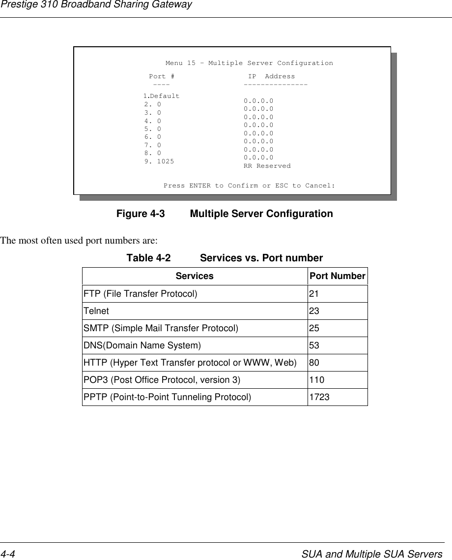
![Prestige 310 Broadband Sharing GatewaySUA and Multiple SUA Servers 4-3When SUA is disabled, the Prestige will send the packets from workstations to the remote host withworkstation's IP and port to the destination's IP and port. If the workstation uses private IP (Private NetworksIPs: 10.0.0.0 ~ 10.255.255.255; 172.16.0.0. ~ 172.31.255.255; 192.168.0.0. ~ 192.168.255.255) in SUAmode, the packet will be routed by the Prestige but will be dropped somewhere and never returned. This isbecause only a legal IP is valid on the Internet. Hence, in non-SUA mode, the workstation must use non-private/legal IP.4.2 Multiple Servers behind SUAIf you wish, you can make inside servers for different services, e.g., web or FTP, visible to the outside users,even though SUA makes your whole inside network appear as a single machine to the outside world. Aservice is identified by the port number, e.g., web service is on port 80 and FTP on port 21.As an example, if you have a web server at 192.168.1.2 and an FTP server 192.168.1.3, then you need tospecify for port 80 (web) the server at IP address 192.168.1.2 and for port 21 (FTP) another at IP address192.168.1.3.Please note that a server can support more than one service, e.g., a server can provide both FTP and DNSservice, while another provides only web service. Also, since you need to specify the IP address of a serverin the Prestige, a server must have a fixed IP address and not be a DHCP client whose IP address potentiallychanges each time it is powered on.In addition to the servers for specific services, SUA supports a default server. A service request that does nothave a server explicitly designated for it is forwarded to the default server. If the default server is notdefined, the service request is simply discarded.To make a server visible to the outside world, specify the port number of the service and the inside IP addressof the server in Menu 15, Multiple Server Configuration.For more information on configuring supporting applications behind SUA refer to theZyNOS Support Note documentation in your Support CD.4.2.1 Configuring a Server behind SUAFollow the steps below to configure a server behind SUA:Step 1 Enter 15 in the main menu to go to Menu 15 - Multiple Server Configuration.Step 2 Enter the service port number in the Port # field and the inside IP address of the server in the IPAddress field.Step 3 Press [Enter] at the “Press ENTER to confirm …” prompt to save your configuration after youdefine all the servers or press ESC at any time to cancel.](https://usermanual.wiki/ZyXEL-Communications/PRESTIGE310S/User-Guide-133477-Page-59.png)
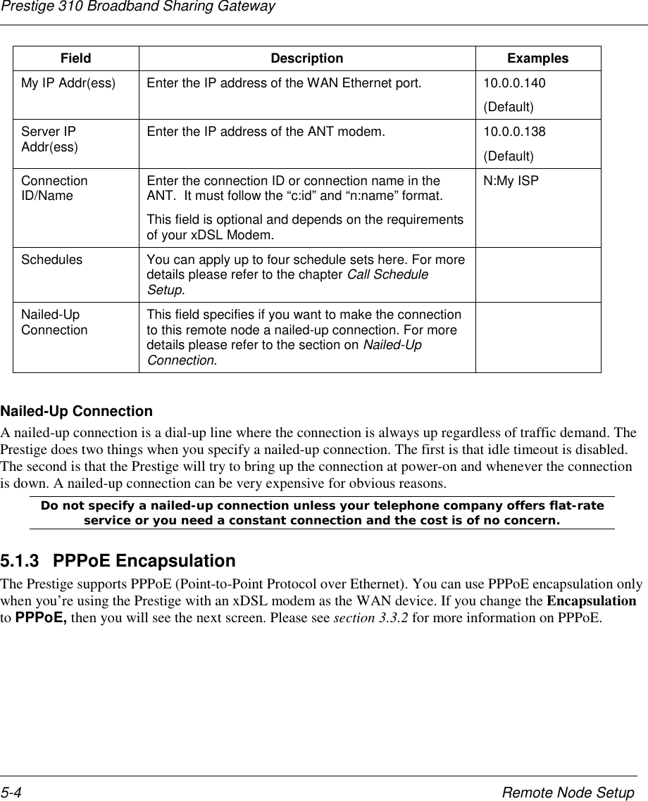
![Prestige 310 Broadband Sharing Gateway5-2 Remote Node SetupTable 5-1 Fields in Menu 11.1 (Ethernet Encapsulation)Field Description ExamplesRem Node Name Enter a descriptive name for the remote node. This field canbe up to eight characters. LAofficeActive Press the [SPACE BAR] to toggle between Yes and No andactivate (deactivate) the remote node. YesEncapsulation Ethernet is the default encapsulation. Press the [SPACE BAR]if you wish to change to PPPoE encapsulation. EthernetService Type Press the [SPACE BAR] to select from Standard, RR-Toshiba(RoadRunner Toshiba authentication method) or RR-Manager(RoadRunner Manager authentication method). Choose one ofthe RoadRunner methods if your ISP is Time Warner'sRoadRunner; otherwise choose Standard.StandardService Name This is valid only when you have chosen PPPoE encapsulation.If you are using PPPoE encapsulation, then type the name ofyour PPPoE service here.poellcOutgoing: MyLogin This field is applicable for PPPoE encapsulation only. Enter thelogin name assigned by your ISP when the Prestige calls thisremote node. Some ISPs append this field to the ServiceName field above (e.g., jim@poellc) to access the PPPoEserver.jimOutgoing: MyPassword Enter the password assigned by your ISP when the Prestigecalls this remote node. Valid for PPPoE encapsulation only. *****Authen=CHAP/PAP This field sets the authentication protocol used for outgoingcalls. Options for this field are:CHAP/PAP - Your Prestige will accept either CHAP or PAPwhen requested by this remote node.CHAP - accept CHAP only.PAP - accept PAP only.CHAP/PAPServer IP This field is valid for RoadRunner service type only. ThePrestige will find the RoadRunner Server IP automatically if thisfield is left blank. If it does not, then you must enter theauthentication server IP address here.Route This field refers to the protocol that will be routed by yourPrestige – IP only for the P310. IPEdit IP This field leads to a “hidden” menu. Press the [SPACE BAR] toselect Yes and press [ENTER] to go to Menu 11.3 - Remote Yes](https://usermanual.wiki/ZyXEL-Communications/PRESTIGE310S/User-Guide-133477-Page-62.png)
![Prestige 310 Broadband Sharing GatewayRemote Node Setup 5-3Field Description ExamplesNode Network Layer Options.Session Options:Edit Filter sets This field leads to another “hidden” menu Use the [SPACEBAR] to toggle this field to Yes and press [ENTER] to openMenu 11.5 to edit the filter sets. See the Remote Node Filtersection for more details.Yes5.1.2 PPTP EncapsulationIf you change the Encapsulation to PPTP in Menu 11.1, then you will see the next screen. Please see theappendix for information.Figure 5-2 Remote Node Profile for PPTP EncapsulationThe next table shows how to configure the new fields in the Remote Node Profile menu.Table 5-2 Fields in Menu 11.1 (PPTP Encapsulation)Field Description ExamplesEncapsulation Toggle the space bar to choose PPTP. You must alsogo to Menu 11.3 to check the IP Address setting onceyou have selected the encapsulation method.PPTP Menu 11.1 - Remote Node Profile Rem Node Name= ChangeMe Route= IP Active= Yes Encapsulation= PPTP Edit IP= No Service Type= Standard Telco Option: Service Name=N/A Allocated Budget(min)= 0 Outgoing= Period(hr)= 0 My Login= Schedules= My Password= ******** Nailed-up Connections= Authen= CHAP/PAP PPTP : Session Options: IP Addr= Edit Filter Sets= No Server IP Addr= Idle Timeout(sec)= 100 Connection ID/Name= Press ENTER to Confirm or ESC to Cancel:Press Space Bar to Toggle.](https://usermanual.wiki/ZyXEL-Communications/PRESTIGE310S/User-Guide-133477-Page-63.png)
![Prestige 310 Broadband Sharing Gateway5-6 Remote Node Setup5.2 Editing TCP/IP Options (with Ethernet Encapsulation)Move the cursor to the Edit IP field in Menu 11.1, then press the [SPACE BAR] to toggle and set the valueto Yes. Press [Enter] to open Menu 11.3 - Network Layer Options.Figure 5-4 Remote Node Network Layer OptionsThe next table gives you instructions about configuring remote node network layer options.Table 5-4 Remote Node Network Layer Options Menu FieldsField Description ExampleIP AddressAssignment If your ISP did not assign you an explicit IP address, select Dynamic;otherwise select Static and enter the IP address & subnet mask inthe following fields.DynamicIP Address If you have a Static IP Assignment, enter the IP address assigned toyou by your ISP.IP SubnetMask If you have a Static IP Assignment, enter the subnet mask assignedto you.Gateway IPAddr If you have a Static IP Assignment, enter the gateway IP addressassigned to you.Single UserAccount Use the [SPACE BAR] to choose Yes or No. YesMetric This field is valid only for PPTP/ PPPoE encapsulation. The metricrepresents the “cost” of transmission for routing purposes. IP routinguses hop count as the measurement of cost, with a minimum of 1 fordirectly connected networks. Enter a number that approximates thecost for this link. The number need not be precise, but it must be3Menu 11.3 - Remote Node Network Layer Options IP Address Assignment= Dynamic IP Address= N/A IP Subnet Mask= N/A Gateway IP Addr= N/A Single User Account= Yes Metric= N/A Private= N/A RIP Direction= None Version= N/A Multicast= None Enter here to CONFIRM or ESC to CANCEL:Press Space Bar to Toggle.](https://usermanual.wiki/ZyXEL-Communications/PRESTIGE310S/User-Guide-133477-Page-66.png)
![Prestige 310 Broadband Sharing GatewayRemote Node Setup 5-7Field Description Examplebetween 1 and 15. In practice, 2 or 3 is usually a good number.Private This field is valid only for PPTP/PPPoE encapsulation. Thisparameter determines if the Prestige will include the route to thisremote node in its RIP broadcasts. If set to Yes, this route is keptprivate and not included in RIP broadcast. If No, the route to thisremote node will be propagated to other hosts through RIPbroadcasts.YesRIP Press the [SPACE BAR] to select the WAN RIP direction from Both/None/In Only/Out Only. None(default)Version Press the [SPACE BAR] to select the RIP version from RIP-1/RIP-2B/RIP-2M and None. RIP-1Multicast Turn on/off IGMP support and select the version from IGMP-v2/IGMP-v1/None. NoneOnce you have completed filling in the Network Layer Options Menu, press [Enter] to return toMenu 11. Press [Enter] at the message [Press ENTER to Confirm...] to save your configuration, orpress [Esc] at any time to cancel.5.2.1 Editing TCP/IP Options (with PPTP Encapsulation)Make sure that Encapsulation is set to PPTP in Menu 11.1. Then move the cursor to the Edit IP field inMenu 11.1, press the [SPACE BAR] to toggle No to Yes. Press [Enter] to open Menu 11.3 - NetworkLayer Options.Figure 5-5 Remote Node Network Layer OptionsThe next table gives you instructions about configuring remote node network layer options.Menu 11.3 - Remote Node Network Layer Options IP Address Assignment= Dynamic Rem IP Address= N/A Rem Subnet Mask= N/A My WAN Addr= 0.0.0.0 Single User Account= Yes Metric= 1 Private= No RIP Direction= None Version= N/A Multicast= None Enter here to CONFIRM or ESC to CANCEL:Press Space Bar to Toggle.](https://usermanual.wiki/ZyXEL-Communications/PRESTIGE310S/User-Guide-133477-Page-67.png)
![Prestige 310 Broadband Sharing Gateway5-8 Remote Node SetupTable 5-5 Remote Node Network Layer Options Menu FieldsField Description ExampleIP AddressAssignment If your ISP did not assign you an explicit IP address, select Dynamic;otherwise select Static and enter the IP address & subnet mask in thefollowing fields.DynamicRem IP Address If you have a Static IP Assignment, enter the IP address assigned tothe remote node.Rem IP SubnetMask If you have a Static IP Assignment, enter the subnet mask assigned tothe remote node.My WAN Addr Some implementations, especially the UNIX derivatives, require theWAN link to have a separate IP network number from the LAN andeach end must have a unique address within the WAN network number.If this is the case, enter the IP address assigned to the WAN port ofyour Prestige.Note that this is the address assigned to your local Prestige, not theremote router.Single UserAccount Use the [SPACE BAR] to choose Yes or No. YesMetric The metric represents the “cost” of transmission for routing purposes.IP routing uses hop count as the measurement of cost, with a minimumof 1 for directly connected networks. Enter a number that approximatesthe cost for this link. The number need not be precise, but it must bebetween 1 and 15. In practice, 2 or 3 is usually a good number.1 to 15Private This parameter determines if the Prestige will include the route to thisremote node in its RIP broadcasts. If set to Yes, this route is keptprivate and not included in RIP broadcast. If No, the route to this remotenode will be propagated to other hosts through RIP broadcasts.Yes/NoRIP Press the [SPACE BAR] to select the RIP direction from Both/ None/InOnly/Out Only and None. None(default)Version Press the [SPACE BAR] to select the RIP version from RIP-1/RIP-2B/RIP-2M. RIP-1Multicast Turn on/off IGMP support and select the version from IGMP-v2/IGMP-v1/None. NoneOnce you have completed filling in the Network Layer Options Menu, press [Enter] to return to Menu 11.Press [Enter] at the message [Press ENTER to Confirm...] to save your configuration, or press [Esc] atany time to cancel.](https://usermanual.wiki/ZyXEL-Communications/PRESTIGE310S/User-Guide-133477-Page-68.png)
![Prestige 310 Broadband Sharing GatewayRemote Node Setup 5-95.2.2 Editing TCP/IP Options (with PPPoE Encapsulation)Make sure that Encapsulation is set to PPPoE in Menu 11.1. Then move the cursor to the Edit IP field inMenu 11.1, press the [SPACE BAR] to toggle No to Yes. Press [Enter] to open Menu 11.3 - NetworkLayer Options.Figure 5-6 Remote Node Network Layer OptionsThe next table gives you instructions about configuring remote node network layer options.Table 5-6 Remote Node Network Layer Options Menu FieldsField Description ExampleIP AddressAssignment If your ISP did not assign you an explicit IP address, select Dynamic;otherwise select Static and enter the IP address & subnet mask in thefollowing fields.DynamicRem IP Address If you have a Static IP Assignment, enter the IP address assigned tothe remote node.Rem IP SubnetMask If you have a Static IP Assignment, enter the subnet mask assigned tothe remote node.My WAN Addr Some implementations, especially the UNIX derivatives, require theWAN link to have a separate IP network number from the LAN andeach end must have a unique address within the WAN network number.If this is the case, enter the IP address assigned to the WAN port ofyour Prestige.Note that this is the address assigned to your local Prestige, not theremote router.Single UserAccount Use the [SPACE BAR] to choose Yes or No. YesMenu 11.3 - Remote Node Network Layer Options IP Address Assignment= Dynamic Rem IP Address= N/A Rem Subnet Mask= N/A My WAN Addr= 0.0.0.0 Single User Account= Yes Metric= 1 Private= No RIP Direction= None Version= N/A Multicast= None Enter here to CONFIRM or ESC to CANCEL:Press Space Bar to Toggle.](https://usermanual.wiki/ZyXEL-Communications/PRESTIGE310S/User-Guide-133477-Page-69.png)
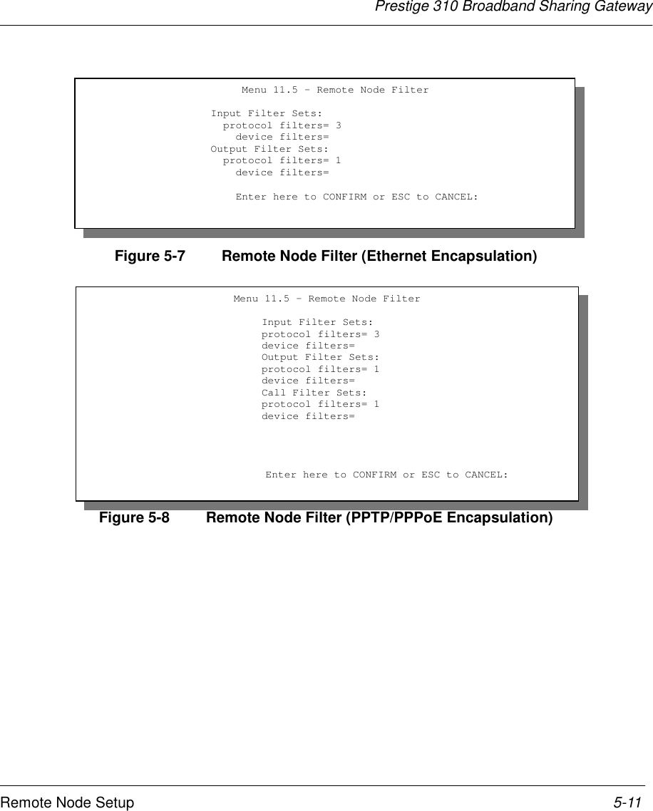
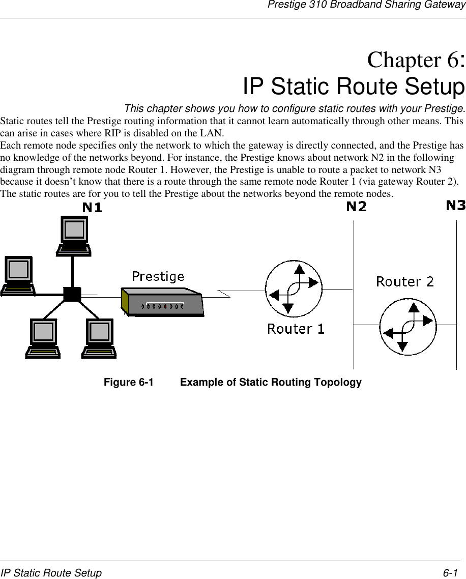
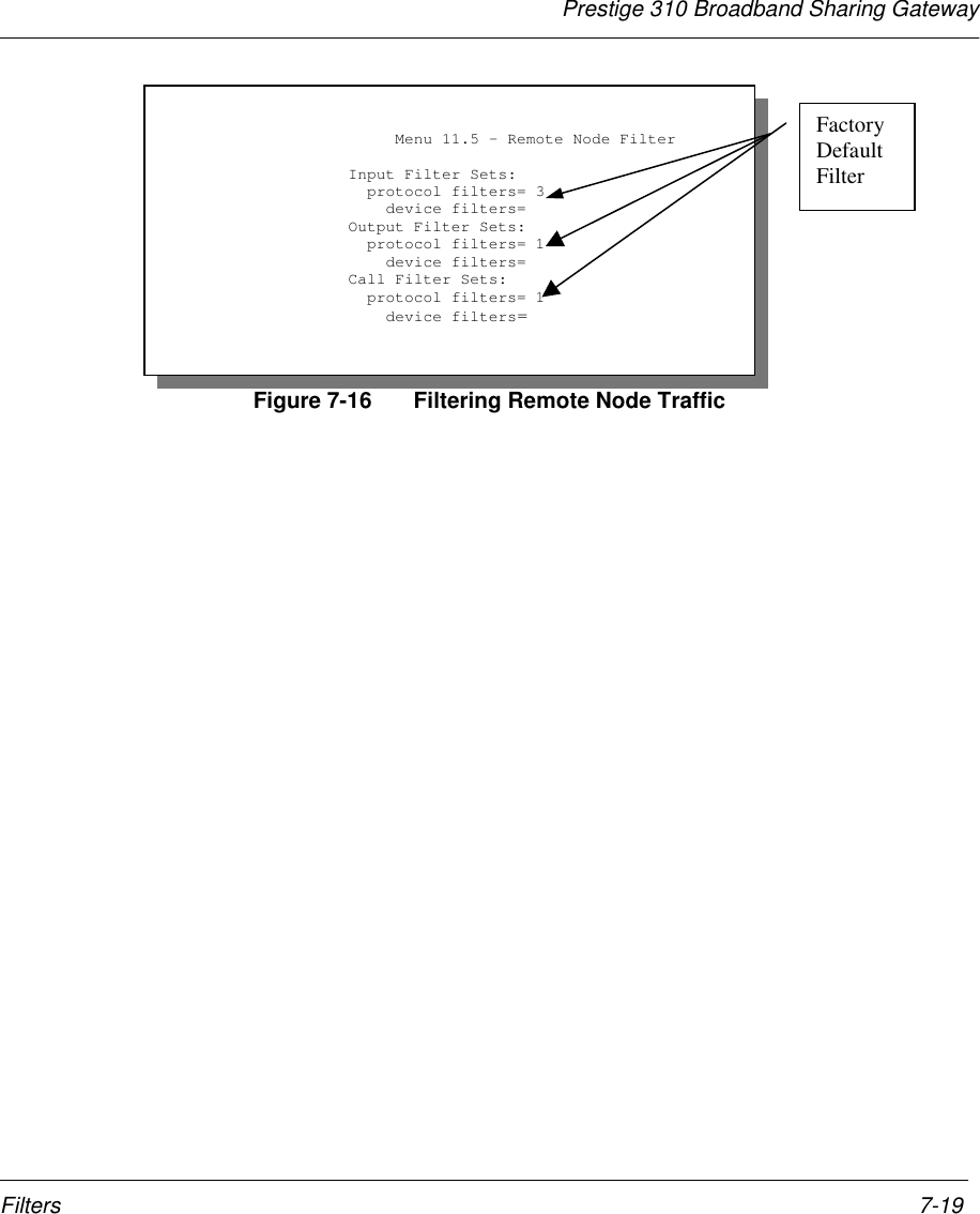
![Prestige 310 Broadband Sharing Gateway5-10 Remote Node SetupField Description ExampleMetric The metric represents the “cost” of transmission for routing purposes.IP routing uses hop count as the measurement of cost, with a minimumof 1 for directly connected networks. Enter a number that approximatesthe cost for this link. The number need not be precise, but it must bebetween 1 and 15. In practice, 2 or 3 is usually a good number.1 to 15Private This parameter determines if the Prestige will include the route to thisremote node in its RIP broadcasts. If set to Yes, this route is keptprivate and not included in RIP broadcast. If No, the route to this remotenode will be propagated to other hosts through RIP broadcasts.Yes/NoRIP Press the [SPACE BAR] to select the WAN RIP direction from Both/None/In Only/Out Only and None. None(default)Version Press the [SPACE BAR] to select the RIP version from RIP-1/RIP-2B/RIP-2M. RIP-1Multicast Turn on/off IGMP support and select the version from IGMP-v2/IGMP-v1/None. NoneOnce you have completed filling in the Network Layer Options Menu, press [Enter] to return to Menu 11.Press [Enter] at the message [Press ENTER to Confirm...] to save your configuration, or press [Esc] atany time to cancel.5.3 Remote Node FilterMove the cursor to the field Edit Filter Sets in Menu 11.1, then press the [SPACE BAR] to toggle and setthe value to YES. Press [ENTER] to open Menu 11.5 – Remote Node Filter.Use Menu 11.5 to specify the filter set(s) to apply to the incoming and outgoing traffic between this remotenode and the Prestige and to prevent certain packets from triggering calls. You can specify up to 4 filter setsseparated by a comma, e.g., 1, 5, 9, 12, in each filter field.Note that spaces are accepted in this field. For more information on defining the filters, please refer toChapter 7. Note that for PPTP and PPPoE encapsulation, you can also specify remote node call filter sets.](https://usermanual.wiki/ZyXEL-Communications/PRESTIGE310S/User-Guide-133477-Page-70.png)
![Prestige 310 Broadband Sharing GatewayIP Static Route Setup 6-3Table 6-1 IP Static Route Menu FieldsField DescriptionRoute # This is the index number of the static route that you chose in Menu 12.Route Name Enter a descriptive name for this route. This is for identification purposes only.Active This field allows you to activate/deactivate this static route.Destination IPAddress This parameter specifies the IP network address of the final destination. Routing isalways based on network number. If you need to specify a route to a single host, usea subnet mask of 255.255.255.255 in the subnet mask field to force the networknumber to be identical to the host ID.IP Subnet Mask Enter the IP subnet mask for this destination.Gateway IPAddress Enter the IP address of the gateway. The gateway is an immediate neighbor of yourPrestige that will forward the packet to the destination. On the LAN, the gateway mustbe a router on the same segment as your Prestige; over the WAN, the gateway mustbe the IP address of one of the Remote Nodes.Metric Metric represents the “cost” of transmission for routing purposes. IP routing uses hopcount as the measurement of cost, with a minimum of 1 for directly connectednetworks. Enter a number that approximates the cost for this link. The number neednot be precise, but it must be between 1 and 15. In practice, 2 or 3 is usually a goodnumber.Private This parameter determines if the Prestige will include the route to this remote node inits RIP broadcasts. If set to Yes, this route is kept private and not included in RIPbroadcast. If No, the route to this remote node will be propagated to other hoststhrough RIP broadcasts.Once you have completed filling in this menu, press [Enter] at the message [Press ENTER to Confirm…]to save your configuration, or press [Esc] to cancel.](https://usermanual.wiki/ZyXEL-Communications/PRESTIGE310S/User-Guide-133477-Page-75.png)
![Prestige 310 Broadband Sharing Gateway7-4 Filters7.2 Configuring a Filter SetTo configure a filter set, follow the procedure below. Select option 21. Filter Set Configuration from theMain Menu to open Menu 21.Step 1. Enter 1 to bring up the following menu.Figure 7-3 Menu 21 - Filter Set ConfigurationStep 2. Select the filter set you wish to configure (no. 1-12) and press [Enter].Step 3. Enter a descriptive name or comment in the Edit Comments field and press [Enter].Step 4. Press [Enter] at the message: [Press ENTER to confirm] to open Menu 21.1.1 - Filter RulesSummary.Menu 21.1 - Filter Set ConfigurationFilterSet #------123456Comments------------------NetBIOS_WANNetBIOS_LANTEL_FTP_WEB_WAN__________________________________________FilterSet #------789101112Comments------------------____________________________________________________________________________________ Enter Filter Set Number to Configure= 0 Edit Comments=Press ENTER to CONFIRM or ESC to CANCEL:](https://usermanual.wiki/ZyXEL-Communications/PRESTIGE310S/User-Guide-133477-Page-82.png)
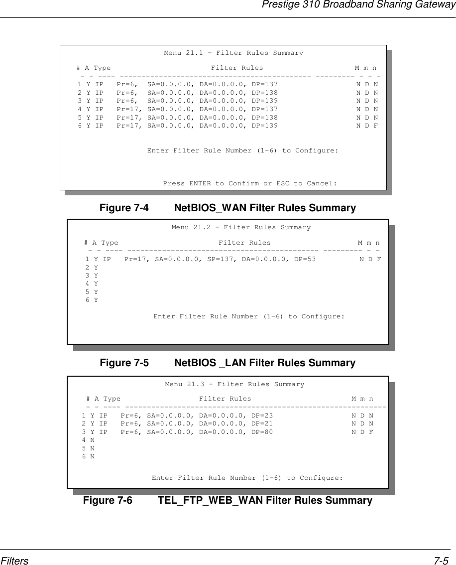
![Prestige 310 Broadband Sharing Gateway7-6 Filters7.2.1 Filter Rules Summary MenuThis screen shows the summary of the existing rules in the filter set. The following tables contain a briefdescription of the abbreviations used in the previous menus.Table 7-1 Abbreviations Used in the Filter Rules Summary MenuAbbreviations Description Display# Refers to the filter rule number (1-6).A Shows whether the rule is active or not. [Y] means the filter rule is active.[N] means the filter rule is inactive.Type Refers to the type of filter rule.This shows GEN for generic, IP forTCP/IP[GEN] for Generic[IP] for TCP/IPFilter Rules The filter rule parameters will bedisplayed here (see below).M Refers to More.[Y] means an action can not yet be takenas there are more rules to check, whichare concatenated with the present ruleto form a rule chain. When the rule chainis complete an action can be taken.[N] means you can now specify an actionto be taken i.e., forward the packet, dropthe packet or check the next rule. For thelatter, the next rule is independent of therule just checked.If More is Yes, then Action Matched andAction Not Matched will be N/A[Y] means there are more rules to check.[N] means there are no more rules to check.m Refers to Action Matched.[F] means to forward the packetimmediately and skip checking theremaining rules.[F] means to forward the packet.[D] means to drop the packet.[N] means check the next rule.n Refers to Action Not Matched.[F] means to forward the packetimmediately and skip checking theremaining rules.[F] means to forward the packet.[D] means to drop the packet.[N] means check the next rule.](https://usermanual.wiki/ZyXEL-Communications/PRESTIGE310S/User-Guide-133477-Page-84.png)
![Prestige 310 Broadband Sharing GatewayFilters 7-7The protocol dependent filter rules abbreviation are listed as follows:# If the filter type is IP, the following abbreviations listed in the following table will be used.Table 7-2 Abbreviations Used If Filter Type Is IPAbbreviation DescriptionPr ProtocolSA Source AddressSP Source Port numberDA Destination AddressDP Destination Port number# If the filter type is GEN (generic), the following abbreviations listed in the following table will be used.Table 7-3 Abbreviations Used If Filter Type Is GENAbbreviation DescriptionOff OffsetLen LengthRefer to the next section for information on configuring the filter rules.7.2.2 Configuring a Filter RuleTo configure a filter rule, type its number in Menu 21.1 - Filter Rules Summary and press [Enter] to openMenu 21.1.1 for the rule.To speed up filtering, all rules in a filter set must be of the same class, i.e., protocol filters or generic filters.The class of a filter set is determined by the first rule that you create. When applying the filter sets to a port,separate menu fields are provided for protocol and device filter sets. If you include a protocol filter set in adevice filter field or vice versa, the Prestige will warn you and will not allow you to save.7.2.3 TCP/IP Filter RuleThis section shows you how to configure a TCP/IP filter rule. TCP/IP rules allow you to base the rule on thefields in the IP and the upper layer protocol, e.g., UDP and TCP, headers.To configure a TCP/IP rules, select TCP/IP Filter Rule from the Filter Type field and press Enter to openMenu 21.1.1 - TCP/IP Filter Rule, as shown below.](https://usermanual.wiki/ZyXEL-Communications/PRESTIGE310S/User-Guide-133477-Page-85.png)
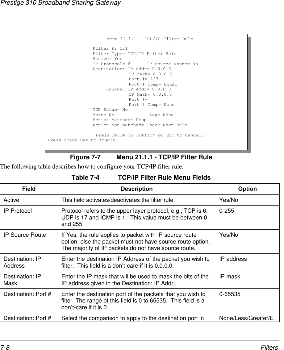
![Prestige 310 Broadband Sharing GatewayFilters 7-9Field Description OptionComp the packet against the value given in Destination: Port #. qual/Not Equal]Source: IP Address Enter the source IP Address of the packet you wish tofilter. This field is a don’t-care if it is 0.0.0.0. IP AddressSource: IP Mask Enter the IP mask that will be used to mask the bits of theIP address given in the Source: IP Addr. IP MaskSource: Port # Enter the source port of the packets that you wish to filter.The range of this field is 0 to 65535. This field is a don’t-care if it is 0.0-65535Source: Port #Comp Select the comparison to apply to the source port in thepacket against the value given in Source: Port #. None/Less/Greater/Equal/Not EqualTCP Estab This field is applicable only when IP Protocol field is 6,TCP. If yes, the rule matches only established TCPconnections; else the rule matches all TCP packets.Yes/NoMore If yes, a matching packet is passed to the next filter rulebefore an action is taken; else the packet is disposed ofaccording to the action fields.If More is Yes, then Action Matched and Action NotMatched will be No.Yes / NoLog Select the logging option from the following:None – No packets will be logged.Action Matched - Only packets that match the ruleparameters will be logged.Action Not Matched - Only packets that do not match therule parameters will be logged.Both – All packets will be logged.NoneAction MatchedAction Not MatchedBothAction Matched Select the action for a matching packet. Check Next RuleForwardDropAction Not Matched Select the action for a packet not matching the rule. Check Next RuleForwardDrop](https://usermanual.wiki/ZyXEL-Communications/PRESTIGE310S/User-Guide-133477-Page-87.png)
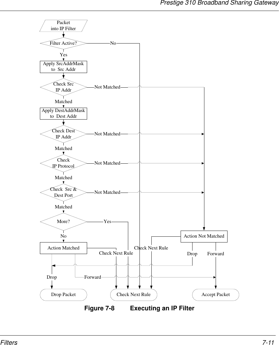
![Prestige 310 Broadband Sharing Gateway7-10 FiltersField Description OptionOnce you have completed filling in Menu 21.1.1.1 - TCP/IP Filter Rule, press [Enter] at the message[Press Enter to Confirm] to save your configuration, or press [Esc] to cancel. This data will now bedisplayed on Menu 21.1.1 - Filter Rules Summary.The following diagram illustrates the logic flow of an IP filter.](https://usermanual.wiki/ZyXEL-Communications/PRESTIGE310S/User-Guide-133477-Page-88.png)
![Prestige 310 Broadband Sharing Gateway7-12 Filters7.2.4 Generic Filter RuleThis section shows you how to configure a generic filter rule. The purpose of generic rules is to allow you tofilter non-IP packets. For IP, it is generally easier to use the IP rules directly.For generic rules, the Prestige treats a packet as a byte stream as opposed to an IP or IPX packet. You specifythe portion of the packet to check with the Offset (from 0) and the Length fields, both in bytes. The Prestigeapplies the Mask (bit-wise ANDing) to the data portion before comparing the result against the Value todetermine a match. The Mask and Value are specified in hexadecimal numbers. Note that it takes twohexadecimal digits to represent a byte, so if the length is 4, the value in either field will take 8 digits, e.g.,FFFFFFFF.To configure a generic rule, select Generic Filter Rule in the Filter Type field in the Menu 21.4.1 and press[Enter] to open Generic Filter Rule, as shown below.Figure 7-9 Menu 21.4.1 - Generic Filter RuleMenu 21.4.1 - Generic Filter RuleFilter #: 4,1Filter Type= Generic Filter RuleActive= NoOffset= 0Length= 0Mask= N/AValue= N/AMore= No Log= NoneAction Matched= Check Next RuleAction Not Matched= Check Next RulePress ENTER to Confirm or ESC to Cancel:Press Space Bar to Toggle.](https://usermanual.wiki/ZyXEL-Communications/PRESTIGE310S/User-Guide-133477-Page-90.png)
![Prestige 310 Broadband Sharing GatewayFilters 7-13The following table describes the fields in the Generic Filter Rule Menu.Table 7-5 Generic Filter Rule Menu FieldsField Description OptionFilter # This is the filter set, filter rule co-ordinates, i.e., 2,3 refers to the secondfilter set and the third rule of that set.Filter Type Use the [SPACE BAR] to toggle between both types of rules.Parameters displayed below each type will be different. Generic FilterRule/ TCP/IP FilterRuleActive Select Yes to turn on the filter rule. Yes/NoOffset Enter the starting byte of the data portion in the packet that you wish tocompare. The range for this field is from 0 to 255. Default = 0Length Enter the byte count of the data portion in the packet that you wish tocompare. The range for this field is 0 to 8. Default = 0Mask Enter the mask (in Hexadecimal) to apply to the data portion beforecomparison.Value Enter the value (in Hexadecimal) to compare with the data portion.More If yes, a matching packet is passed to the next filter rule before anaction is taken; else the packet is disposed of according to the actionfields.If More is Yes, then Action Matched and Action Not Matched will beNo.Yes / NoLog Select the logging option from the following:None – No packets will be logged.Action Matched - Only packets that match the rule parameters will belogged.Action Not Matched - Only packets that do not match the ruleparameters will be logged.Both – All packets will be logged.NoneAction MatchedAction NotMatchedBothActionMatched Select the action for a matching packet. Check Next RuleForwardDropAction NotMatched Select the action for a packet not matching the rule. Check Next RuleForward](https://usermanual.wiki/ZyXEL-Communications/PRESTIGE310S/User-Guide-133477-Page-91.png)
![Prestige 310 Broadband Sharing Gateway7-14 FiltersDropOnce you have completed filling in Menu 21.4.1.1 - Generic Filter Rule, press [Enter] at the message[Press Enter to Confirm] to save your configuration, or press [Esc] to cancel. This data will now bedisplayed on Menu 21.1.1 - Filter Rules Summary.7.3 Example FilterLet’s design a filter to block outside users from telnetting and using FTP connections into the Prestige. Pleasesee our Supporting CD for more example filters.Figure 7-10 Filter Example7.3.1 Before you beginBefore configuring a filter, you must know the following information:1. The inbound packet type (protocol & port number): In this case, it is TCP (06) protocol withport 21 (FTP) and port 23 (Telnet).2. The source IP address: In this case, as all connections from outside are blocked, the source IP is0.0.0.0.3. The destination IP address: It is the Prestige's IP address if SUA is disabled and you have a staticIP; otherwise enter 0.0.0.0 as the destination IP. Once 0.0.0.0 is set as the destination IP, Telnet andFTP connections are not allowed to reach the Prestige. For the LAN-to-LAN connection, you enterthe Prestige's LAN IP as the destination IP in the filter rule. After the Telnet_WAN filter is appliedto the remote node, it blocks the Telnet and FTP connections to the Prestige, but continues to permitFTP connection to the local FTP server.7.3.2 Filter Configuration StepsStep 1. Enter 21 from the Main Menu to open Menu 21.1 - Filter Set Configuration.Step 2. Enter the index of the filter set you wish to configure (e.g., 3) and press [Enter].](https://usermanual.wiki/ZyXEL-Communications/PRESTIGE310S/User-Guide-133477-Page-92.png)
![Prestige 310 Broadband Sharing GatewayFilters 7-15Step 3. Enter a descriptive name or comment in the Edit Comments field (e.g., TELNET_WAN) andpress [Enter].Step 4. Press [Enter] at the message: [Press ENTER to confirm] to open Menu 21.3.1 - Filter RulesSummary.Step 5. Enter 1 to configure the first filter rule. Make the entries in this menu as shown in the followingfigure.Figure 7-11 Example Filter - Menu 21.3.1Menu 21.3.1 - TCP/IP Filter RuleFilter #: 3,1Filter Type= TCP/IP Filter RuleActive= YesIP Protocol= 6 IP Source Route= NoDestination: IP Addr= 0.0.0.0IP Mask= 0.0.0.0Port #= 20Port # Comp= EqualSource: IP Addr= 0.0.0.0IP Mask= 0.0.0.0Port #= 0Port # Comp= NoneTCP Estab= NoMore= No Log= NoneAction Matched= DropAction Not Matched= ForwardPress ENTER to Confirm or ESC to Cancel:Press Space Bar to Toggle.Press [SPACEBAR] to choosethis filter rule type. The firstfilter rule type determines allsubsequent filter types within aset.Select Yes to make the ruleactive.6 is the TCP protocol.The port number for FTP is 21.See RFC 1060 for port numbersof well-known services.Select Equalhere as we arelooking forpackets going toport 21 only.There are nomore rules tocheck.Select Drop here so thatthe packet will bedropped if its destinationis the telnet port. Select Next here so that thenext rule in this set will bechecked.](https://usermanual.wiki/ZyXEL-Communications/PRESTIGE310S/User-Guide-133477-Page-93.png)
![Prestige 310 Broadband Sharing Gateway7-16 FiltersWhen you press [Enter] to confirm, you will see the next screen. Note that there is only one filter rule in thisset.Figure 7-12 Example Filter Rules Summary – Menu 21.3Step 6. Enter 2 in the above menu to configure the second rule.. Configure this filter rule with portnumber as 23 (Telnet) as shown in the next screen (after you press [ENTER] to confirm. Menu 21.3 - Filter Rules Summary # A Type Filter Rules M m n - - ---- --------------------------------------------------------------- - - - 1 Y IP Pr=6, SA=0.0.0.0, DA=0.0.0.0, DP=21 N D N 2 N 4 N 5 N 6 N Enter Filter Rule Number (1-6) to Configure: 2This shows you that you haveconfigured and activated (A =Y) a TCP/IP filter rule (Type =IP, Pr = 6) for destination FTPports (DP = 21).M = N means an action can be takenimmediately. The action is to drop thepacket (m = D) if the action is matched andto forward the packet immediately (n = N) ifthe action is not matched and there are morerules to be checked (there is one more in thisexample).](https://usermanual.wiki/ZyXEL-Communications/PRESTIGE310S/User-Guide-133477-Page-94.png)
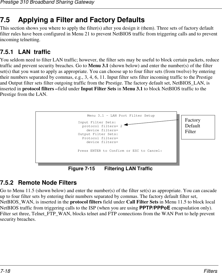
![Prestige 310 Broadband Sharing GatewayFilters 7-17Figure 7-13 Example Filter Rules SummaryAfter you’ve created the filter set, you must apply it.Step 1. Enter 11 from the main menu to go to Menu 11.Step 2. Go to the Edit Filter Sets field, press the [SPACEBAR] to toggle Yes to No and press[ENTER].Step 3. This brings you to Menu 11.5. Apply the TELNET_FTP_WAN filter set (filter set 3) as shown inFigure 7-16.7.4 Filter Types and SUAThere are two classes of filter rules, Generic Filter (Device) rules and Protocol Filter (TCP/IP and IPX)rules. Generic Filter rules act on the raw data from/to LAN and WAN. Protocol Filter rules act on the IP andIPX packets. Generic and TCP/IP filter rules are discussed in more detail in the next section. When SUA isenabled, the inside IP address and port number are replaced on a connection-by-connection basis, whichmakes it impossible to know the exact address and port on the wire. Therefore, the Prestige applies theprotocol filters to the “native” IP address and port number before SUA for outgoing packets and after SUAfor incoming packets. On the other hand, the generic, or device filters are applied to the raw packets thatappear on the wire. They are applied at the point when the Prestige is receiving and sending the packets; i.e.the interface. The interface can be an Ethernet port or any other hardware port. The following diagramillustrates this.Figure 7-14 Protocol and Device Filter Sets Menu 21.5 - Filter Rules Summary # A Type Filter Rules M m n - - ---- ------------------------------------------------------------1 Y IP Pr=6, SA=0.0.0.0, DA=0.0.0.0, DP=21 N D N2 Y IP Pr=6, SA=0.0.0.0, DA=0.0.0.0, DP=23 N D F3 N4 N5 N6 N Enter Filter Rule Number (1-6) to Configure:](https://usermanual.wiki/ZyXEL-Communications/PRESTIGE310S/User-Guide-133477-Page-95.png)
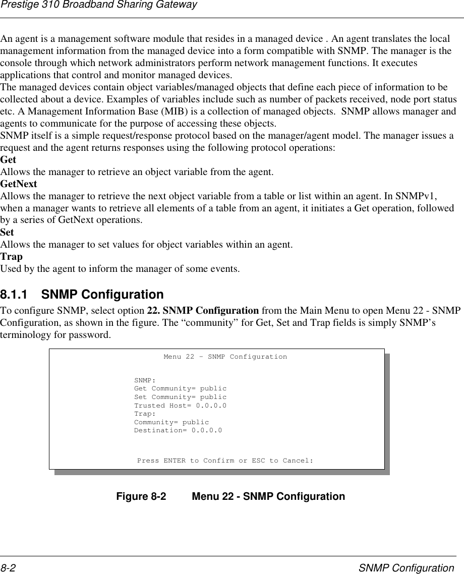
![Prestige 310 Broadband Sharing GatewaySNMP Configuration 8-3The following table describes the SNMP configuration parameters.Table 8-1 SNMP Configuration Menu FieldsField Description OptionGet Community Enter the Get Community, which is the passwordfor the incoming Get- and GetNext- requests fromthe management station.PublicSet Community Enter the set community, which is the password forincoming Set- requests from the managementstation.PublicTrusted Host If you enter a trusted host, your Prestige will onlyrespond to SNMP messages from this address. Ifyou leave the field blank (default), your Prestige willrespond to all SNMP messages it receives,regardless of source.BlankTrap: Community Enter the trap community, which is the passwordsent with each trap to the SNMP manager. PublicTrap: Destination Enter the IP address of the station to send yourSNMP traps to. BlankOnce you have completed filling in Menu 22 - SNMP Configuration, press [ENTER] at themessage [Press ENTER to Confirm...] to save your configuration, or press [ESC] to cancel.](https://usermanual.wiki/ZyXEL-Communications/PRESTIGE310S/User-Guide-133477-Page-101.png)
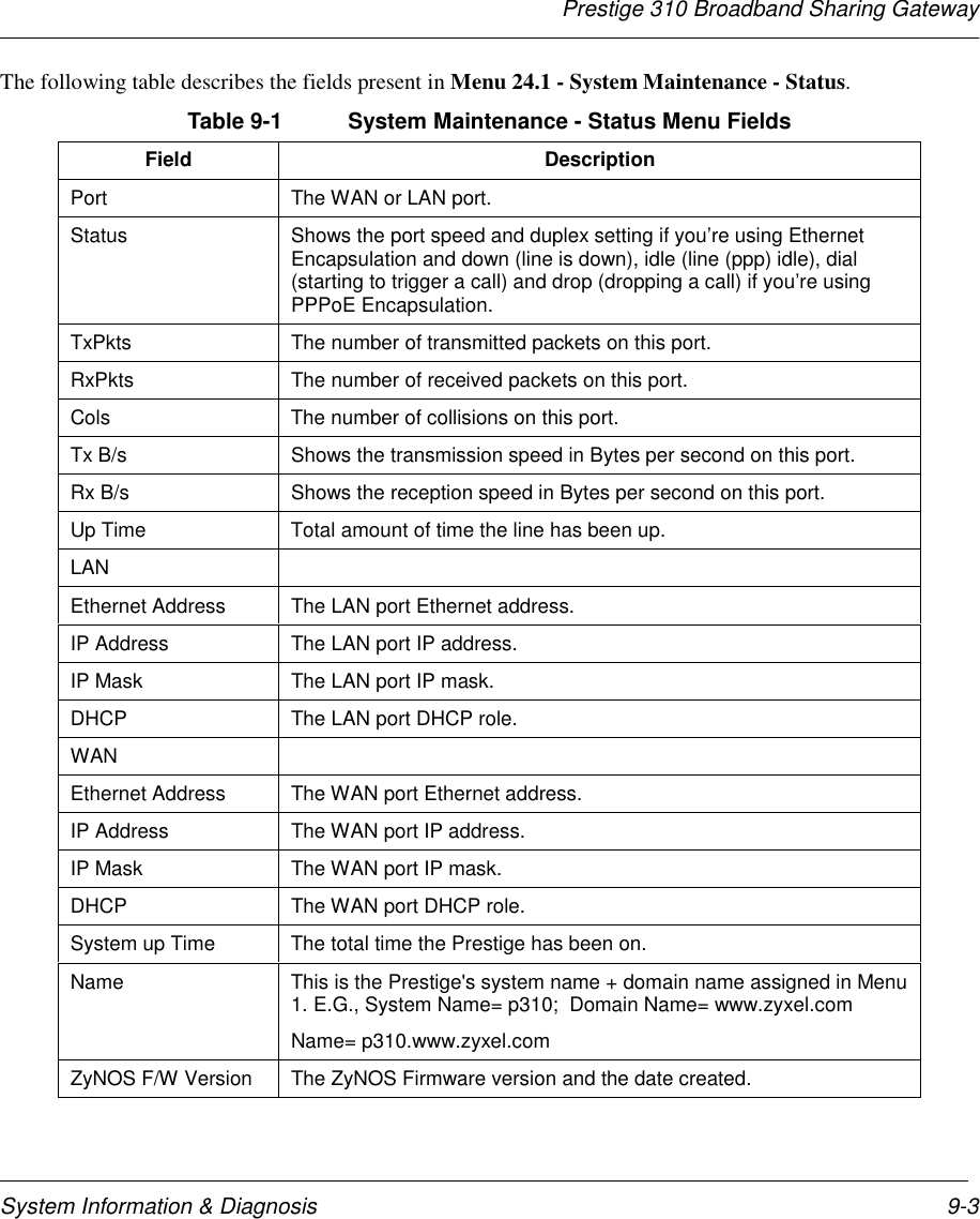
![Prestige 310 Broadband Sharing GatewaySystem Information & Diagnosis9-29.1 System StatusThe first selection, System Status, gives you information on the version of your system firmware and thestatus and statistics of the ports, as shown in the figure below. System Status is a tool that can be used tomonitor your Prestige. Specifically, it gives you information on your system firmware version, number ofpackets sent and number of packets received.To get to the System Status:Step 1. Enter number 24 to go to Menu 24 - System Maintenance.Step 2. In this menu, enter number 1 to open System Maintenance - Status.Step 3. There are three commands in Menu 24.1 - System Maintenance - Status. Entering 1 drops theWAN (PPTP/PPPoE) connection, 9 resets the counters and [Esc] takes you back to the previousscreen.The table below describes the fields present in Menu 24.1 - System Maintenance - Status. It should benoted that these fields are READ-ONLY and are meant to be used for diagnostic purposes.Figure 9-2 Menu 24.1 - System Maintenance – StatusMenu 24.1 -- System Maintenance – Status1:39:06Thus. Jan. 1. 1970PortWANLANStatusDownDownTxPkts 1 0RxPkts00Cols00Tx B/s00Rx B/s00Up Time0:00:000:00:00Port:WANLANEthernet Address00:a0:c5:21:8c:a300:a0:c5:21:8c:a2IP Address 0.0.0.0192.168.1.1IP Mask0.0.0.0255.255.255.0DHCPClientServerSystem up Time: 1:08:22Name: P310.www.zyxel.comRouting: IPZyNOS F/W Version: V.251 : 2/17/2000Press Command:COMMANDS: 1-Drop WAN 9-Reset Counters ESC-Exit](https://usermanual.wiki/ZyXEL-Communications/PRESTIGE310S/User-Guide-133477-Page-104.png)
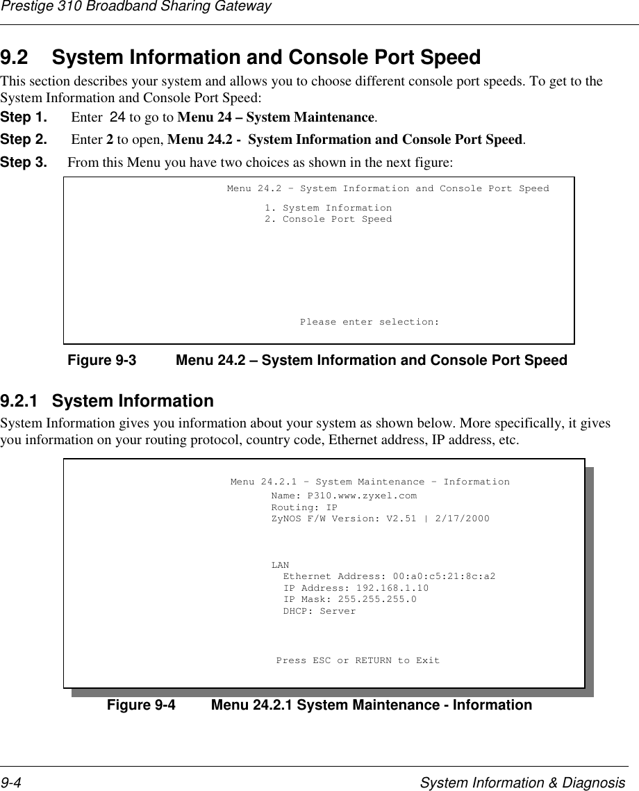
![Prestige 310 Broadband Sharing GatewaySystem Information & Diagnosis 9-5Table 9-2 Fields in System MaintenanceField DescriptionName This is the Prestige's system name + domain name assigned in Menu1. E.G., System Name= Prestige; Domain Name= zyxel.comName= P310.zyxel.comRouting Refers to the routing protocol used.ZyNOS F/W Version Refers to the version of ZyXEL's Network Operating System software.Ethernet Address Refers to the Ethernet MAC (Media Access Control) address of yourPrestige.IP Address This is the IP address of the Prestige in dotted decimal notation.IP Mask This shows the subnet mask of the Prestige.DHCP This field shows the DHCP setting of the Prestige.9.2.2 Console Port SpeedYou can change the speed of the console port through Menu 24.2.2 – Console Port Speed. Your Prestigesupports 9600 (default), 19200, 38400, 57600, and 115200 bps for the console port. Use the [SPACE BAR]to select the desired speed in Menu 24.2.2, as shown below.Figure 9-5 Menu 24.2.2 – System Maintenance – Change Console Port Speed9.3 Log and TraceThere are three logging facilities in the Prestige. The first is the error logs and trace records that are storedlocally. The second is the UNIX syslog facility for message logging. The third logging facilty- Call-Triggering Packet is also stored locally.Menu 24.2.2 – System Maintenance – Change Console Port Speed Console Port Speed: 115200 Press ENTER to Confirm or ESC to Cancel:Press Space Bar to Toggle.](https://usermanual.wiki/ZyXEL-Communications/PRESTIGE310S/User-Guide-133477-Page-107.png)
![Prestige 310 Broadband Sharing GatewaySystem Information & Diagnosis 9-7Figure 9-8 Menu 24.3.2 - System Maintenance – UNIX SyslogYou need to configure the UNIX syslog parameters described in the following table to activate syslog thenchoose what you want to log.Table 9-3 System Maintenance Menu Syslog ParametersParameter DescriptionUNIX Syslog:Active Press the [SPACE BAR] to turn on or off syslog.Syslog IP Address Enter the IP Address of the server that will log the CDR (Call Detail Record) andsystem messages i.e., the syslog server.Log Facility Press the [SPACE BAR] to toggle between the 7 different Local options. The logfacility allows you to log the message to different files in the server. Please refer toyour UNIX manual for more detail.Types:CDR Call Detail Record (CDR) logs all data phone line activity if set to Yes.Packet triggered The first 48 bytes or octets and protocol type of the triggering packet is sent to theUNIX syslog server when this field is set to Yes.Filter log No filters are logged when this field is set to No. Filters with the individual filter LogFilter field set to Yes (Menu 21.x.x).) are logged when this field is set to Yes.PPP log PPP events are logged when this field is set to Yes.Your Prestige sends four types of syslog messages. Some examples (not P310 specific) of these syslogmessages with their message formats are shown next:Menu 24.3.2 -- System Maintenance - UNIX Syslog and AccountingUNIX Syslog:Active= NoSyslog IP Address= ?Log Facility= Local 1Types:CDR= NoPacket triggered= NoFilter log= NoPPP log= NoPress ENTER to Confirm or ESC to Cancel:Press Space Bar to Toggle.](https://usermanual.wiki/ZyXEL-Communications/PRESTIGE310S/User-Guide-133477-Page-109.png)
![Prestige 310 Broadband Sharing GatewaySystem Information & Diagnosis9-8CDRCDR Message FormatSdcmdSyslogSend( SYSLOG_CDR, SYSLOG_INFO, String );String = board xx line xx channel xx, call xx, strboard = the hardware board IDline = the WAN ID in a boardChannel = channel ID within the WANcall = the call reference number which starts from 1 and increments by 1 for each new callstr = C01 Outgoing Call dev xx ch xx (dev:device No. ch:channel No.) L02 Tunnel Connected(L2TP) C02 OutCall Connected xxxx (means connected speed) xxxxx (means Remote Call Number) L02 Call Terminated C02 Call TerminatedJul 19 11:19:27 192.168.102.2 ZyXEL: board 0 line 0 channel 0, call 1, C01 Outgoing Calldev=2 ch=0 40002Jul 19 11:19:32 192.168.102.2 ZyXEL: board 0 line 0 channel 0, call 1, C02 OutCallConnected 64000 40002Jul 19 11:20:06 192.168.102.2 ZyXEL: board 0 line 0 channel 0, call 1, C02 Call Terminated1. Packet triggeredPacket triggered Message FormatsdcmdSyslogSend( SYSLOG_PKTTRI, SYSLOG_NOTICE, String );String = Packet trigger: Protocol=xx Data=xxxxxxxxxx…..xProtocol: (1:IP 2:IPX 3:IPXHC 4:BPDU 5:ATALK 6:IPNG)Data: We will send forty-eight Hex characters to the serverJul 19 11:28:39 192.168.102.2 ZyXEL Communications Corp.: Packet Trigger: Protocol=1,Data=4500003c100100001f010004c0a86614ca849a7b08004a5c020001006162636465666768696a6b6c6d6e6f7071727374Jul 19 11:28:56 192.168.102.2 ZyXEL Communications Corp.: Packet Trigger: Protocol=1,Data=4500002c1b0140001f06b50ec0a86614ca849a7b0427001700195b3e00000000600220008cd40000020405b42. Filter logFilter log Message FormatSdcmdSyslogSend(SYSLOG_FILLOG, SYSLOG_NOTICE, String );String = IP[Src=xx.xx.xx.xx Dst=xx.xx.xx.xx prot spo=xxxxx dpo=xxxxx] S04>R01mDIP[…] is the packet header and S04>R01mD means filter set 4 (S) and rule 1 (R), match (m) drop (D).Src: Source AddressDst: Destination Addressprot: Protocol (“TCP”,”UDP”,”ICMP”)spo: Source portdpo: Destination portJul 19 14:44:00 192.168.102.2 ZyXEL Communications Corp.: IP[Src=192.168.102.20Dst=202.132.154.1 UDP spo=01170 dpo=00057]}S03>R01mF](https://usermanual.wiki/ZyXEL-Communications/PRESTIGE310S/User-Guide-133477-Page-110.png)
![Prestige 310 Broadband Sharing GatewaySystem Information & Diagnosis 9-9Jul 19 14:44:04 192.168.102.2 ZyXEL Communications Corp.: IP[Src=192.168.102.20Dst=202.132.154.1 ICMP]}S03>R01mF3. PPP logPPP Log Message FormatsdcmdSyslogSend( SYSLOG_PPPLOG, SYSLOG_NOTICE, String );String = ppp:Proto Starting / ppp:Proto Opening / ppp:Proto Closing / ppp:Proto ShutdownProto = LCP / ATCP / BACP / BCP / CBCP / CCP / CHAP/ PAP / IPCP /IPXCPJul 19 11:42:44 192.168.102.2 ZyXEL Communications Corp.: ppp:LCP ClosingJul 19 11:42:49 192.168.102.2 ZyXEL Communications Corp.: ppp:IPCP ClosingJul 19 11:42:54 192.168.102.2 ZyXEL Communications Corp.: ppp:CCP Closing](https://usermanual.wiki/ZyXEL-Communications/PRESTIGE310S/User-Guide-133477-Page-111.png)
![Prestige 310 Broadband Sharing GatewayTransferring Files 10-1Chapter 10:Transferring FilesThis chapter tells you how to back up and restore your configuration file as well as upload newfirmware and a new configuration file.10.1 Filename conventionsThe configuration file (often called the romfile or rom-0) contains the factory default settings in the menussuch as password, DHCP Setup, TCP/IP Setup etc. It arrives from ZyXEL with a name of prestige.ROM orsimilar. Once you have customized the Prestige's setting, they can be saved back to PC/workstation under afilename of your choosing. Choose something meaningful, e.g., “prestige.cfg”.The ZyNOS firmware file (sometimes referred to as the ras file) is the file that contains the ZyXEL NetworkOperating System firmware and usually is the Prestige model name with a *.bin extension, e.g., prestige.bin.With serial (XMODEM) transfer, the filenames on the PC are your choice. With many ftp and tftp clients,they are as well as seen next.ftp> put prestige.bin rasThis is a sample ftp session showing the transfer of the file "prestige.bin" on your computer to the Prestigeand renaming it “ras”.ftp> get rom-0 prestige.cfgThis is a sample ftp session saving the current Prestige configuration to the file prestige.cfg on yourcomputer.If your [t]ftp client does not allow you have a destination filename different than the source, you will need torename them as the Prestige only recognizes "rom-0" and "ras". Be sure you keep unaltered copies of bothfiles for later use.The following table is a summary. Please note that the internal filename refers to the filename on the Prestigeand the external filename refers to the filename not on the Prestige, i.e., on your workstation, local networkor ftp site and so the name (but not the extension) will vary. The AT command is the command you enterafter you press “Y” when prompted in the SMT menu to go into debug mode. After uploading new firmwaresee the ZyNOS F/W Version field in Menu 24.2.1 (Figure 9-4 Menu 24.2.1 System Maintenance -Information) to check you have uploaded the correct firmware version.](https://usermanual.wiki/ZyXEL-Communications/PRESTIGE310S/User-Guide-133477-Page-115.png)
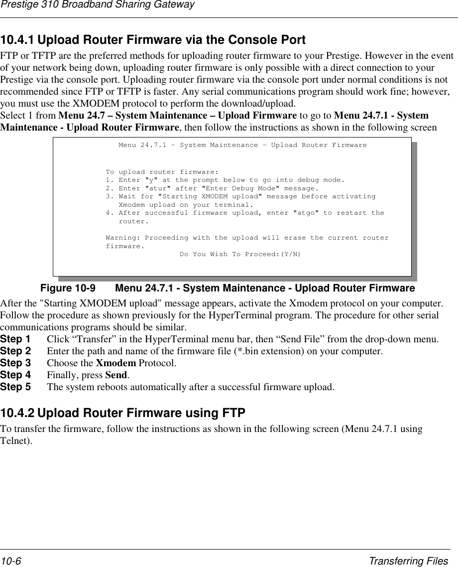
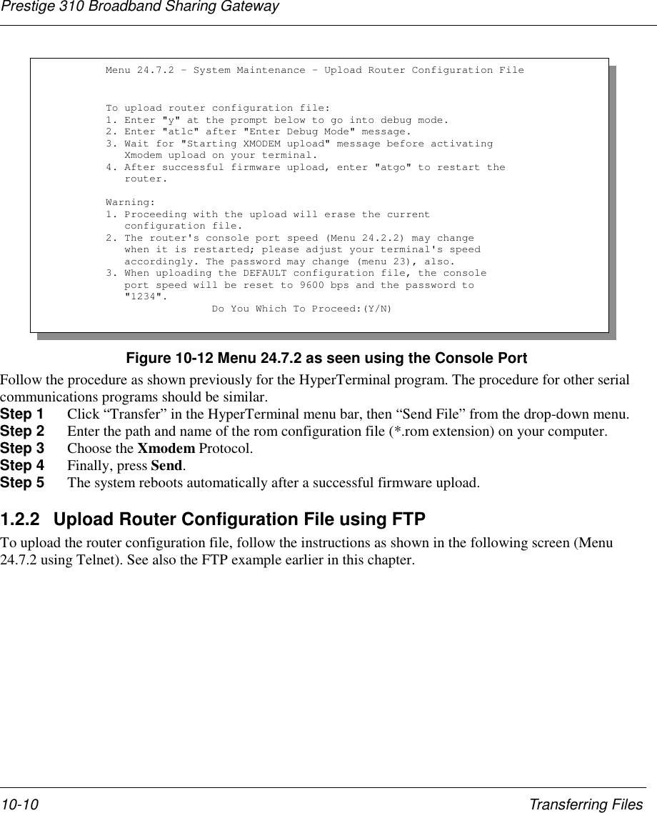
![Prestige 310 Broadband Sharing GatewayTransferring Files 10-91.1.2 Example Using TFTP To Upload Prestige FirmwareThe following is an example tftp command:TFTP [-i] host put prestige.bin raswhere “i” specifies binary image transfer mode (use this mode when transferring binary files), “host” is thePrestige IP address, “put” transfers the file source on the workstation (prestige.bin – name of the firmware onyour computer) to the file destination on the remote host (ras - name of the firmware on the Prestige).The following table describes some of the fields that you may see in third party TFTP clients.Table 10-3 Third Party TFTP Clients –General fieldsHost Enter the IP address of the Prestige. 192.168.1.1 is the Prestigedefault IP address when shipped.Send/Fetch Press “Send” to upload the file to the Prestige and “Fetch” to backup the file on your computer.Local File Enter the path and name of the firmware file (*.bin extension) orconfiguration file (*.rom extension) on your computer.Remote File This is the filename on the Prestige. The filename for the firmwareis “ras” and for the configuration file, is “rom-0”.Binary Transfer the file in binary mode.Abort Stop transfer of the file.1.2 Upload Router Configuration FileThe configuration data, system-related data, the error log and the trace log are all stored in the configurationfile. Please be aware that uploading the configuration file replaces all previous configurations. You canupgrade the configuration file either through an FTP or TFTP client program (preferred method) or throughthe RS-232 console port (in the event of the network being down). Updating the configuration file via theconsole port under normal conditions is not recommended since FTP or TFTP is faster. Please note that youneed to reboot the system after the configuration file update process is complete. Note that if you replace thecurrent configuration with the default configuration file, i.e.. prestige.rom, you will lose all configurationsthat you had before and the speed of the console port will be reset to the default of 9600 bps with 8 data bit,no parity and 1 stop bit(8n1). You will need to change your serial communication software to the defaultbefore you can connect to the Prestige again. The password will be reset to the default of 1234, as well.1.2.1 Upload Router Configuration File using the Console PortSelect 2 from Menu 24.7 – System Maintenance – Upload Firmware to go to Menu 24.7.2 - SystemMaintenance - Upload Router Configuration File. Follow the instructions as shown in the followingscreen.](https://usermanual.wiki/ZyXEL-Communications/PRESTIGE310S/User-Guide-133477-Page-123.png)
![Prestige 310 Broadband Sharing GatewaySystem Maintenance & Information 11-1Chapter 11: System Maintenance & InformationThis chapter leads you through SMT menus 24.8 to 24.11.11.1 Command Interpreter ModeThis option allows you to enter command interpreter mode, a “DOS prompt” type command interface, whichallows more advanced system diagnosis and troubleshooting (beyond the scope of this guide). See oursupporting CD or the zyxel web site at www.zyxel.com for more detailed information on CI commands.Enter 8 from Menu 24 - System Maintenance. A list of valid commands can be found by typing [help] or[?] at the command prompt. Type “exit” to return to the SMT main menu when finished.Figure 11-1 Command Mode11.2 Call Control SupportThe Prestige provides two call control functions: budget management and call history. Please note that thismenu is only applicable when Encapsulation is set to PPPoE in Menu 4 or Menu 11.1.The budget management function allows you to set a limit on the total outgoing call time of the Prestigewithin certain times. When the total outgoing call time exceeds the limit, the current call will be dropped andany future outgoing calls will be blocked.Call history chronicles preceding incoming and outgoing calls.Menu 24 - System Maintenance 1. System Status 2. System Information and Console Port Speed 3. Log and Trace 4. Diagnostic 5. Backup Configuration 6. Restore Configuration 7. Firmware Update 8. Command Interpreter Mode 9. Call Control 10. Time and Date Setting Enter Menu Selection Number:](https://usermanual.wiki/ZyXEL-Communications/PRESTIGE310S/User-Guide-133477-Page-127.png)
![Prestige 310 Broadband Sharing GatewaySystem Maintenance & Information 11-5Figure 11-5 System Maintenance – Time and Date SettingTable 11-3 Time and Date Setting FieldsField DescriptionUse Time Server whenBootup= Enter the time service protocol that your timeserver will send when thePrestige powers up. Choices are Daytime (RFC 867), Time (RFC-868),NTP (RFC-1305) and None. The main differences between them are theformat, e.g., the Daytime (RFC 867) format is day/month/date/year/timezone of the server while the Time (RFC-868) format gives a 4-byteinteger giving the total number of seconds since 1/1/1970 at 0:0:0. TheNTP (RFC-1305) format is similar. Not all timeservers support allprotocols, so you may have to check with your ISP/network administratoror use trial and error to find a protocol that works. If you select None(this is the default value), you can enter the time manually but each timethe system is booted, the time & date will be reset to 2000/01/01 0:0:0.Time Server IPAddress= Enter the IP address of the your timeserver. Check with yourISP/network administrator if you are unsure of this information.Current Time:New Time Enter the new time in hour, minute and second format.Current Date:New Date Enter the new date in year, month, date format.Time Zone= GMT+0800 Press the [SPACE BAR] to set the time difference between your timezone and Greenwich mean Time (GMT). Be aware if/when daylight Menu 24.10 - System Maintenance - Time and Date Setting Use Time Server when Bootup= None Time Server IP Address= N/A Current Time: 00 : 00 : 00 New Time (hh:mm:ss): 1 : 3 : 16 Current Date: 2000/ 01 / 01 New Date (yyyy-mm-dd): 2000/ 01 / 01 Time Zone= GMT+0800 Press ENTER to Confirm or ESC to Cancel:Press Space Bar to Toggle.](https://usermanual.wiki/ZyXEL-Communications/PRESTIGE310S/User-Guide-133477-Page-131.png)
![Prestige 310 Broadband Sharing GatewaySystem Maintenance & Information11-6savings time alters this time difference for your time zone.Once you have filled in the new time and date, press [Enter] to save the setting and press [Esc] toreturn to Menu 24.11.4 Boot commandsIn Debug mode, enter ATHE to view Prestige boot module commands as shown below and then enter ATGOto continue booting the system. For ATBAx, x denotes the number preceding the colon to give the baud ratefollowing the colon in the list of numbers that follows; e.g., ATBA3 will give a baud of 9.6 Kbps. ATSEdisplays the seed that is used to generate a password to turn on the debug flag in the firmware. The ATSHcommand shows product related information such as boot module version, vendor name, product model,RAS code revision, etc.Figure 11-6 Boot Module Commands======= Debug Command Listing =======AT just answer OKATHE print helpATBAx change baudrate. 1:38.4k, 2:19.2k, 3:9.6k 4:57.6k5:115.2kATENx,(y) set BootExtension Debug Flag (y=password)ATSE show the seed of password generatorATTI(h,m,s) change system time to hour:min:sec or show current timeATDA(y,m,d) change system date to year/month/day or show current dateATDS dump RAS stackATDT dump Boot Module Common AreaATDUx,y dump memory contents from address x for length yATWBx,y write address x with 8-bit value yATWWx,y write address x with 16-bit value yATWLx,y write address x with 32-bit value yATRBx display the 8-bit value of address xATRWx display the 16-bit value of address xATRLx display the 32-bit value of address xATGO(x) run program at addr x or boot routerATGR boot routerATGT run Hardware Test ProgramAT%Tx Enable Hardware Test Program at boot up<press any key to continue>](https://usermanual.wiki/ZyXEL-Communications/PRESTIGE310S/User-Guide-133477-Page-132.png)
![Prestige 310 Broadband Sharing GatewayCall Scheduling 12-1Chapter 12: Call Schedule SetupThe call scheduling feature allows the Prestige to manage a remote node and dictate when a remote nodeshould be called and for how long. This feature is just like the scheduler in a video recorder (record theprogram you want in a specified time). You can apply up to 4 schedule sets in Menu 11.1 - Remote NodeProfile. You configure each schedule in Menu 26 - Schedule Setup. Enter 26 from the main menu to bringup the following screen.Figure 12-1 Schedule SetupAs we can have multiple sets that are applied in turn, lowered numbered sets take precedence over highernumbered sets in case of conflict. For example, if we apply sets 1,2,3,4 in a remote node, then set 1 will takeprecedence over set 2, 3 and 4 as it is applied first. Set 2 will take precedence over set 3 and 4, and so on.You can design up to 12 schedule sets but you can only apply up to 4 schedule sets for a remote node.To delete a schedule set, enter the set number and press the [Space Bar] (or delete) inthe Edit Name field to delete the set name. To setup a schedule set select the schedule set you want to setup from Menu 26 (no. 1-12) and press [Enter]to see Menu 26.1 - Schedule Set Setup as shown next.Menu 26 - Schedule SetupScheduleSet #------123456Name------------------____________________________________________________________________________________ScheduleSet #------789101112Name------------------____________________________________________________________________________________Enter Schedule Set Number to Configure=Edit Name=Press ENTER to CONFIRM or ESC to CANCEL:](https://usermanual.wiki/ZyXEL-Communications/PRESTIGE310S/User-Guide-133477-Page-133.png)
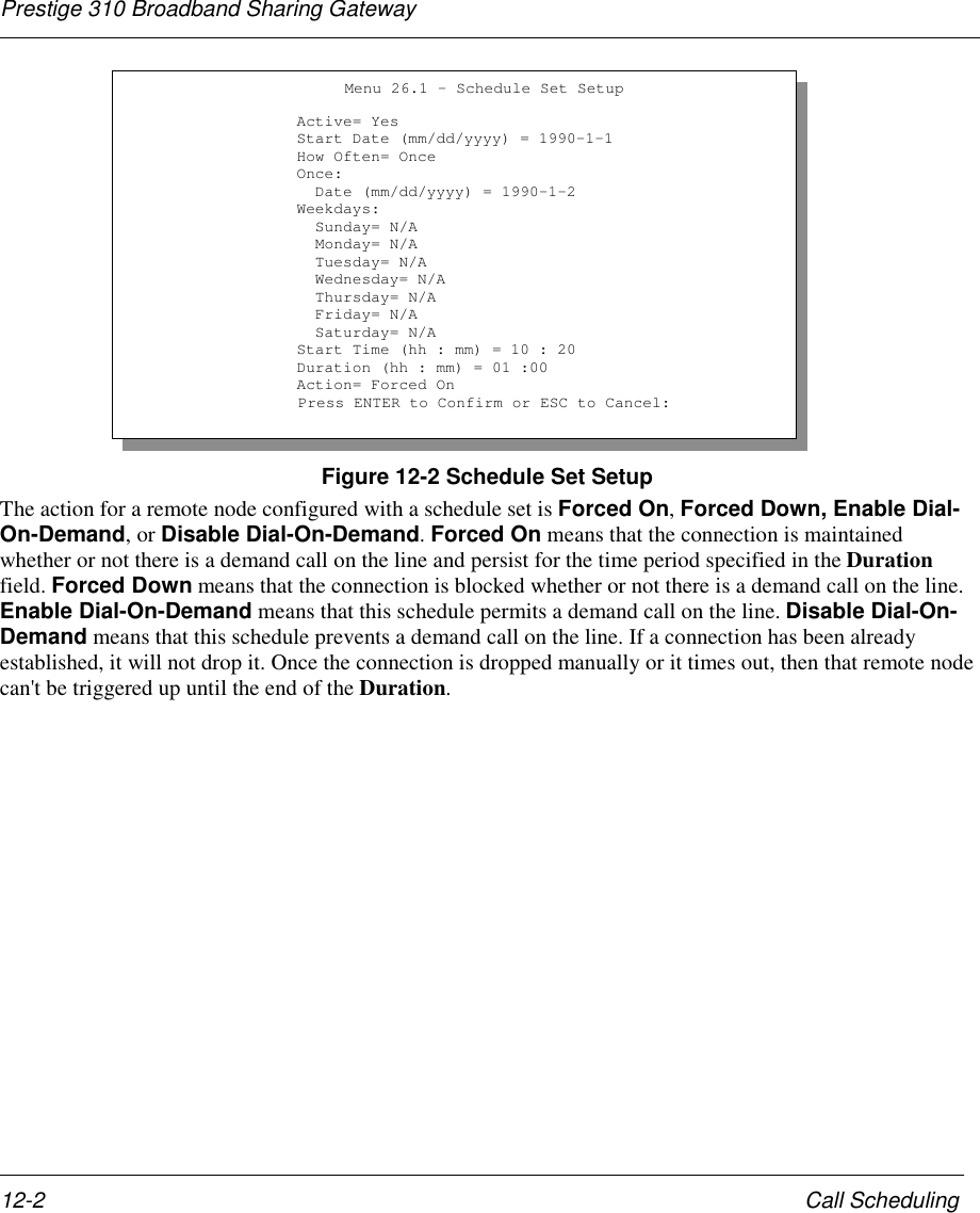
![Prestige 310 Broadband Sharing GatewayCall Scheduling 12-3Table 12-1 Schedule Set Setup FieldsField Description OptionActive Press the [Space Bar] to toggle between Yes and No. Choose Yesand press [Enter] to activate the set. YesNoStart Date Enter the start date that you wish the set to take effect in year-month-date format. Valid dates are from January 1, 1990 to February 5,2036.How Often Should this schedule set recur weekly or be used just once only?Press the [Space Bar] to toggle between Once and Weekly. Boththese options are mutually exclusive. If Once is selected, then allweekday settings are N/A. When Once is selected, the schedule ruledeletes automatically after the scheduled time elapses.OnceWeeklyOnce: Date If you selected Once in the How Often field above, then enter the datethe set should activate here in year-month-date format.Weekday:Day If you selected Weekly in the How Often field above, then select theday(s) the set should activate (and recur) by going to that day(s) andpressing the [Space Bar], then [Enter] to select Yes.YesNoN/AStart Time Enter the start time that you wish the set to take effect in hour : minuteformat.Duration Enter the maximum duration allowed in hour : minute format for thisscheduled connection per call.Action Press the [Space Bar] to toggle between these options. Choose oneand then press [Enter]. Forced On,Forced Down,Enable Dial-On-Demand, orDisable Dial-On-Demand.12.1.1 Applying A Schedule SetAfter you’ve configured your schedule sets, you must apply them to the desired remote node(s). Enter 11from the Main Menu and then select either PPPoE or PPTP encapsulation. You can apply up to 4 schedulesets, separated by commas, for one remote node.](https://usermanual.wiki/ZyXEL-Communications/PRESTIGE310S/User-Guide-133477-Page-135.png)
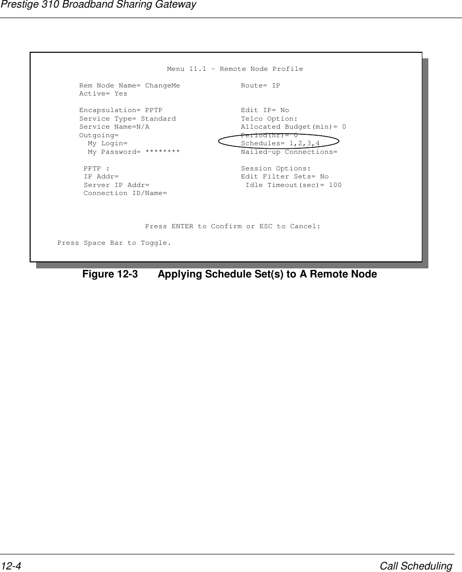
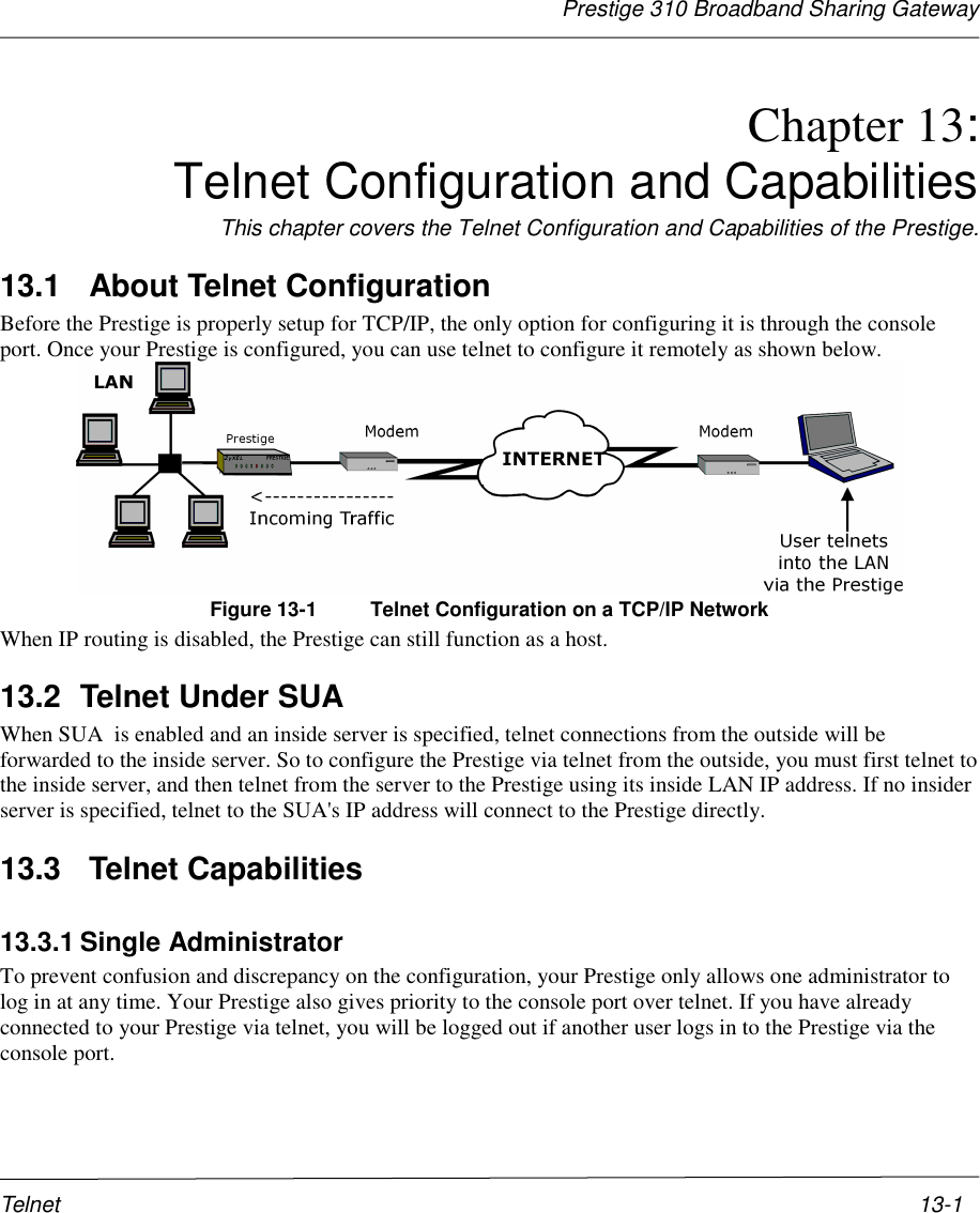
![Prestige 310 Broadband Sharing GatewayTroubleshooting 14-314.4 Problem with Remote Node or ISP ConnectionTable 14-4 Remote Node or ISP ConnectionProblem Corrective ActionCheck Menu 24.1 to verify the line status. If it indicates [down], thenrefer to the section on the line problems.Cannot connect toa remote node orISP In Menu 11.1, verify your login name and password for the remotenode.14.5 Problems with Internet AccessTable 14-5 Internet AccessProblem Corrective ActionConnect your Cable/xDSL modem with the Prestige usingappropriate cable.Check with the manufacturer of your Cable/xDSL modem about thecable requirement because for some modems you may requirecrossover cable and for others regular patch cable.Cannot access theInternet.Verify your settings in Menu 3.2 and Menu 4.14.6 General InstructionsIf you have other problems you can try the following options.• Check the Menu 24.1 System Maintenance – Status, Menu 24.2.1 - System Information and Menu24.3 System Maintenance –Log and Trace in order to locate the problem.• Check the Troubleshooting section in the Support Notes.• Use Debug commands to diagnose problems. In general, ZyXEL recommends that you use thesecommands with the direction of your customer support representative.](https://usermanual.wiki/ZyXEL-Communications/PRESTIGE310S/User-Guide-133477-Page-143.png)