ZyXEL Communications PRESTIGE310S LAN/ Gateway Router User Manual Prestige 310
ZyXEL Communications Corporation LAN/ Gateway Router Prestige 310
users manual

Prestige 310
Broadband Sharing Gateway
User’s Guide
Version 2.51
Nov 2000

Prestige 310 Broadband Sharing Gateway
ii Copyright
Prestige 310
Broadband Sharing Gateway
Copyright
Copyright © 2000 by ZyXEL Communications Corporation.
The contents of this publication may not be reproduced in any part or as a whole, transcribed, stored in a
retrieval system, translated into any language, or transmitted in any form or by any means, electronic,
mechanical, magnetic, optical, chemical, photocopying, manual, or otherwise, without the prior written
permission of ZyXEL Communications Corporation.
Published by ZyXEL Communications Corporation. All rights reserved.
Disclaimer
ZyXEL does not assume any liability arising out of the application or use of any products, or software
described herein. Neither does it convey any license under its patent rights nor the patent rights of others.
ZyXEL further reserves the right to make changes in any products described herein without notice. This
publication is subject to change without notice.
Trademarks
Trademarks mentioned in this publication are used for identification purposes only and may be properties of
their respective owners.

Prestige 310 Broadband Sharing Gateway
FCC iii
Federal Communications Commission (FCC) Interference Statement
This device complies with Part 15 of FCC rules. Operation is subject to the following two conditions:
This device may not cause harmful interference.
This device must accept any interference received, including interference that may cause undesired
operations.
This equipment has been tested and found to comply with the limits for a CLASS B digital device pursuant to
Part 15 of the FCC Rules. These limits are designed to provide reasonable protection against harmful
interference in a commercial environment. This equipment generates, uses, and can radiate radio frequency
energy, and if not installed and used in accordance with the instructions, may cause harmful interference to
radio communications.
If this equipment does cause harmful interference to radio/television reception, which can be determined by
turning the equipment off and on, the user is encouraged to try to correct the interference by one or more of
the following measures:
Reorient or relocate the receiving antenna.
Increase the separation between the equipment and the receiver.
Connect the equipment into an outlet on a circuit different from that to which the receiver is connected.
Consult the dealer or an experienced radio/TV technician for help.
Notice 1
Changes or modifications not expressly approved by the party responsible for compliance could void the
user's authority to operate the equipment.
Notice 2
Shielded RS-232 cables are required to be used to ensure compliance with FCC Part 15, and it is the
responsibility of the user to provide and use shielded RS-232 cables.

Prestige 310 Broadband Sharing Gateway
iv Information for Canadian Users
Information for Canadian Users
The Industry Canada label identifies certified equipment. This certification means that the equipment meets
certain telecommunications network protective, operation, and safety requirements. The Industry Canada
does not guarantee that the equipment will operate to a user's satisfaction.
Before installing this equipment, users should ensure that it is permissible to be connected to the facilities of
the local telecommunications company. The equipment must also be installed using an acceptable method of
connection. In some cases, the company's inside wiring associated with a single line individual service may be
extended by means of a certified connector assembly. The customer should be aware that the compliance
with the above conditions may not prevent degradation of service in some situations.
Repairs to certified equipment should be made by an authorized Canadian maintenance facility designated by
the supplier. Any repairs or alterations made by the user to this equipment, or equipment malfunctions, may
give the telecommunications company cause to request the user to disconnect the equipment.
For their own protection, users should ensure that the electrical ground connections of the power utility,
telephone lines, and internal metallic water pipe system, if present, are connected together. This precaution
may be particularly important in rural areas.
Caution
Users should not attempt to make such connections themselves, but should contact the appropriate electrical
inspection authority, or electrician, as appropriate.
Note
This digital apparatus does not exceed the class A limits for radio noise emissions from digital apparatus set
out in the radio interference regulations of Industry Canada.
Prestige 310 Broadband Sharing Gateway
CE v

Prestige 310 Broadband Sharing Gateway
Declaration of Conformity vii
Declaration of Conformity
We, the Manufacturer/Importer,
ZyXEL Communications Corp.
No. 6, Innovation Rd. II,
Science-Based Industrial Park,
Hsinchu, Taiwan, 300 R.O.C
declare that the product
Prestige 310
is in conformity with
(reference to the specification under which conformity is declared)
Standard Standard Item Version
• EN 55022 Radio disturbance characteristics – Limits and method of
measurement. 1994
• EN 61000-3-2 Disturbance in supply system caused by household appliances
and similar electrical equipment “Harmonics”. 1995
• EN 61000-3-3 Disturbance in supply system caused by household appliances
and similar electrical equipment “Voltage fluctuations”. 1995
• EN 61000-4-2 Electrostatic discharge immunity test – Basic EMC Publication 1995
• EN 61000-4-3 Radiated, radio-frequency, electromagnetic field immunity test 1996
• EN 61000-4-4 Electrical fast transient / burst immunity test - Basic EMC
Publication 1995
• EN 61000-4-5 Surge immunity test 1995
• EN 61000-4-6 Immunity to conducted disturbances, induced by radio-frequency
fields 1996
• EN 61000-4-8 1993
• EN61000-4-11 Voltage dips, short interruptions and voltage variations immunity
tests 1994

Prestige 310 Broadband Sharing Gateway
viii ZyXEL Limited Warranty
ZyXEL Limited Warranty
ZyXEL warrants to the original end user (purchaser) that this product is free from any defects in materials or
workmanship for a period of up to two years from the date of purchase. During the warranty period, and upon
proof of purchase, should the product have indications of failure due to faulty workmanship and/or materials,
ZyXEL will, at its discretion, repair or replace the defective products or components without charge for either
parts or labor, and to whatever extent it shall deem necessary to restore the product or components to proper
operating condition. Any replacement will consist of a new or re-manufactured functionally equivalent product
of equal value, and will be solely at the discretion of ZyXEL. This warranty shall not apply if the product is
modified, misused, tampered with, damaged by an act of God, or subjected to abnormal working conditions.
Note
Repair or replacement, as provided under this warranty, is the exclusive remedy of the purchaser. This
warranty is in lieu of all other warranties, express or implied, including any implied warranty of merchantability
or fitness for a particular use or purpose. ZyXEL shall in no event be held liable for indirect or consequential
damages of any kind of character to the purchaser.
To obtain the services of this warranty, contact ZyXEL's Service Center; refer to the separate Warranty Card
for your Return Material Authorization number (RMA). Products must be returned Postage Prepaid. It is
recommended that the unit be insured when shipped. Any returned products without proof of purchase or
those with an out-dated warranty will be repaired or replaced (at the discretion of ZyXEL) and the customer
will be billed for parts and labor. All repaired or replaced products will be shipped by ZyXEL to the
corresponding return address, Postage Paid (USA and territories only). If the customer desires some other
return destination beyond the U.S. borders, the customer shall bear the cost of the return shipment. This
warranty gives you specific legal rights, and you may also have other rights that vary from state to state.
Please register your ZyWALL (fast, easy online registration at www.zyxel.com) for free
product updates and information.
Prestige 310 Broadband Sharing Gateway
Customer Support ix
Customer Support
If you have questions about your ZyXEL product or desire assistance, contact ZyXEL Communications
Corporation offices worldwide, in one of the ways listed below.
When Contacting Customer Support Representative
When you contact your customer support representative have the following information ready:
• Prestige Model and serial number
• Information in Menu 24.2.1 –System Information
• Warranty Information
• Date you received your Prestige
• Brief description of the problem and the steps you took to solve it.
EMAIL – Support Telephone Web Site
Method
Region EMAIL – Sales Fax FTP Site
Regular Mail
support@zyxel.com.tw
support@europe.zyxel.com +886-3-578-3942 www.zyxel.com
www.europe.zyxel.com
Worldwide
sales@zyxel.com.tw +886-3-578-2439 ftp.europe.zyxel.com
ZyXEL Communications
Corp., 6 Innovation Road II,
Science-Based Industrial
Park, HsinChu, Taiwan.
support@zyxel.com +1-714-632-0882
800-255-4101 www.zyxel.com
North
America sales@zyxel.com +1-714-632-0858 ftp.zyxel.com
ZyXEL Communications Inc.,
1650 Miraloma Avenue,
Placentia, CA 92870, U.S.A.
support@zyxel.dk +45-3955-0700 www.zyxel.dk
Scandinavia sales@zyxel.dk +45-3955-0707 ftp.zyxel.dk
ZyXEL Communications A/S,
Columbusvej 5, 2860
Soeborg, Denmark.
support@zyxel.at +43-1-4948677-0
0810-1-ZyXEL
0810-1-99935
www.zyxel.at
Austria sales@zyxel.at +43-1-4948678 ftp.zyxel.at
Note: for Austrian users with *.at
domain only!
ZyXEL Communications
Services GmbH.,
Thaliastrasse 125a/2/2/4,
A-1160 Vienna, Austria
support@zyxel.de +49-2405-6909-0
0180-5213247
Tech Support hotline
0180-5099935
RMA/Repair hotline
www.zyxel.de
Germany
sales@zyxel.de +49-2405-6909-99 ftp.europe.zyxel.com
ZyXEL Deutschland GmbH.,
Adenauerstr. 20/A4, D-52146
Wuerselen, Germany.

Prestige 310 Broadband Sharing Gateway
Table of Contents xi
Table of Contents
Copyright...................................................................................................................................................ii
Federal Communications Commission (FCC) Interference Statement ................................................... iii
Information for Canadian Users...............................................................................................................iv
ZyXEL Limited Warranty......................................................................................................................viii
Customer Support...........................................................................................................................ix
When Contacting Customer Support Representative ...............................................................................ix
Table of Contents............................................................................................................................xi
List of Figures ..............................................................................................................................xvii
List of Tables.................................................................................................................................xxi
Preface ....................................................................................................................................... xxiii
Part I:............................................................................................................................................. I
Chapter 1 : Getting to Know Your Prestige ..................................................................................1-1
1.1 The Prestige 310 Broadband Sharing Gateway.......................................................................... 1-1
1.2 Quick Feature Overview of the Prestige 310 ............................................................................. 1-1
1.3 Detailed Features of the Prestige 310......................................................................................... 1-1
1.4 Applications for Prestige 310..................................................................................................... 1-3
1.4.1 Broadband Internet Access via Cable or xDSL Modem .................................................... 1-3
1.5 Internet Access Configuration Checklist.................................................................................... 1-3
Chapter 2 : Hardware Installation & Initial Setup .........................................................................2-1
2.1 Front Panel LEDs and Back Panel Ports.................................................................................... 2-1
2.1.1 Front Panel LEDs............................................................................................................... 2-1
2.2 Prestige 310 Rear Panel and Connections.................................................................................. 2-2
2.3 Additional Installation Requirements.........................................................................................2-3
2.4 Power Up Your Prestige............................................................................................................. 2-4
2.5 Navigating the SMT Interface.................................................................................................... 2-5
2.5.1 Main Menu......................................................................................................................... 2-6
2.5.2 System Management Terminal Interface Summary ........................................................... 2-6

Prestige 310 Broadband Sharing Gateway
xii Table of Contents
2.6 Changing the System Password..................................................................................................2-7
2.6.1 Resetting the Prestige..........................................................................................................2-7
2.7 General Setup..............................................................................................................................2-8
2.7.1 Dynamic DNS.....................................................................................................................2-8
2.7.2 Configuring Dynamic DNS.................................................................................................2-9
2.8 WAN Setup...............................................................................................................................2-10
2.9 LAN Setup................................................................................................................................2-11
2.9.1 LAN Port Filter Setup.......................................................................................................2-12
Chapter 3 : Internet Access..........................................................................................................3-1
3.1 TCP/IP and DHCP for LAN .......................................................................................................3-1
3.1.1 Factory LAN Defaults.........................................................................................................3-1
3.1.2 IP Address and Subnet Mask ..............................................................................................3-1
3.1.3 Private IP Addresses ...........................................................................................................3-2
3.1.4 RIP Setup ............................................................................................................................3-2
3.1.5 DHCP Configuration...........................................................................................................3-3
3.1.6 IP Multicast.........................................................................................................................3-3
3.1.7 IP Alias ...............................................................................................................................3-4
3.2 TCP/IP and DHCP Ethernet Setup..............................................................................................3-4
3.2.1 IP Alias Setup .....................................................................................................................3-7
3.3 Internet Access Setup..................................................................................................................3-8
3.3.1 Ethernet Encapsulation .......................................................................................................3-8
3.3.2 PPTP Encapsulation..........................................................................................................3-10
3.3.3 Configure PPTP Client......................................................................................................3-11
3.3.4 PPPoE Encapsulation........................................................................................................3-11
3.4 Internet Test Setup....................................................................................................................3-13
3.5 Basic Setup Complete...............................................................................................................3-13
Part II:...........................................................................................................................................II
Chapter 4 : SUA and Multiple SUA Servers.................................................................................4-1
4.1 Single User Account (SUA)........................................................................................................4-1
4.1.1 Basics..................................................................................................................................4-1
4.1.2 Single User Account Configuration....................................................................................4-2
4.2 Multiple Servers behind SUA.....................................................................................................4-3
4.2.1 Configuring a Server behind SUA......................................................................................4-3
Chapter 5 Remote Node Setup .....................................................................................................5-1

Prestige 310 Broadband Sharing Gateway
Table of Contents xiii
5.1 Remote Node Profile.................................................................................................................. 5-1
5.1.1 Ethernet Encapsulation....................................................................................................... 5-1
5.1.2 PPTP Encapsulation........................................................................................................... 5-3
5.1.3 PPPoE Encapsulation......................................................................................................... 5-4
5.2 Editing TCP/IP Options (with Ethernet Encapsulation)............................................................. 5-6
5.2.1 Editing TCP/IP Options (with PPTP Encapsulation) ......................................................... 5-7
5.2.2 Editing TCP/IP Options (with PPPoE Encapsulation) ....................................................... 5-9
5.3 Remote Node Filter.................................................................................................................. 5-10
Chapter 6 : IP Static Route Setup................................................................................................6-1
6.1 IP Static Route Setup ................................................................................................................. 6-2
Part III:......................................................................................................................................... III
Chapter 7 : Filter Configuration ....................................................................................................7-1
7.1 About Filtering........................................................................................................................... 7-1
7.1.1 The Filter Structure of the Prestige .................................................................................... 7-2
7.2 Configuring a Filter Set.............................................................................................................. 7-4
7.2.1 Filter Rules Summary Menu .............................................................................................. 7-6
7.2.2 Configuring a Filter Rule ................................................................................................... 7-7
7.2.3 TCP/IP Filter Rule.............................................................................................................. 7-7
7.2.4 Generic Filter Rule........................................................................................................... 7-12
7.3 Example Filter.......................................................................................................................... 7-14
7.3.1 Before you begin.............................................................................................................. 7-14
7.3.2 Filter Configuration Steps ................................................................................................ 7-14
7.4 Filter Types and SUA............................................................................................................... 7-17
7.5 Applying a Filter and Factory Defaults.................................................................................... 7-18
7.5.1 LAN traffic...................................................................................................................... 7-18
7.5.2 Remote Node Filters......................................................................................................... 7-18
Chapter 8 : SNMP Configuration..................................................................................................8-1
8.1 SNMP......................................................................................................................................... 8-1
8.1.1 SNMP Configuration.......................................................................................................... 8-2
Chapter 9 : System Information & Diagnosis ...............................................................................9-1
9.1 System Status............................................................................................................................. 9-2
9.2 System Information and Console Port Speed............................................................................. 9-4
9.2.1 System Information............................................................................................................ 9-4

Prestige 310 Broadband Sharing Gateway
xiv Table of Contents
9.2.2 Console Port Speed.............................................................................................................9-5
9.3 Log and Trace.............................................................................................................................9-5
9.3.1 Viewing Error Log..............................................................................................................9-6
9.3.2 UNIX Syslog.......................................................................................................................9-6
9.3.3 Call-Triggering Packet......................................................................................................9-10
9.4 Diagnostic.................................................................................................................................9-11
9.4.1 WAN DHCP .....................................................................................................................9-11
Chapter 10 : Transferring Files ...................................................................................................10-1
10.1 Filename conventions ...............................................................................................................10-1
10.1.1 Firmware Development.....................................................................................................10-2
10.2 Backup Configuration...............................................................................................................10-2
10.3 Restore Configuration...............................................................................................................10-4
10.4 Upload Firmware ......................................................................................................................10-5
10.4.1 Upload Router Firmware via the Console Port .................................................................10-6
10.4.2 Upload Router Firmware using FTP.................................................................................10-6
1.1.1 Example - Using the FTP command from the DOS Prompt.............................................10-7
1.1.1 Upload Router Firmware using TFTP...............................................................................10-8
1.1.2 Example Using TFTP To Upload Prestige Firmware .......................................................10-9
1.2 Upload Router Configuration File ............................................................................................10-9
1.2.1 Upload Router Configuration File using the Console Port ...............................................10-9
1.2.2 Upload Router Configuration File using FTP.................................................................10-10
1.2.3 Upload Router Configuration File using TFTP...............................................................10-11
Chapter 11 : System Maintenance & Information......................................................................11-1
11.1 Command Interpreter Mode......................................................................................................11-1
11.2 Call Control Support.................................................................................................................11-1
11.2.1 Budget Management.........................................................................................................11-2
11.2.2 Call History.......................................................................................................................11-3
11.3 Time and Date Setting ..............................................................................................................11-4
11.4 Boot commands ........................................................................................................................11-6
Chapter 12 : Call Schedule Setup ..............................................................................................12-1
12.1.1 Applying A Schedule Set..................................................................................................12-3
Chapter 13 : Telnet Configuration and Capabilities ....................................................................13-1
13.1 About Telnet Configuration......................................................................................................13-1

Prestige 310 Broadband Sharing Gateway
Table of Contents xv
13.2 Telnet Under SUA.................................................................................................................... 13-1
13.3 Telnet Capabilities ................................................................................................................... 13-1
13.3.1 Single Administrator ........................................................................................................ 13-1
13.3.2 System Timeout................................................................................................................ 13-2
Part IV: ........................................................................................................................................IV
Chapter 14 : Troubleshooting .....................................................................................................14-1
14.1 Problems Starting Up the Prestige............................................................................................ 14-1
14.2 Problems with the LAN Interface ............................................................................................ 14-2
14.3 Problems with the WAN interface ........................................................................................... 14-2
14.4 Problem with Remote Node or ISP Connection....................................................................... 14-3
14.5 Problems with Internet Access................................................................................................. 14-3
14.6 General Instructions ................................................................................................................. 14-3
Appendix A: PPTP..........................................................................................................................E
What is PPTP?.......................................................................................................................................... E
How can we transport PPP frames from a PC to a broadband modem over Ethernet? ............................ E
PPTP and the Prestige .............................................................................................................................. E
PPTP Protocol Overview.......................................................................................................................... E
Control & PPP connections.......................................................................................................................F
Appendix B: PPPoE....................................................................................................................... G
Appendix C: Hardware Specifications .............................................................................................I
Appendix D: Important Safety Instructions .....................................................................................K
Glossary of Terms...........................................................................................................................L
Index...............................................................................................................................................S

Prestige 310 Broadband Sharing Gateway
List of Figures xvii
List of Figures
Figure 1-1 Internet Access Application ................................................................................................... 1-3
Figure 2-1 Front Panel ............................................................................................................................ 2-1
Figure 2-2 Prestige 310 Rear Panel and Connections..............................................................................2-2
Figure 2-3 Initial Screen .......................................................................................................................... 2-4
Figure 2-4 Password Screen..................................................................................................................... 2-5
Figure 2-5 Prestige 310 Main Menu ....................................................................................................... 2-6
Figure 2-6 Menu 23 - System Security.................................................................................................... 2-7
Figure 2-7 Menu 1 – General Setup......................................................................................................... 2-9
Figure 2-8 Configure Dynamic DNS..................................................................................................... 2-10
Figure 2-9 Menu 2 – WAN Setup ...........................................................................................................2-11
Figure 2-10 Menu 3 - LAN Setup............................................................................................................ 2-12
Figure 2-11 Menu 3.1 – LAN Port Filter Setup....................................................................................... 2-12
Figure 3-1 Physical Network ................................................................................................................... 3-4
Figure 3-2 Partitioned Logical Networks................................................................................................. 3-4
Figure 3-3 Menu 3 - LAN Setup (10/100 Mbps Ethernet)....................................................................... 3-5
Figure 3-4 Menu 3.2 – TCP/IP and DHCP Ethernet Setup...................................................................... 3-5
Figure 3-5 Menu 3.2.1 - IP Alias Setup ................................................................................................... 3-7
Figure 3-6 Internet Access Setup (Ethernet)............................................................................................ 3-8
Figure 3-7 Internet Access Setup (PPTP) ...............................................................................................3-11
Figure 3-8 Internet Access (PPPoE) ...................................................................................................... 3-12
Figure 3-9 Internet Setup Test Example................................................................................................. 3-13
Figure 4-1 An Example of Single User Account Topology..................................................................... 4-1
Figure 4-2 Menu 4 - Internet Access Setup for Single User Account...................................................... 4-2
Figure 4-3 Multiple Server Configuration ............................................................................................... 4-4
Figure 5-1 Menu 11.1 Remote Node Profile for Ethernet Encapsulation ................................................ 5-1

Prestige 310 Broadband Sharing Gateway
xviii List of Figures
Figure 5-2 Remote Node Profile for PPTP Encapsulation .......................................................................5-3
Figure 5-3 Menu 11.1 Remote Node Profile for PPPoE Encapsulation ...................................................5-5
Figure 5-4 Remote Node Network Layer Options...................................................................................5-6
Figure 5-5 Remote Node Network Layer Options...................................................................................5-7
Figure 5-6 Remote Node Network Layer Options...................................................................................5-9
Figure 5-7 Remote Node Filter (Ethernet Encapsulation) ......................................................................5-11
Figure 5-8 Remote Node Filter (PPTP/PPPoE Encapsulation................................................................5-11
Figure 6-1 Example of Static Routing Topology......................................................................................6-1
Figure 6-2 Menu 12 - IP Static Route Setup.............................................................................................6-2
Figure 6-3 Menu 12. 1 - Edit IP Static Route...........................................................................................6-2
Figure 7-1 Outgoing Packet Filtering Process..........................................................................................7-1
Figure 7-2 Filter Rule Process..................................................................................................................7-3
Figure 7-3 Menu 21 - Filter Set Configuration.........................................................................................7-4
Figure 7-4 NetBIOS_WAN Filter Rules Summary...................................................................................7-5
Figure 7-5 NetBIOS _LAN Filter Rules Summary ..................................................................................7-5
Figure 7-6 TEL_FTP_WEB_WAN Filter Rules Summary ......................................................................7-5
Figure 7-7 Menu 21.1.1 - TCP/IP Filter Rule...........................................................................................7-8
Figure 7-8 Executing an IP Filter ...........................................................................................................7-11
Figure 7-9 Menu 21.4.1 - Generic Filter Rule ........................................................................................7-12
Figure 7-10 Filter Example.......................................................................................................................7-14
Figure 7-11 Example Filter - Menu 21.3.1 ...............................................................................................7-15
Figure 7-12 Example Filter Rules Summary – Menu 21.3.......................................................................7-16
Figure 7-13 Example Filter Rules Summary............................................................................................7-17
Figure 7-14 Protocol and Device Filter Sets.............................................................................................7-17
Figure 7-15 Filtering LAN Traffic............................................................................................................7-18
Figure 7-16 Filtering Remote Node Traffic..............................................................................................7-19
Figure 8-1 SNMP Management Model ....................................................................................................8-1

Prestige 310 Broadband Sharing Gateway
List of Figures xix
Figure 8-2 Menu 22 - SNMP Configuration............................................................................................ 8-2
Figure 9-1 Menu 24 - System Maintenance............................................................................................. 9-1
Figure 9-2 Menu 24.1 - System Maintenance – Status ............................................................................ 9-2
Figure 9-3 Menu 24.2 – System Information and Console Port Speed................................................... 9-4
Figure 9-4 Menu 24.2.1 System Maintenance - Information.................................................................. 9-4
Figure 9-5 Menu 24.2.2 – System Maintenance – Change Console Port Speed .................................... 9-5
Figure 9-6 Examples of Error and Information Messages ....................................................................... 9-6
Figure 9-7 Examples of Error and Information Messages ....................................................................... 9-6
Figure 9-8 Menu 24.3.2 - System Maintenance – UNIX Syslog ............................................................. 9-7
Figure 9-9 Call-Triggering Packet Example .......................................................................................... 9-10
Figure 9-10 Menu 24.4 - System Maintenance - Diagnostic ....................................................................9-11
Figure 9-11 WAN & LAN DHCP............................................................................................................ 9-12
Figure 10-1 Menu 24.5 - System Maintenance - Backup Configuration (via console port).................... 10-3
Figure 10-2 Backup Example Using HyperTerminal.............................................................................. 10-3
Figure 10-3 Successful Backup Confirmation Screen............................................................................. 10-3
Figure 10-4 Telnet into Menu 24.5 .......................................................................................................... 10-4
Figure 10-5 Menu 24.6 - System Maintenance - Restore Configuration (via console port) .................... 10-4
Figure 10-6 Successful Restoration Confirmation Screen ...................................................................... 10-5
Figure 10-7 Telnet into Menu 24.6 .......................................................................................................... 10-5
Figure 10-8 Menu 24.7 - System Maintenance - Upload Firmware......................................................... 10-5
Figure 10-9 Menu 24.7.1 - System Maintenance - Upload Router Firmware.......................................... 10-6
Figure 10-10 Menu 24.7.1 as seen using Telnet......................................................................................... 10-7
Figure 10-11 FTP Session Example.......................................................................................................... 10-7
Figure 10-12 Menu 24.7.2 as seen using the Console Port ..................................................................... 10-10
Figure 10-13 Menu 24.7.2 as seen using Telnet.......................................................................................10-11
Figure 11-1 Command Mode....................................................................................................................11-1
Figure 11-2 Call Control...........................................................................................................................11-2

Prestige 310 Broadband Sharing Gateway
xx List of Figures
Figure 11-3 Budget Management ............................................................................................................11-2
Figure 11-4 Call History..........................................................................................................................11-3
Figure 11-5 System Maintenance – Time and Date Setting.....................................................................11-5
Figure 11-6 Boot Module Commands ......................................................................................................11-6
Figure 12-1 Schedule Setup.....................................................................................................................12-1
Figure 12-2 Schedule Set Setup...............................................................................................................12-2
Figure 12-3 Applying Schedule Set(s) to A Remote Node.......................................................................12-4
Figure 13-1 Telnet Configuration on a TCP/IP Network..........................................................................13-1

Prestige 310 Broadband Sharing Gateway
List of Tables xxi
List of Tables
Table 1-1 Internet Access Configuration Checklist................................................................................... 1-4
Table 2-1 LED functions........................................................................................................................... 2-1
Table 2-2 Terminal Emulation Software .................................................................................................... 2-4
Table 2-3 Main Menu Commands.............................................................................................................. 2-5
Table 2-4 Main Menu Summary................................................................................................................. 2-6
Table 2-5 General Setup Menu Field ......................................................................................................... 2-9
Table 2-6 Configure Dynamic DNS Menu Fields.................................................................................... 2-10
Table 2-7 WAN Setup Menu Fields...........................................................................................................2-11
Table 3-1 LAN DHCP Setup Menu Fields................................................................................................ 3-6
Table 3-2 LAN TCP/IP Setup Menu Fields ............................................................................................... 3-6
Table 3-3 IP Alias Setup Menu Fields........................................................................................................ 3-7
Table 3-4 Internet Access Setup Menu Fields.......................................................................................... 3-10
Table 3-5 New Fields in Menu 4 (PPTP) screen.......................................................................................3-11
Table 3-6 New Fields in Menu 4 (PPPoE) screen ....................................................................................3-12
Table 4-1 Single User Account Menu Fields.............................................................................................. 4-2
Table 4-2 Services vs. Port number............................................................................................................ 4-4
Table 5-1 Fields in Menu 11.1 (Ethernet Encapsulation) ..........................................................................5-2
Table 5-2 Fields in Menu 11.1 (PPTP Encapsulation)................................................................................ 5-3
Table 5-3 Fields in Menu 11.1 (PPPoE Encapsulation Specific Only)....................................................... 5-5
Table 5-4 Remote Node Network Layer Options Menu Fields................................................................. 5-6
Table 5-5 Remote Node Network Layer Options Menu Fields................................................................. 5-8
Table 5-6 Remote Node Network Layer Options Menu Fields................................................................. 5-9
Table 6-1 IP Static Route Menu Fields....................................................................................................... 6-3
Table 7-1 Abbreviations Used in the Filter Rules Summary Menu............................................................ 7-6
Table 7-2 Abbreviations Used If Filter Type Is IP ..................................................................................... 7-7

Prestige 310 Broadband Sharing Gateway
xxii List of Tables
Table 7-3 Abbreviations Used If Filter Type Is GEN..............................................................................7-7
Table 7-4 TCP/IP Filter Rule Menu Fields .............................................................................................7-8
Table 7-5 Generic Filter Rule Menu Fields...........................................................................................7-13
Table 8-1 SNMP Configuration Menu Fields .........................................................................................8-3
Table 9-1 System Maintenance - Status Menu Fields .............................................................................9-3
Table 9-2 Fields in System Maintenance ................................................................................................9-5
Table 9-3 System Maintenance Menu Syslog Parameters ......................................................................9-7
Table 9-4 System Maintenance Menu Diagnostic.................................................................................9-12
Table 10-1 Filename Conventions...........................................................................................................10-2
Table 10-2 Third Party FTP Clients –General fields...............................................................................10-7
Table 10-3 Third Party TFTP Clients –General fields............................................................................10-9
Table 11-1 Budget Management.............................................................................................................11-3
Table 11-2 Call History Fields................................................................................................................11-4
Table 11-3 Time and Date Setting Fields................................................................................................11-5
Table 12-1 Schedule Set Setup Fields.....................................................................................................12-3
Table 14-1 Troubleshooting the Start-Up of your Prestige .....................................................................14-1
Table 14-2 Troubleshooting the LAN Interface......................................................................................14-2
Table 14-3 Troubleshooting the WAN interface .....................................................................................14-2
Table 14-4 Remote Node or ISP Connection ..........................................................................................14-3
Table 14-5 Internet Access......................................................................................................................14-3

Prestige 310 Broadband Sharing Gateway
Preface xxiii
Preface
About Your Gateway
Congratulations on your purchase of the Prestige 310 Broadband Sharing Gateway. Don’t forget to register
your Prestige (fast, easy online registration at www.zyxel.com) for free future product updates and
information.
The Prestige 310 is a dual Ethernet broadband gateway integrated with network management features that
allows access to the Internet via Cable/xDSL modem. It is designed for:
! Home offices and small businesses with Cable and xDSL modem via Ethernet port as Internet access
media.
! Multiple office/department connections via access devices.
Your Prestige 310 is easy to install and to configure. The embedded web configurator is a convenient
platform-independent GUI (Graphical User Interface) that allows you to access the Prestige’s management
settings.
All functions of the Prestige 310 are also software configurable via the SMT (System Management Terminal)
interface. The SMT is a menu-driven interface that you can access from a terminal emulator through the
console port or over a telnet connection.
About This User's Manual
This manual is designed to guide you through the SMT configuration of your Prestige 310 for its various
applications.
Structure of this Manual
This manual is structured as follows:
Part I. Getting Started (Chapters 1-3) is structured as a step-by-step guide to help you connect,
install and setup your Prestige to operate on your network and access the Internet.
Part II. Advanced Applications (Chapters 4-6) describe the advanced applications of your Prestige,
such as Multiple SUA Server Setup, Remote Node Setup and IP Static routes.
Part III. Advanced Management (Chapter 7 - 13) Chapters 7 - 13 provide information on Prestige
Filtering, System Information and Diagnosis, SNMP configuration, Upgrading Software and Telnet.
Part IV. Troubleshooting (Chapter 14), provides information about solving common problems as well
as some Appendices.
Regardless of your particular application, it is important that you follow the steps outlined in Chapters 1-2 to
connect your Prestige to your LAN. You can then refer to the appropriate chapters of the manual, depending
on your applications.
Related Documentation
" Supporting CD
More detailed information about the Prestige and examples of its use can be found in our Supporting CD.
This CD contains HTML help on the Web Embedded Configurator, our handy web-based Internet access
wizard designed to get you up and running as soon as possible, the Prestige 310 manual in PDF format,

Prestige 310 Broadband Sharing Gateway
xxiv Preface
Support Notes (that include a General FAQ, an Advanced FAQ, Applications Notes, Troubleshooting,
Reference CI Commands) and bundled software.
" Read Me First
Our Read Me First is designed to help you get your Prestige up and running right away. It contains a detailed
easy to follow connection diagram, Prestige default settings, handy checklists and information on setting up
your PC.
" Packing List Card
Finally, you should have a Packing List Card that lists all items that should have come with your Prestige..
" ZyXEL Web Page and FTP Server Site
You can access release notes for firmware upgrades and other information at ZyXEL web pages and FTP
server sites. Refer to the Customer Support page in this User’s Guide for more information.
Syntax Conventions
• “Enter” means for you to type one or more characters and press the carriage return. “Select” or
“Choose” means for you to select one from the predefined choices.
• The SMT menu titles and labels are in Bold Times font. The choices of a menu item are in Bold Arial
font. A single keystroke is in Arial font and enclosed in square brackets, for instance, [ENTER] means
the Enter, or carriage return, key; [ESC] means the Escape Key.
• For brevity’s sake, we will use “e.g.” as a shorthand for “for instance” and “i.e.” for “that is” or “in other
words” throughout this manual.

Prestige 310 Broadband Sharing Gateway
I
Part I:
Getting Started
Chapters 1-3 are structured as a step-by-step guide to help you connect, install and setup your
Prestige to operate on your network and access the Internet.

Prestige 310 Broadband Sharing Gateway
Getting to Know Your Prestige 1-1
Chapter 1:
Getting to Know Your Prestige
This chapter introduces the main features and applications of the Prestige as well as a checklist for
fast Internet access.
1.1 The Prestige 310 Broadband Sharing Gateway
The Prestige 310 is a dual Ethernet broadband gateway integrated with robust network management features
for Internet access via external Cable/xDSL modem. Equipped with 10Mbps Ethernet WAN port for WAN,
an auto-negotiating 10/100Mbps Ethernet port for LAN and the Single User Account (SUA) feature, the
Prestige is uniquely suited as a broadband Internet access sharing gateway for small offices and home offices.
1.2 Quick Feature Overview of the Prestige 310
• 10Mbps Ethernet for cable or xDSL modem connection.
• Auto-negotiating 10/100Mbps Ethernet.
• IP protocol routing.
• SUA/ NAT (Network Address Translation) enables multiple users to share a single ISP account, thereby
accessing the Internet for the cost of a single IP address.
• Packet filtering for controlled access to and from your network.
• DHCP Server and Client Support.
• PPPoE and PPTP Support.
• Enhanced call management using Call Scheduling and Call Control.
• IP Multicast Support.
• IP Alias
• Dynamic DNS Support.
• Time Warner’s RoadRunner Service support.
• Time and Date Setting support.
• Easy network management via console port, Telnet, TFTP, FTP, SNMP and CI mode.
• Built-in message logging and packet tracing and Unix syslog facility support.
• Embedded FTP server for faster firmware upgrade and backup and restoration of configuration file.
• Management via console or Telnet.
• File transfer via console port or use TFTP or FTP.
1.3 Detailed Features of the Prestige 310

Prestige 310 Broadband Sharing Gateway
1-2 Getting to Know Your Prestige
DHCP Support
DHCP (Dynamic Host Configuration Protocol) allows the individual clients (workstations) to obtain the
TCP/IP configuration at start-up from a centralized DHCP server. The Prestige has built-in DHCP server
capability, enabled by default, which means it can assign IP addresses, an IP default gateway and DNS
servers to Windows 9X, Windows NT and other systems that support the DHCP client. The Prestige can now
also act as a surrogate DHCP server (DHCP Relay) where it relays IP address assignment from the actual real
DHCP server to the clients.
Dynamic DNS Support
With Dynamic DNS support, you can have a static hostname alias for a dynamic IP address, allowing the
host to be more easily accessible from various locations on the Internet.
If you want to utilize this service, you must register for this service with a Dynamic DNS client.
PPPoE Support
PPPoE facilitates the interaction of a host with a broadband modem to achieve access to high-speed data
networks via a familiar "dial-up networking" user interface.
PPTP Support
Point-to-Point Tunneling Protocol (PPTP) is a network protocol that enables secure transfer of data from a
remote client to a private server, creating a Virtual Private Network (VPN) using TCP/IP-based networks
PPTP supports on-demand, multi-protocol, and virtual private networking over public networks, such as the
Internet.
IP Alias
The ability to partition physical network into logical network over the same Ethernet interface is referred to
as IP Alias functionality.
Call Scheduling
The Call Scheduling feature allows you to manage a remote node. You can dictate when a remote node
should be called and for how long.
Call Control
The Prestige provides budget management for outgoing calls and chronicles incoming and outgoing calls.
Full Network Management
Your Prestige offers you a variety of options for network management. It supports password protected local
and remote network management via the console port or a telnet connection using SMT (System
Management Interface). It also supports FTP (File Transfer Protocol) server for remote management, TFTP
(Trivial FTP), SNMP (Simple Network Management Protocol) and CI (Command Interpreter) mode.
Time and Date Setting
This new feature (Menu 24.10) allows you to get the current time and date from an external server when you
power up your Prestige. The real time is then displayed in the Prestige Menu 24.1- System Status and error
logs. If you do not choose a time service protocol that your timeserver will send when the Prestige powers up
Prestige 310 Broadband Sharing Gateway
Getting to Know Your Prestige 1-3
you can enter the time manually but each time the system is booted, the time & date will be reset to 1/1/1970
0:0:0.
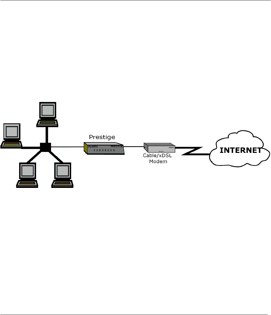
1.4 Applications for Prestige 310
1.4.1 Broadband Internet Access via Cable or xDSL Modem
The Prestige is the ideal high-speed Internet access solution for small offices and home offices. Your Prestige
supports the TCP/IP protocol, which is used by the Internet exclusively. A cable modem or xDSL modem
can connect to the Prestige 310 for broadband Internet access via Ethernet port on the modem. A typical
Internet access application is shown next.
Figure 1-1 Internet Access Application
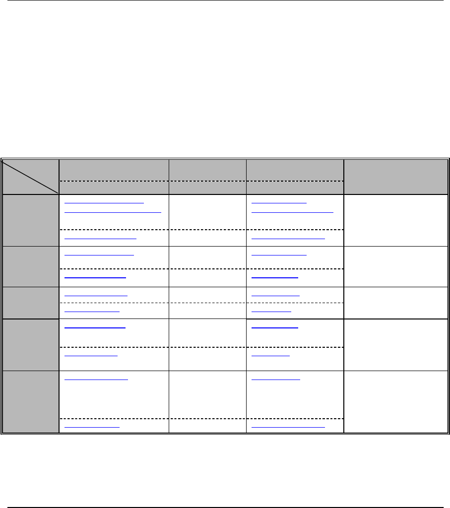
1.5 Internet Access Configuration Checklist
The following table shows the minimum SMT menu configurations you’ll need to make (without changing
the default Prestige values) in order to access the Internet. Please also refer to the Supporting CD which
contains HTML help on the Web Embedded Configurator, our handy web-based Internet access wizard
designed to get you up and running as soon as possible.

Prestige 310 Broadband Sharing Gateway
1-4 Getting to Know Your Prestige
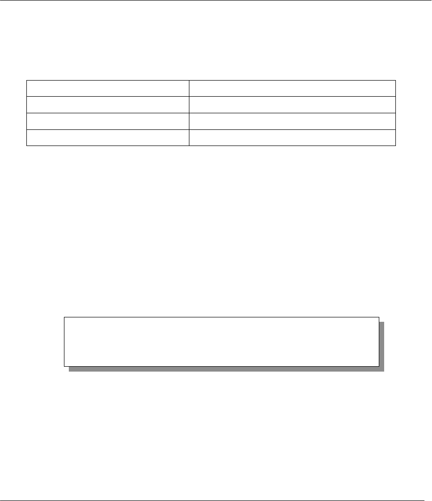
Table 1-1 Internet Access Configuration Checklist
SMT
Menu Field Action
1 System Name This field is for identification purposes but because some ISPs check this name you
should enter your PC’s “Computer Name” Click Start -> Settings -> Control Panel ->
Network. Click the Identification tab, note the entry for the Computer name” field and
enter it as the System Name.
2 MAC Address:
Assigned By The default is Factory Default, which is the factory assigned default MAC Address.
We recommend you choose IP Address attached on LAN and enter the IP address
of the workstation on the LAN whose MAC you are cloning.
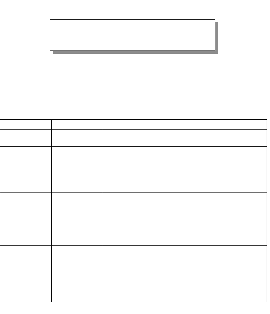
4 Encapsulation Choose PPPoE if you have a dial-up connection to the Internet (or PPTP if you
reside in France or Austria1); otherwise choose Ethernet. Choose from RR-Manager
or RR-Toshiba if your ISP is Time Warner's RoadRunner; otherwise choose
Standard.
PPTP You need to know your login name, password and connection ID/Name. The latter
may not be obligatory for some ISPs, but if it is you must follow the “c:id” and
“n:name” format.
PPPoE You need to know your login name, password and service name. The latter may not
be obligatory for some ISPs.
IP Address
Assignment If your ISP did not assign you a fixed IP address, select Dynamic, otherwise select
Static and enter the IP address & subnet mask in the IP address and IP Subnet
Mask fields.
Once these key fields have been configured, you should be able to enjoy super-fast Internet access with your
Prestige!
1 PPTP only supported in France and Austria at time of writing
Prestige 310 Broadband Sharing Gateway
Hardware Installation & Initial Setup 2-1
Chapter 2:
Hardware Installation & Initial Setup
This chapter shows you how to connect the hardware and perform the initial setup.
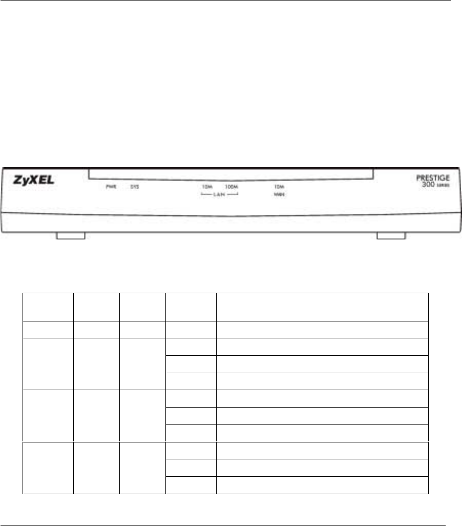
2.1 Front Panel LEDs and Back Panel Ports
2.1.1 Front Panel LEDs
The LEDs on the front panel indicate the operational status of the Prestige.
Figure 2-1 Front Panel
The following table describes the LED functions:
Table 2-1 LED functions
LEDs Function Indicator
Status Active Description
PWR Power Green On The power adapter is connected to the Prestige.
Off The system is not ready or failed.
On The system is ready and running.
SYS System
Flashing The system is rebooting.
Green Off The 10M LAN is not connected.
On The Prestige is connected to a 10M LAN.
10M LAN LAN
Flashing The 10M LAN is sending/receiving packets.
Off The 100M LAN is not connected.
On The Prestige is connected to a 100Mbps LAN.
100M LAN Orange
Flashing The 100M LAN is sending/receiving packets.
Prestige 310 Broadband Sharing Gateway
Hardware Installation & Initial Setup
2-2
LEDs Function Indicator
Status Active Description
Off The WAN Link is not ready, or has failed.
On The WAN Link is ok.
WAN WAN Green
Flashing The 10M WAN link is sending/receiving packets.
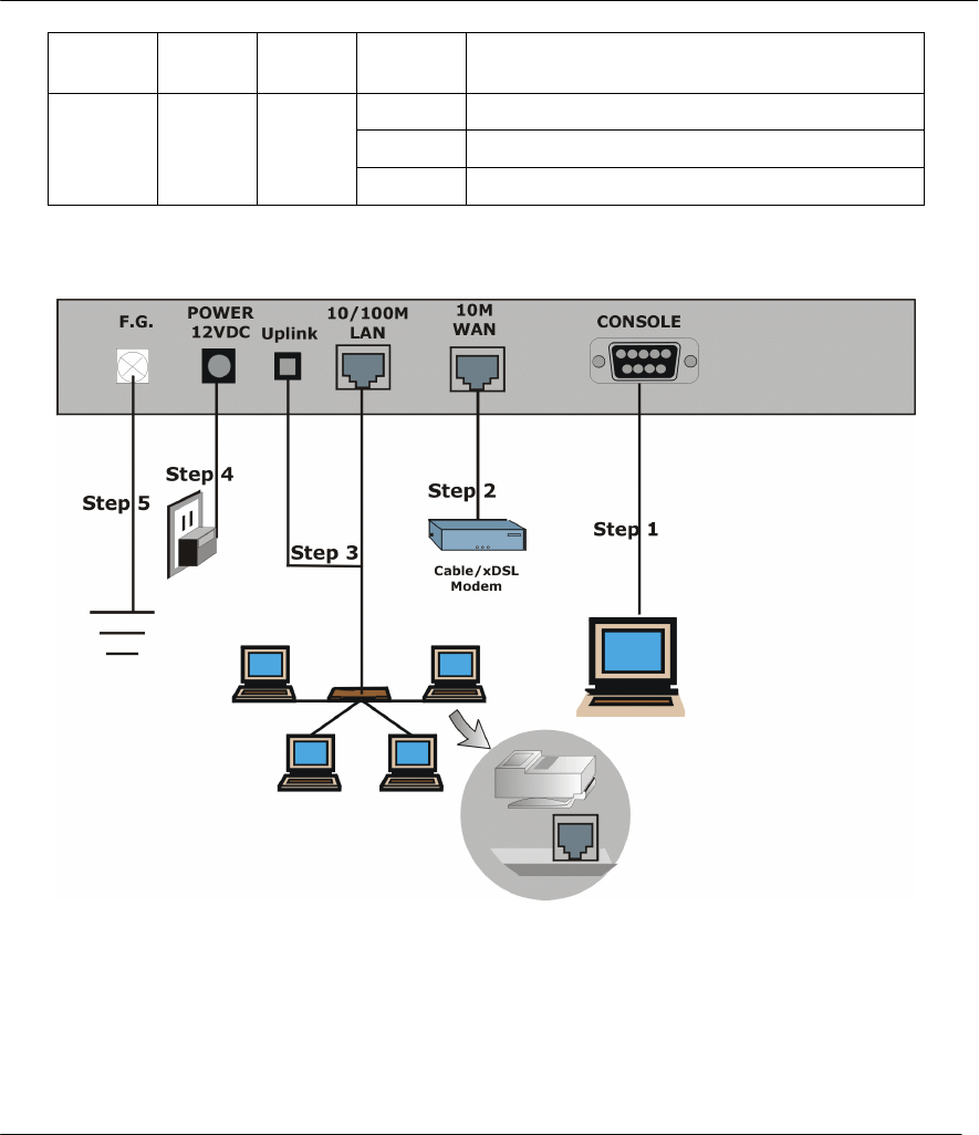
2.2 Prestige 310 Rear Panel and Connections
The figure below shows the rear panel of your Prestige 310 and the connection diagram.
Figure 2-2 Prestige 310 Rear Panel and Connections
This section outlines how to connect your Prestige 310 to the LAN and the WAN. In the case of connecting a
Cable Modem you must connect the coaxial cable from your cable service to the threaded coaxial cable
connector on the back of the cable modem. Connect an xDSL Modem to the xDSL Wall Jack. Please also see
Appendix C for important safety instructions on making connections to the Prestige.
Step 1. Connecting the Console Port

Prestige 310 Broadband Sharing Gateway
Hardware Installation & Initial Setup 2-3
For the initial configuration of your Prestige, you need to use terminal emulator software on a workstation
and connect it to the Prestige through the console port. Connect the 9-pin (smaller) end of the console cable
to the console port of the Prestige and the 25-pin (bigger) end to a serial port (COM1, COM2 or other COM
port) of your workstation. You can use an extension RS-232 cable if the enclosed one is too short. After the
initial setup, you can modify the configuration remotely through telnet connections.
Step 2. Connecting the Prestige to the Broadband Modem
Please use the cable supplied with your broadband modem to connect the broadband
modem and the Prestige.
Step 2a. Connecting the Prestige to the Cable Modem
Connect the WAN port (silver) on the Prestige to the Ethernet port on the cable modem using a straight
through Ethernet cable. The Ethernet port on the cable modem is sometimes labeled "PC" or "Workstation".
OR
Step 2b. Connecting the Prestige to the xDSL Modem
Connect the WAN port (silver) on the Prestige to the Ethernet port on the xDSL modem using a straight
through Ethernet cable.
Step 3. Connecting the Prestige to the LAN
When the Prestige Ethernet cable is correctly connected to the PC or hub, the front
panel LAN will go on.
To connect to a single PC, connect the 10/100M LAN port on the Prestige to the Network Adapter on the PC
using the white straight through cable and depress the Uplink button (“on”). If you do not depress the Uplink
button, you must use a crossover cable for this connection. If you have more than one PC, you must use an
external hub. Connect the 10/100M LAN port (gold) on the Prestige to a port on the hub using a straight
through Ethernet cable and make sure the Uplink button is not depressed (“on”).
Step 4. Connecting the Power Adapter to your Prestige
Connect the power adapter to the port labeled POWER on the rear panel of your Prestige.
Step 5. Grounding the Prestige (Optional)
Ground the Prestige by connecting a grounded wire to the F.G. (Frame Ground) of the Prestige.
2.3 Additional Installation Requirements
In addition to the contents of your package, there are other hardware and software requirements you need
before you can install and use your Prestige. These requirements include:
1. A computer with an Ethernet NIC (Network Interface Card) installed.
2. A computer equipped with communications software called terminal emulation software configured to
the following parameters:
♦ VT100 terminal emulation.
♦ 9600 Baud.
Prestige 310 Broadband Sharing Gateway
Hardware Installation & Initial Setup
2-4
♦ No parity, 8 Data bits, 1 Stop bit, Flow Control set to None.
3. A cable/xDSL modem and an ISP account.
The following table lists some common names for the communications software, based on the type of
computer you are using.
Table 2-2 Terminal Emulation Software
Operating System Software
Windows 95/98 or Windows NT HyperTerminal (bundled with Windows software)
Windows 3.1 Terminal (bundled with Windows software)
Macintosh ProComm, VersaTerm (supplied separately)
After the Prestige is properly set up, you can make future changes to the configuration through telnet
connections.
2.4 Power Up Your Prestige
At this point, you should have connected the console port, the LAN port, the WAN port and the power port to
the appropriate devices or lines. Plug the power adapter into a wall outlet. The Power LED should be on. The
SYS LED will come on after the system tests are complete. The WAN LED and one of the LAN LEDs come
on immediately after the SYS LED comes on, if connections have been made to the LAN and WAN ports.
Initial Screen
When you power on your Prestige, it performs several internal tests as well as line initialization.
After the tests, the Prestige asks you to press [Enter] to continue, as shown.
Figure 2-3 Initial Screen
Entering Password
The login screen appears after you press [Enter], prompting you to enter the password, as shown below.
For your first login, enter the default password 1234. As you type the password, the screen displays an (X)
for each character you type.
Please note that if there is no activity for longer than 5 minutes after you log in, your Prestige will
automatically log you out and will display a blank screen. If you see a blank screen, press [Enter] to bring up
the login screen again.
Copyright (c) 1994 - 2000 ZyXEL Communications Corp.
initialize ch =0, ethernet address: 00:a0:c5:41:51:61
initialize ch =1, ethernet address: 00:a0:c5:41:51:62
Press ENTER to continue...
Prestige 310 Broadband Sharing Gateway
Hardware Installation & Initial Setup 2-5
Figure 2-4 Password Screen
2.5 Navigating the SMT Interface
The SMT (System Management Terminal) is the interface that you use to configure your Prestige.
Several operations that you should be familiar with before you attempt to modify the configuration are listed
in the table below.
Table 2-3 Main Menu Commands
Operation Keystroke Description
Move down to
another menu [ENTER] To move forward to a submenu, type in the number of the desired
submenu and press [ENTER].
Move up to a
previous menu [Esc] Press the [Esc] key to move back to the previous menu.
Move to a “hidden”
menu Press the [SPACE
BAR] to change No
to Yes then press
[ENTER].
Fields beginning with “Edit” lead to hidden menus and have a
default setting of No. Press the [SPACE BAR] to change No to
Yes, then press [ENTER] to go to a “hidden” menu.
Move the cursor [ENTER] or
[Up]/[Down] arrow
keys
Within a menu, press [ENTER] to move to the next field. You can
also use the [Up]/[Down] arrow keys to move to the previous and
the next field, respectively.
Enter information Fill in, or
Press the [SPACE
BAR] to toggle
You need to fill in two types of fields. The first requires you to type
in the appropriate information. The second allows you to cycle
through the available choices by pressing the [Space] bar.
Required fields <? > All fields with the symbol <?> must be filled in order be able to
save the new configuration.
N/A fields <N/A> Some of the fields in the SMT will show a <N/A>. This symbol
refers to an option that is Not Applicable.
Save your
configuration [ENTER] Save your configuration by pressing [ENTER] at the message
[Press ENTER to confirm or ESC to cancel]. Saving the data on
the screen will take you, in most cases to the previous menu.
Enter Password : XXXX
Prestige 310 Broadband Sharing Gateway
Hardware Installation & Initial Setup
2-6
Operation Keystroke Description
Exit the SMT Type 99, then
press [ENTER].
Type 99 at the Main Menu prompt and press [ENTER] to exit the
SMT interface.
2.5.1 Main Menu
After you enter the password, the SMT displays the Prestige 310 Main Menu, as shown next.
Figure 2-5 Prestige 310 Main Menu
2.5.2 System Management Terminal Interface Summary
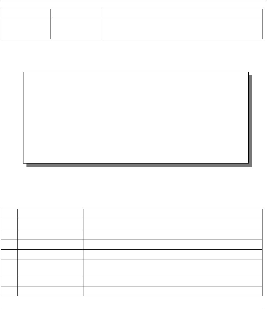
Table 2-4 Main Menu Summary
# Menu Title Description
1 General Setup Use this menu to setup general information.
2 WAN Setup Use this menu to setup the WAN.
3 LAN Setup Use this menu to setup the LAN.
4 Internet Access Setup A quick and easy way to setup Internet connection.
11 Remote Node Setup Use this menu to setup the remote node for LAN-to-LAN connection,
including Internet connection.
12 Static Routing Setup Use this menu to setup static route.
15 SUA Setup Use this menu to specify inside servers when SUA is enabled.
Copyright (c) 1994 - 2000 ZyXEL Communications Corp.
Prestige 310 Main Menu
Getting Started Advanced Management
1. General Setup
2. WAN Setup
3. LAN Setup
4. Internet Access Setup
Advanced Applications
11. Remote Node Setup
12. Static Routing Setup
15. SUA Server Setup
21. Filter Set Configuration
22. SNMP Configuration
23. System Password
24. System Maintenance
26. Schedule Setup
99. Exit
Enter Menu Selection Number:
Prestige 310 Broadband Sharing Gateway
Hardware Installation & Initial Setup 2-7
# Menu Title Description
21 Filter Set Configuration Use this menu to setup filters to provide security.
22 SNMP Configuration Use this menu to setup SNMP related parameters
23 System Password Use this menu to setup a new password.
24 System Maintenance This menu provides system status, diagnostics, firmware upload, etc.
26 Schedule Setup Use this menu to schedule outgoing calls.
99 Exit To exit from SMT and return to the blank screen.
2.6 Changing the System Password
The first thing your should do before anything else is to change the default system password by following the
steps below.
Step 1. Enter 23 in the Main Menu to open Menu 23 - System Password as shown below.
Figure 2-6 Menu 23 - System Security
Step 2. Enter your existing password and press [Enter].
Step 3. Enter your new system password and press [Enter].
Step 4. Re-type your new system password for confirmation and press [Enter].
Note that as you type a password, the screen displays a (X) for each character you type.
2.6.1 Resetting the Prestige
If you have forgotten your password or for some reason cannot access the SMT menu you will need to
reinstall the configuration file. Uploading the configuration file replaces the current configuration file with
the default configuration file, you will lose all configurations that you had before and the speed of the
Menu 23 - System Password
Old Password= ?
New Password= ?
Retype to confirm= ?
Enter here to CONFIRM or ESC to CANCEL:

Prestige 310 Broadband Sharing Gateway
Hardware Installation & Initial Setup
2-8
console port will be reset to the default of 9600bps with 8 data bit, no parity and 1 stop bit (8n1). The
password will be reset to the default of 1234, also.
Turn off the Prestige and begin a terminal emulation software session with the default console port settings.
Turn on the Prestige again. When you see the message "Press Any key to enter Debug Mode within 3
seconds", press any key to enter debug mode. You should already have downloaded the correct file from
your nearest ZyXEL FTP site. See section 10-3 for more information on how to transfer the configuration file
to your Prestige.
2.7 General Setup
Menu 1 - General Setup contains administrative and system-related information. The fields for General
Setup are as shown next. System Name is for identification purposes. However, because some ISPs check
this name you should enter your PC’s “Computer Name” (Start -> Settings -> Control Panel -> Network.
Click the Identification tab, note the entry for the Computer name” field). It is the domain name that will be
propagated to the DHCP clients on the LAN. If you leave this blank, the domain name obtained by DHCP
from the ISP is used. While you must enter the host name (System Name) on each individual machine, the
domain name can be assigned from the Prestige via DHCP.
2.7.1 Dynamic DNS
Dynamic DNS allows you to update your current dynamic IP address with one or many dynamic DNS
services so that anyone can contact you (in NetMeeting, CU-SeeMe, etc.) or access your FTP server or Web
site on your own computer using a DNS-like address (e.g. myhost.dhs.org, where myhost is a name of your
choice) which will never change instead of using your IP address that changes each time you reconnect. Your
friends or relatives will always be able to call you even if they don’t know your IP address.
First of all, you need to have registered a dynamic DNS account with www.dyndns.org. This is for people
with a dynamic IP from their ISP or DHCP server that would still like to have a DNS name.
To use this service, you must register with the Dynamic DNS client. The Dynamic DNS Client service
provider will give you a password or key. The Prestige at the time of writing supports www.ddns.org and
www.dyndns.org clients. You can apply to either of these clients for Dynamic DNS service.
DYNDNS Wildcard
Enabling the wildcard feature for your host causes *.yourhost.dyndns.org to be aliased to the same IP address
as yourhost.dyndns.org. This feature is useful if you want to be able to use for example
www.yourhost.dyndns.org and still reach your hostname.
To enter Menu 1 and fill in the required information, follow these steps:
Step 1. Enter 1 in the Main Menu to open Menu 1 – General Setup.
Step 2. The Menu 1 - General Setup screen appears, as shown below. Fill in the required fields.

Prestige 310 Broadband Sharing Gateway
Hardware Installation & Initial Setup 2-9
Figure 2-7 Menu 1 – General Setup
Table 2-5 General Setup Menu Field
Field Description Example
System Name Choose a descriptive name for identification purposes. It is
recommended you enter your computer’s “Computer name” in this
field. This name can be up to 30 alphanumeric characters long.
Spaces are not allowed, but dashes “-” and underscores "_" are
accepted.
P310
Domain Name Enter the domain name (if you know it) here. If you leave this field
blank, the ISP may assign a domain name via DHCP. You can go to
Menu 24.8 and type "sys domainname" to see the current domain
name used by your gateway.
If you want to clear this field just press the [SPACE BAR]. The
domain name entered by you is given priority over the ISP assigned
domain name.
zyxel.com.tw
Edit Dynamic
DNS Press the [SPACE BAR] to select Yes or No (default). Select Yes to
configure Menu 1.1 – Configure Dynamic DNS discussed next.
2.7.2 Configuring Dynamic DNS
To configure Dynamic DNS, go to Menu 1 – General Setup and press select Yes in the Edit Dynamic
DNS field.
Pressing [ENTER] takes you to Menu 1.1– Configure Dynamic DNS as shown next.
Menu 1 - General Setup
System Name= xxx
Domain Name=zyxel.com.tw
Edit Dynamic DNS= No
Press ENTER to Confirm or ESC to Cancel:

Prestige 310 Broadband Sharing Gateway
Hardware Installation & Initial Setup
2-10
Figure 2-8 Configure Dynamic DNS
Follow the instructions in the next table to configure Dynamic DNS parameters.
Table 2-6 Configure Dynamic DNS Menu Fields
Field Description Example
Service
Provider Enter the name of your Dynamic DNS client. www.ddns.org
Active Press [SPACE BAR] to toggle between Yes or No. Yes
Host Enter the domain name assigned to your Prestige by your
Dynamic DNS provider. me.ddns.org
EMAIL Enter your e-mail address. mail@mailserver
User Enter your user name.
Password Enter the password assigned to you.
Enable
Wildcard Your Prestige supports DYNDNS Wildcard. Press [SPACE
BAR] to toggle between Yes or No This field is N/A when you
choose DDNS client as your service provider.
Yes
The IP address will be updated when you reconfigure Menu 1 or perform DHCP client renewal.
Please note that:
♦ The Prestige supports basic DDNS, i.e., insecure login and password.
♦ If you have a private WAN IP address, then you can not use this service.
2.8 WAN Setup
This section describes how to configure the WAN using Menu 2 – WAN (10Mbps Ethernet) Setup. From
the Main Menu, enter 2 to open Menu 2.
Menu 1.1 - Configure Dynamic DNS
Service Provider = WWW.DynDNS.ORG
Active= Yes
Host= me.ddns.org
EMAIL= mail@mailserver
User= username
Password= ******
Enable Wildcard= No
Press ENTER to confirm or ESC to cancel:

Prestige 310 Broadband Sharing Gateway
Hardware Installation & Initial Setup 2-11
You only need to configure this menu if your WAN connection is a cable modem.
Figure 2-9 Menu 2 – WAN Setup
The MAC address field allows users to configure the WAN port's MAC Address by either using the factory
default or cloning the MAC address from a workstation on your LAN. Once it is successfully configured, the
address will be copied to the rom file (ZyNOS configuration file). It will not change unless you change the
setting in Menu 2 or upload a different rom file.
The following table contains instructions on how to configure your WAN setup.
Table 2-7 WAN Setup Menu Fields
Field Description Examples
MAC Address
Assigned By Press the [SPACEBAR] to choose either of the two methods of
assigning a MAC Address. Choose Factory Default to select the
factory assigned default MAC Address. Choose IP Address attached
on LAN to use the MAC Address of that workstation whose IP you
give in the following field.
Factory Default
IP Address This field is applicable only if you choose IP Address attached on LAN
method. Enter the IP address of the workstation on the LAN whose
MAC you are cloning.
Note: Your Prestige WAN Port is always set at half-duplex mode as most cable modems
only support half-duplex mode. If your cable modem supports full-duplex mode, then
you will be able to manually set it at half-duplex mode.
If the Prestige was set at half-duplex and the cable modem was set at full-duplex then
the WAN port would not function properly.
2.9 LAN Setup
This section describes how to configure the LAN using Menu 3 – LAN Setup (10/100Mbps Ethernet).
From the Main Menu, enter 3 to open Menu 3.
Menu 2 - WAN Setup
MAC Address:
Assigned By=IP address attached on LAN
IP Address= 192.168.1.12
Press ENTER to Confirm or ESC to Cancel:
Press Space Bar to Toggle

Prestige 310 Broadband Sharing Gateway
Hardware Installation & Initial Setup
2-12
Figure 2-10 Menu 3 - LAN Setup
2.9.1 LAN Port Filter Setup
This menu allows you to specify the filter sets that you wish to apply to the LAN traffic. You seldom need to
filter the LAN traffic, however, the filter sets may be useful to block certain packets, reduce traffic and
prevent security breaches.
Figure 2-11 Menu 3.1 – LAN Port Filter Setup
Menu 3.2 is discussed in the next part of the manual. Please read on.
Menu 3 - LAN Setup
1. LAN Port Filter Setup
2. TCP/IP and DHCP Setup
Enter Menu Selection Number:
Menu 3.1 – LAN Port Filter Setup
Input Filter Sets:
protocol filters= 2
device filters=
Output Filter Sets:
protocol filters=
device filters=
Press ENTER to Confirm or ESC to Cancel:

Prestige 310 Broadband Sharing Gateway
Internet Access 3-1
Chapter 3:
Internet Access
This chapter shows you how to configure the LAN as well as the WAN of your Prestige for Internet
access.
3.1 TCP/IP and DHCP for LAN
The Prestige has built-in DHCP server capability that assigns IP addresses and DNS servers to systems that
support DHCP client capability.
3.1.1 Factory LAN Defaults
The LAN parameters of the Prestige are preset in the factory with the following values:
1. IP address of 192.168.1.1 with subnet mask of 255.255.255.0 (24 bits)
2. DHCP server enabled with 32 client IP addresses starting from 192.168.1.33.
These parameters should work for the majority of installations. If the parameters are satisfactory, you can
skip to section 3.2 to enter the DNS server address(es) if your ISP gives you explicit DNS server address(es).
If you wish to change the factory defaults or to learn more about TCP/IP, please read on.
3.1.2 IP Address and Subnet Mask
Similar to the houses on a street that share a common street name, the machines on a LAN share one
common network number, also.
Where you obtain your network number depends on your particular situation. If the ISP or your network
administrator assigns you a block of registered IP addresses, follow their instructions in selecting the IP
addresses and the subnet mask.
If the ISP did not explicitly give you an IP network number, then most likely you have a single user account
and the ISP will assign you a dynamic IP address when the connection is established. If this is the case, it is
recommended that you select a network number from 192.168.0.0 to 192.168.255.0 (ignoring the trailing
zero) and you must enable the Network Address Translation feature of the Prestige. The Internet Assigned
Number Authority (IANA) reserved this block of addresses specifically for private use; please do not use any
other number unless you are told otherwise. Let’s say you select 192.168.1.0 as the network number; which
covers 254 individual addresses, from 192.168.1.1 to 192.168.1.254 (zero and 255 are reserved). In other
words, the first 3 numbers specify the network number while the last number identifies an individual
workstation on that network.
Once you have decided on the network number, pick an IP address that is easy to remember, e.g.,
192.168.1.1, for your Prestige.

Prestige 310 Broadband Sharing Gateway
Internet Access
3-2
192.168.1.1 is the default Ethernet IP for the Prestige. If you select this IP address,
the Prestige will automatically enable various default settings such as, enable DHCP
Server, set this IP as the default gateway etc.
The subnet mask specifies the network number portion of an IP address. Your Prestige will compute the
subnet mask automatically based on the IP address that you entered. You don’t need to change the subnet
mask computed by the Prestige unless you are instructed to do otherwise.
3.1.3 Private IP Addresses
Every machine on the Internet must have a unique address. If your networks are isolated from the Internet,
e.g., only between your two branch offices, you can assign any IP addresses to the hosts without problems.
However, the Internet Assigned Numbers Authority (IANA) has reserved the following three blocks of IP
addresses specifically for private networks:
10.0.0.0 - 10.255.255.255
172.16.0.0 - 172.31.255.255
192.168.0.0 - 192.168.255.255
For this reason, it is recommended that you choose your network number from the above list.
You can obtain your IP address from the IANA, from an ISP, or assigned from a private network. If you
belong to a small organization and your Internet access is through an ISP, the ISP can provide you with the
Internet addresses for your local networks. On the other hand, if you are part of a much larger organization,
you should consult your network administrator for the appropriate IP addresses.
Regardless of your particular situation, do not create an arbitrary IP address; always
follow the guidelines above. For more information on address assignment, please refer
to RFC 1597, Address Allocation for Private Internets and RFC 1466, Guidelines for
Management of IP Address Space.
3.1.4 RIP Setup
RIP (Routing Information Protocol) allows a router to exchange routing information with other routers. The
RIP Direction field controls the sending and receiving of RIP packets. When set to Both or Out Only, the
Prestige will broadcast its routing table periodically. When set to Both or In Only, it will incorporate the
RIP information that it receives; when set to None, it will not send any RIP packets and will ignore any RIP
packets received.
The Version field controls the format and the broadcasting method of the RIP packets that the Prestige
sends (it recognizes both formats when receiving). RIP-1 is universally supported; but RIP-2 carries more
information. RIP-1 is probably adequate for most networks, unless you have an unusual network topology.
Both RIP-2B and RIP-2M sends the routing data in RIP-2 format; the difference being that RIP-2B uses
subnet broadcasting while RIP-2M uses multicasting. Multicasting can reduce the load on non-router
machines since they generally do not listen to the RIP multicast address and so will not receive the RIP
packets. However, if one router uses multicasting, then all routers on your network must use multicasting,

Prestige 310 Broadband Sharing Gateway
Internet Access 3-3
also. By default, RIP direction is set to Both for the LAN and None for the WAN and the Version set to
RIP-1.
3.1.5 DHCP Configuration
DHCP (Dynamic Host Configuration Protocol, RFC 2131 and RFC 2132) allows the individual clients
(workstations) to obtain the TCP/IP configuration at start-up from a server. You can configure the Prestige as
a DHCP Server, Relay or None. When configured as a Server, the Prestige provides the TCP/IP
configuration for the clients. If set to None, DHCP service will be disabled and you must have another
DHCP sever on your LAN, or else the workstation must be manually configured. The Prestige can now also
act as a surrogate DHCP server (Relay) where it relays IP address assignment from the actual real DHCP
server to the clients.
IP Pool Setup
The Prestige is pre-configured with a pool of 32 IP addresses starting from 192.168.1.33 to 192.168.1.64.
This configuration leaves 31 IP addresses (excluding the Prestige itself) in the lower range for other server
machines, e.g., server for mail, FTP, telnet, web, etc., that you may have.
DNS Server Address
DNS (Domain Name System) is for mapping a domain name to its corresponding IP address and vice versa,
e.g., the IP address of www.zyxel.com is 204.217.0.2. The DNS server is extremely important because
without it, you must know the IP address of a machine before you can access it.
There are two ways that an ISP disseminates the DNS server addresses. The first is for an ISP to tell a
customer the DNS server addresses, usually in the form of an information sheet, when you sign up. If your
ISP does give you the DNS server addresses, enter them in the DNS Server fields in DHCP Setup. The
second is to leave this field blank, i.e., 0.0.0.0 – in this case the Prestige acts as a DNS proxy.
Example of network properties for LAN servers with fixed IP#:
Choose an IP: 192.168.1.2 - 192.168.1.32; 192.168.1.65 - 192.168.1.254.
Netmask: 255.255.255.0
Gateway (or default route): 192.168.1.1 (Prestige LAN IP)
DNS server: 192.168.1.1
Domain: (optional)
3.1.6 IP Multicast
Traditionally, IP packets are transmitted in one of either two ways - Unicast (1 sender – 1 recipient) or
Broadcast (1 sender – everybody on the network). Multicast is a third way to deliver IP packets to a group of
hosts on the network - not everybody.
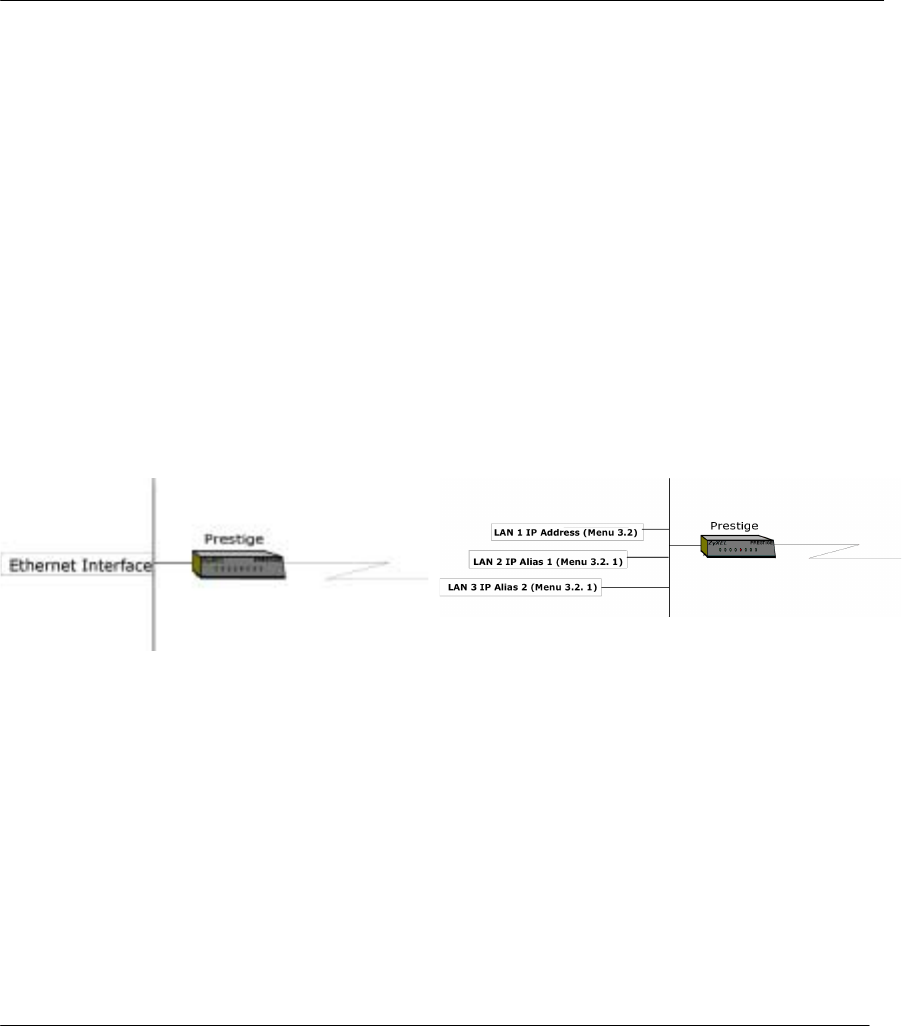
Prestige 310 Broadband Sharing Gateway
Internet Access
3-4
IGMP (Internet Group Multicast Protocol) is a session-layer protocol used to establish membership in a
Multicast group - it is not used to carry user data. IGMP version 2 (RFC 2236) is an improvement over
version 1 (RFC 1112) but IGMP version 1 is still in wide use. If you would like to read more detailed
information about interoperability between IGMP version 2 and version 1, please see sections 4 and 5 of
RFC 2236. The class D IP address is used to identify host groups and can be in the range 224.0.0.0 to
239.255.255.255. The address 224.0.0.0 is not assigned to any group and is used by IP multicast computers.
The address 224.0.0.1 is used for query messages and is assigned to the permanent group of all IP hosts
(including gateways). All hosts must join the 224.0.0.1 group in order to participate in IGMP. The address
224.0.0.2 is assigned to the multicast routers group.
The Prestige supports both IGMP version 1 (IGMP-v1) and IGMP version 2 (IGMP-v2). At start up, the
Prestige queries all directly connected networks to gather group membership. After that, the Prestige
periodically updates this information. IP Multicasting can be enabled/disabled on the Prestige LAN and/or
WAN interfaces using menus 3.2 (LAN) and 11.3 (WAN). Select None to disable IP Multicasting on these
interfaces.
3.1.7 IP Alias
IP Alias allows you to partition a physical network into different logical networks over the same Ethernet
interface. The Prestige supports three logical LAN interfaces via its single physical Ethernet interface with
the Prestige itself as the gateway for each LAN network.
Figure 3-1 Physical Network Figure 3-2 Partitioned Logical Networks
Use menu 3.2.1 to configure IP Alias on your Prestige.
3.2 TCP/IP and DHCP Ethernet Setup
From the Main Menu, enter 3 to open Menu 3 - LAN Setup (10/100 Mbps Ethernet) to configure TCP/IP
(RFC 1155) and DHCP Ethernet setup.
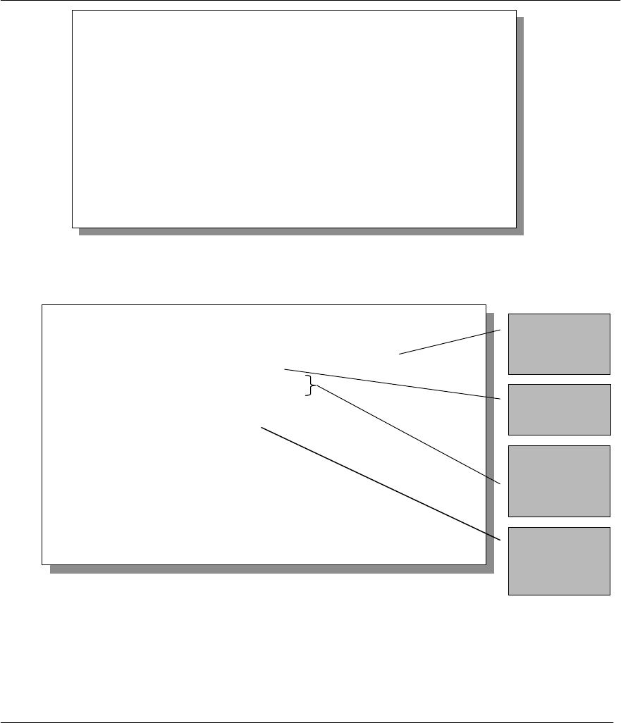
Prestige 310 Broadband Sharing Gateway
Internet Access 3-5
Figure 3-3 Menu 3 - LAN Setup (10/100 Mbps Ethernet)
To edit the TCP/IP and DHCP configuration, enter 2 to open Menu 3.2 - TCP/IP and DHCP Ethernet
Setup as shown next.
Figure 3-4 Menu 3.2 – TCP/IP and DHCP Ethernet Setup
Menu 3 – LAN Setup
1. LAN Port Filter Setup
2. TCP/IP and DHCP Setup
Enter Menu Selection Number:
Menu 3.2 - TCP/IP and DHCP Ethernet Setup
DHCP Setup:
DHCP= Server
Client IP Pool Starting Address= 192.168.1.33
Size of Client IP Pool= 32
Primary DNS Server= 0.0.0.0
Secondary DNS Server= 0.0.0.0
TCP/IP Setup:
IP Address= 192.68.1.1
IP Subnet Mask= 255.255.255.0
RIP Direction= Both
Version= RIP-1
Multicast= None
Edit IP Alias= No
Press ENTER to Confirm or ESC to Cancel:
Press Space Bar to Toggle.
First address
in the IP Pool
Size of the IP
Pool
IP addresses
of the DNS
servers
This is the IP
address of the
Prestige.

Prestige 310 Broadband Sharing Gateway
Internet Access
3-6
Follow the instructions in the following table on how to configure the DHCP fields.
Table 3-1 LAN DHCP Setup Menu Fields
Field Description Example
DHCP= This field enables/disables the DHCP server. If it is set to Server,
your Prestige will act as a DHCP server. If set to None, DHCP
service will be disabled and you must have another DHCP sever
on your LAN, or else the workstation must be manually configured.
When DHCP is set to Server, the following four items need to be
set. The Prestige can now also act as a surrogate DHCP server
(Relay) where it relays IP address assignment from the actual real
DHCP server to the clients.
None
Relay
Server (default)
Client IP Pool Starting
Address This field specifies the first of the contiguous addresses in the IP
address pool. 192.168.1.33
Size of Client IP Pool This field specifies the size, or count, of the IP address pool. 32
Primary DNS Server
Secondary DNS
Server
Enter the IP addresses of the DNS servers. The DNS servers are
passed to the DHCP clients along with the IP address and the
subnet mask. Leave these entries at 0.0.0.0 if they are provided by
a WAN DHCP server.
Follow the instructions in the following table to configure TCP/IP parameters for the LAN port.
Table 3-2 LAN TCP/IP Setup Menu Fields
Field Description Example
TCP/IP Setup
IP Address Enter the IP address of your Prestige in dotted decimal notation 192.168.1.1
(default)
IP Subnet Mask Your Prestige will automatically calculate the subnet mask based on
the IP address that you assign. Unless you are implementing
subnetting, use the subnet mask computed by the Prestige
255.255.255.0
RIP Direction Press the [SPACE BAR] to select the RIP direction from Both/In
Only/Out Only/None.Both
(default)
Version Press the [SPACE BAR] to select the RIP version from RIP-1/RIP-
2B/RIP-2M.RIP-1
(default)
Multicast IGMP (Internet Group Multicast Protocol) is a session-layer protocol
used to establish membership in a Multicast group. The Prestige
supports both IGMP version 1 (IGMP-v1) and IGMP-v2. Press the
None
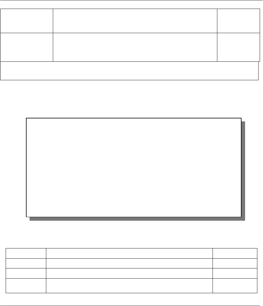
Prestige 310 Broadband Sharing Gateway
Internet Access 3-7
Field Description Example
space bar to enable IP Multicasting or select None (default) to
disable it.
Edit IP Alias The Prestige supports three logical LAN interfaces via its single
physical Ethernet interface with the Prestige itself as the gateway for
each LAN network. Press the space bar to toggle No to Yes, then
press [ENTER] to bring you to menu 3.2.1
Yes
No (default)
When you have completed this menu, press [Enter] at the prompt [Press ENTER to Confirm…] to save your
configuration, or press [Esc] at any time to cancel.
3.2.1 IP Alias Setup
You must use Menu 3.2 to configure the first network and move the cursor to the Edit IP Alias field and
press [SPACE BAR] to choose Yes and press [ENTER] to configure the second and third network.
Pressing [Enter] opens Menu 3.2.1 - IP Alias Setup, as shown next.
Figure 3-5 Menu 3.2.1 - IP Alias Setup
Follow the instructions in the following table to configure IP Alias parameters.
Table 3-3 IP Alias Setup Menu Fields
Field Description Example
IP Alias Choose Yes to configure the LAN network for the Prestige. Yes
IP Address Enter the IP address of your Prestige in dotted decimal notation 192.168.2.1
IP Subnet Mask Your Prestige will automatically calculate the subnet mask based on
the IP address that you assign. Unless you are implementing 255.255.255.0
Menu 3.2.1 - IP Alias Setup
IP Alias 1= No
IP Address= N/A
IP Subnet Mask= N/A
RIP Direction= N/A
Version= N/A
Incoming protocol filters= N/A
Outgoing protocol filters= N/A
IP Alias 2= No
IP Address= N/A
IP Subnet Mask= N/A
RIP Direction= N/A
Version= N/A
Incoming protocol filters= N/A
Outgoing protocol filters= N/A
Enter here to CONFIRM or ESC to CANCEL:
Press S
p
ace Bar to To
gg
le.

Prestige 310 Broadband Sharing Gateway
Internet Access
3-8
subnetting, use the subnet mask computed by the Prestige
RIP Direction Press the space bar to select the RIP direction from None, Both/In
Only/Out Only. None
Version Press the space bar to select the RIP version from RIP-1/RIP-
2B/RIP-2M. RIP-1
Incoming
Protocol Filters Enter the filter set(s) you wish to apply to the incoming traffic
between this node and the Prestige.
Outgoing
Protocol Filters Enter the filter set(s) you wish to apply to the outgoing traffic between
this node and the Prestige.
When you have completed this menu, press [Enter] at the prompt [Press ENTER to Confirm…] to save
your configuration, or press [Esc] at any time to cancel.
3.3 Internet Access Setup
You will see three different Menu 4 screens depending on whether you chose Ethernet, PPTP or PPPoE
Encapsulation.
3.3.1 Ethernet Encapsulation
Step 1. You must choose the Ethernet option when the WAN port is used as a regular Ethernet. The
PPPoE choice is for a dial-up connection using PPPoE. If you choose Ethernet in Menu 4 you will see the
next screen.
Figure 3-6 Internet Access Setup (Ethernet)
Menu 4 - Internet Access Setup
ISP's Name= ChangeMe
Encapsulation= Ethernet
Service Type= Standard
My Login= N/A
My Password= N/A
Login Server IP= N/A
IP Address Assignment= Dynamic
IP Address= N/A
IP Subnet Mask= N/A
Gateway IP Address= N/A
Single User Account= Yes
Press ENTER to Confirm or ESC to Cancel:

Prestige 310 Broadband Sharing Gateway
Internet Access 3-9

Prestige 310 Broadband Sharing Gateway
Internet Access
3-10
The following table describes this screen.
Table 3-4 Internet Access Setup Menu Fields
Field Description
ISP’s Name Enter the name of your Internet Service Provider, e.g., myISP. This
information is for identification purposes only.
Encapsulation Press the [SPACE BAR] and the press [ENTER] to choose Ethernet. The
encapsulation method influences your choices for IP Address.
Service Type This is applicable only when you choose Ethernet as your encapsulation
method. Press the [SPACE BAR] to select Standard, RR-Toshiba
(RoadRunner Toshiba authentication method) or RR-Manager (RoadRunner
Manager authentication method). Choose a RoadRunner flavor if your ISP is
Time Warner's RoadRunner; otherwise choose Standard.
Note: xDSL users must choose the Standard option only. The Server IP, My Login IP and My Password
fields are not applicable in this case.
My Login Name Enter the login name given to you by your ISP.
My Password Enter the password associated with the login name above.
Login Server IP The Prestige will find the RoadRunner Server IP if this field is left blank. If it
does not, then you must enter the authentication server IP address.
IP Address Assignment If your ISP did not assign you a fixed IP address, select Dynamic, otherwise
select Static and enter the IP address & subnet mask in the following fields.
IP Address Enter the (fixed) IP address assigned to you by your ISP (Static IP Address
Assignment is selected in the previous field).
IP Subnet Mask Enter the subnet mask associated with your static IP.
Gateway IP Address Enter the gateway IP address associated with your static IP.
Single User Account Please see the following chapter for a more detailed discussion on the Single
User Account. The default is Yes.
3.3.2 PPTP Encapsulation
Point-to-Point Tunneling Protocol (PPTP) is a network protocol that enables secure transfer of data from a
remote client to a private server, creating a Virtual Private Network (VPN) using TCP/IP-based networks
PPTP supports on-demand, multi-protocol, and virtual private networking over public networks, such as the
Internet.
The P310 supports only one PPTP server connection at any given time.

Prestige 310 Broadband Sharing Gateway
Internet Access 3-11
3.3.3 Configure PPTP Client
To configure a PPTP client, you must configure My Login and Password fields for PPP connection and
PPTP parameters for PPTP connection.
After configuring the User Name and Password for PPP connection, toggle the space bar in the
Encapsulation field in Menu 4 -Internet Access Setup to choose PPTP as your encapsulation option.
If you choose PPTP in Menu 4 you will see the next screen.
Figure 3-7 Internet Access Setup (PPTP)
The following table contains instructions about the new fields when you choose PPTP in the Encapsulation
field in Menu 4.
Table 3-5 New Fields in Menu 4 (PPTP) screen
Field Description Examples
Encapsulation Press the [SPACE BAR] and then press [ENTER] to choose
PPTP. The encapsulation method influences your choices for
IP Address.
PPTP
Idle Timeout This value specifies the time in seconds that elapses before
the Prestige automatically disconnects from the PPTP server. 100
(default)
3.3.4 PPPoE Encapsulation
The Prestige supports PPPoE (Point-to-Point Protocol over Ethernet). You can use PPPoE encapsulation only
when you’re using the Prestige with an xDSL modem as the WAN device.
PPPoE is an IETF Draft standard specifying how a host personal computer (PC) interacts with a broadband
modem (i.e. xDSL, cable, wireless, etc.) to achieve access to high-speed data networks. It preserves the
existing Microsoft Dial-Up Networking experience and requires no new learning or procedures.
Menu 4 - Internet Access Setup
ISP's Name= ChangeMe
Encapsulation= PPTP
Service Type= N/A
My Login= username
My Password= ******
Idle Timeout= 100
IP Address Assignment= Dynamic
IP Address= N/A
IP Subnet Mask= N/A
Gateway IP Address=N/A
Single User Account= Yes
Press ENTER to Confirm or ESC to Cancel:

Prestige 310 Broadband Sharing Gateway
Internet Access
3-12
Operationally, PPPoE saves significant effort for both the end user and ISP/carrier, as it requires no
configuration of the modem at the customer site.
PPPoE uses industry-standard, low-cost Ethernet NICs to connect your PCs to the broadband modem. In
addition, PPPoE allows multiple PCs to share a single broadband connection, making it the best solution for
small offices and homes that have more than one PC needing high-speed network access. For the service
provider, one of the benefits of PPPoE is the ability to let end users access multiple network services, a
function known as dynamic service selection. This enables the service provider to easily create and offer new
IP services.
If you choose PPPoE in Menu 4, you will see the next screen. For extra information on PPPoE, please see
the appendix.
Figure 3-8 Internet Access (PPPoE)
Table 3-6 New Fields in Menu 4 (PPPoE) screen
Field Description Examples
Encapsulation Press the [SPACE BAR] and then press [ENTER] to choose
PPPoE. The encapsulation method influences your choices
for IP Address.
PPPoE
Idle Timeout This value specifies the time in seconds that elapses before
the Prestige automatically disconnects from the PPPoE
server.
100
(default)
Menu 4 - Internet Access Setup
ISP's Name= ChangeMe
Encapsulation= PPPoE
Service Type= N/A
My Login=
My Password= ********
Idle Timeout= 100
IP Address Assignment= Dynamic
IP Address= N/A
IP Subnet Mask= N/A
Gateway IP Address= N/A
Single User Account= Yes
Press ENTER to Confirm or ESC to Cancel:

Prestige 310 Broadband Sharing Gateway
Internet Access 3-13
3.4 Internet Test Setup
After configuring the Menu 4 fields when you press [Enter] to confirm you will see the message, " Do you
wish to perform the Internet Setup Test[y/n]:" if you have chosen PPTP or PPPoE as your encapsulation
method. Say 'Y' to test your setup. An example of Internet Setup Test is shown next.
Figure 3-9 Internet Setup Test Example
3.5 Basic Setup Complete
Well Done! You have successfully connected, installed and set up your Prestige to operate on your network
as well as access the Internet.
Start dialing for node <ChangeMe>...
### Hit any key to continue.###
$$$ DIALING dev=a ch=0..........
$$$ OUTGOING-CALL phone()
$$$ PPTP: Start tunnel setup, send SCCRQ
$$$ PPTP: OCRQ sent
$$$ CALL CONNECT speed<10000000> type<10> chan<0>
$$$ LCP opened
$$$ CHAP login to remote OK
$$$ IPCP negotiation started
$$$ CCP stopped
$$$ BACP stopped
$$$ IPCP neg' Primary DNS 202.xxx.xxx.x
$$$ IPCP opened

Prestige 310 Broadband Sharing Gateway
II
Part II:
Advanced Applications
Advanced Applications (Chapters 4-6) describe the advanced applications of your Prestige, such
as Remote Node Setup, IP Static routes Setup and configuring SUA servers.
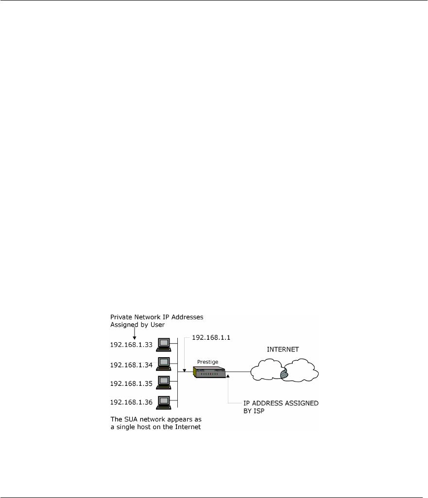
Prestige 310 Broadband Sharing Gateway
SUA and Multiple SUA Servers 4-1
Chapter 4:
SUA and Multiple SUA Servers
This chapter helps you in configuring SUA and setting up multiple inside servers in SUA case.
4.1 Single User Account (SUA)
If you wish to know more about SUA please read on. Or you can skip to the section Single User Account
Configuration for configuring SUA and the section Multiple Servers behind SUA for information about
setting up multiple servers when SUA is enabled.
4.1.1 Basics
Typically, if there are multiple users on the LAN wanting to concurrently access the Internet, you will have
to lease a block of legal, or globally unique, IP addresses from the ISP.
Your Prestige accomplishes address sharing by translating the internal LAN IP addresses to a single address
that is globally unique on the Internet. The SUA feature allows you to have the same benefits as having
multiple legal addresses, but allows you to have one legal IP address and many local LAN IP addresses that
can be used in other domains also, thus conserving the number of global IP addresses.
The Single User Account feature may also be used on connections to remote networks other than the ISP.
For example, this feature can be used to simplify the allocation of IP addresses when connecting branch
offices to the corporate network.
The IP address for the SUA can be either fixed or dynamically assigned. In addition, you can designate
servers, e.g., a web server, on your local network in the client side and make them accessible to outside
world.
Figure 4-1 An Example of Single User Account Topology
SUA offers the additional benefit of firewall protection. All incoming inquiries will be filtered out by your
Prestige and thus preventing intruders from probing your network.
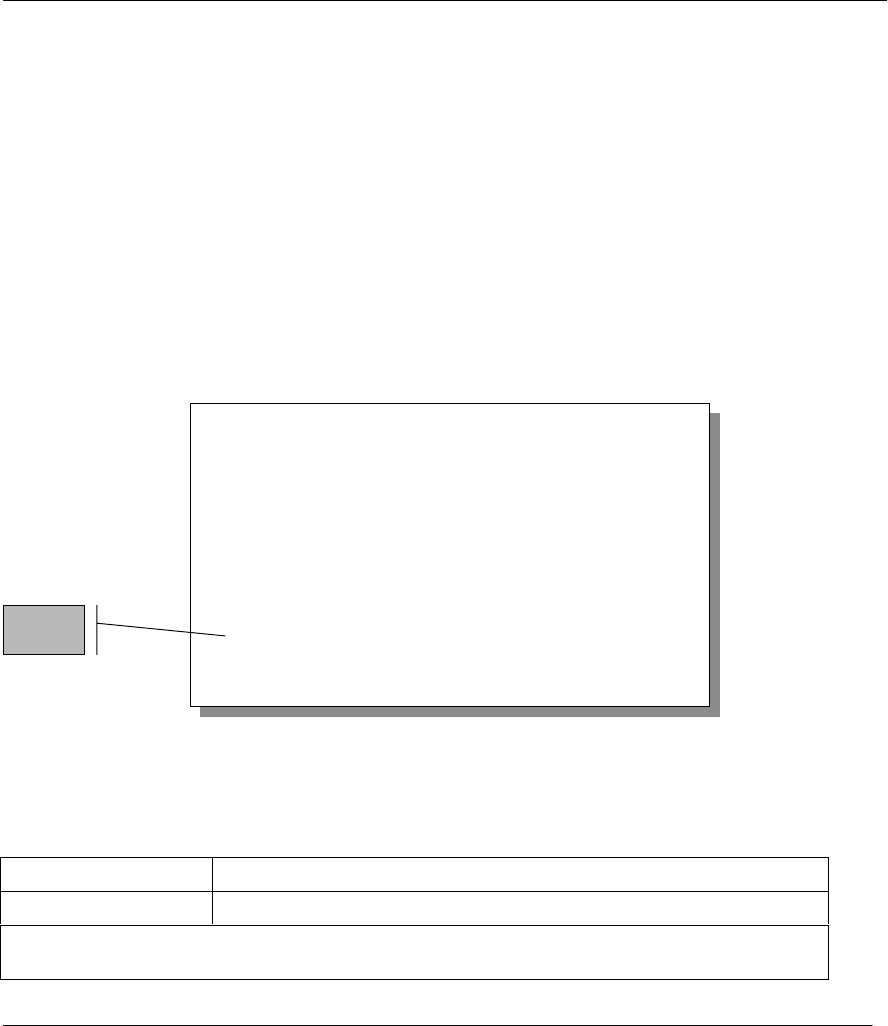
Prestige 310 Broadband Sharing Gateway
4-2 SUA and Multiple SUA Servers
For more information on IP address translation as a solution for IP address depletion problem, refer to RFC
1631, The IP Network Address Translator (NAT).
In summary:
• SUA helps in more efficient IP address management.
• SUA can provide firewall protection. All incoming inquiries will be filtered out by your Prestige.
• UDP and TCP datagrams can be routed. In addition, partial ICMP, including echo (ping) and trace
route, is supported.
• SUA is also a cost-effective solution for offices to access the Internet or other remote TCP/IP networks
as they have to pay for single globally unique IP address only.
4.1.2 Single User Account Configuration
The steps for configuring your Prestige for Single User Account are identical to conventional Internet access
(See configuration instructions in the previous chapter) with the exception that you need to fill in two extra
fields in Menu 4 - Internet Access Setup, as shown in the following figure. SUA here is applied solely to
the output interface and is valid only for LAN to WAN connections and not for connections between LANs.
Figure 4-2 Menu 4 - Internet Access Setup for Single User Account
To enable the SUA feature in Menu 4, move the cursor to the Single User Account field and select Yes (or
No to disable SUA).
Follow the instructions on how to configure the SUA fields in the following table.
Table 4-1 Single User Account Menu Fields
Field Description
Single User Account Select Yes to enable SUA.
Press [ENTER] at the message [Press ENTER to Confirm ...] to save your configuration, or press
[ESC] at any time to cancel.
Menu 4 - Internet Access Setup
ISP's Name= ChangeMe
Encapsulation= Ethernet
Service Type= Standard
My Login= N/A
My Password= N/A
Login Server IP= N/A
IP Address Assignment= Dynamic
IP Address= N/A
IP Subnet Mask= N/A
Gateway IP Address= N/A
Single User Account= Yes
Press ENTER to Confirm or ESC to Cancel:
SUA

Prestige 310 Broadband Sharing Gateway
SUA and Multiple SUA Servers 4-3
When SUA is disabled, the Prestige will send the packets from workstations to the remote host with
workstation's IP and port to the destination's IP and port. If the workstation uses private IP (Private Networks
IPs: 10.0.0.0 ~ 10.255.255.255; 172.16.0.0. ~ 172.31.255.255; 192.168.0.0. ~ 192.168.255.255) in SUA
mode, the packet will be routed by the Prestige but will be dropped somewhere and never returned. This is
because only a legal IP is valid on the Internet. Hence, in non-SUA mode, the workstation must use non-
private/legal IP.
4.2 Multiple Servers behind SUA
If you wish, you can make inside servers for different services, e.g., web or FTP, visible to the outside users,
even though SUA makes your whole inside network appear as a single machine to the outside world. A
service is identified by the port number, e.g., web service is on port 80 and FTP on port 21.
As an example, if you have a web server at 192.168.1.2 and an FTP server 192.168.1.3, then you need to
specify for port 80 (web) the server at IP address 192.168.1.2 and for port 21 (FTP) another at IP address
192.168.1.3.
Please note that a server can support more than one service, e.g., a server can provide both FTP and DNS
service, while another provides only web service. Also, since you need to specify the IP address of a server
in the Prestige, a server must have a fixed IP address and not be a DHCP client whose IP address potentially
changes each time it is powered on.
In addition to the servers for specific services, SUA supports a default server. A service request that does not
have a server explicitly designated for it is forwarded to the default server. If the default server is not
defined, the service request is simply discarded.
To make a server visible to the outside world, specify the port number of the service and the inside IP address
of the server in Menu 15, Multiple Server Configuration.
For more information on configuring supporting applications behind SUA refer to the
ZyNOS Support Note documentation in your Support CD.
4.2.1 Configuring a Server behind SUA
Follow the steps below to configure a server behind SUA:
Step 1 Enter 15 in the main menu to go to Menu 15 - Multiple Server Configuration.
Step 2 Enter the service port number in the Port # field and the inside IP address of the server in the IP
Address field.
Step 3 Press [Enter] at the “Press ENTER to confirm …” prompt to save your configuration after you
define all the servers or press ESC at any time to cancel.

Prestige 310 Broadband Sharing Gateway
4-4 SUA and Multiple SUA Servers
Figure 4-3 Multiple Server Configuration
The most often used port numbers are:
Table 4-2 Services vs. Port number
Services Port Number
FTP (File Transfer Protocol) 21
Telnet 23
SMTP (Simple Mail Transfer Protocol) 25
DNS(Domain Name System) 53
HTTP (Hyper Text Transfer protocol or WWW, Web) 80
POP3 (Post Office Protocol, version 3) 110
PPTP (Point-to-Point Tunneling Protocol) 1723
Menu 15 - Multiple Server Configuration
Port #
----
1.Default
2. 0
3. 0
4. 0
5. 0
6. 0
7. 0
8. 0
9. 1025
IP Address
---------------
0.0.0.0
0.0.0.0
0.0.0.0
0.0.0.0
0.0.0.0
0.0.0.0
0.0.0.0
0.0.0.0
RR Reserved
Press ENTER to Confirm or ESC to Cancel:

Prestige 310 Broadband Sharing Gateway
Remote Node Setup 5-1
Chapter 5
Remote Node Setup
This chapter shows you how to configure a remote node.
A remote node is required for placing calls to a remote gateway. A remote node represents both the remote
gateway and the network behind it across a WAN connection. Note that when you use Menu 4 to set up
Internet access, you are actually configuring a remote node. We will show you how to configure Menu 11.1
Remote Node Profile, Menu 11.3 - Remote Node Network Layer Options and Menu 11.5 - Remote Node
Filter.
5.1 Remote Node Profile
From the Main Menu, select menu option 11 to open Menu 11.1 - Remote Node Profile. There are three
variations of this menu depending on whether you choose Ethernet Encapsulation, PPTP or PPPoE
Encapsulation.
5.1.1 Ethernet Encapsulation
You must choose the Ethernet option when the WAN port is used as a regular Ethernet. The first Menu 11.1
screen you see is for Ethernet Encapsulation shown next.
Figure 5-1 Menu 11.1 Remote Node Profile for Ethernet Encapsulation
Menu 11.1 - Remote Node Profile
Rem Node Name= ChangeMe Route= IP
Active= Yes
Encapsulation= Ethernet Edit IP= No
Service Type= Standard Session Options:
Service Name= N/A Edit Filter Sets= No
Outgoing=
My Login= N/A
My Password= N/A
Server IP= N/A
Press ENTER to Confirm or ESC to Cancel:

Prestige 310 Broadband Sharing Gateway
5-2 Remote Node Setup
Table 5-1 Fields in Menu 11.1 (Ethernet Encapsulation)
Field Description Examples
Rem Node Name Enter a descriptive name for the remote node. This field can
be up to eight characters. LAoffice
Active Press the [SPACE BAR] to toggle between Yes and No and
activate (deactivate) the remote node. Yes
Encapsulation Ethernet is the default encapsulation. Press the [SPACE BAR]
if you wish to change to PPPoE encapsulation. Ethernet
Service Type Press the [SPACE BAR] to select from Standard, RR-Toshiba
(RoadRunner Toshiba authentication method) or RR-Manager
(RoadRunner Manager authentication method). Choose one of
the RoadRunner methods if your ISP is Time Warner's
RoadRunner; otherwise choose Standard.
Standard
Service Name This is valid only when you have chosen PPPoE encapsulation.
If you are using PPPoE encapsulation, then type the name of
your PPPoE service here.
poellc
Outgoing: My
Login This field is applicable for PPPoE encapsulation only. Enter the
login name assigned by your ISP when the Prestige calls this
remote node. Some ISPs append this field to the Service
Name field above (e.g., jim@poellc) to access the PPPoE
server.
jim
Outgoing: My
Password Enter the password assigned by your ISP when the Prestige
calls this remote node. Valid for PPPoE encapsulation only. *****
Authen=
CHAP/PAP This field sets the authentication protocol used for outgoing
calls. Options for this field are:
CHAP/PAP - Your Prestige will accept either CHAP or PAP
when requested by this remote node.
CHAP - accept CHAP only.
PAP - accept PAP only.
CHAP/PAP
Server IP This field is valid for RoadRunner service type only. The
Prestige will find the RoadRunner Server IP automatically if this
field is left blank. If it does not, then you must enter the
authentication server IP address here.
Route This field refers to the protocol that will be routed by your
Prestige – IP only for the P310. IP
Edit IP This field leads to a “hidden” menu. Press the [SPACE BAR] to
select Yes and press [ENTER] to go to Menu 11.3 - Remote Yes
Prestige 310 Broadband Sharing Gateway
Remote Node Setup 5-3
Field Description Examples
Node Network Layer Options.
Session Options:
Edit Filter sets This field leads to another “hidden” menu Use the [SPACE
BAR] to toggle this field to Yes and press [ENTER] to open
Menu 11.5 to edit the filter sets. See the Remote Node Filter
section for more details.
Yes
5.1.2 PPTP Encapsulation
If you change the Encapsulation to PPTP in Menu 11.1, then you will see the next screen. Please see the
appendix for information.
Figure 5-2 Remote Node Profile for PPTP Encapsulation
The next table shows how to configure the new fields in the Remote Node Profile menu.
Table 5-2 Fields in Menu 11.1 (PPTP Encapsulation)
Field Description Examples
Encapsulation Toggle the space bar to choose PPTP. You must also
go to Menu 11.3 to check the IP Address setting once
you have selected the encapsulation method.
PPTP
Menu 11.1 - Remote Node Profile
Rem Node Name= ChangeMe Route= IP
Active= Yes
Encapsulation= PPTP Edit IP= No
Service Type= Standard Telco Option:
Service Name=N/A Allocated Budget(min)= 0
Outgoing= Period(hr)= 0
My Login= Schedules=
My Password= ******** Nailed-up Connections=
Authen= CHAP/PAP
PPTP : Session Options:
IP Addr= Edit Filter Sets= No
Server IP Addr= Idle Timeout(sec)= 100
Connection ID/Name=
Press ENTER to Confirm or ESC to Cancel:
Press Space Bar to Toggle.

Prestige 310 Broadband Sharing Gateway
5-4 Remote Node Setup
Field Description Examples
My IP Addr(ess) Enter the IP address of the WAN Ethernet port. 10.0.0.140
(Default)
Server IP
Addr(ess) Enter the IP address of the ANT modem. 10.0.0.138
(Default)
Connection
ID/Name Enter the connection ID or connection name in the
ANT. It must follow the “c:id” and “n:name” format.
This field is optional and depends on the requirements
of your xDSL Modem.
N:My ISP
Schedules You can apply up to four schedule sets here. For more
details please refer to the chapter Call Schedule
Setup.
Nailed-Up
Connection This field specifies if you want to make the connection
to this remote node a nailed-up connection. For more
details please refer to the section on Nailed-Up
Connection.
Nailed-Up Connection
A nailed-up connection is a dial-up line where the connection is always up regardless of traffic demand. The
Prestige does two things when you specify a nailed-up connection. The first is that idle timeout is disabled.
The second is that the Prestige will try to bring up the connection at power-on and whenever the connection
is down. A nailed-up connection can be very expensive for obvious reasons.
Do not specify a nailed-up connection unless your telephone company offers flat-rate
service or you need a constant connection and the cost is of no concern.
5.1.3 PPPoE Encapsulation
The Prestige supports PPPoE (Point-to-Point Protocol over Ethernet). You can use PPPoE encapsulation only
when you’re using the Prestige with an xDSL modem as the WAN device. If you change the Encapsulation
to PPPoE, then you will see the next screen. Please see section 3.3.2 for more information on PPPoE.

Prestige 310 Broadband Sharing Gateway
Remote Node Setup 5-5
Figure 5-3 Menu 11.1 Remote Node Profile for PPPoE Encapsulation
The next table describes the fields NOT already described in Table 5-1 already.
Table 5-3 Fields in Menu 11.1 (PPPoE Encapsulation Specific Only)
Field Description Examples
Telco Option:
Allocated Budget The field sets a ceiling for outgoing call time for this remote
node. The default for this field is 0 meaning no budget
control. See section 11.2.1 for more information.
10
Period(hr) This field is the time period that the budget should be reset.
For example, if we are allowed to call this remote node for
a maximum of 10 minutes every hour, then the Allocated
Budget is (10 minutes) and the Period(hr) is 1 (hour).
1
Idle Timeout This value specifies the idle time (i.e., the length of time
there is no traffic from the Prestige to the remote node) in
seconds that can elapse before the Prestige automatically
disconnects the dial-up connection. This option only
applies when the Prestige initiates the call.
100
seconds
(default)
Schedules You can apply up to four schedule sets here. For more
details please refer to the chapter Call Schedule Setup.
Nailed-Up
Connection This field specifies if you want to make the connection to
this remote node a nailed-up connection. For more details
please refer to the section on Nailed-Up Connection.
Menu 11.1 - Remote Node Profile
Rem Node Name= ChangeMe Route= IP
Active= Yes
Encapsulation= PPPoE Edit IP= No
Service Type= Standard Telco Option:
Service Name= Allocated Budget(min)= 0
Outgoing= Period(hr)= 0
My Login= Schedules
My Password= ******** Nailed-up Connections=
Authen= CHAP/PAP
Session Options:
Edit Filter Sets= No
Idle Timeout(sec)= 100
Press ENTER to Confirm or ESC to Cancel:
Press Space Bar to Toggle.

Prestige 310 Broadband Sharing Gateway
5-6 Remote Node Setup
5.2 Editing TCP/IP Options (with Ethernet Encapsulation)
Move the cursor to the Edit IP field in Menu 11.1, then press the [SPACE BAR] to toggle and set the value
to Yes. Press [Enter] to open Menu 11.3 - Network Layer Options.
Figure 5-4 Remote Node Network Layer Options
The next table gives you instructions about configuring remote node network layer options.
Table 5-4 Remote Node Network Layer Options Menu Fields
Field Description Example
IP Address
Assignment If your ISP did not assign you an explicit IP address, select Dynamic;
otherwise select Static and enter the IP address & subnet mask in
the following fields.
Dynamic
IP Address If you have a Static IP Assignment, enter the IP address assigned to
you by your ISP.
IP Subnet
Mask If you have a Static IP Assignment, enter the subnet mask assigned
to you.
Gateway IP
Addr If you have a Static IP Assignment, enter the gateway IP address
assigned to you.
Single User
Account Use the [SPACE BAR] to choose Yes or No. Yes
Metric This field is valid only for PPTP/ PPPoE encapsulation. The metric
represents the “cost” of transmission for routing purposes. IP routing
uses hop count as the measurement of cost, with a minimum of 1 for
directly connected networks. Enter a number that approximates the
cost for this link. The number need not be precise, but it must be
3
Menu 11.3 - Remote Node Network Layer Options
IP Address Assignment= Dynamic
IP Address= N/A
IP Subnet Mask= N/A
Gateway IP Addr= N/A
Single User Account= Yes
Metric= N/A
Private= N/A
RIP Direction= None
Version= N/A
Multicast= None
Enter here to CONFIRM or ESC to CANCEL:
Press Space Bar to Toggle.

Prestige 310 Broadband Sharing Gateway
Remote Node Setup 5-7
Field Description Example
between 1 and 15. In practice, 2 or 3 is usually a good number.
Private This field is valid only for PPTP/PPPoE encapsulation. This
parameter determines if the Prestige will include the route to this
remote node in its RIP broadcasts. If set to Yes, this route is kept
private and not included in RIP broadcast. If No, the route to this
remote node will be propagated to other hosts through RIP
broadcasts.
Yes
RIP Press the [SPACE BAR] to select the WAN RIP direction from Both/
None/In Only/Out Only. None
(default)
Version Press the [SPACE BAR] to select the RIP version from RIP-1/RIP-
2B/RIP-2M and None. RIP-1
Multicast Turn on/off IGMP support and select the version from IGMP-
v2/IGMP-v1/None. None
Once you have completed filling in the Network Layer Options Menu, press [Enter] to return to
Menu 11. Press [Enter] at the message [Press ENTER to Confirm...] to save your configuration, or
press [Esc] at any time to cancel.
5.2.1 Editing TCP/IP Options (with PPTP Encapsulation)
Make sure that Encapsulation is set to PPTP in Menu 11.1. Then move the cursor to the Edit IP field in
Menu 11.1, press the [SPACE BAR] to toggle No to Yes. Press [Enter] to open Menu 11.3 - Network
Layer Options.
Figure 5-5 Remote Node Network Layer Options
The next table gives you instructions about configuring remote node network layer options.
Menu 11.3 - Remote Node Network Layer Options
IP Address Assignment= Dynamic
Rem IP Address= N/A
Rem Subnet Mask= N/A
My WAN Addr= 0.0.0.0
Single User Account= Yes
Metric= 1
Private= No
RIP Direction= None
Version= N/A
Multicast= None
Enter here to CONFIRM or ESC to CANCEL:
Press Space Bar to Toggle.

Prestige 310 Broadband Sharing Gateway
5-8 Remote Node Setup
Table 5-5 Remote Node Network Layer Options Menu Fields
Field Description Example
IP Address
Assignment If your ISP did not assign you an explicit IP address, select Dynamic;
otherwise select Static and enter the IP address & subnet mask in the
following fields.
Dynamic
Rem IP Address If you have a Static IP Assignment, enter the IP address assigned to
the remote node.
Rem IP Subnet
Mask If you have a Static IP Assignment, enter the subnet mask assigned to
the remote node.
My WAN Addr Some implementations, especially the UNIX derivatives, require the
WAN link to have a separate IP network number from the LAN and
each end must have a unique address within the WAN network number.
If this is the case, enter the IP address assigned to the WAN port of
your Prestige.
Note that this is the address assigned to your local Prestige, not the
remote router.
Single User
Account Use the [SPACE BAR] to choose Yes or No. Yes
Metric The metric represents the “cost” of transmission for routing purposes.
IP routing uses hop count as the measurement of cost, with a minimum
of 1 for directly connected networks. Enter a number that approximates
the cost for this link. The number need not be precise, but it must be
between 1 and 15. In practice, 2 or 3 is usually a good number.
1 to 15
Private This parameter determines if the Prestige will include the route to this
remote node in its RIP broadcasts. If set to Yes, this route is kept
private and not included in RIP broadcast. If No, the route to this remote
node will be propagated to other hosts through RIP broadcasts.
Yes/No
RIP Press the [SPACE BAR] to select the RIP direction from Both/ None/In
Only/Out Only and None. None
(default)
Version Press the [SPACE BAR] to select the RIP version from RIP-1/RIP-
2B/RIP-2M. RIP-1
Multicast Turn on/off IGMP support and select the version from IGMP-v2/IGMP-
v1/None. None
Once you have completed filling in the Network Layer Options Menu, press [Enter] to return to Menu 11.
Press [Enter] at the message [Press ENTER to Confirm...] to save your configuration, or press [Esc] at
any time to cancel.

Prestige 310 Broadband Sharing Gateway
Remote Node Setup 5-9
5.2.2 Editing TCP/IP Options (with PPPoE Encapsulation)
Make sure that Encapsulation is set to PPPoE in Menu 11.1. Then move the cursor to the Edit IP field in
Menu 11.1, press the [SPACE BAR] to toggle No to Yes. Press [Enter] to open Menu 11.3 - Network
Layer Options.
Figure 5-6 Remote Node Network Layer Options
The next table gives you instructions about configuring remote node network layer options.
Table 5-6 Remote Node Network Layer Options Menu Fields
Field Description Example
IP Address
Assignment If your ISP did not assign you an explicit IP address, select Dynamic;
otherwise select Static and enter the IP address & subnet mask in the
following fields.
Dynamic
Rem IP Address If you have a Static IP Assignment, enter the IP address assigned to
the remote node.
Rem IP Subnet
Mask If you have a Static IP Assignment, enter the subnet mask assigned to
the remote node.
My WAN Addr Some implementations, especially the UNIX derivatives, require the
WAN link to have a separate IP network number from the LAN and
each end must have a unique address within the WAN network number.
If this is the case, enter the IP address assigned to the WAN port of
your Prestige.
Note that this is the address assigned to your local Prestige, not the
remote router.
Single User
Account Use the [SPACE BAR] to choose Yes or No. Yes
Menu 11.3 - Remote Node Network Layer Options
IP Address Assignment= Dynamic
Rem IP Address= N/A
Rem Subnet Mask= N/A
My WAN Addr= 0.0.0.0
Single User Account= Yes
Metric= 1
Private= No
RIP Direction= None
Version= N/A
Multicast= None
Enter here to CONFIRM or ESC to CANCEL:
Press Space Bar to Toggle.

Prestige 310 Broadband Sharing Gateway
5-10 Remote Node Setup
Field Description Example
Metric The metric represents the “cost” of transmission for routing purposes.
IP routing uses hop count as the measurement of cost, with a minimum
of 1 for directly connected networks. Enter a number that approximates
the cost for this link. The number need not be precise, but it must be
between 1 and 15. In practice, 2 or 3 is usually a good number.
1 to 15
Private This parameter determines if the Prestige will include the route to this
remote node in its RIP broadcasts. If set to Yes, this route is kept
private and not included in RIP broadcast. If No, the route to this remote
node will be propagated to other hosts through RIP broadcasts.
Yes/No
RIP Press the [SPACE BAR] to select the WAN RIP direction from Both/
None/In Only/Out Only and None. None
(default)
Version Press the [SPACE BAR] to select the RIP version from RIP-1/RIP-
2B/RIP-2M. RIP-1
Multicast Turn on/off IGMP support and select the version from IGMP-v2/IGMP-
v1/None. None
Once you have completed filling in the Network Layer Options Menu, press [Enter] to return to Menu 11.
Press [Enter] at the message [Press ENTER to Confirm...] to save your configuration, or press [Esc] at
any time to cancel.
5.3 Remote Node Filter
Move the cursor to the field Edit Filter Sets in Menu 11.1, then press the [SPACE BAR] to toggle and set
the value to YES. Press [ENTER] to open Menu 11.5 – Remote Node Filter.
Use Menu 11.5 to specify the filter set(s) to apply to the incoming and outgoing traffic between this remote
node and the Prestige and to prevent certain packets from triggering calls. You can specify up to 4 filter sets
separated by a comma, e.g., 1, 5, 9, 12, in each filter field.
Note that spaces are accepted in this field. For more information on defining the filters, please refer to
Chapter 7. Note that for PPTP and PPPoE encapsulation, you can also specify remote node call filter sets.

Prestige 310 Broadband Sharing Gateway
Remote Node Setup 5-11
Figure 5-7 Remote Node Filter (Ethernet Encapsulation)
Figure 5-8 Remote Node Filter (PPTP/PPPoE Encapsulation)
Menu 11.5 - Remote Node Filter
Input Filter Sets:
protocol filters= 3
device filters=
Output Filter Sets:
protocol filters= 1
device filters=
Enter here to CONFIRM or ESC to CANCEL:
Menu 11.5 - Remote Node Filter
Input Filter Sets:
protocol filters= 3
device filters=
Output Filter Sets:
protocol filters= 1
device filters=
Call Filter Sets:
protocol filters= 1
device filters=
Enter here to CONFIRM or ESC to CANCEL:
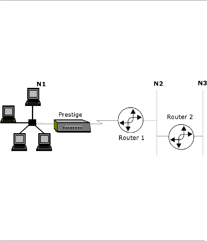
Prestige 310 Broadband Sharing Gateway
IP Static Route Setup 6-1
Chapter 6:
IP Static Route Setup
This chapter shows you how to configure static routes with your Prestige.
Static routes tell the Prestige routing information that it cannot learn automatically through other means. This
can arise in cases where RIP is disabled on the LAN.
Each remote node specifies only the network to which the gateway is directly connected, and the Prestige has
no knowledge of the networks beyond. For instance, the Prestige knows about network N2 in the following
diagram through remote node Router 1. However, the Prestige is unable to route a packet to network N3
because it doesn’t know that there is a route through the same remote node Router 1 (via gateway Router 2).
The static routes are for you to tell the Prestige about the networks beyond the remote nodes.
Figure 6-1 Example of Static Routing Topology

Prestige 310 Broadband Sharing Gateway
6-2 IP Static Route Setup
6.1 IP Static Route Setup
You configure IP static routes in Menu 12. 1, by selecting one of the IP static routes as shown below. Enter
12 from the Main Menu.
Figure 6-2 Menu 12 - IP Static Route Setup
Now, enter the index number of one of the static routes you want to configure.
Figure 6-3 Menu 12. 1 - Edit IP Static Route
`
The next table describes the IP Static Route Menu fields.
Menu 12 - IP Static Route Setup
1. ________
2. ________
3. ________
4. ________
5. ________
6. ________
7. ________
8. ________
Enter selection number:
Menu 12.1 - Edit IP Static Route
Route #: 1
Route Name= ?
Active= No
Destination IP Address= ?
IP Subnet Mask= ?
Gateway IP Address= ?
Metric= 2
Private= No
Press ENTER to CONFIRM or ESC to CANCEL:

Prestige 310 Broadband Sharing Gateway
IP Static Route Setup 6-3
Table 6-1 IP Static Route Menu Fields
Field Description
Route # This is the index number of the static route that you chose in Menu 12.
Route Name Enter a descriptive name for this route. This is for identification purposes only.
Active This field allows you to activate/deactivate this static route.
Destination IP
Address This parameter specifies the IP network address of the final destination. Routing is
always based on network number. If you need to specify a route to a single host, use
a subnet mask of 255.255.255.255 in the subnet mask field to force the network
number to be identical to the host ID.
IP Subnet Mask Enter the IP subnet mask for this destination.
Gateway IP
Address Enter the IP address of the gateway. The gateway is an immediate neighbor of your
Prestige that will forward the packet to the destination. On the LAN, the gateway must
be a router on the same segment as your Prestige; over the WAN, the gateway must
be the IP address of one of the Remote Nodes.
Metric Metric represents the “cost” of transmission for routing purposes. IP routing uses hop
count as the measurement of cost, with a minimum of 1 for directly connected
networks. Enter a number that approximates the cost for this link. The number need
not be precise, but it must be between 1 and 15. In practice, 2 or 3 is usually a good
number.
Private This parameter determines if the Prestige will include the route to this remote node in
its RIP broadcasts. If set to Yes, this route is kept private and not included in RIP
broadcast. If No, the route to this remote node will be propagated to other hosts
through RIP broadcasts.
Once you have completed filling in this menu, press [Enter] at the message [Press ENTER to Confirm…]
to save your configuration, or press [Esc] to cancel.

Prestige 310 Broadband Sharing Gateway
III
Part III:
Advanced Management
Chapters 7 - 11 provide information on Prestige filtering, System Information and Diagnosis, SNMP
Configuration, Transferring Files and Telnet.

Prestige 310 Broadband Sharing Gateway
Filters 7-1
Chapter 7:
Filter Configuration
This chapter shows you how to create and apply filter(s).
7.1 About Filtering
Your Prestige uses filters to decide whether to allow passage of a data packet and/or to make a call. There are
two types of filter applications: data filtering and call filtering. Filters are subdivided into device and protocol
filters, which are discussed later.
Data filtering screens the data to determine if the packet should be allowed to pass. Data filters are divided
into incoming and outgoing filters, depending on the direction of the packet relative to a port. Data filtering
can be applied on either the WAN side or the Ethernet side. Call filtering is used to determine if a packet
should be allowed to trigger a call. Remote node call filtering is only applicable when using PPTP or PPPoE
encapsulation (see Figure 5-8). Outgoing packets must undergo data filtering before they encounter call
filtering as shown in the following figure.
Figure 7-1 Outgoing Packet Filtering Process
For incoming packets, your Prestige applies data filters only. Packets are processed depending upon whether
a match is found. The following sections describe how to configure filter sets
The following sections describe how to configure filter sets.
Data
Filtering
Outgoing
Packet
Drop
packet
Built-in
default
Call Filters
User-defined
Call Filters
(if applicable)
Initiate call
if line not up
Active Data
Send packet
and reset
Idle Timer
Or Or
Drop packet
if line not up Drop packet
if line not up
Send packet
but do not reset
Idle Timer
Send packet
but do not reset
Idle Timer
Match MatchMatch
No
match No
match No
match
Call Filtering

Prestige 310 Broadband Sharing Gateway
7-2 Filters
7.1.1 The Filter Structure of the Prestige
A filter set consists of one or more filter rules. Usually, you would group related rules, e.g., all the rules for
NetBIOS, into a single set and give it a descriptive name. The Prestige allows you to configure up to twelve
filter sets with six rules in each set, for a total of 72 filter rules in the system. You cannot mix device filter
rules and protocol filter rules within the same set. You can apply up to four filter sets to a particular port to
block multiple types of packets. With each filter set having up to six rules, you can have a maximum of 24
rules active for a single port.
Three sets of factory default filter rules have been configured in Menu 21 to prevent NetBIOS traffic from
triggering calls and to prevent incoming telnetting and FTP connections from the WAN side. A summary of
their filter rules is shown in the figures that follow.
The following diagram illustrates the logic flow when executing a filter rule.
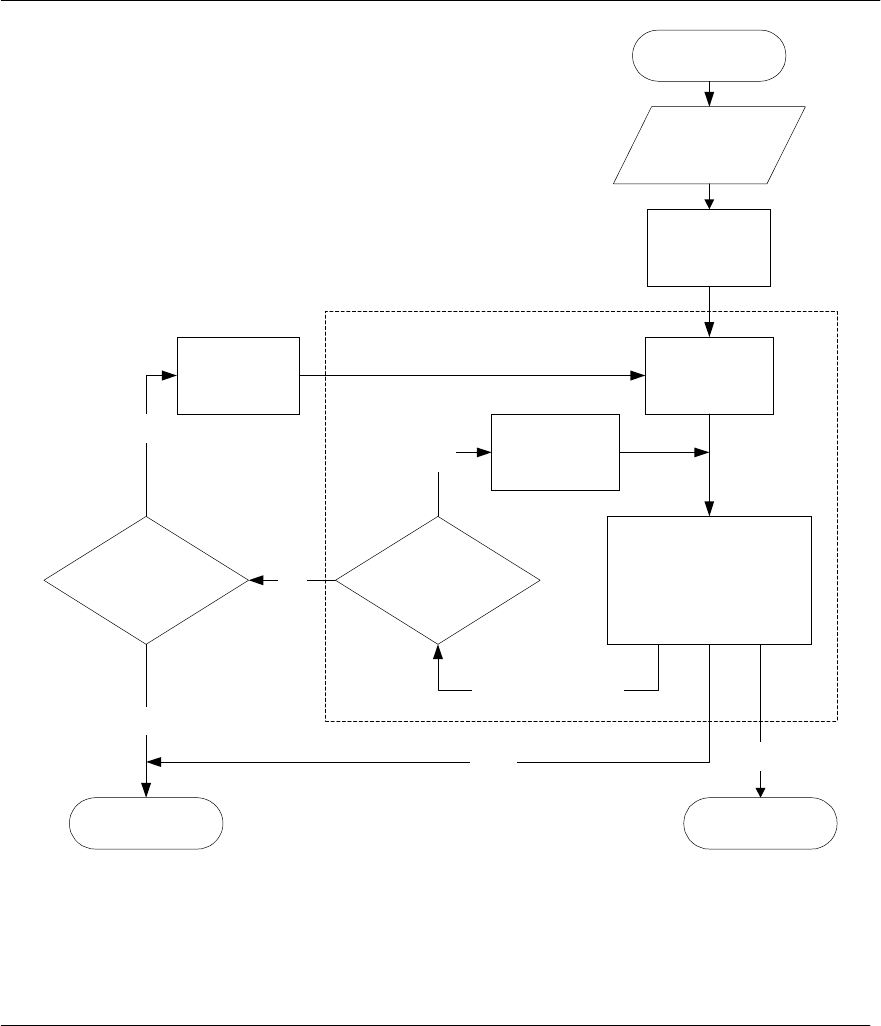
Prestige 310 Broadband Sharing Gateway
Filters 7-3
Start
Packet
into Filter
Accept PacketDrop Packet
Fetch Next
Filter Set
Next Filter Set
Available?
Yes
Filter Set Fetch First
Filter Rule
Execute Filter
Rule
Next Filter Rule
Available?
Fetch Next
Filter Rule
No
Fetch First
Filter Set
Yes
Check Next Rule
Drop
No
Forward
Figure 7-2 Filter Rule Process
You can apply up to four filter sets to a particular port to block multiple types of packets. With each filter set
having up to six rules, you can have a maximum of 24 rules active for a single port.

Prestige 310 Broadband Sharing Gateway
7-4 Filters
7.2 Configuring a Filter Set
To configure a filter set, follow the procedure below. Select option 21. Filter Set Configuration from the
Main Menu to open Menu 21.
Step 1. Enter 1 to bring up the following menu.
Figure 7-3 Menu 21 - Filter Set Configuration
Step 2. Select the filter set you wish to configure (no. 1-12) and press [Enter].
Step 3. Enter a descriptive name or comment in the Edit Comments field and press [Enter].
Step 4. Press [Enter] at the message: [Press ENTER to confirm] to open Menu 21.1.1 - Filter Rules
Summary.
Menu 21.1 - Filter Set Configuration
Filter
Set #
------
1
2
3
4
5
6
Comments
------------------
NetBIOS_WAN
NetBIOS_LAN
TEL_FTP_WEB_WAN
______________
______________
______________
Filter
Set #
------
7
8
9
10
11
12
Comments
------------------
______________
______________
______________
______________
______________
______________
Enter Filter Set Number to Configure= 0
Edit Comments=
Press ENTER to CONFIRM or ESC to CANCEL:

Prestige 310 Broadband Sharing Gateway
Filters 7-5
Figure 7-4 NetBIOS_WAN Filter Rules Summary
Figure 7-5 NetBIOS _LAN Filter Rules Summary
Figure 7-6 TEL_FTP_WEB_WAN Filter Rules Summary
Menu 21.1 - Filter Rules Summary
# A Type Filter Rules M m n
- - ---- -------------------------------------------- --------- - - -
1 Y IP Pr=6, SA=0.0.0.0, DA=0.0.0.0, DP=137 N D N
2 Y IP Pr=6, SA=0.0.0.0, DA=0.0.0.0, DP=138 N D N
3 Y IP Pr=6, SA=0.0.0.0, DA=0.0.0.0, DP=139 N D N
4 Y IP Pr=17, SA=0.0.0.0, DA=0.0.0.0, DP=137 N D N
5 Y IP Pr=17, SA=0.0.0.0, DA=0.0.0.0, DP=138 N D N
6 Y IP Pr=17, SA=0.0.0.0, DA=0.0.0.0, DP=139 N D F
Enter Filter Rule Number (1-6) to Configure:
Press ENTER to Confirm or ESC to Cancel:
Menu 21.2 - Filter Rules Summary
# A Type Filter Rules M m n
- - ---- -------------------------------------------- --------- - -
1 Y IP Pr=17, SA=0.0.0.0, SP=137, DA=0.0.0.0, DP=53 N D F
2 Y
3 Y
4 Y
5 Y
6 Y
Enter Filter Rule Number (1-6) to Configure:
Menu 21.3 - Filter Rules Summary
# A Type Filter Rules M m n
- - ---- ------------------------------------------------------------
1 Y IP Pr=6, SA=0.0.0.0, DA=0.0.0.0, DP=23 N D N
2 Y IP Pr=6, SA=0.0.0.0, DA=0.0.0.0, DP=21 N D N
3 Y IP Pr=6, SA=0.0.0.0, DA=0.0.0.0, DP=80 N D F
4 N
5 N
6 N
Enter Filter Rule Number (1-6) to Configure:

Prestige 310 Broadband Sharing Gateway
7-6 Filters
7.2.1 Filter Rules Summary Menu
This screen shows the summary of the existing rules in the filter set. The following tables contain a brief
description of the abbreviations used in the previous menus.
Table 7-1 Abbreviations Used in the Filter Rules Summary Menu
Abbreviations Description Display
# Refers to the filter rule number (1-6).
A Shows whether the rule is active or not. [Y] means the filter rule is active.
[N] means the filter rule is inactive.
Type Refers to the type of filter rule.
This shows GEN for generic, IP for
TCP/IP
[GEN] for Generic
[IP] for TCP/IP
Filter Rules The filter rule parameters will be
displayed here (see below).
M Refers to More.
[Y] means an action can not yet be taken
as there are more rules to check, which
are concatenated with the present rule
to form a rule chain. When the rule chain
is complete an action can be taken.
[N] means you can now specify an action
to be taken i.e., forward the packet, drop
the packet or check the next rule. For the
latter, the next rule is independent of the
rule just checked.
If More is Yes, then Action Matched and
Action Not Matched will be N/A
[Y] means there are more rules to check.
[N] means there are no more rules to check.
m Refers to Action Matched.
[F] means to forward the packet
immediately and skip checking the
remaining rules.
[F] means to forward the packet.
[D] means to drop the packet.
[N] means check the next rule.
n Refers to Action Not Matched.
[F] means to forward the packet
immediately and skip checking the
remaining rules.
[F] means to forward the packet.
[D] means to drop the packet.
[N] means check the next rule.
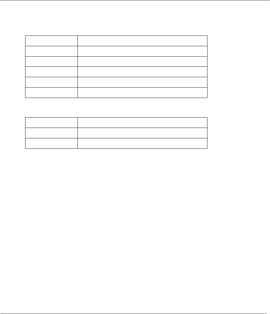
Prestige 310 Broadband Sharing Gateway
Filters 7-7
The protocol dependent filter rules abbreviation are listed as follows:
# If the filter type is IP, the following abbreviations listed in the following table will be used.
Table 7-2 Abbreviations Used If Filter Type Is IP
Abbreviation Description
Pr Protocol
SA Source Address
SP Source Port number
DA Destination Address
DP Destination Port number
# If the filter type is GEN (generic), the following abbreviations listed in the following table will be used.
Table 7-3 Abbreviations Used If Filter Type Is GEN
Abbreviation Description
Off Offset
Len Length
Refer to the next section for information on configuring the filter rules.
7.2.2 Configuring a Filter Rule
To configure a filter rule, type its number in Menu 21.1 - Filter Rules Summary and press [Enter] to open
Menu 21.1.1 for the rule.
To speed up filtering, all rules in a filter set must be of the same class, i.e., protocol filters or generic filters.
The class of a filter set is determined by the first rule that you create. When applying the filter sets to a port,
separate menu fields are provided for protocol and device filter sets. If you include a protocol filter set in a
device filter field or vice versa, the Prestige will warn you and will not allow you to save.
7.2.3 TCP/IP Filter Rule
This section shows you how to configure a TCP/IP filter rule. TCP/IP rules allow you to base the rule on the
fields in the IP and the upper layer protocol, e.g., UDP and TCP, headers.
To configure a TCP/IP rules, select TCP/IP Filter Rule from the Filter Type field and press Enter to open
Menu 21.1.1 - TCP/IP Filter Rule, as shown below.

Prestige 310 Broadband Sharing Gateway
7-8 Filters
Figure 7-7 Menu 21.1.1 - TCP/IP Filter Rule
The following table describes how to configure your TCP/IP filter rule.
Table 7-4 TCP/IP Filter Rule Menu Fields
Field Description Option
Active This field activates/deactivates the filter rule. Yes/No
IP Protocol Protocol refers to the upper layer protocol, e.g., TCP is 6,
UDP is 17 and ICMP is 1. This value must be between 0
and 255
0-255
IP Source Route If Yes, the rule applies to packet with IP source route
option; else the packet must not have source route option.
The majority of IP packets do not have source route.
Yes/No
Destination: IP
Address Enter the destination IP Address of the packet you wish to
filter. This field is a don’t-care if it is 0.0.0.0. IP address
Destination: IP
Mask Enter the IP mask that will be used to mask the bits of the
IP address given in the Destination: IP Addr. IP mask
Destination: Port # Enter the destination port of the packets that you wish to
filter. The range of this field is 0 to 65535. This field is a
don’t-care if it is 0.
0-65535
Destination: Port # Select the comparison to apply to the destination port in None/Less/Greater/E
Menu 21.1.1 - TCP/IP Filter Rule
Filter #: 1,1
Filter Type= TCP/IP Filter Rule
Active= Yes
IP Protocol= 6 IP Source Route= No
Destination: IP Addr= 0.0.0.0
IP Mask= 0.0.0.0
Port #= 137
Port # Comp= Equal
Source: IP Addr= 0.0.0.0
IP Mask= 0.0.0.0
Port #=
Port # Comp= None
TCP Estab= No
More= No Log= None
Action Matched= Drop
Action Not Matched= Check Next Rule
Press ENTER to Confirm or ESC to Cancel:
Press Space Bar to Toggle.

Prestige 310 Broadband Sharing Gateway
Filters 7-9
Field Description Option
Comp the packet against the value given in Destination: Port #. qual/Not Equal]
Source: IP Address Enter the source IP Address of the packet you wish to
filter. This field is a don’t-care if it is 0.0.0.0. IP Address
Source: IP Mask Enter the IP mask that will be used to mask the bits of the
IP address given in the Source: IP Addr. IP Mask
Source: Port # Enter the source port of the packets that you wish to filter.
The range of this field is 0 to 65535. This field is a don’t-
care if it is 0.
0-65535
Source: Port #
Comp Select the comparison to apply to the source port in the
packet against the value given in Source: Port #. None/Less/Greater/E
qual/Not Equal
TCP Estab This field is applicable only when IP Protocol field is 6,
TCP. If yes, the rule matches only established TCP
connections; else the rule matches all TCP packets.
Yes/No
More If yes, a matching packet is passed to the next filter rule
before an action is taken; else the packet is disposed of
according to the action fields.
If More is Yes, then Action Matched and Action Not
Matched will be No.
Yes / No
Log Select the logging option from the following:
None – No packets will be logged.
Action Matched - Only packets that match the rule
parameters will be logged.
Action Not Matched - Only packets that do not match the
rule parameters will be logged.
Both – All packets will be logged.
None
Action Matched
Action Not Matched
Both
Action Matched Select the action for a matching packet. Check Next Rule
Forward
Drop
Action Not Matched Select the action for a packet not matching the rule. Check Next Rule
Forward
Drop

Prestige 310 Broadband Sharing Gateway
7-10 Filters
Field Description Option
Once you have completed filling in Menu 21.1.1.1 - TCP/IP Filter Rule, press [Enter] at the message
[Press Enter to Confirm] to save your configuration, or press [Esc] to cancel. This data will now be
displayed on Menu 21.1.1 - Filter Rules Summary.
The following diagram illustrates the logic flow of an IP filter.
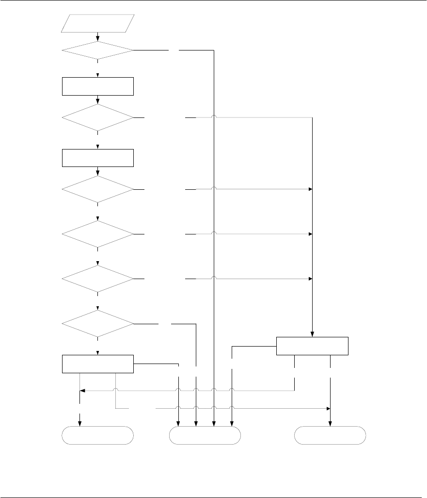
Prestige 310 Broadband Sharing Gateway
Filters 7-11
Packet
into IP Filter
Matched
Matched
Yes
Action Matched
Action Not Matched
More?
No
Filter Active?
Check
IP Protocol
Drop
Drop Packet Accept Packet
Drop Forward
Check Next Rule
Check Next Rule
Check Next Rule
Forward
Not Matched
Yes
No
Check Src
IP Addr
Apply SrcAddrMask
to Src Addr
Matched
Check Dest
IP Addr
Apply DestAddrMask
to Dest Addr
Not Matched
Not Matched
Check Src &
Dest Port
Matched
Not Matched
Figure 7-8 Executing an IP Filter

Prestige 310 Broadband Sharing Gateway
7-12 Filters
7.2.4 Generic Filter Rule
This section shows you how to configure a generic filter rule. The purpose of generic rules is to allow you to
filter non-IP packets. For IP, it is generally easier to use the IP rules directly.
For generic rules, the Prestige treats a packet as a byte stream as opposed to an IP or IPX packet. You specify
the portion of the packet to check with the Offset (from 0) and the Length fields, both in bytes. The Prestige
applies the Mask (bit-wise ANDing) to the data portion before comparing the result against the Value to
determine a match. The Mask and Value are specified in hexadecimal numbers. Note that it takes two
hexadecimal digits to represent a byte, so if the length is 4, the value in either field will take 8 digits, e.g.,
FFFFFFFF.
To configure a generic rule, select Generic Filter Rule in the Filter Type field in the Menu 21.4.1 and press
[Enter] to open Generic Filter Rule, as shown below.
Figure 7-9 Menu 21.4.1 - Generic Filter Rule
Menu 21.4.1 - Generic Filter Rule
Filter #: 4,1
Filter Type= Generic Filter Rule
Active= No
Offset= 0
Length= 0
Mask= N/A
Value= N/A
More= No Log= None
Action Matched= Check Next Rule
Action Not Matched= Check Next Rule
Press ENTER to Confirm or ESC to Cancel:
Press Space Bar to Toggle.

Prestige 310 Broadband Sharing Gateway
Filters 7-13
The following table describes the fields in the Generic Filter Rule Menu.
Table 7-5 Generic Filter Rule Menu Fields
Field Description Option
Filter # This is the filter set, filter rule co-ordinates, i.e., 2,3 refers to the second
filter set and the third rule of that set.
Filter Type Use the [SPACE BAR] to toggle between both types of rules.
Parameters displayed below each type will be different. Generic Filter
Rule/ TCP/IP Filter
Rule
Active Select Yes to turn on the filter rule. Yes/No
Offset Enter the starting byte of the data portion in the packet that you wish to
compare. The range for this field is from 0 to 255. Default = 0
Length Enter the byte count of the data portion in the packet that you wish to
compare. The range for this field is 0 to 8. Default = 0
Mask Enter the mask (in Hexadecimal) to apply to the data portion before
comparison.
Value Enter the value (in Hexadecimal) to compare with the data portion.
More If yes, a matching packet is passed to the next filter rule before an
action is taken; else the packet is disposed of according to the action
fields.
If More is Yes, then Action Matched and Action Not Matched will be
No.
Yes / No
Log Select the logging option from the following:
None – No packets will be logged.
Action Matched - Only packets that match the rule parameters will be
logged.
Action Not Matched - Only packets that do not match the rule
parameters will be logged.
Both – All packets will be logged.
None
Action Matched
Action Not
Matched
Both
Action
Matched Select the action for a matching packet. Check Next Rule
Forward
Drop
Action Not
Matched Select the action for a packet not matching the rule. Check Next Rule
Forward
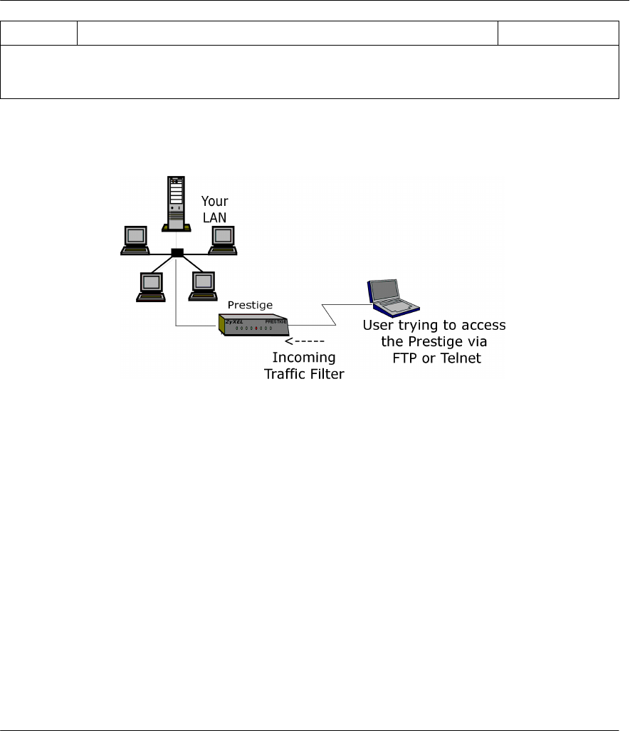
Prestige 310 Broadband Sharing Gateway
7-14 Filters
Drop
Once you have completed filling in Menu 21.4.1.1 - Generic Filter Rule, press [Enter] at the message
[Press Enter to Confirm] to save your configuration, or press [Esc] to cancel. This data will now be
displayed on Menu 21.1.1 - Filter Rules Summary.
7.3 Example Filter
Let’s design a filter to block outside users from telnetting and using FTP connections into the Prestige. Please
see our Supporting CD for more example filters.
Figure 7-10 Filter Example
7.3.1 Before you begin
Before configuring a filter, you must know the following information:
1. The inbound packet type (protocol & port number): In this case, it is TCP (06) protocol with
port 21 (FTP) and port 23 (Telnet).
2. The source IP address: In this case, as all connections from outside are blocked, the source IP is
0.0.0.0.
3. The destination IP address: It is the Prestige's IP address if SUA is disabled and you have a static
IP; otherwise enter 0.0.0.0 as the destination IP. Once 0.0.0.0 is set as the destination IP, Telnet and
FTP connections are not allowed to reach the Prestige. For the LAN-to-LAN connection, you enter
the Prestige's LAN IP as the destination IP in the filter rule. After the Telnet_WAN filter is applied
to the remote node, it blocks the Telnet and FTP connections to the Prestige, but continues to permit
FTP connection to the local FTP server.
7.3.2 Filter Configuration Steps
Step 1. Enter 21 from the Main Menu to open Menu 21.1 - Filter Set Configuration.
Step 2. Enter the index of the filter set you wish to configure (e.g., 3) and press [Enter].
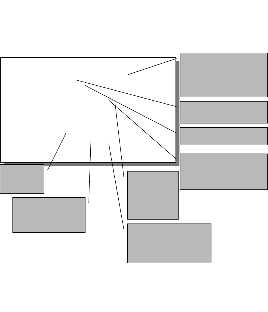
Prestige 310 Broadband Sharing Gateway
Filters 7-15
Step 3. Enter a descriptive name or comment in the Edit Comments field (e.g., TELNET_WAN) and
press [Enter].
Step 4. Press [Enter] at the message: [Press ENTER to confirm] to open Menu 21.3.1 - Filter Rules
Summary.
Step 5. Enter 1 to configure the first filter rule. Make the entries in this menu as shown in the following
figure.
Figure 7-11 Example Filter - Menu 21.3.1
Menu 21.3.1 - TCP/IP Filter Rule
Filter #: 3,1
Filter Type= TCP/IP Filter Rule
Active= Yes
IP Protocol= 6 IP Source Route= No
Destination: IP Addr= 0.0.0.0
IP Mask= 0.0.0.0
Port #= 20
Port # Comp= Equal
Source: IP Addr= 0.0.0.0
IP Mask= 0.0.0.0
Port #= 0
Port # Comp= None
TCP Estab= No
More= No Log= None
Action Matched= Drop
Action Not Matched= Forward
Press ENTER to Confirm or ESC to Cancel:
Press S
p
ace Bar to To
gg
le.
Press [SPACEBAR] to choose
this filter rule type. The first
filter rule type determines all
subsequent filter types within a
set.
Select Yes to make the rule
active.
6 is the TCP protocol.
The port number for FTP is 21.
See RFC 1060 for port numbers
of well-known services.
Select Equal
here as we are
looking for
packets going to
port 21 only.
There are no
more rules to
check.
Select Drop here so that
the packet will be
dropped if its destination
is the telnet port. Select Next here so that the
next rule in this set will be
checked.
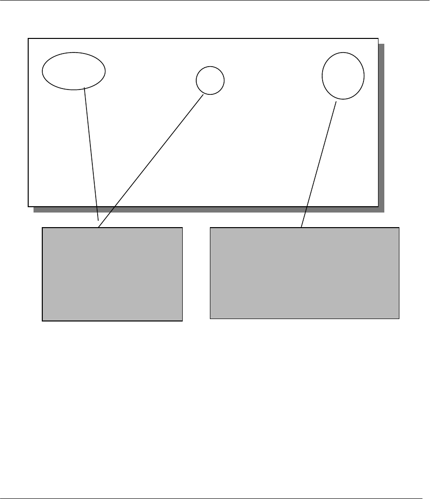
Prestige 310 Broadband Sharing Gateway
7-16 Filters
When you press [Enter] to confirm, you will see the next screen. Note that there is only one filter rule in this
set.
Figure 7-12 Example Filter Rules Summary – Menu 21.3
Step 6. Enter 2 in the above menu to configure the second rule.. Configure this filter rule with port
number as 23 (Telnet) as shown in the next screen (after you press [ENTER] to confirm.
Menu 21.3 - Filter Rules Summary
# A Type Filter Rules M m n
- - ---- --------------------------------------------------------------- - - -
1 Y IP Pr=6, SA=0.0.0.0, DA=0.0.0.0, DP=21 N D N
2 N
4 N
5 N
6 N
Enter Filter Rule Number (1-6) to Configure: 2
This shows you that you have
configured and activated (A =
Y) a TCP/IP filter rule (Type =
IP, Pr = 6) for destination FTP
ports (DP = 21).
M = N means an action can be taken
immediately. The action is to drop the
packet (m = D) if the action is matched and
to forward the packet immediately (n = N) if
the action is not matched and there are more
rules to be checked (there is one more in this
example).
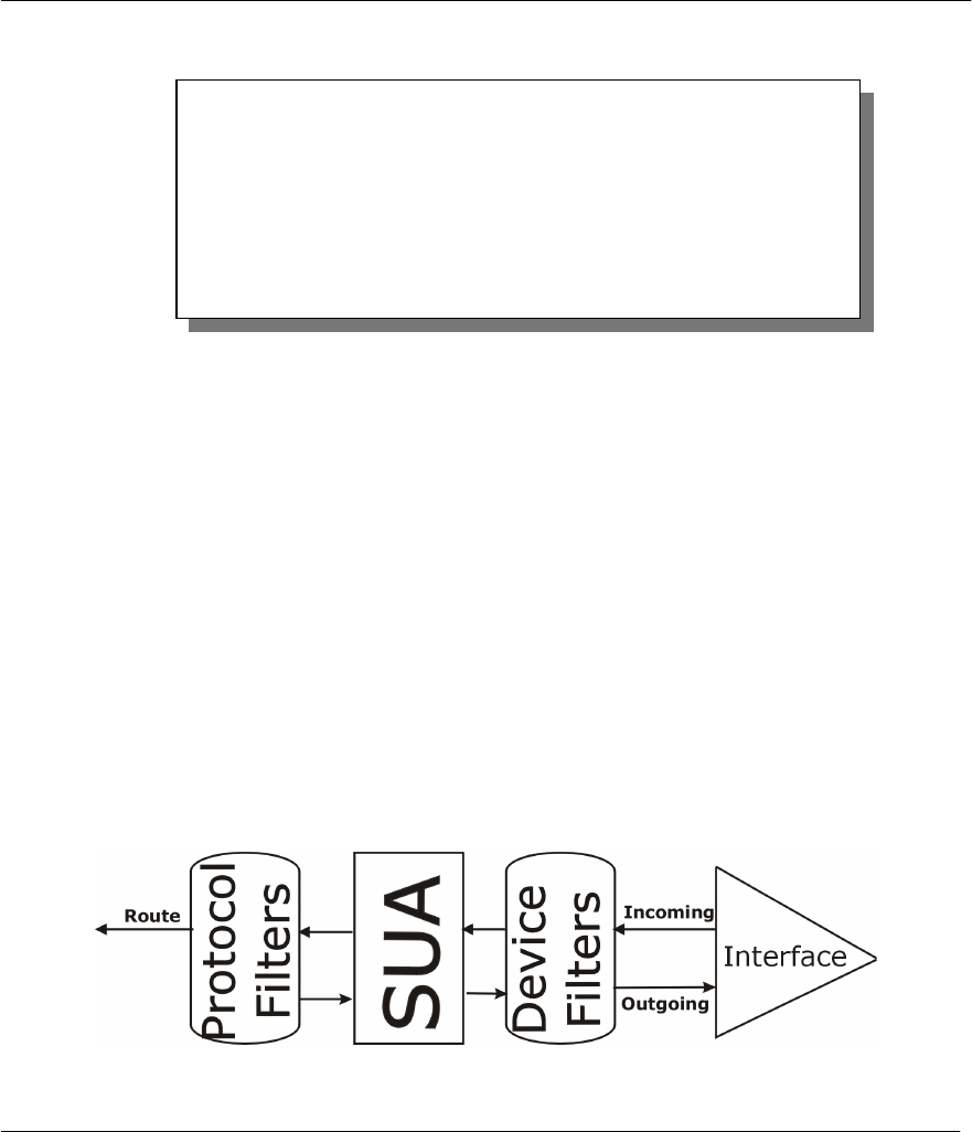
Prestige 310 Broadband Sharing Gateway
Filters 7-17
Figure 7-13 Example Filter Rules Summary
After you’ve created the filter set, you must apply it.
Step 1. Enter 11 from the main menu to go to Menu 11.
Step 2. Go to the Edit Filter Sets field, press the [SPACEBAR] to toggle Yes to No and press
[ENTER].
Step 3. This brings you to Menu 11.5. Apply the TELNET_FTP_WAN filter set (filter set 3) as shown in
Figure 7-16.
7.4 Filter Types and SUA
There are two classes of filter rules, Generic Filter (Device) rules and Protocol Filter (TCP/IP and IPX)
rules. Generic Filter rules act on the raw data from/to LAN and WAN. Protocol Filter rules act on the IP and
IPX packets. Generic and TCP/IP filter rules are discussed in more detail in the next section. When SUA is
enabled, the inside IP address and port number are replaced on a connection-by-connection basis, which
makes it impossible to know the exact address and port on the wire. Therefore, the Prestige applies the
protocol filters to the “native” IP address and port number before SUA for outgoing packets and after SUA
for incoming packets. On the other hand, the generic, or device filters are applied to the raw packets that
appear on the wire. They are applied at the point when the Prestige is receiving and sending the packets; i.e.
the interface. The interface can be an Ethernet port or any other hardware port. The following diagram
illustrates this.
Figure 7-14 Protocol and Device Filter Sets
Menu 21.5 - Filter Rules Summary
# A Type Filter Rules M m n
- - ---- ------------------------------------------------------------
1 Y IP Pr=6, SA=0.0.0.0, DA=0.0.0.0, DP=21 N D N
2 Y IP Pr=6, SA=0.0.0.0, DA=0.0.0.0, DP=23 N D F
3 N
4 N
5 N
6 N
Enter Filter Rule Number (1-6) to Configure:
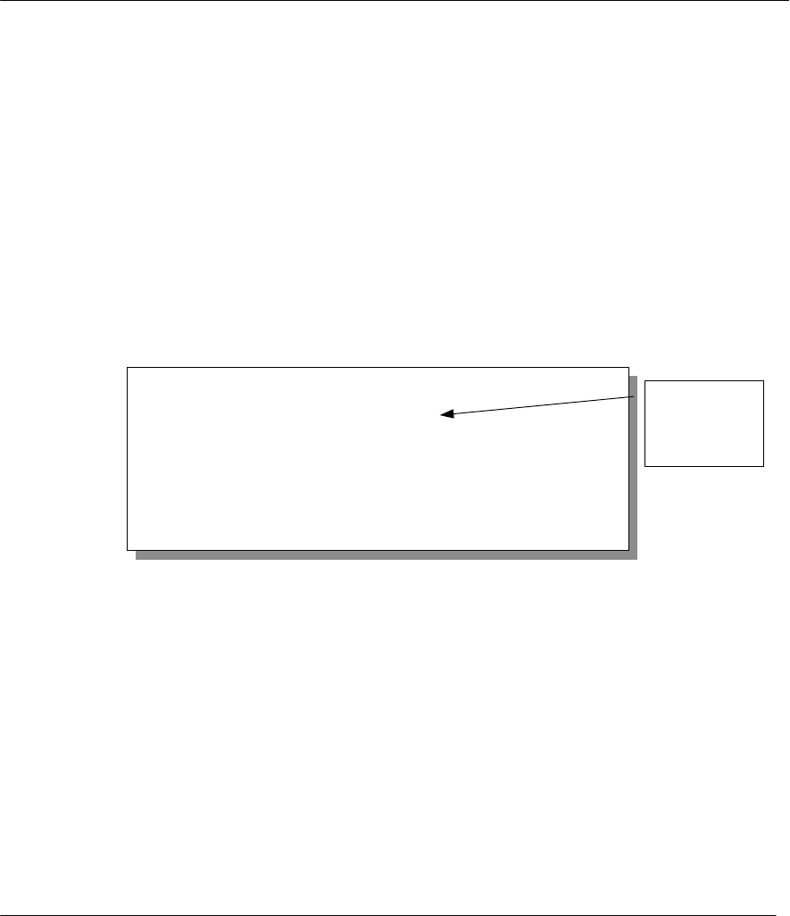
Prestige 310 Broadband Sharing Gateway
7-18 Filters
7.5 Applying a Filter and Factory Defaults
This section shows you where to apply the filter(s) after you design it (them). Three sets of factory default
filter rules have been configured in Menu 21 to prevent NetBIOS traffic from triggering calls and to prevent
incoming telnetting.
7.5.1 LAN traffic
You seldom need to filter LAN traffic; however, the filter sets may be useful to block certain packets, reduce
traffic and prevent security breaches. Go to Menu 3.1 (shown below) and enter the number(s) of the filter
set(s) that you want to apply as appropriate. You can choose up to four filter sets (from twelve) by entering
their numbers separated by commas, e.g., 3, 4, 6, 11. Input filter sets filter incoming traffic to the Prestige
and Output filter sets filter outgoing traffic from the Prestige. The factory default set, NetBIOS_LAN, is
inserted in protocol filters –field under Input Filter Sets in Menu 3.1 to block NetBIOS traffic to the
Prestige from the LAN.
Figure 7-15 Filtering LAN Traffic
7.5.2 Remote Node Filters
Go to Menu 11.5 (shown below) and enter the number(s) of the filter set(s) as appropriate. You can cascade
up to four filter sets by entering their numbers separated by commas. The factory default filter set,
NetBIOS_WAN, is inserted in the protocol filters field under Call Filter Sets in Menu 11.5 to block local
NetBIOS traffic from triggering calls to the ISP (when you are using PPTP/PPPoE encapsulation only).
Filter set three, Telnet_FTP_WAN, blocks telnet and FTP connections from the WAN Port to help prevent
security breaches.
Menu 3.1 – LAN Port Filter Setup
Input Filter Sets:
protocol filters= 2
device filters=
Output Filter Sets:
Protocol filters=
device filters=
Press ENTER to Confirm or ESC to Cancel:
Factory
Default
Filter
Prestige 310 Broadband Sharing Gateway
Filters 7-19
Figure 7-16 Filtering Remote Node Traffic
Menu 11.5 - Remote Node Filter
Input Filter Sets:
protocol filters= 3
device filters=
Output Filter Sets:
protocol filters= 1
device filters=
Call Filter Sets:
protocol filters= 1
device filters=
Factory
Default
Filter
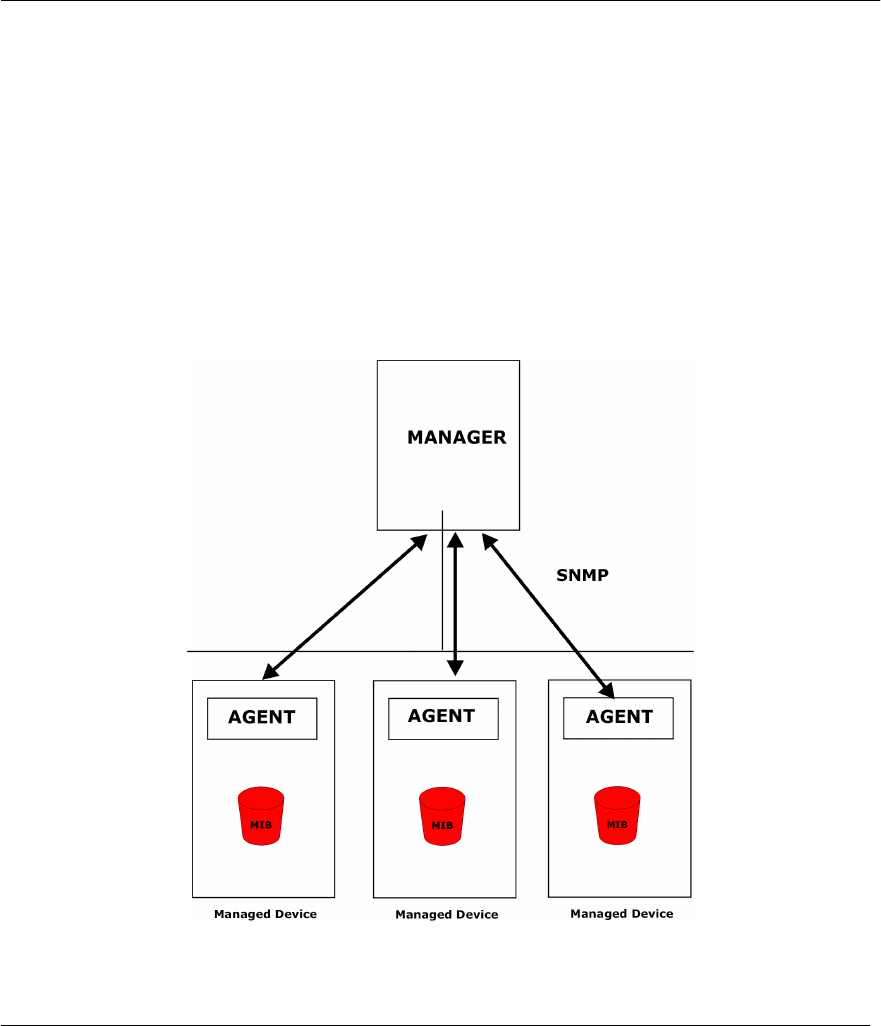
Prestige 310 Broadband Sharing Gateway
SNMP Configuration 8-1
Chapter 8:
SNMP Configuration
8.1 SNMP
SNMP (Simple Network Management Protocol) is a protocol used for exchanging management information
between network devices. SNMP is a member of TCP/IP protocol suite. Your Prestige supports SNMP agent
functionality, which allows a manager station to manage and monitor the Prestige through the network. The
Prestige supports SNMP version one (SNMPv1).
Note: Keep in mind that SNMP is only available if TCP/IP is configured on your Prestige.
The next figure illustrates an SNMP management operation.
Figure 8-1 SNMP Management Model
An SNMP managed network consists of two main components: agents and manager.

Prestige 310 Broadband Sharing Gateway
8-2 SNMP Configuration
An agent is a management software module that resides in a managed device . An agent translates the local
management information from the managed device into a form compatible with SNMP. The manager is the
console through which network administrators perform network management functions. It executes
applications that control and monitor managed devices.
The managed devices contain object variables/managed objects that define each piece of information to be
collected about a device. Examples of variables include such as number of packets received, node port status
etc. A Management Information Base (MIB) is a collection of managed objects. SNMP allows manager and
agents to communicate for the purpose of accessing these objects.
SNMP itself is a simple request/response protocol based on the manager/agent model. The manager issues a
request and the agent returns responses using the following protocol operations:
Get
Allows the manager to retrieve an object variable from the agent.
GetNext
Allows the manager to retrieve the next object variable from a table or list within an agent. In SNMPv1,
when a manager wants to retrieve all elements of a table from an agent, it initiates a Get operation, followed
by a series of GetNext operations.
Set
Allows the manager to set values for object variables within an agent.
Trap
Used by the agent to inform the manager of some events.
8.1.1 SNMP Configuration
To configure SNMP, select option 22. SNMP Configuration from the Main Menu to open Menu 22 - SNMP
Configuration, as shown in the figure. The “community” for Get, Set and Trap fields is simply SNMP’s
terminology for password.
Figure 8-2 Menu 22 - SNMP Configuration
Menu 22 - SNMP Configuration
SNMP:
Get Community= public
Set Community= public
Trusted Host= 0.0.0.0
Trap:
Community= public
Destination= 0.0.0.0
Press ENTER to Confirm or ESC to Cancel:

Prestige 310 Broadband Sharing Gateway
SNMP Configuration 8-3
The following table describes the SNMP configuration parameters.
Table 8-1 SNMP Configuration Menu Fields
Field Description Option
Get Community Enter the Get Community, which is the password
for the incoming Get- and GetNext- requests from
the management station.
Public
Set Community Enter the set community, which is the password for
incoming Set- requests from the management
station.
Public
Trusted Host If you enter a trusted host, your Prestige will only
respond to SNMP messages from this address. If
you leave the field blank (default), your Prestige will
respond to all SNMP messages it receives,
regardless of source.
Blank
Trap: Community Enter the trap community, which is the password
sent with each trap to the SNMP manager. Public
Trap: Destination Enter the IP address of the station to send your
SNMP traps to. Blank
Once you have completed filling in Menu 22 - SNMP Configuration, press [ENTER] at the
message [Press ENTER to Confirm...] to save your configuration, or press [ESC] to cancel.

Prestige 310 Broadband Sharing Gateway
System Information & Diagnosis 9-1
Chapter 9:
System Information & Diagnosis
This chapter talks you through SMT Menus 24.1 to 24 .4.
This chapter covers the diagnostic tools that help you to maintain your Prestige. These tools include updates
on system status, port status, log and trace capabilities and upgrades for the system software. This chapter
describes how to use these tools in detail.
Select menu 24 in the main menu to open Menu 24 - System Maintenance, as shown below.
Figure 9-1 Menu 24 - System Maintenance
Menu 24 - System Maintenance
1. System Status
2. System Information and Console Port Speed
3. Log and Trace
4. Diagnostic
5. Backup Configuration
6. Restore Configuration
7. Upload Firmware
8. Command Interpreter Mode
9. Call Control
10. Time and Date Setting
Enter Menu Selection Number:

Prestige 310 Broadband Sharing Gateway
System Information & Diagnosis
9-2
9.1 System Status
The first selection, System Status, gives you information on the version of your system firmware and the
status and statistics of the ports, as shown in the figure below. System Status is a tool that can be used to
monitor your Prestige. Specifically, it gives you information on your system firmware version, number of
packets sent and number of packets received.
To get to the System Status:
Step 1. Enter number 24 to go to Menu 24 - System Maintenance.
Step 2. In this menu, enter number 1 to open System Maintenance - Status.
Step 3. There are three commands in Menu 24.1 - System Maintenance - Status. Entering 1 drops the
WAN (PPTP/PPPoE) connection, 9 resets the counters and [Esc] takes you back to the previous
screen.
The table below describes the fields present in Menu 24.1 - System Maintenance - Status. It should be
noted that these fields are READ-ONLY and are meant to be used for diagnostic purposes.
Figure 9-2 Menu 24.1 - System Maintenance – Status
Menu 24.1 -- System Maintenance – Status
1:39:06
Thus. Jan. 1. 1970
Port
WAN
LAN
Status
Down
Down
TxPkts
1
0
RxPkts
0
0
Cols
0
0
Tx B/s
0
0
Rx B/s
0
0
Up Time
0:00:00
0:00:00
Port:
WAN
LAN
Ethernet Address
00:a0:c5:21:8c:a3
00:a0:c5:21:8c:a2
IP Address
0.0.0.0
192.168.1.1
IP Mask
0.0.0.0
255.255.255.0
DHCP
Client
Server
System up Time: 1:08:22
Name: P310.www.zyxel.com
Routing: IP
ZyNOS F/W Version: V.251 : 2/17/2000
Press Command:
COMMANDS: 1-Drop WAN 9-Reset Counters ESC-Exit

Prestige 310 Broadband Sharing Gateway
System Information & Diagnosis 9-3
The following table describes the fields present in Menu 24.1 - System Maintenance - Status.
Table 9-1 System Maintenance - Status Menu Fields
Field Description
Port The WAN or LAN port.
Status Shows the port speed and duplex setting if you’re using Ethernet
Encapsulation and down (line is down), idle (line (ppp) idle), dial
(starting to trigger a call) and drop (dropping a call) if you’re using
PPPoE Encapsulation.
TxPkts The number of transmitted packets on this port.
RxPkts The number of received packets on this port.
Cols The number of collisions on this port.
Tx B/s Shows the transmission speed in Bytes per second on this port.
Rx B/s Shows the reception speed in Bytes per second on this port.
Up Time Total amount of time the line has been up.
LAN
Ethernet Address The LAN port Ethernet address.
IP Address The LAN port IP address.
IP Mask The LAN port IP mask.
DHCP The LAN port DHCP role.
WAN
Ethernet Address The WAN port Ethernet address.
IP Address The WAN port IP address.
IP Mask The WAN port IP mask.
DHCP The WAN port DHCP role.
System up Time The total time the Prestige has been on.
Name This is the Prestige's system name + domain name assigned in Menu
1. E.G., System Name= p310; Domain Name= www.zyxel.com
Name= p310.www.zyxel.com
ZyNOS F/W Version The ZyNOS Firmware version and the date created.

Prestige 310 Broadband Sharing Gateway
System Information & Diagnosis
9-4
9.2 System Information and Console Port Speed
This section describes your system and allows you to choose different console port speeds. To get to the
System Information and Console Port Speed:
Step 1. Enter 24 to go to Menu 24 – System Maintenance.
Step 2. Enter 2 to open, Menu 24.2 - System Information and Console Port Speed.
Step 3. From this Menu you have two choices as shown in the next figure:
Figure 9-3 Menu 24.2 – System Information and Console Port Speed
9.2.1 System Information
System Information gives you information about your system as shown below. More specifically, it gives
you information on your routing protocol, country code, Ethernet address, IP address, etc.
Figure 9-4 Menu 24.2.1 System Maintenance - Information
Menu 24.2.1 - System Maintenance - Information
Name: P310.www.zyxel.com
Routing: IP
ZyNOS F/W Version: V2.51 | 2/17/2000
LAN
Ethernet Address: 00:a0:c5:21:8c:a2
IP Address: 192.168.1.10
IP Mask: 255.255.255.0
DHCP: Server
Press ESC or RETURN to Exit
Menu 24.2 - System Information and Console Port Speed
1. System Information
2. Console Port Speed
Please enter selection:

Prestige 310 Broadband Sharing Gateway
System Information & Diagnosis 9-5
Table 9-2 Fields in System Maintenance
Field Description
Name This is the Prestige's system name + domain name assigned in Menu
1. E.G., System Name= Prestige; Domain Name= zyxel.com
Name= P310.zyxel.com
Routing Refers to the routing protocol used.
ZyNOS F/W Version Refers to the version of ZyXEL's Network Operating System software.
Ethernet Address Refers to the Ethernet MAC (Media Access Control) address of your
Prestige.
IP Address This is the IP address of the Prestige in dotted decimal notation.
IP Mask This shows the subnet mask of the Prestige.
DHCP This field shows the DHCP setting of the Prestige.
9.2.2 Console Port Speed
You can change the speed of the console port through Menu 24.2.2 – Console Port Speed. Your Prestige
supports 9600 (default), 19200, 38400, 57600, and 115200 bps for the console port. Use the [SPACE BAR]
to select the desired speed in Menu 24.2.2, as shown below.
Figure 9-5 Menu 24.2.2 – System Maintenance – Change Console Port Speed
9.3 Log and Trace
There are three logging facilities in the Prestige. The first is the error logs and trace records that are stored
locally. The second is the UNIX syslog facility for message logging. The third logging facilty- Call-
Triggering Packet is also stored locally.
Menu 24.2.2 – System Maintenance – Change Console Port Speed
Console Port Speed: 115200
Press ENTER to Confirm or ESC to Cancel:
Press Space Bar to Toggle.
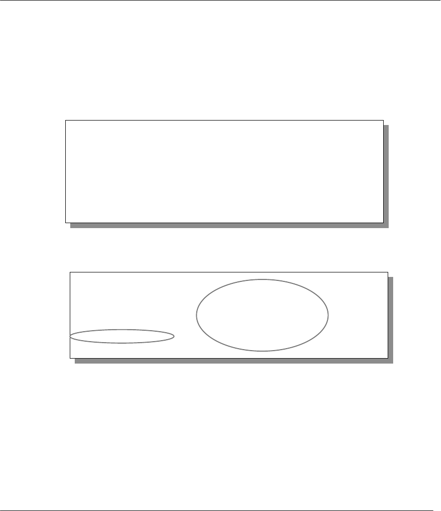
Prestige 310 Broadband Sharing Gateway
System Information & Diagnosis
9-6
9.3.1 Viewing Error Log
The first place you should look for clues when something goes wrong is the error/trace log. Follow the
procedure below to view the local error/trace log:
Step 1. Select option 24 from the Main Menu to open Menu 24 - System Maintenance.
Step 2. From Menu 24, select option 3 to open Menu 24.3 - System Maintenance - Log and Trace.
Step 3. Select the first option from Menu 24.3 - System Maintenance - Log and Trace to display the
error log in the system.
After the Prestige finishes displaying, you will have the option to clear the error log.
Figure 9-6 Examples of Error and Information Messages
Examples of typical error and information messages are presented in the figure below.
Figure 9-7 Examples of Error and Information Messages
9.3.2 UNIX Syslog
The Prestige uses the UNIX syslog facility to log the CDR (Call Detail Record) and system messages to a
syslog server. Syslog and accounting can be configured in Menu 24.3.2 - System Maintenance - Syslog and
Accounting, as shown next.
Menu 24.3 - System Maintenance - Log and Trace
1. View Error Log
2. UNIX Syslog
4. Call-Triggering Packet
Please enter selection
59 Thu Jan 1 00:00:03 1970 PINI INFO SMT Session Begin
60 Thu Jan 1 00:05:11 1970 PINI INFO SMT Session End
61 Thu Jan 1 00:17:59 1970 PINI INFO SMT Session Begin
62 Thu Jan 1 00:24:40 1970 PINI INFO SMT Session End
63 Thu Jan 1 00:35:32 1970 PINI INFO SMT Session Begin
Clear Error Log (y/n):

Prestige 310 Broadband Sharing Gateway
System Information & Diagnosis 9-7
Figure 9-8 Menu 24.3.2 - System Maintenance – UNIX Syslog
You need to configure the UNIX syslog parameters described in the following table to activate syslog then
choose what you want to log.
Table 9-3 System Maintenance Menu Syslog Parameters
Parameter Description
UNIX Syslog:
Active Press the [SPACE BAR] to turn on or off syslog.
Syslog IP Address Enter the IP Address of the server that will log the CDR (Call Detail Record) and
system messages i.e., the syslog server.
Log Facility Press the [SPACE BAR] to toggle between the 7 different Local options. The log
facility allows you to log the message to different files in the server. Please refer to
your UNIX manual for more detail.
Types:
CDR Call Detail Record (CDR) logs all data phone line activity if set to Yes.
Packet triggered The first 48 bytes or octets and protocol type of the triggering packet is sent to the
UNIX syslog server when this field is set to Yes.
Filter log No filters are logged when this field is set to No. Filters with the individual filter Log
Filter field set to Yes (Menu 21.x.x).) are logged when this field is set to Yes.
PPP log PPP events are logged when this field is set to Yes.
Your Prestige sends four types of syslog messages. Some examples (not P310 specific) of these syslog
messages with their message formats are shown next:
Menu 24.3.2 -- System Maintenance - UNIX Syslog and Accounting
UNIX Syslog:
Active= No
Syslog IP Address= ?
Log Facility= Local 1
Types:
CDR= No
Packet triggered= No
Filter log= No
PPP log= No
Press ENTER to Confirm or ESC to Cancel:
Press Space Bar to Toggle.
Prestige 310 Broadband Sharing Gateway
System Information & Diagnosis
9-8
CDR
CDR Message Format
SdcmdSyslogSend( SYSLOG_CDR, SYSLOG_INFO, String );
String = board xx line xx channel xx, call xx, str
board = the hardware board ID
line = the WAN ID in a board
Channel = channel ID within the WAN
call = the call reference number which starts from 1 and increments by 1 for each new call
str = C01 Outgoing Call dev xx ch xx (dev:device No. ch:channel No.)
L02 Tunnel Connected(L2TP)
C02 OutCall Connected xxxx (means connected speed) xxxxx (means Remote Call Number)
L02 Call Terminated
C02 Call Terminated
Jul 19 11:19:27 192.168.102.2 ZyXEL: board 0 line 0 channel 0, call 1, C01 Outgoing Call
dev=2 ch=0 40002
Jul 19 11:19:32 192.168.102.2 ZyXEL: board 0 line 0 channel 0, call 1, C02 OutCall
Connected 64000 40002
Jul 19 11:20:06 192.168.102.2 ZyXEL: board 0 line 0 channel 0, call 1, C02 Call Terminated
1. Packet triggered
Packet triggered Message Format
sdcmdSyslogSend( SYSLOG_PKTTRI, SYSLOG_NOTICE, String );
String = Packet trigger: Protocol=xx Data=xxxxxxxxxx…..x
Protocol: (1:IP 2:IPX 3:IPXHC 4:BPDU 5:ATALK 6:IPNG)
Data: We will send forty-eight Hex characters to the server
Jul 19 11:28:39 192.168.102.2 ZyXEL Communications Corp.: Packet Trigger: Protocol=1,
Data=4500003c100100001f010004c0a86614ca849a7b08004a5c020001006162636465666768696a6b6c6d6e6f
7071727374
Jul 19 11:28:56 192.168.102.2 ZyXEL Communications Corp.: Packet Trigger: Protocol=1,
Data=4500002c1b0140001f06b50ec0a86614ca849a7b0427001700195b3e00000000600220008cd40000020405
b4
2. Filter log
Filter log Message Format
SdcmdSyslogSend(SYSLOG_FILLOG, SYSLOG_NOTICE, String );
String = IP[Src=xx.xx.xx.xx Dst=xx.xx.xx.xx prot spo=xxxxx dpo=xxxxx] S04>R01mD
IP[…] is the packet header and S04>R01mD means filter set 4 (S) and rule 1 (R), match (m) drop (D).
Src: Source Address
Dst: Destination Address
prot: Protocol (“TCP”,”UDP”,”ICMP”)
spo: Source port
dpo: Destination port
Jul 19 14:44:00 192.168.102.2 ZyXEL Communications Corp.: IP[Src=192.168.102.20
Dst=202.132.154.1 UDP spo=01170 dpo=00057]}S03>R01mF
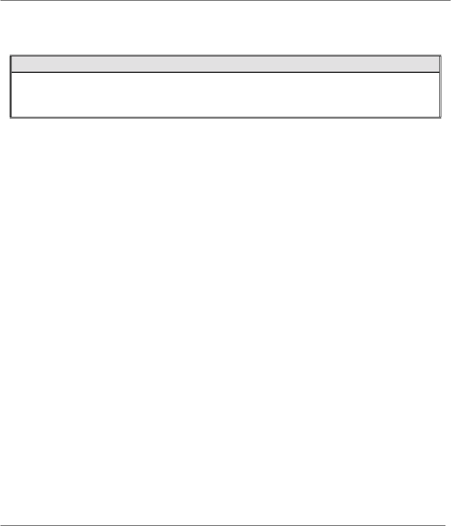
Prestige 310 Broadband Sharing Gateway
System Information & Diagnosis 9-9
Jul 19 14:44:04 192.168.102.2 ZyXEL Communications Corp.: IP[Src=192.168.102.20
Dst=202.132.154.1 ICMP]}S03>R01mF
3. PPP log
PPP Log Message Format
sdcmdSyslogSend( SYSLOG_PPPLOG, SYSLOG_NOTICE, String );
String = ppp:Proto Starting / ppp:Proto Opening / ppp:Proto Closing / ppp:Proto Shutdown
Proto = LCP / ATCP / BACP / BCP / CBCP / CCP / CHAP/ PAP / IPCP /
IPXCP
Jul 19 11:42:44 192.168.102.2 ZyXEL Communications Corp.: ppp:LCP Closing
Jul 19 11:42:49 192.168.102.2 ZyXEL Communications Corp.: ppp:IPCP Closing
Jul 19 11:42:54 192.168.102.2 ZyXEL Communications Corp.: ppp:CCP Closing

Prestige 310 Broadband Sharing Gateway
System Information & Diagnosis
9-10
9.3.3 Call-Triggering Packet
Call-Triggering Packet displays information about the packet that triggered dial-out call in an easy readable
format. Equivalent information is available in Menu 24.1 but in hex format. An example is shown next.
Figure 9-9 Call-Triggering Packet Example
IP Frame: ENET0-RECV Size: 44/ 44 Time: 17:02:44.262
Frame Type:
IP Header:
IP Version = 4
Header Length = 20
Type of Service = 0x00 (0)
Total Length = 0x002C (44)
Identification = 0x0002 (2)
Flags = 0x00
Fragment Offset = 0x00
Time to Live = 0xFE (254)
Protocol = 0x06 (TCP)
Header Checksum = 0xFB20 (64288)
Source IP = 0xC0A80101 (192.168.1.1)
Destination IP = 0x00000000 (0.0.0.0)
TCP Header:
Source Port = 0x0401 (1025)
Destination Port = 0x000D (13)
Sequence Number = 0x05B8D000 (95997952)
Ack Number = 0x00000000 (0)
Header Length = 24
Flags = 0x02 (....S.)
Window Size = 0x2000 (8192)
Checksum = 0xE06A (57450)
Urgent Ptr = 0x0000 (0)
Options =
0000: 02 04 02 00
RAW DATA:
0000: 45 00 00 2C 00 02 00 00-FE 06 FB 20 C0 A8 01 01 E......... ....
0010: 00 00 00 00 04 01 00 0D-05 B8 D0 00 00 00 00 00 ................
0020: 60 02 20 00 E0 6A 00 00-02 04 02 00
Press any key to continue...

Prestige 310 Broadband Sharing Gateway
System Information & Diagnosis 9-11
9.4 Diagnostic
The diagnostic facility allows you to test the different aspects of your Prestige to determine if it is working
properly. Menu 24.4 allows you to choose among various types of diagnostic tests to evaluate your system,
as shown next.
Figure 9-10 Menu 24.4 - System Maintenance - Diagnostic
Follow the procedure below to get to Menu 24.4 - System Maintenance – Diagnostic.
Step 1. From the Main Menu, select option 24 to open Menu 24 - System Maintenance.
Step 2. From this menu, select option 4. Diagnostic. This will open Menu 24.4 - System Maintenance -
Diagnostic.
9.4.1 WAN DHCP
DHCP functionality can be enabled on the LAN or WAN as shown in Figure 9-11. LAN DHCP has already
been discussed in section 3.1.5. The Prestige can act either as a WAN DHCP client (IP Address Assignment
field in Menu 4 or Menu 11.3 is Dynamic and the Encapsulation field in Menu 4 or Menu 11 is Ethernet)
or “none”, i.e., you have a static IP. The WAN Release and Renewal fields in Menu 24.4 conveniently allow
you to release and/or renew the assigned WAN IP address, subnet mask and default gateway in a fashion
similar to winipcfg.
Menu 24.4 - System Maintenance - Diagnostic
TCP/IP
1. Ping Host
2. WAN DHCP Release
3. WAN DHCP Renewal
4. Internet Setup Test
System
11. Reboot System
Enter Menu Selection Number:
Host IP Address= N/A
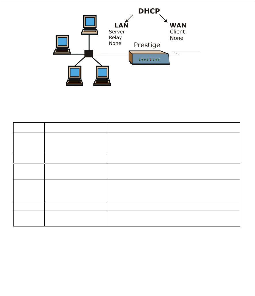
Prestige 310 Broadband Sharing Gateway
System Information & Diagnosis
9-12
Figure 9-11 WAN & LAN DHCP
The following table describes the diagnostic tests available in Menu 24.4 for your Prestige and the
connections.
Table 9-4 System Maintenance Menu Diagnostic
Number Field Description
1 Ping Host Enter 1 to ping any machine (with an IP address) on
your LAN or WAN. Enter its IP address in the Host IP
Address= field mentioned in the last row of this table.
2 WAN DHCP Release Enter 2 to release your WAN DHCP settings.
3 WAN DHCP Renewal Enter 3 to renew your WAN DHCP settings. The
renewal timeout is 32 seconds.
4 Internet Setup Test Enter 4 to test the Internet Setup. You can also test
the Internet Setup in Menu 4 - Internet Access. Please
refer to the chapter- Internet Access for more details.
11 Reboot System Enter 11 to reboot the Prestige.
Host IP Address= If you entered 1 above, then enter the IP address of
the machine you want to ping in this field.

Prestige 310 Broadband Sharing Gateway
Transferring Files 10-1
Chapter 10:
Transferring Files
This chapter tells you how to back up and restore your configuration file as well as upload new
firmware and a new configuration file.
10.1 Filename conventions
The configuration file (often called the romfile or rom-0) contains the factory default settings in the menus
such as password, DHCP Setup, TCP/IP Setup etc. It arrives from ZyXEL with a name of prestige.ROM or
similar. Once you have customized the Prestige's setting, they can be saved back to PC/workstation under a
filename of your choosing. Choose something meaningful, e.g., “prestige.cfg”.
The ZyNOS firmware file (sometimes referred to as the ras file) is the file that contains the ZyXEL Network
Operating System firmware and usually is the Prestige model name with a *.bin extension, e.g., prestige.bin.
With serial (XMODEM) transfer, the filenames on the PC are your choice. With many ftp and tftp clients,
they are as well as seen next.
ftp> put prestige.bin ras
This is a sample ftp session showing the transfer of the file "prestige.bin" on your computer to the Prestige
and renaming it “ras”.
ftp> get rom-0 prestige.cfg
This is a sample ftp session saving the current Prestige configuration to the file prestige.cfg on your
computer.
If your [t]ftp client does not allow you have a destination filename different than the source, you will need to
rename them as the Prestige only recognizes "rom-0" and "ras". Be sure you keep unaltered copies of both
files for later use.
The following table is a summary. Please note that the internal filename refers to the filename on the Prestige
and the external filename refers to the filename not on the Prestige, i.e., on your workstation, local network
or ftp site and so the name (but not the extension) will vary. The AT command is the command you enter
after you press “Y” when prompted in the SMT menu to go into debug mode. After uploading new firmware
see the ZyNOS F/W Version field in Menu 24.2.1 (Figure 9-4 Menu 24.2.1 System Maintenance -
Information) to check you have uploaded the correct firmware version.

Prestige 310 Broadband Sharing Gateway
Transferring Files
10-2
Table 10-1 Filename Conventions
File Type Internal
Name External
Name Description AT
Command
Configuration
File Rom-0 *.rom This is the router configuration filename
on the Prestige. Uploading the rom-0 file
replaces the entire ROM file system,
including your Prestige configurations,
system-related data (including the baud
rate and default password), the error log
and the trace log.
ATLC
Firmware Ras *.bin This is the generic name for the ZyNOS
firmware on the Prestige. ATUR
10.1.1 Firmware Development
It is important to upgrade your firmware regularly, especially if there are problems. If you discover an
unexpected behavior, or bug, see if your problem is mentioned in the release notes. Load it according to
instructions (e.g., see if the default configuration file is needed also). If the problem still exists, e-mail or call
tech support.
10.2 Backup Configuration
The Prestige displays DIFFERENT messages explaining different ways to backup,
restore and upload files in Menu 24.5, 24.6, 24. 7.1 and 24.7.2 when you use the
serial/console port and when you telnet in.
Option 5 from Menu 24 - System Maintenance allows you to backup the current Prestige configuration to
your workstation. Backup is highly recommended once your Prestige is functioning properly. FTP and TFTP
are the preferred methods for backing up your current workstation configuration to your computer since FTP
and TFTP are faster. You can also perform backup and restore using menu 24 through the console port. Any
serial communications program should work fine; however, you must use the XMODEM protocol to perform
the download/upload and you don’t have to rename the files (see section 10.1).
Please note that terms “download” and “upload” are relative to the workstation. Download means to transfer
from another machine to the workstation, while upload means from your workstation to another machine.
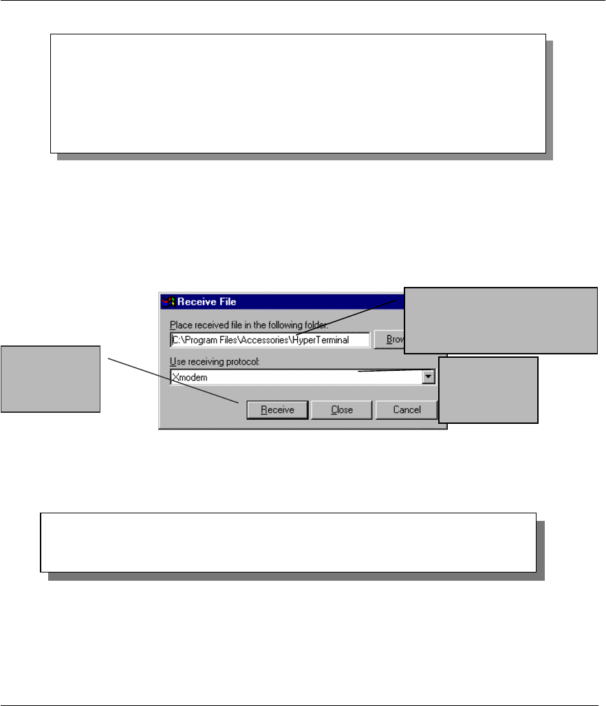
Prestige 310 Broadband Sharing Gateway
Transferring Files 10-3
Figure 10-1 Menu 24.5 - System Maintenance - Backup Configuration (via console port)
Step 1. Go to menu 24.5.
Step 2. Press “Y” to indicate that you want to continue. The following procedure is for the
HyperTerminal program. The procedure for other serial communications programs should be
similar.
Step 3. Click “Transfer” in the HyperTerminal menu bar, then “Receive File” from the drop-down menu
to display the following screen. Follow the instructions as shown.
Figure 10-2 Backup Example Using HyperTerminal
Step 4. After a successful backup you will see the following screen. Press any key to return to the SMT
menu
Figure 10-3 Successful Backup Confirmation Screen
Menu 24.5 -- System Maintenance - Backup Configuration
Ready to backup Configuration via Xmodem.
Do you want to continue (y/n):
** Backup Configuration completed. OK.
### Hit any key to continue.###
Choose the
Xmodem
Protocol.
Enter where you want to place
the rom configuration file on
your computer.
Finally, press
Receive.

Prestige 310 Broadband Sharing Gateway
Transferring Files
10-4
Figure 10-4 Telnet into Menu 24.5
For details about backup using TFTP please refer to the section on TFTP File Transfer.
10.3 Restore Configuration
Menu 24.6 -- System Maintenance - Restore Configuration allows you to restore the configuration via the
console port. Note that this function erases the current configuration before restoring to the previous back up
configuration; please do not attempt to restore unless you have the a backup configuration stored on disk.
FTP and TFTP are the preferred methods for restoring your current workstation configuration to your
Prestige since FTP and TFTP are faster. Please note that the system reboots automatically after the file
transfer is complete.
Figure 10-5 Menu 24.6 - System Maintenance - Restore Configuration (via console port)
Step 1. Go to menu 24.6.
Step 2. Press “Y” to indicate that you want to continue. Follow the procedure as shown previously for the
HyperTerminal program. The procedure for other serial communications programs should be
similar.
Step 3. Click “Transfer” in the HyperTerminal menu bar, then “Send File” from the drop-down menu.
Step 4. Enter where the rom configuration file is on your computer, and make sure you choose the X-
Modem Protocol. Then press “Send”.
Menu 24.6 -- System Maintenance - Restore Configuration
Ready to restore Configuration via Xmodem.
Do you want to continue (y/n):
Menu 24.5 -- System Maintenance - Backup Configuration
To transfer the configuration file to your workstation, follow the procedure
below:
1. Launch the FTP client on your workstation.
2. Type "open" and the IP address of your router. Then type "root" and
SMT password as requested.
3. Locate the 'rom-0' file.
4. Type 'get rom-0' to back up the current router configuration to
your workstation.
For details on FTP commands, please consult the documentation of your FTP
client program. For details on backup using TFTP (note that you must remain
in this menu to back up using TFTP), please see your router manual.
Press ENTER to Exit:

Prestige 310 Broadband Sharing Gateway
Transferring Files 10-5
Step 5. After a successful restoration you will see the following screen. Press any key to return to reboot
the system.
Figure 10-6 Successful Restoration Confirmation Screen
Figure 10-7 Telnet into Menu 24.6
For details about restoring firmware and configuration files using TFTP please refer to
the section on TFTP File Transfer.
10.4 Upload Firmware
Menu 24.7 -- System Maintenance - Upload Firmware allows you to upgrade the firmware and the
configuration file via the console port. Note that this function erases the old data before installing the new
one; please do not attempt to update unless you have the new firmware at hand. There are two components in
the system: the router firmware and the configuration file, as shown below.
Figure 10-8 Menu 24.7 - System Maintenance - Upload Firmware
Menu 24.7 -- System Maintenance - Upload Firmware
1. Upload Router Firmware
2. Upload Router Configuration File
Enter Menu Selection Number:
Menu 24.6 -- System Maintenance - Restore Configuration
To transfer the firmware and configuration file to your workstation, follow the
procedure below:
1. Launch the FTP client on your workstation.
2. Type "open" and the IP address of your router. Then type "root" and
SMT password as requested.
3. Type "put backupfilename rom-0" where backupfilename is the name of
your backup configuration file on your workstation and rom-spt is the
remote file name on the router. This restores the configuration to
your router.
4. The system reboots automatically after a successful file transfer
For details on FTP commands, please consult the documentation of your FTP
client program. For details on backup using TFTP (note that you must remain
in this menu to back up using TFTP), please see your router manual.
Press ENTER to Exit:
Save to ROM
Hit any key to start system reboot.

Prestige 310 Broadband Sharing Gateway
Transferring Files
10-6
10.4.1 Upload Router Firmware via the Console Port
FTP or TFTP are the preferred methods for uploading router firmware to your Prestige. However in the event
of your network being down, uploading router firmware is only possible with a direct connection to your
Prestige via the console port. Uploading router firmware via the console port under normal conditions is not
recommended since FTP or TFTP is faster. Any serial communications program should work fine; however,
you must use the XMODEM protocol to perform the download/upload.
Select 1 from Menu 24.7 – System Maintenance – Upload Firmware to go to Menu 24.7.1 - System
Maintenance - Upload Router Firmware, then follow the instructions as shown in the following screen
Figure 10-9 Menu 24.7.1 - System Maintenance - Upload Router Firmware
After the "Starting XMODEM upload" message appears, activate the Xmodem protocol on your computer.
Follow the procedure as shown previously for the HyperTerminal program. The procedure for other serial
communications programs should be similar.
Step 1 Click “Transfer” in the HyperTerminal menu bar, then “Send File” from the drop-down menu.
Step 2 Enter the path and name of the firmware file (*.bin extension) on your computer.
Step 3 Choose the Xmodem Protocol.
Step 4 Finally, press Send.
Step 5 The system reboots automatically after a successful firmware upload.
10.4.2 Upload Router Firmware using FTP
To transfer the firmware, follow the instructions as shown in the following screen (Menu 24.7.1 using
Telnet).
Menu 24.7.1 - System Maintenance - Upload Router Firmware
To upload router firmware:
1. Enter "y" at the prompt below to go into debug mode.
2. Enter "atur" after "Enter Debug Mode" message.
3. Wait for "Starting XMODEM upload" message before activating
Xmodem upload on your terminal.
4. After successful firmware upload, enter "atgo" to restart the
router.
Warning: Proceeding with the upload will erase the current router
firmware.
Do You Wish To Proceed:(Y/N)

Prestige 310 Broadband Sharing Gateway
Transferring Files 10-7
Figure 10-10 Menu 24.7.1 as seen using Telnet
1.1.1 Example - Using the FTP command from the DOS Prompt
Use “put” to transfer files from the workstation to the Prestige, e.g., put prestige.bin ras transfers
the firmware on your computer (prestige.bin) to the Prestige and renames it “ras”. Similarly put
prestige.rom rom-0 transfers the configuration file on your computer (prestige.rom) to the Prestige
and renames it “rom-0”. See the beginning of this chapter for more information on filenames. Type “quit” to
exit the ftp prompt.
Figure 10-11 FTP Session Example
Note: The system reboots after a successful upload.
The following table describes some of the fields that you may see in third party FTP clients:
Table 10-2 Third Party FTP Clients –General fields
Host Address Enter the address of the host server.
Login Type • Anonymous.
Menu 24.7.1 – Upload Router Firmware using FTP
To upload the router firmware, follow the procedure below:
1. Launch the FTP client on your workstation.
2. Type “open” and the IP address of your Prestige. Then type “root” and your SMT password as
requested.
3. Type “put firmwarefilename ras” where “firmwarefilename” is the name of your firmware
upgrade file on your workstation and “ras” is the remote file name on the Prestige.
4. The system reboots automatically after a successful firmware upload.
For details on FTP commands, please consult the documentation of your FTP client program. For
details on uploading router firmware using TFTP (note that you must remain in menu 24.7.1 to
upload router firmware using TFTP), please see the Prestige manual.
Press ENTER to Exit:
331 Enter PASS command
Password:
230 Logged in
ftp> bin
200 Type I OK
ftp> put prestige.bin ras
200 Port command okay
150 Opening data connection for STOR ras
226 File received OK
ftp: 327680 bytes sent in 1.10Seconds 297.89Kbytes/sec.
ftp> quit

Prestige 310 Broadband Sharing Gateway
Transferring Files
10-8
This is when a user I.D. and password is automatically
supplied to the server for anonymous access. Anonymous
logins will work only if your ISP or service administrator has
enabled this option.
• Normal.
The server requires a unique User ID and Password to login.
Transfer Type Transfer files in either ASCII (plain text format) or in binary
mode.
Initial Remote
Directory. Specify the default remote directory (path).
Initial Local
Directory. Specify the default local directory (path).
1.1.1 Upload Router Firmware using TFTP
Even though TFTP should work over WAN as well, it is not recommended.
To use TFTP, your workstation must have both telnet and TFTP clients. To update your firmware, follow the
procedure below.
Step 1. Use telnet from your workstation to connect to the Prestige and log in. Because TFTP does not
have any security checks, the Prestige records the IP address of the telnet client and accepts TFTP
requests only from this address.
Step 2. Put the SMT in Command Interpreter (CI) mode by entering 8 in Menu 24 – System
Maintenance.
Step 3. Enter command “sys stdio 0” to disable the SMT timeout, so the TFTP transfer will not be
interrupted. Enter command “sys stdio 5” to restore the five-minute SMT timeout (default)
when the file transfer is complete.
Step 4. Launch the TFTP client on your workstation and connect to the Prestige.
Step 5. Go to SMT menu 24.7.1. Note that you must remain in this menu until file transfer is complete.
Step 6. Use the TFTP client to transfer files between the Prestige and the workstation.
Step 7. Specify “ras” as the remote filename if you want to upload firmware from your workstation into
the Prestige.
Step 8. The system reboots automatically after a successful firmware upload.
Note that the telnet connection must be active and the SMT in CI mode before and
during the TFTP transfer. TFTP and FTP over WAN will not work if you have applied a
filter in Menu 11.5 to block Telnet service from the WAN.
For details on TFTP commands, please consult the documentation of your TFTP client program. For UNIX,
use “put” to transfer from the workstation to the Prestige, and “binary” to set binary transfer mode.

Prestige 310 Broadband Sharing Gateway
Transferring Files 10-9
1.1.2 Example Using TFTP To Upload Prestige Firmware
The following is an example tftp command:
TFTP [-i] host put prestige.bin ras
where “i” specifies binary image transfer mode (use this mode when transferring binary files), “host” is the
Prestige IP address, “put” transfers the file source on the workstation (prestige.bin – name of the firmware on
your computer) to the file destination on the remote host (ras - name of the firmware on the Prestige).
The following table describes some of the fields that you may see in third party TFTP clients.
Table 10-3 Third Party TFTP Clients –General fields
Host Enter the IP address of the Prestige. 192.168.1.1 is the Prestige
default IP address when shipped.
Send/Fetch Press “Send” to upload the file to the Prestige and “Fetch” to back
up the file on your computer.
Local File Enter the path and name of the firmware file (*.bin extension) or
configuration file (*.rom extension) on your computer.
Remote File This is the filename on the Prestige. The filename for the firmware
is “ras” and for the configuration file, is “rom-0”.
Binary Transfer the file in binary mode.
Abort Stop transfer of the file.
1.2 Upload Router Configuration File
The configuration data, system-related data, the error log and the trace log are all stored in the configuration
file. Please be aware that uploading the configuration file replaces all previous configurations. You can
upgrade the configuration file either through an FTP or TFTP client program (preferred method) or through
the RS-232 console port (in the event of the network being down). Updating the configuration file via the
console port under normal conditions is not recommended since FTP or TFTP is faster. Please note that you
need to reboot the system after the configuration file update process is complete. Note that if you replace the
current configuration with the default configuration file, i.e.. prestige.rom, you will lose all configurations
that you had before and the speed of the console port will be reset to the default of 9600 bps with 8 data bit,
no parity and 1 stop bit(8n1). You will need to change your serial communication software to the default
before you can connect to the Prestige again. The password will be reset to the default of 1234, as well.
1.2.1 Upload Router Configuration File using the Console Port
Select 2 from Menu 24.7 – System Maintenance – Upload Firmware to go to Menu 24.7.2 - System
Maintenance - Upload Router Configuration File. Follow the instructions as shown in the following
screen.

Prestige 310 Broadband Sharing Gateway
Transferring Files
10-10
Figure 10-12 Menu 24.7.2 as seen using the Console Port
Follow the procedure as shown previously for the HyperTerminal program. The procedure for other serial
communications programs should be similar.
Step 1 Click “Transfer” in the HyperTerminal menu bar, then “Send File” from the drop-down menu.
Step 2 Enter the path and name of the rom configuration file (*.rom extension) on your computer.
Step 3 Choose the Xmodem Protocol.
Step 4 Finally, press Send.
Step 5 The system reboots automatically after a successful firmware upload.
1.2.2 Upload Router Configuration File using FTP
To upload the router configuration file, follow the instructions as shown in the following screen (Menu
24.7.2 using Telnet). See also the FTP example earlier in this chapter.
Menu 24.7.2 - System Maintenance - Upload Router Configuration File
To upload router configuration file:
1. Enter "y" at the prompt below to go into debug mode.
2. Enter "atlc" after "Enter Debug Mode" message.
3. Wait for "Starting XMODEM upload" message before activating
Xmodem upload on your terminal.
4. After successful firmware upload, enter "atgo" to restart the
router.
Warning:
1. Proceeding with the upload will erase the current
configuration file.
2. The router's console port speed (Menu 24.2.2) may change
when it is restarted; please adjust your terminal's speed
accordingly. The password may change (menu 23), also.
3. When uploading the DEFAULT configuration file, the console
port speed will be reset to 9600 bps and the password to
"1234".
Do You Which To Proceed:(Y/N)

Prestige 310 Broadband Sharing Gateway
Transferring Files 10-11
Figure 10-13 Menu 24.7.2 as seen using Telnet
1.2.3 Upload Router Configuration File using TFTP
Even though TFTP should work over WAN as well, it is not recommended.
To use TFTP, your workstation must have both telnet and TFTP clients. To transfer the configuration file,
follow the procedure below and example shown earlier in this chapter.
Menu 24.7.2 – System Maintenance - Upload Router Configuration File
To upload the router configuration file, follow the procedure below:
1. Launch the FTP client on your workstation.
2. Type “open” and the IP address of your Prestige. Then type “root” and your SMT password as
requested.
3. Type “put configurationfilename rom-0” where “configurationfilename” is the name of your
router configuration file on your workstation, which will be transferred to the “rom-0”
file on the Prestige.
4. The system reboots automatically after the upload is complete.
For details on FTP commands, please consult the documentation of your FTP client program. For
details on uploading router firmware using TFTP (note that you must remain in menu 24.7.2 to
upload the router configuration file using TFTP), please see the Prestige manual.
Press ENTER to Exit:

Prestige 310 Broadband Sharing Gateway
System Maintenance & Information 11-1
Chapter 11:
System Maintenance & Information
This chapter leads you through SMT menus 24.8 to 24.11.
11.1 Command Interpreter Mode
This option allows you to enter command interpreter mode, a “DOS prompt” type command interface, which
allows more advanced system diagnosis and troubleshooting (beyond the scope of this guide). See our
supporting CD or the zyxel web site at www.zyxel.com for more detailed information on CI commands.
Enter 8 from Menu 24 - System Maintenance. A list of valid commands can be found by typing [help] or
[?] at the command prompt. Type “exit” to return to the SMT main menu when finished.
Figure 11-1 Command Mode
11.2 Call Control Support
The Prestige provides two call control functions: budget management and call history. Please note that this
menu is only applicable when Encapsulation is set to PPPoE in Menu 4 or Menu 11.1.
The budget management function allows you to set a limit on the total outgoing call time of the Prestige
within certain times. When the total outgoing call time exceeds the limit, the current call will be dropped and
any future outgoing calls will be blocked.
Call history chronicles preceding incoming and outgoing calls.
Menu 24 - System Maintenance
1. System Status
2. System Information and Console Port Speed
3. Log and Trace
4. Diagnostic
5. Backup Configuration
6. Restore Configuration
7. Firmware Update
8. Command Interpreter Mode
9. Call Control
10. Time and Date Setting
Enter Menu Selection Number:

Prestige 310 Broadband Sharing Gateway
System Maintenance & Information
11-2
To access the call control menu, select option 9. Call Control in Menu 24 to go to Menu 24.9 - System
Maintenance - Call Control, as shown in the next table.
Figure 11-2 Call Control
11.2.1 Budget Management
Menu 24.9.3 shows the budget management statistics for outgoing calls. Enter 1 from Menu 24.9 - System
Maintenance - Call Control to bring up the following menu.
Figure 11-3 Budget Management
The total budget is the time limit on the accumulated time for outgoing calls to a remote node. When this
limit is reached, the call will be dropped and further outgoing calls to that remote node will be blocked. After
each period, the total budget is reset. The default for the total budget is 0 minutes and the period is 0 hours,
meaning no budget control. You can reset the accumulated connection time in this menu by entering the
index of a remote node. Enter 1 to clear the budget and 0 to update the screen. The budget and the reset
period can be configured in Menu 11.1 (see Figure 5-3) for the remote node.
Menu 24.9 - System Maintenance - Call Control
1. Budget Management
2. Call History
Enter Menu Selection Number:
Menu 24.9.3 - Budget Management
Remote Node
1. ChangeMe
Connection Time/Total Budget
No Budget
Elapsed Time/Total Period
No Budget
Reset Node (0 to update screen):

Prestige 310 Broadband Sharing Gateway
System Maintenance & Information 11-3
Table 11-1 Budget Management
Field Description Example
Remote Node Enter the index number of the remote node you
want to reset (just one in this case) 1
Connection Time/Total
Budget This is the total connection time (within the
allocated budget that you set in Figure 5-3) that
has gone by.
5/10 means that 5
minutes out of a
total allocation of
10 minutes have
gone by.
Elapsed Time/Total
Period The period is the time cycle in hours that the
allocation budget is reset (see Table 5-3). The
elapsed time is the time used up within this period.
0.5/1 means that
30 minutes out of
the 1 hour time
period has gone
by.
11.2.2 Call History
This is the second option in Menu 24.9 - System Maintenance - Call Control. It displays information about
past incoming and outgoing calls. Enter 2 from Menu 24.9 - System Maintenance - Call Control to bring
up the following menu.
Figure 11-4 Call History
Menu 24.9.4 - Call History
Phone Number
1.
2.
3.
4.
5.
6.
7.
8.
9.
10.
Dir Rate #call Max Min Total
Enter Entry to Delete(0 to exit):

Prestige 310 Broadband Sharing Gateway
System Maintenance & Information
11-4
Table 11-2 Call History Fields
Field Description
Phone Number The PPPoE service names are shown here.
Dir This shows whether the call was incoming or outgoing.
Rate This is the transfer rate of the call.
#call This is the number of calls made to or received from that telephone
number.
Max This is the length of time of the longest telephone call.
Min This is the length of time of the shortest telephone call.
Total This is the total length of time of all the telephone calls to/from that
telephone number.
11.3 Time and Date Setting
There is no Real Time Chip (RTC) chip in the Prestige, so we have a software mechanism to get the current
time and date from an external server when you power up your Prestige. Menu 24.10 does just that – it
allows you to update the time and date settings of your Prestige. The real time is then displayed in the
Prestige error logs. If you do not choose a time service protocol that your timeserver will send when the
Prestige powers up you can enter the time manually but each time the system is booted, the time & date will
be reset to 2000/01/01 0:0:0.

Prestige 310 Broadband Sharing Gateway
System Maintenance & Information 11-5
Figure 11-5 System Maintenance – Time and Date Setting
Table 11-3 Time and Date Setting Fields
Field Description
Use Time Server when
Bootup= Enter the time service protocol that your timeserver will send when the
Prestige powers up. Choices are Daytime (RFC 867), Time (RFC-868),
NTP (RFC-1305) and None. The main differences between them are the
format, e.g., the Daytime (RFC 867) format is day/month/date/year/time
zone of the server while the Time (RFC-868) format gives a 4-byte
integer giving the total number of seconds since 1/1/1970 at 0:0:0. The
NTP (RFC-1305) format is similar. Not all timeservers support all
protocols, so you may have to check with your ISP/network administrator
or use trial and error to find a protocol that works. If you select None
(this is the default value), you can enter the time manually but each time
the system is booted, the time & date will be reset to 2000/01/01 0:0:0.
Time Server IP
Address= Enter the IP address of the your timeserver. Check with your
ISP/network administrator if you are unsure of this information.
Current Time:
New Time Enter the new time in hour, minute and second format.
Current Date:
New Date Enter the new date in year, month, date format.
Time Zone= GMT+0800 Press the [SPACE BAR] to set the time difference between your time
zone and Greenwich mean Time (GMT). Be aware if/when daylight
Menu 24.10 - System Maintenance - Time and Date Setting
Use Time Server when Bootup= None
Time Server IP Address= N/A
Current Time: 00 : 00 : 00
New Time (hh:mm:ss): 1 : 3 : 16
Current Date: 2000/ 01 / 01
New Date (yyyy-mm-dd): 2000/ 01 / 01
Time Zone= GMT+0800
Press ENTER to Confirm or ESC to Cancel:
Press Space Bar to Toggle.

Prestige 310 Broadband Sharing Gateway
System Maintenance & Information
11-6
savings time alters this time difference for your time zone.
Once you have filled in the new time and date, press [Enter] to save the setting and press [Esc] to
return to Menu 24.
11.4 Boot commands
In Debug mode, enter ATHE to view Prestige boot module commands as shown below and then enter ATGO
to continue booting the system. For ATBAx, x denotes the number preceding the colon to give the baud rate
following the colon in the list of numbers that follows; e.g., ATBA3 will give a baud of 9.6 Kbps. ATSE
displays the seed that is used to generate a password to turn on the debug flag in the firmware. The ATSH
command shows product related information such as boot module version, vendor name, product model,
RAS code revision, etc.
Figure 11-6 Boot Module Commands
======= Debug Command Listing =======
AT just answer OK
ATHE print help
ATBAx change baudrate. 1:38.4k, 2:19.2k, 3:9.6k 4:57.6k
5:115.2k
ATENx,(y) set BootExtension Debug Flag (y=password)
ATSE show the seed of password generator
ATTI(h,m,s) change system time to hour:min:sec or show current time
ATDA(y,m,d) change system date to year/month/day or show current date
ATDS dump RAS stack
ATDT dump Boot Module Common Area
ATDUx,y dump memory contents from address x for length y
ATWBx,y write address x with 8-bit value y
ATWWx,y write address x with 16-bit value y
ATWLx,y write address x with 32-bit value y
ATRBx display the 8-bit value of address x
ATRWx display the 16-bit value of address x
ATRLx display the 32-bit value of address x
ATGO(x) run program at addr x or boot router
ATGR boot router
ATGT run Hardware Test Program
AT%Tx Enable Hardware Test Program at boot up
<press any key to continue>

Prestige 310 Broadband Sharing Gateway
Call Scheduling 12-1
Chapter 12:
Call Schedule Setup
The call scheduling feature allows the Prestige to manage a remote node and dictate when a remote node
should be called and for how long. This feature is just like the scheduler in a video recorder (record the
program you want in a specified time). You can apply up to 4 schedule sets in Menu 11.1 - Remote Node
Profile. You configure each schedule in Menu 26 - Schedule Setup. Enter 26 from the main menu to bring
up the following screen.
Figure 12-1 Schedule Setup
As we can have multiple sets that are applied in turn, lowered numbered sets take precedence over higher
numbered sets in case of conflict. For example, if we apply sets 1,2,3,4 in a remote node, then set 1 will take
precedence over set 2, 3 and 4 as it is applied first. Set 2 will take precedence over set 3 and 4, and so on.
You can design up to 12 schedule sets but you can only apply up to 4 schedule sets for a remote node.
To delete a schedule set, enter the set number and press the [Space Bar] (or delete) in
the Edit Name field to delete the set name.
To setup a schedule set select the schedule set you want to setup from Menu 26 (no. 1-12) and press [Enter]
to see Menu 26.1 - Schedule Set Setup as shown next.
Menu 26 - Schedule Setup
Schedule
Set #
------
1
2
3
4
5
6
Name
------------------
______________
______________
______________
______________
______________
______________
Schedule
Set #
------
7
8
9
10
11
12
Name
------------------
______________
______________
______________
______________
______________
______________
Enter Schedule Set Number to Configure=
Edit Name=
Press ENTER to CONFIRM or ESC to CANCEL:

Prestige 310 Broadband Sharing Gateway
Call Scheduling
12-2
Figure 12-2 Schedule Set Setup
The action for a remote node configured with a schedule set is Forced On, Forced Down, Enable Dial-
On-Demand, or Disable Dial-On-Demand. Forced On means that the connection is maintained
whether or not there is a demand call on the line and persist for the time period specified in the Duration
field. Forced Down means that the connection is blocked whether or not there is a demand call on the line.
Enable Dial-On-Demand means that this schedule permits a demand call on the line. Disable Dial-On-
Demand means that this schedule prevents a demand call on the line. If a connection has been already
established, it will not drop it. Once the connection is dropped manually or it times out, then that remote node
can't be triggered up until the end of the Duration.
Menu 26.1 - Schedule Set Setup
Active= Yes
Start Date (mm/dd/yyyy) = 1990-1-1
How Often= Once
Once:
Date (mm/dd/yyyy) = 1990-1-2
Weekdays:
Sunday= N/A
Monday= N/A
Tuesday= N/A
Wednesday= N/A
Thursday= N/A
Friday= N/A
Saturday= N/A
Start Time (hh : mm) = 10 : 20
Duration (hh : mm) = 01 :00
Action= Forced On
Press ENTER to Confirm or ESC to Cancel:

Prestige 310 Broadband Sharing Gateway
Call Scheduling 12-3
Table 12-1 Schedule Set Setup Fields
Field Description Option
Active Press the [Space Bar] to toggle between Yes and No. Choose Yes
and press [Enter] to activate the set. Yes
No
Start Date Enter the start date that you wish the set to take effect in year-month-
date format. Valid dates are from January 1, 1990 to February 5,
2036.
How Often Should this schedule set recur weekly or be used just once only?
Press the [Space Bar] to toggle between Once and Weekly. Both
these options are mutually exclusive. If Once is selected, then all
weekday settings are N/A. When Once is selected, the schedule rule
deletes automatically after the scheduled time elapses.
Once
Weekly
Once: Date If you selected Once in the How Often field above, then enter the date
the set should activate here in year-month-date format.
Weekday:
Day If you selected Weekly in the How Often field above, then select the
day(s) the set should activate (and recur) by going to that day(s) and
pressing the [Space Bar], then [Enter] to select Yes.
Yes
No
N/A
Start Time Enter the start time that you wish the set to take effect in hour : minute
format.
Duration Enter the maximum duration allowed in hour : minute format for this
scheduled connection per call.
Action Press the [Space Bar] to toggle between these options. Choose one
and then press [Enter]. Forced On,
Forced Down,
Enable Dial-On-
Demand, or
Disable Dial-On-
Demand.
12.1.1 Applying A Schedule Set
After you’ve configured your schedule sets, you must apply them to the desired remote node(s). Enter 11
from the Main Menu and then select either PPPoE or PPTP encapsulation. You can apply up to 4 schedule
sets, separated by commas, for one remote node.

Prestige 310 Broadband Sharing Gateway
Call Scheduling
12-4
Figure 12-3 Applying Schedule Set(s) to A Remote Node
Menu 11.1 - Remote Node Profile
Rem Node Name= ChangeMe Route= IP
Active= Yes
Encapsulation= PPTP Edit IP= No
Service Type= Standard Telco Option:
Service Name=N/A Allocated Budget(min)= 0
Outgoing= Period(hr)= 0
My Login= Schedules= 1,2,3,4
My Password= ******** Nailed-up Connections=
PPTP : Session Options:
IP Addr= Edit Filter Sets= No
Server IP Addr= Idle Timeout(sec)= 100
Connection ID/Name=
Press ENTER to Confirm or ESC to Cancel:
Press Space Bar to Toggle.
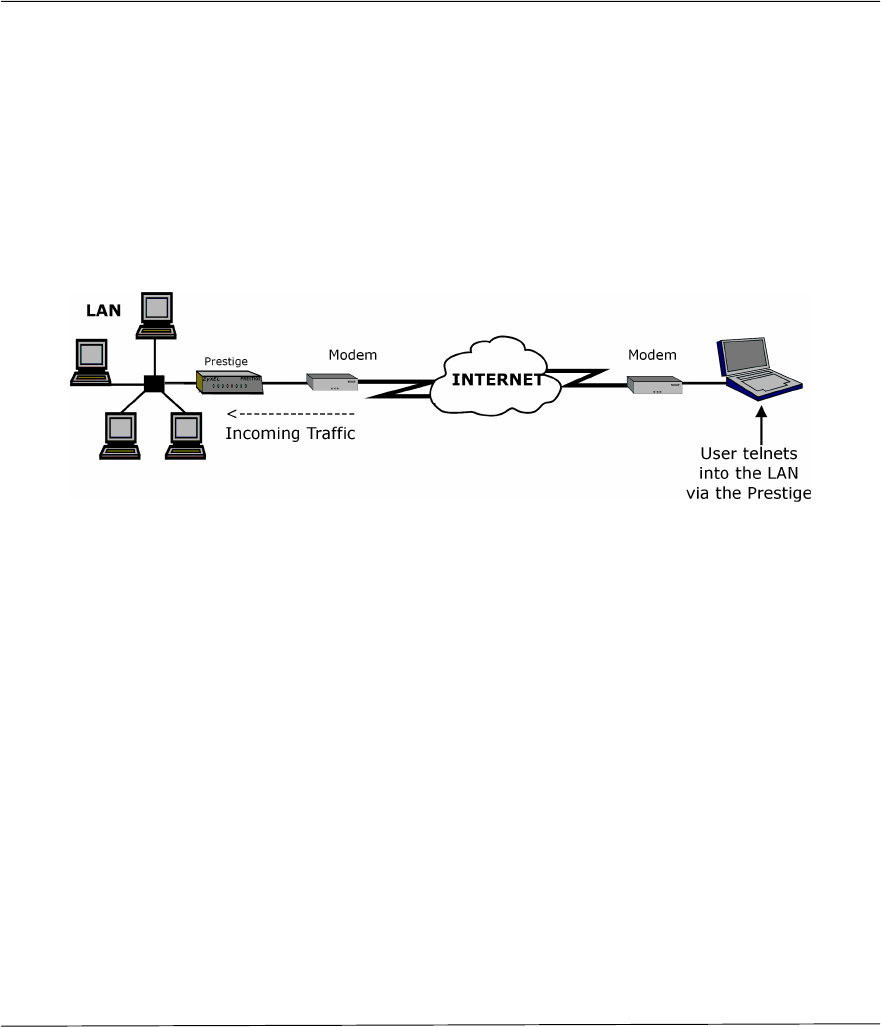
Prestige 310 Broadband Sharing Gateway
Telnet 13-1
Chapter 13:
Telnet Configuration and Capabilities
This chapter covers the Telnet Configuration and Capabilities of the Prestige.
13.1 About Telnet Configuration
Before the Prestige is properly setup for TCP/IP, the only option for configuring it is through the console
port. Once your Prestige is configured, you can use telnet to configure it remotely as shown below.
Figure 13-1 Telnet Configuration on a TCP/IP Network
When IP routing is disabled, the Prestige can still function as a host.
13.2 Telnet Under SUA
When SUA is enabled and an inside server is specified, telnet connections from the outside will be
forwarded to the inside server. So to configure the Prestige via telnet from the outside, you must first telnet to
the inside server, and then telnet from the server to the Prestige using its inside LAN IP address. If no insider
server is specified, telnet to the SUA's IP address will connect to the Prestige directly.
13.3 Telnet Capabilities
13.3.1 Single Administrator
To prevent confusion and discrepancy on the configuration, your Prestige only allows one administrator to
log in at any time. Your Prestige also gives priority to the console port over telnet. If you have already
connected to your Prestige via telnet, you will be logged out if another user logs in to the Prestige via the
console port.

Prestige 310 Broadband Sharing Gateway
Telnet
13-2
13.3.2 System Timeout
There is a system timeout of 5 minutes (300 seconds) for either the console port or telnet. Your Prestige will
automatically log you out if you do nothing in this timeout period, except when it is continuously updating
the status in Menu 24.1.

Prestige 310 Broadband Sharing Gateway
IV
Part IV:
Troubleshooting
Chapter 18 provides information about solving common problems, some Appendices, as well as a
Glossary and Index.

Prestige 310 Broadband Sharing Gateway
Troubleshooting 14-1
Chapter 14:
Troubleshooting
This chapter covers the potential problems you may run into and the possible remedies. After each
problem description, some instructions are provided to help you to diagnose and to solve the
problem. Please see our supporting CD for further information.
14.1 Problems Starting Up the Prestige
Table 14-1 Troubleshooting the Start-Up of your Prestige
Problem Corrective Action
None of the LEDs are on when
you power on the Prestige Check the connection between the AC adapter and the Prestige.
If the error persists, you may have a hardware problem. In this case,
you should contact technical support.
1. Check to see if the Prestige is connected to your computer’s serial
port.
VT100 terminal emulation
9600 bps
Cannot access the Prestige via
the console port.
2. Check to see if the
communications program is
configured correctly. The
communications software should
be configured as follows: No parity, 8 Data bits, 1 Stop bit,
Data Flow set to None.
Prestige 310 Broadband Sharing Gateway
Troubleshooting
14-2
14.2 Problems with the LAN Interface
Table 14-2 Troubleshooting the LAN Interface
Problem Corrective Action
Check the 10M/100M LEDs on the front panel. One of these LEDs
should be on. If they are both off, check the cables between your
Prestige and hub or the station.
Can’t ping any workstation on the
LAN
Verify that the IP address and the subnet mask are consistent
between the Prestige and the workstations.
14.3 Problems with the WAN interface
Table 14-3 Troubleshooting the WAN interface
Problem Corrective Action
The WAN IP is provided when the ISP recognizes the user as an
authorized user after verifying the MAC address or Host Name or
User ID.
Find out the verification method used by your ISP.
If the ISP checks the LAN MAC Address, tell the ISP the WAN MAC
address of the Prestige. The WAN MAC can be obtained from Menu
24.1.
In case the ISP does not allow you to use a new MAC, you can clone
the MAC from the LAN as the WAN MAC and send it to the ISP
using Menu 2 - WAN Setup.
If the ISP checks the Host Name, enter host name in the system field
in Menu 1 - General Setup when you connect the Prestige to a
cable/xDSL modem.
Cannot get WAN IP from the ISP
If the ISP checks the User ID, make sure that you have entered the
correct Service Type, User Name and Password in Menu 4 - Internet
Access Setup.
Can’t connect to a remote node or
ISP Check Menu 24.1 to verify the line status. If it indicates Down, then
refer to the section on the line problems.
Prestige 310 Broadband Sharing Gateway
Troubleshooting 14-3
14.4 Problem with Remote Node or ISP Connection
Table 14-4 Remote Node or ISP Connection
Problem Corrective Action
Check Menu 24.1 to verify the line status. If it indicates [down], then
refer to the section on the line problems.
Cannot connect to
a remote node or
ISP In Menu 11.1, verify your login name and password for the remote
node.
14.5 Problems with Internet Access
Table 14-5 Internet Access
Problem Corrective Action
Connect your Cable/xDSL modem with the Prestige using
appropriate cable.
Check with the manufacturer of your Cable/xDSL modem about the
cable requirement because for some modems you may require
crossover cable and for others regular patch cable.
Cannot access the
Internet.
Verify your settings in Menu 3.2 and Menu 4.
14.6 General Instructions
If you have other problems you can try the following options.
• Check the Menu 24.1 System Maintenance – Status, Menu 24.2.1 - System Information and Menu
24.3 System Maintenance –Log and Trace in order to locate the problem.
• Check the Troubleshooting section in the Support Notes.
• Use Debug commands to diagnose problems. In general, ZyXEL recommends that you use these
commands with the direction of your customer support representative.
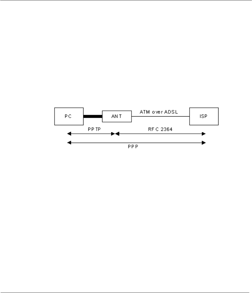
Prestige 310 Broadband Sharing Gateway
PPTP E
Appendix A: PPTP
What is PPTP?
PPTP (Point-to-Point Tunneling Protocol) is a Microsoft proprietary protocol (RFC 2637 for PPTP is
informational only) to tunnel PPP frames.
How can we transport PPP frames from a PC to a broadband modem over Ethernet?
A solution is to build PPTP into the ANT (ADSL Network Termination) where PPTP is used only over the
short haul between the PC and the modem over Ethernet. For the rest of the connection, the PPP frames are
transported with PPP over AAL5 (RFC 2364). The PPP connection, however, is still between the PC and the
ISP. The various connections in this setup are depicted in the following diagram. The drawback of this
solution is that it requires one separate ATM VC per destination.
PPTP and the Prestige
When the Prestige is deployed in such a setup, it appears as a PC to the ANT (ADSL Network Termination).
In Windows VPN or PPTP Pass-Through feature, the PPTP tunneling is created from Windows 95, 98 and
NT clients to an NT server in a remote location. The pass-through feature allows users on the network to
access a different remote server using the Prestige's Internet connection. In SUA mode, the Prestige is able to
pass the PPTP packets to the internal PPTP server (i.e. NT server) behind the NAT. Users need to forward
PPTP packets to port 1723 by configuring the server in Menu 15.1. In the case above as the PPTP connection
is initialized by the remote PPTP Client, the user must configure the PPTP clients. For the Prestige the PPTP
connection is initialized by the Prestige and hence, there is no need to configure the remote PPTP clients.
PPTP Protocol Overview
PPTP is very similar to L2TP, since L2TP is based on both PPTP and L2F (Cisco’s Layer 2 Forwarding).
Conceptually, there are three parties in PPTP, namely the PNS (PPTP Network Server), the PAC (PPTP
Access Concentrator) and the PPTP user. The PNS is the box that hosts both the PPP and the PPTP stacks
and forms one end of the PPTP tunnel. The PAC is the box that dials/answers the phone calls and relays the
PPP frames to the PNS. The PPTP user is not necessarily a PPP client (can be a PPP server too). Both the
PNS and the PAC must have IP connectivity; however, the PAC must in addition have dial-up capability.
The phone call is between the user and the PAC and the PAC tunnels the PPP frames to the PNS. The PPTP
user is unaware of the tunnel between the PAC and the PNS.
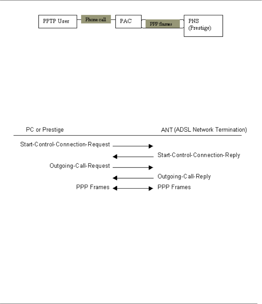
Prestige 310 Broadband Sharing Gateway
PPTP
F
Microsoft includes PPTP as a part of the Windows OS. In Microsoft’s implementation, the PC, and hence the
Prestige, is the PNS that requests the PAC (the ANT) to place an outgoing call over AAL5 to an RFC 2364
server.
Control & PPP connections
Each PPTP session has distinct control connection and PPP data connection.
Call Connection
The control connection runs over TCP. Similar to L2TP, a tunnel control connection is first established
before call control messages can be exchanged. Please note that a tunnel control connection supports
multiple call sessions.
The following diagram depicts the message exchange of a successful call setup between a PC and an ANT.
PPP Data Connection
The PPP frames are tunneled between the PNS and PAC over GRE (General Routing Encapsulation, RFC
1701, 1702). The individual calls within a tunnel are distinguished using the Call ID field in the GRE
header.
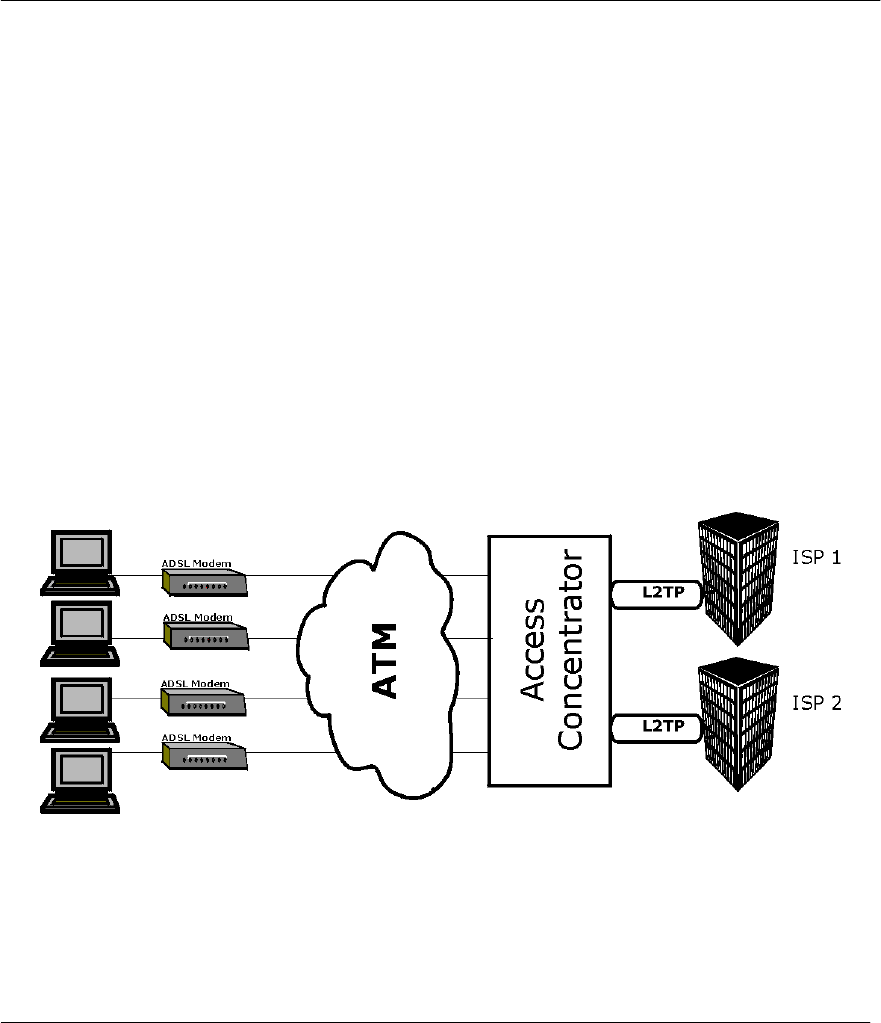
Prestige 310 Broadband Sharing Gateway
PPPoE G
Appendix B: PPPoE
PPPoE in Action
An ADSL modem bridges a PPP session over Ethernet (PPP over Ethernet, RFC 2516) from your PC to an
ATM PVC (Permanent Virtual Circuit) which connects to a xDSL Access Concentrator where the PPP
session terminates (see the next figure). One PVC can support any number of PPP sessions from your LAN.
PPPoE provides access control and billing functionality in a manner similar to dial-up services using PPP.
Benefits of PPPoE
PPPoE offers the following benefits:
1. It provides you with a familiar dial-up networking (DUN) user interface.
2. It lessens the burden on the carriers of provisioning virtual circuits all the way to the ISP on multiple
switches for thousands of users. For GSTN (PSTN & ISDN), the switching fabric is already in place.
3. It allows the ISP to use the existing dial-up model to authenticate and (optionally) to provide
differentiated services.
Traditional Dial-up Scenario
The following diagram depicts a typical hardware configuration where the PCs use traditional dial-up
networking.
Diagram 1 Single-PC per Modem Hardware Configuration
How PPPoE Works
The PPPoE driver makes the Ethernet appear as a serial link to the PC and the PC runs PPP over it, while the
modem bridges the Ethernet frames to the Access Concentrator (AC). Between the AC and an ISP, the AC is
acting as a L2TP (Layer 2 Tunneling Protocol) LAC (L2TP Access Concentrator) and tunnels the PPP
frames to the ISP. The L2TP tunnel is capable of carrying multiple PPP sessions.
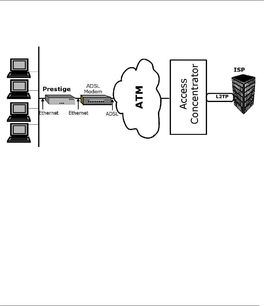
Prestige 310 Broadband Sharing Gateway
PPPoE
H
With PPPoE, the VC (Virtual Circuit) is equivalent to the dial-up connection and is between the modem and
the AC, as opposed to all the way to the ISP. However, the PPP negotiation is between the PC and the ISP.
Prestige as a PPPoE Client
When using the Prestige as a PPPoE client, the PCs on the LAN see only Ethernet and are not aware of
PPPoE. This alleviates the administrator from having to manage the PPPoE clients on the individual PCs.
Diagram 2 Prestige as a PPPoE Client
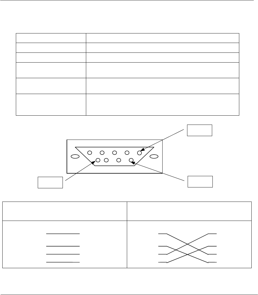
Prestige 310 Broadband Sharing Gateway
Hardware Specifications I
Appendix C: Hardware Specifications
Power Specification I/P AC 120V / 60Hz ; O/P DC 12V 1200 mA
MTBF 100000 hrs
Operation Temperature 0º C ~ 40º C
Ethernet Specification for
WAN 10Mbit Half / Full Manual Setting
Ethernet Specification for
LAN 10/100 Mbit Half / Full Auto-negotiation
Console Port RS – 232 Pin 1 = NON ; Pin 2 = DTE-RXD; Pin 3 = DTE-TXD; Pin 4 =
DTE-DTR; Pin 5 = GND; Pin 6 = DTE-DSR; Pin 7 = DTE-RTS;
Pin 8 = DTE-CTS; PIN 9 = NON. See Figure below
WAN/LAN Cable Pin Layout:
Straight-Through Crossover
(Switch)
1 IRD +
(Adapter)
1 OTD +
(Switch)
1 IRD +
(Switch)
1 IRD +
2 IRD - 2 OTD - 2 IRD - 2 IRD -
3 OTD + 3 IRD + 3 OTD + 3 OTD +
6 OTD - 6 IRD - 6 OTD - 6 OTD -
Pin1
Pin 6
Pin 9

Prestige 310 Broadband Sharing Gateway
Safety Instructions K
Appendix D: Important Safety Instructions
The following safety instructions apply to the Prestige:
1. Be sure to read and follow all warning notices and instructions.
2. The maximum recommended ambient temperature for the Prestige is 40º(104º). Care must be taken to
allow sufficient air circulation or space between units when the Prestige is installed inside a closed rack
assembly. The operating ambient temperature of the rack environment might be greater than room
temperature.
3. Installation in a rack without sufficient airflow can be unsafe.
4. Racks should safely support the combined weight of all equipment.
5. The connections and equipment that supply power to the Prestige should be capable of operating safely
with the maximum power requirements of the Prestige. In case of a power overload, the supply circuits
and supply wiring should not become hazardous. The input rating of the Prestige is printed on the
nameplate.
6. The AC adapter must plug in to the right supply voltage, i.e. 120VAC adapter for North America and
230VAC adapter for Europe. Make sure that the supplied AC voltage is correct and stable. If the input
AC voltage is over 10% lower than the standard may cause the Prestige to malfunction.
7. Installation in restricted access areas must comply with Articles 110-16, 110-17, and 110-18 of the
National Electrical Code, ANSI/NFPA 70.
8. Do not allow anything to rest on the power cord of the AC adapter, and do not locate the product where
anyone can walk on the power cord.
9. Do not service the product by yourself. Opening or removing covers can expose you to dangerous high
voltage points or other risks. Refer all servicing to qualified service personnel.
10. Generally, when installed after the final configuration, the product must comply with the applicable
safety standards and regulatory requirements of the country in which it is installed. If necessary, consult
the appropriate regulatory agencies and inspection authorities to ensure compliance.
11. A rare condition can create a voltage potential between the earth grounds of two or more buildings. If
products installed in separate building are interconnected, the voltage potential can cause a hazardous
condition. Consult a qualified electrical consultant to determine whether or not this phenomenon exists
and, if necessary, implement corrective action before interconnecting the products. If the equipment is to
be used with telecommunications circuit, take the following precautions:
• Never install telephone wiring during a lightning storm.
• Never install telephone jacks in wet location unless the jack is specially designed for wet location.
• Never touch uninsulated telephone wires or terminals unless the telephone line has been
disconnected at the network interface.
• Use caution when installing or modifying telephone lines (other than a cordless telephone) during an
electrical storm. There is a remote risk of electric shock from lightning.
• Do not use a telephone or other equipment connected to telephone lines to report a gas leak near the
leak.
Prestige 310 Broadband Sharing Gateway
Glossary
L
Glossary of Terms
Bandwidth This is the capacity on a link usually measured in bits-per-second (bps).
Bit (Binary Digit) -- A single digit number in base-2, in other words, either a 1 or a zero.
The smallest unit of computerized data.
Broadband Broadband refers to telecommunication that provides multiple channels of data over a
single communications medium.
Byte A set of bits that represent a single character. There are 8 bits in a Byte.
CDR Call Detail Record. This is a name used by telephone companies for call related
information.
CHAP Challenge Handshake Authentication Protocol is an alternative protocol to PAP. It
avoids sending passwords over the wire by using a challenge/response technique.
Client A software program that is used to contact and obtain data from a Server software
program on another computer. Each Client program is designed to work with one or
more specific kinds of Server programs, and each Server requires a specific kind of
Client. A Web Browser is a specific kind of Client.
Crossover Ethernet
cable A cable that wires a pin to its opposite pin, for example, RX+ is wired to TX+. This
cable connects two similar devices, for example, two data terminal equipment (DTE) or
data communications equipment (DCE) devices.
DHCP Dynamic Host Configuration Protocol automatically assigns IP addresses to clients
when they log on. DHCP centralizes IP address management on central computers
that run the DHCP server program. DHCP leases addresses for a period of time which
means that addresses are made available to assign to other systems.
DNS Domain Name System. A database of domain names and their IP addresses. DNS is
the primary naming system for many distributed networks, including the Internet.
Domain Name The unique name that identifies an Internet site. Domain Names always have 2 or
more parts, separated by dots. The part on the left is the most specific, and the part on
the right is the most general.
DSL/xDSL Digital Subscriber Line technologies enhances the data capacity of the existing twisted-
pair wire that runs between the local telephone company switching offices and most
homes and offices. There are actually seven types of DSL service, ranging in speeds
from 16 Kbits/sec to 52 Mbits/sec. The services are either symmetrical (traffic flows at
the same speed in both directions), or asymmetrical (the downstream capacity is
higher than the upstream capacity). DSL connections are point-to-point dedicated
circuits, meaning that they are always connected. There is no dial-up. There is also no
switching, which means that the line is a direct connection into the carrier’s frame
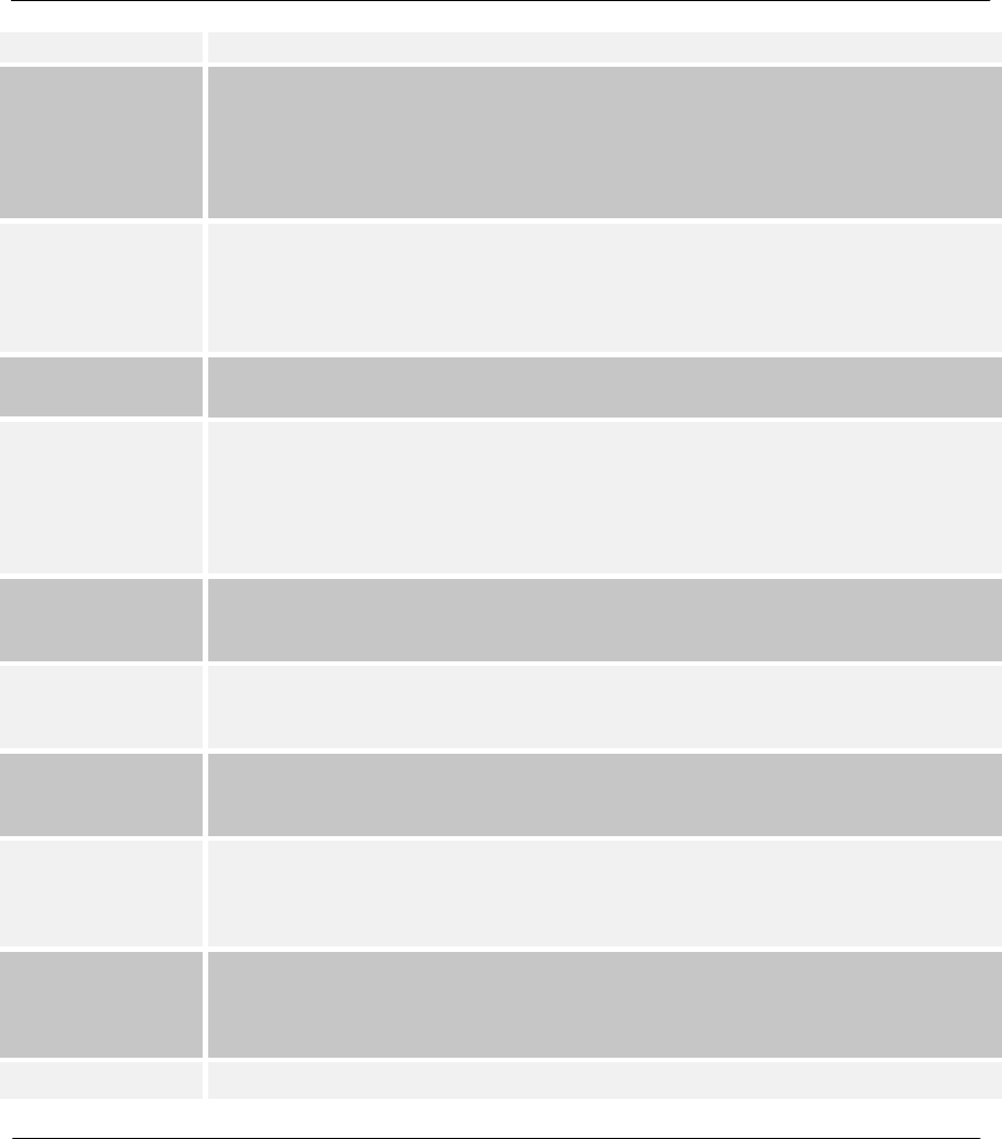
Prestige 310 Broadband Sharing Gateway
Glossary M
relay, ATM (Asynchronous Transfer Mode), or Internet-connect system.
DSLAM A Digital Subscriber Line Access Multiplexer (DSLAM) is a network device, usually at a
telephone company central office, that receives signals from multiple customer Digital
Subscriber Line connections and puts the signals on a high-speed backbone line using
multiplexing techniques. Depending on the product, DSLAM multiplexers connect DSL
lines with some combination of asynchronous transfer mode ATM, frame relay, or IP
networks.
Ethernet A very common method of networking computers in a LAN. There are a number of
adaptations to the IEEE 802.3 Ethernet standard, including adaptations with data rates
of 10 Mbits/sec and 100 Mbits/sec over coaxial cable, twisted-pair cable, and fiber-
optic cable. The latest version of Ethernet, Gigabit Ethernet, has a data rate of 1
Gbit/sec.
Flash memory The nonvolatile storage that can be electrically erased and reprogrammed so that data
can be stored, booted, and rewritten as necessary.
FTP File Transfer Protocol is an Internet file transfer service that operates on the Internet
and over TCP/IP networks. FTP is basically a client/server protocol in which a system
running the FTP server accepts commands from a system running an FTP client. The
service allows users to send commands to the server for uploading and downloading
files. FTP is popular on the Internet because it allows for speedy transfer of large files
between two systems.
Gateway A gateway is a computer system or other device that acts as a translator between two
systems that do not use the same communication protocols, data formatting structures,
languages, and/or architecture.
Host Any computer on a network that is a repository for services available to other
computers on the network. It is quite common to have one host machine provide
several services, such as WWW and USENET.
HTTP Hyper Text Transfer Protocol. The most common protocol used on the Internet. HTTP
is the primary protocol used for web sites and web browsers. It is also prone to certain
kinds of attacks.
IANA Internet Assigned Number Authority acts as the clearinghouse to assign and
coordinate the use of numerous Internet protocol parameters such as Internet
addresses, domain names, protocol numbers, and more. The IANA Web site is at
http://www.isi.edu/iana.
ICMP Internet Control Message Protocol is a message control and error-reporting protocol
between a host server and a gateway to the Internet. ICMP uses Internet Protocol (IP)
datagrams, but the messages are processed by the TCP/IP software and are not
directly apparent to the application user.
Intranet A private network inside a company or organization that uses the same kinds of
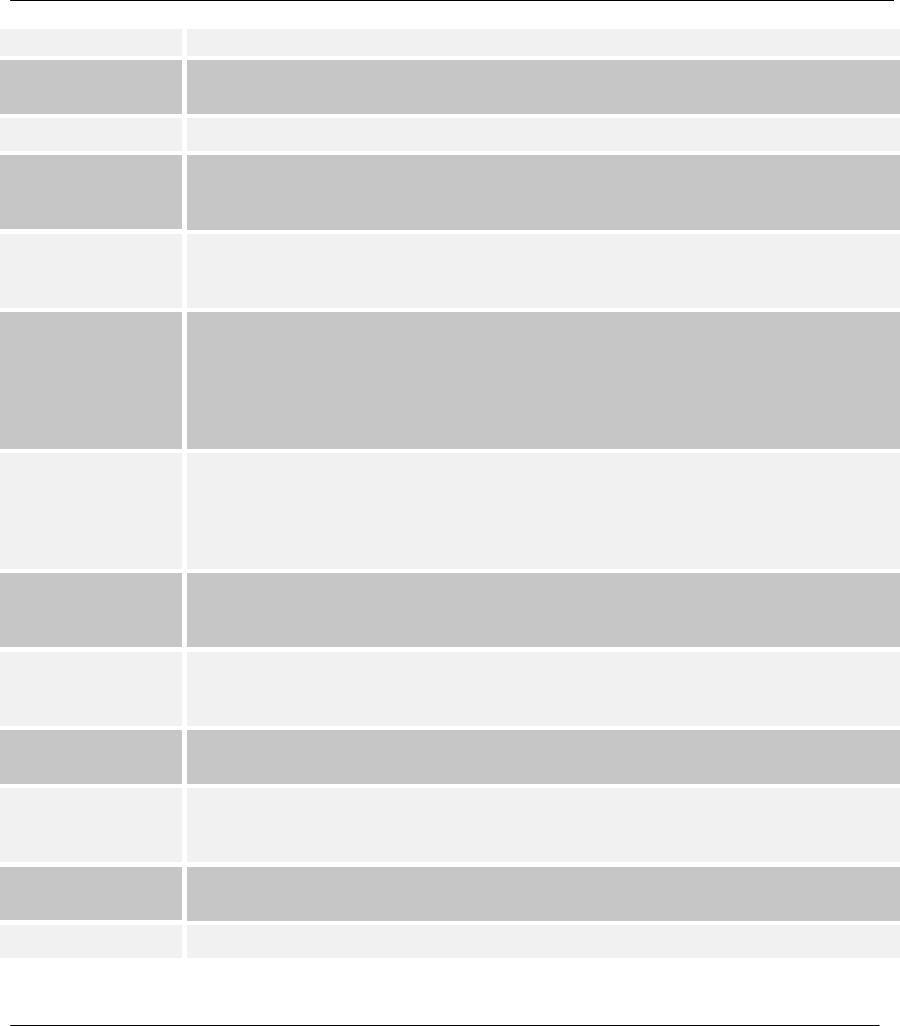
Prestige 310 Broadband Sharing Gateway
Glossary
N
software that you would find on the public Internet, but that is only for internal use.
IP Internet Protocol he IP (currently IP version 4, or IPv4), is the underlying protocol for
routing packets on the Internet and other TCP/IP-based networks.
IPCP (PPP) IP Control Protocol allows changes to IP parameters such as the IP address.
IPX Internetwork Packet eXchange The native NetWare internetworking protocol is IPX
(Internetwork Packet Exchange). Like IP (Internet Protocol), IPX is an internetworking
protocol that provides datagram services.
ISP Internet Service Providers provide connections into the Internet for home users and
businesses. There are local, regional, national, and global ISPs. You can think of local
ISPs as the gatekeepers into the Internet.
LAN Local Area Network is a shared communication system to which many computers are
attached. A LAN, as its name implies, is limited to a local area. This has to do more
with the electrical characteristics of the medium than the fact that many early LANs
were designed for departments, although the latter accurately describes a LAN as well.
LANs have different topologies, the most common being the linear bus and the star
configuration.
MAC On a local area network (LAN) or other network, the MAC (Media Access Control)
address is your computer's unique hardware number. (On an Ethernet LAN, it's the
same as your Ethernet address.) The MAC layer frames data for transmission over the
network, then passes the frame to the physical layer interface where it is transmitted as
a stream of bits.
NAT Network Address Translation is the translation of an Internet Protocol address used
within one network to a different IP address known within another network - see also
SUA.
NDIS Network Driver Interface Specification is a Windows specification for how
communication protocol programs (such as TCP/IP) and network device drivers should
communicate with each other.
NetBIOS Network Basic Input / Output System. NetBIOS is an extension of the DOS BIOS that
enables a PC to connect to and communicate with a LAN.
Network Any time you connect 2 or more computers together so that they can share resources,
you have a computer network. Connect 2 or more networks together and you have an
internet.
NIC Network Interface Card. A board that provides network communication capabilities to
and from a computer system. Also called an adapter.
Node Any single computer connected to a network
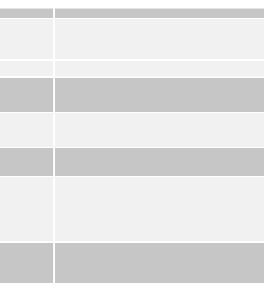
Prestige 310 Broadband Sharing Gateway
Glossary O
Packet Filter A filter that scans packets and decides whether to let them through.
PAP Password Authentication Protocol PAP is a security protocol that requires users to
enter a password before accessing a secure system. The user’s name and password
are sent over the wire to a server, where they are compared with a database of user
account names and passwords. This technique is vulnerable to wiretapping
(eavesdropping) because the password can be captured and used by someone to log
onto the system.
POP Post Office Protocol. This is a common protocol used for sending, receiving, and
delivering mail messages.
POTS Plain Old Telephone Service is the analog telephone service that runs over copper
twisted-pair wires and is based on the original Bell telephone system. Twisted-pair
wires connect homes and businesses to a neighborhood central office. This is called
the local loop. The central office is connected to other central offices and long-distance
facilities.
PPP Point to Point Protocol. PPP encapsulates and transmits IP (Internet Protocol)
datagrams over serial point-to-point links. PPP works with other protocols such as IPX
(Internetwork Packet Exchange). The protocol is defined in IETF (Internet Engineering
Task Force) RFC 1661 through 1663. PPP provides router-to-router, host-to-router,
and host-to-host connections.
Protocol A “language” for communicating on a network. Protocols are sets of standards or rules
used to define, format, and transmit data across a network. There are many different
protocols used on networks. For example, most web pages are transmitted using the
HTTP protocol.
Proxy Server A server that performs network operations in lieu of other systems on the network.
Proxy Servers are most often used as part of a firewall to mask the identity of users
inside a corporate network yet still provide access to the Internet. When a user
connects to a proxy server, via a web browser or other networked application, he
submits commands to the proxy server. The server then submits those same
commands to the Internet, yet without revealing any information about the system that
originally requested the information. Proxy servers are an ideal way to also have all
users on a corporate network channel through one point for all external
communications. Proxy servers can be configured to block certain kinds of connections
and stop some hacks.
PSTN Public Switched Telephone Network was put into place many years ago as a voice
telephone call-switching system. The system transmits voice calls as analog signals
across copper twisted cables from homes and businesses to neighborhood COs
(central offices); this is often called the local loop. The PSTN is a circuit-switched
system, meaning that an end-to-end private circuit is established between caller and
callee.
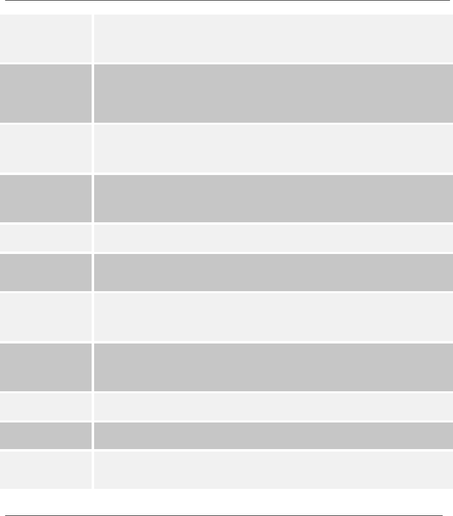
Prestige 310 Broadband Sharing Gateway
Glossary
P
PVC Permanent Virtual Circuit. A PVC is a logical point-to-point circuit between customer
sites. PVCs are low-delay circuits because routing decisions do not need to be made
along the way. Permanent means that the circuit is preprogrammed by the carrier as a
path through the network. It does not need to be set up or torn down for each session.
RFC An RFC (Request for Comments) is an Internet formal document or standard that is the
result of committee drafting and subsequent review by interested parties. Some RFCs
are informational in nature. Of those that are intended to become Internet standards,
the final version of the RFC becomes the standard and no further comments or
changes are permitted. Change can occur, however, through subsequent RFCs.
RIP Routing Information Protocol is an interior or intra-domain routing protocol that uses
the distance-vector routing algorithms. RIP is used on the Internet and is common in
the NetWare environment as a method for exchanging routing information between
routers.
Router A device that connects two networks together. Routers monitor, direct, and filter
information that passes between these networks. Because of their location, routers are
a good place to install traffic or mail filters. Routers are also prone to attacks because
they contain a great deal of information about a network.
Server A computer, or a software package, that provides a specific kind of service to client
software running on other computers.
SNMP System Network Management Protocol is a popular management protocol defined by
the Internet community for TCP/IP networks. It is a communication protocol for
collecting information from devices on the network.
STP Twisted-pair cable consists of copper-core wires surrounded by an insulator. Two wires
are twisted together to form a pair, and the pair form a balanced circuit. The twisting
prevents interference problems. STP (shielded twisted-pair) provides protection
against external crosstalk.
Straight through
Ethernet cable A cable that wires a pin to its equivalent pin. This cable connects two dissimilar
devices, for example, a data terminal equipment (DTE) device and a data
communications equipment (DCE) device. A straight through Ethernet cable is the
most common cable used.
SUA Single User Account – The Prestige's SUA (Single User Account) feature allows
multiple user Internet access for the cost of a single ISP account - see also NAT.
TCP Transmission Control Protocol handles flow control and packet recovery and IP
providing basic addressing and packet-forwarding services.
Telnet Telnet is the login and terminal emulation protocol common on the Internet and in
UNIX environments. It operates over TCP/IP networks. Its primary function is to allow
users to log into remote host systems.
Prestige 310 Broadband Sharing Gateway
Glossary Q
Terminal A device that allows you to send commands to a computer somewhere else. At a
minimum, this usually means a keyboard and a display screen and some simple
circuitry.
Terminal Emulation
Software Software that pretends to be (emulates) a physical terminal and allows you to type
commands to a computer somewhere else.
TFTP Trivial File Transfer Protocol is an Internet file transfer protocol similar to FTP (File
Transfer Protocol), but it is scaled back in functionality so that it requires fewer
resources to run. TFTP uses the UDP (User Datagram Protocol) rather than TCP
(Transmission Control Protocol).
UDP UDP is a connectionless transport service that dispenses with the reliability services
provided by TCP. UDP gives applications a direct interface with IP and the ability to
address a particular application process running on a host via a port number without
setting up a connection session.
UNIX A widely used operating system in large networks.
URL (Uniform Resource Locator) URL is an object on the Internet or an intranet that resides
on a host system. Objects include directories and an assortment of file types, including
text files, graphics, video, and audio. A URL is the address of an object that is normally
typed in the Address field of a Web browser. The URL is basically a pointer to the
location of an object.
VPN Virtual Private Network. These networks use public connections (such as the Internet)
to transfer information. That information is usually encrypted for security purposes.
WAN Wide Area Network s link geographically dispersed offices in other cities or around the
globe. Just about any long-distance communication medium can serve as a WAN link,
including switched and permanent telephone circuits, terrestrial radio systems, and
satellite systems.
WWW (World Wide Web) -- Frequently used when referring to "The Internet", WWW has two
major meanings - First, loosely used: the whole constellation of resources that can be
accessed using Gopher, FTP, HTTP, telnet, USENET, WAIS and some other tools.
Second, the universe of hypertext servers (HTTP servers).

Prestige 310 Broadband Sharing Gateway
Index S
Index
A
AT command, 10-1
B
backup, 10-2
Boot commands, 11-6
Broadband Sharing Gateway, xxiii, 1-1
Budget Management, 11-2, 11-3
C
Cable Modem, 2-2, 2-3
Call Control, 11-1
Call History, 11-3, 11-4
Call-Trigerring Packet, 9-10
CDR, 9-7
CHAP, 5-2
Command Interpreter Mode, 11-1
Community, 8-2
console port, 2-3
Console Port, 2-2, 9-4, 9-5, I
Customer Support, ix
D
DDNS
Configuration, 2-9
DHCP, 1-2, 3-3, 9-11
DHCP (Dynamic Host Configuration Protocol), 1-2, 3-
3
Diagnostic, 9-11
DNS, 3-3, 3-6
Domain Name, 3-3, 9-3, 9-5, L
Dynamic DNS, 2-8, 2-9
DYNDNS Wildcard, 2-8
E
Encapsulation
PPP over Ethernet, G
Error Log, 9-5
Ethernet Encapsulation, 3-8, 5-1, 5-2, 5-3, 5-6, 5-11
F
Factory Default, 2-11
Filename Conventions, 10-1
Filter, 2-12, 5-10, 7-1
About, 7-1
Applying, 7-18
Configuring, 7-4
Example, 7-14
Filter log, 9-7
Generic Filter Rule, 7-12
Structure, 7-2
SUA, 7-17
Filters
Executing a Filter Rule, 7-2
Logic Flow of an IP Filter, 7-10
Flow Control, 2-4
Front Panel LEDs, 2-1
G
General Setup, 2-8
Glossary, L
H
Hidden Menus, 2-5
HTTP, M, O, Q
HyperTerminal, 10-3
I
IANA, 3-1, 3-2

Prestige 310 Broadband Sharing Gateway
TIndex
idle timeout, 5-4
IGMP (Internet Group Multicast Protocol), 3-4
Initial Screen, 2-4
Installation Requirements, 2-3
Internet access, 3-1
Internet Access Setup, 2-6, 3-8, 3-10, 14-2
Internet Assigned Numbers Authority. See IANA
Internet Test Setup, 3-13
IP address, 3-1, 3-6
IP Address, 4-1
IP Address Assignment, 5-6, 5-8, 5-9
IP Alias, 1-2
IP Alias Setup, 3-7
IP Multicast, 3-3
IP Network Number, 3-1
IP Pool, 3-3
IP Static Route, 6-1, 6-2, 6-3
L
LAN Setup, 2-6, 2-11, 2-12, 3-4, 3-5
log, 9-5
Log Facility, 9-7
M
MAC Address, 2-11, 14-2
Main Menu, 2-6
Metric, 5-6, 5-8, 5-10, 6-3
multiple servers, 4-3
My WAN Address, 5-8, 5-9
N
nailed-up connection, 5-4
Network Address Translation (SUA), 13-1
Network Address Translator (NAT), 4-2
P
Packet Triggered, 9-7
Packing List Card, xxiv
PAP, 5-2
password, 2-4
Password, 2-4, 2-7, 8-2
Ping, 9-12
Power Adapter, 2-3
PPP log, 9-7
PPPoE Encapsulation, 3-8, 3-11, 5-1, 5-4, 5-5, 5-9, 5-
11
PPTP Encapsulation, 3-10, 5-1, 5-3, 5-7, 5-10
Private, 3-2, 5-7, 5-8, 5-10, 6-3, Q
Private IP Addresses, 3-2
R
Read Me First, xxiv
Rear Panel, 2-2
Related Documentation, xxiii
remote node, 5-1
Remote Node Filter, 5-10
Required fields, 2-5
Resetting the Prestige, 2-7
Restore Configuration, 10-4
RIP, 3-2, 3-6, 5-7, 5-8, 5-10
S
Safety Instructions, K
Safety Instructions, K
Server, 3-3, 3-6, 3-10, 5-2, 11-5, L, O, P
Service Type, 3-10, 5-2, 14-2
Single User Account, 4-1, 4-2
Configuration, 4-2
SMT, 2-5
SNMP ( Simple Network Management Protocol), 8-1
Community, 8-3
Configuration, 8-2
Traps, 8-3
Trusted Host, 8-3
Structure of this Manual, xxiii
SUA, 5-6, 5-8, 5-9
subnet mask, 3-2
Subnet mask, 3-6
Subnet Mask, 3-1, 3-10, 5-6, 5-8, 5-9, 6-3
Supporting CD, xxiii
sys stdio 0, 10-8
Syslog. See UNIX Syslog
Syslog IP Address, 9-7
System Information, 9-1, 9-4

Prestige 310 Broadband Sharing Gateway
Index U
System Maintenance, 2-7, 9-1, 9-2, 9-3, 9-4, 9-5, 9-6,
9-7, 9-11, 9-12, 10-1, 10-2, 10-3, 10-4, 10-5, 10-6,
11-1, 11-2, 11-3, 11-5
System Name, 2-9
System Status, 9-2
System Timeout, 13-2
T
TCP/IP, 3-1, 3-3, 3-4, 3-5, 3-6, 5-6, 5-9, 7-6, 7-7, 7-8,
7-10, 7-13, 7-17, 13-1, M, N, P
TCP/IP filter rule, 7-7
telnet, 13-1
Telnet Configuration, 13-1
Telnet Under SUA, 13-1
Terminal Emulation, 2-4
TFTP, 10-9
time and date setting, 1-2, 11-4
Time and Date Setting, 11-4, 11-5
Time Zone, 11-5
Timeout, 3-11, 3-12, 5-5
Trace, 9-5
Troubleshooting, 14-1
Internet Access, 14-3
LAN Interface, 14-2
WAN Interface, 14-2
U
Unicast, 3-3
UNIX Syslog, 9-6, 9-7
Upload Firmware, 10-5
Console Port, 10-6
FTP, 10-6
TFTP, 10-8
Upload Router Configuration File, 10-9
FTP, 10-10
TFTP, 10-11
V
VT100, 2-3
W
WAN DHCP, 9-11, 9-12
WAN Setup, 2-6, 2-10, 2-11, 14-2
X
xDSL modem, 1-3, 2-3, 2-4, 3-11, 5-4, 14-2, 14-3
XMODEM protocol, 10-2
Z
ZyNOS, 2-11, 9-3, 9-5, 10-1, 10-2
ZyNOS F/W Version, 9-3, 9-5, 10-1