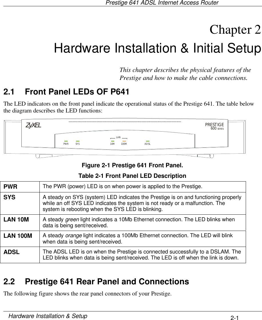
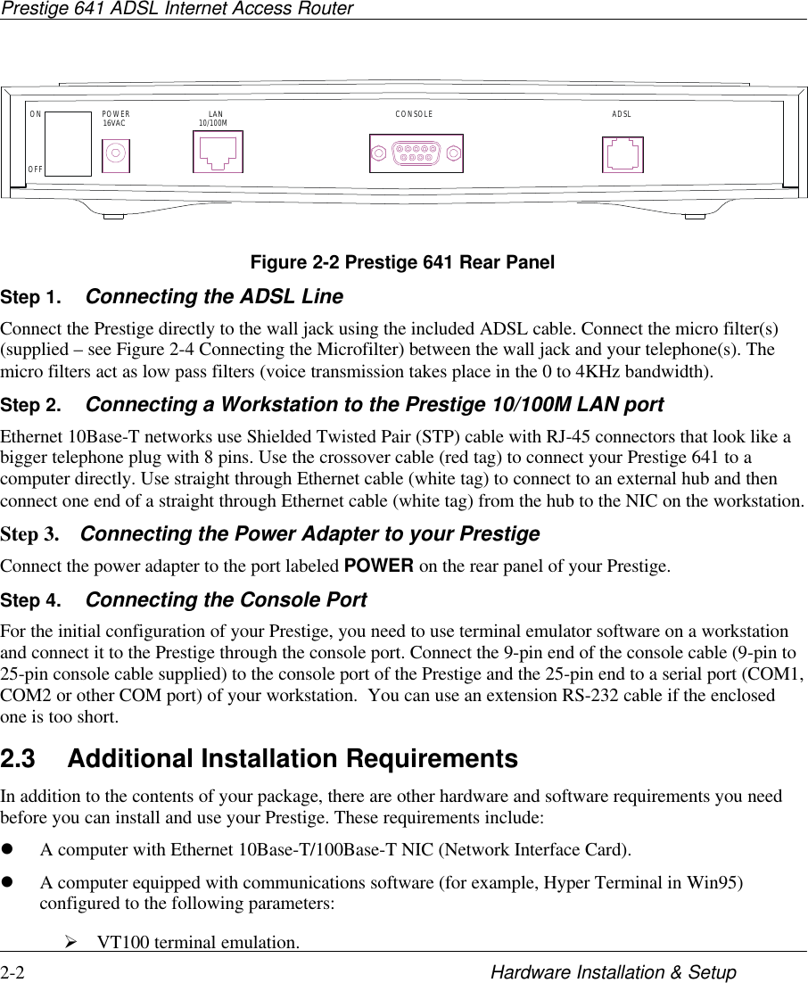
ZyXEL Communications PRESTIGE641 ADSL Router User Manual v10P641
ZyXEL Communications Corporation ADSL Router v10P641
UserManual.wiki
>
ZyXEL Communications
>
PRESTIGE641 User Manual
FCC Statement is on the third page
Navigation menu
Upload a User Manual
Namespaces
Wiki Guide
HTML
PDF
Info
Views
User Manual
Discussion / Help
Navigation
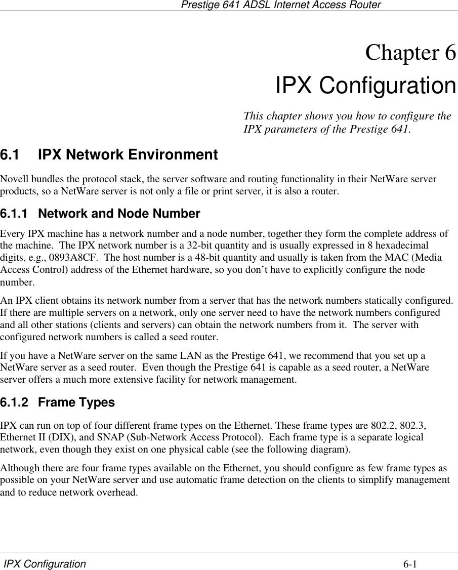
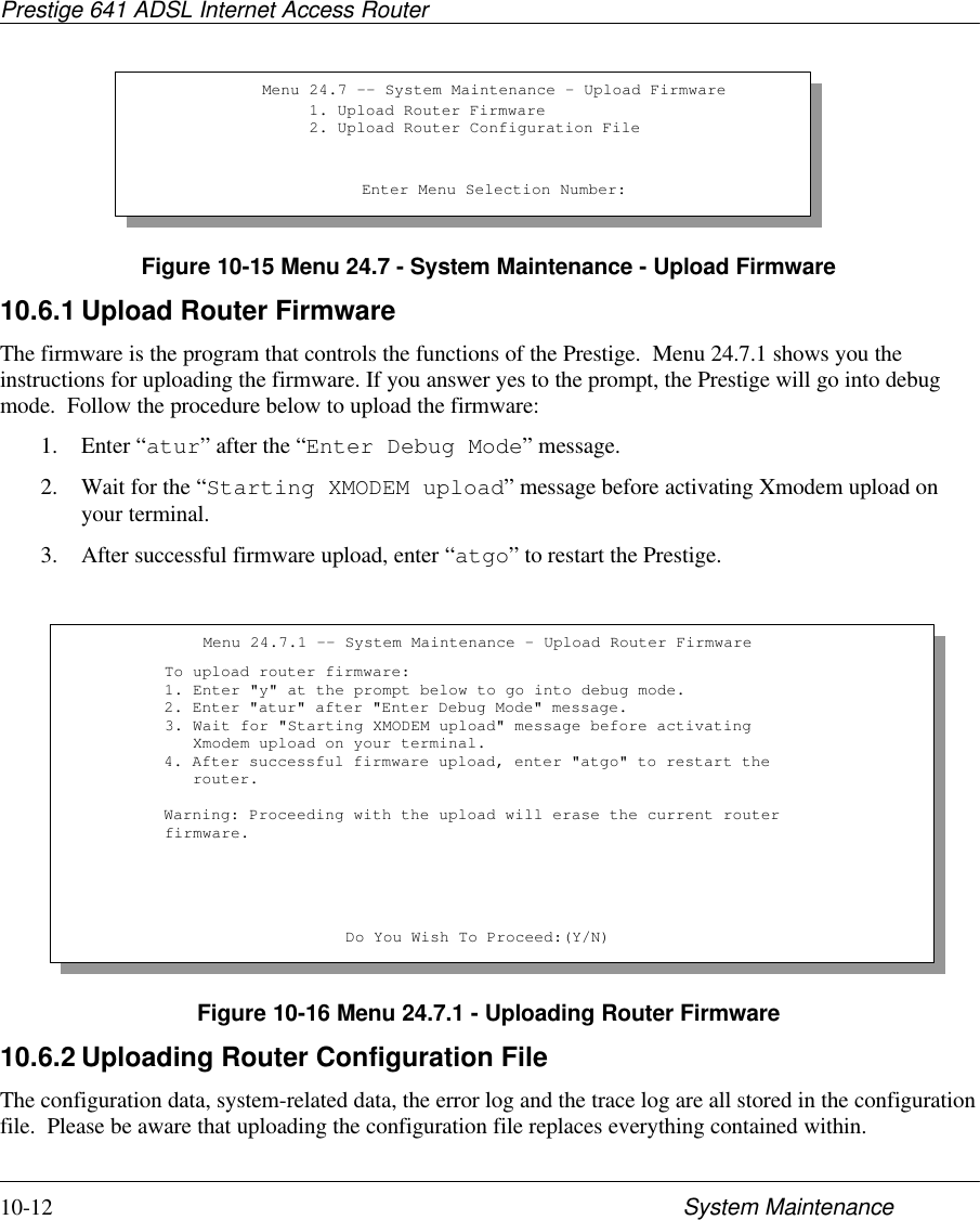
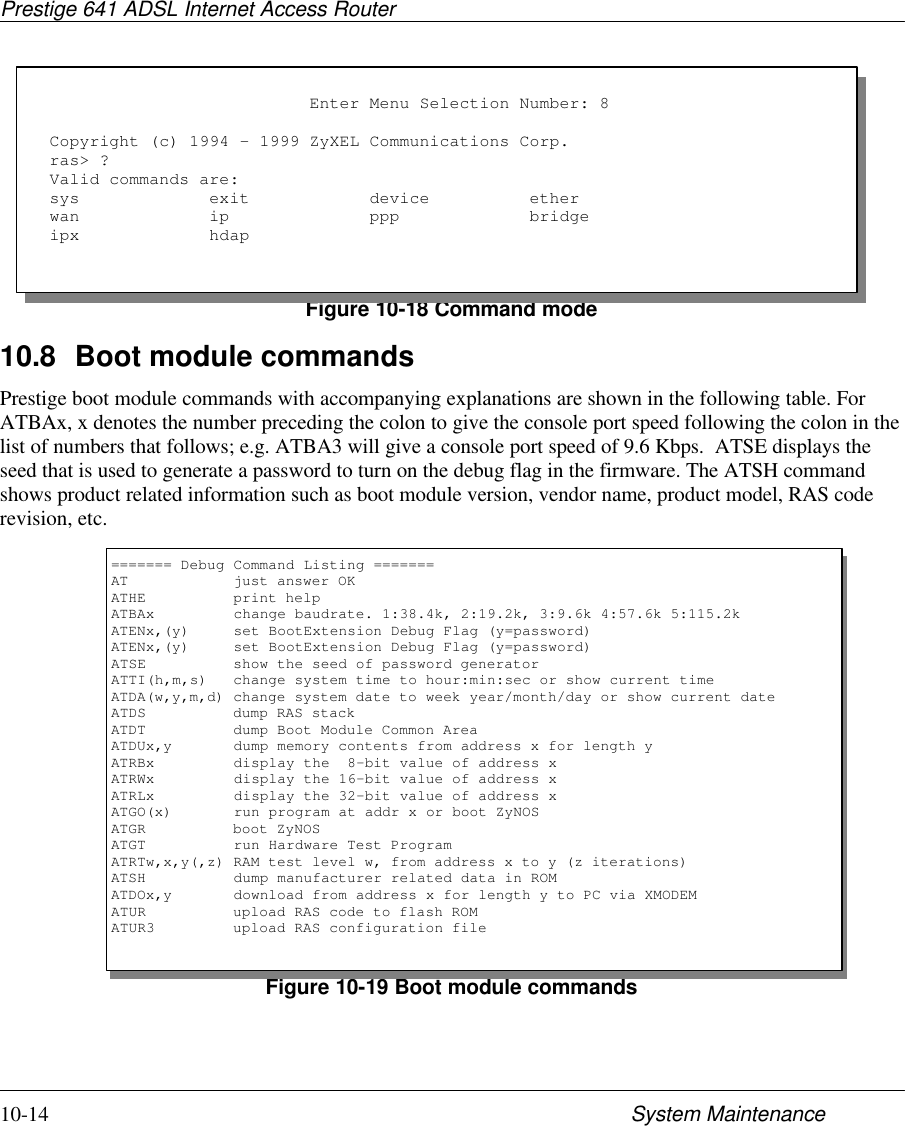
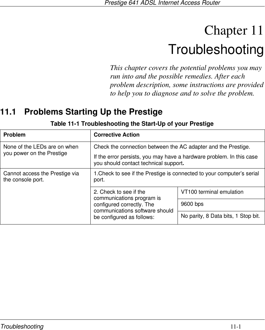
![Prestige 641 ADSL Internet Access Routerxvi PrefacePrefaceAbout Your ADSL Internet Access RouterCongratulations on your purchase of the Prestige 641 ADSL Internet Access Router.The Prestige 641 (P641) is an ADSL router used for Internet/LAN access via an ADSL line. The Prestige641 supports multi-protocol routing for TCP/IP and Novell IPX, as well as transparent bridging for otherprotocols. We will refer to the Prestige 641 as the P641 or simply the Prestige from now on.The P641 can run upstream maximum transmission rates of 640Kbps and downstream maximumtransmission rates of 8Mbps. The actual rate depends on the copper category of your telephone wire,distance from the central office and the type of ADSL service subscribed. See the sections below for morebackground information on DSL and ADSL.The P641's 10/100M auto-negotiating LAN interface enables fast data transfer of either 10Mbps or100Mbps in either half-duplex or full-duplex mode depending on your Ethernet network.Your Prestige is easy to install and to configure. All functions of the Prestige are software configurable viathe SMT (System Management Terminal) Interface.About This User's GuideThis user's guide covers all aspects of the Prestige 641 operations and shows you how to get the best out ofthe multiple advanced features of your ADSL Internet Access Router. This manual is designed to guide youthrough the correct configuration of your Prestige 641 for various applications.Syntax Conventions• “Enter” means for you to type one or more characters and press the carriage return. “Select” or“Choose” means for you to select one from the predefined choices.• The SMT menu titles and labels are in Bold Times font. The choices of a menu item are in BoldArial font. A single keystroke is in Arial font and enclosed in square brackets, for instance, [ENTER]means the Enter, or carriage return, key; [ESC] means the Escape key.• For brevity’s sake, we will use “e.g.” as a shorthand for “for instance”, and “i.e.” as a shorthand for“that is” or “in other words” throughout this manual](https://usermanual.wiki/ZyXEL-Communications/PRESTIGE641/User-Guide-64325-Page-16.png)
![Prestige 641 ADSL Internet Access Router2-5Hardware Installation & SetupFigure 2-5 Power-On DisplayStep 2. Entering PasswordThe login screen appears after you press Enter, prompting you to enter the password, as shown below.For your first login, enter the default password 1234. As you type the password, the screen displays a (X)for each character you type.Please note that if there is no activity for longer than 5 minutes after you log in, your Prestige willautomatically log you out and will display a blank screen. If you see a blank screen, press [Enter] to bringup the login screen again.Figure 2-6 Login ScreenEnter Password : XXXXCopyright (c) 1994 - 1999 ZyXEL Communications Corp.initialize ch =0, ethernet address: 00:a0:c5:01:23:45WAN Channel init....................doneDownload ADSL modem SW.……………………………………………………………………………………………………………………………………………………….Press ENTER to continue...](https://usermanual.wiki/ZyXEL-Communications/PRESTIGE641/User-Guide-64325-Page-27.png)
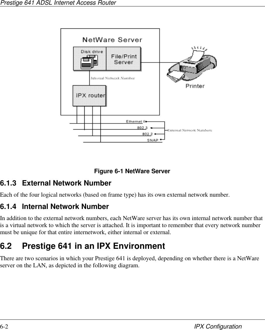
![Prestige 641 ADSL Internet Access Router2-6 Hardware Installation & Setup2.7 Navigating the SMT InterfaceThe SMT (System Management Terminal) is the interface that you use to configure your Prestige.Several operations that you should be familiar with before you attempt to modify the configuration arelisted in the table below.Table 2-2 Main Menu CommandsOperation Press/<read> DescriptionMove forward toanother menu [Enter] To move forward to a sub-menu, type in the number of thedesired sub-menu and press [Enter].Move backward toa previous menu [Esc] Press the [Esc] key to move back to the previous menu.Move to asubmenu Press the [Spacebar] to change Noto Yes then press[ENTER].Fields beginning with “Edit” have a default setting of No. Pressthe [Space bar] to change No to Yes, then press [ENTER] to goto a submenu.Move the cursor [Enter] or[Up]/[Down] arrowkeysWithin a menu, press [Enter] to move to the next field. You canalso use the [Up]/[Down] arrow keys to move to the previous andthe next field, respectively.Enter information Fill in, orPress the [Spacebar] to toggleYou need to fill in two types of fields. The first requires you totype in the appropriate information. The second allows you tocycle through the available choices by pressing the [Space] bar.Required fields <? > All fields with the symbol <?> must be filled in order be able tosave the new configuration.N/A fields <N/A> Some of the fields in the SMT will show a <N/A>. This symbolrefers to an option that is Not Applicable.Save yourconfiguration[Enter] Save your configuration by pressing [Enter] at the message[Press ENTER to confirm or ESC to cancel]. Saving the data onthe screen will take you, in most cases to the previous menu.Exit the SMT Type 99, thenpress [Enter].Type 99 at the Main Menu prompt and press [Enter] to exit theSMT interface.](https://usermanual.wiki/ZyXEL-Communications/PRESTIGE641/User-Guide-64325-Page-28.png)
![Prestige 641 ADSL Internet Access Router2-8 Hardware Installation & Setup2.8 Changing the System PasswordThe first thing your should do before anything else is to change the default system password by followingthe steps below.Step 1. Enter 23 in the Main Menu to open Menu 23 - System Password as shown below.When the Submenu 23 System Password appears, type in your existing system password, i.e., 1234, andpress [Enter].Figure 2-8 Menu 23.1 - System PasswordStep 2. Enter your new system password (up to 30 characters), and press [Enter].Step 3. Re-type your new system password for confirmation and press [Enter].Note that as you type a password, the screen displays a (*) for each character you type.2.9 Resetting the PrestigeIf you have forgotten your password or for some reason cannot access the SMT menu you will need toreinstall the configuration file. Uploading the configuration file replaces the current configuration file withthe default configuration file, you will lose all configurations that you had before and the speed of theconsole port will be reset to the default of 9600 bps with 8 data bit, no parity and 1 stop bit (8n1). Thepassword will be reset to the default of 1234, also.Turn off the Prestige and begin a Telnet session with the default console port settings. Turn on the Prestigeagain. When you see the message " Press Any key to enter Debug Mode within 3 seconds", press any keyto enter debug mode. You should already have downloaded the "romfile.zip" file from the Internet andunzipped it. See section 10.5 Restore Configuration on page 10-10 for more information.2.9.1 Filename conventionsThe configuration filename is the router model name with a rom extension, e.g., p641.rom. The ZyNOSfirmware filename is the router model name with a bin extension, e.g., p641.bin. Rename the latter filenameto “ras” when uploading to the Prestige. See section 10.6 Firmware Update on page 10-11 for moreinformation.Menu 23 – System PasswordOld Password= ****New Password= ****Retype to confirm= ****Enter here to CONFIRM or ESC to CANCEL:](https://usermanual.wiki/ZyXEL-Communications/PRESTIGE641/User-Guide-64325-Page-30.png)
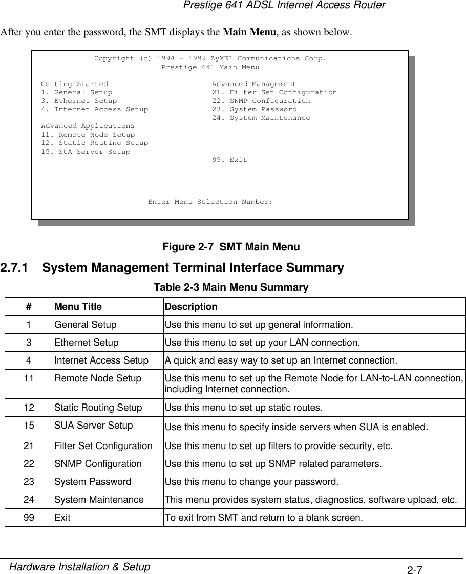
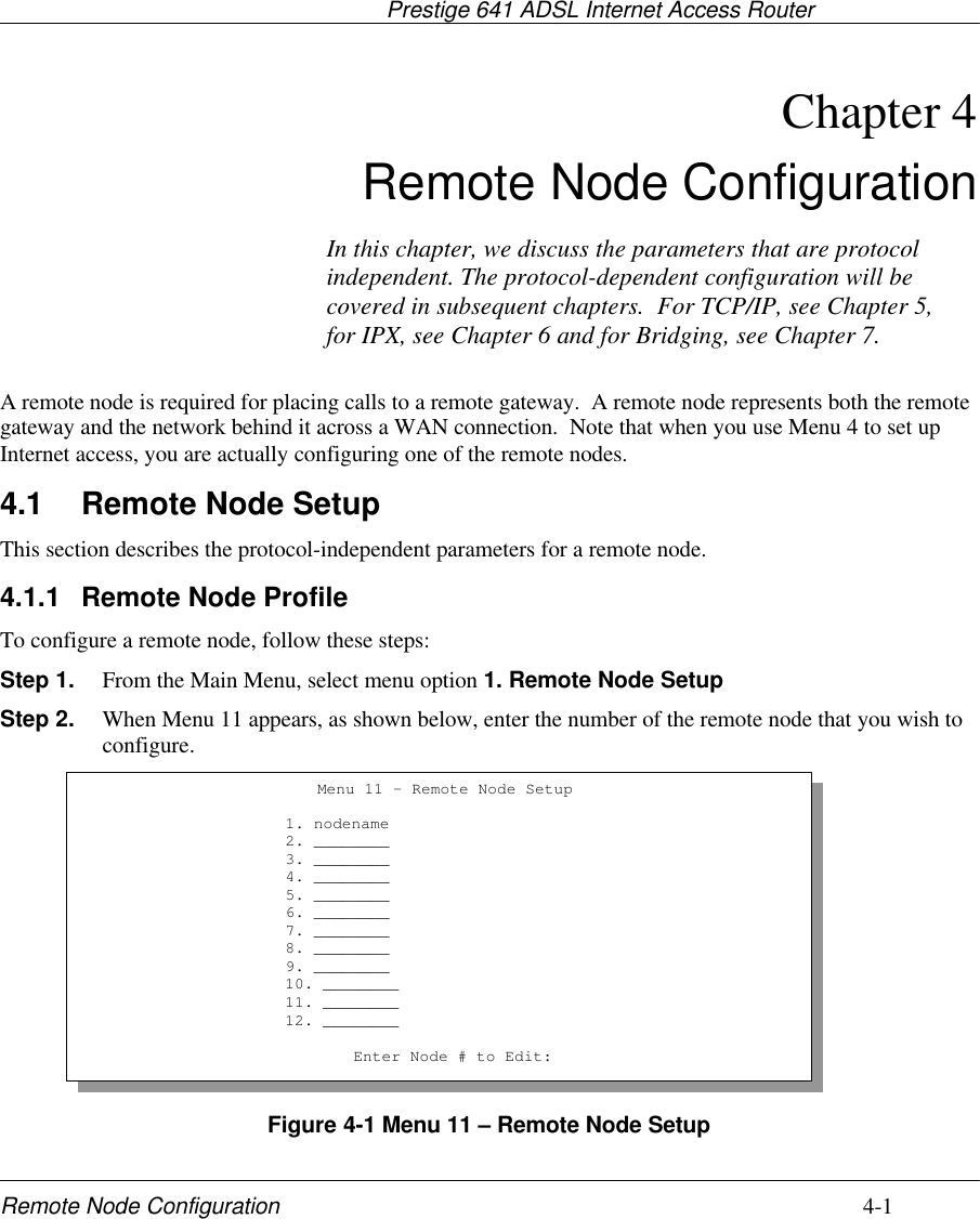
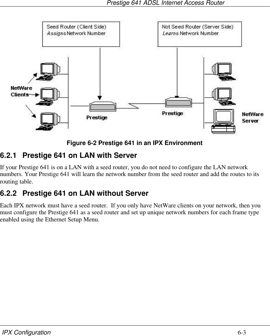
![Prestige 641 ADSL Internet Access Router2-9Hardware Installation & Setup2.10 General SetupMenu 1 - General Setup contains administrative and system-related information.To enter Menu 1 and fill in the required information, follow these steps:Step 1. Enter 1 in the Main Menu to open Menu 1 – General Setup.Step 2. The Menu 1 - General Setup screen appears, as shown below. Fill in the required fields marked[?] and turn on the individual protocols for your applications, as explained in the following table.Figure 2-9 Menu 1 – General SetupMenu 1 - General SetupSystem Name= P641Location= branchContact Person's Name= JohnDoeRoute IP= YesRoute IPX= NoBridge= NoPress ENTER to Confirm or ESC to Cancel:](https://usermanual.wiki/ZyXEL-Communications/PRESTIGE641/User-Guide-64325-Page-31.png)
![Prestige 641 ADSL Internet Access RouterInternet Access 3-3that you enter in the DHCP setup are passed to the client machines along with the assigned IP address andsubnet mask.There are two ways that an ISP disseminates the DNS server addresses. The first is for an ISP to tell acustomer the DNS server addresses, usually in the form of an information sheet, when s/he signs up. Ifyour ISP does give you the DNS server addresses, enter them in the DNS Server fields in DHCP Setup,otherwise, leave them blank.Some ISP’s choose to pass the DNS servers using the DNS server extensions of PPP IPCP (IP ControlProtocol) after the connection is up. If your ISP did not give you explicit DNS servers, chances are theDNS servers are conveyed through IPCP negotiation. The Prestige supports the IPCP DNS serverextensions through the DNS proxy feature.If the Primary and Secondary DNS Server fields in DHCP Setup are not specified, i.e., left as 0.0.0.0, thePrestige tells the DHCP clients that it itself is the DNS server. When a workstation sends a DNS query tothe Prestige, the Prestige forwards the query to the real DNS server learned through IPCP and relays theresponse back to the workstation.Please note that DNS proxy works only when the ISP uses the IPCP DNS server extensions. It does notmean you can leave the DNS servers out of the DHCP setup under all circumstances. If your ISP gives youexplicit DNS servers, make sure that you enter their IP addresses in the DHCP Setup menu. This way, thePrestige can pass the DNS servers to the workstations and the workstations can query the DNS serverdirectly without the Prestige’s intervention.3.3 Route IP SetupThe first step is to enable the IP routing in Menu 1 - General Setup. To edit Menu 1, enter 1 in the Main Menu to select General Setup and press [Enter]. Set the Route IPfield to Yes by pressing the space bar.Figure 3-1 Menu 1 – General SetupMenu 1 - General SetupSystem Name= P641Location= locationContact Person's Name= nameRoute IP= YesRoute IPX= NoBridge= NoPress ENTER to Confirm or ESC to Cancel:](https://usermanual.wiki/ZyXEL-Communications/PRESTIGE641/User-Guide-64325-Page-37.png)
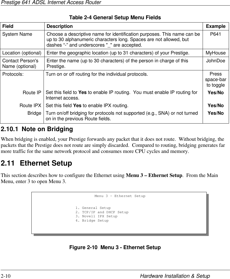
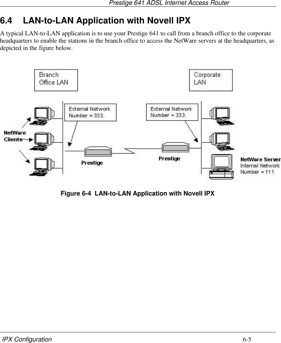
![Prestige 641 ADSL Internet Access Router3-4 Internet Access3.4 TCP/IP Ethernet Setup and DHCPYou will now use Menu 3.2 to configure your Prestige for TCP/IP.To edit Menu 3.2, enter 3 to open the Menu 3 - Ethernet Setup from the Main Menu. When Menu 3appears, select the submenu option TCP/IP and DHCP Setup and press [Enter]. The screen now displaysMenu 3.2 - TCP/IP and DHCP Ethernet Setup, as shown next.Figure 3-2 Menu 3.2 – TCP/IP and DHCP Ethernet SetupFollow the instructions in the following table on how to configure the DHCP fields.Table 3-1 DHCP Ethernet Setup Menu FieldsField Description ExampleDHCP SetupDHCP= This field enables/disables the DHCP server/relay. If it is set toServer, your Prestige will act as a DHCP server. If set to None,the DHCP server will be disabled. If set to Relay, the Prestigeacts as a surrogate DHCP server and relays DHCP requestsand responses between the remote server and the clients.When DHCP is used, the following items need to be set:NoneServer (default)RelayClient IP Pool StartingAddress This field specifies the first of the contiguous addresses in theIP address pool. 192.168.1.33Size of Client IP Pool This field specifies the size, or count, of the IP address pool. 32Primary DNS ServerSecondary DNSServerEnter the IP addresses of the DNS servers. The DNS serversare passed to the DHCP clients along with the IP address andthe subnet mask.Remote DHCPServer If Relay is selected in the DHCP= field above, then enter the IPaddress of the actual, remote DHCP server here.Menu 3.2 - TCP/IP and DHCP Ethernet SetupDHCP Setup:DHCP= ServerClient IP Pool Starting Address= 192.168.1.33Size of Client IP Pool= 32Primary DNS Server= 0.0.0.0Secondary DNS Server= 0.0.0.0Remote DHCP Server= N/ATCP/IP Setup:IP Address= 192.68.1.1IP Subnet Mask= 255.255.255.0RIP Direction= BothVersion= RIP-1Enter here to CONFIRM or ESC to CANCEL:Press Space Bar to Toggle.First addressin the IP PoolSize of the IPPoolIP addressesof the DNSservers](https://usermanual.wiki/ZyXEL-Communications/PRESTIGE641/User-Guide-64325-Page-38.png)
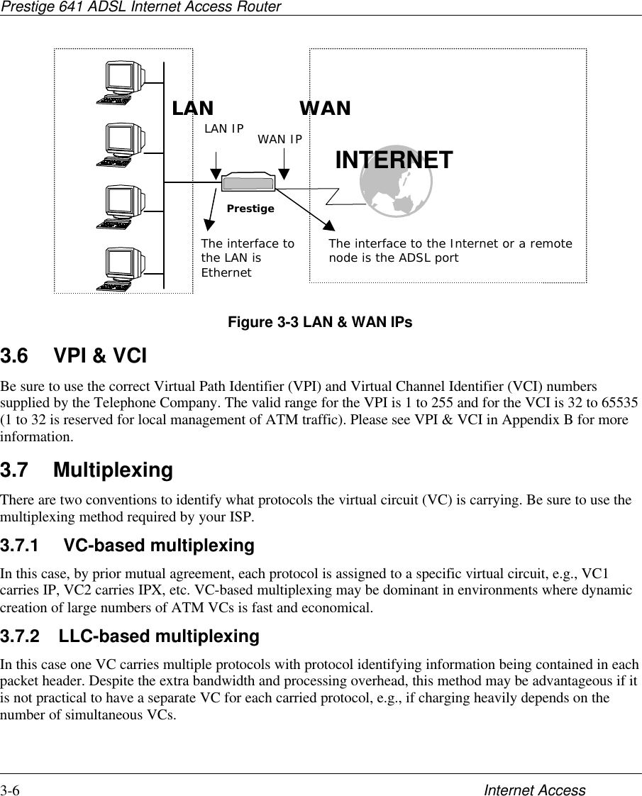
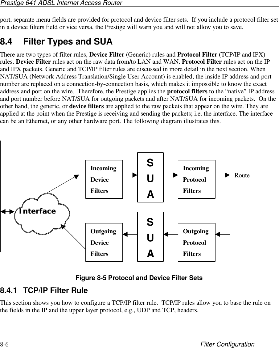
![Prestige 641 ADSL Internet Access RouterInternet Access 3-5Follow the instructions in the following table to configure TCP/IP parameters for the Ethernet port.Table 3-2 TCP/IP Ethernet Setup Menu FieldsField Description ExampleTCP/IP SetupIPAddress Enter the (LAN) IP address of your Prestige in dotted decimalnotation 192.168.1.1(default)IP Subnet Mask Your Prestige will automatically calculate the subnet mask basedon the IP address that you assign. Unless you are implementingsubnetting, use the subnet mask computed by the Prestige255.255.255.0RIPDirection Press the space bar to select the RIP direction from Both/InOnly/Out Only or None. Both(default)Version Press the space bar to select the RIP version from RIP-1/RIP-2B/RIP-2M. RIP-1(default)When you have completed this menu, press [Enter] at the prompt [Press ENTER to Confirm…] tosave your configuration, or press [Esc] at any time to cancel.3.5 LANs & WANsA LAN (Local Area Network) is a computer network limited to the immediate area, usually the samebuilding or floor of a building. A WAN (Wide Area Network), on the other hand is an outside connection toanother network or the Internet.3.5.1 LANs, WANs and the PrestigeThe actual physical connection determines whether the Prestige ports are LAN or WAN ports. There aretwo separate IP networks, one inside, the LAN network; the other outside, the WAN network as shownnext.](https://usermanual.wiki/ZyXEL-Communications/PRESTIGE641/User-Guide-64325-Page-39.png)
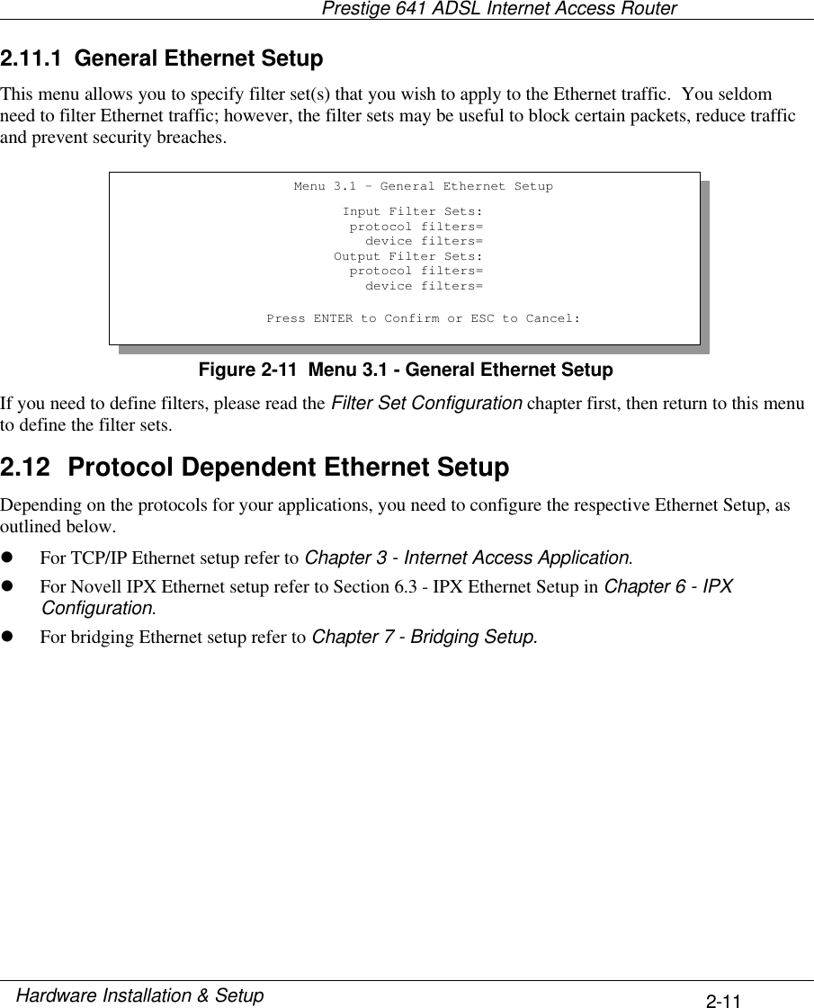
![Prestige 641 ADSL Internet Access Router3-10 Internet AccessFigure 3-4 Internet Access SetupTable 3-4 Internet Access Setup Menu FieldsField Description Options/E.G.ISP’s Name Enter the name of your Internet Service Provider, e.g.,myISP. This information is for identification purposes only. e.g., MyISPEncapsulation Press the spacebar to select the method of encapsulationused by your ISP. Please see section 3.9 for relatedinformation. PPPoE(default),PPP, RFC 1483or ENETENCAP.Multiplexing Press the [Space Bar] to select the method of multiplexingused by your ISP - either VC-based or LLC-based.VC-based LLC-basedVPI # Enter the Virtual Path Identifier (VPI) that the telephonecompany gives you. e.g., 10VCI # Enter the Virtual Channel Identifier (VCI) that the telephonecompany gives you. e.g., 10My Login Enter the login name that your ISP gives you. If you areusing PPPoE encapsulation, then this field must be of theform user@domain where domain identifies your ISP.e.g., tarbuckMy Password Enter the password associated with the login name above. ***Single User Account Press the spacebar to enable or disable SUA. Please see Yes/NoMenu 4 - Internet Access Setup ISP's Name= myISP Encapsulation= ENET ENCAP Multiplexing= LLC-based VPI #= 10 VCI #= 10 My Login= N/A My Password= N/A Single User Account= No J IP Address Assignment= Static IP Address= 192.168.1.100 ENET ENCAP Gateway= 192.168.1.1Press ENTER to confirm or ESC to cancel:Get this informationfrom the telephonecompany. Get theother information fromyour ISP.](https://usermanual.wiki/ZyXEL-Communications/PRESTIGE641/User-Guide-64325-Page-44.png)
![Prestige 641 ADSL Internet Access RouterInternet Access 3-11Field Description Options/E.G.the following section for a more detailed discussion on theSingle User Account feature.IP Address Assignment Press the [Space Bar] to select Static or Dynamic addressassignment. Please see section 3.9 for related information. Static /DynamicIP Address Enter the IP address supplied by your ISP if applicable. e.g.,192.168.1.100ENET ENCAP Gateway Enter the gateway IP address supplied by your ISP ifapplicable. e.g.,192.168.1.1At this point, if all your settings are correct your Prestige should connect automatically to the Internet. If theconnection fails, note the error message that you receive on the screen and take the appropriatetroubleshooting steps.3.11 Single User AccountTypically, if there are multiple users on the LAN wanting to concurrently access the Internet, you will haveto lease a block of legal, or globally unique, IP addresses from the ISP.The Single User Account (SUA) feature allows you to have the same benefits as having multiple legaladdresses, but only pay for one IP address, thus saving significantly on the subscription fees. (Check withyour ISP before you enable this feature). SUA supports popular Internet applications such as MS traceroute,CuSeeMe, IRC, RealAudio, VDOLive, Quake and PPTP with no extra configuration needed.](https://usermanual.wiki/ZyXEL-Communications/PRESTIGE641/User-Guide-64325-Page-45.png)
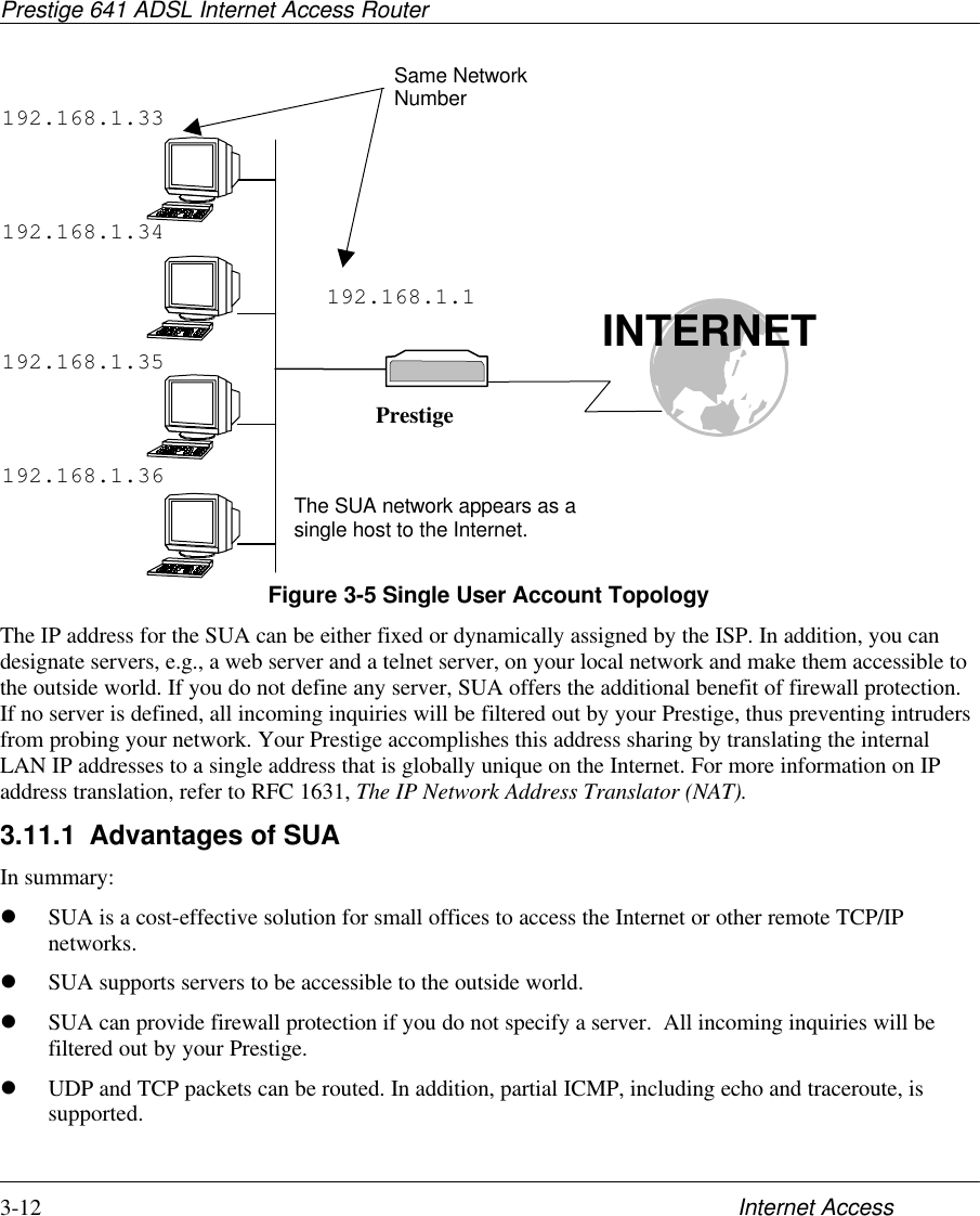
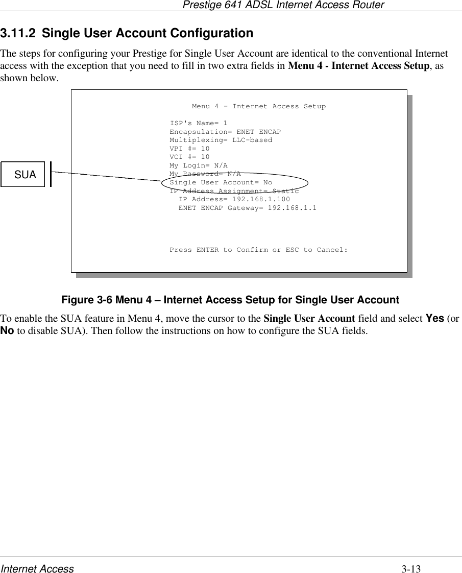
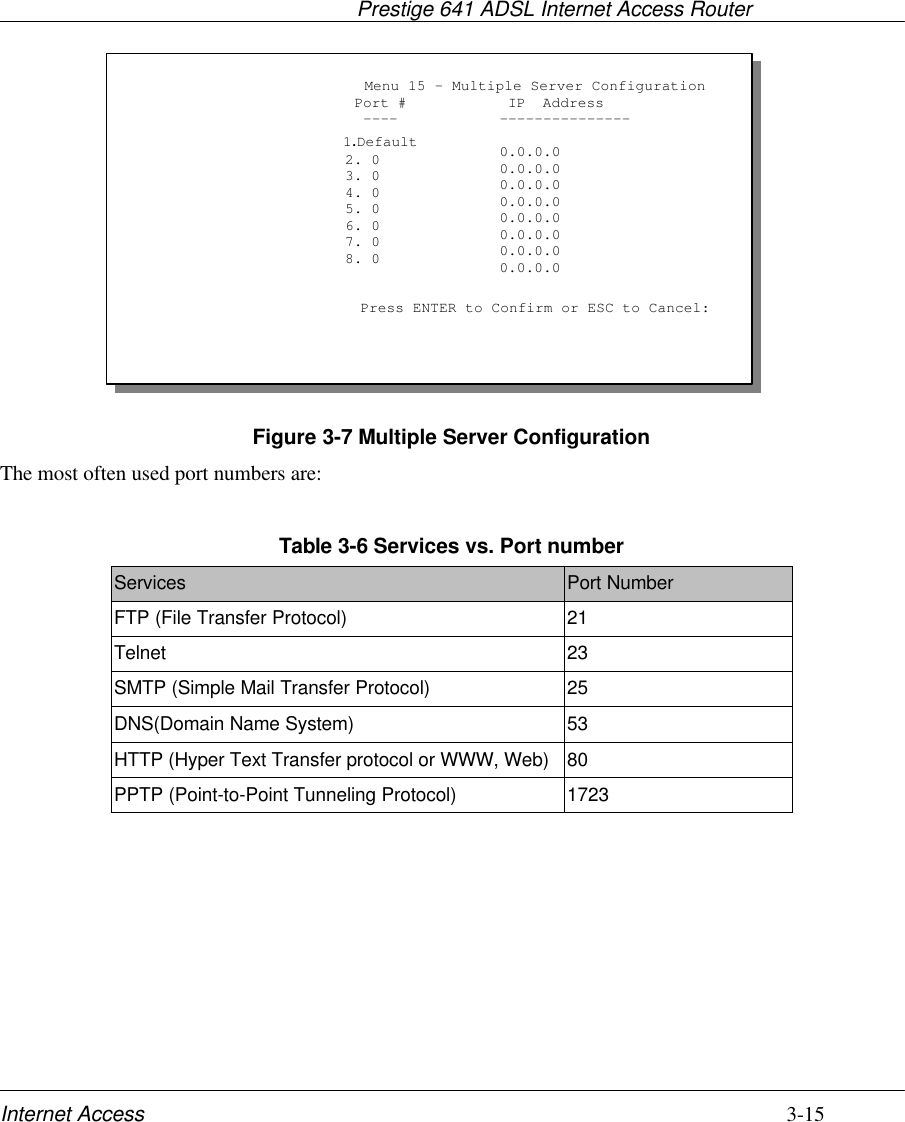
![Prestige 641 ADSL Internet Access Router3-14 Internet AccessTable 3-5 Single User Account Menu FieldsField DescriptionSingle User Account Select Yes to enable SUA. IP Addr. If your ISP did not assign you a static IP address, enter[0.0.0.0] here; otherwise, enter that IP address here.Press [Enter] at the message [Press ENTER to Confirm ...] to save your configuration, orpress [Esc] at any time to cancel.3.12 Multiple Servers behind SUAIf you wish, you can make inside servers for different services, e.g., web or FTP, visible to the outsideusers, even though SUA makes your whole inside network appear as a single machine to the outside world.A service is identified by the port number, e.g., web service is on port 80 and FTP on port 21.As an example, if you have a web server at 192.168.1.2 and an FTP server 192.168.1.3, then you need tospecify for port 80 (web) the server at IP address 192.168.1.2 and for port 21 (FTP) another at IP address192.168.1.3.Please note that a server can support more than one service, e.g., a server can provide both FTP and DNSservice, while another provides only web service. Also, since you need to specify the IP address of a serverin the Prestige, a server must have a fixed IP address and not be a DHCP client whose IP address potentiallychanges each time it is powered on.In addition to the servers for specific services, SUA supports a default server. A service request that doesnot have a server explicitly designated for it is forwarded to the default server. If the default server is notdefined, the service request is simply discarded.To make a server visible to the outside world, specify the port number of the service and the inside IPaddress of the server in Menu 15 - Multiple Server Configuration.3.12.1 Configuring a Server behind SUAFollow the steps below to configure a server behind SUA:1. Enter 15 in the main menu to go to Menu 15 - Multiple Server Configuration.2. Enter an index number in menu 15 to go to Menu 15.1 - SUA Server Configuration.3. Enter the service port number in the Port # field and the inside IP address of the server in the IPAddress field.4. Press ENTER at the “Press ENTER to confirm …” prompt to save your configuration after youdefine all the servers or press ESC at any time to cancel.](https://usermanual.wiki/ZyXEL-Communications/PRESTIGE641/User-Guide-64325-Page-48.png)
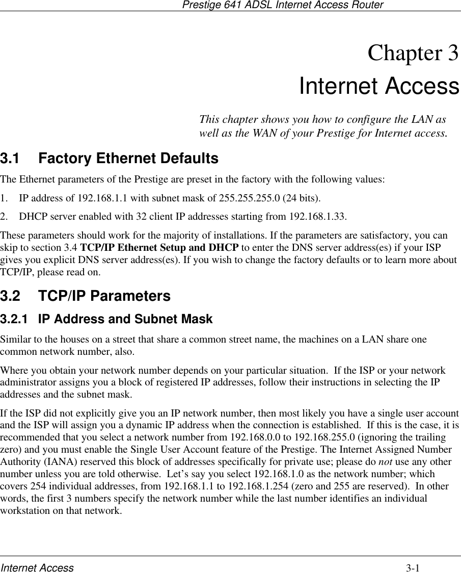
![Prestige 641 ADSL Internet Access RouterRemote Node Configuration 4-3Figure 4-2 Menu 11.1 Remote Node ProfileTable 4-1 Remote Node Profile Menu FieldsField Description OptionsRem Node Name This is a required field [?]. Enter a descriptive name for theremote node, for example, Corp. This field can be up toeight characters. This name must be unique from any otherremote node name.Active Press the spacebar to toggle between Yes and No. Inactivenodes are displayed with a minus sign (-) at the beginning ofthe name in Menu 11.Yes/NoEncapsulation=PPPoE refers to RFC 2516 and PPP refers to RFC 2364, "PPPEncapsulation over ATM Adaptation Layer 5". If RFC 1483("Multiprotocol Encapsulation over ATM Adaptation Layer 5") orENET ENCAP are selected, then the Rem Login, Rem Password,My Login, My Password, Edit PPP Options and Authen fieldswill not be applicable (N/A). Moreover, ENET ENCAPencapsulation does not apply for IPX routing.PPPoE,PPP,RFC 1483or ENETENCAPMultiplexing=Press the spacebar to the select the multiplexing method. VC-basedLLC-basedIncoming: RemLoginNameEnter the login name that this remote node will use when itcalls your Prestige.The login name in this field combined with the Rem NodePassword will be used to authenticate this node.Incoming: RemPassword Enter the password used when this remote node calls yourPrestige.Menu 11.1 - Remote Node Profile Rem Node Name= nodename Active= YesEncapsulation= PPP Multiplexing= VC-based Incoming: Rem Login= Rem Password=******** Outgoing: My Login= oscar My Password= ******** Authen= CHAP/PAPRoute= IPBridge= NoEdit PPP Options= NoRem IP Addr= 0.0.0.0Edit IP/IPX/Bridge= NoSession Options: Edit Filter Sets= NoPPPoE Idle Timeout(sec)= 100Enter here to CONFIRM or ESC to CANCEL:Enter the IPaddress of theremote gatewayhere.Enter a uniquename of less than8 characters forthe remote name.](https://usermanual.wiki/ZyXEL-Communications/PRESTIGE641/User-Guide-64325-Page-53.png)
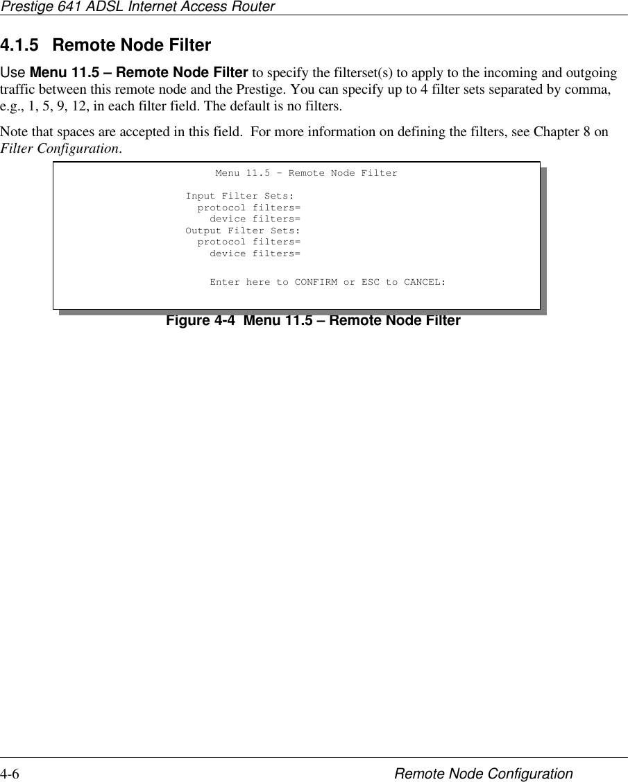
![Prestige 641 ADSL Internet Access Router4-4 Remote Node ConfigurationField Description OptionsOutgoing: My Login Enter the login name for your Prestige when it calls thisremote node. If you are using PPPoE encapsulation, thenthis field must be of the form user@domain where domainidentifies your ISP.Outgoing: MyPassword Enter the password for your Prestige when it calls thisremote node.This field sets the authentication protocol used for outgoingcalls.Options for this field are:l CHAP/PAP - Your Prestige will accept either CHAP orPAP when requested by this remote node. CHAP/PAPl CHAP - accept CHAP only. CHAPOutgoing: Authenl PAP - accept PAP only. PAPRoute This field determines the protocols that your Prestige willroute.Bridge Bridging is used for protocols that the Prestige does notsupport, e.g., SNA, or not turned on in the previous Routefield. When bridging is enabled, your Prestige will forwardany packet that it does not route to this remote node;otherwise, the packets are discarded. .Pressspace barto toggleYes/NoEdit PPP Options To edit the PPP options for this remote node, move thecursor to this field, use the space bar to select Yes andpress [Enter]. This will bring you to Menu 11.2 - RemoteNode PPP Options. For more information on configuringPPP options, see the section Editing PPP Options.Pressspace barto toggleYes thenpress[Enter]Rem IP Addr Enter the IP address of the remote gateway.Edit IP/IPX/Bridge Press the space bar to select Yes and press Enter to go toMenu 11.3 - Remote Node Network Layer Options menu. Yes or NoSession Option:Edit Filter SetsUse the space bar to toggle this field to Yes and press[Enter] to open Menu 11.5 to edit the filter sets. See theRemote Node Filter section for more details.Default=NoPPPoE IdleTimeout(sec)= This value specifies the number of idle seconds that elapsebefore the Prestige automatically disconnects the PPPoEsession.100(default)Once you have completed filling in Menu 11.1 – Remote Node Profile, press [Enter] at the message[Press ENTER to Confirm…] to save your configuration, or press [Esc] at any time to cancel.](https://usermanual.wiki/ZyXEL-Communications/PRESTIGE641/User-Guide-64325-Page-54.png)
![Prestige 641 ADSL Internet Access RouterRemote Node Configuration 4-54.1.3 Outgoing Authentication ProtocolGenerally speaking, you should employ the strongest authentication protocol possible, for obvious reasons.However, some vendor’s implementation includes specific authentication protocol in the user profile. Itwill disconnect if the negotiated protocol is different from that in the user profile, even when the negotiatedprotocol is stronger than specified. If you encounter the case where the peer disconnects right after asuccessful authentication, please make sure that you specify the correct authentication protocol whenconnecting to such an implementation.4.1.4 Editing PPP OptionsTo edit the remote node PPP Options, move the cursor to the Edit PPP Options field in Menu 11.1 -Remote Node Profile, and use the space bar to select Yes. Press Enter to open Menu 11.2, as shownnext.Figure 4-3 Menu 11.2 - Remote Node PPP OptionsThe following table describes the Remote Node PPP Options Menu, and contains instructions on how toconfigure the PPP options fields.Table 4-2 Remote Node PPP Options Menu FieldsField Description OptionStandardPPPEncapsulation Select the CISCO PPP only when this remote nodeis a Cisco machine; otherwise, select the StandardPPP. CISCOPPPCompression Turn on/off Stac Compression. The default for thisfield is Off.On/Off(Default =Off)Once you have completed filling in Menu 11.2 – Remote Node PPP Options, press [Enter] at themessage [Press ENTER to Confirm…] to save your configuration, or press [Esc] at any time tocancel.Menu 11.2 - Remote Node PPP OptionsEncapsulation= Standard PPPCompression= NoPress ENTER to CONFIRM or ESC to CANCEL:Press Space Bar to Toggle.](https://usermanual.wiki/ZyXEL-Communications/PRESTIGE641/User-Guide-64325-Page-55.png)
![Prestige 641 ADSL Internet Access RouterRemote Node TCP/IP Configuration 5-1Chapter 5 Remote Node TCP/IP ConfigurationA typical LAN-to-LAN application is to use your Prestige to connect a branch office to the headquarters, asdepicted in the following diagram.5.1 LAN-to-LAN ApplicationFigure 5-1 TCP/IP LAN-to-LAN ApplicationFor the branch office, you need to configure a remote node in order to dial out to the headquarters.Additionally, you may also need to define static routes if some services reside beyond the immediateremote LAN.5.1.1 Editing TCP/IP OptionsFollow the steps below to edit Menu 11.3 - Remote Node Network Layer Options shown next.In Menu 11.1, move the cursor to the Edit IP/IPX/Bridge, then press the space bar to toggle and set thevalue to Yes. Press [Enter] to open Menu 11.3 - Network Layer Options.This chapter shows you how to configurethe TCP/IP parameters of a remote node.](https://usermanual.wiki/ZyXEL-Communications/PRESTIGE641/User-Guide-64325-Page-57.png)
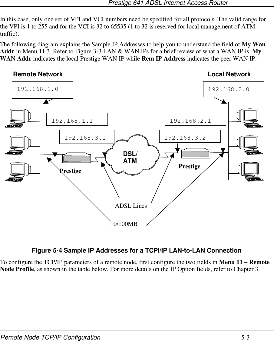
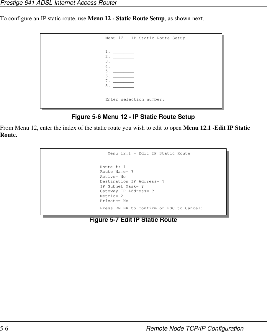
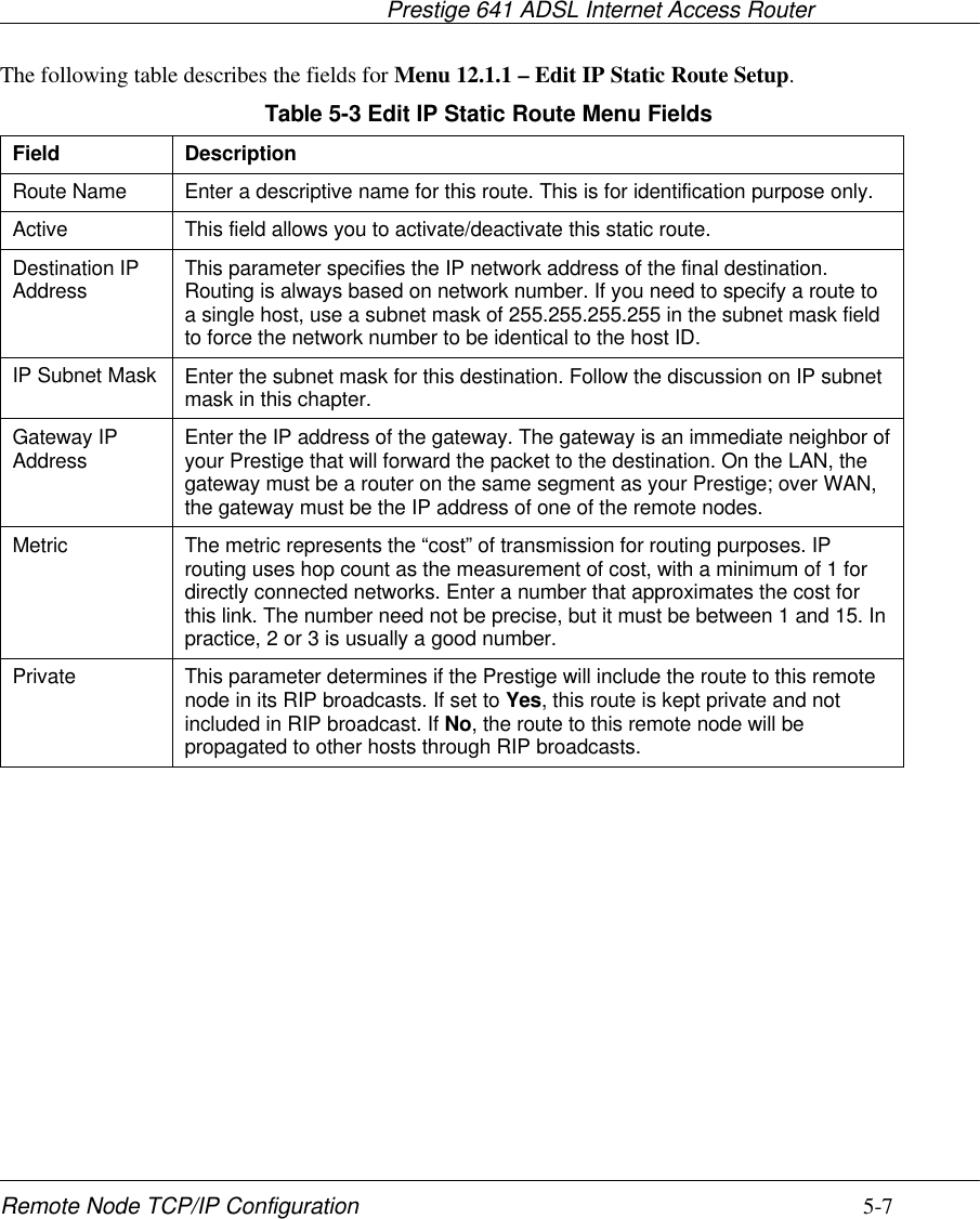
![Prestige 641 ADSL Internet Access RouterRemote Node TCP/IP Configuration 5-5Field Description Optionbroadcasts.RIP Direction Press the space bar to select the RIP direction from Both/InOnly/Out Only or None.(Default= Both)Version= Press the space bar to select the RIP version from RIP-1/RIP-2B/RIP-2M. RIP-1 (default)VPI Enter the Virtual Path Identifier (VPI) number that yourtelephone company supplies.VCI Enter the Virtual Channel Identifier (VCI) number that yourtelephone company supplies.Once you have completed filling in the Network Layer Options Menu, press [Enter] to return to Menu 11.Press [Enter] at the message [Press ENTER to Confirm...] to save your configuration, or press [Esc] at anytime to cancel.5.1.2 Static Route SetupStatic routes tell the Prestige routing information that it cannot learn automatically through other means.This can arise in cases where RIP is disabled on the LAN or a remote network is beyond the one that isdirectly connected to a remote node.Each remote node specifies only the network to which the gateway is directly connected, and the Prestigehas no knowledge of the networks beyond. For instance, the Prestige knows about network N2 in thefollowing diagram through remote node Router 1. However, the Prestige is unable to route a packet tonetwork N3 because it doesn’t know that there is a route through remote node Router 1 (via Router 2). Thestatic routes are for you to tell the Prestige about the networks beyond the remote nodes.Figure 5-5 Example of Static Routing TopologyRouter 2N2 N3Router 1N1](https://usermanual.wiki/ZyXEL-Communications/PRESTIGE641/User-Guide-64325-Page-61.png)
![Prestige 641 ADSL Internet Access Router6-4 IPX Configuration6.3 IPX Ethernet SetupFrom Menu 3 - Ethernet Setup, enter 3 to go to Menu 3.3 - Novell IPX Ethernet Setup as shown in thefigure below.Figure 6-3 Menu 3.3 - Novell IPX Ethernet SetupThe following table describes the Novell IPX Ethernet Setup Menu.Table 6-1 Novell IPX Ethernet Setup FieldsField Description OptionsSeed Router Determine if your Prestige 641 is to act as a seedrouter. Yes/NoFrame Type Enable/Disable the individual frame type.Remember to enable only the ones that are actuallyused on your network.802.2802.3Ethernet IISNAPIPX Network#If your Prestige 641 is a seed router, enter a uniquenetwork number for each frame type enabled.Press [Enter] at the message [Press ENTER to Confirm ...] to save your configuration,or press [Esc] at any time to cancel.Menu 3.3 - Novell IPX Ethernet SetupSeed Router= NoFrame Type 802.2= YesIPX Network #= N/AFrame Type 802.3= NoIPX Network #= N/AFrame Type Ethernet II= NoIPX Network #= N/AFrame Type SNAP= NoIPX Network #= N/AEnter here to CONFIRM or ESC to CANCEL:Press Space Bar to Toggle.](https://usermanual.wiki/ZyXEL-Communications/PRESTIGE641/User-Guide-64325-Page-68.png)
![Prestige 641 ADSL Internet Access Router6-6 IPX Configuration6.4.1 IPX Remote Node SetupFollow the procedure in Chapter 5 to configure the protocol-independent parameters in Menu 11.1 -Remote Node Profile. For the IPX-specific parameters in Menu 11.3 - Remote Node Network LayerOptions follow the instructions below.Step 1. In Menu 11.1, make sure IPX is among the protocols in the Route field. (The Route field shoulddisplay Route = IPX or Route = IP + IPX.)Step 2. Move the cursor to the Edit IP/IPX/Bridge field, then press the space bar to select Yes andpress [Enter] to open Menu 11.3 - Network Layer Options.Figure 6-5 Menu 11.3 - Remote Node Novell IPX OptionsMenu 11.3 - Remote Node Network Layer OptionsLLC-mux or PPP/PPPoE Encap : VPI #= 1 VCI #= 1IP Options: Rem IP Addr: Rem Subnet Mask= N/A My WAN Addr= N/A Single User Account= N/A Metric= N/A Private= N/A RIP Direction= N/A Version= N/AIPX Options:Rem LAN Net #= 00000000My WAN Net #= 00000000Hop Count= 1Tick Count= 2Bridge Options:Ethernet Addr Timeout(min)= N/AEnter here to CONFIRM or ESC to CANCEL:](https://usermanual.wiki/ZyXEL-Communications/PRESTIGE641/User-Guide-64325-Page-70.png)
![Prestige 641 ADSL Internet Access Router IPX Configuration 6-7The table below describes the IPX-specific parameters of the remote node setup.Table 6-2 Remote Node Novell IPX OptionsField Description OptionRem LANNet # In this field, enter the internal network number of the NetWareserver on the remote LAN.My WANNet # In this field, enter the network number of the WAN link. If youleave this field as 00000000, your Prestige will determineautomatically the network number through negotiation with thePPP peer.00000000(default)Hop Count This field indicates the number of intermediate networks that mustbe passed through to reach the remote node. 1(default)Tick Count This field indicates the time-ticks required to reach the remotenode. 2 (default)Once you have completed filling in the Network Layer Options Menu, press [Enter] to return toMenu 11.1. Then press [Enter] at the message [Press ENTER to Confirm] to save yourconfiguration, press [Esc] to cancel.](https://usermanual.wiki/ZyXEL-Communications/PRESTIGE641/User-Guide-64325-Page-71.png)
![Prestige 641 ADSL Internet Access Router IPX Configuration 6-9The following table contains the instructions on how to configure the Edit IP Static Route Menu.Table 6-3 Edit IPX Static Route Menu FieldsField DescriptionServer Name In this field, enter the name of the server. This must be the exact nameconfigured in the NetWare server.Network # This field contains the internal network number of the remote server thatyou wish to access. [00000000] or [FFFFFFFF] are reserved.Node # This field contains the address of the node on which the server resides. Ifyou are using a Novell IPX implementation, this value is [000000000001].Socket # This field contains the socket number on which the server will receiveservice requests. The default for this field is hex [0451].Type # This field identifies the type of service the server provides. The default forthis field is hex [0004].Gateway Node In this field, enter the number of the remote node that is the gateway forthis static route.Hop Count andTick Count These two fields have the same meaning as those in the Ethernet setup.Once you have completed filling in the menu, press [Enter] at the message [Press ENTER toConfirm…] to save your configuration, or press [Esc] to cancel to cancel.](https://usermanual.wiki/ZyXEL-Communications/PRESTIGE641/User-Guide-64325-Page-73.png)
![Prestige 641 ADSL Internet Access RouterBridging Setup 7-3Step 1. In Menu 11.1, make sure the Bridge field is set to Yes.Step 2. Move the cursor to the Edit IP/IPX/Bridge field, then press the space bar to select Yes andpress [Enter] to open Menu 11.3 - Network Layer Options.Figure 7-2 Menu 11.3 - Remote Node Bridging OptionsThe following table describes the bridging-specific parameters in the Remote Node Profile and NetworkLayers menus.Table 7-2 P641 Remote Node Network Layers Menu Bridge OptionsField DescriptionBridge Make sure this field is set to Yes.Edit IP/IPX/Bridge Press the space bar to change it to Yes and press Enter] to go to theNetwork Layer Options Menu.Ethernet AddrTimeout (min) In this field, enter the time (number of minutes) that you wish yourPrestige 641 to retain the Ethernet Addr information in its internal tableswhile the line is down. If this information is retained, your Prestige 641will not have to recompile the tables when the line is brought back up.Once you have completed filling in the Network Layer Options Menu, press [Enter] to return toMenu 11.1. Then press [Enter] at the message [Press ENTER to Confirm…] to save yourconfiguration, or press [Esc] to cancel.Menu 11.3 - Remote Node Network Layer OptionsLLC-mux or PPP/PPPoE Encap : VPI #= 1 VCI #= 1IP Options : Rem IP Addr: 0.0.0.0 Rem Subnet Mask= 0.0.0.0 My WAN Addr= 0.0.0.0 Single User Account= No Metric= 2 Private= No RIP Direction= Both Version= RIP-2BIPX Options :Rem LAN Net #= 00000000My WAN Net #= 00000000Hop Count= 1Tick Count= 2Bridge Options: Ethernet Addr Timeout(min)= 0Enter here to CONFIRM or ESC to CANCEL:](https://usermanual.wiki/ZyXEL-Communications/PRESTIGE641/User-Guide-64325-Page-77.png)
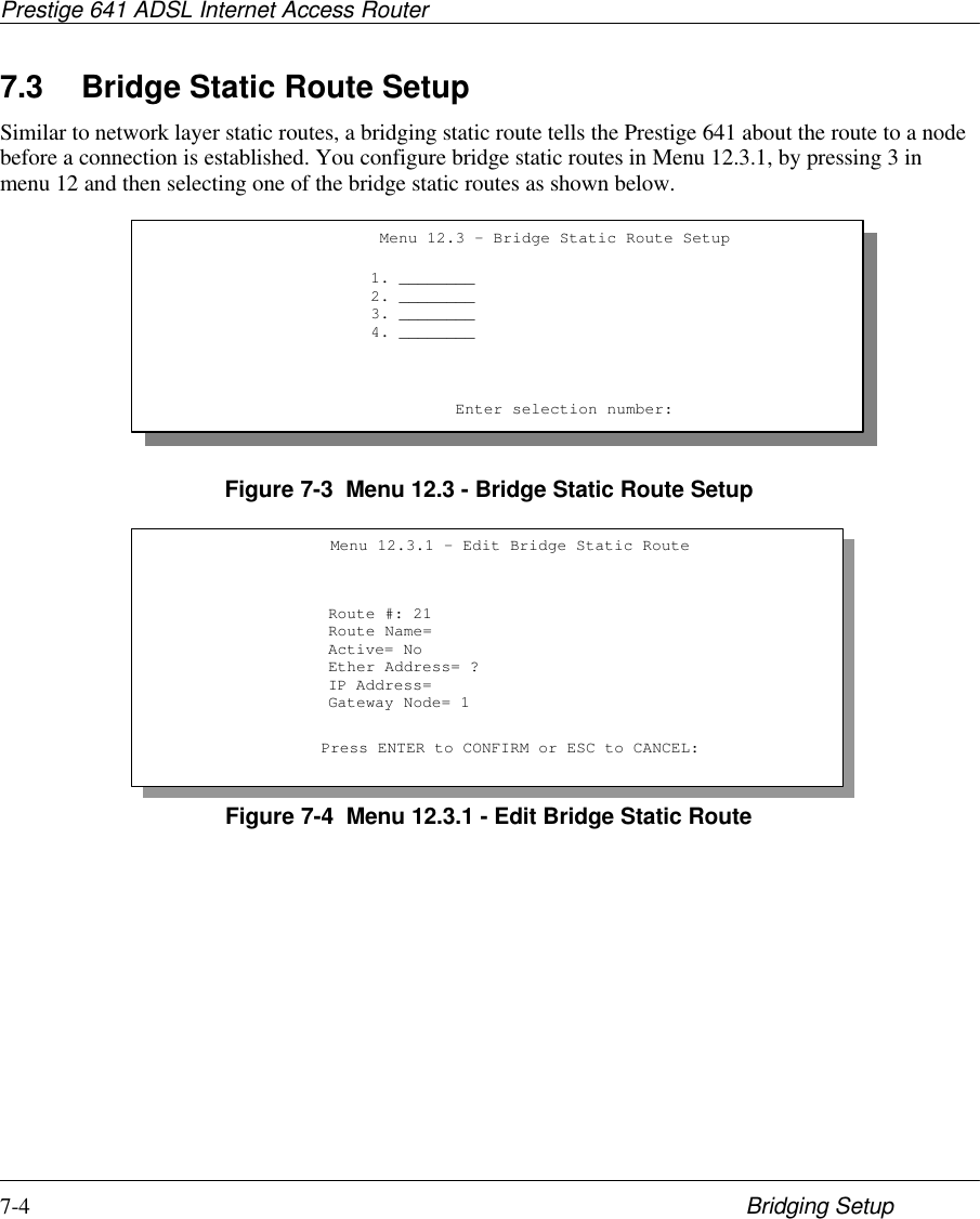
![Prestige 641 ADSL Internet Access RouterBridging Setup 7-5The following table describes the Bridge Static Route Menu.Table 7-3 Bridge Static Route Menu FieldsField DescriptionRoute Name Enter a name for the bridge static route for identification purposes.Active Activate/deactivate the static route.Ether Address Enter the MAC address of the destination machine that you wish tobridge the packets to.IP Address If available, enter the IP address of the destination machine that youwish to bridge the packets to.Gateway Node Enter the number of the remote node that is the gateway of this staticroute.Once you have completed filling in this menu, press [Enter] at the message [PressENTER to Confirm…] to save your configuration, or press [Esc] to cancel.](https://usermanual.wiki/ZyXEL-Communications/PRESTIGE641/User-Guide-64325-Page-79.png)
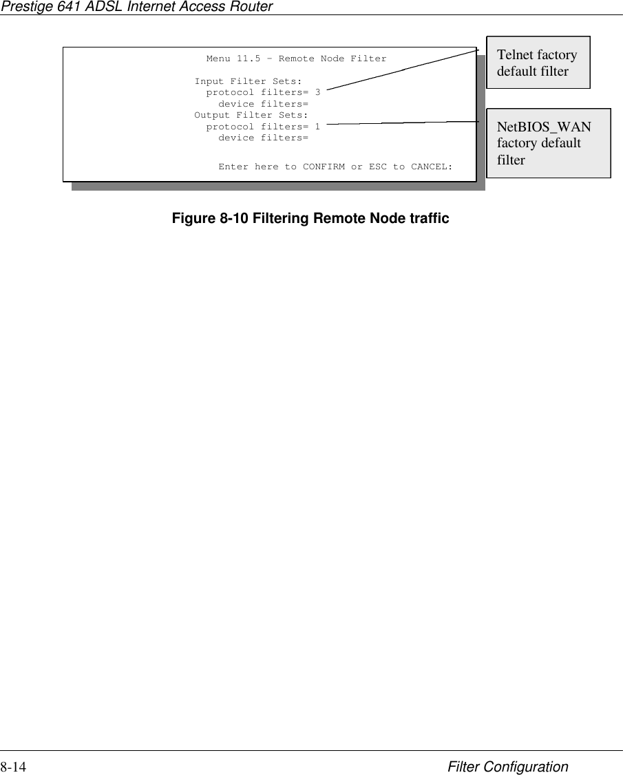
![Prestige 641 ADSL Internet Access Router8-2 Filter ConfigurationFigure 8-1 Menu 21 - Filter Set ConfigurationStep 2. Enter the index of the filter set you wish to configure (no. 1-12) and press [Enter].Step 3. Enter a descriptive name or comment in the Edit Comments field and press Enter.Step 4. Press [Enter] at the message: [Press ENTER to confirm] to open Menu 21.1 - Filter RulesSummary.Figure 8-2 NetBIOS_WAN Filter Rules SummaryMenu 21 - Filter Set ConfigurationFilterSet #------123456Comments------------------NetBIOS_WANNetBIOS_LANTELNET_WAN__________________________________________FilterSet #------789101112Comments------------------____________________________________________________________________________________Enter Filter Set Number to Configure=Edit Comments= NetBIOS_WANPress ENTER to CONFIRM or ESC to CANCEL:Menu 21.1 - Filter Rules Summary# A Type Filter Rules M m n - - ---- -------------------------------------------- --------- - - - 1 Y IP Pr=6, SA=0.0.0.0, DA=0.0.0.0, DP=137 N D N 2 Y IP Pr=6, SA=0.0.0.0, DA=0.0.0.0, DP=138 N D N 3 Y IP Pr=6, SA=0.0.0.0, DA=0.0.0.0, DP=139 N D N 4 Y IP Pr=17, SA=0.0.0.0, DA=0.0.0.0, DP=137 N D N 5 Y IP Pr=17, SA=0.0.0.0, DA=0.0.0.0, DP=138 N D N 6 Y IP Pr=17, SA=0.0.0.0, DA=0.0.0.0, DP=139 N D F Enter Filter Rule Number (1-6) to Configure: 1 Edit Comments= NetBIOS_WAN Press ENTER to Confirm or ESC to Cancel: Enter Filter Rule Number (1-6) to Configure:](https://usermanual.wiki/ZyXEL-Communications/PRESTIGE641/User-Guide-64325-Page-82.png)
![Prestige 641 ADSL Internet Access Router8-4 Filter ConfigurationTable 8-1 Abbreviations Used in the Filter Rules Summary MenuAbbreviations Description Display#Refers to the filter rule number (1-6).ARefers to Active. [Y] means the filter rule is active.[N] means the filter rule is inactive.Type Refers to the type of filter rule.This shows GEN for generic, IP forTCP/IP[GEN] for Generic[IP] for TCP/IPFilter Rules The filter rule parameters are displayedhere (see below).MRefers to More.[Y] means an action can not yet be takenas there are more rules to check, whichare concatenated with the present ruleto form a rule chain. When the rule chainis complete an action can be taken.[N] means you can now specify an actionto be taken i.e., forward the packet, dropthe packet or check the next rule. For thelatter, the next rule is independent of therule just checked.If More is Yes, then Action Matched andAction Not Matched will be N/A[Y][N]mRefers to Action Matched.[F] means to forward the packetimmediately and skip checking theremaining rules.[F] means to forward the packet.[D] means to drop the packet.[N] means check the next rule.nRefers to Action Not Matched.[F] means to forward the packetimmediately and skip checking theremaining rules.[F] means to forward the packet.[D] means to drop the packet.[N] means check the next rule.The protocol dependent filter rules abbreviation are listed as follows:l If the filter type is IP, the following abbreviations listed in the following table will be used.](https://usermanual.wiki/ZyXEL-Communications/PRESTIGE641/User-Guide-64325-Page-84.png)
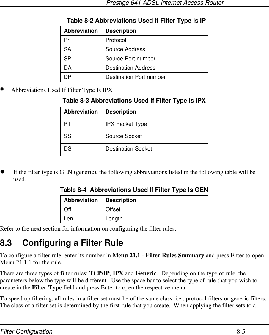
![Prestige 641 ADSL Internet Access Router8-8 Filter ConfigurationField Description OptionDestination: Port #Comp Select the comparison to apply to the destination port inthe packet against the value given in Destination: Port #. None/Less/Greater/Equal/Not EqualSource: IP Addr Enter the source IP Address of the packet you wish tofilter. This field is a don’t-care if it is 0.0.0.0. IP AddressSource: IP Mask Enter the IP subnet mask to apply to the Source: IP Addr. IP MaskSource: Port # Enter the source port of the packets that you wish to filter.The range of this field is 0 to 65535. This field is a don’t-care if it is 0.0-65535Source: Port #Comp Select the comparison to apply to the source port in thepacket against the value given in Source: Port #. None/Less/Greater/Equal/Not EqualTCP Estab This field is applicable only when IP Protocol field is 6,TCP. If yes, the rule matches only established TCPconnections; else the rule matches all TCP packets.Yes/NoMore If yes, a matching packet is passed to the next filter rulebefore an action is taken; else the packet is disposed ofaccording to the action fields.If More is Yes, then Action Matched and Action NotMatched will be N/A.Yes / N/ALog Select the logging option from the following:l None – No packets will be logged.l Action Matched - Only packets that match the ruleparameters will be logged.l Action Not Matched - Only packets that do notmatch the rule parameters will be logged.l Both – All packets will be logged.NoneAction MatchedAction Not MatchedBothAction Matched Select the action for a matching packet. Check Next RuleForwardDropAction Not Matched Select the action for a packet not matching the rule. Check Next RuleForwardDropOnce you have completed filling in Menu 21.1.1 - TCP/IP Filter Rule, press [Enter] at the message [PressEnter to Confirm] to save your configuration, or press [Esc] to cancel. This data will now be displayed onMenu 21.1 - Filter Rules Summary.](https://usermanual.wiki/ZyXEL-Communications/PRESTIGE641/User-Guide-64325-Page-88.png)
![Prestige 641 ADSL Internet Access Router8-10 Filter ConfigurationTable 8-6 Generic Filter Rule Menu FieldsField Description OptionFilter # This is the filter set, filter rule co-ordinates, i.e., 2,3 refers to the secondfilter set and the third filter rule of that set.Filter Type Use the space bar to toggle between both types of rules. Parametersdisplayed below each type will be different. Generic FilterRule/ TCP/IPFilter RuleActive Select Yes to turn on the filter rule. Yes/NoOffset Enter the starting byte of the data portion in the packet that you wish tocompare. The range for this field is from 0 to 255. Default = 0Length Enter the byte count of the data portion in the packet that you wish tocompare. The range for this field is 0 to 8. Default = 0Mask Enter the mask (in Hexadecimal) to apply to the data portion beforecomparison.Value Enter the value (in Hexadecimal) to compare with the data portion.More If yes, a matching packet is passed to the next filter rule before an action istaken; else the packet is disposed of according to the action fields.If More is Yes, then Action Matched and Action Not Matched will be N/A.Yes / N/ALog Select the logging option from the following:l None – No packets will be logged.l Action Matched - Only packets that match the rule parameters willbe logged.l Action Not Matched - Only packets that do not match the ruleparameters will be logged.l Both – All packets will be logged.NoneActionMatchedAction NotMatchedBothActionMatched Select the action for a matching packet. Check NextRuleForwardDropAction NotMatched Select the action for a packet not matching the rule. Check NextRuleForwardDropOnce you have completed filling in Menu 21.1.2 - generic Filter Rule, press [Enter] at the message [PressEnter to Confirm] to save your configuration, or press [Esc] to cancel. This data will now be displayed onMenu 21.1 - Filter Rules Summary.](https://usermanual.wiki/ZyXEL-Communications/PRESTIGE641/User-Guide-64325-Page-90.png)
![Prestige 641 ADSL Internet Access Router8-12 Filter ConfigurationThe table below describes the IPX Filter Rule.Table 8-7 IPX Filter Rule Menu FieldsField DescriptionIPX Packet Type Enter the IPX packet type (1-byte in hexadecimal) you wish tofilter.The popular types are (in hexadecimal):01 - RIP04 - SAP05 - SPX (Sequenced Packet eXchange)11 - NCP (NetWare Core Protocol)14 - Novell NetBIOSDestination/SourceNetwork # Enter the destination/source network numbers (4-byte inhexadecimal) of the packet that you wish to filter.Destination/Source Node#Enter in the destination/source node number (6-byte inhexadecimal) of the packet you wish to filter.Destination/SourceSocket # Enter the destination/source socket number (2-byte inhexadecimal) of the packets that you wish to filter.Destination/SourceSocket # Comp Select the comparison you wish to apply to thedestination/source socket in the packet against that specifiedabove.Operation This field is applicable only if one of the Socket # fields is 0452or 0453 indicating SAP and RIP packets. There are sevenoptions for this field that specify the type of the packet.l None.l RIP Request.l RIP Response.l SAP Request.l SAP Response.l SAP Get Nearest Server Request.l SAP Get Nearest Server ResponseOnce you have completed filling in Menu 21.1.3 - IPX Filter Rule, press [Enter] at themessage [Press Enter to Confirm] to save your configuration, or press [Esc] to cancel. Thisdata will now be displayed on Menu 21.1 - Filter Rules Summary.](https://usermanual.wiki/ZyXEL-Communications/PRESTIGE641/User-Guide-64325-Page-92.png)
![Prestige 641 ADSL Internet Access Router9-2 SNMP ConfigurationThe following table describes the SNMP configuration parameters.Table 9-1 SNMP Configuration Menu FieldsField Description DefaultGetCommunity Enter the get community, which is the password for the incomingGet- and GetNext- requests from the management station. publicSetCommunity Enter the set community, which is the password for incoming Set-requests from the management station. publicTrusted Host If you enter a trusted host, your Prestige will only respond toSNMP messages from this address. If you leave the field blank(default), your Prestige will respond to all SNMP messages itreceives, regardless of source.blankTrap:Community Enter the trap community, which is the password sent with eachtrap to the SNMP manager. publicTrap:Destination Enter the IP address of the station to send your SNMP traps to. blankOnce you have completed filling in Menu 22 - SNMP Configuration, press [Enter] at themessage [Press Enter to Confirm] to save your configuration, or press [Esc] to cancel.](https://usermanual.wiki/ZyXEL-Communications/PRESTIGE641/User-Guide-64325-Page-96.png)
![Prestige 641 ADSL Internet Access Router10-8 System MaintenanceJul 19 11:29:06 192.168.102.2 ZyXEL Communications Corp.: Packet Trigger: Protocol=1,Data=45000028240140001f06ac12c0a86614ca849a7b0427001700195b451d14301350040000776000003. Filter logJul 19 14:43:55 192.168.102.2 ZyXEL Communications Corp.: IP[Src=202.132.154.123Dst=255.255.255.255 UDP spo=0208 dpo=0208]}S03>R01mFJul 19 14:44:00 192.168.102.2 ZyXEL Communications Corp.: IP[Src=192.168.102.20Dst=202.132.154.1 UDP spo=05d4 dpo=0035]}S03>R01mFJul 19 14:44:04 192.168.102.2 ZyXEL Communications Corp.: IP[Src=192.168.102.20Dst=202.132.154.1 UDP spo=05d4 dpo=0035]}S03>R01mF4. PPP logJul 19 11:42:44 192.168.102.2 ZyXEL Communications Corp.: ppp:LCP ClosingJul 19 11:42:49 192.168.102.2 ZyXEL Communications Corp.: ppp:IPCP ClosingJul 19 11:42:54 192.168.102.2 ZyXEL Communications Corp.: ppp:CCP Closing10.3 DiagnosticThe diagnostic facility allows you to test the different aspects of your Prestige to determine if it is workingproperly. Menu 24.4 allows you to choose among various types of diagnostic tests to evaluate your system,as shown.Figure 10-8 Menu 24.4 - System Maintenance - DiagnosticFollow the procedure below to get to DiagnosticStep 1. From the Main Menu, enter 24 to open Menu 24 - System Maintenance.Menu 24.4 - System Maintenance - DiagnosticWAN1. Reset ADSLTCP/IP12. Ping HostSystem21. Reboot System22. Command ModeEnter Menu Selection Number:Host IP Address= N/A](https://usermanual.wiki/ZyXEL-Communications/PRESTIGE641/User-Guide-64325-Page-104.png)
![Prestige 641 ADSL Internet Access RouterSystem Maintenance 10-13Menu 24.7.2 shows you the instructions for uploading the configuration file. If you answer yes to theprompt, the Prestige will go into debug mode. Follow the procedure below to upload the configuration file:1. Enter “atur3” after the “Enter Debug Mode” message.2. Wait for the “Starting XMODEM upload” message before activating Xmodem upload onyour terminal.3. After successful firmware upload, enter “atgo” to restart the Prestige.If you replace the current configuration file with the default configuration file, i.e., P641.rom, you will loseall configurations that you had before and the speed of the console port will be reset to the default of 9600bps with 8 data bit, no parity and 1 stop bit (8n1) . You will need to change your serial communicationssoftware to the default before you can connect to the Prestige again. The password will be reset to thedefault of 1234, also.Figure 10-17 Menu 24.7.2 - System Maintenance - Upload Router Configuration File10.7 Command Interpreter ModeThis option allows you to enter the command interpreter mode. A list of valid commands can be found bytyping [help] at the command prompt. For more detailed information, check the ZyXEL Web site or send e-mail to the ZyXEL Support Group.Menu 24.7.2 - System Maintenance - Upload Router Configuration File To upload router configuration file: 1. Enter "y" at the prompt below to go into debug mode. 2. Enter "atur3" after "Enter Debug Mode" message. 3. Wait for "Starting XMODEM upload" message before activating Xmodem upload on your terminal. 4. After successful firmware upload, enter "atgo" to restart the router. Warning: 1. Proceeding with the upload will erase the current router configuration file. 2. The router's console port speed (Menu 24.2.2) may change when it is restarted; Please adjust your terminal's speed accordingly. Thepassword (menu 23) may change also. 3. When uploading the DEFAULT configuration file, the console port speedwill be reset to 9600 bps and the password to "1234".Do You Which To Proceed:(Y/N)](https://usermanual.wiki/ZyXEL-Communications/PRESTIGE641/User-Guide-64325-Page-109.png)
![Prestige 641 ADSL Internet Access Router11-2 Troubleshooting11.2 Problems With the WAN InterfaceTable 11-2 Troubleshooting the ADSL connectionProblem Corrective ActionInitialization of the PVCconnection failed. Ensure that the cable is connected properly from the ADSL port to the walljack. The ADSL LED on the front panel of the Prestige should be on. Checkthat your VPI, VCI, type of encapsulation and type of multiplexing settings arethe sama as what you collected from your telephone company and ISP. Rebootthe Prestige. If you still have problems, you may need to verify these variableswith the telephone company and/or ISP.11.3 Problems with the LAN InterfaceTable 11-3 Troubleshooting the LAN InterfaceProblem Corrective ActionCheck the Ethernet LEDs on the front panel. The LED should beon for a port that has a station connected. If it is off, check thecables between your Prestige and the station.Can’t ping any station on the LANVerify that the IP address and the subnet mask are consistentbetween the Prestige and the workstations.11.4 Problems Connecting to a Remote Node or ISPTable 11-4 Troubleshooting a Connection to a Remote Node or ISPProblem Corrective ActionCheck Menu 24.1 to verify the line status. If it indicates [down], thenrefer to the section on the line problems.Can’t connect to a remote node orISPIn Menu 11.1, verify your login name and password for the remotenode.](https://usermanual.wiki/ZyXEL-Communications/PRESTIGE641/User-Guide-64325-Page-112.png)
![Prestige 641 ADSL Internet Access RouterFAppendix CAppendix CEnhanced SyslogCDR SdcmdSyslogSend( SYSLOG_CDR, SYSLOG_INFO, String );String = board xx line xx channel xx, call xx, strboard = the hardware board IDline = the WAN ID in a boardChannel = channel ID within the WANcall = the call reference number which starts from 1 and increments by 1 for each new callstr = C01 Outgoing Call dev xx ch xx (dev:device No. ch:channel No.) L02 Tunnel Connected(L2TP) C02 OutCall Connected xxxx (means connected speed) xxxxx (means Remote Call Number) L02 Call Terminated C02 Call TerminatedPacket triggeredsdcmdSyslogSend( SYSLOG_PKTTRI, SYSLOG_NOTICE, String );String = Packet trigger: Protocol=xx Data=xxxxxxxxxx…..xProtocol: (1:IP 2:IPX 3:IPXHC 4:BPDU 5:ATALK 6:IPNG)Data: We will send forty-eight Hex characters to the serverFilter log SdcmdSyslogSend(SYSLOG_FILLOG, SYSLOG_NOTICE, String );String = IP[Src=xx.xx.xx.xx Dst=xx.xx.xx.xx prot spo=xxxx dpo=xxxx] S04>R01mDIP[…] is the packet header and S04>R01mD means filter set 4 (S) and rule 1 (R), match (m) drop (D).Src: Source AddressDst: Destination Addressprot: Protocol (“TCP”,”UDP”,”ICMP”)spo: Source portdpo: Destination portPPP LogsdcmdSyslogSend( SYSLOG_PPPLOG, SYSLOG_NOTICE, String );String = ppp:Proto Starting / ppp:Proto Opening / ppp:Proto Closing / ppp:Proto ShutdownProto = LCP / ATCP / BACP / BCP / CBCP / CCP / CHAP/ PAP / IPCP /IPXCP](https://usermanual.wiki/ZyXEL-Communications/PRESTIGE641/User-Guide-64325-Page-118.png)