ZyXEL Communications UAG50 Unified Access Gateway User Manual
ZyXEL Communications Corporation Unified Access Gateway
UserManual.wiki
>
ZyXEL Communications
>
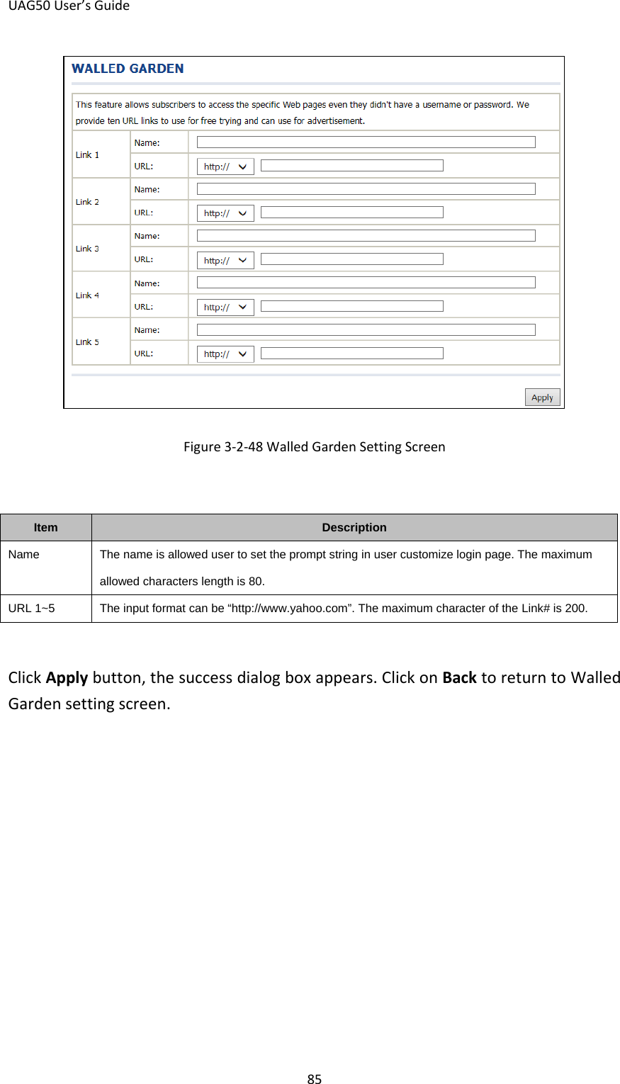
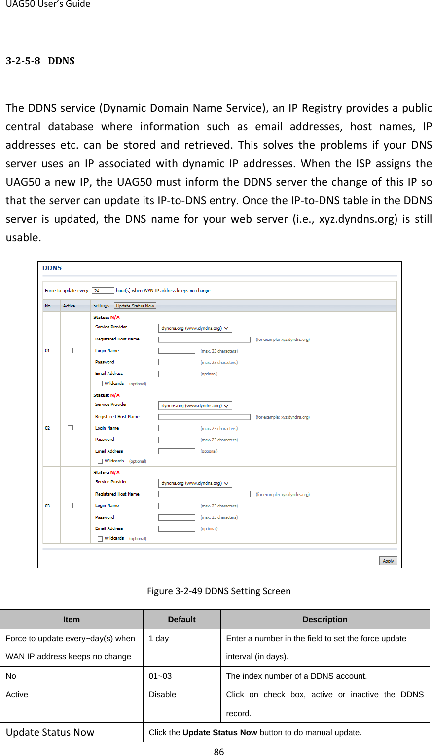
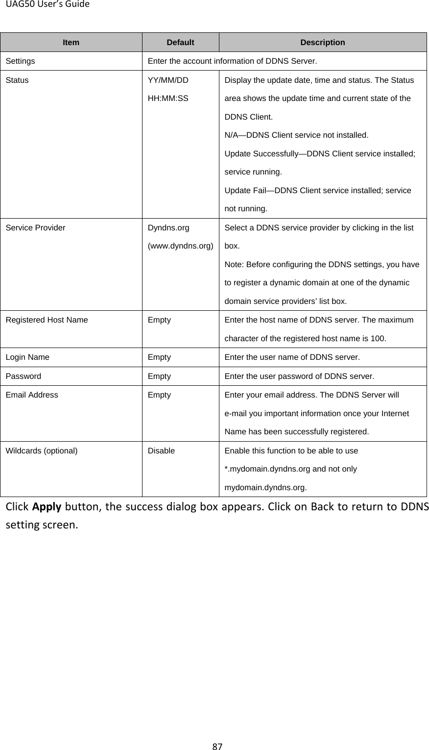
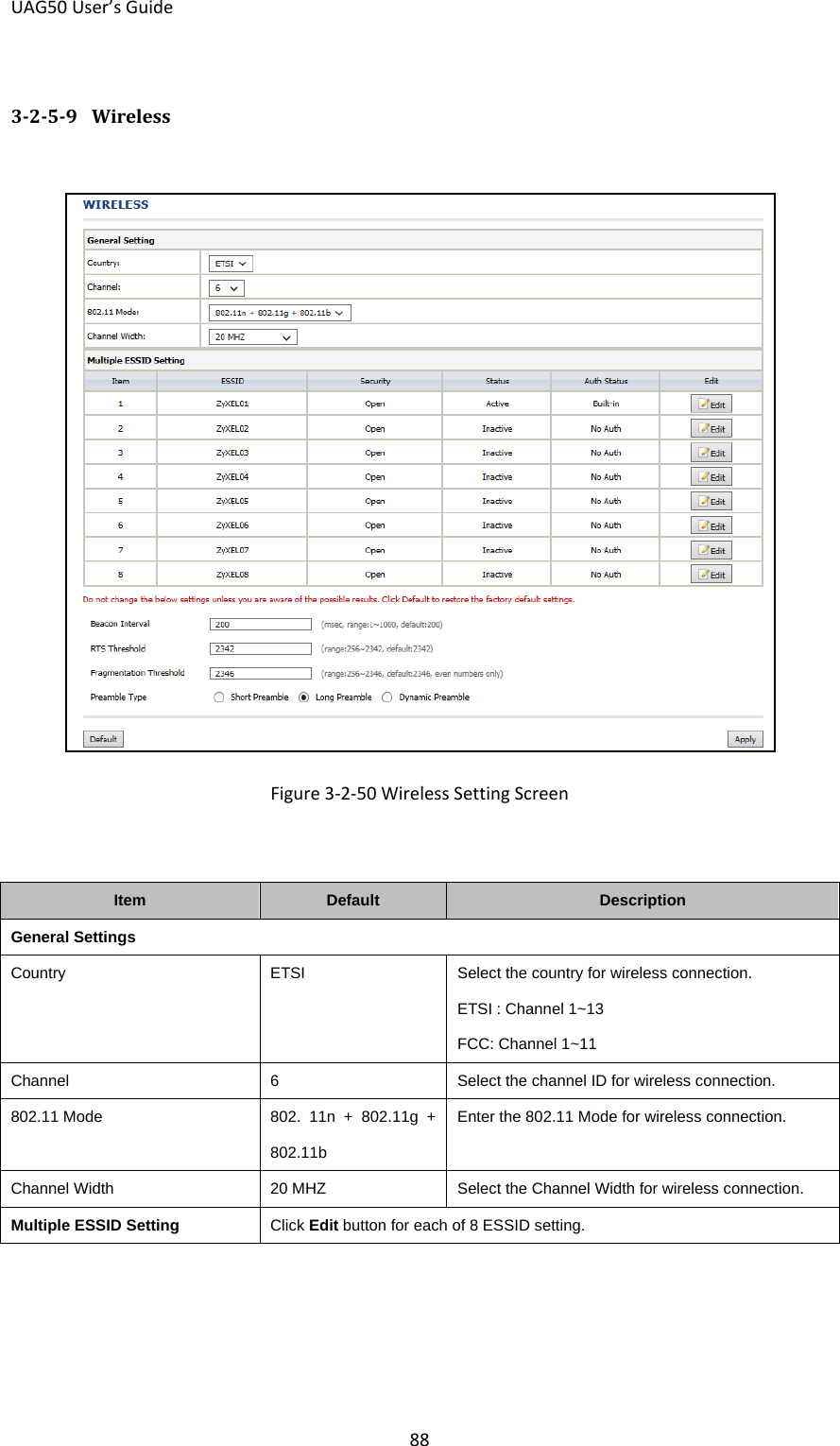
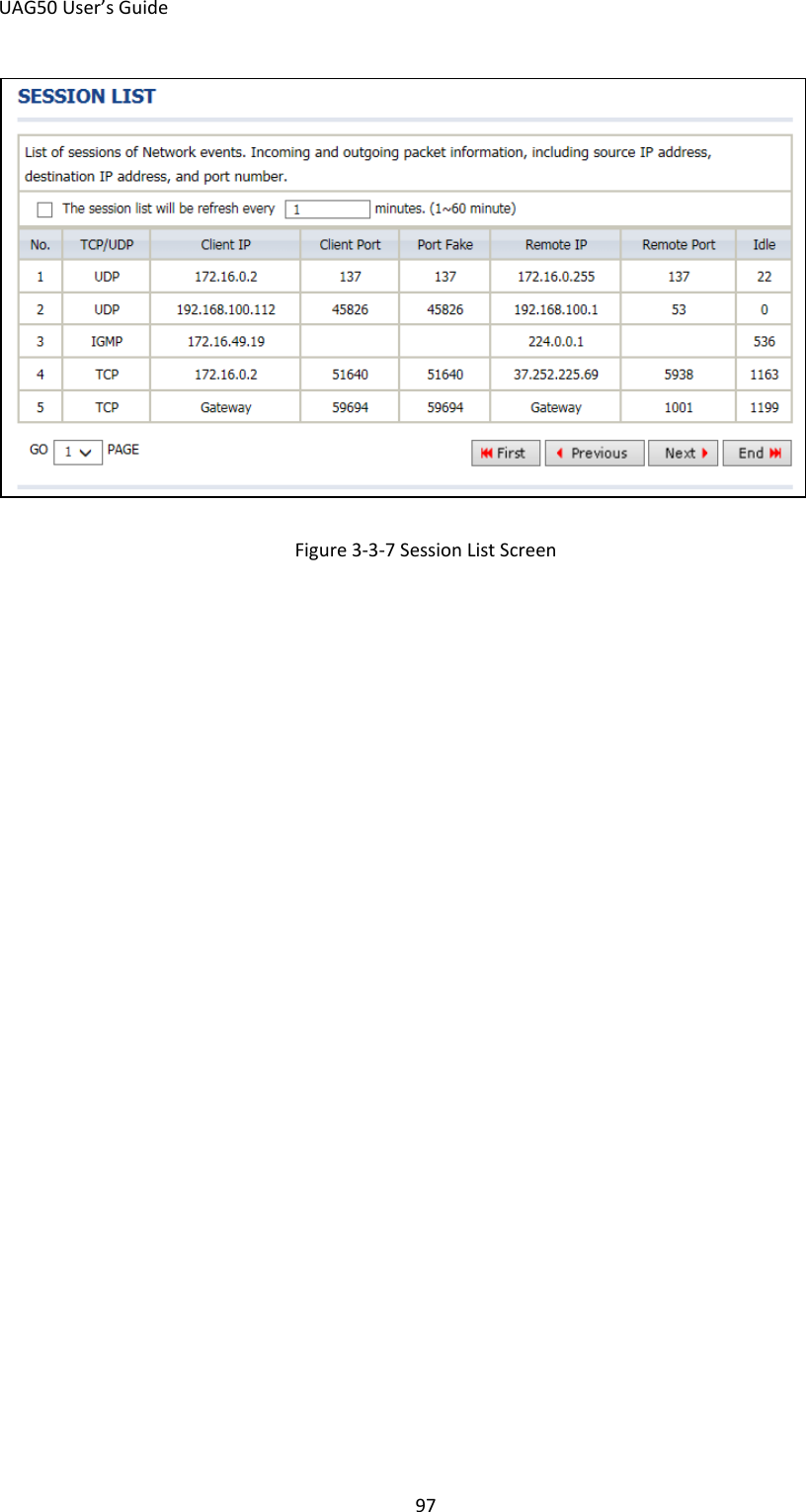
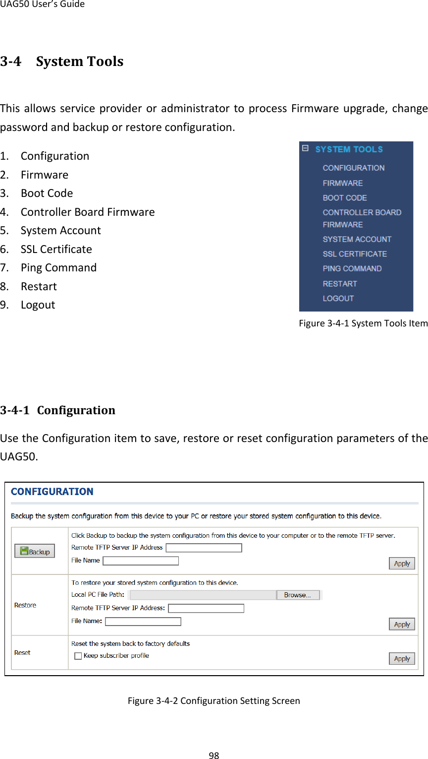
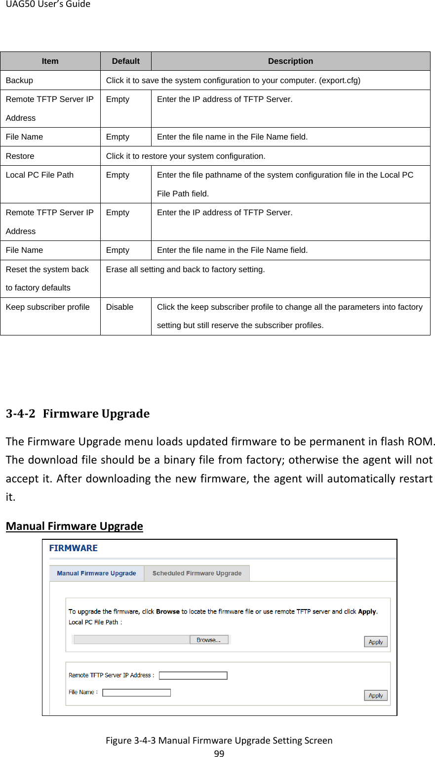
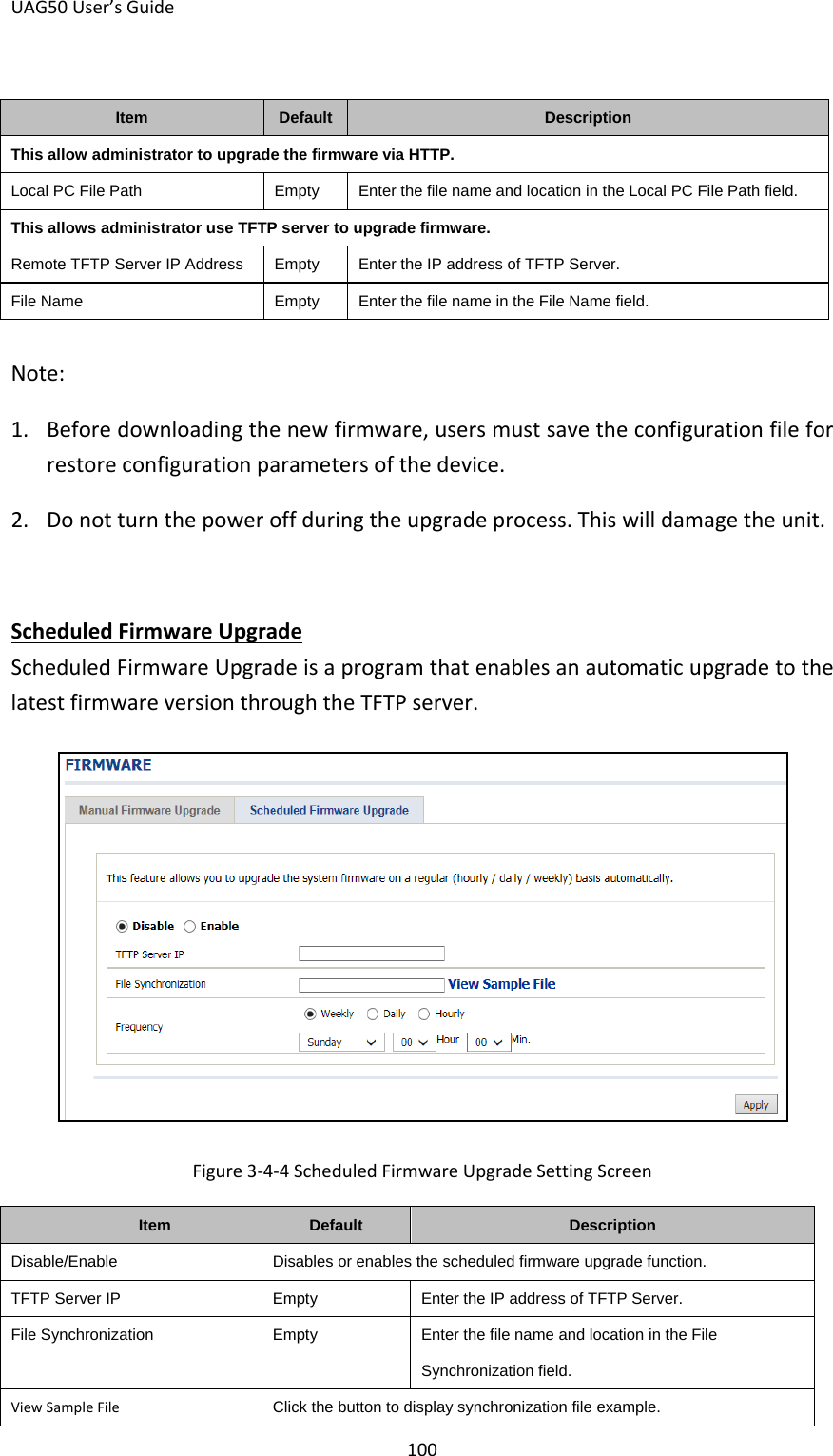
UAG50 User Manual
User manual
Navigation menu
Upload a User Manual
Namespaces
Wiki Guide
HTML
PDF
Info
Views
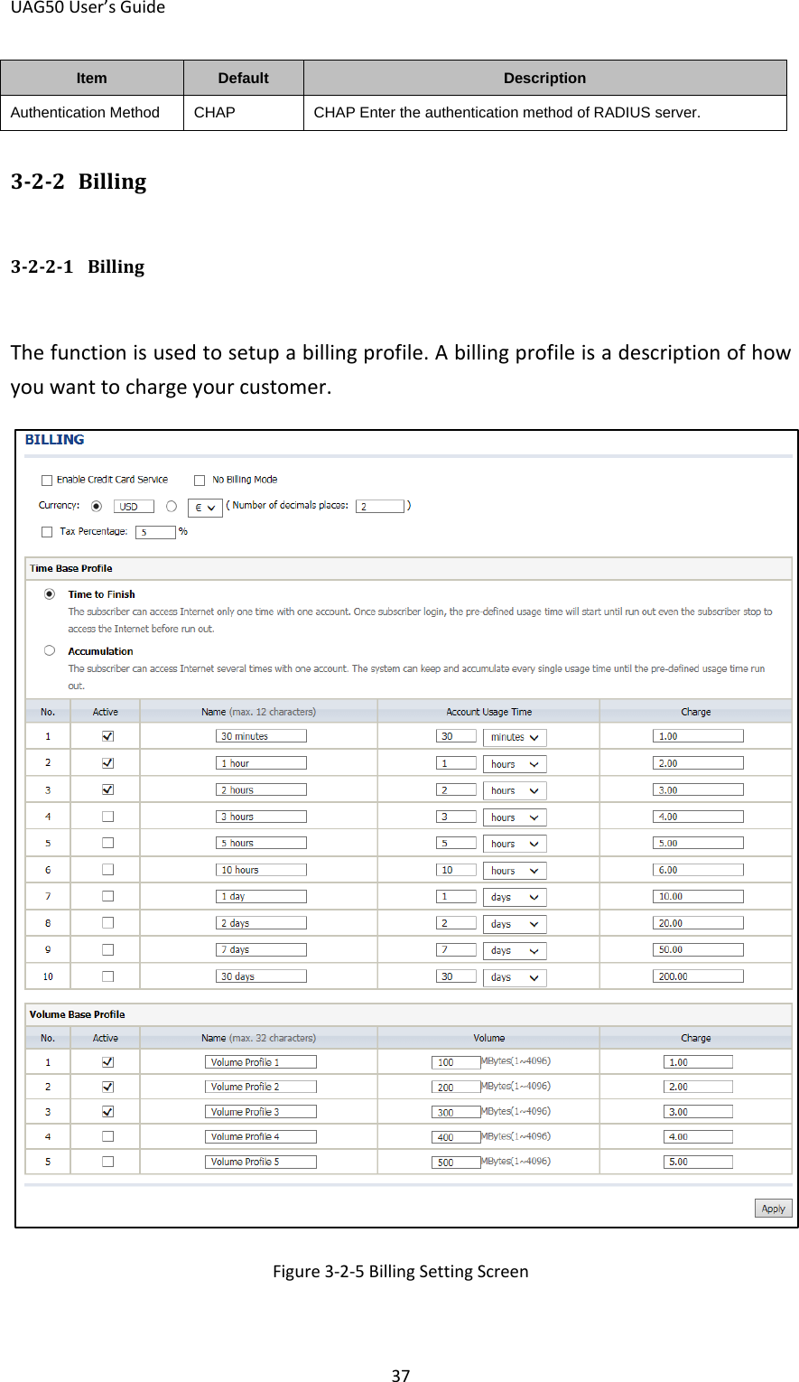
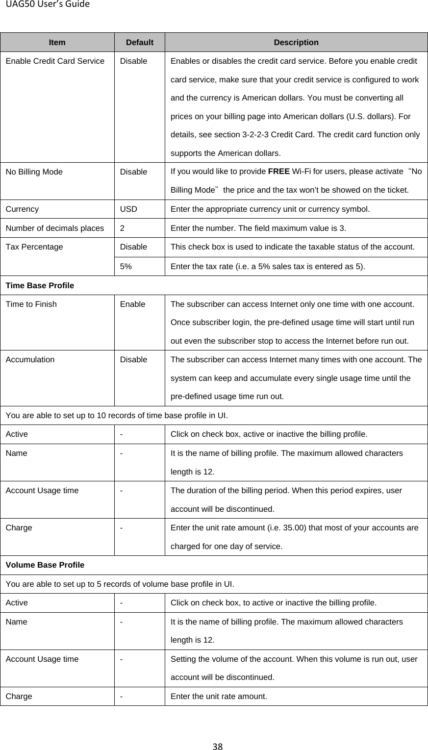
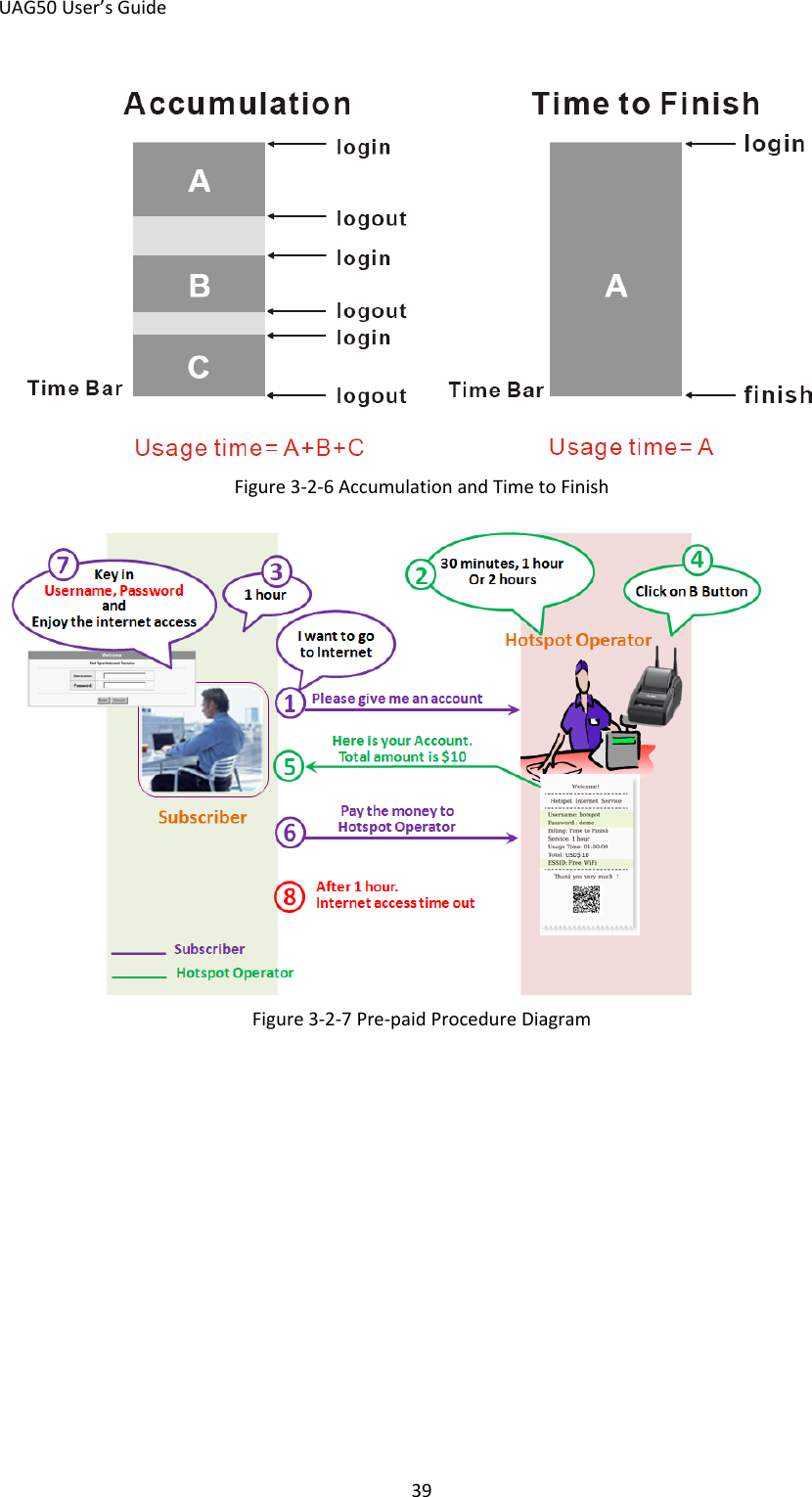
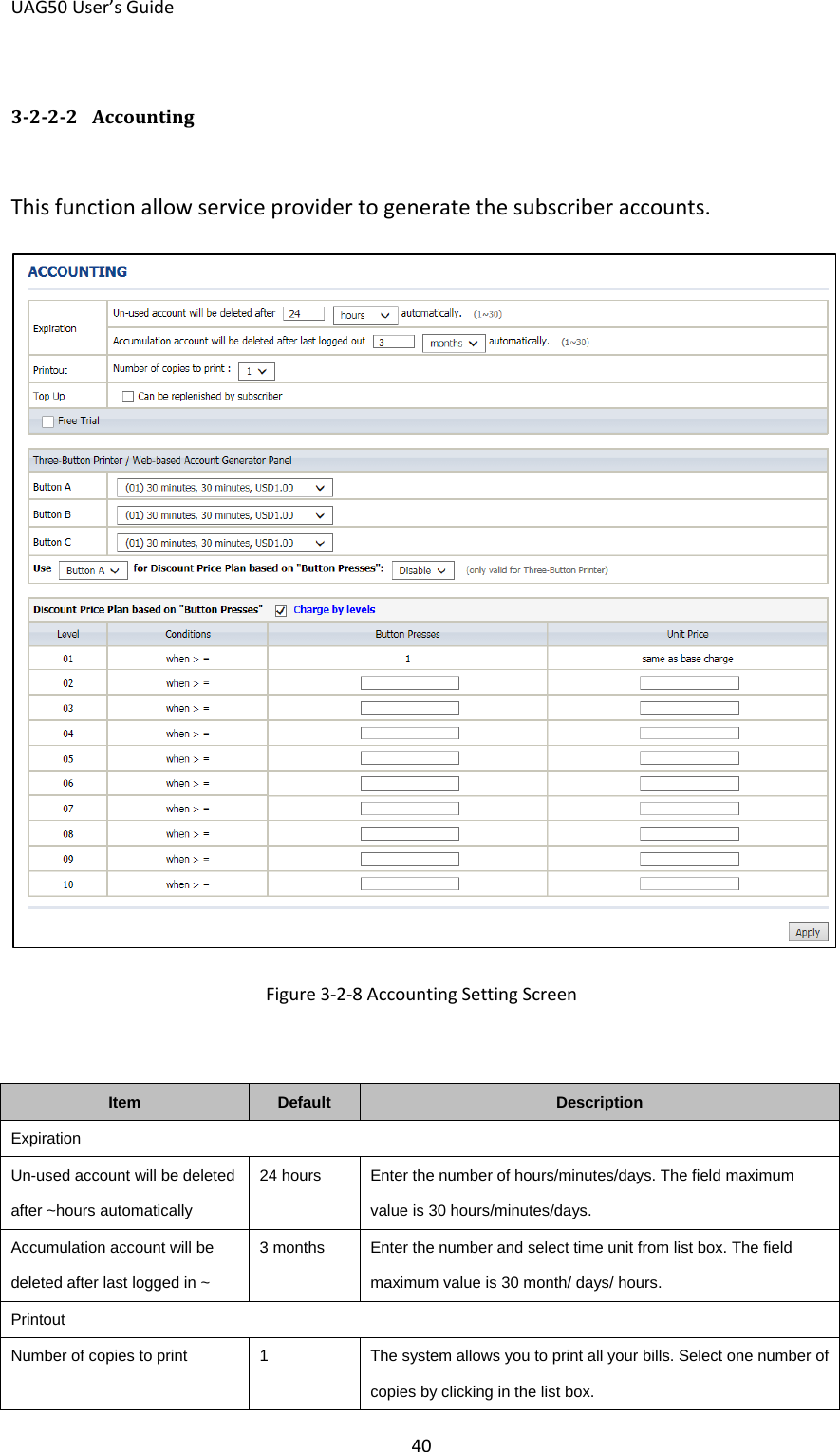
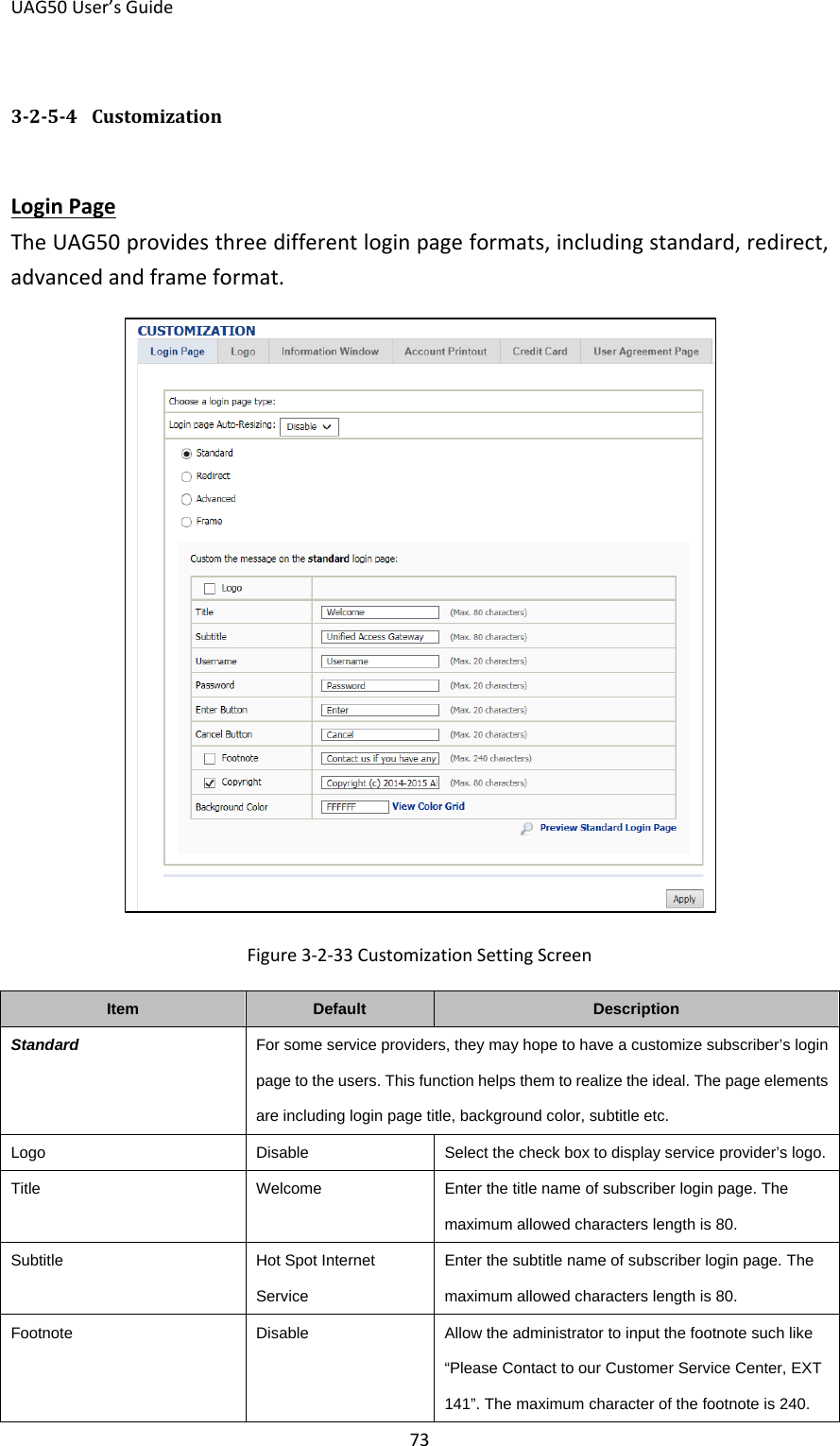
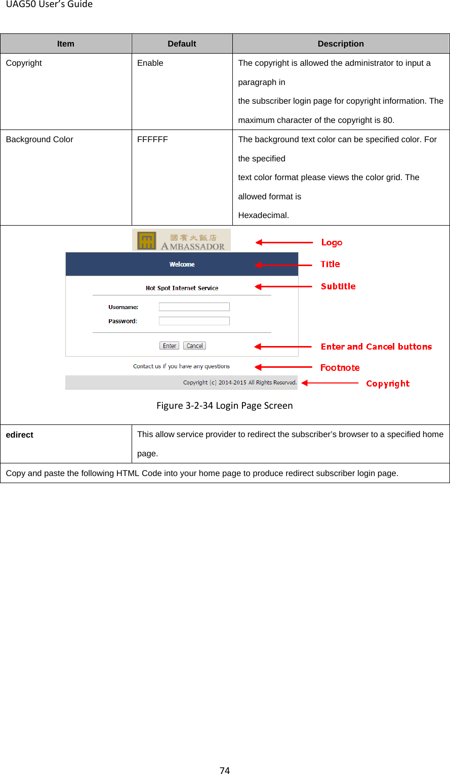
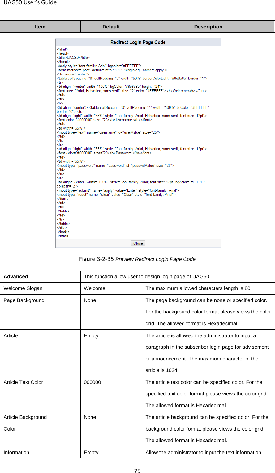
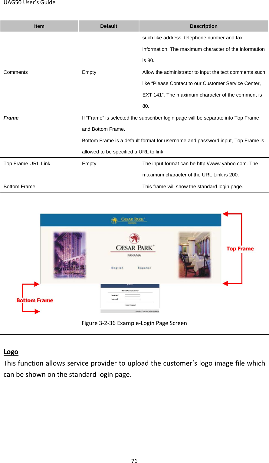
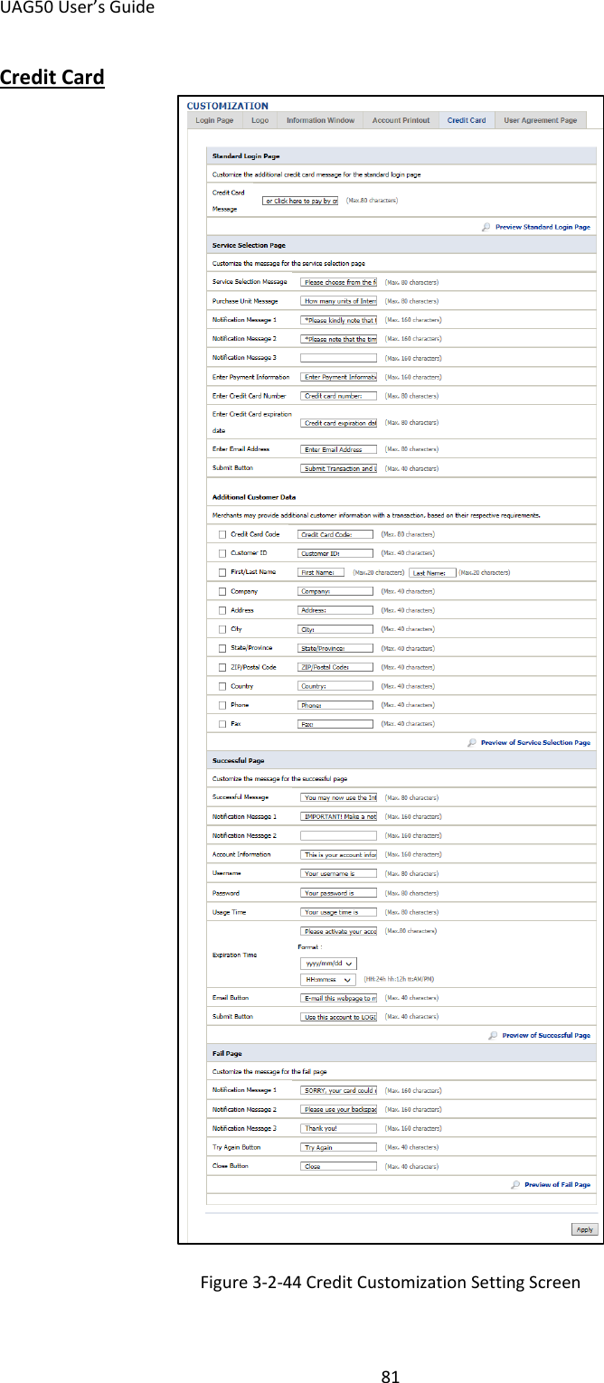
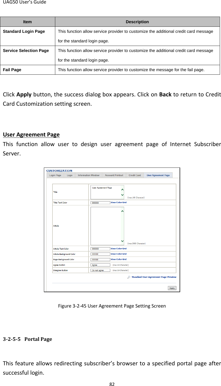
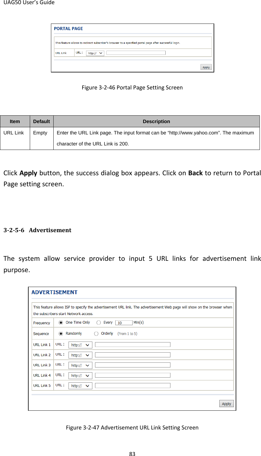
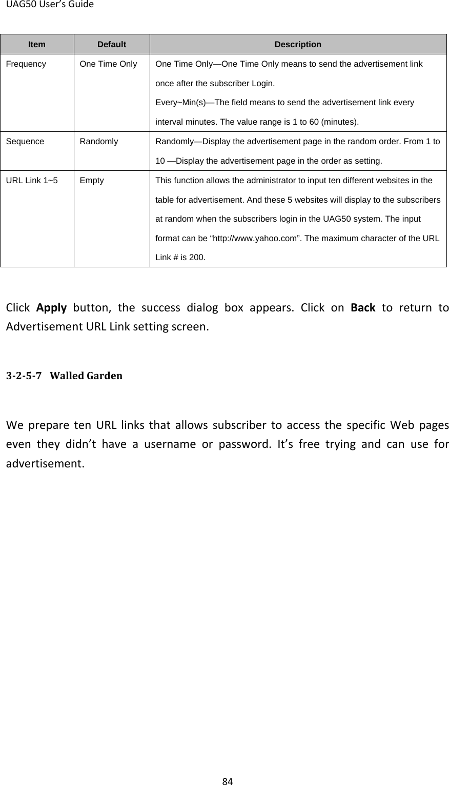
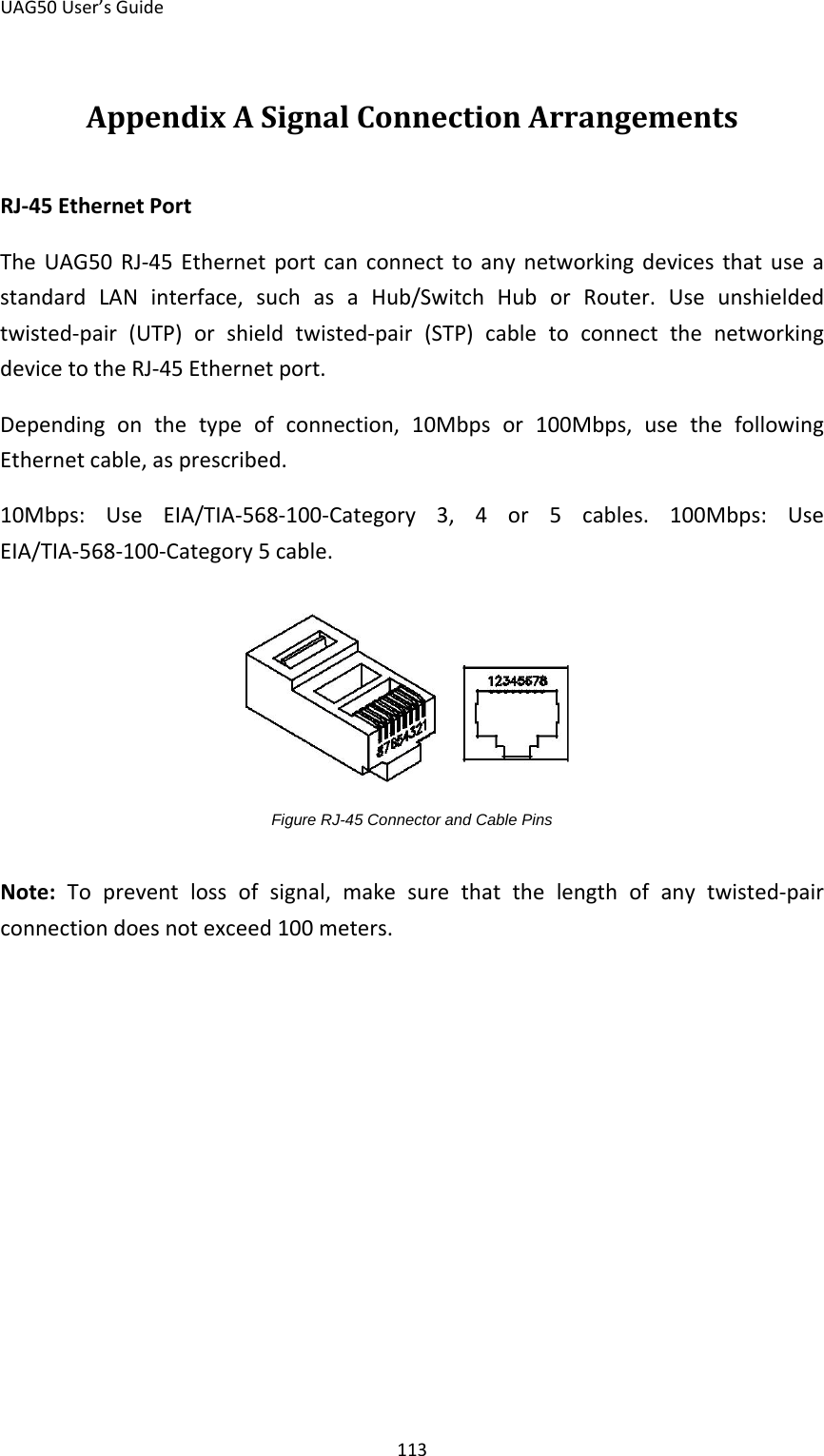
User Manual
Discussion / Help
Navigation