ZyXEL Communications VMG1312B10C Wireless N VDSL2 4-ports Gateway with USB Wireless N VDSL2 4-ports Gateway without USB User Manual
ZyXEL Communications Corporation Wireless N VDSL2 4-ports Gateway with USB Wireless N VDSL2 4-ports Gateway without USB
User manual
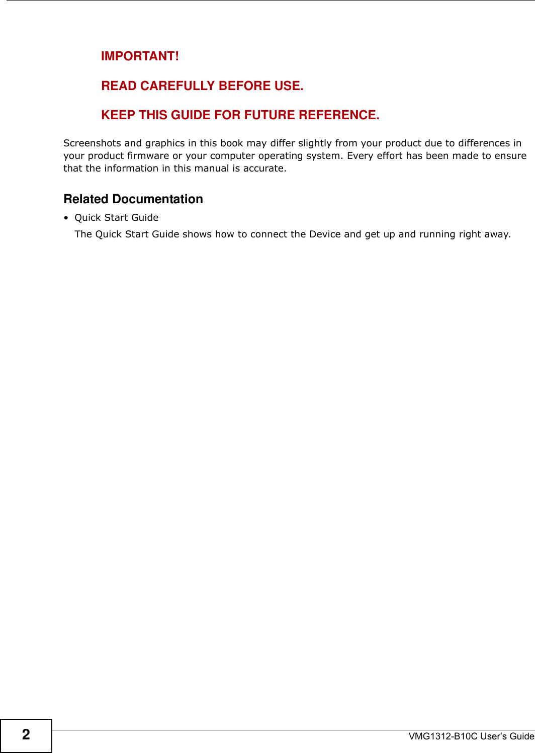


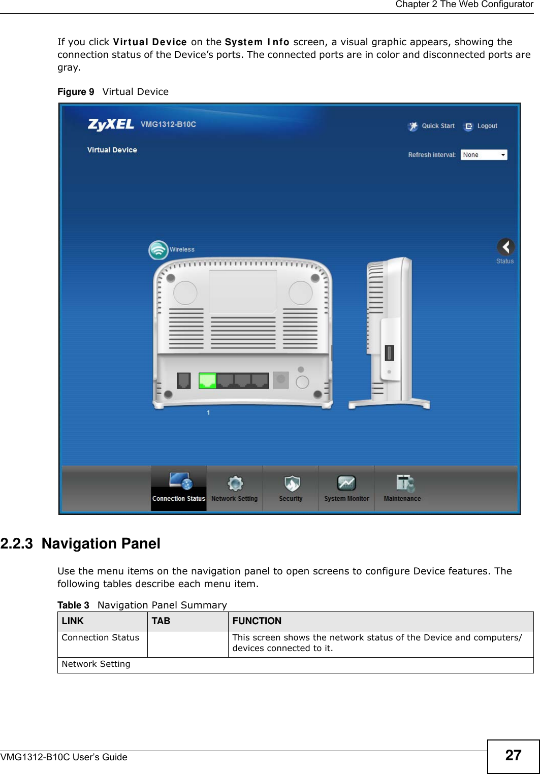
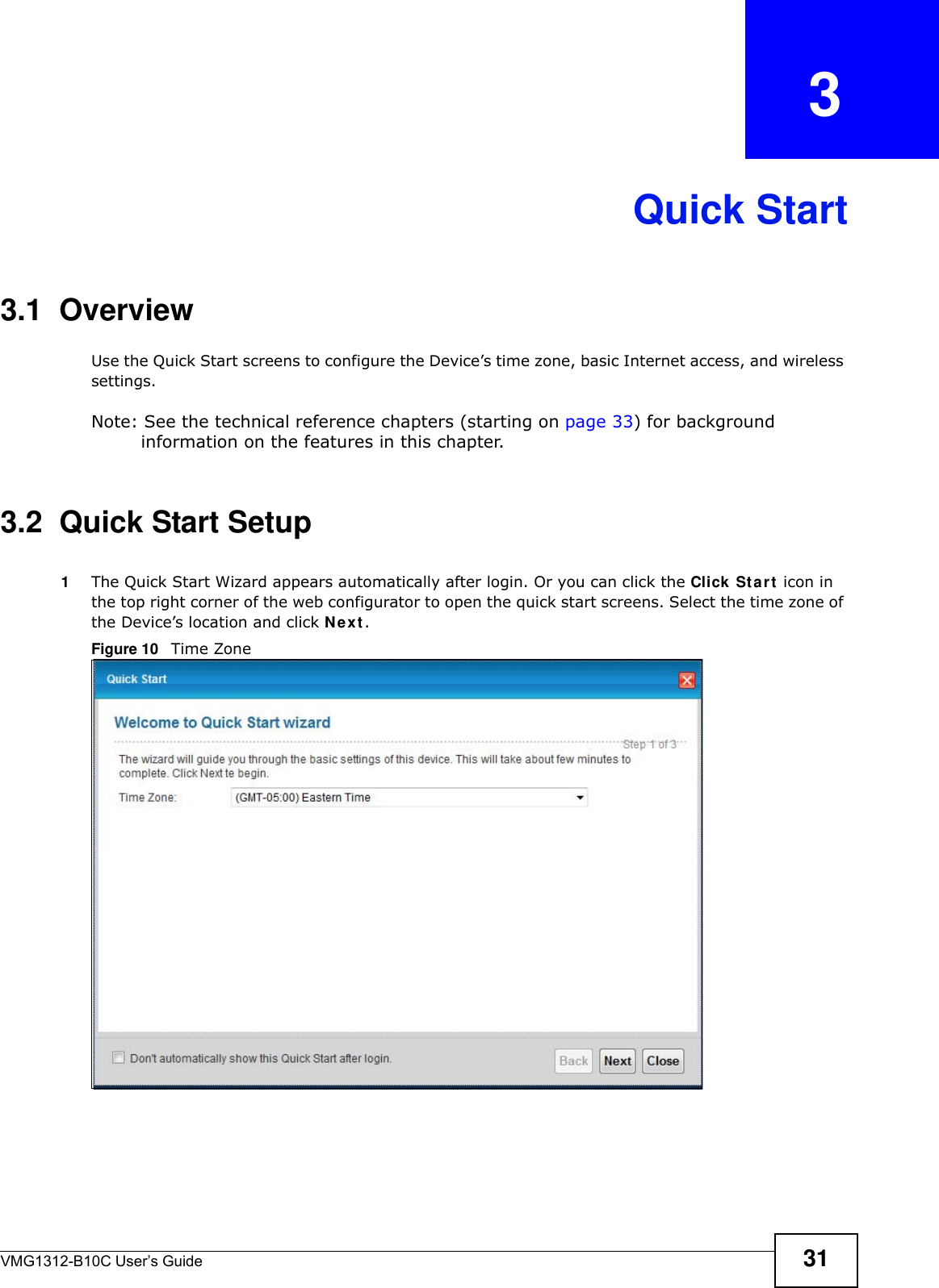
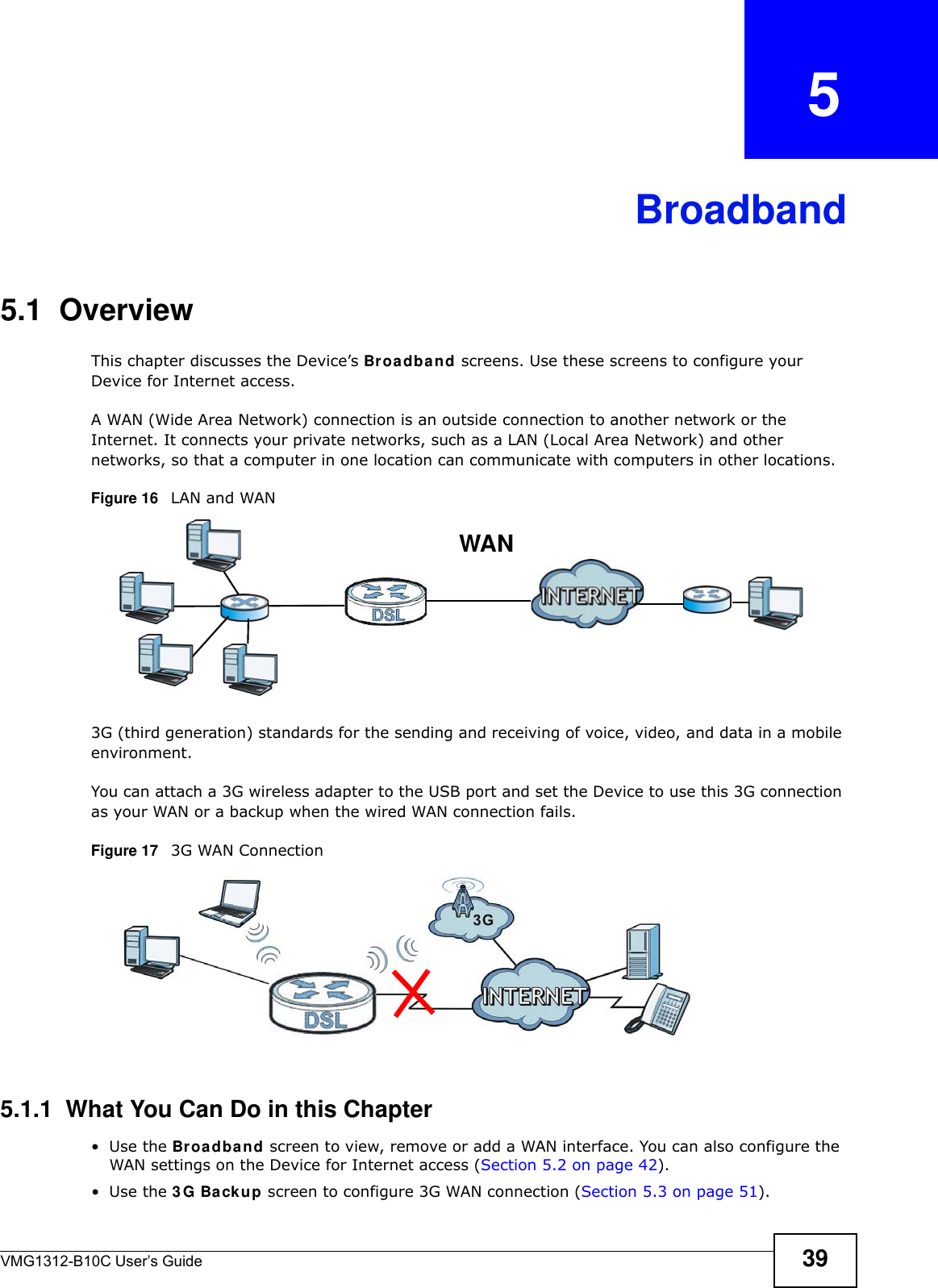
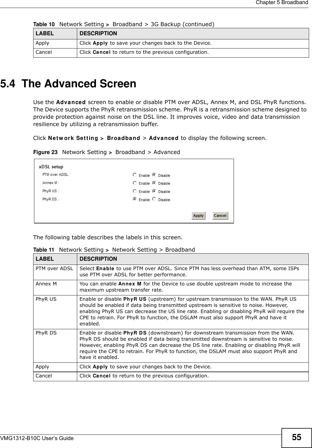
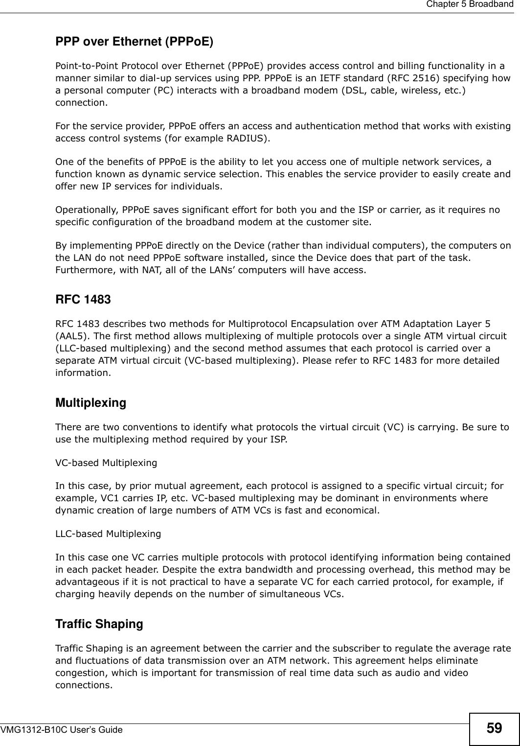
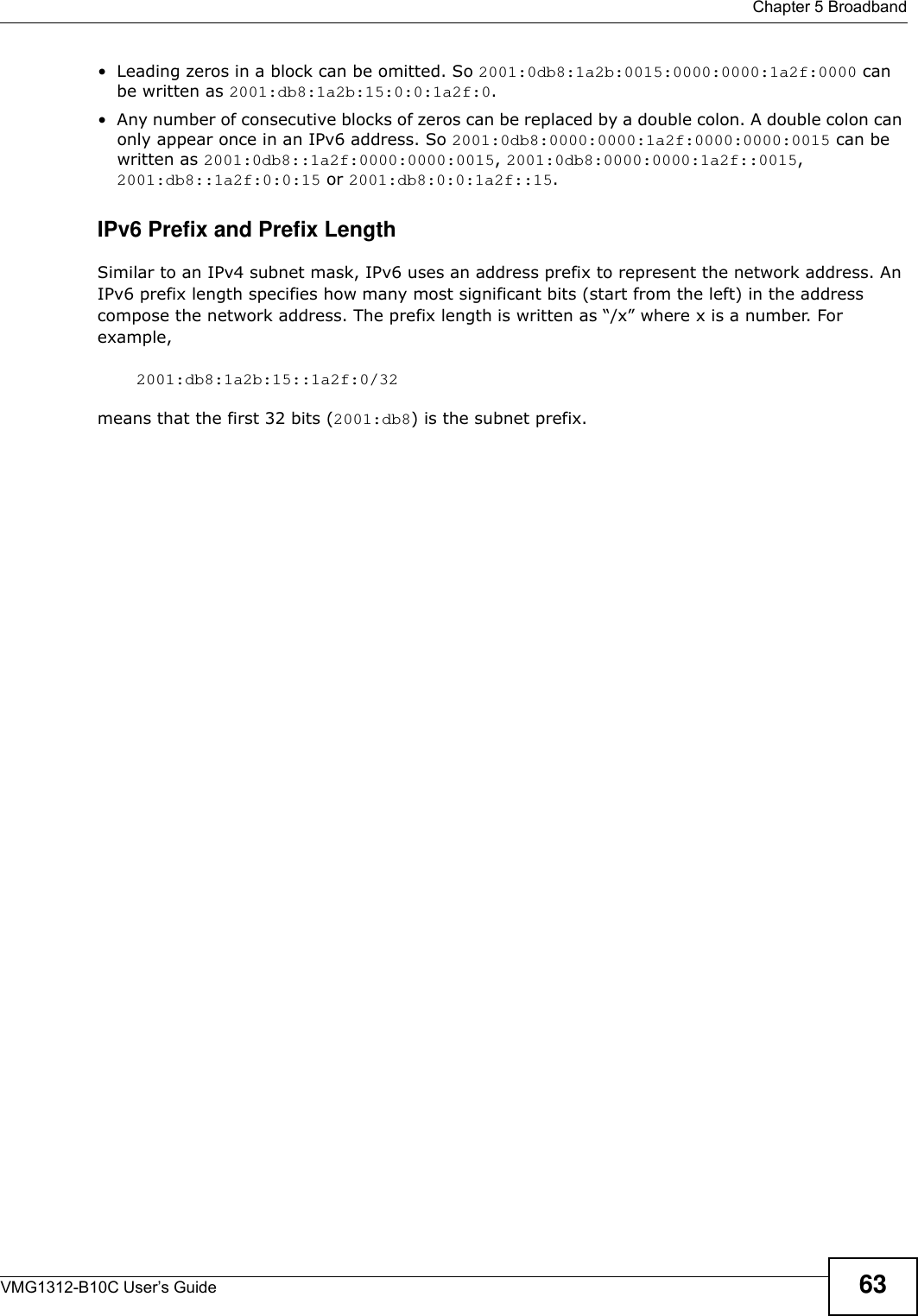
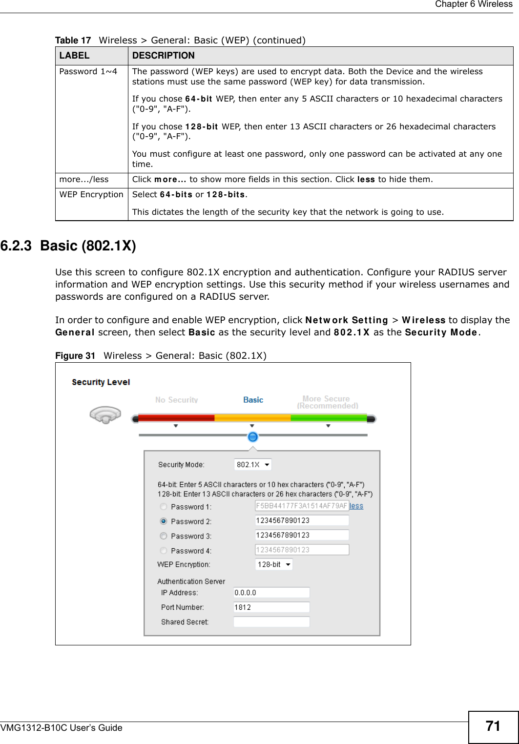
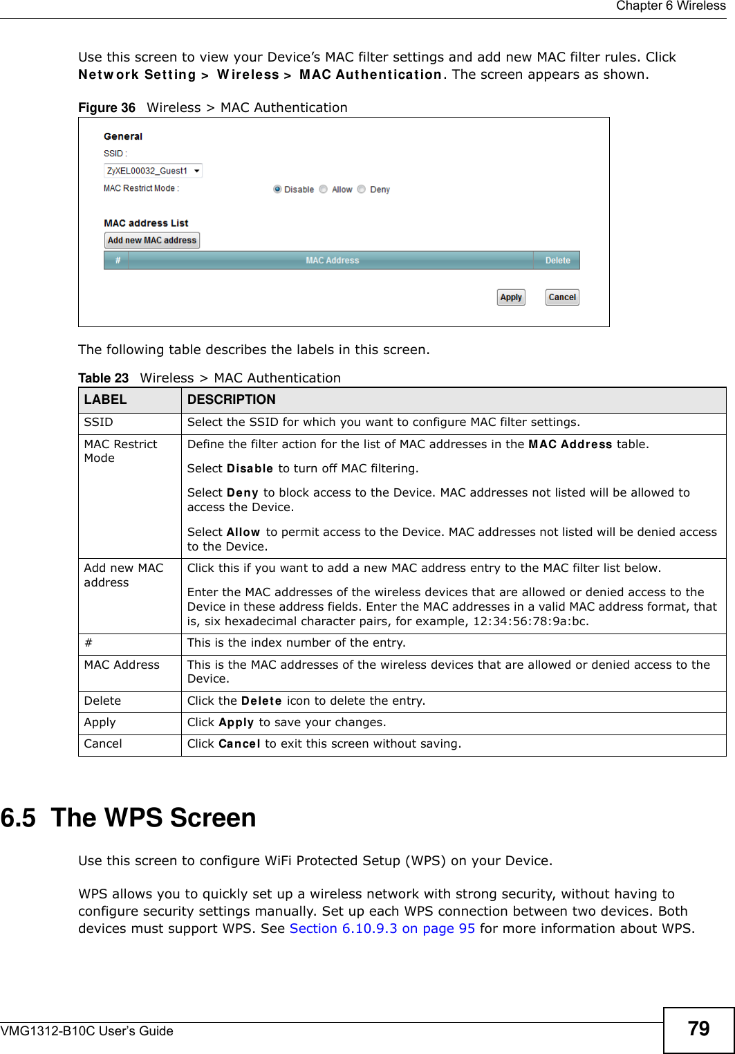
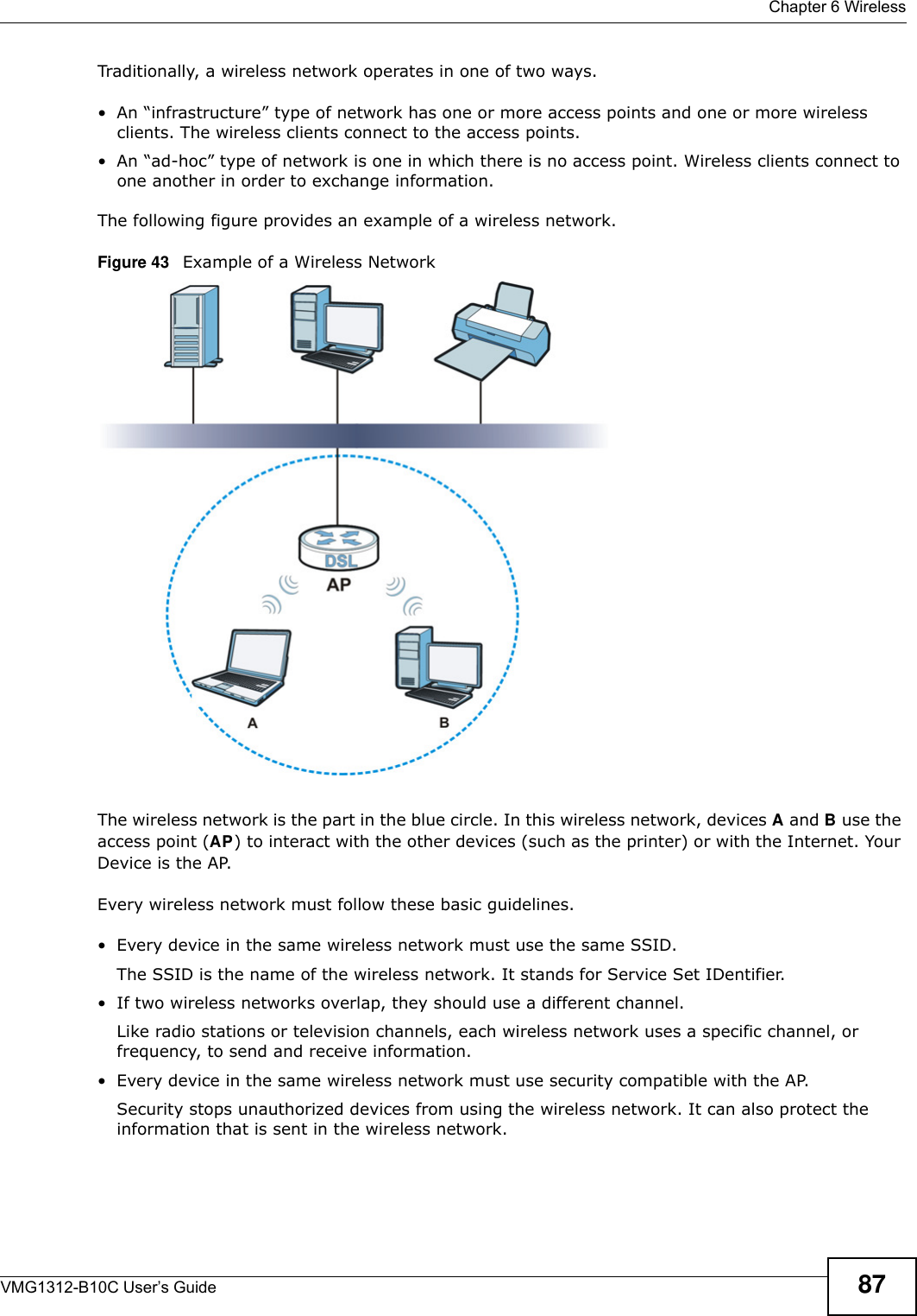
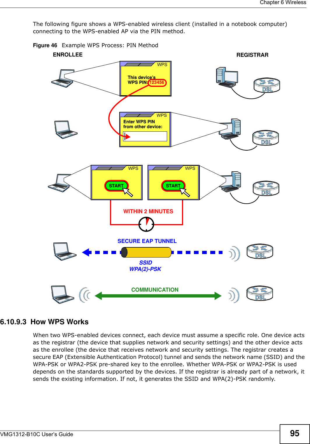
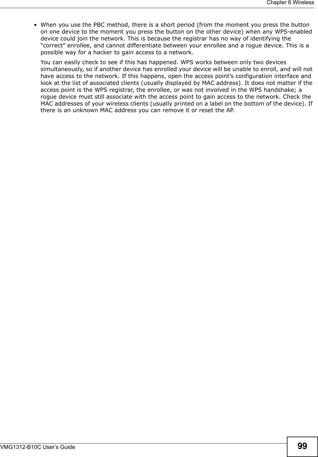

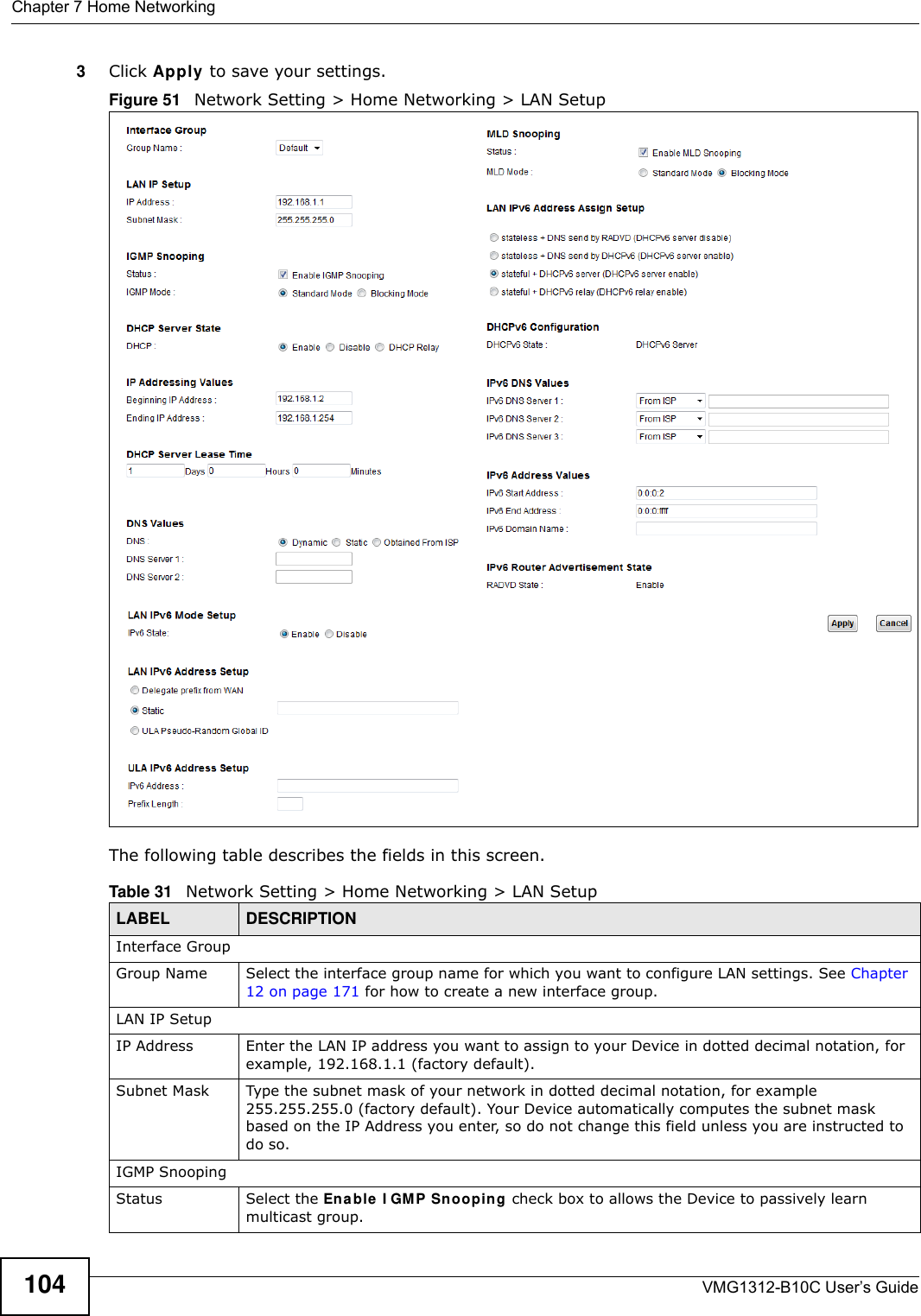
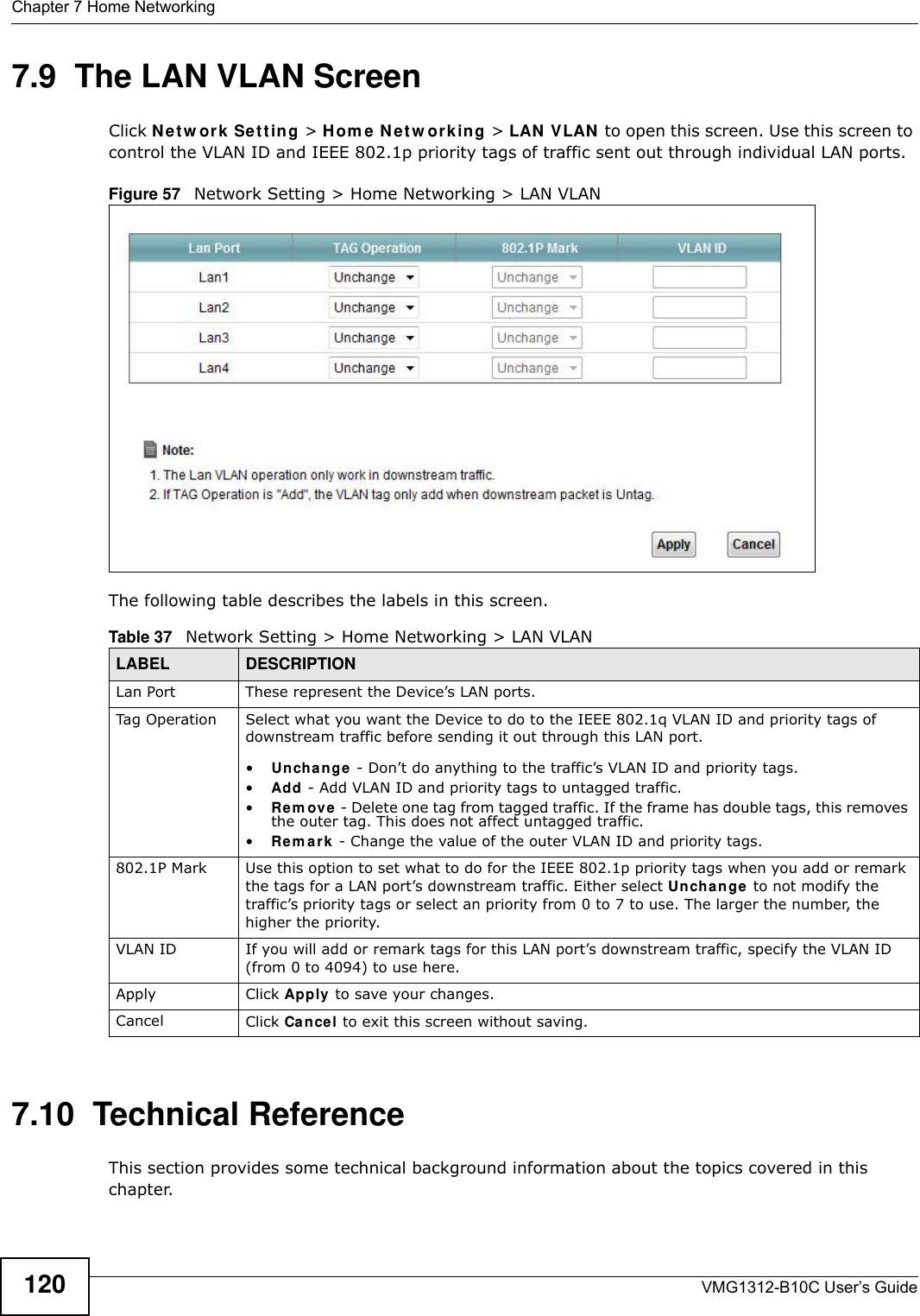

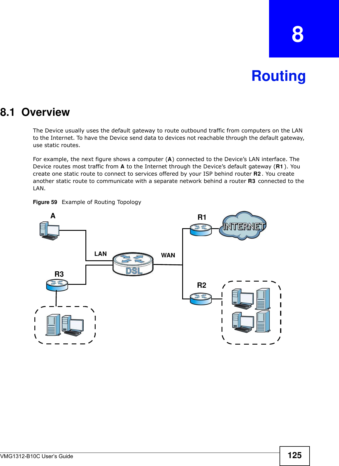
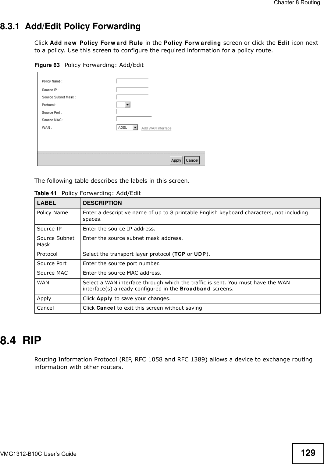
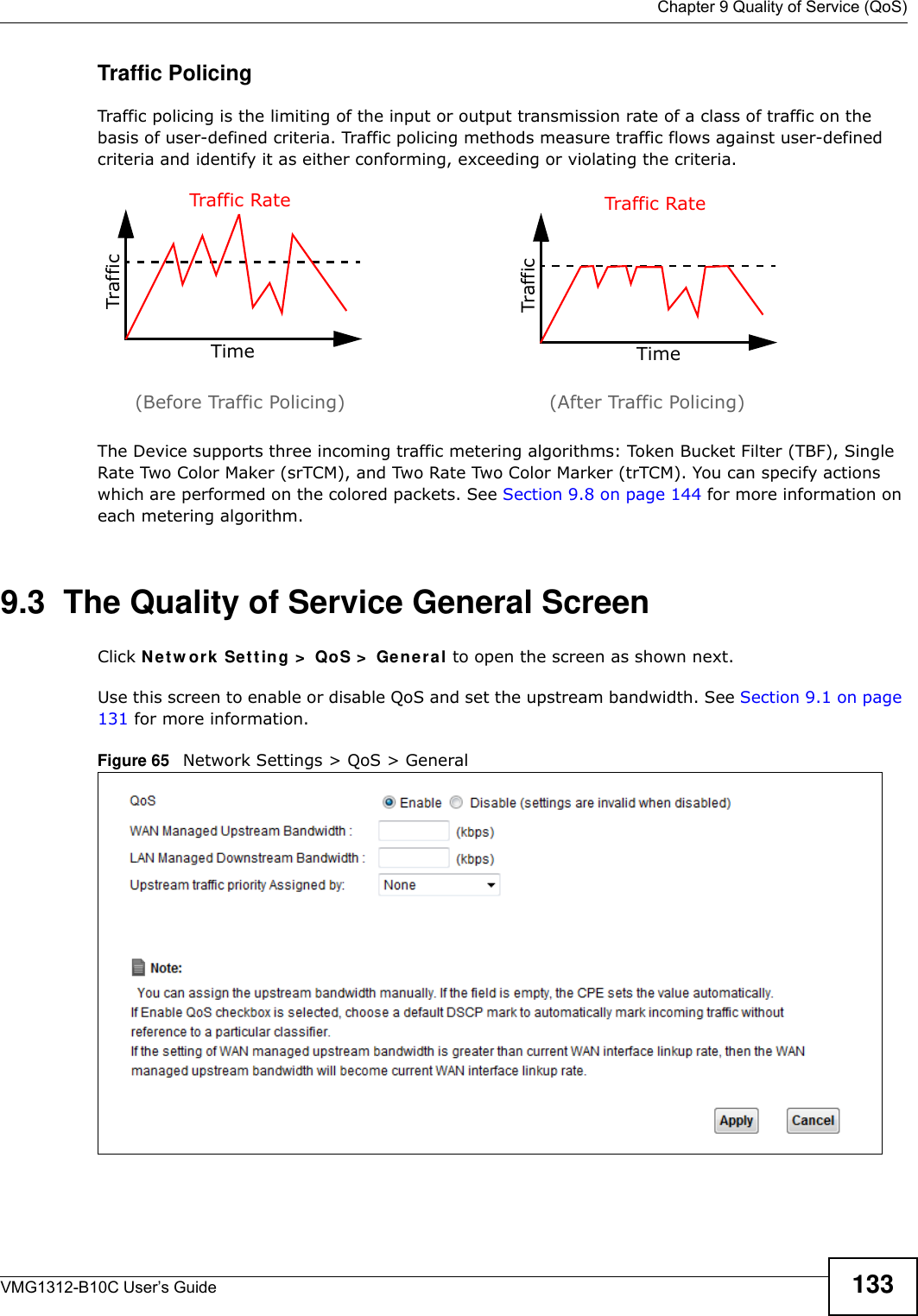
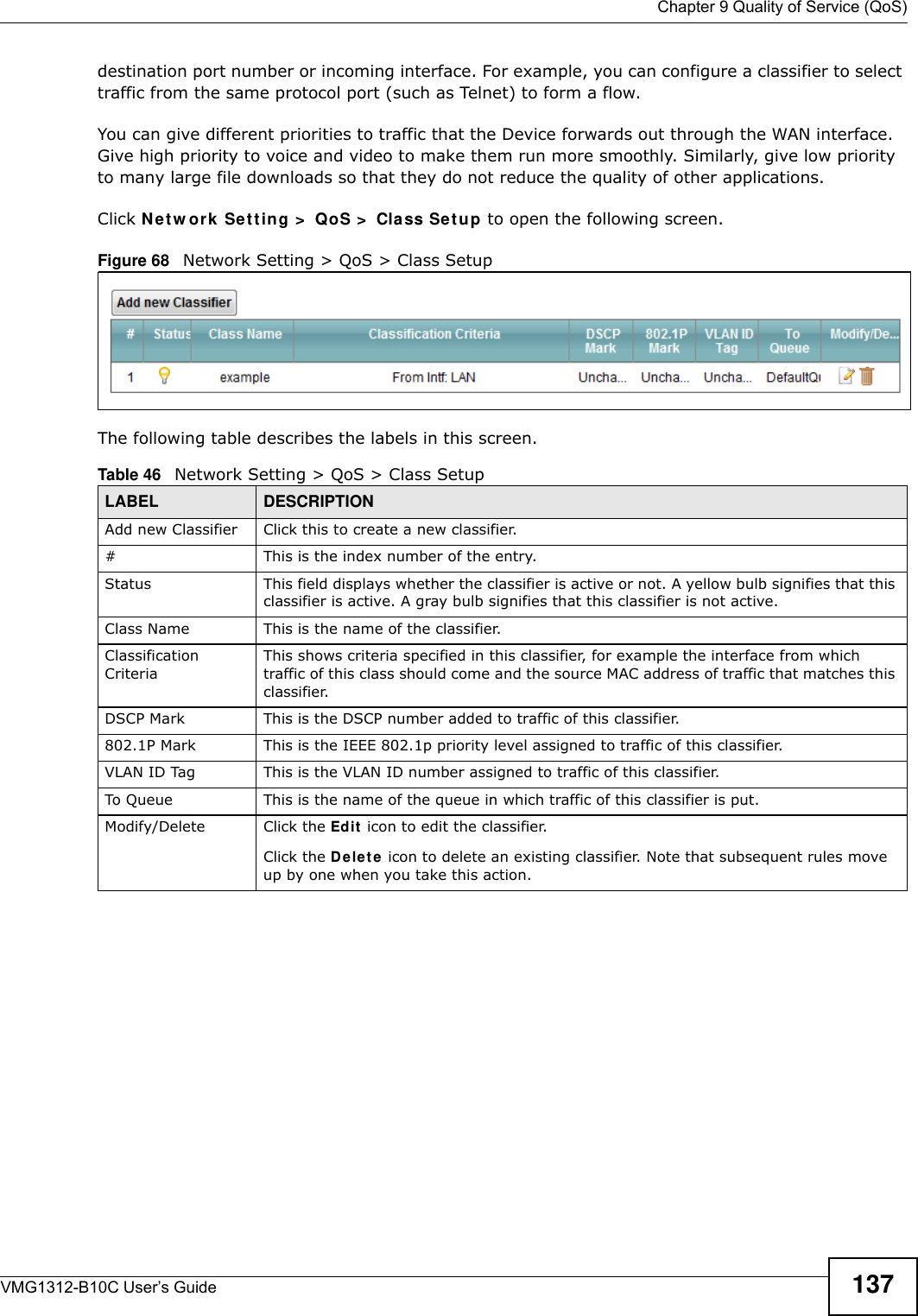
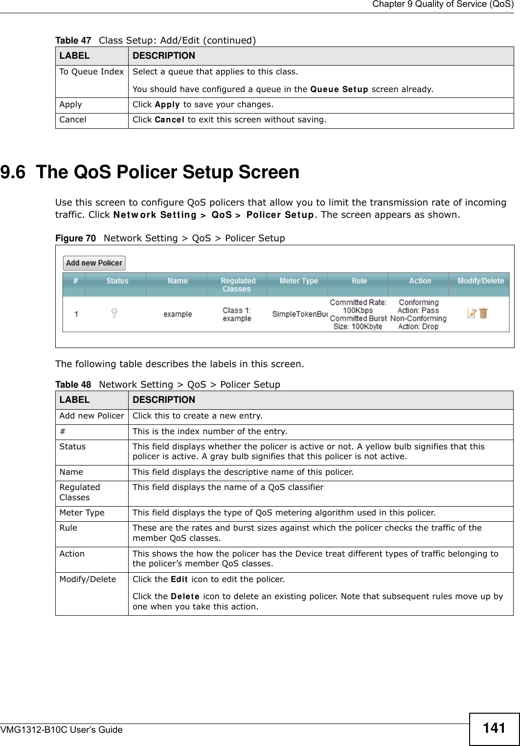
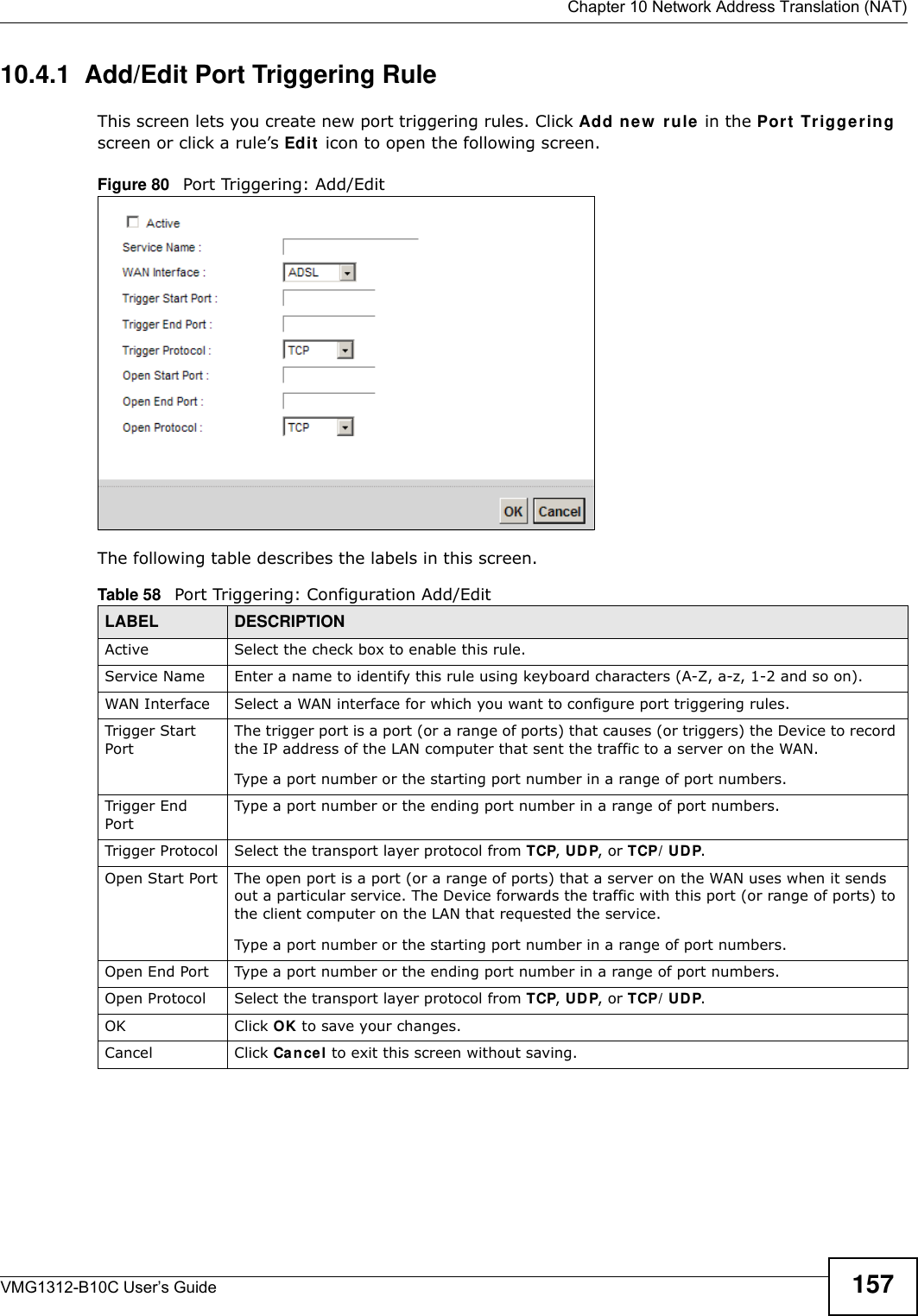
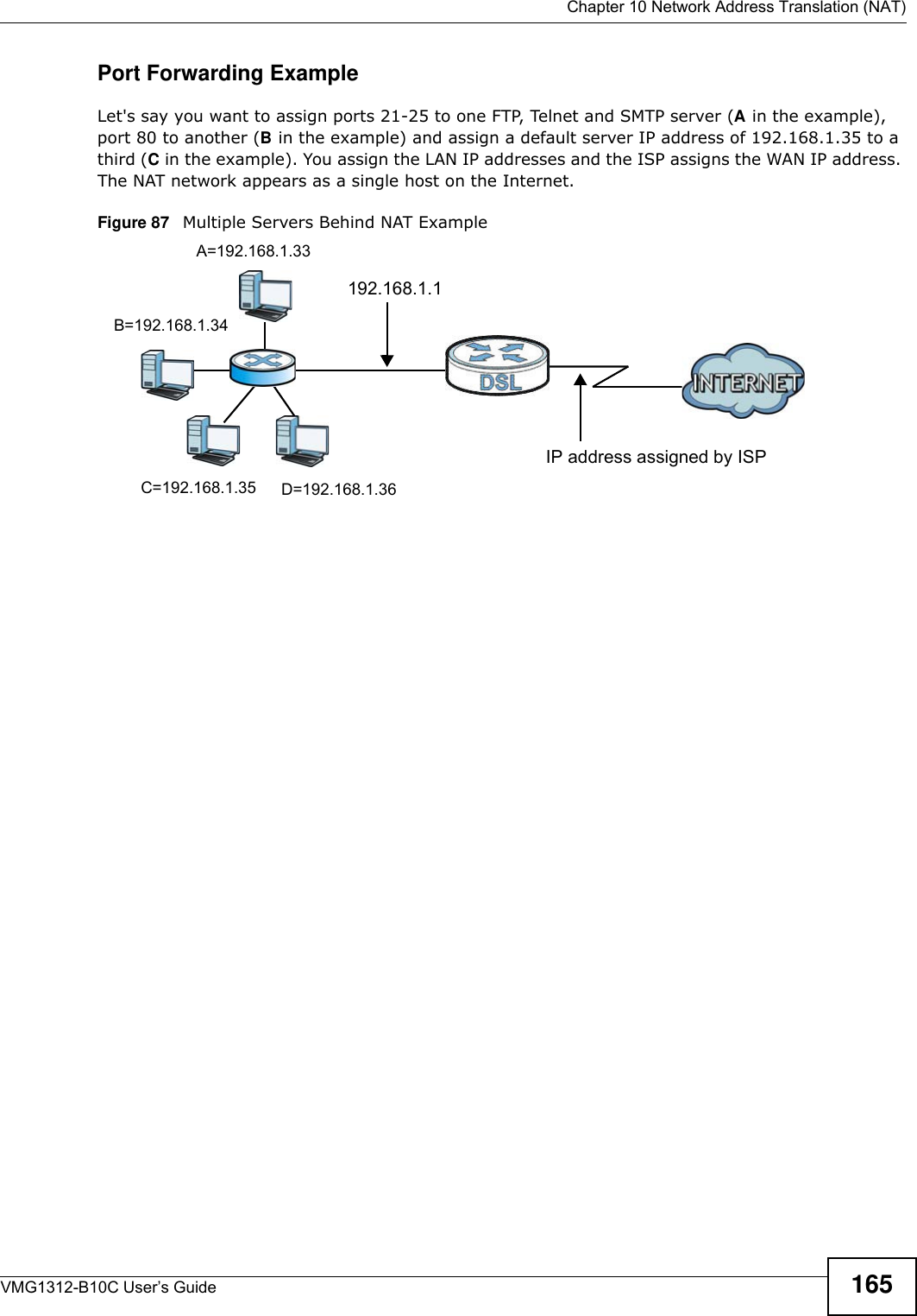
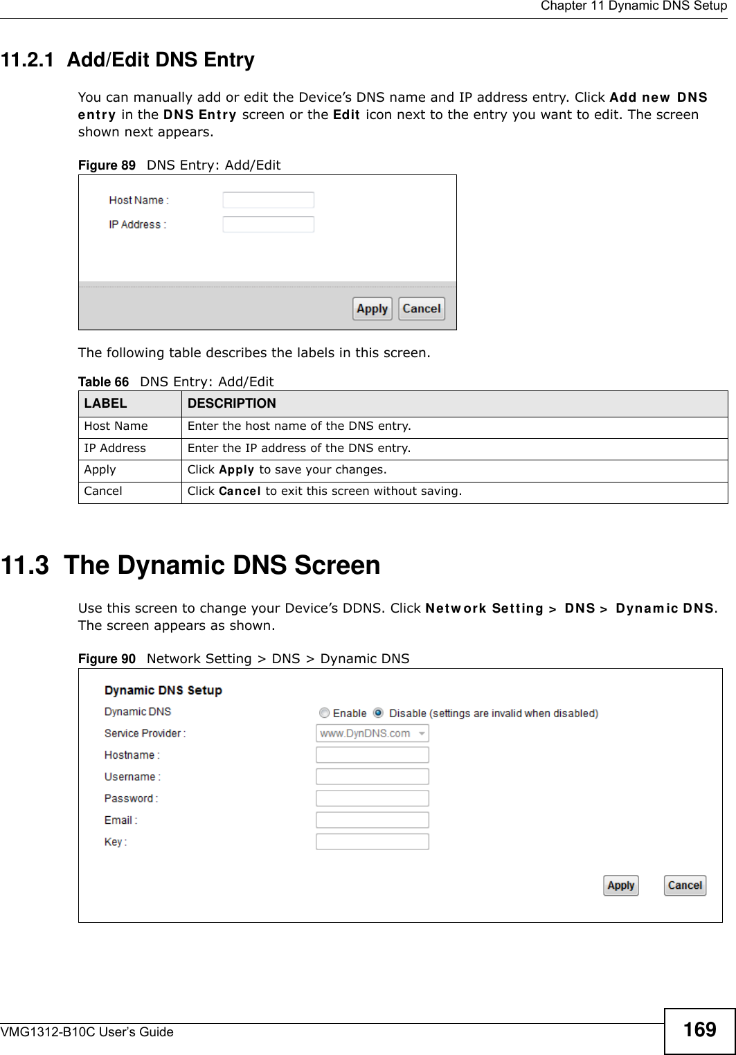

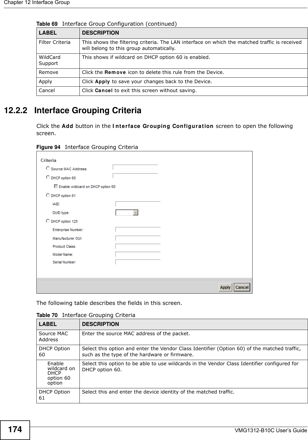

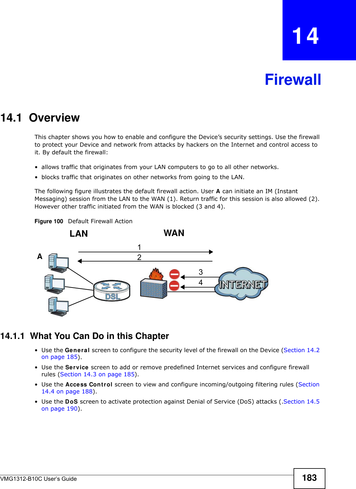
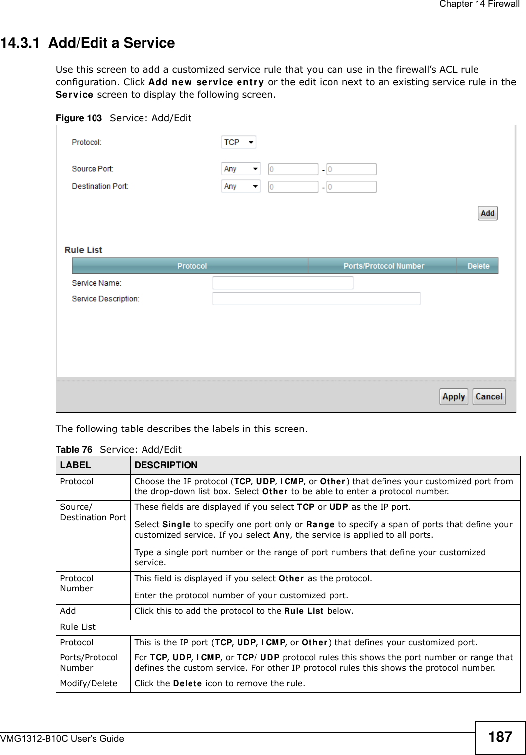


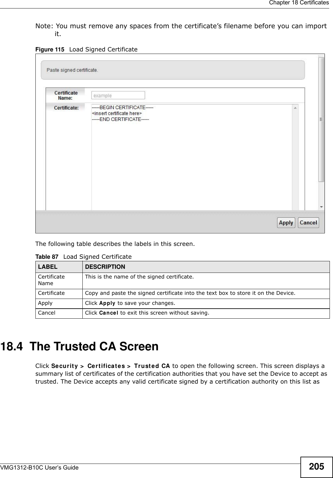

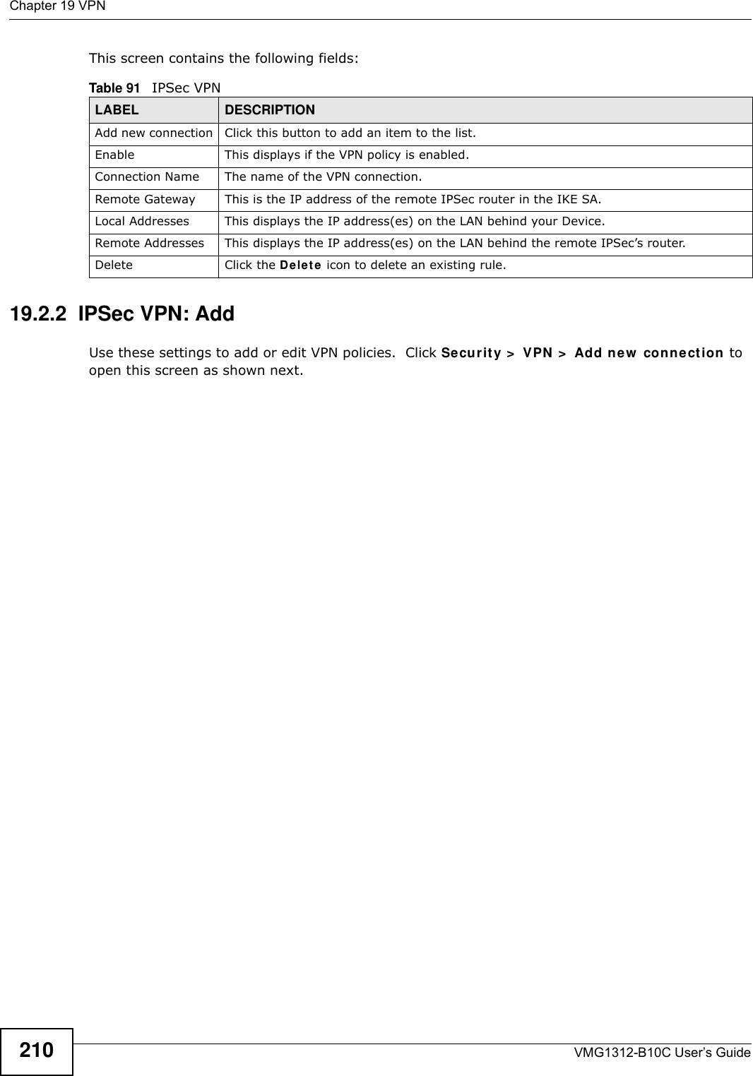
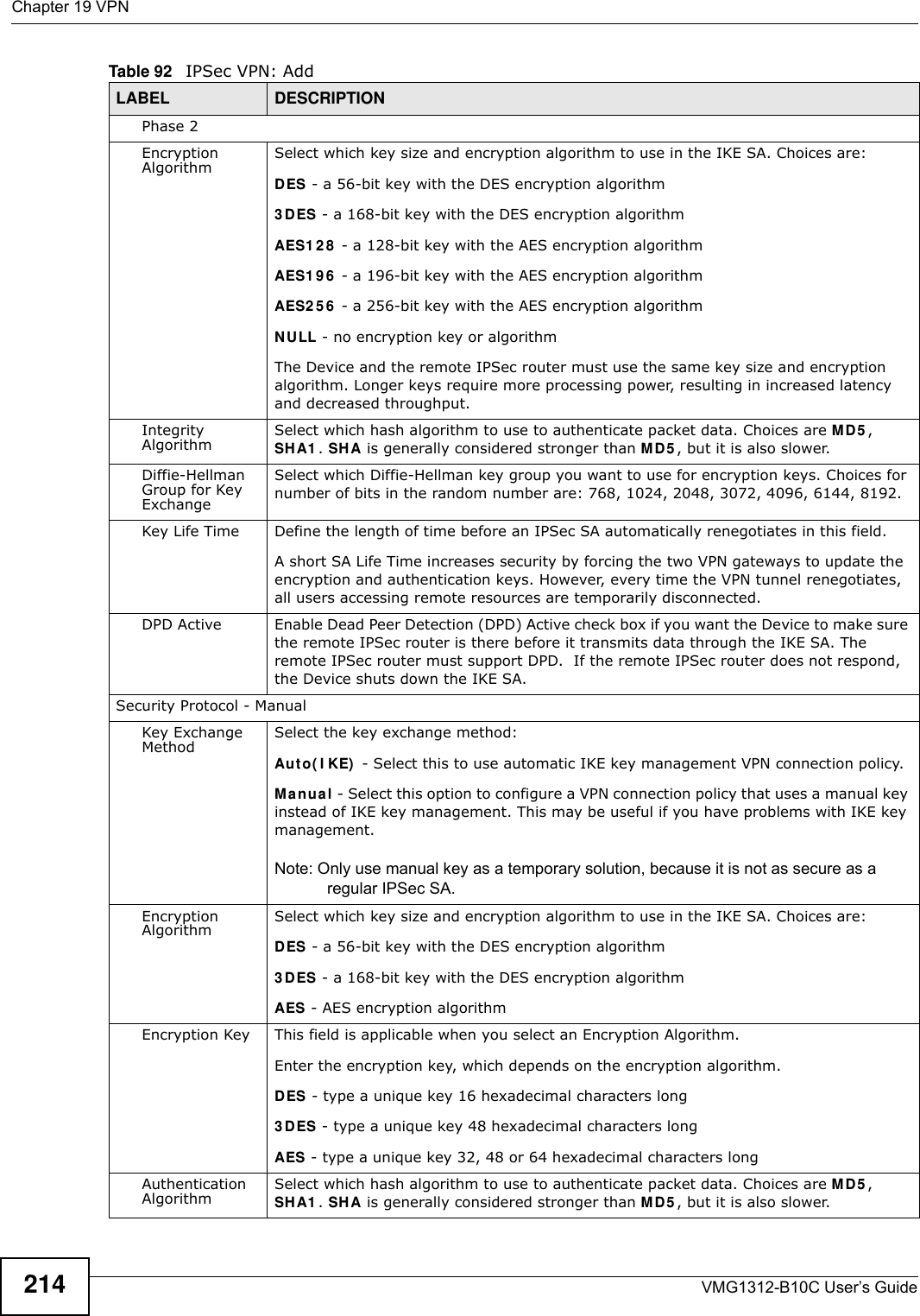
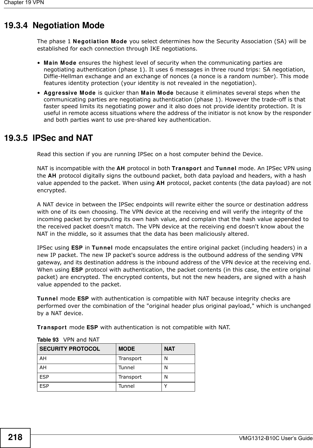

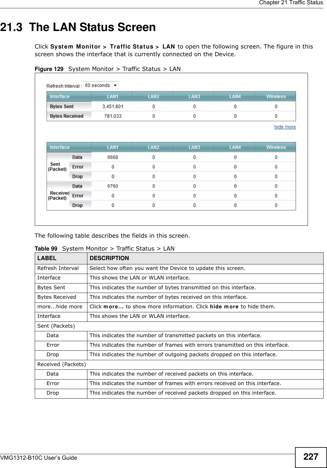


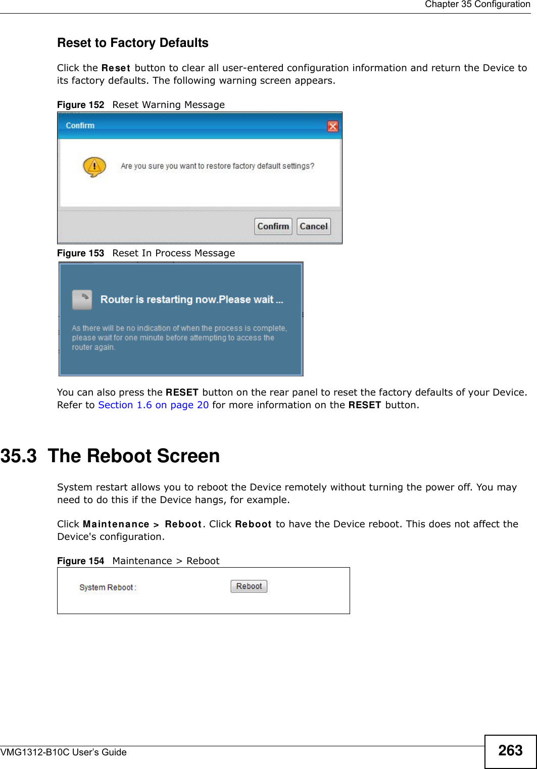

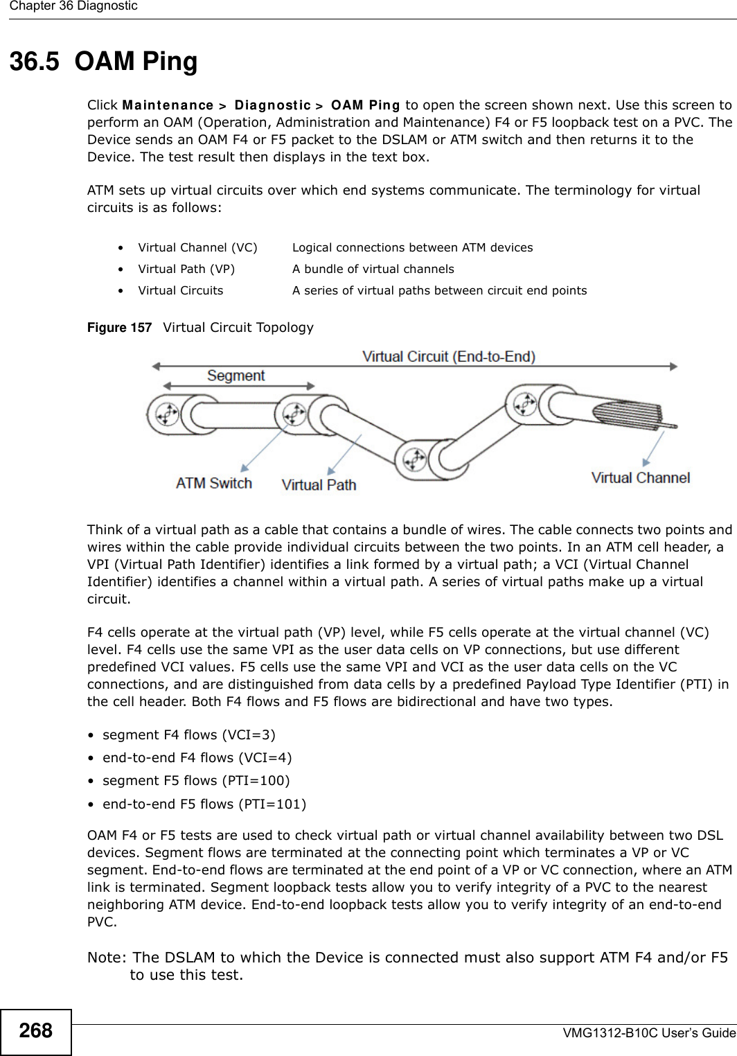

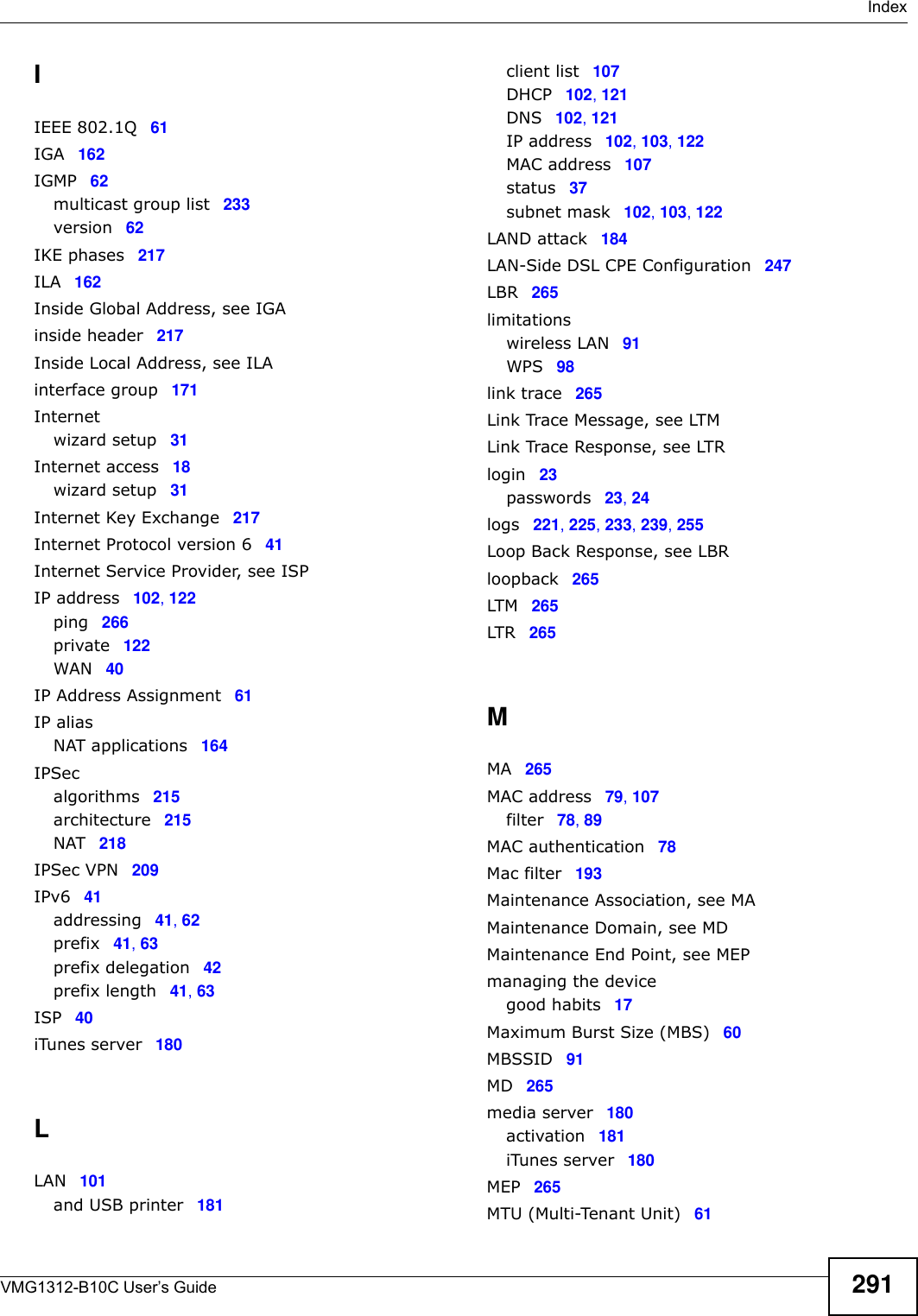
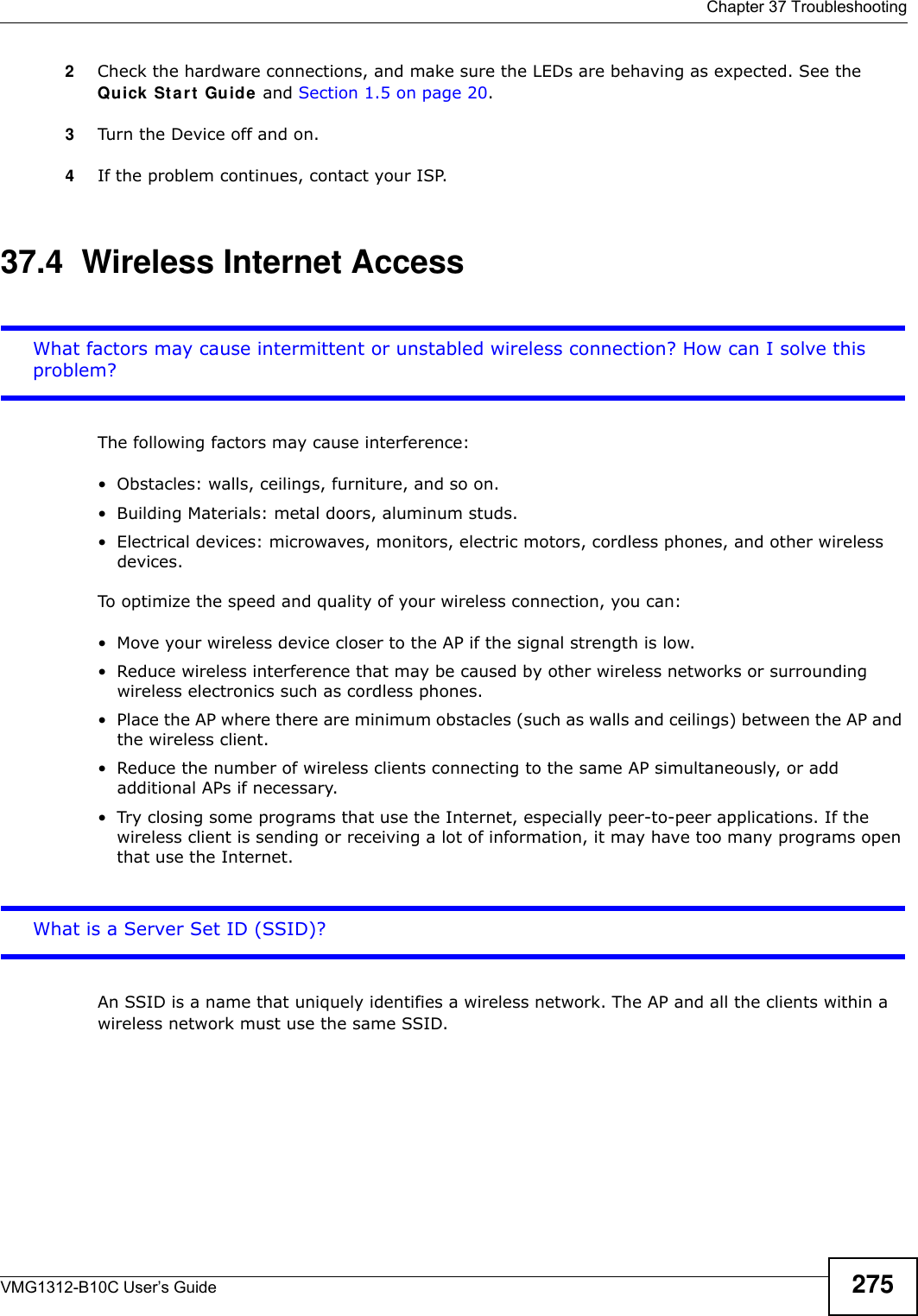
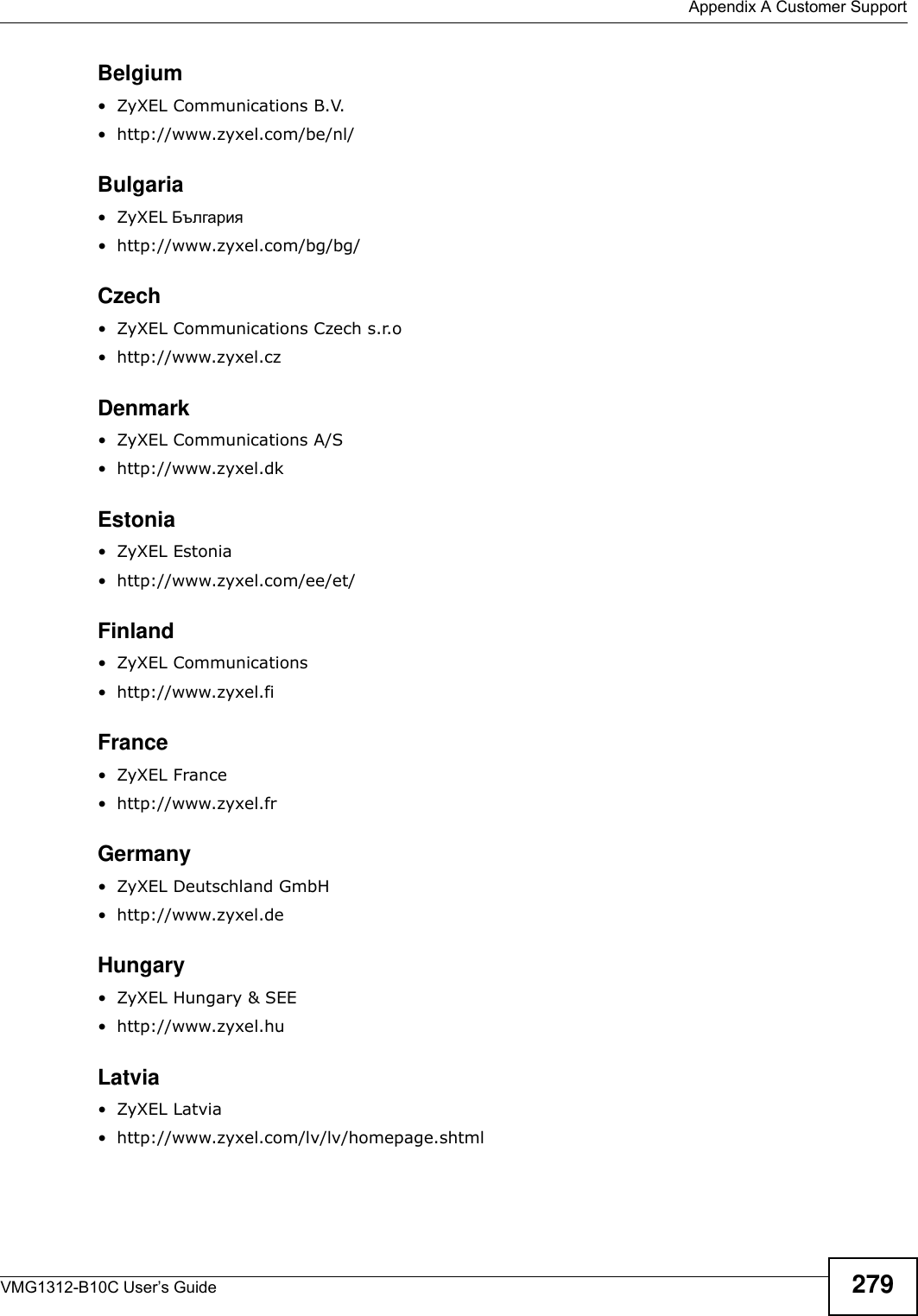
![Chapter 37 TroubleshootingVMG1312-B10C User’s Guide 2735Reset the device to its factory defaults, and try to access the Device with the default IP address. See Section 1.6 on page 20.6If the problem continues, contact the network administrator or vendor, or try one of the advanced suggestions.Adv a n ce d Su gge st ions• Make sure you have logged out of any earlier management sessions using the same user account even if they were through a different interface or using a different browser.• Try to access the Device using another service, such as Telnet. If you can access the Device, check the remote management settings and firewall rules to find out why the Device does not respond to HTTP. I can see the Login screen, but I cannot log in to the Device.1Make sure you have entered the password correctly. The default admin password is 1 2 3 4 . The field is case-sensitive, so make sure [Caps Lock] is not on. 2You cannot log in to the web configurator while someone is using Telnet to access the Device. Log out of the Device in the other session, or ask the person who is logged in to log out. 3Turn the Device off and on. 4If this does not work, you have to reset the device to its factory defaults. See Section 37.1 on page 271.I cannot Telnet to the Device.See the troubleshooting suggestions for I cannot see or access the Login screen in the web configurator. Ignore the suggestions about your browser.I cannot use FTP to upload / download the configuration file. / I cannot use FTP to upload new firmware.See the troubleshooting suggestions for I cannot see or access the Login screen in the web configurator. Ignore the suggestions about your browser.](https://usermanual.wiki/ZyXEL-Communications/VMG1312B10C/User-Guide-2431428-Page-273.png)
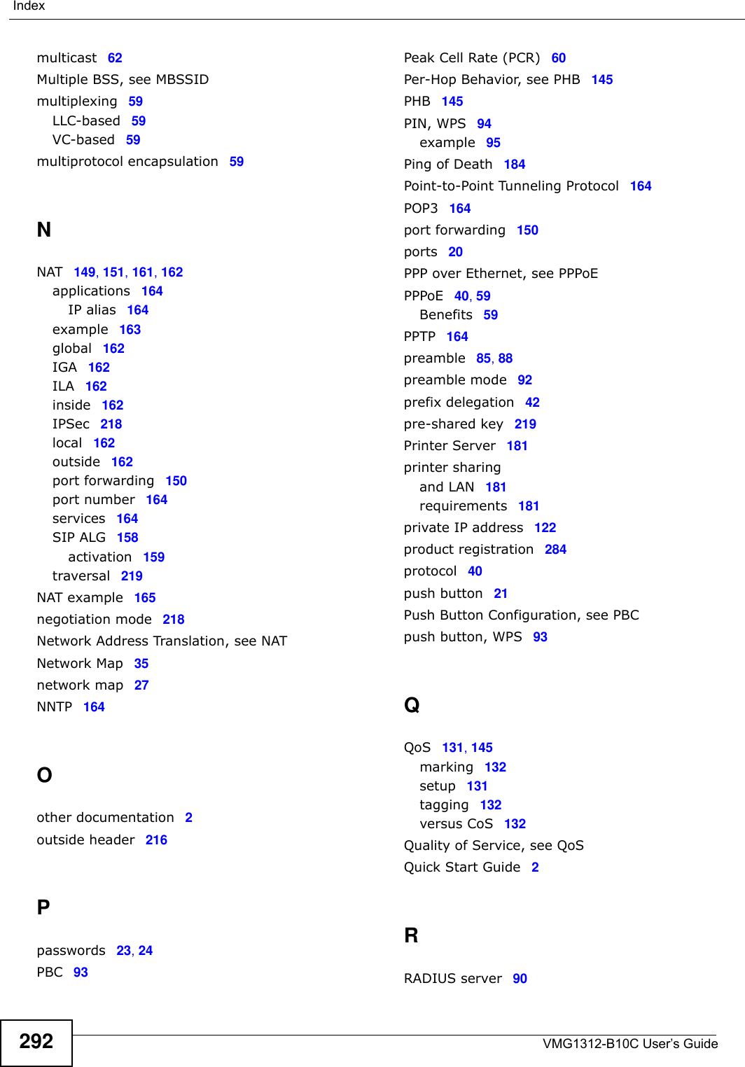
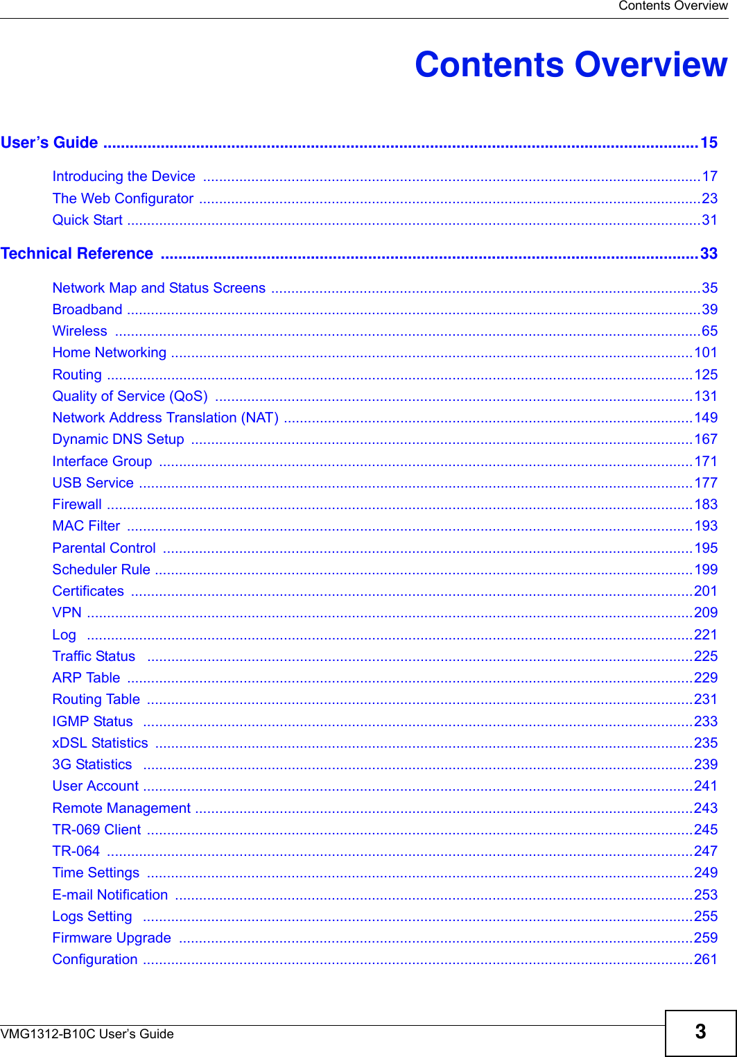
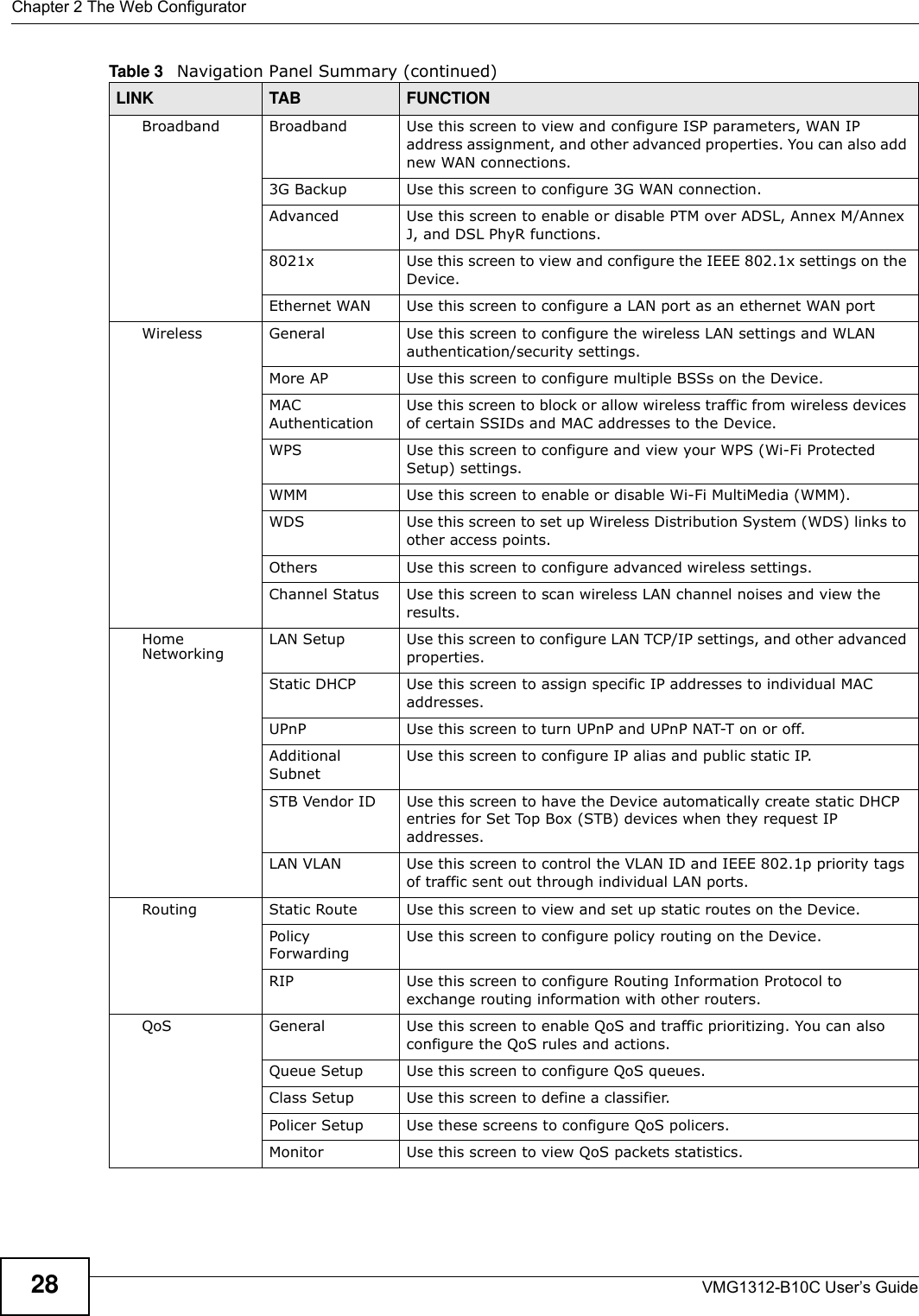
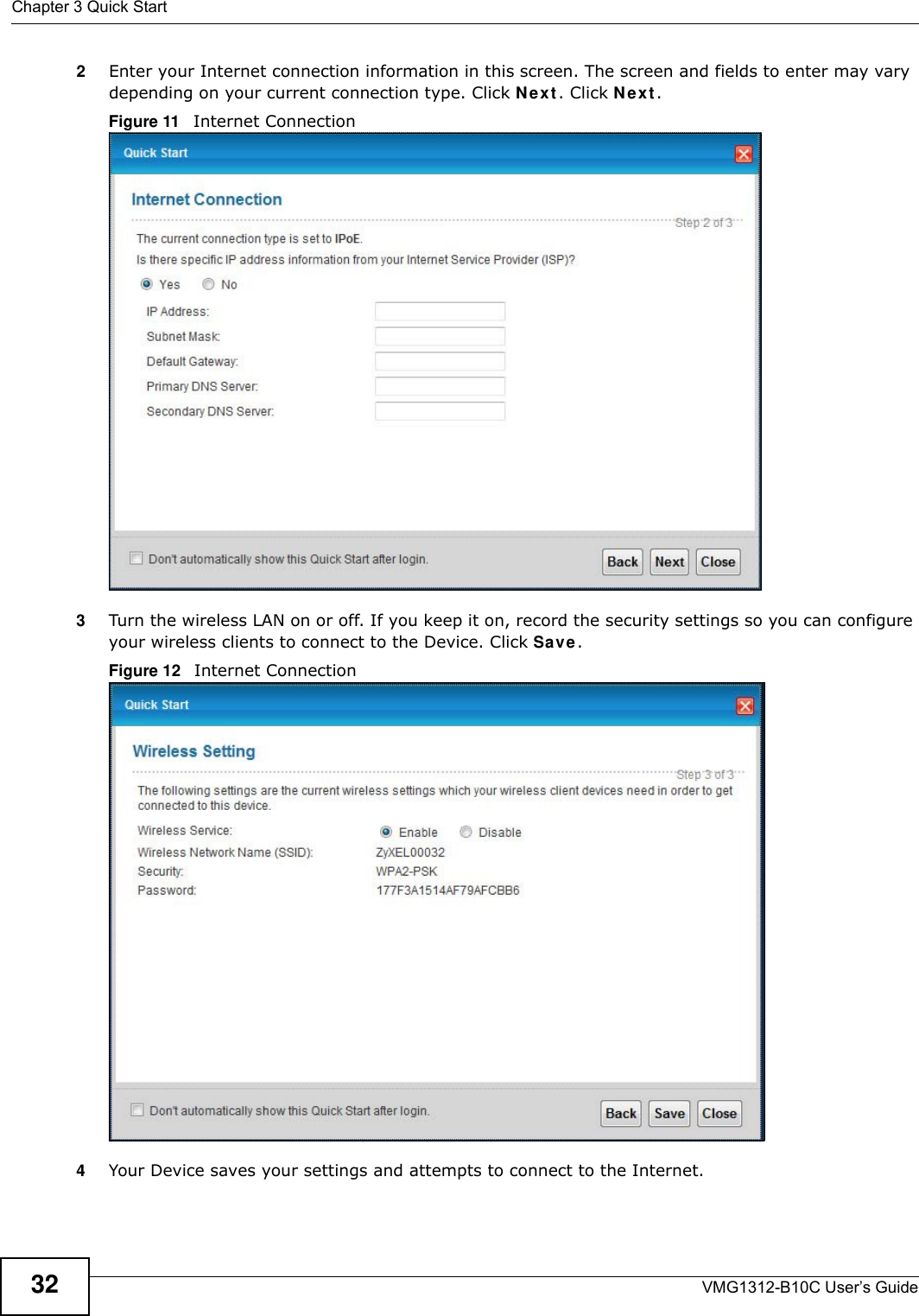
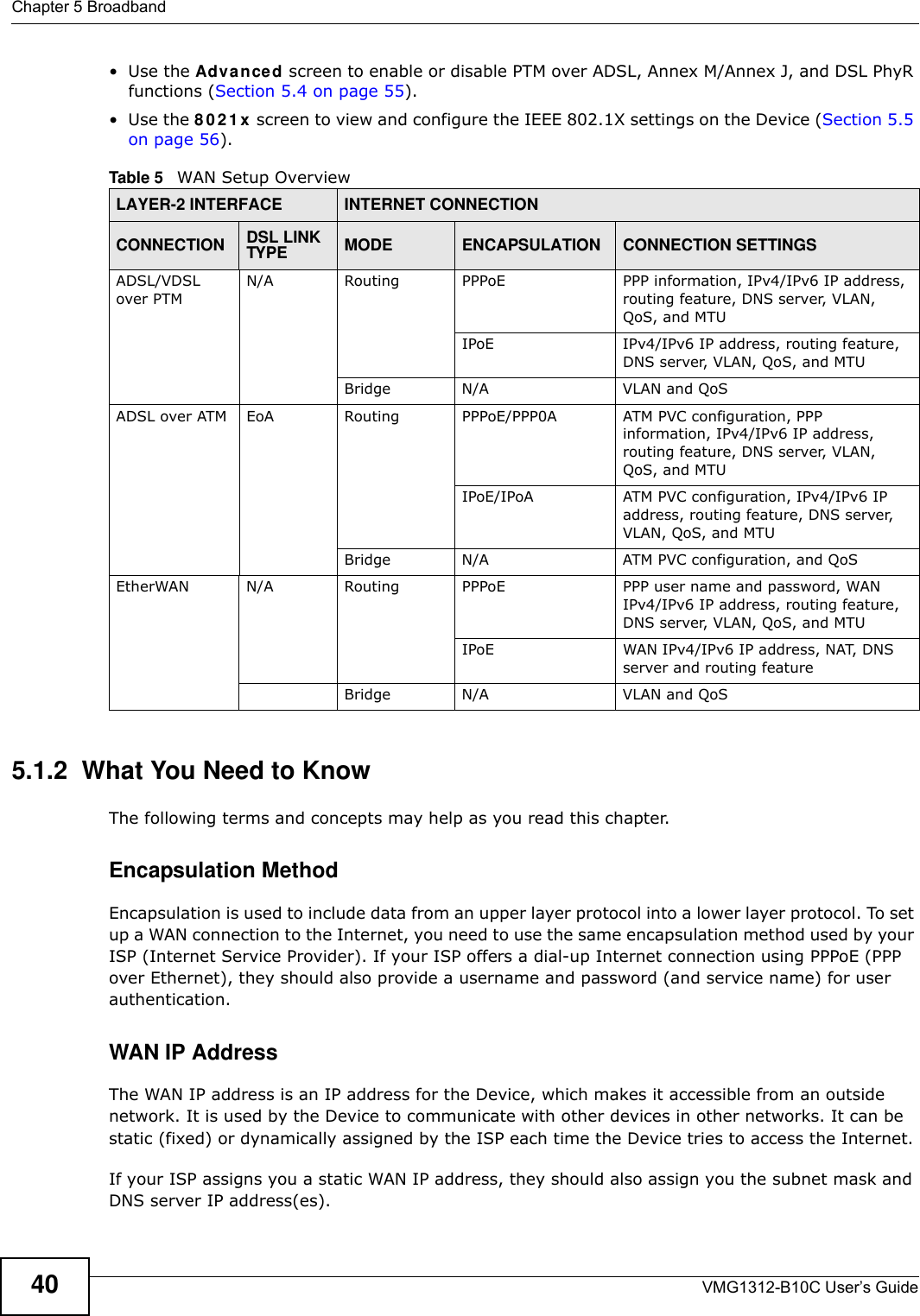
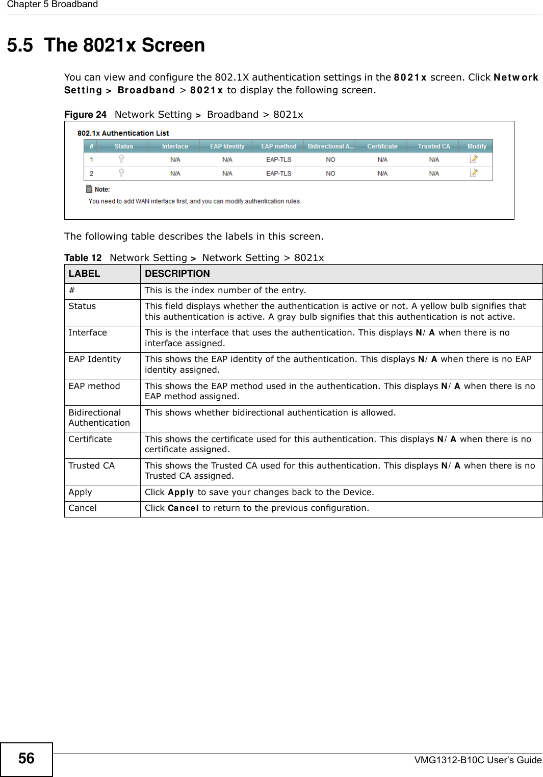
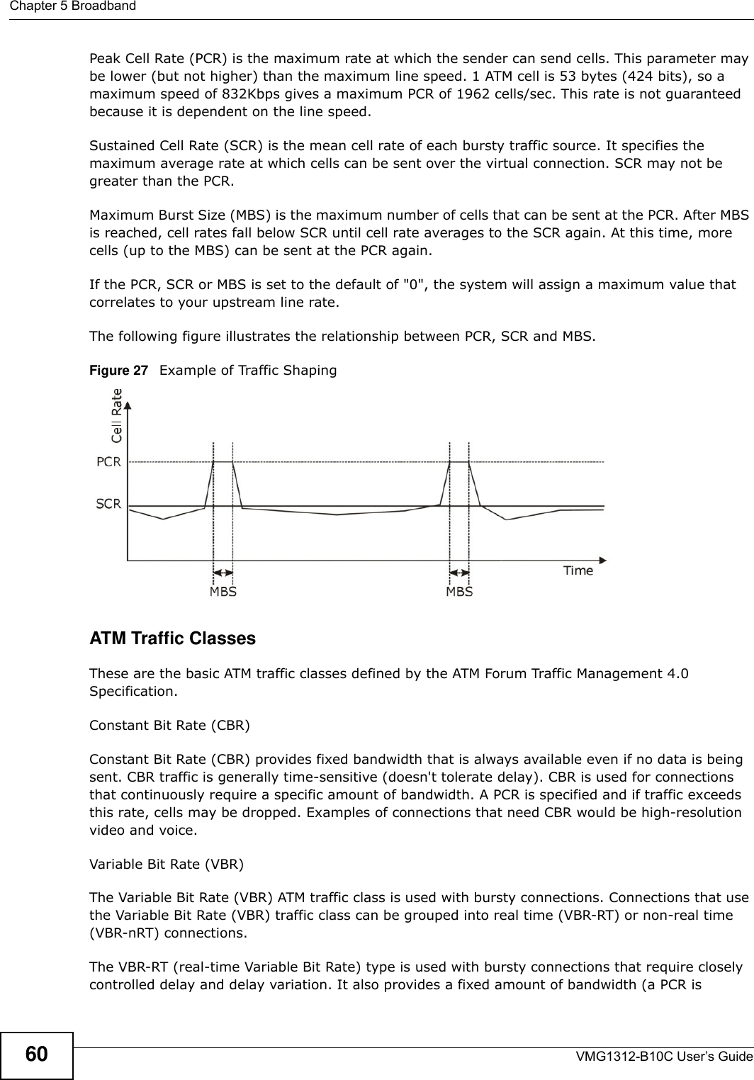
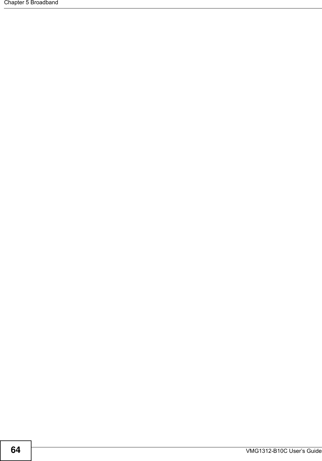
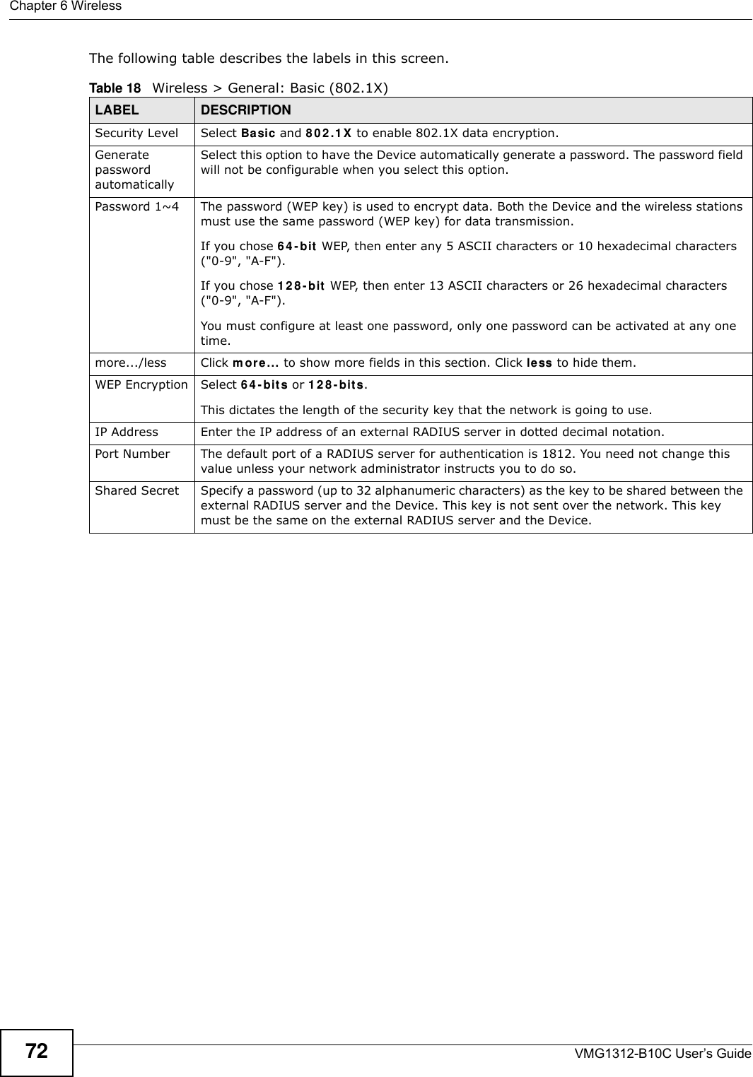
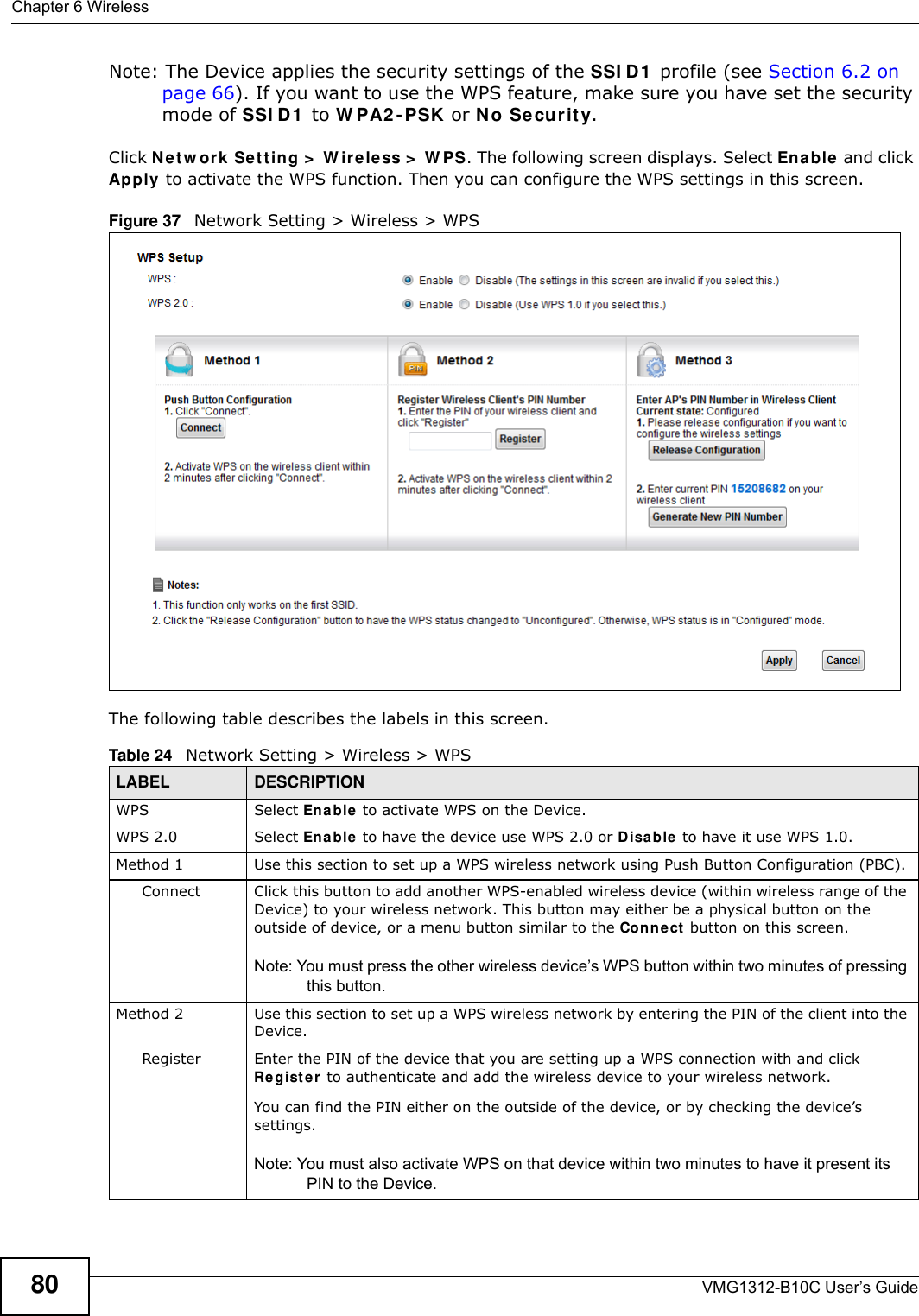
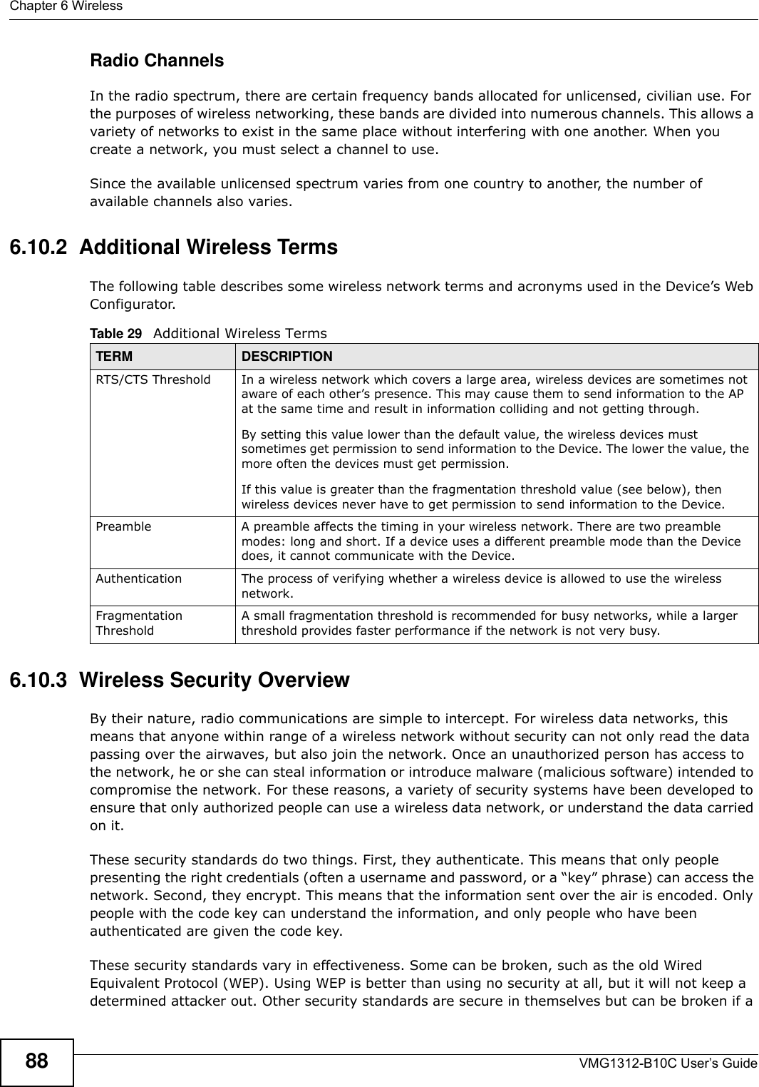
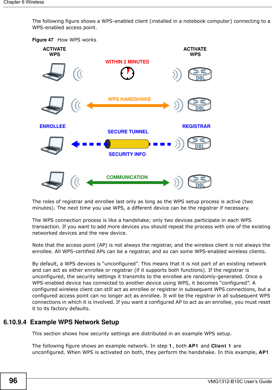
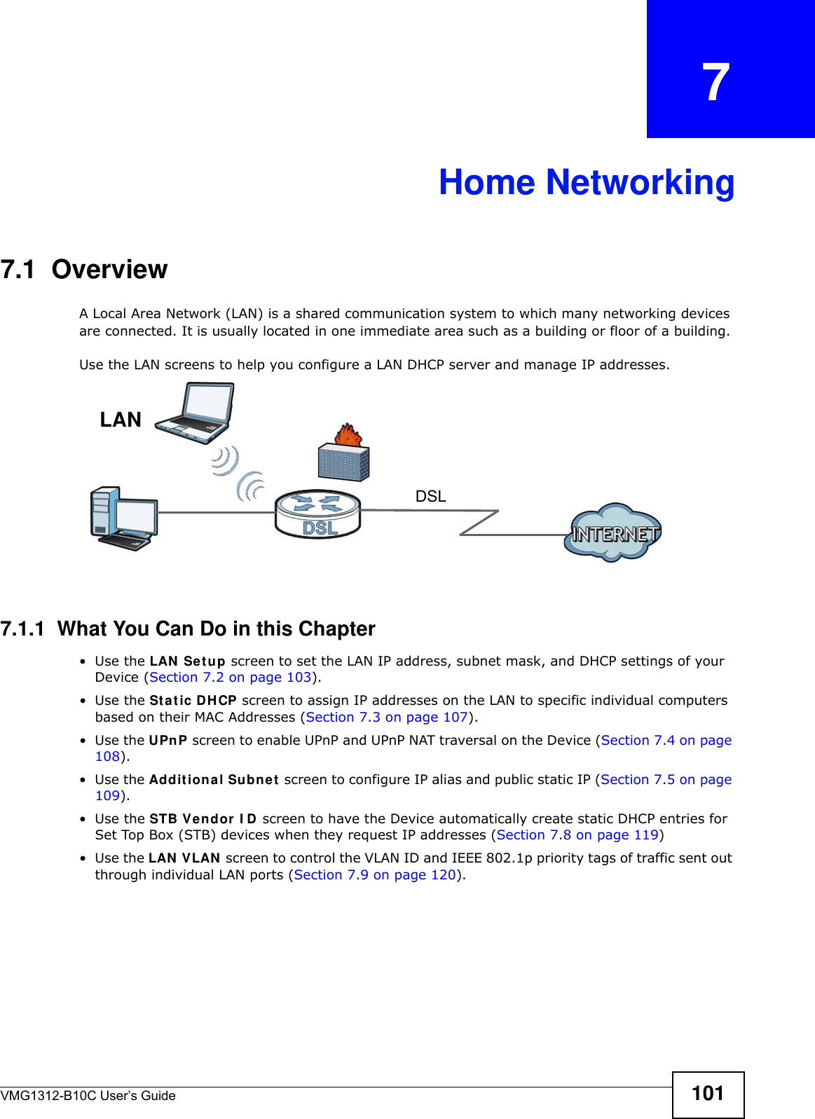
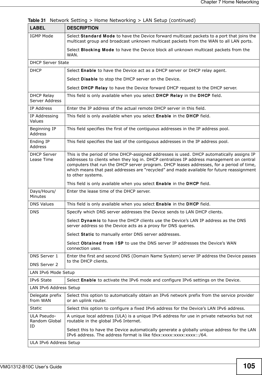
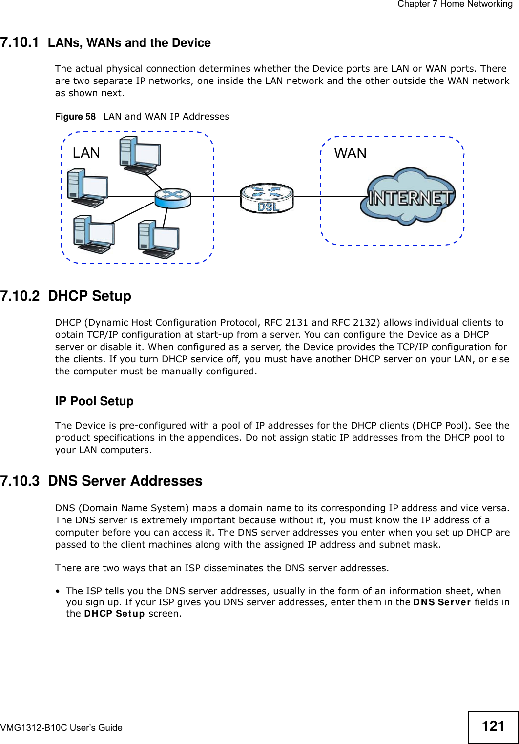
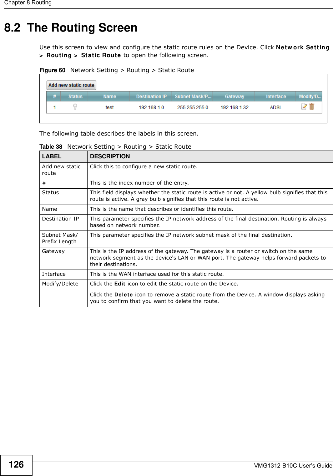
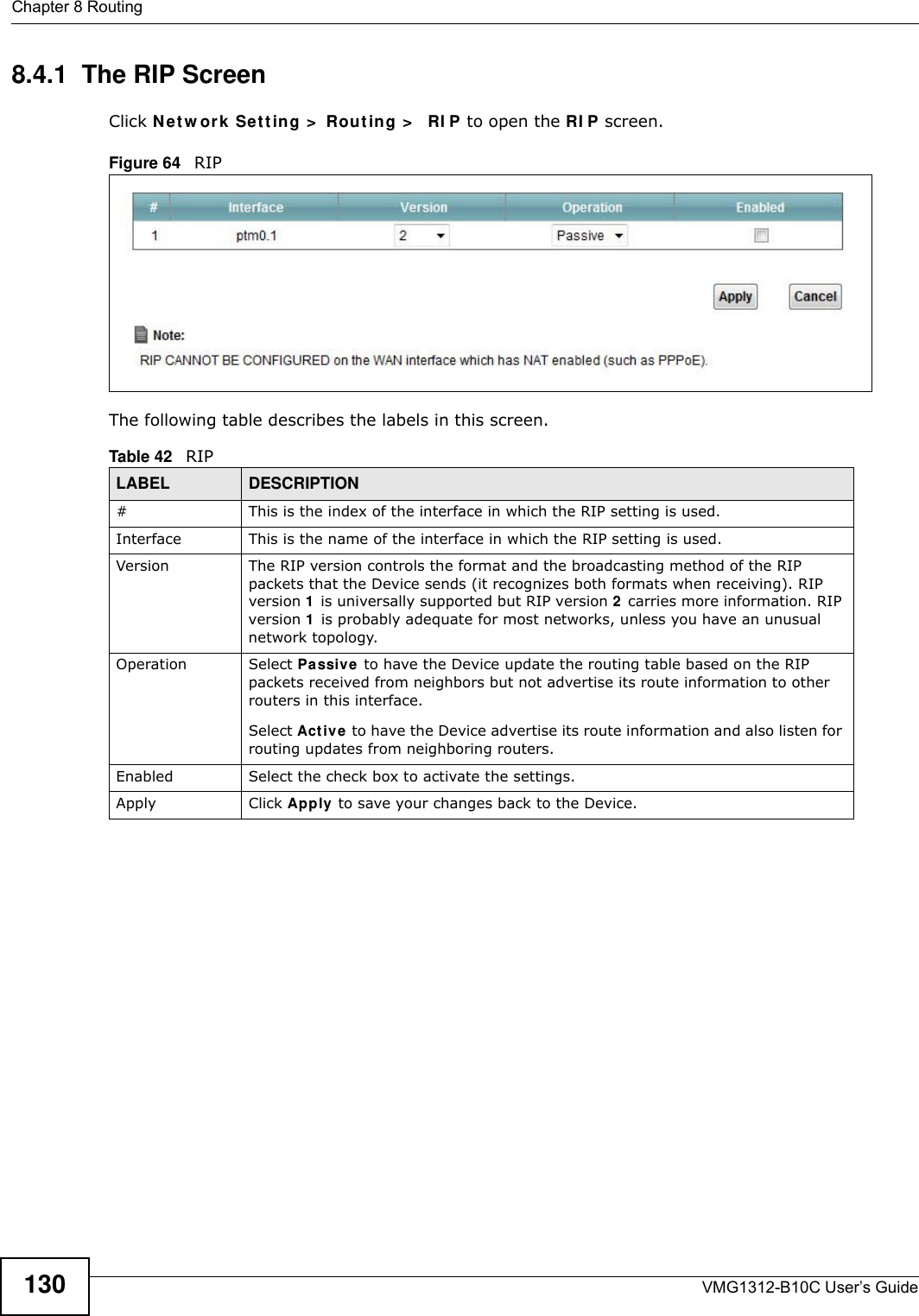
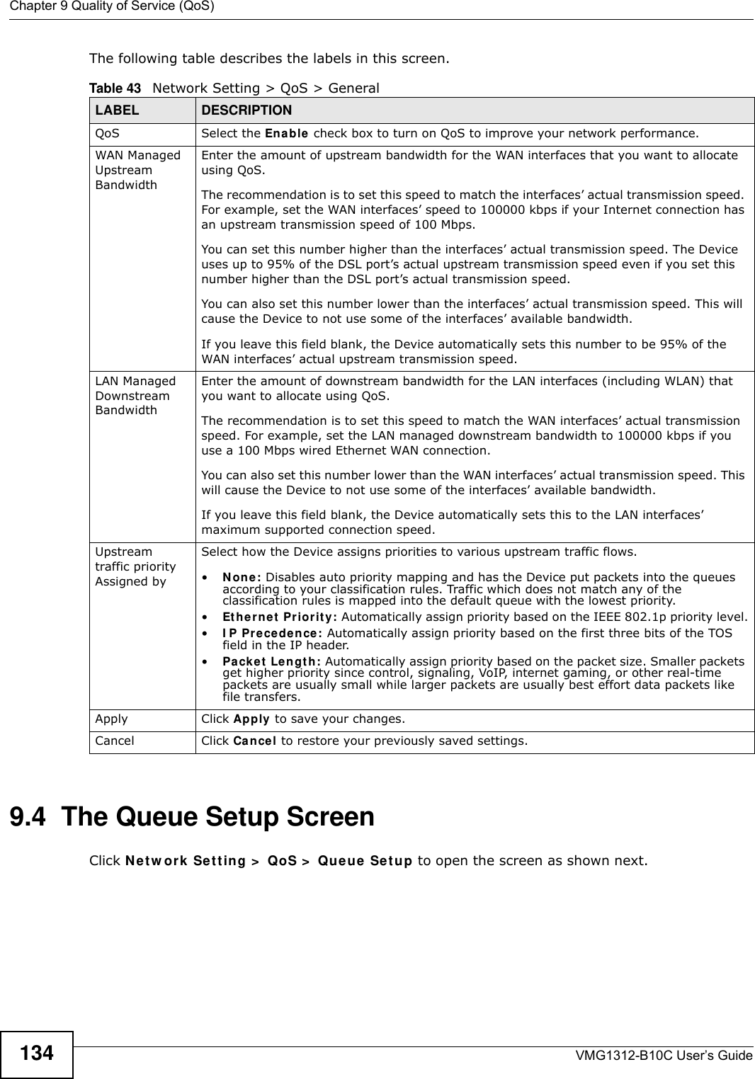
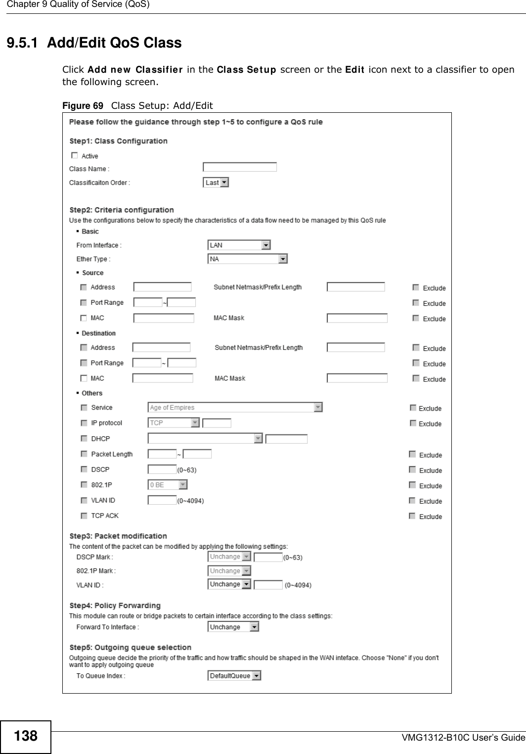
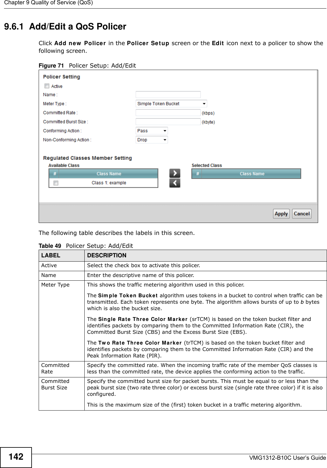
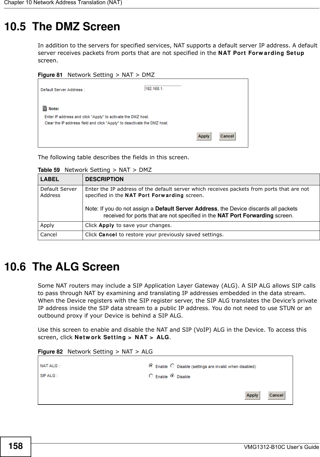
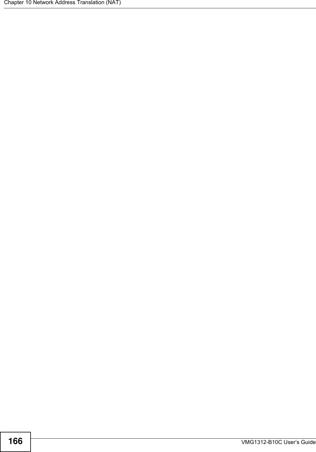
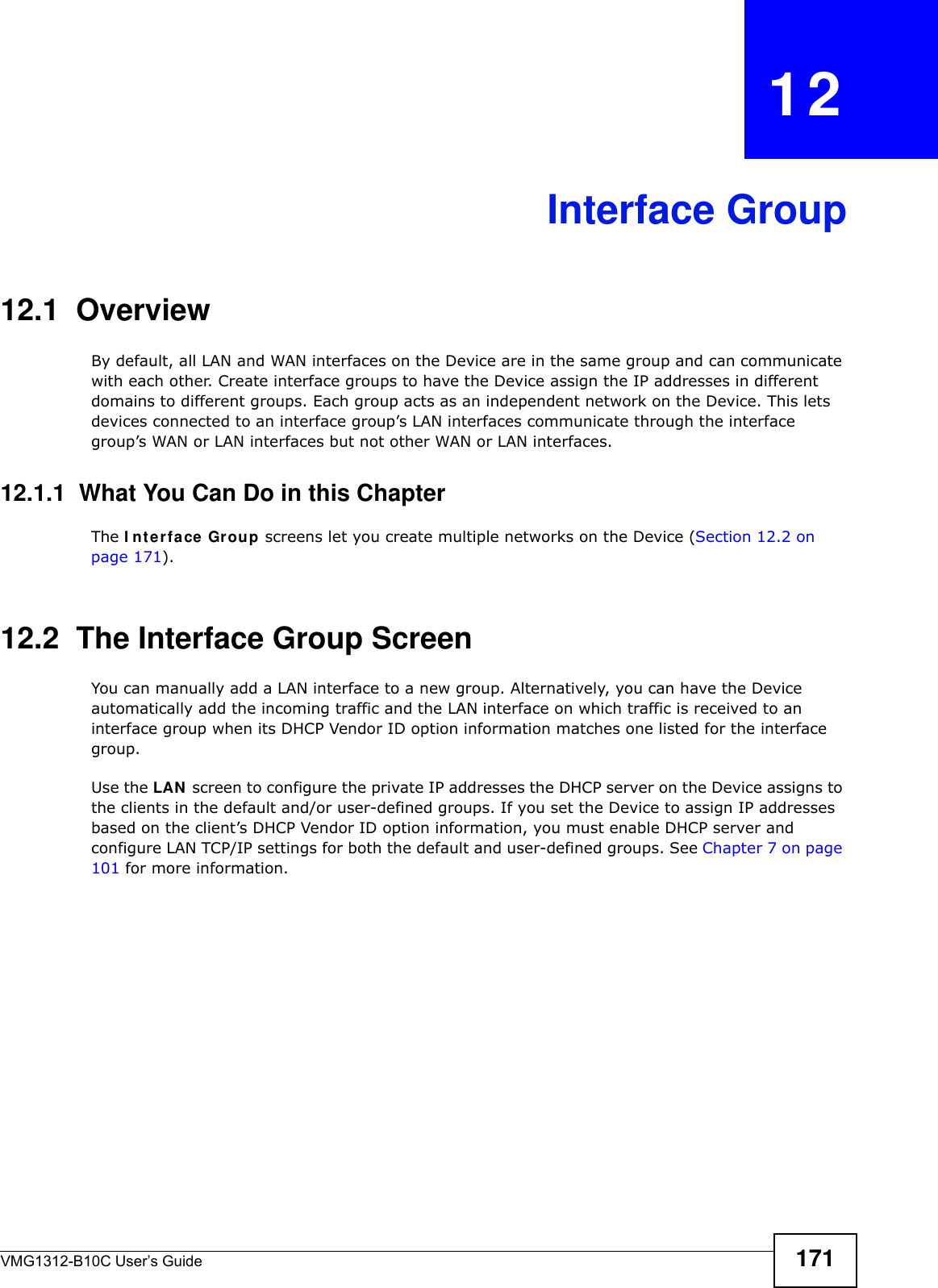
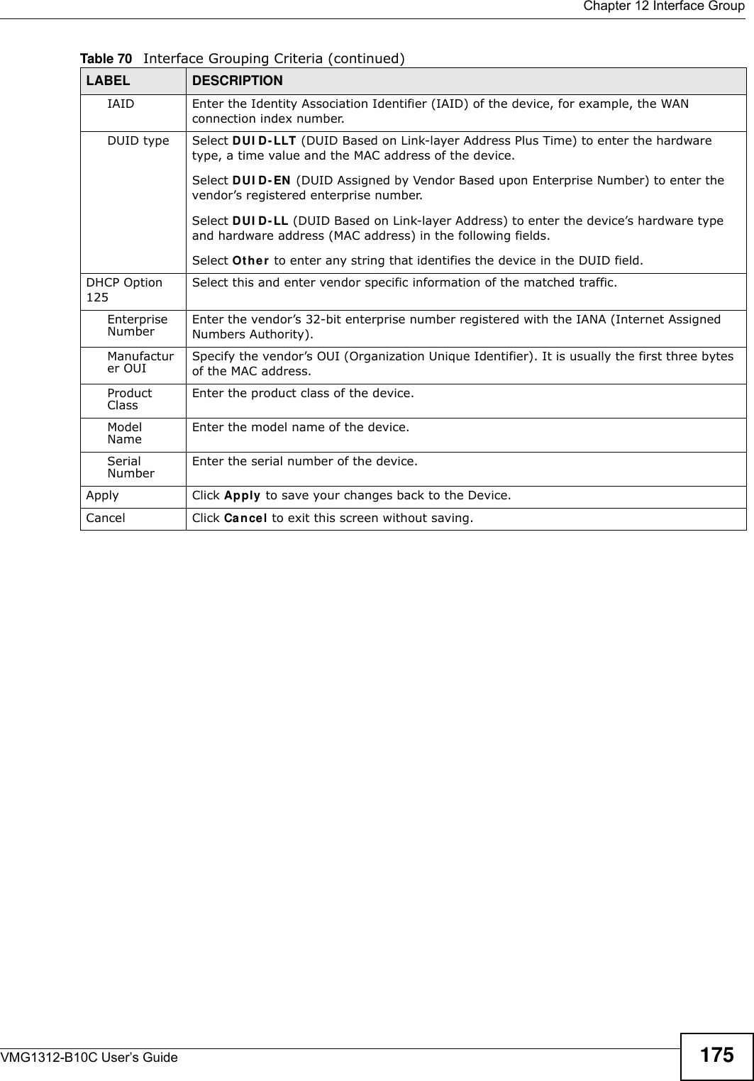
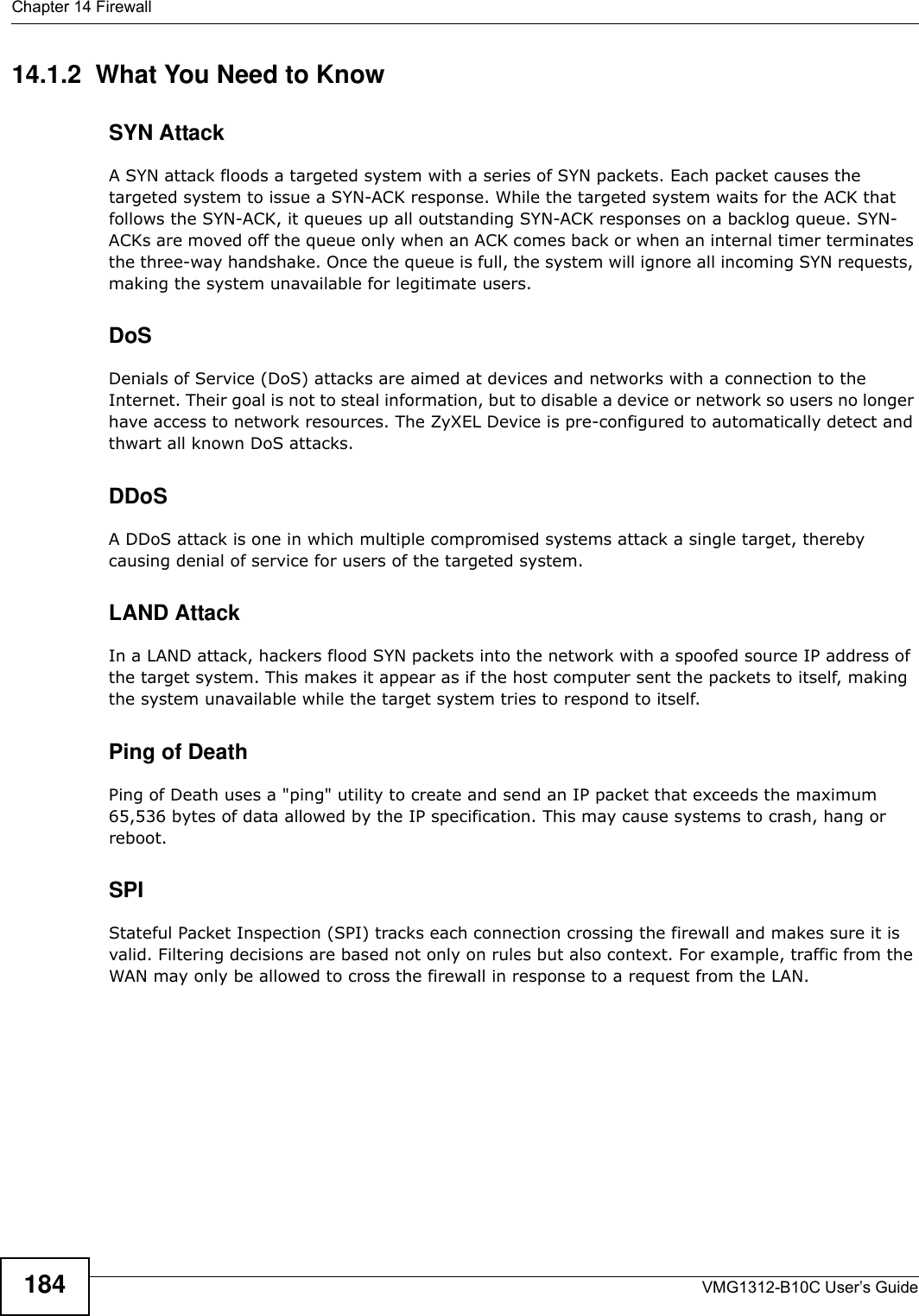
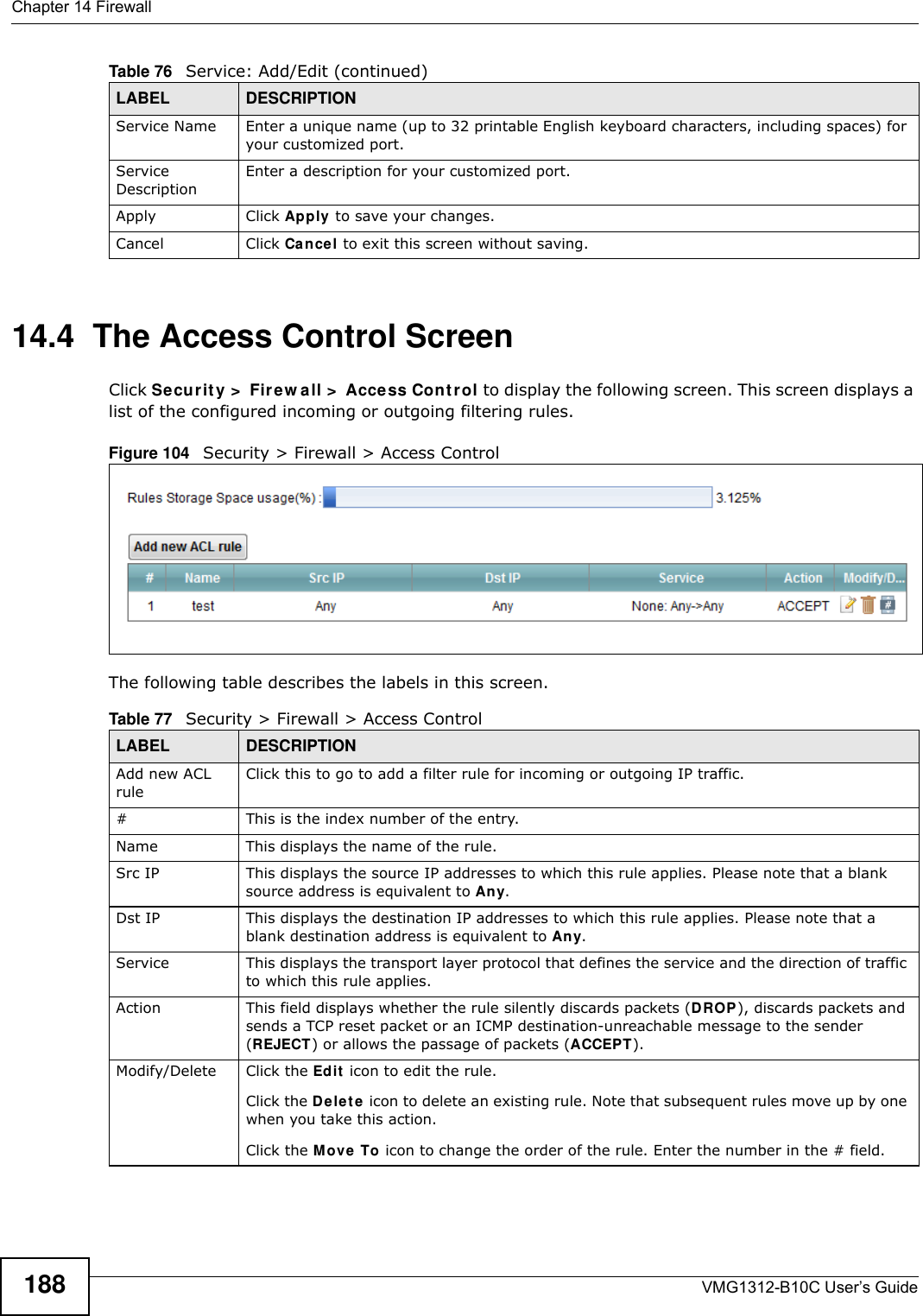
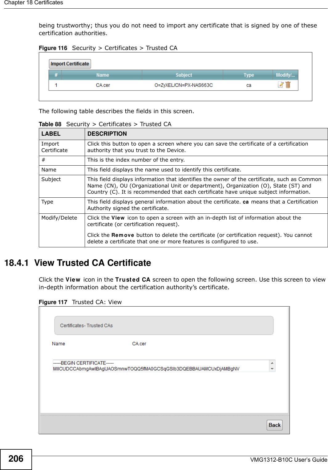
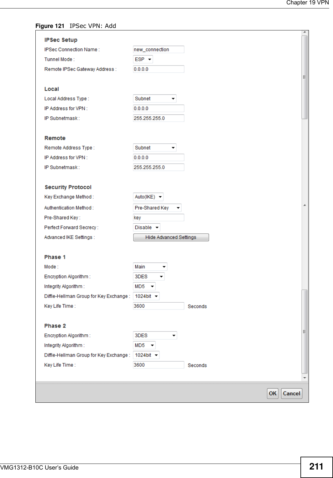
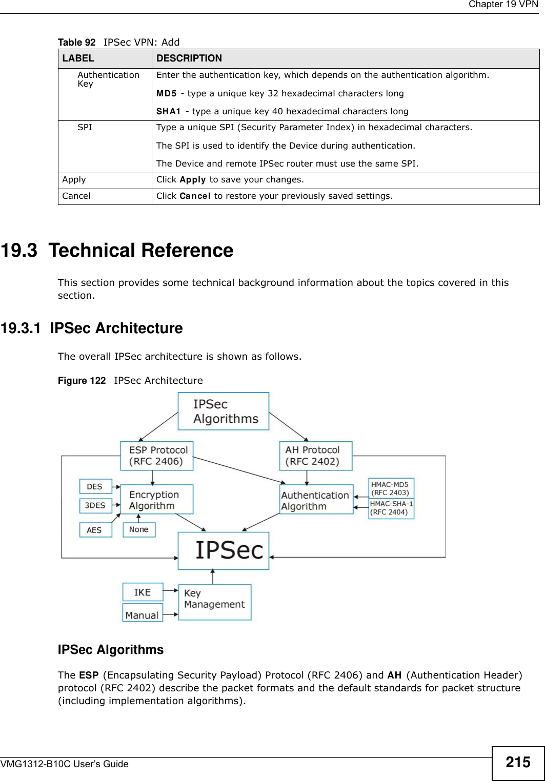
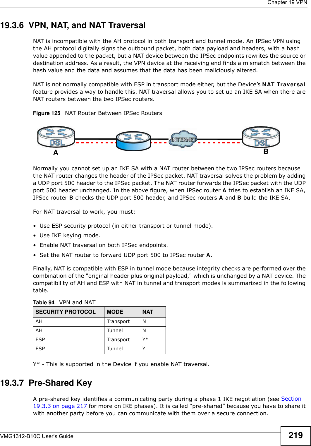
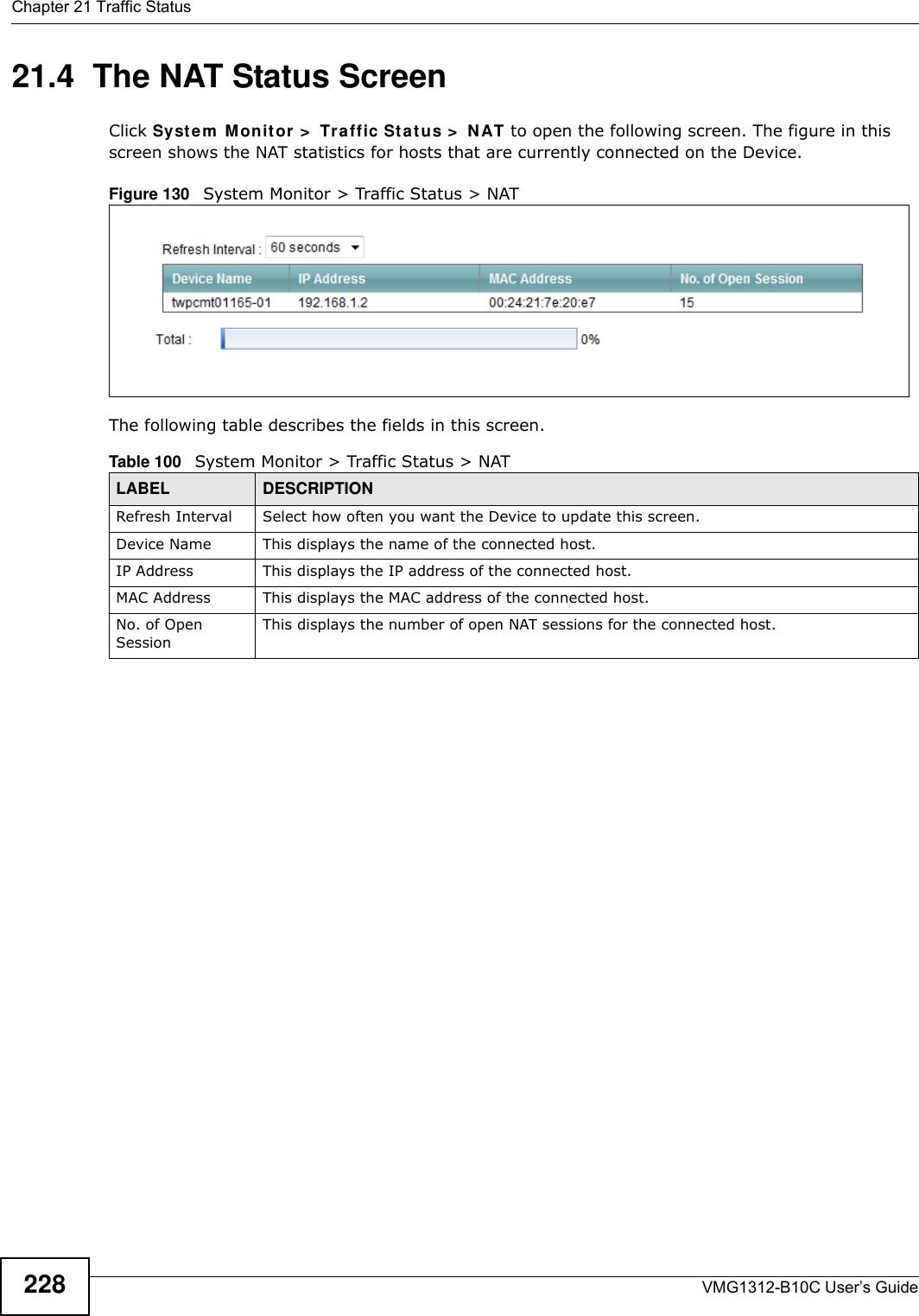
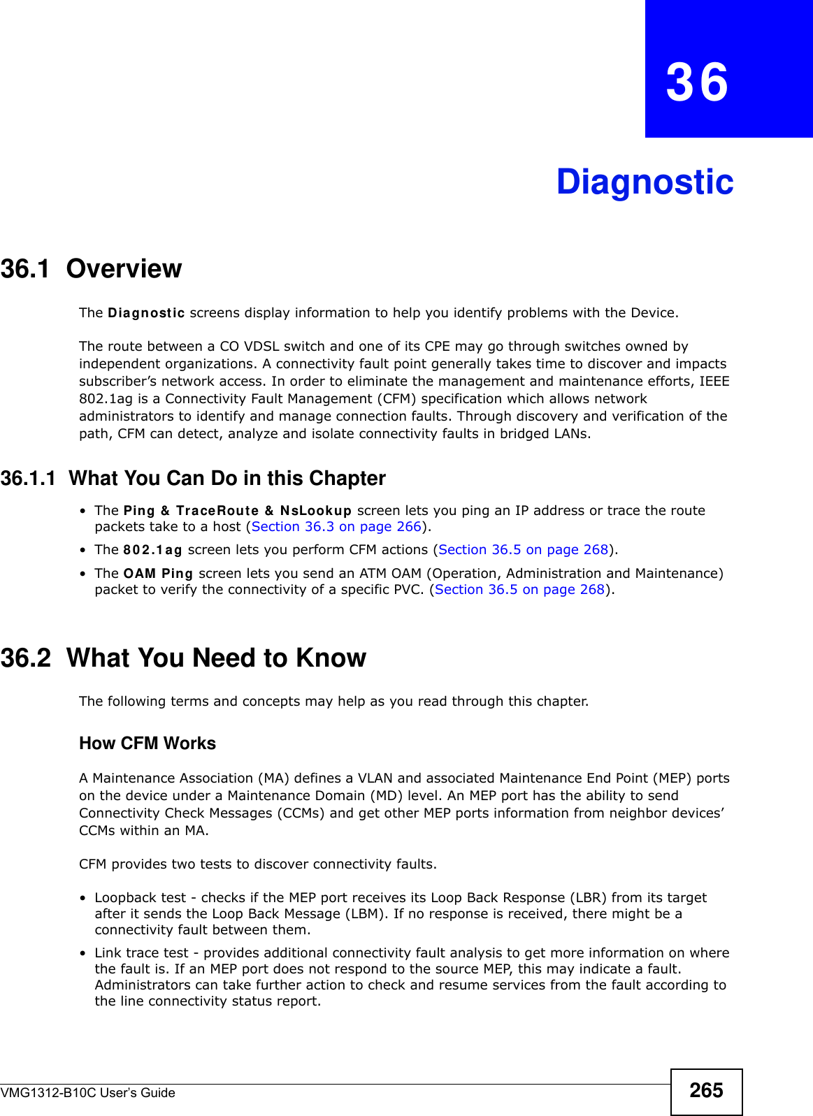
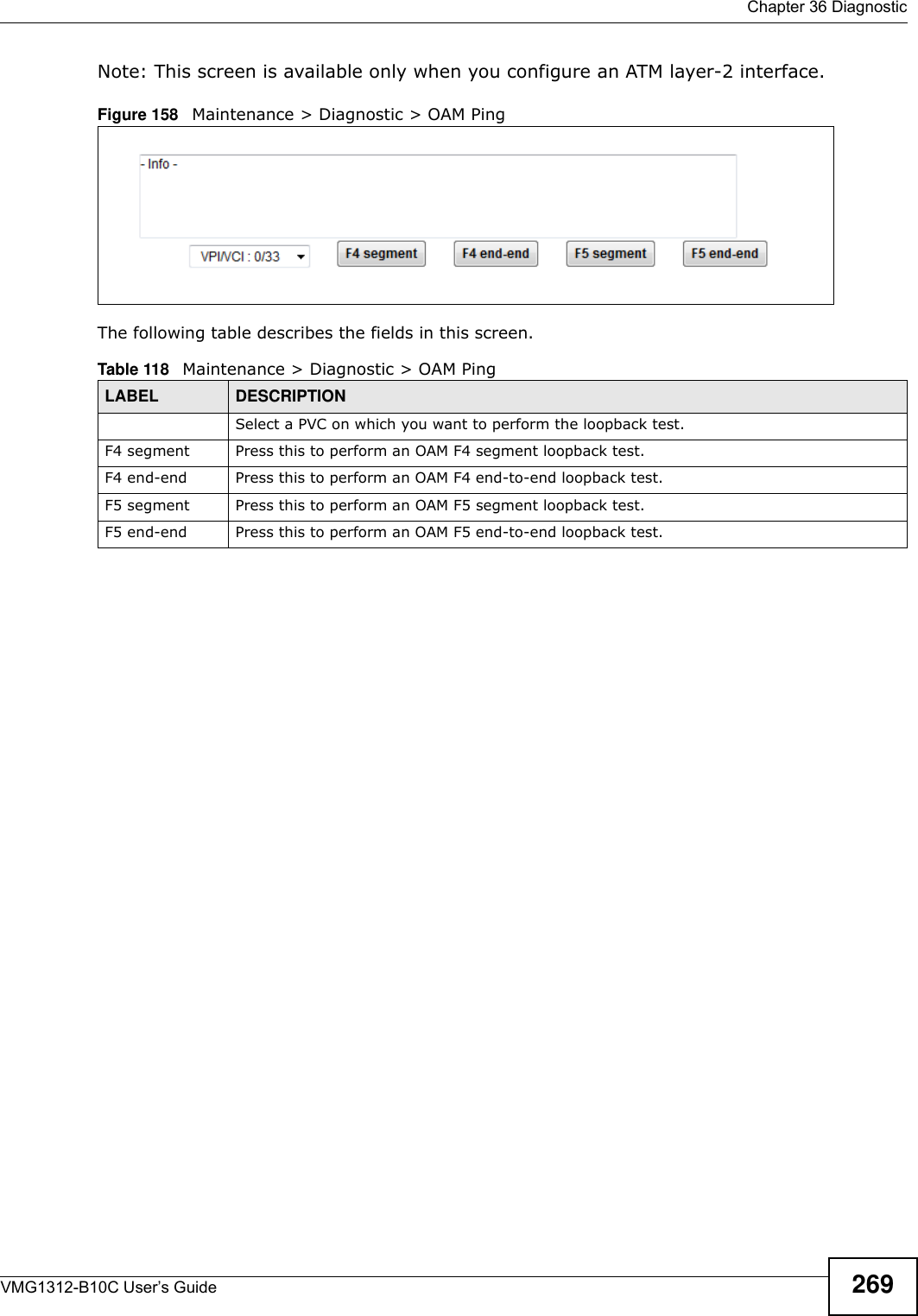
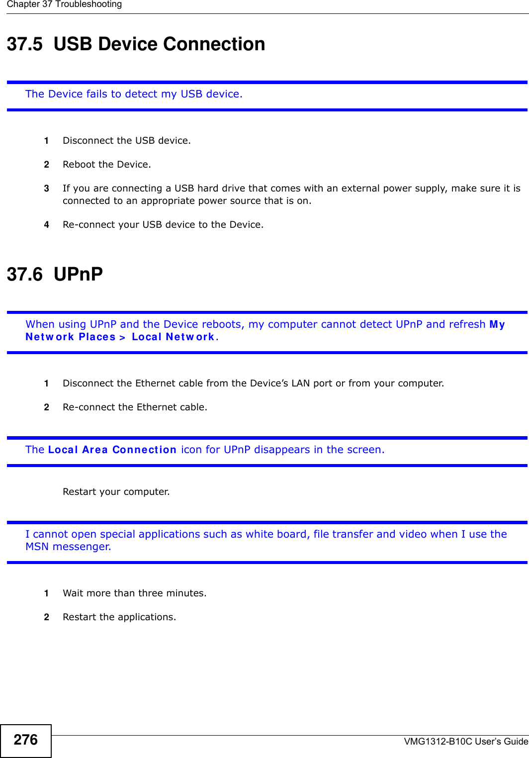
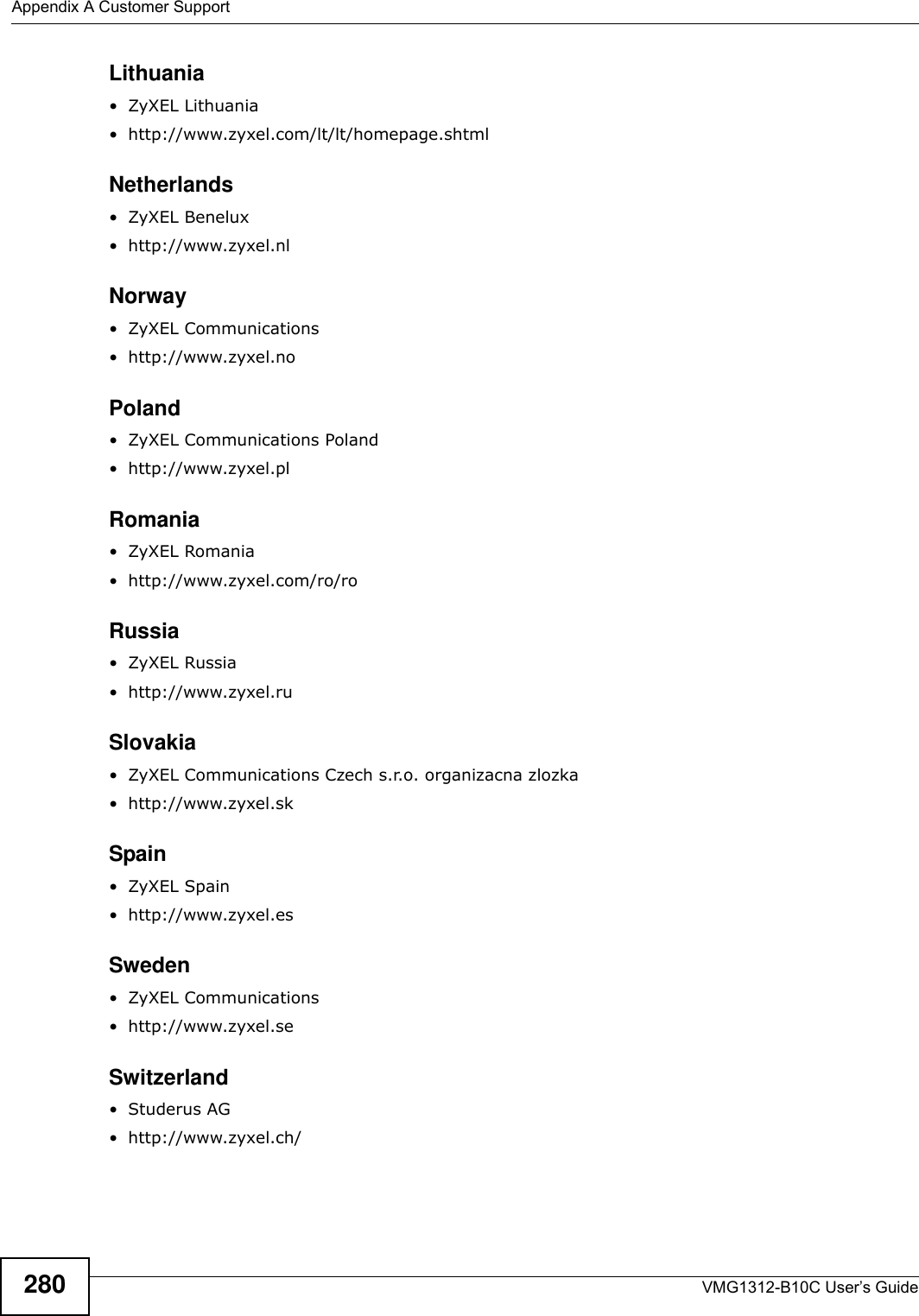
![Chapter 37 TroubleshootingVMG1312-B10C User’s Guide27437.3 Internet AccessI cannot access the Internet.1Check the hardware connections, and make sure the LEDs are behaving as expected. See the Quick St a r t Guide and Section 1.5 on page 20.2Make sure you entered your ISP account information correctly in the N e t w ork Se t t in g > Broadba n d screen. These fields are case-sensitive, so make sure [Caps Lock] is not on. 3If you are trying to access the Internet wirelessly, make sure that you enabled the wireless LAN in the Device and your wireless client and that the wireless settings in the wireless client are the same as the settings in the Device.4Disconnect all the cables from your device and reconnect them. 5If the problem continues, contact your ISP. I cannot access the Internet through a DSL connection.1Make sure you have the D SL W AN port connected to a telephone jack (or the DSL or modem jack on a splitter if you have one).2Make sure you configured a proper DSL WAN interface (Net w ork Set t ing > Br oadba n d screen) with the Internet account information provided by your ISP and that it is enabled.3Check that the LAN interface you are connected to is in the same interface group as the DSL connection (N e t w or k Set t ing > I nt e rfa ce Gr ou p).4If you set up a WAN connection using bridging service, make sure you turn off the DHCP feature in the LAN screen to have the clients get WAN IP addresses directly from your ISP’s DHCP server.I cannot connect to the Internet using a second DSL connection.ADSL and VDSL connections cannot work at the same time. You can only use one type of DSL connection, either ADSL or VDSL connection at one time.I cannot access the Internet anymore. I had access to the Internet (with the Device), but my Internet connection is not available anymore.1Your session with the Device may have expired. Try logging into the Device again.](https://usermanual.wiki/ZyXEL-Communications/VMG1312B10C/User-Guide-2431428-Page-274.png)
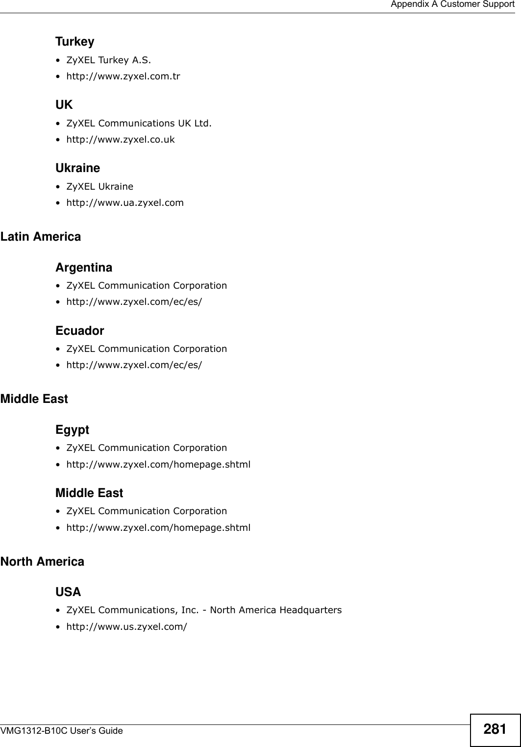
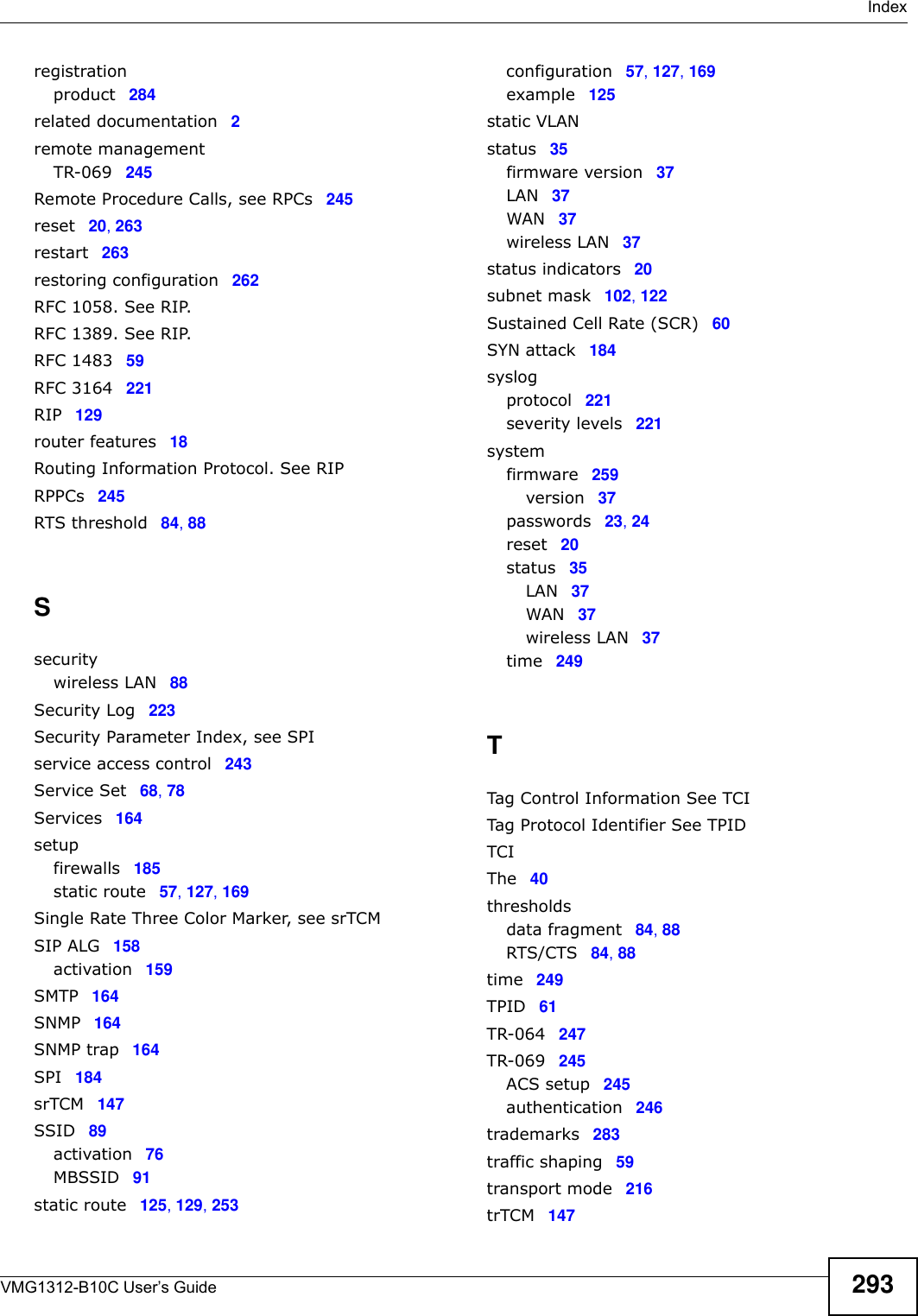
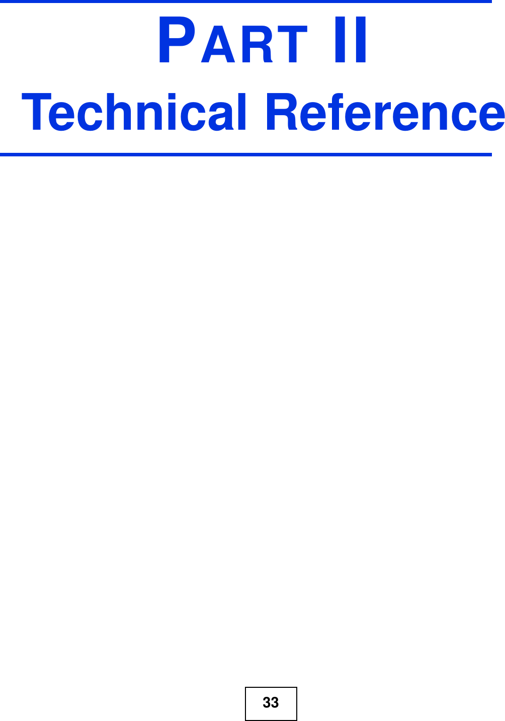
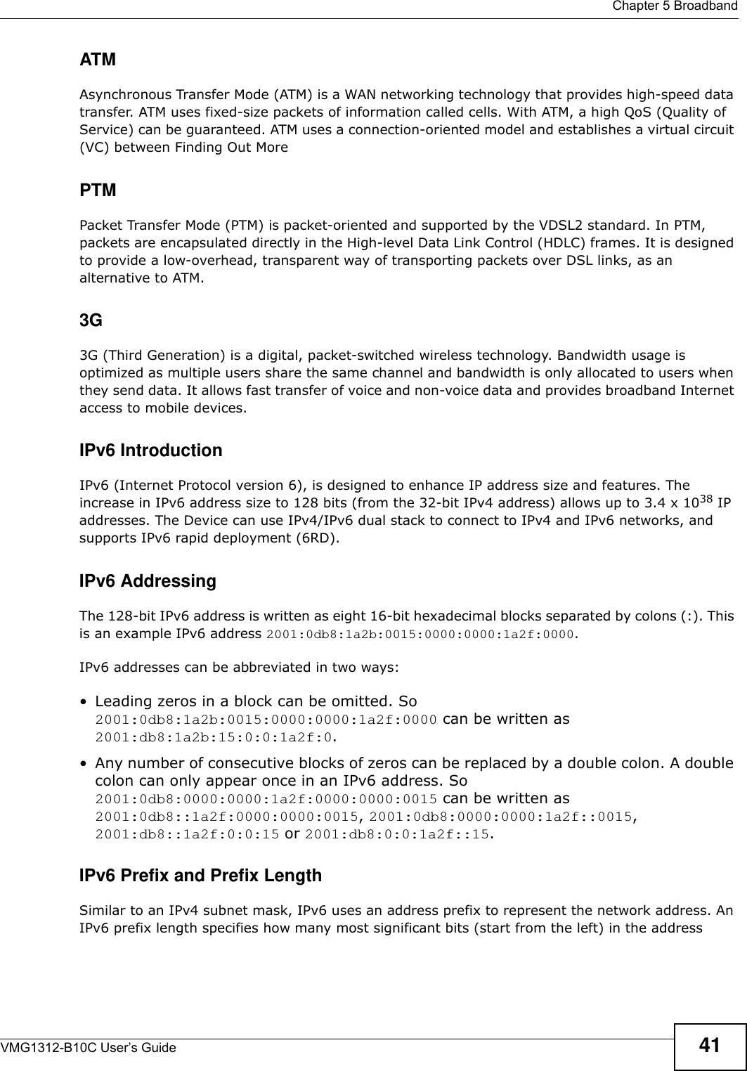
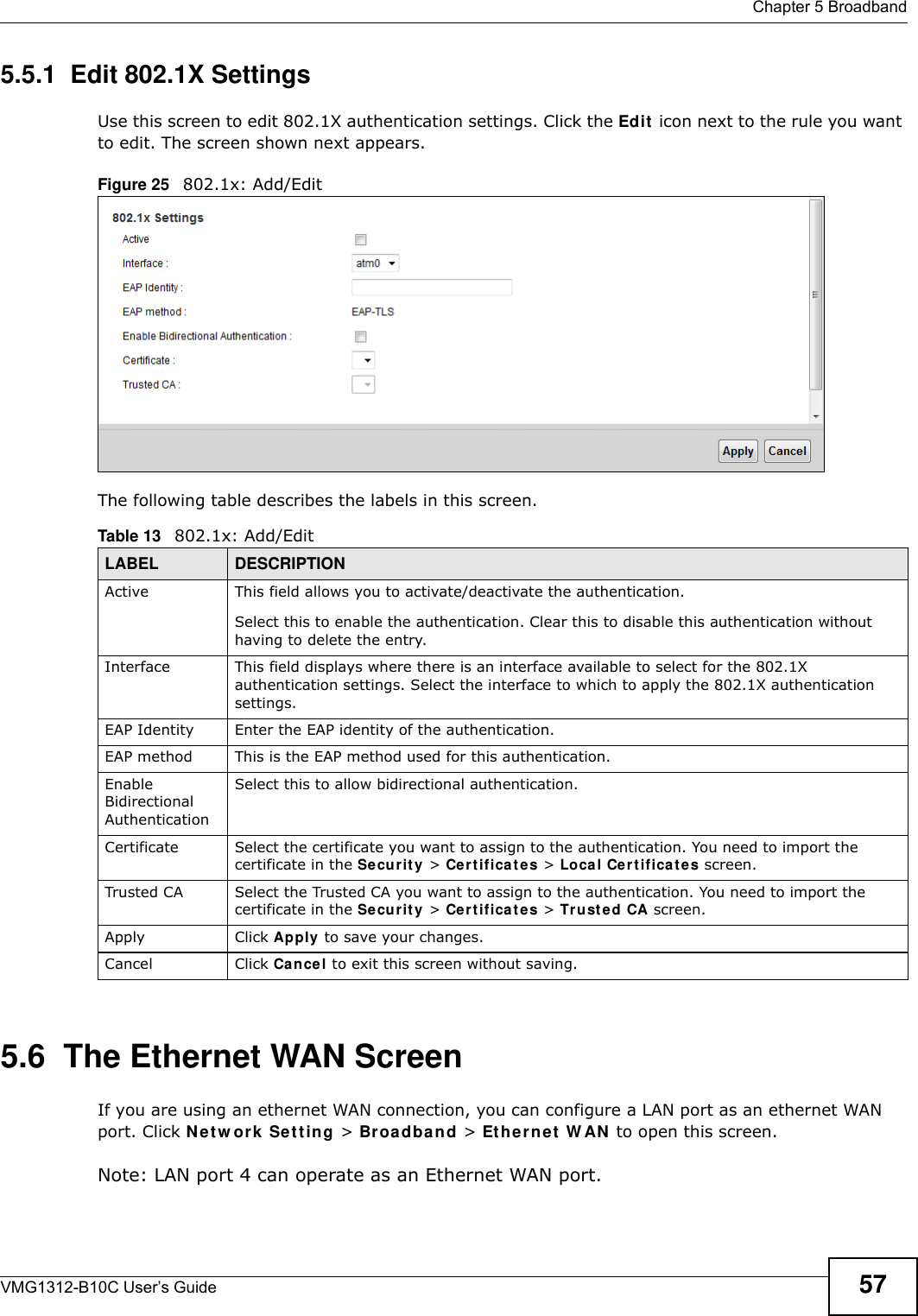
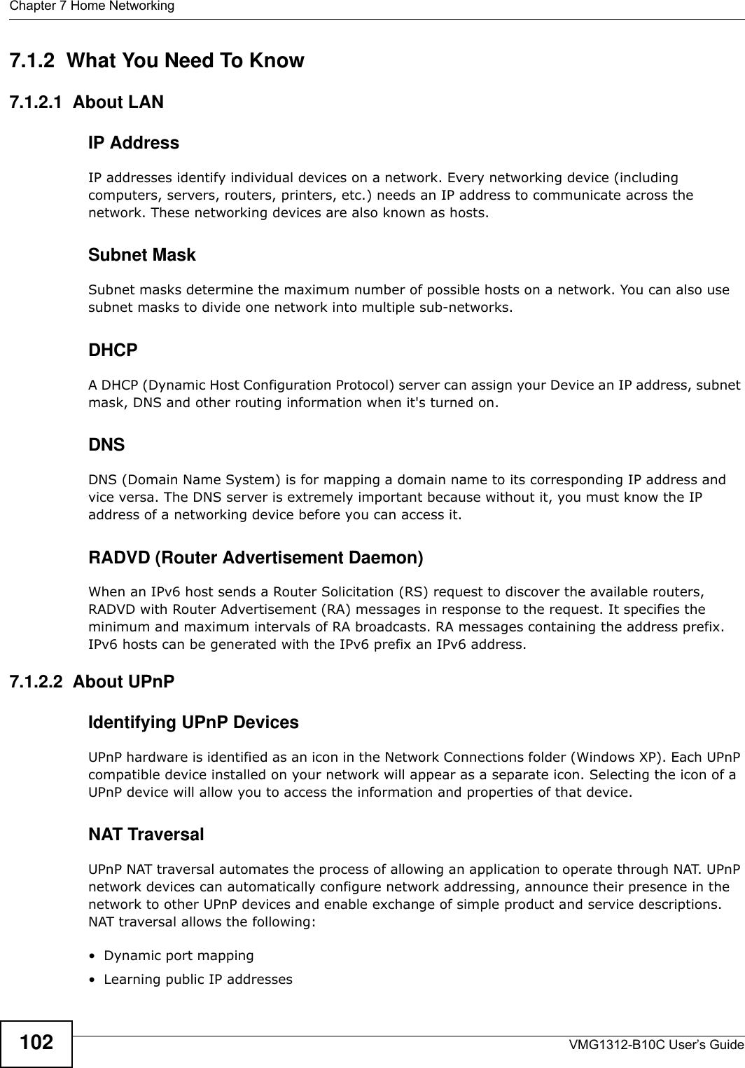
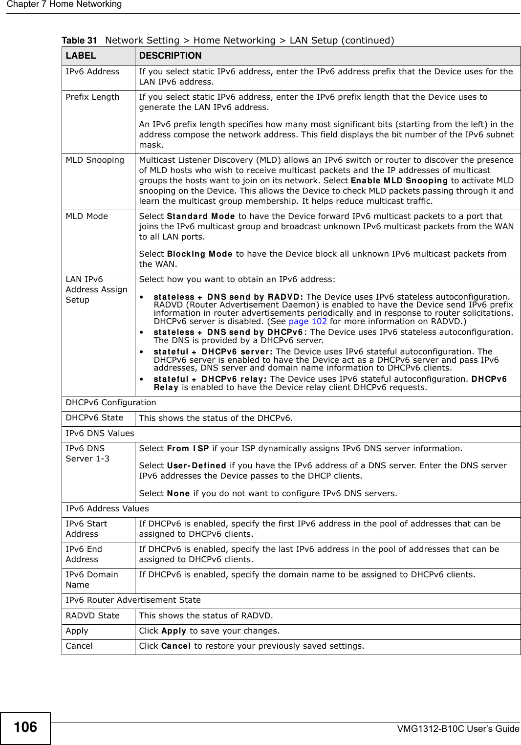
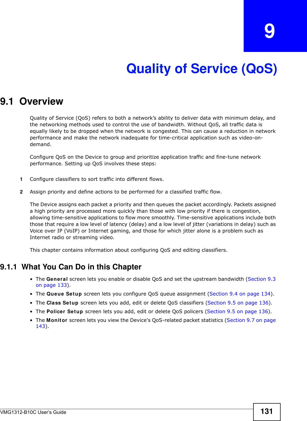
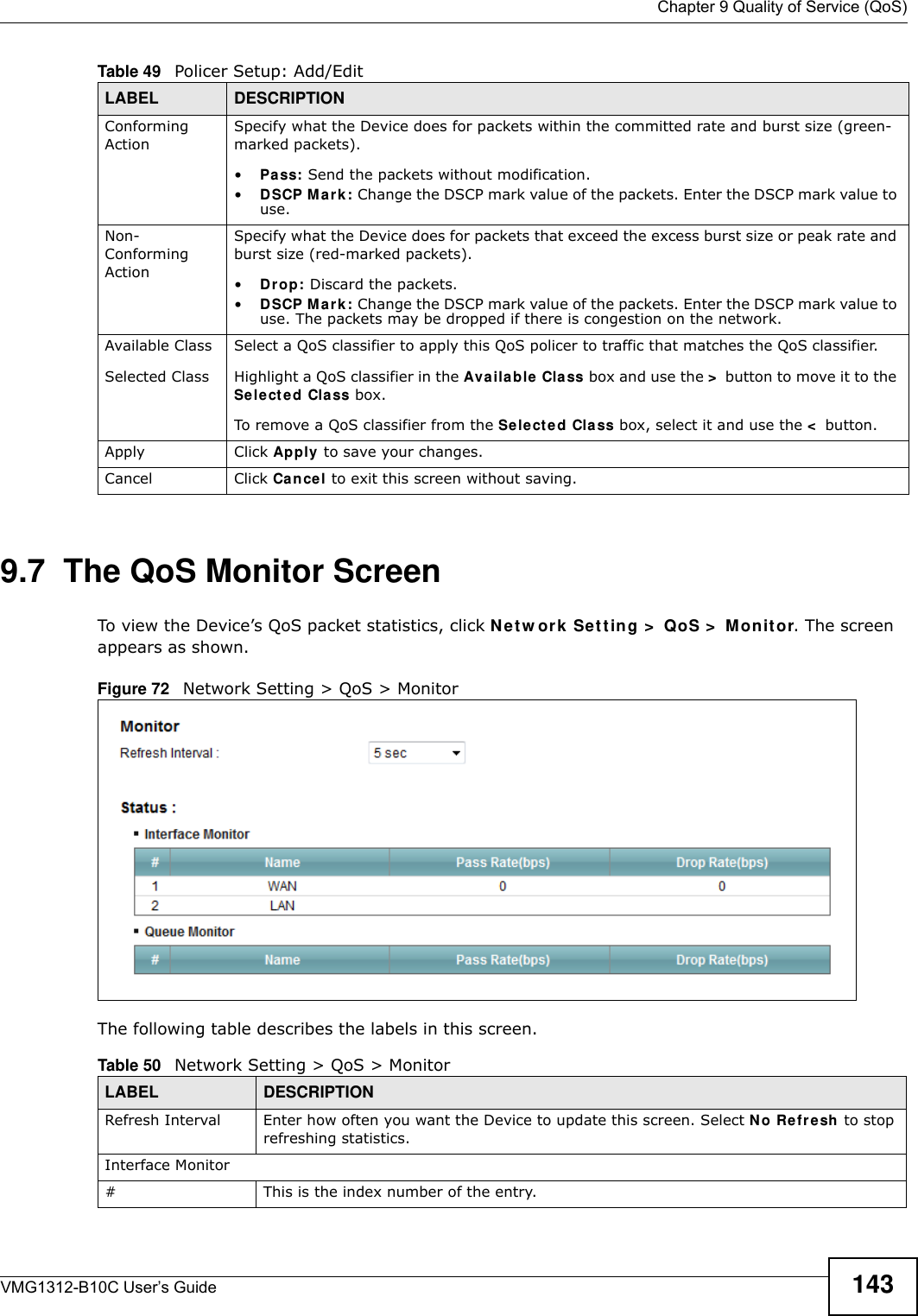
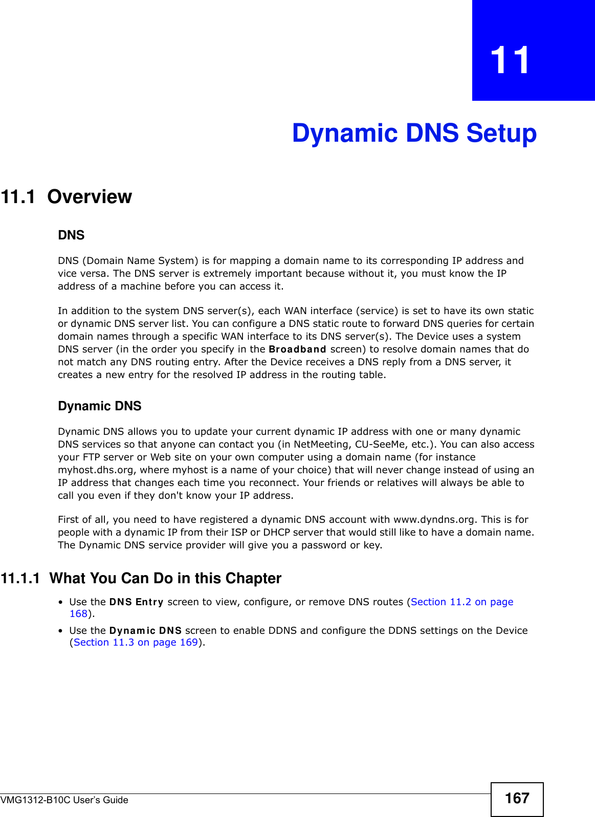
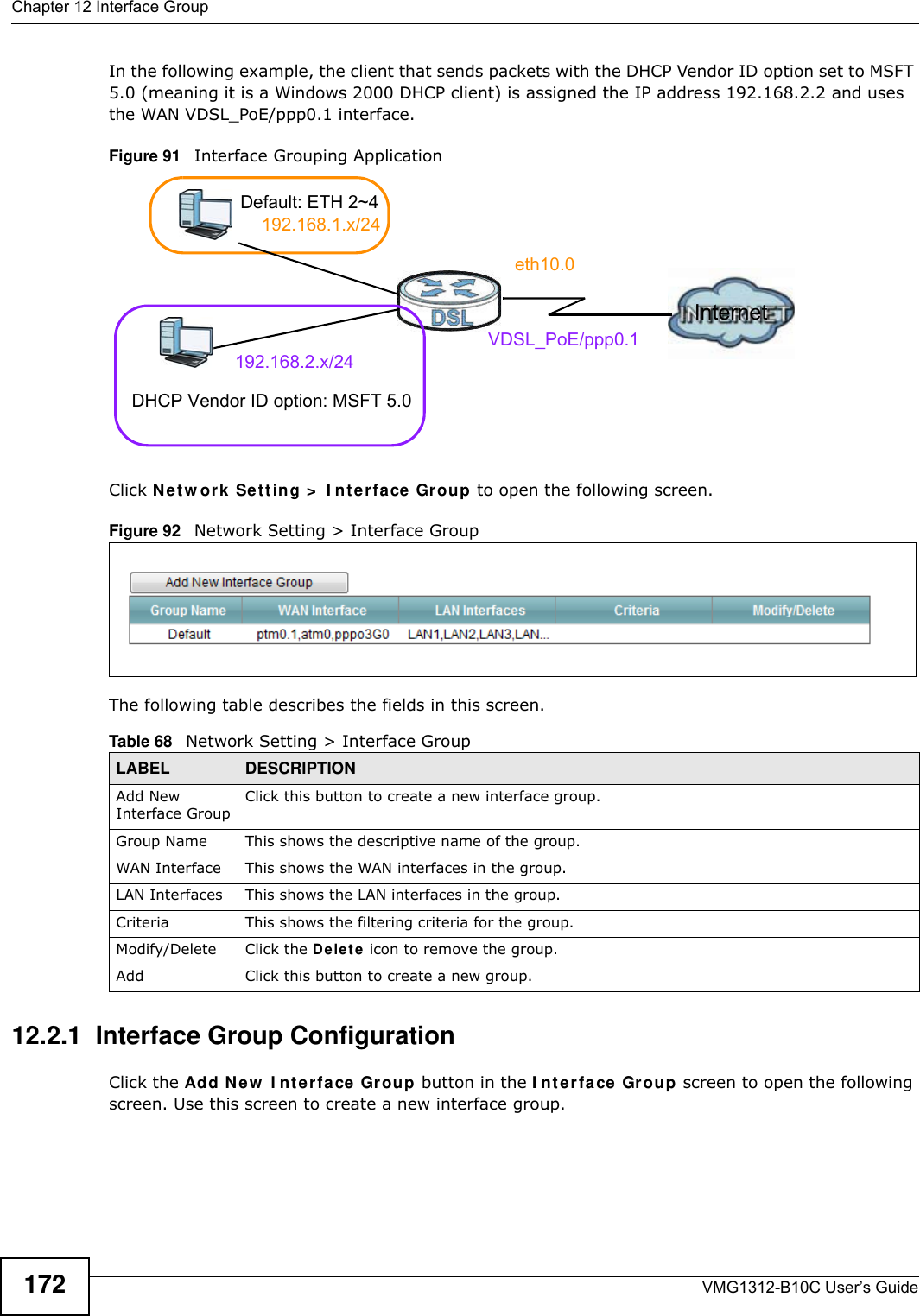
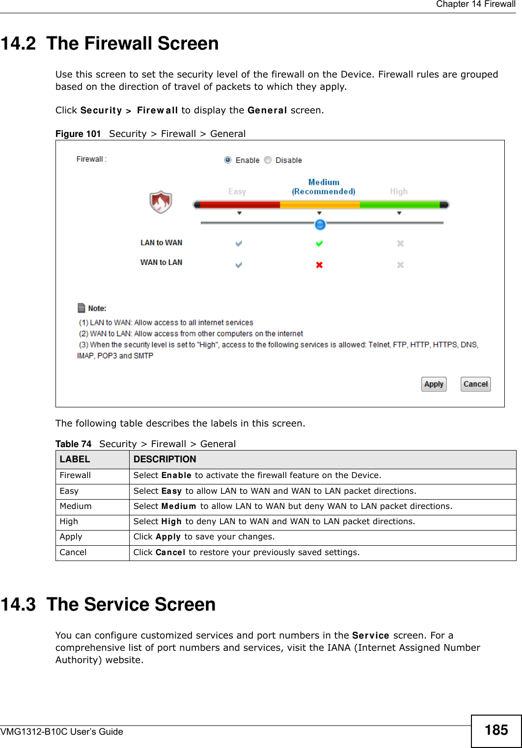
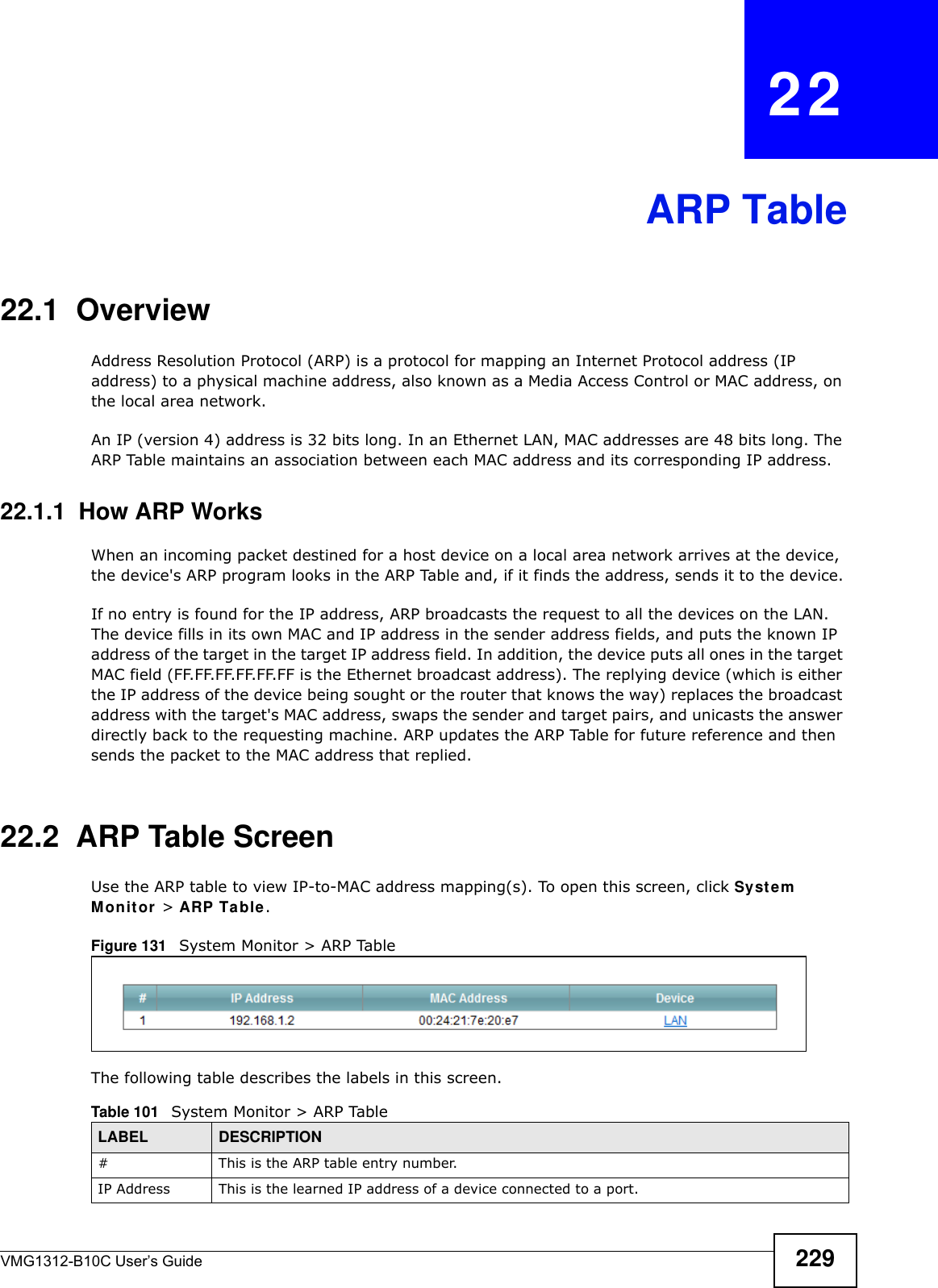
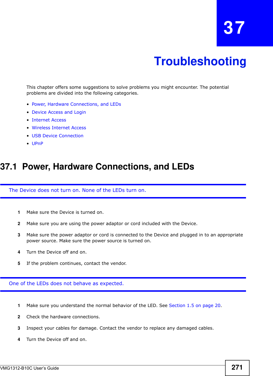
![Appendix B Legal InformationVMG1312-B10C User’s Guide284Viewing Certifications Go to http://www.zyxel.com to view this product’s documentation and certifications.ZyXEL Limited Warranty ZyXEL warrants to the original end user (purchaser) that this product is free from any defects in material or workmanship for a specific period (the Warranty Period) from the date of purchase. The Warranty Period varies by region. Check with your vendor and/or the authorized ZyXEL local distributor for details about the Warranty Period of this product. During the warranty period, and upon proof of purchase, should the product have indications of failure due to faulty workmanship and/or materials, ZyXEL will, at its discretion, repair or replace the defective products or components without charge for either parts or labor, and to whatever extent it shall deem necessary to restore the product or components to proper operating condition. Any replacement will consist of a new or re-manufactured functionally equivalent product of equal or higher value, and will be solely at the discretion of ZyXEL. This warranty shall not apply if the product has been modified, misused, tampered with, damaged by an act of God, or subjected to abnormal working conditions.NoteRepair or replacement, as provided under this warranty, is the exclusive remedy of the purchaser. This warranty is in lieu of all other warranties, express or implied, including any implied warranty of merchantability or fitness for a particular use or purpose. ZyXEL shall in no event be held liable for indirect or consequential damages of any kind to the purchaser.To obtain the services of this warranty, contact your vendor. You may also refer to the warranty policy for the region in which you bought the device at http://www.zyxel.com/web/support_warranty_info.php.RegistrationRegister your product online to receive e-mail notices of firmware upgrades and information at www.zyxel.com for global products, or at www.us.zyxel.com for North American products.Open Source Licenses This product contains in part some free software distributed under GPL license terms and/or GPL like licenses. Open source licenses are provided with the firmware package. You can download the latest firmware at www.zyxel.com. If you cannot find it there, contact your vendor or ZyXEL Technical Support at support@zyxel.com.tw. To obtain the source code covered under those Licenses, please contact your vendor or ZyXEL Technical Support at support@zyxel.com.tw. Regulatory Information European UnionThe following information applies if you use the product within the European Union. Declaration of Conformity with Regard to EU Directive 1999/5/EC (R&TTE Directive)Compliance Information for Wireless Products Relevant to the EU and Other Countries Following the EU Directive 1999/5/EC (R&TTE Directive) [Czech] ZyXEL tímto prohlašuje, že tento zařízení je ve shodě se základními požadavky a dalšími příslušnými ustanoveními směrnice 1999/5/EC.[Danish] Undertegnede ZyXEL erklærer herved, at følgende udstyr udstyr overholder de væsentlige krav og øvrige relevante krav i direktiv 1999/5/EF.[German] Hiermit erklärt ZyXEL, dass sich das Gerät Ausstattung in Übereinstimmung mit den grundlegenden Anforderungen und den übrigen einschlägigen Bestimmungen der Richtlinie 1999/5/EU befindet.[Estonian] Käesolevaga kinnitab ZyXEL seadme seadmed vastavust direktiivi 1999/5/EÜ põhinõuetele ja nimetatud direktiivist tulenevatele teistele asjakohastele sätetele.[English] Hereby, ZyXEL declares that this equipment is in compliance with the essential requirements and other relevant provisions of Directive 1999/5/EC.[Spanish] Por medio de la presente ZyXEL declara que el equipo cumple con los requisitos esenciales y cualesquiera otras disposiciones aplicables o exigibles de la Directiva 1999/5/CE.[Greek] Ε Η ΑΑ ZyXEL ∆ΗΩΕ επισός ΦΩΕΑ Ω∆Ε ΑΑΗΕ Α Ε ΧΕΕ ∆ΑΑΕ Η ∆ΗΓΑ 1999/5/ΕC.[French] Par la présente ZyXEL déclare que l'appareil équipements est conforme aux exigences essentielles et aux autres dispositions pertinentes de la directive 1999/5/EC.[Italian] Con la presente ZyXEL dichiara che questo attrezzatura è conforme ai requisiti essenziali ed alle altre disposizioni pertinenti stabilite dalla direttiva 1999/5/CE.[Latvian] Ar šo ZyXEL deklarē, ka iekārtas atbilst Direktīvas 1999/5/EK būtiskajām prasībām un citiem ar to saistītajiem noteikumiem.[Lithuanian] Šiuo ZyXEL deklaruoja, kad šis įranga atitinka esminius reikalavimus ir kitas 1999/5/EB Direktyvos nuostatas.[Dutch] Hierbij verklaart ZyXEL dat het toestel uitrusting in overeenstemming is met de essentiële eisen en de andere relevante bepalingen van richtlijn 1999/5/EC.[Maltese] Hawnhekk, ZyXEL, jiddikjara li dan tagħmir jikkonforma mal-ħtiġijiet essenzjali u ma provvedimenti oħrajn relevanti li hemm fid-Dirrettiva 1999/5/EC.[Hungarian] Alulírott, ZyXEL nyilatkozom, hogy a berendezés megfelel a vonatkozó alapvetõ követelményeknek és az 1999/5/EK irányelv egyéb elõírásainak.](https://usermanual.wiki/ZyXEL-Communications/VMG1312B10C/User-Guide-2431428-Page-284.png)
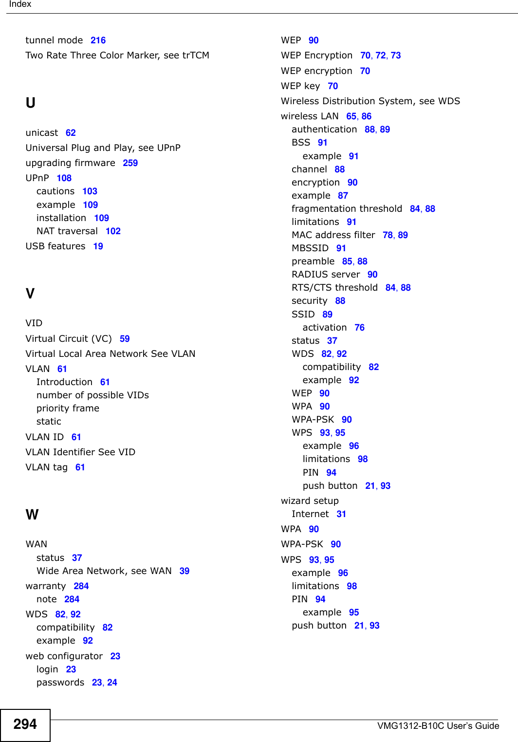
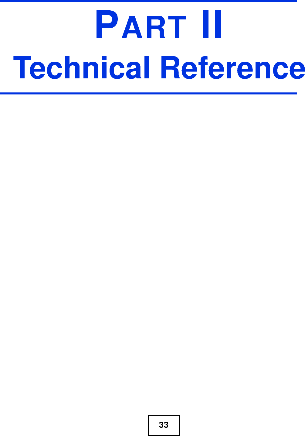
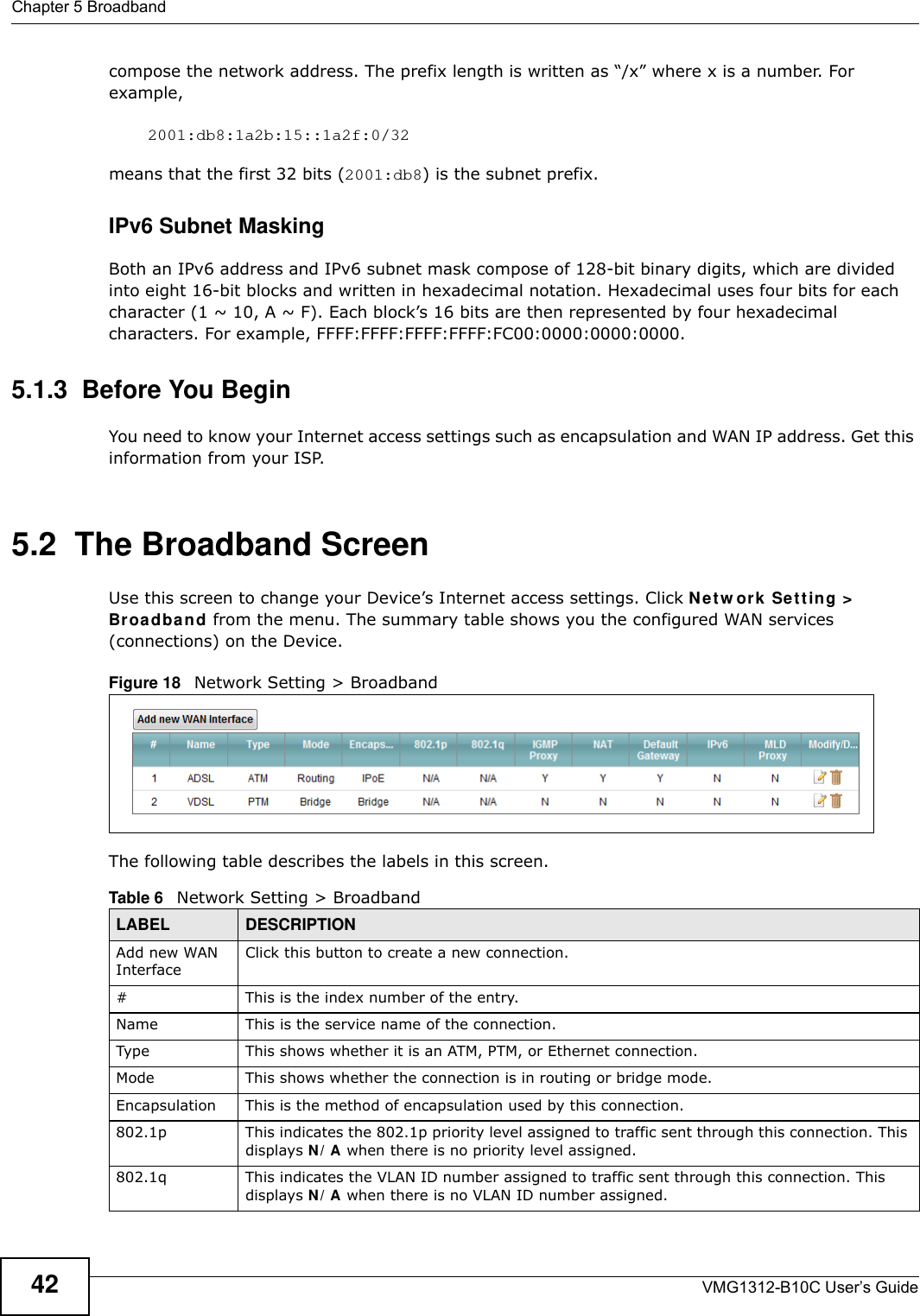
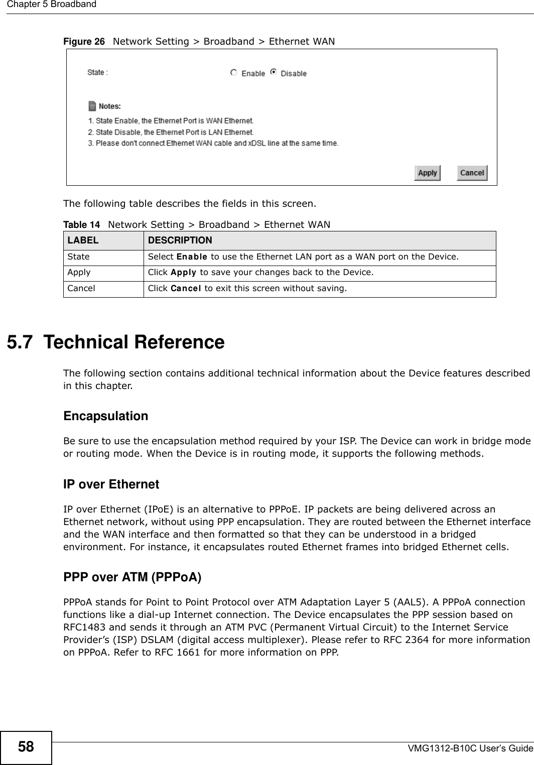
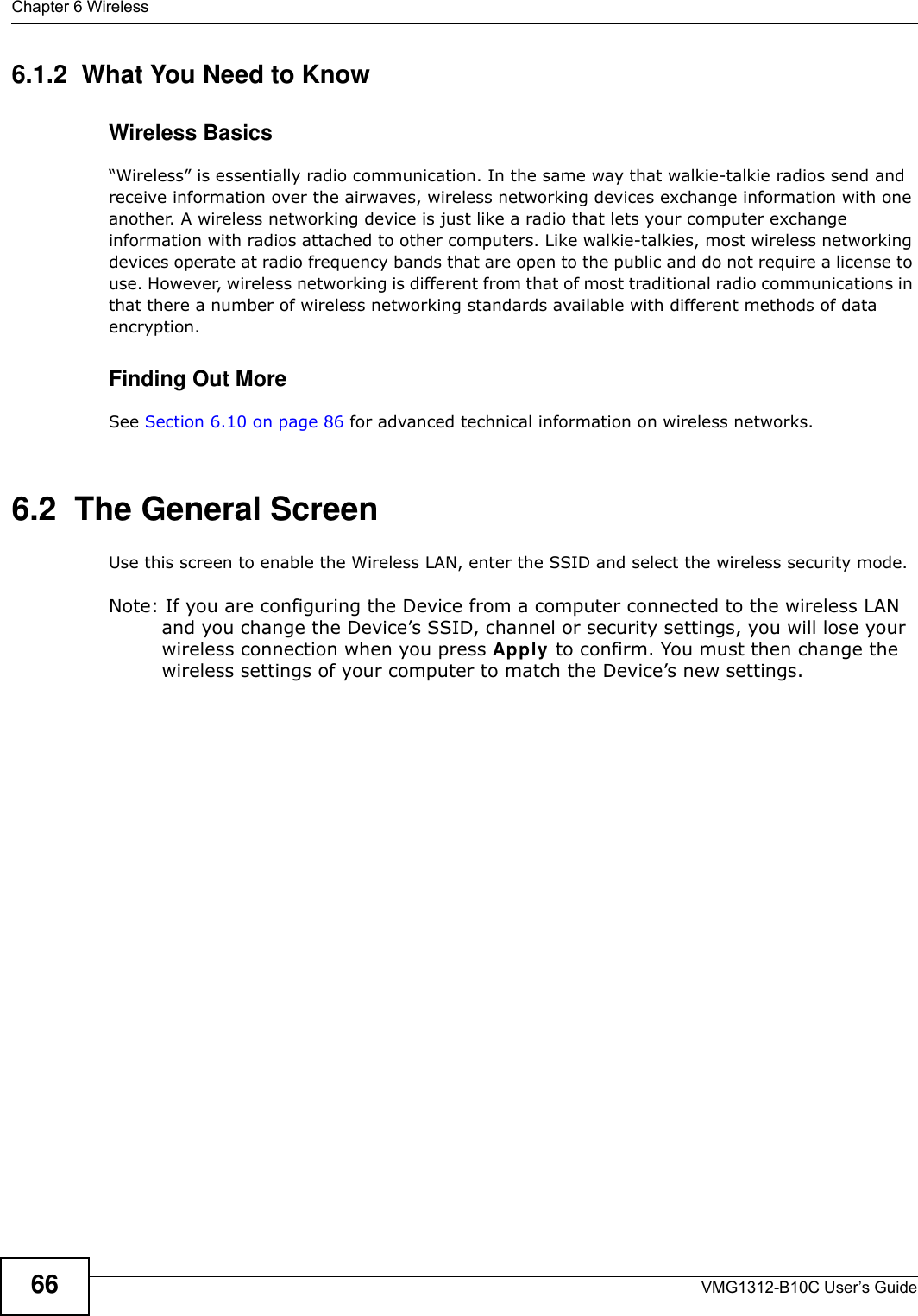
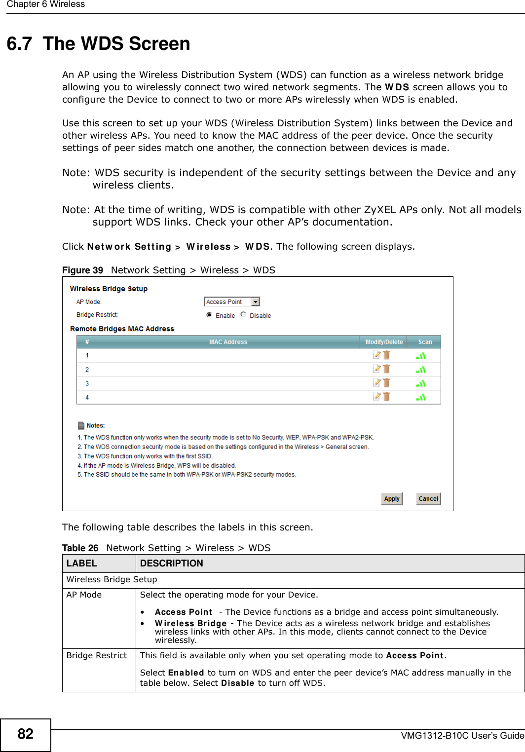
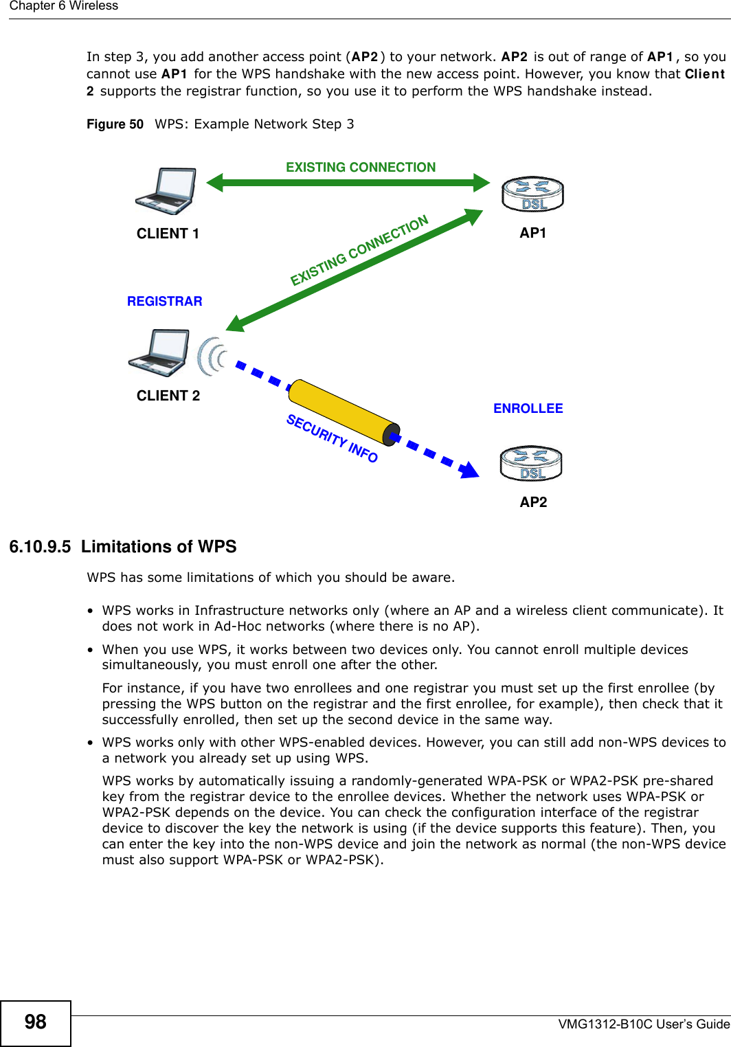
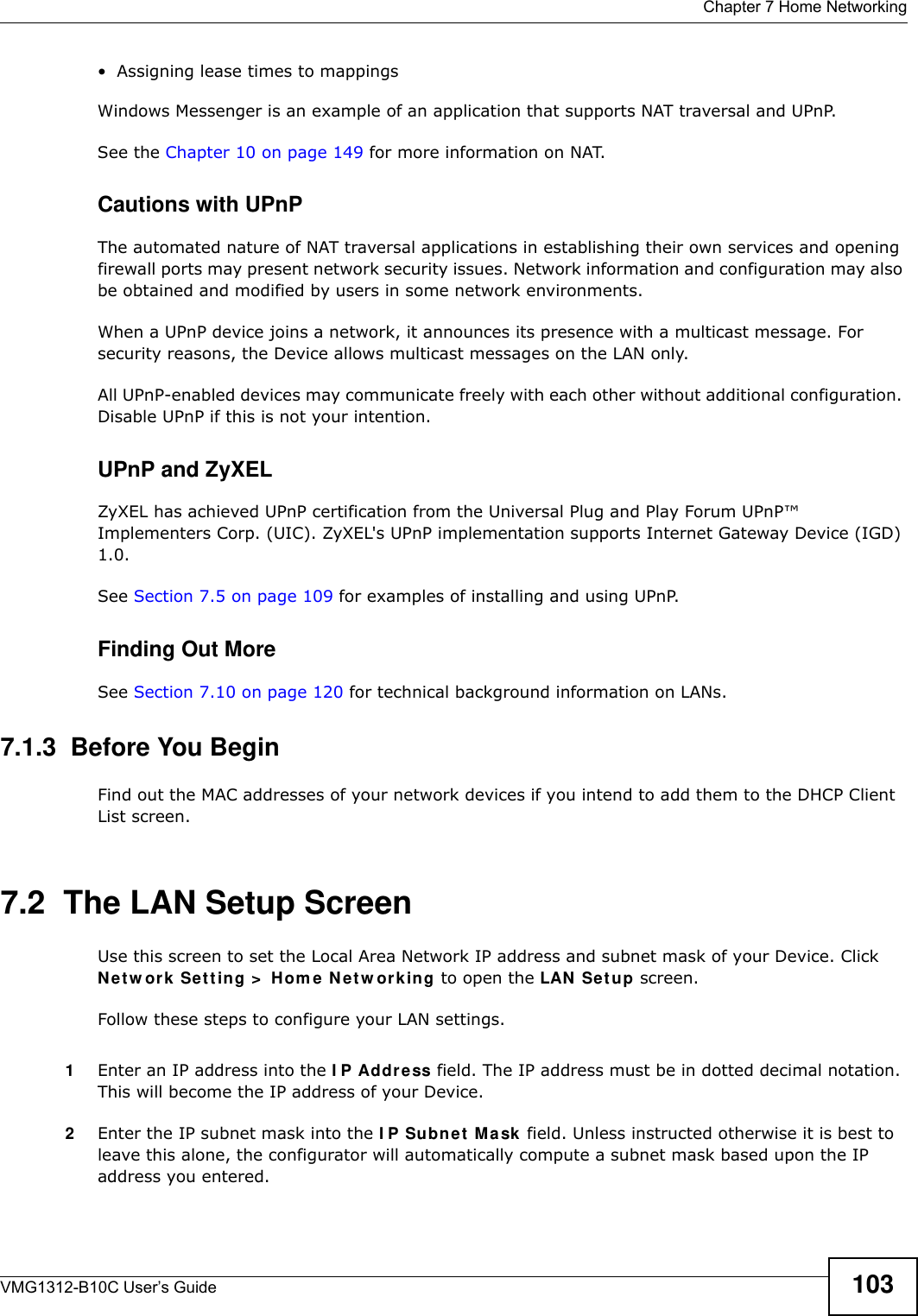
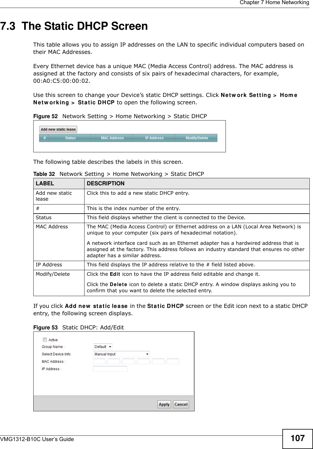
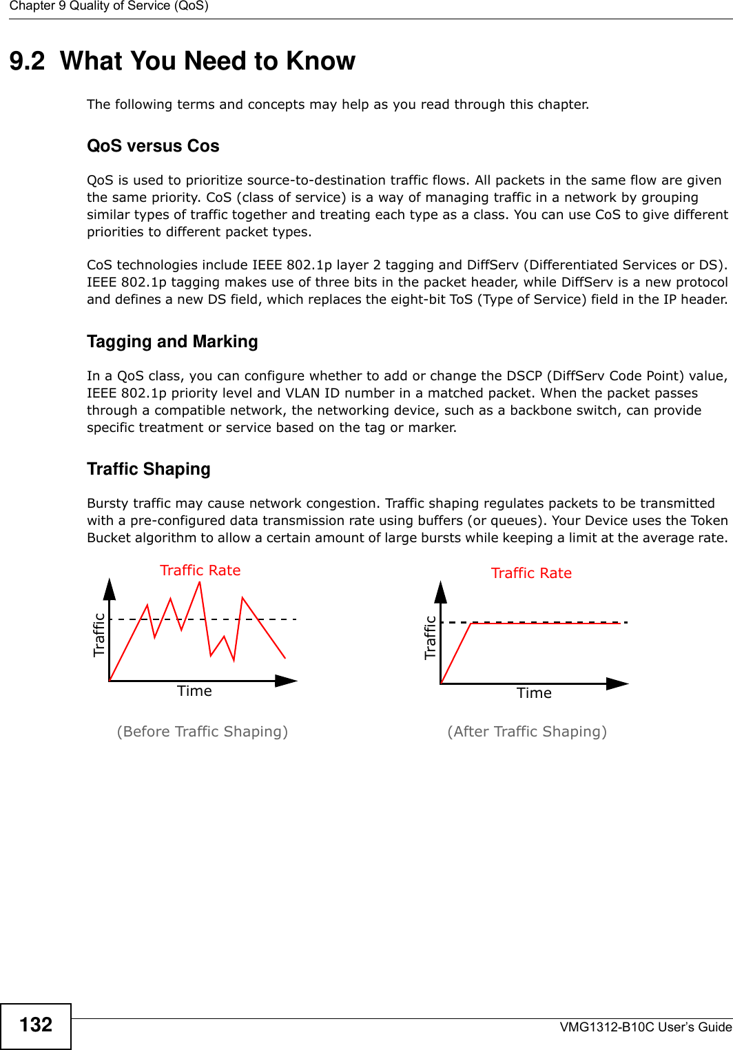
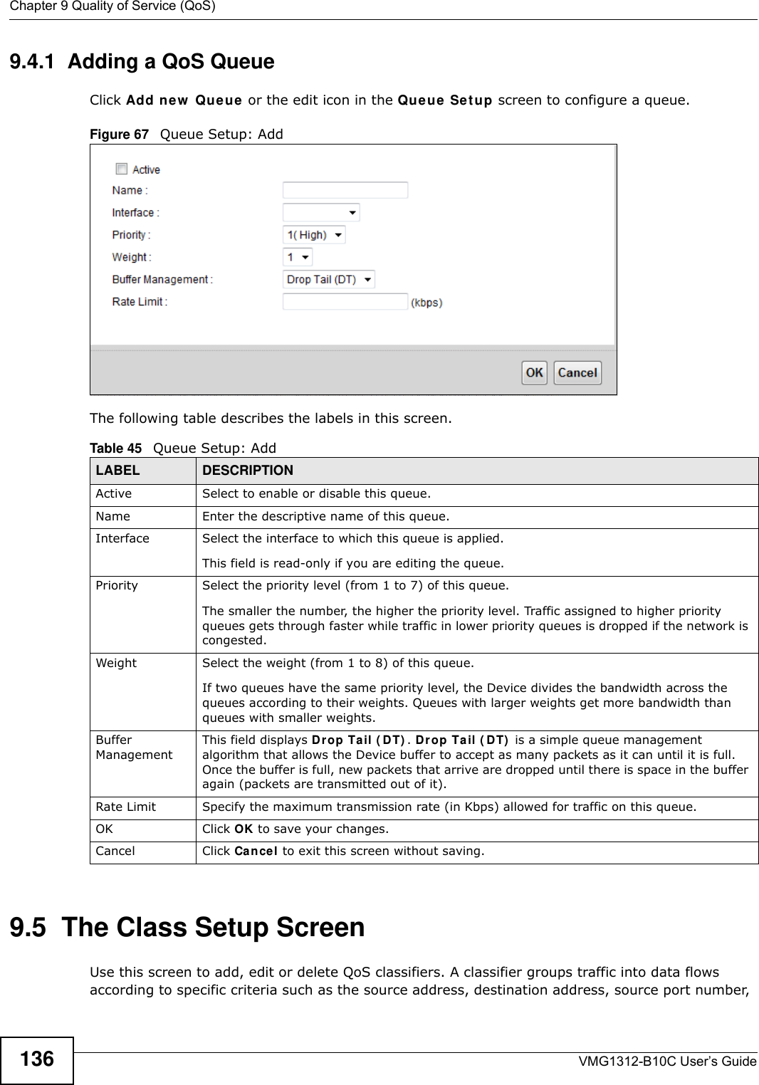
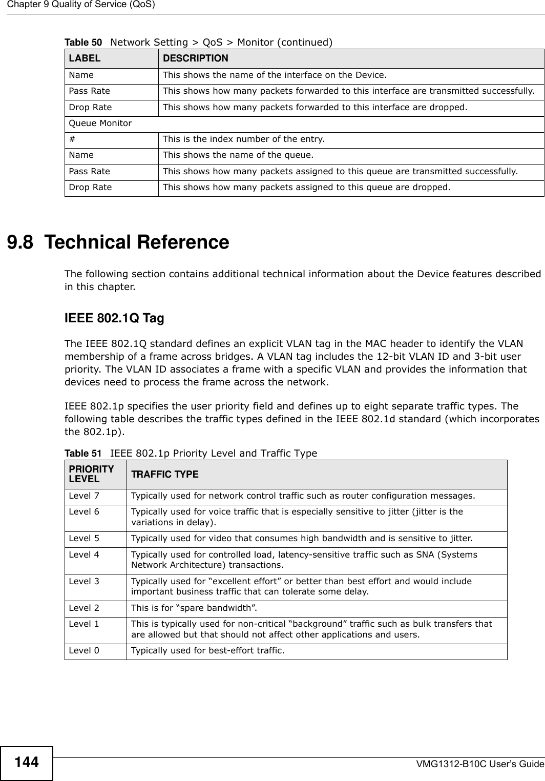
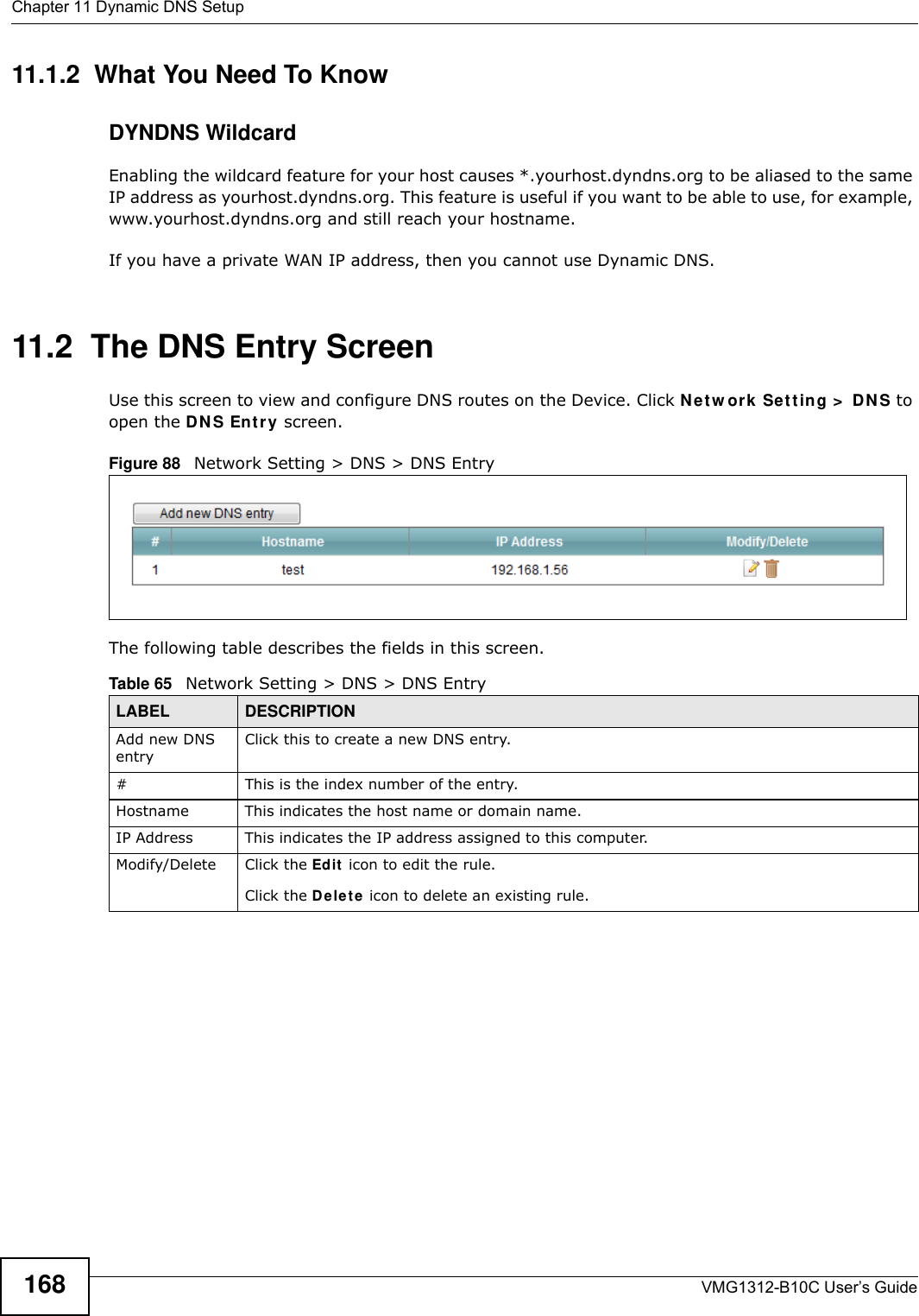
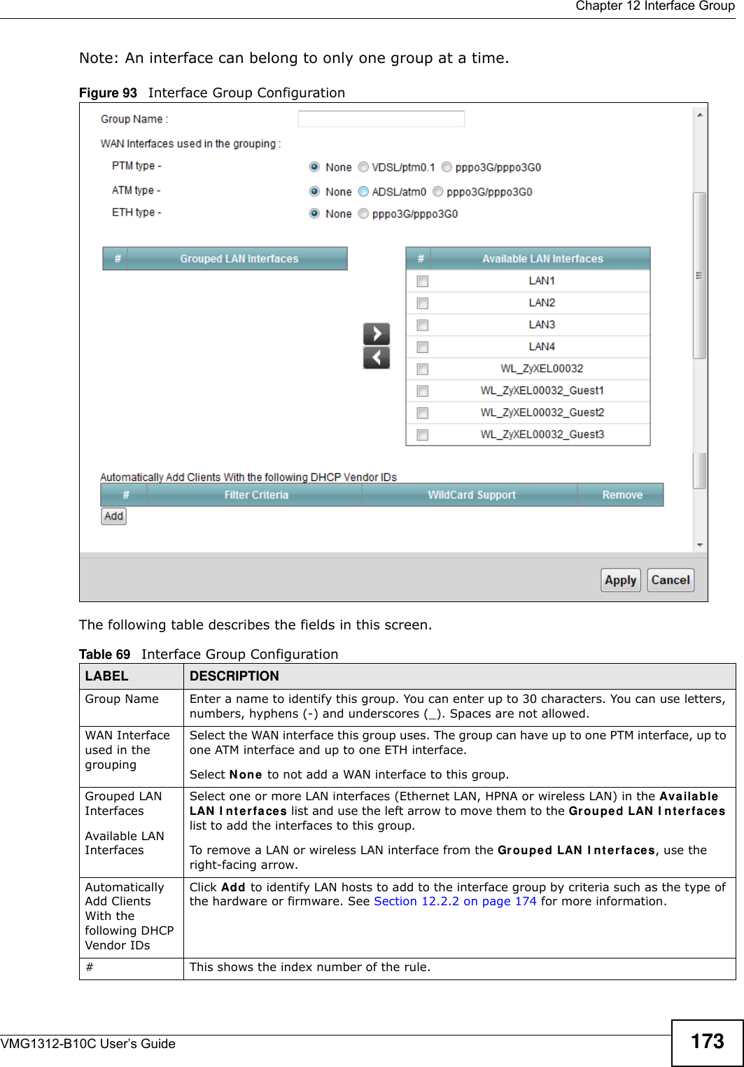
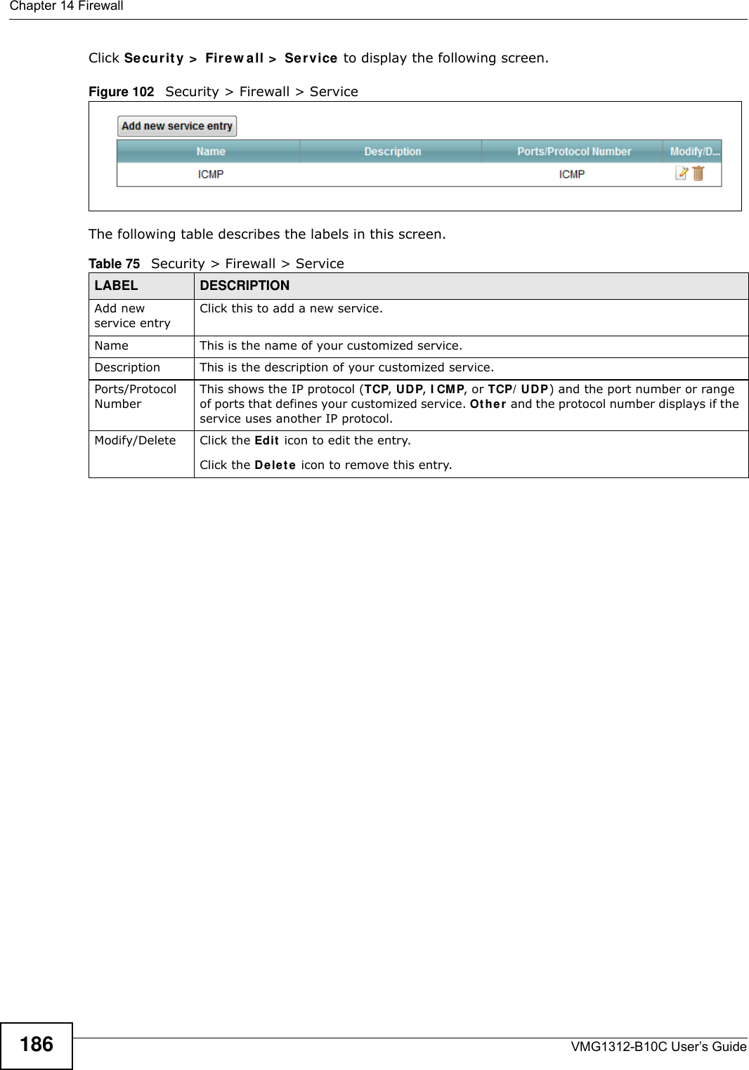
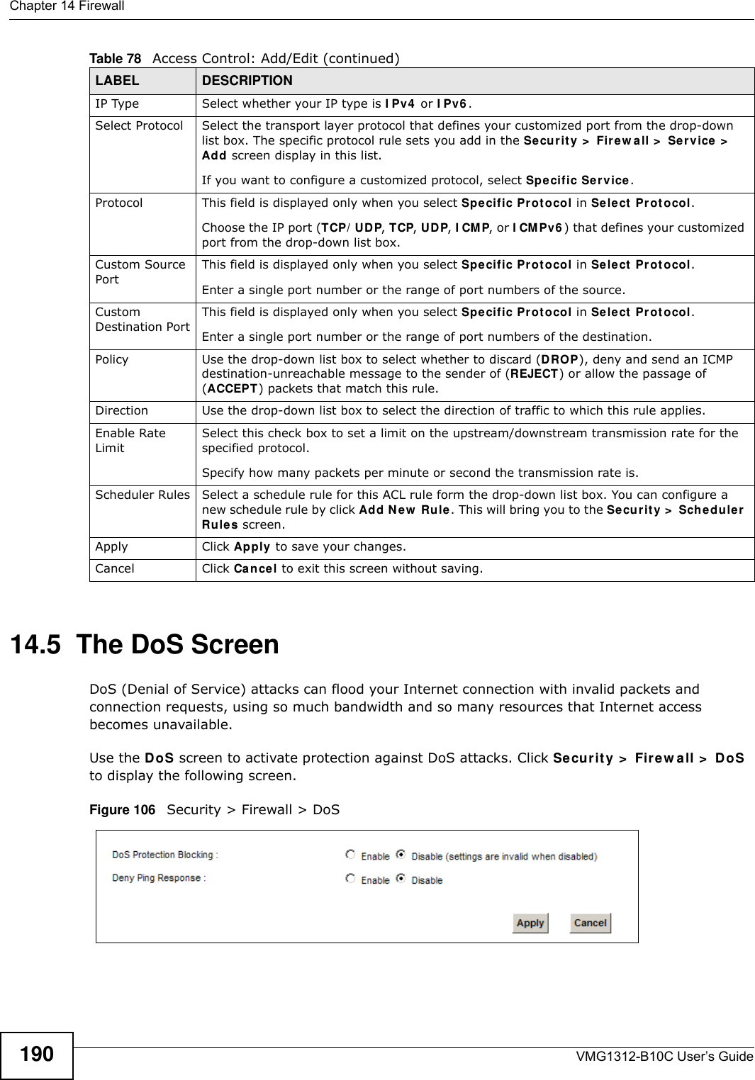
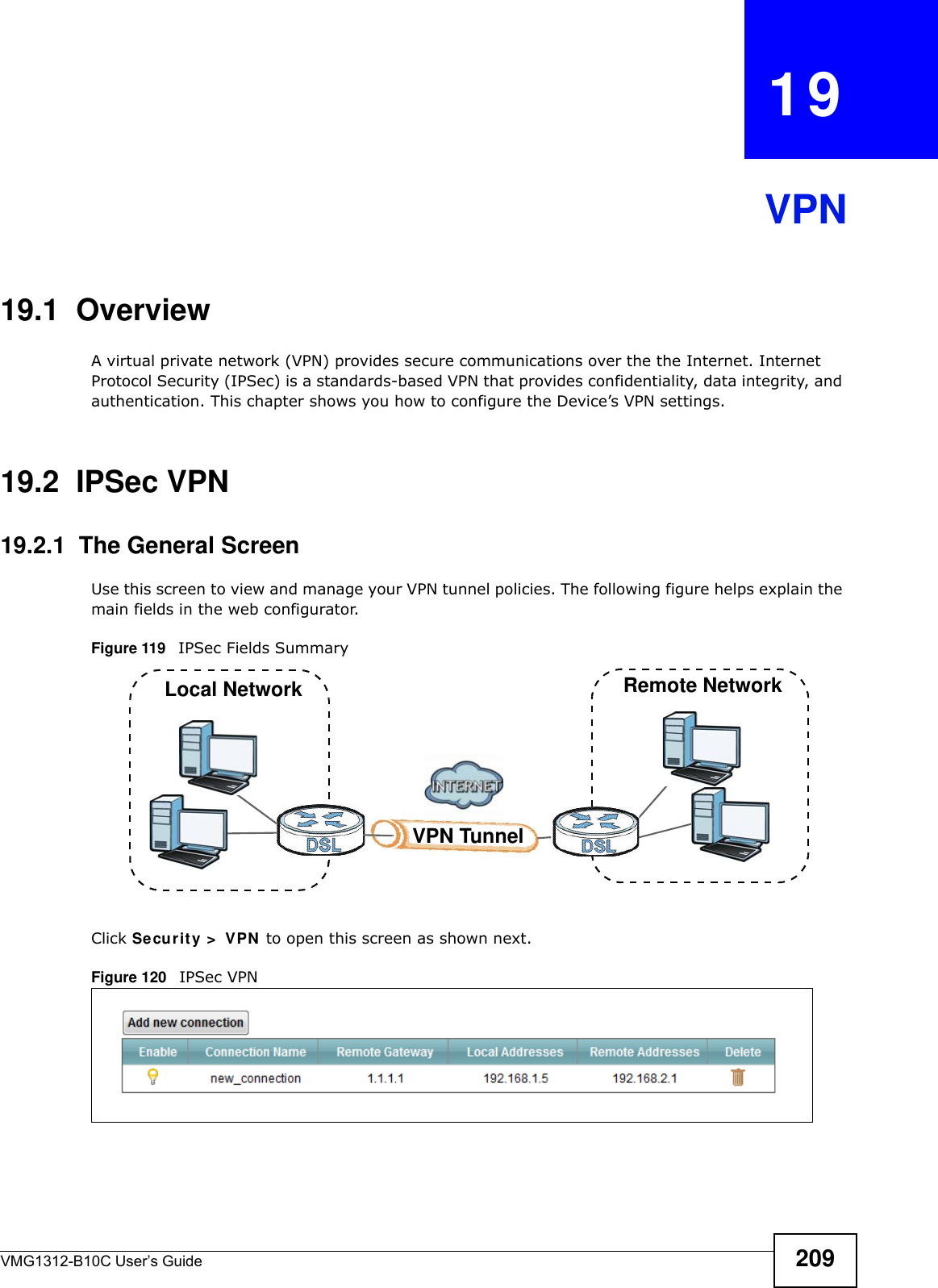
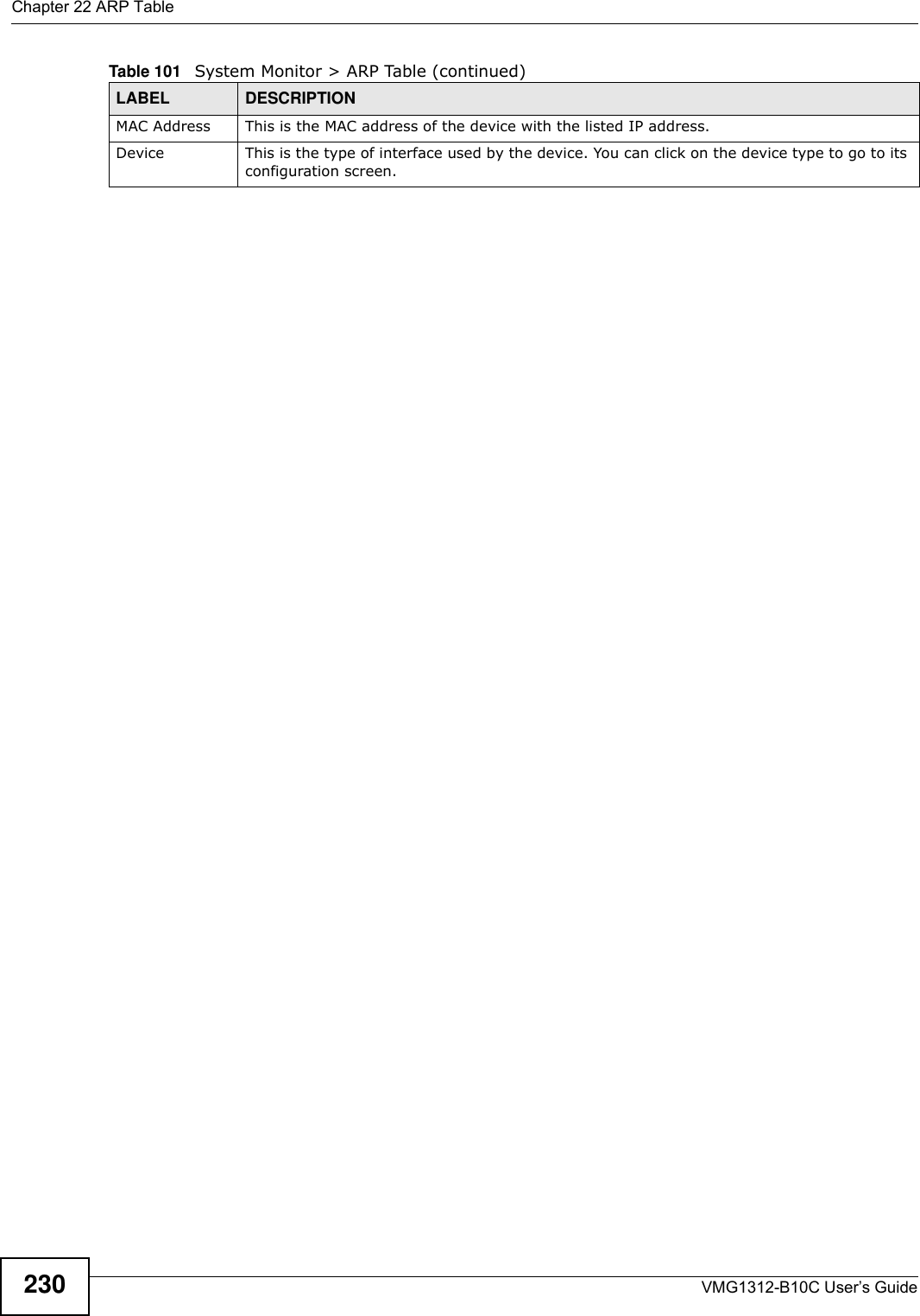
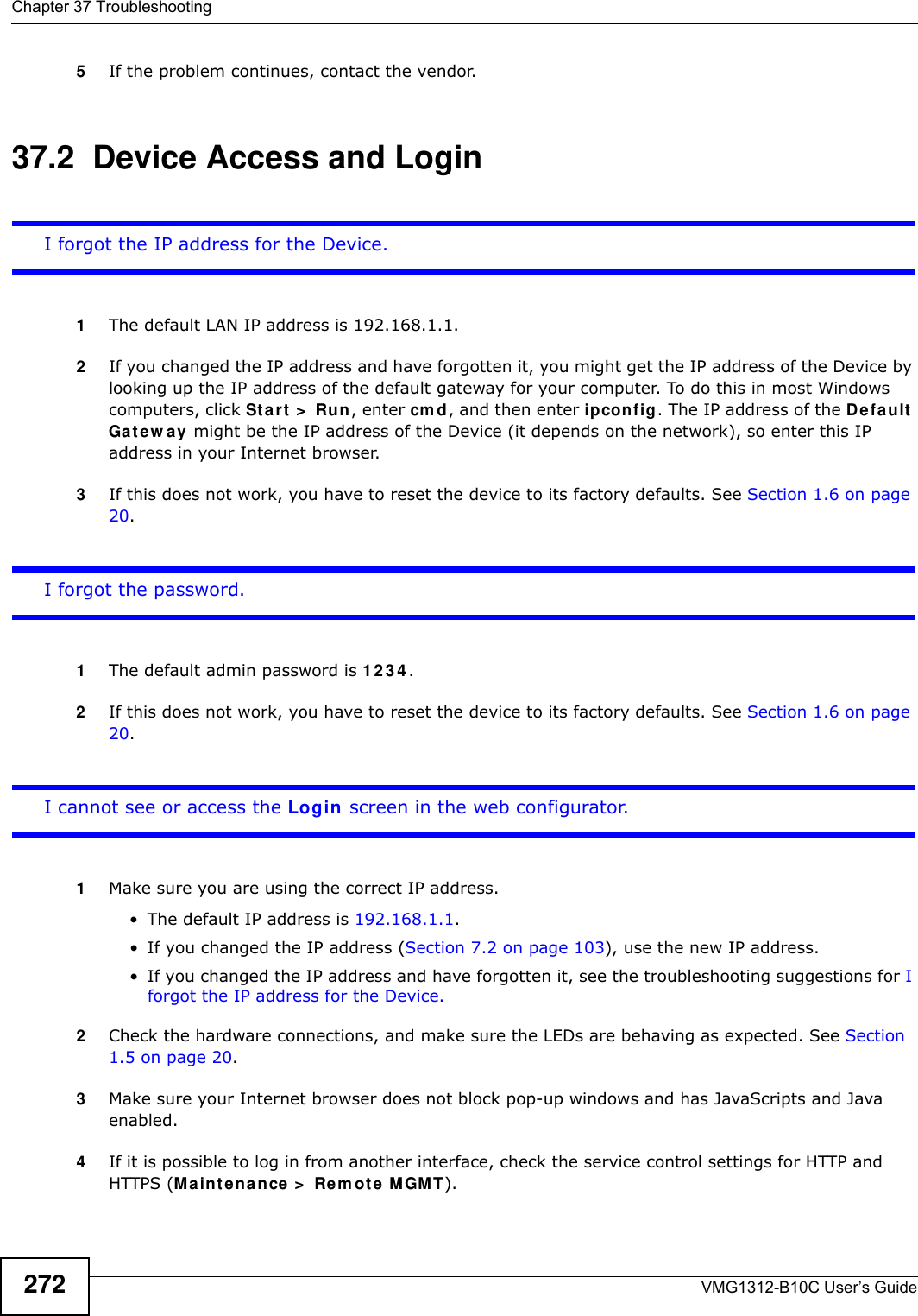
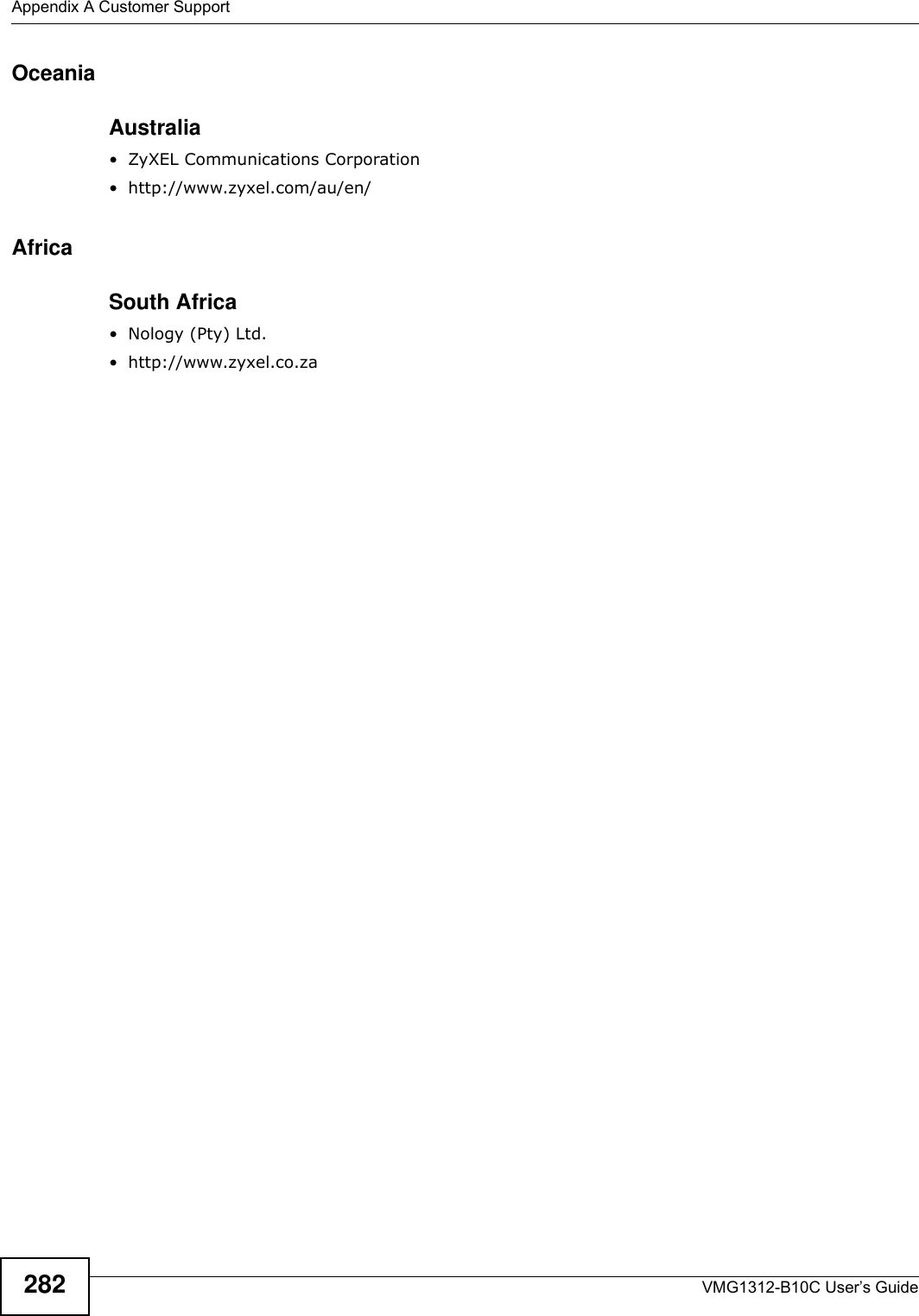
![Appendix B Legal InformationVMG1312-B10C User’s Guide 285National RestrictionsThis product may be used in all EU countries (and other countries following the EU directive 1999/5/EC) without any limitation except for the countries mentioned below:Ce produit peut être utilisé dans tous les pays de l’UE (et dans tous les pays ayant transposés la directive 1999/5/CE) sans aucune limitation, excepté pour les pays mentionnés ci-dessous:Questo prodotto è utilizzabile in tutte i paesi EU (ed in tutti gli altri paesi che seguono le direttive EU 1999/5/EC) senza nessuna limitazione, eccetto per i paesii menzionati di seguito:Das Produkt kann in allen EU Staaten ohne Einschränkungen eingesetzt werden (sowie in anderen Staaten die der EU Direktive 1995/5/CE folgen) mit Außnahme der folgenden aufgeführten Staaten:In the majority of the EU and other European countries, the 2,4-GHz band has been made available for the use of wireless local area networks (LANs). Later in this document you will find an overview of countries inwhich additional restrictions or requirements or both are applicable.The requirements for any country may evolve. ZyXEL recommends that you check with the local authorities for the latest status of their national regulations for 2,4-GHz wireless LANs.The following countries have restrictions and/or requirements in addition to those given in the table labeled “Overview of Regulatory Requirem ents for Wireless LANs”:.BelgiumThe Belgian Institute for Postal Services and Telecommunications (BIPT) must be notified of any outdoor wireless link having a range exceeding 300 meters. Please check http://www.bipt.be for more details.Draadloze verbindingen voor buitengebruik en met een reikwijdte van meer dan 300 meter dienen aangemeld te worden bij het Belgisch Instituut voor postdiensten en telecommunicatie (BIPT). Zie http://www.bipt.be voor meer gegevens.Les liaisons sans fil pour une utilisation en extérieur d’une distance supérieure à 300 mètres doivent être notifiées à l’Institut Belge des services Postaux et des Télécommunications (IBPT). Visitez http://www.ibpt.be pour de plus amples détails.FranceFor 2.4 GHz, the output power is restricted to 10 mW EIRP when the product is used outdoors in the band 2454 - 2483.5 MHz. There are no restrictions when used indoors or in other parts of the 2.4 GHz band. Check http://www.arcep.fr/ for more details.Pour la bande 2.4 GHz, la puissance est limitée à 10 mW en p.i.r.e. pour les équipements utilisés en extérieur dans la bande 2454 - 2483.5 MHz. Il n'y a pas de restrictions pour des utilisations en intérieur ou dans d'autres parties de la bande 2.4 GHz. Consultez http://www.arcep.fr/ pour de plus amples détails.ItalyThis product meets the National Radio Interface and the requirements specified in the National Frequency Allocation Table for Italy. Unless this wireless LAN product is operating within the boundaries of the owner's property, its use requires a “general authorization.” Please check http://www.sviluppoeconomico.gov.it/ for more details.[Polish] Niniejszym ZyXEL oświadcza, że sprzęt jest zgodny z zasadniczymi wymogami oraz pozostałymi stosownymi postanowieniami Dyrektywy 1999/5/EC.[Portuguese] ZyXEL declara que este equipamento está conforme com os requisitos essenciais e outras disposições da Directiva 1999/5/EC.[Slovenian] ZyXEL izjavlja, da je ta oprema v skladu z bistvenimi zahtevami in ostalimi relevantnimi določili direktive 1999/5/EC.[Slovak] ZyXEL týmto vyhlasuje, že zariadenia spĺňa základné požiadavky a všetky príslušné ustanovenia Smernice 1999/5/EC.[Finnish] ZyXEL vakuuttaa täten että laitteet tyyppinen laite on direktiivin 1999/5/EY oleellisten vaatimusten ja sitä koskevien direktiivin muiden ehtojen mukainen.[Swedish] Härmed intygar ZyXEL att denna utrustning står I överensstämmelse med de väsentliga egenskapskrav och övriga relevanta bestämmelser som framgår av direktiv 1999/5/EC.[Bulgarian] С я ZyXEL , ч я 1999/5/C.[Icelandic] Hér með lýsir, ZyXEL því yfir að þessi búnaður er í samræmi við grunnkröfur og önnur viðeigandi ákvæði tilskipunar 1999/5/EC.[Norwegian] Erklærer herved ZyXEL at dette utstyret er I samsvar med de grunnleggende kravene og andre relevante bestemmelser I direktiv 1999/5/EF.[Romanian] Prin prezenta, ZyXEL declară că acest echipament este în conformitate cu cerinţele esenţiale şi alte prevederi relevante ale Directivei 1999/5/EC.R&TTE 1999/5/ECWLAN 2.4 – 2.4835 GHzIEEE 802.11 b/g/nLocation Frequency Range (GHz)Indoor (No restrictions) 2.4 – 2.4835Outdoor 2.4 – 2.4542.454 – 2.4835](https://usermanual.wiki/ZyXEL-Communications/VMG1312B10C/User-Guide-2431428-Page-285.png)