ZyXEL Communications VMG1312B10C Wireless N VDSL2 4-ports Gateway with USB Wireless N VDSL2 4-ports Gateway without USB User Manual
ZyXEL Communications Corporation Wireless N VDSL2 4-ports Gateway with USB Wireless N VDSL2 4-ports Gateway without USB
User manual

Quick Start Guide
www.zyxel.com
VMG1 3 1 2 - B1 0 C
Wireless N VDSL2 4-port Gateway with USB
Version 1.00
Edition 1, 10/2014
Copyright © 2014 ZyXEL Communications Corporation
User’s Guide
Default Login Deta ils
LAN IP Address http://192.168.1.1
Login admin
Password 1234

VMG1312-B10C User’s Guide2
IMPORTANT!
READ CAREFULLY BEFORE USE.
KEEP THIS GUIDE FOR FUTURE REFERENCE.
Screenshots and graphics in this book may differ slightly from your product due to differences in
your product firmware or your computer operating system. Every effort has been made to ensure
that the information in this manual is accurate.
Related Documentation
•Quick Start Guide
The Quick Start Guide shows how to connect the Device and get up and running right away.

Contents Overview
VMG1312-B10C User’s Guide 3
Contents Overview
User’s Guide .......................................................................................................................................15
Introducing the Device ............................................................................................................................17
The Web Configurator .............................................................................................................................23
Quick Start ...............................................................................................................................................31
Technical Reference ..........................................................................................................................33
Network Map and Status Screens ...........................................................................................................35
Broadband ...............................................................................................................................................39
Wireless ..................................................................................................................................................65
Home Networking ..................................................................................................................................101
Routing ..................................................................................................................................................125
Quality of Service (QoS) .......................................................................................................................131
Network Address Translation (NAT) ......................................................................................................149
Dynamic DNS Setup .............................................................................................................................167
Interface Group .....................................................................................................................................171
USB Service ..........................................................................................................................................177
Firewall ..................................................................................................................................................183
MAC Filter .............................................................................................................................................193
Parental Control ....................................................................................................................................195
Scheduler Rule ......................................................................................................................................199
Certificates ............................................................................................................................................201
VPN .......................................................................................................................................................209
Log .......................................................................................................................................................221
Traffic Status ........................................................................................................................................225
ARP Table .............................................................................................................................................229
Routing Table ........................................................................................................................................231
IGMP Status .........................................................................................................................................233
xDSL Statistics ......................................................................................................................................235
3G Statistics .........................................................................................................................................239
User Account .........................................................................................................................................241
Remote Management ............................................................................................................................243
TR-069 Client ........................................................................................................................................245
TR-064 ..................................................................................................................................................247
Time Settings ........................................................................................................................................249
E-mail Notification .................................................................................................................................253
Logs Setting .........................................................................................................................................255
Firmware Upgrade ................................................................................................................................259
Configuration .........................................................................................................................................261

Contents Overview
VMG1312-B10C User’s Guide
4
Diagnostic .............................................................................................................................................265
Troubleshooting ....................................................................................................................................271

Table of Contents
VMG1312-B10C User’s Guide 5
Table of Contents
Contents Overview ..............................................................................................................................3
Table of Contents .................................................................................................................................5
Part I: User’s Guide ......................................................................................... 15
Chapter 1
Introducing the Device .......................................................................................................................17
1.1 Overview ...........................................................................................................................................17
1.2 Ways to Manage the Device .............................................................................................................17
1.3 Good Habits for Managing the Device ..............................................................................................17
1.4 Applications for the Device ...............................................................................................................18
1.4.1 Internet Access ........................................................................................................................18
1.4.2 Device’s USB Support .............................................................................................................19
1.5 LEDs (Lights) ....................................................................................................................................20
1.6 The RESET Button ............................................................................................................................20
1.7 Wireless Access ................................................................................................................................21
1.7.1 Using the WLAN/WPS Button .................................................................................................21
Chapter 2
The Web Configurator ........................................................................................................................23
2.1 Overview ...........................................................................................................................................23
2.1.1 Accessing the Web Configurator .............................................................................................23
2.2 Web Configurator Layout ..................................................................................................................25
2.2.1 Title Bar ...................................................................................................................................25
2.2.2 Main Window ...........................................................................................................................26
2.2.3 Navigation Panel .....................................................................................................................27
Chapter 3
Quick Start...........................................................................................................................................31
3.1 Overview ...........................................................................................................................................31
3.2 Quick Start Setup ..............................................................................................................................31
Part II: Technical Reference............................................................................ 33
Chapter 4
Network Map and Status Screens .....................................................................................................35

Table of Contents
VMG1312-B10C User’s Guide
6
4.1 Overview ...........................................................................................................................................35
4.2 The Network Map Screen .................................................................................................................35
4.3 The Status Screen .............................................................................................................................36
Chapter 5
Broadband...........................................................................................................................................39
5.1 Overview ...........................................................................................................................................39
5.1.1 What You Can Do in this Chapter ............................................................................................39
5.1.2 What You Need to Know ..........................................................................................................40
5.1.3 Before You Begin .....................................................................................................................42
5.2 The Broadband Screen .....................................................................................................................42
5.2.1 Add/Edit Internet Connection ...................................................................................................44
5.3 The 3G Backup Screen .....................................................................................................................51
5.4 The Advanced Screen .......................................................................................................................55
5.5 The 8021x Screen .............................................................................................................................56
5.5.1 Edit 802.1X Settings ................................................................................................................57
5.6 The Ethernet WAN Screen ................................................................................................................57
5.7 Technical Reference ..........................................................................................................................58
Chapter 6
Wireless ...............................................................................................................................................65
6.1 Overview ...........................................................................................................................................65
6.1.1 What You Can Do in this Chapter ............................................................................................65
6.1.2 What You Need to Know ..........................................................................................................66
6.2 The General Screen .........................................................................................................................66
6.2.1 No Security ..............................................................................................................................69
6.2.2 Basic (WEP Encryption) ..........................................................................................................70
6.2.3 Basic (802.1X) .........................................................................................................................71
6.2.4 More Secure (WPA(2)-PSK) ....................................................................................................73
6.2.5 WPA(2) Authentication .............................................................................................................74
6.3 The More AP Screen .........................................................................................................................75
6.3.1 Edit More AP ..........................................................................................................................77
6.4 MAC Authentication ..........................................................................................................................78
6.5 The WPS Screen ..............................................................................................................................79
6.6 The WMM Screen .............................................................................................................................81
6.7 The WDS Screen ..............................................................................................................................82
6.7.1 WDS Scan ...............................................................................................................................83
6.8 The Others Screen ............................................................................................................................84
6.9 The Channel Status Screen ..............................................................................................................86
6.10 Technical Reference ........................................................................................................................86
6.10.1 Wireless Network Overview ...................................................................................................86
6.10.2 Additional Wireless Terms .....................................................................................................88
6.10.3 Wireless Security Overview ...................................................................................................88

Table of Contents
VMG1312-B10C User’s Guide 7
6.10.4 Signal Problems ....................................................................................................................91
6.10.5 BSS .......................................................................................................................................91
6.10.6 MBSSID .................................................................................................................................91
6.10.7 Preamble Type ......................................................................................................................92
6.10.8 Wireless Distribution System (WDS) .....................................................................................92
6.10.9 WiFi Protected Setup (WPS) .................................................................................................93
Chapter 7
Home Networking .............................................................................................................................101
7.1 Overview .........................................................................................................................................101
7.1.1 What You Can Do in this Chapter ..........................................................................................101
7.1.2 What You Need To Know .......................................................................................................102
7.1.3 Before You Begin ...................................................................................................................103
7.2 The LAN Setup Screen ...................................................................................................................103
7.3 The Static DHCP Screen .................................................................................................................107
7.4 The UPnP Screen ...........................................................................................................................108
7.5 Installing UPnP in Windows Example .............................................................................................109
7.6 Using UPnP in Windows XP Example ............................................................................................ 112
7.7 The Additional Subnet Screen ........................................................................................................ 118
7.8 The STB Vendor ID Screen ............................................................................................................. 119
7.9 The LAN VLAN Screen ...................................................................................................................120
7.10 Technical Reference ......................................................................................................................120
7.10.1 LANs, WANs and the Device ...............................................................................................121
7.10.2 DHCP Setup ........................................................................................................................121
7.10.3 DNS Server Addresses .......................................................................................................121
7.10.4 LAN TCP/IP .........................................................................................................................122
Chapter 8
Routing ..............................................................................................................................................125
8.1 Overview ........................................................................................................................................125
8.2 The Routing Screen ........................................................................................................................126
8.2.1 Add/Edit Static Route .............................................................................................................127
8.3 The Policy Forwarding Screen ........................................................................................................127
8.3.1 Add/Edit Policy Forwarding ...................................................................................................129
8.4 RIP ..............................................................................................................................................129
8.4.1 The RIP Screen .....................................................................................................................130
Chapter 9
Quality of Service (QoS)...................................................................................................................131
9.1 Overview ........................................................................................................................................131
9.1.1 What You Can Do in this Chapter ..........................................................................................131
9.2 What You Need to Know .................................................................................................................132
9.3 The Quality of Service General Screen ..........................................................................................133

Table of Contents
VMG1312-B10C User’s Guide
8
9.4 The Queue Setup Screen ...............................................................................................................134
9.4.1 Adding a QoS Queue ...........................................................................................................136
9.5 The Class Setup Screen .................................................................................................................136
9.5.1 Add/Edit QoS Class ..............................................................................................................138
9.6 The QoS Policer Setup Screen .......................................................................................................141
9.6.1 Add/Edit a QoS Policer .........................................................................................................142
9.7 The QoS Monitor Screen ...............................................................................................................143
9.8 Technical Reference ........................................................................................................................144
Chapter 10
Network Address Translation (NAT)................................................................................................149
10.1 Overview .......................................................................................................................................149
10.1.1 What You Can Do in this Chapter ........................................................................................149
10.1.2 What You Need To Know .....................................................................................................149
10.2 The Port Forwarding Screen ........................................................................................................150
10.2.1 Add/Edit Port Forwarding ...................................................................................................152
10.3 The Applications Screen ...............................................................................................................153
10.3.1 Add New Application ...........................................................................................................154
10.4 The Port Triggering Screen ...........................................................................................................155
10.4.1 Add/Edit Port Triggering Rule .............................................................................................157
10.5 The DMZ Screen ...........................................................................................................................158
10.6 The ALG Screen ...........................................................................................................................158
10.7 The Address Mapping Screen .......................................................................................................159
10.7.1 Add/Edit Address Mapping Rule ..........................................................................................160
10.8 Technical Reference ......................................................................................................................161
10.8.1 NAT Definitions ....................................................................................................................161
10.8.2 What NAT Does ...................................................................................................................162
10.8.3 How NAT Works ..................................................................................................................163
10.8.4 NAT Application ...................................................................................................................164
Chapter 11
Dynamic DNS Setup .........................................................................................................................167
11.1 Overview .......................................................................................................................................167
11.1.1 What You Can Do in this Chapter ........................................................................................167
11.1.2 What You Need To Know .....................................................................................................168
11.2 The DNS Entry Screen ..................................................................................................................168
11.2.1 Add/Edit DNS Entry .............................................................................................................169
11.3 The Dynamic DNS Screen ............................................................................................................169
Chapter 12
Interface Group .................................................................................................................................171
12.1 Overview .......................................................................................................................................171
12.1.1 What You Can Do in this Chapter ........................................................................................171

Table of Contents
VMG1312-B10C User’s Guide 9
12.2 The Interface Group Screen ..........................................................................................................171
12.2.1 Interface Group Configuration .............................................................................................172
12.2.2 Interface Grouping Criteria .................................................................................................174
Chapter 13
USB Service ......................................................................................................................................177
13.1 Overview .......................................................................................................................................177
13.1.1 What You Can Do in this Chapter ........................................................................................177
13.1.2 What You Need To Know .....................................................................................................177
13.2 The File Sharing Screen ...............................................................................................................178
13.2.1 Before You Begin .................................................................................................................179
13.3 The Media Server Screen .............................................................................................................180
13.4 The Printer Server Screen ............................................................................................................181
13.4.1 Before You Begin .................................................................................................................181
Chapter 14
Firewall ..............................................................................................................................................183
14.1 Overview .......................................................................................................................................183
14.1.1 What You Can Do in this Chapter ........................................................................................183
14.1.2 What You Need to Know ......................................................................................................184
14.2 The Firewall Screen ......................................................................................................................185
14.3 The Service Screen ......................................................................................................................185
14.3.1 Add/Edit a Service ..............................................................................................................187
14.4 The Access Control Screen ..........................................................................................................188
14.4.1 Add/Edit an ACL Rule ........................................................................................................189
14.5 The DoS Screen ............................................................................................................................190
Chapter 15
MAC Filter..........................................................................................................................................193
15.1 Overview ......................................................................................................................................193
15.2 The MAC Filter Screen ..................................................................................................................193
Chapter 16
Parental Control................................................................................................................................195
16.1 Overview .......................................................................................................................................195
16.2 The Parental Control Screen .........................................................................................................195
16.2.1 Add/Edit a Parental Control Rule .........................................................................................196
Chapter 17
Scheduler Rule..................................................................................................................................199
17.1 Overview .......................................................................................................................................199
17.2 The Scheduler Rule Screen ..........................................................................................................199
17.2.1 Add/Edit a Schedule ............................................................................................................200

Table of Contents
VMG1312-B10C User’s Guide
10
Chapter 18
Certificates ........................................................................................................................................201
18.1 Overview .......................................................................................................................................201
18.1.1 What You Can Do in this Chapter ........................................................................................201
18.2 What You Need to Know ...............................................................................................................201
18.3 The Local Certificates Screen .......................................................................................................202
18.3.1 Create Certificate Request .................................................................................................203
18.3.2 Load Signed Certificate ......................................................................................................204
18.4 The Trusted CA Screen ................................................................................................................205
18.4.1 View Trusted CA Certificate .................................................................................................206
18.4.2 Import Trusted CA Certificate ..............................................................................................207
Chapter 19
VPN ....................................................................................................................................................209
19.1 Overview .......................................................................................................................................209
19.2 IPSec VPN ....................................................................................................................................209
19.2.1 The General Screen ............................................................................................................209
19.2.2 IPSec VPN: Add ..................................................................................................................210
19.3 Technical Reference ......................................................................................................................215
19.3.1 IPSec Architecture ...............................................................................................................215
19.3.2 Encapsulation ......................................................................................................................216
19.3.3 IKE Phases .........................................................................................................................217
19.3.4 Negotiation Mode ................................................................................................................218
19.3.5 IPSec and NAT ....................................................................................................................218
19.3.6 VPN, NAT, and NAT Traversal .............................................................................................219
19.3.7 Pre-Shared Key ...................................................................................................................219
19.3.8 Diffie-Hellman (DH) Key Groups ..........................................................................................220
Chapter 20
Log ....................................................................................................................................................221
20.1 Overview .......................................................................................................................................221
20.1.1 What You Can Do in this Chapter ........................................................................................221
20.1.2 What You Need To Know .....................................................................................................221
20.2 The System Log Screen ................................................................................................................222
20.3 The Security Log Screen ...............................................................................................................223
Chapter 21
Traffic Status ....................................................................................................................................225
21.1 Overview .......................................................................................................................................225
21.1.1 What You Can Do in this Chapter ........................................................................................225
21.2 The WAN Status Screen ...............................................................................................................225
21.3 The LAN Status Screen .................................................................................................................227
21.4 The NAT Status Screen .................................................................................................................228

Table of Contents
VMG1312-B10C User’s Guide 11
Chapter 22
ARP Table ..........................................................................................................................................229
22.1 Overview .......................................................................................................................................229
22.1.1 How ARP Works ..................................................................................................................229
22.2 ARP Table Screen .........................................................................................................................229
Chapter 23
Routing Table ....................................................................................................................................231
23.1 Overview .......................................................................................................................................231
23.2 The Routing Table Screen .............................................................................................................231
Chapter 24
IGMP Status ......................................................................................................................................233
24.1 Overview .......................................................................................................................................233
24.2 The IGMP Group Status Screen ...................................................................................................233
Chapter 25
xDSL Statistics..................................................................................................................................235
25.1 The xDSL Statistics Screen ...........................................................................................................235
Chapter 26
3G Statistics .....................................................................................................................................239
26.1 Overview .......................................................................................................................................239
26.2 The 3G Statistics Screen ...............................................................................................................239
Chapter 27
User Account ....................................................................................................................................241
27.1 Overview ......................................................................................................................................241
27.2 The User Account Screen .............................................................................................................241
Chapter 28
Remote Management........................................................................................................................243
28.1 Overview .......................................................................................................................................243
28.2 The Remote MGMT Screen ..........................................................................................................243
Chapter 29
TR-069 Client.....................................................................................................................................245
29.1 Overview .......................................................................................................................................245
29.2 The TR-069 Client Screen ............................................................................................................245
Chapter 30
TR-064................................................................................................................................................247
30.1 Overview .......................................................................................................................................247

Table of Contents
VMG1312-B10C User’s Guide
12
30.2 The TR-064 Screen .......................................................................................................................247
Chapter 31
Time Settings ....................................................................................................................................249
31.1 Overview .......................................................................................................................................249
31.2 The Time Screen ..........................................................................................................................249
Chapter 32
E-mail Notification ............................................................................................................................253
32.1 Overview ....................................................................................................................................253
32.2 The Email Notification Screen .......................................................................................................253
32.2.1 Email Notification Edit ........................................................................................................254
Chapter 33
Logs Setting .....................................................................................................................................255
33.1 Overview ......................................................................................................................................255
33.2 The Log Settings Screen ...............................................................................................................256
33.2.1 Example E-mail Log ............................................................................................................257
Chapter 34
Firmware Upgrade ............................................................................................................................259
34.1 Overview .......................................................................................................................................259
34.2 The Firmware Screen ....................................................................................................................259
Chapter 35
Configuration ....................................................................................................................................261
35.1 Overview .......................................................................................................................................261
35.2 The Configuration Screen .............................................................................................................261
35.3 The Reboot Screen .......................................................................................................................263
Chapter 36
Diagnostic .........................................................................................................................................265
36.1 Overview .......................................................................................................................................265
36.1.1 What You Can Do in this Chapter ........................................................................................265
36.2 What You Need to Know ...............................................................................................................265
36.3 Ping & TraceRoute & NsLookup ...................................................................................................266
36.4 802.1ag .........................................................................................................................................267
36.5 OAM Ping ......................................................................................................................................268
Chapter 37
Troubleshooting................................................................................................................................271
37.1 Power, Hardware Connections, and LEDs ....................................................................................271
37.2 Device Access and Login ..............................................................................................................272

Table of Contents
VMG1312-B10C User’s Guide 13
37.3 Internet Access .............................................................................................................................274
37.4 Wireless Internet Access ...............................................................................................................275
37.5 USB Device Connection ................................................................................................................276
37.6 UPnP .............................................................................................................................................276
Appendix A Customer Support ........................................................................................................277
Appendix B Legal Information..........................................................................................................283
Index ..................................................................................................................................................289

Table of Contents
VMG1312-B10C User’s Guide
14

15
PART I
User’s Guide

16

VMG1312-B10C User’s Guide 17
CHAPTER 1
Introducing the Device
1.1 Overview
The Device is a wireless VDSL router. It has a DSL port for super-fast Internet access over analog
(POTS) telephone lines. The Device supports both Packet Transfer Mode (PTM) and Asynchronous
Transfer Mode (ATM). It is backward compatible with ADSL, ADSL2 and ADSL2+ in case VDSL is not
available.
Only use firmware for your Device’s specific model. Refer to the label on
the bottom of your Device.
The Device has a USB port used to share files via a USB memory stick or a USB hard drive.
1.2 Ways to Manage the Device
Use any of the following methods to manage the Device.
• Web Configurator. This is recommended for everyday management of the Device using a
(supported) web browser.
• TR-069. This is an auto-configuration server used to remotely configure your device.
1.3 Good Habits for Managing the Device
Do the following things regularly to make the Device more secure and to manage the Device more
effectively.
• Change the password. Use a password that’s not easy to guess and that consists of different
types of characters, such as numbers and letters.
• Write down the password and put it in a safe place.
• Back up the configuration (and make sure you know how to restore it). Restoring an earlier
working configuration may be useful if the device becomes unstable or even crashes. If you
forget your password, you will have to reset the Device to its factory default settings. If you
backed up an earlier configuration file, you would not have to totally re-configure the Device. You
could simply restore your last configuration.
Chapter 1 Introducing the Device
VMG1312-B10C User’s Guide
18
1.4 Applications for the Device
Here are some example uses for which the Device is well suited.
1.4.1 Internet Access
Your Device provides shared Internet access by connecting the DSL port to the DSL or MODEM
jack on a splitter or your telephone jack. You can have multiple WAN services over one ADSL or
VDSL. The Device cannot work in ADSL and VDSL mode at the same time.
Note: The ADSL and VDSL lines share the same WAN (layer-2) interfaces that you
configure in the Device. Refer to Section 5.2 on page 42 for the Net w or k Set t ing
> Broadba nd screen.
Computers can connect to the Device’s LAN ports (or wirelessly).
Figure 1 Device’s Internet Access Application
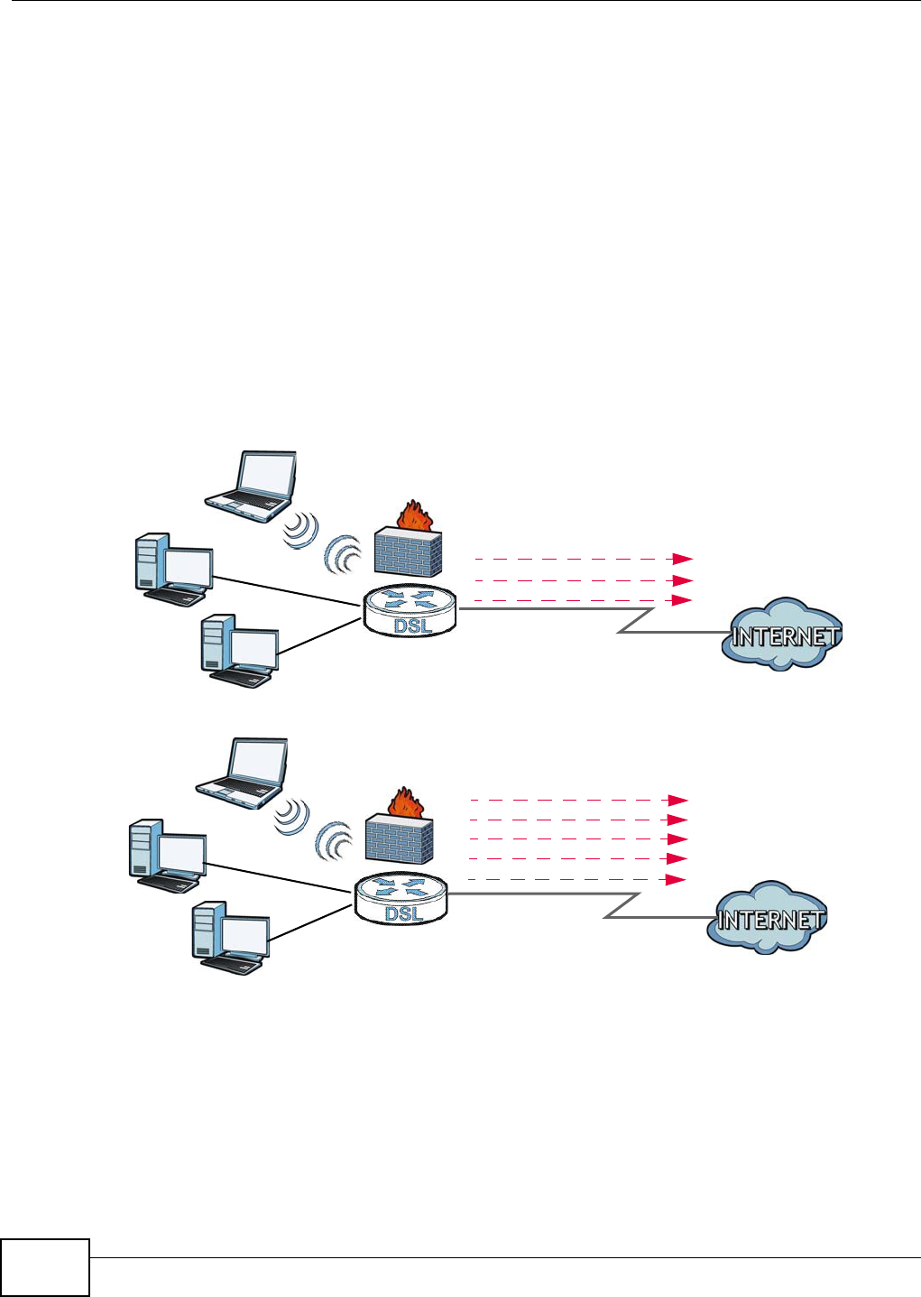
You can also configure IP filtering on the Device for secure Internet access. When the IP filter is on,
all incoming traffic from the Internet to your network is blocked by default unless it is initiated from
your network. This means that probes from the outside to your network are not allowed, but you
can safely browse the Internet and download files.
ADSL / VDSL
WLAN
PPPoE
IPoE
Bridging
WAN
ADSL
IPoA
WAN
LAN
LAN
WLAN
A
A
PPPoA
IPoE
PPPoE
Bridging
Chapter 1 Introducing the Device
VMG1312-B10C User’s Guide 19
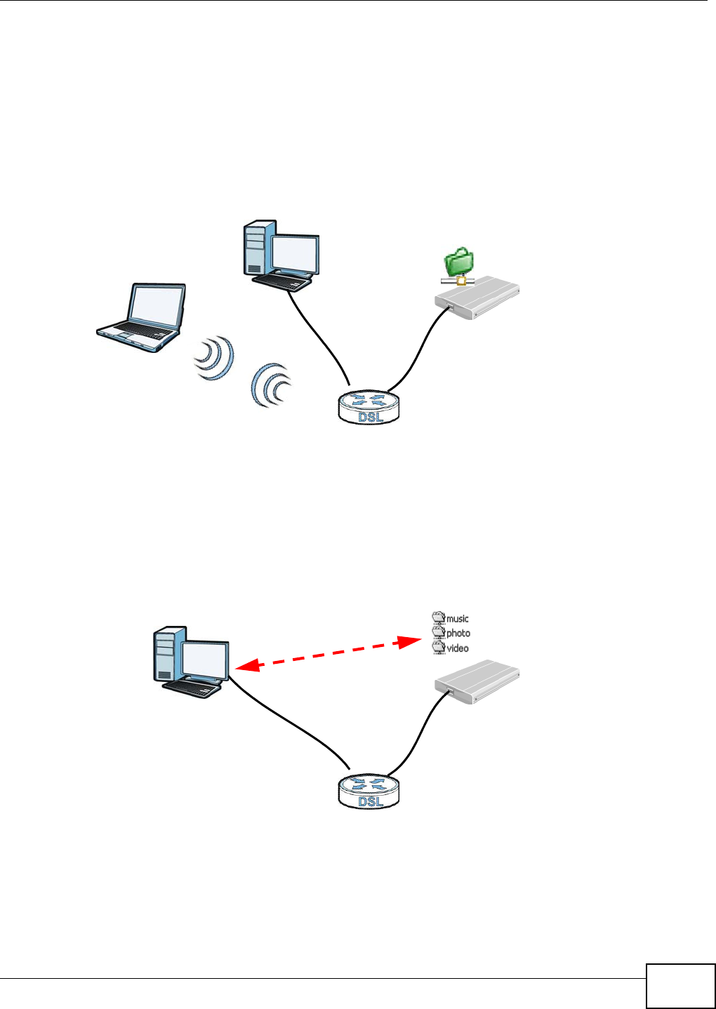
1.4.2 Device’s USB Support
The USB port of the Device is used for file-sharing.
File Sharing
Use the built-in USB 2.0 port to share files on a USB memory stick or a USB hard drive (B). You can
connect one USB hard drive to the Device at a time. Use FTP to access the files on the USB device.
Figure 2 USB File Sharing Application
Media Server
You can also use the Device as a media server. This lets anyone on your network play video, music,
and photos from a USB device (B) connected to the Device’s USB port (without having to copy them
to another computer).
Figure 3 USB Media Server Application
B
A
B
A
Chapter 1 Introducing the Device
VMG1312-B10C User’s Guide
20
1.5 LEDs (Lights)
The following table describes the behavior of the LEDs. None of the LEDs are on if the Device is not
receiving power.
1.6 The RESET Button
If you forget your password or cannot access the web configurator, you will need to use the RESET
button at the back of the device to reload the factory-default configuration file. This means that you
will lose all configurations that you had previously and the password will be reset to “1234”.
Table 1 LED Descriptions
LED COLOR STATUS DESCRIPTION
USB
Green On The Device recognizes a USB connection.
Blinking The Device is sending/receiving data to /from the USB device connected
to it.
Off The Device does not detect a USB connection.
DSL
Green On The ADSL line is up.
Blinking The Device is initializing the ADSL line.
Orange On The VDSL line is up.
Blinking The Device is initializing the VDSL line.
Off The DSL line is down.
WLAN/WPS
Green On The wireless network is activated.
Blinking The Device is communicating with other wireless clients.
Orange Blinking The Device is setting up a WPS connection.
Off The wireless network is not activated.
4~1
ETHERNET
Green On The Device has a successful 100 Mbps Ethernet connection with a device
on the Local Area Network (LAN).
Blinking The Device is sending or receiving data to/from the LAN at 100 Mbps.
Off The Device does not have an Ethernet connection with the LAN.
INTERNET
Green On The Device has an IP connection but no traffic.
Your device has a WAN IP address (either static or assigned by a DHCP
server), PPP negotiation was successfully completed (if used) and the
DSL connection is up.
Blinking The Device is sending or receiving IP traffic.
Off There is no Internet connection or the gateway is in bridged mode.
Red On The Device attempted to make an IP connection but failed. Possible
causes are no response from a DHCP server, no PPPoE response, PPPoE
authentication failed.
POWER
Green On The Device is receiving power and ready for use.
Blinking The Device is self-testing.
Red On The Device detected an error while self-testing, or there is a device
malfunction.
Off The Device is not receiving power.
Blinking Firmware upgrade is in progress.
Chapter 1 Introducing the Device
VMG1312-B10C User’s Guide 21
1Make sure the POW ER LED is on (not blinking).
2To set the device back to the factory default settings, press the RESET button for ten seconds or
until the POW ER LED begins to blink and then release it. When the POW ER LED begins to blink,
the defaults have been restored and the device restarts.
1.7 Wireless Access
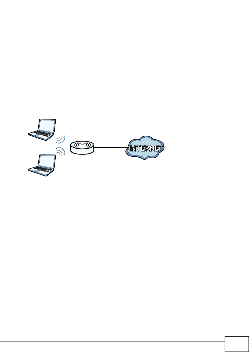
The Device is a wireless Access Point (AP) for wireless clients, such as notebook computers or
tablets. It allows them to connect to the Internet without having to rely on inconvenient Ethernet
cables.
You can configure your wireless network in either the built-in Web Configurator, or using the WPS
button.
Figure 4 Wireless Access Example
1.7.1 Using the WLAN/WPS Button
If the wireless network is turned off, press the W LAN / W PS button at the back of the Device for
one second. Once the W LAN / W PS LED turns green, the wireless network is active.
You can also use the W LAN / W PS button to quickly set up a secure wireless connection between
the Device and a WPS-compatible client by adding one device at a time.
To activate WPS:
1Make sure the POW ER LED is on and not blinking.
2Press the W LAN / W PS button for five seconds and release it.
3Press the WPS button on another WPS-enabled device within range of the Device. The W LAN / W PS
LED flashes orange while the Device sets up a WPS connection with the other wireless device.
4Once the connection is successfully made, the W LAN / W PS LED shines green.
To turn off the wireless network, press the W LAN / W PS button on the front of the Device for one
second. The W LAN / W PS LED turns off when the wireless network is off.

Chapter 1 Introducing the Device
VMG1312-B10C User’s Guide
22

VMG1312-B10C User’s Guide 23
CHAPTER 2
The Web Configurator
2.1 Overview
The web configurator is an HTML-based management interface that allows easy device setup and
management via Internet browser. Use Internet Explorer 6.0 and later versions or Mozilla Firefox 3
and later versions or Safari 2.0 and later versions. The recommended screen resolution is 1024 by
768 pixels.
In order to use the web configurator you need to allow:
• Web browser pop-up windows from your device. Web pop-up blocking is enabled by default in
Windows XP SP (Service Pack) 2.
• JavaScript (enabled by default).
• Java permissions (enabled by default).
2.1.1 Accessing the Web Configurator
1Make sure your Device hardware is properly connected (refer to the Quick Start Guide).
2Launch your web browser. If the Device does not automatically re-direct you to the login screen, go
to http://192.168.1.1.
3A password screen displays. To access the administrative web configurator and manage the Device,
type the default username adm in and password 1 2 3 4 in the password screen and click Login. If
advanced account security is enabled (see Section 27.2 on page 241) the number of dots that
appears when you type the password changes randomly to prevent anyone watching the password
field from knowing the length of your password. If you have changed the password, enter your
password and click Login.
Figure 5 Password Screen
Chapter 2 The Web Configurator
VMG1312-B10C User’s Guide
24
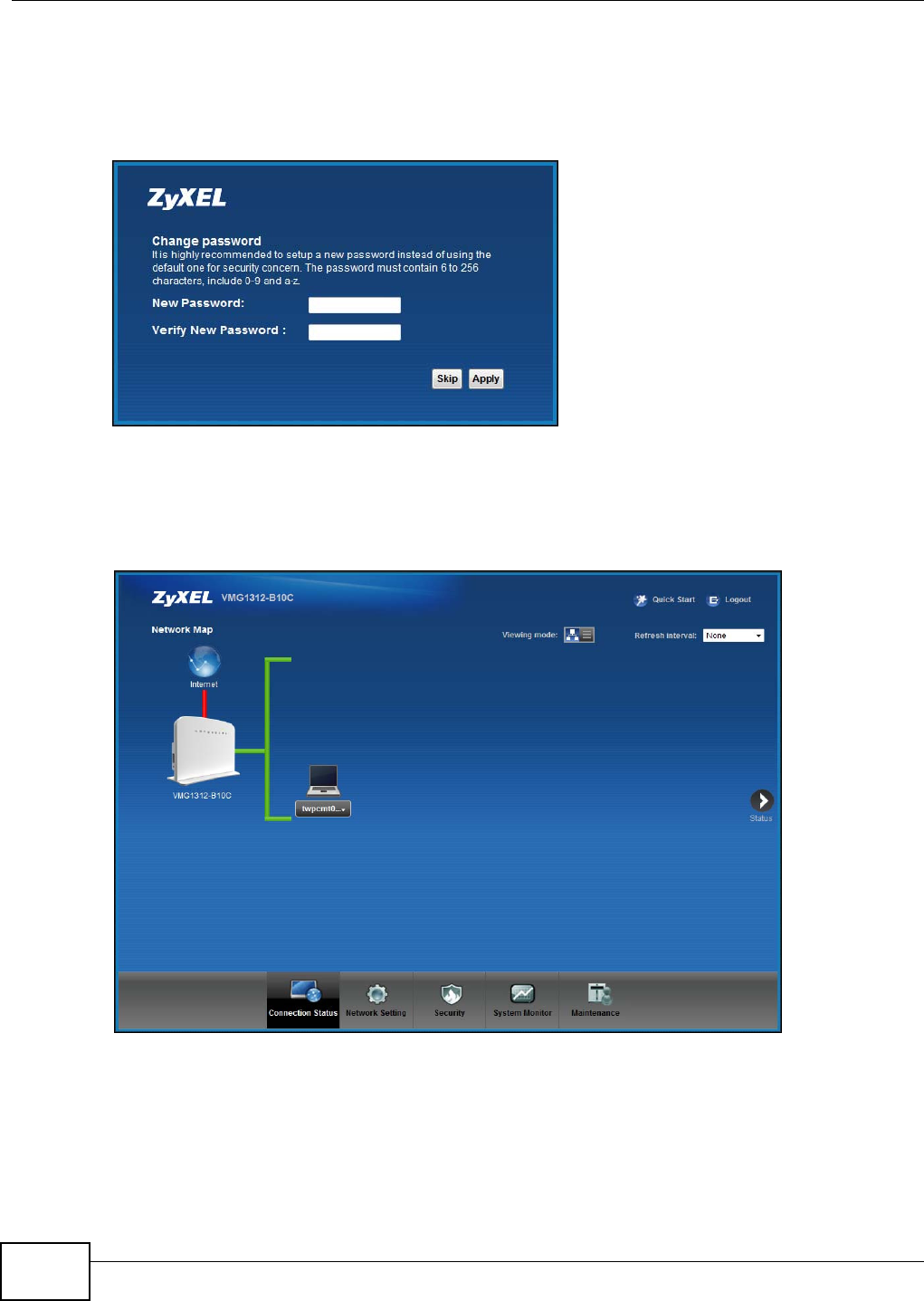
4The following screen displays if you have not yet changed your password. It is strongly
recommended you change the default password. Enter a new password, retype it to confirm and
click Apply; alternatively click Sk ip to proceed to the main menu if you do not want to change the
password now.
Figure 6 Change Password Screen
5The Qu ick St ar t W iza r d screen appears. You can configure the Device’s time zone, basic Internet
access, and wireless settings. See Chapter 3 on page 31 for more information.
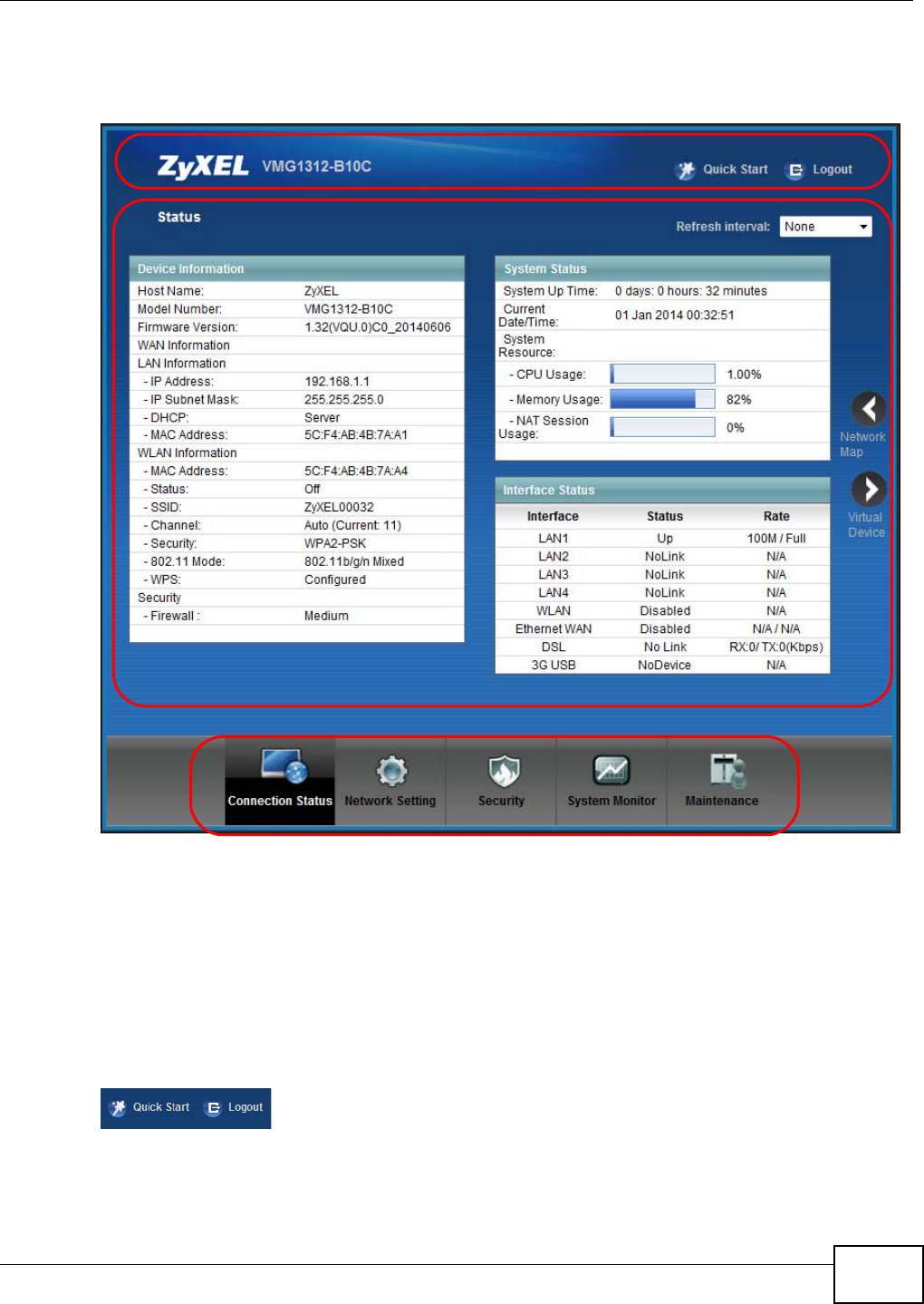
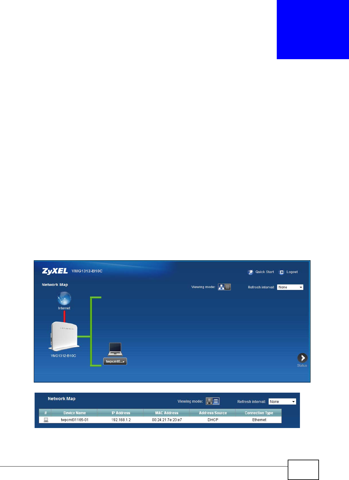
6After you finished or closed the Quick St ar t W iza r d screen, the Net w or k Ma p page appears.
Figure 7 Network Map
7Click St a t u s to display the St a t u s screen, where you can view the Device’s interface and system
information.
Chapter 2 The Web Configurator
VMG1312-B10C User’s Guide 25
2.2 Web Configurator Layout
Figure 8 Screen Layout
As illustrated above, the main screen is divided into these parts:
•A - title bar
•B - main window
•C - navigation panel
2.2.1 Title Bar
The title bar provides some icons in the upper right corner.
B
C
A

Chapter 2 The Web Configurator
VMG1312-B10C User’s Guide
26
The icons provide the following functions.
2.2.2 Main Window
The main window displays information and configuration fields. It is discussed in the rest of this
document.
After you click St a t u s on the Conn e ct ion St a t us page, the St a t u s screen is displayed. See
Chapter 4 on page 36 for more information about the St a t u s screen.
Table 2 Web Configurator Icons in the Title Bar
ICON DESCRIPTION
Quick Start Click this icon to open screens where you can configure the Device’s time zone Internet
access, and wireless settings.
Logout Click this icon to log out of the web configurator.
Chapter 2 The Web Configurator
VMG1312-B10C User’s Guide 27
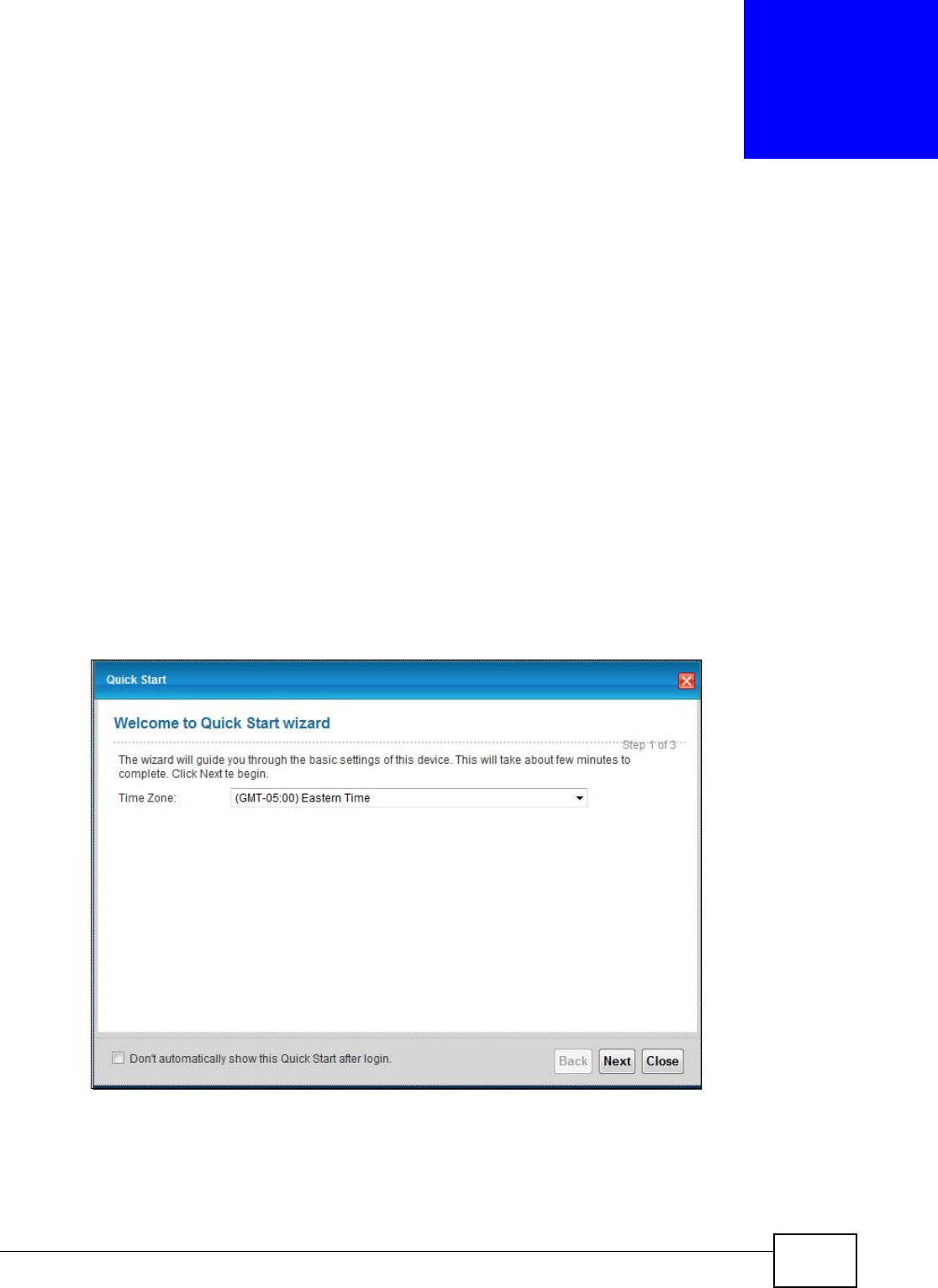
If you click Virt ual D evice on the Syst e m I nfo screen, a visual graphic appears, showing the
connection status of the Device’s ports. The connected ports are in color and disconnected ports are
gray.
Figure 9 Virtual Device
2.2.3 Navigation Panel
Use the menu items on the navigation panel to open screens to configure Device features. The
following tables describe each menu item.
Table 3 Navigation Panel Summary
LINK TAB FUNCTION
Connection Status This screen shows the network status of the Device and computers/
devices connected to it.
Network Setting

Chapter 2 The Web Configurator
VMG1312-B10C User’s Guide
28
Broadband Broadband Use this screen to view and configure ISP parameters, WAN IP
address assignment, and other advanced properties. You can also add
new WAN connections.
3G Backup Use this screen to configure 3G WAN connection.
Advanced Use this screen to enable or disable PTM over ADSL, Annex M/Annex
J, and DSL PhyR functions.
8021x Use this screen to view and configure the IEEE 802.1x settings on the
Device.
Ethernet WAN Use this screen to configure a LAN port as an ethernet WAN port
Wireless General Use this screen to configure the wireless LAN settings and WLAN
authentication/security settings.
More AP Use this screen to configure multiple BSSs on the Device.
MAC
Authentication
Use this screen to block or allow wireless traffic from wireless devices
of certain SSIDs and MAC addresses to the Device.
WPS Use this screen to configure and view your WPS (Wi-Fi Protected
Setup) settings.
WMM Use this screen to enable or disable Wi-Fi MultiMedia (WMM).
WDS Use this screen to set up Wireless Distribution System (WDS) links to
other access points.
Others Use this screen to configure advanced wireless settings.
Channel Status Use this screen to scan wireless LAN channel noises and view the
results.
Home
Networking LAN Setup Use this screen to configure LAN TCP/IP settings, and other advanced
properties.
Static DHCP Use this screen to assign specific IP addresses to individual MAC
addresses.
UPnP Use this screen to turn UPnP and UPnP NAT-T on or off.
Additional
Subnet
Use this screen to configure IP alias and public static IP.
STB Vendor ID Use this screen to have the Device automatically create static DHCP
entries for Set Top Box (STB) devices when they request IP
addresses.
LAN VLAN Use this screen to control the VLAN ID and IEEE 802.1p priority tags
of traffic sent out through individual LAN ports.
Routing Static Route Use this screen to view and set up static routes on the Device.
Policy
Forwarding
Use this screen to configure policy routing on the Device.
RIP Use this screen to configure Routing Information Protocol to
exchange routing information with other routers.
QoS General Use this screen to enable QoS and traffic prioritizing. You can also
configure the QoS rules and actions.
Queue Setup Use this screen to configure QoS queues.
Class Setup Use this screen to define a classifier.
Policer Setup Use these screens to configure QoS policers.
Monitor Use this screen to view QoS packets statistics.
Table 3 Navigation Panel Summary (continued)
LINK TAB FUNCTION

Chapter 2 The Web Configurator
VMG1312-B10C User’s Guide 29
NAT Port Forwarding Use this screen to make your local servers visible to the outside
world.
Applications Use this screen to configure servers behind the Device.
Port Triggering Use this screen to change your Device’s port triggering settings.
DMZ Use this screen to configure a default server which receives packets
from ports that are not specified in the Port For w a r ding screen.
ALG Use this screen to enable or disable SIP ALG.
Address Mapping Use this screen to change your Device’s address mapping settings.
DNS DNS Entry Use this screen to view and configure DNS routes.
Dynamic DNS Use this screen to allow a static hostname alias for a dynamic IP
address.
Interface
Group Use this screen to map a port to a PVC or bridge group.
USB Device File Sharing Use this screen to enable file sharing via the Device.
Media Server Use this screen to use the Device as a media server.
Printer Server Use this screen to enable the print server on the Device and get the
model name of the associated printer.
Security Settings
Firewall General Use this screen to configure the security level of your firewall.
Service Use this screen to add Internet services and configure firewall rules.
Access Control Use this screen to enable specific traffic directions for network
services.
DoS Use this screen to activate protection against Denial of Service (DoS)
attacks.
MAC Filter Use this screen to block or allow traffic from devices of certain MAC
addresses to the Device.
Parental
Control Use this screen to block web sites with the specific URL.
Scheduler Rule Use this screen to configure the days and times when a configured
restriction (such as parental control) is enforced.
Certificates Local Certificates Use this screen to view a summary list of certificates and manage
certificates and certification requests.
Trusted CA Use this screen to view and manage the list of the trusted CAs.
IPSec VPN Use this screen to add or edit VPN policies.
System Monitor
Log System Log Use this screen to view the status of events that occurred to the
Device. You can export or e-mail the logs.
Security Log Use this screen to view the login record of the Device. You can export
or e-mail the logs.
Traffic Status WAN Use this screen to view the status of all network traffic going through
the WAN port of the Device.
LAN Use this screen to view the status of all network traffic going through
the LAN ports of the Device.
NAT Use this screen to view NAT statistics for connected hosts.
ARP Table Use this screen to view the ARP table. It displays the IP and MAC
address of each DHCP connection.
Table 3 Navigation Panel Summary (continued)
LINK TAB FUNCTION

Chapter 2 The Web Configurator
VMG1312-B10C User’s Guide
30
IGMP Group
Status Use this screen to view the status of all IGMP settings on the Device.
xDSL Statistics Use this screen to view the Device’s xDSL traffic statistics.
3G Monitor Use this screen to look at 3G Internet connection status.
Maintenance
User Account Use this screen to change user password on the Device.
Remote MGMT Use this screen to enable specific traffic directions for network
services.
TR-069 Client Use this screen to configure the Device to be managed by an Auto
Configuration Server (ACS).
TR-064 Client Use this screen to enable management via TR-064 on the LAN.
Time Use this screen to change your Device’s time and date.
Email
Notification Use this screen to configure up to two mail servers and sender
addresses on the Device.
Log Setting Use this screen to change your Device’s log settings.
Firmware
Upgrade Use this screen to upload firmware to your device.
Configuration Use this screen to backup and restore your device’s configuration
(settings) or reset the factory default settings.
Reboot Use this screen to reboot the Device without turning the power off.
Diagnostic Ping &
Traceroute &
Nslookup
Use this screen to identify problems with the DSL connection. You can
use Ping, TraceRoute, or Nslookup to help you identify problems.
802.1ag Use this screen to configure CFM (Connectivity Fault Management)
MD (maintenance domain) and MA (maintenance association),
perform connectivity tests and view test reports.
OAM Ping Use this screen to view information to help you identify problems with
the DSL connection.
Table 3 Navigation Panel Summary (continued)
LINK TAB FUNCTION
VMG1312-B10C User’s Guide 31
CHAPTER 3
Quick Start
3.1 Overview
Use the Quick Start screens to configure the Device’s time zone, basic Internet access, and wireless
settings.
Note: See the technical reference chapters (starting on page 33) for background
information on the features in this chapter.
3.2 Quick Start Setup
1The Quick Start Wizard appears automatically after login. Or you can click the Click St a r t icon in
the top right corner of the web configurator to open the quick start screens. Select the time zone of
the Device’s location and click N e x t .
Figure 10 Time Zone
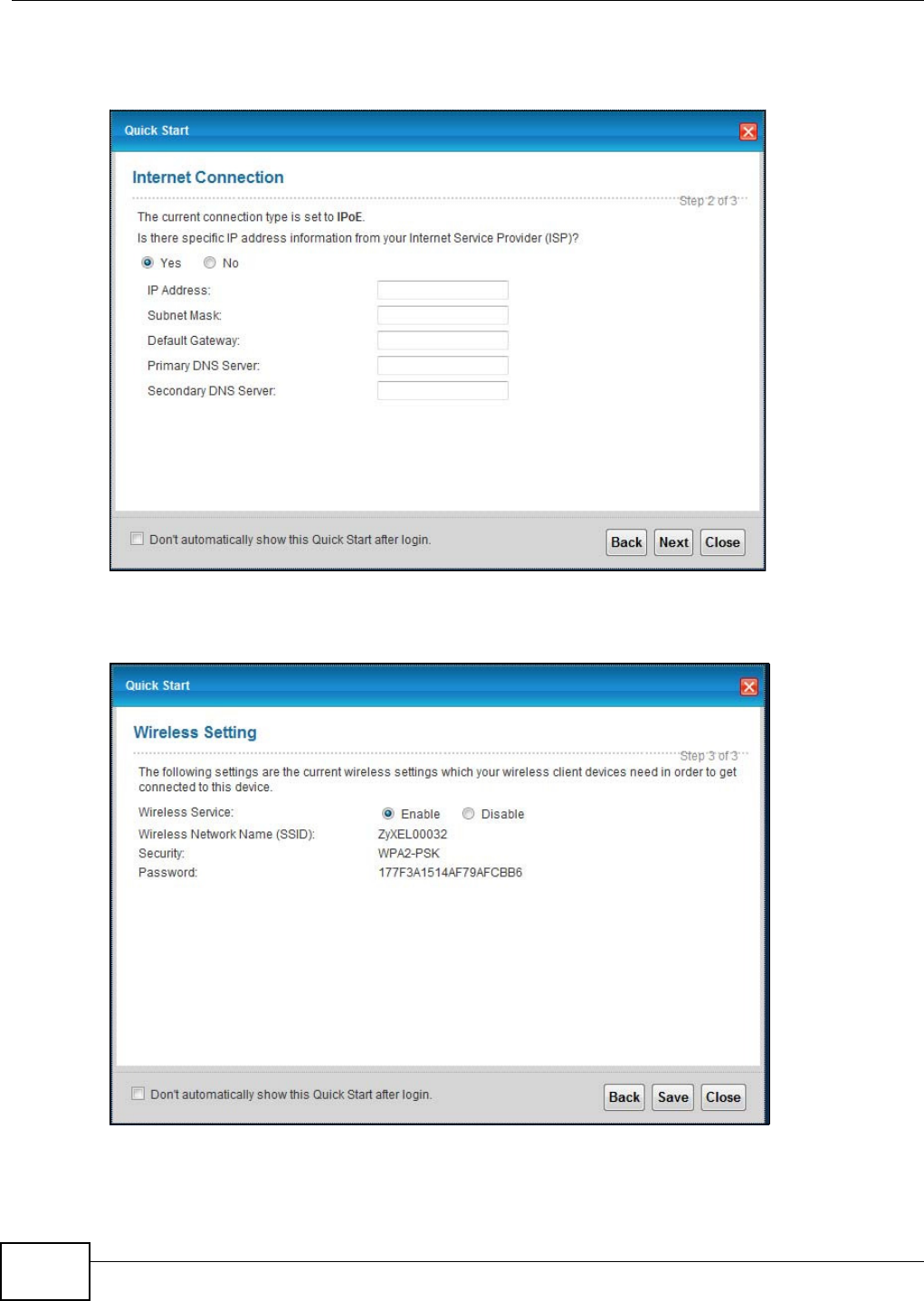
Chapter 3 Quick Start
VMG1312-B10C User’s Guide
32
2Enter your Internet connection information in this screen. The screen and fields to enter may vary
depending on your current connection type. Click N e xt . Click N e x t .
Figure 11 Internet Connection
3Turn the wireless LAN on or off. If you keep it on, record the security settings so you can configure
your wireless clients to connect to the Device. Click Save.
Figure 12 Internet Connection
4Your Device saves your settings and attempts to connect to the Internet.

33
PART II
Technical Reference

34
VMG1312-B10C User’s Guide 35
CHAPTER 4
Network Map and Status Screens
4.1 Overview
After you log into the Web Configurator, the N et w or k M a p screen appears. This shows the network
connection status of the Device and clients connected to it.
You can use the St a t u s screen to look at the current status of the Device, system resources, and
interfaces (LAN, WAN, and WLAN).
4.2 The Network Map Screen
Use this screen to view the network connection status of the device and its clients. A warning
message appears if there is a connection problem.
If you prefer to view the status in a list, click List View in the View in g M ode selection box. You
can configure how often you want the Device to update this screen in Refresh I nt erval.
Figure 13 Network Map: Icon Mode
Figure 14 Network Map: List Mode
Chapter 4 Network Map and Status Screens
VMG1312-B10C User’s Guide
36
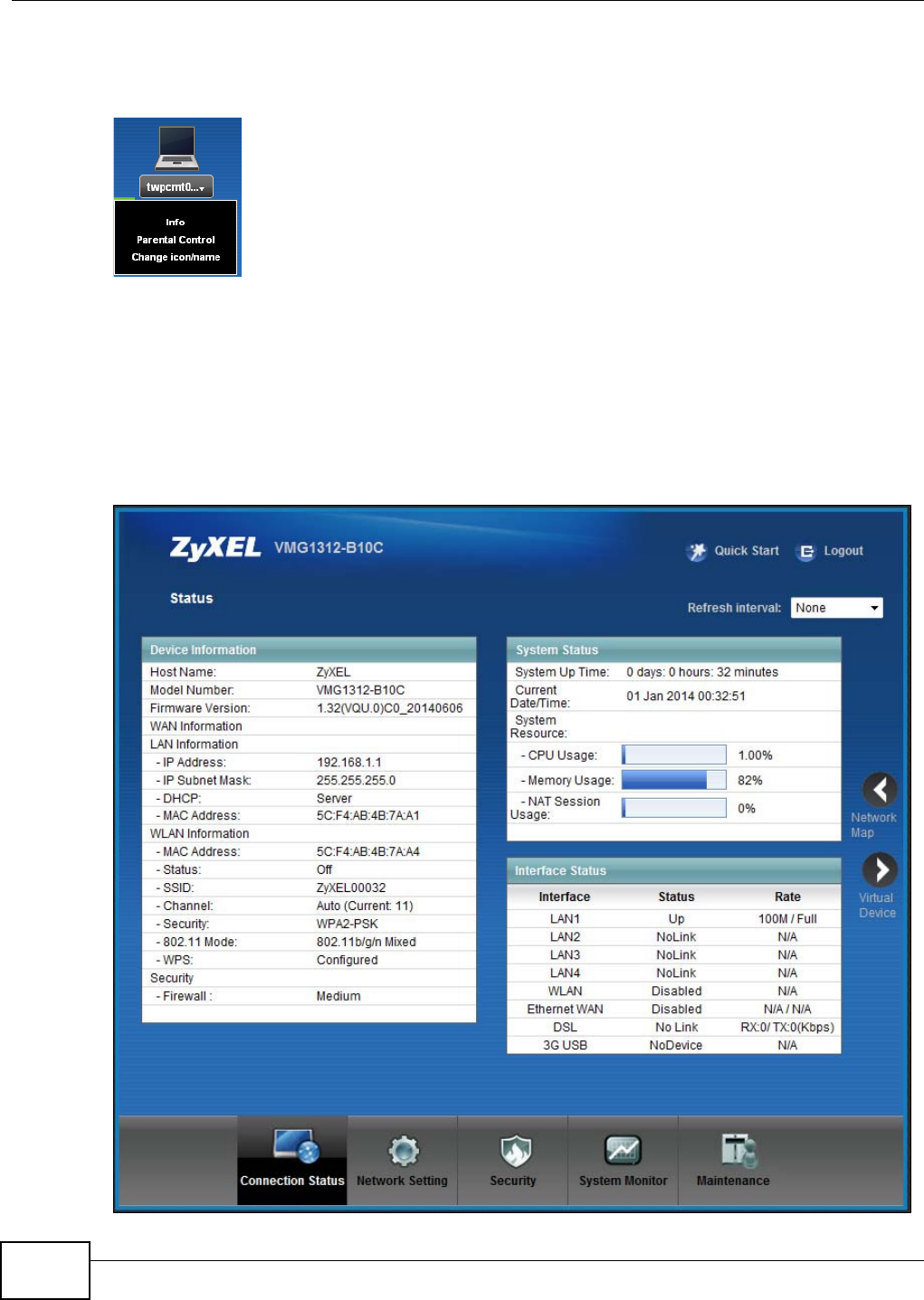
In I con M ode, if you want to view information about a client, click the client’s name and I nfo.
Click the IP address if you want to change it. If you want to change the name or icon of the client,
click Cha nge icon/ na m e .
In List M ode , you can also view the client’s information.
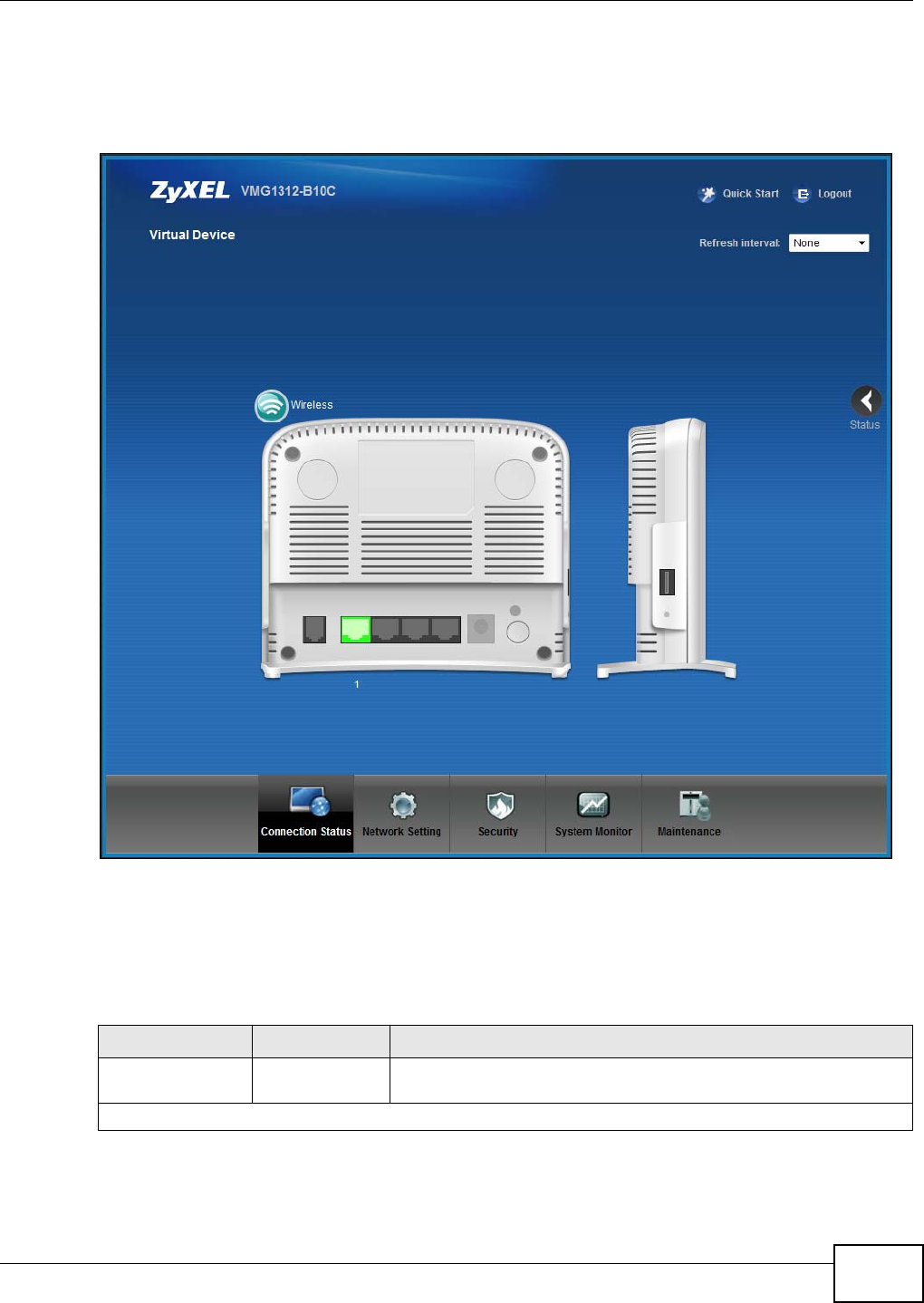
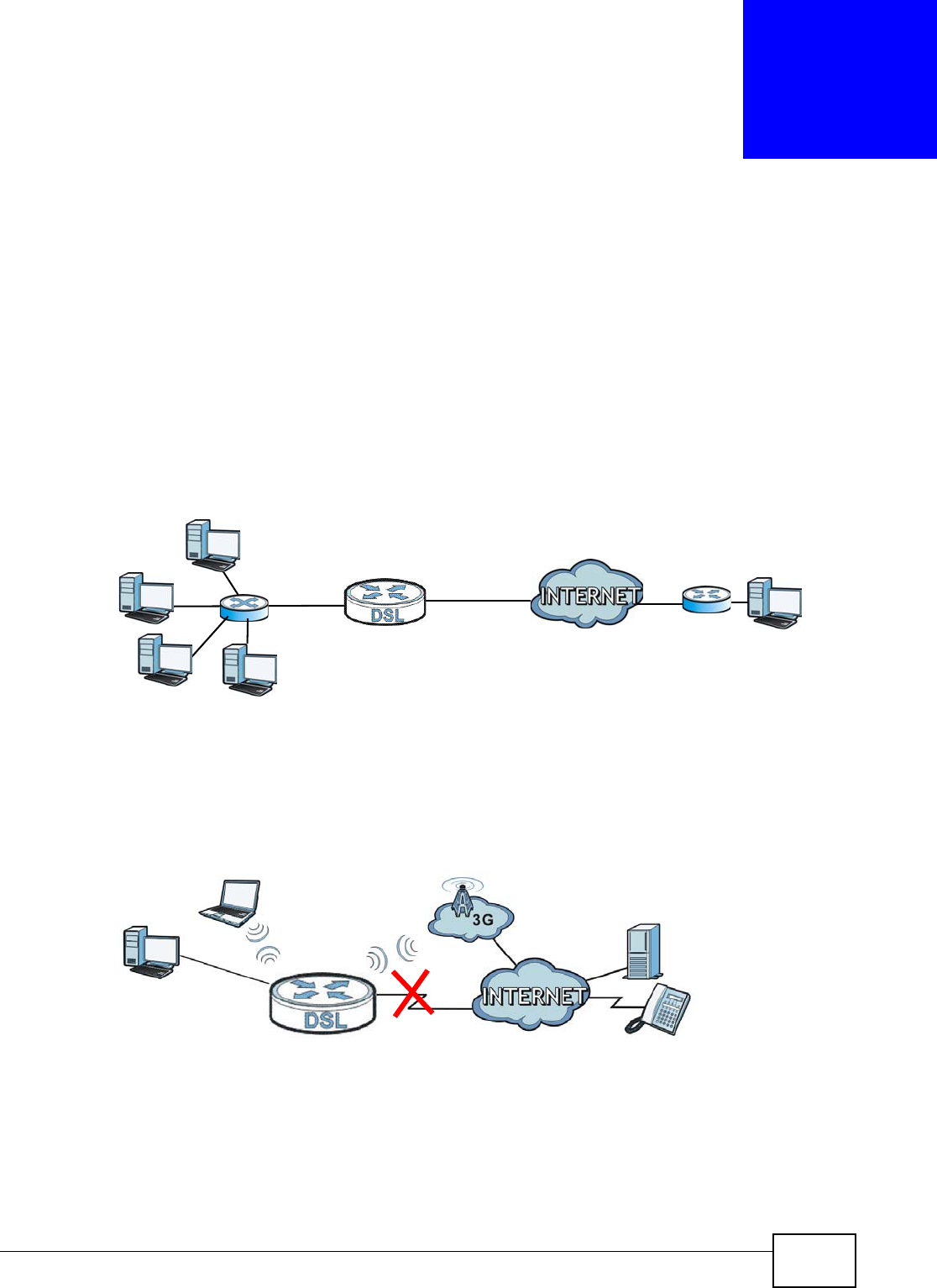
4.3 The Status Screen
Use this screen to view the status of the Device. Click St a t u s to open this screen.
Figure 15 Status Screen

Chapter 4 Network Map and Status Screens
VMG1312-B10C User’s Guide 37
Each field is described in the following table.
Table 4 Status Screen
LABEL DESCRIPTION
Refresh Interval Select how often you want the Device to update this screen.
Device Information
Host Name This field displays the Device system name. It is used for identification.
Model
Number This shows the model number of your Device.
Firmware
Version This is the current version of the firmware inside the Device.
WAN Information (These fields display when you have a WAN connection.)
WAN Type This field displays the current WAN connection type.
MAC Address This shows the WAN Ethernet adapter MAC (Media Access Control) Address of your Device.
IP Address This field displays the current IP address of the Device in the WAN. Click Re le a se to release
your IP address to 0.0.0.0. If you want to renew your IP address, click Ren e w .
IP Subnet Mask This field displays the current subnet mask in the WAN.
Encapsulation This field displays the current encapsulation method.
LAN Information
IP Address This is the current IP address of the Device in the LAN.
IP Subnet
Mask This is the current subnet mask in the LAN.
DHCP This field displays what DHCP services the Device is providing to the LAN. Choices are:
Ser v er - The Device is a DHCP server in the LAN. It assigns IP addresses to other
computers in the LAN.
Rela y - The Device acts as a surrogate DHCP server and relays DHCP requests and
responses between the remote server and the clients.
N on e - The Device is not providing any DHCP services to the LAN.
MAC
Address This shows the LAN Ethernet adapter MAC (Media Access Control) Address of your Device.
WLAN Information
MAC
Address This shows the wireless adapter MAC (Media Access Control) Address of your Device.
Status This displays whether WLAN is activated.
SSID This is the descriptive name used to identify the Device in a wireless LAN.
Channel This is the channel number used by the Device now.
Security This displays the type of security mode the Device is using in the wireless LAN.
802.11
Mode This displays the type of 802.11 mode the Device is using in the wireless LAN.
WPS This displays whether WPS is activated.
Security
Firewall This displays the firewall’s current security level.
System Status
System Up
Time This field displays how long the Device has been running since it last started up. The Device
starts up when you plug it in, when you restart it (Mainten a nce > Re boot ), or when you
reset it.
Current
Date/Time This field displays the current date and time in the Device. You can change this in
Mainten a nce > Tim e Set t ing.

Chapter 4 Network Map and Status Screens
VMG1312-B10C User’s Guide
38
System Resource
CPU Usage This field displays what percentage of the Device’s processing ability is currently used. When
this percentage is close to 100%, the Device is running at full load, and the throughput is
not going to improve anymore. If you want some applications to have more throughput, you
should turn off other applications (for example, using QoS; see Chapter 9 on page 131).
Memory
Usage This field displays what percentage of the Device’s memory is currently used. Usually, this
percentage should not increase much. If memory usage does get close to 100%, the Device
is probably becoming unstable, and you should restart the device. See Section 35.2 on page
261, or turn off the device (unplug the power) for a few seconds.
Table 4 Status Screen (continued)
LABEL DESCRIPTION
VMG1312-B10C User’s Guide 39
CHAPTER 5
Broadband
5.1 Overview
This chapter discusses the Device’s Broadba n d screens. Use these screens to configure your
Device for Internet access.
A WAN (Wide Area Network) connection is an outside connection to another network or the
Internet. It connects your private networks, such as a LAN (Local Area Network) and other
networks, so that a computer in one location can communicate with computers in other locations.
Figure 16 LAN and WAN
3G (third generation) standards for the sending and receiving of voice, video, and data in a mobile
environment.
You can attach a 3G wireless adapter to the USB port and set the Device to use this 3G connection
as your WAN or a backup when the wired WAN connection fails.
Figure 17 3G WAN Connection
5.1.1 What You Can Do in this Chapter
•Use the Broa dba n d screen to view, remove or add a WAN interface. You can also configure the
WAN settings on the Device for Internet access (Section 5.2 on page 42).
•Use the 3 G Ba ckup screen to configure 3G WAN connection (Section 5.3 on page 51).
WAN

Chapter 5 Broadband
VMG1312-B10C User’s Guide
40
•Use the Adva n ce d screen to enable or disable PTM over ADSL, Annex M/Annex J, and DSL PhyR
functions (Section 5.4 on page 55).
•Use the 8 0 2 1 x screen to view and configure the IEEE 802.1X settings on the Device (Section 5.5
on page 56).
5.1.2 What You Need to Know
The following terms and concepts may help as you read this chapter.
Encapsulation Method
Encapsulation is used to include data from an upper layer protocol into a lower layer protocol. To set
up a WAN connection to the Internet, you need to use the same encapsulation method used by your
ISP (Internet Service Provider). If your ISP offers a dial-up Internet connection using PPPoE (PPP
over Ethernet), they should also provide a username and password (and service name) for user
authentication.
WAN IP Address
The WAN IP address is an IP address for the Device, which makes it accessible from an outside
network. It is used by the Device to communicate with other devices in other networks. It can be
static (fixed) or dynamically assigned by the ISP each time the Device tries to access the Internet.
If your ISP assigns you a static WAN IP address, they should also assign you the subnet mask and
DNS server IP address(es).
Table 5 WAN Setup Overview
LAYER-2 INTERFACE INTERNET CONNECTION
CONNECTION DSL LINK
TYPE MODE ENCAPSULATION CONNECTION SETTINGS
ADSL/VDSL
over PTM
N/A Routing PPPoE PPP information, IPv4/IPv6 IP address,
routing feature, DNS server, VLAN,
QoS, and MTU
IPoE IPv4/IPv6 IP address, routing feature,
DNS server, VLAN, QoS, and MTU
Bridge N/A VLAN and QoS
ADSL over ATM EoA Routing PPPoE/PPP0A ATM PVC configuration, PPP
information, IPv4/IPv6 IP address,
routing feature, DNS server, VLAN,
QoS, and MTU
IPoE/IPoA ATM PVC configuration, IPv4/IPv6 IP
address, routing feature, DNS server,
VLAN, QoS, and MTU
Bridge N/A ATM PVC configuration, and QoS
EtherWAN N/A Routing PPPoE PPP user name and password, WAN
IPv4/IPv6 IP address, routing feature,
DNS server, VLAN, QoS, and MTU
IPoE WAN IPv4/IPv6 IP address, NAT, DNS
server and routing feature
Bridge N/A VLAN and QoS

Chapter 5 Broadband
VMG1312-B10C User’s Guide 41
ATM
Asynchronous Transfer Mode (ATM) is a WAN networking technology that provides high-speed data
transfer. ATM uses fixed-size packets of information called cells. With ATM, a high QoS (Quality of
Service) can be guaranteed. ATM uses a connection-oriented model and establishes a virtual circuit
(VC) between Finding Out More
PTM
Packet Transfer Mode (PTM) is packet-oriented and supported by the VDSL2 standard. In PTM,
packets are encapsulated directly in the High-level Data Link Control (HDLC) frames. It is designed
to provide a low-overhead, transparent way of transporting packets over DSL links, as an
alternative to ATM.
3G
3G (Third Generation) is a digital, packet-switched wireless technology. Bandwidth usage is
optimized as multiple users share the same channel and bandwidth is only allocated to users when
they send data. It allows fast transfer of voice and non-voice data and provides broadband Internet
access to mobile devices.
IPv6 Introduction
IPv6 (Internet Protocol version 6), is designed to enhance IP address size and features. The
increase in IPv6 address size to 128 bits (from the 32-bit IPv4 address) allows up to 3.4 x 1038 IP
addresses. The Device can use IPv4/IPv6 dual stack to connect to IPv4 and IPv6 networks, and
supports IPv6 rapid deployment (6RD).
IPv6 Addressing
The 128-bit IPv6 address is written as eight 16-bit hexadecimal blocks separated by colons (:). This
is an example IPv6 address 2001:0db8:1a2b:0015:0000:0000:1a2f:0000.
IPv6 addresses can be abbreviated in two ways:
• Leading zeros in a block can be omitted. So
2001:0db8:1a2b:0015:0000:0000:1a2f:0000 can be written as
2001:db8:1a2b:15:0:0:1a2f:0.
• Any number of consecutive blocks of zeros can be replaced by a double colon. A double
colon can only appear once in an IPv6 address. So
2001:0db8:0000:0000:1a2f:0000:0000:0015 can be written as
2001:0db8::1a2f:0000:0000:0015, 2001:0db8:0000:0000:1a2f::0015,
2001:db8::1a2f:0:0:15 or 2001:db8:0:0:1a2f::15.
IPv6 Prefix and Prefix Length
Similar to an IPv4 subnet mask, IPv6 uses an address prefix to represent the network address. An
IPv6 prefix length specifies how many most significant bits (start from the left) in the address
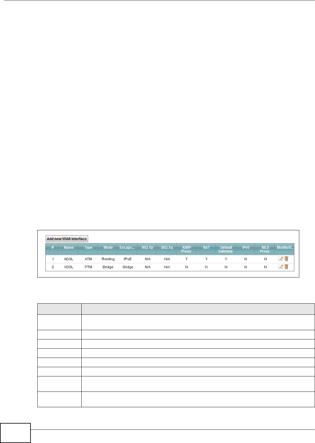
Chapter 5 Broadband
VMG1312-B10C User’s Guide
42
compose the network address. The prefix length is written as “/x” where x is a number. For
example,
2001:db8:1a2b:15::1a2f:0/32
means that the first 32 bits (2001:db8) is the subnet prefix.
IPv6 Subnet Masking
Both an IPv6 address and IPv6 subnet mask compose of 128-bit binary digits, which are divided
into eight 16-bit blocks and written in hexadecimal notation. Hexadecimal uses four bits for each
character (1 ~ 10, A ~ F). Each block’s 16 bits are then represented by four hexadecimal
characters. For example, FFFF:FFFF:FFFF:FFFF:FC00:0000:0000:0000.
5.1.3 Before You Begin
You need to know your Internet access settings such as encapsulation and WAN IP address. Get this
information from your ISP.
5.2 The Broadband Screen
Use this screen to change your Device’s Internet access settings. Click Net w or k Set t ing >
Broadba n d from the menu. The summary table shows you the configured WAN services
(connections) on the Device.
Figure 18 Network Setting > Broadband
The following table describes the labels in this screen.
Table 6 Network Setting > Broadband
LABEL DESCRIPTION
Add new WAN
Interface
Click this button to create a new connection.
# This is the index number of the entry.
Name This is the service name of the connection.
Type This shows whether it is an ATM, PTM, or Ethernet connection.
Mode This shows whether the connection is in routing or bridge mode.
Encapsulation This is the method of encapsulation used by this connection.
802.1p This indicates the 802.1p priority level assigned to traffic sent through this connection. This
displays N / A when there is no priority level assigned.
802.1q This indicates the VLAN ID number assigned to traffic sent through this connection. This
displays N / A when there is no VLAN ID number assigned.

Chapter 5 Broadband
VMG1312-B10C User’s Guide 43
IGMP Proxy This shows whether the Device act as an IGMP proxy on this connection.
NAT This shows whether NAT is activated or not for this connection.
Default
Gateway
This shows whether the Device use the WAN interface of this connection as the system
default gateway.
IPv6 This shows whether IPv6 is activated or not for this connection. IPv6 is not available when
the connection uses the bridging service.
MLD Proxy This shows whether Multicast Listener Discovery (MLD) is activated or not for this
connection. MLD is not available when the connection uses the bridging service.
Modify/Delete Click the Edit icon to configure the WAN connection.
Click the D ele t e icon to remove the WAN connection.
Table 6 Network Setting > Broadband (continued)
LABEL DESCRIPTION
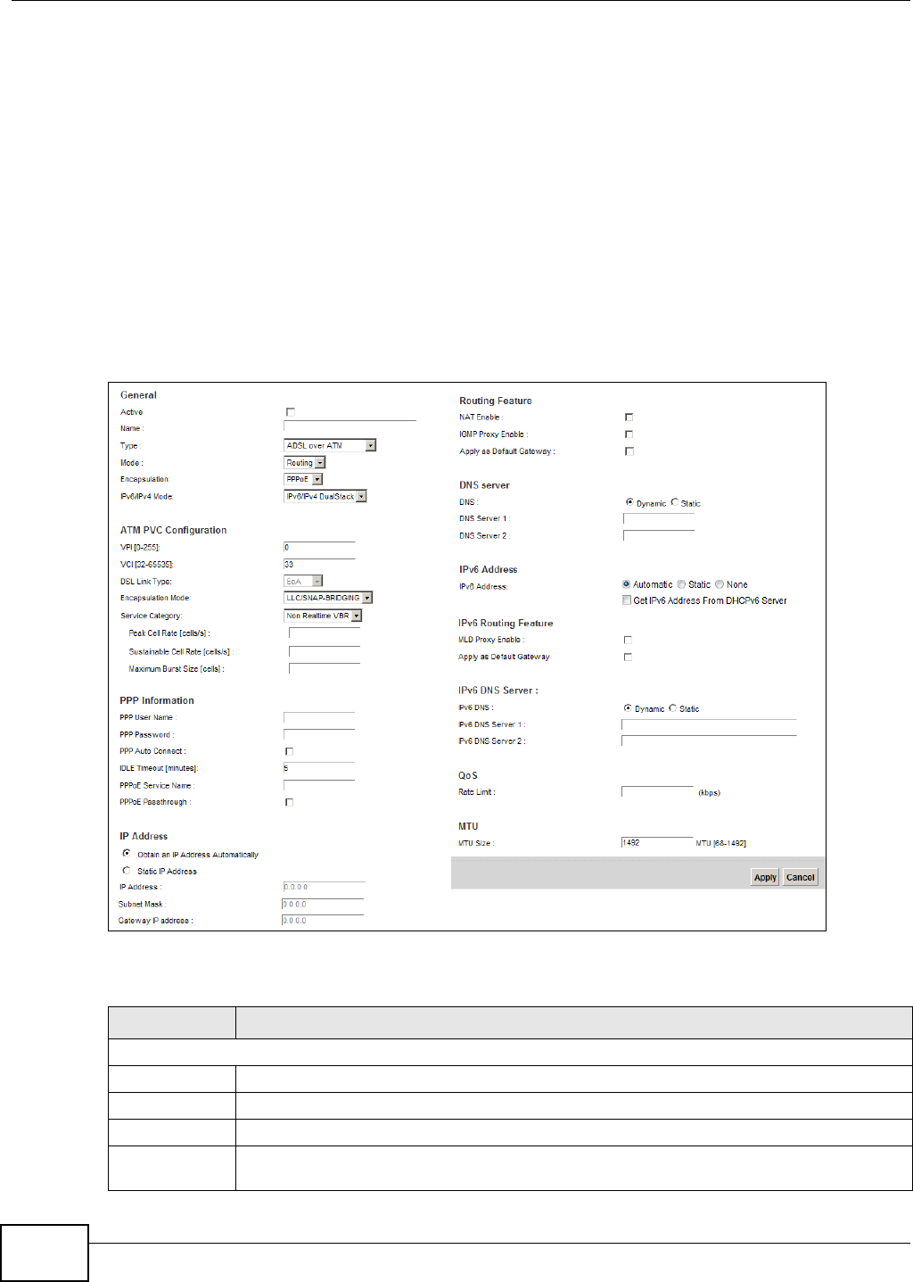
Chapter 5 Broadband
VMG1312-B10C User’s Guide
44
5.2.1 Add/Edit Internet Connection
Click Add n e w W AN I n t e r fa ce in the Broadba n d screen or the Edit icon next to an existing WAN
interface to configure a WAN connection. The screen varies depending on the interface type, mode,
encapsulation, and IPv6/IPv4 mode you select.
5.2.1.1 Routing Mode
Use Rou t ing mode if your ISP give you one IP address only and you want multiple computers to
share an Internet account.
The following example screen displays when you select the ADSL over ATM connection type,
Rou t in g mode, and PPPoE encapsulation. The screen varies when you select other interface type,
encapsulation, and IPv6/IPv4 mode.
Figure 19 Routing Mode
The following table describes the labels in this screen.
Table 7 Routing Mode
LABEL DESCRIPTION
General
Active Select this to activate the WAN configuration settings.
Name Specify a descriptive name for this connection.
Type Select whether it is an ADSL/VDSL over PTM, ADSL over ATM connection or Ethernet.
Mode Select Ro ut in g if your ISP give you one IP address only and you want multiple computers to
share an Internet account.

Chapter 5 Broadband
VMG1312-B10C User’s Guide 45
Encapsulation Select the method of encapsulation used by your ISP from the drop-down list box. This
option is available only when you select Rou t in g in the Mode field.
The choices depend on the connection type you selected. If your connection type is ADSL/
VD SL over PTM, the choices are PPPoE and I PoE. If your connection type is AD SL ove r
ATM , the choices are PPPoE, PPPoA, I PoE and I PoA.
IPv6/IPv4 Mode Select I Pv 4 On ly if you want the Device to run IPv4 only.
Select I Pv6 / I Pv4 D ualSt a ck to allow the Device to run IPv4 and IPv6 at the same time.
Select I Pv6 On ly if you want the Device to run IPv6 only.
ATM PVC Configuration (These fields appear when the Type is set to ADSL ove r ATM.)
VPI The valid range for the VPI is 0 to 255. Enter the VPI assigned to you.
VCI The valid range for the VCI is 32 to 65535 (0 to 31 is reserved for local management of ATM
traffic). Enter the VCI assigned to you.
DSL Link Type This field is not editable. The selection depends on the setting in the En ca p su la t ion field.
EoA (Ethernet over ATM) uses an Ethernet header in the packet, so that you can have
multiple services/connections over one PVC. You can set each connection to have its own
MAC address or all connections share one MAC address but use different VLAN IDs for
different services. EoA supports ENET ENCAP (IPoE), PPPoE and RFC1483/2684 bridging
encapsulation methods.
PPPoA (PPP over ATM) allows just one PPPoA connection over a PVC.
I PoA (IP over ATM) allows just one RFC 1483 routing connection over a PVC.
Encapsulation
Mode
Select the method of multiplexing used by your ISP from the drop-down list box. Choices
are:
•LLC/ SN AP- BRI D GI N G: In LCC encapsulation, bridged PDUs are encapsulated by
identifying the type of the bridged media in the SNAP header. This is available only when
you select I PoE or PPPoE in the Se le ct D SL Link Ty pe field.
•VC/ M UX: In VC multiplexing, each protocol is carried on a single ATM virtual circuit
(VC). To transport multiple protocols, the Device needs separate VCs. There is a binding
between a VC and the type of the network protocol carried on the VC. This reduces
payload overhead since there is no need to carry protocol information in each Protocol
Data Unit (PDU) payload.
•LLC/ EN CAPSU LATI O N : More than one protocol can be carried over the same VC. This
is available only when you select PPPoA in the En ca psula t io n field.
•LLC/ SN AP- ROU TI N G: In LCC encapsulation, an IEEE 802.2 Logical Link Control (LLC)
header is prefixed to each routed PDU to identify the PDUs. The LCC header can be
followed by an IEEE 802.1a SubNetwork Attachment Point (SNAP) header. This is
available only when you select I PoA in the En capsula t ion field.
Service
Category
Select UBR W it hou t PCR or UBR W it h PCR for applications that are non-time sensitive,
such as e-mail.
Select CBR (Continuous Bit Rate) to specify fixed (always-on) bandwidth for voice or data
traffic.
Select N on Re a lt im e VBR (non real-time Variable Bit Rate) for connections that do not
require closely controlled delay and delay variation.
Select Re a lt im e VBR (real-time Variable Bit Rate) for applications with bursty connections
that require closely controlled delay and delay variation.
Peak Cell Rate Divide the DSL line rate (bps) by 424 (the size of an ATM cell) to find the Peak Cell Rate
(PCR). This is the maximum rate at which the sender can send cells. Type the PCR here.This
field is not available when you select UBR W it hou t PCR.
Sustainable
Cell Rate
The Sustainable Cell Rate (SCR) sets the average cell rate (long-term) that can be
transmitted. Type the SCR, which must be less than the PCR. Note that system default is 0
cells/sec.
This field is available only when you select N on Re alt im e VBR or Realt im e VBR.
Table 7 Routing Mode (continued)
LABEL DESCRIPTION

Chapter 5 Broadband
VMG1312-B10C User’s Guide
46
Maximum Burst
Size
Maximum Burst Size (MBS) refers to the maximum number of cells that can be sent at the
peak rate. Type the MBS, which is less than 65535.
This field is available only when you select N on Re alt im e VBR or Realt im e VBR.
PPP
Information
This is available only when you select PPPoE or PPPoA in the Mode field.
PPP User Name Enter the user name exactly as your ISP assigned. If assigned a name in the form
user@domain where domain identifies a service name, then enter both components exactly
as given.
PPP Password Enter the password associated with the user name above.
PPP Auto
Connect
Select this option if you do not want the connection to time out.
IDLE Timeout This value specifies the time in minutes that elapses before the router automatically
disconnects from the PPPoE server.
This field is not configurable if you select PPP Aut o Conn ect .
PPPoE Service
Name
Enter the name of your PPPoE service here.
PPPoE
Passthrough
This field is available when you select PPPoE encapsulation.
In addition to the Device’s built-in PPPoE client, you can enable PPPoE pass through to allow
up to ten hosts on the LAN to use PPPoE client software on their computers to connect to the
ISP via the Device. Each host can have a separate account and a public WAN IP address.
PPPoE pass through is an alternative to NAT for application where NAT is not appropriate.
Disable PPPoE pass through if you do not need to allow hosts on the LAN to use PPPoE client
software on their computers to connect to the ISP.
IP Address This is available only when you select I Pv4 Only or I Pv6 / I Pv4 D ualSt a ck in the I Pv 6 /
I Pv4 M ode field.
Obtain an IP
Address
Automatically
A static IP address is a fixed IP that your ISP gives you. A dynamic IP address is not fixed;
the ISP assigns you a different one each time you connect to the Internet. Select this if you
have a dynamic IP address.
Static IP
Address
Select this option If the ISP assigned a fixed IP address.
IP Address Enter the static IP address provided by your ISP.
Subnet
Mask Enter the subnet mask provided by your ISP.
Gateway IP
Address Enter the gateway IP address provided by your ISP.
Routing Feature This is available only when you select I Pv4 Only or I Pv 6 / I Pv4 Du a lSt a ck in the I Pv6 /
I Pv4 M ode field.
NAT Enable Select this option to activate NAT on this connection.
IGMP Proxy
Enable
Internet Group Multicast Protocol (IGMP) is a network-layer protocol used to establish
membership in a Multicast group - it is not used to carry user data.
Select this option to have the Device act as an IGMP proxy on this connection. This allows
the Device to get subscribing information and maintain a joined member list for each
multicast group. It can reduce multicast traffic significantly.
Apply as
Default
Gateway
Select this option to have the Device use the WAN interface of this connection as the system
default gateway.
DNS Server This is available only when you select I Pv4 Only or I Pv6 / I Pv 4 D u alSt a ck in the I Pv6 /
I Pv4 M ode field.
Table 7 Routing Mode (continued)
LABEL DESCRIPTION

Chapter 5 Broadband
VMG1312-B10C User’s Guide 47
DNS Select Dy na m ic if you want the Device use the DNS server addresses assigned by your ISP.
Select St a t ic if you want the Device use the DNS server addresses you configure manually.
DNS Server 1 Enter the first DNS server address assigned by the ISP.
DNS Server 2 Enter the second DNS server address assigned by the ISP.
WAN MAC Address
Factory
Default Select Fact or y D efau lt to use the factory assigned default MAC address.
Clone the
computer’s
MAC
address
Select this option and enter the IP address of the computer on the LAN whose MAC you are
cloning. It is advisable to clone the MAC address from a computer on your LAN even if your
ISP does not presently require MAC address authentication.
Set WAN
MAC
Address
Select this option and enter the MAC address you want to use.
IPv6 Address This is available only when you select I Pv6 / I Pv4 Dua lSt a ck or I Pv6 On ly in the I Pv6 /
I Pv4 M ode field.
IPv6 Address Select Au t om a t ic if you want to have the Device use the IPv6 prefix from the connected
router’s Router Advertisement (RA) to generate an IPv6 address.
Select the Get I Pv6 Address From D HCPv6 Ser ve r check box if you want to obtain an
IPv6 address from a DHCPv6 server. The IP address assigned by a DHCPv6 server has
priority over the IP address automatically generated by the Device using the IPv6 prefix
from an RA. This option is available only when you choose to get your IPv6 address
automatically.
Select St a t ic if you have a fixed IPv6 address assigned by your ISP.
Select N o ne to not assign any IPv6 address to this WAN connection.
WAN IPv6
Address Enter the IPv6 address assigned by your ISP.
Prefix
Length Enter the address prefix length to specify how many most significant bits in an IPv6 address
compose the network address.
Next Hop Enter the IP address of the next-hop gateway. The gateway is a router or switch on the
same segment as your Device's interface(s). The gateway helps forward packets to their
destinations.
IPv6 Routing
Feature
You can enable IPv6 routing features in the following section.
MLD Proxy
Enable
Select this check box to have the Device act as an MLD proxy on this connection. This allows
the Device to get subscription information and maintain a joined member list for each
multicast group. It can reduce multicast traffic significantly.
Apply as
Default
Gateway
Select this option to have the Device use the WAN interface of this connection as the system
default gateway.
IPv6 DNS
Server
Configure the IPv6 DNS server in the following section.
IPv6 DNS Select D yn am ic to have the Device get the IPv6 DNS server addresses from the ISP
automatically.
Select St a t ic to have the Device use the IPv6 DNS server addresses you configure
manually.
IPv6 DNS
Server 1
Enter the first IPv6 DNS server address assigned by the ISP.
IPv6 DNS
Server 2
Enter the second IPv6 DNS server address assigned by the ISP.
Table 7 Routing Mode (continued)
LABEL DESCRIPTION
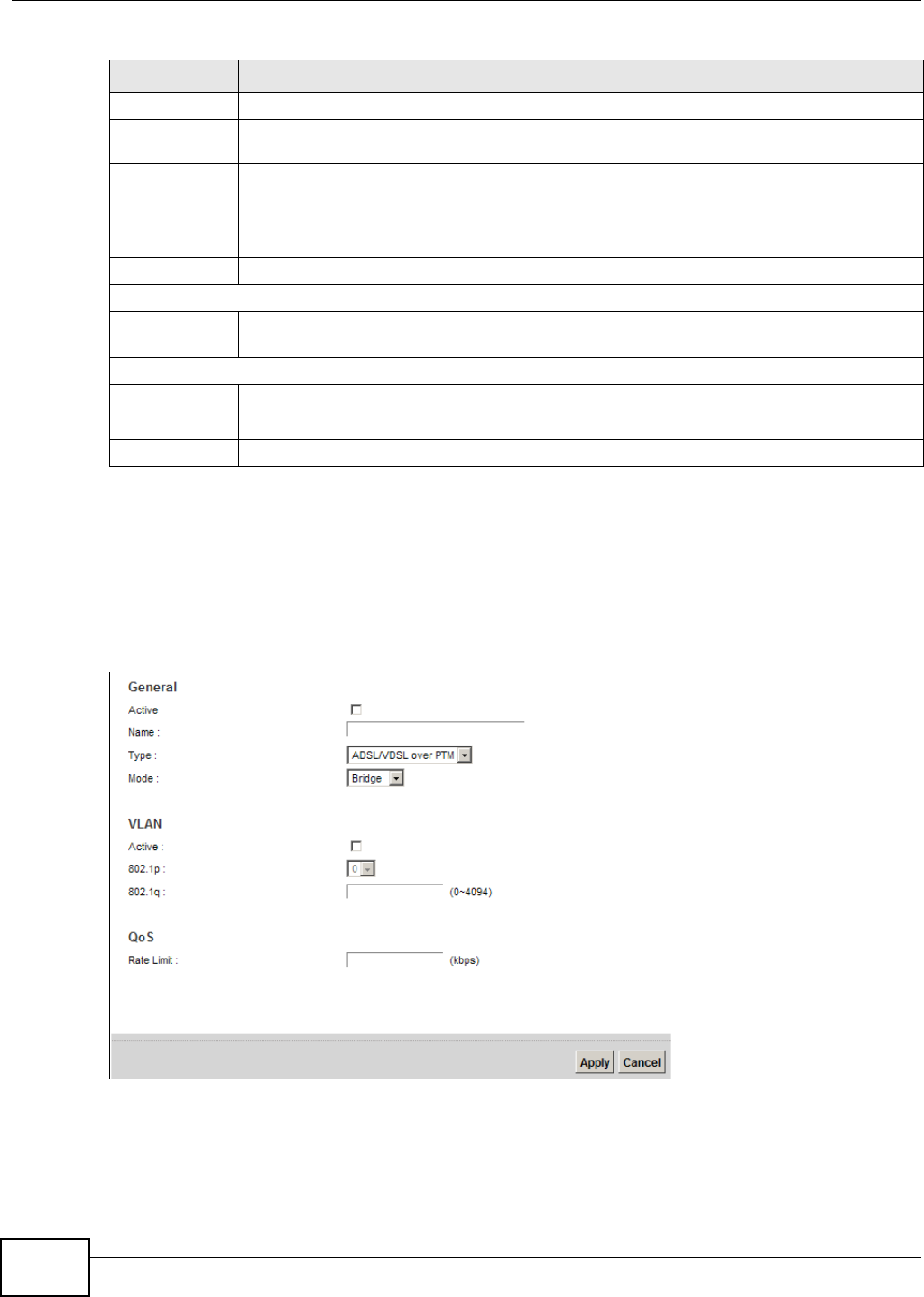
Chapter 5 Broadband
VMG1312-B10C User’s Guide
48
5.2.1.2 Bridge Mode
Click the Add new W AN I nt erface in the N e t w or k Set t ing > Br oadba n d screen or the Edit icon
next to the connection you want to configure. Select Br idge as the encapsulation mode. The screen
varies depending on the interface type you select.
If you select AD SL/ VDSL ove r PTM as the interface type, the following screen appears.
Figure 20 Bridge Mode (ADSL/VDSL over PTM)
VLAN These fields appear when the Ty pe is set to ADSL/ VD SL ov er PTM .
Active Select this option to add the VLAN tag (specified below) to the outgoing traffic through this
connection.
802.1p IEEE 802.1p defines up to 8 separate traffic types by inserting a tag into a MAC-layer frame
that contains bits to define class of service.
Select the IEEE 802.1p priority level (from 0 to 7) to add to traffic through this connection.
The greater the number, the higher the priority level.
802.1q Type the VLAN ID number (from 1 to 4094) for traffic through this connection.
QoS
Rate Limit Enter the rate limit for the connection. This is the maximum transmission rate allowed for
traffic on this connection.
MTU
MTU Size Enter the MTU (Maximum Transfer Unit) size for this traffic.
Apply Click Apply to save your changes back to the Device.
Cancel Click Cancel to exit this screen without saving.
Table 7 Routing Mode (continued)
LABEL DESCRIPTION
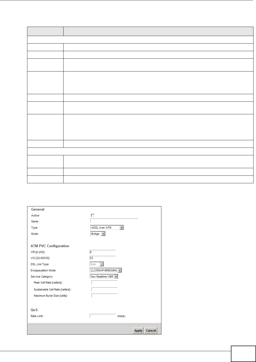
Chapter 5 Broadband
VMG1312-B10C User’s Guide 49
The following table describes the fields in this screen.
If you select AD SL over ATM as the interface type, the following screen appears.
Figure 21 Bridge Mode (ADSL over ATM)
Table 8 Bridge Mode (ADSL/VDSL over PTM)
LABEL DESCRIPTION
General
Active Select this to activate the WAN configuration settings.
Name Enter a service name of the connection.
Type Select ADSL/ VDSL ov er PTM as the interface that you want to configure. The Device uses
the VDSL technology for data transmission over the DSL port.
Mode Select Bridge when your ISP provides you more than one IP address and you want the
connected computers to get individual IP address from ISP’s DHCP server directly. If you
select Br idge, you cannot use routing functions, such as QoS, Firewall, DHCP server and
NAT on traffic from the selected LAN port(s).
VLAN This section is available only when you select AD SL/ VD SL ove r PTM in the Type field.
Active Select this to add the VLAN Tag (specified below) to the outgoing traffic through this
connection.
802.1p IEEE 802.1p defines up to 8 separate traffic types by inserting a tag into a MAC-layer frame
that contains bits to define class of service.
Select the IEEE 802.1p priority level (from 0 to 7) to add to traffic through this connection.
The greater the number, the higher the priority level.
802.1q Type the VLAN ID number (from 0 to 4094) for traffic through this connection.
QoS
Rate Limit Enter the rate limit for the connection. This is the maximum transmission rate allowed for
traffic on this connection.
Apply Click Apply to save your changes.
Cancel Click Cancel to exit this screen without saving.

Chapter 5 Broadband
VMG1312-B10C User’s Guide
50
The following table describes the fields in this screen.
Table 9 Bridge Mode (ADSL over ATM)
LABEL DESCRIPTION
General
Active Select this to activate the WAN configuration settings.
Name Enter a service name of the connection.
Type Select AD SL over ATM as the interface for which you want to configure here. The Device
uses the ADSL technology for data transmission over the DSL port.
Mode Select Bridge when your ISP provides you more than one IP address and you want the
connected computers to get individual IP address from ISP’s DHCP server directly. If you
select Br idge, you cannot use routing functions, such as QoS, Firewall, DHCP server and
NAT on traffic from the selected LAN port(s).
ATM PVC Configuration (These fields appear when the Type is set to ADSL ove r ATM.)
VPI The valid range for the VPI is 0 to 255. Enter the VPI assigned to you.
VCI The valid range for the VCI is 32 to 65535 (0 to 31 is reserved for local management of ATM
traffic). Enter the VCI assigned to you.
DSL Link Type This field is not editable. The selection depends on the setting in the Enca psu la t ion field.
EoA (Ethernet over ATM) uses an Ethernet header in the packet, so that you can have
multiple services/connections over one PVC. You can set each connection to have its own
MAC address or all connections share one MAC address but use different VLAN IDs for
different services. EoA supports ENET ENCAP (IPoE), PPPoE and RFC1483/2684 bridging
encapsulation methods.
PPPoA (PPP over ATM) allows just one PPPoA connection over a PVC.
I PoA (IP over ATM) allows just one RFC 1483 routing connection over a PVC.
Encapsulation
Mode
Select the method of multiplexing used by your ISP from the drop-down list box. Choices
are:
•LLC/ SN AP- BRI D GI N G: In LCC encapsulation, bridged PDUs are encapsulated by
identifying the type of the bridged media in the SNAP header. This is available only when
you select I PoE or PPPoE in the Select DSL Link Type field.
•VC/ M UX: In VC multiplexing, each protocol is carried on a single ATM virtual circuit
(VC). To transport multiple protocols, the Device needs separate VCs. There is a binding
between a VC and the type of the network protocol carried on the VC. This reduces
payload overhead since there is no need to carry protocol information in each Protocol
Data Unit (PDU) payload.
•LLC/ EN CAPSU LATI ON : More than one protocol can be carried over the same VC. This
is available only when you select PPPoA in the En ca psu la t ion field.
•LLC/ SN AP- ROU TI N G: In LCC encapsulation, an IEEE 802.2 Logical Link Control (LLC)
header is prefixed to each routed PDU to identify the PDUs. The LCC header can be
followed by an IEEE 802.1a SubNetwork Attachment Point (SNAP) header. This is
available only when you select I PoA in the Encapsula t ion field.
Service
Category
Select UBR W it hout PCR or UBR W it h PCR for applications that are non-time sensitive,
such as e-mail.
Select CBR (Continuous Bit Rate) to specify fixed (always-on) bandwidth for voice or data
traffic.
Select N on Re a lt im e VBR (non real-time Variable Bit Rate) for connections that do not
require closely controlled delay and delay variation.
Select Realt im e V BR (real-time Variable Bit Rate) for applications with bursty connections
that require closely controlled delay and delay variation.
Peak Cell Rate Divide the DSL line rate (bps) by 424 (the size of an ATM cell) to find the Peak Cell Rate
(PCR). This is the maximum rate at which the sender can send cells. Type the PCR here.This
field is not available when you select UBR W it h ou t PCR.

Chapter 5 Broadband
VMG1312-B10C User’s Guide 51
5.3 The 3G Backup Screen
Use this screen to configure your 3G settings. Click Ne t w ork Se t t ing > Broa dba nd > 3 G
Backup.
Sustainable Cell
Rate
The Sustainable Cell Rate (SCR) sets the average cell rate (long-term) that can be
transmitted. Type the SCR, which must be less than the PCR. Note that system default is 0
cells/sec.
This field is available only when you select Non Rea lt im e V BR or Re a lt im e VBR.
Maximum Burst
Size
Maximum Burst Size (MBS) refers to the maximum number of cells that can be sent at the
peak rate. Type the MBS, which is less than 65535.
This field is available only when you select Non Rea lt im e V BR or Re a lt im e VBR.
QoS
Rate Limit Enter the rate limit for the connection. This is the maximum transmission rate allowed for
traffic on this connection.
Apply Click Apply to save your changes.
Cancel Click Cancel to exit this screen without saving.
Table 9 Bridge Mode (ADSL over ATM) (continued)
LABEL DESCRIPTION
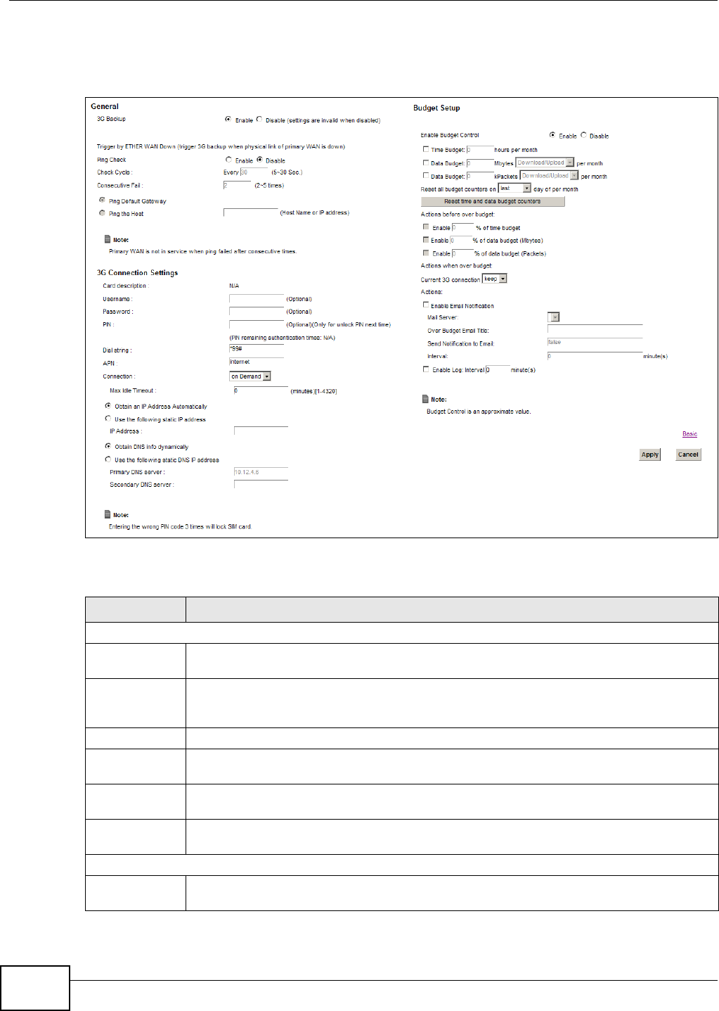
Chapter 5 Broadband
VMG1312-B10C User’s Guide
52
Note: The actual data rate you obtain varies depending the 3G card you use, the signal
strength to the service provider’s base station, and so on.
Figure 22 Network Setting > Broadband > 3G Backup
The following table describes the labels in this screen.
Table 10 Network Setting > Broadband > 3G Backup
LABEL DESCRIPTION
General
3G Backup Select Enable to have the Device use the 3G connection as your WAN or a backup when the
wired WAN connection fails.
Ping Check Select En able if you want the Device to ping check the connection status of your WAN. You
can configure the frequency of the ping check and number of consecutive failures before
triggering 3G backup.
Check Cycle Enter the frequency of the ping check in this field.
Consecutive
Fail
Enter how many consecutive failures are required before 3G backup is triggered.
Ping Default
Gateway
Select this to have the Device ping the WAN interface’s default gateway IP address.
Ping the Host Select this to have the Device ping the particular host name or IP address you typed in this
field.
3G Connection Settings
Card
description
This field displays the manufacturer and model name of your 3G card if you inserted one in
the Device. Otherwise, it displays N / A.

Chapter 5 Broadband
VMG1312-B10C User’s Guide 53
Username Type the user name (of up to 64 ASCII printable characters) given to you by your service
provider.
Password Type the password (of up to 64 ASCII printable characters) associated with the user name
above.
PIN A PIN (Personal Identification Number) code is a key to a 3G card. Without the PIN code,
you cannot use the 3G card.
If your ISP enabled PIN code authentication, enter the 4-digit PIN code (0000 for example)
provided by your ISP. If you enter the PIN code incorrectly, the 3G card may be blocked by
your ISP and you cannot use the account to access the Internet.
If your ISP disabled PIN code authentication, leave this field blank.
Dial string Enter the phone number (dial string) used to dial up a connection to your service provider’s
base station. Your ISP should provide the phone number.
For example, *99# is the dial string to establish a GPRS or 3G connection in Taiwan.
APN Enter the APN (Access Point Name) provided by your service provider. Connections with
different APNs may provide different services (such as Internet access or MMS (Multi-Media
Messaging Service)) and charge method.
You can enter up to 32 ASCII printable characters. Spaces are allowed.
Connection Select N a ile d UP if you do not want the connection to time out.
Select on D e m a n d if you do not want the connection up all the time and specify an idle
time-out in the Ma x I dle Tim eout field.
Max Idle
Timeout
This value specifies the time in minutes that elapses before the Device automatically
disconnects from the ISP.
Obtain an IP
Address
Automatically
Select this option If your ISP did not assign you a fixed IP address.
Use the
following static
IP address
Select this option If the ISP assigned a fixed IP address.
IP Address Enter your WAN IP address in this field if you selected Use t he follow ing st a t ic I P
address.
Obtain DNS
info
dynamically
Select this to have the Device get the DNS server addresses from the ISP automatically.
Use the
following static
DNS IP address
Select this to have the Device use the DNS server addresses you configure manually.
Primary DNS
server
Enter the first DNS server address assigned by the ISP.
Secondary DNS
server
Enter the second DNS server address assigned by the ISP.
Advanced Click this to show the advanced 3G backup settings.
Budget Setup
Enable Budget
Control
Select Enable to set a monthly limit for the user account of the installed 3G card. You can
set a limit on the total traffic and/or call time. The Device takes the actions you specified
when a limit is exceeded during the month.
Time Budget Select this and specify the amount of time (in hours) that the 3G connection can be used
within one month. If you change the value after you configure and enable budget control,
the Device resets the statistics.
Table 10 Network Setting > Broadband > 3G Backup (continued)
LABEL DESCRIPTION

Chapter 5 Broadband
VMG1312-B10C User’s Guide
54
Data Budget
(Mbytes)
Select this and specify how much downstream and/or upstream data (in Mega bytes) can be
transmitted via the 3G connection within one month.
Select Dow nloa d/ Uploa d to set a limit on the total traffic in both directions.
Select Dow nload to set a limit on the downstream traffic (from the ISP to the Device).
Select Upload to set a limit on the upstream traffic (from the Device to the ISP).
If you change the value after you configure and enable budget control, the Device resets the
statistics.
Data Budget
(kPackets)
Select this and specify how much downstream and/or upstream data (in k Packets) can be
transmitted via the 3G connection within one month.
Select Dow nloa d/ Uploa d to set a limit on the total traffic in both directions.
Select Dow nload to set a limit on the downstream traffic (from the ISP to the Device).
Select Upload to set a limit on the upstream traffic (from the Device to the ISP).
If you change the value after you configure and enable budget control, the Device resets the
statistics.
Reset all
budget
counters on
Select the date on which the Device resets the budget every month. Select la st if you want
the Device to reset the budget on the last day of the month. Select spe cific and enter the
number of the date you want the Device to reset the budget
Reset time and
data budget
counters
Click this button to reset the time and data budgets immediately. The count starts over with
the 3G connection’s full configured monthly time and data budgets. This does not affect the
normal monthly budget restart; so if you configured the time and data budget counters to
reset on the second day of the month and you use this button on the first, the time and data
budget counters will still reset on the second.
Actions before
over budget
Specify the actions the Device takes before the time or data limit exceeds.
Enable % of
time budget/
data budget
(Mbytes)/data
budget
(kPackets)
Select Enable and enter a number from 1 to 99 in the percentage fields. If you change the
value after you configure and enable budget control, the Device resets the statistics.
Actions when
over budget
Specify the actions the Device takes when the time or data limit is exceeded.
Current 3G
connection
Select Kee p to maintain an existing 3G connection or Dr op to disconnect it.
Enable Email
Notification
Select this to enable the e-mail notification function. The Device will e-mail you a
notification when there over budget occurs.
Mail Server Select a mail server for the e-mail address specified below.
If you do not select a mail server, e-mail notifications cannot be sent via e-mail. You must
have configured a mail server already in the Ma int e n ance > Em ail N ot ifica tion screen.
Over Budget
Email Title
Type a title that you want to be in the subject line of the e-mail notifications that the Device
sends.
Send
Notification to
Email
Notifications are sent to the e-mail address specified in this field. If this field is left blank,
notifications cannot be sent via e-mail.
Interval Enter the interval of how many minutes you want the Device to e-mail you.
Enable Log Select this to activate the logging function at the interval you set in this field.
Basic Click this to hide the advanced settings of 3G backup.
Table 10 Network Setting > Broadband > 3G Backup (continued)
LABEL DESCRIPTION
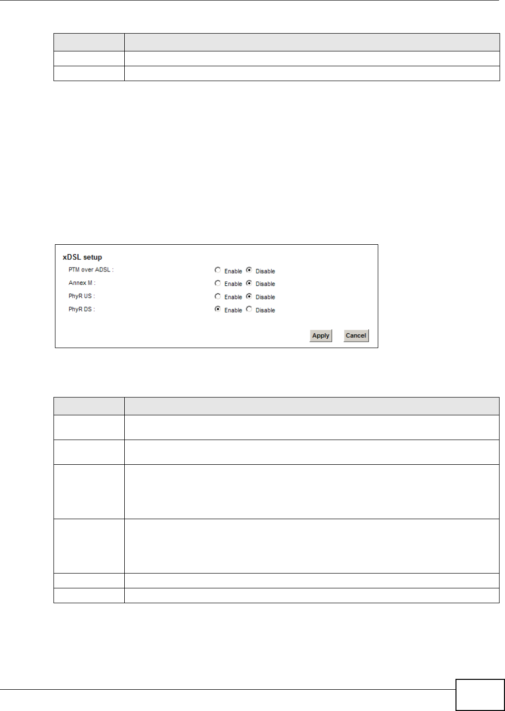
Chapter 5 Broadband
VMG1312-B10C User’s Guide 55
5.4 The Advanced Screen
Use the Adv a nced screen to enable or disable PTM over ADSL, Annex M, and DSL PhyR functions.
The Device supports the PhyR retransmission scheme. PhyR is a retransmission scheme designed to
provide protection against noise on the DSL line. It improves voice, video and data transmission
resilience by utilizing a retransmission buffer.
Click N et w or k Se t t ing > Br oa dband > Adva n ced to display the following screen.
Figure 23 Network Setting > Broadband > Advanced
The following table describes the labels in this screen.
Apply Click Apply to save your changes back to the Device.
Cancel Click Cancel to return to the previous configuration.
Table 10 Network Setting > Broadband > 3G Backup (continued)
LABEL DESCRIPTION
Table 11 Network Setting > Network Setting > Broadband
LABEL DESCRIPTION
PTM over ADSL Select En able to use PTM over ADSL. Since PTM has less overhead than ATM, some ISPs
use PTM over ADSL for better performance.
Annex M You can enable Ann ex M for the Device to use double upstream mode to increase the
maximum upstream transfer rate.
PhyR US Enable or disable PhyR US (upstream) for upstream transmission to the WAN. PhyR US
should be enabled if data being transmitted upstream is sensitive to noise. However,
enabling PhyR US can decrease the US line rate. Enabling or disabling PhyR will require the
CPE to retrain. For PhyR to function, the DSLAM must also support PhyR and have it
enabled.
PhyR DS Enable or disable Ph yR D S (downstream) for downstream transmission from the WAN.
PhyR DS should be enabled if data being transmitted downstream is sensitive to noise.
However, enabling PhyR DS can decrease the DS line rate. Enabling or disabling PhyR will
require the CPE to retrain. For PhyR to function, the DSLAM must also support PhyR and
have it enabled.
Apply Click Apply to save your changes back to the Device.
Cancel Click Cancel to return to the previous configuration.
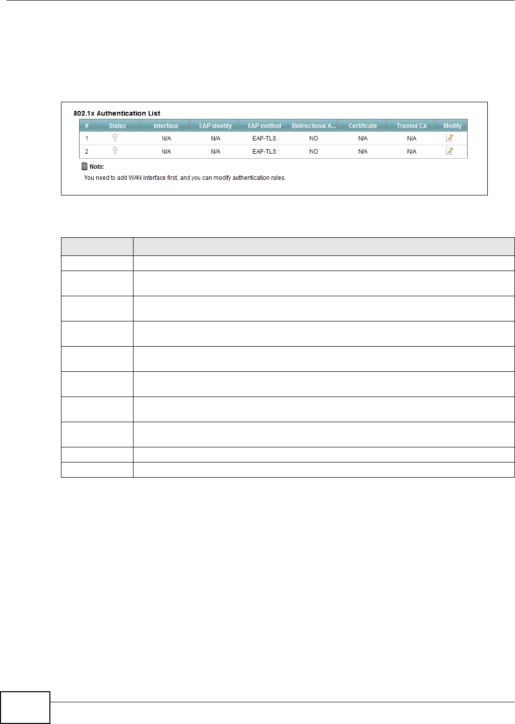
Chapter 5 Broadband
VMG1312-B10C User’s Guide
56
5.5 The 8021x Screen
You can view and configure the 802.1X authentication settings in the 8 0 2 1 x screen. Click Net w or k
Set t ing > Br oa dband > 8 0 2 1 x to display the following screen.
Figure 24 Network Setting > Broadband > 8021x
The following table describes the labels in this screen.
Table 12 Network Setting > Network Setting > 8021x
LABEL DESCRIPTION
# This is the index number of the entry.
Status This field displays whether the authentication is active or not. A yellow bulb signifies that
this authentication is active. A gray bulb signifies that this authentication is not active.
Interface This is the interface that uses the authentication. This displays N / A when there is no
interface assigned.
EAP Identity This shows the EAP identity of the authentication. This displays N / A when there is no EAP
identity assigned.
EAP method This shows the EAP method used in the authentication. This displays N / A when there is no
EAP method assigned.
Bidirectional
Authentication
This shows whether bidirectional authentication is allowed.
Certificate This shows the certificate used for this authentication. This displays N / A when there is no
certificate assigned.
Trusted CA This shows the Trusted CA used for this authentication. This displays N / A when there is no
Trusted CA assigned.
Apply Click Apply to save your changes back to the Device.
Cancel Click Cancel to return to the previous configuration.
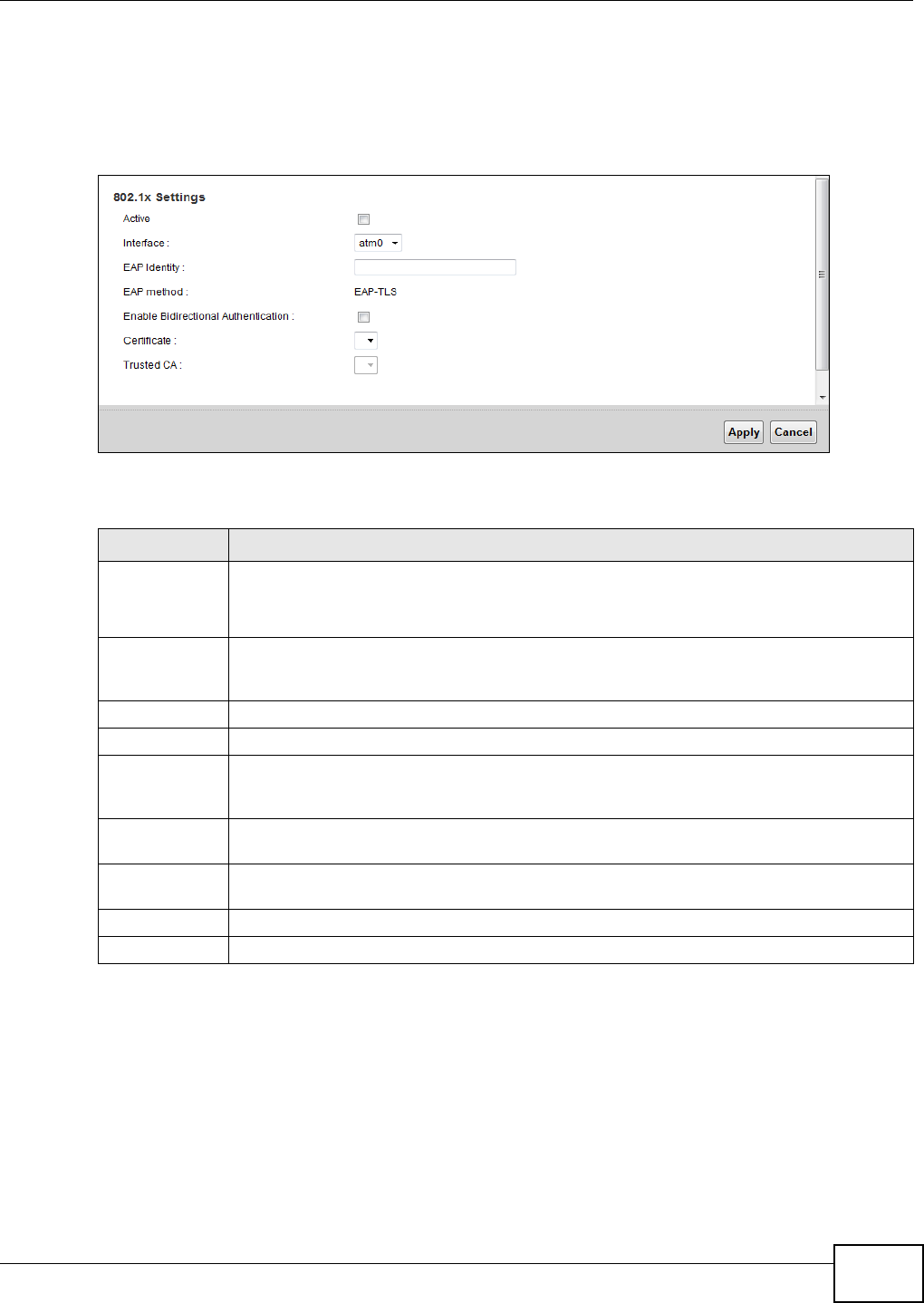
Chapter 5 Broadband
VMG1312-B10C User’s Guide 57
5.5.1 Edit 802.1X Settings
Use this screen to edit 802.1X authentication settings. Click the Edit icon next to the rule you want
to edit. The screen shown next appears.
Figure 25 802.1x: Add/Edit
The following table describes the labels in this screen.
5.6 The Ethernet WAN Screen
If you are using an ethernet WAN connection, you can configure a LAN port as an ethernet WAN
port. Click N e t w ork Se t t in g > Broa dba nd > Et her n e t W AN to open this screen.
Note: LAN port 4 can operate as an Ethernet WAN port.
Table 13 802.1x: Add/Edit
LABEL DESCRIPTION
Active This field allows you to activate/deactivate the authentication.
Select this to enable the authentication. Clear this to disable this authentication without
having to delete the entry.
Interface This field displays where there is an interface available to select for the 802.1X
authentication settings. Select the interface to which to apply the 802.1X authentication
settings.
EAP Identity Enter the EAP identity of the authentication.
EAP method This is the EAP method used for this authentication.
Enable
Bidirectional
Authentication
Select this to allow bidirectional authentication.
Certificate Select the certificate you want to assign to the authentication. You need to import the
certificate in the Se cu r it y > Ce r t ifica t es > Local Cert ifica t es screen.
Trusted CA Select the Trusted CA you want to assign to the authentication. You need to import the
certificate in the Se cu r it y > Ce r t ifica t es > Tr u sted CA screen.
Apply Click Apply to save your changes.
Cancel Click Cance l to exit this screen without saving.
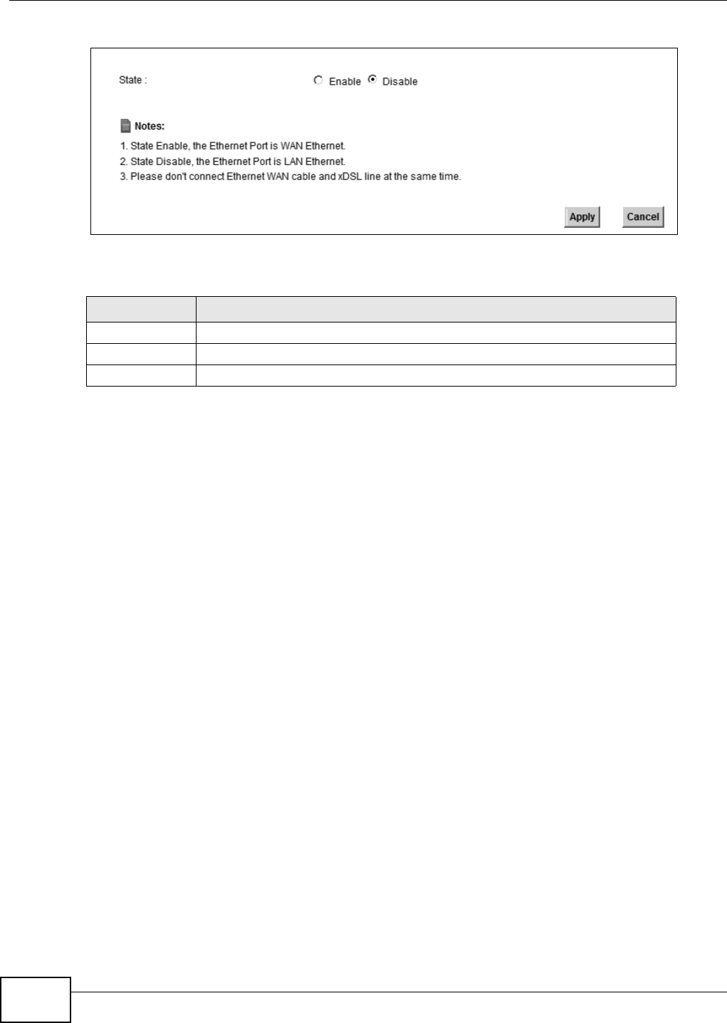
Chapter 5 Broadband
VMG1312-B10C User’s Guide
58
Figure 26 Network Setting > Broadband > Ethernet WAN
The following table describes the fields in this screen.
5.7 Technical Reference
The following section contains additional technical information about the Device features described
in this chapter.
Encapsulation
Be sure to use the encapsulation method required by your ISP. The Device can work in bridge mode
or routing mode. When the Device is in routing mode, it supports the following methods.
IP over Ethernet
IP over Ethernet (IPoE) is an alternative to PPPoE. IP packets are being delivered across an
Ethernet network, without using PPP encapsulation. They are routed between the Ethernet interface
and the WAN interface and then formatted so that they can be understood in a bridged
environment. For instance, it encapsulates routed Ethernet frames into bridged Ethernet cells.
PPP over ATM (PPPoA)
PPPoA stands for Point to Point Protocol over ATM Adaptation Layer 5 (AAL5). A PPPoA connection
functions like a dial-up Internet connection. The Device encapsulates the PPP session based on
RFC1483 and sends it through an ATM PVC (Permanent Virtual Circuit) to the Internet Service
Provider’s (ISP) DSLAM (digital access multiplexer). Please refer to RFC 2364 for more information
on PPPoA. Refer to RFC 1661 for more information on PPP.
Table 14 Network Setting > Broadband > Ethernet WAN
LABEL DESCRIPTION
State Select Ena ble to use the Ethernet LAN port as a WAN port on the Device.
Apply Click Apply to save your changes back to the Device.
Cancel Click Cance l to exit this screen without saving.

Chapter 5 Broadband
VMG1312-B10C User’s Guide 59
PPP over Ethernet (PPPoE)
Point-to-Point Protocol over Ethernet (PPPoE) provides access control and billing functionality in a
manner similar to dial-up services using PPP. PPPoE is an IETF standard (RFC 2516) specifying how
a personal computer (PC) interacts with a broadband modem (DSL, cable, wireless, etc.)
connection.
For the service provider, PPPoE offers an access and authentication method that works with existing
access control systems (for example RADIUS).
One of the benefits of PPPoE is the ability to let you access one of multiple network services, a
function known as dynamic service selection. This enables the service provider to easily create and
offer new IP services for individuals.
Operationally, PPPoE saves significant effort for both you and the ISP or carrier, as it requires no
specific configuration of the broadband modem at the customer site.
By implementing PPPoE directly on the Device (rather than individual computers), the computers on
the LAN do not need PPPoE software installed, since the Device does that part of the task.
Furthermore, with NAT, all of the LANs’ computers will have access.
RFC 1483
RFC 1483 describes two methods for Multiprotocol Encapsulation over ATM Adaptation Layer 5
(AAL5). The first method allows multiplexing of multiple protocols over a single ATM virtual circuit
(LLC-based multiplexing) and the second method assumes that each protocol is carried over a
separate ATM virtual circuit (VC-based multiplexing). Please refer to RFC 1483 for more detailed
information.
Multiplexing
There are two conventions to identify what protocols the virtual circuit (VC) is carrying. Be sure to
use the multiplexing method required by your ISP.
VC-based Multiplexing
In this case, by prior mutual agreement, each protocol is assigned to a specific virtual circuit; for
example, VC1 carries IP, etc. VC-based multiplexing may be dominant in environments where
dynamic creation of large numbers of ATM VCs is fast and economical.
LLC-based Multiplexing
In this case one VC carries multiple protocols with protocol identifying information being contained
in each packet header. Despite the extra bandwidth and processing overhead, this method may be
advantageous if it is not practical to have a separate VC for each carried protocol, for example, if
charging heavily depends on the number of simultaneous VCs.
Traffic Shaping
Traffic Shaping is an agreement between the carrier and the subscriber to regulate the average rate
and fluctuations of data transmission over an ATM network. This agreement helps eliminate
congestion, which is important for transmission of real time data such as audio and video
connections.
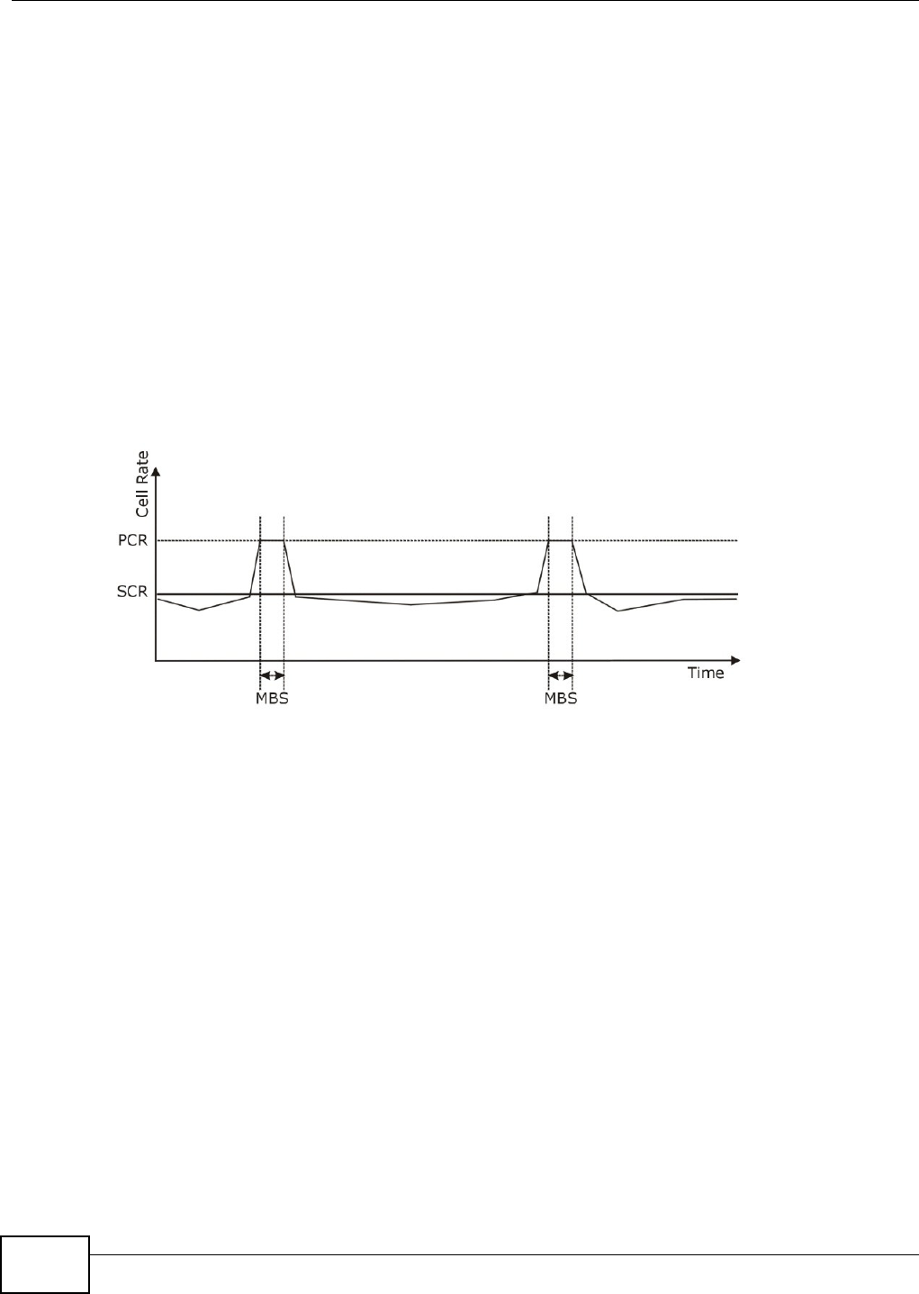
Chapter 5 Broadband
VMG1312-B10C User’s Guide
60
Peak Cell Rate (PCR) is the maximum rate at which the sender can send cells. This parameter may
be lower (but not higher) than the maximum line speed. 1 ATM cell is 53 bytes (424 bits), so a
maximum speed of 832Kbps gives a maximum PCR of 1962 cells/sec. This rate is not guaranteed
because it is dependent on the line speed.
Sustained Cell Rate (SCR) is the mean cell rate of each bursty traffic source. It specifies the
maximum average rate at which cells can be sent over the virtual connection. SCR may not be
greater than the PCR.
Maximum Burst Size (MBS) is the maximum number of cells that can be sent at the PCR. After MBS
is reached, cell rates fall below SCR until cell rate averages to the SCR again. At this time, more
cells (up to the MBS) can be sent at the PCR again.
If the PCR, SCR or MBS is set to the default of "0", the system will assign a maximum value that
correlates to your upstream line rate.
The following figure illustrates the relationship between PCR, SCR and MBS.
Figure 27 Example of Traffic Shaping
ATM Traffic Classes
These are the basic ATM traffic classes defined by the ATM Forum Traffic Management 4.0
Specification.
Constant Bit Rate (CBR)
Constant Bit Rate (CBR) provides fixed bandwidth that is always available even if no data is being
sent. CBR traffic is generally time-sensitive (doesn't tolerate delay). CBR is used for connections
that continuously require a specific amount of bandwidth. A PCR is specified and if traffic exceeds
this rate, cells may be dropped. Examples of connections that need CBR would be high-resolution
video and voice.
Variable Bit Rate (VBR)
The Variable Bit Rate (VBR) ATM traffic class is used with bursty connections. Connections that use
the Variable Bit Rate (VBR) traffic class can be grouped into real time (VBR-RT) or non-real time
(VBR-nRT) connections.
The VBR-RT (real-time Variable Bit Rate) type is used with bursty connections that require closely
controlled delay and delay variation. It also provides a fixed amount of bandwidth (a PCR is

Chapter 5 Broadband
VMG1312-B10C User’s Guide 61
specified) but is only available when data is being sent. An example of an VBR-RT connection would
be video conferencing. Video conferencing requires real-time data transfers and the bandwidth
requirement varies in proportion to the video image's changing dynamics.
The VBR-nRT (non real-time Variable Bit Rate) type is used with bursty connections that do not
require closely controlled delay and delay variation. It is commonly used for "bursty" traffic typical
on LANs. PCR and MBS define the burst levels, SCR defines the minimum level. An example of an
VBR-nRT connection would be non-time sensitive data file transfers.
Unspecified Bit Rate (UBR)
The Unspecified Bit Rate (UBR) ATM traffic class is for bursty data transfers. However, UBR doesn't
guarantee any bandwidth and only delivers traffic when the network has spare bandwidth. An
example application is background file transfer.
IP Address Assignment
A static IP is a fixed IP that your ISP gives you. A dynamic IP is not fixed; the ISP assigns you a
different one each time. The Single User Account feature can be enabled or disabled if you have
either a dynamic or static IP. However the encapsulation method assigned influences your choices
for IP address and default gateway.
Introduction to VLANs
A Virtual Local Area Network (VLAN) allows a physical network to be partitioned into multiple logical
networks. Devices on a logical network belong to one group. A device can belong to more than one
group. With VLAN, a device cannot directly talk to or hear from devices that are not in the same
group(s); the traffic must first go through a router.
In Multi-Tenant Unit (MTU) applications, VLAN is vital in providing isolation and security among the
subscribers. When properly configured, VLAN prevents one subscriber from accessing the network
resources of another on the same LAN, thus a user will not see the printers and hard disks of
another user in the same building.
VLAN also increases network performance by limiting broadcasts to a smaller and more
manageable logical broadcast domain. In traditional switched environments, all broadcast packets
go to each and every individual port. With VLAN, all broadcasts are confined to a specific broadcast
domain.
Introduction to IEEE 802.1Q Tagged VLAN
A tagged VLAN uses an explicit tag (VLAN ID) in the MAC header to identify the VLAN membership
of a frame across bridges - they are not confined to the switch on which they were created. The
VLANs can be created statically by hand or dynamically through GVRP. The VLAN ID associates a
frame with a specific VLAN and provides the information that switches need to process the frame
across the network. A tagged frame is four bytes longer than an untagged frame and contains two
bytes of TPID (Tag Protocol Identifier), residing within the type/length field of the Ethernet frame)
and two bytes of TCI (Tag Control Information), starts after the source address field of the Ethernet
frame).
The CFI (Canonical Format Indicator) is a single-bit flag, always set to zero for Ethernet switches. If
a frame received at an Ethernet port has a CFI set to 1, then that frame should not be forwarded as
it is to an untagged port. The remaining twelve bits define the VLAN ID, giving a possible maximum

Chapter 5 Broadband
VMG1312-B10C User’s Guide
62
number of 4,096 VLANs. Note that user priority and VLAN ID are independent of each other. A
frame with VID (VLAN Identifier) of null (0) is called a priority frame, meaning that only the priority
level is significant and the default VID of the ingress port is given as the VID of the frame. Of the
4096 possible VIDs, a VID of 0 is used to identify priority frames and value 4095 (FFF) is reserved,
so the maximum possible VLAN configurations are 4,094.
Multicast
IP packets are transmitted in either one of two ways - Unicast (1 sender - 1 recipient) or Broadcast
(1 sender - everybody on the network). Multicast delivers IP packets to a group of hosts on the
network - not everybody and not just 1.
Internet Group Multicast Protocol (IGMP) is a network-layer protocol used to establish membership
in a Multicast group - it is not used to carry user data. IGMP version 2 (RFC 2236) is an
improvement over version 1 (RFC 1112) but IGMP version 1 is still in wide use. If you would like to
read more detailed information about interoperability between IGMP version 2 and version 1, please
see sections 4 and 5 of RFC 2236. The class D IP address is used to identify host groups and can be
in the range 224.0.0.0 to 239.255.255.255. The address 224.0.0.0 is not assigned to any group
and is used by IP multicast computers. The address 224.0.0.1 is used for query messages and is
assigned to the permanent group of all IP hosts (including gateways). All hosts must join the
224.0.0.1 group in order to participate in IGMP. The address 224.0.0.2 is assigned to the multicast
routers group.
At start up, the Device queries all directly connected networks to gather group membership. After
that, the Device periodically updates this information.
DNS Server Address Assignment
Use Domain Name System (DNS) to map a domain name to its corresponding IP address and vice
versa, for instance, the IP address of www.zyxel.com is 204.217.0.2. The DNS server is extremely
important because without it, you must know the IP address of a computer before you can access
it.
The Device can get the DNS server addresses in the following ways.
1The ISP tells you the DNS server addresses, usually in the form of an information sheet, when you
sign up. If your ISP gives you DNS server addresses, manually enter them in the DNS server fields.
2If your ISP dynamically assigns the DNS server IP addresses (along with the Device’s WAN IP
address), set the DNS server fields to get the DNS server address from the ISP.
IPv6 Addressing
The 128-bit IPv6 address is written as eight 16-bit hexadecimal blocks separated by colons (:). This
is an example IPv6 address 2001:0db8:1a2b:0015:0000:0000:1a2f:0000.
IPv6 addresses can be abbreviated in two ways:
TPID
2 Bytes
User Priority
3 Bits
CFI
1 Bit
VLAN ID
12 Bits

Chapter 5 Broadband
VMG1312-B10C User’s Guide 63
• Leading zeros in a block can be omitted. So 2001:0db8:1a2b:0015:0000:0000:1a2f:0000 can
be written as 2001:db8:1a2b:15:0:0:1a2f:0.
• Any number of consecutive blocks of zeros can be replaced by a double colon. A double colon can
only appear once in an IPv6 address. So 2001:0db8:0000:0000:1a2f:0000:0000:0015 can be
written as 2001:0db8::1a2f:0000:0000:0015, 2001:0db8:0000:0000:1a2f::0015,
2001:db8::1a2f:0:0:15 or 2001:db8:0:0:1a2f::15.
IPv6 Prefix and Prefix Length
Similar to an IPv4 subnet mask, IPv6 uses an address prefix to represent the network address. An
IPv6 prefix length specifies how many most significant bits (start from the left) in the address
compose the network address. The prefix length is written as “/x” where x is a number. For
example,
2001:db8:1a2b:15::1a2f:0/32
means that the first 32 bits (2001:db8) is the subnet prefix.

Chapter 5 Broadband
VMG1312-B10C User’s Guide
64

VMG1312-B10C User’s Guide 65
CHAPTER 6
Wireless
6.1 Overview
This chapter describes the Device’s Net w or k Set t ing > W ir e le ss screens. Use these screens to
set up your Device’s wireless connection.
6.1.1 What You Can Do in this Chapter
This section describes the Device’s W ir e le ss screens. Use these screens to set up your Device’s
wireless connection.
•Use the Ge n e r a l screen to enable the Wireless LAN, enter the SSID and select the wireless
security mode (Section 6.2 on page 66).
•Use the More AP screen to set up multiple wireless networks on your Device (Section 6.3 on
page 75).
•Use the MAC Aut hent icat ion screen to allow or deny wireless clients based on their MAC
addresses from connecting to the Device (Section 6.4 on page 78).
•Use the W PS screen to enable or disable WPS, view or generate a security PIN (Personal
Identification Number) (Section 6.5 on page 79).
•Use the W MM screen to enable Wi-Fi MultiMedia (WMM) to ensure quality of service in wireless
networks for multimedia applications (Section 6.6 on page 81).
•Use the W DS screen to set up a Wireless Distribution System, in which the Device acts as a
bridge with other ZyXEL access points (Section 6.7 on page 82).
•Use the Ot hers screen to configure wireless advanced features, such as the RTS/CTS Threshold
(Section 6.8 on page 84).
•Use the Cha nnel St a t us screen to scan wireless LAN channel noises and view the results
(Section 6.9 on page 86).

Chapter 6 Wireless
VMG1312-B10C User’s Guide
66
6.1.2 What You Need to Know
Wireless Basics
“Wireless” is essentially radio communication. In the same way that walkie-talkie radios send and
receive information over the airwaves, wireless networking devices exchange information with one
another. A wireless networking device is just like a radio that lets your computer exchange
information with radios attached to other computers. Like walkie-talkies, most wireless networking
devices operate at radio frequency bands that are open to the public and do not require a license to
use. However, wireless networking is different from that of most traditional radio communications in
that there a number of wireless networking standards available with different methods of data
encryption.
Finding Out More
See Section 6.10 on page 86 for advanced technical information on wireless networks.
6.2 The General Screen
Use this screen to enable the Wireless LAN, enter the SSID and select the wireless security mode.
Note: If you are configuring the Device from a computer connected to the wireless LAN
and you change the Device’s SSID, channel or security settings, you will lose your
wireless connection when you press Apply to confirm. You must then change the
wireless settings of your computer to match the Device’s new settings.
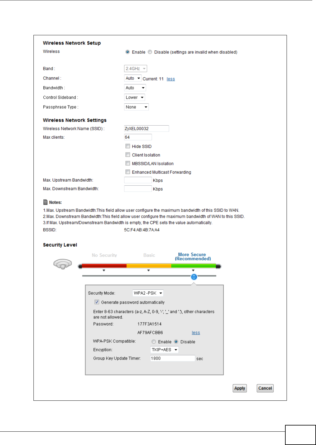
Chapter 6 Wireless
VMG1312-B10C User’s Guide 67
Click N e t w o rk Set t ing > W ire less to open the Ge ne ral screen.
Figure 28 Network Setting > Wireless > General

Chapter 6 Wireless
VMG1312-B10C User’s Guide
68
The following table describes the general wireless LAN labels in this screen.
Table 15 Network Setting > Wireless > General
LABEL DESCRIPTION
Wireless Network Setup
Wireless You can Ena ble or Disable the wireless LAN in this field.
Band This shows the wireless band which this radio profile is using. 2 .4 GHz is the frequency used
by IEEE 802.11b/g/n wireless clients.
Channel Set the channel depending on your particular region.
Select a channel or use Aut o to have the Device automatically determine a channel to use.
If you are having problems with wireless interference, changing the channel may help. Try
to use a channel that is as many channels away from any channels used by neighboring APs
as possible. The channel number which the Device is currently using then displays next to
this field.
more.../less Click m ore ... to show more information. Click less to hide them.
Bandwidth Select whether the Device uses a wireless channel width of 2 0 MH z or 4 0 MH z, or use Au t o
to have the Device automatically select one.
A standard 20MHz channel offers transfer speeds of up to 150Mbps whereas a 40MHz
channel uses two standard channels and offers speeds of up to 300 Mbps.
40MHz (channel bonding or dual channel) bonds two adjacent radio channels to increase
throughput. The wireless clients must also support 40 MHz. It is often better to use the 20
MHz setting in a location where the environment hinders the wireless signal.
Select 2 0 M H z if you want to lessen radio interference with other wireless devices in your
neighborhood or the wireless clients do not support channel bonding.
Control
Sideband
This is available for some regions when you select a specific channel and set the Bandwidth
field to 4 0 M Hz. Set whether the control channel (set in the Cha nne l field) should be in the
Low e r or Uppe r range of channel bands.
Passphrase
Type
If you set security for the wireless LAN and have the Device generate a password, the
setting in this field determines how the Device generates the password.
Select N on e to set the Device’s password generation to not be based on a passphrase.
Select Fix e d to use a 16 character passphrase for generating a password.
Select Varia ble to use a 16 to 63 character passphrase for generating a password.
Passphrase Key For a fixed type passphrase enter 16 alphanumeric characters (0-9, A-Z, with no spaces). It
must contain both letters and numbers and is case-sensitive.
For a variable type passphrase enter 16 to 63 alphanumeric characters (0-9, A-Z, with no
spaces). It must contain both letters and numbers and is case-sensitive.
Wireless Network Settings
Wireless
Network Name
(SSID)
The SSID (Service Set IDentity) identifies the service set with which a wireless device is
associated. Wireless devices associating to the access point (AP) must have the same SSID.
Enter a descriptive name (up to 32 English keyboard characters) for the wireless LAN.
Max clients Specify the maximum number of clients that can connect to this network at the same time.
Hide SSID Select this check box to hide the SSID in the outgoing beacon frame so a station cannot
obtain the SSID through scanning using a site survey tool.
Client Isolation Select this to keep the wireless clients in this SSID from communicating with each other
through the Device.
MBSSID/LAN
Isolation
Select this to keep the wireless clients in this SSID from communicating with clients in other
SSIDs or wired LAN devices through the Device.
Select both Clien t I sola t ion and M BSSI D / LAN I sola t ion to allow this SSID’s wireless
clients to only connect to the Internet through the Device.
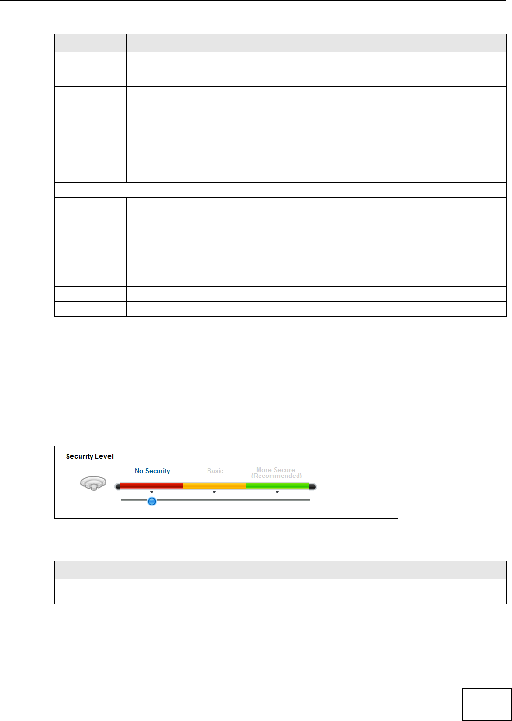
Chapter 6 Wireless
VMG1312-B10C User’s Guide 69
6.2.1 No Security
Select N o Se curit y to allow wireless stations to communicate with the access points without any
data encryption or authentication.
Note: If you do not enable any wireless security on your Device, your network is
accessible to any wireless networking device that is within range.
Figure 29 Wireless > General: No Security
The following table describes the labels in this screen.
Enhanced
Multicast
Forwarding
Select this check box to allow the Device to convert wireless multicast traffic into wireless
unicast traffic.
Maximum
Upstream
Bandwidth
Specify the maximum rate for upstream wireless traffic to the WAN from this WLAN in
kilobits per second (Kbps).
Maximum
Downstream
Bandwidth
Specify the maximum rate for downstream wireless traffic to this WLAN from the WAN in
kilobits per second (Kbps).
BSSID This shows the MAC address of the wireless interface on the Device when wireless LAN is
enabled.
Security Level
Security Mode Select Basic ( W EP, 8 0 2 .1 X ) or M ore Se cur e ( W PA( 2 ) - PSK, W PA( 2 ) ) to add security
on this wireless network. The wireless clients which want to associate to this network must
have same wireless security settings as the Device. When you select to use a security,
additional options appears in this screen.
Or you can select N o Secur it y to allow any client to associate this network without any data
encryption or authentication.
See the following sections for more details about this field.
Apply Click Apply to save your changes.
Cancel Click Cance l to restore your previously saved settings.
Table 15 Network Setting > Wireless > General (continued)
LABEL DESCRIPTION
Table 16 Wireless > General: No Security
LABEL DESCRIPTION
Security Level Choose N o Secur it y to allow all wireless connections without data encryption or
authentication.
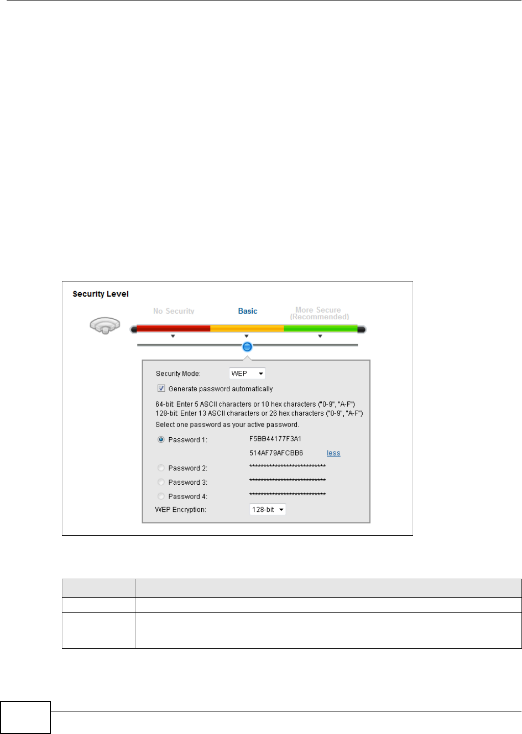
Chapter 6 Wireless
VMG1312-B10C User’s Guide
70
6.2.2 Basic (WEP Encryption)
WEP encryption scrambles the data transmitted between the wireless stations and the access points
(AP) to keep network communications private. Both the wireless stations and the access points
must use the same WEP key.
Note: WEP is extremely insecure. Its encryption can be broken by an attacker, using
widely-available software. It is strongly recommended that you use a more
effective security mechanism. Use the strongest security mechanism that all the
wireless devices in your network support. For example, use WPA-PSK or WPA2-PSK
if all your wireless devices support it, or use WPA or WPA2 if your wireless devices
support it and you have a RADIUS server. If your wireless devices support nothing
stronger than WEP, use the highest encryption level available.
Your Device allows you to configure up to four 64-bit or 128-bit WEP keys but only one key can be
enabled at any one time.
In order to configure and enable WEP encryption, click N e t w o rk Se t t in g > W ir e le ss to display the
Gener a l screen, then select Ba sic as the security level.
Figure 30 Wireless > General: Basic (WEP)
The following table describes the labels in this screen.
Table 17 Wireless > General: Basic (WEP)
LABEL DESCRIPTION
Security Level Select Ba sic to enable WEP data encryption.
Generate
password
automatically
Select this option to have the Device automatically generate a password. The password field
will not be configurable when you select this option.
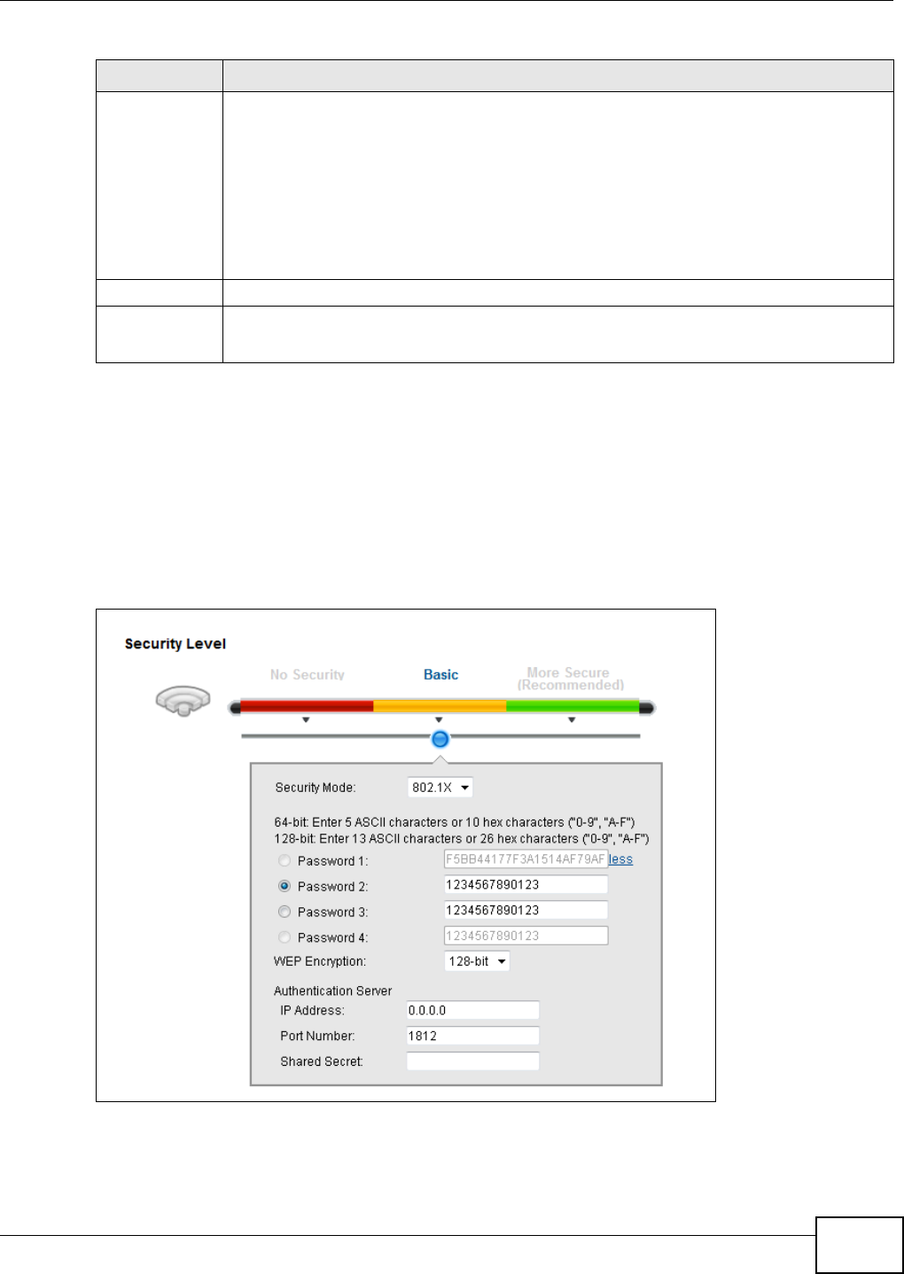
Chapter 6 Wireless
VMG1312-B10C User’s Guide 71
6.2.3 Basic (802.1X)
Use this screen to configure 802.1X encryption and authentication. Configure your RADIUS server
information and WEP encryption settings. Use this security method if your wireless usernames and
passwords are configured on a RADIUS server.
In order to configure and enable WEP encryption, click N e t w o rk Se t t in g > W ir e le ss to display the
Gener a l screen, then select Ba sic as the security level and 8 0 2 .1 X as the Security M ode .
Figure 31 Wireless > General: Basic (802.1X)
Password 1~4 The password (WEP keys) are used to encrypt data. Both the Device and the wireless
stations must use the same password (WEP key) for data transmission.
If you chose 6 4 - bit WEP, then enter any 5 ASCII characters or 10 hexadecimal characters
("0-9", "A-F").
If you chose 1 2 8 - bit WEP, then enter 13 ASCII characters or 26 hexadecimal characters
("0-9", "A-F").
You must configure at least one password, only one password can be activated at any one
time.
more.../less Click m ore... to show more fields in this section. Click less to hide them.
WEP Encryption Select 6 4 - b it s or 1 2 8 - b it s.
This dictates the length of the security key that the network is going to use.
Table 17 Wireless > General: Basic (WEP) (continued)
LABEL DESCRIPTION

Chapter 6 Wireless
VMG1312-B10C User’s Guide
72
The following table describes the labels in this screen.
Table 18 Wireless > General: Basic (802.1X)
LABEL DESCRIPTION
Security Level Select Ba sic and 8 0 2 .1 X to enable 802.1X data encryption.
Generate
password
automatically
Select this option to have the Device automatically generate a password. The password field
will not be configurable when you select this option.
Password 1~4 The password (WEP key) is used to encrypt data. Both the Device and the wireless stations
must use the same password (WEP key) for data transmission.
If you chose 6 4 - bit WEP, then enter any 5 ASCII characters or 10 hexadecimal characters
("0-9", "A-F").
If you chose 1 2 8 - bit WEP, then enter 13 ASCII characters or 26 hexadecimal characters
("0-9", "A-F").
You must configure at least one password, only one password can be activated at any one
time.
more.../less Click m ore... to show more fields in this section. Click less to hide them.
WEP Encryption Select 6 4 - b it s or 1 2 8 - b it s.
This dictates the length of the security key that the network is going to use.
IP Address Enter the IP address of an external RADIUS server in dotted decimal notation.
Port Number The default port of a RADIUS server for authentication is 1812. You need not change this
value unless your network administrator instructs you to do so.
Shared Secret Specify a password (up to 32 alphanumeric characters) as the key to be shared between the
external RADIUS server and the Device. This key is not sent over the network. This key
must be the same on the external RADIUS server and the Device.
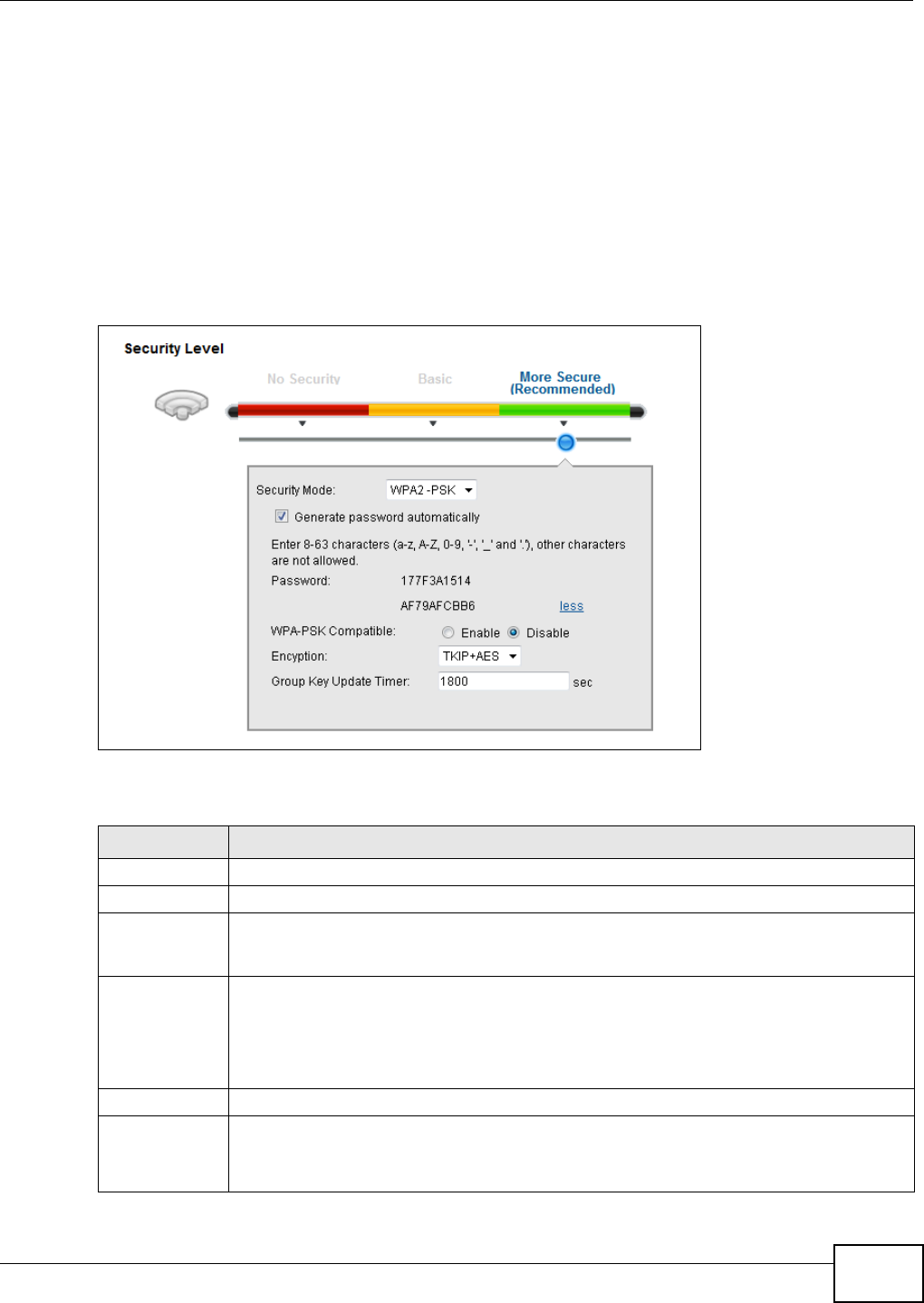
Chapter 6 Wireless
VMG1312-B10C User’s Guide 73
6.2.4 More Secure (WPA(2)-PSK)
The WPA-PSK security mode provides both improved data encryption and user authentication over
WEP. Using a Pre-Shared Key (PSK), both the Device and the connecting client share a common
password in order to validate the connection. This type of encryption, while robust, is not as strong
as WPA, WPA2 or even WPA2-PSK. The WPA2-PSK security mode is a newer, more robust version of
the WPA encryption standard. It offers slightly better security, although the use of PSK makes it
less robust than it could be.
Click N et w ork Set t in g > W ir e le ss to display the Ge ne ral screen. Select M or e Se cure as the
security level. Then select W PA- PSK or W PA2 - PSK from the Se curit y M ode list.
Figure 32 Wireless > General: More Secure: WPA(2)-PSK
The following table describes the labels in this screen.
Table 19 Wireless > General: More Secure: WPA(2)-PSK
LABEL DESCRIPTION
Security Level Select Mor e Secure to enable WPA(2)-PSK data encryption.
Security Mode Select W PA- PSK or W PA2 - PSK from the drop-down list box.
Generate
password
automatically
Select this option to have the Device automatically generate a password. The password field
will not be configurable when you select this option.
Password The encryption mechanisms used for WPA(2) and WPA(2)-PSK are the same. The only
difference between the two is that WPA(2)-PSK uses a simple common password, instead of
user-specific credentials.
If you did not select Ge ne r a t e passw or d a ut om at ically, you can manually type a pre-
shared key from 8 to 64 case-sensitive keyboard characters.
more.../less Click m ore... to show more fields in this section. Click less to hide them.
WPA-PSK
Compatible
This field appears when you choose W PA- PSK2 as the Securit y M ode.
Check this field to allow wireless devices using W PA- PSK security mode to connect to your
Device. The Device supports WPA-PSK and WPA2-PSK simultaneously.
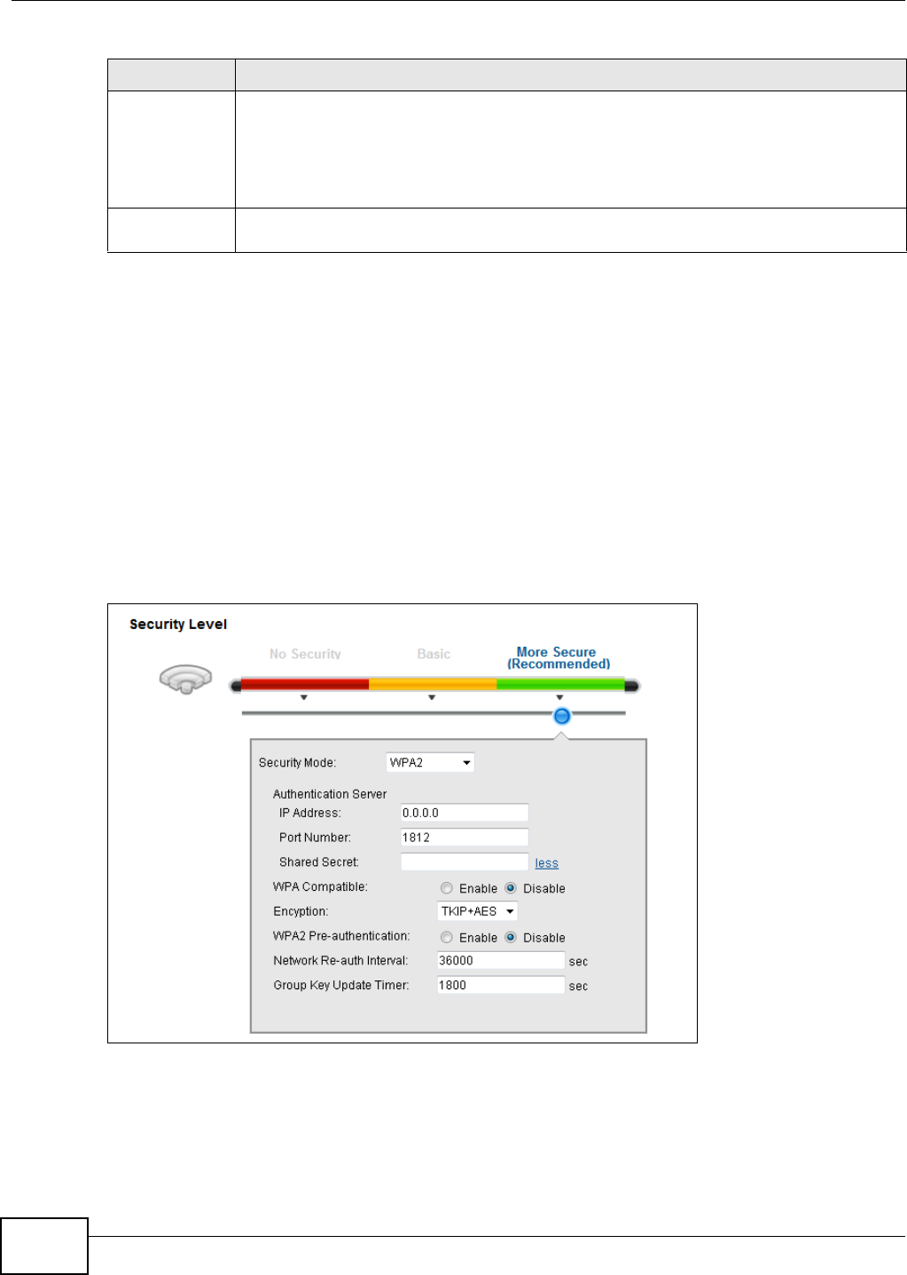
Chapter 6 Wireless
VMG1312-B10C User’s Guide
74
6.2.5 WPA(2) Authentication
The WPA2 security mode is currently the most robust form of encryption for wireless networks. It
requires a RADIUS server to authenticate user credentials and is a full implementation the security
protocol. Use this security option for maximum protection of your network. However, it is the least
backwards compatible with older devices.
The WPA security mode is a security subset of WPA2. It requires the presence of a RADIUS server
on your network in order to validate user credentials. This encryption standard is slightly older than
WPA2 and therefore is more compatible with older devices.
Click N et w ork Set t in g > W ir e le ss to display the Ge ne ral screen. Select M or e Se cure as the
security level. Then select W PA or W PA2 from the Se cur it y Mode list.
Figure 33 Wireless > General: More Secure: WPA(2)
Encryption Select the encryption type (TKI P, AES or TKI P+ AES) for data encryption.
Select TKI P if your wireless clients can all use TKIP.
Select AES if your wireless clients can all use AES.
Select TKI P+ AES to allow the wireless clients to use either TKIP or AES.
Group Key
Update Timer
The Grou p Ke y Updat e Tim er is the rate at which the RADIUS server sends a new group
key out to all clients.
Table 19 Wireless > General: More Secure: WPA(2)-PSK (continued)
LABEL DESCRIPTION

Chapter 6 Wireless
VMG1312-B10C User’s Guide 75
The following table describes the labels in this screen.
6.3 The More AP Screen
This screen allows you to enable and configure multiple Basic Service Sets (BSSs) on the Device.
Table 20 Wireless > General: More Secure: WPA(2)
LABEL DESCRIPTION
Security Level Select Mor e Se cur e to enable WPA(2)-PSK data encryption.
Security Mode Choose W PA or W PA2 from the drop-down list box.
Authentication Server
IP Address Enter the IP address of the external authentication server in dotted decimal notation.
Port
Number Enter the port number of the external authentication server. The default port number is
1 8 1 2 .
You need not change this value unless your network administrator instructs you to do so
with additional information.
Shared
Secret Enter a password (up to 31 alphanumeric characters) as the key to be shared between the
external authentication server and the Device.
The key must be the same on the external authentication server and your Device. The key is
not sent over the network.
more.../less Click m or e... to show more fields in this section. Click less to hide them.
WPA
Compatible
This field is only available for WPA2. Select this if you want the Device to support WPA and
WPA2 simultaneously.
Encryption Select the encryption type (TKI P, AES or TKI P+ AES) for data encryption.
Select TKI P if your wireless clients can all use TKIP.
Select AES if your wireless clients can all use AES.
Select TKI P+ AES to allow the wireless clients to use either TKIP or AES.
WPA2 Pre-
Authentication
This field is available only when you select W PA2 .
Pre-authentication enables fast roaming by allowing the wireless client (already connecting
to an AP) to perform IEEE 802.1x authentication with another AP before connecting to it.
Select En able d to turn on preauthentication in WAP2. Otherwise, select Disabled.
Network Re-
auth Interval
Specify how often wireless stations have to resend usernames and passwords in order to
stay connected.
If wireless station authentication is done using a RADIUS server, the reauthentication timer
on the RADIUS server has priority.
Group Key
Update Timer
The Grou p Ke y Updat e Tim er is the rate at which the RADIUS server sends a new group
key out to all clients.
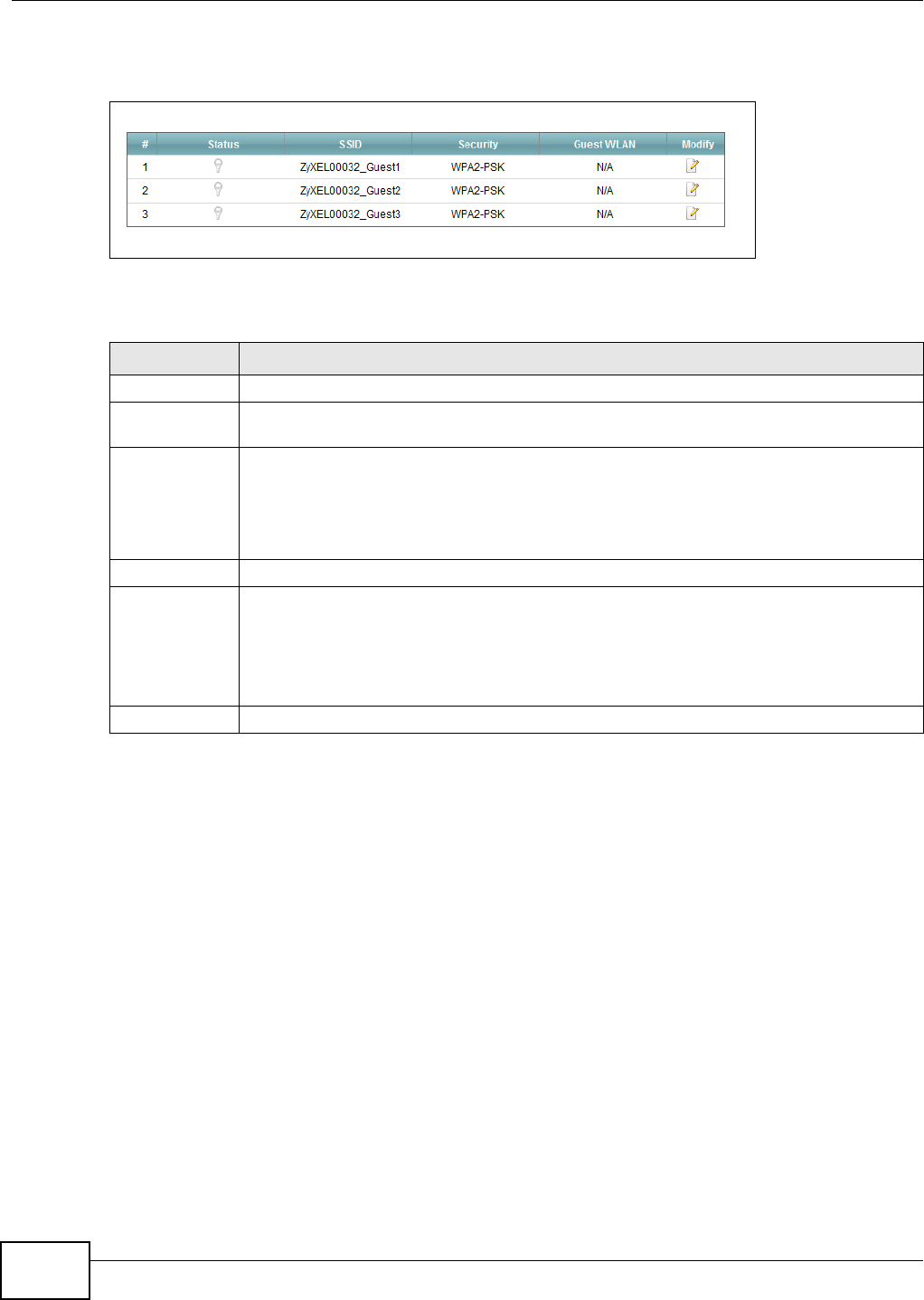
Chapter 6 Wireless
VMG1312-B10C User’s Guide
76
Click N et w or k Set t ing > W ir e le ss > M ore AP. The following screen displays.
Figure 34 Network Setting > Wireless > More AP
The following table describes the labels in this screen.
Table 21 Network Setting > Wireless > More AP
LABEL DESCRIPTION
# This is the index number of the entry.
Status This field indicates whether this SSID is active. A yellow bulb signifies that this SSID is
active. A gray bulb signifies that this SSID is not active.
SSID An SSID profile is the set of parameters relating to one of the Device’s BSSs. The SSID
(Service Set IDentifier) identifies the Service Set with which a wireless device is associated.
This field displays the name of the wireless profile on the network. When a wireless client
scans for an AP to associate with, this is the name that is broadcast and seen in the wireless
client utility.
Security This field indicates the security mode of the SSID profile.
Guest WLAN This displays if the guest WLAN function has been enabled for this WLAN.
If Hom e Gue st displays, clients can connect to each other directly.
If Ex t e r na l Gue st displays, clients are blocked from connecting to each other directly.
N / A displays if guest WLAN is disabled.
Modify Click the Edit icon to configure the SSID profile.
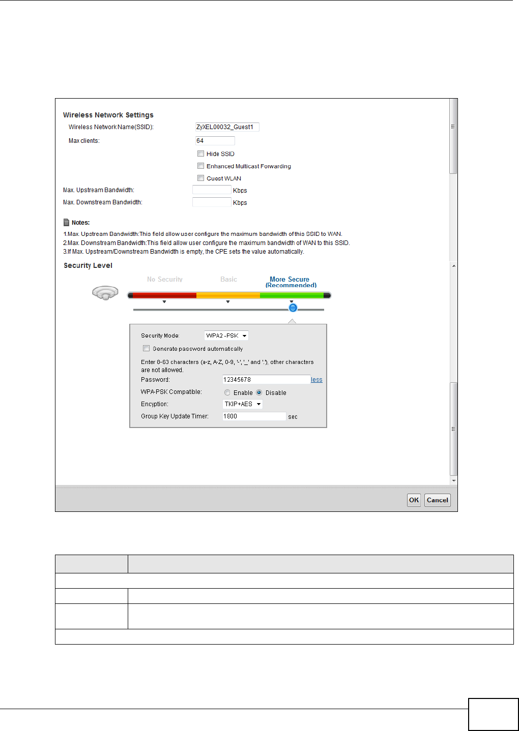
Chapter 6 Wireless
VMG1312-B10C User’s Guide 77
6.3.1 Edit More AP
Use this screen to edit an SSID profile. Click the Edit icon next to an SSID in the M ore AP screen.
The following screen displays.
Figure 35 More AP: Edit
The following table describes the fields in this screen.
Table 22 More AP: Edit
LABEL DESCRIPTION
Wireless Network Setup
Wireless You can En a ble or D isa ble the wireless LAN in this field.
Passphrase
Type
Passphrase type cannot be changed. The default is N on e .
Wireless Network Settings

Chapter 6 Wireless
VMG1312-B10C User’s Guide
78
6.4 MAC Authentication
This screen allows you to configure the ZyXEL Device to give exclusive access to specific devices
( Allow ) or exclude specific devices from accessing the ZyXEL Device ( De ny) . Every Ethernet
device has a unique MAC (Media Access Control) address. The MAC address is assigned at the
factory and consists of six pairs of hexadecimal characters, for example, 00:A0:C5:00:00:02. You
need to know the MAC addresses of the devices to configure this screen.
Wireless
Network Name
(SSID)
The SSID (Service Set IDentity) identifies the service set with which a wireless device is
associated. Wireless devices associating to the access point (AP) must have the same SSID.
Enter a descriptive name (up to 32 English keyboard characters) for the wireless LAN.
Max clients Specify the maximum number of clients that can connect to this network at the same time.
Hide SSID Select this check box to hide the SSID in the outgoing beacon frame so a station cannot
obtain the SSID through scanning using a site survey tool.
Enhanced
Multicast
Forwarding
Select this check box to allow the Device to convert wireless multicast traffic into wireless
unicast traffic.
Guest WLAN Select this to create Guest WLANs for home and external clients. Select the WLAN type in
the Access Scenario field.
Access
Scenario
If you select Hom e Guest , clients can connect to each other directly.
If you select Ext erna l Gue st , clients are blocked from connecting to each other directly.
Maximum
Upstream
Bandwidth
Specify the maximum rate for upstream wireless traffic to the WAN from this WLAN in
kilobits per second (Kbps).
Maximum
Downstream
Bandwidth
Specify the maximum rate for downstream wireless traffic to this WLAN from the WAN in
kilobits per second (Kbps).
Security Level
Security Mode Select Ba sic ( W EP, 8 0 2 .1 X) or M ore Secur e ( W PA( 2 ) - PSK, W PA( 2 ) ) to add security
on this wireless network. The wireless clients which want to associate to this network must
have same wireless security settings as the Device. After you select to use a security,
additional options appears in this screen.
Or you can select No Secur it y to allow any client to associate this network without any data
encryption or authentication.
See Section 6.2.1 on page 69 for more details about this field.
Apply Click Apply to save your changes.
Cancel Click Cance l to exit this screen without saving.
Table 22 More AP: Edit (continued)
LABEL DESCRIPTION
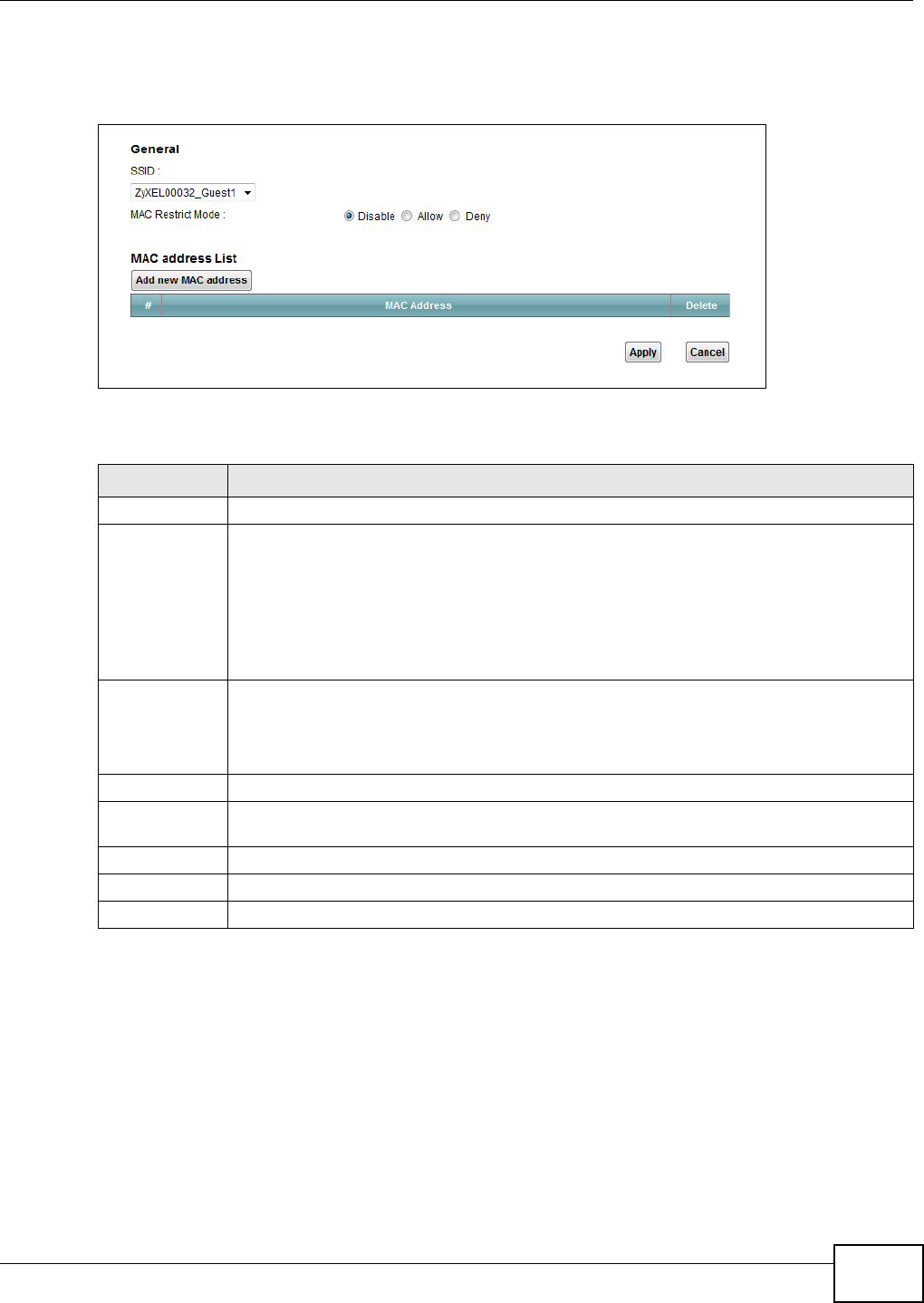
Chapter 6 Wireless
VMG1312-B10C User’s Guide 79
Use this screen to view your Device’s MAC filter settings and add new MAC filter rules. Click
N e t w or k Se t t ing > W ir e le ss > MAC Aut he nt ica t ion. The screen appears as shown.
Figure 36 Wireless > MAC Authentication
The following table describes the labels in this screen.
6.5 The WPS Screen
Use this screen to configure WiFi Protected Setup (WPS) on your Device.
WPS allows you to quickly set up a wireless network with strong security, without having to
configure security settings manually. Set up each WPS connection between two devices. Both
devices must support WPS. See Section 6.10.9.3 on page 95 for more information about WPS.
Table 23 Wireless > MAC Authentication
LABEL DESCRIPTION
SSID Select the SSID for which you want to configure MAC filter settings.
MAC Restrict
Mode
Define the filter action for the list of MAC addresses in the M AC Addr e ss table.
Select D isa ble to turn off MAC filtering.
Select D e ny to block access to the Device. MAC addresses not listed will be allowed to
access the Device.
Select Allow to permit access to the Device. MAC addresses not listed will be denied access
to the Device.
Add new MAC
address
Click this if you want to add a new MAC address entry to the MAC filter list below.
Enter the MAC addresses of the wireless devices that are allowed or denied access to the
Device in these address fields. Enter the MAC addresses in a valid MAC address format, that
is, six hexadecimal character pairs, for example, 12:34:56:78:9a:bc.
#This is the index number of the entry.
MAC Address This is the MAC addresses of the wireless devices that are allowed or denied access to the
Device.
Delete Click the De le t e icon to delete the entry.
Apply Click Apply to save your changes.
Cancel Click Cance l to exit this screen without saving.
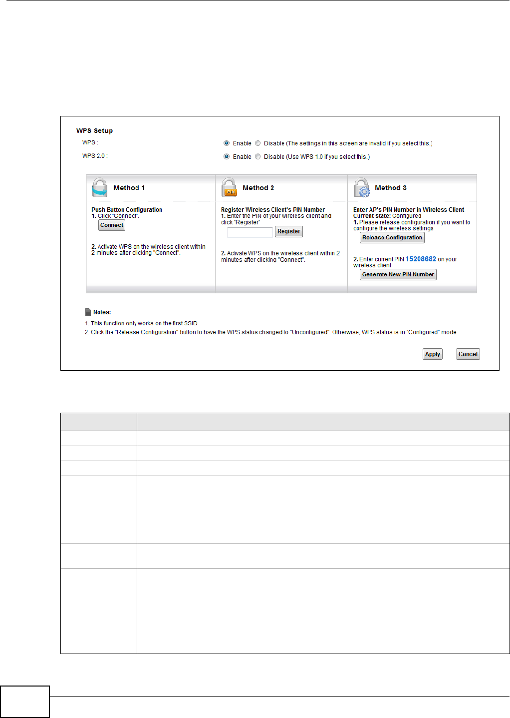
Chapter 6 Wireless
VMG1312-B10C User’s Guide
80
Note: The Device applies the security settings of the SSI D 1 profile (see Section 6.2 on
page 66). If you want to use the WPS feature, make sure you have set the security
mode of SSI D1 to W PA2 - PSK or N o Securit y.
Click N e t w ork Set t in g > W ire le ss > W PS. The following screen displays. Select Ena ble and click
Apply to activate the WPS function. Then you can configure the WPS settings in this screen.
Figure 37 Network Setting > Wireless > WPS
The following table describes the labels in this screen.
Table 24 Network Setting > Wireless > WPS
LABEL DESCRIPTION
WPS Select Enable to activate WPS on the Device.
WPS 2.0 Select En a ble to have the device use WPS 2.0 or Disable to have it use WPS 1.0.
Method 1 Use this section to set up a WPS wireless network using Push Button Configuration (PBC).
Connect Click this button to add another WPS-enabled wireless device (within wireless range of the
Device) to your wireless network. This button may either be a physical button on the
outside of device, or a menu button similar to the Con ne ct button on this screen.
Note: You must press the other wireless device’s WPS button within two minutes of pressing
this button.
Method 2 Use this section to set up a WPS wireless network by entering the PIN of the client into the
Device.
Register Enter the PIN of the device that you are setting up a WPS connection with and click
Re g ist e r to authenticate and add the wireless device to your wireless network.
You can find the PIN either on the outside of the device, or by checking the device’s
settings.
Note: You must also activate WPS on that device within two minutes to have it present its
PIN to the Device.
Chapter 6 Wireless
VMG1312-B10C User’s Guide 81
6.6 The WMM Screen
Use this screen to enable Wi-Fi MultiMedia (WMM) and WMM Power Save in wireless networks for
multimedia applications.
Click N et w or k Set t in g > W ire less > W MM . The following screen displays.
Figure 38 Network Setting > Wireless > WMM
The following table describes the labels in this screen.
Method 3 Use this section to set up a WPS wireless network by entering the PIN of the Device into
the client.
Release
Configuration The default WPS status is configured.
Click this button to remove all configured wireless and wireless security settings for WPS
connections on the Device.
Generate
New PIN
Number
The PIN (Personal Identification Number) of the Device is shown here. Enter this PIN in the
configuration utility of the device you want to connect to using WPS.
The PIN is not necessary when you use WPS push-button method.
Click the Gene r a t e N e w PI N N um ber button to have the Device create a new PIN.
Apply Click Apply to save your changes.
Cancel Click Ca nce l to restore your previously saved settings.
Table 24 Network Setting > Wireless > WPS (continued)
LABEL DESCRIPTION
Table 25 Network Setting > Wireless > WMM
LABEL DESCRIPTION
WMM Select On to have the Device automatically give a service a priority level according to the
ToS value in the IP header of packets it sends. WMM QoS (Wifi MultiMedia Quality of
Service) gives high priority to voice and video, which makes them run more smoothly.
WMM
Automatic
Power Save
Delivery
Select this option to extend the battery life of your mobile devices (especially useful for
small devices that are running multimedia applications). The Device goes to sleep mode to
save power when it is not transmitting data. The AP buffers the packets sent to the Device
until the Device "wakes up". The Device wakes up periodically to check for incoming data.
Note: Note: This works only if the wireless device to which the Device is connected also
supports this feature.
Apply Click Apply to save your changes.
Cancel Click Cance l to restore your previously saved settings.
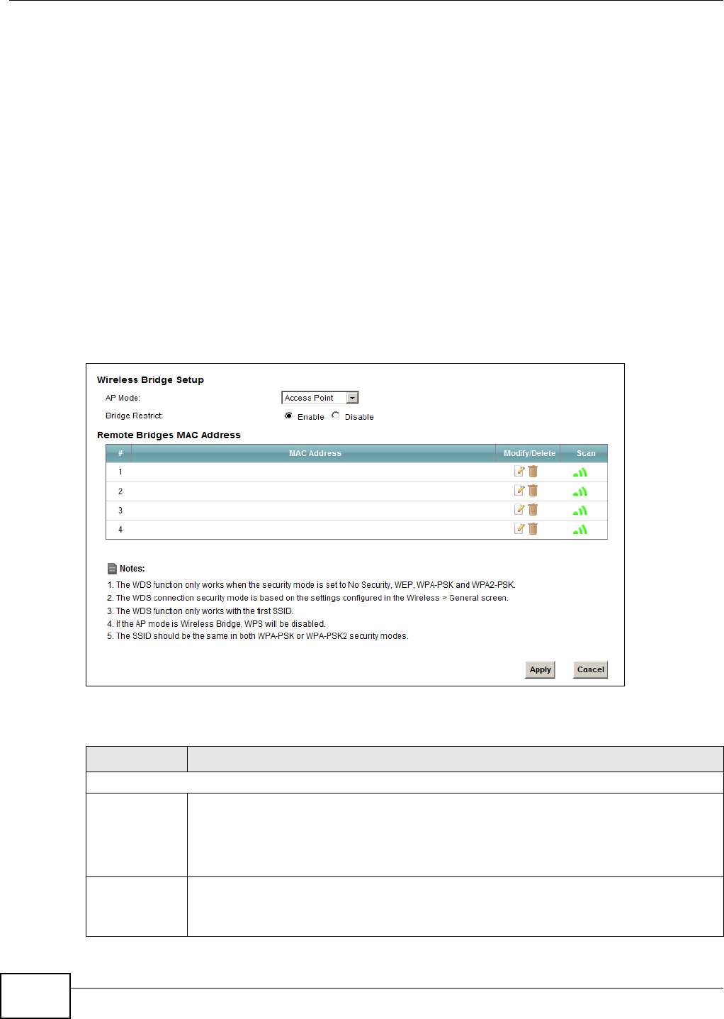
Chapter 6 Wireless
VMG1312-B10C User’s Guide
82
6.7 The WDS Screen
An AP using the Wireless Distribution System (WDS) can function as a wireless network bridge
allowing you to wirelessly connect two wired network segments. The W DS screen allows you to
configure the Device to connect to two or more APs wirelessly when WDS is enabled.
Use this screen to set up your WDS (Wireless Distribution System) links between the Device and
other wireless APs. You need to know the MAC address of the peer device. Once the security
settings of peer sides match one another, the connection between devices is made.
Note: WDS security is independent of the security settings between the Device and any
wireless clients.
Note: At the time of writing, WDS is compatible with other ZyXEL APs only. Not all models
support WDS links. Check your other AP’s documentation.
Click N et w or k Set t in g > W ire less > W DS. The following screen displays.
Figure 39 Network Setting > Wireless > WDS
The following table describes the labels in this screen.
Table 26 Network Setting > Wireless > WDS
LABEL DESCRIPTION
Wireless Bridge Setup
AP Mode Select the operating mode for your Device.
•Acce ss Poin t - The Device functions as a bridge and access point simultaneously.
•W ireless Bridge - The Device acts as a wireless network bridge and establishes
wireless links with other APs. In this mode, clients cannot connect to the Device
wirelessly.
Bridge Restrict This field is available only when you set operating mode to Acce ss Point .
Select Ena bled to turn on WDS and enter the peer device’s MAC address manually in the
table below. Select Disable to turn off WDS.
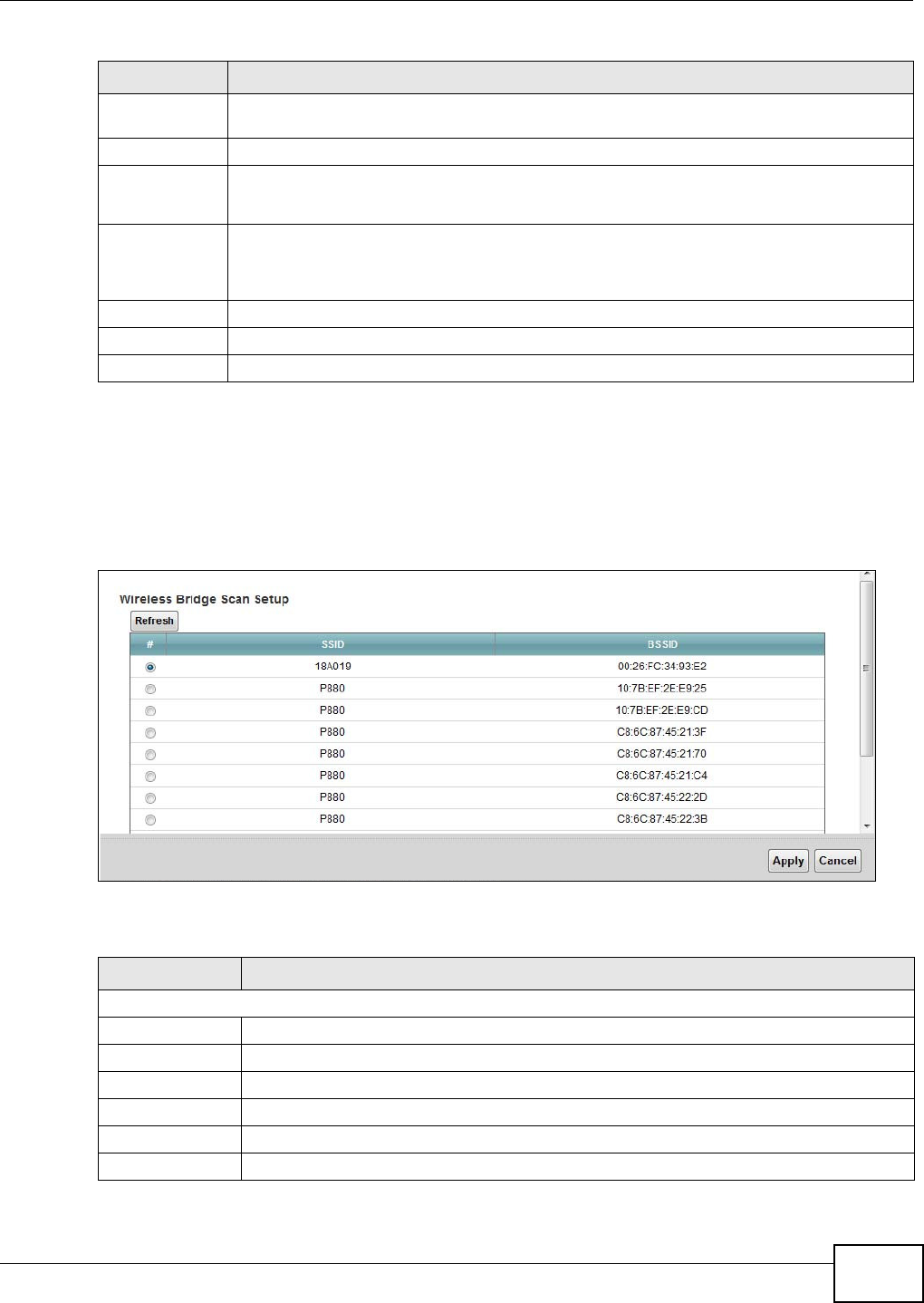
Chapter 6 Wireless
VMG1312-B10C User’s Guide 83
6.7.1 WDS Scan
You can click the Sca n icon in W ir eless > W D S to have the Device automatically search and
display the available APs within range. Select an AP and click Apply to have the Device establish a
wireless link with the selected wireless device.
Figure 40 WDS: Scan
The following table describes the labels in this screen.
Remote Bridge
MAC Address
You can enter the MAC address of the peer device by clicking the Edit icon under M odify.
# This is the index number of the entry.
MAC Address This shows the MAC address of the peer device.
You can connect to up to 4 peer devices.
Modify/Delete Click the Edit icon and type the MAC address of the peer device in a valid MAC address
format (six hexadecimal character pairs, for example 12:34:56:78:9a:bc).
Click the De le t e icon to remove this entry.
Scan Click the Sca n icon to search and display the available APs within range.
Apply Click Apply to save your changes.
Cancel Click Cance l to restore your previously saved settings.
Table 26 Network Setting > Wireless > WDS (continued)
LABEL DESCRIPTION
Table 27 WDS: Scan
LABEL DESCRIPTION
Wireless Bridge Scan Setup
Refresh Click Re fresh to update the table.
# This is the index number of the entry.
SSID This shows the SSID of the available wireless device within range.
BSSID This shows the MAC address of the available wireless device within range.
Apply Click Apply to save your changes.
Cancel Click Can cel to restore your previously saved settings.
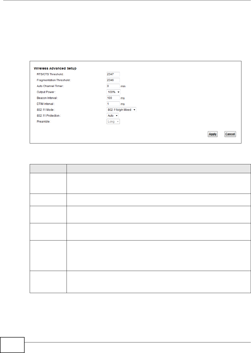
Chapter 6 Wireless
VMG1312-B10C User’s Guide
84
6.8 The Others Screen
Use this screen to configure advanced wireless settings. Click Net w ork Set t ing > W ir e le ss >
Ot h er s. The screen appears as shown.
See Section 6.10.2 on page 88 for detailed definitions of the terms listed in this screen.
Figure 41 Network Setting > Wireless > Others
The following table describes the labels in this screen.
Table 28 Network Setting > Wireless > Others
LABEL DESCRIPTION
RTS/CTS
Threshold
Data with its frame size larger than this value will perform the RTS (Request To Send)/CTS
(Clear To Send) handshake.
Enter a value between 0 and 2347.
Fragmentation
Threshold
This is the maximum data fragment size that can be sent. Enter a value between 256 and
2346.
Auto Channel
Timer
If you set the channel to Au t o in the N e t w or k Se t t ing > W ir ele ss > Ge nera l screen,
specify the interval in minutes for how often the Device scans for the best channel. Enter 0
to disable the periodical scan.
Output Power Set the output power of the Device. If there is a high density of APs in an area, decrease
the output power to reduce interference with other APs. Select one of the following: 2 0 % ,
4 0 % , 6 0 % , 8 0 % or 1 0 0 % .
Beacon Interval When a wirelessly networked device sends a beacon, it includes with it a beacon interval.
This specifies the time period before the device sends the beacon again.
The interval tells receiving devices on the network how long they can wait in low power
mode before waking up to handle the beacon. This value can be set from 50ms to 1000ms.
A high value helps save current consumption of the access point.
DTIM Interval Delivery Traffic Indication Message (DTIM) is the time period after which broadcast and
multicast packets are transmitted to mobile clients in the Power Saving mode. A high DTIM
value can cause clients to lose connectivity with the network. This value can be set from 1
to 255.

Chapter 6 Wireless
VMG1312-B10C User’s Guide 85
802.11 Mode Select 8 0 2 .1 1 b Only to allow only IEEE 802.11b compliant WLAN devices to associate with
the Device.
Select 8 0 2 .1 1 g Only to allow only IEEE 802.11g compliant WLAN devices to associate with
the Device.
Select 8 0 2 .1 1 n Only to allow only IEEE 802.11n compliant WLAN devices to associate with
the Device.
Select 8 0 2 .1 1 b/ g M ix ed to allow either IEEE 802.11b or IEEE 802.11g compliant WLAN
devices to associate with the Device. The transmission rate of your Device might be
reduced.
Select 8 0 2 .1 1 b/ g/ n M ixed to allow IEEE 802.11b, IEEE 802.11g or IEEE802.11n
compliant WLAN devices to associate with the Device. The transmission rate of your Device
might be reduced.
802.11
Protection
Enabling this feature can help prevent collisions in mixed-mode networks (networks with
both IEEE 802.11b and IEEE 802.11g traffic).
Select Auto to have the wireless devices transmit data after a RTS/CTS handshake. This
helps improve IEEE 802.11g performance.
Select Off to disable 802.11 protection. The transmission rate of your Device might be
reduced in a mixed-mode network.
This field displays Off and is not configurable when you set 8 0 2 .1 1 M ode to 8 0 2 .1 1 b
On ly.
Preamble Select a preamble type from the drop-down list box. Choices are Long or Sh or t . See
Section 6.10.7 on page 92 for more information.
This field is configurable only when you set 802.11 Mode to 8 0 2 .1 1 b.
Apply Click Apply to save your changes.
Cancel Click Cancel to restore your previously saved settings.
Table 28 Network Setting > Wireless > Others (continued)
LABEL DESCRIPTION
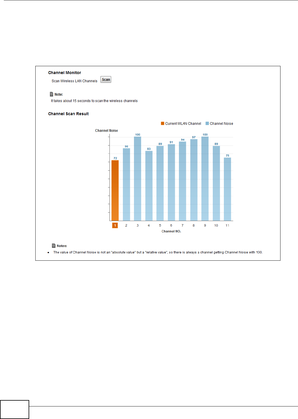
Chapter 6 Wireless
VMG1312-B10C User’s Guide
86
6.9 The Channel Status Screen
Use the Channe l Sta t us screen to scan wireless LAN channel noises and view the results. Click
N e t w or k Se t t ing > W ire le ss > Channel St a t us. The screen appears as shown. Click Sca n to
scan the wireless LAN channels. You can view the results in the Cha n ne l Scan Re sult section.
Figure 42 Network Setting > Wireless > Channel Status
6.10 Technical Reference
This section discusses wireless LANs in depth.
6.10.1 Wireless Network Overview
Wireless networks consist of wireless clients, access points and bridges.
• A wireless client is a radio connected to a user’s computer.
• An access point is a radio with a wired connection to a network, which can connect with
numerous wireless clients and let them access the network.
• A bridge is a radio that relays communications between access points and wireless clients,
extending a network’s range.
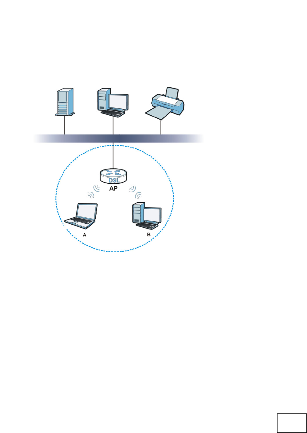
Chapter 6 Wireless
VMG1312-B10C User’s Guide 87
Traditionally, a wireless network operates in one of two ways.
• An “infrastructure” type of network has one or more access points and one or more wireless
clients. The wireless clients connect to the access points.
• An “ad-hoc” type of network is one in which there is no access point. Wireless clients connect to
one another in order to exchange information.
The following figure provides an example of a wireless network.
Figure 43 Example of a Wireless Network
The wireless network is the part in the blue circle. In this wireless network, devices A and B use the
access point (AP) to interact with the other devices (such as the printer) or with the Internet. Your
Device is the AP.
Every wireless network must follow these basic guidelines.
• Every device in the same wireless network must use the same SSID.
The SSID is the name of the wireless network. It stands for Service Set IDentifier.
• If two wireless networks overlap, they should use a different channel.
Like radio stations or television channels, each wireless network uses a specific channel, or
frequency, to send and receive information.
• Every device in the same wireless network must use security compatible with the AP.
Security stops unauthorized devices from using the wireless network. It can also protect the
information that is sent in the wireless network.
Chapter 6 Wireless
VMG1312-B10C User’s Guide
88
Radio Channels
In the radio spectrum, there are certain frequency bands allocated for unlicensed, civilian use. For
the purposes of wireless networking, these bands are divided into numerous channels. This allows a
variety of networks to exist in the same place without interfering with one another. When you
create a network, you must select a channel to use.
Since the available unlicensed spectrum varies from one country to another, the number of
available channels also varies.
6.10.2 Additional Wireless Terms
The following table describes some wireless network terms and acronyms used in the Device’s Web
Configurator.
6.10.3 Wireless Security Overview
By their nature, radio communications are simple to intercept. For wireless data networks, this
means that anyone within range of a wireless network without security can not only read the data
passing over the airwaves, but also join the network. Once an unauthorized person has access to
the network, he or she can steal information or introduce malware (malicious software) intended to
compromise the network. For these reasons, a variety of security systems have been developed to
ensure that only authorized people can use a wireless data network, or understand the data carried
on it.
These security standards do two things. First, they authenticate. This means that only people
presenting the right credentials (often a username and password, or a “key” phrase) can access the
network. Second, they encrypt. This means that the information sent over the air is encoded. Only
people with the code key can understand the information, and only people who have been
authenticated are given the code key.
These security standards vary in effectiveness. Some can be broken, such as the old Wired
Equivalent Protocol (WEP). Using WEP is better than using no security at all, but it will not keep a
determined attacker out. Other security standards are secure in themselves but can be broken if a
Table 29 Additional Wireless Terms
TERM DESCRIPTION
RTS/CTS Threshold In a wireless network which covers a large area, wireless devices are sometimes not
aware of each other’s presence. This may cause them to send information to the AP
at the same time and result in information colliding and not getting through.
By setting this value lower than the default value, the wireless devices must
sometimes get permission to send information to the Device. The lower the value, the
more often the devices must get permission.
If this value is greater than the fragmentation threshold value (see below), then
wireless devices never have to get permission to send information to the Device.
Preamble A preamble affects the timing in your wireless network. There are two preamble
modes: long and short. If a device uses a different preamble mode than the Device
does, it cannot communicate with the Device.
Authentication The process of verifying whether a wireless device is allowed to use the wireless
network.
Fragmentation
Threshold
A small fragmentation threshold is recommended for busy networks, while a larger
threshold provides faster performance if the network is not very busy.

Chapter 6 Wireless
VMG1312-B10C User’s Guide 89
user does not use them properly. For example, the WPA-PSK security standard is very secure if you
use a long key which is difficult for an attacker’s software to guess - for example, a twenty-letter
long string of apparently random numbers and letters - but it is not very secure if you use a short
key which is very easy to guess - for example, a three-letter word from the dictionary.
Because of the damage that can be done by a malicious attacker, it’s not just people who have
sensitive information on their network who should use security. Everybody who uses any wireless
network should ensure that effective security is in place.
A good way to come up with effective security keys, passwords and so on is to use obscure
information that you personally will easily remember, and to enter it in a way that appears random
and does not include real words. For example, if your mother owns a 1970 Dodge Challenger and
her favorite movie is Vanishing Point (which you know was made in 1971) you could use
“70dodchal71vanpoi” as your security key.
The following sections introduce different types of wireless security you can set up in the wireless
network.
6.10.3.1 SSID
Normally, the Device acts like a beacon and regularly broadcasts the SSID in the area. You can hide
the SSID instead, in which case the Device does not broadcast the SSID. In addition, you should
change the default SSID to something that is difficult to guess.
This type of security is fairly weak, however, because there are ways for unauthorized wireless
devices to get the SSID. In addition, unauthorized wireless devices can still see the information that
is sent in the wireless network.
6.10.3.2 MAC Address Filter
Every device that can use a wireless network has a unique identification number, called a MAC
address.1 A MAC address is usually written using twelve hexadecimal characters2; for example,
00A0C5000002 or 00:A0:C5:00:00:02. To get the MAC address for each device in the wireless
network, see the device’s User’s Guide or other documentation.
You can use the MAC address filter to tell the Device which devices are allowed or not allowed to
use the wireless network. If a device is allowed to use the wireless network, it still has to have the
correct information (SSID, channel, and security). If a device is not allowed to use the wireless
network, it does not matter if it has the correct information.
This type of security does not protect the information that is sent in the wireless network.
Furthermore, there are ways for unauthorized wireless devices to get the MAC address of an
authorized device. Then, they can use that MAC address to use the wireless network.
6.10.3.3 User Authentication
Authentication is the process of verifying whether a wireless device is allowed to use the wireless
network. You can make every user log in to the wireless network before using it. However, every
device in the wireless network has to support IEEE 802.1x to do this.
1. Some wireless devices, such as scanners, can detect wireless networks but cannot use wireless networks. These kinds
of wireless devices might not have MAC addresses.
2. Hexadecimal characters are 0, 1, 2, 3, 4, 5, 6, 7, 8, 9, A, B, C, D, E, and F.
Chapter 6 Wireless
VMG1312-B10C User’s Guide
90
For wireless networks, you can store the user names and passwords for each user in a RADIUS
server. This is a server used in businesses more than in homes. If you do not have a RADIUS server,
you cannot set up user names and passwords for your users.
Unauthorized wireless devices can still see the information that is sent in the wireless network,
even if they cannot use the wireless network. Furthermore, there are ways for unauthorized
wireless users to get a valid user name and password. Then, they can use that user name and
password to use the wireless network.
6.10.3.4 Encryption
Wireless networks can use encryption to protect the information that is sent in the wireless
network. Encryption is like a secret code. If you do not know the secret code, you cannot
understand the message.
The types of encryption you can choose depend on the type of authentication. (See Section
6.10.3.3 on page 89 for information about this.)
For example, if the wireless network has a RADIUS server, you can choose W PA or W PA2 . If users
do not log in to the wireless network, you can choose no encryption, St a t ic W EP, W PA- PSK, or
W PA2 - PSK.
Usually, you should set up the strongest encryption that every device in the wireless network
supports. For example, suppose you have a wireless network with the Device and you do not have
a RADIUS server. Therefore, there is no authentication. Suppose the wireless network has two
devices. Device A only supports WEP, and device B supports WEP and WPA. Therefore, you should
set up St a t ic W EP in the wireless network.
Note: It is recommended that wireless networks use W PA- PSK, W PA, or stronger
encryption. The other types of encryption are better than none at all, but it is still
possible for unauthorized wireless devices to figure out the original information
pretty quickly.
When you select W PA2 or W PA2 - PSK in your Device, you can also select an option (W PA
com pat ible) to support WPA as well. In this case, if some of the devices support WPA and some
support WPA2, you should set up W PA2 - PSK or W PA2 (depending on the type of wireless network
login) and select the W PA com pa t ible option in the Device.
Many types of encryption use a key to protect the information in the wireless network. The longer
the key, the stronger the encryption. Every device in the wireless network must have the same key.
Table 30 Types of Encryption for Each Type of Authentication
NO AUTHENTICATION RADIUS SERVER
W ea k est No Security WPA
Static WEP
WPA-PSK
St r on ge st WPA2-PSK WPA2
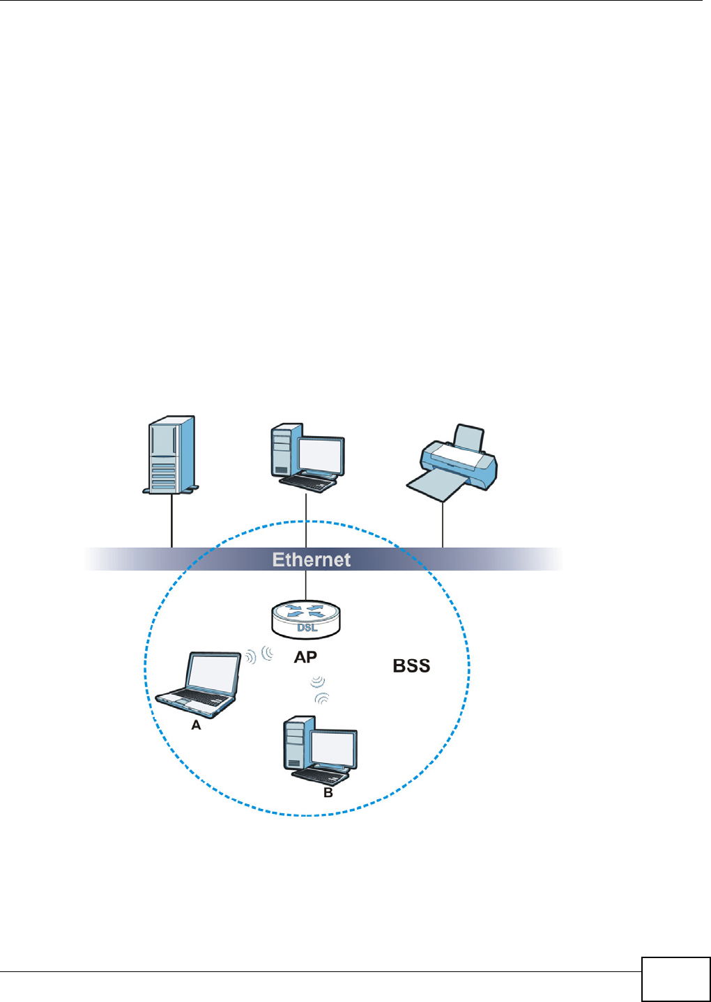
Chapter 6 Wireless
VMG1312-B10C User’s Guide 91
6.10.4 Signal Problems
Because wireless networks are radio networks, their signals are subject to limitations of distance,
interference and absorption.
Problems with distance occur when the two radios are too far apart. Problems with interference
occur when other radio waves interrupt the data signal. Interference may come from other radio
transmissions, such as military or air traffic control communications, or from machines that are
coincidental emitters such as electric motors or microwaves. Problems with absorption occur when
physical objects (such as thick walls) are between the two radios, muffling the signal.
6.10.5 BSS
A Basic Service Set (BSS) exists when all communications between wireless stations or between a
wireless station and a wired network client go through one access point (AP).
Intra-BSS traffic is traffic between wireless stations in the BSS. When Intra-BSS traffic blocking is
disabled, wireless station A and B can access the wired network and communicate with each other.
When Intra-BSS traffic blocking is enabled, wireless station A and B can still access the wired
network but cannot communicate with each other.
Figure 44 Basic Service set
6.10.6 MBSSID
Traditionally, you need to use different APs to configure different Basic Service Sets (BSSs). As well
as the cost of buying extra APs, there is also the possibility of channel interference. The Device’s

Chapter 6 Wireless
VMG1312-B10C User’s Guide
92
MBSSID (Multiple Basic Service Set IDentifier) function allows you to use one access point to
provide several BSSs simultaneously. You can then assign varying QoS priorities and/or security
modes to different SSIDs.
Wireless devices can use different BSSIDs to associate with the same AP.
6.10.6.1 Notes on Multiple BSSs
• A maximum of eight BSSs are allowed on one AP simultaneously.
• You must use different keys for different BSSs. If two wireless devices have different BSSIDs
(they are in different BSSs), but have the same keys, they may hear each other’s
communications (but not communicate with each other).
• MBSSID should not replace but rather be used in conjunction with 802.1x security.
6.10.7 Preamble Type
Preamble is used to signal that data is coming to the receiver. Short and long refer to the length of
the synchronization field in a packet.
Short preamble increases performance as less time sending preamble means more time for sending
data. All IEEE 802.11 compliant wireless adapters support long preamble, but not all support short
preamble.
Use long preamble if you are unsure what preamble mode other wireless devices on the network
support, and to provide more reliable communications in busy wireless networks.
Use short preamble if you are sure all wireless devices on the network support it, and to provide
more efficient communications.
Use the dynamic setting to automatically use short preamble when all wireless devices on the
network support it, otherwise the Device uses long preamble.
Note: The wireless devices MUST use the same preamble mode in order to communicate.
6.10.8 Wireless Distribution System (WDS)
The Device can act as a wireless network bridge and establish WDS (Wireless Distribution System)
links with other APs. You need to know the MAC addresses of the APs you want to link to. Once the
security settings of peer sides match one another, the connection between devices is made.
At the time of writing, WDS security is compatible with other ZyXEL access points only. Refer to
your other access point’s documentation for details.
The following figure illustrates how WDS link works between APs. Notebook computer A is a
wireless client connecting to access point AP 1 . AP 1 has no wired Internet connection, but it can
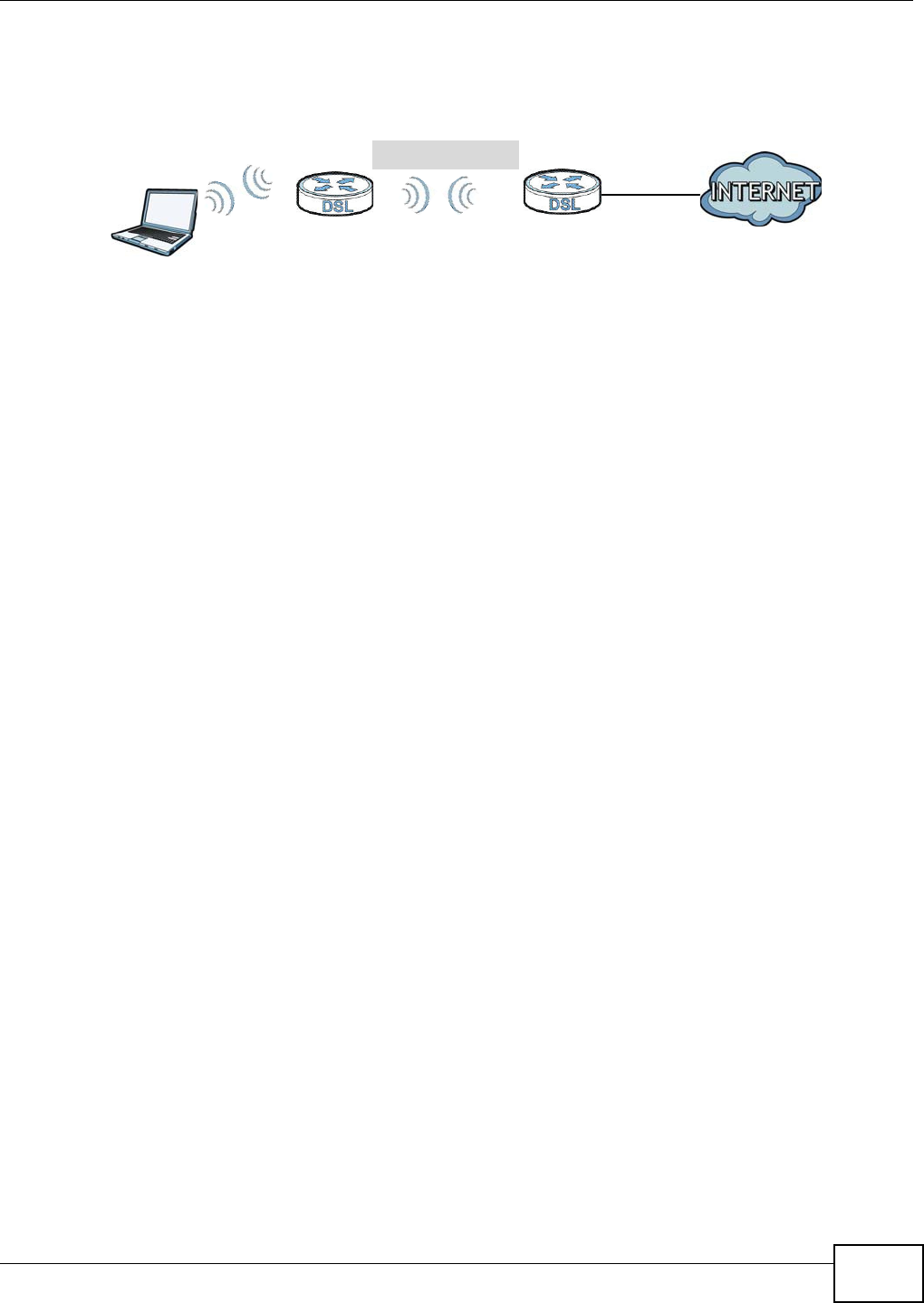
Chapter 6 Wireless
VMG1312-B10C User’s Guide 93
establish a WDS link with access point AP 2 , which has a wired Internet connection. When AP 1
has a WDS link with AP 2 , the notebook computer can access the Internet through AP 2 .
Figure 45 WDS Link Example
6.10.9 WiFi Protected Setup (WPS)
Your Device supports WiFi Protected Setup (WPS), which is an easy way to set up a secure wireless
network. WPS is an industry standard specification, defined by the WiFi Alliance.
WPS allows you to quickly set up a wireless network with strong security, without having to
configure security settings manually. Each WPS connection works between two devices. Both
devices must support WPS (check each device’s documentation to make sure).
Depending on the devices you have, you can either press a button (on the device itself, or in its
configuration utility) or enter a PIN (a unique Personal Identification Number that allows one device
to authenticate the other) in each of the two devices. When WPS is activated on a device, it has two
minutes to find another device that also has WPS activated. Then, the two devices connect and set
up a secure network by themselves.
6.10.9.1 Push Button Configuration
WPS Push Button Configuration (PBC) is initiated by pressing a button on each WPS-enabled
device, and allowing them to connect automatically. You do not need to enter any information.
Not every WPS-enabled device has a physical WPS button. Some may have a WPS PBC button in
their configuration utilities instead of or in addition to the physical button.
Take the following steps to set up WPS using the button.
1Ensure that the two devices you want to set up are within wireless range of one another.
2Look for a WPS button on each device. If the device does not have one, log into its configuration
utility and locate the button (see the device’s User’s Guide for how to do this - for the Device, see
Section 6.6 on page 81).
3Press the button on one of the devices (it doesn’t matter which). For the Device you must press the
WPS button for more than three seconds.
4Within two minutes, press the button on the other device. The registrar sends the network name
(SSID) and security key through an secure connection to the enrollee.
If you need to make sure that WPS worked, check the list of associated wireless clients in the AP’s
configuration utility. If you see the wireless client in the list, WPS was successful.
WDS
AP 2
AP 1
A

Chapter 6 Wireless
VMG1312-B10C User’s Guide
94
6.10.9.2 PIN Configuration
Each WPS-enabled device has its own PIN (Personal Identification Number). This may either be
static (it cannot be changed) or dynamic (in some devices you can generate a new PIN by clicking
on a button in the configuration interface).
Use the PIN method instead of the push-button configuration (PBC) method if you want to ensure
that the connection is established between the devices you specify, not just the first two devices to
activate WPS in range of each other. However, you need to log into the configuration interfaces of
both devices to use the PIN method.
When you use the PIN method, you must enter the PIN from one device (usually the wireless client)
into the second device (usually the Access Point or wireless router). Then, when WPS is activated
on the first device, it presents its PIN to the second device. If the PIN matches, one device sends
the network and security information to the other, allowing it to join the network.
Take the following steps to set up a WPS connection between an access point or wireless router
(referred to here as the AP) and a client device using the PIN method.
1Ensure WPS is enabled on both devices.
2Access the WPS section of the AP’s configuration interface. See the device’s User’s Guide for how to
do this.
3Look for the client’s WPS PIN; it will be displayed either on the device, or in the WPS section of the
client’s configuration interface (see the device’s User’s Guide for how to find the WPS PIN - for the
Device, see Section 6.5 on page 79).
4Enter the client’s PIN in the AP’s configuration interface.
5If the client device’s configuration interface has an area for entering another device’s PIN, you can
either enter the client’s PIN in the AP, or enter the AP’s PIN in the client - it does not matter which.
6Start WPS on both devices within two minutes.
7Use the configuration utility to activate WPS, not the push-button on the device itself.
8On a computer connected to the wireless client, try to connect to the Internet. If you can connect,
WPS was successful.
If you cannot connect, check the list of associated wireless clients in the AP’s configuration utility. If
you see the wireless client in the list, WPS was successful.
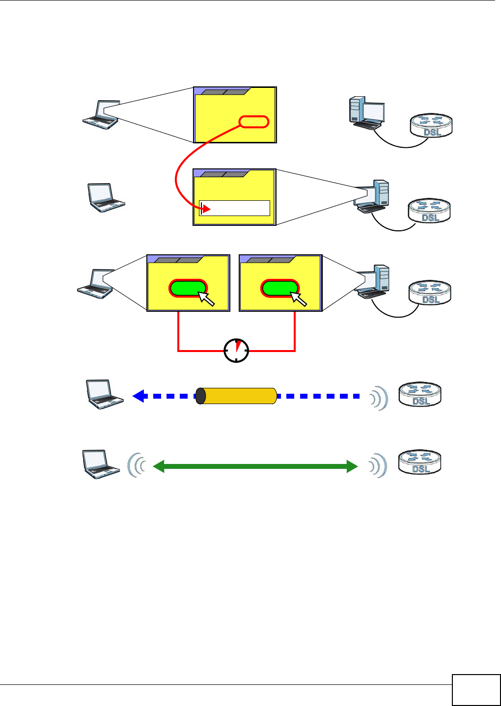
Chapter 6 Wireless
VMG1312-B10C User’s Guide 95
The following figure shows a WPS-enabled wireless client (installed in a notebook computer)
connecting to the WPS-enabled AP via the PIN method.
Figure 46 Example WPS Process: PIN Method
6.10.9.3 How WPS Works
When two WPS-enabled devices connect, each device must assume a specific role. One device acts
as the registrar (the device that supplies network and security settings) and the other device acts
as the enrollee (the device that receives network and security settings. The registrar creates a
secure EAP (Extensible Authentication Protocol) tunnel and sends the network name (SSID) and the
WPA-PSK or WPA2-PSK pre-shared key to the enrollee. Whether WPA-PSK or WPA2-PSK is used
depends on the standards supported by the devices. If the registrar is already part of a network, it
sends the existing information. If not, it generates the SSID and WPA(2)-PSK randomly.
ENROLLEE
SECURE EAP TUNNEL
SSID
WPA(2)-PSK
WITHIN 2 MINUTES
COMMUNICATION
This device’s
WPS
Enter WPS PIN
WPS
from other device:
WPS PIN: 123456
WPS
START
WPS
START
REGISTRAR
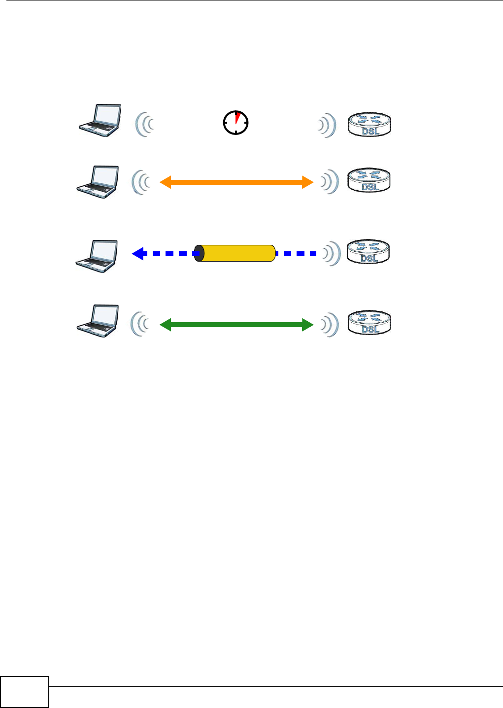
Chapter 6 Wireless
VMG1312-B10C User’s Guide
96
The following figure shows a WPS-enabled client (installed in a notebook computer) connecting to a
WPS-enabled access point.
Figure 47 How WPS works
The roles of registrar and enrollee last only as long as the WPS setup process is active (two
minutes). The next time you use WPS, a different device can be the registrar if necessary.
The WPS connection process is like a handshake; only two devices participate in each WPS
transaction. If you want to add more devices you should repeat the process with one of the existing
networked devices and the new device.
Note that the access point (AP) is not always the registrar, and the wireless client is not always the
enrollee. All WPS-certified APs can be a registrar, and so can some WPS-enabled wireless clients.
By default, a WPS devices is “unconfigured”. This means that it is not part of an existing network
and can act as either enrollee or registrar (if it supports both functions). If the registrar is
unconfigured, the security settings it transmits to the enrollee are randomly-generated. Once a
WPS-enabled device has connected to another device using WPS, it becomes “configured”. A
configured wireless client can still act as enrollee or registrar in subsequent WPS connections, but a
configured access point can no longer act as enrollee. It will be the registrar in all subsequent WPS
connections in which it is involved. If you want a configured AP to act as an enrollee, you must reset
it to its factory defaults.
6.10.9.4 Example WPS Network Setup
This section shows how security settings are distributed in an example WPS setup.
The following figure shows an example network. In step 1, both AP1 and Clie nt 1 are
unconfigured. When WPS is activated on both, they perform the handshake. In this example, AP1
SECURE TUNNEL
SECURITY INFO
WITHIN 2 MINUTES
COMMUNICATION
ACTIVATE
WPS
ACTIVATE
WPS
WPS HANDSHAKE
REGISTRARENROLLEE
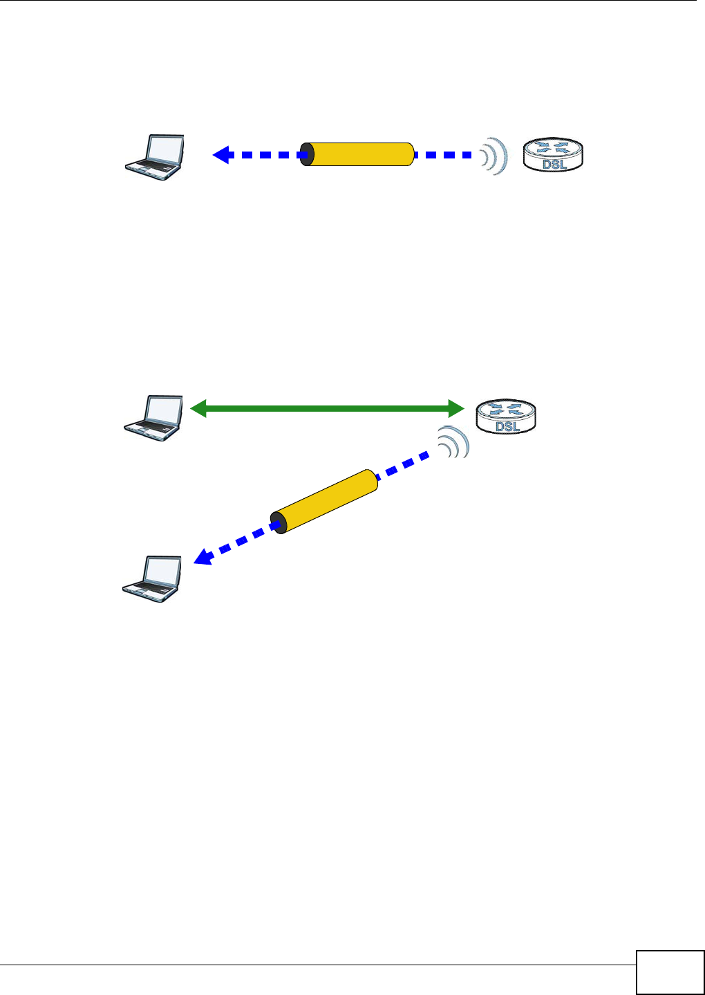
Chapter 6 Wireless
VMG1312-B10C User’s Guide 97
is the registrar, and Client 1 is the enrollee. The registrar randomly generates the security
information to set up the network, since it is unconfigured and has no existing information.
Figure 48 WPS: Example Network Step 1
In step 2 , you add another wireless client to the network. You know that Client 1 supports registrar
mode, but it is better to use AP1 for the WPS handshake with the new client since you must
connect to the access point anyway in order to use the network. In this case, AP1 must be the
registrar, since it is configured (it already has security information for the network). AP1 supplies
the existing security information to Client 2 .
Figure 49 WPS: Example Network Step 2
REGISTRARENROLLEE
SECURITY INFO
CLIENT 1 AP1
REGISTRAR
CLIENT 1 AP1
ENROLLEE
CLIENT 2
EXISTING CONNECTION
SECURITY INFO
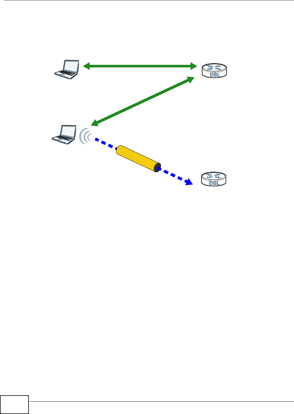
Chapter 6 Wireless
VMG1312-B10C User’s Guide
98
In step 3, you add another access point (AP2 ) to your network. AP2 is out of range of AP1 , so you
cannot use AP1 for the WPS handshake with the new access point. However, you know that Clie n t
2 supports the registrar function, so you use it to perform the WPS handshake instead.
Figure 50 WPS: Example Network Step 3
6.10.9.5 Limitations of WPS
WPS has some limitations of which you should be aware.
• WPS works in Infrastructure networks only (where an AP and a wireless client communicate). It
does not work in Ad-Hoc networks (where there is no AP).
• When you use WPS, it works between two devices only. You cannot enroll multiple devices
simultaneously, you must enroll one after the other.
For instance, if you have two enrollees and one registrar you must set up the first enrollee (by
pressing the WPS button on the registrar and the first enrollee, for example), then check that it
successfully enrolled, then set up the second device in the same way.
• WPS works only with other WPS-enabled devices. However, you can still add non-WPS devices to
a network you already set up using WPS.
WPS works by automatically issuing a randomly-generated WPA-PSK or WPA2-PSK pre-shared
key from the registrar device to the enrollee devices. Whether the network uses WPA-PSK or
WPA2-PSK depends on the device. You can check the configuration interface of the registrar
device to discover the key the network is using (if the device supports this feature). Then, you
can enter the key into the non-WPS device and join the network as normal (the non-WPS device
must also support WPA-PSK or WPA2-PSK).
CLIENT 1 AP1
REGISTRAR
CLIENT 2
EXISTING CONNECTION
SECURITY INFO
ENROLLEE
AP2
EXISTING CONNECTION

Chapter 6 Wireless
VMG1312-B10C User’s Guide 99
• When you use the PBC method, there is a short period (from the moment you press the button
on one device to the moment you press the button on the other device) when any WPS-enabled
device could join the network. This is because the registrar has no way of identifying the
“correct” enrollee, and cannot differentiate between your enrollee and a rogue device. This is a
possible way for a hacker to gain access to a network.
You can easily check to see if this has happened. WPS works between only two devices
simultaneously, so if another device has enrolled your device will be unable to enroll, and will not
have access to the network. If this happens, open the access point’s configuration interface and
look at the list of associated clients (usually displayed by MAC address). It does not matter if the
access point is the WPS registrar, the enrollee, or was not involved in the WPS handshake; a
rogue device must still associate with the access point to gain access to the network. Check the
MAC addresses of your wireless clients (usually printed on a label on the bottom of the device). If
there is an unknown MAC address you can remove it or reset the AP.

Chapter 6 Wireless
VMG1312-B10C User’s Guide
100
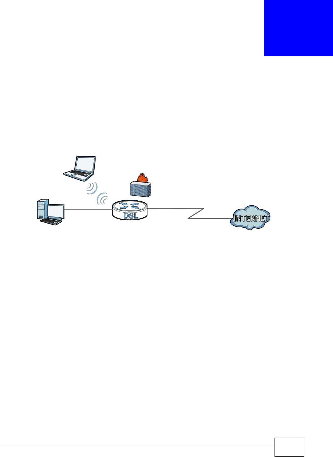
VMG1312-B10C User’s Guide 101
CHAPTER 7
Home Networking
7.1 Overview
A Local Area Network (LAN) is a shared communication system to which many networking devices
are connected. It is usually located in one immediate area such as a building or floor of a building.
Use the LAN screens to help you configure a LAN DHCP server and manage IP addresses.
7.1.1 What You Can Do in this Chapter
•Use the LAN Set up screen to set the LAN IP address, subnet mask, and DHCP settings of your
Device (Section 7.2 on page 103).
•Use the Stat ic DH CP screen to assign IP addresses on the LAN to specific individual computers
based on their MAC Addresses (Section 7.3 on page 107).
•Use the UPnP screen to enable UPnP and UPnP NAT traversal on the Device (Section 7.4 on page
108).
•Use the Addit iona l Subnet screen to configure IP alias and public static IP (Section 7.5 on page
109).
•Use the STB Vendor I D screen to have the Device automatically create static DHCP entries for
Set Top Box (STB) devices when they request IP addresses (Section 7.8 on page 119)
•Use the LAN VLAN screen to control the VLAN ID and IEEE 802.1p priority tags of traffic sent out
through individual LAN ports (Section 7.9 on page 120).
DSL
LAN

Chapter 7 Home Networking
VMG1312-B10C User’s Guide
102
7.1.2 What You Need To Know
7.1.2.1 About LAN
IP Address
IP addresses identify individual devices on a network. Every networking device (including
computers, servers, routers, printers, etc.) needs an IP address to communicate across the
network. These networking devices are also known as hosts.
Subnet Mask
Subnet masks determine the maximum number of possible hosts on a network. You can also use
subnet masks to divide one network into multiple sub-networks.
DHCP
A DHCP (Dynamic Host Configuration Protocol) server can assign your Device an IP address, subnet
mask, DNS and other routing information when it's turned on.
DNS
DNS (Domain Name System) is for mapping a domain name to its corresponding IP address and
vice versa. The DNS server is extremely important because without it, you must know the IP
address of a networking device before you can access it.
RADVD (Router Advertisement Daemon)
When an IPv6 host sends a Router Solicitation (RS) request to discover the available routers,
RADVD with Router Advertisement (RA) messages in response to the request. It specifies the
minimum and maximum intervals of RA broadcasts. RA messages containing the address prefix.
IPv6 hosts can be generated with the IPv6 prefix an IPv6 address.
7.1.2.2 About UPnP
Identifying UPnP Devices
UPnP hardware is identified as an icon in the Network Connections folder (Windows XP). Each UPnP
compatible device installed on your network will appear as a separate icon. Selecting the icon of a
UPnP device will allow you to access the information and properties of that device.
NAT Traversal
UPnP NAT traversal automates the process of allowing an application to operate through NAT. UPnP
network devices can automatically configure network addressing, announce their presence in the
network to other UPnP devices and enable exchange of simple product and service descriptions.
NAT traversal allows the following:
• Dynamic port mapping
• Learning public IP addresses

Chapter 7 Home Networking
VMG1312-B10C User’s Guide 103
• Assigning lease times to mappings
Windows Messenger is an example of an application that supports NAT traversal and UPnP.
See the Chapter 10 on page 149 for more information on NAT.
Cautions with UPnP
The automated nature of NAT traversal applications in establishing their own services and opening
firewall ports may present network security issues. Network information and configuration may also
be obtained and modified by users in some network environments.
When a UPnP device joins a network, it announces its presence with a multicast message. For
security reasons, the Device allows multicast messages on the LAN only.
All UPnP-enabled devices may communicate freely with each other without additional configuration.
Disable UPnP if this is not your intention.
UPnP and ZyXEL
ZyXEL has achieved UPnP certification from the Universal Plug and Play Forum UPnP™
Implementers Corp. (UIC). ZyXEL's UPnP implementation supports Internet Gateway Device (IGD)
1.0.
See Section 7.5 on page 109 for examples of installing and using UPnP.
Finding Out More
See Section 7.10 on page 120 for technical background information on LANs.
7.1.3 Before You Begin
Find out the MAC addresses of your network devices if you intend to add them to the DHCP Client
List screen.
7.2 The LAN Setup Screen
Use this screen to set the Local Area Network IP address and subnet mask of your Device. Click
N e t w or k Se t t ing > H om e N e t w or k ing to open the LAN Se t up screen.
Follow these steps to configure your LAN settings.
1Enter an IP address into the I P Address field. The IP address must be in dotted decimal notation.
This will become the IP address of your Device.
2Enter the IP subnet mask into the I P Subnet M a sk field. Unless instructed otherwise it is best to
leave this alone, the configurator will automatically compute a subnet mask based upon the IP
address you entered.
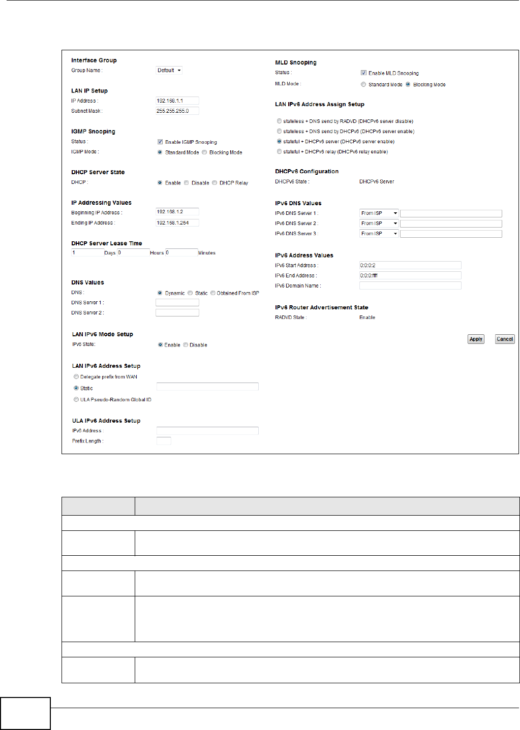
Chapter 7 Home Networking
VMG1312-B10C User’s Guide
104
3Click Apply to save your settings.
Figure 51 Network Setting > Home Networking > LAN Setup
The following table describes the fields in this screen.
Table 31 Network Setting > Home Networking > LAN Setup
LABEL DESCRIPTION
Interface Group
Group Name Select the interface group name for which you want to configure LAN settings. See Chapter
12 on page 171 for how to create a new interface group.
LAN IP Setup
IP Address Enter the LAN IP address you want to assign to your Device in dotted decimal notation, for
example, 192.168.1.1 (factory default).
Subnet Mask Type the subnet mask of your network in dotted decimal notation, for example
255.255.255.0 (factory default). Your Device automatically computes the subnet mask
based on the IP Address you enter, so do not change this field unless you are instructed to
do so.
IGMP Snooping
Status Select the En able I GMP Snooping check box to allows the Device to passively learn
multicast group.

Chapter 7 Home Networking
VMG1312-B10C User’s Guide 105
IGMP Mode Select St an da r d Mode to have the Device forward multicast packets to a port that joins the
multicast group and broadcast unknown multicast packets from the WAN to all LAN ports.
Select Blocking M ode to have the Device block all unknown multicast packets from the
WAN.
DHCP Server State
DHCP Select Enable to have the Device act as a DHCP server or DHCP relay agent.
Select Disable to stop the DHCP server on the Device.
Select DH CP Re la y to have the Device forward DHCP request to the DHCP server.
DHCP Relay
Server Address
This field is only available when you select DHCP Relay in the D H CP field.
IP Address Enter the IP address of the actual remote DHCP server in this field.
IP Addressing
Values
This field is only available when you select En able in the DH CP field.
Beginning IP
Address
This field specifies the first of the contiguous addresses in the IP address pool.
Ending IP
Address
This field specifies the last of the contiguous addresses in the IP address pool.
DHCP Server
Lease Time
This is the period of time DHCP-assigned addresses is used. DHCP automatically assigns IP
addresses to clients when they log in. DHCP centralizes IP address management on central
computers that run the DHCP server program. DHCP leases addresses, for a period of time,
which means that past addresses are “recycled” and made available for future reassignment
to other systems.
This field is only available when you select En able in the DH CP field.
Days/Hours/
Minutes
Enter the lease time of the DHCP server.
DNS Values This field is only available when you select Ena ble in the D H CP field.
DNS Specify which DNS server addresses the Device sends to LAN DHCP clients.
Select Dyna m ic to have the DHCP clients use the Device’s LAN IP address as the DNS
server address so the Device acts as a proxy for DNS queries.
Select St a t ic to manually enter DNS server addresses.
Select Obt ained from I SP to use the DNS server IP addresses the Device’s WAN
connection uses.
DNS Server 1
DNS Server 2
Enter the first and second DNS (Domain Name System) server IP address the Device passes
to the DHCP clients.
LAN IPv6 Mode Setup
IPv6 State Select En a ble to activate the IPv6 mode and configure IPv6 settings on the Device.
LAN IPv6 Address Setup
Delegate prefix
from WAN
Select this option to automatically obtain an IPv6 network prefix from the service provider
or an uplink router.
Static Select this option to configure a fixed IPv6 address for the Device’s LAN IPv6 address.
ULA Pseudo-
Random Global
ID
A unique local address (ULA) is a unique IPv6 address for use in private networks but not
routable in the global IPv6 Internet.
Select this to have the Device automatically generate a globally unique address for the LAN
IPv6 address. The address format is like fdxx:xxxx:xxxx:xxxx::/64.
ULA IPv6 Address Setup
Table 31 Network Setting > Home Networking > LAN Setup (continued)
LABEL DESCRIPTION

Chapter 7 Home Networking
VMG1312-B10C User’s Guide
106
IPv6 Address If you select static IPv6 address, enter the IPv6 address prefix that the Device uses for the
LAN IPv6 address.
Prefix Length If you select static IPv6 address, enter the IPv6 prefix length that the Device uses to
generate the LAN IPv6 address.
An IPv6 prefix length specifies how many most significant bits (starting from the left) in the
address compose the network address. This field displays the bit number of the IPv6 subnet
mask.
MLD Snooping Multicast Listener Discovery (MLD) allows an IPv6 switch or router to discover the presence
of MLD hosts who wish to receive multicast packets and the IP addresses of multicast
groups the hosts want to join on its network. Select Ena ble M LD Snooping to activate MLD
snooping on the Device. This allows the Device to check MLD packets passing through it and
learn the multicast group membership. It helps reduce multicast traffic.
MLD Mode Select St a ndar d M ode to have the Device forward IPv6 multicast packets to a port that
joins the IPv6 multicast group and broadcast unknown IPv6 multicast packets from the WAN
to all LAN ports.
Select Blocking M ode to have the Device block all unknown IPv6 multicast packets from
the WAN.
LAN IPv6
Address Assign
Setup
Select how you want to obtain an IPv6 address:
•sta t e less + DN S send by RADVD : The Device uses IPv6 stateless autoconfiguration.
RADVD (Router Advertisement Daemon) is enabled to have the Device send IPv6 prefix
information in router advertisements periodically and in response to router solicitations.
DHCPv6 server is disabled. (See page 102 for more information on RADVD.)
•sta t e less + DN S sen d by DHCPv6 : The Device uses IPv6 stateless autoconfiguration.
The DNS is provided by a DHCPv6 server.
•sta t e fu l + D H CPv6 ser ve r : The Device uses IPv6 stateful autoconfiguration. The
DHCPv6 server is enabled to have the Device act as a DHCPv6 server and pass IPv6
addresses, DNS server and domain name information to DHCPv6 clients.
•sta t e fu l + DHCPv6 re la y: The Device uses IPv6 stateful autoconfiguration. DH CPv 6
Rela y is enabled to have the Device relay client DHCPv6 requests.
DHCPv6 Configuration
DHCPv6 State This shows the status of the DHCPv6.
IPv6 DNS Values
IPv6 DNS
Server 1-3
Select From I SP if your ISP dynamically assigns IPv6 DNS server information.
Select User - De fine d if you have the IPv6 address of a DNS server. Enter the DNS server
IPv6 addresses the Device passes to the DHCP clients.
Select N on e if you do not want to configure IPv6 DNS servers.
IPv6 Address Values
IPv6 Start
Address
If DHCPv6 is enabled, specify the first IPv6 address in the pool of addresses that can be
assigned to DHCPv6 clients.
IPv6 End
Address
If DHCPv6 is enabled, specify the last IPv6 address in the pool of addresses that can be
assigned to DHCPv6 clients.
IPv6 Domain
Name
If DHCPv6 is enabled, specify the domain name to be assigned to DHCPv6 clients.
IPv6 Router Advertisement State
RADVD State This shows the status of RADVD.
Apply Click Apply to save your changes.
Cancel Click Cance l to restore your previously saved settings.
Table 31 Network Setting > Home Networking > LAN Setup (continued)
LABEL DESCRIPTION
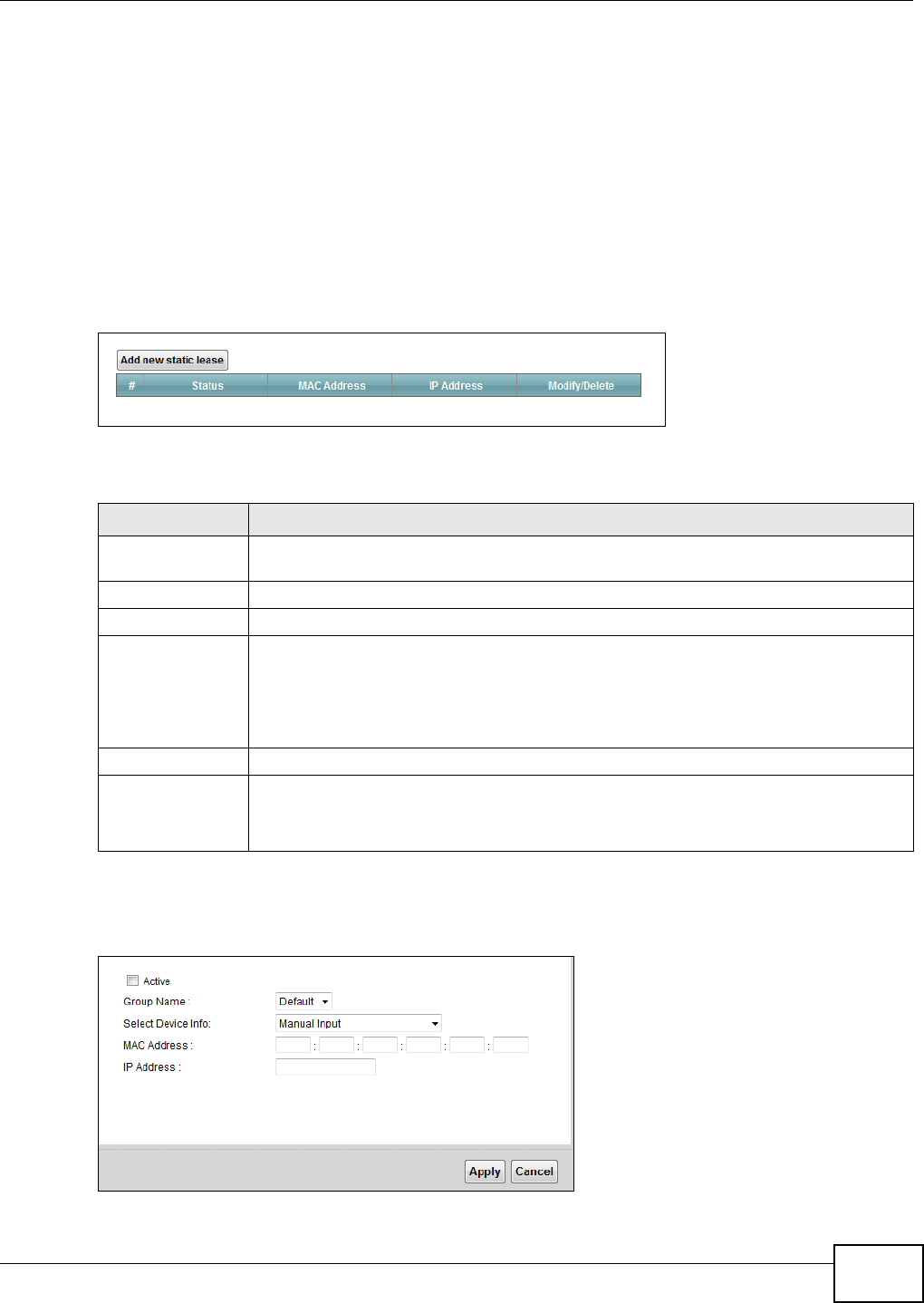
Chapter 7 Home Networking
VMG1312-B10C User’s Guide 107
7.3 The Static DHCP Screen
This table allows you to assign IP addresses on the LAN to specific individual computers based on
their MAC Addresses.
Every Ethernet device has a unique MAC (Media Access Control) address. The MAC address is
assigned at the factory and consists of six pairs of hexadecimal characters, for example,
00:A0:C5:00:00:02.
Use this screen to change your Device’s static DHCP settings. Click Net w ork Set t in g > Hom e
N e t w or k in g > St a t ic DH CP to open the following screen.
Figure 52 Network Setting > Home Networking > Static DHCP
The following table describes the labels in this screen.
If you click Add new st a t ic lea se in the Stat ic DHCP screen or the Edit icon next to a static DHCP
entry, the following screen displays.
Figure 53 Static DHCP: Add/Edit
Table 32 Network Setting > Home Networking > Static DHCP
LABEL DESCRIPTION
Add new static
lease
Click this to add a new static DHCP entry.
# This is the index number of the entry.
Status This field displays whether the client is connected to the Device.
MAC Address The MAC (Media Access Control) or Ethernet address on a LAN (Local Area Network) is
unique to your computer (six pairs of hexadecimal notation).
A network interface card such as an Ethernet adapter has a hardwired address that is
assigned at the factory. This address follows an industry standard that ensures no other
adapter has a similar address.
IP Address This field displays the IP address relative to the # field listed above.
Modify/Delete Click the Edit icon to have the IP address field editable and change it.
Click the D e le t e icon to delete a static DHCP entry. A window displays asking you to
confirm that you want to delete the selected entry.
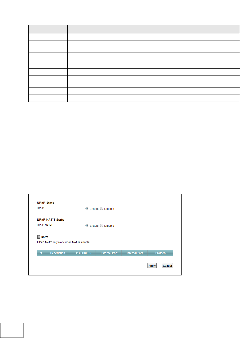
Chapter 7 Home Networking
VMG1312-B10C User’s Guide
108
The following table describes the labels in this screen.
7.4 The UPnP Screen
Universal Plug and Play (UPnP) is a distributed, open networking standard that uses TCP/IP for
simple peer-to-peer network connectivity between devices. A UPnP device can dynamically join a
network, obtain an IP address, convey its capabilities and learn about other devices on the network.
In turn, a device can leave a network smoothly and automatically when it is no longer in use.
See page 102 for more information on UPnP.
Use the following screen to configure the UPnP settings on your Device. Click N et w or k Set t ing >
Hom e N e t w ork in g > UPnP to display the screen shown next.
Figure 54 Network Setting > Home Networking > UPnP
Table 33 Static DHCP: Add/Edit
LABEL DESCRIPTION
Active Select this to activate the connection between the client and the Device.
Group Name Select the interface group name for which you want to configure static DHCP settings.
See Chapter 12 on page 171 for how to create a new interface group.
Select Device Info If you select Ma nual I n put , you can manually type in the MAC address and IP address of
a computer on your LAN. You can also choose the name of a computer from the drop list
and have the MAC Address and IP address auto-detected.
MAC Address If you select M anu a l I npu t , enter the MAC address of a computer on your LAN.
IP Address If you select Manual I n put , enter the IP address that you want to assign to the
computer on your LAN with the MAC address that you will also specify.
Apply Click Apply to save your changes.
Cancel Click Cance l to exit this screen without saving.

Chapter 7 Home Networking
VMG1312-B10C User’s Guide 109
The following table describes the labels in this screen.
7.5 Installing UPnP in Windows Example
This section shows how to install UPnP in Windows Me and Windows XP.
Installing UPnP in Windows Me
Follow the steps below to install the UPnP in Windows Me.
1Click St a r t and Cont rol Pa ne l. Double-click Add/ Re m ove Pr ogr a m s.
Table 34 Network Setting > Home Networking > UPnP
LABEL DESCRIPTION
UPnP Select En able to activate UPnP. Be aware that anyone could use a UPnP application to open
the web configurator's login screen without entering the Device's IP address (although you
must still enter the password to access the web configurator).
UPnP NAT-T Select Ena ble to allow UPnP-enabled applications to automatically configure the Device so
that they can communicate through the Device by using NAT traversal. UPnP applications
automatically reserve a NAT forwarding port in order to communicate with another UPnP
enabled device; this eliminates the need to manually configure port forwarding for the UPnP
enabled application.
The table below displays the NAT port forwarding rules added automatically by UPnP NAT-T.
# This is the index number of the UPnP NAT-T connection.
Description This is the description of the UPnP NAT-T connection.
IP Address This is the IP address of the other connected UPnP enabled device.
External Port This is the external port number that identifies the service.
Internal Port This is the internal port number that identifies the service.
Apply Click Apply to save your changes.
Cancel Click Cancel to exit this screen without saving.
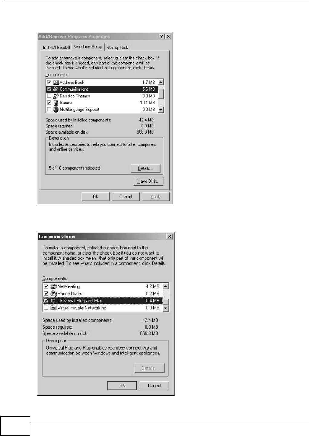
Chapter 7 Home Networking
VMG1312-B10C User’s Guide
110
2Click on the W indow s Se t up tab and select Com m u nica t ion in the Com pone n t s selection box.
Click D e t a ils.
Add/Remove Programs: Windows Setup: Communication
3In the Com m unicat ion s window, select the Un iversa l Plug a n d Pla y check box in the
Com pon e nt s selection box.
Add/Remove Programs: Windows Setup: Communication: Components
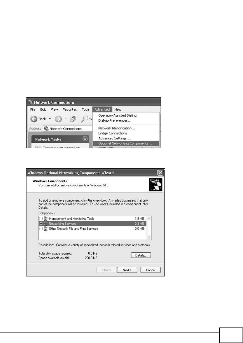
Chapter 7 Home Networking
VMG1312-B10C User’s Guide 111
4Click OK to go back to the Add/ Rem ove Pr ogr a m s Prope rt ie s window and click N e x t.
5Restart the computer when prompted.
Installing UPnP in Windows XP
Follow the steps below to install the UPnP in Windows XP.
1Click St a r t and Con t r ol Panel.
2Double-click N e t w ork Con n e ctions.
3In the N et w or k Connect ions window, click Adva nced in the main menu and select Opt ion a l
N e t w or k in g Com ponent s ….
Network Co nnections
4The W indow s Opt iona l N e t w ork ing Com ponent s W izar d window displays. Select N et w or king
Service in the Com pon e n t s selection box and click D et a ils.
Windows Optional Networking Components Wizard
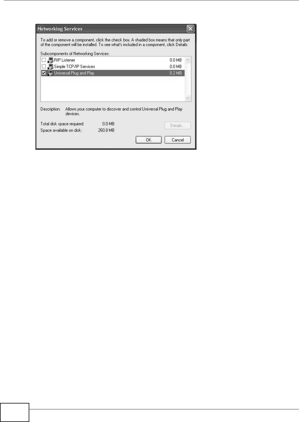
Chapter 7 Home Networking
VMG1312-B10C User’s Guide
112
5In the N et w ork ing Ser vices window, select the Un ive r sa l Plu g and Play check box.
Networking Services
6Click OK to go back to the W indow s Opt iona l N e t w ork in g Com pon e nt W iza r d window and
click N e x t .
7.6 Using UPnP in Windows XP Example
This section shows you how to use the UPnP feature in Windows XP. You must already have UPnP
installed in Windows XP and UPnP activated on the Device.
Make sure the computer is connected to a LAN port of the Device. Turn on your computer and the
Device.
Auto-discover Your UPnP-enabled Network Device
1Click St a r t and Con t r ol Panel. Double-click N et w ork Connect ions. An icon displays under
Internet Gateway.
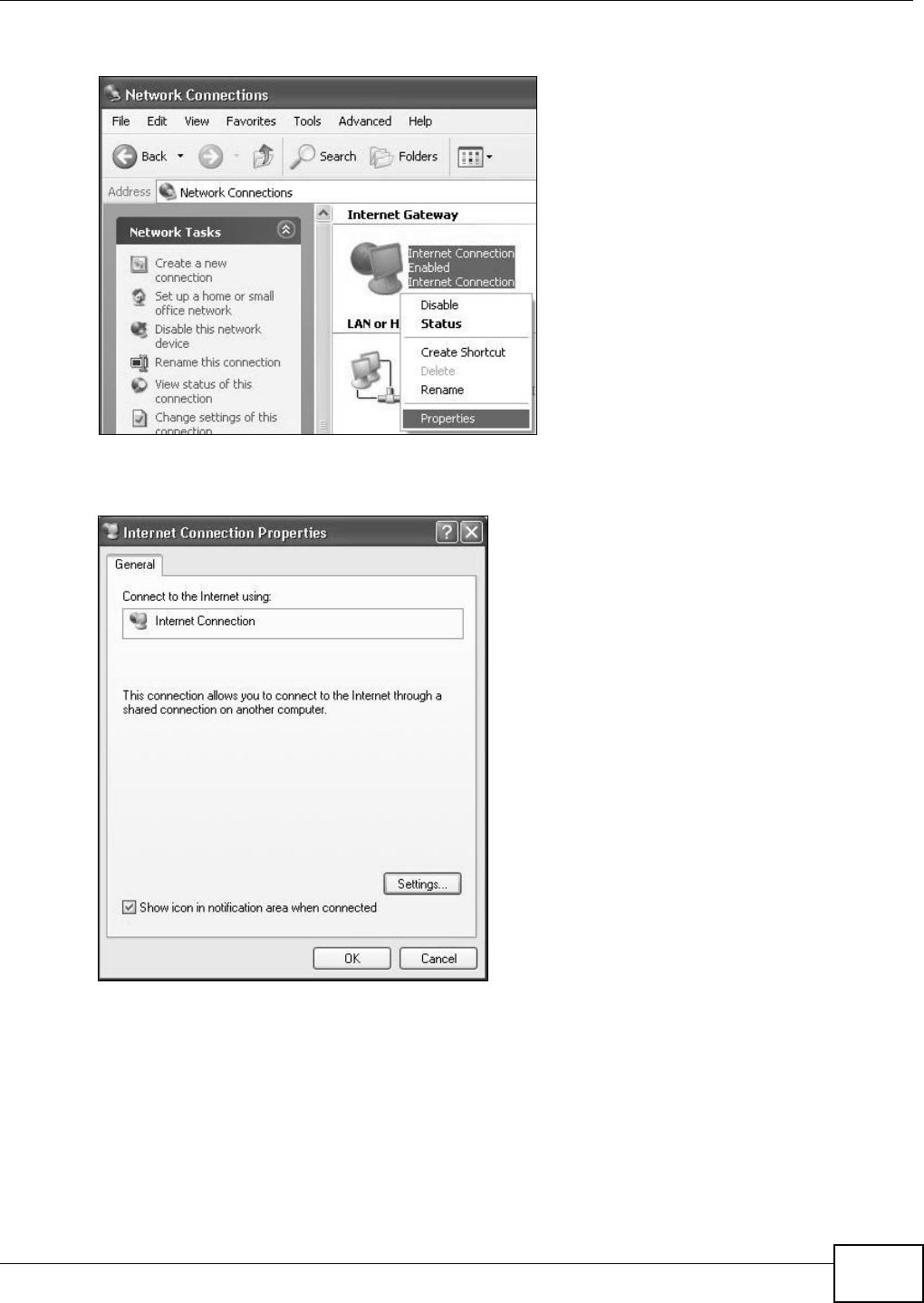
Chapter 7 Home Networking
VMG1312-B10C User’s Guide 113
2Right-click the icon and select Pr op er t ie s.
Network Co nnections
3In the I nt e r n e t Conne ct ion Prope rt ie s window, click Se t t ings to see the port mappings there
were automatically created.
Internet Connec tion Properties
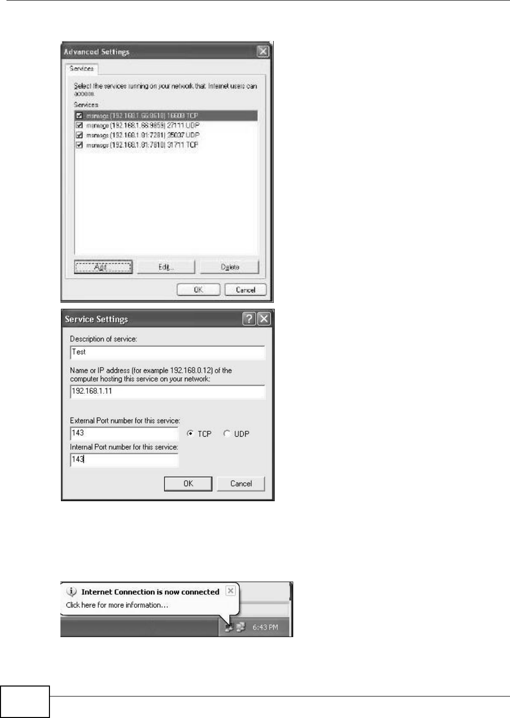
Chapter 7 Home Networking
VMG1312-B10C User’s Guide
114
4You may edit or delete the port mappings or click Add to manually add port mappings.
Internet Connection Properties: Advanced Settings
Internet Connec tion Properties: Advan ced Settings: Add
5When the UPnP-enabled device is disconnected from your computer, all port mappings will be
deleted automatically.
6Select Show icon in not ificat ion are a w hen connect e d option and click OK. An icon displays in
the system tray.
System Tray Icon
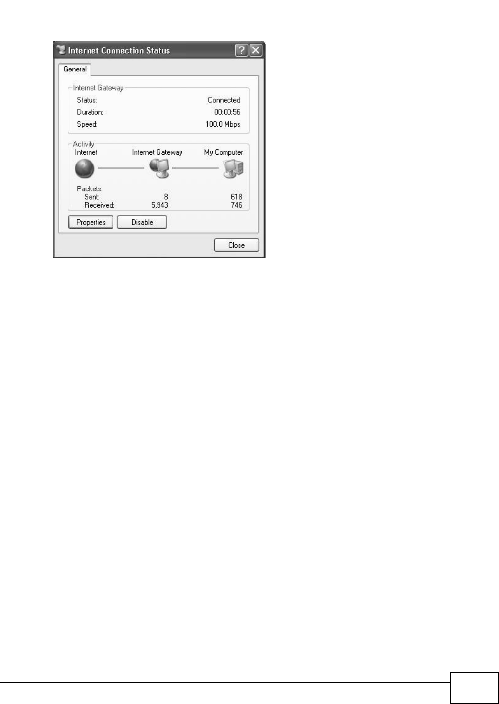
Chapter 7 Home Networking
VMG1312-B10C User’s Guide 115
7Double-click on the icon to display your current Internet connection status.
Internet Conn ection Status
Web Configurator Easy Access
With UPnP, you can access the web-based configurator on the Device without finding out the IP
address of the Device first. This comes helpful if you do not know the IP address of the Device.
Follow the steps below to access the web configurator.
1Click St a r t and then Con t r ol Pa ne l.
2Double-click N e t w ork Con n e ctions.
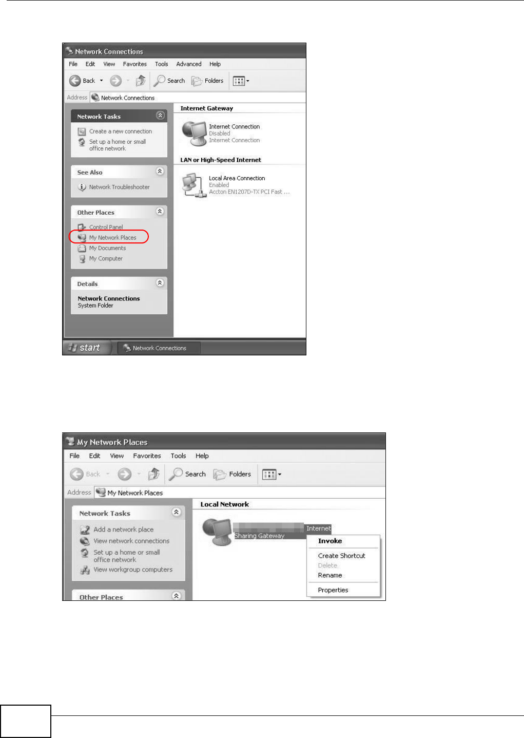
Chapter 7 Home Networking
VMG1312-B10C User’s Guide
116
3Select M y N et w or k Pla ce s under Ot her Pla ces.
Network Co nnections
4An icon with the description for each UPnP-enabled device displays under Loca l N e t w or k .
5Right-click on the icon for your Device and select I n vok e . The web configurator login screen
displays.
Network Co nnections: My Netw ork Places
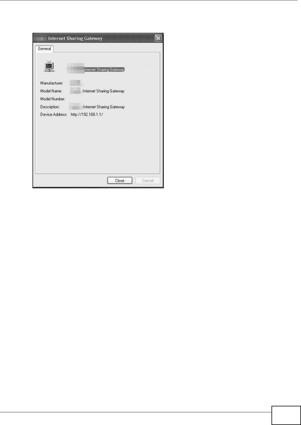
Chapter 7 Home Networking
VMG1312-B10C User’s Guide 117
6Right-click on the icon for your Device and select Pr op er t ie s. A properties window displays with
basic information about the Device.
Network Co nnections: My Netw ork Places: Proper ties: Example
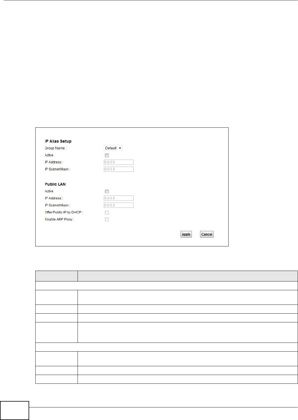
Chapter 7 Home Networking
VMG1312-B10C User’s Guide
118
7.7 The Additional Subnet Screen
Use the Addit iona l Subne t screen to configure IP alias and public static IP.
IP alias allows you to partition a physical network into different logical networks over the same
Ethernet interface. The Device supports multiple logical LAN interfaces via its physical Ethernet
interface with the Device itself as the gateway for the LAN network. When you use IP alias, you can
also configure firewall rules to control access to the LAN's logical network (subnet).
If your ISP provides the Public LAN service, the Device may use an LAN IP address that can be
accessed from the WAN.
Click N et w ork Set t in g > H om e N et w or k in g > Addit ion a l Subn e t to display the screen shown
next.
Figure 55 Network Setting > Home Networking > Additional Subnet
The following table describes the labels in this screen.
Table 35 Network Setting > Home Networking > Additional Subnet
LABEL DESCRIPTION
IP Alias Setup
Group Name Select the interface group name for which you want to configure the IP alias settings. See
Chapter 12 on page 171 for how to create a new interface group.
Active Select the check box to configure a LAN network for the Device.
IP Address Enter the IP address of your Device in dotted decimal notation.
IP Subnet Mask Your Device will automatically calculate the subnet mask based on the IP address that you
assign. Unless you are implementing subnetting, use the subnet mask computed by the
Device.
Public LAN
Active Select the checkbox to enable the Public LAN feature. Your ISP must support Public LAN and
Static IP.
IP Address Enter the public IP address provided by your ISP.
IP Subnet Mask Enter the public IP subnet mask provided by your ISP.
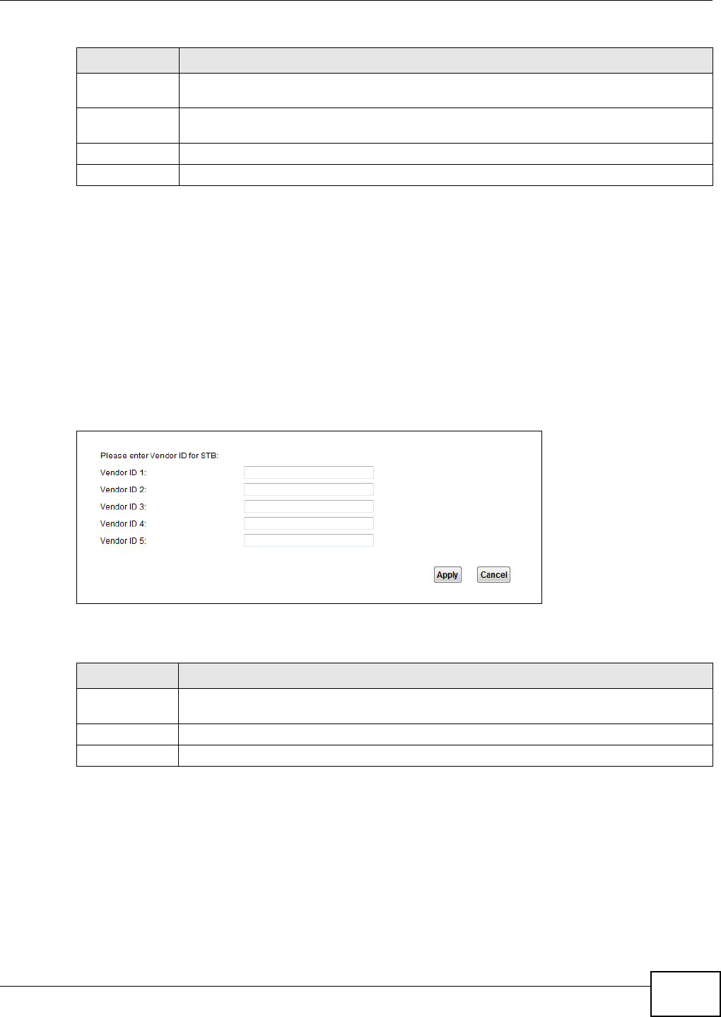
Chapter 7 Home Networking
VMG1312-B10C User’s Guide 119
7.8 The STB Vendor ID Screen
Set Top Box (STB) devices with dynamic IP addresses sometimes don’t renew their IP addresses
before the lease time expires. This could lead to IP address conflicts if the STB continues to use an
IP address that gets assigned to another device. Use this screen to list the Vendor IDs of connected
STBs to have the Device automatically create static DHCP entries for them when they request IP
addresses.
Click N et w ork Set t in g > H om e N e t w ork ing > STB V e n dor I D to open this screen.
Figure 56 Network Setting > Home Networking > STB Vendor ID
The following table describes the labels in this screen.
Offer Public IP
by DHCP
Select the check box to enable the Device to provide public IP addresses by DHCP server.
Enable ARP
Proxy
Select the check box to enable the ARP (Address Resolution Protocol) proxy.
Apply Click Apply to save your changes.
Cancel Click Cance l to exit this screen without saving.
Table 35 Network Setting > Home Networking > Additional Subnet (continued)
LABEL DESCRIPTION
Table 36 Network Setting > Home Networking > STB Vendor ID
LABEL DESCRIPTION
Vendor ID 1 ~
5
Enter the STB’s vendor ID.
Apply Click Apply to save your changes.
Cancel Click Cancel to exit this screen without saving.
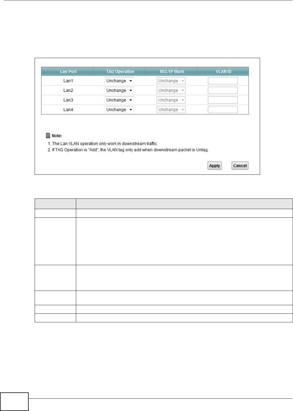
Chapter 7 Home Networking
VMG1312-B10C User’s Guide
120
7.9 The LAN VLAN Screen
Click Ne t w or k Set t ing > Hom e N et w or k ing > LAN V LAN to open this screen. Use this screen to
control the VLAN ID and IEEE 802.1p priority tags of traffic sent out through individual LAN ports.
Figure 57 Network Setting > Home Networking > LAN VLAN
The following table describes the labels in this screen.
7.10 Technical Reference
This section provides some technical background information about the topics covered in this
chapter.
Table 37 Network Setting > Home Networking > LAN VLAN
LABEL DESCRIPTION
Lan Port These represent the Device’s LAN ports.
Tag Operation Select what you want the Device to do to the IEEE 802.1q VLAN ID and priority tags of
downstream traffic before sending it out through this LAN port.
•Unchan ge - Don’t do anything to the traffic’s VLAN ID and priority tags.
•Add - Add VLAN ID and priority tags to untagged traffic.
•Re m ove - Delete one tag from tagged traffic. If the frame has double tags, this removes
the outer tag. This does not affect untagged traffic.
•Re m a rk - Change the value of the outer VLAN ID and priority tags.
802.1P Mark Use this option to set what to do for the IEEE 802.1p priority tags when you add or remark
the tags for a LAN port’s downstream traffic. Either select Uncha n ge to not modify the
traffic’s priority tags or select an priority from 0 to 7 to use. The larger the number, the
higher the priority.
VLAN ID If you will add or remark tags for this LAN port’s downstream traffic, specify the VLAN ID
(from 0 to 4094) to use here.
Apply Click Apply to save your changes.
Cancel Click Cancel to exit this screen without saving.
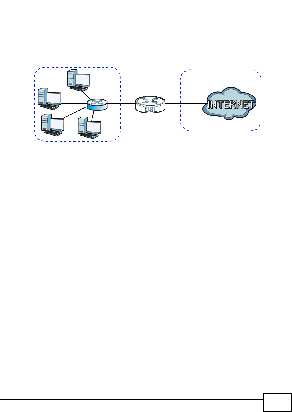
Chapter 7 Home Networking
VMG1312-B10C User’s Guide 121
7.10.1 LANs, WANs and the Device
The actual physical connection determines whether the Device ports are LAN or WAN ports. There
are two separate IP networks, one inside the LAN network and the other outside the WAN network
as shown next.
Figure 58 LAN and WAN IP Addresses
7.10.2 DHCP Setup
DHCP (Dynamic Host Configuration Protocol, RFC 2131 and RFC 2132) allows individual clients to
obtain TCP/IP configuration at start-up from a server. You can configure the Device as a DHCP
server or disable it. When configured as a server, the Device provides the TCP/IP configuration for
the clients. If you turn DHCP service off, you must have another DHCP server on your LAN, or else
the computer must be manually configured.
IP Pool Setup
The Device is pre-configured with a pool of IP addresses for the DHCP clients (DHCP Pool). See the
product specifications in the appendices. Do not assign static IP addresses from the DHCP pool to
your LAN computers.
7.10.3 DNS Server Addresses
DNS (Domain Name System) maps a domain name to its corresponding IP address and vice versa.
The DNS server is extremely important because without it, you must know the IP address of a
computer before you can access it. The DNS server addresses you enter when you set up DHCP are
passed to the client machines along with the assigned IP address and subnet mask.
There are two ways that an ISP disseminates the DNS server addresses.
• The ISP tells you the DNS server addresses, usually in the form of an information sheet, when
you sign up. If your ISP gives you DNS server addresses, enter them in the DN S Se rver fields in
the DH CP Set up screen.
WAN
LAN

Chapter 7 Home Networking
VMG1312-B10C User’s Guide
122
• Some ISPs choose to disseminate the DNS server addresses using the DNS server extensions of
IPCP (IP Control Protocol) after the connection is up. If your ISP did not give you explicit DNS
servers, chances are the DNS servers are conveyed through IPCP negotiation. The Device
supports the IPCP DNS server extensions through the DNS proxy feature.
Please note that DNS proxy works only when the ISP uses the IPCP DNS server extensions. It
does not mean you can leave the DNS servers out of the DHCP setup under all circumstances. If
your ISP gives you explicit DNS servers, make sure that you enter their IP addresses in the
DH CP Se t up screen.
7.10.4 LAN TCP/IP
The Device has built-in DHCP server capability that assigns IP addresses and DNS servers to
systems that support DHCP client capability.
IP Address and Subnet Mask
Similar to the way houses on a street share a common street name, so too do computers on a LAN
share one common network number.
Where you obtain your network number depends on your particular situation. If the ISP or your
network administrator assigns you a block of registered IP addresses, follow their instructions in
selecting the IP addresses and the subnet mask.
If the ISP did not explicitly give you an IP network number, then most likely you have a single user
account and the ISP will assign you a dynamic IP address when the connection is established. If this
is the case, it is recommended that you select a network number from 192.168.0.0 to
192.168.255.0 and you must enable the Network Address Translation (NAT) feature of the Device.
The Internet Assigned Number Authority (IANA) reserved this block of addresses specifically for
private use; please do not use any other number unless you are told otherwise. Let's say you select
192.168.1.0 as the network number; which covers 254 individual addresses, from 192.168.1.1 to
192.168.1.254 (zero and 255 are reserved). In other words, the first three numbers specify the
network number while the last number identifies an individual computer on that network.
Once you have decided on the network number, pick an IP address that is easy to remember, for
instance, 192.168.1.1, for your Device, but make sure that no other device on your network is
using that IP address.
The subnet mask specifies the network number portion of an IP address. Your Device will compute
the subnet mask automatically based on the IP address that you entered. You don't need to change
the subnet mask computed by the Device unless you are instructed to do otherwise.
Private IP Addresses
Every machine on the Internet must have a unique address. If your networks are isolated from the
Internet, for example, only between your two branch offices, you can assign any IP addresses to
the hosts without problems. However, the Internet Assigned Numbers Authority (IANA) has
reserved the following three blocks of IP addresses specifically for private networks:
• 10.0.0.0 — 10.255.255.255
• 172.16.0.0 — 172.31.255.255
• 192.168.0.0 — 192.168.255.255

Chapter 7 Home Networking
VMG1312-B10C User’s Guide 123
You can obtain your IP address from the IANA, from an ISP or it can be assigned from a private
network. If you belong to a small organization and your Internet access is through an ISP, the ISP
can provide you with the Internet addresses for your local networks. On the other hand, if you are
part of a much larger organization, you should consult your network administrator for the
appropriate IP addresses.
Note: Regardless of your particular situation, do not create an arbitrary IP address;
always follow the guidelines above. For more information on address assignment,
please refer to RFC 1597, “Address Allocation for Private Internets” and RFC 1466,
“Guidelines for Management of IP Address Space”.

Chapter 7 Home Networking
VMG1312-B10C User’s Guide
124
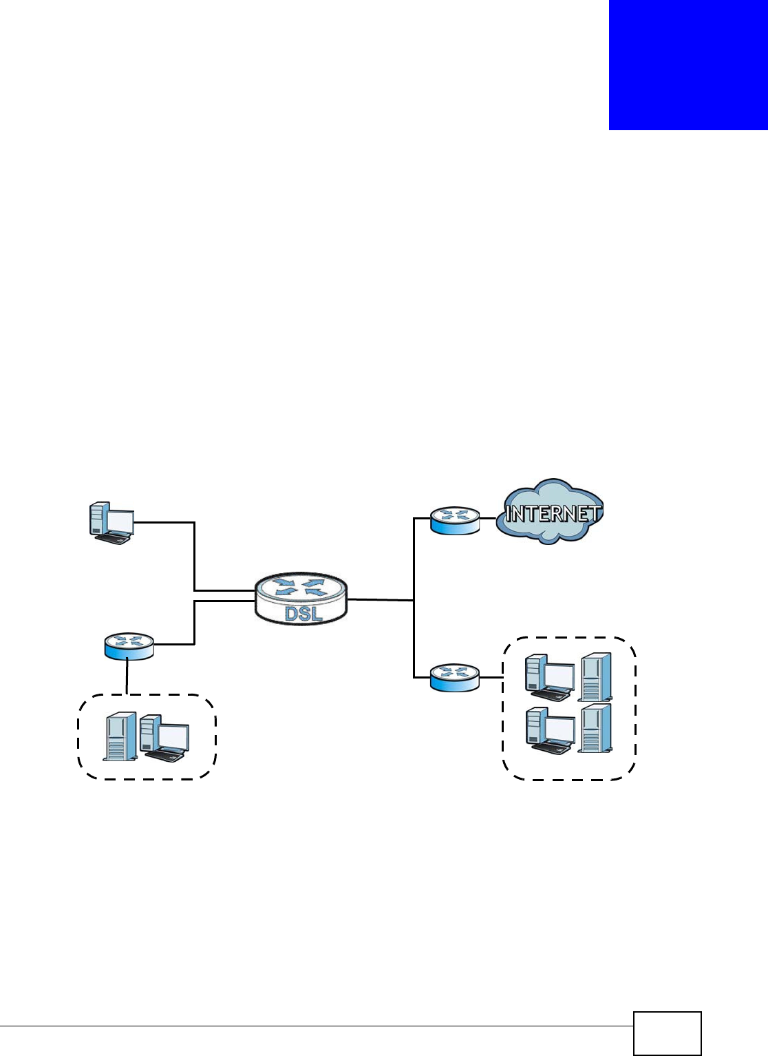
VMG1312-B10C User’s Guide 125
CHAPTER 8
Routing
8.1 Overview
The Device usually uses the default gateway to route outbound traffic from computers on the LAN
to the Internet. To have the Device send data to devices not reachable through the default gateway,
use static routes.
For example, the next figure shows a computer (A) connected to the Device’s LAN interface. The
Device routes most traffic from A to the Internet through the Device’s default gateway (R1 ). You
create one static route to connect to services offered by your ISP behind router R2 . You create
another static route to communicate with a separate network behind a router R3 connected to the
LAN.
Figure 59 Example of Routing Topology
WAN
R1
R2
A
R3
LAN
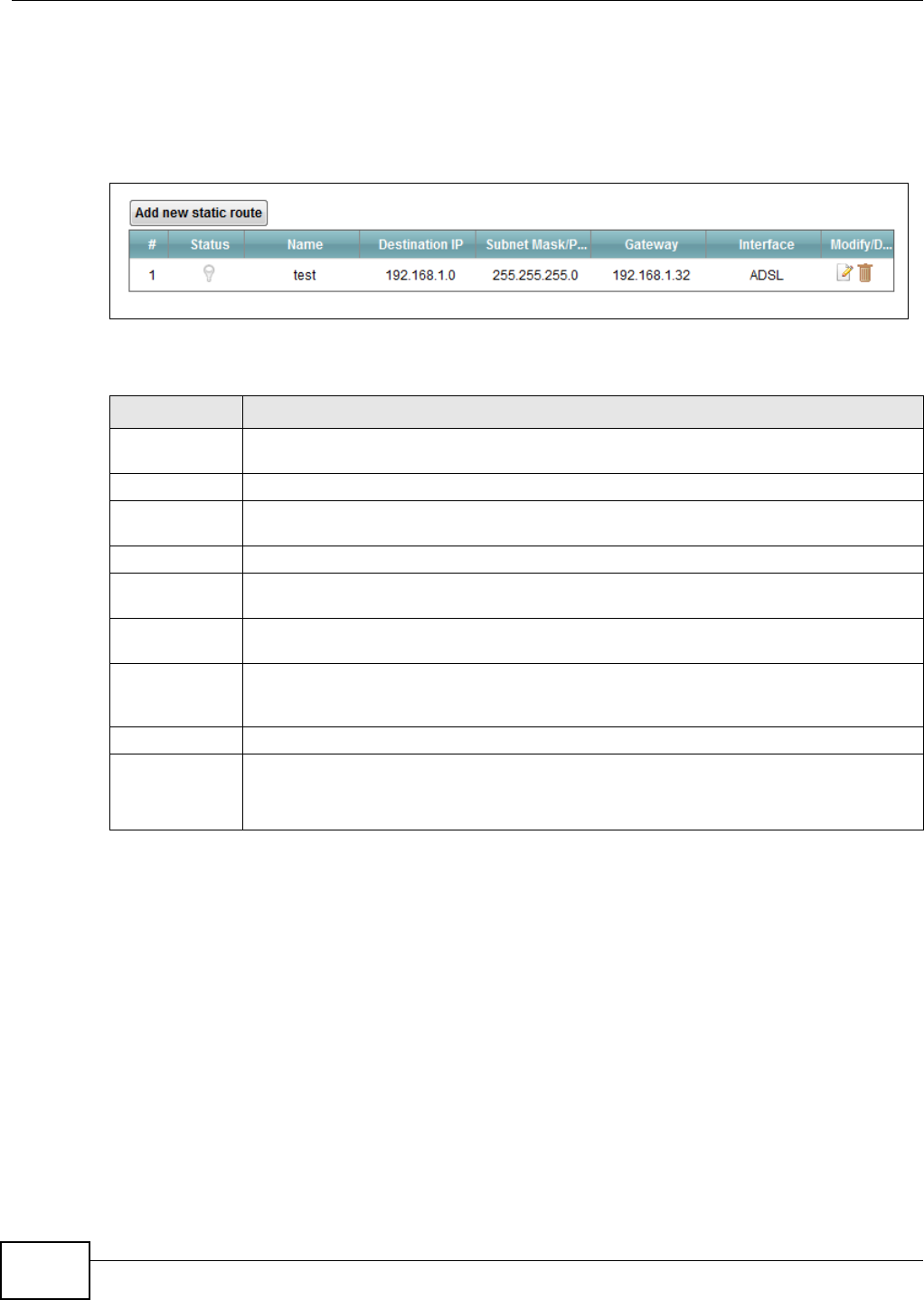
Chapter 8 Routing
VMG1312-B10C User’s Guide
126
8.2 The Routing Screen
Use this screen to view and configure the static route rules on the Device. Click Net w or k Set t ing
> Rou t ing > St at ic Rou t e to open the following screen.
Figure 60 Network Setting > Routing > Static Route
The following table describes the labels in this screen.
Table 38 Network Setting > Routing > Static Route
LABEL DESCRIPTION
Add new static
route
Click this to configure a new static route.
#This is the index number of the entry.
Status This field displays whether the static route is active or not. A yellow bulb signifies that this
route is active. A gray bulb signifies that this route is not active.
Name This is the name that describes or identifies this route.
Destination IP This parameter specifies the IP network address of the final destination. Routing is always
based on network number.
Subnet Mask/
Prefix Length
This parameter specifies the IP network subnet mask of the final destination.
Gateway This is the IP address of the gateway. The gateway is a router or switch on the same
network segment as the device's LAN or WAN port. The gateway helps forward packets to
their destinations.
Interface This is the WAN interface used for this static route.
Modify/Delete Click the Edit icon to edit the static route on the Device.
Click the De le t e icon to remove a static route from the Device. A window displays asking
you to confirm that you want to delete the route.
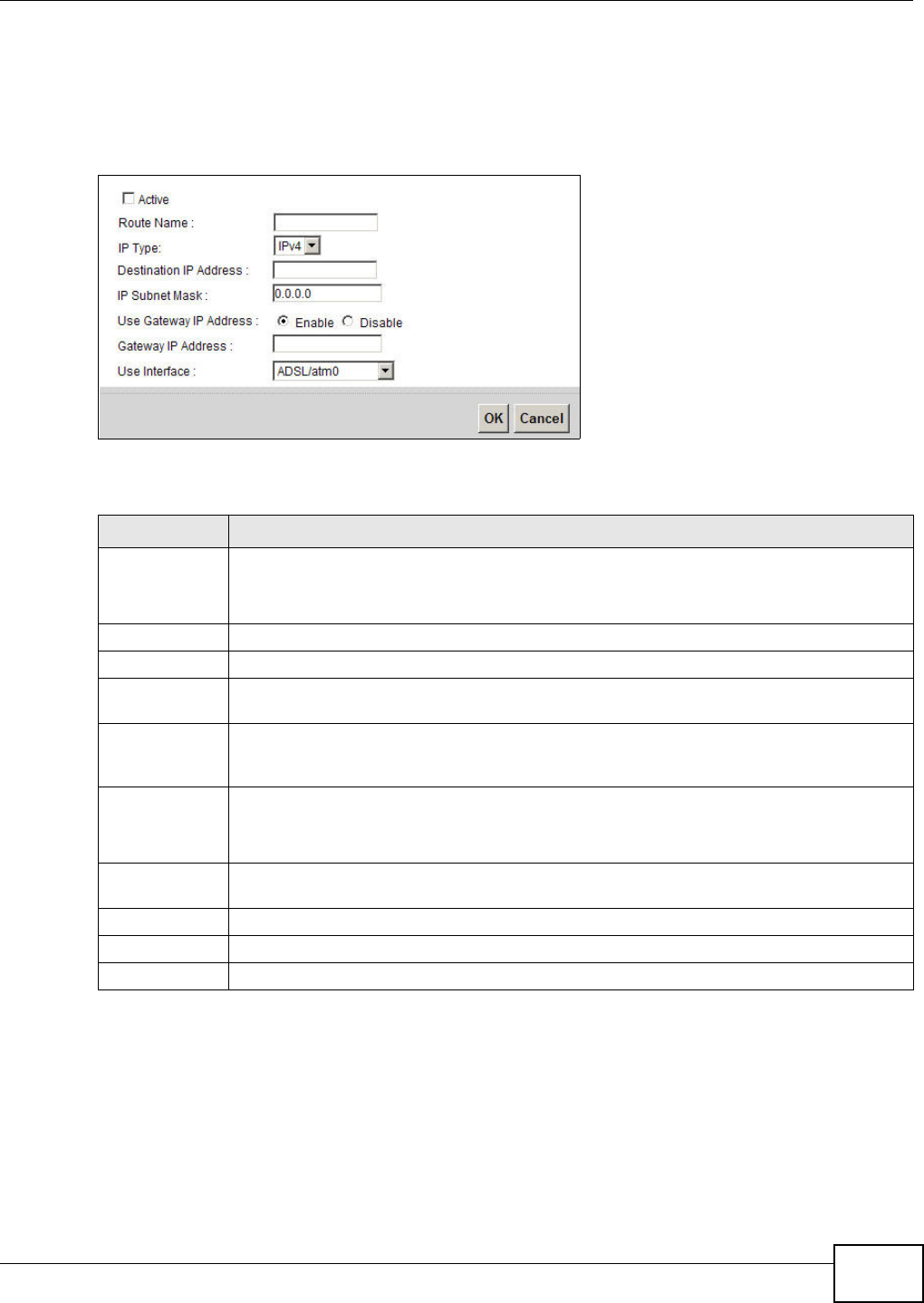
Chapter 8 Routing
VMG1312-B10C User’s Guide 127
8.2.1 Add/Edit Static Route
Use this screen to add or edit a static route. Click Add ne w sta t ic r out e in the Rou t ing screen or
the Ed it icon next to the static route you want to edit. The screen shown next appears.
Figure 61 Routing: Add/Edit
The following table describes the labels in this screen.
8.3 The Policy Forwarding Screen
Traditionally, routing is based on the destination address only and the Device takes the shortest
path to forward a packet. Policy forwarding allows the Device to override the default routing
behavior and alter the packet forwarding based on the policy defined by the network administrator.
Policy-based routing is applied to outgoing packets, prior to the normal routing.
Table 39 Routing: Add/Edit
LABEL DESCRIPTION
Active This field allows you to activate/deactivate this static route.
Select this to enable the static route. Clear this to disable this static route without having to
delete the entry.
Route Name Enter a descriptive name for the static route.
IP Type Select whether your IP type is I Pv4 or I Pv6 .
Destination IP
Address
Enter the IPv4 or IPv6 network address of the final destination.
IP Subnet Mask If you are using IPv4 and need to specify a route to a single host, use a subnet mask of
255.255.255.255 in the subnet mask field to force the network number to be identical to
the host ID. Enter the IP subnet mask here.
Use Gateway IP
Address
The gateway is a router or switch on the same network segment as the device's LAN or WAN
port. The gateway helps forward packets to their destinations.
If you want to use the gateway IP address, select Ena b le .
Gateway IP
Address
Enter the IP address of the gateway.
Use Interface Select the WAN interface you want to use for this static route.
Apply Click Apply to save your changes.
Cancel Click Cance l to exit this screen without saving.
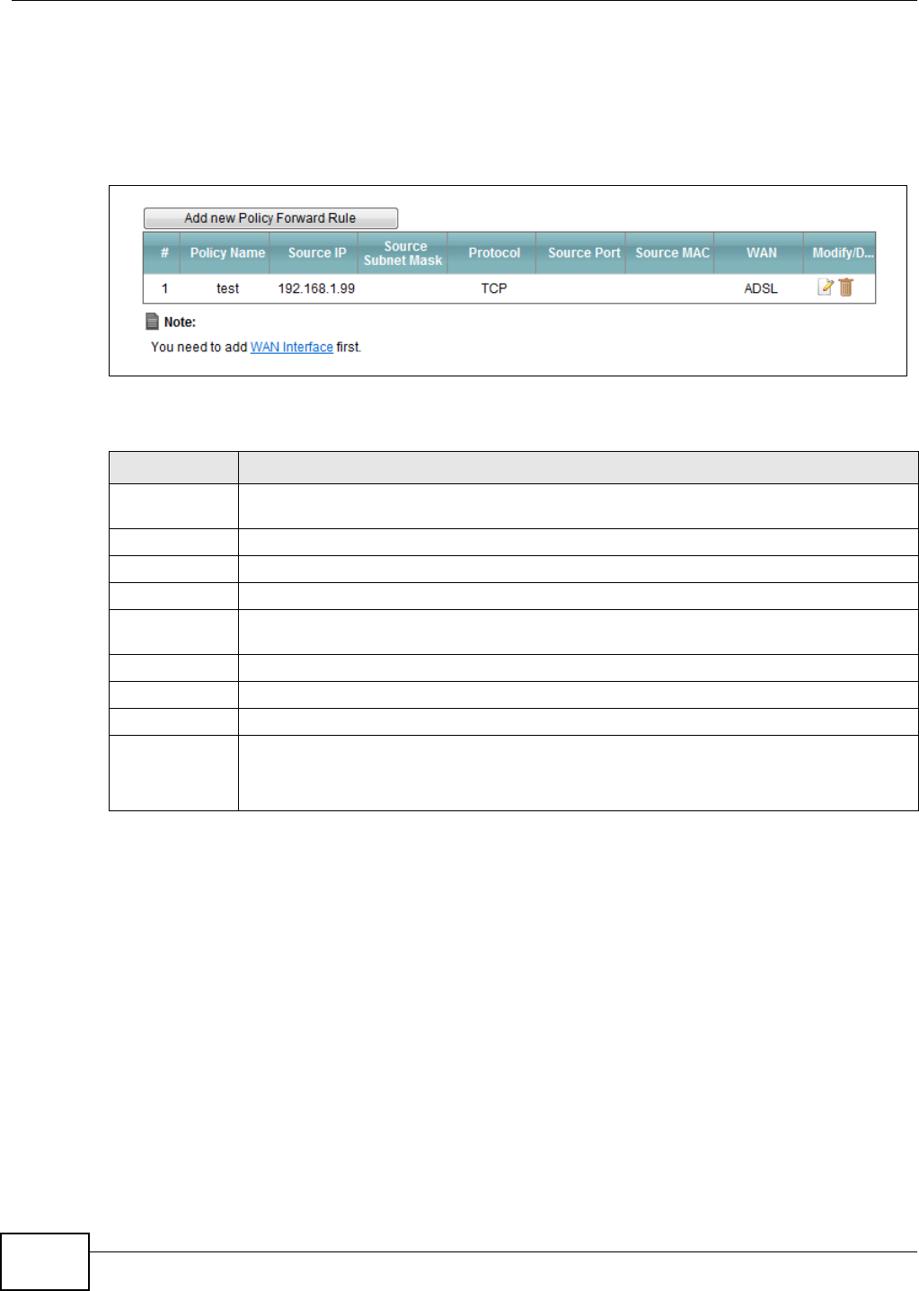
Chapter 8 Routing
VMG1312-B10C User’s Guide
128
You can use source-based policy forwarding to direct traffic from different users through different
connections or distribute traffic among multiple paths for load sharing.
The Policy For w a r ding screen let you view and configure routing policies on the Device. Click
N e t w or k Se t t ing > Rout ing > Policy Forw ar din g to open the following screen.
Figure 62 Network Setting > Routing > Policy Forwarding
The following table describes the labels in this screen.
Table 40 Network Setting > Routing >Policy Forwarding
LABEL DESCRIPTION
Add new Policy
Forward Rule
Click this to create a new policy forwarding rule.
#This is the index number of the entry.
Policy Name This is the name of the rule.
Source IP This is the source IP address.
Source Subnet
Mask
his is the source subnet mask address.
Protocol This is the transport layer protocol.
Source Port This is the source port number.
WAN This is the WAN interface through which the traffic is routed.
Modify/Delete Click the Ed it icon to edit this policy.
Click the De le t e icon to remove a policy from the Device. A window displays asking you to
confirm that you want to delete the policy.
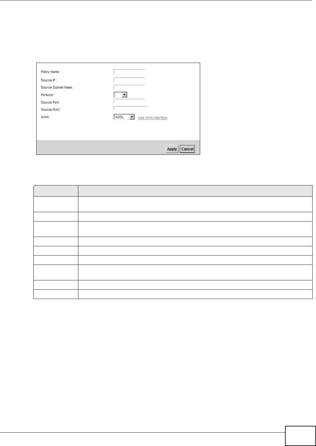
Chapter 8 Routing
VMG1312-B10C User’s Guide 129
8.3.1 Add/Edit Policy Forwarding
Click Add new Policy Forw ar d Rule in the Policy Forw arding screen or click the Edit icon next
to a policy. Use this screen to configure the required information for a policy route.
Figure 63 Policy Forwarding: Add/Edit
The following table describes the labels in this screen.
8.4 RIP
Routing Information Protocol (RIP, RFC 1058 and RFC 1389) allows a device to exchange routing
information with other routers.
Table 41 Policy Forwarding: Add/Edit
LABEL DESCRIPTION
Policy Name Enter a descriptive name of up to 8 printable English keyboard characters, not including
spaces.
Source IP Enter the source IP address.
Source Subnet
Mask
Enter the source subnet mask address.
Protocol Select the transport layer protocol (TCP or UD P).
Source Port Enter the source port number.
Source MAC Enter the source MAC address.
WAN Select a WAN interface through which the traffic is sent. You must have the WAN
interface(s) already configured in the Broa dba nd screens.
Apply Click Apply to save your changes.
Cancel Click Cance l to exit this screen without saving.
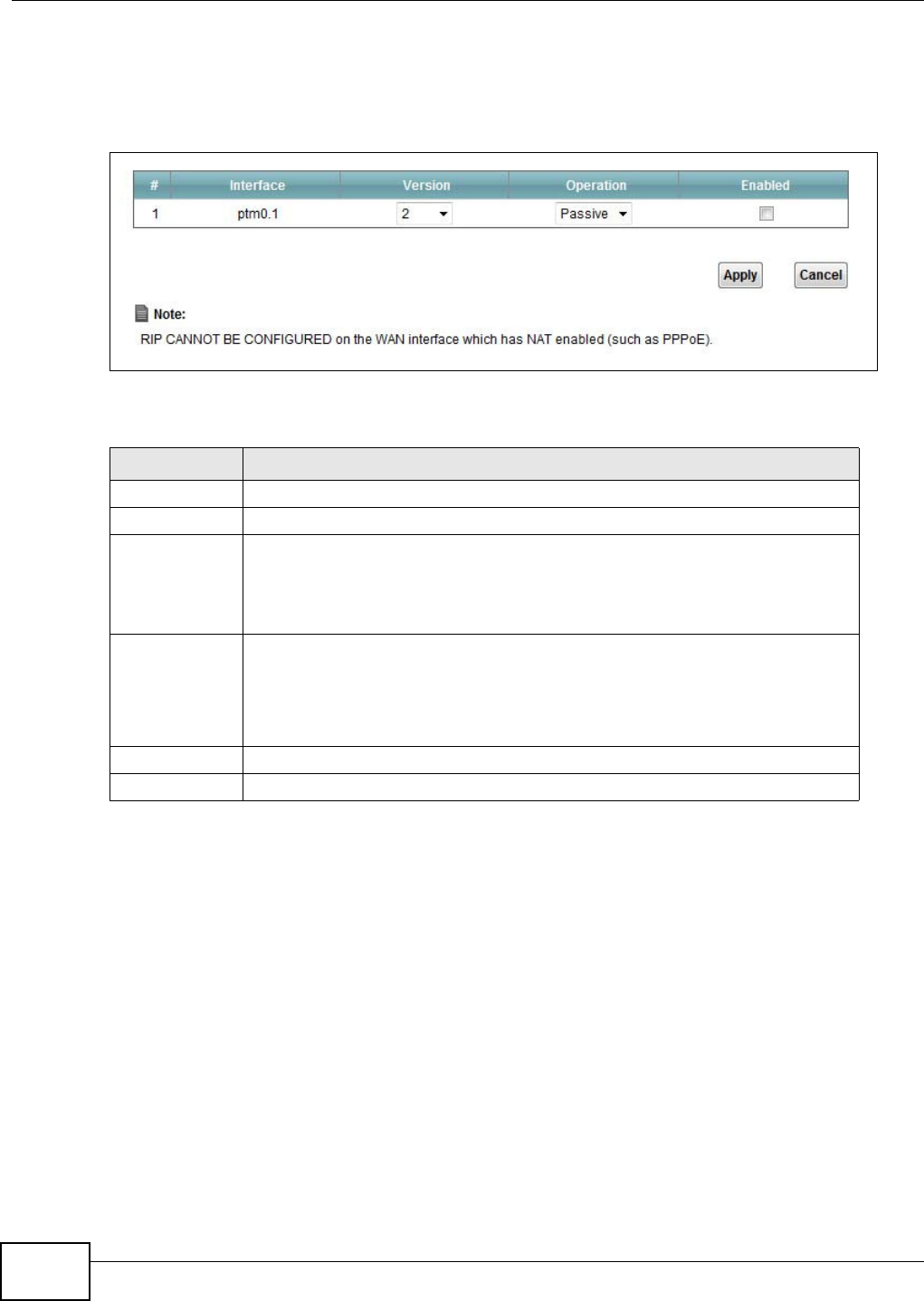
Chapter 8 Routing
VMG1312-B10C User’s Guide
130
8.4.1 The RIP Screen
Click N et w ork Se t t ing > Rou t ing > RI P to open the RI P screen.
Figure 64 RIP
The following table describes the labels in this screen.
Table 42 RIP
LABEL DESCRIPTION
#This is the index of the interface in which the RIP setting is used.
Interface This is the name of the interface in which the RIP setting is used.
Version The RIP version controls the format and the broadcasting method of the RIP
packets that the Device sends (it recognizes both formats when receiving). RIP
version 1 is universally supported but RIP version 2 carries more information. RIP
version 1 is probably adequate for most networks, unless you have an unusual
network topology.
Operation Select Pa ssive to have the Device update the routing table based on the RIP
packets received from neighbors but not advertise its route information to other
routers in this interface.
Select Act iv e to have the Device advertise its route information and also listen for
routing updates from neighboring routers.
Enabled Select the check box to activate the settings.
Apply Click Apply to save your changes back to the Device.

VMG1312-B10C User’s Guide 131
CHAPTER 9
Quality of Service (QoS)
9.1 Overview
Quality of Service (QoS) refers to both a network’s ability to deliver data with minimum delay, and
the networking methods used to control the use of bandwidth. Without QoS, all traffic data is
equally likely to be dropped when the network is congested. This can cause a reduction in network
performance and make the network inadequate for time-critical application such as video-on-
demand.
Configure QoS on the Device to group and prioritize application traffic and fine-tune network
performance. Setting up QoS involves these steps:
1Configure classifiers to sort traffic into different flows.
2Assign priority and define actions to be performed for a classified traffic flow.
The Device assigns each packet a priority and then queues the packet accordingly. Packets assigned
a high priority are processed more quickly than those with low priority if there is congestion,
allowing time-sensitive applications to flow more smoothly. Time-sensitive applications include both
those that require a low level of latency (delay) and a low level of jitter (variations in delay) such as
Voice over IP (VoIP) or Internet gaming, and those for which jitter alone is a problem such as
Internet radio or streaming video.
This chapter contains information about configuring QoS and editing classifiers.
9.1.1 What You Can Do in this Chapter
•The Gen e r a l screen lets you enable or disable QoS and set the upstream bandwidth (Section 9.3
on page 133).
•The Qu e ue Set up screen lets you configure QoS queue assignment (Section 9.4 on page 134).
•The Class Se t u p screen lets you add, edit or delete QoS classifiers (Section 9.5 on page 136).
•The Policer Set u p screen lets you add, edit or delete QoS policers (Section 9.5 on page 136).
•The M on it or screen lets you view the Device's QoS-related packet statistics (Section 9.7 on page
143).
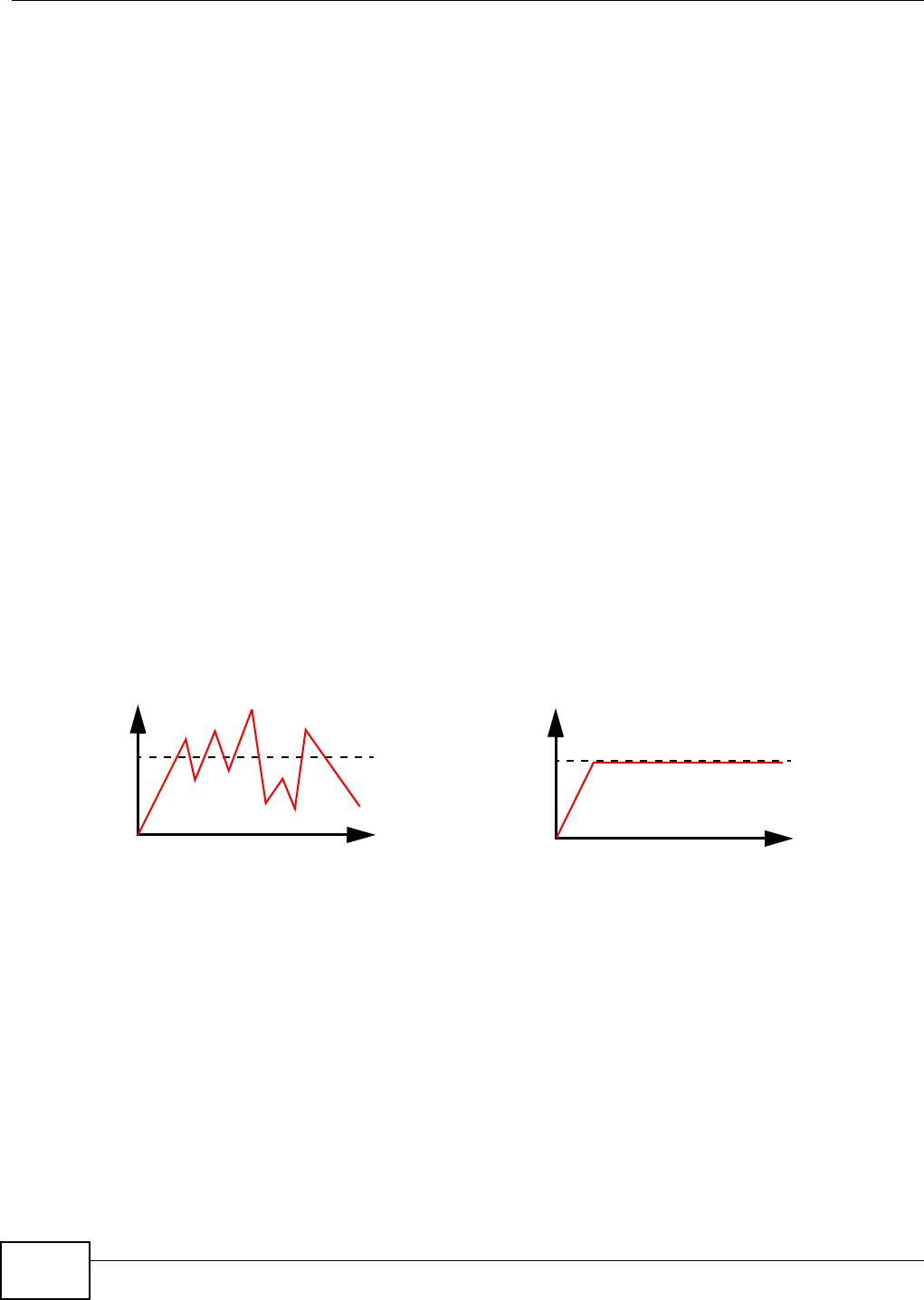
Chapter 9 Quality of Service (QoS)
VMG1312-B10C User’s Guide
132
9.2 What You Need to Know
The following terms and concepts may help as you read through this chapter.
QoS versus Cos
QoS is used to prioritize source-to-destination traffic flows. All packets in the same flow are given
the same priority. CoS (class of service) is a way of managing traffic in a network by grouping
similar types of traffic together and treating each type as a class. You can use CoS to give different
priorities to different packet types.
CoS technologies include IEEE 802.1p layer 2 tagging and DiffServ (Differentiated Services or DS).
IEEE 802.1p tagging makes use of three bits in the packet header, while DiffServ is a new protocol
and defines a new DS field, which replaces the eight-bit ToS (Type of Service) field in the IP header.
Tagging and Marking
In a QoS class, you can configure whether to add or change the DSCP (DiffServ Code Point) value,
IEEE 802.1p priority level and VLAN ID number in a matched packet. When the packet passes
through a compatible network, the networking device, such as a backbone switch, can provide
specific treatment or service based on the tag or marker.
Traffic Shaping
Bursty traffic may cause network congestion. Traffic shaping regulates packets to be transmitted
with a pre-configured data transmission rate using buffers (or queues). Your Device uses the Token
Bucket algorithm to allow a certain amount of large bursts while keeping a limit at the average rate.
Traffic
Time
Traffic Rate
Traffic
Time
Traffic Rate
(Before Traffic Shaping) (After Traffic Shaping)
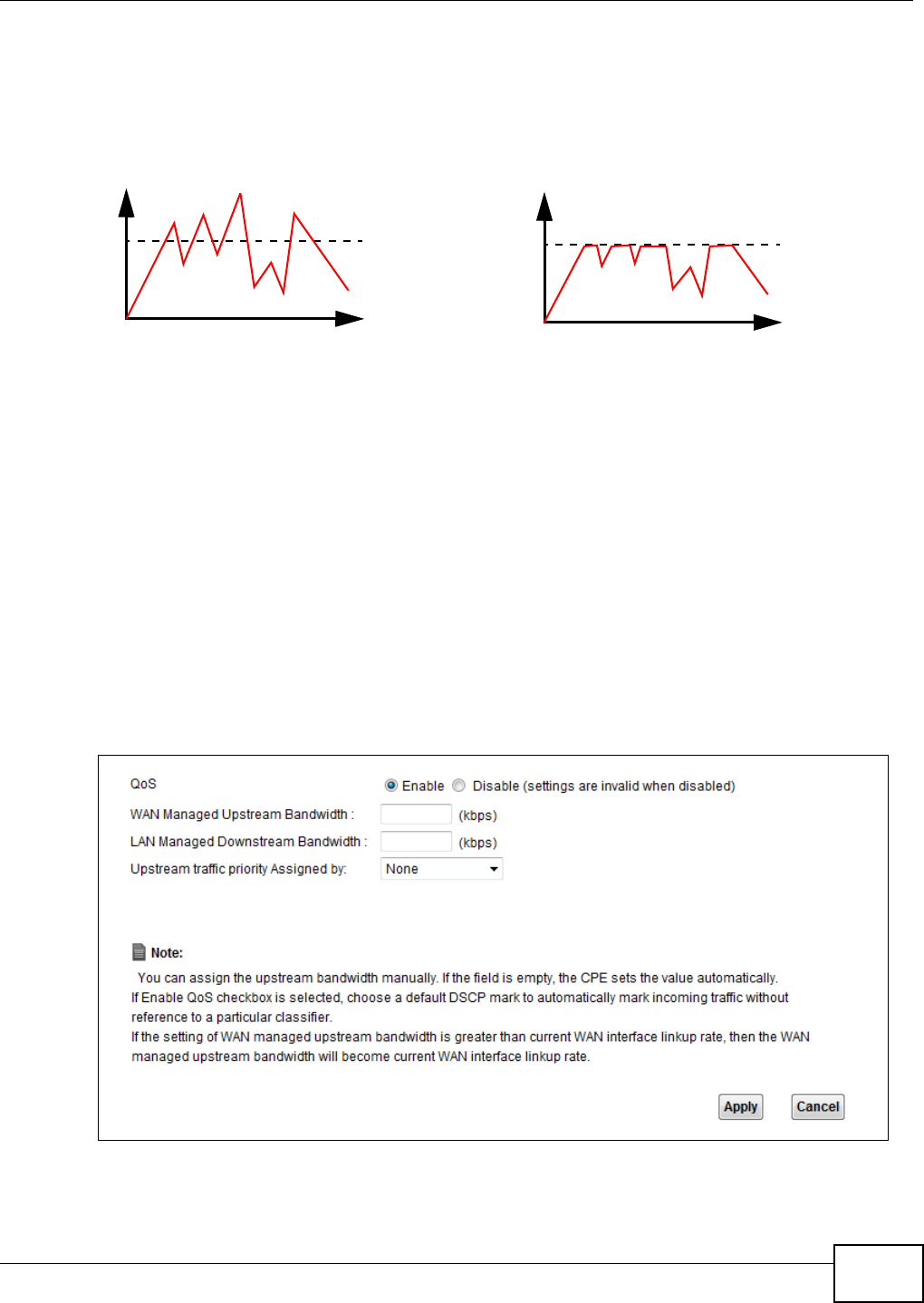
Chapter 9 Quality of Service (QoS)
VMG1312-B10C User’s Guide 133
Traffic Policing
Traffic policing is the limiting of the input or output transmission rate of a class of traffic on the
basis of user-defined criteria. Traffic policing methods measure traffic flows against user-defined
criteria and identify it as either conforming, exceeding or violating the criteria.
The Device supports three incoming traffic metering algorithms: Token Bucket Filter (TBF), Single
Rate Two Color Maker (srTCM), and Two Rate Two Color Marker (trTCM). You can specify actions
which are performed on the colored packets. See Section 9.8 on page 144 for more information on
each metering algorithm.
9.3 The Quality of Service General Screen
Click N e t w or k Set t in g > QoS > Ge n e ra l to open the screen as shown next.
Use this screen to enable or disable QoS and set the upstream bandwidth. See Section 9.1 on page
131 for more information.
Figure 65 Network Settings > QoS > General
Traffic
Time
Traffic Rate
Traffic
Time
Traffic Rate
(Before Traffic Policing) (After Traffic Policing)

Chapter 9 Quality of Service (QoS)
VMG1312-B10C User’s Guide
134
The following table describes the labels in this screen.
9.4 The Queue Setup Screen
Click N et w ork Set t in g > QoS > Queue Se t up to open the screen as shown next.
Table 43 Network Setting > QoS > General
LABEL DESCRIPTION
QoS Select the Ena b le check box to turn on QoS to improve your network performance.
WAN Managed
Upstream
Bandwidth
Enter the amount of upstream bandwidth for the WAN interfaces that you want to allocate
using QoS.
The recommendation is to set this speed to match the interfaces’ actual transmission speed.
For example, set the WAN interfaces’ speed to 100000 kbps if your Internet connection has
an upstream transmission speed of 100 Mbps.
You can set this number higher than the interfaces’ actual transmission speed. The Device
uses up to 95% of the DSL port’s actual upstream transmission speed even if you set this
number higher than the DSL port’s actual transmission speed.
You can also set this number lower than the interfaces’ actual transmission speed. This will
cause the Device to not use some of the interfaces’ available bandwidth.
If you leave this field blank, the Device automatically sets this number to be 95% of the
WAN interfaces’ actual upstream transmission speed.
LAN Managed
Downstream
Bandwidth
Enter the amount of downstream bandwidth for the LAN interfaces (including WLAN) that
you want to allocate using QoS.
The recommendation is to set this speed to match the WAN interfaces’ actual transmission
speed. For example, set the LAN managed downstream bandwidth to 100000 kbps if you
use a 100 Mbps wired Ethernet WAN connection.
You can also set this number lower than the WAN interfaces’ actual transmission speed. This
will cause the Device to not use some of the interfaces’ available bandwidth.
If you leave this field blank, the Device automatically sets this to the LAN interfaces’
maximum supported connection speed.
Upstream
traffic priority
Assigned by
Select how the Device assigns priorities to various upstream traffic flows.
•N on e : Disables auto priority mapping and has the Device put packets into the queues
according to your classification rules. Traffic which does not match any of the
classification rules is mapped into the default queue with the lowest priority.
•Et h ern e t Pr ior it y : Automatically assign priority based on the IEEE 802.1p priority level.
•I P Pr ecede n ce: Automatically assign priority based on the first three bits of the TOS
field in the IP header.
•Pa cke t Lengt h: Automatically assign priority based on the packet size. Smaller packets
get higher priority since control, signaling, VoIP, internet gaming, or other real-time
packets are usually small while larger packets are usually best effort data packets like
file transfers.
Apply Click Apply to save your changes.
Cancel Click Ca ncel to restore your previously saved settings.
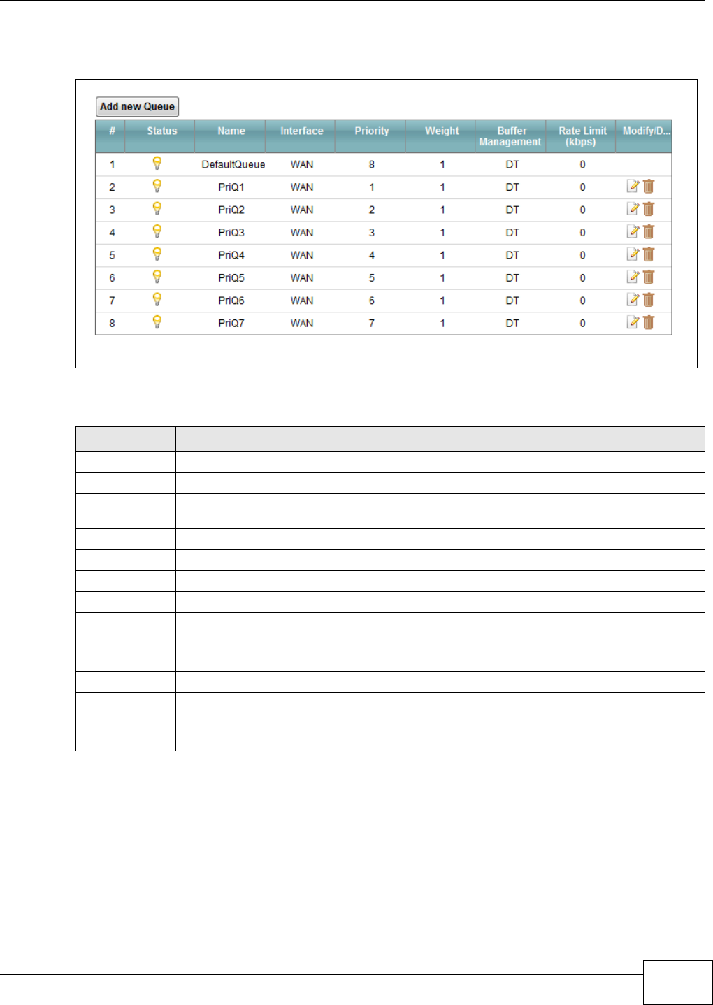
Chapter 9 Quality of Service (QoS)
VMG1312-B10C User’s Guide 135
Use this screen to configure QoS queue assignment.
Figure 66 Network Setting > QoS > Queue Setup
The following table describes the labels in this screen.
Table 44 Network Setting > QoS > Queue Setup
LABEL DESCRIPTION
Add new Queue Click this button to create a new queue entry.
#This is the index number of the entry.
Status This field displays whether the queue is active or not. A yellow bulb signifies that this queue
is active. A gray bulb signifies that this queue is not active.
Name This shows the descriptive name of this queue.
Interface This shows the name of the Device’s interface through which traffic in this queue passes.
Priority This shows the priority of this queue.
Weight This shows the weight of this queue.
Buffer
Management
This shows the queue management algorithm used for this queue.
Queue management algorithms determine how the Device should handle packets when it
receives too many (network congestion).
Rate Limit This shows the maximum transmission rate allowed for traffic on this queue.
Modify/Delete Click the Ed it icon to edit the queue.
Click the De le t e icon to delete an existing queue. Note that subsequent rules move up by
one when you take this action.
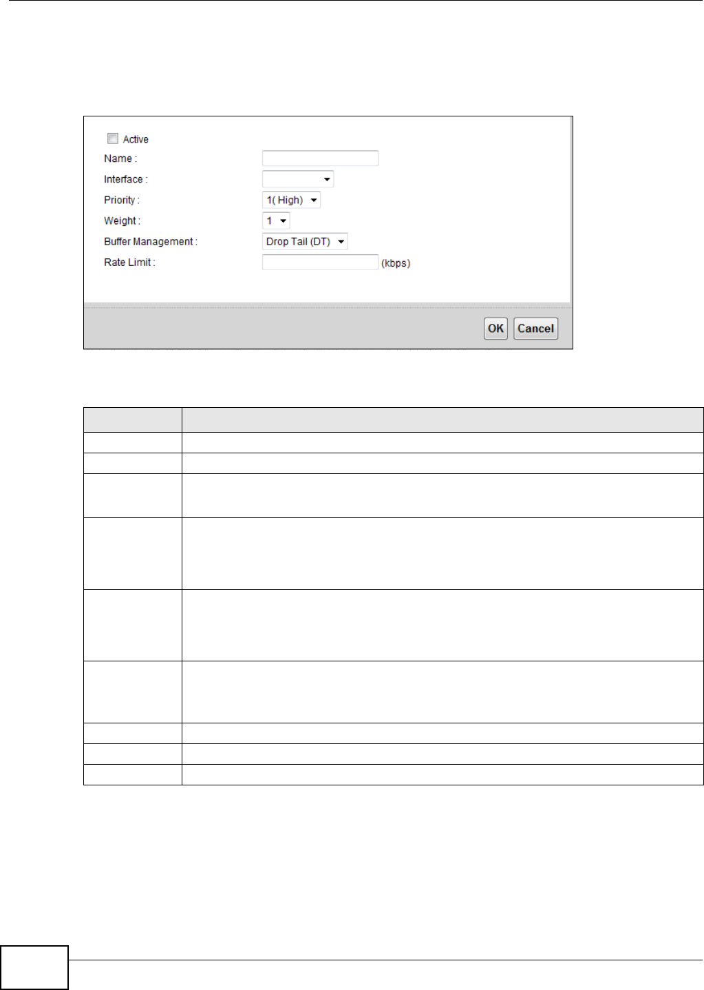
Chapter 9 Quality of Service (QoS)
VMG1312-B10C User’s Guide
136
9.4.1 Adding a QoS Queue
Click Add ne w Queue or the edit icon in the Qu e u e Se t u p screen to configure a queue.
Figure 67 Queue Setup: Add
The following table describes the labels in this screen.
9.5 The Class Setup Screen
Use this screen to add, edit or delete QoS classifiers. A classifier groups traffic into data flows
according to specific criteria such as the source address, destination address, source port number,
Table 45 Queue Setup: Add
LABEL DESCRIPTION
Active Select to enable or disable this queue.
Name Enter the descriptive name of this queue.
Interface Select the interface to which this queue is applied.
This field is read-only if you are editing the queue.
Priority Select the priority level (from 1 to 7) of this queue.
The smaller the number, the higher the priority level. Traffic assigned to higher priority
queues gets through faster while traffic in lower priority queues is dropped if the network is
congested.
Weight Select the weight (from 1 to 8) of this queue.
If two queues have the same priority level, the Device divides the bandwidth across the
queues according to their weights. Queues with larger weights get more bandwidth than
queues with smaller weights.
Buffer
Management
This field displays Dr op Ta il ( D T) . Drop Tail ( D T) is a simple queue management
algorithm that allows the Device buffer to accept as many packets as it can until it is full.
Once the buffer is full, new packets that arrive are dropped until there is space in the buffer
again (packets are transmitted out of it).
Rate Limit Specify the maximum transmission rate (in Kbps) allowed for traffic on this queue.
OK Click OK to save your changes.
Cancel Click Cancel to exit this screen without saving.
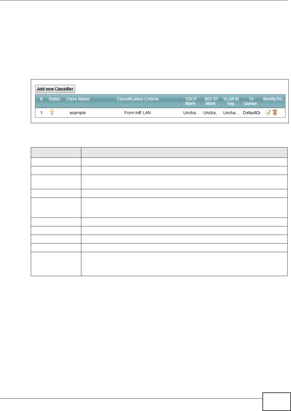
Chapter 9 Quality of Service (QoS)
VMG1312-B10C User’s Guide 137
destination port number or incoming interface. For example, you can configure a classifier to select
traffic from the same protocol port (such as Telnet) to form a flow.
You can give different priorities to traffic that the Device forwards out through the WAN interface.
Give high priority to voice and video to make them run more smoothly. Similarly, give low priority
to many large file downloads so that they do not reduce the quality of other applications.
Click N et w ork Set t in g > QoS > Class Se t up to open the following screen.
Figure 68 Network Setting > QoS > Class Setup
The following table describes the labels in this screen.
Table 46 Network Setting > QoS > Class Setup
LABEL DESCRIPTION
Add new Classifier Click this to create a new classifier.
#This is the index number of the entry.
Status This field displays whether the classifier is active or not. A yellow bulb signifies that this
classifier is active. A gray bulb signifies that this classifier is not active.
Class Name This is the name of the classifier.
Classification
Criteria
This shows criteria specified in this classifier, for example the interface from which
traffic of this class should come and the source MAC address of traffic that matches this
classifier.
DSCP Mark This is the DSCP number added to traffic of this classifier.
802.1P Mark This is the IEEE 802.1p priority level assigned to traffic of this classifier.
VLAN ID Tag This is the VLAN ID number assigned to traffic of this classifier.
To Queue This is the name of the queue in which traffic of this classifier is put.
Modify/Delete Click the Ed it icon to edit the classifier.
Click the D e let e icon to delete an existing classifier. Note that subsequent rules move
up by one when you take this action.
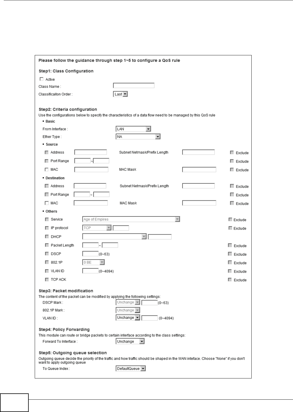
Chapter 9 Quality of Service (QoS)
VMG1312-B10C User’s Guide
138
9.5.1 Add/Edit QoS Class
Click Add ne w Cla ssifie r in the Class Se t u p screen or the Edit icon next to a classifier to open
the following screen.
Figure 69 Class Setup: Add/Edit

Chapter 9 Quality of Service (QoS)
VMG1312-B10C User’s Guide 139
The following table describes the labels in this screen.
Table 47 Class Setup: Add/Edit
LABEL DESCRIPTION
Active Select this to enable this classifier.
Class Name Enter a descriptive name of up to 15 printable English keyboard characters, not including
spaces.
Classification
Order
Select an existing number for where you want to put this classifier to move the classifier to
the number you selected after clicking App ly.
Select La st to put this rule in the back of the classifier list.
From Interface If you want to classify the traffic by an ingress interface, select an interface from the From
I n t e r fa ce drop-down list box.
Ether Type Select a predefined application to configure a class for the matched traffic.
If you select I P, you also need to configure source or destination MAC address, IP address,
DHCP options, DSCP value or the protocol type.
If you select 8 0 2 .1 Q, you can configure an 802.1p priority level.
Source
Address Select the check box and enter the source IP address in dotted decimal notation. A blank
source IP address means any source IP address.
Subnet
Netmask Enter the source subnet mask.
Port Range If you select TCP or UD P in the I P Prot ocol field, select the check box and enter the port
number(s) of the source.
MAC Select the check box and enter the source MAC address of the packet.
MAC Mask Type the mask for the specified MAC address to determine which bits a packet’s MAC
address should match.
Enter “f” for each bit of the specified source MAC address that the traffic’s MAC address
should match. Enter “0” for the bit(s) of the matched traffic’s MAC address, which can be of
any hexadecimal character(s). For example, if you set the MAC address to
00:13:49:00:00:00 and the mask to ff:ff:ff:00:00:00, a packet with a MAC address of
00:13:49:12:34:56 matches this criteria.
Exclude Select this option to exclude the packets that match the specified criteria from this classifier.
Destination
Address Select the check box and enter the source IP address in dotted decimal notation. A blank
source IP address means any source IP address.
Subnet
Netmask Enter the source subnet mask.
Port Range If you select TCP or UD P in the I P Prot ocol field, select the check box and enter the port
number(s) of the source.
MAC Select the check box and enter the source MAC address of the packet.
MAC Mask Type the mask for the specified MAC address to determine which bits a packet’s MAC
address should match.
Enter “f” for each bit of the specified source MAC address that the traffic’s MAC address
should match. Enter “0” for the bit(s) of the matched traffic’s MAC address, which can be of
any hexadecimal character(s). For example, if you set the MAC address to
00:13:49:00:00:00 and the mask to ff:ff:ff:00:00:00, a packet with a MAC address of
00:13:49:12:34:56 matches this criteria.
Exclude Select this option to exclude the packets that match the specified criteria from this classifier.
Others

Chapter 9 Quality of Service (QoS)
VMG1312-B10C User’s Guide
140
Service This field is available only when you select I P in the Et h er Type field.
This field simplifies classifier configuration by allowing you to select a predefined
application. When you select a predefined application, you do not configure the rest of the
filter fields.
IP Protocol This field is available only when you select I P in the Et her Ty pe field.
Select this option and select the protocol (service type) from TCP, UDP, I CM P or I GMP. If
you select Use r de fine d, enter the protocol (service type) number.
DHCP This field is available only when you select I P in the Et h er Type field.
Select this option and select a DHCP option.
If you select Ven dor Class I D ( DH CP Opt ion 6 0 ) , enter the Vendor Class Identifier
(Option 60) of the matched traffic, such as the type of the hardware or firmware.
If you select Use r Class I D ( D H CP Opt ion 7 7 ) , enter a string that identifies the user’s
category or application type in the matched DHCP packets.
Packet
Length This field is available only when you select I P in the Et he r Type field.
Select this option and enter the minimum and maximum packet length (from 46 to 1500) in
the fields provided.
DSCP This field is available only when you select I P in the Et h er Type field.
Select this option and specify a DSCP (DiffServ Code Point) number between 0 and 63 in the
field provided.
802.1P This field is available only when you select 80 2 .1 Q in the Et her Type field.
Select this option and select a priority level (between 0 and 7) from the drop-down list box.
"0" is the lowest priority level and "7" is the highest.
VLAN ID This field is available only when you select 8 0 2 .1 Q in the Et her Ty pe field.
Select this option and specify a VLAN ID number.
TCP ACK This field is available only when you select I P in the Eth e r Type field.
If you select this option, the matched TCP packets must contain the ACK (Acknowledge)
flag.
Exclude Select this option to exclude the packets that match the specified criteria from this classifier.
DSCP Mark This field is available only when you select I P in the Et h er Ty pe field.
If you select Ma r k, enter a DSCP value with which the Device replaces the DSCP field in the
packets.
If you select Un cha ng e, the Device keep the DSCP field in the packets.
802.1P Mark Select a priority level with which the Device replaces the IEEE 802.1p priority field in the
packets.
If you select Un cha ng e, the Device keep the 802.1p priority field in the packets.
VLAN ID If you select Rem a r k , enter a VLAN ID number with which the Device replaces the VLAN ID
of the frames.
If you select Rem ove, the Device deletes the VLAN ID of the frames before forwarding
them out.
If you select Add, the Device treat all matched traffic untagged and add a second VLAN ID.
If you select Un cha ng e, the Device keep the VLAN ID in the packets.
Forward to
Interface
Select a WAN interface through which traffic of this class will be forwarded out. If you select
Unchan ge , the Device forward traffic of this class according to the default routing table.
Table 47 Class Setup: Add/Edit (continued)
LABEL DESCRIPTION
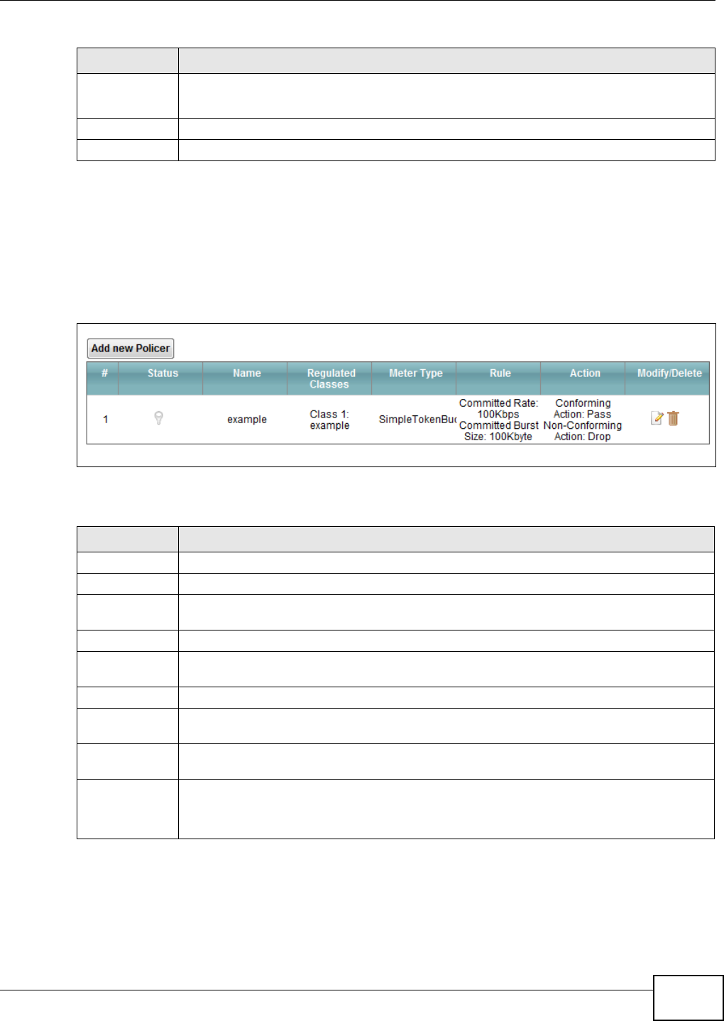
Chapter 9 Quality of Service (QoS)
VMG1312-B10C User’s Guide 141
9.6 The QoS Policer Setup Screen
Use this screen to configure QoS policers that allow you to limit the transmission rate of incoming
traffic. Click N et w ork Set ting > QoS > Policer Se t u p. The screen appears as shown.
Figure 70 Network Setting > QoS > Policer Setup
The following table describes the labels in this screen.
To Queue Index Select a queue that applies to this class.
You should have configured a queue in the Que u e Se t up screen already.
Apply Click Apply to save your changes.
Cancel Click Cance l to exit this screen without saving.
Table 47 Class Setup: Add/Edit (continued)
LABEL DESCRIPTION
Table 48 Network Setting > QoS > Policer Setup
LABEL DESCRIPTION
Add new Policer Click this to create a new entry.
#This is the index number of the entry.
Status This field displays whether the policer is active or not. A yellow bulb signifies that this
policer is active. A gray bulb signifies that this policer is not active.
Name This field displays the descriptive name of this policer.
Regulated
Classes
This field displays the name of a QoS classifier
Meter Type This field displays the type of QoS metering algorithm used in this policer.
Rule These are the rates and burst sizes against which the policer checks the traffic of the
member QoS classes.
Action This shows the how the policer has the Device treat different types of traffic belonging to
the policer’s member QoS classes.
Modify/Delete Click the Ed it icon to edit the policer.
Click the D e let e icon to delete an existing policer. Note that subsequent rules move up by
one when you take this action.
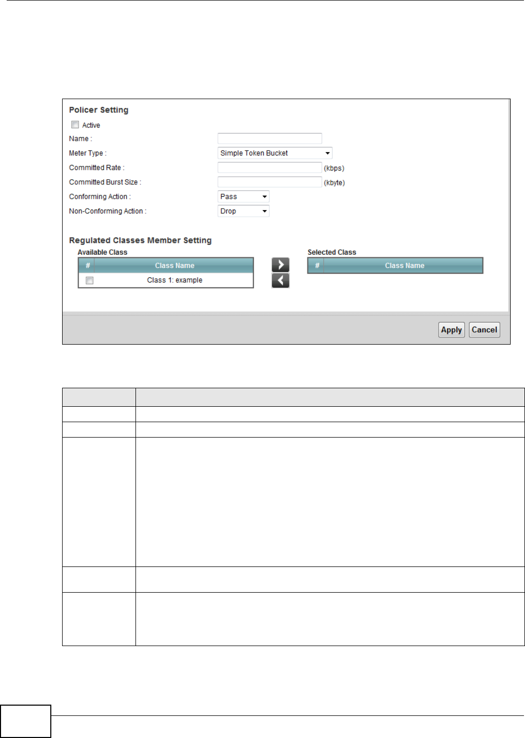
Chapter 9 Quality of Service (QoS)
VMG1312-B10C User’s Guide
142
9.6.1 Add/Edit a QoS Policer
Click Add ne w Police r in the Policer Se t u p screen or the Edit icon next to a policer to show the
following screen.
Figure 71 Policer Setup: Add/Edit
The following table describes the labels in this screen.
Table 49 Policer Setup: Add/Edit
LABEL DESCRIPTION
Active Select the check box to activate this policer.
Name Enter the descriptive name of this policer.
Meter Type This shows the traffic metering algorithm used in this policer.
The Sim ple Tok en Buck et algorithm uses tokens in a bucket to control when traffic can be
transmitted. Each token represents one byte. The algorithm allows bursts of up to b bytes
which is also the bucket size.
The Single Ra t e Thre e Color M ark e r (srTCM) is based on the token bucket filter and
identifies packets by comparing them to the Committed Information Rate (CIR), the
Committed Burst Size (CBS) and the Excess Burst Size (EBS).
The Tw o Ra t e Th ree Color M a r k e r (trTCM) is based on the token bucket filter and
identifies packets by comparing them to the Committed Information Rate (CIR) and the
Peak Information Rate (PIR).
Committed
Rate
Specify the committed rate. When the incoming traffic rate of the member QoS classes is
less than the committed rate, the device applies the conforming action to the traffic.
Committed
Burst Size
Specify the committed burst size for packet bursts. This must be equal to or less than the
peak burst size (two rate three color) or excess burst size (single rate three color) if it is also
configured.
This is the maximum size of the (first) token bucket in a traffic metering algorithm.
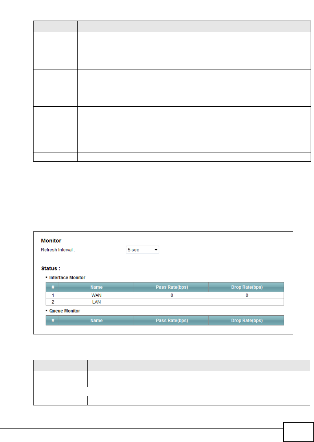
Chapter 9 Quality of Service (QoS)
VMG1312-B10C User’s Guide 143
9.7 The QoS Monitor Screen
To view the Device’s QoS packet statistics, click Net w or k Set t ing > QoS > M on it or. The screen
appears as shown.
Figure 72 Network Setting > QoS > Monitor
The following table describes the labels in this screen.
Conforming
Action
Specify what the Device does for packets within the committed rate and burst size (green-
marked packets).
•Pa ss: Send the packets without modification.
•DSCP M ark : Change the DSCP mark value of the packets. Enter the DSCP mark value to
use.
Non-
Conforming
Action
Specify what the Device does for packets that exceed the excess burst size or peak rate and
burst size (red-marked packets).
•Dr op: Discard the packets.
•DSCP M ark : Change the DSCP mark value of the packets. Enter the DSCP mark value to
use. The packets may be dropped if there is congestion on the network.
Available Class
Selected Class
Select a QoS classifier to apply this QoS policer to traffic that matches the QoS classifier.
Highlight a QoS classifier in the Availa ble Class box and use the > button to move it to the
Sele cted Cla ss box.
To remove a QoS classifier from the Sele cte d Cla ss box, select it and use the < button.
Apply Click Apply to save your changes.
Cancel Click Ca ncel to exit this screen without saving.
Table 49 Policer Setup: Add/Edit
LABEL DESCRIPTION
Table 50 Network Setting > QoS > Monitor
LABEL DESCRIPTION
Refresh Interval Enter how often you want the Device to update this screen. Select N o Re fr esh to stop
refreshing statistics.
Interface Monitor
# This is the index number of the entry.
Chapter 9 Quality of Service (QoS)
VMG1312-B10C User’s Guide
144
9.8 Technical Reference
The following section contains additional technical information about the Device features described
in this chapter.
IEEE 802.1Q Tag
The IEEE 802.1Q standard defines an explicit VLAN tag in the MAC header to identify the VLAN
membership of a frame across bridges. A VLAN tag includes the 12-bit VLAN ID and 3-bit user
priority. The VLAN ID associates a frame with a specific VLAN and provides the information that
devices need to process the frame across the network.
IEEE 802.1p specifies the user priority field and defines up to eight separate traffic types. The
following table describes the traffic types defined in the IEEE 802.1d standard (which incorporates
the 802.1p).
Name This shows the name of the interface on the Device.
Pass Rate This shows how many packets forwarded to this interface are transmitted successfully.
Drop Rate This shows how many packets forwarded to this interface are dropped.
Queue Monitor
# This is the index number of the entry.
Name This shows the name of the queue.
Pass Rate This shows how many packets assigned to this queue are transmitted successfully.
Drop Rate This shows how many packets assigned to this queue are dropped.
Table 50 Network Setting > QoS > Monitor (continued)
LABEL DESCRIPTION
Table 51 IEEE 802.1p Priority Level and Traffic Type
PRIORITY
LEVEL TRAFFIC TYPE
Level 7 Typically used for network control traffic such as router configuration messages.
Level 6 Typically used for voice traffic that is especially sensitive to jitter (jitter is the
variations in delay).
Level 5 Typically used for video that consumes high bandwidth and is sensitive to jitter.
Level 4 Typically used for controlled load, latency-sensitive traffic such as SNA (Systems
Network Architecture) transactions.
Level 3 Typically used for “excellent effort” or better than best effort and would include
important business traffic that can tolerate some delay.
Level 2 This is for “spare bandwidth”.
Level 1 This is typically used for non-critical “background” traffic such as bulk transfers that
are allowed but that should not affect other applications and users.
Level 0 Typically used for best-effort traffic.

Chapter 9 Quality of Service (QoS)
VMG1312-B10C User’s Guide 145
DiffServ
QoS is used to prioritize source-to-destination traffic flows. All packets in the flow are given the
same priority. You can use CoS (class of service) to give different priorities to different packet
types.
DiffServ (Differentiated Services) is a class of service (CoS) model that marks packets so that they
receive specific per-hop treatment at DiffServ-compliant network devices along the route based on
the application types and traffic flow. Packets are marked with DiffServ Code Points (DSCPs)
indicating the level of service desired. This allows the intermediary DiffServ-compliant network
devices to handle the packets differently depending on the code points without the need to
negotiate paths or remember state information for every flow. In addition, applications do not have
to request a particular service or give advanced notice of where the traffic is going.
DSCP and Per-Hop Behavior
DiffServ defines a new Differentiated Services (DS) field to replace the Type of Service (TOS) field
in the IP header. The DS field contains a 2-bit unused field and a 6-bit DSCP field which can define
up to 64 service levels. The following figure illustrates the DS field.
DSCP is backward compatible with the three precedence bits in the ToS octet so that non-DiffServ
compliant, ToS-enabled network device will not conflict with the DSCP mapping.
The DSCP value determines the forwarding behavior, the PHB (Per-Hop Behavior), that each packet
gets across the DiffServ network. Based on the marking rule, different kinds of traffic can be
marked for different kinds of forwarding. Resources can then be allocated according to the DSCP
values and the configured policies.
IP Precedence
Similar to IEEE 802.1p prioritization at layer-2, you can use IP precedence to prioritize packets in a
layer-3 network. IP precedence uses three bits of the eight-bit ToS (Type of Service) field in the IP
header. There are eight classes of services (ranging from zero to seven) in IP precedence. Zero is
the lowest priority level and seven is the highest.
Automatic Priority Queue Assignment
If you enable QoS on the Device, the Device can automatically base on the IEEE 802.1p priority
level, IP precedence and/or packet length to assign priority to traffic which does not match a class.
DSCP (6 bits) Unused (2 bits)

Chapter 9 Quality of Service (QoS)
VMG1312-B10C User’s Guide
146
The following table shows you the internal layer-2 and layer-3 QoS mapping on the Device. On the
Device, traffic assigned to higher priority queues gets through faster while traffic in lower index
queues is dropped if the network is congested.
Token Bucket
The token bucket algorithm uses tokens in a bucket to control when traffic can be transmitted. The
bucket stores tokens, each of which represents one byte. The algorithm allows bursts of up to b
bytes which is also the bucket size, so the bucket can hold up to b tokens. Tokens are generated
and added into the bucket at a constant rate. The following shows how tokens work with packets:
• A packet can be transmitted if the number of tokens in the bucket is equal to or greater than the
size of the packet (in bytes).
• After a packet is transmitted, a number of tokens corresponding to the packet size is removed
from the bucket.
Table 52 Internal Layer2 and Layer3 QoS Mapping
PRIORITY
QUEUE
LAYER 2 LAYER 3
IEEE 802.1P USER
PRIORITY
(ETHERNET
PRIORITY)
TOS (IP
PRECEDENCE) DSCP IP PACKET
LENGTH (BYTE)
0 1 0 000000
12
2 0 0 000000 >1100
3 3 1 001110
001100
001010
001000
250~1100
4 4 2 010110
010100
010010
010000
5 5 3 011110
011100
011010
011000
<250
6 6 4 100110
100100
100010
100000
5 101110
101000
7 7 6 110000
111000
7

Chapter 9 Quality of Service (QoS)
VMG1312-B10C User’s Guide 147
• If there are no tokens in the bucket, the Device stops transmitting until enough tokens are
generated.
• If not enough tokens are available, the Device treats the packet in either one of the following
ways:
In traffic shaping:
• Holds it in the queue until enough tokens are available in the bucket.
In traffic policing:
•Drops it.
• Transmits it but adds a DSCP mark. The Device may drop these marked packets if the network
is overloaded.
Configure the bucket size to be equal to or less than the amount of the bandwidth that the interface
can support. It does not help if you set it to a bucket size over the interface’s capability. The smaller
the bucket size, the lower the data transmission rate and that may cause outgoing packets to be
dropped. A larger transmission rate requires a big bucket size. For example, use a bucket size of 10
kbytes to get the transmission rate up to 10 Mbps.
Single Rate Three Color Marker
The Single Rate Three Color Marker (srTCM, defined in RFC 2697) is a type of traffic policing that
identifies packets by comparing them to one user-defined rate, the Committed Information Rate
(CIR), and two burst sizes: the Committed Burst Size (CBS) and Excess Burst Size (EBS).
The srTCM evaluates incoming packets and marks them with one of three colors which refer to
packet loss priority levels. High packet loss priority level is referred to as red, medium is referred to
as yellow and low is referred to as green.
The srTCM is based on the token bucket filter and has two token buckets (CBS and EBS). Tokens
are generated and added into the bucket at a constant rate, called Committed Information Rate
(CIR). When the first bucket (CBS) is full, new tokens overflow into the second bucket (EBS).
All packets are evaluated against the CBS. If a packet does not exceed the CBS it is marked green.
Otherwise it is evaluated against the EBS. If it is below the EBS then it is marked yellow. If it
exceeds the EBS then it is marked red.
The following shows how tokens work with incoming packets in srTCM:
• A packet arrives. The packet is marked green and can be transmitted if the number of tokens in
the CBS bucket is equal to or greater than the size of the packet (in bytes).
• After a packet is transmitted, a number of tokens corresponding to the packet size is removed
from the CBS bucket.
• If there are not enough tokens in the CBS bucket, the Device checks the EBS bucket. The packet
is marked yellow if there are sufficient tokens in the EBS bucket. Otherwise, the packet is marked
red. No tokens are removed if the packet is dropped.
Two Rate Three Color Marker
The Two Rate Three Color Marker (trTCM, defined in RFC 2698) is a type of traffic policing that
identifies packets by comparing them to two user-defined rates: the Committed Information Rate
(CIR) and the Peak Information Rate (PIR). The CIR specifies the average rate at which packets are
admitted to the network. The PIR is greater than or equal to the CIR. CIR and PIR values are based

Chapter 9 Quality of Service (QoS)
VMG1312-B10C User’s Guide
148
on the guaranteed and maximum bandwidth respectively as negotiated between a service provider
and client.
The trTCM evaluates incoming packets and marks them with one of three colors which refer to
packet loss priority levels. High packet loss priority level is referred to as red, medium is referred to
as yellow and low is referred to as green.
The trTCM is based on the token bucket filter and has two token buckets (Committed Burst Size
(CBS) and Peak Burst Size (PBS)). Tokens are generated and added into the two buckets at the CIR
and PIR respectively.
All packets are evaluated against the PIR. If a packet exceeds the PIR it is marked red. Otherwise it
is evaluated against the CIR. If it exceeds the CIR then it is marked yellow. Finally, if it is below the
CIR then it is marked green.
The following shows how tokens work with incoming packets in trTCM:
• A packet arrives. If the number of tokens in the PBS bucket is less than the size of the packet (in
bytes), the packet is marked red and may be dropped regardless of the CBS bucket. No tokens
are removed if the packet is dropped.
• If the PBS bucket has enough tokens, the Device checks the CBS bucket. The packet is marked
green and can be transmitted if the number of tokens in the CBS bucket is equal to or greater
than the size of the packet (in bytes). Otherwise, the packet is marked yellow.

VMG1312-B10C User’s Guide 149
CHAPTER 10
Network Address Translation (NAT)
10.1 Overview
This chapter discusses how to configure NAT on the Device. NAT (Network Address Translation -
NAT, RFC 1631) is the translation of the IP address of a host in a packet, for example, the source
address of an outgoing packet, used within one network to a different IP address known within
another network.
10.1.1 What You Can Do in this Chapter
•Use the Por t For w ar din g screen to configure forward incoming service requests to the server(s)
on your local network (Section 10.2 on page 150).
•Use the App lica t ion s screen to forward incoming service requests to the server(s) on your local
network (Section 10.3 on page 153).
•Use the Port Tr igge rin g screen to add and configure the Device’s trigger port settings (Section
10.4 on page 155).
•Use the DM Z screen to configure a default server (Section 10.5 on page 158).
•Use the ALG screen to enable and disable the NAT and SIP (VoIP) ALG in the Device (Section
10.6 on page 158).
•Use the Addr ess M a pping screen to configure the Device's address mapping settings (Section
10.7 on page 159).
10.1.2 What You Need To Know
Inside/Outside
Inside/outside denotes where a host is located relative to the Device, for example, the computers
of your subscribers are the inside hosts, while the web servers on the Internet are the outside
hosts.
Global/Local
Global/local denotes the IP address of a host in a packet as the packet traverses a router, for
example, the local address refers to the IP address of a host when the packet is in the local
network, while the global address refers to the IP address of the host when the same packet is
traveling in the WAN side.
NAT
In the simplest form, NAT changes the source IP address in a packet received from a subscriber
(the inside local address) to another (the inside global address) before forwarding the packet to the

Chapter 10 Network Address Translation (NAT)
VMG1312-B10C User’s Guide
150
WAN side. When the response comes back, NAT translates the destination address (the inside
global address) back to the inside local address before forwarding it to the original inside host.
Port Forwarding
A port forwarding set is a list of inside (behind NAT on the LAN) servers, for example, web or FTP,
that you can make visible to the outside world even though NAT makes your whole inside network
appear as a single computer to the outside world.
Finding Out More
See Section 10.8 on page 161 for advanced technical information on NAT.
10.2 The Port Forwarding Screen
Use the Port For w arding screen to forward incoming service requests to the server(s) on your
local network.
You may enter a single port number or a range of port numbers to be forwarded, and the local IP
address of the desired server. The port number identifies a service; for example, web service is on
port 80 and FTP on port 21. In some cases, such as for unknown services or where one server can
support more than one service (for example both FTP and web service), it might be better to
specify a range of port numbers. You can allocate a server IP address that corresponds to a port or
a range of ports.
Please refer to RFC 1700 for further information about port numbers.
Note: Many residential broadband ISP accounts do not allow you to run any server
processes (such as a Web or FTP server) from your location. Your ISP may
periodically check for servers and may suspend your account if it discovers any
active services at your location. If you are unsure, refer to your ISP.
Configuring Servers Behind Port Forwarding (Example)
Let's say you want to assign ports 21-25 to one FTP, Telnet and SMTP server (A in the example),
port 80 to another (B in the example) and assign a default server IP address of 192.168.1.35 to a
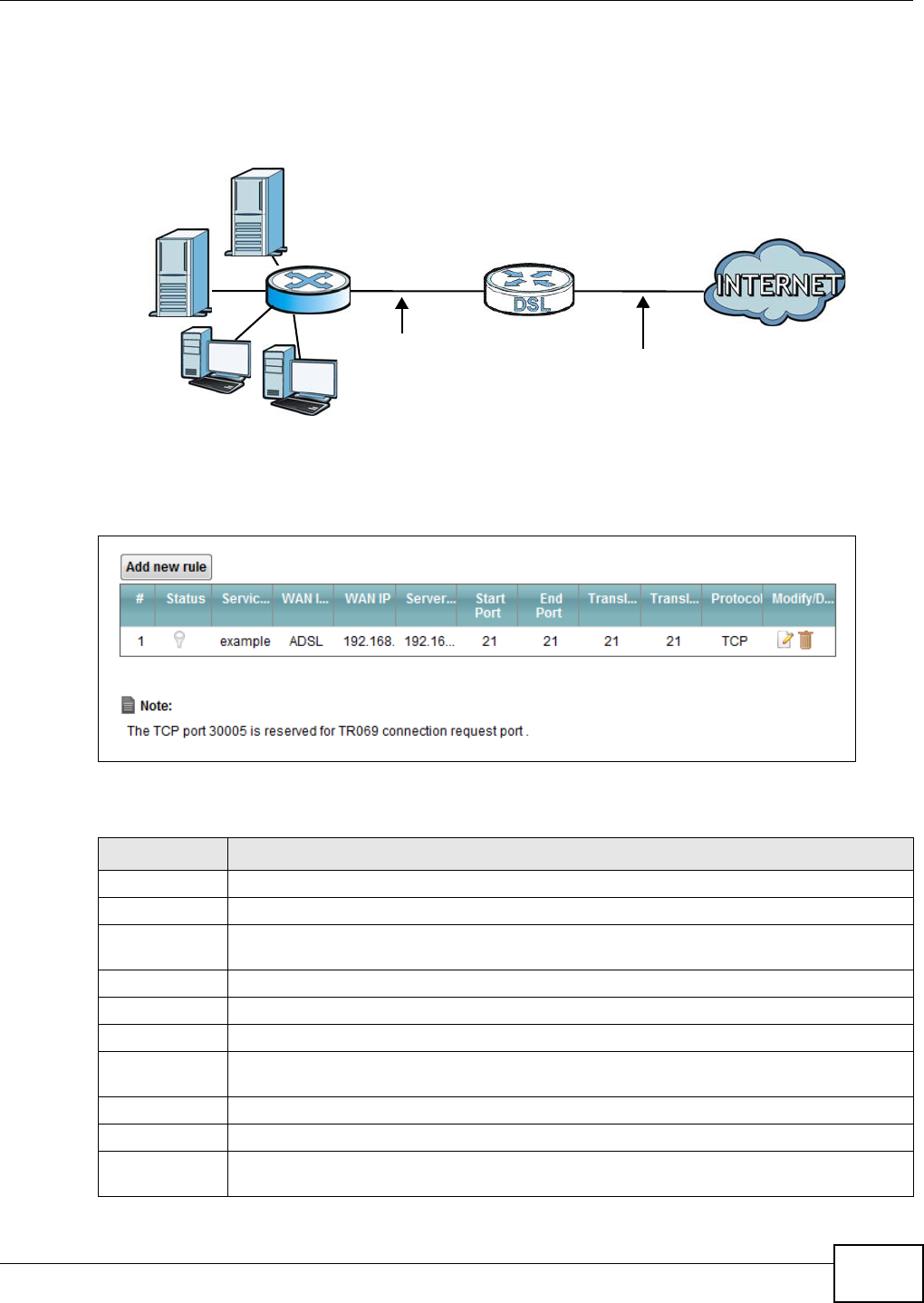
Chapter 10 Network Address Translation (NAT)
VMG1312-B10C User’s Guide 151
third (C in the example). You assign the LAN IP addresses and the ISP assigns the WAN IP address.
The NAT network appears as a single host on the Internet.
Figure 73 Multiple Servers Behind NAT Example
Click N et w or k Set t ing > N AT > Port For w a rding to open the following screen.
Figure 74 Network Setting > NAT > Port Forwarding
The following table describes the fields in this screen.
Table 53 Network Setting > NAT > Port Forwarding
LABEL DESCRIPTION
Add new rule Click this to add a new rule.
#This is the index number of the entry.
Status This field displays whether the NAT rule is active or not. A yellow bulb signifies that this rule
is active. A gray bulb signifies that this rule is not active.
Service Name This shows the service’s name.
WAN Interface This shows the WAN interface through which the service is forwarded.
WAN IP This field displays the incoming packet’s destination IP address.
Server IP
Address
This is the server’s IP address.
Start Port This is the first external port number that identifies a service.
End Port This is the last external port number that identifies a service.
Translation
Start Port
This is the first internal port number that identifies a service.
A=192.168.1.33
D=192.168.1.36
C=192.168.1.3
B=192.168.1.34
WAN
LAN
192.168.1.1 IP Address assigned by ISP
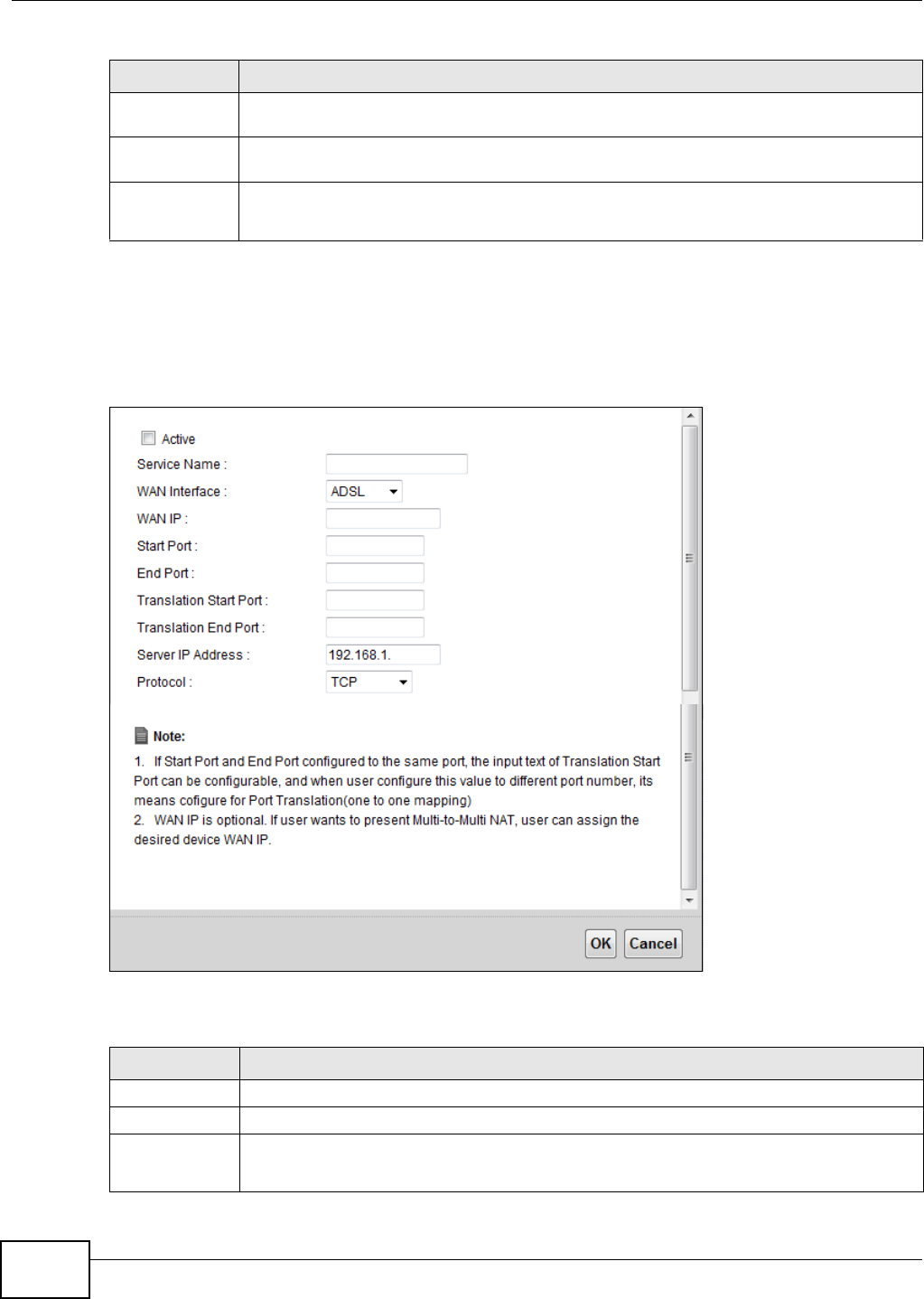
Chapter 10 Network Address Translation (NAT)
VMG1312-B10C User’s Guide
152
10.2.1 Add/Edit Port Forwarding
Click Add ne w rule in the Por t For w a rding screen or click the Edit icon next to an existing rule to
open the following screen.
Figure 75 Port Forwarding: Add/Edit
The following table describes the labels in this screen.
Translation End
Port
This is the last internal port number that identifies a service.
Protocol This shows the IP protocol supported by this virtual server, whether it is TCP, UD P, or TCP/
UDP.
Modify/Delete Click the Ed it icon to edit this rule.
Click the De le t e icon to delete an existing rule.
Table 53 Network Setting > NAT > Port Forwarding (continued)
LABEL DESCRIPTION
Table 54 Port Forwarding: Add/Edit
LABEL DESCRIPTION
Active Clear the checkbox to disable the rule. Select the check box to enable it.
Service Name Enter a name to identify this rule using keyboard characters (A-Z, a-z, 1-2 and so on).
WAN Interface Select the WAN interface through which the service is forwarded.
You must have already configured a WAN connection with NAT enabled.
Chapter 10 Network Address Translation (NAT)
VMG1312-B10C User’s Guide 153
10.3 The Applications Screen
This screen provides a summary of all NAT applications and their configuration. In addition, this
screen allows you to create new applications and/or remove existing ones.
To access this screen, click N et w or k Set t ing > N AT > Applica t ions. The following screen
appears.
Figure 76 Network Setting > NAT > Applications
WAN IP Enter the WAN IP address for which the incoming service is destined. If the packet’s
destination IP address doesn’t match the one specified here, the port forwarding rule will
not be applied.
Start Port Enter the original destination port for the packets.
To forward only one port, enter the port number again in the End Port field.
To forward a series of ports, enter the start port number here and the end port number in
the En d Port field.
End Port Enter the last port of the original destination port range.
To forward only one port, enter the port number in the St a r t Por t field above and then
enter it again in this field.
To forward a series of ports, enter the last port number in a series that begins with the port
number in the St a rt Port field above.
Translation
Start Port
This shows the port number to which you want the Device to translate the incoming port.
For a range of ports, enter the first number of the range to which you want the incoming
ports translated.
Translation End
Port
This shows the last port of the translated port range.
Server IP
Address
Enter the inside IP address of the virtual server here.
Protocol Select the protocol supported by this virtual server. Choices are TCP, UD P, or TCP/ UDP.
OK Click OK to save your changes.
Cancel Click Cancel to exit this screen without saving.
Table 54 Port Forwarding: Add/Edit (continued)
LABEL DESCRIPTION
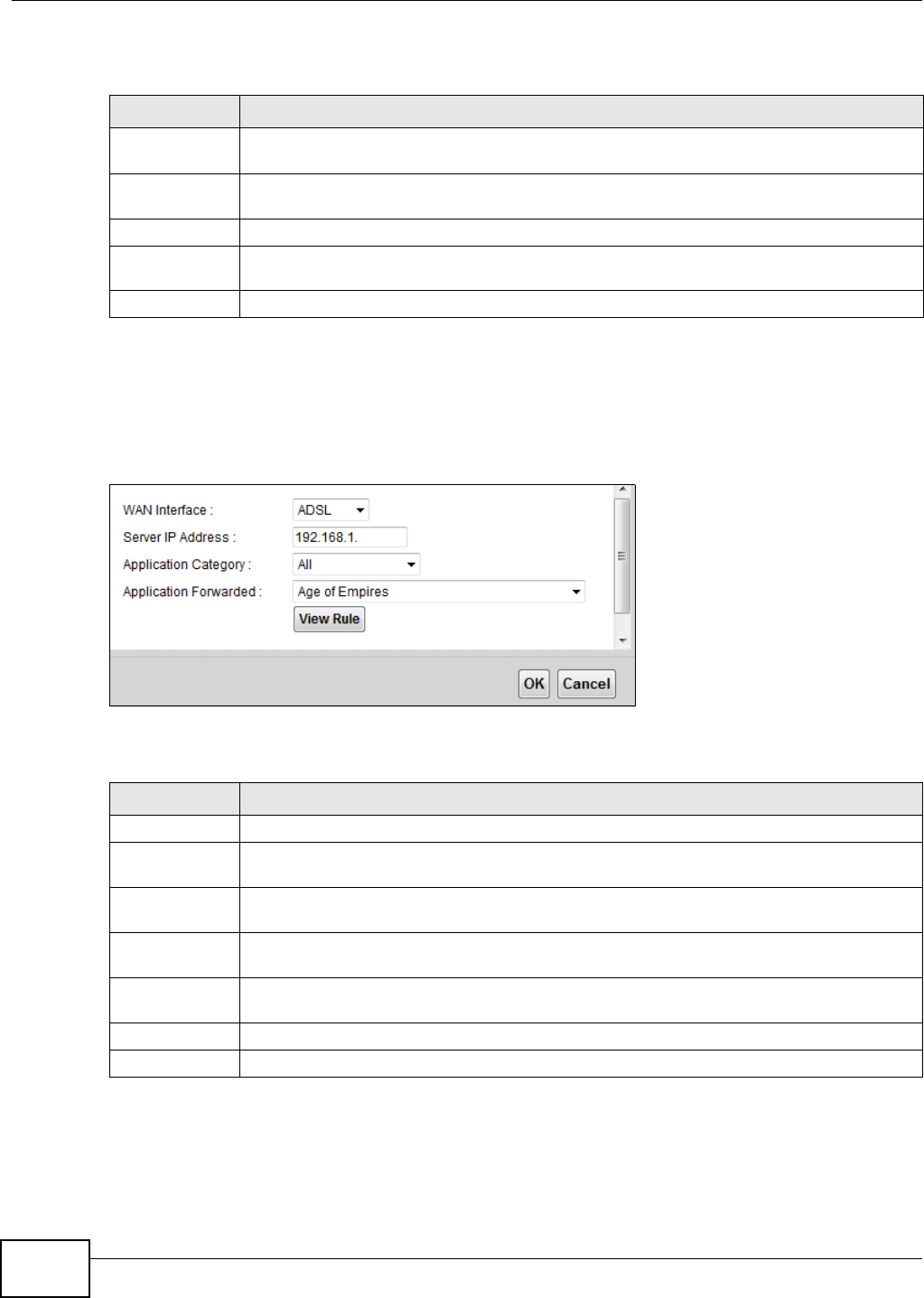
Chapter 10 Network Address Translation (NAT)
VMG1312-B10C User’s Guide
154
The following table describes the labels in this screen.
10.3.1 Add New Application
This screen lets you create new NAT application rules. Click Add n e w applicat ion in the
Applicat ions screen to open the following screen.
Figure 77 Applications: Add
The following table describes the labels in this screen.
Table 55 Network Setting > NAT > Applications
LABEL DESCRIPTION
Add new
application
Click this to add a new NAT application rule.
Application
Forwarded
This field shows the type of application that the service forwards.
WAN Interface This field shows the WAN interface through which the service is forwarded.
Server IP
Address
This field displays the destination IP address for the service.
Delete Click the De let e icon to delete the rule.
Table 56 Applications: Add
LABEL DESCRIPTION
WAN Interface Select the WAN interface that you want to apply this NAT rule to.
Server IP
Address
Enter the inside IP address of the application here.
Application
Category
Select the category of the application from the drop-down list box.
Application
Forwarded
Select a service from the drop-down list box and the Device automatically configures the
protocol, start, end, and map port number that define the service.
View Rule Click this to display the configuration of the service that you have chosen in Applica t ion
Fow a rded.
OK Click OK to save your changes.
Cancel Click Cancel to exit this screen without saving.
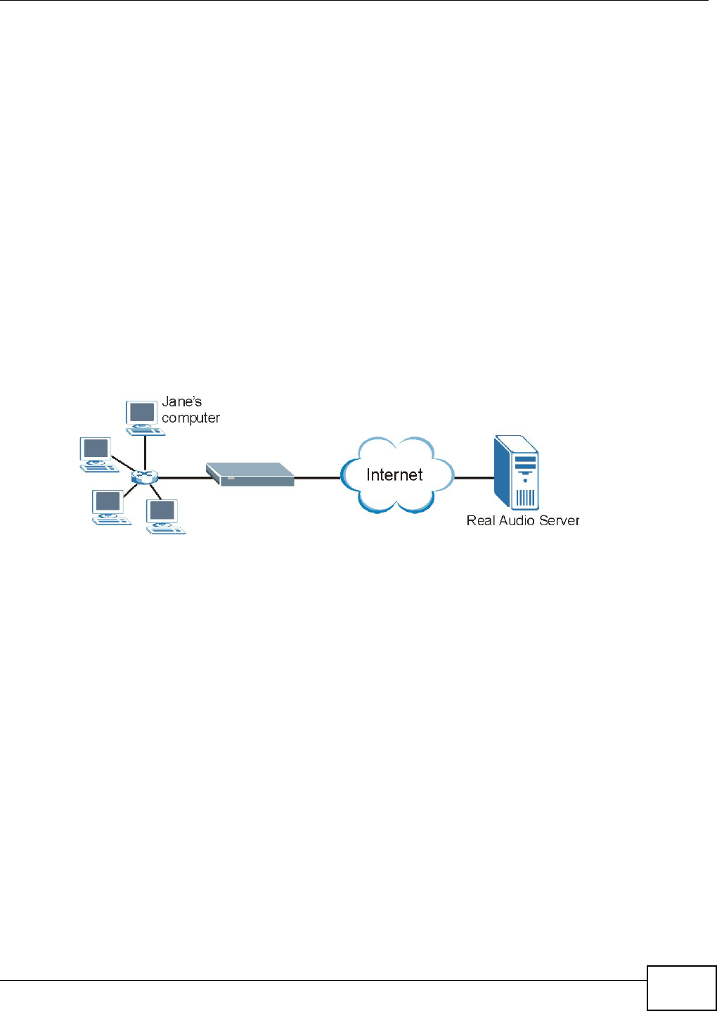
Chapter 10 Network Address Translation (NAT)
VMG1312-B10C User’s Guide 155
10.4 The Port Triggering Screen
Some services use a dedicated range of ports on the client side and a dedicated range of ports on
the server side. With regular port forwarding you set a forwarding port in NAT to forward a service
(coming in from the server on the WAN) to the IP address of a computer on the client side (LAN).
The problem is that port forwarding only forwards a service to a single LAN IP address. In order to
use the same service on a different LAN computer, you have to manually replace the LAN
computer's IP address in the forwarding port with another LAN computer's IP address.
Trigger port forwarding solves this problem by allowing computers on the LAN to dynamically take
turns using the service. The Device records the IP address of a LAN computer that sends traffic to
the WAN to request a service with a specific port number and protocol (a "trigger" port). When the
Device's WAN port receives a response with a specific port number and protocol ("open" port), the
Device forwards the traffic to the LAN IP address of the computer that sent the request. After that
computer’s connection for that service closes, another computer on the LAN can use the service in
the same manner. This way you do not need to configure a new IP address each time you want a
different LAN computer to use the application.
For example:
Figure 78 Trigger Port Forwarding Process: Example
1Jane requests a file from the Real Audio server (port 7070).
2Port 7070 is a “trigger” port and causes the Device to record Jane’s computer IP address. The
Device associates Jane's computer IP address with the "open" port range of 6970-7170.
3The Real Audio server responds using a port number ranging between 6970-7170.
4The Device forwards the traffic to Jane’s computer IP address.
5Only Jane can connect to the Real Audio server until the connection is closed or times out. The
Device times out in three minutes with UDP (User Datagram Protocol) or two hours with TCP/IP
(Transfer Control Protocol/Internet Protocol).
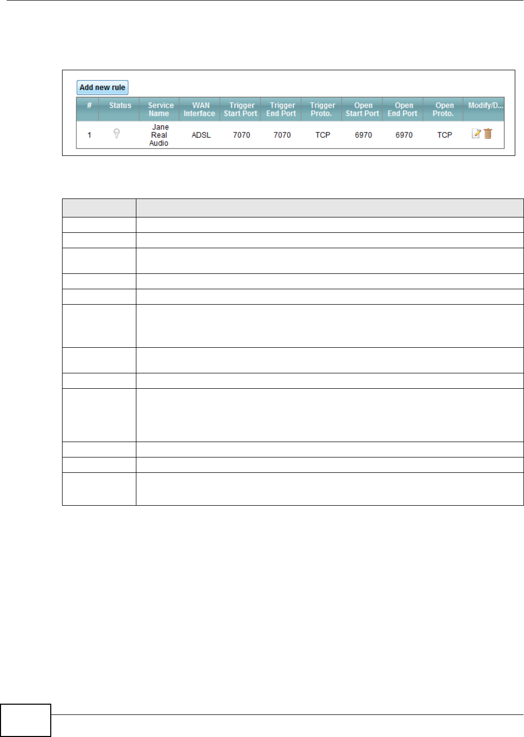
Chapter 10 Network Address Translation (NAT)
VMG1312-B10C User’s Guide
156
Click Net w ork Se t t in g > N AT > Por t Tr igger ing to open the following screen. Use this screen to
view your Device’s trigger port settings.
Figure 79 Network Setting > NAT > Port Triggering
The following table describes the labels in this screen.
Table 57 Network Setting > NAT > Port Triggering
LABEL DESCRIPTION
Add new rule Click this to create a new rule.
#This is the index number of the entry.
Status This field displays whether the port triggering rule is active or not. A yellow bulb signifies
that this rule is active. A gray bulb signifies that this rule is not active.
Service Name This field displays the name of the service used by this rule.
WAN Interface This field shows the WAN interface through which the service is forwarded.
Trigger Start
Port
The trigger port is a port (or a range of ports) that causes (or triggers) the Device to record
the IP address of the LAN computer that sent the traffic to a server on the WAN.
This is the first port number that identifies a service.
Trigger End
Port
This is the last port number that identifies a service.
Trigger Proto. This is the trigger transport layer protocol.
Open Start Port The open port is a port (or a range of ports) that a server on the WAN uses when it sends
out a particular service. The Device forwards the traffic with this port (or range of ports) to
the client computer on the LAN that requested the service.
This is the first port number that identifies a service.
Open End Port This is the last port number that identifies a service.
Open Proto. This is the open transport layer protocol.
Modify/Delete Click the Edit icon to edit this rule.
Click the D e le t e icon to delete an existing rule.
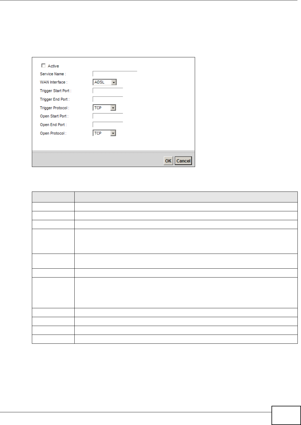
Chapter 10 Network Address Translation (NAT)
VMG1312-B10C User’s Guide 157
10.4.1 Add/Edit Port Triggering Rule
This screen lets you create new port triggering rules. Click Add new r u le in the Port Tr iggering
screen or click a rule’s Edit icon to open the following screen.
Figure 80 Port Triggering: Add/Edit
The following table describes the labels in this screen.
Table 58 Port Triggering: Configuration Add/Edit
LABEL DESCRIPTION
Active Select the check box to enable this rule.
Service Name Enter a name to identify this rule using keyboard characters (A-Z, a-z, 1-2 and so on).
WAN Interface Select a WAN interface for which you want to configure port triggering rules.
Trigger Start
Port
The trigger port is a port (or a range of ports) that causes (or triggers) the Device to record
the IP address of the LAN computer that sent the traffic to a server on the WAN.
Type a port number or the starting port number in a range of port numbers.
Trigger End
Port
Type a port number or the ending port number in a range of port numbers.
Trigger Protocol Select the transport layer protocol from TCP, UD P, or TCP/ UDP.
Open Start Port The open port is a port (or a range of ports) that a server on the WAN uses when it sends
out a particular service. The Device forwards the traffic with this port (or range of ports) to
the client computer on the LAN that requested the service.
Type a port number or the starting port number in a range of port numbers.
Open End Port Type a port number or the ending port number in a range of port numbers.
Open Protocol Select the transport layer protocol from TCP, UD P, or TCP/ UDP.
OK Click OK to save your changes.
Cancel Click Cancel to exit this screen without saving.
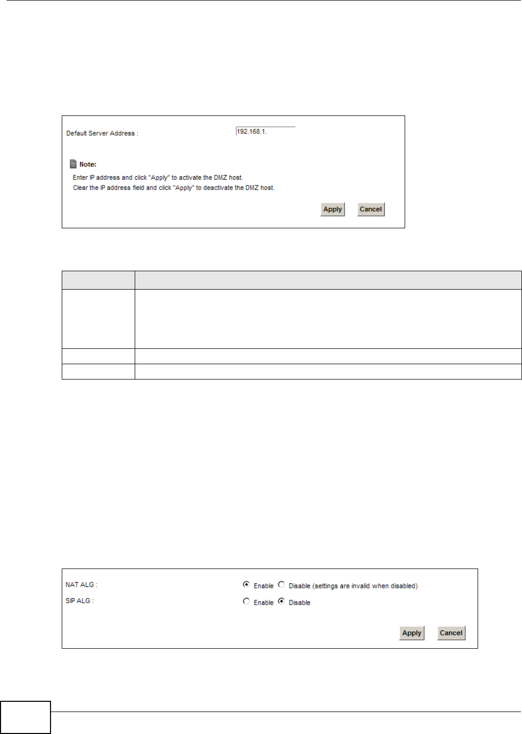
Chapter 10 Network Address Translation (NAT)
VMG1312-B10C User’s Guide
158
10.5 The DMZ Screen
In addition to the servers for specified services, NAT supports a default server IP address. A default
server receives packets from ports that are not specified in the N AT Por t For w a r din g Set u p
screen.
Figure 81 Network Setting > NAT > DMZ
The following table describes the fields in this screen.
10.6 The ALG Screen
Some NAT routers may include a SIP Application Layer Gateway (ALG). A SIP ALG allows SIP calls
to pass through NAT by examining and translating IP addresses embedded in the data stream.
When the Device registers with the SIP register server, the SIP ALG translates the Device’s private
IP address inside the SIP data stream to a public IP address. You do not need to use STUN or an
outbound proxy if your Device is behind a SIP ALG.
Use this screen to enable and disable the NAT and SIP (VoIP) ALG in the Device. To access this
screen, click N e t w ork Se t t in g > N AT > ALG.
Figure 82 Network Setting > NAT > ALG
Table 59 Network Setting > NAT > DMZ
LABEL DESCRIPTION
Default Server
Address
Enter the IP address of the default server which receives packets from ports that are not
specified in the NAT Por t For w a r din g screen.
Note: If you do not assign a Default Server Address, the Device discards all packets
received for ports that are not specified in the NAT Port Forwarding screen.
Apply Click Apply to save your changes.
Cancel Click Cance l to restore your previously saved settings.
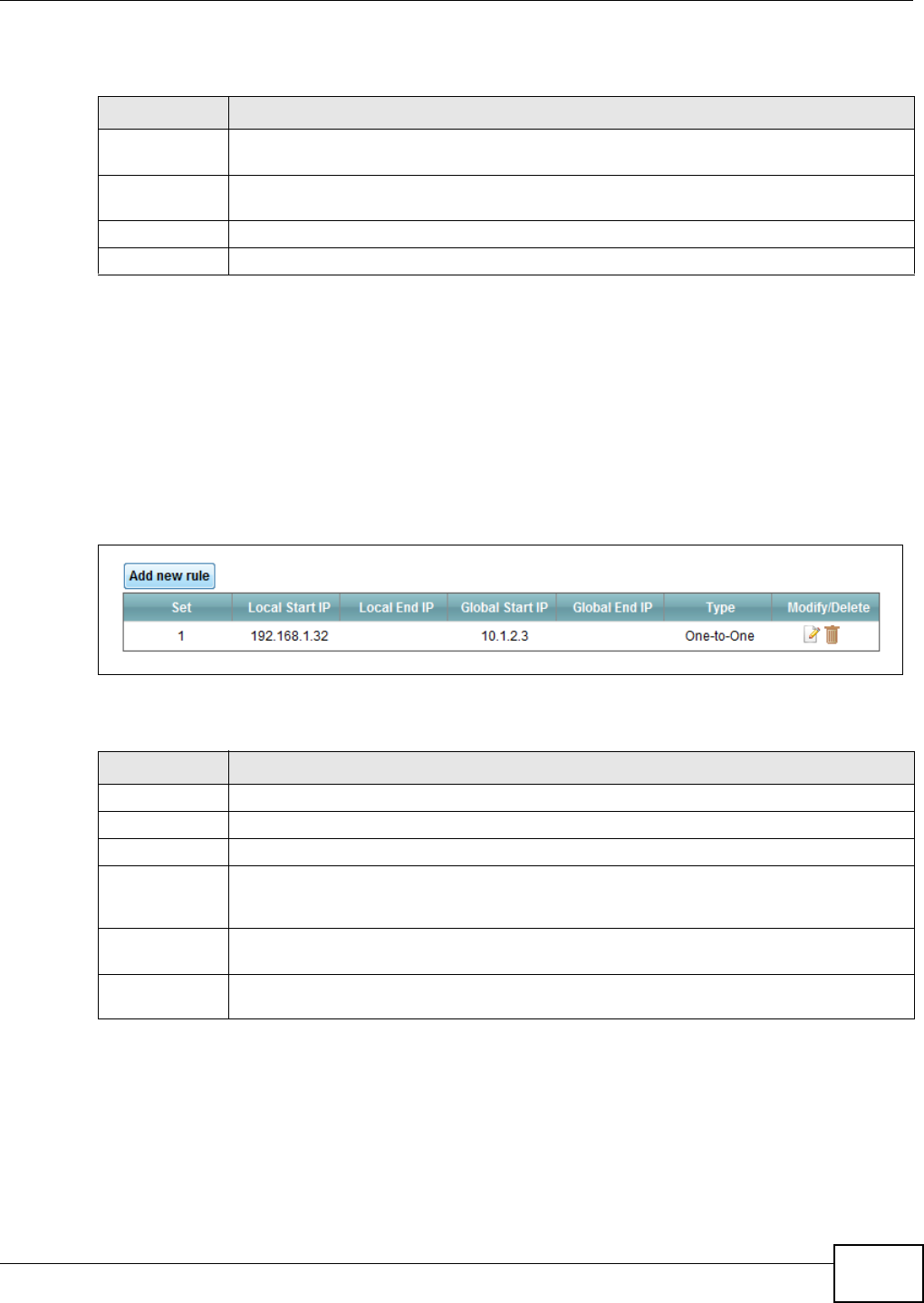
Chapter 10 Network Address Translation (NAT)
VMG1312-B10C User’s Guide 159
The following table describes the fields in this screen.
10.7 The Address Mapping Screen
Ordering your rules is important because the Device applies the rules in the order that you specify.
When a rule matches the current packet, the Device takes the corresponding action and the
remaining rules are ignored.
Click N et w ork Set t in g > N AT > Addr ess M a ppin g to display the following screen.
Figure 83 Network Setting > NAT > Address Mapping
The following table describes the fields in this screen.
Table 60 Network Setting > NAT > ALG
LABEL DESCRIPTION
NAT ALG Enable this to make sure applications such as FTP and file transfer in IM applications work
correctly with port-forwarding and address-mapping rules.
SIP ALG Enable this to make sure SIP (VoIP) works correctly with port-forwarding and address-
mapping rules.
Apply Click Apply to save your changes.
Cancel Click Cancel to restore your previously saved settings.
Table 61 Network Setting > NAT > Address Mapping
LABEL DESCRIPTION
Add new rule Click this to create a new rule.
Set This is the index number of the address mapping set.
Local Start IP This is the starting Inside Local IP Address (ILA).
Local End IP This is the ending Inside Local IP Address (ILA). If the rule is for all local IP addresses, then
this field displays 0.0.0.0 as the Local Start IP address and 255.255.255.255 as the Local
End IP address. This field is blank for On e - t o - On e mapping types.
Global Start IP This is the starting Inside Global IP Address (IGA). Enter 0.0.0.0 here if you have a dynamic
IP address from your ISP. You can only do this for the M any- t o- On e mapping type.
Global End IP This is the ending Inside Global IP Address (IGA). This field is blank for One- t o- On e and
Man y- t o- On e mapping types.
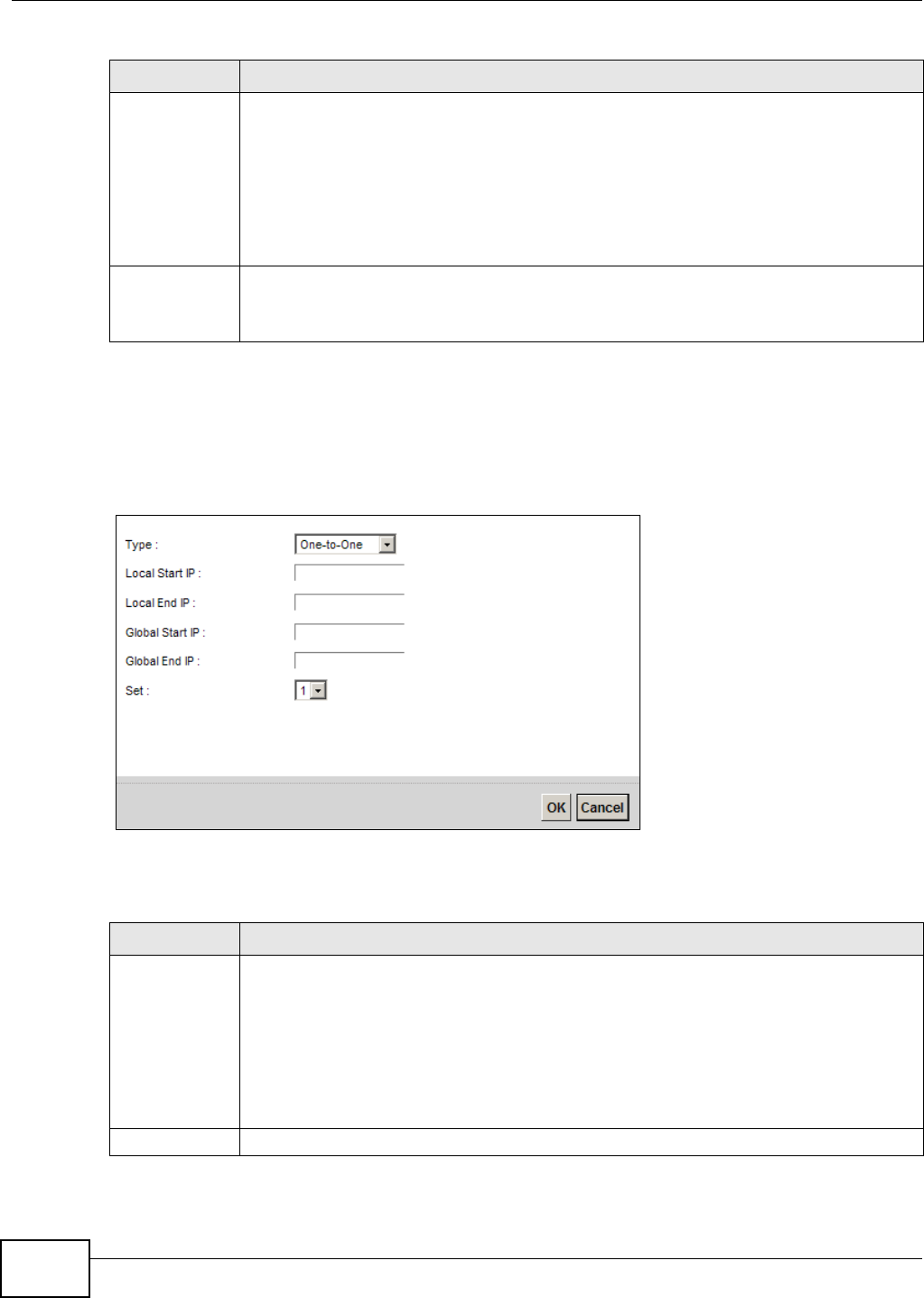
Chapter 10 Network Address Translation (NAT)
VMG1312-B10C User’s Guide
160
10.7.1 Add/Edit Address Mapping Rule
To add or edit an address mapping rule, click Add ne w rule or the rule’s edit icon in the Addr e ss
Ma pping screen to display the screen shown next.
Figure 84 Address Mapping: Add/Edit
The following table describes the fields in this screen.
Type This is the address mapping type.
On e- t o- One : This mode maps one local IP address to one global IP address. Note that port
numbers do not change for the One-to-one NAT mapping type.
M a ny - t o- O ne : This mode maps multiple local IP addresses to one global IP address. This is
equivalent to SUA (i.e., PAT, port address translation), the Device's Single User Account
feature that previous routers supported only.
M a ny - t o- M a n y: This mode maps multiple local IP addresses to shared global IP addresses.
Modify/Delete Click the Edit icon to go to the screen where you can edit the address mapping rule.
Click the D e let e icon to delete an existing address mapping rule. Note that subsequent
address mapping rules move up by one when you take this action.
Table 61 Network Setting > NAT > Address Mapping (continued)
LABEL DESCRIPTION
Table 62 Address Mapping: Add/Edit
LABEL DESCRIPTION
Type Choose the IP/port mapping type from one of the following.
On e- t o- One : This mode maps one local IP address to one global IP address. Note that port
numbers do not change for the One-to-one NAT mapping type.
M a ny - t o- O ne : This mode maps multiple local IP addresses to one global IP address. This is
equivalent to SUA (i.e., PAT, port address translation), the Device's Single User Account
feature that previous routers supported only.
M a ny - t o- M a n y: This mode maps multiple local IP addresses to shared global IP addresses.
Local Start IP Enter the starting Inside Local IP Address (ILA).

Chapter 10 Network Address Translation (NAT)
VMG1312-B10C User’s Guide 161
10.8 Technical Reference
This part contains more information regarding NAT.
10.8.1 NAT Definitions
Inside/outside denotes where a host is located relative to the Device, for example, the computers
of your subscribers are the inside hosts, while the web servers on the Internet are the outside
hosts.
Global/local denotes the IP address of a host in a packet as the packet traverses a router, for
example, the local address refers to the IP address of a host when the packet is in the local
network, while the global address refers to the IP address of the host when the same packet is
traveling in the WAN side.
Local End IP Enter the ending Inside Local IP Address (ILA). If the rule is for all local IP addresses, then
this field displays 0.0.0.0 as the Local Start IP address and 255.255.255.255 as the Local
End IP address. This field is blank for On e - t o - On e mapping types.
Global Start IP Enter the starting Inside Global IP Address (IGA). Enter 0.0.0.0 here if you have a dynamic
IP address from your ISP. You can only do this for the M any- t o- On e mapping type.
Global End IP Enter the ending Inside Global IP Address (IGA). This field is blank for One - t o- One and
Man y- t o- On e mapping types.
Set Select the number of the mapping set for which you want to configure.
OK Click OK to save your changes.
Cancel Click Cance l to exit this screen without saving.
Table 62 Address Mapping: Add/Edit (continued)
LABEL DESCRIPTION

Chapter 10 Network Address Translation (NAT)
VMG1312-B10C User’s Guide
162
Note that inside/outside refers to the location of a host, while global/local refers to the IP address
of a host used in a packet. Thus, an inside local address (ILA) is the IP address of an inside host in
a packet when the packet is still in the local network, while an inside global address (IGA) is the IP
address of the same inside host when the packet is on the WAN side. The following table
summarizes this information.
NAT never changes the IP address (either local or global) of an outside host.
10.8.2 What NAT Does
In the simplest form, NAT changes the source IP address in a packet received from a subscriber
(the inside local address) to another (the inside global address) before forwarding the packet to the
WAN side. When the response comes back, NAT translates the destination address (the inside
global address) back to the inside local address before forwarding it to the original inside host. Note
that the IP address (either local or global) of an outside host is never changed.
The global IP addresses for the inside hosts can be either static or dynamically assigned by the ISP.
In addition, you can designate servers, for example, a web server and a telnet server, on your local
network and make them accessible to the outside world. If you do not define any servers (for Many-
to-One and Many-to-Many Overload mapping), NAT offers the additional benefit of firewall
protection. With no servers defined, your Device filters out all incoming inquiries, thus preventing
intruders from probing your network. For more information on IP address translation, refer to RFC
1631, The I P Net work Address Translator ( NAT) .
Table 63 NAT Definitions
ITEM DESCRIPTION
Inside This refers to the host on the LAN.
Outside This refers to the host on the WAN.
Local This refers to the packet address (source or destination) as the packet travels on the
LAN.
Global This refers to the packet address (source or destination) as the packet travels on the
WAN.
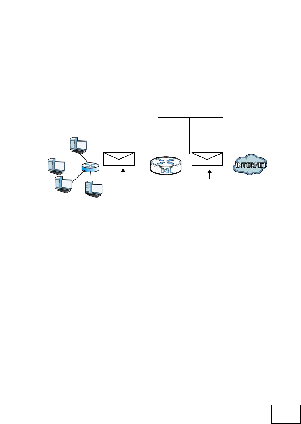
Chapter 10 Network Address Translation (NAT)
VMG1312-B10C User’s Guide 163
10.8.3 How NAT Works
Each packet has two addresses – a source address and a destination address. For outgoing packets,
the ILA (Inside Local Address) is the source address on the LAN, and the IGA (Inside Global
Address) is the source address on the WAN. For incoming packets, the ILA is the destination
address on the LAN, and the IGA is the destination address on the WAN. NAT maps private (local)
IP addresses to globally unique ones required for communication with hosts on other networks. It
replaces the original IP source address (and TCP or UDP source port numbers for Many-to-One and
Many-to-Many Overload NAT mapping) in each packet and then forwards it to the Internet. The
Device keeps track of the original addresses and port numbers so incoming reply packets can have
their original values restored. The following figure illustrates this.
Figure 85 How NAT Works
192.168.1.13
192.168.1.10
192.168.1.11
192.168.1.12 SA
192.168.1.10
SA
IGA1
Inside Local
IP Address
192.168.1.10
192.168.1.11
192.168.1.12
192.168.1.13
Inside Global
IP Address
IGA 1
IGA 2
IGA 3
IGA 4
NAT Table
WAN
LAN
Inside Local
Address (ILA)
Inside Global
Address (IGA)
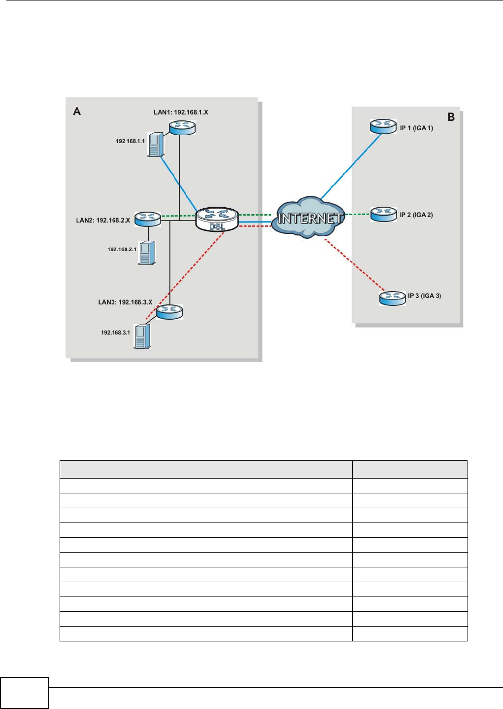
Chapter 10 Network Address Translation (NAT)
VMG1312-B10C User’s Guide
164
10.8.4 NAT Application
The following figure illustrates a possible NAT application, where three inside LANs (logical LANs
using IP alias) behind the Device can communicate with three distinct WAN networks.
Figure 86 NAT Application With IP Alias
Port Forwarding: Services and Port Numbers
The most often used port numbers are shown in the following table. Please refer to RFC 1700 for
further information about port numbers. Please also refer to the Supporting CD for more examples
and details on port forwarding and NAT.
Table 64 Services and Port Numbers
SERVICES PORT NUMBER
ECHO 7
FTP (File Transfer Protocol) 21
SMTP (Simple Mail Transfer Protocol) 25
DNS (Domain Name System) 53
Finger 79
HTTP (Hyper Text Transfer protocol or WWW, Web) 80
POP3 (Post Office Protocol) 110
NNTP (Network News Transport Protocol) 119
SNMP (Simple Network Management Protocol) 161
SNMP trap 162
PPTP (Point-to-Point Tunneling Protocol) 1723
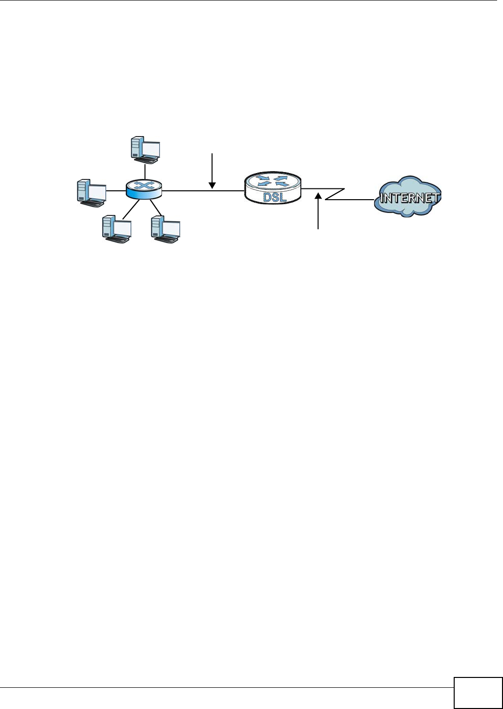
Chapter 10 Network Address Translation (NAT)
VMG1312-B10C User’s Guide 165
Port Forwarding Example
Let's say you want to assign ports 21-25 to one FTP, Telnet and SMTP server (A in the example),
port 80 to another (B in the example) and assign a default server IP address of 192.168.1.35 to a
third (C in the example). You assign the LAN IP addresses and the ISP assigns the WAN IP address.
The NAT network appears as a single host on the Internet.
Figure 87 Multiple Servers Behind NAT Example
D=192.168.1.36
192.168.1.1
IP address assigned by ISP
A=192.168.1.33
B=192.168.1.34
C=192.168.1.35

Chapter 10 Network Address Translation (NAT)
VMG1312-B10C User’s Guide
166

VMG1312-B10C User’s Guide 167
CHAPTER 11
Dynamic DNS Setup
11.1 Overview
DNS
DNS (Domain Name System) is for mapping a domain name to its corresponding IP address and
vice versa. The DNS server is extremely important because without it, you must know the IP
address of a machine before you can access it.
In addition to the system DNS server(s), each WAN interface (service) is set to have its own static
or dynamic DNS server list. You can configure a DNS static route to forward DNS queries for certain
domain names through a specific WAN interface to its DNS server(s). The Device uses a system
DNS server (in the order you specify in the Broa dba nd screen) to resolve domain names that do
not match any DNS routing entry. After the Device receives a DNS reply from a DNS server, it
creates a new entry for the resolved IP address in the routing table.
Dynamic DNS
Dynamic DNS allows you to update your current dynamic IP address with one or many dynamic
DNS services so that anyone can contact you (in NetMeeting, CU-SeeMe, etc.). You can also access
your FTP server or Web site on your own computer using a domain name (for instance
myhost.dhs.org, where myhost is a name of your choice) that will never change instead of using an
IP address that changes each time you reconnect. Your friends or relatives will always be able to
call you even if they don't know your IP address.
First of all, you need to have registered a dynamic DNS account with www.dyndns.org. This is for
people with a dynamic IP from their ISP or DHCP server that would still like to have a domain name.
The Dynamic DNS service provider will give you a password or key.
11.1.1 What You Can Do in this Chapter
•Use the DN S Ent ry screen to view, configure, or remove DNS routes (Section 11.2 on page
168).
•Use the Dyna m ic D N S screen to enable DDNS and configure the DDNS settings on the Device
(Section 11.3 on page 169).
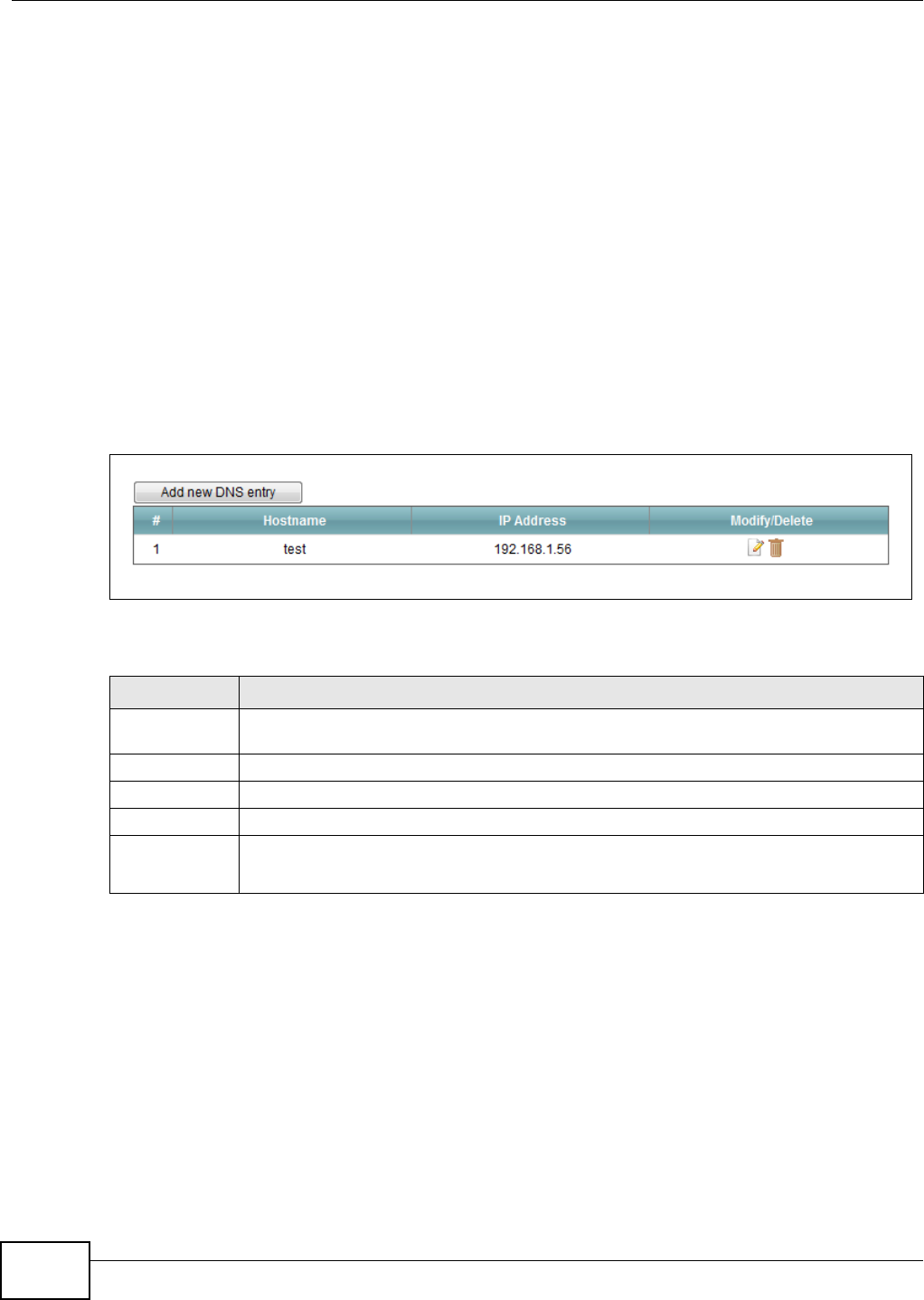
Chapter 11 Dynamic DNS Setup
VMG1312-B10C User’s Guide
168
11.1.2 What You Need To Know
DYNDNS Wildcard
Enabling the wildcard feature for your host causes *.yourhost.dyndns.org to be aliased to the same
IP address as yourhost.dyndns.org. This feature is useful if you want to be able to use, for example,
www.yourhost.dyndns.org and still reach your hostname.
If you have a private WAN IP address, then you cannot use Dynamic DNS.
11.2 The DNS Entry Screen
Use this screen to view and configure DNS routes on the Device. Click Ne t w ork Se t t ing > D N S to
open the D N S Ent ry screen.
Figure 88 Network Setting > DNS > DNS Entry
The following table describes the fields in this screen.
Table 65 Network Setting > DNS > DNS Entry
LABEL DESCRIPTION
Add new DNS
entry
Click this to create a new DNS entry.
#This is the index number of the entry.
Hostname This indicates the host name or domain name.
IP Address This indicates the IP address assigned to this computer.
Modify/Delete Click the Ed it icon to edit the rule.
Click the De le t e icon to delete an existing rule.
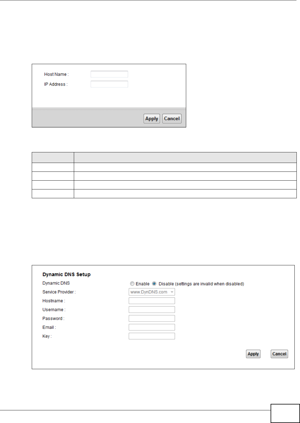
Chapter 11 Dynamic DNS Setup
VMG1312-B10C User’s Guide 169
11.2.1 Add/Edit DNS Entry
You can manually add or edit the Device’s DNS name and IP address entry. Click Add new D N S
e nt r y in the DN S En t r y screen or the Ed it icon next to the entry you want to edit. The screen
shown next appears.
Figure 89 DNS Entry: Add/Edit
The following table describes the labels in this screen.
11.3 The Dynamic DNS Screen
Use this screen to change your Device’s DDNS. Click Net w ork Se t t ing > DN S > Dynam ic D N S.
The screen appears as shown.
Figure 90 Network Setting > DNS > Dynamic DNS
Table 66 DNS Entry: Add/Edit
LABEL DESCRIPTION
Host Name Enter the host name of the DNS entry.
IP Address Enter the IP address of the DNS entry.
Apply Click Apply to save your changes.
Cancel Click Cancel to exit this screen without saving.

Chapter 11 Dynamic DNS Setup
VMG1312-B10C User’s Guide
170
The following table describes the fields in this screen.
Table 67 Network Setting > DNS > > Dynamic DNS
LABEL DESCRIPTION
Dynamic DNS Select En a ble to use dynamic DNS.
Service
Provider
Select your Dynamic DNS service provider from the drop-down list box.
Hostname Type the domain name assigned to your Device by your Dynamic DNS provider.
You can specify up to two host names in the field separated by a comma (",").
Username Type your user name.
Password Type the password assigned to you.
Email If you select TZO in the Ser vice Pr ov ider field, enter the user name you used to register
for this service.
Key If you select TZO in the Se r v ice Pr ovide r field, enter the password you used to register for
this service.
Apply Click Apply to save your changes.
Cancel Click Cancel to exit this screen without saving.

VMG1312-B10C User’s Guide 171
CHAPTER 12
Interface Group
12.1 Overview
By default, all LAN and WAN interfaces on the Device are in the same group and can communicate
with each other. Create interface groups to have the Device assign the IP addresses in different
domains to different groups. Each group acts as an independent network on the Device. This lets
devices connected to an interface group’s LAN interfaces communicate through the interface
group’s WAN or LAN interfaces but not other WAN or LAN interfaces.
12.1.1 What You Can Do in this Chapter
The I nt erface Gr ou p screens let you create multiple networks on the Device (Section 12.2 on
page 171).
12.2 The Interface Group Screen
You can manually add a LAN interface to a new group. Alternatively, you can have the Device
automatically add the incoming traffic and the LAN interface on which traffic is received to an
interface group when its DHCP Vendor ID option information matches one listed for the interface
group.
Use the LAN screen to configure the private IP addresses the DHCP server on the Device assigns to
the clients in the default and/or user-defined groups. If you set the Device to assign IP addresses
based on the client’s DHCP Vendor ID option information, you must enable DHCP server and
configure LAN TCP/IP settings for both the default and user-defined groups. See Chapter 7 on page
101 for more information.
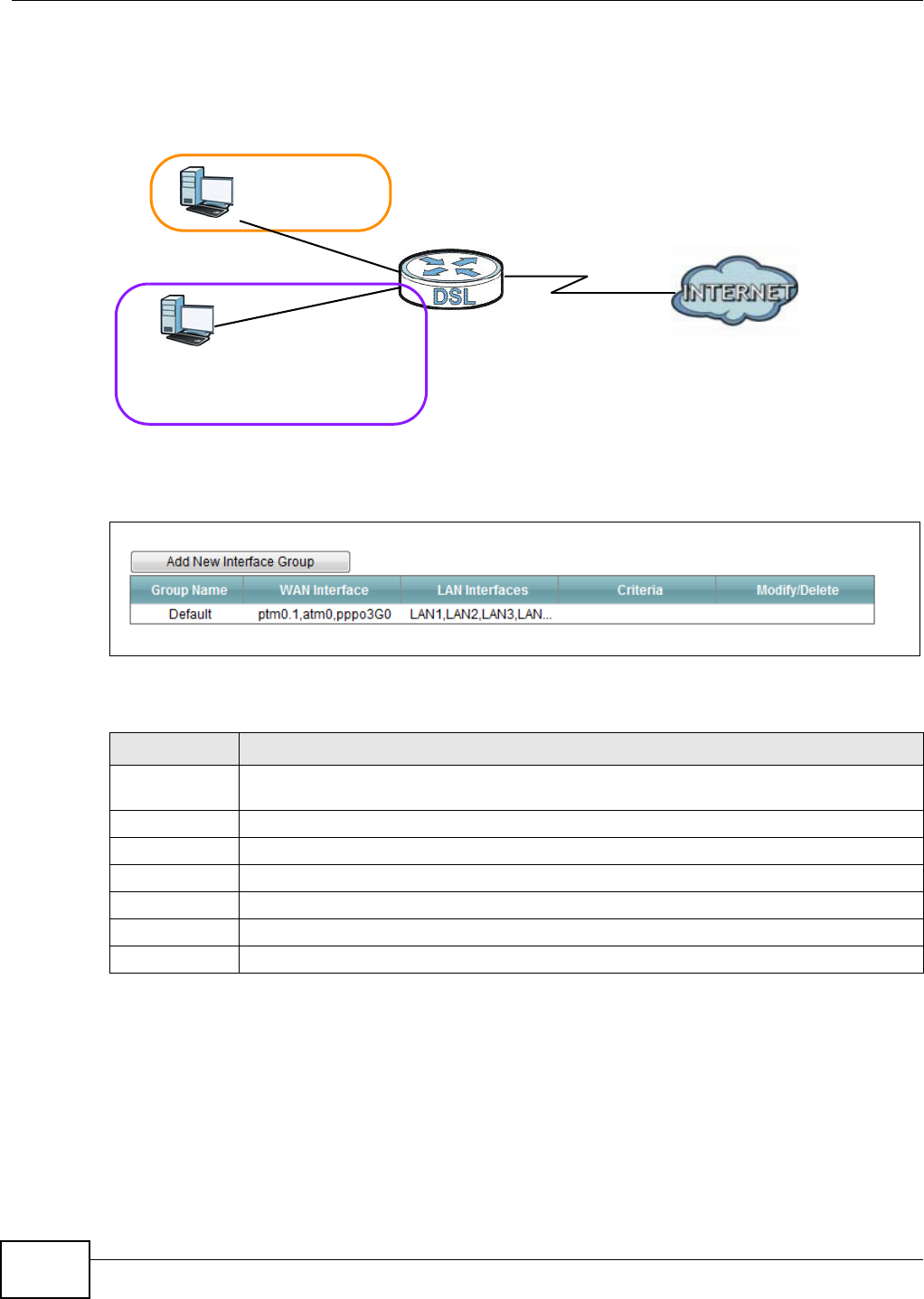
Chapter 12 Interface Group
VMG1312-B10C User’s Guide
172
In the following example, the client that sends packets with the DHCP Vendor ID option set to MSFT
5.0 (meaning it is a Windows 2000 DHCP client) is assigned the IP address 192.168.2.2 and uses
the WAN VDSL_PoE/ppp0.1 interface.
Figure 91 Interface Grouping Application
Click N et w or k Se t t ing > I nt e rface Gr oup to open the following screen.
Figure 92 Network Setting > Interface Group
The following table describes the fields in this screen.
12.2.1 Interface Group Configuration
Click the Add N ew I nt erfa ce Group button in the I nt e r fa ce Group screen to open the following
screen. Use this screen to create a new interface group.
Table 68 Network Setting > Interface Group
LABEL DESCRIPTION
Add New
Interface Group
Click this button to create a new interface group.
Group Name This shows the descriptive name of the group.
WAN Interface This shows the WAN interfaces in the group.
LAN Interfaces This shows the LAN interfaces in the group.
Criteria This shows the filtering criteria for the group.
Modify/Delete Click the Dele t e icon to remove the group.
Add Click this button to create a new group.
Default: ETH 2~4
Internet
192.168.1.x/24
192.168.2.x/24
VDSL_PoE/ppp0.1
eth10.0
DHCP Vendor ID option: MSFT 5.0
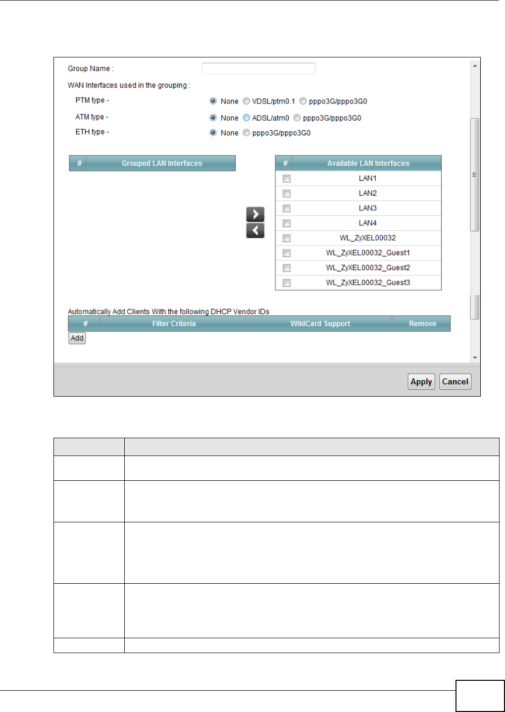
Chapter 12 Interface Group
VMG1312-B10C User’s Guide 173
Note: An interface can belong to only one group at a time.
Figure 93 Interface Group Configuration
The following table describes the fields in this screen.
Table 69 Interface Group Configuration
LABEL DESCRIPTION
Group Name Enter a name to identify this group. You can enter up to 30 characters. You can use letters,
numbers, hyphens (-) and underscores (_). Spaces are not allowed.
WAN Interface
used in the
grouping
Select the WAN interface this group uses. The group can have up to one PTM interface, up to
one ATM interface and up to one ETH interface.
Select N on e to not add a WAN interface to this group.
Grouped LAN
Interfaces
Available LAN
Interfaces
Select one or more LAN interfaces (Ethernet LAN, HPNA or wireless LAN) in the Ava ila ble
LAN I n t e r fa ces list and use the left arrow to move them to the Grou pe d LAN I nt er face s
list to add the interfaces to this group.
To remove a LAN or wireless LAN interface from the Grouped LAN I nt e rfaces, use the
right-facing arrow.
Automatically
Add Clients
With the
following DHCP
Vendor IDs
Click Add to identify LAN hosts to add to the interface group by criteria such as the type of
the hardware or firmware. See Section 12.2.2 on page 174 for more information.
#This shows the index number of the rule.
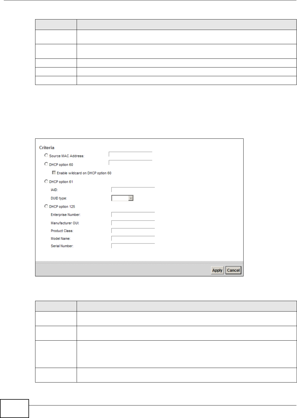
Chapter 12 Interface Group
VMG1312-B10C User’s Guide
174
12.2.2 Interface Grouping Criteria
Click the Add button in the I nt er fa ce Grouping Configura t ion screen to open the following
screen.
Figure 94 Interface Grouping Criteria
The following table describes the fields in this screen.
Filter Criteria This shows the filtering criteria. The LAN interface on which the matched traffic is received
will belong to this group automatically.
WildCard
Support
This shows if wildcard on DHCP option 60 is enabled.
Remove Click the Re m ove icon to delete this rule from the Device.
Apply Click Apply to save your changes back to the Device.
Cancel Click Cancel to exit this screen without saving.
Table 69 Interface Group Configuration (continued)
LABEL DESCRIPTION
Table 70 Interface Grouping Criteria
LABEL DESCRIPTION
Source MAC
Address
Enter the source MAC address of the packet.
DHCP Option
60
Select this option and enter the Vendor Class Identifier (Option 60) of the matched traffic,
such as the type of the hardware or firmware.
Enable
wildcard on
DHCP
option 60
option
Select this option to be able to use wildcards in the Vendor Class Identifier configured for
DHCP option 60.
DHCP Option
61
Select this and enter the device identity of the matched traffic.

Chapter 12 Interface Group
VMG1312-B10C User’s Guide 175
IAID Enter the Identity Association Identifier (IAID) of the device, for example, the WAN
connection index number.
DUID type Select D UI D- LLT (DUID Based on Link-layer Address Plus Time) to enter the hardware
type, a time value and the MAC address of the device.
Select D UI D - EN (DUID Assigned by Vendor Based upon Enterprise Number) to enter the
vendor’s registered enterprise number.
Select D UI D- LL (DUID Based on Link-layer Address) to enter the device’s hardware type
and hardware address (MAC address) in the following fields.
Select Ot he r to enter any string that identifies the device in the DUID field.
DHCP Option
125
Select this and enter vendor specific information of the matched traffic.
Enterprise
Number Enter the vendor’s 32-bit enterprise number registered with the IANA (Internet Assigned
Numbers Authority).
Manufactur
er OUI Specify the vendor’s OUI (Organization Unique Identifier). It is usually the first three bytes
of the MAC address.
Product
Class Enter the product class of the device.
Model
Name Enter the model name of the device.
Serial
Number Enter the serial number of the device.
Apply Click Apply to save your changes back to the Device.
Cancel Click Cancel to exit this screen without saving.
Table 70 Interface Grouping Criteria (continued)
LABEL DESCRIPTION

Chapter 12 Interface Group
VMG1312-B10C User’s Guide
176

VMG1312-B10C User’s Guide 177
CHAPTER 13
USB Service
13.1 Overview
The Device has a USB port used to share files via a USB memory stick or a USB hard drive. In the
USB Se r v ice screens, you can enable file-sharing server, media server, and printer server.
13.1.1 What You Can Do in this Chapter
•Use the File Sh a ring screen to enable file-sharing server (Section 13.2 on page 178).
•Use the Media Se r ve r screen to enable or disable the sharing of media files (Section 13.3 on
page 180).
•Use the Pr int er Server screen to enable the print server (Section 13.4 on page 181).
13.1.2 What You Need To Know
The following terms and concepts may help as you read this chapter.
13.1.2.1 About File Sharing
Workgroup name
This is the name given to a set of computers that are connected on a network and share resources
such as a printer or files. Windows automatically assigns the workgroup name when you set up a
network.
Shares
When settings are set to default, each USB device connected to the Device is given a folder, called
a “share”. If a USB hard drive connected to the Device has more than one partition, then each
partition will be allocated a share. You can also configure a “share” to be a sub-folder or file on the
USB device.
File Systems
A file system is a way of storing and organizing files on your hard drive and storage device. Often
different operating systems such as Windows or Linux have different file systems. The file sharing
feature on your Device supports File Allocation Table (FAT) and FAT32.
Common Internet File System
The Device uses Common Internet File System (CIFS) protocol for its file sharing functions. CIFS
compatible computers can access the USB file storage devices connected to the Device. CIFS

Chapter 13 USB Service
VMG1312-B10C User’s Guide
178
protocol is supported on Microsoft Windows, Linux Samba and other operating systems (refer to
your systems specifications for CIFS compatibility).
13.1.2.2 About Printer Server
Print Server
This is a computer or other device which manages one or more printers, and which sends print jobs
to each printer from the computer itself or other devices.
Operating System
An operating system (OS) is the interface which helps you manage a computer. Common examples
are Microsoft Windows, Mac OS or Linux.
TCP/IP
TCP/IP (Transmission Control Protocol/ Internet Protocol) is a set of communications protocols that
most of the Internet runs on.
Port
A port maps a network service such as http to a process running on your computer, such as a
process run by your web browser. When traffic from the Internet is received on your computer, the
port number is used to identify which process running on your computer it is intended for.
Supported OSs
Your operating system must support TCP/IP ports for printing and be compatible with the RAW (port
9100) protocol.
The following OSs support Device’s printer sharing feature.
• Microsoft Windows 95, Windows 98 SE (Second Edition), Windows Me, Windows NT 4.0, Windows
2000, Windows XP or Macintosh OS X.
13.2 The File Sharing Screen
You can share files on a USB memory stick or hard drive connected to your Device with users on
your network.
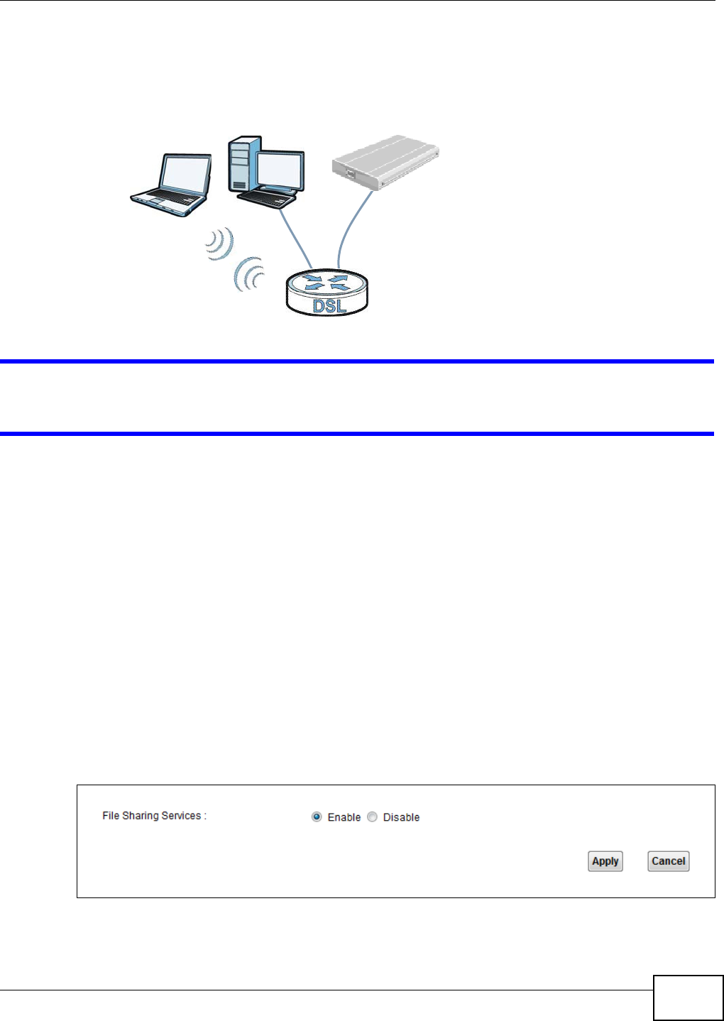
Chapter 13 USB Service
VMG1312-B10C User’s Guide 179
The following figure is an overview of the Device’s file server feature. Computers A and B can
access files on a USB device (C) which is connected to the Device.
Figure 95 File Sharing Overview
The Device will not be able to join the workgroup if your local area network has restrictions
set up that do not allow devices to join a workgroup. In this case, contact your network
administrator.
13.2.1 Before You Begin
Make sure the Device is connected to your network and turned on.
1Connect the USB device to one of the Device’s USB port. Make sure the Device is connected to your
network.
2The Device detects the USB device and makes its contents available for browsing. If you are
connecting a USB hard drive that comes with an external power supply, make sure it is connected
to an appropriate power source that is on.
Note: If your USB device cannot be detected by the Device, see the troubleshooting for
suggestions.
Use this screen to set up file sharing using the Device. To access this screen, click Net w or k
Set t ing > USB Se rvice > File Shar ing.
Figure 96 Network Setting > USB Service > File Sharing
A
BC
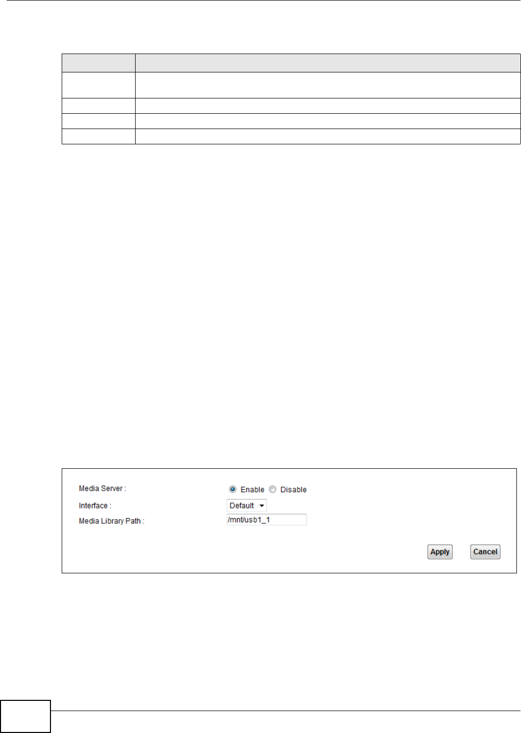
Chapter 13 USB Service
VMG1312-B10C User’s Guide
180
Each field is described in the following table.
13.3 The Media Server Screen
The media server feature lets anyone on your network play video, music, and photos from the USB
storage device connected to your Device (without having to copy them to another computer). The
Device can function as a DLNA-compliant media server. The Device streams files to DLNA-compliant
media clients (like Windows Media Player). The Digital Living Network Alliance (DLNA) is a group of
personal computer and electronics companies that works to make products compatible in a home
network.
The Device media server enables you to:
• Publish all shares for everyone to play media files in the USB storage device connected to the
Device.
• Use hardware-based media clients like the DMA-2500 to play the files.
Note: Anyone on your network can play the media files in the published shares. No user
name and password or other form of security is used. The media server is enabled
by default with the video, photo, and music shares published.
To change your Device’s media server settings, click Net w or k Set t ing > USB Ser vice > Me dia
Serve r. The screen appears as shown.
Figure 97 Network Setting > USB Service > Media Server
Table 71 Network Setting > Home Networking > File Sharing
LABEL DESCRIPTION
File Sharing
Services
Select Enable to activate file sharing through the Device.
Host Name Enter the host name on the share.
Apply Click Apply to save your changes.
Cancel Click Cance l to restore your previously saved settings.
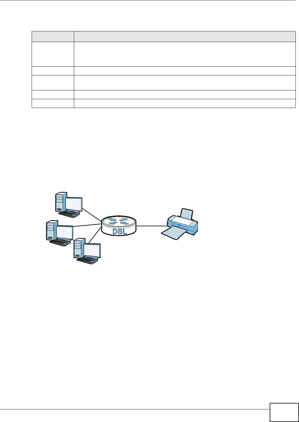
Chapter 13 USB Service
VMG1312-B10C User’s Guide 181
The following table describes the labels in this menu.
13.4 The Printer Server Screen
The Device allows you to share a USB printer on your LAN. You can do this by connecting a USB
printer to one of the USB ports on the Device and then configuring a TCP/IP port on the computers
connected to your network.
Figure 98 Sharing a USB Printer
13.4.1 Before You Begin
To configure the print server you need the following:
• Your Device must be connected to your computer and any other devices on your network. The
USB printer must be connected to your Device.
• A USB printer with the driver already installed on your computer.
• The computers on your network must have the printer software already installed before they can
create a TCP/IP port for printing via the network. Follow your printer manufacturers instructions
on how to install the printer software on your computer.
Note: Your printer’s installation instructions may ask that you connect the printer to your
computer. Connect your printer to the Device instead.
Use this screen to enable or disable sharing of a USB printer via your Device.
Table 72 Network Setting > USB Service > Media Server
LABEL DESCRIPTION
Media Server Select Enable to have the Device function as a DLNA-compliant media server.
Enable the media server to let (DLNA-compliant) media clients on your network play media
files located in the shares.
Interface Select the interface on which you want to enable the media server function.
Media Library
Path
Enter the path clients use to access the media files on a USB storage device connected to
the Device.
Apply Click Apply to save your changes.
Cancel Click Cancel to restore your previously saved settings.
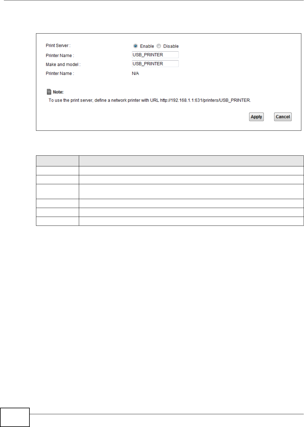
Chapter 13 USB Service
VMG1312-B10C User’s Guide
182
To access this screen, click Net w ork Se t t in g > USB Ser vice > Pr int er Ser ve r.
Figure 99 Network Setting > USB Service > Printer Server
The following table describes the labels in this menu.
Table 73 Network Setting > USB Service > Print Server
LABEL DESCRIPTION
Printer Server Select Ena ble to have the Device share a USB printer.
Printer Name Enter the name of the printer.
Make and
model
Enter the manufacturer and model number of the printer.
Printer Name This displays the system name for the printer.
Apply Click Apply to save your changes.
Cancel Click Cancel to restore your previously saved settings.
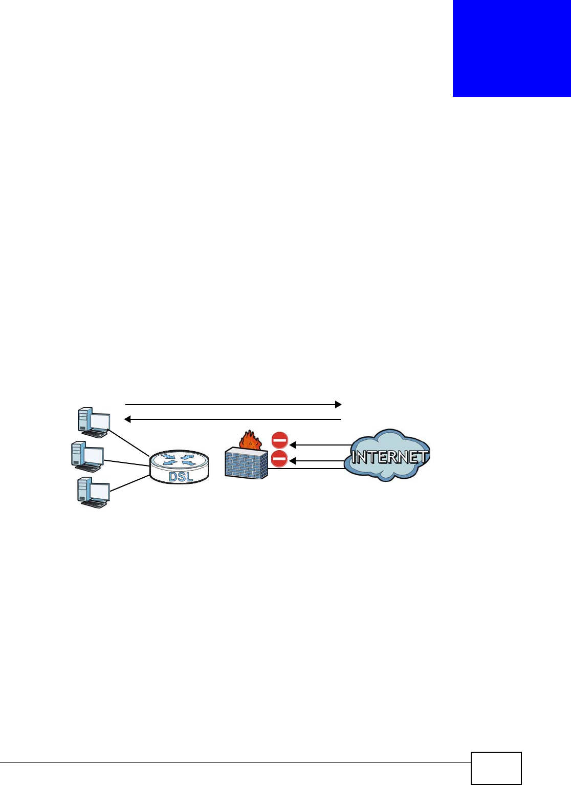
VMG1312-B10C User’s Guide 183
CHAPTER 14
Firewall
14.1 Overview
This chapter shows you how to enable and configure the Device’s security settings. Use the firewall
to protect your Device and network from attacks by hackers on the Internet and control access to
it. By default the firewall:
• allows traffic that originates from your LAN computers to go to all other networks.
• blocks traffic that originates on other networks from going to the LAN.
The following figure illustrates the default firewall action. User A can initiate an IM (Instant
Messaging) session from the LAN to the WAN (1). Return traffic for this session is also allowed (2).
However other traffic initiated from the WAN is blocked (3 and 4).
Figure 100 Default Firewall Action
14.1.1 What You Can Do in this Chapter
•Use the Gener a l screen to configure the security level of the firewall on the Device (Section 14.2
on page 185).
•Use the Ser vice screen to add or remove predefined Internet services and configure firewall
rules (Section 14.3 on page 185).
•Use the Access Cont rol screen to view and configure incoming/outgoing filtering rules (Section
14.4 on page 188).
•Use the DoS screen to activate protection against Denial of Service (DoS) attacks (.Section 14.5
on page 190).
WAN
LAN
3
4
1
2
A

Chapter 14 Firewall
VMG1312-B10C User’s Guide
184
14.1.2 What You Need to Know
SYN Attack
A SYN attack floods a targeted system with a series of SYN packets. Each packet causes the
targeted system to issue a SYN-ACK response. While the targeted system waits for the ACK that
follows the SYN-ACK, it queues up all outstanding SYN-ACK responses on a backlog queue. SYN-
ACKs are moved off the queue only when an ACK comes back or when an internal timer terminates
the three-way handshake. Once the queue is full, the system will ignore all incoming SYN requests,
making the system unavailable for legitimate users.
DoS
Denials of Service (DoS) attacks are aimed at devices and networks with a connection to the
Internet. Their goal is not to steal information, but to disable a device or network so users no longer
have access to network resources. The ZyXEL Device is pre-configured to automatically detect and
thwart all known DoS attacks.
DDoS
A DDoS attack is one in which multiple compromised systems attack a single target, thereby
causing denial of service for users of the targeted system.
LAND Attack
In a LAND attack, hackers flood SYN packets into the network with a spoofed source IP address of
the target system. This makes it appear as if the host computer sent the packets to itself, making
the system unavailable while the target system tries to respond to itself.
Ping of Death
Ping of Death uses a "ping" utility to create and send an IP packet that exceeds the maximum
65,536 bytes of data allowed by the IP specification. This may cause systems to crash, hang or
reboot.
SPI
Stateful Packet Inspection (SPI) tracks each connection crossing the firewall and makes sure it is
valid. Filtering decisions are based not only on rules but also context. For example, traffic from the
WAN may only be allowed to cross the firewall in response to a request from the LAN.
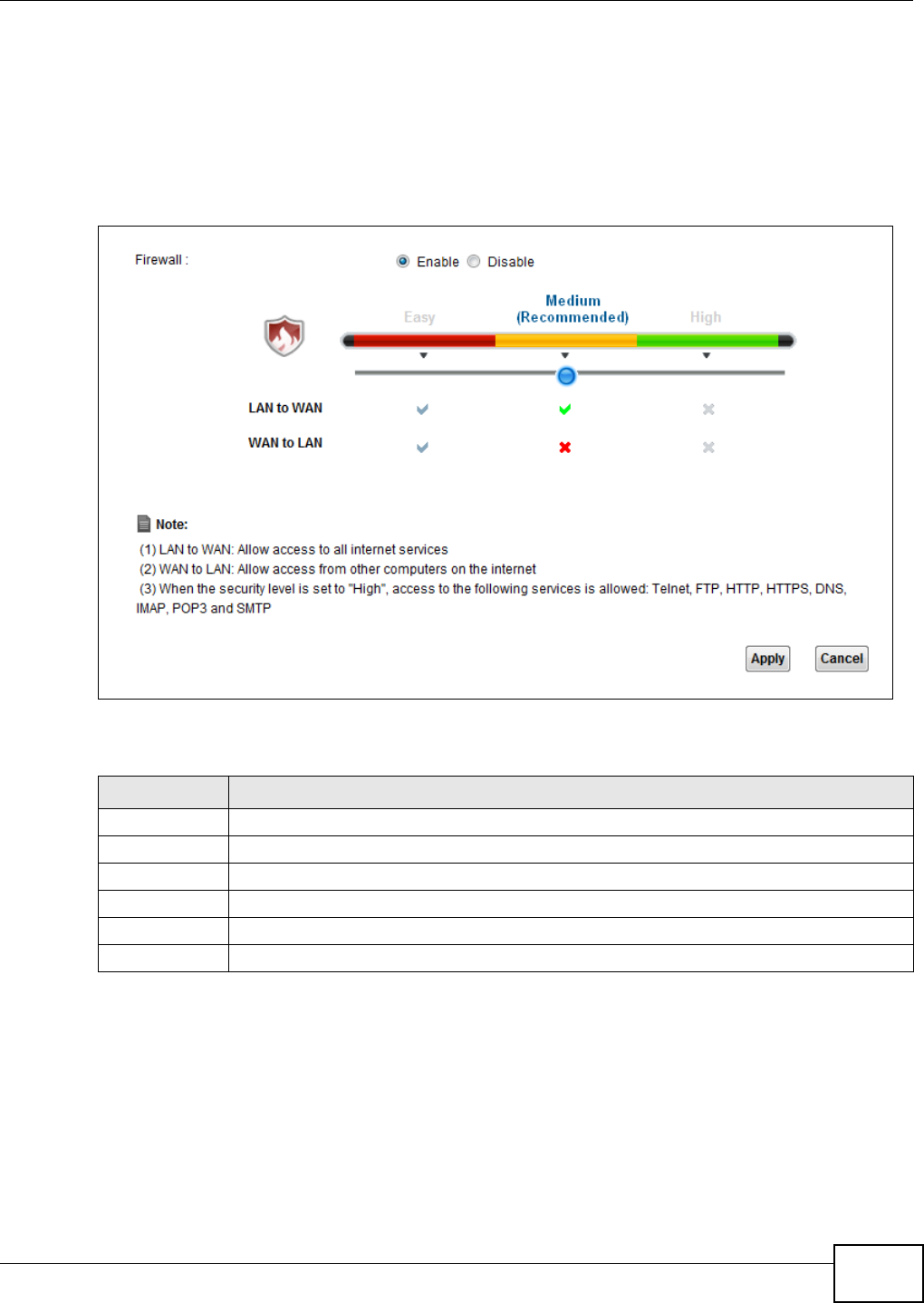
Chapter 14 Firewall
VMG1312-B10C User’s Guide 185
14.2 The Firewall Screen
Use this screen to set the security level of the firewall on the Device. Firewall rules are grouped
based on the direction of travel of packets to which they apply.
Click Se curit y > Fir e w a ll to display the Gene r al screen.
Figure 101 Security > Firewall > General
The following table describes the labels in this screen.
14.3 The Service Screen
You can configure customized services and port numbers in the Se r v ice screen. For a
comprehensive list of port numbers and services, visit the IANA (Internet Assigned Number
Authority) website.
Table 74 Security > Firewall > General
LABEL DESCRIPTION
Firewall Select Ena ble to activate the firewall feature on the Device.
Easy Select Ea sy to allow LAN to WAN and WAN to LAN packet directions.
Medium Select Me dium to allow LAN to WAN but deny WAN to LAN packet directions.
High Select H igh to deny LAN to WAN and WAN to LAN packet directions.
Apply Click Apply to save your changes.
Cancel Click Cancel to restore your previously saved settings.
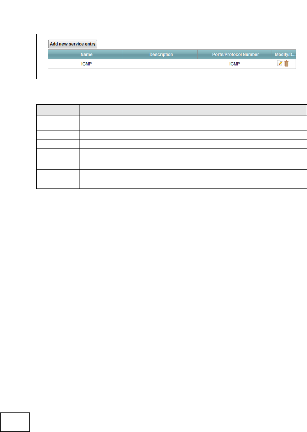
Chapter 14 Firewall
VMG1312-B10C User’s Guide
186
Click Se curit y > Fire w a ll > Se r vice to display the following screen.
Figure 102 Security > Firewall > Service
The following table describes the labels in this screen.
Table 75 Security > Firewall > Service
LABEL DESCRIPTION
Add new
service entry
Click this to add a new service.
Name This is the name of your customized service.
Description This is the description of your customized service.
Ports/Protocol
Number
This shows the IP protocol (TCP, UDP, I CM P, or TCP/ UDP) and the port number or range
of ports that defines your customized service. Ot h e r and the protocol number displays if the
service uses another IP protocol.
Modify/Delete Click the Ed it icon to edit the entry.
Click the D e let e icon to remove this entry.
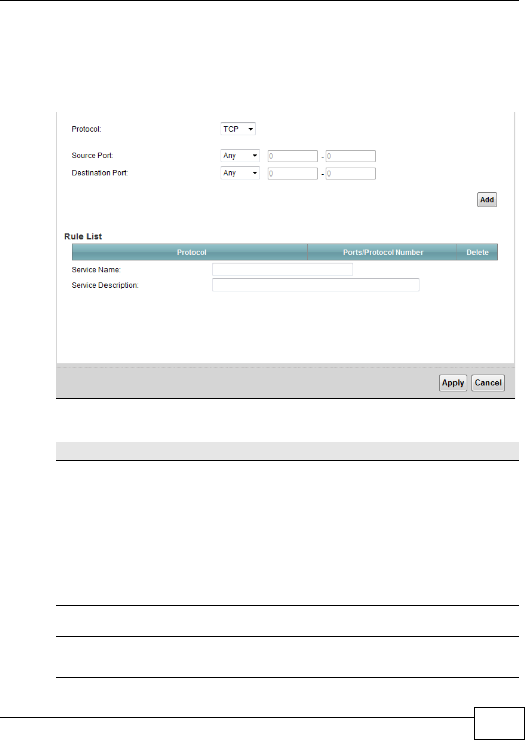
Chapter 14 Firewall
VMG1312-B10C User’s Guide 187
14.3.1 Add/Edit a Service
Use this screen to add a customized service rule that you can use in the firewall’s ACL rule
configuration. Click Add new se r vice e nt r y or the edit icon next to an existing service rule in the
Service screen to display the following screen.
Figure 103 Service: Add/Edit
The following table describes the labels in this screen.
Table 76 Service: Add/Edit
LABEL DESCRIPTION
Protocol Choose the IP protocol (TCP, UD P, I CM P, or O t he r ) that defines your customized port from
the drop-down list box. Select Ot h e r to be able to enter a protocol number.
Source/
Destination Port
These fields are displayed if you select TCP or UD P as the IP port.
Select Single to specify one port only or Ran ge to specify a span of ports that define your
customized service. If you select An y, the service is applied to all ports.
Type a single port number or the range of port numbers that define your customized
service.
Protocol
Number
This field is displayed if you select Ot h e r as the protocol.
Enter the protocol number of your customized port.
Add Click this to add the protocol to the Rule List below.
Rule List
Protocol This is the IP port (TCP, UD P, I CMP, or Ot h er ) that defines your customized port.
Ports/Protocol
Number
For TCP, UD P, I CM P, or TCP/ UD P protocol rules this shows the port number or range that
defines the custom service. For other IP protocol rules this shows the protocol number.
Modify/Delete Click the Dele t e icon to remove the rule.
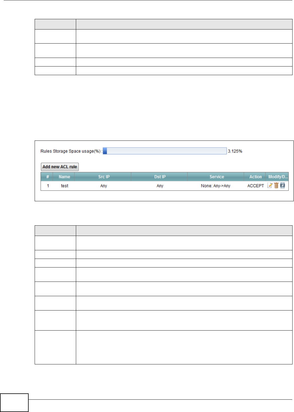
Chapter 14 Firewall
VMG1312-B10C User’s Guide
188
14.4 The Access Control Screen
Click Secur it y > Fir e w all > Acce ss Con t r ol to display the following screen. This screen displays a
list of the configured incoming or outgoing filtering rules.
Figure 104 Security > Firewall > Access Control
The following table describes the labels in this screen.
Service Name Enter a unique name (up to 32 printable English keyboard characters, including spaces) for
your customized port.
Service
Description
Enter a description for your customized port.
Apply Click Apply to save your changes.
Cancel Click Cancel to exit this screen without saving.
Table 76 Service: Add/Edit (continued)
LABEL DESCRIPTION
Table 77 Security > Firewall > Access Control
LABEL DESCRIPTION
Add new ACL
rule
Click this to go to add a filter rule for incoming or outgoing IP traffic.
#This is the index number of the entry.
Name This displays the name of the rule.
Src IP This displays the source IP addresses to which this rule applies. Please note that a blank
source address is equivalent to An y.
Dst IP This displays the destination IP addresses to which this rule applies. Please note that a
blank destination address is equivalent to An y.
Service This displays the transport layer protocol that defines the service and the direction of traffic
to which this rule applies.
Action This field displays whether the rule silently discards packets (DROP), discards packets and
sends a TCP reset packet or an ICMP destination-unreachable message to the sender
(REJECT) or allows the passage of packets (ACCEPT).
Modify/Delete Click the Ed it icon to edit the rule.
Click the D e let e icon to delete an existing rule. Note that subsequent rules move up by one
when you take this action.
Click the M ove To icon to change the order of the rule. Enter the number in the # field.
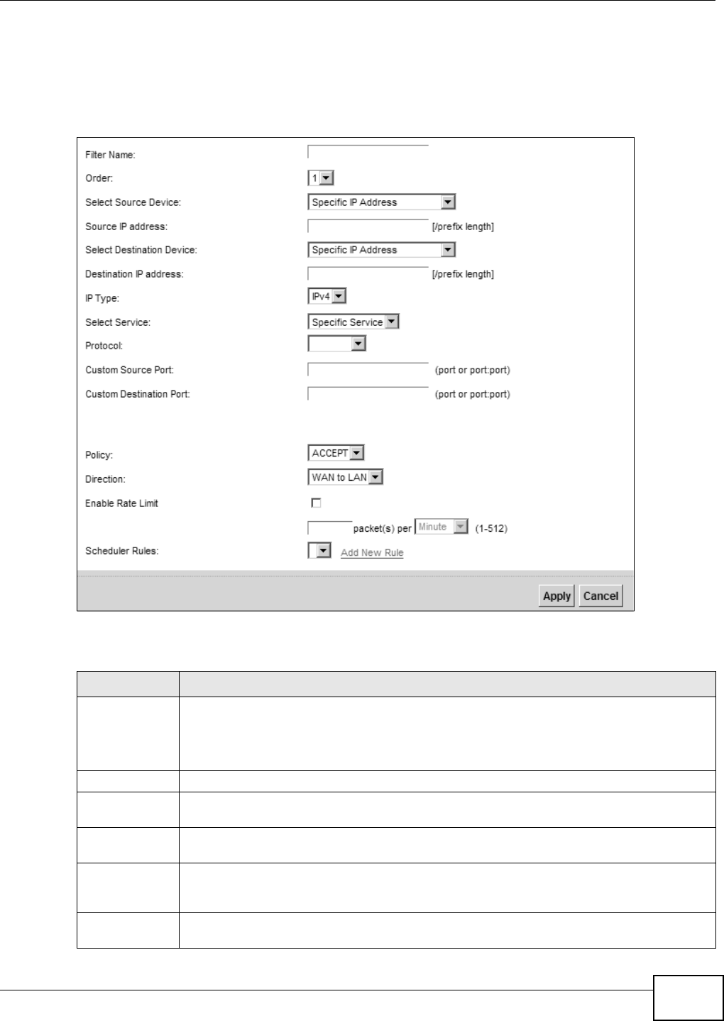
Chapter 14 Firewall
VMG1312-B10C User’s Guide 189
14.4.1 Add/Edit an ACL Rule
Click Add ne w ACL rule or the Ed it icon next to an existing ACL rule in the Access Cont rol
screen. The following screen displays.
Figure 105 Access Control: Add/Edit
The following table describes the labels in this screen.
Table 78 Access Control: Add/Edit
LABEL DESCRIPTION
Filter Name Enter a descriptive name of up to 16 alphanumeric characters, not including spaces,
underscores, and dashes.
You must enter the filter name to add an ACL rule. This field is read-only if you are editing
the ACL rule.
Order Select the order of the ACL rule.
Select Source
Device
Select the source device to which the ACL rule applies. If you select Specific I P Addre ss,
enter the source IP address in the field below.
Source IP
Address
Enter the source IP address.
Select
Destination
Device
Select the destination device to which the ACL rule applies. If you select Specific I P
Addr e ss, enter the destiniation IP address in the field below.
Destination IP
Address
Enter the destination IP address.
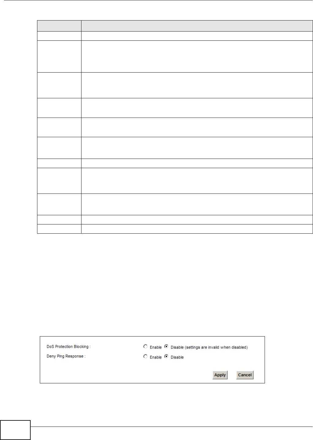
Chapter 14 Firewall
VMG1312-B10C User’s Guide
190
14.5 The DoS Screen
DoS (Denial of Service) attacks can flood your Internet connection with invalid packets and
connection requests, using so much bandwidth and so many resources that Internet access
becomes unavailable.
Use the DoS screen to activate protection against DoS attacks. Click Secur it y > Firew all > DoS
to display the following screen.
Figure 106 Security > Firewall > DoS
IP Type Select whether your IP type is I Pv4 or I Pv6 .
Select Protocol Select the transport layer protocol that defines your customized port from the drop-down
list box. The specific protocol rule sets you add in the Securit y > Fire w a ll > Service >
Add screen display in this list.
If you want to configure a customized protocol, select Spe cific Se r vice.
Protocol This field is displayed only when you select Spe cific Pr ot ocol in Se lect Pr ot ocol.
Choose the IP port (TCP/ UDP, TCP, UDP, I CMP, or I CM Pv6 ) that defines your customized
port from the drop-down list box.
Custom Source
Port
This field is displayed only when you select Spe cific Pr ot ocol in Sele ct Pr ot ocol.
Enter a single port number or the range of port numbers of the source.
Custom
Destination Port
This field is displayed only when you select Spe cific Pr ot ocol in Sele ct Pr ot ocol.
Enter a single port number or the range of port numbers of the destination.
Policy Use the drop-down list box to select whether to discard (DROP), deny and send an ICMP
destination-unreachable message to the sender of (REJECT) or allow the passage of
(ACCEPT) packets that match this rule.
Direction Use the drop-down list box to select the direction of traffic to which this rule applies.
Enable Rate
Limit
Select this check box to set a limit on the upstream/downstream transmission rate for the
specified protocol.
Specify how many packets per minute or second the transmission rate is.
Scheduler Rules Select a schedule rule for this ACL rule form the drop-down list box. You can configure a
new schedule rule by click Add N ew Ru le . This will bring you to the Secur it y > Sch e duler
Rule s screen.
Apply Click Apply to save your changes.
Cancel Click Cancel to exit this screen without saving.
Table 78 Access Control: Add/Edit (continued)
LABEL DESCRIPTION

Chapter 14 Firewall
VMG1312-B10C User’s Guide 191
The following table describes the labels in this screen.
Table 79 Security > Firewall > DoS
LABEL DESCRIPTION
DoS Protection
Blocking
Select Enable to enable protection against DoS attacks.
Deny Ping
Response
Select Enable to block ping request packets.
Apply Click Apply to save your changes.
Cancel Click Cance l to exit this screen without saving.

Chapter 14 Firewall
VMG1312-B10C User’s Guide
192
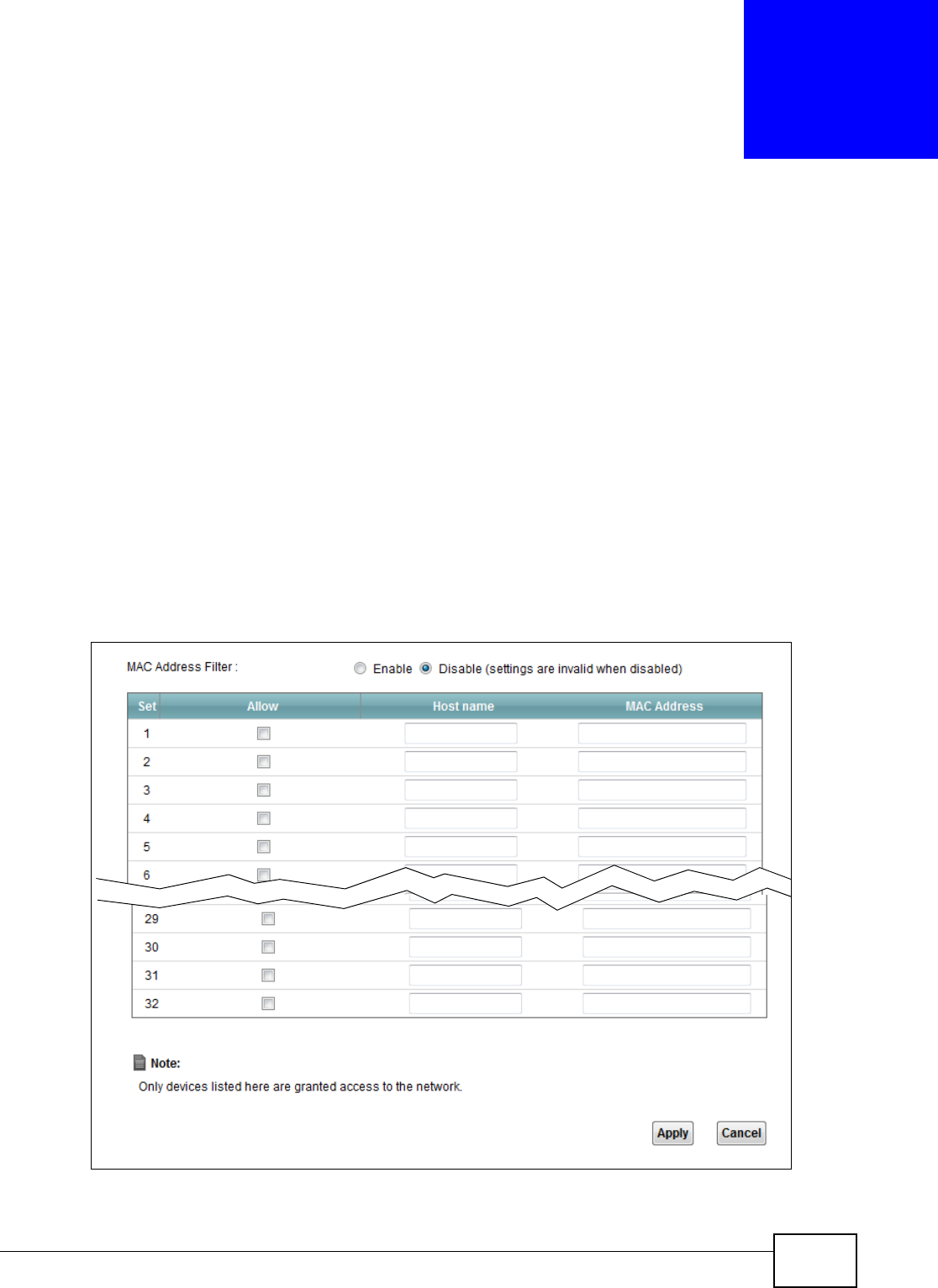
VMG1312-B10C User’s Guide 193
CHAPTER 15
MAC Filter
15.1 Overview
You can configure the Device to permit access to clients based on their MAC addresses in the MAC
Filt e r screen. This applies to wired and wireless connections. Every Ethernet device has a unique
MAC (Media Access Control) address. The MAC address is assigned at the factory and consists of six
pairs of hexadecimal characters, for example, 00:A0:C5:00:00:02. You need to know the MAC
addresses of the devices to configure this screen.
15.2 The MAC Filter Screen
Use this screen to allow wireless and LAN clients access to the Device. Click Secur it y > MAC Filt e r.
The screen appears as shown.
Figure 107 Security > MAC Filter

Chapter 15 MAC Filter
VMG1312-B10C User’s Guide
194
The following table describes the labels in this screen.
Table 80 Security > MAC Filter
LABEL DESCRIPTION
MAC Address Filter Select Enable to activate the MAC filter function.
Set This is the index number of the MAC address.
Allow Select Allow to permit access to the Device. MAC addresses not listed will be denied
access to the Device.
If you clear this, the MAC Address field for this set clears.
Host name Enter the host name of the wireless or LAN clients that are allowed access to the
Device.
MAC Address Enter the MAC addresses of the wireless or LAN clients that are allowed access to the
Device in these address fields. Enter the MAC addresses in a valid MAC address format,
that is, six hexadecimal character pairs, for example, 12:34:56:78:9a:bc.
Apply Click Apply to save your changes.
Cancel Click Ca nce l to restore your previously saved settings.
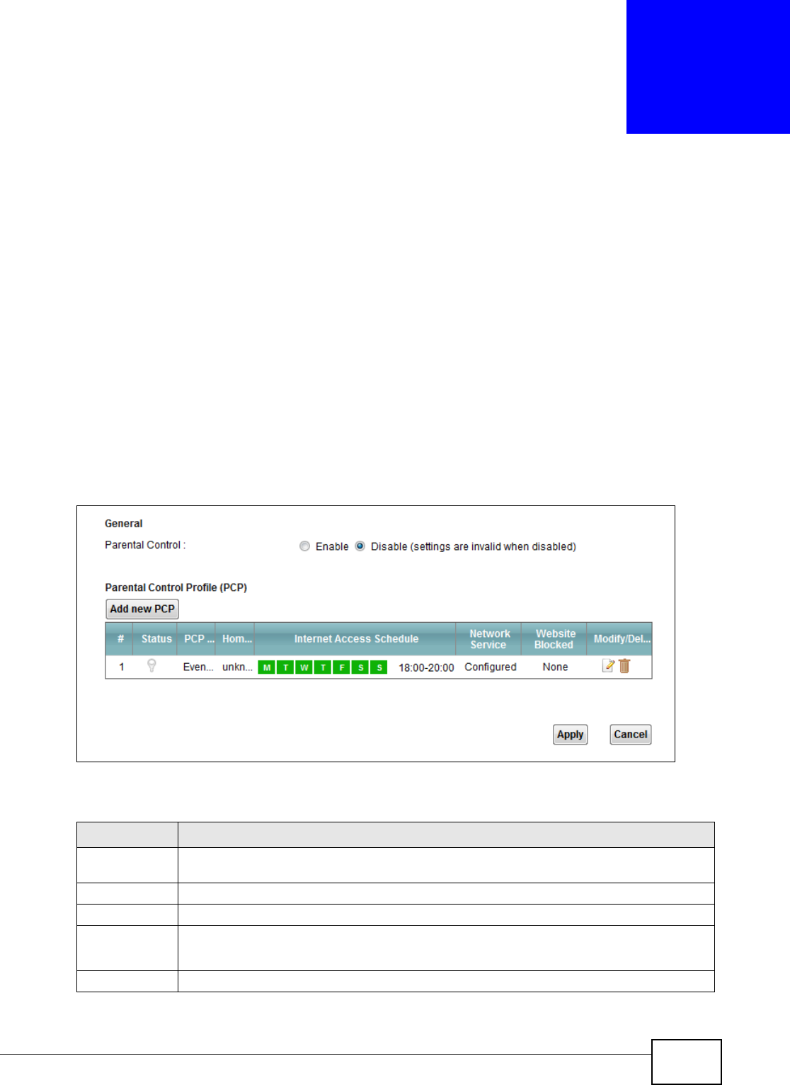
VMG1312-B10C User’s Guide 195
CHAPTER 16
Parental Control
16.1 Overview
Parental control allows you to block web sites with the specific URL. You can also define time
periods and days during which the Device performs parental control on a specific user.
16.2 The Parental Control Screen
Use this screen to enable parental control, view the parental control rules and schedules.
Click Se cur it y > Pa r e nt al Cont r ol to open the following screen.
Figure 108 Security > Parental Control
The following table describes the fields in this screen.
Table 81 Security > Parental Control
LABEL DESCRIPTION
Parental
Control
Select Enable to activate parental control.
Add new PCP Click this if you want to configure a new parental control rule.
#This shows the index number of the rule.
Status This indicates whether the rule is active or not.
A yellow bulb signifies that this rule is active. A gray bulb signifies that this rule is not active.
PCP Name This shows the name of the rule.
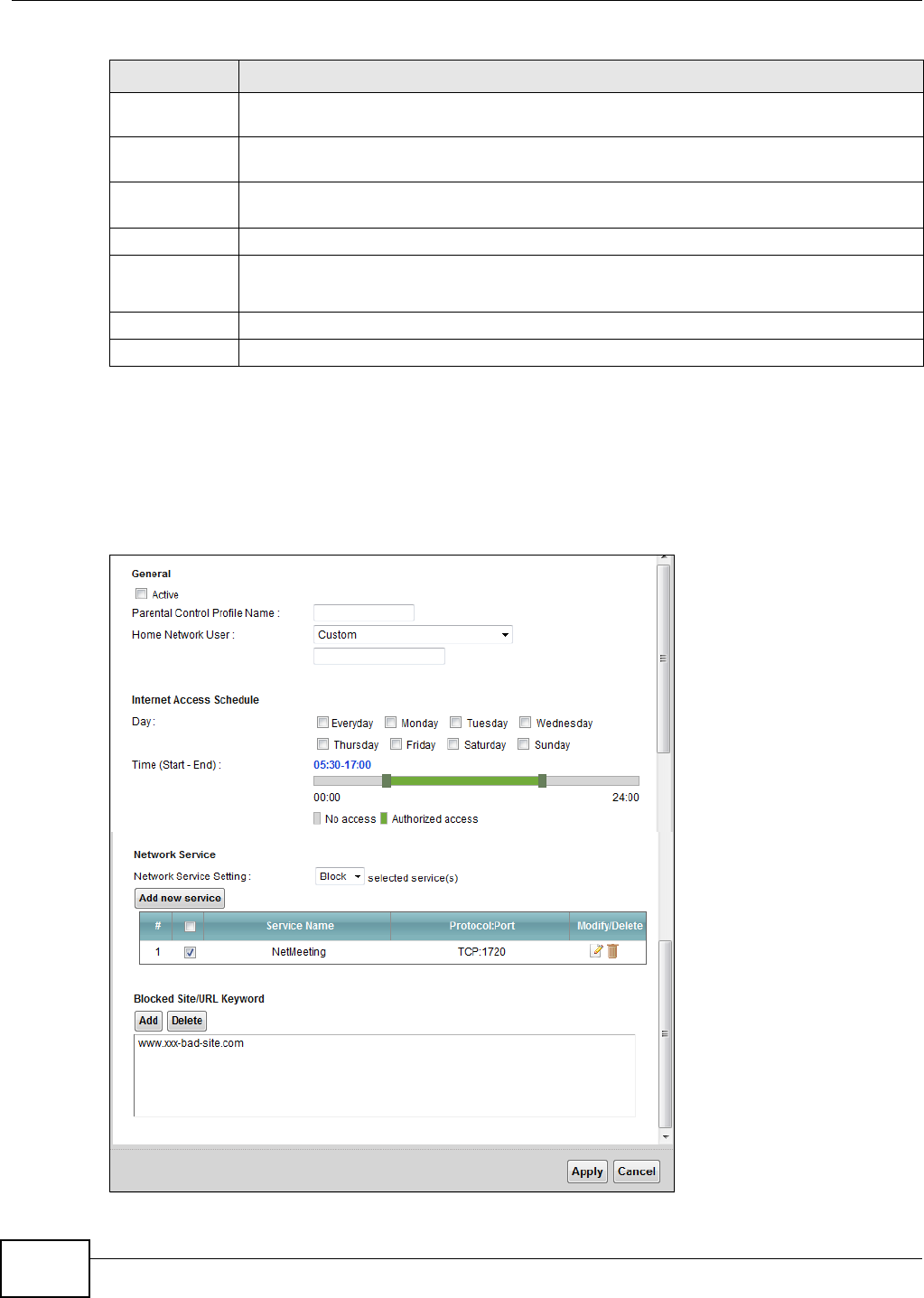
Chapter 16 Parental Control
VMG1312-B10C User’s Guide
196
16.2.1 Add/Edit a Parental Control Rule
Click Add ne w PCP in the Pa r e nt a l Cont r ol screen to add a new rule or click the Edit icon next to
an existing rule to edit it. Use this screen to configure a restricted access schedule and/or URL
filtering settings to block the users on your network from accessing certain web sites.
Figure 109 Parental Control Rule: Add/Edit
Home Network
User (MAC)
This shows the MAC address of the LAN user’s computer to which this rule applies.
Internet Access
Schedule
This shows the day(s) and time on which parental control is enabled.
Network
Service
This shows whether the network service is configured. If not, N on e will be shown.
Website Block This shows whether the website block is configured. If not, N on e will be shown.
Modify/Delete Click the Edit icon to go to the screen where you can edit the rule.
Click the D ele t e icon to delete an existing rule.
Apply Click Apply to save your changes.
Cancel Click Cancel to restore your previously saved settings.
Table 81 Security > Parental Control (continued)
LABEL DESCRIPTION

Chapter 16 Parental Control
VMG1312-B10C User’s Guide 197
The following table describes the fields in this screen.
Table 82 Parental Control Rule: Add/Edit
LABEL DESCRIPTION
General
Active Select the checkbox to activate this parental control rule.
Parental
Control Profile
Name
Enter a descriptive name for the rule.
Home Network
User
Select the LAN user that you want to apply this rule to from the drop-down list box. If you
select Cu st om , enter the LAN user’s MAC address. If you select All, the rule applies to all
LAN users.
Internet Access Schedule
Day Select check boxes for the days that you want the Device to perform parental control.
Time Drag the time bar to define the time that the LAN user is allowed access.
Network Service
Network
Service Setting
If you select Block, the Device prohibits the users from viewing the Web sites with the URLs
listed below.
If you select Allow , the Device blocks access to all URLs except ones listed below.
Add new
service
Click this to show a screen in which you can add a new service rule. You can configure the
Ser vice N a m e , Pr ot o col, and N a m e of the new rule.
#This shows the index number of the rule. Select the checkbox next to the rule to activate it.
Service Name This shows the name of the rule.
Protocol:Port This shows the protocol and the port of the rule.
Modify/Delete Click the Edit icon to go to the screen where you can edit the rule.
Click the D ele t e icon to delete an existing rule.
Blocked Site/
URL Keyword
Click Add to show a screen to enter the URL of web site or URL keyword to which the Device
blocks access. Click De le t e to remove it.
Apply Click this button to save your settings back to the Device.
Cancel Click Cancel to restore your previously saved settings.

Chapter 16 Parental Control
VMG1312-B10C User’s Guide
198
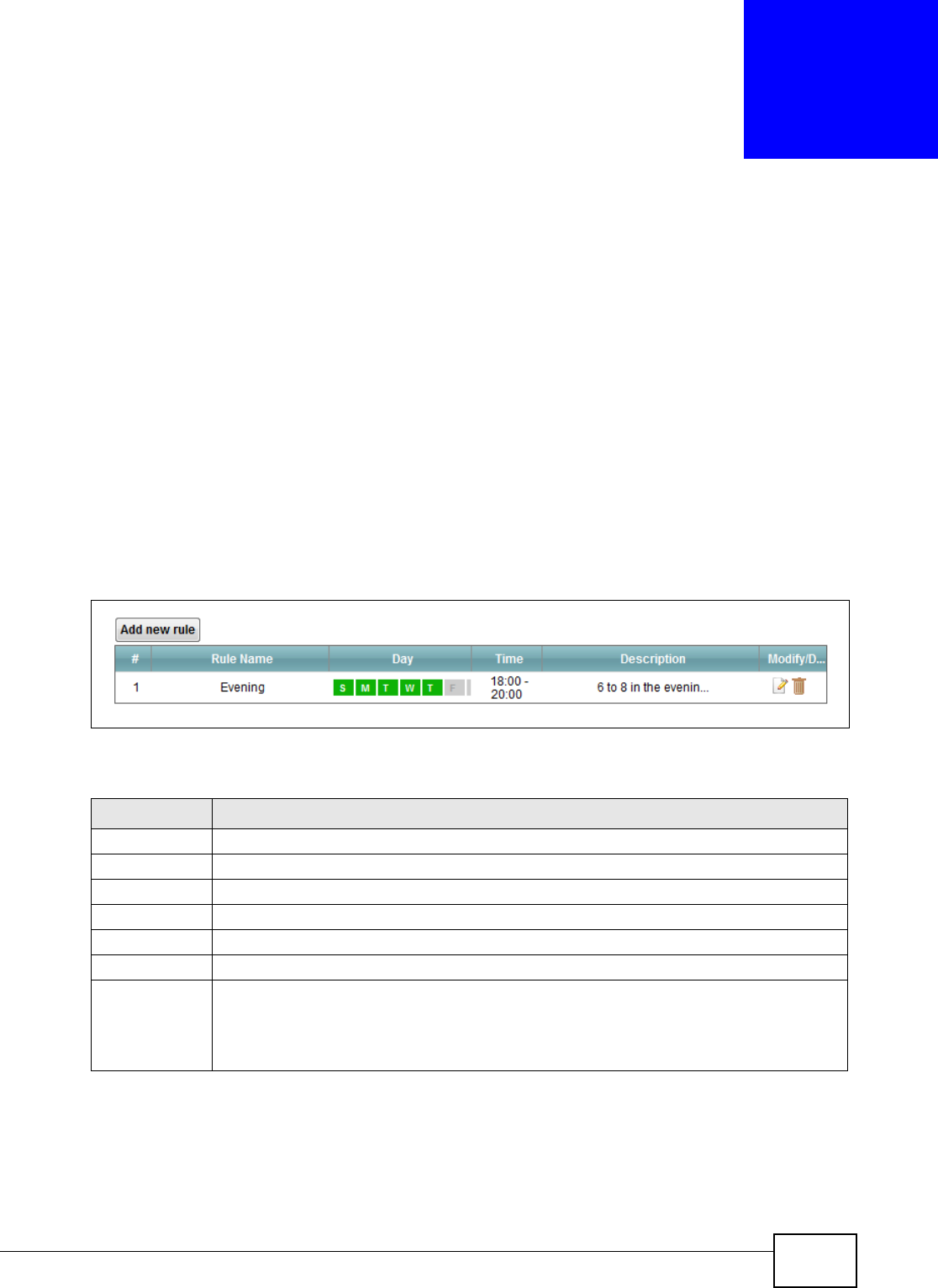
VMG1312-B10C User’s Guide 199
CHAPTER 17
Scheduler Rule
17.1 Overview
You can define time periods and days during which the Device performs scheduled rules of certain
features (such as Firewall Access Control) in the Scheduler Rule screen.
17.2 The Scheduler Rule Screen
Use this screen to view, add, or edit time schedule rules.
Click Securit y > Sche dule r Rule to open the following screen.
Figure 110 Security > Scheduler Rule
The following table describes the fields in this screen.
Table 83 Security > Scheduler Rule
LABEL DESCRIPTION
Add new rule Click this to create a new rule.
#This is the index number of the entry.
Rule Name This shows the name of the rule.
Day This shows the day(s) on which this rule is enabled.
Time This shows the period of time on which this rule is enabled.
Description This shows the description of this rule.
Modify/Delete Click the Ed it icon to edit the schedule.
Click the De le t e icon to delete a scheduler rule.
Note: You cannot delete a scheduler rule once it is applied to a certain feature.
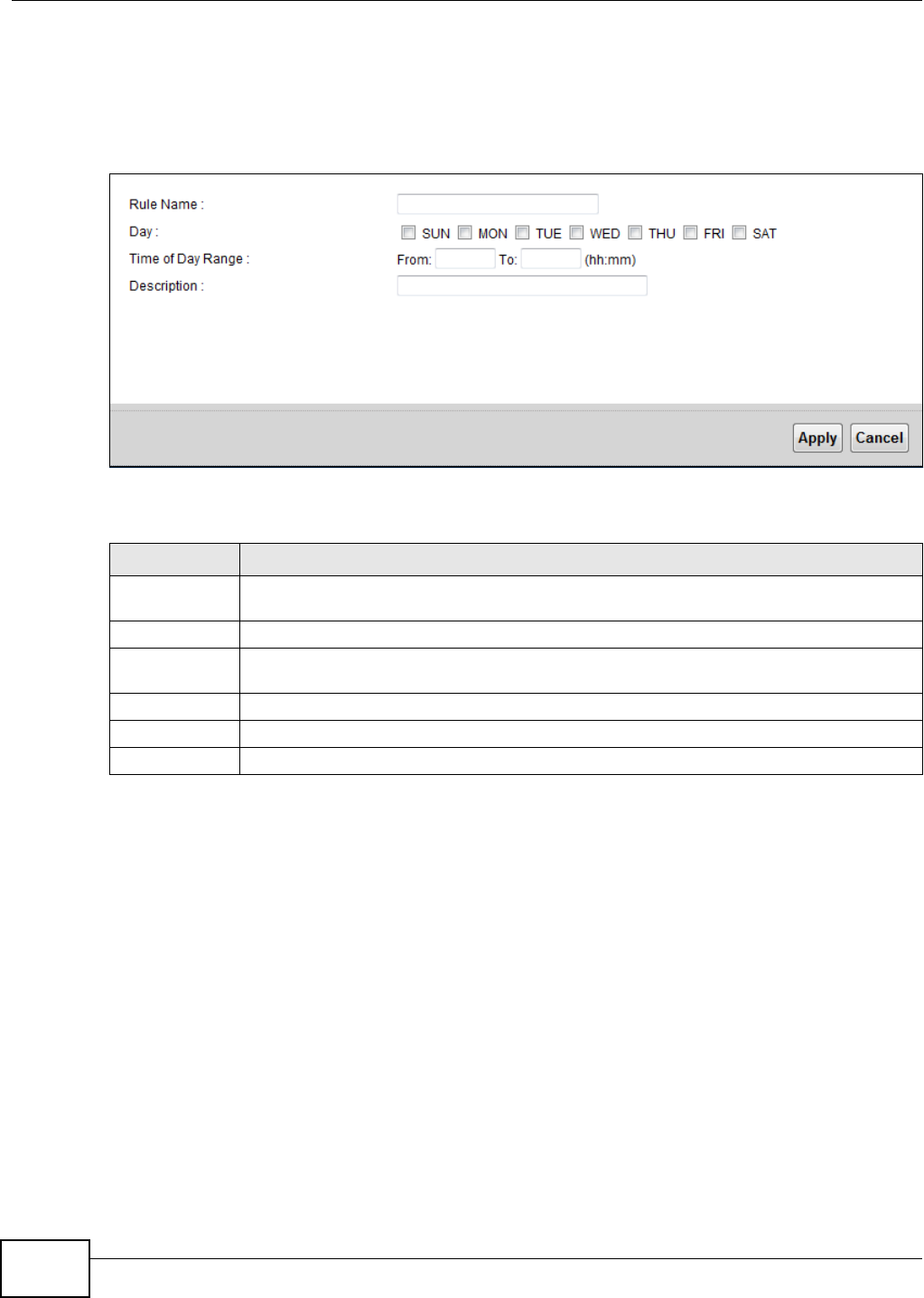
Chapter 17 Scheduler Rule
VMG1312-B10C User’s Guide
200
17.2.1 Add/Edit a Schedule
Click the Add button in the Schedu ler Rule screen or click the Edit icon next to a schedule rule to
open the following screen. Use this screen to configure a restricted access schedule.
Figure 111 Scheduler Rule: Add/Edit
The following table describes the fields in this screen.
Table 84 Scheduler Rule: Add/Edit
LABEL DESCRIPTION
Rule Name Enter a name (up to 31 printable English keyboard characters, not including spaces) for this
schedule.
Day Select check boxes for the days that you want the Device to perform this scheduler rule.
Time if Day
Range
Enter the time period of each day, in 24-hour format, during which the rule will be enforced.
Description Enter a description for this scheduler rule.
Apply Click Apply to save your changes.
Cancel Click Cancel to exit this screen without saving.

VMG1312-B10C User’s Guide 201
CHAPTER 18
Certificates
18.1 Overview
The Device can use certificates (also called digital IDs) to authenticate users. Certificates are based
on public-private key pairs. A certificate contains the certificate owner’s identity and public key.
Certificates provide a way to exchange public keys for use in authentication.
18.1.1 What You Can Do in this Chapter
•The Local Ce r t ifica t e s screen lets you generate certification requests and import the Device's
CA-signed certificates (Section 18.4 on page 205).
•The Tr uste d CA screen lets you save the certificates of trusted CAs to the Device (Section 18.4
on page 205).
18.2 What You Need to Know
The following terms and concepts may help as you read through this chapter.
Certification Authority
A Certification Authority (CA) issues certificates and guarantees the identity of each certificate
owner. There are commercial certification authorities like CyberTrust or VeriSign and government
certification authorities. The certification authority uses its private key to sign certificates. Anyone
can then use the certification authority's public key to verify the certificates. You can use the Device
to generate certification requests that contain identifying information and public keys and then send
the certification requests to a certification authority.
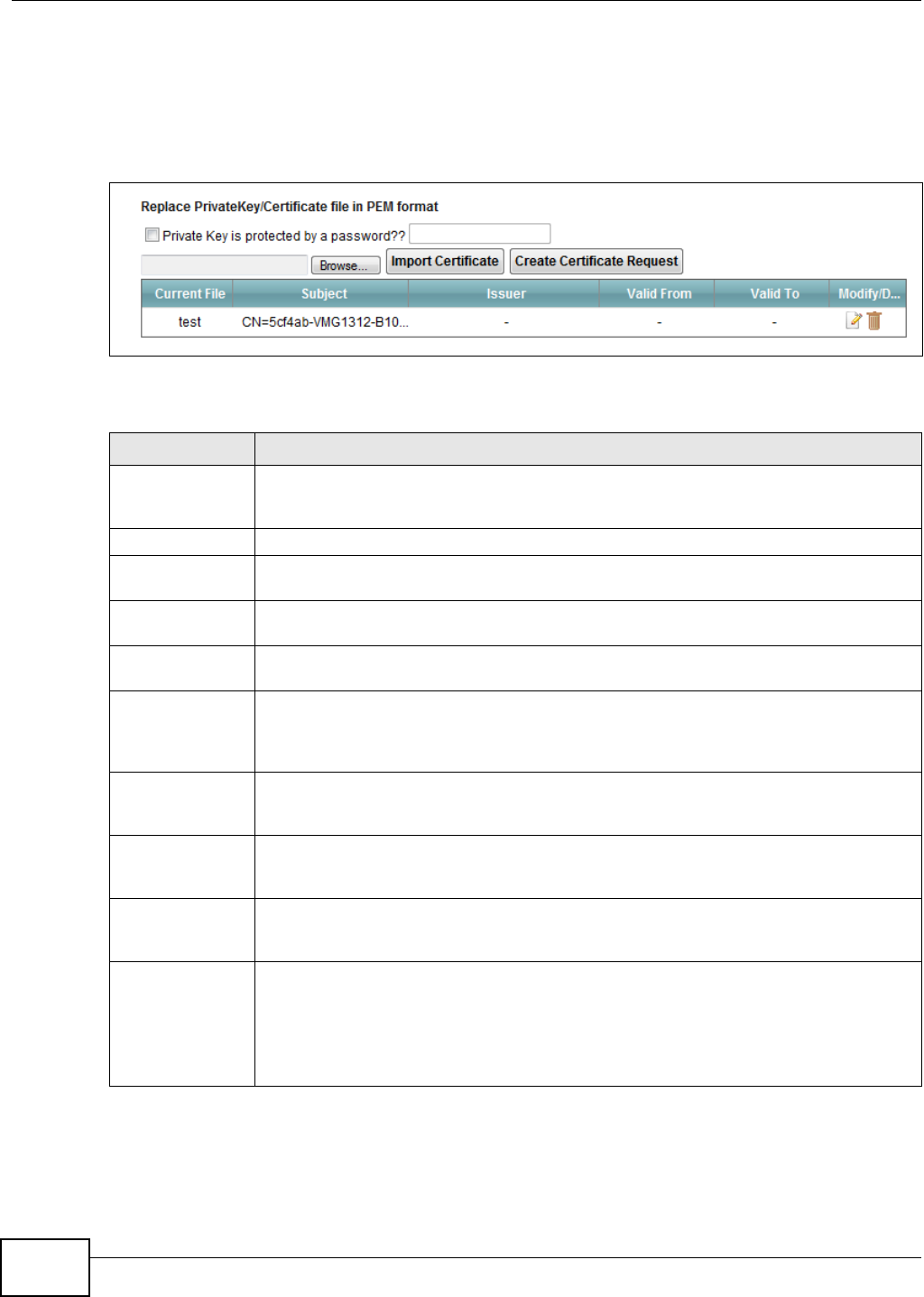
Chapter 18 Certificates
VMG1312-B10C User’s Guide
202
18.3 The Local Certificates Screen
Click Secur it y > Ce r t if ica t es to open the Loca l Cer t ificat es screen. This is the Device’s summary
list of certificates and certification requests.
Figure 112 Security > Certificates > Local Certificates
The following table describes the labels in this screen.
Table 85 Security > Certificates > Local Certificates
LABEL DESCRIPTION
Private Key is
protected by a
password?
Select the check box and enter the private key into the text box to store it on the Device.
The private key should not exceed 63 ASCII characters (not including spaces).
Browse... Click this to find the certificate file you want to upload.
Import Certificate Click this button to save the certificate that you have enrolled from a certification
authority from your computer to the Device.
Create Certificate
Request
Click this button to go to the screen where you can have the Device generate a
certification request.
Current File This field displays the name used to identify this certificate. It is recommended that you
give each certificate a unique name.
Subject This field displays identifying information about the certificate’s owner, such as CN
(Common Name), OU (Organizational Unit or department), O (Organization or company)
and C (Country). It is recommended that each certificate have unique subject
information.
Issuer This field displays identifying information about the certificate’s issuing certification
authority, such as a common name, organizational unit or department, organization or
company and country.
Valid From This field displays the date that the certificate becomes applicable. The text displays in
red and includes a N ot Ye t V a lid! message if the certificate has not yet become
applicable.
Valid To This field displays the date that the certificate expires. The text displays in red and
includes an Expir ing! or Expir ed! message if the certificate is about to expire or has
already expired.
Modify/Delete Click the View icon to open a screen with an in-depth list of information about the
certificate (or certification request).
For a certification request, click Loa d Signed to import the signed certificate.
Click the Rem ove icon to delete the certificate (or certification request). You cannot
delete a certificate that one or more features is configured to use.
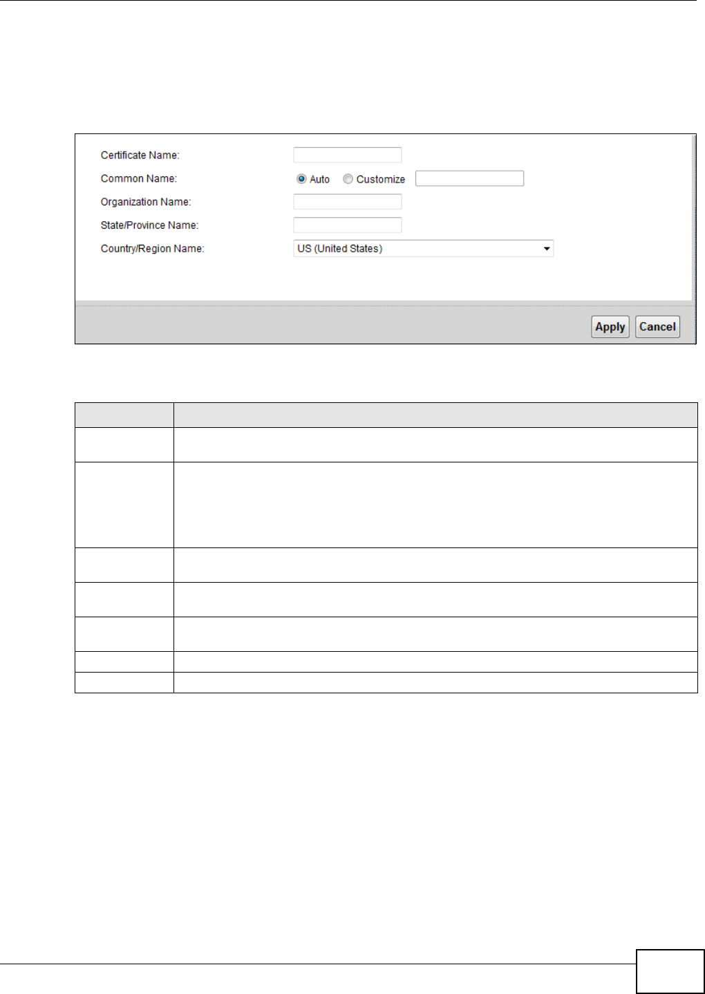
Chapter 18 Certificates
VMG1312-B10C User’s Guide 203
18.3.1 Create Certificate Request
Click Se cur it y > Cer t if icat e s > Local Ce rt ificat e s and then Creat e Cert ificat e Re quest to
open the following screen. Use this screen to have the Device generate a certification request.
Figure 113 Create Certificate Request
The following table describes the labels in this screen.
After you click Apply, the following screen displays to notify you that you need to get the certificate
request signed by a Certificate Authority. If you already have, click Load_ Signe d to import the
signed certificate into the Device. Otherwise click Ba ck to return to the Local Cer t ifica t e s screen.
Table 86 Create Certificate Request
LABEL DESCRIPTION
Certificate
Name
Type up to 63 ASCII characters (not including spaces) to identify this certificate.
Common Name Select Au t o to have the Device configure this field automatically. Or select Cu st o m iz e to
enter it manually.
Type the IP address (in dotted decimal notation), domain name or e-mail address in the field
provided. The domain name or e-mail address can be up to 63 ASCII characters. The
domain name or e-mail address is for identification purposes only and can be any string.
Organization
Name
Type up to 63 characters to identify the company or group to which the certificate owner
belongs. You may use any character, including spaces, but the Device drops trailing spaces.
State/Province
Name
Type up to 32 characters to identify the state or province where the certificate owner is
located. You may use any character, including spaces, but the Device drops trailing spaces.
Country/Region
Name
Select a country to identify the nation where the certificate owner is located.
Apply Click Apply to save your changes.
Cancel Click Cance l to exit this screen without saving.
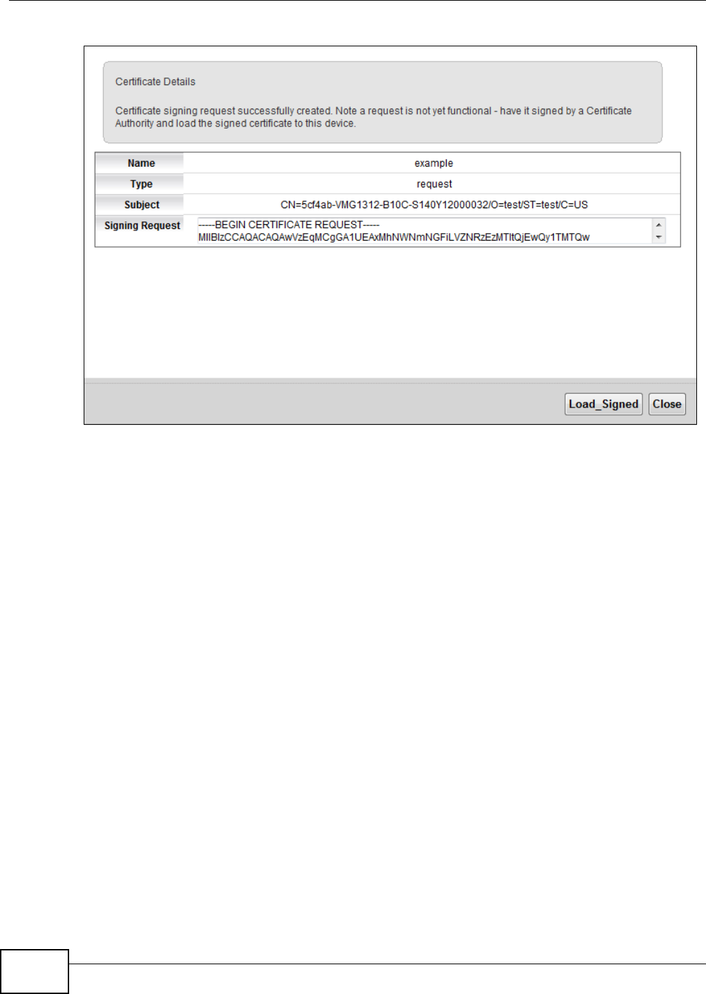
Chapter 18 Certificates
VMG1312-B10C User’s Guide
204
Figure 114 Certificate Request Created
18.3.2 Load Signed Certificate
After you create a certificate request and have it signed by a Certificate Authority, in the Local
Ce r t ifica t e s screen click the certificate request’s Loa d Signed icon to import the signed certificate
into the Device.
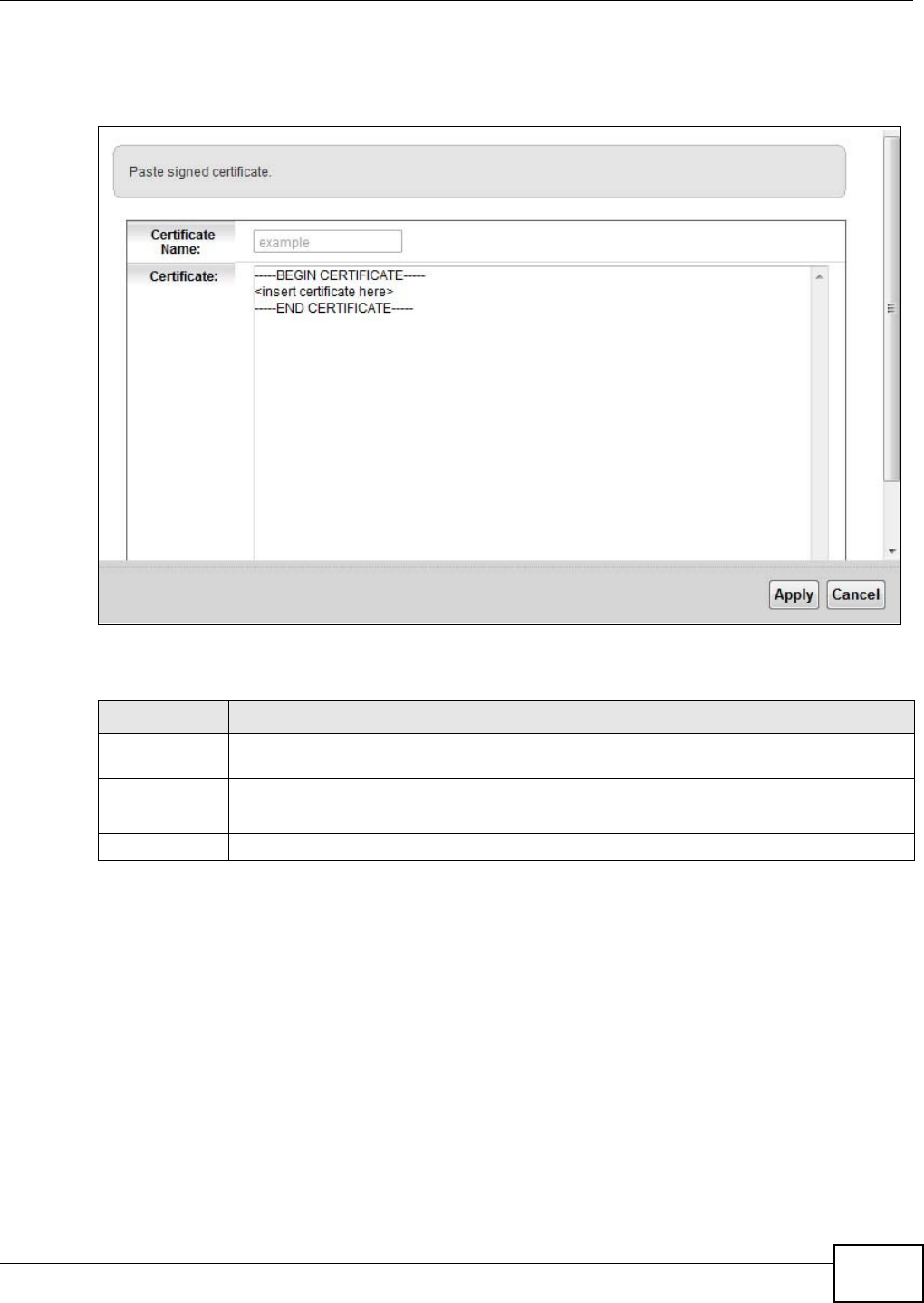
Chapter 18 Certificates
VMG1312-B10C User’s Guide 205
Note: You must remove any spaces from the certificate’s filename before you can import
it.
Figure 115 Load Signed Certificate
The following table describes the labels in this screen.
18.4 The Trusted CA Screen
Click Securit y > Cert ifica t es > Tr usted CA to open the following screen. This screen displays a
summary list of certificates of the certification authorities that you have set the Device to accept as
trusted. The Device accepts any valid certificate signed by a certification authority on this list as
Table 87 Load Signed Certificate
LABEL DESCRIPTION
Certificate
Name
This is the name of the signed certificate.
Certificate Copy and paste the signed certificate into the text box to store it on the Device.
Apply Click Apply to save your changes.
Cancel Click Cance l to exit this screen without saving.
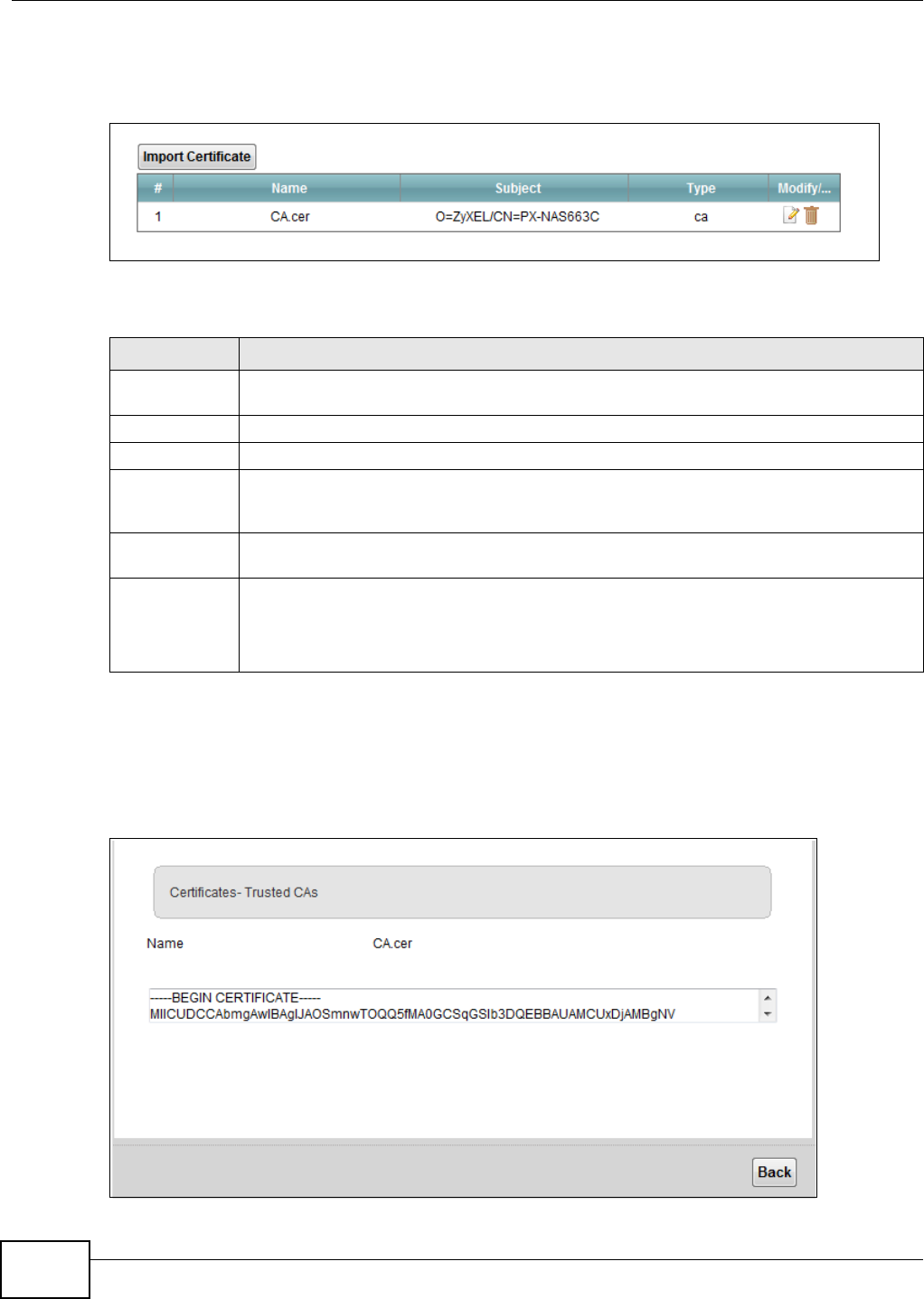
Chapter 18 Certificates
VMG1312-B10C User’s Guide
206
being trustworthy; thus you do not need to import any certificate that is signed by one of these
certification authorities.
Figure 116 Security > Certificates > Trusted CA
The following table describes the fields in this screen.
18.4.1 View Trusted CA Certificate
Click the View icon in the Tr uste d CA screen to open the following screen. Use this screen to view
in-depth information about the certification authority’s certificate.
Figure 117 Trusted CA: View
Table 88 Security > Certificates > Trusted CA
LABEL DESCRIPTION
Import
Certificate
Click this button to open a screen where you can save the certificate of a certification
authority that you trust to the Device.
# This is the index number of the entry.
Name This field displays the name used to identify this certificate.
Subject This field displays information that identifies the owner of the certificate, such as Common
Name (CN), OU (Organizational Unit or department), Organization (O), State (ST) and
Country (C). It is recommended that each certificate have unique subject information.
Type This field displays general information about the certificate. ca means that a Certification
Authority signed the certificate.
Modify/Delete Click the Vie w icon to open a screen with an in-depth list of information about the
certificate (or certification request).
Click the Rem ov e button to delete the certificate (or certification request). You cannot
delete a certificate that one or more features is configured to use.
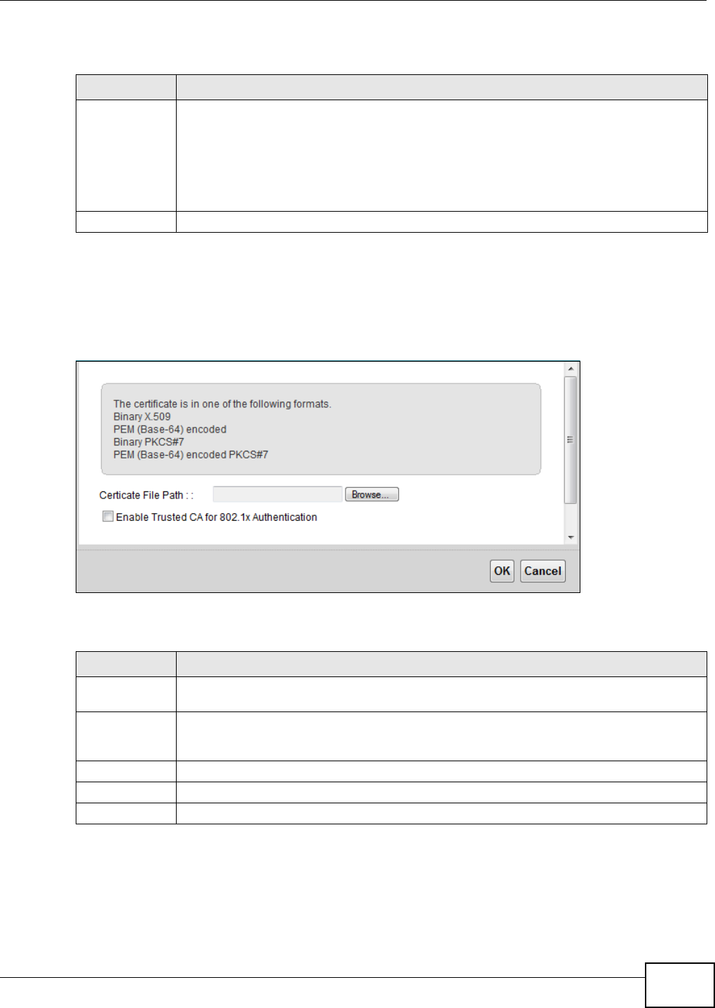
Chapter 18 Certificates
VMG1312-B10C User’s Guide 207
The following table describes the fields in this screen.
18.4.2 Import Trusted CA Certificate
Click the I m por t Cer t ificat e button in the Tr u st ed CA screen to open the following screen. The
Device trusts any valid certificate signed by any of the imported trusted CA certificates.
Figure 118 Trusted CA: Import Certificate
The following table describes the fields in this screen.
Table 89 Trusted CA: View
LABEL DESCRIPTION
Name This field displays the identifying name of this certificate.
The read-only text box displays the certificate in Privacy Enhanced Mail (PEM) format. PEM
uses base 64 to convert the binary certificate into a printable form.
You can copy and paste the certificate into an e-mail to send to friends or colleagues or you
can copy and paste the certificate into a text editor and save the file on a management
computer for later distribution (via floppy disk for example).
Back Click Back to return to the previous screen.
Table 90 Trusted CA: Import Certificate
LABEL DESCRIPTION
Certificate File
Path
Type in the location of the certificate you want to upload in this field or click Brow se ... to
find it.
Enable Trusted
CA for 802.1x
Authentication
If you select this check box, the trusted CA will be used for 802.1x authentication. The
selected trusted CA will be displayed in the N et w ork Set t in g > Br oa d ba n d > 8 0 2 .1 x :
Edit screen.
Certificate Copy and paste the certificate into the text box to store it on the Device.
OK Click OK to save your changes.
Cancel Click Cancel to exit this screen without saving.

Chapter 18 Certificates
VMG1312-B10C User’s Guide
208
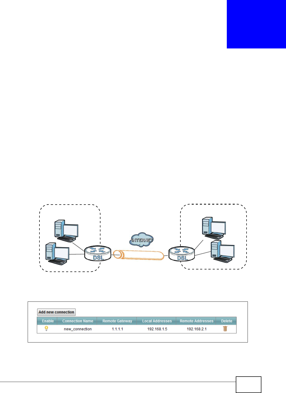
VMG1312-B10C User’s Guide 209
CHAPTER 19
VPN
19.1 Overview
A virtual private network (VPN) provides secure communications over the the Internet. Internet
Protocol Security (IPSec) is a standards-based VPN that provides confidentiality, data integrity, and
authentication. This chapter shows you how to configure the Device’s VPN settings.
19.2 IPSec VPN
19.2.1 The General Screen
Use this screen to view and manage your VPN tunnel policies. The following figure helps explain the
main fields in the web configurator.
Figure 119 IPSec Fields Summary
Click Se cur it y > V PN to open this screen as shown next.
Figure 120 IPSec VPN
Local Network Remote Network
VPN Tunnel

Chapter 19 VPN
VMG1312-B10C User’s Guide
210
This screen contains the following fields:
19.2.2 IPSec VPN: Add
Use these settings to add or edit VPN policies. Click Secur it y > VPN > Add n e w conn e ction to
open this screen as shown next.
Table 91 IPSec VPN
LABEL DESCRIPTION
Add new connection Click this button to add an item to the list.
Enable This displays if the VPN policy is enabled.
Connection Name The name of the VPN connection.
Remote Gateway This is the IP address of the remote IPSec router in the IKE SA.
Local Addresses This displays the IP address(es) on the LAN behind your Device.
Remote Addresses This displays the IP address(es) on the LAN behind the remote IPSec’s router.
Delete Click the De le t e icon to delete an existing rule.
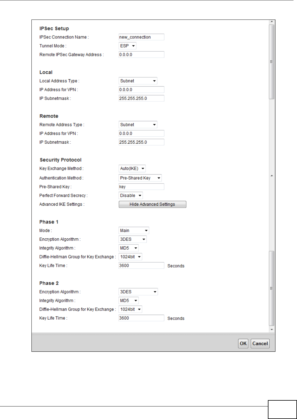
Chapter 19 VPN
VMG1312-B10C User’s Guide 211
Figure 121 IPSec VPN: Add

Chapter 19 VPN
VMG1312-B10C User’s Guide
212
This screen contains the following fields:
Table 92 IPSec VPN: Add
LABEL DESCRIPTION
IPSec Setup
IPSec
Connection
Name
Enter the name of the VPN connection.
Tunnel Mode Select which protocol you want to use in the IPSec SA. Choices are:
AH (RFC 2402) - provides integrity, authentication, sequence integrity (replay
resistance), and non-repudiation but not encryption. If you select AH , you must select
an Au t he n t ica t ion algorithm.
ESP (RFC 2406) - provides encryption and the same services offered by AH, but its
authentication is weaker. If you select ESP, you must select an En cr yp t ion algorithm
and Authentication algorithm.
Both AH and ESP increase processing requirements and latency (delay). The Device
and remote IPSec router must use the same active protocol.
Remote IPSec
Gateway
Address
Enter the IP address of the remote IPSec router in the IKE SA.
Local
Local Address
Type Select Sin gle to have only one local LAN IP address use the VPN tunnel. Select Sub ne t
to specify local LAN IP addresses by their subnet mask.
IP Address for
VPN If Sin gle is selected, enter a (static) IP address on the LAN behind your Device.
If Subn et is selected, specify IP addresses on a network by their subnet mask by
entering a (static) IP address on the LAN behind your Device. Then enter the subnet
mask to identify the network address.
IP Subnetmask If Subne t is selected, enter the subnet mask to identify the network address.
Remote
Remote Address
Type Select Sin gle to have only one remote LAN IP address use the VPN tunnel. Select
Su bn e t to specify remote LAN IP addresses by their subnet mask.
IP Address for
VPN If Sin gle is selected, enter a (static) IP address on the LAN behind the remote IPSec’s
router.
If Subn et is selected, specify IP addresses on a network by their subnet mask by
entering a (static) IP address on the LAN behind the remote IPSec’s router. Then enter
the subnet mask to identify the network address.
IP Subnetmask If Subne t is selected, enter the subnet mask to identify the network address.
Security Protocol - Auto
Key Exchange
Method Select the key exchange method:
Au t o( I KE) - Select this to use automatic IKE key management VPN connection policy.
Man ual - Select this option to configure a VPN connection policy that uses a manual key
instead of IKE key management. This may be useful if you have problems with IKE key
management.
Note: Only use manual key as a temporary solution, because it is not as secure as a
regular IPSec SA.
Authentication
Method Select Pr e- Share d Key to use a pre-shared key for authentication, and type in your
pre-shared key. A pre-shared key identifies a communicating party during a phase 1 IKE
negotiation. It is called "pre-shared" because you have to share it with another party
before you can communicate with them over a secure connection.
Select Ce rt if ica t e to use a certificate for authentication.

Chapter 19 VPN
VMG1312-B10C User’s Guide 213
Pre-Shared Key Type your pre-shared key in this field. A pre-shared key identifies a communicating
party during a phase 1 IKE negotiation.
Type from 8 to 31 case-sensitive ASCII characters or from 16 to 62 hexadecimal ("0-9",
"A-F") characters. You must precede a hexadecimal key with a "0x” (zero x), which is
not counted as part of the 16 to 62 character range for the key. For example, in
"0x0123456789ABCDEF", “0x” denotes that the key is hexadecimal and
“0123456789ABCDEF” is the key itself.
Certificates If you use a certificate for authentication, select the certificates to use from the lists.
You can import certificates in the Se cur it y > Cer t ifica t es screens.
Perfect Forward
Secrecy (PFS) Select whether or not you want to enable Perfect Forward Secrecy (PFS)
PFS changes the root key that is used to generate encryption keys for each IPSec SA.
The longer the key, the more secure the encryption, but also the longer it takes to
encrypt and decrypt information. Both routers must use the same DH key group.
Choices are:
Diffie - H e llm an Group2 - use a 1024-bit random number
Diffie - H e llm an Group5 - use a 1536-bit random number
Diffie - H e llm an Group1 4 - use a 2048-bit random number
Show Advanced
Settings Click this to display advanced settings.
Advanced Setting - Phase 1
Mode Select the negotiation mode to use to negotiate the IKE SA. Choices are:
Main - this encrypts the Device’s and remote IPSec router’s identities but takes more
time to establish the IKE SA.
Aggr e ssive - this is faster but does not encrypt the identities.
The Device and the remote IPSec router must use the same negotiation mode.
Encryption
Algorithm Select which key size and encryption algorithm to use in the IKE SA. Choices are:
DES - a 56-bit key with the DES encryption algorithm
3 DES - a 168-bit key with the DES encryption algorithm
AES1 2 8 - a 128-bit key with the AES encryption algorithm
AES1 9 6 - a 196-bit key with the AES encryption algorithm
AES2 5 6 - a 256-bit key with the AES encryption algorithm
The Device and the remote IPSec router must use the same key size and encryption
algorithm. Longer keys require more processing power, resulting in increased latency
and decreased throughput.
Integrity
Algorithm Select which hash algorithm to use to authenticate packet data. Choices are MD 5 ,
SH A1 , SH A2 - 2 5 6 and SHA2 - 5 1 2 . SH A is generally considered stronger than MD5 ,
but it is also slower.
Diffie-Hellman
Group for Key
Exchange
Select which Diffie-Hellman key group you want to use for encryption keys. Choices for
number of bits in the random number are: 768, 1024, 2048, 3072, 4096, 6144, 8192.
The longer the key, the more secure the encryption, but also the longer it takes to
encrypt and decrypt information. Both routers must use the same DH key group.
Key Life Time Define the length of time before an IPSec SA automatically renegotiates in this field.
A short SA Life Time increases security by forcing the two VPN gateways to update the
encryption and authentication keys. However, every time the VPN tunnel renegotiates,
all users accessing remote resources are temporarily disconnected.
Table 92 IPSec VPN: Add
LABEL DESCRIPTION

Chapter 19 VPN
VMG1312-B10C User’s Guide
214
Phase 2
Encryption
Algorithm Select which key size and encryption algorithm to use in the IKE SA. Choices are:
DES - a 56-bit key with the DES encryption algorithm
3 DES - a 168-bit key with the DES encryption algorithm
AES1 2 8 - a 128-bit key with the AES encryption algorithm
AES1 9 6 - a 196-bit key with the AES encryption algorithm
AES2 5 6 - a 256-bit key with the AES encryption algorithm
N ULL - no encryption key or algorithm
The Device and the remote IPSec router must use the same key size and encryption
algorithm. Longer keys require more processing power, resulting in increased latency
and decreased throughput.
Integrity
Algorithm Select which hash algorithm to use to authenticate packet data. Choices are MD 5 ,
SH A1 . SH A is generally considered stronger than MD5 , but it is also slower.
Diffie-Hellman
Group for Key
Exchange
Select which Diffie-Hellman key group you want to use for encryption keys. Choices for
number of bits in the random number are: 768, 1024, 2048, 3072, 4096, 6144, 8192.
Key Life Time Define the length of time before an IPSec SA automatically renegotiates in this field.
A short SA Life Time increases security by forcing the two VPN gateways to update the
encryption and authentication keys. However, every time the VPN tunnel renegotiates,
all users accessing remote resources are temporarily disconnected.
DPD Active Enable Dead Peer Detection (DPD) Active check box if you want the Device to make sure
the remote IPSec router is there before it transmits data through the IKE SA. The
remote IPSec router must support DPD. If the remote IPSec router does not respond,
the Device shuts down the IKE SA.
Security Protocol - Manual
Key Exchange
Method Select the key exchange method:
Au t o( I KE) - Select this to use automatic IKE key management VPN connection policy.
Man ual - Select this option to configure a VPN connection policy that uses a manual key
instead of IKE key management. This may be useful if you have problems with IKE key
management.
Note: Only use manual key as a temporary solution, because it is not as secure as a
regular IPSec SA.
Encryption
Algorithm Select which key size and encryption algorithm to use in the IKE SA. Choices are:
DES - a 56-bit key with the DES encryption algorithm
3 DES - a 168-bit key with the DES encryption algorithm
AES - AES encryption algorithm
Encryption Key This field is applicable when you select an Encryption Algorithm.
Enter the encryption key, which depends on the encryption algorithm.
DES - type a unique key 16 hexadecimal characters long
3 DES - type a unique key 48 hexadecimal characters long
AES - type a unique key 32, 48 or 64 hexadecimal characters long
Authentication
Algorithm Select which hash algorithm to use to authenticate packet data. Choices are MD 5 ,
SH A1 . SH A is generally considered stronger than MD5 , but it is also slower.
Table 92 IPSec VPN: Add
LABEL DESCRIPTION
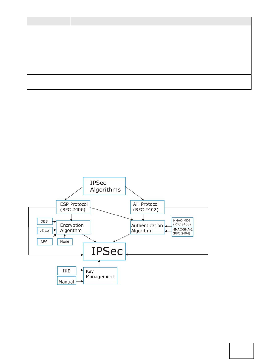
Chapter 19 VPN
VMG1312-B10C User’s Guide 215
19.3 Technical Reference
This section provides some technical background information about the topics covered in this
section.
19.3.1 IPSec Architecture
The overall IPSec architecture is shown as follows.
Figure 122 IPSec Architecture
IPSec Algorithms
The ESP (Encapsulating Security Payload) Protocol (RFC 2406) and AH (Authentication Header)
protocol (RFC 2402) describe the packet formats and the default standards for packet structure
(including implementation algorithms).
Authentication
Key Enter the authentication key, which depends on the authentication algorithm.
MD5 - type a unique key 32 hexadecimal characters long
SH A1 - type a unique key 40 hexadecimal characters long
SPI Type a unique SPI (Security Parameter Index) in hexadecimal characters.
The SPI is used to identify the Device during authentication.
The Device and remote IPSec router must use the same SPI.
Apply Click Apply to save your changes.
Cancel Click Cancel to restore your previously saved settings.
Table 92 IPSec VPN: Add
LABEL DESCRIPTION
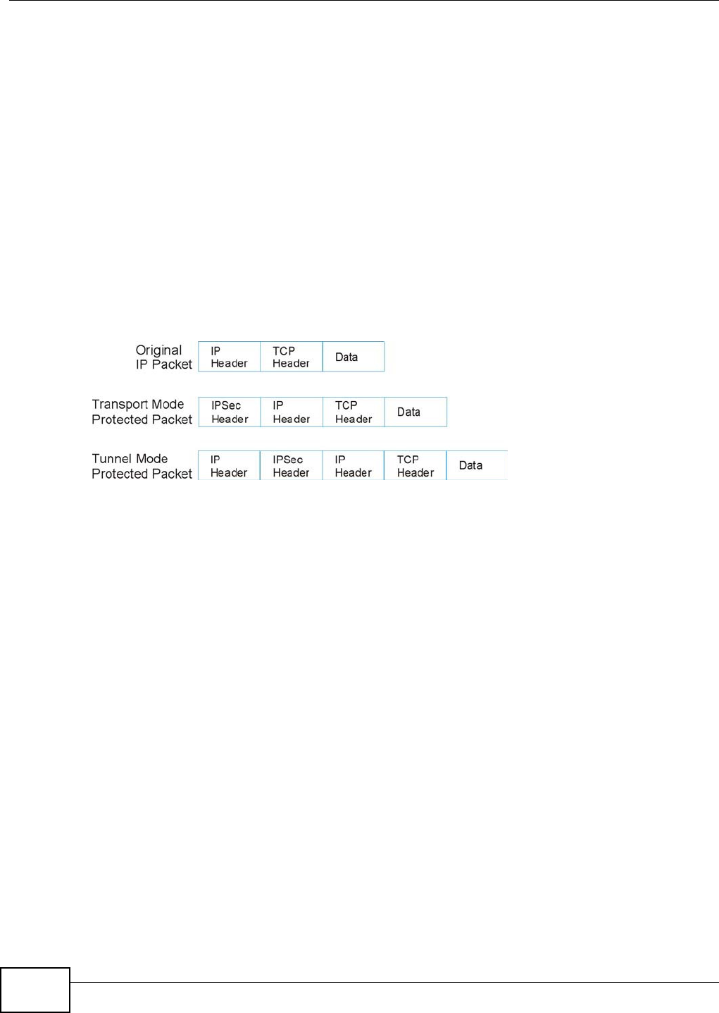
Chapter 19 VPN
VMG1312-B10C User’s Guide
216
The Encryption Algorithm describes the use of encryption techniques such as DES (Data Encryption
Standard) and Triple DES algorithms.
The Authentication Algorithms, HMAC-MD5 (RFC 2403) and HMAC-SHA-1 (RFC 2404, provide an
authentication mechanism for the AH and ESP protocols.
Key Management
Key management allows you to determine whether to use IKE (ISAKMP) or manual key
configuration in order to set up a VPN.
19.3.2 Encapsulation
The two modes of operation for IPSec VPNs are Tr a n spo rt mode and Tunnel mode. At the time of
writing, the Device supports Tunnel mode only.
Figure 123 Transport and Tunnel Mode IPSec Encapsulation
Transport Mode
Tr a n sp or t mode is used to protect upper layer protocols and only affects the data in the IP packet.
In Tr a n sp or t mode, the IP packet contains the security protocol (AH or ESP) located after the
original IP header and options, but before any upper layer protocols contained in the packet (such
as TCP and UDP).
With ESP, protection is applied only to the upper layer protocols contained in the packet. The IP
header information and options are not used in the authentication process. Therefore, the
originating IP address cannot be verified for integrity against the data.
With the use of AH as the security protocol, protection is extended forward into the IP header to
verify the integrity of the entire packet by use of portions of the original IP header in the hashing
process.
Tunnel Mode
Tu n n e l mode encapsulates the entire IP packet to transmit it securely. A Tunne l mode is required
for gateway services to provide access to internal systems. Tunne l mode is fundamentally an IP
tunnel with authentication and encryption. This is the most common mode of operation. Tunne l
mode is required for gateway to gateway and host to gateway communications. Tunnel mode
communications have two sets of IP headers:
•Out side he a de r: The outside IP header contains the destination IP address of the VPN gateway.
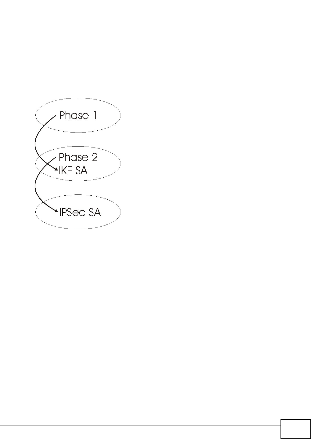
Chapter 19 VPN
VMG1312-B10C User’s Guide 217
•I nside hea de r : The inside IP header contains the destination IP address of the final system
behind the VPN gateway. The security protocol appears after the outer IP header and before the
inside IP header.
19.3.3 IKE Phases
There are two phases to every IKE (Internet Key Exchange) negotiation – phase 1 (Authentication)
and phase 2 (Key Exchange). A phase 1 exchange establishes an IKE SA and the second one uses
that SA to negotiate SAs for IPSec.
Figure 124 Two Phases to Set Up the IPSec SA
In phase 1 you must:
• Choose a negotiation mode.
• Authenticate the connection by entering a pre-shared key.
• Choose an encryption algorithm.
• Choose an authentication algorithm.
• Choose a Diffie-Hellman public-key cryptography key group.
• Set the IKE SA lifetime. This field allows you to determine how long an IKE SA should stay up
before it times out. An IKE SA times out when the IKE SA lifetime period expires. If an IKE SA
times out when an IPSec SA is already established, the IPSec SA stays connected.
In phase 2 you must:
• Choose an encryption algorithm.
• Choose an authentication algorithm
• Choose a Diffie-Hellman public-key cryptography key group.
• Set the IPSec SA lifetime. This field allows you to determine how long the IPSec SA should stay
up before it times out. The Device automatically renegotiates the IPSec SA if there is traffic when
the IPSec SA lifetime period expires. If an IPSec SA times out, then the IPSec router must
renegotiate the SA the next time someone attempts to send traffic.

Chapter 19 VPN
VMG1312-B10C User’s Guide
218
19.3.4 Negotiation Mode
The phase 1 N e got iat ion M ode you select determines how the Security Association (SA) will be
established for each connection through IKE negotiations.
•Ma in Mode ensures the highest level of security when the communicating parties are
negotiating authentication (phase 1). It uses 6 messages in three round trips: SA negotiation,
Diffie-Hellman exchange and an exchange of nonces (a nonce is a random number). This mode
features identity protection (your identity is not revealed in the negotiation).
•Aggre ssive M ode is quicker than Ma in M ode because it eliminates several steps when the
communicating parties are negotiating authentication (phase 1). However the trade-off is that
faster speed limits its negotiating power and it also does not provide identity protection. It is
useful in remote access situations where the address of the initiator is not know by the responder
and both parties want to use pre-shared key authentication.
19.3.5 IPSec and NAT
Read this section if you are running IPSec on a host computer behind the Device.
NAT is incompatible with the AH protocol in both Transpor t and Tu n n e l mode. An IPSec VPN using
the AH protocol digitally signs the outbound packet, both data payload and headers, with a hash
value appended to the packet. When using AH protocol, packet contents (the data payload) are not
encrypted.
A NAT device in between the IPSec endpoints will rewrite either the source or destination address
with one of its own choosing. The VPN device at the receiving end will verify the integrity of the
incoming packet by computing its own hash value, and complain that the hash value appended to
the received packet doesn't match. The VPN device at the receiving end doesn't know about the
NAT in the middle, so it assumes that the data has been maliciously altered.
IPSec using ESP in Tu n ne l mode encapsulates the entire original packet (including headers) in a
new IP packet. The new IP packet's source address is the outbound address of the sending VPN
gateway, and its destination address is the inbound address of the VPN device at the receiving end.
When using ESP protocol with authentication, the packet contents (in this case, the entire original
packet) are encrypted. The encrypted contents, but not the new headers, are signed with a hash
value appended to the packet.
Tu n n e l mode ESP with authentication is compatible with NAT because integrity checks are
performed over the combination of the "original header plus original payload," which is unchanged
by a NAT device.
Tr a n sp or t mode ESP with authentication is not compatible with NAT.
Table 93 VPN and NAT
SECURITY PROTOCOL MODE NAT
AH Transport N
AH Tunnel N
ESP Transport N
ESP Tunnel Y
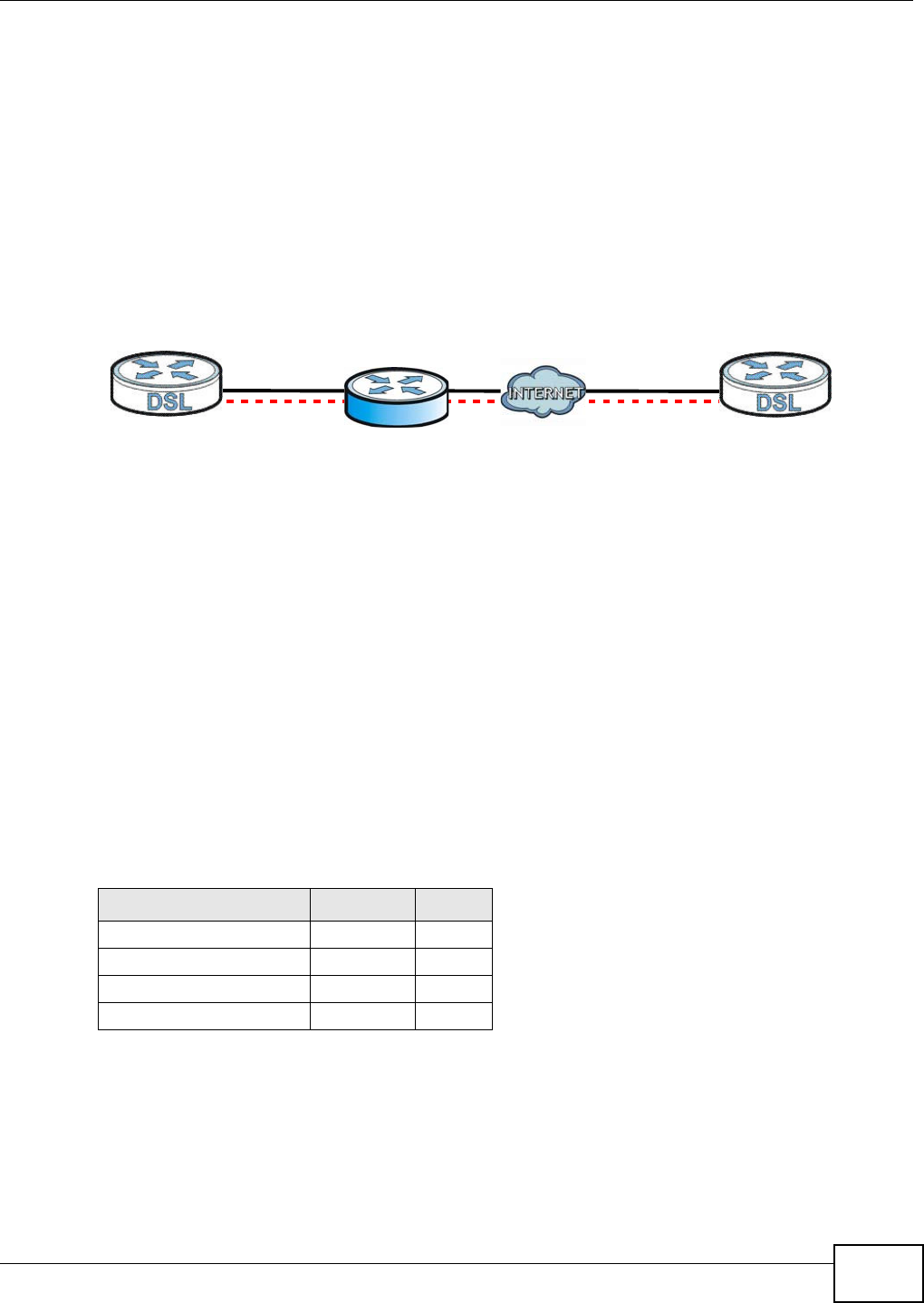
Chapter 19 VPN
VMG1312-B10C User’s Guide 219
19.3.6 VPN, NAT, and NAT Traversal
NAT is incompatible with the AH protocol in both transport and tunnel mode. An IPSec VPN using
the AH protocol digitally signs the outbound packet, both data payload and headers, with a hash
value appended to the packet, but a NAT device between the IPSec endpoints rewrites the source or
destination address. As a result, the VPN device at the receiving end finds a mismatch between the
hash value and the data and assumes that the data has been maliciously altered.
NAT is not normally compatible with ESP in transport mode either, but the Device’s NAT Tra ve r sa l
feature provides a way to handle this. NAT traversal allows you to set up an IKE SA when there are
NAT routers between the two IPSec routers.
Figure 125 NAT Router Between IPSec Routers
Normally you cannot set up an IKE SA with a NAT router between the two IPSec routers because
the NAT router changes the header of the IPSec packet. NAT traversal solves the problem by adding
a UDP port 500 header to the IPSec packet. The NAT router forwards the IPSec packet with the UDP
port 500 header unchanged. In the above figure, when IPSec router A tries to establish an IKE SA,
IPSec router B checks the UDP port 500 header, and IPSec routers A and B build the IKE SA.
For NAT traversal to work, you must:
• Use ESP security protocol (in either transport or tunnel mode).
•Use IKE keying mode.
• Enable NAT traversal on both IPSec endpoints.
• Set the NAT router to forward UDP port 500 to IPSec router A.
Finally, NAT is compatible with ESP in tunnel mode because integrity checks are performed over the
combination of the "original header plus original payload," which is unchanged by a NAT device. The
compatibility of AH and ESP with NAT in tunnel and transport modes is summarized in the following
table.
Y* - This is supported in the Device if you enable NAT traversal.
19.3.7 Pre-Shared Key
A pre-shared key identifies a communicating party during a phase 1 IKE negotiation (see Section
19.3.3 on page 217 for more on IKE phases). It is called “pre-shared” because you have to share it
with another party before you can communicate with them over a secure connection.
Table 94 VPN and NAT
SECURITY PROTOCOL MODE NAT
AH Transport N
AH Tunnel N
ESP Transport Y*
ESP Tunnel Y
AB

Chapter 19 VPN
VMG1312-B10C User’s Guide
220
19.3.8 Diffie-Hellman (DH) Key Groups
Diffie-Hellman (DH) is a public-key cryptography protocol that allows two parties to establish a
shared secret over an unsecured communications channel. Diffie-Hellman is used within IKE SA
setup to establish session keys. Upon completion of the Diffie-Hellman exchange, the two peers
have a shared secret, but the IKE SA is not authenticated. For authentication, use pre-shared keys.

VMG1312-B10C User’s Guide 221
CHAPTER 20
Log
20.1 Overview
The web configurator allows you to choose which categories of events and/or alerts to have the
Device log and then display the logs or have the Device send them to an administrator (as e-mail)
or to a syslog server.
20.1.1 What You Can Do in this Chapter
•Use the Syste m Log screen to see the system logs (Section 20.2 on page 222).
•Use the Securit y Log screen to see the security-related logs for the categories that you select
(Section 20.3 on page 223).
20.1.2 What You Need To Know
The following terms and concepts may help as you read this chapter.
Alerts and Logs
An alert is a type of log that warrants more serious attention. They include system errors, attacks
(access control) and attempted access to blocked web sites. Some categories such as Syst em
Er r ors consist of both logs and alerts. You may differentiate them by their color in the Vie w Log
screen. Alerts display in red and logs display in black.
Syslog Overview
The syslog protocol allows devices to send event notification messages across an IP network to
syslog servers that collect the event messages. A syslog-enabled device can generate a syslog
message and send it to a syslog server.
Syslog is defined in RFC 3164. The RFC defines the packet format, content and system log related
information of syslog messages. Each syslog message has a facility and severity level. The syslog
facility identifies a file in the syslog server. Refer to the documentation of your syslog program for
details. The following table describes the syslog severity levels.
Table 95 Syslog Severity Levels
CODE SEVERITY
0 Emergency: The system is unusable.
1 Alert: Action must be taken immediately.
2 Critical: The system condition is critical.
3 Error: There is an error condition on the system.
4 Warning: There is a warning condition on the system.
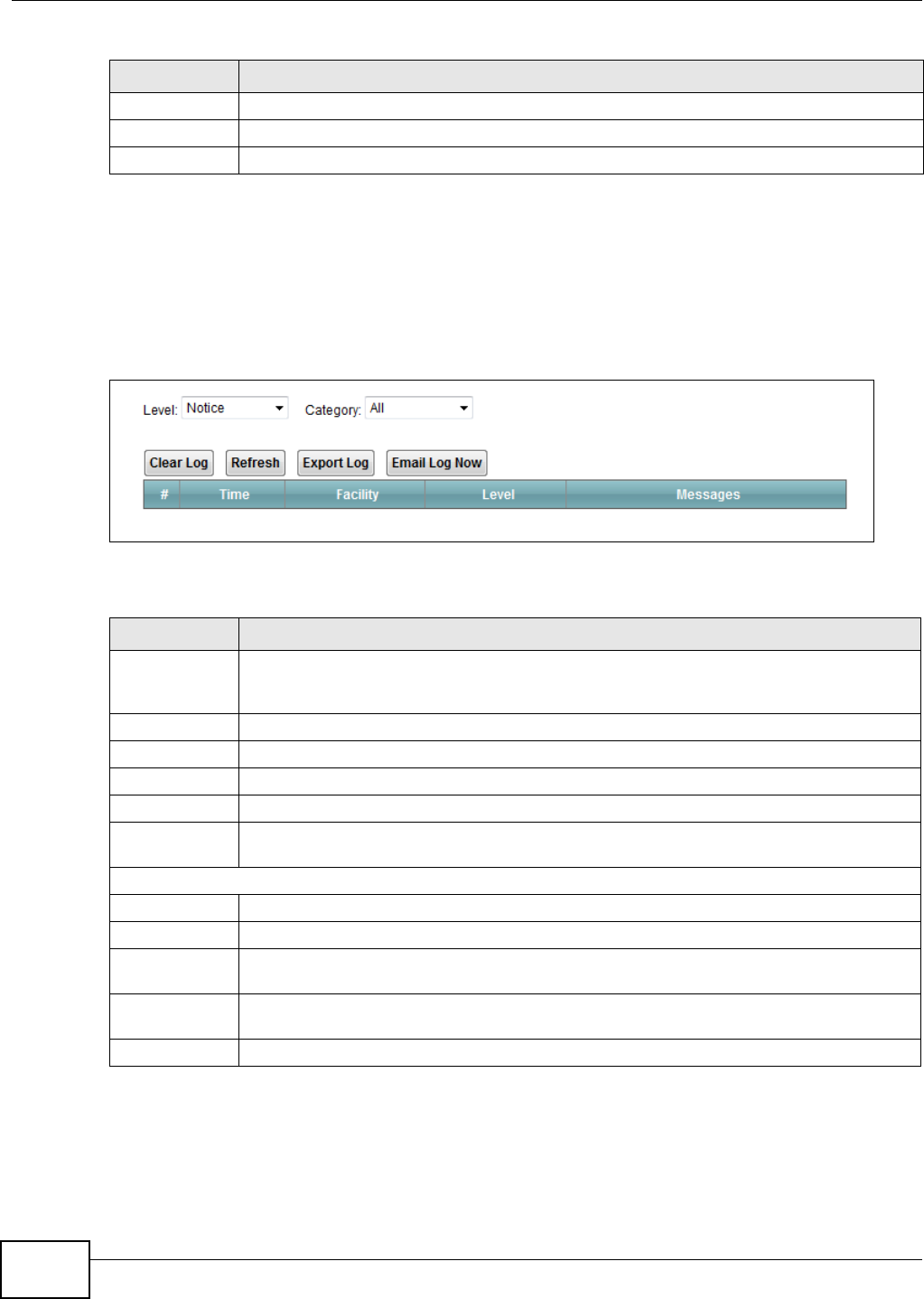
Chapter 20 Log
VMG1312-B10C User’s Guide
222
20.2 The System Log Screen
Use the Syst em Log screen to see the system logs. Click Syst em Mon it or > Log to open the
Syst e m Log screen.
Figure 126 System Monitor > Log > System Log
The following table describes the fields in this screen.
5 Notice: There is a normal but significant condition on the system.
6 Informational: The syslog contains an informational message.
7 Debug: The message is intended for debug-level purposes.
Table 95 Syslog Severity Levels
CODE SEVERITY
Table 96 System Monitor > Log > System Log
LABEL DESCRIPTION
Level Select a severity level from the drop-down list box. This filters search results according to
the severity level you have selected. When you select a severity, the Device searches
through all logs of that severity or higher.
Category Select the type of logs to display.
Clear Log Click this to delete all the logs.
Refresh Click this to renew the log screen.
Export Log Click this to export the selected log(s).
Email Log Now Click this to send the log file(s) to the E-mail address you specify in the M a in t e na n ce >
Logs Set t in g screen.
System Log
#This field is a sequential value and is not associated with a specific entry.
Time This field displays the time the log was recorded.
Facility The log facility allows you to send logs to different files in the syslog server. Refer to the
documentation of your syslog program for more details.
Level This field displays the severity level of the logs that the device is to send to this syslog
server.
Messages This field states the reason for the log.
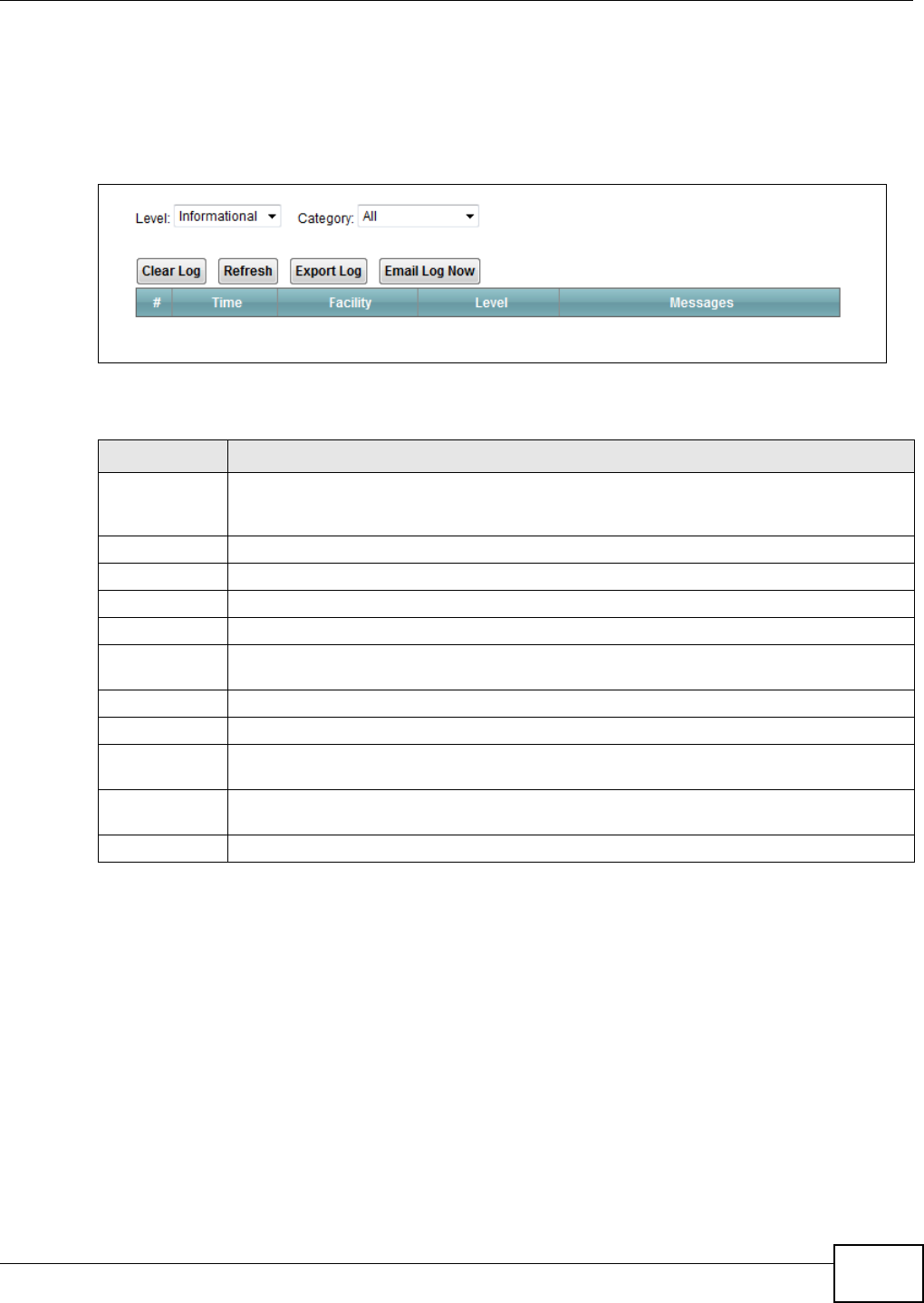
Chapter 20 Log
VMG1312-B10C User’s Guide 223
20.3 The Security Log Screen
Use the Secur it y Log screen to see the security-related logs for the categories that you select.
Click Syst e m M onit or > Log > Se curit y Log to open the following screen.
Figure 127 System Monitor > Log > Security Log
The following table describes the fields in this screen.
Table 97 System Monitor > Log > Security Log
LABEL DESCRIPTION
Level Select a severity level from the drop-down list box. This filters search results according to
the severity level you have selected. When you select a severity, the Device searches
through all logs of that severity or higher.
Category Select the type of logs to display.
Clear Log Click this to delete all the logs.
Refresh Click this to renew the log screen.
Export Log Click this to export the selected log(s).
Email Log Now Click this to send the log file(s) to the E-mail address you specify in the M a in t e na n ce >
Logs Set t in g screen.
#This field is a sequential value and is not associated with a specific entry.
Time This field displays the time the log was recorded.
Facility The log facility allows you to send logs to different files in the syslog server. Refer to the
documentation of your syslog program for more details.
Level This field displays the severity level of the logs that the device is to send to this syslog
server.
Messages This field states the reason for the log.

Chapter 20 Log
VMG1312-B10C User’s Guide
224
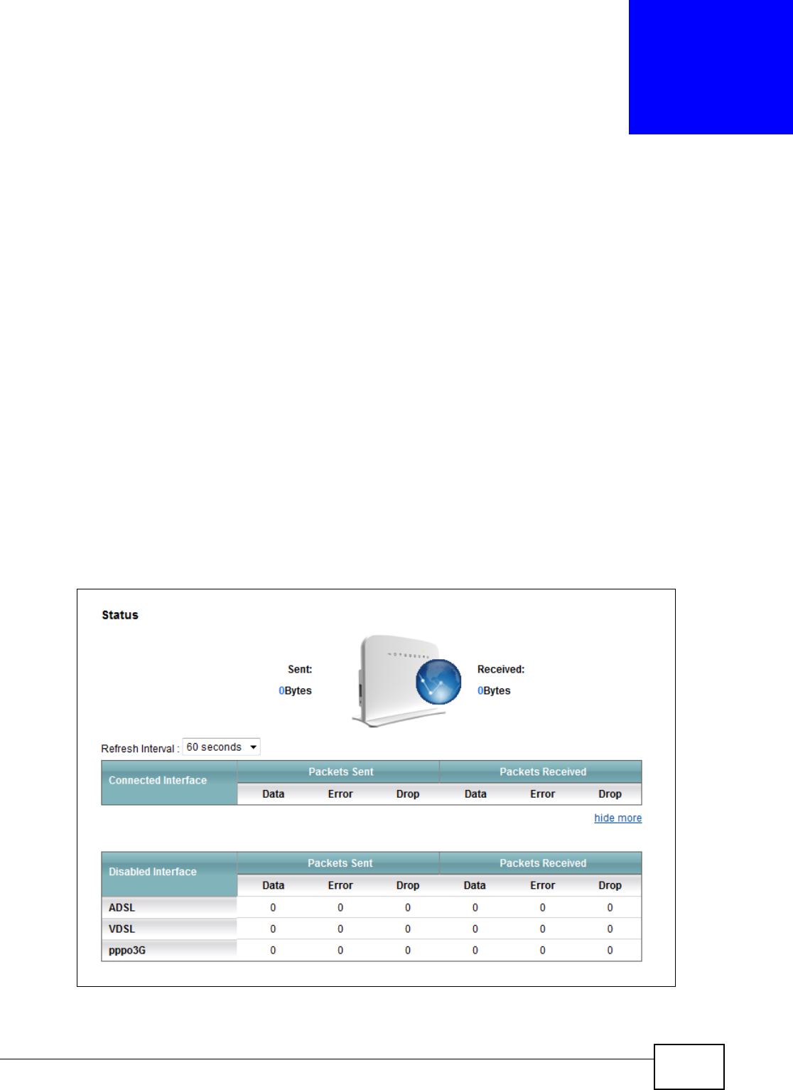
VMG1312-B10C User’s Guide 225
CHAPTER 21
Traffic Status
21.1 Overview
Use the Tr a ffic St at us screens to look at network traffic status and statistics of the WAN and LAN
interfaces.
21.1.1 What You Can Do in this Chapter
•Use the W AN screen to view the WAN traffic statistics (Section 21.2 on page 225).
•Use the LAN screen to view the LAN traffic statistics (Section 21.3 on page 227).
21.2 The WAN Status Screen
Click Syst e m M onit or > Tr affic St a t us to open the W AN screen. The figure in this screen shows
the number of bytes received and sent on the Device.
Figure 128 System Monitor > Traffic Status > WAN

Chapter 21 Traffic Status
VMG1312-B10C User’s Guide
226
The following table describes the fields in this screen.
Table 98 System Monitor > Traffic Status > WAN
LABEL DESCRIPTION
Connected
Interface
This shows the name of the WAN interface that is currently connected.
Packets Sent
Data This indicates the number of transmitted packets on this interface.
Error This indicates the number of frames with errors transmitted on this interface.
Drop This indicates the number of outgoing packets dropped on this interface.
Packets Received
Data This indicates the number of received packets on this interface.
Error This indicates the number of frames with errors received on this interface.
Drop This indicates the number of received packets dropped on this interface.
more...hide
more
Click m ore ... to show more information. Click hid e m or e to hide them.
Disabled
Interface
This shows the name of the WAN interface that is currently disconnected.
Packets Sent
Data This indicates the number of transmitted packets on this interface.
Error This indicates the number of frames with errors transmitted on this interface.
Drop This indicates the number of outgoing packets dropped on this interface.
Packets Received
Data This indicates the number of received packets on this interface.
Error This indicates the number of frames with errors received on this interface.
Drop This indicates the number of received packets dropped on this interface.
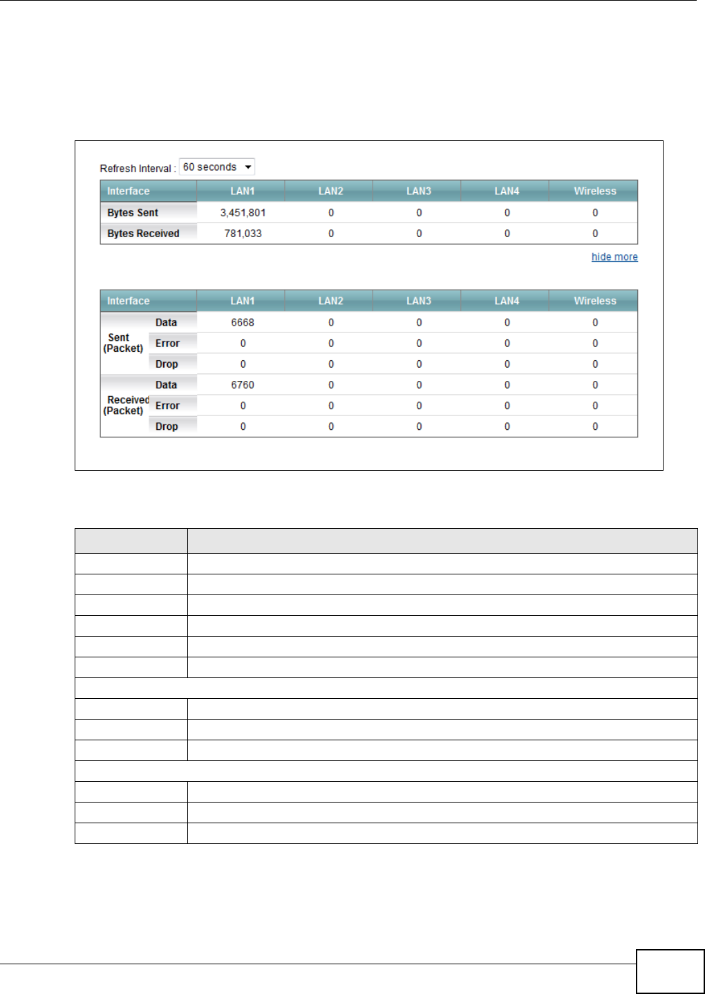
Chapter 21 Traffic Status
VMG1312-B10C User’s Guide 227
21.3 The LAN Status Screen
Click Syst e m M onit or > Tra ffic St a t us > LAN to open the following screen. The figure in this
screen shows the interface that is currently connected on the Device.
Figure 129 System Monitor > Traffic Status > LAN
The following table describes the fields in this screen.
Table 99 System Monitor > Traffic Status > LAN
LABEL DESCRIPTION
Refresh Interval Select how often you want the Device to update this screen.
Interface This shows the LAN or WLAN interface.
Bytes Sent This indicates the number of bytes transmitted on this interface.
Bytes Received This indicates the number of bytes received on this interface.
more...hide more Click m or e ... to show more information. Click hide m or e to hide them.
Interface This shows the LAN or WLAN interface.
Sent (Packets)
Data This indicates the number of transmitted packets on this interface.
Error This indicates the number of frames with errors transmitted on this interface.
Drop This indicates the number of outgoing packets dropped on this interface.
Received (Packets)
Data This indicates the number of received packets on this interface.
Error This indicates the number of frames with errors received on this interface.
Drop This indicates the number of received packets dropped on this interface.
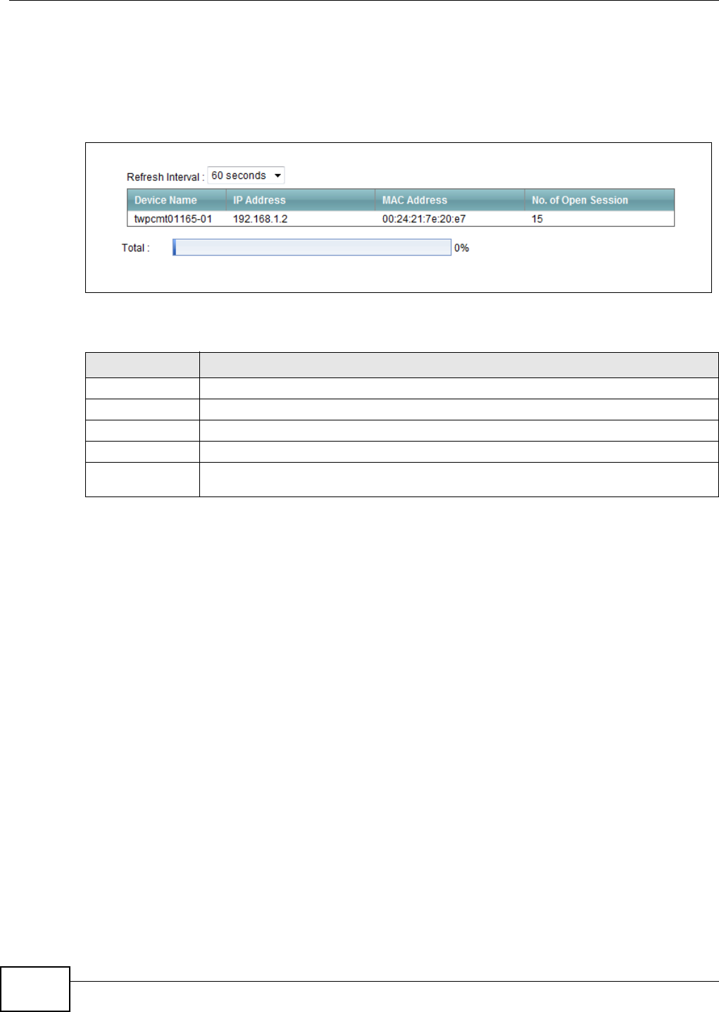
Chapter 21 Traffic Status
VMG1312-B10C User’s Guide
228
21.4 The NAT Status Screen
Click Syst e m M onit or > Tra ffic St a t us > N AT to open the following screen. The figure in this
screen shows the NAT statistics for hosts that are currently connected on the Device.
Figure 130 System Monitor > Traffic Status > NAT
The following table describes the fields in this screen.
Table 100 System Monitor > Traffic Status > NAT
LABEL DESCRIPTION
Refresh Interval Select how often you want the Device to update this screen.
Device Name This displays the name of the connected host.
IP Address This displays the IP address of the connected host.
MAC Address This displays the MAC address of the connected host.
No. of Open
Session
This displays the number of open NAT sessions for the connected host.

VMG1312-B10C User’s Guide 229
CHAPTER 22
ARP Table
22.1 Overview
Address Resolution Protocol (ARP) is a protocol for mapping an Internet Protocol address (IP
address) to a physical machine address, also known as a Media Access Control or MAC address, on
the local area network.
An IP (version 4) address is 32 bits long. In an Ethernet LAN, MAC addresses are 48 bits long. The
ARP Table maintains an association between each MAC address and its corresponding IP address.
22.1.1 How ARP Works
When an incoming packet destined for a host device on a local area network arrives at the device,
the device's ARP program looks in the ARP Table and, if it finds the address, sends it to the device.
If no entry is found for the IP address, ARP broadcasts the request to all the devices on the LAN.
The device fills in its own MAC and IP address in the sender address fields, and puts the known IP
address of the target in the target IP address field. In addition, the device puts all ones in the target
MA C f i el d ( F F.F F.F F. F F. FF. F F i s t he E th er n et br o ad ca s t address). The replying device (which is either
the IP address of the device being sought or the router that knows the way) replaces the broadcast
address with the target's MAC address, swaps the sender and target pairs, and unicasts the answer
directly back to the requesting machine. ARP updates the ARP Table for future reference and then
sends the packet to the MAC address that replied.
22.2 ARP Table Screen
Use the ARP table to view IP-to-MAC address mapping(s). To open this screen, click Syst em
M on it or > ARP Table.
Figure 131 System Monitor > ARP Table
The following table describes the labels in this screen.
Table 101 System Monitor > ARP Table
LABEL DESCRIPTION
# This is the ARP table entry number.
IP Address This is the learned IP address of a device connected to a port.

Chapter 22 ARP Table
VMG1312-B10C User’s Guide
230
MAC Address This is the MAC address of the device with the listed IP address.
Device This is the type of interface used by the device. You can click on the device type to go to its
configuration screen.
Table 101 System Monitor > ARP Table (continued)
LABEL DESCRIPTION

VMG1312-B10C User’s Guide 231
CHAPTER 23
Routing Table
23.1 Overview
Routing is based on the destination address only and the Device takes the shortest path to forward
a packet.
23.2 The Routing Table Screen
Click Syst e m M onit or > Rou t ing Ta ble to open the following screen.
Figure 132 System Monitor > Routing Table
The following table describes the labels in this screen.
Table 102 System Monitor > Routing Table
LABEL DESCRIPTION
Destination This indicates the destination IP address of this route.
Gateway This indicates the IP address of the gateway that helps forward this route’s traffic.
Subnet Mask This indicates the destination subnet mask of this route.
Flag This indicates the route status.
U- Up: The route is up.
!- Re j e ct : The route is blocked and will force a route lookup to fail.
G- Ga tew a y: The route uses a gateway to forward traffic.
H - H ost : The target of the route is a host.
R- Re in st a t e : The route is reinstated for dynamic routing.
D- D yn a m ic ( redir ect ) : The route is dynamically installed by a routing daemon or redirect.
M- M odified ( redirect ) : The route is modified from a routing daemon or redirect.
Metric The metric represents the "cost of transmission". A router determines the best route for
transmission by choosing a path with the lowest "cost". The smaller the number, the lower
the "cost".

Chapter 23 Routing Table
VMG1312-B10C User’s Guide
232
Service This indicates the name of the service used to forward the route.
Interface This indicates the name of the interface through which the route is forwarded.
br0 indicates the LAN interface.
ptm 0 indicates the WAN interface using IPoE or in bridge mode.
ppp0 indicates the WAN interface using PPPoE.
Table 102 System Monitor > Routing Table (continued)
LABEL DESCRIPTION
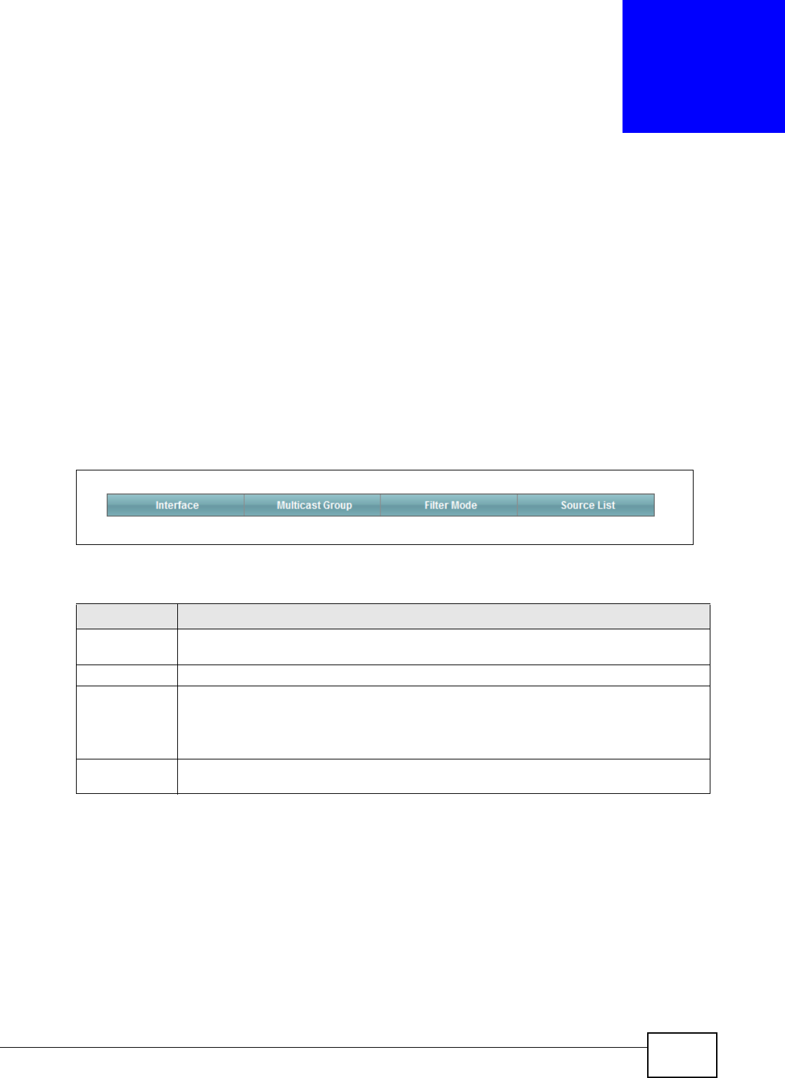
VMG1312-B10C User’s Guide 233
CHAPTER 24
IGMP Status
24.1 Overview
Use the I GM P St a t us screens to look at IGMP group status and traffic statistics.
24.2 The IGMP Group Status Screen
Use this screen to look at the current list of multicast groups the Device has joined and which ports
have joined it. To open this screen, click Syst e m M onit or > I GM P Gr ou p St a t us.
Figure 133 System Monitor > IGMP Group Status
The following table describes the labels in this screen.
Table 103 System Monitor > IGMP Group Status
LABEL DESCRIPTION
Interface This field displays the name of an interface on the Device that belongs to an IGMP multicast
group.
Multicast Group This field displays the name of the IGMP multicast group to which the interface belongs.
Filter Mode I N CLUD E means that only the IP addresses in the Sour ce List get to receive the multicast
group’s traffic.
EXCLUD E means that the IP addresses in the Sou rce List are not allowed to receive the
multicast group’s traffic but other IP addresses can.
Source List This is the list of IP addresses that are allowed or not allowed to receive the multicast
group’s traffic depending on the filter mode.

Chapter 24 IGMP Status
VMG1312-B10C User’s Guide
234
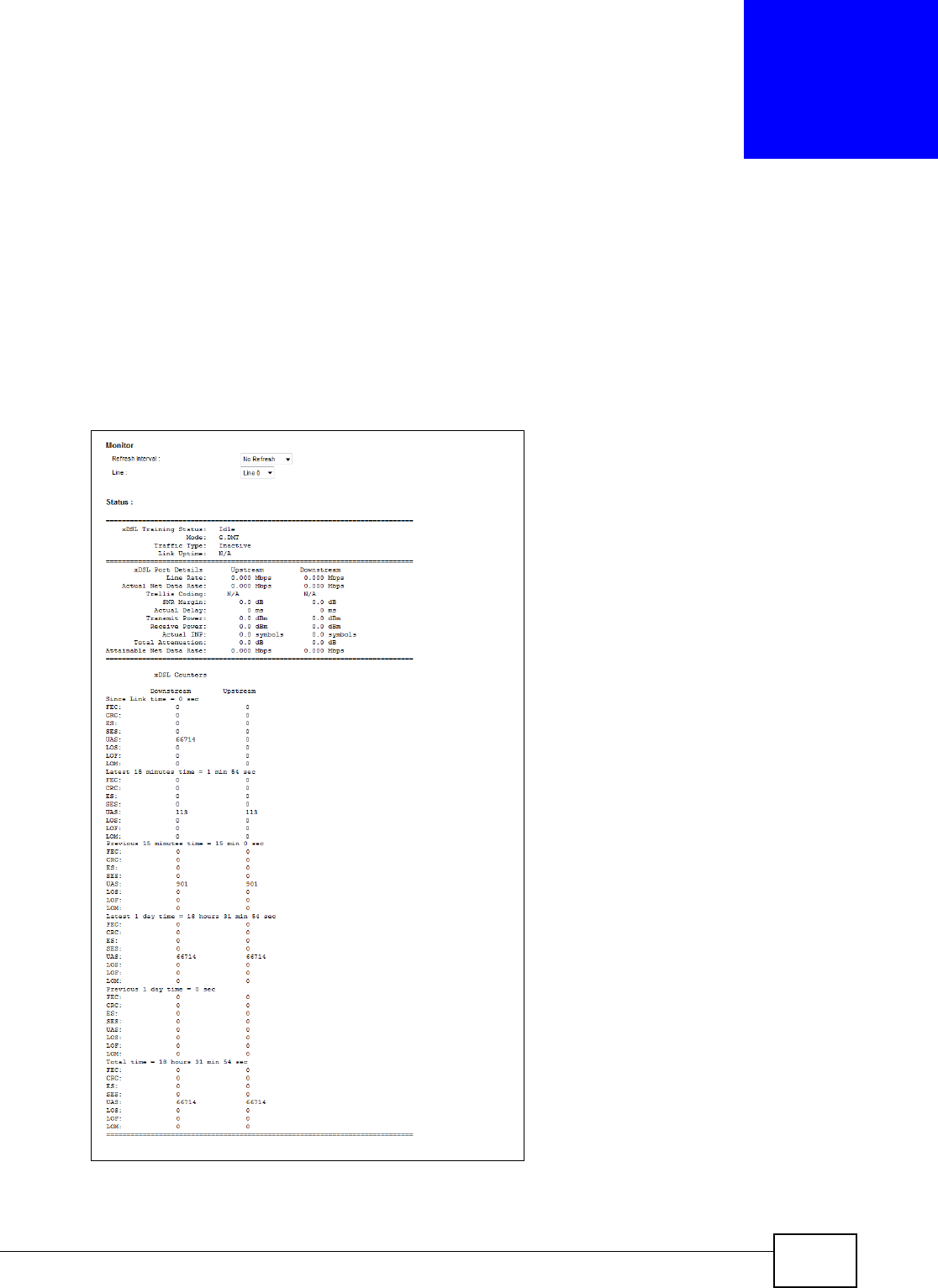
VMG1312-B10C User’s Guide 235
CHAPTER 25
xDSL Statistics
25.1 The xDSL Statistics Screen
Use this screen to view detailed DSL statistics. Click Syst e m M onit or > x D SL St a t istics to open
the following screen.
Figure 134 System Monitor > xDSL Statistics

Chapter 25 xDSL Statistics
VMG1312-B10C User’s Guide
236
The following table describes the labels in this screen.
Table 104 Status > xDSL Statistics
LABEL DESCRIPTION
Refresh Interval Select the time interval for refreshing statistics.
Line Select which DSL line’s statistics you want to display.
xDSL Training
Status
This displays the current state of setting up the DSL connection.
Mode This displays the ITU standard used for this connection.
Traffic Type This displays the type of traffic the DSL port is sending and receiving. I n a ct iv e displays if
the DSL port is not currently sending or receiving traffic.
Link Uptime This displays how long the port has been running (or connected) since the last time it was
started.
xDSL Port Details
Upstream These are the statistics for the traffic direction going out from the port to the service
provider.
Downstream These are the statistics for the traffic direction coming into the port from the service
provider.
Line Rate These are the data transfer rates at which the port is sending and receiving data.
Actual Net Data
Rate
These are the rates at which the port is sending and receiving the payload data without
transport layer protocol headers and traffic.
Trellis Coding This displays whether or not the port is using Trellis coding for traffic it is sending and
receiving. Trellis coding helps to reduce the noise in ADSL transmissions. Trellis may reduce
throughput but it makes the connection more stable.
SNR Margin This is the upstream and downstream Signal-to-Noise Ratio margin (in dB). A DMT sub-
carrier’s SNR is the ratio between the received signal power and the received noise power.
The signal-to-noise ratio margin is the maximum that the received noise power could
increase with the system still being able to meet its transmission targets.
Actual Delay This is the upstream and downstream interleave delay. It is the wait (in milliseconds) that
determines the size of a single block of data to be interleaved (assembled) and then
transmitted. Interleave delay is used when transmission error correction (Reed- Solomon)
is necessary due to a less than ideal telephone line. The bigger the delay, the bigger the
data block size, allowing better error correction to be performed.
Transmit Power This is the upstream and downstream far end actual aggregate transmit power (in dBm).
Upstream is how much power the port is using to transmit to the service provider.
Downstream is how much port the service provider is using to transmit to the port.
Receive Power Upstream is how much power the service provider is receiving from the port. Downstream
is how much power the port is receiving from the service provider.
Actual INP Sudden spikes in the line’s level of external noise (impulse noise) can cause errors and
result in lost packets. This could especially impact the quality of multimedia traffic such as
voice or video. Impulse noise protection (INP) provides a buffer to allow for correction of
errors caused by error correction to deal with this. The number of DMT (Discrete Multi-
Tone) symbols shows the level of impulse noise protection for the upstream and
downstream traffic. A higher symbol value provides higher error correction capability, but it
causes overhead and higher delay which may increase error rates in received multimedia
data.
Total Attenuation This is the upstream and downstream line attenuation, measured in decibels (dB). This
attenuation is the difference between the power transmitted at the near-end and the power
received at the far-end. Attenuation is affected by the channel characteristics (wire gauge,
quality, condition and length of the physical line).
Attainable Net
Data Rate
These are the highest theoretically possible transfer rates at which the port could send and
receive payload data without transport layer protocol headers and traffic.
xDSL Counters

Chapter 25 xDSL Statistics
VMG1312-B10C User’s Guide 237
Downstream These are the statistics for the traffic direction coming into the port from the service
provider.
Upstream These are the statistics for the traffic direction going out from the port to the service
provider.
FEC This is the number of Far End Corrected blocks.
CRC This is the number of Cyclic Redundancy Checks.
ES This is the number of Errored Seconds meaning the number of seconds containing at least
one errored block or at least one defect.
SES This is the number of Severely Errored Seconds meaning the number of seconds containing
30% or more errored blocks or at least one defect. This is a subset of ES.
UAS This is the number of UnAvailable Seconds.
LOS This is the number of Loss Of Signal seconds.
LOF This is the number of Loss Of Frame seconds.
LOM This is the number of Loss of Margin seconds.
Table 104 Status > xDSL Statistics (continued)
LABEL DESCRIPTION

Chapter 25 xDSL Statistics
VMG1312-B10C User’s Guide
238
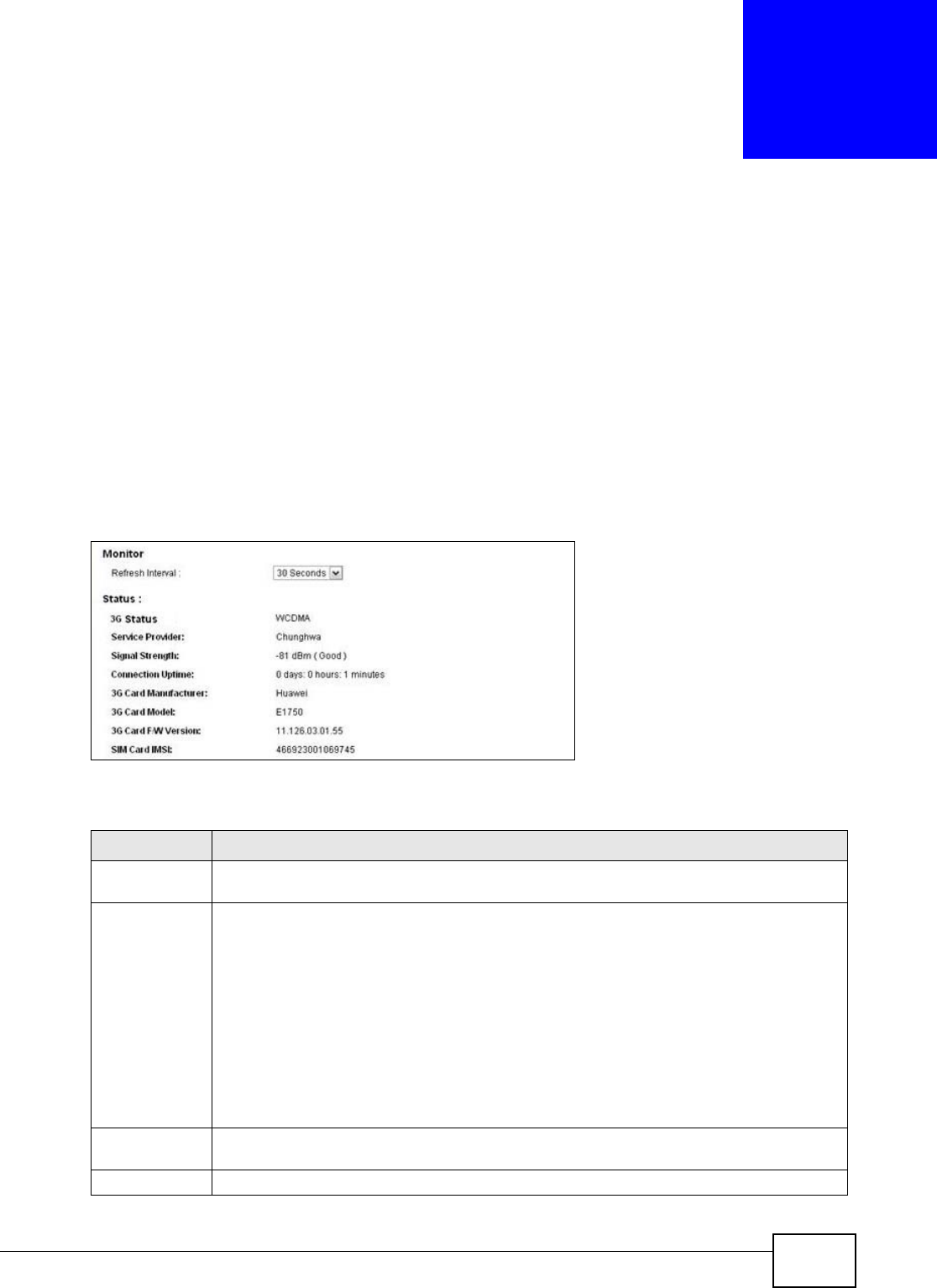
VMG1312-B10C User’s Guide 239
CHAPTER 26
3G Statistics
26.1 Overview
Use the 3 G St a t ist ics screens to look at 3G Internet connection status.
26.2 The 3G Statistics Screen
To open this screen, click Syst em Mon it or > 3 G St at ist ics.
Figure 135 System Monitor > 3G Statistics
The following table describes the labels in this screen.
Table 105 System Monitor > 3G Statistics
LABEL DESCRIPTION
Refresh
Interval
Select how often you want the Device to update this screen. Select N o Refresh to stop
refreshing.
3G Status This field displays the status of the 3G Internet connection. This field can display:
GSM - Global System for Mobile Communications, 2G
GPRS - General Packet Radio Service, 2.5G
ED GE - Enhanced Data rates for GSM Evolution, 2.75G
W CDMA - Wideband Code Division Multiple Access, 3G
HSDPA - High-Speed Downlink Packet Access, 3.5G
HSUPA - High-Speed Uplink Packet Access, 3.75G
HSPA - HSDPA+HSUPA, 3.75G
Service
Provider
This field displays the name of the service provider.
Signal Strength This field displays the strength of the signal in dBm.

Chapter 26 3G Statistics
VMG1312-B10C User’s Guide
240
Connection
Uptime
This field displays the time the connection has been up.
3G Card
Manufacturer
This field displays the manufacturer of the 3G card.
3G Card Model This field displays the model name of the 3G card.
3G Card F/W
Version
This field displays the firmware version of the 3G card.
SIM Card IMSI The International Mobile Subscriber Identity or IMSI is a unique identification number
associated with all cellular networks. This number is provisioned in the SIM card.
Table 105 System Monitor > 3G Statistics (continued)
LABEL DESCRIPTION
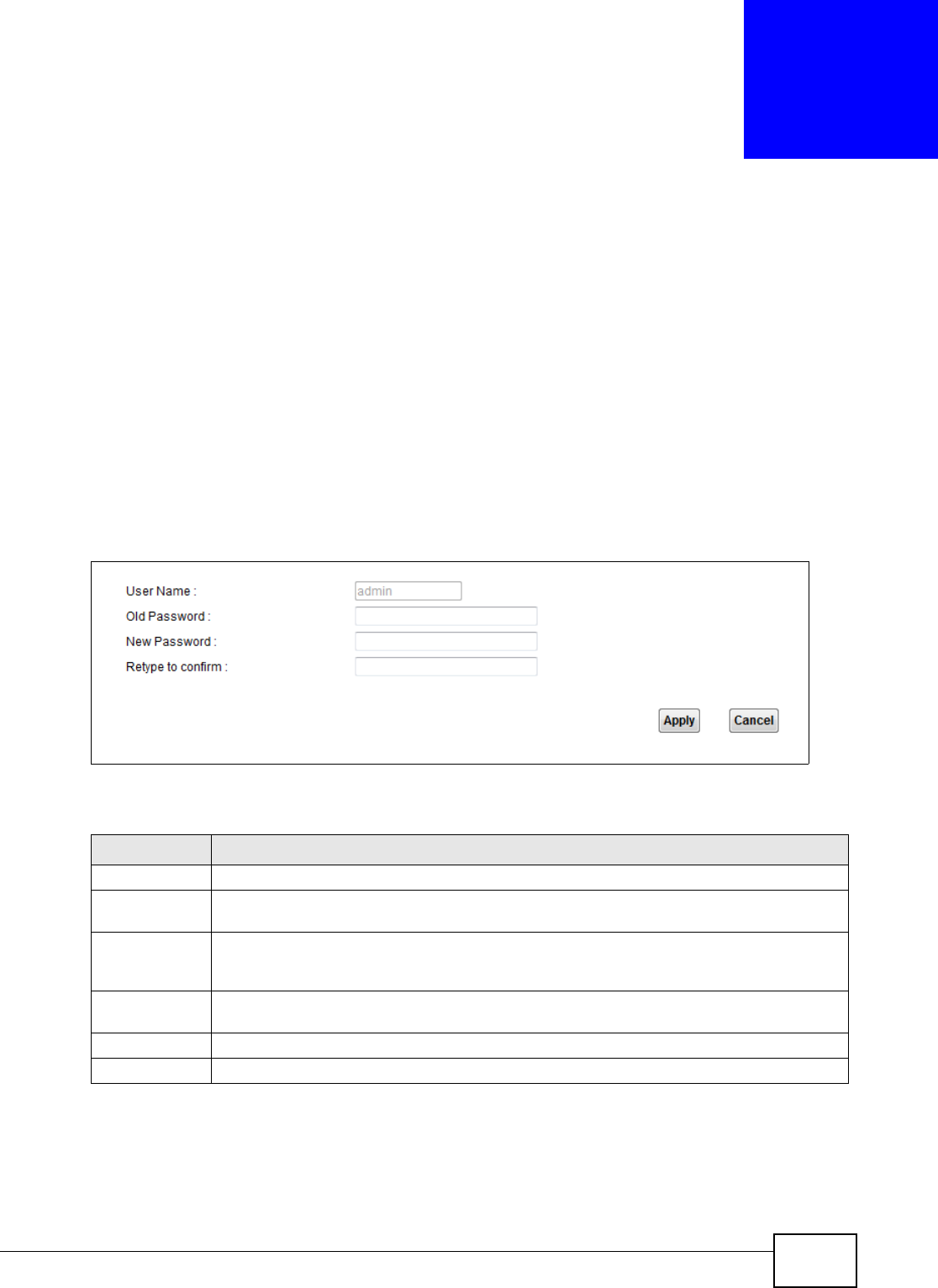
VMG1312-B10C User’s Guide 241
CHAPTER 27
User Account
27.1 Overview
In the Use r s Account screen, you can change the password of the user account that you used to
log in the Device.
27.2 The User Account Screen
Click M a in t e na n ce > User Accoun t to open the following screen.
Figure 136 Maintenance > User Account
The following table describes the labels in this screen.
Table 106 Maintenance > User Account
LABEL DESCRIPTION
User Name This field displays the name of the account that you used to log in the system.
Old Password Type the default password or the existing password you use to access the system in this
field.
New Password Type your new system password (up to 256 characters). Note that as you type a password,
the screen displays a (*) for each character you type. After you change the password, use
the new password to access the Device.
Retype to
confirm
Type the new password again for confirmation.
Apply Click Apply to save your changes.
Cancel Click Can cel to restore your previously saved settings.

Chapter 27 User Account
VMG1312-B10C User’s Guide
242
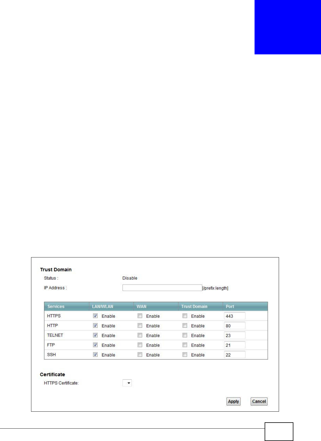
VMG1312-B10C User’s Guide 243
CHAPTER 28
Remote Management
28.1 Overview
Remote Management allows you to manage your Device from a remote location through the
following interfaces:
•LAN
•WAN
•Trust Domain
Note: The Device is managed using the Web Configurator.
28.2 The Remote MGMT Screen
Use this screen to configure through which interface(s) users can use which service(s) to manage
the Device.
Click M a in t e n a nce > Rem ot e M GMT to open the following screen.
Figure 137 Maintenance > Remote MGMT

Chapter 28 Remote Management
VMG1312-B10C User’s Guide
244
The following table describes the fields in this screen.
Table 107 Maintenance > Remote MGMT
LABEL DESCRIPTION
Trust Domain
Status This field displays whether the Trust Domain is active or not.
IP Address Enter the Trust Domain IP address.
Services This is the service you may use to access the Device.
LAN/WLAN Select the Ena ble check box for the corresponding services that you want to allow access to
the Device from the LAN/WLAN.
WAN Select the Ena ble check box for the corresponding services that you want to allow access to
the Device from the WAN.
Trust Domain Select the Ena ble check box for the corresponding services that you want to allow access to
the Device from the Trust Domain.
Port You may change the server port number for a service if needed, however you must use the
same port number in order to use that service for remote management.
Certificate
HTTPS
Certificate
Select a certificate the HTTPS server (the Device) uses to authenticate itself to the HTTPS
client. You must have certificates already configured in the Ce r t if ica t e s screen.
Apply Click Apply to save your changes back to the Device.
Cancel Click Cancel to restore your previously saved settings.
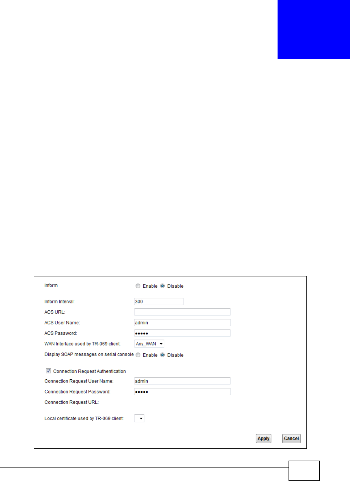
VMG1312-B10C User’s Guide 245
CHAPTER 29
TR-069 Client
29.1 Overview
This chapter explains how to configure the Device’s TR-069 auto-configuration settings.
29.2 The TR-069 Client Screen
TR-069 defines how Customer Premise Equipment (CPE), for example your Device, can be managed
over the WAN by an Auto Configuration Server (ACS). TR-069 is based on sending Remote
Procedure Calls (RPCs) between an ACS and a client device. RPCs are sent in Extensible Markup
Language (XML) format over HTTP or HTTPS.
An administrator can use an ACS to remotely set up the Device, modify settings, perform firmware
upgrades as well as monitor and diagnose the Device. You have to enable the device to be managed
by the ACS and specify the ACS IP address or domain name and username and password.
Click M a in t e n a nce > TR- 0 6 9 Clie n t to open the following screen. Use this screen to configure
your Device to be managed by an ACS.
Figure 138 Maintenance > TR-069 Client

Chapter 29 TR-069 Client
VMG1312-B10C User’s Guide
246
The following table describes the fields in this screen.
Table 108 Maintenance > TR-069 Client
LABEL DESCRIPTION
Inform Select Ena ble for the Device to send periodic inform via TR-069 on the WAN. Otherwise,
select D isable.
Inform Interval Enter the time interval (in seconds) at which the Device sends information to the auto-
configuration server.
ACS URL Enter the URL or IP address of the auto-configuration server.
ACS User Name Enter the TR-069 user name for authentication with the auto-configuration server.
ACS Password Enter the TR-069 password for authentication with the auto-configuration server.
WAN Interface
used by TR-069
client
Select a WAN interface through which the TR-069 traffic passes.
If you select An y_ W AN , you should also select the pre-configured WAN connection(s).
Display SOAP
messages on
serial console
Select Enable to show the SOAP messages on the console.
Connection
Request
Authentication
Select this option to enable authentication when there is a connection request from the ACS.
Connection
Request User
Name
Enter the connection request user name.
When the ACS makes a connection request to the Device, this user name is used to
authenticate the ACS.
Connection
Request
Password
Enter the connection request password.
When the ACS makes a connection request to the Device, this password is used to
authenticate the ACS.
Connection
Request URL
This shows the connection request URL.
The ACS can use this URL to make a connection request to the Device.
Local certificate
used by TR-069
client
You can choose a local certificate used by TR-069 client. The local certificate should be
imported in the Se cu rit y > Ce rt ificat e s > Local Cer t ificat es screen.
Apply Click Apply to save your changes.
Cancel Click Cancel to exit this screen without saving.
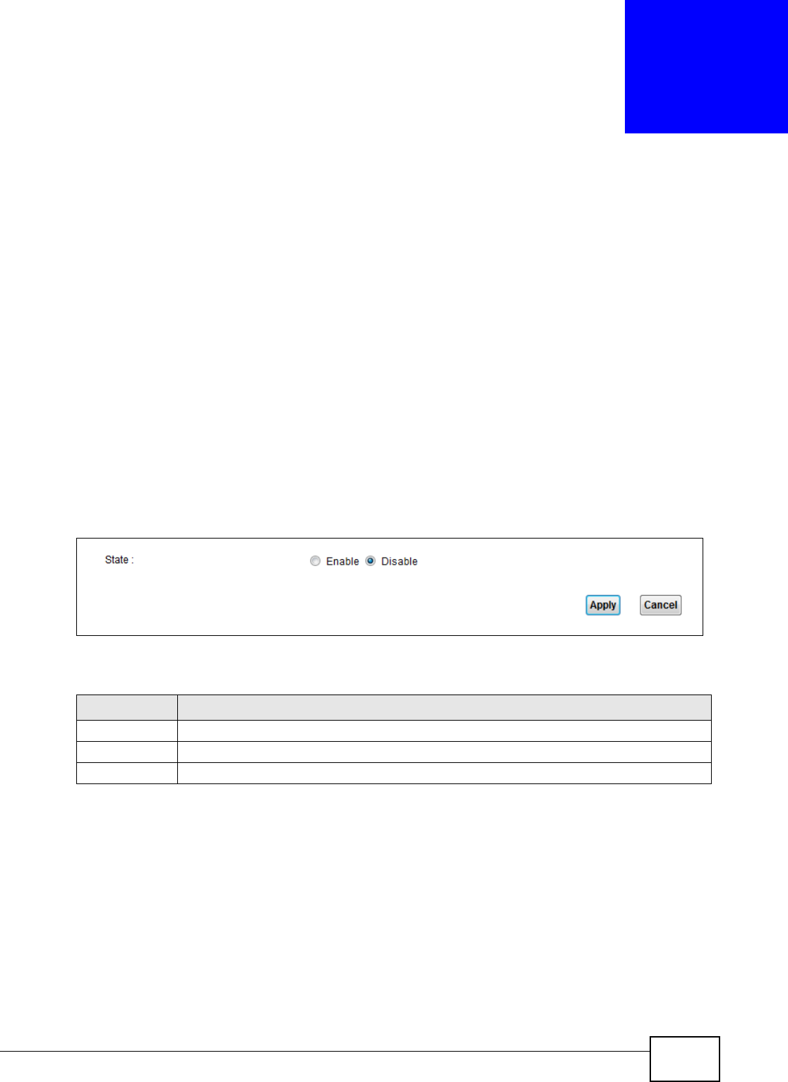
VMG1312-B10C User’s Guide 247
CHAPTER 30
TR-064
30.1 Overview
This chapter explains how to configure the Device’s TR-064 auto-configuration settings.
30.2 The TR-064 Screen
TR-064 is a LAN-Side DSL CPE Configuration protocol defined by the DSL Forum. TR-064 is built on
top of UPnP. It allows the users to use a TR-064 compliant CPE management application on their
computers from the LAN to discover the CPE and configure user-specific parameters, such as the
username and password.
Click M a in t e na n ce > TR- 0 6 4 to open the following screen.
Figure 139 Maintenance > TR-064
The following table describes the fields in this screen.
Table 109 Maintenance > TR-064
LABEL DESCRIPTION
State Select Enable to activate management via TR-064 on the LAN.
Apply Click Apply to save your changes.
Cancel Click Cancel to exit this screen without saving.

Chapter 30 TR-064
VMG1312-B10C User’s Guide
248
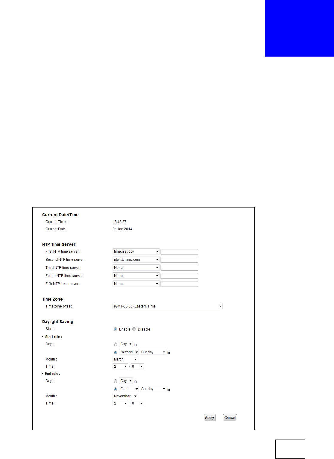
VMG1312-B10C User’s Guide 249
CHAPTER 31
Time Settings
31.1 Overview
This chapter shows you how to configure system related settings, such as system time, password,
name, the domain name and the inactivity timeout interval.
31.2 The Time Screen
To change your Device’s time and date, click Maint enance > Tim e. The screen appears as shown.
Use this screen to configure the Device’s time based on your local time zone.
Figure 140 Maintenance > Time Setting

Chapter 31 Time Settings
VMG1312-B10C User’s Guide
250
The following table describes the fields in this screen.
Table 110 Maintenance > Time Setting
LABEL DESCRIPTION
Current Date/Time
Current Time This field displays the time of your Device.
Each time you reload this page, the Device synchronizes the time with the time server.
Current Date This field displays the date of your Device.
Each time you reload this page, the Device synchronizes the date with the time server.
NTP Time Server
First ~ Fifth NTP
time server
Select an NTP time server from the drop-down list box.
Otherwise, select Ot h e r and enter the IP address or URL (up to 29 extended ASCII
characters in length) of your time server.
Select N on e if you don’t want to configure the time server.
Check with your ISP/network administrator if you are unsure of this information.
Time Zone
Time zone offset Choose the time zone of your location. This will set the time difference between your time
zone and Greenwich Mean Time (GMT).
Daylight Saving Daylight Saving Time is a period from late spring to early fall when many countries set
their clocks ahead of normal local time by one hour to give more daytime light in the
evening.
State Select Ena ble if you use Daylight Saving Time.
Start rule: Configure the day and time when Daylight Saving Time starts if you enabled Daylight
Saving. You can select a specific date in a particular month or a specific day of a specific
week in a particular month. The Tim e field uses the 24 hour format. Here are a couple of
examples:
Daylight Saving Time starts in most parts of the United States on the second Sunday of
March. Each time zone in the United States starts using Daylight Saving Time at 2 A.M.
local time. So in the United States, set the day to Second, Sunda y, the month to M a rch
and the time to 2 in the Hour field.
Daylight Saving Time starts in the European Union on the last Sunday of March. All of the
time zones in the European Union start using Daylight Saving Time at the same moment
(1 A.M. GMT or UTC). So in the European Union you would set the day to La st , Su nday
and the month to Ma r ch. The time you select in the o'clock field depends on your time
zone. In Germany for instance, you would select 2 in the Hou r field because Germany's
time zone is one hour ahead of GMT or UTC (GMT+1).
End rule Configure the day and time when Daylight Saving Time ends if you enabled Daylight
Saving. You can select a specific date in a particular month or a specific day of a specific
week in a particular month. The Tim e field uses the 24 hour format. Here are a couple of
examples:
Daylight Saving Time ends in the United States on the first Sunday of November. Each
time zone in the United States stops using Daylight Saving Time at 2 A.M. local time. So
in the United States you would set the day to Fir st , Sunda y, the month to Nove m be r
and the time to 2 in the Hour field.
Daylight Saving Time ends in the European Union on the last Sunday of October. All of the
time zones in the European Union stop using Daylight Saving Time at the same moment
(1 A.M. GMT or UTC). So in the European Union you would set the day to Last, Sun da y,
and the month to Oct ob e r. The time you select in the o' clock field depends on your time
zone. In Germany for instance, you would select 2 in the Hou r field because Germany's
time zone is one hour ahead of GMT or UTC (GMT+1).

Chapter 31 Time Settings
VMG1312-B10C User’s Guide 251
Apply Click Apply to save your changes.
Cancel Click Can cel to exit this screen without saving.
Table 110 Maintenance > Time Setting (continued)
LABEL DESCRIPTION

Chapter 31 Time Settings
VMG1312-B10C User’s Guide
252

VMG1312-B10C User’s Guide 253
CHAPTER 32
E-mail Notification
32.1 Overview
A mail server is an application or a computer that runs such an application to receive, forward and
deliver e-mail messages.
To have the Device send reports, logs or notifications via e-mail, you must specify an e-mail server
and the e-mail addresses of the sender and receiver.
32.2 The Email Notification Screen
Click Ma int enance > Em a il N ot ificat ion to open the Em ail N ot ificat ion screen. Use this screen
to view, remove and add mail server information on the Device.
Figure 141 Maintenance > Email Notification
The following table describes the labels in this screen.
Table 111 Maintenance > Email Notification
LABEL DESCRIPTION
Add New Email Click this button to create a new entry.
Mail Server
Address
This field displays the server name or the IP address of the mail server.
Username This field displays the user name of the sender’s mail account.
Password This field displays the password of the sender’s mail account.
Email Address This field displays the e-mail address that you want to be in the from/sender line of the e-
mail that the Device sends.
Delete Click this button to delete the selected entries.
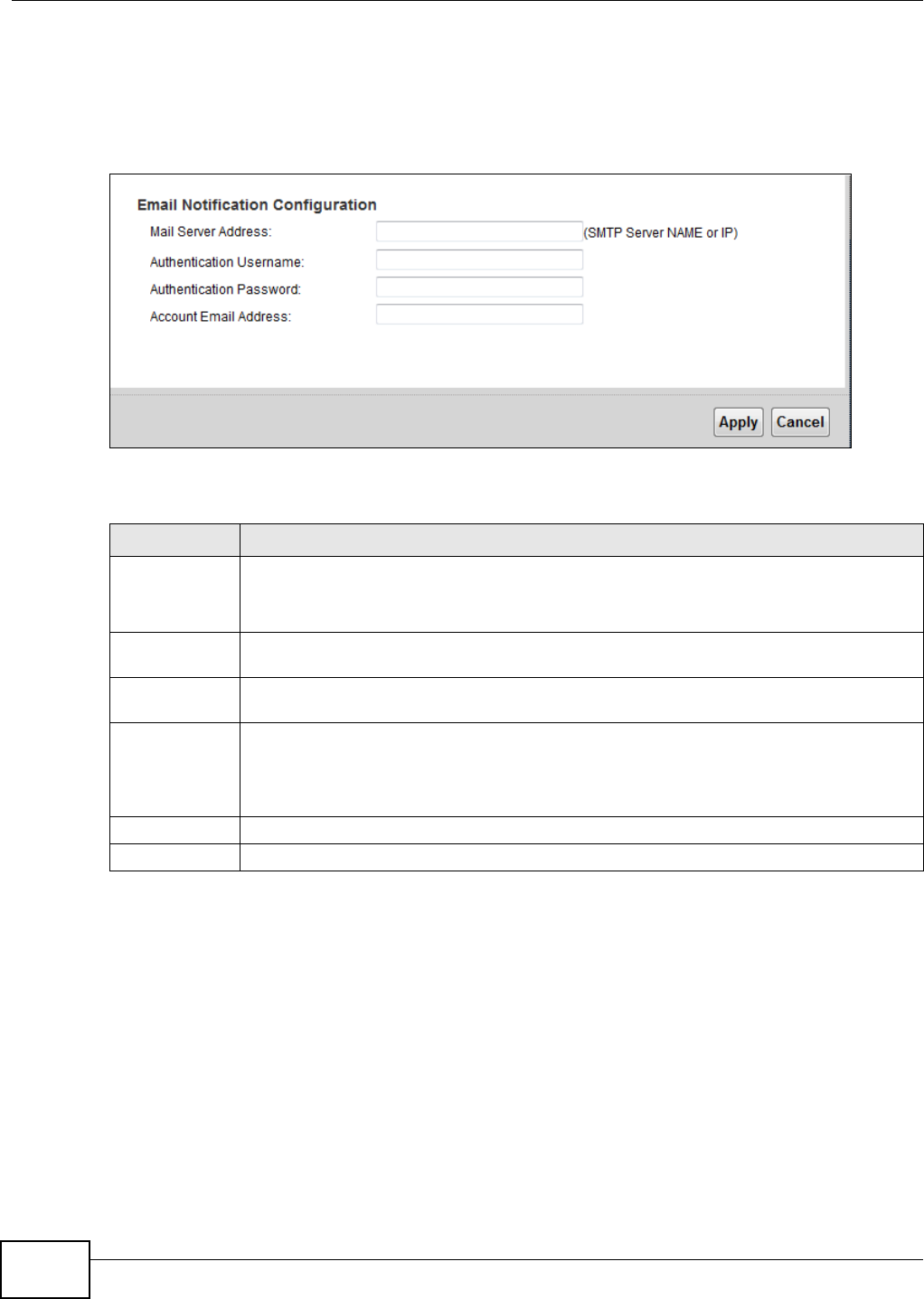
Chapter 32 E-mail Notification
VMG1312-B10C User’s Guide
254
32.2.1 Email Notification Edit
Click the Add button in the Em a il N ot ificat ion screen. Use this screen to configure the required
information for sending e-mail via a mail server.
Figure 142 Email Notification > Add
The following table describes the labels in this screen.
Table 112 Email Notification > Add
LABEL DESCRIPTION
Mail Server
Address
Enter the server name or the IP address of the mail server for the e-mail address specified
in the Accou nt Em ail Add ress field.
If this field is left blank, reports, logs or notifications will not be sent via e-mail.
Authentication
Username
Enter the user name (up to 32 characters). This is usually the user name of a mail account
you specified in the Accou nt Em ail Addr e ss field.
Authentication
Password
Enter the password associated with the user name above.
Account Email
Address
Enter the e-mail address that you want to be in the from/sender line of the e-mail
notification that the Device sends.
If you activate SSL/TLS authentication, the e-mail address must be able to be authenticated
by the mail server as well.
Apply Click this button to save your changes and return to the previous screen.
Cancel Click this button to begin configuring this screen afresh.

VMG1312-B10C User’s Guide 255
CHAPTER 33
Logs Setting
33.1 Overview
You can configure where the Device sends logs and which logs and/or immediate alerts the Device
records in the Logs Se t t ing screen.
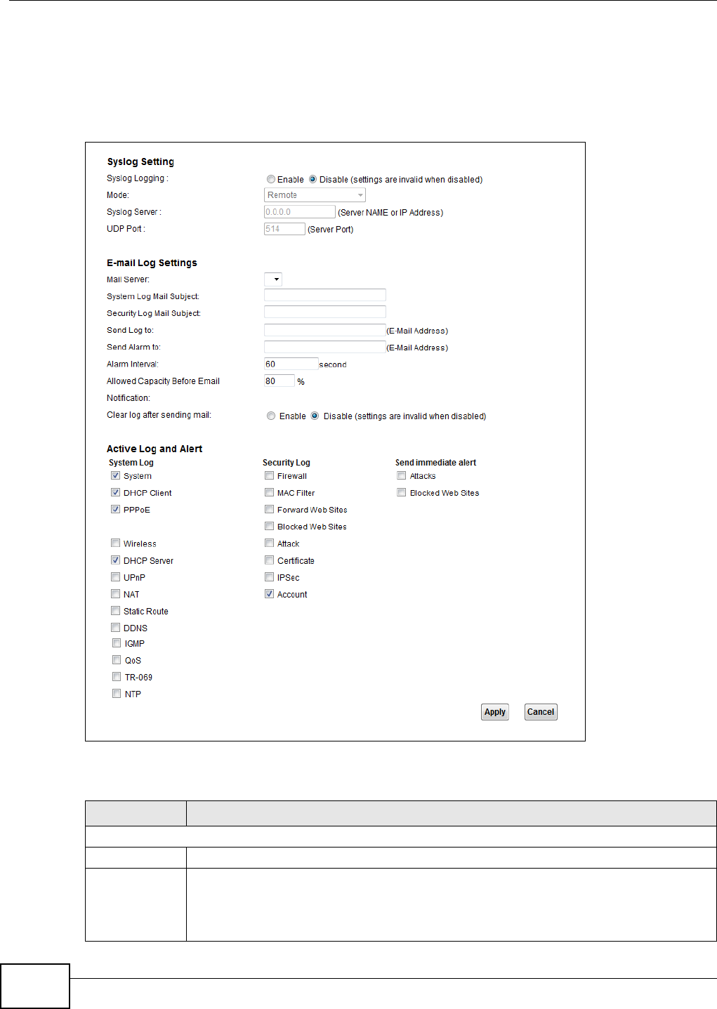
Chapter 33 Logs Setting
VMG1312-B10C User’s Guide
256
33.2 The Log Settings Screen
To change your Device’s log settings, click Maint e nance > Logs Se tt in g. The screen appears as
shown.
Figure 143 Maintenance > Logs Setting
The following table describes the fields in this screen.
Table 113 Maintenance > Logs Setting
LABEL DESCRIPTION
Syslog Setting
Syslog Logging The Device sends a log to an external syslog server. Select Ena ble to enable syslog logging.
Mode Select the syslog destination from the drop-down list box.
If you select Re m o t e, the log(s) will be sent to a remote syslog server. If you select Local
File , the log(s) will be saved in a local file. If you want to send the log(s) to a remote syslog
server and save it in a local file, select Loca l File a n d Re m ot e.

Chapter 33 Logs Setting
VMG1312-B10C User’s Guide 257
33.2.1 Example E-mail Log
An "End of Log" message displays for each mail in which a complete log has been sent. The
following is an example of a log sent by e-mail.
• You may edit the subject title.
• The date format here is Day-Month-Year.
• The date format here is Month-Day-Year. The time format is Hour-Minute-Second.
Syslog Server Enter the server name or IP address of the syslog server that will log the selected categories
of logs.
UDP Port Enter the port number used by the syslog server.
E-mail Log Settings
Mail Server Enter the server name or the IP address of the mail server for the e-mail addresses
specified below. If this field is left blank, logs and alert messages will not be sent via E-mail.
System Log
Mail Subject
Type a title that you want to be in the subject line of the system log e-mail message that
the Device sends.
Security Log
Mail Subject
Type a title that you want to be in the subject line of the security log e-mail message that
the Device sends.
Send Log to The Device sends logs to the e-mail address specified in this field. If this field is left blank,
the Device does not send logs via E-mail.
Send Alarm to Alerts are real-time notifications that are sent as soon as an event, such as a DoS attack,
system error, or forbidden web access attempt occurs. Enter the E-mail address where the
alert messages will be sent. Alerts include system errors, attacks and attempted access to
blocked web sites. If this field is left blank, alert messages will not be sent via E-mail.
Alarm Interval Specify how often the alarm should be updated.
Allowed
Capacity Before
Email
Set what percent of the Device’s log storage space can be filled before the Device sends a
log e-mail.
Clear log after
sending mail
Select this to delete all the logs after the Device sends an E-mail of the logs.
Active Log and Alert
System Log Select the categories of system logs that you want to record.
Security Log Select the categories of security logs that you want to record.
Send
immediate alert
Select log categories for which you want the Device to send E-mail alerts immediately.
Apply Click Apply to save your changes.
Cancel Click Cancel to restore your previously saved settings.
Table 113 Maintenance > Logs Setting (continued)
LABEL DESCRIPTION

Chapter 33 Logs Setting
VMG1312-B10C User’s Guide
258
•"End of Log" message shows that a complete log has been sent.
Figure 144 E-mail Log Example
Subject:
Firewall Alert From
Date:
Fri, 07 Apr 2000 10:05:42
From:
user@zyxel.com
To:
user@zyxel.com
1|Apr 7 00 |From:192.168.1.1 To:192.168.1.255 |default policy |forward
| 09:54:03 |UDP src port:00520 dest port:00520 |<1,00> |
2|Apr 7 00 |From:192.168.1.131 To:192.168.1.255 |default policy |forward
| 09:54:17 |UDP src port:00520 dest port:00520 |<1,00> |
3|Apr 7 00 |From:192.168.1.6 To:10.10.10.10 |match |forward
| 09:54:19 |UDP src port:03516 dest port:00053 |<1,01> |
……………………………..{snip}…………………………………..
……………………………..{snip}…………………………………..
126|Apr 7 00 |From:192.168.1.1 To:192.168.1.255 |match |forward
| 10:05:00 |UDP src port:00520 dest port:00520 |<1,02> |
127|Apr 7 00 |From:192.168.1.131 To:192.168.1.255 |match |forward
| 10:05:17 |UDP src port:00520 dest port:00520 |<1,02> |
128|Apr 7 00 |From:192.168.1.1 To:192.168.1.255 |match |forward
| 10:05:30 |UDP src port:00520 dest port:00520 |<1,02> |
End of Firewall Log
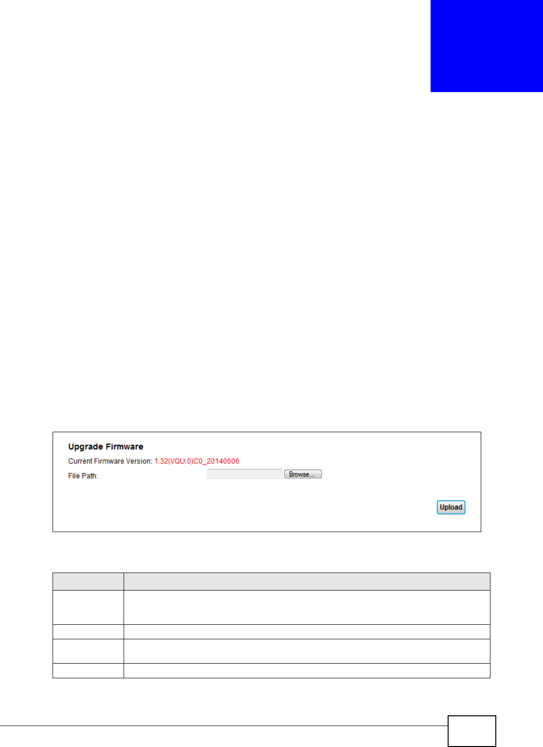
VMG1312-B10C User’s Guide 259
CHAPTER 34
Firmware Upgrade
34.1 Overview
This chapter explains how to upload new firmware to your Device. You can download new firmware
releases from your nearest ZyXEL FTP site (or www.zyxel.com) to use to upgrade your device’s
performance.
Only use firmware for your device’s specific model. Refer to the label on
the bottom of your Device.
34.2 The Firmware Screen
Click M a in t e n a nce > Fir m w a r e Upgr a de to open the following screen. The upload process uses
HTTP (Hypertext Transfer Protocol) and may take up to two minutes. After a successful upload, the
system will reboot.
Do NOT turn off the Device while firmware upload is in progress!
Figure 145 Maintenance > Firmware Upgrade
The following table describes the labels in this screen.
Table 114 Maintenance > Firmware Upgrade
LABEL DESCRIPTION
Current
Firmware
Version
This is the present Firmware version and the date created.
File Path Type in the location of the file you want to upload in this field or click Brow se ... to find it.
Browse... Click this to find the .bin file you want to upload. Remember that you must decompress
compressed (.zip) files before you can upload them.
Upload Click this to begin the upload process. This process may take up to two minutes.
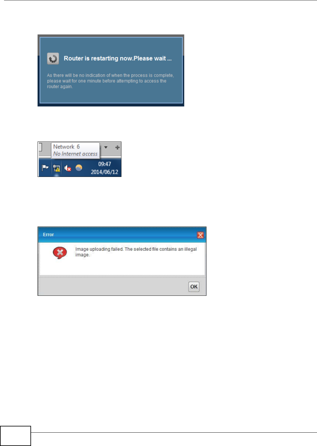
Chapter 34 Firmware Upgrade
VMG1312-B10C User’s Guide
260
After you see the firmware updating screen, wait two minutes before logging into the Device again.
Figure 146 Firmware Uploading
The Device automatically restarts in this time causing a temporary network disconnect. In some
operating systems, you may see the following icon on your desktop.
Figure 147 Network Temporarily Disconnected
After two minutes, log in again and check your new firmware version in the St a t u s screen.
If the upload was not successful, the following screen will appear. Click OK to go back to the
Firm w are Upgrade screen.
Figure 148 Error Message

VMG1312-B10C User’s Guide 261
CHAPTER 35
Configuration
35.1 Overview
The Configurat ion screen allows you to backup and restore device configurations. You can also
reset your device settings back to the factory default.
35.2 The Configuration Screen
Click M a in t e na n ce > Con figu r a t ion. Information related to factory defaults, backup
configuration, and restoring configuration appears in this screen, as shown next.
Figure 149 Maintenance > Configuration
Backup Configuration
Backup Configuration allows you to back up (save) the Device’s current configuration to a file on
your computer. Once your Device is configured and functioning properly, it is highly recommended
that you back up your configuration file before making configuration changes. The backup
configuration file will be useful in case you need to return to your previous settings.
Click Ba ck u p to save the Device’s current configuration to your computer.
Chapter 35 Configuration
VMG1312-B10C User’s Guide
262
Restore Configuration
Restore Configuration allows you to upload a new or previously saved configuration file from your
computer to your Device.
Do not turn off the Device while configuration file upload is in progress.
After the Device configuration has been restored successfully, the login screen appears. Login again
to restart the Device.
The Device automatically restarts in this time causing a temporary network disconnect. In some
operating systems, you may see the following icon on your desktop.
Figure 150 Network Temporarily Disconnected
If you uploaded the default configuration file you may need to change the IP address of your
computer to be in the same subnet as that of the default device IP address (192.168.1.1).
If the upload was not successful, the following screen will appear. Click OK to go back to the
Con fig ur a t ion screen.
Figure 151 Configuration Upload Error
Table 115 Restore Configuration
LABEL DESCRIPTION
File Path Type in the location of the file you want to upload in this field or click Brow se ... to find it.
Browse... Click this to find the file you want to upload. Remember that you must decompress
compressed (.ZIP) files before you can upload them.
Upload Click this to begin the upload process.
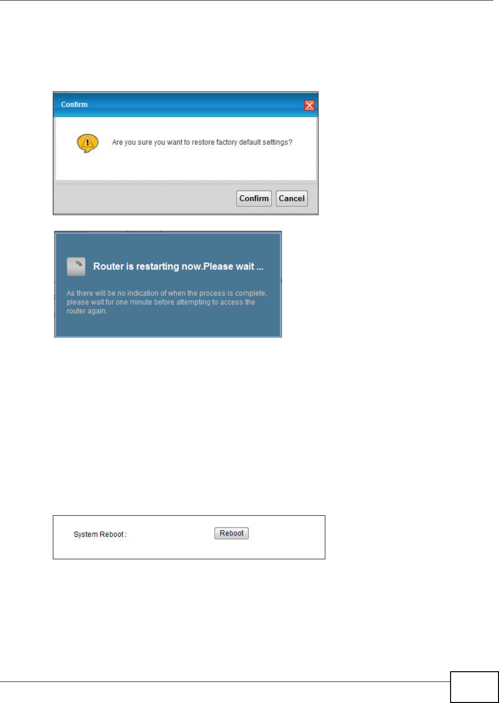
Chapter 35 Configuration
VMG1312-B10C User’s Guide 263
Reset to Factory Defaults
Click the Re se t button to clear all user-entered configuration information and return the Device to
its factory defaults. The following warning screen appears.
Figure 152 Reset Warning Message
Figure 153 Reset In Process Message
You can also press the RESET button on the rear panel to reset the factory defaults of your Device.
Refer to Section 1.6 on page 20 for more information on the RESET button.
35.3 The Reboot Screen
System restart allows you to reboot the Device remotely without turning the power off. You may
need to do this if the Device hangs, for example.
Click M a in t e n a nce > Reboot. Click Re boot to have the Device reboot. This does not affect the
Device's configuration.
Figure 154 Maintenance > Reboot

Chapter 35 Configuration
VMG1312-B10C User’s Guide
264

VMG1312-B10C User’s Guide 265
CHAPTER 36
Diagnostic
36.1 Overview
The D ia gn ost ic screens display information to help you identify problems with the Device.
The route between a CO VDSL switch and one of its CPE may go through switches owned by
independent organizations. A connectivity fault point generally takes time to discover and impacts
subscriber’s network access. In order to eliminate the management and maintenance efforts, IEEE
802.1ag is a Connectivity Fault Management (CFM) specification which allows network
administrators to identify and manage connection faults. Through discovery and verification of the
path, CFM can detect, analyze and isolate connectivity faults in bridged LANs.
36.1.1 What You Can Do in this Chapter
•The Ping & Tra ce Rout e & N sLook up screen lets you ping an IP address or trace the route
packets take to a host (Section 36.3 on page 266).
•The 8 0 2 .1 a g screen lets you perform CFM actions (Section 36.5 on page 268).
•The OAM Ping screen lets you send an ATM OAM (Operation, Administration and Maintenance)
packet to verify the connectivity of a specific PVC. (Section 36.5 on page 268).
36.2 What You Need to Know
The following terms and concepts may help as you read through this chapter.
How CFM Works
A Maintenance Association (MA) defines a VLAN and associated Maintenance End Point (MEP) ports
on the device under a Maintenance Domain (MD) level. An MEP port has the ability to send
Connectivity Check Messages (CCMs) and get other MEP ports information from neighbor devices’
CCMs within an MA.
CFM provides two tests to discover connectivity faults.
• Loopback test - checks if the MEP port receives its Loop Back Response (LBR) from its target
after it sends the Loop Back Message (LBM). If no response is received, there might be a
connectivity fault between them.
• Link trace test - provides additional connectivity fault analysis to get more information on where
the fault is. If an MEP port does not respond to the source MEP, this may indicate a fault.
Administrators can take further action to check and resume services from the fault according to
the line connectivity status report.
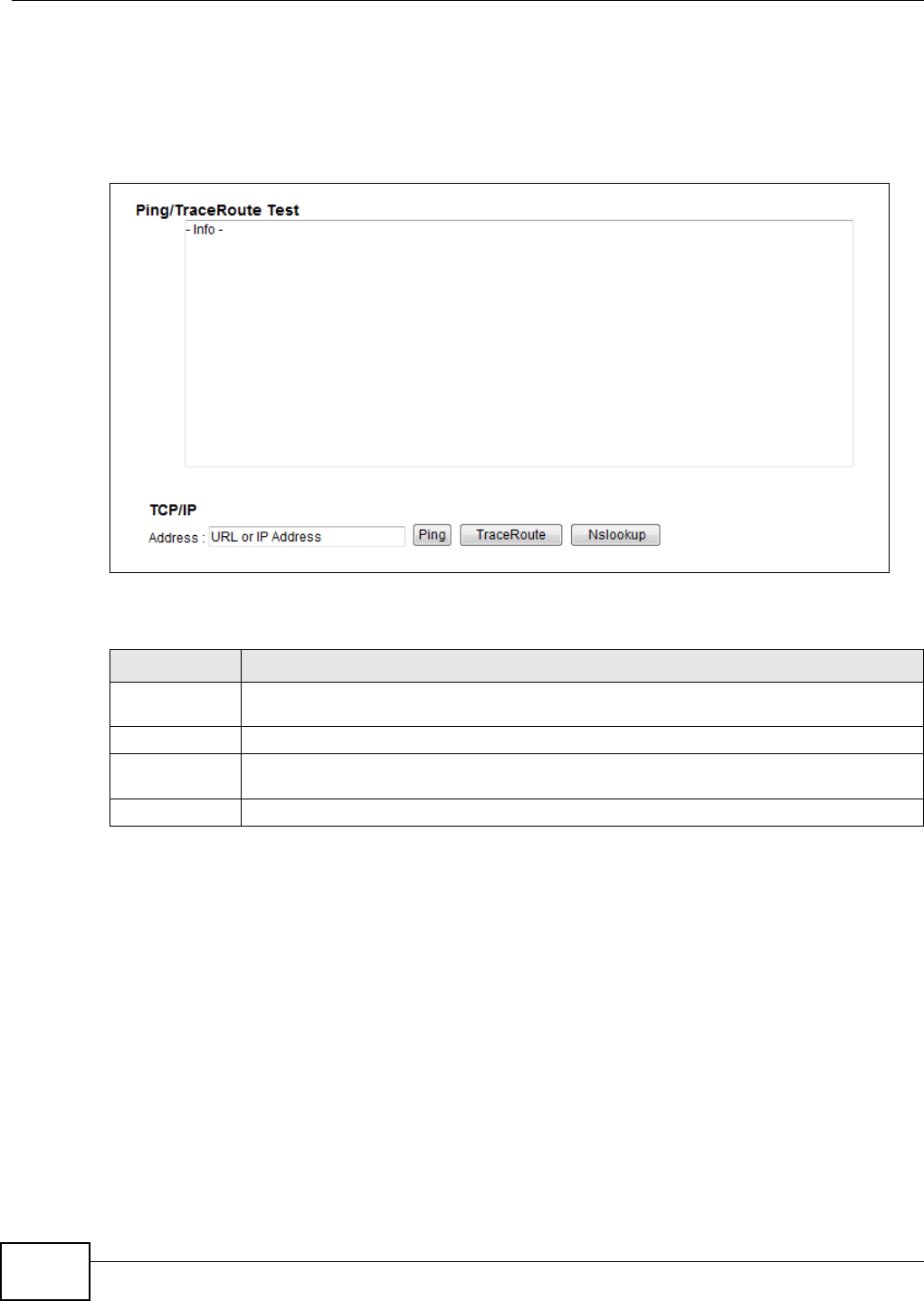
Chapter 36 Diagnostic
VMG1312-B10C User’s Guide
266
36.3 Ping & TraceRoute & NsLookup
Use this screen to ping, traceroute, or nslookup an IP address. Click Ma int ena n ce > Dia gnost ic >
Ping & Tr a ceRout e & N sLook up to open the screen shown next.
Figure 155 Maintenance > Diagnostic > Ping & TraceRoute & NsLookup
The following table describes the fields in this screen.
Table 116 Maintenance > Diagnostic > Ping & TraceRoute & NsLookup
LABEL DESCRIPTION
URL or IP
Address
Type the IP address of a computer that you want to perform ping, traceroute, or nslookup in
order to test a connection.
Ping Click this to ping the IP address that you entered.
TraceRoute Click this button to perform the traceroute function. This determines the path a packet
takes to the specified computer.
Nslookup Click this button to perform a DNS lookup on the IP address of a computer you enter.
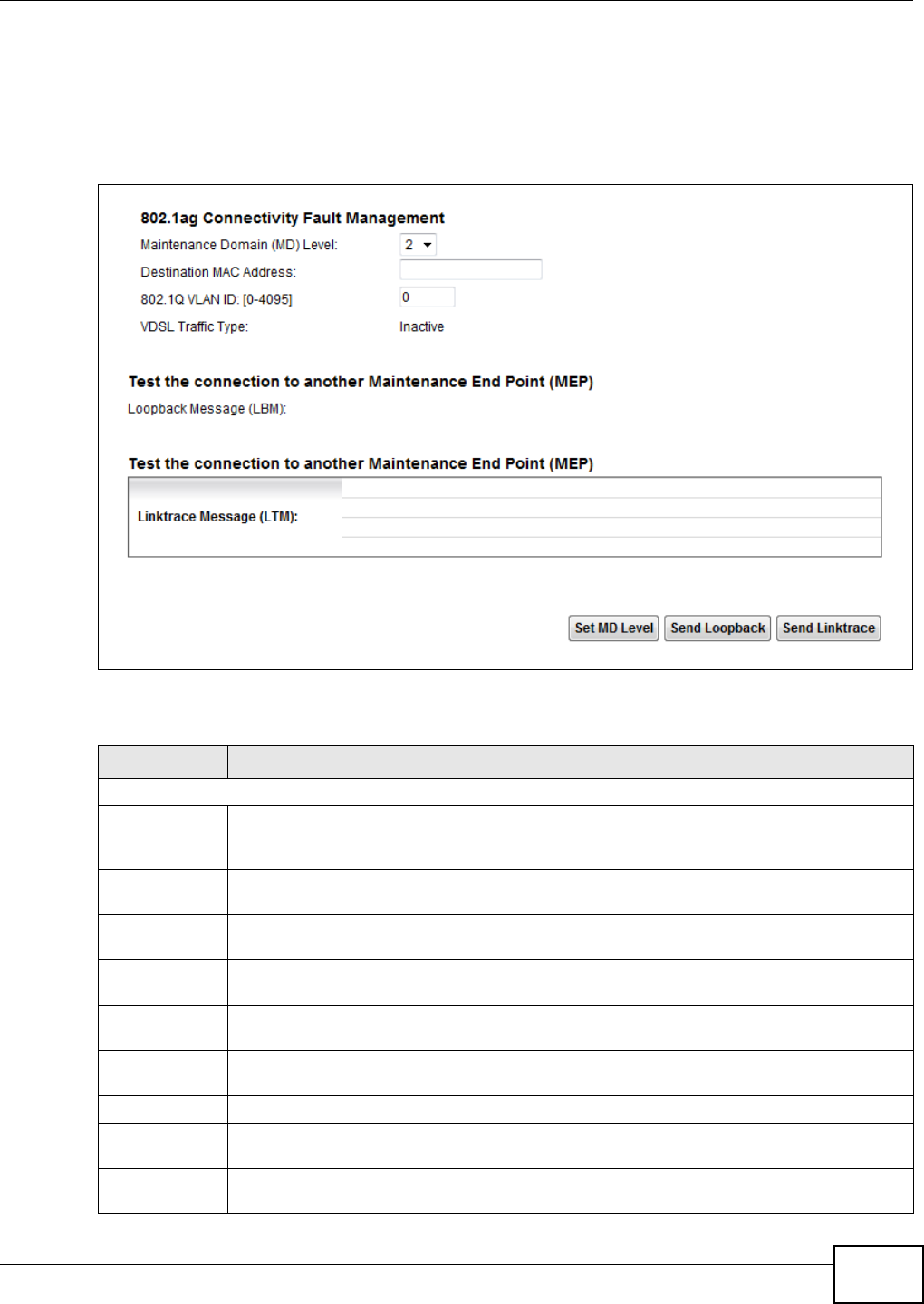
Chapter 36 Diagnostic
VMG1312-B10C User’s Guide 267
36.4 802.1ag
Click M a in t e n a nce > D ia gnost ic > 8 .2 .1 a g to open the following screen. Use this screen to
perform CFM actions.
Figure 156 Maintenance > Diagnostic > 802.1ag
The following table describes the fields in this screen.
Table 117 Maintenance > Diagnostic > 802.1ag
LABEL DESCRIPTION
802.1ag Connectivity Fault Management
Maintenance
Domain (MD)
Level
Select a level (0-7) under which you want to create an MA.
Destination
MAC Address
Enter the target device’s MAC address to which the Device performs a CFM loopback test.
802.1Q VLAN
ID
Type a VLAN ID (0-4095) for this MA.
VDSL Traffic
Type
This shows whether the VDSL traffic is activated.
Loopback
Message (LBM)
This shows how many Loop Back Messages (LBMs) are sent and if there is any inorder or
outorder Loop Back Response (LBR) received from a remote MEP.
Linktrace
Message (LTM)
This shows the destination MAC address in the Link Trace Response (LTR).
Set MD Level Click this button to configure the MD (Maintenance Domain) level.
Send Loopback Click this button to have the selected MEP send the LBM (Loop Back Message) to a specified
remote end point.
Send Linktrace Click this button to have the selected MEP send the LTMs (Link Trace Messages) to a
specified remote end point.
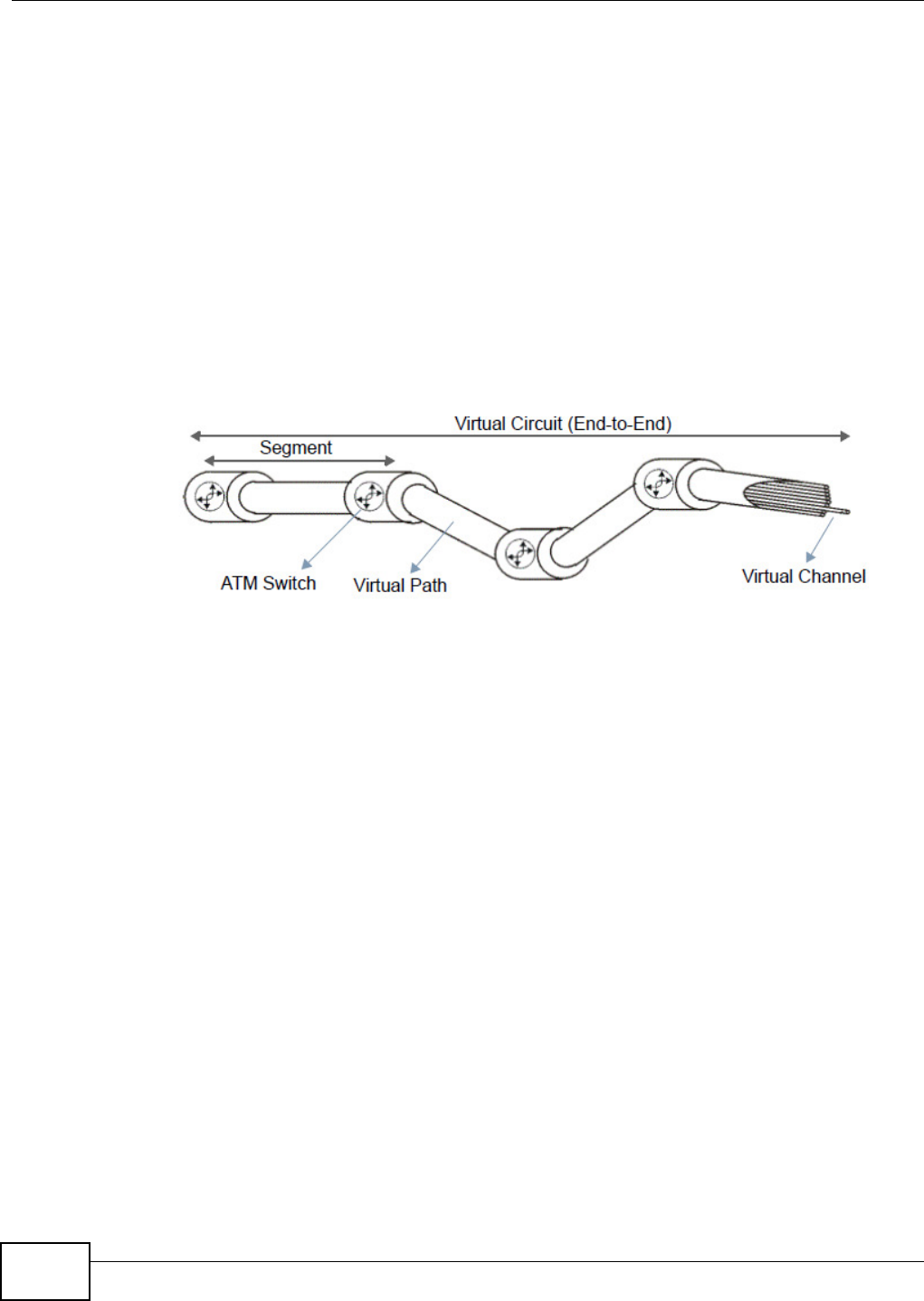
Chapter 36 Diagnostic
VMG1312-B10C User’s Guide
268
36.5 OAM Ping
Click Ma int ena nce > D ia gnost ic > OAM Pin g to open the screen shown next. Use this screen to
perform an OAM (Operation, Administration and Maintenance) F4 or F5 loopback test on a PVC. The
Device sends an OAM F4 or F5 packet to the DSLAM or ATM switch and then returns it to the
Device. The test result then displays in the text box.
ATM sets up virtual circuits over which end systems communicate. The terminology for virtual
circuits is as follows:
Figure 157 Virtual Circuit Topology
Think of a virtual path as a cable that contains a bundle of wires. The cable connects two points and
wires within the cable provide individual circuits between the two points. In an ATM cell header, a
VPI (Virtual Path Identifier) identifies a link formed by a virtual path; a VCI (Virtual Channel
Identifier) identifies a channel within a virtual path. A series of virtual paths make up a virtual
circuit.
F4 cells operate at the virtual path (VP) level, while F5 cells operate at the virtual channel (VC)
level. F4 cells use the same VPI as the user data cells on VP connections, but use different
predefined VCI values. F5 cells use the same VPI and VCI as the user data cells on the VC
connections, and are distinguished from data cells by a predefined Payload Type Identifier (PTI) in
the cell header. Both F4 flows and F5 flows are bidirectional and have two types.
• segment F4 flows (VCI=3)
• end-to-end F4 flows (VCI=4)
• segment F5 flows (PTI=100)
• end-to-end F5 flows (PTI=101)
OAM F4 or F5 tests are used to check virtual path or virtual channel availability between two DSL
devices. Segment flows are terminated at the connecting point which terminates a VP or VC
segment. End-to-end flows are terminated at the end point of a VP or VC connection, where an ATM
link is terminated. Segment loopback tests allow you to verify integrity of a PVC to the nearest
neighboring ATM device. End-to-end loopback tests allow you to verify integrity of an end-to-end
PVC.
Note: The DSLAM to which the Device is connected must also support ATM F4 and/or F5
to use this test.
• Virtual Channel (VC) Logical connections between ATM devices
• Virtual Path (VP) A bundle of virtual channels
• Virtual Circuits A series of virtual paths between circuit end points
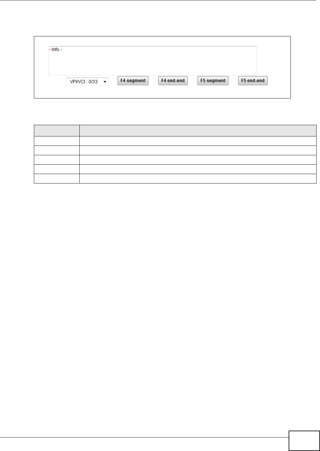
Chapter 36 Diagnostic
VMG1312-B10C User’s Guide 269
Note: This screen is available only when you configure an ATM layer-2 interface.
Figure 158 Maintenance > Diagnostic > OAM Ping
The following table describes the fields in this screen.
Table 118 Maintenance > Diagnostic > OAM Ping
LABEL DESCRIPTION
Select a PVC on which you want to perform the loopback test.
F4 segment Press this to perform an OAM F4 segment loopback test.
F4 end-end Press this to perform an OAM F4 end-to-end loopback test.
F5 segment Press this to perform an OAM F5 segment loopback test.
F5 end-end Press this to perform an OAM F5 end-to-end loopback test.

Chapter 36 Diagnostic
VMG1312-B10C User’s Guide
270

VMG1312-B10C User’s Guide 271
CHAPTER 37
Troubleshooting
This chapter offers some suggestions to solve problems you might encounter. The potential
problems are divided into the following categories.
•Power, Hardware Connections, and LEDs
•Device Access and Login
•Internet Access
•Wireless Internet Access
•USB Device Connection
•UPnP
37.1 Power, Hardware Connections, and LEDs
The Device does not turn on. None of the LEDs turn on.
1Make sure the Device is turned on.
2Make sure you are using the power adaptor or cord included with the Device.
3Make sure the power adaptor or cord is connected to the Device and plugged in to an appropriate
power source. Make sure the power source is turned on.
4Turn the Device off and on.
5If the problem continues, contact the vendor.
One of the LEDs does not behave as expected.
1Make sure you understand the normal behavior of the LED. See Section 1.5 on page 20.
2Check the hardware connections.
3Inspect your cables for damage. Contact the vendor to replace any damaged cables.
4Turn the Device off and on.

Chapter 37 Troubleshooting
VMG1312-B10C User’s Guide
272
5If the problem continues, contact the vendor.
37.2 Device Access and Login
I forgot the IP address for the Device.
1The default LAN IP address is 192.168.1.1.
2If you changed the IP address and have forgotten it, you might get the IP address of the Device by
looking up the IP address of the default gateway for your computer. To do this in most Windows
computers, click Sta r t > Run, enter cm d, and then enter ipcon fig. The IP address of the De fa u lt
Ga t ew a y might be the IP address of the Device (it depends on the network), so enter this IP
address in your Internet browser.
3If this does not work, you have to reset the device to its factory defaults. See Section 1.6 on page
20.
I forgot the password.
1The default admin password is 1 2 3 4 .
2If this does not work, you have to reset the device to its factory defaults. See Section 1.6 on page
20.
I cannot see or access the Login screen in the web configurator.
1Make sure you are using the correct IP address.
• The default IP address is 192.168.1.1.
• If you changed the IP address (Section 7.2 on page 103), use the new IP address.
• If you changed the IP address and have forgotten it, see the troubleshooting suggestions for I
forgot the IP address for the Device.
2Check the hardware connections, and make sure the LEDs are behaving as expected. See Section
1.5 on page 20.
3Make sure your Internet browser does not block pop-up windows and has JavaScripts and Java
enabled.
4If it is possible to log in from another interface, check the service control settings for HTTP and
HTTPS (Maint e n a nce > Rem ot e MGM T).

Chapter 37 Troubleshooting
VMG1312-B10C User’s Guide 273
5Reset the device to its factory defaults, and try to access the Device with the default IP address.
See Section 1.6 on page 20.
6If the problem continues, contact the network administrator or vendor, or try one of the advanced
suggestions.
Adv a n ce d Su gge st ions
• Make sure you have logged out of any earlier management sessions using the same user account
even if they were through a different interface or using a different browser.
• Try to access the Device using another service, such as Telnet. If you can access the Device,
check the remote management settings and firewall rules to find out why the Device does not
respond to HTTP.
I can see the Login screen, but I cannot log in to the Device.
1Make sure you have entered the password correctly. The default admin password is 1 2 3 4 . The field
is case-sensitive, so make sure [Caps Lock] is not on.
2You cannot log in to the web configurator while someone is using Telnet to access the Device. Log
out of the Device in the other session, or ask the person who is logged in to log out.
3Turn the Device off and on.
4If this does not work, you have to reset the device to its factory defaults. See Section 37.1 on page
271.
I cannot Telnet to the Device.
See the troubleshooting suggestions for I cannot see or access the Login screen in the web
configurator. Ignore the suggestions about your browser.
I cannot use FTP to upload / download the configuration file. / I cannot use FTP to upload
new firmware.
See the troubleshooting suggestions for I cannot see or access the Login screen in the web
configurator. Ignore the suggestions about your browser.

Chapter 37 Troubleshooting
VMG1312-B10C User’s Guide
274
37.3 Internet Access
I cannot access the Internet.
1Check the hardware connections, and make sure the LEDs are behaving as expected. See the
Quick St a r t Guide and Section 1.5 on page 20.
2Make sure you entered your ISP account information correctly in the N e t w ork Se t t in g >
Broadba n d screen. These fields are case-sensitive, so make sure [Caps Lock] is not on.
3If you are trying to access the Internet wirelessly, make sure that you enabled the wireless LAN in
the Device and your wireless client and that the wireless settings in the wireless client are the same
as the settings in the Device.
4Disconnect all the cables from your device and reconnect them.
5If the problem continues, contact your ISP.
I cannot access the Internet through a DSL connection.
1Make sure you have the D SL W AN port connected to a telephone jack (or the DSL or modem jack
on a splitter if you have one).
2Make sure you configured a proper DSL WAN interface (Net w ork Set t ing > Br oadba n d screen)
with the Internet account information provided by your ISP and that it is enabled.
3Check that the LAN interface you are connected to is in the same interface group as the DSL
connection (N e t w or k Set t ing > I nt e rfa ce Gr ou p).
4If you set up a WAN connection using bridging service, make sure you turn off the DHCP feature in
the LAN screen to have the clients get WAN IP addresses directly from your ISP’s DHCP server.
I cannot connect to the Internet using a second DSL connection.
ADSL and VDSL connections cannot work at the same time. You can only use one type of DSL
connection, either ADSL or VDSL connection at one time.
I cannot access the Internet anymore. I had access to the Internet (with the Device), but my
Internet connection is not available anymore.
1Your session with the Device may have expired. Try logging into the Device again.

Chapter 37 Troubleshooting
VMG1312-B10C User’s Guide 275
2Check the hardware connections, and make sure the LEDs are behaving as expected. See the
Quick St a r t Guide and Section 1.5 on page 20.
3Turn the Device off and on.
4If the problem continues, contact your ISP.
37.4 Wireless Internet Access
What factors may cause intermittent or unstabled wireless connection? How can I solve this
problem?
The following factors may cause interference:
• Obstacles: walls, ceilings, furniture, and so on.
• Building Materials: metal doors, aluminum studs.
• Electrical devices: microwaves, monitors, electric motors, cordless phones, and other wireless
devices.
To optimize the speed and quality of your wireless connection, you can:
• Move your wireless device closer to the AP if the signal strength is low.
• Reduce wireless interference that may be caused by other wireless networks or surrounding
wireless electronics such as cordless phones.
• Place the AP where there are minimum obstacles (such as walls and ceilings) between the AP and
the wireless client.
• Reduce the number of wireless clients connecting to the same AP simultaneously, or add
additional APs if necessary.
• Try closing some programs that use the Internet, especially peer-to-peer applications. If the
wireless client is sending or receiving a lot of information, it may have too many programs open
that use the Internet.
What is a Server Set ID (SSID)?
An SSID is a name that uniquely identifies a wireless network. The AP and all the clients within a
wireless network must use the same SSID.

Chapter 37 Troubleshooting
VMG1312-B10C User’s Guide
276
37.5 USB Device Connection
The Device fails to detect my USB device.
1Disconnect the USB device.
2Reboot the Device.
3If you are connecting a USB hard drive that comes with an external power supply, make sure it is
connected to an appropriate power source that is on.
4Re-connect your USB device to the Device.
37.6 UPnP
When using UPnP and the Device reboots, my computer cannot detect UPnP and refresh My
N et w or k Place s > Local N e t w ork .
1Disconnect the Ethernet cable from the Device’s LAN port or from your computer.
2Re-connect the Ethernet cable.
The Local Area Con nection icon for UPnP disappears in the screen.
Restart your computer.
I cannot open special applications such as white board, file transfer and video when I use the
MSN messenger.
1Wait more than three minutes.
2Restart the applications.

VMG1312-B10C User’s Guide 277
APPENDIX A
Customer Support
In the event of problems that cannot be solved by using this manual, you should contact your
vendor. If you cannot contact your vendor, then contact a ZyXEL office for the region in which you
bought the device. Regional websites are listed below (see also http://www.zyxel.com/
about_zyxel/zyxel_worldwide.shtml). Please have the following information ready when you
contact an office.
Required Information
• Product model and serial number.
• Warranty Information.
• Date that you received your device.
• Brief description of the problem and the steps you took to solve it.
Corporate Headquarters (Worldwide)
Taiwan
• ZyXEL Communications Corporation
• http://www.zyxel.com
Asia
China
• ZyXEL Communications (Shanghai) Corp.
ZyXEL Communications (Beijing) Corp.
ZyXEL Communications (Tianjin) Corp.
• http://www.zyxel.cn
India
• ZyXEL Technology India Pvt Ltd
• http://www.zyxel.in
Kazakhstan
•ZyXEL Kazakhstan
• http://www.zyxel.kz

Appendix A Customer Support
VMG1312-B10C User’s Guide
278
Korea
• ZyXEL Korea Corp.
• http://www.zyxel.kr
Malaysia
• ZyXEL Malaysia Sdn Bhd.
• http://www.zyxel.com.my
Pakistan
• ZyXEL Pakistan (Pvt.) Ltd.
• http://www.zyxel.com.pk
Philippines
• ZyXEL Philippines
• http://www.zyxel.com.ph
Singapore
• ZyXEL Singapore Pte Ltd.
• http://www.zyxel.com.sg
Taiwan
• ZyXEL Communications Corporation
• http://www.zyxel.com
Thailand
• ZyXEL Thailand Co., Ltd
• http://www.zyxel.co.th
Vietnam
• ZyXEL Communications Corporation-Vietnam Office
• http://www.zyxel.com/vn/vi
Europe
Austria
• ZyXEL Deutschland GmbH
• http://www.zyxel.de
Belarus
•ZyXEL BY
• http://www.zyxel.by

Appendix A Customer Support
VMG1312-B10C User’s Guide 279
Belgium
• ZyXEL Communications B.V.
• http://www.zyxel.com/be/nl/
Bulgaria
•ZyXEL България
• http://www.zyxel.com/bg/bg/
Czech
• ZyXEL Communications Czech s.r.o
• http://www.zyxel.cz
Denmark
• ZyXEL Communications A/S
• http://www.zyxel.dk
Estonia
•ZyXEL Estonia
• http://www.zyxel.com/ee/et/
Finland
• ZyXEL Communications
• http://www.zyxel.fi
France
•ZyXEL France
• http://www.zyxel.fr
Germany
• ZyXEL Deutschland GmbH
• http://www.zyxel.de
Hungary
• ZyXEL Hungary & SEE
• http://www.zyxel.hu
Latvia
•ZyXEL Latvia
• http://www.zyxel.com/lv/lv/homepage.shtml

Appendix A Customer Support
VMG1312-B10C User’s Guide
280
Lithuania
• ZyXEL Lithuania
• http://www.zyxel.com/lt/lt/homepage.shtml
Netherlands
•ZyXEL Benelux
• http://www.zyxel.nl
Norway
• ZyXEL Communications
• http://www.zyxel.no
Poland
• ZyXEL Communications Poland
• http://www.zyxel.pl
Romania
•ZyXEL Romania
• http://www.zyxel.com/ro/ro
Russia
• ZyXEL Russia
• http://www.zyxel.ru
Slovakia
• ZyXEL Communications Czech s.r.o. organizacna zlozka
• http://www.zyxel.sk
Spain
•ZyXEL Spain
• http://www.zyxel.es
Sweden
• ZyXEL Communications
• http://www.zyxel.se
Switzerland
•Studerus AG
• http://www.zyxel.ch/

Appendix A Customer Support
VMG1312-B10C User’s Guide 281
Turkey
•ZyXEL Turkey A.S.
• http://www.zyxel.com.tr
UK
• ZyXEL Communications UK Ltd.
• http://www.zyxel.co.uk
Ukraine
•ZyXEL Ukraine
• http://www.ua.zyxel.com
Latin America
Argentina
• ZyXEL Communication Corporation
• http://www.zyxel.com/ec/es/
Ecuador
• ZyXEL Communication Corporation
• http://www.zyxel.com/ec/es/
Middle East
Egypt
• ZyXEL Communication Corporation
• http://www.zyxel.com/homepage.shtml
Middle East
• ZyXEL Communication Corporation
• http://www.zyxel.com/homepage.shtml
North America
USA
• ZyXEL Communications, Inc. - North America Headquarters
• http://www.us.zyxel.com/

Appendix A Customer Support
VMG1312-B10C User’s Guide
282
Oceania
Australia
• ZyXEL Communications Corporation
• http://www.zyxel.com/au/en/
Africa
South Africa
• Nology (Pty) Ltd.
• http://www.zyxel.co.za

VMG1312-B10C User’s Guide 283
APPENDIX B
Legal Information
Copyright
Copyright © 2014 by ZyXEL Communications Corporation.
The contents of this publication may not be reproduced in any part or as a whole, transcribed, stored in a retrieval system, translated into
any language, or transmitted in any form or by any means, electronic, mechanical, magnetic, optical, chemical, photocopying, manual, or
otherwise, without the prior written permission of ZyXEL Communications Corporation.
Published by ZyXEL Communications Corporation. All rights reserved.
Disclaimer
ZyXEL does not assume any liability arising out of the application or use of any products, or software described herein. Neither does it
convey any license under its patent rights nor the patent rights of others. ZyXEL further reserves the right to make changes in any
products described herein without notice. This publication is subject to change without notice.
Your use of the Device is subject to the terms and conditions of any related service providers.
Trademarks
ZyNOS (ZyXEL Network Operating System) is a registered trademark of ZyXEL Communications, Inc. Other trademarks mentioned in this
publication are used for identification purposes only and may be properties of their respective owners.
Trademarks mentioned in this publication are used for identification purposes only and may be properties of their respective owners.
Certifications
Federal Communications Commission (FCC) Interference Statement
The device complies with Part 15 of FCC rules. Operation is subject to the following two conditions:
• This device may not cause harmful interference.
• This device must accept any interference received, including interference that may cause undesired operations.
This device has been tested and found to comply with the limits for a Class B digital device pursuant to Part 15 of the FCC Rules. These
limits are designed to provide reasonable protection against harmful interference in a residential installation. This device generates, uses,
and can radiate radio frequency energy, and if not installed and used in accordance with the instructions, may cause harmful interference
to radio communications. However, there is no guarantee that interference will not occur in a particular installation.
If this device does cause harmful interference to radio/television reception, which can be determined by turning the device off and on, the
user is encouraged to try to correct the interference by one or more of the following measures:
1Reorient or relocate the receiving antenna.
2Increase the separation between the equipment and the receiver.
3Connect the equipment into an outlet on a circuit different from that to which the receiver is connected.
4Consult the dealer or an experienced radio/TV technician for help.
FCC Caution: Any changes or modifications not expressly approved by the party responsible for compliance could void the user's authority
to operate this equipment.
FCC Radiation Exposure Statement
• This transmitter must not be co-located or operating in conjunction with any other antenna or transmitter.
• IEEE 802.11b, 802.11g or 802.11n (20MHz) operation of this product in the U.S.A. is firmware-limited to channels 1 through 11. IEEE
802.11n (40MHz) operation of this product in the U.S.A. is firmware-limited to channels 3 through 9.
• IEEE 802.11b or 802.11g operation of this product in the U.S.A. is firmware-limited to channels 1 through 11.
• To comply with FCC RF exposure compliance requirements, a separation distance of at least 20 cm must be maintained between the
antenna of this device and all persons.
IC Radiation Exposure Statement
This equipment complies with IC radiation exposure limits set forth for an uncontrolled environment. End users must follow the specific
operating instructions for satisfying RF exposure compliance.
Notices
Changes or modifications not expressly approved by the party responsible for compliance could void the user's authority to operate the
equipment.
This device is designed for the WLAN 2.4 GHz networks throughout the EC region and Switzerland, with restrictions in France.
Ce produit est conçu pour les bandes de fréquences 2,4 GHz conformément à la législation Européenne. En France métropolitaine, suivant
les décisions n°03-908 et 03-909 de l’ARCEP, la puissance d’émission ne devra pas dépasser 10 mW (10 dB) dans le cadre d’une
installation WiFi en extérieur pour les fréquences comprises entre 2454 MHz et 2483,5 MHz.

Appendix B Legal Information
VMG1312-B10C User’s Guide
284
Viewing Certifications
Go to http://www.zyxel.com to view this product’s documentation and certifications.
ZyXEL Limited Warranty
ZyXEL warrants to the original end user (purchaser) that this product is free from any defects in material or workmanship for a specific
period (the Warranty Period) from the date of purchase. The Warranty Period varies by region. Check with your vendor and/or the
authorized ZyXEL local distributor for details about the Warranty Period of this product. During the warranty period, and upon proof of
purchase, should the product have indications of failure due to faulty workmanship and/or materials, ZyXEL will, at its discretion, repair or
replace the defective products or components without charge for either parts or labor, and to whatever extent it shall deem necessary to
restore the product or components to proper operating condition. Any replacement will consist of a new or re-manufactured functionally
equivalent product of equal or higher value, and will be solely at the discretion of ZyXEL. This warranty shall not apply if the product has
been modified, misused, tampered with, damaged by an act of God, or subjected to abnormal working conditions.
Note
Repair or replacement, as provided under this warranty, is the exclusive remedy of the purchaser. This warranty is in lieu of all other
warranties, express or implied, including any implied warranty of merchantability or fitness for a particular use or purpose. ZyXEL shall in
no event be held liable for indirect or consequential damages of any kind to the purchaser.
To obtain the services of this warranty, contact your vendor. You may also refer to the warranty policy for the region in which you bought
the device at http://www.zyxel.com/web/support_warranty_info.php.
Registration
Register your product online to receive e-mail notices of firmware upgrades and information at www.zyxel.com for global products, or at
www.us.zyxel.com for North American products.
Open Source Licenses
This product contains in part some free software distributed under GPL license terms and/or GPL like licenses. Open source licenses are
provided with the firmware package. You can download the latest firmware at www.zyxel.com. If you cannot find it there, contact your
vendor or ZyXEL Technical Support at support@zyxel.com.tw. To obtain the source code covered under those Licenses, please contact
your vendor or ZyXEL Technical Support at support@zyxel.com.tw.
Regulatory Information
European Union
The following information applies if you use the product within the European Union.
Declaration of Conformity with Regard to EU Directive 1999/5/EC (R&TTE Directive)
Compliance Information for Wireless Products Relevant to the EU and Other Countries Following the EU Directive 1999/5/EC (R&TTE Directive)
[Czech] ZyXEL tímto prohlašuje, že tento zařízení je ve shodě se základními požadavky a dalšími příslušnými ustanoveními
směrnice 1999/5/EC.
[Danish] Undertegnede ZyXEL erklærer herved, at følgende udstyr udstyr overholder de væsentlige krav og øvrige relevante
krav i direktiv 1999/5/EF.
[German] Hiermit erklärt ZyXEL, dass sich das Gerät Ausstattung in Übereinstimmung mit den grundlegenden Anforderungen
und den übrigen einschlägigen Bestimmungen der Richtlinie 1999/5/EU befindet.
[Estonian] Käesolevaga kinnitab ZyXEL seadme seadmed vastavust direktiivi 1999/5/EÜ põhinõuetele ja nimetatud direktiivist
tulenevatele teistele asjakohastele sätetele.
[English] Hereby, ZyXEL declares that this equipment is in compliance with the essential requirements and other relevant
provisions of Directive 1999/5/EC.
[Spanish] Por medio de la presente ZyXEL declara que el equipo cumple con los requisitos esenciales y cualesquiera otras
disposiciones aplicables o exigibles de la Directiva 1999/5/CE.
[Greek] Ε Η ΑΑ ZyXEL ∆ΗΩΕ επισός ΦΩΕΑ Ω∆Ε ΑΑΗΕ Α
Ε ΧΕΕ ∆ΑΑΕ Η ∆ΗΓΑ 1999/5/ΕC.
[French] Par la présente ZyXEL déclare que l'appareil équipements est conforme aux exigences essentielles et aux autres
dispositions pertinentes de la directive 1999/5/EC.
[Italian] Con la presente ZyXEL dichiara che questo attrezzatura è conforme ai requisiti essenziali ed alle altre disposizioni
pertinenti stabilite dalla direttiva 1999/5/CE.
[Latvian] Ar šo ZyXEL deklarē, ka iekārtas atbilst Direktīvas 1999/5/EK būtiskajām prasībām un citiem ar to saistītajiem
noteikumiem.
[Lithuanian] Šiuo ZyXEL deklaruoja, kad šis įranga atitinka esminius reikalavimus ir kitas 1999/5/EB Direktyvos nuostatas.
[Dutch] Hierbij verklaart ZyXEL dat het toestel uitrusting in overeenstemming is met de essentiële eisen en de andere
relevante bepalingen van richtlijn 1999/5/EC.
[Maltese] Hawnhekk, ZyXEL, jiddikjara li dan tagħmir jikkonforma mal-ħtiġijiet essenzjali u ma provvedimenti oħrajn relevanti li
hemm fid-Dirrettiva 1999/5/EC.
[Hungarian] Alulírott, ZyXEL nyilatkozom, hogy a berendezés megfelel a vonatkozó alapvetõ követelményeknek és az 1999/5/EK
irányelv egyéb elõírásainak.

Appendix B Legal Information
VMG1312-B10C User’s Guide 285
National Restrictions
This product may be used in all EU countries (and other countries following the EU directive 1999/5/EC) without any limitation except for
the countries mentioned below:
Ce produit peut être utilisé dans tous les pays de l’UE (et dans tous les pays ayant transposés la directive 1999/5/CE) sans aucune
limitation, excepté pour les pays mentionnés ci-dessous:
Questo prodotto è utilizzabile in tutte i paesi EU (ed in tutti gli altri paesi che seguono le direttive EU 1999/5/EC) senza nessuna
limitazione, eccetto per i paesii menzionati di seguito:
Das Produkt kann in allen EU Staaten ohne Einschränkungen eingesetzt werden (sowie in anderen Staaten die der EU Direktive 1995/5/CE
folgen) mit Außnahme der folgenden aufgeführten Staaten:
In the majority of the EU and other European countries, the 2,4-GHz band has been made available for the use of wireless local area
networks (LANs). Later in this document you will find an overview of countries inwhich additional restrictions or requirements or both are
applicable.
The requirements for any country may evolve. ZyXEL recommends that you check with the local authorities for the latest status of their
national regulations for 2,4-GHz wireless LANs.
The following countries have restrictions and/or requirements in addition to those given in the table labeled “Overview of Regulatory
Requirem ents for Wireless LANs”:.
Belgium
The Belgian Institute for Postal Services and Telecommunications (BIPT) must be notified of any outdoor wireless link having a range
exceeding 300 meters. Please check http://www.bipt.be for more details.
Draadloze verbindingen voor buitengebruik en met een reikwijdte van meer dan 300 meter dienen aangemeld te worden bij het Belgisch
Instituut voor postdiensten en telecommunicatie (BIPT). Zie http://www.bipt.be voor meer gegevens.
Les liaisons sans fil pour une utilisation en extérieur d’une distance supérieure à 300 mètres doivent être notifiées à l’Institut Belge des
services Postaux et des Télécommunications (IBPT). Visitez http://www.ibpt.be pour de plus amples détails.
France
For 2.4 GHz, the output power is restricted to 10 mW EIRP when the product is used outdoors in the band 2454 - 2483.5 MHz. There are
no restrictions when used indoors or in other parts of the 2.4 GHz band. Check http://www.arcep.fr/ for more details.
Pour la bande 2.4 GHz, la puissance est limitée à 10 mW en p.i.r.e. pour les équipements utilisés en extérieur dans la bande 2454 -
2483.5 MHz. Il n'y a pas de restrictions pour des utilisations en intérieur ou dans d'autres parties de la bande 2.4 GHz. Consultez http://
www.arcep.fr/ pour de plus amples détails.
Italy
This product meets the National Radio Interface and the requirements specified in the National Frequency Allocation Table for Italy. Unless
this wireless LAN product is operating within the boundaries of the owner's property, its use requires a “general authorization.” Please
check http://www.sviluppoeconomico.gov.it/ for more details.
[Polish] Niniejszym ZyXEL oświadcza, że sprzęt jest zgodny z zasadniczymi wymogami oraz pozostałymi stosownymi
postanowieniami Dyrektywy 1999/5/EC.
[Portuguese] ZyXEL declara que este equipamento está conforme com os requisitos essenciais e outras disposições da Directiva
1999/5/EC.
[Slovenian] ZyXEL izjavlja, da je ta oprema v skladu z bistvenimi zahtevami in ostalimi relevantnimi določili direktive 1999/5/EC.
[Slovak] ZyXEL týmto vyhlasuje, že zariadenia spĺňa základné požiadavky a všetky príslušné ustanovenia Smernice 1999/5/EC.
[Finnish] ZyXEL vakuuttaa täten että laitteet tyyppinen laite on direktiivin 1999/5/EY oleellisten vaatimusten ja sitä koskevien
direktiivin muiden ehtojen mukainen.
[Swedish] Härmed intygar ZyXEL att denna utrustning står I överensstämmelse med de väsentliga egenskapskrav och övriga
relevanta bestämmelser som framgår av direktiv 1999/5/EC.
[Bulgarian] С я ZyXEL , ч я
1999/5/C.
[Icelandic] Hér með lýsir, ZyXEL því yfir að þessi búnaður er í samræmi við grunnkröfur og önnur viðeigandi ákvæði tilskipunar
1999/5/EC.
[Norwegian] Erklærer herved ZyXEL at dette utstyret er I samsvar med de grunnleggende kravene og andre relevante
bestemmelser I direktiv 1999/5/EF.
[Romanian] Prin prezenta, ZyXEL declară că acest echipament este în conformitate cu cerinţele esenţiale şi alte prevederi
relevante ale Directivei 1999/5/EC.
R&TTE 1999/5/EC
WLAN 2.4 – 2.4835 GHz
IEEE 802.11 b/g/n
Location Frequency Range (GHz)
Indoor (No restrictions) 2.4 – 2.4835
Outdoor 2.4 – 2.454
2.454 – 2.4835

Appendix B Legal Information
VMG1312-B10C User’s Guide
286
Questo prodotto è conforme alla specifiche di Interfaccia Radio Nazionali e rispetta il Piano Nazionale di ripartizione delle frequenze in
Italia. Se non viene installato all 'interno del proprio fondo, l'utilizzo di prodotti Wireless LAN richiede una “Autorizzazione Generale”.
Consultare http://www.sviluppoeconomico.gov.it/ per maggiori dettagli.
Latvia
The outdoor usage of the 2.4 GHz band requires an authorization from the Electronic Communications Office. Please check http://
www.esd.lv for more details.
2.4 GHz frekvenèu joslas izmantoðanai ârpus telpâm nepiecieðama atïauja no Elektronisko sakaru direkcijas. Vairâk informâcijas: http://www.esd.lv.
Notes:
1. Although Norway, Switzerland and Liechtenstein are not EU member states, the EU Directive 1999/5/EC has also been implemented in
those countries.
2. The regulatory limits for maximum output power are specified in EIRP. The EIRP level (in dBm) of a device can be calculated by adding
the gain of the antenna used(specified in dBi) to the output power available at the connector (specified in dBm).
List of national codes
Safety Warnings
• Do NOT use this product near water, for example, in a wet basement or near a swimming pool.
• Do NOT expose your device to dampness, dust or corrosive liquids.
• Do NOT store things on the device.
• Do NOT install, use, or service this device during a thunderstorm. There is a remote risk of electric shock from lightning.
• Connect ONLY suitable accessories to the device.
• Do NOT open the device or unit. Opening or removing covers can expose you to dangerous high voltage points or other risks. ONLY
qualified service personnel should service or disassemble this device. Please contact your vendor for further information.
• Make sure to connect the cables to the correct ports.
• Place connecting cables carefully so that no one will step on them or stumble over them.
• Always disconnect all cables from this device before servicing or disassembling.
• Use ONLY an appropriate power adaptor or cord for your device. Connect it to the right supply voltage (for example, 110V AC in North
America or 230V AC in Europe).
• Do NOT allow anything to rest on the power adaptor or cord and do NOT place the product where anyone can walk on the power
adaptor or cord.
• Do NOT use the device if the power adaptor or cord is damaged as it might cause electrocution.
• If the power adaptor or cord is damaged, remove it from the device and the power source.
• Do NOT attempt to repair the power adaptor or cord. Contact your local vendor to order a new one.
• Do not use the device outside, and make sure all the connections are indoors. There is a remote risk of electric shock from lightning.
• Do NOT obstruct the device ventilation slots, as insufficient airflow may harm your device.
• Use only No. 26 AWG (American Wire Gauge) or larger telecommunication line cord.
• Antenna Warning! This device meets ETSI and FCC certification requirements when using the included antenna(s). Only use the
included antenna(s).
• If you wall mount your device, make sure that no electrical lines, gas or water pipes will be damaged.
• This product is for indoor use only (utilisation intérieure exclusivement).
• Do not use this product near water for example, near a bathtub, washbowl, kitchen sink or laundry tub, in a wet basement or near a
swimming pool.
• Avoid using a telephone (other than a cordless type) during an electrical storm. There may be a remote risk of electric shock from
lightning.
• Do not use the telephone to report a gas leak in the vicinity of the leak.
COUNTRY ISO 3166 2 LETTER CODE COUNTRY ISO 3166 2 LETTER CODE
Austria AT Malta MT
Belgium BE Netherlands NL
Cyprus CY Poland PL
Czech Republic CR Portugal PT
Denmark DK Slovakia SK
Estonia EE Slovenia SI
Finland FI Spain ES
France FR Sweden SE
Germany DE United Kingdom GB
Greece GR Iceland IS
Hungary HU Liechtenstein LI
Ireland IE Norway NO
Italy IT Switzerland CH
Latvia LV Bulgaria BG
Lithuania LT Romania RO
Luxembourg LU Turkey TR

Appendix B Legal Information
VMG1312-B10C User’s Guide 287
Your product is marked with this symbol, which is known as the WEEE mark. WEEE stands for Waste Electronics and
Electrical Equipment. It means that used electrical and electronic products should not be mixed with general waste. Used
electrical and electronic equipment should be treated separately.

Appendix B Legal Information
VMG1312-B10C User’s Guide
288

Index
VMG1312-B10C User’s Guide 289
Index
A
ACL rule 189
ACS 245
activation
firewalls 185
media server 181
SIP ALG 159
SSID 76
Address Resolution Protocol 229
administrator password 24
AH 215
algorithms 215
applications
Internet access 18
media server 180
activation 181
iTunes server 180
applications, NAT 164
ARP Table 229, 231
authentication 88, 89
RADIUS server 90
Auto Configuration Server, see ACS 245
B
backup
configuration 261
Basic Service Set, see BSS
blinking LEDs 20
Broadband 39
broadcast 62
BSS 91
example 91
C
CA 201
Canonical Format Indicator See CFI
CCMs 265
certificate
factory default 202
certificates 201
authentication 201
CA
creating 203
public key 201
replacing 202
storage space 202
Certification Authority 201
Certification Authority. see CA
certifications 283
notices 283
viewing 284
CFI 61
CFM 265
CCMs 265
link trace test 265
loopback test 265
MA 265
MD 265
MEP 265
MIP 265
channel, wireless LAN 88
client list 107
compatibility, WDS 82
configuration
backup 261
firewalls 185
reset 263
restoring 262
static route 57, 127, 169
Connectivity Check Messages, see CCMs
contact information 277
copyright 283
CoS 145
CoS technologies 132
creating certificates 203
CTS threshold 84, 88

VMG1312-B10C User’s Guide290
Index
customer support 277
D
data fragment threshold 84, 88
DDoS 184
default server address 158
Denials of Service, see DoS
DH 220
DHCP 102, 121
Differentiated Services, see DiffServ 145
Diffie-Hellman key groups 220
DiffServ 145
marking rule 145
digital IDs 201
disclaimer 283
DLNA 180
DMZ 158
DNS 102, 121
DNS server address assignment 62
documentation
related 2
Domain Name 164
Domain Name System, see DNS
Domain Name System. See DNS.
DoS 184
DS field 145
DS, dee differentiated services
DSCP 145
dynamic DNS 167
wildcard 168
Dynamic Host Configuration Protocol, see DHCP
DYNDNS wildcard 168
E
ECHO 164
e-mail
log example 257
Encapsulation 58
MER 58
PPP over Ethernet 59
encapsulation 40, 216
RFC 1483 59
encryption 90
ESP 215
Extended Service Set IDentification 68, 78
F
FCC interference statement 283
File Sharing 178
file sharing 19
filters
MAC address 78, 89
Finger 164
firewalls 183
add protocols 185
configuration 185
DDoS 184
DoS 184
LAND attack 184
Ping of Death 184
SYN attack 184
firmware 259
version 37
forwarding ports 150
fragmentation threshold 84, 88
FTP 150, 164
G
General wireless LAN screen 66
Guide
Quick Start 2
H
HTTP 164

Index
VMG1312-B10C User’s Guide 291
I
IEEE 802.1Q 61
IGA 162
IGMP 62
multicast group list 233
version 62
IKE phases 217
ILA 162
Inside Global Address, see IGA
inside header 217
Inside Local Address, see ILA
interface group 171
Internet
wizard setup 31
Internet access 18
wizard setup 31
Internet Key Exchange 217
Internet Protocol version 6 41
Internet Service Provider, see ISP
IP address 102, 122
ping 266
private 122
WAN 40
IP Address Assignment 61
IP alias
NAT applications 164
IPSec
algorithms 215
architecture 215
NAT 218
IPSec VPN 209
IPv6 41
addressing 41, 62
prefix 41, 63
prefix delegation 42
prefix length 41, 63
ISP 40
iTunes server 180
L
LAN 101
and USB printer 181
client list 107
DHCP 102, 121
DNS 102, 121
IP address 102, 103, 122
MAC address 107
status 37
subnet mask 102, 103, 122
LAND attack 184
LAN-Side DSL CPE Configuration 247
LBR 265
limitations
wireless LAN 91
WPS 98
link trace 265
Link Trace Message, see LTM
Link Trace Response, see LTR
login 23
passwords 23, 24
logs 221, 225, 233, 239, 255
Loop Back Response, see LBR
loopback 265
LTM 265
LTR 265
M
MA 265
MAC address 79, 107
filter 78, 89
MAC authentication 78
Mac filter 193
Maintenance Association, see MA
Maintenance Domain, see MD
Maintenance End Point, see MEP
managing the device
good habits 17
Maximum Burst Size (MBS) 60
MBSSID 91
MD 265
media server 180
activation 181
iTunes server 180
MEP 265
MTU (Multi-Tenant Unit) 61

VMG1312-B10C User’s Guide292
Index
multicast 62
Multiple BSS, see MBSSID
multiplexing 59
LLC-based 59
VC-based 59
multiprotocol encapsulation 59
N
NAT 149, 151, 161, 162
applications 164
IP alias 164
example 163
global 162
IGA 162
ILA 162
inside 162
IPSec 218
local 162
outside 162
port forwarding 150
port number 164
services 164
SIP ALG 158
activation 159
traversal 219
NAT example 165
negotiation mode 218
Network Address Translation, see NAT
Network Map 35
network map 27
NNTP 164
O
other documentation 2
outside header 216
P
passwords 23, 24
PBC 93
Peak Cell Rate (PCR) 60
Per-Hop Behavior, see PHB 145
PHB 145
PIN, WPS 94
example 95
Ping of Death 184
Point-to-Point Tunneling Protocol 164
POP3 164
port forwarding 150
ports 20
PPP over Ethernet, see PPPoE
PPPoE 40, 59
Benefits 59
PPTP 164
preamble 85, 88
preamble mode 92
prefix delegation 42
pre-shared key 219
Printer Server 181
printer sharing
and LAN 181
requirements 181
private IP address 122
product registration 284
protocol 40
push button 21
Push Button Configuration, see PBC
push button, WPS 93
Q
QoS 131, 145
marking 132
setup 131
tagging 132
versus CoS 132
Quality of Service, see QoS
Quick Start Guide 2
R
RADIUS server 90

Index
VMG1312-B10C User’s Guide 293
registration
product 284
related documentation 2
remote management
TR-069 245
Remote Procedure Calls, see RPCs 245
reset 20, 263
restart 263
restoring configuration 262
RFC 1058. See RIP.
RFC 1389. See RIP.
RFC 1483 59
RFC 3164 221
RIP 129
router features 18
Routing Information Protocol. See RIP
RPPCs 245
RTS threshold 84, 88
S
security
wireless LAN 88
Security Log 223
Security Parameter Index, see SPI
service access control 243
Service Set 68, 78
Services 164
setup
firewalls 185
static route 57, 127, 169
Single Rate Three Color Marker, see srTCM
SIP ALG 158
activation 159
SMTP 164
SNMP 164
SNMP trap 164
SPI 184
srTCM 147
SSID 89
activation 76
MBSSID 91
static route 125, 129, 253
configuration 57, 127, 169
example 125
static VLAN
status 35
firmware version 37
LAN 37
WAN 37
wireless LAN 37
status indicators 20
subnet mask 102, 122
Sustained Cell Rate (SCR) 60
SYN attack 184
syslog
protocol 221
severity levels 221
system
firmware 259
version 37
passwords 23, 24
reset 20
status 35
LAN 37
WAN 37
wireless LAN 37
time 249
T
Tag Control Information See TCI
Tag Protocol Identifier See TPID
TCI
The 40
thresholds
data fragment 84, 88
RTS/CTS 84, 88
time 249
TPID 61
TR-064 247
TR-069 245
ACS setup 245
authentication 246
trademarks 283
traffic shaping 59
transport mode 216
trTCM 147

VMG1312-B10C User’s Guide294
Index
tunnel mode 216
Two Rate Three Color Marker, see trTCM
U
unicast 62
Universal Plug and Play, see UPnP
upgrading firmware 259
UPnP 108
cautions 103
example 109
installation 109
NAT traversal 102
USB features 19
V
VID
Virtual Circuit (VC) 59
Virtual Local Area Network See VLAN
VLAN 61
Introduction 61
number of possible VIDs
priority frame
static
VLAN ID 61
VLAN Identifier See VID
VLAN tag 61
W
WAN
status 37
Wide Area Network, see WAN 39
warranty 284
note 284
WDS 82, 92
compatibility 82
example 92
web configurator 23
login 23
passwords 23, 24
WEP 90
WEP Encryption 70, 72, 73
WEP encryption 70
WEP key 70
Wireless Distribution System, see WDS
wireless LAN 65, 86
authentication 88, 89
BSS 91
example 91
channel 88
encryption 90
example 87
fragmentation threshold 84, 88
limitations 91
MAC address filter 78, 89
MBSSID 91
preamble 85, 88
RADIUS server 90
RTS/CTS threshold 84, 88
security 88
SSID 89
activation 76
status 37
WDS 82, 92
compatibility 82
example 92
WEP 90
WPA 90
WPA-PSK 90
WPS 93, 95
example 96
limitations 98
PIN 94
push button 21, 93
wizard setup
Internet 31
WPA 90
WPA-PSK 90
WPS 93, 95
example 96
limitations 98
PIN 94
example 95
push button 21, 93