ZyXEL Communications VMG1312B10D Wireless N VDSL2 Gateway with USB User Manual Book
ZyXEL Communications Corporation Wireless N VDSL2 Gateway with USB Book
UserManual.wiki
>
ZyXEL Communications
>
VMG1312B10D User Manual
>
User Manual-1
Contents
1.
User Manual-1
2.
User Manual-2
User Manual-1
Navigation menu
Upload a User Manual
Namespaces
Wiki Guide
HTML
PDF
Info
Views
User Manual
Discussion / Help
Navigation
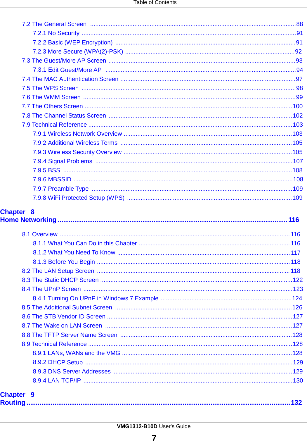
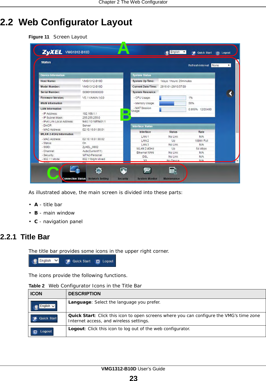
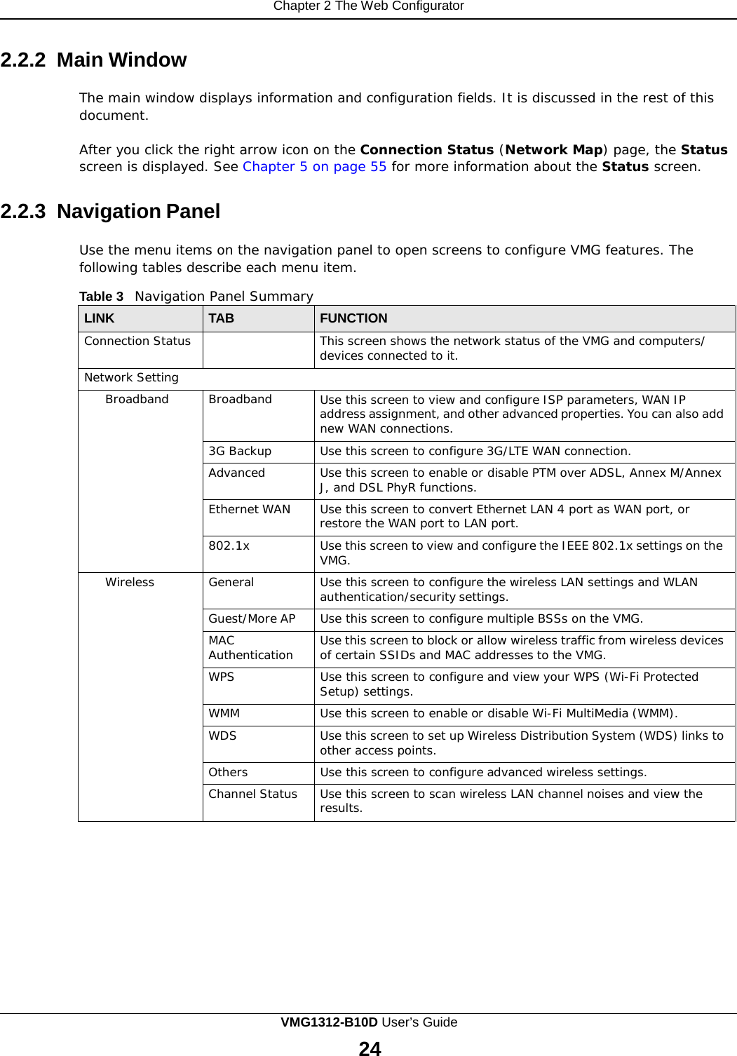
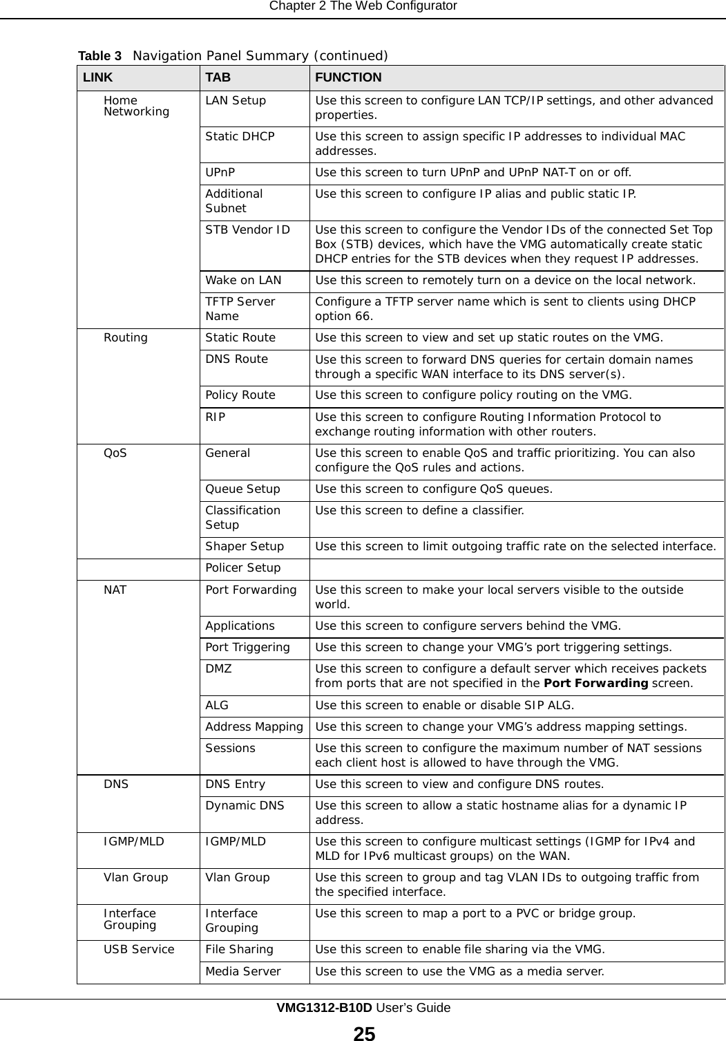
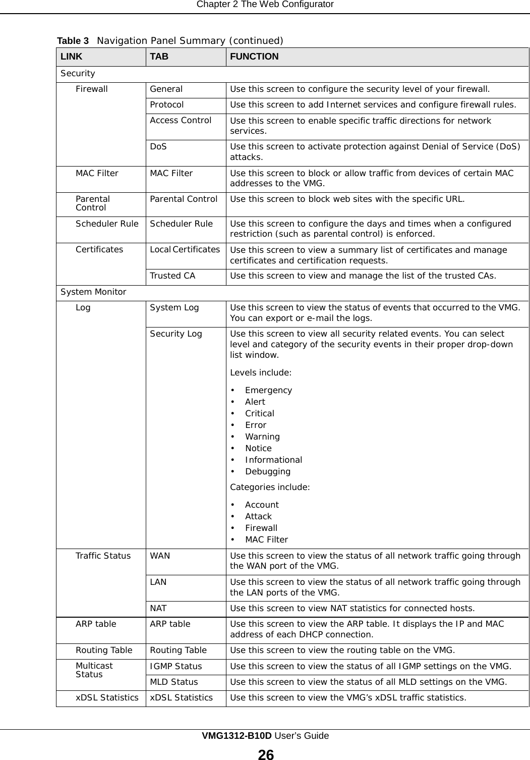
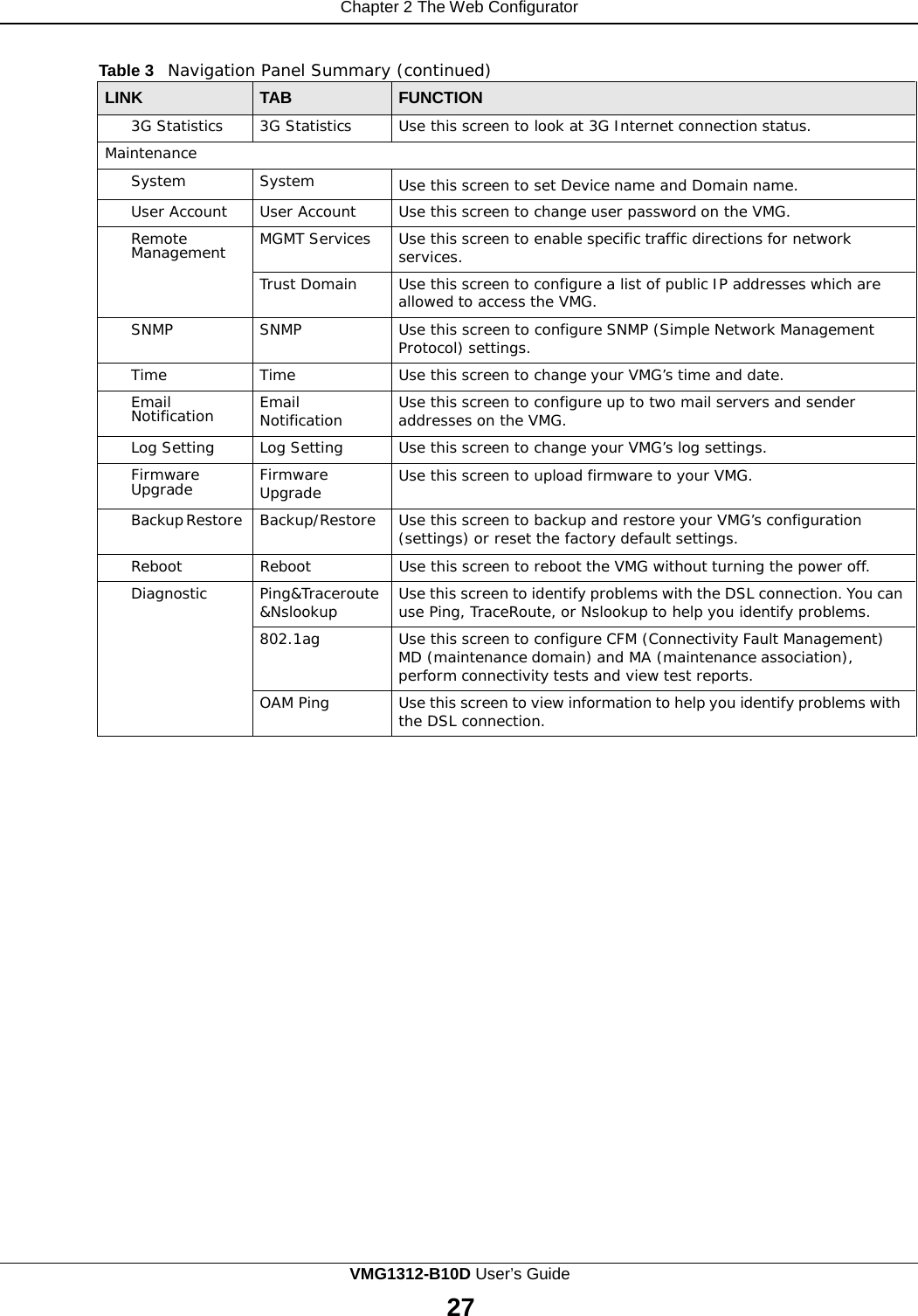
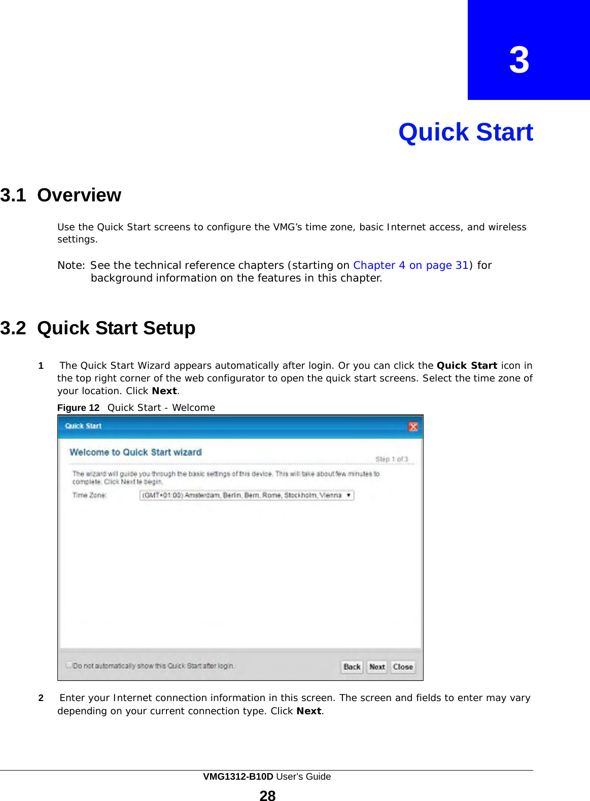
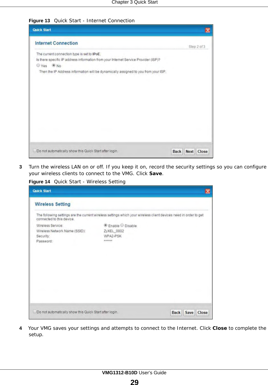
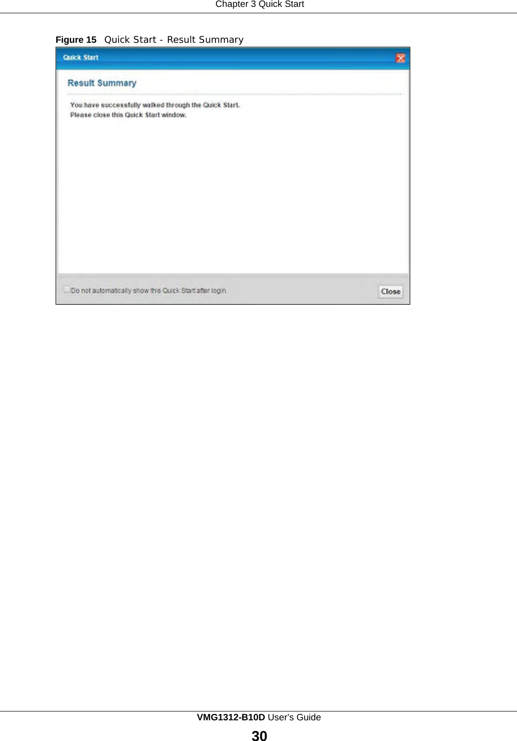
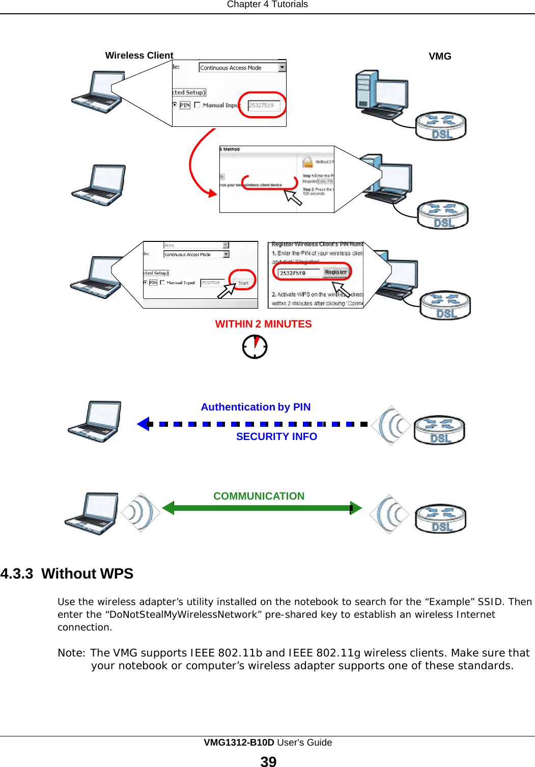
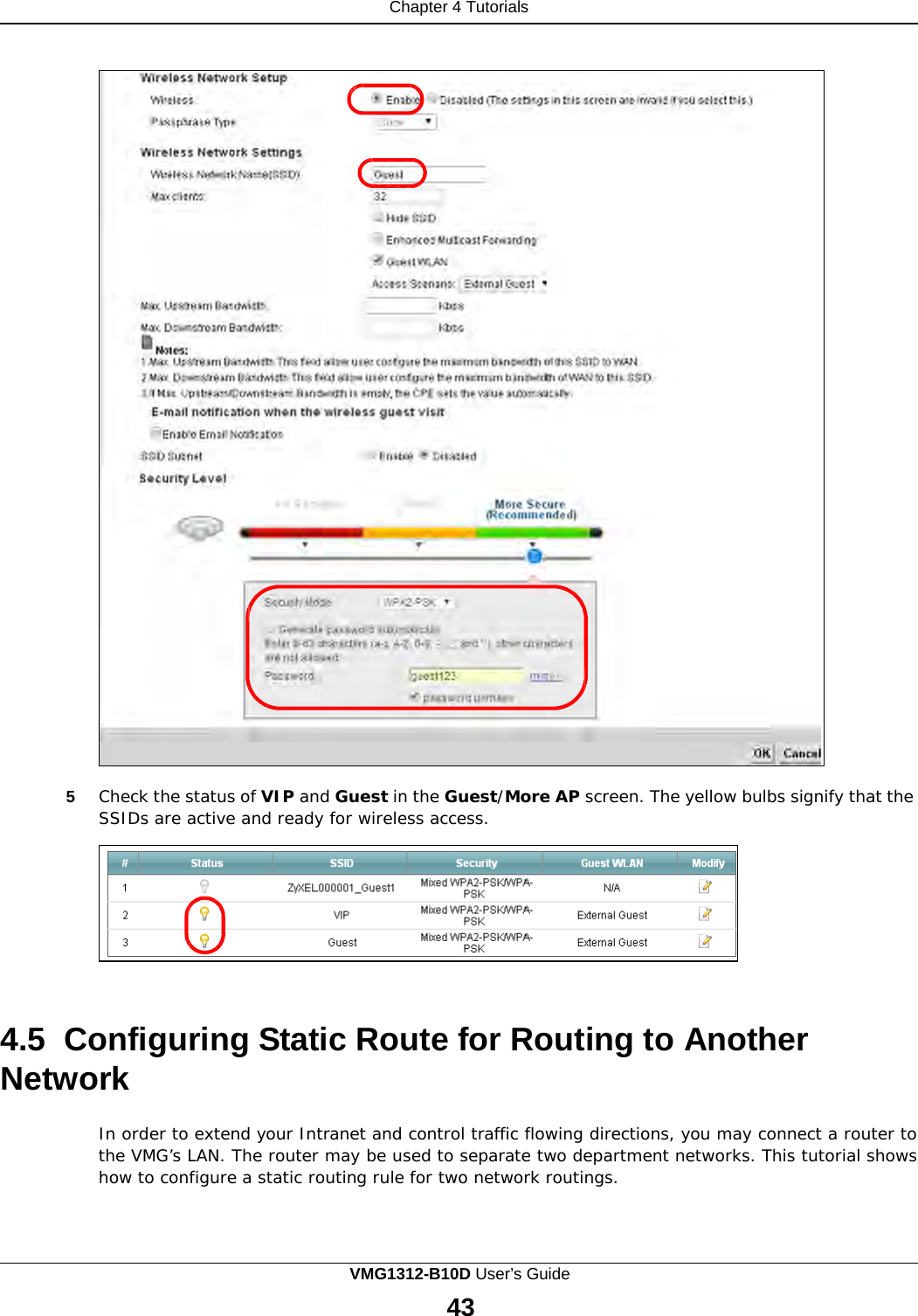
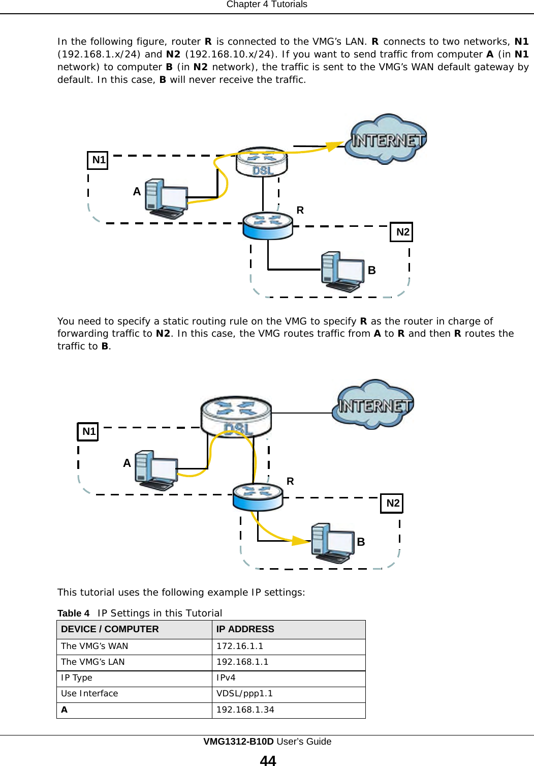
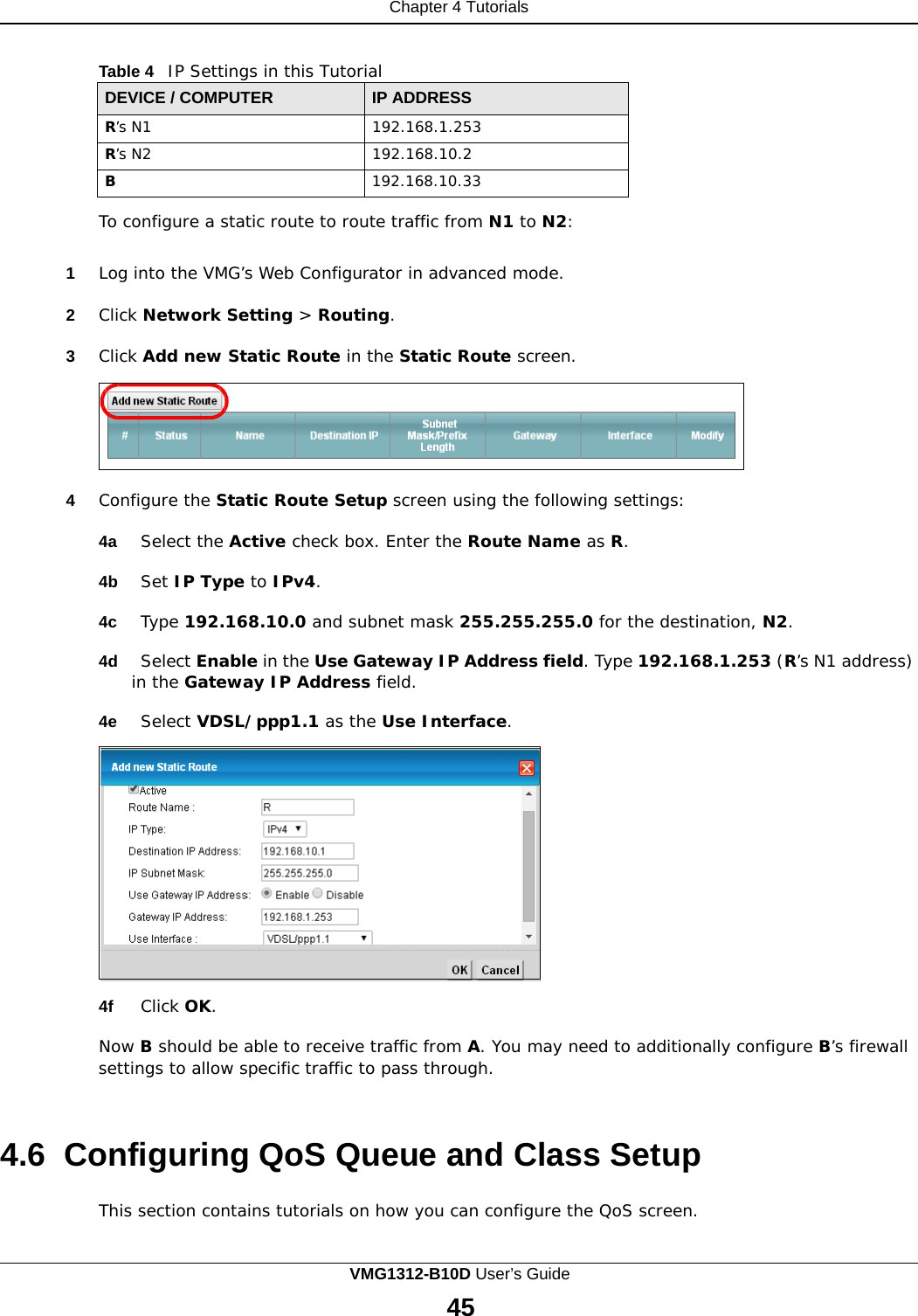
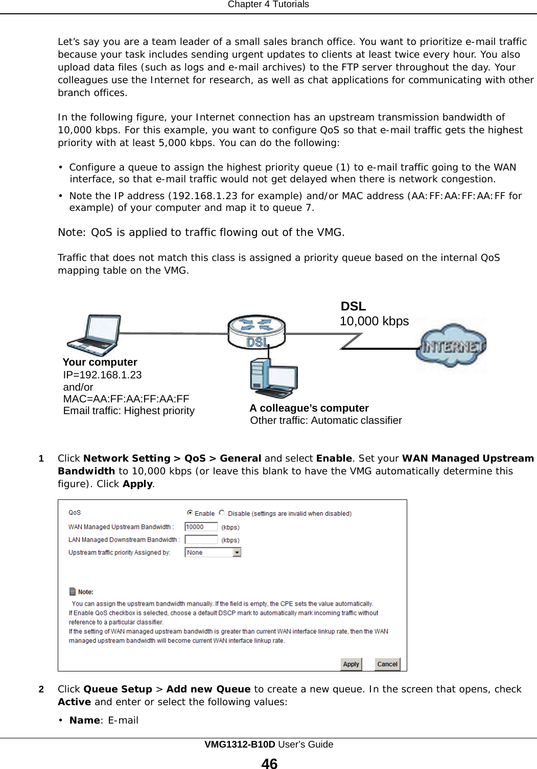
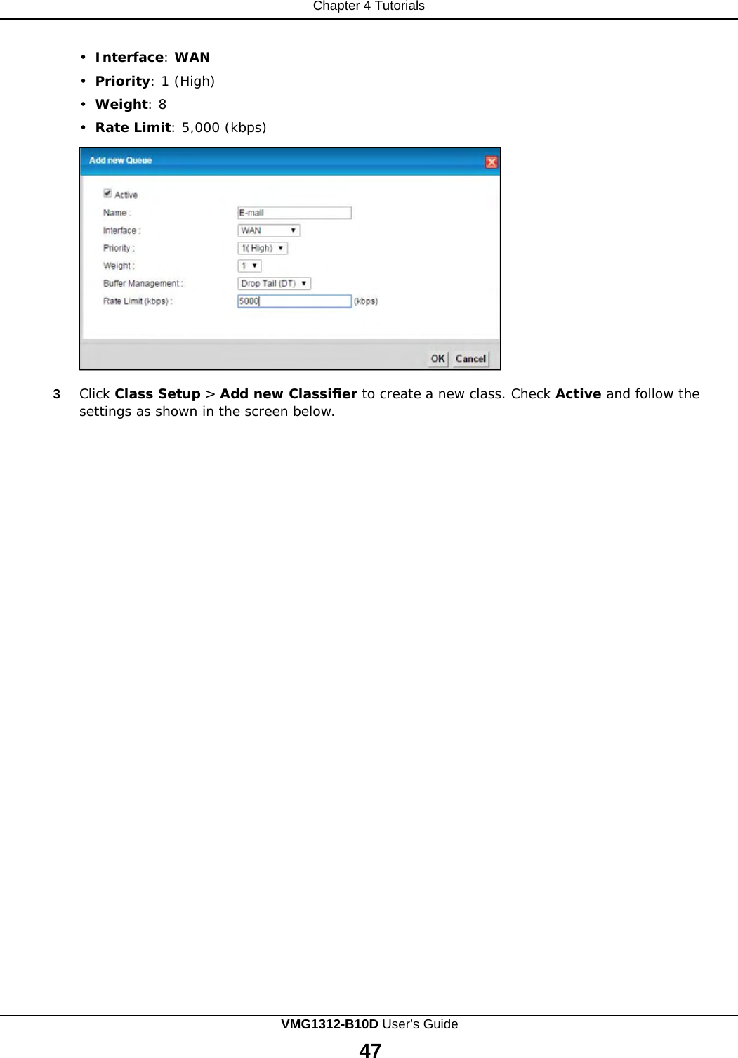
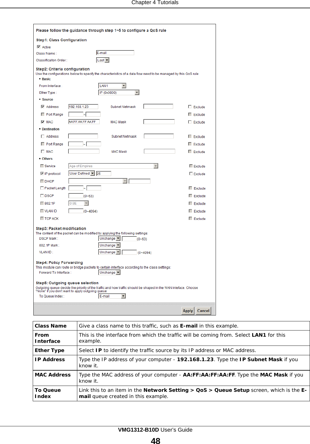
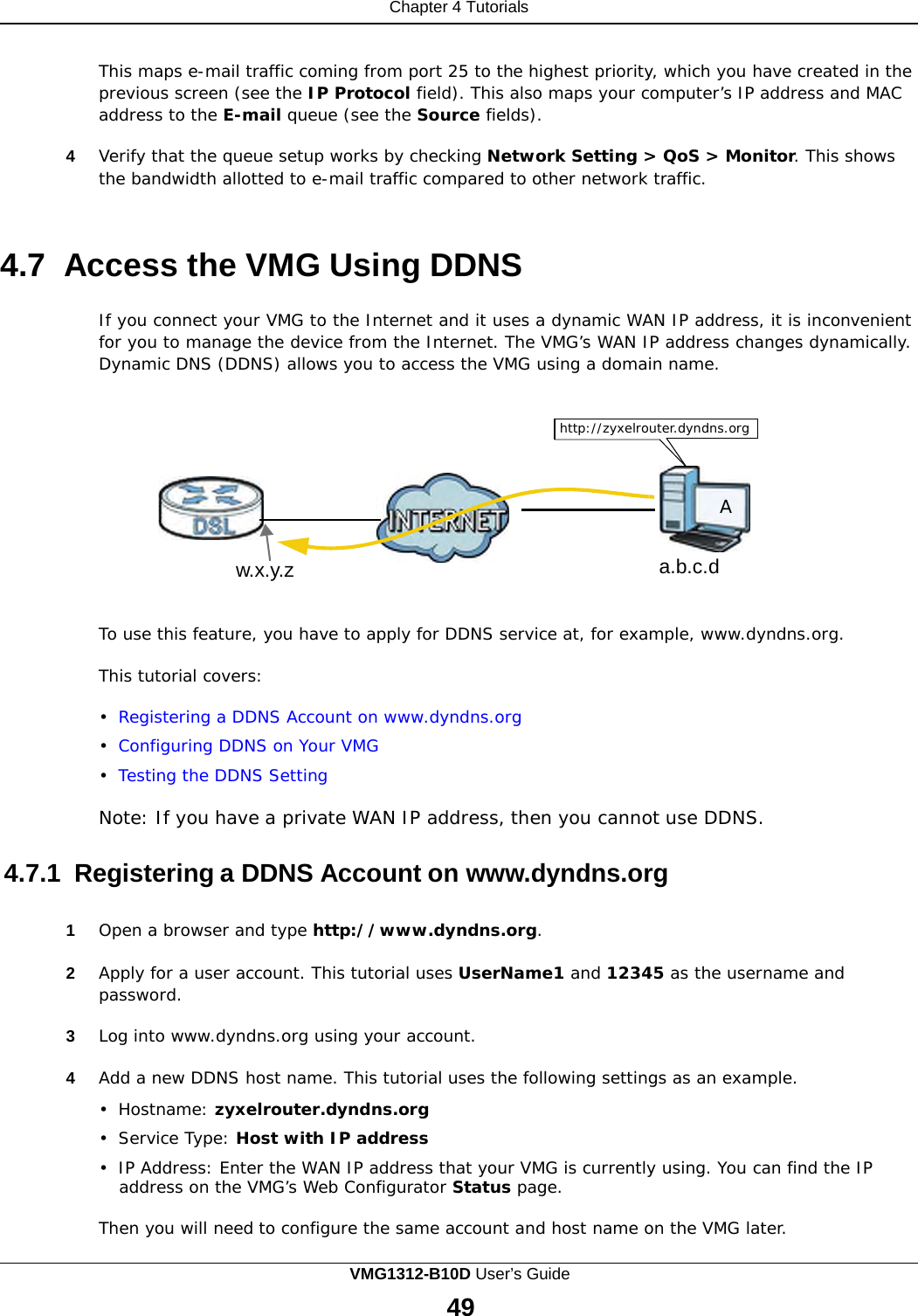
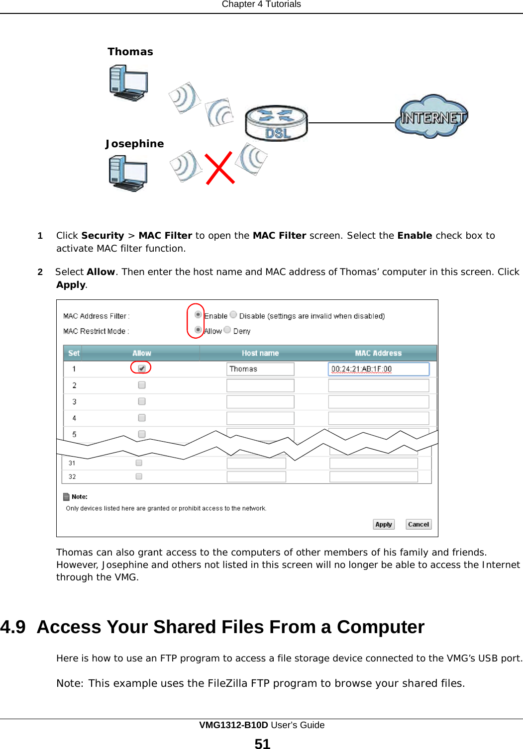
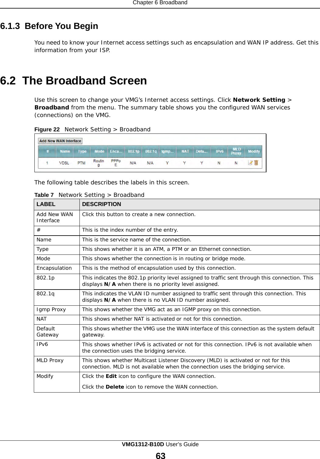
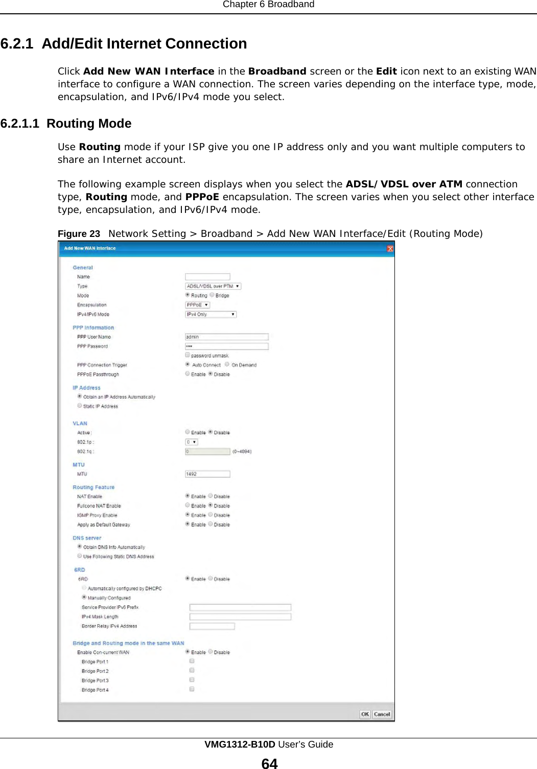
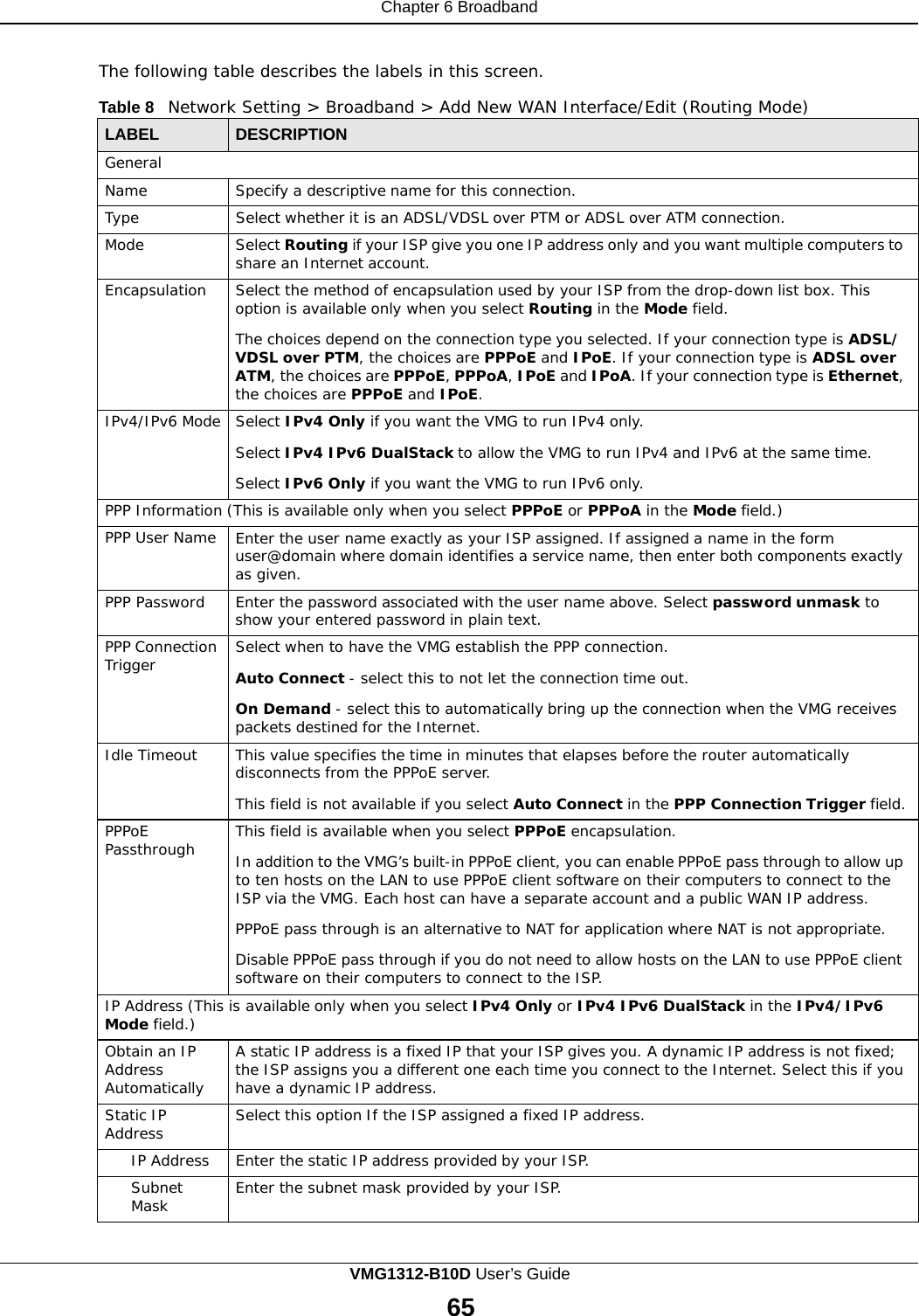
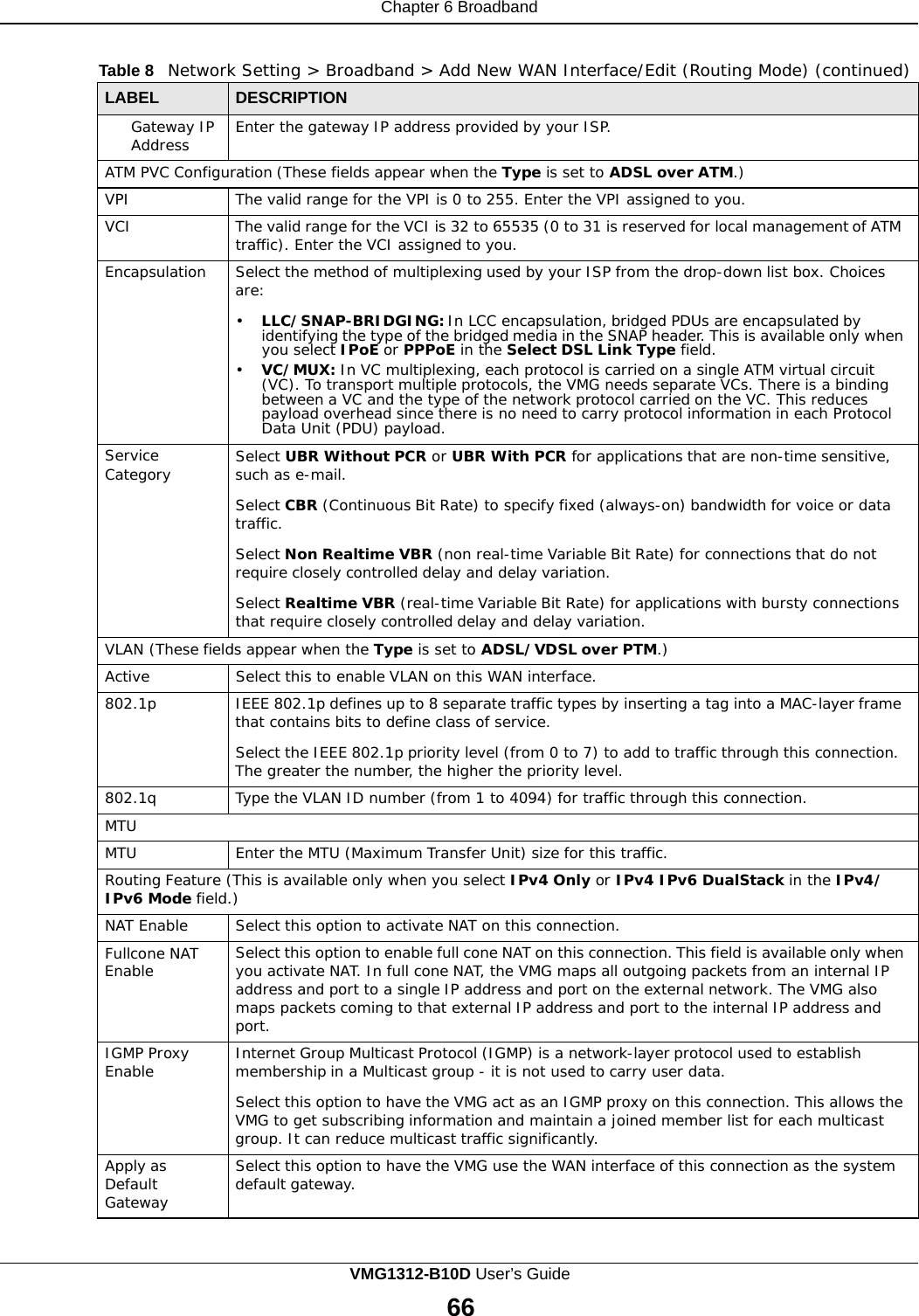
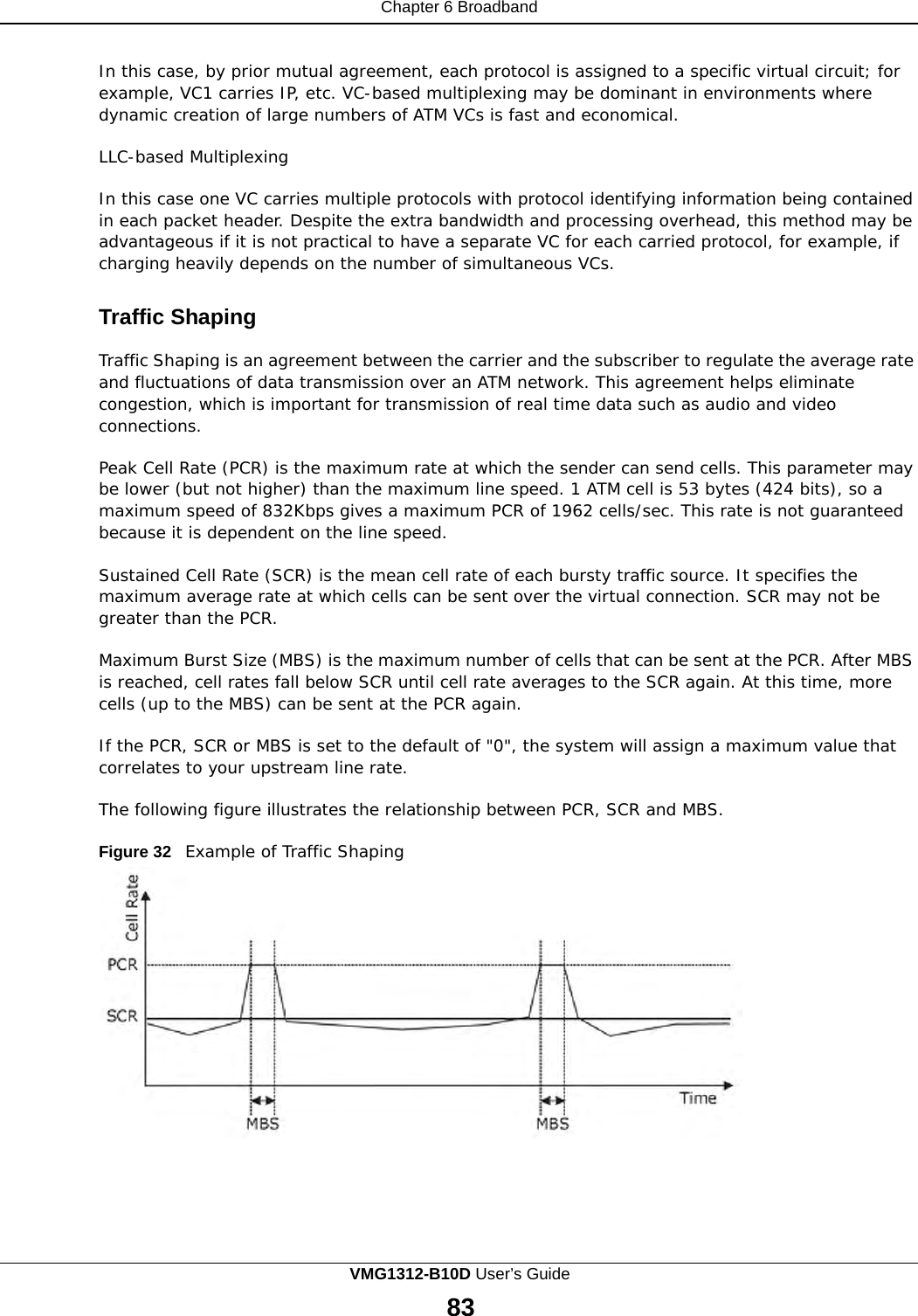
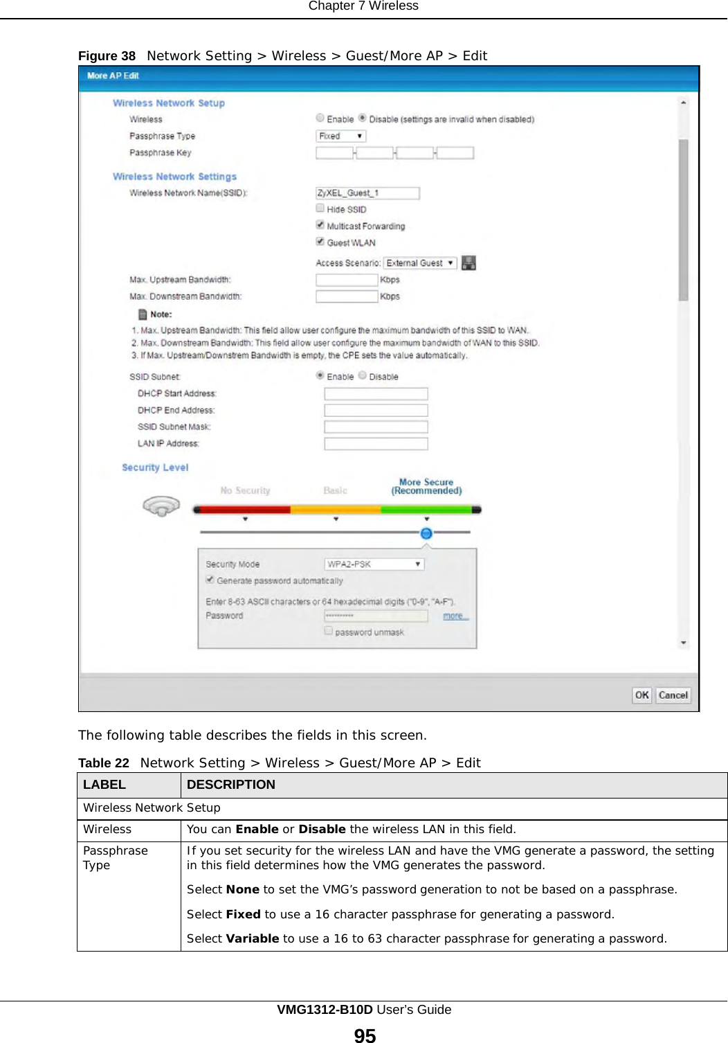
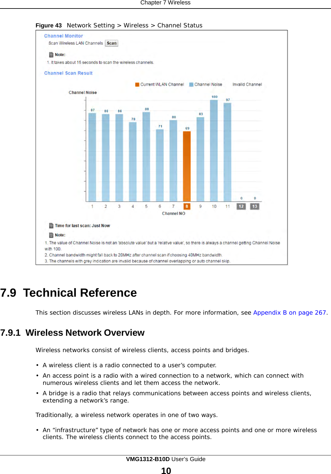
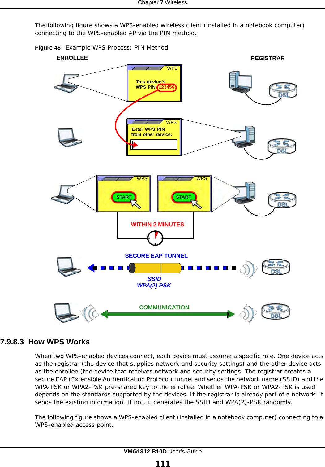
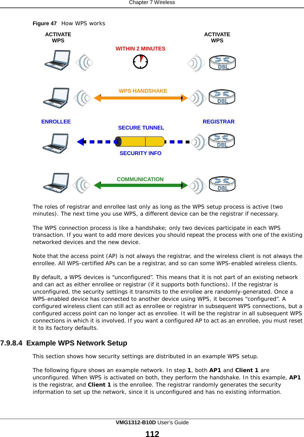
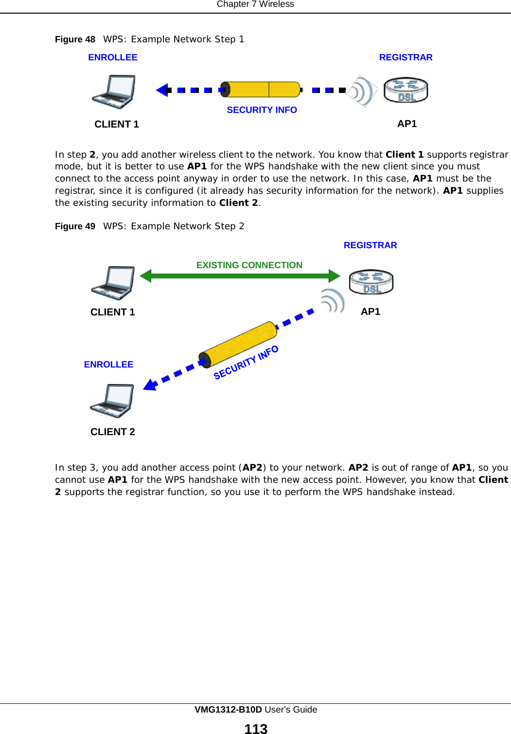
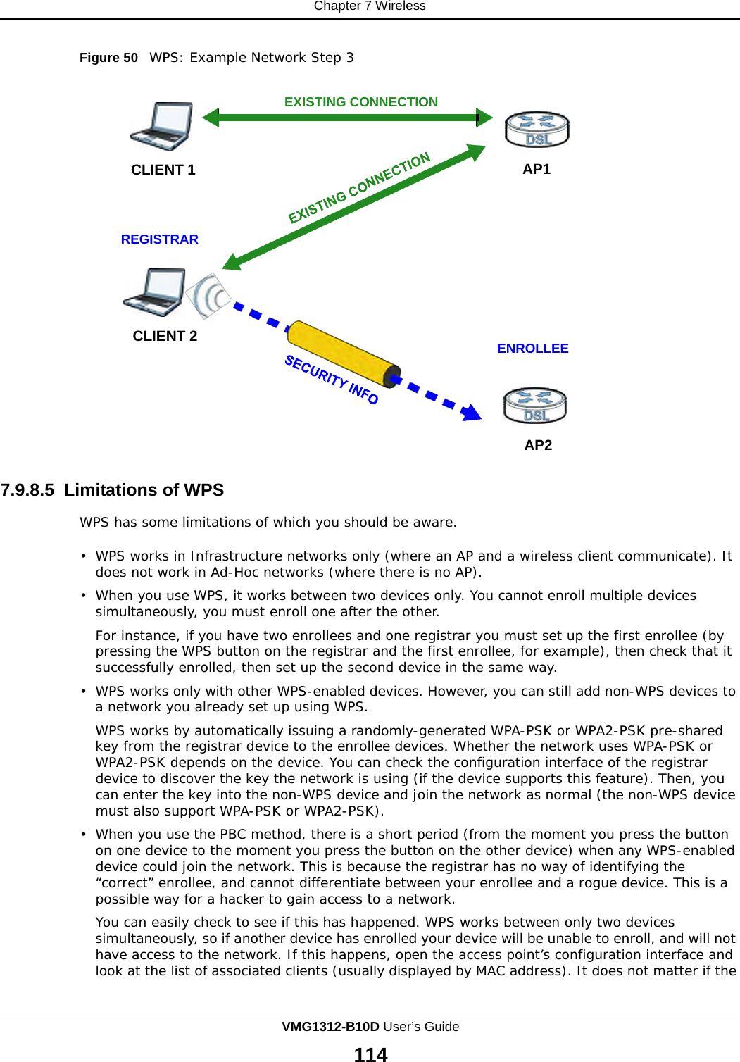
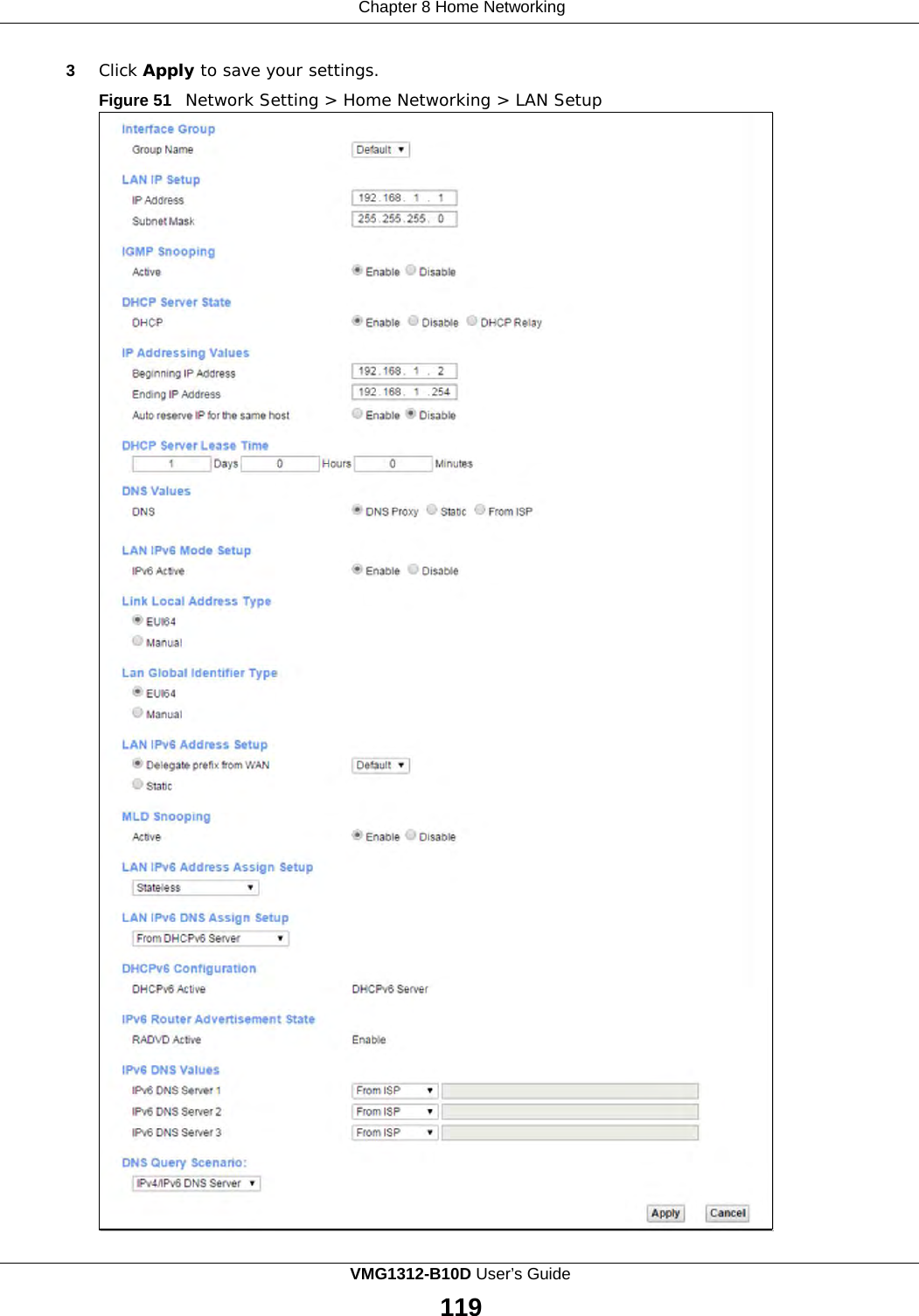
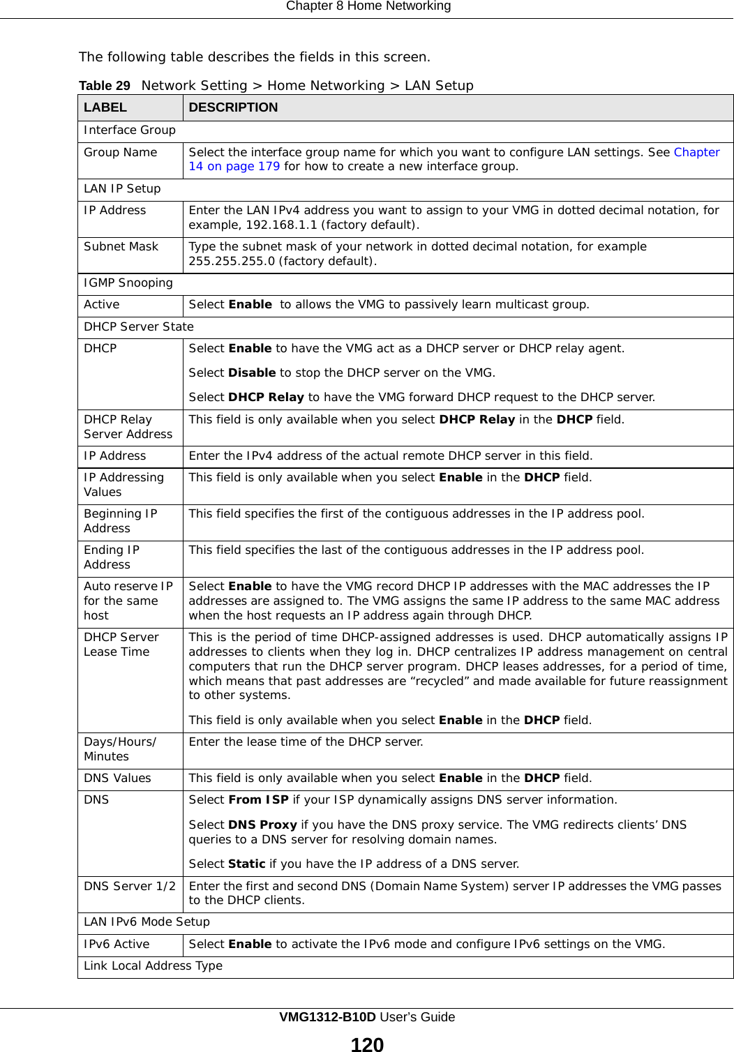
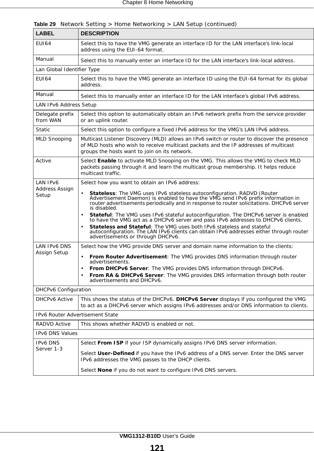
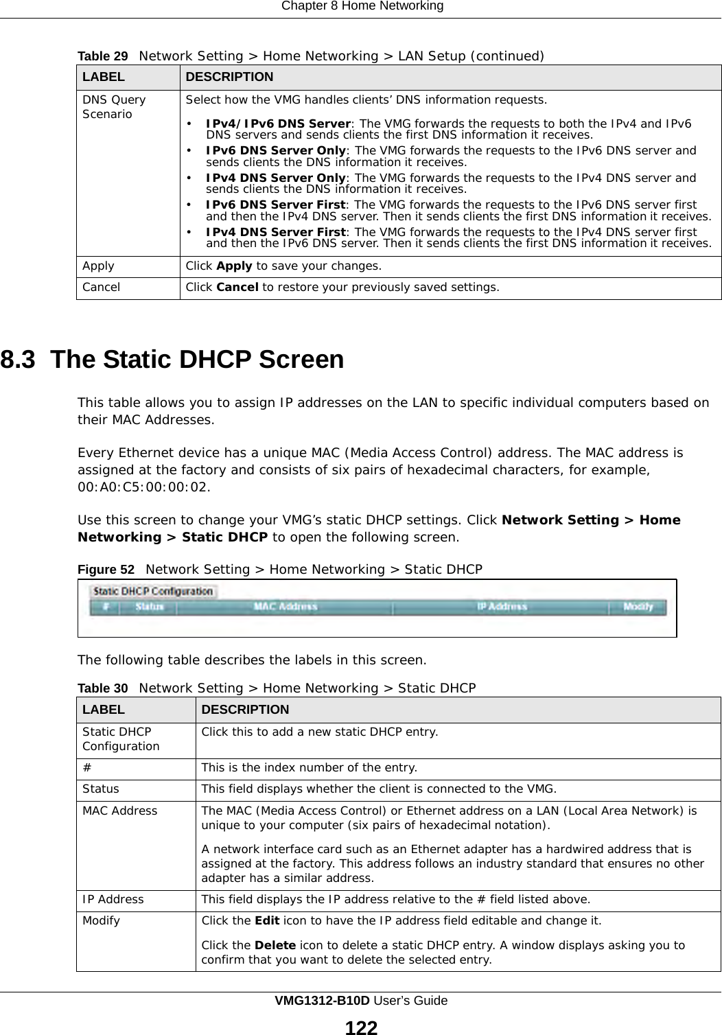
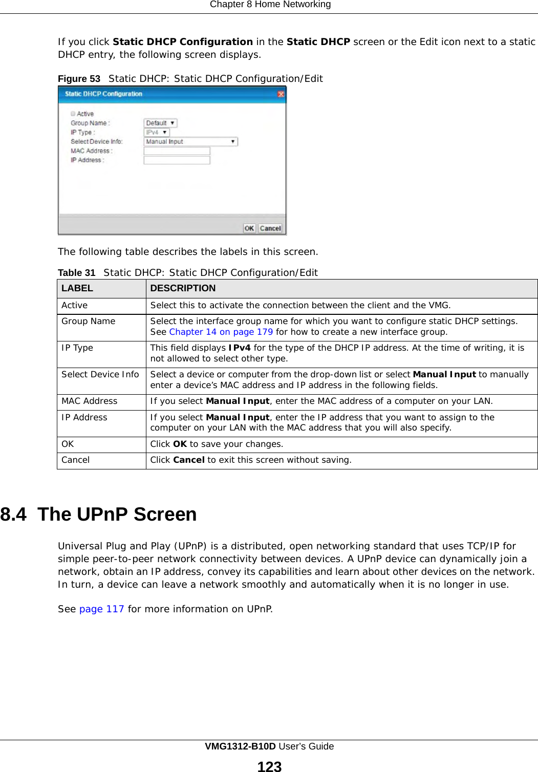
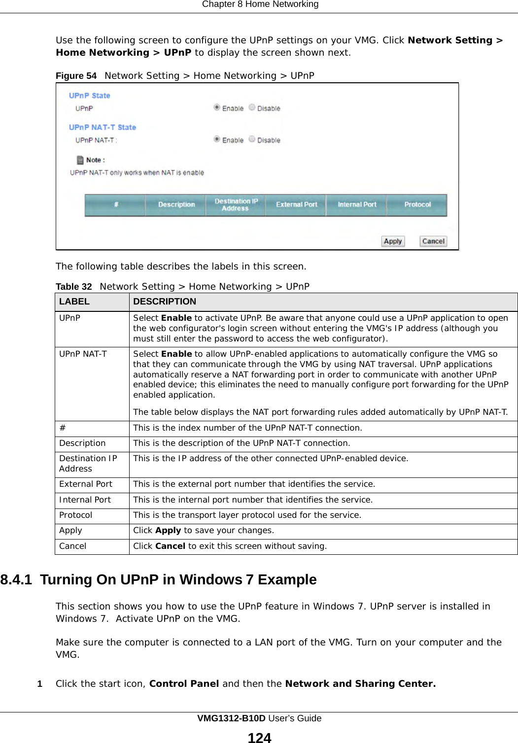
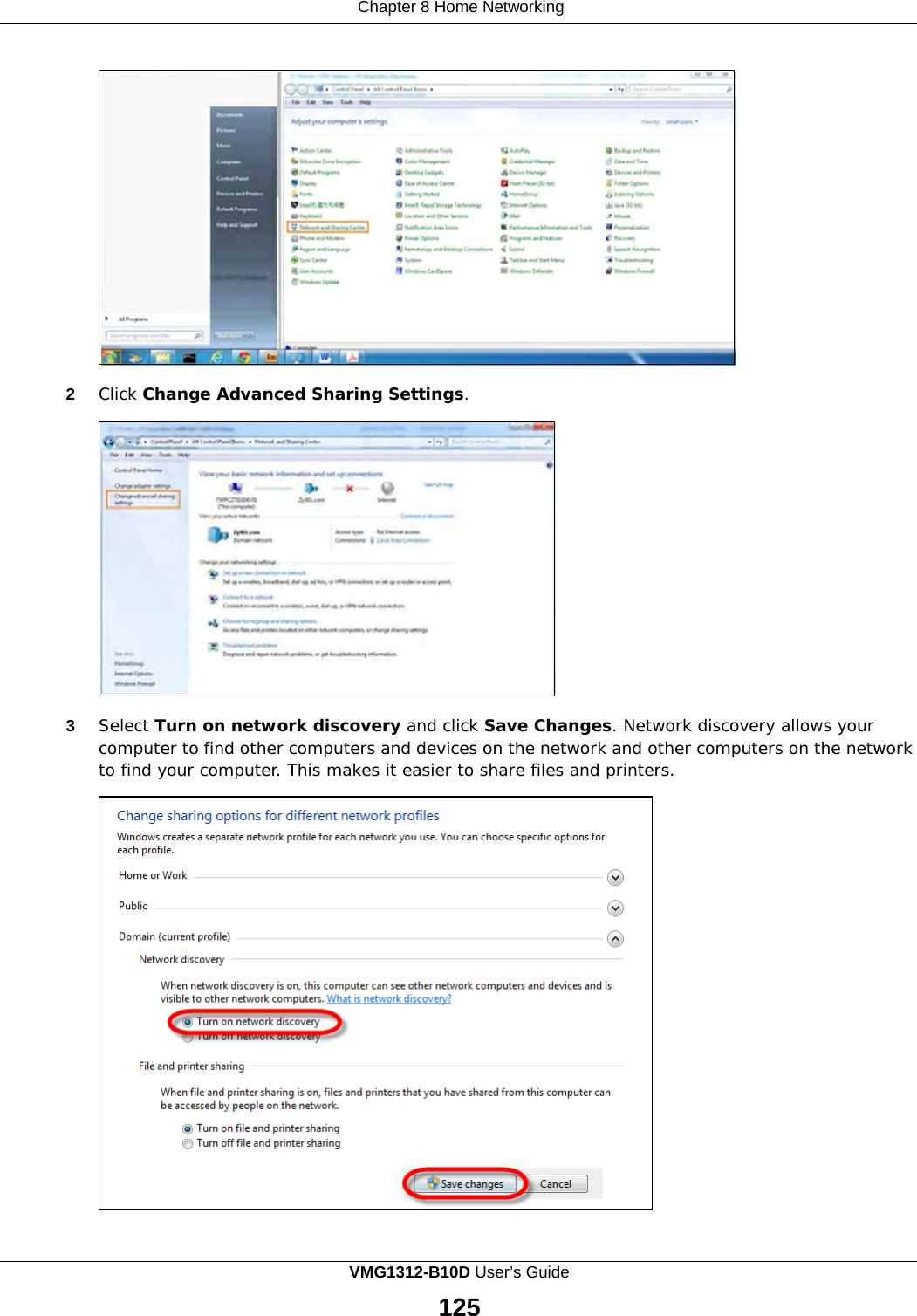
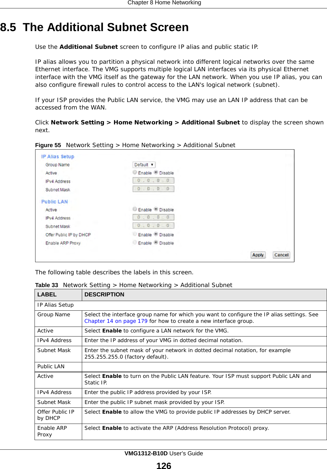
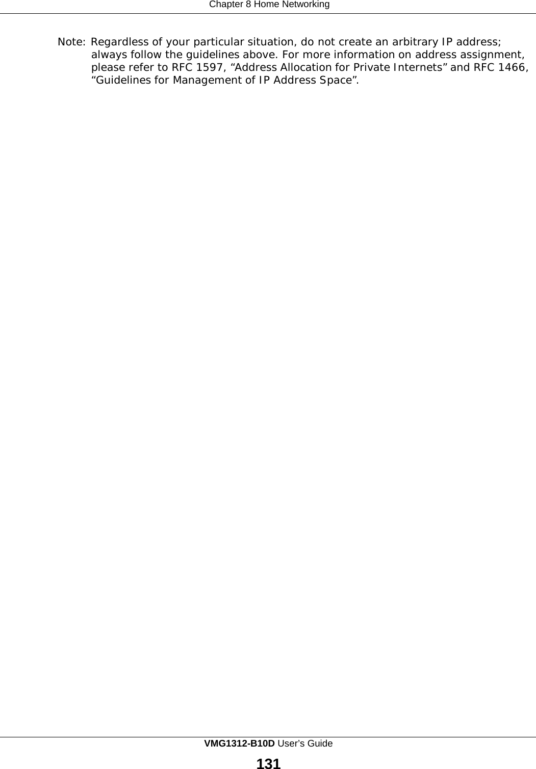
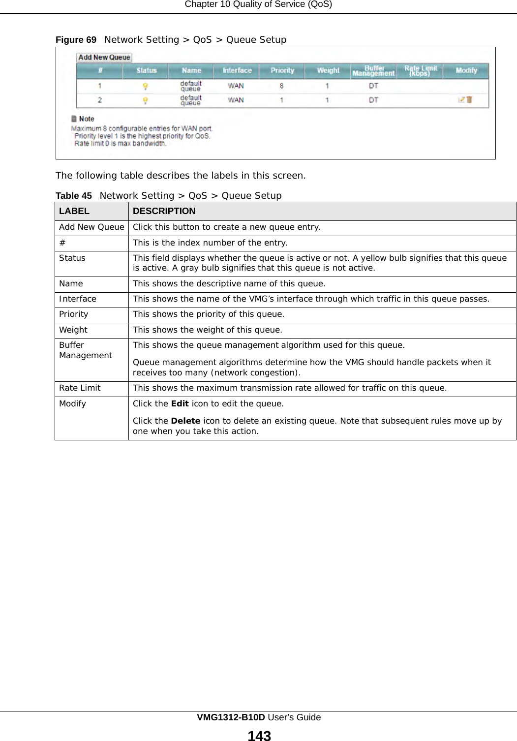
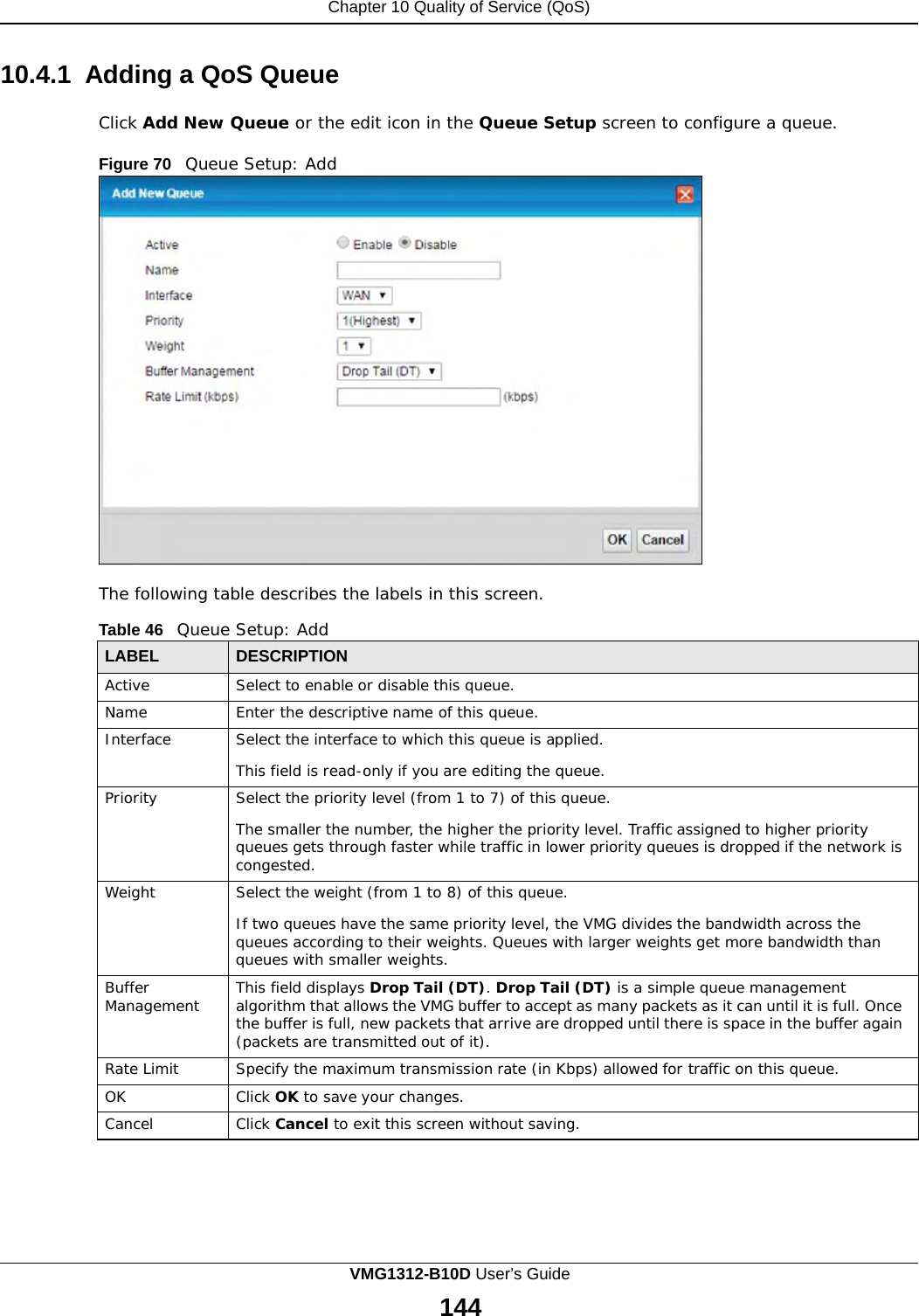
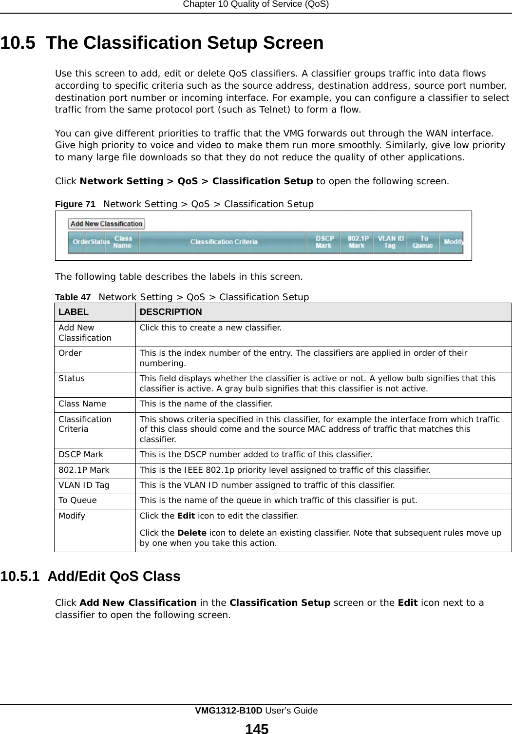
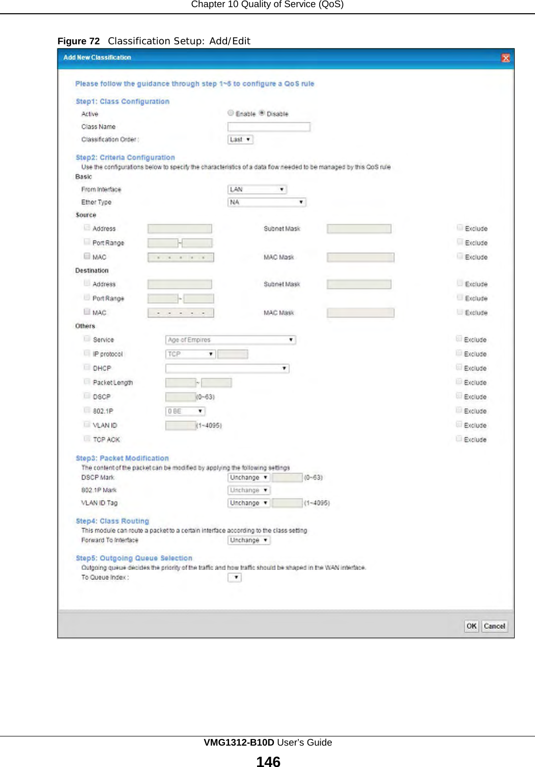
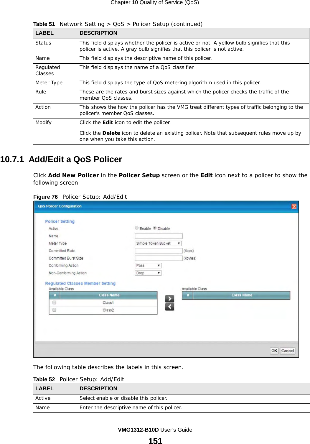
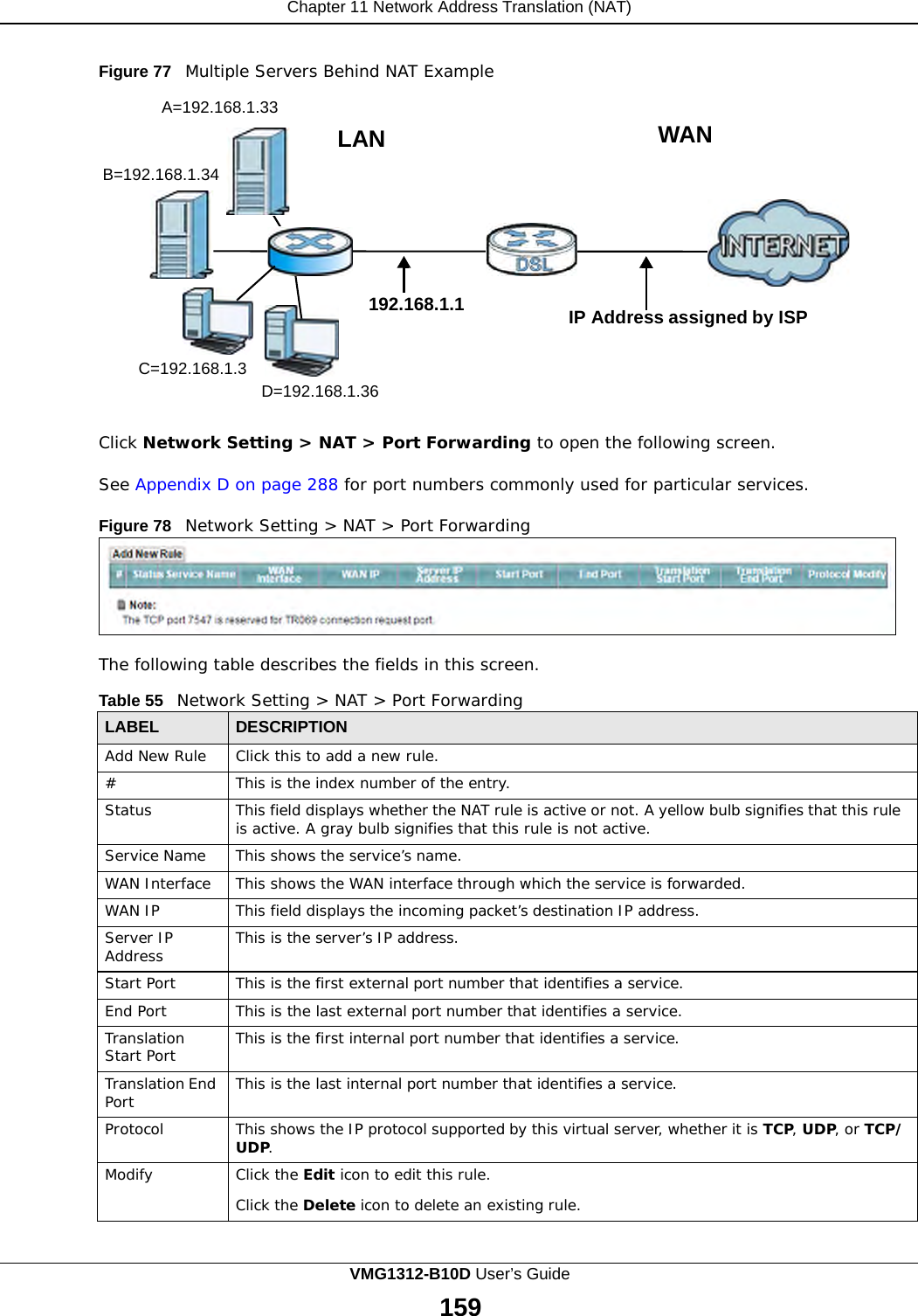
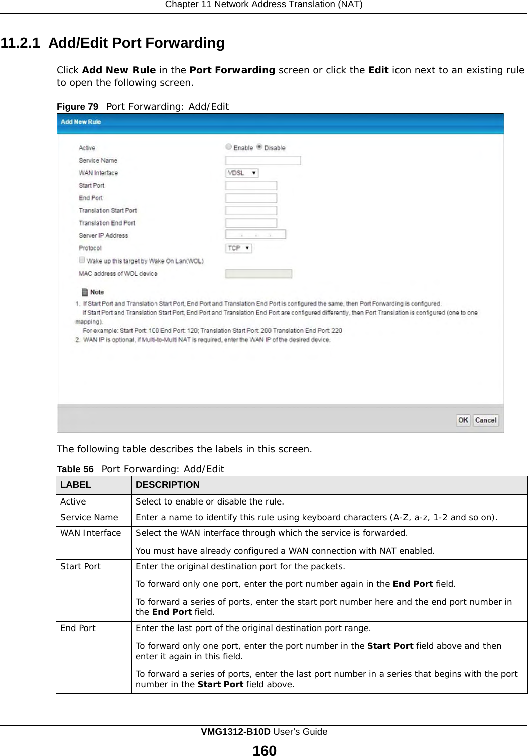
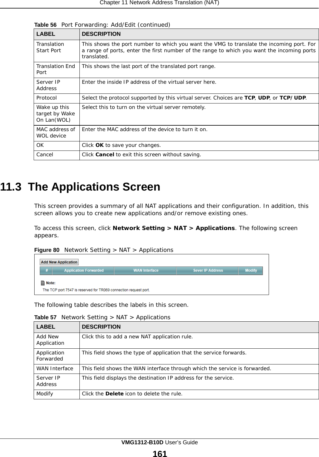
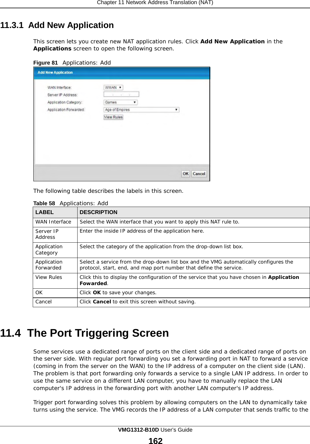
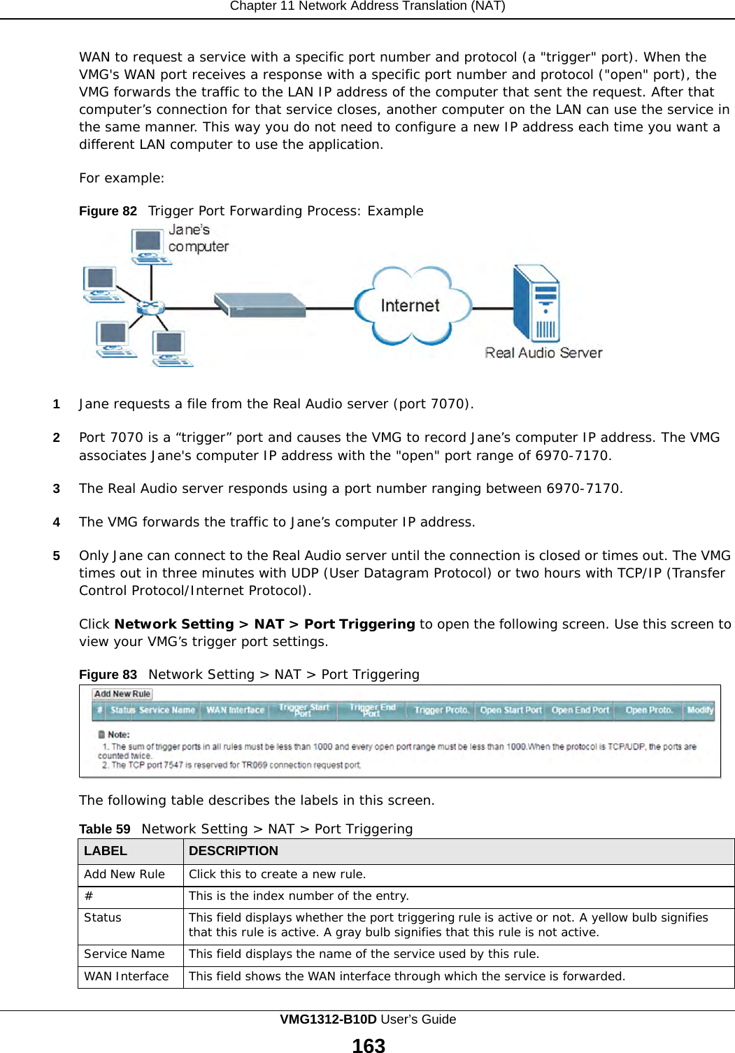
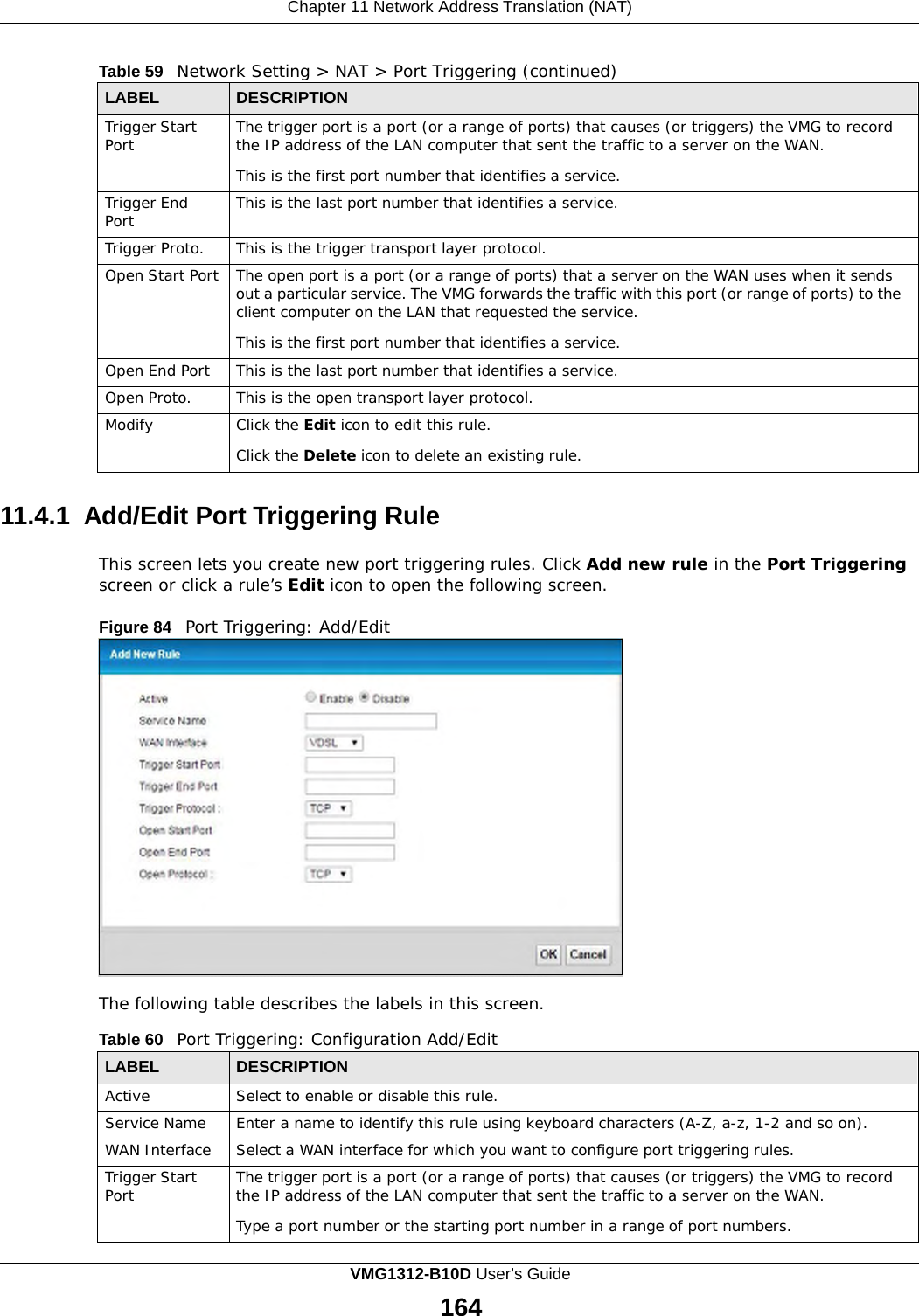
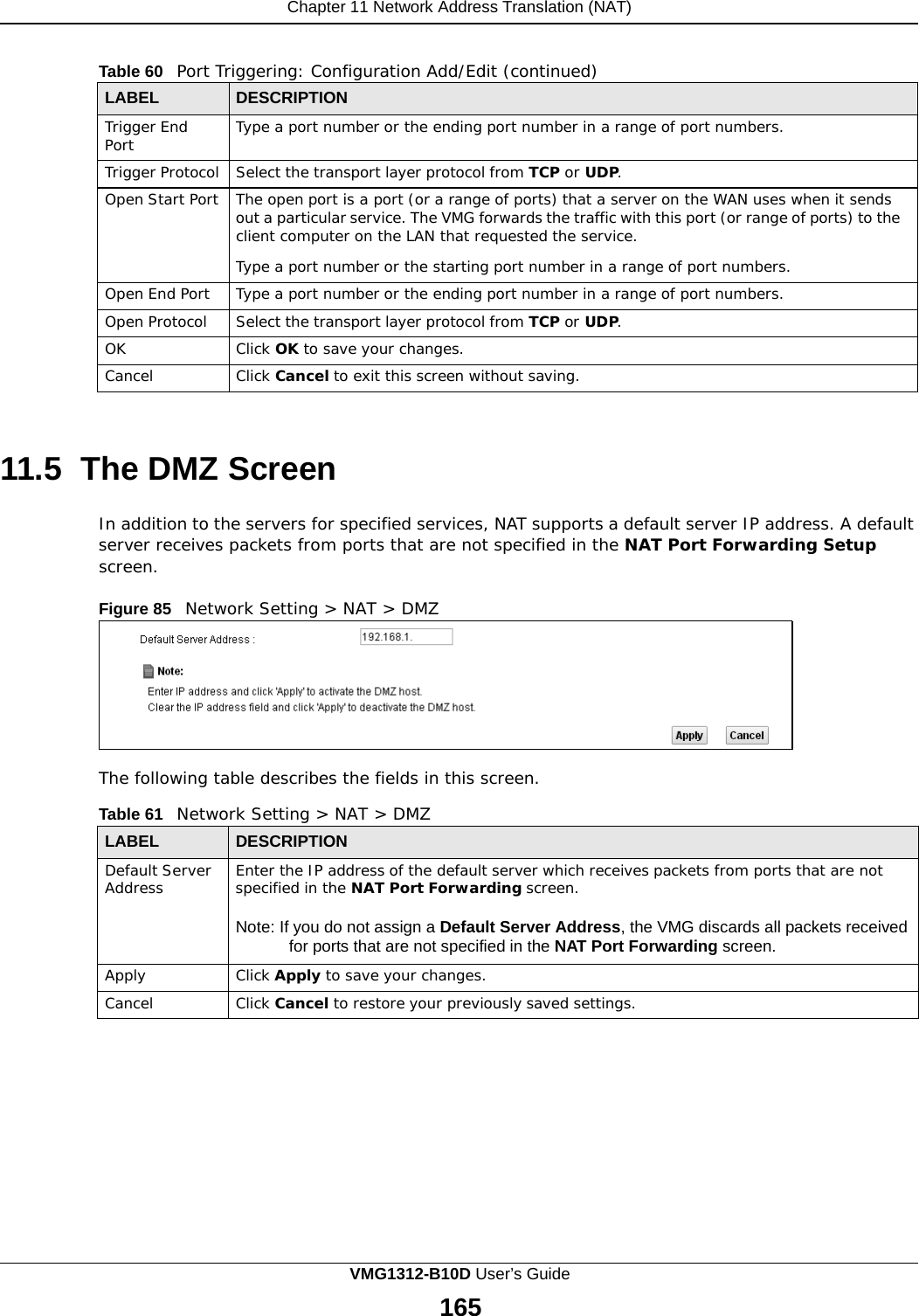
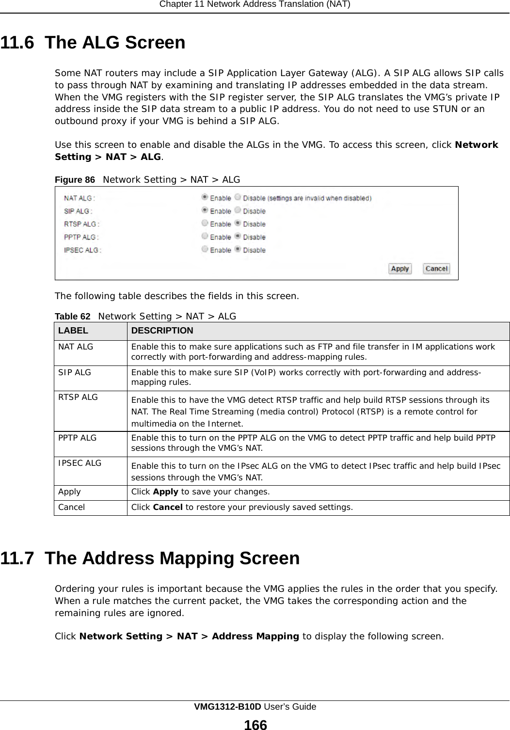
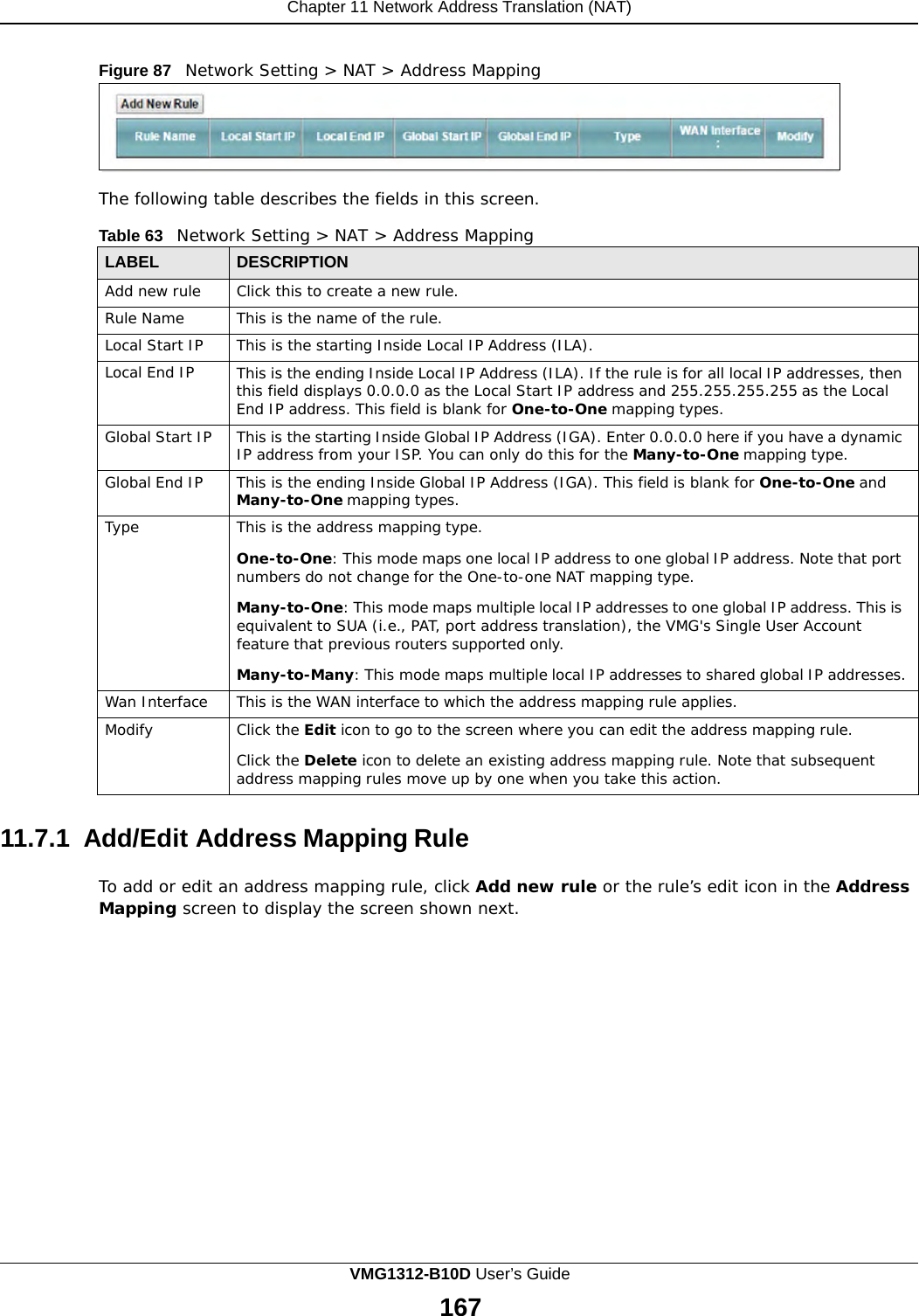
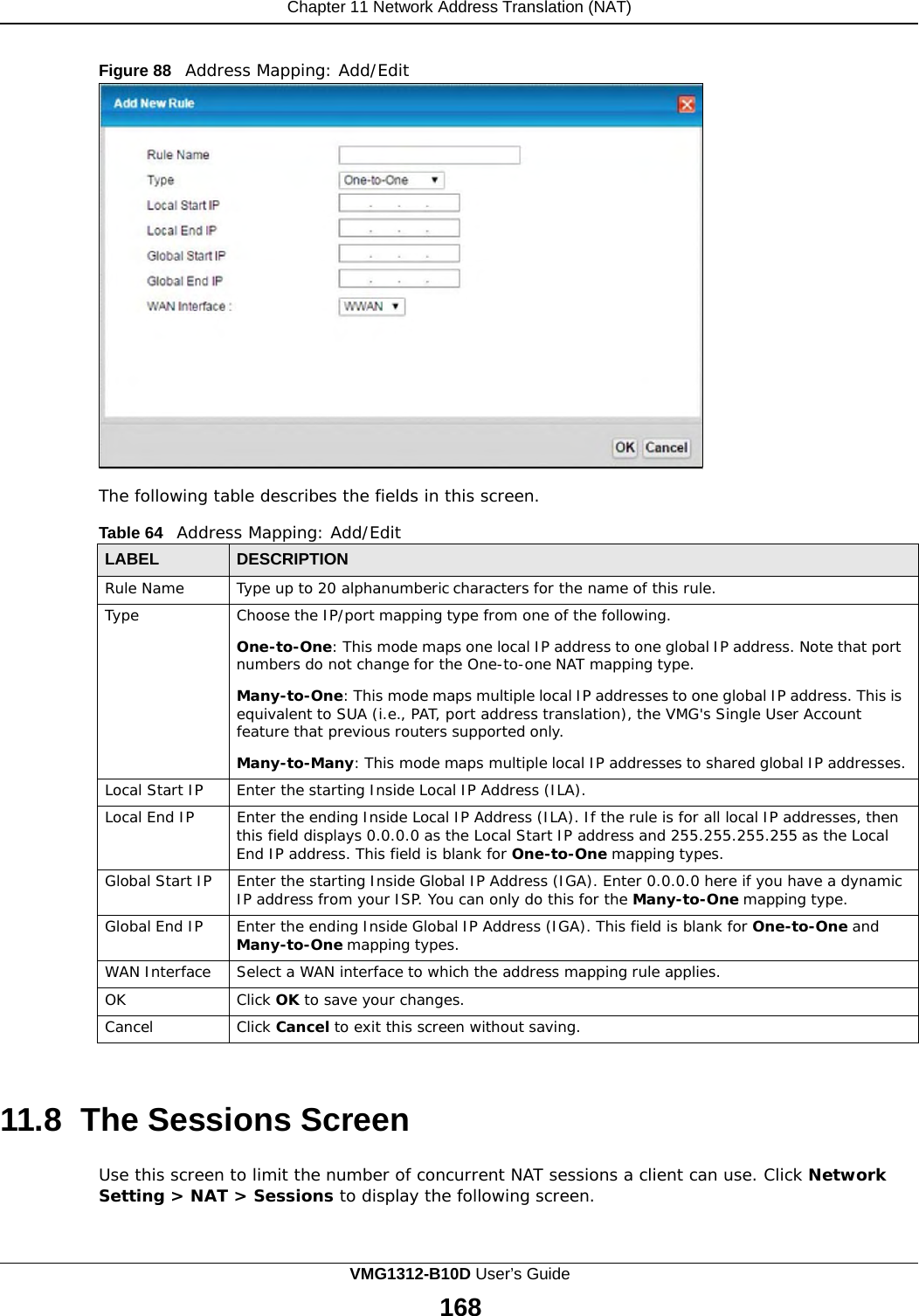
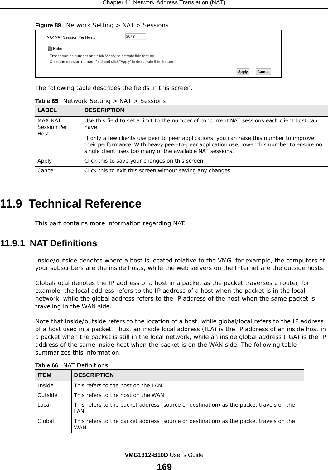
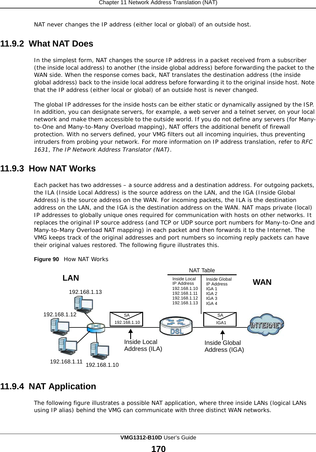
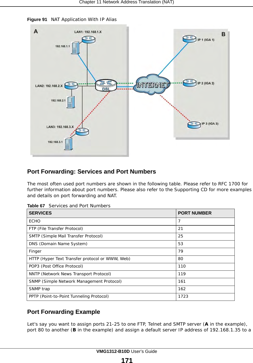
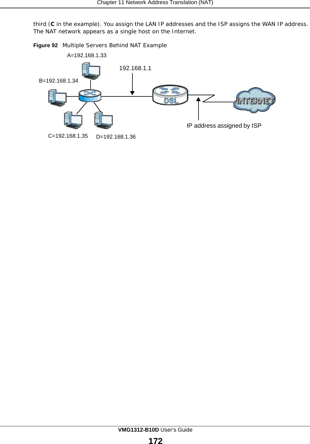
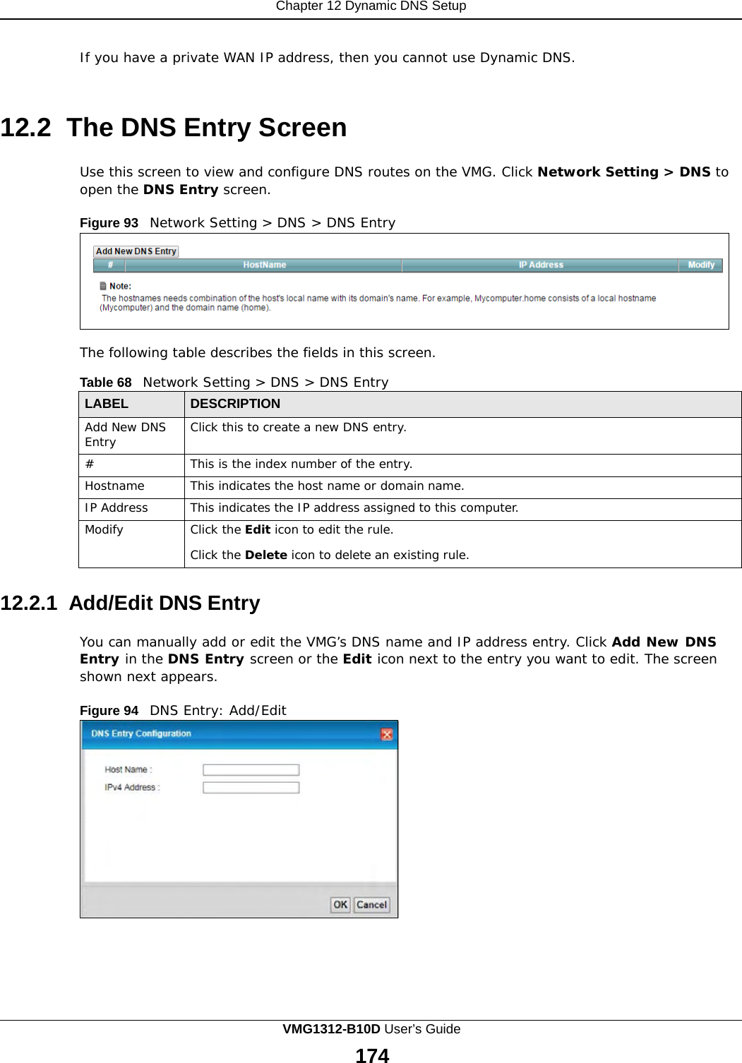
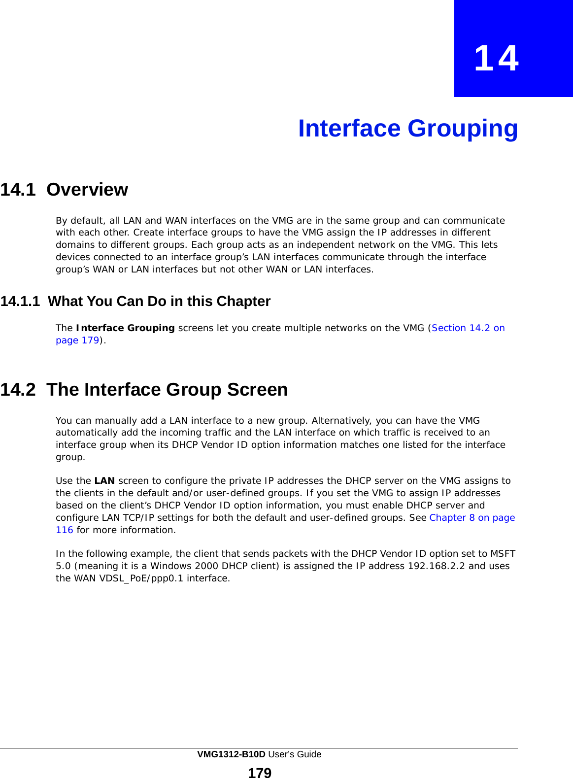
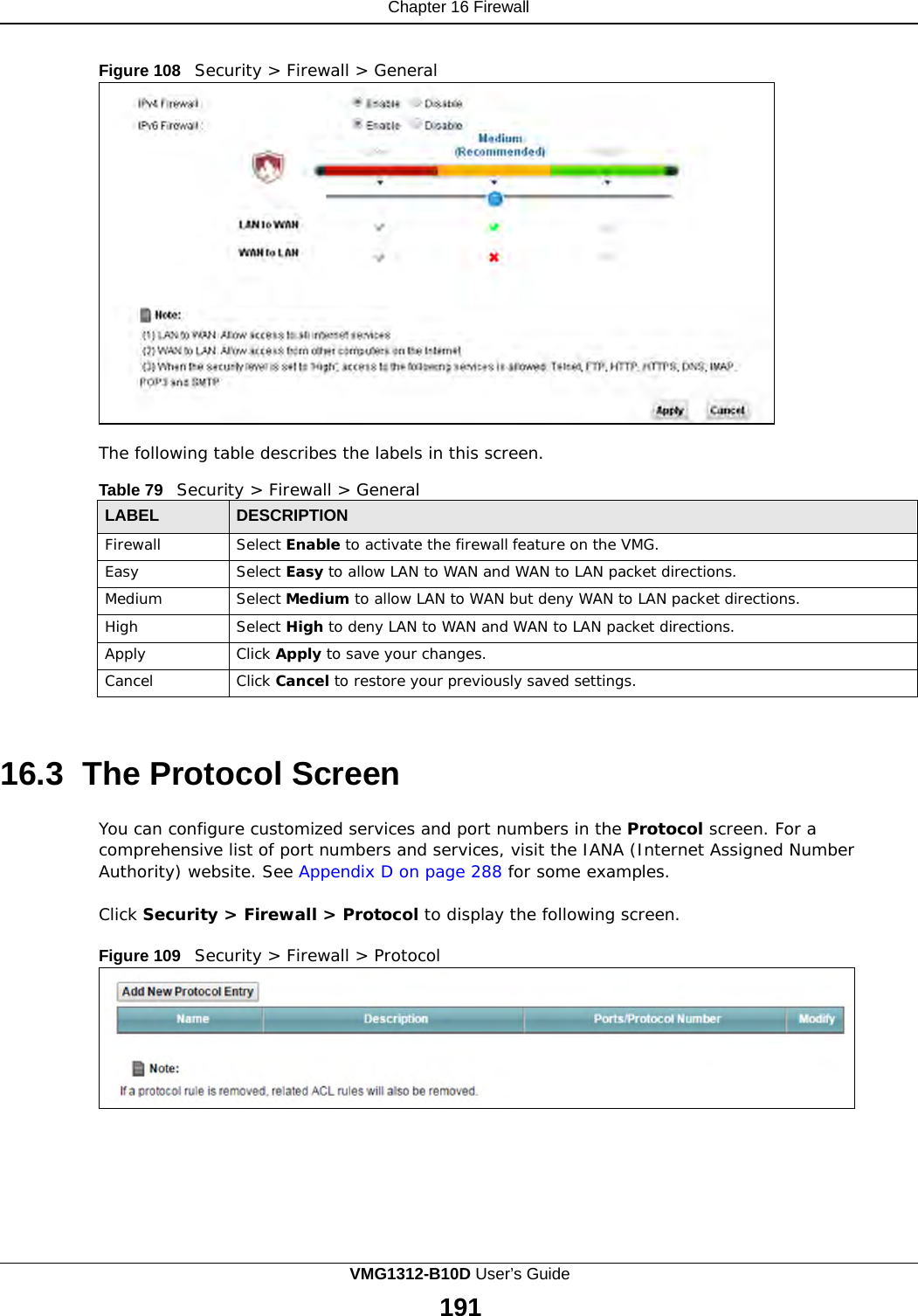
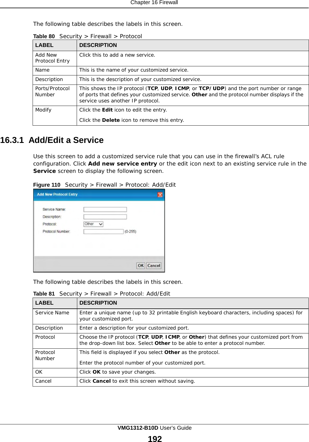
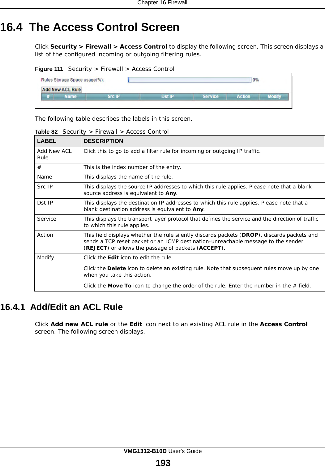
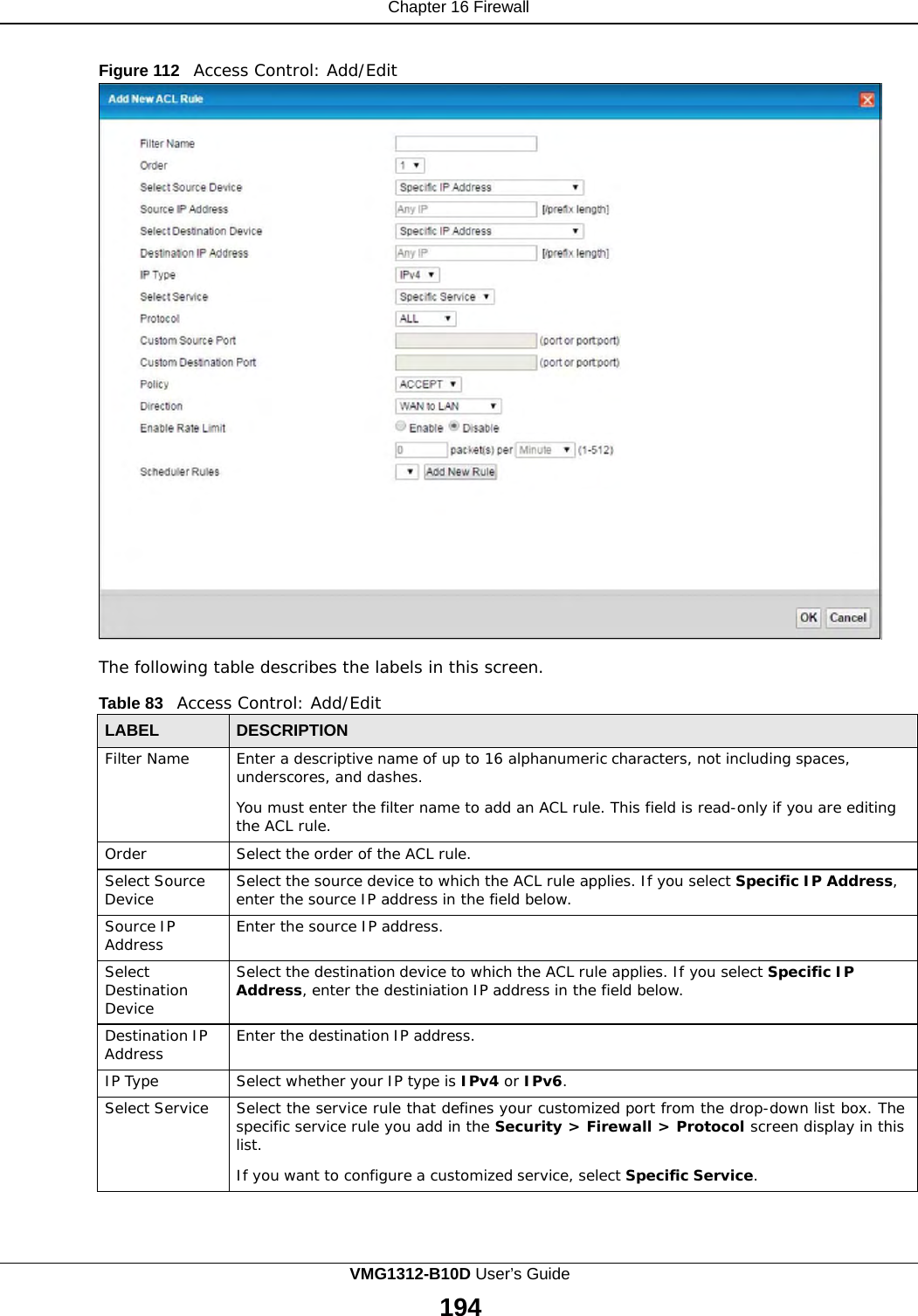
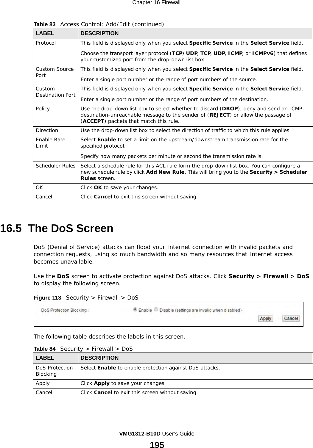
![Chapter 4 Tutorials 4.7.2 Configuring DDNS on Your VMG Configure the following settings in the Network Setting > DNS > Dynamic DNS screen. • Select Enable Dynamic DNS. • Select www.DynDNS.com as the service provider. • Type zyxelrouter.dyndns.org in the Host Name field. • Enter the user name (UserName1) and password (12345). Click Apply. 4.7.3 Testing the DDNS Setting Now you should be able to access the VMG from the Internet. To test this: 1 Open a web browser on the computer (using the IP address a.b.c.d) that is connected to the Internet. 2 Type http://zyxelrouter.dyndns.org and press [Enter]. 3 The VMG’s login page should appear. You can then log into the VMG and manage it. 4.8 Configuring the MAC Address Filter Thomas noticed that his daughter Josephine spends too much time surfing the web and downloading media files. He decided to prevent Josephine from accessing the Internet so that she can concentrate on preparing for her final exams. Josephine’s computer connects wirelessly to the Internet through the VMG. Thomas decides to use the Security > MAC Filter screen to grant wireless network access to his computer but not to Josephine’s computer. VMG1312-B10D User’s Guide 50](https://usermanual.wiki/ZyXEL-Communications/VMG1312B10D.User-Manual-1/User-Guide-3227519-Page-50.png)