ZyXEL Communications VMG4380B10A Wireles N VDSL2 4-port Bonding Combo WAN Gateway with HPNA User Manual Manual 1
ZyXEL Communications Corporation Wireles N VDSL2 4-port Bonding Combo WAN Gateway with HPNA Manual 1
Contents
- 1. Manual 1
- 2. Manual 2
Manual 1
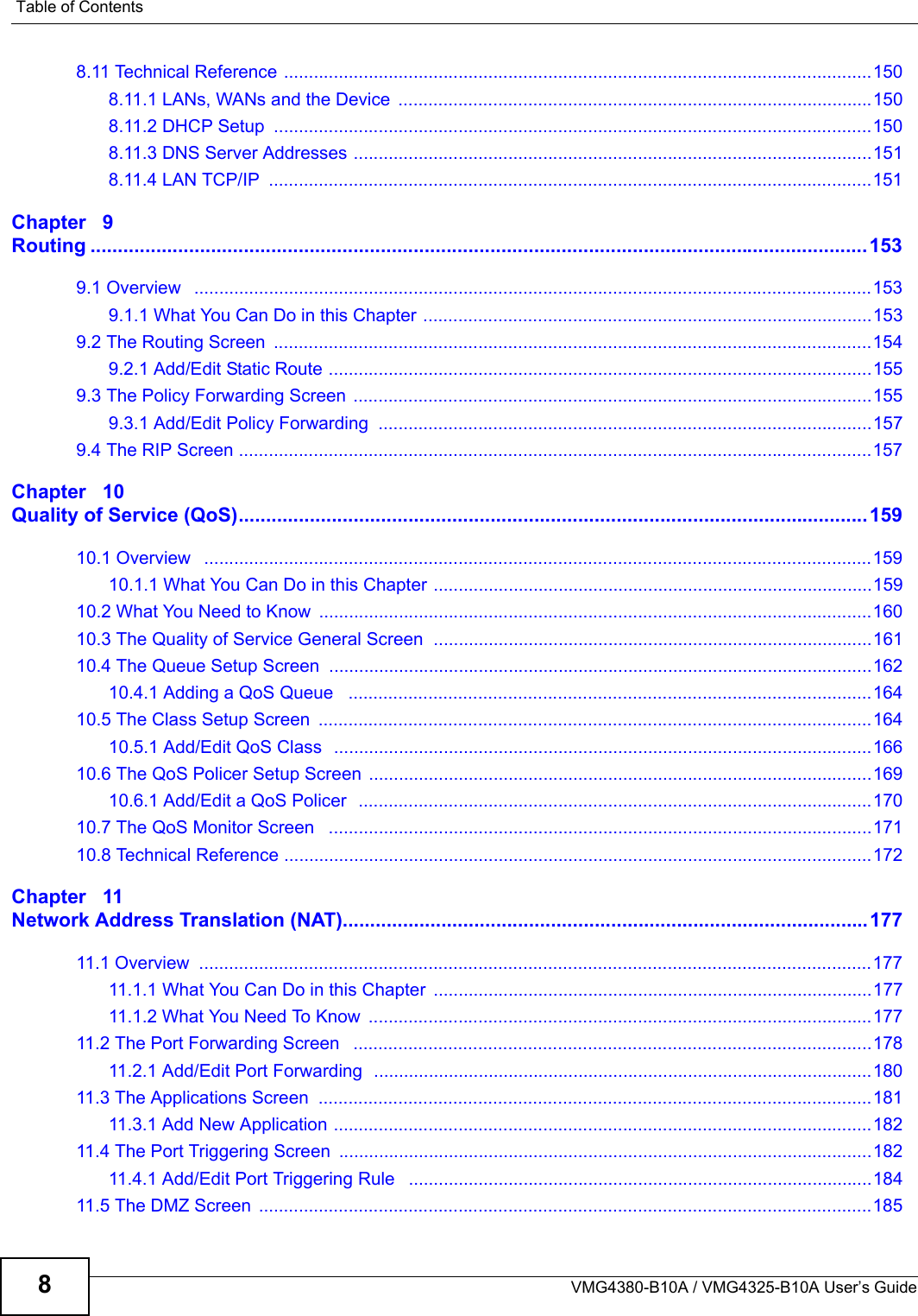


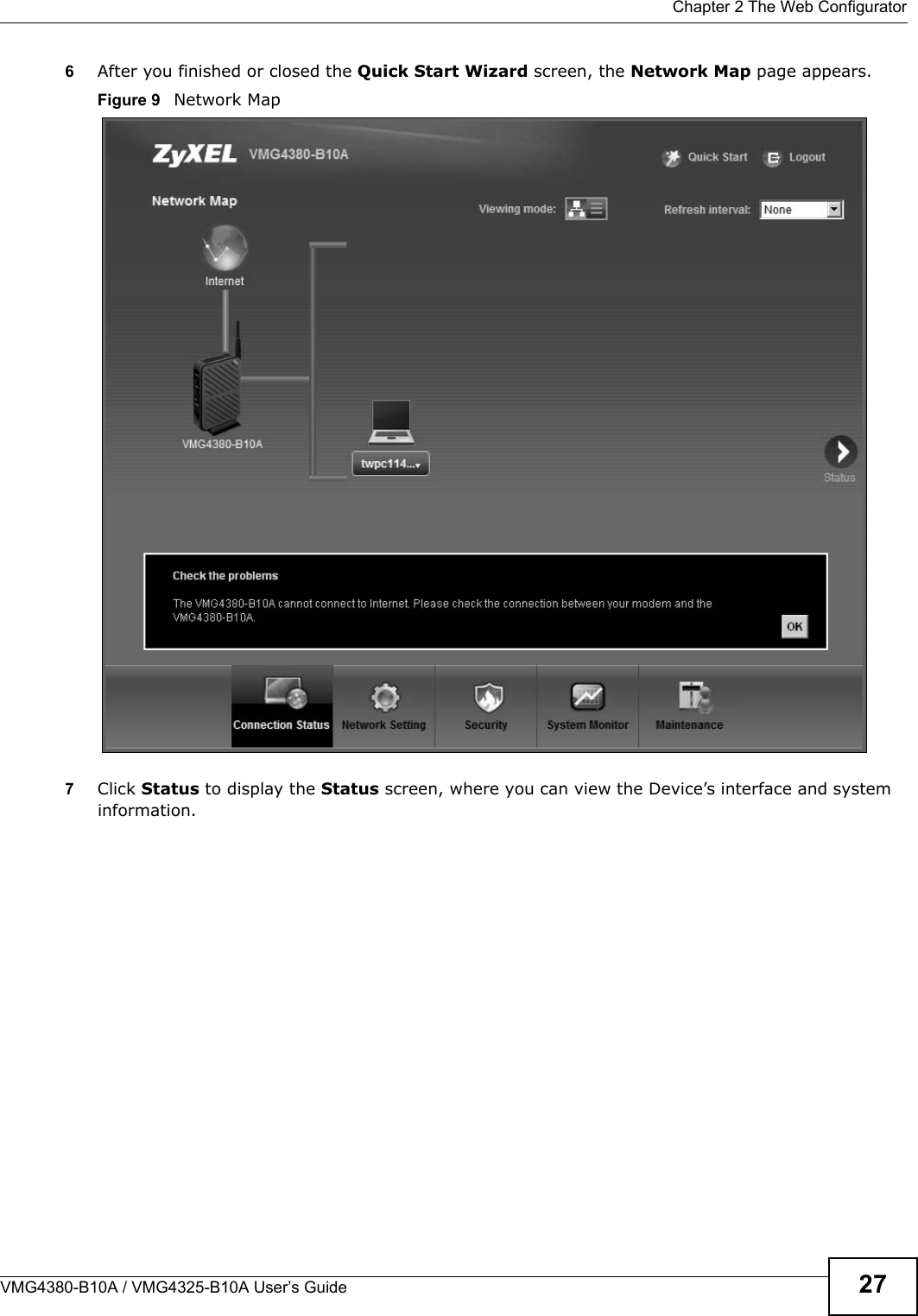
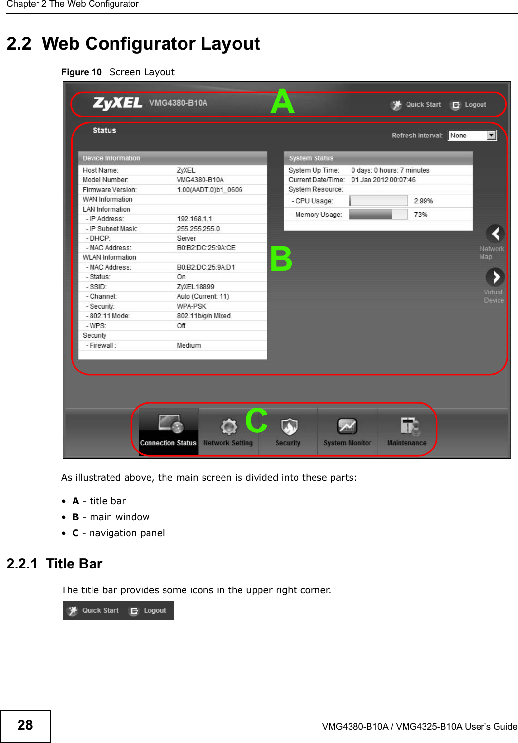
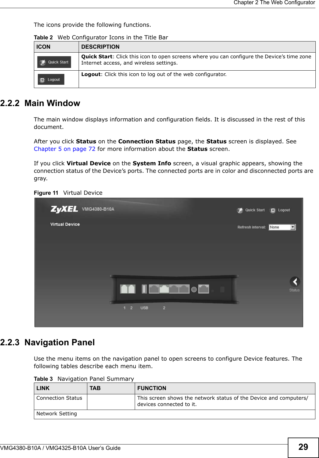
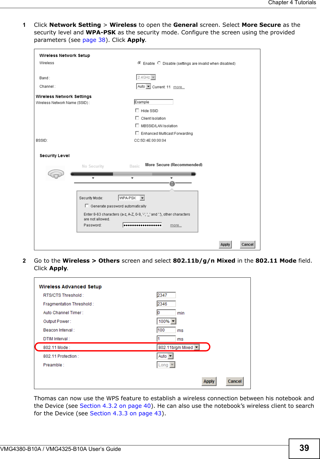
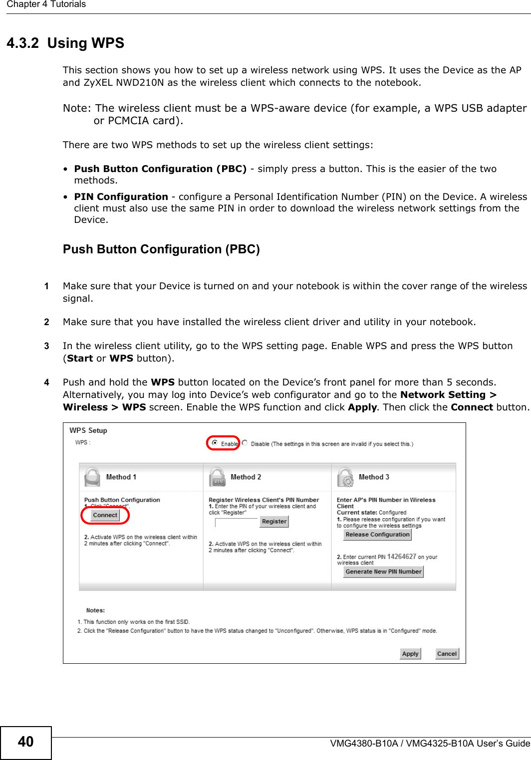
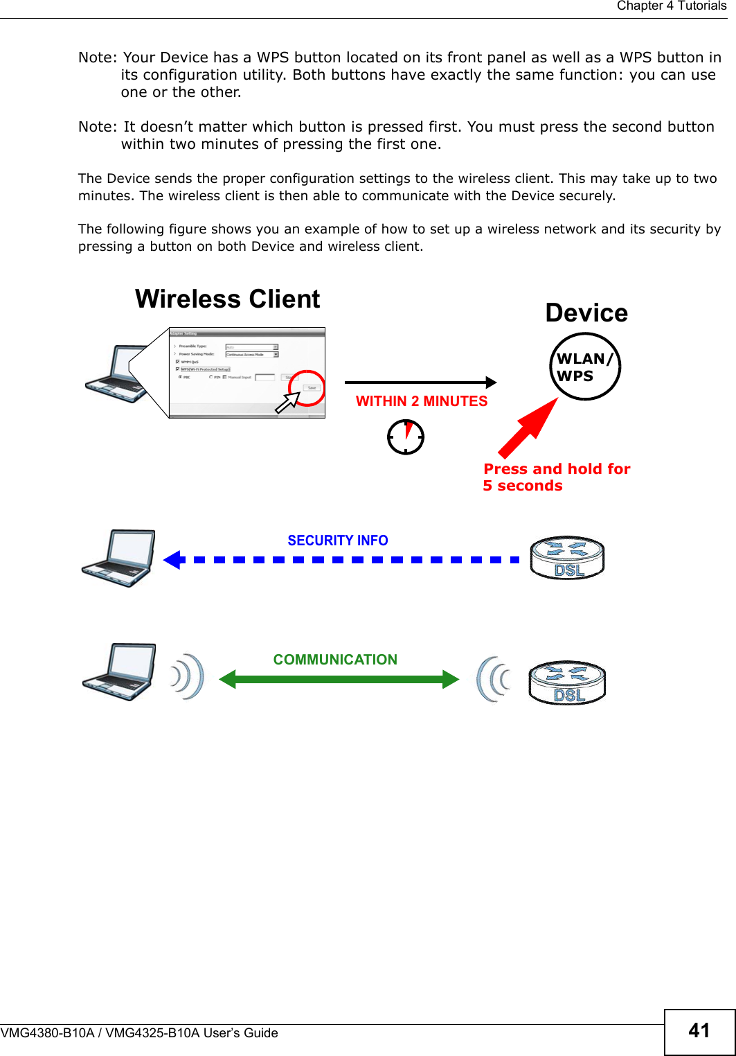
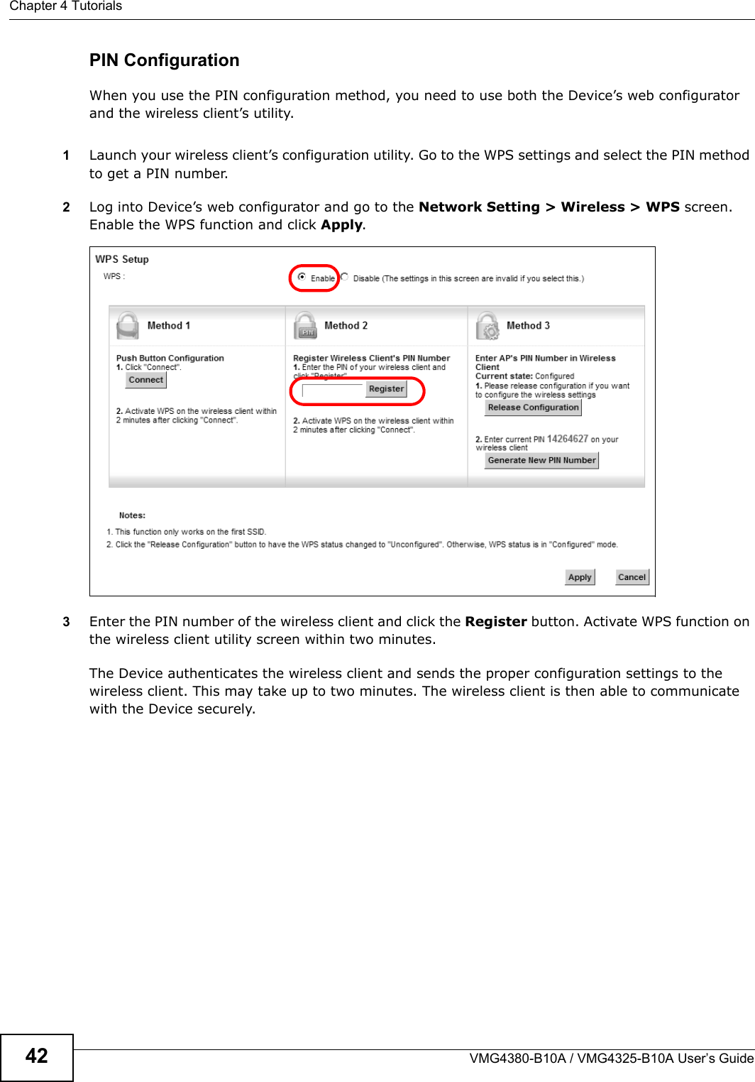
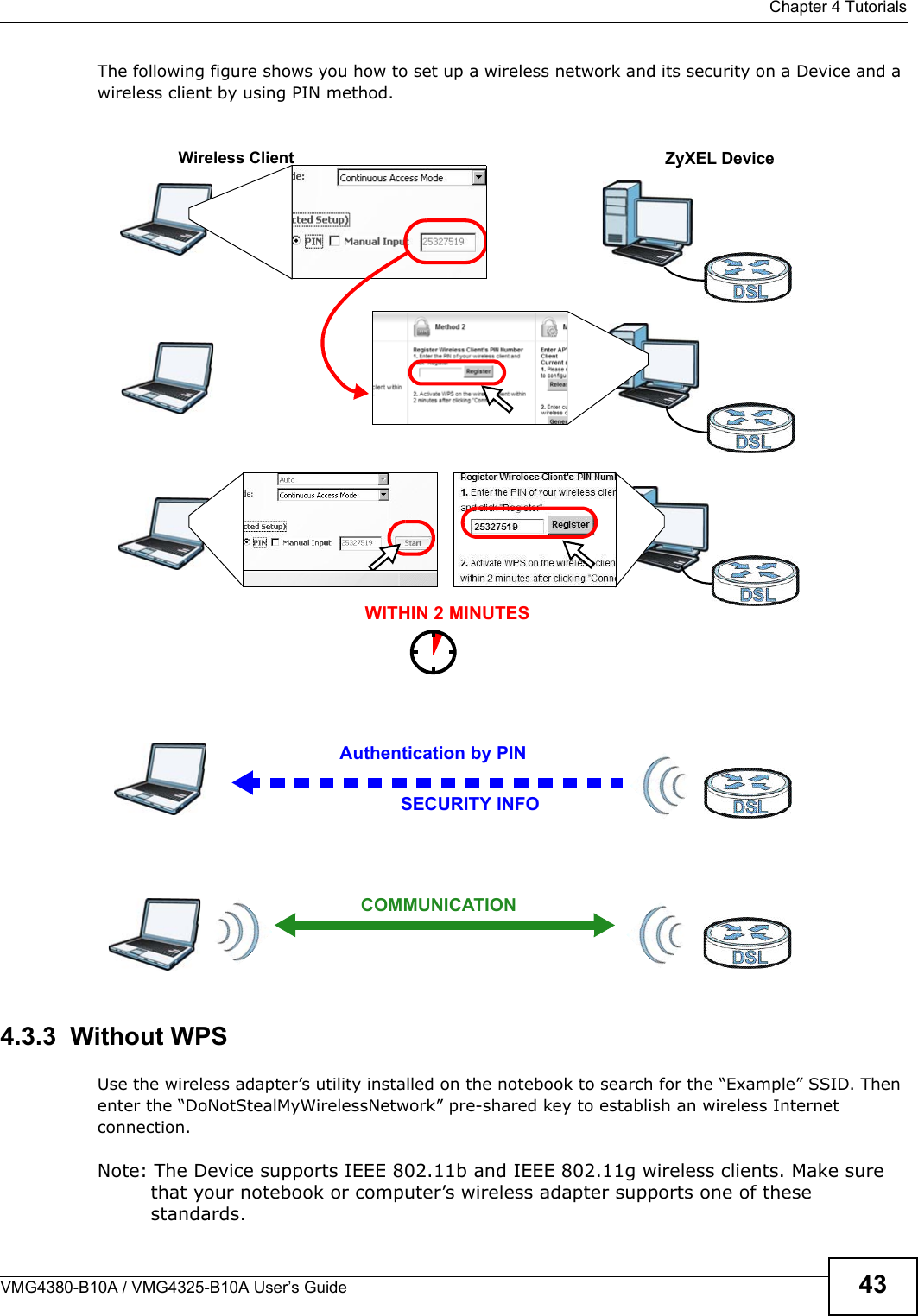
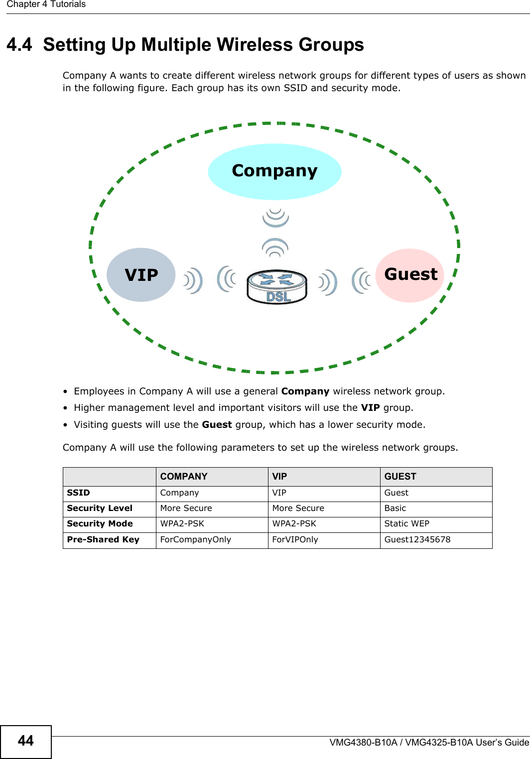
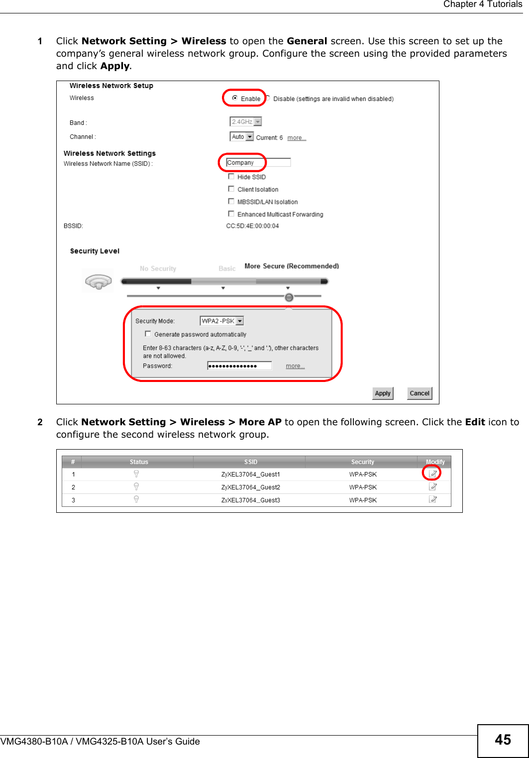
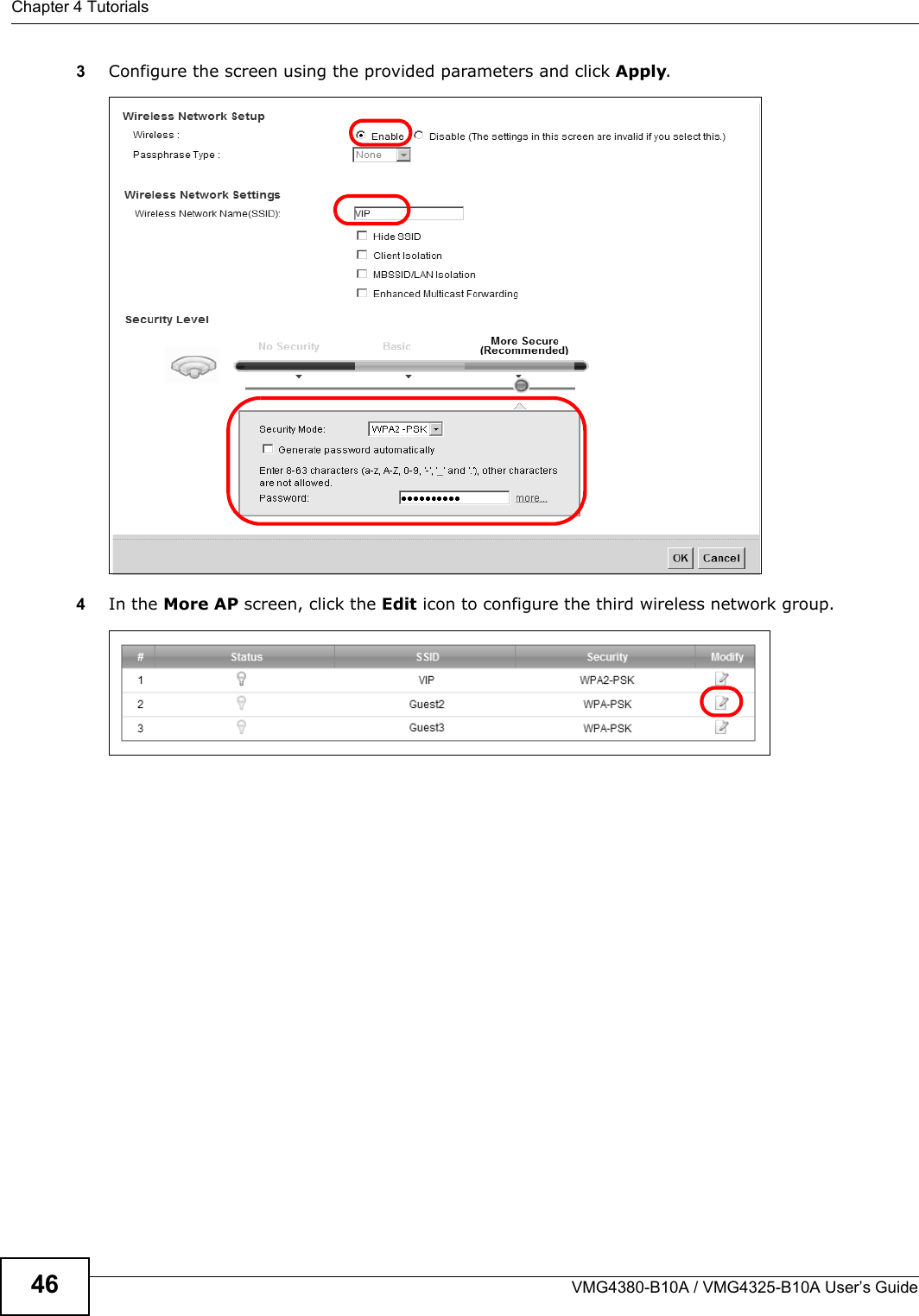
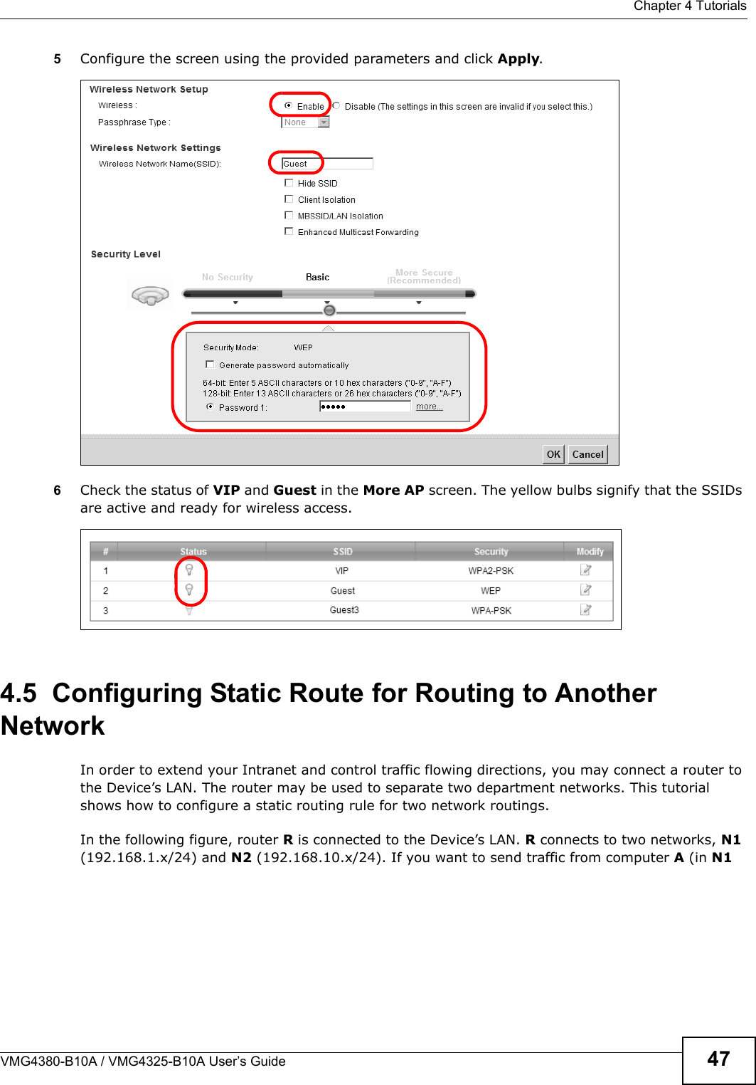
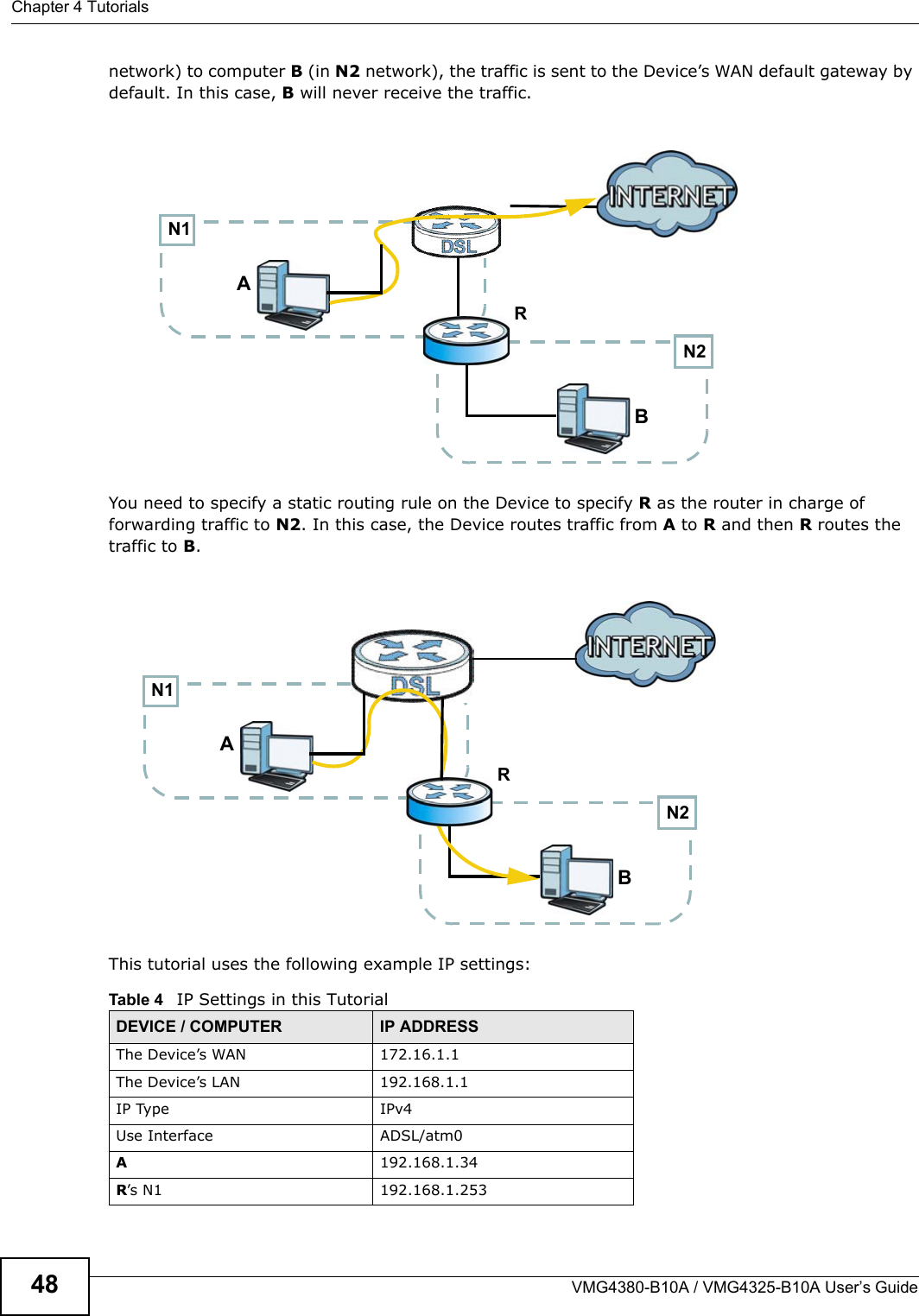
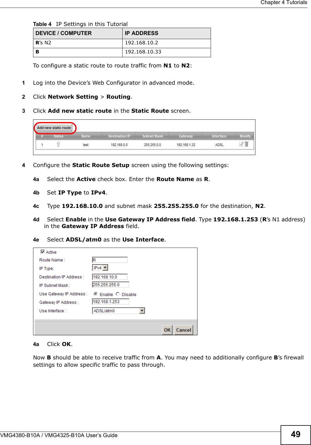
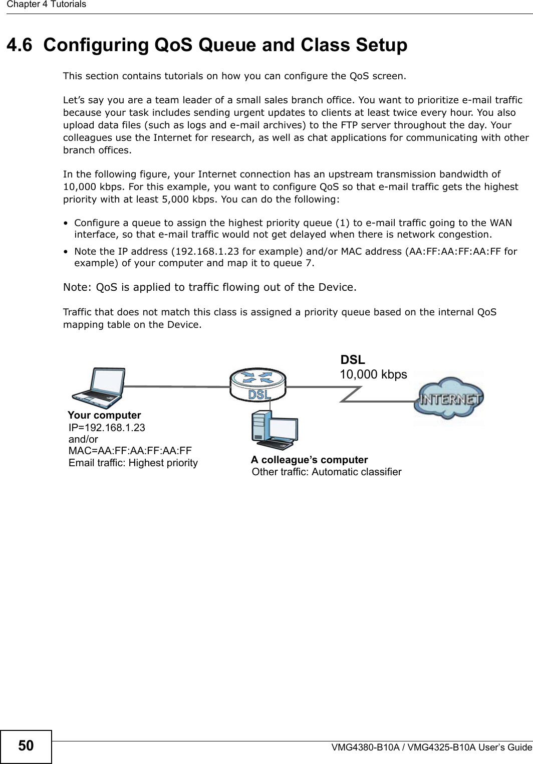
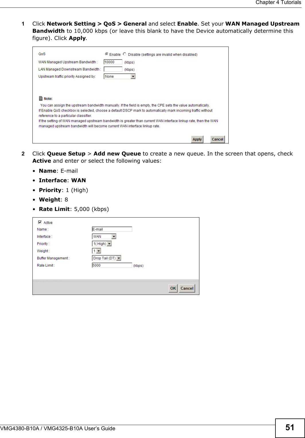
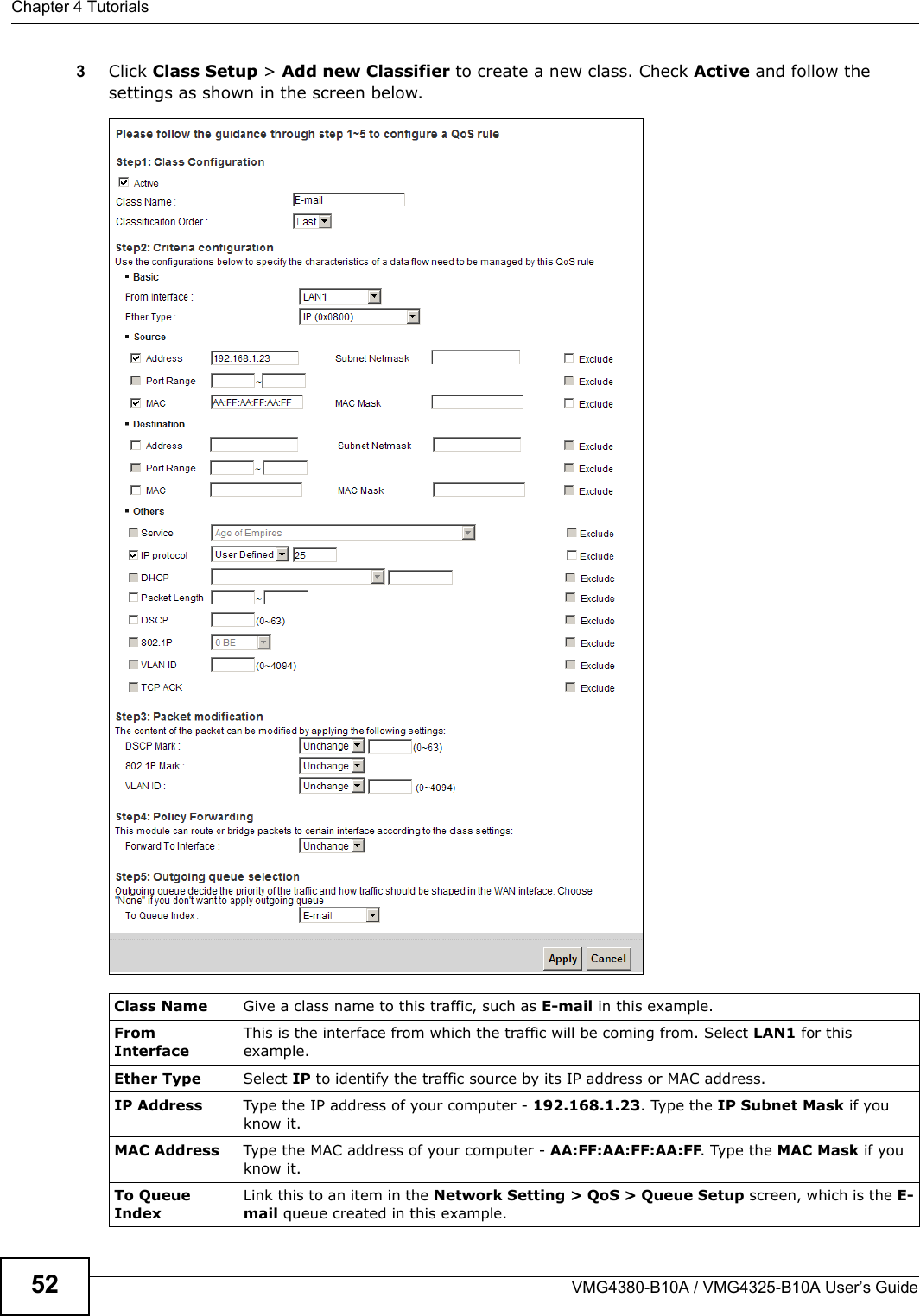
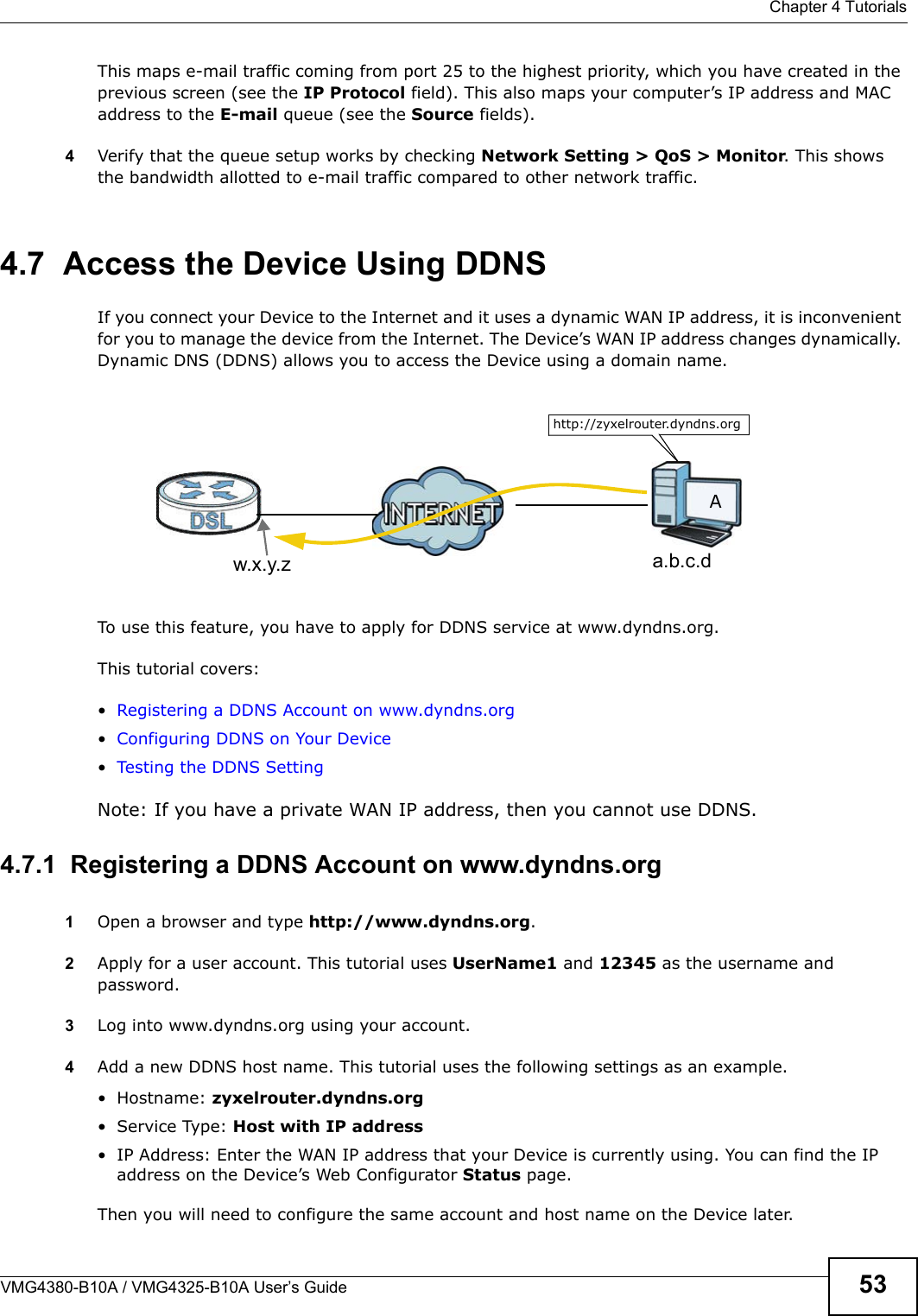
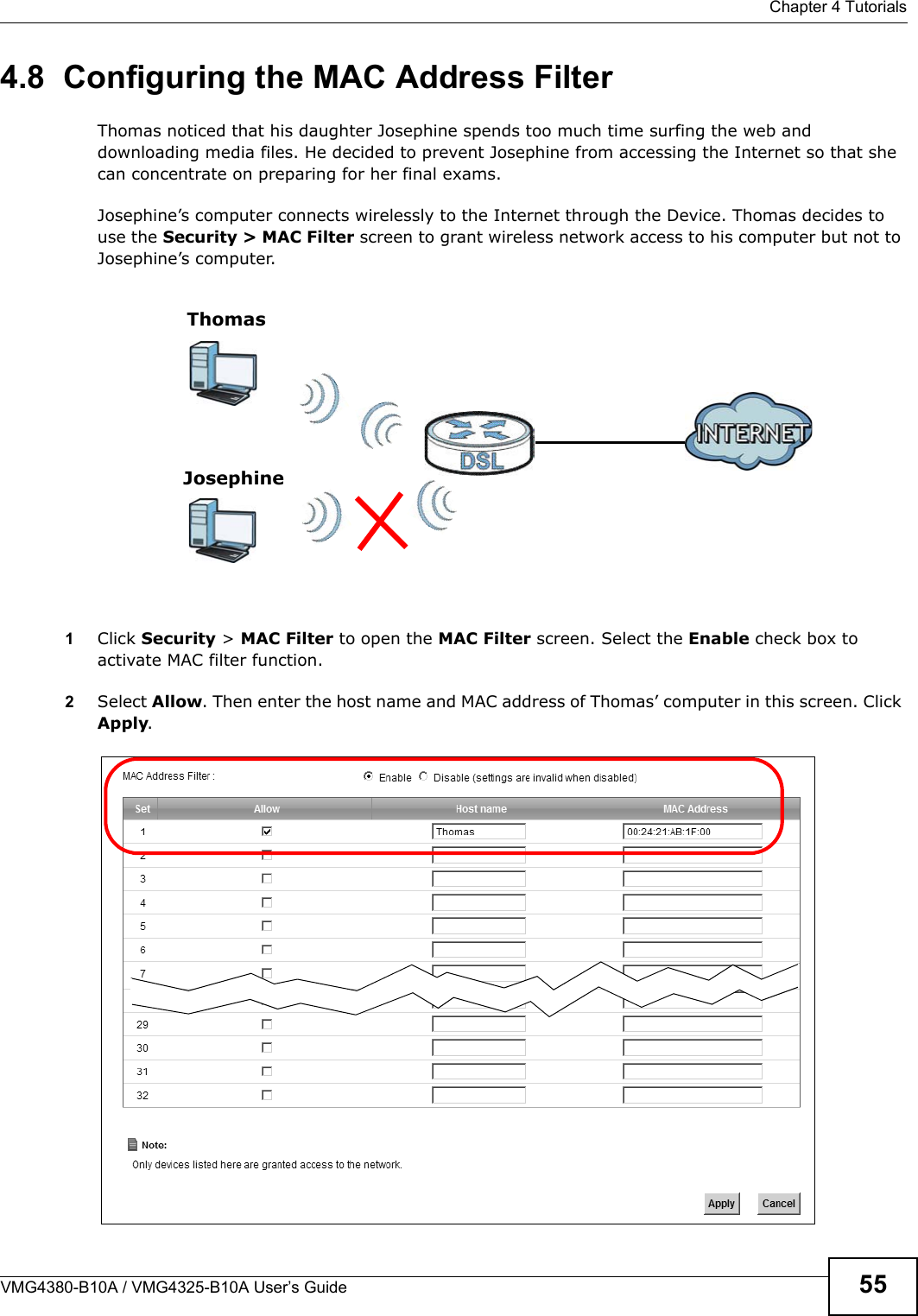
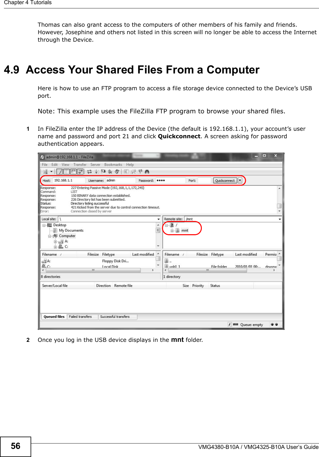
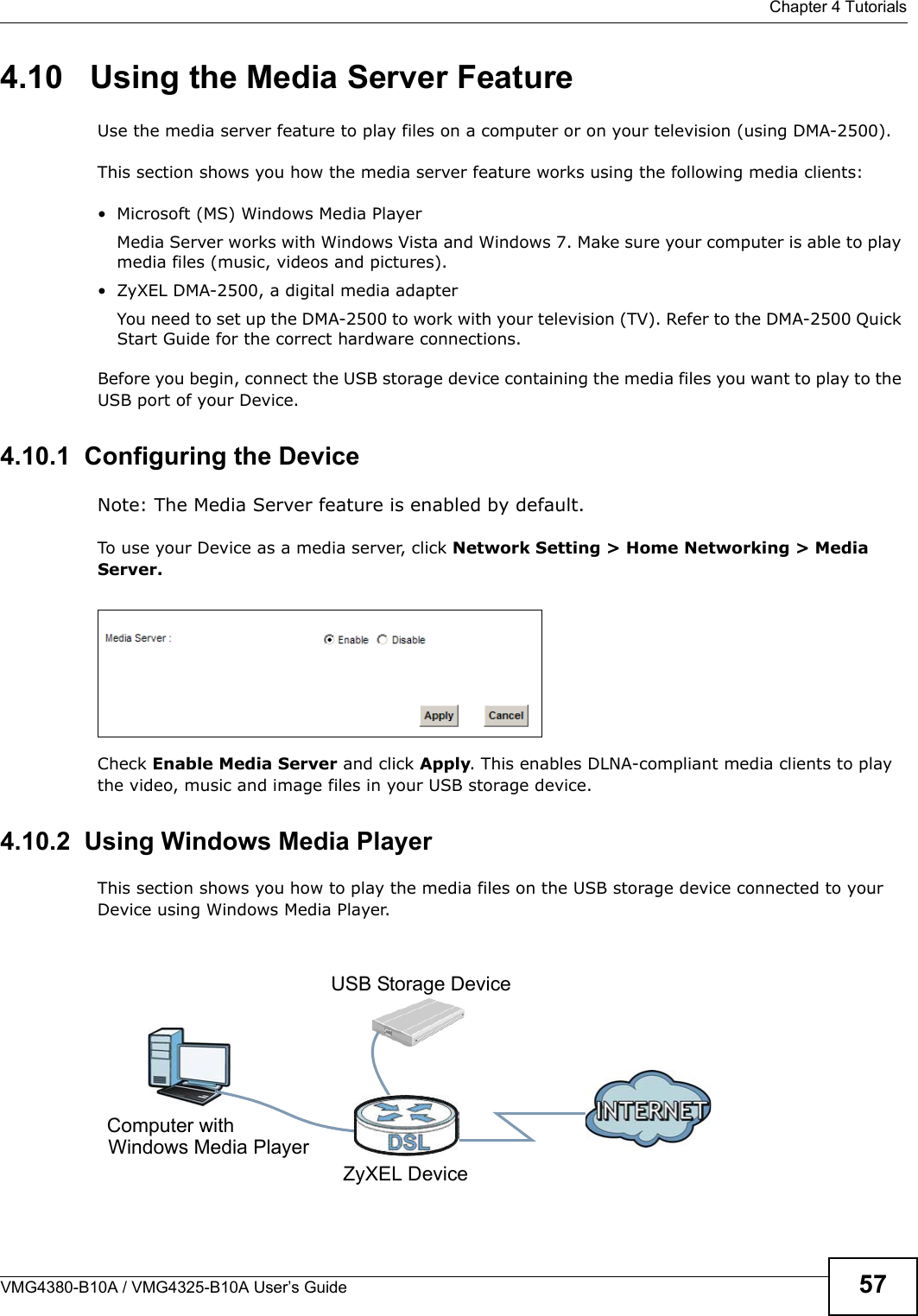
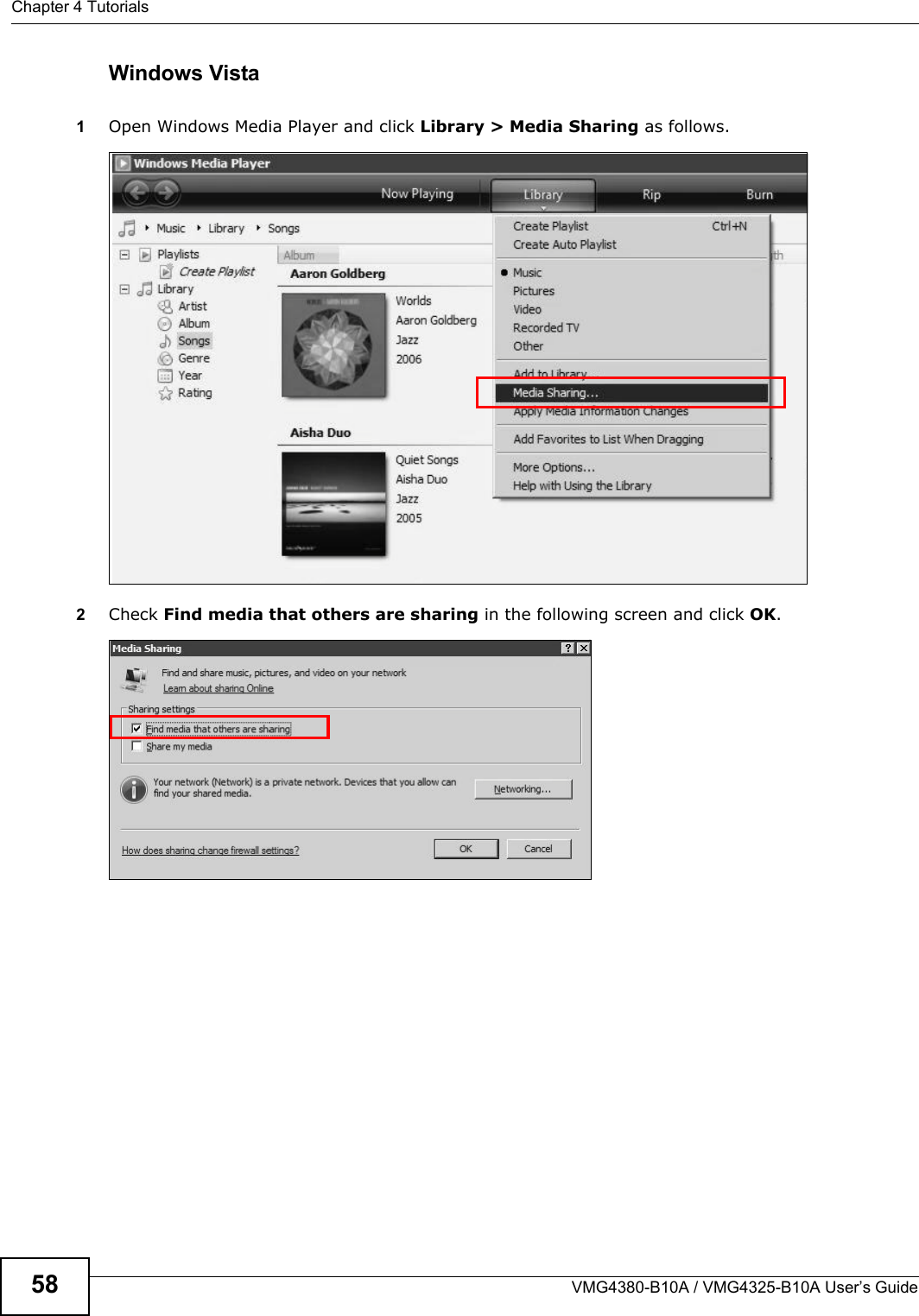
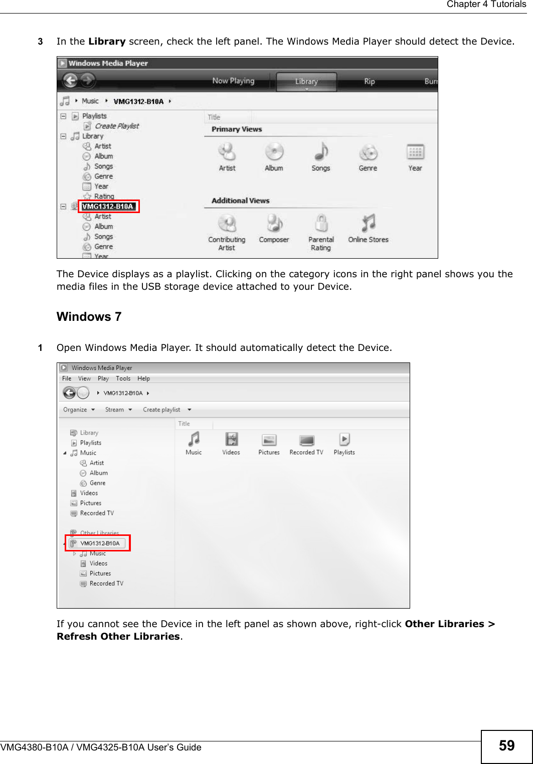
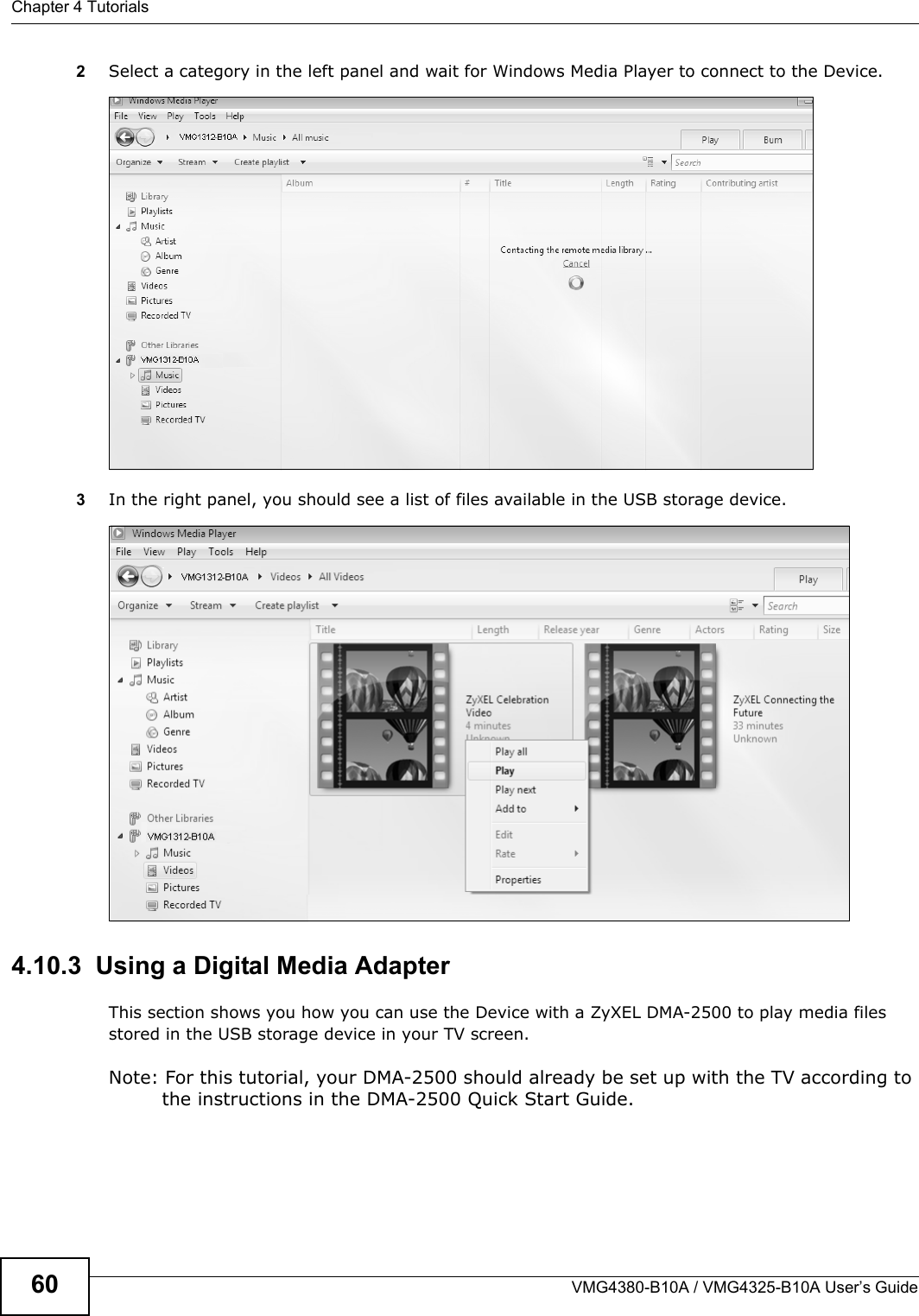
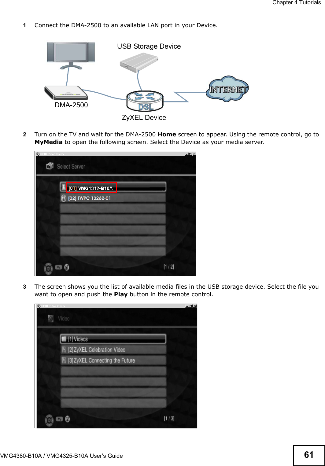
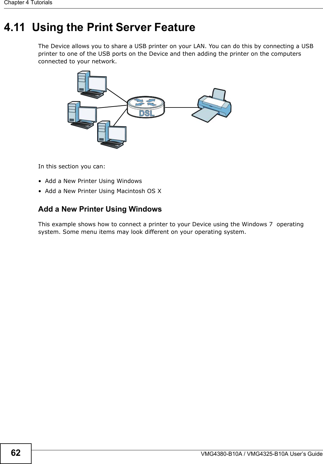
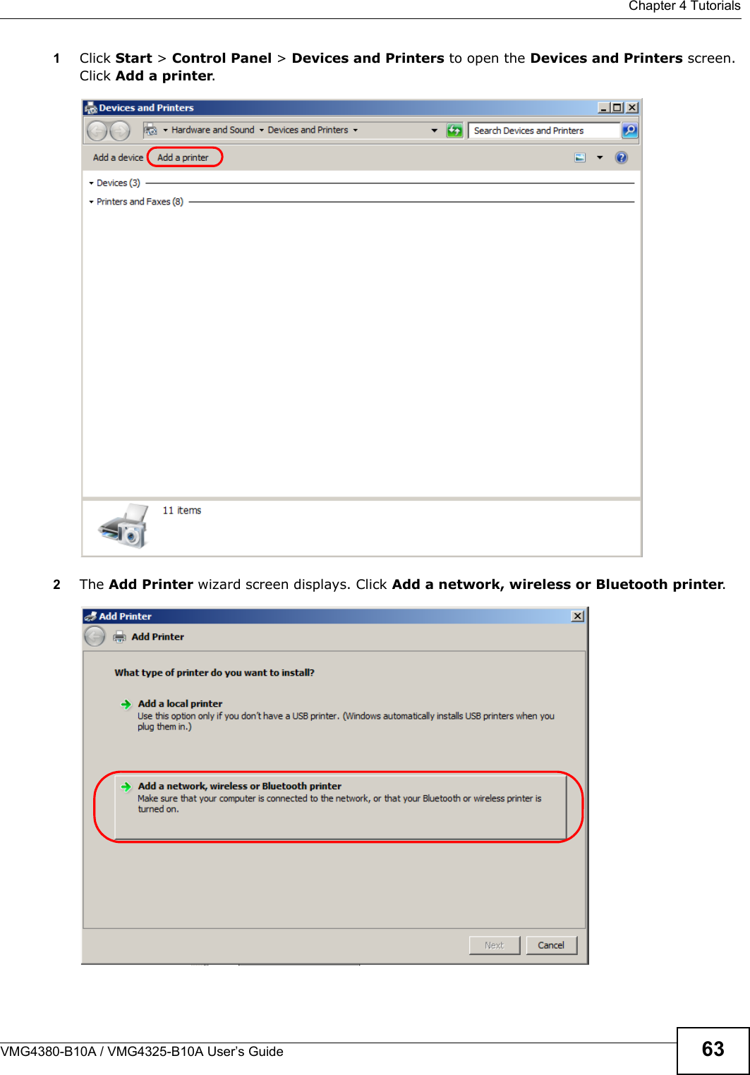
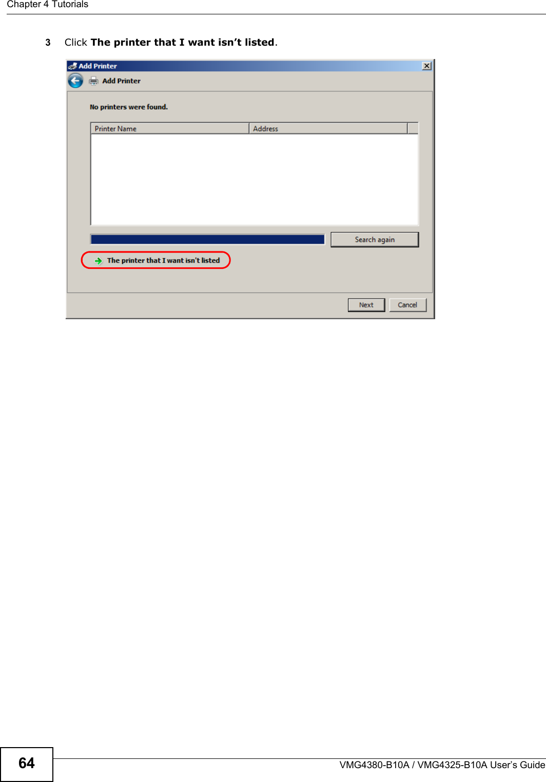
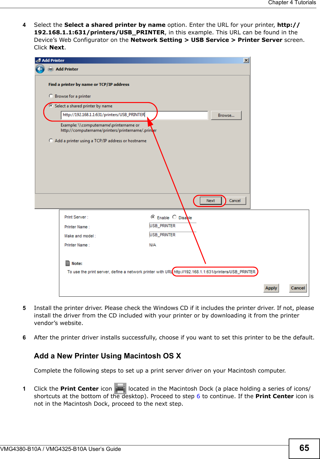
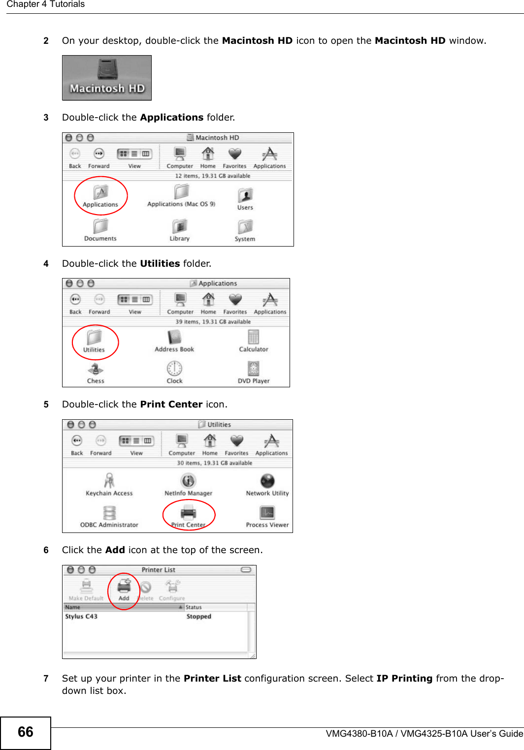
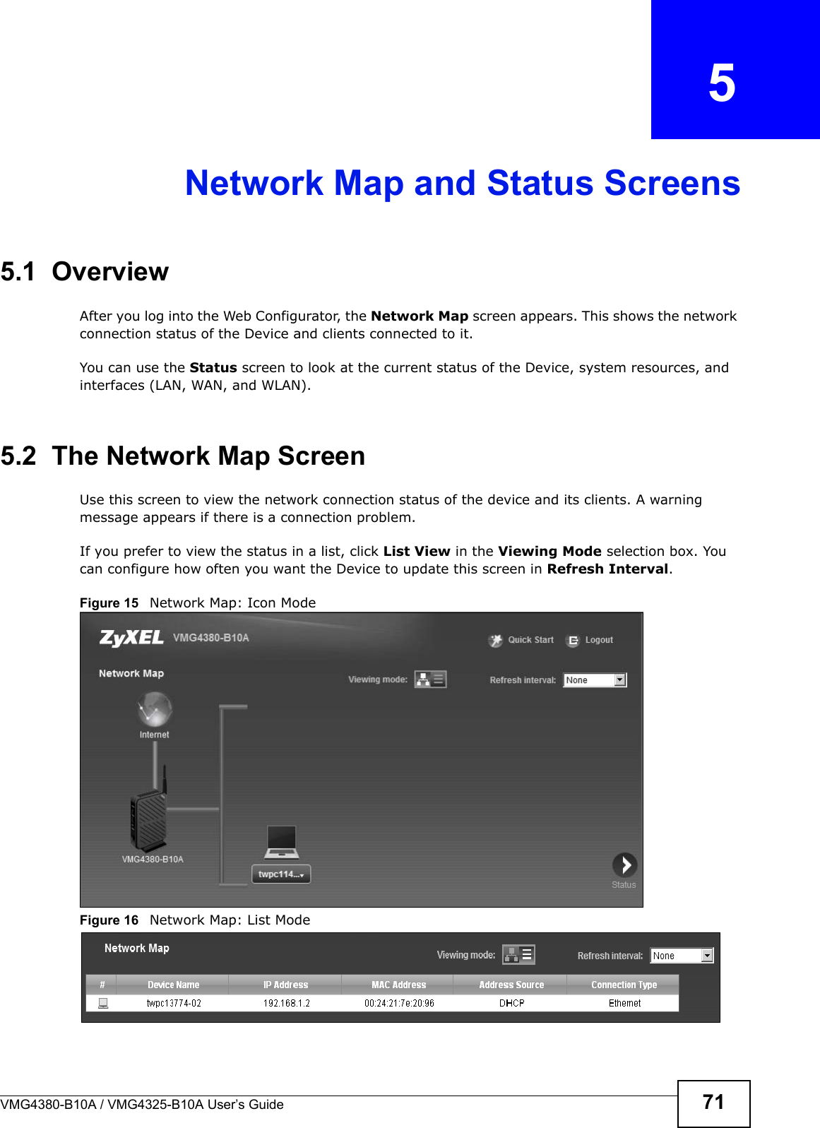
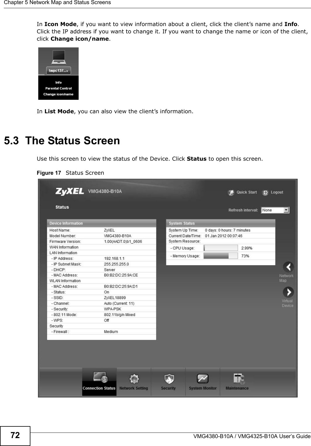
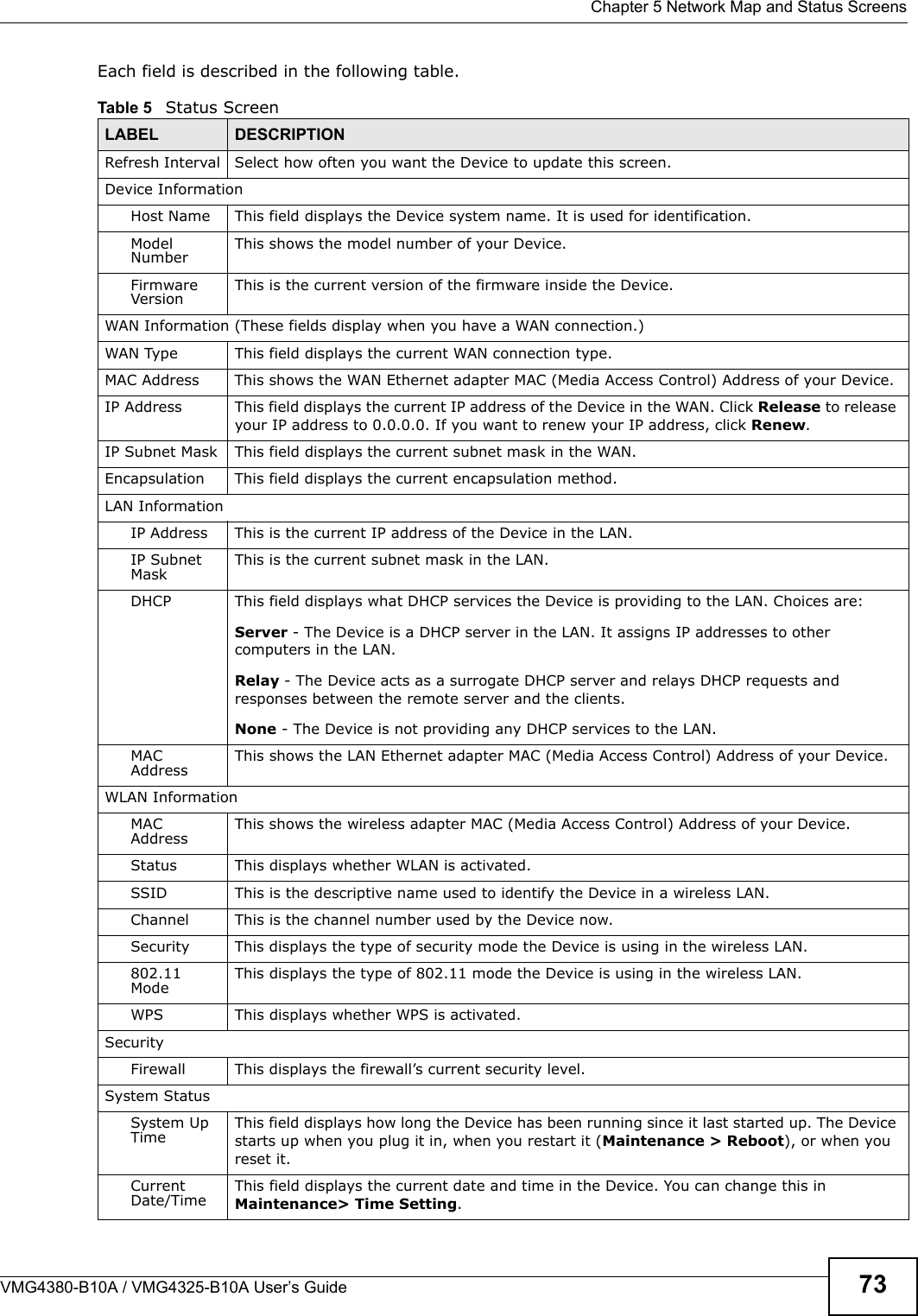
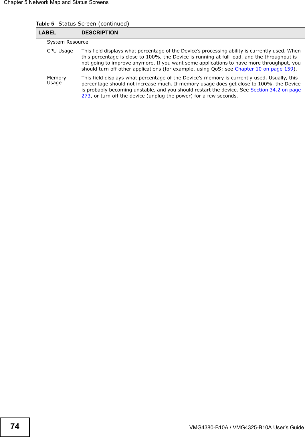
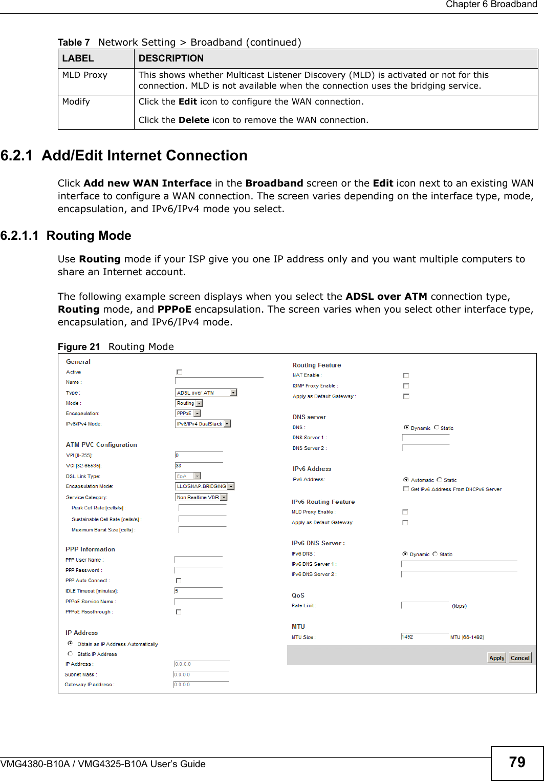
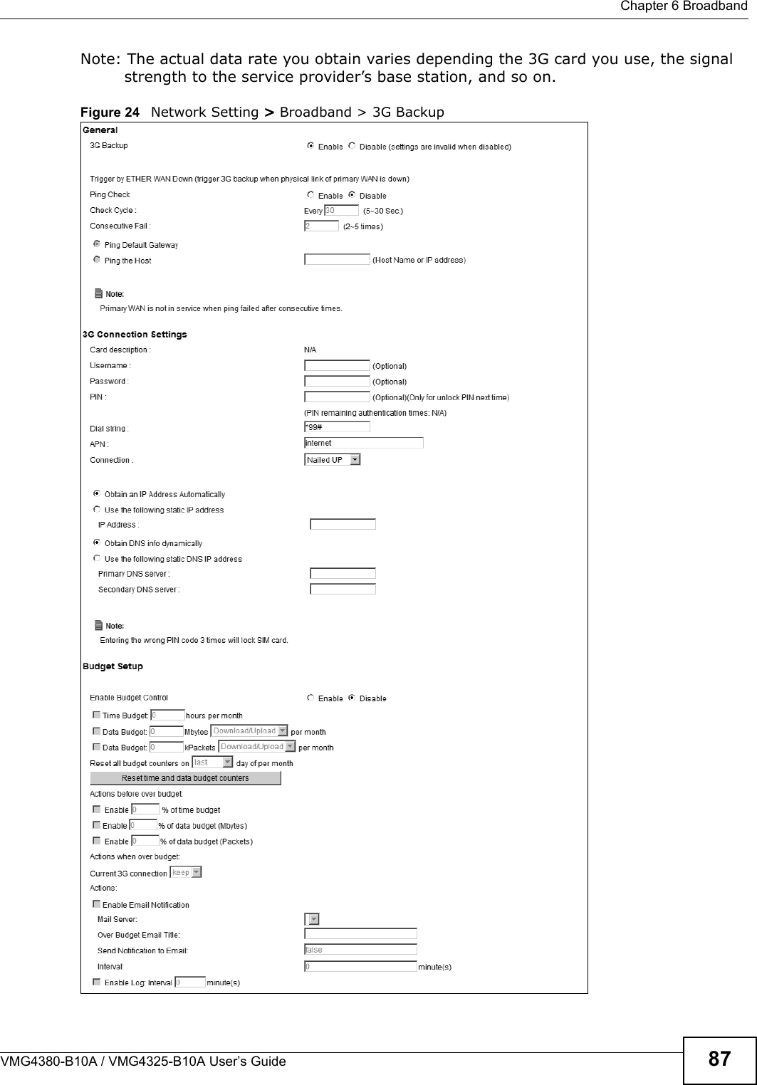
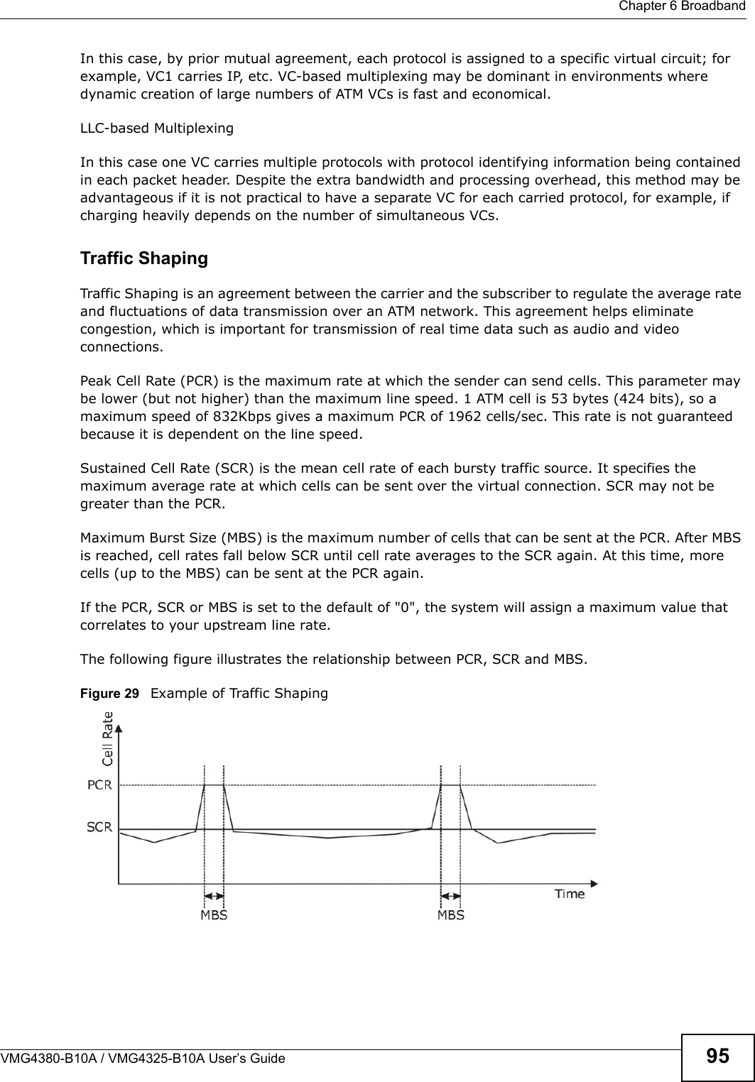
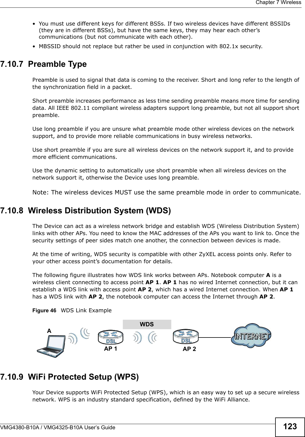
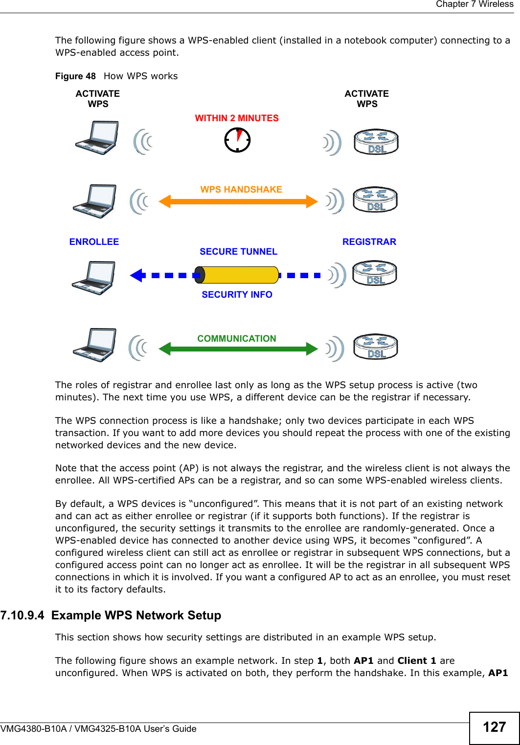
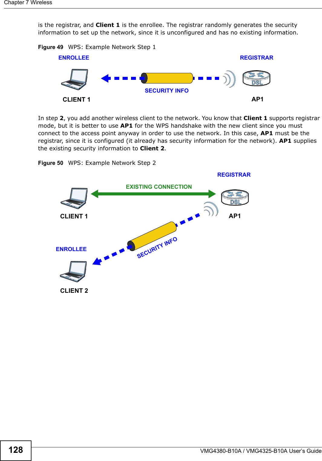
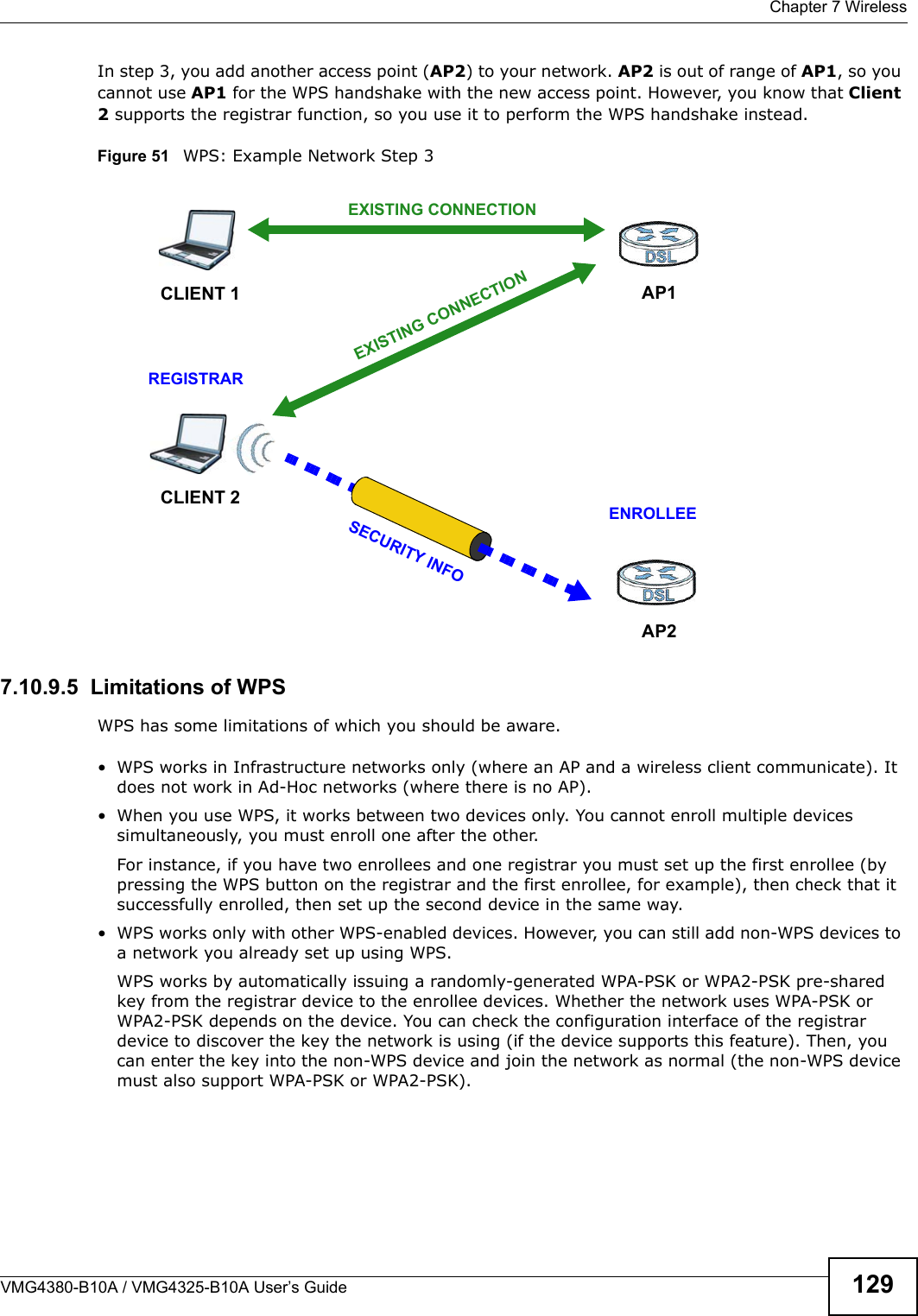
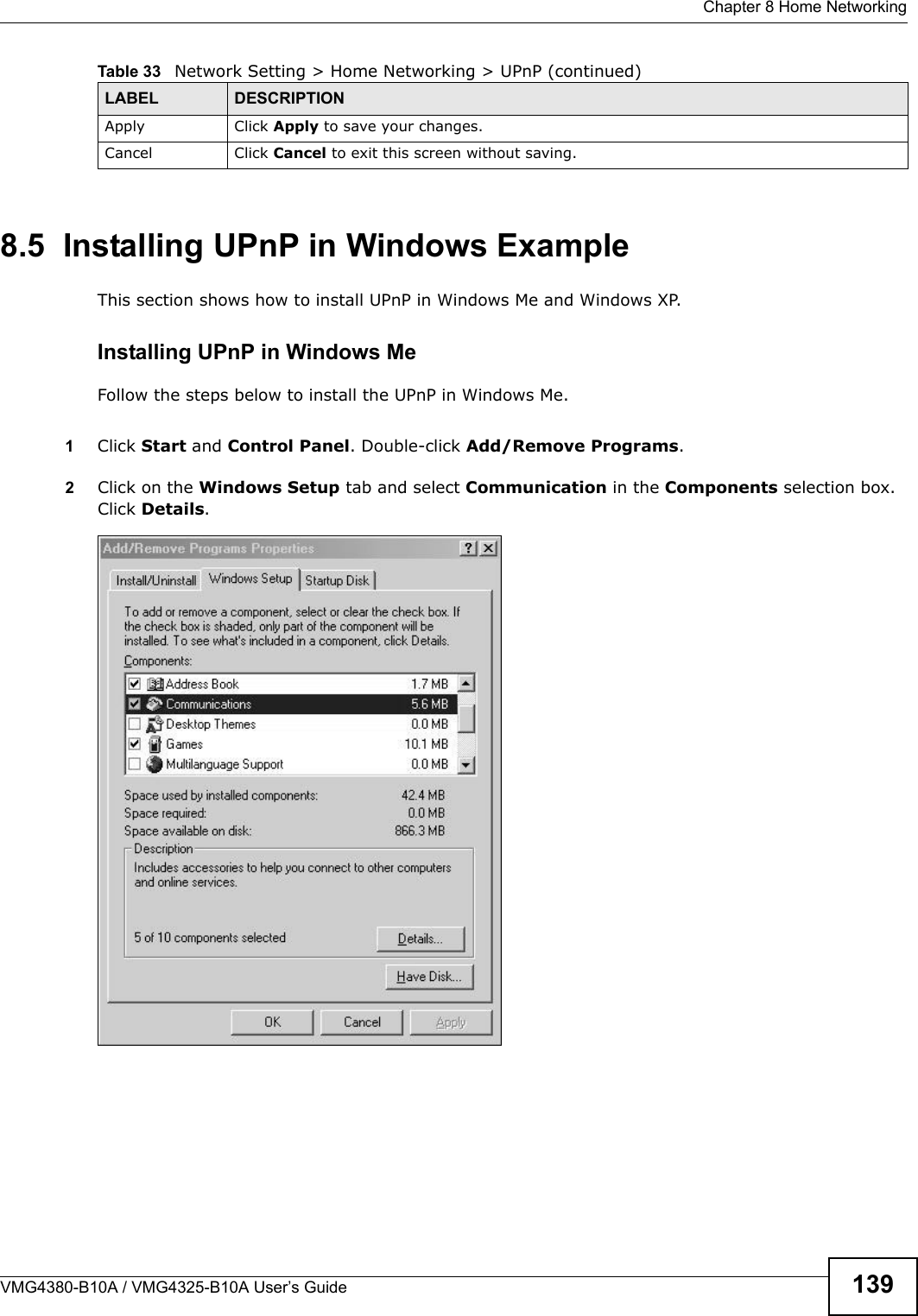
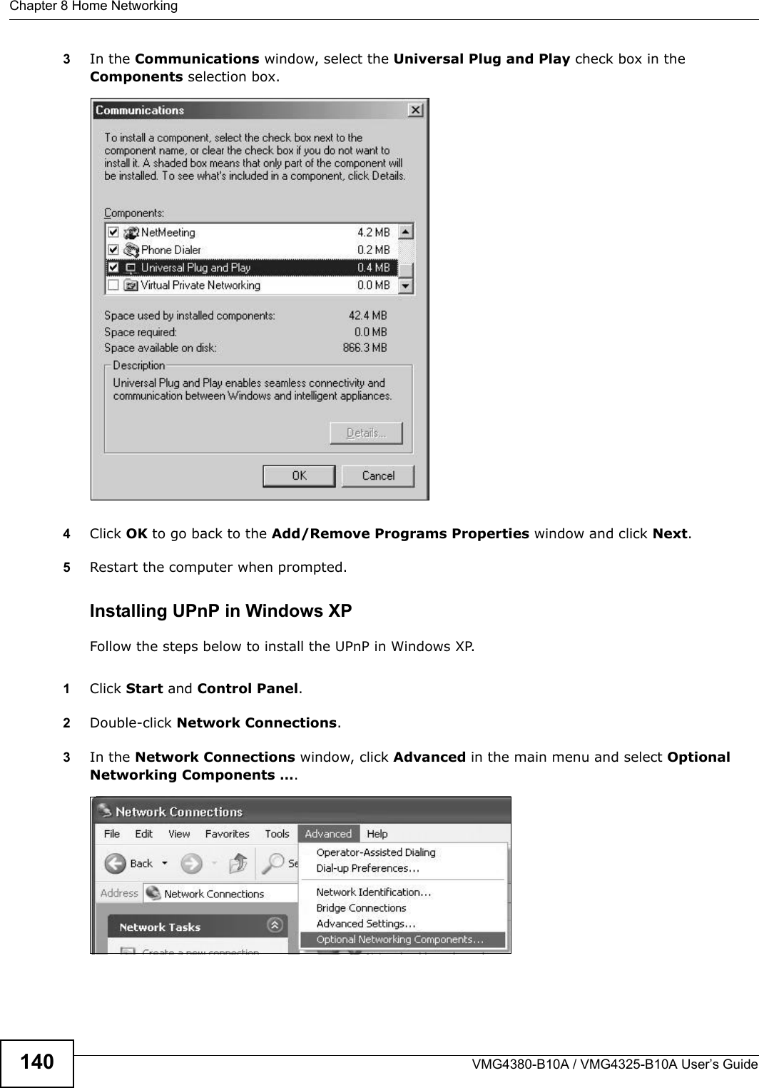
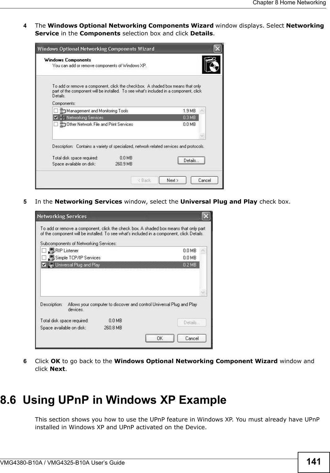
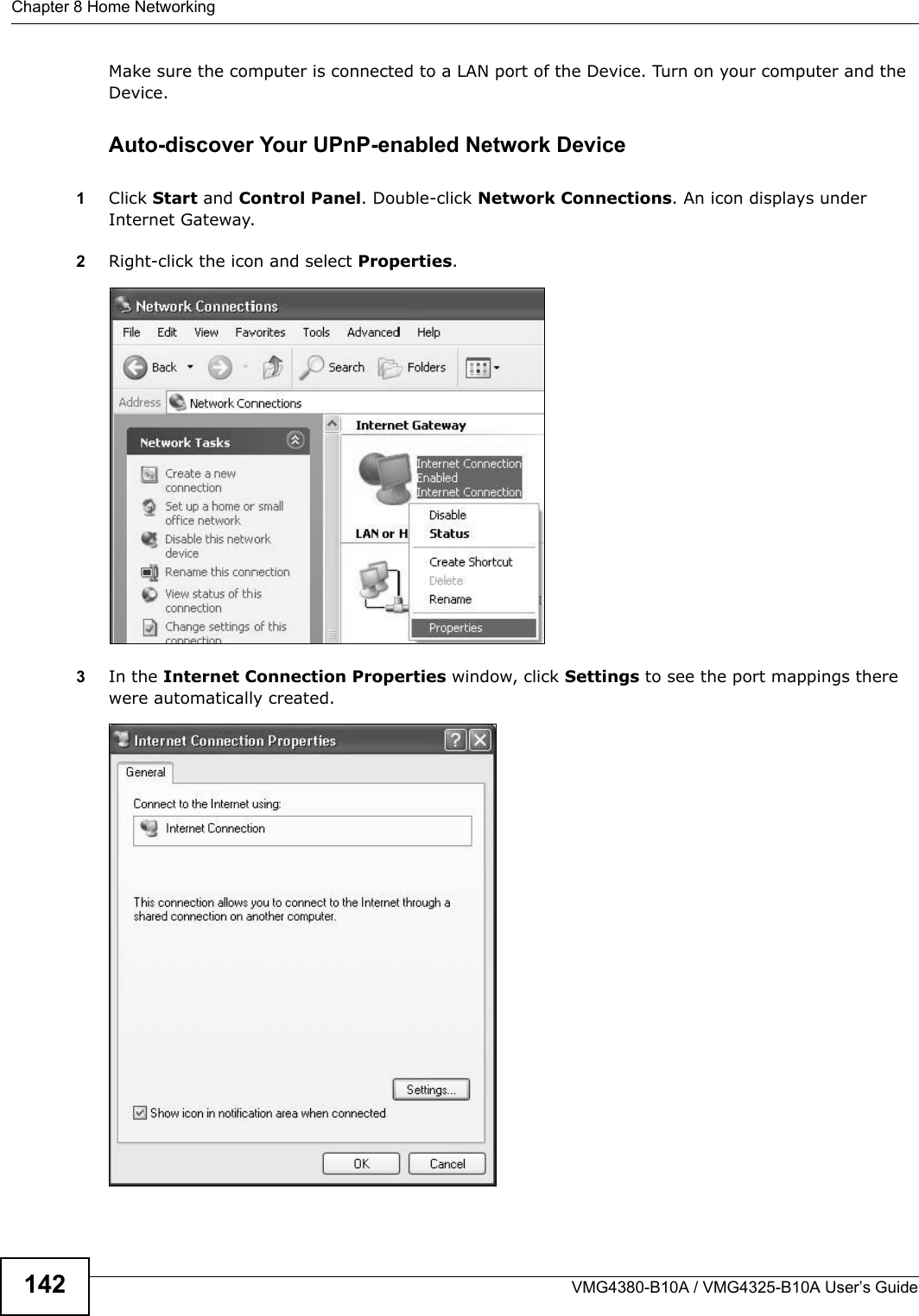
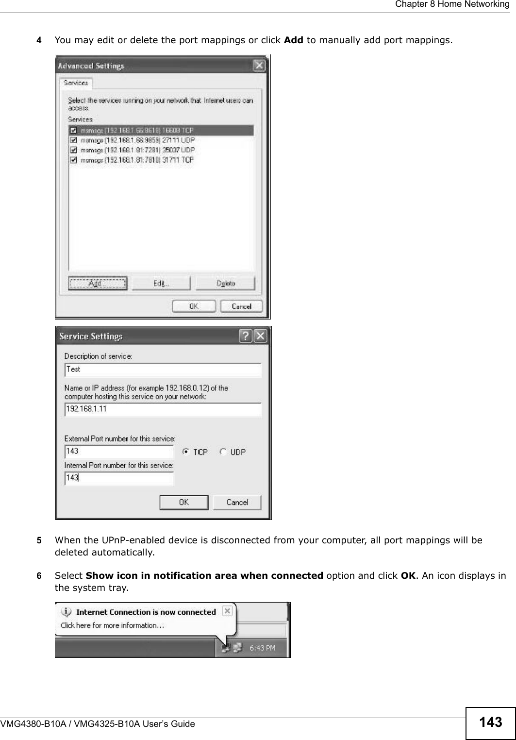
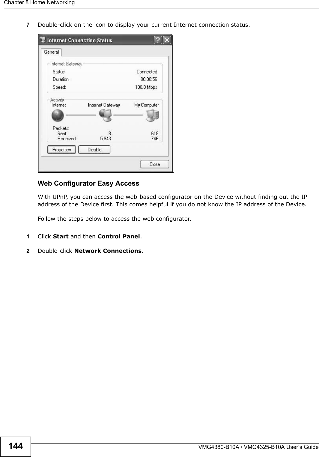
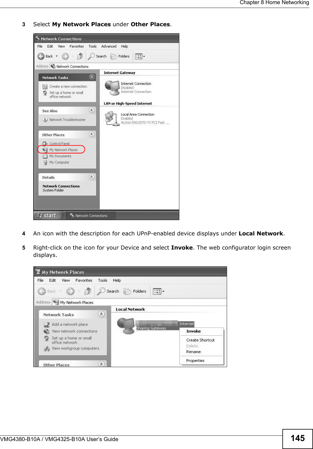
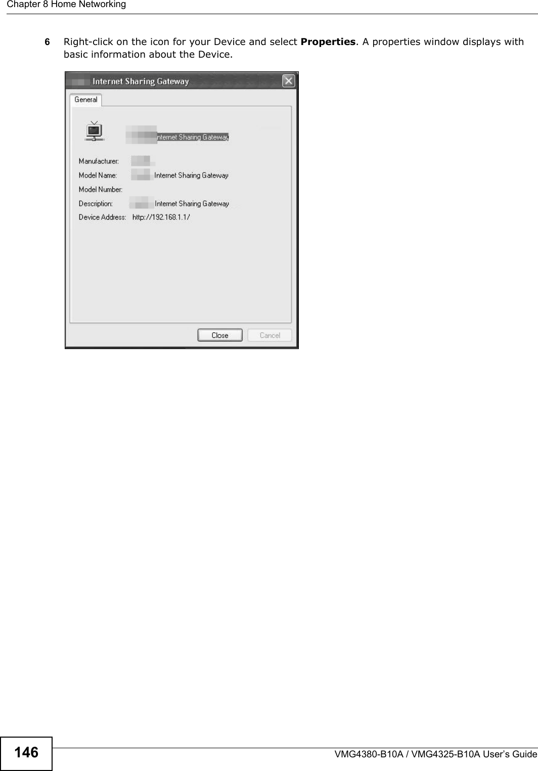
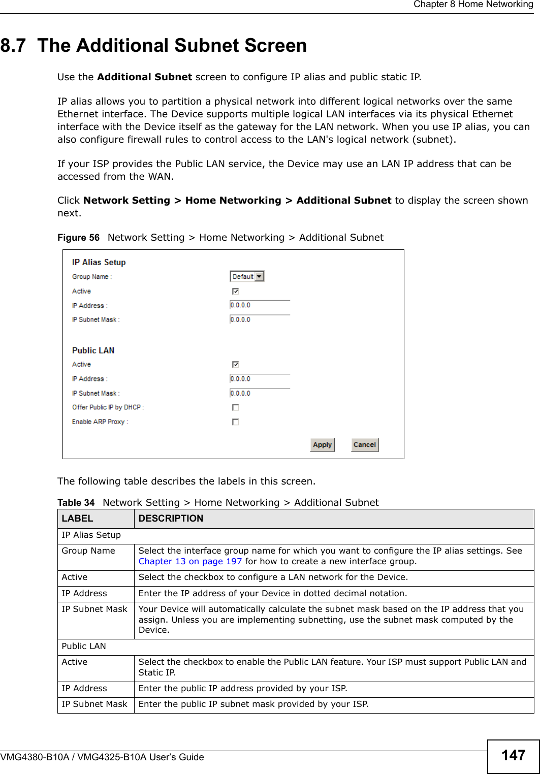
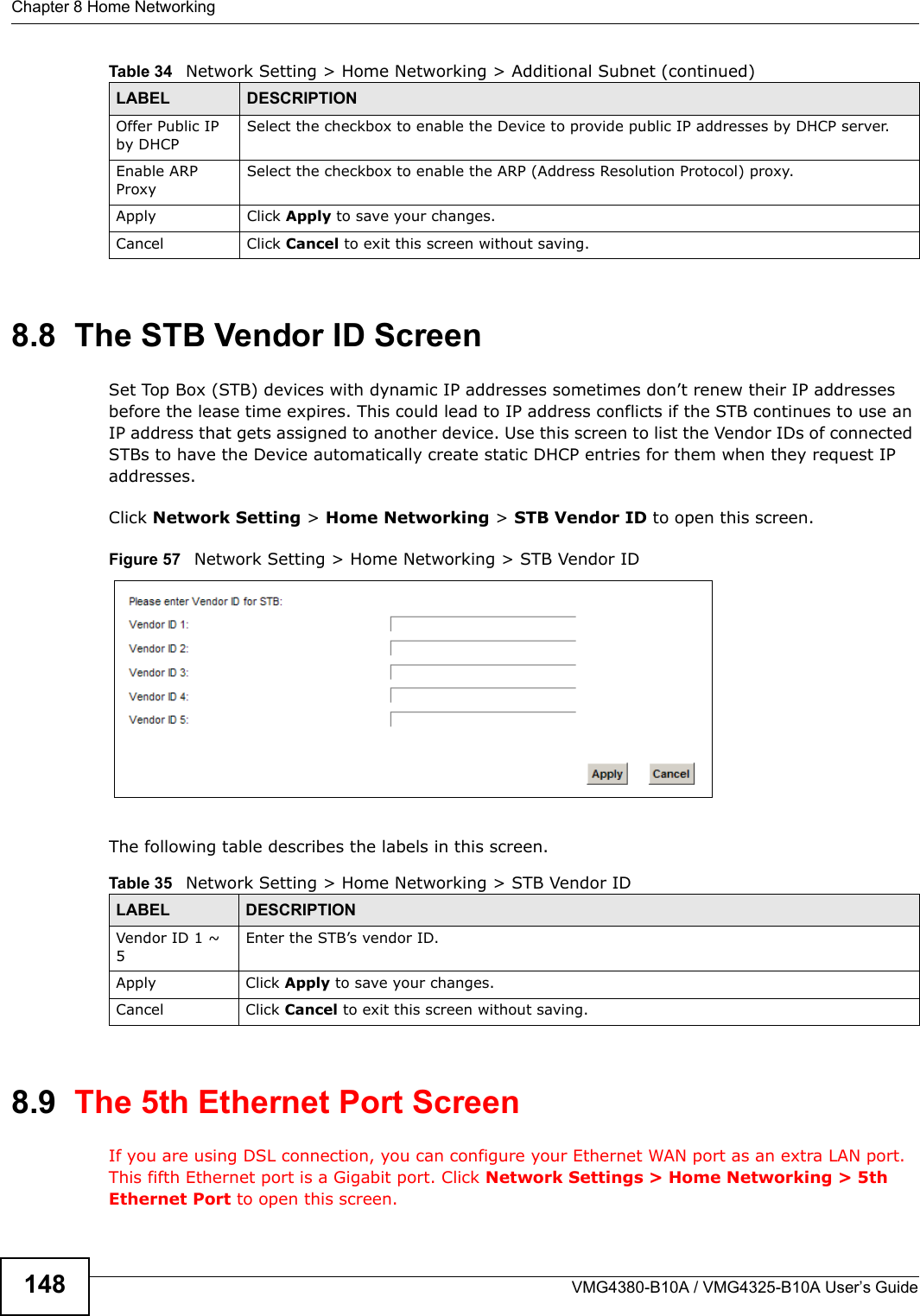
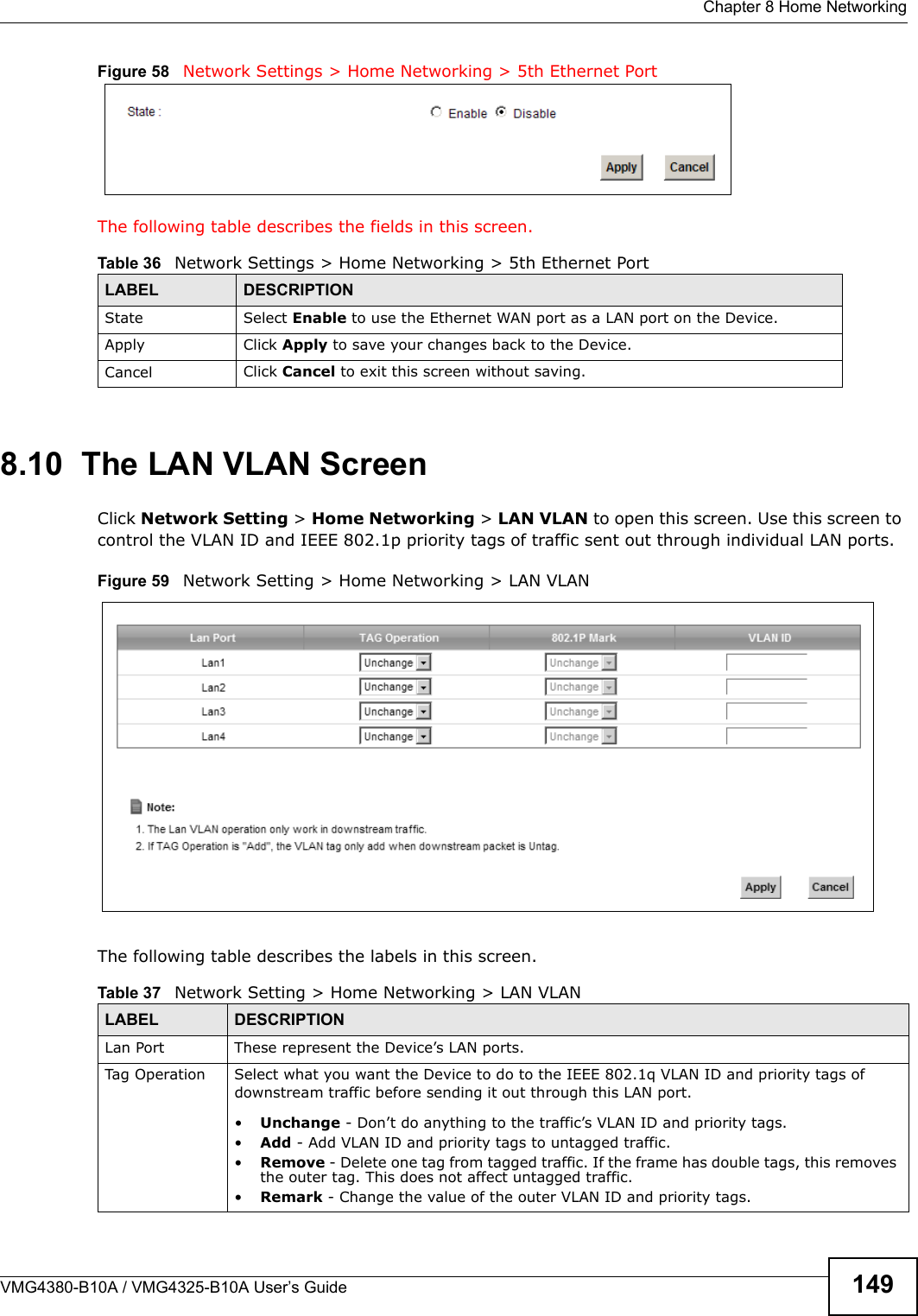
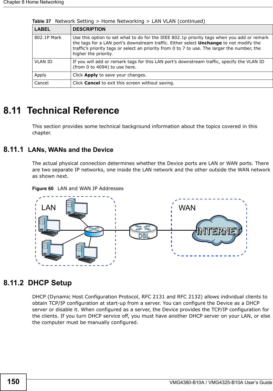
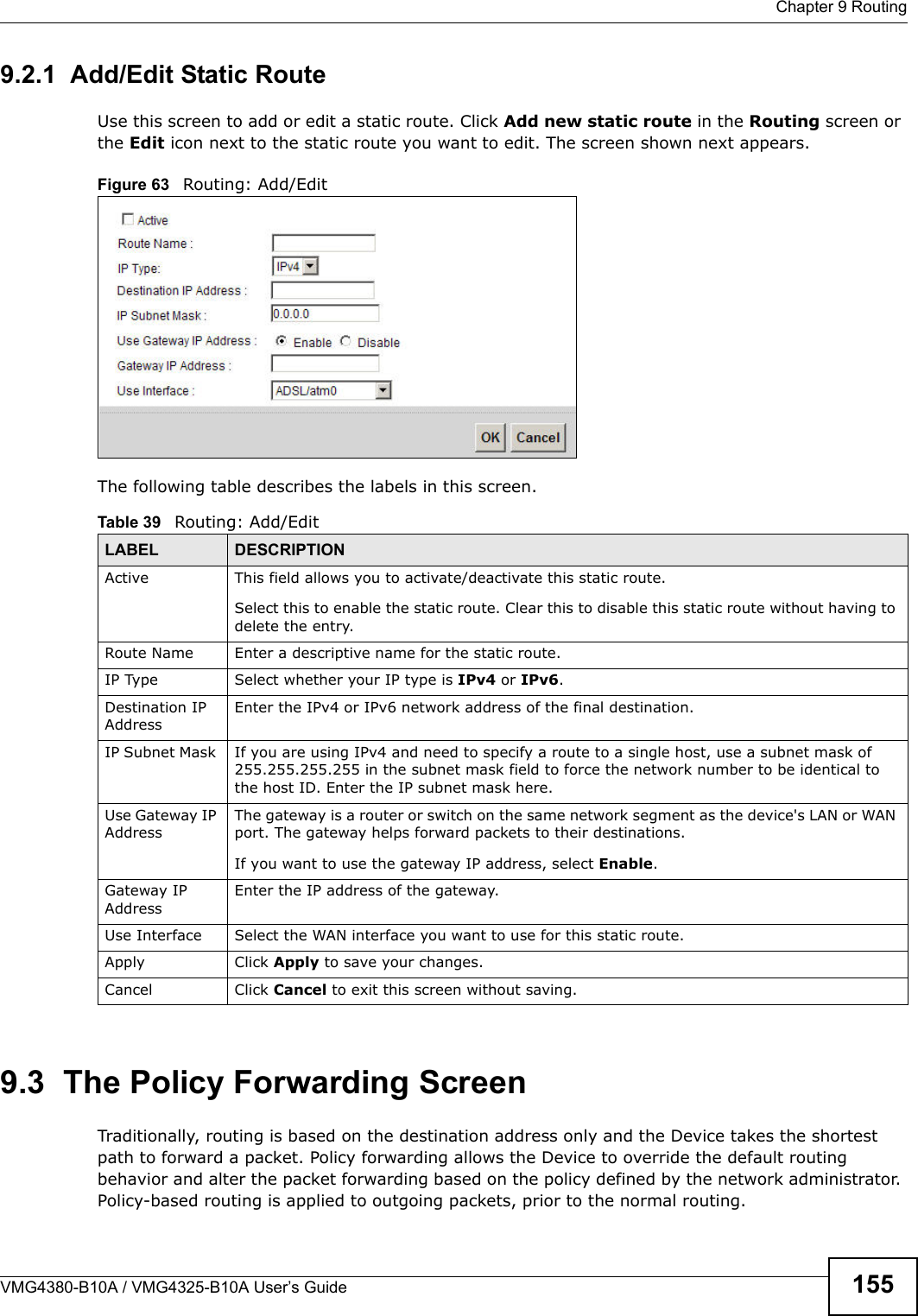
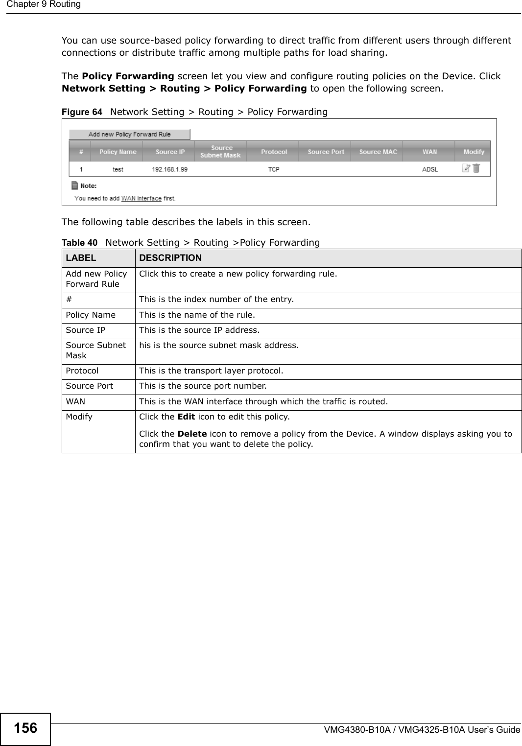
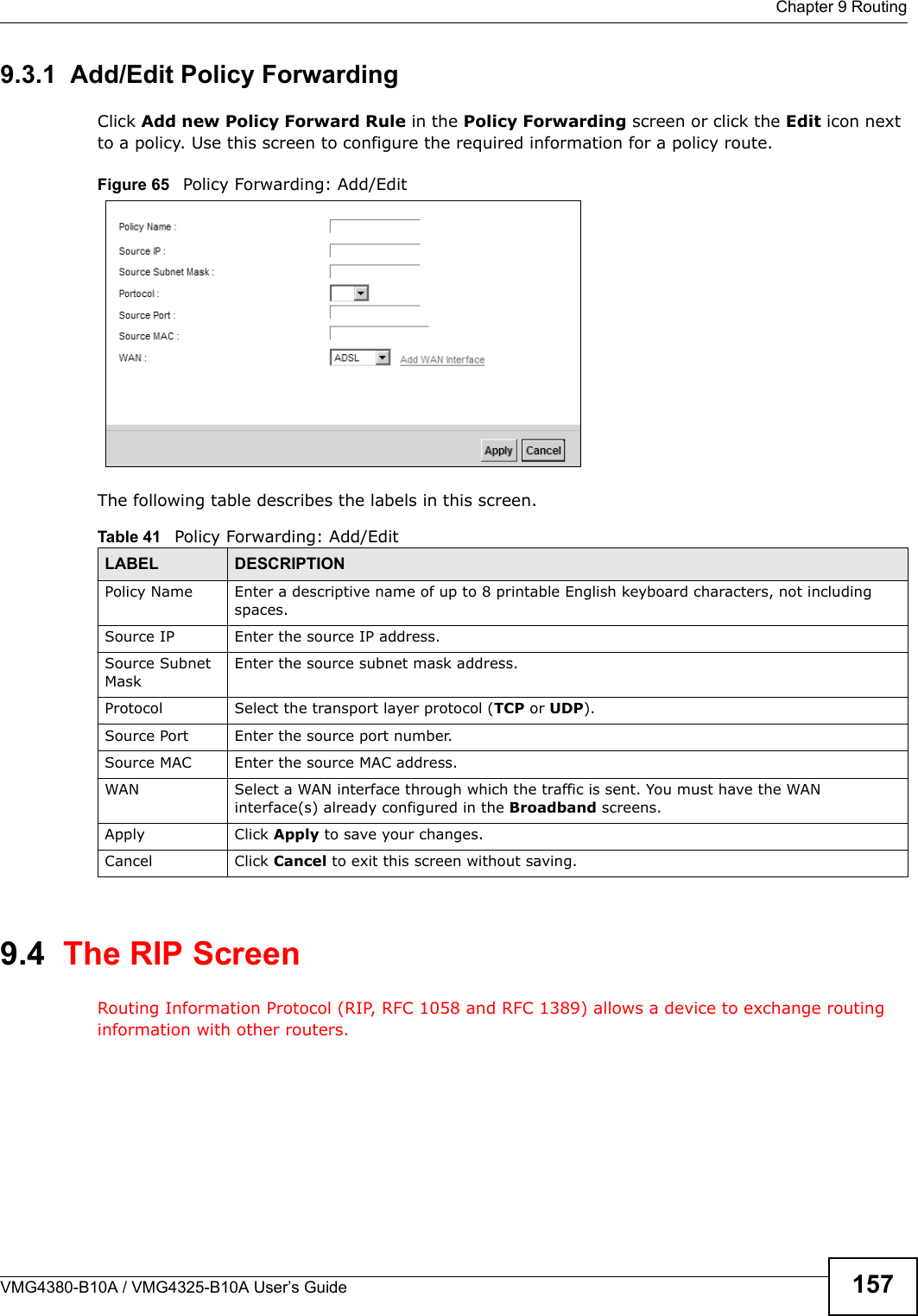
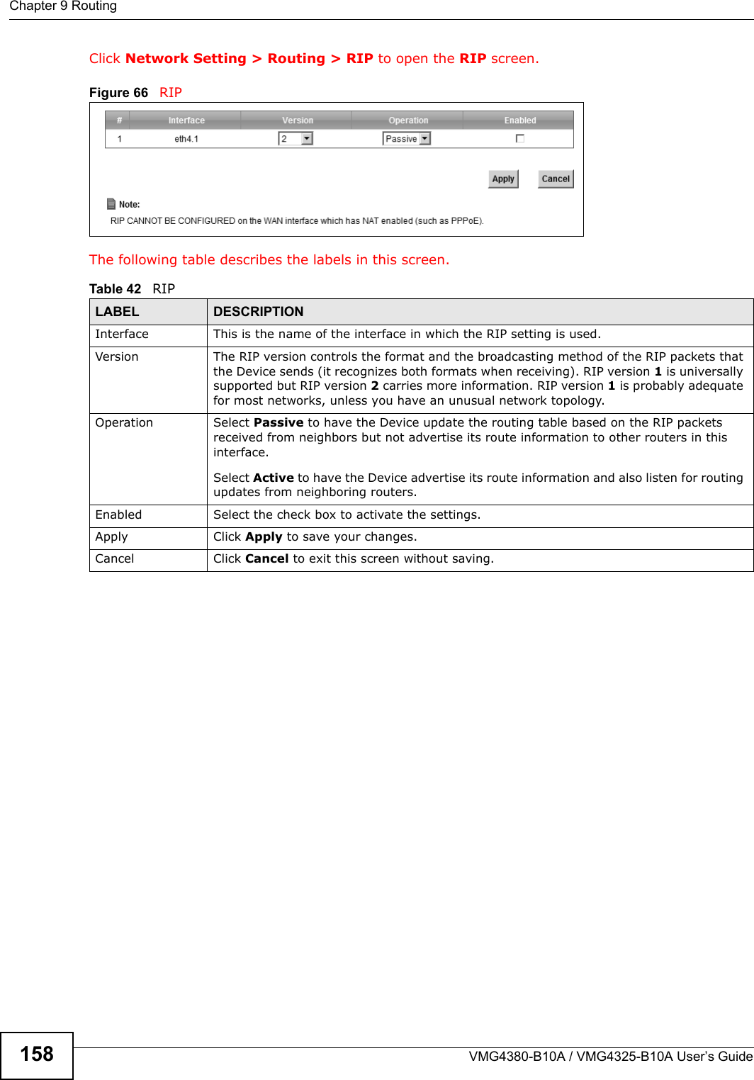
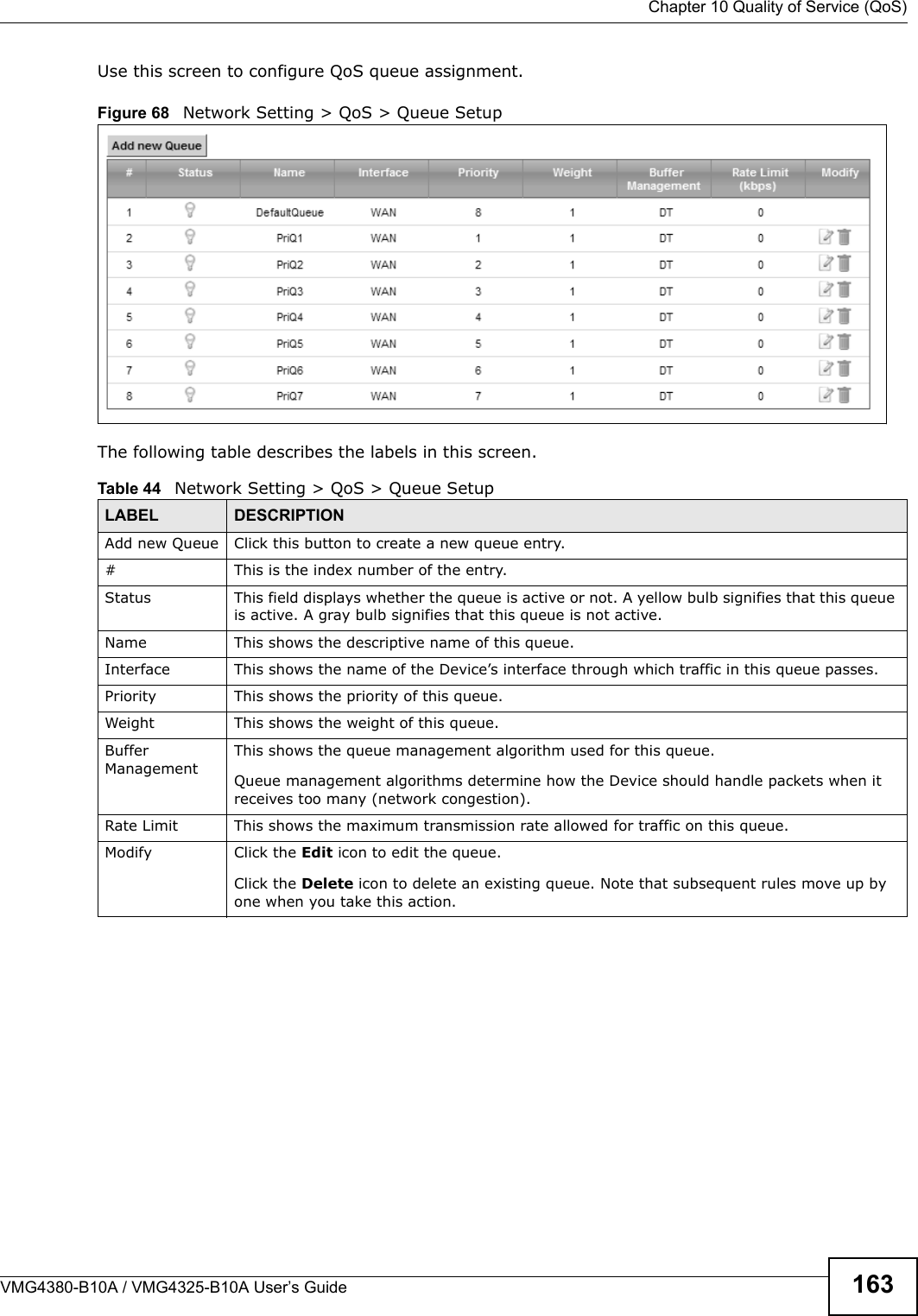
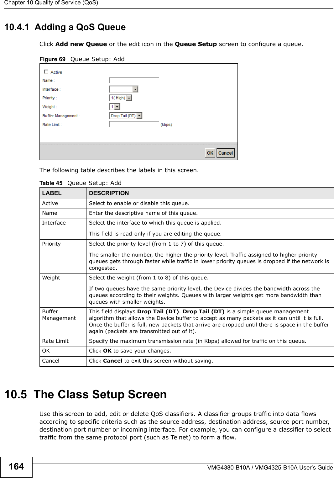
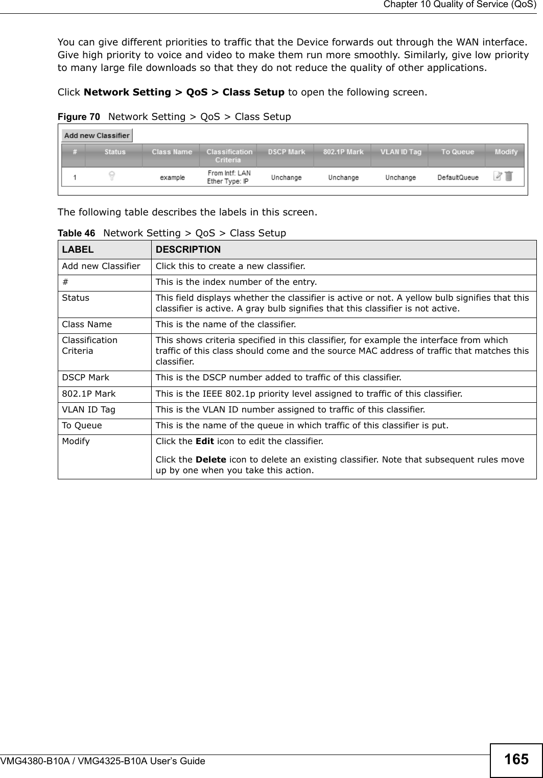
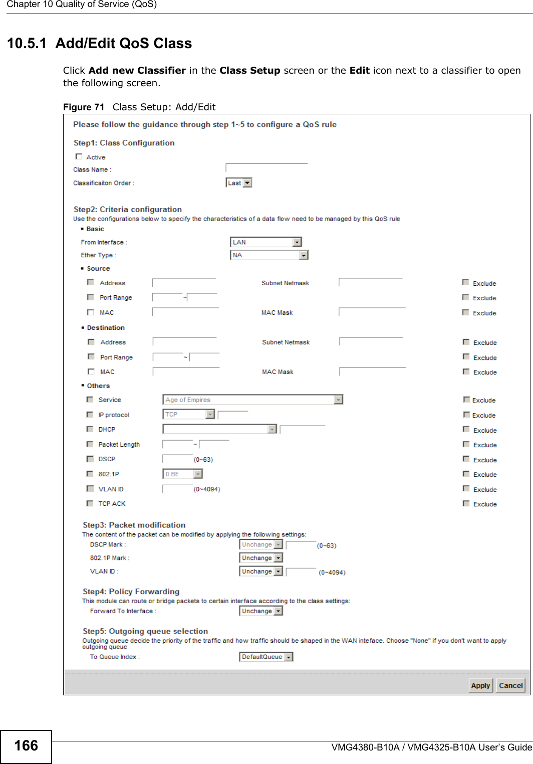
![Chapter 4 TutorialsVMG4380-B10A / VMG4325-B10A User’s Guide544.7.2 Configuring DDNS on Your DeviceConfigure the following settings in the Network Setting > DNS > Dynamic DNS screen.• Select Enable Dynamic DNS.• Select www.DynDNS.com as the service provider.• Type zyxelrouter.dyndns.org in the Host Name field.• Enter the user name (UserName1) and password (12345).Click Apply.4.7.3 Testing the DDNS SettingNow you should be able to access the Device from the Internet. To test this:1Open a web browser on the computer (using the IP address a.b.c.d) that is connected to the Internet.2Type http://zyxelrouter.dyndns.org and press [Enter].3The Device’s login page should appear. You can then log into the Device and manage it.](https://usermanual.wiki/ZyXEL-Communications/VMG4380B10A.Manual-1/User-Guide-1816559-Page-54.png)