ZyXEL Communications VMG4381B10A Wireless N VDSL2 4-port Bonding Combo WAN Gigabit Gateway with MoCA User Manual Part 2
ZyXEL Communications Corporation Wireless N VDSL2 4-port Bonding Combo WAN Gigabit Gateway with MoCA Part 2
Contents
- 1. Part 1
- 2. Part 2
Part 2
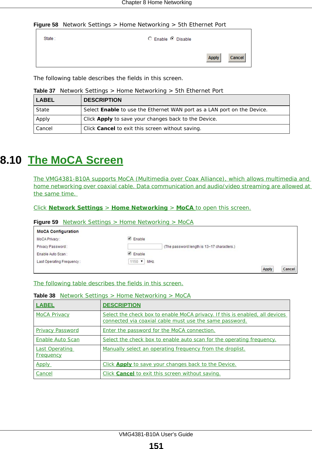
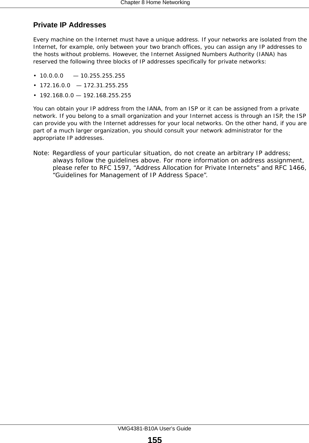


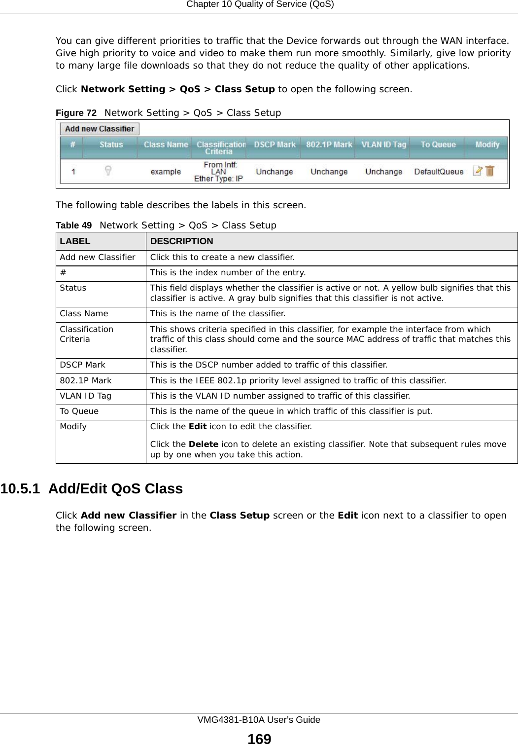
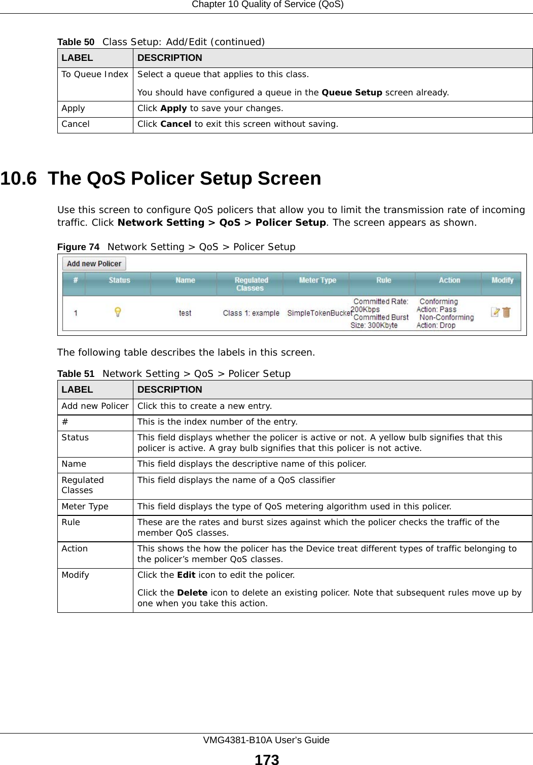

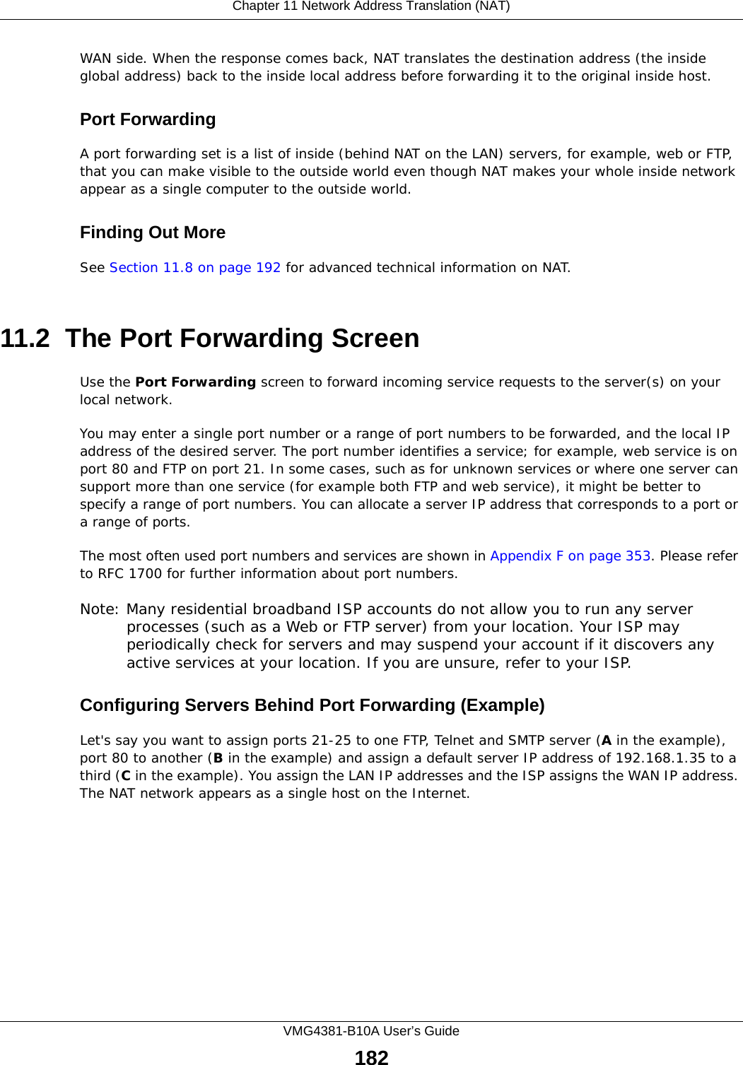
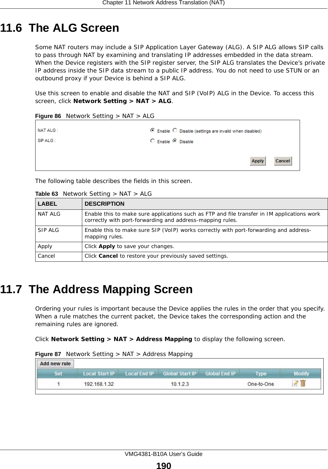
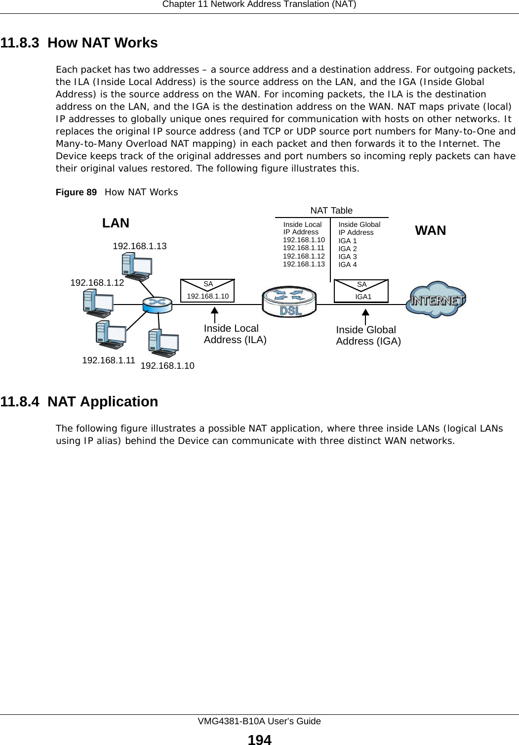

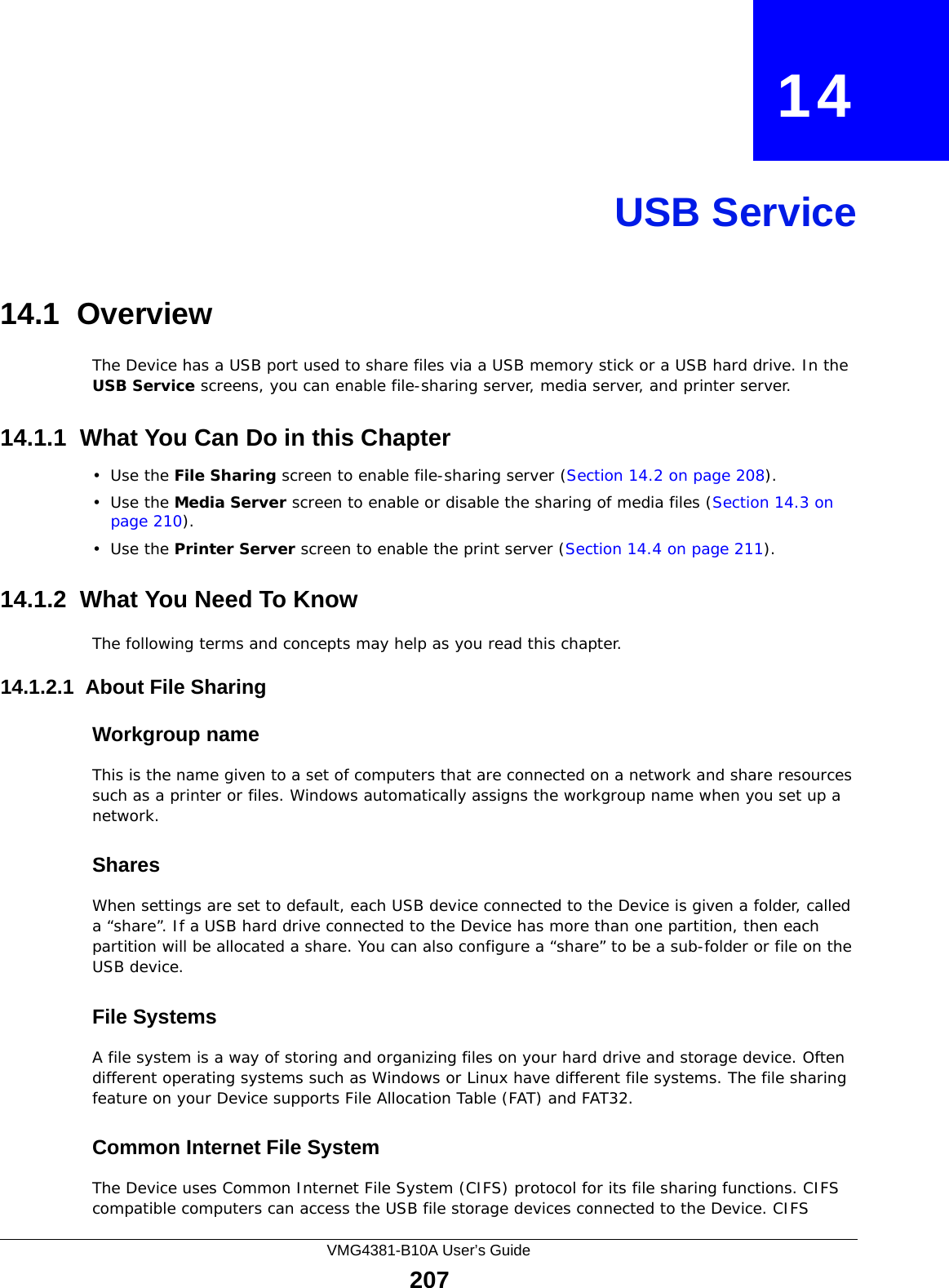
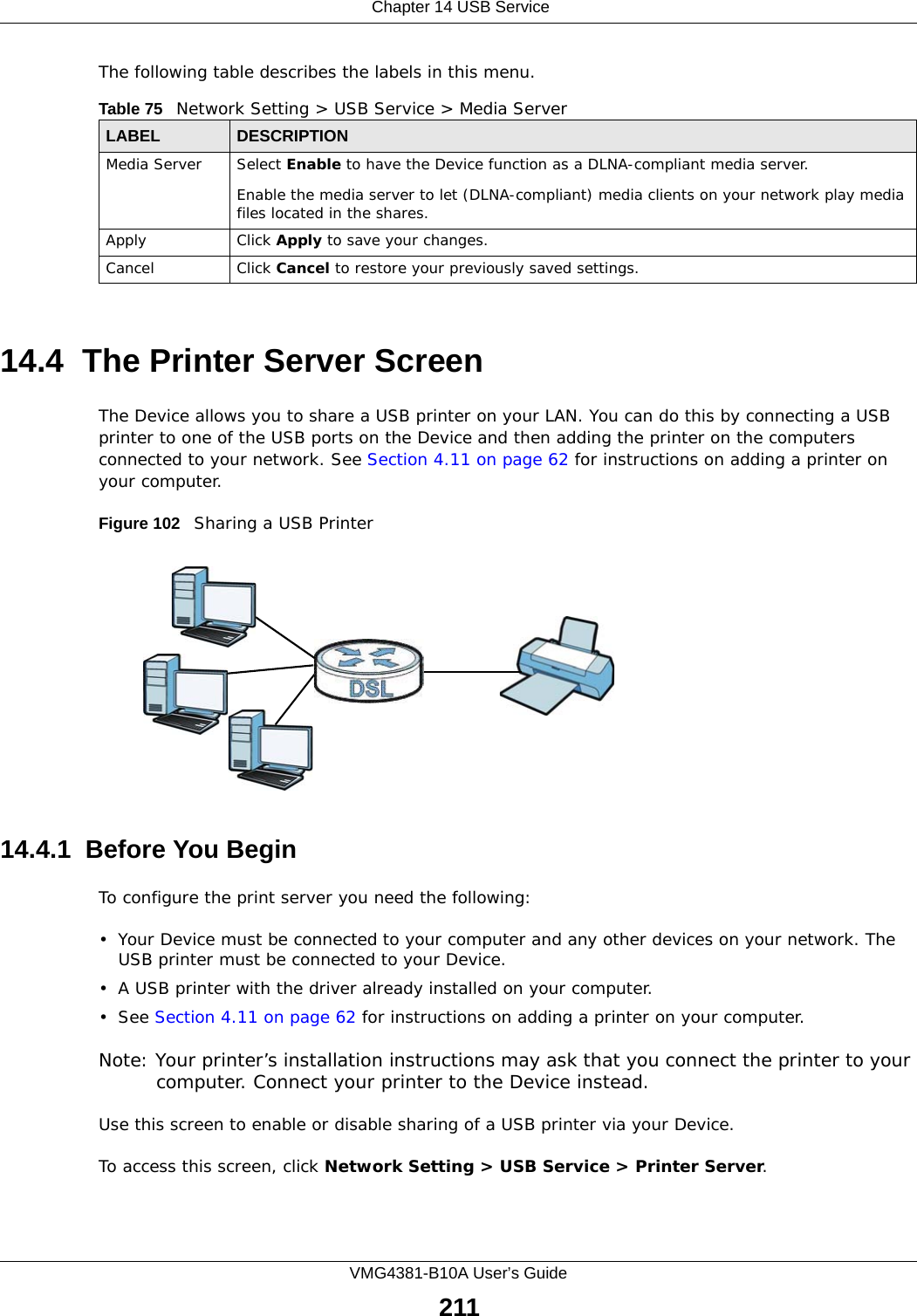
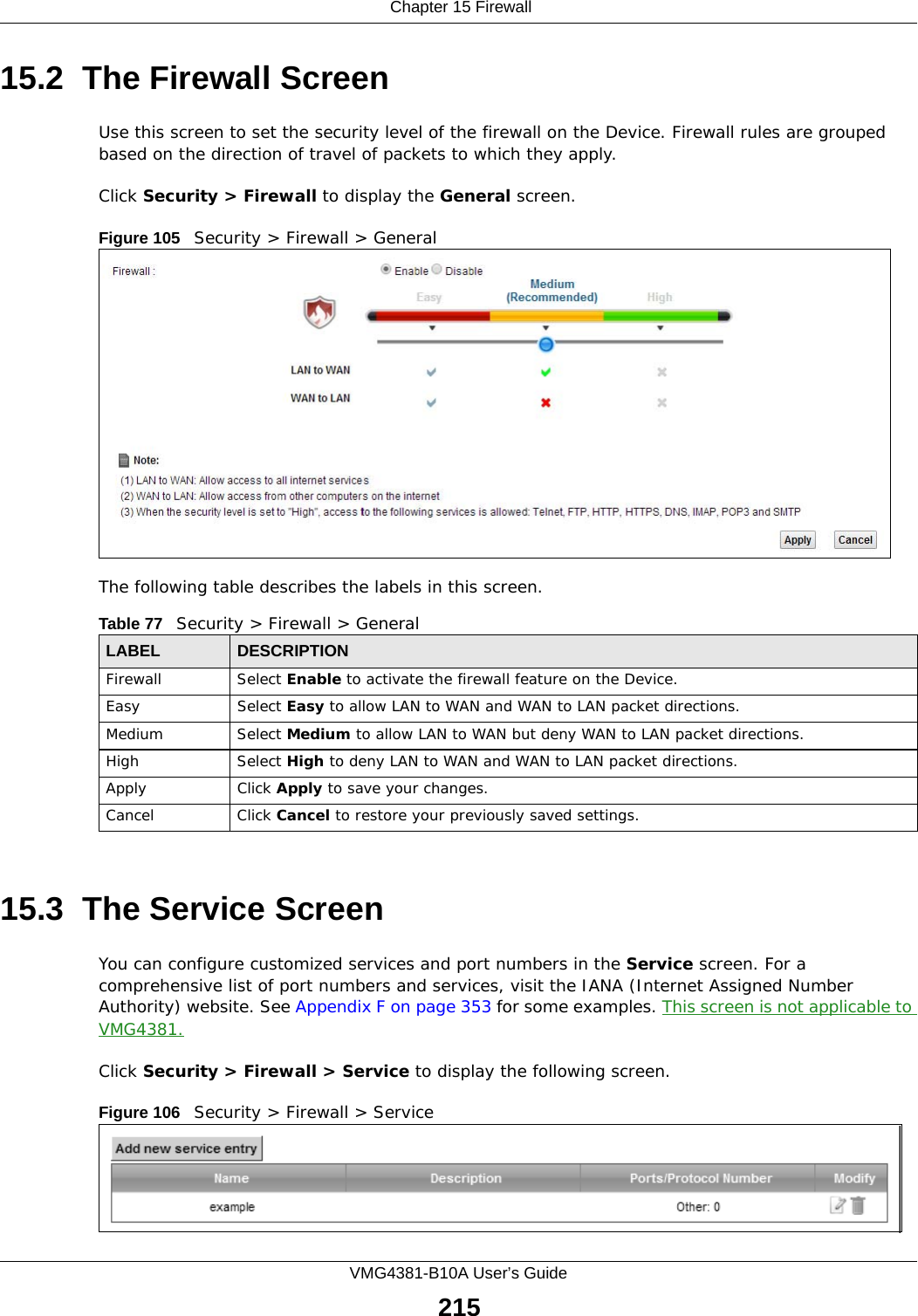
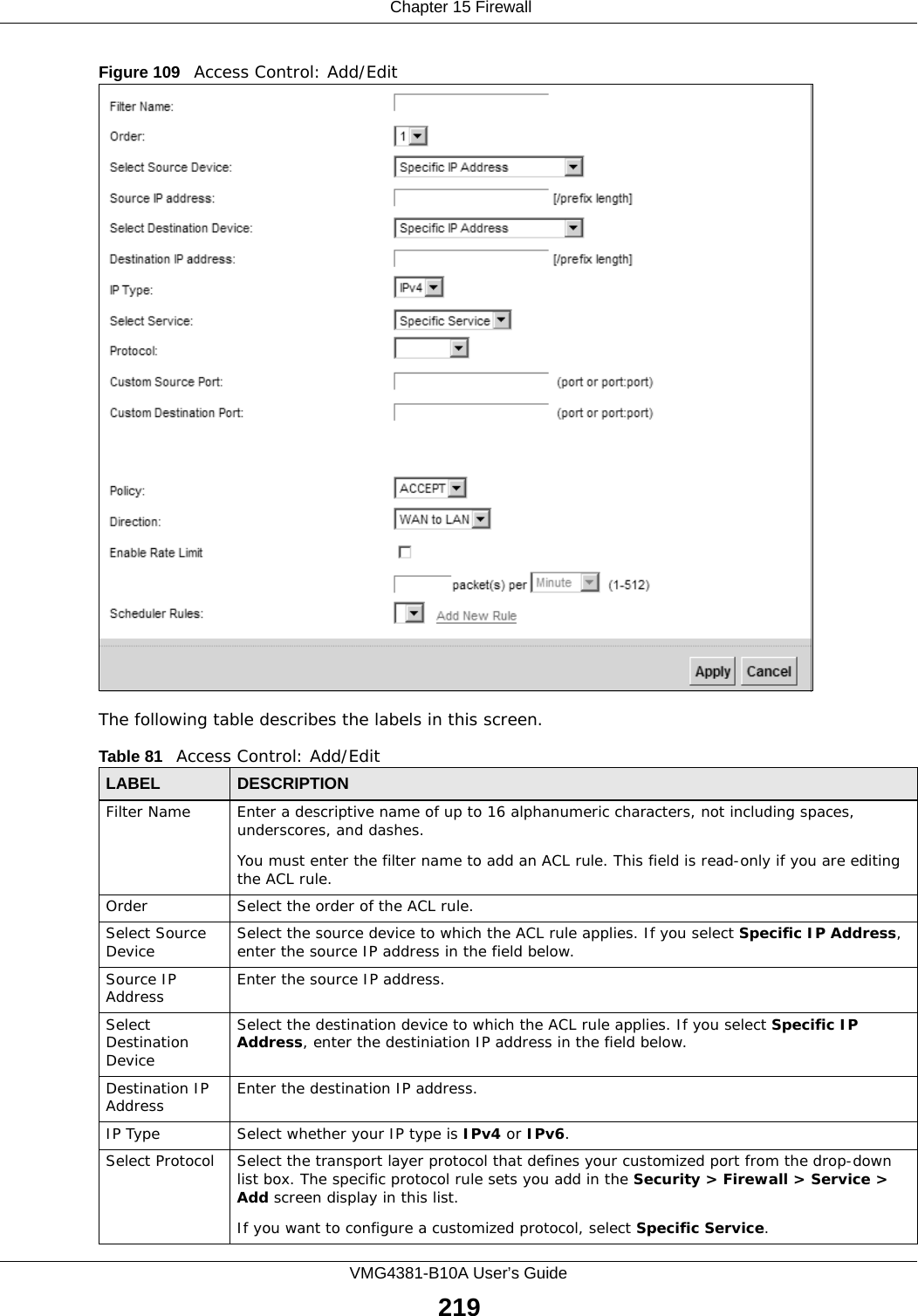


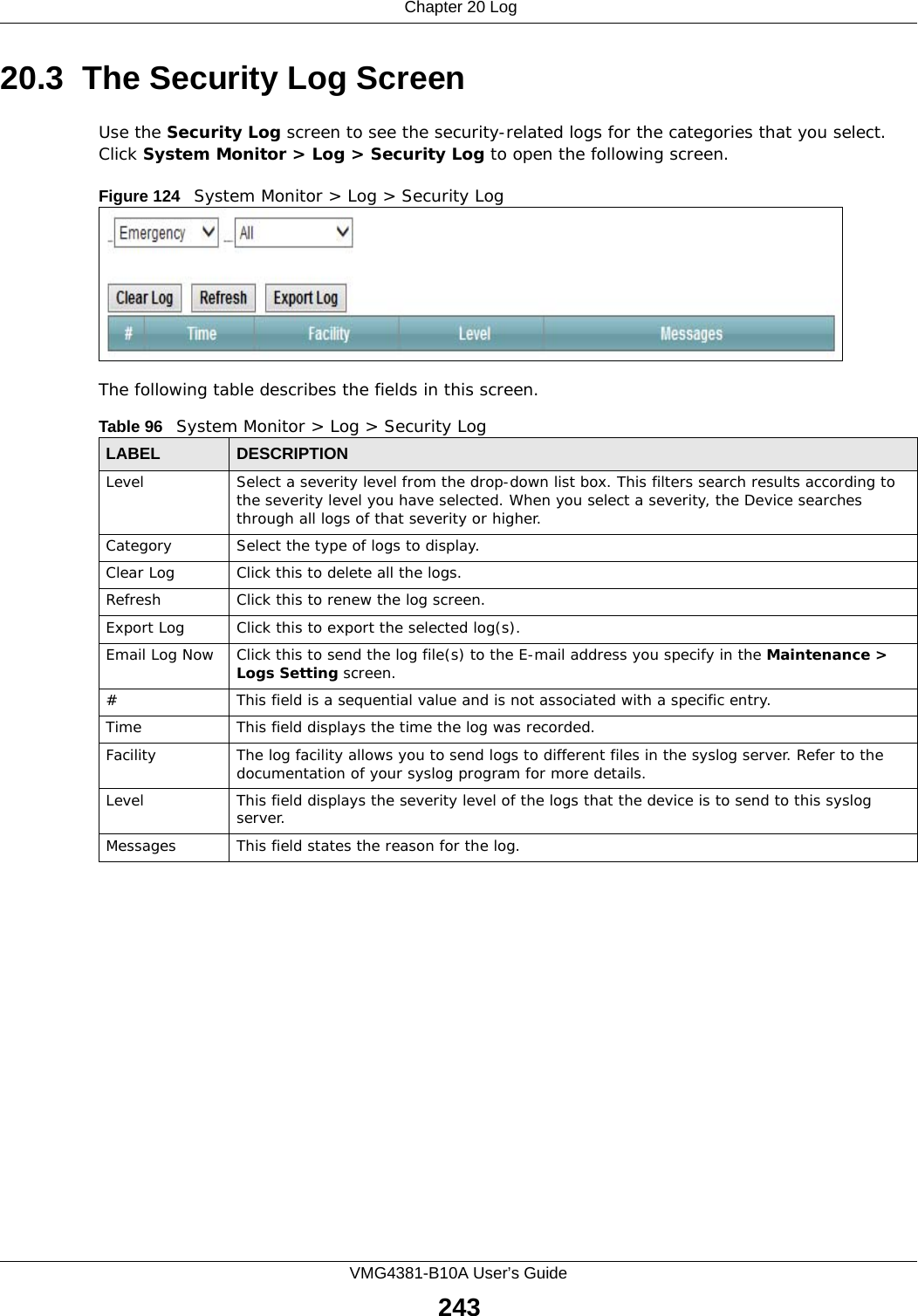


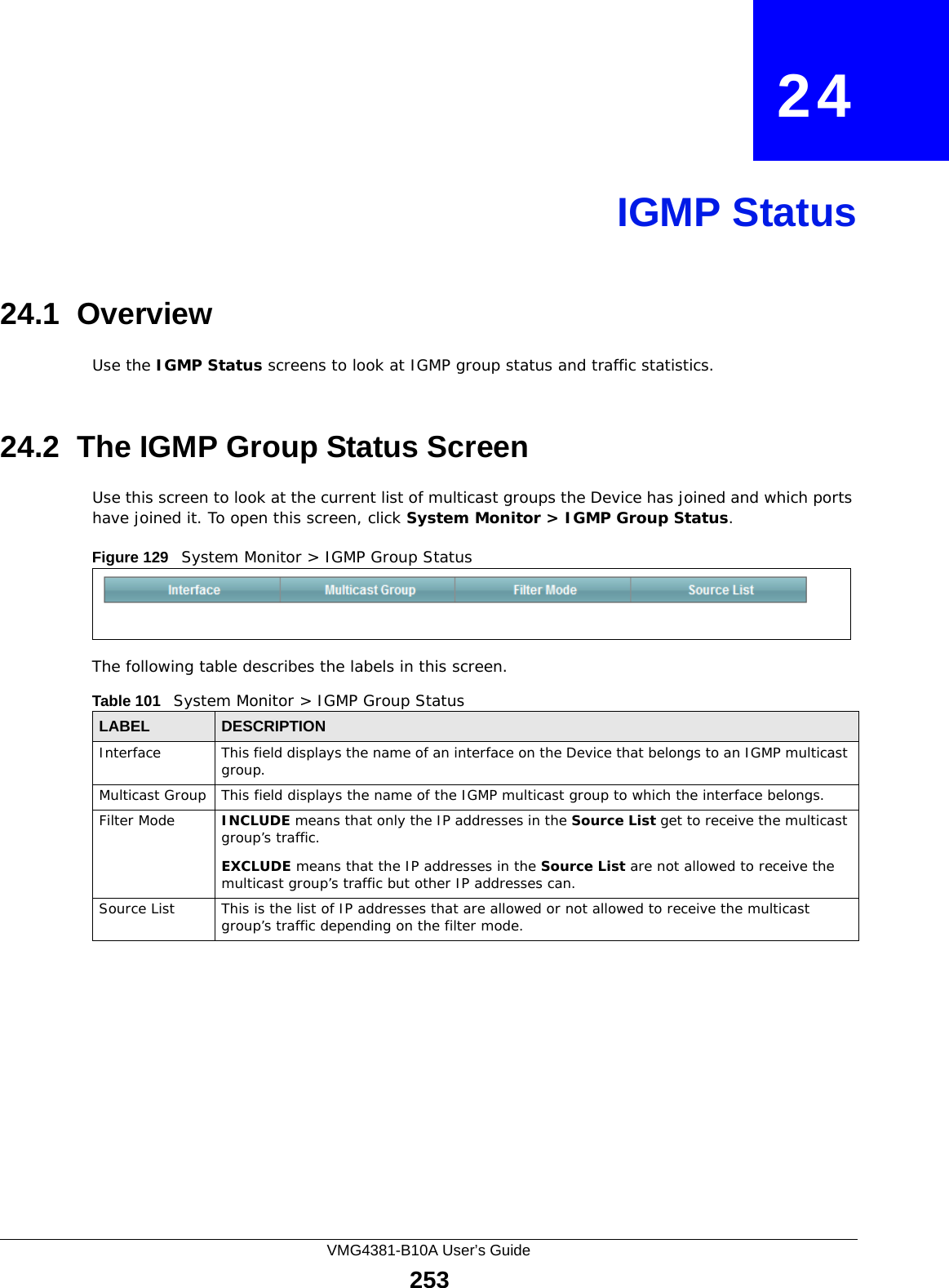


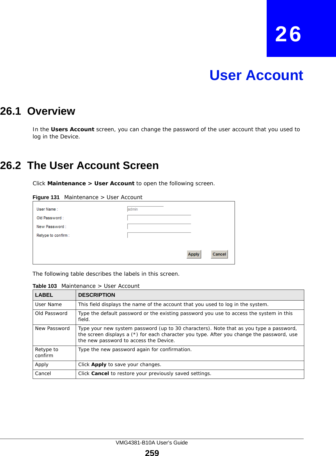


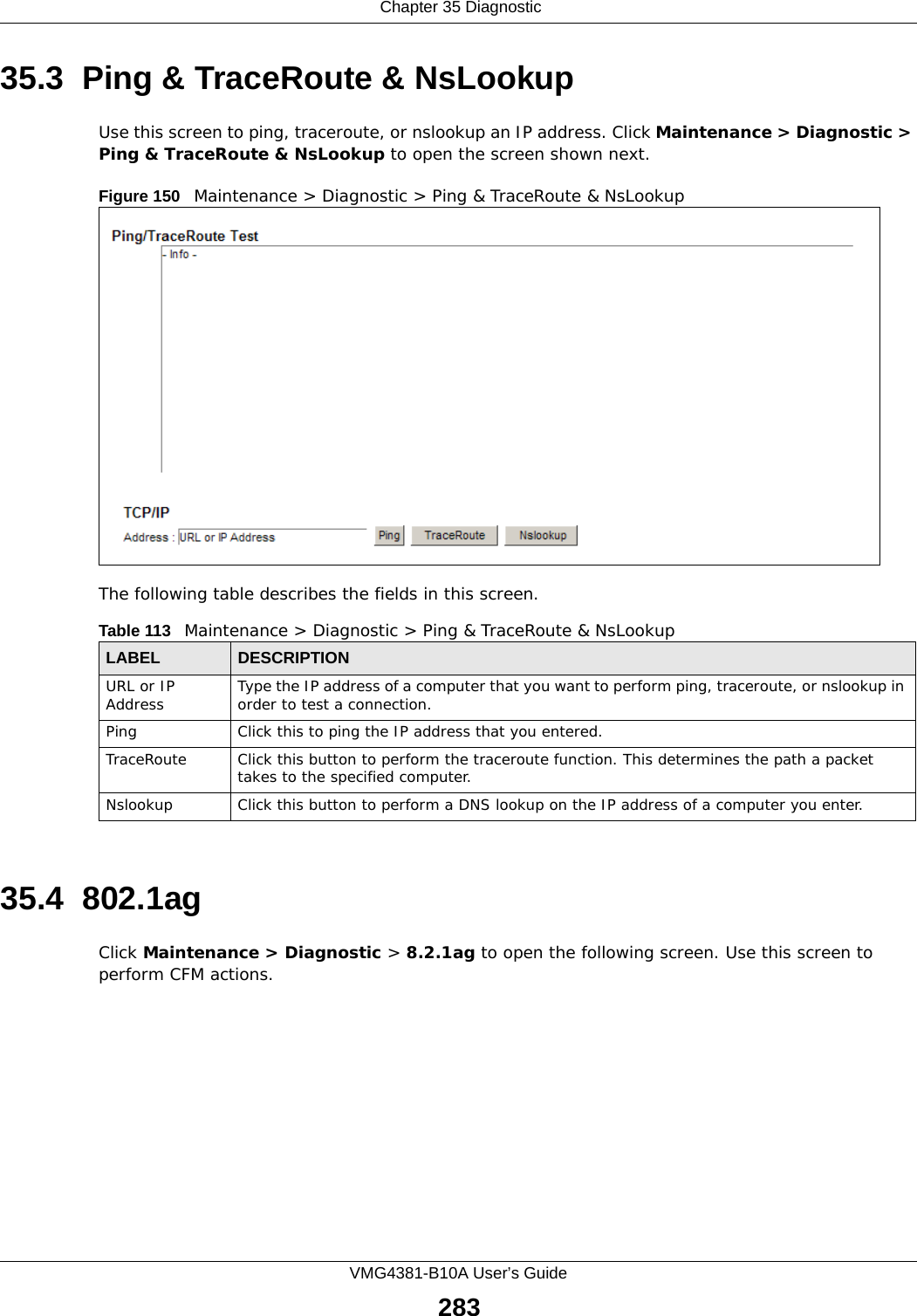
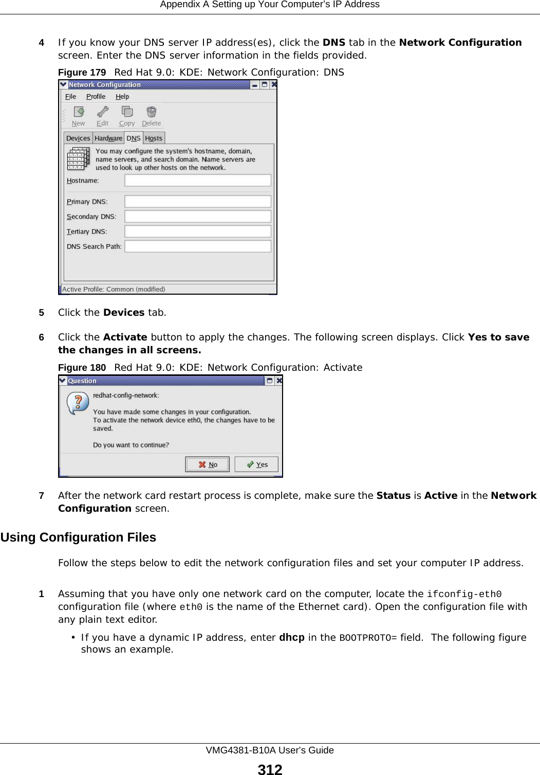
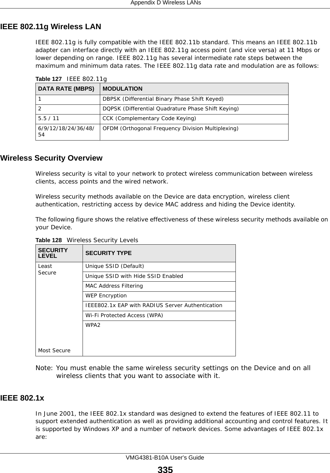
![Chapter 36 TroubleshootingVMG4381-B10A User’s Guide2895Reset the device to its factory defaults, and try to access the Device with the default IP address. See Section 1.6 on page 22.6If the problem continues, contact the network administrator or vendor, or try one of the advanced suggestions.Advanced Suggestions• Make sure you have logged out of any earlier management sessions using the same user account even if they were through a different interface or using a different browser.• Try to access the Device using another service, such as Telnet. If you can access the Device, check the remote management settings and firewall rules to find out why the Device does not respond to HTTP. I can see the Login screen, but I cannot log in to the Device.1Make sure you have entered the password correctly. The default admin password is 1234. The field is case-sensitive, so make sure [Caps Lock] is not on. 2You cannot log in to the web configurator while someone is using Telnet to access the Device. Log out of the Device in the other session, or ask the person who is logged in to log out. 3Turn the Device off and on. 4If this does not work, you have to reset the device to its factory defaults. See Section 36.1 on page 287.I cannot Telnet to the Device.See the troubleshooting suggestions for I cannot see or access the Login screen in the web configurator. Ignore the suggestions about your browser.I cannot use FTP to upload / download the configuration file. / I cannot use FTP to upload new firmware.See the troubleshooting suggestions for I cannot see or access the Login screen in the web configurator. Ignore the suggestions about your browser.](https://usermanual.wiki/ZyXEL-Communications/VMG4381B10A.Part-2/User-Guide-2291793-Page-139.png)
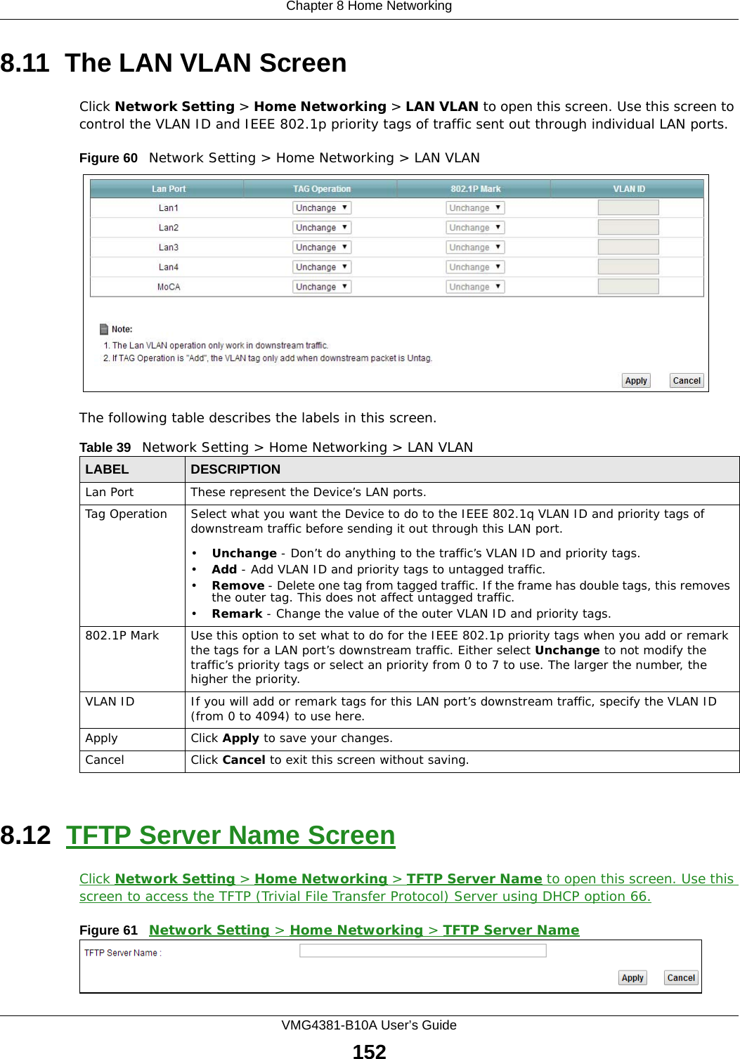
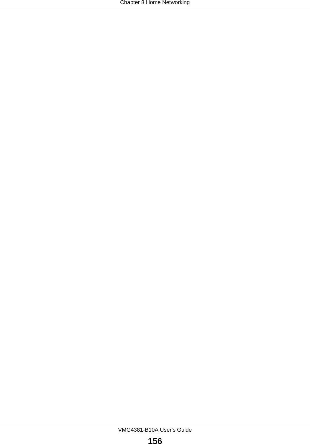
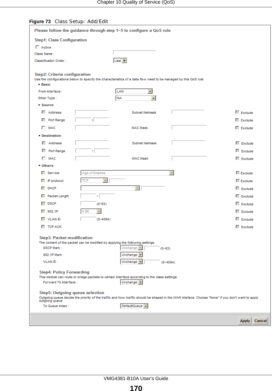
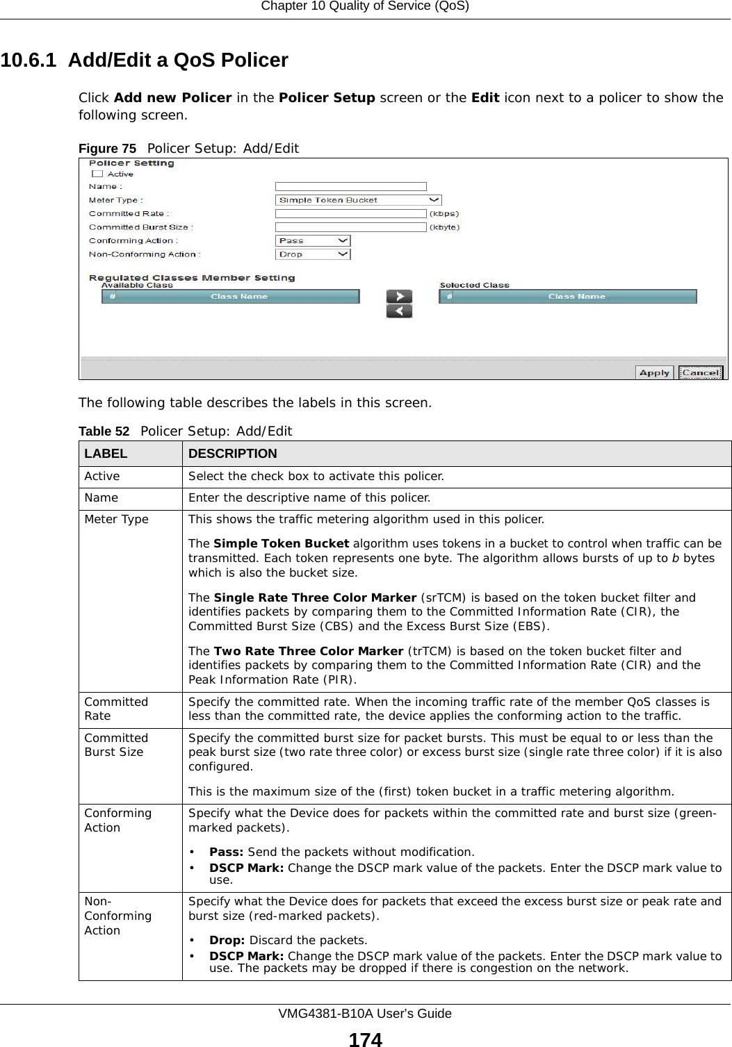
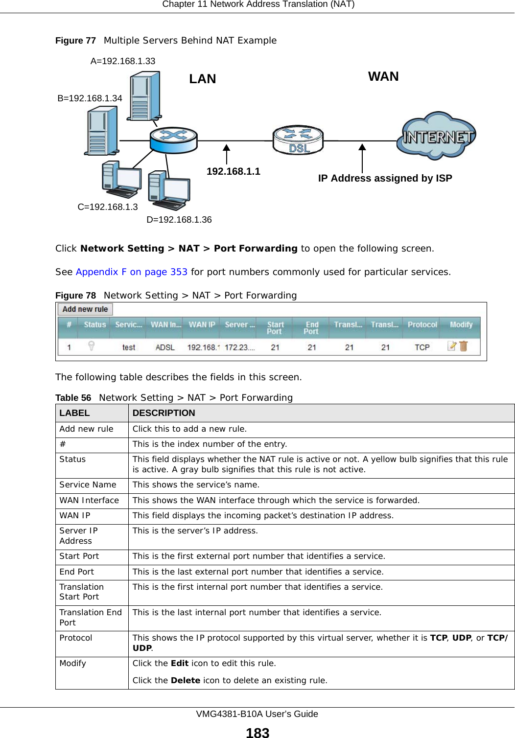
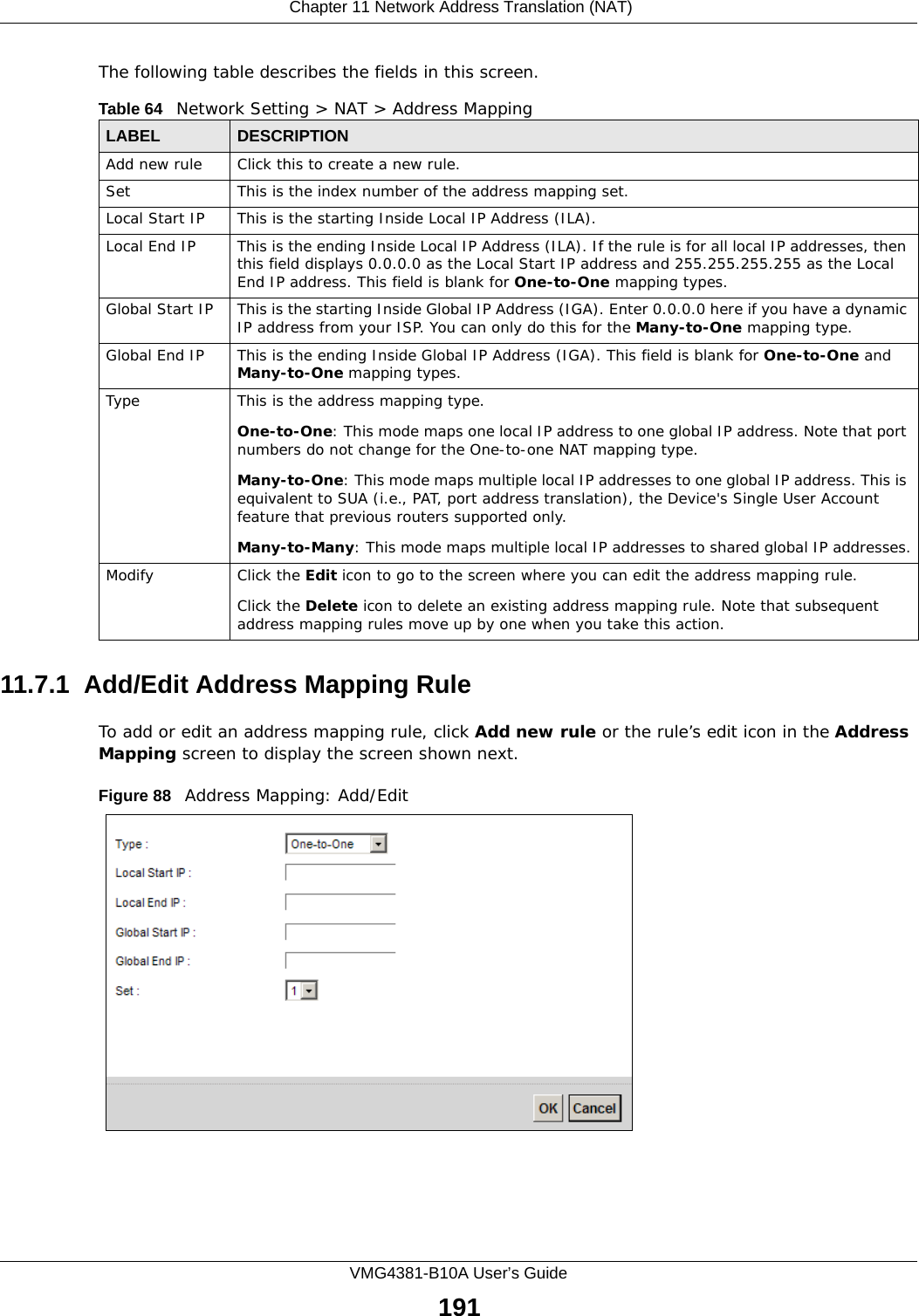
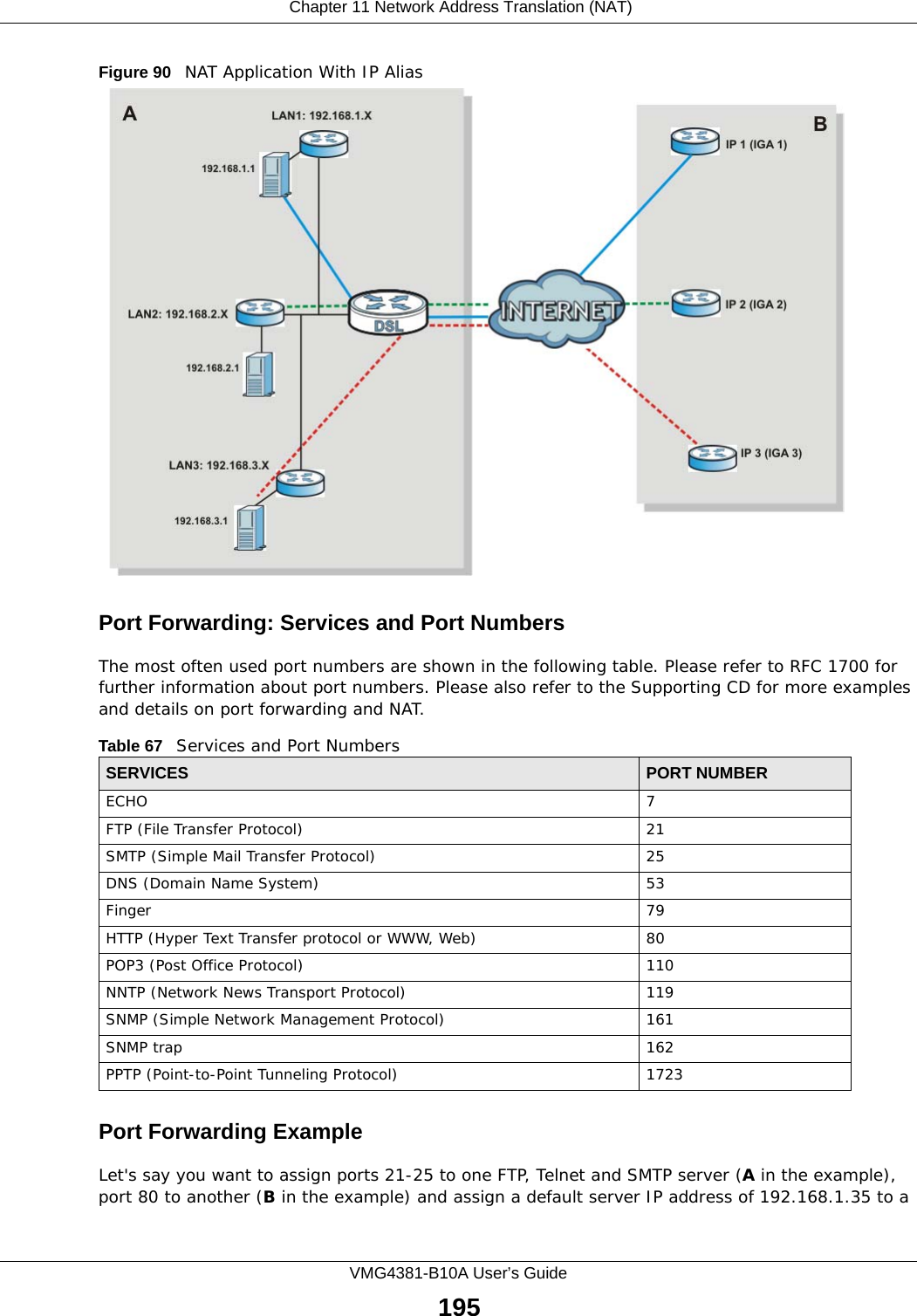
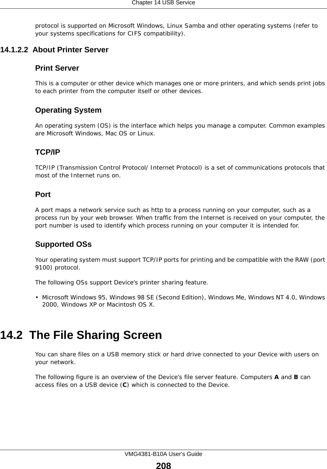
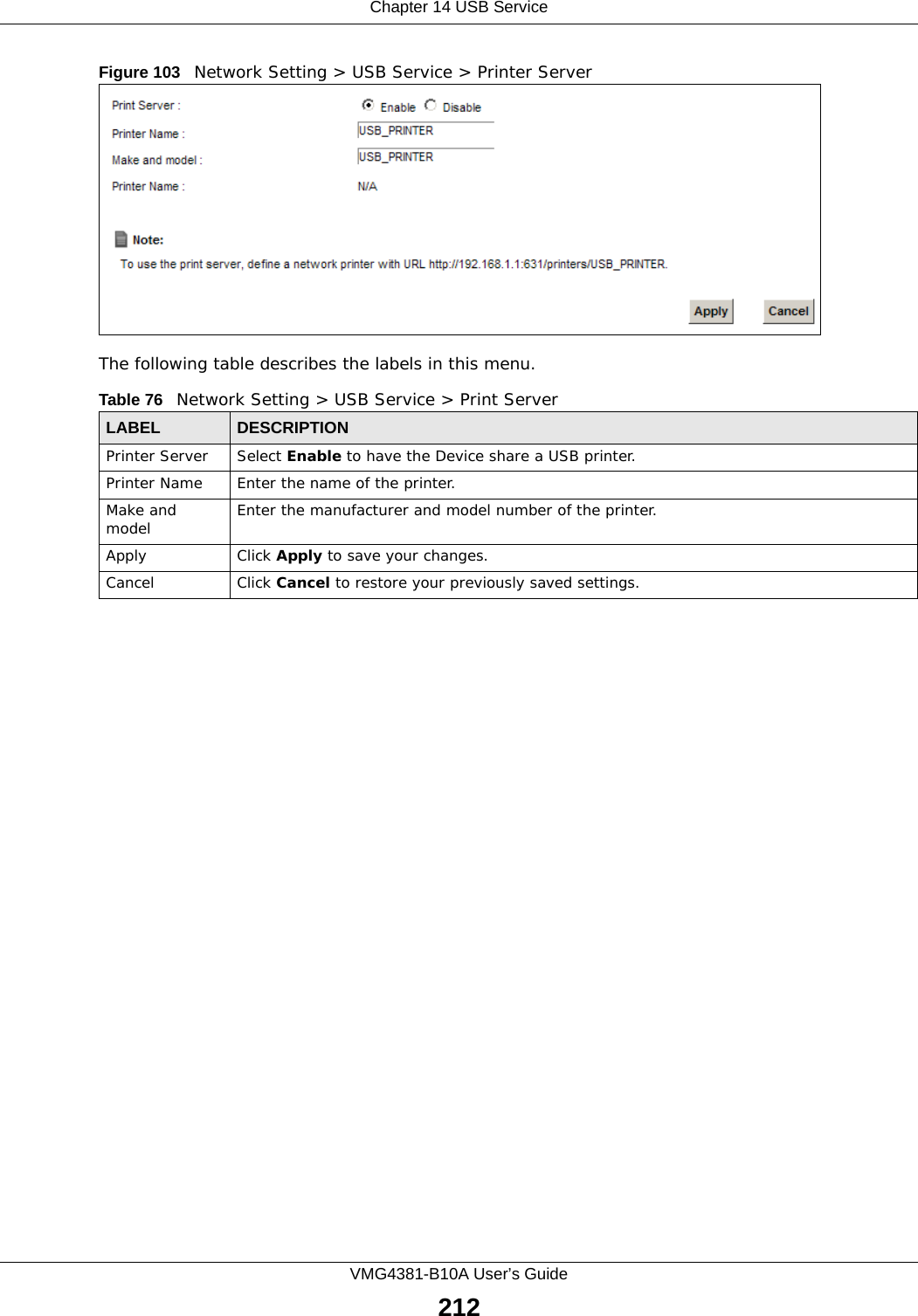
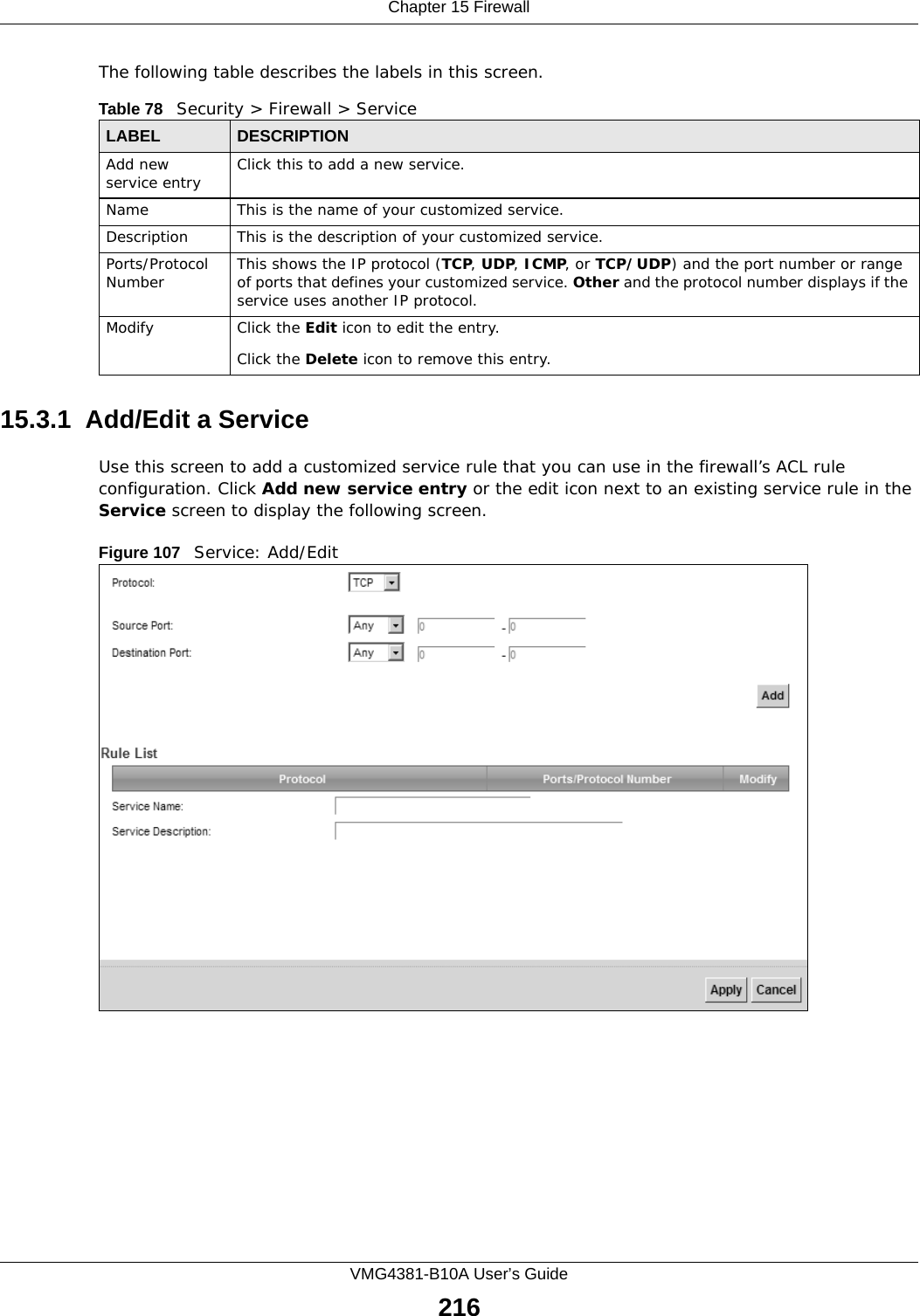
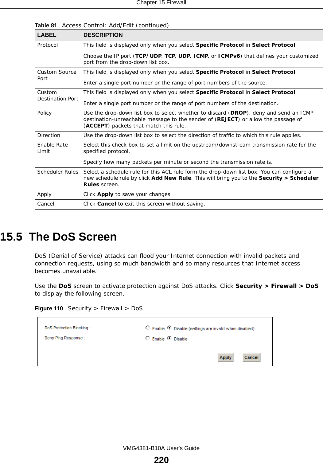
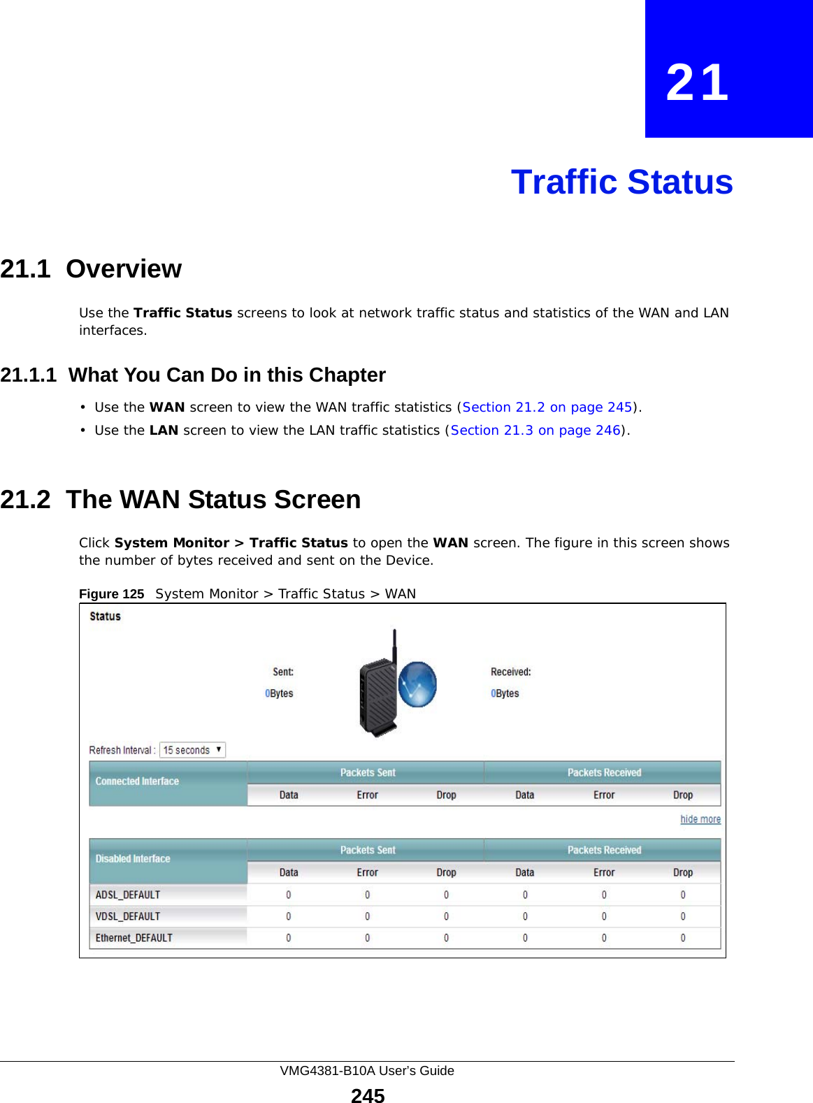
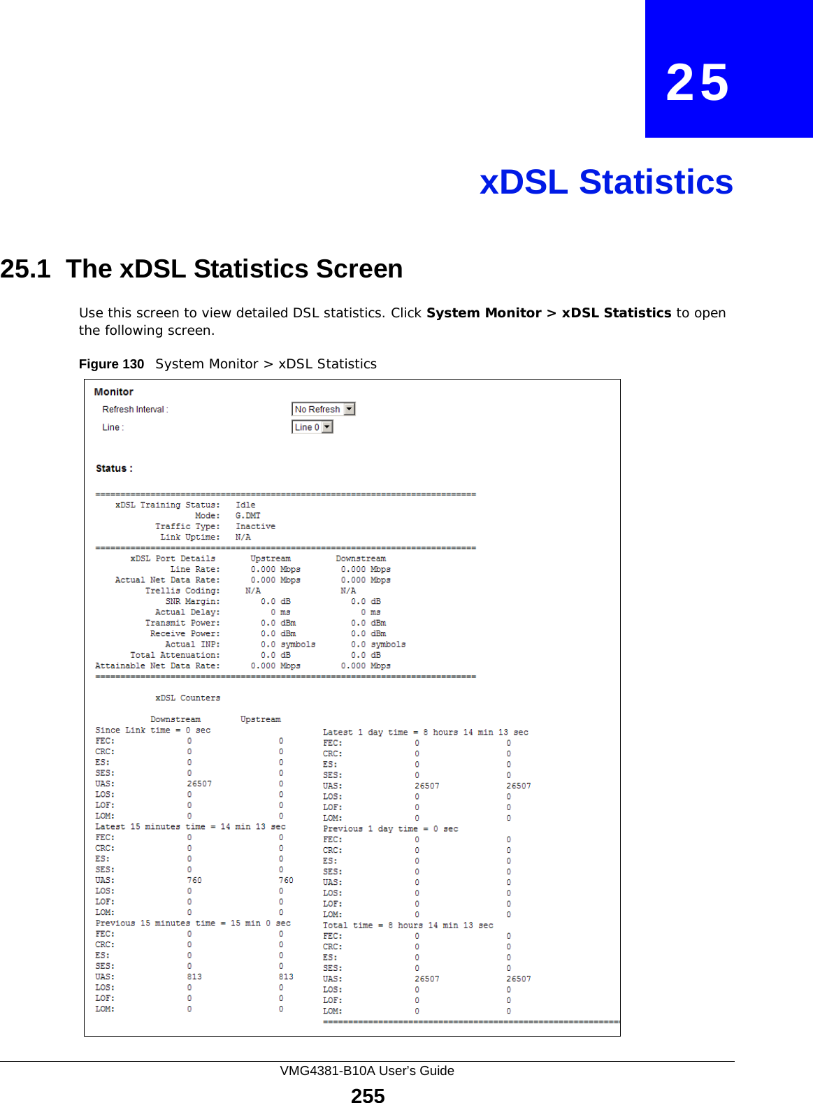
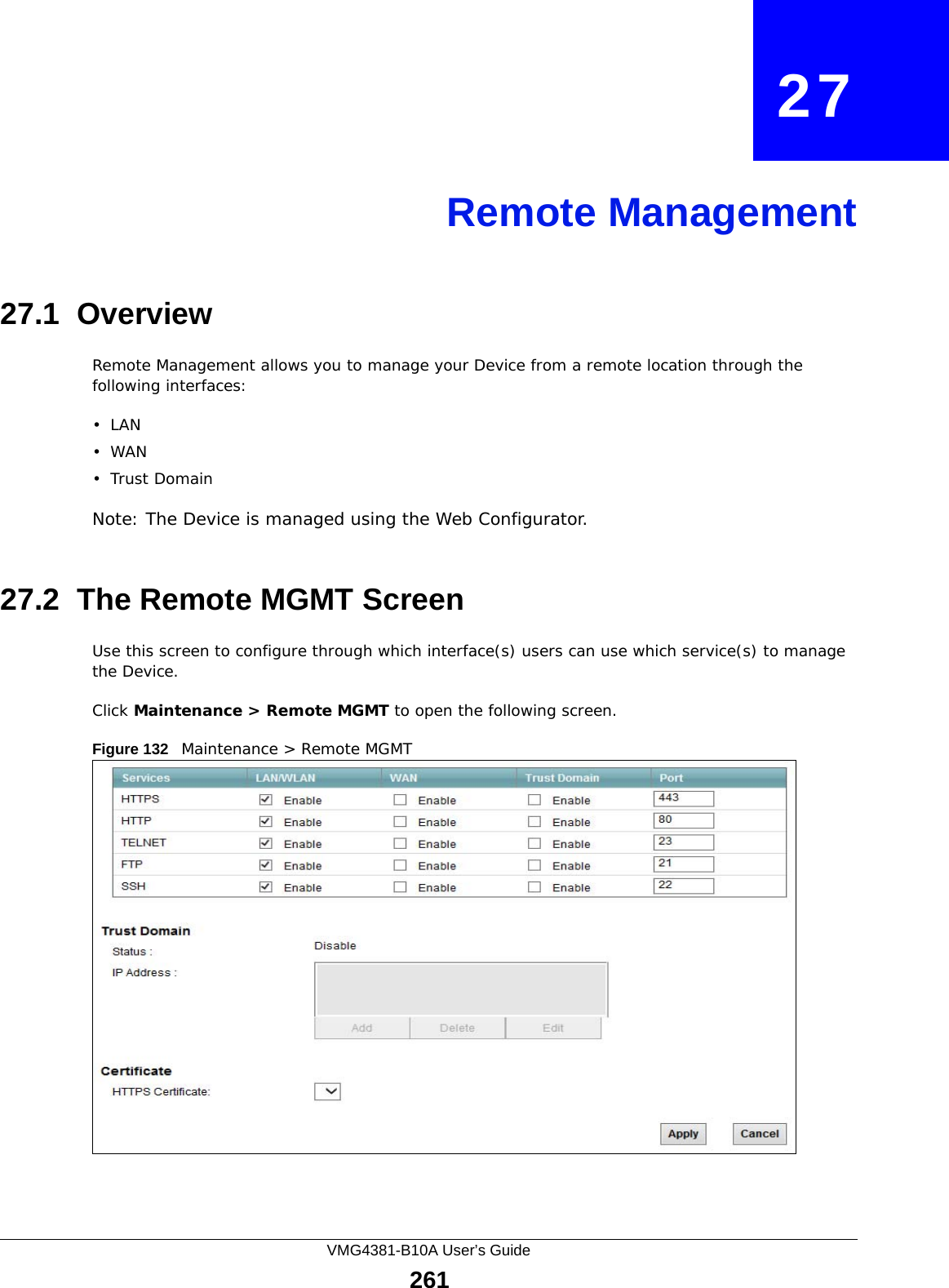
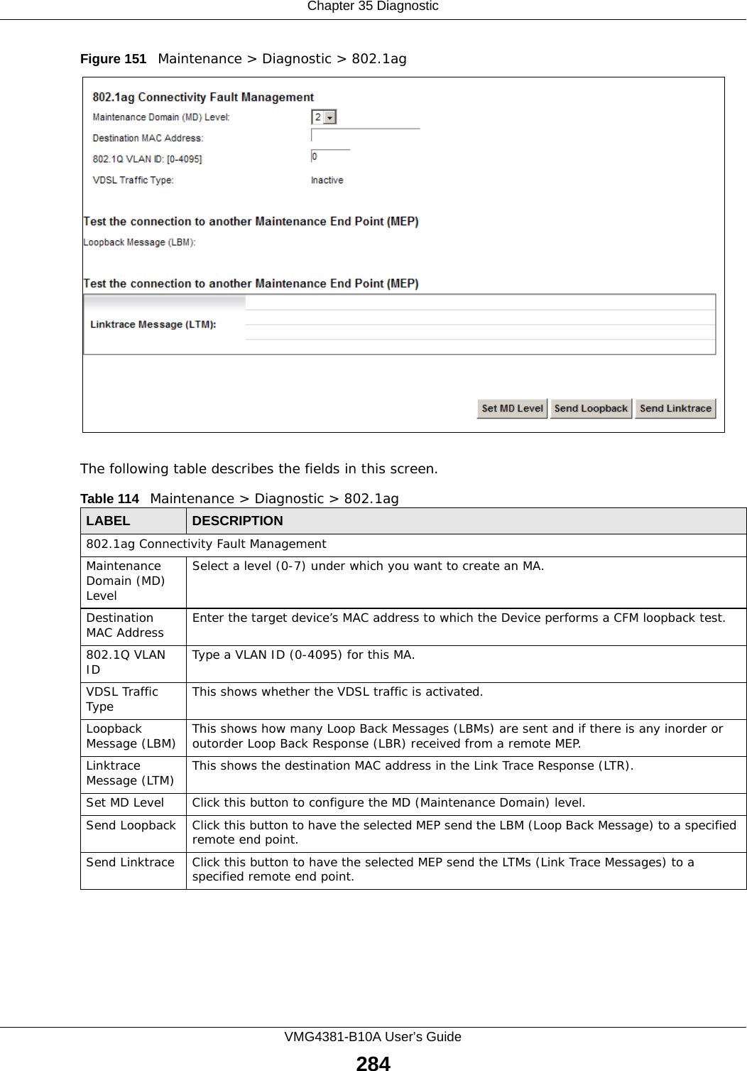
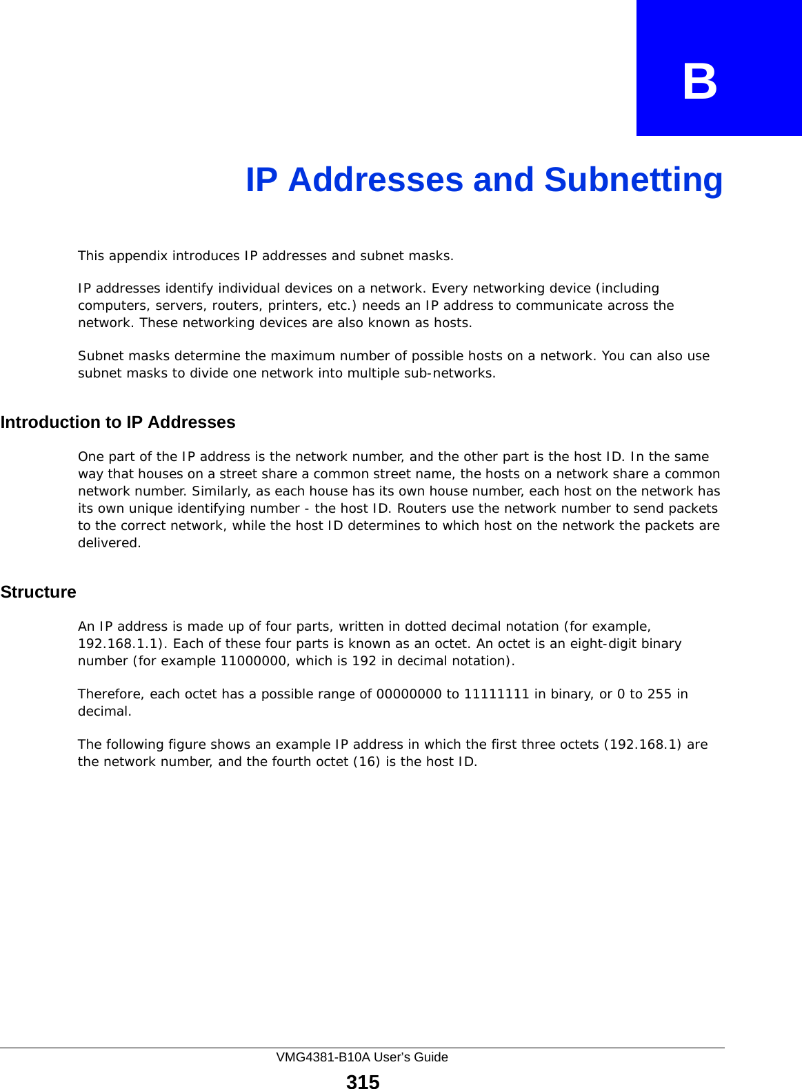
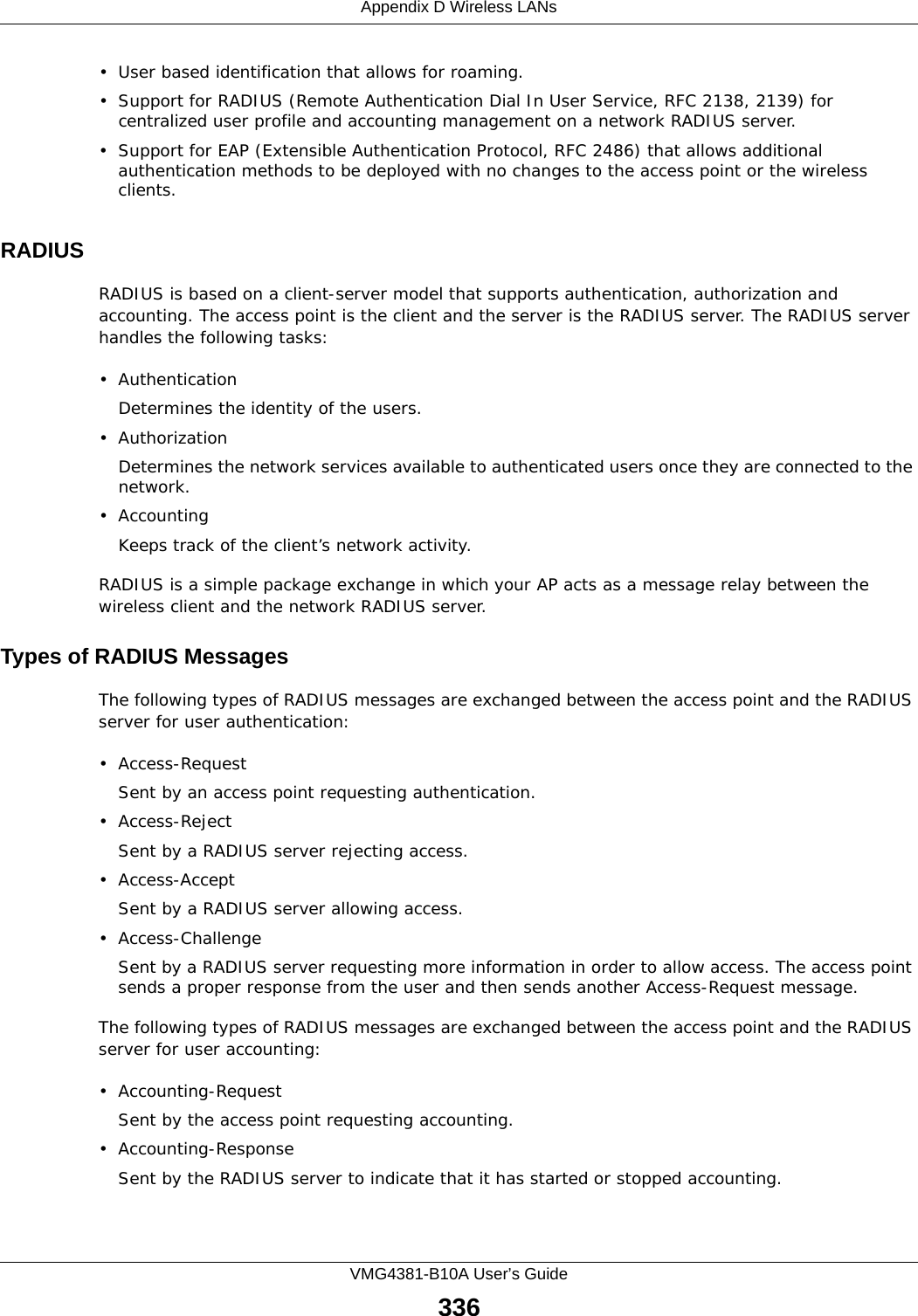
![Chapter 36 TroubleshootingVMG4381-B10A User’s Guide29036.3 Internet AccessI cannot access the Internet.1Check the hardware connections, and make sure the LEDs are behaving as expected. See the Quick Start Guide and Section 1.5 on page 21.2Make sure you entered your ISP account information correctly in the Network Setting > Broadband screen. These fields are case-sensitive, so make sure [Caps Lock] is not on. 3If you are trying to access the Internet wirelessly, make sure that you enabled the wireless LAN in the Device and your wireless client and that the wireless settings in the wireless client are the same as the settings in the Device.4Disconnect all the cables from your device and reconnect them. 5If the problem continues, contact your ISP. I cannot access the Internet through a DSL connection.1Make sure you have the DSL WAN port connected to a telephone jack (or the DSL or modem jack on a splitter if you have one).2Make sure you configured a proper DSL WAN interface (Network Setting > Broadband screen) with the Internet account information provided by your ISP and that it is enabled.3Check that the LAN interface you are connected to is in the same interface group as the DSL connection (Network Setting > Interface Group).4If you set up a WAN connection using bridging service, make sure you turn off the DHCP feature in the LAN screen to have the clients get WAN IP addresses directly from your ISP’s DHCP server.I cannot connect to the Internet using a second DSL connection.ADSL and VDSL connections cannot work at the same time. You can only use one type of DSL connection, either ADSL or VDSL connection at one time.I cannot access the Internet anymore. I had access to the Internet (with the Device), but my Internet connection is not available anymore.1Your session with the Device may have expired. Try logging into the Device again.](https://usermanual.wiki/ZyXEL-Communications/VMG4381B10A.Part-2/User-Guide-2291793-Page-140.png)
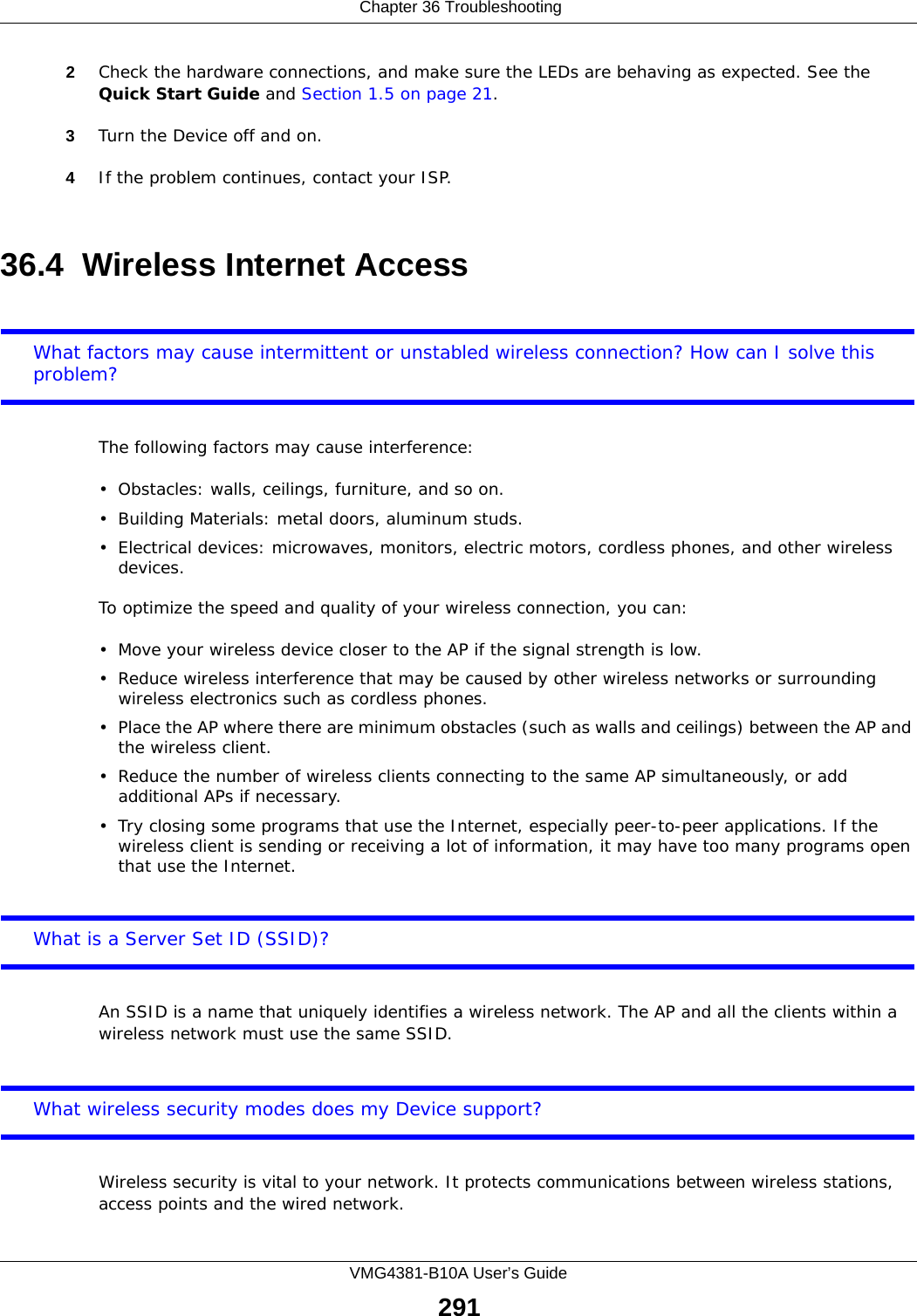

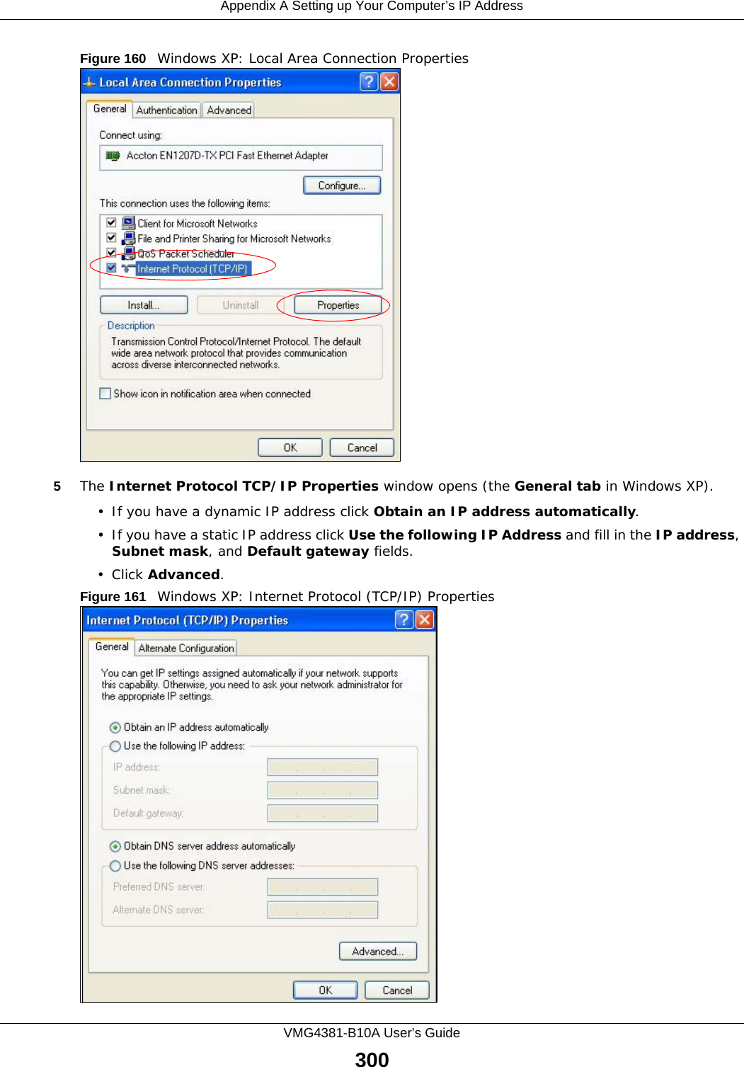
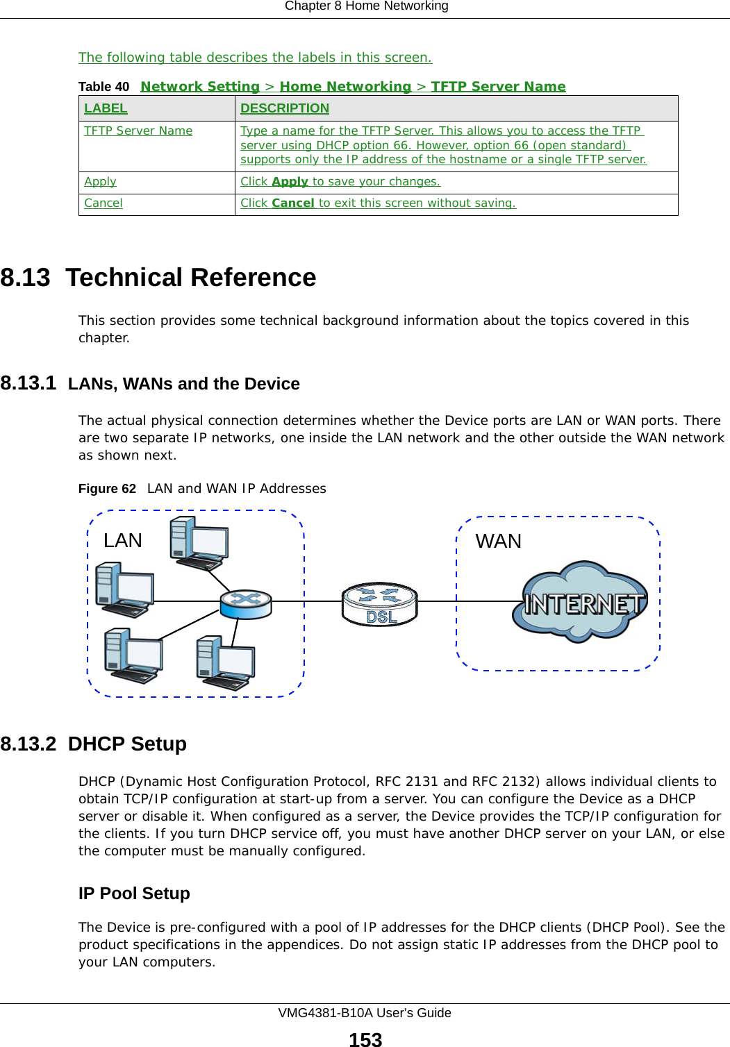
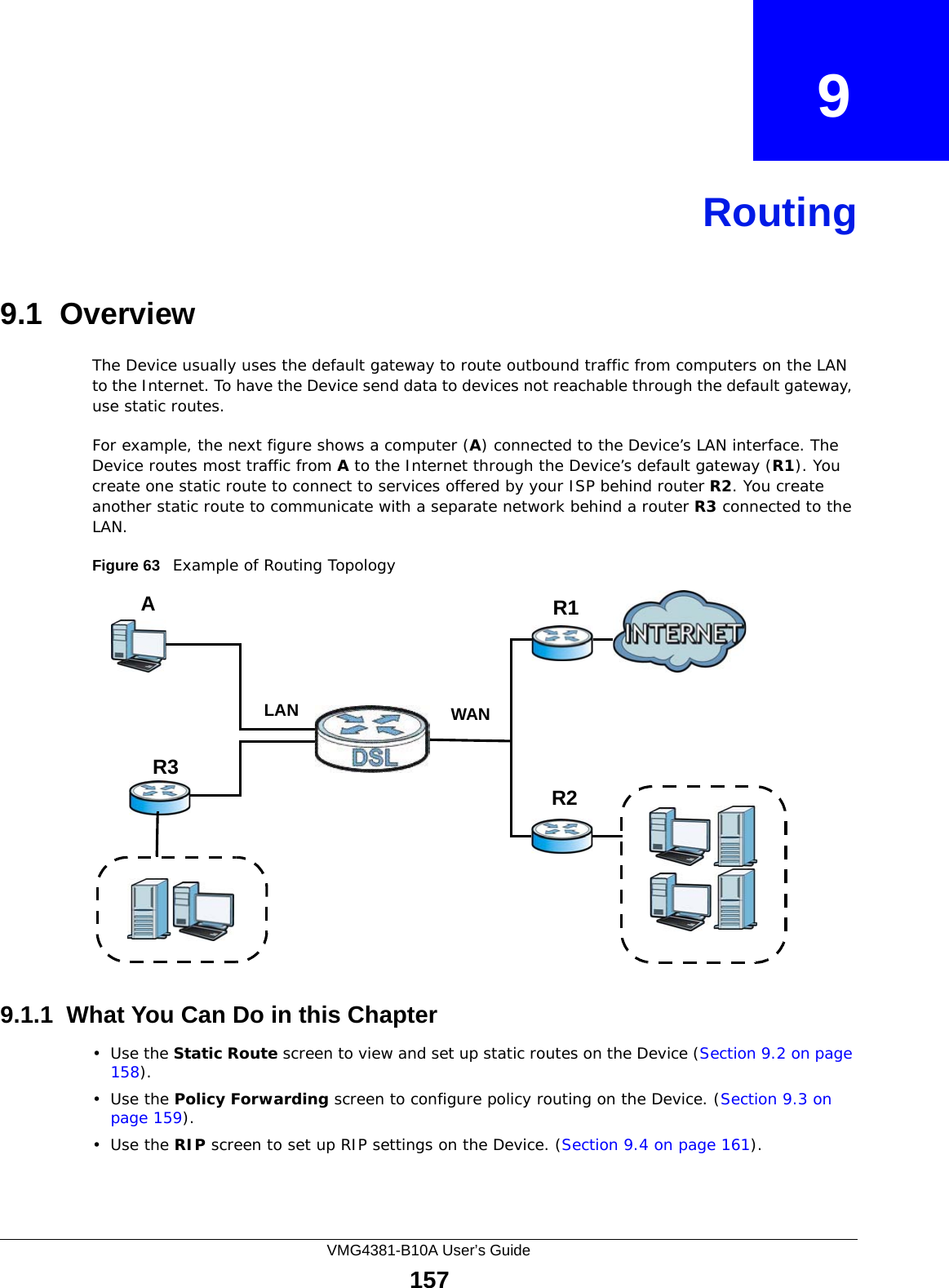
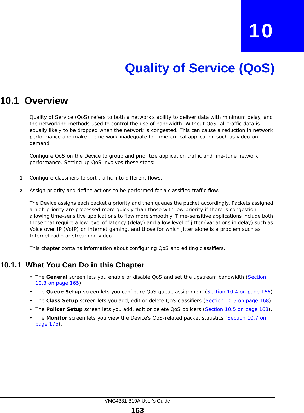
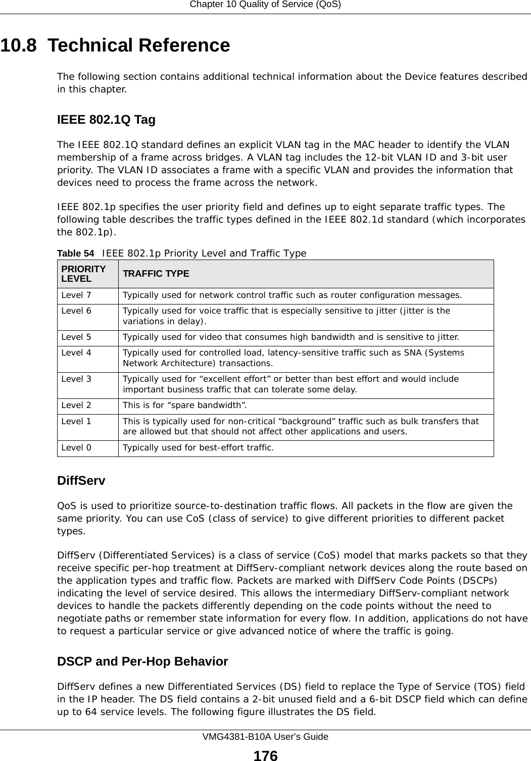
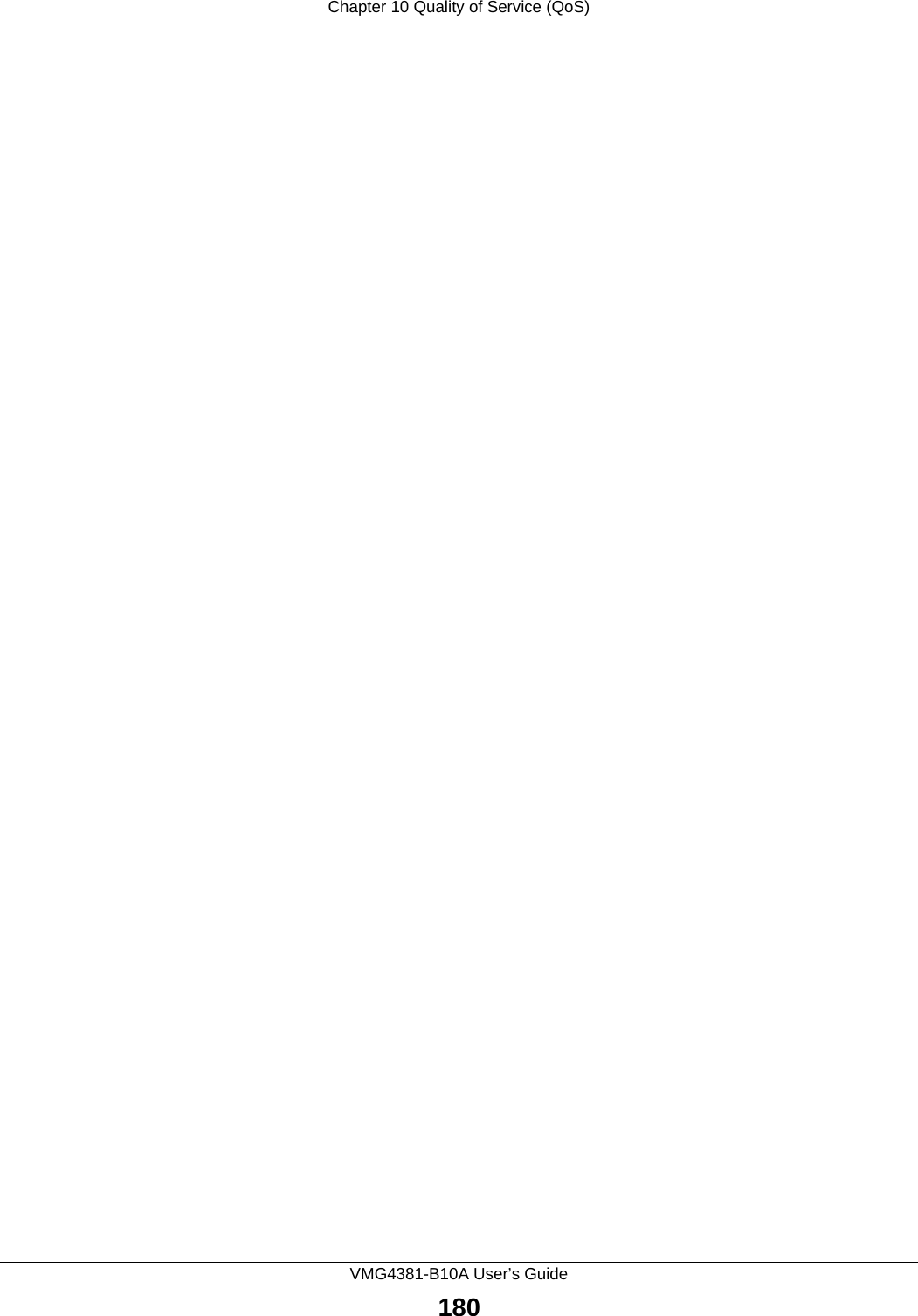
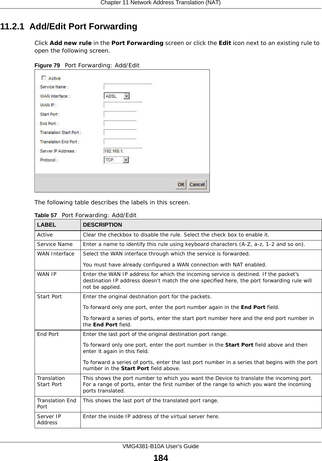
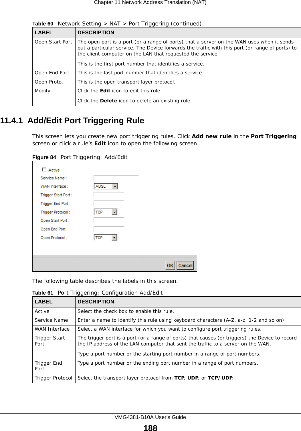
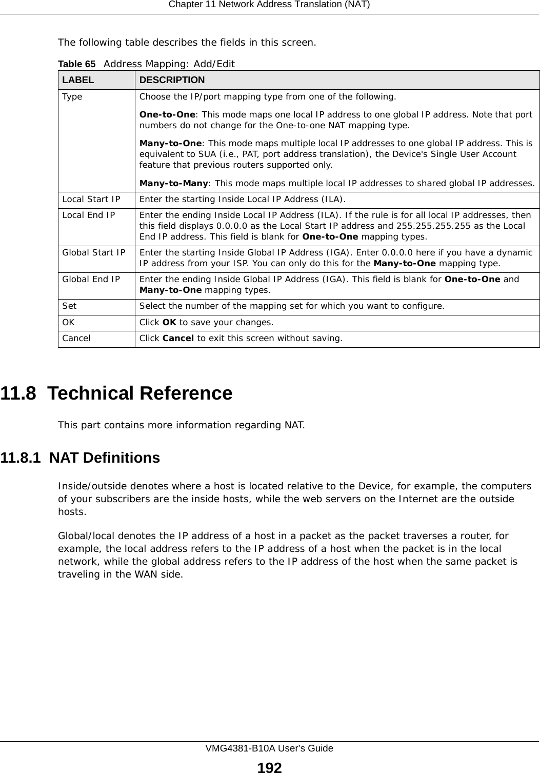
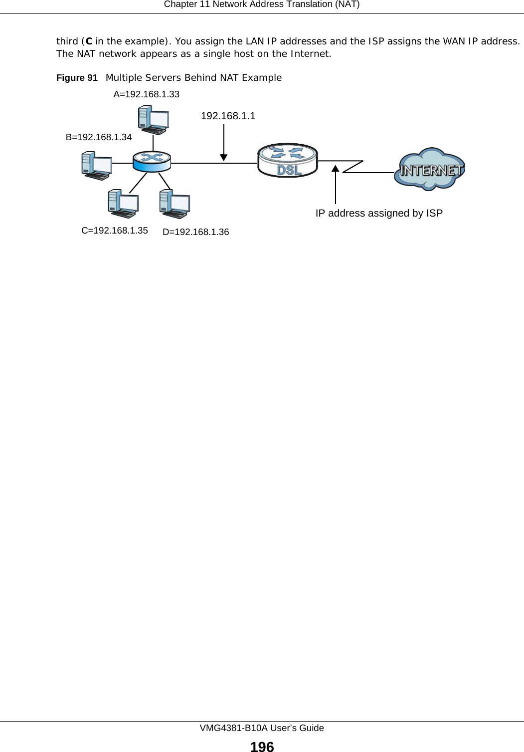
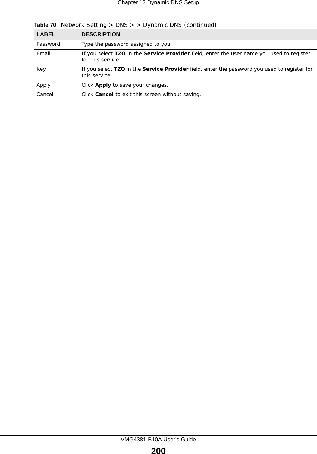
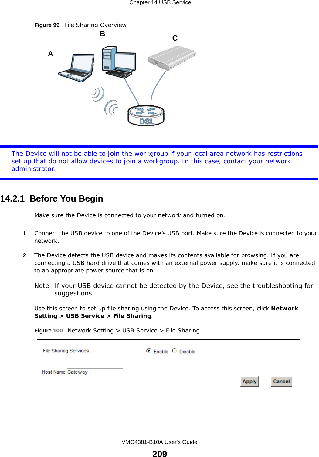
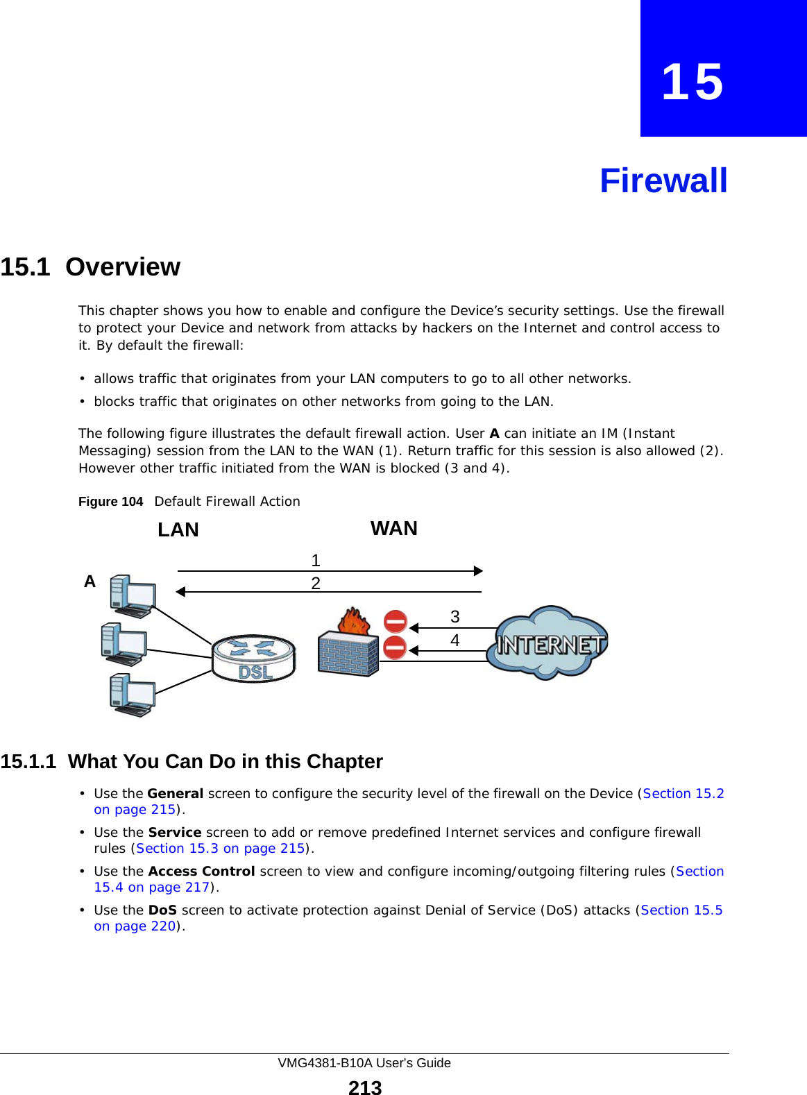
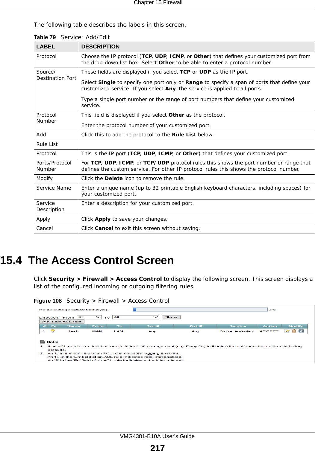
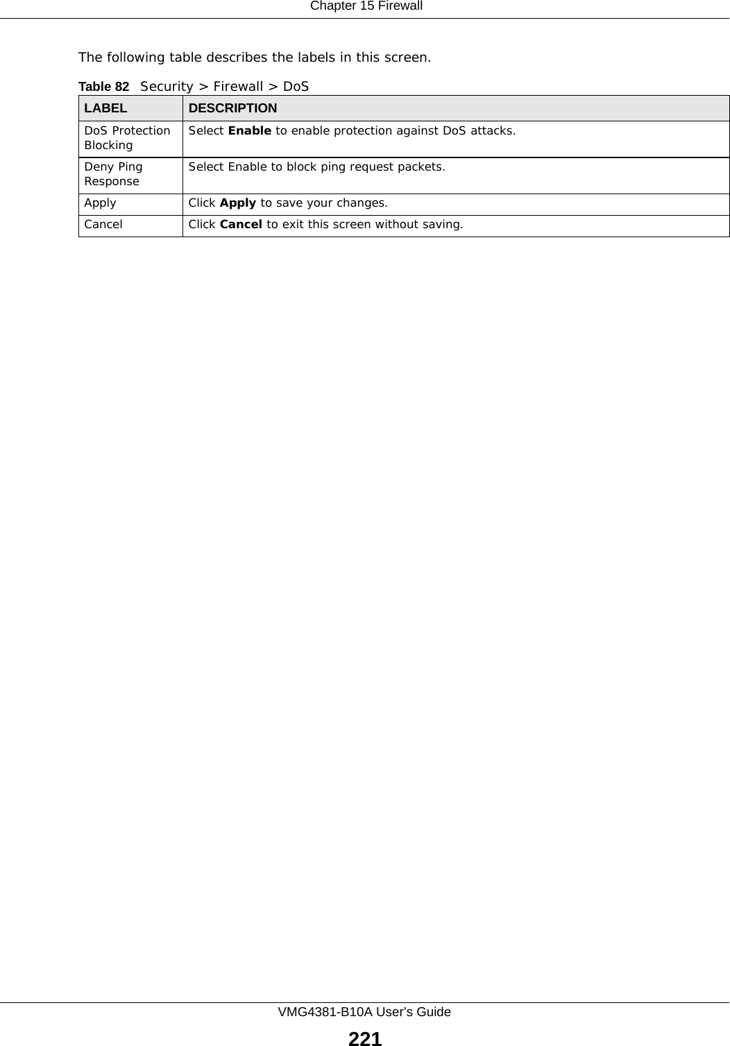
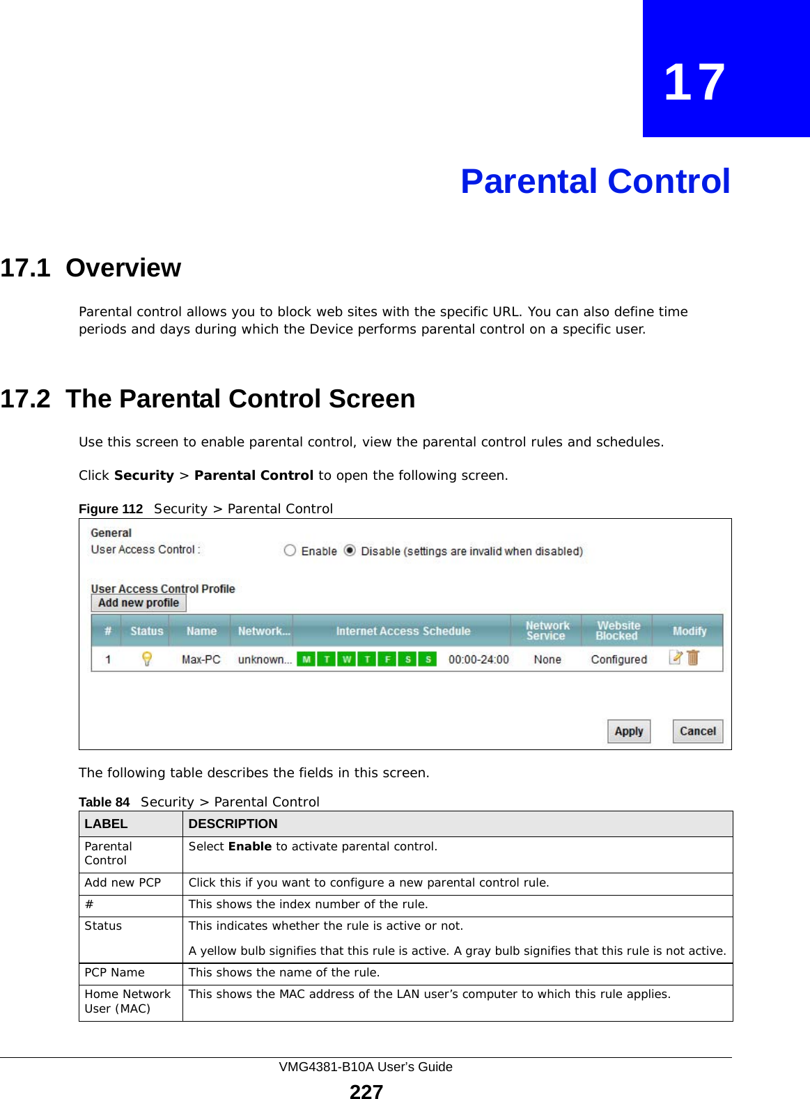
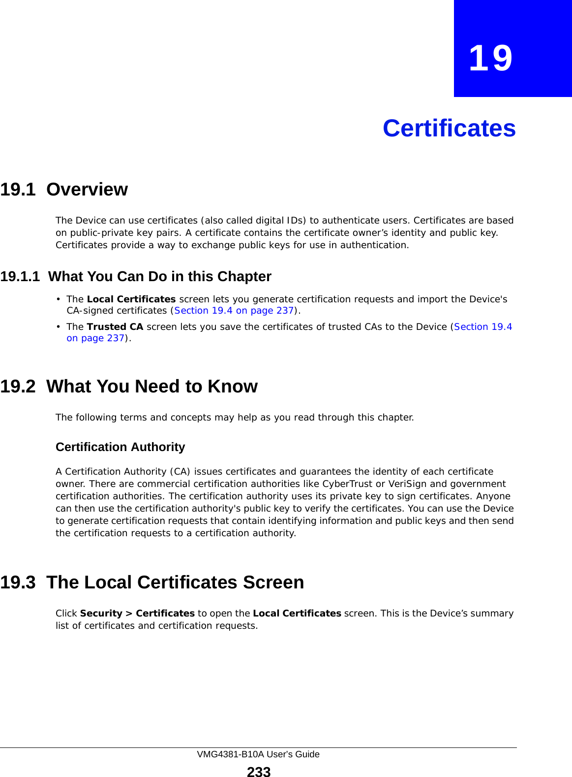
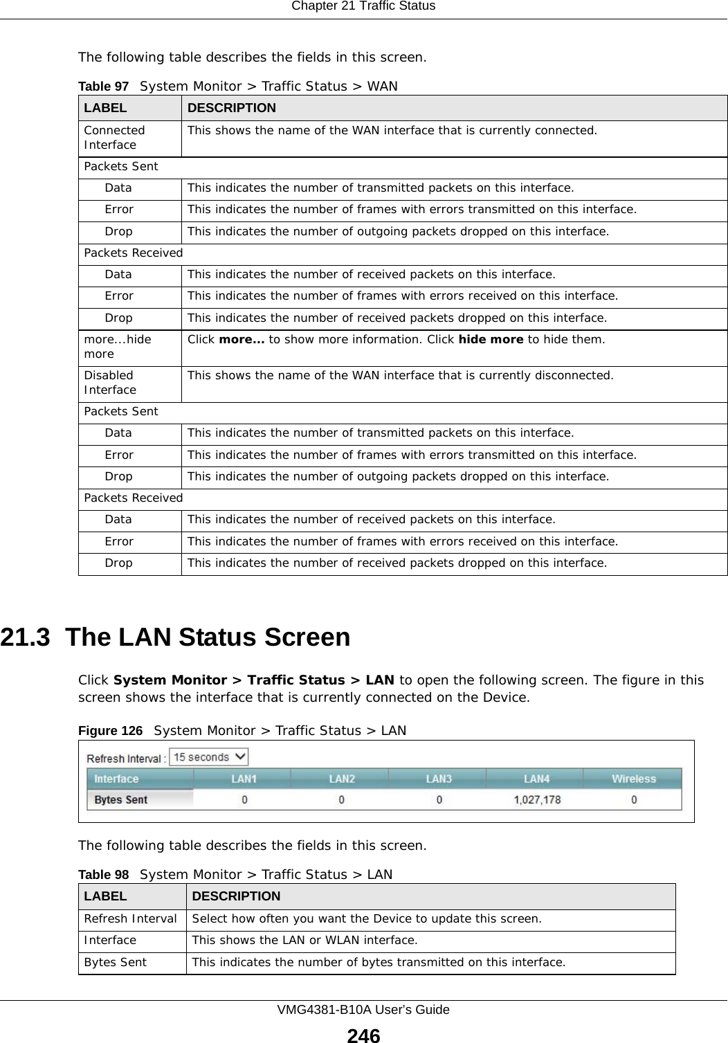
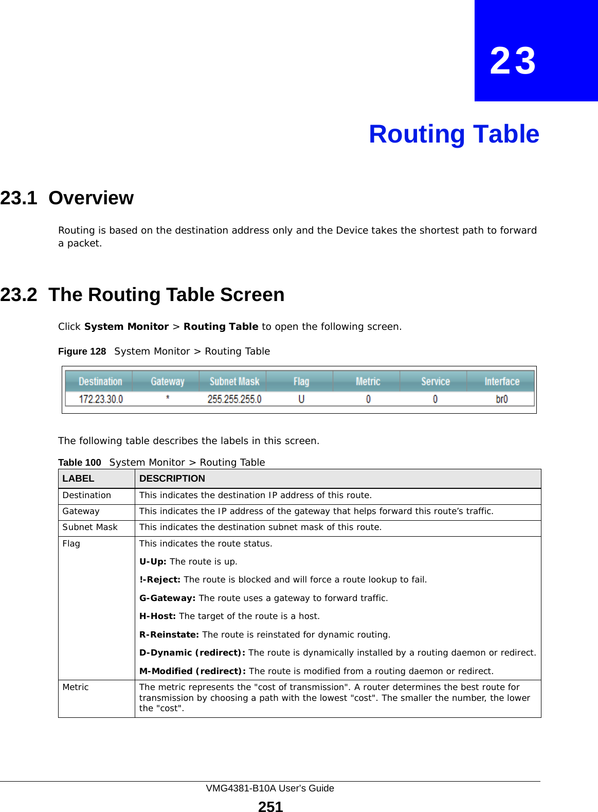
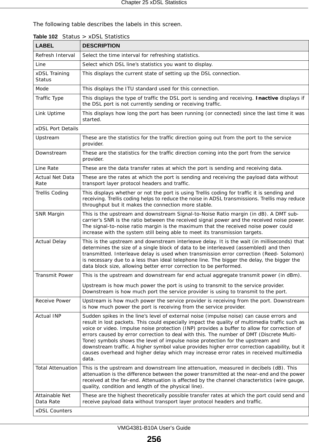
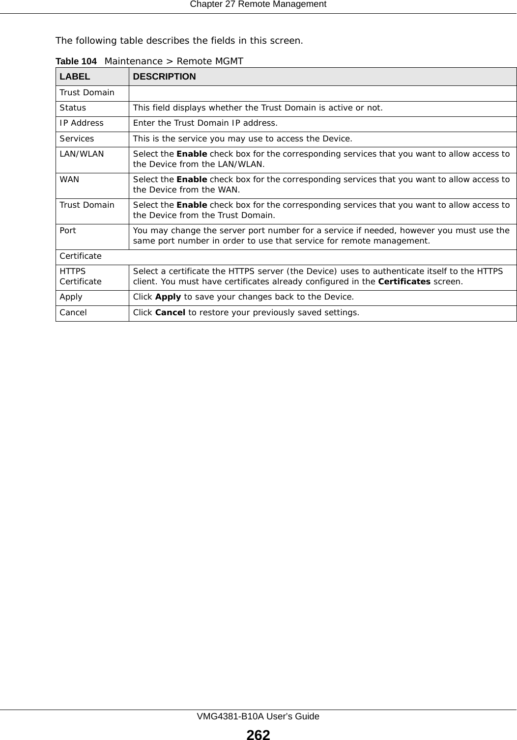
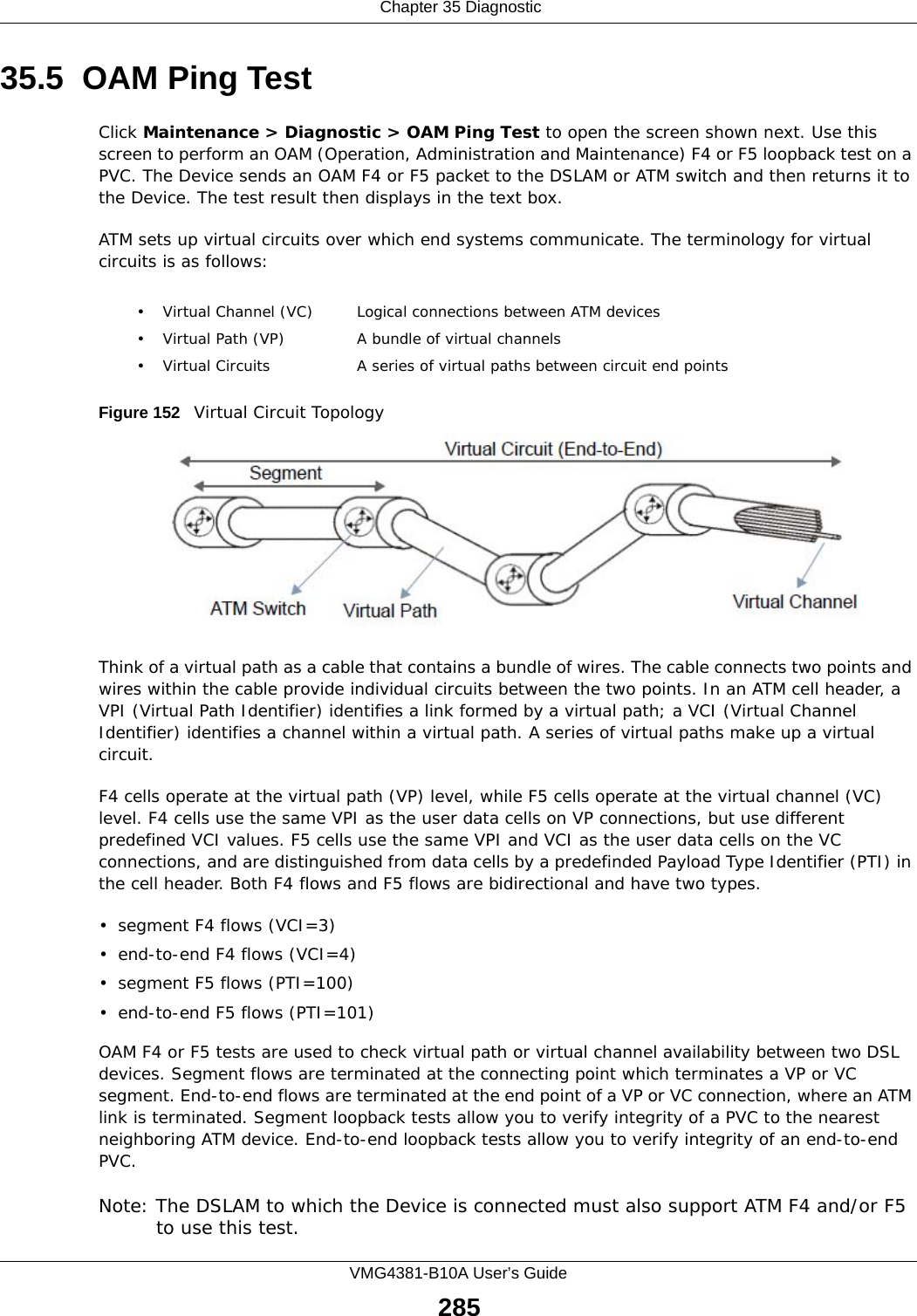
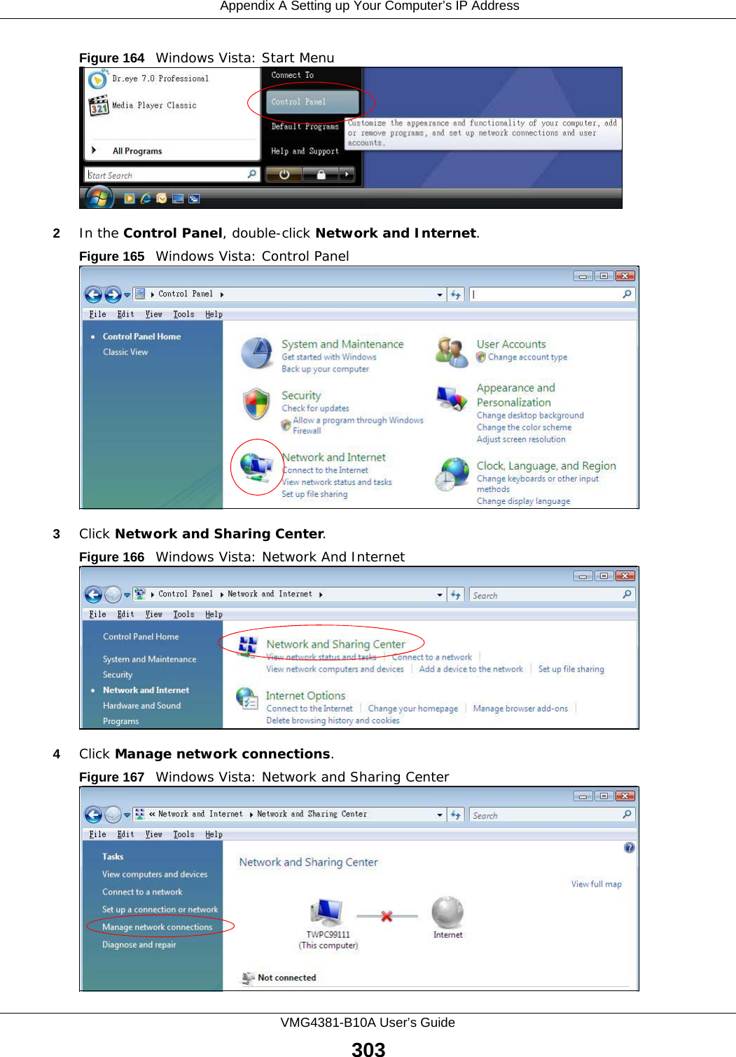
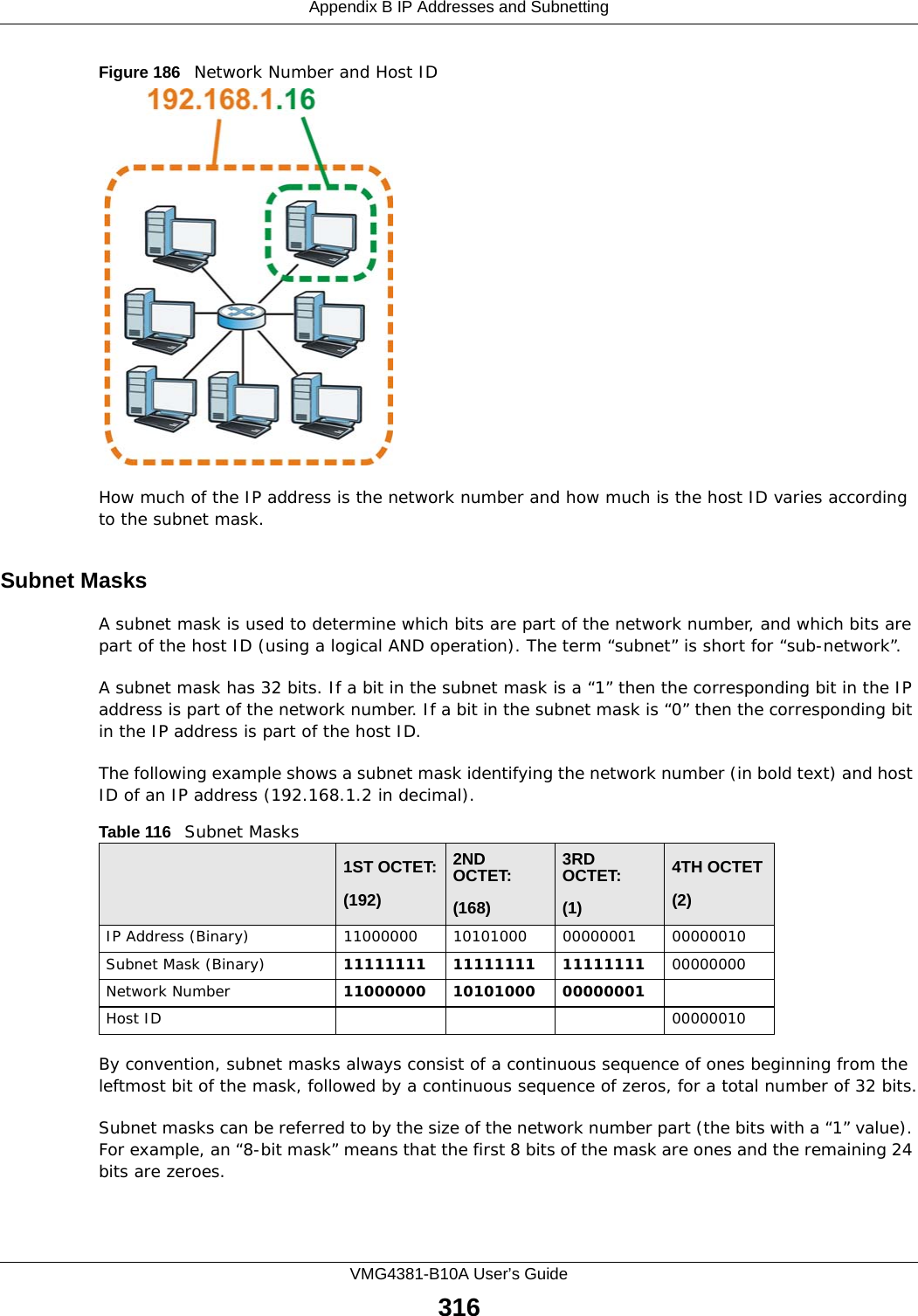
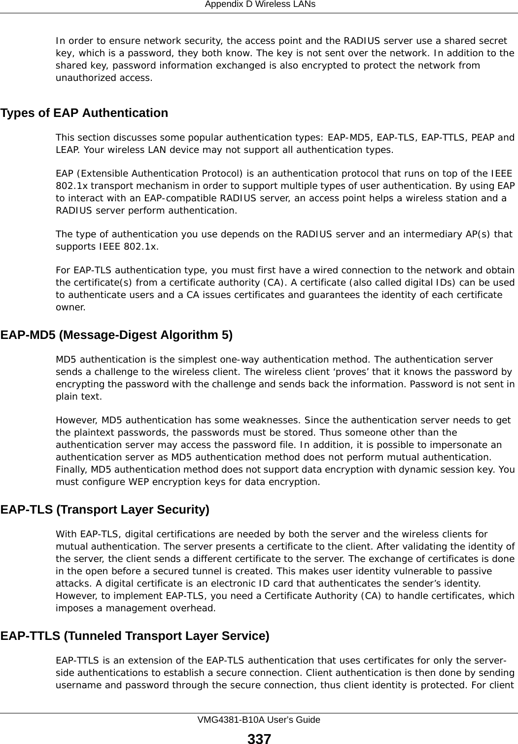
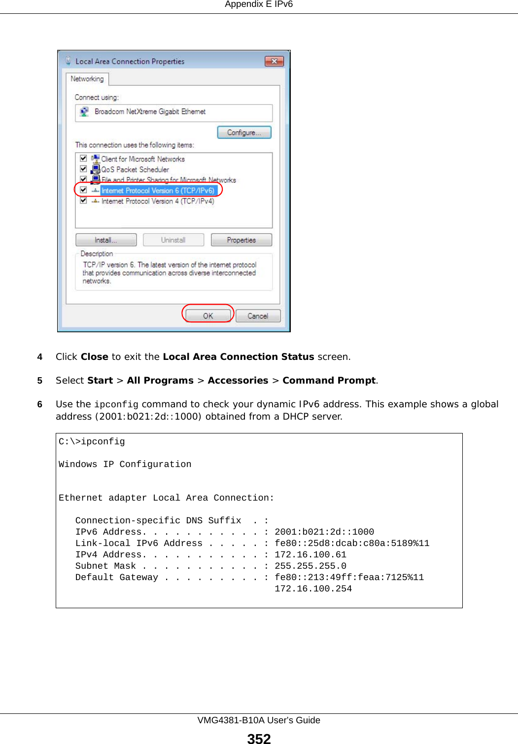
![Appendix A Setting up Your Computer’s IP AddressVMG4381-B10A User’s Guide302Figure 163 Windows XP: Internet Protocol (TCP/IP) Properties8Click OK to close the Internet Protocol (TCP/IP) Properties window.9Click Close (OK in Windows 2000/NT) to close the Local Area Connection Properties window.10 Close the Network Connections window (Network and Dial-up Connections in Windows 2000/NT).11 Turn on your Device and restart your computer (if prompted).Verifying Settings1Click Start, All Programs, Accessories and then Command Prompt.2In the Command Prompt window, type "ipconfig" and then press [ENTER]. You can also open Network Connections, right-click a network connection, click Status and then click the Support tab.Windows VistaThis section shows screens from Windows Vista Enterprise Version 6.0.1Click the Start icon, Control Panel.](https://usermanual.wiki/ZyXEL-Communications/VMG4381B10A.Part-2/User-Guide-2291793-Page-152.png)
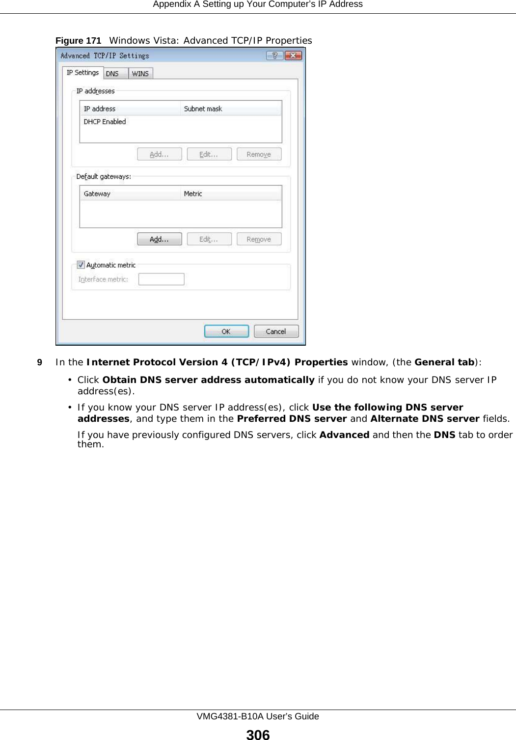
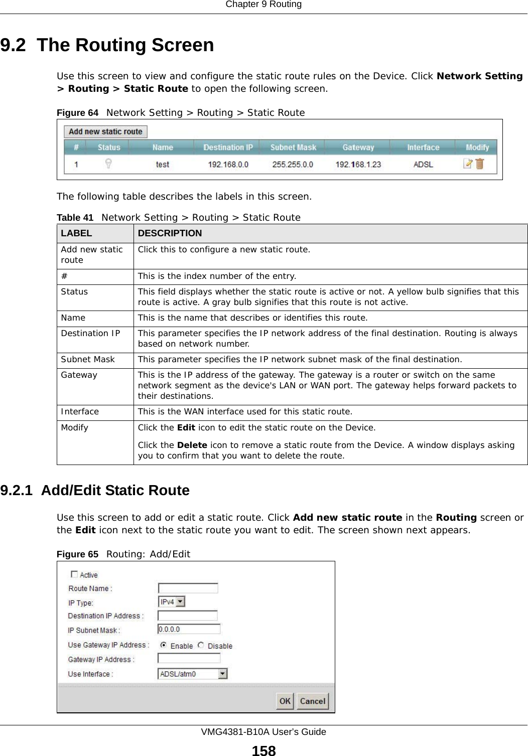
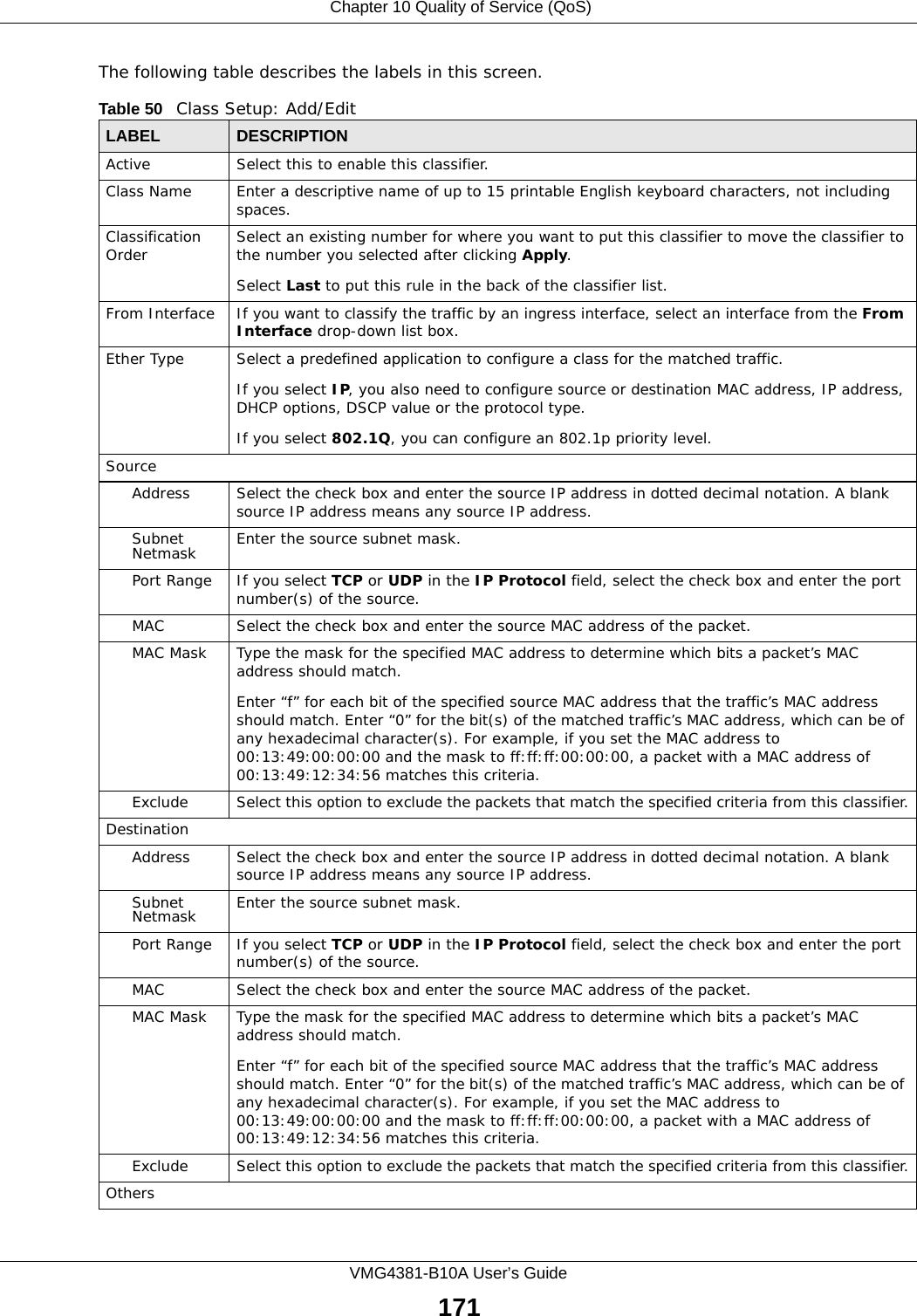
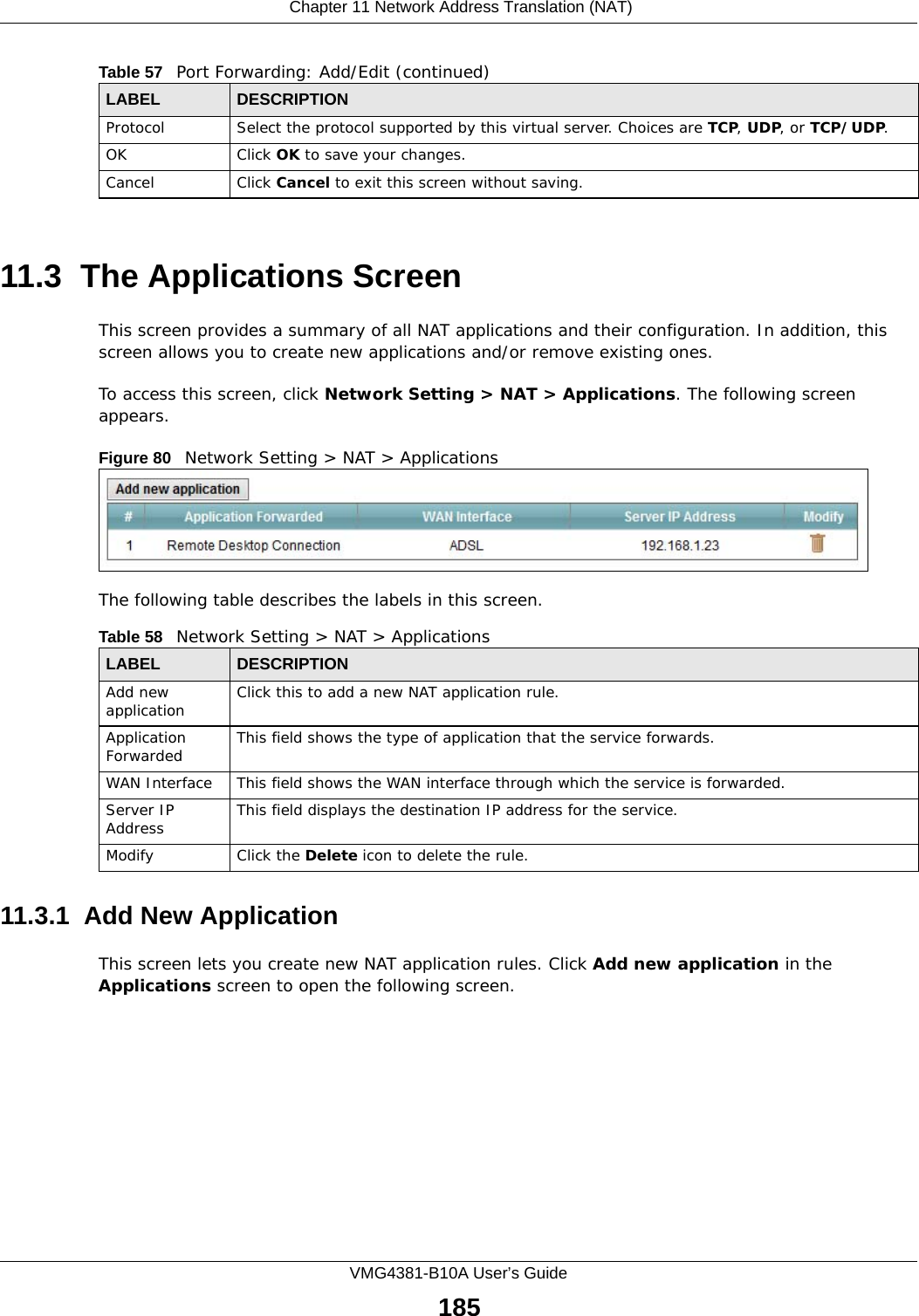
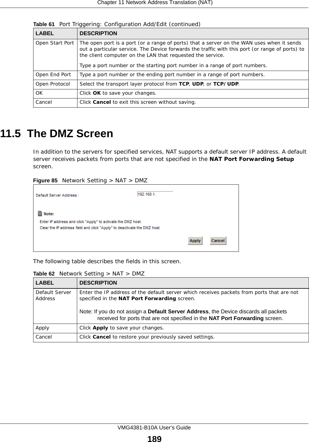
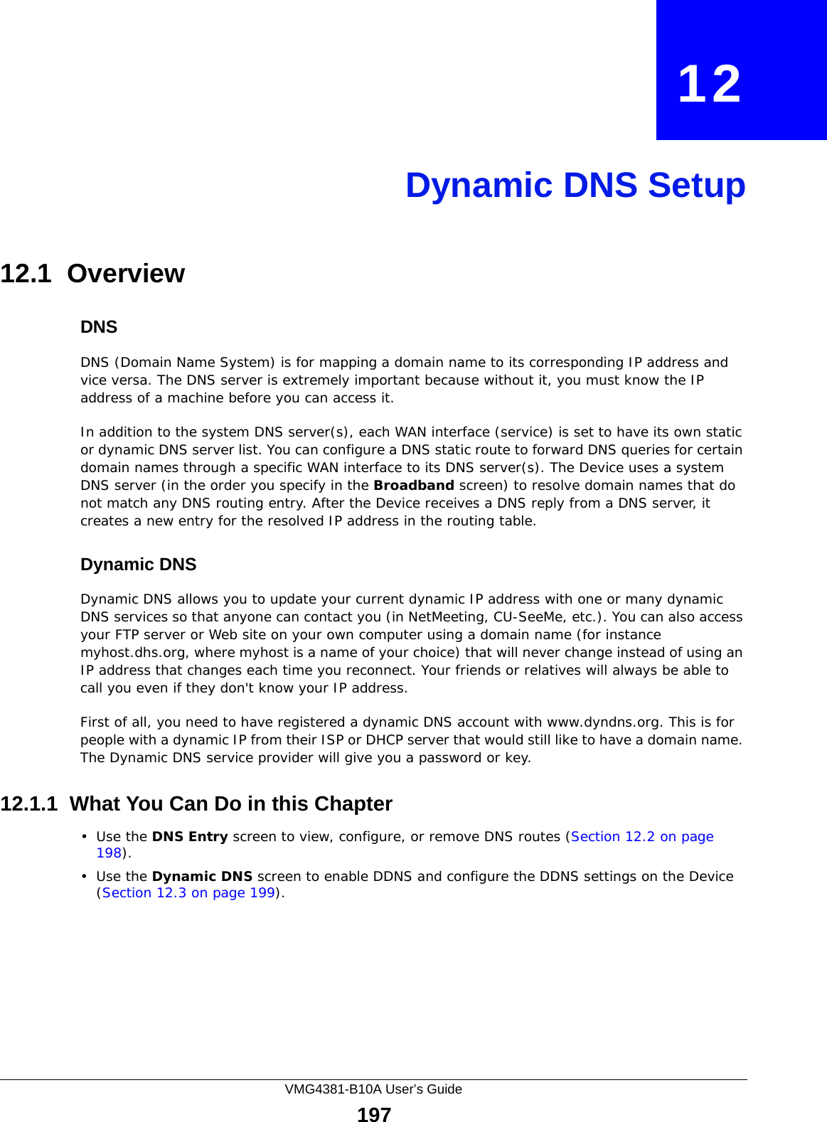
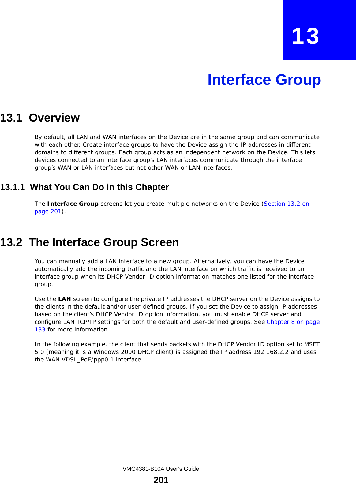
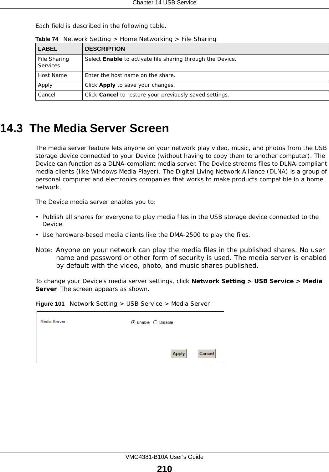
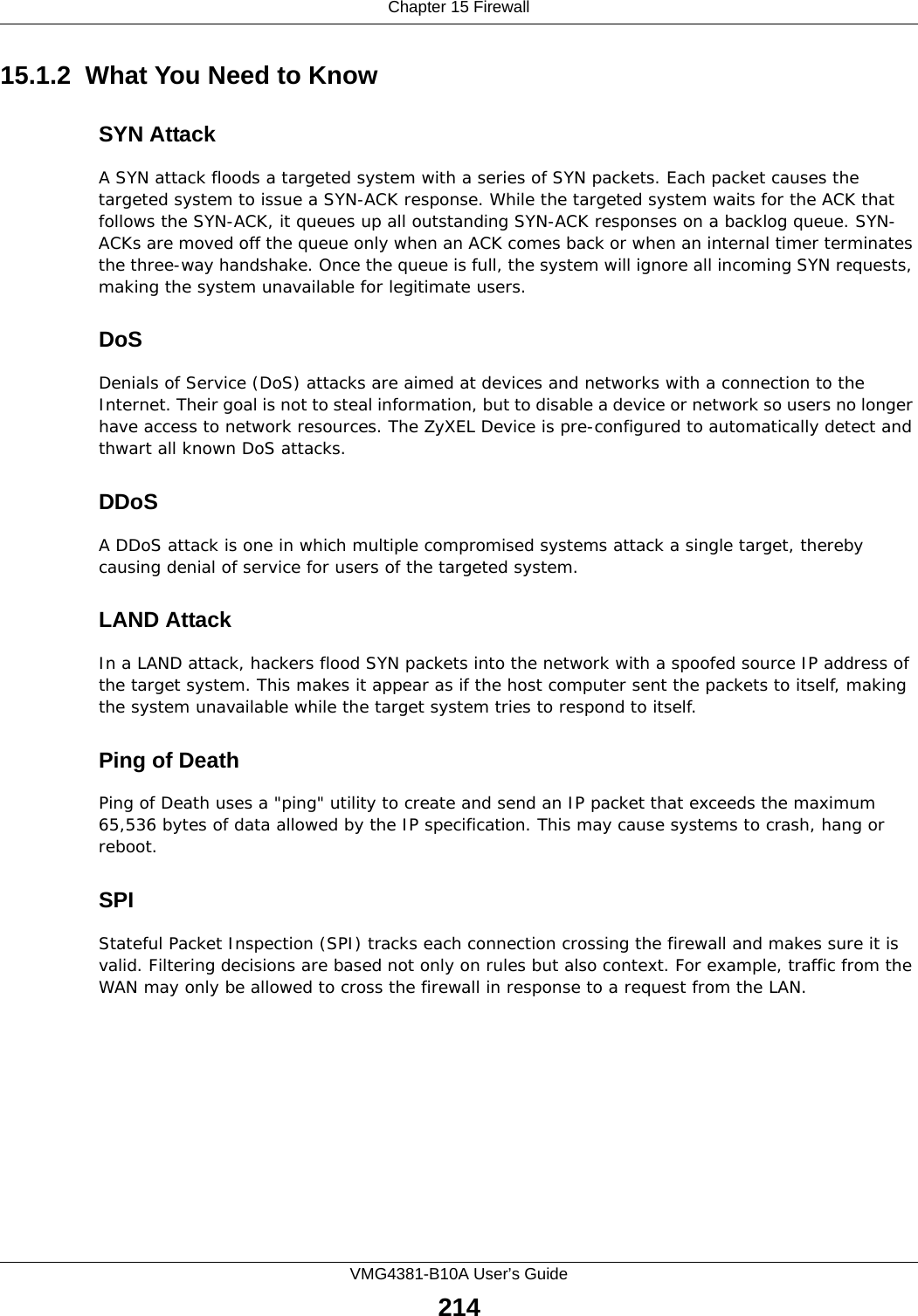
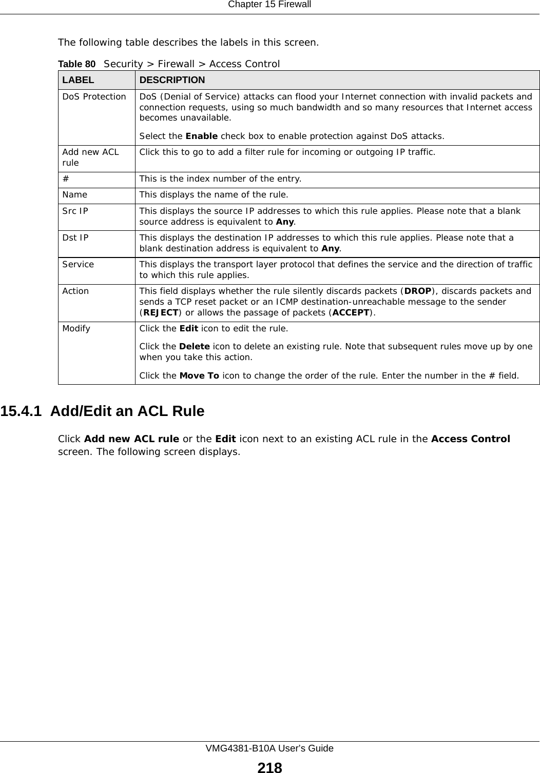
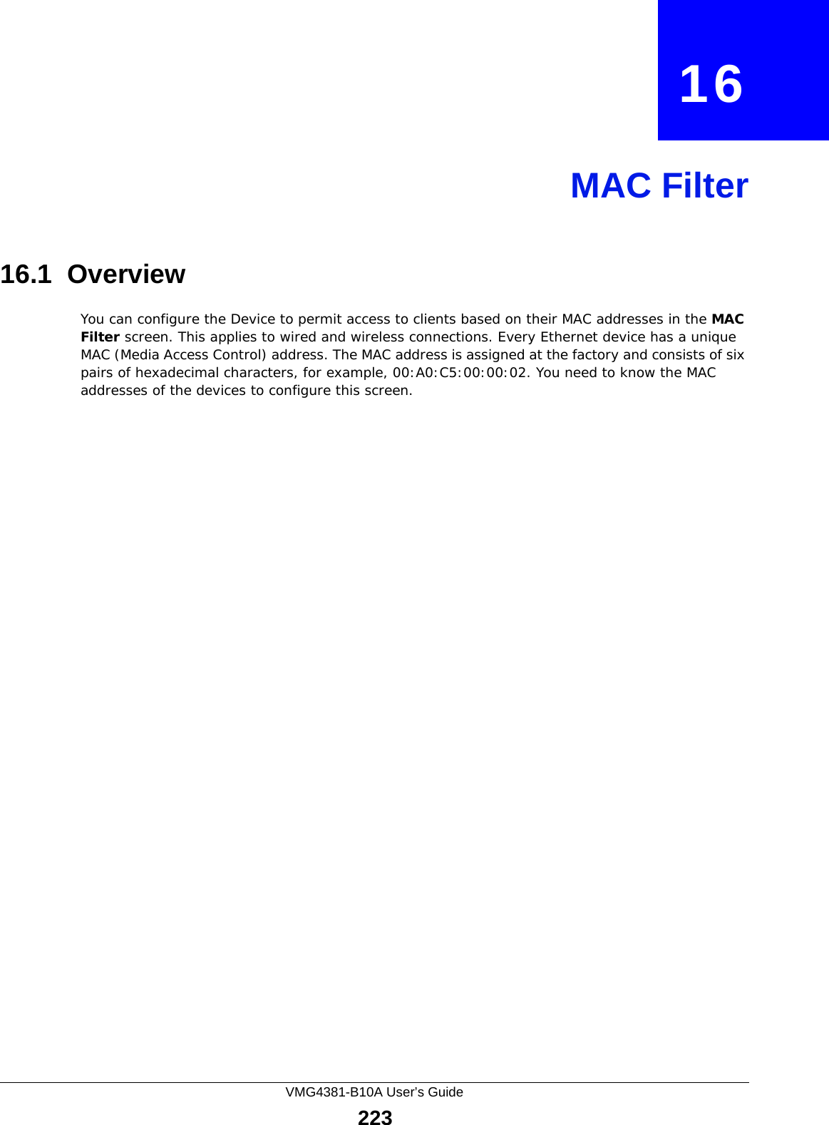
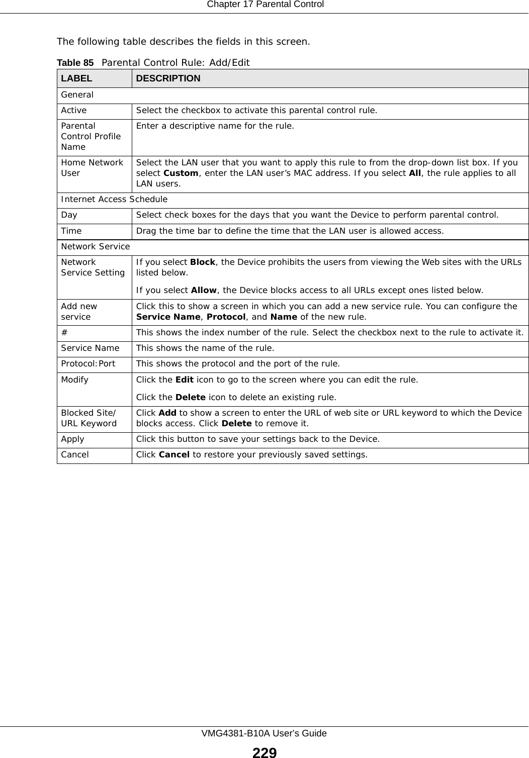
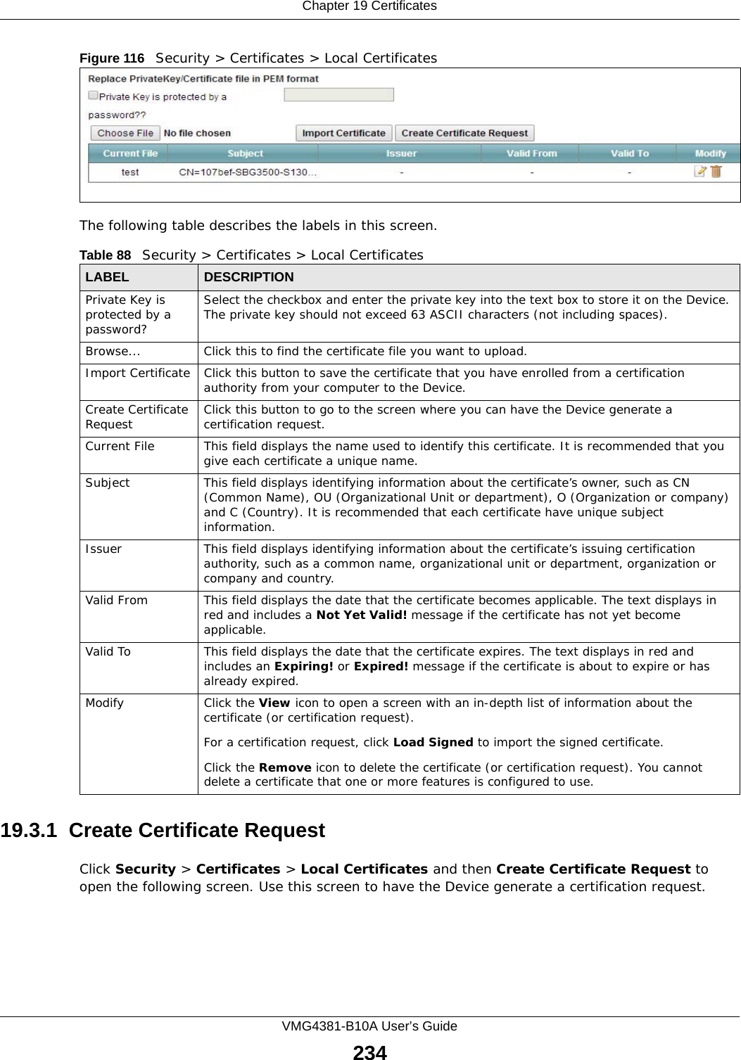
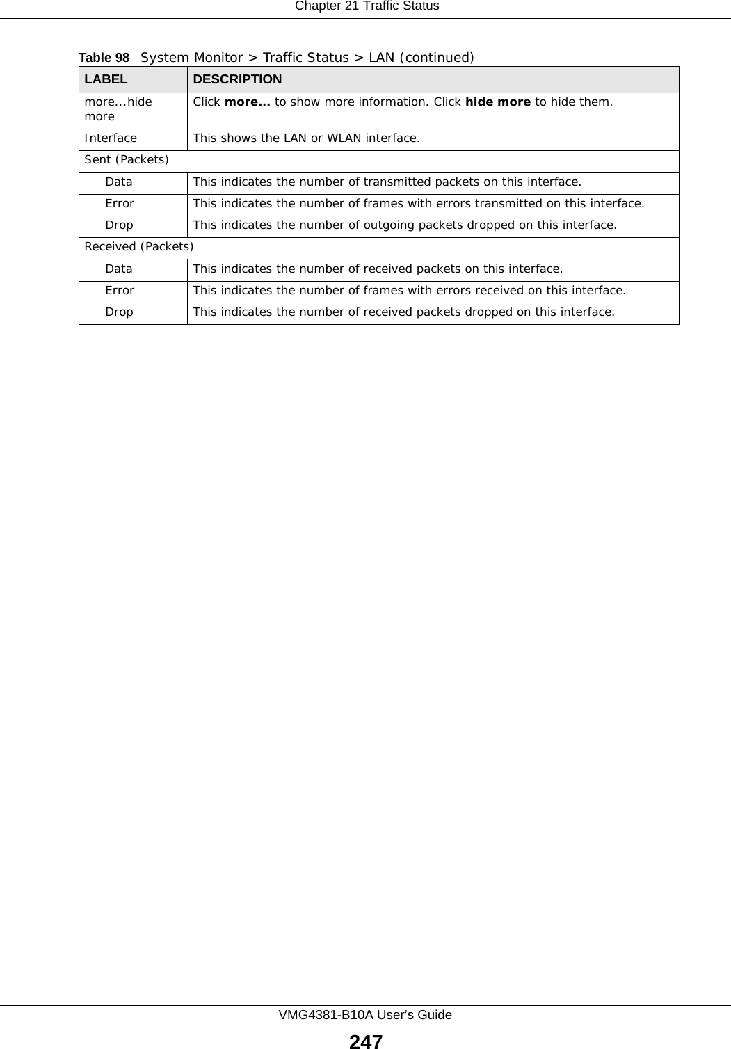
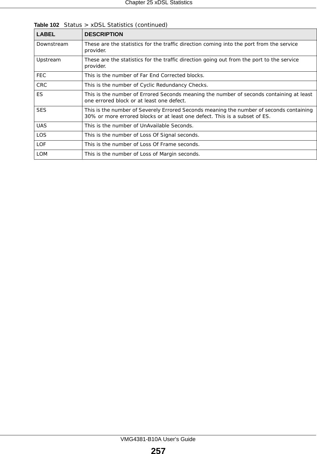
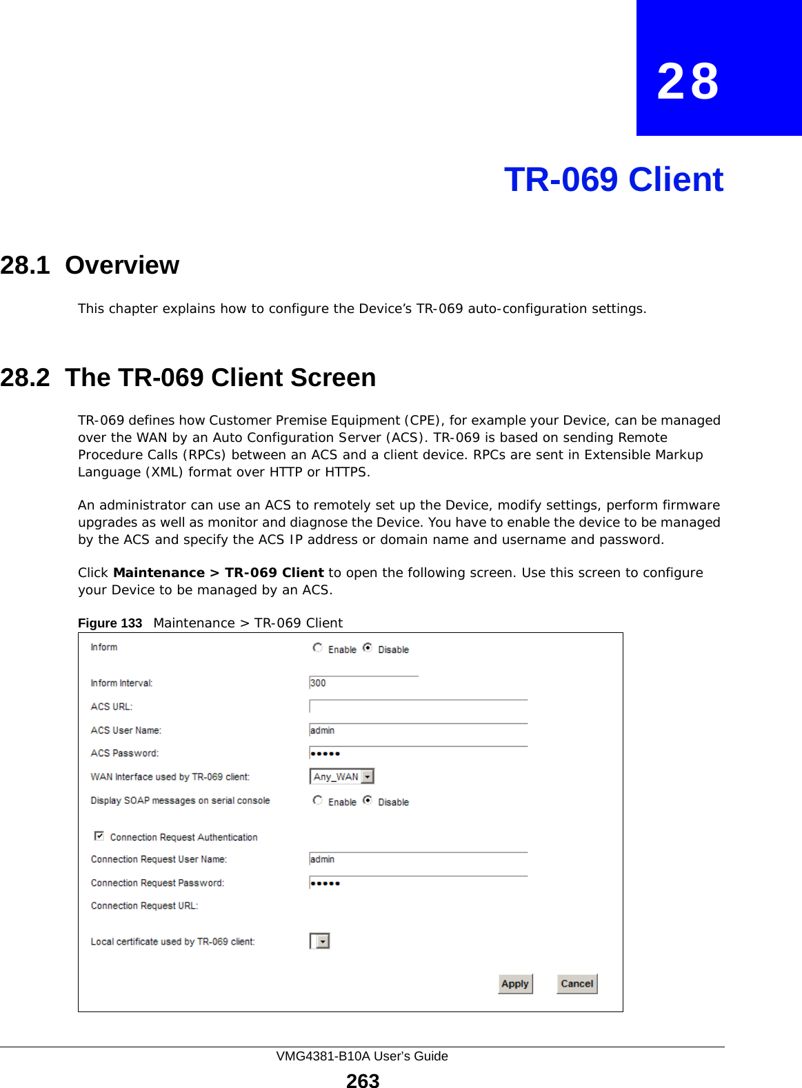
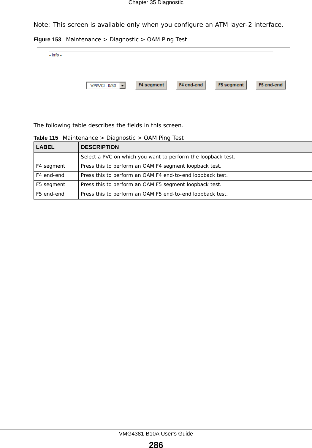
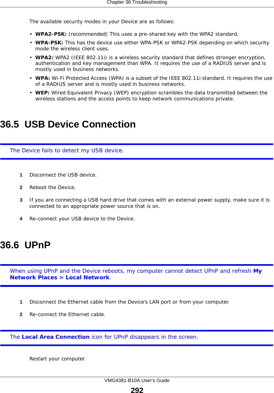
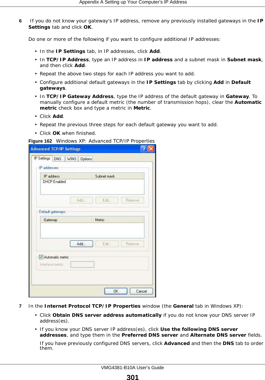
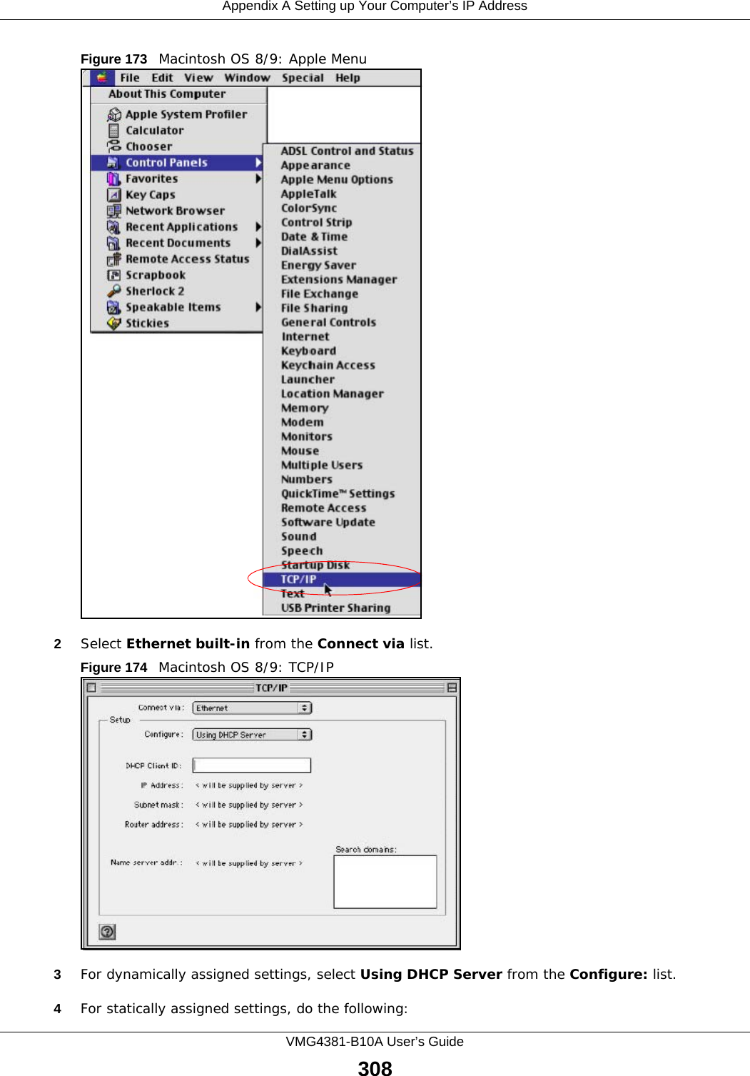
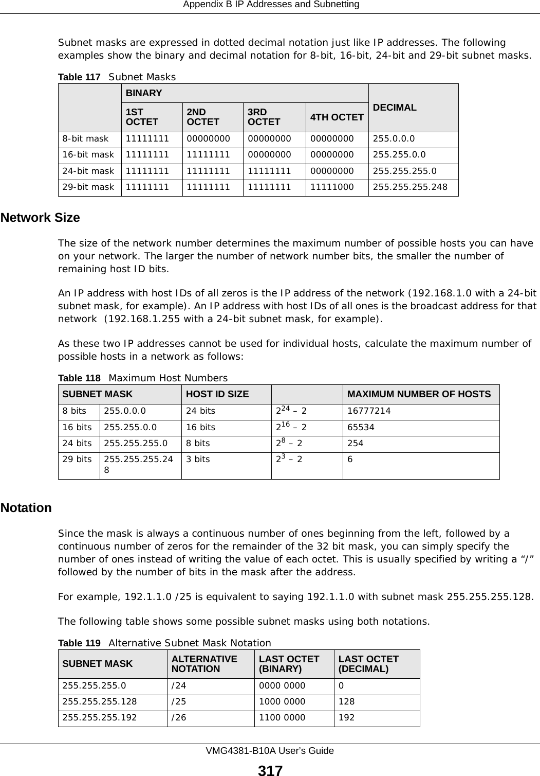
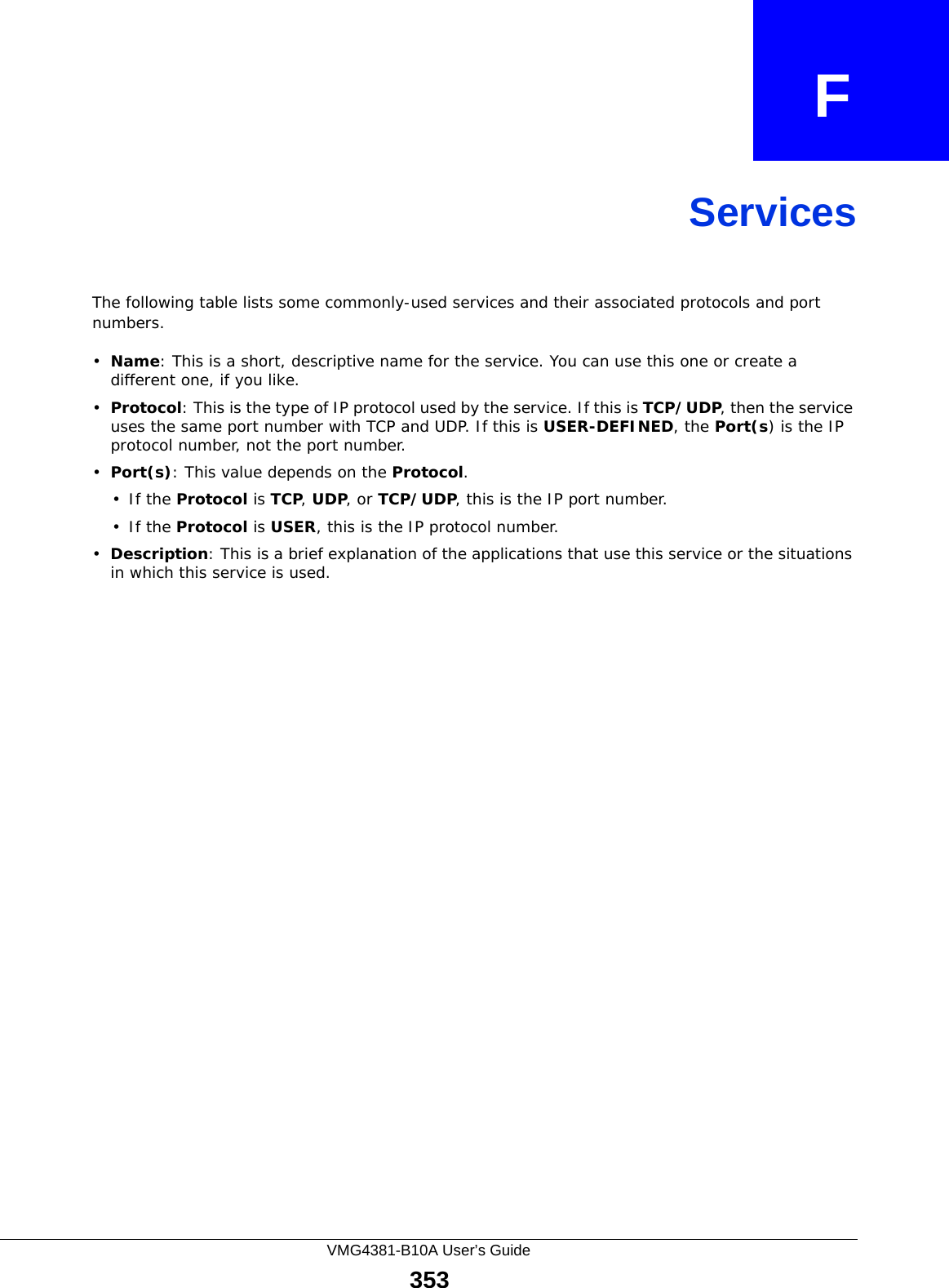
![Appendix A Setting up Your Computer’s IP AddressVMG4381-B10A User’s Guide307Figure 172 Windows Vista: Internet Protocol Version 4 (TCP/IPv4) Properties10 Click OK to close the Internet Protocol Version 4 (TCP/IPv4) Properties window.11 Click Close to close the Local Area Connection Properties window.12 Close the Network Connections window.13 Turn on your Device and restart your computer (if prompted).Verifying Settings1Click Start, All Programs, Accessories and then Command Prompt.2In the Command Prompt window, type "ipconfig" and then press [ENTER]. You can also open Network Connections, right-click a network connection, click Status and then click the Support tab.Macintosh OS 8/9 1Click the Apple menu, Control Panel and double-click TCP/IP to open the TCP/IP Control Panel.](https://usermanual.wiki/ZyXEL-Communications/VMG4381B10A.Part-2/User-Guide-2291793-Page-157.png)
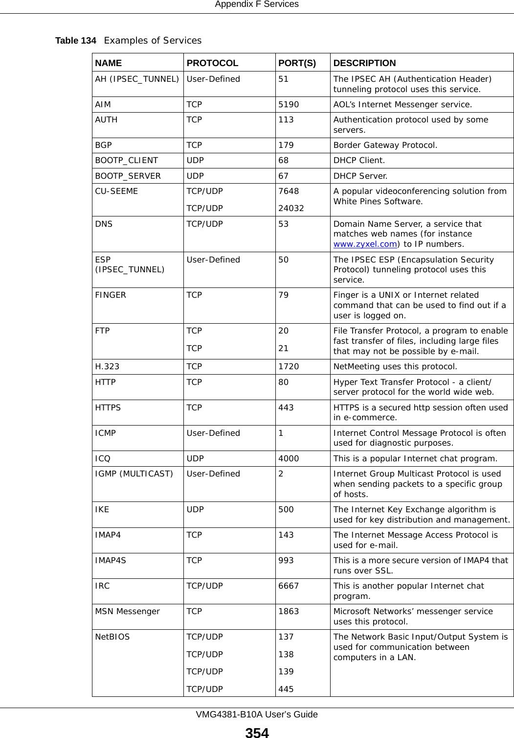
![Appendix A Setting up Your Computer’s IP AddressVMG4381-B10A User’s Guide313Figure 181 Red Hat 9.0: Dynamic IP Address Setting in ifconfig-eth0 • If you have a static IP address, enter static in the BOOTPROTO= field. Type IPADDR= followed by the IP address (in dotted decimal notation) and type NETMASK= followed by the subnet mask. The following example shows an example where the static IP address is 192.168.1.10 and the subnet mask is 255.255.255.0. Figure 182 Red Hat 9.0: Static IP Address Setting in ifconfig-eth0 2If you know your DNS server IP address(es), enter the DNS server information in the resolv.conf file in the /etc directory. The following figure shows an example where two DNS server IP addresses are specified.Figure 183 Red Hat 9.0: DNS Settings in resolv.conf 3After you edit and save the configuration files, you must restart the network card. Enter ./network restart in the /etc/rc.d/init.d directory. The following figure shows an example.Figure 184 Red Hat 9.0: Restart Ethernet Card Verifying SettingsEnter ifconfig in a terminal screen to check your TCP/IP properties. DEVICE=eth0ONBOOT=yesBOOTPROTO=dhcpUSERCTL=noPEERDNS=yesTYPE=EthernetDEVICE=eth0ONBOOT=yesBOOTPROTO=staticIPADDR=192.168.1.10NETMASK=255.255.255.0USERCTL=noPEERDNS=yesTYPE=Ethernetnameserver 172.23.5.1nameserver 172.23.5.2[root@localhost init.d]# network restartShutting down interface eth0: [OK]Shutting down loopback interface: [OK]Setting network parameters: [OK]Bringing up loopback interface: [OK]Bringing up interface eth0: [OK]](https://usermanual.wiki/ZyXEL-Communications/VMG4381B10A.Part-2/User-Guide-2291793-Page-163.png)
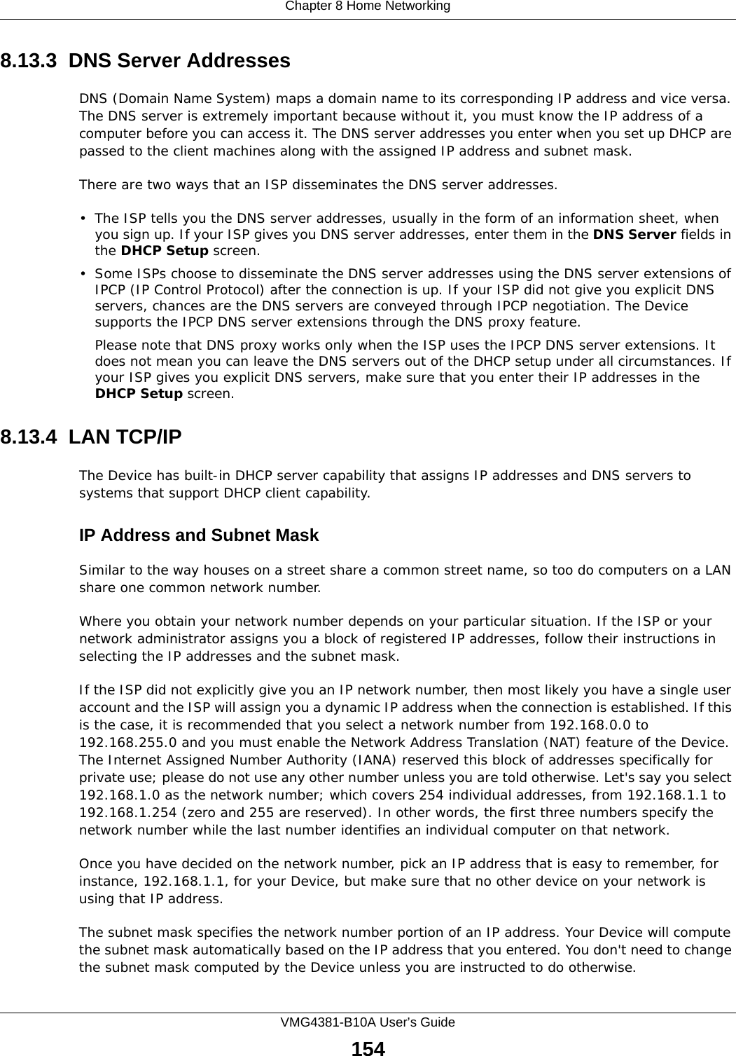
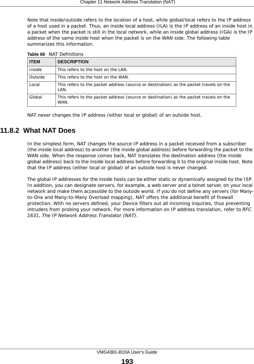
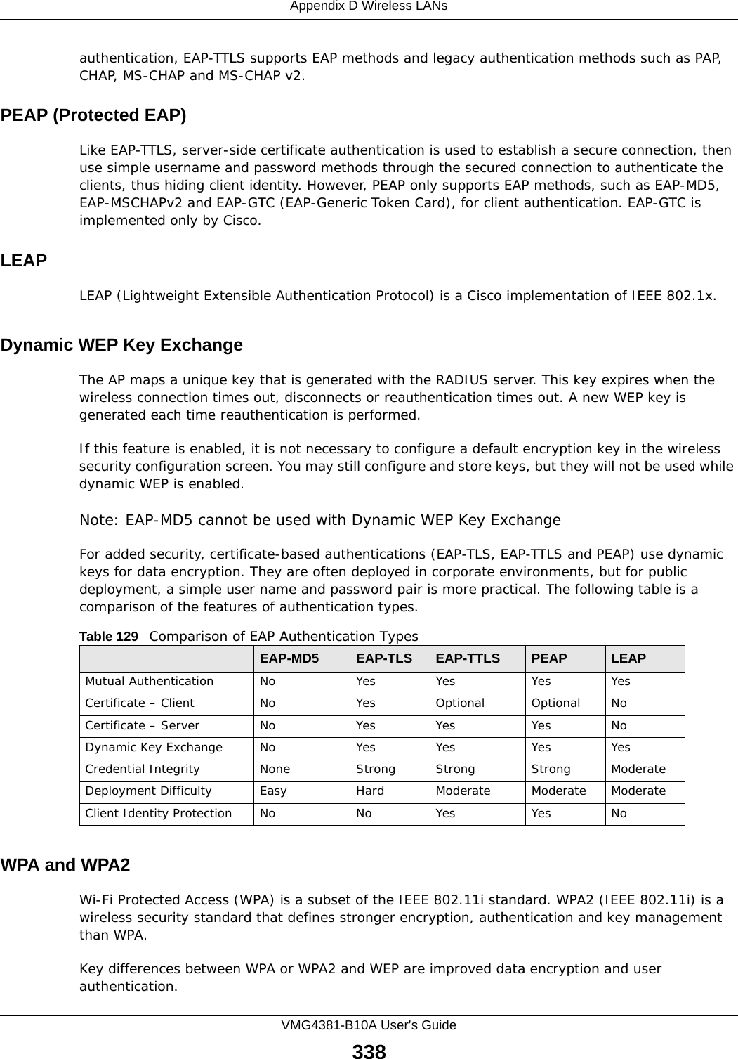
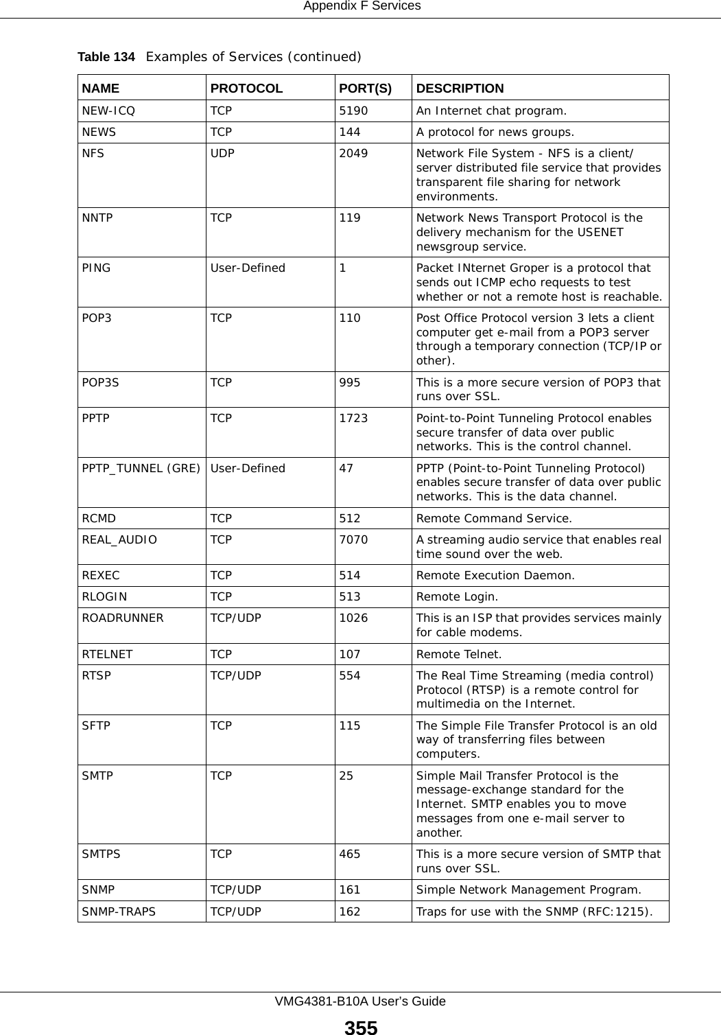
![Appendix A Setting up Your Computer’s IP AddressVMG4381-B10A User’s Guide314Figure 185 Red Hat 9.0: Checking TCP/IP Properties [root@localhost]# ifconfig eth0 Link encap:Ethernet HWaddr 00:50:BA:72:5B:44 inet addr:172.23.19.129 Bcast:172.23.19.255 Mask:255.255.255.0 UP BROADCAST RUNNING MULTICAST MTU:1500 Metric:1 RX packets:717 errors:0 dropped:0 overruns:0 frame:0 TX packets:13 errors:0 dropped:0 overruns:0 carrier:0 collisions:0 txqueuelen:100 RX bytes:730412 (713.2 Kb) TX bytes:1570 (1.5 Kb) Interrupt:10 Base address:0x1000 [root@localhost]#](https://usermanual.wiki/ZyXEL-Communications/VMG4381B10A.Part-2/User-Guide-2291793-Page-164.png)


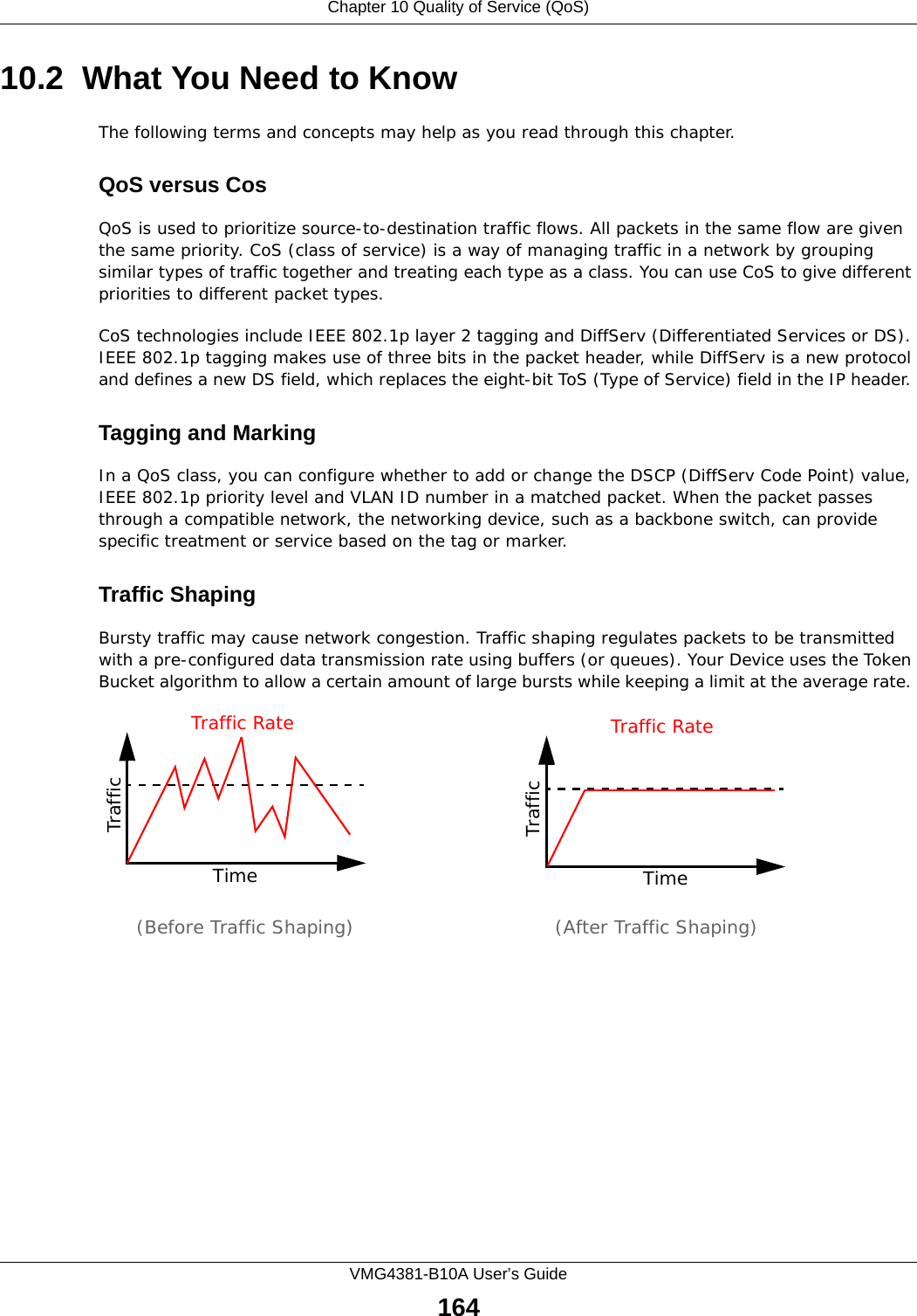
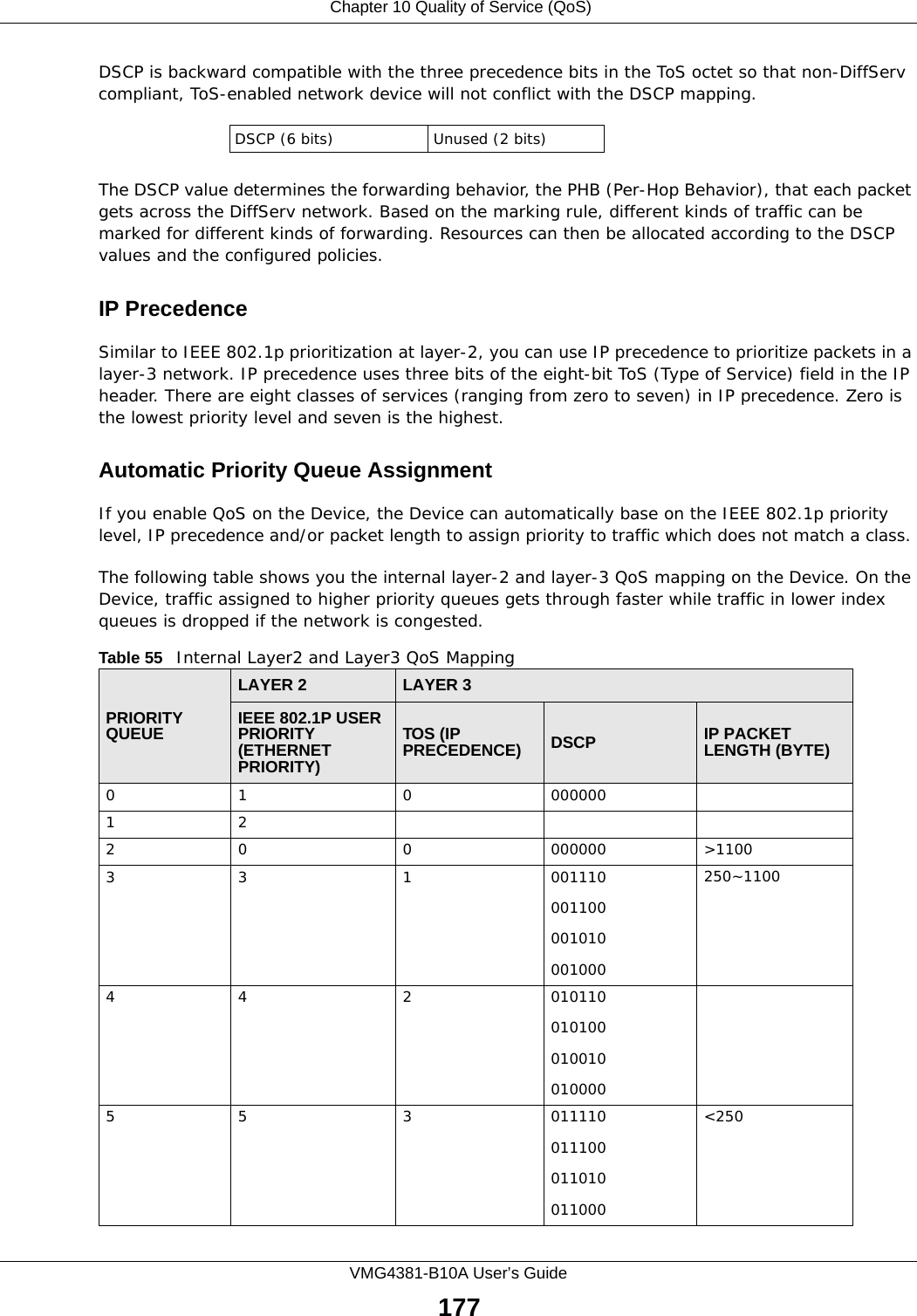
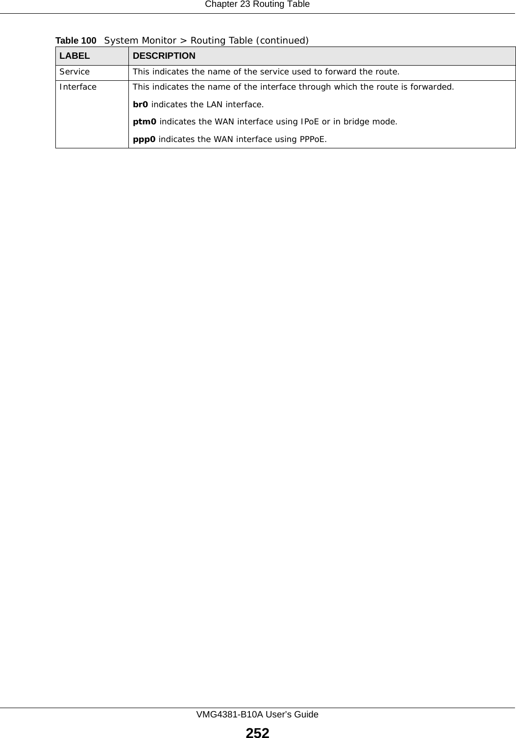
![Appendix G Legal InformationVMG4381-B10A User’s Guide3583Connect the equipment into an outlet on a circuit different from that to which the receiver is connected.4Consult the dealer or an experienced radio/TV technician for help.FCC Radiation Exposure Statement• This transmitter must not be co-located or operating in conjunction with any other antenna or transmitter. • IEEE 802.11b or 802.11g operation of this product in the U.S.A. is firmware-limited to channels 1 through 11. • To comply with FCC RF exposure compliance requirements, a separation distance of at least 20 cm must be maintained between the antenna of this device and all persons. 注意 !依據 低功率電波輻射性電機管理辦法第十二條 經型式認證合格之低功率射頻電機,非經許可,公司、商號或使用者均不得擅自變更頻率、加大功率或變更原設計之特性及功能。第十四條 低功率射頻電機之使用不得影響飛航安全及干擾合法通信;經發現有干擾現象時,應立即停用,並改善至無干擾時方得繼續使用。前項合法通信,指依電信規定作業之無線電信。低功率射頻電機須忍受合法通信或工業、科學及醫療用電波輻射性電機設備之干擾。 本機限在不干擾合法電臺與不受被干擾保障條件下於室內使用。 減少電磁波影響,請妥適使用。 Notices Changes or modifications not expressly approved by the party responsible for compliance could void the user's authority to operate the equipment.This device has been designed for the WLAN 2.4 GHz network throughout the EC region and Switzerland, with restrictions in France. Ce produit est conçu pour les bandes de fréquences 2,4 GHz et/ou 5 GHz conformément à la législation Européenne. En France métropolitaine, suivant les décisions n°03-908 et 03-909 de l’ARCEP, la puissance d’émission ne devra pas dépasser 10 mW (10 dB) dans le cadre d’une installation WiFi en extérieur pour les fréquences comprises entre 2454 MHz et 2483,5 MHz.This Class [*] digital apparatus complies with Canadian ICES-003.Cet appareil numérique de la classe [*] est conforme à la norme NMB-003 du Canada.ZyXEL Limited WarrantyZyXEL warrants to the original end user (purchaser) that this product is free from any defects in materials or workmanship for a period of up to two years from the date of purchase. During the](https://usermanual.wiki/ZyXEL-Communications/VMG4381B10A.Part-2/User-Guide-2291793-Page-208.png)