ZyXEL Communications VMG8924B10A Dual Band Wireless AC/N VDSL2 VoIP Combo WAN Gigabit IAD User Manual VMG8924 B10A 1

ZyXEL Communications Corporation Dual Band Wireless AC/N VDSL2 VoIP Combo WAN Gigabit IAD VMG8924 B10A 1

Contents

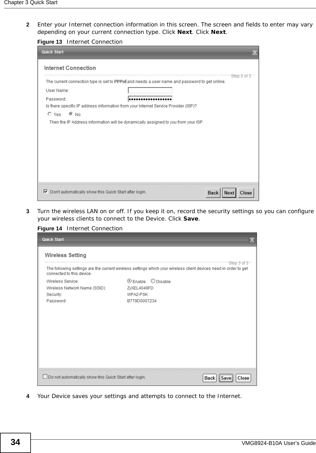
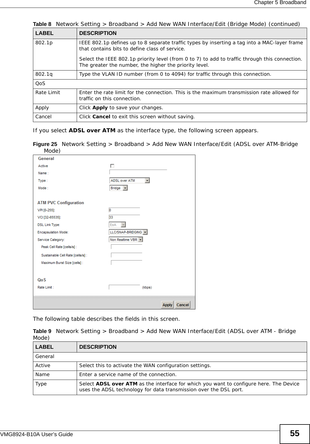
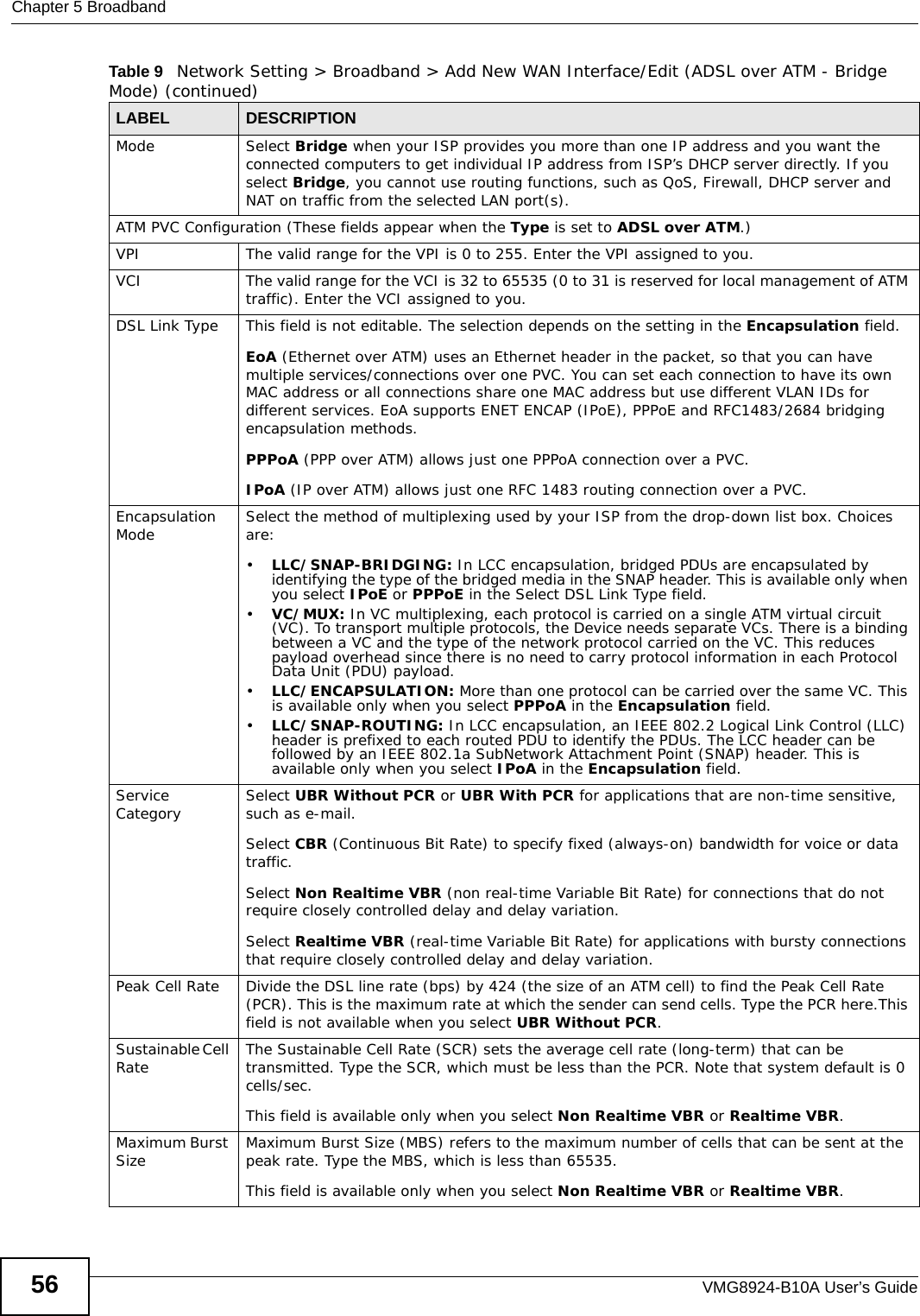
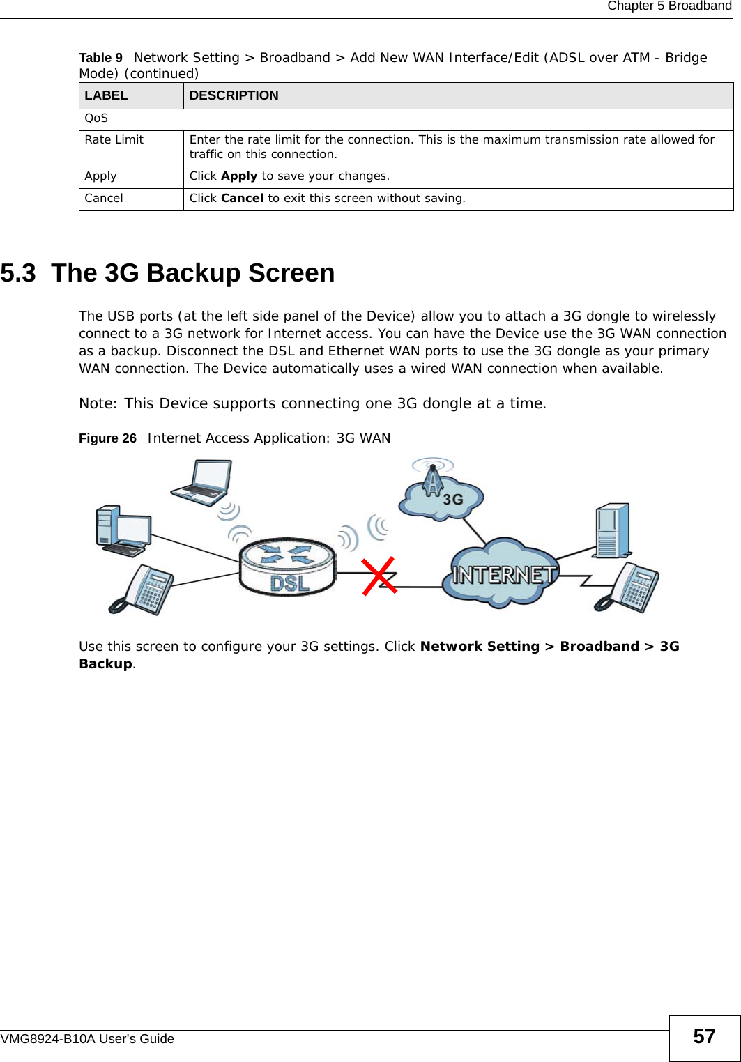
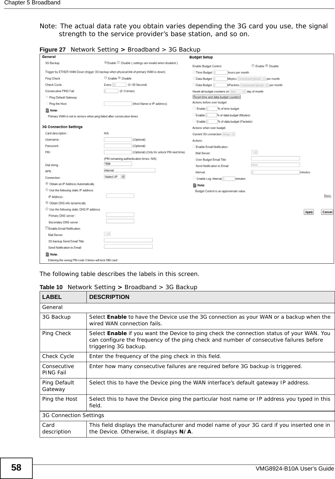
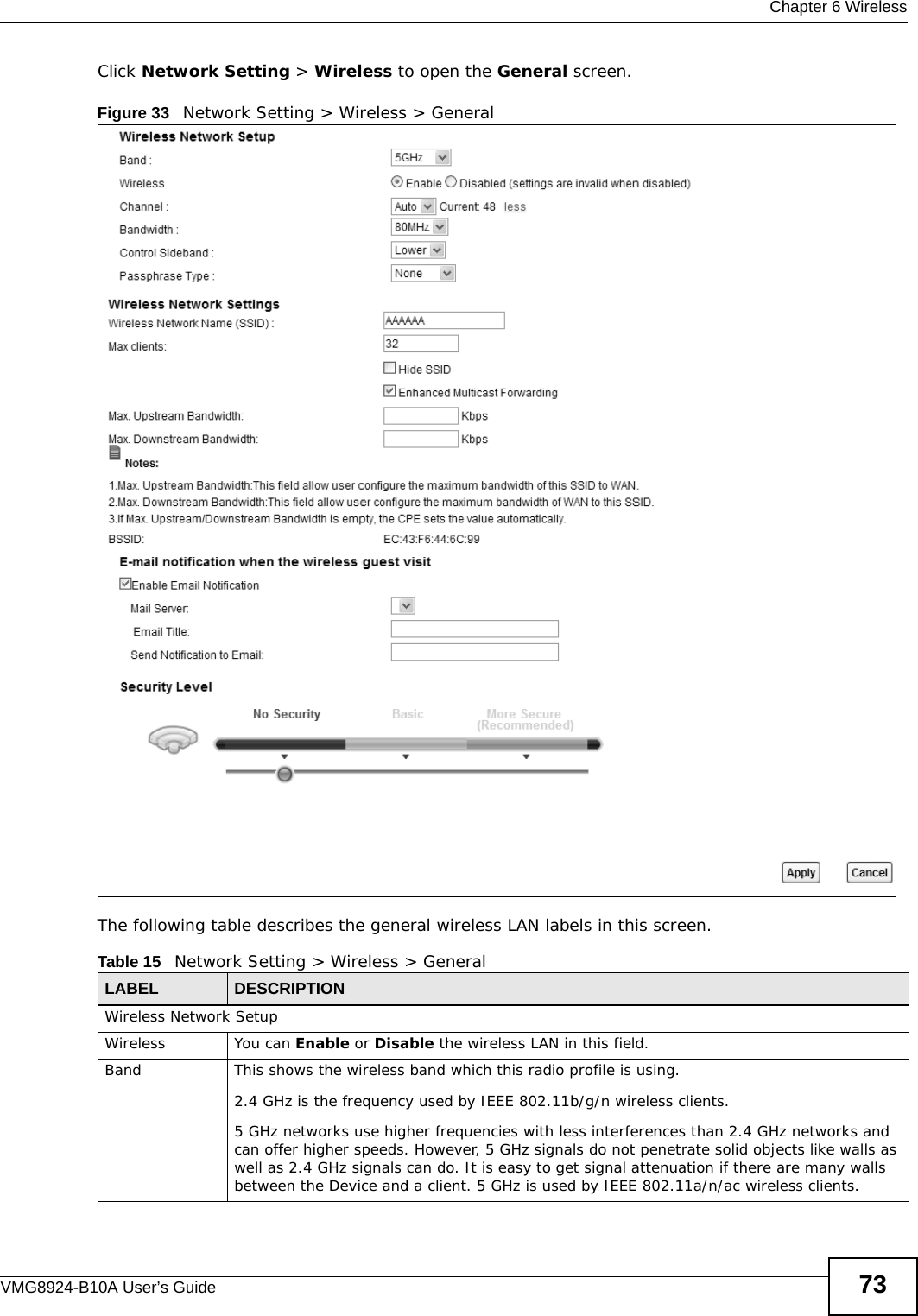
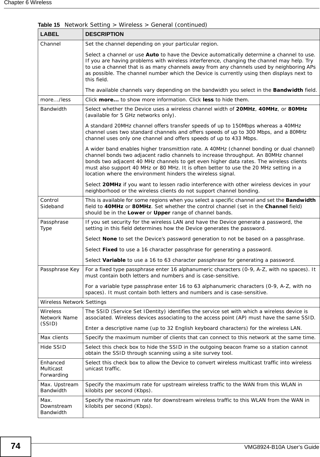
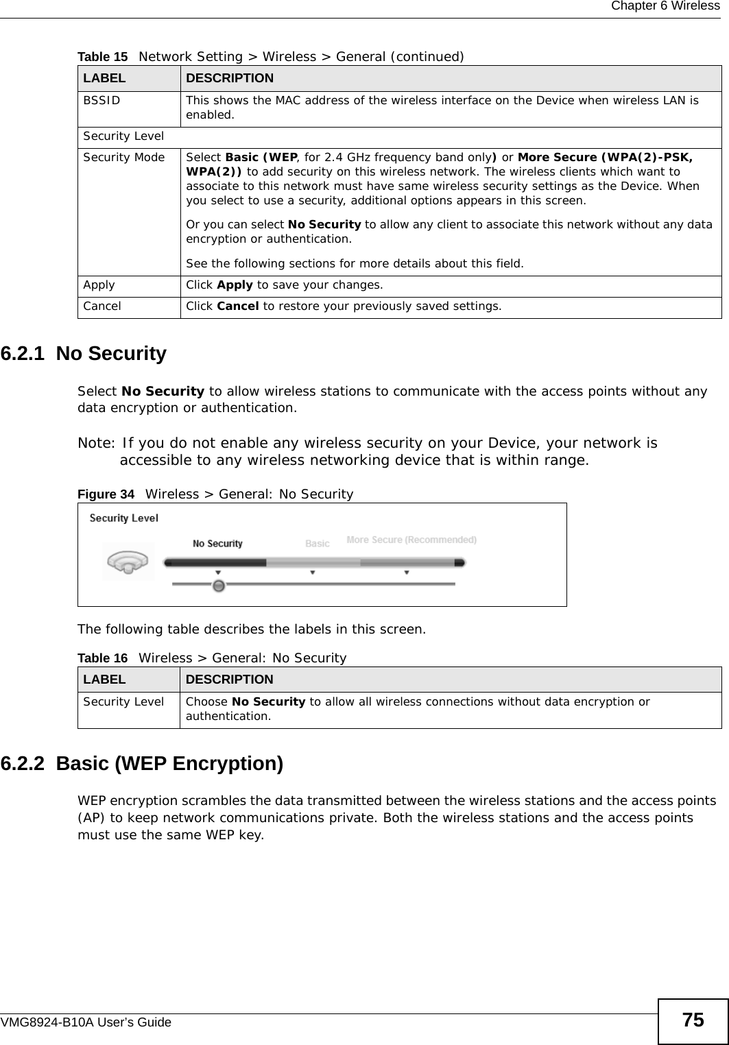
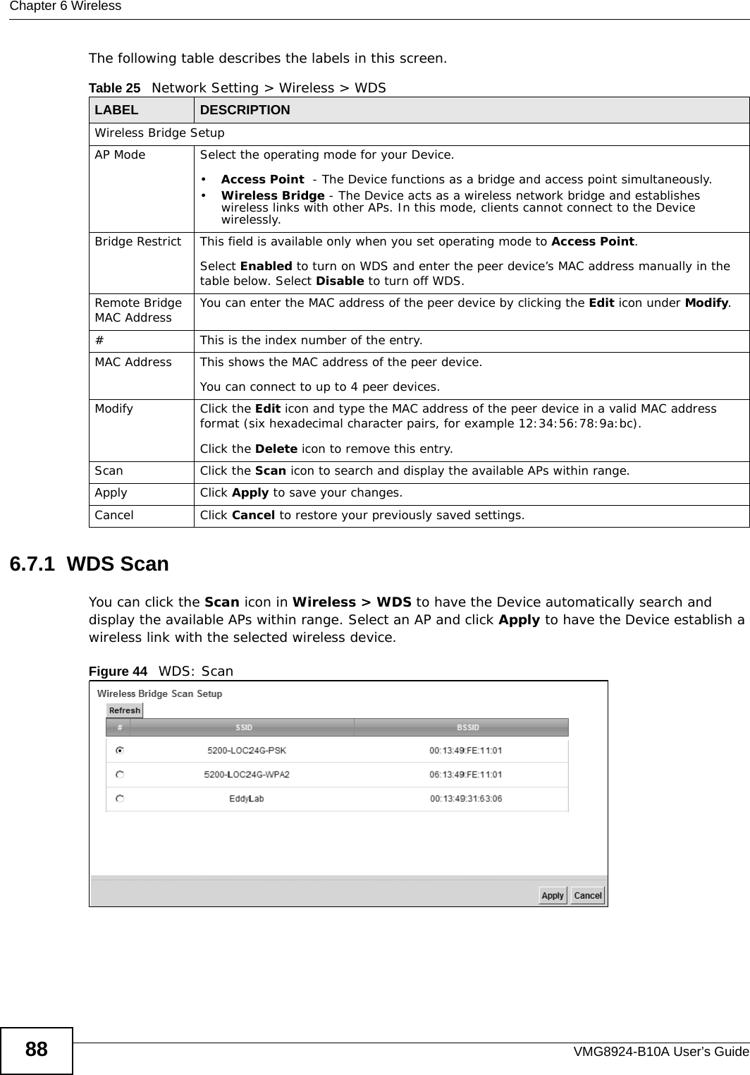
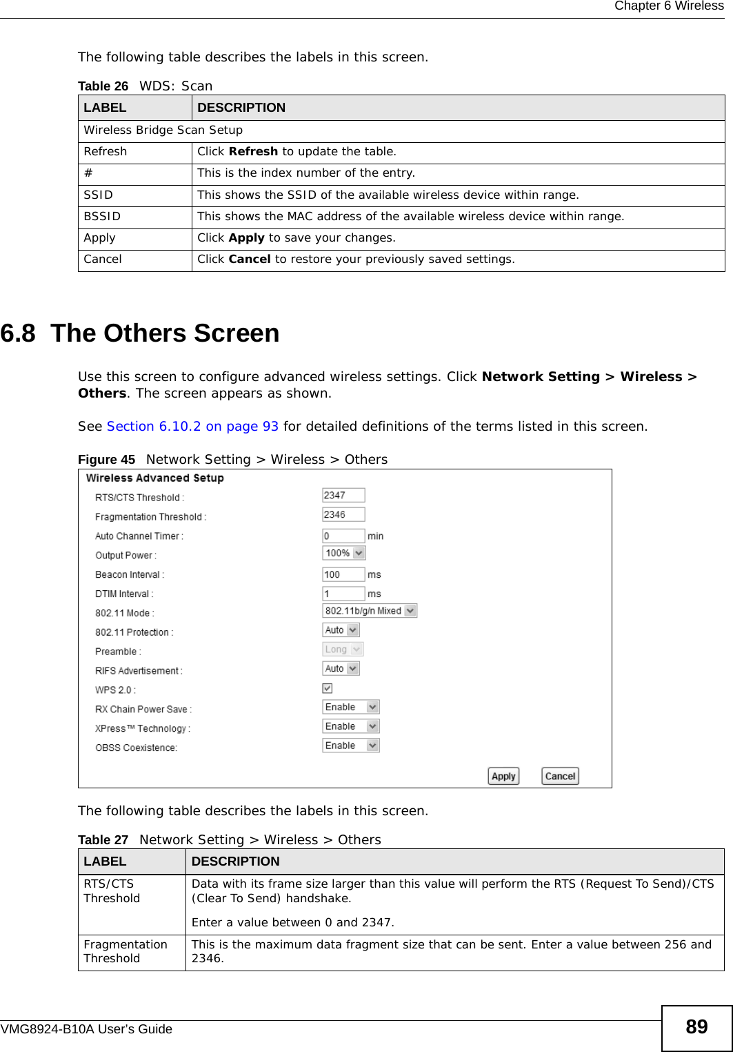
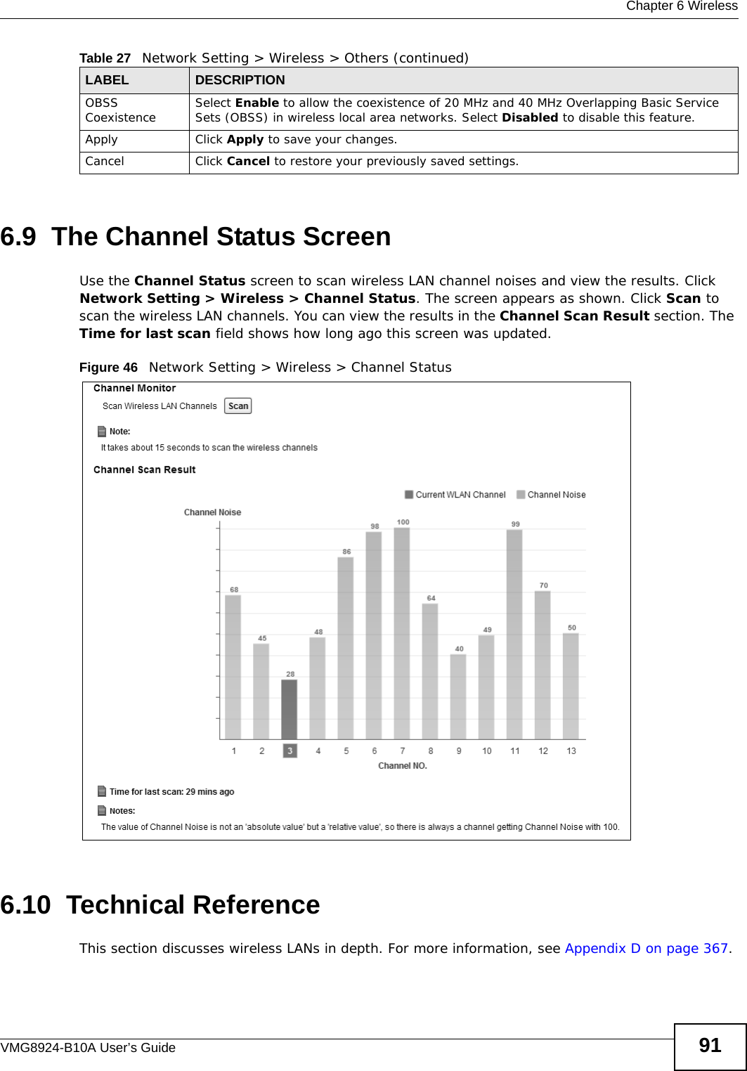
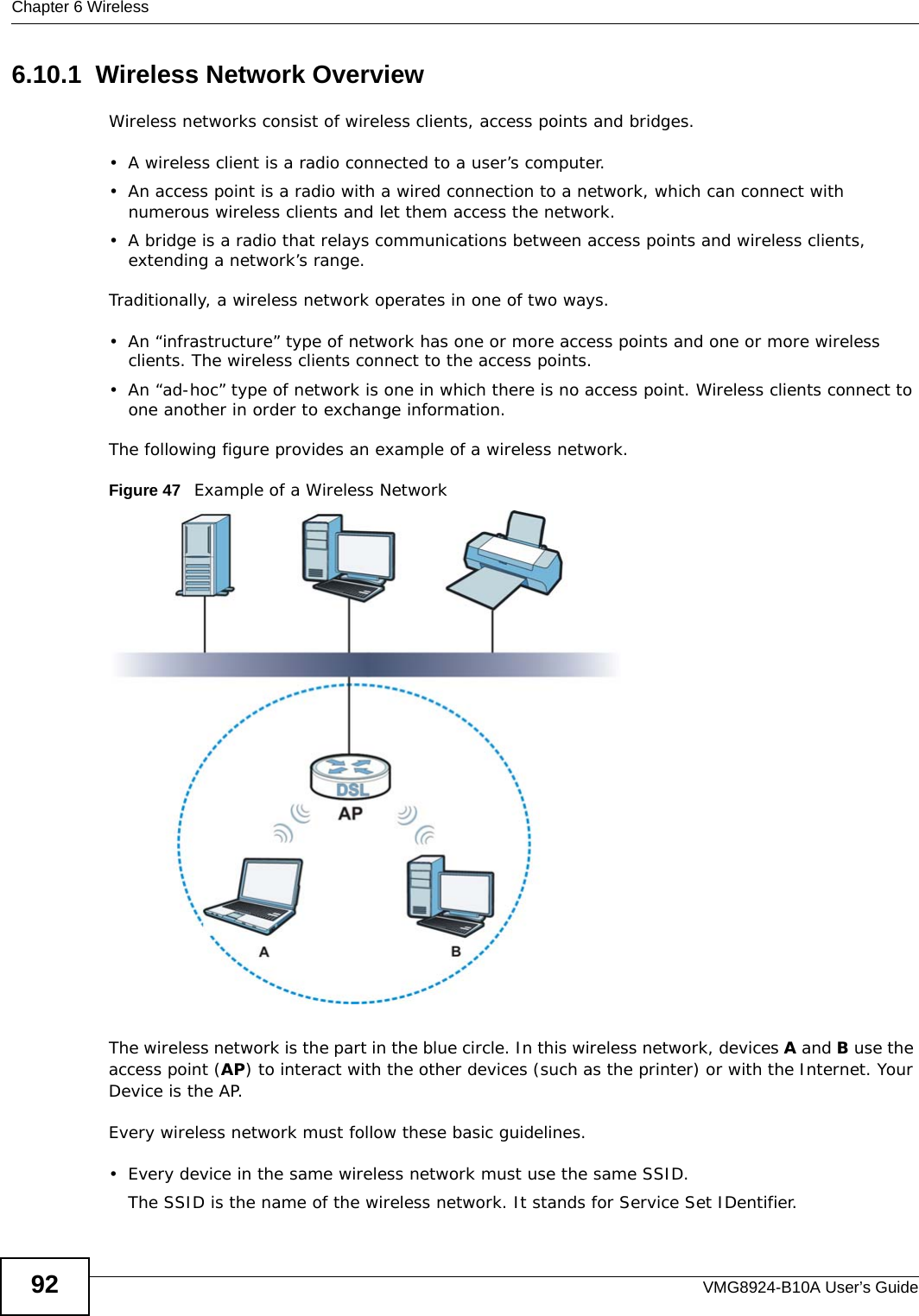
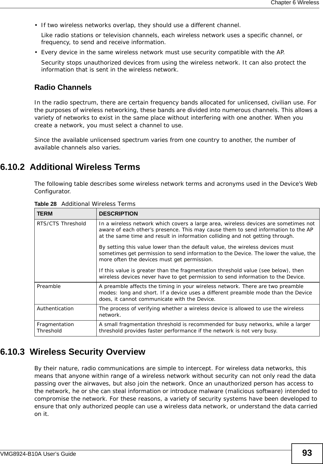
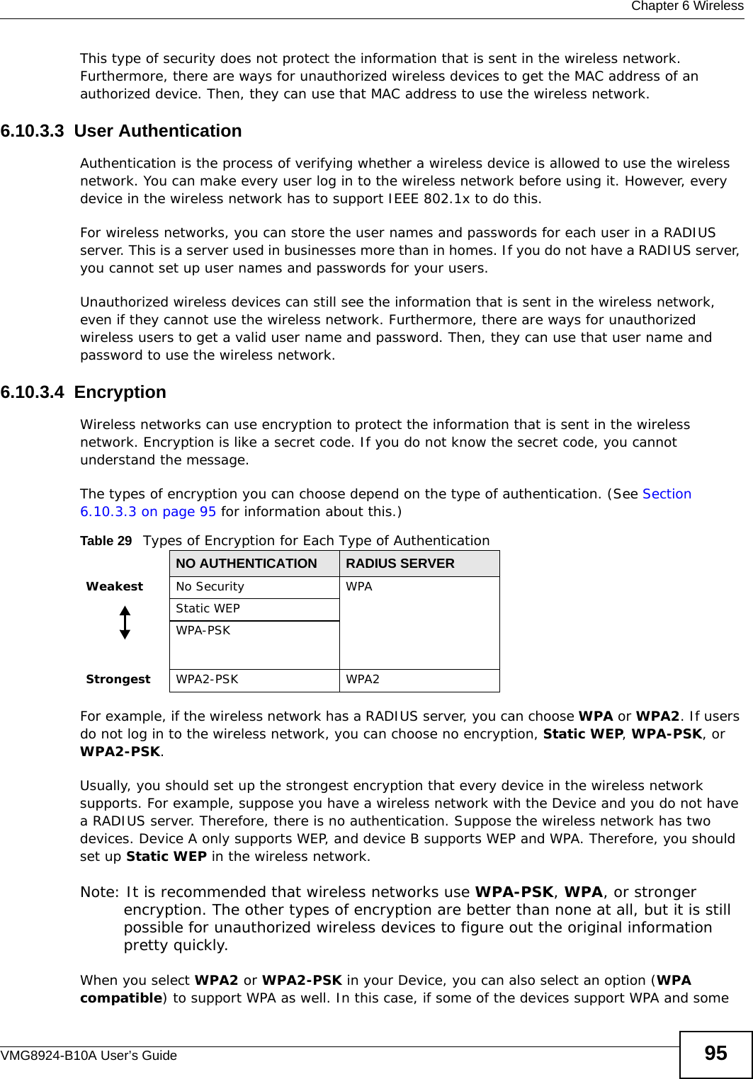
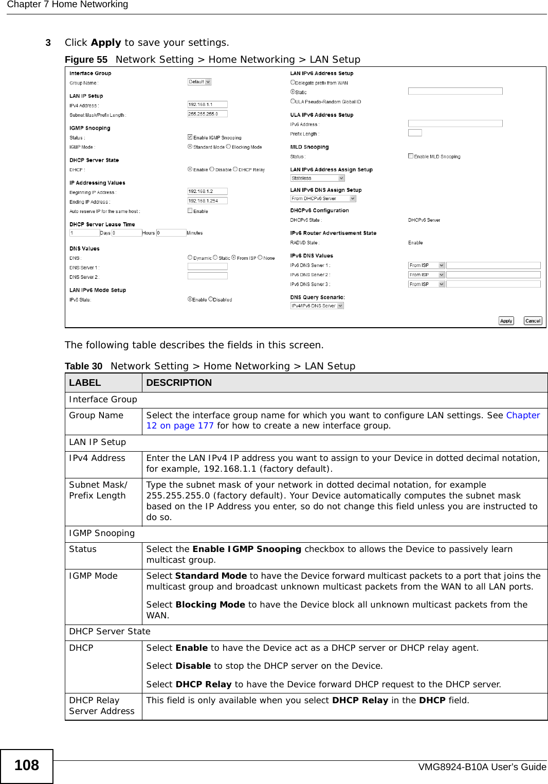
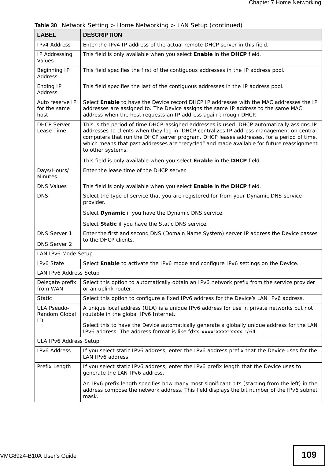
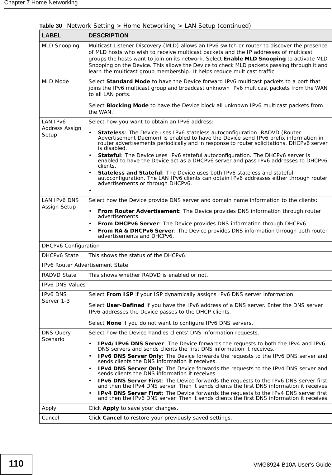
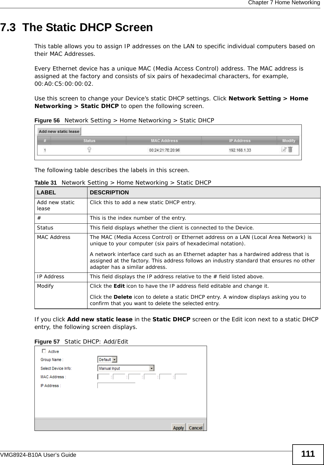
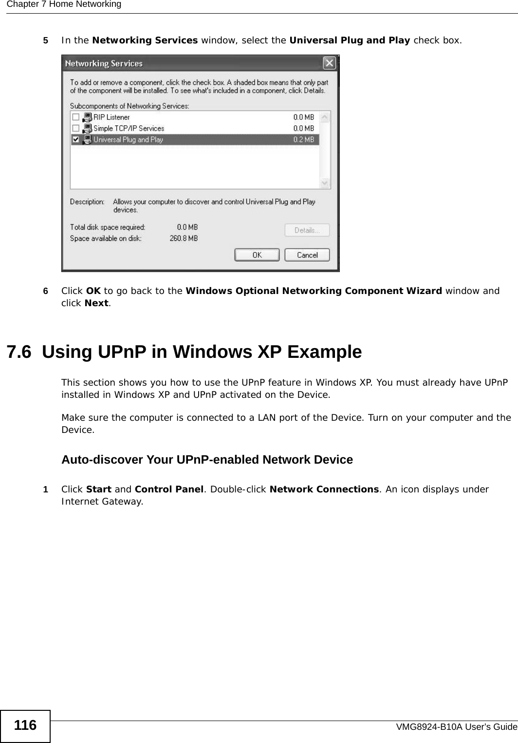
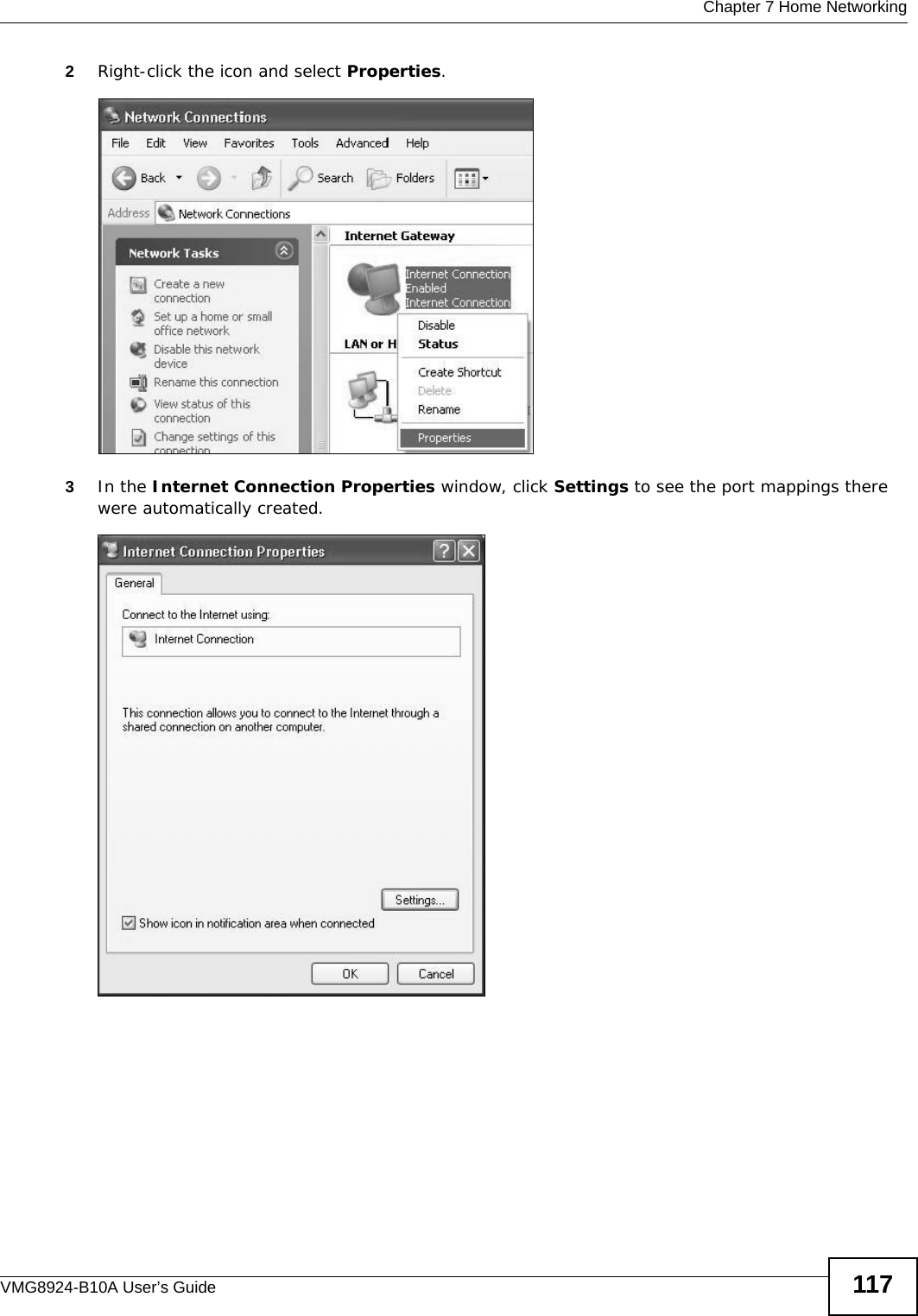
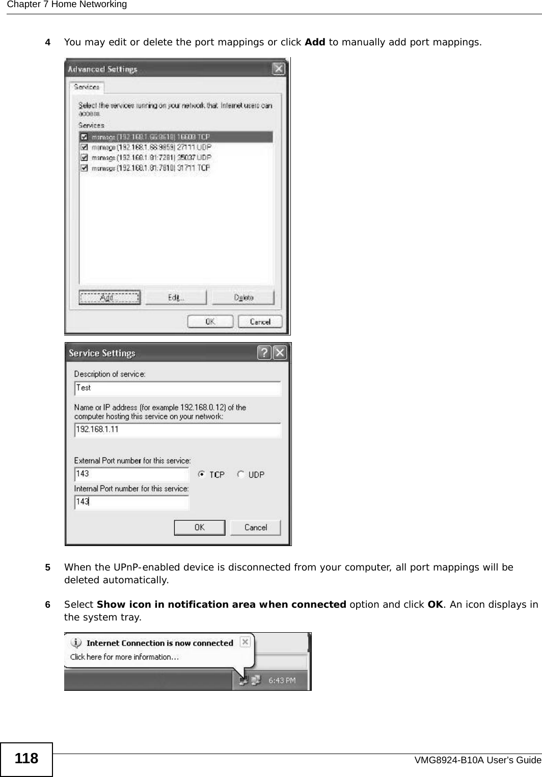
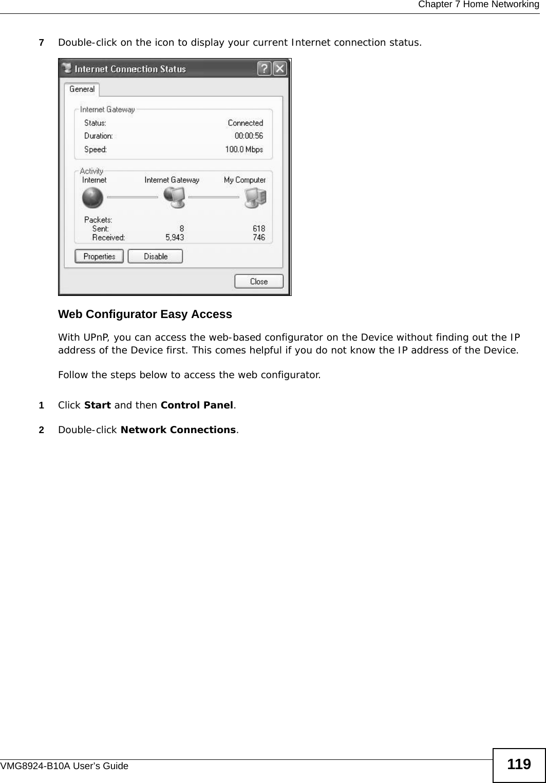
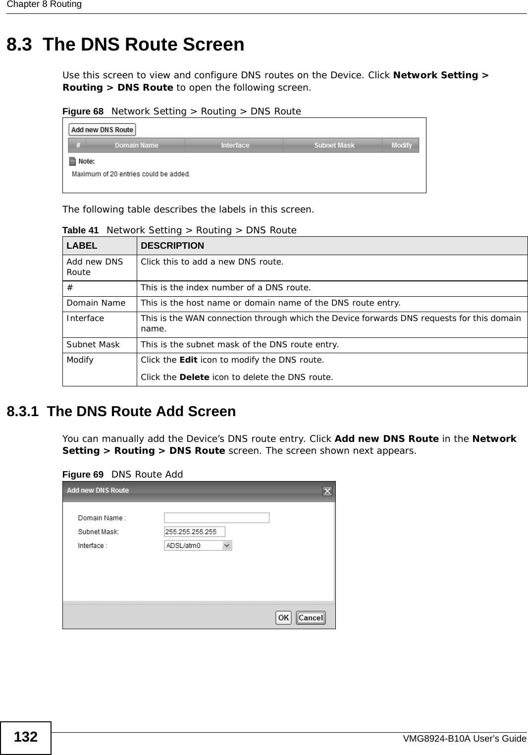
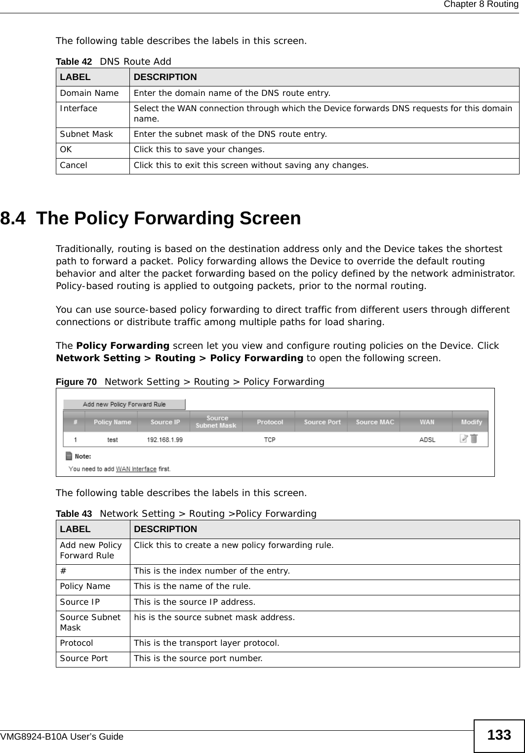
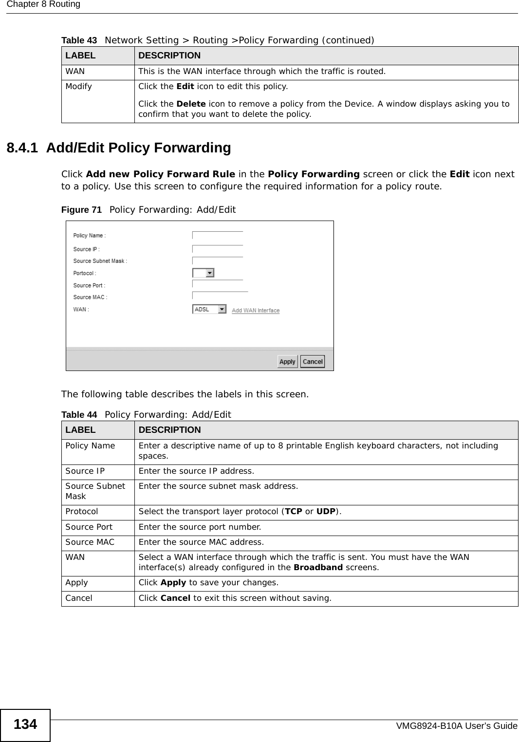
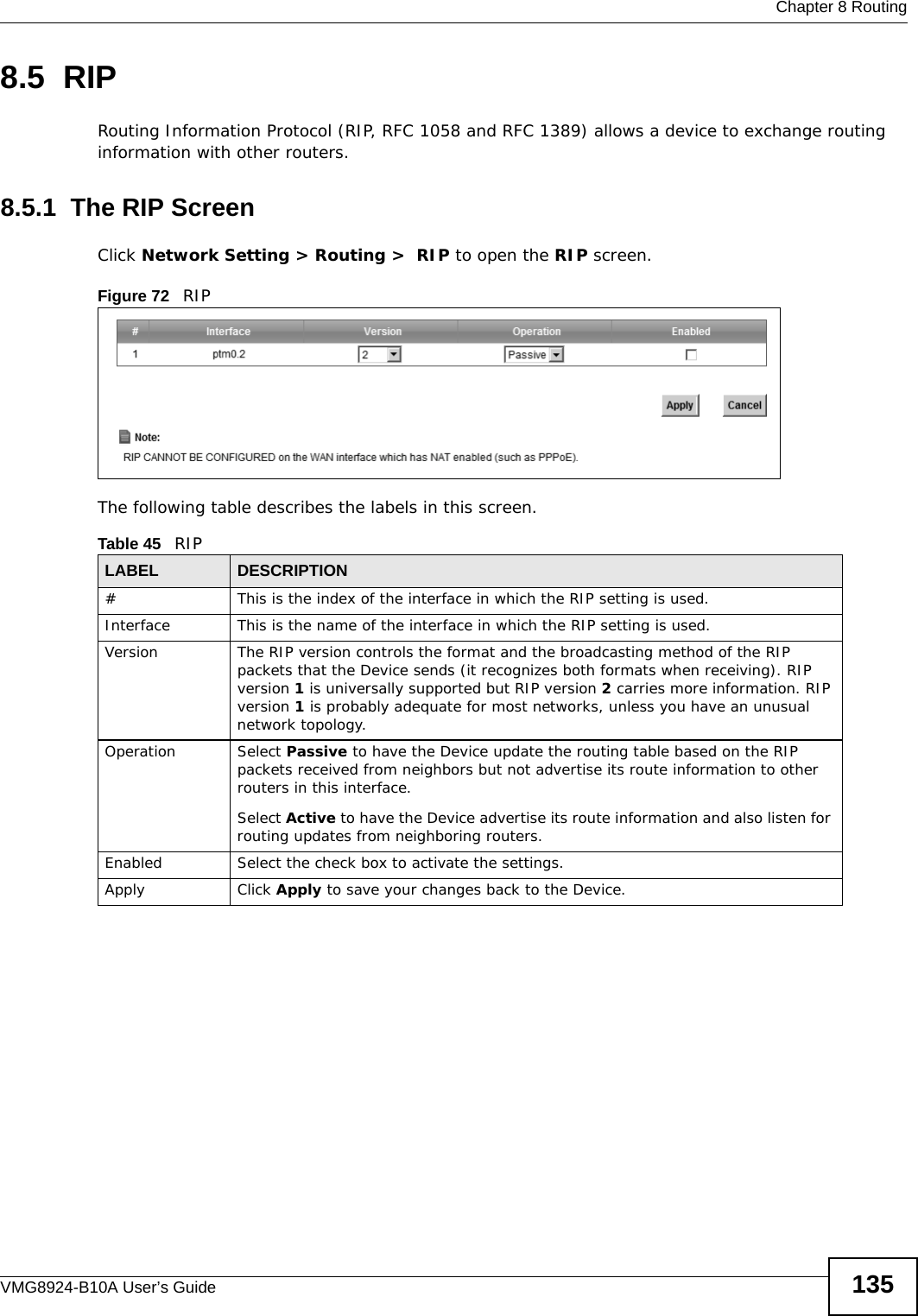
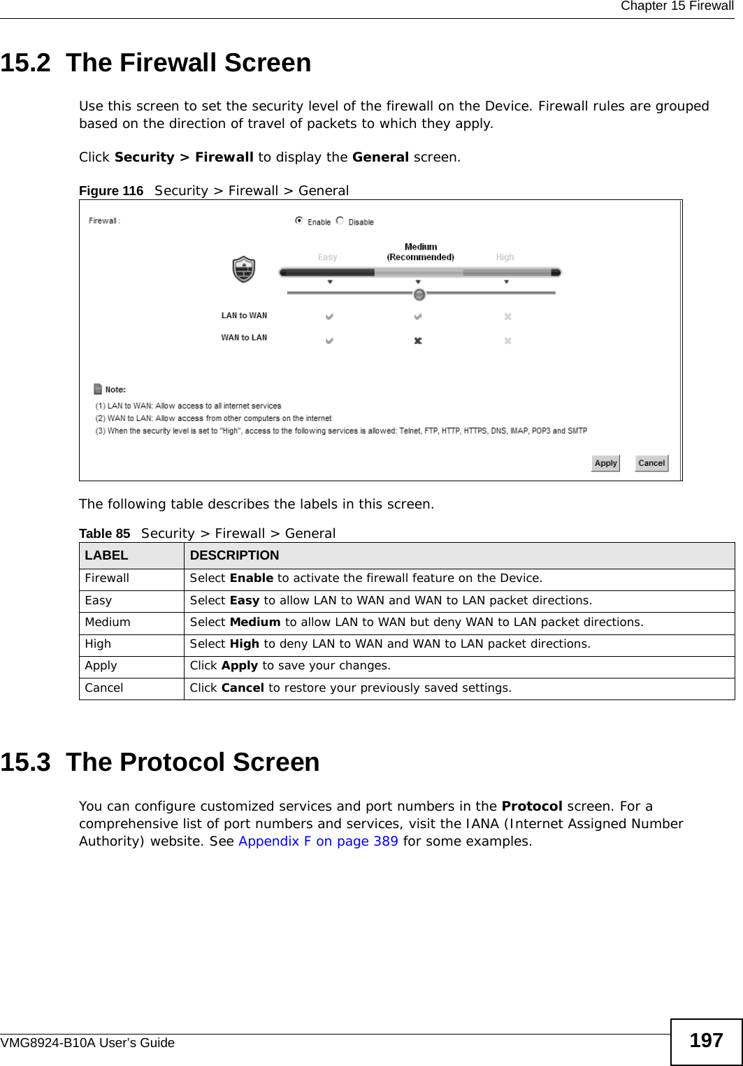
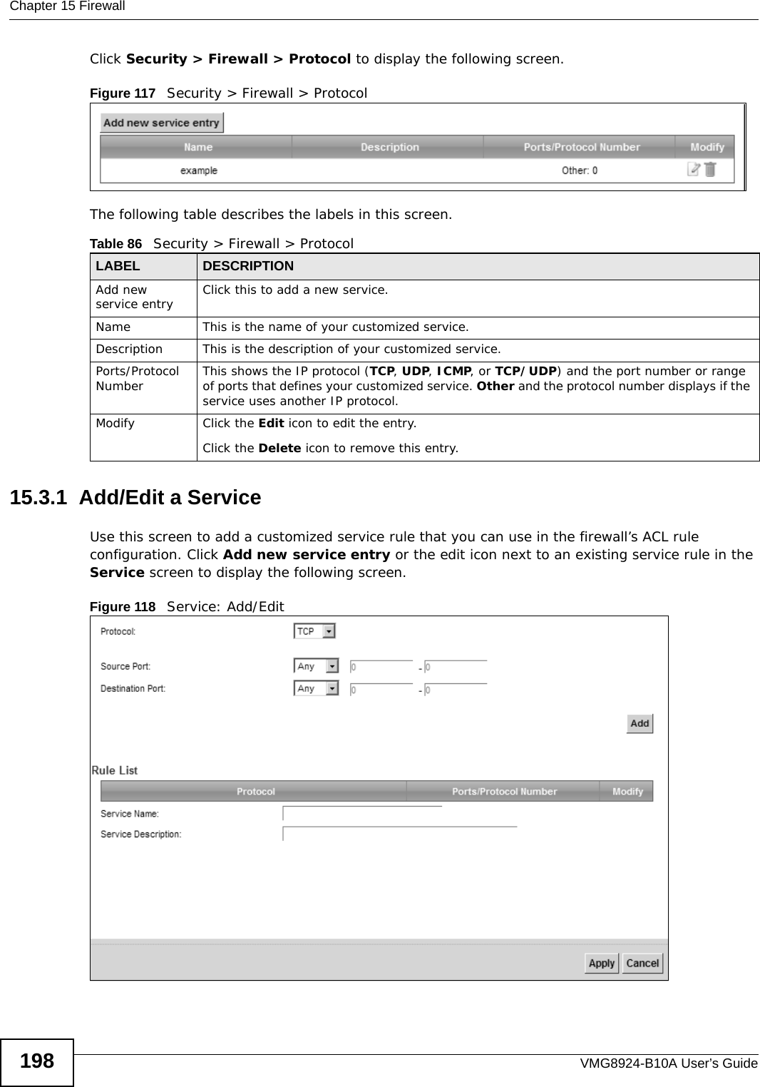
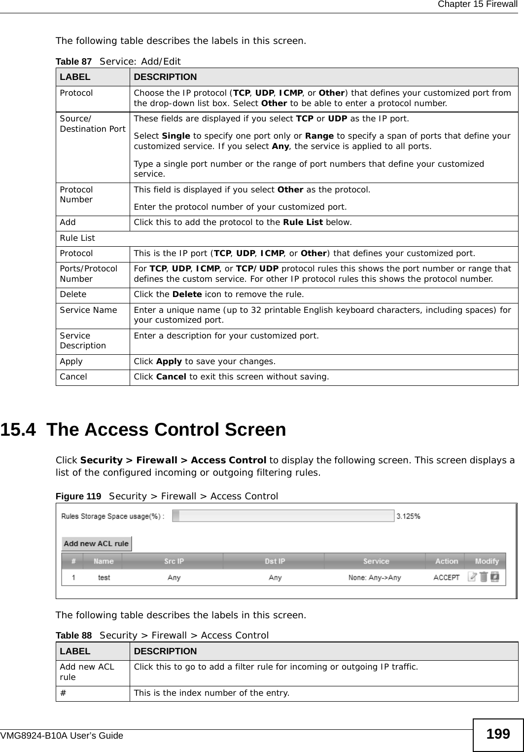
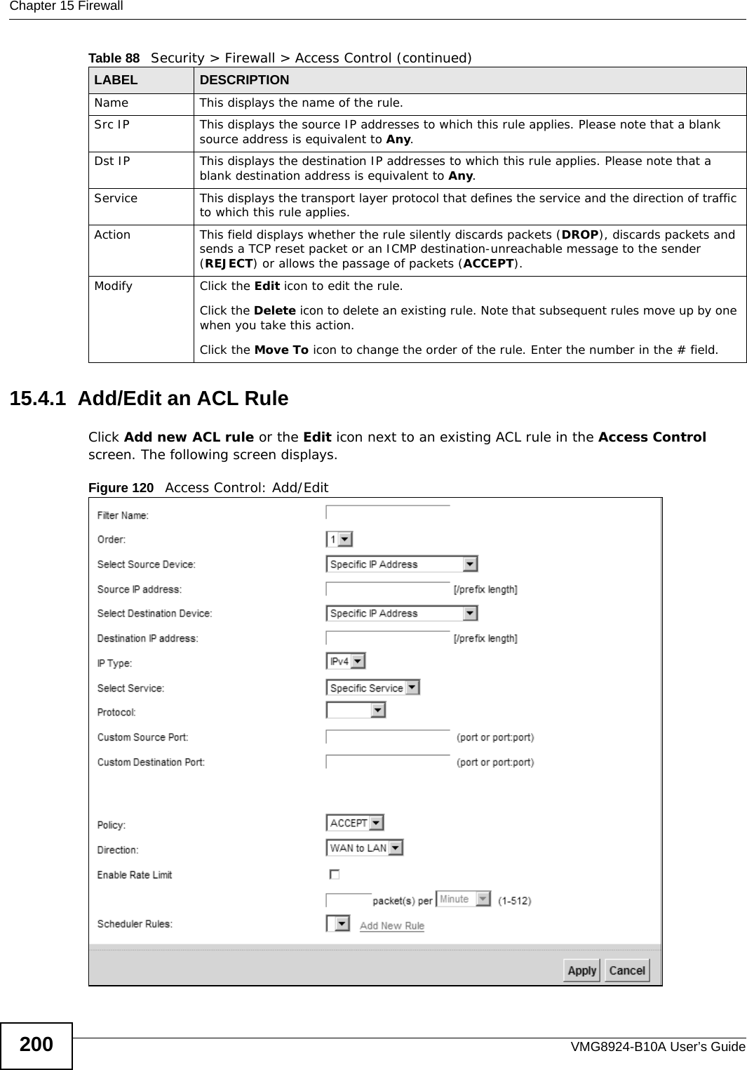
(VMG8924-B10A) User Manual-1

Quick Start Guidewww.zyxel.comVMG8924-B10ADual Band Wireless AC/N VDSL2 VoIP Combo WAN Gigabit IADVersion 1.00Edition 1, 6/2013Copyright © 2013 ZyXEL Communications CorporationUser’s GuideDefault Login DetailsLAN IP Address http://192.168.1.1Login adminPassword 1234
VMG8924-B10A User’s Guide2IMPORTANT!READ CAREFULLY BEFORE USE.KEEP THIS GUIDE FOR FUTURE REFERENCE.Screenshots and graphics in this book may differ slightly from your product due to differences in your product firmware or your computer operating system. Every effort has been made to ensure that the information in this manual is accurate.Related Documentation•Quick Start Guide The Quick Start Guide shows how to connect the Device and get up and running right away.
 Contents OverviewVMG8924-B10A User’s Guide 3Contents OverviewUser’s Guide .......................................................................................................................................15Introducing the Device  ............................................................................................................................17The Web Configurator .............................................................................................................................25Quick Start ...............................................................................................................................................33Technical Reference ..........................................................................................................................35Network Map and Status Screens ...........................................................................................................37Broadband ...............................................................................................................................................43Wireless ..................................................................................................................................................71Home Networking ..................................................................................................................................105Routing ..................................................................................................................................................129Quality of Service (QoS)  .......................................................................................................................137Network Address Translation (NAT) ......................................................................................................155Dynamic DNS Setup  .............................................................................................................................173Interface Group  .....................................................................................................................................177USB Service ..........................................................................................................................................183Power Management ..............................................................................................................................191Firewall ..................................................................................................................................................195MAC Filter  .............................................................................................................................................203Parental Control  ....................................................................................................................................205Scheduler Rule ......................................................................................................................................209Certificates ............................................................................................................................................ 211VPN .......................................................................................................................................................219Voice .....................................................................................................................................................233Log   .......................................................................................................................................................265Traffic Status   ........................................................................................................................................269 VoIP Status ...........................................................................................................................................273ARP Table  .............................................................................................................................................275Routing Table  ........................................................................................................................................277IGMP/MLD Status   ................................................................................................................................279xDSL Statistics  ......................................................................................................................................2813G Statistics   .........................................................................................................................................285User Account .........................................................................................................................................287Remote Management ............................................................................................................................289TR-069 Client ........................................................................................................................................293TR-064 ..................................................................................................................................................295SNMP ....................................................................................................................................................297Time Settings  ........................................................................................................................................299
Contents OverviewVMG8924-B10A User’s Guide4E-mail Notification  .................................................................................................................................303Logs Setting   .........................................................................................................................................305Firmware Upgrade  ................................................................................................................................309Configuration ......................................................................................................................................... 311Diagnostic .............................................................................................................................................315Troubleshooting ....................................................................................................................................321
  Table of ContentsVMG8924-B10A User’s Guide 5Table of ContentsContents Overview  ..............................................................................................................................3Table of Contents .................................................................................................................................5Part I: User’s Guide ......................................................................................... 15Chapter   1Introducing the Device.......................................................................................................................171.1 Overview  ...........................................................................................................................................171.2 Ways to Manage the Device  .............................................................................................................171.3 Good Habits for Managing the Device  ..............................................................................................171.4 Applications for the Device  ...............................................................................................................181.4.1 Internet Access ........................................................................................................................181.4.2 Device’s USB Support  .............................................................................................................191.5 LEDs (Lights)  ....................................................................................................................................201.6 The RESET Button ............................................................................................................................221.7 Wireless Access ................................................................................................................................221.7.1 Using the Wi-Fi and WPS Buttons ...........................................................................................221.8 Wall-mounting Instructions ................................................................................................................23Chapter   2The Web Configurator........................................................................................................................252.1 Overview  ...........................................................................................................................................252.1.1 Accessing the Web Configurator  .............................................................................................252.2 Web Configurator Layout  ..................................................................................................................272.2.1 Title Bar  ...................................................................................................................................272.2.2 Main Window  ...........................................................................................................................282.2.3 Navigation Panel  .....................................................................................................................29Chapter   3Quick Start...........................................................................................................................................333.1 Overview  ...........................................................................................................................................333.2 Quick Start Setup  ..............................................................................................................................33Part II: Technical Reference............................................................................ 35
Table of ContentsVMG8924-B10A User’s Guide6Chapter   4Network Map and Status Screens .....................................................................................................374.1 Overview  ...........................................................................................................................................374.2 The Network Map Screen  .................................................................................................................374.3 The Status Screen .............................................................................................................................38Chapter   5Broadband...........................................................................................................................................435.1 Overview  ...........................................................................................................................................435.1.1 What You Can Do in this Chapter ............................................................................................435.1.2 What You Need to Know ..........................................................................................................445.1.3 Before You Begin .....................................................................................................................475.2 The Broadband Screen .....................................................................................................................475.2.1 Add/Edit Internet Connection ...................................................................................................495.3 The 3G Backup Screen .....................................................................................................................575.4 The Advanced Screen .......................................................................................................................615.5 The 802.1x Screen ............................................................................................................................625.5.1 Edit 802.1X Settings  ................................................................................................................635.6 The WAN Status Screen  ...................................................................................................................635.7 Technical Reference ..........................................................................................................................64Chapter   6Wireless...............................................................................................................................................716.1 Overview  ...........................................................................................................................................716.1.1 What You Can Do in this Chapter ............................................................................................716.1.2 What You Need to Know ..........................................................................................................726.2 The General Screen  .........................................................................................................................726.2.1 No Security  ..............................................................................................................................756.2.2 Basic (WEP Encryption)  ..........................................................................................................756.2.3 More Secure (WPA(2)-PSK) ....................................................................................................786.2.4 WPA(2) Authentication .............................................................................................................796.3 The More AP Screen .........................................................................................................................806.3.1 Edit More AP   ..........................................................................................................................826.4 MAC Authentication  ..........................................................................................................................846.5 The WPS Screen  ..............................................................................................................................856.6 The WMM Screen  .............................................................................................................................866.7 The WDS Screen  ..............................................................................................................................876.7.1 WDS Scan  ...............................................................................................................................886.8 The Others Screen ............................................................................................................................896.9 The Channel Status Screen  ..............................................................................................................916.10 Technical Reference ........................................................................................................................916.10.1 Wireless Network Overview ...................................................................................................926.10.2 Additional Wireless Terms  .....................................................................................................93
  Table of ContentsVMG8924-B10A User’s Guide 76.10.3 Wireless Security Overview ...................................................................................................936.10.4 Signal Problems  ....................................................................................................................966.10.5 BSS  .......................................................................................................................................966.10.6 MBSSID .................................................................................................................................976.10.7 Preamble Type  ......................................................................................................................976.10.8 Wireless Distribution System (WDS)  .....................................................................................976.10.9 WiFi Protected Setup (WPS)  .................................................................................................98Chapter   7Home Networking .............................................................................................................................1057.1 Overview  .........................................................................................................................................1057.1.1 What You Can Do in this Chapter ..........................................................................................1057.1.2 What You Need To Know .......................................................................................................1067.1.3 Before You Begin ...................................................................................................................1077.2 The LAN Setup Screen  ...................................................................................................................1077.3 The Static DHCP Screen ................................................................................................................. 1117.4 The UPnP Screen  ........................................................................................................................... 1127.5 Installing UPnP in Windows Example  ............................................................................................. 1137.6 Using UPnP in Windows XP Example  ............................................................................................ 1167.7 The Additional Subnet Screen  ........................................................................................................1227.8 The STB Vendor ID Screen .............................................................................................................1237.9 The 5th Ethernet Port Screen  .........................................................................................................1237.10 The LAN VLAN Screen  .................................................................................................................1247.11 The Wake on LAN Screen .............................................................................................................1257.12 Technical Reference ......................................................................................................................1267.12.1 LANs, WANs and the Device ...............................................................................................1267.12.2 DHCP Setup ........................................................................................................................1267.12.3 DNS Server Addresses .......................................................................................................1267.12.4 LAN TCP/IP  .........................................................................................................................127Chapter   8Routing ..............................................................................................................................................1298.1 Overview   ........................................................................................................................................1298.2 The Routing Screen  ........................................................................................................................1308.2.1 Add/Edit Static Route .............................................................................................................1318.3 The DNS Route Screen  ..................................................................................................................1328.3.1 The DNS Route Add Screen  .................................................................................................1328.4 The Policy Forwarding Screen ........................................................................................................1338.4.1 Add/Edit Policy Forwarding  ...................................................................................................1348.5 RIP      ..............................................................................................................................................1358.5.1 The RIP Screen  .....................................................................................................................135Chapter   9Quality of Service (QoS)...................................................................................................................137
Table of ContentsVMG8924-B10A User’s Guide89.1 Overview   ........................................................................................................................................1379.1.1 What You Can Do in this Chapter ..........................................................................................1379.2 What You Need to Know .................................................................................................................1379.3 The Quality of Service General Screen  ..........................................................................................1399.4 The Queue Setup Screen  ...............................................................................................................1409.4.1 Adding a QoS Queue   ...........................................................................................................1419.5 The Class Setup Screen  .................................................................................................................1429.5.1 Add/Edit QoS Class  ..............................................................................................................1449.6 The QoS Policer Setup Screen .......................................................................................................1479.6.1 Add/Edit a QoS Policer  .........................................................................................................1489.7 The QoS Monitor Screen   ...............................................................................................................1499.8 Technical Reference ........................................................................................................................150Chapter   10Network Address Translation (NAT)................................................................................................15510.1 Overview  .......................................................................................................................................15510.1.1 What You Can Do in this Chapter ........................................................................................15510.1.2 What You Need To Know .....................................................................................................15510.2 The Port Forwarding Screen  ........................................................................................................15610.2.1 Add/Edit Port Forwarding   ...................................................................................................15810.3 The Applications Screen  ...............................................................................................................15910.3.1 Add New Application  ...........................................................................................................16010.4 The Port Triggering Screen ...........................................................................................................16110.4.1 Add/Edit Port Triggering Rule  .............................................................................................16310.5 The DMZ Screen ...........................................................................................................................16410.6 The ALG Screen  ...........................................................................................................................16410.7 The Address Mapping Screen .......................................................................................................16510.7.1 Add/Edit Address Mapping Rule ..........................................................................................16610.8 The Address Mapping Screen .......................................................................................................16710.9 The Sessions Screen ....................................................................................................................16810.10 Technical Reference ....................................................................................................................16810.10.1 NAT Definitions ..................................................................................................................16810.10.2 What NAT Does .................................................................................................................16910.10.3 How NAT Works  ................................................................................................................17010.10.4 NAT Application  .................................................................................................................171Chapter   11Dynamic DNS Setup .........................................................................................................................17311.1 Overview  .......................................................................................................................................17311.1.1 What You Can Do in this Chapter  ........................................................................................17311.1.2 What You Need To Know .....................................................................................................17411.2 The DNS Entry Screen ..................................................................................................................17411.2.1 Add/Edit DNS Entry  .............................................................................................................175
  Table of ContentsVMG8924-B10A User’s Guide 911.3 The Dynamic DNS Screen  ............................................................................................................175Chapter   12Interface Group.................................................................................................................................17712.1 Overview  .......................................................................................................................................17712.1.1 What You Can Do in this Chapter ........................................................................................17712.2 The Interface Group Screen ..........................................................................................................17712.2.1 Interface Group Configuration .............................................................................................17812.2.2  Interface Grouping Criteria  .................................................................................................180Chapter   13USB Service ......................................................................................................................................18313.1 Overview  .......................................................................................................................................18313.1.1 What You Can Do in this Chapter ........................................................................................18313.1.2 What You Need To Know .....................................................................................................18313.1.3 Before You Begin .................................................................................................................18513.2 The File Sharing Screen  ...............................................................................................................18613.2.1 The Add New Share Screen ................................................................................................18713.2.2 The Add New User Screen ..................................................................................................18813.3 The Media Server Screen  .............................................................................................................18813.4 Printer Server  ...............................................................................................................................18913.4.1 Before You Begin .................................................................................................................18913.4.2 The Printer Server Screen ...................................................................................................190Chapter   14Power Management..........................................................................................................................19114.1 Overview  .......................................................................................................................................19114.1.1 What You Can Do in this Chapter ........................................................................................19114.1.2 What You Need To Know .....................................................................................................19114.2 The Power Management Screen  ..................................................................................................19114.3 The Auto Switch Off Screen ..........................................................................................................19214.3.1 The Auto Switch Off Add/Edit Screen ..................................................................................19314.3.2 The Add/Edit Rule Screen ...................................................................................................193Chapter   15Firewall ..............................................................................................................................................19515.1 Overview  .......................................................................................................................................19515.1.1 What You Can Do in this Chapter ........................................................................................19515.1.2 What You Need to Know ......................................................................................................19615.2 The Firewall Screen  ......................................................................................................................19715.3 The Protocol Screen   ....................................................................................................................19715.3.1 Add/Edit a Service   ..............................................................................................................19815.4 The Access Control Screen  ..........................................................................................................199
Table of ContentsVMG8924-B10A User’s Guide1015.4.1 Add/Edit an ACL Rule   ........................................................................................................20015.5 The DoS Screen ............................................................................................................................202Chapter   16MAC Filter..........................................................................................................................................20316.1 Overview   ......................................................................................................................................20316.2 The MAC Filter Screen ..................................................................................................................203Chapter   17Parental Control................................................................................................................................20517.1 Overview  .......................................................................................................................................20517.2 The Parental Control Screen .........................................................................................................20517.2.1 Add/Edit a Parental Control Rule .........................................................................................206Chapter   18Scheduler Rule..................................................................................................................................20918.1 Overview  .......................................................................................................................................20918.2 The Scheduler Rule Screen ..........................................................................................................20918.2.1 Add/Edit a Schedule  ............................................................................................................210Chapter   19Certificates ........................................................................................................................................21119.1 Overview  .......................................................................................................................................21119.1.1 What You Can Do in this Chapter ........................................................................................21119.2 What You Need to Know  ...............................................................................................................21119.3 The Local Certificates Screen ....................................................................................................... 21119.3.1 Create Certificate Request   .................................................................................................21219.3.2 Load Signed Certificate   ......................................................................................................21319.4 The Trusted CA Screen ................................................................................................................21419.4.1 View Trusted CA Certificate .................................................................................................21619.4.2 Import Trusted CA Certificate  ..............................................................................................217Chapter   20VPN ....................................................................................................................................................21920.1 Overview  .......................................................................................................................................21920.2 The IPSec VPN General Screen ...................................................................................................21920.3 The IPSec VPN Add/Edit Screen ..................................................................................................22020.4 The IPSec VPN Monitor Screen ....................................................................................................22620.5 Technical Reference ......................................................................................................................22620.5.1 IPSec Architecture ...............................................................................................................22620.5.2 Encapsulation  ......................................................................................................................22720.5.3  IKE Phases .........................................................................................................................22820.5.4 Negotiation Mode  ................................................................................................................229
  Table of ContentsVMG8924-B10A User’s Guide 1120.5.5 IPSec and NAT  ....................................................................................................................23020.5.6 VPN, NAT, and NAT Traversal .............................................................................................23020.5.7 ID Type and Content ............................................................................................................23120.5.8 Pre-Shared Key  ...................................................................................................................23220.5.9 Diffie-Hellman (DH) Key Groups ..........................................................................................232Chapter   21Voice ..................................................................................................................................................23321.1 Overview  .......................................................................................................................................23321.1.1 What You Can Do in this Chapter ........................................................................................23321.1.2 What You Need to Know About VoIP ...................................................................................23421.2 Before You Begin  ..........................................................................................................................23421.3 The SIP Account Screen  ..............................................................................................................23421.3.1 The SIP Account Add/Edit Screen  ......................................................................................23521.4 The SIP Service Provider Screen   ................................................................................................23921.4.1 The SIP Service Provider Add/Edit Screen   ........................................................................24021.4.2 Dial Plan Rules  ....................................................................................................................24621.5 The Phone Screen   .......................................................................................................................24721.6 The Call Rule Screen ....................................................................................................................24721.7 The Call History Summary Screen ................................................................................................24821.8 The Call History Outgoing Calls Screen ........................................................................................24921.9 The Call History Incoming Calls Screen ........................................................................................24921.10 Technical Reference ....................................................................................................................25021.10.1 Quality of Service (QoS) ....................................................................................................25821.10.2 Phone Services Overview  .................................................................................................258Chapter   22Log ....................................................................................................................................................26522.1 Overview  .......................................................................................................................................26522.1.1 What You Can Do in this Chapter ........................................................................................26522.1.2 What You Need To Know .....................................................................................................26522.2 The System Log Screen ................................................................................................................26622.3 The Security Log Screen ...............................................................................................................267Chapter   23Traffic Status  ....................................................................................................................................26923.1 Overview  .......................................................................................................................................26923.1.1 What You Can Do in this Chapter ........................................................................................26923.2 The WAN Status Screen  ...............................................................................................................26923.3 The LAN Status Screen .................................................................................................................27123.4 The NAT Status Screen .................................................................................................................272Chapter   24 VoIP Status .......................................................................................................................................273
Table of ContentsVMG8924-B10A User’s Guide1224.1 The VoIP Status Screen ................................................................................................................273Chapter   25ARP Table..........................................................................................................................................27525.1 Overview  .......................................................................................................................................27525.1.1 How ARP Works ..................................................................................................................27525.2 ARP Table Screen .........................................................................................................................275Chapter   26Routing Table....................................................................................................................................27726.1 Overview  .......................................................................................................................................27726.2 The Routing Table Screen .............................................................................................................277Chapter   27IGMP/MLD Status .............................................................................................................................27927.1 Overview  .......................................................................................................................................27927.2 The IGMP/MLD Group Status Screen ...........................................................................................279Chapter   28xDSL Statistics..................................................................................................................................28128.1 The xDSL Statistics Screen ...........................................................................................................281Chapter   293G Statistics  .....................................................................................................................................28529.1 Overview  .......................................................................................................................................28529.2 The 3G Statistics Screen ...............................................................................................................285Chapter   30User Account ....................................................................................................................................28730.1 Overview   ......................................................................................................................................28730.2 The User Account Screen .............................................................................................................287Chapter   31Remote Management........................................................................................................................28931.1 Overview  .......................................................................................................................................28931.2 The Remote MGMT Screen ..........................................................................................................28931.3 The Trust Domain Screen  .............................................................................................................29031.4 The Add Trust Domain Screen ......................................................................................................291Chapter   32TR-069 Client.....................................................................................................................................29332.1 Overview  .......................................................................................................................................29332.2 The TR-069 Client Screen ............................................................................................................293
  Table of ContentsVMG8924-B10A User’s Guide 13Chapter   33TR-064................................................................................................................................................29533.1 Overview  .......................................................................................................................................29533.2 The TR-064 Screen .......................................................................................................................295Chapter   34SNMP .................................................................................................................................................29734.1 Overview  .......................................................................................................................................29734.2 The SNMP Screen  ........................................................................................................................297Chapter   35Time Settings ....................................................................................................................................29935.1 Overview  .......................................................................................................................................29935.2 The Time Screen  ..........................................................................................................................299Chapter   36E-mail Notification ............................................................................................................................30336.1 Overview     ....................................................................................................................................30336.2 The Email Notification Screen .......................................................................................................30336.2.1 Email Notification Edit   ........................................................................................................304Chapter   37Logs Setting .....................................................................................................................................30537.1 Overview   ......................................................................................................................................30537.2 The Log Settings Screen ...............................................................................................................30537.2.1 Example E-mail Log  ............................................................................................................306Chapter   38Firmware Upgrade ............................................................................................................................30938.1 Overview  .......................................................................................................................................30938.2 The Firmware Screen ....................................................................................................................309Chapter   39Configuration ....................................................................................................................................31139.1 Overview  .......................................................................................................................................31139.2 The Configuration Screen  ............................................................................................................. 31139.3 The Reboot Screen .......................................................................................................................313Chapter   40Diagnostic .........................................................................................................................................31540.1 Overview  .......................................................................................................................................31540.1.1 What You Can Do in this Chapter ........................................................................................31540.2 What You Need to Know  ...............................................................................................................315
Table of ContentsVMG8924-B10A User’s Guide1440.3 Ping & TraceRoute & NsLookup  ...................................................................................................31640.4 802.1ag  .........................................................................................................................................31740.5 OAM Ping ......................................................................................................................................318Chapter   41Troubleshooting................................................................................................................................32141.1 Power, Hardware Connections, and LEDs ....................................................................................32141.2 Device Access and Login ..............................................................................................................32241.3 Internet Access  .............................................................................................................................32441.4 Wireless Internet Access ...............................................................................................................32541.5 USB Device Connection ................................................................................................................32641.6 UPnP .............................................................................................................................................326Appendix   A  Setting up Your Computer’s IP Address.......................................................................327Appendix   B  IP Addresses and Subnetting.......................................................................................349Appendix   C  Pop-up Windows, JavaScripts and Java Permissions .................................................357Appendix   D  Wireless LANs..............................................................................................................367Appendix   E  IPv6 ..............................................................................................................................381Appendix   F  Services........................................................................................................................389Appendix   G  Legal Information .........................................................................................................393Index ..................................................................................................................................................397
15PART IUser’s Guide
16
VMG8924-B10A User’s Guide 17CHAPTER   1Introducing the Device1.1  OverviewThe Device is a wireless VDSL router and Gigabit Ethernet gateway. It has a DSL port and a Gigabit Ethernet port for super-fast Internet access. The Device supports both Packet Transfer Mode (PTM) and Asynchronous Transfer Mode (ATM). It is backward compatible with ADSL, ADSL2 and ADSL2+ in case VDSL is not available.Only use firmware for your Device’s specific model. Refer to the label on the bottom of your Device.The Device has two USB ports for sharing files via a USB storage device, sharing a USB printer, or connecting a 3G dongle for a WAN backup connection. The Device works over the analog telephone system, POTS (Plain Old Telephone Service). 1.2  Ways to Manage the DeviceUse any of the following methods to manage the Device.• Web Configurator. This is recommended for everyday management of the Device using a (supported) web browser.• TR-069. This is an auto-configuration server used to remotely configure your device.1.3  Good Habits for Managing the DeviceDo the following things regularly to make the Device more secure and to manage the Device more effectively.• Change the password. Use a password that’s not easy to guess and that consists of different types of characters, such as numbers and letters.• Write down the password and put it in a safe place.• Back up the configuration (and make sure you know how to restore it). Restoring an earlier working configuration may be useful if the device becomes unstable or even crashes. If you forget your password, you will have to reset the Device to its factory default settings. If you backed up an earlier configuration file, you would not have to totally re-configure the Device. You could simply restore your last configuration.
Chapter 1 Introducing the DeviceVMG8924-B10A User’s Guide181.4  Applications for the Device Here are some example uses for which the Device is well suited.1.4.1  Internet AccessYour Device provides shared Internet access by connecting the DSL port to the DSL or MODEM jack on a splitter or your telephone jack. You can have multiple WAN services over one ADSL or VDSL. The Device cannot work in ADSL and VDSL mode at the same time.Note: The ADSL and VDSL lines share the same WAN (layer-2) interfaces that you configure in the Device. Refer to Section 5.2 on page 47 for the Network Setting > Broadband screen.Computers can connect to the Device’s LAN ports (or wirelessly).Figure 1   Device’s Internet Access Application You can also configure IP filtering on the Device for secure Internet access. When the IP filter is on, all incoming traffic from the Internet to your network is blocked by default unless it is initiated from your network. This means that probes from the outside to your network are not allowed, but you can safely browse the Internet and download files.ADSL / VDSLWLANPPPoEIPoEBridgingWANADSL    IPoAWANLANLANWLANAAPPPoAIPoEPPPoEBridging
 Chapter 1 Introducing the DeviceVMG8924-B10A User’s Guide 191.4.2  Device’s USB SupportThe USB port of the Device is used for file-sharing, media server and printer-sharing.File SharingUse the built-in USB 2.0 port to share files on a USB memory stick or a USB hard drive (B). You can connect one USB hard drive to the Device at a time. Use FTP to access the files on the USB device.Figure 2   USB File Sharing Application Media ServerYou can also use the Device as a media server. This lets anyone on your network play video, music, and photos from a USB device (B) connected to the Device’s USB port (without having to copy them to another computer). Figure 3   USB Media Server Application  BABA
Chapter 1 Introducing the DeviceVMG8924-B10A User’s Guide20Printer ServerThe Device allows you to share a USB printer on your LAN. You can do this by connecting a USB printer to one of the USB ports on the Device and then configuring a TCP/IP port on the computers connected to your network. Figure 4   Sharing a USB Printer1.5  LEDs (Lights)The following graphic displays the labels of the LEDs. Figure 5   LEDs on the DeviceNone of the LEDs are on if the Device is not receiving power.Table 1   LED DescriptionsLED COLOR STATUS DESCRIPTIONPWR/SYSGreen On The Device is receiving power and ready for use.Blinking The Device is self-testing.Red On The Device detected an error while self-testing, or there is a device malfunction.Off The Device is not receiving power.DSLGreen On The ADSL line is up.Blinking The Device is initializing the ADSL line.Orange On The VDSL line is up.Blinking The Device is initializing the VDSL line.Off The DSL line is down.2.4G 5G
 Chapter 1 Introducing the DeviceVMG8924-B10A User’s Guide 21INTERNETGreen On The Device has an IP connection but no traffic.Your device has a WAN IP address (either static or assigned by a DHCP server), PPP negotiation was successfully completed (if used) and the DSL connection is up.Blinking The Device is sending or receiving IP traffic.Off There is no Internet connection or the gateway is in bridged mode.Red On The Device attempted to make an IP connection but failed. Possible causes are no response from a DHCP server, no PPPoE response, PPPoE authentication failed.WANGreen On The Device has a successful 1000 Mbps Ethernet connection on the WAN. Blinking  The Device is sending or receiving data to/from the WAN at 1000 Mbps.Orange On The Device has a successful 10/100 Mbps Ethernet connection on the WAN. Blinking The Device is sending or receiving data to/from the WAN at 10/100 Mbps.Off There is no Ethernet connection on the WAN.LANGreen On The Device has a successful 1000 Mbps Ethernet connection with a device on the Local Area Network (LAN). Blinking  The Device is sending or receiving data to/from the LAN at 1000 Mbps.Off The Device does not have an Ethernet connection with the LAN.WiFi 2.4GGreen On The 2.4 GHz wireless network is activated.Blinking The Device is communicating with 2.4 GHz wireless clients.Orange Blinking The Device is setting up a WPS connection with a 2.4 GHz wireless client.Off The 2.4 GHz wireless network is not activated.WiFi 5GGreen On The 5 GHz wireless network is activated.Blinking The Device is communicating with 5 GHz wireless clients.Orange Blinking The Device is setting up a WPS connection with a 5 GHz wireless client.Off The 5 GHz wireless network is not activated.Phone1, Phone2Green On A SIP account is registered for the phone port.Blinking A telephone connected to the phone port has its receiver off of the hook or there is an incoming call.Orange On A SIP account is registered for the phone port and there is a voice message in the corresponding SIP account.Blinking A telephone connected to the phone port has its receiver off of the hook and there is a voice message in the corresponding SIP account.Off The phone port does not have a SIP account registered.USB1Green On The Device recognizes a USB connection through the USB1 slot.Blinking The Device is sending/receiving data to /from the USB device connected to it.Off The Device does not detect a USB connection through the USB1 slot.Table 1   LED Descriptions (continued)LED COLOR STATUS DESCRIPTION
Chapter 1 Introducing the DeviceVMG8924-B10A User’s Guide221.6  The RESET ButtonIf you forget your password or cannot access the Web Configurator, you will need to use the RESET button at the back of the device to reload the factory-default configuration file. This means that you will lose all configurations that you had previously and the password will be reset to “1234”. 1Make sure the PWR/SYS LED is on (not blinking).2To set the device back to the factory default settings, press the RESET button for ten seconds or until the PWR/SYS LED begins to blink and then release it. When the PWR/SYS LED begins to blink, the defaults have been restored and the device restarts.1.7  Wireless AccessThe Device is a wireless Access Point (AP) for wireless clients, such as notebook computers or PDAs and iPads. It allows them to connect to the Internet without having to rely on inconvenient Ethernet cables.You can configure your wireless network in either the built-in Web Configurator, or using the WPS button.Figure 6   Wireless Access Example1.7.1  Using the Wi-Fi and WPS ButtonsIf the wireless network is turned off, press the Wi-Fi button for one second. Once the WiFi 2.4G LED turns green, the wireless network is active.You can also use the WPS button to quickly set up a secure wireless connection between the Device and a WPS-compatible client by adding one device at a time.USB2Green On The Device recognizes a USB connection through the USB2 slot.Blinking The Device is sending/receiving data to /from the USB device connected to it.Off The Device does not detect a USB connection through the USB2 slot.Table 1   LED Descriptions (continued)LED COLOR STATUS DESCRIPTION
 Chapter 1 Introducing the DeviceVMG8924-B10A User’s Guide 23To activate WPS:1Make sure the PWR/SYS LED is on and not blinking.2Press the WPS button for five seconds and release it.3Press the WPS button on another WPS-enabled device within range of the Device. The WiFi 2.4G LED flashes orange while the Device sets up a WPS connection with the other wireless device. 4Once the connection is successfully made, the WiFi 2.4G LED shines green.To turn off the wireless network, press the Wi-Fi button for one to five seconds. The WiFi 2.4G LED turns off when the wireless network is off.1.8  Wall-mounting InstructionsDo the following to hang your Device on a wall.1Locate a high position on a wall that is free of obstructions. Use a sturdy wall.2Hold the bracket against the wall and mark where to drill the holes.3Drill the two screw holes in the wall.Be careful to avoid damaging pipes or cables located inside the wall when drilling holes for the screws.4Align and insert the bracket to the wall-mounting notches on the rear panel of the Device.
Chapter 1 Introducing the DeviceVMG8924-B10A User’s Guide245Push the bracket up to tightly attach it to the Device.6Mount the Device on the screws which are already installed on the wall. Make sure that the Device is firmly attached to the screws so it does not fall off.
VMG8924-B10A User’s Guide 25CHAPTER   2The Web Configurator2.1  OverviewThe web configurator is an HTML-based management interface that allows easy device setup and management via Internet browser. Use Internet Explorer 6.0 and later versions or Mozilla Firefox 3 and later versions or Safari 2.0 and later versions. The recommended screen resolution is 1024 by 768 pixels.In order to use the web configurator you need to allow:• Web browser pop-up windows from your device. Web pop-up blocking is enabled by default in Windows XP SP (Service Pack) 2.• JavaScript (enabled by default).• Java permissions (enabled by default).See Appendix C on page 357 if you need to make sure these functions are allowed in Internet Explorer. 2.1.1  Accessing the Web Configurator1Make sure your Device hardware is properly connected (refer to the Quick Start Guide).2Launch your web browser. If the Device does not automatically re-direct you to the login screen, go to http://192.168.1.1.3A password screen displays. To access the administrative web configurator and manage the Device, type the default username admin and password 1234 in the password screen and click Login. If advanced account security is enabled (see Section 30.2 on page 287) the number of dots that appears when you type the password changes randomly to prevent anyone watching the password field from knowing the length of your password. If you have changed the password, enter your password and click Login. Figure 7   Password Screen
Chapter 2 The Web ConfiguratorVMG8924-B10A User’s Guide264The following screen displays if you have not yet changed your password. It is strongly recommended you change the default password. Enter a new password, retype it to confirm and click Apply; alternatively click Skip to proceed to the main menu if you do not want to change the password now.Figure 8   Change Password Screen5The Quick Start Wizard screen appears. You can configure the Device’s time zone, basic Internet access, and wireless settings. See Chapter 3 on page 33 for more information.6After you finished or closed the Quick Start Wizard screen, the Network Map page appears. Figure 9   Network Map 7Click Status to display the Status screen, where you can view the Device’s interface and system information.
 Chapter 2 The Web ConfiguratorVMG8924-B10A User’s Guide 272.2  Web Configurator LayoutFigure 10   Screen LayoutAs illustrated above, the main screen is divided into these parts:•A - title bar•B - main window •C - navigation panel2.2.1  Title BarThe title bar provides some icons in the upper right corner.The icons provide the following functions.BCATable 2   Web Configurator Icons in the Title BarICON  DESCRIPTIONLanguage: Select the language you prefer.
Chapter 2 The Web ConfiguratorVMG8924-B10A User’s Guide282.2.2  Main WindowThe main window displays information and configuration fields. It is discussed in the rest of this document.After you click Status on the Connection Status page, the Status screen is displayed. See Chapter 4 on page 38 for more information about the Status screen.If you click Virtual Device on the StatusSystem Info screen, a visual graphic appears, showing the connection status of the Device’s ports. The connected ports are in color and disconnected ports are gray.Figure 11   Virtual DeviceQuick Start: Click this icon to open screens where you can configure the Device’s time zone Internet access, and wireless settings.Logout: Click this icon to log out of the web configurator.Table 2   Web Configurator Icons in the Title BarICON  DESCRIPTION
 Chapter 2 The Web ConfiguratorVMG8924-B10A User’s Guide 292.2.3  Navigation PanelUse the menu items on the navigation panel to open screens to configure Device features. The following tables describe each menu item. Table 3   Navigation Panel SummaryLINK TAB FUNCTIONConnection Status This screen shows the network status of the Device and computers/devices connected to it.Network SettingBroadband Broadband Use this screen to view and configure ISP parameters, WAN IP address assignment, and other advanced properties. You can also add new WAN connections.3G Backup Use this screen to configure 3G WAN connection.Advanced Use this screen to enable or disable PTM over ADSL, Annex M/Annex J, and DSL PhyR functions.802.1x Use this screen to view and configure the IEEE 802.1x settings on the Device.Wan Status Use this screen to view historical traffic transmission statistics of a WAN interface.Wireless General Use this screen to configure the wireless LAN settings and WLAN authentication/security settings. More AP Use this screen to configure multiple BSSs on the Device.MAC Authentication Use this screen to block or allow wireless traffic from wireless devices of certain SSIDs and MAC addresses to the Device.WPS Use this screen to configure and view your WPS (Wi-Fi Protected Setup) settings.WMM Use this screen to enable or disable Wi-Fi MultiMedia (WMM).WDS Use this screen to set up Wireless Distribution System (WDS) links to other access points.Others Use this screen to configure advanced wireless settings.Channel Status Use this screen to scan wireless LAN channel noises and view the results.Home Networking LAN Setup Use this screen to configure LAN TCP/IP settings, and other advanced properties.Static DHCP  Use this screen to assign specific IP addresses to individual MAC addresses.UPnP Use this screen to turn UPnP and UPnP NAT-T on or off.Additional Subnet Use this screen to configure IP alias and public static IP.STB Vendor ID Use this screen to have the Device automatically create static DHCP entries for Set Top Box (STB) devices when they request IP addresses.5th Ethernet port Use this screen to configure the role of the WAN port. It can be either the Ethernet WAN or a LAN port.LAN VLAN Use this screen to control the VLAN ID and IEEE 802.1p priority tags of traffic sent out through individual LAN ports.Wake on Lan Use this screen to remotely turn on a device on the network.
Chapter 2 The Web ConfiguratorVMG8924-B10A User’s Guide30Routing Static Route Use this screen to view and set up static routes on the Device.DNS Route Use this screen to forward DNS queries for certain domain names through a specific WAN interface to its DNS server(s).Policy Forwarding Use this screen to configure policy routing on the Device.RIP Use this screen to configure Routing Information Protocol to exchange routing information with other routers.QoS General Use this screen to enable QoS and traffic prioritizing. You can also configure the QoS rules and actions.Queue Setup Use this screen to configure QoS queues.Class Setup Use this screen to define a classifier.Policer Setup Use these screens to configure QoS policers.NAT Port Forwarding Use this screen to make your local servers visible to the outside world.Applications Use this screen to configure servers behind the Device.Port Triggering Use this screen to change your Device’s port triggering settings.DMZ Use this screen to configure a default server which receives packets from ports that are not specified in the Port Forwarding screen.ALG Use this screen to enable or disable SIP ALG.Address Mapping Use this screen to change your Device’s address mapping settings.Sessions Use this screen to configure the maximum number of NAT sessions each client host is allowed to have through the Device.DNS DNS Entry Use this screen to view and configure DNS routes.Dynamic DNS Use this screen to allow a static hostname alias for a dynamic IP address.Interface Group Use this screen to map a port to a PVC or bridge group.USB Service File Sharing Use this screen to enable file sharing via the Device.Media Server Use this screen to use the Device as a media server.Printer Server Use this screen to enable the print server on the Device and get the model name of the associated printer.Power Management Power Management This screen is only available for supervisors. Use this screen to manually turn on/off specific interface(s) and/or all LEDs immediately.Auto Switch Off This screen is only available for supervisors. Use this screen to configure schedules to have the Device automatically turn on/off specific interface(s) and/or all LEDs.Security SettingsFirewall General Use this screen to configure the security level of your firewall.Protocol Use this screen to add Internet services and configure firewall rules.Access Control Use this screen to enable specific traffic directions for network services.DoS Use this screen to activate protection against Denial of Service (DoS) attacks.MAC Filter Use this screen to block or allow traffic from devices of certain MAC addresses to the Device.Table 3   Navigation Panel Summary (continued)LINK TAB FUNCTION
 Chapter 2 The Web ConfiguratorVMG8924-B10A User’s Guide 31Parental Control Use this screen to block web sites with the specific URL.Scheduler Rules Use this screen to configure the days and times when a configured restriction (such as parental control) is enforced.Certificates Local Certificates  Use this screen to view a summary list of certificates and manage certificates and certification requests.Trusted CA Use this screen to view and manage the list of the trusted CAs.IPSec VPN Setup Use this screen to add or edit VPN policies.Monitor Use this screen to view the status of all IPSec VPN tunnels. You can also manually initiate a tunnel in this screen.VoIPSIP SIP Account Use this screen to set up information about your SIP account and configure audio settings such as volume levels for the phones connected to the ZyXEL Device.SIP Service Provider Use this screen to configure your ZyXEL Device’s Voice over IP settings.Phone Use this screen to select your location and a call service mode.Call Rule Use this screen to configure speed dial for SIP phone numbers that you call often.Call History Call History Summary Use this screen to view a call history list.Call History Outgoing Use this screen to view detailed information for each outgoing call you made.Call History Incoming Use this screen to view detailed information for each incoming call from someone calling you.Line Test This screen is only available for supervisors. Use this screen to do various tests for a phone line.System MonitorLog System Log Use this screen to view the status of events that occurred to the Device. You can export or e-mail the logs.Security Log Use this screen to view the login record of the Device. You can export or e-mail the logs.Traffic Status WAN Use this screen to view the status of all network traffic going through the WAN port of the Device.LAN Use this screen to view the status of all network traffic going through the LAN ports of the Device.NAT Use this screen to view NAT statistics for connected hosts.VoIP Status Use this screen to view VoIP registration, current call statust and phone numbers for the phone ports.ARP Table Use this screen to view the ARP table. It displays the IP and MAC address of each DHCP connection.Routing Table Use this screen to view the routing table on the Device.IGMP/MLD Group Status Use this screen to view the status of all IGMP settings on the Device.xDSL Statistics Use this screen to view the Device’s xDSL traffic statistics.3G Statistics  Use this screen to look at 3G Internet connection status. MaintenanceTable 3   Navigation Panel Summary (continued)LINK TAB FUNCTION
Chapter 2 The Web ConfiguratorVMG8924-B10A User’s Guide32User Account Use this screen to change user password on the Device. Remote MGMT Use this screen to enable specific traffic directions for network services.TR-069 Client Use this screen to configure the Device to be managed by an Auto Configuration Server (ACS).TR-064 Use this screen to enable management via TR-064 on the LAN.SNMP Use this screen to configure SNMP (Simple Network Management Protocol) settings. Time Use this screen to change your Device’s time and date.Email Notification Use this screen to configure up to two mail servers and sender addresses on the Device.Log Setting Use this screen to change your Device’s log settings.Firmware Upgrade Use this screen to upload firmware to your device.Configuration Use this screen to backup and restore your device’s configuration (settings) or reset the factory default settings.Reboot Use this screen to reboot the Device without turning the power off.Diagnostic Ping & Traceroute & NslookupUse this screen to identify problems with the DSL connection. You can use Ping, TraceRoute, or Nslookup to help you identify problems.802.1ag Use this screen to configure CFM (Connectivity Fault Management) MD (maintenance domain) and MA (maintenance association), perform connectivity tests and view test reports.OAM Ping Use this screen to view information to help you identify problems with the DSL connection.Table 3   Navigation Panel Summary (continued)LINK TAB FUNCTION
VMG8924-B10A User’s Guide 33CHAPTER   3Quick Start3.1  OverviewUse the Quick Start screens to configure the Device’s time zone, basic Internet access, and wireless settings.Note: See the technical reference chapters (starting on page 35) for background information on the features in this chapter.3.2  Quick Start Setup1The Quick Start Wizard appears automatically after login. Or you can click the Click Start icon in the top right corner of the web configurator to open the quick start screens. Select the time zone of the Device’s location and click Next. Figure 12   Time Zone
Chapter 3 Quick StartVMG8924-B10A User’s Guide342Enter your Internet connection information in this screen. The screen and fields to enter may vary depending on your current connection type. Click Next. Click Next.Figure 13   Internet Connection3Turn the wireless LAN on or off. If you keep it on, record the security settings so you can configure your wireless clients to connect to the Device. Click Save.Figure 14   Internet Connection4Your Device saves your settings and attempts to connect to the Internet.
35PART IITechnical Reference
36
VMG8924-B10A User’s Guide 37CHAPTER   4Network Map and Status Screens4.1  OverviewAfter you log into the Web Configurator, the Network Map screen appears. This shows the network connection status of the Device and clients connected to it. You can use the Status screen to look at the current status of the Device, system resources, and interfaces (LAN, WAN, and WLAN). 4.2  The Network Map ScreenUse this screen to view the network connection status of the device and its clients. A warning message appears if there is a connection problem. Figure 15   Network Map: Icon View Mode
Chapter 4 Network Map and Status ScreensVMG8924-B10A User’s Guide38If you want to view information about a client, click the client’s name and Info. Click the IP address if you want to change it. If you want to change the name or icon of the client, click Change name/icon. If you prefer to view the status in a list, click List View in the Viewing mode selection box. You can configure how often you want the Device to update this screen in Refresh interval.Figure 16   Network Map: List View Mode4.3  The Status Screen Use this screen to view the status of the Device. Click Status to open this screen.Figure 17   Status Screen
 Chapter 4 Network Map and Status ScreensVMG8924-B10A User’s Guide 39Each field is described in the following table.Table 4   Status ScreenLABEL DESCRIPTIONRefresh Interval Select how often you want the Device to update this screen.Device InformationHost Name This field displays the Device system name. It is used for identification. Model Number This shows the model number of your Device.Firmware Version This is the current version of the firmware inside the Device. WAN Information (These fields display when you have a WAN connection.)WAN Type This field displays the current WAN connection type.MAC Address This shows the WAN Ethernet adapter MAC (Media Access Control) Address of your Device.IP Address This field displays the current IP address of the Device in the WAN. Click Release to release your IP address to 0.0.0.0. If you want to renew your IP address, click Renew.IP Subnet Mask This field displays the current subnet mask in the WAN.Encapsulation This field displays the current encapsulation method.LAN InformationIPv4 Address This is the current IPv4 IP address of the Device in the LAN. IPv4 Subnet Mask This is the current subnet mask in the LAN.DHCP This field displays what DHCP services the Device is providing to the LAN. Choices are:Server - The Device is a DHCP server in the LAN. It assigns IP addresses to other computers in the LAN.Relay - The Device acts as a surrogate DHCP server and relays DHCP requests and responses between the remote server and the clients.None - The Device is not providing any DHCP services to the LAN.MAC Address This shows the LAN Ethernet adapter MAC (Media Access Control) Address of your Device.WLAN InformationMAC Address This shows the wireless adapter MAC (Media Access Control) Address of your Device. Status This displays whether WLAN is activated.SSID This is the descriptive name used to identify the Device in a wireless LAN. Channel This is the channel number used by the Device now.Security This displays the type of security mode the Device is using in the wireless LAN.802.11 Mode This displays the type of 802.11 mode the Device is using in the wireless LAN.WPS This displays whether WPS is activated. SecurityFirewall This displays the firewall’s current security level.System StatusSystem Up Time This field displays how long the Device has been running since it last started up. The Device starts up when you plug it in, when you restart it (Maintenance > Reboot), or when you reset it.Current Date/Time This field displays the current date and time in the Device. You can change this in Maintenance> Time Setting.System Resource
Chapter 4 Network Map and Status ScreensVMG8924-B10A User’s Guide40CPU Usage This field displays what percentage of the Device’s processing ability is currently used. When this percentage is close to 100%, the Device is running at full load, and the throughput is not going to improve anymore. If you want some applications to have more throughput, you should turn off other applications (for example, using QoS; see Chapter 9 on page 137).Memory Usage This field displays what percentage of the Device’s memory is currently used. Usually, this percentage should not increase much. If memory usage does get close to 100%, the Device is probably becoming unstable, and you should restart the device. See Section 39.2 on page 311, or turn off the device (unplug the power) for a few seconds.NAT Session Usage This field displays what percentage of the Device supported NAT sessions are currently being used.Interface StatusInterface This column displays each interface the Device has.Status This field indicates the interface’s use status.For the DSL interface, this field displays Down (line down), Up (line up or connected) and Drop (dropping a call) if you're using PPPoE encapsulation.For the Ethernet WAN and LAN interface, this field displays Up when using the interface and NoLink when not using the interface.For the WLAN interface, this field displays the enabled (Active) or disabled (InActive) state of the interface.For the 3G USB interface, this field displays Up when using the interface and NoDevice when no device is detected in any USB slot.Rate For the Ethernet WAN and LAN interface, this displays the port speed and duplex setting.For the DSL interface, it displays the downstream and upstream transmission rate.For the WLAN interface, it displays the maximum transmission rate or N/A with WLAN disabled.For the 3G USB interface, this field displays Up when a 3G USB device is installed in a USB slot and NoDevice when no device is detected in any USB slot.Registration StatusAccount This column displays each SIP account in the Device.Action If the SIP account is already registered with the SIP server, the Account Status field displays Registered.Click Unregister to delete the SIP account’s registration in the SIP server. This does not cancel your SIP account, but it deletes the mapping between your SIP identity and your IP address or domain name.If the SIP account is not registered with the SIP server, the Account Status field displays Not Registered.Click Register to have the Device attempt to register the SIP account with the SIP server.The button is grayed out if the SIP account is disabled.Table 4   Status Screen (continued)LABEL DESCRIPTION
 Chapter 4 Network Map and Status ScreensVMG8924-B10A User’s Guide 41Account Status This field displays the current registration status of the SIP account. You have to register SIP accounts with a SIP server to use VoIP.Inactive - The SIP account is not active. You can activate it in VoIP > SIP > SIP Account.Not Registered -  The last time the Device tried to register the SIP account with the SIP server, the attempt failed. Use the Register button to register the account again. The Device automatically tries to register the SIP account when you turn on the Device or when you activate it.Registered -  The SIP account is already registered with the SIP server. You can use it to make a VoIP call.Service-Provider This column displays the service provider name and SIP number for each SIP account.URI This field displays the account number and service domain of the SIP account. You can change these in the VoIP > SIP screens.Table 4   Status Screen (continued)LABEL DESCRIPTION
Chapter 4 Network Map and Status ScreensVMG8924-B10A User’s Guide42
VMG8924-B10A User’s Guide 43CHAPTER   5Broadband5.1  OverviewThis chapter discusses the Device’s Broadband screens. Use these screens to configure your Device for Internet access.A WAN (Wide Area Network) connection is an outside connection to another network or the Internet. It connects your private networks, such as a LAN (Local Area Network) and other networks, so that a computer in one location can communicate with computers in other locations.Figure 18   LAN and WAN3G (third generation) standards for the sending and receiving of voice, video, and data in a mobile environment. You can attach a 3G wireless adapter to the USB port and set the Device to use this 3G connection as your WAN or a backup when the wired WAN connection fails.Figure 19   3G WAN Connection 5.1.1  What You Can Do in this Chapter•Use the Broadband screen to view, remove or add a WAN interface. You can also configure the WAN settings on the Device for Internet access (Section 5.2 on page 47).•Use the 3G Backup screen to configure 3G WAN connection (Section 5.3 on page 57). WAN
Chapter 5 BroadbandVMG8924-B10A User’s Guide44•Use the Advanced screen to enable or disable PTM over ADSL, Annex M/Annex J, and DSL PhyR functions (Section 5.4 on page 61). •Use the 802.1x screen to view and configure the IEEE 802.1X settings on the Device (Section 5.5 on page 62). •Use the Wan Status screen to view a WAN interface’s historical traffic transmission rate. (Section 5.6 on page 63).5.1.2  What You Need to KnowThe following terms and concepts may help as you read this chapter.Encapsulation MethodEncapsulation is used to include data from an upper layer protocol into a lower layer protocol. To set up a WAN connection to the Internet, you need to use the same encapsulation method used by your ISP (Internet Service Provider). If your ISP offers a dial-up Internet connection using PPPoE (PPP over Ethernet), they should also provide a username and password (and service name) for user authentication.Table 5   WAN Setup Overview LAYER-2 INTERFACE INTERNET CONNECTIONCONNECTION DSL LINK TYPE MODE ENCAPSULATION CONNECTION SETTINGSADSL/VDSL over PTM N/A Routing PPPoE PPP information, IPv4/IPv6 IP address, routing feature, DNS server, VLAN, QoS, and MTUIPoE IPv4/IPv6 IP address, routing feature, DNS server, VLAN, QoS, and MTUBridge N/A VLAN and QoSADSL over ATM EoA Routing PPPoE/PPP0A ATM PVC configuration, PPP information, IPv4/IPv6 IP address, routing feature, DNS server, VLAN, QoS, and MTUIPoE/IPoA ATM PVC configuration, IPv4/IPv6 IP address, routing feature, DNS server, VLAN, QoS, and MTUBridge N/A ATM PVC configuration, and QoSEtherWAN N/A Routing PPPoE PPP user name and password, WAN IPv4/IPv6 IP address, routing feature, DNS server, VLAN, QoS, and MTUIPoE WAN IPv4/IPv6 IP address, NAT, DNS server and routing featureBridge N/A VLAN and QoS
 Chapter 5 BroadbandVMG8924-B10A User’s Guide 45WAN IP AddressThe WAN IP address is an IP address for the Device, which makes it accessible from an outside network. It is used by the Device to communicate with other devices in other networks. It can be static (fixed) or dynamically assigned by the ISP each time the Device tries to access the Internet.If your ISP assigns you a static WAN IP address, they should also assign you the subnet mask and DNS server IP address(es).ATMAsynchronous Transfer Mode (ATM) is a WAN networking technology that provides high-speed data transfer. ATM uses fixed-size packets of information called cells. With ATM, a high QoS (Quality of Service) can be guaranteed. ATM uses a connection-oriented model and establishes a virtual circuit (VC) between Finding Out MorePTMPacket Transfer Mode (PTM) is packet-oriented and supported by the VDSL2 standard. In PTM, packets are encapsulated directly in the High-level Data Link Control (HDLC) frames. It is designed to provide a low-overhead, transparent way of transporting packets over DSL links, as an alternative to ATM.3G 3G (Third Generation) is a digital, packet-switched wireless technology. Bandwidth usage is optimized as multiple users share the same channel and bandwidth is only allocated to users when they send data. It allows fast transfer of voice and non-voice data and provides broadband Internet access to mobile devices. IPv6 IntroductionIPv6 (Internet Protocol version 6), is designed to enhance IP address size and features. The increase in IPv6 address size to 128 bits (from the 32-bit IPv4 address) allows up to 3.4 x 1038 IP addresses. The Device can use IPv4/IPv6 dual stack to connect to IPv4 and IPv6 networks, and supports IPv6 rapid deployment (6RD). IPv6 AddressingThe 128-bit IPv6 address is written as eight 16-bit hexadecimal blocks separated by colons (:). This is an example IPv6 address 2001:0db8:1a2b:0015:0000:0000:1a2f:0000.IPv6 addresses can be abbreviated in two ways:• Leading zeros in a block can be omitted. So 2001:0db8:1a2b:0015:0000:0000:1a2f:0000 can be written as 2001:db8:1a2b:15:0:0:1a2f:0.
Chapter 5 BroadbandVMG8924-B10A User’s Guide46• Any number of consecutive blocks of zeros can be replaced by a double colon. A double colon can only appear once in an IPv6 address. So 2001:0db8:0000:0000:1a2f:0000:0000:0015 can be written as 2001:0db8::1a2f:0000:0000:0015, 2001:0db8:0000:0000:1a2f::0015, 2001:db8::1a2f:0:0:15 or 2001:db8:0:0:1a2f::15.IPv6 Prefix and Prefix LengthSimilar to an IPv4 subnet mask, IPv6 uses an address prefix to represent the network address. An IPv6 prefix length specifies how many most significant bits (start from the left) in the address compose the network address. The prefix length is written as “/x” where x is a number. For example, 2001:db8:1a2b:15::1a2f:0/32means that the first 32 bits (2001:db8) is the subnet prefix. IPv6 Subnet MaskingBoth an IPv6 address and IPv6 subnet mask compose of 128-bit binary digits, which are divided into eight 16-bit blocks and written in hexadecimal notation. Hexadecimal uses four bits for each character (1 ~ 10, A ~ F). Each block’s 16 bits are then represented by four hexadecimal characters. For example, FFFF:FFFF:FFFF:FFFF:FC00:0000:0000:0000.IPv6 Rapid DeploymentUse IPv6 Rapid Deployment (6rd) when the local network uses IPv6 and the ISP has an IPv4 network. When the Device has an IPv4 WAN address and you set IPv6/IPv4 Mode to IPv4 Only, you can enable 6rd to encapsulate IPv6 packets in IPv4 packets to cross the ISP’s IPv4 network. The Device generates a global IPv6 prefix from its IPv4 WAN address and tunnels IPv6 traffic to the ISP’s Border Relay router (BR in the figure) to connect to the native IPv6 Internet. The local network can also use IPv4 services. The Device uses it’s configured IPv4 WAN IP to route IPv4 traffic to the IPv4 Internet.Figure 20   IPv6 Rapid DeploymentISP (IPv4) IPv6 Internet IPv4 IPv6 BRIPv6 in IPv4IPv4 InternetIPv4 +LAN- IPv6- IPv4WAN- IPv4- IPv6 in IPv4
 Chapter 5 BroadbandVMG8924-B10A User’s Guide 47Dual Stack Lite   Use Dual Stack Lite when local network computers use IPv4 and the ISP has an IPv6 network. When the Device has an IPv6 WAN address and you set IPv6/IPv4 Mode to IPv6 Only, you can enable Dual Stack Lite to use IPv4 computers and services. The Device tunnels IPv4 packets inside IPv6 encapsulation packets to the ISP’s Address Family Transition Router (AFTR in the graphic) to connect to the IPv4 Internet. The local network can also use IPv6 services. The Device uses it’s configured IPv6 WAN IP to route IPv6 traffic to the IPv6 Internet.Figure 21   Dual Stack Lite5.1.3  Before You BeginYou need to know your Internet access settings such as encapsulation and WAN IP address. Get this information from your ISP.5.2  The Broadband ScreenUse this screen to change your Device’s Internet access settings. Click Network Setting > Broadband from the menu. The summary table shows you the configured WAN services (connections) on the Device.Figure 22   Network Setting > Broadband ISP (IPv6) IPv6 Internet IPv6 AFTRIPv4 in IPv6IPv4 InternetIPv6  IPv4 +LAN- IPv6- IPv4WAN- IPv6- IPv4 in IPv6
Chapter 5 BroadbandVMG8924-B10A User’s Guide48The following table describes the labels in this screen. Table 6   Network Setting > BroadbandLABEL DESCRIPTIONAdd New WAN Interface Click this button to create a new connection.# This is the index number of the entry.Name This is the service name of the connection.Type This shows whether it is an ATM, Ethernet or a PTM connection.Mode This shows whether the connection is in routing or bridge mode.Encapsulation This is the method of encapsulation used by this connection. 802.1p This indicates the 802.1p priority level assigned to traffic sent through this connection. This displays N/A when there is no priority level assigned.802.1q This indicates the VLAN ID number assigned to traffic sent through this connection. This displays N/A when there is no VLAN ID number assigned.IGMP Proxy This shows whether the Device act as an IGMP proxy on this connection.NAT This shows whether NAT is activated or not for this connection. Default Gateway This shows whether the Device use the WAN interface of this connection as the system default gateway.IPv6 This shows whether IPv6 is activated or not for this connection. IPv6 is not available when the connection uses the bridging service.MLD Proxy This shows whether Multicast Listener Discovery (MLD) is activated or not for this connection. MLD is not available when the connection uses the bridging service.Modify Click the Edit icon to configure the WAN connection.Click the Delete icon to remove the WAN connection.
 Chapter 5 BroadbandVMG8924-B10A User’s Guide 495.2.1  Add/Edit Internet ConnectionClick Add New WAN Interface in the Broadband screen or the Edit icon next to an existing WAN interface to configure a WAN connection. The screen varies depending on the interface type, mode, encapsulation, and IPv6/IPv4 mode you select. 5.2.1.1  Routing ModeUse Routing mode if your ISP give you one IP address only and you want multiple computers to share an Internet account. The following example screen displays when you select the ADSL/VDSL over ATM connection type, Routing mode, and PPPoE encapsulation. The screen varies when you select other interface type, encapsulation, and IPv6/IPv4 mode.Figure 23   Network Setting > Broadband > Add New WAN Interface/Edit (Routing Mode)The following table describes the labels in this screen.Table 7   Network Setting > Broadband > Add New WAN Interface/Edit (Routing Mode)LABEL DESCRIPTIONGeneralActive Select this to activate the WAN configuration settings.Name Specify a descriptive name for this connection.Type Select whether it is an ADSL/VDSL over PTM, ADSL over ATM connection or Ethernet.
Chapter 5 BroadbandVMG8924-B10A User’s Guide50Mode Select Routing if your ISP give you one IP address only and you want multiple computers to share an Internet account. Encapsulation Select the method of encapsulation used by your ISP from the drop-down list box. This option is available only when you select Routing in the Mode field. The choices depend on the connection type you selected. If your connection type is ADSL/VDSL over PTM, the choices are PPPoE and IPoE. If your connection type is ADSL over ATM, the choices are PPPoE, PPPoA, IPoE and IPoA. IPv6/IPv4 Mode Select IPv4 Only if you want the Device to run IPv4 only. Select IPv6/IPv4 DualStack to allow the Device to run IPv4 and IPv6 at the same time.Select IPv6 Only if you want the Device to run IPv6 only.ATM PVC Configuration (These fields appear when the Type is set to ADSL over ATM.)VPI  The valid range for the VPI is 0 to 255. Enter the VPI assigned to you.VCI  The valid range for the VCI is 32 to 65535 (0 to 31 is reserved for local management of ATM traffic). Enter the VCI assigned to you.DSL Link Type This field is not editable. The selection depends on the setting in the Encapsulation field.EoA (Ethernet over ATM) uses an Ethernet header in the packet, so that you can have multiple services/connections over one PVC. You can set each connection to have its own MAC address or all connections share one MAC address but use different VLAN IDs for different services. EoA supports ENET ENCAP (IPoE), PPPoE and RFC1483/2684 bridging encapsulation methods. PPPoA (PPP over ATM) allows just one PPPoA connection over a PVC.IPoA (IP over ATM) allows just one RFC 1483 routing connection over a PVC.Encapsulation Mode Select the method of multiplexing used by your ISP from the drop-down list box. Choices are:•LLC/SNAP-BRIDGING: In LCC encapsulation, bridged PDUs are encapsulated by identifying the type of the bridged media in the SNAP header. This is available only when you select IPoE or PPPoE in the Select DSL Link Type field. •VC/MUX: In VC multiplexing, each protocol is carried on a single ATM virtual circuit (VC). To transport multiple protocols, the Device needs separate VCs. There is a binding between a VC and the type of the network protocol carried on the VC. This reduces payload overhead since there is no need to carry protocol information in each Protocol Data Unit (PDU) payload.•LLC/ENCAPSULATION: More than one protocol can be carried over the same VC. This is available only when you select PPPoA in the Encapsulation field.•LLC/SNAP-ROUTING: In LCC encapsulation, an IEEE 802.2 Logical Link Control (LLC) header is prefixed to each routed PDU to identify the PDUs. The LCC header can be followed by an IEEE 802.1a SubNetwork Attachment Point (SNAP) header. This is available only when you select IPoA in the Encapsulation field. Service Category Select UBR Without PCR or UBR With PCR for applications that are non-time sensitive, such as e-mail. Select CBR (Continuous Bit Rate) to specify fixed (always-on) bandwidth for voice or data traffic. Select Non Realtime VBR (non real-time Variable Bit Rate) for connections that do not require closely controlled delay and delay variation.Select Realtime VBR (real-time Variable Bit Rate) for applications with bursty connections that require closely controlled delay and delay variation. Peak Cell Rate Divide the DSL line rate (bps) by 424 (the size of an ATM cell) to find the Peak Cell Rate (PCR). This is the maximum rate at which the sender can send cells. Type the PCR here.This field is not available when you select UBR Without PCR.Table 7   Network Setting > Broadband > Add New WAN Interface/Edit (Routing Mode) (continued)LABEL DESCRIPTION
 Chapter 5 BroadbandVMG8924-B10A User’s Guide 51Sustainable Cell Rate The Sustainable Cell Rate (SCR) sets the average cell rate (long-term) that can be transmitted. Type the SCR, which must be less than the PCR. Note that system default is 0 cells/sec. This field is available only when you select Non Realtime VBR or Realtime VBR.Maximum Burst Size Maximum Burst Size (MBS) refers to the maximum number of cells that can be sent at the peak rate. Type the MBS, which is less than 65535.This field is available only when you select Non Realtime VBR or Realtime VBR.PPP Information (This is available only when you select PPPoE or PPPoA in the Mode field.)PPP User Name  Enter the user name exactly as your ISP assigned. If assigned a name in the form user@domain where domain identifies a service name, then enter both components exactly as given.PPP Password Enter the password associated with the user name above. Select password unmask to show your entered password in plain text.PPP Triger Type Select when to have the Device establish the PPP connection.Auto Connect - select this to not let the connection time out.Connect on Demand - select this to automatically bring up the connection when the Device receives packets destined for the Internet.Manual - select this if you want to manually trigger the connection up.Idle Timeout This value specifies the time in minutes that elapses before the router automatically disconnects from the PPPoE server.This field is not configurable if you select Auto Connect in the PPP Triger Type field.PPPoE Service Name  Enter the name of your PPPoE service here.PPPoE Passthrough This field is available when you select PPPoE encapsulation. In addition to the Device’s built-in PPPoE client, you can enable PPPoE pass through to allow up to ten hosts on the LAN to use PPPoE client software on their computers to connect to the ISP via the Device. Each host can have a separate account and a public WAN IP address.PPPoE pass through is an alternative to NAT for application where NAT is not appropriate.Disable PPPoE pass through if you do not need to allow hosts on the LAN to use PPPoE client software on their computers to connect to the ISP.IP Address (This is available only when you select IPv4 Only or IPv6/IPv4 DualStack in the IPv6/IPv4 Mode field.)Obtain an IP Address AutomaticallyA static IP address is a fixed IP that your ISP gives you. A dynamic IP address is not fixed; the ISP assigns you a different one each time you connect to the Internet. Select this if you have a dynamic IP address.DHCP option 60/Vendor IDThis field displays when editing an existing WAN interface. Type the class vender ID you want the Device to add in the DHCP Discovery packets that go to the DHCP server.DHCP option 43 EnableThis field displays when editing an existing WAN interface. Type the vender specific information you want the Device to add in the DHCP Offer packets. The information is used, for example, for configuring an ACS’s (Auto Configuration Server) URL.Static IP Address  Select this option If the ISP assigned a fixed IP address. IP Address Enter the static IP address provided by your ISP.Subnet Mask Enter the subnet mask provided by your ISP.Gateway IP Address Enter the gateway IP address provided by your ISP.Table 7   Network Setting > Broadband > Add New WAN Interface/Edit (Routing Mode) (continued)LABEL DESCRIPTION
Chapter 5 BroadbandVMG8924-B10A User’s Guide52Routing Feature (This is available only when you select IPv4 Only or IPv6/IPv4 DualStack in the IPv6/IPv4 Mode field.)NAT Enable  Select this option to activate NAT on this connection.IGMP Proxy Enable  Internet Group Multicast Protocol (IGMP) is a network-layer protocol used to establish membership in a Multicast group - it is not used to carry user data.Select this option to have the Device act as an IGMP proxy on this connection. This allows the Device to get subscribing information and maintain a joined member list for each multicast group. It can reduce multicast traffic significantly.Apply as Default GatewaySelect this option to have the Device use the WAN interface of this connection as the system default gateway.DNS Server (This is available only when you select IPv4 Only or IPv6/IPv4 DualStack in the IPv6/IPv4 Mode field.)DNS Select Dynamic if you want the Device use the DNS server addresses assigned by your ISP.Select Static if you want the Device use the DNS server addresses you configure manually.DNS Server 1 Enter the first DNS server address assigned by the ISP.DNS Server 2 Enter the second DNS server address assigned by the ISP.WAN MAC Address Factory Default  Select Factory Default to use the factory assigned default MAC address.Clone the computer’s MAC address - IP AddressSelect this option and enter the IP address of the computer on the LAN whose MAC you are cloning. It is advisable to clone the MAC address from a computer on your LAN even if your ISP does not presently require MAC address authentication. Set WAN MAC AddressSelect this option and enter the MAC address you want to use.Tunnel (This is available only when you select IPv4 Only or IPv6 Only in the IPv6/IPv4 Mode field.)The DS-Lite (Dual Stack Lite) fields display when you set the IPv6/IPv4 Mode field to IPv6 Only.Enable Dual Stack Lite to let local computers use IPv4 through an ISP’s IPv6 network. See Dual Stack Lite on page 47 for more information.The 6RD (IPv6 rapid deployment) fields display when you set the IPv6/IPv4 Mode field to IPv4 Only. See IPv6 Rapid Deployment on page 46 for more information.Enable DS-Lite This is available only when you select IPv6 Only in the IPv6/IPv4 Mode field. Select Enable to let local computers use IPv4 through an ISP’s IPv6 network.DS-Lite Relay Server IP Specify the transition router’s IPv6 address.Enable 6RD This is available only when you select IPv4 Only in the IPv6/IPv4 Mode field. Select  Enable to tunnel IPv6 traffic from the local network through the ISP’s IPv4 network.6RD Type Select Static if you have the IPv4 address of the relay server, otherwise select DHCP to have the Device detect it automatically through DHCP.IPv4 Mask Length Enter the subnet mask number (1~32) for the IPv4 network.6RD Border Relay Server IP When you set the 6RD Type to Static, specify the relay server’s IPv4 address in this field.6RD IPv6 Prefix Enter an IPv6 prefix for tunneling IPv6 traffic to the ISP’s border relay router and connecting to the native IPv6 Internet.IPv6 Address (This is available only when you select IPv6/IPv4 DualStack or IPv6 Only in the IPv6/IPv4 Mode field.)Table 7   Network Setting > Broadband > Add New WAN Interface/Edit (Routing Mode) (continued)LABEL DESCRIPTION
 Chapter 5 BroadbandVMG8924-B10A User’s Guide 53IPv6 Address Select Automatic if you want to have the Device use the IPv6 prefix from the connected router’s Router Advertisement (RA) to generate an IPv6 address. • Select Get IPv6 Address From DHCPv6 Server(IA_NA) if you want to obtain an IPv6 address from a DHCPv6 server. The IP address assigned by a DHCPv6 server has priority over the IP address automatically generated by the Device using the IPv6 prefix from an RA. This option is available only when you choose to get your IPv6 address automatically.• Select Prefix Delegation(IA_PD) to use DHCP PD (Prefix Delegation) which enables the Device to pass the IPv6 prefix information to its LAN hosts. The hosts can then use the prefix to generate their IPv6 addresses.Select Static if you have a fixed IPv6 address assigned by your ISP.Select None to not assign any IPv6 address to this WAN connection.WAN IPv6 Address  Enter the IPv6 address assigned by your ISP.Prefix Length  Enter the address prefix length to specify how many most significant bits in an IPv6 address compose the network address.Next Hop  Enter the IP address of the next-hop gateway. The gateway is a router or switch on the same segment as your Device's interface(s). The gateway helps forward packets to their destinations.IPv6 Routing Feature (This is available only when you select IPv6/IPv4 DualStack or IPv6 Only in the IPv6/IPv4 Mode field. You can enable IPv6 routing features in the following section.)MLD Proxy Enable  Select this checkbox to have the Device act as an MLD proxy on this connection. This allows the Device to get subscription information and maintain a joined member list for each multicast group. It can reduce multicast traffic significantly.Apply as Default GatewaySelect this option to have the Device use the WAN interface of this connection as the system default gateway.IPv6 DNS Server  Configure the IPv6 DNS server in the following section.IPv6 DNS  Select Dynamic to have the Device get the IPv6 DNS server addresses from the ISP automatically.Select Static to have the Device use the IPv6 DNS server addresses you configure manually.IPv6 DNS Server 1 Enter the first IPv6 DNS server address assigned by the ISP.IPv6 DNS Server 2 Enter the second IPv6 DNS server address assigned by the ISP.VLAN (These fields appear when the Type is set to ADSL/VDSL over PTM.)Active Select this option to add the VLAN tag (specified below) to the outgoing traffic through this connection.802.1p  IEEE 802.1p defines up to 8 separate traffic types by inserting a tag into a MAC-layer frame that contains bits to define class of service. Select the IEEE 802.1p priority level (from 0 to 7) to add to traffic through this connection. The greater the number, the higher the priority level.802.1q Type the VLAN ID number (from 1 to 4094) for traffic through this connection.QoSRate Limit Enter the rate limit for the connection. This is the maximum transmission rate allowed for traffic on this connection.WAN Outgoing Default Tag Select Enable and enter a DSCP (DiffServ Code Point) value to have the Device add it in the packets sent by this WAN interface. Table 7   Network Setting > Broadband > Add New WAN Interface/Edit (Routing Mode) (continued)LABEL DESCRIPTION
Chapter 5 BroadbandVMG8924-B10A User’s Guide545.2.1.2  Bridge ModeClick the Add new WAN Interface in the Network Setting > Broadband screen or the Edit icon next to the connection you want to configure. Select Bridge as the encapsulation mode. The screen varies depending on the interface type you select. If you select ADSL/VDSL over PTM as the interface type, the following screen appears.Figure 24   Network Setting > Broadband > Add New WAN Interface/Edit (Bridge Mode )The following table describes the fields in this screen.MTUMTU Size Enter the MTU (Maximum Transfer Unit) size for this traffic.Apply Click Apply to save your changes back to the Device.Cancel Click Cancel to exit this screen without saving.Table 7   Network Setting > Broadband > Add New WAN Interface/Edit (Routing Mode) (continued)LABEL DESCRIPTIONTable 8   Network Setting > Broadband > Add New WAN Interface/Edit (Bridge Mode)LABEL DESCRIPTIONGeneralActive Select this to activate the WAN configuration settings.Name Enter a service name of the connection.Type Select ADSL/VDSL over PTM as the interface that you want to configure. The Device uses the VDSL technology for data transmission over the DSL port.Mode Select Bridge when your ISP provides you more than one IP address and you want the connected computers to get individual IP address from ISP’s DHCP server directly. If you select Bridge, you cannot use routing functions, such as QoS, Firewall, DHCP server and NAT on traffic from the selected LAN port(s).VLAN This section is available only when you select ADSL/VDSL over PTM in the Type field.Active Select this to add the VLAN Tag (specified below) to the outgoing traffic through this connection.
 Chapter 5 BroadbandVMG8924-B10A User’s Guide 55If you select ADSL over ATM as the interface type, the following screen appears.Figure 25   Network Setting > Broadband > Add New WAN Interface/Edit (ADSL over ATM-Bridge Mode)The following table describes the fields in this screen.802.1p IEEE 802.1p defines up to 8 separate traffic types by inserting a tag into a MAC-layer frame that contains bits to define class of service. Select the IEEE 802.1p priority level (from 0 to 7) to add to traffic through this connection. The greater the number, the higher the priority level.802.1q Type the VLAN ID number (from 0 to 4094) for traffic through this connection.QoSRate Limit Enter the rate limit for the connection. This is the maximum transmission rate allowed for traffic on this connection.Apply Click Apply to save your changes.Cancel Click Cancel to exit this screen without saving.Table 9   Network Setting > Broadband > Add New WAN Interface/Edit (ADSL over ATM - Bridge Mode)LABEL DESCRIPTIONGeneralActive Select this to activate the WAN configuration settings.Name Enter a service name of the connection.Type Select ADSL over ATM as the interface for which you want to configure here. The Device uses the ADSL technology for data transmission over the DSL port.Table 8   Network Setting > Broadband > Add New WAN Interface/Edit (Bridge Mode) (continued)LABEL DESCRIPTION
Chapter 5 BroadbandVMG8924-B10A User’s Guide56Mode Select Bridge when your ISP provides you more than one IP address and you want the connected computers to get individual IP address from ISP’s DHCP server directly. If you select Bridge, you cannot use routing functions, such as QoS, Firewall, DHCP server and NAT on traffic from the selected LAN port(s).ATM PVC Configuration (These fields appear when the Type is set to ADSL over ATM.)VPI  The valid range for the VPI is 0 to 255. Enter the VPI assigned to you.VCI  The valid range for the VCI is 32 to 65535 (0 to 31 is reserved for local management of ATM traffic). Enter the VCI assigned to you.DSL Link Type This field is not editable. The selection depends on the setting in the Encapsulation field.EoA (Ethernet over ATM) uses an Ethernet header in the packet, so that you can have multiple services/connections over one PVC. You can set each connection to have its own MAC address or all connections share one MAC address but use different VLAN IDs for different services. EoA supports ENET ENCAP (IPoE), PPPoE and RFC1483/2684 bridging encapsulation methods. PPPoA (PPP over ATM) allows just one PPPoA connection over a PVC.IPoA (IP over ATM) allows just one RFC 1483 routing connection over a PVC.Encapsulation Mode Select the method of multiplexing used by your ISP from the drop-down list box. Choices are:•LLC/SNAP-BRIDGING: In LCC encapsulation, bridged PDUs are encapsulated by identifying the type of the bridged media in the SNAP header. This is available only when you select IPoE or PPPoE in the Select DSL Link Type field. •VC/MUX: In VC multiplexing, each protocol is carried on a single ATM virtual circuit (VC). To transport multiple protocols, the Device needs separate VCs. There is a binding between a VC and the type of the network protocol carried on the VC. This reduces payload overhead since there is no need to carry protocol information in each Protocol Data Unit (PDU) payload.•LLC/ENCAPSULATION: More than one protocol can be carried over the same VC. This is available only when you select PPPoA in the Encapsulation field.•LLC/SNAP-ROUTING: In LCC encapsulation, an IEEE 802.2 Logical Link Control (LLC) header is prefixed to each routed PDU to identify the PDUs. The LCC header can be followed by an IEEE 802.1a SubNetwork Attachment Point (SNAP) header. This is available only when you select IPoA in the Encapsulation field. Service Category Select UBR Without PCR or UBR With PCR for applications that are non-time sensitive, such as e-mail. Select CBR (Continuous Bit Rate) to specify fixed (always-on) bandwidth for voice or data traffic. Select Non Realtime VBR (non real-time Variable Bit Rate) for connections that do not require closely controlled delay and delay variation.Select Realtime VBR (real-time Variable Bit Rate) for applications with bursty connections that require closely controlled delay and delay variation. Peak Cell Rate Divide the DSL line rate (bps) by 424 (the size of an ATM cell) to find the Peak Cell Rate (PCR). This is the maximum rate at which the sender can send cells. Type the PCR here.This field is not available when you select UBR Without PCR.Sustainable Cell Rate The Sustainable Cell Rate (SCR) sets the average cell rate (long-term) that can be transmitted. Type the SCR, which must be less than the PCR. Note that system default is 0 cells/sec. This field is available only when you select Non Realtime VBR or Realtime VBR.Maximum Burst Size Maximum Burst Size (MBS) refers to the maximum number of cells that can be sent at the peak rate. Type the MBS, which is less than 65535.This field is available only when you select Non Realtime VBR or Realtime VBR.Table 9   Network Setting > Broadband > Add New WAN Interface/Edit (ADSL over ATM - Bridge Mode) (continued)LABEL DESCRIPTION
 Chapter 5 BroadbandVMG8924-B10A User’s Guide 575.3  The 3G Backup ScreenThe USB ports (at the left side panel of the Device) allow you to attach a 3G dongle to wirelessly connect to a 3G network for Internet access. You can have the Device use the 3G WAN connection as a backup. Disconnect the DSL and Ethernet WAN ports to use the 3G dongle as your primary WAN connection. The Device automatically uses a wired WAN connection when available.Note: This Device supports connecting one 3G dongle at a time.Figure 26   Internet Access Application: 3G WAN Use this screen to configure your 3G settings. Click Network Setting > Broadband > 3G Backup.QoSRate Limit Enter the rate limit for the connection. This is the maximum transmission rate allowed for traffic on this connection.Apply Click Apply to save your changes.Cancel Click Cancel to exit this screen without saving.Table 9   Network Setting > Broadband > Add New WAN Interface/Edit (ADSL over ATM - Bridge Mode) (continued)LABEL DESCRIPTION
Chapter 5 BroadbandVMG8924-B10A User’s Guide58Note: The actual data rate you obtain varies depending the 3G card you use, the signal strength to the service provider’s base station, and so on.Figure 27   Network Setting > Broadband > 3G Backup The following table describes the labels in this screen. Table 10   Network Setting > Broadband > 3G BackupLABEL DESCRIPTIONGeneral3G Backup Select Enable to have the Device use the 3G connection as your WAN or a backup when the wired WAN connection fails.Ping Check Select Enable if you want the Device to ping check the connection status of your WAN. You can configure the frequency of the ping check and number of consecutive failures before triggering 3G backup.Check Cycle  Enter the frequency of the ping check in this field.Consecutive PING Fail  Enter how many consecutive failures are required before 3G backup is triggered.Ping Default Gateway Select this to have the Device ping the WAN interface’s default gateway IP address.Ping the Host Select this to have the Device ping the particular host name or IP address you typed in this field.3G Connection SettingsCard description This field displays the manufacturer and model name of your 3G card if you inserted one in the Device. Otherwise, it displays N/A.
 Chapter 5 BroadbandVMG8924-B10A User’s Guide 59Username Type the user name (of up to 64 ASCII printable characters) given to you by your service provider.Password Type the password (of up to 64 ASCII printable characters) associated with the user name above.PIN A PIN (Personal Identification Number) code is a key to a 3G card. Without the PIN code, you cannot use the 3G card.If your ISP enabled PIN code authentication, enter the 4-digit PIN code (0000 for example) provided by your ISP. If you enter the PIN code incorrectly, the 3G card may be blocked by your ISP and you cannot use the account to access the Internet.If your ISP disabled PIN code authentication, leave this field blank.Dial string Enter the phone number (dial string) used to dial up a connection to your service provider’s base station. Your ISP should provide the phone number.For example, *99# is the dial string to establish a GPRS or 3G connection in Taiwan.APN Enter the APN (Access Point Name) provided by your service provider. Connections with different APNs may provide different services (such as Internet access or MMS (Multi-Media Messaging Service)) and charge method.You can enter up to 32 ASCII printable characters. Spaces are allowed.Connection Select Nailed UP if you do not want the connection to time out.Select on Demand if you do not want the connection up all the time and specify an idle time-out in the Max Idle Timeout field.Max Idle Timeout  This value specifies the time in minutes that elapses before the Device automatically disconnects from the ISP.Obtain an IP Address AutomaticallySelect this option if your ISP did not assign you a fixed IP address. Use the following static IP addressSelect this option if the ISP assigned a fixed IP address. IP Address Enter your WAN IP address in this field if you selected Use the following static IP address. Obtain DNS info dynamically Select this to have the Device get the DNS server addresses from the ISP automatically. Use the following static DNS IP addressSelect this to have the Device use the DNS server addresses you configure manually.Primary DNS server Enter the first DNS server address assigned by the ISP.Secondary DNS server Enter the second DNS server address assigned by the ISP.Enable Email Notification  Select this to enable the e-mail notification function. The Device will e-mail you a notification when the 3G connection is up.Mail Server Select a mail server for the e-mail address specified below. If you do not select a mail server, e-mail notifications cannot be sent via e-mail. You must have configured a mail server already in the Maintenance > Email Notification screen.3G backup Send Email TitleType a title that you want to be in the subject line of the e-mail notifications that the Device sends.Table 10   Network Setting > Broadband > 3G Backup (continued)LABEL DESCRIPTION
Chapter 5 BroadbandVMG8924-B10A User’s Guide60Send Notification to EmailNotifications are sent to the e-mail address specified in this field. If this field is left blank, notifications cannot be sent via e-mail. Advanced Click this to show the advanced 3G backup settings.Budget SetupEnable Budget Control Select Enable to set a monthly limit for the user account of the installed 3G card. You can set a limit on the total traffic and/or call time. The Device takes the actions you specified when a limit is exceeded during the month.Time Budget Select this and specify the amount of time (in hours) that the 3G connection can be used within one month. If you change the value after you configure and enable budget control, the Device resets the statistics.Data Budget (Mbytes) Select this and specify how much downstream and/or upstream data (in Mega bytes) can be transmitted via the 3G connection within one month.Select Download/Upload to set a limit on the total traffic in both directions.Select Download to set a limit on the downstream traffic (from the ISP to the Device).Select Upload to set a limit on the upstream traffic (from the Device to the ISP).If you change the value after you configure and enable budget control, the Device resets the statistics.Data Budget (kPackets) Select this and specify how much downstream and/or upstream data (in k Packets) can be transmitted via the 3G connection within one month.Select Download/Upload to set a limit on the total traffic in both directions.Select Download to set a limit on the downstream traffic (from the ISP to the Device).Select Upload to set a limit on the upstream traffic (from the Device to the ISP).If you change the value after you configure and enable budget control, the Device resets the statistics.Reset all budget counters on Select the date on which the Device resets the budget every month. Select last if you want the Device to reset the budget on the last day of the month. Select specific and enter the number of the date you want the Device to reset the budget Reset time and data budget countersClick this button to reset the time and data budgets immediately. The count starts over with the 3G connection’s full configured monthly time and data budgets. This does not affect the normal monthly budget restart; so if you configured the time and data budget counters to reset on the second day of the month and you use this button on the first, the time and data budget counters will still reset on the second.Actions before over budget  Specify the actions the Device takes before the time or data limit exceeds.Enable % of time budget/data budget (Mbytes)/data budget (kPackets)Select Enable and enter a number from 1 to 99 in the percentage fields. If you change the value after you configure and enable budget control, the Device resets the statistics.Actions when over budget Specify the actions the Device takes when the time or data limit is exceeded. Current 3G connection  Select Keep to maintain an existing 3G connection or Drop to disconnect it. ActionsEnable Email Notification  Select this to enable the e-mail notification function. The Device will e-mail you a notification when there over budget occurs.Table 10   Network Setting > Broadband > 3G Backup (continued)LABEL DESCRIPTION
 Chapter 5 BroadbandVMG8924-B10A User’s Guide 615.4  The Advanced ScreenUse the Advanced screen to enable or disable ADSL over PTM, Annex M, DSL PhyR, and SRA (Seamless Rate Adaption) functions. The Device supports the PhyR retransmission scheme. PhyR is a retransmission scheme designed to provide protection against noise on the DSL line. It improves voice, video and data transmission resilience by utilizing a retransmission buffer.Click Network Setting > Broadband > Advanced to display the following screen.Figure 28   Network Setting > Broadband > Advanced The following table describes the labels in this screen. Mail Server Select a mail server for the e-mail address specified below. If you do not select a mail server, e-mail notifications cannot be sent via e-mail. You must have configured a mail server already in the Maintenance > Email Notification screen.Over Budget Email Title Type a title that you want to be in the subject line of the e-mail notifications that the Device sends.Send Notification to EmailNotifications are sent to the e-mail address specified in this field. If this field is left blank, notifications cannot be sent via e-mail. Interval Enter the interval of how many minutes you want the Device to e-mail you.Enable Log Select this to activate the logging function at the interval you set in this field. Basic Click this to hide the advanced settings of 3G backup.Apply Click Apply to save your changes back to the Device.Cancel Click Cancel to return to the previous configuration.Table 10   Network Setting > Broadband > 3G Backup (continued)LABEL DESCRIPTIONTable 11   Network Setting > Network Setting > BroadbandLABEL DESCRIPTIONADSL over PTM Select Enable to use ADSL over PTM. Since PTM has less overhead than ATM, some ISPs use ADSL over PTM for better performance.Annex M You can enable Annex M for the Device to use double upstream mode to increase the maximum upstream transfer rate.PhyR US Enable or disable PhyR US (upstream) for upstream transmission to the WAN. PhyR US should be enabled if data being transmitted upstream is sensitive to noise. However, enabling PhyR US can decrease the US line rate. Enabling or disabling PhyR will require the CPE to retrain. For PhyR to function, the DSLAM must also support PhyR and have it enabled.
Chapter 5 BroadbandVMG8924-B10A User’s Guide625.5  The 802.1x ScreenYou can view and configure the 802.1X authentication settings in the 802.1x screen. Click Network Setting > Broadband > 802.1x to display the following screen.Figure 29   Network Setting > Broadband > 802.1xThe following table describes the labels in this screen. PhyR DS Enable or disable PhyR DS (downstream) for downstream transmission from the WAN. PhyR DS should be enabled if data being transmitted downstream is sensitive to noise. However, enabling PhyR DS can decrease the DS line rate. Enabling or disabling PhyR will require the CPE to retrain. For PhyR to function, the DSLAM must also support PhyR and have it enabled.SRA Enable or disable Seamless Rate Adaption (SRA). Select Enable to have the Device automatically adjust the connection’s data rate according to line conditions without interrupting service.Apply Click Apply to save your changes back to the Device.Cancel Click Cancel to return to the previous configuration.Table 11   Network Setting > Network Setting > Broadband (continued)LABEL DESCRIPTIONTable 12   Network Setting > Network Setting > 802.1xLABEL DESCRIPTION# This is the index number of the entry.Status  This field displays whether the authentication is active or not. A yellow bulb signifies that this authentication is active. A gray bulb signifies that this authentication is not active.Interface This is the interface that uses the authentication. This displays N/A when there is no interface assigned.EAP Identity This shows the EAP identity of the authentication. This displays N/A when there is no EAP identity assigned.EAP method This shows the EAP method used in the authentication. This displays N/A when there is no EAP method assigned.Bidirectional Authentication This shows whether bidirectional authentication is allowed. Certificate This shows the certificate used for this authentication. This displays N/A when there is no certificate assigned.Trusted CA This shows the Trusted CA used for this authentication. This displays N/A when there is no Trusted CA assigned.Apply Click Apply to save your changes back to the Device.Cancel Click Cancel to return to the previous configuration.
 Chapter 5 BroadbandVMG8924-B10A User’s Guide 635.5.1  Edit 802.1X Settings Use this screen to edit 802.1X authentication settings. Click the Edit icon next to the rule you want to edit. The screen shown next appears.Figure 30   Network Setting > Broadband > 802.1x: EditThe following table describes the labels in this screen.  5.6  The WAN Status ScreenClick Network Setting > Broadband > Wan Status to open this screen. Use this screen to query and view the historical traffic transmission rate for a WAN interface in a bar chart. N/A displays if the specified WAN interface was disconnected at that time.Table 13   Network Setting > Broadband > 802.1x: EditLABEL DESCRIPTIONActive This field allows you to activate/deactivate the authentication.Select this to enable the authentication. Clear this to disable this authentication without having to delete the entry.Interface Select an interface to which the authentication applies.EAP Identity Enter the EAP identity of the authentication.EAP method This is the EAP method used for this authentication.Enable Bidirectional AuthenticationSelect this to allow bidirectional authentication.Certificate Select the certificate you want to assign to the authentication. You need to import the certificate in the Security > Certificates > Local Certificates screen.Trusted CA Select the Trusted CA you want to assign to the authentication. You need to import the certificate in the Security > Certificates > Trusted CA screen.Apply Click Apply to save your changes.Cancel Click Cancel to exit this screen without saving.
Chapter 5 BroadbandVMG8924-B10A User’s Guide64Figure 31   Network Setting > Broadband > Wan StatusThe following table describes the labels in this screen.  5.7  Technical ReferenceThe following section contains additional technical information about the Device features described in this chapter.EncapsulationBe sure to use the encapsulation method required by your ISP. The Device can work in bridge mode or routing mode. When the Device is in routing mode, it supports the following methods.IP over Ethernet IP over Ethernet (IPoE) is an alternative to PPPoE. IP packets are being delivered across an Ethernet network, without using PPP encapsulation. They are routed between the Ethernet interface Table 14   Network Setting > Broadband > Wan StatusLABEL DESCRIPTIONInterface Select a WAN interface to see its historical traffic transmission rate in the chart.Direction Select RX or TX to display received traffic only or transmitted traffic only in the chart.Time Interval Select the time periods to display in the chart. Available choices are Minute, Day, and Month.Scan Click this to update the chart according to your selected criteria.
 Chapter 5 BroadbandVMG8924-B10A User’s Guide 65and the WAN interface and then formatted so that they can be understood in a bridged environment. For instance, it encapsulates routed Ethernet frames into bridged Ethernet cells. PPP over ATM (PPPoA)PPPoA stands for Point to Point Protocol over ATM Adaptation Layer 5 (AAL5). A PPPoA connection functions like a dial-up Internet connection. The Device encapsulates the PPP session based on RFC1483 and sends it through an ATM PVC (Permanent Virtual Circuit) to the Internet Service Provider’s (ISP) DSLAM (digital access multiplexer). Please refer to RFC 2364 for more information on PPPoA. Refer to RFC 1661 for more information on PPP.PPP over Ethernet (PPPoE)Point-to-Point Protocol over Ethernet (PPPoE) provides access control and billing functionality in a manner similar to dial-up services using PPP. PPPoE is an IETF standard (RFC 2516) specifying how a personal computer (PC) interacts with a broadband modem (DSL, cable, wireless, etc.) connection. For the service provider, PPPoE offers an access and authentication method that works with existing access control systems (for example RADIUS).One of the benefits of PPPoE is the ability to let you access one of multiple network services, a function known as dynamic service selection. This enables the service provider to easily create and offer new IP services for individuals.Operationally, PPPoE saves significant effort for both you and the ISP or carrier, as it requires no specific configuration of the broadband modem at the customer site.By implementing PPPoE directly on the Device (rather than individual computers), the computers on the LAN do not need PPPoE software installed, since the Device does that part of the task. Furthermore, with NAT, all of the LANs’ computers will have access.RFC 1483RFC 1483 describes two methods for Multiprotocol Encapsulation over ATM Adaptation Layer 5 (AAL5). The first method allows multiplexing of multiple protocols over a single ATM virtual circuit (LLC-based multiplexing) and the second method assumes that each protocol is carried over a separate ATM virtual circuit (VC-based multiplexing). Please refer to RFC 1483 for more detailed information.MultiplexingThere are two conventions to identify what protocols the virtual circuit (VC) is carrying. Be sure to use the multiplexing method required by your ISP.VC-based MultiplexingIn this case, by prior mutual agreement, each protocol is assigned to a specific virtual circuit; for example, VC1 carries IP, etc. VC-based multiplexing may be dominant in environments where dynamic creation of large numbers of ATM VCs is fast and economical.LLC-based Multiplexing
Chapter 5 BroadbandVMG8924-B10A User’s Guide66In this case one VC carries multiple protocols with protocol identifying information being contained in each packet header. Despite the extra bandwidth and processing overhead, this method may be advantageous if it is not practical to have a separate VC for each carried protocol, for example, if charging heavily depends on the number of simultaneous VCs.Traffic ShapingTraffic Shaping is an agreement between the carrier and the subscriber to regulate the average rate and fluctuations of data transmission over an ATM network. This agreement helps eliminate congestion, which is important for transmission of real time data such as audio and video connections.Peak Cell Rate (PCR) is the maximum rate at which the sender can send cells. This parameter may be lower (but not higher) than the maximum line speed. 1 ATM cell is 53 bytes (424 bits), so a maximum speed of 832Kbps gives a maximum PCR of 1962 cells/sec. This rate is not guaranteed because it is dependent on the line speed.Sustained Cell Rate (SCR) is the mean cell rate of each bursty traffic source. It specifies the maximum average rate at which cells can be sent over the virtual connection. SCR may not be greater than the PCR.Maximum Burst Size (MBS) is the maximum number of cells that can be sent at the PCR. After MBS is reached, cell rates fall below SCR until cell rate averages to the SCR again. At this time, more cells (up to the MBS) can be sent at the PCR again.If the PCR, SCR or MBS is set to the default of "0", the system will assign a maximum value that correlates to your upstream line rate. The following figure illustrates the relationship between PCR, SCR and MBS. Figure 32   Example of Traffic ShapingATM Traffic ClassesThese are the basic ATM traffic classes defined by the ATM Forum Traffic Management 4.0 Specification. Constant Bit Rate (CBR)Constant Bit Rate (CBR) provides fixed bandwidth that is always available even if no data is being sent. CBR traffic is generally time-sensitive (doesn't tolerate delay). CBR is used for connections
 Chapter 5 BroadbandVMG8924-B10A User’s Guide 67that continuously require a specific amount of bandwidth. A PCR is specified and if traffic exceeds this rate, cells may be dropped. Examples of connections that need CBR would be high-resolution video and voice.Variable Bit Rate (VBR) The Variable Bit Rate (VBR) ATM traffic class is used with bursty connections. Connections that use the Variable Bit Rate (VBR) traffic class can be grouped into real time (VBR-RT) or non-real time (VBR-nRT) connections. The VBR-RT (real-time Variable Bit Rate) type is used with bursty connections that require closely controlled delay and delay variation. It also provides a fixed amount of bandwidth (a PCR is specified) but is only available when data is being sent. An example of an VBR-RT connection would be video conferencing. Video conferencing requires real-time data transfers and the bandwidth requirement varies in proportion to the video image's changing dynamics. The VBR-nRT (non real-time Variable Bit Rate) type is used with bursty connections that do not require closely controlled delay and delay variation. It is commonly used for "bursty" traffic typical on LANs. PCR and MBS define the burst levels, SCR defines the minimum level. An example of an VBR-nRT connection would be non-time sensitive data file transfers.Unspecified Bit Rate (UBR)The Unspecified Bit Rate (UBR) ATM traffic class is for bursty data transfers. However, UBR doesn't guarantee any bandwidth and only delivers traffic when the network has spare bandwidth. An example application is background file transfer.IP Address AssignmentA static IP is a fixed IP that your ISP gives you. A dynamic IP is not fixed; the ISP assigns you a different one each time. The Single User Account feature can be enabled or disabled if you have either a dynamic or static IP. However the encapsulation method assigned influences your choices for IP address and default gateway.Introduction to VLANs A Virtual Local Area Network (VLAN) allows a physical network to be partitioned into multiple logical networks. Devices on a logical network belong to one group. A device can belong to more than one group. With VLAN, a device cannot directly talk to or hear from devices that are not in the same group(s); the traffic must first go through a router.In Multi-Tenant Unit (MTU) applications, VLAN is vital in providing isolation and security among the subscribers. When properly configured, VLAN prevents one subscriber from accessing the network resources of another on the same LAN, thus a user will not see the printers and hard disks of another user in the same building. VLAN also increases network performance by limiting broadcasts to a smaller and more manageable logical broadcast domain. In traditional switched environments, all broadcast packets go to each and every individual port. With VLAN, all broadcasts are confined to a specific broadcast domain.
Chapter 5 BroadbandVMG8924-B10A User’s Guide68Introduction to IEEE 802.1Q Tagged VLAN A tagged VLAN uses an explicit tag (VLAN ID) in the MAC header to identify the VLAN membership of a frame across bridges - they are not confined to the switch on which they were created. The VLANs can be created statically by hand or dynamically through GVRP. The VLAN ID associates a frame with a specific VLAN and provides the information that switches need to process the frame across the network. A tagged frame is four bytes longer than an untagged frame and contains two bytes of TPID (Tag Protocol Identifier), residing within the type/length field of the Ethernet frame) and two bytes of TCI (Tag Control Information), starts after the source address field of the Ethernet frame). The CFI (Canonical Format Indicator) is a single-bit flag, always set to zero for Ethernet switches. If a frame received at an Ethernet port has a CFI set to 1, then that frame should not be forwarded as it is to an untagged port. The remaining twelve bits define the VLAN ID, giving a possible maximum number of 4,096 VLANs. Note that user priority and VLAN ID are independent of each other. A frame with VID (VLAN Identifier) of null (0) is called a priority frame, meaning that only the priority level is significant and the default VID of the ingress port is given as the VID of the frame. Of the 4096 possible VIDs, a VID of 0 is used to identify priority frames and value 4095 (FFF) is reserved, so the maximum possible VLAN configurations are 4,094. MulticastIP packets are transmitted in either one of two ways - Unicast (1 sender - 1 recipient) or Broadcast (1 sender - everybody on the network). Multicast delivers IP packets to a group of hosts on the network - not everybody and not just 1. Internet Group Multicast Protocol (IGMP) is a network-layer protocol used to establish membership in a Multicast group - it is not used to carry user data. IGMP version 2 (RFC 2236) is an improvement over version 1 (RFC 1112) but IGMP version 1 is still in wide use. If you would like to read more detailed information about interoperability between IGMP version 2 and version 1, please see sections 4 and 5 of RFC 2236. The class D IP address is used to identify host groups and can be in the range 224.0.0.0 to 239.255.255.255. The address 224.0.0.0 is not assigned to any group and is used by IP multicast computers. The address 224.0.0.1 is used for query messages and is assigned to the permanent group of all IP hosts (including gateways). All hosts must join the 224.0.0.1 group in order to participate in IGMP. The address 224.0.0.2 is assigned to the multicast routers group. At start up, the Device queries all directly connected networks to gather group membership. After that, the Device periodically updates this information.DNS Server Address AssignmentUse Domain Name System (DNS) to map a domain name to its corresponding IP address and vice versa, for instance, the IP address of www.zyxel.com is 204.217.0.2. The DNS server is extremely important because without it, you must know the IP address of a computer before you can access it. The Device can get the DNS server addresses in the following ways.TPID 2 BytesUser Priority 3 BitsCFI1 BitVLAN ID12 Bits
 Chapter 5 BroadbandVMG8924-B10A User’s Guide 691The ISP tells you the DNS server addresses, usually in the form of an information sheet, when you sign up. If your ISP gives you DNS server addresses, manually enter them in the DNS server fields.2If your ISP dynamically assigns the DNS server IP addresses (along with the Device’s WAN IP address), set the DNS server fields to get the DNS server address from the ISP.IPv6 AddressingThe 128-bit IPv6 address is written as eight 16-bit hexadecimal blocks separated by colons (:). This is an example IPv6 address 2001:0db8:1a2b:0015:0000:0000:1a2f:0000.IPv6 addresses can be abbreviated in two ways:• Leading zeros in a block can be omitted. So 2001:0db8:1a2b:0015:0000:0000:1a2f:0000 can be written as 2001:db8:1a2b:15:0:0:1a2f:0. • Any number of consecutive blocks of zeros can be replaced by a double colon. A double colon can only appear once in an IPv6 address. So 2001:0db8:0000:0000:1a2f:0000:0000:0015 can be written as 2001:0db8::1a2f:0000:0000:0015, 2001:0db8:0000:0000:1a2f::0015, 2001:db8::1a2f:0:0:15 or 2001:db8:0:0:1a2f::15.IPv6 Prefix and Prefix LengthSimilar to an IPv4 subnet mask, IPv6 uses an address prefix to represent the network address. An IPv6 prefix length specifies how many most significant bits (start from the left) in the address compose the network address. The prefix length is written as “/x” where x is a number. For example, 2001:db8:1a2b:15::1a2f:0/32means that the first 32 bits (2001:db8) is the subnet prefix.
Chapter 5 BroadbandVMG8924-B10A User’s Guide70
VMG8924-B10A User’s Guide 71CHAPTER   6Wireless6.1  Overview This chapter describes the Device’s Network Setting > Wireless screens. Use these screens to set up your Device’s wireless connection.6.1.1  What You Can Do in this ChapterThis section describes the Device’s Wireless screens. Use these screens to set up your Device’s wireless connection.•Use the General screen to enable the Wireless LAN, enter the SSID and select the wireless security mode (Section 6.2 on page 72).•Use the More AP screen to set up multiple wireless networks on your Device (Section 6.3 on page 80).•Use the MAC Authentication screen to allow or deny wireless clients based on their MAC addresses from connecting to the Device (Section 6.4 on page 84).•Use the WPS screen to enable or disable WPS, view or generate a security PIN (Personal Identification Number) (Section 6.5 on page 85).•Use the WMM screen to enable Wi-Fi MultiMedia (WMM) to ensure quality of service in wireless networks for multimedia applications (Section 6.6 on page 86). •Use the WDS screen to set up a Wireless Distribution System, in which the Device acts as a bridge with other ZyXEL access points (Section 6.7 on page 87).•Use the Others screen to configure wireless advanced features, such as the RTS/CTS Threshold (Section 6.8 on page 89).•Use the Channel Status screen to scan wireless LAN channel noises and view the results (Section 6.9 on page 91).
Chapter 6 WirelessVMG8924-B10A User’s Guide726.1.2  What You Need to KnowWireless Basics“Wireless” is essentially radio communication. In the same way that walkie-talkie radios send and receive information over the airwaves, wireless networking devices exchange information with one another. A wireless networking device is just like a radio that lets your computer exchange information with radios attached to other computers. Like walkie-talkies, most wireless networking devices operate at radio frequency bands that are open to the public and do not require a license to use. However, wireless networking is different from that of most traditional radio communications in that there a number of wireless networking standards available with different methods of data encryption.Finding Out MoreSee Section 6.10 on page 91 for advanced technical information on wireless networks.6.2  The General Screen Use this screen to enable the Wireless LAN, enter the SSID and select the wireless security mode.Note: If you are configuring the Device from a computer connected to the wireless LAN and you change the Device’s SSID, channel or security settings, you will lose your wireless connection when you press Apply to confirm. You must then change the wireless settings of your computer to match the Device’s new settings.
 Chapter 6 WirelessVMG8924-B10A User’s Guide 73Click Network Setting > Wireless to open the General screen.Figure 33   Network Setting > Wireless > General The following table describes the general wireless LAN labels in this screen.Table 15   Network Setting > Wireless > GeneralLABEL DESCRIPTIONWireless Network SetupWireless You can Enable or Disable the wireless LAN in this field.Band This shows the wireless band which this radio profile is using. 2.4 GHz is the frequency used by IEEE 802.11b/g/n wireless clients. 5 GHz networks use higher frequencies with less interferences than 2.4 GHz networks and can offer higher speeds. However, 5 GHz signals do not penetrate solid objects like walls as well as 2.4 GHz signals can do. It is easy to get signal attenuation if there are many walls between the Device and a client. 5 GHz is used by IEEE 802.11a/n/ac wireless clients.
Chapter 6 WirelessVMG8924-B10A User’s Guide74Channel  Set the channel depending on your particular region.Select a channel or use Auto to have the Device automatically determine a channel to use. If you are having problems with wireless interference, changing the channel may help. Try to use a channel that is as many channels away from any channels used by neighboring APs as possible. The channel number which the Device is currently using then displays next to this field.The available channels vary depending on the bandwidth you select in the Bandwidth field.more.../less Click more... to show more information. Click less to hide them.Bandwidth Select whether the Device uses a wireless channel width of 20MHz, 40MHz, or 80MHz (available for 5 GHz networks only).A standard 20MHz channel offers transfer speeds of up to 150Mbps whereas a 40MHz channel uses two standard channels and offers speeds of up to 300 Mbps, and a 80MHz channel uses only one channel and offers speeds of up to 433 Mbps.A wider band enables higher transmittion rate. A 40MHz (channel bonding or dual channel) channel bonds two adjacent radio channels to increase throughput. An 80MHz channel bonds two adjacent 40 MHz channels to get even higher data rates. The wireless clients must also support 40 MHz or 80 MHz. It is often better to use the 20 MHz setting in a location where the environment hinders the wireless signal.Select 20MHz if you want to lessen radio interference with other wireless devices in your neighborhood or the wireless clients do not support channel bonding.Control Sideband This is available for some regions when you select a specific channel and set the Bandwidth field to 40MHz or 80MHz. Set whether the control channel (set in the Channel field) should be in the Lower or Upper range of channel bands.Passphrase Type If you set security for the wireless LAN and have the Device generate a password, the setting in this field determines how the Device generates the password.Select None to set the Device’s password generation to not be based on a passphrase. Select Fixed to use a 16 character passphrase for generating a password.Select Variable to use a 16 to 63 character passphrase for generating a password.Passphrase Key For a fixed type passphrase enter 16 alphanumeric characters (0-9, A-Z, with no spaces). It must contain both letters and numbers and is case-sensitive.For a variable type passphrase enter 16 to 63 alphanumeric characters (0-9, A-Z, with no spaces). It must contain both letters and numbers and is case-sensitive.Wireless Network SettingsWireless Network Name (SSID)The SSID (Service Set IDentity) identifies the service set with which a wireless device is associated. Wireless devices associating to the access point (AP) must have the same SSID. Enter a descriptive name (up to 32 English keyboard characters) for the wireless LAN. Max clients Specify the maximum number of clients that can connect to this network at the same time.Hide SSID Select this check box to hide the SSID in the outgoing beacon frame so a station cannot obtain the SSID through scanning using a site survey tool.Enhanced Multicast Forwarding Select this check box to allow the Device to convert wireless multicast traffic into wireless unicast traffic.Max. Upstream Bandwidth Specify the maximum rate for upstream wireless traffic to the WAN from this WLAN in kilobits per second (Kbps).Max. Downstream BandwidthSpecify the maximum rate for downstream wireless traffic to this WLAN from the WAN in kilobits per second (Kbps).Table 15   Network Setting > Wireless > General (continued)LABEL DESCRIPTION
 Chapter 6 WirelessVMG8924-B10A User’s Guide 756.2.1  No SecuritySelect No Security to allow wireless stations to communicate with the access points without any data encryption or authentication.Note: If you do not enable any wireless security on your Device, your network is accessible to any wireless networking device that is within range.Figure 34   Wireless > General: No SecurityThe following table describes the labels in this screen.6.2.2  Basic (WEP Encryption)WEP encryption scrambles the data transmitted between the wireless stations and the access points (AP) to keep network communications private. Both the wireless stations and the access points must use the same WEP key.BSSID This shows the MAC address of the wireless interface on the Device when wireless LAN is enabled.Security LevelSecurity Mode Select Basic (WEP, for 2.4 GHz frequency band only) or More Secure (WPA(2)-PSK, WPA(2)) to add security on this wireless network. The wireless clients which want to associate to this network must have same wireless security settings as the Device. When you select to use a security, additional options appears in this screen. Or you can select No Security to allow any client to associate this network without any data encryption or authentication.See the following sections for more details about this field.Apply Click Apply to save your changes.Cancel Click Cancel to restore your previously saved settings.Table 15   Network Setting > Wireless > General (continued)LABEL DESCRIPTIONTable 16   Wireless > General: No SecurityLABEL DESCRIPTIONSecurity Level Choose No Security to allow all wireless connections without data encryption or authentication.
Chapter 6 WirelessVMG8924-B10A User’s Guide76Note: WEP is extremely insecure. Its encryption can be broken by an attacker, using widely-available software. It is strongly recommended that you use a more effective security mechanism. Use the strongest security mechanism that all the wireless devices in your network support. For example, use WPA-PSK or WPA2-PSK if all your wireless devices support it, or use WPA or WPA2 if your wireless devices support it and you have a RADIUS server. If your wireless devices support nothing stronger than WEP, use the highest encryption level available.Note: WEP encryption is not available when using the 5 GHz frequency band.Your Device allows you to configure up to four 64-bit or 128-bit WEP keys but only one key can be enabled at any one time.In order to configure and enable WEP encryption, click Network Setting > Wireless to display the General screen, then select Basic as the security level.Figure 35   Wireless > General: Basic (WEP) The following table describes the labels in this screen. Table 17   Wireless > General: Basic (WEP)LABEL DESCRIPTIONSecurity Level Select Basic to enable WEP data encryption.Generate password automatically Select this option to have the Device automatically generate a password. The password field will not be configurable when you select this option.Password 1~4 The password (WEP keys) are used to encrypt data. Both the Device and the wireless stations must use the same password (WEP key) for data transmission.If you chose 64-bit WEP, then enter any 5 ASCII characters or 10 hexadecimal characters ("0-9", "A-F").If you chose 128-bit WEP, then enter 13 ASCII characters or 26 hexadecimal characters ("0-9", "A-F"). You must configure at least one password, only one password can be activated at any one time.
 Chapter 6 WirelessVMG8924-B10A User’s Guide 77more.../less Click more... to show more fields in this section. Click less to hide them.WEP Encryption Select 64-bits or 128-bits.This dictates the length of the security key that the network is going to use.Table 17   Wireless > General: Basic (WEP) (continued)LABEL DESCRIPTION
Chapter 6 WirelessVMG8924-B10A User’s Guide786.2.3  More Secure (WPA(2)-PSK)The WPA-PSK security mode provides both improved data encryption and user authentication over WEP. Using a Pre-Shared Key (PSK), both the Device and the connecting client share a common password in order to validate the connection. This type of encryption, while robust, is not as strong as WPA, WPA2 or even WPA2-PSK. The WPA2-PSK security mode is a newer, more robust version of the WPA encryption standard. It offers slightly better security, although the use of PSK makes it less robust than it could be. Click Network Setting > Wireless to display the General screen. Select More Secure as the security level. Then select WPA-PSK or WPA2-PSK from the Security Mode list.Figure 36   Wireless > General: More Secure: WPA(2)-PSKThe following table describes the labels in this screen.Table 18   Wireless > General: More Secure: WPA(2)-PSKLABEL DESCRIPTIONSecurity Level Select More Secure to enable WPA(2)-PSK data encryption.Security Mode Select WPA-PSK or WPA2-PSK from the drop-down list box.Generate password automatically Select this option to have the Device automatically generate a password. The password field will not be configurable when you select this option.Password  The encryption mechanisms used for WPA(2) and WPA(2)-PSK are the same. The only difference between the two is that WPA(2)-PSK uses a simple common password, instead of user-specific credentials.If you did not select Generate password automatically, you can manually type a pre-shared key from 8 to 64 case-sensitive keyboard characters.more.../less Click more... to show more fields in this section. Click less to hide them.WPA-PSK Compatible This field appears when you choose WPA-PSK2 as the Security Mode.Check this field to allow wireless devices using WPA-PSK security mode to connect to your Device. The Device supports WPA-PSK and WPA2-PSK simultaneously.
 Chapter 6 WirelessVMG8924-B10A User’s Guide 796.2.4  WPA(2) AuthenticationThe WPA2 security mode is currently the most robust form of encryption for wireless networks. It requires a RADIUS server to authenticate user credentials and is a full implementation the security protocol. Use this security option for maximum protection of your network. However, it is the least backwards compatible with older devices.The WPA security mode is a security subset of WPA2. It requires the presence of a RADIUS server on your network in order to validate user credentials. This encryption standard is slightly older than WPA2 and therefore is more compatible with older devices.Click Network Setting > Wireless to display the General screen. Select More Secure as the security level. Then select WPA or WPA2 from the Security Mode list.Figure 37   Wireless > General: More Secure: WPA(2)The following table describes the labels in this screen.Encryption Select the encryption type (TKIP, AES or TKIP+AES) for data encryption.Select TKIP if your wireless clients can all use TKIP.Select AES if your wireless clients can all use AES.Select TKIP+AES to allow the wireless clients to use either TKIP or AES.Group Key Update Timer The Group Key Update Timer is the rate at which the RADIUS server sends a new group key out to all clients. Table 18   Wireless > General: More Secure: WPA(2)-PSK (continued)LABEL DESCRIPTIONTable 19   Wireless > General: More Secure: WPA(2)LABEL DESCRIPTIONSecurity Level Select More Secure to enable WPA(2)-PSK data encryption.Security Mode Choose WPA or WPA2 from the drop-down list box.
Chapter 6 WirelessVMG8924-B10A User’s Guide806.3  The More AP ScreenThis screen allows you to enable and configure multiple Basic Service Sets (BSSs) on the Device.Click Network Setting > Wireless > More AP. The following screen displays.Figure 38   Network Setting > Wireless > More APAuthentication ServerIP Address Enter the IP address of the external authentication server in dotted decimal notation.Port Number Enter the port number of the external authentication server. The default port number is 1812. You need not change this value unless your network administrator instructs you to do so with additional information. Shared Secret Enter a password (up to 31 alphanumeric characters) as the key to be shared between the external authentication server and the Device.The key must be the same on the external authentication server and your Device. The key is not sent over the network. Select password unmask to show your entered password in plain text.more.../less Click more... to show more fields in this section. Click less to hide them.WPA Compatible This field is only available for WPA2. Select this if you want the Device to support WPA and WPA2 simultaneously.Encryption Select the encryption type (TKIP, AES or TKIP+AES) for data encryption.Select TKIP if your wireless clients can all use TKIP.Select AES if your wireless clients can all use AES.Select TKIP+AES to allow the wireless clients to use either TKIP or AES.WPA2 Pre-Authentication This field is available only when you select WPA2.Pre-authentication enables fast roaming by allowing the wireless client (already connecting to an AP) to perform IEEE 802.1x authentication with another AP before connecting to it. Select Enabled to turn on preauthentication in WAP2. Otherwise, select Disabled.Network Re-auth Interval Specify how often wireless stations have to resend usernames and passwords in order to stay connected.If wireless station authentication is done using a RADIUS server, the reauthentication timer on the RADIUS server has priority.Group Key Update Timer The Group Key Update Timer is the rate at which the RADIUS server sends a new group key out to all clients. Table 19   Wireless > General: More Secure: WPA(2) (continued)LABEL DESCRIPTION
 Chapter 6 WirelessVMG8924-B10A User’s Guide 81The following table describes the labels in this screen.Table 20   Network Setting > Wireless > More APLABEL DESCRIPTION# This is the index number of the entry. Status This field indicates whether this SSID is active. A yellow bulb signifies that this SSID is active. A gray bulb signifies that this SSID is not active.SSID An SSID profile is the set of parameters relating to one of the Device’s BSSs. The SSID (Service Set IDentifier) identifies the Service Set with which a wireless device is associated. This field displays the name of the wireless profile on the network. When a wireless client scans for an AP to associate with, this is the name that is broadcast and seen in the wireless client utility.Security This field indicates the security mode of the SSID profile.Guest WLAN This displays if the guest WLAN function has been enabled for this WLAN.If Home Guest displays, clients can connect to each other directly.If External Guest displays, clients are blocked from connecting to each other directly.N/A displays if guest WLAN is disabled.Modify Click the Edit icon to configure the SSID profile.
Chapter 6 WirelessVMG8924-B10A User’s Guide826.3.1  Edit More AP Use this screen to edit an SSID profile. Click the Edit icon next to an SSID in the More AP screen. The following screen displays.Figure 39   Network Setting > Wireless > More AP > EditThe following table describes the fields in this screen.Table 21   Network Setting > Wireless > More AP > EditLABEL DESCRIPTIONWireless Network SetupWireless You can Enable or Disable the wireless LAN in this field.Passphrase Type Passphrase type cannot be changed. The default is None.Wireless Network Settings
 Chapter 6 WirelessVMG8924-B10A User’s Guide 83Wireless Network Name (SSID)The SSID (Service Set IDentity) identifies the service set with which a wireless device is associated. Wireless devices associating to the access point (AP) must have the same SSID. Enter a descriptive name (up to 32 English keyboard characters) for the wireless LAN. Max clients Specify the maximum number of clients that can connect to this network at the same time.Hide SSID Select this check box to hide the SSID in the outgoing beacon frame so a station cannot obtain the SSID through scanning using a site survey tool.Enhanced Multicast Forwarding Select this check box to allow the Device to convert wireless multicast traffic into wireless unicast traffic.Guest WLAN Select this to create Guest WLANs for home and external clients. Select the WLAN type in the Access Scenario field.Access Scenario If you select Home Guest, clients can connect to each other directly.If you select External Guest, clients are blocked from connecting to each other directly.Maximum Upstream BandwidthSpecify the maximum rate for upstream wireless traffic to the WAN from this WLAN in kilobits per second (Kbps).Maximum Downstream BandwidthSpecify the maximum rate for downstream wireless traffic to this WLAN from the WAN in kilobits per second (Kbps).BSSID This shows the MAC address of the wireless interface on the Device when wireless LAN is enabled.E-mail notification when the wireless guest visitEnable Email Notification Select this to have the Device e-mail you a notification when a wireless client is connected to the wireless network.Mail Server Select a mail server for the e-mail address specified below. If you do not select a mail server, e-mail notifications cannot be sent via e-mail. You must have configured a mail server already in the Maintenance > Email Notification screen.Email Title Type a title that you want to be in the subject line of the e-mail notifications that the Device sends.Send Notification to EmailNotifications are sent to the e-mail address specified in this field. If this field is left blank, notifications cannot be sent via e-mail. Security LevelSecurity Mode Select Basic (WEP, 802.1X) or More Secure (WPA(2)-PSK, WPA(2)) to add security on this wireless network. The wireless clients which want to associate to this network must have same wireless security settings as the Device. After you select to use a security, additional options appears in this screen.  Or you can select No Security to allow any client to associate this network without any data encryption or authentication.See Section 6.2.1 on page 75 for more details about this field.Apply Click Apply to save your changes.Cancel Click Cancel to exit this screen without saving.Table 21   Network Setting > Wireless > More AP > Edit (continued)LABEL DESCRIPTION
Chapter 6 WirelessVMG8924-B10A User’s Guide846.4  MAC Authentication This screen allows you to configure the ZyXEL Device to give exclusive access to specific devices (Allow) or exclude specific devices from accessing the ZyXEL Device (Deny). Every Ethernet device has a unique MAC (Media Access Control) address. The MAC address is assigned at the factory and consists of six pairs of hexadecimal characters, for example, 00:A0:C5:00:00:02. You need to know the MAC addresses of the devices to configure this screen.Use this screen to view your Device’s MAC filter settings and add new MAC filter rules. Click Network Setting > Wireless > MAC Authentication. The screen appears as shown.Figure 40   Wireless > MAC AuthenticationThe following table describes the labels in this screen.Table 22   Wireless > MAC AuthenticationLABEL DESCRIPTIONSSID Select the SSID for which you want to configure MAC filter settings.MAC Restrict Mode  Define the filter action for the list of MAC addresses in the MAC Address table. Select Disable to turn off MAC filtering.Select Deny to block access to the Device. MAC addresses not listed will be allowed to access the Device. Select Allow to permit access to the Device. MAC addresses not listed will be denied access to the Device. Add new MAC address Click this if you want to add a new MAC address entry to the MAC filter list below.Enter the MAC addresses of the wireless devices that are allowed or denied access to the Device in these address fields. Enter the MAC addresses in a valid MAC address format, that is, six hexadecimal character pairs, for example, 12:34:56:78:9a:bc.#This is the index number of the entry.MAC Address This is the MAC addresses of the wireless devices that are allowed or denied access to the Device.Delete Click the Delete icon to delete the entry.Apply Click Apply to save your changes.Cancel Click Cancel to exit this screen without saving.
 Chapter 6 WirelessVMG8924-B10A User’s Guide 856.5  The WPS ScreenUse this screen to configure WiFi Protected Setup (WPS) on your Device.WPS allows you to quickly set up a wireless network with strong security, without having to configure security settings manually. Set up each WPS connection between two devices. Both devices must support WPS. See Section 6.10.9.3 on page 100 for more information about WPS.Note: The Device applies the security settings of the SSID1 profile (see Section 6.2 on page 72). If you want to use the WPS feature, make sure you have set the security mode of SSID1 to WPA2-PSK or No Security.Click Network Setting > Wireless > WPS. The following screen displays. Select Enable and click Apply to activate the WPS function. Then you can configure the WPS settings in this screen. Figure 41   Network Setting > Wireless > WPSThe following table describes the labels in this screen.Table 23   Network Setting > Wireless > WPSLABEL DESCRIPTIONWPS Select Disabled to deactivate WPS on the Device. Otherwise, keep Disabled unselected.Method 1 Use this section to set up a WPS wireless network using Push Button Configuration (PBC).Connect Click this button to add another WPS-enabled wireless device (within wireless range of the Device) to your wireless network. This button may either be a physical button on the outside of device, or a menu button similar to the Connect button on this screen.Note: You must press the other wireless device’s WPS button within two minutes of pressing this button.Method 2 Use this section to set up a WPS wireless network by entering the PIN of the client into the Device.
Chapter 6 WirelessVMG8924-B10A User’s Guide866.6  The WMM ScreenUse this screen to enable Wi-Fi MultiMedia (WMM) and WMM Power Save in wireless networks for multimedia applications.Click Network Setting > Wireless > WMM. The following screen displays.Figure 42   Network Setting > Wireless > WMMThe following table describes the labels in this screen.Register Enter the PIN of the device that you are setting up a WPS connection with and click Register to authenticate and add the wireless device to your wireless network.You can find the PIN either on the outside of the device, or by checking the device’s settings.Note: You must also activate WPS on that device within two minutes to have it present its PIN to the Device.Method 3 Use this section to set up a WPS wireless network by entering the PIN of the Device into the client.Release ConfigurationThe default WPS status is configured.Click this button to remove all configured wireless and wireless security settings for WPS connections on the Device.Generate New PIN NumberThe PIN (Personal Identification Number) of the Device is shown here. Enter this PIN in the configuration utility of the device you want to connect to using WPS.The PIN is not necessary when you use WPS push-button method.Click the Generate New PIN Number button to have the Device create a new PIN. Apply Click Apply to save your changes.Cancel Click Cancel to restore your previously saved settings.Table 23   Network Setting > Wireless > WPS (continued)LABEL DESCRIPTIONTable 24   Network Setting > Wireless > WMMLABEL DESCRIPTIONWMM Select On to have the Device automatically give a service a priority level according to the ToS value in the IP header of packets it sends. WMM QoS (Wifi MultiMedia Quality of Service) gives high priority to voice and video, which makes them run more smoothly.WMM Automatic Power Save DeliverySelect this option to extend the battery life of your mobile devices (especially useful for small devices that are running multimedia applications). The Device goes to sleep mode to save power when it is not transmitting data. The AP buffers the packets sent to the Device until the Device "wakes up". The Device wakes up periodically to check for incoming data.Note: Note: This works only if the wireless device to which the Device is connected also supports this feature.
 Chapter 6 WirelessVMG8924-B10A User’s Guide 876.7  The WDS ScreenAn AP using the Wireless Distribution System (WDS) can function as a wireless network bridge allowing you to wirelessly connect two wired network segments. The WDS screen allows you to configure the Device to connect to two or more APs wirelessly when WDS is enabled. Use this screen to set up your WDS (Wireless Distribution System) links between the Device and other wireless APs. You need to know the MAC address of the peer device. Once the security settings of peer sides match one another, the connection between devices is made. Note: WDS security is independent of the security settings between the Device and any wireless clients.Note: At the time of writing, WDS is compatible with other ZyXEL APs only. Not all models support WDS links. Check your other AP’s documentation.Click Network Setting > Wireless > WDS. The following screen displays.Figure 43   Network Setting > Wireless > WDSApply Click Apply to save your changes.Cancel Click Cancel to restore your previously saved settings.Table 24   Network Setting > Wireless > WMM (continued)LABEL DESCRIPTION
Chapter 6 WirelessVMG8924-B10A User’s Guide88The following table describes the labels in this screen.6.7.1  WDS ScanYou can click the Scan icon in Wireless > WDS to have the Device automatically search and display the available APs within range. Select an AP and click Apply to have the Device establish a wireless link with the selected wireless device. Figure 44   WDS: ScanTable 25   Network Setting > Wireless > WDSLABEL DESCRIPTIONWireless Bridge SetupAP Mode Select the operating mode for your Device.•Access Point  - The Device functions as a bridge and access point simultaneously. •Wireless Bridge - The Device acts as a wireless network bridge and establishes wireless links with other APs. In this mode, clients cannot connect to the Device wirelessly.Bridge Restrict This field is available only when you set operating mode to Access Point.Select Enabled to turn on WDS and enter the peer device’s MAC address manually in the table below. Select Disable to turn off WDS.Remote Bridge MAC Address You can enter the MAC address of the peer device by clicking the Edit icon under Modify. # This is the index number of the entry.MAC Address This shows the MAC address of the peer device. You can connect to up to 4 peer devices.Modify Click the Edit icon and type the MAC address of the peer device in a valid MAC address format (six hexadecimal character pairs, for example 12:34:56:78:9a:bc).Click the Delete icon to remove this entry.Scan Click the Scan icon to search and display the available APs within range.Apply Click Apply to save your changes.Cancel Click Cancel to restore your previously saved settings.
 Chapter 6 WirelessVMG8924-B10A User’s Guide 89The following table describes the labels in this screen.6.8  The Others ScreenUse this screen to configure advanced wireless settings. Click Network Setting > Wireless > Others. The screen appears as shown.See Section 6.10.2 on page 93 for detailed definitions of the terms listed in this screen.Figure 45   Network Setting > Wireless > OthersThe following table describes the labels in this screen. Table 26   WDS: ScanLABEL DESCRIPTIONWireless Bridge Scan SetupRefresh Click Refresh to update the table. # This is the index number of the entry.SSID This shows the SSID of the available wireless device within range.BSSID This shows the MAC address of the available wireless device within range.Apply Click Apply to save your changes.Cancel Click Cancel to restore your previously saved settings.Table 27   Network Setting > Wireless > OthersLABEL DESCRIPTIONRTS/CTS Threshold Data with its frame size larger than this value will perform the RTS (Request To Send)/CTS (Clear To Send) handshake. Enter a value between 0 and 2347. Fragmentation Threshold This is the maximum data fragment size that can be sent. Enter a value between 256 and 2346.
Chapter 6 WirelessVMG8924-B10A User’s Guide90Auto Channel Timer If you set the channel to Auto in the Network Setting > Wireless > General screen, specify the interval in minutes for how often the Device scans for the best channel. Enter 0 to disable the periodical scan.Output Power Set the output power of the Device. If there is a high density of APs in an area, decrease the output power to reduce interference with other APs. Select one of the following: 20%, 40%, 60%, 80% or 100%. Beacon Interval When a wirelessly networked device sends a beacon, it includes with it a beacon interval. This specifies the time period before the device sends the beacon again.The interval tells receiving devices on the network how long they can wait in low power mode before waking up to handle the beacon. This value can be set from 50ms to 1000ms. A high value helps save current consumption of the access point.DTIM Interval Delivery Traffic Indication Message (DTIM) is the time period after which broadcast and multicast packets are transmitted to mobile clients in the Power Saving mode. A high DTIM value can cause clients to lose connectivity with the network. This value can be set from 1 to 255.802.11 Mode Select 802.11b Only to allow only IEEE 802.11b compliant WLAN devices to associate with the Device.Select 802.11g Only to allow only IEEE 802.11g compliant WLAN devices to associate with the Device.Select 802.11n Only to allow only IEEE 802.11n compliant WLAN devices to associate with the Device.Select 802.11b/g Mixed to allow either IEEE 802.11b or IEEE 802.11g compliant WLAN devices to associate with the Device. The transmission rate of your Device might be reduced.Select 802.11b/g/n Mixed to allow IEEE 802.11b, IEEE 802.11g or IEEE802.11n compliant WLAN devices to associate with the Device. The transmission rate of your Device might be reduced.802.11 Protection Enabling this feature can help prevent collisions in mixed-mode networks (networks with both IEEE 802.11b and IEEE 802.11g traffic).Select Auto to have the wireless devices transmit data after a RTS/CTS handshake. This helps improve IEEE 802.11g performance.Select Off to disable 802.11 protection. The transmission rate of your Device might be reduced in a mixed-mode network.This field displays Off and is not configurable when you set 802.11 Mode to 802.11b Only.Preamble Select a preamble type from the drop-down list box. Choices are Long or Short. See Section 6.10.7 on page 97 for more information.This field is configurable only when you set 802.11 Mode to 802.11b.RIFS Advertisement Select Auto to enable the Reduced Inter-frame Spacing (RIFS) feature. It improves the Device’s performance by reducing the amount of dead time required between OFDM transmissions. Select Off to disable the feature.WPS 2.0 Select this to support WPS 2.0 which enhances WPS security and flexibility on configuration.RX Chain Power Save Select Enable to activate the RX Chain Power Save feature. It turns off one of the Receive chains to save power when it is not in use. Select Disabled to disable this feature.XPressTM Technology Select Enable for higher speeds, especially if you have both IEEE 802.11b and IEEE 802.11g wireless clients. The wireless clients do not have to support XPress™ Technology, although the performance enhancement is greater if they do. Select Disabled to disable this feature.Table 27   Network Setting > Wireless > Others (continued)LABEL DESCRIPTION
 Chapter 6 WirelessVMG8924-B10A User’s Guide 916.9  The Channel Status ScreenUse the Channel Status screen to scan wireless LAN channel noises and view the results. Click Network Setting > Wireless > Channel Status. The screen appears as shown. Click Scan to scan the wireless LAN channels. You can view the results in the Channel Scan Result section. The Time for last scan field shows how long ago this screen was updated.Figure 46   Network Setting > Wireless > Channel Status6.10  Technical ReferenceThis section discusses wireless LANs in depth. For more information, see Appendix D on page 367.OBSS Coexistence Select Enable to allow the coexistence of 20 MHz and 40 MHz Overlapping Basic Service Sets (OBSS) in wireless local area networks. Select Disabled to disable this feature.Apply Click Apply to save your changes.Cancel Click Cancel to restore your previously saved settings.Table 27   Network Setting > Wireless > Others (continued)LABEL DESCRIPTION
Chapter 6 WirelessVMG8924-B10A User’s Guide926.10.1  Wireless Network OverviewWireless networks consist of wireless clients, access points and bridges. • A wireless client is a radio connected to a user’s computer. • An access point is a radio with a wired connection to a network, which can connect with numerous wireless clients and let them access the network. • A bridge is a radio that relays communications between access points and wireless clients, extending a network’s range. Traditionally, a wireless network operates in one of two ways.• An “infrastructure” type of network has one or more access points and one or more wireless clients. The wireless clients connect to the access points.• An “ad-hoc” type of network is one in which there is no access point. Wireless clients connect to one another in order to exchange information.The following figure provides an example of a wireless network.Figure 47   Example of a Wireless NetworkThe wireless network is the part in the blue circle. In this wireless network, devices A and B use the access point (AP) to interact with the other devices (such as the printer) or with the Internet. Your Device is the AP.Every wireless network must follow these basic guidelines.• Every device in the same wireless network must use the same SSID.The SSID is the name of the wireless network. It stands for Service Set IDentifier.
 Chapter 6 WirelessVMG8924-B10A User’s Guide 93• If two wireless networks overlap, they should use a different channel.Like radio stations or television channels, each wireless network uses a specific channel, or frequency, to send and receive information.• Every device in the same wireless network must use security compatible with the AP.Security stops unauthorized devices from using the wireless network. It can also protect the information that is sent in the wireless network.Radio ChannelsIn the radio spectrum, there are certain frequency bands allocated for unlicensed, civilian use. For the purposes of wireless networking, these bands are divided into numerous channels. This allows a variety of networks to exist in the same place without interfering with one another. When you create a network, you must select a channel to use. Since the available unlicensed spectrum varies from one country to another, the number of available channels also varies. 6.10.2  Additional Wireless TermsThe following table describes some wireless network terms and acronyms used in the Device’s Web Configurator.6.10.3  Wireless Security OverviewBy their nature, radio communications are simple to intercept. For wireless data networks, this means that anyone within range of a wireless network without security can not only read the data passing over the airwaves, but also join the network. Once an unauthorized person has access to the network, he or she can steal information or introduce malware (malicious software) intended to compromise the network. For these reasons, a variety of security systems have been developed to ensure that only authorized people can use a wireless data network, or understand the data carried on it.Table 28   Additional Wireless TermsTERM DESCRIPTIONRTS/CTS Threshold In a wireless network which covers a large area, wireless devices are sometimes not aware of each other’s presence. This may cause them to send information to the AP at the same time and result in information colliding and not getting through.By setting this value lower than the default value, the wireless devices must sometimes get permission to send information to the Device. The lower the value, the more often the devices must get permission.If this value is greater than the fragmentation threshold value (see below), then wireless devices never have to get permission to send information to the Device.Preamble A preamble affects the timing in your wireless network. There are two preamble modes: long and short. If a device uses a different preamble mode than the Device does, it cannot communicate with the Device.Authentication The process of verifying whether a wireless device is allowed to use the wireless network.Fragmentation Threshold A small fragmentation threshold is recommended for busy networks, while a larger threshold provides faster performance if the network is not very busy.
Chapter 6 WirelessVMG8924-B10A User’s Guide94These security standards do two things. First, they authenticate. This means that only people presenting the right credentials (often a username and password, or a “key” phrase) can access the network. Second, they encrypt. This means that the information sent over the air is encoded. Only people with the code key can understand the information, and only people who have been authenticated are given the code key.These security standards vary in effectiveness. Some can be broken, such as the old Wired Equivalent Protocol (WEP). Using WEP is better than using no security at all, but it will not keep a determined attacker out. Other security standards are secure in themselves but can be broken if a user does not use them properly. For example, the WPA-PSK security standard is very secure if you use a long key which is difficult for an attacker’s software to guess - for example, a twenty-letter long string of apparently random numbers and letters - but it is not very secure if you use a short key which is very easy to guess - for example, a three-letter word from the dictionary.Because of the damage that can be done by a malicious attacker, it’s not just people who have sensitive information on their network who should use security. Everybody who uses any wireless network should ensure that effective security is in place.A good way to come up with effective security keys, passwords and so on is to use obscure information that you personally will easily remember, and to enter it in a way that appears random and does not include real words. For example, if your mother owns a 1970 Dodge Challenger and her favorite movie is Vanishing Point (which you know was made in 1971) you could use “70dodchal71vanpoi” as your security key.The following sections introduce different types of wireless security you can set up in the wireless network.6.10.3.1  SSIDNormally, the Device acts like a beacon and regularly broadcasts the SSID in the area. You can hide the SSID instead, in which case the Device does not broadcast the SSID. In addition, you should change the default SSID to something that is difficult to guess.This type of security is fairly weak, however, because there are ways for unauthorized wireless devices to get the SSID. In addition, unauthorized wireless devices can still see the information that is sent in the wireless network.6.10.3.2  MAC Address FilterEvery device that can use a wireless network has a unique identification number, called a MAC address.1 A MAC address is usually written using twelve hexadecimal characters2; for example, 00A0C5000002 or 00:A0:C5:00:00:02. To get the MAC address for each device in the wireless network, see the device’s User’s Guide or other documentation.You can use the MAC address filter to tell the Device which devices are allowed or not allowed to use the wireless network. If a device is allowed to use the wireless network, it still has to have the correct information (SSID, channel, and security). If a device is not allowed to use the wireless network, it does not matter if it has the correct information.1. Some wireless devices, such as scanners, can detect wireless networks but cannot use wireless networks. These kinds of wireless devices might not have MAC addresses.2. Hexadecimal characters are 0, 1, 2, 3, 4, 5, 6, 7, 8, 9, A, B, C, D, E, and F.
 Chapter 6 WirelessVMG8924-B10A User’s Guide 95This type of security does not protect the information that is sent in the wireless network. Furthermore, there are ways for unauthorized wireless devices to get the MAC address of an authorized device. Then, they can use that MAC address to use the wireless network.6.10.3.3  User AuthenticationAuthentication is the process of verifying whether a wireless device is allowed to use the wireless network. You can make every user log in to the wireless network before using it. However, every device in the wireless network has to support IEEE 802.1x to do this.For wireless networks, you can store the user names and passwords for each user in a RADIUS server. This is a server used in businesses more than in homes. If you do not have a RADIUS server, you cannot set up user names and passwords for your users.Unauthorized wireless devices can still see the information that is sent in the wireless network, even if they cannot use the wireless network. Furthermore, there are ways for unauthorized wireless users to get a valid user name and password. Then, they can use that user name and password to use the wireless network.6.10.3.4  EncryptionWireless networks can use encryption to protect the information that is sent in the wireless network. Encryption is like a secret code. If you do not know the secret code, you cannot understand the message.The types of encryption you can choose depend on the type of authentication. (See Section 6.10.3.3 on page 95 for information about this.)For example, if the wireless network has a RADIUS server, you can choose WPA or WPA2. If users do not log in to the wireless network, you can choose no encryption, Static WEP, WPA-PSK, or WPA2-PSK.Usually, you should set up the strongest encryption that every device in the wireless network supports. For example, suppose you have a wireless network with the Device and you do not have a RADIUS server. Therefore, there is no authentication. Suppose the wireless network has two devices. Device A only supports WEP, and device B supports WEP and WPA. Therefore, you should set up Static WEP in the wireless network.Note: It is recommended that wireless networks use WPA-PSK, WPA, or stronger encryption. The other types of encryption are better than none at all, but it is still possible for unauthorized wireless devices to figure out the original information pretty quickly.When you select WPA2 or WPA2-PSK in your Device, you can also select an option (WPA compatible) to support WPA as well. In this case, if some of the devices support WPA and some Table 29   Types of Encryption for Each Type of AuthenticationNO AUTHENTICATION RADIUS SERVERWeakest No Security WPAStatic WEPWPA-PSKStrongest WPA2-PSK WPA2
Chapter 6 WirelessVMG8924-B10A User’s Guide96support WPA2, you should set up WPA2-PSK or WPA2 (depending on the type of wireless network login) and select the WPA compatible option in the Device.Many types of encryption use a key to protect the information in the wireless network. The longer the key, the stronger the encryption. Every device in the wireless network must have the same key.6.10.4  Signal ProblemsBecause wireless networks are radio networks, their signals are subject to limitations of distance, interference and absorption.Problems with distance occur when the two radios are too far apart. Problems with interference occur when other radio waves interrupt the data signal. Interference may come from other radio transmissions, such as military or air traffic control communications, or from machines that are coincidental emitters such as electric motors or microwaves. Problems with absorption occur when physical objects (such as thick walls) are between the two radios, muffling the signal.6.10.5  BSSA Basic Service Set (BSS) exists when all communications between wireless stations or between a wireless station and a wired network client go through one access point (AP). Intra-BSS traffic is traffic between wireless stations in the BSS. When Intra-BSS traffic blocking is disabled, wireless station A and B can access the wired network and communicate with each other. When Intra-BSS traffic blocking is enabled, wireless station A and B can still access the wired network but cannot communicate with each other.Figure 48   Basic Service set
 Chapter 6 WirelessVMG8924-B10A User’s Guide 976.10.6  MBSSIDTraditionally, you need to use different APs to configure different Basic Service Sets (BSSs). As well as the cost of buying extra APs, there is also the possibility of channel interference. The Device’s MBSSID (Multiple Basic Service Set IDentifier) function allows you to use one access point to provide several BSSs simultaneously. You can then assign varying QoS priorities and/or security modes to different SSIDs.Wireless devices can use different BSSIDs to associate with the same AP.6.10.6.1  Notes on Multiple BSSs• A maximum of eight BSSs are allowed on one AP simultaneously.• You must use different keys for different BSSs. If two wireless devices have different BSSIDs (they are in different BSSs), but have the same keys, they may hear each other’s communications (but not communicate with each other).• MBSSID should not replace but rather be used in conjunction with 802.1x security.6.10.7  Preamble TypePreamble is used to signal that data is coming to the receiver. Short and long refer to the length of the synchronization field in a packet.Short preamble increases performance as less time sending preamble means more time for sending data. All IEEE 802.11 compliant wireless adapters support long preamble, but not all support short preamble. Use long preamble if you are unsure what preamble mode other wireless devices on the network support, and to provide more reliable communications in busy wireless networks. Use short preamble if you are sure all wireless devices on the network support it, and to provide more efficient communications.Use the dynamic setting to automatically use short preamble when all wireless devices on the network support it, otherwise the Device uses long preamble.Note: The wireless devices MUST use the same preamble mode in order to communicate.6.10.8  Wireless Distribution System (WDS)The Device can act as a wireless network bridge and establish WDS (Wireless Distribution System) links with other APs. You need to know the MAC addresses of the APs you want to link to. Once the security settings of peer sides match one another, the connection between devices is made.At the time of writing, WDS security is compatible with other ZyXEL access points only. Refer to your other access point’s documentation for details.The following figure illustrates how WDS link works between APs. Notebook computer A is a wireless client connecting to access point AP 1. AP 1 has no wired Internet connection, but it can
Chapter 6 WirelessVMG8924-B10A User’s Guide98establish a WDS link with access point AP 2, which has a wired Internet connection. When AP 1 has a WDS link with AP 2, the notebook computer can access the Internet through AP 2.Figure 49   WDS Link Example6.10.9  WiFi Protected Setup (WPS)Your Device supports WiFi Protected Setup (WPS), which is an easy way to set up a secure wireless network. WPS is an industry standard specification, defined by the WiFi Alliance.WPS allows you to quickly set up a wireless network with strong security, without having to configure security settings manually. Each WPS connection works between two devices. Both devices must support WPS (check each device’s documentation to make sure). Depending on the devices you have, you can either press a button (on the device itself, or in its configuration utility) or enter a PIN (a unique Personal Identification Number that allows one device to authenticate the other) in each of the two devices. When WPS is activated on a device, it has two minutes to find another device that also has WPS activated. Then, the two devices connect and set up a secure network by themselves.6.10.9.1  Push Button ConfigurationWPS Push Button Configuration (PBC) is initiated by pressing a button on each WPS-enabled device, and allowing them to connect automatically. You do not need to enter any information. Not every WPS-enabled device has a physical WPS button. Some may have a WPS PBC button in their configuration utilities instead of or in addition to the physical button.Take the following steps to set up WPS using the button.1Ensure that the two devices you want to set up are within wireless range of one another. 2Look for a WPS button on each device. If the device does not have one, log into its configuration utility and locate the button (see the device’s User’s Guide for how to do this - for the Device, see Section 6.6 on page 86).3Press the button on one of the devices (it doesn’t matter which). For the Device you must press the WPS button for more than three seconds.4Within two minutes, press the button on the other device. The registrar sends the network name (SSID) and security key through an secure connection to the enrollee.If you need to make sure that WPS worked, check the list of associated wireless clients in the AP’s configuration utility. If you see the wireless client in the list, WPS was successful.WDSAP 2AP 1A
 Chapter 6 WirelessVMG8924-B10A User’s Guide 996.10.9.2  PIN ConfigurationEach WPS-enabled device has its own PIN (Personal Identification Number). This may either be static (it cannot be changed) or dynamic (in some devices you can generate a new PIN by clicking on a button in the configuration interface). Use the PIN method instead of the push-button configuration (PBC) method if you want to ensure that the connection is established between the devices you specify, not just the first two devices to activate WPS in range of each other. However, you need to log into the configuration interfaces of both devices to use the PIN method.When you use the PIN method, you must enter the PIN from one device (usually the wireless client) into the second device (usually the Access Point or wireless router). Then, when WPS is activated on the first device, it presents its PIN to the second device. If the PIN matches, one device sends the network and security information to the other, allowing it to join the network.Take the following steps to set up a WPS connection between an access point or wireless router (referred to here as the AP) and a client device using the PIN method.1Ensure WPS is enabled on both devices.2Access the WPS section of the AP’s configuration interface. See the device’s User’s Guide for how to do this. 3Look for the client’s WPS PIN; it will be displayed either on the device, or in the WPS section of the client’s configuration interface (see the device’s User’s Guide for how to find the WPS PIN - for the Device, see Section 6.5 on page 85).4Enter the client’s PIN in the AP’s configuration interface.5If the client device’s configuration interface has an area for entering another device’s PIN, you can either enter the client’s PIN in the AP, or enter the AP’s PIN in the client - it does not matter which. 6Start WPS on both devices within two minutes. 7Use the configuration utility to activate WPS, not the push-button on the device itself.8On a computer connected to the wireless client, try to connect to the Internet. If you can connect, WPS was successful.If you cannot connect, check the list of associated wireless clients in the AP’s configuration utility. If you see the wireless client in the list, WPS was successful.
Chapter 6 WirelessVMG8924-B10A User’s Guide100The following figure shows a WPS-enabled wireless client (installed in a notebook computer) connecting to the WPS-enabled AP via the PIN method.Figure 50   Example WPS Process: PIN Method6.10.9.3  How WPS WorksWhen two WPS-enabled devices connect, each device must assume a specific role. One device acts as the registrar (the device that supplies network and security settings) and the other device acts as the enrollee (the device that receives network and security settings. The registrar creates a secure EAP (Extensible Authentication Protocol) tunnel and sends the network name (SSID) and the WPA-PSK or WPA2-PSK pre-shared key to the enrollee. Whether WPA-PSK or WPA2-PSK is used depends on the standards supported by the devices. If the registrar is already part of a network, it sends the existing information. If not, it generates the SSID and WPA(2)-PSK randomly.ENROLLEESECURE EAP TUNNELSSIDWPA(2)-PSKWITHIN 2 MINUTESCOMMUNICATIONThis device’s WPSEnter WPS PIN  WPSfrom other device: WPS PIN: 123456WPSSTARTWPSSTARTREGISTRAR
 Chapter 6 WirelessVMG8924-B10A User’s Guide 101The following figure shows a WPS-enabled client (installed in a notebook computer) connecting to a WPS-enabled access point.Figure 51   How WPS worksThe roles of registrar and enrollee last only as long as the WPS setup process is active (two minutes). The next time you use WPS, a different device can be the registrar if necessary.The WPS connection process is like a handshake; only two devices participate in each WPS transaction. If you want to add more devices you should repeat the process with one of the existing networked devices and the new device.Note that the access point (AP) is not always the registrar, and the wireless client is not always the enrollee. All WPS-certified APs can be a registrar, and so can some WPS-enabled wireless clients.By default, a WPS devices is “unconfigured”. This means that it is not part of an existing network and can act as either enrollee or registrar (if it supports both functions). If the registrar is unconfigured, the security settings it transmits to the enrollee are randomly-generated. Once a WPS-enabled device has connected to another device using WPS, it becomes “configured”. A configured wireless client can still act as enrollee or registrar in subsequent WPS connections, but a configured access point can no longer act as enrollee. It will be the registrar in all subsequent WPS connections in which it is involved. If you want a configured AP to act as an enrollee, you must reset it to its factory defaults.6.10.9.4  Example WPS Network SetupThis section shows how security settings are distributed in an example WPS setup.The following figure shows an example network. In step 1, both AP1 and Client 1 are unconfigured. When WPS is activated on both, they perform the handshake. In this example, AP1 SECURE TUNNELSECURITY INFOWITHIN 2 MINUTESCOMMUNICATIONACTIVATEWPSACTIVATEWPSWPS HANDSHAKEREGISTRARENROLLEE
Chapter 6 WirelessVMG8924-B10A User’s Guide102is the registrar, and Client 1 is the enrollee. The registrar randomly generates the security information to set up the network, since it is unconfigured and has no existing information.Figure 52   WPS: Example Network Step 1In step 2, you add another wireless client to the network. You know that Client 1 supports registrar mode, but it is better to use AP1 for the WPS handshake with the new client since you must connect to the access point anyway in order to use the network. In this case, AP1 must be the registrar, since it is configured (it already has security information for the network). AP1 supplies the existing security information to Client 2.Figure 53   WPS: Example Network Step 2REGISTRARENROLLEESECURITY INFOCLIENT 1 AP1REGISTRARCLIENT 1 AP1ENROLLEECLIENT 2EXISTING CONNECTIONSECURITY INFO
 Chapter 6 WirelessVMG8924-B10A User’s Guide 103In step 3, you add another access point (AP2) to your network. AP2 is out of range of AP1, so you cannot use AP1 for the WPS handshake with the new access point. However, you know that Client 2 supports the registrar function, so you use it to perform the WPS handshake instead.Figure 54   WPS: Example Network Step 36.10.9.5  Limitations of WPSWPS has some limitations of which you should be aware. • WPS works in Infrastructure networks only (where an AP and a wireless client communicate). It does not work in Ad-Hoc networks (where there is no AP).• When you use WPS, it works between two devices only. You cannot enroll multiple devices simultaneously, you must enroll one after the other. For instance, if you have two enrollees and one registrar you must set up the first enrollee (by pressing the WPS button on the registrar and the first enrollee, for example), then check that it successfully enrolled, then set up the second device in the same way.• WPS works only with other WPS-enabled devices. However, you can still add non-WPS devices to a network you already set up using WPS. WPS works by automatically issuing a randomly-generated WPA-PSK or WPA2-PSK pre-shared key from the registrar device to the enrollee devices. Whether the network uses WPA-PSK or WPA2-PSK depends on the device. You can check the configuration interface of the registrar device to discover the key the network is using (if the device supports this feature). Then, you can enter the key into the non-WPS device and join the network as normal (the non-WPS device must also support WPA-PSK or WPA2-PSK).CLIENT 1 AP1REGISTRARCLIENT 2EXISTING CONNECTIONSECURITY INFOENROLLEEAP2EXISTING CONNECTION
Chapter 6 WirelessVMG8924-B10A User’s Guide104• When you use the PBC method, there is a short period (from the moment you press the button on one device to the moment you press the button on the other device) when any WPS-enabled device could join the network. This is because the registrar has no way of identifying the “correct” enrollee, and cannot differentiate between your enrollee and a rogue device. This is a possible way for a hacker to gain access to a network.You can easily check to see if this has happened. WPS works between only two devices simultaneously, so if another device has enrolled your device will be unable to enroll, and will not have access to the network. If this happens, open the access point’s configuration interface and look at the list of associated clients (usually displayed by MAC address). It does not matter if the access point is the WPS registrar, the enrollee, or was not involved in the WPS handshake; a rogue device must still associate with the access point to gain access to the network. Check the MAC addresses of your wireless clients (usually printed on a label on the bottom of the device). If there is an unknown MAC address you can remove it or reset the AP.
VMG8924-B10A User’s Guide 105CHAPTER   7Home Networking7.1  OverviewA Local Area Network (LAN) is a shared communication system to which many networking devices are connected. It is usually located in one immediate area such as a building or floor of a building.Use the LAN screens to help you configure a LAN DHCP server and manage IP addresses.7.1.1  What You Can Do in this Chapter•Use the LAN Setup screen to set the LAN IP address, subnet mask, and DHCP settings of your Device (Section 7.2 on page 107).•Use the Static DHCP screen to assign IP addresses on the LAN to specific individual computers based on their MAC Addresses (Section 7.3 on page 111). •Use the UPnP screen to enable UPnP and UPnP NAT traversal on the Device (Section 7.4 on page 112).•Use the Additional Subnet screen to configure IP alias and public static IP (Section 7.7 on page 122).•Use the STB Vendor ID screen to have the Device automatically create static DHCP entries for Set Top Box (STB) devices when they request IP addresses (Section 7.8 on page 123)•Use the 5th Ethernet Port screen to configure the WAN port as the Ethernet WAN port or a LAN port (Section 7.9 on page 123).•Use the LAN VLAN screen to control the VLAN ID and IEEE 802.1p priority tags of traffic sent out through individual LAN ports (Section 7.10 on page 124).•Use the Wake on Lan screen to remotely turn on a device on the network. (Section 7.11 on page 125).DSLLAN
Chapter 7 Home NetworkingVMG8924-B10A User’s Guide1067.1.2  What You Need To Know7.1.2.1  About LANIP AddressIP addresses identify individual devices on a network. Every networking device (including computers, servers, routers, printers, etc.) needs an IP address to communicate across the network. These networking devices are also known as hosts.Subnet MaskSubnet masks determine the maximum number of possible hosts on a network. You can also use subnet masks to divide one network into multiple sub-networks.DHCPA DHCP (Dynamic Host Configuration Protocol) server can assign your Device an IP address, subnet mask, DNS and other routing information when it's turned on.DNSDNS (Domain Name System) is for mapping a domain name to its corresponding IP address and vice versa. The DNS server is extremely important because without it, you must know the IP address of a networking device before you can access it.RADVD (Router Advertisement Daemon)When an IPv6 host sends a Router Solicitation (RS) request to discover the available routers, RADVD with Router Advertisement (RA) messages in response to the request. It specifies the minimum and maximum intervals of RA broadcasts. RA messages containing the address prefix. IPv6 hosts can be generated with the IPv6 prefix an IPv6 address.7.1.2.2  About UPnPIdentifying UPnP DevicesUPnP hardware is identified as an icon in the Network Connections folder (Windows XP). Each UPnP compatible device installed on your network will appear as a separate icon. Selecting the icon of a UPnP device will allow you to access the information and properties of that device. NAT TraversalUPnP NAT traversal automates the process of allowing an application to operate through NAT. UPnP network devices can automatically configure network addressing, announce their presence in the network to other UPnP devices and enable exchange of simple product and service descriptions. NAT traversal allows the following:• Dynamic port mapping• Learning public IP addresses
 Chapter 7 Home NetworkingVMG8924-B10A User’s Guide 107• Assigning lease times to mappingsWindows Messenger is an example of an application that supports NAT traversal and UPnP. See the Chapter 10 on page 155 for more information on NAT.Cautions with UPnPThe automated nature of NAT traversal applications in establishing their own services and opening firewall ports may present network security issues. Network information and configuration may also be obtained and modified by users in some network environments. When a UPnP device joins a network, it announces its presence with a multicast message. For security reasons, the Device allows multicast messages on the LAN only.All UPnP-enabled devices may communicate freely with each other without additional configuration. Disable UPnP if this is not your intention. UPnP and ZyXELZyXEL has achieved UPnP certification from the Universal Plug and Play Forum UPnP™ Implementers Corp. (UIC). ZyXEL's UPnP implementation supports Internet Gateway Device (IGD) 1.0. See Section 7.5 on page 113 for examples of installing and using UPnP.Finding Out MoreSee Section 7.12 on page 126 for technical background information on LANs.7.1.3  Before You BeginFind out the MAC addresses of your network devices if you intend to add them to the DHCP Client List screen.7.2  The LAN Setup ScreenUse this screen to set the Local Area Network IP address and subnet mask of your Device. Click Network Setting > Home Networking to open the LAN Setup screen. Follow these steps to configure your LAN settings.1Enter an IP address into the IP Address field. The IP address must be in dotted decimal notation. This will become the IP address of your Device.2Enter the IP subnet mask into the IP Subnet Mask field. Unless instructed otherwise it is best to leave this alone, the configurator will automatically compute a subnet mask based upon the IP address you entered.
Chapter 7 Home NetworkingVMG8924-B10A User’s Guide1083Click Apply to save your settings.Figure 55   Network Setting > Home Networking > LAN SetupThe following table describes the fields in this screen.  Table 30   Network Setting > Home Networking > LAN SetupLABEL DESCRIPTIONInterface GroupGroup Name Select the interface group name for which you want to configure LAN settings. See Chapter 12 on page 177 for how to create a new interface group.LAN IP SetupIPv4 Address Enter the LAN IPv4 IP address you want to assign to your Device in dotted decimal notation, for example, 192.168.1.1 (factory default). Subnet Mask/Prefix Length  Type the subnet mask of your network in dotted decimal notation, for example 255.255.255.0 (factory default). Your Device automatically computes the subnet mask based on the IP Address you enter, so do not change this field unless you are instructed to do so.IGMP SnoopingStatus Select the Enable IGMP Snooping checkbox to allows the Device to passively learn multicast group.IGMP Mode Select Standard Mode to have the Device forward multicast packets to a port that joins the multicast group and broadcast unknown multicast packets from the WAN to all LAN ports.Select Blocking Mode to have the Device block all unknown multicast packets from the WAN.DHCP Server StateDHCP Select Enable to have the Device act as a DHCP server or DHCP relay agent. Select Disable to stop the DHCP server on the Device. Select DHCP Relay to have the Device forward DHCP request to the DHCP server. DHCP Relay Server Address This field is only available when you select DHCP Relay in the DHCP field.
 Chapter 7 Home NetworkingVMG8924-B10A User’s Guide 109IPv4 Address Enter the IPv4 IP address of the actual remote DHCP server in this field.IP Addressing Values This field is only available when you select Enable in the DHCP field. Beginning IP Address This field specifies the first of the contiguous addresses in the IP address pool.Ending IP Address This field specifies the last of the contiguous addresses in the IP address pool.Auto reserve IP for the same hostSelect Enable to have the Device record DHCP IP addresses with the MAC addresses the IP addresses are assigned to. The Device assigns the same IP address to the same MAC address when the host requests an IP address again through DHCP.DHCP Server Lease Time This is the period of time DHCP-assigned addresses is used. DHCP automatically assigns IP addresses to clients when they log in. DHCP centralizes IP address management on central computers that run the DHCP server program. DHCP leases addresses, for a period of time, which means that past addresses are “recycled” and made available for future reassignment to other systems.This field is only available when you select Enable in the DHCP field. Days/Hours/Minutes Enter the lease time of the DHCP server.DNS Values This field is only available when you select Enable in the DHCP field. DNS Select the type of service that you are registered for from your Dynamic DNS service provider. Select Dynamic if you have the Dynamic DNS service. Select Static if you have the Static DNS service. DNS Server 1DNS Server 2Enter the first and second DNS (Domain Name System) server IP address the Device passes to the DHCP clients. LAN IPv6 Mode SetupIPv6 State Select Enable to activate the IPv6 mode and configure IPv6 settings on the Device.LAN IPv6 Address SetupDelegate prefix from WAN Select this option to automatically obtain an IPv6 network prefix from the service provider or an uplink router.Static Select this option to configure a fixed IPv6 address for the Device’s LAN IPv6 address.ULA Pseudo-Random Global ID A unique local address (ULA) is a unique IPv6 address for use in private networks but not routable in the global IPv6 Internet. Select this to have the Device automatically generate a globally unique address for the LAN IPv6 address. The address format is like fdxx:xxxx:xxxx:xxxx::/64.ULA IPv6 Address SetupIPv6 Address  If you select static IPv6 address, enter the IPv6 address prefix that the Device uses for the LAN IPv6 address.Prefix Length  If you select static IPv6 address, enter the IPv6 prefix length that the Device uses to generate the LAN IPv6 address.An IPv6 prefix length specifies how many most significant bits (starting from the left) in the address compose the network address. This field displays the bit number of the IPv6 subnet mask.Table 30   Network Setting > Home Networking > LAN Setup (continued)LABEL DESCRIPTION
Chapter 7 Home NetworkingVMG8924-B10A User’s Guide110MLD Snooping Multicast Listener Discovery (MLD) allows an IPv6 switch or router to discover the presence of MLD hosts who wish to receive multicast packets and the IP addresses of multicast groups the hosts want to join on its network. Select Enable MLD Snooping to activate MLD Snooping on the Device. This allows the Device to check MLD packets passing through it and learn the multicast group membership. It helps reduce multicast traffic.MLD Mode  Select Standard Mode to have the Device forward IPv6 multicast packets to a port that joins the IPv6 multicast group and broadcast unknown IPv6 multicast packets from the WAN to all LAN ports.Select Blocking Mode to have the Device block all unknown IPv6 multicast packets from the WAN.LAN IPv6 Address Assign SetupSelect how you want to obtain an IPv6 address: •Stateless: The Device uses IPv6 stateless autoconfiguration. RADVD (Router Advertisement Daemon) is enabled to have the Device send IPv6 prefix information in router advertisements periodically and in response to router solicitations. DHCPv6 server is disabled.•Stateful: The Device uses IPv6 stateful autoconfiguration. The DHCPv6 server is enabled to have the Device act as a DHCPv6 server and pass IPv6 addresses to DHCPv6 clients.•Stateless and Stateful: The Device uses both IPv6 stateless and stateful autoconfiguration. The LAN IPv6 clients can obtain IPv6 addresses either through router advertisements or through DHCPv6.•LAN IPv6 DNS Assign Setup Select how the Device provide DNS server and domain name information to the clients: •From Router Advertisement: The Device provides DNS information through router advertisements.•From DHCPv6 Server: The Device provides DNS information through DHCPv6.•From RA & DHCPv6 Server: The Device provides DNS information through both router advertisements and DHCPv6.DHCPv6 ConfigurationDHCPv6 State  This shows the status of the DHCPv6. IPv6 Router Advertisement StateRADVD State  This shows whether RADVD is enabled or not.IPv6 DNS ValuesIPv6 DNS Server 1-3 Select From ISP if your ISP dynamically assigns IPv6 DNS server information.Select User-Defined if you have the IPv6 address of a DNS server. Enter the DNS server IPv6 addresses the Device passes to the DHCP clients.Select None if you do not want to configure IPv6 DNS servers.DNS Query Scenario Select how the Device handles clients’ DNS information requests.•IPv4/IPv6 DNS Server: The Device forwards the requests to both the IPv4 and IPv6 DNS servers and sends clients the first DNS information it receives.•IPv6 DNS Server Only: The Device forwards the requests to the IPv6 DNS server and sends clients the DNS information it receives. •IPv4 DNS Server Only: The Device forwards the requests to the IPv4 DNS server and sends clients the DNS information it receives.•IPv6 DNS Server First: The Device forwards the requests to the IPv6 DNS server first and then the IPv4 DNS server. Then it sends clients the first DNS information it receives.•IPv4 DNS Server First: The Device forwards the requests to the IPv4 DNS server first and then the IPv6 DNS server. Then it sends clients the first DNS information it receives.Apply Click Apply to save your changes.Cancel Click Cancel to restore your previously saved settings.Table 30   Network Setting > Home Networking > LAN Setup (continued)LABEL DESCRIPTION
 Chapter 7 Home NetworkingVMG8924-B10A User’s Guide 1117.3  The Static DHCP ScreenThis table allows you to assign IP addresses on the LAN to specific individual computers based on their MAC Addresses. Every Ethernet device has a unique MAC (Media Access Control) address. The MAC address is assigned at the factory and consists of six pairs of hexadecimal characters, for example, 00:A0:C5:00:00:02.Use this screen to change your Device’s static DHCP settings. Click Network Setting > Home Networking > Static DHCP to open the following screen.Figure 56   Network Setting > Home Networking > Static DHCP The following table describes the labels in this screen.If you click Add new static lease in the Static DHCP screen or the Edit icon next to a static DHCP entry, the following screen displays.Figure 57   Static DHCP: Add/EditTable 31   Network Setting > Home Networking > Static DHCPLABEL DESCRIPTIONAdd new static lease Click this to add a new static DHCP entry. # This is the index number of the entry.Status This field displays whether the client is connected to the Device.MAC Address The MAC (Media Access Control) or Ethernet address on a LAN (Local Area Network) is unique to your computer (six pairs of hexadecimal notation).A network interface card such as an Ethernet adapter has a hardwired address that is assigned at the factory. This address follows an industry standard that ensures no other adapter has a similar address.IP Address This field displays the IP address relative to the # field listed above.Modify Click the Edit icon to have the IP address field editable and change it.Click the Delete icon to delete a static DHCP entry. A window displays asking you to confirm that you want to delete the selected entry.
Chapter 7 Home NetworkingVMG8924-B10A User’s Guide112The following table describes the labels in this screen.7.4  The UPnP ScreenUniversal Plug and Play (UPnP) is a distributed, open networking standard that uses TCP/IP for simple peer-to-peer network connectivity between devices. A UPnP device can dynamically join a network, obtain an IP address, convey its capabilities and learn about other devices on the network. In turn, a device can leave a network smoothly and automatically when it is no longer in use.See page 106 for more information on UPnP.Use the following screen to configure the UPnP settings on your Device. Click Network Setting > Home Networking > UPnP to display the screen shown next.Figure 58   Network Setting > Home Networking > UPnPTable 32   Static DHCP: Add/EditLABEL DESCRIPTIONActive Select this to activate the connection between the client and the Device.Group Name Select the interface group name for which you want to configure static DHCP settings. See Chapter 12 on page 177 for how to create a new interface group.Select Device Info Select a device or computer from the drop-down list or select Manual Input to manually enter a device’s MAC address and IP address in the following fields.MAC Address If you select Manual Input, enter the MAC address of a computer on your LAN.IP Address If you select Manual Input, enter the IP address that you want to assign to the computer on your LAN with the MAC address that you will also specify.Apply Click Apply to save your changes.Cancel Click Cancel to exit this screen without saving.
 Chapter 7 Home NetworkingVMG8924-B10A User’s Guide 113The following table describes the labels in this screen.7.5  Installing UPnP in Windows ExampleThis section shows how to install UPnP in Windows Me and Windows XP. Installing UPnP in Windows MeFollow the steps below to install the UPnP in Windows Me. 1Click Start and Control Panel. Double-click Add/Remove Programs.Table 33   Network Setting > Home Networking > UPnPLABEL DESCRIPTIONUPnP Select Enable to activate UPnP. Be aware that anyone could use a UPnP application to open the web configurator's login screen without entering the Device's IP address (although you must still enter the password to access the web configurator).UPnP NAT-T Select Enable to allow UPnP-enabled applications to automatically configure the Device so that they can communicate through the Device by using NAT traversal. UPnP applications automatically reserve a NAT forwarding port in order to communicate with another UPnP enabled device; this eliminates the need to manually configure port forwarding for the UPnP enabled application. The table below displays the NAT port forwarding rules added automatically by UPnP NAT-T.# This is the index number of the UPnP NAT-T connection.Description This is the description of the UPnP NAT-T connection.IP Address This is the IP address of the other connected UPnP enabled device.External Port This is the external port number that identifies the service.Internal Port This is the internal port number that identifies the service.Apply Click Apply to save your changes.Cancel Click Cancel to exit this screen without saving.
Chapter 7 Home NetworkingVMG8924-B10A User’s Guide1142Click on the Windows Setup tab and select Communication in the Components selection box. Click Details. Add/Remove Programs: Windows Setup: Communication 3In the Communications window, select the Universal Plug and Play check box in the Components selection box. Add/Remove Programs: Windows Setup: Communication: Components
 Chapter 7 Home NetworkingVMG8924-B10A User’s Guide 1154Click OK to go back to the Add/Remove Programs Properties window and click Next. 5Restart the computer when prompted. Installing UPnP in Windows XPFollow the steps below to install the UPnP in Windows XP.1Click Start and Control Panel. 2Double-click Network Connections.3In the Network Connections window, click Advanced in the main menu and select Optional Networking Components …. Network Co nnections4The Windows Optional Networking Components Wizard window displays. Select Networking Service in the Components selection box and click Details. Windows Optional Networking Components Wizard
Chapter 7 Home NetworkingVMG8924-B10A User’s Guide1165In the Networking Services window, select the Universal Plug and Play check box. Networking Services6Click OK to go back to the Windows Optional Networking Component Wizard window and click Next. 7.6  Using UPnP in Windows XP ExampleThis section shows you how to use the UPnP feature in Windows XP. You must already have UPnP installed in Windows XP and UPnP activated on the Device.Make sure the computer is connected to a LAN port of the Device. Turn on your computer and the Device. Auto-discover Your UPnP-enabled Network Device1Click Start and Control Panel. Double-click Network Connections. An icon displays under Internet Gateway.
 Chapter 7 Home NetworkingVMG8924-B10A User’s Guide 1172Right-click the icon and select Properties. Network Co nnections3In the Internet Connection Properties window, click Settings to see the port mappings there were automatically created. Internet Connection Properties
Chapter 7 Home NetworkingVMG8924-B10A User’s Guide1184You may edit or delete the port mappings or click Add to manually add port mappings. Internet Connection Properties: Advanced SettingsInternet Connection Properties: Advanced Settings: Add5When the UPnP-enabled device is disconnected from your computer, all port mappings will be deleted automatically.6Select Show icon in notification area when connected option and click OK. An icon displays in the system tray. System Tray Icon
 Chapter 7 Home NetworkingVMG8924-B10A User’s Guide 1197Double-click on the icon to display your current Internet connection status.Internet Connection StatusWeb Configurator Easy AccessWith UPnP, you can access the web-based configurator on the Device without finding out the IP address of the Device first. This comes helpful if you do not know the IP address of the Device.Follow the steps below to access the web configurator.1Click Start and then Control Panel. 2Double-click Network Connections.
Chapter 7 Home NetworkingVMG8924-B10A User’s Guide1203Select My Network Places under Other Places. Network Co nnections4An icon with the description for each UPnP-enabled device displays under Local Network. 5Right-click on the icon for your Device and select Invoke. The web configurator login screen displays. Network Co nnections: My Netw ork Places
 Chapter 7 Home NetworkingVMG8924-B10A User’s Guide 1216Right-click on the icon for your Device and select Properties. A properties window displays with basic information about the Device. Network Co nnections: My Netw ork Places: Proper ties: Example
Chapter 7 Home NetworkingVMG8924-B10A User’s Guide1227.7  The Additional Subnet ScreenUse the Additional Subnet screen to configure IP alias and public static IP. IP alias allows you to partition a physical network into different logical networks over the same Ethernet interface. The Device supports multiple logical LAN interfaces via its physical Ethernet interface with the Device itself as the gateway for the LAN network. When you use IP alias, you can also configure firewall rules to control access to the LAN's logical network (subnet).If your ISP provides the Public LAN service, the Device may use an LAN IP address that can be accessed from the WAN. Click Network Setting > Home Networking > Additional Subnet to display the screen shown next.Figure 59   Network Setting > Home Networking > Additional SubnetThe following table describes the labels in this screen.Table 34   Network Setting > Home Networking > Additional SubnetLABEL DESCRIPTIONIP Alias SetupGroup Name Select the interface group name for which you want to configure the IP alias settings. See Chapter 12 on page 177 for how to create a new interface group.Active Select the checkbox to configure a LAN network for the Device.IP Address Enter the IP address of your Device in dotted decimal notation. IP Subnet Mask  Your Device will automatically calculate the subnet mask based on the IP address that you assign. Unless you are implementing subnetting, use the subnet mask computed by the Device.Public LANActive Select the checkbox to enable the Public LAN feature. Your ISP must support Public LAN and Static IP. IP Address Enter the public IP address provided by your ISP.IP Subnet Mask  Enter the public IP subnet mask provided by your ISP.
 Chapter 7 Home NetworkingVMG8924-B10A User’s Guide 1237.8  The STB Vendor ID ScreenSet Top Box (STB) devices with dynamic IP addresses sometimes don’t renew their IP addresses before the lease time expires. This could lead to IP address conflicts if the STB continues to use an IP address that gets assigned to another device. Use this screen to list the Vendor IDs of connected STBs to have the Device automatically create static DHCP entries for them when they request IP addresses.Click Network Setting > Home Networking > STB Vendor ID to open this screen. Figure 60   Network Setting > Home Networking > STB Vendor IDThe following table describes the labels in this screen.7.9  The 5th Ethernet Port ScreenIf you use a DSL connection, you can configure your Ethernet WAN port as an extra LAN port. This Gigabit Ethernet port provides faster transmission speeds. Click Network Setting > Home Networking > 5th Ethernet Port to open this screen.Offer Public IP by DHCP Select the checkbox to enable the Device to provide public IP addresses by DHCP server.Enable ARP Proxy Select the checkbox to enable the ARP (Address Resolution Protocol) proxy.Apply Click Apply to save your changes.Cancel Click Cancel to exit this screen without saving.Table 34   Network Setting > Home Networking > Additional Subnet (continued)LABEL DESCRIPTIONTable 35   Network Setting > Home Networking > STB Vendor IDLABEL DESCRIPTIONVendor ID 1 ~ 5Enter the STB’s vendor ID.Apply Click Apply to save your changes.Cancel Click Cancel to exit this screen without saving.
Chapter 7 Home NetworkingVMG8924-B10A User’s Guide124Note: The Device needs to restart to make the role change take effect.Figure 61   Network Setting > Home Networking > 5th Ethernet Port The following table describes the labels in this screen.7.10  The LAN VLAN ScreenClick Network Setting > Home Networking > LAN VLAN to open this screen. Use this screen to control the VLAN ID and IEEE 802.1p priority tags of traffic sent out through individual LAN ports. Figure 62   Network Setting > Home Networking > LAN VLANTable 36   Network Setting > Home Networking > 5th Ethernet PortLABEL DESCRIPTIONState Select Enable to use the Ethernet WAN port as a LAN port on the Device. Apply Click Apply to save your changes.Cancel Click Cancel to exit this screen without saving.
 Chapter 7 Home NetworkingVMG8924-B10A User’s Guide 125The following table describes the labels in this screen.7.11  The Wake on LAN ScreenUse this screen to turn on a device on the LAN network. To use this feature, the remote device must also support Wake On LAN.You need to know the MAC address of the LAN device. It may be on a label on the device or in its documentation.Click Network Setting > Home Networking > Wake on Lan to open this screen.  Figure 63   Network Setting > Home Networking > Wake on LanThe following table describes the labels in this screen.Table 37   Network Setting > Home Networking > LAN VLANLABEL DESCRIPTIONLan Port These represent the Device’s LAN ports.Tag Operation Select what you want the Device to do to the IEEE 802.1q VLAN ID and priority tags of downstream traffic before sending it out through this LAN port.•Unchange - Don’t do anything to the traffic’s VLAN ID and priority tags.•Add - Add VLAN ID and priority tags to untagged traffic.•Remove - Delete one tag from tagged traffic. If the frame has double tags, this removes the outer tag. This does not affect untagged traffic.•Remark - Change the value of the outer VLAN ID and priority tags.802.1P Mark Use this option to set what to do for the IEEE 802.1p priority tags when you add or remark the tags for a LAN port’s downstream traffic. Either select Unchange to not modify the traffic’s priority tags or select an priority from 0 to 7 to use. The larger the number, the higher the priority.VLAN ID If you will add or remark tags for this LAN port’s downstream traffic, specify the VLAN ID (from 0 to 4094) to use here.Apply Click Apply to save your changes.Cancel Click Cancel to exit this screen without saving.Table 38   Network Setting > Home Networking > Wake on LanLABEL DESCRIPTIONWake by Address Select Manual and enter the IP address or MAC address of the device to turn it on remotely. The drop-down list also lists the IP addresses that can be found in the Device’s ARP table. Select an IP address and it will then automatically update the IP address and MAC address in the following fields.IP Address Enter the IPv4 IP address of the device to turn it on.MAC Address Enter the MAC address of the device to turn it on. A MAC address consists of six hexadecimal character pairs.Wake up Click this to send a wake up packet to wake up the specified device.
Chapter 7 Home NetworkingVMG8924-B10A User’s Guide1267.12  Technical ReferenceThis section provides some technical background information about the topics covered in this chapter.7.12.1  LANs, WANs and the DeviceThe actual physical connection determines whether the Device ports are LAN or WAN ports. There are two separate IP networks, one inside the LAN network and the other outside the WAN network as shown next.Figure 64   LAN and WAN IP Addresses7.12.2  DHCP SetupDHCP (Dynamic Host Configuration Protocol, RFC 2131 and RFC 2132) allows individual clients to obtain TCP/IP configuration at start-up from a server. You can configure the Device as a DHCP server or disable it. When configured as a server, the Device provides the TCP/IP configuration for the clients. If you turn DHCP service off, you must have another DHCP server on your LAN, or else the computer must be manually configured. IP Pool SetupThe Device is pre-configured with a pool of IP addresses for the DHCP clients (DHCP Pool). See the product specifications in the appendices. Do not assign static IP addresses from the DHCP pool to your LAN computers.7.12.3  DNS Server Addresses DNS (Domain Name System) maps a domain name to its corresponding IP address and vice versa. The DNS server is extremely important because without it, you must know the IP address of a computer before you can access it. The DNS server addresses you enter when you set up DHCP are passed to the client machines along with the assigned IP address and subnet mask.There are two ways that an ISP disseminates the DNS server addresses. • The ISP tells you the DNS server addresses, usually in the form of an information sheet, when you sign up. If your ISP gives you DNS server addresses, enter them in the DNS Server fields in the DHCP Setup screen.WANLAN
 Chapter 7 Home NetworkingVMG8924-B10A User’s Guide 127• Some ISPs choose to disseminate the DNS server addresses using the DNS server extensions of IPCP (IP Control Protocol) after the connection is up. If your ISP did not give you explicit DNS servers, chances are the DNS servers are conveyed through IPCP negotiation. The Device supports the IPCP DNS server extensions through the DNS proxy feature.Please note that DNS proxy works only when the ISP uses the IPCP DNS server extensions. It does not mean you can leave the DNS servers out of the DHCP setup under all circumstances. If your ISP gives you explicit DNS servers, make sure that you enter their IP addresses in the DHCP Setup screen.7.12.4  LAN TCP/IP The Device has built-in DHCP server capability that assigns IP addresses and DNS servers to systems that support DHCP client capability.IP Address and Subnet MaskSimilar to the way houses on a street share a common street name, so too do computers on a LAN share one common network number.Where you obtain your network number depends on your particular situation. If the ISP or your network administrator assigns you a block of registered IP addresses, follow their instructions in selecting the IP addresses and the subnet mask.If the ISP did not explicitly give you an IP network number, then most likely you have a single user account and the ISP will assign you a dynamic IP address when the connection is established. If this is the case, it is recommended that you select a network number from 192.168.0.0 to 192.168.255.0 and you must enable the Network Address Translation (NAT) feature of the Device. The Internet Assigned Number Authority (IANA) reserved this block of addresses specifically for private use; please do not use any other number unless you are told otherwise. Let's say you select 192.168.1.0 as the network number; which covers 254 individual addresses, from 192.168.1.1 to 192.168.1.254 (zero and 255 are reserved). In other words, the first three numbers specify the network number while the last number identifies an individual computer on that network.Once you have decided on the network number, pick an IP address that is easy to remember, for instance, 192.168.1.1, for your Device, but make sure that no other device on your network is using that IP address.The subnet mask specifies the network number portion of an IP address. Your Device will compute the subnet mask automatically based on the IP address that you entered. You don't need to change the subnet mask computed by the Device unless you are instructed to do otherwise.Private IP AddressesEvery machine on the Internet must have a unique address. If your networks are isolated from the Internet, for example, only between your two branch offices, you can assign any IP addresses to the hosts without problems. However, the Internet Assigned Numbers Authority (IANA) has reserved the following three blocks of IP addresses specifically for private networks:• 10.0.0.0     — 10.255.255.255• 172.16.0.0   — 172.31.255.255• 192.168.0.0 — 192.168.255.255
Chapter 7 Home NetworkingVMG8924-B10A User’s Guide128You can obtain your IP address from the IANA, from an ISP or it can be assigned from a private network. If you belong to a small organization and your Internet access is through an ISP, the ISP can provide you with the Internet addresses for your local networks. On the other hand, if you are part of a much larger organization, you should consult your network administrator for the appropriate IP addresses.Note: Regardless of your particular situation, do not create an arbitrary IP address; always follow the guidelines above. For more information on address assignment, please refer to RFC 1597, “Address Allocation for Private Internets” and RFC 1466, “Guidelines for Management of IP Address Space”.
VMG8924-B10A User’s Guide 129CHAPTER   8Routing8.1  Overview The Device usually uses the default gateway to route outbound traffic from computers on the LAN to the Internet. To have the Device send data to devices not reachable through the default gateway, use static routes.For example, the next figure shows a computer (A) connected to the Device’s LAN interface. The Device routes most traffic from A to the Internet through the Device’s default gateway (R1). You create one static route to connect to services offered by your ISP behind router R2. You create another static route to communicate with a separate network behind a router R3 connected to the LAN.   Figure 65   Example of Routing TopologyWANR1R2AR3LAN
Chapter 8 RoutingVMG8924-B10A User’s Guide1308.2  The Routing ScreenUse this screen to view and configure the static route rules on the Device. Click Network Setting > Routing > Static Route to open the following screen.Figure 66   Network Setting > Routing > Static RouteThe following table describes the labels in this screen. Table 39   Network Setting > Routing > Static RouteLABEL DESCRIPTIONAdd new static route Click this to configure a new static route.#This is the index number of the entry.Status This field displays whether the static route is active or not. A yellow bulb signifies that this route is active. A gray bulb signifies that this route is not active.Name This is the name that describes or identifies this route. Destination IP This parameter specifies the IP network address of the final destination. Routing is always based on network number. Subnet Mask This parameter specifies the IP network subnet mask of the final destination.Gateway This is the IP address of the gateway. The gateway is a router or switch on the same network segment as the device's LAN or WAN port. The gateway helps forward packets to their destinations.Interface This is the WAN interface used for this static route.Modify Click the Edit icon to edit the static route on the Device.Click the Delete icon to remove a static route from the Device. A window displays asking you to confirm that you want to delete the route.
 Chapter 8 RoutingVMG8924-B10A User’s Guide 1318.2.1  Add/Edit Static Route Use this screen to add or edit a static route. Click Add new static route in the Routing screen or the Edit icon next to the static route you want to edit. The screen shown next appears.Figure 67   Routing: Add/EditThe following table describes the labels in this screen. Table 40   Routing: Add/EditLABEL DESCRIPTIONActive This field allows you to activate/deactivate this static route.Select this to enable the static route. Clear this to disable this static route without having to delete the entry.Route Name Enter a descriptive name for the static route.IP Type Select whether your IP type is IPv4 or IPv6. Destination IP Address Enter the IPv4 or IPv6 network address of the final destination. IP Subnet Mask  If you are using IPv4 and need to specify a route to a single host, use a subnet mask of 255.255.255.255 in the subnet mask field to force the network number to be identical to the host ID. Enter the IP subnet mask here.Use Gateway IP Address  The gateway is a router or switch on the same network segment as the device's LAN or WAN port. The gateway helps forward packets to their destinations.If you want to use the gateway IP address, select Enable.Gateway IP Address Enter the IP address of the gateway. Use Interface Select the WAN interface you want to use for this static route.Apply Click Apply to save your changes.Cancel Click Cancel to exit this screen without saving.
Chapter 8 RoutingVMG8924-B10A User’s Guide1328.3  The DNS Route ScreenUse this screen to view and configure DNS routes on the Device. Click Network Setting > Routing > DNS Route to open the following screen.Figure 68   Network Setting > Routing > DNS RouteThe following table describes the labels in this screen. 8.3.1  The DNS Route Add ScreenYou can manually add the Device’s DNS route entry. Click Add new DNS Route in the Network Setting > Routing > DNS Route screen. The screen shown next appears.Figure 69   DNS Route AddTable 41   Network Setting > Routing > DNS RouteLABEL DESCRIPTIONAdd new DNS Route Click this to add a new DNS route.#This is the index number of a DNS route.Domain Name This is the host name or domain name of the DNS route entry.Interface This is the WAN connection through which the Device forwards DNS requests for this domain name.Subnet Mask This is the subnet mask of the DNS route entry. Modify Click the Edit icon to modify the DNS route.Click the Delete icon to delete the DNS route.
 Chapter 8 RoutingVMG8924-B10A User’s Guide 133The following table describes the labels in this screen. 8.4  The Policy Forwarding ScreenTraditionally, routing is based on the destination address only and the Device takes the shortest path to forward a packet. Policy forwarding allows the Device to override the default routing behavior and alter the packet forwarding based on the policy defined by the network administrator. Policy-based routing is applied to outgoing packets, prior to the normal routing.You can use source-based policy forwarding to direct traffic from different users through different connections or distribute traffic among multiple paths for load sharing.The Policy Forwarding screen let you view and configure routing policies on the Device. Click Network Setting > Routing > Policy Forwarding to open the following screen.Figure 70   Network Setting > Routing > Policy ForwardingThe following table describes the labels in this screen. Table 42   DNS Route AddLABEL DESCRIPTIONDomain Name Enter the domain name of the DNS route entry.Interface Select the WAN connection through which the Device forwards DNS requests for this domain name.Subnet Mask Enter the subnet mask of the DNS route entry.OK Click this to save your changes.Cancel Click this to exit this screen without saving any changes.Table 43   Network Setting > Routing >Policy ForwardingLABEL DESCRIPTIONAdd new Policy Forward Rule Click this to create a new policy forwarding rule.#This is the index number of the entry.Policy Name This is the name of the rule.Source IP This is the source IP address.Source Subnet Mask his is the source subnet mask address.Protocol This is the transport layer protocol.Source Port This is the source port number.
Chapter 8 RoutingVMG8924-B10A User’s Guide1348.4.1  Add/Edit Policy Forwarding Click Add new Policy Forward Rule in the Policy Forwarding screen or click the Edit icon next to a policy. Use this screen to configure the required information for a policy route.Figure 71   Policy Forwarding: Add/Edit The following table describes the labels in this screen. WAN This is the WAN interface through which the traffic is routed. Modify Click the Edit icon to edit this policy.Click the Delete icon to remove a policy from the Device. A window displays asking you to confirm that you want to delete the policy. Table 43   Network Setting > Routing >Policy Forwarding (continued)LABEL DESCRIPTIONTable 44   Policy Forwarding: Add/EditLABEL DESCRIPTIONPolicy Name Enter a descriptive name of up to 8 printable English keyboard characters, not including spaces.Source IP  Enter the source IP address.Source Subnet Mask Enter the source subnet mask address. Protocol Select the transport layer protocol (TCP or UDP). Source Port  Enter the source port number. Source MAC  Enter the source MAC address. WAN Select a WAN interface through which the traffic is sent. You must have the WAN interface(s) already configured in the Broadband screens. Apply Click Apply to save your changes.Cancel Click Cancel to exit this screen without saving.
 Chapter 8 RoutingVMG8924-B10A User’s Guide 1358.5  RIP    Routing Information Protocol (RIP, RFC 1058 and RFC 1389) allows a device to exchange routing information with other routers.8.5.1  The RIP ScreenClick Network Setting > Routing >  RIP to open the RIP screen. Figure 72   RIP The following table describes the labels in this screen. Table 45   RIPLABEL DESCRIPTION#This is the index of the interface in which the RIP setting is used. Interface This is the name of the interface in which the RIP setting is used. Version The RIP version controls the format and the broadcasting method of the RIP packets that the Device sends (it recognizes both formats when receiving). RIP version 1 is universally supported but RIP version 2 carries more information. RIP version 1 is probably adequate for most networks, unless you have an unusual network topology. Operation Select Passive to have the Device update the routing table based on the RIP packets received from neighbors but not advertise its route information to other routers in this interface.Select Active to have the Device advertise its route information and also listen for routing updates from neighboring routers.Enabled Select the check box to activate the settings.Apply Click Apply to save your changes back to the Device.
Chapter 8 RoutingVMG8924-B10A User’s Guide136
VMG8924-B10A User’s Guide 137CHAPTER   9Quality of Service (QoS)9.1  Overview Quality of Service (QoS) refers to both a network’s ability to deliver data with minimum delay, and the networking methods used to control the use of bandwidth. Without QoS, all traffic data is equally likely to be dropped when the network is congested. This can cause a reduction in network performance and make the network inadequate for time-critical application such as video-on-demand.Configure QoS on the Device to group and prioritize application traffic and fine-tune network performance. Setting up QoS involves these steps:1Configure classifiers to sort traffic into different flows. 2Assign priority and define actions to be performed for a classified traffic flow. The Device assigns each packet a priority and then queues the packet accordingly. Packets assigned a high priority are processed more quickly than those with low priority if there is congestion, allowing time-sensitive applications to flow more smoothly. Time-sensitive applications include both those that require a low level of latency (delay) and a low level of jitter (variations in delay) such as Voice over IP (VoIP) or Internet gaming, and those for which jitter alone is a problem such as Internet radio or streaming video.This chapter contains information about configuring QoS and editing classifiers.9.1.1  What You Can Do in this Chapter•The General screen lets you enable or disable QoS and set the upstream bandwidth (Section 9.3 on page 139).•The Queue Setup screen lets you configure QoS queue assignment (Section 9.4 on page 140).•The Class Setup screen lets you add, edit or delete QoS classifiers (Section 9.5 on page 142).•The Policer Setup screen lets you add, edit or delete QoS policers (Section 9.5 on page 142).9.2  What You Need to KnowThe following terms and concepts may help as you read through this chapter.QoS versus CosQoS is used to prioritize source-to-destination traffic flows. All packets in the same flow are given the same priority. CoS (class of service) is a way of managing traffic in a network by grouping
Chapter 9 Quality of Service (QoS)VMG8924-B10A User’s Guide138similar types of traffic together and treating each type as a class. You can use CoS to give different priorities to different packet types. CoS technologies include IEEE 802.1p layer 2 tagging and DiffServ (Differentiated Services or DS). IEEE 802.1p tagging makes use of three bits in the packet header, while DiffServ is a new protocol and defines a new DS field, which replaces the eight-bit ToS (Type of Service) field in the IP header. Tagging and MarkingIn a QoS class, you can configure whether to add or change the DSCP (DiffServ Code Point) value, IEEE 802.1p priority level and VLAN ID number in a matched packet. When the packet passes through a compatible network, the networking device, such as a backbone switch, can provide specific treatment or service based on the tag or marker.Traffic ShapingBursty traffic may cause network congestion. Traffic shaping regulates packets to be transmitted with a pre-configured data transmission rate using buffers (or queues). Your Device uses the Token Bucket algorithm to allow a certain amount of large bursts while keeping a limit at the average rate. Traffic PolicingTraffic policing is the limiting of the input or output transmission rate of a class of traffic on the basis of user-defined criteria. Traffic policing methods measure traffic flows against user-defined criteria and identify it as either conforming, exceeding or violating the criteria.The Device supports three incoming traffic metering algorithms: Token Bucket Filter (TBF), Single Rate Two Color Maker (srTCM), and Two Rate Two Color Marker (trTCM). You can specify actions TrafficTimeTraffic RateTrafficTimeTraffic Rate(Before Traffic Shaping) (After Traffic Shaping)TrafficTimeTraffic RateTrafficTimeTraffic Rate(Before Traffic Policing) (After Traffic Policing)
 Chapter 9 Quality of Service (QoS)VMG8924-B10A User’s Guide 139which are performed on the colored packets. See Section 9.8 on page 150 for more information on each metering algorithm.9.3  The Quality of Service General Screen Click Network Setting > QoS > General to open the screen as shown next. Use this screen to enable or disable QoS and set the upstream bandwidth. See Section 9.1 on page 137 for more information.Figure 73   Network Settings > QoS > General The following table describes the labels in this screen. Table 46   Network Setting > QoS > GeneralLABEL DESCRIPTIONQoS Select the Enable check box to turn on QoS to improve your network performance. WAN Managed Upstream Bandwidth Enter the amount of upstream bandwidth for the WAN interfaces that you want to allocate using QoS. The recommendation is to set this speed to match the interfaces’ actual transmission speed. For example, set the WAN interfaces’ speed to 100000 kbps if your Internet connection has an upstream transmission speed of 100 Mbps.        You can set this number higher than the interfaces’ actual transmission speed. The Device uses up to 95% of the DSL port’s actual upstream transmission speed even if you set this number higher than the DSL port’s actual transmission speed.You can also set this number lower than the interfaces’ actual transmission speed. This will cause the Device to not use some of the interfaces’ available bandwidth.If you leave this field blank, the Device automatically sets this number to be 95% of the WAN interfaces’ actual upstream transmission speed.
Chapter 9 Quality of Service (QoS)VMG8924-B10A User’s Guide1409.4  The Queue Setup ScreenClick Network Setting > QoS > Queue Setup to open the screen as shown next. Use this screen to configure QoS queue assignment. Figure 74   Network Setting > QoS > Queue Setup LAN Managed Downstream Bandwidth Enter the amount of downstream bandwidth for the LAN interfaces (including WLAN) that you want to allocate using QoS. The recommendation is to set this speed to match the WAN interfaces’ actual transmission speed. For example, set the LAN managed downstream bandwidth to 100000 kbps if you use a 100 Mbps wired Ethernet WAN connection.        You can also set this number lower than the WAN interfaces’ actual transmission speed. This will cause the Device to not use some of the interfaces’ available bandwidth.If you leave this field blank, the Device automatically sets this to the LAN interfaces’ maximum supported connection speed.Upstream traffic priority Assigned bySelect how the Device assigns priorities to various upstream traffic flows.•None: Disables auto priority mapping and has the Device put packets into the queues according to your classification rules. Traffic which does not match any of the classification rules is mapped into the default queue with the lowest priority.•Ethernet Priority: Automatically assign priority based on the IEEE 802.1p priority level.•IP Precedence: Automatically assign priority based on the first three bits of the TOS field in the IP header.•Packet Length: Automatically assign priority based on the packet size. Smaller packets get higher priority since control, signaling, VoIP, internet gaming, or other real-time packets are usually small while larger packets are usually best effort data packets like file transfers.Apply Click Apply to save your changes.Cancel Click Cancel to restore your previously saved settings.Table 46   Network Setting > QoS > General (continued) (continued)LABEL DESCRIPTION
 Chapter 9 Quality of Service (QoS)VMG8924-B10A User’s Guide 141The following table describes the labels in this screen. 9.4.1  Adding a QoS Queue Click Add new Queue or the edit icon in the Queue Setup screen to configure a queue. Figure 75   Queue Setup: Add The following table describes the labels in this screen.  Table 47   Network Setting > QoS > Queue SetupLABEL DESCRIPTIONAdd new Queue Click this button to create a new queue entry.#This is the index number of the entry.Status This field displays whether the queue is active or not. A yellow bulb signifies that this queue is active. A gray bulb signifies that this queue is not active.Name This shows the descriptive name of this queue.Interface This shows the name of the Device’s interface through which traffic in this queue passes.Priority This shows the priority of this queue.Weight This shows the weight of this queue.Buffer Management  This shows the queue management algorithm used for this queue.Queue management algorithms determine how the Device should handle packets when it receives too many (network congestion). Rate Limit This shows the maximum transmission rate allowed for traffic on this queue.Modify Click the Edit icon to edit the queue.Click the Delete icon to delete an existing queue. Note that subsequent rules move up by one when you take this action.Table 48   Queue Setup: AddLABEL DESCRIPTIONActive Select to enable or disable this queue.Name Enter the descriptive name of this queue.Interface Select the interface to which this queue is applied.This field is read-only if you are editing the queue.
Chapter 9 Quality of Service (QoS)VMG8924-B10A User’s Guide1429.5  The Class Setup Screen Use this screen to add, edit or delete QoS classifiers. A classifier groups traffic into data flows according to specific criteria such as the source address, destination address, source port number, destination port number or incoming interface. For example, you can configure a classifier to select traffic from the same protocol port (such as Telnet) to form a flow.You can give different priorities to traffic that the Device forwards out through the WAN interface. Give high priority to voice and video to make them run more smoothly. Similarly, give low priority to many large file downloads so that they do not reduce the quality of other applications. Click Network Setting > QoS > Class Setup to open the following screen.Figure 76   Network Setting > QoS > Class Setup The following table describes the labels in this screen.  Priority Select the priority level (from 1 to 7) of this queue.The smaller the number, the higher the priority level. Traffic assigned to higher priority queues gets through faster while traffic in lower priority queues is dropped if the network is congested.Weight Select the weight (from 1 to 8) of this queue. If two queues have the same priority level, the Device divides the bandwidth across the queues according to their weights. Queues with larger weights get more bandwidth than queues with smaller weights.Buffer Management This field displays Drop Tail (DT). Drop Tail (DT) is a simple queue management algorithm that allows the Device buffer to accept as many packets as it can until it is full. Once the buffer is full, new packets that arrive are dropped until there is space in the buffer again (packets are transmitted out of it). Rate Limit Specify the maximum transmission rate (in Kbps) allowed for traffic on this queue.OK Click OK to save your changes.Cancel Click Cancel to exit this screen without saving.Table 48   Queue Setup: Add (continued)LABEL DESCRIPTIONTable 49   Network Setting > QoS > Class SetupLABEL DESCRIPTIONAdd new Classifier Click this to create a new classifier.#This is the index number of the entry.Status This field displays whether the classifier is active or not. A yellow bulb signifies that this classifier is active. A gray bulb signifies that this classifier is not active.Class Name This is the name of the classifier.Classification Criteria This shows criteria specified in this classifier, for example the interface from which traffic of this class should come and the source MAC address of traffic that matches this classifier.
 Chapter 9 Quality of Service (QoS)VMG8924-B10A User’s Guide 143DSCP Mark This is the DSCP number added to traffic of this classifier.802.1P Mark This is the IEEE 802.1p priority level assigned to traffic of this classifier.VLAN ID Tag This is the VLAN ID number assigned to traffic of this classifier.To Queue This is the name of the queue in which traffic of this classifier is put.Modify Click the Edit icon to edit the classifier.Click the Delete icon to delete an existing classifier. Note that subsequent rules move up by one when you take this action.Table 49   Network Setting > QoS > Class Setup (continued)LABEL DESCRIPTION
Chapter 9 Quality of Service (QoS)VMG8924-B10A User’s Guide1449.5.1  Add/Edit QoS Class Click Add new Classifier in the Class Setup screen or the Edit icon next to a classifier to open the following screen. Figure 77   Class Setup: Add/Edit
 Chapter 9 Quality of Service (QoS)VMG8924-B10A User’s Guide 145The following table describes the labels in this screen.  Table 50   Class Setup: Add/EditLABEL DESCRIPTIONActive Select this to enable this classifier.Class Name Enter a descriptive name of up to 15 printable English keyboard characters, not including spaces.Classification Order Select an existing number for where you want to put this classifier to move the classifier to the number you selected after clicking Apply.Select Last to put this rule in the back of the classifier list.From Interface  If you want to classify the traffic by an ingress interface, select an interface from the From Interface drop-down list box. Ether Type Select a predefined application to configure a class for the matched traffic.If you select IP, you also need to configure source or destination MAC address, IP address, DHCP options, DSCP value or the protocol type.If you select 802.1Q, you can configure an 802.1p priority level.SourceAddress Select the check box and enter the source IP address in dotted decimal notation. A blank source IP address means any source IP address. Subnet Netmask Enter the source subnet mask.Port Range If you select TCP or UDP in the IP Protocol field, select the check box and enter the port number(s) of the source. MAC Select the check box and enter the source MAC address of the packet.MAC Mask Type the mask for the specified MAC address to determine which bits a packet’s MAC address should match. Enter “f” for each bit of the specified source MAC address that the traffic’s MAC address should match. Enter “0” for the bit(s) of the matched traffic’s MAC address, which can be of any hexadecimal character(s). For example, if you set the MAC address to 00:13:49:00:00:00 and the mask to ff:ff:ff:00:00:00, a packet with a MAC address of 00:13:49:12:34:56 matches this criteria.Exclude Select this option to exclude the packets that match the specified criteria from this classifier.DestinationAddress Select the check box and enter the source IP address in dotted decimal notation. A blank source IP address means any source IP address. Subnet Netmask Enter the source subnet mask.Port Range If you select TCP or UDP in the IP Protocol field, select the check box and enter the port number(s) of the source. MAC Select the check box and enter the source MAC address of the packet.MAC Mask Type the mask for the specified MAC address to determine which bits a packet’s MAC address should match. Enter “f” for each bit of the specified source MAC address that the traffic’s MAC address should match. Enter “0” for the bit(s) of the matched traffic’s MAC address, which can be of any hexadecimal character(s). For example, if you set the MAC address to 00:13:49:00:00:00 and the mask to ff:ff:ff:00:00:00, a packet with a MAC address of 00:13:49:12:34:56 matches this criteria.Exclude Select this option to exclude the packets that match the specified criteria from this classifier.Others
Chapter 9 Quality of Service (QoS)VMG8924-B10A User’s Guide146Service This field is available only when you select IP in the Ether Type field.This field simplifies classifier configuration by allowing you to select a predefined application. When you select a predefined application, you do not configure the rest of the filter fields.IP Protocol This field is available only when you select IP in the Ether Type field.Select this option and select the protocol (service type) from TCP, UDP, ICMP or IGMP. If you select User defined, enter the protocol (service type) number. DHCP This field is available only when you select IP in the Ether Type field.Select this option and select a DHCP option. If you select Vendor Class ID (DHCP Option 60), enter the Vendor Class Identifier (Option 60) of the matched traffic, such as the type of the hardware or firmware.If you select User Class ID (DHCP Option 77), enter a string that identifies the user’s category or application type in the matched DHCP packets.Packet Length This field is available only when you select IP in the Ether Type field.Select this option and enter the minimum and maximum packet length (from 46 to 1500) in the fields provided.DSCP This field is available only when you select IP in the Ether Type field.Select this option and specify a DSCP (DiffServ Code Point) number between 0 and 63 in the field provided.802.1P This field is available only when you select 802.1Q in the Ether Type field.Select this option and select a priority level (between 0 and 7) from the drop-down list box."0" is the lowest priority level and "7" is the highest.VLAN ID This field is available only when you select 802.1Q in the Ether Type field.Select this option and specify a VLAN ID number. TCP ACK This field is available only when you select IP in the Ether Type field.If you select this option, the matched TCP packets must contain the ACK (Acknowledge) flag.Exclude Select this option to exclude the packets that match the specified criteria from this classifier.DSCP Mark This field is available only when you select IP in the Ether Type field.If you select Mark, enter a DSCP value with which the Device replaces the DSCP field in the packets.If you select Unchange, the Device keep the DSCP field in the packets.802.1P Mark Select a priority level with which the Device replaces the IEEE 802.1p priority field in the packets.If you select Unchange, the Device keep the 802.1p priority field in the packets.VLAN ID If you select Remark, enter a VLAN ID number with which the Device replaces the VLAN ID of the frames.If you select Remove, the Device deletes the VLAN ID of the frames before forwarding them out.If you select Add, the Device treat all matched traffic untagged and add a second VLAN ID.If you select Unchange, the Device keep the VLAN ID in the packets.Forward to Interface Select a WAN interface through which traffic of this class will be forwarded out. If you select Unchange, the Device forward traffic of this class according to the default routing table.Table 50   Class Setup: Add/Edit (continued)LABEL DESCRIPTION
 Chapter 9 Quality of Service (QoS)VMG8924-B10A User’s Guide 1479.6  The QoS Policer Setup ScreenUse this screen to configure QoS policers that allow you to limit the transmission rate of incoming traffic. Click Network Setting > QoS > Policer Setup. The screen appears as shown. Figure 78   Network Setting > QoS > Policer Setup The following table describes the labels in this screen.  To Queue Index Select a queue that applies to this class.You should have configured a queue in the Queue Setup screen already.Apply Click Apply to save your changes.Cancel Click Cancel to exit this screen without saving.Table 50   Class Setup: Add/Edit (continued)LABEL DESCRIPTIONTable 51   Network Setting > QoS > Policer SetupLABEL DESCRIPTIONAdd new Policer Click this to create a new entry.#This is the index number of the entry.Status This field displays whether the policer is active or not. A yellow bulb signifies that this policer is active. A gray bulb signifies that this policer is not active.Name This field displays the descriptive name of this policer.Regulated Classes This field displays the name of a QoS classifierMeter Type This field displays the type of QoS metering algorithm used in this policer.Rule These are the rates and burst sizes against which the policer checks the traffic of the member QoS classes.Action This shows the how the policer has the Device treat different types of traffic belonging to the policer’s member QoS classes.Modify Click the Edit icon to edit the policer.Click the Delete icon to delete an existing policer. Note that subsequent rules move up by one when you take this action.
Chapter 9 Quality of Service (QoS)VMG8924-B10A User’s Guide1489.6.1  Add/Edit a QoS Policer Click Add new Policer in the Policer Setup screen or the Edit icon next to a policer to show the following screen. Figure 79   Policer Setup: Add/Edit The following table describes the labels in this screen. Table 52   Policer Setup: Add/EditLABEL DESCRIPTIONActive Select the check box to activate this policer.Name Enter the descriptive name of this policer.Meter Type This shows the traffic metering algorithm used in this policer.The Simple Token Bucket algorithm uses tokens in a bucket to control when traffic can be transmitted. Each token represents one byte. The algorithm allows bursts of up to b bytes which is also the bucket size.The Single Rate Three Color Marker (srTCM) is based on the token bucket filter and identifies packets by comparing them to the Committed Information Rate (CIR), the Committed Burst Size (CBS) and the Excess Burst Size (EBS).The Two Rate Three Color Marker (trTCM) is based on the token bucket filter and identifies packets by comparing them to the Committed Information Rate (CIR) and the Peak Information Rate (PIR).Committed Rate Specify the committed rate. When the incoming traffic rate of the member QoS classes is less than the committed rate, the device applies the conforming action to the traffic.Committed Burst Size Specify the committed burst size for packet bursts. This must be equal to or less than the peak burst size (two rate three color) or excess burst size (single rate three color) if it is also configured.This is the maximum size of the (first) token bucket in a traffic metering algorithm.Conforming Action Specify what the Device does for packets within the committed rate and burst size (green-marked packets). •Pass: Send the packets without modification.•DSCP Mark: Change the DSCP mark value of the packets. Enter the DSCP mark value to use. Non-Conforming ActionSpecify what the Device does for packets that exceed the excess burst size or peak rate and burst size (red-marked packets). •Drop: Discard the packets.•DSCP Mark: Change the DSCP mark value of the packets. Enter the DSCP mark value to use. The packets may be dropped if there is congestion on the network.
 Chapter 9 Quality of Service (QoS)VMG8924-B10A User’s Guide 1499.7  The QoS Monitor Screen This screen is available only when you set a rate limit for a WAN queue in the Queue Setup screen and the WAN interface is connected. Use this screen to monitor the traffic statistics for both the WAN and LAN interfaces. To view the Device’s QoS packet statistics, click Network Setting > QoS > Monitor. The screen appears as shown. Figure 80   Network Setting > QoS > Monitor The following table describes the labels in this screen.  Available ClassSelected Class Select a QoS classifier to apply this QoS policer to traffic that matches the QoS classifier.Highlight a QoS classifier in the Available Class box and use the > button to move it to the Selected Class box.To remove a QoS classifier from the Selected Class box, select it and use the < button.Apply Click Apply to save your changes.Cancel Click Cancel to exit this screen without saving.Table 52   Policer Setup: Add/EditLABEL DESCRIPTIONTable 53   Network Setting > QoS > MonitorLABEL DESCRIPTIONRefresh Interval Enter how often you want the Device to update this screen. Select No Refresh to stop refreshing statistics.Interface Monitor# This is the index number of the entry.Name This shows the name of the interface on the Device. Pass Rate This shows how many packets forwarded to this interface are transmitted successfully.Drop Rate This shows how many packets forwarded to this interface are dropped.Queue Monitor# This is the index number of the entry.
Chapter 9 Quality of Service (QoS)VMG8924-B10A User’s Guide1509.8  Technical ReferenceThe following section contains additional technical information about the Device features described in this chapter.IEEE 802.1Q TagThe IEEE 802.1Q standard defines an explicit VLAN tag in the MAC header to identify the VLAN membership of a frame across bridges. A VLAN tag includes the 12-bit VLAN ID and 3-bit user priority. The VLAN ID associates a frame with a specific VLAN and provides the information that devices need to process the frame across the network. IEEE 802.1p specifies the user priority field and defines up to eight separate traffic types. The following table describes the traffic types defined in the IEEE 802.1d standard (which incorporates the 802.1p).  DiffServ QoS is used to prioritize source-to-destination traffic flows. All packets in the flow are given the same priority. You can use CoS (class of service) to give different priorities to different packet types.DiffServ (Differentiated Services) is a class of service (CoS) model that marks packets so that they receive specific per-hop treatment at DiffServ-compliant network devices along the route based on the application types and traffic flow. Packets are marked with DiffServ Code Points (DSCPs) Name This shows the name of the queue. Pass Rate This shows how many packets assigned to this queue are transmitted successfully.Drop Rate This shows how many packets assigned to this queue are dropped.Table 53   Network Setting > QoS > Monitor (continued)LABEL DESCRIPTIONTable 54   IEEE 802.1p Priority Level and Traffic TypePRIORITY LEVEL TRAFFIC TYPELevel 7 Typically used for network control traffic such as router configuration messages.Level 6 Typically used for voice traffic that is especially sensitive to jitter (jitter is the variations in delay).Level 5 Typically used for video that consumes high bandwidth and is sensitive to jitter.Level 4 Typically used for controlled load, latency-sensitive traffic such as SNA (Systems Network Architecture) transactions.Level 3 Typically used for “excellent effort” or better than best effort and would include important business traffic that can tolerate some delay.Level 2 This is for “spare bandwidth”. Level 1 This is typically used for non-critical “background” traffic such as bulk transfers that are allowed but that should not affect other applications and users. Level 0 Typically used for best-effort traffic.
 Chapter 9 Quality of Service (QoS)VMG8924-B10A User’s Guide 151indicating the level of service desired. This allows the intermediary DiffServ-compliant network devices to handle the packets differently depending on the code points without the need to negotiate paths or remember state information for every flow. In addition, applications do not have to request a particular service or give advanced notice of where the traffic is going. DSCP and Per-Hop Behavior DiffServ defines a new Differentiated Services (DS) field to replace the Type of Service (TOS) field in the IP header. The DS field contains a 2-bit unused field and a 6-bit DSCP field which can define up to 64 service levels. The following figure illustrates the DS field. DSCP is backward compatible with the three precedence bits in the ToS octet so that non-DiffServ compliant, ToS-enabled network device will not conflict with the DSCP mapping.The DSCP value determines the forwarding behavior, the PHB (Per-Hop Behavior), that each packet gets across the DiffServ network. Based on the marking rule, different kinds of traffic can be marked for different kinds of forwarding. Resources can then be allocated according to the DSCP values and the configured policies.IP PrecedenceSimilar to IEEE 802.1p prioritization at layer-2, you can use IP precedence to prioritize packets in a layer-3 network. IP precedence uses three bits of the eight-bit ToS (Type of Service) field in the IP header. There are eight classes of services (ranging from zero to seven) in IP precedence. Zero is the lowest priority level and seven is the highest. Automatic Priority Queue AssignmentIf you enable QoS on the Device, the Device can automatically base on the IEEE 802.1p priority level, IP precedence and/or packet length to assign priority to traffic which does not match a class. The following table shows you the internal layer-2 and layer-3 QoS mapping on the Device. On the Device, traffic assigned to higher priority queues gets through faster while traffic in lower index queues is dropped if the network is congested.DSCP (6 bits) Unused (2 bits)Table 55   Internal Layer2 and Layer3 QoS MappingPRIORITY QUEUELAYER 2 LAYER 3IEEE 802.1P USER PRIORITY (ETHERNET PRIORITY)TOS (IP PRECEDENCE) DSCP IP PACKET LENGTH (BYTE)0 1 0 000000122 0 0 000000 >11003 3 1 001110001100001010001000250~1100
Chapter 9 Quality of Service (QoS)VMG8924-B10A User’s Guide152Token BucketThe token bucket algorithm uses tokens in a bucket to control when traffic can be transmitted. The bucket stores tokens, each of which represents one byte. The algorithm allows bursts of up to b bytes which is also the bucket size, so the bucket can hold up to b tokens. Tokens are generated and added into the bucket at a constant rate. The following shows how tokens work with packets:• A packet can be transmitted if the number of tokens in the bucket is equal to or greater than the size of the packet (in bytes). • After a packet is transmitted, a number of tokens corresponding to the packet size is removed from the bucket. • If there are no tokens in the bucket, the Device stops transmitting until enough tokens are generated. • If not enough tokens are available, the Device treats the packet in either one of the following ways:In traffic shaping:• Holds it in the queue until enough tokens are available in the bucket.In traffic policing:•Drops it.• Transmits it but adds a DSCP mark. The Device may drop these marked packets if the network is overloaded.4 4 2 0101100101000100100100005 5 3 011110011100011010011000<2506 6 4 1001101001001000101000005 1011101010007 7 6 1100001110007Table 55   Internal Layer2 and Layer3 QoS MappingPRIORITY QUEUELAYER 2 LAYER 3IEEE 802.1P USER PRIORITY (ETHERNET PRIORITY)TOS (IP PRECEDENCE) DSCP IP PACKET LENGTH (BYTE)
 Chapter 9 Quality of Service (QoS)VMG8924-B10A User’s Guide 153Configure the bucket size to be equal to or less than the amount of the bandwidth that the interface can support. It does not help if you set it to a bucket size over the interface’s capability. The smaller the bucket size, the lower the data transmission rate and that may cause outgoing packets to be dropped. A larger transmission rate requires a big bucket size. For example, use a bucket size of 10 kbytes to get the transmission rate up to 10 Mbps.Single Rate Three Color Marker The Single Rate Three Color Marker (srTCM, defined in RFC 2697) is a type of traffic policing that identifies packets by comparing them to one user-defined rate, the Committed Information Rate (CIR), and two burst sizes: the Committed Burst Size (CBS) and Excess Burst Size (EBS).The srTCM evaluates incoming packets and marks them with one of three colors which refer to packet loss priority levels. High packet loss priority level is referred to as red, medium is referred to as yellow and low is referred to as green. The srTCM is based on the token bucket filter and has two token buckets (CBS and EBS). Tokens are generated and added into the bucket at a constant rate, called Committed Information Rate (CIR). When the first bucket (CBS) is full, new tokens overflow into the second bucket (EBS).All packets are evaluated against the CBS. If a packet does not exceed the CBS it is marked green. Otherwise it is evaluated against the EBS. If it is below the EBS then it is marked yellow. If it exceeds the EBS then it is marked red.The following shows how tokens work with incoming packets in srTCM:• A packet arrives. The packet is marked green and can be transmitted if the number of tokens in the CBS bucket is equal to or greater than the size of the packet (in bytes).• After a packet is transmitted, a number of tokens corresponding to the packet size is removed from the CBS bucket. • If there are not enough tokens in the CBS bucket, the Device checks the EBS bucket. The packet is marked yellow if there are sufficient tokens in the EBS bucket. Otherwise, the packet is marked red. No tokens are removed if the packet is dropped.Two Rate Three Color Marker The Two Rate Three Color Marker (trTCM, defined in RFC 2698) is a type of traffic policing that identifies packets by comparing them to two user-defined rates: the Committed Information Rate (CIR) and the Peak Information Rate (PIR). The CIR specifies the average rate at which packets are admitted to the network. The PIR is greater than or equal to the CIR. CIR and PIR values are based on the guaranteed and maximum bandwidth respectively as negotiated between a service provider and client.The trTCM evaluates incoming packets and marks them with one of three colors which refer to packet loss priority levels. High packet loss priority level is referred to as red, medium is referred to as yellow and low is referred to as green. The trTCM is based on the token bucket filter and has two token buckets (Committed Burst Size (CBS) and Peak Burst Size (PBS)). Tokens are generated and added into the two buckets at the CIR and PIR respectively.
Chapter 9 Quality of Service (QoS)VMG8924-B10A User’s Guide154All packets are evaluated against the PIR. If a packet exceeds the PIR it is marked red. Otherwise it is evaluated against the CIR. If it exceeds the CIR then it is marked yellow. Finally, if it is below the CIR then it is marked green.The following shows how tokens work with incoming packets in trTCM:• A packet arrives. If the number of tokens in the PBS bucket is less than the size of the packet (in bytes), the packet is marked red and may be dropped regardless of the CBS bucket. No tokens are removed if the packet is dropped.• If the PBS bucket has enough tokens, the Device checks the CBS bucket. The packet is marked green and can be transmitted if the number of tokens in the CBS bucket is equal to or greater than the size of the packet (in bytes). Otherwise, the packet is marked yellow.
VMG8924-B10A User’s Guide 155CHAPTER   10Network Address Translation (NAT)10.1  OverviewThis chapter discusses how to configure NAT on the Device. NAT (Network Address Translation - NAT, RFC 1631) is the translation of the IP address of a host in a packet, for example, the source address of an outgoing packet, used within one network to a different IP address known within another network.10.1.1  What You Can Do in this Chapter•Use the Port Forwarding screen to configure forward incoming service requests to the server(s) on your local network (Section 10.2 on page 156). •Use the Applications screen to forward incoming service requests to the server(s) on your local network (Section 10.3 on page 159).•Use the Port Triggering screen to add and configure the Device’s trigger port settings (Section 10.4 on page 161).•Use the DMZ screen to configure a default server (Section 10.5 on page 164).•Use the ALG screen to enable and disable the NAT and SIP (VoIP) ALG in the Device (Section 10.6 on page 164).•Use the Address Mapping screen to configure the Device's address mapping settings (Section 10.7 on page 165). •Use the Sessions screen to configure the Device's maximum number of NAT sessions (Section 10.7 on page 165). 10.1.2  What You Need To KnowInside/OutsideInside/outside denotes where a host is located relative to the Device, for example, the computers of your subscribers are the inside hosts, while the web servers on the Internet are the outside hosts. Global/LocalGlobal/local denotes the IP address of a host in a packet as the packet traverses a router, for example, the local address refers to the IP address of a host when the packet is in the local network, while the global address refers to the IP address of the host when the same packet is traveling in the WAN side.
Chapter 10 Network Address Translation (NAT)VMG8924-B10A User’s Guide156NATIn the simplest form, NAT changes the source IP address in a packet received from a subscriber (the inside local address) to another (the inside global address) before forwarding the packet to the WAN side. When the response comes back, NAT translates the destination address (the inside global address) back to the inside local address before forwarding it to the original inside host.Port ForwardingA port forwarding set is a list of inside (behind NAT on the LAN) servers, for example, web or FTP, that you can make visible to the outside world even though NAT makes your whole inside network appear as a single computer to the outside world.Finding Out MoreSee Section 10.10 on page 168 for advanced technical information on NAT.10.2  The Port Forwarding Screen Use the Port Forwarding screen to forward incoming service requests to the server(s) on your local network.You may enter a single port number or a range of port numbers to be forwarded, and the local IP address of the desired server. The port number identifies a service; for example, web service is on port 80 and FTP on port 21. In some cases, such as for unknown services or where one server can support more than one service (for example both FTP and web service), it might be better to specify a range of port numbers. You can allocate a server IP address that corresponds to a port or a range of ports.The most often used port numbers and services are shown in Appendix F on page 389. Please refer to RFC 1700 for further information about port numbers. Note: Many residential broadband ISP accounts do not allow you to run any server processes (such as a Web or FTP server) from your location. Your ISP may periodically check for servers and may suspend your account if it discovers any active services at your location. If you are unsure, refer to your ISP.Configuring Servers Behind Port Forwarding (Example)Let's say you want to assign ports 21-25 to one FTP, Telnet and SMTP server (A in the example), port 80 to another (B in the example) and assign a default server IP address of 192.168.1.35 to a
 Chapter 10 Network Address Translation (NAT)VMG8924-B10A User’s Guide 157third (C in the example). You assign the LAN IP addresses and the ISP assigns the WAN IP address. The NAT network appears as a single host on the Internet.Figure 81   Multiple Servers Behind NAT ExampleClick Network Setting > NAT > Port Forwarding to open the following screen.See Appendix F on page 389 for port numbers commonly used for particular services. Figure 82   Network Setting > NAT > Port ForwardingThe following table describes the fields in this screen. Table 56   Network Setting > NAT > Port ForwardingLABEL DESCRIPTIONAdd Click this to add a new rule.#This is the index number of the entry.Status This field displays whether the NAT rule is active or not. A yellow bulb signifies that this rule is active. A gray bulb signifies that this rule is not active. Click the bulb to enable/disable this rule.Service Name This shows the service’s name.WAN Interface This shows the WAN interface through which the service is forwarded.WAN IP This field displays the incoming packet’s destination IP address.Server IP Address This is the server’s IP address to which the service is forwarded.Start Port  This is the first external port number that identifies a service.End Port  This is the last external port number that identifies a service.Translation Start Port  This is the first internal port number that identifies a service.A=192.168.1.33D=192.168.1.36C=192.168.1.3B=192.168.1.34WANLAN192.168.1.1 IP Address assigned by ISP
Chapter 10 Network Address Translation (NAT)VMG8924-B10A User’s Guide15810.2.1  Add/Edit Port Forwarding Click Add new rule in the Port Forwarding screen or click the Edit icon next to an existing rule to open the following screen.Figure 83   Port Forwarding: Add/Edit The following table describes the labels in this screen. Translation End Port  This is the last internal port number that identifies a service.Protocol This shows the IP protocol supported by this virtual server, whether it is TCP, UDP, or TCP/UDP.Modify Click the Edit icon to edit this rule.Click the Delete icon to delete an existing rule. Table 56   Network Setting > NAT > Port Forwarding (continued)LABEL DESCRIPTIONTable 57   Port Forwarding: Add/EditLABEL DESCRIPTIONActive Clear the checkbox to disable the rule. Select the check box to enable it.Service Name Enter a name to identify this rule using keyboard characters (A-Z, a-z, 1-2 and so on). WAN Interface Select the WAN interface through which the service is forwarded.You must have already configured a WAN connection with NAT enabled.WAN IP Enter the WAN IP address for which the incoming service is destined. If the packet’s destination IP address doesn’t match the one specified here, the port forwarding rule will not be applied.
 Chapter 10 Network Address Translation (NAT)VMG8924-B10A User’s Guide 15910.3  The Applications ScreenThis screen provides a summary of all NAT applications and their configuration. In addition, this screen allows you to create new applications and/or remove existing ones.To access this screen, click Network Setting > NAT > Applications. The following screen appears.Figure 84   Network Setting > NAT > ApplicationsStart Port Enter the original destination port for the packets.To forward only one port, enter the port number again in the End Port field. To forward a series of ports, enter the start port number here and the end port number in the End Port field.End Port  Enter the last port of the original destination port range. To forward only one port, enter the port number in the Start Port field above and then enter it again in this field. To forward a series of ports, enter the last port number in a series that begins with the port number in the Start Port field above.Translation Start Port This shows the port number to which you want the Device to translate the incoming port. For a range of ports, enter the first number of the range to which you want the incoming ports translated.Translation End Port  This shows the last port of the translated port range.Server IP Address Enter the inside IP address of the virtual server here.Protocol Select the protocol supported by this virtual server. Choices are TCP, UDP, or TCP/UDP.Wake up this target by Wake On Lan(WOL)Select this and enter the MAC address of a LAN device if you want to turn the device on remotely from the Internet or the WAN network using this port forwarding rule.MAC address of WOL device Enter the MAC address of the LAN device. A MAC address consists of six hexadecimal character pairs.OK Click OK to save your changes.Cancel Click Cancel to exit this screen without saving.Table 57   Port Forwarding: Add/Edit (continued)LABEL DESCRIPTION
Chapter 10 Network Address Translation (NAT)VMG8924-B10A User’s Guide160The following table describes the labels in this screen. 10.3.1  Add New ApplicationThis screen lets you create new NAT application rules. Click Add new application in the Applications screen to open the following screen.Figure 85   Applications: Add The following table describes the labels in this screen. Table 58   Network Setting > NAT > ApplicationsLABEL DESCRIPTIONAdd new application Click this to add a new NAT application rule.Application Forwarded This field shows the type of application that the service forwards.WAN Interface This field shows the WAN interface through which the service is forwarded.Server IP Address This field displays the destination IP address for the service.Modify Click the Delete icon to delete the rule.Table 59   Applications: AddLABEL DESCRIPTIONWAN Interface Select the WAN interface that you want to apply this NAT rule to.Server IP Address Enter the inside IP address of the application here.Application Category Select the category of the application from the drop-down list box.Application Forwarded Select a service from the drop-down list box and the Device automatically configures the protocol, start, end, and map port number that define the service.View Rule Click this to display the configuration of the service that you have chosen in Application Fowarded.OK Click OK to save your changes.Cancel Click Cancel to exit this screen without saving.
 Chapter 10 Network Address Translation (NAT)VMG8924-B10A User’s Guide 16110.4  The Port Triggering ScreenSome services use a dedicated range of ports on the client side and a dedicated range of ports on the server side. With regular port forwarding you set a forwarding port in NAT to forward a service (coming in from the server on the WAN) to the IP address of a computer on the client side (LAN). The problem is that port forwarding only forwards a service to a single LAN IP address. In order to use the same service on a different LAN computer, you have to manually replace the LAN computer's IP address in the forwarding port with another LAN computer's IP address. Trigger port forwarding solves this problem by allowing computers on the LAN to dynamically take turns using the service. The Device records the IP address of a LAN computer that sends traffic to the WAN to request a service with a specific port number and protocol (a "trigger" port). When the Device's WAN port receives a response with a specific port number and protocol ("open" port), the Device forwards the traffic to the LAN IP address of the computer that sent the request. After that computer’s connection for that service closes, another computer on the LAN can use the service in the same manner. This way you do not need to configure a new IP address each time you want a different LAN computer to use the application.For example:Figure 86   Trigger Port Forwarding Process: Example1Jane requests a file from the Real Audio server (port 7070).2Port 7070 is a “trigger” port and causes the Device to record Jane’s computer IP address. The Device associates Jane's computer IP address with the "open" port range of 6970-7170.3The Real Audio server responds using a port number ranging between 6970-7170.4The Device forwards the traffic to Jane’s computer IP address. 5Only Jane can connect to the Real Audio server until the connection is closed or times out. The Device times out in three minutes with UDP (User Datagram Protocol) or two hours with TCP/IP (Transfer Control Protocol/Internet Protocol).
Chapter 10 Network Address Translation (NAT)VMG8924-B10A User’s Guide162Click Network Setting > NAT > Port Triggering to open the following screen. Use this screen to view your Device’s trigger port settings.Figure 87   Network Setting > NAT > Port Triggering The following table describes the labels in this screen. Table 60   Network Setting > NAT > Port TriggeringLABEL DESCRIPTIONAdd Click this to create a new rule.#This is the index number of the entry.Status This field displays whether the port triggering rule is active or not. A yellow bulb signifies that this rule is active. A gray bulb signifies that this rule is not active.Service Name This field displays the name of the service used by this rule.WAN Interface This field shows the WAN interface through which the service is forwarded.Trigger Start Port The trigger port is a port (or a range of ports) that causes (or triggers) the Device to record the IP address of the LAN computer that sent the traffic to a server on the WAN.This is the first port number that identifies a service.Trigger End Port This is the last port number that identifies a service.Trigger Proto. This is the trigger transport layer protocol. Open Start Port The open port is a port (or a range of ports) that a server on the WAN uses when it sends out a particular service. The Device forwards the traffic with this port (or range of ports) to the client computer on the LAN that requested the service. This is the first port number that identifies a service.Open End Port This is the last port number that identifies a service.Open Proto. This is the open transport layer protocol.Modify Click the Edit icon to edit this rule.Click the Delete icon to delete an existing rule.
 Chapter 10 Network Address Translation (NAT)VMG8924-B10A User’s Guide 16310.4.1  Add/Edit Port Triggering Rule This screen lets you create new port triggering rules. Click Add new rule in the Port Triggering screen or click a rule’s Edit icon to open the following screen.Figure 88   Port Triggering: Add/Edit The following table describes the labels in this screen. Table 61   Port Triggering: Configuration Add/EditLABEL DESCRIPTIONActive Select the check box to enable this rule.Service Name Enter a name to identify this rule using keyboard characters (A-Z, a-z, 1-2 and so on). WAN Interface Select a WAN interface for which you want to configure port triggering rules.Trigger Start Port The trigger port is a port (or a range of ports) that causes (or triggers) the Device to record the IP address of the LAN computer that sent the traffic to a server on the WAN.Type a port number or the starting port number in a range of port numbers.Trigger End Port  Type a port number or the ending port number in a range of port numbers.Trigger Protocol Select the transport layer protocol from TCP, UDP, or TCP/UDP.Open Start Port The open port is a port (or a range of ports) that a server on the WAN uses when it sends out a particular service. The Device forwards the traffic with this port (or range of ports) to the client computer on the LAN that requested the service. Type a port number or the starting port number in a range of port numbers.Open End Port  Type a port number or the ending port number in a range of port numbers.Open Protocol Select the transport layer protocol from TCP, UDP, or TCP/UDP.OK Click OK to save your changes.Cancel Click Cancel to exit this screen without saving.
Chapter 10 Network Address Translation (NAT)VMG8924-B10A User’s Guide16410.5  The DMZ ScreenIn addition to the servers for specified services, NAT supports a default server IP address. A default server receives packets from ports that are not specified in the NAT Port Forwarding Setup screen.Figure 89   Network Setting > NAT > DMZ The following table describes the fields in this screen. 10.6  The ALG ScreenSome NAT routers may include a SIP Application Layer Gateway (ALG). A SIP ALG allows SIP calls to pass through NAT by examining and translating IP addresses embedded in the data stream. When the Device registers with the SIP register server, the SIP ALG translates the Device’s private IP address inside the SIP data stream to a public IP address. You do not need to use STUN or an outbound proxy if your Device is behind a SIP ALG.Use this screen to enable and disable the NAT and SIP (VoIP) ALG in the Device. To access this screen, click Network Setting > NAT > ALG.Figure 90   Network Setting > NAT > ALGTable 62   Network Setting > NAT > DMZLABEL DESCRIPTIONDefault Server Address Enter the IP address of the default server which receives packets from ports that are not specified in the NAT Port Forwarding screen. Note: If you do not assign a Default Server Address, the Device discards all packets received for ports that are not specified in the NAT Port Forwarding screen.Apply Click Apply to save your changes.Cancel Click Cancel to restore your previously saved settings.
 Chapter 10 Network Address Translation (NAT)VMG8924-B10A User’s Guide 165The following table describes the fields in this screen.10.7  The Address Mapping ScreenOrdering your rules is important because the Device applies the rules in the order that you specify. When a rule matches the current packet, the Device takes the corresponding action and the remaining rules are ignored. Click Network Setting > NAT > Address Mapping to display the following screen. Figure 91   Network Setting > NAT > Address MappingThe following table describes the fields in this screen.Table 63   Network Setting > NAT > ALGLABEL DESCRIPTIONNAT ALG Enable this to make sure applications such as FTP and file transfer in IM applications work correctly with port-forwarding and address-mapping rules.SIP ALG Enable this to make sure SIP (VoIP) works correctly with port-forwarding and address-mapping rules.RTSP ALG Enable this to have the Device detect RTSP traffic and help build RTSP sessions through its NAT. The Real Time Streaming (media control) Protocol (RTSP) is a remote control for multimedia on the Internet.Apply Click Apply to save your changes.Cancel Click Cancel to restore your previously saved settings.Table 64   Network Setting > NAT > Address MappingLABEL DESCRIPTIONAdd new rule Click this to create a new rule.Set This is the index number of the address mapping set.Local Start IP This is the starting Inside Local IP Address (ILA).Local End IP This is the ending Inside Local IP Address (ILA). If the rule is for all local IP addresses, then this field displays 0.0.0.0 as the Local Start IP address and 255.255.255.255 as the Local End IP address. This field is blank for One-to-One mapping types.Global Start IP This is the starting Inside Global IP Address (IGA). Enter 0.0.0.0 here if you have a dynamic IP address from your ISP. You can only do this for the Many-to-One mapping type. Global End IP This is the ending Inside Global IP Address (IGA). This field is blank for One-to-One and Many-to-One mapping types.
Chapter 10 Network Address Translation (NAT)VMG8924-B10A User’s Guide16610.7.1  Add/Edit Address Mapping RuleTo add or edit an address mapping rule, click Add new rule or the rule’s edit icon in the Address Mapping screen to display the screen shown next. Figure 92   Address Mapping: Add/EditThe following table describes the fields in this screen.Type This is the address mapping type.One-to-One: This mode maps one local IP address to one global IP address. Note that port numbers do not change for the One-to-one NAT mapping type.Many-to-One: This mode maps multiple local IP addresses to one global IP address. This is equivalent to SUA (i.e., PAT, port address translation), the Device's Single User Account feature that previous routers supported only. Many-to-Many: This mode maps multiple local IP addresses to shared global IP addresses.Modify Click the Edit icon to go to the screen where you can edit the address mapping rule.Click the Delete icon to delete an existing address mapping rule. Note that subsequent address mapping rules move up by one when you take this action.Table 64   Network Setting > NAT > Address Mapping (continued)LABEL DESCRIPTIONTable 65   Address Mapping: Add/EditLABEL DESCRIPTIONType Choose the IP/port mapping type from one of the following.One-to-One: This mode maps one local IP address to one global IP address. Note that port numbers do not change for the One-to-one NAT mapping type.Many-to-One: This mode maps multiple local IP addresses to one global IP address. This is equivalent to SUA (i.e., PAT, port address translation), the Device's Single User Account feature that previous routers supported only. Many-to-Many: This mode maps multiple local IP addresses to shared global IP addresses.Local Start IP Enter the starting Inside Local IP Address (ILA).Local End IP Enter the ending Inside Local IP Address (ILA). If the rule is for all local IP addresses, then this field displays 0.0.0.0 as the Local Start IP address and 255.255.255.255 as the Local End IP address. This field is blank for One-to-One mapping types.Global Start IP Enter the starting Inside Global IP Address (IGA). Enter 0.0.0.0 here if you have a dynamic IP address from your ISP. You can only do this for the Many-to-One mapping type.
 Chapter 10 Network Address Translation (NAT)VMG8924-B10A User’s Guide 16710.8  The Address Mapping ScreenOrdering your rules is important because the Device applies the rules in the order that you specify. When a rule matches the current packet, the Device takes the corresponding action and the remaining rules are ignored. Click Network Setting > NAT > Address Mapping to display the following screen. Figure 93   Network Setting > NAT > Address MappingThe following table describes the fields in this screen.Global End IP Enter the ending Inside Global IP Address (IGA). This field is blank for One-to-One and Many-to-One mapping types.Set Select the number of the mapping set for which you want to configure.OK Click OK to save your changes.Cancel Click Cancel to exit this screen without saving.Table 65   Address Mapping: Add/Edit (continued)LABEL DESCRIPTIONTable 66   Network Setting > NAT > Address MappingLABEL DESCRIPTIONAdd new rule Click this to create a new rule.Set This is the index number of the address mapping set.Local Start IP This is the starting Inside Local IP Address (ILA).Local End IP This is the ending Inside Local IP Address (ILA). If the rule is for all local IP addresses, then this field displays 0.0.0.0 as the Local Start IP address and 255.255.255.255 as the Local End IP address. This field is blank for One-to-One mapping types.Global Start IP This is the starting Inside Global IP Address (IGA). Enter 0.0.0.0 here if you have a dynamic IP address from your ISP. You can only do this for the Many-to-One mapping type. Global End IP This is the ending Inside Global IP Address (IGA). This field is blank for One-to-One and Many-to-One mapping types.Type This is the address mapping type.One-to-One: This mode maps one local IP address to one global IP address. Note that port numbers do not change for the One-to-one NAT mapping type.Many-to-One: This mode maps multiple local IP addresses to one global IP address. This is equivalent to SUA (i.e., PAT, port address translation), the Device's Single User Account feature that previous routers supported only. Many-to-Many: This mode maps multiple local IP addresses to shared global IP addresses.Modify Click the Edit icon to go to the screen where you can edit the address mapping rule.Click the Delete icon to delete an existing address mapping rule. Note that subsequent address mapping rules move up by one when you take this action.
Chapter 10 Network Address Translation (NAT)VMG8924-B10A User’s Guide16810.9  The Sessions ScreenUse this screen to limit the number of concurrent NAT sessions a client can use. Click Network Setting > NAT > Sessions to display the following screen. Figure 94   Network Setting > NAT > SessionsThe following table describes the fields in this screen.10.10  Technical ReferenceThis part contains more information regarding NAT.10.10.1  NAT DefinitionsInside/outside denotes where a host is located relative to the Device, for example, the computers of your subscribers are the inside hosts, while the web servers on the Internet are the outside hosts. Global/local denotes the IP address of a host in a packet as the packet traverses a router, for example, the local address refers to the IP address of a host when the packet is in the local network, while the global address refers to the IP address of the host when the same packet is traveling in the WAN side. Table 67   Network Setting > NAT > SessionsLABEL DESCRIPTIONWAX NAT Session Per HostUse this field to set a limit to the number of concurrent NAT sessions each client host can have.If only a few clients use peer to peer applications, you can raise this number to improve their performance. With heavy peer-to-peer application use, lower this number to ensure no single client uses too many of the available NAT sessions.Apply Click this to save your changes on this screen.Cancel Click this to exit this screen without saving any changes.
 Chapter 10 Network Address Translation (NAT)VMG8924-B10A User’s Guide 169Note that inside/outside refers to the location of a host, while global/local refers to the IP address of a host used in a packet. Thus, an inside local address (ILA) is the IP address of an inside host in a packet when the packet is still in the local network, while an inside global address (IGA) is the IP address of the same inside host when the packet is on the WAN side. The following table summarizes this information.NAT never changes the IP address (either local or global) of an outside host.10.10.2  What NAT DoesIn the simplest form, NAT changes the source IP address in a packet received from a subscriber (the inside local address) to another (the inside global address) before forwarding the packet to the WAN side. When the response comes back, NAT translates the destination address (the inside global address) back to the inside local address before forwarding it to the original inside host. Note that the IP address (either local or global) of an outside host is never changed.The global IP addresses for the inside hosts can be either static or dynamically assigned by the ISP. In addition, you can designate servers, for example, a web server and a telnet server, on your local network and make them accessible to the outside world. If you do not define any servers (for Many-to-One and Many-to-Many Overload mapping), NAT offers the additional benefit of firewall protection. With no servers defined, your Device filters out all incoming inquiries, thus preventing intruders from probing your network. For more information on IP address translation, refer to RFC 1631, The IP Network Address Translator (NAT).Table 68   NAT DefinitionsITEM DESCRIPTIONInside This refers to the host on the LAN.Outside This refers to the host on the WAN.Local This refers to the packet address (source or destination) as the packet travels on the LAN.Global This refers to the packet address (source or destination) as the packet travels on the WAN.
Chapter 10 Network Address Translation (NAT)VMG8924-B10A User’s Guide17010.10.3  How NAT WorksEach packet has two addresses – a source address and a destination address. For outgoing packets, the ILA (Inside Local Address) is the source address on the LAN, and the IGA (Inside Global Address) is the source address on the WAN. For incoming packets, the ILA is the destination address on the LAN, and the IGA is the destination address on the WAN. NAT maps private (local) IP addresses to globally unique ones required for communication with hosts on other networks. It replaces the original IP source address (and TCP or UDP source port numbers for Many-to-One and Many-to-Many Overload NAT mapping) in each packet and then forwards it to the Internet. The Device keeps track of the original addresses and port numbers so incoming reply packets can have their original values restored. The following figure illustrates this.Figure 95   How NAT Works192.168.1.13192.168.1.10192.168.1.11192.168.1.12 SA192.168.1.10SAIGA1Inside LocalIP Address192.168.1.10192.168.1.11192.168.1.12192.168.1.13Inside Global IP AddressIGA 1IGA 2IGA 3IGA 4NAT TableWANLANInside LocalAddress (ILA) Inside GlobalAddress (IGA)
 Chapter 10 Network Address Translation (NAT)VMG8924-B10A User’s Guide 17110.10.4  NAT ApplicationThe following figure illustrates a possible NAT application, where three inside LANs (logical LANs using IP alias) behind the Device can communicate with three distinct WAN networks.Figure 96   NAT Application With IP AliasPort Forwarding: Services and Port NumbersThe most often used port numbers are shown in the following table. Please refer to RFC 1700 for further information about port numbers. Please also refer to the Supporting CD for more examples and details on port forwarding and NAT.Table 69   Services and Port NumbersSERVICES PORT NUMBERECHO 7FTP (File Transfer Protocol) 21SMTP (Simple Mail Transfer Protocol) 25DNS (Domain Name System) 53Finger 79HTTP (Hyper Text Transfer protocol or WWW, Web) 80POP3 (Post Office Protocol) 110NNTP (Network News Transport Protocol) 119SNMP (Simple Network Management Protocol) 161SNMP trap 162PPTP (Point-to-Point Tunneling Protocol) 1723
Chapter 10 Network Address Translation (NAT)VMG8924-B10A User’s Guide172Port Forwarding ExampleLet's say you want to assign ports 21-25 to one FTP, Telnet and SMTP server (A in the example), port 80 to another (B in the example) and assign a default server IP address of 192.168.1.35 to a third (C in the example). You assign the LAN IP addresses and the ISP assigns the WAN IP address. The NAT network appears as a single host on the Internet.Figure 97   Multiple Servers Behind NAT ExampleD=192.168.1.36192.168.1.1IP address assigned by ISPA=192.168.1.33B=192.168.1.34C=192.168.1.35
VMG8924-B10A User’s Guide 173CHAPTER   11Dynamic DNS Setup11.1  Overview DNSDNS (Domain Name System) is for mapping a domain name to its corresponding IP address and vice versa. The DNS server is extremely important because without it, you must know the IP address of a machine before you can access it. In addition to the system DNS server(s), each WAN interface (service) is set to have its own static or dynamic DNS server list. You can configure a DNS static route to forward DNS queries for certain domain names through a specific WAN interface to its DNS server(s). The Device uses a system DNS server (in the order you specify in the Broadband screen) to resolve domain names that do not match any DNS routing entry. After the Device receives a DNS reply from a DNS server, it creates a new entry for the resolved IP address in the routing table.Dynamic DNSDynamic DNS allows you to update your current dynamic IP address with one or many dynamic DNS services so that anyone can contact you (in NetMeeting, CU-SeeMe, etc.). You can also access your FTP server or Web site on your own computer using a domain name (for instance myhost.dhs.org, where myhost is a name of your choice) that will never change instead of using an IP address that changes each time you reconnect. Your friends or relatives will always be able to call you even if they don't know your IP address.First of all, you need to have registered a dynamic DNS account with www.dyndns.org. This is for people with a dynamic IP from their ISP or DHCP server that would still like to have a domain name. The Dynamic DNS service provider will give you a password or key. 11.1.1  What You Can Do in this Chapter•Use the DNS Entry screen to view, configure, or remove DNS routes (Section 11.2 on page 174).•Use the Dynamic DNS screen to enable DDNS and configure the DDNS settings on the Device (Section 11.3 on page 175).
Chapter 11 Dynamic DNS SetupVMG8924-B10A User’s Guide17411.1.2  What You Need To KnowDYNDNS WildcardEnabling the wildcard feature for your host causes *.yourhost.dyndns.org to be aliased to the same IP address as yourhost.dyndns.org. This feature is useful if you want to be able to use, for example, www.yourhost.dyndns.org and still reach your hostname.If you have a private WAN IP address, then you cannot use Dynamic DNS.11.2  The DNS Entry ScreenUse this screen to view and configure DNS routes on the Device. Click Network Setting > DNS to open the DNS Entry screen.Figure 98   Network Setting > DNS > DNS EntryThe following table describes the fields in this screen. Table 70   Network Setting > DNS > DNS EntryLABEL DESCRIPTIONAdd new DNS entry Click this to create a new DNS entry.#This is the index number of the entry.Hostname This indicates the host name or domain name.IP Address This indicates the IP address assigned to this computer.Modify Click the Edit icon to edit the rule.Click the Delete icon to delete an existing rule.
 Chapter 11 Dynamic DNS SetupVMG8924-B10A User’s Guide 17511.2.1  Add/Edit DNS EntryYou can manually add or edit the Device’s DNS name and IP address entry. Click Add new DNS entry in the DNS Entry screen or the Edit icon next to the entry you want to edit. The screen shown next appears.Figure 99   DNS Entry: Add/EditThe following table describes the labels in this screen. 11.3  The Dynamic DNS ScreenUse this screen to change your Device’s DDNS. Click Network Setting > DNS > Dynamic DNS. The screen appears as shown.Figure 100   Network Setting > DNS > Dynamic DNSTable 71   DNS Entry: Add/EditLABEL DESCRIPTIONHost Name Enter the host name of the DNS entry.IP Address Enter the IP address of the DNS entry.Apply Click Apply to save your changes.Cancel Click Cancel to exit this screen without saving.
Chapter 11 Dynamic DNS SetupVMG8924-B10A User’s Guide176The following table describes the fields in this screen. Table 72   Network Setting > DNS > > Dynamic DNSLABEL DESCRIPTIONDynamic DNS Select Enable to use dynamic DNS.Service Provider Select your Dynamic DNS service provider from the drop-down list box.Hostname Type the domain name assigned to your Device by your Dynamic DNS provider.You can specify up to two host names in the field separated by a comma (",").Username Type your user name.Password Type the password assigned to you.Email If you select TZO in the Service Provider field, enter the user name you used to register for this service.Key If you select TZO in the Service Provider field, enter the password you used to register for this service.Apply Click Apply to save your changes.Cancel Click Cancel to exit this screen without saving.
VMG8924-B10A User’s Guide 177CHAPTER   12Interface Group12.1  OverviewBy default, all LAN and WAN interfaces on the Device are in the same group and can communicate with each other. Create interface groups to have the Device assign the IP addresses in different domains to different groups. Each group acts as an independent network on the Device. This lets devices connected to an interface group’s LAN interfaces communicate through the interface group’s WAN or LAN interfaces but not other WAN or LAN interfaces.12.1.1  What You Can Do in this ChapterThe Interface Group screens let you create multiple networks on the Device (Section 12.2 on page 177).12.2  The Interface Group ScreenYou can manually add a LAN interface to a new group. Alternatively, you can have the Device automatically add the incoming traffic and the LAN interface on which traffic is received to an interface group when its DHCP Vendor ID option information matches one listed for the interface group. Use the LAN screen to configure the private IP addresses the DHCP server on the Device assigns to the clients in the default and/or user-defined groups. If you set the Device to assign IP addresses based on the client’s DHCP Vendor ID option information, you must enable DHCP server and configure LAN TCP/IP settings for both the default and user-defined groups. See Chapter 7 on page 105 for more information.
Chapter 12 Interface GroupVMG8924-B10A User’s Guide178In the following example, the client that sends packets with the DHCP Vendor ID option set to MSFT 5.0 (meaning it is a Windows 2000 DHCP client) is assigned the IP address 192.168.2.2 and uses the WAN VDSL_PoE/ppp0.1 interface.Figure 101   Interface Grouping ApplicationClick Network Setting > Interface Group to open the following screen. Figure 102   Network Setting > Interface Group The following table describes the fields in this screen. 12.2.1  Interface Group ConfigurationClick the Add New Interface Group button in the Interface Group screen to open the following screen. Use this screen to create a new interface group. Table 73   Network Setting > Interface GroupLABEL DESCRIPTIONAdd New Interface Group Click this button to create a new interface group.Group Name This shows the descriptive name of the group.WAN Interface This shows the WAN interfaces in the group.LAN Interfaces This shows the LAN interfaces in the group.Criteria This shows the filtering criteria for the group.Modify Click the Delete icon to remove the group.Add Click this button to create a new group.Default: ETH 2~4Internet192.168.1.x/24192.168.2.x/24VDSL_PoE/ppp0.1eth10.0DHCP Vendor ID option: MSFT 5.0
 Chapter 12 Interface GroupVMG8924-B10A User’s Guide 179Note: An interface can belong to only one group at a time.Figure 103   Interface Group Configuration The following table describes the fields in this screen. Table 74   Interface Group ConfigurationLABEL DESCRIPTIONGroup Name Enter a name to identify this group. You can enter up to 30 characters. You can use letters, numbers, hyphens (-) and underscores (_). Spaces are not allowed.WAN Interface used in the groupingSelect the WAN interface this group uses. The group can have up to one PTM interface, up to one ATM interface and up to one ETH interface.Select None to not add a WAN interface to this group.Grouped LAN InterfacesAvailable LAN InterfacesSelect one or more LAN interfaces (Ethernet LAN, HPNA or wireless LAN) in the Available LAN Interfaces list and use the left arrow to move them to the Grouped LAN Interfaces list to add the interfaces to this group.To remove a LAN or wireless LAN interface from the Grouped LAN Interfaces, use the right-facing arrow.Automatically Add Clients With the following DHCP Vendor IDsClick Add to identify LAN hosts to add to the interface group by criteria such as the type of the hardware or firmware. See Section 12.2.2 on page 180 for more information.
Chapter 12 Interface GroupVMG8924-B10A User’s Guide18012.2.2   Interface Grouping CriteriaClick the Add button in the Interface Grouping Configuration screen to open the following screen.Figure 104   Interface Grouping Criteria The following table describes the fields in this screen. #This shows the index number of the rule.Filter Criteria This shows the filtering criteria. The LAN interface on which the matched traffic is received will belong to this group automatically.WildCard Support This shows if wildcard on DHCP option 60 is enabled.Remove Click the Remove icon to delete this rule from the Device.Apply Click Apply to save your changes back to the Device.Cancel Click Cancel to exit this screen without saving.Table 74   Interface Group Configuration (continued)LABEL DESCRIPTIONTable 75   Interface Grouping CriteriaLABEL DESCRIPTIONSource MAC Address Enter the source MAC address of the packet.DHCP Option 60 Select this option and enter the Vendor Class Identifier (Option 60) of the matched traffic, such as the type of the hardware or firmware.Enable wildcard on DHCP option 60 optionSelect this option to be able to use wildcards in the Vendor Class Identifier configured for DHCP option 60.
 Chapter 12 Interface GroupVMG8924-B10A User’s Guide 181DHCP Option 61 Select this and enter the device identity of the matched traffic.IAID Enter the Identity Association Identifier (IAID) of the device, for example, the WAN connection index number.DUID type Select DUID-LLT (DUID Based on Link-layer Address Plus Time) to enter the hardware type, a time value and the MAC address of the device.Select DUID-EN (DUID Assigned by Vendor Based upon Enterprise Number) to enter the vendor’s registered enterprise number.Select DUID-LL (DUID Based on Link-layer Address) to enter the device’s hardware type and hardware address (MAC address) in the following fields.Select Other to enter any string that identifies the device in the DUID field.DHCP Option 125 Select this and enter vendor specific information of the matched traffic.Enterprise Number Enter the vendor’s 32-bit enterprise number registered with the IANA (Internet Assigned Numbers Authority).Manufacturer OUI Specify the vendor’s OUI (Organization Unique Identifier). It is usually the first three bytes of the MAC address.Product Class Enter the product class of the device.Model Name Enter the model name of the device.Serial Number Enter the serial number of the device.Apply Click Apply to save your changes back to the Device.Cancel Click Cancel to exit this screen without saving.Table 75   Interface Grouping Criteria (continued)LABEL DESCRIPTION
Chapter 12 Interface GroupVMG8924-B10A User’s Guide182
VMG8924-B10A User’s Guide 183CHAPTER   13USB Service13.1  Overview You can share files on a USB memory stick or hard drive connected to your Device with users on your network. The following figure is an overview of the Device’s file server feature. Computers A and B can access files on a USB device (C) which is connected to the Device.Figure 105   File Sharing OverviewThe Device will not be able to join the workgroup if your local area network has restrictions set up that do not allow devices to join a workgroup. In this case, contact your network administrator.13.1.1  What You Can Do in this Chapter•Use the File Sharing screen to enable file-sharing server (Section 13.1.3 on page 185). •Use the Media Server screen to enable or disable the sharing of media files (Section 13.3 on page 188).•Use the Printer Server screen to enable the print server (Section 13.4 on page 189).13.1.2  What You Need To KnowThe following terms and concepts may help as you read this chapter.ABC
Chapter 13 USB ServiceVMG8924-B10A User’s Guide18413.1.2.1  About File SharingWorkgroup nameThis is the name given to a set of computers that are connected on a network and share resources such as a printer or files. Windows automatically assigns the workgroup name when you set up a network. SharesWhen settings are set to default, each USB device connected to the Device is given a folder, called a “share”. If a USB hard drive connected to the Device has more than one partition, then each partition will be allocated a share. You can also configure a “share” to be a sub-folder or file on the USB device.File SystemsA file system is a way of storing and organizing files on your hard drive and storage device. Often different operating systems such as Windows or Linux have different file systems. The file sharing feature on your Device supports File Allocation Table (FAT) and FAT32. Common Internet File SystemThe Device uses Common Internet File System (CIFS) protocol for its file sharing functions. CIFS compatible computers can access the USB file storage devices connected to the Device. CIFS protocol is supported on Microsoft Windows, Linux Samba and other operating systems (refer to your systems specifications for CIFS compatibility). 13.1.2.2  About Printer ServerPrint ServerThis is a computer or other device which manages one or more printers, and which sends print jobs to each printer from the computer itself or other devices.Operating SystemAn operating system (OS) is the interface which helps you manage a computer. Common examples are Microsoft Windows, Mac OS or Linux.TCP/IPTCP/IP (Transmission Control Protocol/ Internet Protocol) is a set of communications protocols that most of the Internet runs on.   PortA port maps a network service such as http to a process running on your computer, such as a process run by your web browser. When traffic from the Internet is received on your computer, the port number is used to identify which process running on your computer it is intended for.
 Chapter 13 USB ServiceVMG8924-B10A User’s Guide 185Supported OSsYour operating system must support TCP/IP ports for printing and be compatible with the RAW (port 9100) protocol.The following OSs support Device’s printer sharing feature.• Microsoft Windows 95, Windows 98 SE (Second Edition), Windows Me, Windows NT 4.0, Windows 2000, Windows XP or Macintosh OS X. 13.1.3  Before You BeginMake sure the Device is connected to your network and turned on.1Connect the USB device to one of the Device’s USB port. Make sure the Device is connected to your network.2The Device detects the USB device and makes its contents available for browsing. If you are connecting a USB hard drive that comes with an external power supply, make sure it is connected to an appropriate power source that is on.Note: If your USB device cannot be detected by the Device, see the troubleshooting for suggestions.
Chapter 13 USB ServiceVMG8924-B10A User’s Guide18613.2  The File Sharing ScreenUse this screen to set up file sharing through the Device. The Device’s LAN users can access the shared folder (or share) from the USB device inserted in the Device. To access this screen, click Network Setting > USB Service > File Sharing.Figure 106   Network Setting > USB Service > File SharingEach field is described in the following table.Table 76   Network Setting > Home Networking > File SharingLABEL DESCRIPTIONInformationVolume This is the volume name the Device gives to an inserted USB device.Capacity This is the total available memory size (in megabytes) on the USB device.Used Space This is the memory size (in megabytes) already used on the USB device.Server ConfigurationFile Sharing Services Select Enable to activate file sharing through the Device. Host Name Enter the host name on the share.Share Directory ListAdd New Share Click this to create a new share for users to access through the Device.Active Select this to activate the share.Status This field shows the status of the share.: The share is not activated.: The share is activated and shared to all users.: The share is activated and only shared to the specified users listed in the Account Management section below.
 Chapter 13 USB ServiceVMG8924-B10A User’s Guide 18713.2.1  The Add New Share ScreenUse this screen to create a share. To access this screen, click the Add new share button in the Network Setting > USB Service > File Sharing screen.Figure 107   Network Setting > USB Service > File Sharing > Add new shareEach field is described in the following table.Share Name This field shows the name of a folder that is shared through the Device.Share Path This field shows the location of the share in the Device.Share Description This field shows a short description of the share.Modify Click the Edit icon to modify the share.Click the Delete icon to remove the share from the Device.Account ManagementAdd New User Click this button to create a user account to access the secured shares.Active Select this to allow the user to access the secured shares.Status This field shows the status of the user.: The user account is not activated for the share.: The user account is activated for the share.User Name This is the name of a user who is allowed to access the secured shares on the USB device.Modify Click the Edit icon to modify the user account.Click the Delete icon to remove the user account from the Device.Apply Click this to save your changes to the Device.Cancel Click this to restore your previously saved settings.Table 76   Network Setting > Home Networking > File SharingLABEL DESCRIPTIONTable 77   Network Setting > Home Networking > File Sharing > Add new shareLABEL DESCRIPTIONVolume Select the volume where you want to create the share.Share Path Type in the location of the share or click the Browse button to locate the folder.Description Type more information to describe the share optionally.
Chapter 13 USB ServiceVMG8924-B10A User’s Guide18813.2.2  The Add New User ScreenUse this screen to create a user account that can access the secured shares on the USB device. To access this screen, click the Add new user button in the Network Setting > USB Service > File Sharing screen.Figure 108   Network Setting > USB Service > File Sharing > Add new userEach field is described in the following table.13.3  The Media Server ScreenThe media server feature lets anyone on your network play video, music, and photos from the USB storage device connected to your Device (without having to copy them to another computer). The Device can function as a DLNA-compliant media server. The Device streams files to DLNA-compliant Access Level Select Public to allow all users on the network to access the shared files.Select Security to require users to log in to access shared files.Set up user accounts in the Account Management section.Apply Click this to save your changes to the Device.Back Click this to return to the previous screen.Table 77   Network Setting > Home Networking > File Sharing > Add new shareLABEL DESCRIPTIONTable 78   Network Setting > Home Networking > File Sharing > Add new userLABEL DESCRIPTIONUser Name Enter a user name. You can enter up to 16 characters. Only letters and numbers allowed.New Password Enter the password used to access the secured share. The password must be 5 to 15 characters long. Only letters and numbers are allowed. The password is case sensitive.Retype New Password Retype the password that you entered above.Apply Click this to save your changes to the Device.Back Click this to return to the previous screen.
 Chapter 13 USB ServiceVMG8924-B10A User’s Guide 189media clients (like Windows Media Player). The Digital Living Network Alliance (DLNA) is a group of personal computer and electronics companies that works to make products compatible in a home network.The Device media server enables you to:• Publish all shares for everyone to play media files in the USB storage device connected to the Device.• Use hardware-based media clients like the DMA-2500 to play the files. Note: Anyone on your network can play the media files in the published shares. No user name and password or other form of security is used. The media server is enabled by default with the video, photo, and music shares published. To change your Device’s media server settings, click Network Setting > USB Service > Media Server. The screen appears as shown.Figure 109   Network Setting > USB Service > Media ServerThe following table describes the labels in this menu.13.4  Printer Server The Device allows you to share a USB printer on your LAN. You can do this by connecting a USB printer to one of the USB ports on the Device and then configuring a TCP/IP port on the computers connected to your network. 13.4.1  Before You BeginTo configure the print server you need the following:• Your Device must be connected to your computer and any other devices on your network. The USB printer must be connected to your Device.Table 79   Network Setting > USB Service > Media ServerLABEL DESCRIPTIONMedia Server Select Enable to have the Device function as a DLNA-compliant media server.Enable the media server to let (DLNA-compliant) media clients on your network play media files located in the shares. Interface Select an interface on which you want to enable the media server function.Media Library Path Enter the path clients use to access the media files on a USB storage device connected to the Device.Apply Click Apply to save your changes.Cancel Click Cancel to restore your previously saved settings.
Chapter 13 USB ServiceVMG8924-B10A User’s Guide190• A USB printer with the driver already installed on your computer.• The computers on your network must have the printer software already installed before they can create a TCP/IP port for printing via the network. Follow your printer manufacturers instructions on how to install the printer software on your computer. Note: Your printer’s installation instructions may ask that you connect the printer to your computer. Connect your printer to the Device instead.13.4.2  The Printer Server ScreenUse this screen to enable or disable sharing of a USB printer via your Device. To access this screen, click Network Setting > USB Service > Printer Server.Figure 110   Network Setting > USB Service > Printer ServerThe following table describes the labels in this menu.Table 80   Network Setting > USB Service > Print ServerLABEL DESCRIPTIONPrinter Server  Select Enable to have the Device share a USB printer.User Defined Printer Name Type the name for the printer.Maker and model Type up to 80 characters for the manufacturer and model number of the printer.System Printer Name This field shows the printer’s system name the Device has detected from one of the USB ports.Apply Click Apply to save your changes.Cancel Click Cancel to restore your previously saved settings.
VMG8924-B10A User’s Guide 191CHAPTER   14Power Management14.1  Overview Power management allows you to turn on/off one or more interfaces and all LED lights without power off the whole system when necessary. You can configure a schedule to do so automatically or manually do it on the Web Configurator.14.1.1  What You Can Do in this Chapter•Use the Power Management screen to manually turn on/off interface(s) and/or LEDs (Section 14.2 on page 191). •Use the Auto Switch Off screen to configure schedules for turning on/off interface(s) and/or LEDs automatically (Section 14.3 on page 192).14.1.2  What You Need To Know• These screens are only available for the “supervisor” user.•The Power Management and Auto Switch Off screens are dependant. You can only configure the on/off switches of the same interface and LEDs in one of the two screens.14.2  The Power Management ScreenUse this screen to manually turn on/off interface(s) or LEDs. Click Network Setting > Power Management > Power Management. The screen appears as shown.Figure 111   Network Setting > Power Management
Chapter 14 Power ManagementVMG8924-B10A User’s Guide192Each field is described in the following table.14.3  The Auto Switch Off ScreenUse this screen to view schedules to turn on or off specific interface(s) and/or all LED lights on the Device. To access this screen, click Network Setting > Power Management > Auto Switch Off.Figure 112   Network Setting > Power Managment > Auto Switch Off The following table describes the labels in this menu.Table 81   Network Setting > Power ManagementLABEL DESCRIPTIONManually Switch On/Off Select POWER ON or POWER OFF to turn on/off the interface or LED lights.Apply Click Apply to save your changes.Cancel Click Cancel to restore your previously saved settings.Table 82   Network Setting > Power Managment > Auto Switch OffNetwork Setting > Power Managment > Auto Switch OffLABEL DESCRIPTIONAdd or modify rules Click this link to create or edit a schedule.#This is the index number of a schedule rule.Rule Name This field shows the name of the schedule rule.Day This field shows which week days (in green) the interface(s) and/or LEDs are turned on and the days (grayed-out) they are turned off automatically.Time This field shows the time period the interface(s) and/or LEDs are turned on.Wireless This field shows whether this schedule applies to the wireless LAN interface.DSL WAN This field shows whether this schedule applies to the DSL WAN interface.Eth WAN This field shows whether this schedule applies to the Ethernet WAN interface.LAN1~LAN4 This field shows whether this schedule applies to the corresponding LAN interface.LED This field shows whether this schedule applies to the LEDs.Apply Click Apply to save your changes.Cancel Click Cancel to restore your previously saved settings.
 Chapter 14 Power ManagementVMG8924-B10A User’s Guide 19314.3.1  The Auto Switch Off Add/Edit ScreenUse this screen to manage the auto switch off schedules. To access this screen, click the Add or modify rules link in the Network Setting > Power Management > Auto Switch Off screen.Figure 113   Network Setting > Power Managment > Auto Switch Off > Add or modify rulesThe following table describes the labels in this menu.14.3.2  The Add/Edit Rule ScreenUse this screen to configure a schedule rule. To access this screen, click the Add new rule link or the Edit icon in the Network Setting > Power Management > Auto Switch Off > Add or modify rules screen.Figure 114   Network Setting > Power Management > Auto Switch Off > Add or modify rules > Add new rule/EditTable 83   Network Setting > Power Managment > Auto Switch Off Network Setting > Power Managment > Auto Switch Off > Add or modify rulesLABEL DESCRIPTIONAdd new rule Click this link to create a rule.#This is the index number of a rule.Rule Name This field shows the name of the rule.Day This field shows the week days of the schedule (in green).Time This field shows the time period of the schedule.Description This field shows more information about this rule.Modify Click the Edit icon to modify the rule or click the Delete icon to remove it.
Chapter 14 Power ManagementVMG8924-B10A User’s Guide194Each field is described in the following table.Table 84   Network Setting > Power Management > Auto Switch Off > Add or modify rules > Add new rule/Edit> LABEL DESCRIPTIONRule Name Type up to 31 alphanumberic characters for the name of this rule.Day Select the week day(s) of the schedule.Time of Day Range Enter the From and To times (in hh:mm format) to set a time period for the schedule. You can only enter a time period between 00:00 and 23:59.To set a time period crossing over midnight, you must split the time period into two schedule rules. For example, for a time period from 10:00 PM to the next day’s 8:00 AM, you can set one schedule for 22:00~23:59 and another schedule for 00:00~08:00.Description Enter more information for this rule here.Apply Click Apply to save your changes.Cancel Click Cancel to restore your previously saved settings.
VMG8924-B10A User’s Guide 195CHAPTER   15Firewall15.1  OverviewThis chapter shows you how to enable and configure the Device’s security settings. Use the firewall to protect your Device and network from attacks by hackers on the Internet and control access to it. By default the firewall:• allows traffic that originates from your LAN computers to go to all other networks. • blocks traffic that originates on other networks from going to the LAN. The following figure illustrates the default firewall action. User A can initiate an IM (Instant Messaging) session from the LAN to the WAN (1). Return traffic for this session is also allowed (2). However other traffic initiated from the WAN is blocked (3 and 4).Figure 115   Default Firewall Action15.1.1  What You Can Do in this Chapter•Use the General screen to configure the security level of the firewall on the Device (Section 15.2 on page 197).•Use the Protocol screen to add or remove predefined Internet services and configure firewall rules (Section 15.3 on page 197).•Use the Access Control screen to view and configure incoming/outgoing filtering rules (Section 15.4 on page 199). •Use the DoS screen to activate protection against Denial of Service (DoS) attacks (.Section 15.5 on page 202).WANLAN3412A
Chapter 15 FirewallVMG8924-B10A User’s Guide19615.1.2  What You Need to KnowSYN AttackA SYN attack floods a targeted system with a series of SYN packets. Each packet causes the targeted system to issue a SYN-ACK response. While the targeted system waits for the ACK that follows the SYN-ACK, it queues up all outstanding SYN-ACK responses on a backlog queue. SYN-ACKs are moved off the queue only when an ACK comes back or when an internal timer terminates the three-way handshake. Once the queue is full, the system will ignore all incoming SYN requests, making the system unavailable for legitimate users.DoSDenials of Service (DoS) attacks are aimed at devices and networks with a connection to the Internet. Their goal is not to steal information, but to disable a device or network so users no longer have access to network resources. The ZyXEL Device is pre-configured to automatically detect and thwart all known DoS attacks.DDoSA DDoS attack is one in which multiple compromised systems attack a single target, thereby causing denial of service for users of the targeted system.LAND AttackIn a LAND attack, hackers flood SYN packets into the network with a spoofed source IP address of the target system. This makes it appear as if the host computer sent the packets to itself, making the system unavailable while the target system tries to respond to itself.Ping of DeathPing of Death uses a "ping" utility to create and send an IP packet that exceeds the maximum 65,536 bytes of data allowed by the IP specification. This may cause systems to crash, hang or reboot.SPIStateful Packet Inspection (SPI) tracks each connection crossing the firewall and makes sure it is valid. Filtering decisions are based not only on rules but also context. For example, traffic from the WAN may only be allowed to cross the firewall in response to a request from the LAN.
 Chapter 15 FirewallVMG8924-B10A User’s Guide 19715.2  The Firewall ScreenUse this screen to set the security level of the firewall on the Device. Firewall rules are grouped based on the direction of travel of packets to which they apply. Click Security > Firewall to display the General screen. Figure 116   Security > Firewall > GeneralThe following table describes the labels in this screen.15.3  The Protocol Screen You can configure customized services and port numbers in the Protocol screen. For a comprehensive list of port numbers and services, visit the IANA (Internet Assigned Number Authority) website. See Appendix F on page 389 for some examples. Table 85   Security > Firewall > GeneralLABEL DESCRIPTIONFirewall Select Enable to activate the firewall feature on the Device.Easy Select Easy to allow LAN to WAN and WAN to LAN packet directions.Medium Select Medium to allow LAN to WAN but deny WAN to LAN packet directions.High Select High to deny LAN to WAN and WAN to LAN packet directions.Apply Click Apply to save your changes.Cancel Click Cancel to restore your previously saved settings.
Chapter 15 FirewallVMG8924-B10A User’s Guide198Click Security > Firewall > Protocol to display the following screen.Figure 117   Security > Firewall > Protocol The following table describes the labels in this screen. 15.3.1  Add/Edit a Service Use this screen to add a customized service rule that you can use in the firewall’s ACL rule configuration. Click Add new service entry or the edit icon next to an existing service rule in the Service screen to display the following screen.Figure 118   Service: Add/EditTable 86   Security > Firewall > ProtocolLABEL DESCRIPTIONAdd new service entry Click this to add a new service.Name This is the name of your customized service.Description This is the description of your customized service.Ports/Protocol Number This shows the IP protocol (TCP, UDP, ICMP, or TCP/UDP) and the port number or range of ports that defines your customized service. Other and the protocol number displays if the service uses another IP protocol.Modify Click the Edit icon to edit the entry.Click the Delete icon to remove this entry.
 Chapter 15 FirewallVMG8924-B10A User’s Guide 199The following table describes the labels in this screen.15.4  The Access Control ScreenClick Security > Firewall > Access Control to display the following screen. This screen displays a list of the configured incoming or outgoing filtering rules. Figure 119   Security > Firewall > Access Control The following table describes the labels in this screen. Table 87   Service: Add/EditLABEL DESCRIPTIONProtocol Choose the IP protocol (TCP, UDP, ICMP, or Other) that defines your customized port from the drop-down list box. Select Other to be able to enter a protocol number.Source/Destination Port These fields are displayed if you select TCP or UDP as the IP port. Select Single to specify one port only or Range to specify a span of ports that define your customized service. If you select Any, the service is applied to all ports.Type a single port number or the range of port numbers that define your customized service.Protocol Number This field is displayed if you select Other as the protocol.Enter the protocol number of your customized port. Add Click this to add the protocol to the Rule List below.Rule ListProtocol This is the IP port (TCP, UDP, ICMP, or Other) that defines your customized port.Ports/Protocol Number For TCP, UDP, ICMP, or TCP/UDP protocol rules this shows the port number or range that defines the custom service. For other IP protocol rules this shows the protocol number. Delete Click the Delete icon to remove the rule.Service Name Enter a unique name (up to 32 printable English keyboard characters, including spaces) for your customized port. Service Description Enter a description for your customized port.Apply Click Apply to save your changes.Cancel Click Cancel to exit this screen without saving.Table 88   Security > Firewall > Access ControlLABEL DESCRIPTIONAdd new ACL rule Click this to go to add a filter rule for incoming or outgoing IP traffic.#This is the index number of the entry.
Chapter 15 FirewallVMG8924-B10A User’s Guide20015.4.1  Add/Edit an ACL Rule   Click Add new ACL rule or the Edit icon next to an existing ACL rule in the Access Control screen. The following screen displays.Figure 120   Access Control: Add/EditName This displays the name of the rule.Src IP  This displays the source IP addresses to which this rule applies. Please note that a blank source address is equivalent to Any.Dst IP This displays the destination IP addresses to which this rule applies. Please note that a blank destination address is equivalent to Any.Service This displays the transport layer protocol that defines the service and the direction of traffic to which this rule applies. Action This field displays whether the rule silently discards packets (DROP), discards packets and sends a TCP reset packet or an ICMP destination-unreachable message to the sender (REJECT) or allows the passage of packets (ACCEPT).Modify Click the Edit icon to edit the rule.Click the Delete icon to delete an existing rule. Note that subsequent rules move up by one when you take this action.Click the Move To icon to change the order of the rule. Enter the number in the # field.Table 88   Security > Firewall > Access Control (continued)LABEL DESCRIPTION

Navigation menu