ZyXEL Communications VMG8924B10A Dual Band Wireless AC/N VDSL2 VoIP Combo WAN Gigabit IAD User Manual VMG8924 B10A 2
ZyXEL Communications Corporation Dual Band Wireless AC/N VDSL2 VoIP Combo WAN Gigabit IAD VMG8924 B10A 2
Contents
- 1. (VMG8924-B10A) User Manual-1
- 2. (VMG8924-B10A) User Manual-2
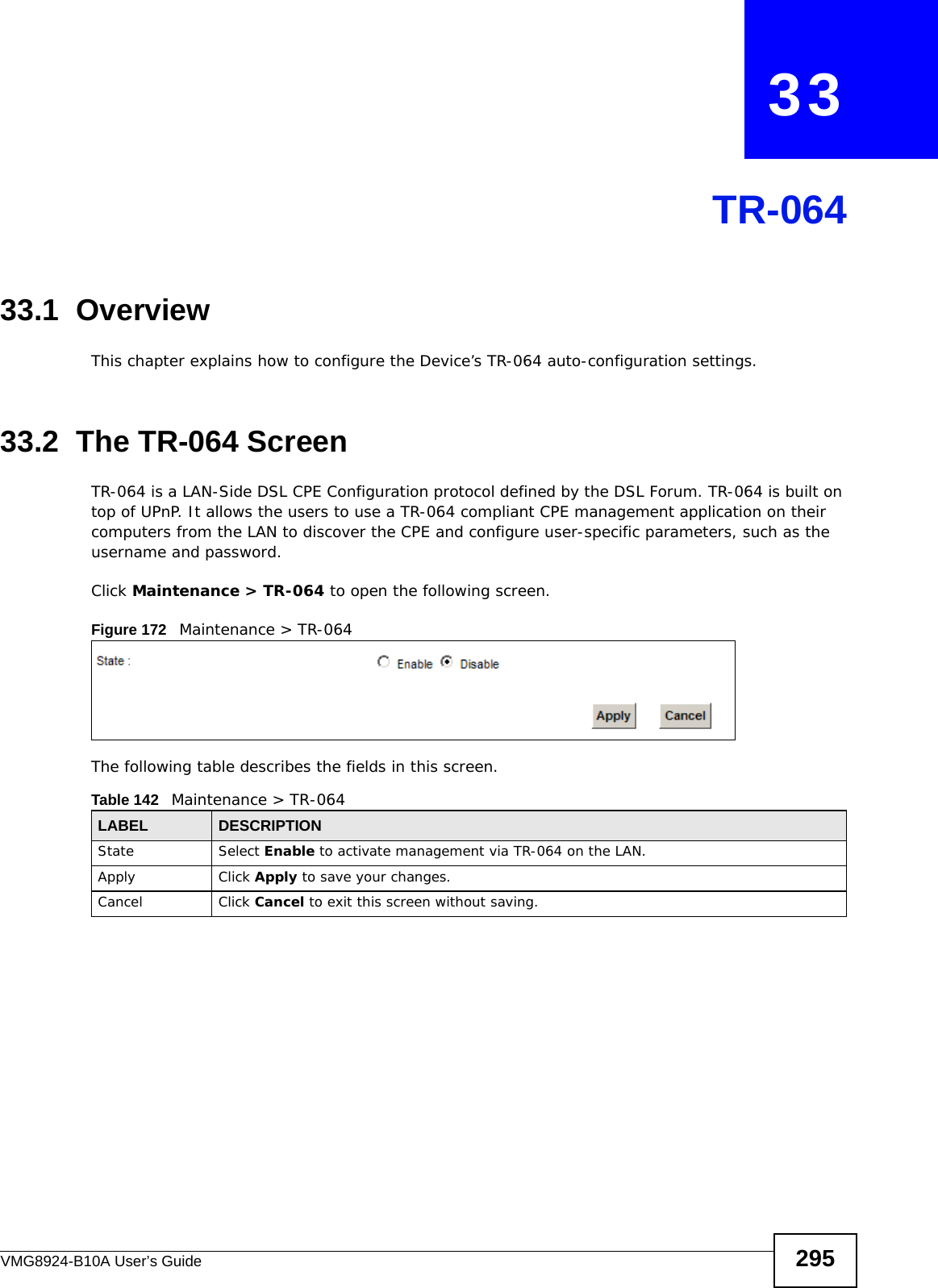
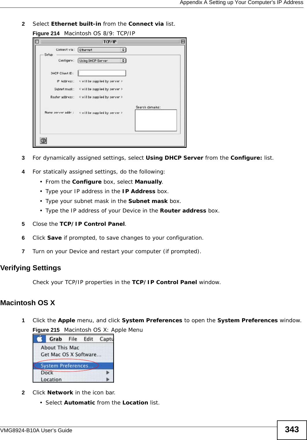
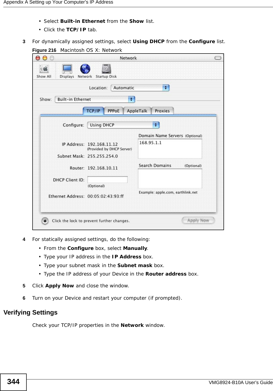
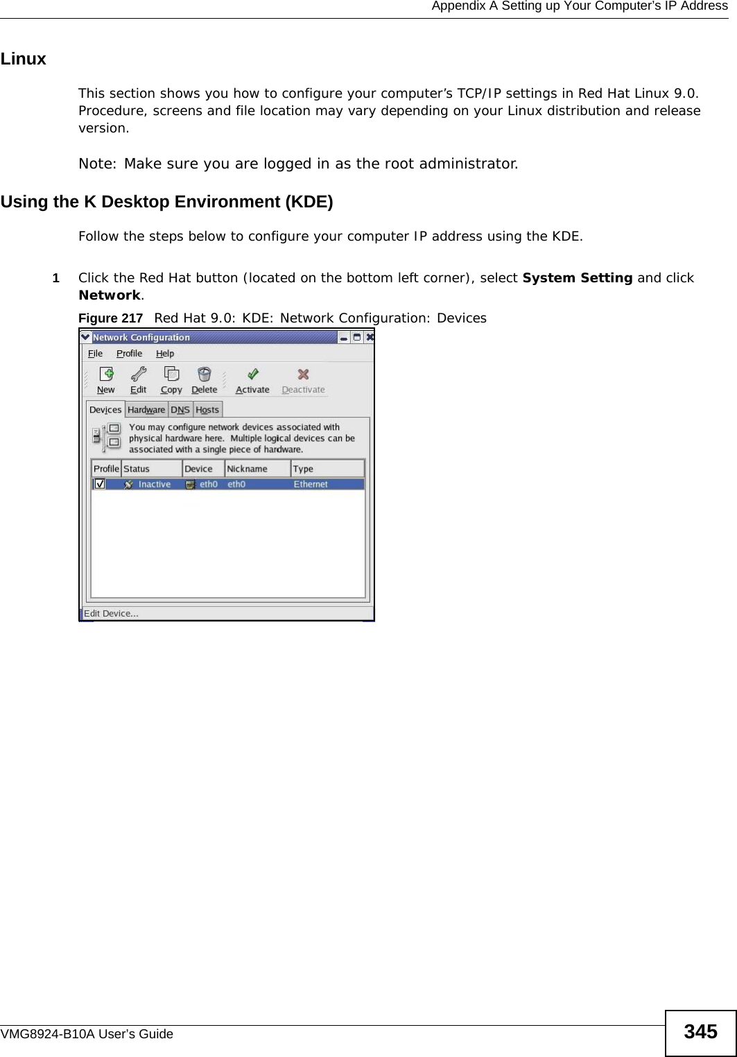
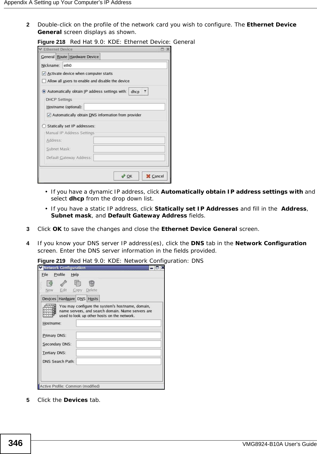
(VMG8924-B10A) User Manual-2
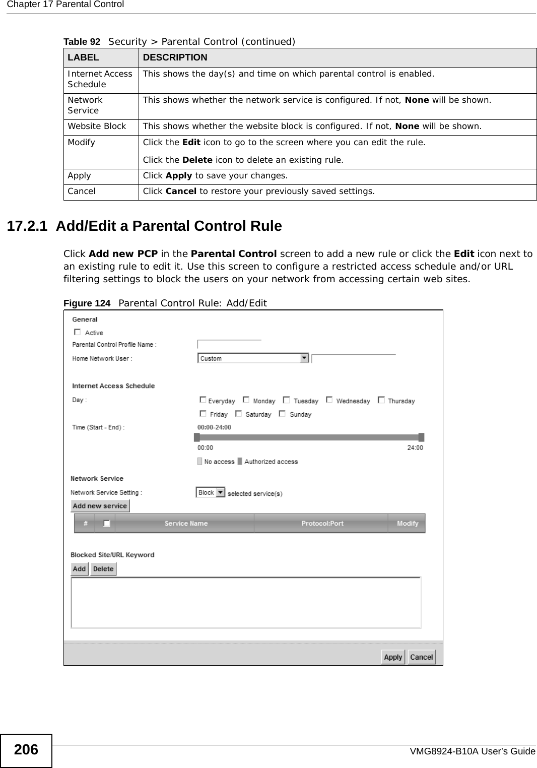

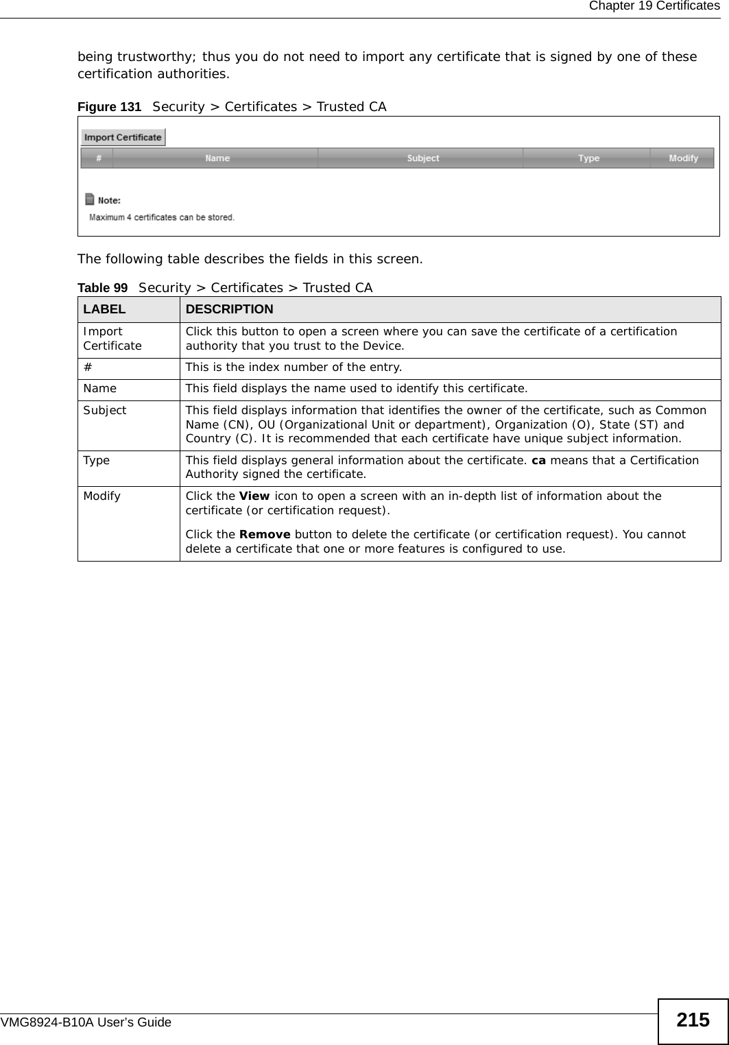


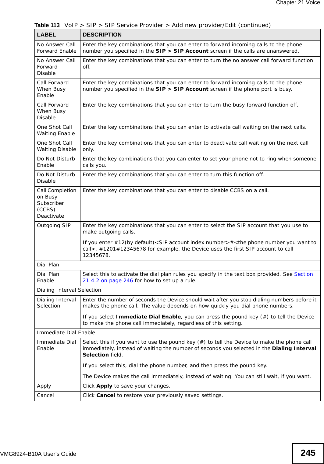
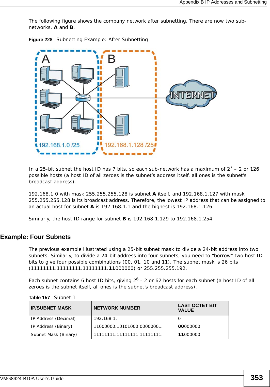
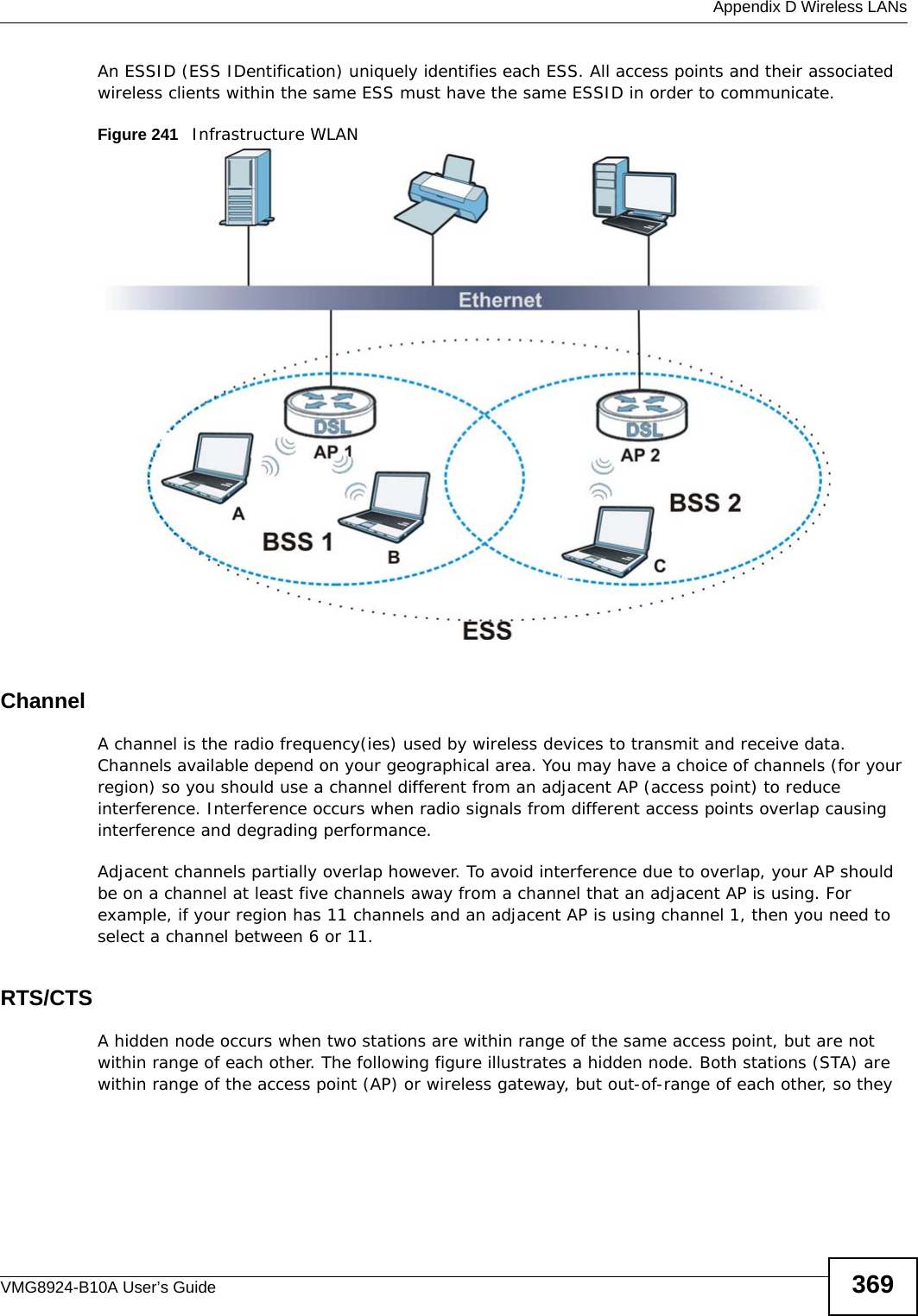
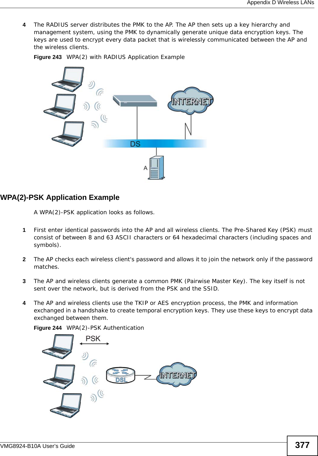
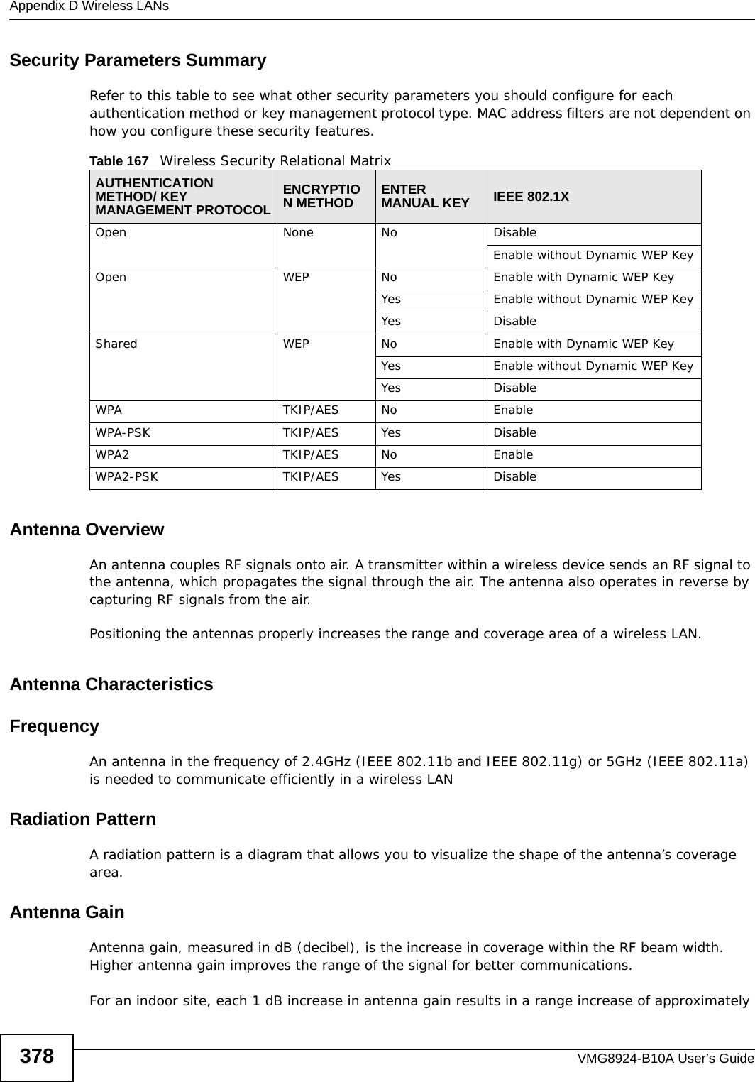
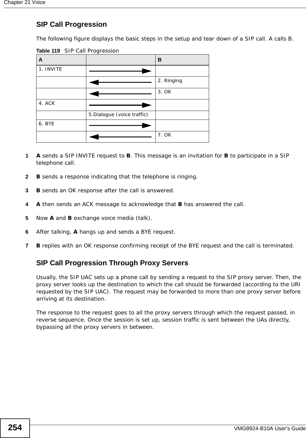
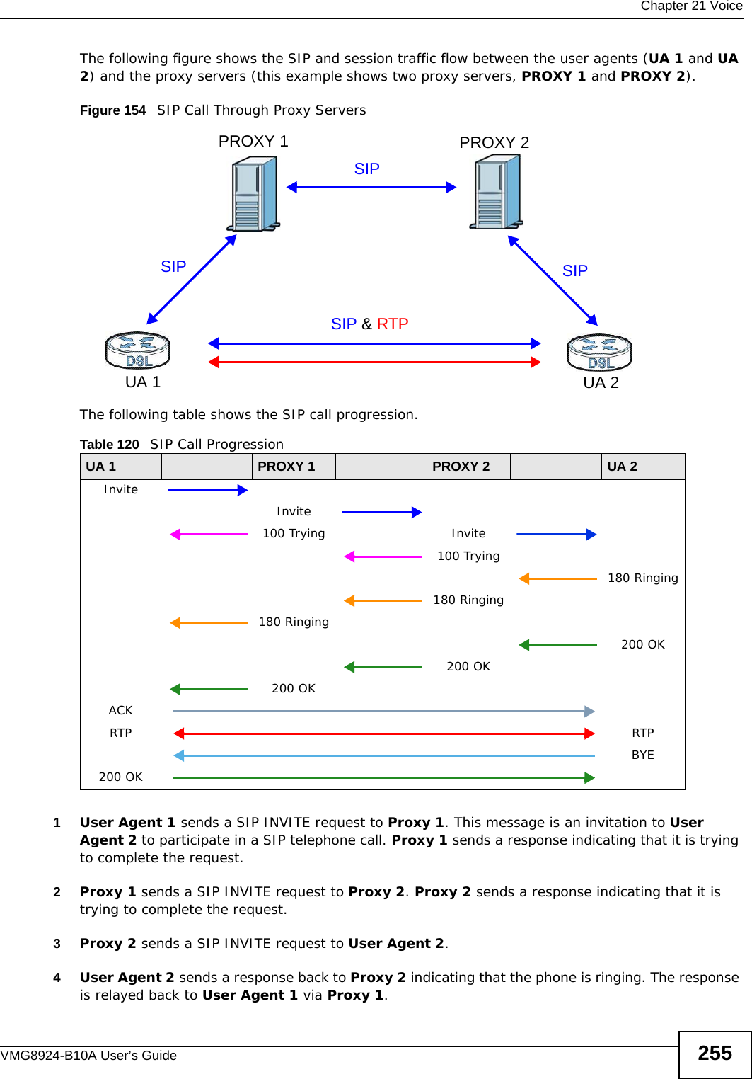
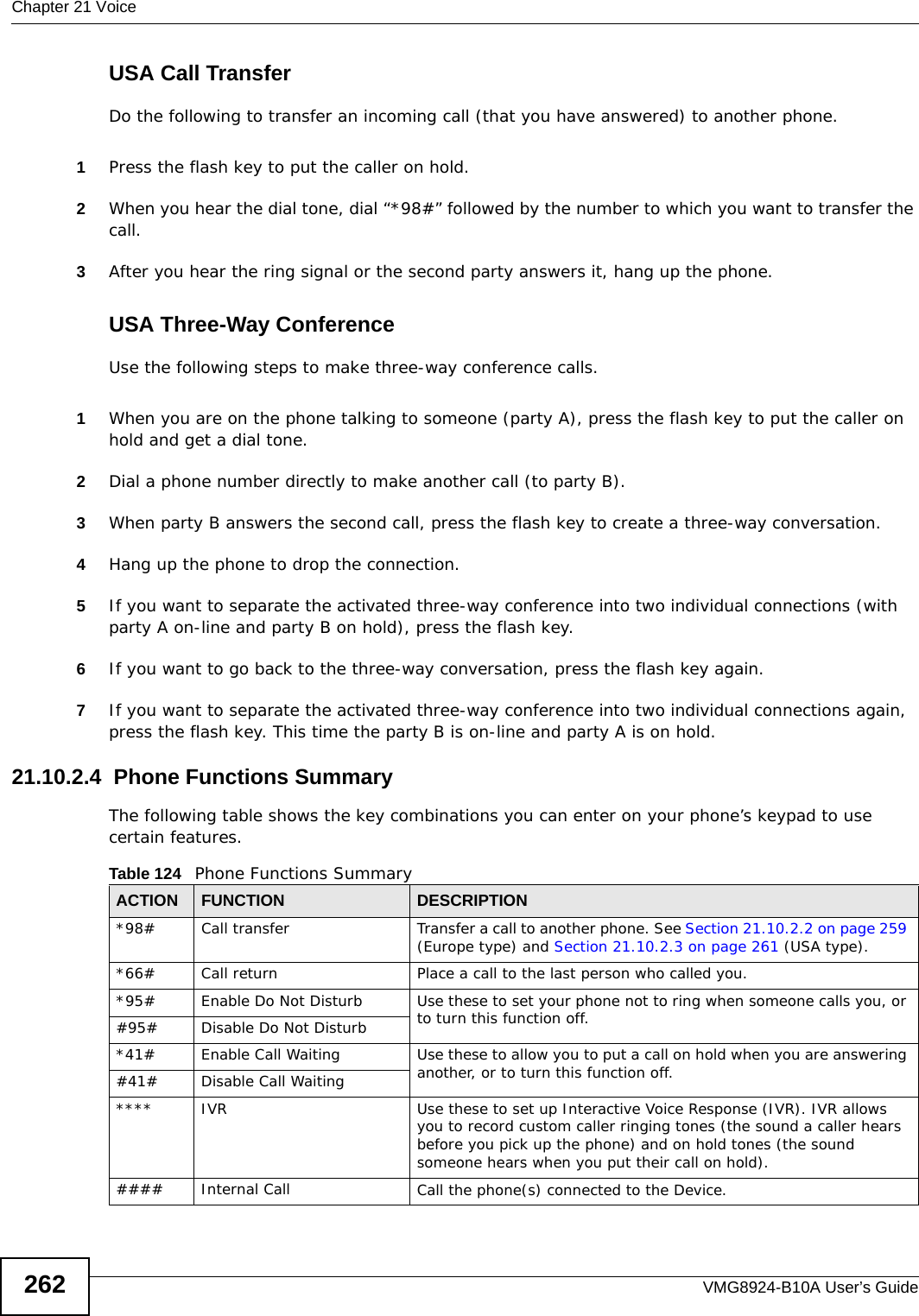
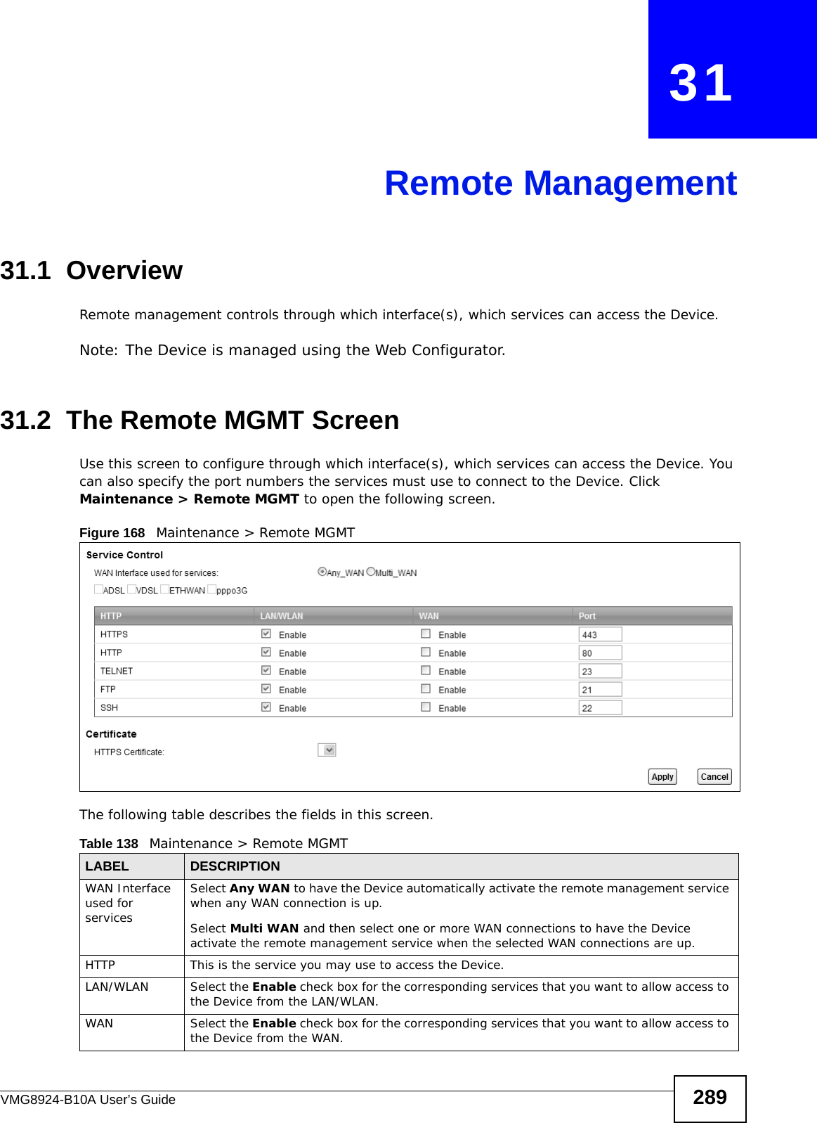
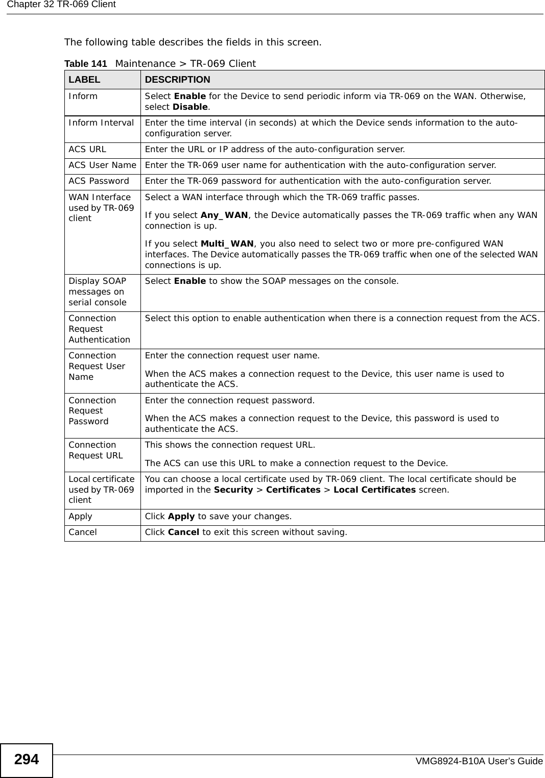
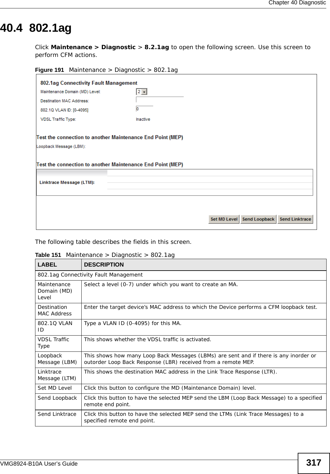
![Chapter 21 VoiceVMG8924-B10A User’s Guide24621.4.2 Dial Plan RulesA dial plan defines the dialing patterns, such as the length and range of the digits for a telephone number. It also includes country codes, access codes, area codes, local numbers, long distance numbers or international call prefixes. For example, the dial plan ([2-9]xxxxxx) does not allow a local number which begins with 1 or 0.Without a dial plan, users have to manually enter the whole callee’s number and wait for the specified dialing interval to time out or press a terminator key (usually the pound key on the phone keypad) before the Device makes the call.The Device initializes a call when the dialed number matches any one of the rules in the dial plan. Dial plan rules follow these conventions:• The collection of rules is in parentheses ().• Rules are separated by the | (bar) symbol.• “x” stands for a wildcard and can be any digit from 0 to 9.• A subset of keys is in a square bracket []. Ranges are allowed.For example, [359] means a number matching this rule can be 3, 5 or 9. [26-8*] means a number matching this rule can be 2, 6, 7, 8 or *.• The dot “.” appended to a digit allows the digit to be ignored or repeated multiple times. Any digit (0~9, *, #) after the dot will be ignored.For example, (01.) means a number matching this rule can be 0, 01, 0111, 01111, and so on.• <dialed-number:translated-number> indicates the number after the colon replaces the number before the colon in an angle bracket <>. For example, (<:1212> xxxxxxx) means the Device automatically prefixes the translated-number “1212” to the number you dialed before making the call. This can be used for local calls in the US.(<9:> xxx xxxxxxx) means the Device automatically removes the specified prefix “9” from the number you dialed before making the call. This is always used for making outside calls from an office. (xx<123:456>xxxx) means the Device automatically translates “123” to “456” in the number you dialed before making the call.• Calls with a number followed by the exclamation mark “!” will be dropped.• Calls with a number followed by the termination character “@” will be made immediately. Any digit (0~9, *, #) after the @ character will be ignored.In this example dial plan (0 | [49]11 | 1 [2-9]xx xxxxxxx | 1 947 xxxxxxx !), you can dial “0” to call the local operator, call 411 or 911, or make a long distance call with an area code starting from 2 to 9 in the US. The calls with the area code 947 will be dropped.](https://usermanual.wiki/ZyXEL-Communications/VMG8924B10A.VMG8924-B10A-User-Manual-2/User-Guide-2104365-Page-46.png)


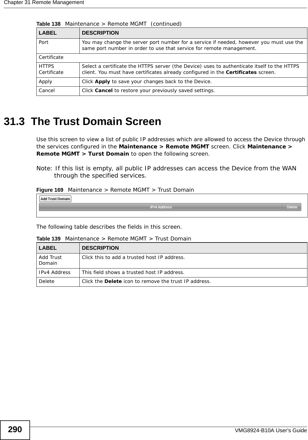


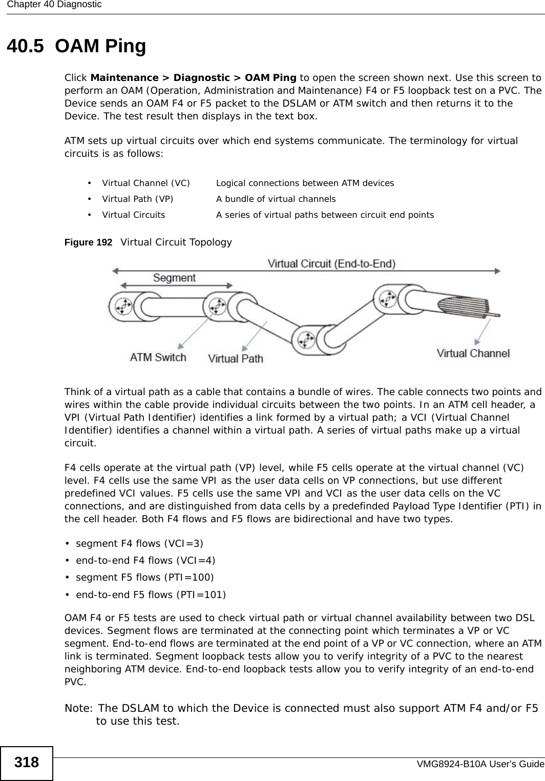

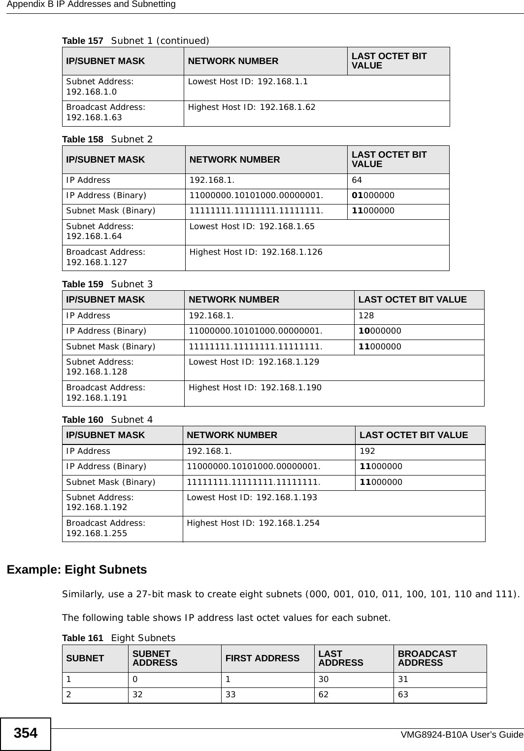
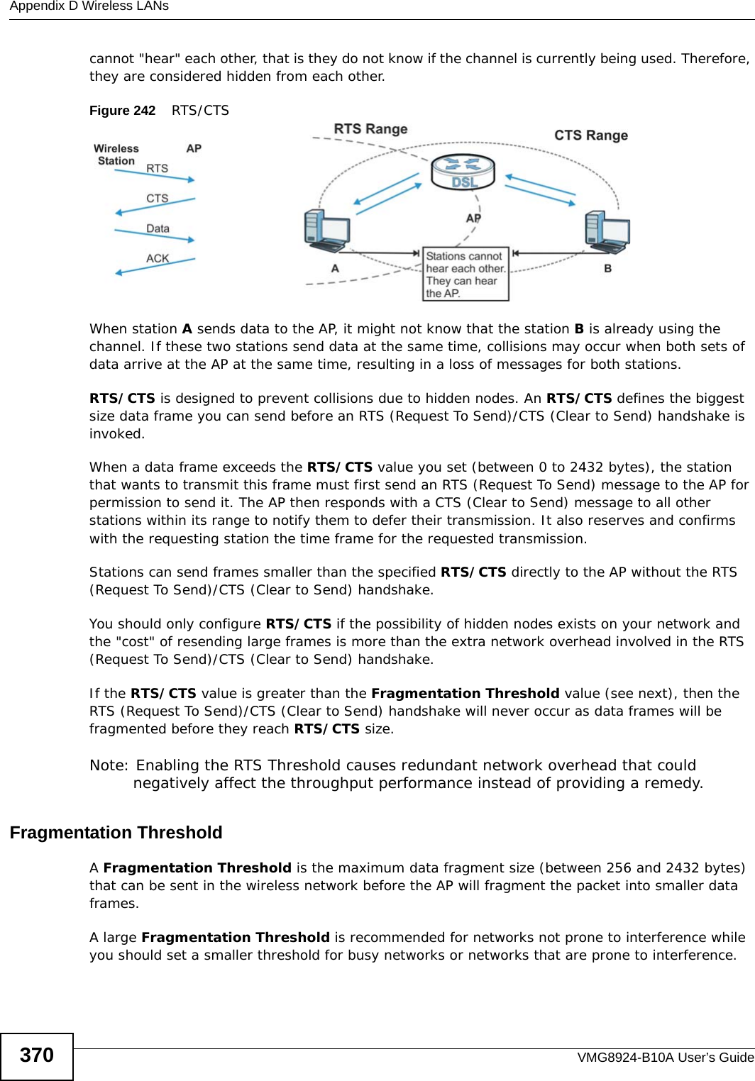
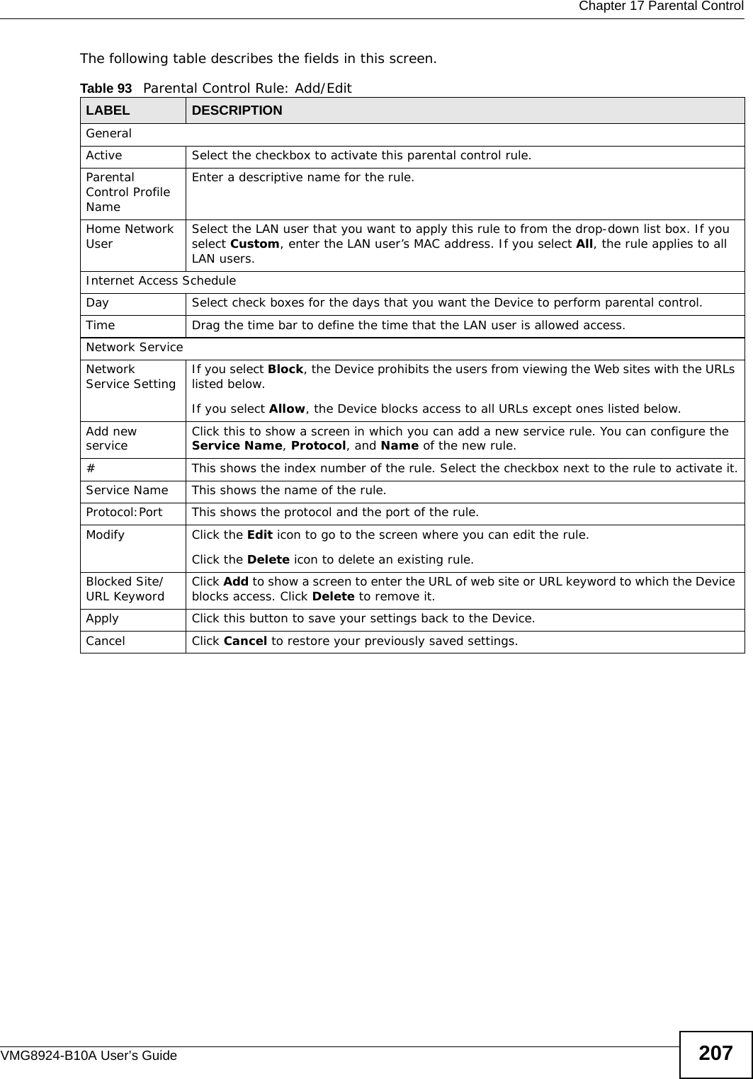
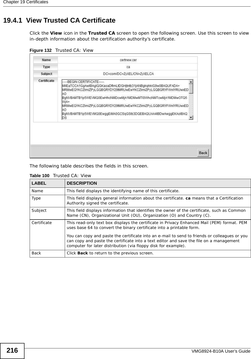
![Chapter 41 TroubleshootingVMG8924-B10A User’s Guide 3235Reset the device to its factory defaults, and try to access the Device with the default IP address. See Section 1.6 on page 22.6If the problem continues, contact the network administrator or vendor, or try one of the advanced suggestions.Advanced Suggestions• Make sure you have logged out of any earlier management sessions using the same user account even if they were through a different interface or using a different browser.• Try to access the Device using another service, such as Telnet. If you can access the Device, check the remote management settings and firewall rules to find out why the Device does not respond to HTTP. I can see the Login screen, but I cannot log in to the Device.1Make sure you have entered the password correctly. The default admin password is 1234. The field is case-sensitive, so make sure [Caps Lock] is not on. 2You cannot log in to the web configurator while someone is using Telnet to access the Device. Log out of the Device in the other session, or ask the person who is logged in to log out. 3Turn the Device off and on. 4If this does not work, you have to reset the device to its factory defaults. See Section 41.1 on page 321.I cannot Telnet to the Device.See the troubleshooting suggestions for I cannot see or access the Login screen in the web configurator. Ignore the suggestions about your browser.I cannot use FTP to upload / download the configuration file. / I cannot use FTP to upload new firmware.See the troubleshooting suggestions for I cannot see or access the Login screen in the web configurator. Ignore the suggestions about your browser.](https://usermanual.wiki/ZyXEL-Communications/VMG8924B10A.VMG8924-B10A-User-Manual-2/User-Guide-2104365-Page-123.png)
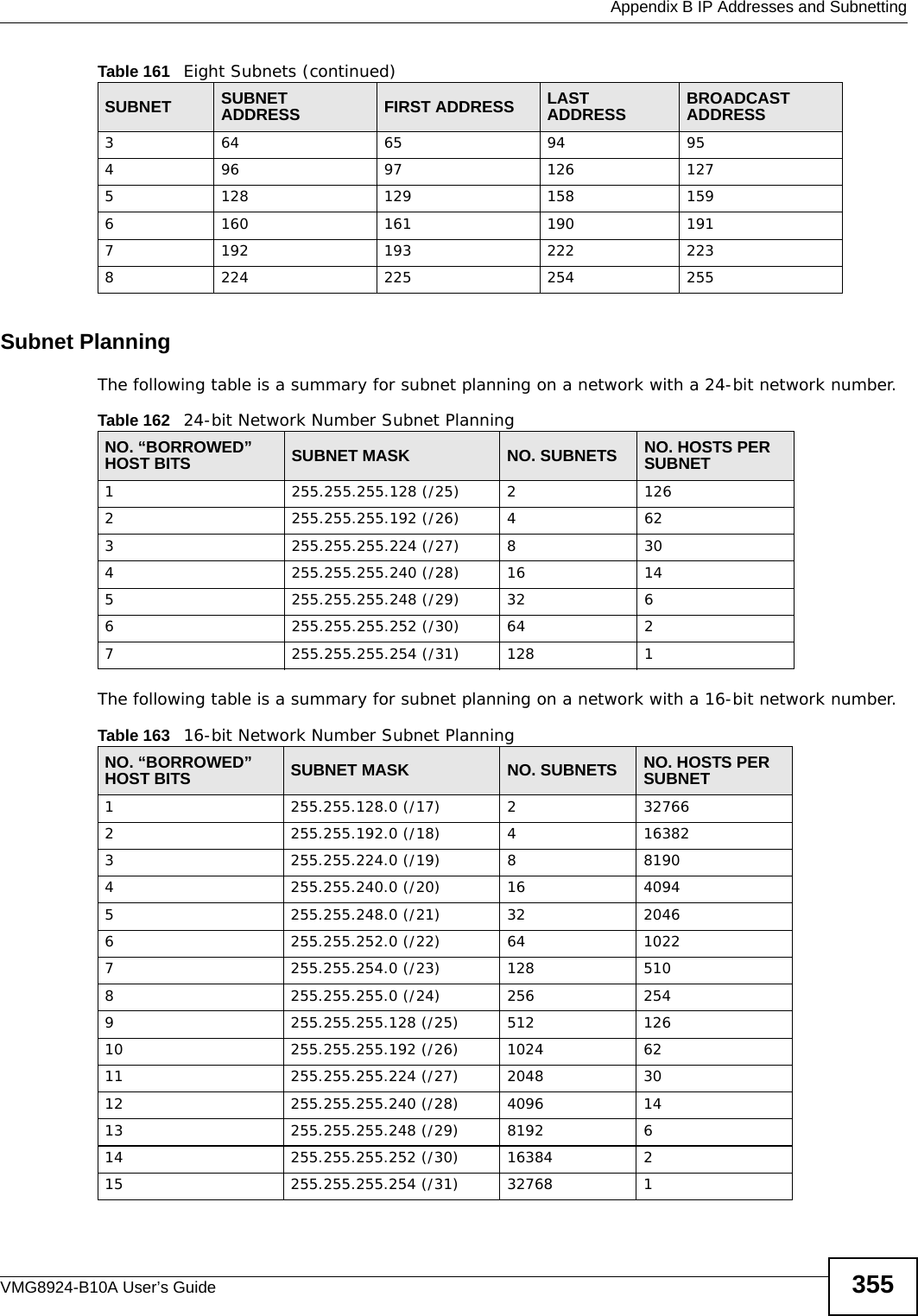
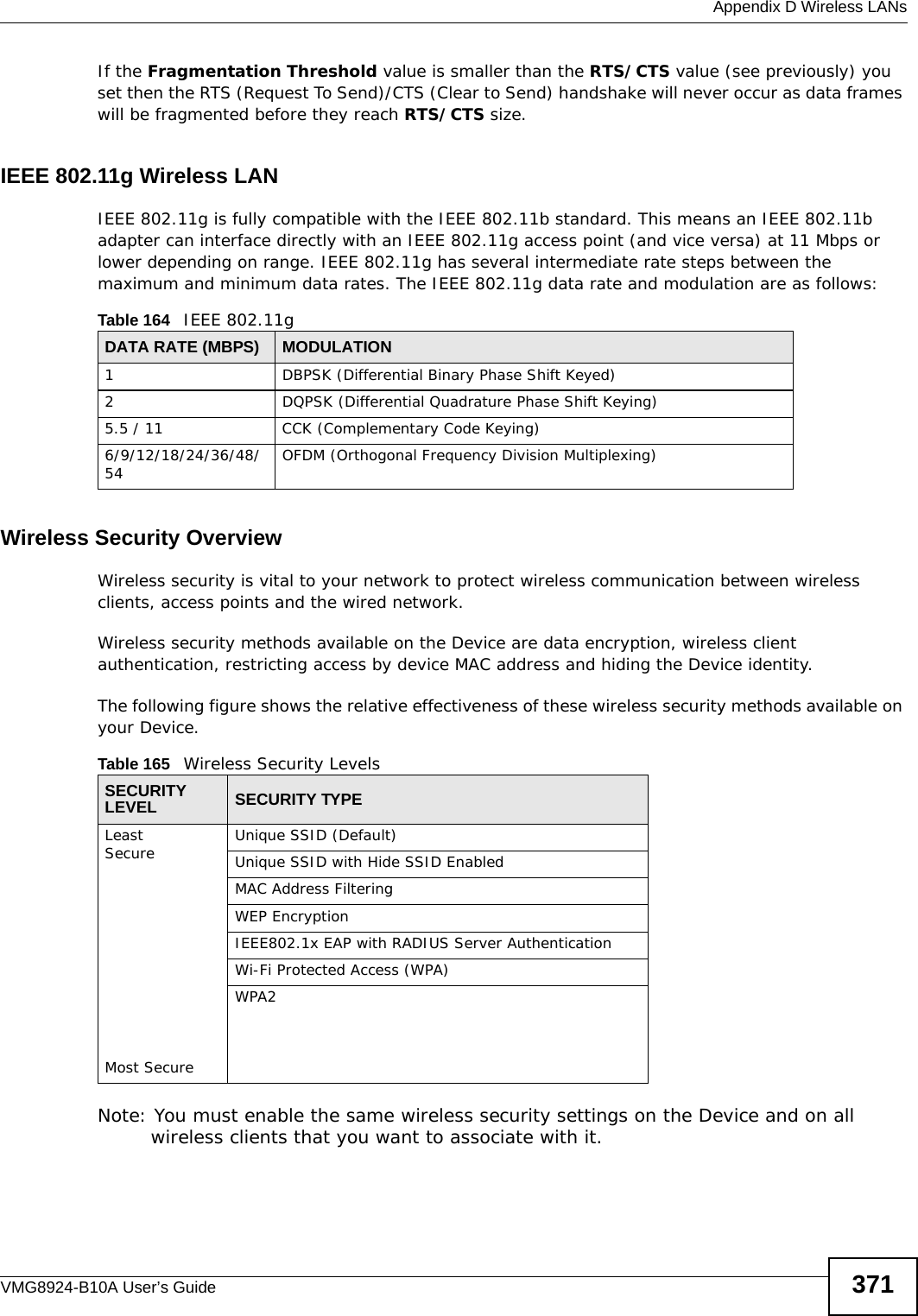
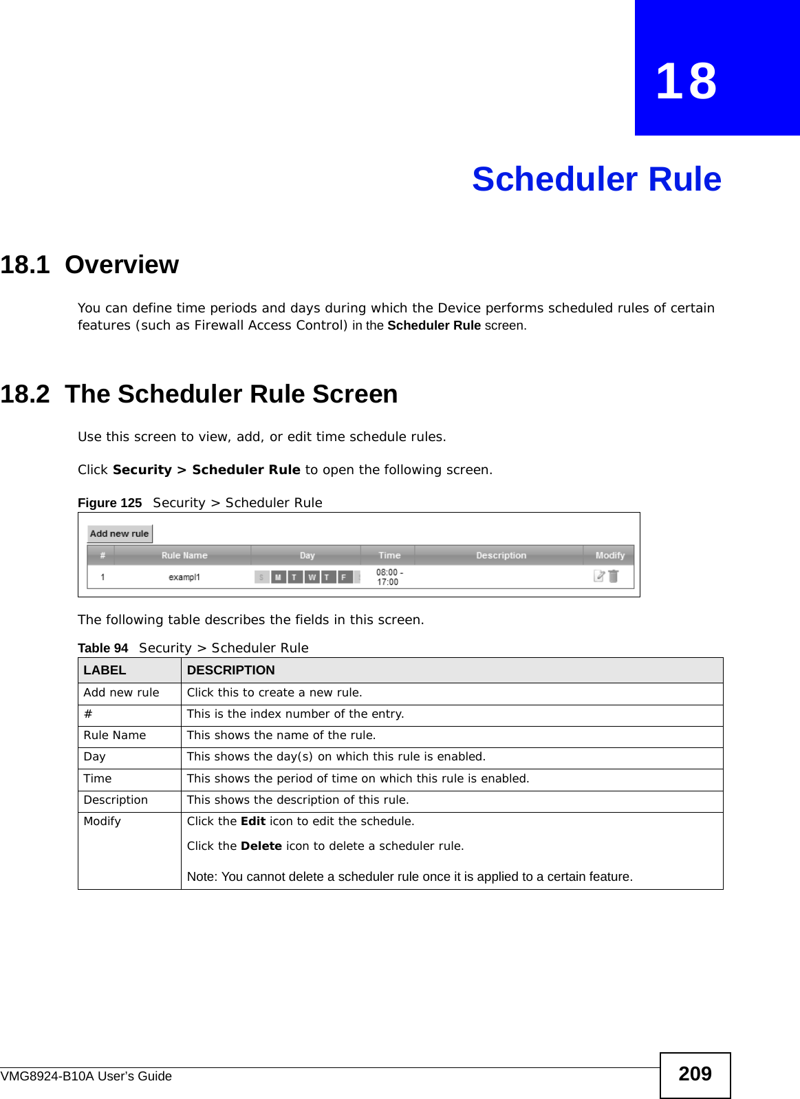
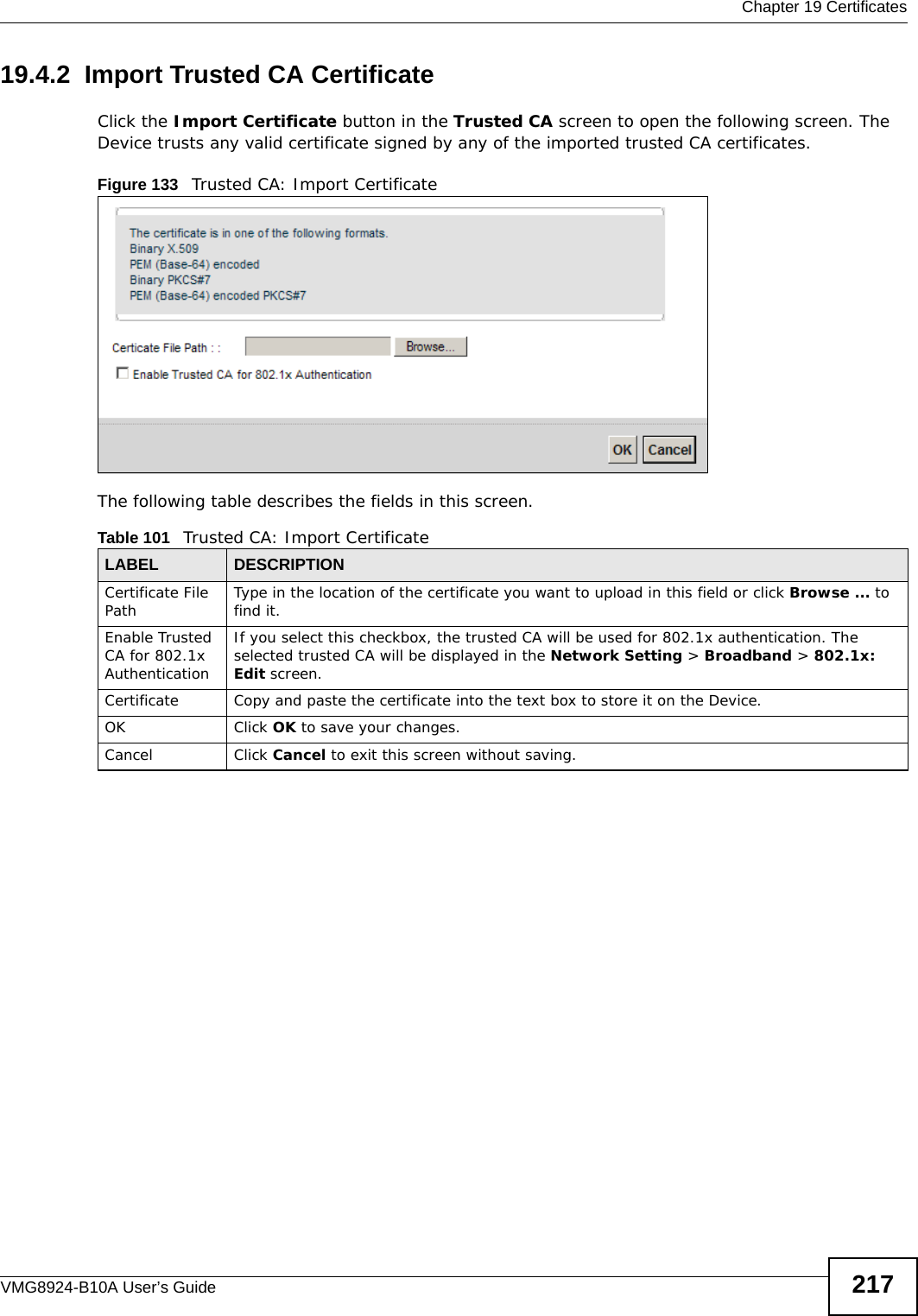
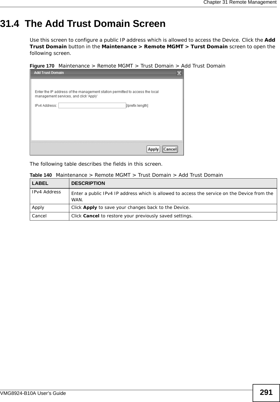
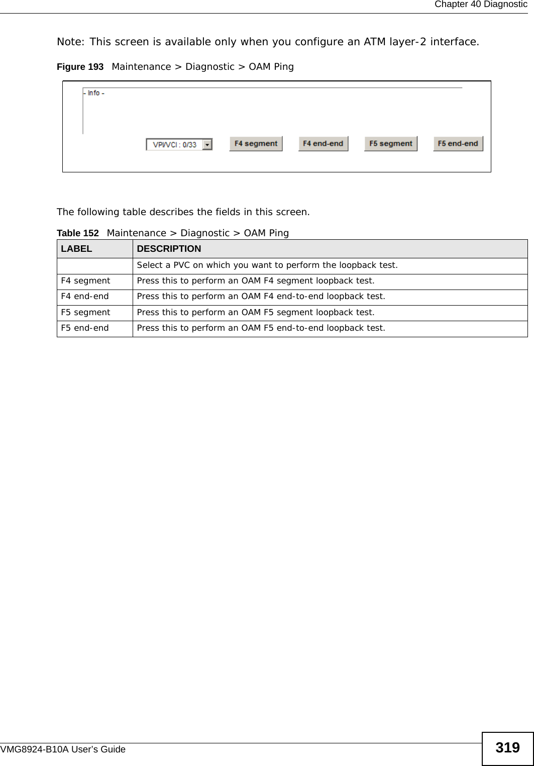
![Chapter 41 TroubleshootingVMG8924-B10A User’s Guide32441.3 Internet AccessI cannot access the Internet.1Check the hardware connections, and make sure the LEDs are behaving as expected. See the Quick Start Guide and Section 1.5 on page 20.2Make sure you entered your ISP account information correctly in the Network Setting > Broadband screen. These fields are case-sensitive, so make sure [Caps Lock] is not on. 3If you are trying to access the Internet wirelessly, make sure that you enabled the wireless LAN in the Device and your wireless client and that the wireless settings in the wireless client are the same as the settings in the Device.4Disconnect all the cables from your device and reconnect them. 5If the problem continues, contact your ISP. I cannot access the Internet through a DSL connection.1Make sure you have the DSL WAN port connected to a telephone jack (or the DSL or modem jack on a splitter if you have one).2Make sure you configured a proper DSL WAN interface (Network Setting > Broadband screen) with the Internet account information provided by your ISP and that it is enabled.3Check that the LAN interface you are connected to is in the same interface group as the DSL connection (Network Setting > Interface Group).4If you set up a WAN connection using bridging service, make sure you turn off the DHCP feature in the LAN screen to have the clients get WAN IP addresses directly from your ISP’s DHCP server.I cannot connect to the Internet using a second DSL connection.ADSL and VDSL connections cannot work at the same time. You can only use one type of DSL connection, either ADSL or VDSL connection at one time.I cannot access the Internet anymore. I had access to the Internet (with the Device), but my Internet connection is not available anymore.1Your session with the Device may have expired. Try logging into the Device again.](https://usermanual.wiki/ZyXEL-Communications/VMG8924B10A.VMG8924-B10A-User-Manual-2/User-Guide-2104365-Page-124.png)
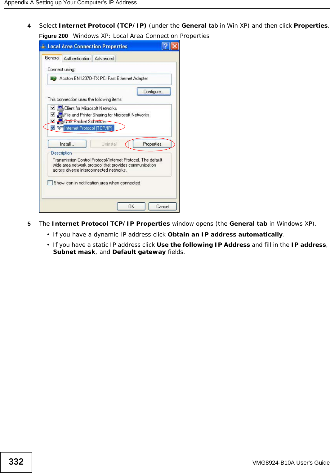
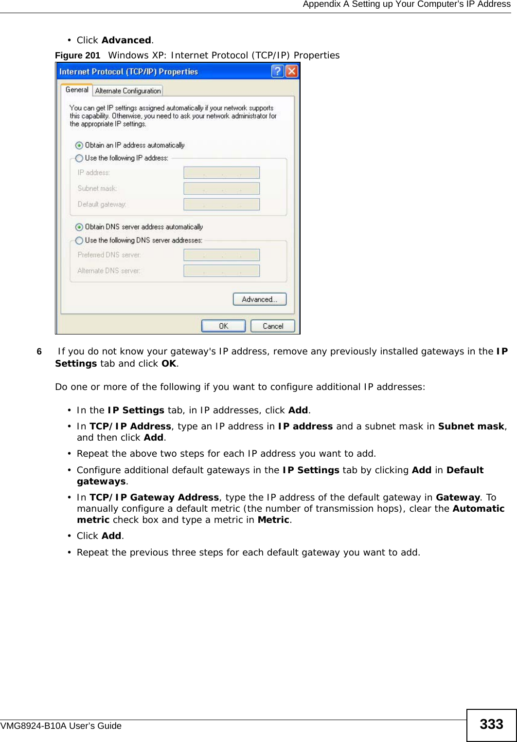
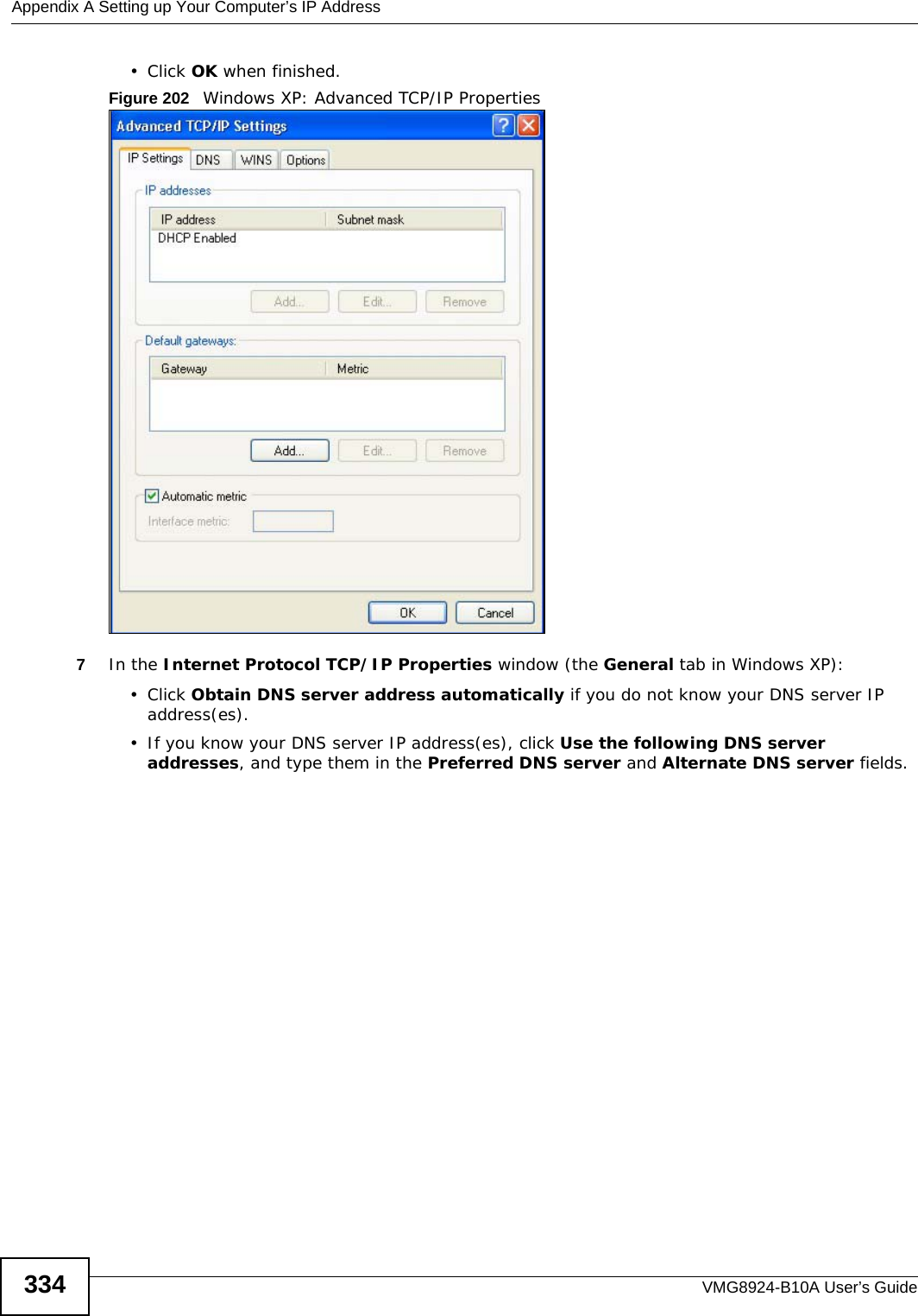
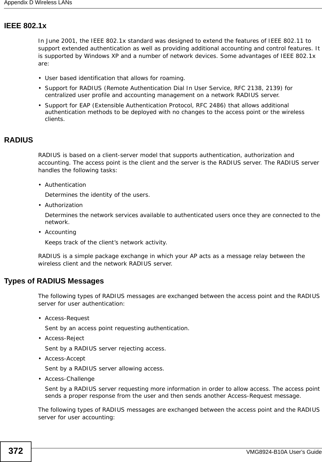
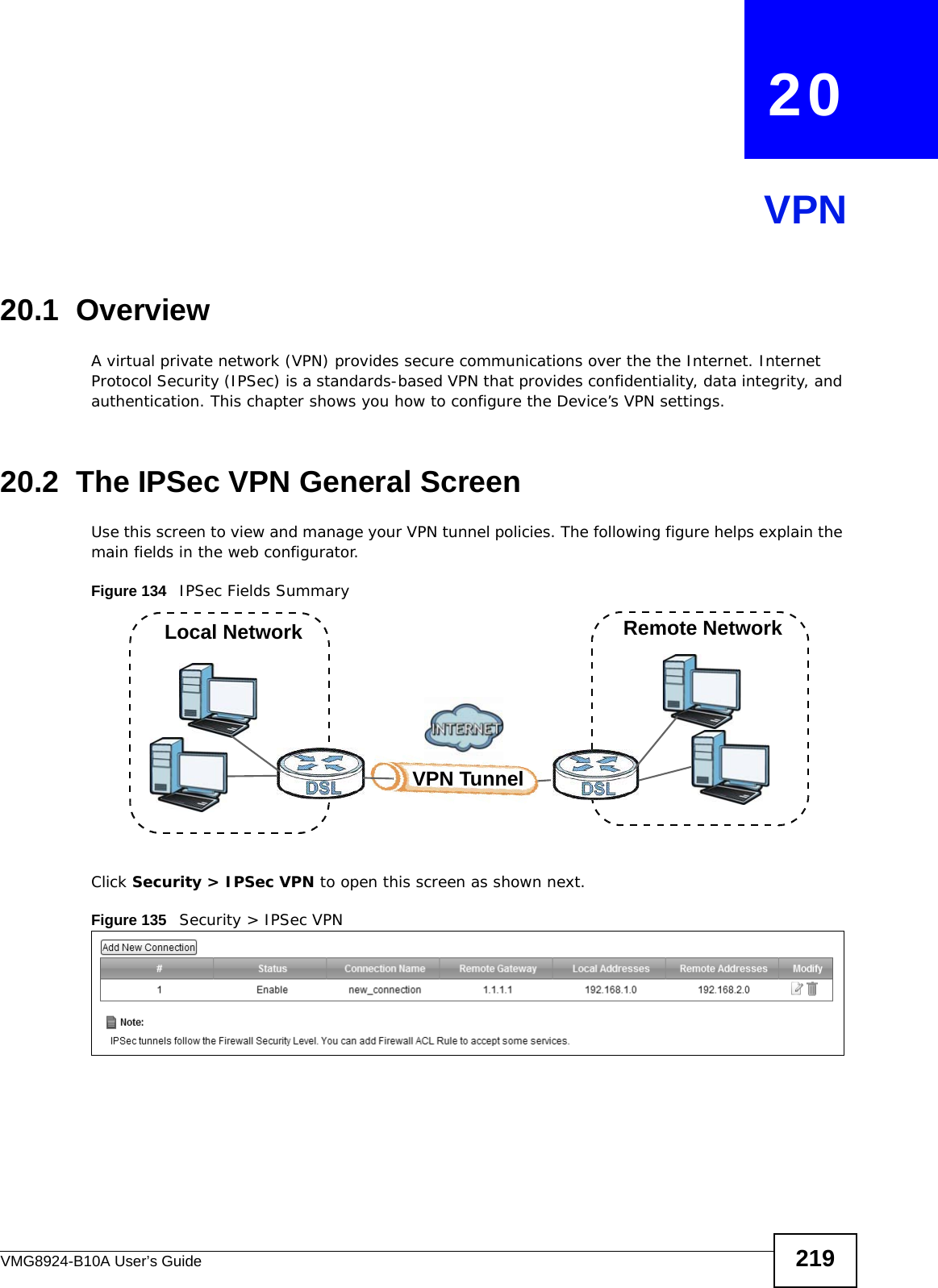
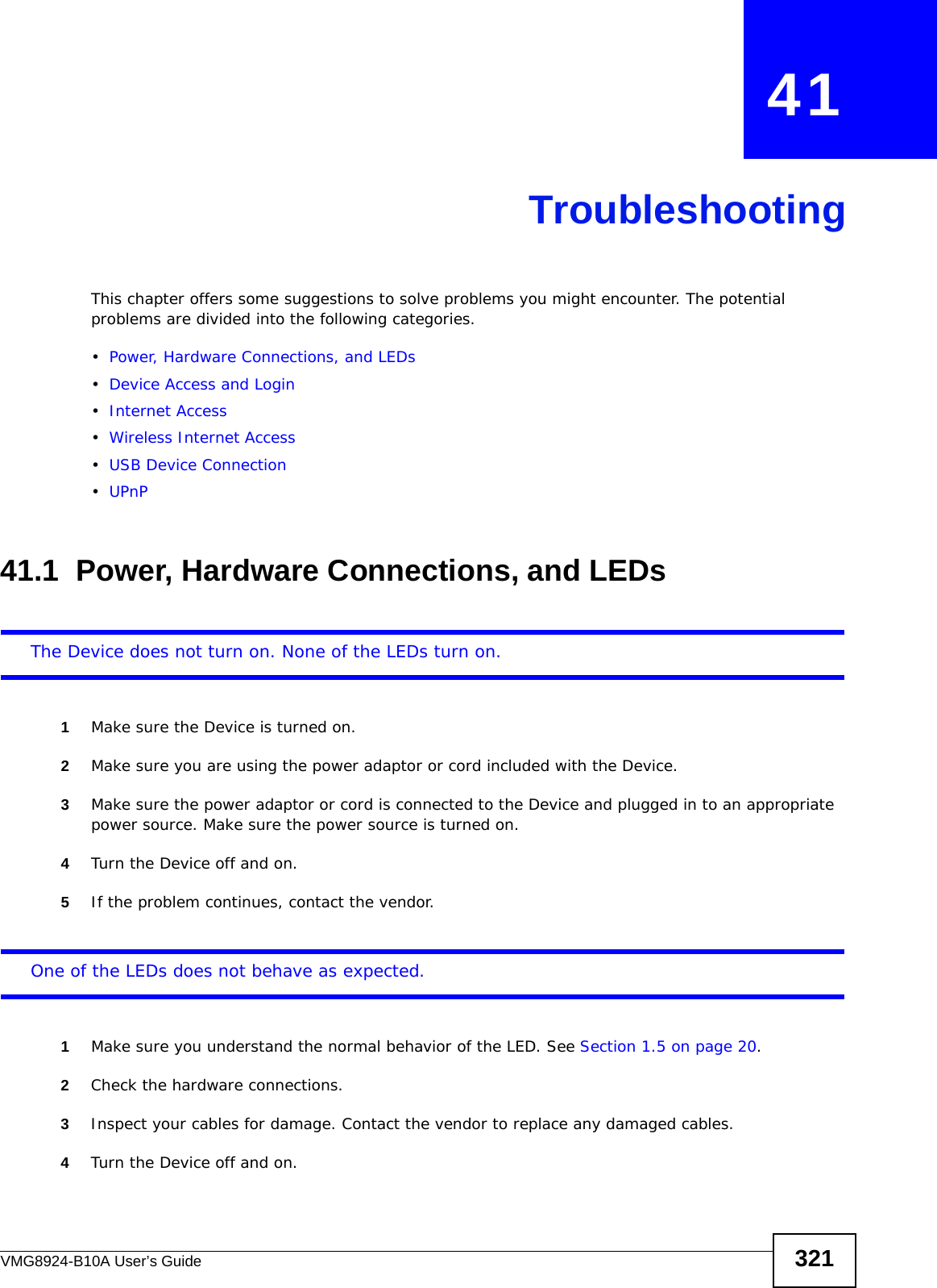
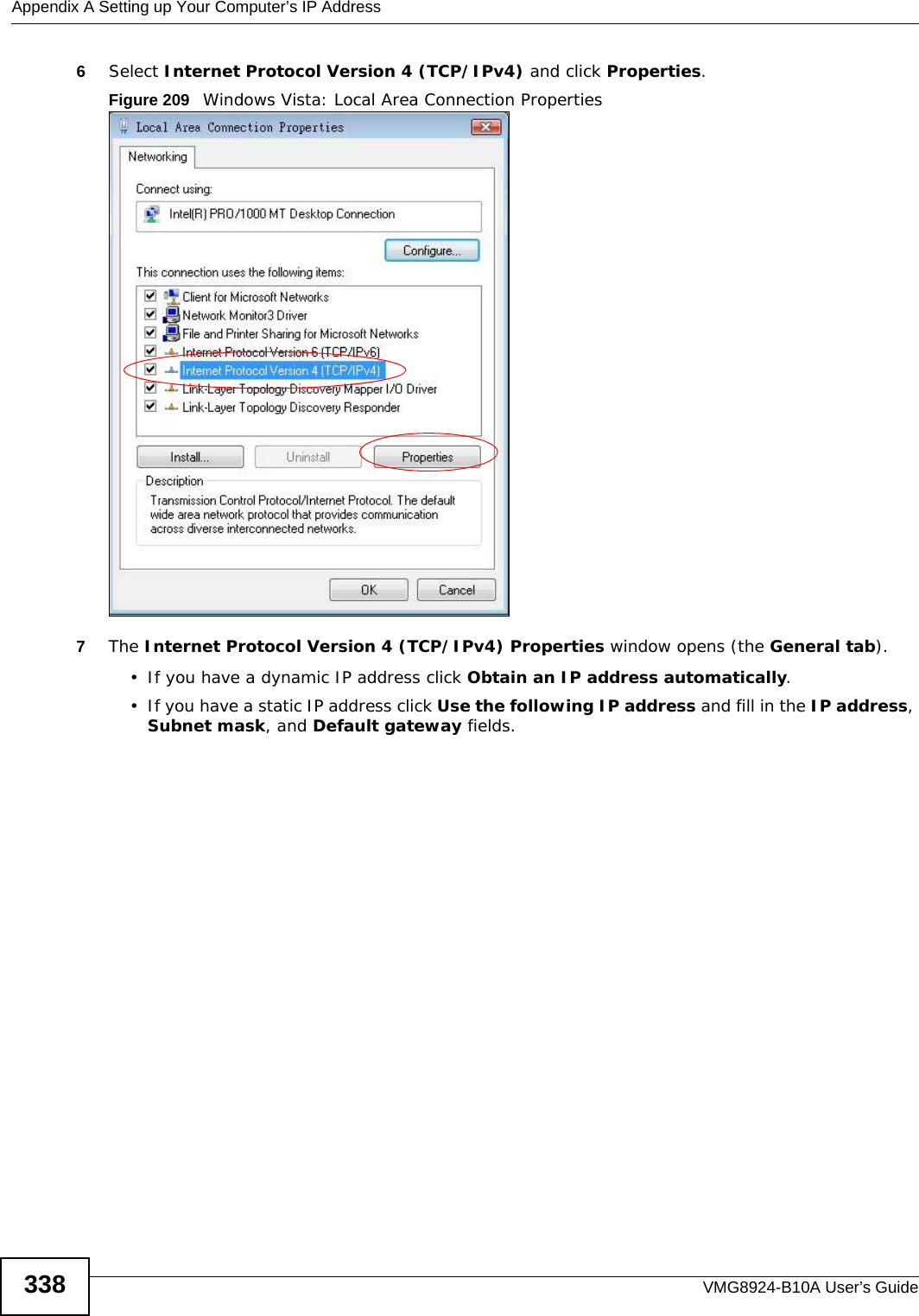
![Appendix A Setting up Your Computer’s IP AddressVMG8924-B10A User’s Guide 335If you have previously configured DNS servers, click Advanced and then the DNS tab to order them.Figure 203 Windows XP: Internet Protocol (TCP/IP) Properties8Click OK to close the Internet Protocol (TCP/IP) Properties window.9Click Close (OK in Windows 2000/NT) to close the Local Area Connection Properties window.10 Close the Network Connections window (Network and Dial-up Connections in Windows 2000/NT).11 Turn on your Device and restart your computer (if prompted).Verifying Settings1Click Start, All Programs, Accessories and then Command Prompt.2In the Command Prompt window, type "ipconfig" and then press [ENTER]. You can also open Network Connections, right-click a network connection, click Status and then click the Support tab.Windows VistaThis section shows screens from Windows Vista Enterprise Version 6.0.](https://usermanual.wiki/ZyXEL-Communications/VMG8924B10A.VMG8924-B10A-User-Manual-2/User-Guide-2104365-Page-135.png)

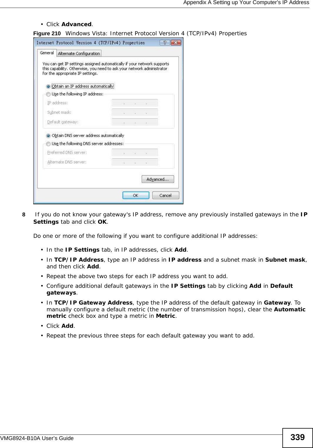
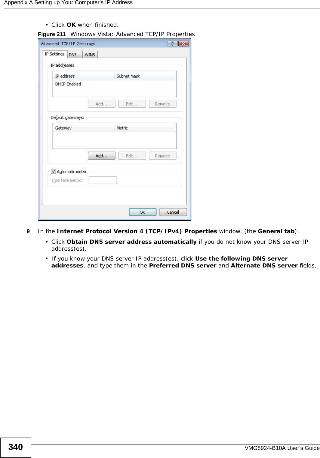
![Appendix A Setting up Your Computer’s IP AddressVMG8924-B10A User’s Guide 341If you have previously configured DNS servers, click Advanced and then the DNS tab to order them.Figure 212 Windows Vista: Internet Protocol Version 4 (TCP/IPv4) Properties10 Click OK to close the Internet Protocol Version 4 (TCP/IPv4) Properties window.11 Click Close to close the Local Area Connection Properties window.12 Close the Network Connections window.13 Turn on your Device and restart your computer (if prompted).Verifying Settings1Click Start, All Programs, Accessories and then Command Prompt.2In the Command Prompt window, type "ipconfig" and then press [ENTER]. You can also open Network Connections, right-click a network connection, click Status and then click the Support tab.](https://usermanual.wiki/ZyXEL-Communications/VMG8924B10A.VMG8924-B10A-User-Manual-2/User-Guide-2104365-Page-141.png)
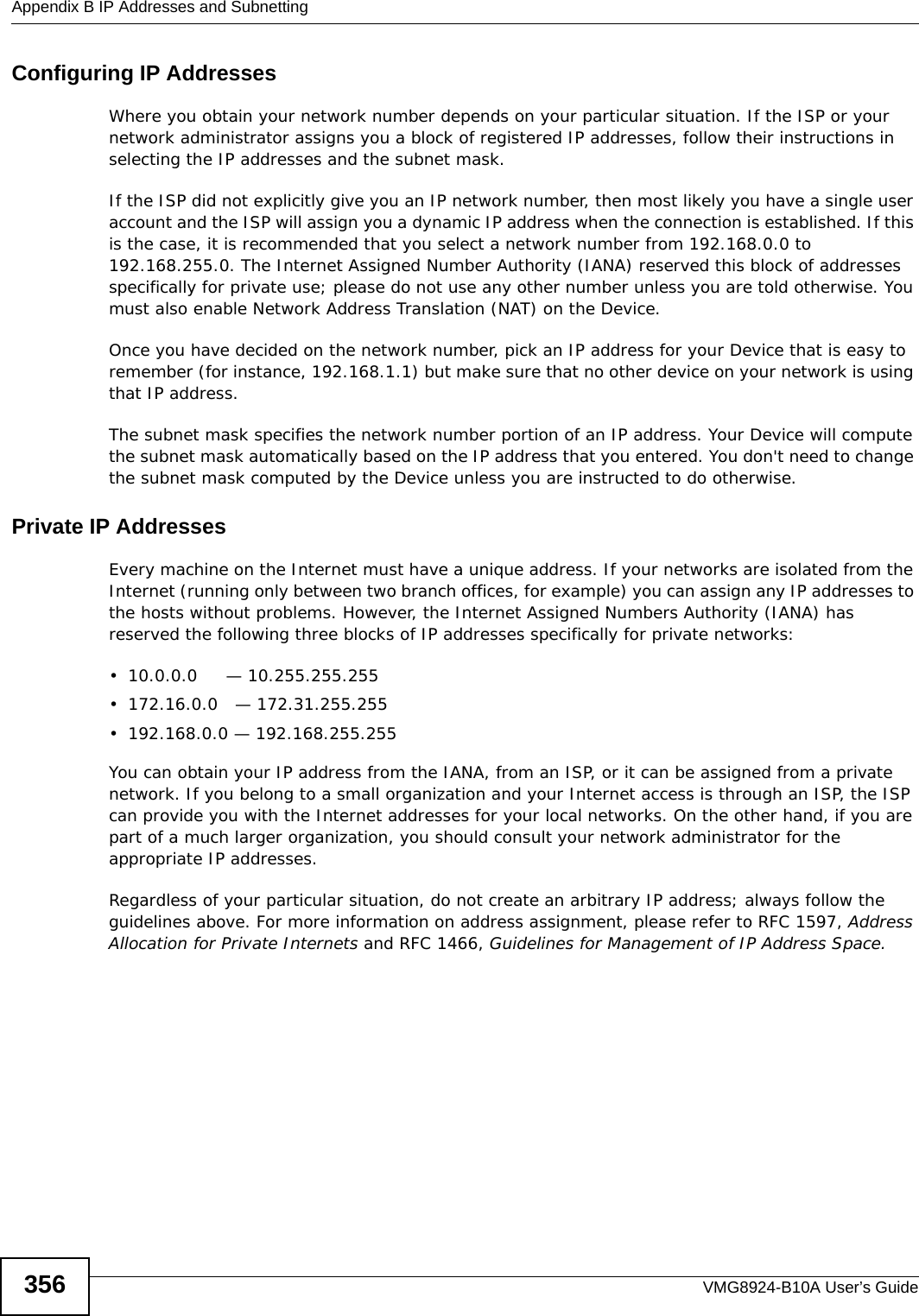
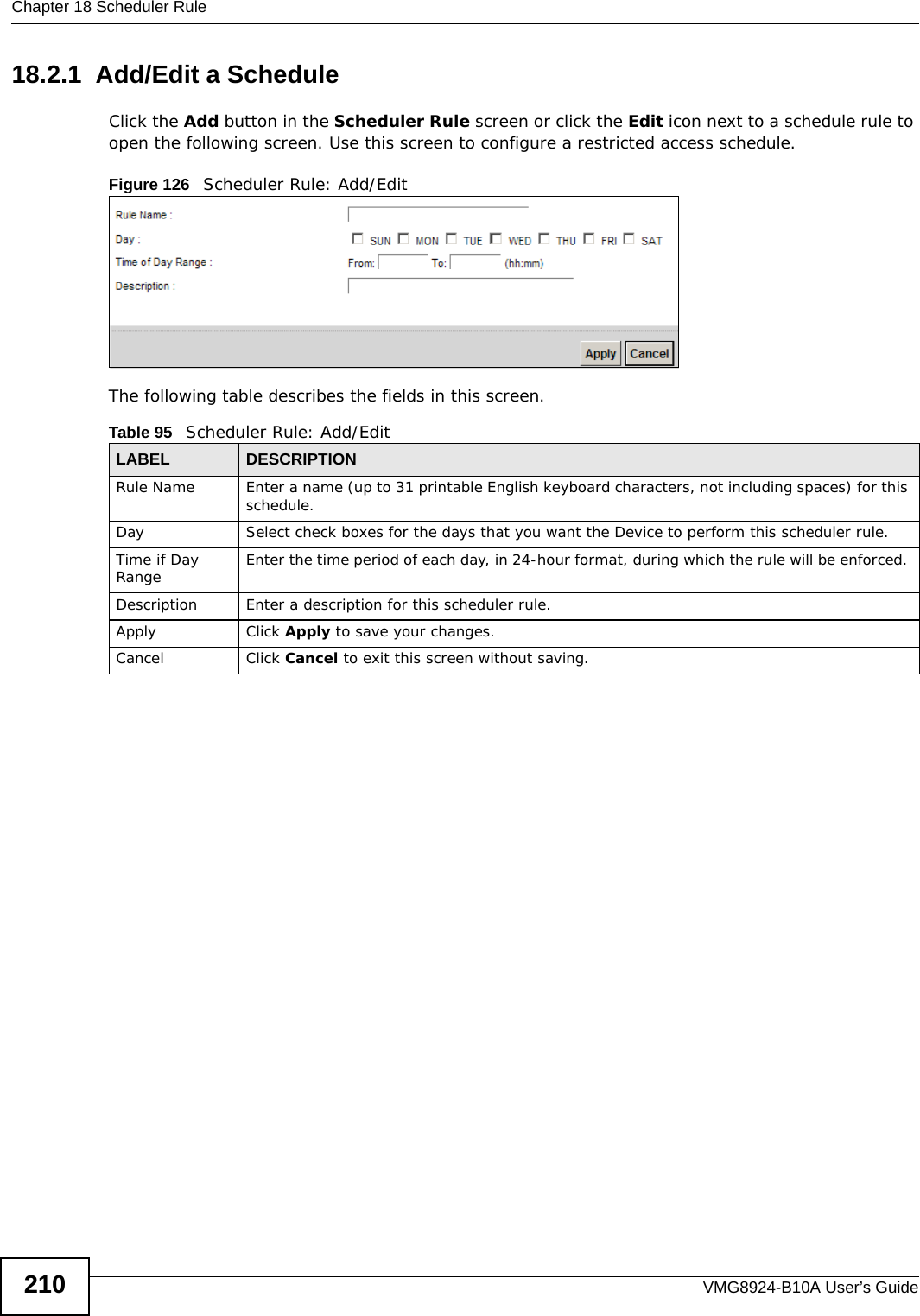
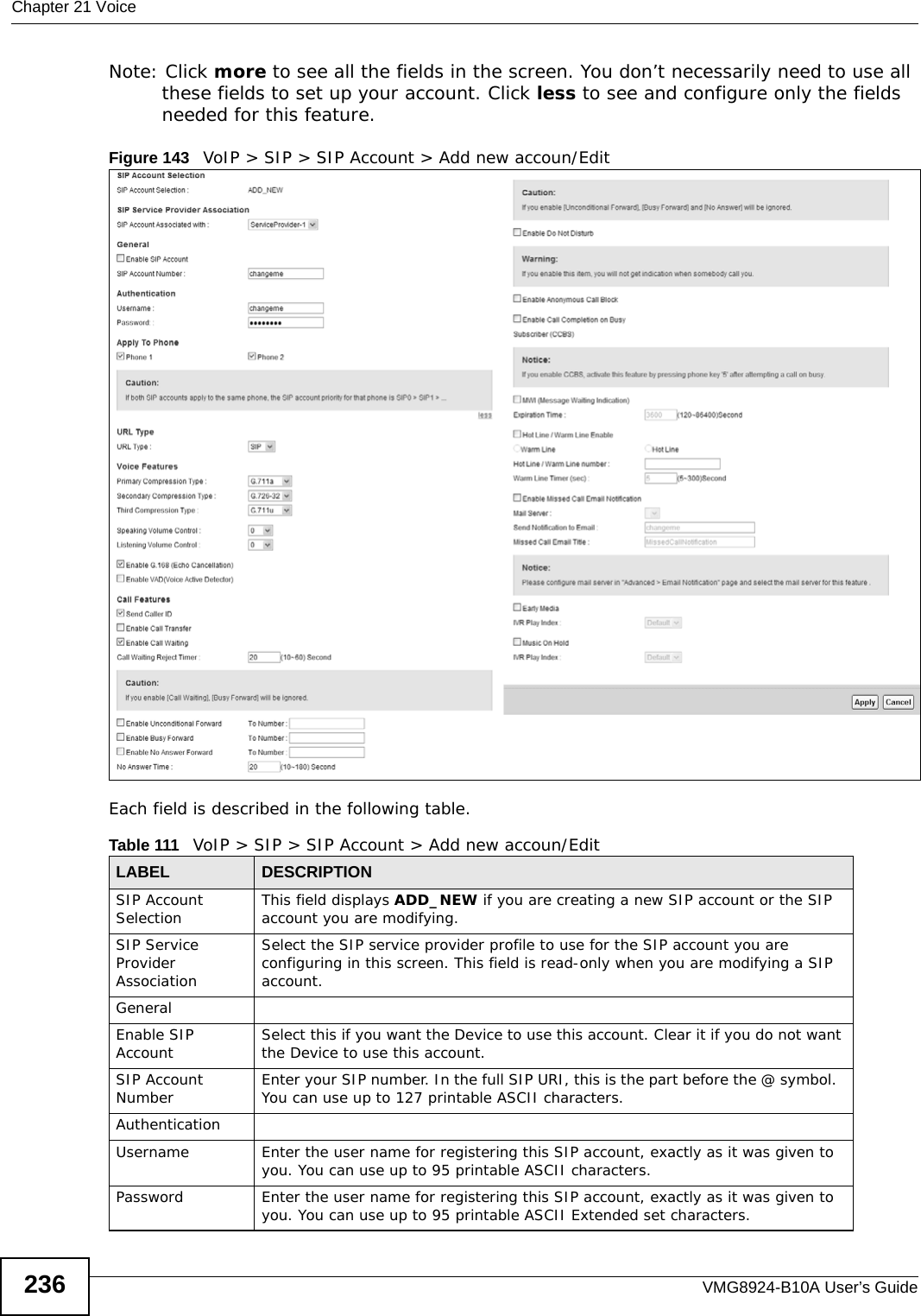
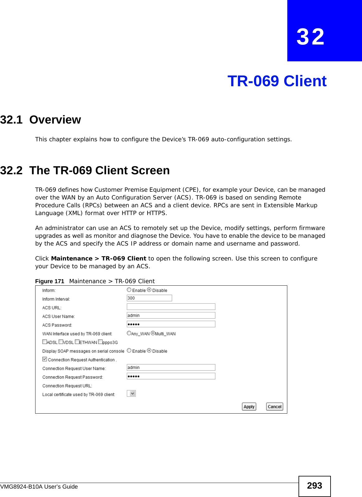
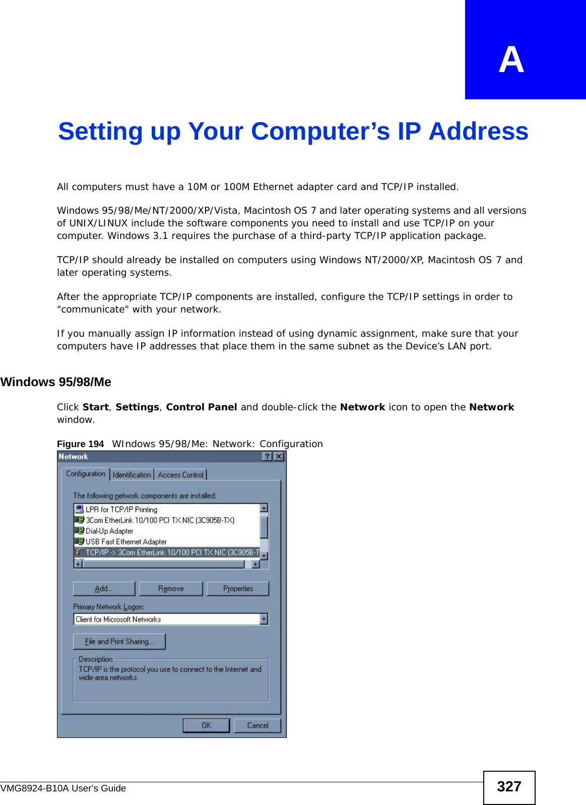
![Appendix A Setting up Your Computer’s IP AddressVMG8924-B10A User’s Guide3482If you know your DNS server IP address(es), enter the DNS server information in the resolv.conf file in the /etc directory. The following figure shows an example where two DNS server IP addresses are specified.Figure 223 Red Hat 9.0: DNS Settings in resolv.conf 3After you edit and save the configuration files, you must restart the network card. Enter ./network restart in the /etc/rc.d/init.d directory. The following figure shows an example.Figure 224 Red Hat 9.0: Restart Ethernet Card Verifying SettingsEnter ifconfig in a terminal screen to check your TCP/IP properties. Figure 225 Red Hat 9.0: Checking TCP/IP Properties nameserver 172.23.5.1nameserver 172.23.5.2[root@localhost init.d]# network restartShutting down interface eth0: [OK]Shutting down loopback interface: [OK]Setting network parameters: [OK]Bringing up loopback interface: [OK]Bringing up interface eth0: [OK][root@localhost]# ifconfig eth0 Link encap:Ethernet HWaddr 00:50:BA:72:5B:44 inet addr:172.23.19.129 Bcast:172.23.19.255 Mask:255.255.255.0 UP BROADCAST RUNNING MULTICAST MTU:1500 Metric:1 RX packets:717 errors:0 dropped:0 overruns:0 frame:0 TX packets:13 errors:0 dropped:0 overruns:0 carrier:0 collisions:0 txqueuelen:100 RX bytes:730412 (713.2 Kb) TX bytes:1570 (1.5 Kb) Interrupt:10 Base address:0x1000 [root@localhost]#](https://usermanual.wiki/ZyXEL-Communications/VMG8924B10A.VMG8924-B10A-User-Manual-2/User-Guide-2104365-Page-148.png)