ZyXEL Communications WAC5302D-S 802.11ac Wall-Plate Unified Access Point User Manual Book
ZyXEL Communications Corporation 802.11ac Wall-Plate Unified Access Point Book
UserManual.wiki
>
ZyXEL Communications
>
WAC5302D-S User Manual
>
Users Manual-1
Contents
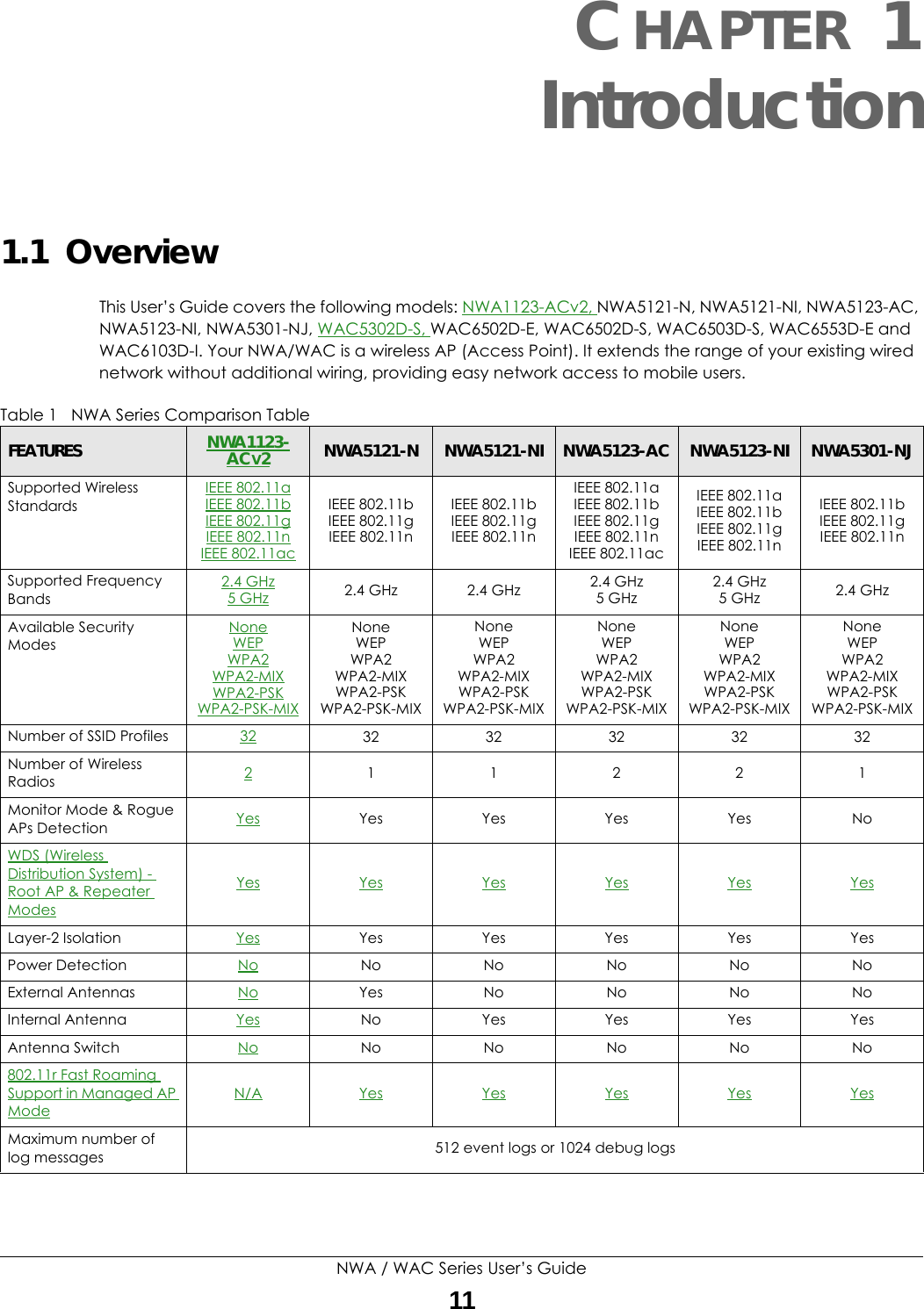
1.
Users Manual-1
2.
Users Manual-2
Users Manual-1
Navigation menu
Upload a User Manual
Namespaces
Wiki Guide
HTML
PDF
Info
Views
User Manual
Discussion / Help
Navigation
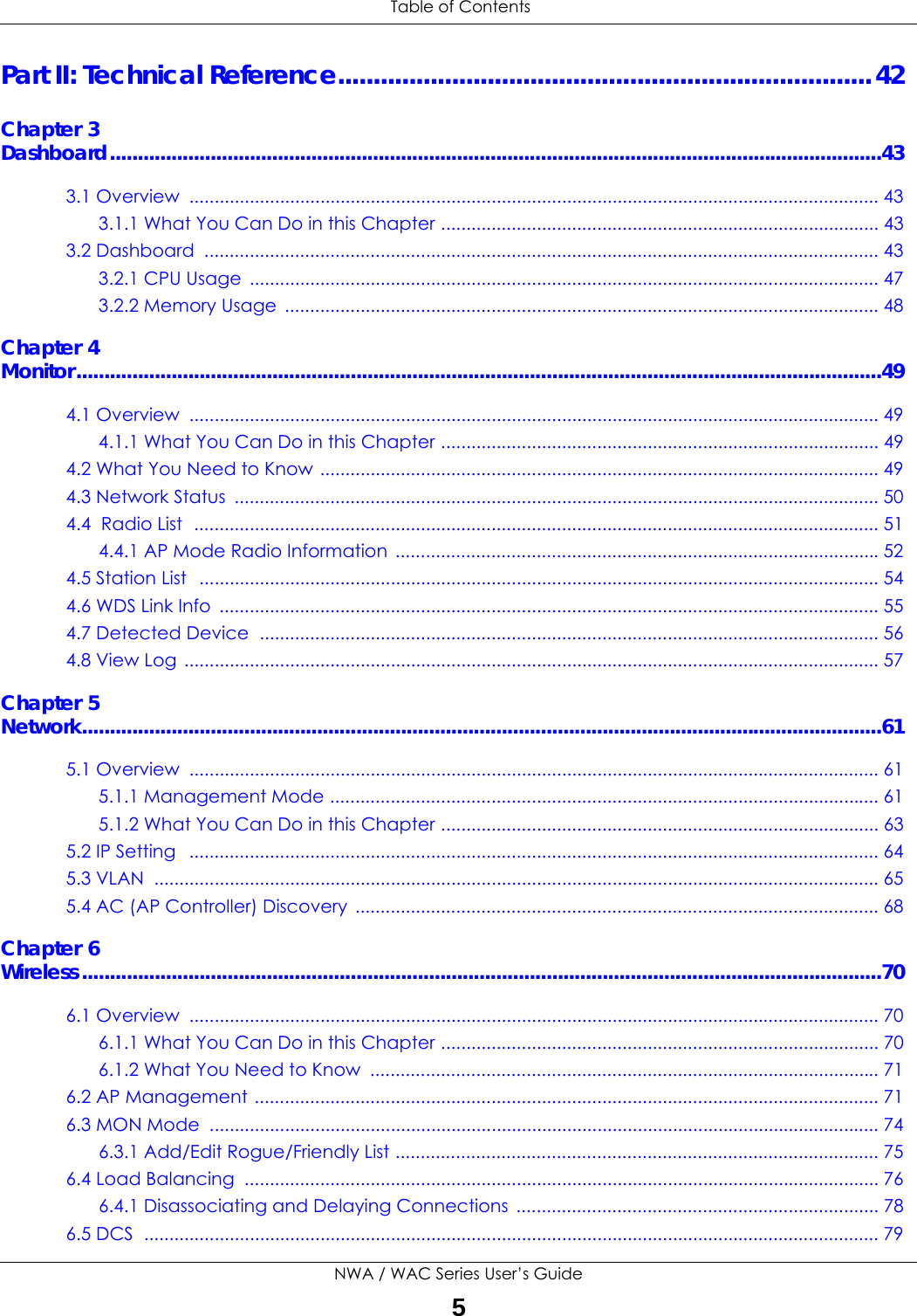
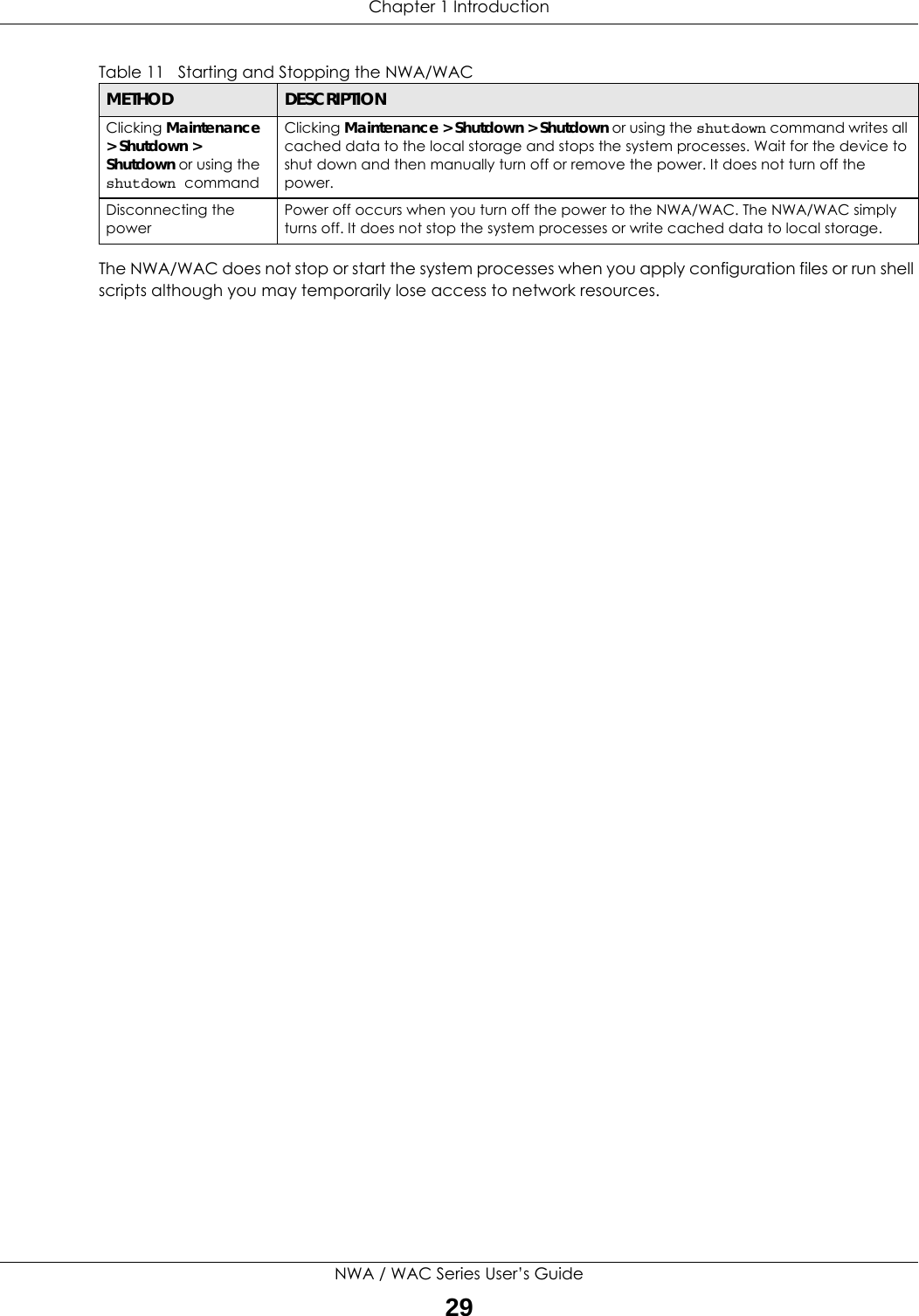
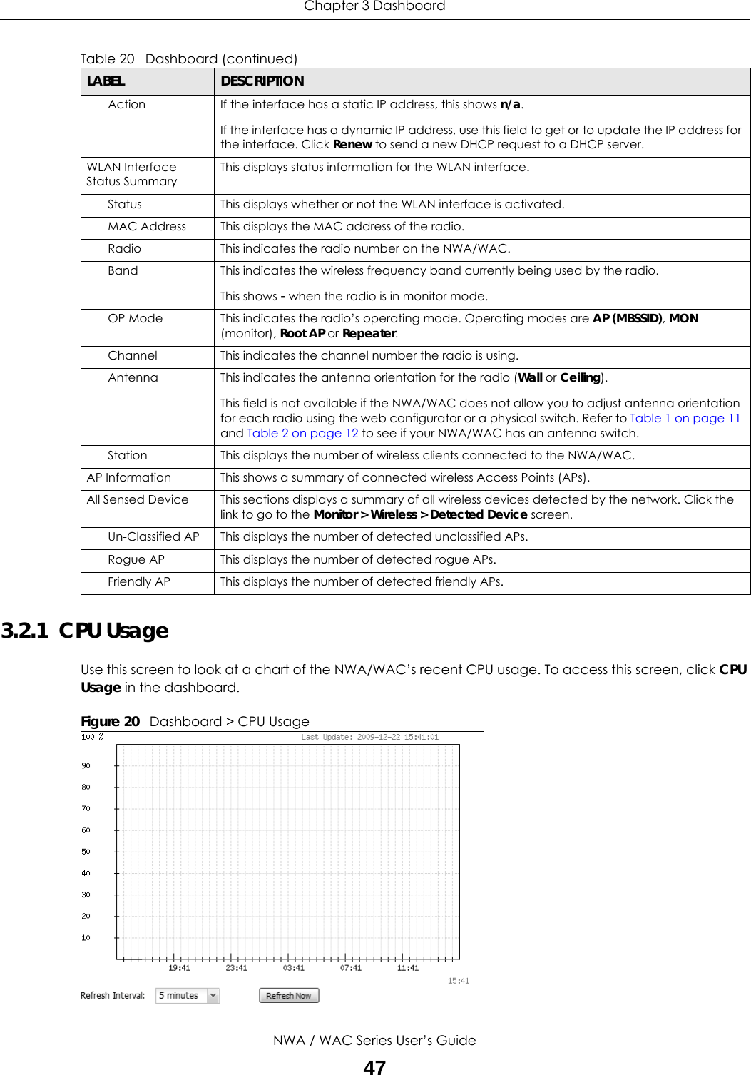
![Chapter 2 The Web ConfiguratorNWA / WAC Series User’s Guide404Select a column heading and drag and drop it to change the column order. A green check mark displays next to the column’s title when you drag the column to a valid new location. 5Use the icons and fields at the bottom of the table to navigate to different pages of entries and control how many entries display at a time. 2.3.4.2 Working with Table EntriesThe tables have icons for working with table entries. A sample is shown next. You can often use the [Shift] or [Ctrl] key to select multiple entries to remove, activate, or deactivate. Table 18 Common Table IconsHere are descriptions for the most common table icons.Table 19 Common Table IconsLABEL DESCRIPTIONAdd Click this to create a new entry. For features where the entry’s position in the numbered list is important (features where the NWA/WAC applies the table’s entries in order like the firewall for example), you can select an entry and click Add to create a new entry after the selected entry.Edit Double-click an entry or select it and click Edit to open a screen where you can modify the entry’s settings. In some tables you can just click a table entry and edit it directly in the table. For those types of tables small red triangles display for table entries with changes that you have not yet applied.](https://usermanual.wiki/ZyXEL-Communications/WAC5302D-S.Users-Manual-1/User-Guide-3283705-Page-40.png)
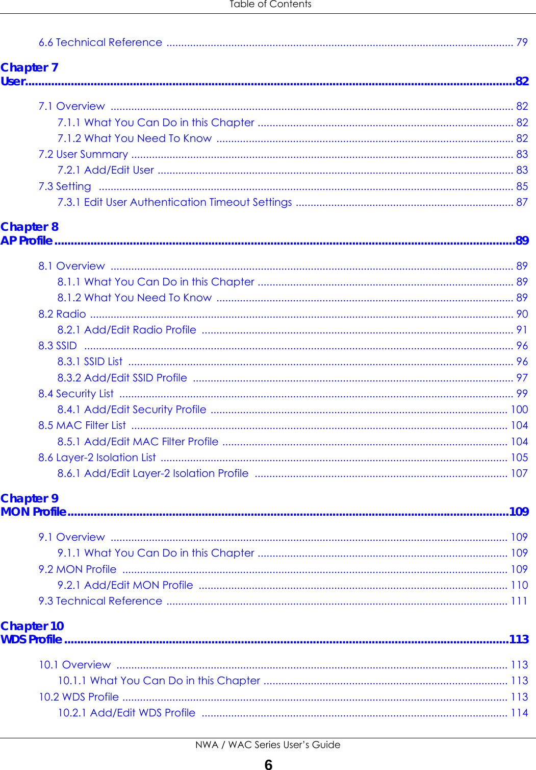
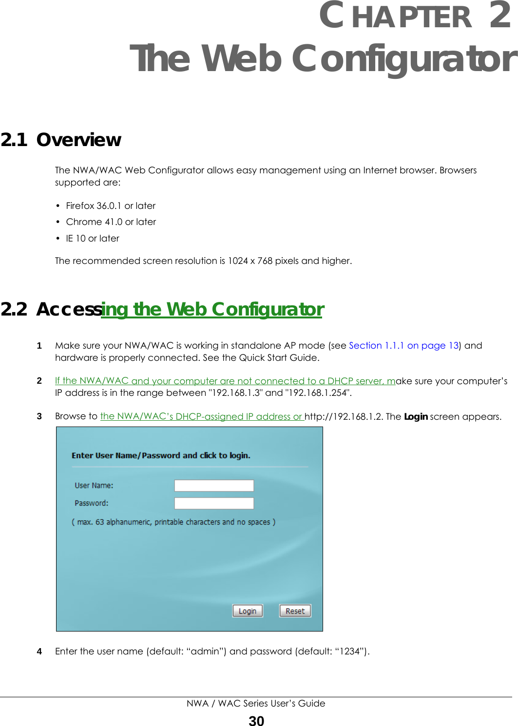
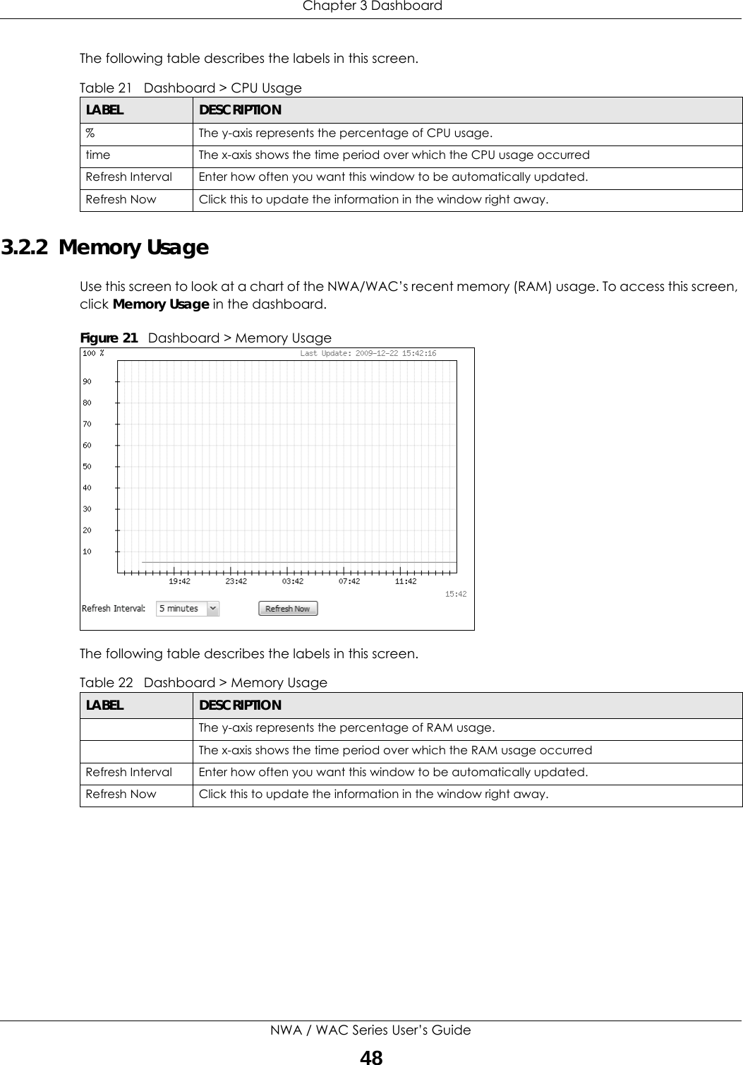
![Chapter 2 The Web ConfiguratorNWA / WAC Series User’s Guide412.3.4.3 Working with ListsWhen a list of available entries displays next to a list of selected entries, you can often just double-click an entry to move it from one list to the other. In some lists you can also use the [Shift] or [Ctrl] key to select multiple entries, and then use the arrow button to move them to the other list. Figure 18 Working with Lists Remove To remove an entry, select it and click Remove. The NWA/WAC confirms you want to remove it before doing so.Activate To turn on an entry, select it and click Activate.Inactivate To turn off an entry, select it and click Inactivate.Object Reference Select an entry and click Object Reference to open a screen that shows which settings use the entry.Table 19 Common Table Icons (continued)LABEL DESCRIPTION](https://usermanual.wiki/ZyXEL-Communications/WAC5302D-S.Users-Manual-1/User-Guide-3283705-Page-41.png)
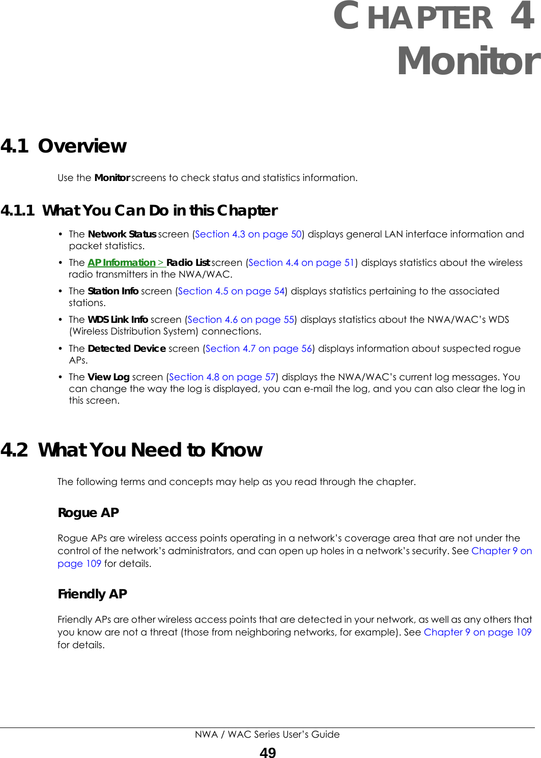
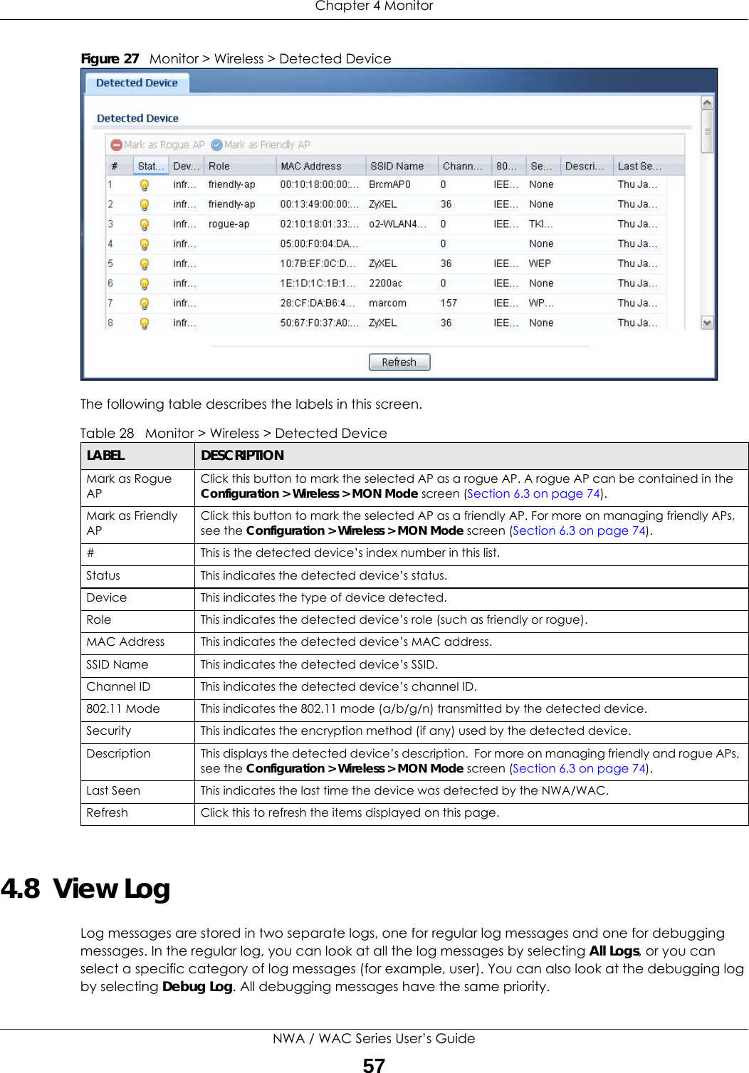
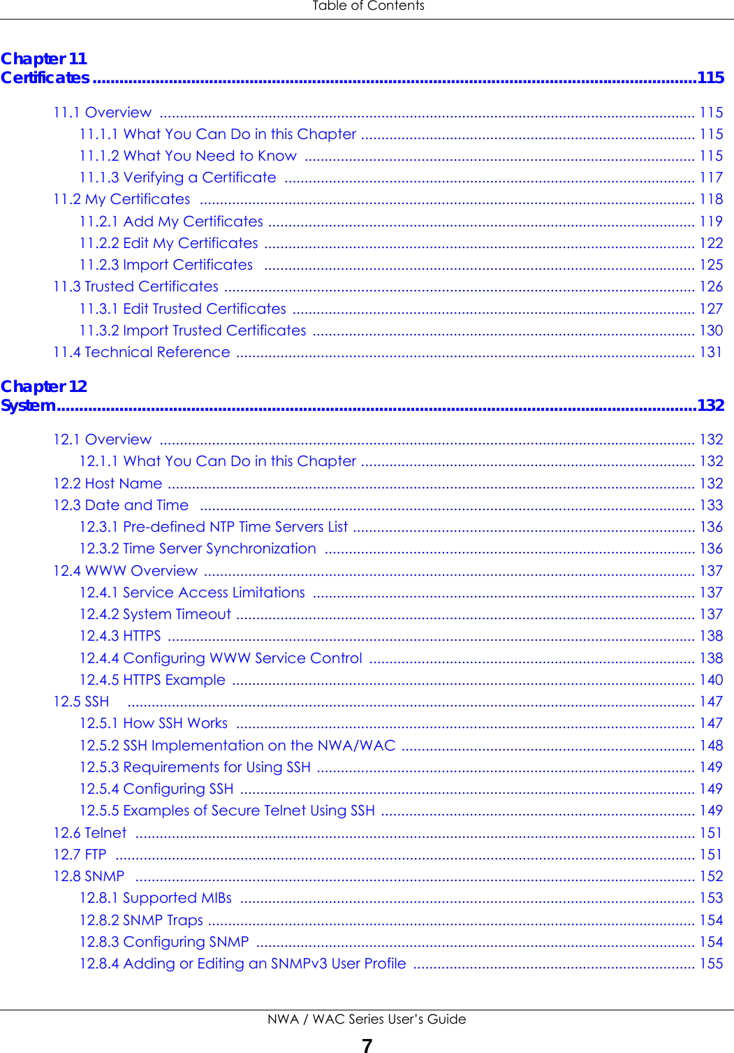
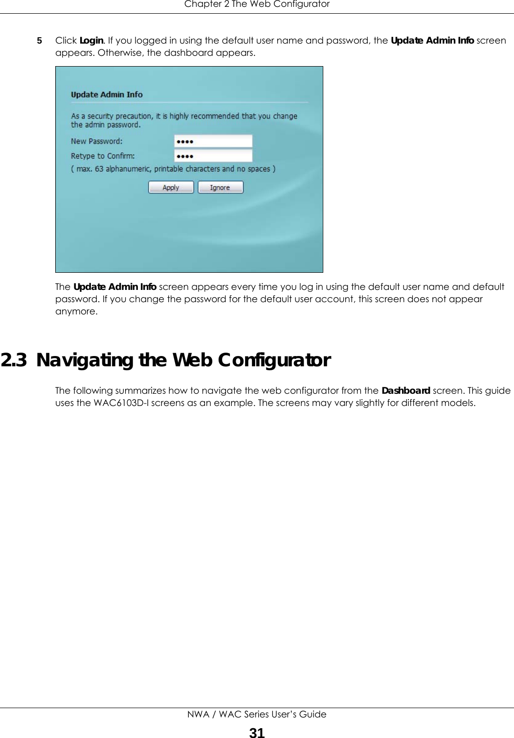
![Chapter 4 MonitorNWA / WAC Series User’s Guide59The following table describes the labels in this screen. Table 29 Monitor > Log > View LogLABEL DESCRIPTIONShow Filter / Hide FilterClick this button to show or hide the filter settings.If the filter settings are hidden, the Display, Email Log Now, Refresh, and Clear Log fields are available.If the filter settings are shown, the Display, Priority, Source Address, Destination Address, Source Interface, Destination Interface, Protocol, Keyword, and Search fields are available.Display Select the category of log message(s) you want to view. You can also view All Logs at one time, or you can view the Debug Log.Priority This displays when you show the filter. Select the priority of log messages to display. The log displays the log messages with this priority or higher. Choices are: any, emerg, alert, crit, error, warn, notice, and info, from highest priority to lowest priority. This field is read-only if the Category is Debug Log. Source Address This displays when you show the filter. Type the source IP address of the incoming packet that generated the log message. Do not include the port in this filter.Destination AddressThis displays when you show the filter. Type the IP address of the destination of the incoming packet when the log message was generated. Do not include the port in this filter.Source Interface This displays when you show the filter. Select the source interface of the packet that generated the log message. Destination InterfaceThis displays when you show the filter. Select the destination interface of the packet that generated the log message. Protocol This displays when you show the filter. Select a service protocol whose log messages you would like to see. Keyword This displays when you show the filter. Type a keyword to look for in the Message, Source, Destination and Note fields. If a match is found in any field, the log message is displayed. You can use up to 63 alphanumeric characters and the underscore, as well as punctuation marks ()’ ,:;?! +-*/= #$% @ ; the period, double quotes, and brackets are not allowed.Search This displays when you show the filter. Click this button to update the log using the current filter settings.Email Log Now Click this button to send log messages to the Active e-mail addresses specified in the Send Log To field on the Configuration > Log & Report > Log Settings screen.Refresh Click this to update the list of logs.Clear Log Click this button to clear the whole log, regardless of what is currently displayed on the screen.#This field is a sequential value, and it is not associated with a specific log message.Time This field displays the time the log message was recorded.Priority This field displays the priority of the log message. It has the same range of values as the Priority field above.Category This field displays the log that generated the log message. It is the same value used in the Display and (other) Category fields.Message This field displays the reason the log message was generated. The text “[count=x]”, where x is a number, appears at the end of the Message field if log consolidation is turned on and multiple entries were aggregated to generate into this one.Source This field displays the source IP address and the port number in the event that generated the log message.Source Interface This field displays the source interface of the packet that generated the log message.Destination This field displays the destination IP address and the port number of the event that generated the log message.Destination InterfaceThis field displays the destination interface of the packet that generated the log message.](https://usermanual.wiki/ZyXEL-Communications/WAC5302D-S.Users-Manual-1/User-Guide-3283705-Page-59.png)
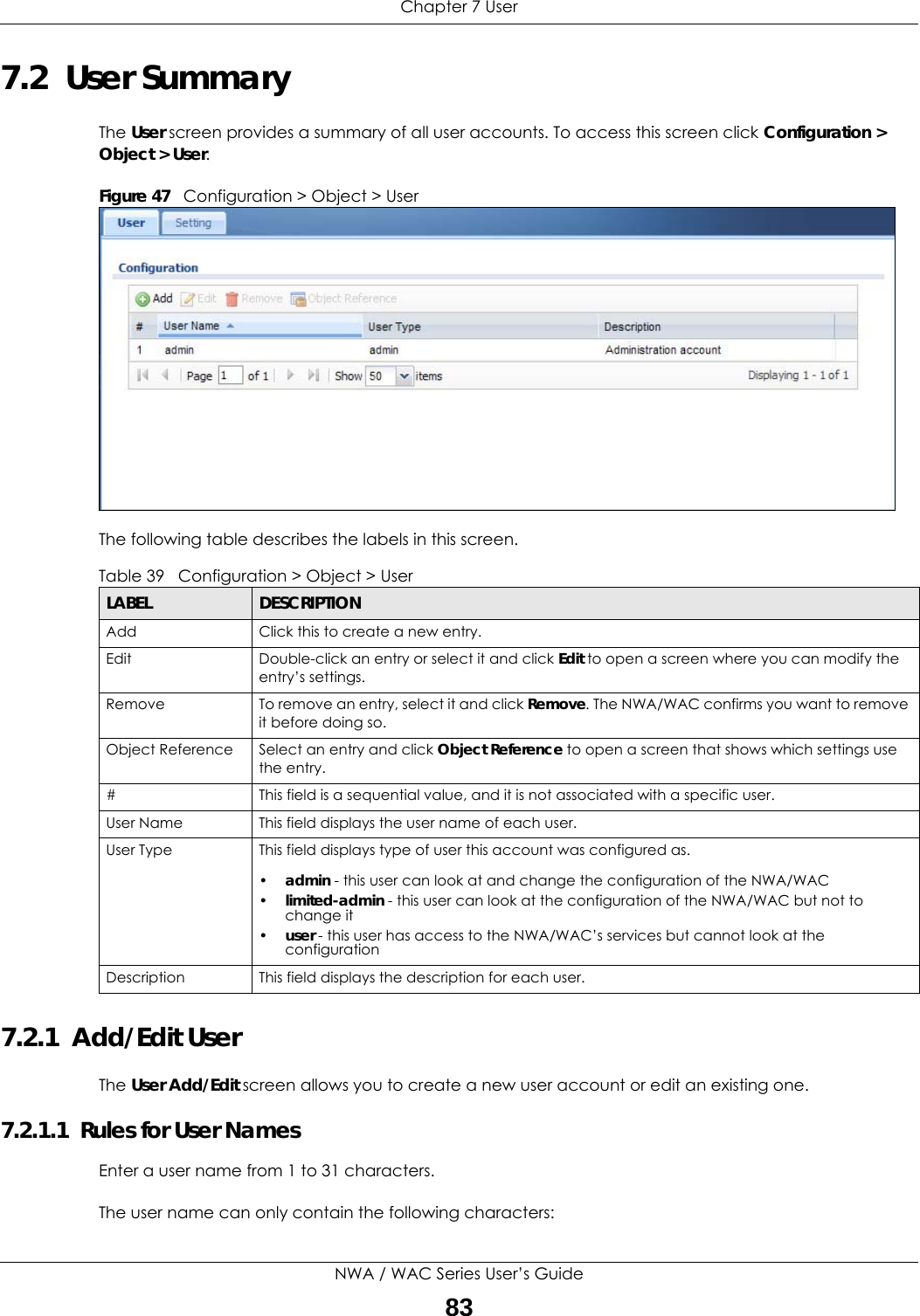
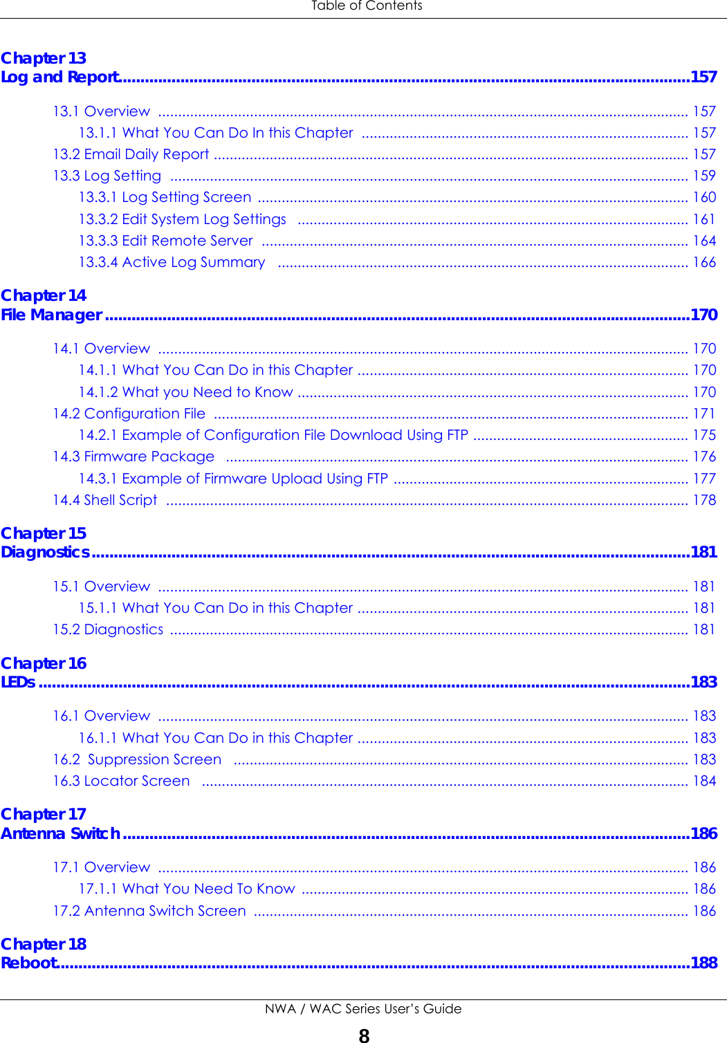
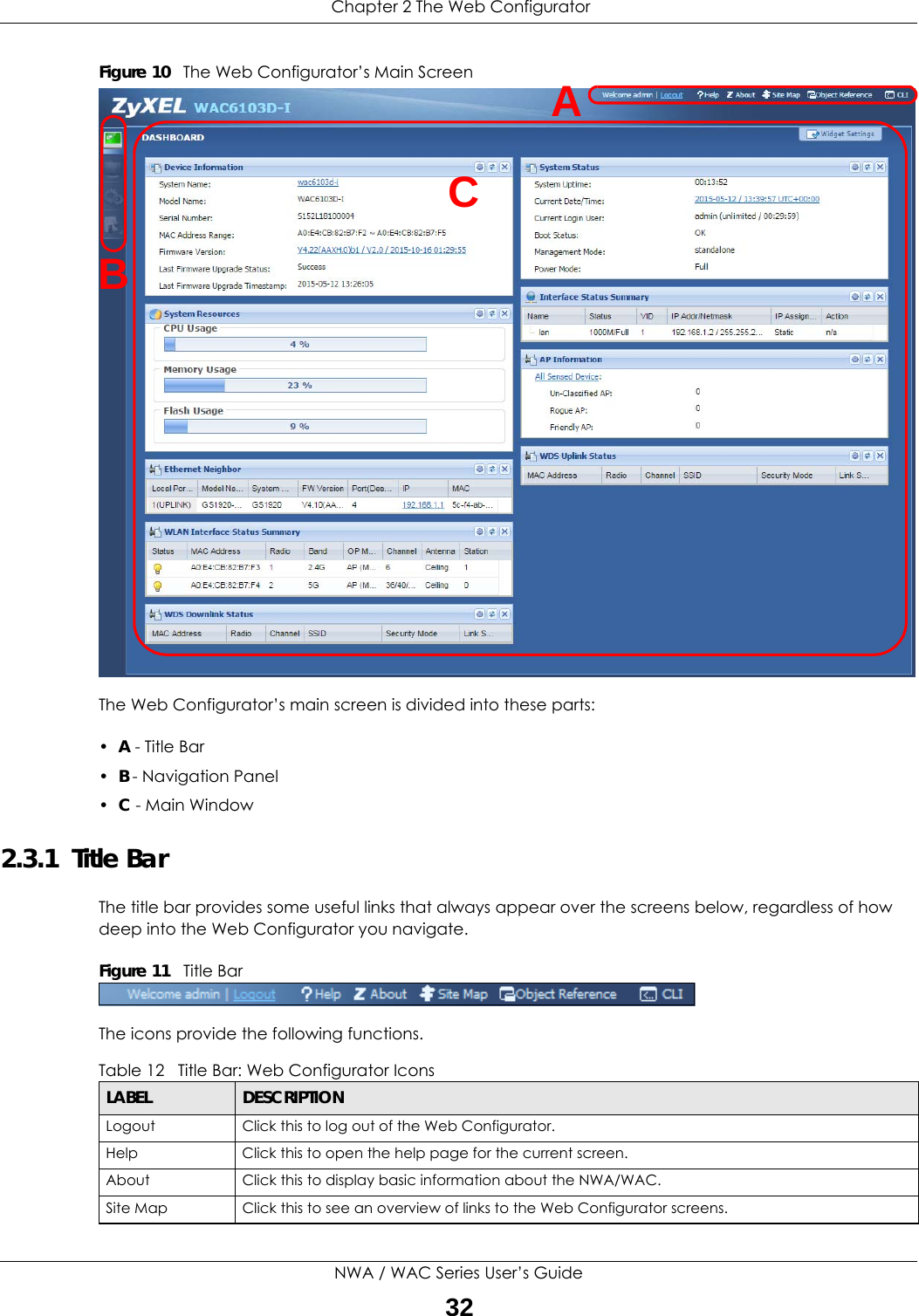
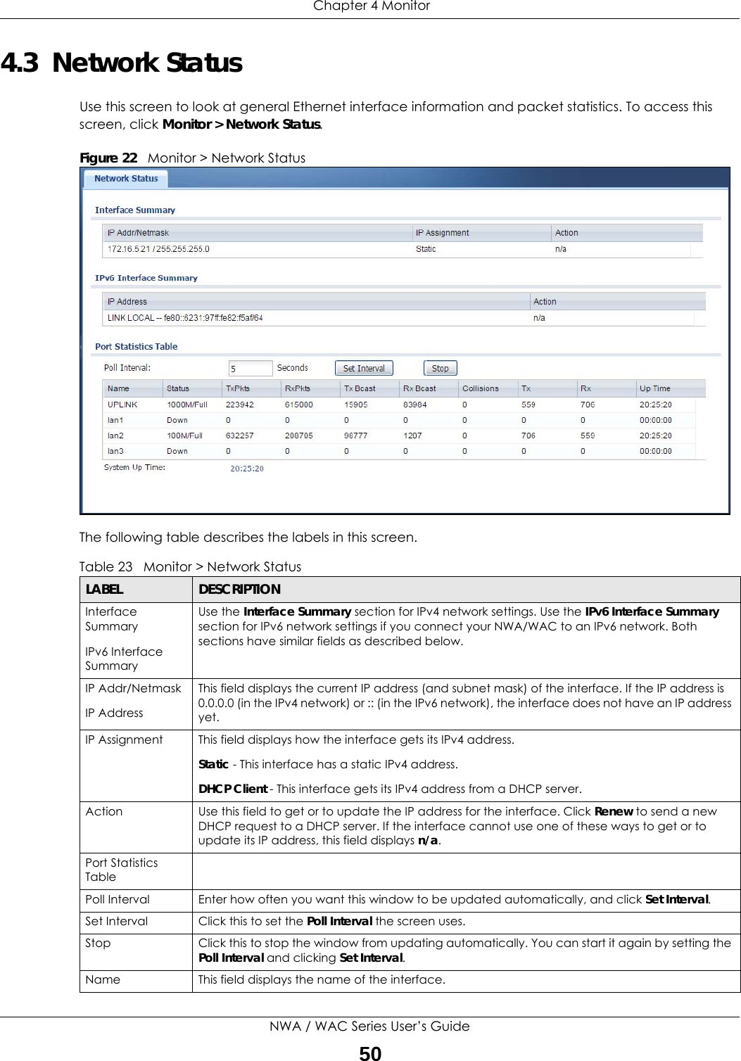
![Chapter 7 UserNWA / WAC Series User’s Guide84• Alphanumeric A-z 0-9 (there is no unicode support)• _ [underscores] • - [dashes]The first character must be alphabetical (A-Z a-z), an underscore (_), or a dash (-). Other limitations on user names are:• User names are case-sensitive. If you enter a user 'bob' but use 'BOB' when connecting via CIFS or FTP, it will use the account settings used for 'BOB' not ‘bob’.• User names have to be different than user group names.• Here are the reserved user names:To access this screen, go to the User screen, and click Add or Edit.Figure 48 Configuration > Object > User > Add/Edit A User•adm •admin •any •bin •daemon•debug •devicehaecived•ftp •games •halt•ldap-users •lp •mail •news •nobody• operator • radius-users • root • shutdown • sshd• sync • uucp • zyxel](https://usermanual.wiki/ZyXEL-Communications/WAC5302D-S.Users-Manual-1/User-Guide-3283705-Page-84.png)