ZyXEL Communications WAC5302D-S 802.11ac Wall-Plate Unified Access Point User Manual Book
ZyXEL Communications Corporation 802.11ac Wall-Plate Unified Access Point Book
Contents
- 1. Users Manual-1
- 2. Users Manual-2
Users Manual-1
Default Login Details
User’s Guide
NWA/WAC Series
WAC5302D-S
802.11ac Wall Plate Unified Access Point
Copyright © 2016 Zyxel Communications Corporation
LAN IP Address DHCP-assigned
OR
http://192.168.1.2
User Name admin
Password 1234
Version 5.00 Edition 1, 11/2016

NWA / WAC Series User’s Guide
2
IMPORTANT!
READ CAREFULLY BEFORE USE.
KEEP THIS GUIDE FOR FUTURE REFERENCE.
This is a User’s Guide for a series of products. Not all products support all firmware features. Screenshots
and graphics in this book may differ slightly from your product due to differences in your product
firmware or your computer operating system. Every effort has been made to ensure that the information
in this manual is accurate.
Related Documentation
•Quick Start Guide
The Quick Start Guide shows how to connect the NWA/WAC and access the Web Configurator.
•CLI Reference Guide
The CLI Reference Guide explains how to use the Command-Line Interface (CLI) and CLI commands
to configure the NWA/WAC.
Note: It is recommended you use the Web Configurator to configure the NWA/WAC.
• Web Configurator Online Help
Click the help icon in any screen for help in configuring that screen and supplementary information.
•More Information
Go to support.zyxel.com to find other information on the NWA/WAC.

Contents Overview
NWA / WAC Series User’s Guide
3
Contents Overview
User’s Guide ......................................................................................................................................10
Introduction ........................................................................................................................................... 11
The Web Configurator ......................................................................................................................... 30
Technical Reference ........................................................................................................................42
Dashboard ............................................................................................................................................ 43
Monitor ................................................................................................................................................... 49
Network ................................................................................................................................................. 61
Wireless ................................................................................................................................................... 70
User ......................................................................................................................................................... 82
AP Profile ................................................................................................................................................ 89
MON Profile ......................................................................................................................................... 109
WDS Profile ........................................................................................................................................... 113
Certificates .......................................................................................................................................... 115
System .................................................................................................................................................. 132
Log and Report ................................................................................................................................... 157
File Manager ....................................................................................................................................... 170
Diagnostics .......................................................................................................................................... 181
LEDs ...................................................................................................................................................... 183
Antenna Switch .................................................................................................................................. 186
Reboot ................................................................................................................................................. 188
Shutdown ............................................................................................................................................. 189
Troubleshooting .................................................................................................................................. 190

Table of Contents
NWA / WAC Series User’s Guide
4
Table of Contents
Contents Overview .............................................................................................................................3
Table of Contents.................................................................................................................................4
Part I: User’s Guide..........................................................................................10
Chapter 1
Introduction ........................................................................................................................................11
1.1 Overview ........................................................................................................................................ 11
1.1.1 Management Mode ............................................................................................................. 13
1.1.2 MBSSID .................................................................................................................................... 13
1.1.3 Dual-Radio ............................................................................................................................. 14
1.1.4 Root AP ................................................................................................................................... 15
1.1.5 Repeater ................................................................................................................................ 16
1.2 Ways to Manage the NWA/WAC .................................................................................................17
1.3 Good Habits for Managing the NWA/WAC ................................................................................ 17
1.4 Hardware Connections ................................................................................................................. 17
1.5 NWA5301-NJ Hardware ................................................................................................................. 18
1.5.1 110 Punch-Down Block ......................................................................................................... 18
1.5.2 Phone Port ............................................................................................................................. 19
1.5.3 Console Port .......................................................................................................................... 19
1.6 LEDs .................................................................................................................................................. 20
1.6.1 WAC6502D-E, WAC6502D-S, and WAC6503D-S ................................................................ 21
1.6.2 WAC6103D-I ........................................................................................................................... 22
1.6.3 NWA5301-NJ .......................................................................................................................... 24
1.6.4 NWA1123-ACv2, NWA5121-N, NWA5121-NI, NWA5123-AC and NWA5123-NI .............. 25
1.6.5 WAC5302D-S .......................................................................................................................... 27
1.7 Starting and Stopping the NWA/WAC ......................................................................................... 28
Chapter 2
The Web Configurator........................................................................................................................30
2.1 Overview ......................................................................................................................................... 30
2.2 Accessing the Web Configurator ................................................................................................. 30
2.3 Navigating the Web Configurator ............................................................................................... 31
2.3.1 Title Bar ................................................................................................................................... 32
2.3.2 Navigation Panel .................................................................................................................. 35
2.3.3 Warning Messages ................................................................................................................ 38
2.3.4 Tables and Lists ...................................................................................................................... 38

Table of Contents
NWA / WAC Series User’s Guide
5
Part II: Technical Reference...........................................................................42
Chapter 3
Dashboard..........................................................................................................................................43
3.1 Overview ......................................................................................................................................... 43
3.1.1 What You Can Do in this Chapter ....................................................................................... 43
3.2 Dashboard ...................................................................................................................................... 43
3.2.1 CPU Usage ............................................................................................................................. 47
3.2.2 Memory Usage ...................................................................................................................... 48
Chapter 4
Monitor................................................................................................................................................49
4.1 Overview ......................................................................................................................................... 49
4.1.1 What You Can Do in this Chapter ....................................................................................... 49
4.2 What You Need to Know ............................................................................................................... 49
4.3 Network Status ................................................................................................................................ 50
4.4 Radio List ........................................................................................................................................ 51
4.4.1 AP Mode Radio Information ................................................................................................52
4.5 Station List ....................................................................................................................................... 54
4.6 WDS Link Info ................................................................................................................................... 55
4.7 Detected Device ........................................................................................................................... 56
4.8 View Log .......................................................................................................................................... 57
Chapter 5
Network...............................................................................................................................................61
5.1 Overview ......................................................................................................................................... 61
5.1.1 Management Mode ............................................................................................................. 61
5.1.2 What You Can Do in this Chapter ....................................................................................... 63
5.2 IP Setting ......................................................................................................................................... 64
5.3 VLAN ................................................................................................................................................ 65
5.4 AC (AP Controller) Discovery ........................................................................................................ 68
Chapter 6
Wireless...............................................................................................................................................70
6.1 Overview ......................................................................................................................................... 70
6.1.1 What You Can Do in this Chapter ....................................................................................... 70
6.1.2 What You Need to Know ..................................................................................................... 71
6.2 AP Management ............................................................................................................................ 71
6.3 MON Mode ..................................................................................................................................... 74
6.3.1 Add/Edit Rogue/Friendly List ................................................................................................ 75
6.4 Load Balancing .............................................................................................................................. 76
6.4.1 Disassociating and Delaying Connections ........................................................................ 78
6.5 DCS .................................................................................................................................................. 79

Table of Contents
NWA / WAC Series User’s Guide
6
6.6 Technical Reference ...................................................................................................................... 79
Chapter 7
User......................................................................................................................................................82
7.1 Overview ......................................................................................................................................... 82
7.1.1 What You Can Do in this Chapter ....................................................................................... 82
7.1.2 What You Need To Know ..................................................................................................... 82
7.2 User Summary .................................................................................................................................. 83
7.2.1 Add/Edit User ......................................................................................................................... 83
7.3 Setting ............................................................................................................................................. 85
7.3.1 Edit User Authentication Timeout Settings .......................................................................... 87
Chapter 8
AP Profile.............................................................................................................................................89
8.1 Overview ......................................................................................................................................... 89
8.1.1 What You Can Do in this Chapter ....................................................................................... 89
8.1.2 What You Need To Know ..................................................................................................... 89
8.2 Radio ................................................................................................................................................ 90
8.2.1 Add/Edit Radio Profile .......................................................................................................... 91
8.3 SSID .................................................................................................................................................. 96
8.3.1 SSID List ................................................................................................................................... 96
8.3.2 Add/Edit SSID Profile ............................................................................................................. 97
8.4 Security List ...................................................................................................................................... 99
8.4.1 Add/Edit Security Profile ..................................................................................................... 100
8.5 MAC Filter List ................................................................................................................................ 104
8.5.1 Add/Edit MAC Filter Profile ................................................................................................. 104
8.6 Layer-2 Isolation List ...................................................................................................................... 105
8.6.1 Add/Edit Layer-2 Isolation Profile ...................................................................................... 107
Chapter 9
MON Profile.......................................................................................................................................109
9.1 Overview ....................................................................................................................................... 109
9.1.1 What You Can Do in this Chapter ..................................................................................... 109
9.2 MON Profile ................................................................................................................................... 109
9.2.1 Add/Edit MON Profile ......................................................................................................... 110
9.3 Technical Reference .................................................................................................................... 111
Chapter 10
WDS Profile........................................................................................................................................113
10.1 Overview ..................................................................................................................................... 113
10.1.1 What You Can Do in this Chapter ................................................................................... 113
10.2 WDS Profile ................................................................................................................................... 113
10.2.1 Add/Edit WDS Profile ........................................................................................................ 114

Table of Contents
NWA / WAC Series User’s Guide
7
Chapter 11
Certificates .......................................................................................................................................115
11.1 Overview ..................................................................................................................................... 115
11.1.1 What You Can Do in this Chapter ................................................................................... 115
11.1.2 What You Need to Know ................................................................................................. 115
11.1.3 Verifying a Certificate ...................................................................................................... 117
11.2 My Certificates ........................................................................................................................... 118
11.2.1 Add My Certificates .......................................................................................................... 119
11.2.2 Edit My Certificates ........................................................................................................... 122
11.2.3 Import Certificates ........................................................................................................... 125
11.3 Trusted Certificates ..................................................................................................................... 126
11.3.1 Edit Trusted Certificates .................................................................................................... 127
11.3.2 Import Trusted Certificates ............................................................................................... 130
11.4 Technical Reference .................................................................................................................. 131
Chapter 12
System...............................................................................................................................................132
12.1 Overview ..................................................................................................................................... 132
12.1.1 What You Can Do in this Chapter ................................................................................... 132
12.2 Host Name ................................................................................................................................... 132
12.3 Date and Time ........................................................................................................................... 133
12.3.1 Pre-defined NTP Time Servers List ..................................................................................... 136
12.3.2 Time Server Synchronization ............................................................................................ 136
12.4 WWW Overview .......................................................................................................................... 137
12.4.1 Service Access Limitations ............................................................................................... 137
12.4.2 System Timeout .................................................................................................................. 137
12.4.3 HTTPS ................................................................................................................................... 138
12.4.4 Configuring WWW Service Control ................................................................................. 138
12.4.5 HTTPS Example ................................................................................................................... 140
12.5 SSH ............................................................................................................................................. 147
12.5.1 How SSH Works .................................................................................................................. 147
12.5.2 SSH Implementation on the NWA/WAC ......................................................................... 148
12.5.3 Requirements for Using SSH ..............................................................................................149
12.5.4 Configuring SSH ................................................................................................................. 149
12.5.5 Examples of Secure Telnet Using SSH .............................................................................. 149
12.6 Telnet ........................................................................................................................................... 151
12.7 FTP ................................................................................................................................................ 151
12.8 SNMP ........................................................................................................................................... 152
12.8.1 Supported MIBs ................................................................................................................. 153
12.8.2 SNMP Traps ......................................................................................................................... 154
12.8.3 Configuring SNMP ............................................................................................................. 154
12.8.4 Adding or Editing an SNMPv3 User Profile ...................................................................... 155

Table of Contents
NWA / WAC Series User’s Guide
8
Chapter 13
Log and Report.................................................................................................................................157
13.1 Overview ..................................................................................................................................... 157
13.1.1 What You Can Do In this Chapter .................................................................................. 157
13.2 Email Daily Report ....................................................................................................................... 157
13.3 Log Setting .................................................................................................................................. 159
13.3.1 Log Setting Screen ............................................................................................................ 160
13.3.2 Edit System Log Settings .................................................................................................. 161
13.3.3 Edit Remote Server ........................................................................................................... 164
13.3.4 Active Log Summary ....................................................................................................... 166
Chapter 14
File Manager ....................................................................................................................................170
14.1 Overview ..................................................................................................................................... 170
14.1.1 What You Can Do in this Chapter ................................................................................... 170
14.1.2 What you Need to Know .................................................................................................. 170
14.2 Configuration File ....................................................................................................................... 171
14.2.1 Example of Configuration File Download Using FTP ...................................................... 175
14.3 Firmware Package .................................................................................................................... 176
14.3.1 Example of Firmware Upload Using FTP .......................................................................... 177
14.4 Shell Script ................................................................................................................................... 178
Chapter 15
Diagnostics.......................................................................................................................................181
15.1 Overview ..................................................................................................................................... 181
15.1.1 What You Can Do in this Chapter ................................................................................... 181
15.2 Diagnostics .................................................................................................................................. 181
Chapter 16
LEDs ...................................................................................................................................................183
16.1 Overview ..................................................................................................................................... 183
16.1.1 What You Can Do in this Chapter ................................................................................... 183
16.2 Suppression Screen .................................................................................................................. 183
16.3 Locator Screen .......................................................................................................................... 184
Chapter 17
Antenna Switch................................................................................................................................186
17.1 Overview ..................................................................................................................................... 186
17.1.1 What You Need To Know ................................................................................................. 186
17.2 Antenna Switch Screen ............................................................................................................. 186
Chapter 18
Reboot...............................................................................................................................................188

Table of Contents
NWA / WAC Series User’s Guide
9
18.1 Overview ..................................................................................................................................... 188
18.1.1 What You Need To Know ................................................................................................. 188
18.2 Reboot ......................................................................................................................................... 188
Chapter 19
Shutdown..........................................................................................................................................189
19.1 Overview ..................................................................................................................................... 189
19.1.1 What You Need To Know ................................................................................................. 189
19.2 Shutdown ..................................................................................................................................... 189
Chapter 20
Troubleshooting................................................................................................................................190
20.1 Overview ..................................................................................................................................... 190
20.2 Power, Hardware Connections, and LED ................................................................................ 190
20.3 NWA/WAC Access and Login ................................................................................................... 191
20.4 Internet Access ........................................................................................................................... 192
20.5 Wireless Connections ................................................................................................................. 193
20.6 Resetting the NWA/WAC ........................................................................................................... 197
20.7 Getting More Troubleshooting Help .........................................................................................197
Appendix A Importing Certificates ............................................................................................... 198
Appendix B IPv6............................................................................................................................... 211
Appendix C Customer Support ..................................................................................................... 219
Appendix D Legal Information ...................................................................................................... 225
Index.................................................................................................................................................235

10
PART I
User’s Guide

NWA / WAC Series User’s Guide
11
CHAPTER 1
Introduction
1.1 Overview
This User’s Guide covers the following models: NWA1123-ACv2, NWA5121-N, NWA5121-NI, NWA5123-AC,
NWA5123-NI, NWA5301-NJ, WAC5302D-S, WAC6502D-E, WAC6502D-S, WAC6503D-S, WAC6553D-E and
WAC6103D-I. Your NWA/WAC is a wireless AP (Access Point). It extends the range of your existing wired
network without additional wiring, providing easy network access to mobile users.
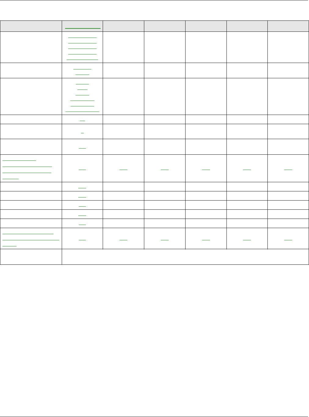
Table 1 NWA Series Comparison Table
FEATURES NWA1123-
ACV2NWA5121-N NWA5121-NI NWA5123-AC NWA5123-NI NWA5301-NJ
Supported Wireless
Standards
IEEE 802.11a
IEEE 802.11b
IEEE 802.11g
IEEE 802.11n
IEEE 802.11ac
IEEE 802.11b
IEEE 802.11g
IEEE 802.11n
IEEE 802.11b
IEEE 802.11g
IEEE 802.11n
IEEE 802.11a
IEEE 802.11b
IEEE 802.11g
IEEE 802.11n
IEEE 802.11ac
IEEE 802.11a
IEEE 802.11b
IEEE 802.11g
IEEE 802.11n
IEEE 802.11b
IEEE 802.11g
IEEE 802.11n
Supported Frequency
Bands
2.4 GHz
5 GHz 2.4 GHz 2.4 GHz 2.4 GHz
5 GHz 2.4 GHz
5 GHz 2.4 GHz
Available Security
Modes
None
WEP
WPA2
WPA2-MIX
WPA2-PSK
WPA2-PSK-MIX
None
WEP
WPA2
WPA2-MIX
WPA2-PSK
WPA2-PSK-MIX
None
WEP
WPA2
WPA2-MIX
WPA2-PSK
WPA2-PSK-MIX
None
WEP
WPA2
WPA2-MIX
WPA2-PSK
WPA2-PSK-MIX
None
WEP
WPA2
WPA2-MIX
WPA2-PSK
WPA2-PSK-MIX
None
WEP
WPA2
WPA2-MIX
WPA2-PSK
WPA2-PSK-MIX
Number of SSID Profiles 32 32 32 32 32 32
Number of Wireless
Radios 211221
Monitor Mode & Rogue
APs Detection Yes Yes Yes Yes Yes No
WDS (Wireless
Distribution System) -
Root AP & Repeater
Modes
Yes Yes Yes Yes Yes Yes
Layer-2 Isolation Yes Yes Yes Yes Yes Yes
Power Detection No No No No No No
External Antennas No YesNoNoNoNo
Internal Antenna Yes NoYesYesYesYes
Antenna Switch No No No No No No
802.11r Fast Roaming
Support in Managed AP
Mode
N/A Yes Yes Yes Yes Yes
Maximum number of
log messages 512 event logs or 1024 debug logs
Chapter 1 Introduction
NWA / WAC Series User’s Guide
12
You can set the NWA/WAC to operate in either standalone AP or managed AP mode. When the NWA/
WAC is in standalone AP mode, it can serve as a normal AP, as an RF monitor to search for rouge APs to
help eliminate network threats (if it supports monitor mode and rogue APs detection), or even as a root
AP or a wireless repeater to establish wireless links with other APs in a WDS (Wireless Distribution System). A
WDS is a wireless connection between two or more APs.
Your NWA/WAC’s business-class reliability, SMB features, and centralized wireless management make it
ideally suited for advanced service delivery in mission-critical networks. It uses Multiple BSSID and VLAN
to provide simultaneous independent virtual APs. Additionally, innovations in roaming technology and
QoS features eliminate voice call disruptions.
The NWA/WAC controls network access with Media Access Control (MAC) address filtering, and rogue
Access Point (AP) detection. It also provides a high level of network traffic security, supporting IEEE
802.1x, Wi-Fi Protected Access 2 and Wired Equivalent Privacy (WEP) data encryption.
Your NWA/WAC is easy to install, configure and use. The embedded Web-based configurator enables
simple, straightforward management and maintenance. See the Quick Start Guide for how to make
hardware connections.
Table 2 WAC Series Comparison Table
FEATURES WAC5302D-S WAC6502D-E WAC6502D-S WAC6503D-S WAC6553D-E WAC6103D-I
Supported Wireless
Standards
IEEE 802.11a
IEEE 802.11b
IEEE 802.11g
IEEE 802.11n
IEEE 802.11ac
IEEE 802.11a
IEEE 802.11b
IEEE 802.11g
IEEE 802.11n
IEEE 802.11ac
IEEE 802.11a
IEEE 802.11b
IEEE 802.11g
IEEE 802.11n
IEEE 802.11ac
IEEE 802.11a
IEEE 802.11b
IEEE 802.11g
IEEE 802.11n
IEEE 802.11ac
IEEE 802.11a
IEEE 802.11b
IEEE 802.11g
IEEE 802.11n
IEEE 802.11ac
IEEE 802.11a
IEEE 802.11b
IEEE 802.11g
IEEE 802.11n
IEEE 802.11ac
Supported Frequency
Bands
2.4 GHz
5 GHz 2.4 GHz
5 GHz 2.4 GHz
5 GHz 2.4 GHz
5 GHz 2.4 GHz
5 GHz 2.4 GHz
5 GHz
Available Security
Modes
None
WEP
WPA2
WPA2-MIX
WPA2-PSK
WPA2-PSK-MIX
None
WEP
WPA2
WPA2-MIX
WPA2-PSK
WPA2-PSK-MIX
None
WEP
WPA2
WPA2-MIX
WPA2-PSK
WPA2-PSK-MIX
None
WEP
WPA2
WPA2-MIX
WPA2-PSK
WPA2-PSK-MIX
None
WEP
WPA2
WPA2-MIX
WPA2-PSK
WPA2-PSK-MIX
None
WEP
WPA2
WPA2-MIX
WPA2-PSK
WPA2-PSK-MIX
Number of SSID Profiles 32 32 32 32 32 32
Number of Wireless
Radios 222222
Monitor Mode & Rogue
APs Detection No Yes Yes Yes Yes Yes
WDS (Wireless
Distribution System) -
Root AP & Repeater
Modes
No Yes Yes Yes Yes Yes
Layer-2 Isolation Yes Yes Yes Yes Yes Yes
Power Detection Yes Yes Yes Yes Yes No
External Antennas No Yes No No Yes No
Internal Antenna Yes No Yes Yes No Yes
Antenna Switch No No No No No Yes
802.11r Fast Roaming
Support in Managed AP
Mode
No Yes Yes Yes Yes Yes
Maximum number of
log messages 512 event logs or 1024 debug logs

Chapter 1 Introduction
NWA / WAC Series User’s Guide
13
1.1.1 Management Mode
The NWA/WAC is a unified AP and can work either in standalone AP mode or in managed AP mode. If
the NWA/WAC and a Zyxel AP controller, such as the NXC2500 or NXC5500, are in the same subnet, it will
be managed by the controller automatically.
An AP controller uses Control And Provisioning of Wireless Access Points (CAPWAP, see RFC 5415) to
discover and configure multiple managed APs.
To set the NWA/WAC to be managed by an AP controller in a different subnet or change between
management modes, use the AC (AP Controller) Discovery screen (see Section 5.4 on page 68).
When the NWA/WAC is in standalone AP mode and connects to a DHCP server, it uses the IP address
assigned by the DHCP server. Otherwise, the NWA/WAC uses the default static management IP address
(192.168.1.2). You can use the AC Discovery screen to have the NWA/WAC work as a managed AP.
When the NWA/WAC is in managed AP mode, it acts as a DHCP client and obtains an IP address from
the AP controller. It can be configured ONLY by the AP controller. To change the NWA/WAC back to
standalone AP mode, use the Reset button to restore the default configuration. Alternatively, you need
to check the AP controller for the NWA/WAC’s IP address and use FTP to upload the default
configuration file at conf/system-default.conf to the NWA/WAC and reboot the device.
1.1.2 MBSSID
A Basic Service Set (BSS) is the set of devices forming a single wireless network (usually an access point
and one or more wireless clients). The Service Set IDentifier (SSID) is the name of a BSS. In Multiple BSS
(MBSSID) mode, the NWA/WAC provides multiple virtual APs, each forming its own BSS and using its own
individual SSID profile.
You can configure multiple SSID profiles, and have all of them active at any one time.
You can assign different wireless and security settings to each SSID profile. This allows you to
compartmentalize groups of users, set varying access privileges, and prioritize network traffic to and
from certain BSSs.
To the wireless clients in the network, each SSID appears to be a different access point. As in any wireless
network, clients can associate only with the SSIDs for which they have the correct security settings.
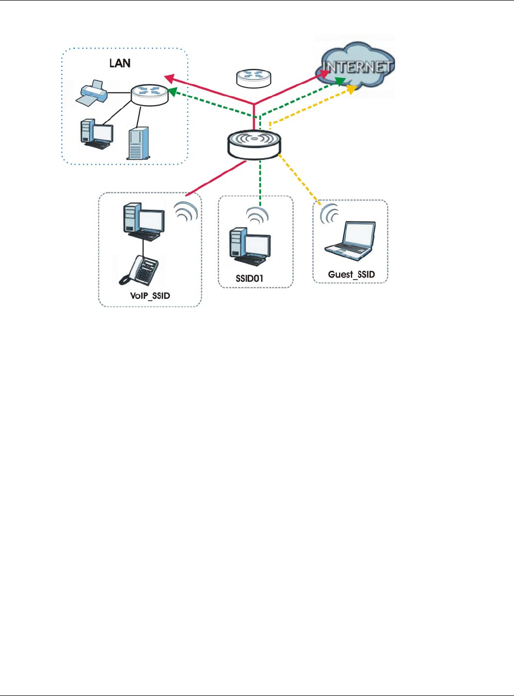
For example, you might want to set up a wireless network in your office where Internet telephony (VoIP)
users have priority. You also want a regular wireless network for standard users, as well as a ‘guest’
wireless network for visitors. In the following figure, VoIP_SSID users have QoS priority, SSID01 is the wireless
network for standard users, and Guest_SSID is the wireless network for guest users. In this example, the
guest user is forbidden access to the wired Land Area Network (LAN) behind the AP and can access
only the Internet.
Table 3 NWA/WAC Management Mode Comparison
MANAGEMENT MODE DEFAULT IP ADDRESS UPLOAD FIRMWARE VIA
Standalone AP
Dynamic or
Static (192.168.1.2) Web Configurator or FTP
Managed AP Dynamic CAPWAP or FTP
Chapter 1 Introduction
NWA / WAC Series User’s Guide
14
Figure 1 Multiple BSSs
1.1.3 Dual-Radio
Some of the NWA/WAC models are equipped with dual wireless radios. This means you can configure
two different wireless networks to operate simultaneously.
Note: A different channel should be configured for each WLAN interface to reduce the
effects of radio interference.
You could use the 2.4 GHz band for regular Internet surfing and downloading while using the 5 GHz
band for time sensitive traffic like high-definition video, music, and gaming.
Chapter 1 Introduction
NWA / WAC Series User’s Guide
15
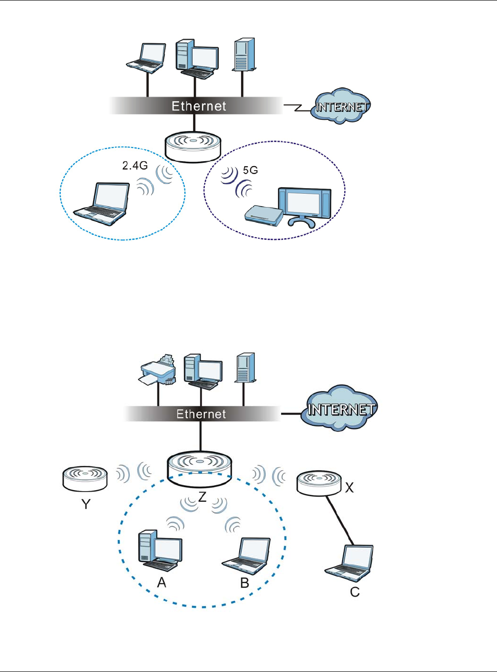
Figure 2 Dual-Radio Application
1.1.4 Root AP
In Root AP mode, the NWA/WAC (Z) can act as the root AP in a wireless network and also allow
repeaters (X and Y) to extend the range of its wireless network at the same time. In the figure below,
both clients A, B and C can access the wired network through the root AP.
Figure 3 Root AP Application
On the NWA/WAC in Root AP mode, you can have multiple SSIDs active for regular wireless connections
and one SSID for the connection with a repeater (repeater SSID). Wireless clients can use either SSID to
Chapter 1 Introduction
NWA / WAC Series User’s Guide
16
associate with the NWA/WAC in Root AP mode. A repeater must use the repeater SSID to connect to
the NWA/WAC in Root AP mode.
When the NWA/WAC is in Root AP mode, repeater security between the NWA/WAC and other repeater
is independent of the security between the wireless clients and the AP or repeater. When repeater
security is enabled, both APs and repeaters must use the same pre-shared key. See Section 6.2 on page
71 and Section 10.2 on page 113 for more details.
Unless specified, the term “security settings” refers to the traffic between the wireless clients and the AP.
At the time of writing, repeater security is compatible with the NWA/WAC only.
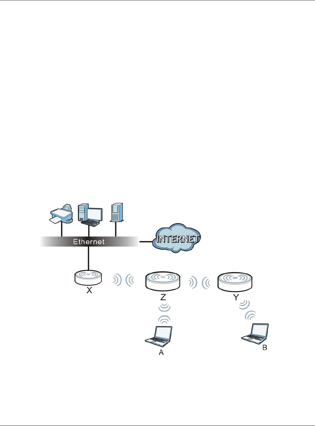
1.1.5 Repeater
The NWA/WAC can act as a wireless network repeater to extend a root AP’s wireless network range,
and also establish wireless connections with wireless clients.
Using Repeater mode, your NWA/WAC can extend the range of the WLAN. In the figure below, the
NWA/WAC in Repeater mode (Z) has a wireless connection to the NWA/WAC in Root AP mode (X)
which is connected to a wired network and also has a wireless connection to another NWA/WAC in
Repeater mode (Y) at the same time. Z and Y act as repeaters that forward traffic between associated
wireless clients and the wired LAN. Clients A and B access the AP and the wired network behind the AP
through repeaters Z and Y.
Figure 4 Repeater Application
When the NWA/WAC is in Repeater mode, repeater security between the NWA/WAC and other
repeater is independent of the security between the wireless clients and the AP or repeater. When
repeater security is enabled, both APs and repeaters must use the same pre-shared key. See Section 6.2
on page 71 and Section 10.2 on page 113 for more details.
Once the security settings of peer sides match one another, the connection between devices is made.

Chapter 1 Introduction
NWA / WAC Series User’s Guide
17
At the time of writing, repeater security is compatible with the NWA/WAC only.
1.2 Ways to Manage the NWA/WAC
You can use the following ways to manage the NWA/WAC.
Web Configurator
The Web Configurator allows easy NWA/WAC setup and management using an Internet browser. This
User’s Guide provides information about the Web Configurator.
Command-Line Interface (CLI)
The CLI allows you to use text-based commands to configure the NWA/WAC. You can access it using
remote management (for example, SSH or Telnet). See the Command Reference Guide for more
information.
File Transfer Protocol (FTP)
This protocol can be used for firmware upgrades and configuration backup and restore.
Simple Network Management Protocol (SNMP)
The NWA/WAC can be monitored by an SNMP manager. See the SNMP chapter in this User’s Guide.
1.3 Good Habits for Managing the NWA/WAC
Do the following things regularly to make the NWA/WAC more secure and to manage it more
effectively.
• Change the password often. Use a password that’s not easy to guess and that consists of different
types of characters, such as numbers and letters.
• Write down the password and put it in a safe place.
• Back up the configuration (and make sure you know how to restore it). Restoring an earlier working
configuration may be useful if the device becomes unstable or even crashes. If you forget your
password, you will have to reset the NWA/WAC to its factory default settings. If you backed up an
earlier configuration file, you won’t have to totally re-configure the NWA/WAC; you can simply restore
your last configuration.
1.4 Hardware Connections
See your Quick Start Guide for information on making hardware connections.
Chapter 1 Introduction
NWA / WAC Series User’s Guide
18
1.5 NWA5301-NJ Hardware
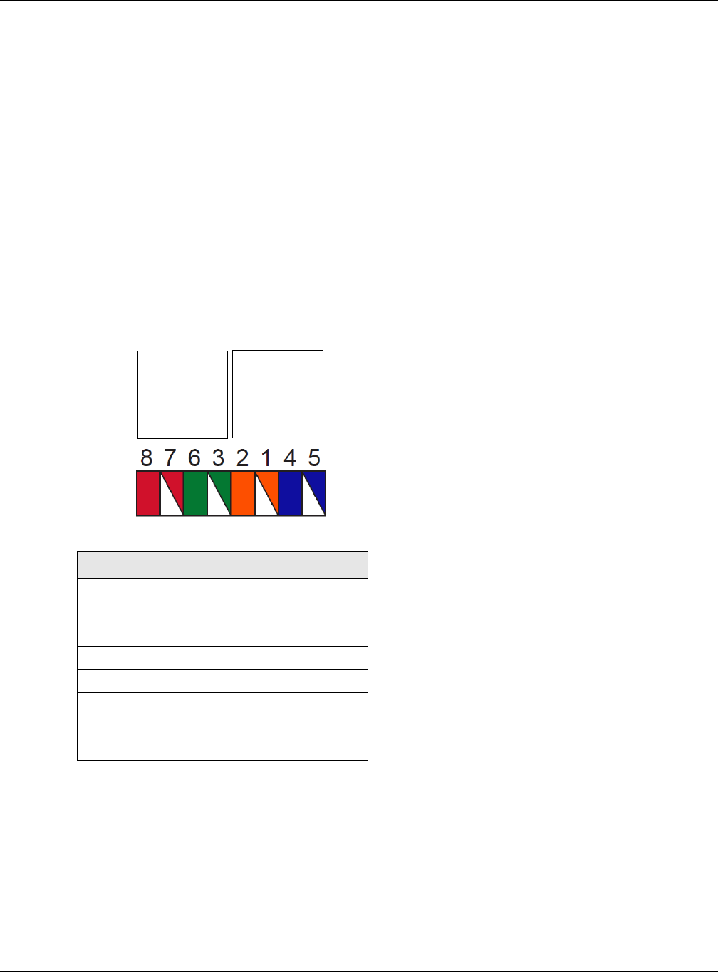
1.5.1 110 Punch-Down Block
This section shows you how to use a punch-down tool to seat an 8-wire Ethernet cable to the 110 punch-
down block. You can connect a PoE switch to the 110 punch-down block to provide power and
Internet access to the NWA through this connection. An 8-pin Ethernet cable has four pairs of color
coded wires.
1Cut out one and a half inches of the jacket from the Ethernet cable to expose the wires.
2Untwist the wire pairs no more than one inch.
3Match each wire to the correct slot according to the color codes for wiring shown below.
4Use a punch-down tool to seat the wires down properly into the slot.
Table 4 Color Codes for 110 Punch Down Block Wiring
PIN# WIRE COLOR
1White/Orange
2Orange
3 White/Green
4Blue
5White/Blue
6 Green
7White/Brown
8Brown
PIN#
PHONE
PORT UPLINK
PORT
NWA Rear Panel
Chapter 1 Introduction
NWA / WAC Series User’s Guide
19
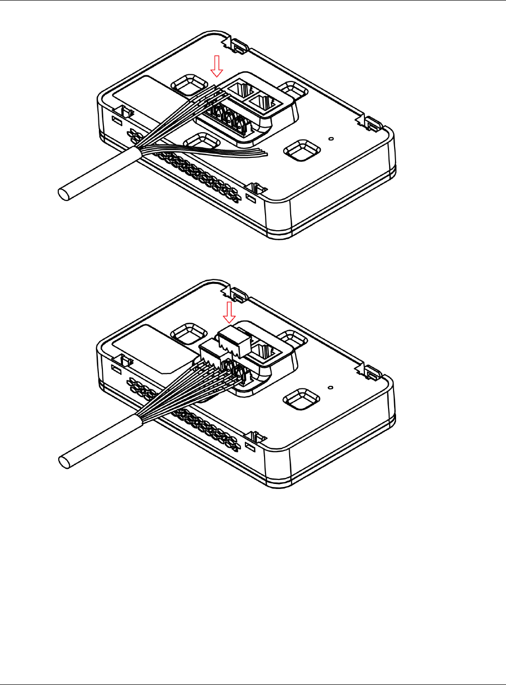
5Trim any excess wires. Place the dust caps over the terminated wires.
1.5.2 Phone Port
Connect a digital telephone to the RJ-45 PHONE port at the bottom of the NWA to forward voice traffic
to/from the telephone switchboard that is connected to the RJ-45 PHONE port on the back of the NWA.
The NWA does not support VoIP (Voice over Internet Protocol) and the PHONE port is NOT for making
calls over the regular networking network (PSTN), either.
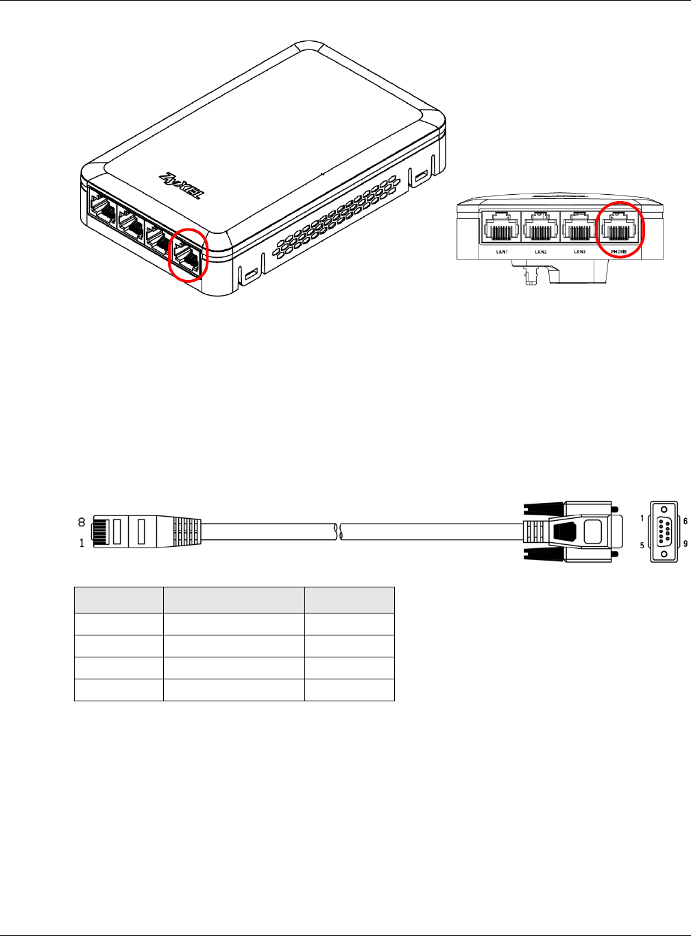
1.5.3 Console Port
To use the CLI commands to configure the NWA, connect an RJ-45-to-DB-9 cable to the PHONE port at
the bottom of the NWA.
Chapter 1 Introduction
NWA / WAC Series User’s Guide
20
For local management, you can use a computer with terminal emulation software configured to the
following parameters:
• VT100 terminal emulation
• 115200 bps
• No parity, 8 data bits, 1 stop bit
• No flow control
The following table shows you the wire color codes and pin assignment for the console cable.
1.6 LEDs
The LEDs of your WAC6500 and NWA5301 can be controlled by using the Suppression feature such that
the LEDs stay lit (ON) or OFF after the device is ready.
The WAC6500 also features Locator LED which allows you to see the actual location of the WAC6500
between several devices in the network.
Following are LED descriptions for the NWA/WAC series models.
Table 5 RJ45-to-DB-9 Console Cable Color Codes
RJ45 PIN# WIRE COLOR DB-9 PIN#
1Black 1
7Brown 2
2Blue 3
8Purple 5
Chapter 1 Introduction
NWA / WAC Series User’s Guide
21
1.6.1 WAC6502D-E, WAC6502D-S, and WAC6503D-S
The LEDs will stay ON when the WAC6500 Series is ready. You can change this setting in the Maintenance
> LEDs > Suppression screen.
Figure 5 WAC6500 Series LEDs
The following table describes the LEDs.
Table 6 WAC6500 Series LEDs
LED COLOR STATUS DESCRIPTION
PWR/SYS Red Slow Blinking (On for 1s,
Off for 1s)
The WAC is booting up.
Green On
Red Off The WAC is ready for use.
Green On
Red On There is system error and the WAC cannot boot up, or the
WAC suffered a system failure.
Green Off
Red Fast Blinking (on for
50ms, Off for 50ms)
The WAC is doing firmware upgrade.
Green Off
Red Slow Blinking (blink for 3
times, Off for 3s)
The Uplink port is disconnected.
Green Off
Red Slow Blinking (blink for 2
times, Off for 3s)
The wireless module of the WAC is disabled or failed.
Green Off
Chapter 1 Introduction
NWA / WAC Series User’s Guide
22
1.6.2 WAC6103D-I
The LEDs will stay ON when the WAC6103D-I is ready. You can change this setting in the Maintenance >
LEDs > Suppression screen.
Figure 6 WAC6103D-I LEDs
Management Green On The WAC AP is managed by a controller.
Slow Blinking (blink for 3
times, Off for 3s)
The WAC AP is searching (discovery) for a controller.
Off The WAC AP is in standalone mode.
WLAN Green On The 2.4 GHz WLAN is active.
Blinking The 2.4 GHz WLAN is transmitting or receiving data.
Off The 2.4 GHz WLAN is not active.
WLAN Green On The 5 GHz WLAN is active.
Blinking The 5 GHz WLAN is transmitting or receiving data.
Off The 5 GHz WLAN is not active.
UPLINK Amber/
Green
On Amber - The port is operating as a 100-Mbps connection.
Green - The port is operating as a Gigabit connection
(1000 Mbps).
Blinking The WAC is sending/receiving data through the port.
Off The port is not connected.
LAN Amber/
Green
On Amber - The port is operating as a 100-Mbps connection.
Green - The port is operating as a Gigabit connection
(1000 Mbps).
Blinking The LAN port is sending/receiving data through the port.
Off The LAN port is not connected.
Locator White Blinking The Locator is activated and will show the actual location
of the WAC between several devices in the network.
Off The Locator function is off.
Table 6 WAC6500 Series LEDs (continued)
LED COLOR STATUS DESCRIPTION
Chapter 1 Introduction
NWA / WAC Series User’s Guide
23
The following table describes the LEDs.
Table 7 WAC6103D-I LEDs
LED COLOR STATUS DESCRIPTION
PWR/SYS Red Slow Blinking (On for 1s,
Off for 1s)
The WAC is booting up.
Green On
Red Off The WAC is ready for use.
Green On
Red On There is system error and the WAC cannot boot up, or the
WAC suffered a system failure.
Green Off
Red Fast Blinking (on for
50ms, Off for 50ms)
The WAC is doing firmware upgrade.
Green Off
Red Slow Blinking (blink for 3
times, Off for 3s)
The Uplink port is disconnected.
Green Off
Red Slow Blinking (blink for 2
times, Off for 3s)
The wireless module of the WAC is disabled or failed.
Green Off
Management Green On The WAC is managed by a controller.
Slow Blinking (blink for 3
times, Off for 3s)
The WAC is searching (discovery) for a controller.
Off The WAC is in standalone mode.
WLAN Green On The antenna switch is set to “Ceiling” for the radio.
The 2.4 GHz WLAN is active.
Blinking The antenna switch is set to “Ceiling” for the radio.
The 2.4 GHz WLAN is transmitting or receiving data.
Amber On The antenna switch is set to “Wall” for the radio.
The 2.4 GHz WLAN is active.
Blinking The antenna switch is set to “Wall” for the radio.
The 2.4 GHz WLAN is transmitting or receiving data.
Off The 2.4 GHz WLAN is not active.
WLAN Green On The antenna switch is set to “Ceiling” for the radio.
The 5 GHz WLAN is active.
Blinking The antenna switch is set to “Ceiling” for the radio.
The 5 GHz WLAN is transmitting or receiving data.
Amber On The antenna switch is set to “Wall” for the radio.
The 5 GHz WLAN is active.
Blinking The antenna switch is set to “Wall” for the radio.
The 5 GHz WLAN is transmitting or receiving data.
Off The 5 GHz WLAN is not active.
Chapter 1 Introduction
NWA / WAC Series User’s Guide
24
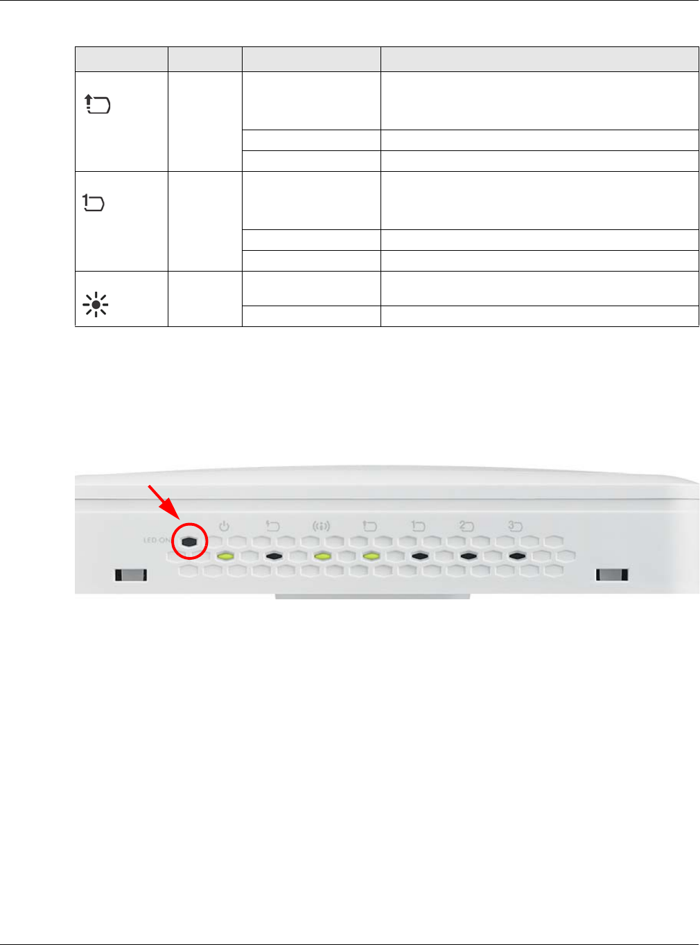
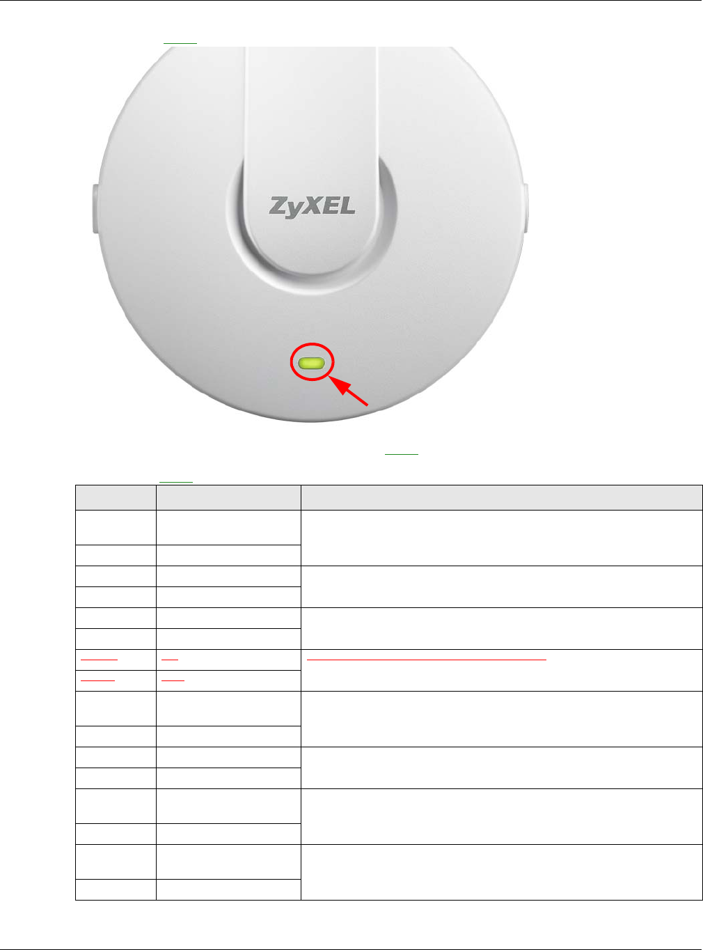
1.6.3 NWA5301-NJ
The LEDs automatically turn off when the NWA5301-NJ is ready. You can press the LED ON button for one
second to turn on the LEDs again. The LEDs will blink and turn off after two minutes.
Figure 7 NWA5301-NJ LEDs
UPLINK Amber/
Green
On Amber - The port is operating as a 100-Mbps connection.
Green - The port is operating as a Gigabit connection
(1000 Mbps).
Blinking The WAC is sending/receiving data through the port.
Off The port is not connected.
LAN Amber/
Green
On Amber - The port is operating as a 100-Mbps connection.
Green - The port is operating as a Gigabit connection
(1000 Mbps).
Blinking The LAN port is sending/receiving data through the port.
Off The LAN port is not connected.
Locator White Blinking The Locator is activated and will show the actual location
of the WAC between several devices in the network.
Off The Locator function is off.
Table 7 WAC6103D-I LEDs (continued)
LED COLOR STATUS DESCRIPTION
Chapter 1 Introduction
NWA / WAC Series User’s Guide
25
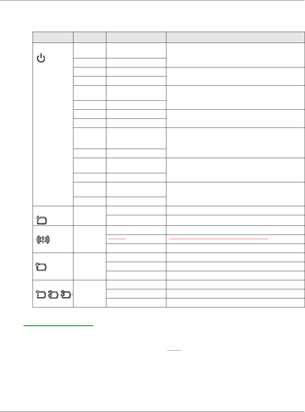
The following are the LED descriptions for your NWA5301-NJ.
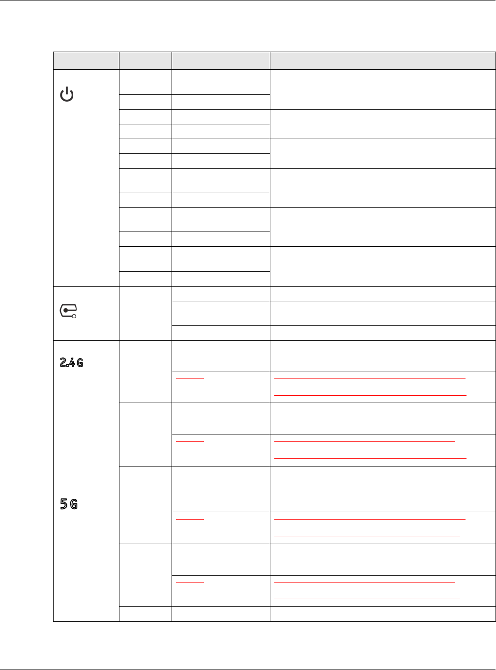
1.6.4 NWA1123-ACv2, NWA5121-N, NWA5121-NI, NWA5123-AC and
NWA5123-NI
The following are the LED descriptions for your NWA1123/5120 series.
Table 8 NWA5301-NJ LEDs
LABEL COLOR STATUS DESCRIPTION
PWR/SYS Amber Slow Blinking (On for 1s,
Off for 1s)
The NWA is booting up.
Green On
Amber Off The NWA is ready for use.
Green On
Amber Slow Blinking (blink for 3
times, Off for 3s)
The NWA is discovering an AP controller
Green On
Amber On The NWA failed to boot up or is experiencing system
failure.
Green Off
Amber Fast Blinking (On for
50ms times, Off for
50ms)
The NWA is undergoing firmware upgrade.
Green Off
Amber Slow Blinking (blink for 3
times, Off for 3s)
The Uplink port is disconnected.
Green Off
Amber Slow Blinking (blink for 2
times, Off for 3s)
The wireless module of the WAC is disabled or failed.
Green Off
PoE Green On Power is supplied to the yellow PoE Ethernet port (LAN1).
Off There is no power supply.
WLAN Green On The WLAN is active.
Blinking The WLAN is transmitting or receiving data.
Off The WLAN is not active.
UPLINK Green On The port is connected.
Blinking The NWA is sending/receiving data through the port.
Off The port is not connected.
LAN1-3 Green On The port is connected.
Blinking The NWA is sending/receiving data through the port.
Off The port is not connected.
Chapter 1 Introduction
NWA / WAC Series User’s Guide
26
Figure 8 NWA1123/5120 Series LED
The following are the LED descriptions for your NWA1123/5120 series.
Table 9 NWA1123/5120 Series LED
COLOR STATUS DESCRIPTION
Amber Slow Blinking (On for 1s,
Off for 1s)
The NWA is booting up.
Green Off
Amber Off The NWA is ready for use.
Green Off
Amber Off The NWA’s wireless interface is activated.
Green On
Amber Off The NWA is receiving/sending wireless traffic.
Green Blink
Amber Slow Blinking (blink for 3
times, Off for 3s)
The NWA is discovering an AP controller.
Green On
Amber On The NWA failed to boot up or is experience system failure.
Green Off
Amber Fast Blinking (On for
50ms, Off for 50ms)
The NWA is undergoing firmware upgrade.
Green Off
Amber Slow Blinking (blink for 3
times, Off for 3s)
The Uplink port is disconnected.
Green Off
Chapter 1 Introduction
NWA / WAC Series User’s Guide
27
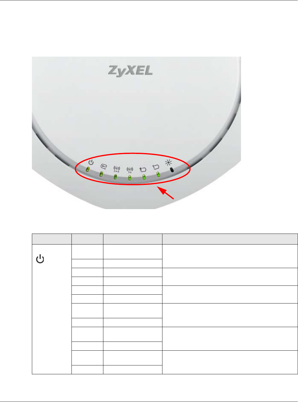
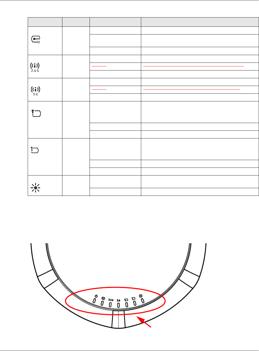
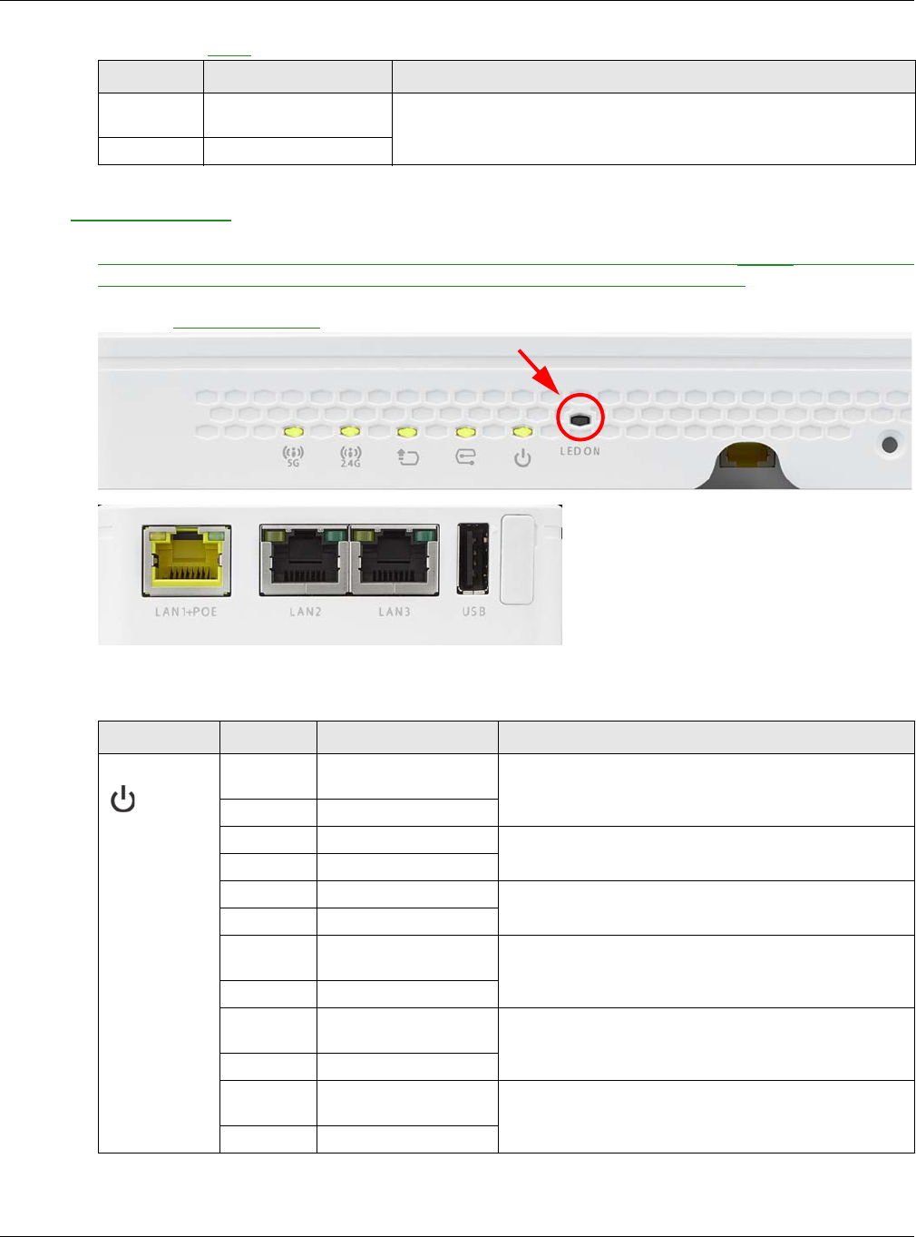
1.6.5 WAC5302D-S
The LEDs automatically turn off when the WAC5302D-S is ready. You can press the LED ON button for one
second to turn on the LEDs again. The LEDs will blink and turn off after two minutes.
Figure 9 WAC5302D-S LEDs
The following table describes the LEDs.
Amber Slow Blinking (blink for 2
times, Off for 3s)
The wireless LAN is disabled or fails.
Green Off
Table 9 NWA1123/5120 Series LED (continued)
COLOR STATUS DESCRIPTION
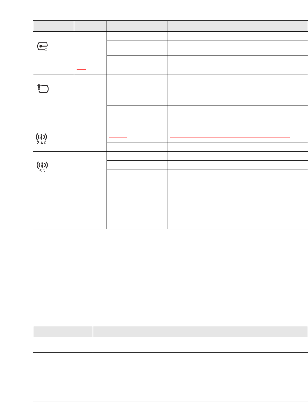
Table 10 WAC5302D-S LEDs
LED COLOR STATUS DESCRIPTION
PWR/SYS Red Slow Blinking (On for 1s,
Off for 1s)
The WAC is booting up.
Green On
Red Off The WAC is ready for use.
Green On
Red On There is system error and the WAC cannot boot up, or the
WAC suffered a system failure.
Green Off
Red Fast Blinking (on for
50ms, Off for 50ms)
The WAC is doing firmware upgrade.
Green Off
Red Slow Blinking (blink for 3
times, Off for 3s)
The Uplink port is disconnected.
Green Off
Red Slow Blinking (blink for 2
times, Off for 3s)
The wireless module of the WAC is disabled or failed.
Green Off
Chapter 1 Introduction
NWA / WAC Series User’s Guide
28
1.7 Starting and Stopping the NWA/WAC
Here are some of the ways to start and stop the NWA/WAC.
Always use Maintenance > Shutdown or the shutdown command
before you turn off the NWA/WAC or remove the power. Not doing so
can cause the firmware to become corrupt.
Management Green On The WAC AP is managed by a controller.
Slow Blinking (blink for 3
times, Off for 3s)
The WAC AP is searching (discovery) for a controller.
Off The WAC AP is in standalone mode.
Red
UPLINK Amber/
Green
On Amber - The port is operating as a 10/100-Mbps
connection.
Green - The port is operating as a Gigabit connection
(1000 Mbps).
Blinking The WAC is sending/receiving data through the port.
Off The port is not connected.
WLAN Green On The 2.4 GHz WLAN is active.
Blinking The 2.4 GHz WLAN is transmitting or receiving data.
Off The 2.4 GHz WLAN is not active.
WLAN Green On The 5 GHz WLAN is active.
Blinking The 5 GHz WLAN is transmitting or receiving data.
Off The 5 GHz WLAN is not active.
LAN Amber/
Green
On Amber - The port is operating as a 10/100-Mbps
connection.
Green - The port is operating as a Gigabit connection
(1000 Mbps).
Blinking The LAN port is sending/receiving data through the port.
Off The LAN port is not connected.
Table 10 WAC5302D-S LEDs (continued)
LED COLOR STATUS DESCRIPTION
Table 11 Starting and Stopping the NWA/WAC
METHOD DESCRIPTION
Turning on the power A cold start occurs when you turn on the power to the NWA/WAC. The NWA/WAC
powers up, checks the hardware, and starts the system processes.
Rebooting the NWA/
WAC
A warm start (without powering down and powering up again) occurs when you use the
Reboot button in the Reboot screen or when you use the reboot command. The NWA/
WAC writes all cached data to the local storage, stops the system processes, and then
does a warm start.
Using the RESET button If you press the RESET button on the back of the NWA/WAC, the NWA/WAC sets the
configuration to its default values and then reboots. See Section 20.6 on page 197 for
more information.

Chapter 1 Introduction
NWA / WAC Series User’s Guide
29
The NWA/WAC does not stop or start the system processes when you apply configuration files or run shell
scripts although you may temporarily lose access to network resources.
Clicking Maintenance
> Shutdown >
Shutdown or using the
shutdown command
Clicking Maintenance > Shutdown > Shutdown or using the shutdown command writes all
cached data to the local storage and stops the system processes. Wait for the device to
shut down and then manually turn off or remove the power. It does not turn off the
power.
Disconnecting the
power
Power off occurs when you turn off the power to the NWA/WAC. The NWA/WAC simply
turns off. It does not stop the system processes or write cached data to local storage.
Table 11 Starting and Stopping the NWA/WAC
METHOD DESCRIPTION
NWA / WAC Series User’s Guide
30
CHAPTER 2
The Web Configurator
2.1 Overview
The NWA/WAC Web Configurator allows easy management using an Internet browser. Browsers
supported are:
• Firefox 36.0.1 or later
• Chrome 41.0 or later
• IE 10 or later
The recommended screen resolution is 1024 x 768 pixels and higher.
2.2 Accessing the Web Configurator
1Make sure your NWA/WAC is working in standalone AP mode (see Section 1.1.1 on page 13) and
hardware is properly connected. See the Quick Start Guide.
2If the NWA/WAC and your computer are not connected to a DHCP server, make sure your computer’s
IP address is in the range between "192.168.1.3" and "192.168.1.254".
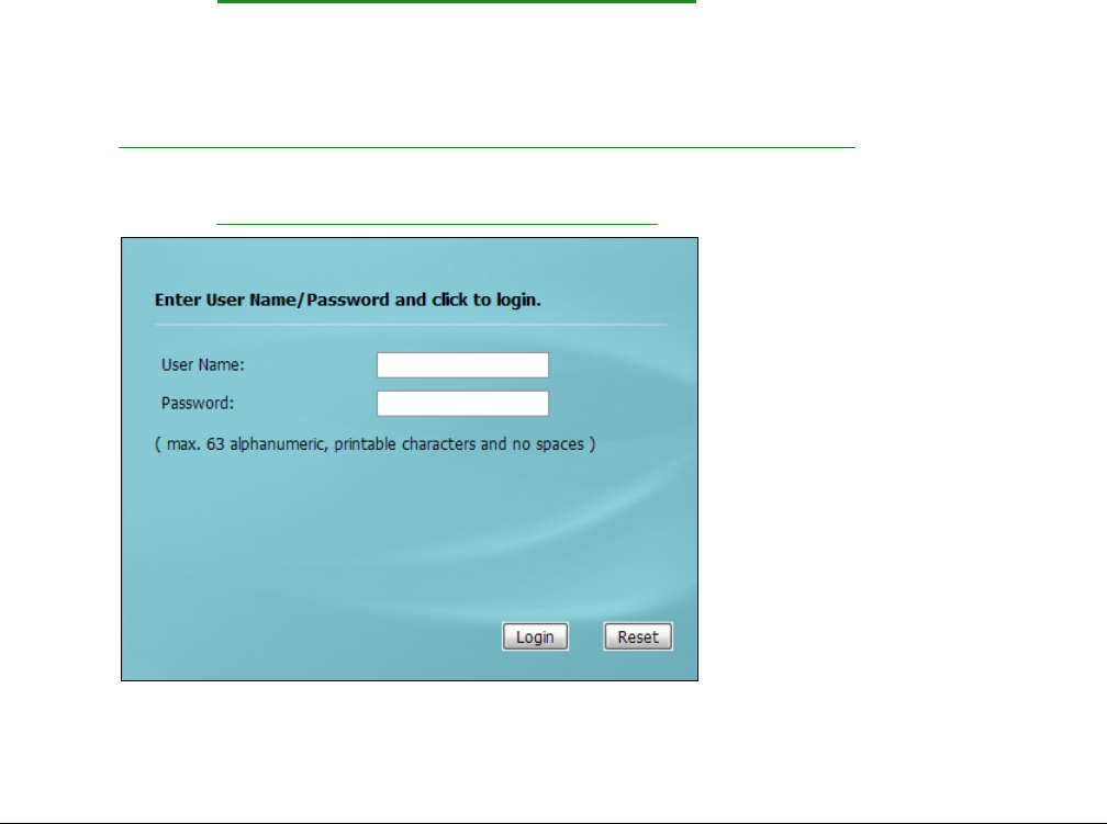
3Browse to the NWA/WAC’s DHCP-assigned IP address or http://192.168.1.2. The Login screen appears.
4Enter the user name (default: “admin”) and password (default: “1234”).
Chapter 2 The Web Configurator
NWA / WAC Series User’s Guide
31
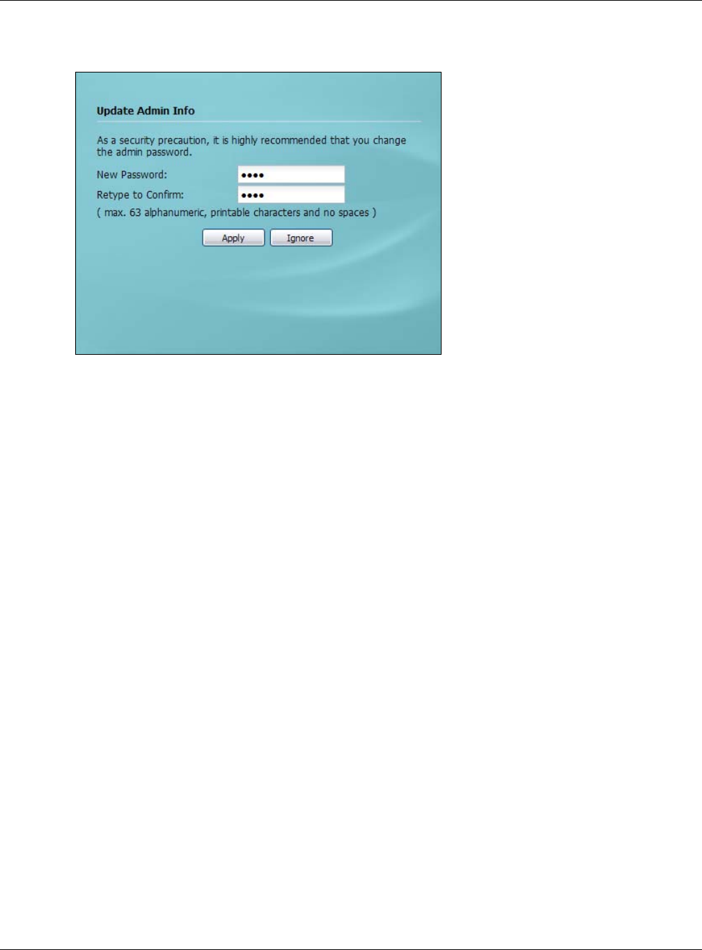
5Click Login. If you logged in using the default user name and password, the Update Admin Info screen
appears. Otherwise, the dashboard appears.
The Update Admin Info screen appears every time you log in using the default user name and default
password. If you change the password for the default user account, this screen does not appear
anymore.
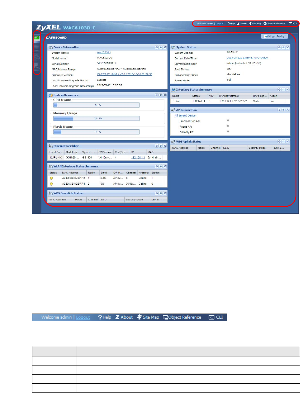
2.3 Navigating the Web Configurator
The following summarizes how to navigate the web configurator from the Dashboard screen. This guide
uses the WAC6103D-I screens as an example. The screens may vary slightly for different models.
Chapter 2 The Web Configurator
NWA / WAC Series User’s Guide
32
Figure 10 The Web Configurator’s Main Screen
The Web Configurator’s main screen is divided into these parts:
•A - Title Bar
•B - Navigation Panel
•C - Main Window
2.3.1 Title Bar
The title bar provides some useful links that always appear over the screens below, regardless of how
deep into the Web Configurator you navigate.
Figure 11 Title Bar
The icons provide the following functions.
A
C
B
Table 12 Title Bar: Web Configurator Icons
LABEL DESCRIPTION
Logout Click this to log out of the Web Configurator.
Help Click this to open the help page for the current screen.
About Click this to display basic information about the NWA/WAC.
Site Map Click this to see an overview of links to the Web Configurator screens.
Chapter 2 The Web Configurator
NWA / WAC Series User’s Guide
33
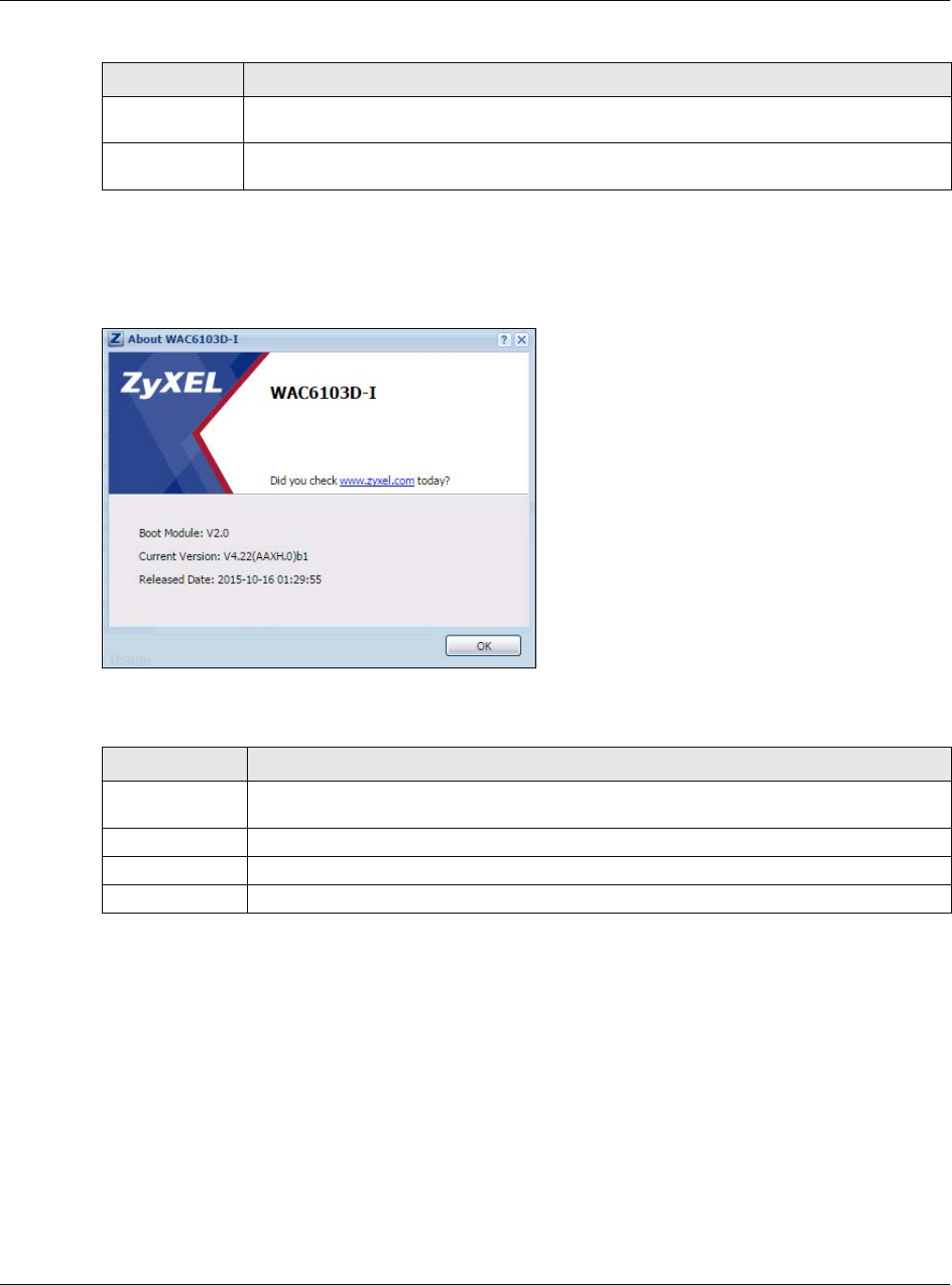
About
Click About to display basic information about the NWA/WAC.
Figure 12 About
The following table describes labels that can appear in this screen.
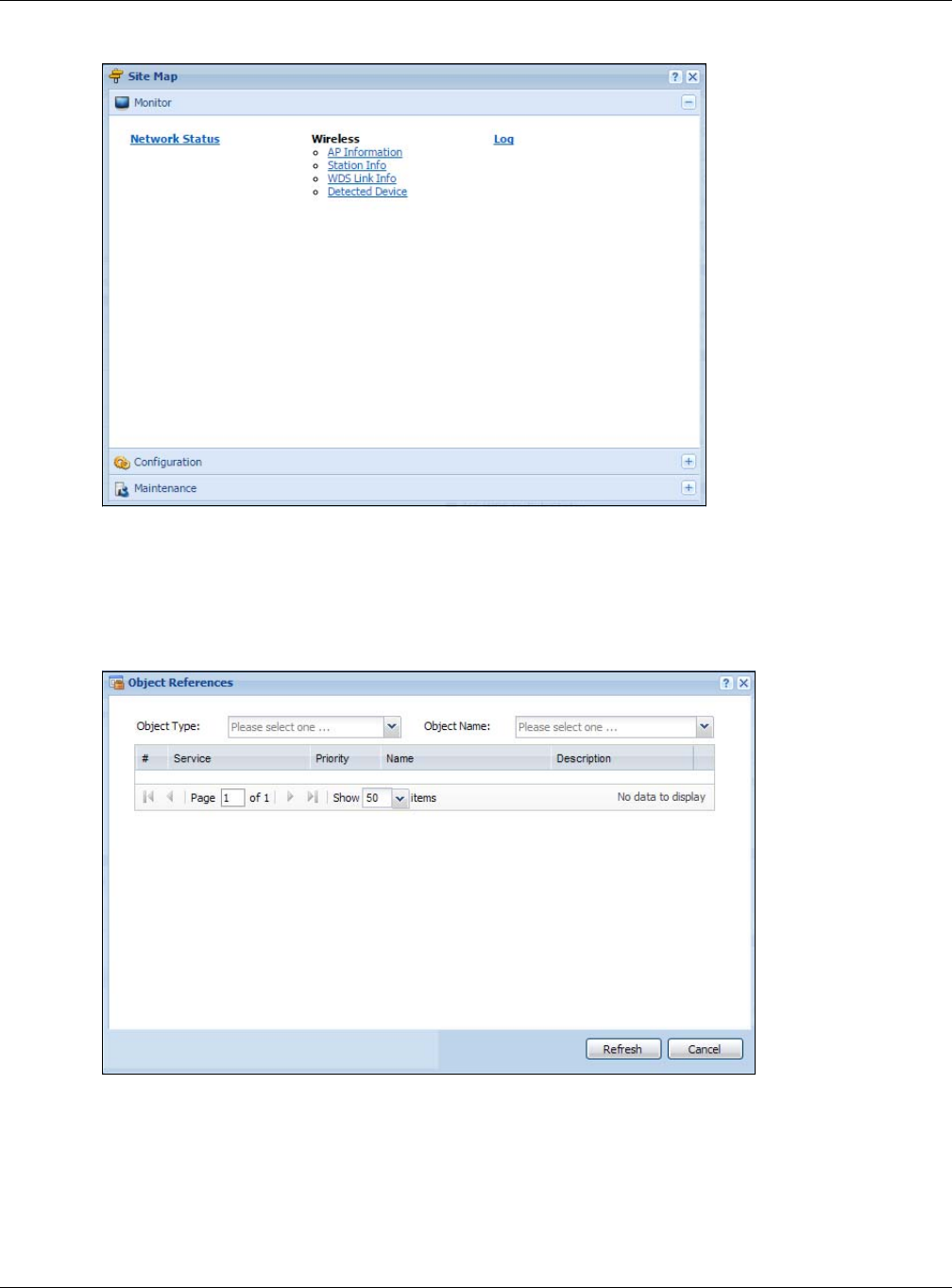
Site Map
Click Site MAP to see an overview of links to the Web Configurator screens. Click a screen’s link to go to
that screen.
Object
Reference
Click this to open a screen where you can check which configuration items reference an
object.
CLI Click this to open a popup window that displays the CLI commands sent by the Web
Configurator.
Table 13 About
LABEL DESCRIPTION
Boot Module This shows the version number of the software that handles the booting process of the NWA/
WAC.
Current Version This shows the firmware version of the NWA/WAC.
Released Date This shows the date (yyyy-mm-dd) and time (hh:mm:ss) when the firmware is released.
OK Click this to close the screen.
Table 12 Title Bar: Web Configurator Icons (continued)
LABEL DESCRIPTION
Chapter 2 The Web Configurator
NWA / WAC Series User’s Guide
34
Figure 13 Site Map
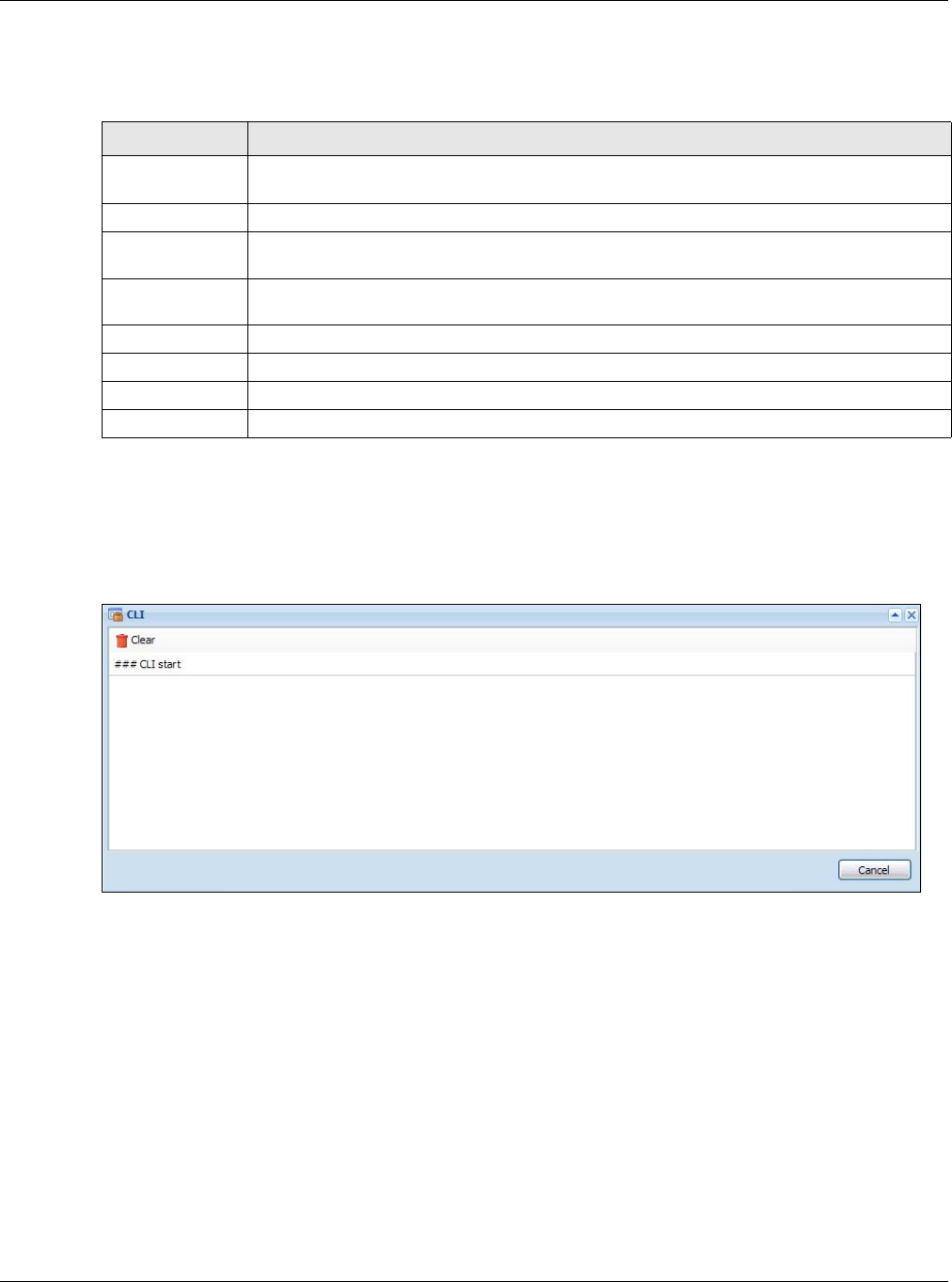
Object Reference
Click Object Reference to open the Object Reference screen. Select the type of object and the
individual object and click Refresh to show which configuration settings reference the object.
Figure 14 Object Reference
Chapter 2 The Web Configurator
NWA / WAC Series User’s Guide
35
The fields vary with the type of object. The following table describes labels that can appear in this
screen.
CLI Messages
Click CLI to look at the CLI commands sent by the Web Configurator. These commands appear in a
popup window, such as the following.
Figure 15 CLI Messages
Click Clear to remove the currently displayed information.
Note: See the Command Reference Guide for information about the commands.
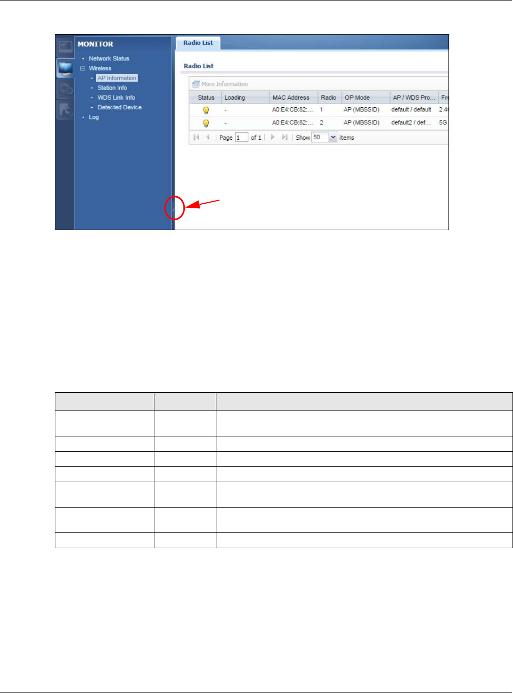
2.3.2 Navigation Panel
Use the menu items on the navigation panel to open screens to configure NWA/WAC features. Click the
arrow in the middle of the right edge of the navigation panel to hide the navigation panel menus or
drag it to resize them. The following sections introduce the NWA/WAC’s navigation panel menus and
their screens.
Table 14 Object References
LABEL DESCRIPTION
Object Name This identifies the object for which the configuration settings that use it are displayed. Click the
object’s name to display the object’s configuration screen in the main window.
# This field is a sequential value, and it is not associated with any entry.
Service This is the type of setting that references the selected object. Click a service’s name to display
the service’s configuration screen in the main window.
Priority If it is applicable, this field lists the referencing configuration item’s position in its list, otherwise N/
A displays.
Name This field identifies the configuration item that references the object.
Description If the referencing configuration item has a description configured, it displays here.
Refresh Click this to update the information in this screen.
Cancel Click Cancel to close the screen.
Chapter 2 The Web Configurator
NWA / WAC Series User’s Guide
36
Figure 16 Navigation Panel
Dashboard
The dashboard displays general device information, system status, system resource usage, and
interface status in widgets that you can re-arrange to suit your needs.
For details on the Dashboard’s features, see Chapter 3 on page 43.
Monitor Menu
The monitor menu screens display status and statistics information.
Table 15 Monitor Menu Screens Summary
FOLDER OR LINK TAB FUNCTION
Network Status Network
Status
Display general LAN interface information and packet statistics.
Wireless
AP Information Radio List Display information about the radios of the connected APs.
Station Info Station List Display information about the connected stations.
WDS Link Info WDS Link Info Display statistics about the NWA/WAC’s WDS (Wireless Disctribution
System) connections.
Detected Device Detected
Device
Display information about suspected rogue APs.
Log View Log Display log entries for the NWA/WAC.

Chapter 2 The Web Configurator
NWA / WAC Series User’s Guide
37
Configuration Menu
Use the configuration menu screens to configure the NWA/WAC’s features.
Table 16 Configuration Menu Screens Summary
FOLDER OR LINK TAB FUNCTION
Network IP Setting Configure the IP address for the NWA/WAC Ethernet interface.
VLAN Manage the Ethernet interface VLAN settings.
AC Discovery Configures the NWA/WAC’s AP Controller settings.
Wireless
AP
Management WLAN Setting Manage the NWA/WAC’s general wireless settings.
MON Mode Rogue/Friendly AP
List
Configure how the NWA/WAC monitors for rogue APs.
Load Balancing Load Balancing Configure load balancing for traffic moving to and from wireless
clients.
DCS DCS Configure dynamic wireless channel selection.
Object
User User Create and manage users.
Setting Manage default settings for all users, general settings for user sessions,
and rules to force user authentication.
AP Profile Radio Create and manage wireless radio settings files that can be
associated with different APs.
SSID Create and manage wireless SSID, security, MAC filtering, and layer-2
isolation files that can be associated with different APs.
MON Profile MON Profile Create and manage rogue AP monitoring files that can be
associated with different APs.
WDS Profile WDS Create and manage WDS profiles that can be used to connect to
different APs in WDS.
Certificate My Certificates Create and manage th e NWA/WAC’s certificates.
Trusted Certificates Import and manage certificates from trusted sources.
System
Host Name Host Name Configure the system and domain name for the NWA/WAC.
Date/Time Date/Time Configure the current date, time, and time zone in the NWA/WAC.
WWW Service Control Configure HTTP, HTTPS, and general authentication.
SSH SSH Configure SSH server and SSH service settings.
TELNET TELNET Configure telnet server settings for the NWA/WAC.
FTP FTP Configure FTP server settings.
SNMP SNMP Configure SNMP communities and services.
Log & Report
Email Daily
Report Email Daily Report Configure where and how to send daily reports and what reports to
send.
Log Setting Log Setting Configure the system log, e-mail logs, and remote syslog servers.
Chapter 2 The Web Configurator
NWA / WAC Series User’s Guide
38
Maintenance Menu
Use the maintenance menu screens to manage configuration and firmware files, run diagnostics, and
reboot or shut down the NWA/WAC.
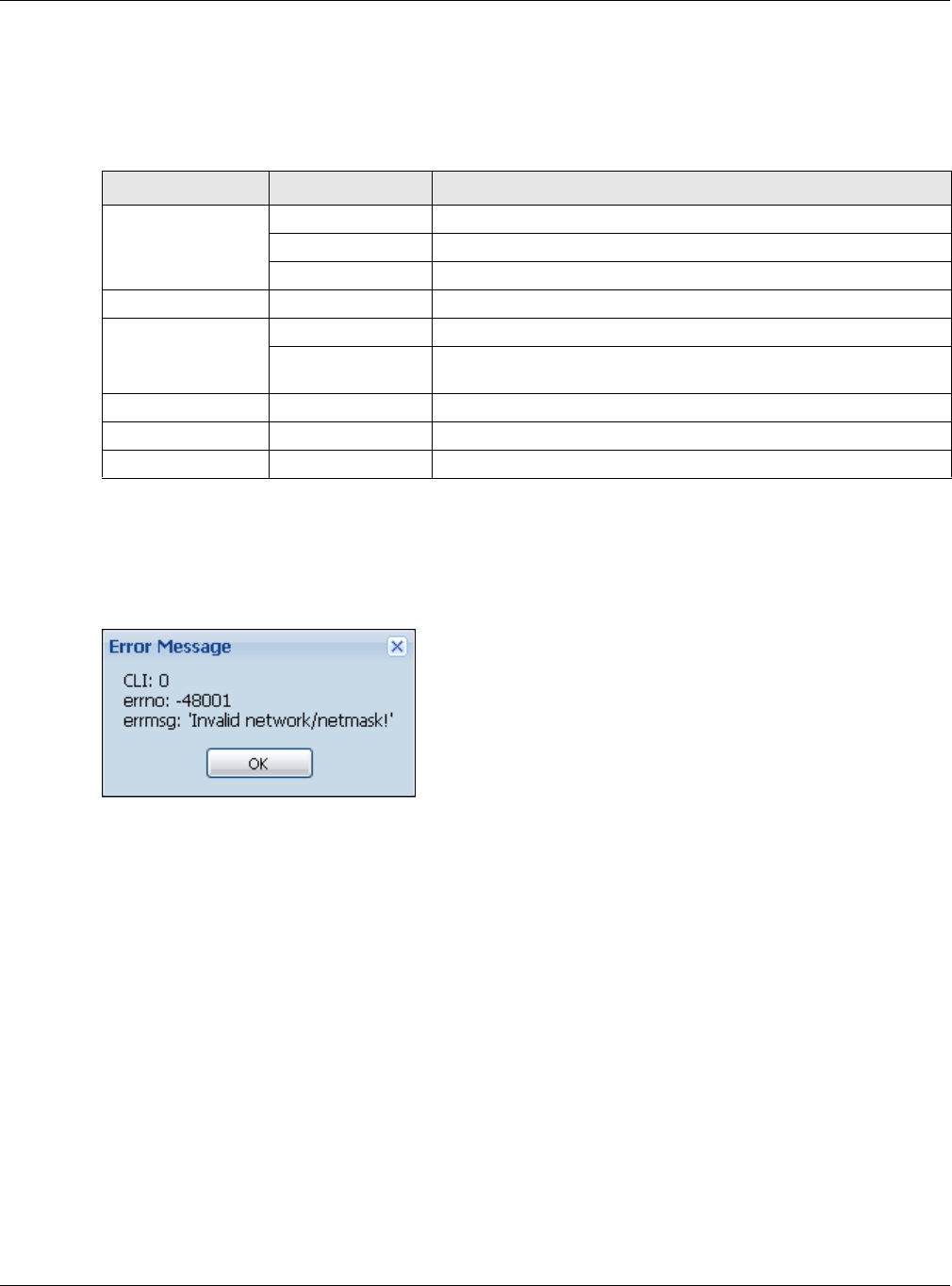
2.3.3 Warning Messages
Warning messages, such as those resulting from misconfiguration, display in a pop up window.
Figure 17 Warning Message
2.3.4 Tables and Lists
The Web Configurator tables and lists are quite flexible and provide several options for how to display
their entries.
2.3.4.1 Manipulating Table Display
Here are some of the ways you can manipulate the Web Configurator tables.
Table 17 Maintenance Menu Screens Summary
FOLDER OR LINK TAB FUNCTION
File Manager Configuration File Manage and upload configuration files for the NWA/WAC.
Firmware Package View the current firmware version and to upload firmware.
Shell Script Manage and run shell script files for the NWA/WAC.
Diagnostics Diagnostics Collect diagnostic information.
LEDs Suppression Enable this feature to keep the LEDs off after the NWA/WAC starts.
Locator Enable this feature to see the actual location of the NWA/WAC
between several devices in the network.
Antenna Antenna Switch Change antenna orientation for the radios.
Reboot Reboot Restart the NWA/WAC.
Shutdown Shutdown Turn off the NWA/WAC.
Chapter 2 The Web Configurator
NWA / WAC Series User’s Guide
39
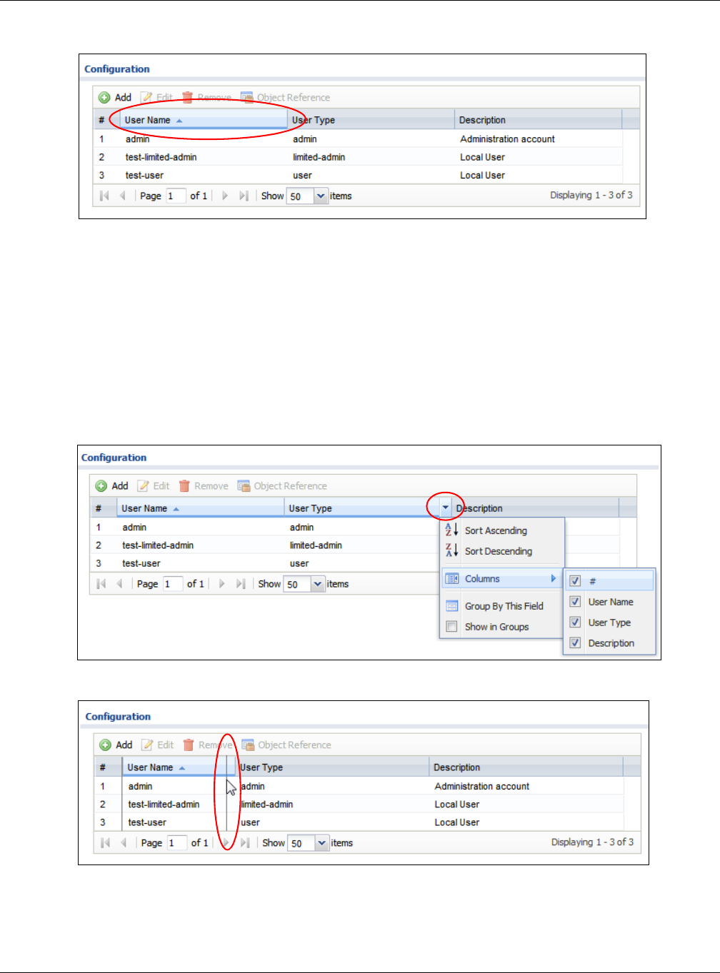
1Click a column heading to sort the table’s entries according to that column’s criteria.
2Click the down arrow next to a column heading for more options about how to display the entries. The
options available vary depending on the type of fields in the column. Here are some examples of what
you can do:
• Sort in ascending alphabetical order
• Sort in descending (reverse) alphabetical order
• Select which columns to display
•Group entries by field
•Show entries in groups
• Filter by mathematical operators (<, >, or =) or searching for text.
3Select a column heading cell’s right border and drag to re-size the column.
Chapter 2 The Web Configurator
NWA / WAC Series User’s Guide
40
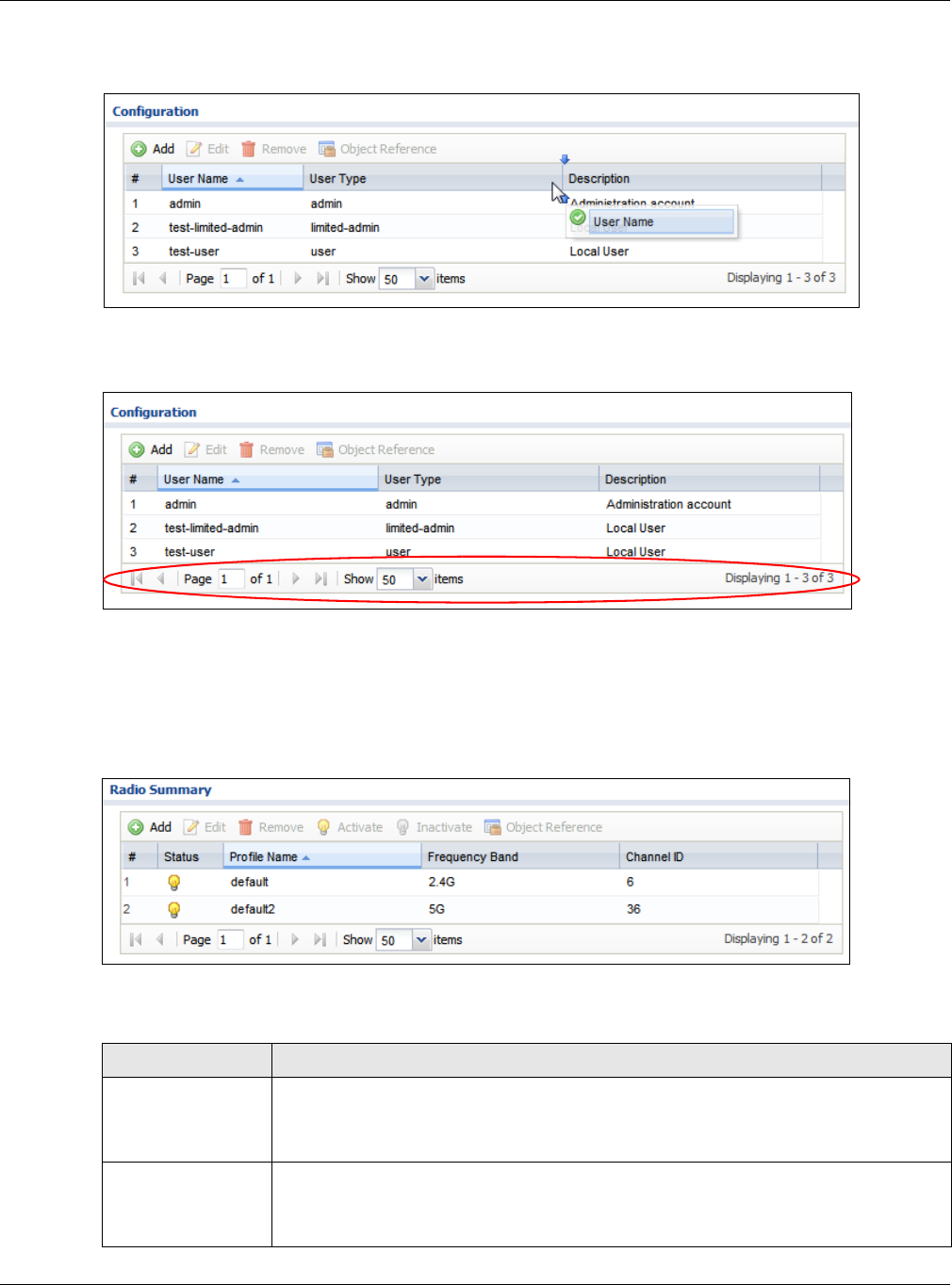
4Select a column heading and drag and drop it to change the column order. A green check mark
displays next to the column’s title when you drag the column to a valid new location.
5Use the icons and fields at the bottom of the table to navigate to different pages of entries and control
how many entries display at a time.
2.3.4.2 Working with Table Entries
The tables have icons for working with table entries. A sample is shown next. You can often use the [Shift]
or [Ctrl] key to select multiple entries to remove, activate, or deactivate.
Table 18 Common Table Icons
Here are descriptions for the most common table icons.
Table 19 Common Table Icons
LABEL DESCRIPTION
Add Click this to create a new entry. For features where the entry’s position in the numbered list is
important (features where the NWA/WAC applies the table’s entries in order like the firewall
for example), you can select an entry and click Add to create a new entry after the
selected entry.
Edit Double-click an entry or select it and click Edit to open a screen where you can modify the
entry’s settings. In some tables you can just click a table entry and edit it directly in the
table. For those types of tables small red triangles display for table entries with changes that
you have not yet applied.
Chapter 2 The Web Configurator
NWA / WAC Series User’s Guide
41
2.3.4.3 Working with Lists
When a list of available entries displays next to a list of selected entries, you can often just double-click
an entry to move it from one list to the other. In some lists you can also use the [Shift] or [Ctrl] key to
select multiple entries, and then use the arrow button to move them to the other list.
Figure 18 Working with Lists
Remove To remove an entry, select it and click Remove. The NWA/WAC confirms you want to
remove it before doing so.
Activate To turn on an entry, select it and click Activate.
Inactivate To turn off an entry, select it and click Inactivate.
Object Reference Select an entry and click Object Reference to open a screen that shows which settings use
the entry.
Table 19 Common Table Icons (continued)
LABEL DESCRIPTION

42
PART II
Technical Reference

NWA / WAC Series User’s Guide
43
CHAPTER 3
Dashboard
3.1 Overview
Use the Dashboard screens to check status information about the NWA/WAC.
3.1.1 What You Can Do in this Chapter
• The main Dashboard screen (Section 3.2 on page 43) displays the NWA/WAC’s general device
information, system status, system resource usage, and interface status. You can also display other
status screens for more information.
3.2 Dashboard
This screen is the first thing you see when you log into the NWA/WAC. It also appears every time you click
the Dashboard icon in the navigation panel. The Dashboard displays general device information, system
status, system resource usage, and interface status in widgets that you can re-arrange to suit your
needs. You can also collapse, refresh, and close individual widgets.
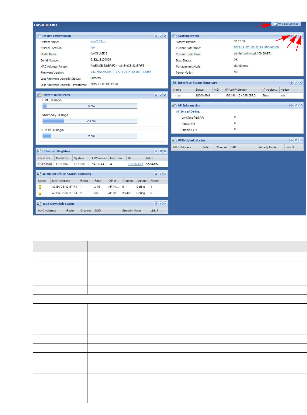
Chapter 3 Dashboard
NWA / WAC Series User’s Guide
44
Figure 19 Dashboard
The following table describes the labels in this screen.
Table 20 Dashboard
LABEL DESCRIPTION
Widget Settings (A) Use this link to re-open closed widgets. Widgets that are already open appear grayed out.
Refresh Time Setting
(B)
Set the interval for refreshing the information displayed in the widget.
Refresh Now (C) Click this to update the widget’s information immediately.
Close Widget (D) Click this to close the widget. Use Widget Setting to re-open it.
Device Information
System Name This field displays the name used to identify the NWA/WAC on any network. Click the icon to
open the screen where you can change it.
System Location This field displays the location of the NWA/WAC. Click the icon to open the screen where
you can change it.
Model Name This field displays the model name of this NWA/WAC.
Serial Number This field displays the serial number of this NWA/WAC.
MAC Address
Range This field displays the MAC addresses used by the NWA/WAC. Each physical port or wireless
radio has one MAC address. The first MAC address is assigned to the Ethernet LAN port, the
second MAC address is assigned to the first radio, and so on.
Firmware Version This field displays the version number and date of the firmware the NWA/WAC is currently
running. Click the icon to open the screen where you can upload firmware.
Last Firmware
Upgrade Status This field displays whether the latest firmware update was successfully completed.
B
CD
A

Chapter 3 Dashboard
NWA / WAC Series User’s Guide
45
Last Firmware
Upgrade
Timestamp
This field displays the date and time when the last firmware update was made.
System Resources
CPU Usage This field displays what percentage of the NWA/WAC’s processing capability is currently
being used. Hover your cursor over this field to display the Show CPU Usage icon that takes
you to a chart of the NWA/WAC’s recent CPU usage.
Memory Usage This field displays what percentage of the NWA/WAC’s RAM is currently being used. Hover
your cursor over this field to display the Show Memory Usage icon that takes you to a chart
of the NWA/WAC’s recent memory usage.
Flash Usage This field displays what percentage of the NWA/WAC’s onboard flash memory is currently
being used.
Ethernet Neighbor
Local Port
(Description) This field displays the port of the NWA/WAC, on which the neighboring device is discovered.
Model Name This field displays the model name of the discovered device.
System Name This field displays the system name of the discovered device.
FW Version This field displays the firmware version of the discovered device.
Port (Description) This field displays the discovered device’s port which is connected to the NWA/WAC.
IP This field displays the IP address of the discovered device. Click the IP address to access
and manage the discovered device using its web configurator.
MAC This field displays the MAC address of the discovered device.
WDS (Wireless Distribution System) Uplink/Downlink Status
MAC Address This field displays the MAC address of the root AP or repeater to which the NWA/WAC is
connected using WDS.
Radio This field displays the radio number on the root AP or repeater to which the NWA/WAC is
connected using WDS.
Channel This field displays the channel number on the root AP or repeater to which the NWA/WAC is
connected using WDS.
SSID This field displays the name of the wireless network to which the NWA/WAC is connected
using WDS.
Security Mode This field displays which secure encryption methods is being used by the NWA/WAC to
connect to the root AP or repeater using WDS.
Link Status This field displays the RSSI (Received Signal Strength Indicator) and transmission/reception
rate of the wireless connection in WDS.
System Status
System Uptime This field displays how long the NWA/WAC has been running since it last restarted or was
turned on.
Current Date/
Time This field displays the current date and time in the NWA/WAC. The format is yyyy-mm-dd
hh:mm:ss.
Current Login
User This field displays the user name used to log in to the current session, the amount of
reauthentication time remaining, and the amount of lease time remaining.
Table 20 Dashboard (continued)
LABEL DESCRIPTION

Chapter 3 Dashboard
NWA / WAC Series User’s Guide
46
Boot Status This field displays details about the NWA/WAC’s startup state.
OK - The NWA/WAC started up successfully.
Firmware update OK - A firmware update was successful.
Problematic configuration after firmware update - The application of the configuration
failed after a firmware upgrade.
System default configuration - The NWA/WAC successfully applied the system default
configuration. This occurs when the NWA/WAC starts for the first time or you intentionally
reset the NWA/WAC to the system default settings.
Fallback to lastgood configuration - The NWA/WAC was unable to apply the startup-
config.conf configuration file and fell back to the lastgood.conf configuration file.
Fallback to system default configuration - The NWA/WAC was unable to apply the
lastgood.conf configuration file and fell back to the system default configuration file
(system-default.conf).
Booting in progress - The NWA/WAC is still applying the system configuration.
Management
Mode This shows whether the NWA/WAC is set to work as a stand alone AP.
Power Mode This displays the NWA/WAC’s power status.
Full - the NWA/WAC reveives power using a power adaptor and/or through a PoE switch/
injector using IEEE 802.3at PoE plus.
Limited - the NWA/WAC reveives power through a PoE switch/injector using IEEE 802.3af PoE
even when it is also connected to a power source using a power adaptor.
When the NWA/WAC is in limited power mode, the NWA/WAC throughput decreases and
has just one transmitting radio chain.
It always shows Full if the NWA/WAC does not support power detection. At the time of
writing, only the WAC6500 series APs support the power detection feature.
Interface Status
Summary
If an Ethernet interface does not have any physical ports associated with it, its entry is
displayed in light gray text. Click the Detail icon to go to a (more detailed) summary screen
of interface statistics.
Name This field displays the name of each interface.
Status This field displays the current status of each interface. The possible values depend on what
type of interface it is.
Inactive - The Ethernet interface is disabled.
Down - The Ethernet interface is enabled but not connected.
Speed / Duplex - The Ethernet interface is enabled and connected. This field displays the
port speed and duplex setting (Full or Half).
VID This field displays the VLAN ID to which the interface belongs.
IP Addr/Netmask This field displays the current IP address and subnet mask assigned to the interface. If the IP
address is 0.0.0.0, the interface is disabled or did not receive an IP address and subnet mask
via DHCP.
If this interface is a member of an active virtual router, this field displays the IP address it is
currently using. This is either the static IP address of the interface (if it is the master) or the
management IP address (if it is a backup).
IP Assignment This field displays how the interface gets its IP address.
Static - This interface has a static IP address.
DHCP Client - This interface gets its IP address from a DHCP server.
Table 20 Dashboard (continued)
LABEL DESCRIPTION
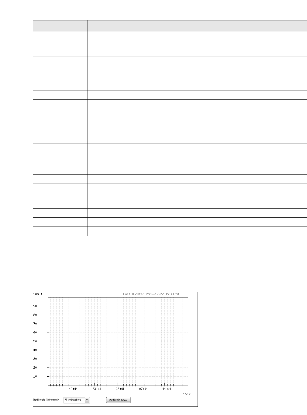
Chapter 3 Dashboard
NWA / WAC Series User’s Guide
47
3.2.1 CPU Usage
Use this screen to look at a chart of the NWA/WAC’s recent CPU usage. To access this screen, click CPU
Usage in the dashboard.
Figure 20 Dashboard > CPU Usage
Action If the interface has a static IP address, this shows n/a.
If the interface has a dynamic IP address, use this field to get or to update the IP address for
the interface. Click Renew to send a new DHCP request to a DHCP server.
WLAN Interface
Status Summary
This displays status information for the WLAN interface.
Status This displays whether or not the WLAN interface is activated.
MAC Address This displays the MAC address of the radio.
Radio This indicates the radio number on the NWA/WAC.
Band This indicates the wireless frequency band currently being used by the radio.
This shows - when the radio is in monitor mode.
OP Mode This indicates the radio’s operating mode. Operating modes are AP (MBSSID), MON
(monitor), Root AP or Repeater.
Channel This indicates the channel number the radio is using.
Antenna This indicates the antenna orientation for the radio (Wall or Ceiling).
This field is not available if the NWA/WAC does not allow you to adjust antenna orientation
for each radio using the web configurator or a physical switch. Refer to Table 1 on page 11
and Table 2 on page 12 to see if your NWA/WAC has an antenna switch.
Station This displays the number of wireless clients connected to the NWA/WAC.
AP Information This shows a summary of connected wireless Access Points (APs).
All Sensed Device This sections displays a summary of all wireless devices detected by the network. Click the
link to go to the Monitor > Wireless > Detected Device screen.
Un-Classified AP This displays the number of detected unclassified APs.
Rogue AP This displays the number of detected rogue APs.
Friendly AP This displays the number of detected friendly APs.
Table 20 Dashboard (continued)
LABEL DESCRIPTION
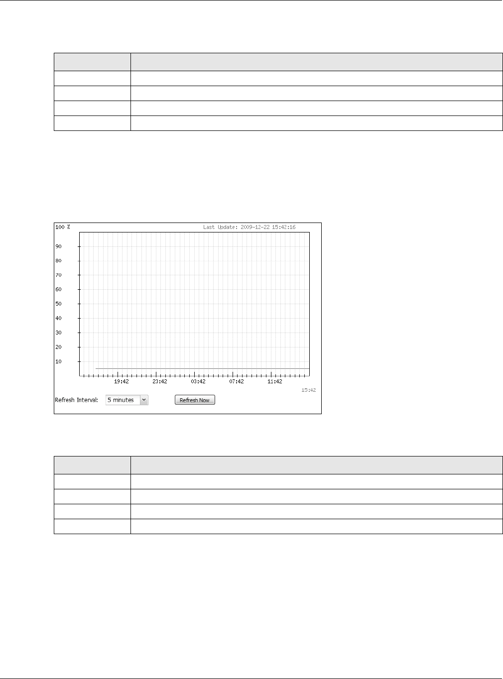
Chapter 3 Dashboard
NWA / WAC Series User’s Guide
48
The following table describes the labels in this screen.
3.2.2 Memory Usage
Use this screen to look at a chart of the NWA/WAC’s recent memory (RAM) usage. To access this screen,
click Memory Usage in the dashboard.
Figure 21 Dashboard > Memory Usage
The following table describes the labels in this screen.
Table 21 Dashboard > CPU Usage
LABEL DESCRIPTION
% The y-axis represents the percentage of CPU usage.
time The x-axis shows the time period over which the CPU usage occurred
Refresh Interval Enter how often you want this window to be automatically updated.
Refresh Now Click this to update the information in the window right away.
Table 22 Dashboard > Memory Usage
LABEL DESCRIPTION
The y-axis represents the percentage of RAM usage.
The x-axis shows the time period over which the RAM usage occurred
Refresh Interval Enter how often you want this window to be automatically updated.
Refresh Now Click this to update the information in the window right away.

NWA / WAC Series User’s Guide
49
CHAPTER 4
Monitor
4.1 Overview
Use the Monitor screens to check status and statistics information.
4.1.1 What You Can Do in this Chapter
• The Network Status screen (Section 4.3 on page 50) displays general LAN interface information and
packet statistics.
• The AP Information > Radio List screen (Section 4.4 on page 51) displays statistics about the wireless
radio transmitters in the NWA/WAC.
• The Station Info screen (Section 4.5 on page 54) displays statistics pertaining to the associated
stations.
• The WDS Link Info screen (Section 4.6 on page 55) displays statistics about the NWA/WAC’s WDS
(Wireless Distribution System) connections.
• The Detected Device screen (Section 4.7 on page 56) displays information about suspected rogue
APs.
• The View Log screen (Section 4.8 on page 57) displays the NWA/WAC’s current log messages. You
can change the way the log is displayed, you can e-mail the log, and you can also clear the log in
this screen.
4.2 What You Need to Know
The following terms and concepts may help as you read through the chapter.
Rogue AP
Rogue APs are wireless access points operating in a network’s coverage area that are not under the
control of the network’s administrators, and can open up holes in a network’s security. See Chapter 9 on
page 109 for details.
Friendly AP
Friendly APs are other wireless access points that are detected in your network, as well as any others that
you know are not a threat (those from neighboring networks, for example). See Chapter 9 on page 109
for details.
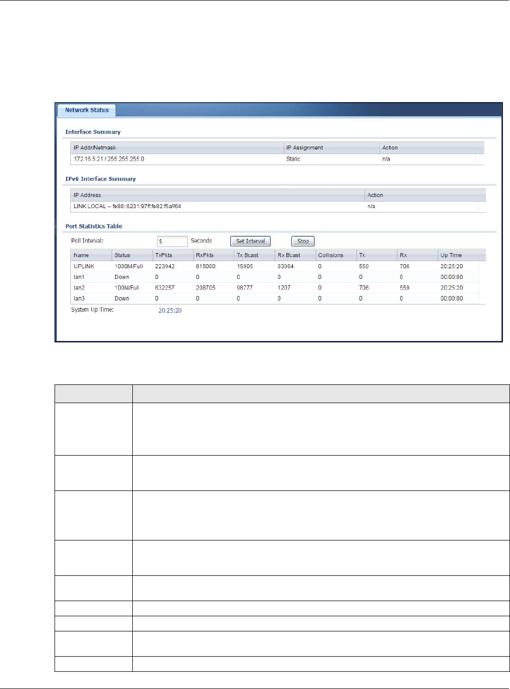
Chapter 4 Monitor
NWA / WAC Series User’s Guide
50
4.3 Network Status
Use this screen to look at general Ethernet interface information and packet statistics. To access this
screen, click Monitor > Network Status.
Figure 22 Monitor > Network Status
The following table describes the labels in this screen.
Table 23 Monitor > Network Status
LABEL DESCRIPTION
Interface
Summary
IPv6 Interface
Summary
Use the Interface Summary section for IPv4 network settings. Use the IPv6 Interface Summary
section for IPv6 network settings if you connect your NWA/WAC to an IPv6 network. Both
sections have similar fields as described below.
IP Addr/Netmask
IP Address
This field displays the current IP address (and subnet mask) of the interface. If the IP address is
0.0.0.0 (in the IPv4 network) or :: (in the IPv6 network), the interface does not have an IP address
yet.
IP Assignment This field displays how the interface gets its IPv4 address.
Static - This interface has a static IPv4 address.
DHCP Client - This interface gets its IPv4 address from a DHCP server.
Action Use this field to get or to update the IP address for the interface. Click Renew to send a new
DHCP request to a DHCP server. If the interface cannot use one of these ways to get or to
update its IP address, this field displays n/a.
Port Statistics
Table
Poll Interval Enter how often you want this window to be updated automatically, and click Set Interval.
Set Interval Click this to set the Poll Interval the screen uses.
Stop Click this to stop the window from updating automatically. You can start it again by setting the
Poll Interval and clicking Set Interval.
Name This field displays the name of the interface.
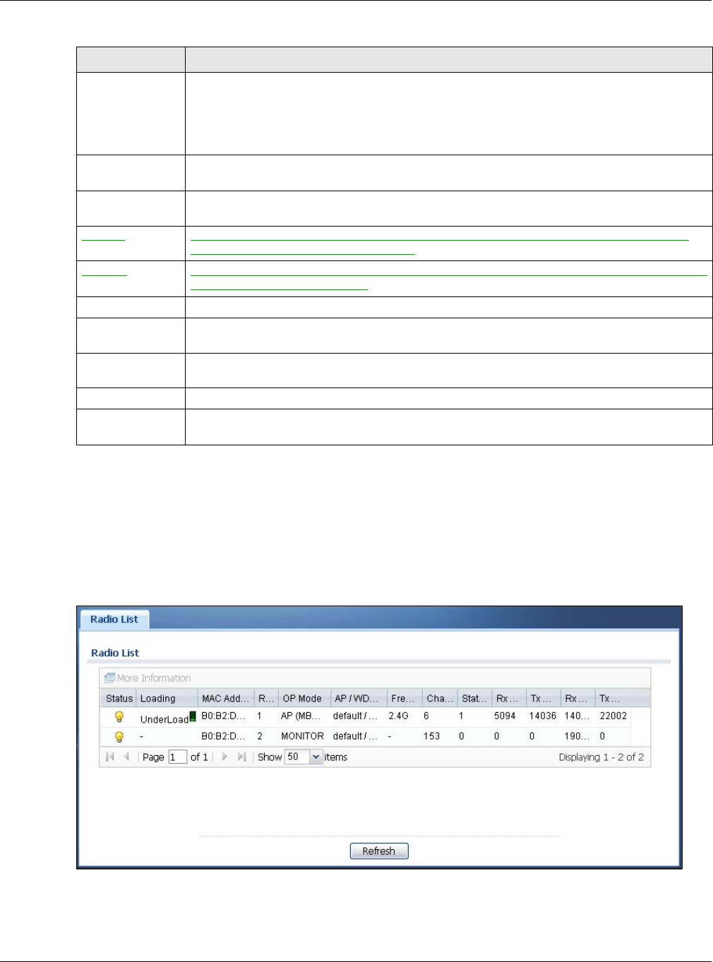
Chapter 4 Monitor
NWA / WAC Series User’s Guide
51
4.4 Radio List
Use this screen to view statistics for the NWA/WAC’s wireless radio transmitters. To access this screen,
click Monitor > Wireless > AP Information > Radio List.
Figure 23 Monitor > Wireless > AP Information > Radio List
Status This field displays the current status of the physical port.
Down - The physical port is not connected.
Speed / Duplex - The physical port is connected. This field displays the port speed and duplex
setting (Full or Half).
TxPkts This field displays the number of packets transmitted from the NWA/WAC on the physical port
since it was last connected.
RxPkts This field displays the number of packets received by the NWA/WAC on the physical port since
it was last connected.
Tx Bcast This field displays the number of broadcast packets transmitted from the NWA/WAC on the
physical port since it was last connected.
Rx Bcast This field displays the number of broadcast packets received by the NWA/WAC on the physical
port since it was last connected.
Collisions This field displays the number of collisions on the physical port since it was last connected.
Tx This field displays the transmission speed, in bytes per second, on the physical port in the one-
second interval before the screen updated.
Rx This field displays the reception speed, in bytes per second, on the physical port in the one-
second interval before the screen updated.
Up Time This field displays how long the physical port has been connected.
System Up Time This field displays how long the NWA/WAC has been running since it last restarted or was turned
on.
Table 23 Monitor > Network Status (continued)
LABEL DESCRIPTION

Chapter 4 Monitor
NWA / WAC Series User’s Guide
52
The following table describes the labels in this screen.
4.4.1 AP Mode Radio Information
This screen allows you to view a selected radio’s SSID details, wireless traffic statistics and station count
for the preceding 24 hours. To access this window, select a radio and click the More Information button
in the Radio List screen.
Table 24 Monitor > Wireless > AP Information > Radio List
LABEL DESCRIPTION
More Information Click this to view additional information about the selected radio’s wireless traffic and station
count. Information spans a 24 hour period.
Status This displays whether or not the radio is enabled.
Loading This indicates the AP’s load balance status (UnderLoad or OverLoad) when load balancing is
enabled on the NWA/WAC. Otherwise, it shows - when load balancing is disabled or the radio
is in monitor mode.
MAC Address This displays the MAC address of the radio.
Radio This indicates the radio number on the NWA/WAC to which it belongs.
OP Mode This indicates the radio’s operating mode. Operating modes are AP (MBSSID), MONITOR, Root
AP or Repeater
AP/WDS Profile This indicates the AP profile name and WDS profile name to which the radio belongs.
Profile This indicates the AP profile name to which the radio belongs.
This field is available only on the NWA/WAC that doesn’t support WDS.
Frequency Band This indicates the wireless frequency band currently being used by the radio.
This shows - when the radio is in monitor mode.
Channel This indicates the radio’s channel ID.
Tx Power This displays the output power of the radio.
Station This displays the number of wireless clients connected to this radio on the NWA/WAC.
Rx PKT This displays the total number of packets received by the radio.
Tx PKT This displays the total number of packets transmitted by the radio.
Rx FCS Error
Count
This indicates the number of received packet errors accrued by the radio.
Tx Retry Count This indicates the number of times the radio has attempted to re-transmit packets.
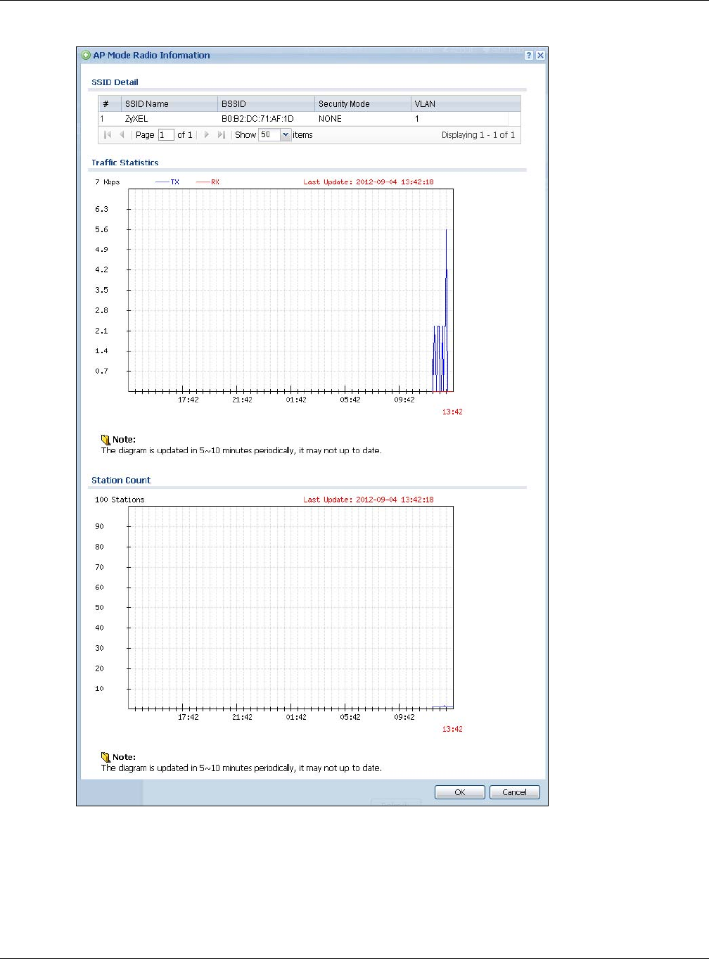
Chapter 4 Monitor
NWA / WAC Series User’s Guide
53
Figure 24 Monitor > Wireless > AP Information > Radio List > More Information
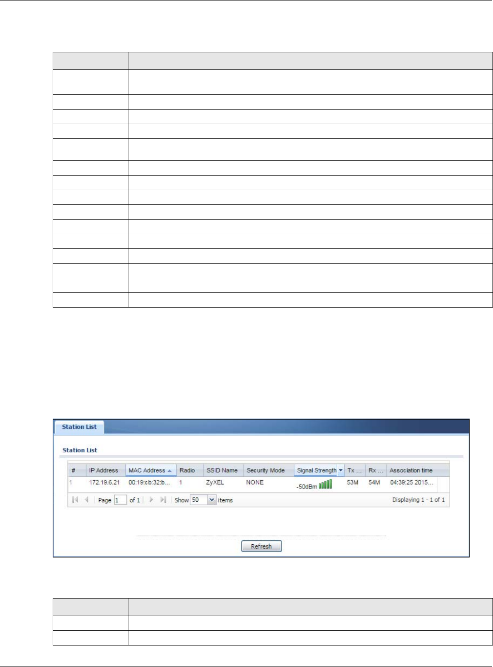
Chapter 4 Monitor
NWA / WAC Series User’s Guide
54
The following table describes the labels in this screen.
4.5 Station List
Use this screen to view statistics pertaining to the associated stations (or “wireless clients”). Click Monitor
> Wireless > Station Info to access this screen.
Figure 25 Monitor > Wireless > Station Info
The following table describes the labels in this screen.
Table 25 Monitor > Wireless > AP Information > Radio List > More Information
LABEL DESCRIPTION
SSID Detail This list shows information about all the wireless clients that have connected to the specified
radio over the preceding 24 hours.
# This is the items sequential number in the list. It has no bearing on the actual data in this list.
SSID Name This displays an SSID associated with this radio. There can be up to eight maximum.
BSSID This displays a BSSID associated with this radio. The BSSID is tied to the SSID.
Security
Mode This displays the security mode in which the SSID is operating.
VLAN This displays the VLAN ID associated with the SSID.
Traffic Statistics This graph displays the overall traffic information of the radio over the preceding 24 hours.
This y-axis represents the amount of data moved across this radio in megabytes per second.
This x-axis represents the amount of time over which the data moved across this radio.
Station Count This graph displays the connected station information of the radio over the preceding 24 hours
The y-axis represents the number of connected stations.
The x-axis shows the time period over which a station was connected.
Last Update This field displays the date and time the information in the window was last updated.
OK Click this to close this window.
Cancel Click this to close this window.
Table 26 Monitor > Wireless > Station Info
LABEL DESCRIPTION
# This is the station’s index number in this list.
IP Addresss This is the station’s IP address.
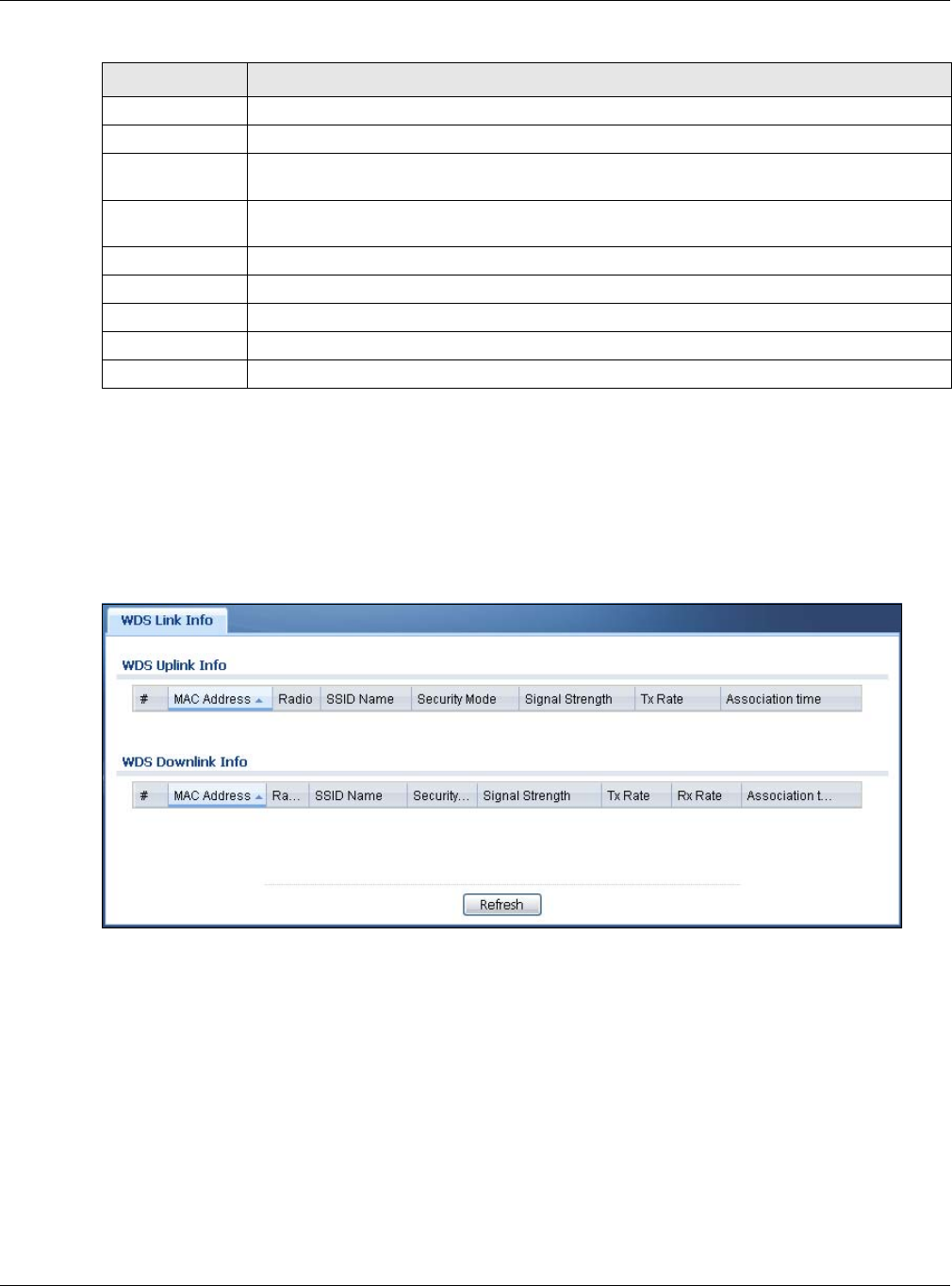
Chapter 4 Monitor
NWA / WAC Series User’s Guide
55
4.6 WDS Link Info
Use this screen to view the WDS traffic statistics between the NWA/WAC and a root AP or repeaters.
Click Monitor > Wireless > WDS Link Info to access this screen.
Figure 26 Monitor > Wireless > WDS Link Info
MAC Address This is the station’s MAC address.
Radio This is the radio number on the NWA/WAC to which the station is connected.
SSID Name This indicates the name of the wireless network to which the station is connected. A single AP
can have multiple SSIDs or networks.
Security Mode This indicates which secure encryption methods is being used by the station to connect to the
network.
Signal Strength This is the RSSI (Received Signal Strength Indicator) of the station’s wireless connection.
Tx Rate This is the maximum transmission rate of the station.
Rx Rate This is the maximum reception rate of the station.
Association Time This displays the time the station first associated with the NWA/WAC’s wireless network.
Refresh Click this to refresh the items displayed on this page.
Table 26 Monitor > Wireless > Station Info (continued)
LABEL DESCRIPTION

Chapter 4 Monitor
NWA / WAC Series User’s Guide
56
The following table describes the labels in this screen.
4.7 Detected Device
Use this screen to view information about suspected rogue APs. Click Monitor > Wireless > Detected
Device to access this screen. Not all NWA/WACs support monitor mode and rogue APs detection.
Note: The radio or at least one of the NWA/WAC’s radio must be set to monitor mode (in the
Wireless > AP Management screen) in order to detect other wireless devices in its
vicinity.
Table 27 Monitor > Wireless > WDS Link Info
LABEL DESCRIPTION
WDS Uplink Info
WDS Downlink
Info
Uplink refers to the WDS link from the repeaters to the root AP.
Downlink refers to the WDS link from the root AP to the repeaters.
When the NWA/WAC is in root AP mode and connected to a repeater, only the downlink
information is displayed.
When the NWA/WAC is in repeater mode and connected to a root AP directly or via another
repeater, the uplink information is displayed.
When the NWA/WAC is in repeater mode and connected to a root AP and other repeater(s),
both the uplink and downlink information would be displayed.
# This is the index number of the root AP or repeater in this list.
MAC Address This is the MAC address of the root AP or repeater to which the NWA/WAC is connected using
WDS.
Radio This is the radio number on the root AP or repeater to which the NWA/WAC is connected using
WDS.
SSID Name This indicates the name of the wireless network to which the NWA/WAC is connected using
WDS.
Security Mode This indicates which secure encryption methods is being used by the NWA/WAC to connect to
the root AP or repeater using WDS.
Signal Strength This is the RSSI (Received Signal Strength Indicator) of the wireless connection in WDS.
Tx Rate This is the maximum transmission rate of the root AP or repeater to which the NWA/WAC is
connected using WDS.
Rx Rate This is the maximum reception rate of the root AP or repeater to which the NWA/WAC is
connected using WDS.
Association Time This displays the time the NWA/WAC first associated with the wireless network using WDS.
Refresh Click this to refresh the items displayed on this page.
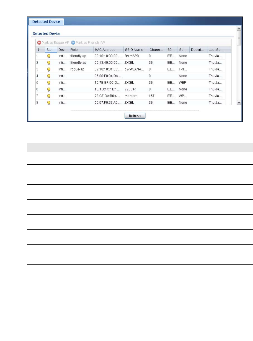
Chapter 4 Monitor
NWA / WAC Series User’s Guide
57
Figure 27 Monitor > Wireless > Detected Device
The following table describes the labels in this screen.
4.8 View Log
Log messages are stored in two separate logs, one for regular log messages and one for debugging
messages. In the regular log, you can look at all the log messages by selecting All Logs, or you can
select a specific category of log messages (for example, user). You can also look at the debugging log
by selecting Debug Log. All debugging messages have the same priority.
Table 28 Monitor > Wireless > Detected Device
LABEL DESCRIPTION
Mark as Rogue
AP
Click this button to mark the selected AP as a rogue AP. A rogue AP can be contained in the
Configuration > Wireless > MON Mode screen (Section 6.3 on page 74).
Mark as Friendly
AP
Click this button to mark the selected AP as a friendly AP. For more on managing friendly APs,
see the Configuration > Wireless > MON Mode screen (Section 6.3 on page 74).
# This is the detected device’s index number in this list.
Status This indicates the detected device’s status.
Device This indicates the type of device detected.
Role This indicates the detected device’s role (such as friendly or rogue).
MAC Address This indicates the detected device’s MAC address.
SSID Name This indicates the detected device’s SSID.
Channel ID This indicates the detected device’s channel ID.
802.11 Mode This indicates the 802.11 mode (a/b/g/n) transmitted by the detected device.
Security This indicates the encryption method (if any) used by the detected device.
Description This displays the detected device’s description. For more on managing friendly and rogue APs,
see the Configuration > Wireless > MON Mode screen (Section 6.3 on page 74).
Last Seen This indicates the last time the device was detected by the NWA/WAC.
Refresh Click this to refresh the items displayed on this page.
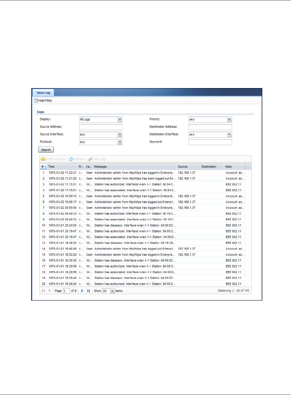
Chapter 4 Monitor
NWA / WAC Series User’s Guide
58
To access this screen, click Monitor > Log. The log is displayed in the following screen.
Note: When a log reaches the maximum number of log messages, new log messages
automatically overwrite existing log messages, starting with the oldest existing log
message first.
Events that generate an alert (as well as a log message) display in red. Regular logs display in black.
Click a column’s heading cell to sort the table entries by that column’s criteria. Click the heading cell
again to reverse the sort order.
Figure 28 Monitor > Log > View Log

Chapter 4 Monitor
NWA / WAC Series User’s Guide
59
The following table describes the labels in this screen.
Table 29 Monitor > Log > View Log
LABEL DESCRIPTION
Show Filter / Hide
Filter
Click this button to show or hide the filter settings.
If the filter settings are hidden, the Display, Email Log Now, Refresh, and Clear Log fields are
available.
If the filter settings are shown, the Display, Priority, Source Address, Destination Address, Source
Interface, Destination Interface, Protocol, Keyword, and Search fields are available.
Display Select the category of log message(s) you want to view. You can also view All Logs at one
time, or you can view the Debug Log.
Priority This displays when you show the filter. Select the priority of log messages to display. The log
displays the log messages with this priority or higher. Choices are: any, emerg, alert, crit, error,
warn, notice, and info, from highest priority to lowest priority. This field is read-only if the
Category is Debug Log.
Source Address This displays when you show the filter. Type the source IP address of the incoming packet that
generated the log message. Do not include the port in this filter.
Destination
Address
This displays when you show the filter. Type the IP address of the destination of the incoming
packet when the log message was generated. Do not include the port in this filter.
Source Interface This displays when you show the filter. Select the source interface of the packet that generated
the log message.
Destination
Interface
This displays when you show the filter. Select the destination interface of the packet that
generated the log message.
Protocol This displays when you show the filter. Select a service protocol whose log messages you would
like to see.
Keyword This displays when you show the filter. Type a keyword to look for in the Message, Source,
Destination and Note fields. If a match is found in any field, the log message is displayed. You
can use up to 63 alphanumeric characters and the underscore, as well as punctuation marks
()’ ,:;?! +-*/= #$% @ ; the period, double quotes, and brackets are not allowed.
Search This displays when you show the filter. Click this button to update the log using the current filter
settings.
Email Log Now Click this button to send log messages to the Active e-mail addresses specified in the Send Log
To field on the Configuration > Log & Report > Log Settings screen.
Refresh Click this to update the list of logs.
Clear Log Click this button to clear the whole log, regardless of what is currently displayed on the screen.
#This field is a sequential value, and it is not associated with a specific log message.
Time This field displays the time the log message was recorded.
Priority This field displays the priority of the log message. It has the same range of values as the Priority
field above.
Category This field displays the log that generated the log message. It is the same value used in the
Display and (other) Category fields.
Message This field displays the reason the log message was generated. The text “[count=x]”, where x is a
number, appears at the end of the Message field if log consolidation is turned on and multiple
entries were aggregated to generate into this one.
Source This field displays the source IP address and the port number in the event that generated the
log message.
Source Interface This field displays the source interface of the packet that generated the log message.
Destination This field displays the destination IP address and the port number of the event that generated
the log message.
Destination
Interface
This field displays the destination interface of the packet that generated the log message.

Chapter 4 Monitor
NWA / WAC Series User’s Guide
60
The Web Configurator saves the filter settings if you leave the View Log screen and return to it later.
Protocol This field displays the service protocol in the event that generated the log message.
Note This field displays any additional information about the log message.
Table 29 Monitor > Log > View Log (continued)
LABEL DESCRIPTION
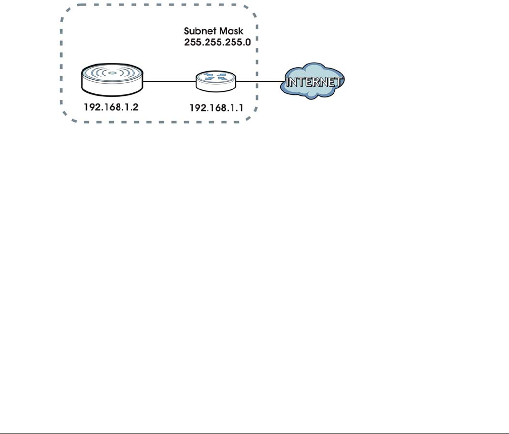
NWA / WAC Series User’s Guide
61
CHAPTER 5
Network
5.1 Overview
This chapter describes how you can configure the management IP address and VLAN settings of your
NWA/WAC.
The Internet Protocol (IP) address identifies a device on a network. Every networking device (including
computers, servers, routers, printers, etc.) needs an IP address to communicate across the network.
These networking devices are also known as hosts.
Figure 29 IP Setup
The figure above illustrates one possible setup of your NWA/WAC. The gateway IP address is 192.168.1.1
and the managed IP address of the NWA/WAC is 192.168.1.2 (default), but if the NWA/WAC is assigned
an IP address by a DHCP server, the default (192.168.1.2) will not be used. The gateway and the NWA/
WAC must belong in the same IP subnet to be able to communicate with each other.
5.1.1 Management Mode
This discusses using the NWA/WAC in management mode, which determines whether the NWA/WAC is
used in its standalone mode, or as part of a Control And Provisioning of Wireless Access Points (CAPWAP)
network.
About CAPWAP
The NWA/WAC supports CAPWAP. This is Zyxel’s implementation of the CAPWAP protocol (RFC 5415).
The CAPWAP dataflow is protected by Datagram Transport Layer Security (DTLS).
The following figure illustrates a CAPWAP wireless network. You (U) configure the AP controller (C), which
then automatically updates the configurations of the managed APs (M1 ~ M4).
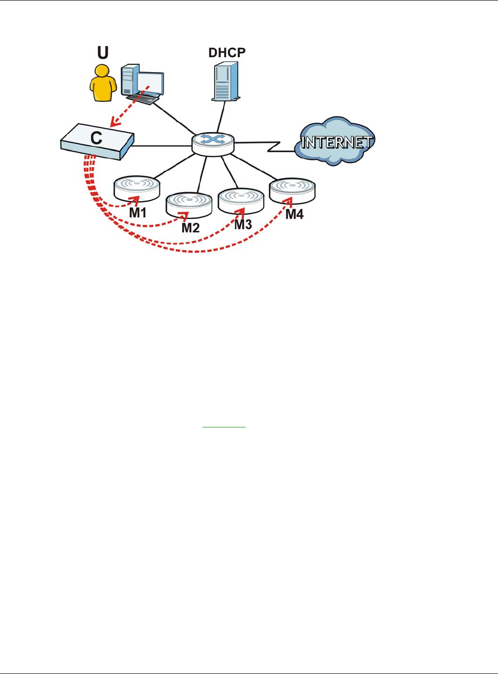
Chapter 5 Network
NWA / WAC Series User’s Guide
62
Figure 30 CAPWAP Network Example
Note: The NWA/WAC can be a standalone AP (default), or a CAPWAP managed AP.
CAPWAP Discovery and Management
The link between CAPWAP-enabled access points proceeds as follows:
1An AP in managed AP mode joins a wired network (receives a dynamic IP address).
2The AP sends out a discovery request, looking for a CAPWAP AP controller.
3If there is an AP controller on the network, it receives the discovery request. If the AP controller is in
Manual mode it adds the details of the AP to its Unmanaged Access Points list, and you decide which
available APs to manage. If the AP controller is in Always Accept mode, it automatically adds the AP to
its Managed Access Points list and provides the managed AP with default configuration information, as
well as securely transmitting the DTLS pre-shared key. The managed AP is ready for association with
wireless clients.
Managed AP Finds the Controller
A managed NWA/WAC can find the controller in one of the following ways:
• Manually specify the controller’s IP address in the Web Configurator’s AC (AP Controller) Discovery
screen.
• Get the controller’s IP address from a DHCP server with the controller’s IP address configured as
option 138.
• Get the controller’s IP address from a DNS server SRV (Service) record.
• Broadcasting to discover the controller within the broadcast domain.
Note: The AP controller needs to have a static IP address. If it is a DHCP client, set the DHCP
server to reserve an IP address for the AP controller.
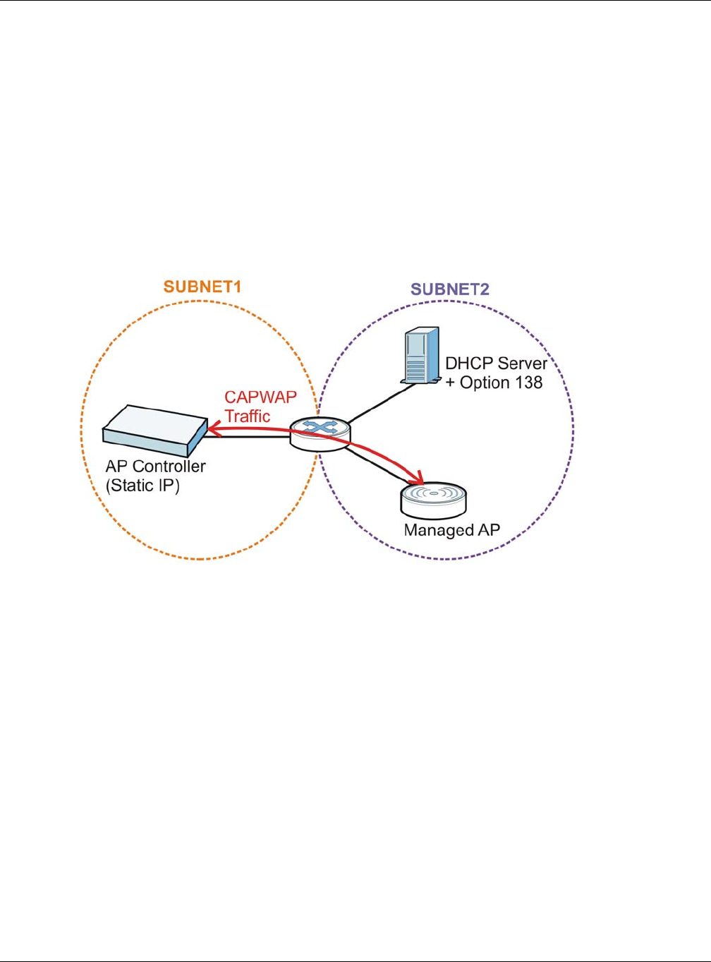
Chapter 5 Network
NWA / WAC Series User’s Guide
63
CAPWAP and IP Subnets
By default, CAPWAP works only between devices with IP addresses in the same subnet.
However, you can configure CAPWAP to operate between devices with IP addresses in different
subnets by doing the following.
• Activate DHCP. Your network’s DHCP server must support option 138 defined in RFC 5415.
• Configure DHCP option 138 with the IP address of the CAPWAP AP controller on your network.
DHCP Option 138 allows the CAPWAP management request (from the AP in managed AP mode) to
reach the AP controller in a different subnet, as shown in the following figure.
Figure 31 CAPWAP and DHCP Option 138
Notes on CAPWAP
This section lists some additional features of Zyxel’s implementation of the CAPWAP protocol.
• When the AP controller uses its internal Remote Authentication Dial In User Service (RADIUS) server,
managed APs also use the AP controller’s authentication server to authenticate wireless clients.
• If a managed AP’s link to the AP controller is broken, the managed AP continues to use the wireless
settings with which it was last provided.
5.1.2 What You Can Do in this Chapter
• The IP Setting screen (Section 5.2 on page 64) configures the NWA/WAC’s LAN IP address.
• The VLAN screen (Section 5.3 on page 65) configures the NWA/WAC’s VLAN settings.
• The AC (AP Controller) Discovery screen (Section 5.3 on page 65) configures the NWA/WAC’s AP
Controller settings.
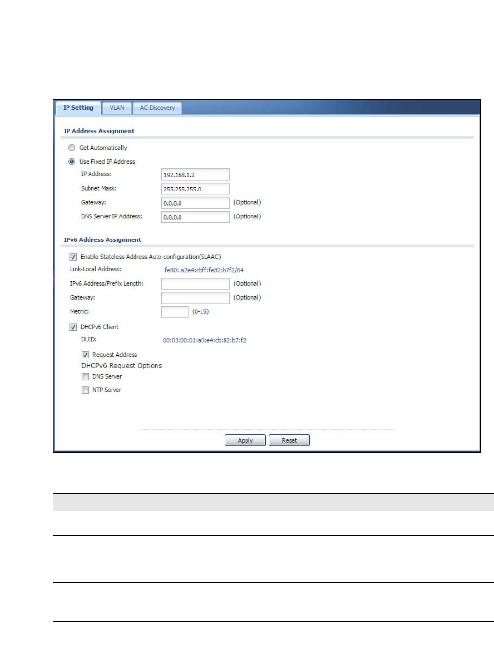
Chapter 5 Network
NWA / WAC Series User’s Guide
64
5.2 IP Setting
Use this screen to configure the IP address for your NWA/WAC. To access this screen, click Configuration
> Network > IP Setting.
Figure 32 Configuration > Network > IP Setting (Retake screenshot)
Each field is described in the following table.
Table 30 Configuration > Network > IP Setting
LABEL DESCRIPTION
IP Address
Assignment
Get
Automatically Select this to make the interface a DHCP client and automatically get the IP address,
subnet mask, and gateway address from a DHCP server.
Use Fixed IP
Address Select this if you want to specify the IP address, subnet mask, and gateway manually.
IP Address Enter the IP address for this interface.
Subnet Mask Enter the subnet mask of this interface in dot decimal notation. The subnet mask indicates
what part of the IP address is the same for all computers in the network.
Gateway Enter the IP address of the gateway. The NWA/WAC sends packets to the gateway when it
does not know how to route the packet to its destination. The gateway should be on the
same network as the interface.

Chapter 5 Network
NWA / WAC Series User’s Guide
65
5.3 VLAN
This section discusses how to configure the NWA/WAC’s VLAN settings.
DNS Server IP
Address Enter the IP address of the DNS server.
IPv6 Address
Assignment
Enable Stateless
Address Auto-
configuration
(SLAAC)
Select this to enable IPv6 stateless auto-configuration on the NWA/WAC. The NWA/WAC will
generate an IPv6 address itself from a prefix obtained from an IPv6 router in the network.
Link-Local
Address This displays the IPv6 link-local address and the network prefix that the NWA/WAC
generates itself for the LAN interface.
IPv6 Address/
Prefix Length Enter the IPv6 address and the prefix length for the LAN interface if you want to use a static
IP address. This field is optional.
The prefix length indicates what the left-most part of the IP address is the same for all
computers in the network, that is, the network address.
Gateway Enter the IPv6 address of the default outgoing gateway using colon (:) hexadecimal
notation.
Metric Enter the priority of the gateway (if any) on the LAN interface. The NWA/WAC decides
which gateway to use based on this priority. The lower the number, the higher the priority. If
two or more gateways have the same priority, the NWA/WAC uses the one that was
configured first.
DHCPv6 Client Select this option to set the NWA/WAC to act as a DHCPv6 client.
DUID This field displays the DHCP Unique IDentifier (DUID) of the NWA/WAC, which is unique and
used for identification purposes when the NWA/WAC is exchanging DHCPv6 messages with
others. See Appendix B on page 211 for more information.
Request Address Select this option to get an IPv6 address from the DHCPv6 server.
DHCPv6 Request
Options
Select this option to determine what additional information to get from the DHCPv6 server.
DNS Server Select this option to obtain the IP address of the DNS server.
NTP Server Select this option to obtain the IP address of the NTP server.
Apply Click Apply to save your changes back to the NWA/WAC.
Reset Click Reset to return the screen to its last-saved settings.
Table 30 Configuration > Network > IP Setting (continued)
LABEL DESCRIPTION
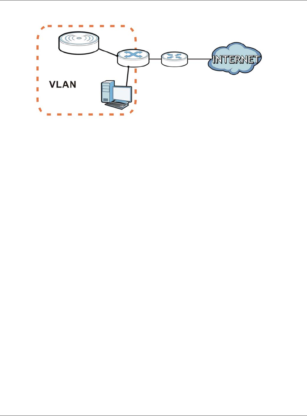
Chapter 5 Network
NWA / WAC Series User’s Guide
66
Figure 33 Management VLAN Setup
In the figure above, to access and manage the NWA/WAC from computer A, the NWA/WAC and
switch B’s ports to which computer A and the NWA/WAC are connected should be in the same VLAN.
A Virtual Local Area Network (VLAN) allows a physical network to be partitioned into multiple logical
networks. Devices on a logical network belong to one group. A device can belong to more than one
group. With VLAN, a device cannot directly talk to or hear from devices that are not in the same
group(s); the traffic must first go through a router.
VLAN also increases network performance by limiting broadcasts to a smaller and more manageable
logical broadcast domain. In traditional switched environments, all broadcast packets go to each and
every individual port. With VLAN, all broadcasts are confined to a specific broadcast domain.
IEEE 802.1Q Tag
The IEEE 802.1Q standard defines an explicit VLAN tag in the MAC header to identify the VLAN
membership of a frame across bridges. A VLAN tag includes the 12-bit VLAN ID and 3-bit user priority.
The VLAN ID associates a frame with a specific VLAN and provides the information that devices need to
process the frame across the network.
Use this screen to configure the VLAN settings for your NWA/WAC. To access this screen, click
Configuration > Network > VLAN.
A
B
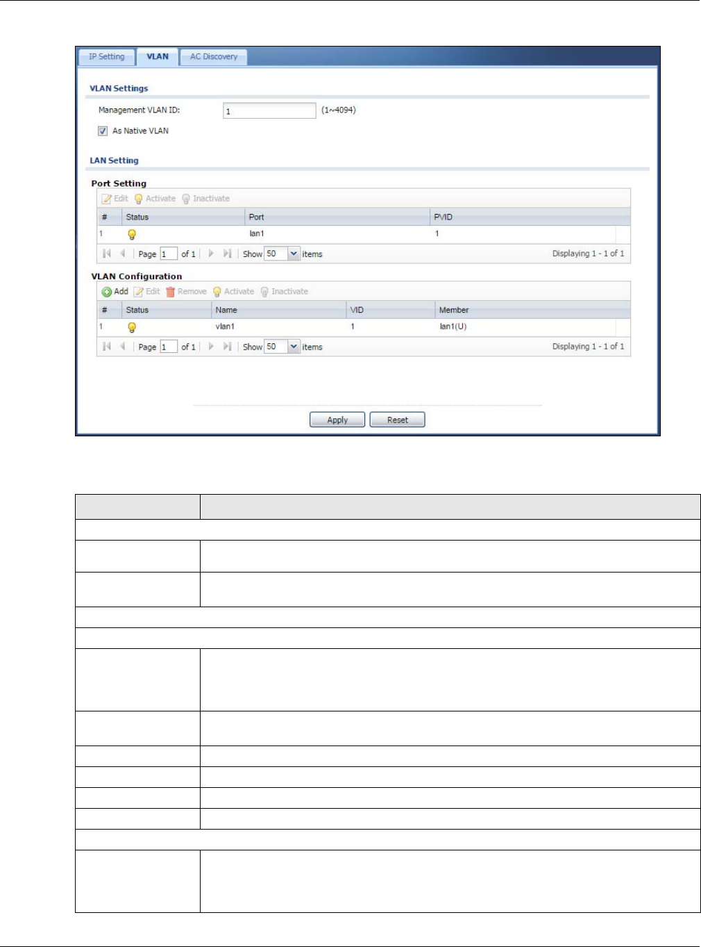
Chapter 5 Network
NWA / WAC Series User’s Guide
67
Figure 34 Configuration > Network > VLAN
Each field is described in the following table.
Table 31 Configuration > Network > VLAN
LABEL DESCRIPTION
VLAN Settings
Management
VLAN ID Enter a VLAN ID for the NWA/WAC.
As Native VLAN Select this option to treat this VLAN ID as a VLAN created on the NWA/WAC and not one
assigned to it from outside the network.
LAN Setting
Port Setting
Edit Double-click an entry or select it and click Edit to open a screen where you can modify the
entry’s settings. In some tables you can just click a table entry and edit it directly in the
table. For those types of tables small red triangles display for table entries with changes that
you have not yet applied.
Activate/
Inactivate To turn on an entry, select it and click Activate. To turn off an entry, select it and click
Inactivate.
# This is the index number of the port.
Status This field indicates whether the port is enabled (a yellow bulb) or not (a gray bulb).
Port This field displays the name of the port.
PVID This field displays the port number of the VLAN ID.
VLAN Configuration
Add Click this to create a new entry. For features where the entry’s position in the numbered list is
important (features where the NWA/WAC applies the table’s entries in order like the SSID for
example), you can select an entry and click Add to create a new entry after the selected
entry.

Chapter 5 Network
NWA / WAC Series User’s Guide
68
5.4 AC (AP Controller) Discovery
This section discusses how to configure the NWA/WAC’s AC (AP Controller) Discovery settings. You can
have the NWA/WAC managed by an AP controller on your network. When you do this, the NWA/WAC
can be configured ONLY by the AP controller. See Section 5.1.1 on page 61 for more information on
management mode and AP Controller.
If you want to return the NWA/WAC to standalone AP mode, you can do one of the two following
options:
• Press the Reset button.
• Check the AP controller for the NWA/WAC’s IP address and use FTP to upload the default
configuration file to the NWA/WAC. You can get the configuration file at conf/system-default.conf.
You must reboot the device after uploading the configuration file.
To access the Controller Discover screen, click Configuration > Network > AC Discovery.
Edit Double-click an entry or select it and click Edit to open a screen where you can modify the
entry’s settings. In some tables you can just click a table entry and edit it directly in the
table. For those types of tables small red triangles display for table entries with changes that
you have not yet applied.
Remove To remove an entry, select it and click Remove. The NWA/WAC confirms you want to
remove it before doing so.
Activate/
Inactivate To turn on an entry, select it and click Activate. To turn off an entry, select it and click
Inactivate.
# This is the index number of the VLAN ID
Status This field indicates whether the VLAN is enabled (a yellow bulb) or not (a gray bulb).
Name This field displays the name of each VLAN.
VID This field displays the VLAN ID.
Member This field displays the VLAN membership to which the port belongs.
Apply Click Apply to save your changes back to the NWA/WAC.
Reset Click Reset to return the screen to its last-saved settings.
Table 31 Configuration > Network > VLAN (continued)
LABEL DESCRIPTION
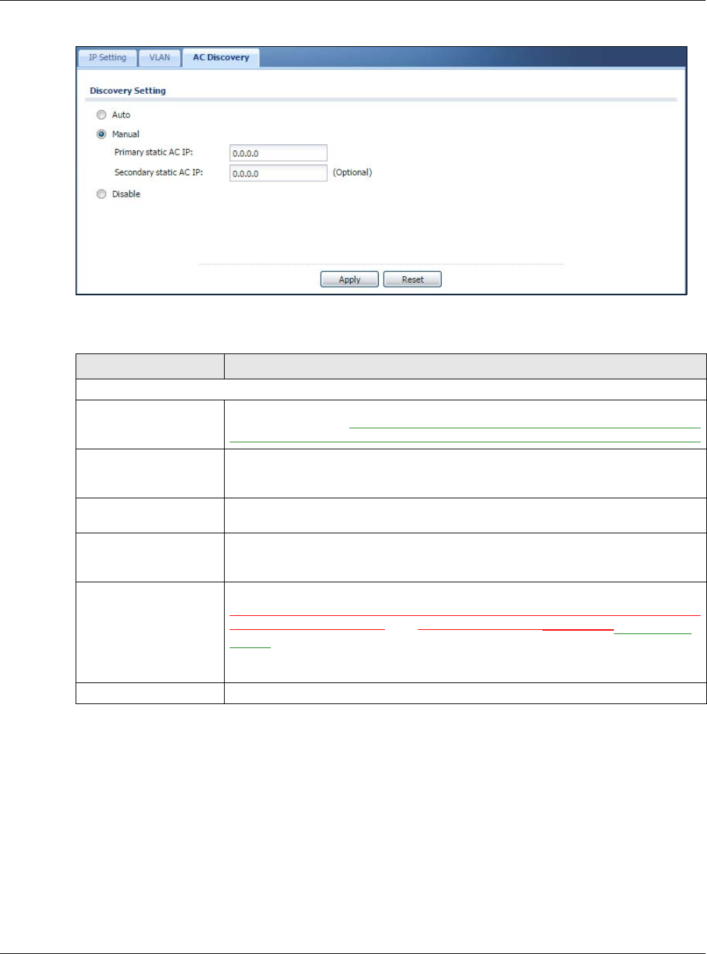
Chapter 5 Network
NWA / WAC Series User’s Guide
69
Figure 35 Configuration > Network > AC Discovery
Each field is described in the following table.
Table 32 Configuration > Network > AC Discovery
LABEL DESCRIPTION
Discovery Setting
Auto Select this option to use DHCP option 138/DNS SRV record/Broadcast to get the AP
controller’s IP address. If the NWA/WAC and a Zyxel AP controller, such as the NXC2500
or NXC5500, are in the same subnet, it will be managed by the controller automatically.
Manual Select this option and enter the IP address of the AP controller manually. This is
necessary when the AP Controller is not in the same subnet and you want it to manage
the NWA/WAC.
Primary / Secondary
Static AC IP Specify the primary and secondary IP address of the AP controller to which the NWA/
WAC connects.
Disable Select this to manage the NWA/WAC using its own web configurator, neither managing
nor managed by other devices. Please note if an AP Controller is in the same subnet,
you will need to click Disable if you do not want the NWA/WAC to be managed.
Apply Click Apply to save the information entered in this screen.
If you change the mode in this screen, the NWA/WAC restarts. Wait a short while before
you attempt to log in again. If you changed the mode to Managed APselect Auto or
Manual, the AP controller uploads the firmware package for managed AP mode to the
NWA/WAC and you cannot log in as the web configurator is disabled; you must
manage the NWA/WAC through the AP controller on your network.
Reset Click Reset to return the screen to its last-saved settings.
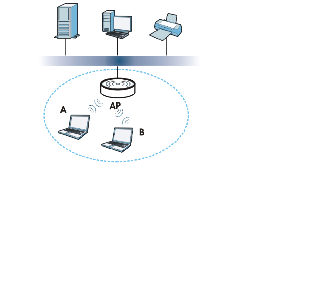
NWA / WAC Series User’s Guide
70
CHAPTER 6
Wireless
6.1 Overview
This chapter discusses how to configure the wireless network settings in your NWA/WAC.
The following figure provides an example of a wireless network.
Figure 36 Example of a Wireless Network
The wireless network is the part in the blue circle. In this wireless network, devices A and B are called
wireless clients. The wireless clients use the access point (AP) to interact with other devices (such as the
printer) or with the Internet. Your NWA/WAC is the AP.
6.1.1 What You Can Do in this Chapter
• The AP Management screen (Section 6.2 on page 71) manages the NWA/WAC’s general wireless
settings.
• The MON Mode screen (Section 6.3 on page 74) allows you to assign APs either to the rogue AP list or
the friendly AP list.
• The Load Balancing screen (Section 6.4 on page 76) configures network traffic load balancing
between the APs and the NWA/WAC.
• The DCS screen (Section 6.5 on page 79) configures dynamic radio channel selection.

Chapter 6 Wireless
NWA / WAC Series User’s Guide
71
6.1.2 What You Need to Know
The following terms and concepts may help as you read this chapter.
Station / Wireless Client
A station or wireless client is any wireless-capable device that can connect to an AP using a wireless
signal.
Dynamic Channel Selection (DCS)
Dynamic Channel Selection (DCS) is a feature that allows an AP to automatically select the radio
channel upon which it broadcasts by scanning the area around it and determining what channels are
currently being used by other devices.
Load Balancing (Wireless)
Wireless load balancing is the process where you limit the number of connections allowed on an wireless
access point (AP) or you limit the amount of wireless traffic transmitted and received on it so the AP
does not become overloaded.
6.2 AP Management
Use this screen to manage the NWA/WAC’s general wireless settings. Click Configuration > Wireless > AP
Management to access this screen.
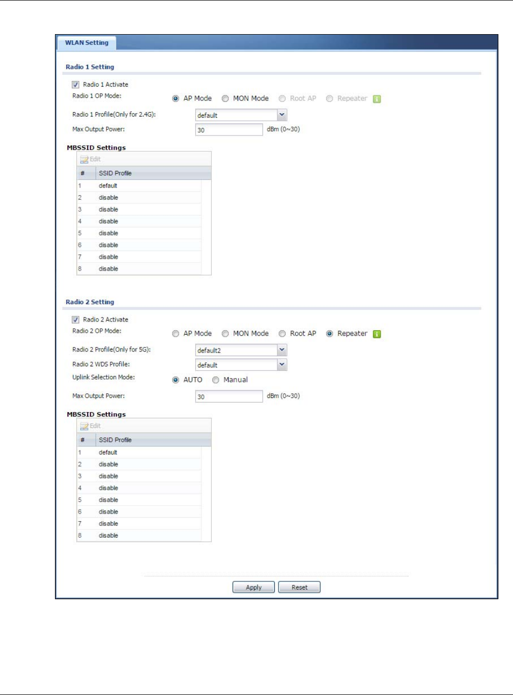
Chapter 6 Wireless
NWA / WAC Series User’s Guide
72
Figure 37 Configuration > Wireless > AP Management

Chapter 6 Wireless
NWA / WAC Series User’s Guide
73
Each field is described in the following table.
Table 33 Configuration > Wireless > AP Management
LABEL DESCRIPTION
Radio 1 Setting
Radio 1 Activate Select the check box to enable the NWA/WAC’s first (default) radio.
Radio 1 OP Mode Select the operating mode for radio 1.
AP Mode means the radio can receive connections from wireless clients and pass their data
traffic through to the NWA/WAC to be managed (or subsequently passed on to an
upstream gateway for managing).
MON Mode means the radio monitors the broadcast area for other APs, then passes their
information on to the NWA/WAC where it can be determined if those APs are friendly or
rogue. If a radio is set to this mode it cannot receive connections from wireless clients.
Root AP means the radio acts as an AP and also supports the wireless connections with
other APs (in repeater mode) to form a WDS (Wireless Distribution System) to extend its
wireless network.
Repeater means the radio can establish a wireless connection with other APs (in either root
AP or repeater mode) to form a WDS.
Radio 1 Profile Select the radio profile the radio uses.
Note: You can only apply a 2.4G AP radio profile to radio 1. Otherwise, the first
radio will not be working.
Radio 1 WDS Profile This field is available only when the radio is in Root AP or Repeater mode.
Select the WDS profile the radio uses to connect to a root AP or repeater.
Uplink Selection
Mode
This field is available only when the radio is in Repeater mode.
Select AUTO to have the NWA/WAC automatically use the settings in the applied WDS
profile to connect to a root AP or repeater.
Select Manual to have the NWA/WAC connect to the root AP or repeater with the MAC
address specified in the Radio 1 Uplink MAC Address field.
Max Output Power Enter the maximum output power (between 0 to 30 dBm) of the NWA/WAC in this field. If
there is a high density of APs in an area, decrease the output power of the NWA/WAC to
reduce interference with other APs.
Note: Reducing the output power also reduces the NWA/WAC’s effective
broadcast radius.
MBSSID Settings
Edit Double-click an entry or select it and click Edit to open a screen where you can modify the
entry’s settings. In some tables you can just click a table entry and edit it directly in the
table. For those types of tables small red triangles display for table entries with changes that
you have not yet applied.
# This field shows the index number of the SSID
SSID Profile This field displays the SSID profile that is associated with the radio profile.
Radio 2 Setting
Radio 2 Activate This displays if the NWA/WAC has a second radio.
Select the check box to enable the NWA/WAC’s second radio.

Chapter 6 Wireless
NWA / WAC Series User’s Guide
74
6.3 MON Mode
Use this screen to assign APs either to the rogue AP list or the friendly AP list. A rogue AP is a wireless
access point operating in a network’s coverage area that is not under the control of the network
administrator, and which can potentially open up holes in a network’s security.
Click Configuration > Wireless > MON Mode to access this screen.
Radio 2 OP Mode This displays if the NWA/WAC has a second radio. Select the operating mode for radio 2.
AP Mode means the radio can receive connections from wireless clients and pass their data
traffic through to the NWA/WAC to be managed (or subsequently passed on to an
upstream gateway for managing).
MON Mode means the radio monitors the broadcast area for other APs, then passes their
information on to the NWA/WAC where it can be determined if those APs are friendly or
rogue. If a radio is set to this mode it cannot receive connections from wireless clients.
Root AP means the radio acts as an AP and also supports the wireless connections with
other APs (in repeater mode) to form a WDS to extend its wireless network.
Repeater means the radio can establish a wireless connection with other APs (in either root
AP or repeater mode) to form a WDS.
Radio 2 Profile This displays if the NWA/WAC has a second radio. Select the radio profile the radio uses.
Note: You can only apply a 5G AP radio profile to radio 2. Otherwise, the second
radio will not be working.
Radio 2 WDS Profile This field is available only when the radio is in Root AP or Repeater mode.
Select the WDS profile the radio uses to connect to a root AP or repeater.
Uplink Selection
Mode
This field is available only when the radio is in Repeater mode.
Select AUTO to have the NWA/WAC automatically use the settings in the applied WDS
profile to connect to a root AP or repeater.
Select Manual to have the NWA/WAC connect to the root AP or repeater with tbe MAC
address specified in the Radio 2 Uplink MAC Address field.
Max Output Power Enter the maximum output power (between 0 to 30 dBm) of the NWA/WAC in this field. If
there is a high density of APs in an area, decrease the output power of the NWA/WAC to
reduce interference with other APs.
Note: Reducing the output power also reduces the NWA/WAC’s effective
broadcast radius.
MBSSID Settings
Edit Double-click an entry or select it and click Edit to open a screen where you can modify the
entry’s settings. In some tables you can just click a table entry and edit it directly in the
table. For those types of tables small red triangles display for table entries with changes that
you have not yet applied.
# This field shows the index number of the SSID
SSID Profile This field shows the SSID profile that is associated with the radio profile.
Apply Click Apply to save your changes back to the NWA/WAC.
Reset Click Reset to return the screen to its last-saved settings.
Table 33 Configuration > Wireless > AP Management (continued)
LABEL DESCRIPTION
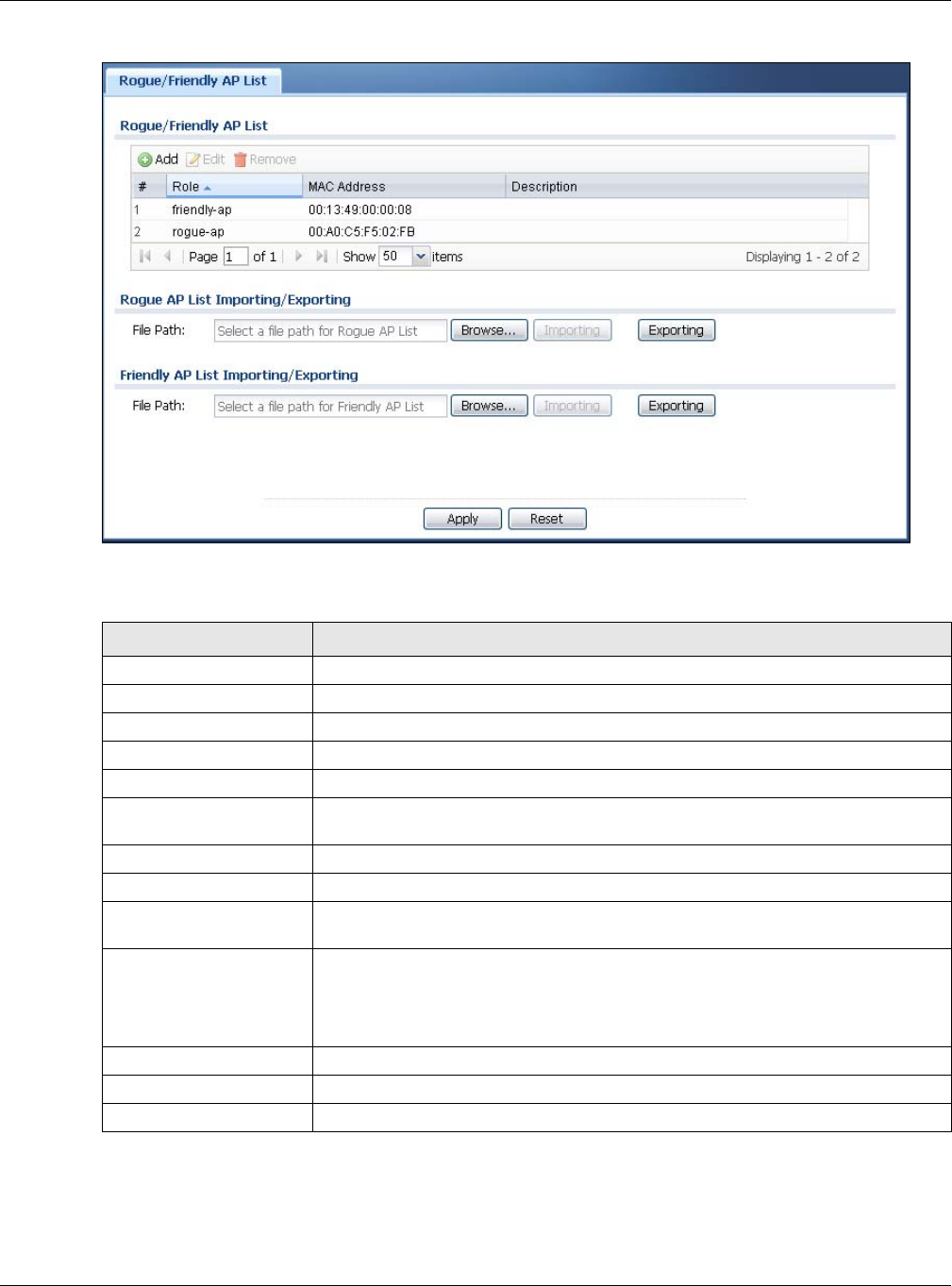
Chapter 6 Wireless
NWA / WAC Series User’s Guide
75
Figure 38 Configuration > Wireless > MON Mode
Each field is described in the following table.
6.3.1 Add/Edit Rogue/Friendly List
Click Add or select an AP and click the Edit button in the Configuration > Wireless > MON Mode table to
display this screen.
Table 34 Configuration > Wireless > MON Mode
LABEL DESCRIPTION
Rogue/Friendly AP List
Add Click this button to add an AP to the list and assign it either friendly or rogue status.
Edit Select an AP in the list to edit and reassign its status.
Remove Select an AP in the list to remove.
# This field is a sequential value, and it is not associated with any interface.
Role This field indicates whether the selected AP is a rogue-ap or a friendly-ap. To change
the AP’s role, click the Edit button.
MAC Address This field indicates the AP’s radio MAC address.
Description This field displays the AP’s description. You can modify this by clicking the Edit button.
Importing/Exporting These controls allow you to export the current list of rogue and friendly APs or import
existing lists.
File Path / Browse /
Importing Enter the file name and path of the list you want to import or click the Browse button
to locate it. Once the File Path field has been populated, click Importing to bring the
list into the NWA/WAC.
You need to wait a while for the importing process to finish.
Exporting Click this button to export the current list of either rogue APs or friendly APS.
Apply Click Apply to save your changes back to the NWA/WAC.
Reset Click Reset to return the screen to its last-saved settings.
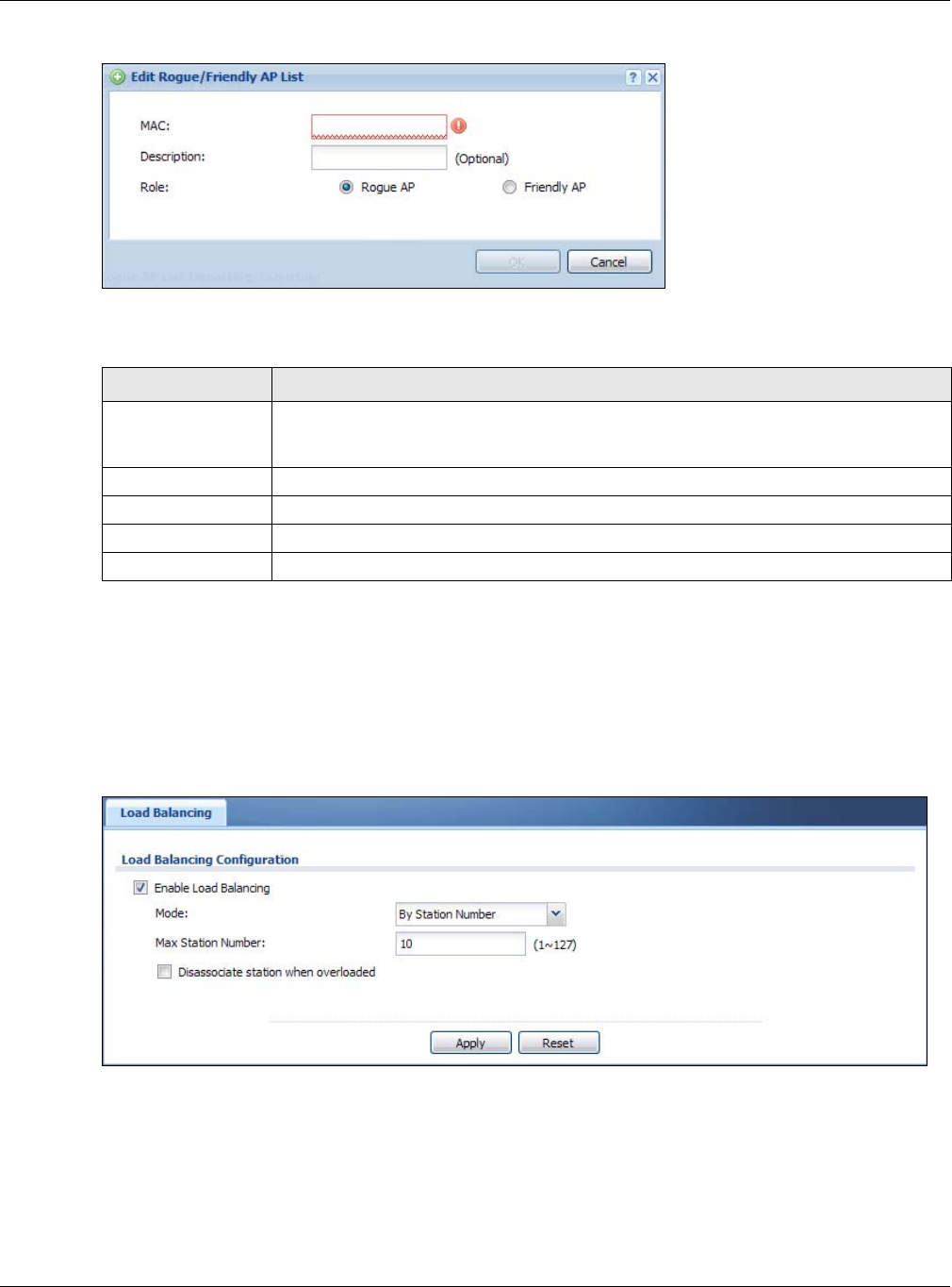
Chapter 6 Wireless
NWA / WAC Series User’s Guide
76
Figure 39 Configuration > Wireless > MON Mode > Add/Edit Rogue/Friendly AP List
Each field is described in the following table.
6.4 Load Balancing
Use this screen to configure wireless network traffic load balancing between the APs on your network.
Click Configuration > Wireless > Load Balancing to access this screen.
Figure 40 Configuration > Wireless > Load Balancing
Table 35 Configuration > Wireless > MON Mode > Add/Edit Rogue/Friendly AP List
LABEL DESCRIPTION
MAC Enter the MAC address of the AP you want to add to the list. A MAC address is a unique
hardware identifier in the following hexadecimal format: xx:xx:xx:xx:xx:xx where xx is a
hexadecimal number separated by colons.
Description Enter up to 60 characters for the AP’s description. Spaces and underscores are allowed.
Role Select either Rogue AP or Friendly AP for the AP’s role.
OK Click OK to save your changes back to the NWA/WAC.
Cancel Click Cancel to close the window with changes unsaved.

Chapter 6 Wireless
NWA / WAC Series User’s Guide
77
Each field is described in the following table.
Table 36 Configuration > Wireless > Load Balancing
LABEL DESCRIPTION
Enable Load
Balancing
Select this to enable load balancing on the NWA/WAC.
Use this section to configure wireless network traffic load balancing between the managd
APs in this group.
Mode Select a mode by which load balancing is carried out.
Select By Station Number to balance network traffic based on the number of specified
stations connected to the NWA/WAC.
Select By Traffic Level to balance network traffic based on the volume generated by the
stations connected to the NWA/WAC.
Select By Smart Classroom to balance network traffic based on the number of specified
stations connected to the NWA/WAC. The NWA/WAC ignores association request and
authentication request packets from any new station when the maximum number of
stations is reached.
If you select By Station Number or By Traffic Level, once the threshold is crossed (either the
maximum station numbers or with network traffic), the NWA/WAC delays association
request and authentication request packets from any new station that attempts to make a
connection. This allows the station to automatically attempt to connect to another, less
burdened AP if one is available.
Max Station
Number Enter the threshold number of stations at which the NWA/WAC begins load balancing its
connections.
Traffic Level Select the threshold traffic level at which the NWA/WAC begins load balancing its
connections (Low, Medium, High).
The maximum bandwidth allowed for each level is:
•Low - 11 Mbps,
•Medium - 23 Mbps
•High - 35M bps
Disassociate
station when
overloaded
This function is enabled by default and the disassociation priority is always Signal Strength
when you set Mode to By Smart Classroom.
Select this option to disassociate wireless clients connected to the AP when it becomes
overloaded. If you do not enable this option, then the AP simply delays the connection until
it can afford the bandwidth it requires, or it transfers the connection to another AP within its
broadcast radius.
The disassociation priority is determined automatically by the NWA/WAC and is as follows:
•Idle Timeout - Devices that have been idle the longest will be kicked first. If none of the
connected devices are idle, then the priority shifts to Signal Strength.
•Signal Strength - Devices with the weakest signal strength will be kicked first.
Note: If you enable this function, you should ensure that there are multiple APs
within the broadcast radius that can accept any rejected or kicked
wireless clients; otherwise, a wireless client attempting to connect to an
overloaded AP will be disassociated permanently and never be allowed to
connect.
Apply Click Apply to save your changes back to the NWA/WAC.
Reset Click Reset to return the screen to its last-saved settings.
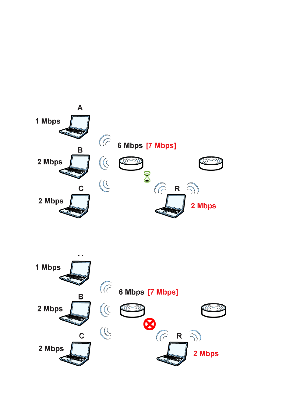
Chapter 6 Wireless
NWA / WAC Series User’s Guide
78
6.4.1 Disassociating and Delaying Connections
When your AP becomes overloaded, there are two basic responses it can take. The first one is to
“delay” a client connection. This means that the AP withholds the connection until the data transfer
throughput is lowered or the client connection is picked up by another AP. If the client is picked up by
another AP then the original AP cannot resume the connection.
For example, here the AP has a balanced bandwidth allotment of 6 Mbps. If laptop R connects and it
pushes the AP over its allotment, say to 7 Mbps, then the AP delays the red laptop’s connection until it
can afford the bandwidth or the laptop is picked up by a different AP with bandwidth to spare.
Figure 41 Delaying a Connection
The second response your AP can take is to kick the connections that are pushing it over its balanced
bandwidth allotment.
Figure 42 Kicking a Connection
Connections are kicked based on either idle timeout or signal strength. The NWA/WAC first looks to see
which devices have been idle the longest, then starts kicking them in order of highest idle time. If no
connections are idle, the next criteria the NWA/WAC analyzes is signal strength. Devices with the
weakest signal strength are kicked first.
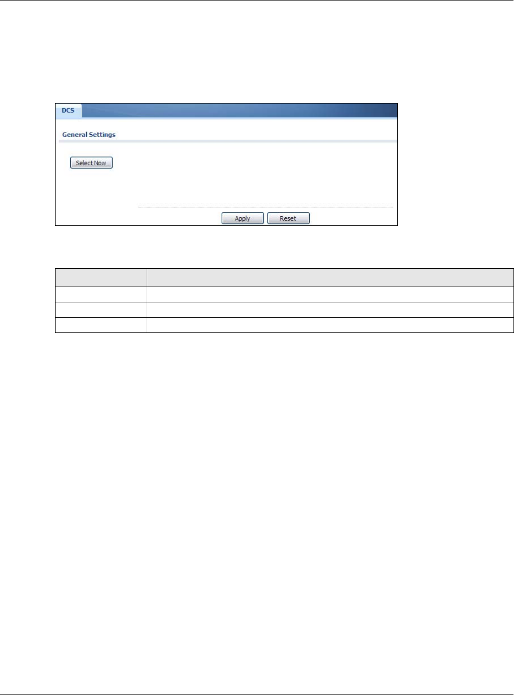
Chapter 6 Wireless
NWA / WAC Series User’s Guide
79
6.5 DCS
Use this screen to configure dynamic radio channel selection. Click Configuration > Wireless > DCS to
access this screen.
Figure 43 Configuration > Wireless > DCS
Each field is described in the following table.
6.6 Technical Reference
The following section contains additional technical information about the features described in this
chapter.
Dynamic Channel Selection
When numerous APs broadcast within a given area, they introduce the possibility of heightened radio
interference, especially if some or all of them are broadcasting on the same radio channel. If the
interference becomes too great, then the network administrator must open his AP configuration options
and manually change the channel to one that no other AP is using (or at least a channel that has a
lower level of interference) in order to give the connected stations a minimum degree of interference.
Dynamic channel selection frees the network administrator from this task by letting the AP do it
automatically. The AP can scan the area around it looking for the channel with the least amount of
interference.
In the 2.4 GHz spectrum, each channel from 1 to 13 is broken up into discrete 22 MHz segments that are
spaced 5 MHz apart. Channel 1 is centered on 2.412 GHz while channel 13 is centered on 2.472 GHz.
Table 37 Configuration > Wireless > DCS
LABEL DESCRIPTION
Select Now Click this to have the NWA/WAC scan for and select an available channel immediately.
Apply Click Apply to save your changes back to the NWA/WAC.
Reset Click Reset to return the screen to its last-saved settings.
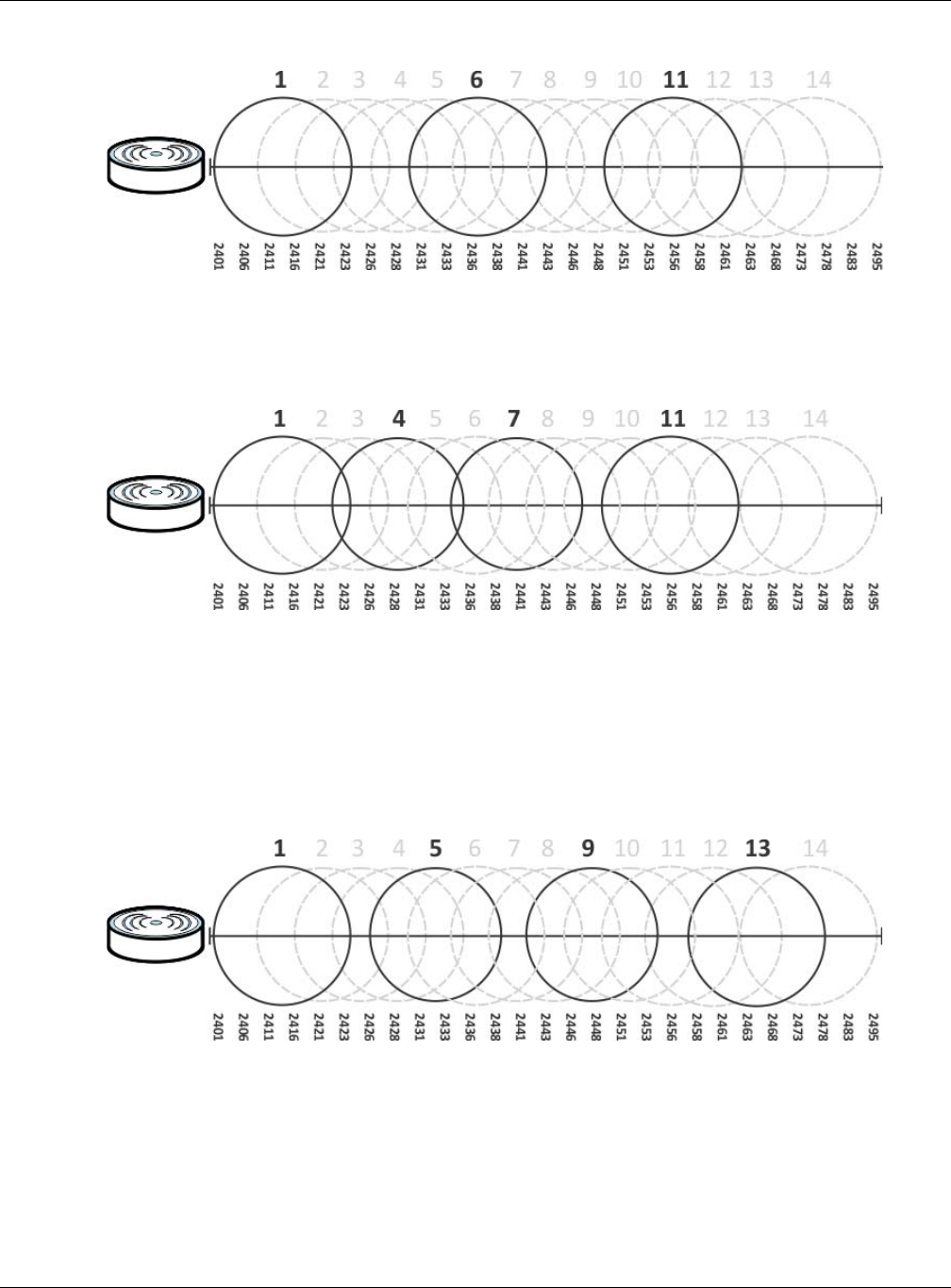
Chapter 6 Wireless
NWA / WAC Series User’s Guide
80
Figure 44 An Example Three-Channel Deployment
Three channels are situated in such a way as to create almost no interference with one another if used
exclusively: 1, 6 and 11. When an AP broadcasts on any of these three channels, it should not interfere
with neighboring APs as long as they are also limited to same trio.
Figure 45 An Example Four-Channel Deployment
However, some regions require the use of other channels and often use a safety scheme with the
following four channels: 1, 4, 7 and 11. While they are situated sufficiently close to both each other and
the three so-called “safe” channels (1,6 and 11) that interference becomes inevitable, the severity of it is
dependent upon other factors: proximity to the affected AP, signal strength, activity, and so on.
Finally, there is an alternative four channel scheme for ETSI, consisting of channels 1, 5, 9, 13. This offers
significantly less overlap that the other one.
Figure 46 An Alternative Four-Channel Deployment
Load Balancing
Because there is a hard upper limit on an AP’s wireless bandwidth, load balancing can be crucial in
areas crowded with wireless users. Rather than let every user connect and subsequently dilute the
available bandwidth to the point where each connecting device receives a meager trickle, the load
balanced AP instead limits the incoming connections as a means to maintain bandwidth integrity.
There are three kinds of wireless load balancing available on the NWA/WAC:

Chapter 6 Wireless
NWA / WAC Series User’s Guide
81
Load balancing by station number limits the number of devices allowed to connect to your AP. If you
know exactly how many stations you want to let connect, choose this option.
For example, if your company’s graphic design team has their own AP and they have 10 computers,
you can load balance for 10. Later, if someone from the sales department visits the graphic design
team’s offices for a meeting and he tries to access the network, his computer’s connection is delayed,
giving it the opportunity to connect to a different, neighboring AP. If he still connects to the AP
regardless of the delay, then the AP may boot other people who are already connected in order to
associate with the new connection.
Load balancing by smart classroom also limits the number of devices allowed to connect to your AP.
But any new connections will be just rejected when the AP is overloaded.
Load balancing by traffic level limits the number of connections to the AP based on maximum
bandwidth available. If you are uncertain as to the exact number of wireless connections you will have
then choose this option. By setting a maximum bandwidth cap, you allow any number of devices to
connect as long as their total bandwidth usage does not exceed the configured bandwidth cap
associated with this setting. Once the cap is hit, any new connections are rejected or delayed provided
that there are other APs in range.
Imagine a coffee shop in a crowded business district that offers free wireless connectivity to its
customers. The coffee shop owner can’t possibly know how many connections his AP will have at any
given moment. As such, he decides to put a limit on the bandwidth that is available to his customers but
not on the actual number of connections he allows. This means anyone can connect to his wireless
network as long as the AP has the bandwidth to spare. If too many people connect and the AP hits its
bandwidth cap then all new connections must basically wait for their turn or get shunted to the nearest
identical AP.

NWA / WAC Series User’s Guide
82
CHAPTER 7
User
7.1 Overview
This chapter describes how to set up user accounts and user settings for the NWA/WAC.
7.1.1 What You Can Do in this Chapter
• The User screen (see Section 7.2 on page 83) provides a summary of all user accounts.
•The Setting screen (see Section 7.3 on page 85) controls default settings, login settings, lockout
settings, and other user settings for the NWA/WAC.
7.1.2 What You Need To Know
The following terms and concepts may help as you read this chapter.
User Account
A user account defines the privileges of a user logged into the NWA/WAC. User accounts are used in
controlling access to configuration and services in the NWA/WAC.
User Types
These are the types of user accounts the NWA/WAC uses.
Note: The default admin account is always authenticated locally, regardless of the
authentication method setting.
Table 38 Types of User Accounts
TYPE ABILITIES LOGIN METHOD(S)
Admin Users
admin Change NWA/WAC configuration (web, CLI) WWW, TELNET, SSH, FTP
limited-admin Look at NWA/WAC configuration (web, CLI)
Perform basic diagnostics (CLI)
WWW, TELNET, SSH
Access Users
user Used for the embedded RADIUS server and
SNMPv3 user access
Browse user-mode commands (CLI)
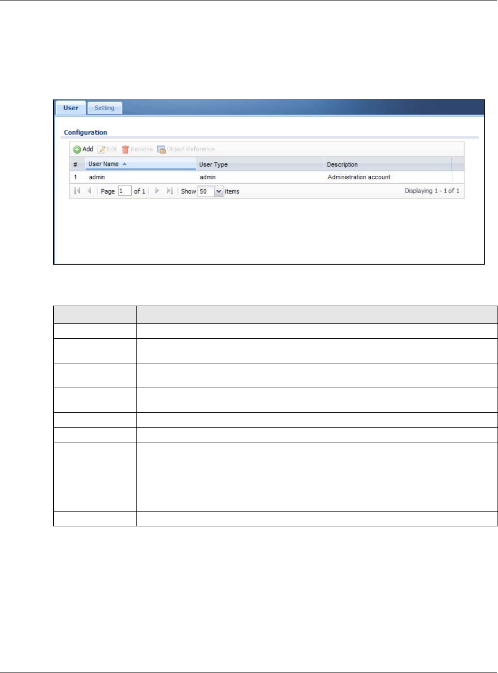
Chapter 7 User
NWA / WAC Series User’s Guide
83
7.2 User Summary
The User screen provides a summary of all user accounts. To access this screen click Configuration >
Object > User.
Figure 47 Configuration > Object > User
The following table describes the labels in this screen.
7.2.1 Add/Edit User
The User Add/Edit screen allows you to create a new user account or edit an existing one.
7.2.1.1 Rules for User Names
Enter a user name from 1 to 31 characters.
The user name can only contain the following characters:
Table 39 Configuration > Object > User
LABEL DESCRIPTION
Add Click this to create a new entry.
Edit Double-click an entry or select it and click Edit to open a screen where you can modify the
entry’s settings.
Remove To remove an entry, select it and click Remove. The NWA/WAC confirms you want to remove
it before doing so.
Object Reference Select an entry and click Object Reference to open a screen that shows which settings use
the entry.
# This field is a sequential value, and it is not associated with a specific user.
User Name This field displays the user name of each user.
User Type This field displays type of user this account was configured as.
•admin - this user can look at and change the configuration of the NWA/WAC
•limited-admin - this user can look at the configuration of the NWA/WAC but not to
change it
•user - this user has access to the NWA/WAC’s services but cannot look at the
configuration
Description This field displays the description for each user.
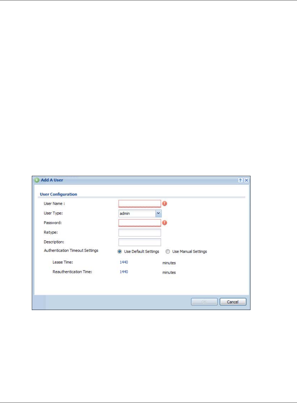
Chapter 7 User
NWA / WAC Series User’s Guide
84
• Alphanumeric A-z 0-9 (there is no unicode support)
• _ [underscores]
• - [dashes]
The first character must be alphabetical (A-Z a-z), an underscore (_), or a dash (-). Other limitations on
user names are:
• User names are case-sensitive. If you enter a user 'bob' but use 'BOB' when connecting via CIFS or FTP,
it will use the account settings used for 'BOB' not ‘bob’.
• User names have to be different than user group names.
• Here are the reserved user names:
To access this screen, go to the User screen, and click Add or Edit.
Figure 48 Configuration > Object > User > Add/Edit A User
•adm •admin •any •bin •daemon
•debug •devicehaecived•ftp •games •halt
•ldap-users •lp •mail •news •nobody
• operator • radius-users • root • shutdown • sshd
• sync • uucp • zyxel

Chapter 7 User
NWA / WAC Series User’s Guide
85
The following table describes the labels in this screen.
7.3 Setting
This screen controls default settings, login settings, lockout settings, and other user settings for the NWA/
WAC.
To access this screen, login to the Web Configurator, and click Configuration > Object > User > Setting.
Table 40 Configuration > User > User > Add/Edit A User
LABEL DESCRIPTION
User Name Type the user name for this user account. You may use 1-31 alphanumeric characters,
underscores(_), or dashes (-), but the first character cannot be a number. This value is case-
sensitive. User names have to be different than user group names, and some words are
reserved.
User Type Select what type of user this is. Choices are:
•admin - this user can look at and change the configuration of the NWA/WAC
•limited-admin - this user can look at the configuration of the NWA/WAC but not to
change it
•user - this is used for embedded RADIUS server and SNMPv3 user access
Password Enter the password of this user account. It can consist of 4 - 63 alphanumeric characters.
Retype Re-enter the password to make sure you have entered it correctly.
Description Enter the description of each user, if any. You can use up to 60 printable ASCII characters.
Default descriptions are provided.
Authentication
Timeout Settings
This field is not available if the user type is user.
If you want to set authentication timeout to a value other than the default settings, select
Use Manual Settings then fill your preferred values in the fields that follow.
Lease Time This field is not available if the user type is user.
Enter the number of minutes this user has to renew the current session before the user is
logged out. You can specify 1 to 1440 minutes. You can enter 0 to make the number of
minutes unlimited. Admin users renew the session every time the main screen refreshes in the
Web Configurator.
Reauthentication
Time
This field is not available if the user type is user.
Type the number of minutes this user can be logged into the NWA/WAC in one session
before the user has to log in again. You can specify 1 to 1440 minutes. You can enter 0 to
make the number of minutes unlimited. Unlike Lease Time, the user has no opportunity to
renew the session without logging out.
OK Click OK to save your changes back to the NWA/WAC.
Cancel Click Cancel to exit this screen without saving your changes.
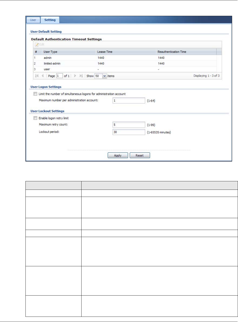
Chapter 7 User
NWA / WAC Series User’s Guide
86
Figure 49 Configuration > Object > User > Setting
The following table describes the labels in this screen.
Table 41 Configuration > Object > User > Setting
LABEL DESCRIPTION
User Default Setting
Default Authentication
Timeout Settings
These authentication timeout settings are used by default when you create a new
user account. They also control the settings for any existing user accounts that are
set to use the default settings. You can still manually configure any user account’s
authentication timeout settings.
Edit Double-click an entry or select it and click Edit to open a screen where you can
modify the entry’s settings.
# This field is a sequential value, and it is not associated with a specific entry.
User Type These are the kinds of user account the NWA/WAC supports.
•admin - this user can look at and change the configuration of the NWA/WAC
•limited-admin - this user can look at the configuration of the NWA/WAC but not
to change it
•user - this is used for embedded RADIUS server and SNMPv3 user access
Lease Time This is the default lease time in minutes for each type of user account. It defines the
number of minutes the user has to renew the current session before the user is
logged out.
Admin users renew the session every time the main screen refreshes in the Web
Configurator.
Reauthentication Time This is the default reauthentication time in minutes for each type of user account. It
defines the number of minutes the user can be logged into the NWA/WAC in one
session before having to log in again. Unlike Lease Time, the user has no opportunity
to renew the session without logging out.
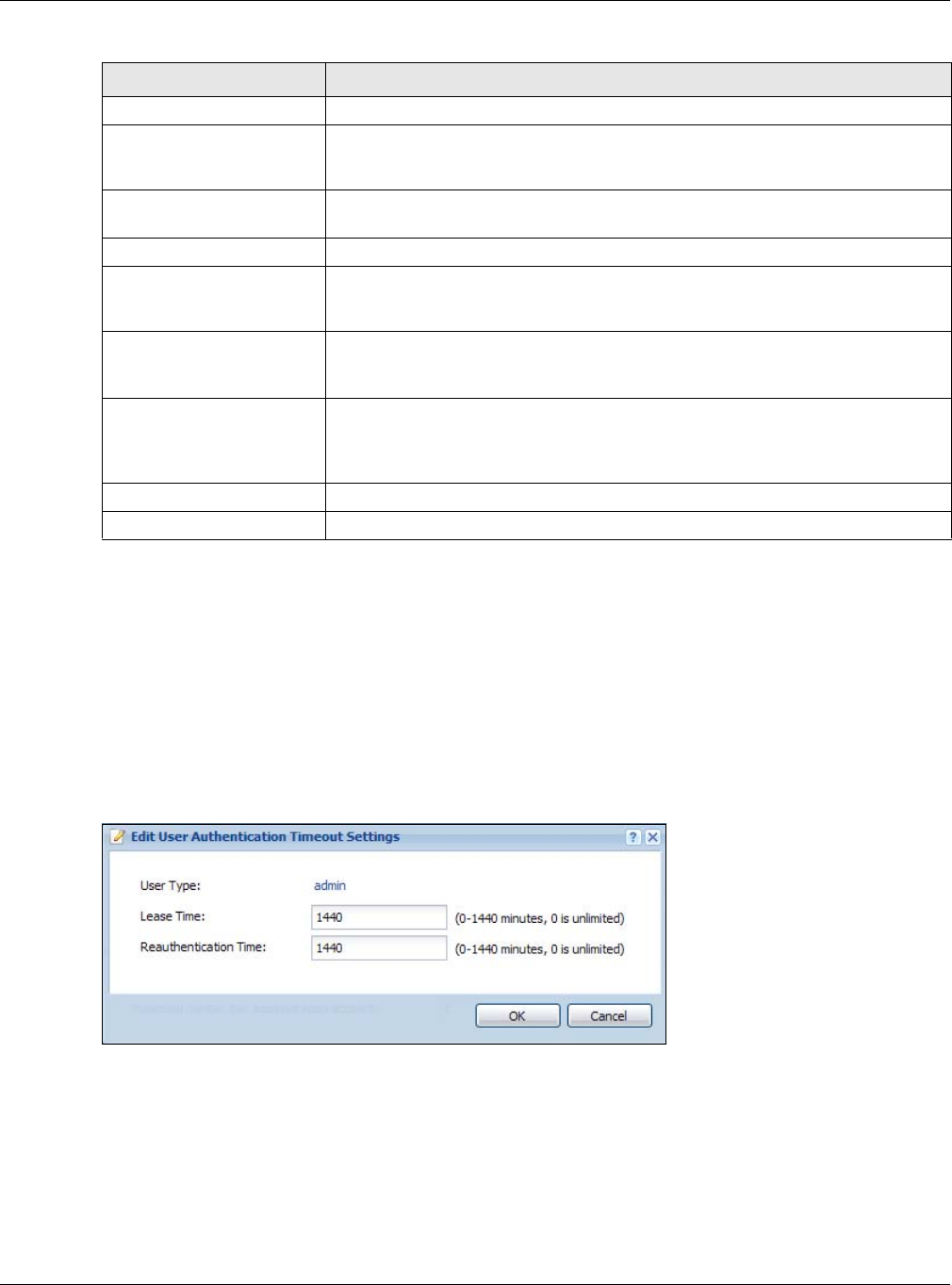
Chapter 7 User
NWA / WAC Series User’s Guide
87
7.3.1 Edit User Authentication Timeout Settings
This screen allows you to set the default authentication timeout settings for the selected type of user
account. These default authentication timeout settings also control the settings for any existing user
accounts that are set to use the default settings. You can still manually configure any user account’s
authentication timeout settings.
To access this screen, go to the Configuration > Object > User > Setting screen, select one of the Default
Authentication Timeout Settings entry and click the Edit icon.
Figure 50 User > Setting > Edit User Authentication Timeout Settings
User Logon Settings
Limit the number of
simultaneous logons for
administration account
Select this check box if you want to set a limit on the number of simultaneous logins
by admin users. If you do not select this, admin users can login as many times as they
want at the same time using the same or different IP addresses.
Maximum number per
administration account This field is effective when Limit ... for administration account is checked. Type the
maximum number of simultaneous logins by each admin user.
User Lockout Settings
Enable logon retry limit Select this check box to set a limit on the number of times each user can login
unsuccessfully (for example, wrong password) before the IP address is locked out for
a specified amount of time.
Maximum retry count This field is effective when Enable logon retry limit is checked. Type the maximum
number of times each user can login unsuccessfully before the IP address is locked
out for the specified lockout period. The number must be between 1 and 99.
Lockout period This field is effective when Enable logon retry limit is checked. Type the number of
minutes the user must wait to try to login again, if logon retry limit is enabled and the
maximum retry count is reached. This number must be between 1 and 65,535 (about
45.5 days).
Apply Click Apply to save the changes.
Reset Click Reset to return the screen to its last-saved settings.
Table 41 Configuration > Object > User > Setting (continued)
LABEL DESCRIPTION

Chapter 7 User
NWA / WAC Series User’s Guide
88
The following table describes the labels in this screen.
Table 42 User > Setting > Edit User Authentication Timeout Settings
LABEL DESCRIPTION
User Type This read-only field identifies the type of user account for which you are configuring the
default settings.
•admin - this user can look at and change the configuration of the NWA/WAC.
•limited-admin - this user can look at the configuration of the NWA/WAC but not to
change it.
Lease Time Enter the number of minutes this type of user account has to renew the current session
before the user is logged out. You can specify 1 to 1440 minutes. You can enter 0 to make
the number of minutes unlimited.
Admin users renew the session every time the main screen refreshes in the Web Configurator.
Access users can renew the session by clicking the Renew button on their screen. If you allow
access users to renew time automatically, the users can select this check box on their screen
as well. In this case, the session is automatically renewed before the lease time expires.
Reauthentication
Time
Type the number of minutes this type of user account can be logged into the NWA/WAC in
one session before the user has to log in again. You can specify 1 to 1440 minutes. You can
enter 0 to make the number of minutes unlimited. Unlike Lease Time, the user has no
opportunity to renew the session without logging out.
OK Click OK to save your changes back to the NWA/WAC.
Cancel Click Cancel to exit this screen without saving your changes.

NWA / WAC Series User’s Guide
89
CHAPTER 8
AP Profile
8.1 Overview
This chapter shows you how to configure preset profiles for the NWA/WAC.
8.1.1 What You Can Do in this Chapter
• The Radio screen (Section 8.2 on page 90) creates radio configurations that can be used by the APs.
• The SSID screen (Section 8.3 on page 96) configures three different types of profiles for your
networked APs.
8.1.2 What You Need To Know
The following terms and concepts may help as you read this chapter.
Wireless Profiles
At the heart of all wireless AP configurations on the NWA/WAC are profiles. A profile represents a group
of saved settings that you can use across any number of connected APs. You can set up the following
wireless profile types:
•Radio - This profile type defines the properties of an AP’s radio transmitter. You can have a maximum
of 32 radio profiles on the NWA/WAC.
•SSID - This profile type defines the properties of a single wireless network signal broadcast by an AP.
Each radio on a single AP can broadcast up to 8 SSIDs. You can have a maximum of 32 SSID profiles
on the NWA/WAC.
•Security - This profile type defines the security settings used by a single SSID. It controls the encryption
method required for a wireless client to associate itself with the SSID. You can have a maximum of 32
security profiles on the NWA/WAC.
•MAC Filtering - This profile provides an additional layer of security for an SSID, allowing you to block
access or allow access to that SSID based on wireless client MAC addresses. If a client’s MAC address
is on the list, then it is either allowed or denied, depending on how you set up the MAC Filter profile.
You can have a maximum of 32 MAC filtering profiles on the NWA/WAC.
•Layer-2 Isolation - This profile defines the MAC addresses of the devices that you want to allow the
associated wireless clients to have access to when layer-2 isolation is enabled.
SSID
The SSID (Service Set IDentifier) is the name that identifies the Service Set with which a wireless station is
associated. Wireless stations associating to the access point (AP) must have the same SSID. In other
words, it is the name of the wireless network that clients use to connect to it.
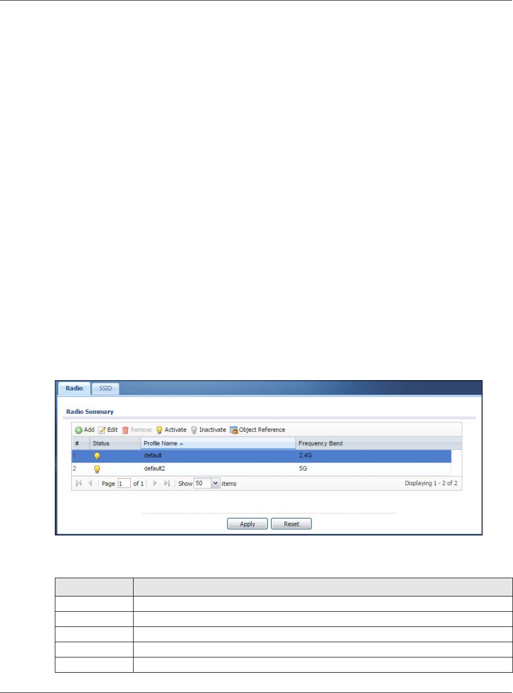
Chapter 8 AP Profile
NWA / WAC Series User’s Guide
90
WEP
WEP (Wired Equivalent Privacy) encryption scrambles all data packets transmitted between the AP and
the wireless stations associated with it in order to keep network communications private. Both the
wireless stations and the access points must use the same WEP key for data encryption and decryption.
WPA2
WPA2 (IEEE 802.11i) is a wireless security standard that defines stronger encryption, authentication and
key management than WPA. Key differences between WPA2 and WEP are improved data encryption
and user authentication.
IEEE 802.1x
The IEEE 802.1x standard outlines enhanced security methods for both the authentication of wireless
stations and encryption key management. Authentication is done using an external RADIUS server.
8.2 Radio
This screen allows you to create radio profiles for the NWA/WAC. A radio profile is a list of settings that an
NWA/WAC can use to configure its radio transmitter(s). To access this screen click Configuration >
Object > AP Profile.
Note: You can have a maximum of 32 radio profiles on the NWA/WAC.
Figure 51 Configuration > Object > AP Profile > Radio
The following table describes the labels in this screen.
Table 43 Configuration > Object > AP Profile > Radio
LABEL DESCRIPTION
Add Click this to add a new radio profile.
Edit Click this to edit the selected radio profile.
Remove Click this to remove the selected radio profile.
Activate To turn on an entry, select it and click Activate.
Inactivate To turn off an entry, select it and click Inactivate.

Chapter 8 AP Profile
NWA / WAC Series User’s Guide
91
8.2.1 Add/Edit Radio Profile
This screen allows you to create a new radio profile or edit an existing one. To access this screen, click
the Add button or select a radio profile from the list and click the Edit button.
Object
Reference
Click this to view which other objects are linked to the selected radio profile.
# This field is a sequential value, and it is not associated with a specific user.
Status This field shows whether or not the entry is activated.
A yellow bulb signifies that this rule is active. A gray bulb signifies that this rule is not active.
Profile Name This field indicates the name assigned to the radio profile.
Frequency Band This field indicates the frequency band which this radio profile is configured to use.
Apply Click Apply to save your changes back to the NWA/WAC.
Reset Click Reset to return the screen to its last-saved settings.
Table 43 Configuration > Object > AP Profile > Radio (continued)
LABEL DESCRIPTION
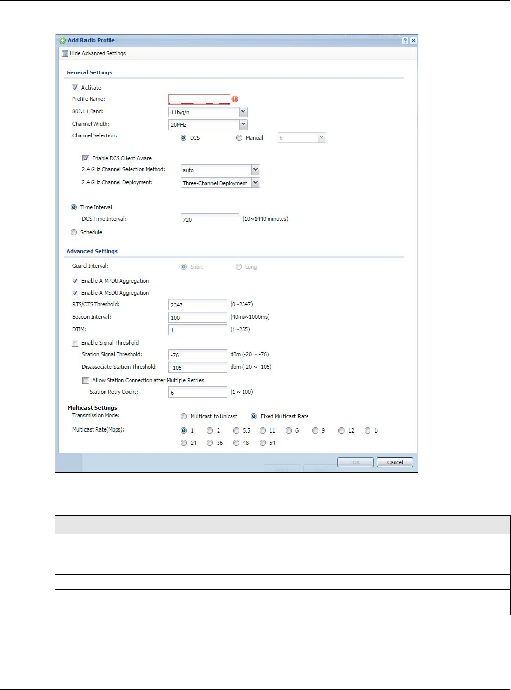
Chapter 8 AP Profile
NWA / WAC Series User’s Guide
92
Figure 52 Configuration > Object > AP Profile > Add/Edit Profile
The following table describes the labels in this screen.
Table 44 Configuration > Object > AP Profile > Add/Edit Profile
LABEL DESCRIPTION
Hide / Show
Advanced Settings
Click this to hide or show the Advanced Settings in this window.
General Settings
Activate Select this option to make this profile active.
Profile Name Enter up to 31 alphanumeric characters to be used as this profile’s name. Spaces and
underscores are allowed.

Chapter 8 AP Profile
NWA / WAC Series User’s Guide
93
802.11 Band Select the wireless band which this radio profile should use. Not all NWA/WACs support
both 2.4 GHz and 5 GHz frequency bands.
2.4 GHz is the frequency used by IEEE 802.11b/g/n wireless clients.
5 GHz is the frequency used by IEEE 802.11ac/a/n wireless clients.
•11b/g: allows either IEEE 802.11b or IEEE 802.11g compliant WLAN devices to associate
with the NWA/WAC. The NWA/WAC adjusts the transmission rate automatically
according to the wireless standard supported by the wireless devices.
•11b/g/n: allows IEEE802.11b, IEEE802.11g and IEEE802.11n compliant WLAN devices to
associate with the NWA/WAC. The transmission rate of your NWA/WAC might be
reduced.
•11a: allows only IEEE 802.11a compliant WLAN devices to associate with the NWA/WAC.
•11a/n: allows both IEEE802.11n and IEEE802.11a compliant WLAN devices to associate
with the NWA/WAC. The transmission rate of your NWA/WAC might be reduced.
•11ac: allows IEEE 802.11ac compliant WLAN devices to associate with the WAC.
Channel Width Select the channel bandwidth you want to use for your wireless network.
Select 20 MHz if you want to lessen radio interference with other wireless devices in your
neighborhood.
Select 20/40 MHz to allow the NWA/WAC to choose the channel bandwidth (20 or 40 MHz)
that has least interference.
Select 20/40/80 MHz to allow the NWA/WAC to choose the channel bandwidth (20 or 40 or
80 MHz) that has least interference. This option is available only when you select 11ac in the
802.11 Band field.
Channel
Selection This is the radio channel which the signal will use for broadcasting by this radio profile.
•DCS: Choose Dynamic Channel Selection to have the NWA/WAC choose a radio
channel that has least interference.
•Manual: Choose from the available radio channels in the list. If your NWA/WAC is
outdoor type, be sure to choose non-indoors channels.
Enable DCS
Client Aware Select this to have the AP wait until all connected clients have disconnected before
switching channels.
If you disable this then the AP switches channels immediately regardless of any client
connections. In this instance, clients that are connected to the AP when it switches
channels are dropped.
2.4 GHz Channel
Selection Method Select how you want to specify the channels the NWA/WAC switches between for 2.4 GHz
operation. This field appears only when you choose 802.11b/g/n mode.
Select auto to have the NWA/WAC display a 2.4 GHz Channel Deployment field you can
use to limit channel switching to 3 or 4 channels.
Select manual to select the individual channels the NWA/WAC switches between.
Note: The method is automatically set to auto when no channel is selected or
any one of the previously selected channels is not supported.
Channel ID This field is available only when you set Channel Selection to DCS and set 2.4 GHz Channel
Selection Method to manual.
Select the check boxes of the channels that you want the NWA/WAC to use.
Table 44 Configuration > Object > AP Profile > Add/Edit Profile (continued)
LABEL DESCRIPTION

Chapter 8 AP Profile
NWA / WAC Series User’s Guide
94
2.4 GHz Channel
Deployment This is available when the 2.4 GHz Channel Selection Method is set to auto.
Select Three-Channel Deployment to limit channel switching to channels 1,6, and 11, the
three channels that are sufficiently attenuated to have almost no impact on one another.
In other words, this allows you to minimize channel interference by limiting channel-
hopping to these three “safe” channels.
Select Four-Channel Deployment to limit channel switching to four channels. Depending
on the country domain, if the only allowable channels are 1-11 then the NWA/WAC uses
channels 1, 4, 7, 11 in this configuration; otherwise, the NWA/WAC uses channels 1, 5, 9, 13
in this configuration. Four channel deployment expands your pool of possible channels
while keeping the channel interference to a minimum.
Enable 5 GHz DFS
Aware This field is available only when you select 11a, 11a/n or 11ac in the 802.11 Band field and
set 5 GHz Channel Selection Method to auto.
Select this if your APs are operating in an area known to have RADAR devices. This allows
the devide to downgrade its frequency to below 5 GHz in the event RADAR signal is
detected, thus preventing it from interfering with that signal.
Enabling this forces the AP to select a non-DFS channel.
5 GHz Channel
Selection Method Select how you want to specify the channels the NWA/WAC switches between for 5 GHz
operation.
Select Auto to have the NWA/WAC automatically select the best channel.
Select manual to select the individual channels the NWA/WAC switches between.
Note: The method is automatically set to auto when no channel is selected or
any one of the previously selected channels is not supported.
Channel ID This field is available only when you set Channel Selection to DCS and set 5 GHz Channel
Selection Method to manual.
Select the check boxes of the channels that you want the NWA/WAC to use.
Time Interval Select this option to have the NWA/WAC survey the other APs within its broadcast radius at
the end of the specified time interval.
DCS Time Interval This field is available when you set Channel Selection to DCS and select the Time Interval
option.
Enter a number of minutes. This regulates how often the NWA/WAC surveys the other APs
within its broadcast radius. If the channel on which it is currently broadcasting suddenly
comes into use by another AP, the NWA/WAC will then dynamically select the next
available clean channel or a channel with lower interference.
Schedule Select this option to have the NWA/WAC survey the other APs within its broadcast radius at
a specifc time on selected days of the week.
Start Time Specify the time of the day (in 24-hour format) to have the NWA/WAC use DCS to
automatically scan and find a less-used channel.
Week Days Select each day of the week to have the NWA/WAC use DCS to automatically scan and
find a less-used channel.
Advanced Settings
Guard Interval Set the guard interval for this radio profile to either short or long. This option isn’t applicable
if you set 802.11 Band to 11a or 11b/g and/or choose 20 MHz channel width.
The guard interval is the gap introduced between data transmission from users in order to
reduce interference. Reducing the interval increases data transfer rates but also increases
interference. Increasing the interval reduces data transfer rates but also reduces
interference.
Table 44 Configuration > Object > AP Profile > Add/Edit Profile (continued)
LABEL DESCRIPTION

Chapter 8 AP Profile
NWA / WAC Series User’s Guide
95
Enable A-MPDU
Aggregation Select this to enable A-MPDU aggregation. This field is not available if you set 802.11 Band
to 11a or 11b/g.
Message Protocol Data Unit (MPDU) aggregation collects Ethernet frames along with their
802.11n headers and wraps them in a 802.11n MAC header. This method is useful for
increasing bandwidth throughput in environments that are prone to high error rates.
Enable A-MSDU
Aggregation Select this to enable A-MSDU aggregation. This field is not available if you set 802.11 Band
to 11a or 11b/g.
Mac Service Data Unit (MSDU) aggregation collects Ethernet frames without any of their
802.11n headers and wraps the header-less payload in a single 802.11n MAC header. This
method is useful for increasing bandwidth throughput. It is also more efficient than A-MPDU
except in environments that are prone to high error rates.
RTS/CTS Threshold Use RTS/CTS to reduce data collisions on the wireless network if you have wireless clients
that are associated with the same AP but out of range of one another. When enabled, a
wireless client sends an RTS (Request To Send) and then waits for a CTS (Clear To Send)
before it transmits. This stops wireless clients from transmitting packets at the same time
(and causing data collisions).
A wireless client sends an RTS for all packets larger than the number (of bytes) that you
enter here. Set the RTS/CTS equal to or higher than the fragmentation threshold to turn RTS/
CTS off.
Beacon Interval When a wirelessly networked device sends a beacon, it includes with it a beacon interval.
This specifies the time period before the device sends the beacon again. The interval tells
receiving devices on the network how long they can wait in low-power mode before
waking up to handle the beacon. A high value helps save current consumption of the
access point.
DTIM Delivery Traffic Indication Message (DTIM) is the time period after which broadcast and
multicast packets are transmitted to mobile clients in the Active Power Management
mode. A high DTIM value can cause clients to lose connectivity with the network. This value
can be set from 1 to 255.
Enable Signal
Threshold Select the check box to use the signal threshold to ensure wireless clients receive good
throughput. This allows only wireless clients with a strong signal to connect to the AP.
Clear the check box to not require wireless clients to have a minimum signal strength to
connect to the AP.
Station Signal
Threshold Set a minimum client signal strength. A wireless client is allowed to connect to the AP only
when its signal strength is stronger than the specified threshold.
-20 dBm is the strongest signal you can require and -76 is the weakest.
Disassociate
Station Threshold Set a minimum kick-off signal strength. When a wireless client’s signal strength is lower than
the specified threshold, the NWA/WAC disconnects the wireless client from the AP.
-20 dBm is the strongest signal you can require and -90 is the weakest.
Allow Station
Connection after
Multiple Retries
Select this option to allow a wireless client to try to associate with the AP again after it is
disconnected due to weak signal strength.
Station Retry
Count Set the maximum number of times a wireless client can attempt to re-connect to the AP
Multicast Settings
Table 44 Configuration > Object > AP Profile > Add/Edit Profile (continued)
LABEL DESCRIPTION
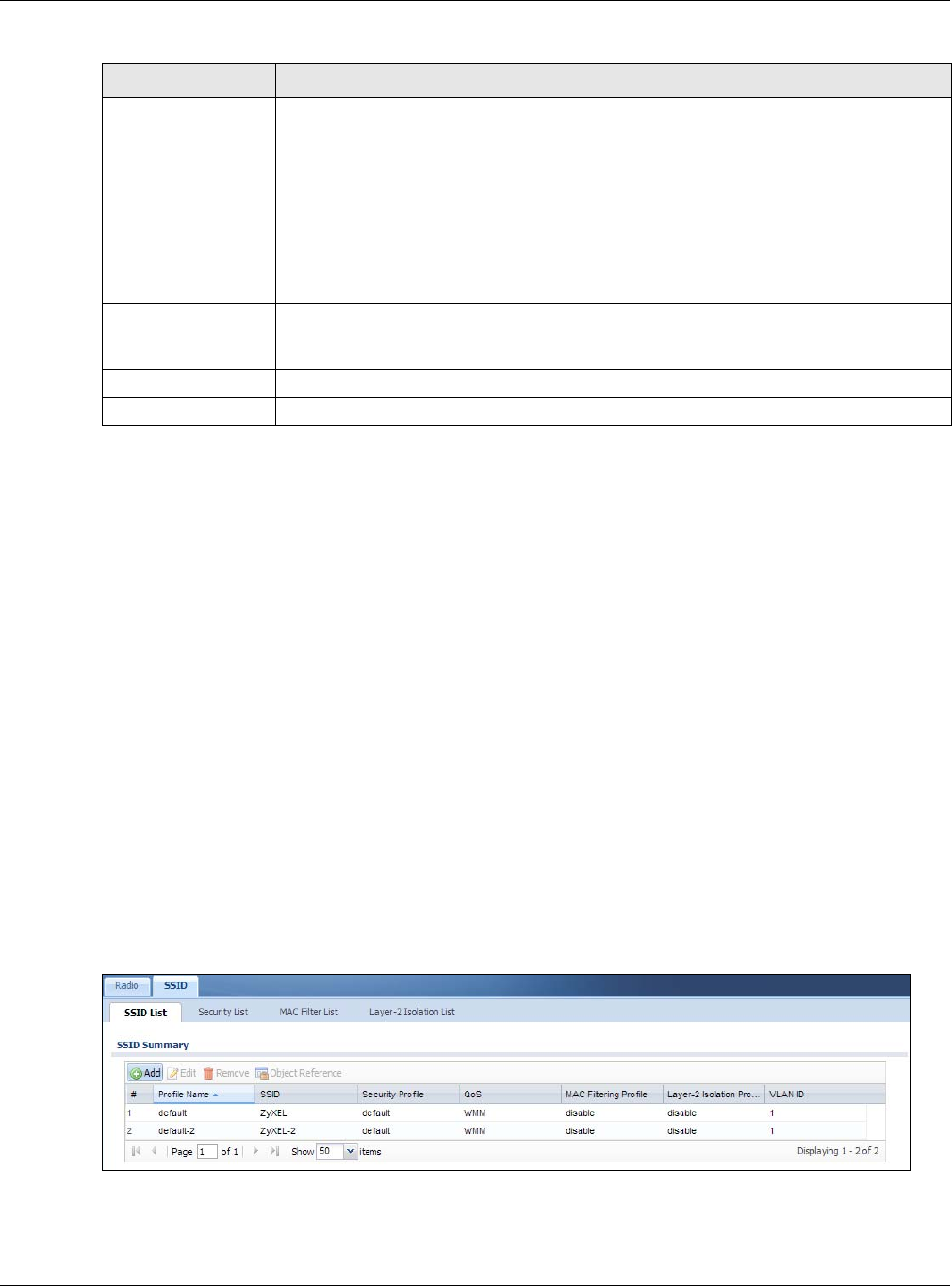
Chapter 8 AP Profile
NWA / WAC Series User’s Guide
96
8.3 SSID
The SSID screens allow you to configure three different types of profiles for your networked APs: an SSID
list, which can assign specific SSID configurations to your APs; a security list, which can assign specific
encryption methods to the APs when allowing wireless clients to connect to them; and a MAC filter list,
which can limit connections to an AP based on wireless clients MAC addresses.
8.3.1 SSID List
This screen allows you to create and manage SSID configurations that can be used by the APs. An SSID,
or Service Set IDentifier, is basically the name of the wireless network to which a wireless client can
connect. The SSID appears as readable text to any device capable of scanning for wireless frequencies
(such as the WiFi adapter in a laptop), and is displayed as the wireless network name when a person
makes a connection to it.
To access this screen click Configuration > Object > AP Profile > SSID.
Note: You can have a maximum of 32 SSID profiles on the NWA/WAC.
Figure 53 Configuration > Object > AP Profile > SSID List
Transmission
Mode Specify how the NWA/WAC handles wireless multicast traffic.
Select Multicast to Unicast to broadcast wireless multicast traffic to all of the wireless clients
as unicast traffic. Unicast traffic dynamically changes the data rate based on the
application’s bandwidth requirements. The retransmit mechanism of unicast traffic
provides more reliable transmission of the multicast traffic, although it also produces
duplicate packets.
Select Fixed Multicast Rate to send multicast traffic to all wireless clients at a single data
rate. You must know the multicast application’s bandwidth requirements and set it in the
following field.
Multicast
Rate(Mbps) If you set Transmission Mode to Fixed Multicast Rate, select a data rate at which the NWA/
WAC transmits multicast packets to wireless clients. For example, to deploy 4 Mbps video,
select a fixed multicast rate higher than 4 Mbps.
OK Click OK to save your changes back to the NWA/WAC.
Cancel Click Cancel to exit this screen without saving your changes.
Table 44 Configuration > Object > AP Profile > Add/Edit Profile (continued)
LABEL DESCRIPTION
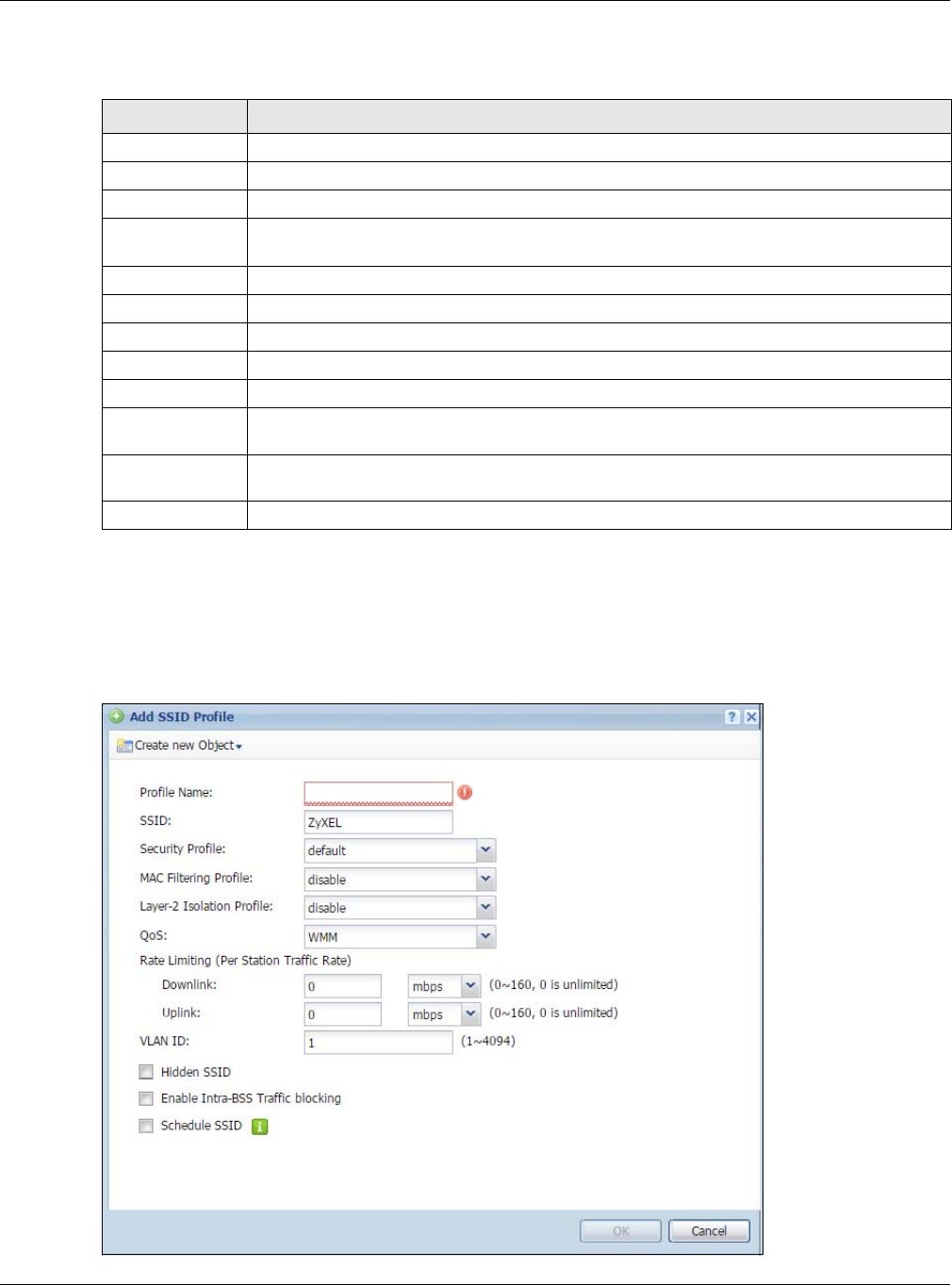
Chapter 8 AP Profile
NWA / WAC Series User’s Guide
97
The following table describes the labels in this screen.
8.3.2 Add/Edit SSID Profile
This screen allows you to create a new SSID profile or edit an existing one. To access this screen, click the
Add button or select a SSID profile from the list and click the Edit button.
Figure 54 Configuration > Object > AP Profile > Add/Edit SSID Profile
Table 45 Configuration > Object > AP Profile > SSID List
LABEL DESCRIPTION
Add Click this to add a new SSID profile.
Edit Click this to edit the selected SSID profile.
Remove Click this to remove the selected SSID profile.
Object
Reference
Click this to view which other objects are linked to the selected SSID profile (for example, radio
profile).
# This field is a sequential value, and it is not associated with a specific user.
Profile Name This field indicates the name assigned to the SSID profile.
SSID This field indicates the SSID name as it appears to wireless clients.
Security Profile This field indicates which (if any) security profile is associated with the SSID profile.
QOS This field indicates the QoS type associated with the SSID profile.
MAC Filtering
Profile
This field indicates which (if any) MAC filter Profile is associated with the SSID profile.
Layer-2 Isolation
Profile
This field indicates which (if any) layer-2 isolation Profile is associated with the SSID profile.
VLAN ID This field indicates the VLAN ID associated with the SSID profile.

Chapter 8 AP Profile
NWA / WAC Series User’s Guide
98
The following table describes the labels in this screen.
Table 46 Configuration > Object > AP Profile > Add/Edit SSID Profile
LABEL DESCRIPTION
Create new
Object
Select an object type from the list to create a new one associated with this SSID profile.
Profile Name Enter up to 31 alphanumeric characters for the profile name. This name is only visible in the
Web Configurator and is only for management purposes. Spaces and underscores are
allowed.
SSID Enter the SSID name for this profile. This is the name visible on the network to wireless clients.
Enter up to 32 characters, spaces and underscores are allowed.
Security Profile Select a security profile from this list to associate with this SSID. If none exist, you can use the
Create new Object menu to create one.
Note: It is highly recommended that you create security profiles for all of your SSIDs to
enhance your network security.
MAC Filtering
Profile
Select a MAC filtering profile from the list to associate with this SSID. If none exist, you can use
the Create new Object menu to create one.
MAC filtering allows you to limit the wireless clients connecting to your network through a
particular SSID by wireless client MAC addresses. Any clients that have MAC addresses not in
the MAC filtering profile of allowed addresses are denied connections.
The disable setting means no MAC filtering is used.
Layer-2 Isolation
Profile
Select a layer-2 isolation profile from the list to associate with this SSID. If none exist, you can use
the Create new Object menu to create one.
Layer-2 isolation allows you to prevent wireless clients associated with your NWA/WAC from
communicating with other wireless clients, APs, computers or routers in a network.
The disable setting means no layer-2 isolation is used.
QoS Select a Quality of Service (QoS) access category to associate with this SSID. Access categories
minimize the delay of data packets across a wireless network. Certain categories, such as
video or voice, are given a higher priority due to the time sensitive nature of their data packets.
QoS access categories are as follows:
disable: Turns off QoS for this SSID. All data packets are treated equally and not tagged with
access categories.
WMM: Enables automatic tagging of data packets. The NWA/WAC assigns access categories
to the SSID by examining data as it passes through it and making a best guess effort. If
something looks like video traffic, for instance, it is tagged as such.
WMM_VOICE: All wireless traffic to the SSID is tagged as voice data. This is recommended if an
SSID is used for activities like placing and receiving VoIP phone calls.
WMM_VIDEO: All wireless traffic to the SSID is tagged as video data. This is recommended for
activities like video conferencing.
WMM_BEST_EFFORT: All wireless traffic to the SSID is tagged as “best effort,” meaning the data
travels the best route it can without displacing higher priority traffic. This is good for activities
that do not require the best bandwidth throughput, such as surfing the Internet.
WMM_BACKGROUND: All wireless traffic to the SSID is tagged as low priority or “background
traffic”, meaning all other access categories take precedence over this one. If traffic from an
SSID does not have strict throughput requirements, then this access category is recommended.
For example, an SSID that only has network printers connected to it.
Rate Limiting
Downlink Define the maximum incoming transmission data rate (either in mbps or kbps) on a perstation
basis.
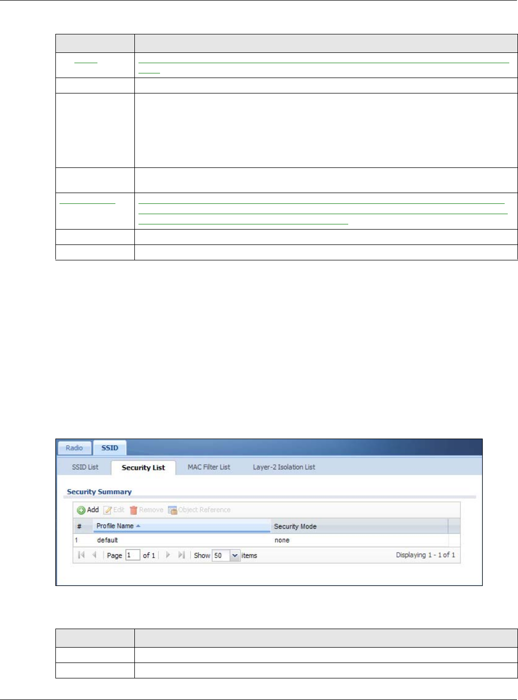
Chapter 8 AP Profile
NWA / WAC Series User’s Guide
99
8.4 Security List
This screen allows you to manage wireless security configurations that can be used by your SSIDs.
Wireless security is implemented strictly between the AP broadcasting the SSID and the stations that are
connected to it.
To access this screen click Configuration > Object > AP Profile > SSID > Security List.
Note: You can have a maximum of 32 security profiles on the NWA/WAC.
Figure 55 Configuration > Object > AP Profile > SSID > Security List
The following table describes the labels in this screen.
Uplink Define the maximum outgoing transmission data rate (either in mbps or kbps) on a perstation
basis.
VLAN ID Enter a VLAN ID for the NWA/WAC to use to tag traffic originating from this SSID.
Hidden SSID Select this if you want to “hide” your SSID from wireless clients. This tells any wireless clients in the
vicinity of the AP using this SSID profile not to display its SSID name as a potential connection.
Not all wireless clients respect this flag and display it anyway.
When a SSID is “hidden” and a wireless client cannot see it, the only way you can connect to
the SSID is by manually entering the SSID name in your wireless connection setup screen(s)
(these vary by client, client connectivity software, and operating system).
Enable Intra-BSS
Traffic Blocking
Select this option to prevent crossover traffic from within the same SSID on the NWA/WAC.
Schedule SSID Select this option and set whether the SSID is enabled or disabled on each day of the week.
You also need to select the hour and minute (in 24-hour format) to specify the time period of
each day during which the SSID is enabled/enabled.
OK Click OK to save your changes back to the NWA/WAC.
Cancel Click Cancel to exit this screen without saving your changes.
Table 46 Configuration > Object > AP Profile > Add/Edit SSID Profile (continued)
LABEL DESCRIPTION
Table 47 Configuration > Object > AP Profile > SSID > Security List
LABEL DESCRIPTION
Add Click this to add a new security profile.
Edit Click this to edit the selected security profile.

Chapter 8 AP Profile
NWA / WAC Series User’s Guide
100
8.4.1 Add/Edit Security Profile
This screen allows you to create a new security profile or edit an existing one. To access this screen, click
the Add button or select a security profile from the list and click the Edit button.
Note: This screen’s options change based on the Security Mode selected. Only the default
screen is displayed here.
Remove Click this to remove the selected security profile.
Object
Reference
Click this to view which other objects are linked to the selected security profile (for example,
SSID profile).
# This field is a sequential value, and it is not associated with a specific user.
Profile Name This field indicates the name assigned to the security profile.
Security Mode This field indicates this profile’s security mode (if any).
Table 47 Configuration > Object > AP Profile > SSID > Security List (continued)
LABEL DESCRIPTION