ZyXEL Communications WAP5705 5-GHz Wireless HD Media Streaming Box User Manual Book
ZyXEL Communications Corporation 5-GHz Wireless HD Media Streaming Box Book
UserManual.wiki
>
ZyXEL Communications
>
WAP5705 User Manual
User Manual
Navigation menu
Upload a User Manual
Namespaces
Wiki Guide
HTML
PDF
Info
Views
User Manual
Discussion / Help
Navigation
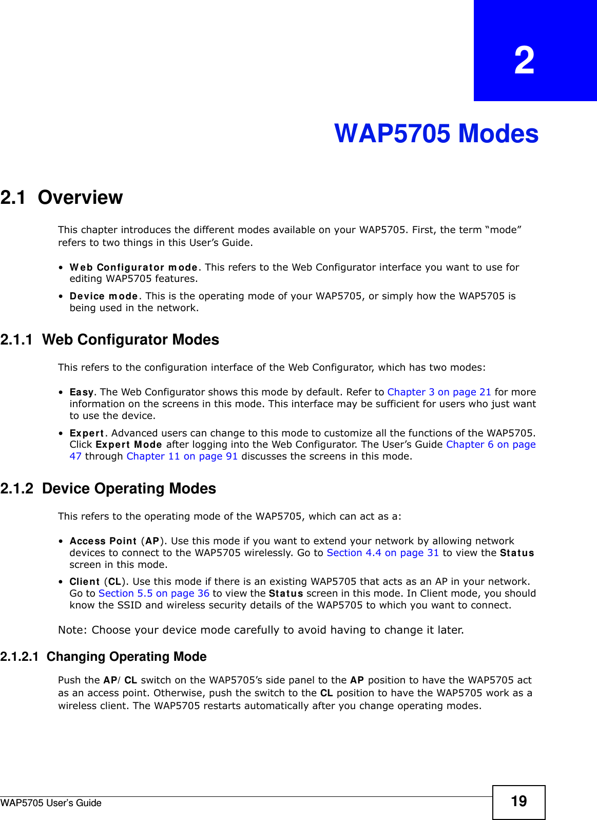
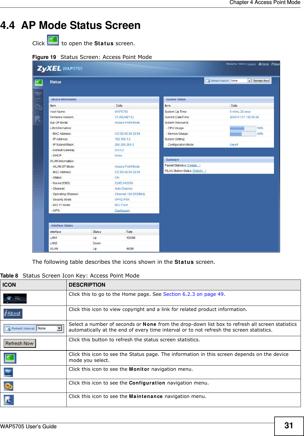

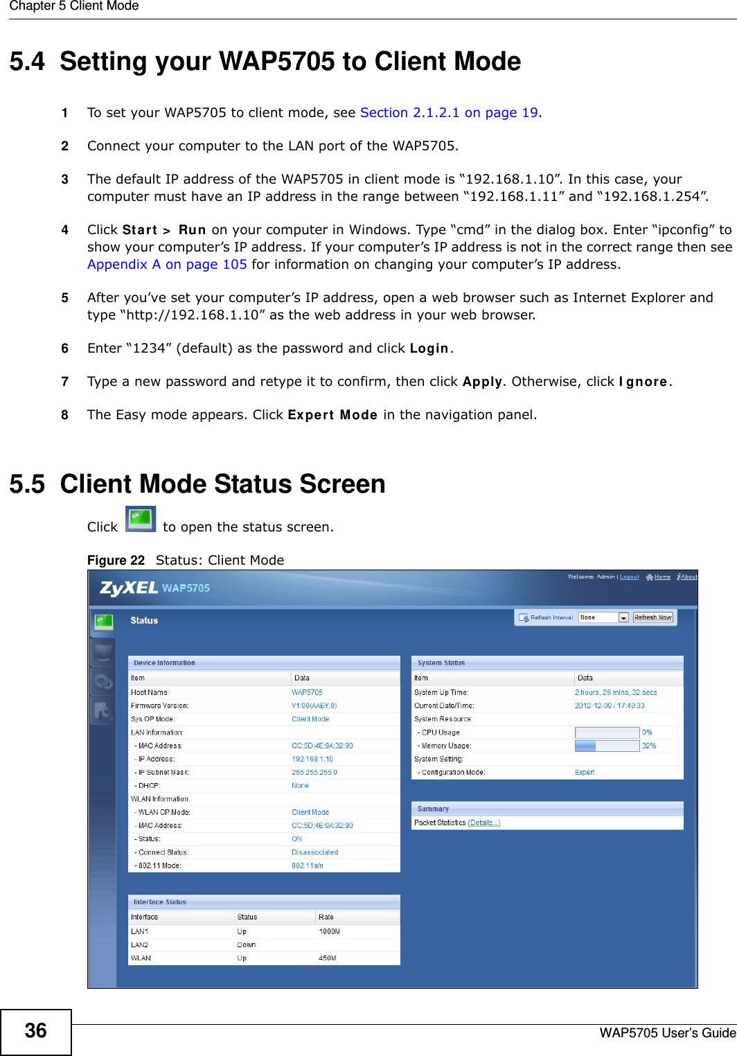
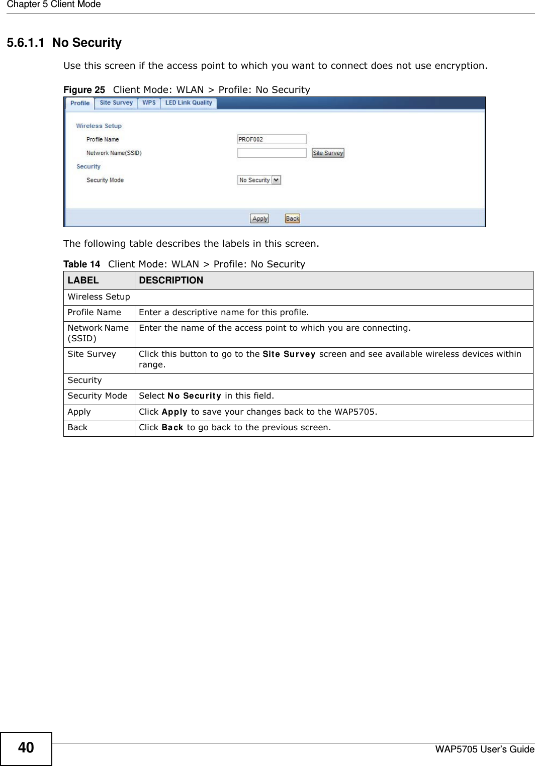
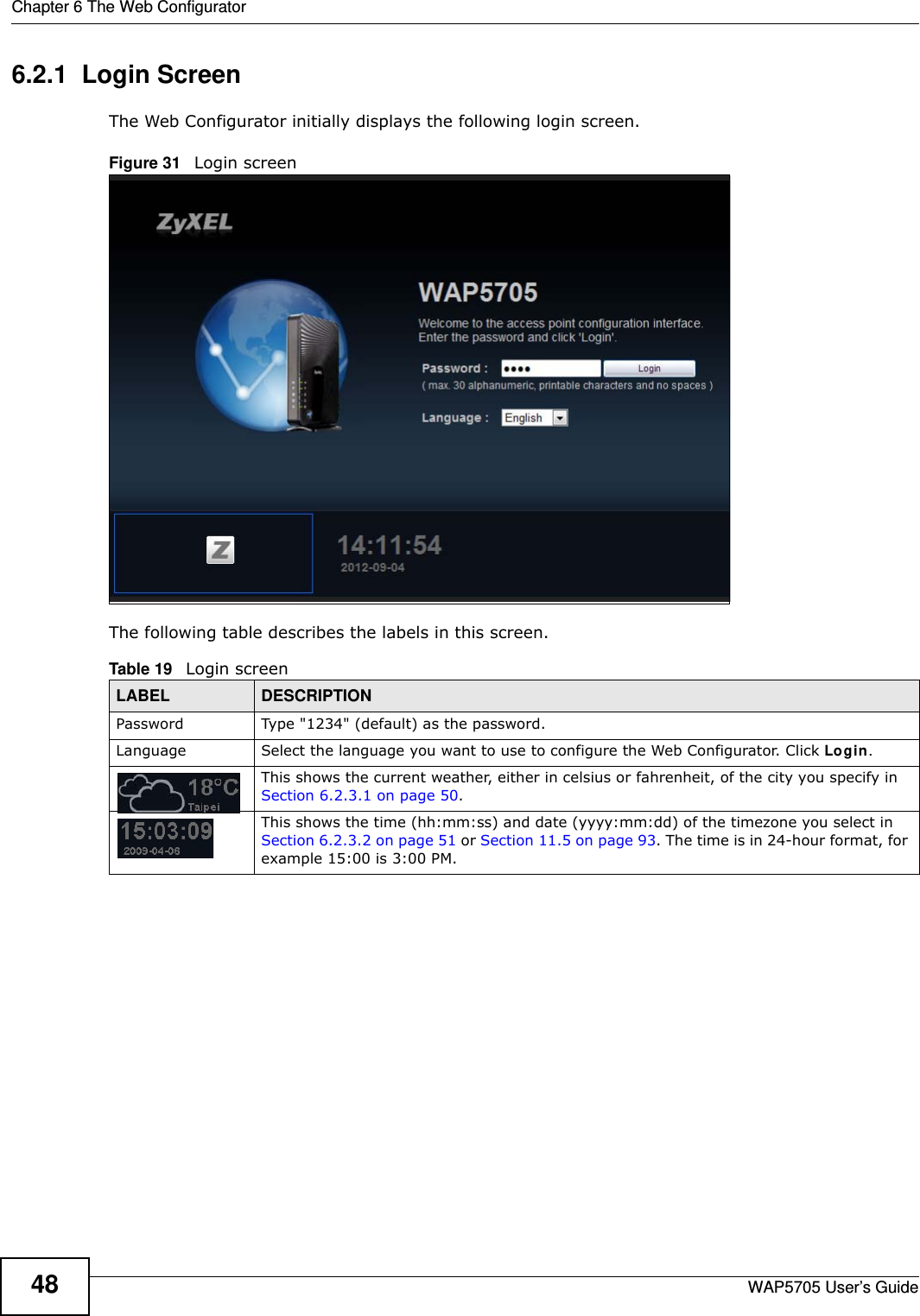

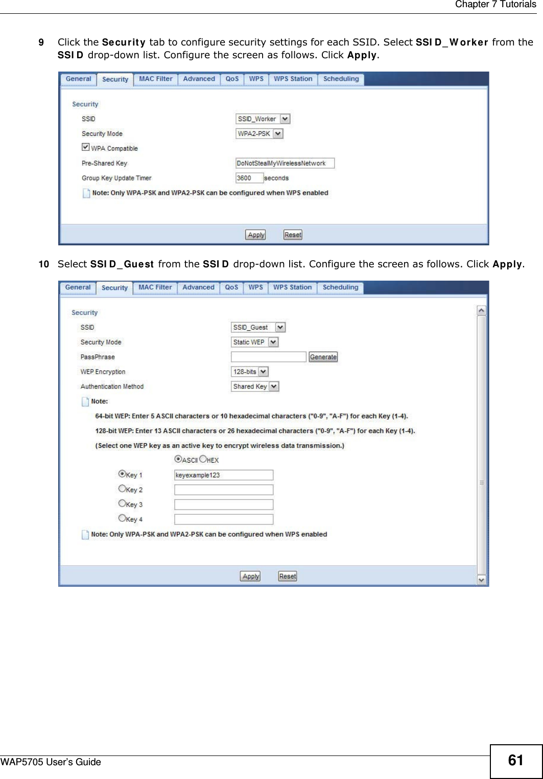
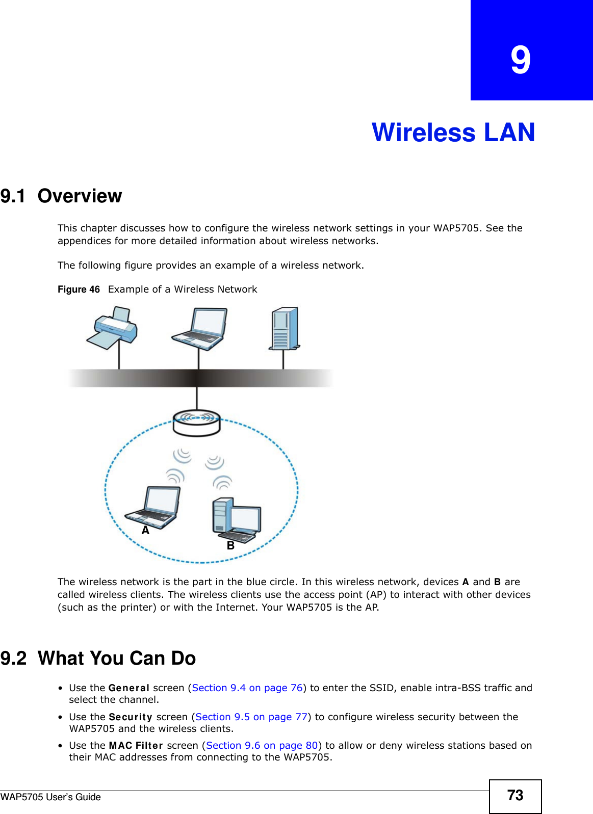
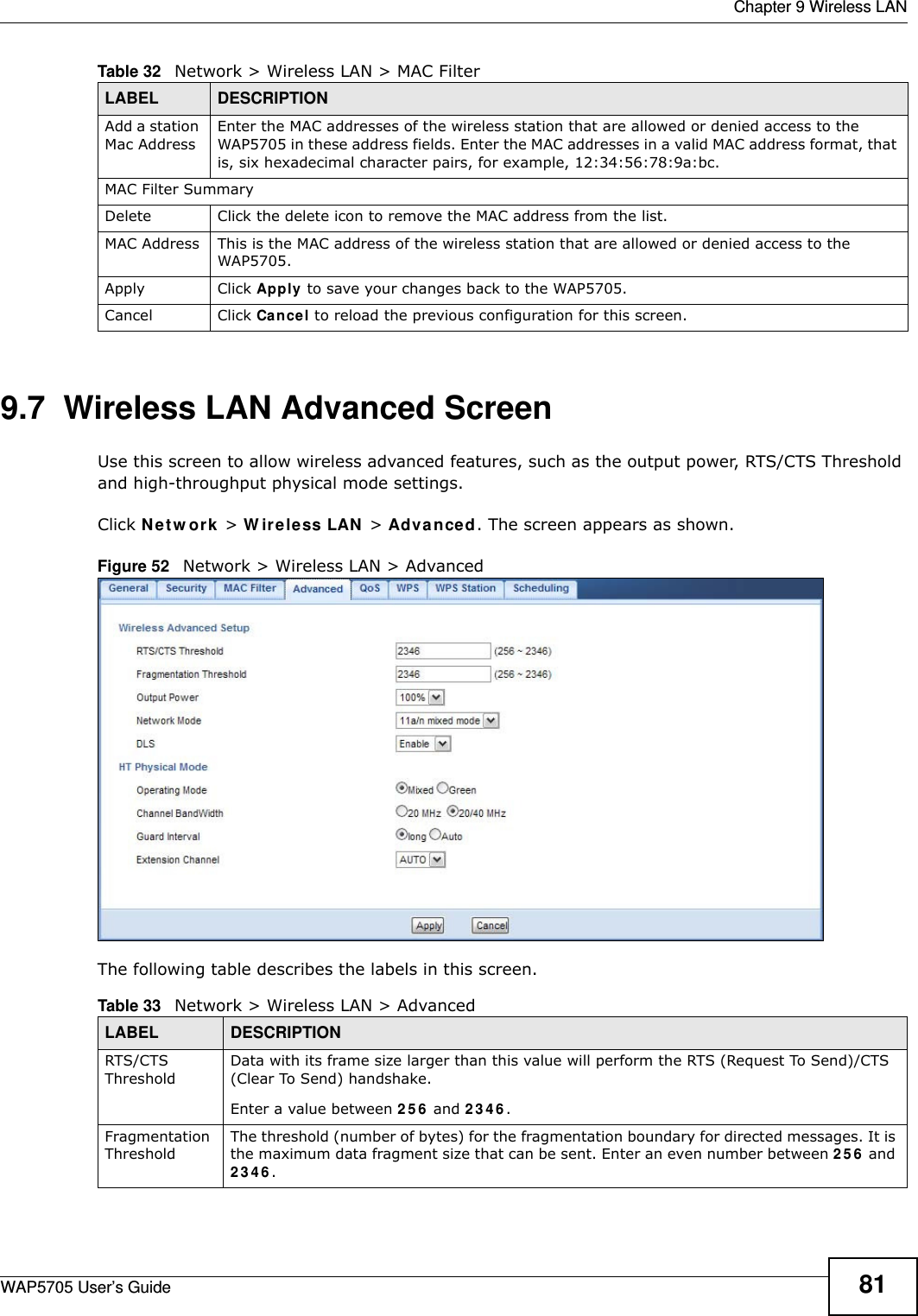
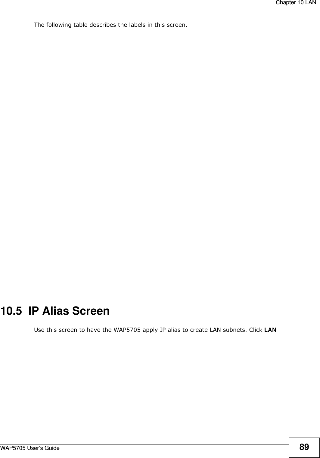
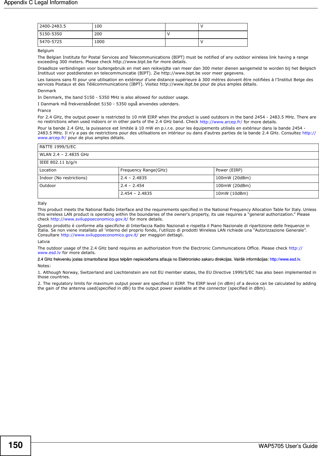
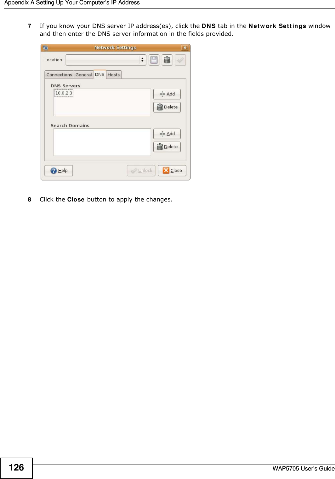
![Chapter 12 TroubleshootingWAP5705 User’s Guide 101• If there is no DHCP server on your network, make sure your computer’s IP address is in the same subnet as the WAP5705. See Appendix A on page 105.5Reset the device to its factory defaults, and try to access the WAP5705 with the default IP address. See Section 11.7 on page 96.6If the problem continues, contact the network administrator or vendor, or try one of the advanced suggestions.Adva n ced Suggestion• If your computer is connected wirelessly, use a computer that is connected to a LAN port.I can see the Login screen, but I cannot log in to the WAP5705.1Make sure you have entered the password correctly. The default password is 1 2 3 4 . This field is case-sensitive, so make sure [Caps Lock] is not on. 2This can happen when you fail to log out properly from your last session. Try logging in again after 5 minutes.3Disconnect and re-connect the power adaptor or cord to the WAP5705. 4If this does not work, you have to reset the device to its factory defaults. See Section 12.4 on page 102.12.3 Internet AccessI cannot access the Internet.1Check the hardware connections, and make sure the LEDs are behaving as expected. See the Quick Start Guide.2Make sure the WAP5705 in access point mode is connected to a broadband modem or router with Internet access. Connect to another WAP5705 in client mode to access the Internet through the WAP5705 in access point mode. Use the switch on the WAP5705’s side panel to change your system operating mode setting (see Section 2.1.2.1 on page 19). Make sure the client is within the transmission range of the AP.3If you are trying to access the Internet wirelessly, make sure the wireless settings in the wireless client are the same as the settings in the AP.4Disconnect all the cables from your device, and follow the directions in the Quick Start Guide again. 5If the problem continues, contact your ISP.](https://usermanual.wiki/ZyXEL-Communications/WAP5705/User-Guide-2316945-Page-101.png)
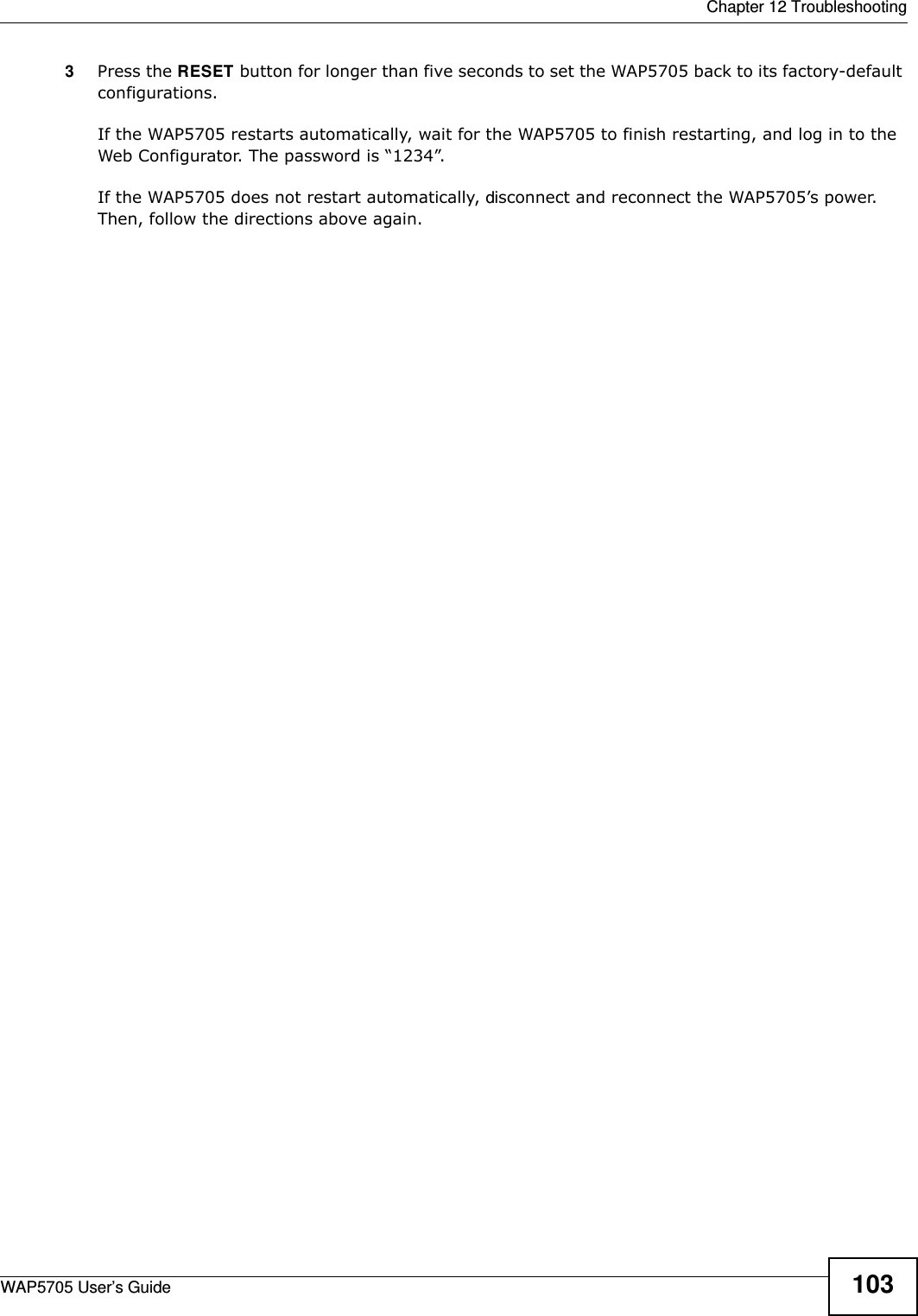

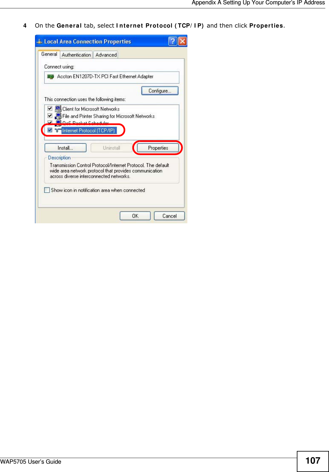
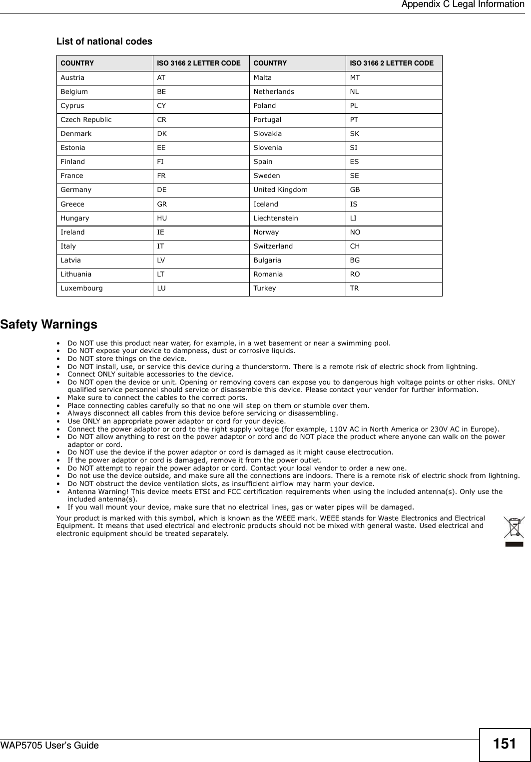
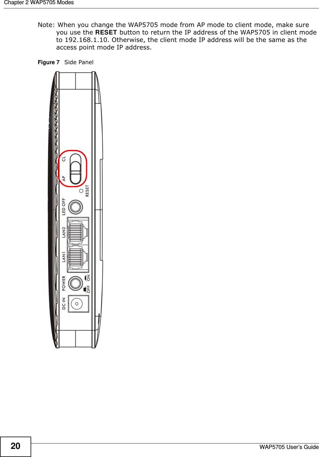
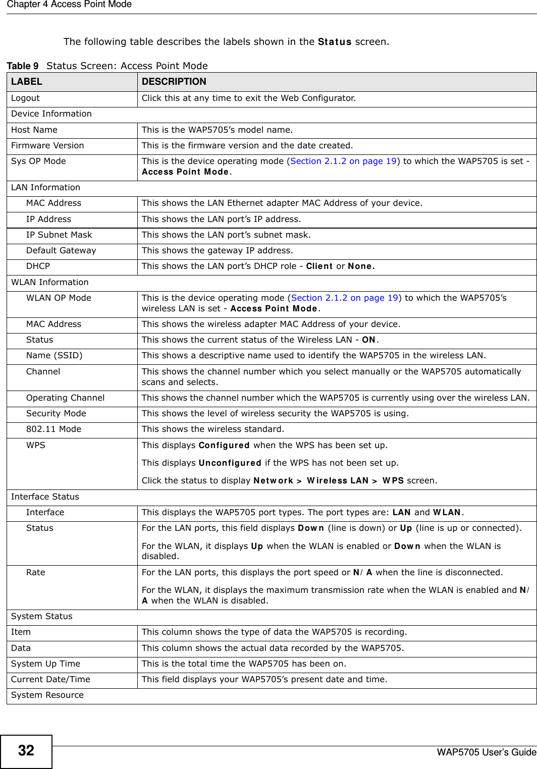
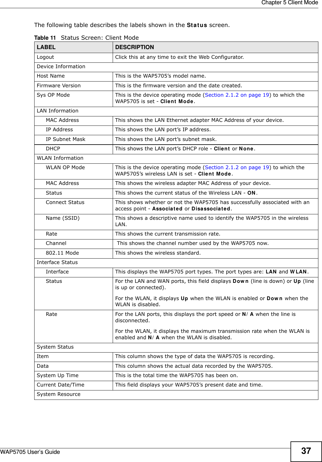
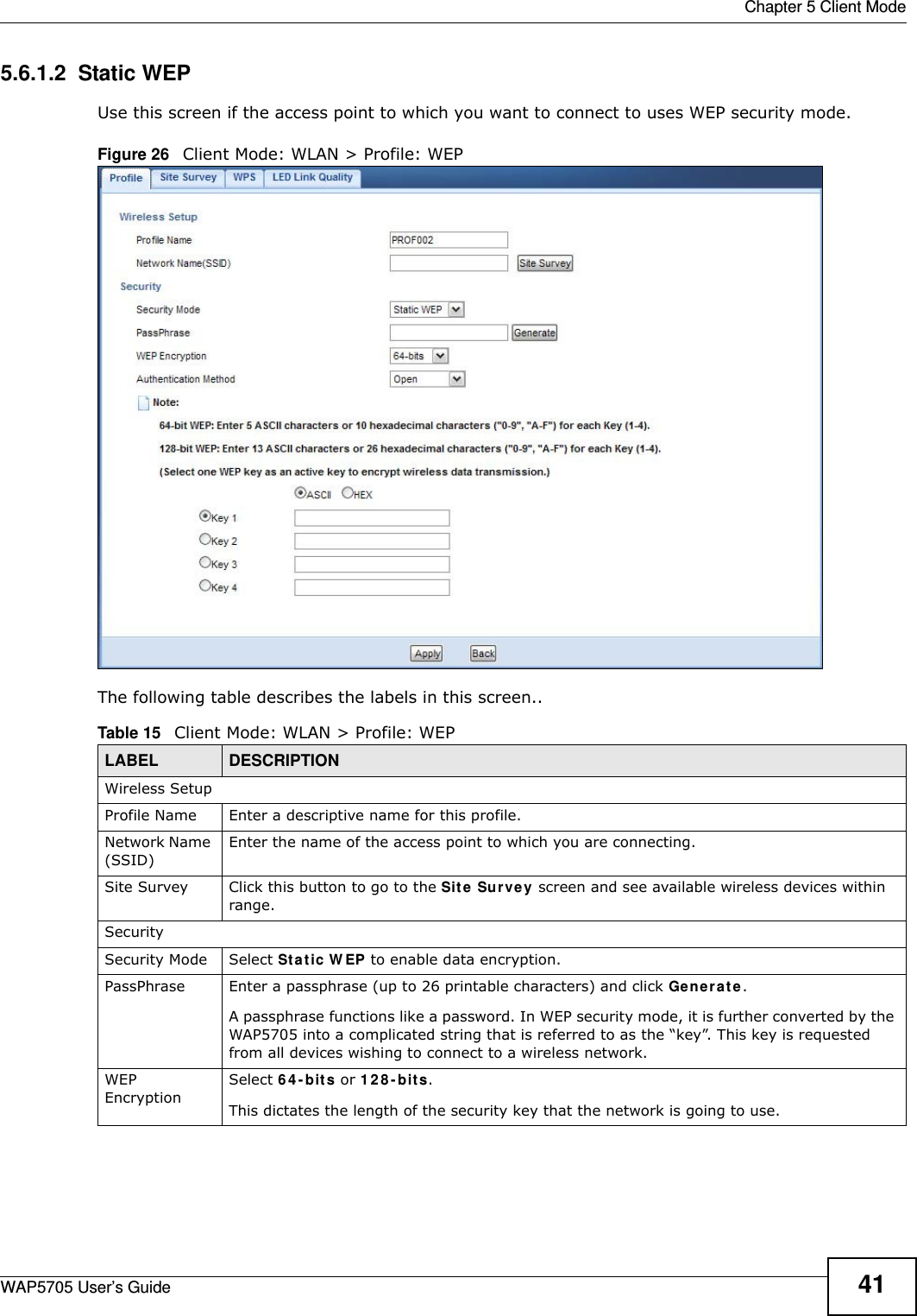
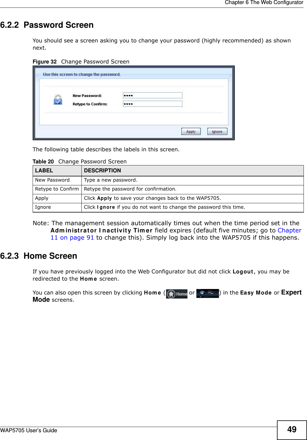
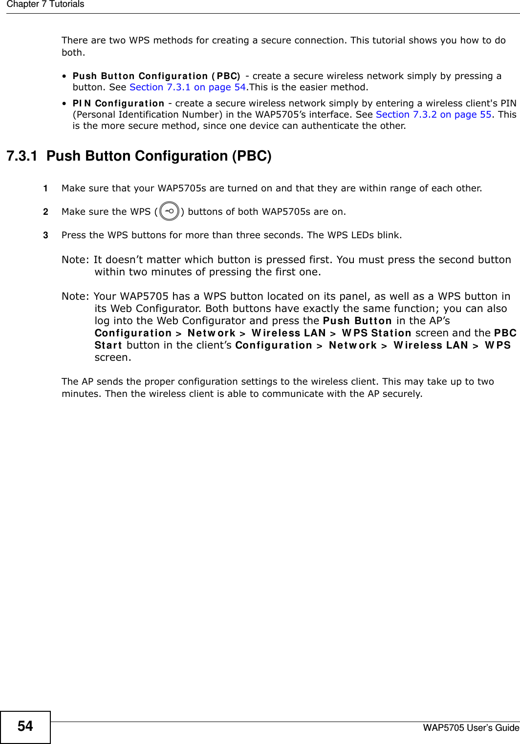
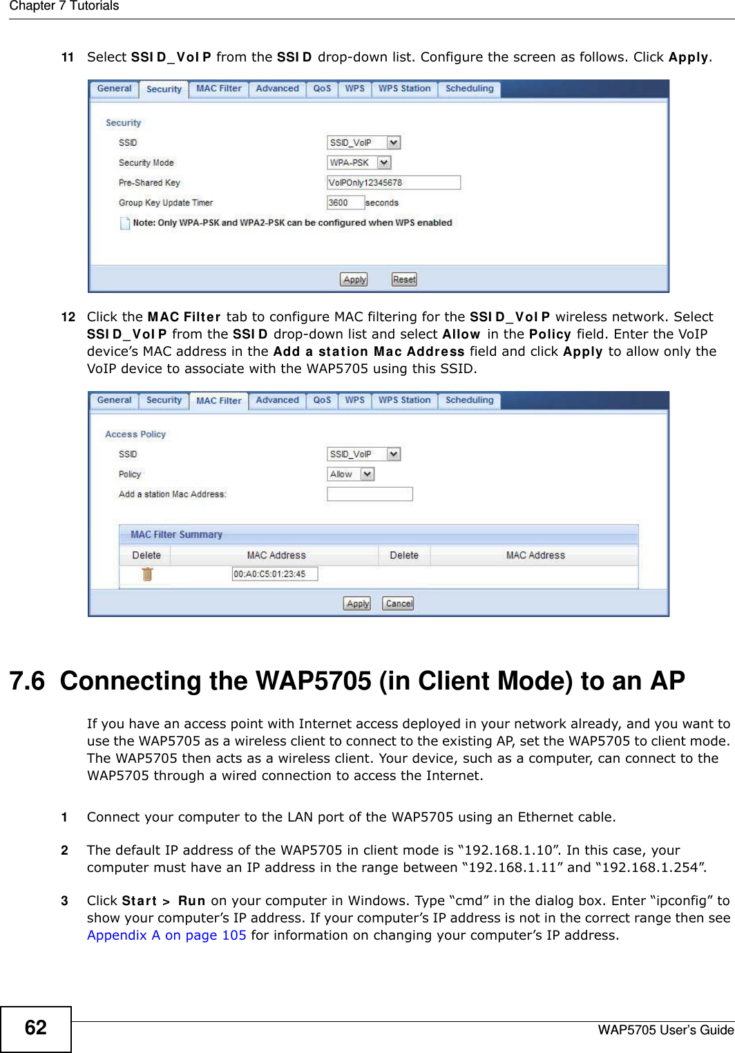
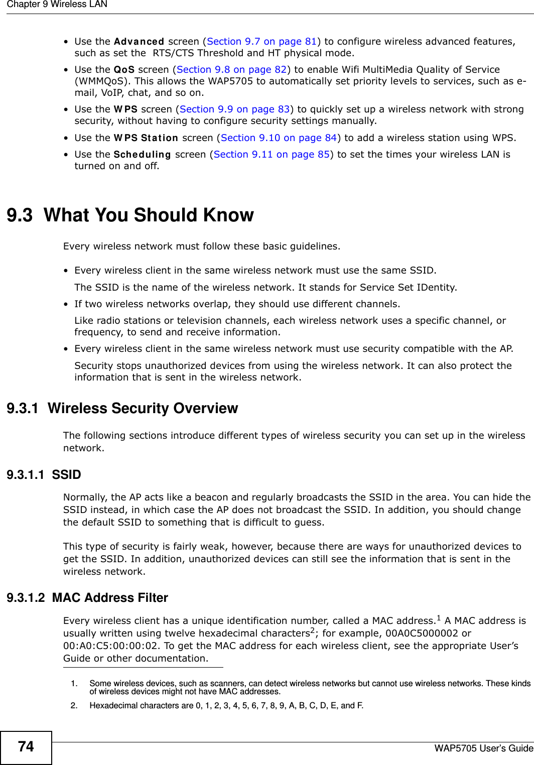
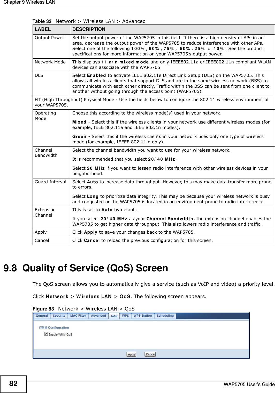
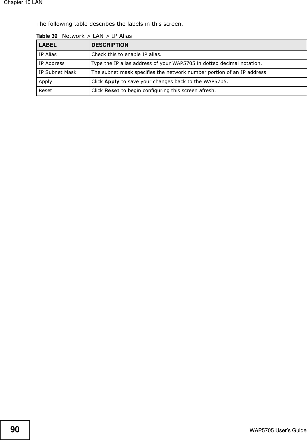
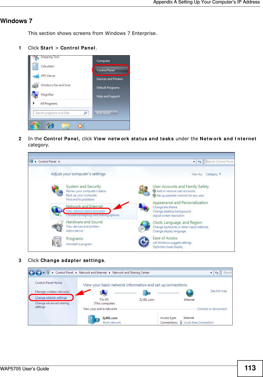
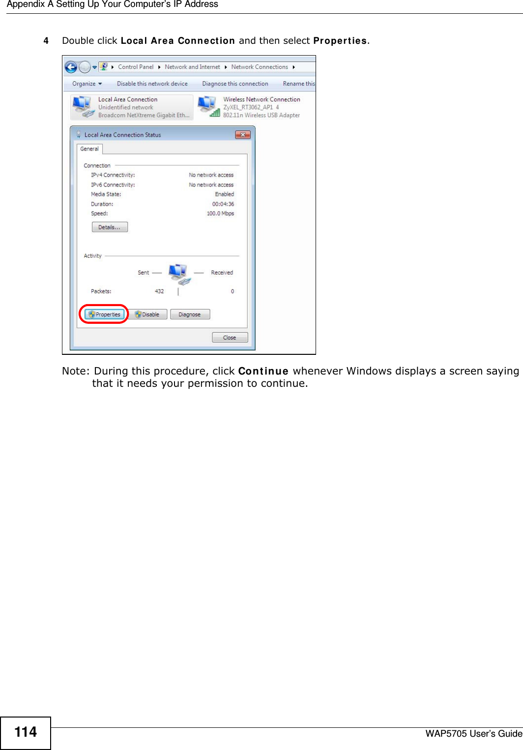
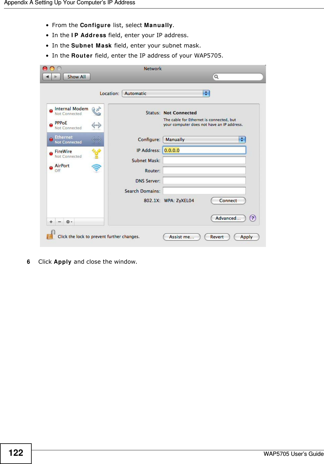
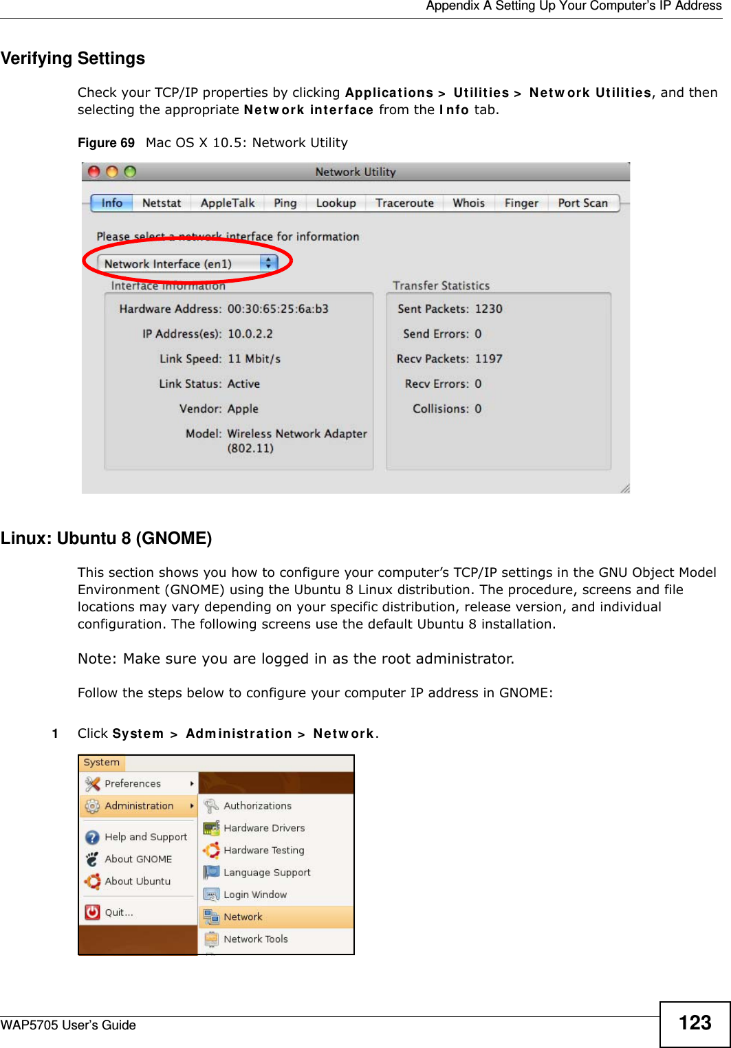
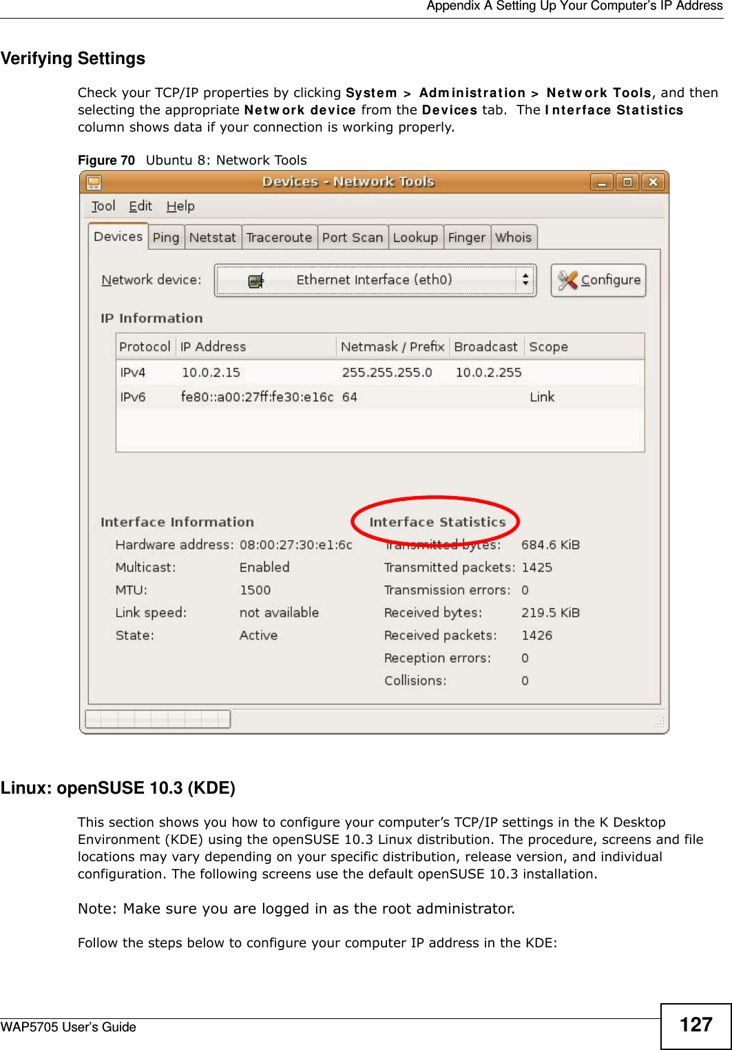
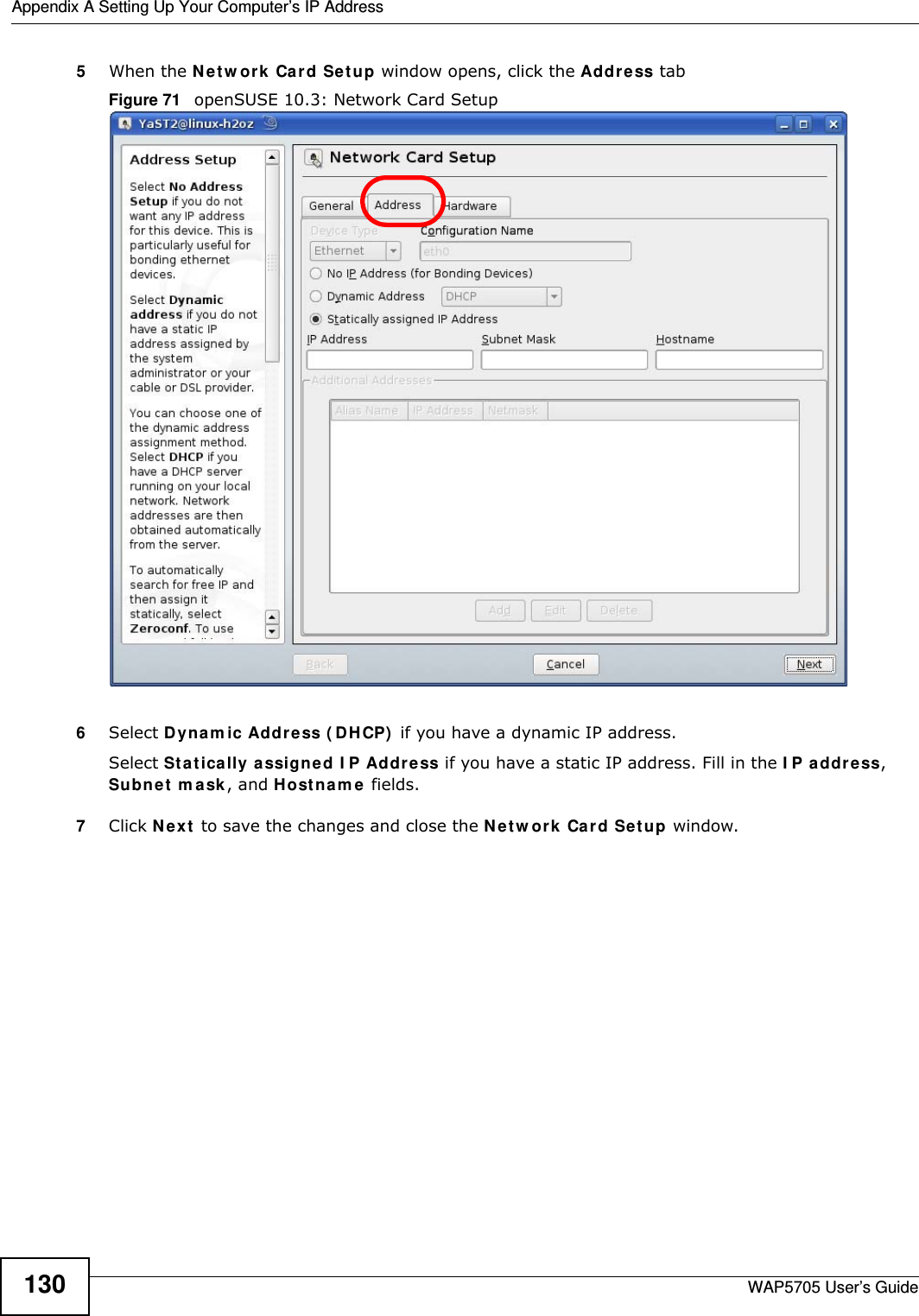
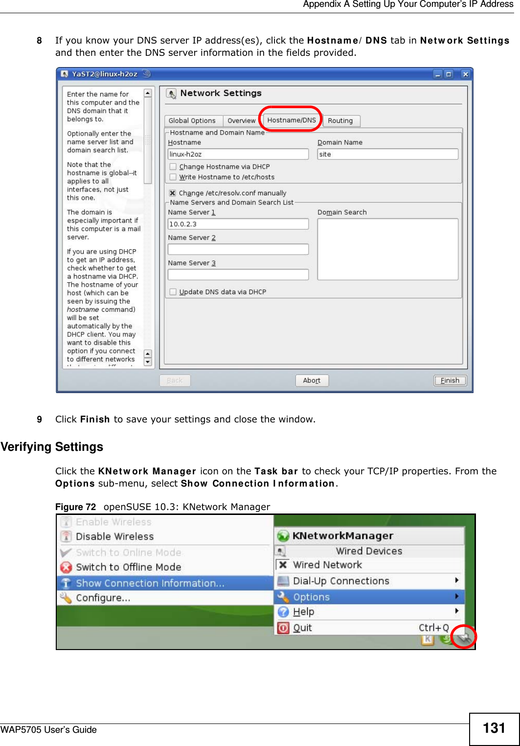
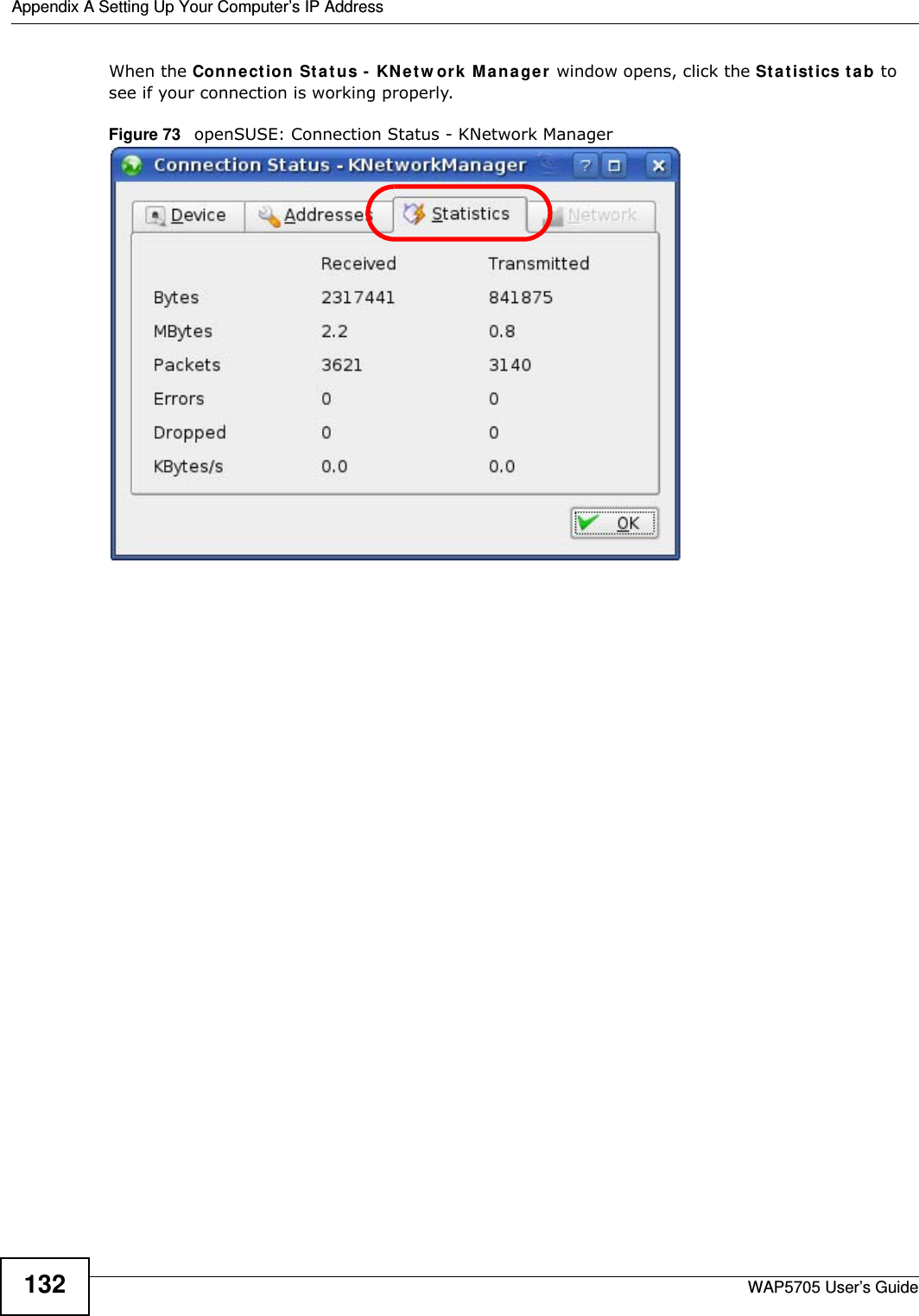
![Appendix A Setting Up Your Computer’s IP AddressWAP5705 User’s Guide1085The I nt e rne t Pr ot ocol TCP/ I P Proper t ies window opens.6Select Obt a in an I P a ddre ss a ut om a t ically if your network administrator or ISP assigns your IP address dynamically.Select Use t h e follow ing I P Addr e ss and fill in the I P a ddr e ss, Subnet m ask , and D e fa ult ga t e w a y fields if you have a static IP address that was assigned to you by your network administrator or ISP. You may also have to enter a Preferre d D N S ser ve r and an Alt e r na t e DN S ser ve r , if that information was provided.7Click OK to close the I nt e r ne t Prot ocol ( TCP/ I P) Propert ies window.8Click OK to close the Local Area Conn ection Pr ope r t ies window.Verifying Settings1Click St a r t > All Pr ogr a m s > Acce ssor ies > Com m a nd Prom pt .2In the Com m and Pr om pt window, type "ipconfig" and then press [ENTER]. You can also go to St art > Cont rol Pa nel > Netw or k Conn ections, right-click a network connection, click St a t us and then click the Support tab to view your IP address and connection information.](https://usermanual.wiki/ZyXEL-Communications/WAP5705/User-Guide-2316945-Page-108.png)
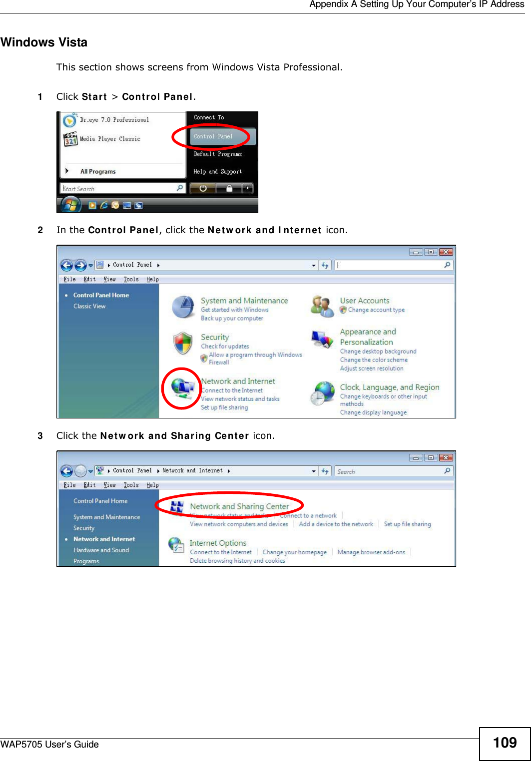
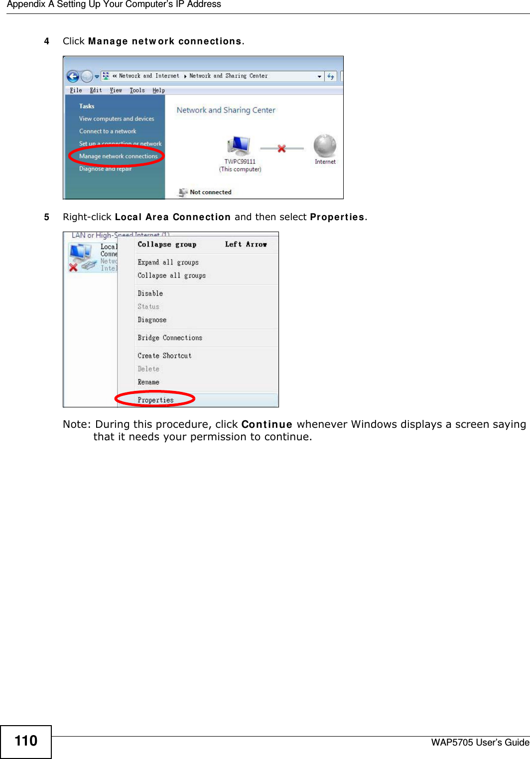
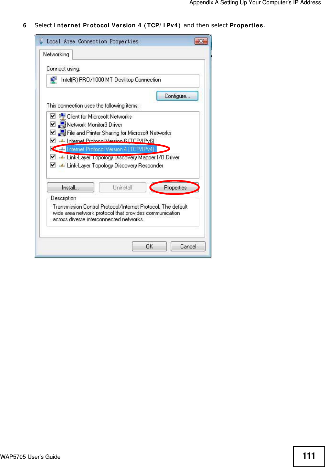
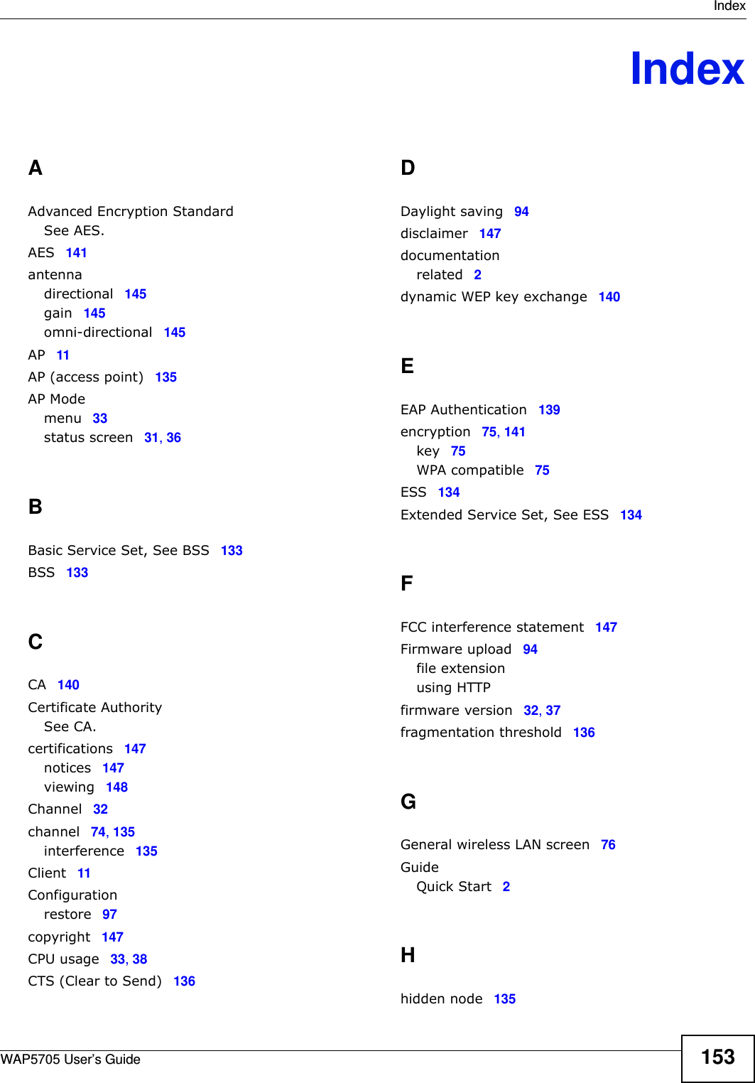
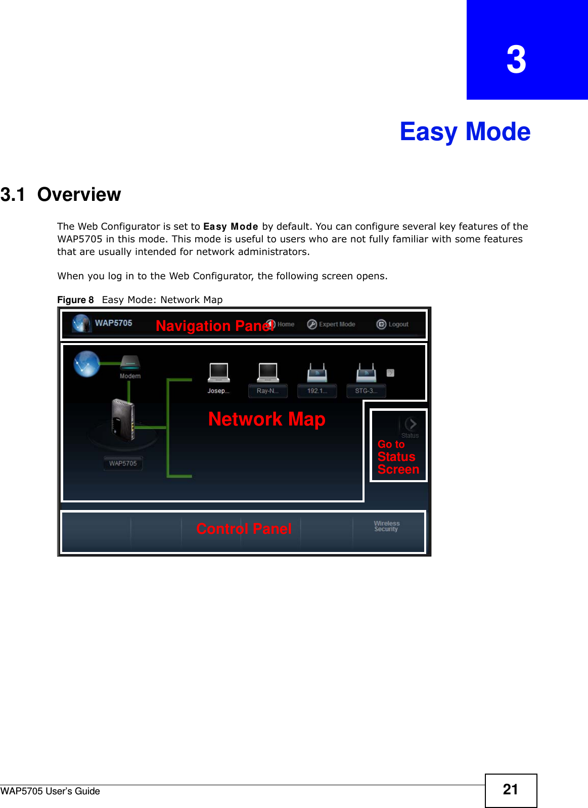
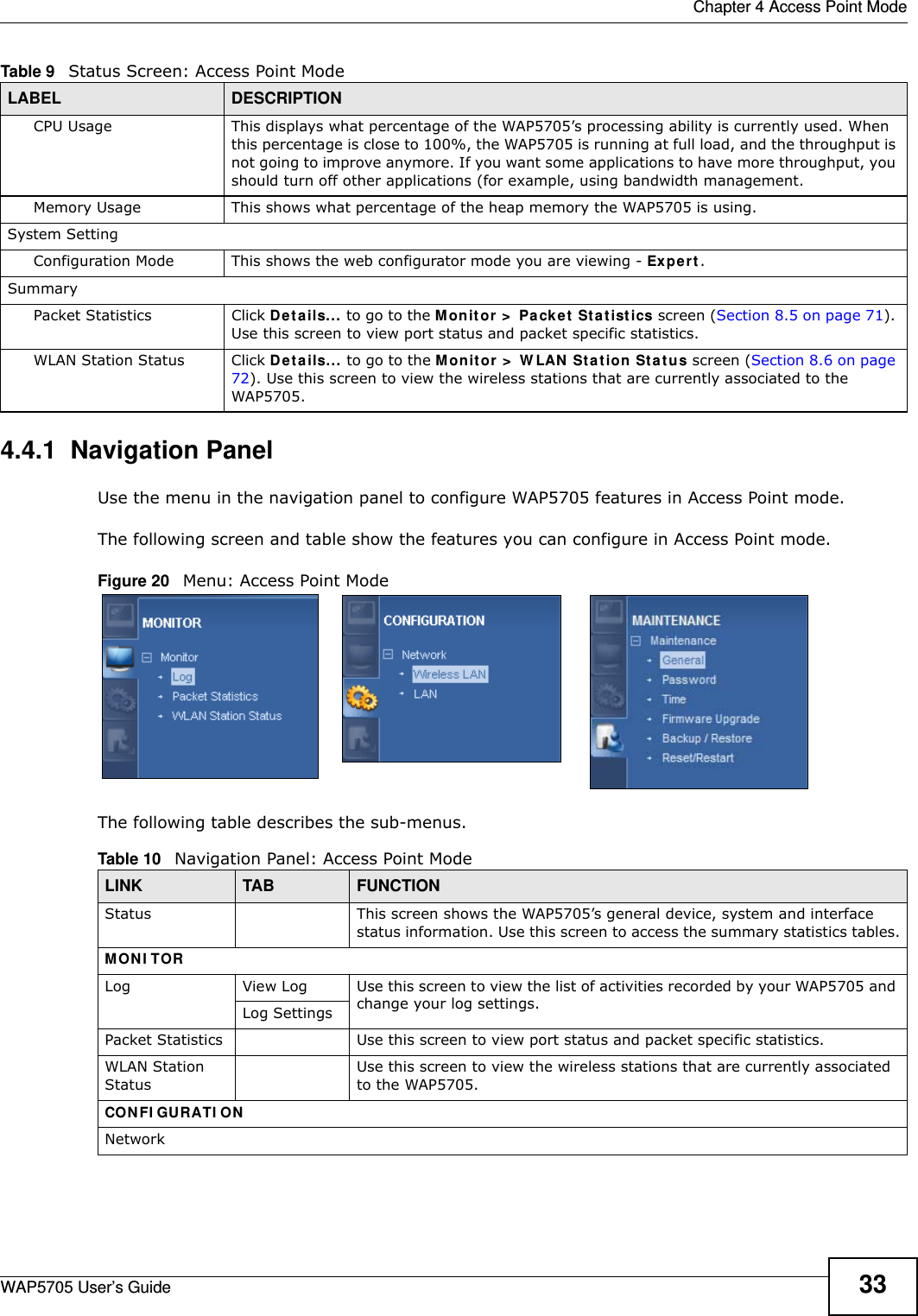
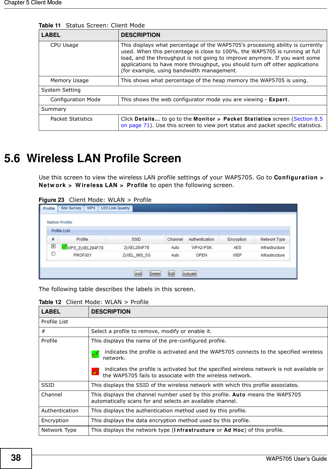
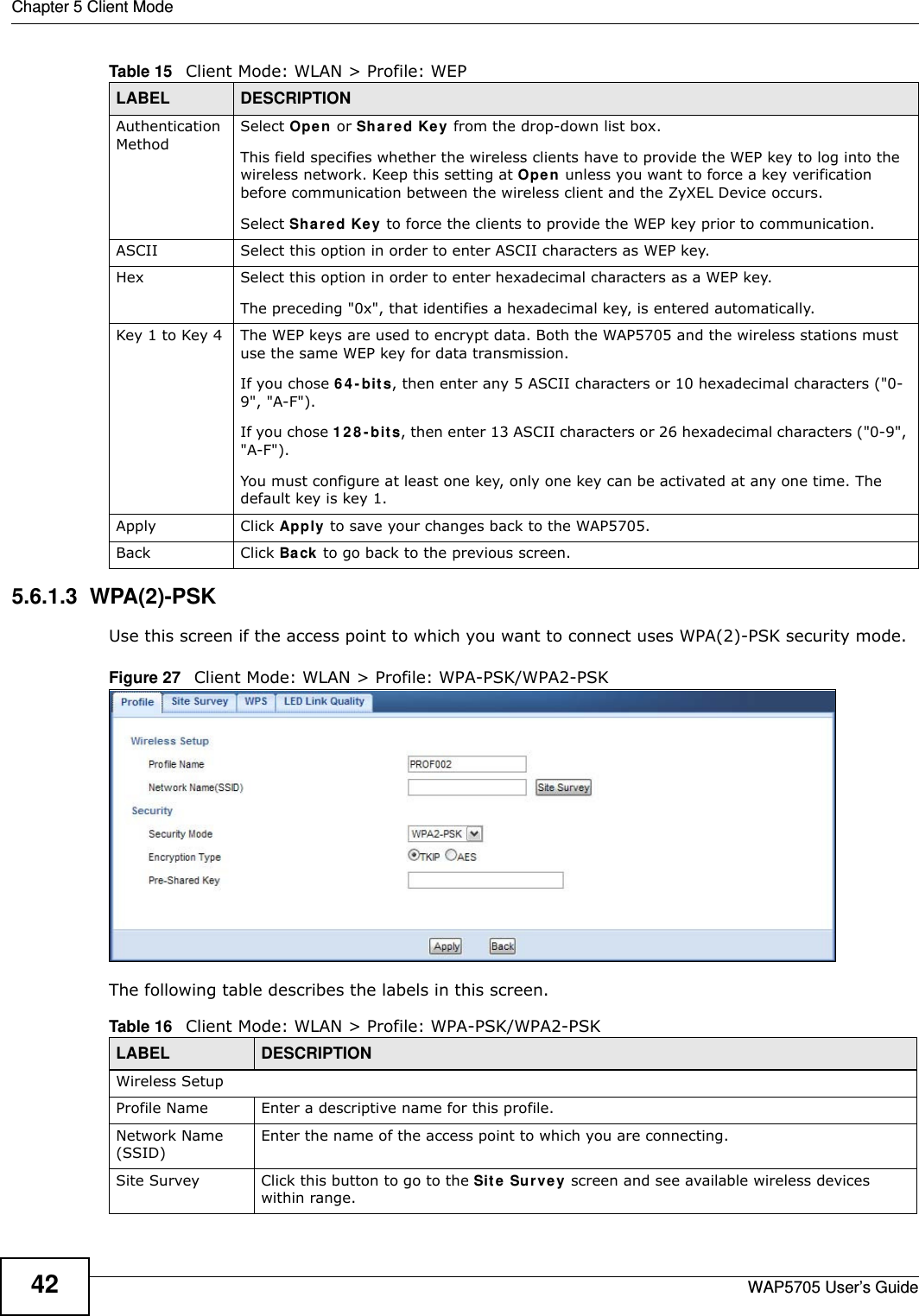
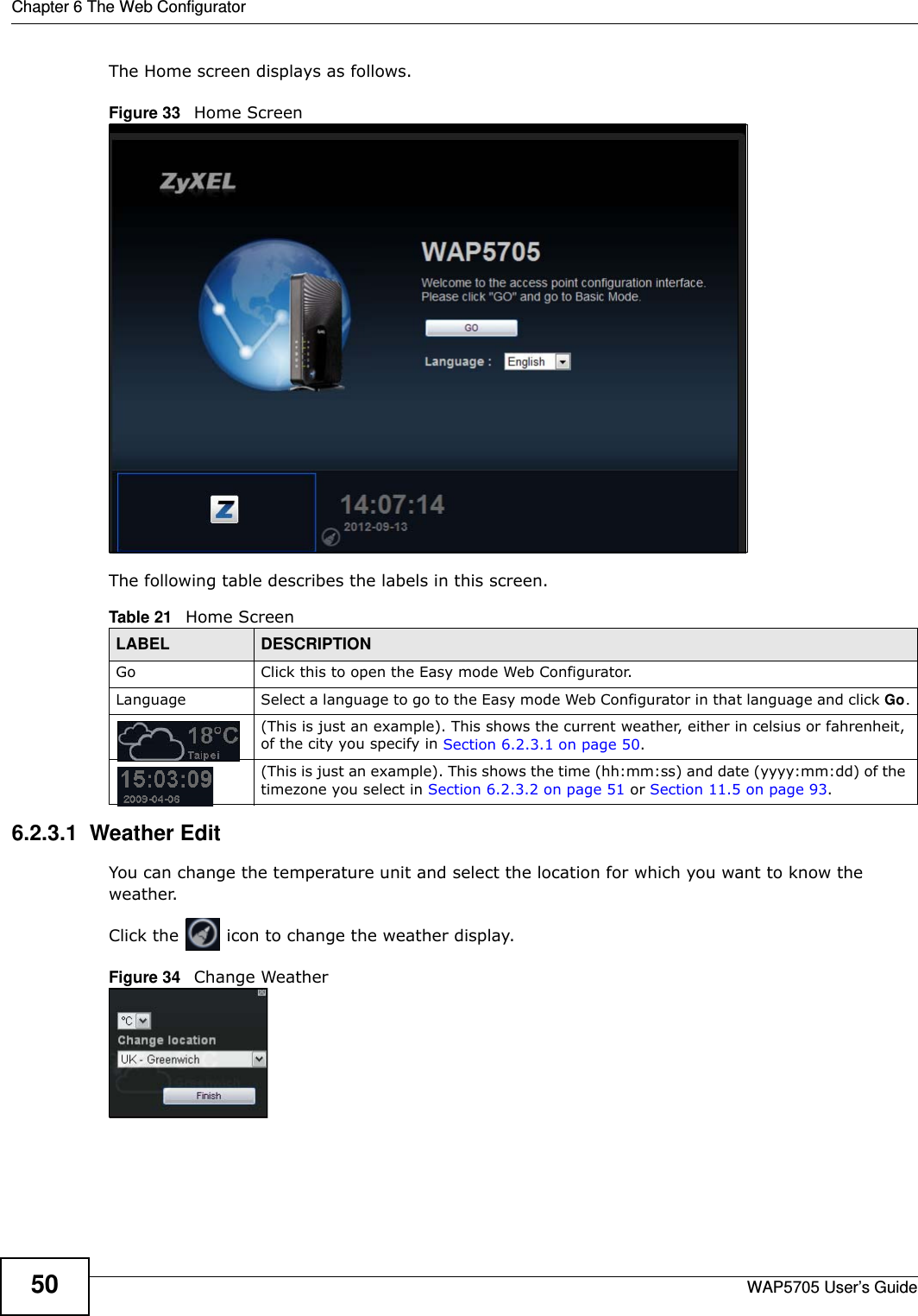
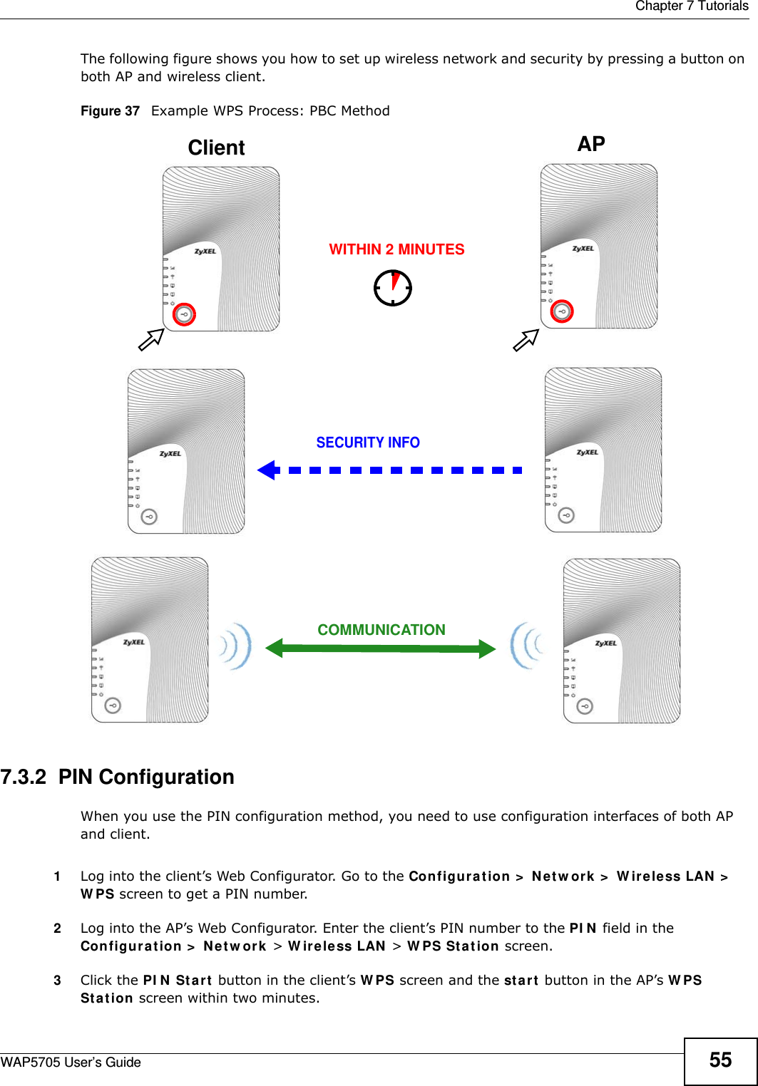
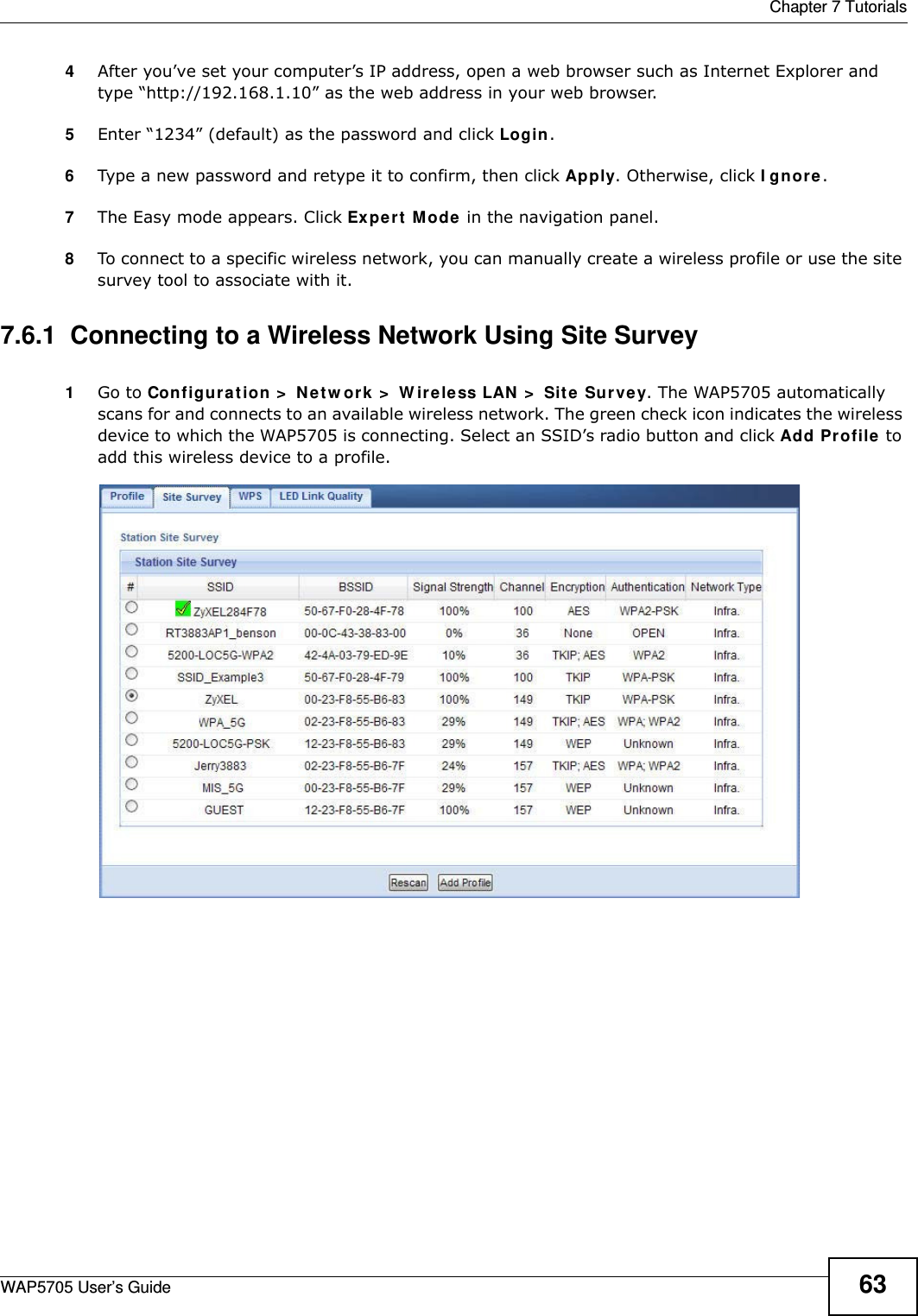
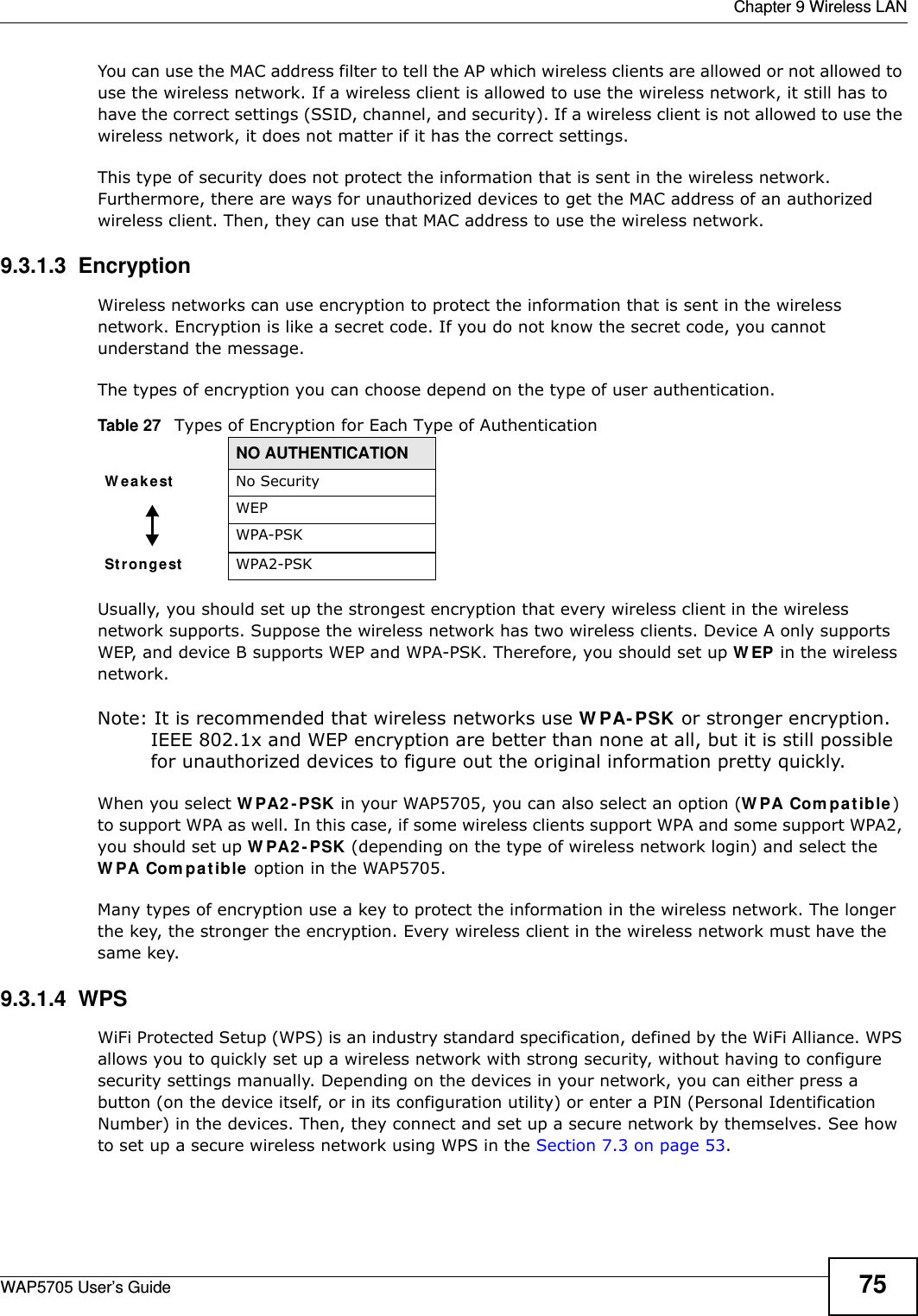
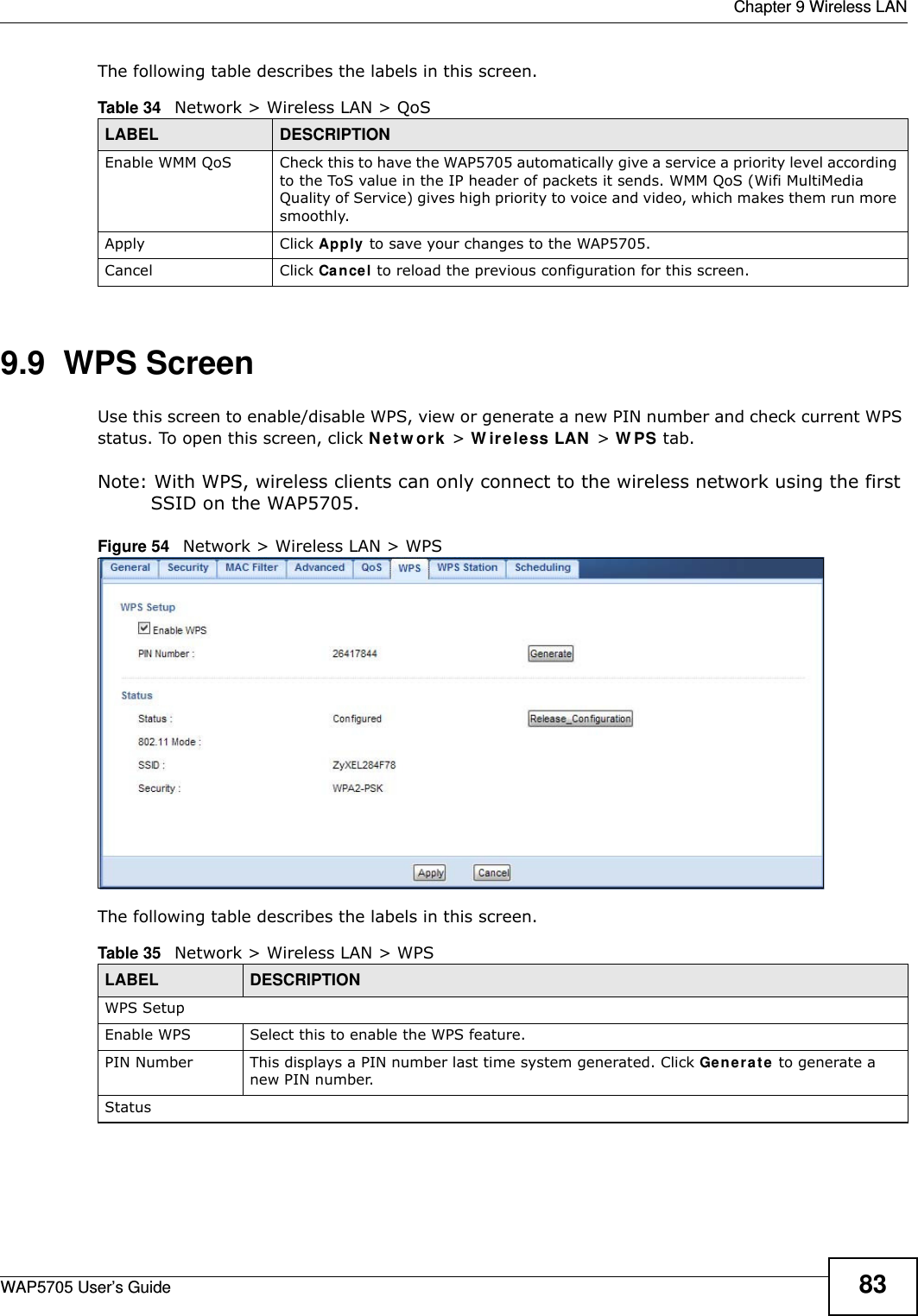
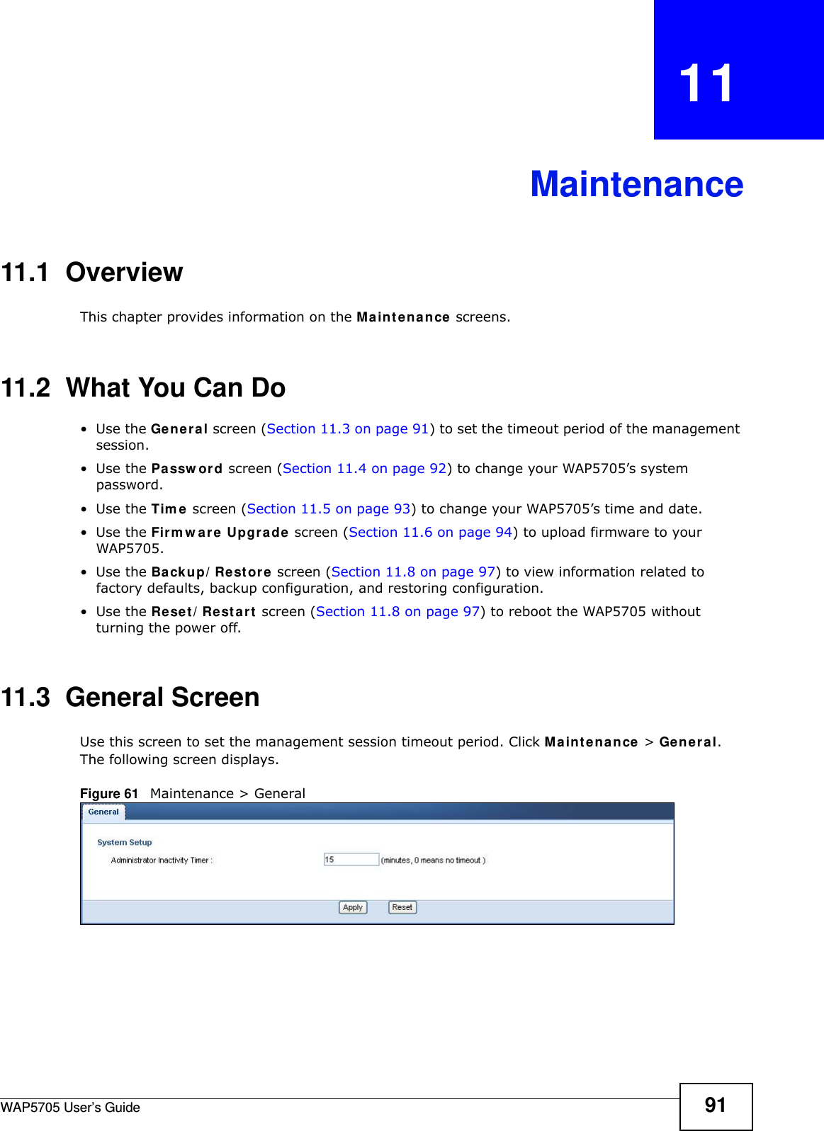
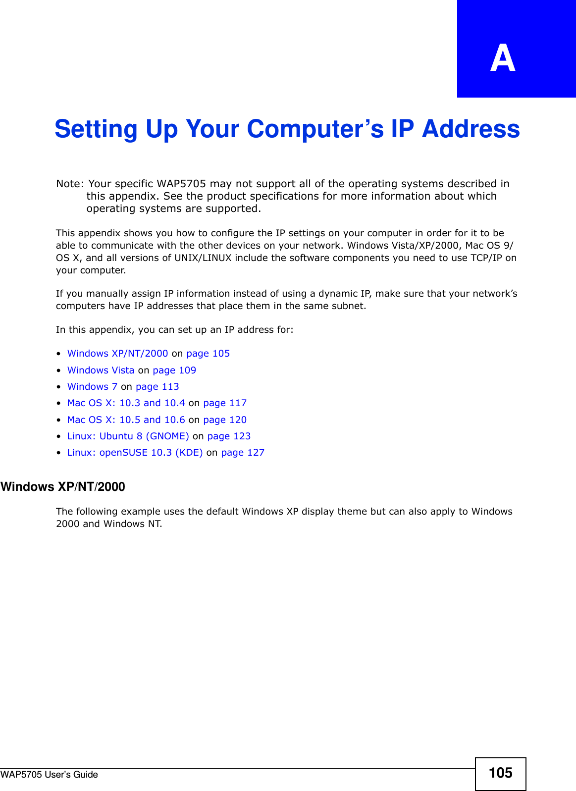
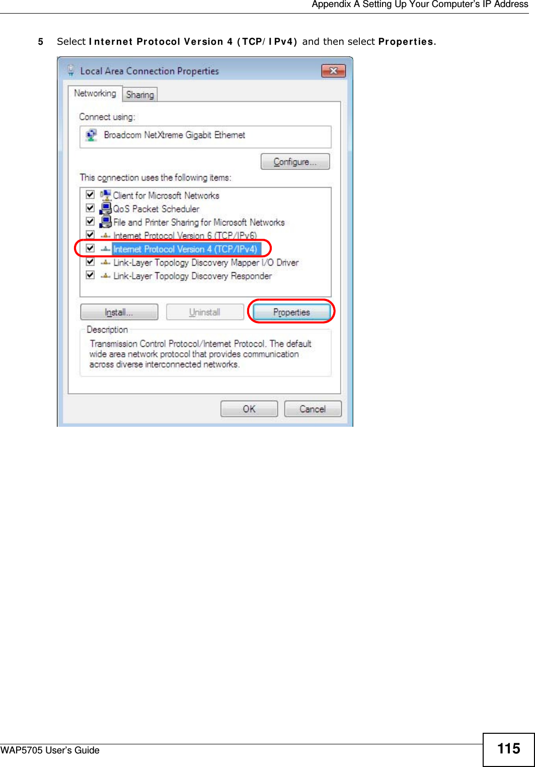
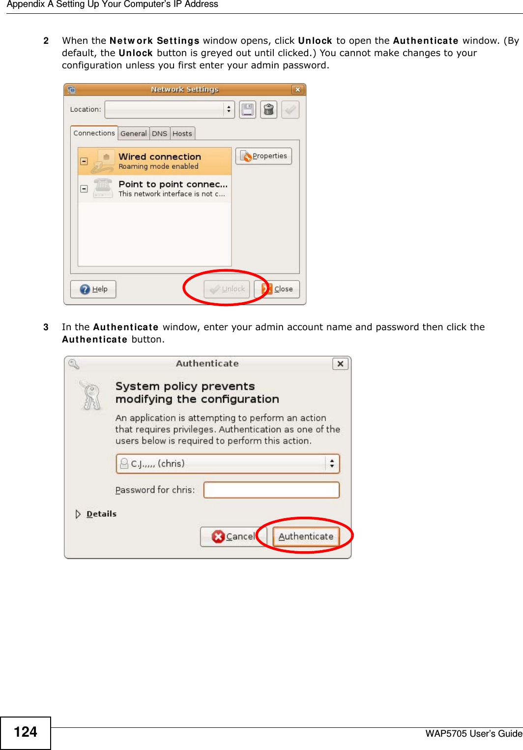
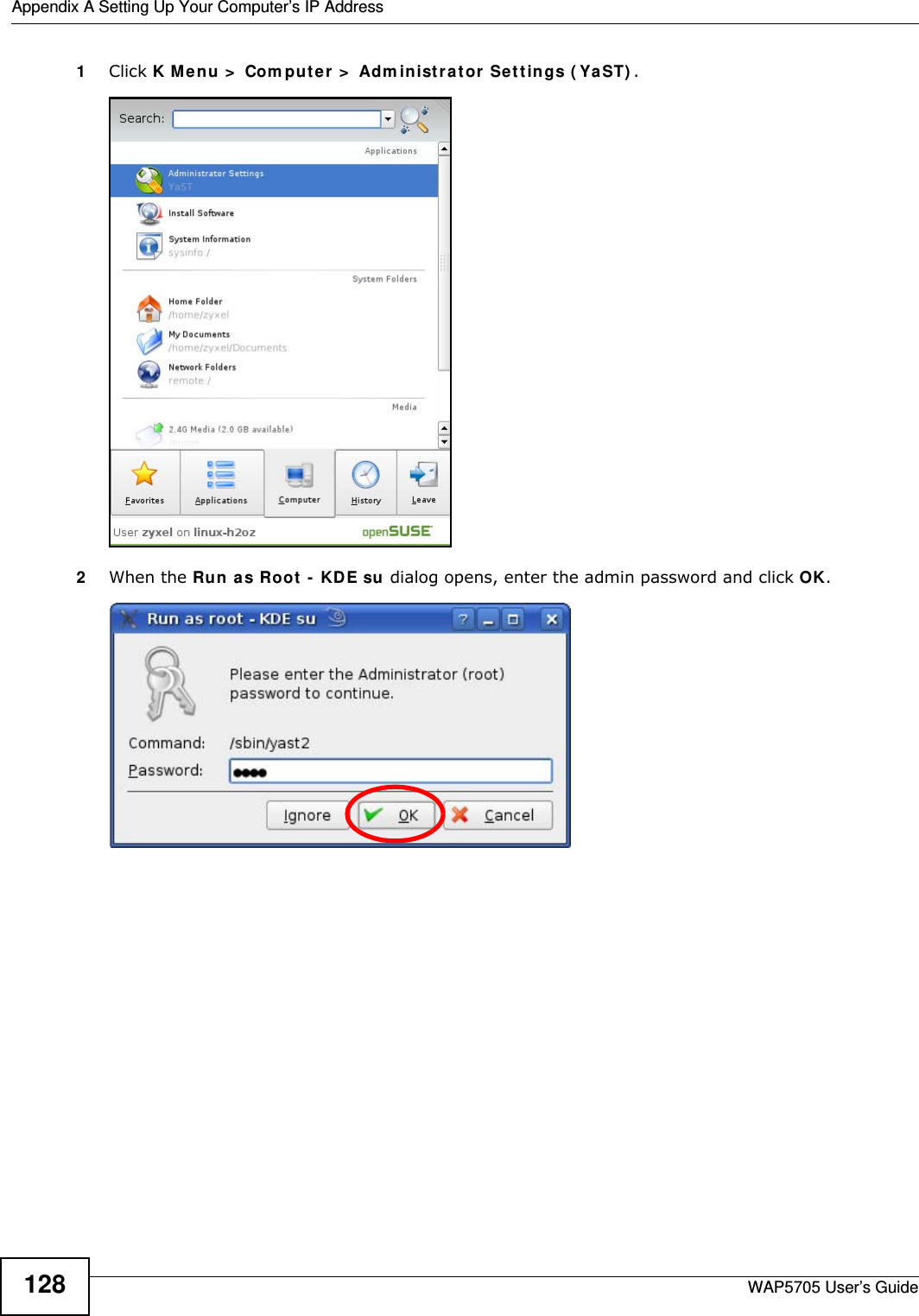
![Appendix A Setting Up Your Computer’s IP AddressWAP5705 User’s Guide1127The I nt e rne t Pr ot ocol V ersion 4 ( TCP/ I Pv4 ) Propert ies window opens.8Select Obt a in an I P a ddre ss a ut om a t ically if your network administrator or ISP assigns your IP address dynamically.Select Use t h e follow ing I P Addr e ss and fill in the I P a ddr e ss, Subnet m ask , and D e fa ult ga t e w a y fields if you have a static IP address that was assigned to you by your network administrator or ISP. You may also have to enter a Preferre d D N S ser ve r and an Alt e r na t e DN S ser ve r , if that information was provided.Click Advanced.9Click OK to close the I nt e r ne t Prot ocol ( TCP/ I P) Propert ies window.10 Click OK to close the Local Area Conn ection Pr ope r t ies window.Verifying Settings1Click St a r t > All Pr ogr a m s > Acce ssor ies > Com m a nd Prom pt .2In the Com m and Pr om pt window, type "ipconfig" and then press [ENTER]. You can also go to St art > Cont rol Pa nel > Netw or k Conn ections, right-click a network connection, click St a t us and then click the Support tab to view your IP address and connection information.](https://usermanual.wiki/ZyXEL-Communications/WAP5705/User-Guide-2316945-Page-112.png)
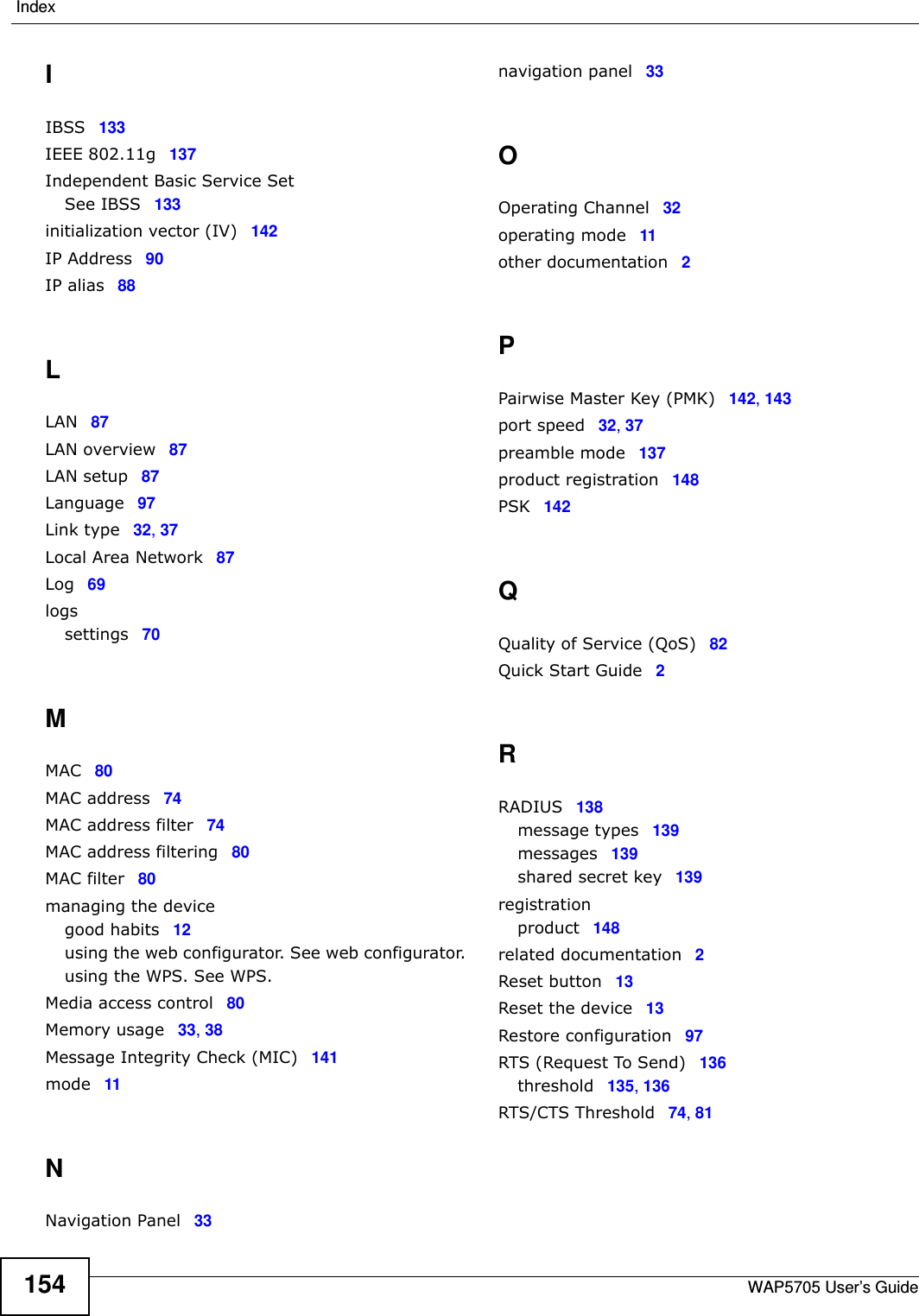
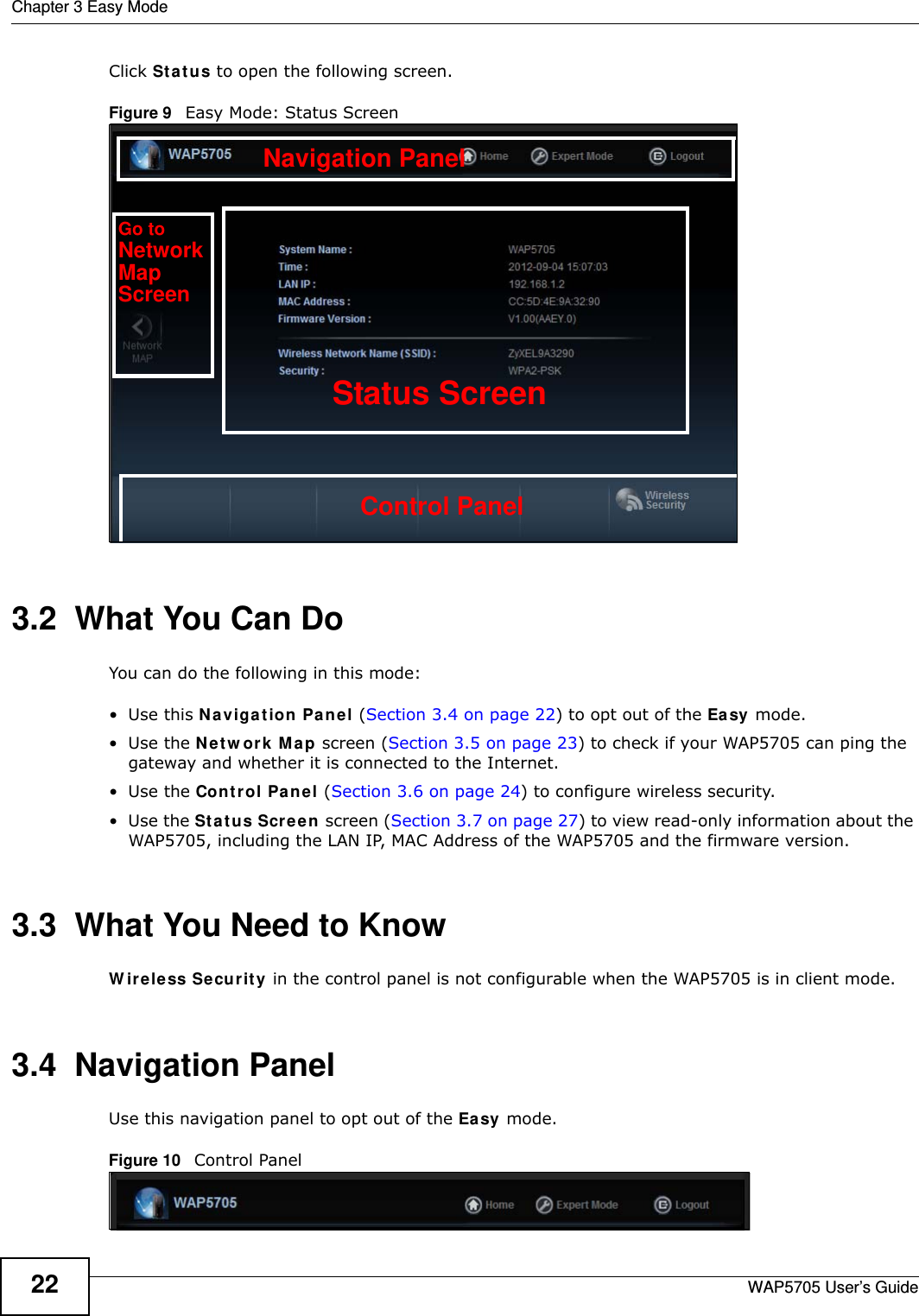
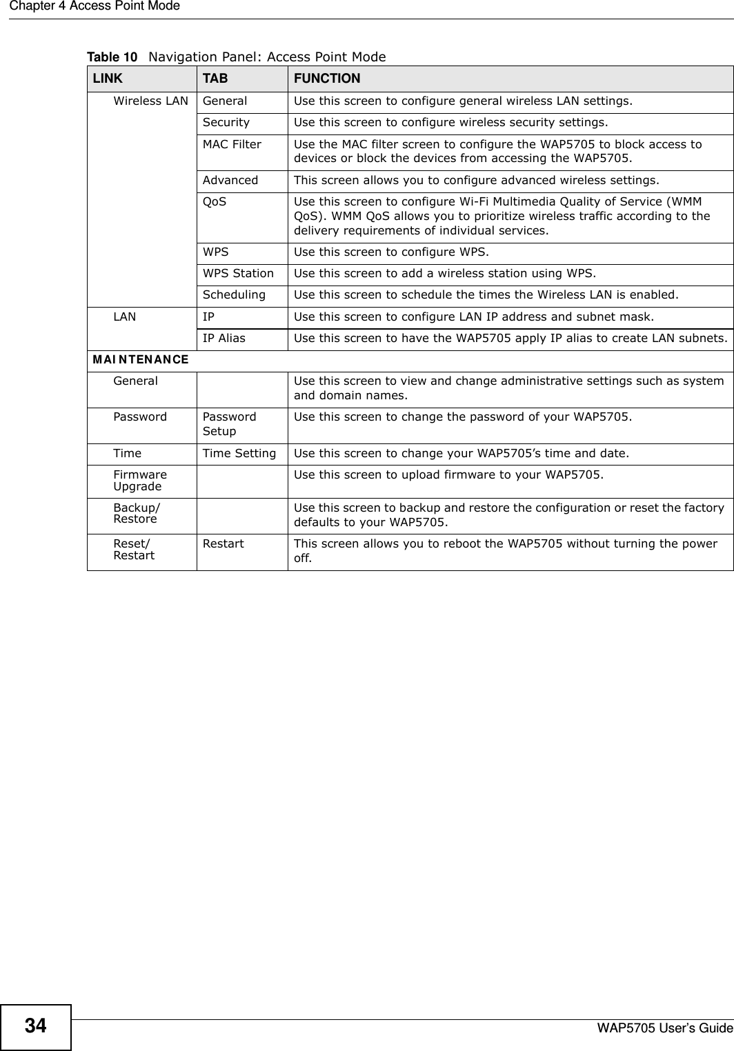
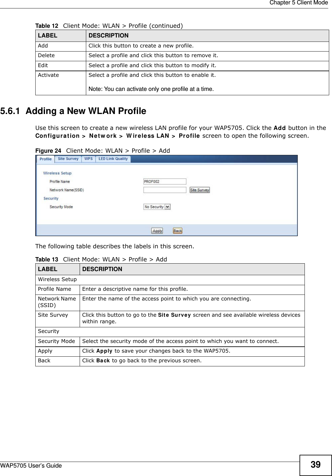
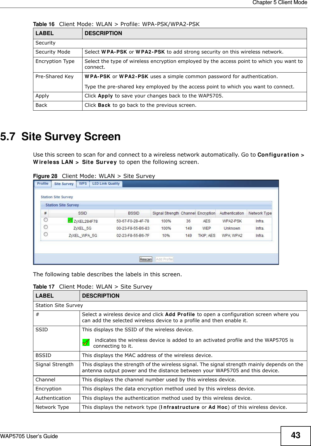
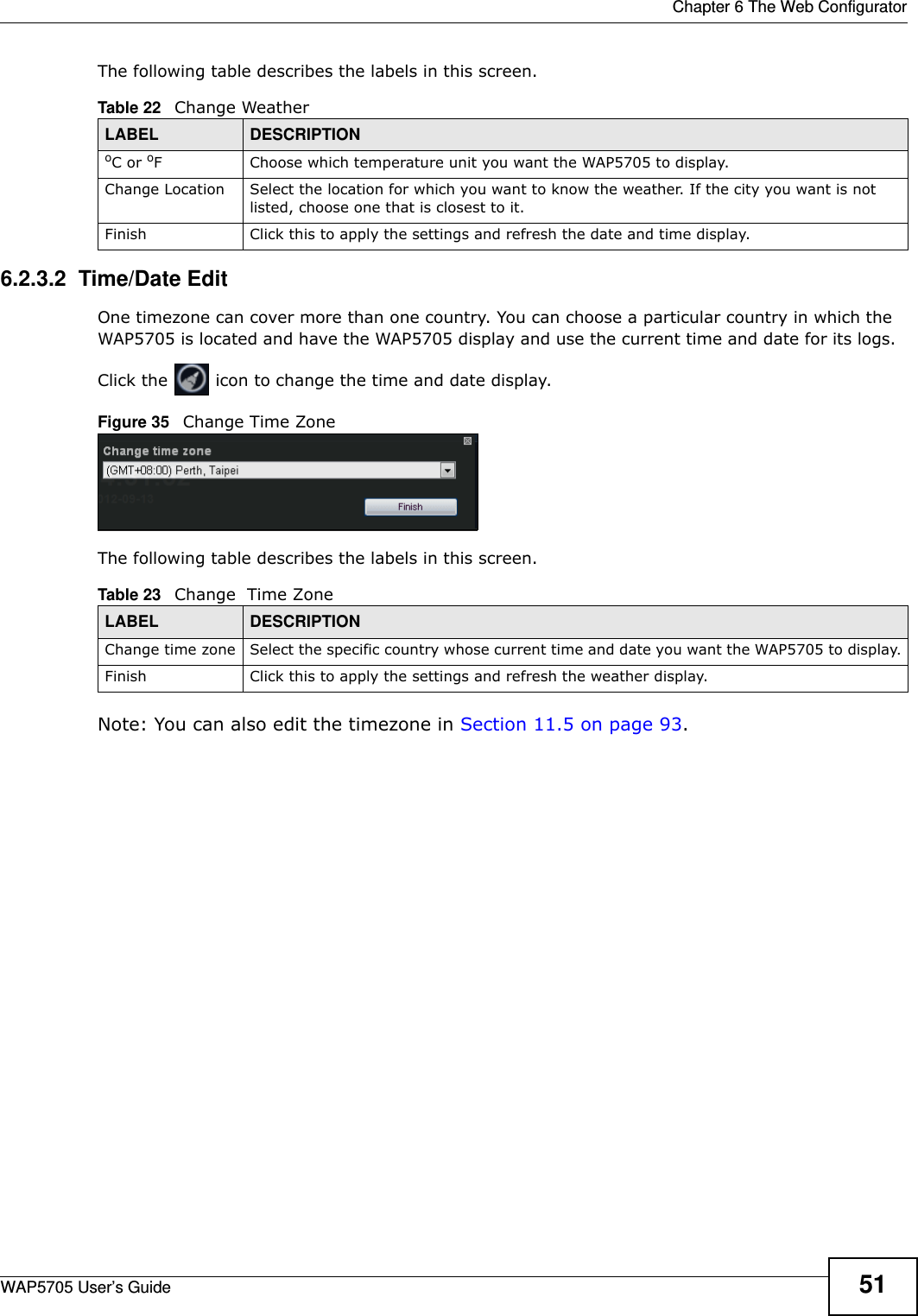
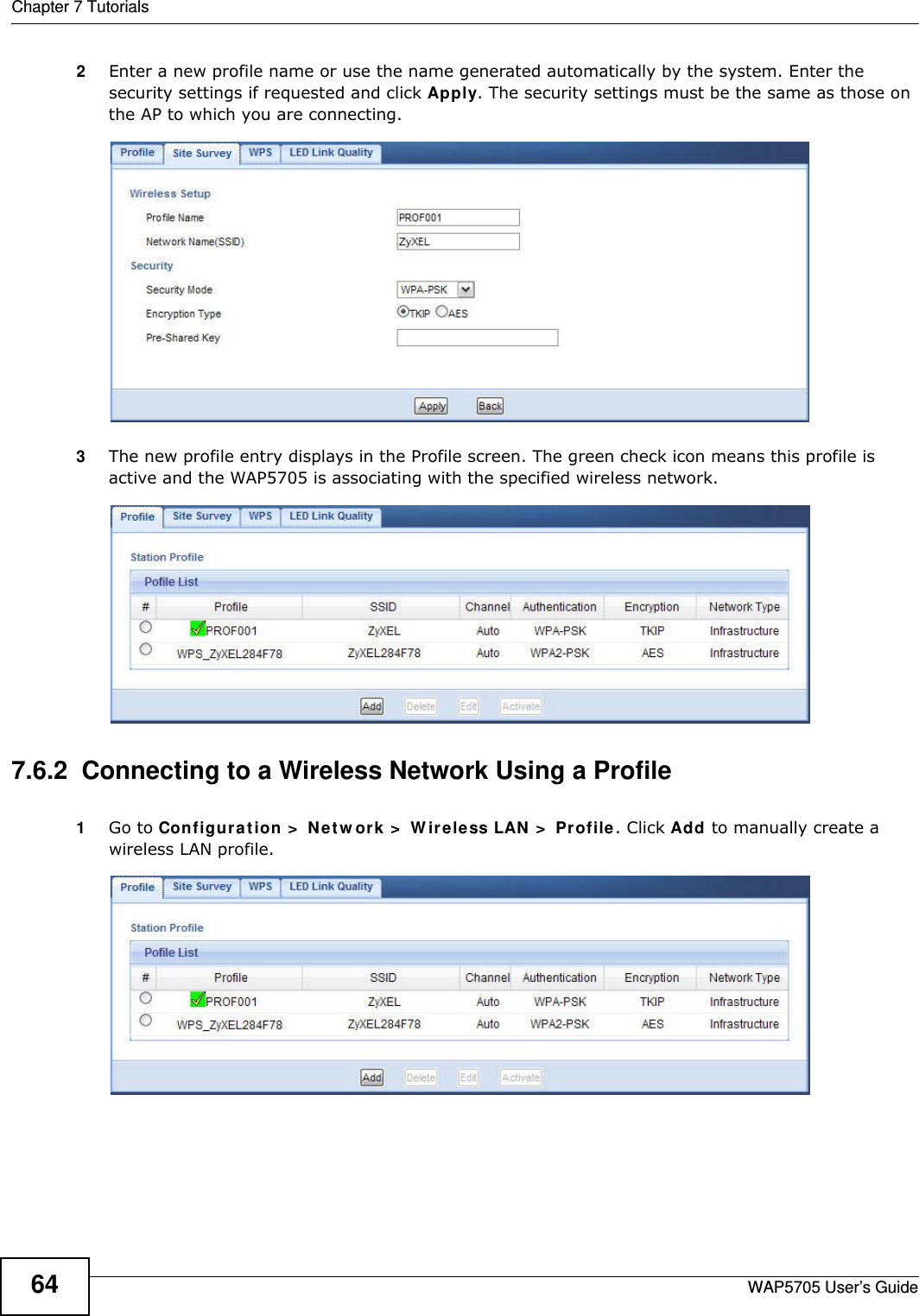
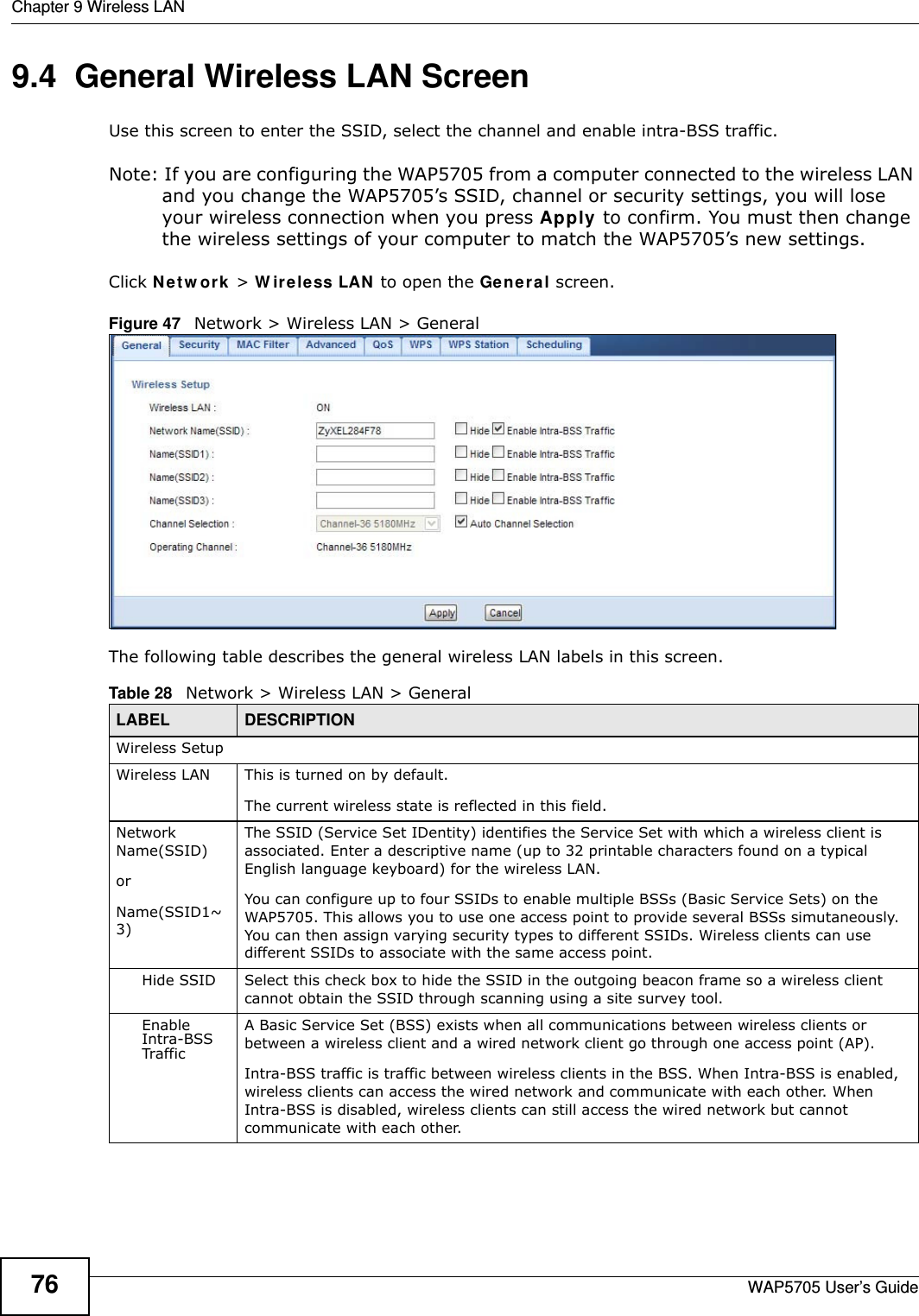
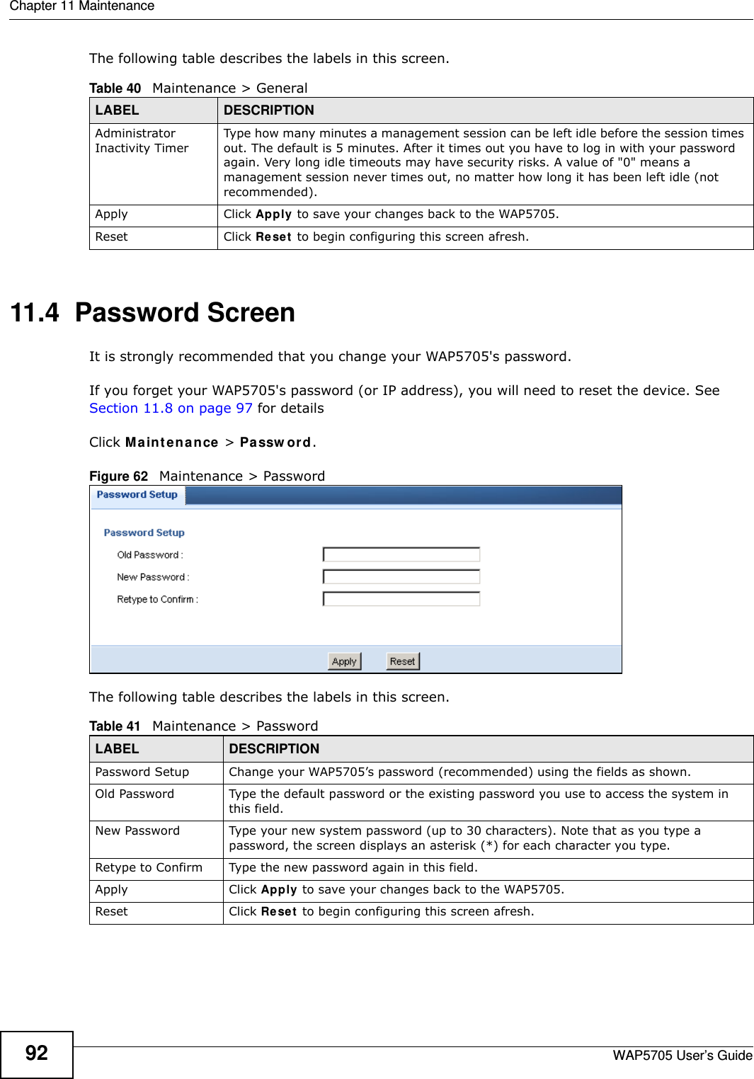
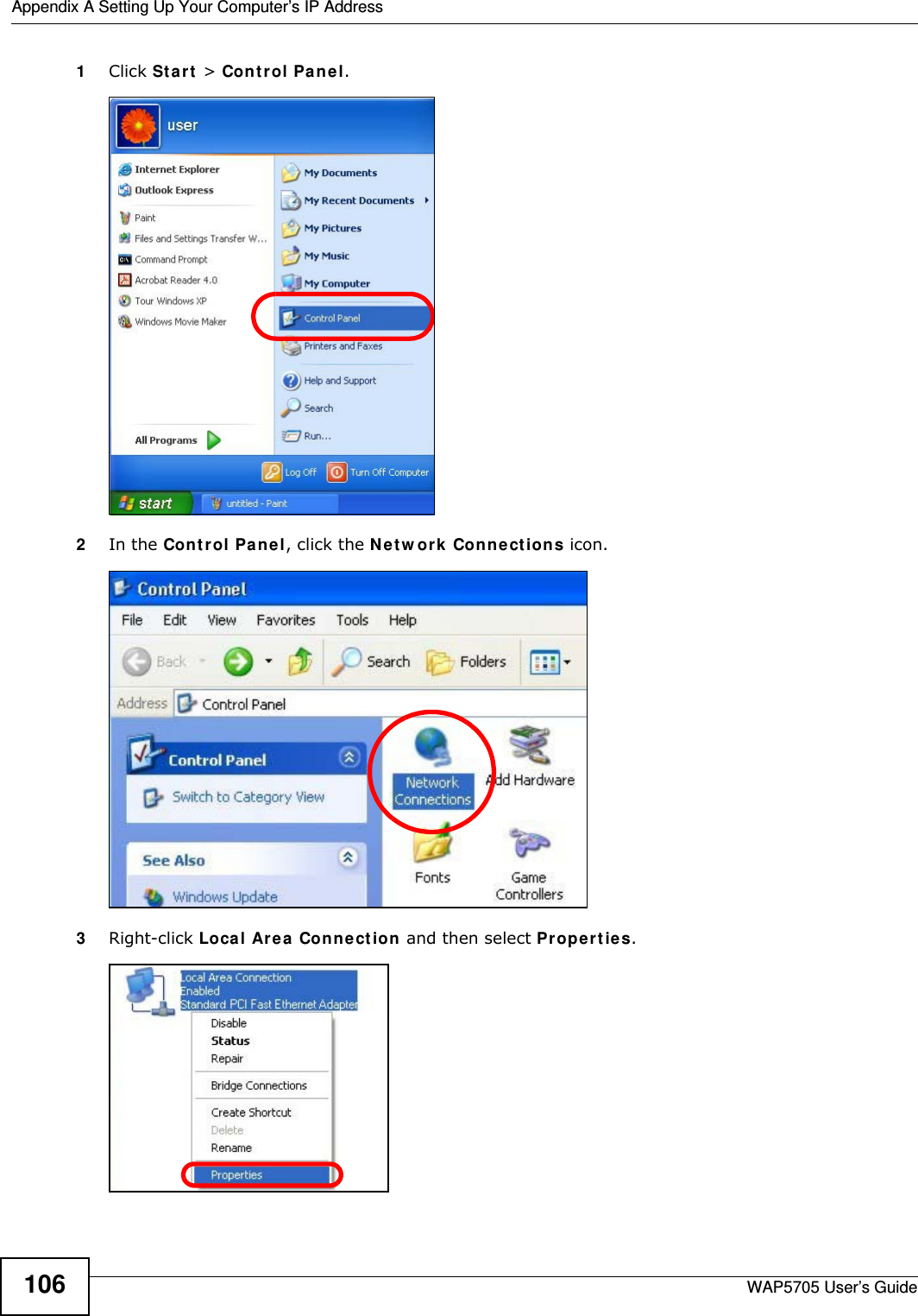
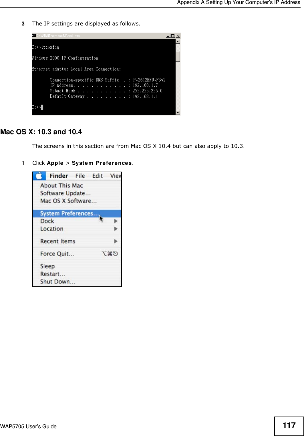
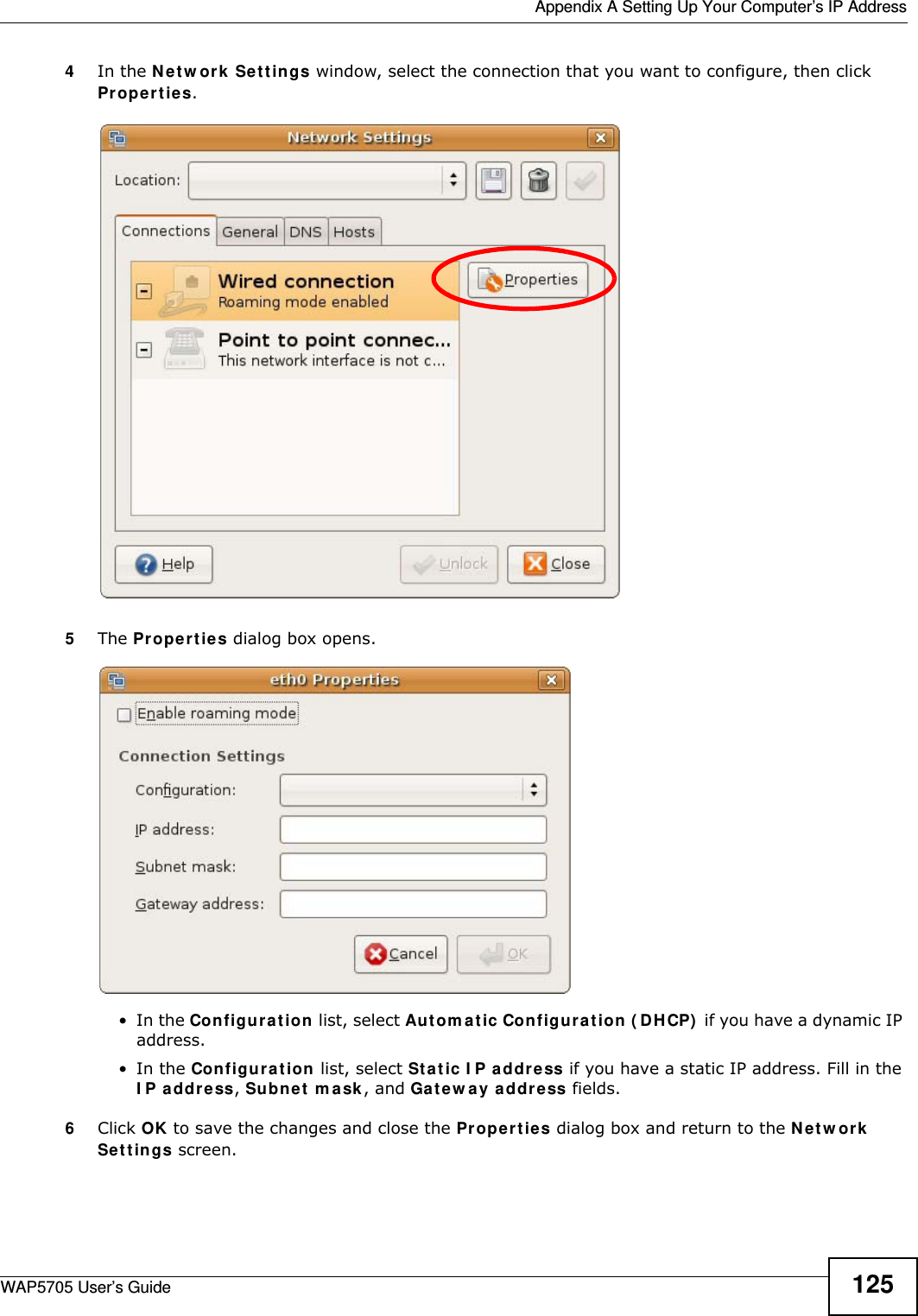
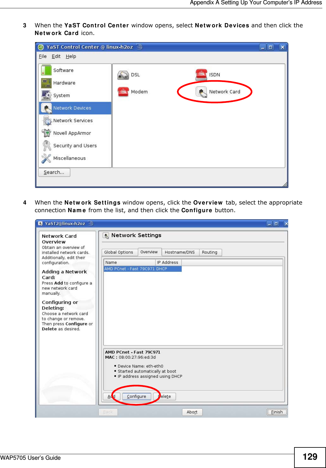
![Appendix A Setting Up Your Computer’s IP AddressWAP5705 User’s Guide1166The I nt e rne t Pr ot ocol V ersion 4 ( TCP/ I Pv4 ) Propert ies window opens.7Select Obt a in an I P a ddre ss a ut om a t ically if your network administrator or ISP assigns your IP address dynamically.Select Use t h e follow ing I P Addr e ss and fill in the I P a ddr e ss, Subnet m ask , and D e fa ult ga t e w a y fields if you have a static IP address that was assigned to you by your network administrator or ISP. You may also have to enter a Preferre d D N S ser ve r and an Alt e r na t e DN S ser ve r , if that information was provided. Click Adva n ced if you want to configure advanced settings for IP, DNS and WINS. 8Click OK to close the I nt e r ne t Prot ocol ( TCP/ I P) Propert ies window.9Click OK to close the Local Area Conn ection Pr ope r t ies window.Verifying Settings1Click St a r t > All Pr ogr a m s > Acce ssor ies > Com m a nd Prom pt .2In the Com m and Pr om pt window, type "ipconfig" and then press [ENTER].](https://usermanual.wiki/ZyXEL-Communications/WAP5705/User-Guide-2316945-Page-116.png)

![Appendix C Legal InformationWAP5705 User’s Guide148Ce produit est conçu pour les bandes de fréquences 5 GHz conformément à la législation Européenne. En France métropolitaine, suivant les décisions n°03-908 et 03-909 de l’ARCEP, la puissance d’émission ne devra pas dépasser 10 mW (10 dB) dans le cadre d’une installation WiFi en extérieur pour les fréquences comprises entre 2454 MHz et 2483,5 MHz. This Class B digital apparatus complies with Canadian ICES-003.Cet appareil numérique de la classe B est conforme à la norme NMB-003 du Canada.Industry Canada StatementThis device complies with RSS-210 of the Industry Canada Rules. Operation is subject to the following two conditions:1this device may not cause interference and2this device must accept any interference, including interference that may cause undesired operation of the deviceThis device has been designed to operate with an antenna having a maximum gain of 2dBi.Antenna having a higher gain is strictly prohibited per regulations of Industry Canada. The required antenna impedance is 50 ohms.To reduce potential radio interference to other users, the antenna type and its gain should be so chosen that the EIRP is not more than required for successful communication.IMPORTANT NOTEDevice for the band 5150-5250 MHz is only for indoor usage to reduce potential for harmful interference to co-channel mobile satellite systems; users should also be cautioned to take note that high-power radars are allocated as primary users (meaning they have priority) of the bands 5250-5350 MHz and 5650-5850 MHz and these radars could cause interference and/or damage to LE-LAN devices.IC Radiation Exposure Statement:This equipment complies with IC radiation exposure limits set forth for an uncontrolled environment. This equipment should be installed and operated with minimum distance 20cm between the radiator & your body.Viewing CertificationsGo to http://www.zyxel.com to view this product’s documentation and certifications.ZyXEL Limited WarrantyZyXEL warrants to the original end user (purchaser) that this product is free from any defects in materials or workmanship for a period of up to two years from the date of purchase. During the warranty period, and upon proof of purchase, should the product have indications of failure due to faulty workmanship and/or materials, ZyXEL will, at its discretion, repair or replace the defective products or components without charge for either parts or labor, and to whatever extent it shall deem necessary to restore the product or components to proper operating condition. Any replacement will consist of a new or re-manufactured functionally equivalent product of equal or higher value, and will be solely at the discretion of ZyXEL. This warranty shall not apply if the product has been modified, misused, tampered with, damaged by an act of God, or subjected to abnormal working conditions.NoteRepair or replacement, as provided under this warranty, is the exclusive remedy of the purchaser. This warranty is in lieu of all other warranties, express or implied, including any implied warranty of merchantability or fitness for a particular use or purpose. ZyXEL shall in no event be held liable for indirect or consequential damages of any kind to the purchaser.To obtain the services of this warranty, contact your vendor. You may also refer to the warranty policy for the region in which you bought the device at http://www.zyxel.com/web/support_warranty_info.php.RegistrationRegister your product online to receive e-mail notices of firmware upgrades and information at www.zyxel.com for global products, or at www.us.zyxel.com for North American products.Open Source Licenses This product contains in part some free software distributed under GPL license terms and/or GPL like licenses. Open source licenses are provided with the firmware package. You can download the latest firmware at www.zyxel.com. To obtain the source code covered under those Licenses, please contact support@zyxel.com.tw to get it. Regulatory InformationEuropean UnionThe following information applies if you use the product within the European Union. Declaration of Conformity with Regard to EU Directive 1999/5/EC (R&TTE Directive)Compliance Information for 2.4GHz and 5GHz Wireless Products Relevant to the EU and Other Countries Following the EU Directive 1999/5/EC (R&TTE Directive) [Czech] ZyXEL tímto prohlašuje, že tento zařízení je ve shodě se základními požadavky a dalšími příslušnými ustanoveními směrnice 1999/5/EC.[Danish] Undertegnede ZyXEL erklærer herved, at følgende udstyr udstyr overholder de væsentlige krav og øvrige relevante krav i direktiv 1999/5/EF.[German] Hiermit erklärt ZyXEL, dass sich das Gerät Ausstattung in Übereinstimmung mit den grundlegenden Anforderungen und den übrigen einschlägigen Bestimmungen der Richtlinie 1999/5/EU befindet.[Estonian] Käesolevaga kinnitab ZyXEL seadme seadmed vastavust direktiivi 1999/5/EÜ põhinõuetele ja nimetatud direktiivist tulenevatele teistele asjakohastele sätetele.](https://usermanual.wiki/ZyXEL-Communications/WAP5705/User-Guide-2316945-Page-148.png)
![Appendix C Legal InformationWAP5705 User’s Guide 149National RestrictionsThis product may be used in all EU countries (and other countries following the EU directive 1999/5/EC) without any limitation except for the countries mentioned below:Ce produit peut être utilisé dans tous les pays de l’UE (et dans tous les pays ayant transposés la directive 1999/5/CE) sans aucune limitation, excepté pour les pays mentionnés ci-dessous:Questo prodotto è utilizzabile in tutte i paesi EU (ed in tutti gli altri paesi che seguono le direttive EU 1999/5/EC) senza nessuna limitazione, eccetto per i paesii menzionati di seguito:Das Produkt kann in allen EU Staaten ohne Einschränkungen eingesetzt werden (sowie in anderen Staaten die der EU Direktive 1995/5/CE folgen) mit Außnahme der folgenden aufgeführten Staaten:In the majority of the EU and other European countries, the 2, 4- and 5-GHz bands have been made available for the use of wireless local area networks (LANs). Later in this document you will find an overview of countries inwhich additional restrictions or requirements or both are applicable.The requirements for any country may evolve. ZyXEL recommends that you check with the local authorities for the latest status of their national regulations for both the 2,4- and 5-GHz wireless LANs.The following countries have restrictions and/or requirements in addition to those given in the table labeled “Overv iew of Regu latory Requirem ents for Wireless LANs”:.English Hereby, ZyXEL declares that this equipment is in compliance with the essential requirements and other relevant provisions of Directive 1999/5/EC.[Spanish] Por medio de la presente ZyXEL declara que el equipo cumple con los requisitos esenciales y cualesquiera otras disposiciones aplicables o exigibles de la Directiva 1999/5/CE.[Greek] Ε Η ΑΑ ZyXEL ∆ΗΩΕ επισός ΦΩΕΑ Ω∆Ε ΑΑΗΕ Α Ε ΧΕΕ ∆ΑΑΕ Η ∆ΗΓΑ 1999/5/ΕC.[French] Par la présente ZyXEL déclare que l'appareil équipements est conforme aux exigences essentielles et aux autres dispositions pertinentes de la directive 1999/5/EC.[Italian] Con la presente ZyXEL dichiara che questo attrezzatura è conforme ai requisiti essenziali ed alle altre disposizioni pertinenti stabilite dalla direttiva 1999/5/CE.[Latvian] Ar šo ZyXEL deklarē, ka iekārtas atbilst Direktīvas 1999/5/EK būtiskajām prasībām un citiem ar to saistītajiem noteikumiem.[Lithuanian] Šiuo ZyXEL deklaruoja, kad šis įranga atitinka esminius reikalavimus ir kitas 1999/5/EB Direktyvos nuostatas.[Dutch] Hierbij verklaart ZyXEL dat het toestel uitrusting in overeenstemming is met de essentiële eisen en de andere relevante bepalingen van richtlijn 1999/5/EC.[Maltese] Hawnhekk, ZyXEL, jiddikjara li dan tagħmir jikkonforma mal-ħtiġijiet essenzjali u ma provvedimenti oħrajn relevanti li hemm fid-Dirrettiva 1999/5/EC.[Hungarian] Alulírott, ZyXEL nyilatkozom, hogy a berendezés megfelel a vonatkozó alapvetõ követelményeknek és az 1999/5/EK irányelv egyéb elõírásainak.[Polish] Niniejszym ZyXEL oświadcza, że sprzęt jest zgodny z zasadniczymi wymogami oraz pozostałymi stosownymi postanowieniami Dyrektywy 1999/5/EC.[Portuguese] ZyXEL declara que este equipamento está conforme com os requisitos essenciais e outras disposições da Directiva 1999/5/EC.[Slovenian] ZyXEL izjavlja, da je ta oprema v skladu z bistvenimi zahtevami in ostalimi relevantnimi določili direktive 1999/5/EC.[Slovak] ZyXEL týmto vyhlasuje, že zariadenia spĺňa základné požiadavky a všetky príslušné ustanovenia Smernice 1999/5/EC.[Finnish] ZyXEL vakuuttaa täten että laitteet tyyppinen laite on direktiivin 1999/5/EY oleellisten vaatimusten ja sitä koskevien direktiivin muiden ehtojen mukainen.[Swedish] Härmed intygar ZyXEL att denna utrustning står I överensstämmelse med de väsentliga egenskapskrav och övriga relevanta bestämmelser som framgår av direktiv 1999/5/EC.[Bulgarian] С я ZyXEL , ч я 1999/5/C.[Icelandic] Hér með lýsir, ZyXEL því yfir að þessi búnaður er í samræmi við grunnkröfur og önnur viðeigandi ákvæði tilskipunar 1999/5/EC.[Norwegian] Erklærer herved ZyXEL at dette utstyret er I samsvar med de grunnleggende kravene og andre relevante bestemmelser I direktiv 1999/5/EF.[Romanian] Prin prezenta, ZyXEL declară că acest echipament este în conformitate cu cerinţele esenţiale şi alte prevederi relevante ale Directivei 1999/5/EC.Overview of Regulatory Requirements for Wireless LANs Frequency Band (MHz) Max Power Level (EIRP)1 (mW) Indoor ONLY Indoor and Outdoor](https://usermanual.wiki/ZyXEL-Communications/WAP5705/User-Guide-2316945-Page-149.png)