ZyXEL Communications WAP5705 5-GHz Wireless HD Media Streaming Box User Manual Book
ZyXEL Communications Corporation 5-GHz Wireless HD Media Streaming Box Book
User Manual

Quick Start Guide
www.zyxel.com
W AP5 7 0 5
5-GHz Wireless HD Media Streaming Box
Version 1.00
Edition 1, 10/2012
Copyright © 2012 ZyXEL Communications Corporation
User’s Guide
Defa ult Login Det ails
IP Address AP: 192.168.1.2
Client: 192.168.1.10
User Name admin
Password 1234

WAP5705 User’s Guide2
IMPORTANT!
READ CAREFULLY BEFORE USE.
KEEP THIS GUIDE FOR FUTURE REFERENCE.
Graphics in this book may differ slightly from the product due to differences in operating systems,
operating system versions, or if you installed updated firmware/software for your device. Every
effort has been made to ensure that the information in this manual is accurate.
Related Documentation
•Quick Start Guide
The Quick Start Guide shows how to connect the WAP5705 and access the Web Configurator
wizards.
Note: It is recommended you use the Web Configurator to configure the WAP5705.

Contents Overview
WAP5705 User’s Guide 3
Contents Overview
User’s Guide .........................................................................................................................................9
Getting to Know Your WAP5705 ............................................................................................................. 11
WAP5705 Modes ....................................................................................................................................19
Easy Mode ..............................................................................................................................................21
Access Point Mode .................................................................................................................................29
Client Mode .............................................................................................................................................35
The Web Configurator .............................................................................................................................47
Tutorials ..................................................................................................................................................53
Technical Reference ..........................................................................................................................67
Monitor ....................................................................................................................................................69
Wireless LAN ..........................................................................................................................................73
LAN .........................................................................................................................................................87
Maintenance ............................................................................................................................................91
Troubleshooting ......................................................................................................................................99

Contents Overview
WAP5705 User’s Guide
4

Table of Contents
WAP5705 User’s Guide 5
Table of Contents
Contents Overview ..............................................................................................................................3
Table of Contents .................................................................................................................................5
Part I: User’s Guide ........................................................................................... 9
Chapter 1
Getting to Know Your WAP5705 ........................................................................................................ 11
1.1 Overview ......................................................................................................................................... 11
1.2 Applications ...................................................................................................................................... 11
1.3 Ways to Manage the WAP5705 ........................................................................................................12
1.4 Good Habits for Managing the WAP5705 .........................................................................................12
1.5 Resetting the WAP5705 ....................................................................................................................13
1.5.1 Procedure to Use the Reset Button .........................................................................................13
1.6 The WPS Button ...............................................................................................................................13
1.7 LEDs .................................................................................................................................................14
1.8 Desktop Installation ...........................................................................................................................16
1.9 Wall-mounting Instructions ................................................................................................................17
Chapter 2
WAP5705 Modes .................................................................................................................................19
2.1 Overview ...........................................................................................................................................19
2.1.1 Web Configurator Modes .........................................................................................................19
2.1.2 Device Operating Modes .........................................................................................................19
Chapter 3
Easy Mode ...........................................................................................................................................21
3.1 Overview ...........................................................................................................................................21
3.2 What You Can Do .............................................................................................................................22
3.3 What You Need to Know ...................................................................................................................22
3.4 Navigation Panel ...............................................................................................................................22
3.5 Network Map .....................................................................................................................................23
3.6 Control Panel ....................................................................................................................................24
3.6.1 Wireless Security .....................................................................................................................25
3.6.2 WPS ........................................................................................................................................26
3.7 Status Screen in Easy Mode .............................................................................................................27

Table of Contents
WAP5705 User’s Guide
6
Chapter 4
Access Point Mode.............................................................................................................................29
4.1 Overview ...........................................................................................................................................29
4.2 What You Can Do .............................................................................................................................29
4.3 What You Need to Know ...................................................................................................................30
4.3.1 Setting your WAP5705 to AP Mode .........................................................................................30
4.3.2 Configuring your WLAN, LAN and Maintenance Settings .......................................................30
4.4 AP Mode Status Screen ....................................................................................................................31
4.4.1 Navigation Panel .....................................................................................................................33
Chapter 5
Client Mode .........................................................................................................................................35
5.1 Overview ...........................................................................................................................................35
5.2 What You Can Do .............................................................................................................................35
5.3 What You Need to Know ...................................................................................................................35
5.4 Setting your WAP5705 to Client Mode ..............................................................................................36
5.5 Client Mode Status Screen ................................................................................................................36
5.6 Wireless LAN Profile Screen .............................................................................................................38
5.6.1 Adding a New WLAN Profile ....................................................................................................39
5.7 Site Survey Screen ...........................................................................................................................43
5.8 WPS Screen ......................................................................................................................................44
5.9 LED Link Quality Screen ...................................................................................................................45
Chapter 6
The Web Configurator ........................................................................................................................47
6.1 Overview ...........................................................................................................................................47
6.2 Accessing the Web Configurator ......................................................................................................47
6.2.1 Login Screen ...........................................................................................................................48
6.2.2 Password Screen ....................................................................................................................49
6.2.3 Home Screen ...........................................................................................................................49
Chapter 7
Tutorials...............................................................................................................................................53
7.1 Overview ...........................................................................................................................................53
7.2 Connecting to the Internet from an Access Point ..............................................................................53
7.3 Configuring Wireless Security Using WPS ........................................................................................53
7.3.1 Push Button Configuration (PBC) ............................................................................................54
7.3.2 PIN Configuration ....................................................................................................................55
7.4 Enabling and Configuring Wireless Security (No WPS) ....................................................................57
7.4.1 Configuring Your Wireless Client .............................................................................................59
7.5 Using Multiple SSIDs on the WAP5705 ............................................................................................59
7.5.1 Configuring Security Settings of Multiple SSIDs ......................................................................60
7.6 Connecting the WAP5705 (in Client Mode) to an AP ........................................................................62

Table of Contents
WAP5705 User’s Guide 7
7.6.1 Connecting to a Wireless Network Using Site Survey .............................................................63
7.6.2 Connecting to a Wireless Network Using a Profile ..................................................................64
7.6.3 Deploying the WAP5705 in your Network ................................................................................65
Part II: Technical Reference............................................................................ 67
Chapter 8
Monitor.................................................................................................................................................69
8.1 Overview ...........................................................................................................................................69
8.2 What You Can Do .............................................................................................................................69
8.3 View Log ...........................................................................................................................................69
8.4 Log Settings .....................................................................................................................................70
8.5 Packet Statistics ..............................................................................................................................71
8.6 WLAN Station Status ........................................................................................................................72
Chapter 9
Wireless LAN.......................................................................................................................................73
9.1 Overview ...........................................................................................................................................73
9.2 What You Can Do .............................................................................................................................73
9.3 What You Should Know ....................................................................................................................74
9.3.1 Wireless Security Overview .....................................................................................................74
9.4 General Wireless LAN Screen ...................................................................................................76
9.5 Wireless Security Screen .................................................................................................................77
9.5.1 No Security ..............................................................................................................................77
9.5.2 WEP Encryption ......................................................................................................................78
9.5.3 WPA-PSK/WPA2-PSK .............................................................................................................79
9.6 MAC Filter ........................................................................................................................................80
9.7 Wireless LAN Advanced Screen ......................................................................................................81
9.8 Quality of Service (QoS) Screen ......................................................................................................82
9.9 WPS Screen .....................................................................................................................................83
9.10 WPS Station Screen .......................................................................................................................84
9.11 Scheduling Screen .........................................................................................................................85
Chapter 10
LAN ......................................................................................................................................................87
10.1 Overview .........................................................................................................................................87
10.2 What You Can Do ...........................................................................................................................87
10.3 What You Need To Know ................................................................................................................88
10.3.1 IP Alias ..................................................................................................................................88
10.4 LAN IP Screen ...............................................................................................................................88
10.5 IP Alias Screen ...............................................................................................................................89

Table of Contents
WAP5705 User’s Guide
8
Chapter 11
Maintenance ........................................................................................................................................91
11.1 Overview .........................................................................................................................................91
11.2 What You Can Do ............................................................................................................................91
11.3 General Screen ............................................................................................................................91
11.4 Password Screen ...........................................................................................................................92
11.5 Time Setting Screen .......................................................................................................................93
11.6 Firmware Upgrade Screen .............................................................................................................94
11.7 Configuration Backup/Restore Screen ...........................................................................................96
11.8 Reset/Restart Screen .....................................................................................................................97
Chapter 12
Troubleshooting..................................................................................................................................99
12.1 Power, Hardware Connections, and LEDs ......................................................................................99
12.2 WAP5705 Access and Login .........................................................................................................100
12.3 Internet Access .............................................................................................................................101
12.4 Resetting the WAP5705 to Its Factory Defaults ............................................................................102
Appendix A Setting Up Your Computer’s IP Address ......................................................................105
Appendix B Wireless LANs..............................................................................................................133
Appendix C Legal Information .........................................................................................................147
Index ..................................................................................................................................................153

9
PART I
User’s Guide

10

WAP5705 User’s Guide 11
CHAPTER 1
Getting to Know Your WAP5705
1.1 Overview
This chapter introduces the main features and applications of the WAP5705.
The WAP5705 extends the range of your existing wired network without additional wiring, providing
easy network access to mobile users. You can set up a wireless network with other IEEE 802.11a/n
wireless devices using the 5 GHz frequency bands. The WAP5705 can serve as either an access
point (AP) or a wireless client. At the time of writing, the WAP5705 can only wirelessly
communicate with other WAP5705s.
With data rates of up to 300 Mbps, you can enjoy a breathtaking high-speed connection at home or
in the office. It is an excellent solution for daily activities such as file transfers, music downloading,
video streaming and online gaming.
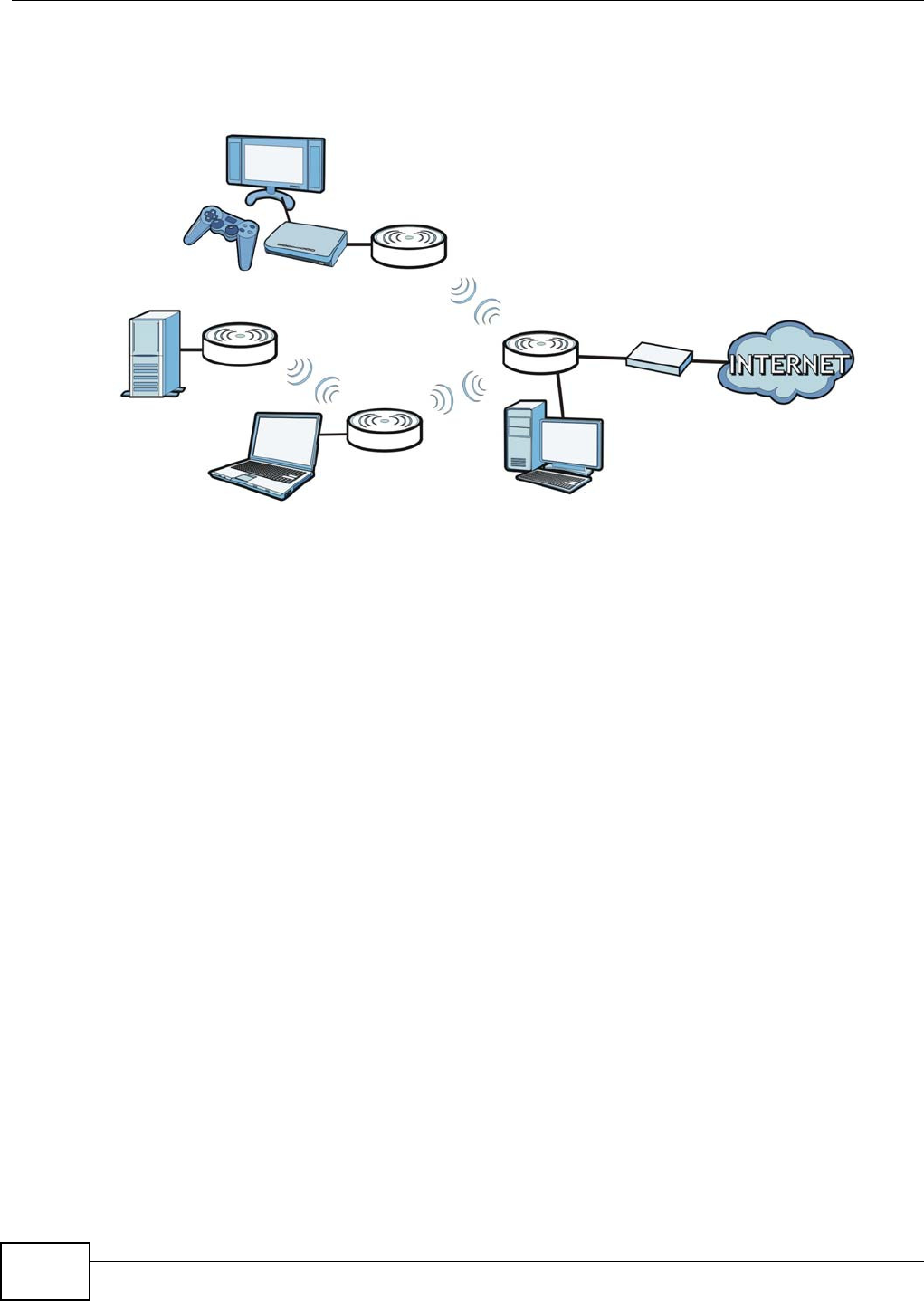
1.2 Applications
The WAP5705 can be configured to use the following operating modes:
•AP. Use the switch on the side panel to set the WAP5705 to work in AP mode (AP). You can
connect to a broadband modem/router for Internet access and/or connect network devices via
the Ethernet ports of the WAP5705 in AP mode so that they can communicate with each other
and access the Internet. Wireless clients can connect to the WAP5705 in AP mode to access
network resources.
Chapter 1 Getting to Know Your WAP5705
WAP5705 User’s Guide
12
•Clie n t . Use the switch on the side panel to set the WAP5705 to work in client mode (CL). The
WAP5705 in client mode can access the Internet through a WAP5705 in AP mode and/or connect
to another WAP5705 in client mode using IEEE 802.11e Direct Link Setup (DLS).
Figure 1 WAP5705 Applications
1.3 Ways to Manage the WAP5705
Use any of the following methods to manage the WAP5705.
• Web Configurator. This is recommended for everyday management of the WAP5705 using a
(supported) web browser.
• WPS (Wi-Fi Protected Setup) button. You can use the WPS button or the WPS section of the Web
Configurator to set up a wireless network with your WAP5705.
1.4 Good Habits for Managing the WAP5705
Do the following things regularly to make the WAP5705 more secure and to manage the WAP5705
more effectively.
• Change the password. Use a password that’s not easy to guess and that consists of different
types of characters, such as numbers and letters.
• Write down the password and put it in a safe place.
• Back up the configuration (and make sure you know how to restore it). Restoring an earlier
working configuration may be useful if the device becomes unstable or even crashes. If you
forget your password, you will have to reset the WAP5705 to its factory default settings. If you
backed up an earlier configuration file, you would not have to totally re-configure the WAP5705.
You could simply restore your last configuration.
AP
CL
CL
CL

Chapter 1 Getting to Know Your WAP5705
WAP5705 User’s Guide 13
1.5 Resetting the WAP5705
If you forget your password or IP address, or you cannot access the Web Configurator, you will need
to use the RESET button at the back of the WAP5705 to reload the factory-default configuration
file. This means that you will lose all configurations that you had previously saved, the password
will be reset to “1234” and the IP address of the WAP5705 in AP mode will be reset to
“192.168.1.2” and the IP address of the WAP5705 in client mode will be reset to “192.168.1.10”.
1.5.1 Procedure to Use the Reset Button
1Make sure the power LED is on.
2Press the RESET button for longer than 1 second to restart/reboot the WAP5705.
3Press the RESET button for longer than five seconds to set the WAP5705 back to its factory-default
configurations.
1.6 The WPS Button
You can use the WPS button ( ) on the front panel of the WAP5705 to activate WPS in order to
quickly set up a wireless network with strong security.
1Make sure the POW ER LED is on (not blinking).
2Press the WPS button for more than three seconds and release it. Press the WPS button on another
WPS-enabled device within range of the WAP5705.
Note: You must activate WPS in the WAP5705 that acts as the AP and in another
WAP5705 that acts as the client within two minutes of each other.

Chapter 1 Getting to Know Your WAP5705
WAP5705 User’s Guide
14
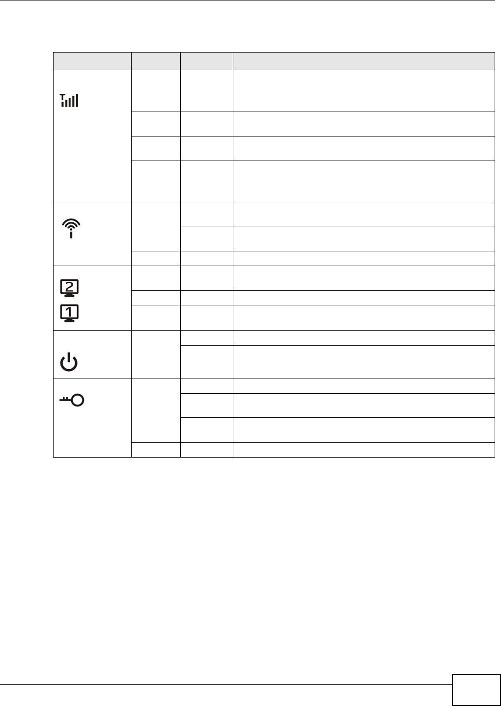
1.7 LEDs
Figure 2 Front Panel
Chapter 1 Getting to Know Your WAP5705
WAP5705 User’s Guide 15
The following table describes the LEDs and the WPS button.
Table 1 Front Panel LEDs and WPS Button
LED COLOR STATUS DESCRIPTION
Quality Green On AP mode: This LED is always on after the system starts up.
Client mode: The WAP5705 is connecting to an AP and the
transmission rate is 65 Mbps or above.
Amber On Client mode: The WAP5705 is connecting to an AP and the
transmission rate is between 65 Mbps and 19.5 Mbps.
Red On Client mode: The WAP5705 is connecting to an AP and the
transmission rate is below 19.5 Mbps.
Off AP mode: The WAP5705 is not receiving power.
Client mode: The WAP5705 is not receiving power or not
associating with an AP.
Wireless Green On The WAP5705 is ready, but is not sending/receiving data
through the wireless LAN.
Blinking The WAP5705 is sending/receiving data through the wireless
LAN.
Off The wireless LAN is not ready or has failed.
LAN 1-2 Green On The WAP5705 has a successful 10/100/1000 Mbps Ethernet
connection.
Blinking The WAP5705 is sending/receiving data through the LAN.
Off The LAN is not connected.
Power Green On The WAP5705 is receiving power and functioning properly.
Off The WAP5705 is not receiving power.
WPS Blue On WPS is enabled.
Blinking
(slow)
The WAP5705 is negotiating a WPS connection with a wireless
device.
Blinking
(fast)
The WPS negotiation failed.
Off The wireless LAN is not ready or has failed.
Chapter 1 Getting to Know Your WAP5705
WAP5705 User’s Guide
16
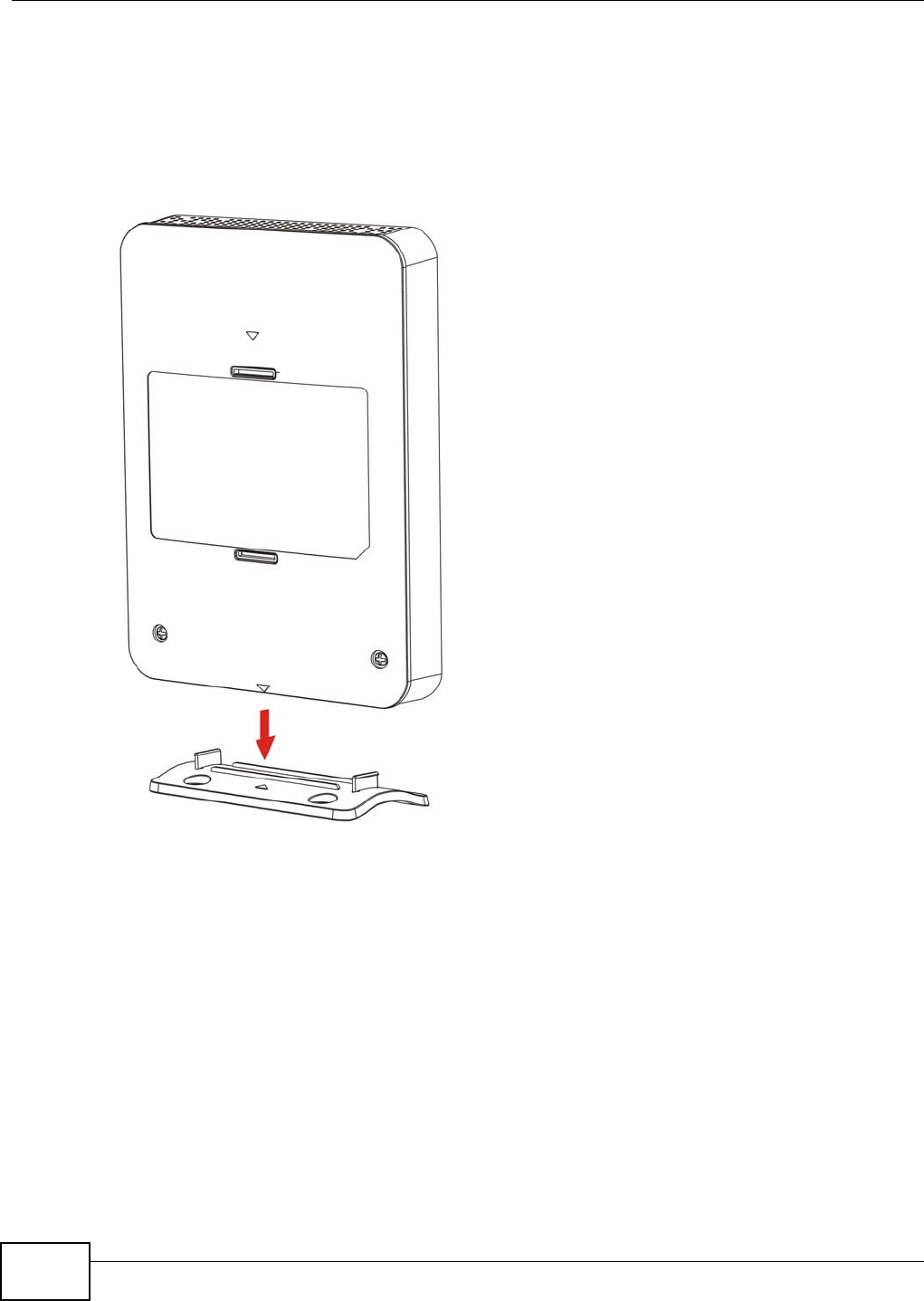
1.8 Desktop Installation
Either place the WAP5705 flat on a desk or table or use the stand for a vertical installation. To
attach the stand, line up the arrow on the stand with the arrow on the bottom of the WAP5705 as
shown. Press gently but firmly until the WAP5705 clicks into place.
Figure 3 Stand Installation Example
Chapter 1 Getting to Know Your WAP5705
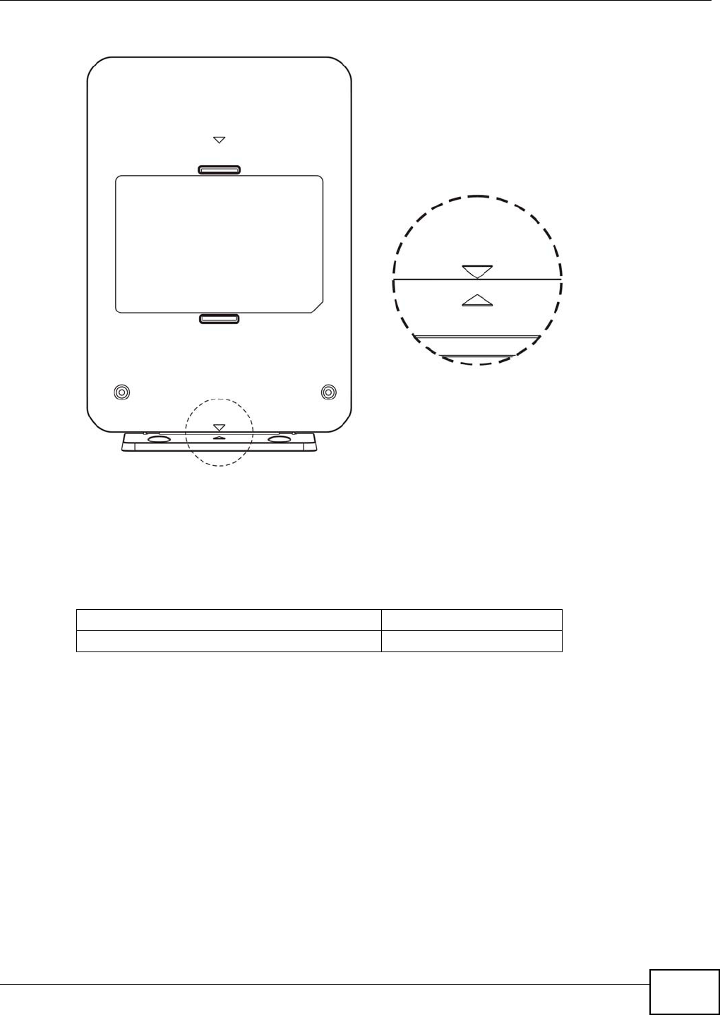
WAP5705 User’s Guide 17
Figure 4 Arrows on the Stand and WAP5705
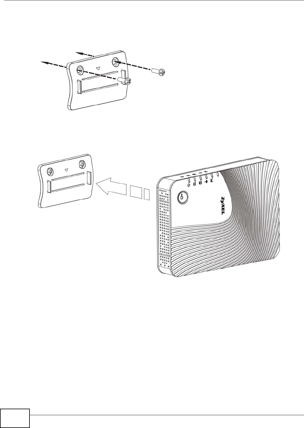
1.9 Wall-mounting Instructions
Complete the following steps to hang your WAP5705 on a wall.
1Select a position free of obstructions on a sturdy wall.
2Install the stand on the wall. Make sure the screw holes of the stand are on the top and screws are
snugly fastened to the wall. The stand needs to hold the weight of the WAP5705 with the
connection cables.
Table 2 Wall Mounting Information
Distance between holes 5 cm
M4 Screws Two
Chapter 1 Getting to Know Your WAP5705
WAP5705 User’s Guide
18
Be careful to avoid damaging pipes or cables located inside the wall
when installing the stand.
Figure 5 Installing the Stand
3Hold the WAP5705 with the LEDs facing upward. Align the holes on the back of the WAP5705 with
the tabs on the stand. Attach the WAP5705 to the stand. Press gently but firmly until the WAP5705
clicks into place.
Figure 6 Attaching the WAP5705 to the Stand

WAP5705 User’s Guide 19
CHAPTER 2
WAP5705 Modes
2.1 Overview
This chapter introduces the different modes available on your WAP5705. First, the term “mode”
refers to two things in this User’s Guide.
•W e b Configur a t or m ode . This refers to the Web Configurator interface you want to use for
editing WAP5705 features.
•De vice m ode . This is the operating mode of your WAP5705, or simply how the WAP5705 is
being used in the network.
2.1.1 Web Configurator Modes
This refers to the configuration interface of the Web Configurator, which has two modes:
•Ea sy. The Web Configurator shows this mode by default. Refer to Chapter 3 on page 21 for more
information on the screens in this mode. This interface may be sufficient for users who just want
to use the device.
•Ex p er t . Advanced users can change to this mode to customize all the functions of the WAP5705.
Click Ex per t M ode after logging into the Web Configurator. The User’s Guide Chapter 6 on page
47 through Chapter 11 on page 91 discusses the screens in this mode.
2.1.2 Device Operating Modes
This refers to the operating mode of the WAP5705, which can act as a:
•Acce ss Point (AP). Use this mode if you want to extend your network by allowing network
devices to connect to the WAP5705 wirelessly. Go to Section 4.4 on page 31 to view the St a t us
screen in this mode.
•Client (CL). Use this mode if there is an existing WAP5705 that acts as an AP in your network.
Go to Section 5.5 on page 36 to view the St a t u s screen in this mode. In Client mode, you should
know the SSID and wireless security details of the WAP5705 to which you want to connect.
Note: Choose your device mode carefully to avoid having to change it later.
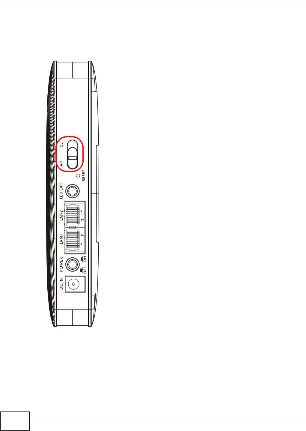
2.1.2.1 Changing Operating Mode
Push the AP/ CL switch on the WAP5705’s side panel to the AP position to have the WAP5705 act
as an access point. Otherwise, push the switch to the CL position to have the WAP5705 work as a
wireless client. The WAP5705 restarts automatically after you change operating modes.
Chapter 2 WAP5705 Modes
WAP5705 User’s Guide
20
Note: When you change the WAP5705 mode from AP mode to client mode, make sure
you use the RESET button to return the IP address of the WAP5705 in client mode
to 192.168.1.10. Otherwise, the client mode IP address will be the same as the
access point mode IP address.
Figure 7 Side Panel
WAP5705 User’s Guide 21
CHAPTER 3
Easy Mode
3.1 Overview
The Web Configurator is set to Easy M ode by default. You can configure several key features of the
WAP5705 in this mode. This mode is useful to users who are not fully familiar with some features
that are usually intended for network administrators.
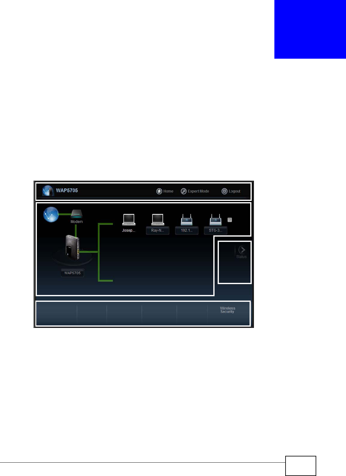
When you log in to the Web Configurator, the following screen opens.
Figure 8 Easy Mode: Network Map
Network Map
Control Panel
Go to
Status
Screen
Navigation Panel
Chapter 3 Easy Mode
WAP5705 User’s Guide
22
Click St a t u s to open the following screen.
Figure 9 Easy Mode: Status Screen
3.2 What You Can Do
You can do the following in this mode:
•Use this Naviga t ion Pa nel (Section 3.4 on page 22) to opt out of the Ea sy mode.
•Use the N e t w ork M a p screen (Section 3.5 on page 23) to check if your WAP5705 can ping the
gateway and whether it is connected to the Internet.
•Use the Cont rol Pane l (Section 3.6 on page 24) to configure wireless security.
•Use the St at us Scre e n screen (Section 3.7 on page 27) to view read-only information about the
WAP5705, including the LAN IP, MAC Address of the WAP5705 and the firmware version.
3.3 What You Need to Know
W ire less Securit y in the control panel is not configurable when the WAP5705 is in client mode.
3.4 Navigation Panel
Use this navigation panel to opt out of the Easy mode.
Figure 10 Control Panel
Control Panel
Status Screen
Go to
Network
Map
Screen
Navigation Panel
Chapter 3 Easy Mode
WAP5705 User’s Guide 23
The following table describes the labels in this screen.
3.5 Network Map
Note: The Network MAP is viewable by Windows XP (need to install patch), Windows Vista
and Windows 7 users only. For Windows XP (Service Pack 2) users, you can see the
network devices connected to the WAP5705 by downloading the LLTD (Link Layer
Topology Discovery) patch from the Microsoft Website.
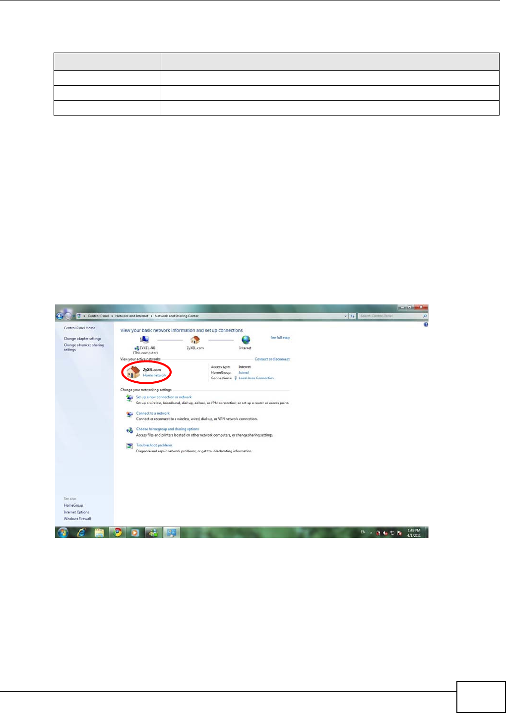
Note: In Windows Vista or Windows 7, you should set your network location to “Home
network” in the Control Panel > Network and Internet > Network and Sharing
Center screen.
Figure 11 Set Network Location to Home Network in Windows Vista or 7
Note: Don’t worry if the Network Map does not display in your web browser. This feature
may not be supported by your system. You can still configure the Control Panel
(Section 3.6 on page 24) in the Easy Mode and the WAP5705 features that you
want to use in the Expert Mode.
Table 3 Control Panel
ITEM DESCRIPTION
Home Click this to go to the Login page.
Expert Mode Click this to change to Ex pe rt mode and customize features of the WAP5705.
Logout Click this to end the Web Configurator session.
Chapter 3 Easy Mode
WAP5705 User’s Guide
24
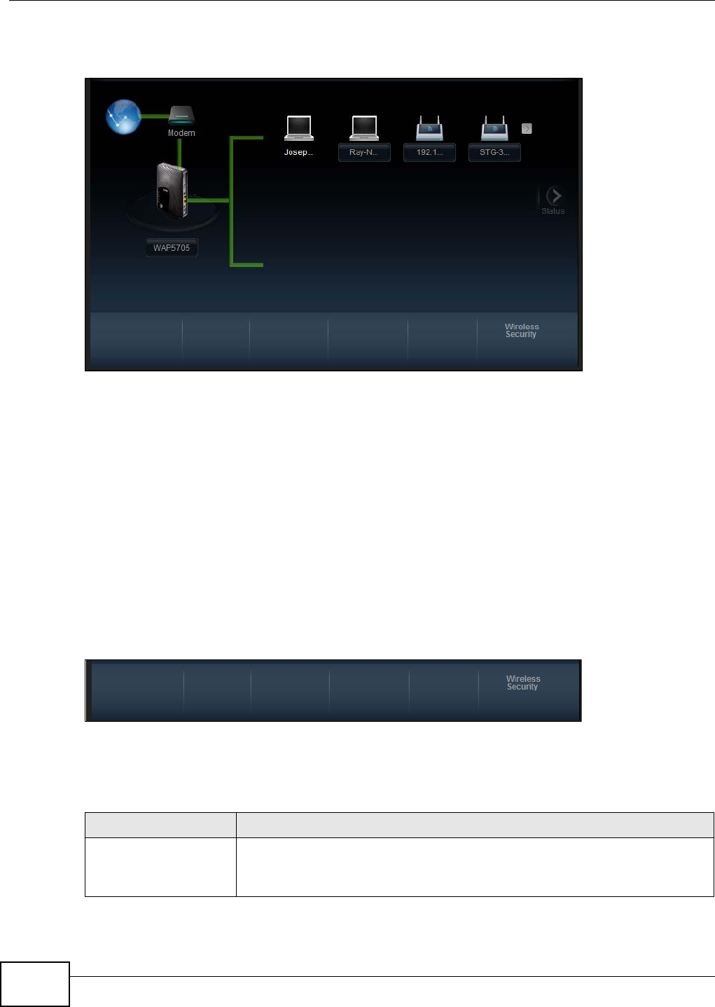
When you log into the Web Configurator, the Network Map is shown as follows.
Figure 12 Network Map
The line connecting the WAP5705 to the gateway becomes green when the WAP5705 is able to ping
the gateway. It becomes red when the ping initiating from the WAP5705 does not get a response
from the gateway. The same rule applies to the line connecting the gateway to the Internet.
You can also view the devices (represented by icons indicating the kind of network device)
connected to the WAP5705, including those connecting wirelessly. Right-click on the WAP5705 icon
to refresh the network map. Right click on the other icons to view information about the device or
left-click the device icon to access its web configurator or files in the shared folder.
3.6 Control Panel
The features configurable in Ea sy M ode are shown in the Con t r ol Pa n el.
Figure 13 Control Panel
Click the feature to open a screen where you can edit its settings.
The following table describes the labels in this screen.
Table 4 Control Panel
ITEM DESCRIPTION
Wireless Security Click this to configure the wireless security, such as SSID, security mode and WPS
key on your WAP5705.
Refer to Section 3.6.1 on page 25 to see this screen.
Chapter 3 Easy Mode
WAP5705 User’s Guide 25
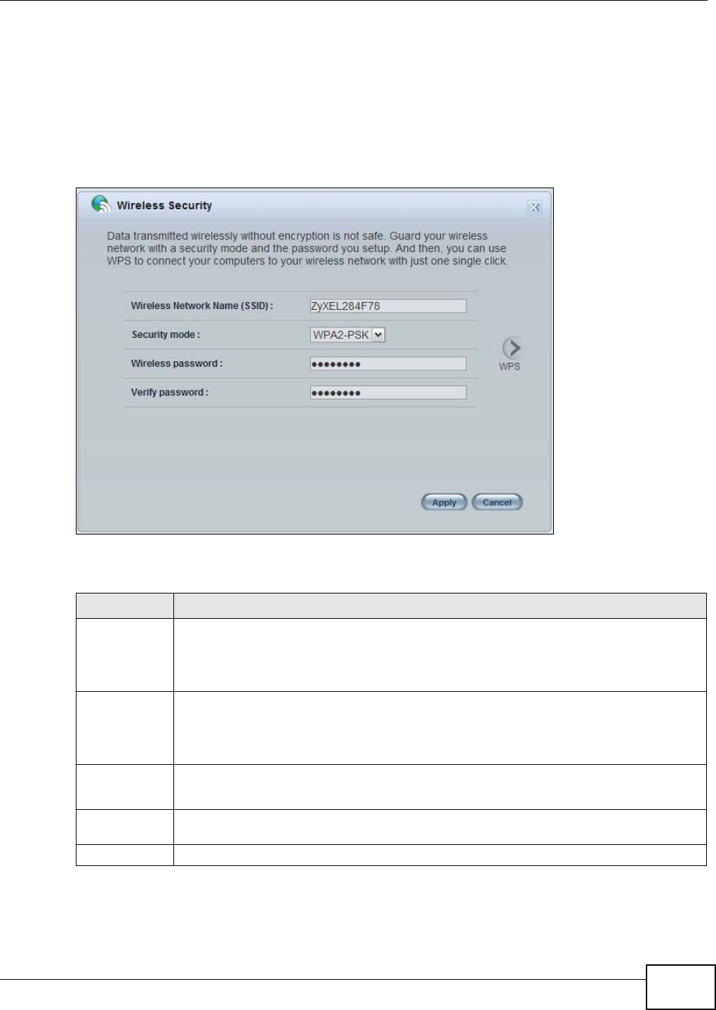
3.6.1 Wireless Security
Use this screen to configure security for your the wreless LAN. You can enter the SSID and select
the wireless security mode in the following screen.
Note: W ir e less Securit y in the control panel is not configurable when the WAP5705 is in
client mode.
Figure 14 Wireless Security
The following table describes the general wireless LAN labels in this screen.
Table 5 Wireless Security
LABEL DESCRIPTION
Wireless
Network Name
(SSID)
(Service Set IDentity) The SSID identifies the Service Set with which a wireless station is
associated. Wireless stations associating to the access point (AP) must have the same SSID.
Enter a descriptive name (up to 32 keyboard characters) for the wireless LAN.
The default SSID is “ZyXEL+(the last six characters of the WAP5705’s MAC address)”.
Security mode Select W PA- PSK or W PA2 - PSK to add security on this wireless network. The wireless
clients which want to associate to this network must have same wireless security settings as
this device. After you select to use a security, additional options appears in this screen.
Select N o Securit y to allow any client to connect to this network without authentication.
Wireless
password
This field appears when you choose wither W PA- PSK or W PA2 - PSK as the security mode.
Type a pre-shared key from 8 to 63 case-sensitive keyboard characters.
Verify
password
Type the password again to confirm.
Apply Click Apply to save your changes back to the WAP5705.
Chapter 3 Easy Mode
WAP5705 User’s Guide
26
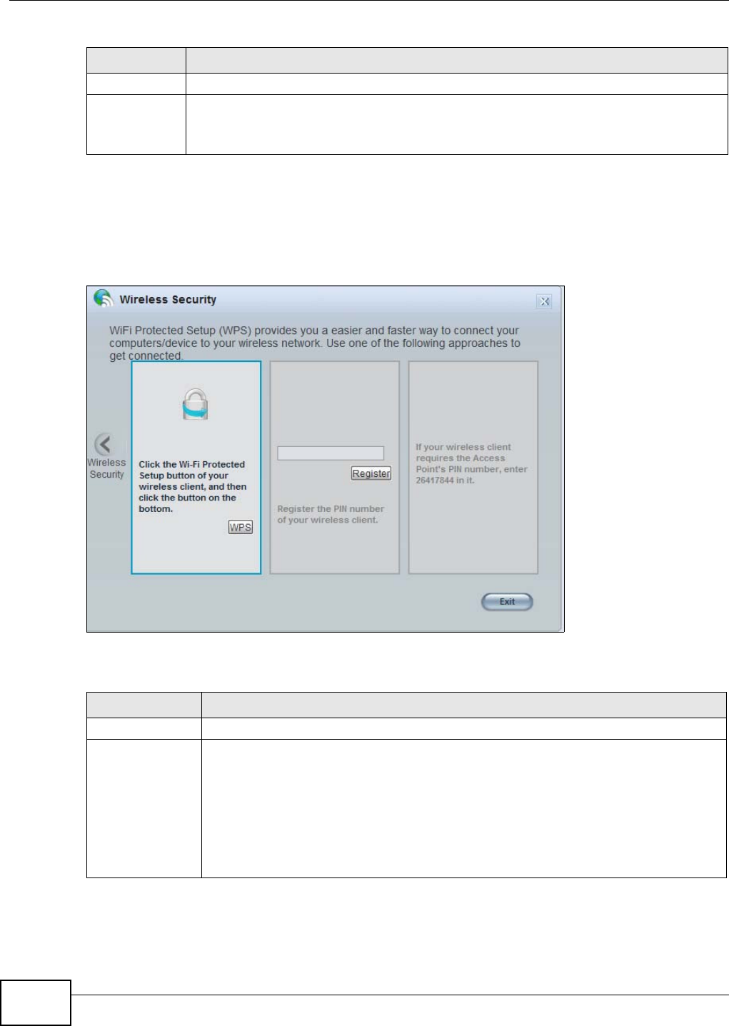
3.6.2 WPS
Use this screen to add a wireless station to the network with the WAP5705’s first SSID using WPS.
Click W PS in the W ir ele ss Securit y to open the following screen.
Figure 15 Wireless Security: WPS
The following table describes the labels in this screen.
Cancel Click Cancel to close this screen.
WPS Click this to configure the WPS screen.
You can transfer the wireless settings configured here (W ir ele ss Secur it y screen) to
another wireless device that supports WPS.
Table 5 Wireless Security
LABEL DESCRIPTION
Table 6 Wireless Security: WPS
LABEL DESCRIPTION
Wireless Security Click this to go back to the W ire less Secur it y screen.
WPS Create a secure wireless network simply by pressing the button.
The WAP5705 scans for a WPS-enabled device within the range and performs wireless
security information synchronization.
Note: After you click the WPS button on this screen, you have to press a similar button in
the wireless station utility within 2 minutes. To add the second wireless station, you
have to press these buttons on both device and the wireless station again after the
first 2 minutes.
Chapter 3 Easy Mode
WAP5705 User’s Guide 27
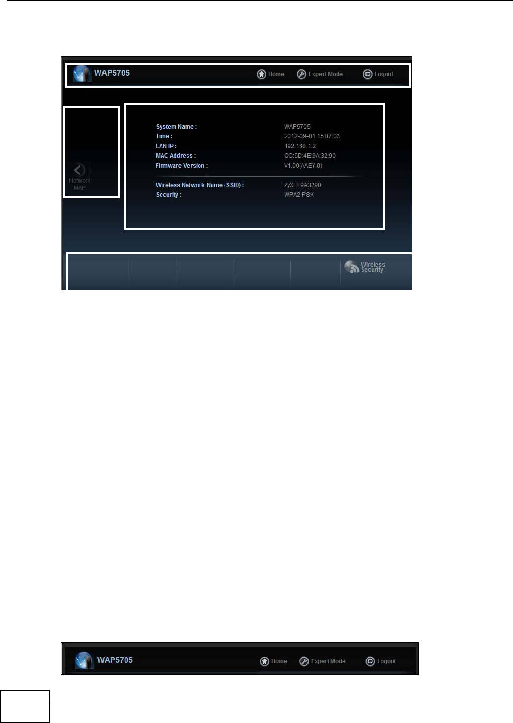
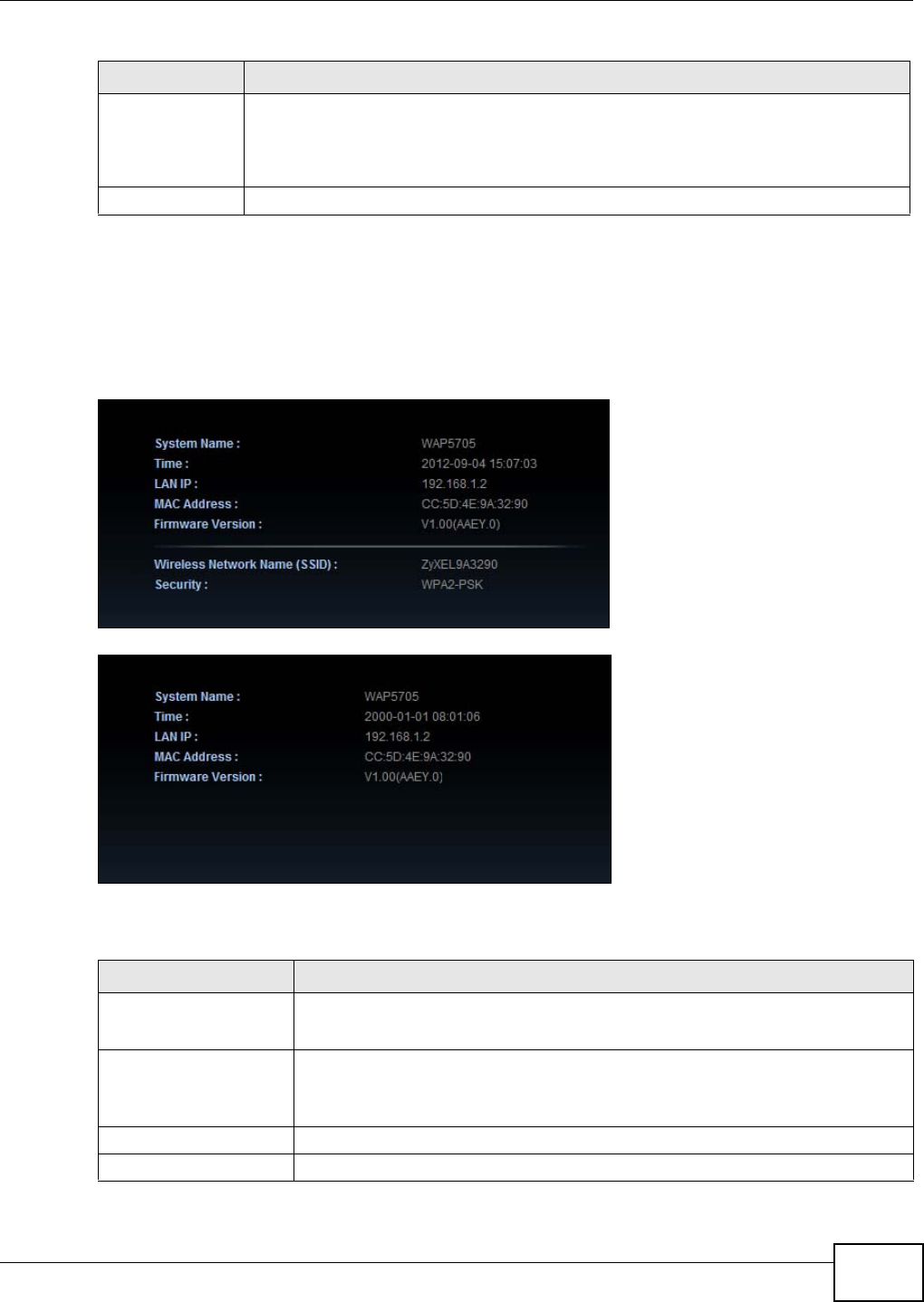
3.7 Status Screen in Easy Mode
In the Network Map screen, click St a t u s to view read-only information about the WAP5705.
Figure 16 Status Screen in Easy Mode (AP)
Figure 17 Status Screen in Easy Mode (Client)
The following table describes the labels in this screen.
Register Create a secure wireless network simply by entering a wireless client's PIN (Personal
Identification Number) in the WAP5705’s interface and pushing this button.
Type the same PIN number generated in the wireless station’s utility. Then click Re g ist e r
to associate to each other and perform the wireless security information synchronization.
Exit Click Ex it to close this screen.
Table 6 Wireless Security: WPS
LABEL DESCRIPTION
Table 7 Status Screen in Easy Mode
ITEM DESCRIPTION
Name This is the name of the WAP5705 in th
e network.
Time This is the current system date and time.
The date is in YYYY:MM:DD (Year-Month-Day) format. The time is in HH:MM:SS
(Hour:Minutes:Seconds) format.
LAN IP This is the IP address of the LAN port.
MAC Address This is the MAC address of the WAP5705.

Chapter 3 Easy Mode
WAP5705 User’s Guide
28
Firmware Version This shows the firmware version of the WAP5705.
The firmware version format shows the trunk version, model code and release
number.
Wireless Network Name
(SSID)
This shows the SSID of the wireless network. You can configure this in the
W ire le ss Securit y screen (Section 3.6.1 on page 25; Section 9.5 on page 77).
Security This shows the wireless security used by the WAP5705.
Table 7 Status Screen in Easy Mode
ITEM DESCRIPTION
WAP5705 User’s Guide 29
CHAPTER 4
Access Point Mode
4.1 Overview
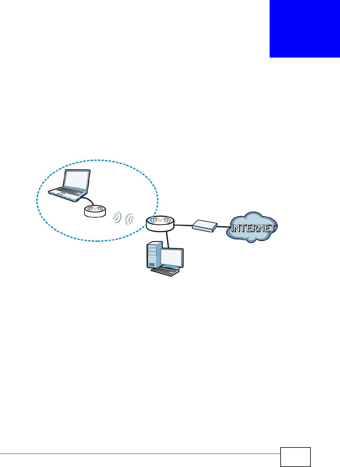
The WAP5705 is set to access point mode by default. In this mode your WAP5705 bridges a wired
network (LAN) and wireless LAN (WLAN) in the same subnet. See the figure below for an example.
Figure 18 Wireless Internet Access in Access Point Mode
Note: See Chapter 7 on page 53 for an example of setting up a wireless network in
Access Point mode.
4.2 What You Can Do
•Use the St a t us screen (Section 4.4 on page 31) to view read-only information about your
WAP5705.
•Use the LAN screen (Chapter 10 on page 87) to set the IP address for your WAP5705 acting as
an access point.
•Use the W ir e le ss LAN screens (Chapter 9 on page 73) to configure the wireless settings and
wireless security between the wireless clients and the WAP5705.
WLAN
LAN

Chapter 4 Access Point Mode
WAP5705 User’s Guide
30
4.3 What You Need to Know
See Chapter 7 on page 53 for a tutorial on setting up a network with the WAP5705 as an access
point.
4.3.1 Setting your WAP5705 to AP Mode
1To use your WAP5705 as an access point, see Section 2.1.2.1 on page 19.
2Connect your computer to the LAN port of the WAP5705.
3The default IP address of the WAP5705 in access point mode is “192.168.1.2”. In this case, your
computer must have an IP address in the range between “192.168.1.3” and “192.168.1.254”.
4Click St a r t > Run on your computer in Windows. Type “cmd” in the dialog box. Enter “ipconfig” to
show your computer’s IP address. If your computer’s IP address is not in the correct range then see
Appendix A on page 105 for information on changing your computer’s IP address.
5After you’ve set your computer’s IP address, open a web browser such as Internet Explorer and
type “http://192.168.1.2” as the web address in your web browser.
6Enter “1234” (default) as the password and click Login.
7Type a new password and retype it to confirm, then click Apply. Otherwise, click I gn ore.
8The Easy mode appears. Click Expert Mode in the navigation panel.
4.3.2 Configuring your WLAN, LAN and Maintenance Settings
•See
Chapter 9 on page 73 and Chapter 10 on page 87 for information on the configuring your
wireless network and LAN settings.
•See Chapter 11 on page 91 for information on configuring your Maintenance settings.
Chapter 4 Access Point Mode
WAP5705 User’s Guide 31
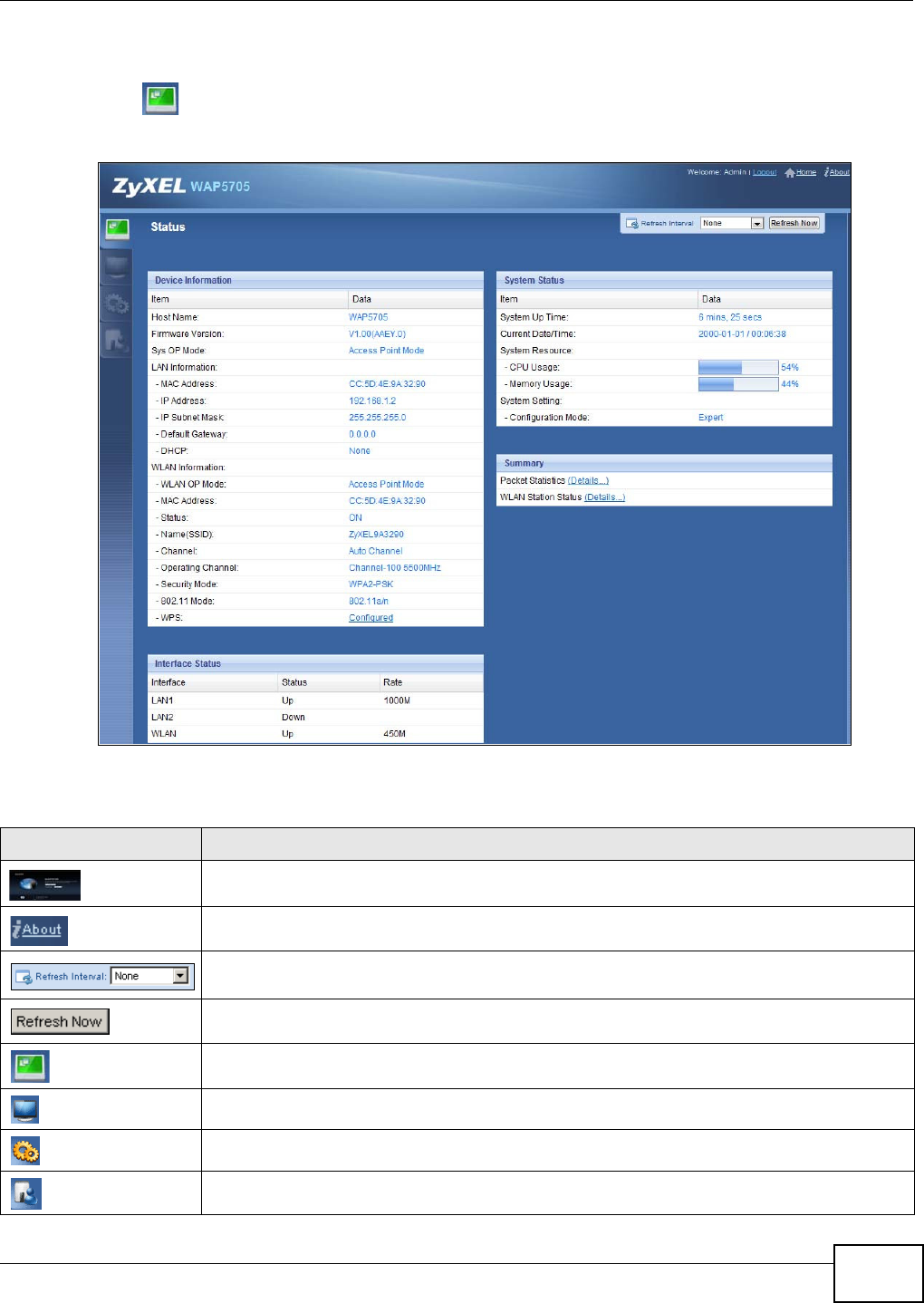
4.4 AP Mode Status Screen
Click to open the St a t us screen.
Figure 19 Status Screen: Access Point Mode
The following table describes the icons shown in the St a t us screen.
Table 8 Status Screen Icon Key: Access Point Mode
ICON DESCRIPTION
Click this to go to the Home page. See Section 6.2.3 on page 49.
Click this icon to view copyright and a link for related product information.
Select a number of seconds or N on e from the drop-down list box to refresh all screen statistics
automatically at the end of every time interval or to not refresh the screen statistics.
Click this button to refresh the status screen statistics.
Click this icon to see the Status page. The information in this screen depends on the device
mode you select.
Click this icon to see the M on it or navigation menu.
Click this icon to see the Con fi gu ra t ion navigation menu.
Click this icon to see the Ma int en an ce navigation menu.

Chapter 4 Access Point Mode
WAP5705 User’s Guide
32
The following table describes the labels shown in the St a t us screen.
Table 9 Status Screen: Access Point Mode
LABEL DESCRIPTION
Logout Click this at any time to exit the Web Configurator.
Device Information
Host Name This is the WAP5705’s model name.
Firmware Version This is the firmware version and the date created.
Sys OP Mode This is the device operating mode (Section 2.1.2 on page 19) to which the WAP5705 is set -
Acce ss Point M ode .
LAN Information
MAC Address This shows the LAN Ethernet adapter MAC Address of your device.
IP Address This shows the LAN port’s IP address.
IP Subnet Mask This shows the LAN port’s subnet mask.
Default Gateway This shows the gateway IP address.
DHCP This shows the LAN port’s DHCP role - Client or N one.
WLAN Information
WLAN OP Mode This is the device operating mode (Section 2.1.2 on page 19) to which the WAP5705’s
wireless LAN is set - Acce ss Point M ode .
MAC Address This shows the wireless adapter MAC Address of your device.
Status This shows the current status of the Wireless LAN - ON .
Name (SSID) This shows a descriptive name used to identify the WAP5705 in the wireless LAN.
Channel This shows the channel number which you select manually or the WAP5705 automatically
scans and selects.
Operating Channel This shows the channel number which the WAP5705 is currently using over the wireless LAN.
Security Mode This shows the level of wireless security the WAP5705 is using.
802.11 Mode This shows the wireless standard.
WPS This displays Configu red when the WPS has been set up.
This displays Unconfigure d if the WPS has not been set up.
Click the status to display N et w ork > W ir ele ss LAN > W PS screen.
Interface Status
Interface This displays the WAP5705 port types. The port types are: LAN and W LAN .
Status For the LAN ports, this field displays Dow n (line is down) or Up (line is up or connected).
For the WLAN, it displays Up when the WLAN is enabled or Dow n when the WLAN is
disabled.
Rate For the LAN ports, this displays the port speed or N / A when the line is disconnected.
For the WLAN, it displays the maximum transmission rate when the WLAN is enabled and N /
A when the WLAN is disabled.
System Status
Item This column shows the type of data the WAP5705 is recording.
Data This column shows the actual data recorded by the WAP5705.
System Up Time This is the total time the WAP5705 has been on.
Current Date/Time This field displays your WAP5705’s present date and time.
System Resource
Chapter 4 Access Point Mode
WAP5705 User’s Guide 33
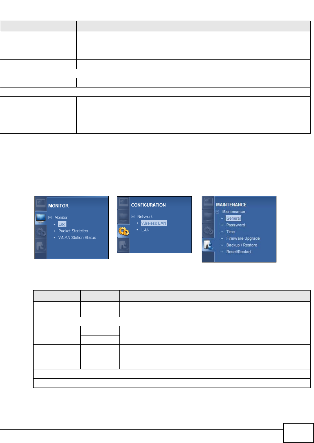
4.4.1 Navigation Panel
Use the menu in the navigation panel to configure WAP5705 features in Access Point mode.
The following screen and table show the features you can configure in Access Point mode.
Figure 20 Menu: Access Point Mode
The following table describes the sub-menus.
CPU Usage This displays what percentage of the WAP5705’s processing ability is currently used. When
this percentage is close to 100%, the WAP5705 is running at full load, and the throughput is
not going to improve anymore. If you want some applications to have more throughput, you
should turn off other applications (for example, using bandwidth management.
Memory Usage This shows what percentage of the heap memory the WAP5705 is using.
System Setting
Configuration Mode This shows the web configurator mode you are viewing - Exper t .
Summary
Packet Statistics Click De t a ils... to go to the M on it or > Pack e t Sta t istics screen (Section 8.5 on page 71).
Use this screen to view port status and packet specific statistics.
WLAN Station Status Click De t a ils... to go to the M on itor > W LAN St at ion St at us screen (Section 8.6 on page
72). Use this screen to view the wireless stations that are currently associated to the
WAP5705.
Table 9 Status Screen: Access Point Mode
LABEL DESCRIPTION
Table 10 Navigation Panel: Access Point Mode
LINK TAB FUNCTION
Status This screen shows the WAP5705’s general device, system and interface
status information. Use this screen to access the summary statistics tables.
M ON I TOR
Log View Log Use this screen to view the list of activities recorded by your WAP5705 and
change your log settings.
Log Settings
Packet Statistics Use this screen to view port status and packet specific statistics.
WLAN Station
Status
Use this screen to view the wireless stations that are currently associated
to the WAP5705.
CON FI GURATI ON
Network

Chapter 4 Access Point Mode
WAP5705 User’s Guide
34
Wireless LAN General Use this screen to configure general wireless LAN settings.
Security Use this screen to configure wireless security settings.
MAC Filter Use the MAC filter screen to configure the WAP5705 to block access to
devices or block the devices from accessing the WAP5705.
Advanced This screen allows you to configure advanced wireless settings.
QoS Use this screen to configure Wi-Fi Multimedia Quality of Service (WMM
QoS). WMM QoS allows you to prioritize wireless traffic according to the
delivery requirements of individual services.
WPS Use this screen to configure WPS.
WPS Station Use this screen to add a wireless station using WPS.
Scheduling Use this screen to schedule the times the Wireless LAN is enabled.
LAN IP Use this screen to configure LAN IP address and subnet mask.
IP Alias Use this screen to have the WAP5705 apply IP alias to create LAN subnets.
M AI N T EN AN CE
General Use this screen to view and change administrative settings such as system
and domain names.
Password Password
Setup
Use this screen to change the password of your WAP5705.
Time Time Setting Use this screen to change your WAP5705’s time and date.
Firmware
Upgrade Use this screen to upload firmware to your WAP5705.
Backup/
Restore Use this screen to backup and restore the configuration or reset the factory
defaults to your WAP5705.
Reset/
Restart Restart This screen allows you to reboot the WAP5705 without turning the power
off.
Table 10 Navigation Panel: Access Point Mode
LINK TAB FUNCTION
WAP5705 User’s Guide 35
CHAPTER 5
Client Mode
5.1 Overview
Your WAP5705 can act as a wireless client. In wireless client mode, it can connect to an existing
network via an access point. Use this mode if you already have a WAP5705 working as an access
point in your network.
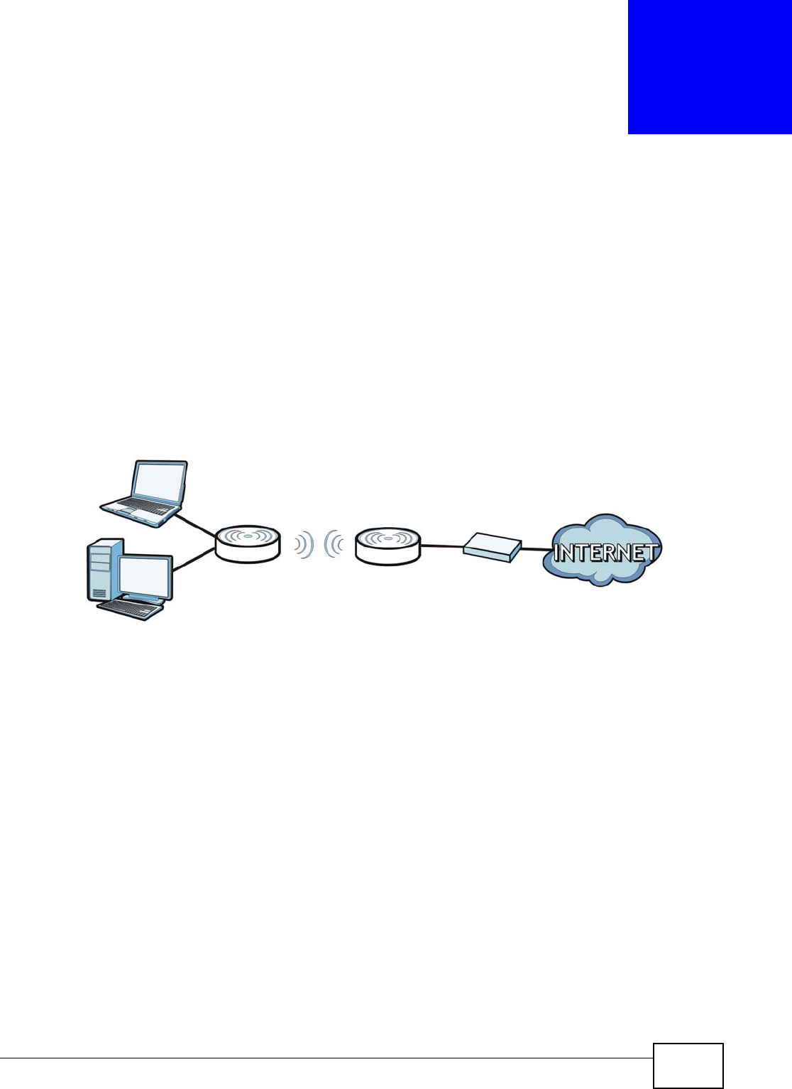
In the example below, one WAP5705 (A) is configured as a wireless client and another is used as an
access point (B). The WAP5705 has two clients that need to connect to the Internet. The WAP5705
wirelessly connects to the available access point (B).
Figure 21 Wireless Client Mode
After the WAP5705 and the access point connect, the WAP5705 acquires its WAN IP address from
the access point. The clients of the WAP5705 can now surf the Internet.
5.2 What You Can Do
•Use the St a t us screen (Section 5.5 on page 36) to view read-only information about your
WAP5705.
•Use the LAN screen (Chapter 10 on page 87) to set the IP address for your WAP5705.
•Use the W ire less LAN screen (Section 5.6 on page 38) to associate your WAP5705 (acting as a
wireless client) with an existing access point.
5.3 What You Need to Know
With the exception of the W ireless LAN screens, the LAN , M on it or, and Ma in t e na nce screens in
client mode are similar to the ones in access point Mode. See Chapter 10 on page 87 through
Chapter 11 on page 91 of this User’s Guide.
AB
Chapter 5 Client Mode
WAP5705 User’s Guide
36
5.4 Setting your WAP5705 to Client Mode
1To set your WAP5705 to client mode, see Section 2.1.2.1 on page 19.
2Connect your computer to the LAN port of the WAP5705.
3The default IP address of the WAP5705 in client mode is “192.168.1.10”. In this case, your
computer must have an IP address in the range between “192.168.1.11” and “192.168.1.254”.
4Click St a r t > Run on your computer in Windows. Type “cmd” in the dialog box. Enter “ipconfig” to
show your computer’s IP address. If your computer’s IP address is not in the correct range then see
Appendix A on page 105 for information on changing your computer’s IP address.
5After you’ve set your computer’s IP address, open a web browser such as Internet Explorer and
type “http://192.168.1.10” as the web address in your web browser.
6Enter “1234” (default) as the password and click Login.
7Type a new password and retype it to confirm, then click Apply. Otherwise, click I gn ore.
8The Easy mode appears. Click Expert Mode in the navigation panel.
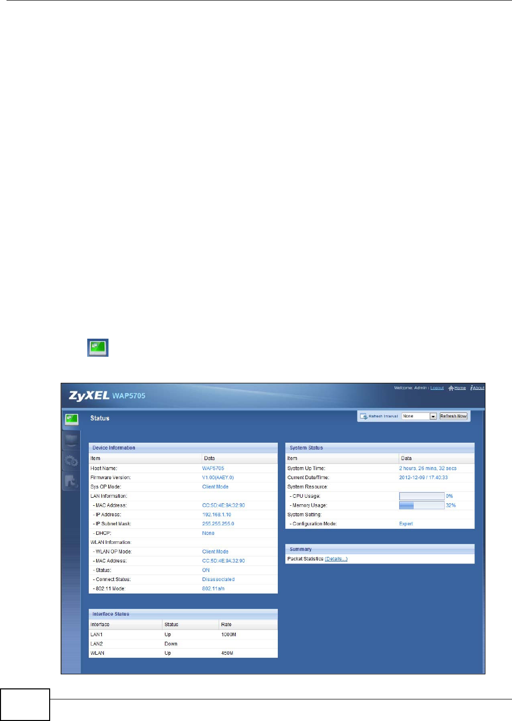
5.5 Client Mode Status Screen
Click to open the status screen.
Figure 22 Status: Client Mode

Chapter 5 Client Mode
WAP5705 User’s Guide 37
The following table describes the labels shown in the St a t us screen.
Table 11 Status Screen: Client Mode
LABEL DESCRIPTION
Logout Click this at any time to exit the Web Configurator.
Device Information
Host Name This is the WAP5705’s model name.
Firmware Version This is the firmware version and the date created.
Sys OP Mode This is the device operating mode (Section 2.1.2 on page 19) to which the
WAP5705 is set - Clien t Mode.
LAN Information
MAC Address This shows the LAN Ethernet adapter MAC Address of your device.
IP Address This shows the LAN port’s IP address.
IP Subnet Mask This shows the LAN port’s subnet mask.
DHCP This shows the LAN port’s DHCP role - Clie nt or N on e.
WLAN Information
WLAN OP Mode This is the device operating mode (Section 2.1.2 on page 19) to which the
WAP5705’s wireless LAN is set - Clie nt M ode.
MAC Address This shows the wireless adapter MAC Address of your device.
Status This shows the current status of the Wireless LAN - ON .
Connect Status This shows whether or not the WAP5705 has successfully associated with an
access point - Associat e d or D isa ssocia t e d.
Name (SSID) This shows a descriptive name used to identify the WAP5705 in the wireless
LAN.
Rate This shows the current transmission rate.
Channel This shows the channel number used by the WAP5705 now.
802.11 Mode This shows the wireless standard.
Interface Status
Interface This displays the WAP5705 port types. The port types are: LAN and W LAN .
Status For the LAN and WAN ports, this field displays Dow n (line is down) or Up (line
is up or connected).
For the WLAN, it displays Up when the WLAN is enabled or Dow n when the
WLAN is disabled.
Rate For the LAN ports, this displays the port speed or N / A when the line is
disconnected.
For the WLAN, it displays the maximum transmission rate when the WLAN is
enabled and N / A when the WLAN is disabled.
System Status
Item This column shows the type of data the WAP5705 is recording.
Data This column shows the actual data recorded by the WAP5705.
System Up Time This is the total time the WAP5705 has been on.
Current Date/Time This field displays your WAP5705’s present date and time.
System Resource
Chapter 5 Client Mode
WAP5705 User’s Guide
38
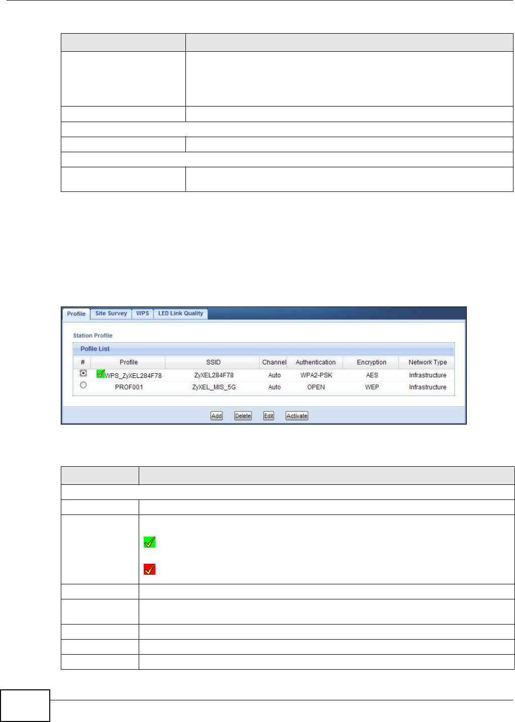
5.6 Wireless LAN Profile Screen
Use this screen to view the wireless LAN profile settings of your WAP5705. Go to Configura t ion >
N et w ork > W ireless LAN > Pr ofile to open the following screen.
Figure 23 Client Mode: WLAN > Profile
The following table describes the labels in this screen.
CPU Usage This displays what percentage of the WAP5705’s processing ability is currently
used. When this percentage is close to 100%, the WAP5705 is running at full
load, and the throughput is not going to improve anymore. If you want some
applications to have more throughput, you should turn off other applications
(for example, using bandwidth management.
Memory Usage This shows what percentage of the heap memory the WAP5705 is using.
System Setting
Configuration Mode This shows the web configurator mode you are viewing - Exper t .
Summary
Packet Statistics Click De t a ils.. . to go to the Monit or > Pa ck e t Sta tist ics screen (Section 8.5
on page 71). Use this screen to view port status and packet specific statistics.
Table 11 Status Screen: Client Mode
LABEL DESCRIPTION
Table 12 Client Mode: WLAN > Profile
LABEL DESCRIPTION
Profile List
# Select a profile to remove, modify or enable it.
Profile This displays the name of the pre-configured profile.
indicates the profile is activated and the WAP5705 connects to the specified wireless
network.
indicates the profile is activated but the specified wireless network is not available or
the WAP5705 fails to associate with the wireless network.
SSID This displays the SSID of the wireless network with which this profile associates.
Channel This displays the channel number used by this profile. Aut o means the WAP5705
automatically scans for and selects an available channel.
Authentication This displays the authentication method used by this profile.
Encryption This displays the data encryption method used by this profile.
Network Type This displays the network type (I n fr a st r u ct u r e or Ad H oc) of this profile.
Chapter 5 Client Mode
WAP5705 User’s Guide 39
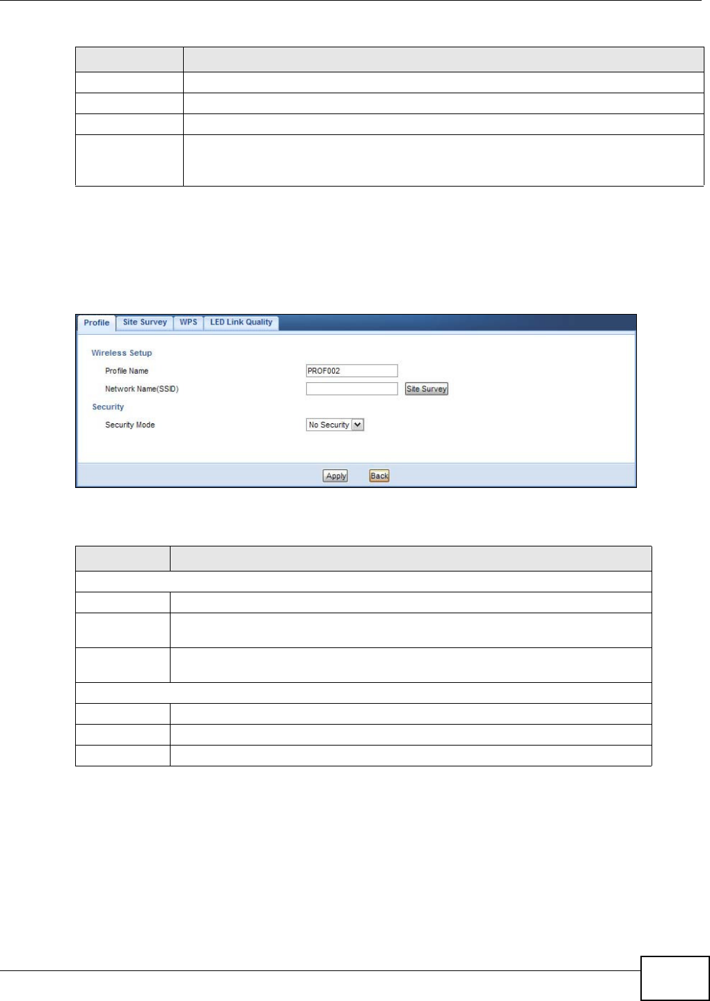
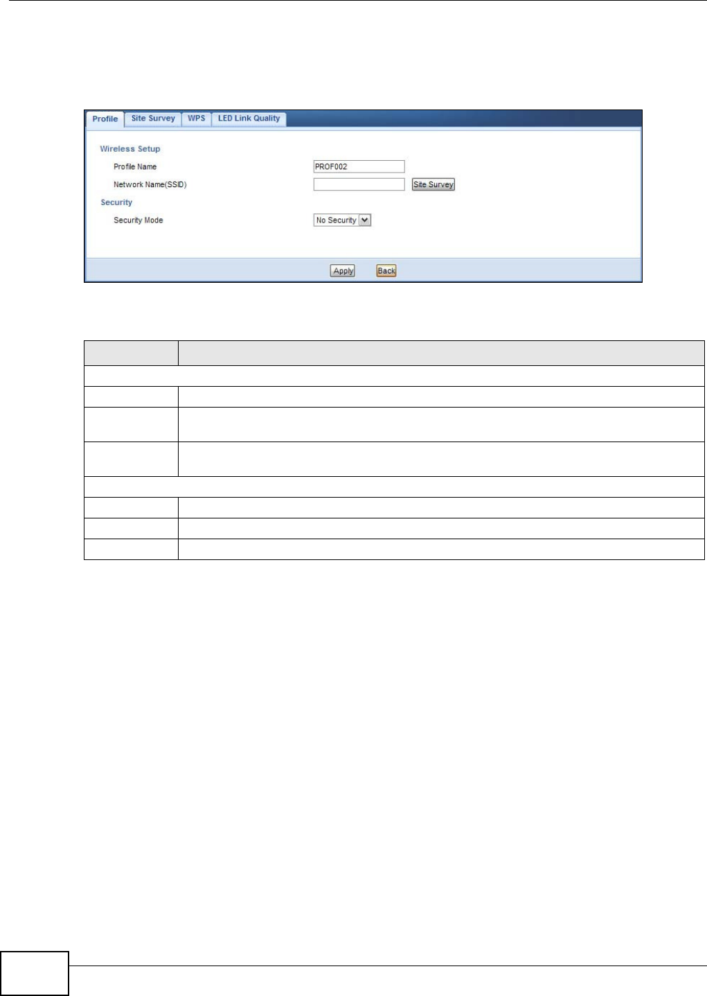
5.6.1 Adding a New WLAN Profile
Use this screen to create a new wireless LAN profile for your WAP5705. Click the Add button in the
Configurat ion > N e t w or k > W ireless LAN > Profile screen to open the following screen.
Figure 24 Client Mode: WLAN > Profile > Add
The following table describes the labels in this screen.
Add Click this button to create a new profile.
Delete Select a profile and click this button to remove it.
Edit Select a profile and click this button to modify it.
Activate Select a profile and click this button to enable it.
Note: You can activate only one profile at a time.
Table 12 Client Mode: WLAN > Profile (continued)
LABEL DESCRIPTION
Table 13 Client Mode: WLAN > Profile > Add
LABEL DESCRIPTION
Wireless Setup
Profile Name Enter a descriptive name for this profile.
Network Name
(SSID)
Enter the name of the access point to which you are connecting.
Site Survey Click this button to go to the Sit e Sur vey screen and see available wireless devices
within range.
Security
Security Mode Select the security mode of the access point to which you want to connect.
Apply Click Apply to save your changes back to the WAP5705.
Back Click Ba ck to go back to the previous screen.
Chapter 5 Client Mode
WAP5705 User’s Guide
40
5.6.1.1 No Security
Use this screen if the access point to which you want to connect does not use encryption.
Figure 25 Client Mode: WLAN > Profile: No Security
The following table describes the labels in this screen.
Table 14 Client Mode: WLAN > Profile: No Security
LABEL DESCRIPTION
Wireless Setup
Profile Name Enter a descriptive name for this profile.
Network Name
(SSID)
Enter the name of the access point to which you are connecting.
Site Survey Click this button to go to the Sit e Sur vey screen and see available wireless devices within
range.
Security
Security Mode Select N o Securit y in this field.
Apply Click Apply to save your changes back to the WAP5705.
Back Click Ba ck to go back to the previous screen.
Chapter 5 Client Mode
WAP5705 User’s Guide 41
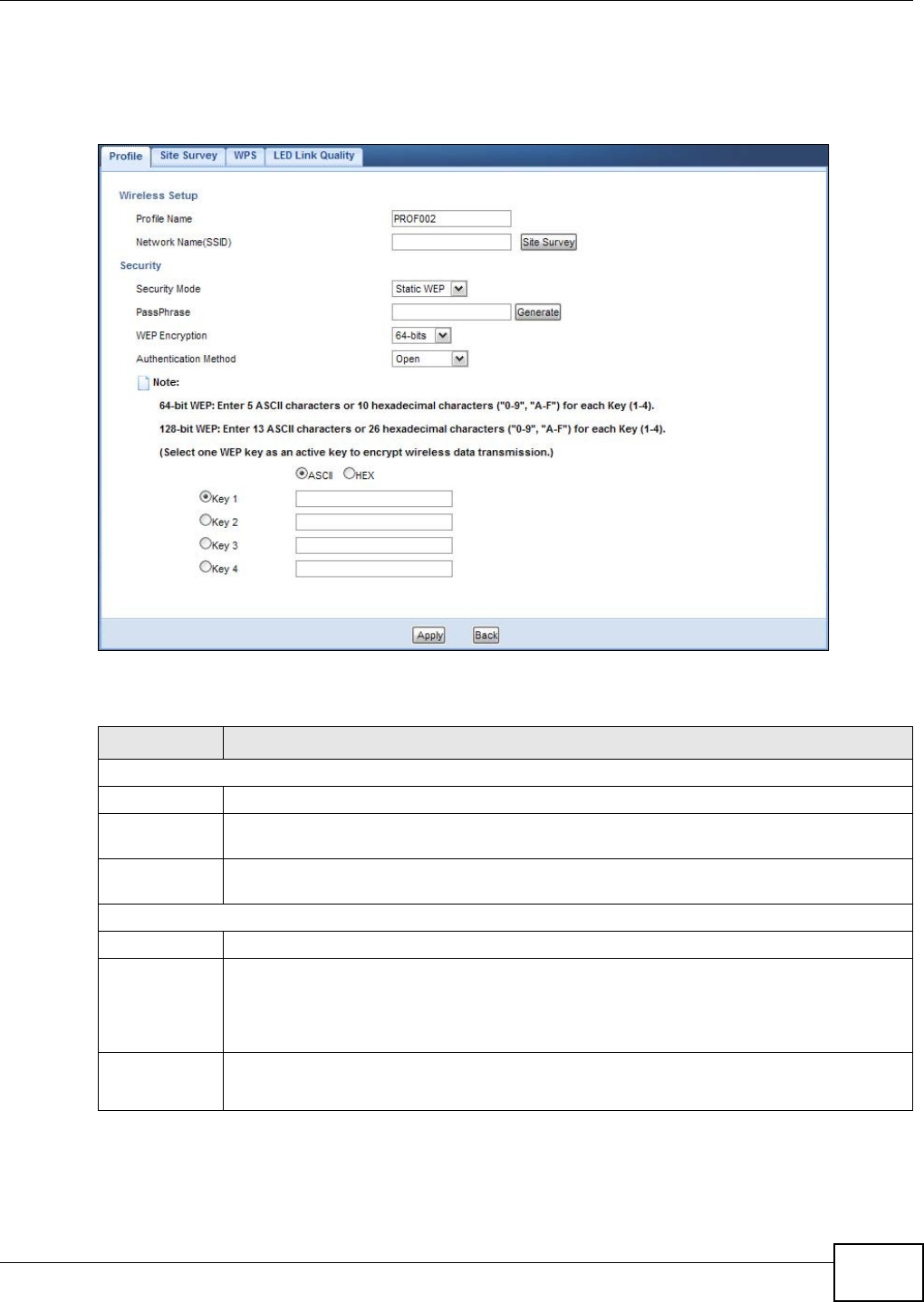
5.6.1.2 Static WEP
Use this screen if the access point to which you want to connect to uses WEP security mode.
Figure 26 Client Mode: WLAN > Profile: WEP
The following table describes the labels in this screen..
Table 15 Client Mode: WLAN > Profile: WEP
LABEL DESCRIPTION
Wireless Setup
Profile Name Enter a descriptive name for this profile.
Network Name
(SSID)
Enter the name of the access point to which you are connecting.
Site Survey Click this button to go to the Sit e Sur v ey screen and see available wireless devices within
range.
Security
Security Mode Select St a t ic W EP to enable data encryption.
PassPhrase Enter a passphrase (up to 26 printable characters) and click Gen er a t e .
A passphrase functions like a password. In WEP security mode, it is further converted by the
WAP5705 into a complicated string that is referred to as the “key”. This key is requested
from all devices wishing to connect to a wireless network.
WEP
Encryption
Select 6 4 - b it s or 1 2 8 - bits.
This dictates the length of the security key that the network is going to use.
Chapter 5 Client Mode
WAP5705 User’s Guide
42
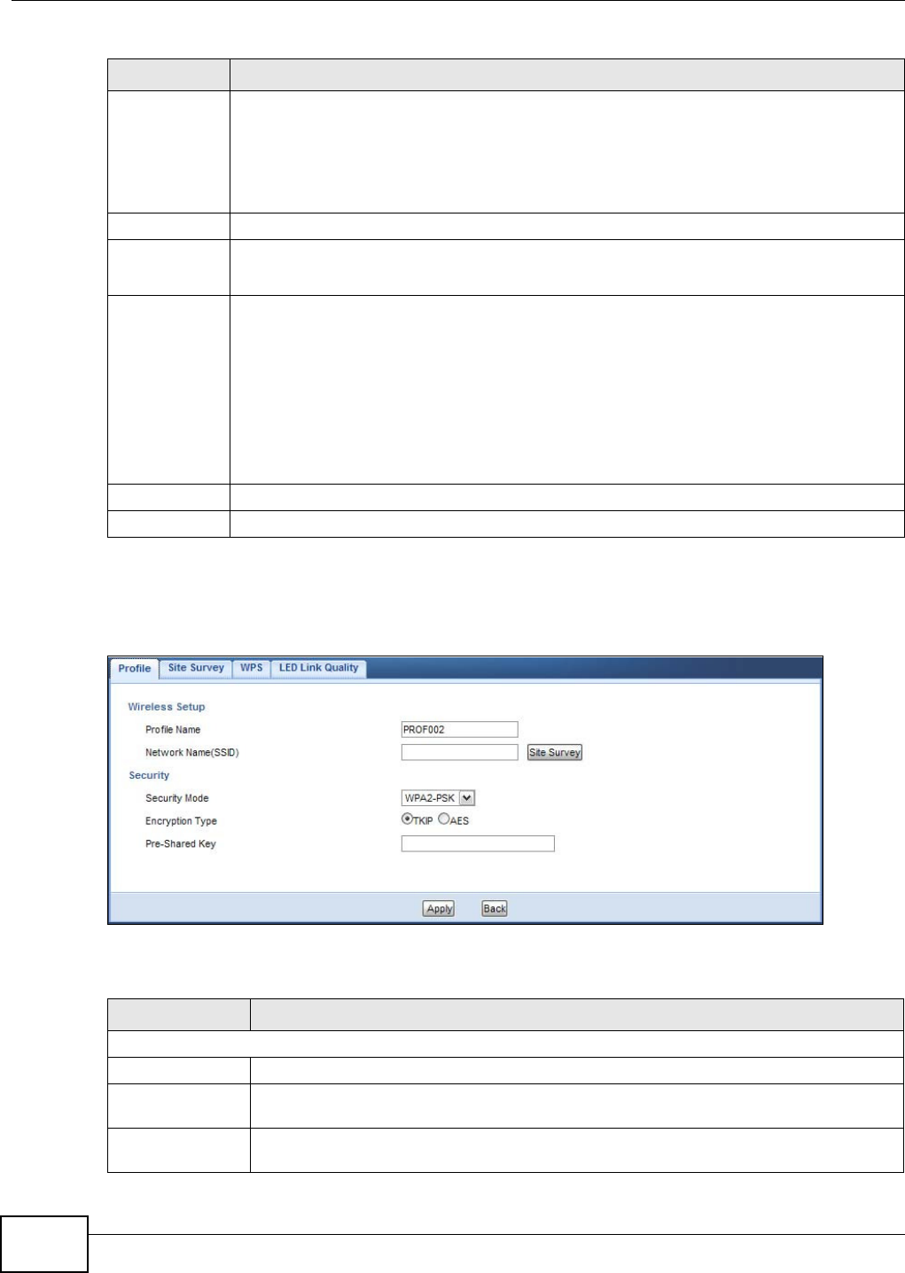
5.6.1.3 WPA(2)-PSK
Use this screen if the access point to which you want to connect uses WPA(2)-PSK security mode.
Figure 27 Client Mode: WLAN > Profile: WPA-PSK/WPA2-PSK
The following table describes the labels in this screen.
Authentication
Method
Select Ope n or Shar ed Ke y from the drop-down list box.
This field specifies whether the wireless clients have to provide the WEP key to log into the
wireless network. Keep this setting at Ope n unless you want to force a key verification
before communication between the wireless client and the ZyXEL Device occurs.
Select Sha re d Key to force the clients to provide the WEP key prior to communication.
ASCII Select this option in order to enter ASCII characters as WEP key.
Hex Select this option in order to enter hexadecimal characters as a WEP key.
The preceding "0x", that identifies a hexadecimal key, is entered automatically.
Key 1 to Key 4 The WEP keys are used to encrypt data. Both the WAP5705 and the wireless stations must
use the same WEP key for data transmission.
If you chose 6 4 - b it s, then enter any 5 ASCII characters or 10 hexadecimal characters ("0-
9", "A-F").
If you chose 1 2 8 - bit s, then enter 13 ASCII characters or 26 hexadecimal characters ("0-9",
"A-F").
You must configure at least one key, only one key can be activated at any one time. The
default key is key 1.
Apply Click Apply to save your changes back to the WAP5705.
Back Click Ba ck to go back to the previous screen.
Table 15 Client Mode: WLAN > Profile: WEP
LABEL DESCRIPTION
Table 16 Client Mode: WLAN > Profile: WPA-PSK/WPA2-PSK
LABEL DESCRIPTION
Wireless Setup
Profile Name Enter a descriptive name for this profile.
Network Name
(SSID)
Enter the name of the access point to which you are connecting.
Site Survey Click this button to go to the Sit e Sur vey screen and see available wireless devices
within range.
Chapter 5 Client Mode
WAP5705 User’s Guide 43
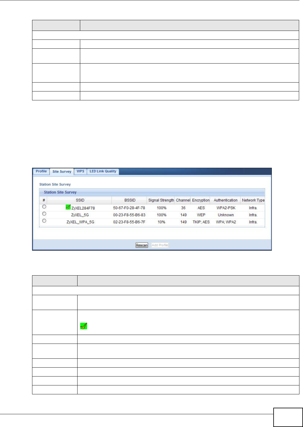
5.7 Site Survey Screen
Use this screen to scan for and connect to a wireless network automatically. Go to Configuration >
W ire le ss LAN > Sit e Su rve y to open the following screen.
Figure 28 Client Mode: WLAN > Site Survey
The following table describes the labels in this screen.
Security
Security Mode Select W PA- PSK or W PA2 - PSK to add strong security on this wireless network.
Encryption Type Select the type of wireless encryption employed by the access point to which you want to
connect.
Pre-Shared Key W PA- PSK or W PA2 - PSK uses a simple common password for authentication.
Type the pre-shared key employed by the access point to which you want to connect.
Apply Click Apply to save your changes back to the WAP5705.
Back Click Ba ck to go back to the previous screen.
Table 16 Client Mode: WLAN > Profile: WPA-PSK/WPA2-PSK
LABEL DESCRIPTION
Table 17 Client Mode: WLAN > Site Survey
LABEL DESCRIPTION
Station Site Survey
# Select a wireless device and click Add Pr ofile to open a configuration screen where you
can add the selected wireless device to a profile and then enable it.
SSID This displays the SSID of the wireless device.
indicates the wireless device is added to an activated profile and the WAP5705 is
connecting to it.
BSSID This displays the MAC address of the wireless device.
Signal Strength This displays the strength of the wireless signal. The signal strength mainly depends on the
antenna output power and the distance between your WAP5705 and this device.
Channel This displays the channel number used by this wireless device.
Encryption This displays the data encryption method used by this wireless device.
Authentication This displays the authentication method used by this wireless device.
Network Type This displays the network type (I n fr a st r uct u re or Ad H oc) of this wireless device.
Chapter 5 Client Mode
WAP5705 User’s Guide
44
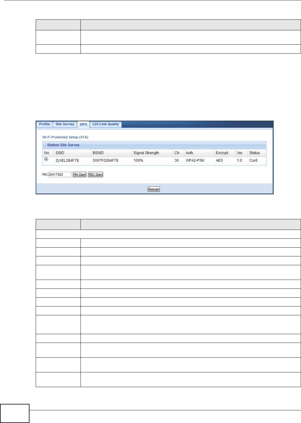
5.8 WPS Screen
Use this screen to enable Wi-Fi Protected Setup (WPS) on the WAP5705. Go to Configur a t ion >
W ire less LAN > W PS to open the following screen.
Figure 29 Client Mode: WLAN > WPS
The following table describes the labels in this screen.
Rescan Click this button to search for available wireless devices within transmission range and
update this table.
Add Profile Select a wireless device and click this button to add it to a profile.
Table 17 Client Mode: WLAN > Site Survey (continued)
LABEL DESCRIPTION
Table 18 Client Mode: WLAN > WPS
LABEL DESCRIPTION
Station Site Survey
No. Use the radio button to select the wireless device to which you want to connect using WPS.
SSID This displays the SSID of the wireless device.
BSSID This displays the MAC address of the wireless device.
Signal Strength This displays the strength of the wireless signal. The signal strength mainly depends on the
antenna output power and the distance between your WAP5705 and this device.
Ch. This displays the channel number used by this wireless device.
Auth. This displays the authentication method used by this wireless device.
Encrypt This displays the data encryption method used by this wireless device.
Ver. This displays the firmware version running on the wireless device.
Status This displays Conf. (configured) when WPS has been set up on the wireless device.
This displays Uncon f. (unconfigured) if WPS has not been set up on the wireless device.
PIN This displays the PIN number of the WAP5705.
PIN Start Click this button to perform wireless security information synchronization using the PIN
configuration method.
PBC Start Click this button to perform wireless security information synchronization using the Push
Button Configuration (PBC) method.
Rescan Click this button to search for available for WPS-enabled devices within transmission range
and update this table.
Chapter 5 Client Mode
WAP5705 User’s Guide 45
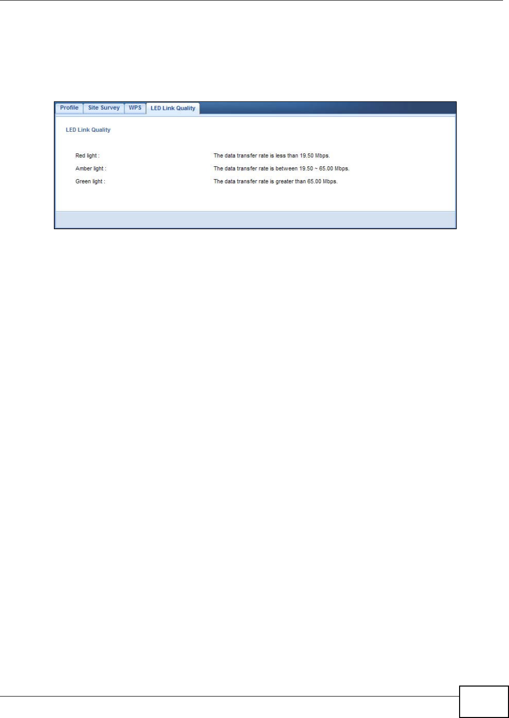
5.9 LED Link Quality Screen
Use this screen to view the threshold for each color of the quality LED on the WAP5705. Go to
Configurat ion > W ire less LAN > LED Link Qua lit y to open the following screen.
Figure 30 Client Mode: WLAN > LED Link Quality

Chapter 5 Client Mode
WAP5705 User’s Guide
46

WAP5705 User’s Guide 47
CHAPTER 6
The Web Configurator
6.1 Overview
This chapter describes how to access the WAP5705 Web Configurator and provides an overview of
its screens.
The Web Configurator is an HTML-based management interface that allows easy setup and
management of the WAP5705 via Internet browser. Use Internet Explorer 6.0 and later or Firefox
2.0 and later versions. The recommended screen resolution is 1024 by 768 pixels.
In order to use the Web Configurator you need to allow:
• Web browser pop-up windows from your device. Web pop-up blocking is enabled by default in
Windows XP SP (Service Pack) 2.
• JavaScripts (enabled by default).
• Java permissions (enabled by default).
Refer to the Troubleshooting chapter (Chapter 12 on page 99) to see how to make sure these
functions are allowed in Internet Explorer.
6.2 Accessing the Web Configurator
1Connect your computer to the LAN port of the WAP5705.
2The default IP address of the WAP5705 in access point mode is “192.168.1.2”. In this case, your
computer must have an IP address in the range between “192.168.1.3” and “192.168.1.254”.
3Click St a r t > Run on your computer in Windows. Type “cmd” in the dialog box. Enter “ipconfig” to
show your computer’s IP address. If your computer’s IP address is not in the correct range then see
Appendix A on page 105 for information on changing your computer’s IP address.
4After you’ve set your computer’s IP address, open a web browser such as Internet Explorer and
type “http://192.168.1.2” as the web address in your web browser.
Chapter 6 The Web Configurator
WAP5705 User’s Guide
48
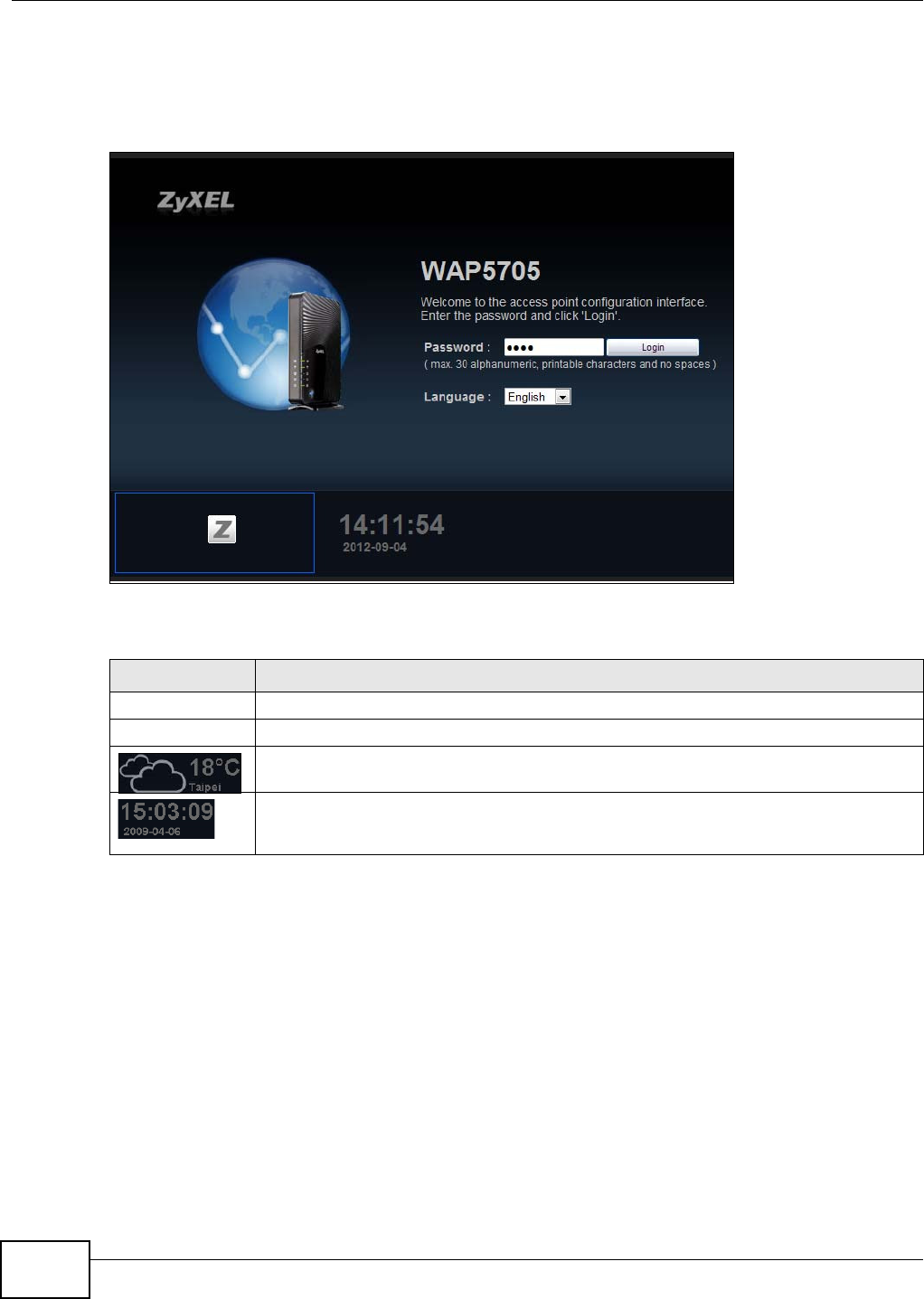
6.2.1 Login Screen
The Web Configurator initially displays the following login screen.
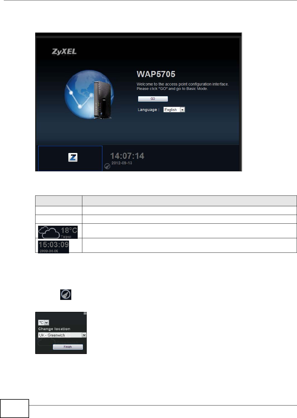
Figure 31 Login screen
The following table describes the labels in this screen.
Table 19 Login screen
LABEL DESCRIPTION
Password Type "1234" (default) as the password.
Language Select the language you want to use to configure the Web Configurator. Click Login.
This shows the current weather, either in celsius or fahrenheit, of the city you specify in
Section 6.2.3.1 on page 50.
This shows the time (hh:mm:ss) and date (yyyy:mm:dd) of the timezone you select in
Section 6.2.3.2 on page 51 or Section 11.5 on page 93. The time is in 24-hour format, for
example 15:00 is 3:00 PM.
Chapter 6 The Web Configurator
WAP5705 User’s Guide 49
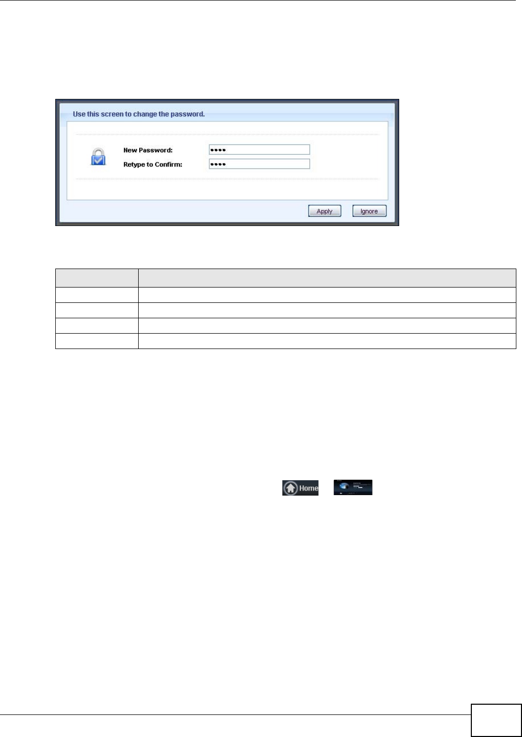
6.2.2 Password Screen
You should see a screen asking you to change your password (highly recommended) as shown
next.
Figure 32 Change Password Screen
The following table describes the labels in this screen.
Note: The management session automatically times out when the time period set in the
Adm inist ra t or I na ct ivit y Tim er field expires (default five minutes; go to Chapter
11 on page 91 to change this). Simply log back into the WAP5705 if this happens.
6.2.3 Home Screen
If you have previously logged into the Web Configurator but did not click Logou t , you may be
redirected to the Hom e screen.
You can also open this screen by clicking Hom e ( or ) in the Ea sy Mode or Expert
Mode screens.
Table 20 Change Password Screen
LABEL DESCRIPTION
New Password Type a new password.
Retype to Confirm Retype the password for confirmation.
Apply Click Apply to save your changes back to the WAP5705.
Ignore Click I gnore if you do not want to change the password this time.
Chapter 6 The Web Configurator
WAP5705 User’s Guide
50
The Home screen displays as follows.
Figure 33 Home Screen
The following table describes the labels in this screen.
6.2.3.1 Weather Edit
You can change the temperature unit and select the location for which you want to know the
weather.
Click the icon to change the weather display.
Figure 34 Change Weather
Table 21 Home Screen
LABEL DESCRIPTION
Go Click this to open the Easy mode Web Configurator.
Language Select a language to go to the Easy mode Web Configurator in that language and click Go.
(This is just an example). This shows the current weather, either in celsius or fahrenheit,
of the city you specify in Section 6.2.3.1 on page 50.
(This is just an example). This shows the time (hh:mm:ss) and date (yyyy:mm:dd) of the
timezone you select in Section 6.2.3.2 on page 51 or Section 11.5 on page 93.
Chapter 6 The Web Configurator
WAP5705 User’s Guide 51
The following table describes the labels in this screen.
6.2.3.2 Time/Date Edit
One timezone can cover more than one country. You can choose a particular country in which the
WAP5705 is located and have the WAP5705 display and use the current time and date for its logs.
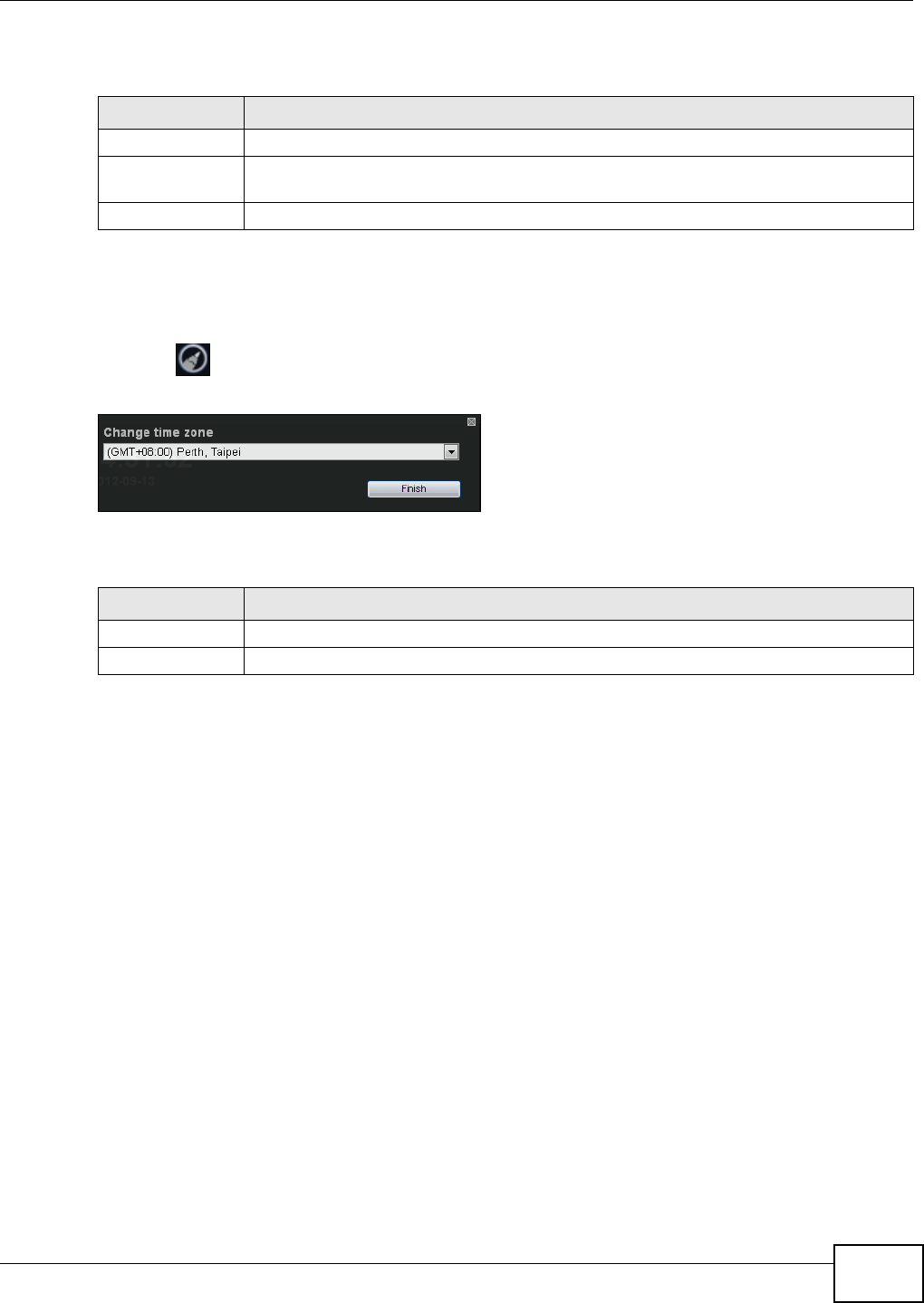
Click the icon to change the time and date display.
Figure 35 Change Time Zone
The following table describes the labels in this screen.
Note: You can also edit the timezone in Section 11.5 on page 93.
Table 22 Change Weather
LABEL DESCRIPTION
oC or oF Choose which temperature unit you want the WAP5705 to display.
Change Location Select the location for which you want to know the weather. If the city you want is not
listed, choose one that is closest to it.
Finish Click this to apply the settings and refresh the date and time display.
Table 23 Change Time Zone
LABEL DESCRIPTION
Change time zone Select the specific country whose current time and date you want the WAP5705 to display.
Finish Click this to apply the settings and refresh the weather display.

Chapter 6 The Web Configurator
WAP5705 User’s Guide
52
WAP5705 User’s Guide 53
CHAPTER 7
Tutorials
7.1 Overview
This chapter provides tutorials for your WAP5705 (in access point mode) as follows:
•Connecting to the Internet from an Access Point
•Configuring Wireless Security Using WPS
•Enabling and Configuring Wireless Security (No WPS)
•Using Multiple SSIDs on the WAP5705
This chapter provides tutorials for your WAP5705 (in client mode) as follows:
•Connecting the WAP5705 (in Client Mode) to an AP
7.2 Connecting to the Internet from an Access Point
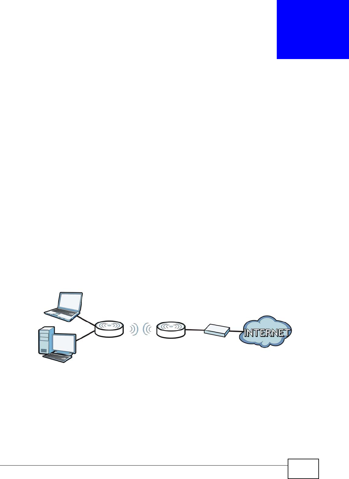
This section gives you an example of how to set up an access point (A) and wireless client (B in this
example) for wireless communication. Computers that connect to B can access the Internet
through the access point wirelessly.
Figure 36 Wireless Access Point Connection to the Internet
7.3 Configuring Wireless Security Using WPS
This section gives you an example of how to set up wireless network using WPS. This example uses
the WAP5705 in AP mode as the AP and WAP5705 in client mode as the wireless client which
connects to a notebook.
A
B

Chapter 7 Tutorials
WAP5705 User’s Guide
54
There are two WPS methods for creating a secure connection. This tutorial shows you how to do
both.
•Push But t on Configurat ion ( PBC) - create a secure wireless network simply by pressing a
button. See Section 7.3.1 on page 54.This is the easier method.
•PI N Configu rat ion - create a secure wireless network simply by entering a wireless client's PIN
(Personal Identification Number) in the WAP5705’s interface. See Section 7.3.2 on page 55. This
is the more secure method, since one device can authenticate the other.
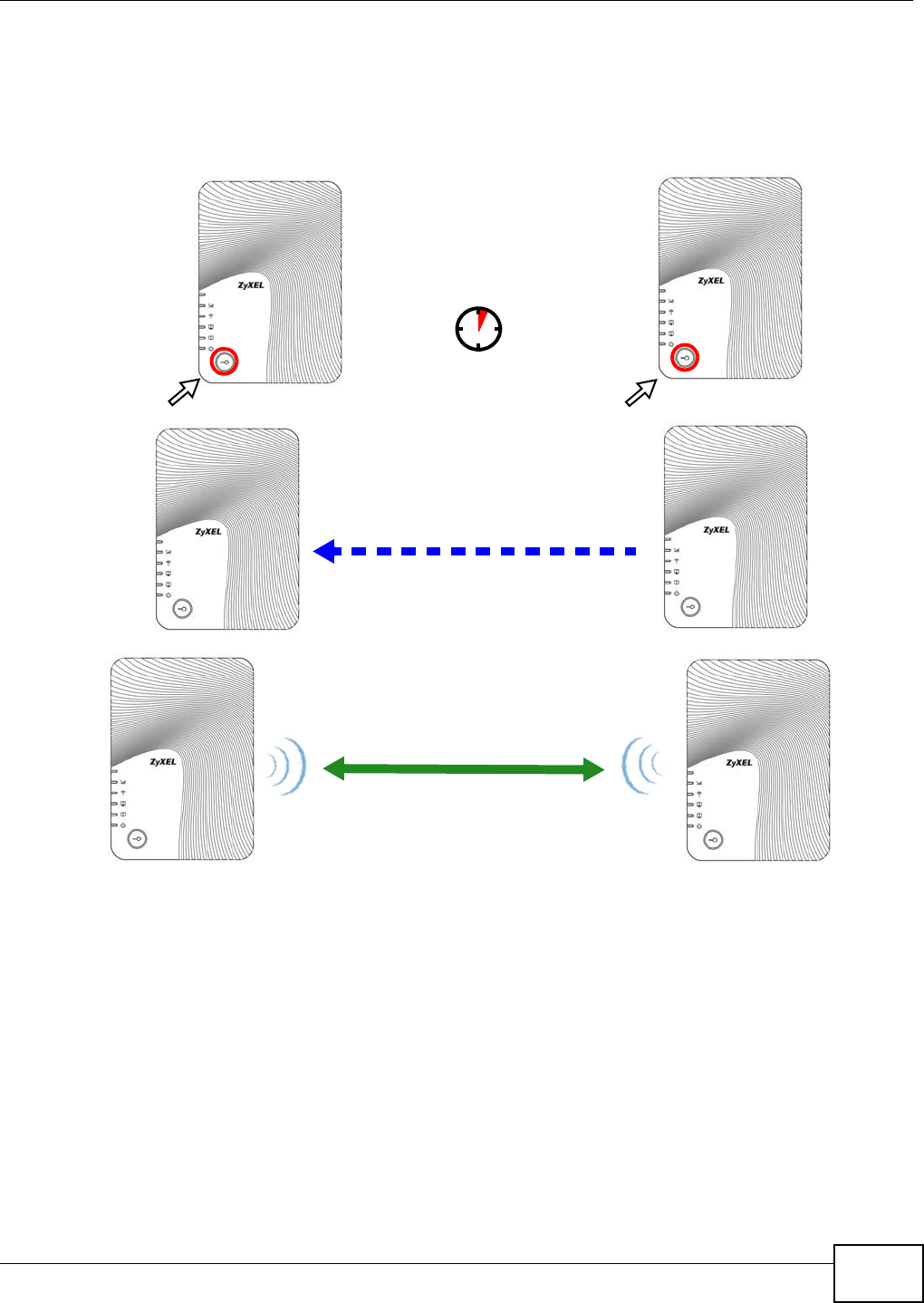
7.3.1 Push Button Configuration (PBC)
1Make sure that your WAP5705s are turned on and that they are within range of each other.
2Make sure the WPS ( ) buttons of both WAP5705s are on.
3Press the WPS buttons for more than three seconds. The WPS LEDs blink.
Note: It doesn’t matter which button is pressed first. You must press the second button
within two minutes of pressing the first one.
Note: Your WAP5705 has a WPS button located on its panel, as well as a WPS button in
its Web Configurator. Both buttons have exactly the same function; you can also
log into the Web Configurator and press the Push But t on in the AP’s
Configu r at ion > N e tw or k > W ir eless LAN > W PS St a tion screen and the PBC
St a rt button in the client’s Configurat ion > N et w ork > W ir e le ss LAN > W PS
screen.
The AP sends the proper configuration settings to the wireless client. This may take up to two
minutes. Then the wireless client is able to communicate with the AP securely.
Chapter 7 Tutorials
WAP5705 User’s Guide 55
The following figure shows you how to set up wireless network and security by pressing a button on
both AP and wireless client.
Figure 37 Example WPS Process: PBC Method
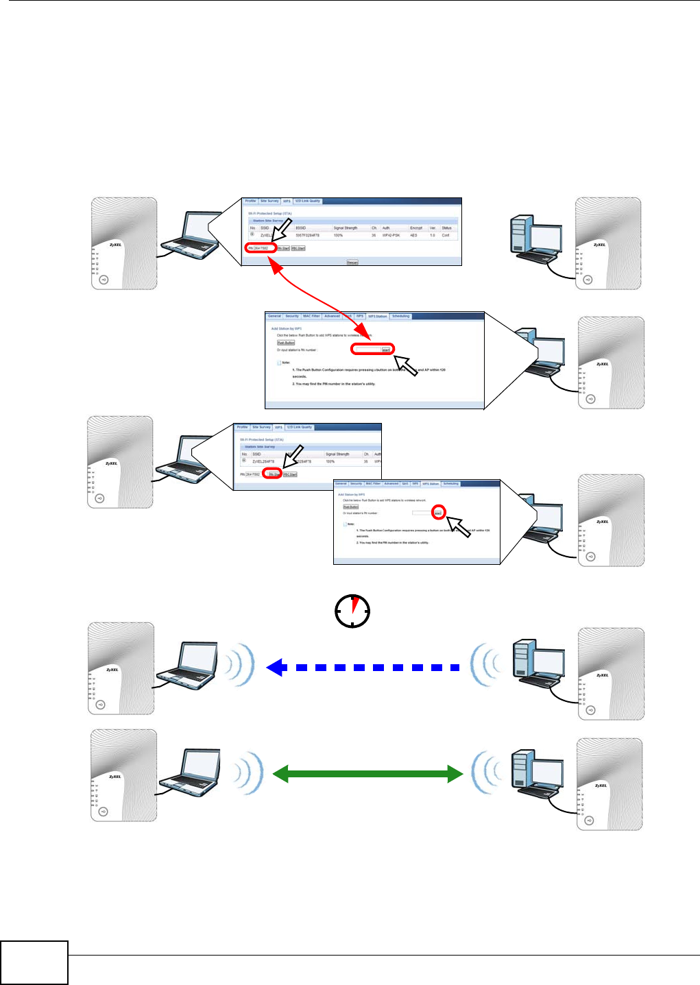
7.3.2 PIN Configuration
When you use the PIN configuration method, you need to use configuration interfaces of both AP
and client.
1Log into the client’s Web Configurator. Go to the Configur a t ion > N et w ork > W irele ss LAN >
W PS screen to get a PIN number.
2Log into the AP’s Web Configurator. Enter the client’s PIN number to the PI N field in the
Configurat ion > N e t w or k > W ireless LAN > W PS St at ion screen.
3Click the PI N St a rt button in the client’s W PS screen and the st a r t button in the AP’s W PS
Sta t ion screen within two minutes.
Client
SECURITY INFO
COMMUNICATION
WITHIN 2 MINUTES
AP
Chapter 7 Tutorials
WAP5705 User’s Guide
56
The AP authenticates the wireless client and sends the proper configuration settings to the wireless
client. This may take up to two minutes. Then the wireless client is able to communicate with the AP
securely.
The following figure shows you how to set up wireless network and security on AP and wireless
client by using PIN method.
Figure 38 Example WPS Process: PIN Method
Authentication by PIN
SECURITY INFO
WITHIN 2 MINUTES
Client
COMMUNICATION
AP
Chapter 7 Tutorials
WAP5705 User’s Guide 57
7.4 Enabling and Configuring Wireless Security (No WPS)
This example shows you how to configure wireless security settings with the following parameters
on your WAP5705.
Follow the steps below to configure the wireless settings on your WAP5705.
The instructions require that your hardware is connected (see the Quick Start Guide) and you are
logged into the Web Configurator through your LAN connection (see Section 6.2 on page 47).
1Open the W ire less LAN > Gener a l screen in the AP’s Web Configurator.
2Enter SSI D_ Ex am ple 3 as the SSID and select a channel or select Aut o Ch ann el Se lect ion to
have the WAP5705 scans for and select an available channel automatically. Click Apply.
Figure 39 Tutorial: Network > Wireless LAN > General
3Click the Se cu r it y tab.
SSI D SSID_Example3
Cha nne l Auto
Securit y WPA-PSK
(Pre-Shared Key: ThisismyWPA-PSKpre-sharedkey)
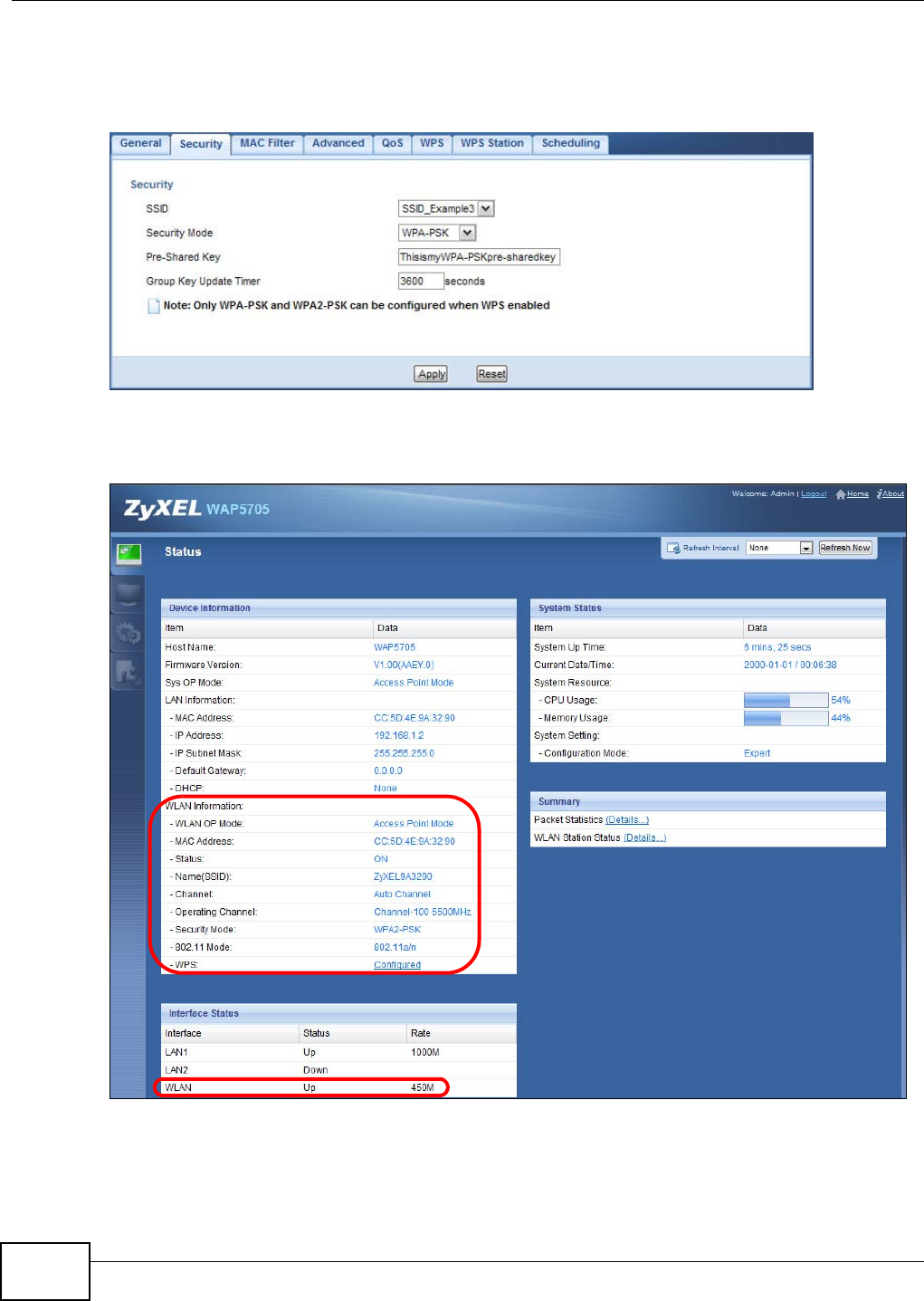
Chapter 7 Tutorials
WAP5705 User’s Guide
58
4Select the SSID (SSI D_ Exa m ple3 ) for which you want to configure the security. Set security mode
to W PA- PSK and enter Thisism yW PA- PSKpre- share dk ey in the Pr e- Shared Ke y field. Click
Apply.
Figure 40 Tutorial: Network > Wireless LAN > Security
5Open the St a t us screen. Verify your wireless and wireless security settings under De vice
I nfor m a t ion and check if the WLAN connection is up under I nt erface Stat us.
Figure 41 Tutorial: Checking Wireless Settings
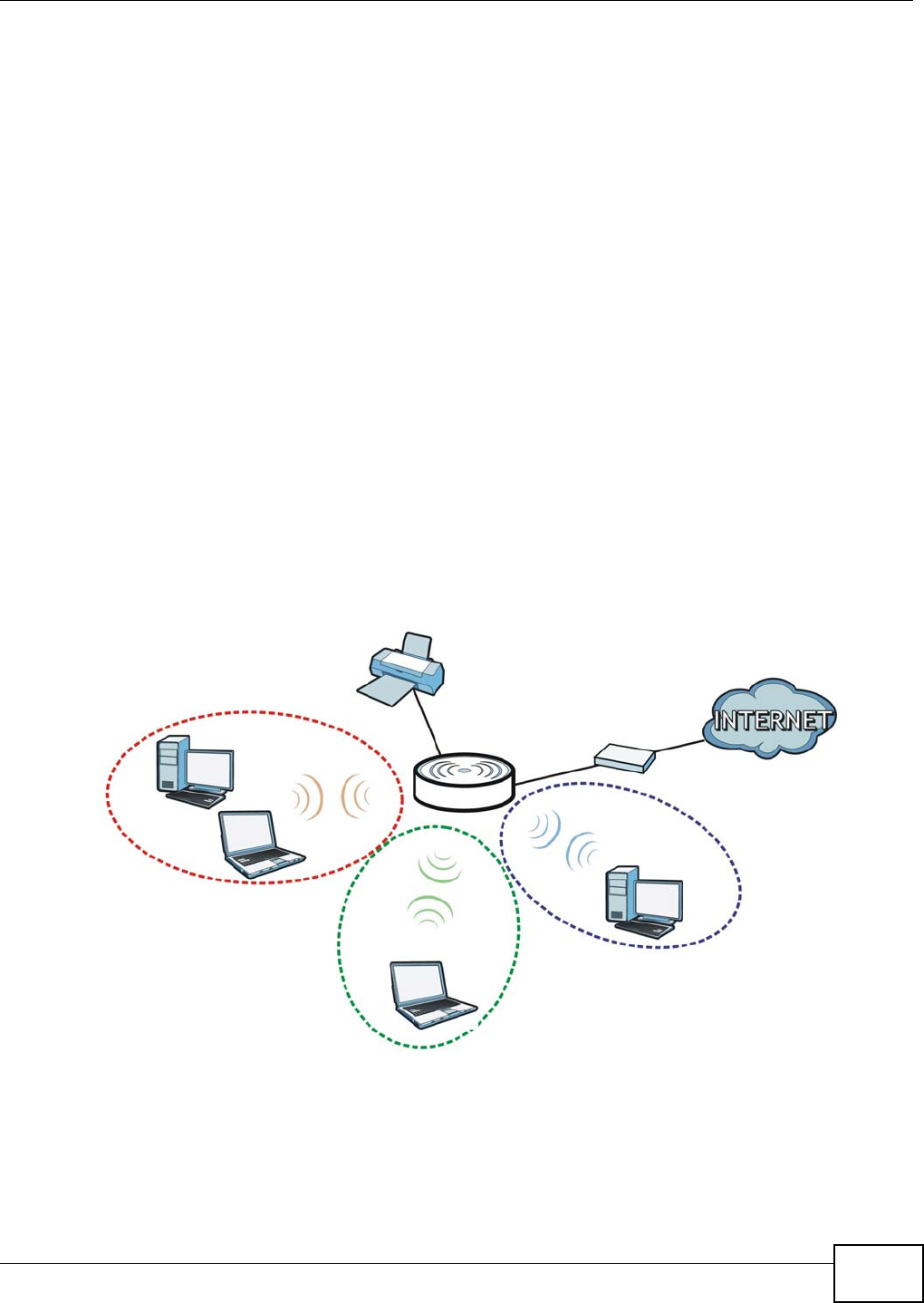
Chapter 7 Tutorials
WAP5705 User’s Guide 59
7.4.1 Configuring Your Wireless Client
Note: At the time of writing, you can only use the WAP5705 in client mode as a wireless
client to wirelessly connect to a WAP5705 in AP mode.
See Section 7.6 on page 62 for how to connect the client to your AP. If your connection is
successful, open your Internet browser and enter http://www.zyxel.com or the URL of any other
web site in the address bar. If you are able to access the web site, your wireless connection is
successfully configured.
7.5 Using Multiple SSIDs on the WAP5705
You can configure more than one SSID on a WAP5705 when it is operating in access point mode.
This allows you to configure multiple independent wireless networks on the WAP5705 as if there
were multiple APs (virtual APs). Each virtual AP has its own SSID, wireless security type and MAC
filtering settings. That is, each SSID on the WAP5705 represents a different access point/wireless
network to wireless clients in the network.
Clients can associate only with the SSIDs for which they have the correct security settings. Clients
using different SSIDs can access the Internet and the wired network behind the WAP5705 (such as
a printer), but they cannot listen to each other’s traffic.
For example, you may set up three wireless networks (A, B and C) in your office. A is for workers,
B is for guests and C is specific to a VoIP device in the meeting room.
A
B
C
SSI D_ Gue st
SSI D _ W orker
SSI D_ VoI P
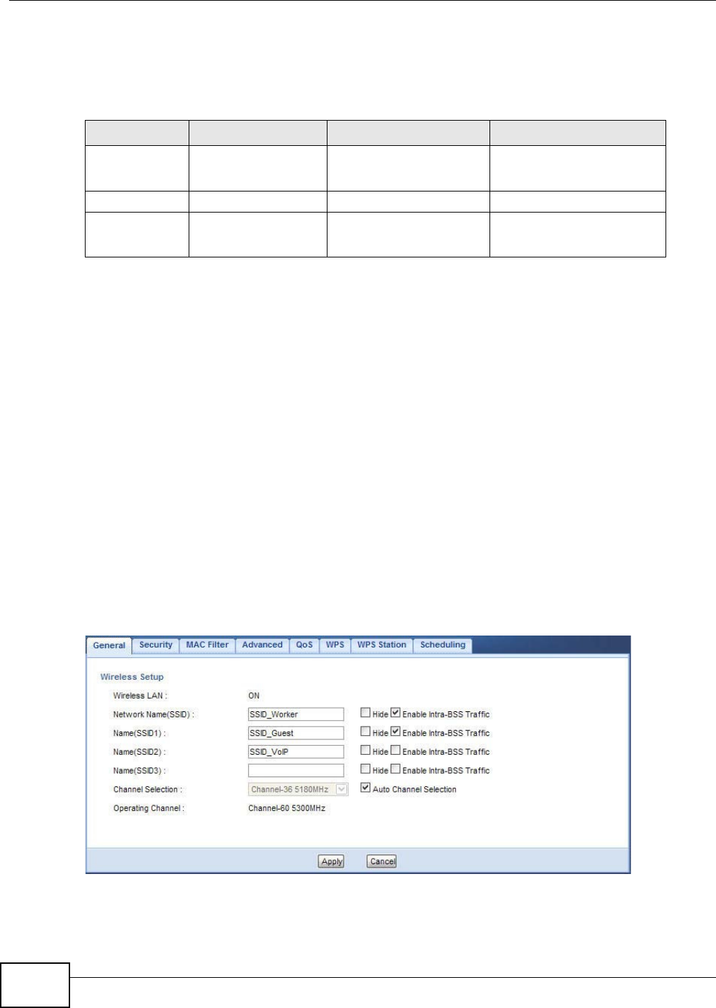
Chapter 7 Tutorials
WAP5705 User’s Guide
60
7.5.1 Configuring Security Settings of Multiple SSIDs
This example shows you how to configure the SSIDs with the following parameters on your
WAP5705 (in access point mode).
1Connect your computer to the LAN port of the WAP5705 using an Ethernet cable.
2The default IP address of the WAP5705 is “192.168.1.2”. In this case, your computer must have an
IP address in the range between “192.168.1.3” and “192.168.1.254”.
3Click St a r t > Run on your computer in Windows. Type “cmd” in the dialog box. Enter “ipconfig” to
show your computer’s IP address. If your computer’s IP address is not in the correct range then see
Appendix A on page 105 for information on changing your computer’s IP address.
4After you’ve set your computer’s IP address, open a web browser such as Internet Explorer and
type “http://192.168.1.2” as the web address in your web browser.
5Enter “1234” (default) as the password and click Login.
6Type a new password and retype it to confirm, then click Apply. Otherwise, click I gn ore.
7The Easy mode appears. Click Expert Mode in the navigation panel.
8Go to Configurat ion > N e t w ork > W ir e le ss LAN > Genera l. Configure the screen as follows. In
this example, you select Ena ble I nt ra - BSS Tr a ffic for SSID_Worker and SSID_Guest to allow
wireless clients in the same wireless network to communicate with each other. Click Apply.
SSID SECURITY TYPE KEY MAC FILTERING
SSID_Worker WPA2-PSK
WPA Compatible
DoNotStealMyWirelessNet
work
Disable
SSID_Guest Static WEP 128bit keyexample123 Disable
SSID_VoIP WPA-PSK VoIPOnly12345678 Allow
00:A0:C5:01:23:45
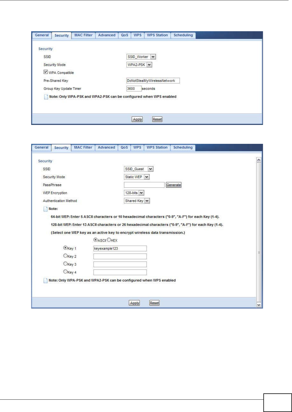
Chapter 7 Tutorials
WAP5705 User’s Guide 61
9Click the Se cu rit y tab to configure security settings for each SSID. Select SSI D _ W or ker from the
SSI D drop-down list. Configure the screen as follows. Click Apply.
10 Select SSI D_ Gue st from the SSI D drop-down list. Configure the screen as follows. Click Apply.
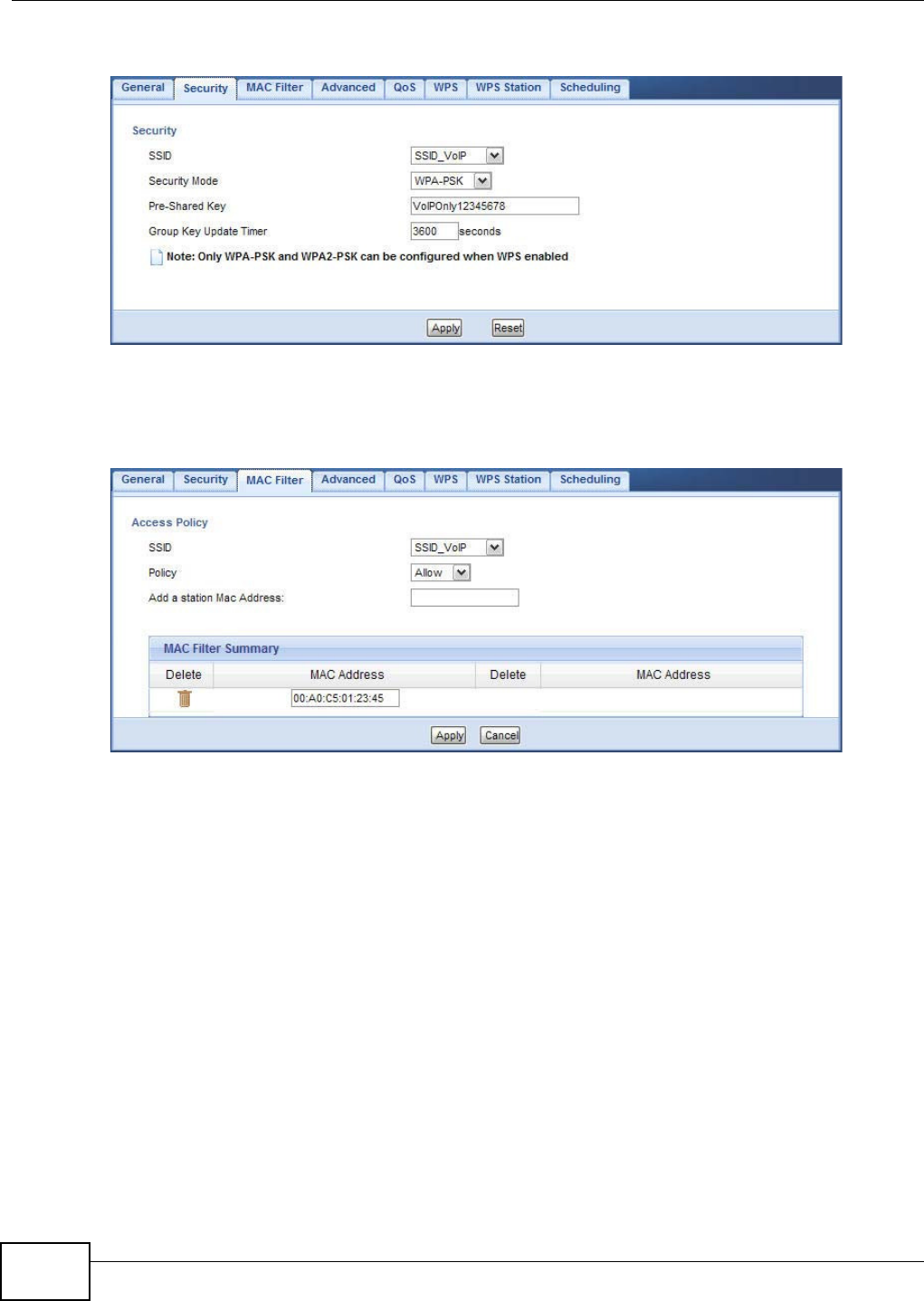
Chapter 7 Tutorials
WAP5705 User’s Guide
62
11 Select SSI D_ VoI P from the SSI D drop-down list. Configure the screen as follows. Click Apply.
12 Click the M AC Filt er tab to configure MAC filtering for the SSI D_ VoI P wireless network. Select
SSI D_ VoI P from the SSI D drop-down list and select Allow in the Policy field. Enter the VoIP
device’s MAC address in the Add a st a t ion Mac Addr e ss field and click Apply to allow only the
VoIP device to associate with the WAP5705 using this SSID.
7.6 Connecting the WAP5705 (in Client Mode) to an AP
If you have an access point with Internet access deployed in your network already, and you want to
use the WAP5705 as a wireless client to connect to the existing AP, set the WAP5705 to client mode.
The WAP5705 then acts as a wireless client. Your device, such as a computer, can connect to the
WAP5705 through a wired connection to access the Internet.
1Connect your computer to the LAN port of the WAP5705 using an Ethernet cable.
2The default IP address of the WAP5705 in client mode is “192.168.1.10”. In this case, your
computer must have an IP address in the range between “192.168.1.11” and “192.168.1.254”.
3Click St a r t > Run on your computer in Windows. Type “cmd” in the dialog box. Enter “ipconfig” to
show your computer’s IP address. If your computer’s IP address is not in the correct range then see
Appendix A on page 105 for information on changing your computer’s IP address.
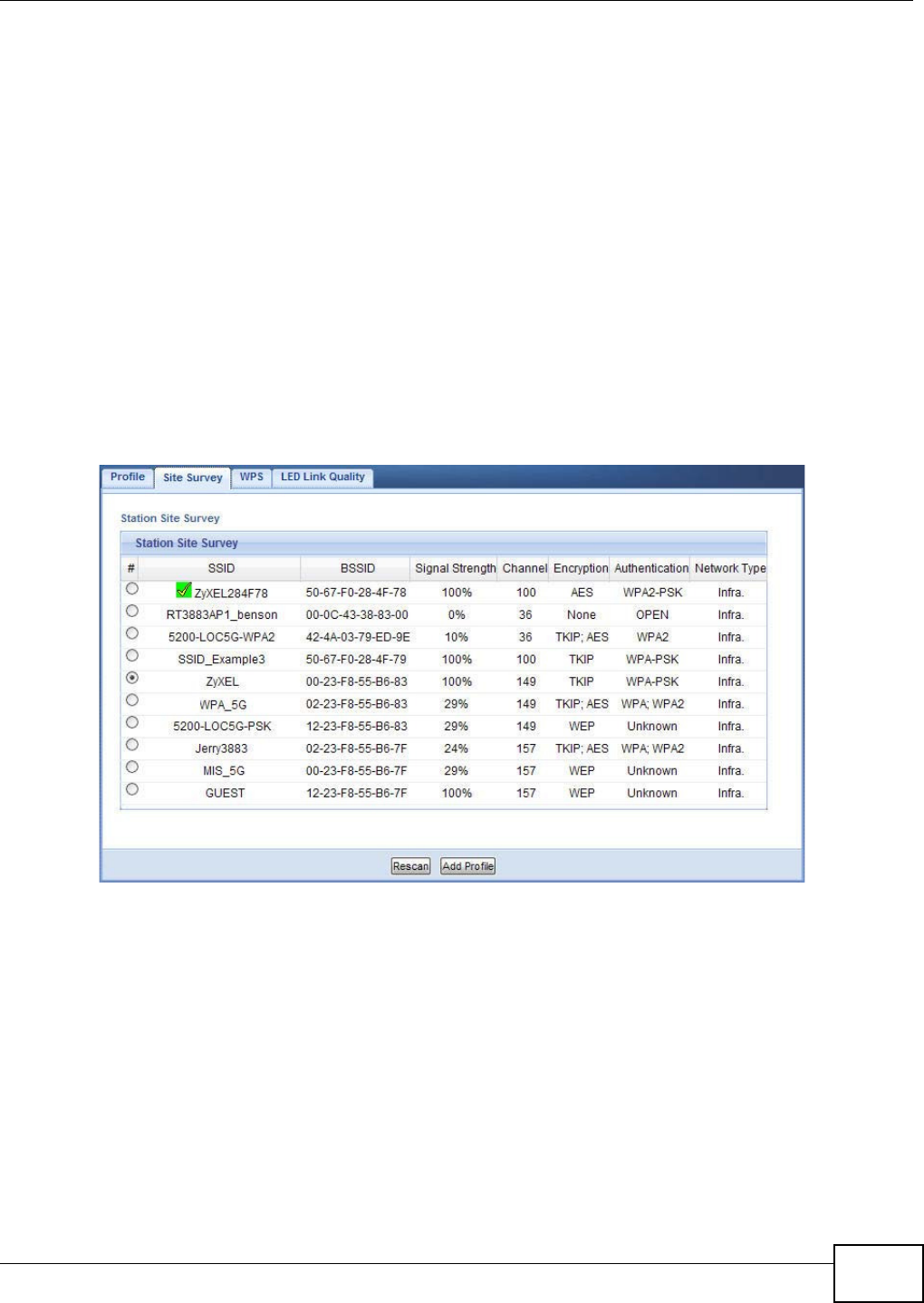
Chapter 7 Tutorials
WAP5705 User’s Guide 63
4After you’ve set your computer’s IP address, open a web browser such as Internet Explorer and
type “http://192.168.1.10” as the web address in your web browser.
5Enter “1234” (default) as the password and click Login.
6Type a new password and retype it to confirm, then click Apply. Otherwise, click I gn ore.
7The Easy mode appears. Click Expert Mode in the navigation panel.
8To connect to a specific wireless network, you can manually create a wireless profile or use the site
survey tool to associate with it.
7.6.1 Connecting to a Wireless Network Using Site Survey
1Go to Configur a t ion > N et w ork > W ireless LAN > Sit e Sur ve y. The WAP5705 automatically
scans for and connects to an available wireless network. The green check icon indicates the wireless
device to which the WAP5705 is connecting. Select an SSID’s radio button and click Add Profile to
add this wireless device to a profile.
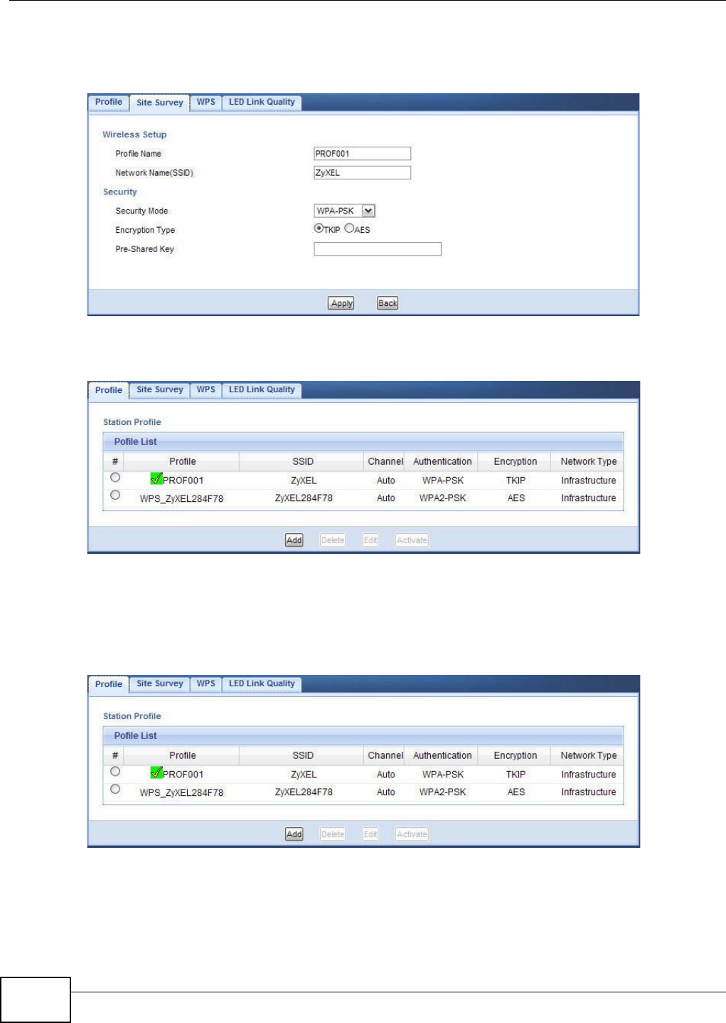
Chapter 7 Tutorials
WAP5705 User’s Guide
64
2Enter a new profile name or use the name generated automatically by the system. Enter the
security settings if requested and click Apply. The security settings must be the same as those on
the AP to which you are connecting.
3The new profile entry displays in the Profile screen. The green check icon means this profile is
active and the WAP5705 is associating with the specified wireless network.
7.6.2 Connecting to a Wireless Network Using a Profile
1Go to Configu ration > N e t w ork > W ire less LAN > Profile. Click Add to manually create a
wireless LAN profile.
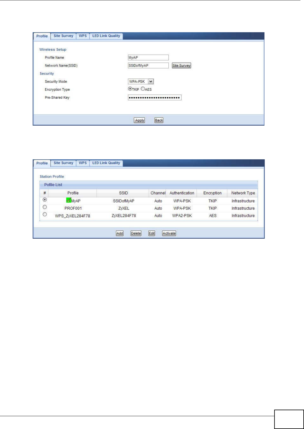
Chapter 7 Tutorials
WAP5705 User’s Guide 65
2Enter a descriptive profile name and the SSID and security settings of the wireless device to which
you want to connect. Click Apply.
3The new profile entry displays in the Pr ofile screen. To enable a profile, select the corresponding
radio button and click Act iv at e . The green check icon means this profile is active and the WAP5705
is associating with the specified wireless network.
7.6.3 Deploying the WAP5705 in your Network
1After you finish configuring the operating mode and wireless settings on the WAP5705, disconnect
the computer from the WAP5705 and change its TCP/IP settings back to the previous ones.
2Connect a device to the WAP5705, which you want to use to access the AP or wireless router
through the WAP5705. Make sure the device is set to obtain an IP address automatically.

Chapter 7 Tutorials
WAP5705 User’s Guide
66

67
PART II
Technical Reference

68

WAP5705 User’s Guide 69
CHAPTER 8
Monitor
8.1 Overview
This chapter discusses read-only information related to the device state of the WAP5705.
Note: To access the Monitor screens, you can also click the links in the Summary table of
the Status screen to view the packets sent/received as well as the status of clients
connected to the WAP5705.
8.2 What You Can Do
•Use the Vie w Log screen (Section 8.3 on page 69) to see the logs for the categories that you
selected in the Log Set t ings screen.
•Use the Log Set tings screen (Section 8.4 on page 70) to configure which logs and/or immediate
alerts the WAP5705 is to record.
•use the Pa cket St a t istics screen (Section 8.5 on page 71) to view port status, packet specific
statistics, the "system up time" and so on.
•Use the W LAN St a t ion St a t us screen (Section 8.6 on page 72) to view the wireless stations
that are currently associated to the WAP5705.
8.3 View Log
Use the View Log screen to see the logged messages for the WAP5705.
Log entries in red indicate system error logs. The log wraps around and deletes the old entries after
it fills.
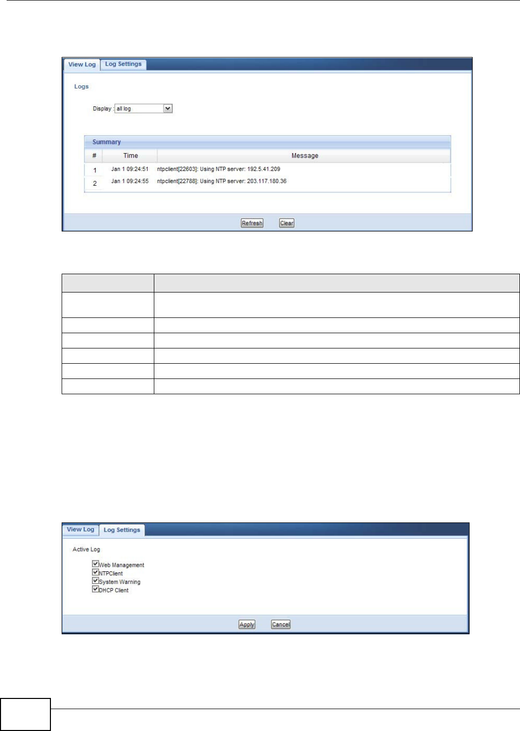
Chapter 8 Monitor
WAP5705 User’s Guide
70
Click M on it or > Log.
Figure 42 Monitor > Log
The following table describes the labels in this screen.
8.4 Log Settings
Use the Log Set t ings screen to choose which categories of events and/or alerts the WAP5705 is to
log and then display the logs. To change your WAP5705’s log settings, click Mon it or > Log > Log
Se t t in gs. The screen appears as shown.
Figure 43 Monitor > Log > Log Settings
Table 24 Monitor > Log
LABEL DESCRIPTION
Display Select a category of logs to view. Select all log to view logs from all of the log
categories that you selected in the Log Set t ings screen.
#This field is a sequential value and is not associated with a specific entry.
Time This field displays the time the log was recorded.
Message This field states the reason for the log.
Refresh Click Refre sh to renew the log screen.
Clear Click Clea r to delete all the logs.
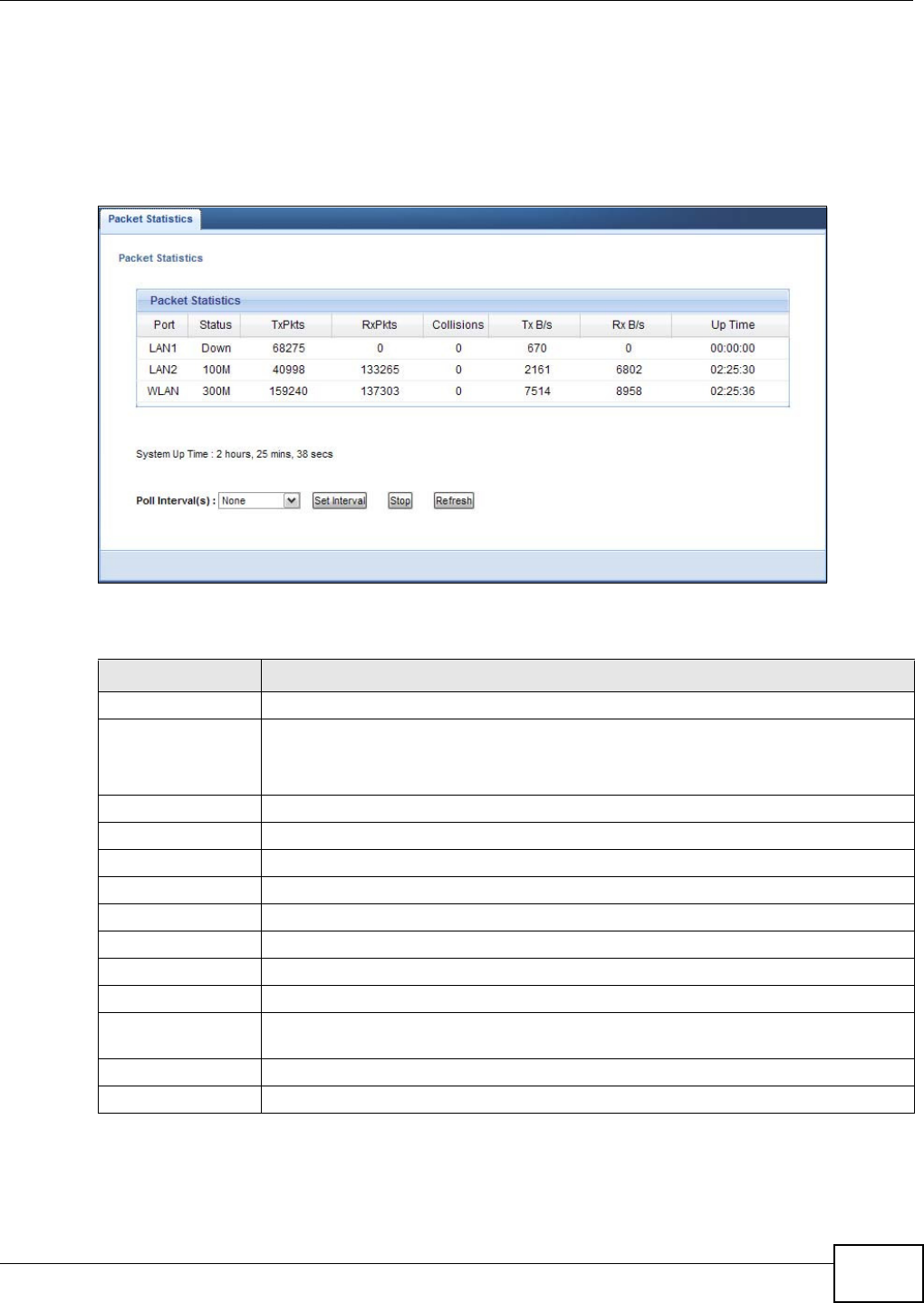
Chapter 8 Monitor
WAP5705 User’s Guide 71
8.5 Packet Statistics
Click the Pa ck et St a t istics ( Det ails...) hyperlink in the St a t us screen or M on it or > Pa cke t
St a t ist ics. Read-only information here includes port status, packet specific statistics and the
"system up time". The Poll I nt e r val( s) field is configurable and is used for refreshing the screen.
Figure 44 Monitor > Packet Statistics
The following table describes the labels in this screen.
Table 25 Monitor > Packet Statistics
LABEL DESCRIPTION
Port This is the WAP5705’s port type.
Status For the LAN ports, this displays the port speed or Dow n when the line is disconnected.
For the WLAN, it displays the maximum transmission rate when the WLAN is enabled
and Dow n when the WLAN is disabled.
TxPkts This is the number of transmitted packets on this port.
RxPkts This is the number of received packets on this port.
Collisions This is the number of collisions on this port.
Tx B/s This displays the transmission speed in bytes per second on this port.
Rx B/s This displays the reception speed in bytes per second on this port.
Up Time This is the total time the WAP5705 has been for each session.
System Up Time This is the total time the WAP5705 has been on.
Poll Interval(s) Enter the time interval in seconds for refreshing statistics in this field.
Set Interval Click this button to apply the new poll interval you entered in the Poll I nt erva l( s)
field.
Stop Click St op to stop refreshing statistics.
Refresh Click Refre sh to update this screen.
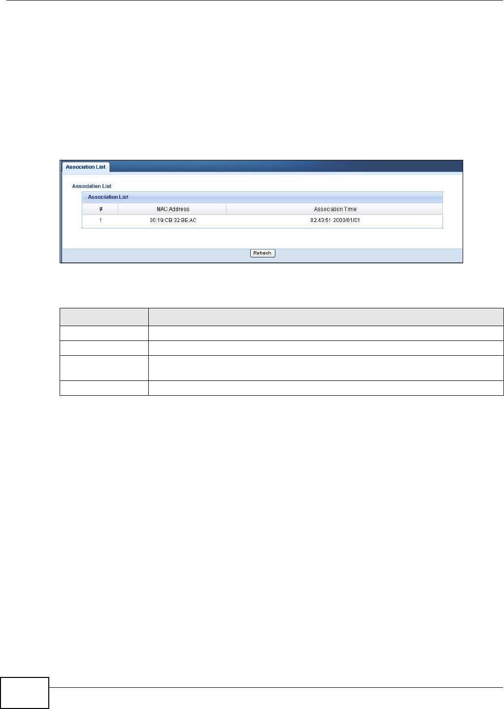
Chapter 8 Monitor
WAP5705 User’s Guide
72
8.6 WLAN Station Status
Click the W LAN Stat ion Stat us ( De t ails...) hyperlink in the St at u s screen or M on it or > W LAN
Sta t ion St at u s. View the wireless stations that are currently associated to the WAP5705 in the
Associa t ion List . Association means that a wireless client (for example, your network or computer
with a wireless network card) has connected successfully to the AP (or wireless router) using the
same SSID, channel and security settings.
Note: This screen is not available when the WAP5705 is in Client mode.
Figure 45 Monitor > WLAN Station Status > Association List
The following table describes the labels in this screen.
Table 26 Monitor > WLAN Station Status > Association List
LABEL DESCRIPTION
# This is the index number of an associated wireless station.
MAC Address This field displays the MAC address of an associated wireless station.
Association Time This field displays the time a wireless station first associated with the WAP5705’s WLAN
network.
Refresh Click Refre sh to reload the list.
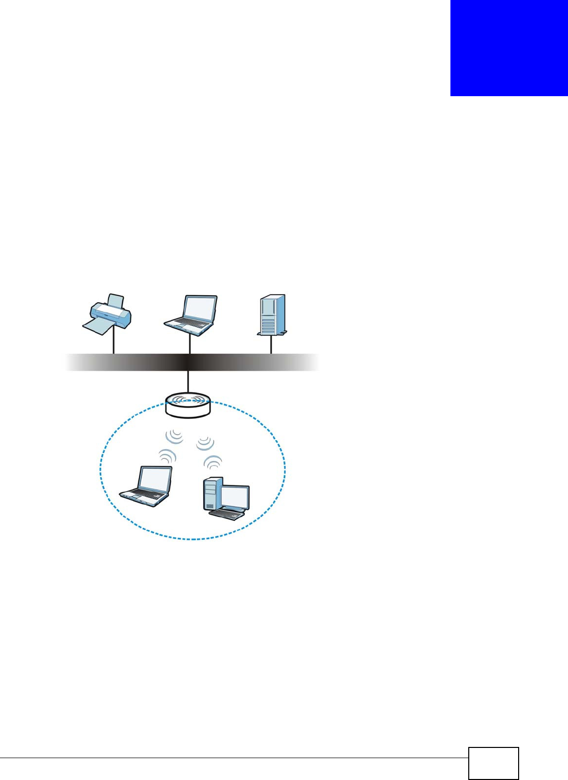
WAP5705 User’s Guide 73
CHAPTER 9
Wireless LAN
9.1 Overview
This chapter discusses how to configure the wireless network settings in your WAP5705. See the
appendices for more detailed information about wireless networks.
The following figure provides an example of a wireless network.
Figure 46 Example of a Wireless Network
The wireless network is the part in the blue circle. In this wireless network, devices A and B are
called wireless clients. The wireless clients use the access point (AP) to interact with other devices
(such as the printer) or with the Internet. Your WAP5705 is the AP.
9.2 What You Can Do
•Use the Gen e ral screen (Section 9.4 on page 76) to enter the SSID, enable intra-BSS traffic and
select the channel.
•Use the Securit y screen (Section 9.5 on page 77) to configure wireless security between the
WAP5705 and the wireless clients.
•Use the MAC Filt er screen (Section 9.6 on page 80) to allow or deny wireless stations based on
their MAC addresses from connecting to the WAP5705.
A
B

Chapter 9 Wireless LAN
WAP5705 User’s Guide
74
•Use the Adv anced screen (Section 9.7 on page 81) to configure wireless advanced features,
such as set the RTS/CTS Threshold and HT physical mode.
•Use the QoS screen (Section 9.8 on page 82) to enable Wifi MultiMedia Quality of Service
(WMMQoS). This allows the WAP5705 to automatically set priority levels to services, such as e-
mail, VoIP, chat, and so on.
•Use the W PS screen (Section 9.9 on page 83) to quickly set up a wireless network with strong
security, without having to configure security settings manually.
•Use the W PS Stat ion screen (Section 9.10 on page 84) to add a wireless station using WPS.
•Use the Scheduling screen (Section 9.11 on page 85) to set the times your wireless LAN is
turned on and off.
9.3 What You Should Know
Every wireless network must follow these basic guidelines.
• Every wireless client in the same wireless network must use the same SSID.
The SSID is the name of the wireless network. It stands for Service Set IDentity.
• If two wireless networks overlap, they should use different channels.
Like radio stations or television channels, each wireless network uses a specific channel, or
frequency, to send and receive information.
• Every wireless client in the same wireless network must use security compatible with the AP.
Security stops unauthorized devices from using the wireless network. It can also protect the
information that is sent in the wireless network.
9.3.1 Wireless Security Overview
The following sections introduce different types of wireless security you can set up in the wireless
network.
9.3.1.1 SSID
Normally, the AP acts like a beacon and regularly broadcasts the SSID in the area. You can hide the
SSID instead, in which case the AP does not broadcast the SSID. In addition, you should change
the default SSID to something that is difficult to guess.
This type of security is fairly weak, however, because there are ways for unauthorized devices to
get the SSID. In addition, unauthorized devices can still see the information that is sent in the
wireless network.
9.3.1.2 MAC Address Filter
Every wireless client has a unique identification number, called a MAC address.1 A MAC address is
usually written using twelve hexadecimal characters2; for example, 00A0C5000002 or
00:A0:C5:00:00:02. To get the MAC address for each wireless client, see the appropriate User’s
Guide or other documentation.
1. Some wireless devices, such as scanners, can detect wireless networks but cannot use wireless networks. These kinds
of wireless devices might not have MAC addresses.
2. Hexadecimal characters are 0, 1, 2, 3, 4, 5, 6, 7, 8, 9, A, B, C, D, E, and F.

Chapter 9 Wireless LAN
WAP5705 User’s Guide 75
You can use the MAC address filter to tell the AP which wireless clients are allowed or not allowed to
use the wireless network. If a wireless client is allowed to use the wireless network, it still has to
have the correct settings (SSID, channel, and security). If a wireless client is not allowed to use the
wireless network, it does not matter if it has the correct settings.
This type of security does not protect the information that is sent in the wireless network.
Furthermore, there are ways for unauthorized devices to get the MAC address of an authorized
wireless client. Then, they can use that MAC address to use the wireless network.
9.3.1.3 Encryption
Wireless networks can use encryption to protect the information that is sent in the wireless
network. Encryption is like a secret code. If you do not know the secret code, you cannot
understand the message.
The types of encryption you can choose depend on the type of user authentication.
Usually, you should set up the strongest encryption that every wireless client in the wireless
network supports. Suppose the wireless network has two wireless clients. Device A only supports
WEP, and device B supports WEP and WPA-PSK. Therefore, you should set up W EP in the wireless
network.
Note: It is recommended that wireless networks use W PA- PSK or stronger encryption.
IEEE 802.1x and WEP encryption are better than none at all, but it is still possible
for unauthorized devices to figure out the original information pretty quickly.
When you select W PA2 - PSK in your WAP5705, you can also select an option (W PA Com pat ible )
to support WPA as well. In this case, if some wireless clients support WPA and some support WPA2,
you should set up W PA2 - PSK (depending on the type of wireless network login) and select the
W PA Com pat ible option in the WAP5705.
Many types of encryption use a key to protect the information in the wireless network. The longer
the key, the stronger the encryption. Every wireless client in the wireless network must have the
same key.
9.3.1.4 WPS
WiFi Protected Setup (WPS) is an industry standard specification, defined by the WiFi Alliance. WPS
allows you to quickly set up a wireless network with strong security, without having to configure
security settings manually. Depending on the devices in your network, you can either press a
button (on the device itself, or in its configuration utility) or enter a PIN (Personal Identification
Number) in the devices. Then, they connect and set up a secure network by themselves. See how
to set up a secure wireless network using WPS in the Section 7.3 on page 53.
Table 27 Types of Encryption for Each Type of Authentication
NO AUTHENTICATION
W eak est No Security
WEP
WPA-PSK
St r on ge st WPA2-PSK
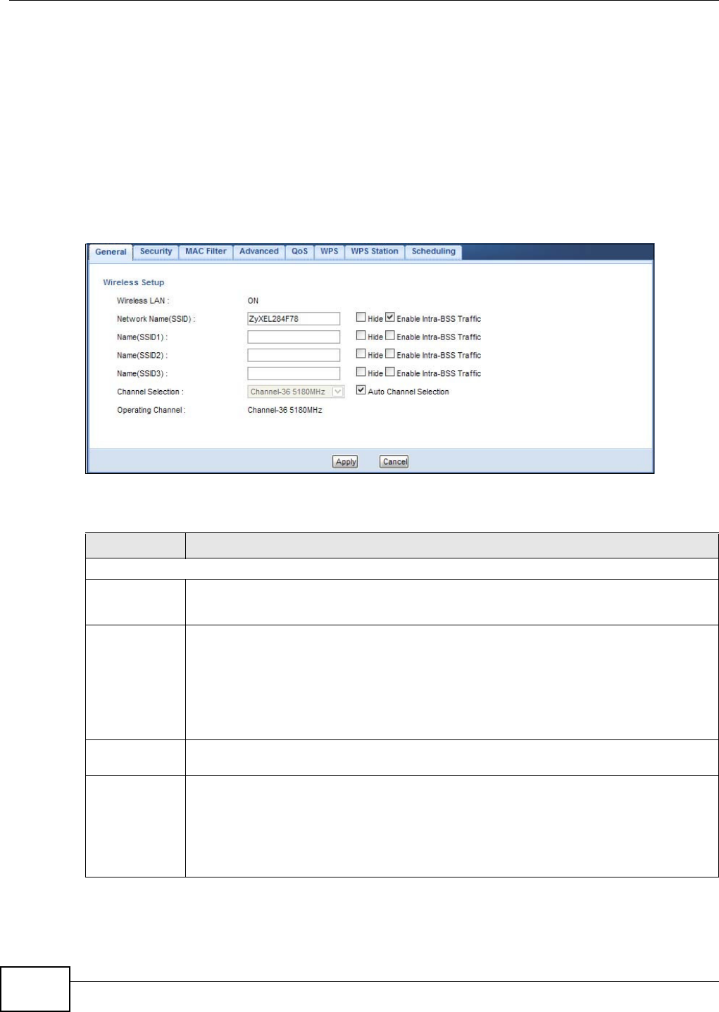
Chapter 9 Wireless LAN
WAP5705 User’s Guide
76
9.4 General Wireless LAN Screen
Use this screen to enter the SSID, select the channel and enable intra-BSS traffic.
Note: If you are configuring the WAP5705 from a computer connected to the wireless LAN
and you change the WAP5705’s SSID, channel or security settings, you will lose
your wireless connection when you press Apply to confirm. You must then change
the wireless settings of your computer to match the WAP5705’s new settings.
Click N e t w o rk > W ir e le ss LAN to open the Ge ner a l screen.
Figure 47 Network > Wireless LAN > General
The following table describes the general wireless LAN labels in this screen.
Table 28 Network > Wireless LAN > General
LABEL DESCRIPTION
Wireless Setup
Wireless LAN This is turned on by default.
The current wireless state is reflected in this field.
Network
Name(SSID)
or
Name(SSID1~
3)
The SSID (Service Set IDentity) identifies the Service Set with which a wireless client is
associated. Enter a descriptive name (up to 32 printable characters found on a typical
English language keyboard) for the wireless LAN.
You can configure up to four SSIDs to enable multiple BSSs (Basic Service Sets) on the
WAP5705. This allows you to use one access point to provide several BSSs simutaneously.
You can then assign varying security types to different SSIDs. Wireless clients can use
different SSIDs to associate with the same access point.
Hide SSID Select this check box to hide the SSID in the outgoing beacon frame so a wireless client
cannot obtain the SSID through scanning using a site survey tool.
Enable
Intra-BSS
Traffic
A Basic Service Set (BSS) exists when all communications between wireless clients or
between a wireless client and a wired network client go through one access point (AP).
Intra-BSS traffic is traffic between wireless clients in the BSS. When Intra-BSS is enabled,
wireless clients can access the wired network and communicate with each other. When
Intra-BSS is disabled, wireless clients can still access the wired network but cannot
communicate with each other.
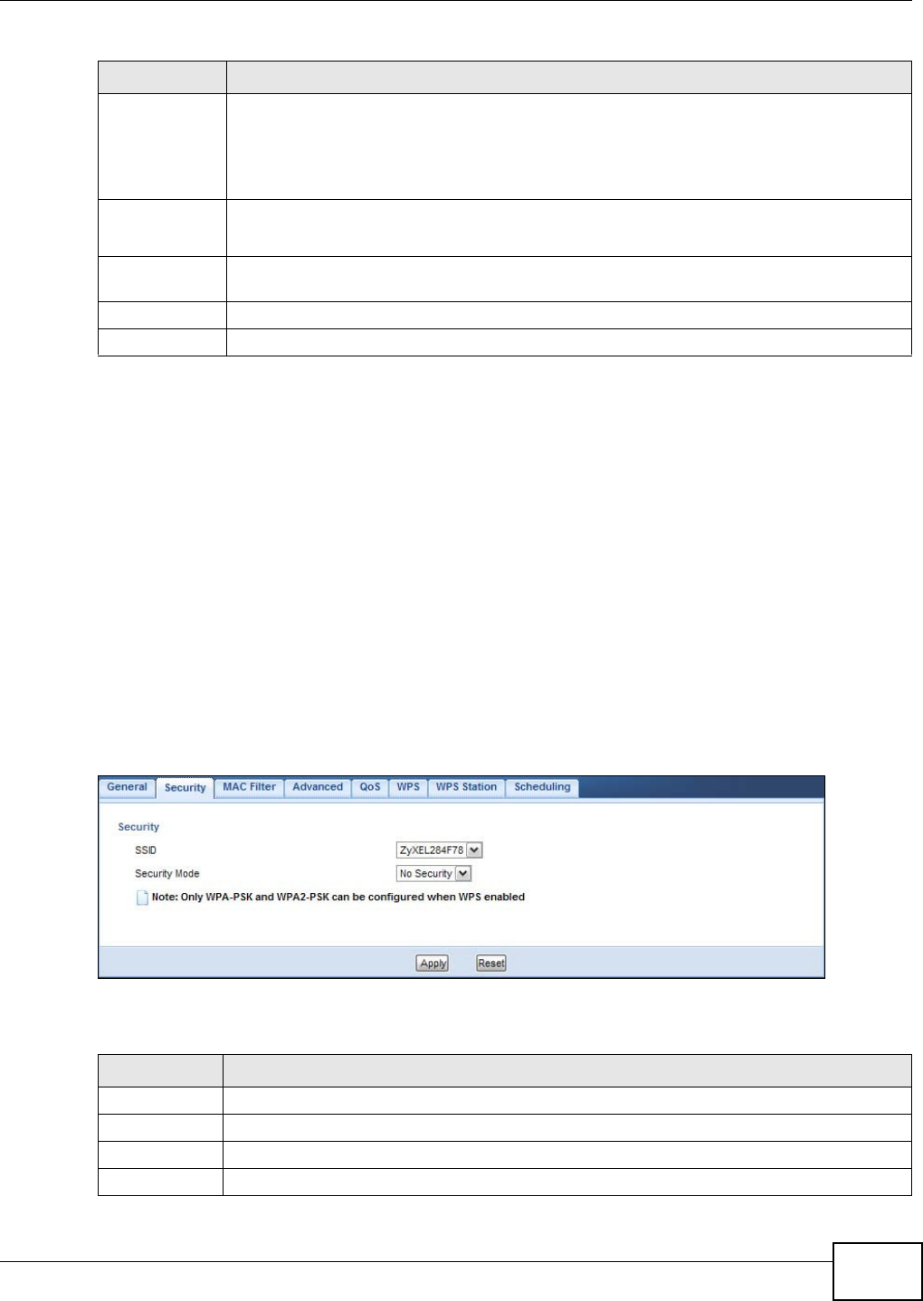
Chapter 9 Wireless LAN
WAP5705 User’s Guide 77
9.5 Wireless Security Screen
Use this screen to select the wireless security mode for each SSID. Click N et w or k > W irele ss LAN
> Se cu rit y to open the Securit y screen. The screen varies depending on what you select in the
Securit y M ode field.
9.5.1 No Security
Select N o Se cur it y to allow wireless clients to communicate with the access points without any
data encryption.
Note: If you do not enable any wireless security on your WAP5705, your network is
accessible to any wireless networking device that is within range.
Figure 48 Network > Wireless LAN > Security: No Security
The following table describes the labels in this screen.
Channel
Selection
Set the operating frequency/channel depending on your particular region.
Select a channel from the drop-down list box. The options vary depending on the frequency
band and the country you are in.
This option is only available if Aut o Cha nne l Sele ct ion is disabled.
Auto
Channel
Selection
Select the check box to have the WAP5705 automatically scan for and select a channel
which is not used by another device.
Operating
Channel
This displays the channel the WAP5705 is currently using.
Apply Click Apply to save your changes back to the WAP5705.
Cancel Click Cancel to reload the previous configuration for this screen.
Table 28 Network > Wireless LAN > General
LABEL DESCRIPTION
Table 29 Network > Wireless LAN > Security: No Security
LABEL DESCRIPTION
SSID Select the SSID for which you want to configure the security.
Security Mode Choose No Security from the drop-down list box.
Apply Click Apply to save your changes back to the WAP5705.
Cancel Click Cancel to reload the previous configuration for this screen.
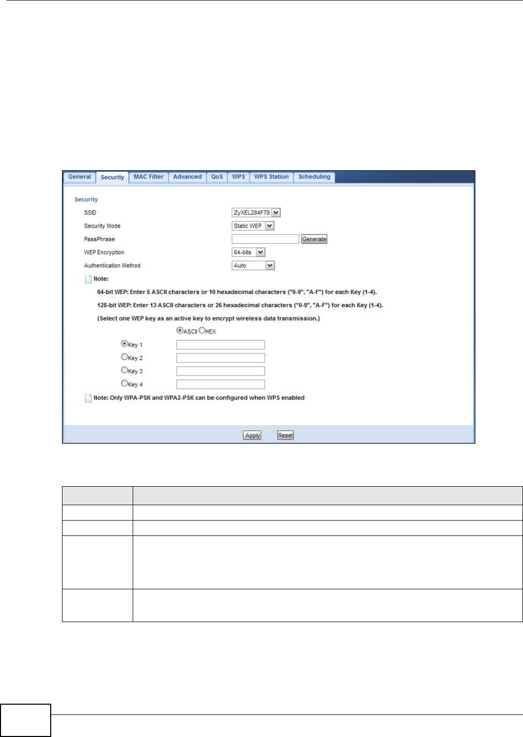
Chapter 9 Wireless LAN
WAP5705 User’s Guide
78
9.5.2 WEP Encryption
WEP encryption scrambles the data transmitted between the wireless stations and the access points
to keep network communications private. It encrypts unicast and multicast communications in a
network. Both the wireless stations and the access points must use the same WEP key.
Your WAP5705 allows you to configure up to four 64-bit or 128-bit WEP keys but only one key can
be enabled at any one time.
Select St a t ic W EP from the Securit y M ode list.
Figure 49 Network > Wireless LAN > Security: Static WEP
The following table describes the wireless LAN security labels in this screen.
Table 30 Network > Wireless LAN > Security: Static WEP
LABEL DESCRIPTION
SSID Select the SSID for which you want to configure the security.
Security Mode Select St a t ic W EP to enable data encryption.
PassPhrase Enter a Passphrase (up to 26 printable characters) and click Generate.
A passphrase functions like a password. In WEP security mode, it is further converted by the
WAP5705 into a complicated string that is referred to as the “key”. This key is requested
from all devices wishing to connect to a wireless network.
WEP
Encryption
Select 6 4 - b it s or 1 2 8 - bits.
This dictates the length of the security key that the network is going to use.
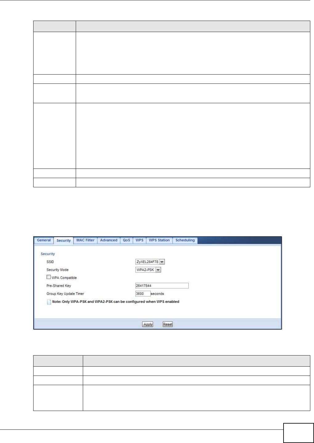
Chapter 9 Wireless LAN
WAP5705 User’s Guide 79
9.5.3 WPA-PSK/WPA2-PSK
Select W PA- PSK or W PA2 - PSK from the Securit y M ode list.
Figure 50 Network > Wireless LAN > Security: WPA-PSK/WPA2-PSK
The following table describes the labels in this screen.
Authentication
Method
Select Aut o or Sh ar ed Ke y from the drop-down list box.
This field specifies whether the wireless clients have to provide the WEP key to login to the
wireless client. Keep this setting at Aut o unless you want to force a key verification before
communication between the wireless client and the WAP5705 occurs.
Select Sha re d Ke y to force the clients to provide the WEP key prior to communication.
ASCII Select this option in order to enter ASCII characters as WEP key.
Hex Select this option in order to enter hexadecimal characters as a WEP key.
The preceding "0x", that identifies a hexadecimal key, is entered automatically.
Key 1 to Key 4 The WEP keys are used to encrypt data. Both the WAP5705 and the wireless stations must
use the same WEP key for data transmission.
If you chose 6 4 - bit W EP, then enter any 5 ASCII characters or 10 hexadecimal characters
("0-9", "A-F").
If you chose 1 2 8 - bit W EP, then enter 13 ASCII characters or 26 hexadecimal characters
("0-9", "A-F").
You must configure at least one key, only one key can be activated at any one time. The
default key is key 1.
Apply Click Apply to save your changes back to the WAP5705.
Cancel Click Cancel to reload the previous configuration for this screen.
Table 30 Network > Wireless LAN > Security: Static WEP
LABEL DESCRIPTION
Table 31 Network > Wireless LAN > Security: WPA-PSK/WPA2-PSK
LABEL DESCRIPTION
SSID Select the SSID for which you want to configure the security.
Security Mode Select W PA- PSK or W PA2 - PSK to enable data encryption.
WPA Compatible This field appears when you choose W PA2 - PSK as the Securit y Mode .
Check this field to allow wireless devices using W PA- PSK security mode to connect to
your WAP5705.
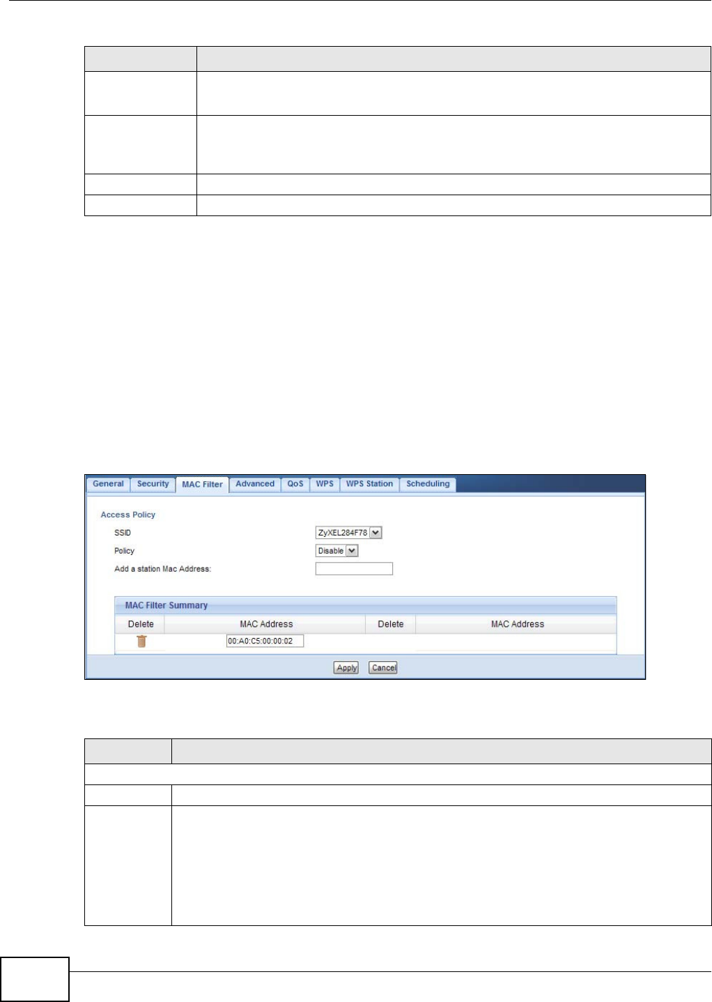
Chapter 9 Wireless LAN
WAP5705 User’s Guide
80
9.6 MAC Filter
The MAC filter screen allows you to configure the WAP5705 to give exclusive access to devices
(Allow) or exclude devices from accessing the WAP5705 (Deny). Every Ethernet device has a
unique MAC (Media Access Control) address. The MAC address is assigned at the factory and
consists of six pairs of hexadecimal characters, for example, 00:A0:C5:00:00:02. You need to know
the MAC address of the devices to configure this screen.
To change your WAP5705’s MAC filter settings, click N e t w o rk > W ir ele ss LAN > MAC Filt er. The
screen appears as shown.
Figure 51 Network > Wireless LAN > MAC Filter
The following table describes the labels in this menu.
Pre-Shared Key W PA- PSK/W PA2 - PSK uses a simple common password for authentication.
Type a pre-shared key from 8 to 63 case-sensitive keyboard characters.
Group Key
Update Timer
The Gr oup Key Updat e Tim er is the rate at which the AP sends a new group key out to
all clients.
The default is 3 6 0 0 seconds (60 minutes).
Apply Click Apply to save your changes back to the WAP5705.
Cancel Click Cancel to reload the previous configuration for this screen.
Table 31 Network > Wireless LAN > Security: WPA-PSK/WPA2-PSK
LABEL DESCRIPTION
Table 32 Network > Wireless LAN > MAC Filter
LABEL DESCRIPTION
Access Policy
SSID Select the SSID for which you want to configure MAC filtering.
Policy Define the filter action for the list of MAC addresses in the MAC Addre ss table.
Select Disa ble to deactivate the MAC filtering rule you configure below.
Select Allow to permit access to the WAP5705, MAC addresses not listed will be denied access
to the WAP5705.
Select Re j e ct to block access to the WAP5705, MAC addresses not listed will be allowed to
access the WAP5705
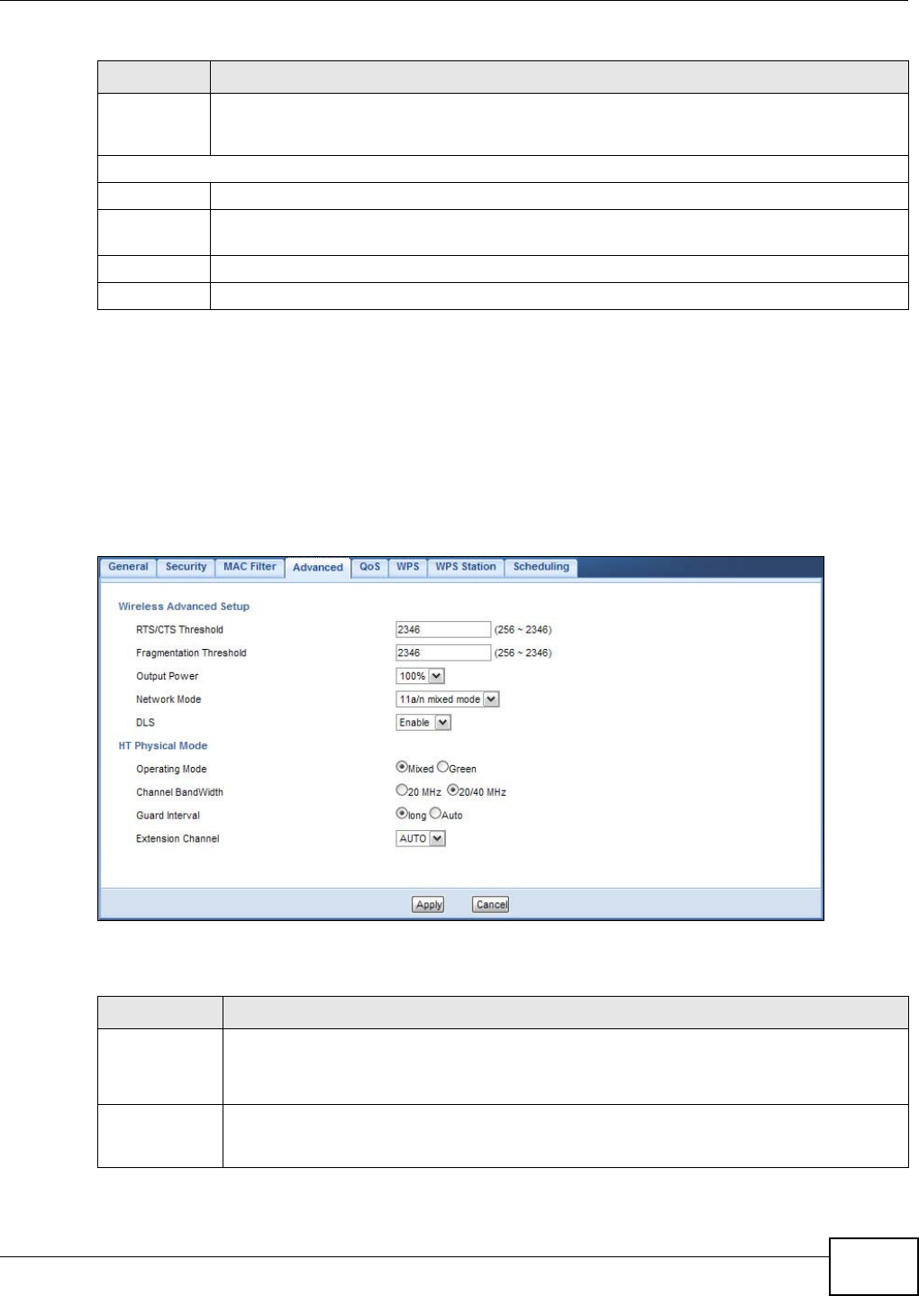
Chapter 9 Wireless LAN
WAP5705 User’s Guide 81
9.7 Wireless LAN Advanced Screen
Use this screen to allow wireless advanced features, such as the output power, RTS/CTS Threshold
and high-throughput physical mode settings.
Click N e t w o rk > W ir e le ss LAN > Adva nced. The screen appears as shown.
Figure 52 Network > Wireless LAN > Advanced
The following table describes the labels in this screen.
Add a station
Mac Address
Enter the MAC addresses of the wireless station that are allowed or denied access to the
WAP5705 in these address fields. Enter the MAC addresses in a valid MAC address format, that
is, six hexadecimal character pairs, for example, 12:34:56:78:9a:bc.
MAC Filter Summary
Delete Click the delete icon to remove the MAC address from the list.
MAC Address This is the MAC address of the wireless station that are allowed or denied access to the
WAP5705.
Apply Click Apply to save your changes back to the WAP5705.
Cancel Click Cancel to reload the previous configuration for this screen.
Table 32 Network > Wireless LAN > MAC Filter
LABEL DESCRIPTION
Table 33 Network > Wireless LAN > Advanced
LABEL DESCRIPTION
RTS/CTS
Threshold
Data with its frame size larger than this value will perform the RTS (Request To Send)/CTS
(Clear To Send) handshake.
Enter a value between 2 5 6 and 2 3 4 6 .
Fragmentation
Threshold
The threshold (number of bytes) for the fragmentation boundary for directed messages. It is
the maximum data fragment size that can be sent. Enter an even number between 2 5 6 and
2 3 4 6 .

Chapter 9 Wireless LAN
WAP5705 User’s Guide
82
9.8 Quality of Service (QoS) Screen
The QoS screen allows you to automatically give a service (such as VoIP and video) a priority level.
Click N e t w o rk > W ir e le ss LAN > QoS. The following screen appears.
Figure 53 Network > Wireless LAN > QoS
Output Power Set the output power of the WAP5705 in this field. If there is a high density of APs in an
area, decrease the output power of the WAP5705 to reduce interference with other APs.
Select one of the following 1 0 0 % , 9 0 % , 7 5 % , 5 0 % , 2 5 % or 1 0 % . See the product
specifications for more information on your WAP5705’s output power.
Network Mode This displays 1 1 a/ n m ix ed m od e and only IEEE802.11a or IEEE802.11n compliant WLAN
devices can associate with the WAP5705.
DLS Select Ena ble d to activate IEEE 802.11e Direct Link Setup (DLS) on the WAP5705. This
allows all wireless clients that support DLS and are in the same wireless network (BSS) to
communicate with each other directly. Traffic within the BSS can be sent from one client to
another without going through the access point (WAP5705).
HT (High Throughput) Physical Mode - Use the fields below to configure the 802.11 wireless environment of
your WAP5705.
Operating
Mode
Choose this according to the wireless mode(s) used in your network.
M ix e d - Select this if the wireless clients in your network use different wireless modes (for
example, IEEE 802.11a and IEEE 802.1n modes).
Green - Select this if the wireless clients in your network uses only one type of wireless
mode (for example, IEEEE 802.11 n only).
Channel
Bandwidth
Select the channel bandwidth you want to use for your wireless network.
It is recommended that you select 2 0 / 4 0 M H z.
Select 2 0 M Hz if you want to lessen radio interference with other wireless devices in your
neighborhood.
Guard Interval Select Au t o to increase data throughput. However, this may make data transfer more prone
to errors.
Select Long to prioritize data integrity. This may be because your wireless network is busy
and congested or the WAP5705 is located in an environment prone to radio interference.
Extension
Channel
This is set to Au t o by default.
If you select 2 0/ 4 0 M Hz as your Chann el Ba ndw idt h, the extension channel enables the
WAP5705 to get higher data throughput. This also lowers radio interference and traffic.
Apply Click Apply to save your changes back to the WAP5705.
Cancel Click Cancel to reload the previous configuration for this screen.
Table 33 Network > Wireless LAN > Advanced
LABEL DESCRIPTION
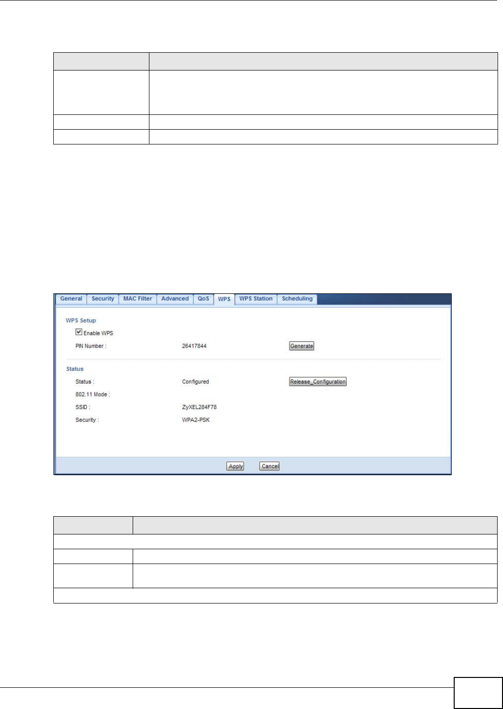
Chapter 9 Wireless LAN
WAP5705 User’s Guide 83
The following table describes the labels in this screen.
9.9 WPS Screen
Use this screen to enable/disable WPS, view or generate a new PIN number and check current WPS
status. To open this screen, click N e t w ork > W irele ss LAN > W PS tab.
Note: With WPS, wireless clients can only connect to the wireless network using the first
SSID on the WAP5705.
Figure 54 Network > Wireless LAN > WPS
The following table describes the labels in this screen.
Table 34 Network > Wireless LAN > QoS
LABEL DESCRIPTION
Enable WMM QoS Check this to have the WAP5705 automatically give a service a priority level according
to the ToS value in the IP header of packets it sends. WMM QoS (Wifi MultiMedia
Quality of Service) gives high priority to voice and video, which makes them run more
smoothly.
Apply Click Apply to save your changes to the WAP5705.
Cancel Click Cancel to reload the previous configuration for this screen.
Table 35 Network > Wireless LAN > WPS
LABEL DESCRIPTION
WPS Setup
Enable WPS Select this to enable the WPS feature.
PIN Number This displays a PIN number last time system generated. Click Ge ne r a t e to generate a
new PIN number.
Status
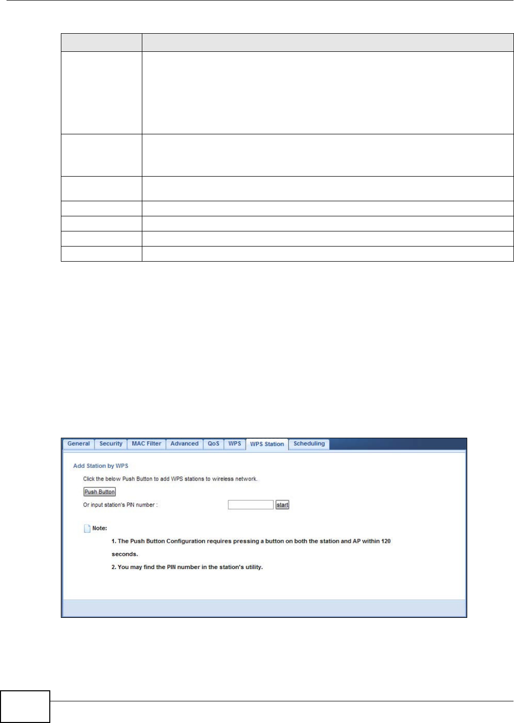
Chapter 9 Wireless LAN
WAP5705 User’s Guide
84
9.10 WPS Station Screen
Use this screen when you want to add a wireless station using WPS. To open this screen, click
N e t w o rk > W ir e less LAN > W PS St at ion tab.
Note: After you click Push Bu t ton on this screen, you have to press a similar button in
the wireless station utility within 2 minutes. To add the second wireless station, you
have to press these buttons on both device and the wireless station again after the
first 2 minutes.
Figure 55 Network > Wireless LAN > WPS Station
Status This displays Configu re d when the WAP5705 has connected to a wireless network using
WPS or when Ena ble W PS is selected and wireless or wireless security settings have
been changed. The current wireless and wireless security settings also appear in the
screen.
This displays Un configur ed if WPS is disabled and there are no wireless or wireless
security changes on the WAP5705 or you click Re le a se _ Co nf igu ra t ion to remove the
configured wireless and wireless security settings.
Release
Configuration
This button is only available when the WPS status displays Con figur ed .
Click this button to remove all configured wireless and wireless security settings for WPS
connections on the WAP5705.
802.11 Mode This is the 802.11 mode used. Only compliant WLAN devices can associate with the
WAP5705.
SSID This is the name of the wireless network (the WAP5705’s first SSID).
Security This is the type of wireless security employed by the network.
Apply Click Apply to save your changes back to the WAP5705.
Cancel Click Cancel to reload the previous configuration for this screen.
Table 35 Network > Wireless LAN > WPS
LABEL DESCRIPTION
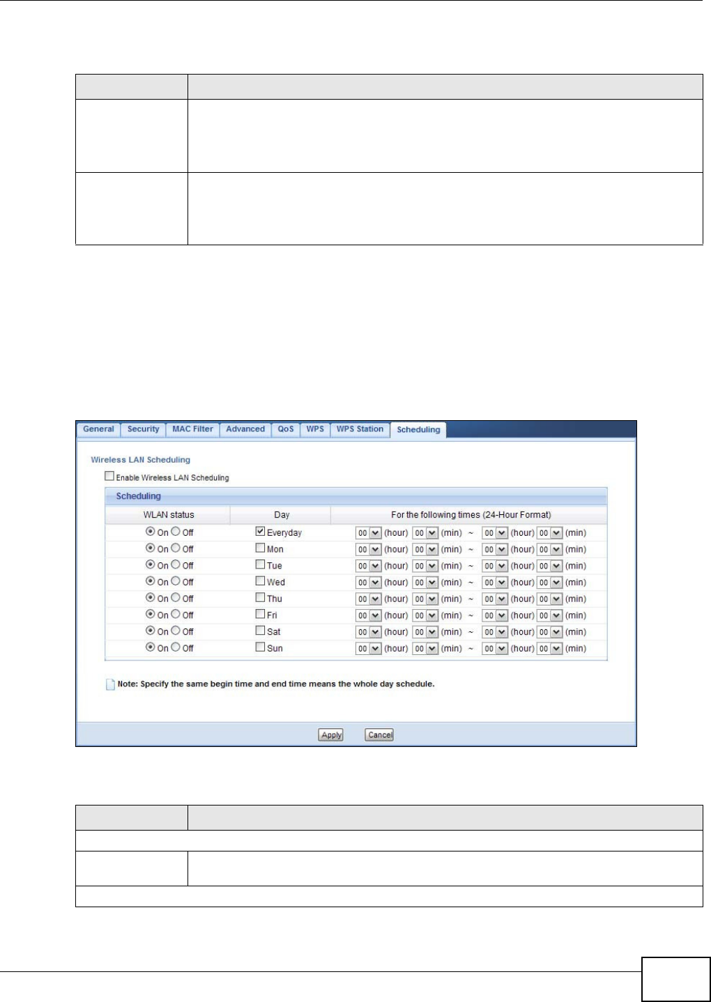
Chapter 9 Wireless LAN
WAP5705 User’s Guide 85
The following table describes the labels in this screen.
9.11 Scheduling Screen
Use this screen to set the times your wireless LAN is turned on and off. Wireless LAN scheduling is
disabled by default. The wireless LAN can be scheduled to turn on or off on certain days and at
certain times. To open this screen, click N e t w or k > W irele ss LAN > Scheduling tab.
Figure 56 Network > Wireless LAN > Scheduling
The following table describes the labels in this screen.
Table 36 Network > Wireless LAN > WPS Station
LABEL DESCRIPTION
Push Button Use this button when you use the PBC (Push Button Configuration) method to configure
wireless stations’s wireless settings. See Section 7.3.1 on page 54.
Click this to start WPS-aware wireless station scanning and the wireless security
information synchronization.
Or input station’s
PIN number
Use this button when you use the PIN Configuration method to configure wireless station’s
wireless settings. See Section 7.3.2 on page 55.
Type the same PIN number generated in the wireless station’s utility. Then click St a r t to
associate to each other and perform the wireless security information synchronization.
Table 37 Network > Wireless LAN > Scheduling
LABEL DESCRIPTION
Wireless LAN Scheduling
Enable Wireless
LAN Scheduling
Select this to enable Wireless LAN scheduling.
Scheduling

Chapter 9 Wireless LAN
WAP5705 User’s Guide
86
WLAN Status Select On or Off to specify whether the Wireless LAN is turned on or off. This field works
in conjunction with the Day and For t he follow ing t im es fields.
Day Select Ever yday or the specific days to turn the Wireless LAN on or off. If you select
Eve ryda y you can not select any specific days. This field works in conjunction with the
For t he follow ing t im es field.
For the following
times (24-Hour
Format)
Select a begin time using the first set of hour and minute (m in) drop down boxes and
select an end time using the second set of hour and minute (m in) drop down boxes. If
you have chosen On earlier for the WLAN Status the Wireless LAN will turn on between
the two times you enter in these fields. If you have chosen Off earlier for the WLAN
Status the Wireless LAN will turn off between the two times you enter in these fields.
Apply Click Apply to save your changes back to the WAP5705.
Cancel Click Cancel to reload the previous configuration for this screen.
Table 37 Network > Wireless LAN > Scheduling
LABEL DESCRIPTION
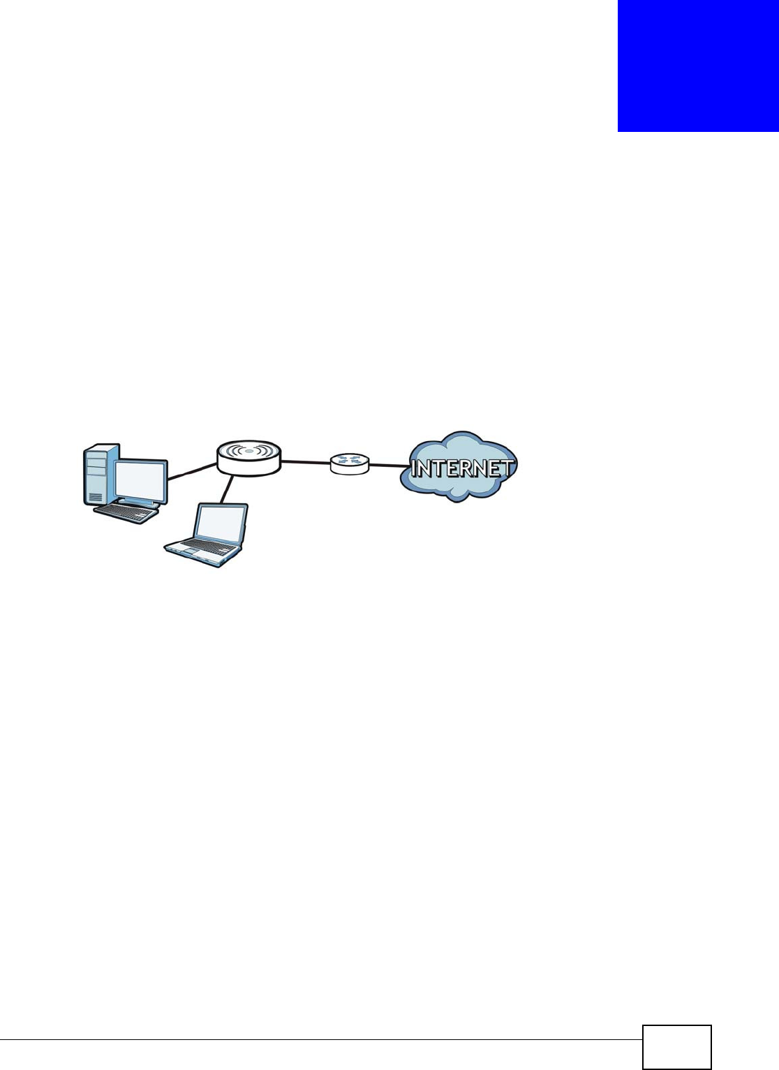
WAP5705 User’s Guide 87
CHAPTER 10
LAN
10.1 Overview
This chapter describes how to configure LAN settings.
A Local Area Network (LAN) is a shared communication system to which many computers are
attached. A LAN is a computer network limited to the immediate area, usually the same building or
floor of a building. The LAN screens can help you configure a LAN DHCP server, manage IP
addresses, and partition your physical network into logical networks.
Figure 57 LAN Example
The LAN screens can help you manage IP addresses.
10.2 What You Can Do
•Use the I P screen (Section 10.4 on page 88) to change the IP address for your WAP5705 and
DNS server information.
•Use the I P Alia s screen (Section 10.5 on page 89) to have the WAP5705 apply IP alias to create
LAN subnets.
LAN
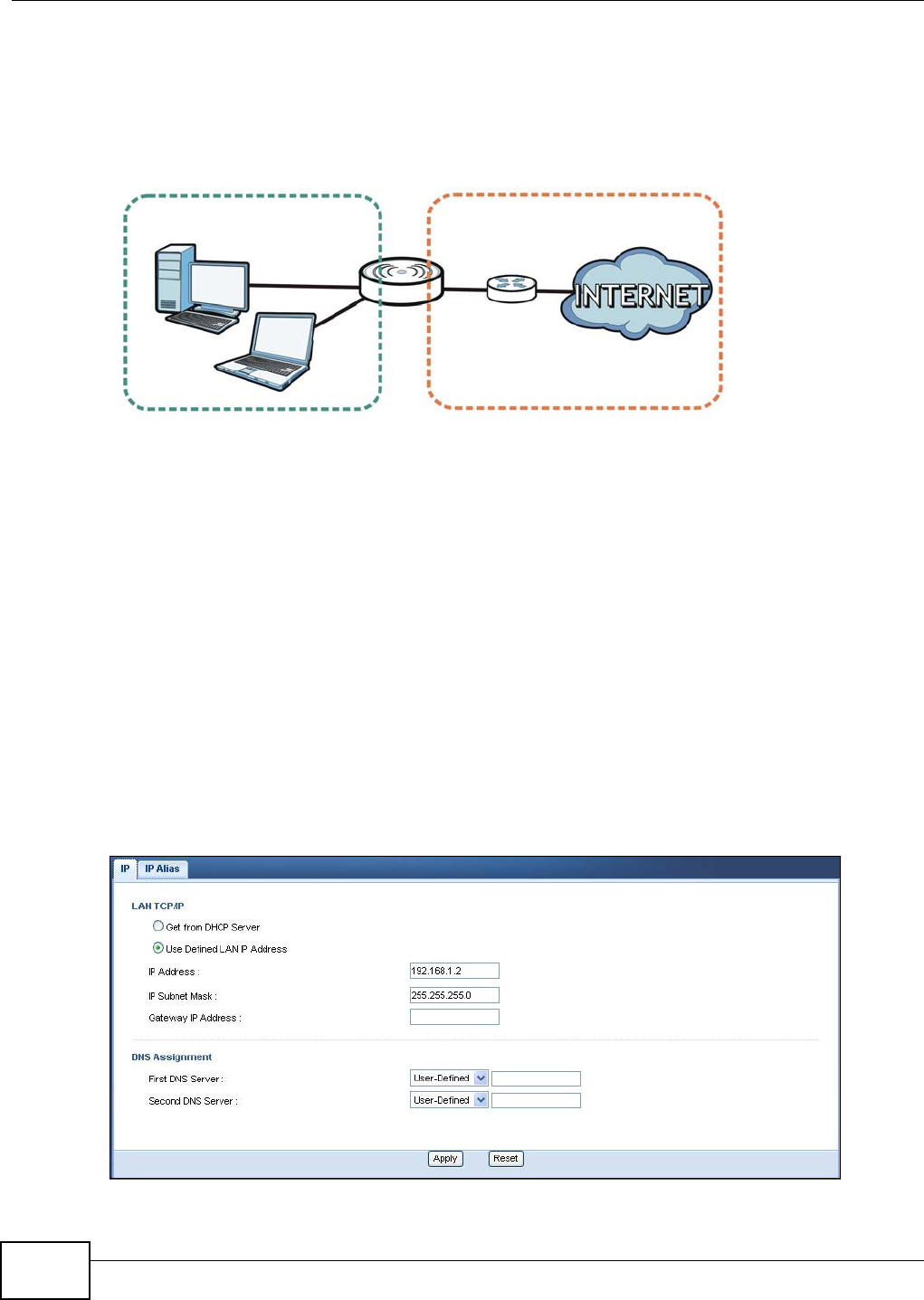
Chapter 10 LAN
WAP5705 User’s Guide
88
10.3 What You Need To Know
There are two separate IP networks, one inside the LAN network and the other outside the WAN
network as shown next.
Figure 58 LAN and WAN IP Addresses
The LAN parameters of the WAP5705 are preset in the factory with the following values:
• AP mode: IP address of 192.168.1.2 with subnet mask of 255.255.255.0 (24 bits)
• Client mode: IP address of 192.168.1.10 with subnet mask of 255.255.255.0 (24 bits)
10.3.1 IP Alias
IP alias allows you to partition a physical network into different logical networks over the same
Ethernet interface. The WAP5705 supports three logical LAN interfaces via its single physical
Ethernet interface with the WAP5705 itself as the gateway for each LAN network.
10.4 LAN IP Screen
Use this screen to change the IP address for your WAP5705. Click Ne t w or k > LAN > I P.
Figure 59 Network > LAN > IP
WAN
LAN


Chapter 10 LAN
WAP5705 User’s Guide
90
The following table describes the labels in this screen.
Table 39 Network > LAN > IP Alias
LABEL DESCRIPTION
IP Alias Check this to enable IP alias.
IP Address Type the IP alias address of your WAP5705 in dotted decimal notation.
IP Subnet Mask The subnet mask specifies the network number portion of an IP address.
Apply Click Apply to save your changes back to the WAP5705.
Reset Click Re set to begin configuring this screen afresh.
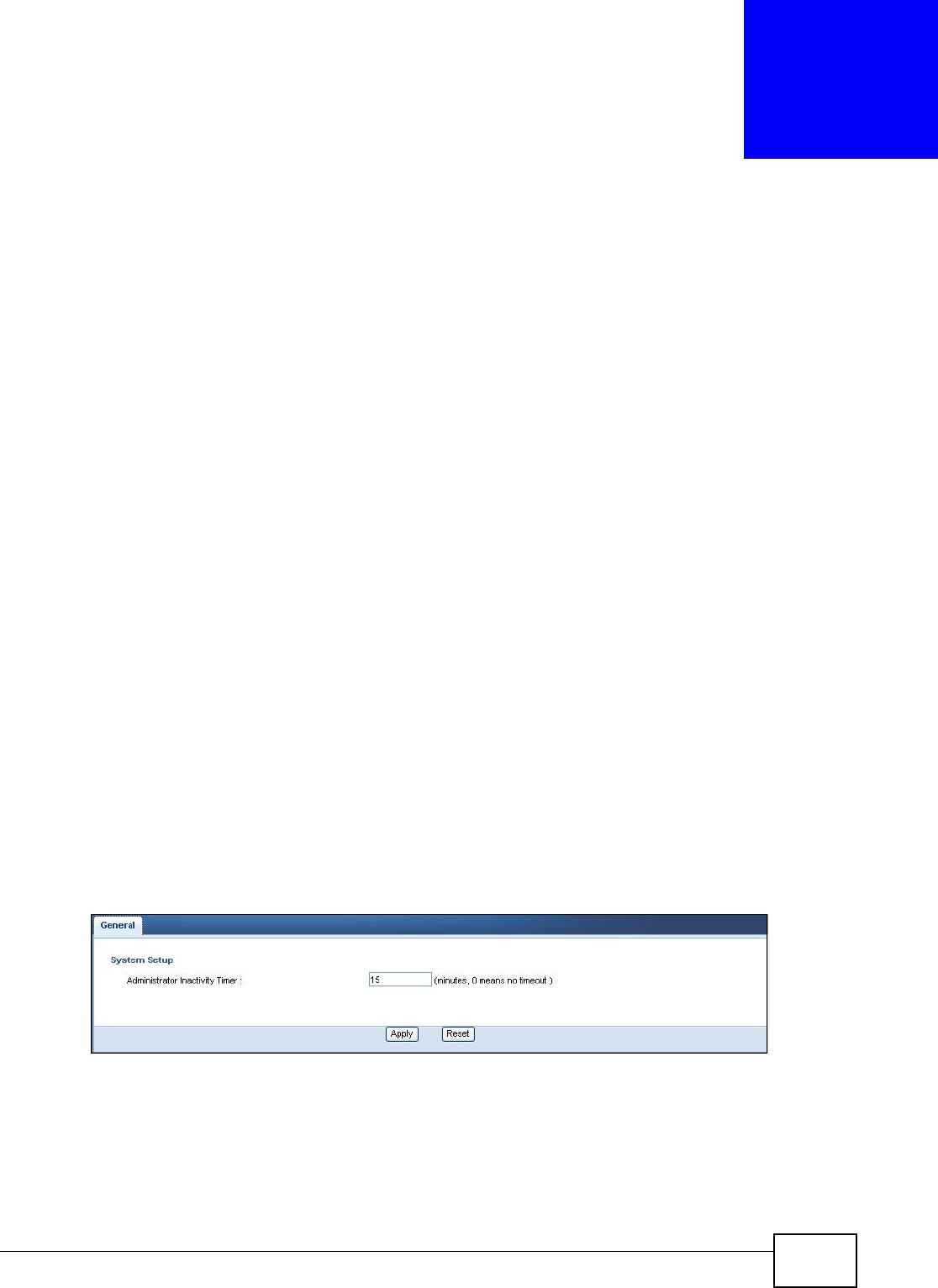
WAP5705 User’s Guide 91
CHAPTER 11
Maintenance
11.1 Overview
This chapter provides information on the Ma int enan ce screens.
11.2 What You Can Do
•Use the General screen (Section 11.3 on page 91) to set the timeout period of the management
session.
•Use the Passw ord screen (Section 11.4 on page 92) to change your WAP5705’s system
password.
•Use the Tim e screen (Section 11.5 on page 93) to change your WAP5705’s time and date.
•Use the Firm w ar e Upgr a de screen (Section 11.6 on page 94) to upload firmware to your
WAP5705.
•Use the Backup/ Re stor e screen (Section 11.8 on page 97) to view information related to
factory defaults, backup configuration, and restoring configuration.
•Use the Re se t / Re st a r t screen (Section 11.8 on page 97) to reboot the WAP5705 without
turning the power off.
11.3 General Screen
Use this screen to set the management session timeout period. Click M a int e n an ce > Ge ner a l.
The following screen displays.
Figure 61 Maintenance > General
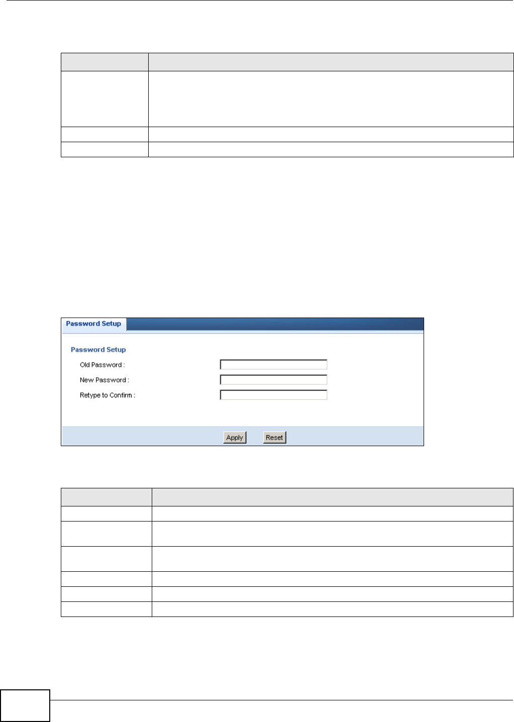
Chapter 11 Maintenance
WAP5705 User’s Guide
92
The following table describes the labels in this screen.
11.4 Password Screen
It is strongly recommended that you change your WAP5705's password.
If you forget your WAP5705's password (or IP address), you will need to reset the device. See
Section 11.8 on page 97 for details
Click M a in t e na n ce > Passw or d.
Figure 62 Maintenance > Password
The following table describes the labels in this screen.
Table 40 Maintenance > General
LABEL DESCRIPTION
Administrator
Inactivity Timer
Type how many minutes a management session can be left idle before the session times
out. The default is 5 minutes. After it times out you have to log in with your password
again. Very long idle timeouts may have security risks. A value of "0" means a
management session never times out, no matter how long it has been left idle (not
recommended).
Apply Click Apply to save your changes back to the WAP5705.
Reset Click Re set to begin configuring this screen afresh.
Table 41 Maintenance > Password
LABEL DESCRIPTION
Password Setup Change your WAP5705’s password (recommended) using the fields as shown.
Old Password Type the default password or the existing password you use to access the system in
this field.
New Password Type your new system password (up to 30 characters). Note that as you type a
password, the screen displays an asterisk (*) for each character you type.
Retype to Confirm Type the new password again in this field.
Apply Click Apply to save your changes back to the WAP5705.
Reset Click Re set to begin configuring this screen afresh.
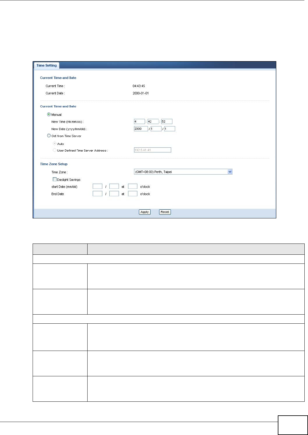
Chapter 11 Maintenance
WAP5705 User’s Guide 93
11.5 Time Setting Screen
Use this screen to configure the WAP5705’s time based on your local time zone. To change your
WAP5705’s time and date, click M a in t en a nce > Tim e. The screen appears as shown.
Figure 63 Maintenance > Time
he following table describes the labels in this screen.
Table 42 Maintenance > Time
LABEL DESCRIPTION
Current Time and Date
Current Time This field displays the time of your WAP5705.
Each time you reload this page, the WAP5705 synchronizes the time with the time
server.
Current Date This field displays the date of your WAP5705.
Each time you reload this page, the WAP5705 synchronizes the date with the time
server.
Current Time and Date
Manual Select this radio button to enter the time and date manually. If you configure a new
time and date, Time Zone and Daylight Saving at the same time, the new time and date
you entered has priority and the Time Zone and Daylight Saving settings do not affect
it.
New Time
(hh:mm:ss)
This field displays the last updated time from the time server or the last time
configured manually.
When you select Man ua l, enter the new time in this field and then click Apply.
New Date
(yyyy/mm/dd)
This field displays the last updated date from the time server or the last date configured
manually.
When you select Man ua l, enter the new date in this field and then click Apply.

Chapter 11 Maintenance
WAP5705 User’s Guide
94
11.6 Firmware Upgrade Screen
Find firmware at www.zyxel.com in a file that (usually) uses the system model name with a “*.bin”
extension, e.g., “WAP5705.bin”. The upload process uses HTTP (Hypertext Transfer Protocol) and
may take up to two minutes. After a successful upload, the system will reboot.
Get from Time
Server
Select this radio button to have the WAP5705 get the time and date from the time
server you specified below.
Auto Select Au t o to have the WAP5705 automatically search for an available time server and
synchronize the date and time with the time server after you click Apply.
User Defined Time
Server Address
Select User De fined Tim e Se rve r Addr ess and enter the IP address or URL (up to 20
extended ASCII characters in length) of your time server. Check with your ISP/network
administrator if you are unsure of this information.
Time Zone Setup
Time Zone Choose the time zone of your location. This will set the time difference between your
time zone and Greenwich Mean Time (GMT).
Daylight Savings Daylight saving is a period from late spring to fall when many countries set their clocks
ahead of normal local time by one hour to give more daytime light in the evening.
Select this option if you use Daylight Saving Time.
Start Date Configure the day and time when Daylight Saving Time starts if you selected Da ylight
Savin gs. The o'clock field uses the 24 hour format. Here are a couple of examples:
Daylight Saving Time starts in most parts of the United States on the second Sunday of
March. Each time zone in the United States starts using Daylight Saving Time at 2 A.M.
local time. So in the United States you would select Se cond, Sun day, Ma rch and type
2 in the o'clock field.
Daylight Saving Time starts in the European Union on the last Sunday of March. All of
the time zones in the European Union start using Daylight Saving Time at the same
moment (1 A.M. GMT or UTC). So in the European Union you would select Last ,
Sun day, Ma rch. The time you type in the o'clock field depends on your time zone. In
Germany for instance, you would type 2 because Germany's time zone is one hour
ahead of GMT or UTC (GMT+1).
End Date Configure the day and time when Daylight Saving Time ends if you selected Da yligh t
Savin gs. The o' clo ck field uses the 24 hour format. Here are a couple of examples:
Daylight Saving Time ends in the United States on the first Sunday of November. Each
time zone in the United States stops using Daylight Saving Time at 2 A.M. local time.
So in the United States you would select Fir st , Sunda y, N ove m ber and type 2 in the
o' clock field.
Daylight Saving Time ends in the European Union on the last Sunday of October. All of
the time zones in the European Union stop using Daylight Saving Time at the same
moment (1 A.M. GMT or UTC). So in the European Union you would select Last ,
Sun day, Oct ob er. The time you type in the o'clock field depends on your time zone.
In Germany for instance, you would type 2 because Germany's time zone is one hour
ahead of GMT or UTC (GMT+1).
Apply Click Apply to save your changes back to the WAP5705.
Reset Click Re set to begin configuring this screen afresh.
Table 42 Maintenance > Time
LABEL DESCRIPTION
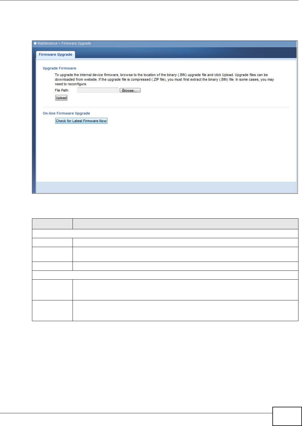
Chapter 11 Maintenance
WAP5705 User’s Guide 95
Click M a in t e nance > Fir m w a r e Upgrade. Follow the instructions in this screen to upload
firmware to your WAP5705.
Figure 64 Maintenance > Firmware Upgrade
The following table describes the labels in this screen.
Note: Do not turn off the WAP5705 while firmware upload is in progress!
After you see the Fir m w a re Upload I n Pr ocess screen, wait two minutes before logging into the
WAP5705 again.
Table 43 Maintenance > Firmware Upgrade
LABEL DESCRIPTION
Upgrade Firmware
File Path Type in the location of the file you want to upload in this field or click Br ow se... to find it.
Browse... Click Brow se... to find the .bin file you want to upload. Remember that you must
decompress compressed (.zip) files before you can upload them.
Upload Click Uploa d to begin the upload process. This process may take up to two minutes.
On-line Firmware Upgrade
Check for
Latest
Firmware Now
Click this button to get the latest firmware information, such as the version number, release
date, release note and file size from the ZyXEL website. Make sure your WAP5705 has
Internet access.
Do-
Firmware_Upg
rade
Click this button to download and install the latest firmware in your WAP5705.
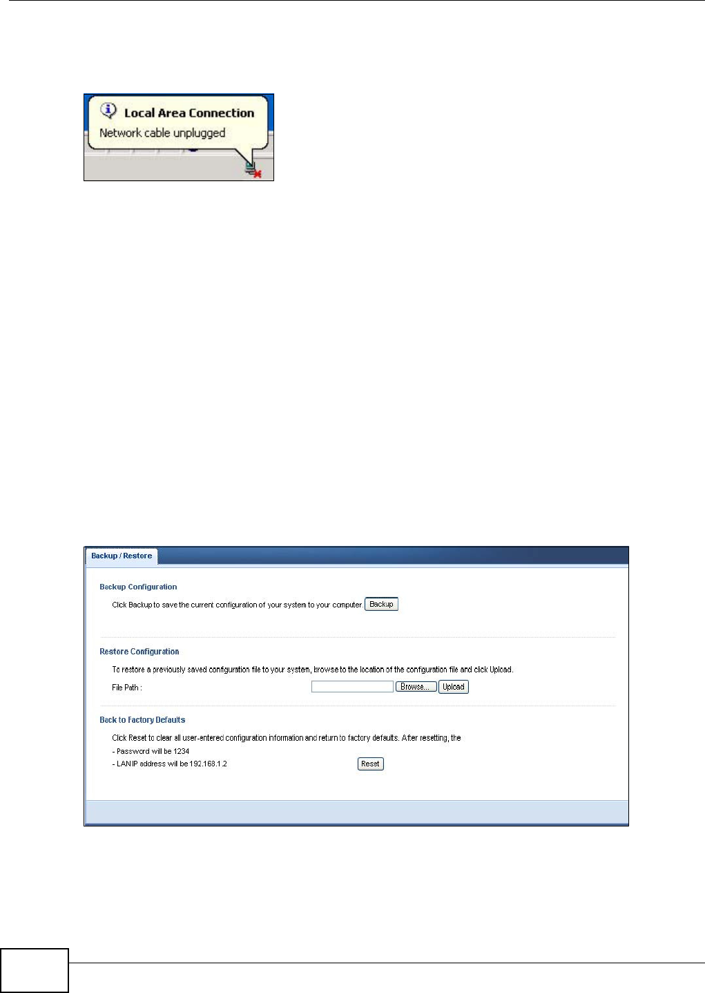
Chapter 11 Maintenance
WAP5705 User’s Guide
96
The WAP5705 automatically restarts in this time causing a temporary network disconnect. In some
operating systems, you may see the following icon on your desktop.
Figure 65 Network Temporarily Disconnected
After two minutes, log in again and check your new firmware version in the St a t u s screen.
If the upload was not successful, an error message appears. Click Re t u rn to go back to the
Firm w a r e Upgra de screen.
11.7 Configuration Backup/Restore Screen
Backup configuration allows you to back up (save) the WAP5705’s current configuration to a file on
your computer. Once your WAP5705 is configured and functioning properly, it is highly
recommended that you back up your configuration file before making configuration changes. The
backup configuration file will be useful in case you need to return to your previous settings.
Restore configuration allows you to upload a new or previously saved configuration file from your
computer to your WAP5705.
Click M a in t e nance > Back up/ Re st ore. Information related to factory defaults, backup
configuration, and restoring configuration appears as shown next.
Figure 66 Maintenance > Backup/Restore
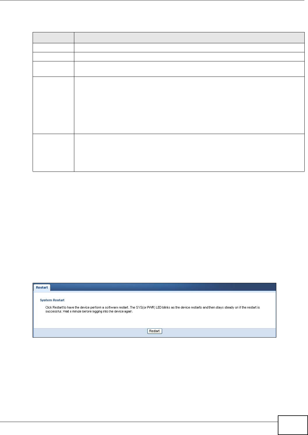
Chapter 11 Maintenance
WAP5705 User’s Guide 97
The following table describes the labels in this screen.
Note: If you uploaded the default configuration file you may need to change the IP
address of your computer to be in the same subnet as that of the default WAP5705
IP address. See Appendix A on page 105 for details on how to set up your
computer’s IP address.
11.8 Reset/Restart Screen
System restart allows you to reboot the WAP5705 without turning the power off.
Click M a in t e nance > Re set / Rest a r t to open the following screen.
Figure 67 Maintenance > Reset/Restart
Click Re st a rt to have the WAP5705 reboot. This does not affect the WAP5705's configuration.
Table 44 Maintenance > Backup/Restore
LABEL DESCRIPTION
Backup Click Ba ck up to save the WAP5705’s current configuration to your computer.
File Path Type in the location of the file you want to upload in this field or click Br ow se... to find it.
Browse... Click Brow se... to find the file you want to upload. Remember that you must decompress
compressed (.ZIP) files before you can upload them.
Upload Click Uploa d to begin the upload process.
Note: Do not turn off the WAP5705 while configuration file upload is in progress.
After you see a “configuration upload successful” screen, you must then wait one minute
before logging into the WAP5705 again. The WAP5705 automatically restarts in this time
causing a temporary network disconnect.
If you see an error screen, click Back to return to the Backup/Restore screen.
Reset Pressing the Re se t button in this section clears all user-entered configuration information
and returns the WAP5705 to its factory defaults.
You can also press the RESET button on the rear panel to reset the factory defaults of your
WAP5705. Refer to the chapter about introducing the Web Configurator for more information
on the RESET button.

Chapter 11 Maintenance
WAP5705 User’s Guide
98

WAP5705 User’s Guide 99
CHAPTER 12
Troubleshooting
This chapter offers some suggestions to solve problems you might encounter. The potential
problems are divided into the following categories.
•Power, Hardware Connections, and LEDs
•WAP5705 Access and Login
•Internet Access
•Resetting the WAP5705 to Its Factory Defaults
12.1 Power, Hardware Connections, and LEDs
The WAP5705 does not turn on. None of the LEDs turn on.
1Make sure you are using the power adaptor or cord included with the WAP5705.
2Make sure the power adaptor or cord is connected to the WAP5705 and plugged in to an
appropriate power source. Make sure the power source is turned on.
3Disconnect and re-connect the power adaptor or cord to the WAP5705.
4If the problem continues, contact the vendor.
One of the LEDs does not behave as expected.
1Make sure you understand the normal behavior of the LED. See Section 1.6 on page 13.
2Check the hardware connections. See the Quick Start Guide.
3Inspect your cables for damage. Contact the vendor to replace any damaged cables.
4Disconnect and re-connect the power adaptor to the WAP5705.
5If the problem continues, contact the vendor.

Chapter 12 Troubleshooting
WAP5705 User’s Guide
100
12.2 WAP5705 Access and Login
I don’t know the IP address of my WAP5705.
1The default IP address of the WAP5705 in access point mode is 1 9 2 .1 6 8 .1 .2 and the default IP
address of the WAP5705 in client mode is 1 9 2 .1 6 8 .1 .1 0 .
2If you changed the IP address and have forgotten it,
• and your WAP5705 is a DHCP client, you can find your IP address from the DHCP server. This
information is only available from the DHCP server which allocates IP addresses on your network.
Find this information directly from the DHCP server or contact your system administrator for
more information.
• reset your WAP5705 to change all settings back to their default. This means your current settings
are lost. See Section 12.4 on page 102 in the Tr ou ble shoot in g for information on resetting your
WAP5705.
I forgot the password.
1The default password is 1 2 3 4 .
2If this does not work, you have to reset the device to its factory defaults. See Section 12.4 on page
102.
I cannot see or access the Login screen in the Web Configurator.
1Make sure you are using the correct IP address.
• The default IP address of the WAP5705 in access point mode is 1 9 2 .1 6 8 .1 .2 and the default
IP address of the WAP5705 in client mode is 1 9 2 .1 6 8 .1 .1 0 .
• If you changed the IP address (Section 10.4 on page 88), use the new IP address.
• If you changed the IP address and have forgotten it, see the troubleshooting suggestions for I
don’t know the IP address of my WAP5705.
2Check the hardware connections, and make sure the LEDs are behaving as expected. See the Quick
Start Guide.
3Make sure your Internet browser does not block pop-up windows and has JavaScripts and Java
enabled. See your browser help.
4Make sure your computer is in the same subnet as the WAP5705. (If you know that there are
routers between your computer and the WAP5705, skip this step.)
• If there is a DHCP server on your network, make sure your computer is using a dynamic IP
address. See Section 10.4 on page 88.

Chapter 12 Troubleshooting
WAP5705 User’s Guide 101
• If there is no DHCP server on your network, make sure your computer’s IP address is in the
same subnet as the WAP5705. See Appendix A on page 105.
5Reset the device to its factory defaults, and try to access the WAP5705 with the default IP address.
See Section 11.7 on page 96.
6If the problem continues, contact the network administrator or vendor, or try one of the advanced
suggestions.
Adva n ced Suggestion
• If your computer is connected wirelessly, use a computer that is connected to a LAN port.
I can see the Login screen, but I cannot log in to the WAP5705.
1Make sure you have entered the password correctly. The default password is 1 2 3 4 . This field is
case-sensitive, so make sure [Caps Lock] is not on.
2This can happen when you fail to log out properly from your last session. Try logging in again after
5 minutes.
3Disconnect and re-connect the power adaptor or cord to the WAP5705.
4If this does not work, you have to reset the device to its factory defaults. See Section 12.4 on page
102.
12.3 Internet Access
I cannot access the Internet.
1Check the hardware connections, and make sure the LEDs are behaving as expected. See the Quick
Start Guide.
2Make sure the WAP5705 in access point mode is connected to a broadband modem or router with
Internet access. Connect to another WAP5705 in client mode to access the Internet through the
WAP5705 in access point mode. Use the switch on the WAP5705’s side panel to change your system
operating mode setting (see Section 2.1.2.1 on page 19). Make sure the client is within the
transmission range of the AP.
3If you are trying to access the Internet wirelessly, make sure the wireless settings in the wireless
client are the same as the settings in the AP.
4Disconnect all the cables from your device, and follow the directions in the Quick Start Guide again.
5If the problem continues, contact your ISP.

Chapter 12 Troubleshooting
WAP5705 User’s Guide
102
I cannot access the Internet anymore. I had access to the Internet (with the WAP5705), but
my Internet connection is not available anymore.
1Check the hardware connections, and make sure the LEDs are behaving as expected. See the Quick
Start Guide and Section 1.6 on page 13.
2Reboot the WAP5705.
3If the problem continues, contact your ISP.
The Internet connection is slow or intermittent.
1There might be a lot of traffic on the network. Look at the LEDs, and check Section 1.6 on page 13.
If the WAP5705 is sending or receiving a lot of information, try closing some programs that use the
Internet, especially peer-to-peer applications.
2Check the signal strength. If the signal strength is low, try moving the clients closer to the AP if
possible, and look around to see if there are any devices that might be interfering with the wireless
network (for example, microwaves, other wireless networks, and so on).
3Reboot the WAP5705.
4If the problem continues, contact the network administrator or vendor, or try one of the advanced
suggestions.
Adva n ced Suggestions
• Check the settings for QoS. If it is disabled, you might consider activating it.
12.4 Resetting the WAP5705 to Its Factory Defaults
If you reset the WAP5705, you lose all of the changes you have made. The WAP5705 re-loads its
default settings, and the password resets to 1 2 3 4 . You have to make all of your changes again.
You will lose all of your changes when you push the RESET button.
To reset the WAP5705,
1Make sure the power LED is on.
2Press the RESET button for longer than 1 second to restart/reboot the WAP5705.

Chapter 12 Troubleshooting
WAP5705 User’s Guide 103
3Press the RESET button for longer than five seconds to set the WAP5705 back to its factory-default
configurations.
If the WAP5705 restarts automatically, wait for the WAP5705 to finish restarting, and log in to the
Web Configurator. The password is “1234”.
If the WAP5705 does not restart automatically, disconnect and reconnect the WAP5705’s power.
Then, follow the directions above again.

Chapter 12 Troubleshooting
WAP5705 User’s Guide
104

WAP5705 User’s Guide 105
APPENDIX A
Setting Up Your Computer’s IP Address
Note: Your specific WAP5705 may not support all of the operating systems described in
this appendix. See the product specifications for more information about which
operating systems are supported.
This appendix shows you how to configure the IP settings on your computer in order for it to be
able to communicate with the other devices on your network. Windows Vista/XP/2000, Mac OS 9/
OS X, and all versions of UNIX/LINUX include the software components you need to use TCP/IP on
your computer.
If you manually assign IP information instead of using a dynamic IP, make sure that your network’s
computers have IP addresses that place them in the same subnet.
In this appendix, you can set up an IP address for:
•Windows XP/NT/2000 on page 105
•Windows Vista on page 109
•Windows 7 on page 113
•Mac OS X: 10.3 and 10.4 on page 117
•Mac OS X: 10.5 and 10.6 on page 120
•Linux: Ubuntu 8 (GNOME) on page 123
•Linux: openSUSE 10.3 (KDE) on page 127
Windows XP/NT/2000
The following example uses the default Windows XP display theme but can also apply to Windows
2000 and Windows NT.
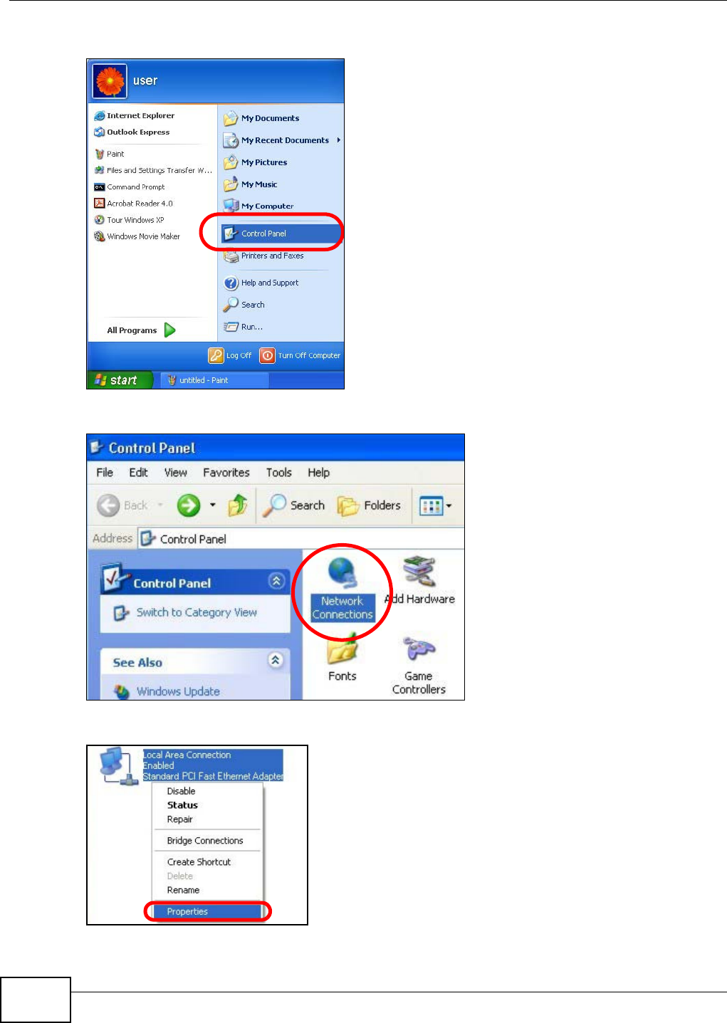
Appendix A Setting Up Your Computer’s IP Address
WAP5705 User’s Guide
106
1Click St a r t > Cont rol Pa nel.
2In the Cont rol Pa nel, click the N et w ork Connections icon.
3Right-click Local Ar e a Conne ct ion and then select Pr op er t ie s.
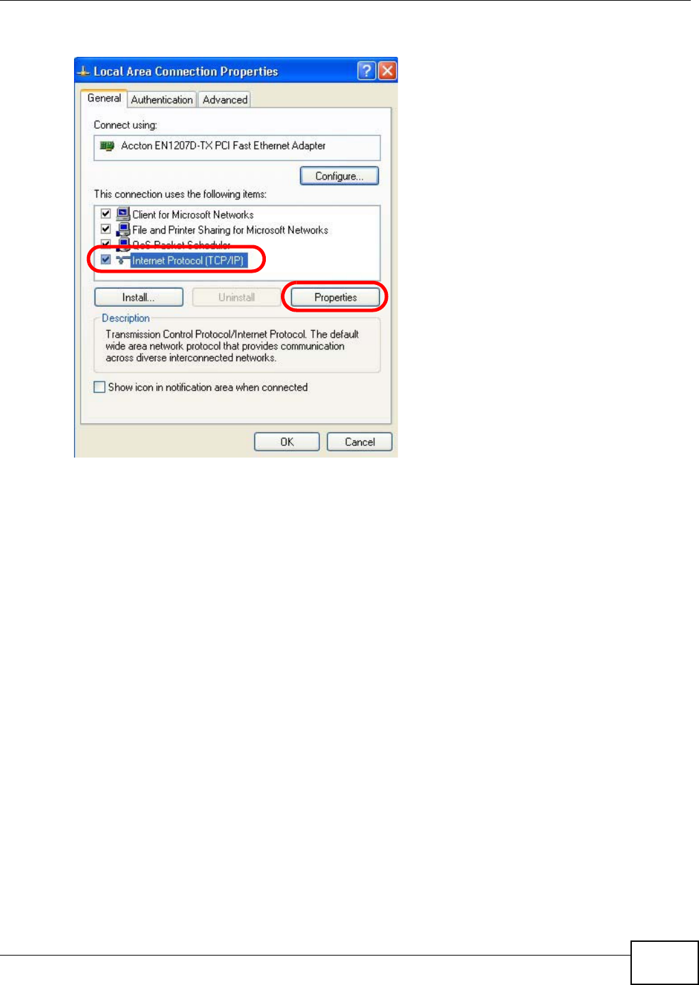
Appendix A Setting Up Your Computer’s IP Address
WAP5705 User’s Guide 107
4On the Gener a l tab, select I nt e r net Pr ot ocol ( TCP/ I P) and then click Pr ope rt ie s.
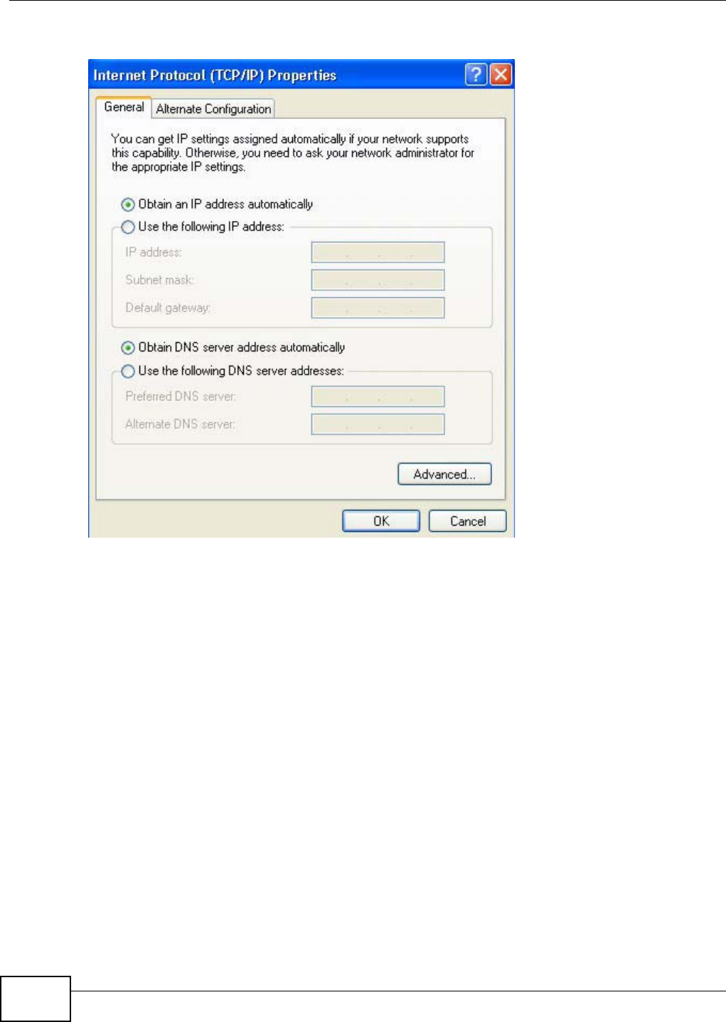
Appendix A Setting Up Your Computer’s IP Address
WAP5705 User’s Guide
108
5The I nt e rne t Pr ot ocol TCP/ I P Proper t ies window opens.
6Select Obt a in an I P a ddre ss a ut om a t ically if your network administrator or ISP assigns your IP
address dynamically.
Select Use t h e follow ing I P Addr e ss and fill in the I P a ddr e ss, Subnet m ask , and D e fa ult
ga t e w a y fields if you have a static IP address that was assigned to you by your network
administrator or ISP. You may also have to enter a Preferre d D N S ser ve r and an Alt e r na t e DN S
ser ve r , if that information was provided.
7Click OK to close the I nt e r ne t Prot ocol ( TCP/ I P) Propert ies window.
8Click OK to close the Local Area Conn ection Pr ope r t ies window.
Verifying Settings
1Click St a r t > All Pr ogr a m s > Acce ssor ies > Com m a nd Prom pt .
2In the Com m and Pr om pt window, type "ipconfig" and then press [ENTER].
You can also go to St art > Cont rol Pa nel > Netw or k Conn ections, right-click a network
connection, click St a t us and then click the Support tab to view your IP address and connection
information.
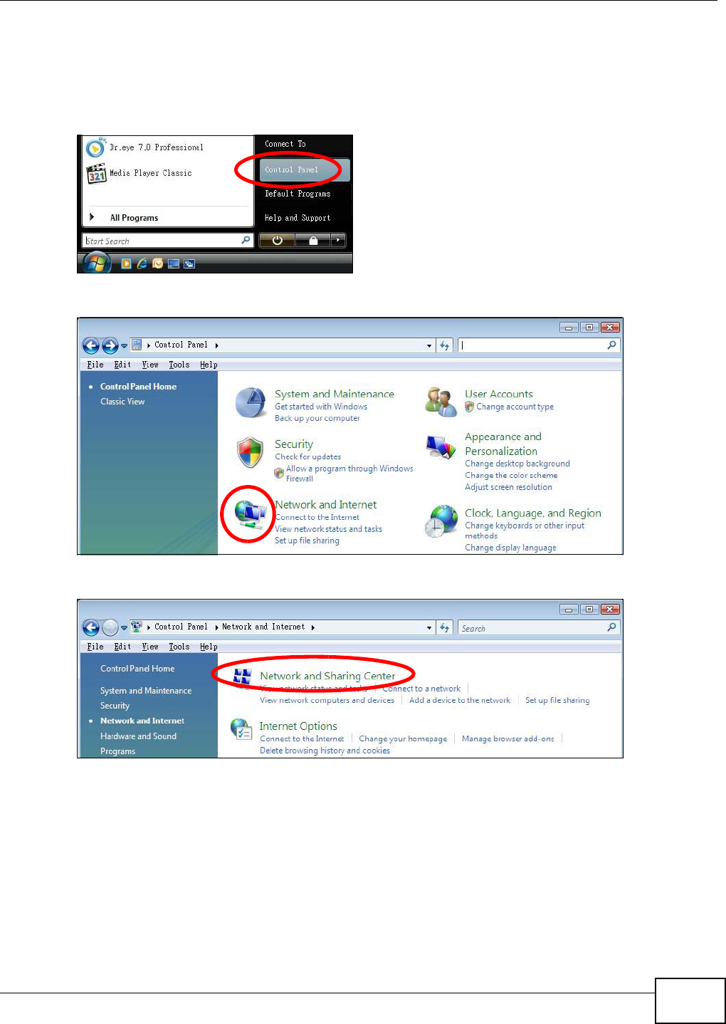
Appendix A Setting Up Your Computer’s IP Address
WAP5705 User’s Guide 109
Windows Vista
This section shows screens from Windows Vista Professional.
1Click St a r t > Cont rol Pa ne l.
2In the Cont rol Pa nel, click the N et w ork a nd I nt erne t icon.
3Click the N e t w ork a nd Sh aring Ce nt er icon.
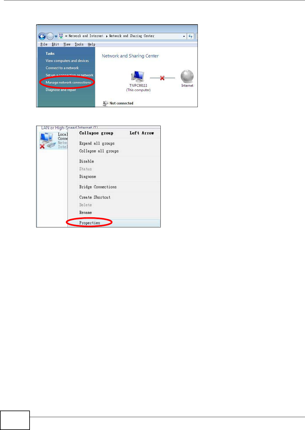
Appendix A Setting Up Your Computer’s IP Address
WAP5705 User’s Guide
110
4Click M a nage net w ork conne ct ions.
5Right-click Local Ar e a Conne ct ion and then select Pr op er t ie s.
Note: During this procedure, click Cont inue whenever Windows displays a screen saying
that it needs your permission to continue.
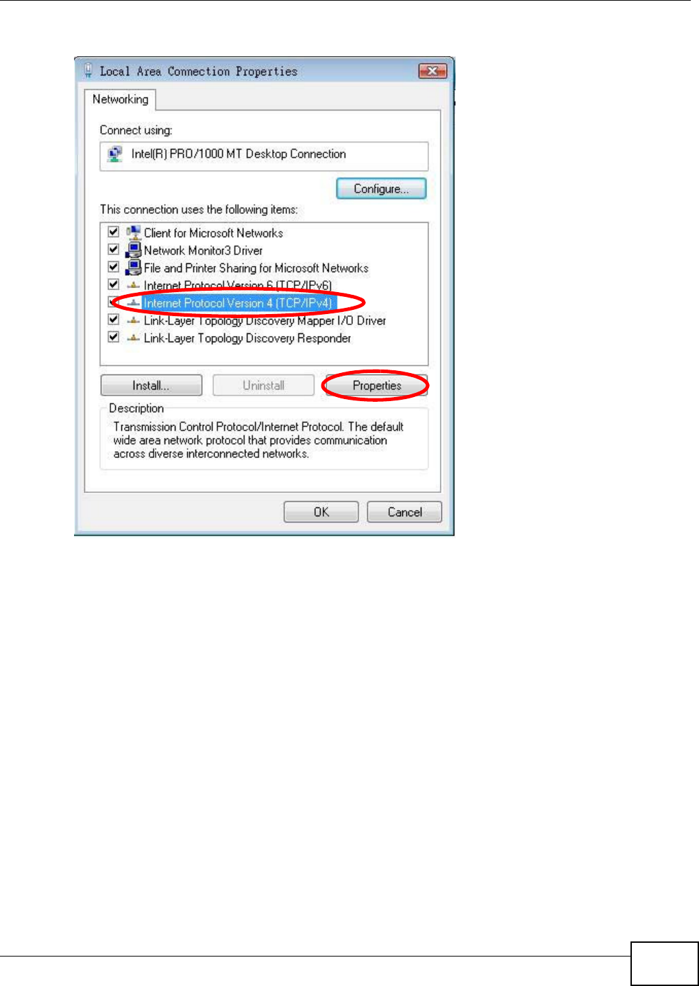
Appendix A Setting Up Your Computer’s IP Address
WAP5705 User’s Guide 111
6Select I nt e r net Pr ot ocol Version 4 ( TCP/ I Pv4 ) and then select Pr op er t ie s.
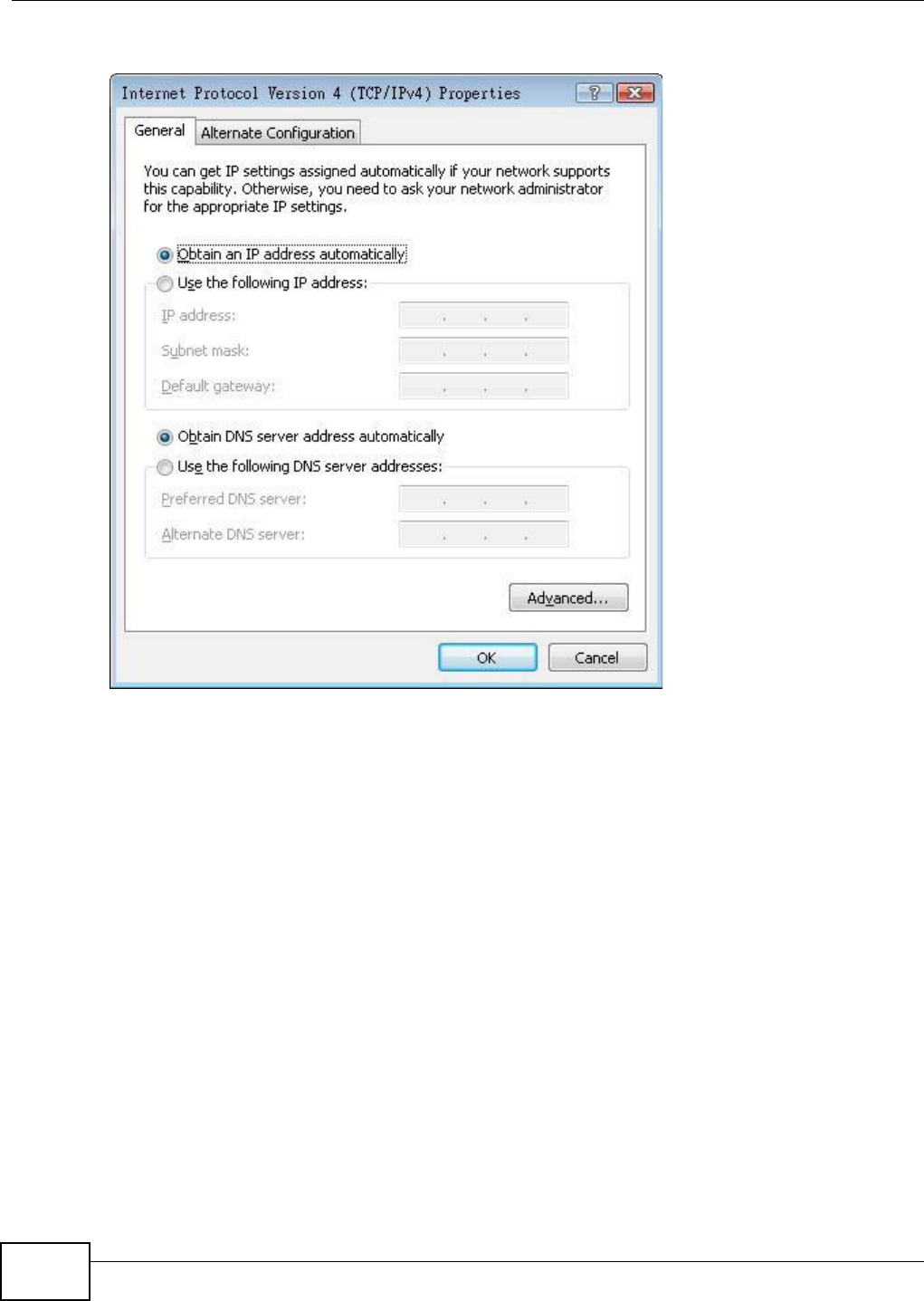
Appendix A Setting Up Your Computer’s IP Address
WAP5705 User’s Guide
112
7The I nt e rne t Pr ot ocol V ersion 4 ( TCP/ I Pv4 ) Propert ies window opens.
8Select Obt a in an I P a ddre ss a ut om a t ically if your network administrator or ISP assigns your IP
address dynamically.
Select Use t h e follow ing I P Addr e ss and fill in the I P a ddr e ss, Subnet m ask , and D e fa ult
ga t e w a y fields if you have a static IP address that was assigned to you by your network
administrator or ISP. You may also have to enter a Preferre d D N S ser ve r and an Alt e r na t e DN S
ser ve r , if that information was provided.Click Advanced.
9Click OK to close the I nt e r ne t Prot ocol ( TCP/ I P) Propert ies window.
10 Click OK to close the Local Area Conn ection Pr ope r t ies window.
Verifying Settings
1Click St a r t > All Pr ogr a m s > Acce ssor ies > Com m a nd Prom pt .
2In the Com m and Pr om pt window, type "ipconfig" and then press [ENTER].
You can also go to St art > Cont rol Pa nel > Netw or k Conn ections, right-click a network
connection, click St a t us and then click the Support tab to view your IP address and connection
information.
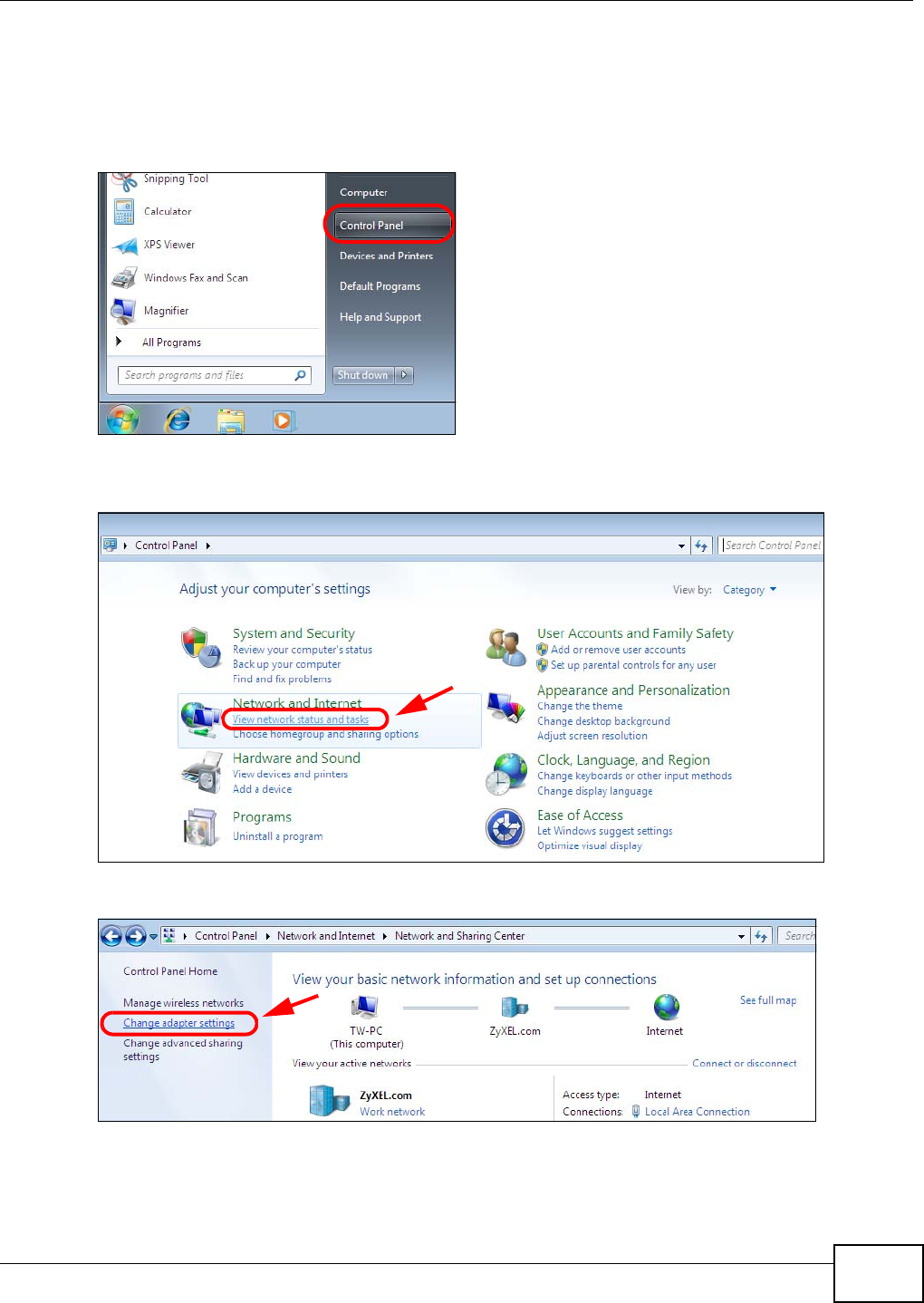
Appendix A Setting Up Your Computer’s IP Address
WAP5705 User’s Guide 113
Windows 7
This section shows screens from Windows 7 Enterprise.
1Click St a r t > Cont rol Pa ne l.
2In the Cont rol Pa nel, click View net w ork st a t u s and t a sks under the Net w or k and I nt e rne t
category.
3Click Change adapt e r set t ings.
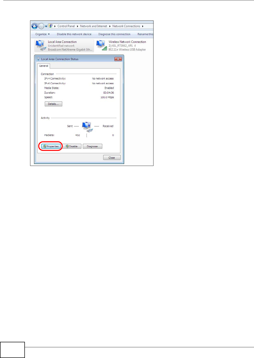
Appendix A Setting Up Your Computer’s IP Address
WAP5705 User’s Guide
114
4Double click Local Ar e a Conne ct ion and then select Pr op er t ie s.
Note: During this procedure, click Cont inue whenever Windows displays a screen saying
that it needs your permission to continue.
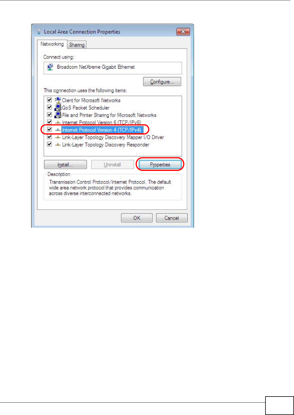
Appendix A Setting Up Your Computer’s IP Address
WAP5705 User’s Guide 115
5Select I nt e r net Pr ot ocol Version 4 ( TCP/ I Pv4 ) and then select Pr op er t ie s.
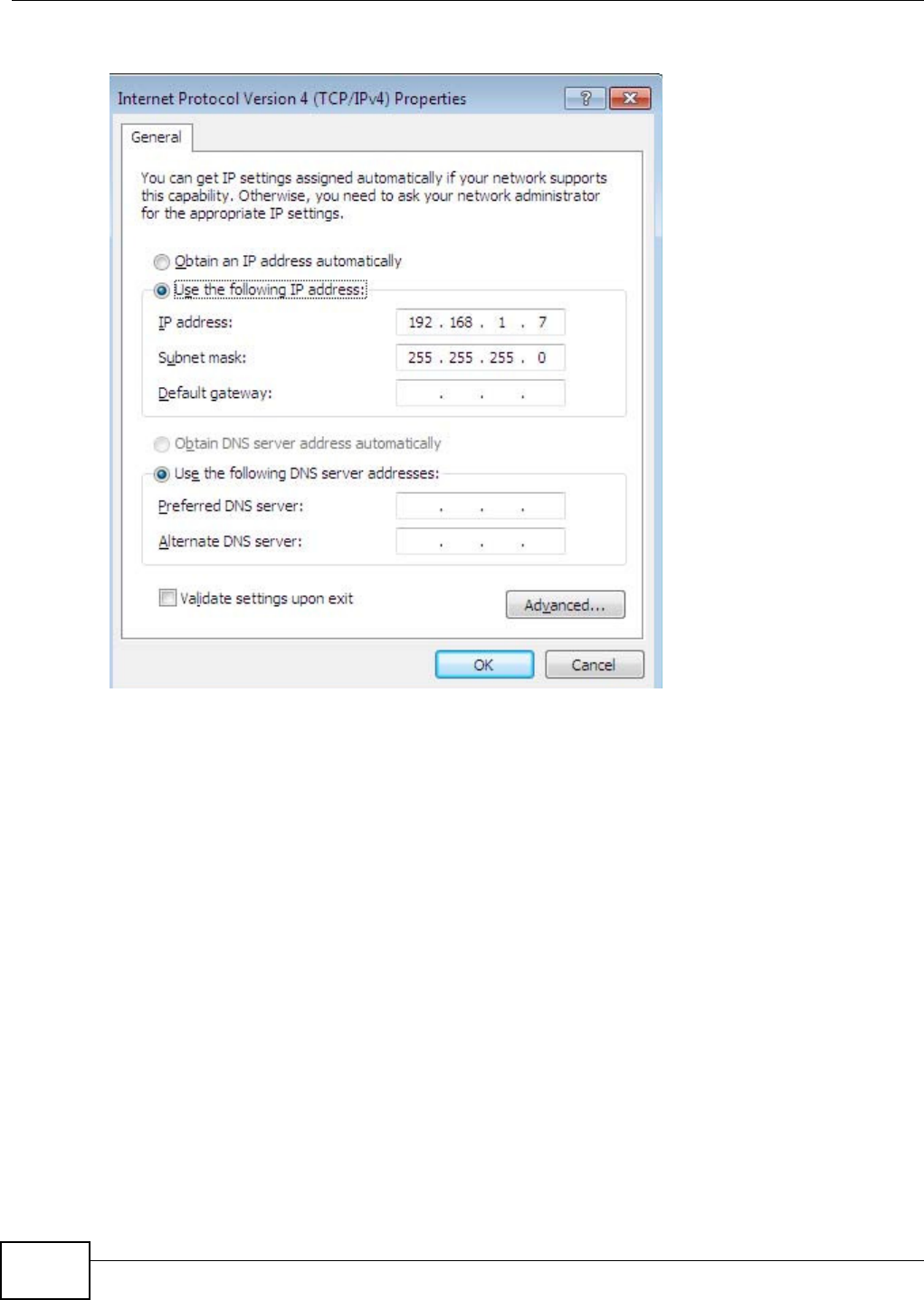
Appendix A Setting Up Your Computer’s IP Address
WAP5705 User’s Guide
116
6The I nt e rne t Pr ot ocol V ersion 4 ( TCP/ I Pv4 ) Propert ies window opens.
7Select Obt a in an I P a ddre ss a ut om a t ically if your network administrator or ISP assigns your IP
address dynamically.
Select Use t h e follow ing I P Addr e ss and fill in the I P a ddr e ss, Subnet m ask , and D e fa ult
ga t e w a y fields if you have a static IP address that was assigned to you by your network
administrator or ISP. You may also have to enter a Preferre d D N S ser ve r and an Alt e r na t e DN S
ser ve r , if that information was provided. Click Adva n ced if you want to configure advanced
settings for IP, DNS and WINS.
8Click OK to close the I nt e r ne t Prot ocol ( TCP/ I P) Propert ies window.
9Click OK to close the Local Area Conn ection Pr ope r t ies window.
Verifying Settings
1Click St a r t > All Pr ogr a m s > Acce ssor ies > Com m a nd Prom pt .
2In the Com m and Pr om pt window, type "ipconfig" and then press [ENTER].
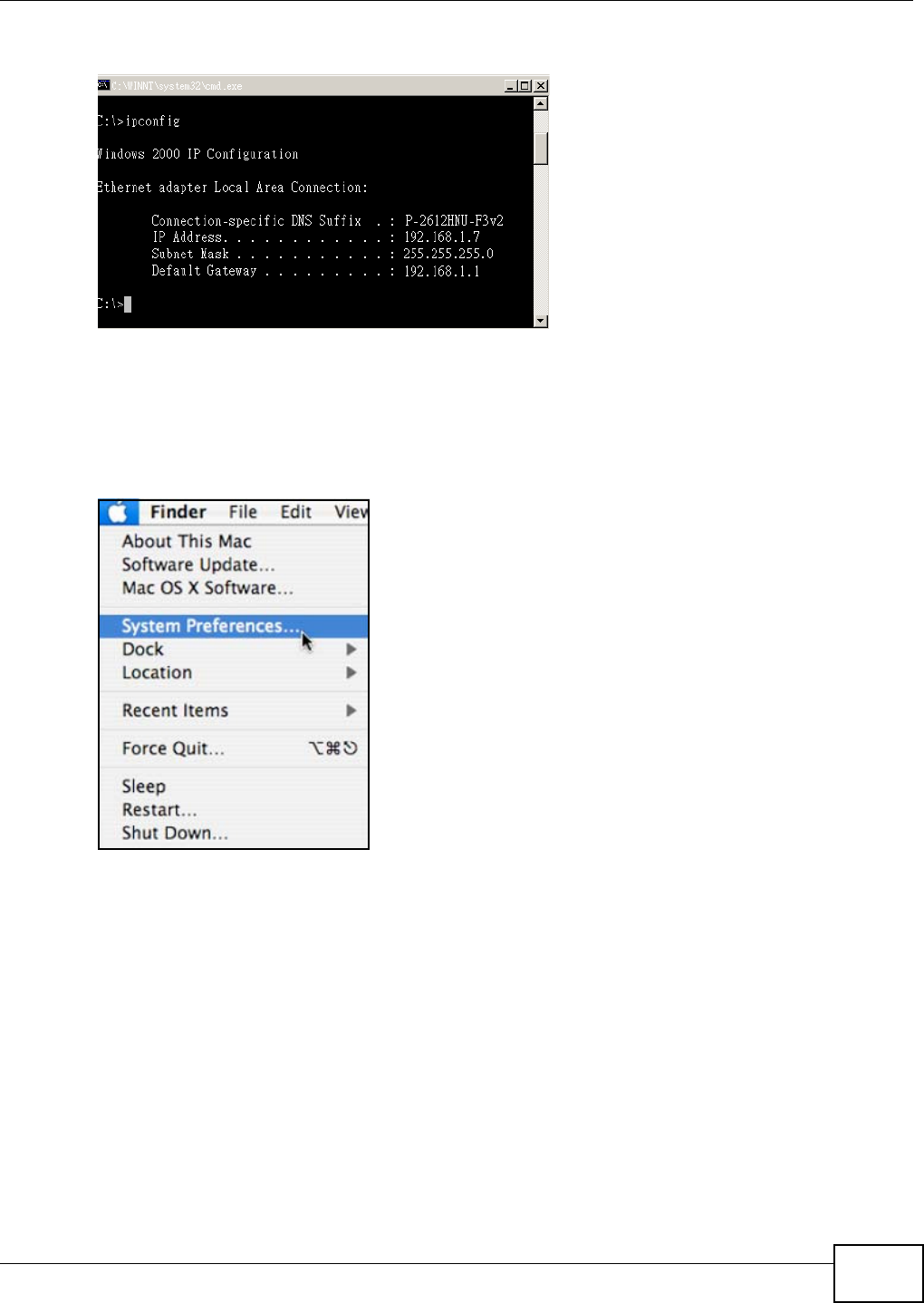
Appendix A Setting Up Your Computer’s IP Address
WAP5705 User’s Guide 117
3The IP settings are displayed as follows.
Mac OS X: 10.3 and 10.4
The screens in this section are from Mac OS X 10.4 but can also apply to 10.3.
1Click Apple > System Pr efere nce s.
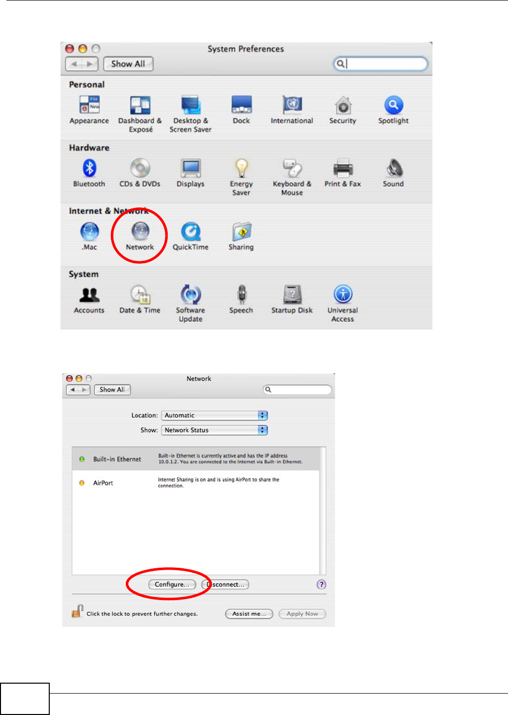
Appendix A Setting Up Your Computer’s IP Address
WAP5705 User’s Guide
118
2In the Syst em Pre fe rences window, click the Net w ork icon.
3When the N e t w o rk preferences pane opens, select Built - in Et hern et from the network
connection type list, and then click Configure .
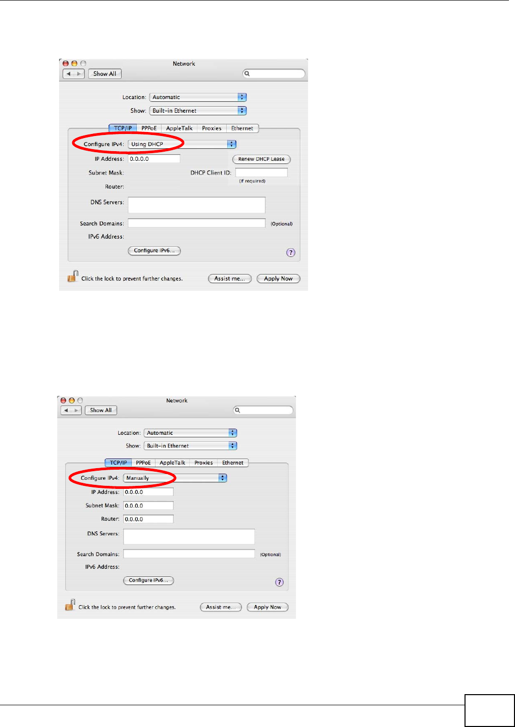
Appendix A Setting Up Your Computer’s IP Address
WAP5705 User’s Guide 119
4For dynamically assigned settings, select Using D H CP from the Configure I Pv4 list in the TCP/ I P
tab.
5For statically assigned settings, do the following:
•From the Configur e I Pv4 list, select M a n ually.
•In the I P Addr e ss field, type your IP address.
•In the Subn et M a sk field, type your subnet mask.
•In the Ro ut e r field, type the IP address of your device.
6Click Apply N ow and close the window.
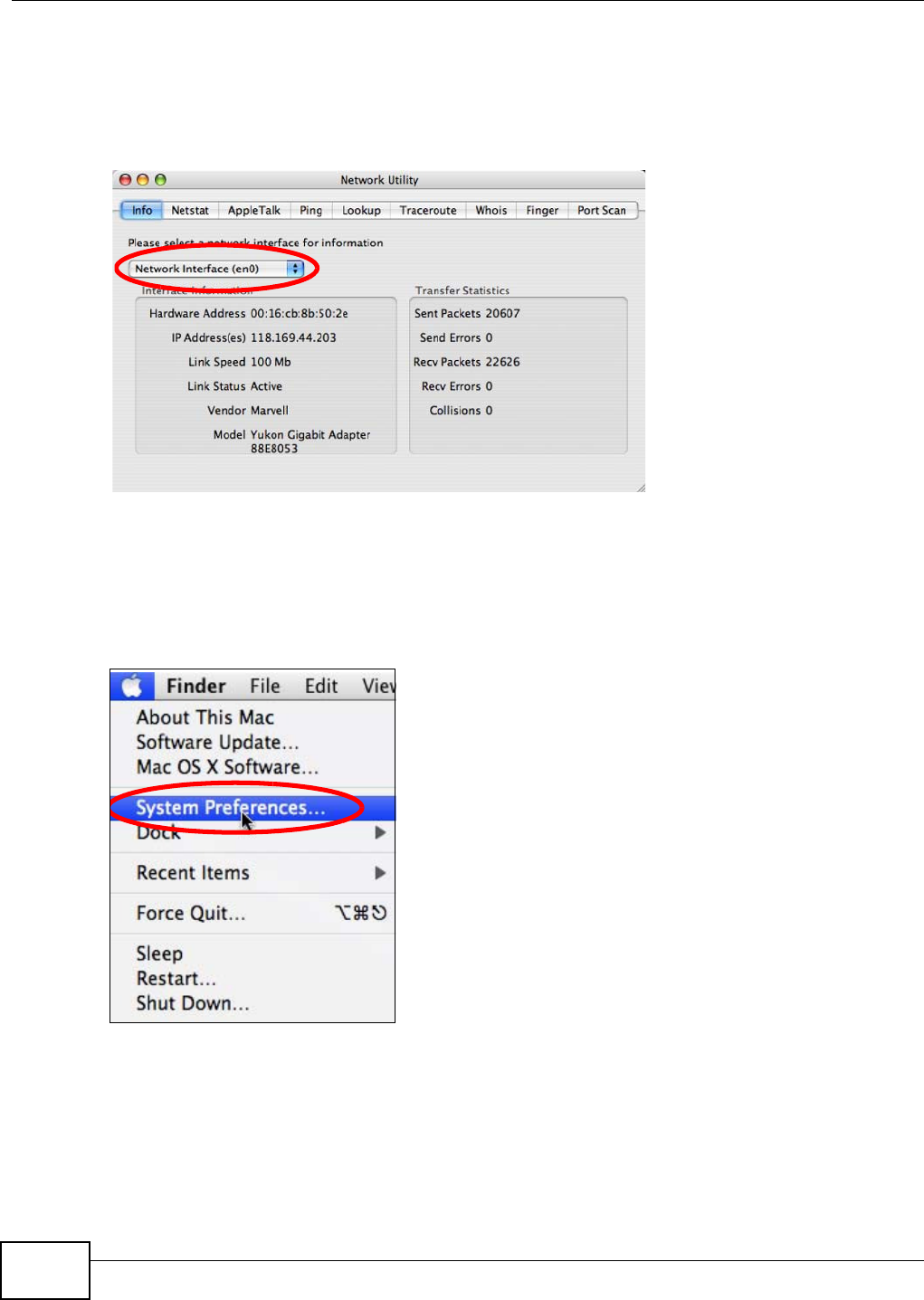
Appendix A Setting Up Your Computer’s IP Address
WAP5705 User’s Guide
120
Verifying Settings
Check your TCP/IP properties by clicking Applicat ions > Ut ilit ies > N e t w ork Ut ilit ie s, and then
selecting the appropriate N e t w or k I nt erf ace from the I nfo tab.
Figure 68 Mac OS X 10.4: Network Utility
Mac OS X: 10.5 and 10.6
The screens in this section are from Mac OS X 10.5 but can also apply to 10.6.
1Click Apple > System Pr efere nce s.
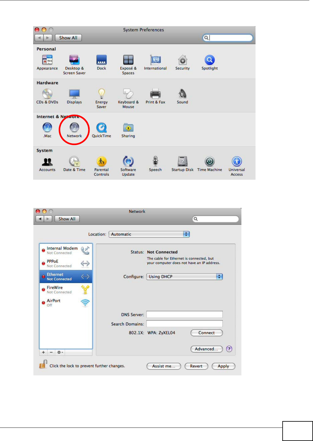
Appendix A Setting Up Your Computer’s IP Address
WAP5705 User’s Guide 121
2In Syst e m Pr efe rences, click the N e t w o rk icon.
3When the N et w ork preferences pane opens, select Et h e rn e t from the list of available connection
types.
4From the Configur e list, select Using D H CP for dynamically assigned settings.
5For statically assigned settings, do the following:
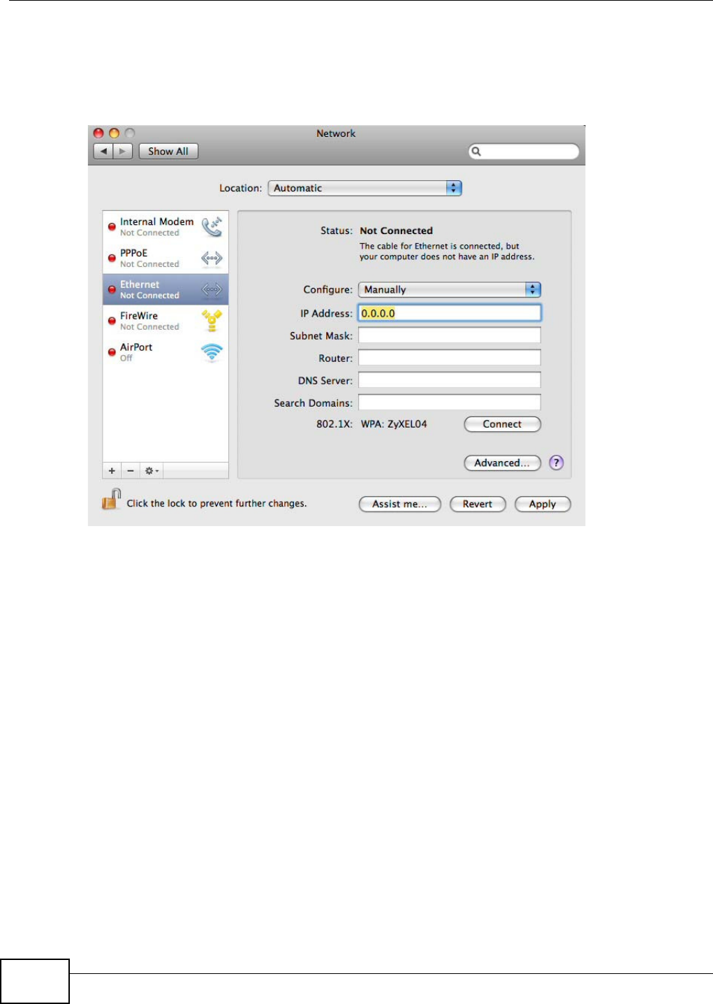
Appendix A Setting Up Your Computer’s IP Address
WAP5705 User’s Guide
122
•From the Configur e list, select M a nua lly.
•In the I P Addr e ss field, enter your IP address.
•In the Subn et M a sk field, enter your subnet mask.
•In the Ro ut e r field, enter the IP address of your WAP5705.
6Click Apply and close the window.
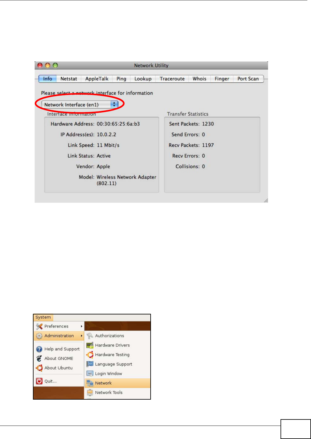
Appendix A Setting Up Your Computer’s IP Address
WAP5705 User’s Guide 123
Verifying Settings
Check your TCP/IP properties by clicking Applicat ions > Ut ilit ies > N e t w ork Ut ilit ie s, and then
selecting the appropriate N e t w or k interface from the I nfo tab.
Figure 69 Mac OS X 10.5: Network Utility
Linux: Ubuntu 8 (GNOME)
This section shows you how to configure your computer’s TCP/IP settings in the GNU Object Model
Environment (GNOME) using the Ubuntu 8 Linux distribution. The procedure, screens and file
locations may vary depending on your specific distribution, release version, and individual
configuration. The following screens use the default Ubuntu 8 installation.
Note: Make sure you are logged in as the root administrator.
Follow the steps below to configure your computer IP address in GNOME:
1Click Syst e m > Adm inist r a t ion > Net w ork.
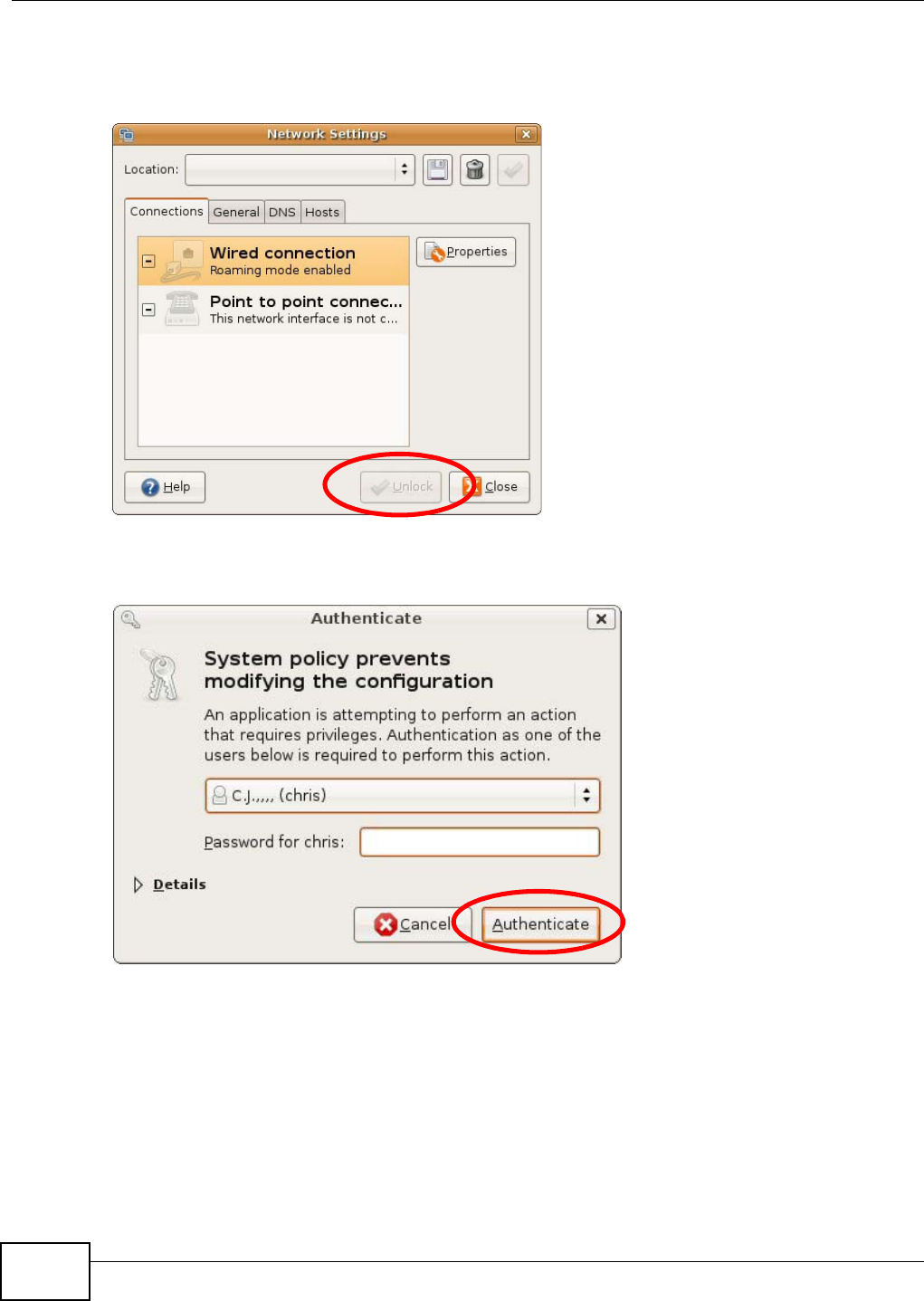
Appendix A Setting Up Your Computer’s IP Address
WAP5705 User’s Guide
124
2When the N et w ork Set t ings window opens, click Un lock to open the Au t he n t icat e window. (By
default, the Unlock button is greyed out until clicked.) You cannot make changes to your
configuration unless you first enter your admin password.
3In the Au t he n t icat e window, enter your admin account name and password then click the
Au t he nt ica t e button.
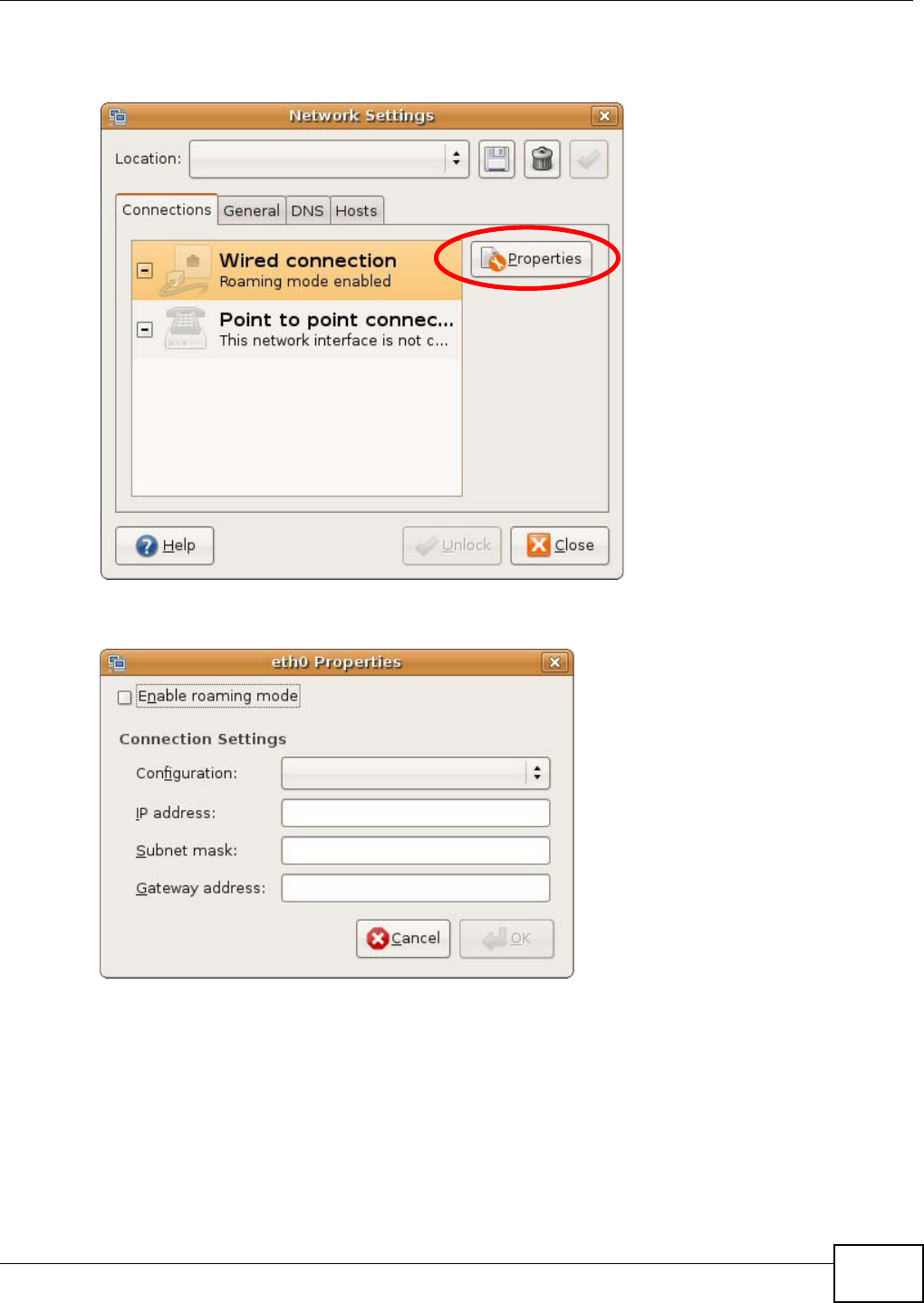
Appendix A Setting Up Your Computer’s IP Address
WAP5705 User’s Guide 125
4In the N e t w or k Se t t ings window, select the connection that you want to configure, then click
Pr ope r t ie s.
5The Pr ope r t ie s dialog box opens.
•In the Configur a t ion list, select Au t om a t ic Configura t ion ( DH CP) if you have a dynamic IP
address.
•In the Conf igur a t ion list, select St a t ic I P a ddress if you have a static IP address. Fill in the
I P a ddr ess, Su bn et m ask , and Gat ew ay addr ess fields.
6Click OK to save the changes and close the Pr op e rt ie s dialog box and return to the N e t w ork
Se t t in gs screen.
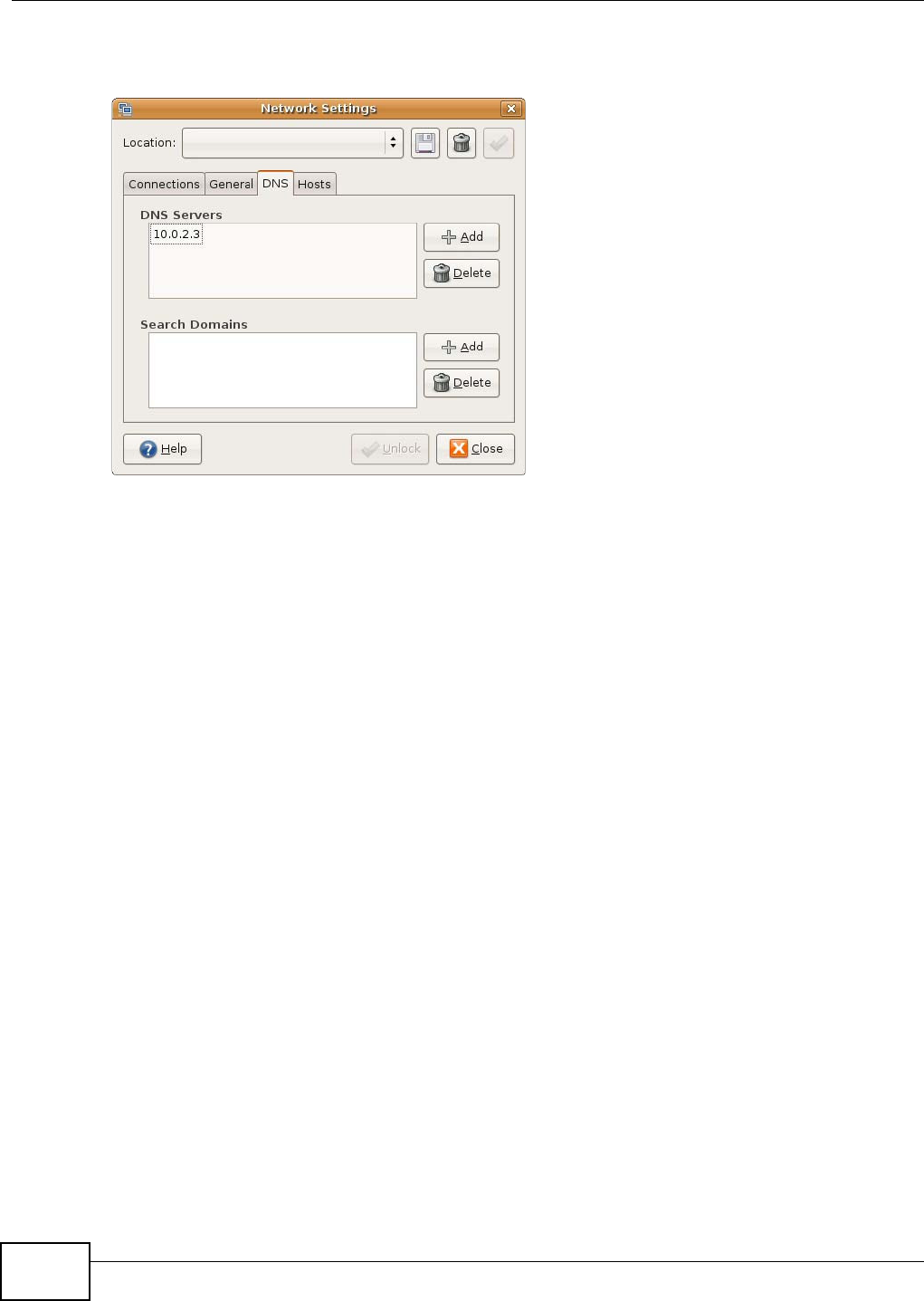
Appendix A Setting Up Your Computer’s IP Address
WAP5705 User’s Guide
126
7If you know your DNS server IP address(es), click the D N S tab in the Netw or k Set t ings window
and then enter the DNS server information in the fields provided.
8Click the Close button to apply the changes.
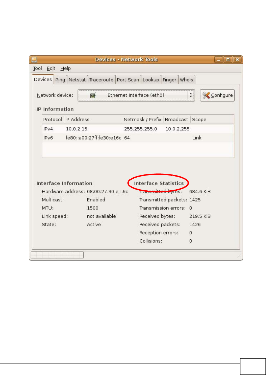
Appendix A Setting Up Your Computer’s IP Address
WAP5705 User’s Guide 127
Verifying Settings
Check your TCP/IP properties by clicking System > Adm in ist r a t ion > Netw or k Tools, and then
selecting the appropriate N e t w ork de vice from the Devices tab. The I nt e r fa ce St a t istics
column shows data if your connection is working properly.
Figure 70 Ubuntu 8: Network Tools
Linux: openSUSE 10.3 (KDE)
This section shows you how to configure your computer’s TCP/IP settings in the K Desktop
Environment (KDE) using the openSUSE 10.3 Linux distribution. The procedure, screens and file
locations may vary depending on your specific distribution, release version, and individual
configuration. The following screens use the default openSUSE 10.3 installation.
Note: Make sure you are logged in as the root administrator.
Follow the steps below to configure your computer IP address in the KDE:
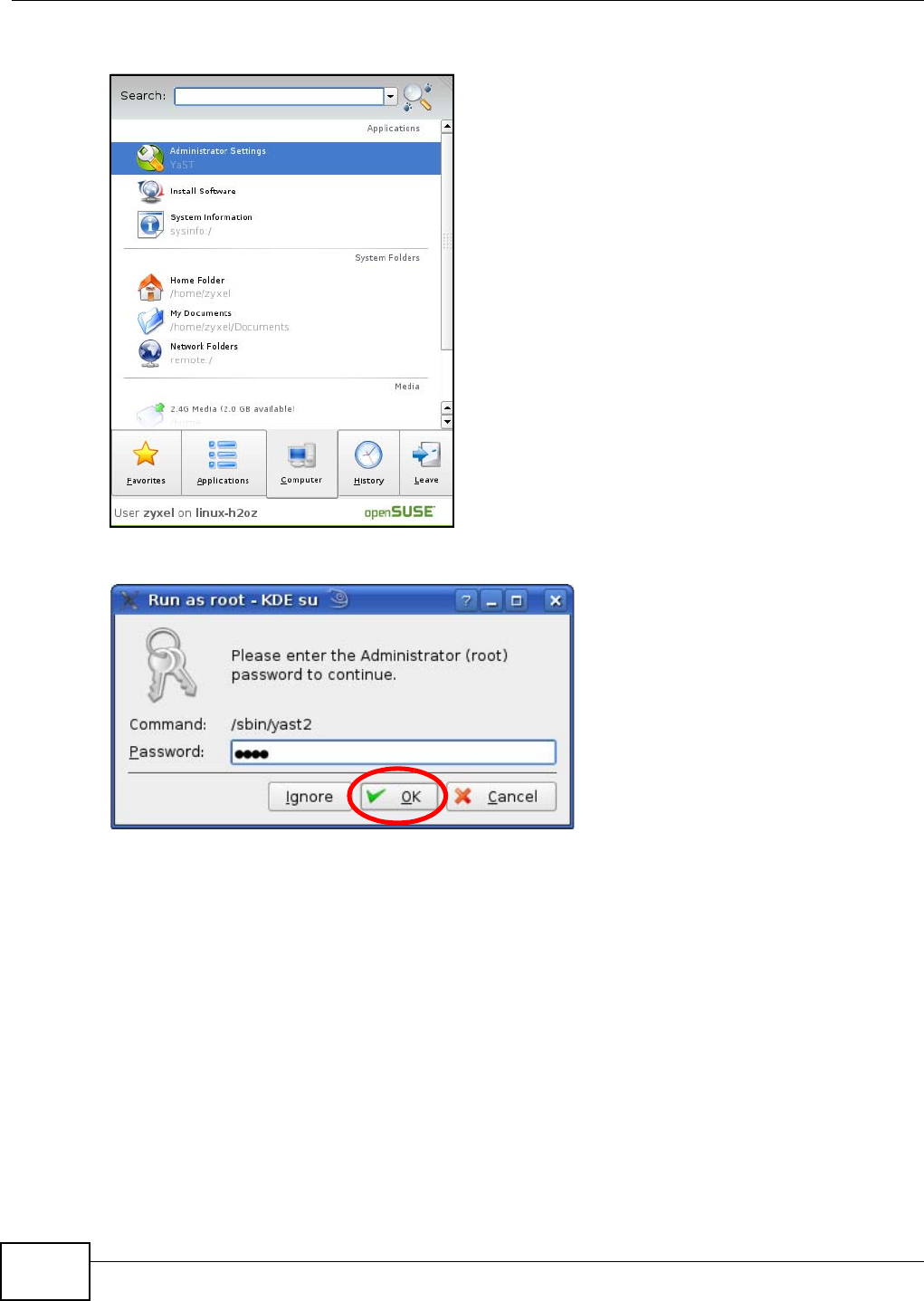
Appendix A Setting Up Your Computer’s IP Address
WAP5705 User’s Guide
128
1Click K M e n u > Com put er > Adm inist rat or Set t ings ( Ya ST) .
2When the Run as Root - KD E su dialog opens, enter the admin password and click OK.
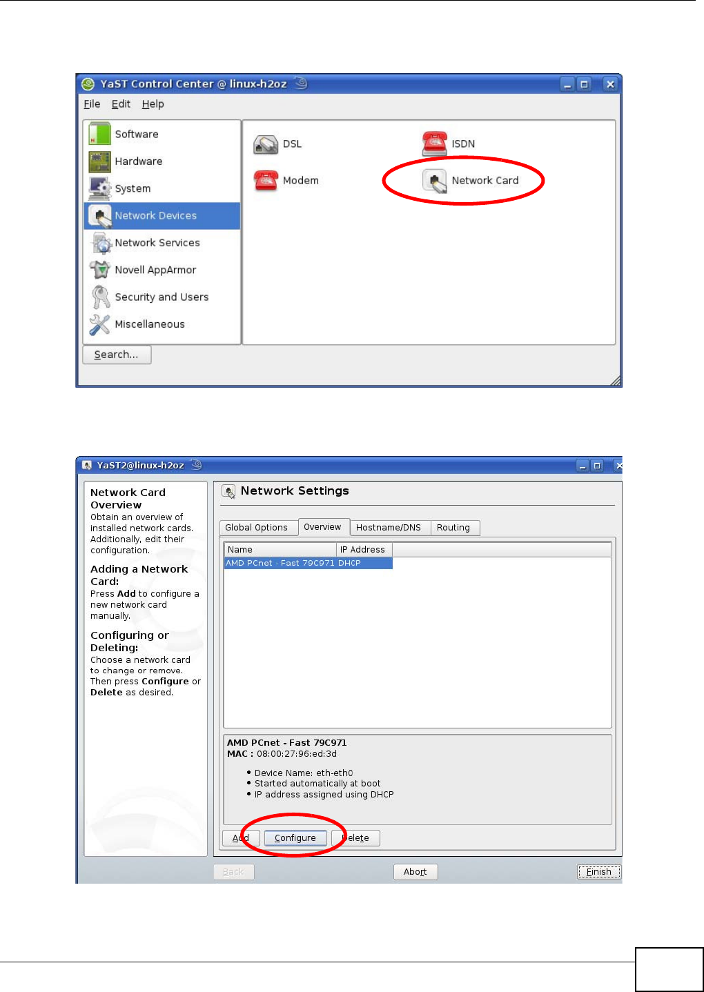
Appendix A Setting Up Your Computer’s IP Address
WAP5705 User’s Guide 129
3When the YaST Control Ce n t e r window opens, select Ne t w or k D e vices and then click the
N et w ork Ca rd icon.
4When the N et w ork Set t ings window opens, click the Ov erview tab, select the appropriate
connection N a m e from the list, and then click the Configure button.
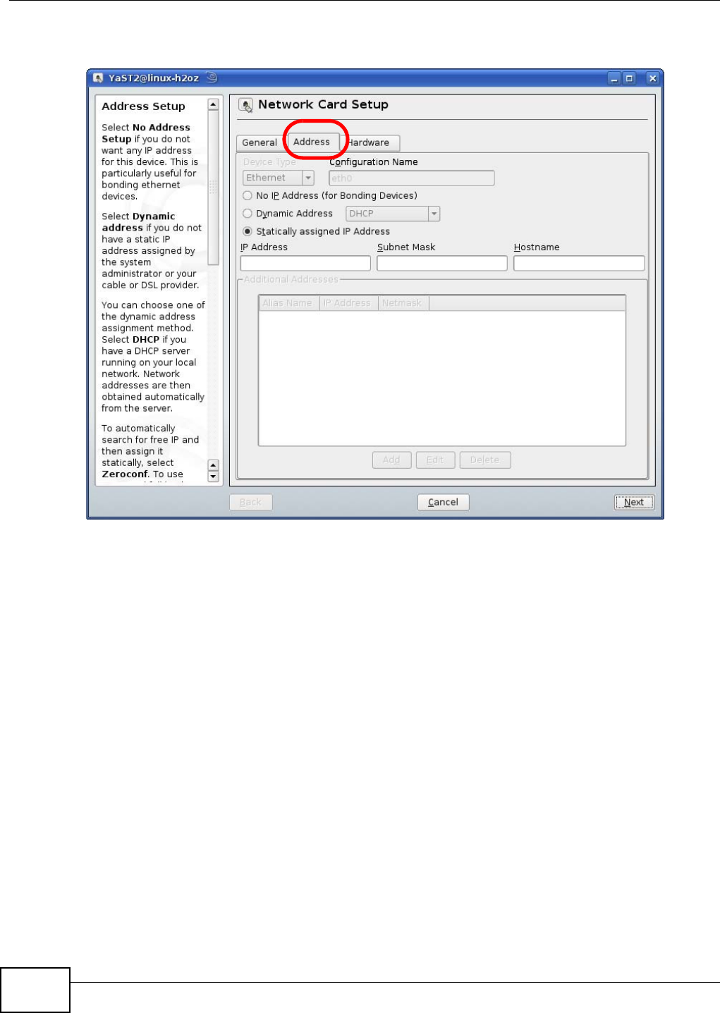
Appendix A Setting Up Your Computer’s IP Address
WAP5705 User’s Guide
130
5When the N et w ork Ca r d Set up window opens, click the Address tab
Figure 71 openSUSE 10.3: Network Card Setup
6Select Dynam ic Addr e ss ( DHCP) if you have a dynamic IP address.
Select St a t ically a ssigned I P Addr e ss if you have a static IP address. Fill in the I P addr ess,
Subn e t m ask, and Hostn a m e fields.
7Click N e x t to save the changes and close the N etw or k Ca rd Set up window.
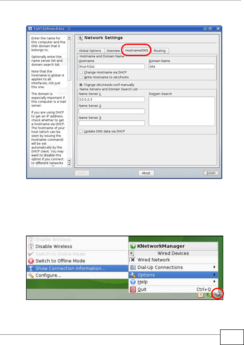
Appendix A Setting Up Your Computer’s IP Address
WAP5705 User’s Guide 131
8If you know your DNS server IP address(es), click the H ost n am e / D N S tab in Ne t w or k Se t t ings
and then enter the DNS server information in the fields provided.
9Click Finish to save your settings and close the window.
Verifying Settings
Click the KN e t w or k Mana ge r icon on the Ta sk bar to check your TCP/IP properties. From the
Op t ion s sub-menu, select Show Conne ction I nform at ion.
Figure 72 openSUSE 10.3: KNetwork Manager
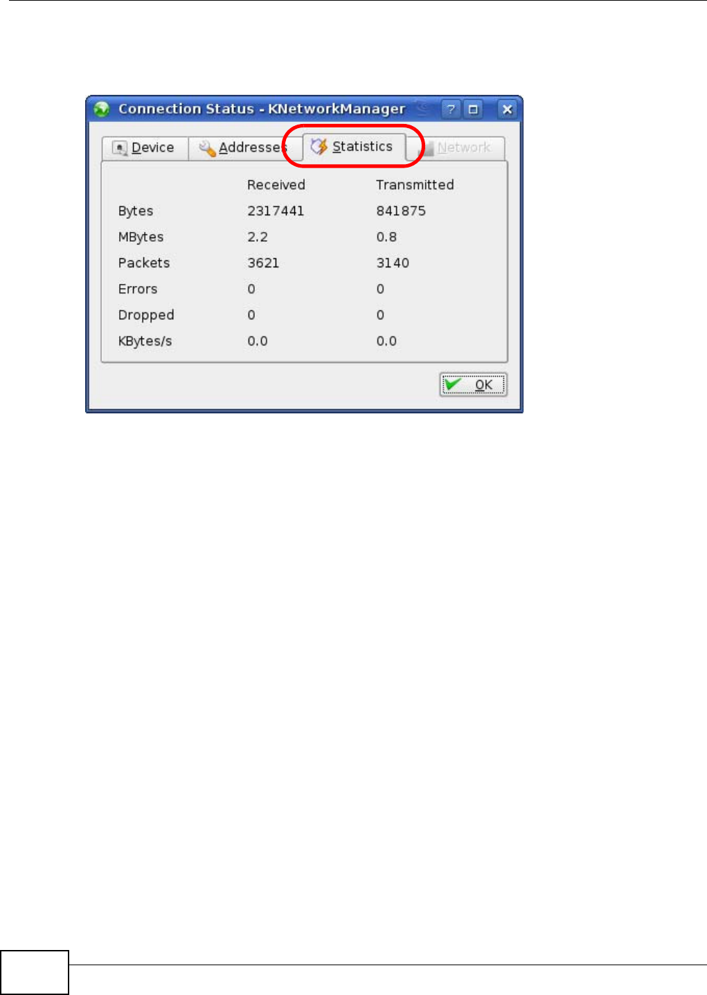
Appendix A Setting Up Your Computer’s IP Address
WAP5705 User’s Guide
132
When the Connect ion Stat us - KNetw or k Mana ge r window opens, click the St a t istics t a b to
see if your connection is working properly.
Figure 73 openSUSE: Connection Status - KNetwork Manager
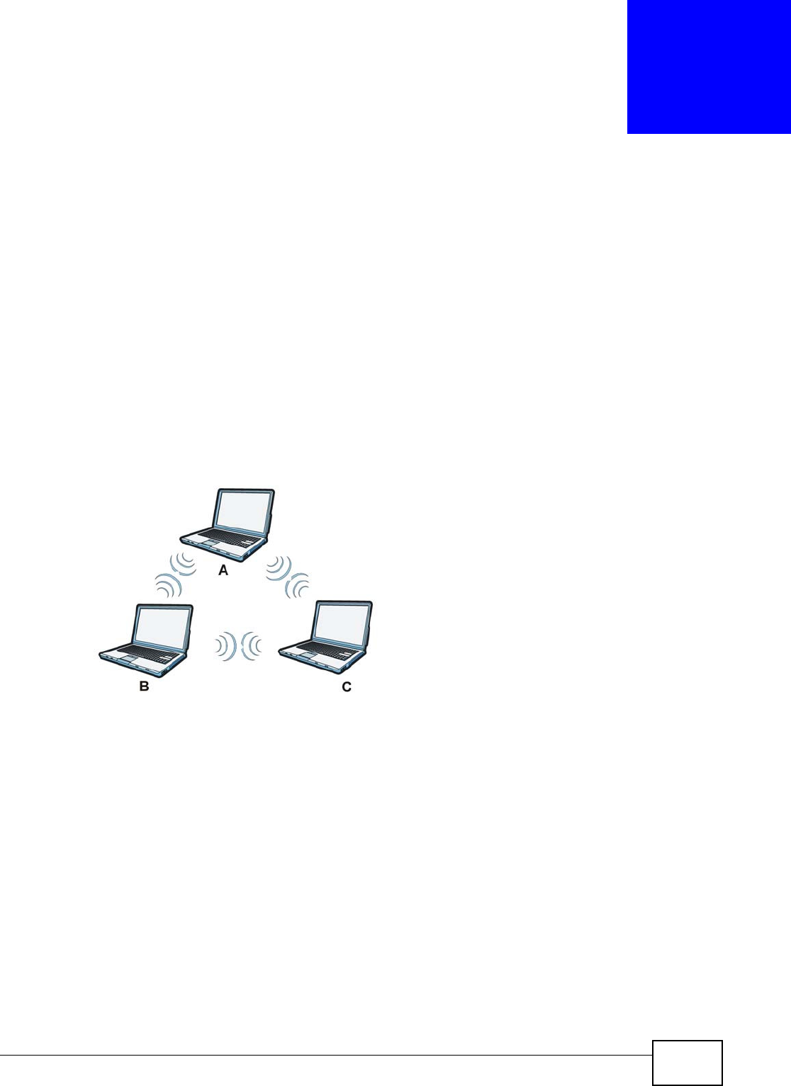
WAP5705 User’s Guide 133
APPENDIX B
Wireless LANs
Wireless LAN Topologies
This section discusses ad-hoc and infrastructure wireless LAN topologies.
Ad-hoc Wireless LAN Configuration
The simplest WLAN configuration is an independent (Ad-hoc) WLAN that connects a set of
computers with wireless adapters (A, B, C). Any time two or more wireless adapters are within
range of each other, they can set up an independent network, which is commonly referred to as an
ad-hoc network or Independent Basic Service Set (IBSS). The following diagram shows an example
of notebook computers using wireless adapters to form an ad-hoc wireless LAN.
Figure 74 Peer-to-Peer Communication in an Ad-hoc Network
BSS
A Basic Service Set (BSS) exists when all communications between wireless clients or between a
wireless client and a wired network client go through one access point (AP).
Intra-BSS traffic is traffic between wireless clients in the BSS. When Intra-BSS is enabled, wireless
client A and B can access the wired network and communicate with each other. When Intra-BSS is
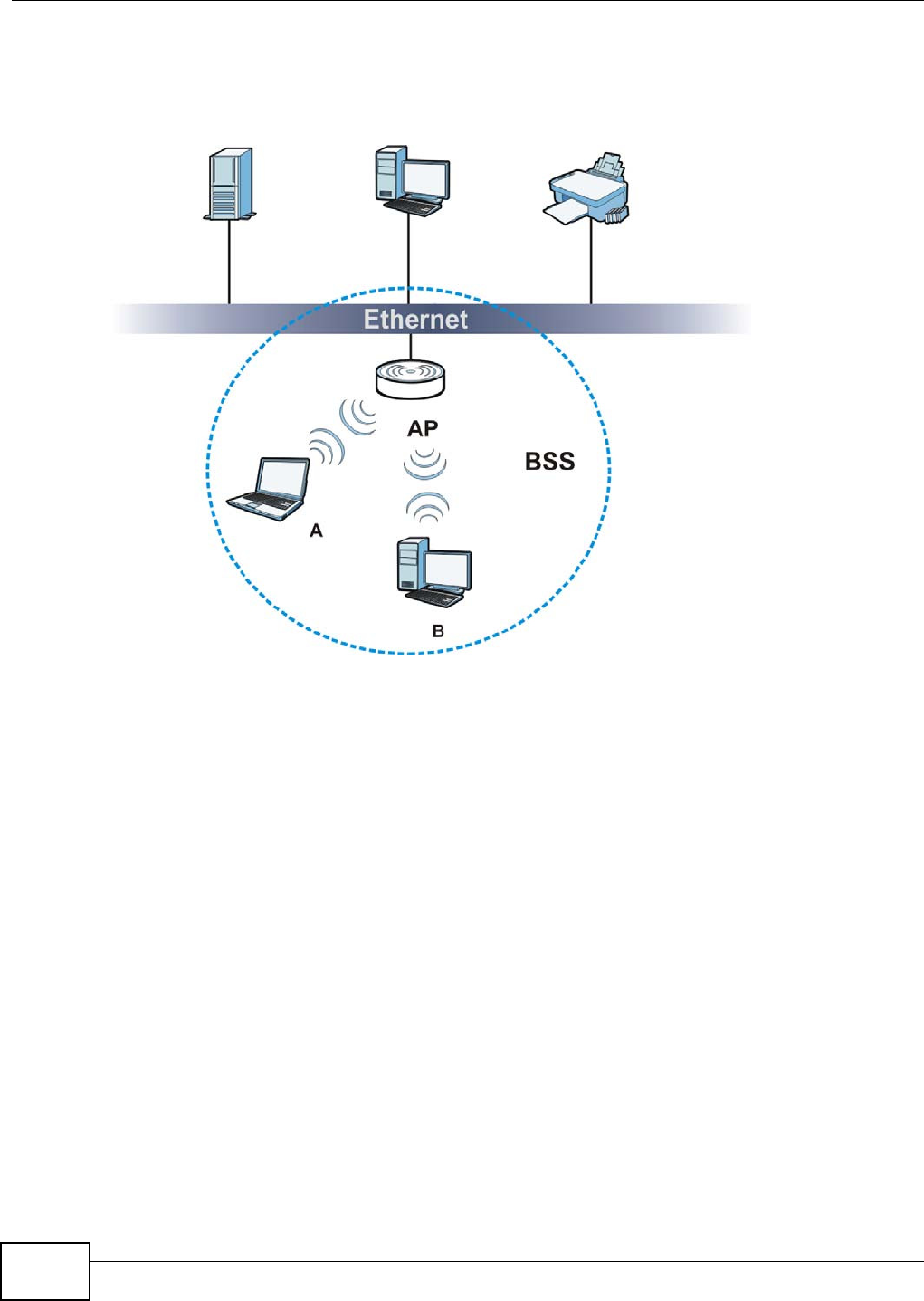
Appendix B Wireless LANs
WAP5705 User’s Guide
134
disabled, wireless client A and B can still access the wired network but cannot communicate with
each other.
Figure 75 Basic Service Set
ESS
An Extended Service Set (ESS) consists of a series of overlapping BSSs, each containing an access
point, with each access point connected together by a wired network. This wired connection
between APs is called a Distribution System (DS).
This type of wireless LAN topology is called an Infrastructure WLAN. The Access Points not only
provide communication with the wired network but also mediate wireless network traffic in the
immediate neighborhood.
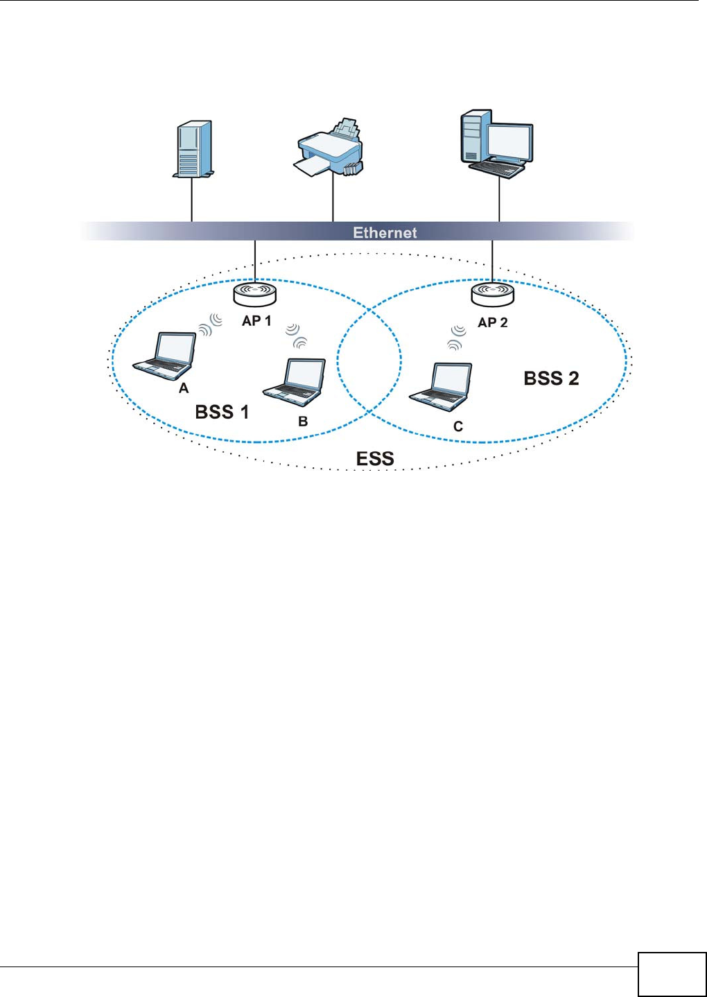
Appendix B Wireless LANs
WAP5705 User’s Guide 135
An ESSID (ESS IDentification) uniquely identifies each ESS. All access points and their associated
wireless clients within the same ESS must have the same ESSID in order to communicate.
Figure 76 Infrastructure WLAN
Channel
A channel is the radio frequency(ies) used by wireless devices to transmit and receive data.
Channels available depend on your geographical area. You may have a choice of channels (for your
region) so you should use a channel different from an adjacent AP (access point) to reduce
interference. Interference occurs when radio signals from different access points overlap causing
interference and degrading performance.
Adjacent channels partially overlap however. To avoid interference due to overlap, your AP should
be on a channel at least five channels away from a channel that an adjacent AP is using. For
example, if your region has 11 channels and an adjacent AP is using channel 1, then you need to
select a channel between 6 or 11.
RTS/CTS
A hidden node occurs when two stations are within range of the same access point, but are not
within range of each other. The following figure illustrates a hidden node. Both stations (STA) are
within range of the access point (AP) or wireless gateway, but out-of-range of each other, so they
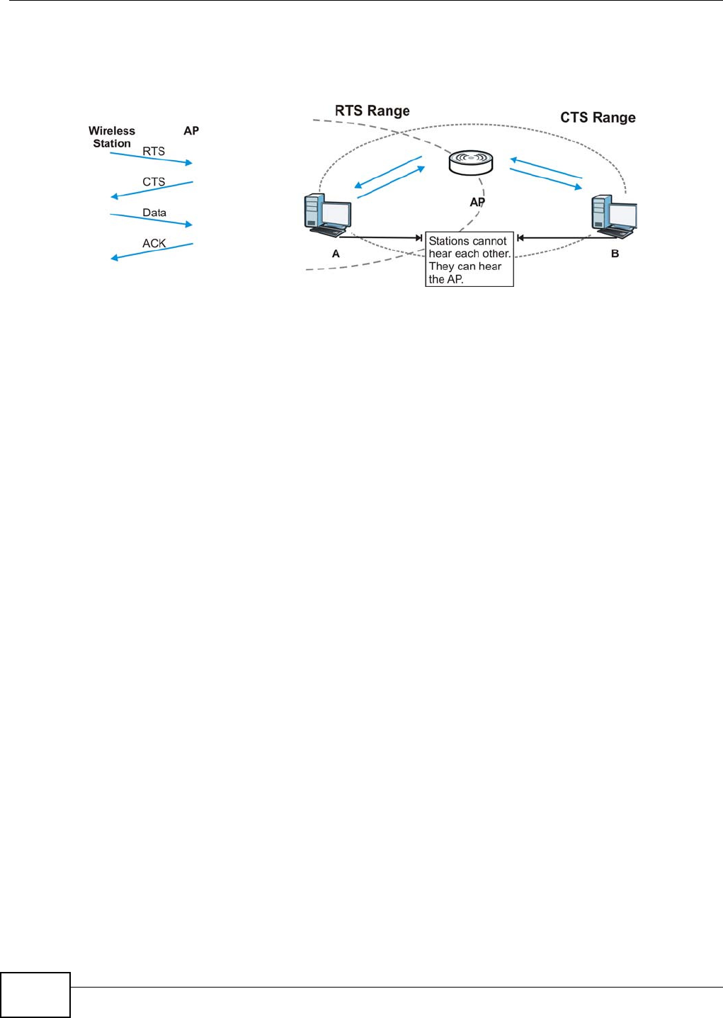
Appendix B Wireless LANs
WAP5705 User’s Guide
136
cannot "hear" each other, that is they do not know if the channel is currently being used. Therefore,
they are considered hidden from each other.
Figure 77 RTS/CTS
When station A sends data to the AP, it might not know that the station B is already using the
channel. If these two stations send data at the same time, collisions may occur when both sets of
data arrive at the AP at the same time, resulting in a loss of messages for both stations.
RTS/ CTS is designed to prevent collisions due to hidden nodes. An RTS/ CTS defines the biggest
size data frame you can send before an RTS (Request To Send)/CTS (Clear to Send) handshake is
invoked.
When a data frame exceeds the RTS/ CTS value you set (between 0 to 2432 bytes), the station
that wants to transmit this frame must first send an RTS (Request To Send) message to the AP for
permission to send it. The AP then responds with a CTS (Clear to Send) message to all other
stations within its range to notify them to defer their transmission. It also reserves and confirms
with the requesting station the time frame for the requested transmission.
Stations can send frames smaller than the specified RTS/ CTS directly to the AP without the RTS
(Request To Send)/CTS (Clear to Send) handshake.
You should only configure RTS/ CTS if the possibility of hidden nodes exists on your network and
the "cost" of resending large frames is more than the extra network overhead involved in the RTS
(Request To Send)/CTS (Clear to Send) handshake.
If the RTS/ CTS value is greater than the Fr a gm e n t a t ion Thr eshold value (see next), then the
RTS (Request To Send)/CTS (Clear to Send) handshake will never occur as data frames will be
fragmented before they reach RTS/ CTS size.
Note: Enabling the RTS Threshold causes redundant network overhead that could
negatively affect the throughput performance instead of providing a remedy.
Fragmentation Threshold
A Fra gm ent a t ion Th r eshold is the maximum data fragment size (between 256 and 2432 bytes)
that can be sent in the wireless network before the AP will fragment the packet into smaller data
frames.
A large Fra gm e nt a t ion Threshold is recommended for networks not prone to interference while
you should set a smaller threshold for busy networks or networks that are prone to interference.

Appendix B Wireless LANs
WAP5705 User’s Guide 137
If the Fra gm en t a t ion Thre shold value is smaller than the RTS/ CTS value (see previously) you
set then the RTS (Request To Send)/CTS (Clear to Send) handshake will never occur as data frames
will be fragmented before they reach RTS/ CTS size.
Preamble Type
Preamble is used to signal that data is coming to the receiver. Short and long refer to the length of
the synchronization field in a packet.
Short preamble increases performance as less time sending preamble means more time for sending
data. All IEEE 802.11 compliant wireless adapters support long preamble, but not all support short
preamble.
Use long preamble if you are unsure what preamble mode other wireless devices on the network
support, and to provide more reliable communications in busy wireless networks.
Use short preamble if you are sure all wireless devices on the network support it, and to provide
more efficient communications.
Use the dynamic setting to automatically use short preamble when all wireless devices on the
network support it, otherwise the WAP5705 uses long preamble.
Note: The wireless devices MUST use the same preamble mode in order to communicate.
IEEE 802.11g Wireless LAN
IEEE 802.11g is fully compatible with the IEEE 802.11b standard. This means an IEEE 802.11b
adapter can interface directly with an IEEE 802.11g access point (and vice versa) at 11 Mbps or
lower depending on range. IEEE 802.11g has several intermediate rate steps between the
maximum and minimum data rates. The IEEE 802.11g data rate and modulation are as follows:
Wireless Security Overview
Wireless security is vital to your network to protect wireless communication between wireless
clients, access points and the wired network.
Wireless security methods available on the WAP5705 are data encryption, wireless client
authentication, restricting access by device MAC address and hiding the WAP5705 identity.
Table 45 IEEE 802.11g
DATA RATE (MBPS) MODULATION
1 DBPSK (Differential Binary Phase Shift Keyed)
2 DQPSK (Differential Quadrature Phase Shift Keying)
5.5 / 11 CCK (Complementary Code Keying)
6/9/12/18/24/36/48/
54
OFDM (Orthogonal Frequency Division Multiplexing)

Appendix B Wireless LANs
WAP5705 User’s Guide
138
The following figure shows the relative effectiveness of these wireless security methods available on
your WAP5705.
Note: You must enable the same wireless security settings on the WAP5705 and on all
wireless clients that you want to associate with it.
IEEE 802.1x
In June 2001, the IEEE 802.1x standard was designed to extend the features of IEEE 802.11 to
support extended authentication as well as providing additional accounting and control features. It
is supported by Windows XP and a number of network devices. Some advantages of IEEE 802.1x
are:
• User based identification that allows for roaming.
• Support for RADIUS (Remote Authentication Dial In User Service, RFC 2138, 2139) for
centralized user profile and accounting management on a network RADIUS server.
• Support for EAP (Extensible Authentication Protocol, RFC 2486) that allows additional
authentication methods to be deployed with no changes to the access point or the wireless
clients.
RADIUS
RADIUS is based on a client-server model that supports authentication, authorization and
accounting. The access point is the client and the server is the RADIUS server. The RADIUS server
handles the following tasks:
• Authentication
Determines the identity of the users.
•Authorization
Determines the network services available to authenticated users once they are connected to the
network.
• Accounting
Keeps track of the client’s network activity.
Table 46 Wireless Security Levels
SECURITY
LEVEL SECURITY TYPE
Least
Secure
Most Secure
Unique SSID (Default)
Unique SSID with Hide SSID Enabled
MAC Address Filtering
WEP Encryption
IEEE802.1x EAP with RADIUS Server Authentication
Wi-Fi Protected Access (WPA)
WPA2

Appendix B Wireless LANs
WAP5705 User’s Guide 139
RADIUS is a simple package exchange in which your AP acts as a message relay between the
wireless client and the network RADIUS server.
Types of RADIUS Messages
The following types of RADIUS messages are exchanged between the access point and the RADIUS
server for user authentication:
• Access-Request
Sent by an access point requesting authentication.
• Access-Reject
Sent by a RADIUS server rejecting access.
• Access-Accept
Sent by a RADIUS server allowing access.
• Access-Challenge
Sent by a RADIUS server requesting more information in order to allow access. The access point
sends a proper response from the user and then sends another Access-Request message.
The following types of RADIUS messages are exchanged between the access point and the RADIUS
server for user accounting:
• Accounting-Request
Sent by the access point requesting accounting.
• Accounting-Response
Sent by the RADIUS server to indicate that it has started or stopped accounting.
In order to ensure network security, the access point and the RADIUS server use a shared secret
key, which is a password, they both know. The key is not sent over the network. In addition to the
shared key, password information exchanged is also encrypted to protect the network from
unauthorized access.
Types of EAP Authentication
This section discusses some popular authentication types: EAP-MD5, EAP-TLS, EAP-TTLS, PEAP and
LEAP. Your wireless LAN device may not support all authentication types.
EAP (Extensible Authentication Protocol) is an authentication protocol that runs on top of the IEEE
802.1x transport mechanism in order to support multiple types of user authentication. By using EAP
to interact with an EAP-compatible RADIUS server, an access point helps a wireless station and a
RADIUS server perform authentication.
The type of authentication you use depends on the RADIUS server and an intermediary AP(s) that
supports IEEE 802.1x. .
For EAP-TLS authentication type, you must first have a wired connection to the network and obtain
the certificate(s) from a certificate authority (CA). A certificate (also called digital IDs) can be used
to authenticate users and a CA issues certificates and guarantees the identity of each certificate
owner.

Appendix B Wireless LANs
WAP5705 User’s Guide
140
EAP-MD5 (Message-Digest Algorithm 5)
MD5 authentication is the simplest one-way authentication method. The authentication server
sends a challenge to the wireless client. The wireless client ‘proves’ that it knows the password by
encrypting the password with the challenge and sends back the information. Password is not sent in
plain text.
However, MD5 authentication has some weaknesses. Since the authentication server needs to get
the plaintext passwords, the passwords must be stored. Thus someone other than the
authentication server may access the password file. In addition, it is possible to impersonate an
authentication server as MD5 authentication method does not perform mutual authentication.
Finally, MD5 authentication method does not support data encryption with dynamic session key. You
must configure WEP encryption keys for data encryption.
EAP-TLS (Transport Layer Security)
With EAP-TLS, digital certifications are needed by both the server and the wireless clients for
mutual authentication. The server presents a certificate to the client. After validating the identity of
the server, the client sends a different certificate to the server. The exchange of certificates is done
in the open before a secured tunnel is created. This makes user identity vulnerable to passive
attacks. A digital certificate is an electronic ID card that authenticates the sender’s identity.
However, to implement EAP-TLS, you need a Certificate Authority (CA) to handle certificates, which
imposes a management overhead.
EAP-TTLS (Tunneled Transport Layer Service)
EAP-TTLS is an extension of the EAP-TLS authentication that uses certificates for only the server-
side authentications to establish a secure connection. Client authentication is then done by sending
username and password through the secure connection, thus client identity is protected. For client
authentication, EAP-TTLS supports EAP methods and legacy authentication methods such as PAP,
CHAP, MS-CHAP and MS-CHAP v2.
PEAP (Protected EAP)
Like EAP-TTLS, server-side certificate authentication is used to establish a secure connection, then
use simple username and password methods through the secured connection to authenticate the
clients, thus hiding client identity. However, PEAP only supports EAP methods, such as EAP-MD5,
EAP-MSCHAPv2 and EAP-GTC (EAP-Generic Token Card), for client authentication. EAP-GTC is
implemented only by Cisco.
LEAP
LEAP (Lightweight Extensible Authentication Protocol) is a Cisco implementation of IEEE 802.1x.
Dynamic WEP Key Exchange
The AP maps a unique key that is generated with the RADIUS server. This key expires when the
wireless connection times out, disconnects or reauthentication times out. A new WEP key is
generated each time reauthentication is performed.

Appendix B Wireless LANs
WAP5705 User’s Guide 141
If this feature is enabled, it is not necessary to configure a default encryption key in the wireless
security configuration screen. You may still configure and store keys, but they will not be used while
dynamic WEP is enabled.
Note: EAP-MD5 cannot be used with Dynamic WEP Key Exchange
For added security, certificate-based authentications (EAP-TLS, EAP-TTLS and PEAP) use dynamic
keys for data encryption. They are often deployed in corporate environments, but for public
deployment, a simple user name and password pair is more practical. The following table is a
comparison of the features of authentication types.
WPA and WPA2
Wi-Fi Protected Access (WPA) is a subset of the IEEE 802.11i standard. WPA2 (IEEE 802.11i) is a
wireless security standard that defines stronger encryption, authentication and key management
than WPA.
Key differences between WPA or WPA2 and WEP are improved data encryption and user
authentication.
If both an AP and the wireless clients support WPA2 and you have an external RADIUS server, use
WPA2 for stronger data encryption. If you don't have an external RADIUS server, you should use
WPA2-PSK (WPA2-Pre-Shared Key) that only requires a single (identical) password entered into
each access point, wireless gateway and wireless client. As long as the passwords match, a wireless
client will be granted access to a WLAN.
If the AP or the wireless clients do not support WPA2, just use WPA or WPA-PSK depending on
whether you have an external RADIUS server or not.
Select WEP only when the AP and/or wireless clients do not support WPA or WPA2. WEP is less
secure than WPA or WPA2.
Encryption
WPA improves data encryption by using Temporal Key Integrity Protocol (TKIP), Message Integrity
Check (MIC) and IEEE 802.1x. WPA2 also uses TKIP when required for compatibility reasons, but
offers stronger encryption than TKIP with Advanced Encryption Standard (AES) in the Counter
mode with Cipher block chaining Message authentication code Protocol (CCMP).
TKIP uses 128-bit keys that are dynamically generated and distributed by the authentication server.
AES (Advanced Encryption Standard) is a block cipher that uses a 256-bit mathematical algorithm
Table 47 Comparison of EAP Authentication Types
EAP-MD5 EAP-TLS EAP-TTLS PEAP LEAP
Mutual Authentication No Yes Yes Yes Yes
Certificate – Client No Yes Optional Optional No
Certificate – Server No Yes Yes Yes No
Dynamic Key Exchange No Yes Yes Yes Yes
Credential Integrity None Strong Strong Strong Moderate
Deployment Difficulty Easy Hard Moderate Moderate Moderate
Client Identity Protection No No Yes Yes No

Appendix B Wireless LANs
WAP5705 User’s Guide
142
called Rijndael. They both include a per-packet key mixing function, a Message Integrity Check
(MIC) named Michael, an extended initialization vector (IV) with sequencing rules, and a re-keying
mechanism.
WPA and WPA2 regularly change and rotate the encryption keys so that the same encryption key is
never used twice.
The RADIUS server distributes a Pairwise Master Key (PMK) key to the AP that then sets up a key
hierarchy and management system, using the PMK to dynamically generate unique data encryption
keys to encrypt every data packet that is wirelessly communicated between the AP and the wireless
clients. This all happens in the background automatically.
The Message Integrity Check (MIC) is designed to prevent an attacker from capturing data packets,
altering them and resending them. The MIC provides a strong mathematical function in which the
receiver and the transmitter each compute and then compare the MIC. If they do not match, it is
assumed that the data has been tampered with and the packet is dropped.
By generating unique data encryption keys for every data packet and by creating an integrity
checking mechanism (MIC), with TKIP and AES it is more difficult to decrypt data on a Wi-Fi
network than WEP and difficult for an intruder to break into the network.
The encryption mechanisms used for WPA(2) and WPA(2)-PSK are the same. The only difference
between the two is that WPA(2)-PSK uses a simple common password, instead of user-specific
credentials. The common-password approach makes WPA(2)-PSK susceptible to brute-force
password-guessing attacks but it’s still an improvement over WEP as it employs a consistent,
single, alphanumeric password to derive a PMK which is used to generate unique temporal
encryption keys. This prevent all wireless devices sharing the same encryption keys. (a weakness of
WEP)
User Authentication
WPA and WPA2 apply IEEE 802.1x and Extensible Authentication Protocol (EAP) to authenticate
wireless clients using an external RADIUS database. WPA2 reduces the number of key exchange
messages from six to four (CCMP 4-way handshake) and shortens the time required to connect to a
network. Other WPA2 authentication features that are different from WPA include key caching and
pre-authentication. These two features are optional and may not be supported in all wireless
devices.
Key caching allows a wireless client to store the PMK it derived through a successful authentication
with an AP. The wireless client uses the PMK when it tries to connect to the same AP and does not
need to go with the authentication process again.
Pre-authentication enables fast roaming by allowing the wireless client (already connecting to an
AP) to perform IEEE 802.1x authentication with another AP before connecting to it.
Wireless Client WPA Supplicants
A wireless client supplicant is the software that runs on an operating system instructing the wireless
client how to use WPA. At the time of writing, the most widely available supplicant is the WPA patch
for Windows XP, Funk Software's Odyssey client.
The Windows XP patch is a free download that adds WPA capability to Windows XP's built-in "Zero
Configuration" wireless client. However, you must run Windows XP to use it.
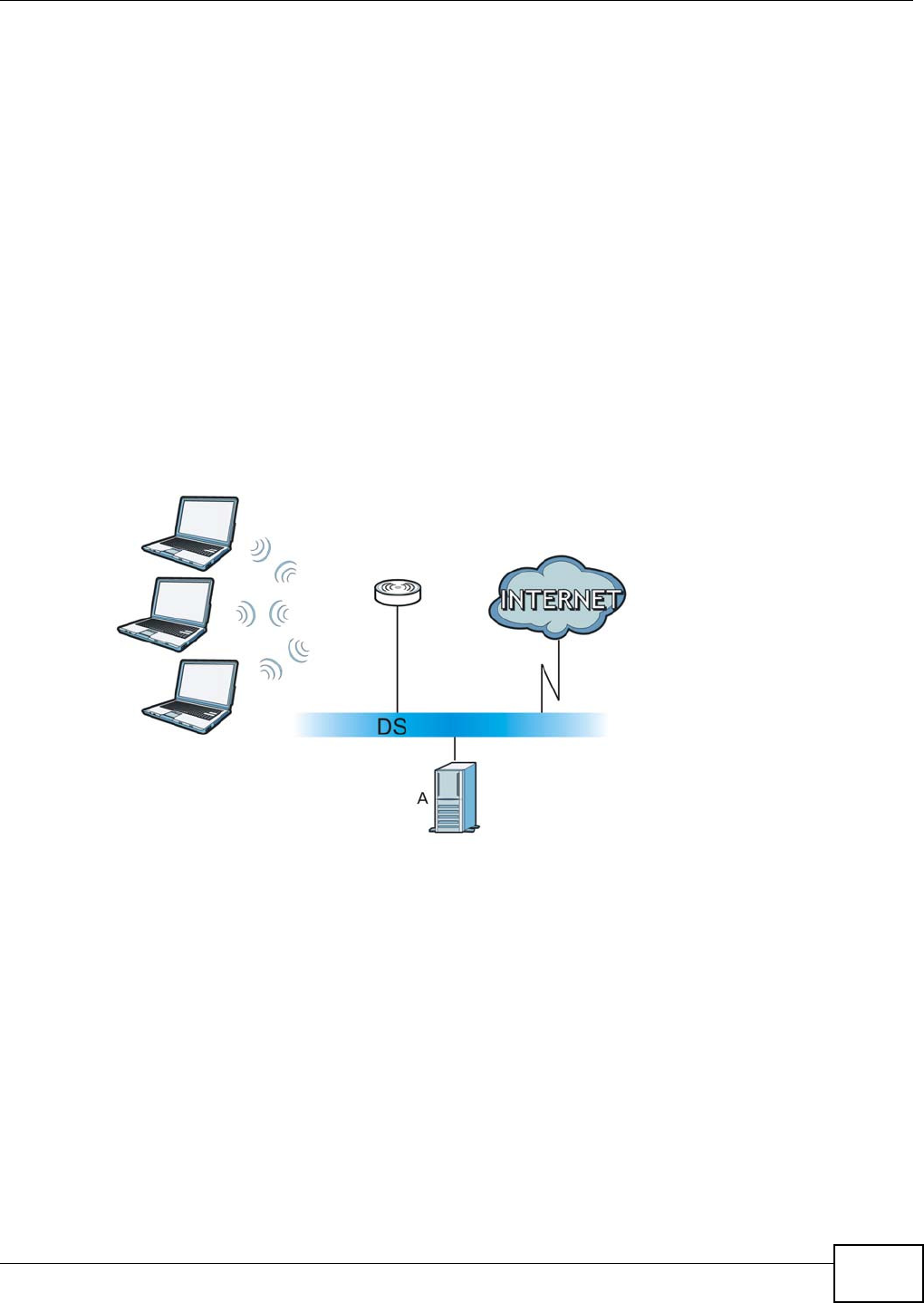
Appendix B Wireless LANs
WAP5705 User’s Guide 143
WPA(2) with RADIUS Application Example
To set up WPA(2), you need the IP address of the RADIUS server, its port number (default is 1812),
and the RADIUS shared secret. A WPA(2) application example with an external RADIUS server
looks as follows. "A" is the RADIUS server. "DS" is the distribution system.
1The AP passes the wireless client's authentication request to the RADIUS server.
2The RADIUS server then checks the user's identification against its database and grants or denies
network access accordingly.
3A 256-bit Pairwise Master Key (PMK) is derived from the authentication process by the RADIUS
server and the client.
4The RADIUS server distributes the PMK to the AP. The AP then sets up a key hierarchy and
management system, using the PMK to dynamically generate unique data encryption keys. The
keys are used to encrypt every data packet that is wirelessly communicated between the AP and
the wireless clients.
Figure 78 WPA(2) with RADIUS Application Example
WPA(2)-PSK Application Example
A WPA(2)-PSK application looks as follows.
1First enter identical passwords into the AP and all wireless clients. The Pre-Shared Key (PSK) must
consist of between 8 and 63 ASCII characters or 64 hexadecimal characters (including spaces and
symbols).
2The AP checks each wireless client's password and allows it to join the network only if the password
matches.
3The AP and wireless clients generate a common PMK (Pairwise Master Key). The key itself is not
sent over the network, but is derived from the PSK and the SSID.
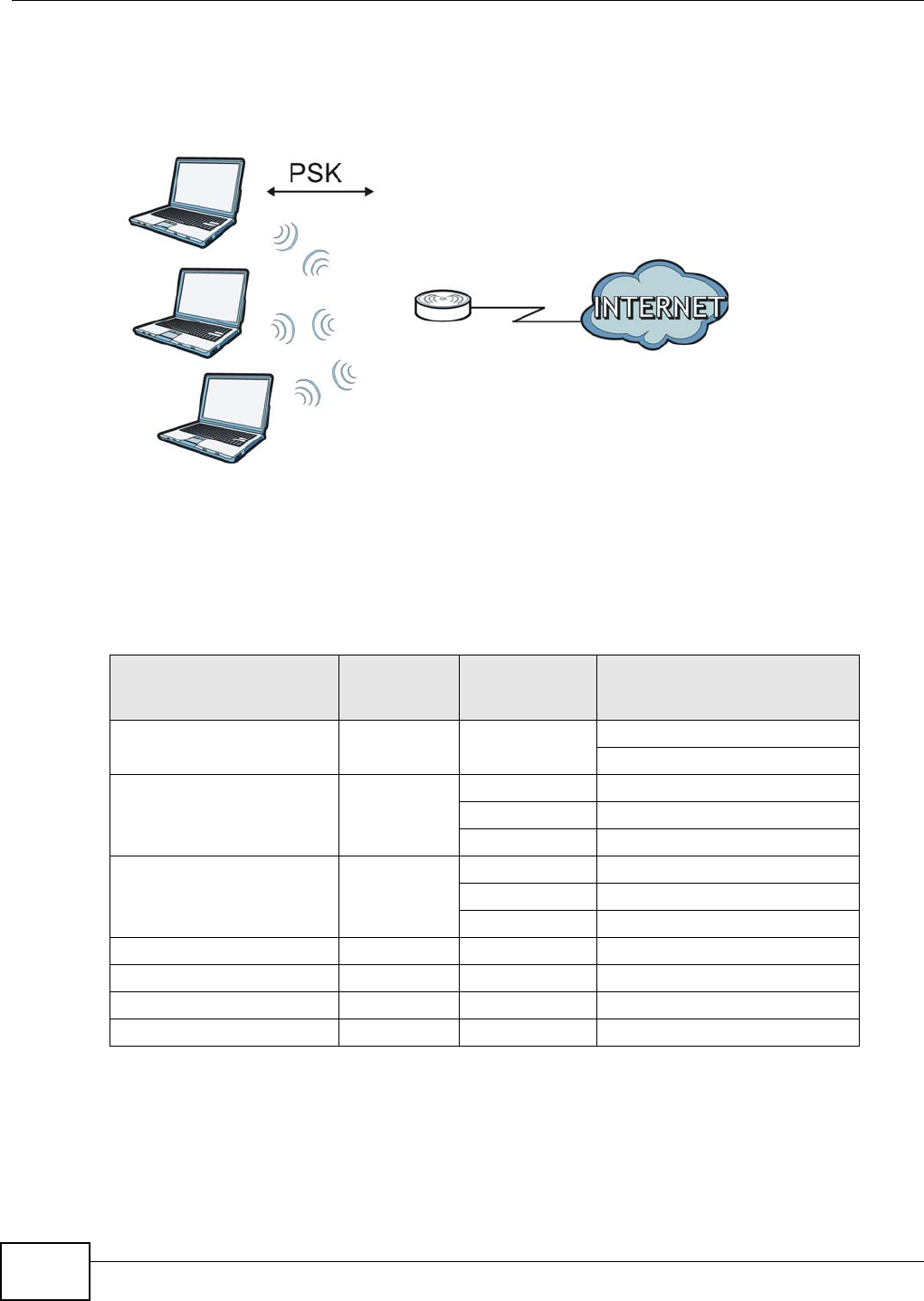
Appendix B Wireless LANs
WAP5705 User’s Guide
144
4The AP and wireless clients use the TKIP or AES encryption process, the PMK and information
exchanged in a handshake to create temporal encryption keys. They use these keys to encrypt data
exchanged between them.
Figure 79 WPA(2)-PSK Authentication
Security Parameters Summary
Refer to this table to see what other security parameters you should configure for each
authentication method or key management protocol type. MAC address filters are not dependent on
how you configure these security features.
Antenna Overview
An antenna couples RF signals onto air. A transmitter within a wireless device sends an RF signal to
the antenna, which propagates the signal through the air. The antenna also operates in reverse by
capturing RF signals from the air.
Table 48 Wireless Security Relational Matrix
AUTHENTICATION
METHOD/ KEY
MANAGEMENT PROTOCOL
ENCRYPTIO
N METHOD
ENTER
MANUAL KEY IEEE 802.1X
Open None No Disable
Enable without Dynamic WEP Key
Open WEP No Enable with Dynamic WEP Key
Yes Enable without Dynamic WEP Key
Yes Disable
Shared WEP No Enable with Dynamic WEP Key
Yes Enable without Dynamic WEP Key
Yes Disable
WPA TKIP/AES No Enable
WPA-PSK TKIP/AES Yes Disable
WPA2 TKIP/AES No Enable
WPA2-PSK TKIP/AES Yes Disable

Appendix B Wireless LANs
WAP5705 User’s Guide 145
Positioning the antennas properly increases the range and coverage area of a wireless LAN.
Antenna Characteristics
Frequency
An antenna in the frequency of 5GHz is needed to communicate efficiently in a wireless LAN.
Radiation Pattern
A radiation pattern is a diagram that allows you to visualize the shape of the antenna’s coverage
area.
Antenna Gain
Antenna gain, measured in dB (decibel), is the increase in coverage within the RF beam width.
Higher antenna gain improves the range of the signal for better communications.
For an indoor site, each 1 dB increase in antenna gain results in a range increase of approximately
2.5%. For an unobstructed outdoor site, each 1dB increase in gain results in a range increase of
approximately 5%. Actual results may vary depending on the network environment.
Antenna gain is sometimes specified in dBi, which is how much the antenna increases the signal
power compared to using an isotropic antenna. An isotropic antenna is a theoretical perfect antenna
that sends out radio signals equally well in all directions. dBi represents the true gain that the
antenna provides.
Types of Antennas for WLAN
There are two types of antennas used for wireless LAN applications.
• Omni-directional antennas send the RF signal out in all directions on a horizontal plane. The
coverage area is torus-shaped (like a donut) which makes these antennas ideal for a room
environment. With a wide coverage area, it is possible to make circular overlapping coverage
areas with multiple access points.
• Directional antennas concentrate the RF signal in a beam, like a flashlight does with the light
from its bulb. The angle of the beam determines the width of the coverage pattern. Angles
typically range from 20 degrees (very directional) to 120 degrees (less directional). Directional
antennas are ideal for hallways and outdoor point-to-point applications.
Positioning Antennas
In general, antennas should be mounted as high as practically possible and free of obstructions. In
point-to–point application, position both antennas at the same height and in a direct line of sight to
each other to attain the best performance.
For omni-directional antennas mounted on a table, desk, and so on, point the antenna up. For
omni-directional antennas mounted on a wall or ceiling, point the antenna down. For a single AP
application, place omni-directional antennas as close to the center of the coverage area as possible.
For directional antennas, point the antenna in the direction of the desired coverage area.

Appendix B Wireless LANs
WAP5705 User’s Guide
146

WAP5705 User’s Guide 147
APPENDIX C
Legal Information
Copyright
Copyright © 2012 by ZyXEL Communications Corporation.
The contents of this publication may not be reproduced in any part or as a whole, transcribed, stored in a retrieval system, translated into
any language, or transmitted in any form or by any means, electronic, mechanical, magnetic, optical, chemical, photocopying, manual, or
otherwise, without the prior written permission of ZyXEL Communications Corporation.
Published by ZyXEL Communications Corporation. All rights reserved.
Disclaimer
ZyXEL does not assume any liability arising out of the application or use of any products, or software described herein. Neither does it
convey any license under its patent rights nor the patent rights of others. ZyXEL further reserves the right to make changes in any
products described herein without notice. This publication is subject to change without notice.
Certifications
Federal Communications Commission (FCC) Interference Statement
The device complies with Part 15 of FCC rules. Operation is subject to the following two conditions:
• This device may not cause harmful interference.
• This device must accept any interference received, including interference that may cause undesired operations.
This device has been tested and found to comply with the limits for a Class B digital device pursuant to Part 15 of the FCC Rules. These
limits are designed to provide reasonable protection against harmful interference in a residential installation. This device generates, uses,
and can radiate radio frequency energy, and if not installed and used in accordance with the instructions, may cause harmful interference
to radio communications. However, there is no guarantee that interference will not occur in a particular installation.
If this device does cause harmful interference to radio/television reception, which can be determined by turning the device off and on, the
user is encouraged to try to correct the interference by one or more of the following measures:
1Reorient or relocate the receiving antenna.
2Increase the separation between the equipment and the receiver.
3Connect the equipment into an outlet on a circuit different from that to which the receiver is connected.
4Consult the dealer or an experienced radio/TV technician for help.
FCC Radiation Exposure Statement
• This transmitter must not be co-located or operating in conjunction with any other antenna or transmitter.
• IEEE 802.11n (20MHz) operation of this product in the U.S.A. is firmware-limited to channels 1 through 11. IEEE 802.11n (40MHz)
operation of this product in the U.S.A. is firmware-limited to channels 3 through 9.
• To comply with FCC RF exposure compliance requirements, a separation distance of at least 20 cm must be maintained between the
antenna of this device and all persons.
注意 !
依據 低率電波輻射性電機管理辦法
第十二條 經型式認證合格之低率射頻電機,非經許可,公司商號或使用
者均不得擅自變更頻率大率或變更原設計之特性及能
第十四條 低率射頻電機之使用不得影響飛航安及干擾合法通信;經發現
有干擾現象時,應立即停用,並改善至無干擾時方得繼續使用
前項合法通信,指依電信規定作業之無線電信低率射頻電機須忍
受合法通信或工業科學及醫療用電波輻射性電機設備之干擾
本機限在不干擾合法電臺與不受被干擾保障條件下於室使用
減少電磁波影響,請妥適使用
Notices
Changes or modifications not expressly approved by the party responsible for compliance could void the user's authority to operate the
equipment.
This device is designed for the WLAN 5 GHz networks throughout the EC region and Switzerland, with restrictions in France.

Appendix C Legal Information
WAP5705 User’s Guide
148
Ce produit est conçu pour les bandes de fréquences 5 GHz conformément à la législation Européenne. En France métropolitaine, suivant
les décisions n°03-908 et 03-909 de l’ARCEP, la puissance d’émission ne devra pas dépasser 10 mW (10 dB) dans le cadre d’une
installation WiFi en extérieur pour les fréquences comprises entre 2454 MHz et 2483,5 MHz.
This Class B digital apparatus complies with Canadian ICES-003.
Cet appareil numérique de la classe B est conforme à la norme NMB-003 du Canada.
Industry Canada Statement
This device complies with RSS-210 of the Industry Canada Rules. Operation is subject to the following two conditions:
1this device may not cause interference and
2this device must accept any interference, including interference that may cause undesired operation of the device
This device has been designed to operate with an antenna having a maximum gain of 2dBi.
Antenna having a higher gain is strictly prohibited per regulations of Industry Canada. The required antenna impedance is 50 ohms.
To reduce potential radio interference to other users, the antenna type and its gain should be so chosen that the EIRP is not more than
required for successful communication.
IMPORTANT NOTE
Device for the band 5150-5250 MHz is only for indoor usage to reduce potential for harmful interference to co-channel mobile satellite
systems; users should also be cautioned to take note that high-power radars are allocated as primary users (meaning they have priority)
of the bands 5250-5350 MHz and 5650-5850 MHz and these radars could cause interference and/or damage to LE-LAN devices.
IC Radiation Exposure Statement:
This equipment complies with IC radiation exposure limits set forth for an uncontrolled environment. This equipment should be installed
and operated with minimum distance 20cm between the radiator & your body.
Viewing Certifications
Go to http://www.zyxel.com to view this product’s documentation and certifications.
ZyXEL Limited Warranty
ZyXEL warrants to the original end user (purchaser) that this product is free from any defects in materials or workmanship for a period of
up to two years from the date of purchase. During the warranty period, and upon proof of purchase, should the product have indications
of failure due to faulty workmanship and/or materials, ZyXEL will, at its discretion, repair or replace the defective products or components
without charge for either parts or labor, and to whatever extent it shall deem necessary to restore the product or components to proper
operating condition. Any replacement will consist of a new or re-manufactured functionally equivalent product of equal or higher value,
and will be solely at the discretion of ZyXEL. This warranty shall not apply if the product has been modified, misused, tampered with,
damaged by an act of God, or subjected to abnormal working conditions.
Note
Repair or replacement, as provided under this warranty, is the exclusive remedy of the purchaser. This warranty is in lieu of all other
warranties, express or implied, including any implied warranty of merchantability or fitness for a particular use or purpose. ZyXEL shall in
no event be held liable for indirect or consequential damages of any kind to the purchaser.
To obtain the services of this warranty, contact your vendor. You may also refer to the warranty policy for the region in which you bought
the device at http://www.zyxel.com/web/support_warranty_info.php.
Registration
Register your product online to receive e-mail notices of firmware upgrades and information at www.zyxel.com for global products, or at
www.us.zyxel.com for North American products.
Open Source Licenses
This product contains in part some free software distributed under GPL license terms and/or GPL like licenses. Open source licenses are
provided with the firmware package. You can download the latest firmware at www.zyxel.com. To obtain the source code covered under
those Licenses, please contact support@zyxel.com.tw to get it.
Regulatory Information
European Union
The following information applies if you use the product within the European Union.
Declaration of Conformity with Regard to EU Directive 1999/5/EC (R&TTE Directive)
Compliance Information for 2.4GHz and 5GHz Wireless Products Relevant to the EU and Other Countries Following the EU Directive 1999/5/EC
(R&TTE Directive)
[Czech] ZyXEL tímto prohlašuje, že tento zařízení je ve shodě se základními požadavky a dalšími příslušnými ustanoveními
směrnice 1999/5/EC.
[Danish] Undertegnede ZyXEL erklærer herved, at følgende udstyr udstyr overholder de væsentlige krav og øvrige relevante
krav i direktiv 1999/5/EF.
[German] Hiermit erklärt ZyXEL, dass sich das Gerät Ausstattung in Übereinstimmung mit den grundlegenden Anforderungen
und den übrigen einschlägigen Bestimmungen der Richtlinie 1999/5/EU befindet.
[Estonian] Käesolevaga kinnitab ZyXEL seadme seadmed vastavust direktiivi 1999/5/EÜ põhinõuetele ja nimetatud direktiivist
tulenevatele teistele asjakohastele sätetele.

Appendix C Legal Information
WAP5705 User’s Guide 149
National Restrictions
This product may be used in all EU countries (and other countries following the EU directive 1999/5/EC) without any limitation except for
the countries mentioned below:
Ce produit peut être utilisé dans tous les pays de l’UE (et dans tous les pays ayant transposés la directive 1999/5/CE) sans aucune
limitation, excepté pour les pays mentionnés ci-dessous:
Questo prodotto è utilizzabile in tutte i paesi EU (ed in tutti gli altri paesi che seguono le direttive EU 1999/5/EC) senza nessuna
limitazione, eccetto per i paesii menzionati di seguito:
Das Produkt kann in allen EU Staaten ohne Einschränkungen eingesetzt werden (sowie in anderen Staaten die der EU Direktive 1995/5/CE
folgen) mit Außnahme der folgenden aufgeführten Staaten:
In the majority of the EU and other European countries, the 2, 4- and 5-GHz bands have been made available for the use of wireless local
area networks (LANs). Later in this document you will find an overview of countries inwhich additional restrictions or requirements or both
are applicable.
The requirements for any country may evolve. ZyXEL recommends that you check with the local authorities for the latest status of their
national regulations for both the 2,4- and 5-GHz wireless LANs.
The following countries have restrictions and/or requirements in addition to those given in the table labeled “Overv iew of Regu latory
Requirem ents for Wireless LANs”:.
English Hereby, ZyXEL declares that this equipment is in compliance with the essential requirements and other relevant
provisions of Directive 1999/5/EC.
[Spanish] Por medio de la presente ZyXEL declara que el equipo cumple con los requisitos esenciales y cualesquiera otras
disposiciones aplicables o exigibles de la Directiva 1999/5/CE.
[Greek] Ε Η ΑΑ ZyXEL ∆ΗΩΕ επισός ΦΩΕΑ Ω∆Ε ΑΑΗΕ Α
Ε ΧΕΕ ∆ΑΑΕ Η ∆ΗΓΑ 1999/5/ΕC.
[French] Par la présente ZyXEL déclare que l'appareil équipements est conforme aux exigences essentielles et aux autres
dispositions pertinentes de la directive 1999/5/EC.
[Italian] Con la presente ZyXEL dichiara che questo attrezzatura è conforme ai requisiti essenziali ed alle altre disposizioni
pertinenti stabilite dalla direttiva 1999/5/CE.
[Latvian] Ar šo ZyXEL deklarē, ka iekārtas atbilst Direktīvas 1999/5/EK būtiskajām prasībām un citiem ar to saistītajiem
noteikumiem.
[Lithuanian] Šiuo ZyXEL deklaruoja, kad šis įranga atitinka esminius reikalavimus ir kitas 1999/5/EB Direktyvos nuostatas.
[Dutch] Hierbij verklaart ZyXEL dat het toestel uitrusting in overeenstemming is met de essentiële eisen en de andere
relevante bepalingen van richtlijn 1999/5/EC.
[Maltese] Hawnhekk, ZyXEL, jiddikjara li dan tagħmir jikkonforma mal-ħtiġijiet essenzjali u ma provvedimenti oħrajn relevanti li
hemm fid-Dirrettiva 1999/5/EC.
[Hungarian] Alulírott, ZyXEL nyilatkozom, hogy a berendezés megfelel a vonatkozó alapvetõ követelményeknek és az 1999/5/EK
irányelv egyéb elõírásainak.
[Polish] Niniejszym ZyXEL oświadcza, że sprzęt jest zgodny z zasadniczymi wymogami oraz pozostałymi stosownymi
postanowieniami Dyrektywy 1999/5/EC.
[Portuguese] ZyXEL declara que este equipamento está conforme com os requisitos essenciais e outras disposições da Directiva
1999/5/EC.
[Slovenian] ZyXEL izjavlja, da je ta oprema v skladu z bistvenimi zahtevami in ostalimi relevantnimi določili direktive 1999/5/EC.
[Slovak] ZyXEL týmto vyhlasuje, že zariadenia spĺňa základné požiadavky a všetky príslušné ustanovenia Smernice 1999/5/EC.
[Finnish] ZyXEL vakuuttaa täten että laitteet tyyppinen laite on direktiivin 1999/5/EY oleellisten vaatimusten ja sitä koskevien
direktiivin muiden ehtojen mukainen.
[Swedish] Härmed intygar ZyXEL att denna utrustning står I överensstämmelse med de väsentliga egenskapskrav och övriga
relevanta bestämmelser som framgår av direktiv 1999/5/EC.
[Bulgarian] С я ZyXEL , ч я
1999/5/C.
[Icelandic] Hér með lýsir, ZyXEL því yfir að þessi búnaður er í samræmi við grunnkröfur og önnur viðeigandi ákvæði tilskipunar
1999/5/EC.
[Norwegian] Erklærer herved ZyXEL at dette utstyret er I samsvar med de grunnleggende kravene og andre relevante
bestemmelser I direktiv 1999/5/EF.
[Romanian] Prin prezenta, ZyXEL declară că acest echipament este în conformitate cu cerinţele esenţiale şi alte prevederi
relevante ale Directivei 1999/5/EC.
Overview of Regulatory Requirements for Wireless LANs
Frequency Band (MHz) Max Power Level (EIRP)1 (mW) Indoor ONLY Indoor and Outdoor

Appendix C Legal Information
WAP5705 User’s Guide
150
Belgium
The Belgian Institute for Postal Services and Telecommunications (BIPT) must be notified of any outdoor wireless link having a range
exceeding 300 meters. Please check http://www.bipt.be for more details.
Draadloze verbindingen voor buitengebruik en met een reikwijdte van meer dan 300 meter dienen aangemeld te worden bij het Belgisch
Instituut voor postdiensten en telecommunicatie (BIPT). Zie http://www.bipt.be voor meer gegevens.
Les liaisons sans fil pour une utilisation en extérieur d’une distance supérieure à 300 mètres doivent être notifiées à l’Institut Belge des
services Postaux et des Télécommunications (IBPT). Visitez http://www.ibpt.be pour de plus amples détails.
Denmark
In Denmark, the band 5150 - 5350 MHz is also allowed for outdoor usage.
I Danmark må frekvensbåndet 5150 - 5350 også anvendes udendørs.
France
For 2.4 GHz, the output power is restricted to 10 mW EIRP when the product is used outdoors in the band 2454 - 2483.5 MHz. There are
no restrictions when used indoors or in other parts of the 2.4 GHz band. Check http://www.arcep.fr/ for more details.
Pour la bande 2.4 GHz, la puissance est limitée à 10 mW en p.i.r.e. pour les équipements utilisés en extérieur dans la bande 2454 -
2483.5 MHz. Il n'y a pas de restrictions pour des utilisations en intérieur ou dans d'autres parties de la bande 2.4 GHz. Consultez http://
www.arcep.fr/ pour de plus amples détails.
Italy
This product meets the National Radio Interface and the requirements specified in the National Frequency Allocation Table for Italy. Unless
this wireless LAN product is operating within the boundaries of the owner's property, its use requires a “general authorization.” Please
check http://www.sviluppoeconomico.gov.it/ for more details.
Questo prodotto è conforme alla specifiche di Interfaccia Radio Nazionali e rispetta il Piano Nazionale di ripartizione delle frequenze in
Italia. Se non viene installato all 'interno del proprio fondo, l'utilizzo di prodotti Wireless LAN richiede una “Autorizzazione Generale”.
Consultare http://www.sviluppoeconomico.gov.it/ per maggiori dettagli.
Latvia
The outdoor usage of the 2.4 GHz band requires an authorization from the Electronic Communications Office. Please check http://
www.esd.lv for more details.
2.4 GHz frekvenèu joslas izmantoðanai ârpus telpâm nepiecieðama atïauja no Elektronisko sakaru direkcijas. Vairâk informâcijas: http://www.esd.lv.
Notes:
1. Although Norway, Switzerland and Liechtenstein are not EU member states, the EU Directive 1999/5/EC has also been implemented in
those countries.
2. The regulatory limits for maximum output power are specified in EIRP. The EIRP level (in dBm) of a device can be calculated by adding
the gain of the antenna used(specified in dBi) to the output power available at the connector (specified in dBm).
2400-2483.5 100 V
5150-5350 200 V
5470-5725 1000 V
R&TTE 1999/5/EC
WLAN 2.4 – 2.4835 GHz
IEEE 802.11 b/g/n
Location Frequency Range(GHz) Power (EIRP)
Indoor (No restrictions) 2.4 – 2.4835 100mW (20dBm)
Outdoor 2.4 – 2.454 100mW (20dBm)
2.454 – 2.4835 10mW (10dBm)

Appendix C Legal Information
WAP5705 User’s Guide 151
List of national codes
Safety Warnings
• Do NOT use this product near water, for example, in a wet basement or near a swimming pool.
• Do NOT expose your device to dampness, dust or corrosive liquids.
• Do NOT store things on the device.
• Do NOT install, use, or service this device during a thunderstorm. There is a remote risk of electric shock from lightning.
• Connect ONLY suitable accessories to the device.
• Do NOT open the device or unit. Opening or removing covers can expose you to dangerous high voltage points or other risks. ONLY
qualified service personnel should service or disassemble this device. Please contact your vendor for further information.
• Make sure to connect the cables to the correct ports.
• Place connecting cables carefully so that no one will step on them or stumble over them.
• Always disconnect all cables from this device before servicing or disassembling.
• Use ONLY an appropriate power adaptor or cord for your device.
• Connect the power adaptor or cord to the right supply voltage (for example, 110V AC in North America or 230V AC in Europe).
• Do NOT allow anything to rest on the power adaptor or cord and do NOT place the product where anyone can walk on the power
adaptor or cord.
• Do NOT use the device if the power adaptor or cord is damaged as it might cause electrocution.
• If the power adaptor or cord is damaged, remove it from the power outlet.
• Do NOT attempt to repair the power adaptor or cord. Contact your local vendor to order a new one.
• Do not use the device outside, and make sure all the connections are indoors. There is a remote risk of electric shock from lightning.
• Do NOT obstruct the device ventilation slots, as insufficient airflow may harm your device.
• Antenna Warning! This device meets ETSI and FCC certification requirements when using the included antenna(s). Only use the
included antenna(s).
• If you wall mount your device, make sure that no electrical lines, gas or water pipes will be damaged.
Your product is marked with this symbol, which is known as the WEEE mark. WEEE stands for Waste Electronics and Electrical
Equipment. It means that used electrical and electronic products should not be mixed with general waste. Used electrical and
electronic equipment should be treated separately.
COUNTRY ISO 3166 2 LETTER CODE COUNTRY ISO 3166 2 LETTER CODE
Austria AT Malta MT
Belgium BE Netherlands NL
Cyprus CY Poland PL
Czech Republic CR Portugal PT
Denmark DK Slovakia SK
Estonia EE Slovenia SI
Finland FI Spain ES
France FR Sweden SE
Germany DE United Kingdom GB
Greece GR Iceland IS
Hungary HU Liechtenstein LI
Ireland IE Norway NO
Italy IT Switzerland CH
Latvia LV Bulgaria BG
Lithuania LT Romania RO
Luxembourg LU Turkey TR

Appendix C Legal Information
WAP5705 User’s Guide
152

Index
WAP5705 User’s Guide 153
Index
A
Advanced Encryption Standard
See AES.
AES 141
antenna
directional 145
gain 145
omni-directional 145
AP 11
AP (access point) 135
AP Mode
menu 33
status screen 31, 36
B
Basic Service Set, See BSS 133
BSS 133
C
CA 140
Certificate Authority
See CA.
certifications 147
notices 147
viewing 148
Channel 32
channel 74, 135
interference 135
Client 11
Configuration
restore 97
copyright 147
CPU usage 33, 38
CTS (Clear to Send) 136
D
Daylight saving 94
disclaimer 147
documentation
related 2
dynamic WEP key exchange 140
E
EAP Authentication 139
encryption 75, 141
key 75
WPA compatible 75
ESS 134
Extended Service Set, See ESS 134
F
FCC interference statement 147
Firmware upload 94
file extension
using HTTP
firmware version 32, 37
fragmentation threshold 136
G
General wireless LAN screen 76
Guide
Quick Start 2
H
hidden node 135

Index
WAP5705 User’s Guide154
I
IBSS 133
IEEE 802.11g 137
Independent Basic Service Set
See IBSS 133
initialization vector (IV) 142
IP Address 90
IP alias 88
L
LAN 87
LAN overview 87
LAN setup 87
Language 97
Link type 32, 37
Local Area Network 87
Log 69
logs
settings 70
M
MAC 80
MAC address 74
MAC address filter 74
MAC address filtering 80
MAC filter 80
managing the device
good habits 12
using the web configurator. See web configurator.
using the WPS. See WPS.
Media access control 80
Memory usage 33, 38
Message Integrity Check (MIC) 141
mode 11
N
Navigation Panel 33
navigation panel 33
O
Operating Channel 32
operating mode 11
other documentation 2
P
Pairwise Master Key (PMK) 142, 143
port speed 32, 37
preamble mode 137
product registration 148
PSK 142
Q
Quality of Service (QoS) 82
Quick Start Guide 2
R
RADIUS 138
message types 139
messages 139
shared secret key 139
registration
product 148
related documentation 2
Reset button 13
Reset the device 13
Restore configuration 97
RTS (Request To Send) 136
threshold 135, 136
RTS/CTS Threshold 74, 81

Index
WAP5705 User’s Guide 155
S
safety warnings 151
Scheduling 85
Service Set 25, 76
Service Set IDentification 25, 76
Service Set IDentity. See SSID.
SSID 25, 32, 37, 74, 76
Subnet Mask 90
Summary
Packet statistics 71
Wireless station status 72
System General Setup 91
System restart 97
T
Temporal Key Integrity Protocol (TKIP) 141
Time setting 93
W
warranty 148
note 148
Web Configurator
how to access 47
Overview 47
web configurator 12
WEP Encryption 41, 43, 78, 79
WEP encryption 78
WEP key 78
Wi-Fi Protected Access 141
Wireless association list 72
wireless client WPA supplicants 142
wireless LAN scheduling 85
Wireless network
basic guidelines 73
channel 74
encryption 75
example 73
MAC address filter 74
overview 73
security 74
SSID 74
Wireless security 74
overview 74
type 74
wireless security 137
Wireless tutorial 53
WPS 53
WLAN
interference 135
security parameters 144
WLAN button 13
WPA 141
key caching 142
pre-authentication 142
user authentication 142
vs WPA-PSK 142
wireless client supplicant 142
with RADIUS application example 143
WPA compatible 75
WPA2 141
user authentication 142
vs WPA2-PSK 142
wireless client supplicant 142
with RADIUS application example 143
WPA2-Pre-Shared Key 141
WPA2-PSK 141, 142
application example 143
WPA-PSK 141, 142
application example 143
WPS 12

Index
WAP5705 User’s Guide156