ZyXEL Communications WRE2206 Wireless N300 Range Extender User Manual WRE2205
ZyXEL Communications Corporation Wireless N300 Range Extender WRE2205
User Manual.pdf
Quick Start Guide
www.zyxel.com
W RE2 2 0 6
Wireless N300 Range Extender
Version 1.00
Edition 1, 01/2015
Copyright © 2015 ZyXEL Communications Corporation
User’s Guide
Defa ult Details
Web Address http://zyxelsetup
OR
http://192.168.1.2
User Name admin
Password 1234
SSID ZyXEL
Pre-shared Key 00000000

WRE2206 User’s Guide2
IMPORTANT!
READ CAREFULLY BEFORE USE.
KEEP THIS GUIDE FOR FUTURE REFERENCE.
Related Documentation
•Quick Start Guide
The Quick Start Guide shows how to connect the WRE2206 and access the Web Configurator
wizards.

Contents Overview
WRE2206 User’s Guide 3
Contents Overview
User’s Guide .........................................................................................................................................7
Introduction ...............................................................................................................................................9
The Web Configurator .............................................................................................................................13
Connection Wizard ..................................................................................................................................15
Status ......................................................................................................................................................21
Tutorials ..................................................................................................................................................26
Technical Reference ..........................................................................................................................36
Wireless LAN ..........................................................................................................................................38
LAN .........................................................................................................................................................47
System ....................................................................................................................................................49
Tools ........................................................................................................................................................50
Troubleshooting ......................................................................................................................................56

Table of Contents
WRE2206 User’s Guide
4
Table of Contents
Contents Overview ..............................................................................................................................3
Table of Contents .................................................................................................................................4
Part I: User’s Guide ........................................................................................... 7
Chapter 1
Introduction...........................................................................................................................................9
1.1 Overview .............................................................................................................................................9
1.2 Securing the WRE2206 .....................................................................................................................10
1.3 Front Panel ........................................................................................................................................10
1.4 The WPS Button ............................................................................................................................... 11
1.4.1 WiFi Protected Setup ...............................................................................................................12
Chapter 2
The Web Configurator ........................................................................................................................13
2.1 Overview ...........................................................................................................................................13
2.2 Accessing the Web Configurator .......................................................................................................13
2.3 Resetting the WRE2206 ....................................................................................................................14
Chapter 3
Connection Wizard .............................................................................................................................15
3.1 Overview ...........................................................................................................................................15
3.2 Configuring the WRE2206 for Connection to an AP .........................................................................15
3.2.1 Selecting Automatically Detected AP Parameters ...................................................................15
3.2.2 Manually Configuring AP Parameters .....................................................................................17
3.3 Completing the Connection Wizard ...................................................................................................18
Chapter 4
Status ...................................................................................................................................................21
4.1 WRE2206 Status ...............................................................................................................................21
4.1.1 Summary: Packet Statistics ....................................................................................................23
4.1.2 Summary: WLAN Station Status ..........................................................................................24
4.2 Navigation Panel ...............................................................................................................................24
Chapter 5
Tutorials...............................................................................................................................................26
5.1 Overview ...........................................................................................................................................26

Table of Contents
WRE2206 User’s Guide 5
5.2 Connecting a Wireless Client using WPS .........................................................................................26
5.2.1 Push Button Configuration (PBC) ............................................................................................26
5.2.2 PIN Configuration ....................................................................................................................28
5.3 Connecting the WRE2206 to an AP ..................................................................................................29
5.3.1 Connecting to an AP with the WPS PBC Method ....................................................................30
5.3.2 Connecting to an AP with the WPS PIN Method .....................................................................31
5.3.3 Selecting an AP from an Automatically Detected List .............................................................32
5.3.4 Selecting an AP by Manually Entering Security Information ...................................................34
Part II: Technical Reference............................................................................ 36
Chapter 6
Wireless LAN.......................................................................................................................................38
6.1 Overview ...........................................................................................................................................38
6.2 What You Can Do .............................................................................................................................38
6.3 What You Should Know ....................................................................................................................38
6.3.1 Wireless Security Overview .....................................................................................................39
6.4 General Wireless LAN Screen .........................................................................................................40
6.5 MAC Address List .............................................................................................................................41
6.6 Wireless LAN Advanced Screen .......................................................................................................42
6.7 Quality of Service (QoS) Screen .......................................................................................................43
6.8 WPS Screen ......................................................................................................................................43
6.9 WPS Station Screen ..........................................................................................................................44
6.10 AP Select Screen ............................................................................................................................45
Chapter 7
LAN ......................................................................................................................................................47
7.1 Overview ...........................................................................................................................................47
7.2 What You Need To Know ..................................................................................................................47
7.3 LAN IP Screen ..................................................................................................................................47
Chapter 8
System .................................................................................................................................................49
8.1 Overview ...........................................................................................................................................49
8.2 What You Can Do .............................................................................................................................49
8.3 System Password Screen ................................................................................................................49
Chapter 9
Tools ....................................................................................................................................................50
9.1 Overview ...........................................................................................................................................50
9.2 What You Can Do .............................................................................................................................50

Table of Contents
WRE2206 User’s Guide
6
9.3 Firmware Upload Screen ..................................................................................................................50
9.4 Configuration Screen ........................................................................................................................52
9.4.1 Backup Configuration ..............................................................................................................53
9.4.2 Restore Configuration ..............................................................................................................53
9.4.3 Back to Factory Defaults .........................................................................................................54
9.5 Restart Screen ..................................................................................................................................54
9.6 LED Screen .......................................................................................................................................54
Chapter 10
Troubleshooting..................................................................................................................................56
10.1 Power, Hardware Connections, and LEDs ......................................................................................56
10.2 WRE2206 Access and Login ..........................................................................................................57
10.3 Internet Access ...............................................................................................................................58
10.4 Resetting the WRE2206 to Its Factory Defaults ..............................................................................60
10.5 Wireless Problems ..........................................................................................................................60
Appendix A Legal Information............................................................................................................61
Index ....................................................................................................................................................69

7
PART I
User’s Guide

8
WRE2206 User’s Guide 9
CHAPTER 1
Introduction
1.1 Overview
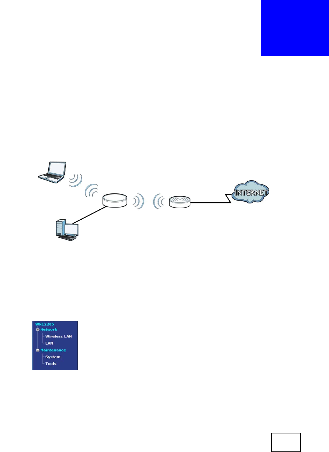
The WRE2206 (N) is a universal repeater that is an access point and a wireless client at the same
time. The WRE2206 (N) wirelessly relays communications from its wireless clients to the access
point.
Figure 1 Universal Repeater
Your can create the following connections using the WRE2206:
•LAN . You can connect network devices via the Ethernet port of the WRE2206 so that they can
communicate with each other and access the Internet.
•W LAN . Wireless clients can connect to the WRE2206 to access network resources.
Use a (supported) web browser to manage the WRE2206.
See Chapter 4 on page 21 for more information.
LEW
N
AP
WLAN
Chapter 1 Introduction
WRE2206 User’s Guide
10
1.2 Securing the WRE2206
Do the following things regularly to make the WRE2206 more secure and to manage the WRE2206
more effectively.
• Change the password. Use a password that’s not easy to guess and that consists of different
types of characters, such as numbers and letters.
• Write down the password and put it in a safe place.
• Back up the configuration (and make sure you know how to restore it). Restoring an earlier
working configuration may be useful if the device becomes unstable or even crashes. If you
forget your password, you will have to reset the WRE2206 to its factory default settings. If you
backed up an earlier configuration file, you would not have to totally re-configure the WRE2206.
You could simply restore your last configuration.
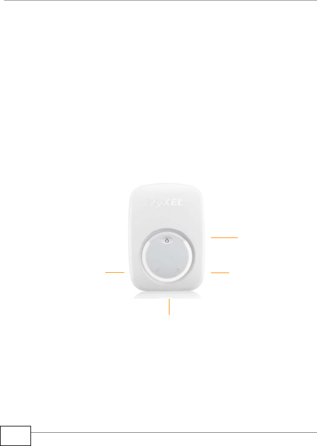
1.3 Front Panel
Figure 2 Front Panel
WPS Button
Signal Strength
Ethernet Port
Number of Clients Indicator
Chapter 1 Introduction
WRE2206 User’s Guide 11
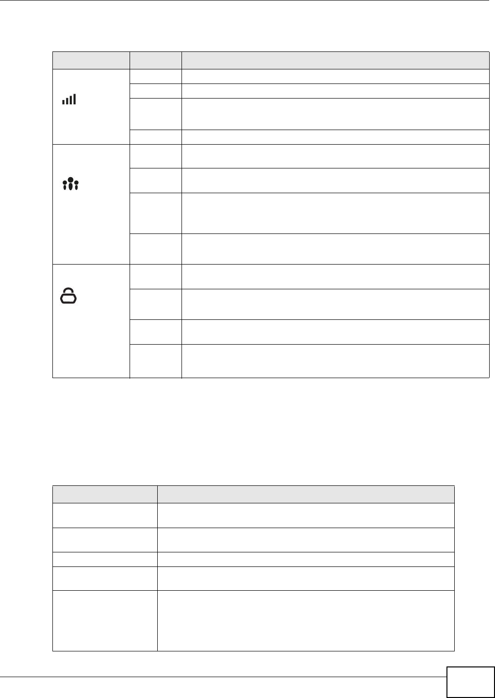
The following table describes the LEDs and the WPS button.
1.4 The WPS Button
The WPS button can be used to begin WiFi Protected Setup (WPS), reboot the WRE2206 while
keeping it’s configuration or reboot the WRE2206 to factory default configuration.
Table 1 Front Panel LEDs and WPS Button
LED STATUS DESCRIPTION
Signal Strength 3 LED On The signal strength is 50-100%.
2 LED On The signal strength is 25-50%.
1 LED On The signal strength is <25%.
The WRE2206 is in the process of starting up.
Off No signal detected, disconnected or the LED is turned off in the firmware.
Number of
Clients Indicator
1 LED On The number of wireless clients connecting to the WRE2206 is greater than or
equal to ten.
2 LED On The number of wireless clients connecting to the WRE2206 is greater than or
equal to five, but less than ten.
3 LED On The number of wireless clients connecting to the WRE2206 is greater than or
equal to one, but less than five.
The WRE2206 is in the process of starting up.
Off The wireless LAN is not ready.
The number of wireless clients connecting to the WRE2206 is zero.
WPS On This remains on for 5 minutes after a successful WPS connection has been
established.
Blinking
Slowly
The WRE2206 is waiting for another WPS device to connect.
The WRE2206 is in the process of starting up, rebooting or resetting.
Blinking
Rapidly
The WRE2206 fails to connect to a router or AP using WPS.
Off There is no WPS connection established or a WPS connection has been
established for more than five minutes, or the LED is turned off in the
firmware.
Table 2 WPS Button Functions
ACTION RESULT
Push once or hold for
less than 5 seconds
The WRE2206 begins connecting to an AP via WPS. See Section 5.3 on
page 29.
Push twice The WRE2206 begins connecting to a wireless client via WPS. See Section
5.2 on page 26.
Hold for 5 to 10 seconds The WRE2206 keeps its configuration and reboots.
Hold for more than 10
seconds
The WRE2206 resets its configuration to factory defaults and reboots. See
Section 2.3 on page 14.
Push three times Push three times to turn off the WPS LED. After turning off the LED, the
WRE2206 disconnects the connection to a wireless client via WPS and
returns to the normal state.
The physical WPS button has priority over the WPS button in the Web
Configurator.

Chapter 1 Introduction
WRE2206 User’s Guide
12
1.4.1 WiFi Protected Setup
Your WRE2206 supports Wi-Fi Protected Setup (WPS), which is an easy way to set up a secure
wireless network. WPS is an industry standard specification, defined by the WiFi Alliance.
WPS allows you to quickly set up a wireless network with strong security, without having to
configure security settings manually. Each WPS connection works between two devices. Both
devices must support WPS (check each device’s documentation to make sure).
Depending on the devices you have, you can either press a button (recommended) on the device
itself, or in its configuration utility or enter a PIN (a unique Personal Identification Number that
allows one device to authenticate the other) in each of the two devices. When WPS is activated on
a device, it has two minutes to find another device that also has WPS activated. Then, the two
devices connect and set up a secure network by themselves.
For more information on using WPS, see Section 5.2 on page 26.

WRE2206 User’s Guide 13
CHAPTER 2
The Web Configurator
2.1 Overview
This chapter describes how to access the WRE2206 Web Configurator and provides an overview of
its screens.
The Web Configurator is an HTML-based management interface that allows easy setup and
management of the WRE2206 via Internet browser. Use Internet Explorer 6.0 and later versions,
Mozilla Firefox 3 and later versions, or Safari 2.0 and later versions. The recommended screen
resolution is 1024 by 768 pixels.
In order to use the Web Configurator you need to allow:
• Web browser pop-up windows from your device. Web pop-up blocking is enabled by default in
Windows XP SP (Service Pack) 2.
• JavaScript (enabled by default).
• Java permissions (enabled by default).
Refer to Chapter 10 Troubleshooting to see how to make sure these functions are allowed in
Internet Explorer.
2.2 Accessing the Web Configurator
1Make sure your WRE2206 hardware is properly connected and prepare your computer or computer
network to connect to the WRE2206 (refer to the Quick Start Guide).
Note: Your computer or the part of your network connected to the WRE2206 must be on
the same subnet as the WRE2206.
The WRE2206’s DHCP server is enabled before the WRE2206 is associated with
your AP or wireless router and disabled after association. If this is the first time you
are accessing your WRE2206, you can configure your computer as a DHCP client
(computer factory default) so it will get an IP address automatically from the
WRE2206. After the WRE2206 is associated with your wireless router, your
computer will get its IP address from the wireless router.
2Launch your web browser.
3If this is the first time you are accessing your WRE2206, type "http://192.168.1.2" as the website
address in your web browser. This is the default LAN IP address. Alternatively, after the WRE2206
has successfully associated with your wireless router, type "http://zyxelsetup" instead of the default
IP address.
Chapter 2 The Web Configurator
WRE2206 User’s Guide
14
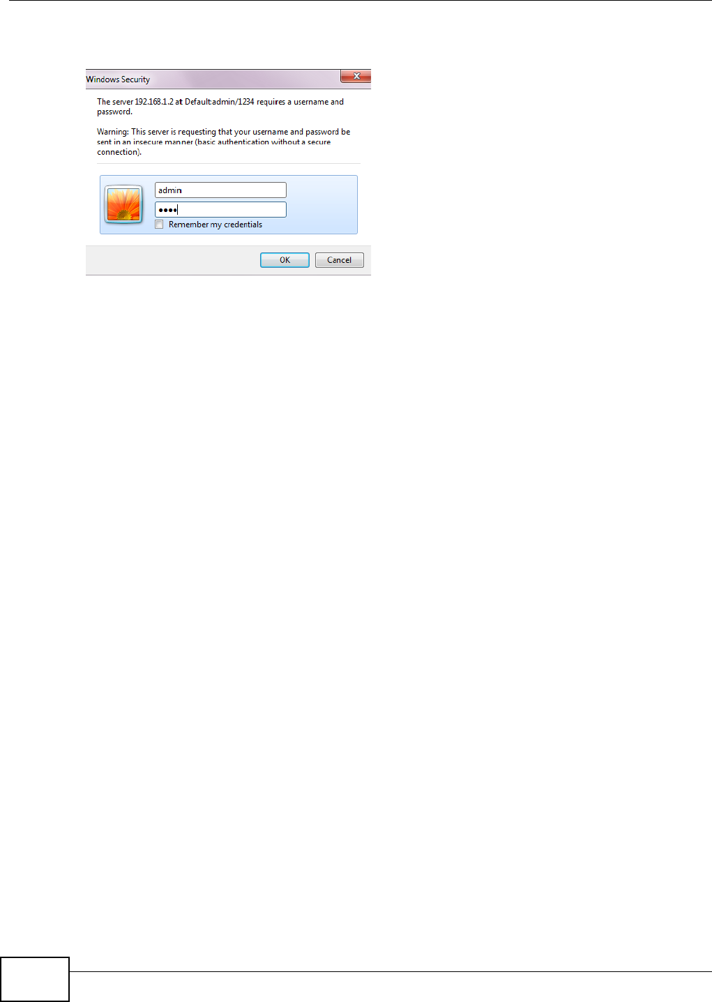
4Type a dm in (default) as the user name and 1 2 3 4 (default) as the password and click OK.
Figure 3 Login Screen
2.3 Resetting the WRE2206
If you forget your password or IP address, or you cannot access the Web Configurator, press the
W PS button for more than 10 seconds to reload the factory-default configuration file. This means
that you will lose all configurations that you had previously saved, the username will be reset to
adm in and password will be reset to 1 2 3 4 . The IP address will be reset to “192.168.1.2”.
1Press and hold the W PS button, the WPS LED begins flashing immediately.
2Release the W PS button. The WRE2206 reloads factory defaults and begins to reboot.
WRE2206 User’s Guide 15
CHAPTER 3
Connection Wizard
3.1 Overview
This chapter provides information on the wizard setup screens in the Web Configurator.
The Web Configurator’s wizard setup helps you configure your device. The first time you access the
WRE2206 Web Configurator, the wizard displays automatically. For subsequent access, click to
start the wizardsetup.
3.2 Configuring the WRE2206 for Connection to an AP
In this step of the configuration wizard, you must configure the WRE2206 with the security
parameters of the AP you want to connect to. These parameters can be configured by selecting
those automatically detected by the WRE2206, or by configuring them manually. Manual
configuration is useful when the AP is hidden.
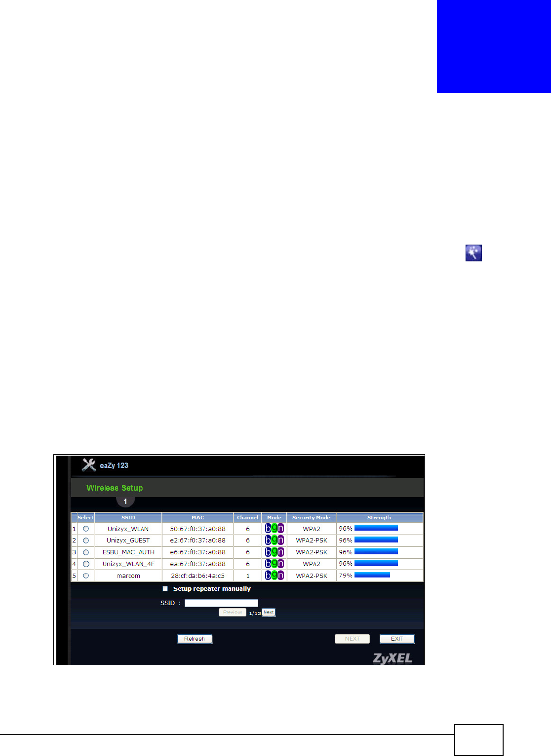
3.2.1 Selecting Automatically Detected AP Parameters
1Select an AP using the following screen.
Figure 4 Wizard: Wireless Setup
Chapter 3 Connection Wizard
WRE2206 User’s Guide
16
The following table describes the labels in this screen.
Note: The wireless stations and WRE2206 must use the same SSID, channel ID, WPA-PSK
(if WPA-PSK is enabled) or WPA2-PSK (if WPA2-PSK is enabled) for wireless
communication.
2Type a key. The number of characters accepted by the KEY field is shown in the following table.
Table 3 Network > Wireless LAN > AP Select
LABEL DESCRIPTION
Select Use the radio button to select the wireless device to which you want to connect.
SSID This displays the Service Set IDentity of the wireless device. The SSID is a unique name
that identifies a wireless network. All devices in a wireless network must use the same
SSID.
MAC This displays the MAC address of the wireless device.
Channel This displays the channel number used by this wireless device.
Mode This displays which IEEE 802.11b/g/n wireless networking standards the wireless device
supports.
Security Mode This displays the type of security configured on the wireless device. When no is shown, no
security is configured and you can connect to it without a password.
Strength This displays the strength of the wireless signal. The signal strength mainly depends on
the antenna output power and the distance between your WRE2206 and this device.
Setup repeater
manually
Select this to setup the AP manually.
SSID If Set u p re pe a t e r m anua lly is selected, use this field to type the SSID of the AP. This is
useful when the AP’s SSID is hidden.
Refresh Click this to search for available wireless devices within transmission range and update
this table.
BACK Click this to go back to the previous step in the wizard.
NEXT Click this to start the next step in the AP setup process.
EXIT Click this to exit the wizard.
Previous Click this to see the previous page of APs.
Next Click this to see the next page of APs.
Table 4 Maximum Key Lengths
ENCRYPTION KEY FORMAT KEY LENGTH
64-bit WEP ASCII 5 characters
Hex 10 characters
128-bit WEP ASCII 13 characters
Hex 26 characters
WPA pre-shared key Passphrase 8-63 characters
Hex 64 characters
Chapter 3 Connection Wizard
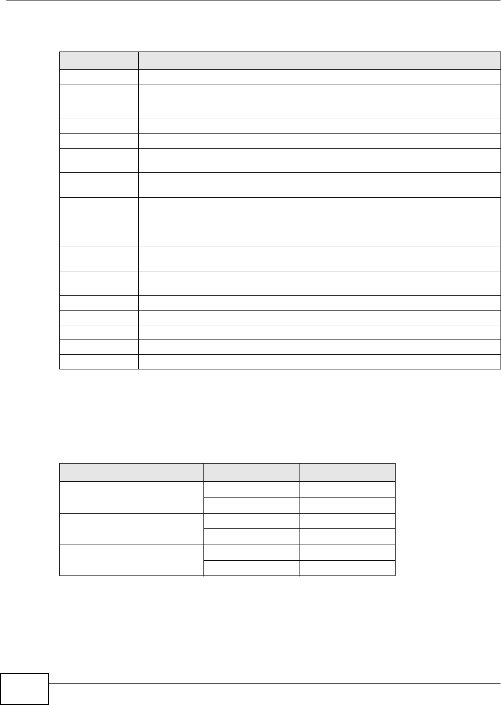
WRE2206 User’s Guide 17
Figure 5 Wizard: Type a Key
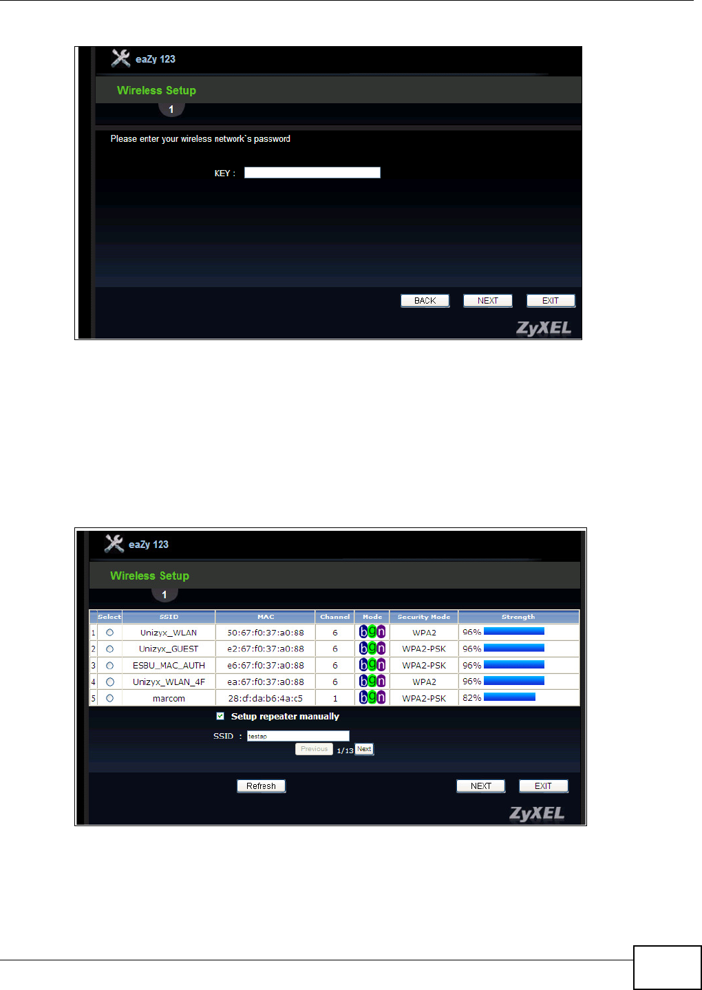
3.2.2 Manually Configuring AP Parameters
If the AP you want to connect to is not listed, then follow these steps to configure the security
settings of the AP manually.
1Select Set up repea t er m a nua lly.
2Type the SSID of the AP into the SSI D field.
Figure 6 Wizard: Manually Typing the SSID
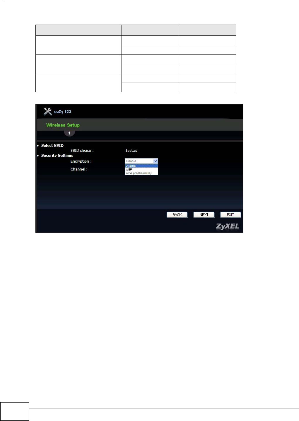
3Configure the security settings. The number of characters accepted by the KEY field is shown in the
following table.
Chapter 3 Connection Wizard
WRE2206 User’s Guide
18
Figure 7 Wizard: Manually Configuring Security Settings
3.3 Completing the Connection Wizard
1Click N e x t . The key verification screen appears.
Table 5 Maximum Key Lengths
ENCRYPTION KEY FORMAT KEY LENGTH
64-bit WEP ASCII 5 characters
Hex 10 characters
128-bit WEP ASCII 13 characters
Hex 26 characters
WPA pre-shared key Passphrase 8-63 characters
Hex 64 characters
Chapter 3 Connection Wizard
WRE2206 User’s Guide 19
Figure 8 Wizard: Verifying the Key
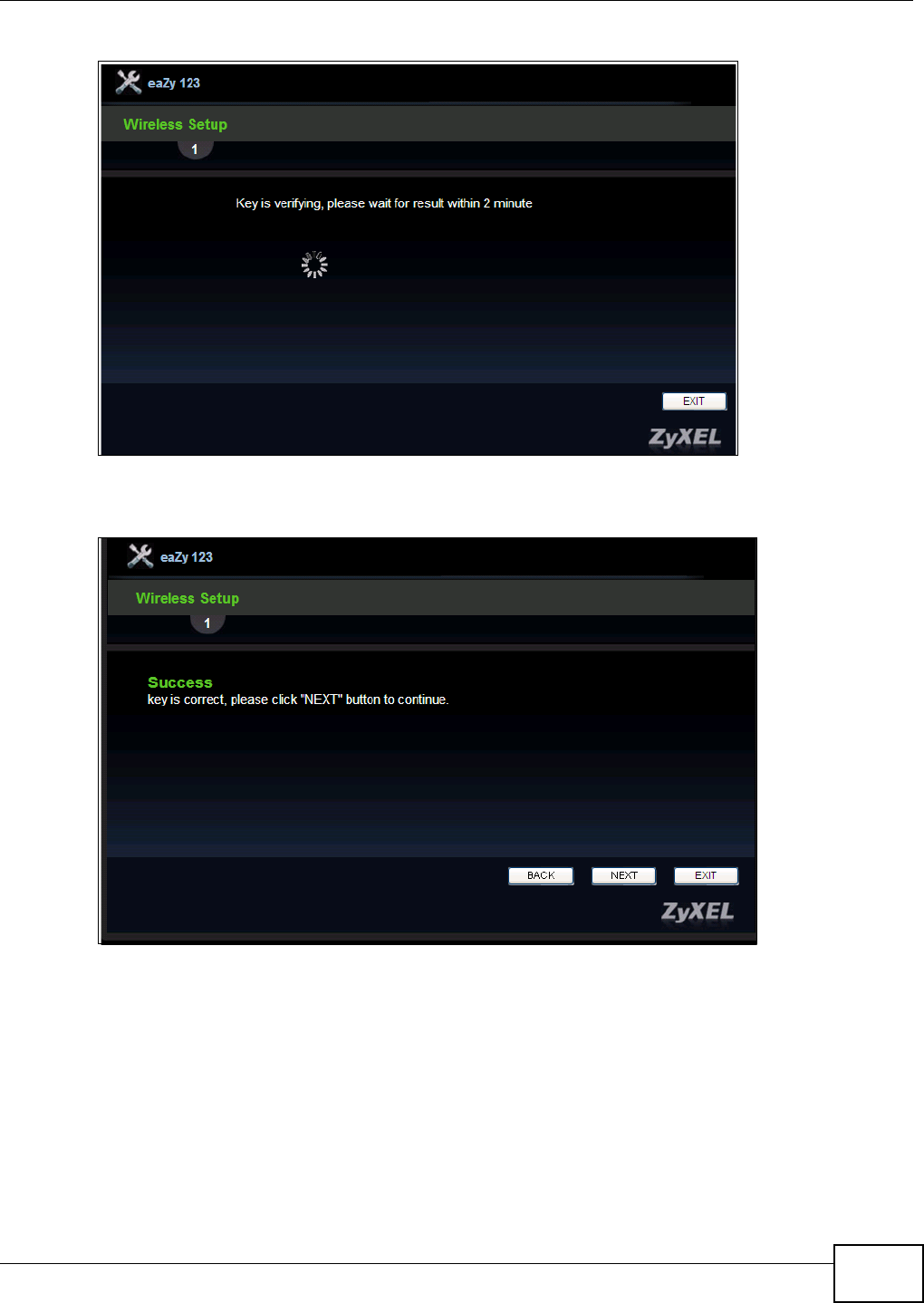
The following screen appears if the key verifies successfully.
Figure 9 Wizard: Key Verification Success
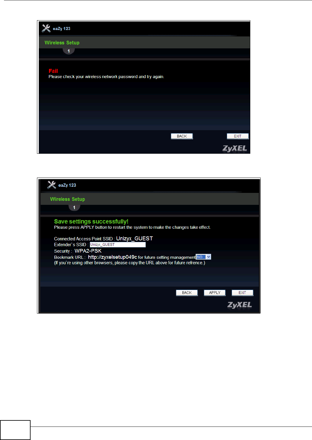
The following screen appears if the key fails to verify. Click BACK and check the key.
Chapter 3 Connection Wizard
WRE2206 User’s Guide
20
Figure 10 Wizard: Key Verification Failed
2Click Apply to complete the wizard setup and restart the WRE2206.
Figure 11 Connection Wizard Complete
WRE2206 User’s Guide 21
CHAPTER 4
Status
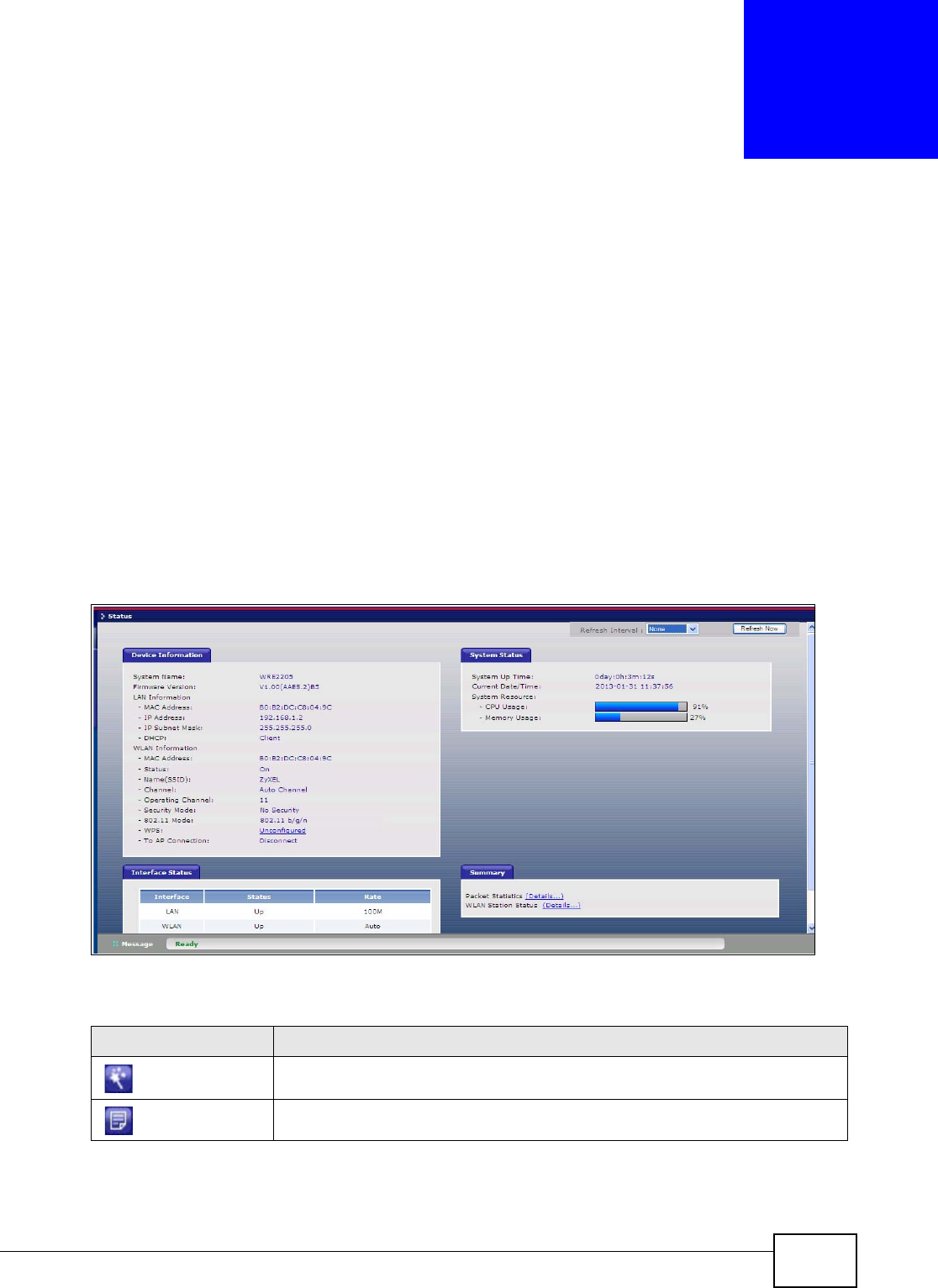
4.1 WRE2206 Status
The screen below shows the status screen.
Figure 12 Status Screen
The following table describes the icons shown in the St a t us screen.
Table 6 Status Screen Icon Key
ICON DESCRIPTION
Click this icon to open the setup wizard.
Click this icon to view copyright and a link for related product information.
Chapter 4 Status
WRE2206 User’s Guide
22
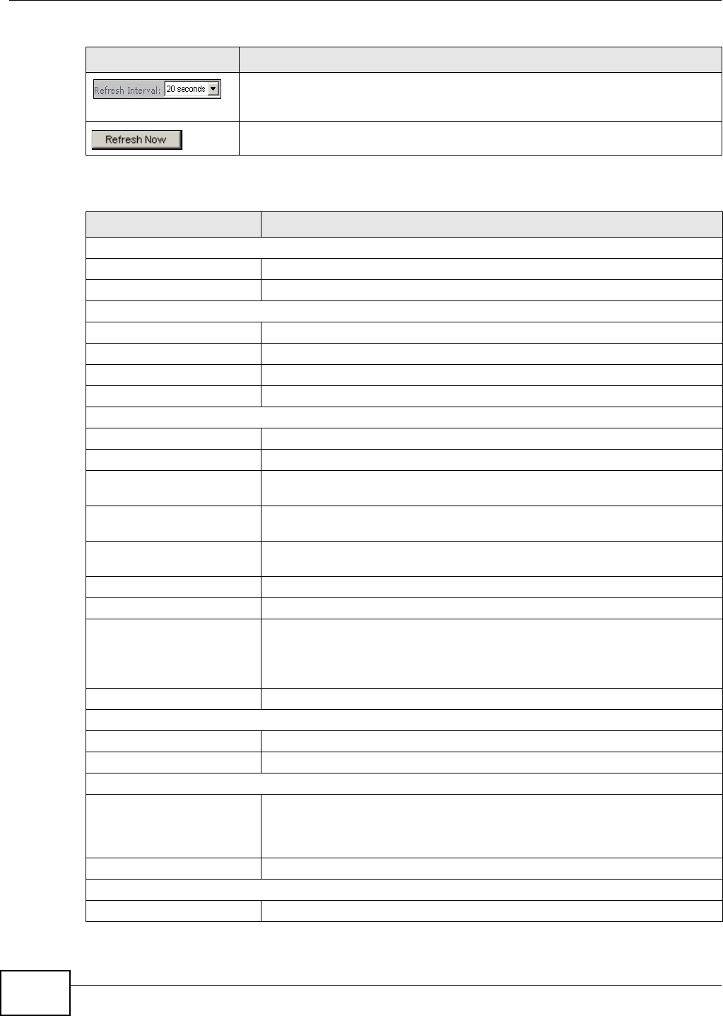
The following table describes the labels shown in the St a t us screen.
Select a number of seconds or N o ne from the drop-down list box to refresh all
screen statistics automatically at the end of every time interval or to not refresh
the screen statistics.
Click this button to refresh the status screen statistics.
Table 7 Web Configurator Status Screen
LABEL DESCRIPTION
Device Information
System Name This is the Syste m N am e .
Firmware Version This is the current firmware version of the WRE2206.
LAN Information
- MAC Address This shows the LAN Ethernet adapter MAC Address of your device.
- IP Address This shows the LAN port’s IP address.
- IP Subnet Mask This shows the LAN port’s subnet mask.
- DHCP This shows the LAN port’s DHCP role.
WLAN Information
- MAC Address This shows the wireless adapter MAC Address of your device.
- Status This shows the current status of the Wireless LAN - On or Off.
- Name (SSID) This shows a descriptive name used to identify the WRE2206 in the wireless
LAN.
- Channel This shows the channel number which you select manually or the WRE2206
automatically scans and selects.
- Operating Channel This shows the channel number which the WRE2206 is currently using over the
wireless LAN.
- Security Mode This shows the level of wireless security the WRE2206 is using.
- 802.11 Mode This shows the wireless standard.
- WPS This displays Configur ed when the WPS has been set up.
This displays Unconfigu r ed if the WPS has not been set up.
Click the status to display Net w or k > W ire le ss LAN > W PS screen.
- To AP Connection This shows whether the WRE2206 is connected to an AP or not.
System Status
System Up Time This is the total time the WRE2206 has been on.
Current Date/Time This field displays your WRE2206’s present date and time.
System Resource
- CPU Usage This displays what percentage of the WRE2206’s processing ability is currently
used. When this percentage is close to 100%, the WRE2206 is running at full
load, and the throughput is not going to improve anymore. If you want some
applications to have more throughput, you should turn off other applications.
- Memory Usage This shows what percentage of the heap memory the WRE2206 is using.
Interface Status
Interface This displays the WRE2206 port types. The port types are: LAN and W LAN .
Table 6 Status Screen Icon Key (continued)
ICON DESCRIPTION
Chapter 4 Status
WRE2206 User’s Guide 23
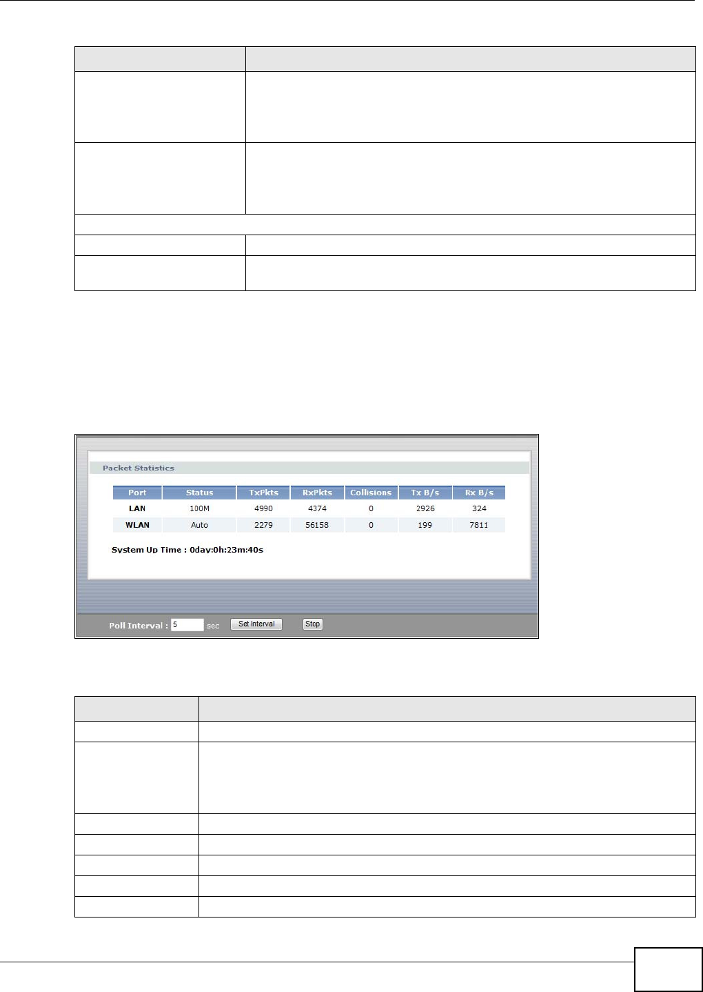
4.1.1 Summary: Packet Statistics
Click the Pa cket St a t ist ics ( Det ails...) hyperlink in the St at us screen. Read-only information
here includes port status, packet specific statistics and the "system up time". The Poll I nt er val( s)
field is configurable and is used for refreshing the screen.
Figure 13 Summary: Packet Statistics
The following table describes the labels in this screen.
Status For the LAN port, this field displays Dow n (line is down) or Up (line is up or
connected).
For the WLAN, it displays Up when the WLAN is enabled or Dow n when the
WLAN is disabled.
Rate For the LAN ports, this displays the port speed and duplex setting or N A when
the line is disconnected.
For the WLAN, it displays the maximum transmission rate when the WLAN is
enabled and N A when the WLAN is disabled or Au t o.
Summary
Packet Statistics Use this screen to view port status and packet specific statistics.
WLAN Station Status Use this screen to view the wireless stations that are currently associated to
the WRE2206.
Table 7 Web Configurator Status Screen (continued)
LABEL DESCRIPTION
Table 8 Summary: Packet Statistics
LABEL DESCRIPTION
Port This is the WRE2206’s port type.
Status For the LAN ports, this displays the port speed and duplex setting or Dow n when the
line is disconnected.
For the WLAN, it displays Up when the WLAN is enabled or Dow n when the WLAN is
disabled or Au t o.
TxPkts This is the number of transmitted packets on this port.
RxPkts This is the number of received packets on this port.
Collisions This is the number of collisions on this port.
Tx B/s This displays the transmission speed in bytes per second on this port.
Rx B/s This displays the reception speed in bytes per second on this port.
Chapter 4 Status
WRE2206 User’s Guide
24
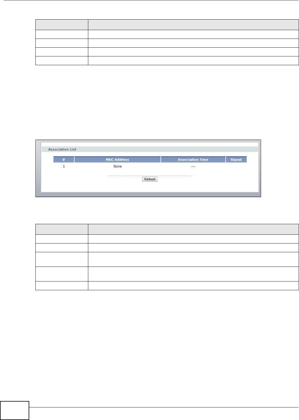
4.1.2 Summary: WLAN Station Status
Click the W LAN St a t ion Stat us ( D et a ils...) hyperlink in the St a t u s screen. View the wireless
stations that are currently associated to the WRE2206 in the Associa t ion List. Association means
that a wireless client (for example, your network or computer with a wireless network card) has
connected successfully to the AP (or wireless router) using the same SSID, channel and security
settings.
Figure 14 Summary: WLAN Station Status
The following table describes the labels in this screen.
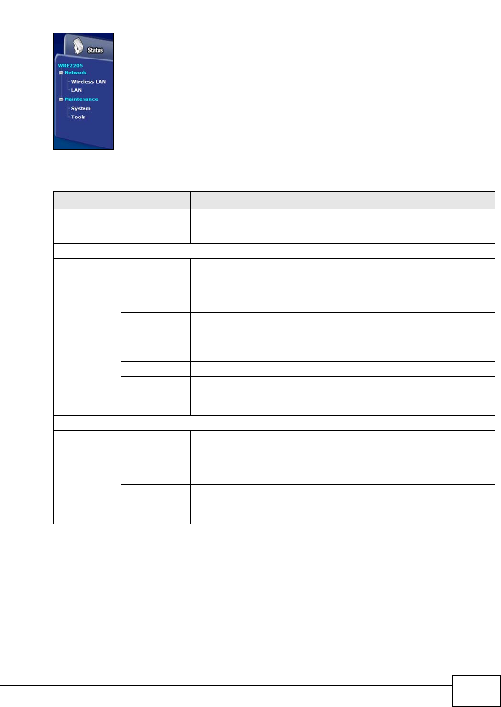
4.2 Navigation Panel
Use the menu in the navigation panel menus to configure WRE2206 features.
System Up Time This is the total time the WRE2206 has been on.
Poll Interval Enter the time interval for refreshing statistics in this field.
Set Interval Click this button to apply the new poll interval you entered in the Poll I nt er val field.
Stop Click St op to stop refreshing statistics.
Table 8 Summary: Packet Statistics (continued)
LABEL DESCRIPTION
Table 9 Summary: WLAN Station Status
LABEL DESCRIPTION
# This is the index number of an associated wireless station.
MAC Address This field displays the MAC address of an associated wireless station.
Association Time This field displays the time a wireless station first associated with the WRE2206’s WLAN
network.
Signal This field displays the signal strength of a wireless station (client) associated with the
WRE2206’s wireless network. The number of signal strength shows from 10 to 100.
Refresh Click Refresh to reload the list.
Chapter 4 Status
WRE2206 User’s Guide 25
Figure 15 Menus
The following table describes the sub-menus.
Table 10 Menus
LINK TAB FUNCTION
Status This screen shows the WRE2206’s general device, system and interface
status information. Use this screen to access the wizard, and summary
statistics tables.
Network
Wireless
LAN AP Select Use this screen to connect to an access point.
General Use this screen to configure wireless LAN.
MAC Address
List
Use the MAC Address List screen to allow devices to access the WRE2206.
Advanced This screen allows you to configure advanced wireless settings.
QoS Use this screen to configure Wi-Fi Multimedia Quality of Service (WMM
QoS). WMM QoS allows you to prioritize wireless traffic according to the
delivery requirements of individual services.
WPS Use this screen to configure WPS.
WPS Station Use this screen to connect the WRE2206 to a wireless station or access
point using WPS.
LAN IP Use this screen to configure LAN IP address, subnet mask and gateway.
Maintenance
System Password Use this screen to change the password.
Tools Firmware Use this screen to upload firmware to your WRE2206.
Configuration Use this screen to backup and restore the configuration or reset the factory
defaults to your WRE2206.
Restart This screen allows you to reboot the WRE2206 without turning the power
off.
LED Use this screen to configure which LEDs are enabled or disabled.

WRE2206 User’s Guide 26
CHAPTER 5
Tutorials
5.1 Overview
This chapter provides tutorials for your WRE2206 as follows:
• Connecting a Wireless Client using WPS
•Push Button Configuration (PBC)
•PIN Configuration
• Connecting the WRE2206 to an AP
•Connecting to an AP with the WPS PBC Method
•Connecting to an AP with the WPS PIN Method
•Selecting an AP from an Automatically Detected List
•Selecting an AP by Manually Entering Security Information
5.2 Connecting a Wireless Client using WPS
This section gives you an example of how to connect a client to the WRE2206 using WPS.
There are two WPS methods for creating a secure connection. This tutorial shows you how to do
both.
•Push But t on Configur a t ion ( PBC) - create a secure wireless network by simply pressing the
WPS button twice on the WRE2206’s front panel or by clicking the Star t PBC button in the
N e t w or k > W ire le ss LAN > W PS St a t ion screen. See Section 5.2.1 on page 26. This is the
easier method.
•PI N Configurat ion - create a secure wireless network simply by entering a wireless client's PIN
(Personal Identification Number) in the WRE2206’s interface. See Section 5.2.2 on page 28. This
is the more secure method, since one device can authenticate the other.
Note: The wireless client must be a WPS-aware device (for example, a WPS USB adapter
or PCI card).
5.2.1 Push Button Configuration (PBC)
This section gives you an example of how to set up a wireless network using WPS PBC. This
example uses the WRE2206 as the registrar and NWD210N as the wireless client in a notebook.
1Make sure that your WRE2206 is turned on and that it is within range of your computer.
Chapter 5 Tutorials
WRE2206 User’s Guide 27
2Make sure that you have installed the wireless client (this example uses the NWD210N) driver and
utility in your notebook.
3In the wireless client utility, find the WPS settings. Enable WPS and press the WPS button (St a r t or
W PS button)
4Log into WRE2206’s Web Configurator and navigate to the N e t w or k > W irele ss LAN > W PS
St a t ion screen.
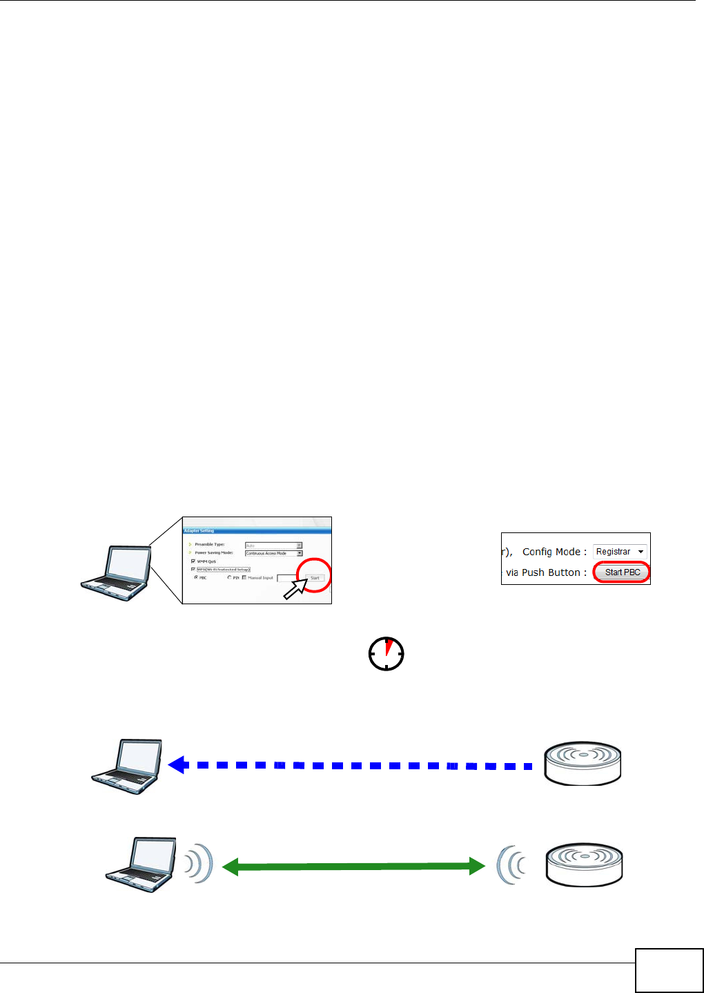
5In the WRE2206’s Web Configurator, select Re gist r a r in Config Mode and then press St art PBC.
Note: Your WRE2206 has a WPS button, as well as a St a rt PBC button in the Web
Configurator. Both buttons have exactly the same function; you can use one or the
other.
Note: It doesn’t matter whether you press the button on the WRE2206 or the wireless
client first. WPS times out after two minutes of pressing a button. Press the button
on the second device within about a minute of the first, then wait two minutes for
the WPS configuration to complete.
The WRE2206 sends the proper configuration settings to the wireless client. Then the wireless client
is able to communicate with the WRE2206 securely.
The following figure shows an example of how to set up wireless network and security by pressing a
button on both WRE2206 and wireless client (the NWD210N in this example).
Figure 16 Example WPS Process: PBC Method
Wireless Client WRE2206
SECURITY INFO
COMMUNICATION
WITHIN 1 MINUTE

Chapter 5 Tutorials
WRE2206 User’s Guide
28
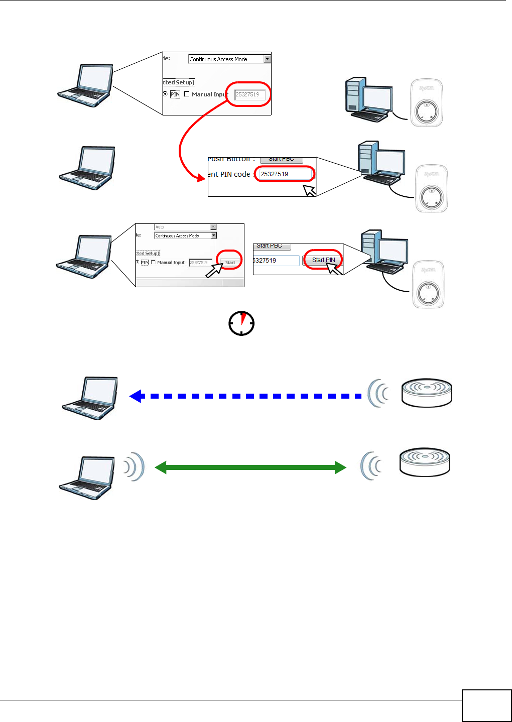
5.2.2 PIN Configuration
When you use the PIN configuration method, you need to use both WRE2206’s configuration
interface and the client’s utilities.
1Launch your wireless client’s configuration utility. Go to the WPS settings and select the PIN method
to get a PIN number.
2On the WRE2206, navigate to the N et w o rk > W ireless LAN > W PS St ation screen.
3In the WRE2206’s Web Configurator, select Re gist r a r in Config Mode.
4In the WRE2206’s Web Configurator, enter the PIN number in the I npu t clie nt PI N code.
5Click the St a r t buttons (or the buttons next to the PIN fields) on both the wireless client utility
screen and the WRE2206’s W PS St ation screen within about one minute, then wait two minutes
for the WPS configuration to complete.
The WRE2206 authenticates the wireless client and sends the proper configuration settings to the
wireless client. Then the wireless client is able to communicate with the WRE2206 securely.
The following figure shows an example of how to set up wireless network and security on WRE2206
and wireless client (ex. NWD210N in this example) by using PIN method.
Chapter 5 Tutorials
WRE2206 User’s Guide 29
Figure 17 Example WPS Process: PIN Method
5.3 Connecting the WRE2206 to an AP
This section gives you an example of how to connect the WRE2206 to an AP.
There are four AP connection methods. This tutorial shows you how to use all of them.
•Con ne cting t o a n AP w ith t he W PS PBC m ethod - create a secure wireless network simply by
pressing a button. See Section 5.3.1 on page 30. This is the easier method.
Authentication by PIN
SECURITY INFO
WITHIN 1 MINUTE
Wireless Client
WRE2206
COMMUNICATION

Chapter 5 Tutorials
WRE2206 User’s Guide
30
•Con n e ct i n g t o a n AP w i t h t h e W PS PI N m e t h o d - create a secure wireless network simply by
entering the WRE2206's PIN (Personal Identification Number) in the AP’s interface. See Section
5.3.2 on page 31. This is the more secure method, since one device can authenticate the other.
•Select ing a n AP from a n Au t om at ically D e t e ct e d List - create a secure wireless network
simply by selecting an AP from a list of detected APs. See Section 5.3.3 on page 32.This is the
easier method.
•Select ing a n AP by M a n ually Ent e r in g Se cur it y I nform a t ion - create a secure wireless
network by manually entering the AP’s wireless security settings in the WRE2206’s interface. See
Section 5.3.4 on page 34. This is useful when the AP is hidden.
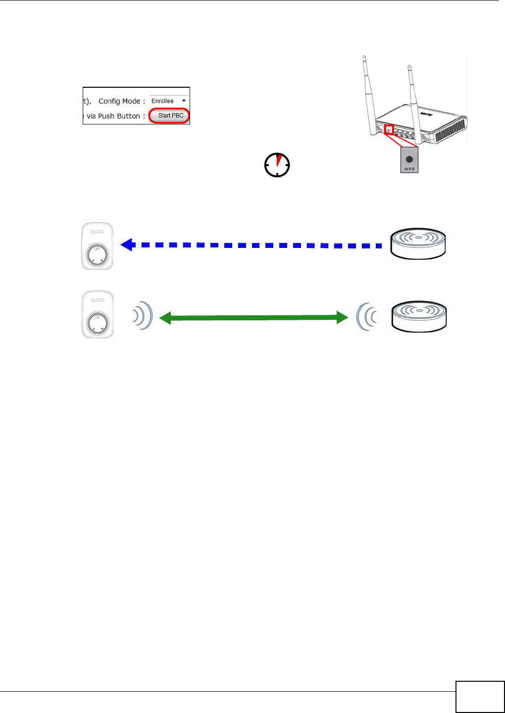
5.3.1 Connecting to an AP with the WPS PBC Method
This section gives you an example of how to connect to an AP using WPS PBC. This example uses
the WRE2206 as the enrollee and an AP as the registrar.
1Make sure that your WRE2206 is turned on and that it is within range of the AP.
2Make sure that you have installed the AP and have access to the configuration interface of the AP or
the AP’s WPS button.
3Log into WRE2206’s Web Configurator and navigate to the N e t w or k > W irele ss LAN > W PS
St a t ion screen. Select Enrolle e in Config M ode and press Start PBC.
4In the configuration interface of the AP, find the WPS settings. Enable WPS and press the WPS
button (Start or W PS button)
Note: Your WRE2206 has a WPS button located on its panel, as well as a WPS button in
its configuration utility. Both buttons have exactly the same function; you can use
one or the other.
Note: It doesn’t matter whether you press the button on the WRE2206 or the AP first.
WPS times out after two minutes of pressing a button. Press the button on the
second device within about a minute of the first, then wait two minutes for the WPS
configuration to complete.
The AP sends the proper configuration settings to the WRE2206. Then the WRE2206 is able to
communicate with the AP securely.
The following figure shows an example of how to set up wireless network and security by pressing a
button on both WRE2206 and AP.
Chapter 5 Tutorials
WRE2206 User’s Guide 31
Figure 18 Example Connection to AP using WPS: PBC Method
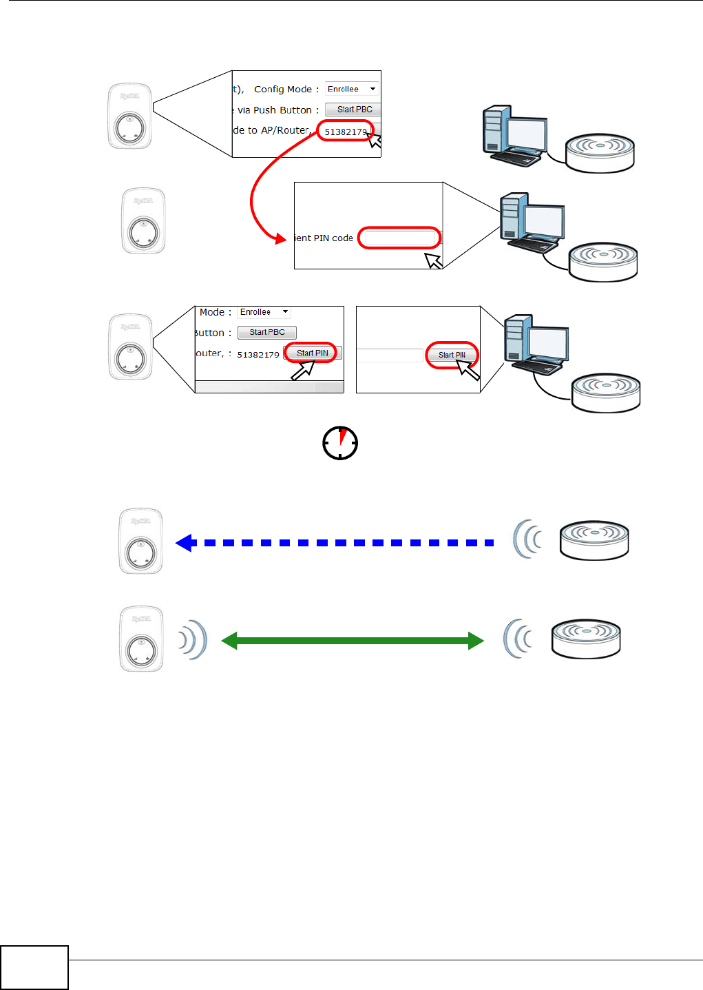
5.3.2 Connecting to an AP with the WPS PIN Method
When you use the PIN configuration method, you need to use both the configuration interface of
the AP and the WRE2206’s configuration interface.
1Log into WRE2206’s Web Configurator and navigate to the N e t w or k > W ir ele ss LAN > W PS
St a t ion screen. Select Enrolle e in Config M ode to get a PIN number.
2Enter the PIN number in the WPS PIN field of the AP’s configuration interface.
3Click the St a rt PI N button on the WRE2206 and the Start button (or the button next to the PIN
field) on the AP’s configuration interface within about one minute, then wait two minutes for the
WPS configuration to complete.
The AP authenticates the WRE2206 and sends the proper configuration settings to the WRE2206.
This may take up to two minutes. Then the WRE2206 is able to communicate with the AP securely.
The following figure shows an example of how to set up wireless network and security on the AP
and WRE2206 by using PIN method.
WRE2206
SECURITY INFO
COMMUNICATION
WITHIN 1 MINUTE
AP
Chapter 5 Tutorials
WRE2206 User’s Guide
32
Figure 19 Example Connection to AP using WPS: PIN Method
5.3.3 Selecting an AP from an Automatically Detected List
Follow the steps below to create a secure wireless network by selecting an AP from a list of detected
APs.
The instructions require that your hardware is connected (see the Quick Start Guide) and you are
logged into the Web Configurator through your LAN connection (see Section 2.2 on page 13).
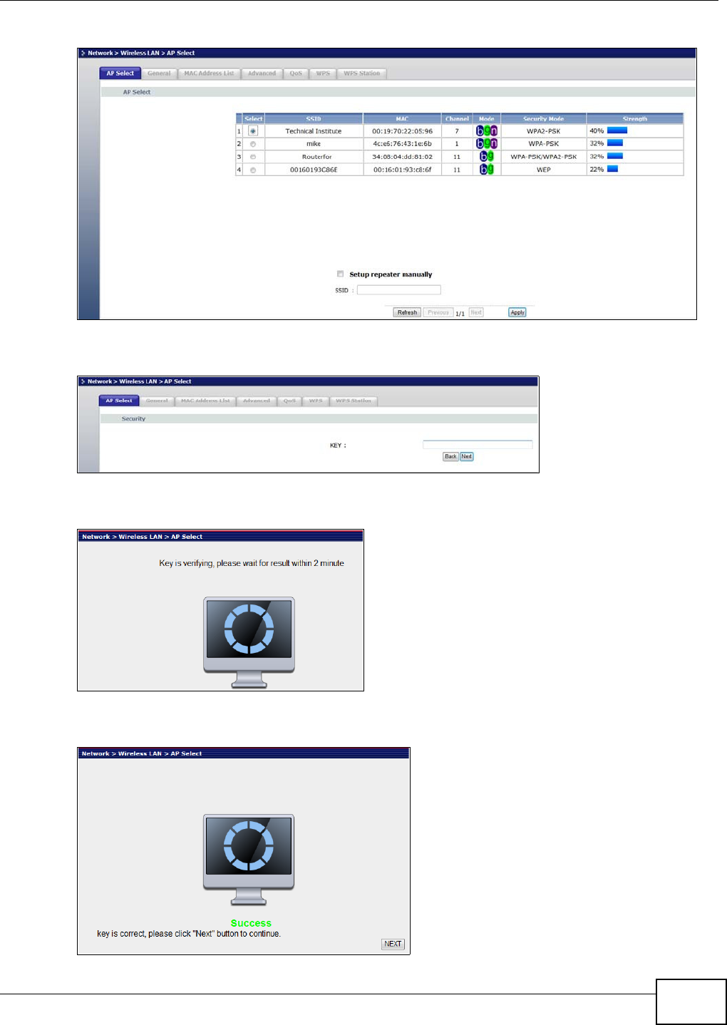
1Select an AP form the Se le ct column and click N e xt .
Authentication by PIN
SECURITY INFO
WITHIN 1 MINUTE
AP
WRE2206
COMMUNICATION
51382179
Chapter 5 Tutorials
WRE2206 User’s Guide 33
Figure 20 Tutorial: Selecting an automatically detected AP
2Type a key into the KEY field and click N e xt .
Figure 21 Tutorial: The KEY field
3Wait for the WRE2206 to verify the key with the AP.
Figure 22 Tutorial: Verifying the key
4When the key is verified, click N ex t .
Figure 23 Tutorial: Successful key verification
Chapter 5 Tutorials
WRE2206 User’s Guide
34
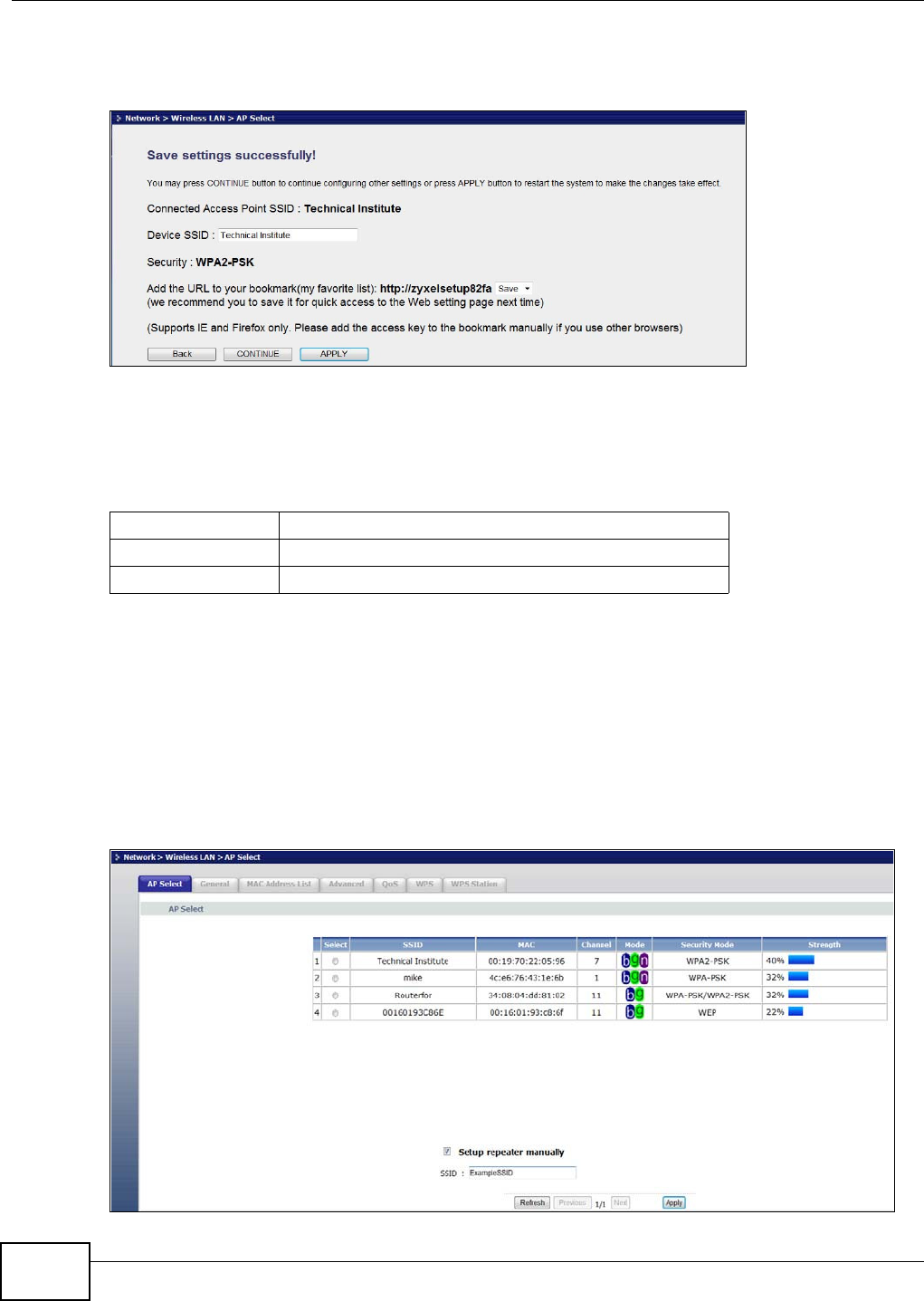
5Click APPLY to save settings and restart the WRE2206. Click CON TI N U E to go to the Status
screen without saving the settings and restarting the WRE2206.
Figure 24 Tutorial: Saving settings
5.3.4 Selecting an AP by Manually Entering Security Information
This example shows you how to configure wireless security settings with the following parameters
on your WRE2206.
Follow the steps below to create a secure wireless network by manually entering the AP’s wireless
security settings in the WRE2206’s interface.
The instructions require that your hardware is connected (see the Quick Start Guide) and you are
logged into the Web Configurator through your LAN connection (see Section 2.2 on page 13).
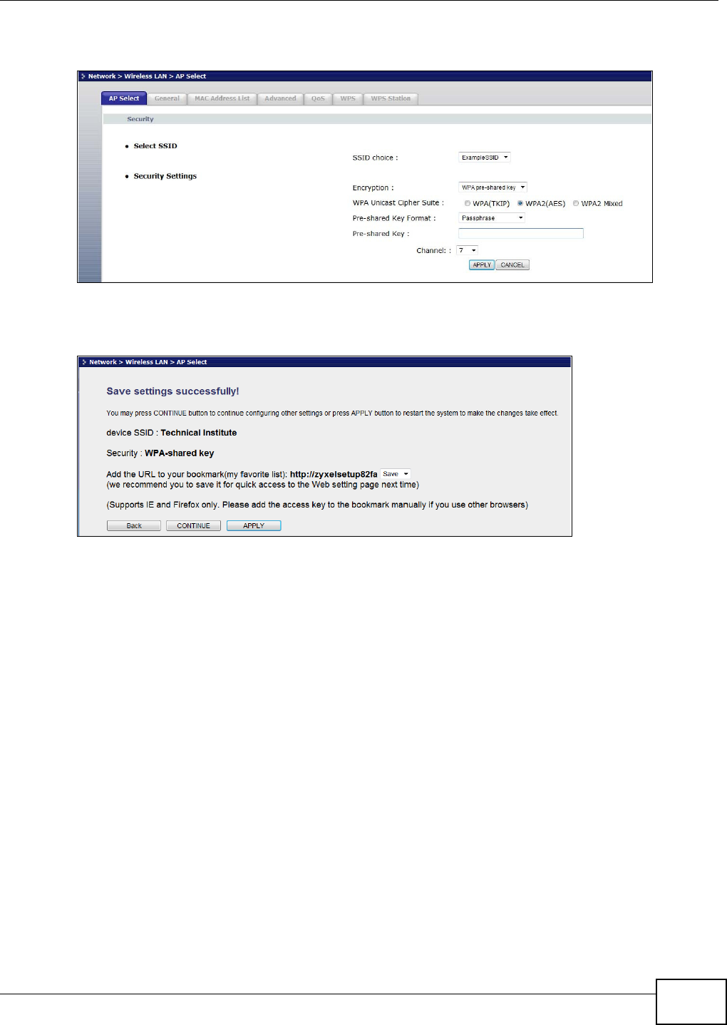
1Select Set up repea t er m a nua lly.
2Type the SSID of the AP into the SSI D field and click N e x t .
Figure 25 Tutorial: Typing an SSID
SSI D ExampleSSID
Cha n nel 7
Securit y WPA2 PSK
Chapter 5 Tutorials
WRE2206 User’s Guide 35
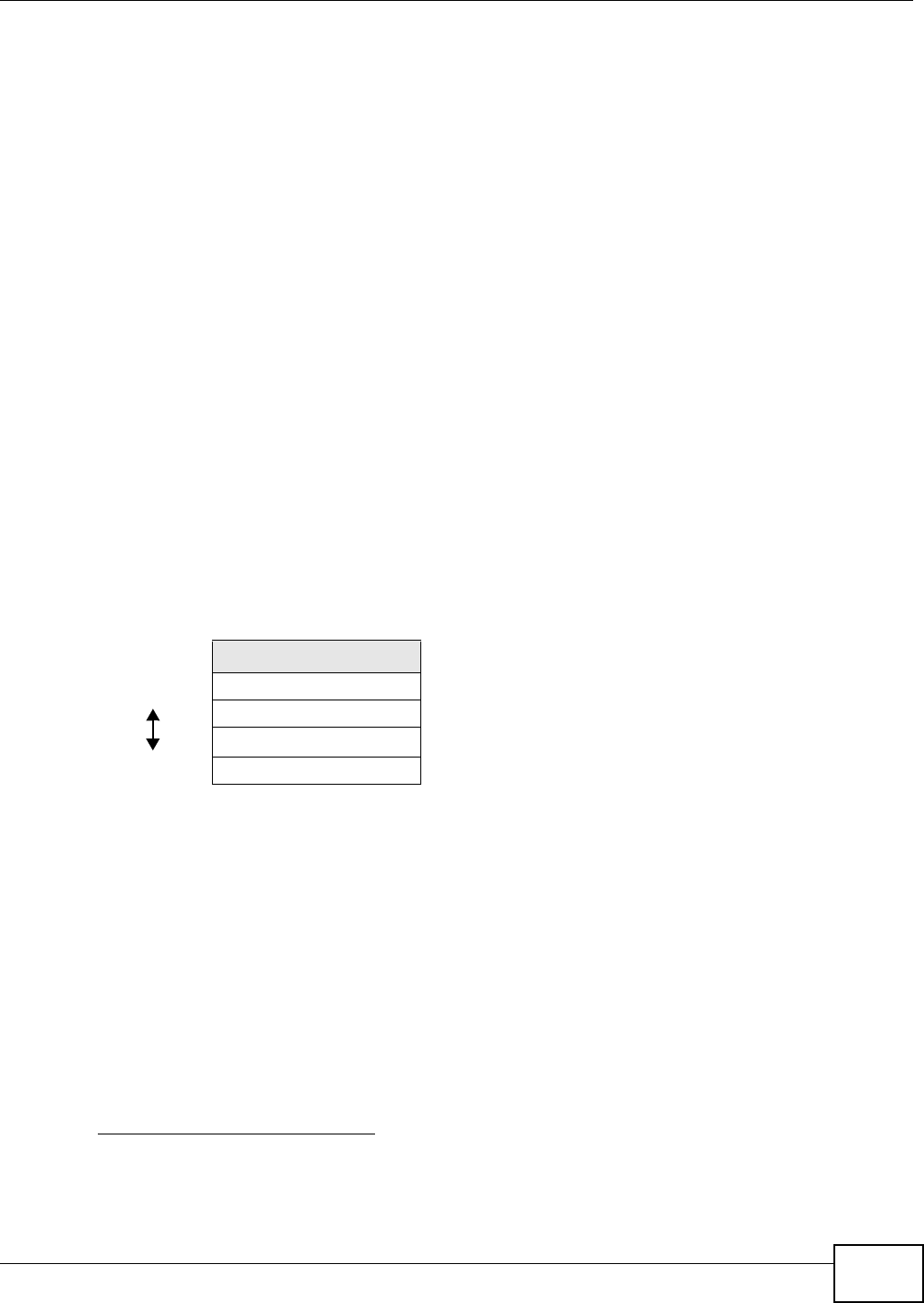
3Select the security settings and click N e x t .
Figure 26 Tutorial: Security Settings
4Click Apply to save settings and restart the WRE2206. Click CON TI N UE to go to the Status screen
without saving the settings and restarting the WRE2206.
Figure 27 Tutorial: Saving settings

36
PART II
Technical Reference

37

WRE2206 User’s Guide 38
CHAPTER 6
Wireless LAN
6.1 Overview
This chapter discusses how to configure the wireless network settings in your WRE2206. See
Section 1.1 on page 9 for an overview of wireless networks.
6.2 What You Can Do
•Use the Ge ner a l screen to enable the Wireless LAN, enter the SSID and select the wireless
security mode (Section 6.4 on page 40).
•Use the MAC Address List screen to allow or deny wireless stations based on their MAC
addresses from connecting to the WRE2206 (Section 6.5 on page 41).
•Use the Adva nced screen to allow intra-BSS networking and set the RTS/CTS Threshold (Section
6.6 on page 42).
•Use the QoS screen to enable Wifi MultiMedia Quality of Service (WMM QoS). WMM QoS
prioritizes traffic using pre-defined voice, video, best-effort and background priorities (Section
6.7 on page 43).
•Use the W PS screen to quickly set up a wireless network with strong security, without having to
configure security settings manually (Section 6.8 on page 43).
•Use the W PS St a t ion screen to add a wireless station using WPS (Section 6.9 on page 44).
•Use the AP Select screen to choose an access point that you want the WRE2206 to connect to.
You should know the security settings of the target AP (Section 6.10 on page 45).
6.3 What You Should Know
Every wireless network must follow these basic guidelines.
• Every wireless client in the same wireless network must use the same SSID.
The SSID is the name of the wireless network. It stands for Service Set IDentity.
• If two wireless networks overlap, they should use different channels.
Like radio stations or television channels, each wireless network uses a specific channel, or
frequency, to send and receive information.
• Every wireless client in the same wireless network must use security compatible with the AP.
Security stops unauthorized devices from using the wireless network. It can also protect the
information that is sent in the wireless network.
Chapter 6 Wireless LAN
WRE2206 User’s Guide 39
6.3.1 Wireless Security Overview
The following sections introduce different types of wireless security you can set up in the wireless
network.
6.3.1.1 MAC Address List
Every wireless client has a unique identification number, called a MAC address.1 A MAC address is
usually written using twelve hexadecimal characters2; for example, 00A0C5000002 or
00:A0:C5:00:00:02. To get the MAC address for each wireless client, see the appropriate User’s
Guide or other documentation.
You can use the MAC Address List to tell the AP which wireless clients are allowed to use the
wireless network. If a wireless client is allowed to use the wireless network, it still has to have the
correct settings (SSID, channel, and security). If a wireless client is not allowed to use the wireless
network, it does not matter if it has the correct settings.
This type of security does not protect the information that is sent in the wireless network.
Furthermore, there are ways for unauthorized devices to get the MAC address of an authorized
wireless client. Then, they can use that MAC address to use the wireless network.
6.3.1.2 Encryption
Wireless networks can use encryption to protect the information that is sent in the wireless
network. Encryption is like a secret code. If you do not know the secret code, you cannot
understand the message.
For example, if users do not log in to the wireless network, you can choose no authentication, if
users do log on to the wireless network, you can choose No Security, St a t ic W EP, W PA- PSK, or
W PA2 - PSK.
Usually, you should set up the strongest encryption that every wireless client in the wireless
network supports. Suppose the wireless network has two wireless clients. Device A only supports
WEP, and device B supports WEP and WPA-PSK. Therefore, you should set up St a t ic W EP in the
wireless network.
Note: It is recommended that wireless networks use WPA-PSK, or stronger encryption.
IEEE 802.1x and WEP encryption are better than none at all, but it is still possible
for unauthorized devices to figure out the original information pretty quickly.
1. Some wireless devices, such as scanners, can detect wireless networks but cannot use wireless networks. These kinds
of wireless devices might not have MAC addresses.
2. Hexadecimal characters are 0, 1, 2, 3, 4, 5, 6, 7, 8, 9, A, B, C, D, E, and F.
Table 11 Types of Encryption for Each Type of Authentication
NO AUTHENTICATION
W eak est No Security
Static WEP
WPA-PSK
St r on ge st WPA2-PSK
Chapter 6 Wireless LAN
WRE2206 User’s Guide
40
Many types of encryption use a key to protect the information in the wireless network. The longer
the key, the stronger the encryption. Every wireless client in the wireless network must have the
same key.
6.3.1.3 WPS
WiFi Protected Setup (WPS) is an industry standard specification, defined by the WiFi Alliance. WPS
allows you to quickly set up a wireless network with strong security, without having to configure
security settings manually. Depending on the devices in your network, you can either press a
button (on the device itself, or in its configuration utility) or enter a PIN (Personal Identification
Number) in the devices. Then, they connect and set up a secure network by themselves. See how
to set up a secure wireless network using WPS in the Section 5.2 on page 26.
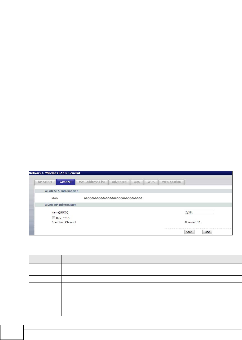
6.4 General Wireless LAN Screen
Use this screen to enable the Wireless LAN, enter the SSID and select the wireless security mode.
Note: If you are configuring the WRE2206 from a computer connected to the wireless
LAN and you change the WRE2206’s SSID, channel or security settings, you will
lose your wireless connection when you press Apply to confirm. You must then
change the wireless settings of your computer to match the WRE2206’s new
settings.
Click N e t w or k > W ir e le ss LAN to open the Gene ral screen.
Figure 28 Network > Wireless LAN > General
The following table describes the general wireless LAN labels in this screen.
Table 12 Network > Wireless LAN > General
LABEL DESCRIPTION
WLAN STA
Information
This shows the wireless and security settings of the selected AP wireless network.
SSID This displays the Service Set IDentity of the wireless device to which you are connecting.
WLAN AP
Information /
Wireless Setup
Use this section to configure the wireless settings between the WRE2206 and its wireless
clients.
Name(SSID) (Service Set IDentity) The SSID identifies the Service Set with which a wireless station is
associated. Wireless stations associating to the access point (AP) must have the same SSID.
Enter a descriptive name (up to 32 printable 7-bit ASCII characters) for the wireless LAN.
Chapter 6 Wireless LAN
WRE2206 User’s Guide 41
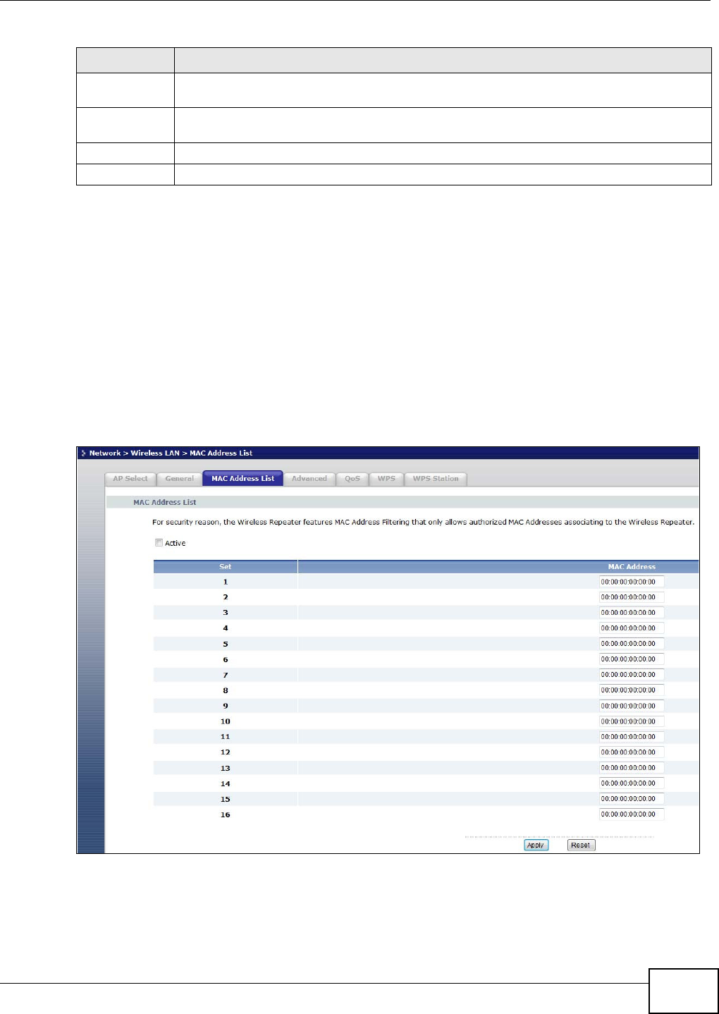
6.5 MAC Address List
The MAC Address List screen allows you to specify which devices are allowed to access the
WRE2206, while denying access to all unspecified devices. Every Ethernet device has a unique MAC
(Media Access Control) address. The MAC address is assigned at the factory and consists of six
pairs of hexadecimal characters, for example, 00:A0:C5:00:00:02. You need to know the MAC
address of the devices to configure this screen.
To change your WRE2206’s MAC Address List settings, click N e t w or k > W ir e le ss LAN > M AC
Addr ess List. The screen appears as shown.
Figure 29 Network > Wireless LAN > MAC Address List
Hide SSID Select this check box to hide the SSID in the outgoing beacon frame so a station cannot
obtain the SSID through scanning using a site survey tool.
Operating
Channel
This displays the channel the WRE2206 is currently using.
Apply Click Apply to save your changes back to the WRE2206.
Reset Click Reset to reload the previous configuration for this screen.
Table 12 Network > Wireless LAN > General (continued)
LABEL DESCRIPTION
Chapter 6 Wireless LAN
WRE2206 User’s Guide
42
The following table describes the labels in this menu.
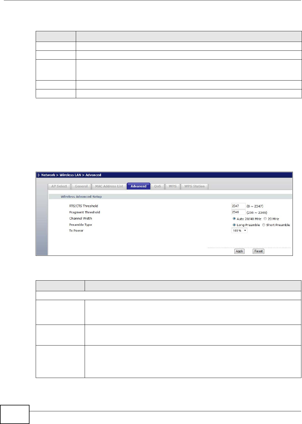
6.6 Wireless LAN Advanced Screen
Use this screen to configure advanced wireless LAN parameters.
Click N e t w or k > W ir e le ss LAN > Advanced. The screen appears as shown.
Figure 30 Network > Wireless LAN > Advanced
The following table describes the labels in this screen.
Table 13 Network > Wireless LAN > MAC Address List
LABEL DESCRIPTION
Active Select this to enable MAC address filtering.
Set This is the index number of the MAC address.
MAC Address Enter the MAC addresses of the wireless station that are allowed access to the WRE2206 in
these address fields. Enter the MAC addresses in a valid MAC address format, that is, six
hexadecimal character pairs, for example, 12:34:56:78:9a:bc.
Apply Click Apply to save your changes back to the WRE2206.
Reset Click Reset to reload the previous configuration for this screen.
Table 14 Network > Wireless LAN > Advanced
LABEL DESCRIPTION
Wireless Advanced Setup
RTS/CTS
Threshold
Data with its frame size larger than this value will perform the RTS (Request To Send)/
CTS (Clear To Send) handshake.
Enter a value between 0 and 2 3 4 7 .
Fragmentation
Threshold
The threshold (number of bytes) for the fragmentation boundary for directed messages.
It is the maximum data fragment size that can be sent. Enter an even number between
2 5 6 and 2 3 4 6 .
Channel Width Select whether the WRE2206 uses a wireless channel width of 20MHz or Auto 20/40MHz.
A standard 20MHz channel offers transfer speeds of up to 150Mbps whereas a 40MHz
channel uses two standard channels and offers speeds of up to 300 Mbps. Because not all
devices support 40MHz channels, select Auto 20/40MHz to allow the WRE2206 to adjust
the channel bandwidth automatically.
Chapter 6 Wireless LAN
WRE2206 User’s Guide 43
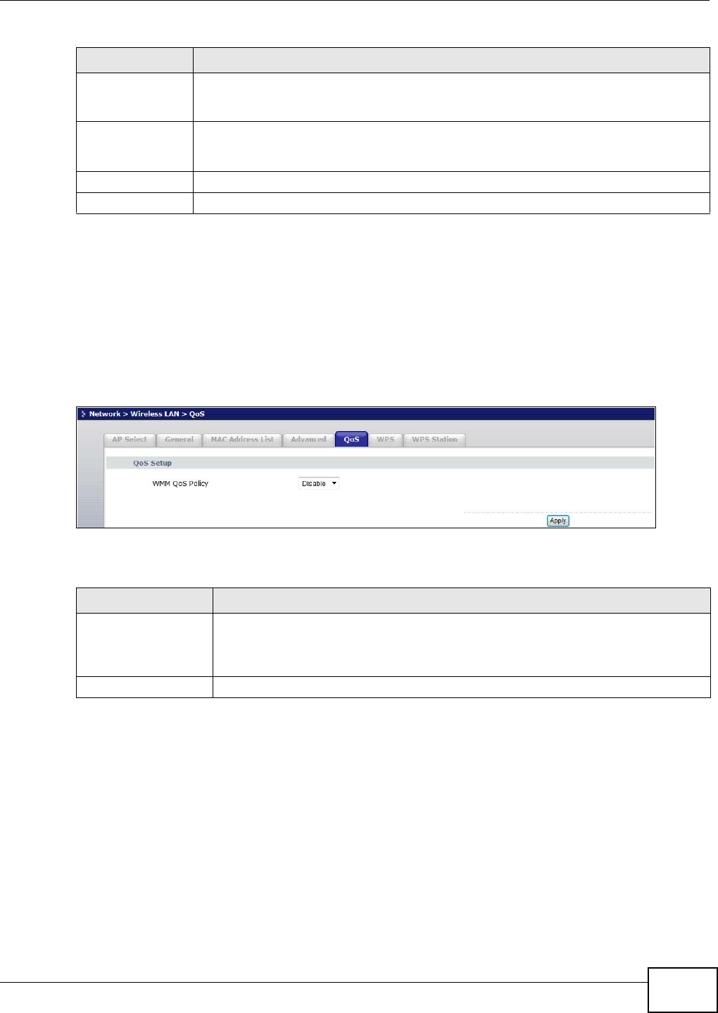
6.7 Quality of Service (QoS) Screen
Use the QoS screen to enable Wifi MultiMedia Quality of Service (WMM QoS). WMM QoS prioritizes
traffic using pre-defined voice, video, best-effort and background priorities.
Click N e t w or k > W ir e le ss LAN > QoS. The following screen appears.
Figure 31 Network > Wireless LAN > QoS
The following table describes the labels in this screen.
6.8 WPS Screen
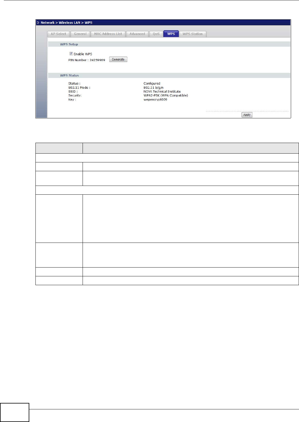
Use this screen to enable/disable WPS, view or generate a new PIN and check current WPS status.
To open this screen, click Net w ork > W ir e le ss LAN > W PS tab.
Preamble Type A preamble affects the timing in your wireless network. There are two preamble modes:
long and short. If a device uses a different preamble mode than the WRE2206 does, it
cannot communicate with the WRE2206.
Tx Power This field controls the transmission power of the WRE2206. When using the WRE2206
with a notebook computer, select a lower transmission power level when you are close to
the AP in order to conserve battery power.
Apply Click Apply to save your changes to the WRE2206.
Reset Click Reset to reload the previous configuration for this screen.
Table 14 Network > Wireless LAN > Advanced (continued)
LABEL DESCRIPTION
Table 15 Network > Wireless LAN > QoS
LABEL DESCRIPTION
WMM QoS Policy Enable this to have the WRE2206 automatically give a service a priority level
according to the ToS value in the IP header of packets it sends. WMM QoS (Wifi
MultiMedia Quality of Service) gives high priority to voice and video, which makes
them run more smoothly.
Apply Click Apply to save your changes to the WRE2206.
Chapter 6 Wireless LAN
WRE2206 User’s Guide
44
Figure 32 Network > Wireless LAN > WPS
The following table describes the labels in this screen.
6.9 WPS Station Screen
Use this screen when you want to add a wireless station using WPS.
Note: WPS can only be configured between two devices at a time. For example if devices
A and B are first configured using WPS, then use either A or B to configure device C
using WPS.
To open this screen, click N e t w or k > W ireless LAN > W PS Stat ion tab.
Table 16 Network > Wireless LAN > WPS
LABEL DESCRIPTION
WPS Setup
Enable WPS Select this to enable the WPS feature.
PIN Number This displays a PIN number last time system generated. Click Ge ne r a t e to generate a
new PIN number.
WPS Status
Status This displays Configur e d when the WRE2206 has connected to a wireless network using
WPS or when Ena ble W PS is selected and wireless or wireless security settings have
been changed. The current wireless and wireless security settings also appear in the
screen.
This displays Un configure d if WPS is disabled and there are no wireless or wireless
security changes on the WRE2206 or you click Rele ase_ Configu ra tion to remove the
configured wireless and wireless security settings.
Release
Configuration
This button is only available when the WPS status displays Con figur ed.
Click this button to remove all configured wireless and wireless security settings for WPS
connections on the WRE2206.
Apply Click Apply to save your changes back to the WRE2206.
Refresh Click Refre sh to get this screen information afresh.

Chapter 6 Wireless LAN
WRE2206 User’s Guide 45
Note: WPS times out after two minutes of pressing a button. Press the button on the
second device within about a minute of the first, then wait two minutes for the WPS
configuration to complete.
To add the second wireless station, you have to press these buttons on both device and the wireless
station again after the first 2 minutes.
Figure 33 Network > Wireless LAN > WPS Station
The following table describes the labels in this screen.
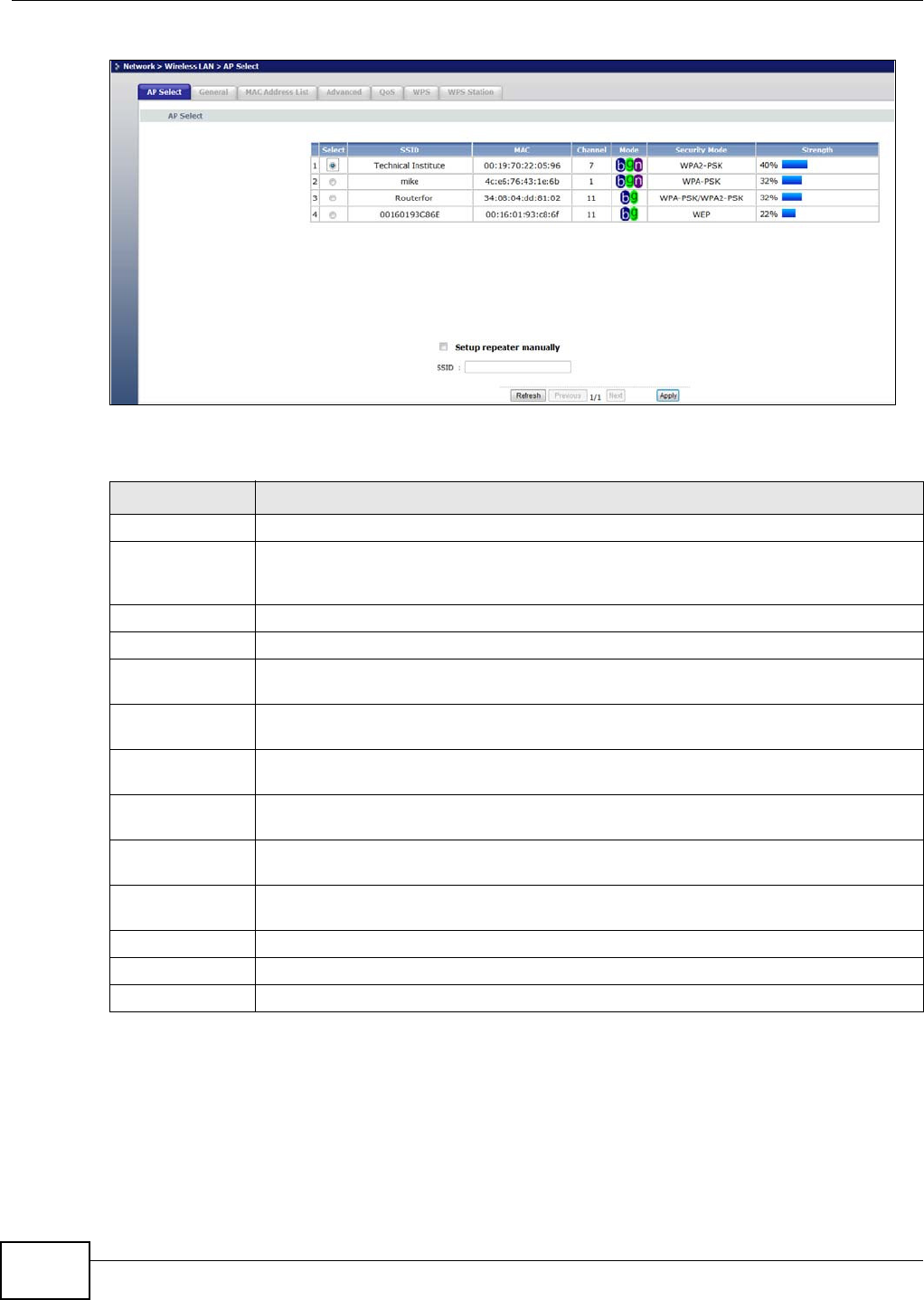
6.10 AP Select Screen
Use this screen to choose an access point that you want the WRE2206 to connect to. You should
know the security settings of the target AP.
To open this screen, click N e t w or k > W ireless LAN > AP Select tab.
Table 17 Network > Wireless LAN > WPS Station
LABEL DESCRIPTION
Config Mode Use this to select Re gist r a r or Enr ollee mode. Select Regi st r a r mode to make wireless
clients follow the wireless settings of the WRE2206. Select Enr ollee mode to make the
WRE2206 follow the wireless settings of an access point.
Push Button Use this button when you use the PBC (Push Button Configuration) method to configure
wireless stations’s wireless settings. See Section 5.2.1 on page 26.
Click this to start WPS-aware wireless station scanning and the wireless security
information synchronization.
Input station’s
PIN number
Use this button when you use the PIN Configuration method to configure wireless station’s
wireless settings. See Section 5.2.2 on page 28.
Type the same PIN number generated in the wireless station’s utility. Then click St ar t to
associate to each other and perform the wireless security information synchronization.
Chapter 6 Wireless LAN
WRE2206 User’s Guide
46
Figure 34 Network > Wireless LAN > AP Select
The following table describes the labels in this screen.
Table 18 Network > Wireless LAN > AP Select
LABEL DESCRIPTION
Select Use the radio button to select the wireless device to which you want to connect.
SSID This displays the Service Set IDentity of the wireless device. The SSID is a unique name
that identifies a wireless network. All devices in a wireless network must use the same
SSID.
MAC This displays the MAC address of the wireless device.
Channel This displays the channel number used by this wireless device.
Mode This displays which IEEE 802.11b/g/n wireless networking standards the wireless device
supports.
Security Mode This displays the type of security configured on the wireless device. When no is shown, no
security is configured and you can connect to it without a password.
Strength This displays the strength of the wireless signal. The signal strength mainly depends on
the antenna output power and the distance between your WRE2206 and this device.
Setup repeater
manually
Select this to setup the AP manually.
SSID If Set u p re pe a t e r m anua lly is selected, use this field to type the SSID of the AP. This is
useful when the AP’s SSID is hidden.
Refresh Click this to search for available wireless devices within transmission range and update
this table.
Previous Click this to see the previous page of APs.
Next Click this to see the next page of APs.
Apply Click this to start the next step in the AP setup process.
WRE2206 User’s Guide 47
CHAPTER 7
LAN
7.1 Overview
This screen allows you to assign the WRE2206 a fixed or dynamic IP address. The default IP
address is 192.168.1.2. In initial configuration, the WRE2206 acts as a DHCP server, so it can
assign your computer an IP address in the same network range as the default IP. After the
WRE2206 connects to an AP, the DHCP server function is disabled and your computer gets its IP
from the AP. If the AP connection is dropped, connect to the WRE2206 again using the default
domain name, http://zyxelsetupxxxx where xxxx is the last four numbers of the MAC address. The
MAC address can be found on a label on the product.
7.2 What You Need To Know
The LAN parameters of the WRE2206 are preset in the factory with the following values:
• IP address of 192.168.1.2 with subnet mask of 255.255.255.0 (24 bits)
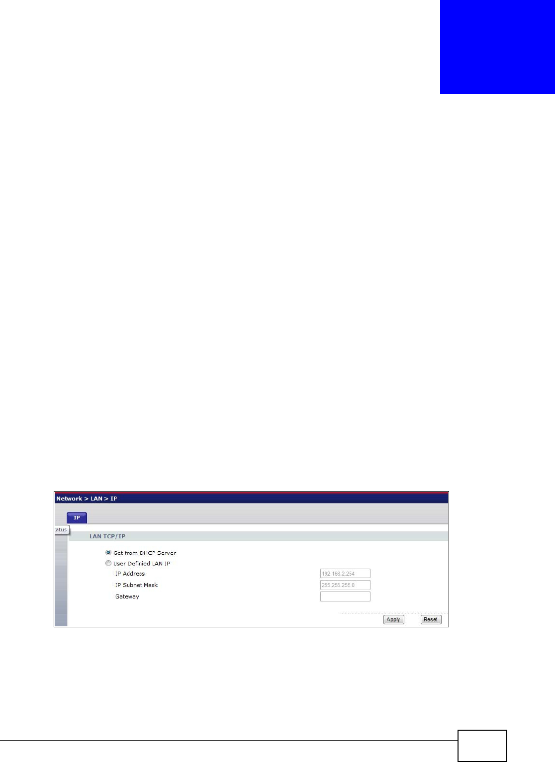
7.3 LAN IP Screen
Use this screen to change your basic LAN settings. Click N et w or k > LAN .
Figure 35 Network > LAN > IP

Chapter 7 LAN
WRE2206 User’s Guide
48
The following table describes the labels in this screen.
Table 19 Network > LAN > IP
LABEL DESCRIPTION
Get from DHCP
Server
Select this to have the WRE2206 get a dynamic IP address from a DHCP server.
User Defined LAN
IP
Click this to enable the manual IP configuration.
IP Address Type the IP address of your WRE2206 in dotted decimal notation 192.168.1.2 (factory
default).
IP Subnet Mask The subnet mask specifies the network number portion of an IP address.
Apply Click Apply to save your changes back to the WRE2206.
Reset Click Re se t to begin configuring this screen afresh.
WRE2206 User’s Guide 49
CHAPTER 8
System
8.1 Overview
This chapter provides information on the Syste m screen.
8.2 What You Can Do
Use the Pa ssw ord screen to set the password (Section 8.3 on page 49).
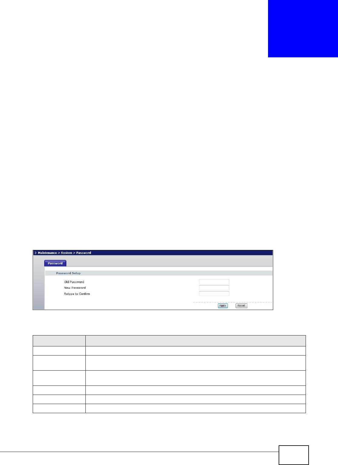
8.3 System Password Screen
Use this screen to set the web configurator password. Click M a in t ena nce > Syst e m . The following
screen displays.
Figure 36 Maintenance > System > Password
The following table describes the labels in this screen.
Table 20 Maintenance > System > Password
LABEL DESCRIPTION
Password Setup Change your WRE2206’s password (recommended) using the fields as shown.
Old Password Type the default password or the existing password you use to access the system in this
field.
New Password Type your new system password (up to 30 characters). Note that as you type a
password, the screen displays an asterisk (*) for each character you type.
Retype to Confirm Type the new password again in this field.
Apply Click Apply to save your changes back to the WRE2206.
Reset Click Re se t to begin configuring this screen afresh.

WRE2206 User’s Guide 50
CHAPTER 9
Tools
9.1 Overview
This chapter shows you how to upload a new firmware, upload or save backup configuration files,
restart the WRE2206 and configure LEDs.
9.2 What You Can Do
•Use the Firm w a r e screen to upload firmware to your WRE2206 (Section 9.3 on page 50).
•Use the Configu r at ion screen to view information related to factory defaults, backup
configuration, and restore configuration (Section 9.4 on page 52).
•Use the Rest art screen to have the WRE2206 reboot (Section 9.5 on page 54).
•Use the LED screen to configure the LEDs (Section 9.6 on page 54).
9.3 Firmware Upload Screen
Find firmware at www.zyxel.com in a file that (usually) uses the system model name with a “*.bin”
extension, e.g., “WRE2206.bin”. The upload process uses HTTP (Hypertext Transfer Protocol) and
may take up to two minutes. After a successful upload, the system will reboot.
Click M a in t e na n ce > Tools. Follow the instructions in this screen to upload firmware to your
WRE2206.
Chapter 9 Tools
WRE2206 User’s Guide 51
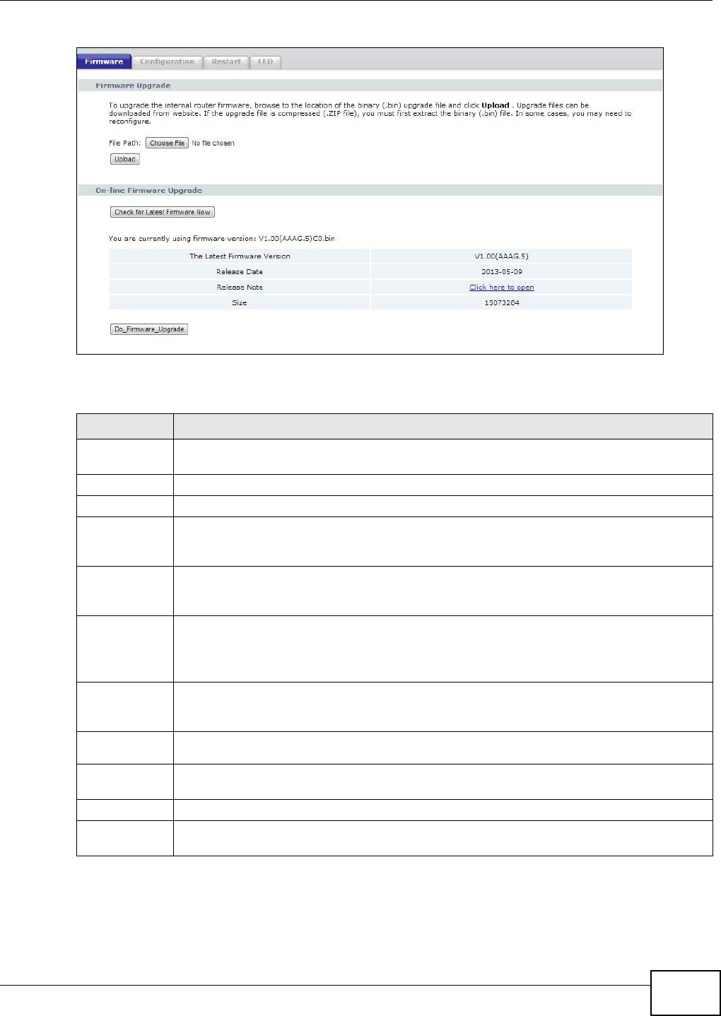
Figure 37 Maintenance > Tools > Firmware
The following table describes the labels in this screen.
Note: Do not turn off the WRE2206 while firmware upload is in progress!
After you see the Fir m w a re Upgra ding screen, wait until the upgrade process is complete.
Table 21 Maintenance > Tools > Firmware
LABEL DESCRIPTION
Firmware
Upgrade
Use this section if you have already manually downloaded new firmware from the website.
Remember that you must decompress compressed (.zip) files before you can upload them.
File Path Click Choose File to find the location of the firmware .bin file you want to upload.
Upload Click Uploa d to begin the upload process. This process may take up to two minutes.
On-line
Firmware
Upgrade
Use this section if you have want to check for new firmware on the website and the WRE2206
has an Internet connection.
Check for
latest
Firmware Now
The following fields display when you click this button.
You are
currently
using
firmware
version:
The firmware version conists of the trunk version number, model code, and release number.
For example, V1.00(AAAG.5) means V1.00 is the trunk number, AAAG represents WRE2206,
and 5 means the fifth release.
The Latest
Firmware
Version
Compare the release number in the previous field with the release number in this one to see
if you have the latest firmware. In this example, V1.00(AAAG.5), the numbers are the same
(5), so the WRE2206 already has the latest firmware.
Release
Date The date the firmware was issued is shown in year-month-date format.
Release
Note The release note shows what has changed (new features, bug fixes, known issues) in this
firmware version. Check the Release Note before deciding to use new firmware.
Size This is the size of the firmware in bytes. 15073234 is about 15 MB.
Do_Firmware_
Upgrade
Click this button to download and upgrade the new firmware to the WRE2206.
Chapter 9 Tools
WRE2206 User’s Guide
52
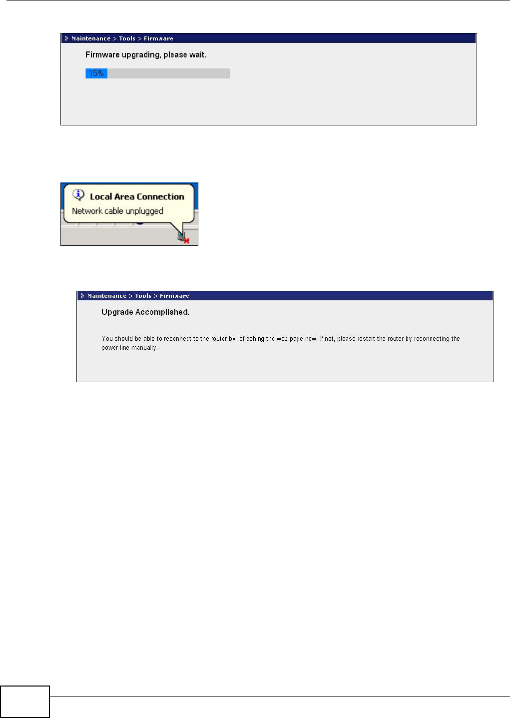
Figure 38 Firmware Upgrading
The WRE2206 automatically restarts in this time causing a temporary network disconnect. In some
operating systems, you may see the following icon on your desktop.
Figure 39 Network Temporarily Disconnected
After the WRE2206 restarts, the Upgr a de Accom plished screen appears.
Figure 40 Upgrade Accomplished
Refresh the web page and log in again and check your new firmware version in the St a t us screen.
9.4 Configuration Screen
Click M a in t e na n ce > Tools > Con fig ur a t ion . Information related to factory defaults, backup
configuration, and restoring configuration appears as shown next.
Chapter 9 Tools
WRE2206 User’s Guide 53
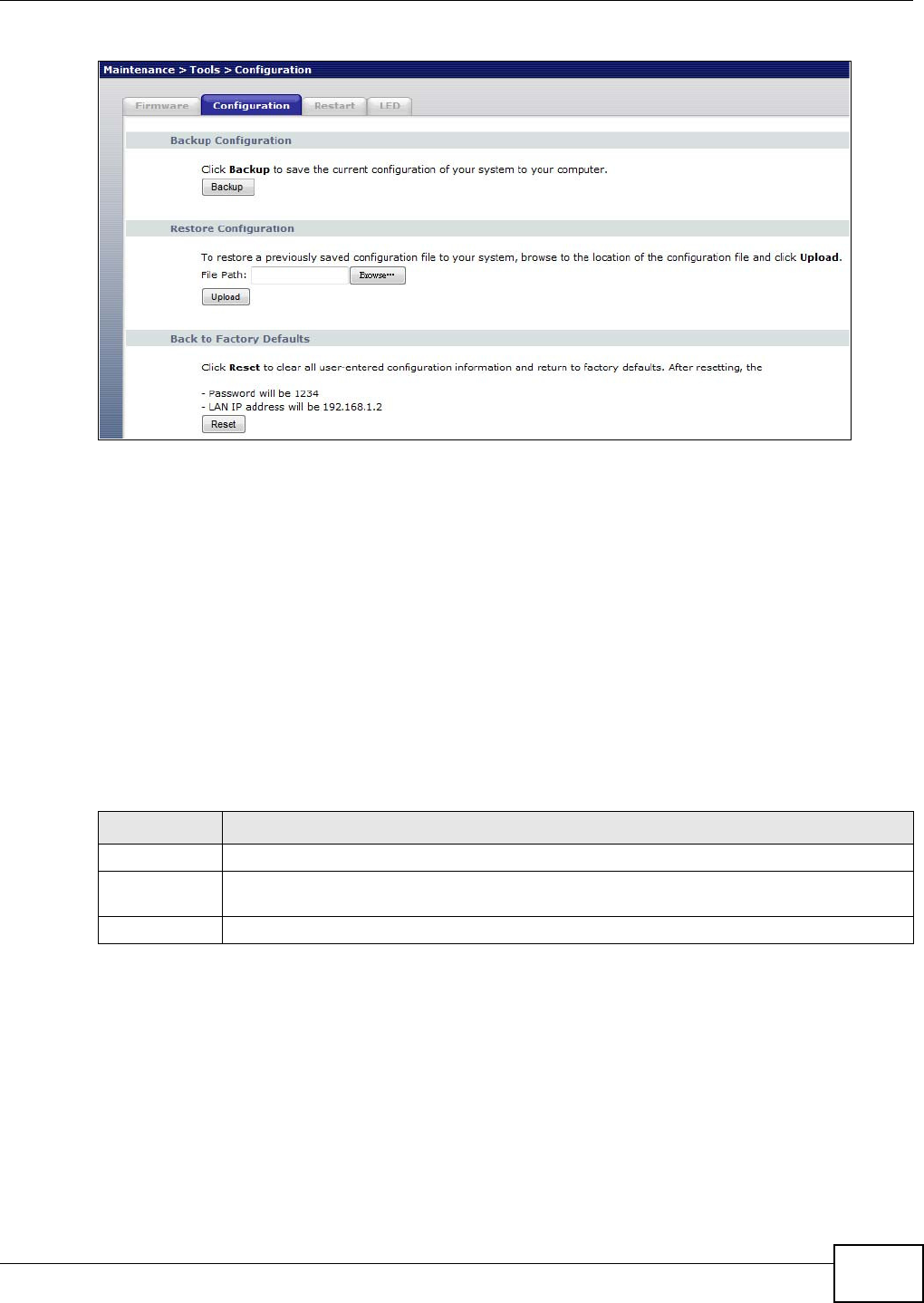
Figure 41 Maintenance > Tools > Configuration
9.4.1 Backup Configuration
Backup configuration allows you to back up (save) the WRE2206’s current configuration to a file on
your computer. Once your WRE2206 is configured and functioning properly, it is highly
recommended that you back up your configuration file before making configuration changes. The
backup configuration file will be useful in case you need to return to your previous settings.
Click Backup to save the WRE2206’s current configuration to your computer.
9.4.2 Restore Configuration
Restore configuration allows you to upload a new or previously saved configuration file from your
computer to your WRE2206.
Note: Do not turn off the WRE2206 while configuration file upload is in progress.
After you see a “configuration upload successful” screen, you must then wait one minute before
logging into the WRE2206 again.
The WRE2206 automatically restarts in this time causing a temporary network disconnect. In some
operating systems, you may see the following icon on your desktop.
Table 22 Maintenance Restore Configuration
LABEL DESCRIPTION
File Path Type in the location of the file you want to upload in this field or click Brow se... to find it.
Browse... Click Br ow se... to find the file you want to upload. Remember that you must decompress
compressed (.ZIP) files before you can upload them.
Upload Click Uploa d to begin the upload process.
Chapter 9 Tools
WRE2206 User’s Guide
54
Figure 42 Temporarily Disconnected
If you uploaded the default configuration file you may need to change the IP address of your
computer to be in the same subnet as that of the default WRE2206 IP address (192.168.1.2). Refer
to your operating system’s help files for details on how to set up your computer’s IP address.
9.4.3 Back to Factory Defaults
Pressing the Re se t button on the Maintenance > Tools > Configuration screen clears all user-
entered configuration information and returns the WRE2206 to its factory defaults.
You can also press the W PS button on the front panel for more than 10 seconds to reset the factory
defaults of your WRE2206. Refer to Section 2.3 on page 14 for more information on the resetting
the WRE2206.
9.5 Restart Screen
System restart allows you to reboot the WRE2206 without turning the power off.
Click Maint e na nce > Tools > Re st a r t . Click Re st a r t to have the WRE2206 reboot. This does not
affect the WRE2206's configuration.
Figure 43 Maintenance > Tools > Restart
9.6 LED Screen
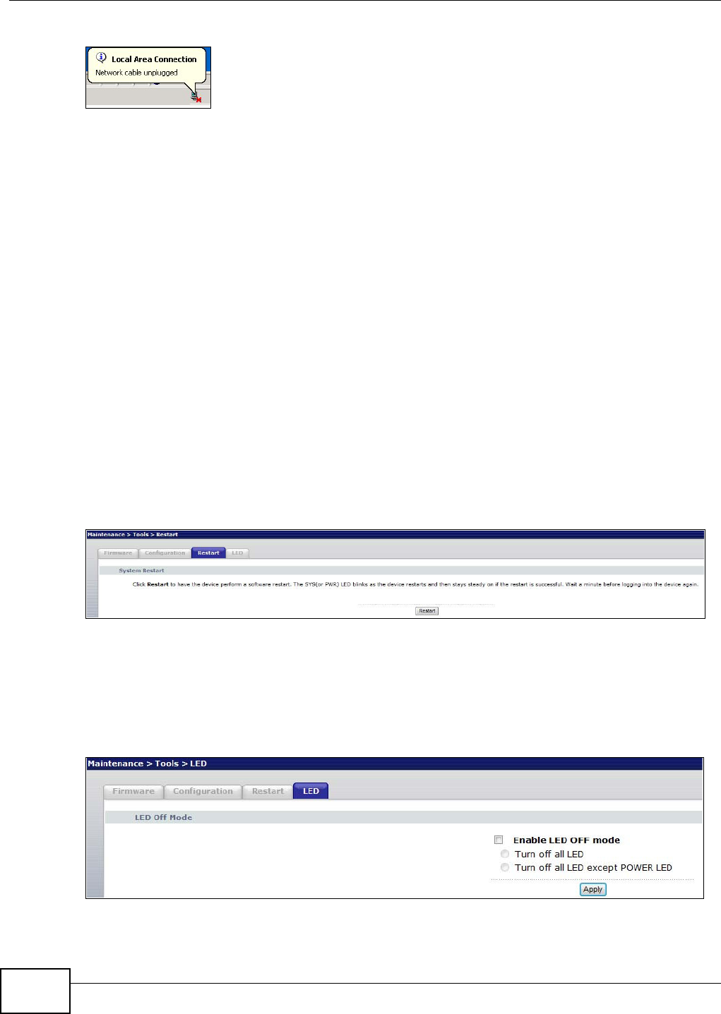
Click M a int e na n ce > Tools > LED. Use this screen to configure which LEDs are enabled or disabled.
Figure 44 Maintenance > Tools > LED

Chapter 9 Tools
WRE2206 User’s Guide 55
The following table describes the labels on the LED screen.
Table 23 Maintenance > Tools > LED Screen
LABEL DESCRIPTION
Enable LED
OFF mode
Type in the location of the file you want to upload in this field or click Brow se... to find it.
Turn off all LED Select this to turn off all LEDs.
Turn off all LED
except POWER
LED
Select this to turn off all LEDs except the power LED.
Apply Click Apply to save your changes back to the WRE2206.

WRE2206 User’s Guide 56
CHAPTER 10
Troubleshooting
This chapter offers some suggestions to solve problems you might encounter. The potential
problems are divided into the following categories.
•Power, Hardware Connections, and LEDs
•WRE2206 Access and Login
•Internet Access
•Resetting the WRE2206 to Its Factory Defaults
•Wireless Problems
10.1 Power, Hardware Connections, and LEDs
The WRE2206 does not turn on. None of the LEDs turn on.
1Make sure the WRE2206 is plugged in to an appropriate power source. Make sure the power source
is turned on.
2Unplug and re-plug the WRE2206.
3If the problem continues, contact the vendor.
One of the LEDs does not behave as expected.
1Make sure you understand the normal behavior of the LED. See Section 1.3 on page 10.
2Make sure you understand how the LEDs are enabled or disabled. See Section 9.6 on page 54.
3Check the hardware connections. See the Quick Start Guide.
4Inspect your cables for damage. Contact the vendor to replace any damaged cables.
5Disconnect and re-connect the power adaptor to the WRE2206.
6If the problem continues, contact the vendor.

Chapter 10 Troubleshooting
WRE2206 User’s Guide 57
10.2 WRE2206 Access and Login
I don’t know the IP address of my WRE2206.
1Click St a rt > Run, enter cm d, and then enter Ping zyxelset up. You can find the MAC address on
a label on the WRE2206.
2The default URL is h t t p:/ / z yx e lse t up. The default IP address is 192.168.1.2.
3If you changed the IP address and have forgotten it, you might get the IP address of the WRE2206
by looking up the IP address of the default gateway for your computer. To do this in most Windows
computers, click Star t > Ru n, enter cm d, and then enter ipcon fig. The IP address of the Default
Gat e w a y might be the IP address of the WRE2206 (it depends on the network), so enter this IP
address in your Internet browser. Login (see the Quick Start Guide for instructions) and go to the
De vice I nfor m at ion table in the St a t u s screen. Your WRE2206’s IP address is available in the
De vice I nfor m at ion table.
•If the DHCP setting under LAN infor m at ion is N o ne , your device has a fixed IP address.
•If the DHCP setting under LAN infor m a t ion is Clie n t , then your device receives an IP
address from a DHCP server on the network.
4If your WRE2206 is a DHCP client, you can find your IP address from the DHCP server. This
information is only available from the DHCP server which allocates IP addresses on your network.
Find this information directly from the DHCP server or contact your system administrator for more
information.
5Reset your WRE2206 to change all settings back to their default. This means your current settings
are lost. See Section 10.4 on page 60 in the Tr ou ble sh oo t ing for information on resetting your
WRE2206.
I forgot the username and password.
1The default username is adm in and default password is 1 2 3 4 .
2If this does not work, you have to reset the device to its factory defaults. See Section 10.4 on page
60.
I cannot see or access the Login screen in the Web Configurator.
1Make sure you are using the correct URL and IP address.
• The default URL is http://zyxelsetup. The default IP address is 192.168.1.2.
• If you changed the IP address, use the new IP address.

Chapter 10 Troubleshooting
WRE2206 User’s Guide
58
• If you changed the IP address and have forgotten it, see the troubleshooting suggestions for I
don’t know the IP address of my WRE2206.
2Check the hardware connections, and make sure the LEDs are behaving as expected. See the Quick
Start Guide.
3Make sure your Internet browser does not block pop-up windows and has JavaScript and Java
enabled.
4Make sure your computer is in the same subnet as the WRE2206. (If you know that there are
routers between your computer and the WRE2206, skip this step.)
• If there is a DHCP server on your network, make sure your computer is using a dynamic IP
address.
• If there is no DHCP server on your network, make sure your computer’s IP address is in the
same subnet as the WRE2206.
5Reset the device to its factory defaults, and try to access the WRE2206 with the default IP address.
6If the problem continues, contact the network administrator or vendor, or try one of the advanced
suggestions.
Adva n ced Sugge st ions
• If your computer is connected wirelessly, use a computer that is connected to a LAN /ETH ERNET
port.
I can see the Login screen, but I cannot log in to the WRE2206.
1Make sure you have entered the password correctly. The default username is adm in and default
password is 1 2 3 4 . This field is case-sensitive, so make sure [Caps Lock] is not on.
2This can happen when you fail to log out properly from your last session. Try logging in again after
5 minutes.
3Disconnect and re-connect the power adaptor or cord to the WRE2206.
4If this does not work, you have to reset the device to its factory defaults. See Section 10.4 on page
60.
10.3 Internet Access
I cannot access the Internet.
1Check the hardware connections, and make sure the LEDs are behaving as expected. See the Quick
Start Guide.

Chapter 10 Troubleshooting
WRE2206 User’s Guide 59
2Try to connect directly to the AP. If you can access the Internet, check that the WRE2206 has
associated with the AP by checking the W LAN STA I n for m a t ion SSID field shows the SSID of the
AP. See Section 6.4 on page 40.
3If you are trying to access the Internet wirelessly, make sure the wireless settings in the wireless
client are the same as the settings in the AP.
4Disconnect all the cables from your device, and follow the directions in the Quick Start Guide again.
5If the problem continues, contact your ISP.
I cannot access the Internet anymore. I had access to the Internet (with the WRE2206), but
my Internet connection is not available anymore.
1Check the hardware connections, and make sure the LEDs are behaving as expected. See the Quick
Start Guide and Section 1.3 on page 10.
2Reboot the WRE2206.
3Try to connect directly to the AP. If you can access the Internet, check that the WRE2206 has
associated with the AP by checking the W LAN STA I n for m a t ion SSID field shows the SSID of the
AP. See Section 6.4 on page 40.
4If the problem continues, contact your ISP.
The Internet connection is slow or intermittent.
1There might be a lot of traffic on the network. Look at the LEDs, and check Section 1.3 on page 10.
If the WRE2206 is sending or receiving a lot of information, try closing some programs that use the
Internet, especially peer-to-peer applications.
2Check the signal strength. If the signal strength is low, try moving the WRE2206 closer to the AP if
possible, and look around to see if there are any devices that might be interfering with the wireless
network (for example, microwaves, other wireless networks, and so on).
3Reboot the WRE2206.
4If the problem continues, contact the network administrator or vendor, or try one of the advanced
suggestions.
Adva n ced Sugge st ion
• Check the settings for QoS. If it is disabled, you might consider activating it.

Chapter 10 Troubleshooting
WRE2206 User’s Guide
60
10.4 Resetting the WRE2206 to Its Factory Defaults
If you reset the WRE2206, you lose all of the changes you have made. The WRE2206 re-loads its
default settings, and the username/password resets to adm in /1 2 3 4 . You have to make all of your
changes again.
You will lose all of your changes when you reset the WRE2206 to its factory defaults.
To reset the WRE2206,
1Make sure the power LED is on.
2Press the W PS button for longer than 10 seconds to set the WRE2206 back to its factory-default
configuration.
OR
3Click M a in t e na n ce > Tools > Re st a r t and then click Resta r t .
If the WRE2206 restarts automatically, wait for the WRE2206 to finish restarting, and log in to the
Web Configurator. The username is adm in and password is 1 2 3 4 .
If the WRE2206 does not restart automatically, disconnect and reconnect the WRE2206’s power.
Then, follow the directions above again.
10.5 Wireless Problems
I cannot access the WRE2206 or ping any computer from the WLAN.
1Make sure the wireless LAN is enabled on the WRE2206.
2Make sure the wireless adapter on the wireless station is working properly.
3Make sure the wireless adapter installed on your computer is IEEE 802.11 compatible and supports
the same wireless standard as the WRE2206.
4Make sure your computer (with a wireless adapter installed) is within the transmission range of the
WRE2206.
5Check that both the WRE2206 and your wireless station are using the same wireless and wireless
security settings, and that both the WRE2206 and the AP are using the same wireless and wireless
security settings.
6Make sure traffic between the WLAN and the LAN is not blocked by the MAC Address List of the
WRE2206. See Section 6.5 on page 41.

WRE2206 User’s Guide 61
APPENDIX A
Legal Information
Copyright
Copyright © 2015 by ZyXEL Communications Corporation.
The contents of this publication may not be reproduced in any part or as a whole, transcribed, stored in a retrieval system, translated into
any language, or transmitted in any form or by any means, electronic, mechanical, magnetic, optical, chemical, photocopying, manual, or
otherwise, without the prior written permission of ZyXEL Communications Corporation.
Published by ZyXEL Communications Corporation. All rights reserved.
Disclaimer
ZyXEL does not assume any liability arising out of the application or use of any products, or software described herein. Neither does it
convey any license under its patent rights nor the patent rights of others. ZyXEL further reserves the right to make changes in any
products described herein without notice. This publication is subject to change without notice.
Regulatory Notice and Statement
UNITED STATE AMERICA
The following information applies if you use the product within USA area.
FCC EMC Statement
• The device complies with Part 15 of FCC rules. Operation is subject to the following two conditions:
(1) This device may not cause harmful interference, and
(2) this device must accept any interference received, including interference that may cause undesired operation.
• Changes or modifications not expressly approved by the party responsible for compliance could void the user’s authority to operate the
equipment.
• This product has been tested and complies with the specifications for a Class B digital device, pursuant to Part 15 of the FCC Rules.
These limits are designed to provide reasonable protection against harmful interference in a residential installation. This equipment
generates, uses, and can radiate radio frequency energy and, if not installed and used according to the instructions, may cause
harmful interference to radio communications. However, there is no guarantee that interference will not occur in a particular
installation.
• If this equipment does cause harmful interference to radio or television reception, which is found by turning the equipment off and on,
the user is encouraged to try to correct the interference by one or more of the following measures:
•Reorient or relocate the receiving antenna
•Increase the separation between the equipment or devices
•Connect the equipment to an outlet other than the receiver’s
•Consult a dealer or an experienced radio/TV technician for assistance
FCC Radiation Exposure Statement
This equipment complies with FCC RF radiation exposure limits set forth for an uncontrolled environment.
This transmitter must be at least 20 cm from the user and must not be co-located or operating in conjunction with any other antenna or
transmitter.
CANADA
The following information applies if you use the product within Canada area
Industry Canada ICES statement
CAN ICES-3 (B)/NMB-3(B)
Industry Canada RSS-GEN & RSS-210 statement
• This device complies with Industry Canada’s licence-exempt RSSs. Operation is subject to the following two conditions:(1) This device
may not cause interference; and (2) This device must accept any interference, including interference that may cause undesired
operation of the device.

Appendix A Legal Information
WRE2206 User’s Guide
62
• This radio transmitter (2468C-WRE2206) has been approved by Industry Canada to operate with the antenna types listed below with
the maximum permissible gain and required antenna impedance for each antenna type indicated. Antenna types not included in this
list, having a gain greater than the maximum gain indicated for that type, are strictly prohibited for use with this device.
• If you use the produce with 5G wireless function, the following attention shall be paid that,
(i) the device for operation in the band 5150-5250 MHz is only for indoor use to reduce the potential for harmful interference to co-
channel mobile satellite systems;
(ii) the maximum antenna gain permitted for devices in the bands 5250-5350 MHz and 5470-5725 MHz shall comply with the e.i.r.p. limit;
and
(iii) the maximum antenna gain permitted for devices in the band 5725-5825 MHz shall comply with the e.i.r.p. limits specified for point-
to-point and non point-to-point operation as appropriate.
(iv) high-power radars are allocated as primary users (i.e. priority users) of the bands 5250-5350 MHz and 5650-5850 MHz and that these
radars could cause interference and/or damage to LE-LAN devices.
• Ce dispositif est conforme à la norme CNR-210 d'Industrie Canada applicable aux appareils radio exempts de licence. Son
fonctionnement est sujet aux deux conditions suivantes: (1) le dispositif ne doit pas produire de brouillage préjudiciable, et (2) ce
dispositif doit accepter tout brouillage reçu, y compris un brouillage susceptible de provoquer un fonctionnement indésirable.
• Le présent émetteur radio (2468C-WRE2206) de modèle s'il fait partie du matériel de catégorieI) a été approuvé par Industrie Canada
pour fonctionner avec les types d'antenne énumérés ci-dessous et ayant un gain admissible maximal et l'impédance requise pour
chaque type d'antenne. Les types d'antenne non inclus dans cette liste, ou dont le gain est supérieur au gain maximal indiqué, sont
strictement interdits pour l'exploitation de l'émetteur.
• Si vous utilisez le produit avec 5G sans fil fonction, suivant l'attention doit être versée que,
(i) les dispositifs fonctionnant dans la bande 5150-5250 MHz sont réservés uniquement pour une utilisation à l’intérieur afin de réduire les
risques de brouillage préjudiciable aux systèmes de satellites mobiles utilisant les mêmes canaux;
(ii) le gain maximal d’antenne permis pour les dispositifs utilisant les bandes 5 250-5 350 MHz et 5 470-5 725 MHz doit se conformer à la
limite de p.i.r.e.;
(iii) le gain maximal d’antenne permis (pour les dispositifs utilisant la bande 5 725-5 825 MHz) doit se conformer à la limite de p.i.r.e.
spécifiée pour l’exploitation point à point et non point à point, selon le cas.
(iv) De plus, les utilisateurs devraient aussi être avisés que les utilisateurs de radars de haute puissance sont désignés utilisateurs
principaux (c.-à-d., qu’ils ont la priorité) pour les bandes 5 250-5 350 MHz et 5 650-5 850 MHz et que ces radars pourraient causer du
brouillage et/ou des dommages aux dispositifs LAN-EL.
Industry Canada Radiation Exposure Statement
This equipment complies with IC radiation exposure limits set forth for an uncontrolled environment. This equipment should be installed
and operated with a minimum distance of 20cm between the radiator and your body.
Déclaration d’exposition aux radiations:
Cet équipement est conforme aux limites d’exposition aux rayonnements IC établies pour un environnement non contrôlé.Cet équipement
doit être installé et utilisé avec un minimum de 20 cm de distance entre la source de rayonnement et votre corps.
EUROPEAN UNION
The following information applies if you use the product within the European Union.
Declaration of Conformity with Regard to EU Directive 1999/5/EC (R&TTE Directive)
Compliance information for 2.4GHz and/or 5GHz wireless products relevant to the EU and other Countries following the EU Directive 1999/
5/EC (R&TTE)
Б
(Bulgarian) С я ZyXEL , ч я
1999/5/C.
Español
(Spanish) Por medio de la presente ZyXEL declara que el equipo cumple con los requisitos esenciales y cualesquiera otras
disposiciones aplicables o exigibles de la Directiva 1999/5/CE.
Čeština
(Czech) ZyXEL tímto prohlašuje, že tento zařízení je ve shodě se základními požadavky a dalšími příslušnými ustanoveními
směrnice 1999/5/EC.
Dansk (Danish) Undertegnede ZyXEL erklærer herved, at følgende udstyr udstyr overholder de væsentlige krav og øvrige relevante
krav i direktiv 1999/5/EF.
Deutsch
(German) Hiermit erklärt ZyXEL, dass sich das Gerät Ausstattung in Übereinstimmung mit den grundlegenden Anforderungen
und den übrigen einschlägigen Bestimmungen der Richtlinie 1999/5/EU befindet.
Eesti keel
(Estonian) Käesolevaga kinnitab ZyXEL seadme seadmed vastavust direktiivi 1999/5/EÜ põhinõuetele ja nimetatud direktiivist
tulenevatele teistele asjakohastele sätetele.
Εηά
(Greek) Ε Η ΑΑ ZyXEL ∆ΗΩΕ επσός ΦΩΕΑ Ω∆Ε ΑΑΗΕ Α
Ε ΧΕΕ ∆ΑΑΕ Η ∆ΗΓΑ 1999/5/ΕC.
English Hereby, ZyXEL declares that this equipment is in compliance with the essential requirements and other relevant
provisions of Directive 1999/5/EC.

Appendix A Legal Information
WRE2206 User’s Guide 63
National Restrictions
This product may be used in all EU countries (and other countries following the EU Directive 1999/5/EC) without any limitation except for
the countries mentioned below:
Ce produit peut être utilisé dans tous les pays de l’UE (et dans tous les pays ayant transposés la directive 1999/5/CE) sans aucune
limitation, excepté pour les pays mentionnés ci-dessous:
Questo prodotto è utilizzabile in tutte i paesi EU (ed in tutti gli altri paesi che seguono le direttiva 1999/5/EC) senza nessuna
limitazione, eccetto per i paesii menzionati di seguito:
Das Produkt kann in allen EU Staaten ohne Einschränkungen eingesetzt werden (sowie in anderen Staaten die der Richtlinie 1999/5/CE
folgen) mit Außnahme der folgenden aufgeführten Staaten:
In the majority of the EU and other European countries, the 2.4GHz and 5GHz bands have been made available for the use of wireless
local area networks (LANs). Later in this document you will find an overview of countries in which additional restrictions or requirements
or both are applicable.
The requirements for any country may evolve. ZyXEL recommends that you check with the local authorities for the latest status of their
national regulations for both the 2.4GHz and 5GHz wireless LANs.
The following countries have restrictions and/or requirements in addition to those given in the table labeled “Overview of Regulatory
Requirements for Wireless LANs”:.
Belgium
The Belgian Institute for Postal Services and Telecommunications (BIPT) must be notified of any outdoor wireless link having a range
exceeding 300 meters. Please check http://www.bipt.be for more details.
Draadloze verbindingen voor buitengebruik en met een reikwijdte van meer dan 300 meter dienen aangemeld te worden bij het Belgisch
Instituut voor postdiensten en telecommunicatie (BIPT). Zie http://www.bipt.be voor meer gegevens.
Les liaisons sans fil pour une utilisation en extérieur d’une distance supérieure à 300 mètres doivent être notifiées à l’Institut Belge des
services Postaux et des Télécommunications (IBPT). Visitez http://www.ibpt.be pour de plus amples détails.
Denmark
In Denmark, the band 5150 - 5350 MHz is also allowed for outdoor usage.
Français
(French) Par la présente ZyXEL déclare que l'appareil équipements est conforme aux exigences essentielles et aux autres
dispositions pertinentes de la directive 1999/5/EC.
Hrvatski
(Croatian) ZyXEL ovime izjavljuje da je radijska oprema tipa u skladu s Direktivom 1999/5/EC.
Íslenska
(Icelandic) Hér með lýsir, ZyXEL því yfir að þessi búnaður er í samræmi við grunnkröfur og önnur viðeigandi ákvæði tilskipunar
1999/5/EC.
Italiano
(Italian) Con la presente ZyXEL dichiara che questo attrezzatura è conforme ai requisiti essenziali ed alle altre disposizioni
pertinenti stabilite dalla direttiva 1999/5/CE.
Latviešu valoda
(Latvian) Ar šo ZyXEL deklarē, ka iekārtas atbilst Direktīvas 1999/5/EK būtiskajām prasībām un citiem ar to saistītajiem
noteikumiem.
Lietuvių kalba
(Lithuanian) Šiuo ZyXEL deklaruoja, kad šis įranga atitinka esminius reikalavimus ir kitas 1999/5/EB Direktyvos nuostatas.
Magyar
(Hungarian) Alulírott, ZyXEL nyilatkozom, hogy a berendezés megfelel a vonatkozó alapvetõ követelményeknek és az 1999/5/EK
irányelv egyéb elõírásainak.
Malti (Maltese) Hawnhekk, ZyXEL, jiddikjara li dan tagħmir jikkonforma mal-ħtiġijiet essenzjali u ma provvedimenti oħrajn relevanti li
hemm fid-Dirrettiva 1999/5/EC.
Nederlands
(Dutch) Hierbij verklaart ZyXEL dat het toestel uitrusting in overeenstemming is met de essentiële eisen en de andere
relevante bepalingen van richtlijn 1999/5/EC.
Polski (Polish) Niniejszym ZyXEL oświadcza, że sprzęt jest zgodny z zasadniczymi wymogami oraz pozostałymi stosownymi
postanowieniami Dyrektywy 1999/5/EC.
Português
(Portuguese) ZyXEL declara que este equipamento está conforme com os requisitos essenciais e outras disposições da Directiva
1999/5/EC.
Română
(Romanian) Prin prezenta, ZyXEL declară că acest echipament este în conformitate cu cerinţele esenţiale şi alte prevederi
relevante ale Directivei 1999/5/EC.
Slovenčina
(Slovak) ZyXEL týmto vyhlasuje, že zariadenia spĺňa základné požiadavky a všetky príslušné ustanovenia Smernice 1999/5/EC.
Slovenščina
(Slovene) ZyXEL izjavlja, da je ta oprema v skladu z bistvenimi zahtevami in ostalimi relevantnimi določili direktive 1999/5/EC.
Suomi
(Finnish) ZyXEL vakuuttaa täten että laitteet tyyppinen laite on direktiivin 1999/5/EY oleellisten vaatimusten ja sitä koskevien
direktiivin muiden ehtojen mukainen.
Svenska
(Swedish) Härmed intygar ZyXEL att denna utrustning står I överensstämmelse med de väsentliga egenskapskrav och övriga
relevanta bestämmelser som framgår av direktiv 1999/5/EC.
Norsk
(Norwegian) Erklærer herved ZyXEL at dette utstyret er I samsvar med de grunnleggende kravene og andre relevante
bestemmelser I direktiv 1999/5/EF.
Appendix A Legal Information
WRE2206 User’s Guide
64
I Danmark må frekvensbåndet 5150 - 5350 også anvendes udendørs.
Italy
This product meets the National Radio Interface and the requirements specified in the National Frequency Allocation Table for Italy. Unless
this wireless LAN product is operating within the boundaries of the owner's property, its use requires a “general authorization.” Please
check http://www.sviluppoeconomico.gov.it/ for more details.
Questo prodotto è conforme alla specifiche di Interfaccia Radio Nazionali e rispetta il Piano Nazionale di ripartizione delle frequenze in
Italia. Se non viene installato all 'interno del proprio fondo, l'utilizzo di prodotti Wireless LAN richiede una “Autorizzazione Generale”.
Consultare http://www.sviluppoeconomico.gov.it/ per maggiori dettagli.
Latvia
The outdoor usage of the 2.4 GHz band requires an authorization from the Electronic Communications Office. Please check http://
www.esd.lv for more details.
2.4 GHz frekvenèu joslas izmantoðanai ârpus telpâm nepiecieðama atïauja no Elektronisko sakaru direkcijas. Vairâk informâcijas: http://
www.esd.lv.
N o t es:
1. Although Norway, Switzerland and Liechtenstein are not EU member states, the EU Directive 1999/5/EC has also been implemented in
those countries.
2. The regulatory limits for maximum output power are specified in EIRP. The EIRP level (in dBm) of a device can be calculated by adding
the gain of the antenna used(specified in dBi) to the output power available at the connector (specified in dBm).
List of national codes
Safety Warnings
• DO NOT use this product near water, for example, in a wet basement or near a swimming pool.
• DO NOT expose your device to dampness, dust or corrosive liquids.
• DO NOT store things on the device.
• DO NOT install, use, or service this device during a thunderstorm. There is a remote risk of electric shock from lightning.
• Connect ONLY suitable accessories to the device.
• DO NOT open the device or unit. Opening or removing covers can expose you to dangerous high voltage points or other risks. ONLY
qualified service personnel should service or disassemble this device. Please contact your vendor for further information.
• Make sure to connect the cables to the correct ports.
• Place connecting cables carefully so that no one will step on them or stumble over them.
• Always disconnect all cables from this device before servicing or disassembling.
• Use ONLY an appropriate power adaptor or cord for your device. Connect it to the right supply voltage (for example, 110V AC in North
America or 230V AC in Europe).
• DO NOT remove the plug and connect it to a power outlet by itself; always attach the plug to the power adaptor first before connecting
it to a power outlet.
• DO NOT allow anything to rest on the power adaptor or cord and do NOT place the product where anyone can walk on the power
adaptor or cord.
COUNTRY ISO 3166 2 LETTER CODE COUNTRY ISO 3166 2 LETTER CODE
Austria AT Liechtenstein LI
Belgium BE Lithuania LT
Bulgaria BG Luxembourg LU
Croatia HR Malta MT
Cyprus CY Netherlands NL
Czech Republic CZ Norway NO
Denmark DK Poland PL
Estonia EE Portugal PT
Finland FI Romania RO
France FR Serbia RS
Germany DE Slovakia SK
Greece GR Slovenia SI
Hungary HU Spain ES
Iceland IS Switzerland CH
Ireland IE Sweden SE
Italy IT Turkey TR
Latvia LV United Kingdom GB
Appendix A Legal Information
WRE2206 User’s Guide 65
• DO NOT use the device if the power adaptor or cord is damaged as it might cause electrocution.
• If the power adaptor or cord is damaged, remove it from the device and the power source.
• DO NOT attempt to repair the power adaptor or cord. Contact your local vendor to order a new one.
• DO NOT use the device outside, and make sure all the connections are indoors. There is a remote risk of electric shock from lightning.
• CAUTION: RISK OF EXPLOSION IF BATTERY (on the motherboard) IS REPLACED BY AN INCORRECT TYPE. DISPOSE OF USED
BATTERIES ACCORDING TO THE INSTRUCTIONS. Dispose them at the applicable collection point for the recycling of electrical and
electronic equipment. For detailed information about recycling of this product, please contact your local city office, your household
waste disposal service or the store where you purchased the product.
• DO NOT obstruct the device ventilation slots, as insufficient airflow may harm your device.
The following warnings apply if product is disconnect device?
• A readily accessible disconnect device shall be incorporated external to the equipment; and/or
• The socket-outlet shall be installed near the equipment and shall be easily accessible.
Environment Statement
ErP (Energy-related Products)
ZyXEL products put on the EU market in compliance with the requirement of the European Parliament and the Council published
Directive 2009/125/EC establishing a framework for the setting of ecodesign requirements for energy-related products (recast), so called
as "ErP Directive (Energy-related Products directive) as well as ecodesign requirement laid down in applicable implementing measures,
power consumption has satisfied regulation requirements which are:
Network standby power consumption < 12W, and/or
Off mode power consumption < 0.5W, and/or
Standby mode power consumption < 0.5W.
Wireless setting, please refer to "Wireless" chapter for more detail.
WEEE Directive
Your product is marked with this symbol, which is known as the WEEE mark. WEEE stands for Waste Electronics and
Electrical Equipment. It means that used electrical and electronic products should not be mixed with general waste. Used
electrical and electronic equipment should be treated separately.
"INFORMAZIONI AGLI UTENTI"
Ai sensi della Direttiva 2012/19/UE del Parlamento europeo e del Consiglio, del 4 luglio 2012, sui rifiuti di apparecchiature elettriche ed
elettroniche (RAEE)
Il simbolo del cassonetto barrato riportato sull’apparecchiatura o sulla sua confezione indica che il prodotto alla fine della propria vita utile
deve essere raccolto separatamente dagli altri rifiuti.
La raccolta differenziata della presente apparecchiatura giunta a fine vita e organizzata e gestita dal produttore. L’utente che vorra disfarsi
della presente apparecchiatura dovra quindi contattare il produttore e seguire il sistema che questo ha adottato per consentire la raccolta
separata dell’apparecchiatura giunta a fine vita.
L’adeguata raccolta differenziata per l’avvio successivo dell’apparecchiatura dismessa al riciclaggio, al trattamento e allo smaltimento
ambientalmente compatibile contribuisce ad evitare possibili effetti negativi sull’ambiente e sulla salute e favorisce il reimpiego e/o riciclo
dei materiali di cui e composta l’apparecchiatura.
Lo smaltimento abusivo del prodotto da parte del detentore comporta l’applicazione delle sanzioni amministrative previste dalla normativa
vigente."
Appendix A Legal Information
WRE2206 User’s Guide
66
Environmental Product Declaration

Appendix A Legal Information
WRE2206 User’s Guide 67

Appendix A Legal Information
WRE2206 User’s Guide
68
灣
以下訊息僅適用於產品銷售至灣地
第二條經型式認證合格之低率射頻電機,非經許,公司商號或使用者均不得擅自變更頻率大率或變更原設計之特性及能
第四條低率射頻電機之使用不得影響飛航安全及干擾合法通信;經發現有干擾現象時,應立即停用,並改善至無干擾時方得繼續使用
前項合法通信,指依電信法規定作業之無線電通信低率射頻電機須忍受合法通信或工業科學及醫療用電波輻射性電機設備之干擾
Viewing Certifications
Go to http://www.zyxel.com to view this product’s documentation and certifications.
ZyXEL Limited Warranty
ZyXEL warrants to the original end user (purchaser) that this product is free from any defects in material or workmanship for a specific
period (the Warranty Period) from the date of purchase. The Warranty Period varies by region. Check with your vendor and/or the
authorized ZyXEL local distributor for details about the Warranty Period of this product. During the warranty period, and upon proof of
purchase, should the product have indications of failure due to faulty workmanship and/or materials, ZyXEL will, at its discretion, repair or
replace the defective products or components without charge for either parts or labor, and to whatever extent it shall deem necessary to
restore the product or components to proper operating condition. Any replacement will consist of a new or re-manufactured functionally
equivalent product of equal or higher value, and will be solely at the discretion of ZyXEL. This warranty shall not apply if the product has
been modified, misused, tampered with, damaged by an act of God, or subjected to abnormal working conditions.
Note
Repair or replacement, as provided under this warranty, is the exclusive remedy of the purchaser. This warranty is in lieu of all other
warranties, express or implied, including any implied warranty of merchantability or fitness for a particular use or purpose. ZyXEL shall in
no event be held liable for indirect or consequential damages of any kind to the purchaser.
To obtain the services of this warranty, contact your vendor. You may also refer to the warranty policy for the region in which you bought
the device at http://www.zyxel.com/web/support_warranty_info.php.
Registration
Register your product online to receive e-mail notices of firmware upgrades and information at www.zyxel.com for global products, or at
www.us.zyxel.com for North American products.
Open Source Licenses
This product contains in part some free software distributed under GPL license terms and/or GPL like licenses. Open source licenses are
provided with the firmware package. You can download the latest firmware at www.zyxel.com. To obtain the source code covered under
those Licenses, please contact support@zyxel.com.tw to get it.

Index
WRE2206 User’s Guide 69
Index
B
Backup configuration 53
C
certifications 63
viewing 68
Channel 22
Configuration
backup 53
reset the factory defaults 54
restore 53
copyright 61
CPU usage 22
D
disclaimer 61
documentation
related 2
duplex setting 23
E
encryption 39
key 40
F
FCC interference statement 63
Firmware upload 50
file extension
using HTTP
firmware version 22
G
General wireless LAN screen 40
Guide
Quick Start 2
I
IP Address 48
L
LAN setup 47
Link type 22
M
MAC 41
MAC address 39
MAC address filtering 41
MAC Address List 39, 41
managing the device
good habits 10
Media access control 41
Memory usage 22
N
Navigation Panel 24
O
other documentation 2

Index
WRE2206 User’s Guide70
overview 9
P
port speed 23
Q
Quality of Service (QoS) 43
Quick Start Guide 2
R
related documentation 2
Reset the device 14
Restore configuration 53
RTS/CTS Threshold 42
S
Service Set 40
Service Set IDentification 16, 40, 46
Service Set IDentity. See SSID.
SSID 16, 22, 38, 40, 46
Subnet Mask 48
Summary
Packet statistics 23
Wireless station status 24
System General Setup 49
System restart 54
W
warranty 68
note 68
Web Configurator
how to access 13
Overview 13
Wireless association list 24
wireless channel 60
wireless LAN 60
Wireless LAN wizard 15
Wireless network 39
basic guidelines 38
encryption 39
security 38
SSID 38
Wireless security 38
overview 39
troubleshooting 60
type 39
Wireless tutorial 26
WPS 26
Wizard setup 15
complete 20
wireless LAN 15
WPS button 11, 14