ZyXEL Communications X550NH Wireless Gigabit Router User Manual NBG334W User Guide
ZyXEL Communications Corporation Wireless Gigabit Router NBG334W User Guide
Contents
- 1. Users manual part1
- 2. Users manual part2
- 3. Users manual part3
- 4. Users manual part4
Users manual part3
Chapter 17 Bandwidth Management
NBG460N User’s Guide 201
17.6 Predefined Bandwidth Management Services
The following is a description of the services that you can select and to which you can apply
media bandwidth management using the wizard screens.
17.6.1 Services and Port Numbers
See Appendix F on page 321 for commonly used services and port numbers.
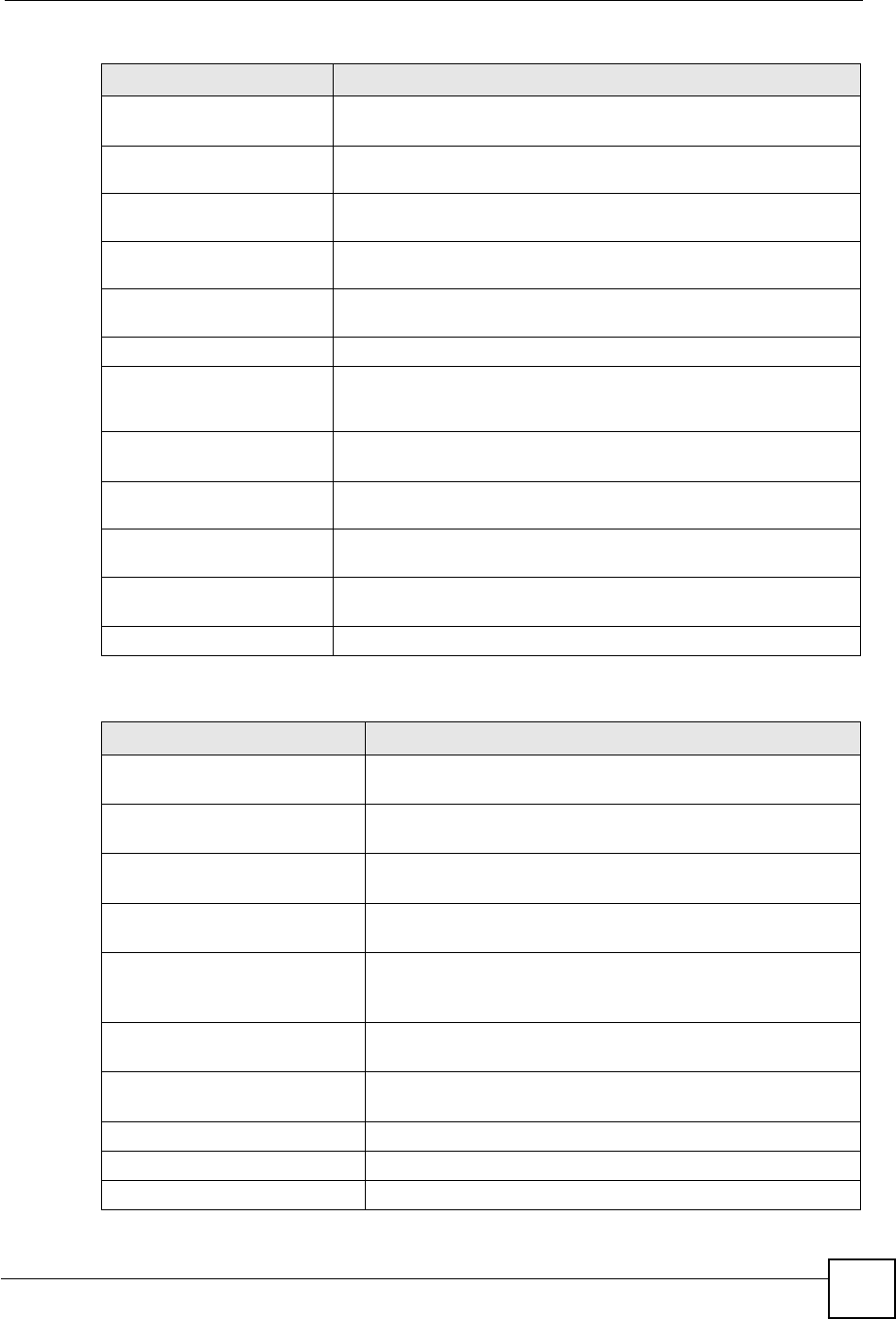
Mid Typically used for “excellent effort” or better than best effort and would include
important business traffic that can tolerate some delay.
Low This is typically used for non-critical “background” traffic such as bulk
transfers that are allowed but that should not affect other applications and
users.
Table 72 Bandwidth Management Priorities
PRIORITY LEVELS: TRAFFIC WITH A HIGHER PRIORITY GETS THROUGH FASTER WHILE
TRAFFIC WITH A LOWER PRIORITY IS DROPPED IF THE NETWORK IS CONGESTED.
Table 73 Media Bandwidth Management Setup: Services
SERVICE DESCRIPTION
Xbox Live This is Microsoft’s online gaming service that lets you play multiplayer Xbox
games on the Internet via broadband technology. Xbox Live uses port 3074.
VoIP (SIP) Sending voice signals over the Internet is called Voice over IP or VoIP. Session
Initiated Protocol (SIP) is an internationally recognized standard for implementing
VoIP. SIP is an application-layer control (signaling) protocol that handles the
setting up, altering and tearing down of voice and multimedia sessions over the
Internet.
SIP is transported primarily over UDP but can also be transported over TCP, using
the default port number 5060.
FTP File Transfer Program enables fast transfer of files, including large files that may
not be possible by e-mail. FTP uses port number 21.
E-Mail Electronic mail consists of messages sent through a computer network to specific
groups or individuals. Here are some default ports for e-mail:
POP3 - port 110
IMAP - port 143
SMTP - port 25
HTTP - port 80
BitTorrent BitTorrent is a free P2P (peer-to-peer) sharing tool allowing you to distribute large
software and media files using ports 6881 to 6889. BitTorrent requires you to
search for a file with a searching engine yourself. It distributes files by corporation
and trading, that is, the client downloads the file in small pieces and share the
pieces with other peers to get other half of the file.
MSN Webcam MSN messenger allows you to chat online and send instant messages. If you use
MSN messenger and also have a webcam, you can send your image/photo in
real-time along with messages
WWW The World Wide Web (WWW) is an Internet system to distribute graphical, hyper-
linked information, based on Hyper Text Transfer Protocol (HTTP) - a client/server
protocol for the World Wide Web. The Web is not synonymous with the Internet;
rather, it is just one service on the Internet. Other services on the Internet include
Internet Relay Chat and Newsgroups. The Web is accessed through use of a
browser.
Chapter 17 Bandwidth Management
NBG460N User’s Guide
202
17.7 Default Bandwidth Management Classes and Priorities
If you enable bandwidth management but do not configure a rule for critical traffic like VoIP,
the voice traffic may then get delayed due to insufficient bandwidth. With the automatic traffic
classifier feature activated, the NBG460N automatically assigns a default bandwidth
management class and priority to traffic that does not match any of the user-defined rules. The
traffic is classified based on the traffic type. Real-time traffic always gets higher priority over
other traffic.
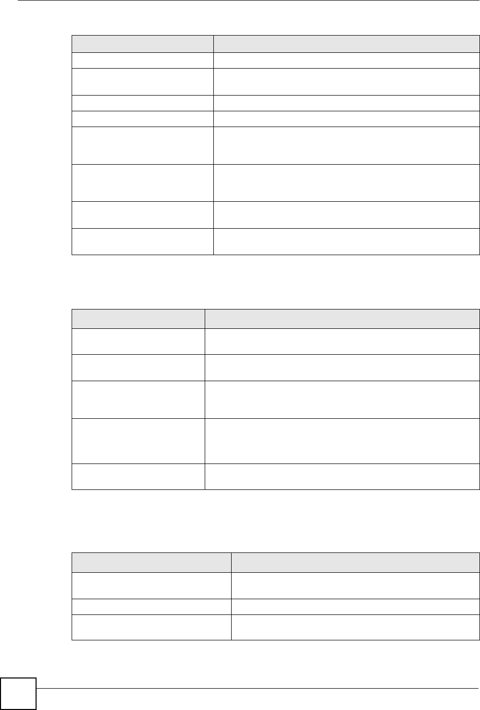
The following table shows you the priorities between the three default classes (AutoClass_H,
AutoClass_M and Default Class) and user-defined rules. 6 is the highest priority.
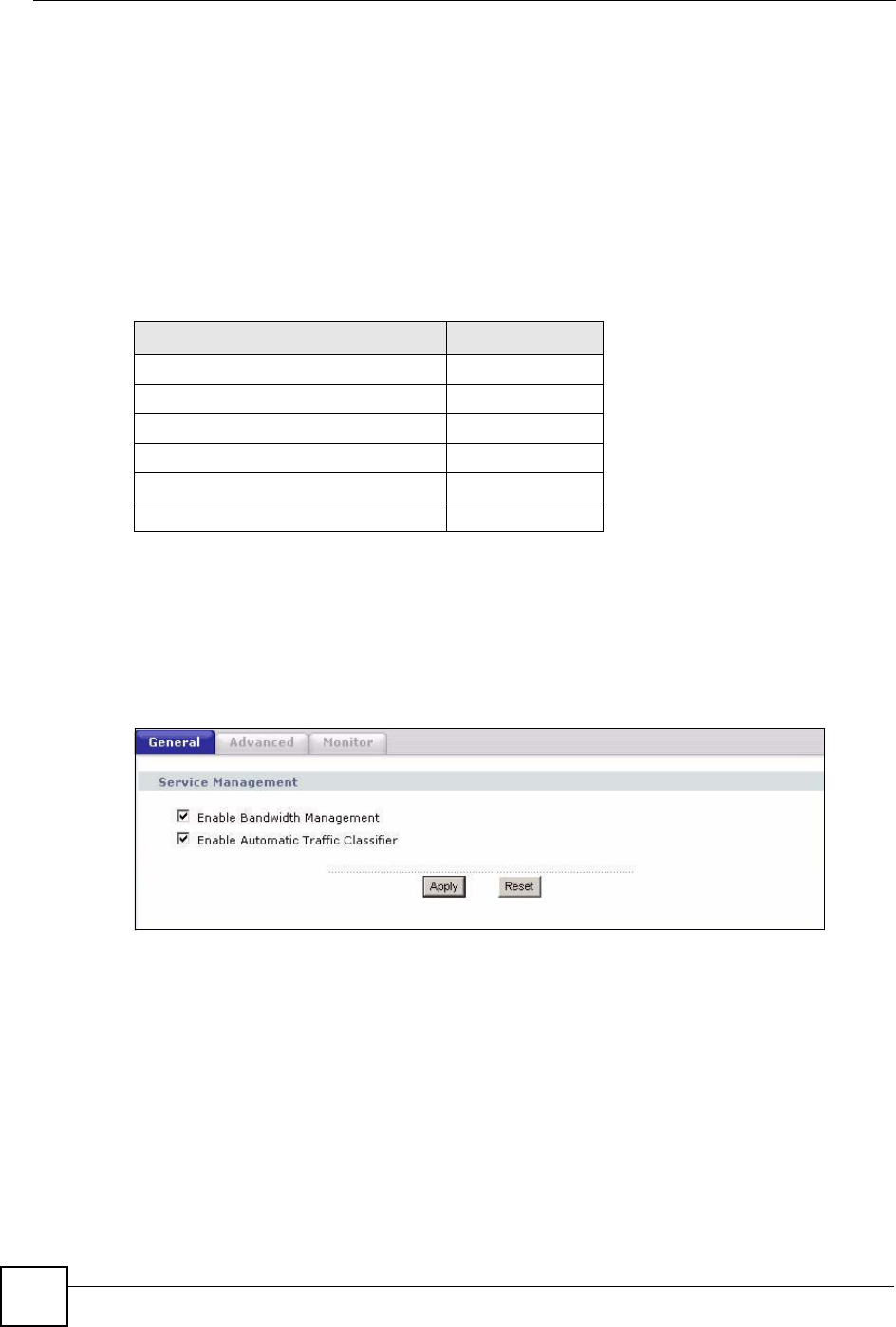
17.8 Bandwidth Management General Configuration
Click Management > Bandwidth MGMT to open the bandwidth management General
screen.
Figure 121 Management > Bandwidth MGMT > General
Table 74 Bandwidth Management Priority with Default Classes
CLASS TYPE PRIORITY
User-defined with high priority 6
AutoClass_H 5
User-defined with medium priority 4
AutoClass_M 3
User-defined with low priority 2
Default Class 1
Chapter 17 Bandwidth Management
NBG460N User’s Guide 203
The following table describes the labels in this screen.
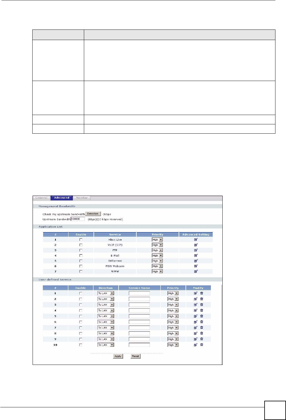
17.9 Bandwidth Management Advanced Configuration
Click Management > Bandwidth MGMT > Advanced to open the bandwidth management
Advanced screen.
Figure 122 Management > Bandwidth MGMT > Advanced
Table 75 Management > Bandwidth MGMT > General
LABEL DESCRIPTION
Enable Bandwidth
Management
Select this check box to have the NBG460N apply bandwidth management.
Enable bandwidth management to give traffic that matches a bandwidth rule
priority over traffic that does not match a bandwidth rule.
Enabling bandwidth management also allows you to control the maximum or
minimum amounts of bandwidth that can be used by traffic that matches a
bandwidth rule.
Enable Automatic
Traffic Classifier
This field is only applicable when you select the Enable Bandwidth
Management check box.
Select this check box to have the NBG460N base on the default bandwidth
classes to apply bandwidth management. Real-time packets, such as VoIP traffic
always get higher priority.
Apply Click Apply to save your customized settings.
Reset Click Reset to begin configuring this screen afresh.

Chapter 17 Bandwidth Management
NBG460N User’s Guide
204
The following table describes the labels in this screen.
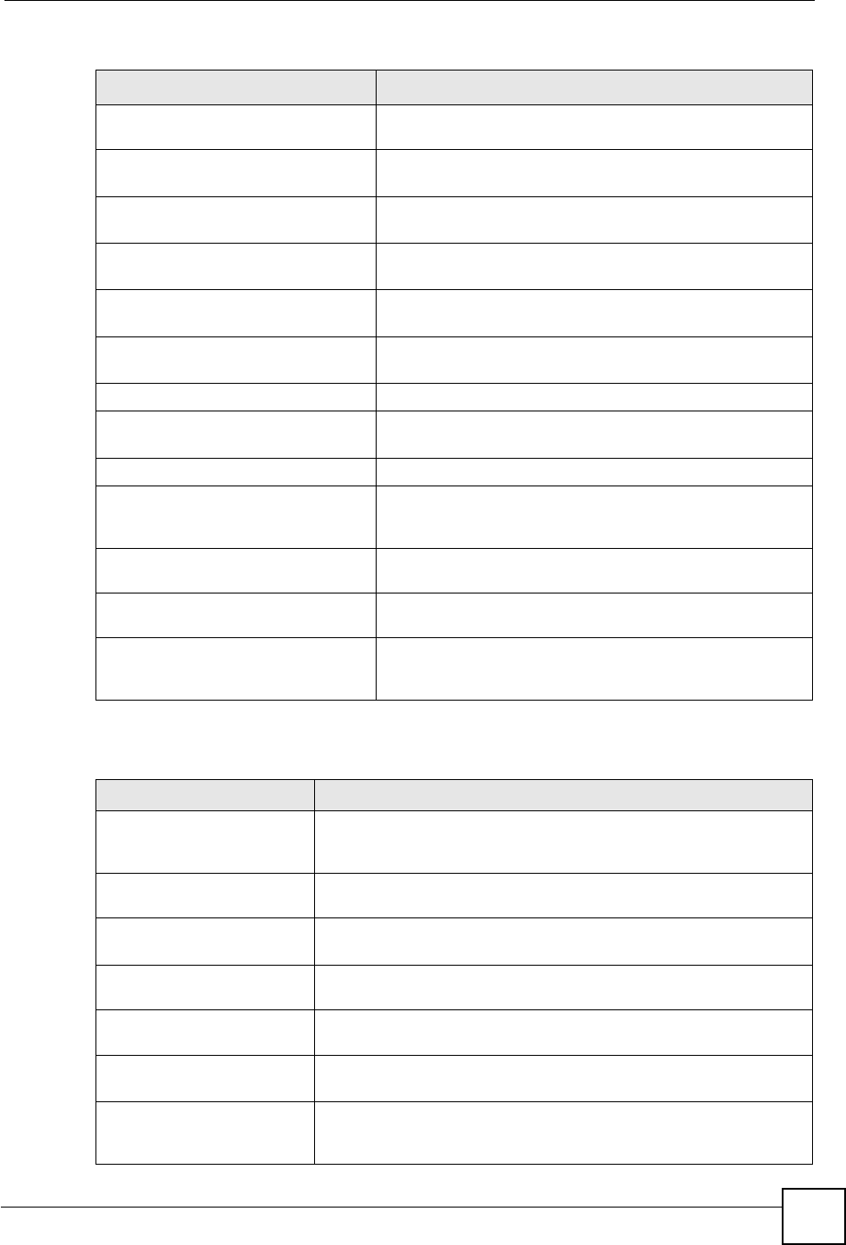
Table 76 Management > Bandwidth MGMT > Advanced
LABEL DESCRIPTION
Check my
upstream
bandwidth
Click the Detection button to check the size of your upstream bandwidth.
Upstream
Bandwidth (kbps)
Enter the amount of bandwidth in kbps (2 to 100,000) that you want to allocate for
traffic. 20 kbps to 20,000 kbps is recommended.
The recommendation is to set this speed to be equal to or less than the speed of
the broadband device connected to the WAN port. For example, set the speed to
1000 Kbps (or less) if the broadband device connected to the WAN port has an
upstream speed of 1000 Kbps.
Application List Use this table to allocate specific amounts of bandwidth based on the pre-defined
service.
#This is the number of an individual bandwidth management rule.
Enable Select this check box to have the NBG460N apply this bandwidth management
rule.
Service This is the name of the service.
Priority Select a priority from the drop down list box. Choose High,Mid or Low.
Advanced Setting Click the Edit icon to open the Rule Configuration screen where you can modify
the rule.
User-defined
Service
Use this table to allocate specific amounts of bandwidth to specific applications
and/or subnets.
#This is the number of an individual bandwidth management rule.
Enable Select this check box to have the NBG460N apply this bandwidth management
rule.
Direction Select To LAN to apply bandwidth management to traffic that the NBG460N
forwards to the LAN.
Select To WAN to apply bandwidth management to traffic that the NBG460N
forwards to the WAN.
Select To WLAN to apply bandwidth management to traffic that the NBG460N
forwards to the WLAN.
Service Name Enter a descriptive name of up to 19 alphanumeric characters, including spaces.
Priority Select a priority from the drop down list box. Choose High,Mid or Low.
Modify Click the Edit icon to open the Rule Configuration screen. Modify an existing rule
or create a new rule in the Rule Configuration screen. See Section 17.9.2 on
page 205 for more information.
Click the Remove icon to delete a rule.
Apply Click Apply to save your customized settings.
Reset Click Reset to begin configuring this screen afresh.
Chapter 17 Bandwidth Management
NBG460N User’s Guide 205
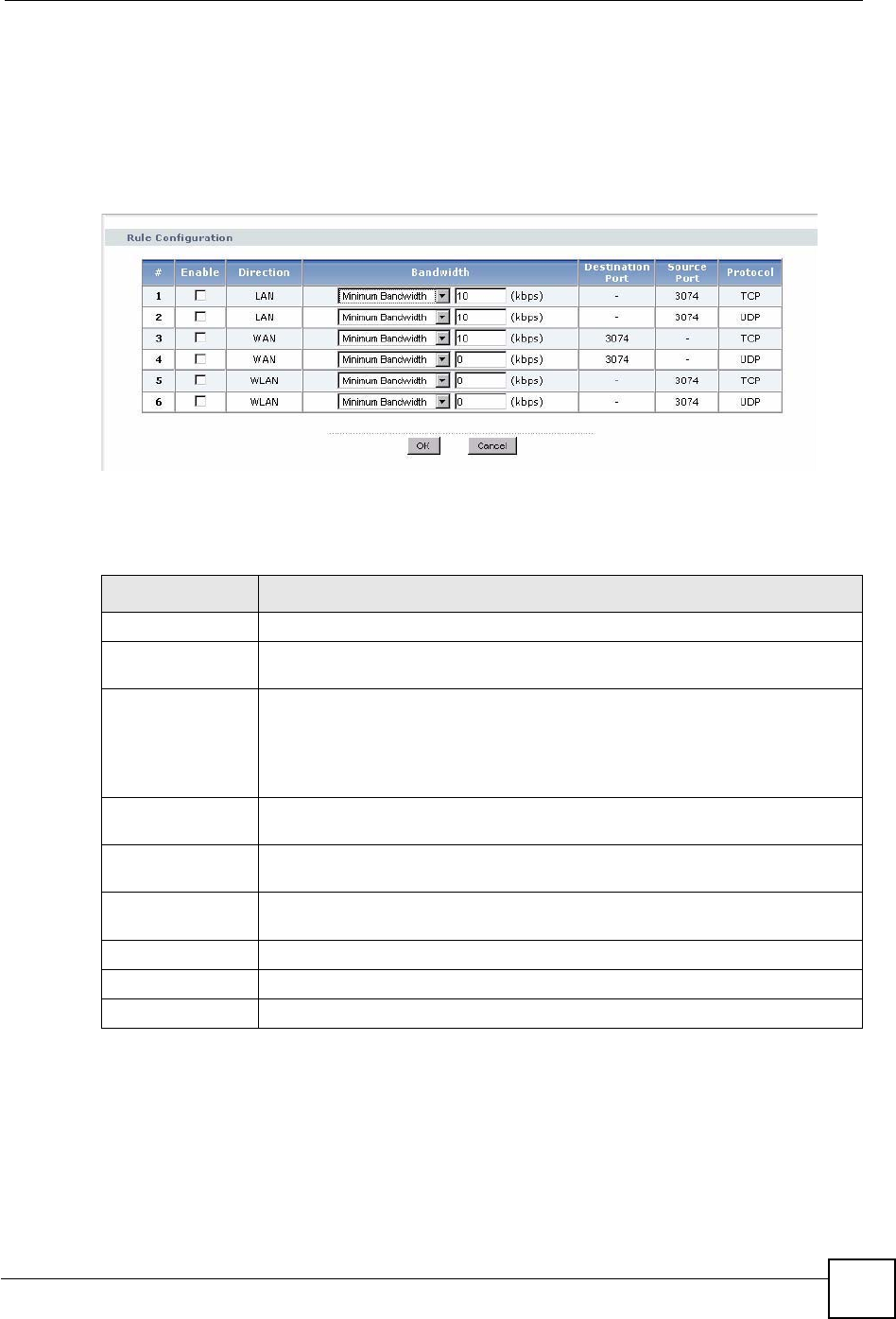
17.9.1 Rule Configuration with the Pre-defined Service
To edit a bandwidth management rule for the pre-defined service in the NBG460N, click the
Edit icon in the Application List table of the Advanced screen. The following screen
displays.
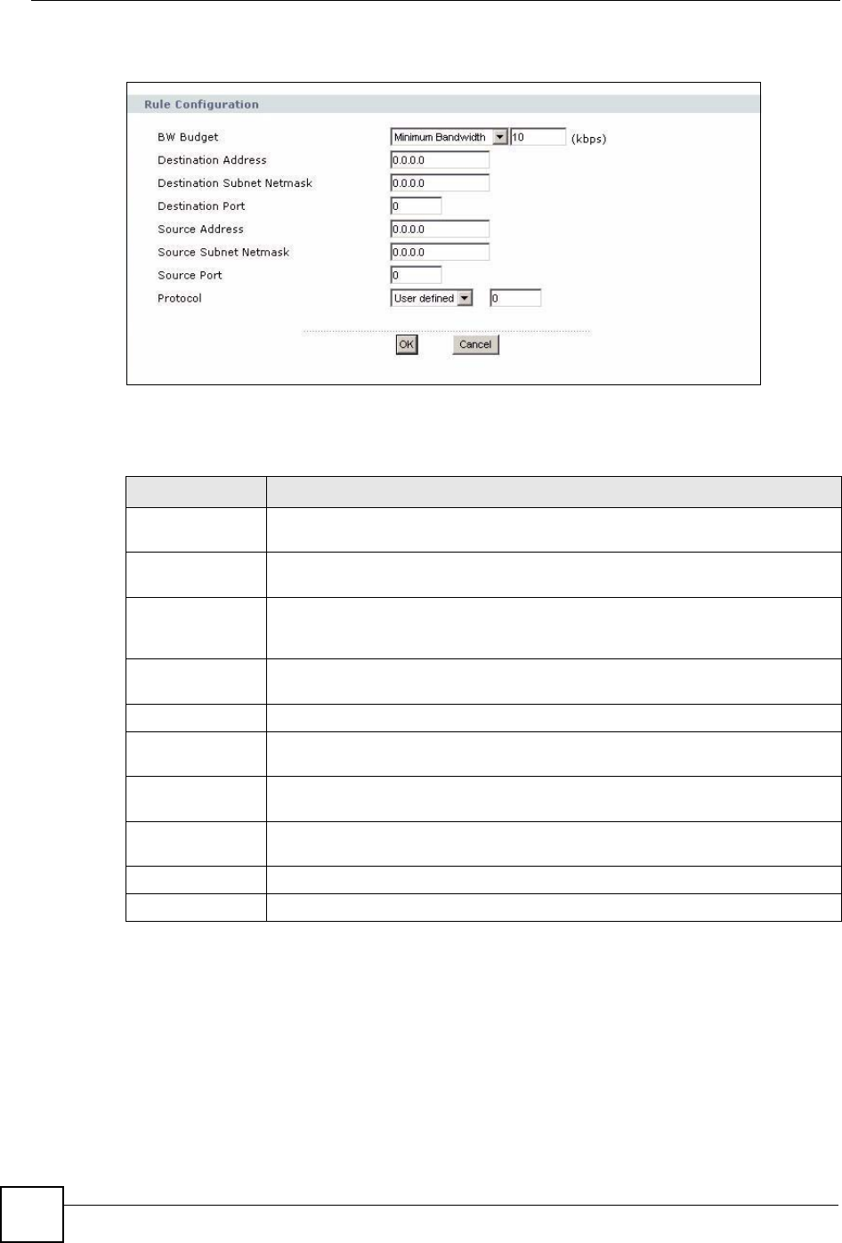
Figure 123 Bandwidth Management Rule Configuration: Pre-defined Service
The following table describes the labels in this screen.
17.9.2 Rule Configuration: User Defined Service Rule Configuration
If you want to edit a bandwidth management rule for other applications and/or subnets, click
the Edit icon in the User-defined Service table of the Advanced screen. The following screen
displays.
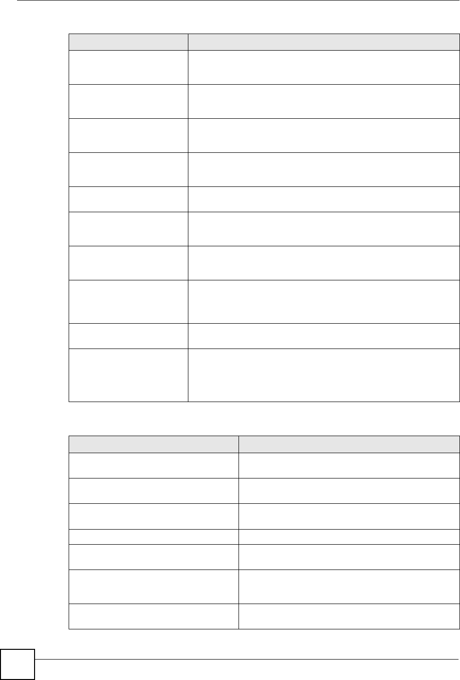
Table 77 Bandwidth Management Rule Configuration: Pre-defined Service
LABEL DESCRIPTION
#This is the number of an individual bandwidth management rule.
Enable Select an interface’s check box to enable bandwidth management on that
interface.
Direction These read-only labels represent the physical interfaces. Bandwidth management
applies to all traffic flowing out of the router through the interface, regardless of
the traffic’s source.
Traffic redirect or IP alias may cause LAN-to-LAN traffic to pass through the
NBG460N and be managed by bandwidth management.
Bandwidth Select Maximum Bandwidth or Minimum Bandwidth and specify the maximum
or minimum bandwidth allowed for the rule in kilobits per second.
Destination Port This is the port number of the destination. See Appendix F on page 321 for some
common services and port numbers.
Source Port This is the port number of the source. See Appendix F on page 321 for some
common services and port numbers.
Protocol This is the protocol (TCP or UDP) used for the service.
OK Click OK to save your customized settings.
Cancel Click Cancel to exit this screen without saving.
Chapter 17 Bandwidth Management
NBG460N User’s Guide
206
Figure 124 Management > Bandwidth MGMT > Advanced: User-defined Service Rule
Configuration
The following table describes the labels in this screen
Table 78 Management > Bandwidth MGMT > Advanced: User-defined Service Rule
Configuration
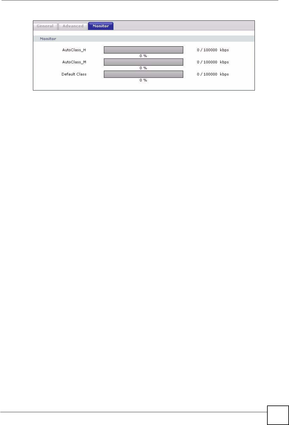
17.10 Bandwidth Management Monitor
Click Management > Bandwidth MGMT > Monitor to open the bandwidth management
Monitor screen. View the bandwidth usage of the WAN configured bandwidth rules. This is
also shown as bandwidth usage over the bandwidth budget for each rule. The gray section of
the bar represents the percentage of unused bandwidth and the blue color represents the
percentage of bandwidth in use.
LABEL DESCRIPTION
BW Budget Select Maximum Bandwidth or Minimum Bandwidth and specify the maximum
or minimum bandwidth allowed for the rule in kilobits per second.
Destination
Address
Enter the destination IP address in dotted decimal notation.
Destination
Subnet Netmask
Enter the destination subnet mask. This field is N/A if you do not specify a
Destination Address. Refer to the appendices for more information on IP
subnetting.
Destination Port Enter the port number of the destination. See Appendix F on page 321 for some
common services and port numbers.
Source Address Enter the source IP address in dotted decimal notation.
Source Subnet
Netmask
Enter the destination subnet mask. This field is N/A if you do not specify a Source
Address. Refer to the appendices for more information on IP subnetting.
Source Port Enter the port number of the source. See Appendix F on page 321 for some
common services and port numbers.
Protocol Select the protocol (TCP or UDP) or select User defined and enter the protocol
(service type) number.
OK Click OK to save your customized settings.
Cancel Click Cancel to exit this screen without saving.
Chapter 17 Bandwidth Management
NBG460N User’s Guide 207
Figure 125 Management > Bandwidth MGMT > Monitor

Chapter 17 Bandwidth Management
NBG460N User’s Guide
208

NBG460N User’s Guide 209
CHAPTER 18
Remote Management
This chapter provides information on the Remote Management screens.
18.1 Remote Management Overview
Remote management allows you to determine which services/protocols can access which
NBG460N interface (if any) from which computers.
"
When you configure remote management to allow management from the
WAN, you still need to configure a firewall rule to allow access. See the firewall
chapters for details on configuring firewall rules.
You may manage your NBG460N from a remote location via:
"
When you choose WAN or LAN & WAN, you still need to configure a firewall
rule to allow access.
To disable remote management of a service, select Disable in the corresponding Server
Access field.
You may only have one remote management session running at a time. The NBG460N
automatically disconnects a remote management session of lower priority when another
remote management session of higher priority starts. The priorities for the different types of
remote management sessions are as follows.
1Telnet
2HTTP
18.1.1 Remote Management Limitations
Remote management over LAN or WAN will not work when:
• Internet (WAN only) • ALL (LAN and WAN)
• LAN only • Neither (Disable).
Chapter 18 Remote Management
NBG460N User’s Guide
210
1You have disabled that service in one of the remote management screens.
2The IP address in the Secured Client IP Address field does not match the client IP
address. If it does not match, the NBG460N will disconnect the session immediately.
3There is already another remote management session with an equal or higher priority
running. You may only have one remote management session running at one time.
4There is a firewall rule that blocks it.
18.1.2 Remote Management and NAT
When NAT is enabled:
• Use the NBG460N’s WAN IP address when configuring from the WAN.
• Use the NBG460N’s LAN IP address when configuring from the LAN.
18.1.3 System Timeout
There is a default system management idle timeout of five minutes (three hundred seconds).
The NBG460N automatically logs you out if the management session remains idle for longer
than this timeout period. The management session does not time out when a statistics screen is
polling. You can change the timeout period in the System screen
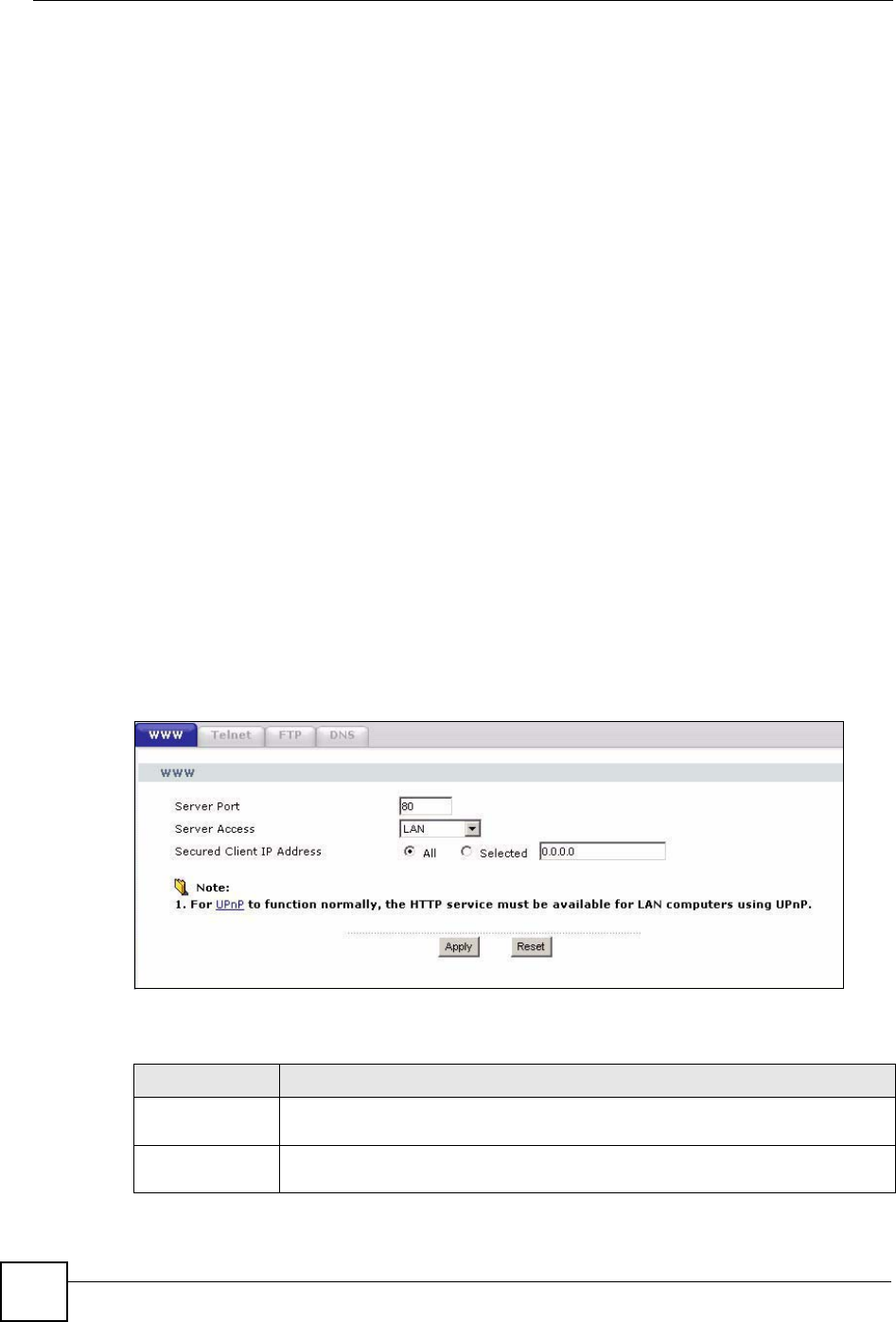
18.2 WWW Screen
To change your NBG460N’s World Wide Web settings, click Management > Remote
MGMT to display the WWW screen.
Figure 126 Management > Remote MGMT > WWW
The following table describes the labels in this screen
Table 79 Management > Remote MGMT > WWW
LABEL DESCRIPTION
Server Port You may change the server port number for a service if needed, however you must
use the same port number in order to use that service for remote management.
Server Access Select the interface(s) through which a computer may access the NBG460N using
this service.
Chapter 18 Remote Management
NBG460N User’s Guide 211
18.3 Telnet
You can use Telnet to access the NBG460N’s command line interface. Specify which
interfaces allow Telnet access and from which IP address the access can come.
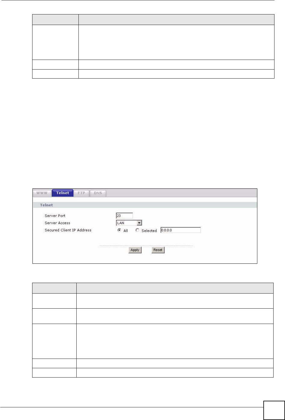
18.4 Telnet Screen
To change your NBG460N’s Telnet settings, click Management > Remote MGMT > Telnet.
The following screen displays.
Figure 127 Management > Remote MGMT > Telnet
The following table describes the labels in this screen.
Secured Client IP
Address
A secured client is a “trusted” computer that is allowed to communicate with the
NBG460N using this service.
Select All to allow any computer to access the NBG460N using this service.
Choose Selected to just allow the computer with the IP address that you specify to
access the NBG460N using this service.
Apply Click Apply to save your customized settings and exit this screen.
Reset Click Reset to begin configuring this screen afresh.
LABEL DESCRIPTION
Table 80 Management > Remote MGMT > Telnet
LABEL DESCRIPTION
Server Port You may change the server port number for a service if needed, however you must
use the same port number in order to use that service for remote management.
Server Access Select the interface(s) through which a computer may access the NBG460N using
this service.
Secured Client
IP Address
A secured client is a “trusted” computer that is allowed to communicate with the
NBG460N using this service.
Select All to allow any computer to access the NBG460N using this service.
Choose Selected to just allow the computer with the IP address that you specify to
access the NBG460N using this service.
Apply Click Apply to save your customized settings and exit this screen.
Reset Click Reset to begin configuring this screen afresh.
Chapter 18 Remote Management
NBG460N User’s Guide
212
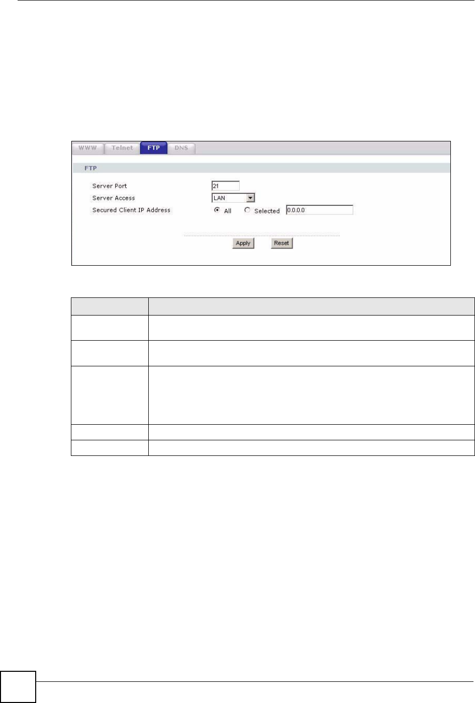
18.5 FTP Screen
You can use FTP (File Transfer Protocol) to upload and download the NBG460N’s firmware
and configuration files. To use this feature, your computer must have an FTP client.
To change your NBG460N’s FTP settings, click Management > Remote MGMT > FTP. The
screen appears as shown. Use this screen to specify which interfaces allow FTP access and
from which IP address the access can come.
Figure 128 Management > Remote MGMT > FTP
The following table describes the labels in this screen.
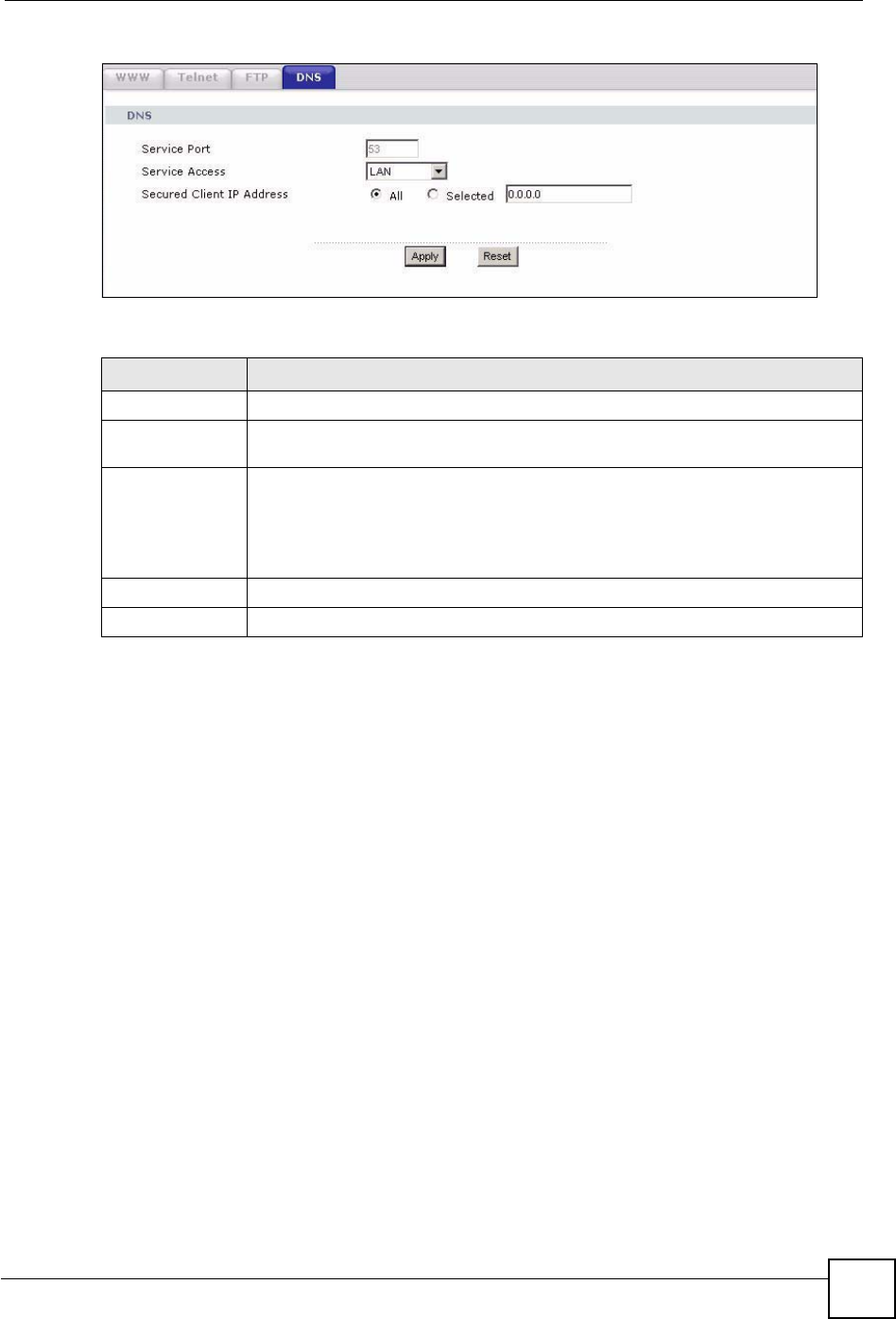
18.6 DNS Screen
Use DNS (Domain Name System) to map a domain name to its corresponding IP address and
vice versa. Refer to the chapter on Wizard Setup for background information.
To change your NBG460N’s DNS settings, click Management > Remote MGMT > DNS.
The screen appears as shown.
Table 81 Management > Remote MGMT > FTP
LABEL DESCRIPTION
Server Port You may change the server port number for a service if needed, however you must
use the same port number in order to use that service for remote management.
Server Access Select the interface(s) through which a computer may access the NBG460N using
this service.
Secured Client IP
Address
A secured client is a “trusted” computer that is allowed to communicate with the
NBG460N using this service.
Select All to allow any computer to access the NBG460N using this service.
Choose Selected to just allow the computer with the IP address that you specify to
access the NBG460N using this service.
Apply Click Apply to save your customized settings and exit this screen.
Reset Click Reset to begin configuring this screen afresh.
Chapter 18 Remote Management
NBG460N User’s Guide 213
Figure 129 Management > Remote MGMT > DNS
The following table describes the labels in this screen.
Table 82 Management > Remote MGMT > DNS
LABEL DESCRIPTION
Server Port The DNS service port number is 53 and cannot be changed here.
Server Access Select the interface(s) through which a computer may send DNS queries to the
NBG460N.
Secured Client IP
Address
A secured client is a “trusted” computer that is allowed to send DNS queries to the
NBG460N.
Select All to allow any computer to send DNS queries to the NBG460N.
Choose Selected to just allow the computer with the IP address that you specify to
send DNS queries to the NBG460N.
Apply Click Apply to save your customized settings and exit this screen.
Reset Click Reset to begin configuring this screen afresh.

Chapter 18 Remote Management
NBG460N User’s Guide
214

NBG460N User’s Guide 215
CHAPTER 19
Universal Plug-and-Play (UPnP)
This chapter introduces the UPnP feature in the web configurator.
19.1 Introducing Universal Plug and Play
Universal Plug and Play (UPnP) is a distributed, open networking standard that uses TCP/IP
for simple peer-to-peer network connectivity between devices. A UPnP device can
dynamically join a network, obtain an IP address, convey its capabilities and learn about other
devices on the network. In turn, a device can leave a network smoothly and automatically
when it is no longer in use.
See Section 19.3 on page 216 for configuration instructions.
19.1.1 How do I know if I'm using UPnP?
UPnP hardware is identified as an icon in the Network Connections folder (Windows XP).
Each UPnP compatible device installed on your network will appear as a separate icon.
Selecting the icon of a UPnP device will allow you to access the information and properties of
that device.
19.1.2 NAT Traversal
UPnP NAT traversal automates the process of allowing an application to operate through NAT.
UPnP network devices can automatically configure network addressing, announce their
presence in the network to other UPnP devices and enable exchange of simple product and
service descriptions. NAT traversal allows the following:
• Dynamic port mapping
• Learning public IP addresses
• Assigning lease times to mappings
Windows Messenger is an example of an application that supports NAT traversal and UPnP.
See the NAT chapter for more information on NAT.
19.1.3 Cautions with UPnP
The automated nature of NAT traversal applications in establishing their own services and
opening firewall ports may present network security issues. Network information and
configuration may also be obtained and modified by users in some network environments.
Chapter 19 Universal Plug-and-Play (UPnP)
NBG460N User’s Guide
216
When a UPnP device joins a network, it announces its presence with a multicast message. For
security reasons, the NBG460N allows multicast messages on the LAN only.
All UPnP-enabled devices may communicate freely with each other without additional
configuration. Disable UPnP if this is not your intention.
19.2 UPnP and ZyXEL
ZyXEL has achieved UPnP certification from the Universal Plug and Play Forum UPnP™
Implementers Corp. (UIC). ZyXEL's UPnP implementation supports Internet Gateway Device
(IGD) 1.0.
See the following sections for examples of installing and using UPnP.
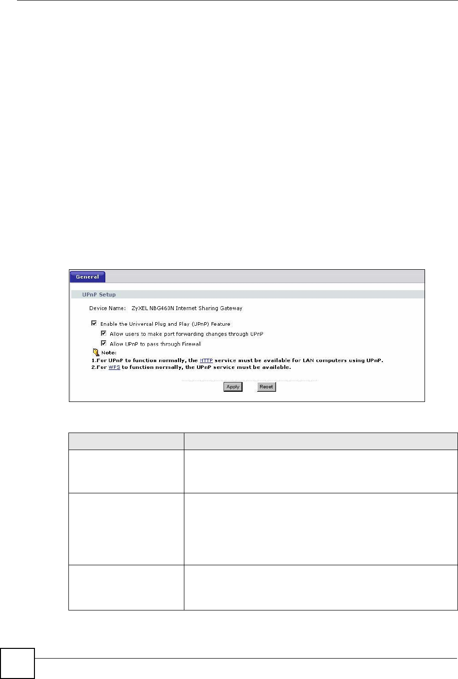
19.3 UPnP Screen
Click the Management > UPnP to display the UPnP screen.
Figure 130 Management > UPnP > General
The following table describes the labels in this screen.
Table 83 Management > UPnP > General
LABEL DESCRIPTION
Enable the Universal Plug
and Play (UPnP) Feature
Select this check box to activate UPnP. Be aware that anyone could use
a UPnP application to open the web configurator's login screen without
entering the NBG460N's IP address (although you must still enter the
password to access the web configurator).
Allow users to make
configuration changes
through UPnP
Select this check box to allow UPnP-enabled applications to
automatically configure the NBG460N so that they can communicate
through the NBG460N, for example by using NAT traversal, UPnP
applications automatically reserve a NAT forwarding port in order to
communicate with another UPnP enabled device; this eliminates the
need to manually configure port forwarding for the UPnP enabled
application.
Allow UPnP to pass through
Firewall
Select this check box to allow traffic from UPnP-enabled applications to
bypass the firewall.
Clear this check box to have the firewall block all UPnP application
packets (for example, MSN packets).
Chapter 19 Universal Plug-and-Play (UPnP)
NBG460N User’s Guide 217
19.4 Installing UPnP in Windows Example
This section shows how to install UPnP in Windows Me and Windows XP.
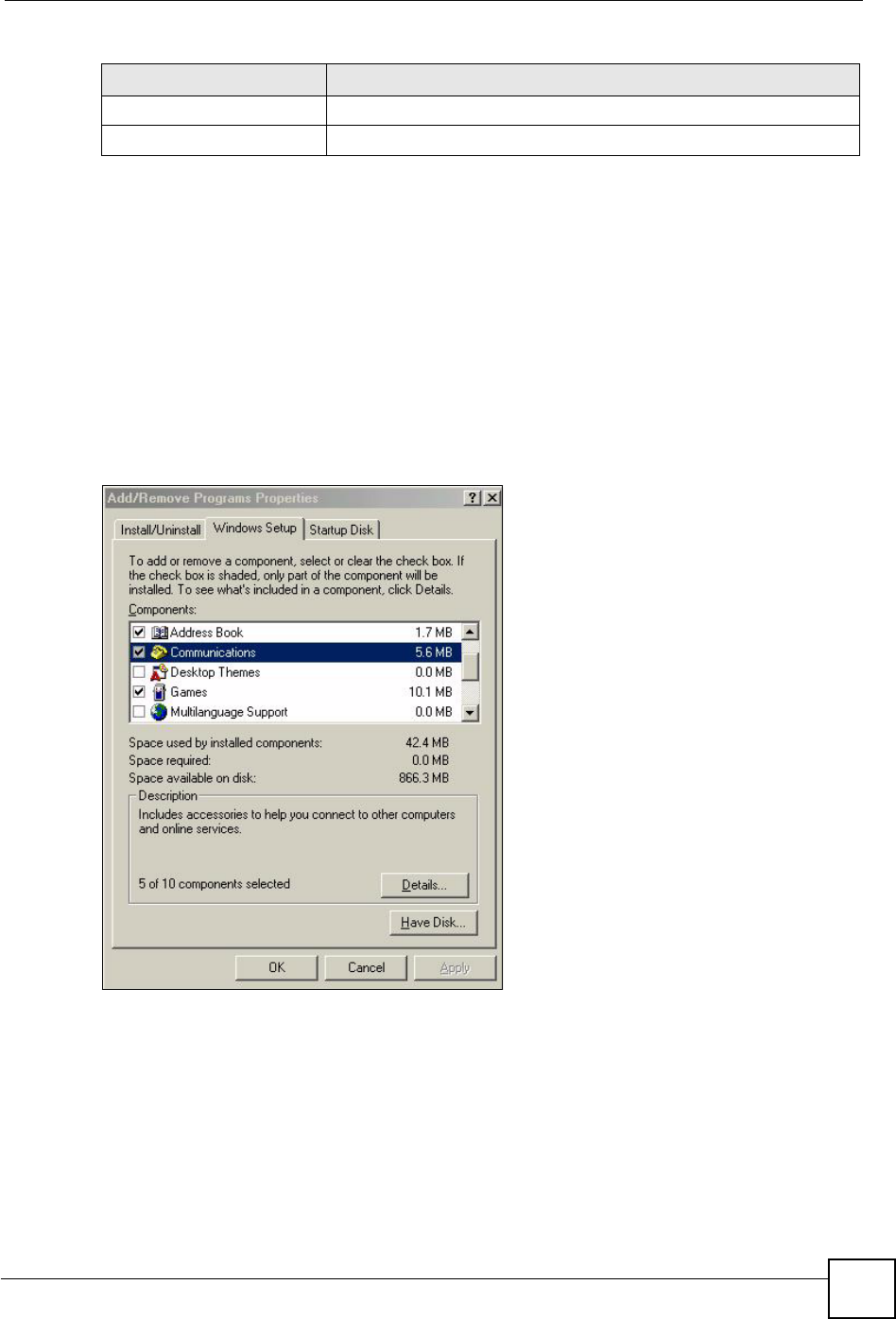
19.4.0.1 Installing UPnP in Windows Me
Follow the steps below to install the UPnP in Windows Me.
1Click Start and Control Panel. Double-click Add/Remove Programs.
2Click on the Windows Setup tab and select Communication in the Components
selection box. Click Details.
Figure 131 Add/Remove Programs: Windows Setup: Communication
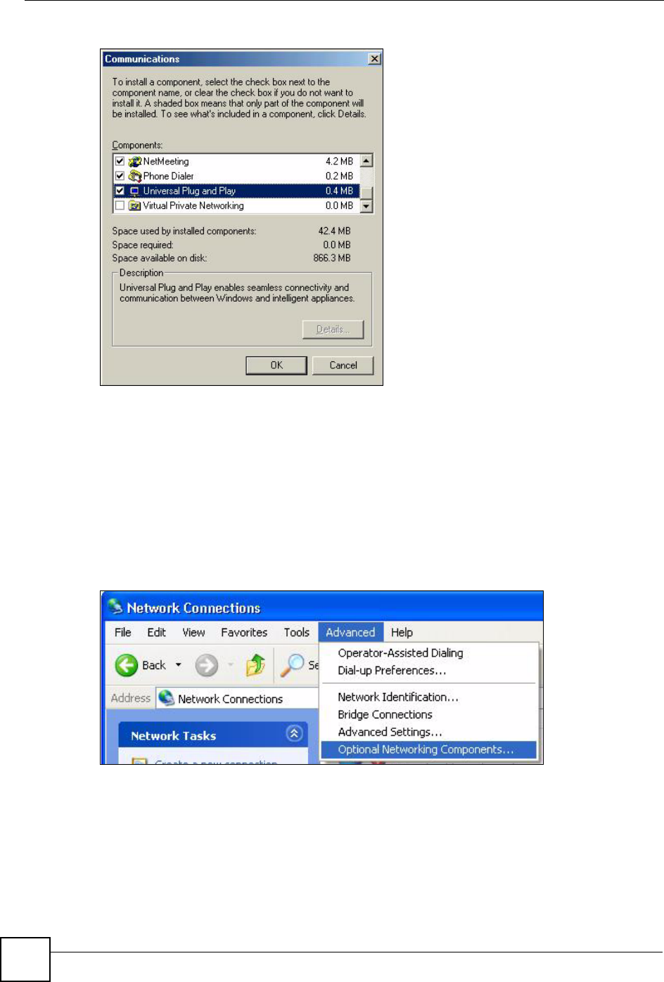
3In the Communications window, select the Universal Plug and Play check box in the
Components selection box.
Apply Click Apply to save the setting to the NBG460N.
Reset Click Reset to begin configuring this screen afresh.
Table 83 Management > UPnP > General
LABEL DESCRIPTION
Chapter 19 Universal Plug-and-Play (UPnP)
NBG460N User’s Guide
218
Figure 132 Add/Remove Programs: Windows Setup: Communication: Components
4Click OK to go back to the Add/Remove Programs Properties window and click Next.
5Restart the computer when prompted.
Installing UPnP in Windows XP
Follow the steps below to install the UPnP in Windows XP.
1Click Start and Control Panel.
2Double-click Network Connections.
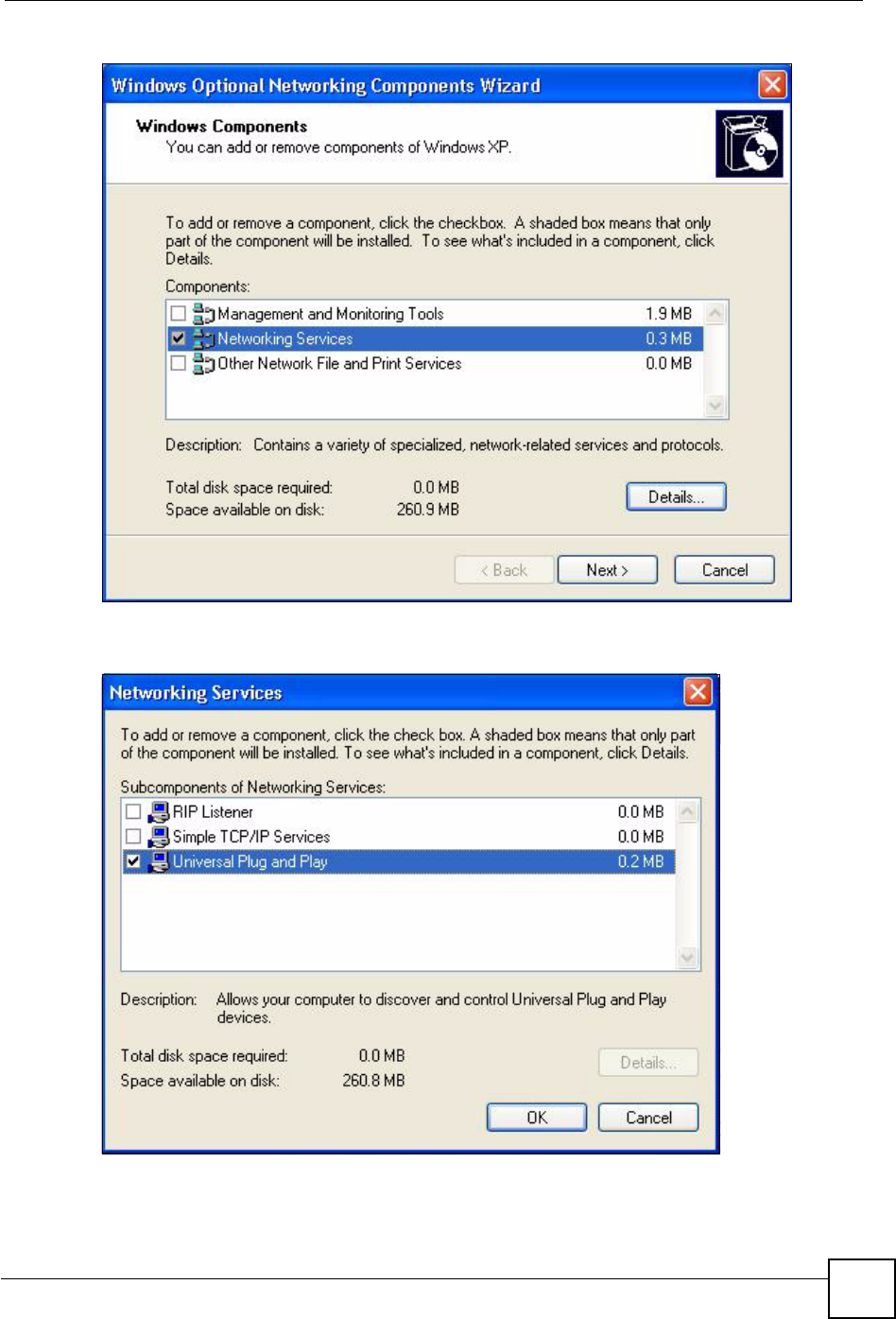
3In the Network Connections window, click Advanced in the main menu and select
Optional Networking Components ….
Figure 133 Network Connections
4The Windows Optional Networking Components Wizard window displays. Select
Networking Service in the Components selection box and click Details.
Chapter 19 Universal Plug-and-Play (UPnP)
NBG460N User’s Guide 219
Figure 134 Windows Optional Networking Components Wizard
5In the Networking Services window, select the Universal Plug and Play check box.
Figure 135 Networking Services
6Click OK to go back to the Windows Optional Networking Component Wizard
window and click Next.
Chapter 19 Universal Plug-and-Play (UPnP)
NBG460N User’s Guide
220
19.4.0.2 Using UPnP in Windows XP Example
This section shows you how to use the UPnP feature in Windows XP. You must already have
UPnP installed in Windows XP and UPnP activated on the NBG460N.
Make sure the computer is connected to a LAN port of the NBG460N. Turn on your computer
and the NBG460N.
Auto-discover Your UPnP-enabled Network Device
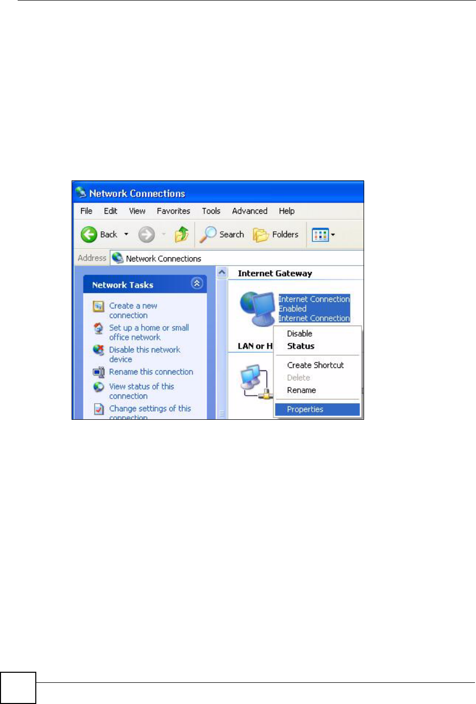
1Click Start and Control Panel. Double-click Network Connections. An icon displays
under Internet Gateway.
2Right-click the icon and select Properties.
Figure 136 Network Connections
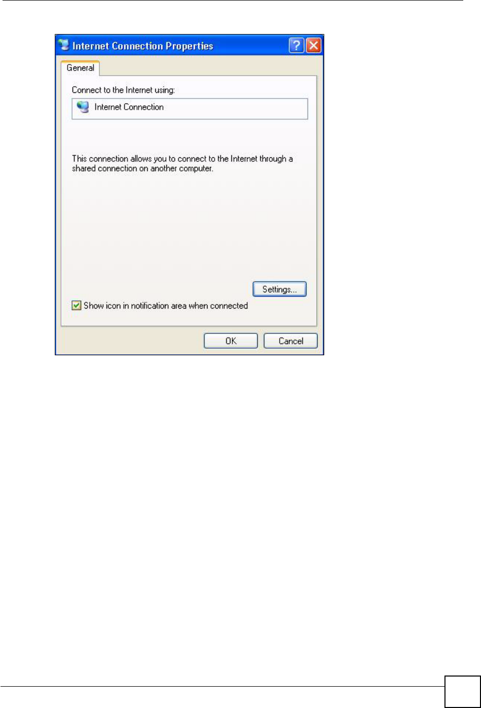
3In the Internet Connection Properties window, click Settings to see the port mappings
there were automatically created.
Chapter 19 Universal Plug-and-Play (UPnP)
NBG460N User’s Guide 221
Figure 137 Internet Connection Properties
4You may edit or delete the port mappings or click Add to manually add port mappings.
Chapter 19 Universal Plug-and-Play (UPnP)
NBG460N User’s Guide
222
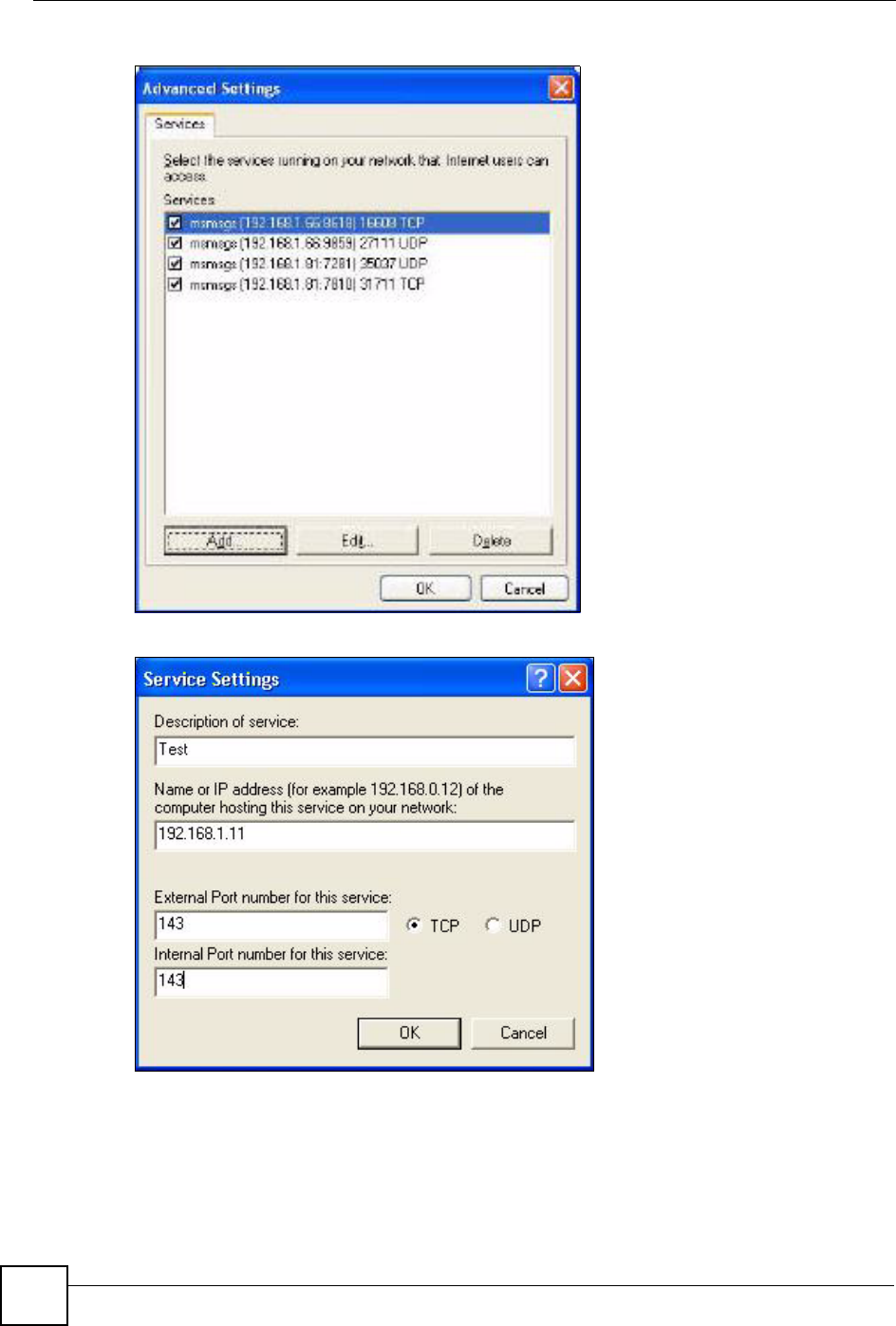
Figure 138 Internet Connection Properties: Advanced Settings
Figure 139 Internet Connection Properties: Advanced Settings: Add
5When the UPnP-enabled device is disconnected from your computer, all port mappings
will be deleted automatically.
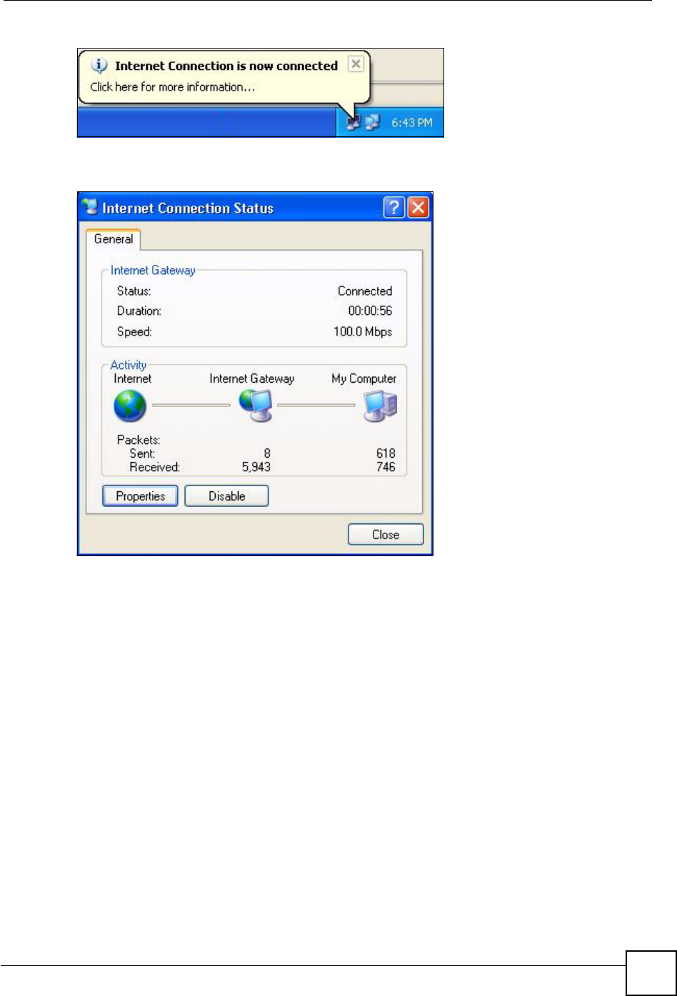
6Select Show icon in notification area when connected option and click OK. An icon
displays in the system tray.
Chapter 19 Universal Plug-and-Play (UPnP)
NBG460N User’s Guide 223
Figure 140 System Tray Icon
7Double-click on the icon to display your current Internet connection status.
Figure 141 Internet Connection Status
Web Configurator Easy Access
With UPnP, you can access the web-based configurator on the NBG460N without finding out
the IP address of the NBG460N first. This comes helpful if you do not know the IP address of
the NBG460N.
Follow the steps below to access the web configurator.
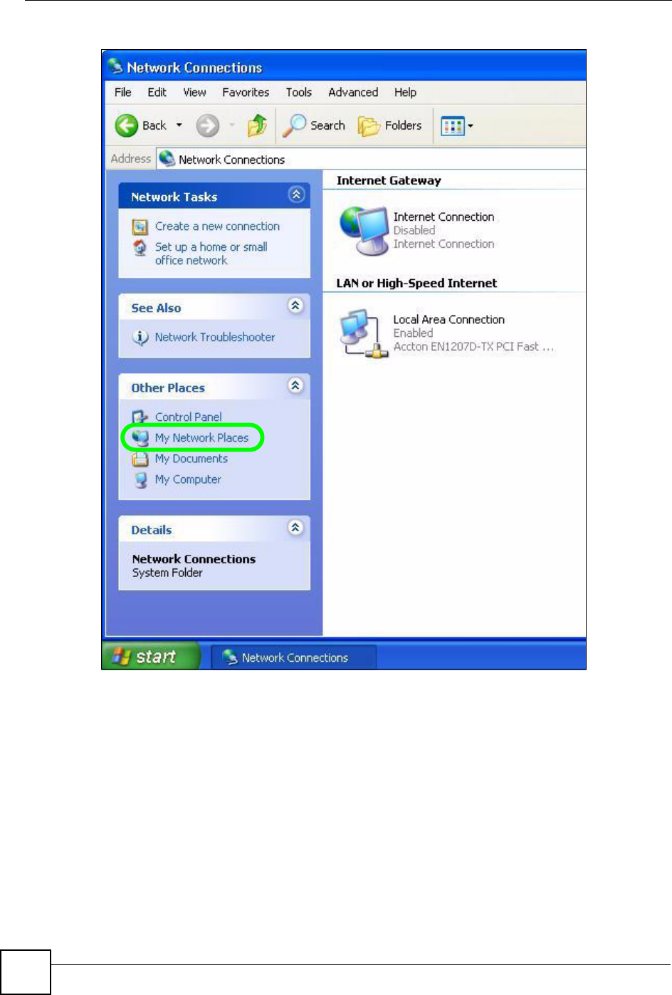
1Click Start and then Control Panel.
2Double-click Network Connections.
3Select My Network Places under Other Places.
Chapter 19 Universal Plug-and-Play (UPnP)
NBG460N User’s Guide
224
Figure 142 Network Connections
4An icon with the description for each UPnP-enabled device displays under Local
Network.
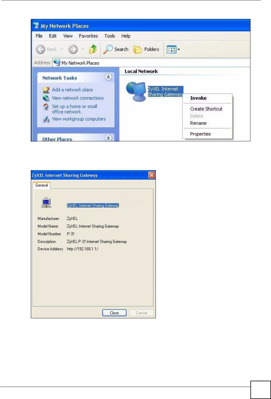
5Right-click on the icon for your NBG460N and select Invoke. The web configurator
login screen displays.
Chapter 19 Universal Plug-and-Play (UPnP)
NBG460N User’s Guide 225
Figure 143 Network Connections: My Network Places
6Right-click on the icon for your NBG460N and select Properties. A properties window
displays with basic information about the NBG460N.
Figure 144 Network Connections: My Network Places: Properties: Example

Chapter 19 Universal Plug-and-Play (UPnP)
NBG460N User’s Guide
226

227
PART V
Maintenance and
Troubleshooting
System (229)
Logs (233)
Tools (251)
Configuration Mode (257)
Sys Op Mode (259)
Language (263)
Troubleshooting (265)

228
NBG460N User’s Guide 229
CHAPTER 20
System
This chapter provides information on the System screens.
20.1 System Overview
See the chapter about wizard setup for more information on the next few screens.
20.2 System General Screen
Click Maintenance > System. The following screen displays.
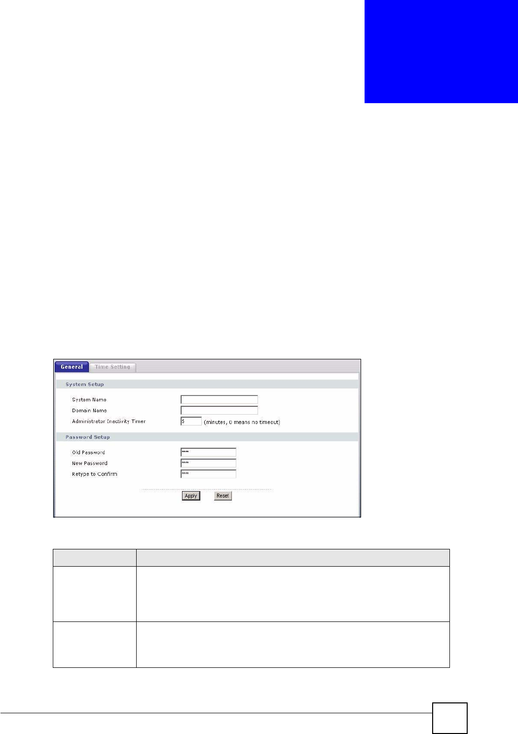
Figure 145 Maintenance > System > General
The following table describes the labels in this screen.
Table 84 Maintenance > System > General
LABEL DESCRIPTION
System Name System Name is a unique name to identify the NBG460N in an Ethernet network.
It is recommended you enter your computer’s “Computer name” in this field (see
the chapter about wizard setup for how to find your computer’s name).
This name can be up to 30 alphanumeric characters long. Spaces are not
allowed, but dashes “-” and underscores "_" are accepted.
Domain Name Enter the domain name (if you know it) here. If you leave this field blank, the ISP
may assign a domain name via DHCP.
The domain name entered by you is given priority over the ISP assigned domain
name.
Chapter 20 System
NBG460N User’s Guide
230
20.3 Time Setting Screen
To change your NBG460N’s time and date, click Maintenance > System > Time Setting.
The screen appears as shown. Use this screen to configure the NBG460N’s time based on your
local time zone.
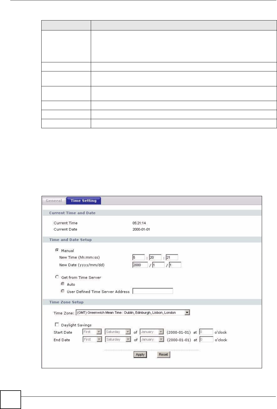
Figure 146 Maintenance > System > Time Setting
Administrator
Inactivity Timer
Type how many minutes a management session can be left idle before the
session times out. The default is 5 minutes. After it times out you have to log in
with your password again. Very long idle timeouts may have security risks. A
value of "0" means a management session never times out, no matter how long it
has been left idle (not recommended).
Password Setup Change your NBG460N’s password (recommended) using the fields as shown.
Old Password Type the default password or the existing password you use to access the
system in this field.
New Password Type your new system password (up to 30 characters). Note that as you type a
password, the screen displays an asterisk (*) for each character you type.
Retype to Confirm Type the new password again in this field.
Apply Click Apply to save your changes back to the NBG460N.
Reset Click Reset to begin configuring this screen afresh.
Table 84 Maintenance > System > General
LABEL DESCRIPTION

Chapter 20 System
NBG460N User’s Guide 231
The following table describes the labels in this screen.
Table 85 Maintenance > System > Time Setting
LABEL DESCRIPTION
Current Time and
Date
Current Time This field displays the time of your NBG460N.
Each time you reload this page, the NBG460N synchronizes the time with the
time server.
Current Date This field displays the date of your NBG460N.
Each time you reload this page, the NBG460N synchronizes the date with the
time server.
Time and Date
Setup
Manual Select this radio button to enter the time and date manually. If you configure a
new time and date, Time Zone and Daylight Saving at the same time, the new
time and date you entered has priority and the Time Zone and Daylight Saving
settings do not affect it.
New Time
(hh:mm:ss)
This field displays the last updated time from the time server or the last time
configured manually.
When you set Time and Date Setup to Manual, enter the new time in this field
and then click Apply.
New Date
(yyyy/mm/dd)
This field displays the last updated date from the time server or the last date
configured manually.
When you set Time and Date Setup to Manual, enter the new date in this field
and then click Apply.
Get from Time
Server
Select this radio button to have the NBG460N get the time and date from the
time server you specified below.
Auto Select Auto to have the NBG460N automatically search for an available time
server and synchronize the date and time with the time server after you click
Apply.
User Defined Time
Server Address
Select User Defined Time Server Address and enter the IP address or URL
(up to 20 extended ASCII characters in length) of your time server. Check with
your ISP/network administrator if you are unsure of this information.
Time Zone Setup
Time Zone Choose the time zone of your location. This will set the time difference between
your time zone and Greenwich Mean Time (GMT).
Daylight Savings Daylight saving is a period from late spring to early fall when many countries set
their clocks ahead of normal local time by one hour to give more daytime light in
the evening.
Select this option if you use Daylight Saving Time.
Start Date Configure the day and time when Daylight Saving Time starts if you selected
Daylight Savings. The o'clock field uses the 24 hour format. Here are a
couple of examples:
Daylight Saving Time starts in most parts of the United States on the first
Sunday of April. Each time zone in the United States starts using Daylight
Saving Time at 2 A.M. local time. So in the United States you would select First,
Sunday,April and type 2 in the o'clock field.
Daylight Saving Time starts in the European Union on the last Sunday of March.
All of the time zones in the European Union start using Daylight Saving Time at
the same moment (1 A.M. GMT or UTC). So in the European Union you would
select Last,Sunday,March. The time you type in the o'clock field depends on
your time zone. In Germany for instance, you would type 2 because Germany's
time zone is one hour ahead of GMT or UTC (GMT+1).

Chapter 20 System
NBG460N User’s Guide
232
End Date Configure the day and time when Daylight Saving Time ends if you selected
Daylight Savings. The o'clock field uses the 24 hour format. Here are a
couple of examples:
Daylight Saving Time ends in the United States on the last Sunday of October.
Each time zone in the United States stops using Daylight Saving Time at 2 A.M.
local time. So in the United States you would select Last,Sunday,October and
type 2 in the o'clock field.
Daylight Saving Time ends in the European Union on the last Sunday of
October. All of the time zones in the European Union stop using Daylight Saving
Time at the same moment (1 A.M. GMT or UTC). So in the European Union you
would select Last,Sunday,October. The time you type in the o'clock field
depends on your time zone. In Germany for instance, you would type 2 because
Germany's time zone is one hour ahead of GMT or UTC (GMT+1).
Apply Click Apply to save your changes back to the NBG460N.
Reset Click Reset to begin configuring this screen afresh.
Table 85 Maintenance > System > Time Setting
LABEL DESCRIPTION
NBG460N User’s Guide 233
CHAPTER 21
Logs
This chapter contains information about configuring general log settings and viewing the
NBG460N’s logs. Refer to the appendices for example log message explanations.
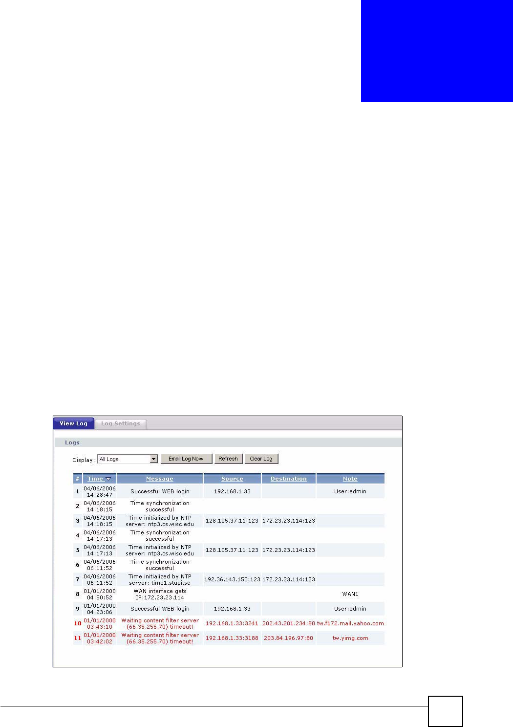
21.1 View Log
The web configurator allows you to look at all of the NBG460N’s logs in one location.
Click Maintenance > Logs to open the View Log screen.
Use the View Log screen to see the logs for the categories that you selected in the Log
Settings screen (see Section 21.2 on page 234). Options include logs about system
maintenance, system errors, access control, allowed or blocked web sites, blocked web
features (such as ActiveX controls, Java and cookies), attacks (such as DoS) and IPSec.
Log entries in red indicate system error logs. The log wraps around and deletes the old entries
after it fills. Click a column heading to sort the entries. A triangle indicates ascending or
descending sort order.
Figure 147 Maintenance > Logs > View Log
Chapter 21 Logs
NBG460N User’s Guide
234
The following table describes the labels in this screen.
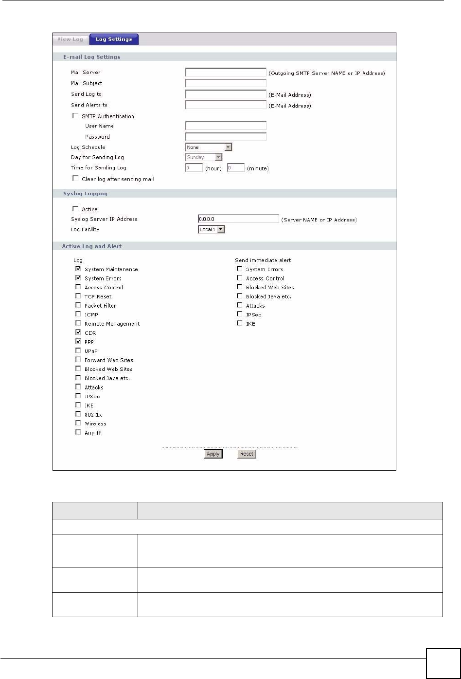
21.2 Log Settings
You can configure the NBG460N’s general log settings in one location.
Click Maintenance > Logs > Log Settings to open the Log Settings screen.
Use the Log Settings screen to configure to where the NBG460N is to send logs; the schedule
for when the NBG460N is to send the logs and which logs and/or immediate alerts the
NBG460N to send.
An alert is a type of log that warrants more serious attention. They include system errors,
attacks (access control) and attempted access to blocked web sites or web sites with restricted
web features such as cookies, active X and so on. Some categories such as System Errors
consist of both logs and alerts. You may differentiate them by their color in the View Log
screen. Alerts display in red and logs display in black.
Alerts are e-mailed as soon as they happen. Logs may be e-mailed as soon as the log is full
(see Log Schedule). Selecting many alert and/or log categories (especially Access Control)
may result in many e-mails being sent.
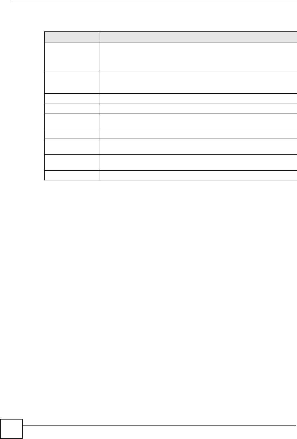
Table 86 Maintenance > Logs > View Log
LABEL DESCRIPTION
Display The categories that you select in the Log Settings page (see Section 21.2 on
page 234) display in the drop-down list box.
Select a category of logs to view; select All Logs to view logs from all of the log
categories that you selected in the Log Settings page.
Email Log Now Click Email Log Now to send the log screen to the e-mail address specified in
the Log Settings page (make sure that you have first filled in the Address Info
fields in Log Settings).
Refresh Click Refresh to renew the log screen.
Clear Log Click Clear Log to delete all the logs.
Time This field displays the time the log was recorded. See the chapter on system
maintenance and information to configure the NBG460N’s time and date.
Message This field states the reason for the log.
Source This field lists the source IP address and the port number of the incoming
packet.
Destination This field lists the destination IP address and the port number of the incoming
packet.
Note This field displays additional information about the log entry.
Chapter 21 Logs
NBG460N User’s Guide 235
Figure 148 Maintenance > Logs > Log Settings
The following table describes the labels in this screen.
Table 87 Maintenance > Logs > Log Settings
LABEL DESCRIPTION
E-mail Log Settings
Mail Server Enter the server name or the IP address of the mail server for the e-mail
addresses specified below. If this field is left blank, logs and alert messages will
not be sent via E-mail.
Mail Subject Type a title that you want to be in the subject line of the log e-mail message that
the NBG460N sends. Not all NBG460N models have this field.
Send Log To The NBG460N sends logs to the e-mail address specified in this field. If this
field is left blank, the NBG460N does not send logs via e-mail.

Chapter 21 Logs
NBG460N User’s Guide
236
Send Alerts To Alerts are real-time notifications that are sent as soon as an event, such as a
DoS attack, system error, or forbidden web access attempt occurs. Enter the E-
mail address where the alert messages will be sent. Alerts include system
errors, attacks and attempted access to blocked web sites. If this field is left
blank, alert messages will not be sent via E-mail.
SMTP
Authentication
SMTP (Simple Mail Transfer Protocol) is the message-exchange standard for
the Internet. SMTP enables you to move messages from one e-mail server to
another.
Select the check box to activate SMTP authentication. If mail server
authentication is needed but this feature is disabled, you will not receive the e-
mail logs.
User Name Enter the user name (up to 31 characters) (usually the user name of a mail
account).
Password Enter the password associated with the user name above.
Log Schedule This drop-down menu is used to configure the frequency of log messages being
sent as E-mail:
•Daily
• Weekly
• Hourly
• When Log is Full
• None.
If you select Weekly or Daily, specify a time of day when the E-mail should be
sent. If you select Weekly, then also specify which day of the week the E-mail
should be sent. If you select When Log is Full, an alert is sent when the log fills
up. If you select None, no log messages are sent.
Day for Sending Log Use the drop down list box to select which day of the week to send the logs.
Time for Sending
Log
Enter the time of the day in 24-hour format (for example 23:00 equals 11:00 pm)
to send the logs.
Clear log after
sending mail
Select the checkbox to delete all the logs after the NBG460N sends an E-mail
of the logs.
Syslog Logging The NBG460N sends a log to an external syslog server.
Active Click Active to enable syslog logging.
Syslog Server IP
Address
Enter the server name or IP address of the syslog server that will log the
selected categories of logs.
Log Facility Select a location from the drop down list box. The log facility allows you to log
the messages to different files in the syslog server. Refer to the syslog server
manual for more information.
Active Log and Alert
Log Select the categories of logs that you want to record.
Send Immediate
Alert
Select log categories for which you want the NBG460N to send E-mail alerts
immediately.
Apply Click Apply to save your changes.
Reset Click Reset to begin configuring this screen afresh.
Table 87 Maintenance > Logs > Log Settings
LABEL DESCRIPTION

Chapter 21 Logs
NBG460N User’s Guide 237
21.3 Log Descriptions
This section provides descriptions of example log messages.
Table 88 System Maintenance Logs
LOG MESSAGE DESCRIPTION
Time calibration is
successful
The router has adjusted its time based on information from
the time server.
Time calibration failed The router failed to get information from the time server.
WAN interface gets IP:%s A WAN interface got a new IP address from the DHCP,
PPPoE, PPTP or dial-up server.
DHCP client IP expired A DHCP client's IP address has expired.
DHCP server assigns%s The DHCP server assigned an IP address to a client.
Successful WEB login Someone has logged on to the router's web configurator
interface.
WEB login failed Someone has failed to log on to the router's web configurator
interface.
Successful TELNET login Someone has logged on to the router via telnet.
TELNET login failed Someone has failed to log on to the router via telnet.
Successful FTP login Someone has logged on to the router via ftp.
FTP login failed Someone has failed to log on to the router via ftp.
NAT Session Table is Full! The maximum number of NAT session table entries has been
exceeded and the table is full.
Starting Connectivity
Monitor
Starting Connectivity Monitor.
Time initialized by Daytime
Server
The router got the time and date from the Daytime server.
Time initialized by Time
server
The router got the time and date from the time server.
Time initialized by NTP
server
The router got the time and date from the NTP server.
Connect to Daytime server
fail
The router was not able to connect to the Daytime server.
Connect to Time server fail The router was not able to connect to the Time server.
Connect to NTP server fail The router was not able to connect to the NTP server.
Too large ICMP packet has
been dropped
The router dropped an ICMP packet that was too large.
Configuration Change: PC =
0x%x, Task ID = 0x%x
The router is saving configuration changes.
Successful SSH login Someone has logged on to the router’s SSH server.
SSH login failed Someone has failed to log on to the router’s SSH server.
Successful HTTPS login Someone has logged on to the router's web configurator
interface using HTTPS protocol.
HTTPS login failed Someone has failed to log on to the router's web configurator
interface using HTTPS protocol.
Chapter 21 Logs
NBG460N User’s Guide
238
Table 89 System Error Logs
LOG MESSAGE DESCRIPTION
%s exceeds the max.
number of session per
host!
This attempt to create a NAT session exceeds the maximum
number of NAT session table entries allowed to be created per
host.
setNetBIOSFilter: calloc
error
The router failed to allocate memory for the NetBIOS filter
settings.
readNetBIOSFilter: calloc
error
The router failed to allocate memory for the NetBIOS filter
settings.
WAN connection is down. A WAN connection is down. You cannot access the network
through this interface.
Table 90 Access Control Logs
LOG MESSAGE DESCRIPTION
Firewall default policy: [TCP |
UDP | IGMP | ESP | GRE | OSPF]
<Packet Direction>
Attempted TCP/UDP/IGMP/ESP/GRE/OSPF access
matched the default policy and was blocked or forwarded
according to the default policy’s setting.
Firewall rule [NOT] match:[TCP |
UDP | IGMP | ESP | GRE | OSPF]
<Packet Direction>, <rule:%d>
Attempted TCP/UDP/IGMP/ESP/GRE/OSPF access
matched (or did not match) a configured firewall rule
(denoted by its number) and was blocked or forwarded
according to the rule.
Triangle route packet forwarded:
[TCP | UDP | IGMP | ESP | GRE |
OSPF]
The firewall allowed a triangle route session to pass
through.
Packet without a NAT table entry
blocked: [TCP | UDP | IGMP | ESP
| GRE | OSPF]
The router blocked a packet that didn't have a
corresponding NAT table entry.
Router sent blocked web site
message: TCP
The router sent a message to notify a user that the router
blocked access to a web site that the user requested.
Table 91 TCP Reset Logs
LOG MESSAGE DESCRIPTION
Under SYN flood attack,
sent TCP RST
The router sent a TCP reset packet when a host was under a SYN
flood attack (the TCP incomplete count is per destination host.)
Exceed TCP MAX
incomplete, sent TCP RST
The router sent a TCP reset packet when the number of TCP
incomplete connections exceeded the user configured threshold.
(the TCP incomplete count is per destination host.) Note: Refer to
TCP Maximum Incomplete in the Firewall Attack Alerts screen.
Peer TCP state out of
order, sent TCP RST
The router sent a TCP reset packet when a TCP connection state
was out of order.Note: The firewall refers to RFC793 Figure 6 to
check the TCP state.
Chapter 21 Logs
NBG460N User’s Guide 239
Firewall session time
out, sent TCP RST
The router sent a TCP reset packet when a dynamic firewall
session timed out.
The default timeout values are as follows:
ICMP idle timeout: 3 minutes
UDP idle timeout: 3 minutes
TCP connection (three way handshaking) timeout: 270 seconds
TCP FIN-wait timeout: 2 MSL (Maximum Segment Lifetime set in
the TCP header).
TCP idle (established) timeout (s): 150 minutes
TCP reset timeout: 10 seconds
Exceed MAX incomplete,
sent TCP RST
The router sent a TCP reset packet when the number of
incomplete connections (TCP and UDP) exceeded the user-
configured threshold. (Incomplete count is for all TCP and UDP
connections through the firewall.)Note: When the number of
incomplete connections (TCP + UDP) > “Maximum Incomplete
High”, the router sends TCP RST packets for TCP connections
and destroys TOS (firewall dynamic sessions) until incomplete
connections < “Maximum Incomplete Low”.
Access block, sent TCP
RST
The router sends a TCP RST packet and generates this log if you
turn on the firewall TCP reset mechanism (via CI command: "sys
firewall tcprst").
Table 92 Packet Filter Logs
LOG MESSAGE DESCRIPTION
[TCP | UDP | ICMP | IGMP |
Generic] packet filter
matched (set:%d, rule:%d)
Attempted access matched a configured filter rule (denoted
by its set and rule number) and was blocked or forwarded
according to the rule.
Table 93 ICMP Logs
LOG MESSAGE DESCRIPTION
Firewall default policy: ICMP
<Packet Direction>, <type:%d>,
<code:%d>
ICMP access matched the default policy and was
blocked or forwarded according to the user's setting. For
type and code details, see Table 104 on page 247.
Firewall rule [NOT] match: ICMP
<Packet Direction>, <rule:%d>,
<type:%d>, <code:%d>
ICMP access matched (or didn’t match) a firewall rule
(denoted by its number) and was blocked or forwarded
according to the rule. For type and code details, see
Table 104 on page 247.
Triangle route packet forwarded:
ICMP
The firewall allowed a triangle route session to pass
through.
Packet without a NAT table entry
blocked: ICMP
The router blocked a packet that didn’t have a
corresponding NAT table entry.
Unsupported/out-of-order ICMP:
ICMP
The firewall does not support this kind of ICMP packets
or the ICMP packets are out of order.
Router reply ICMP packet: ICMP The router sent an ICMP reply packet to the sender.
Table 91 TCP Reset Logs (continued)
LOG MESSAGE DESCRIPTION
Chapter 21 Logs
NBG460N User’s Guide
240
Table 94 CDR Logs
LOG MESSAGE DESCRIPTION
board%d line%d channel%d,
call%d,%s C01 Outgoing Call
dev=%x ch=%x%s
The router received the setup requirements for a call. “call” is
the reference (count) number of the call. “dev” is the device
type (3 is for dial-up, 6 is for PPPoE, 10 is for PPTP).
"channel" or “ch” is the call channel ID.For example,"board 0
line 0 channel 0, call 3, C01 Outgoing Call dev=6 ch=0
"Means the router has dialed to the PPPoE server 3 times.
board%d line%d channel%d,
call%d,%s C02 OutCall
Connected%d%s
The PPPoE, PPTP or dial-up call is connected.
board%d line%d channel%d,
call%d,%s C02 Call
Terminated
The PPPoE, PPTP or dial-up call was disconnected.
Table 95 PPP Logs
LOG MESSAGE DESCRIPTION
ppp:LCP Starting The PPP connection’s Link Control Protocol stage has started.
ppp:LCP Opening The PPP connection’s Link Control Protocol stage is opening.
ppp:CHAP Opening The PPP connection’s Challenge Handshake Authentication Protocol stage is
opening.
ppp:IPCP
Starting
The PPP connection’s Internet Protocol Control Protocol stage is starting.
ppp:IPCP Opening The PPP connection’s Internet Protocol Control Protocol stage is opening.
ppp:LCP Closing The PPP connection’s Link Control Protocol stage is closing.
ppp:IPCP Closing The PPP connection’s Internet Protocol Control Protocol stage is closing.
Table 96 UPnP Logs
LOG MESSAGE DESCRIPTION
UPnP pass through Firewall UPnP packets can pass through the firewall.
Table 97 Content Filtering Logs
LOG MESSAGE DESCRIPTION
%s: Keyword blocking The content of a requested web page matched a user defined
keyword.
%s: Not in trusted web
list
The web site is not in a trusted domain, and the router blocks all traffic
except trusted domain sites.
%s: Forbidden Web site The web site is in the forbidden web site list.
%s: Contains ActiveX The web site contains ActiveX.
%s: Contains Java
applet
The web site contains a Java applet.
%s: Contains cookie The web site contains a cookie.
Chapter 21 Logs
NBG460N User’s Guide 241
%s: Proxy mode
detected
The router detected proxy mode in the packet.
%s The content filter server responded that the web site is in the blocked
category list, but it did not return the category type.
%s:%s The content filter server responded that the web site is in the blocked
category list, and returned the category type.
%s(cache hit) The system detected that the web site is in the blocked list from the
local cache, but does not know the category type.
%s:%s(cache hit) The system detected that the web site is in blocked list from the local
cache, and knows the category type.
%s: Trusted Web site The web site is in a trusted domain.
%s When the content filter is not on according to the time schedule or you
didn't select the "Block Matched Web Site” check box, the system
forwards the web content.
Waiting content filter
server timeout
The external content filtering server did not respond within the timeout
period.
DNS resolving failed The NBG460N cannot get the IP address of the external content
filtering via DNS query.
Creating socket failed The NBG460N cannot issue a query because TCP/IP socket creation
failed, port:port number.
Connecting to content
filter server fail
The connection to the external content filtering server failed.
License key is invalid The external content filtering license key is invalid.
Table 98 Attack Logs
LOG MESSAGE DESCRIPTION
attack [TCP | UDP | IGMP
| ESP | GRE | OSPF]
The firewall detected a TCP/UDP/IGMP/ESP/GRE/OSPF attack.
attack ICMP (type:%d,
code:%d)
The firewall detected an ICMP attack. For type and code details,
see Table 104 on page 247.
land [TCP | UDP | IGMP |
ESP | GRE | OSPF]
The firewall detected a TCP/UDP/IGMP/ESP/GRE/OSPF land
attack.
land ICMP (type:%d,
code:%d)
The firewall detected an ICMP land attack. For type and code
details, see Table 104 on page 247.
ip spoofing - WAN [TCP |
UDP | IGMP | ESP | GRE |
OSPF]
The firewall detected an IP spoofing attack on the WAN port.
ip spoofing - WAN ICMP
(type:%d, code:%d)
The firewall detected an ICMP IP spoofing attack on the WAN
port. For type and code details, see Table 104 on page 247.
icmp echo: ICMP (type:%d,
code:%d)
The firewall detected an ICMP echo attack. For type and code
details, see Table 104 on page 247.
syn flood TCP The firewall detected a TCP syn flood attack.
ports scan TCP The firewall detected a TCP port scan attack.
teardrop TCP The firewall detected a TCP teardrop attack.
Table 97 Content Filtering Logs (continued)
LOG MESSAGE DESCRIPTION
Chapter 21 Logs
NBG460N User’s Guide
242
teardrop UDP The firewall detected an UDP teardrop attack.
teardrop ICMP (type:%d,
code:%d)
The firewall detected an ICMP teardrop attack. For type and code
details, see Table 104 on page 247.
illegal command TCP The firewall detected a TCP illegal command attack.
NetBIOS TCP The firewall detected a TCP NetBIOS attack.
ip spoofing - no routing
entry [TCP | UDP | IGMP |
ESP | GRE | OSPF]
The firewall classified a packet with no source routing entry as an
IP spoofing attack.
ip spoofing - no routing
entry ICMP (type:%d,
code:%d)
The firewall classified an ICMP packet with no source routing
entry as an IP spoofing attack.
vulnerability ICMP
(type:%d, code:%d)
The firewall detected an ICMP vulnerability attack. For type and
code details, see Table 104 on page 247.
traceroute ICMP (type:%d,
code:%d)
The firewall detected an ICMP traceroute attack. For type and
code details, see Table 104 on page 247.
Table 99 IPSec Logs
LOG MESSAGE DESCRIPTION
Discard REPLAY packet The router received and discarded a packet with an incorrect
sequence number.
Inbound packet
authentication failed
The router received a packet that has been altered. A third party may
have altered or tampered with the packet.
Receive IPSec packet,
but no corresponding
tunnel exists
The router dropped an inbound packet for which SPI could not find a
corresponding phase 2 SA.
Rule <%d> idle time out,
disconnect
The router dropped a connection that had outbound traffic and no
inbound traffic for a certain time period. You can use the "ipsec timer
chk_conn" CI command to set the time period. The default value is 2
minutes.
WAN IP changed to <IP> The router dropped all connections with the “MyIP” configured as
“0.0.0.0” when the WAN IP address changed.
Table 100 IKE Logs
LOG MESSAGE DESCRIPTION
Active connection allowed
exceeded
The IKE process for a new connection failed because the limit
of simultaneous phase 2 SAs has been reached.
Start Phase 2: Quick Mode Phase 2 Quick Mode has started.
Verifying Remote ID failed: The connection failed during IKE phase 2 because the router
and the peer’s Local/Remote Addresses don’t match.
Table 98 Attack Logs (continued)
LOG MESSAGE DESCRIPTION

Chapter 21 Logs
NBG460N User’s Guide 243
Verifying Local ID failed: The connection failed during IKE phase 2 because the router
and the peer’s Local/Remote Addresses don’t match.
IKE Packet Retransmit The router retransmitted the last packet sent because there
was no response from the peer.
Failed to send IKE Packet An Ethernet error stopped the router from sending IKE
packets.
Too many errors! Deleting SA An SA was deleted because there were too many errors.
Phase 1 IKE SA process done The phase 1 IKE SA process has been completed.
Duplicate requests with the
same cookie
The router received multiple requests from the same peer
while still processing the first IKE packet from the peer.
IKE Negotiation is in process The router has already started negotiating with the peer for
the connection, but the IKE process has not finished yet.
No proposal chosen Phase 1 or phase 2 parameters don’t match. Please check all
protocols / settings. Ex. One device being configured for
3DES and the other being configured for DES causes the
connection to fail.
Local / remote IPs of
incoming request conflict
with rule <%d>
The security gateway is set to “0.0.0.0” and the router used
the peer’s “Local Address” as the router’s “Remote Address”.
This information conflicted with static rule #d; thus the
connection is not allowed.
Cannot resolve Secure Gateway
Addr for rule <%d>
The router couldn’t resolve the IP address from the domain
name that was used for the secure gateway address.
Peer ID: <peer id> <My remote
type> -<My local type>
The displayed ID information did not match between the two
ends of the connection.
vs. My Remote <My remote> -
<My remote>
The displayed ID information did not match between the two
ends of the connection.
vs. My Local <My local>-<My
local>
The displayed ID information did not match between the two
ends of the connection.
Send <packet> A packet was sent.
Recv <packet> IKE uses ISAKMP to transmit data. Each ISAKMP packet
contains many different types of payloads. All of them show in
the LOG. Refer to RFC2408 – ISAKMP for a list of all ISAKMP
payload types.
Recv <Main or Aggressive>
Mode request from <IP>
The router received an IKE negotiation request from the peer
address specified.
Send <Main or Aggressive>
Mode request to <IP>
The router started negotiation with the peer.
Invalid IP <Peer local> /
<Peer local>
The peer’s “Local IP Address” is invalid.
Remote IP <Remote IP> /
<Remote IP> conflicts
The security gateway is set to “0.0.0.0” and the router used
the peer’s “Local Address” as the router’s “Remote Address”.
This information conflicted with static rule #d; thus the
connection is not allowed.
Phase 1 ID type mismatch This router’s "Peer ID Type" is different from the peer IPSec
router's "Local ID Type".
Phase 1 ID content mismatch This router’s "Peer ID Content" is different from the peer
IPSec router's "Local ID Content".
Table 100 IKE Logs (continued)
LOG MESSAGE DESCRIPTION

Chapter 21 Logs
NBG460N User’s Guide
244
No known phase 1 ID type
found
The router could not find a known phase 1 ID in the
connection attempt.
ID type mismatch. Local /
Peer: <Local ID type/Peer ID
type>
The phase 1 ID types do not match.
ID content mismatch The phase 1 ID contents do not match.
Configured Peer ID Content:
<Configured Peer ID Content>
The phase 1 ID contents do not match and the configured
"Peer ID Content" is displayed.
Incoming ID Content:
<Incoming Peer ID Content>
The phase 1 ID contents do not match and the incoming
packet's ID content is displayed.
Unsupported local ID Type:
<%d>
The phase 1 ID type is not supported by the router.
Build Phase 1 ID The router has started to build the phase 1 ID.
Adjust TCP MSS to%d The router automatically changed the TCP Maximum
Segment Size value after establishing a tunnel.
Rule <%d> input idle time
out, disconnect
The tunnel for the listed rule was dropped because there was
no inbound traffic within the idle timeout period.
XAUTH succeed! Username:
<Username>
The router used extended authentication to authenticate the
listed username.
XAUTH fail! Username:
<Username>
The router was not able to use extended authentication to
authenticate the listed username.
Rule[%d] Phase 1 negotiation
mode mismatch
The listed rule’s IKE phase 1 negotiation mode did not match
between the router and the peer.
Rule [%d] Phase 1 encryption
algorithm mismatch
The listed rule’s IKE phase 1 encryption algorithm did not
match between the router and the peer.
Rule [%d] Phase 1
authentication algorithm
mismatch
The listed rule’s IKE phase 1 authentication algorithm did not
match between the router and the peer.
Rule [%d] Phase 1
authentication method
mismatch
The listed rule’s IKE phase 1 authentication method did not
match between the router and the peer.
Rule [%d] Phase 1 key group
mismatch
The listed rule’s IKE phase 1 key group did not match
between the router and the peer.
Rule [%d] Phase 2 protocol
mismatch
The listed rule’s IKE phase 2 protocol did not match between
the router and the peer.
Rule [%d] Phase 2 encryption
algorithm mismatch
The listed rule’s IKE phase 2 encryption algorithm did not
match between the router and the peer.
Rule [%d] Phase 2
authentication algorithm
mismatch
The listed rule’s IKE phase 2 authentication algorithm did not
match between the router and the peer.
Rule [%d] Phase 2
encapsulation mismatch
The listed rule’s IKE phase 2 encapsulation did not match
between the router and the peer.
Rule [%d]> Phase 2 pfs
mismatch
The listed rule’s IKE phase 2 perfect forward secret (pfs)
setting did not match between the router and the peer.
Table 100 IKE Logs (continued)
LOG MESSAGE DESCRIPTION
Chapter 21 Logs
NBG460N User’s Guide 245
Rule [%d] Phase 1 ID mismatch The listed rule’s IKE phase 1 ID did not match between the
router and the peer.
Rule [%d] Phase 1 hash
mismatch
The listed rule’s IKE phase 1 hash did not match between the
router and the peer.
Rule [%d] Phase 1 preshared
key mismatch
The listed rule’s IKE phase 1 pre-shared key did not match
between the router and the peer.
Rule [%d] Tunnel built
successfully
The listed rule’s IPSec tunnel has been built successfully.
Rule [%d] Peer's public key
not found
The listed rule’s IKE phase 1 peer’s public key was not found.
Rule [%d] Verify peer's
signature failed
The listed rule’s IKE phase 1verification of the peer’s
signature failed.
Rule [%d] Sending IKE request IKE sent an IKE request for the listed rule.
Rule [%d] Receiving IKE
request
IKE received an IKE request for the listed rule.
Swap rule to rule [%d] The router changed to using the listed rule.
Rule [%d] Phase 1 key length
mismatch
The listed rule’s IKE phase 1 key length (with the AES
encryption algorithm) did not match between the router and
the peer.
Rule [%d] phase 1 mismatch The listed rule’s IKE phase 1 did not match between the router
and the peer.
Rule [%d] phase 2 mismatch The listed rule’s IKE phase 2 did not match between the router
and the peer.
Rule [%d] Phase 2 key length
mismatch
The listed rule’s IKE phase 2 key lengths (with the AES
encryption algorithm) did not match between the router and
the peer.
Table 101 PKI Logs
LOG MESSAGE DESCRIPTION
Enrollment successful The SCEP online certificate enrollment was successful. The
Destination field records the certification authority server IP address
and port.
Enrollment failed The SCEP online certificate enrollment failed. The Destination field
records the certification authority server’s IP address and port.
Failed to resolve
<SCEP CA server url>
The SCEP online certificate enrollment failed because the certification
authority server’s address cannot be resolved.
Enrollment successful The CMP online certificate enrollment was successful. The Destination
field records the certification authority server’s IP address and port.
Enrollment failed The CMP online certificate enrollment failed. The Destination field
records the certification authority server’s IP address and port.
Failed to resolve <CMP
CA server url>
The CMP online certificate enrollment failed because the certification
authority server’s IP address cannot be resolved.
Rcvd ca cert: <subject
name>
The router received a certification authority certificate, with subject
name as recorded, from the LDAP server whose IP address and port
are recorded in the Source field.
Table 100 IKE Logs (continued)
LOG MESSAGE DESCRIPTION
Chapter 21 Logs
NBG460N User’s Guide
246
Rcvd user cert:
<subject name>
The router received a user certificate, with subject name as recorded,
from the LDAP server whose IP address and port are recorded in the
Source field.
Rcvd CRL <size>:
<issuer name>
The router received a CRL (Certificate Revocation List), with size and
issuer name as recorded, from the LDAP server whose IP address and
port are recorded in the Source field.
Rcvd ARL <size>:
<issuer name>
The router received an ARL (Authority Revocation List), with size and
issuer name as recorded, from the LDAP server whose address and
port are recorded in the Source field.
Failed to decode the
received ca cert
The router received a corrupted certification authority certificate from
the LDAP server whose address and port are recorded in the Source
field.
Failed to decode the
received user cert
The router received a corrupted user certificate from the LDAP server
whose address and port are recorded in the Source field.
Failed to decode the
received CRL
The router received a corrupted CRL (Certificate Revocation List) from
the LDAP server whose address and port are recorded in the Source
field.
Failed to decode the
received ARL
The router received a corrupted ARL (Authority Revocation List) from
the LDAP server whose address and port are recorded in the Source
field.
Rcvd data <size> too
large! Max size
allowed: <max size>
The router received directory data that was too large (the size is listed)
from the LDAP server whose address and port are recorded in the
Source field. The maximum size of directory data that the router allows
is also recorded.
Cert trusted: <subject
name>
The router has verified the path of the certificate with the listed subject
name.
Due to <reason codes>,
cert not trusted:
<subject name>
Due to the reasons listed, the certificate with the listed subject name
has not passed the path verification. The recorded reason codes are
only approximate reasons for not trusting the certificate. Please see
Table 104 on page 247 for the corresponding descriptions of the
codes.
Table 102 802.1X Logs
LOG MESSAGE DESCRIPTION
Local User Database accepts
user.
A user was authenticated by the local user database.
Local User Database reports user
credential error.
A user was not authenticated by the local user database
because of an incorrect user password.
Local User Database does not
find user`s credential.
A user was not authenticated by the local user database
because the user is not listed in the local user database.
RADIUS accepts user. A user was authenticated by the RADIUS Server.
RADIUS rejects user. Pls check
RADIUS Server.
A user was not authenticated by the RADIUS Server.
Please check the RADIUS Server.
Local User Database does not
support authentication method.
The local user database only supports the EAP-MD5
method. A user tried to use another authentication
method and was not authenticated.
User logout because of session
timeout expired.
The router logged out a user whose session expired.
Table 101 PKI Logs (continued)
LOG MESSAGE DESCRIPTION

Chapter 21 Logs
NBG460N User’s Guide 247
User logout because of user
deassociation.
The router logged out a user who ended the session.
User logout because of no
authentication response from
user.
The router logged out a user from which there was no
authentication response.
User logout because of idle
timeout expired.
The router logged out a user whose idle timeout period
expired.
User logout because of user
request.
A user logged out.
Local User Database does not
support authentication method.
A user tried to use an authentication method that the
local user database does not support (it only supports
EAP-MD5).
No response from RADIUS. Pls
check RADIUS Server.
There is no response message from the RADIUS server,
please check the RADIUS server.
Use Local User Database to
authenticate user.
The local user database is operating as the
authentication server.
Use RADIUS to authenticate user. The RADIUS server is operating as the authentication
server.
No Server to authenticate user. There is no authentication server to authenticate a user.
Local User Database does not
find user`s credential.
A user was not authenticated by the local user database
because the user is not listed in the local user database.
Table 103 ACL Setting Notes
PACKET DIRECTION DIRECTION DESCRIPTION
(L to W) LAN to WAN ACL set for packets traveling from the LAN to the WAN.
(W to L) WAN to LAN ACL set for packets traveling from the WAN to the LAN.
(L to L/P) LAN to LAN/
NBG460N
ACL set for packets traveling from the LAN to the LAN or
the NBG460N.
(W to W/P) WAN to WAN/
NBG460N
ACL set for packets traveling from the WAN to the WAN
or the NBG460N.
Table 104 ICMP Notes
TYPE CODE DESCRIPTION
0Echo Reply
0Echo reply message
3Destination Unreachable
0Net unreachable
1Host unreachable
2Protocol unreachable
3Port unreachable
4A packet that needed fragmentation was dropped because it was set to Don't
Fragment (DF)
Table 102 802.1X Logs (continued)
LOG MESSAGE DESCRIPTION

Chapter 21 Logs
NBG460N User’s Guide
248
5Source route failed
4Source Quench
0A gateway may discard internet datagrams if it does not have the buffer space
needed to queue the datagrams for output to the next network on the route to
the destination network.
5Redirect
0Redirect datagrams for the Network
1Redirect datagrams for the Host
2Redirect datagrams for the Type of Service and Network
3Redirect datagrams for the Type of Service and Host
8Echo
0Echo message
11 Time Exceeded
0Time to live exceeded in transit
1Fragment reassembly time exceeded
12 Parameter Problem
0Pointer indicates the error
13 Timestamp
0Timestamp request message
14 Timestamp Reply
0Timestamp reply message
15 Information Request
0Information request message
16 Information Reply
0Information reply message
Table 105 Syslog Logs
LOG MESSAGE DESCRIPTION
<Facility*8 + Severity>Mon dd
hr:mm:ss hostname
src="<srcIP:srcPort>"
dst="<dstIP:dstPort>"
msg="<msg>" note="<note>"
devID="<mac address last three
numbers>" cat="<category>
"This message is sent by the system ("RAS" displays as
the system name if you haven’t configured one) when the
router generates a syslog. The facility is defined in the web
MAIN MENU->LOGS->Log Settings page. The severity is
the log’s syslog class. The definition of messages and
notes are defined in the various log charts throughout this
appendix. The “devID” is the last three characters of the
MAC address of the router’s LAN port. The “cat” is the
same as the category in the router’s logs.
Table 104 ICMP Notes (continued)
TYPE CODE DESCRIPTION

Chapter 21 Logs
NBG460N User’s Guide 249
The following table shows RFC-2408 ISAKMP payload types that the log displays. Please
refer to the RFC for detailed information on each type.
Table 106 RFC-2408 ISAKMP Payload Types
LOG DISPLAY PAYLOAD TYPE
SA Security Association
PROP Proposal
TRANS Transform
KE Key Exchange
ID Identification
CER Certificate
CER_REQ Certificate Request
HASH Hash
SIG Signature
NONCE Nonce
NOTFY Notification
DEL Delete
VID Vendor ID

Chapter 21 Logs
NBG460N User’s Guide
250
NBG460N User’s Guide 251
CHAPTER 22
Tools
This chapter shows you how to upload a new firmware, upload or save backup configuration
files and restart the NBG460N.
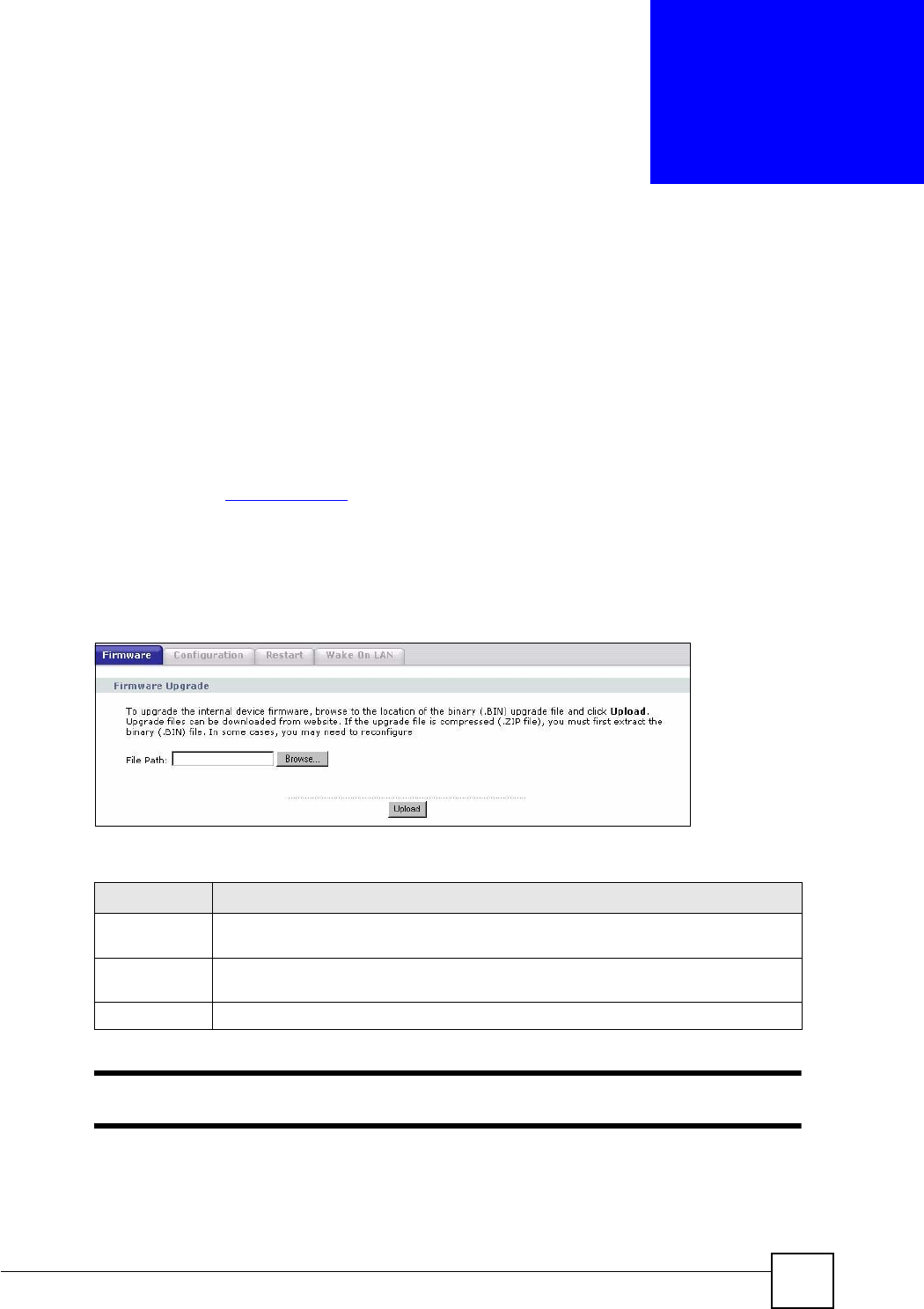
22.1 Firmware Upload Screen
Find firmware at www.zyxel.com in a file that (usually) uses the system model name with a
“*.bin” extension, e.g., “NBG460N.bin”. The upload process uses HTTP (Hypertext Transfer
Protocol) and may take up to two minutes. After a successful upload, the system will reboot.
Click Maintenance > Tools. Follow the instructions in this screen to upload firmware to your
NBG460N.
Figure 149 Maintenance > Tools > Firmware
The following table describes the labels in this screen.
"
Do not turn off the NBG460N while firmware upload is in progress!
After you see the Firmware Upload In Process screen, wait two minutes before logging into
the NBG460N again.
Table 107 Maintenance > Tools > Firmware
LABEL DESCRIPTION
File Path Type in the location of the file you want to upload in this field or click Browse... to find
it.
Browse... Click Browse... to find the .bin file you want to upload. Remember that you must
decompress compressed (.zip) files before you can upload them.
Upload Click Upload to begin the upload process. This process may take up to two minutes.
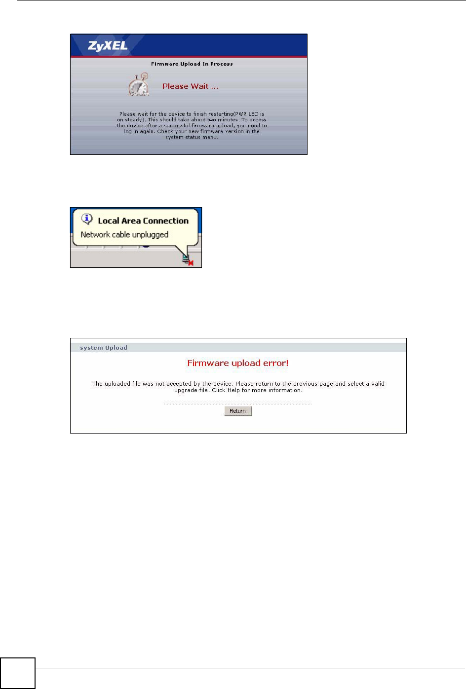
Chapter 22 Tools
NBG460N User’s Guide
252
Figure 150 Upload Warning
The NBG460N automatically restarts in this time causing a temporary network disconnect. In
some operating systems, you may see the following icon on your desktop.
Figure 151 Network Temporarily Disconnected
After two minutes, log in again and check your new firmware version in the Status screen.
If the upload was not successful, the following screen will appear. Click Return to go back to
the Firmware screen.
Figure 152 Upload Error Message
22.2 Configuration Screen
Click Maintenance > Tools > Configuration. Information related to factory defaults, backup
configuration, and restoring configuration appears as shown next.
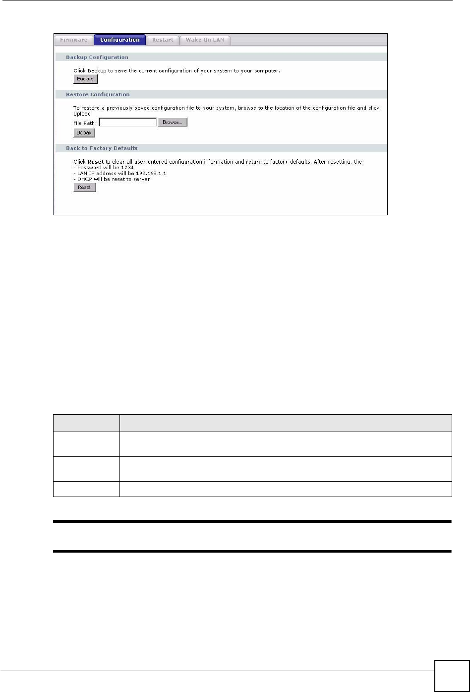
Chapter 22 Tools
NBG460N User’s Guide 253
Figure 153 Maintenance > Tools > Configuration
22.2.1 Backup Configuration
Backup configuration allows you to back up (save) the NBG460N’s current configuration to a
file on your computer. Once your NBG460N is configured and functioning properly, it is
highly recommended that you back up your configuration file before making configuration
changes. The backup configuration file will be useful in case you need to return to your
previous settings.
Click Backup to save the NBG460N’s current configuration to your computer.
22.2.2 Restore Configuration
Restore configuration allows you to upload a new or previously saved configuration file from
your computer to your NBG460N.
"
Do not turn off the NBG460N while configuration file upload is in progress
After you see a “configuration upload successful” screen, you must then wait one minute
before logging into the NBG460N again.
Table 108 Maintenance Restore Configuration
LABEL DESCRIPTION
File Path Type in the location of the file you want to upload in this field or click Browse... to find
it.
Browse... Click Browse... to find the file you want to upload. Remember that you must
decompress compressed (.ZIP) files before you can upload them.
Upload Click Upload to begin the upload process.
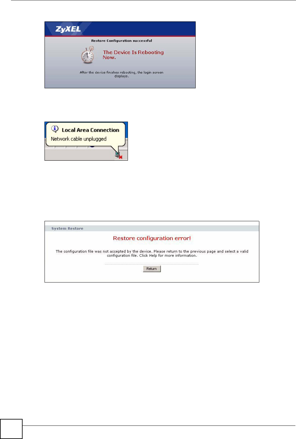
Chapter 22 Tools
NBG460N User’s Guide
254
Figure 154 Configuration Restore Successful
The NBG460N automatically restarts in this time causing a temporary network disconnect. In
some operating systems, you may see the following icon on your desktop.
Figure 155 Temporarily Disconnected
If you uploaded the default configuration file you may need to change the IP address of your
computer to be in the same subnet as that of the default NBG460N IP address (192.168.1.1).
See Appendix D on page 293 for details on how to set up your computer’s IP address.
If the upload was not successful, the following screen will appear. Click Return to go back to
the Configuration screen.
Figure 156 Configuration Restore Error
22.2.3 Back to Factory Defaults
Pressing the Reset button in this section clears all user-entered configuration information and
returns the NBG460N to its factory defaults.
You can also press the RESET button on the rear panel to reset the factory defaults of your
NBG460N. Refer to the chapter about introducing the web configurator for more information
on the RESET button.
22.3 Restart Screen
System restart allows you to reboot the NBG460N without turning the power off.
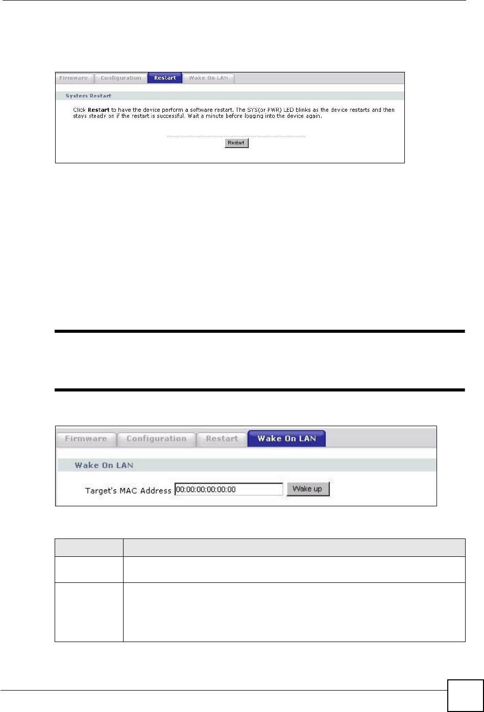
Chapter 22 Tools
NBG460N User’s Guide 255
Click Maintenance > Tools > Restart. Click Restart to have the NBG460N reboot. This does
not affect the NBG460N's configuration.
Figure 157 Maintenance > Tools > Restart
22.4 Wake On LAN
Wake On LAN (WoL) allows you to remotely turn on a device on the network. To use this
feature the remote hardware (for example the network adapter on your computer) must support
Wake On LAN using the “Magic Packet” method.
You need to know the MAC address of the remote device. It may be on a label on the device or
in it’s documentation.
Click Maintenance > Tools > Wake On LAN to use this feature.
"
The NBG460N can only wake up remote devices that exist in it’s ARP table.
For the remote device to exist in the NBG460N’s ARP table it should have had
a prior connection with the NBG460N.
Figure 158 Maintenance > Tools > Wake On LAN
The following table describes the labels in this screen.
Table 109 Maintenance > Tools > Wake On LAN
LABEL DESCRIPTION
Target’s MAC
Address
Enter the MAC Address of the device on the network that will be turned on. A MAC
address consists of six hexadecimal character pairs.
Wake up Click this to turn the specified device on. The status bar will refresh and indicate
either Ready or MAC Address error.
If it displays Ready you should check if the remote device has turned on.
If the status bar displays MAC Address error it means you may have input the MAC
Address incorrectly. Make sure you are entering it in the correct format.

Chapter 22 Tools
NBG460N User’s Guide
256
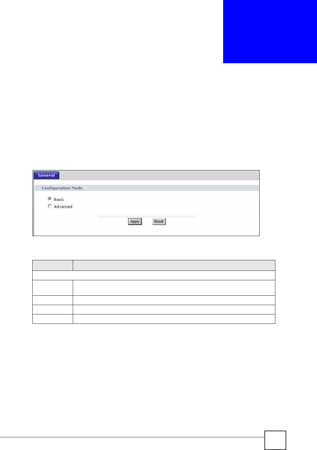
NBG460N User’s Guide 257
CHAPTER 23
Configuration Mode
Click Maintenance > Config Mode to open the following screen. This screen allows you to
hide or display the advanced screens of some features or the advanced features, such as MAC
filter or static route. Basic is selected by default and you cannot see the advanced screens or
features. If you want to view and configure all screens including the advanced ones, select
Advanced and click Apply.
Figure 159 Maintenance > Config Mode > General
The following table describes the labels in the screen.
Table 110 Maintenance > Config Mode > General
The following table includes the screens that you can view and configure only when you select
Advanced.
LABEL DESCRIPTION
Configuration Mode
Basic Select Basic mode to enable or disable features and to monitor the status of your
device.
Advanced Select Advanced mode to set advanced settings.
Apply Click on this to set the mode.
Reset Click on this to reset your selection.

Chapter 23 Configuration Mode
NBG460N User’s Guide
258
Table 111 Advanced Configuration Options
"
In AP Mode many screens will not be available. See Chapter 5 on page 65 for
more information.
CATEGORY LINK TAB
Network Wireless LAN MAC Filter
Advanced
QoS
Scheduling
WAN Advanced
LAN IP Alias
Advanced
DHCP Server Advanced
NAT Advanced
Security Firewall Services
Content Filter Schedule
Management Static Route IP Static Route
Bandwidth MGMT Advanced
Monitor
Remote MGMT Telnet
FTP
DNS
Maintenance Logs Log Settings
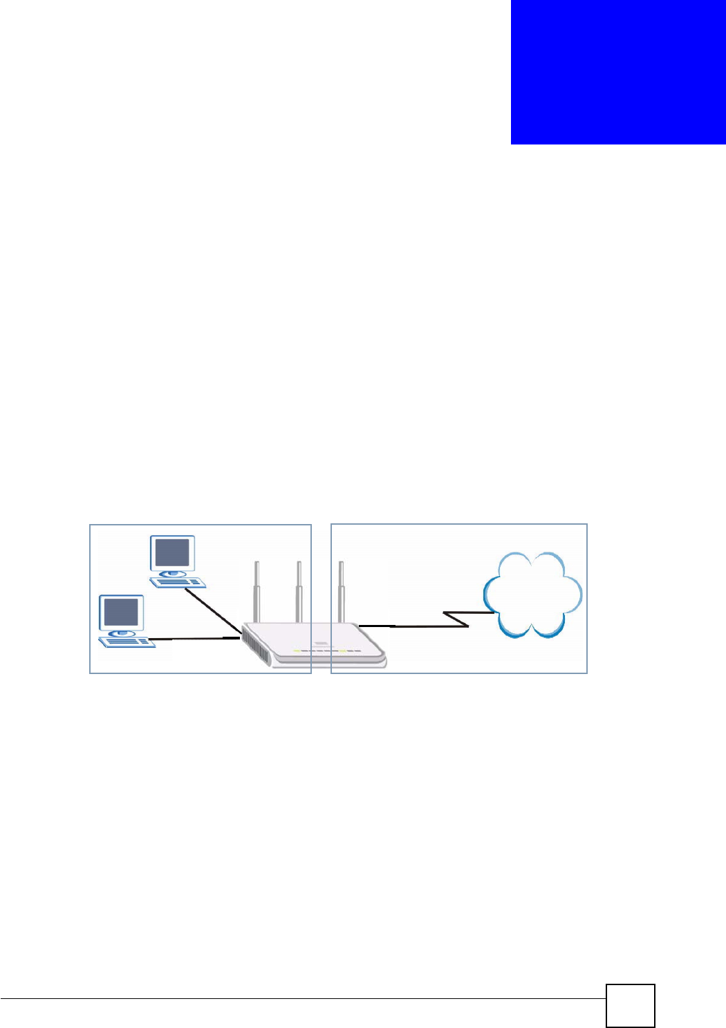
NBG460N User’s Guide 259
CHAPTER 24
Sys Op Mode
24.1 Overview
The Sys Op Mode (System Operation Mode) function lets you configure whether your
NBG460N is a router or AP. You can choose between Router Mode and AP Mode depending
on your network topology and the features you require from your device. See Section 1.1 on
page 31 for more information on which mode to choose.
24.1.1 Router
A router connects your local network with another network, such as the Internet. The router
has two IP addresses, the LAN IP address and the WAN IP address.
Figure 160 LAN and WAN IP Addresses in Router Mode
24.1.2 AP
An AP extends one network and so has just one IP address. All Ethernet ports on the AP have
the same IP address. To connect to the Internet, another device, such as a router, is required.
WAN IP
Internet
LAN WAN
LAN IP
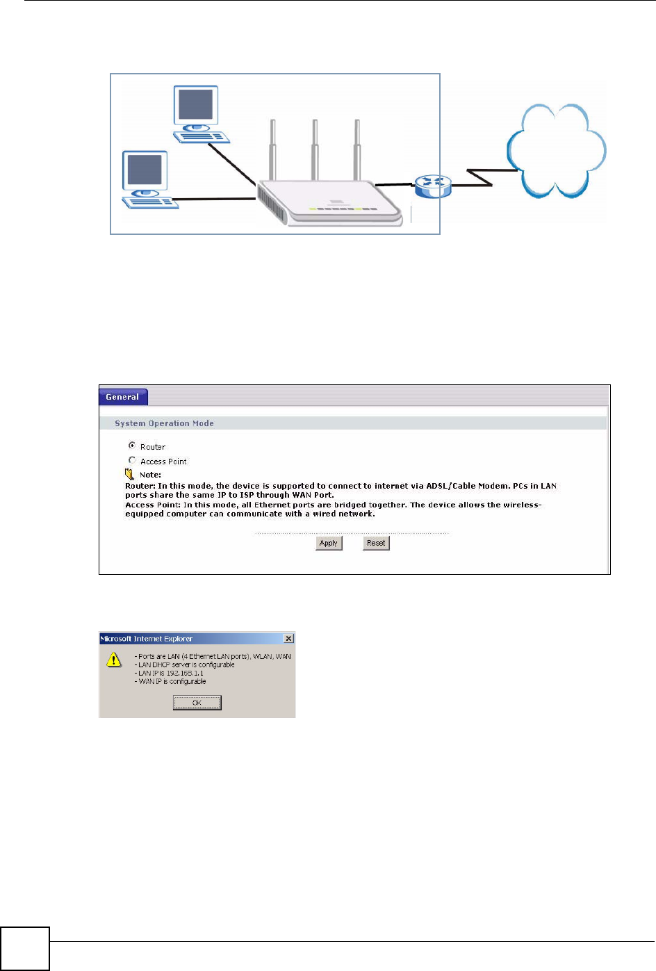
Chapter 24 Sys Op Mode
NBG460N User’s Guide
260
Figure 161 IP Address in AP Mode
24.2 Selecting System Operation Mode
Use this screen to select how you connect to the Internet.
Figure 162 Maintenance > Sys OP Mode > General
If you select Router Mode, the following pop-up message window appears.
Figure 163 Maintenance > Sys Op Mode > General: Router
• In this mode there are both LAN and WAN ports. The LAN Ethernet and WAN Ethernet
ports have different IP addresses.
• The DHCP server on your device is enabled and allocates IP addresses to other devices on
your local network.
• The LAN IP address of the device on the local network is set to 192.168.1.1.
• You can configure the IP address settings on your WAN port. Contact your ISP or system
administrator for more information on appropriate settings.
If you select Access Point the following pop-up message window appears.
1 IP
LAN
Internet
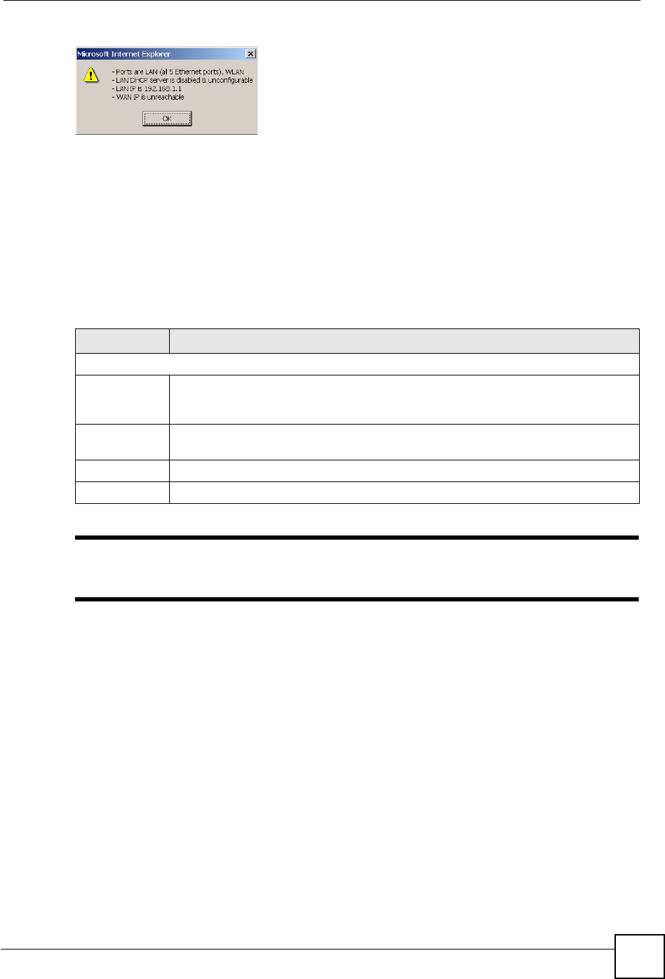
Chapter 24 Sys Op Mode
NBG460N User’s Guide 261
Figure 164 Maintenance > Sys Op Mode > General: AP
•In AP Mode all Ethernet ports have the same IP address.
• All ports on the rear panel of the device are LAN ports, including the port labeled WAN.
There is no WAN port.
• The DHCP server on your device is disabled. In AP mode there must be a device with a
DHCP server on your network such as a router or gateway which can allocate IP
addresses.
The IP address of the device on the local network is set to 192.168.1.1.
The following table describes the labels in the General screen.
Table 112 Maintenance > Sys OP Mode > General
"
If you select the incorrect System Operation Mode you cannot connect to the
Internet.
LABEL DESCRIPTION
System Operation Mode
Router Select Router if your device routes traffic between a local network and another
network such as the Internet. This mode offers services such as a firewall or
bandwidth management.
Access Point Select Access Point if your device bridges traffic between clients on the same
network.
Apply Click Apply to save your settings.
Reset Click Reset to return your settings to the default (Router)

Chapter 24 Sys Op Mode
NBG460N User’s Guide
262
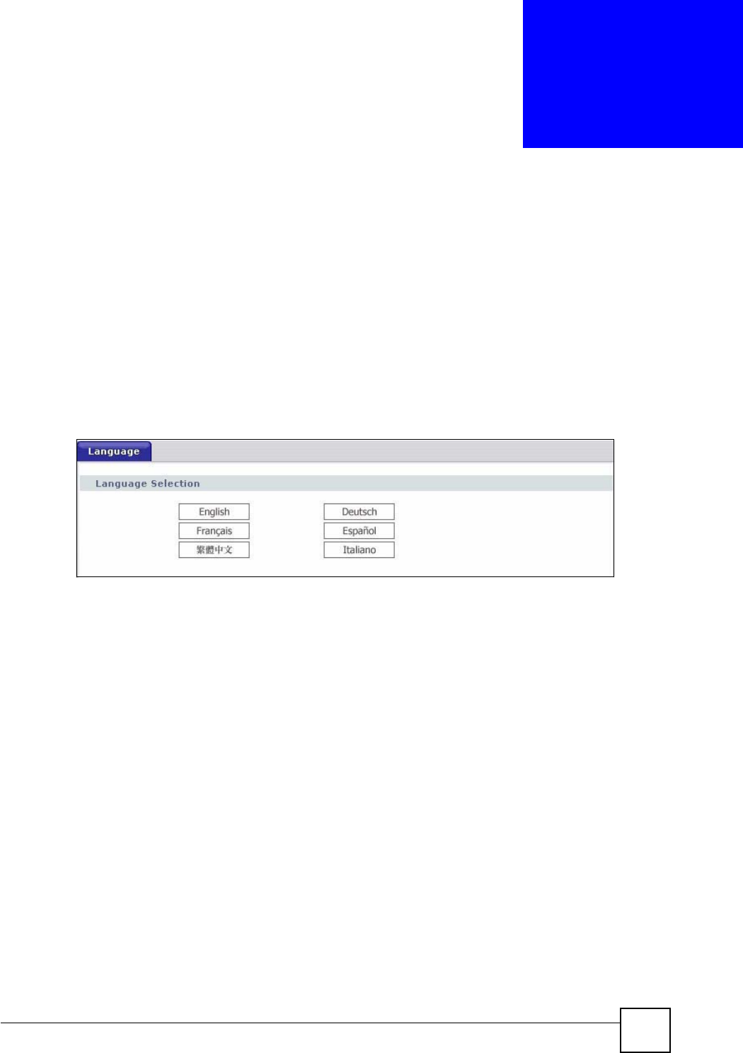
NBG460N User’s Guide 263
CHAPTER 25
Language
Use this screen to change the language for the web configurator display.
25.1 Language Screen
Click the language you prefer. The web configurator language changes after a while without
restarting the NBG460N.
Figure 165 Language

Chapter 25 Language
NBG460N User’s Guide
264

NBG460N User’s Guide 265
CHAPTER 26
Troubleshooting
This chapter offers some suggestions to solve problems you might encounter. The potential
problems are divided into the following categories.
•Power, Hardware Connections, and LEDs
•NBG460N Access and Login
•Internet Access
•Resetting the NBG460N to Its Factory Defaults
•Wireless Router/AP Troubleshooting
•Advanced Features
26.1 Power, Hardware Connections, and LEDs
VThe NBG460N does not turn on. None of the LEDs turn on.
1Make sure you are using the power adaptor or cord included with the NBG460N.
2Make sure the power adaptor or cord is connected to the NBG460N and plugged in to an
appropriate power source. Make sure the power source is turned on.
3Disconnect and re-connect the power adaptor or cord to the NBG460N.
4If the problem continues, contact the vendor.
VOne of the LEDs does not behave as expected.
1Make sure you understand the normal behavior of the LED. See Section 1.7 on page 33.
2Check the hardware connections. See the Quick Start Guide.
3Inspect your cables for damage. Contact the vendor to replace any damaged cables.
4Disconnect and re-connect the power adaptor to the NBG460N.
5If the problem continues, contact the vendor.

Chapter 26 Troubleshooting
NBG460N User’s Guide
266
26.2 NBG460N Access and Login
VI don’t know the IP address of my NBG460N.
1The default IP address is 192.168.1.1.
2If you changed the IP address and have forgotten it, you might get the IP address of the
NBG460N by looking up the IP address of the default gateway for your computer. To do
this in most Windows computers, click Start > Run, enter cmd, and then enter ipconfig.
The IP address of the Default Gateway might be the IP address of the NBG460N (it
depends on the network), so enter this IP address in your Internet browser.Set your
device to Router Mode, login (see the Quick Start Guide for instructions) and go to the
Device Information table in the Status screen. Your NBG460N’s IP address is available
in the Device Information table.
• If the DHCP setting under LAN information is None, your device has a fixed IP
address.
• If the DHCP setting under LAN information is Client, then your device receives an
IP address from a DHCP server on the network.
3If your NBG460N is a DHCP client, you can find your IP address from the DHCP server.
This information is only available from the DHCP server which allocates IP addresses
on your network. Find this information directly from the DHCP server or contact your
system administrator for more information.
4Reset your NBG460N to change all settings back to their default. This means your
current settings are lost. See Section 26.4 on page 269 in the Troubleshooting for
information on resetting your NBG460N.
VI forgot the password.
1The default password is 1234.
2If this does not work, you have to reset the device to its factory defaults. See Section
26.4 on page 269.
VI cannot see or access the Login screen in the web configurator.
1Make sure you are using the correct IP address.
• The default IP address is 192.168.1.1.
• If you changed the IP address (Section 7.3 on page 102), use the new IP address.
• If you changed the IP address and have forgotten it, see the troubleshooting
suggestions for I don’t know the IP address of my NBG460N.

Chapter 26 Troubleshooting
NBG460N User’s Guide 267
2Check the hardware connections, and make sure the LEDs are behaving as expected. See
the Quick Start Guide.
3Make sure your Internet browser does not block pop-up windows and has JavaScripts
and Java enabled. See Appendix B on page 279.
4Make sure your computer is in the same subnet as the NBG460N. (If you know that there
are routers between your computer and the NBG460N, skip this step.)
• If there is a DHCP server on your network, make sure your computer is using a
dynamic IP address. See Section 7.3 on page 102.
• If there is no DHCP server on your network, make sure your computer’s IP address is
in the same subnet as the NBG460N. See Section 7.3 on page 102.
5Reset the device to its factory defaults, and try to access the NBG460N with the default
IP address. See Section 7.3 on page 102.
6If the problem continues, contact the network administrator or vendor, or try one of the
advanced suggestions.
Advanced Suggestions
• Try to access the NBG460N using another service, such as Telnet. If you can access the
NBG460N, check the remote management settings and firewall rules to find out why the
NBG460N does not respond to HTTP.
• If your computer is connected to the WA N port or is connected wirelessly, use a computer
that is connected to a LAN/ETHERNET port.
VI can see the Login screen, but I cannot log in to the NBG460N.
1Make sure you have entered the password correctly. The default password is 1234. This
field is case-sensitive, so make sure [Caps Lock] is not on.
2You cannot log in to the web configurator while someone is using Telnet to access the
NBG460N. Log out of the NBG460N in the other session, or ask the person who is
logged in to log out.
3Disconnect and re-connect the power adaptor or cord to the NBG460N.
4If this does not work, you have to reset the device to its factory defaults. See Section
26.4 on page 269.
VI cannot Telnet to the NBG460N.
See the troubleshooting suggestions for I cannot see or access the Login screen in the web
configurator. Ignore the suggestions about your browser.
VI cannot use FTP to upload / download the configuration file. / I cannot use
FTP to upload new firmware.

Chapter 26 Troubleshooting
NBG460N User’s Guide
268
See the troubleshooting suggestions for I cannot see or access the Login screen in the web
configurator. Ignore the suggestions about your browser.
26.3 Internet Access
VI cannot access the Internet.
1Check the hardware connections, and make sure the LEDs are behaving as expected. See
the Quick Start Guide.
2Make sure you entered your ISP account information correctly in the wizard. These
fields are case-sensitive, so make sure [Caps Lock] is not on.
3If you are trying to access the Internet wirelessly, make sure the wireless settings in the
wireless client are the same as the settings in the AP.
4Disconnect all the cables from your device, and follow the directions in the Quick Start
Guide again.
5Go to Maintenance > Sys OP Mode > General. Check your System Operation Mode
setting.
• Select Router if your device routes traffic between a local network and another
network such as the Internet.
• Select Access Point if your device bridges traffic between clients on the same
network.
6If the problem continues, contact your ISP.
VI cannot access the Internet anymore. I had access to the Internet (with the
NBG460N), but my Internet connection is not available anymore.
1Check the hardware connections, and make sure the LEDs are behaving as expected. See
the Quick Start Guide and Section 1.7 on page 33.
2Reboot the NBG460N.
3If the problem continues, contact your ISP.
VThe Internet connection is slow or intermittent.
1There might be a lot of traffic on the network. Look at the LEDs, and check Section 1.7
on page 33. If the NBG460N is sending or receiving a lot of information, try closing
some programs that use the Internet, especially peer-to-peer applications.
2Check the signal strength. If the signal strength is low, try moving the NBG460N closer
to the AP if possible, and look around to see if there are any devices that might be

Chapter 26 Troubleshooting
NBG460N User’s Guide 269
interfering with the wireless network (for example, microwaves, other wireless
networks, and so on).
3Reboot the NBG460N.
4If the problem continues, contact the network administrator or vendor, or try one of the
advanced suggestions.
Advanced Suggestions
• Check the settings for bandwidth management. If it is disabled, you might consider
activating it. If it is enabled, you might consider changing the allocations.
• Check the settings for QoS. If it is disabled, you might consider activating it. If it is
enabled, you might consider raising or lowering the priority for some applications.
26.4 Resetting the NBG460N to Its Factory Defaults
If you reset the NBG460N, you lose all of the changes you have made. The NBG460N re-
loads its default settings, and the password resets to 1234. You have to make all of your
changes again.
VYou will lose all of your changes when you push the RESET button.
To reset the NBG460N,
1Make sure the power LED is on and not blinking.
2Press and hold the RESET button for five to ten seconds. Release the RESET button
when the power LED begins to blink. The default settings have been restored.
If the NBG460N restarts automatically, wait for the NBG460N to finish restarting, and log in
to the web configurator. The password is “1234”.
If the NBG460N does not restart automatically, disconnect and reconnect the NBG460N’s
power. Then, follow the directions above again.
26.5 Wireless Router/AP Troubleshooting
VI cannot access the NBG460N or ping any computer from the WLAN (wireless
AP or router).
1Make sure the wireless LAN is enabled on the NBG460N
2Make sure the wireless adapter on the wireless station is working properly.
3Make sure the wireless adapter installed on your computer is IEEE 802.11 compatible
and supports the same wireless standard as the NBG460N.

Chapter 26 Troubleshooting
NBG460N User’s Guide
270
4Make sure your computer (with a wireless adapter installed) is within the transmission
range of the NBG460N.
5Check that both the NBG460N and your wireless station are using the same wireless and
wireless security settings.
6Make sure traffic between the WLAN and the LAN is not blocked by the firewall on the
NBG460N.
7Make sure you allow the NBG460N to be remotely accessed through the WLAN
interface. Check your remote management settings.
• See the chapter on Wireless LAN in the User’s Guide for more information.
26.6 Advanced Features
VI can log in, but I cannot see some of the screens or fields in the Web
Configurator.
You may be accessing the Web Configurator in Basic mode. Some screens and fields are
available only in Advanced mode. Use the Maintenance > Config Mode screen to select
Advanced mode.
You may be accessing the Web Configurator in AP Mode. Some screens and fields are
available only in Router Mode. Use the Maintenance > Sys OP Mode screen to select Router
Mode.
VI set up URL keyword blocking, but I can still access a website that should be
blocked.
Make sure that you select the Enable URL Keyword Blocking check box in the Content
Filtering screen. Make sure that the keywords that you type are listed in the Keyword List.
If a keyword that is listed in the Keyword List is not blocked when it is found in a URL,
customize the keyword blocking using commands. See the Customizing Keyword Blocking
URL Checking section in the Content Filter chapter.