ZyXEL Communications X550NH Wireless Gigabit Router User Manual NBG334W User Guide
ZyXEL Communications Corporation Wireless Gigabit Router NBG334W User Guide
Contents
- 1. Users manual part1
- 2. Users manual part2
- 3. Users manual part3
- 4. Users manual part4
Users manual part3
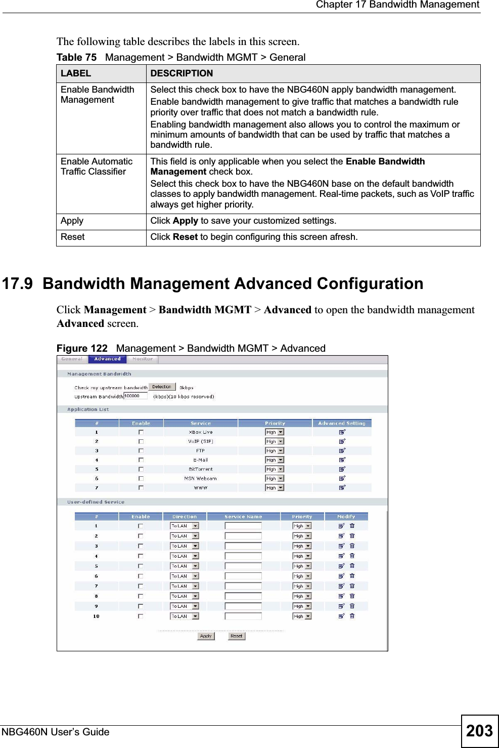
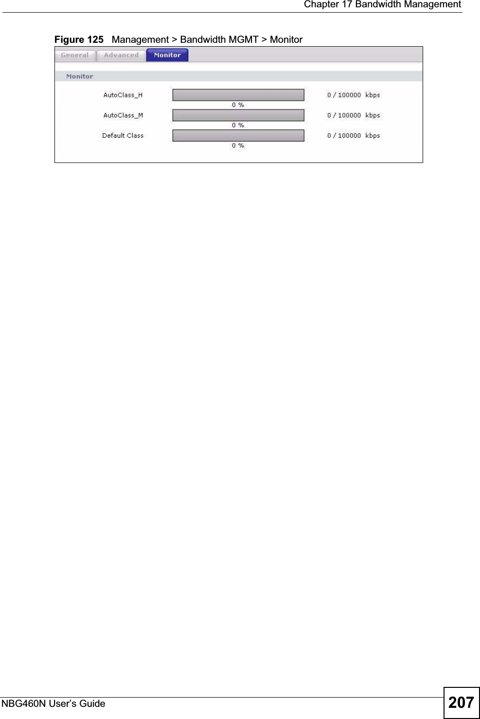

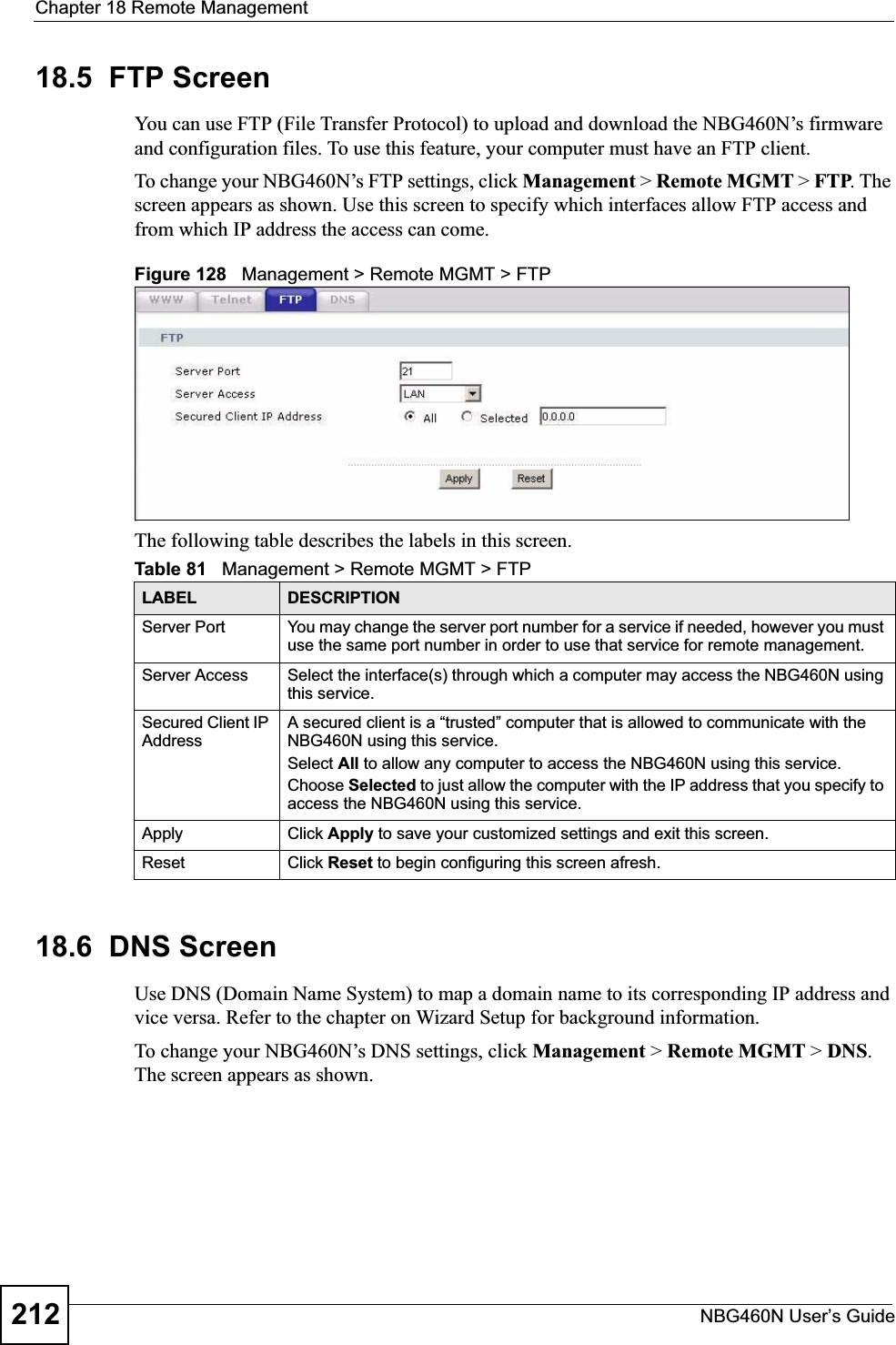

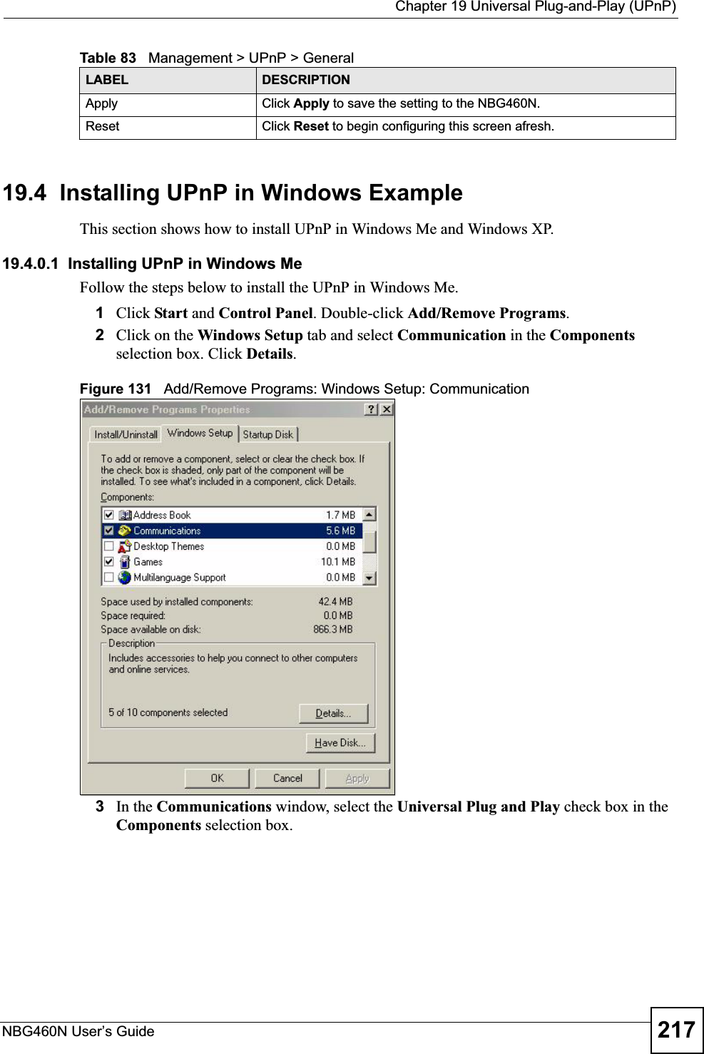
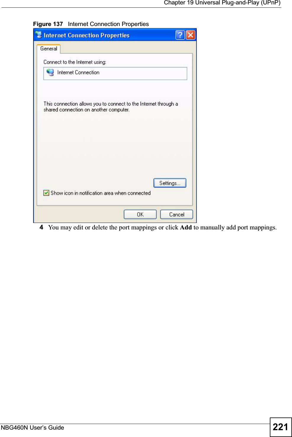
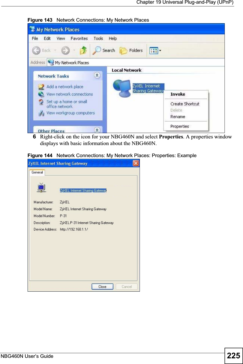


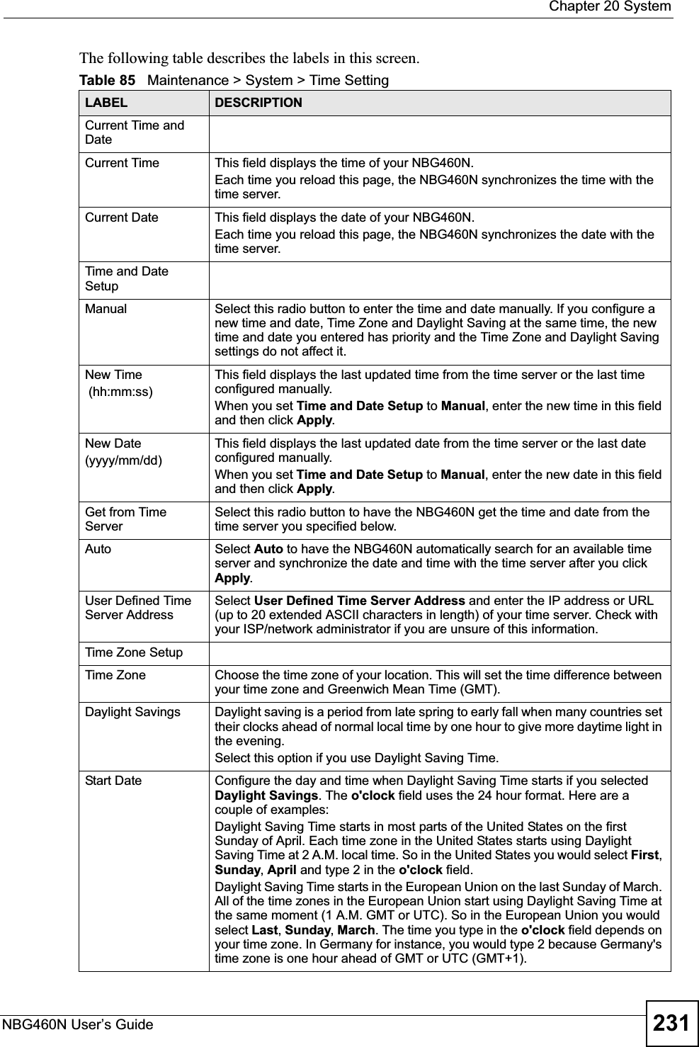
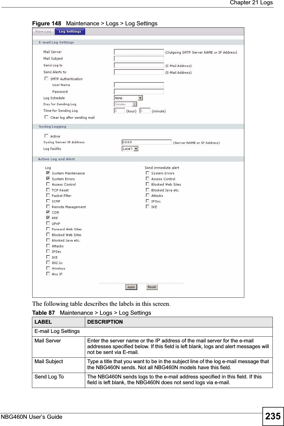
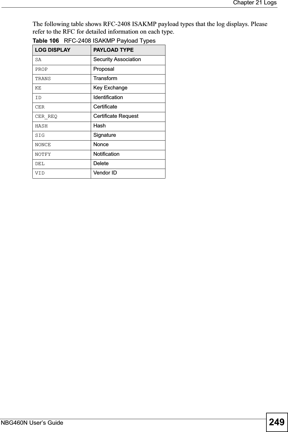
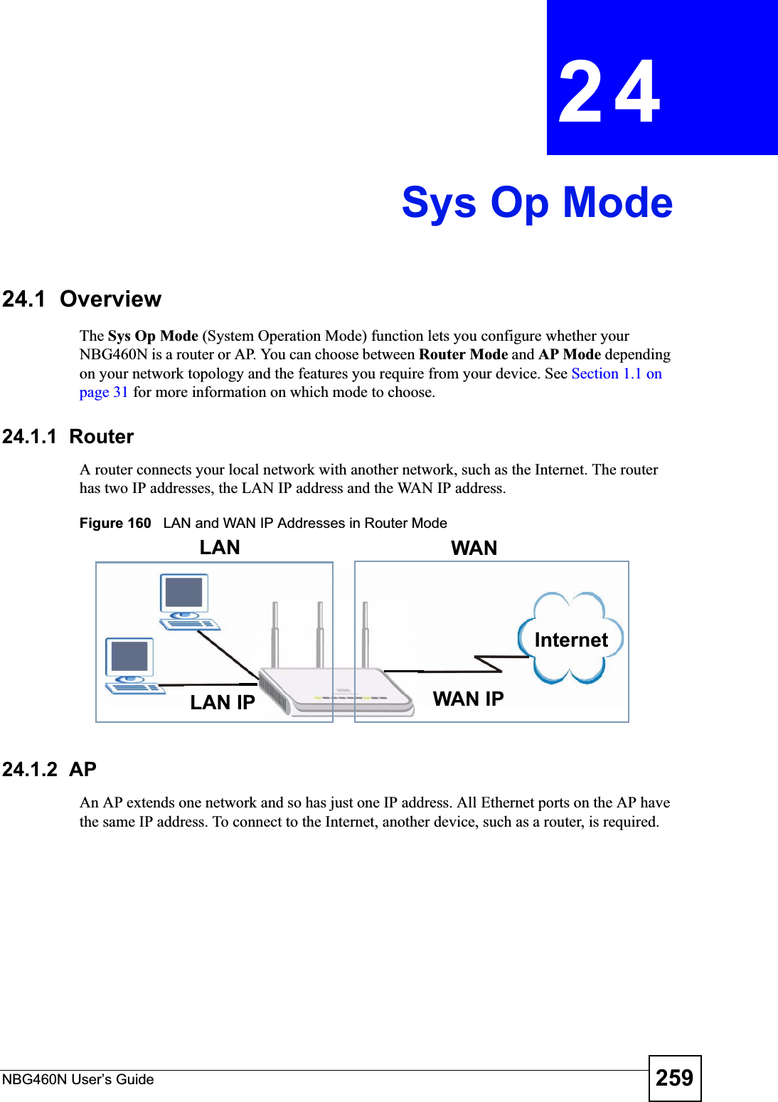
![Chapter 21 LogsNBG460N User’s Guide238Table 89 System Error LogsLOG MESSAGE DESCRIPTION%s exceeds the max. number of session per host!This attempt to create a NAT session exceeds the maximum number of NAT session table entries allowed to be created per host.setNetBIOSFilter: calloc errorThe router failed to allocate memory for the NetBIOS filter settings.readNetBIOSFilter: calloc errorThe router failed to allocate memory for the NetBIOS filter settings.WAN connection is down. A WAN connection is down. You cannot access the network through this interface.Table 90 Access Control LogsLOG MESSAGE DESCRIPTIONFirewall default policy: [TCP | UDP | IGMP | ESP | GRE | OSPF] <Packet Direction>Attempted TCP/UDP/IGMP/ESP/GRE/OSPF access matched the default policy and was blocked or forwarded according to the default policy’s setting.Firewall rule [NOT] match:[TCP | UDP | IGMP | ESP | GRE | OSPF] <Packet Direction>, <rule:%d>Attempted TCP/UDP/IGMP/ESP/GRE/OSPF access matched (or did not match) a configured firewall rule (denoted by its number) and was blocked or forwarded according to the rule. Triangle route packet forwarded: [TCP | UDP | IGMP | ESP | GRE | OSPF]The firewall allowed a triangle route session to pass through.Packet without a NAT table entry blocked: [TCP | UDP | IGMP | ESP | GRE | OSPF]The router blocked a packet that didn't have a corresponding NAT table entry.Router sent blocked web site message: TCPThe router sent a message to notify a user that the router blocked access to a web site that the user requested.Table 91 TCP Reset LogsLOG MESSAGE DESCRIPTIONUnder SYN flood attack, sent TCP RSTThe router sent a TCP reset packet when a host was under a SYN flood attack (the TCP incomplete count is per destination host.) Exceed TCP MAX incomplete, sent TCP RSTThe router sent a TCP reset packet when the number of TCP incomplete connections exceeded the user configured threshold. (the TCP incomplete count is per destination host.) Note: Refer to TCP Maximum Incomplete in the Firewall Attack Alerts screen. Peer TCP state out of order, sent TCP RSTThe router sent a TCP reset packet when a TCP connection state was out of order.Note: The firewall refers to RFC793 Figure 6 to check the TCP state.](https://usermanual.wiki/ZyXEL-Communications/X550NH.Users-manual-part3/User-Guide-939019-Page-38.png)
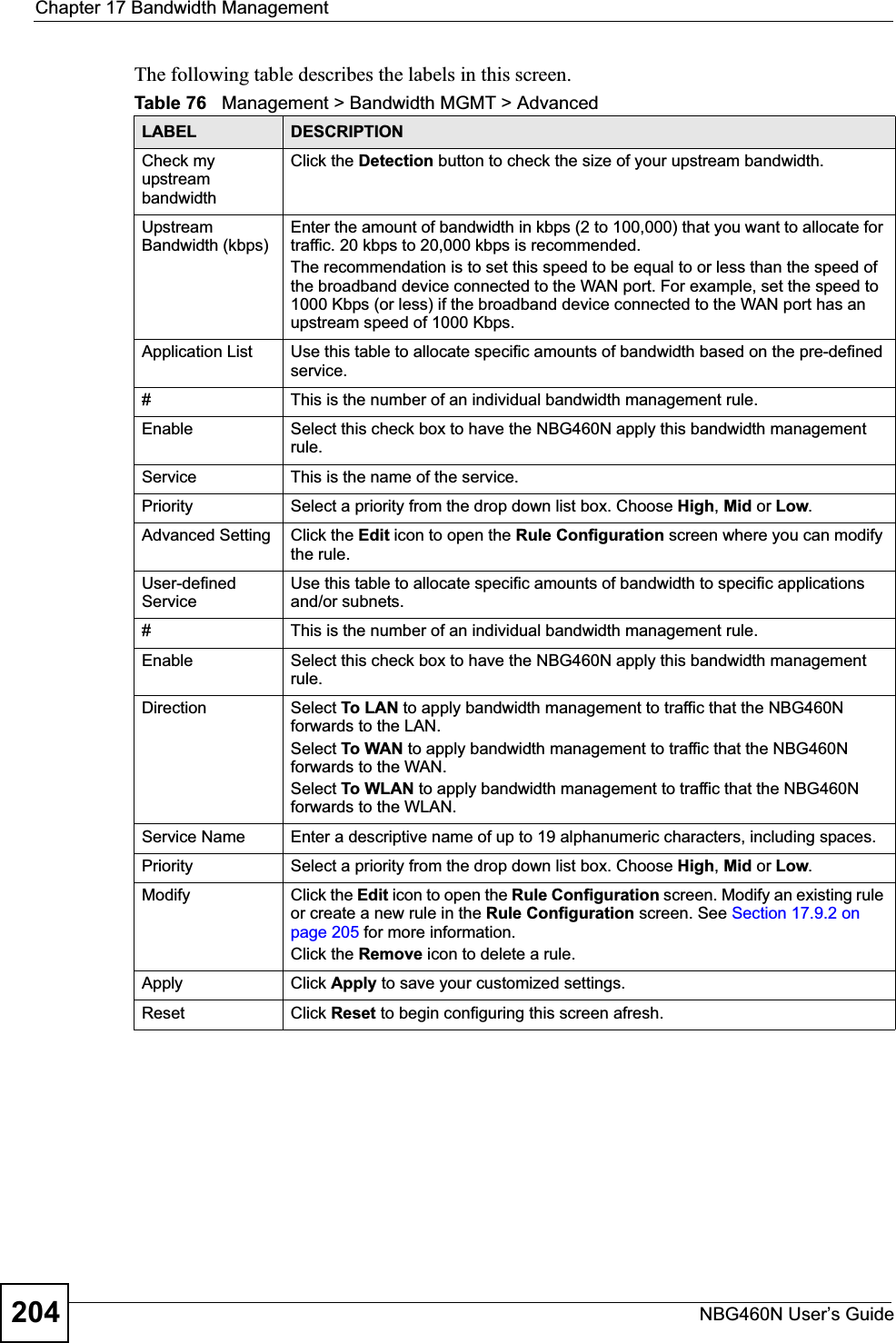
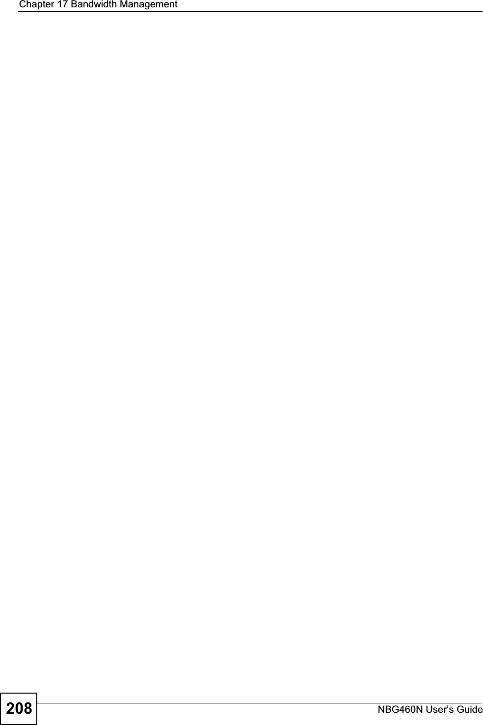
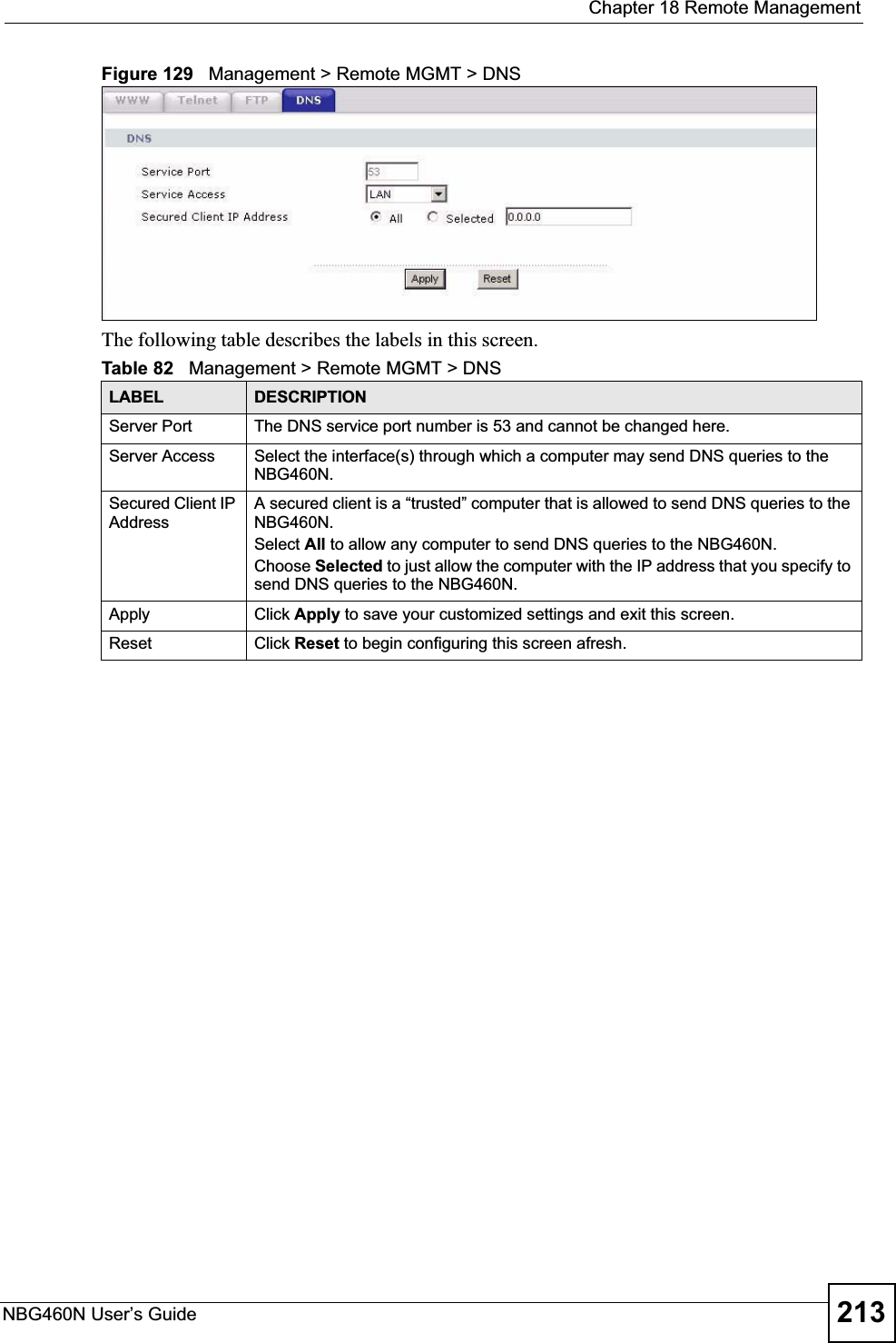
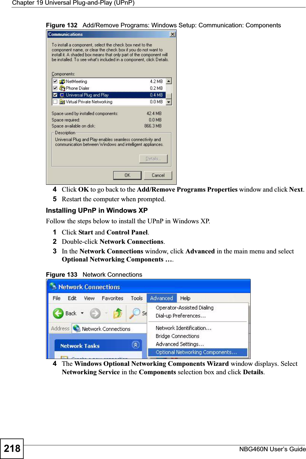
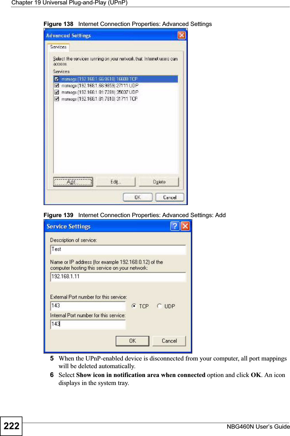
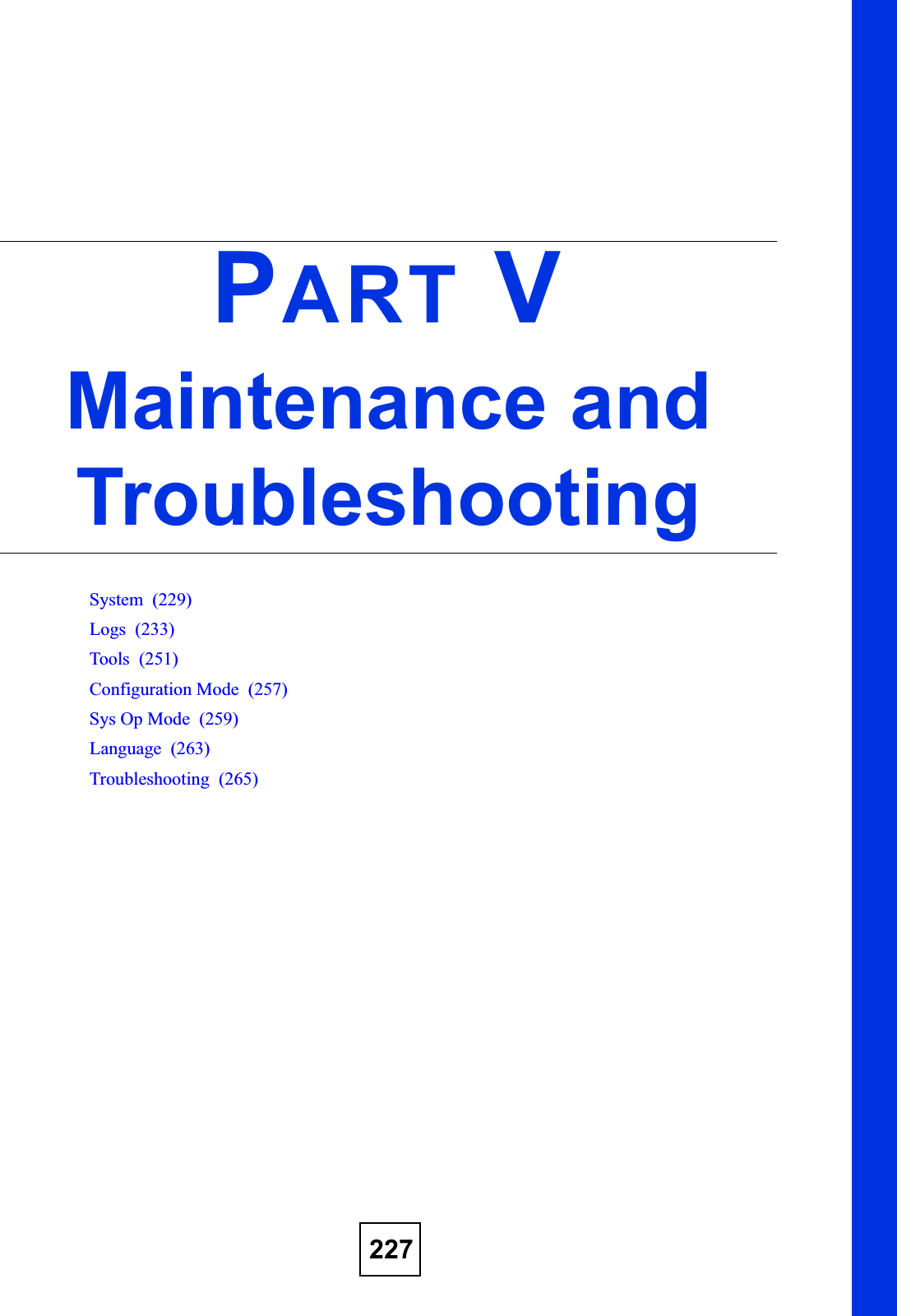
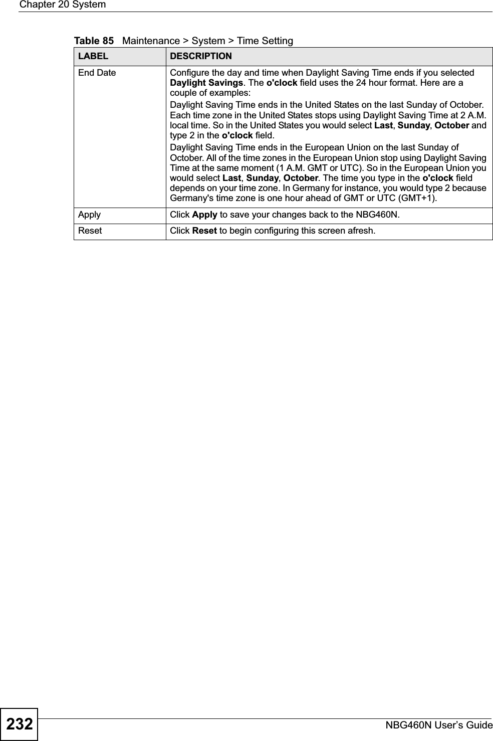
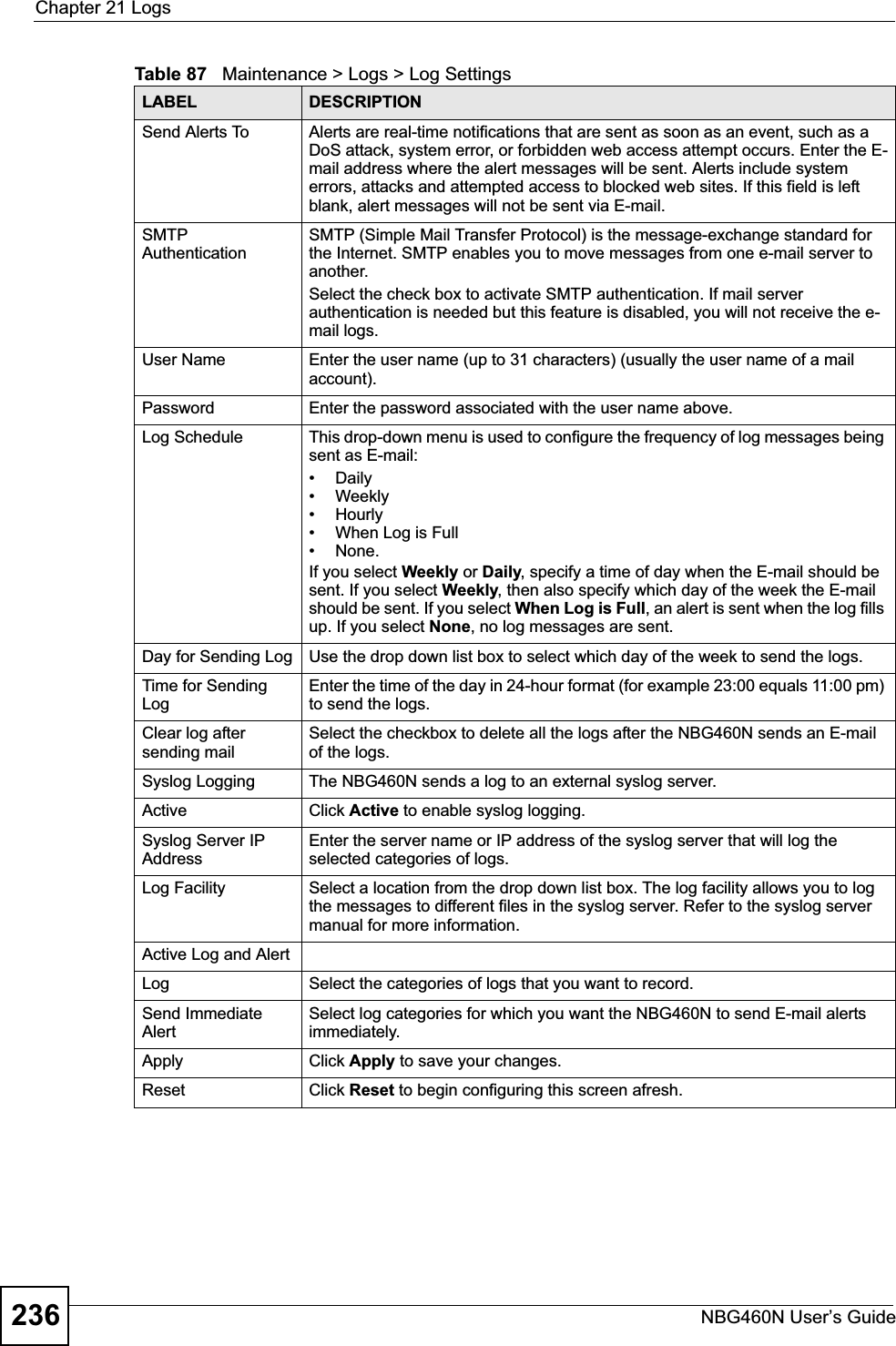
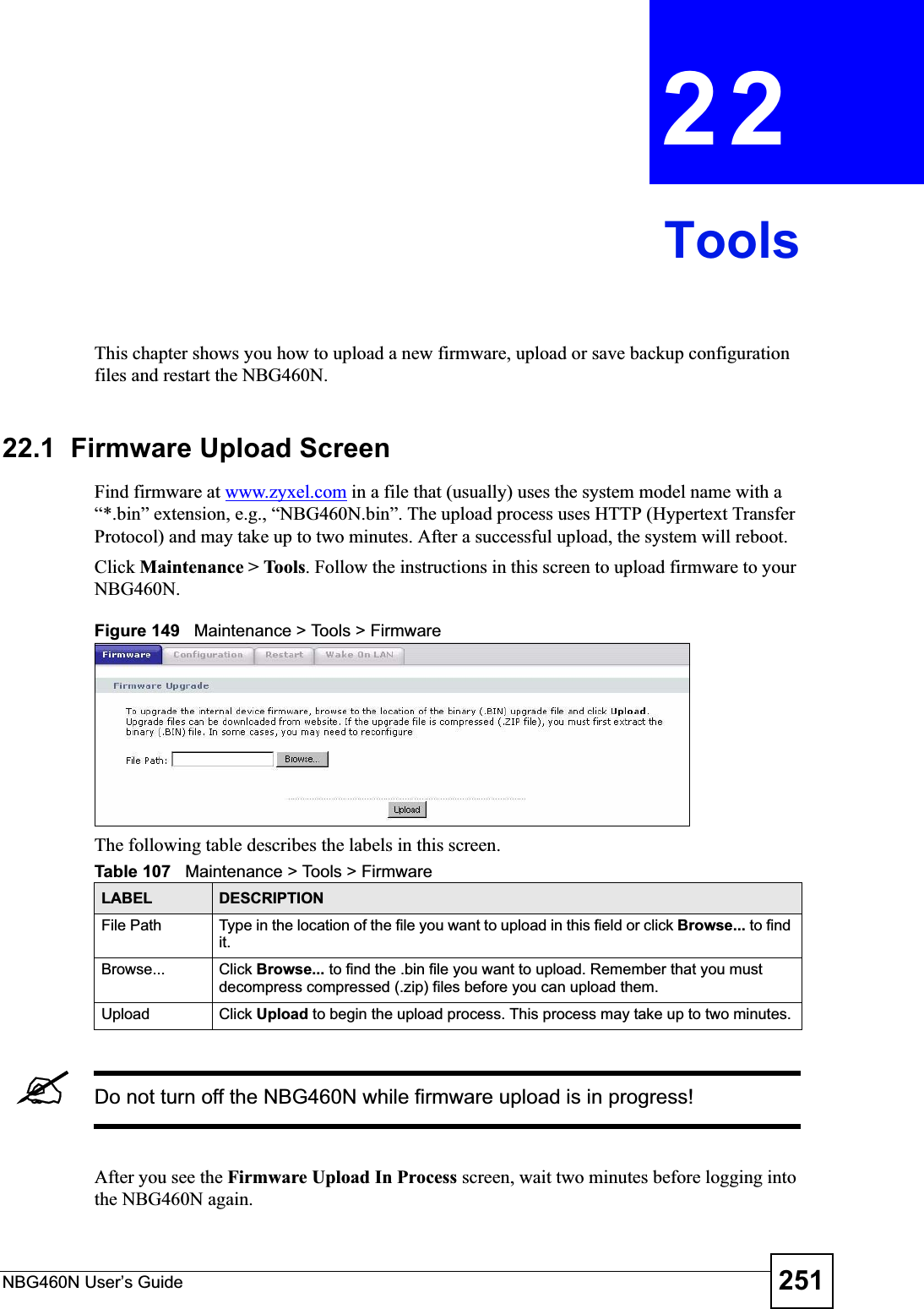
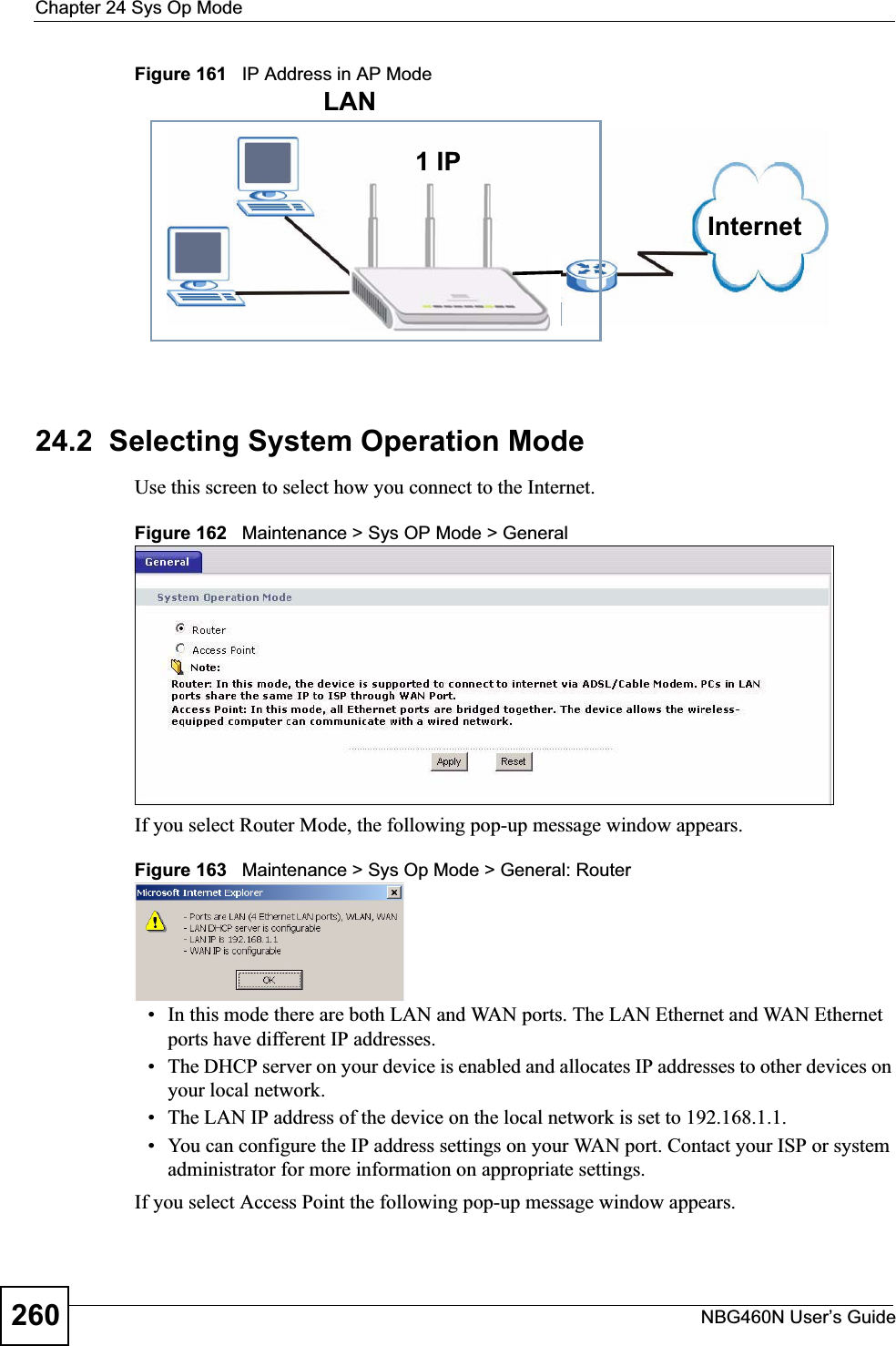
![Chapter 21 LogsNBG460N User’s Guide 239Firewall session time out, sent TCP RSTThe router sent a TCP reset packet when a dynamic firewall session timed out.The default timeout values are as follows:ICMP idle timeout: 3 minutesUDP idle timeout: 3 minutesTCP connection (three way handshaking) timeout: 270 secondsTCP FIN-wait timeout: 2 MSL (Maximum Segment Lifetime set in the TCP header).TCP idle (established) timeout (s): 150 minutesTCP reset timeout: 10 secondsExceed MAX incomplete, sent TCP RSTThe router sent a TCP reset packet when the number of incomplete connections (TCP and UDP) exceeded the user-configured threshold. (Incomplete count is for all TCP and UDP connections through the firewall.)Note: When the number of incomplete connections (TCP + UDP) > “Maximum Incomplete High”, the router sends TCP RST packets for TCP connections and destroys TOS (firewall dynamic sessions) until incomplete connections < “Maximum Incomplete Low”.Access block, sent TCP RSTThe router sends a TCP RST packet and generates this log if you turn on the firewall TCP reset mechanism (via CI command: "sys firewall tcprst").Table 92 Packet Filter LogsLOG MESSAGE DESCRIPTION[TCP | UDP | ICMP | IGMP | Generic] packet filter matched (set:%d, rule:%d)Attempted access matched a configured filter rule (denoted by its set and rule number) and was blocked or forwarded according to the rule.Table 93 ICMP LogsLOG MESSAGE DESCRIPTIONFirewall default policy: ICMP <Packet Direction>, <type:%d>, <code:%d>ICMP access matched the default policy and was blocked or forwarded according to the user's setting. For type and code details, see Table 104 on page 247.Firewall rule [NOT] match: ICMP <Packet Direction>, <rule:%d>, <type:%d>, <code:%d>ICMP access matched (or didn’t match) a firewall rule (denoted by its number) and was blocked or forwarded according to the rule. For type and code details, see Table 104 on page 247.Triangle route packet forwarded: ICMPThe firewall allowed a triangle route session to pass through.Packet without a NAT table entry blocked: ICMPThe router blocked a packet that didn’t have a corresponding NAT table entry.Unsupported/out-of-order ICMP: ICMPThe firewall does not support this kind of ICMP packets or the ICMP packets are out of order.Router reply ICMP packet: ICMP The router sent an ICMP reply packet to the sender.Table 91 TCP Reset Logs (continued)LOG MESSAGE DESCRIPTION](https://usermanual.wiki/ZyXEL-Communications/X550NH.Users-manual-part3/User-Guide-939019-Page-39.png)
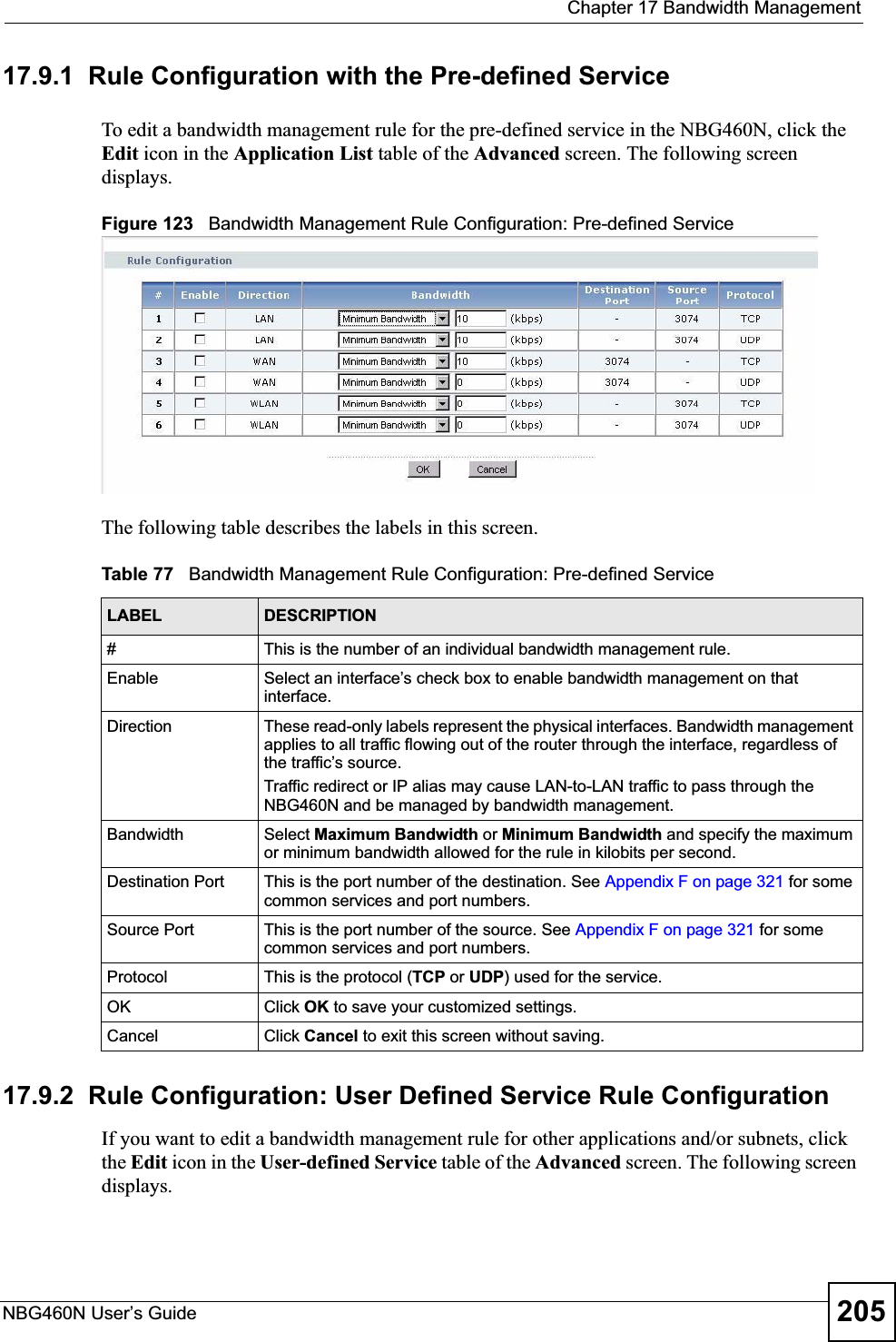
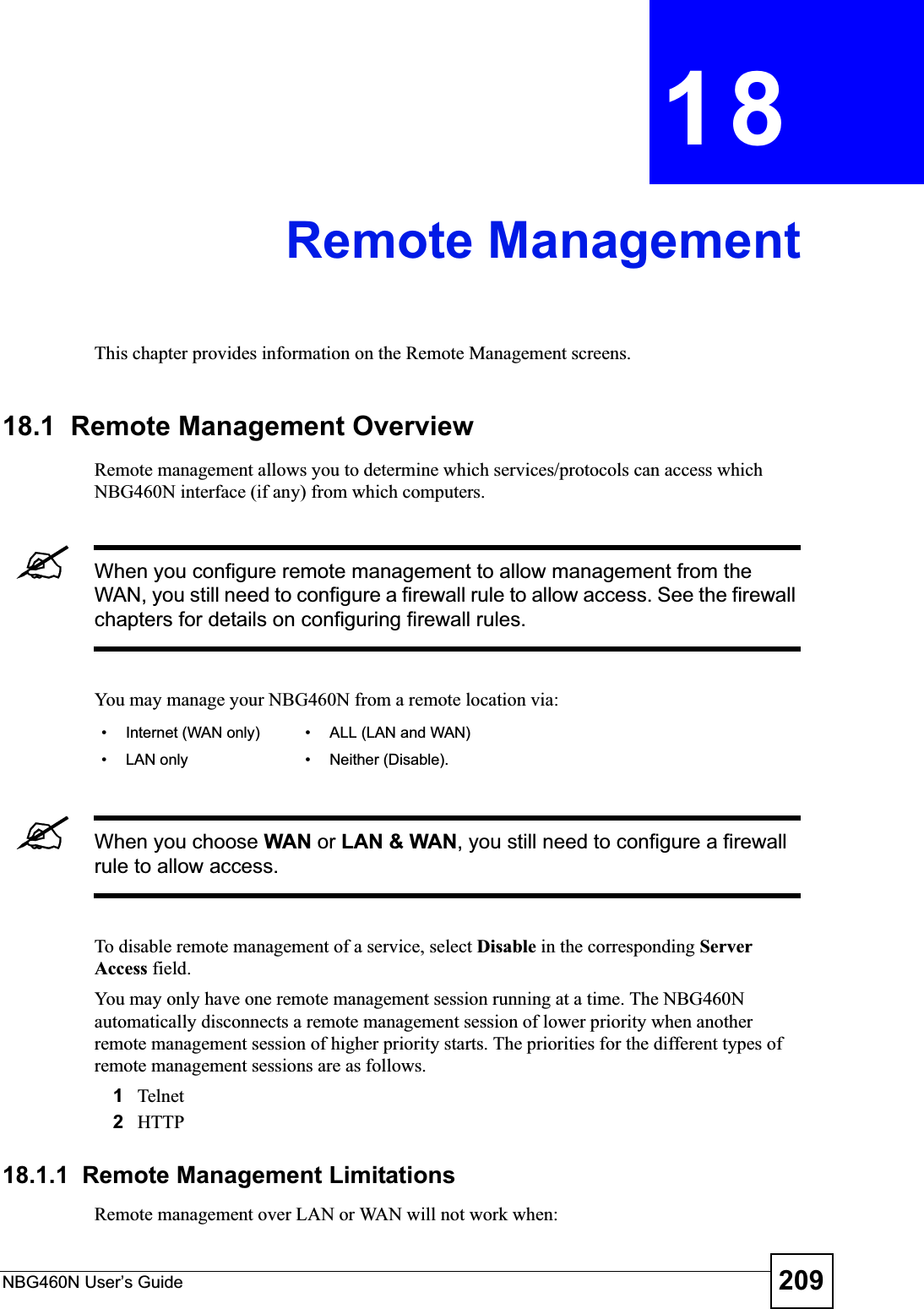
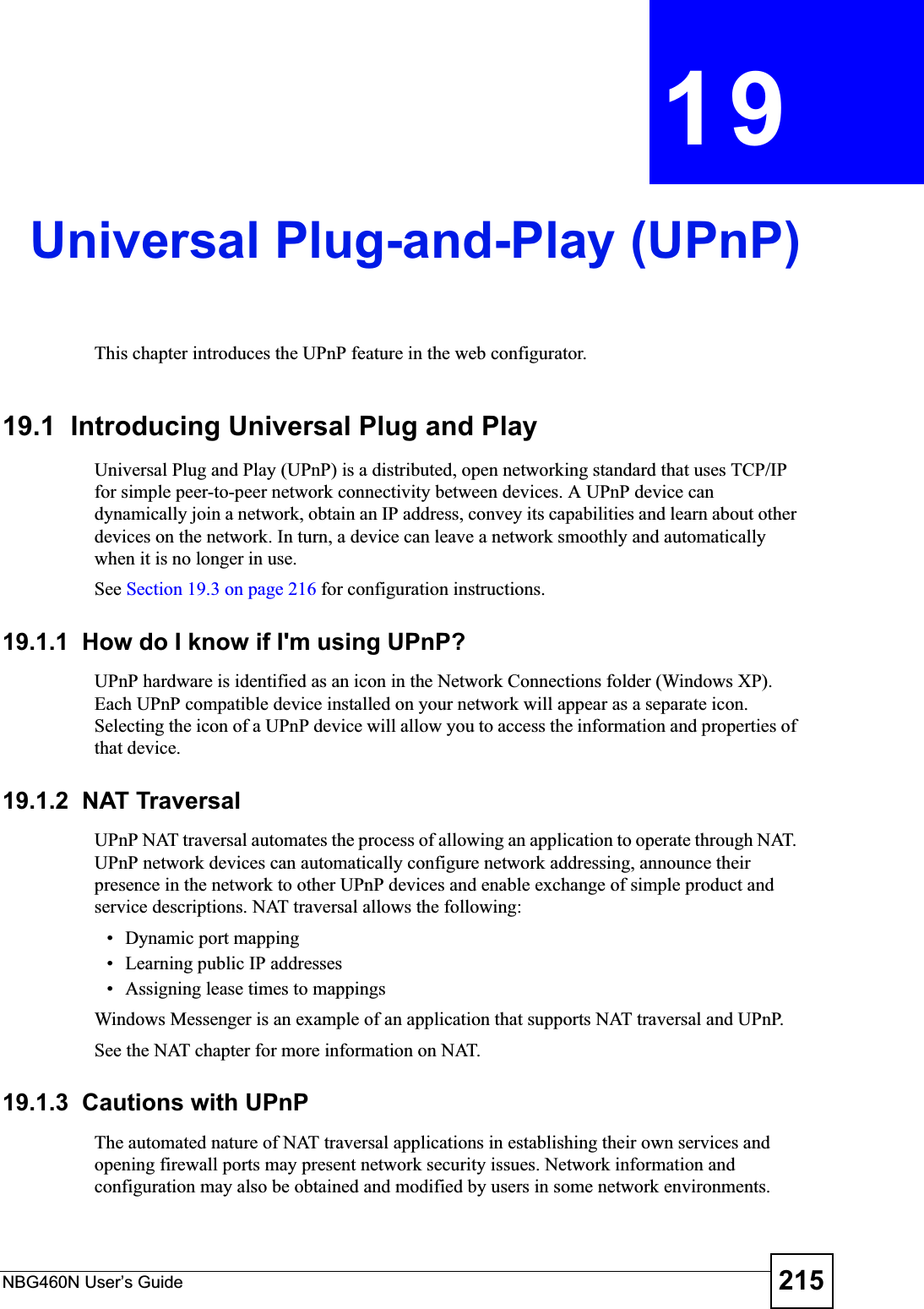
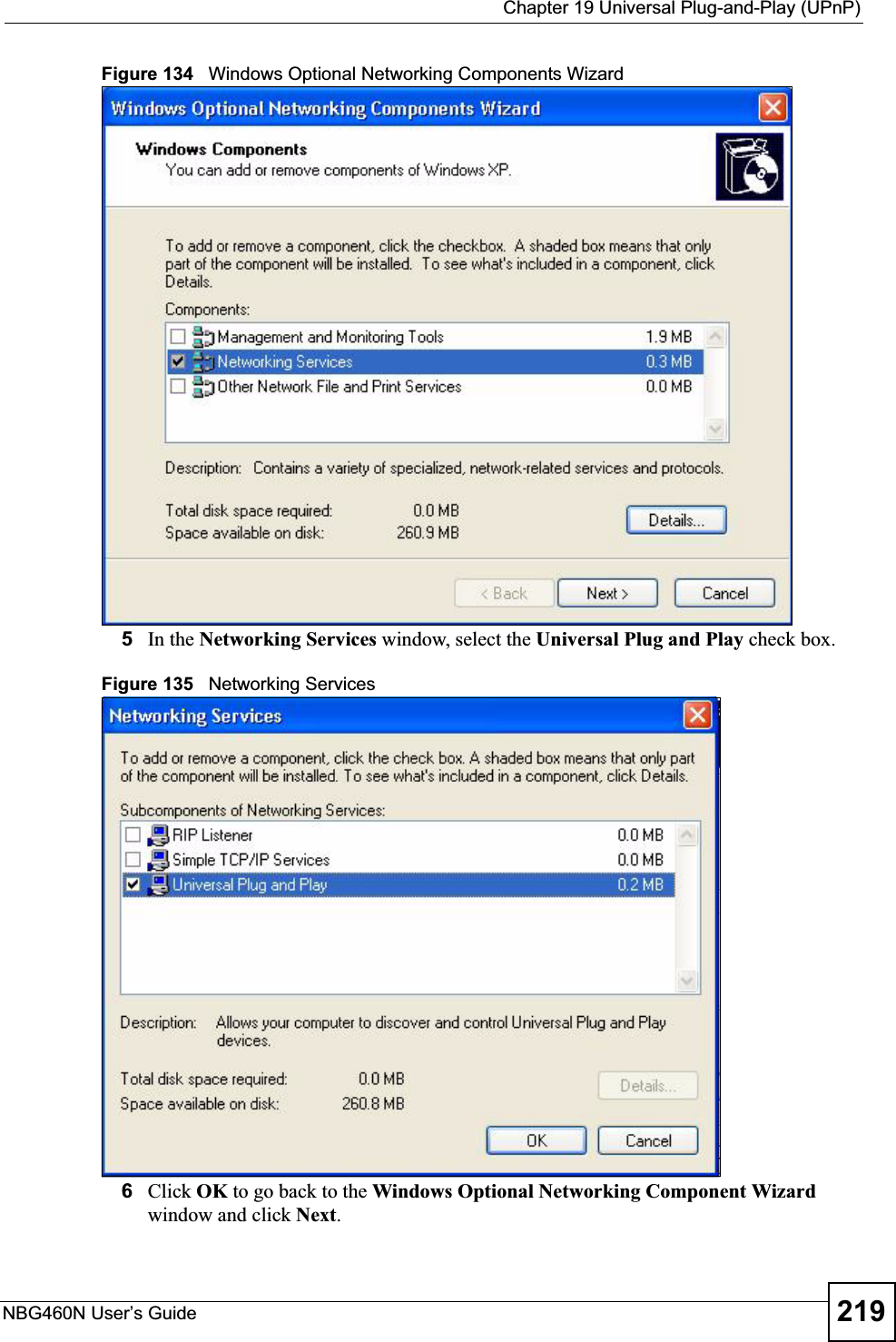
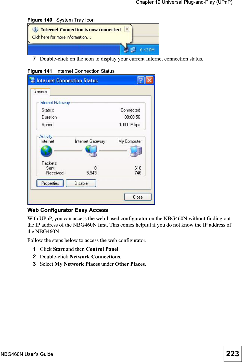
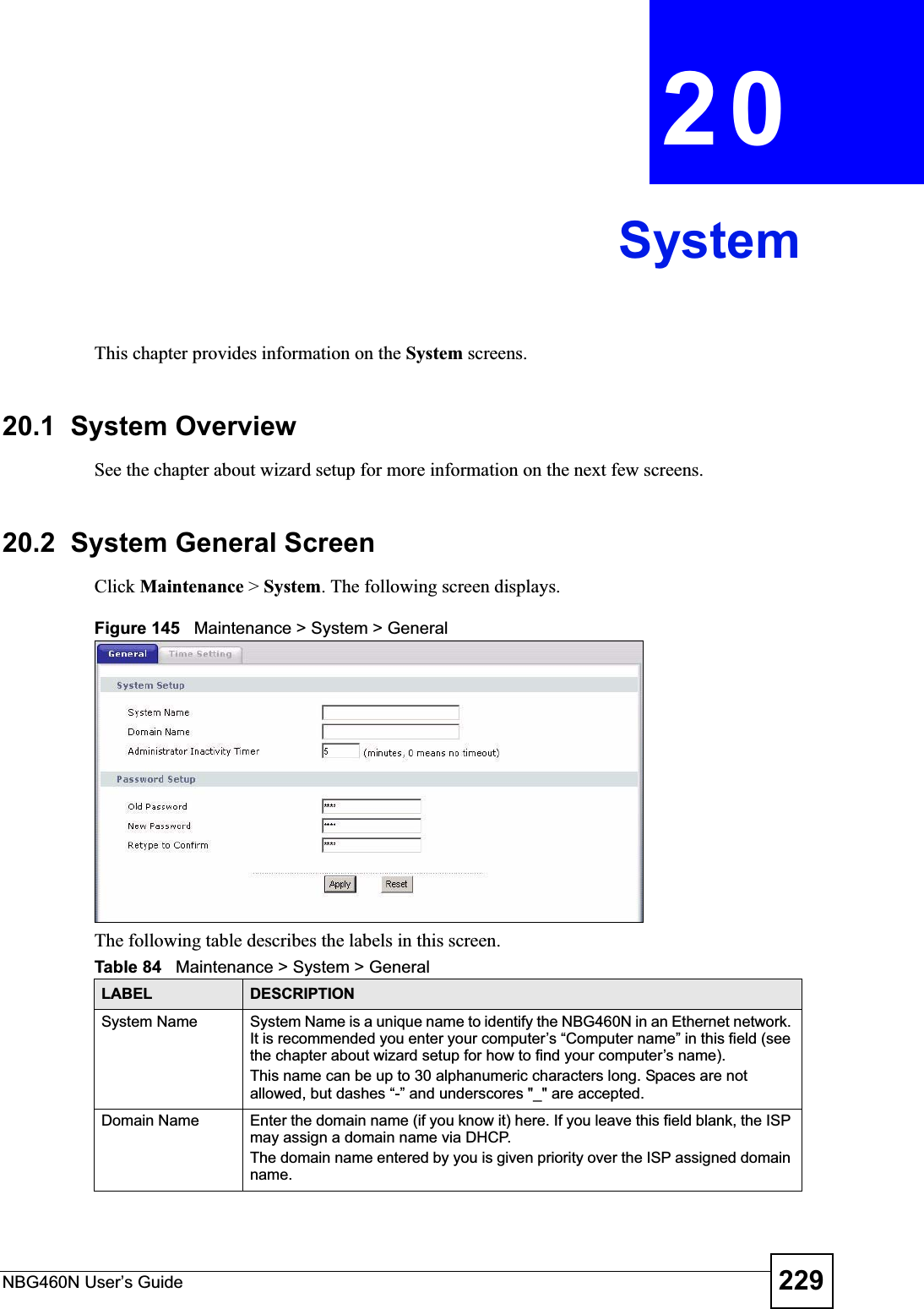
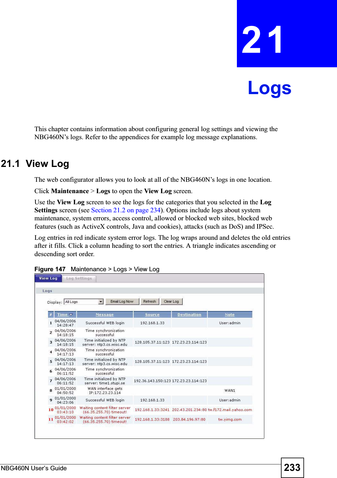
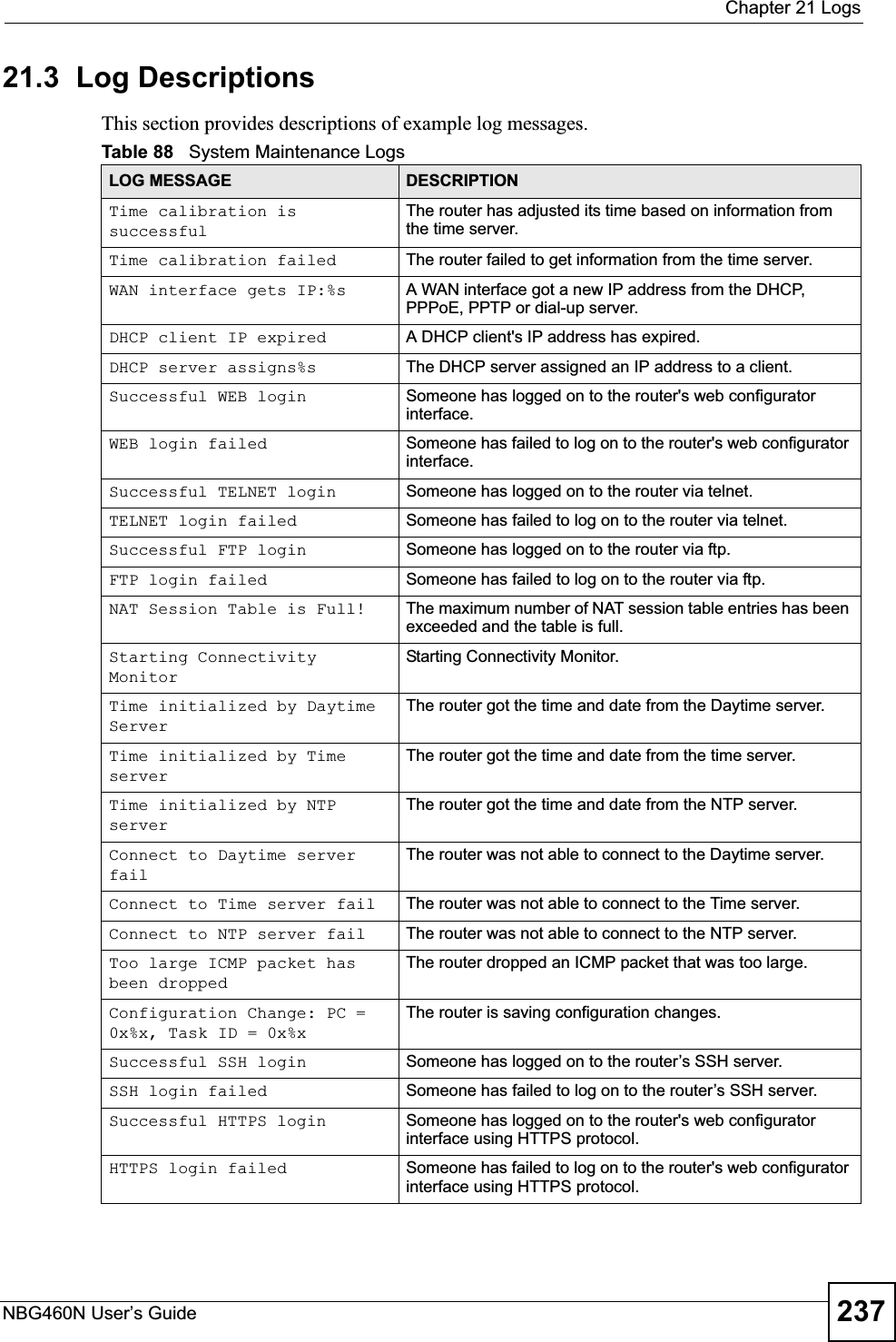
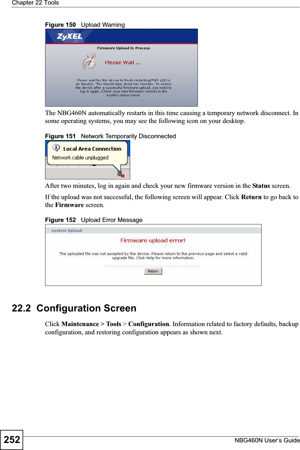
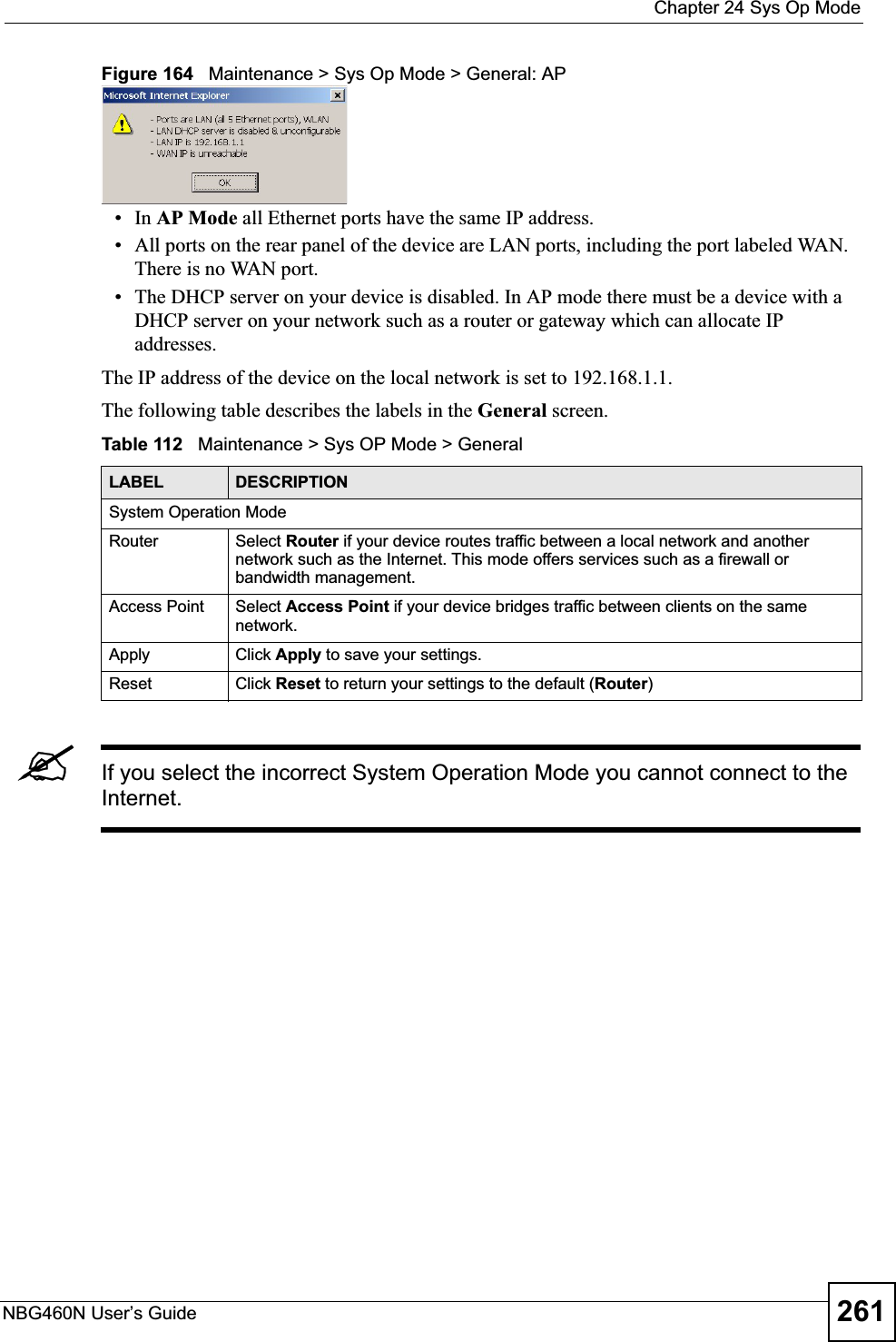
![Chapter 21 LogsNBG460N User’s Guide 241%s: Proxy mode detectedThe router detected proxy mode in the packet.%s The content filter server responded that the web site is in the blocked category list, but it did not return the category type.%s:%s The content filter server responded that the web site is in the blocked category list, and returned the category type.%s(cache hit) The system detected that the web site is in the blocked list from the local cache, but does not know the category type.%s:%s(cache hit) The system detected that the web site is in blocked list from the local cache, and knows the category type.%s: Trusted Web site The web site is in a trusted domain.%s When the content filter is not on according to the time schedule or you didn't select the "Block Matched Web Site” check box, the system forwards the web content.Waiting content filter server timeoutThe external content filtering server did not respond within the timeout period.DNS resolving failed The NBG460N cannot get the IP address of the external content filtering via DNS query.Creating socket failed The NBG460N cannot issue a query because TCP/IP socket creation failed, port:port number.Connecting to content filter server failThe connection to the external content filtering server failed.License key is invalid The external content filtering license key is invalid.Table 98 Attack LogsLOG MESSAGE DESCRIPTIONattack [TCP | UDP | IGMP | ESP | GRE | OSPF]The firewall detected a TCP/UDP/IGMP/ESP/GRE/OSPF attack.attack ICMP (type:%d, code:%d)The firewall detected an ICMP attack. For type and code details, see Table 104 on page 247.land [TCP | UDP | IGMP | ESP | GRE | OSPF]The firewall detected a TCP/UDP/IGMP/ESP/GRE/OSPF land attack.land ICMP (type:%d, code:%d)The firewall detected an ICMP land attack. For type and code details, see Table 104 on page 247.ip spoofing - WAN [TCP | UDP | IGMP | ESP | GRE | OSPF]The firewall detected an IP spoofing attack on the WAN port.ip spoofing - WAN ICMP (type:%d, code:%d)The firewall detected an ICMP IP spoofing attack on the WAN port. For type and code details, see Table 104 on page 247.icmp echo: ICMP (type:%d, code:%d)The firewall detected an ICMP echo attack. For type and code details, see Table 104 on page 247.syn flood TCP The firewall detected a TCP syn flood attack.ports scan TCP The firewall detected a TCP port scan attack.teardrop TCP The firewall detected a TCP teardrop attack.Table 97 Content Filtering Logs (continued)LOG MESSAGE DESCRIPTION](https://usermanual.wiki/ZyXEL-Communications/X550NH.Users-manual-part3/User-Guide-939019-Page-41.png)
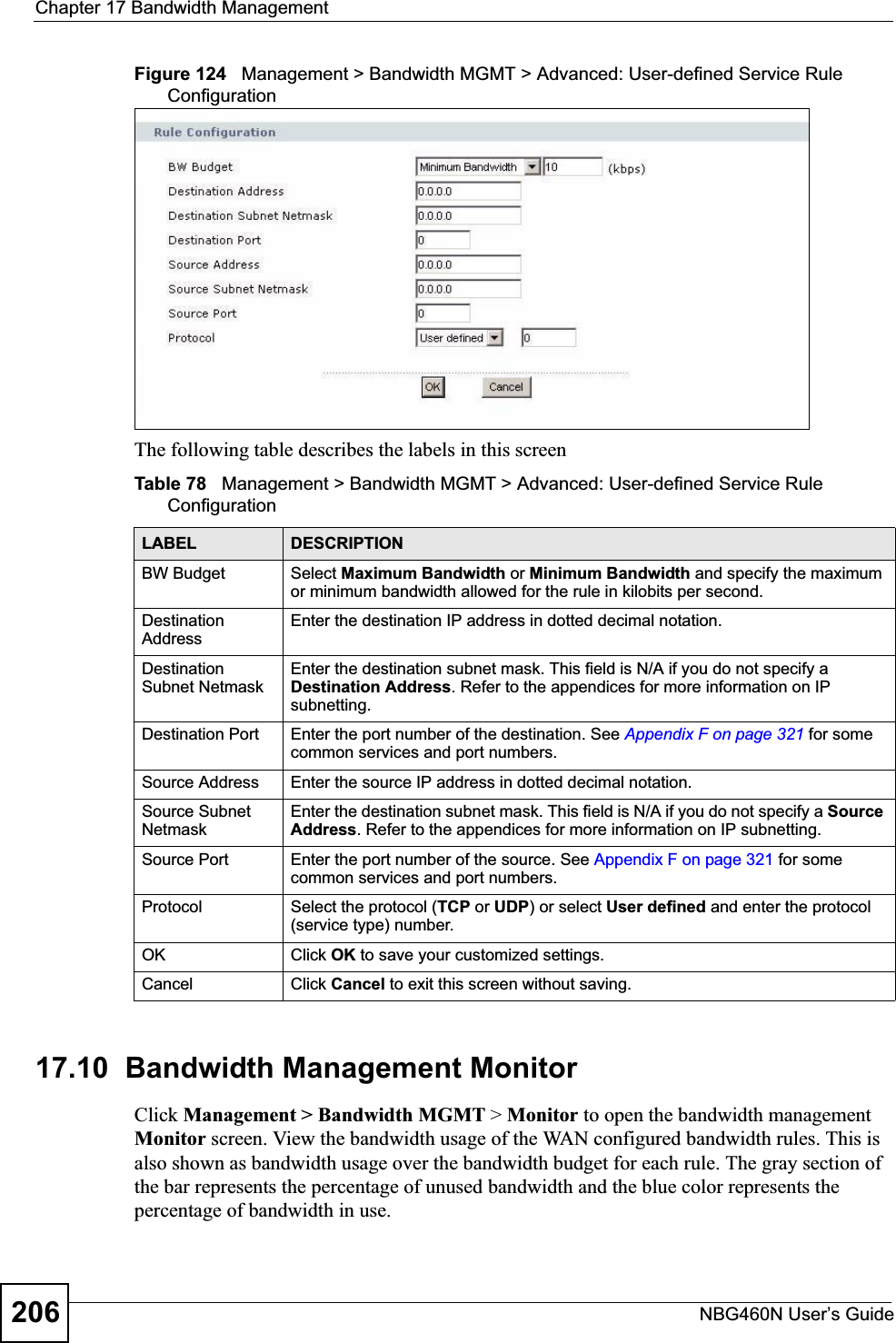
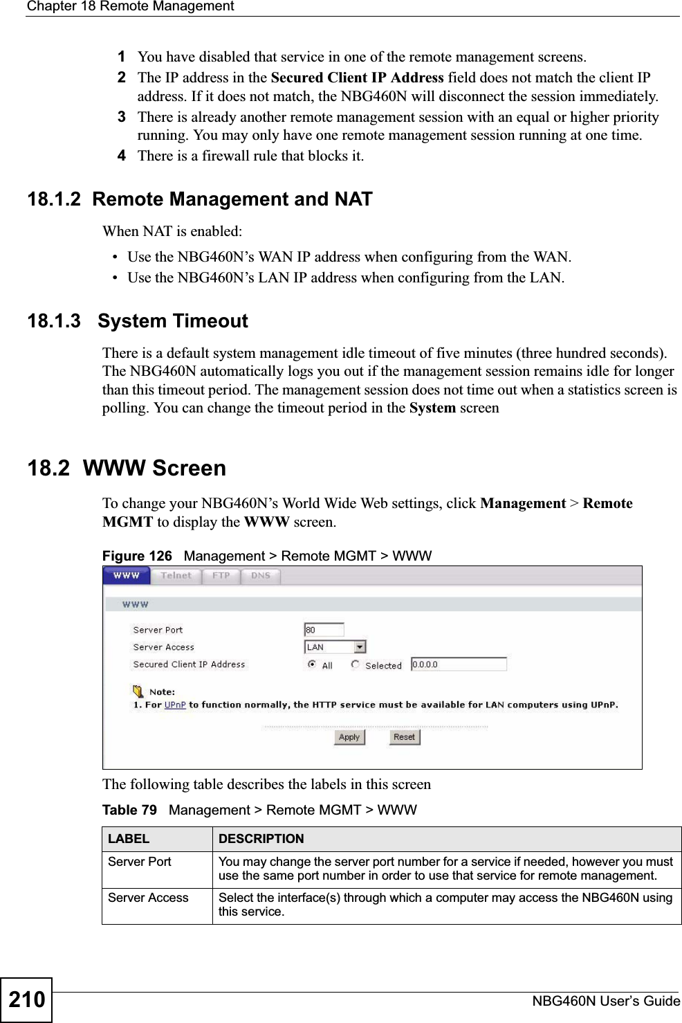
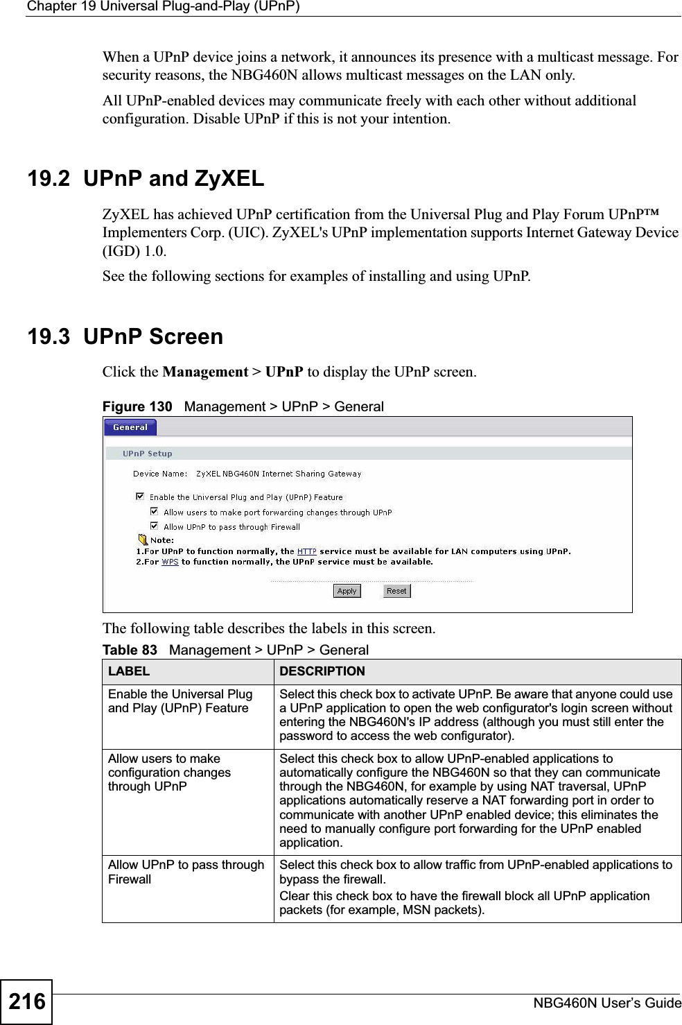
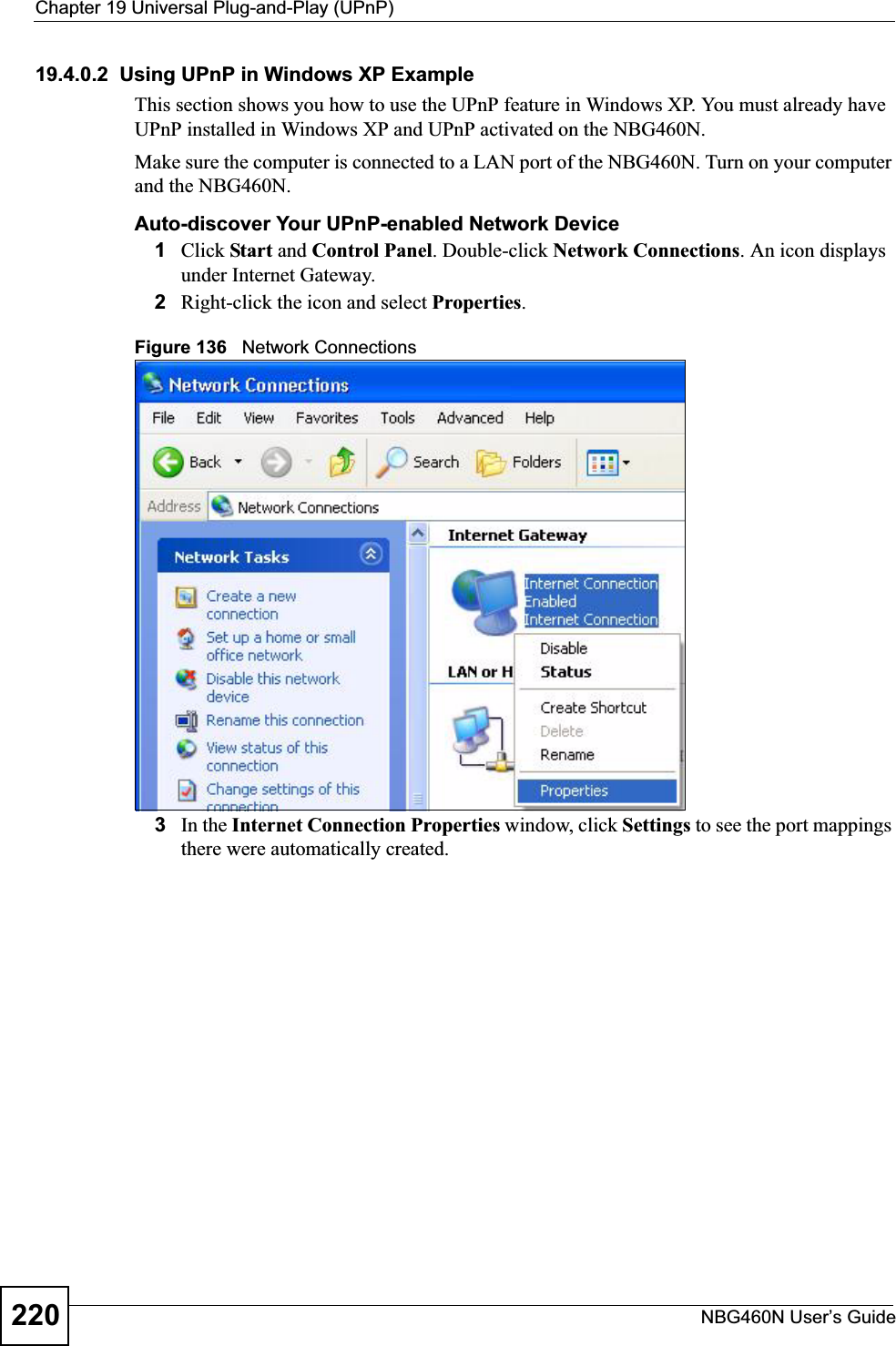
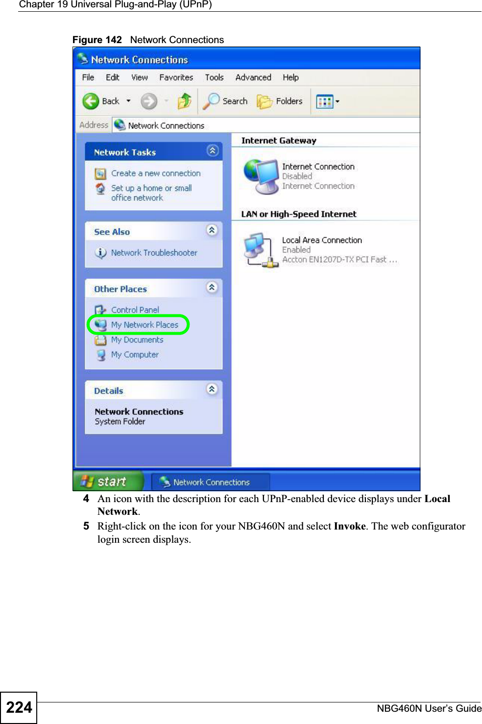
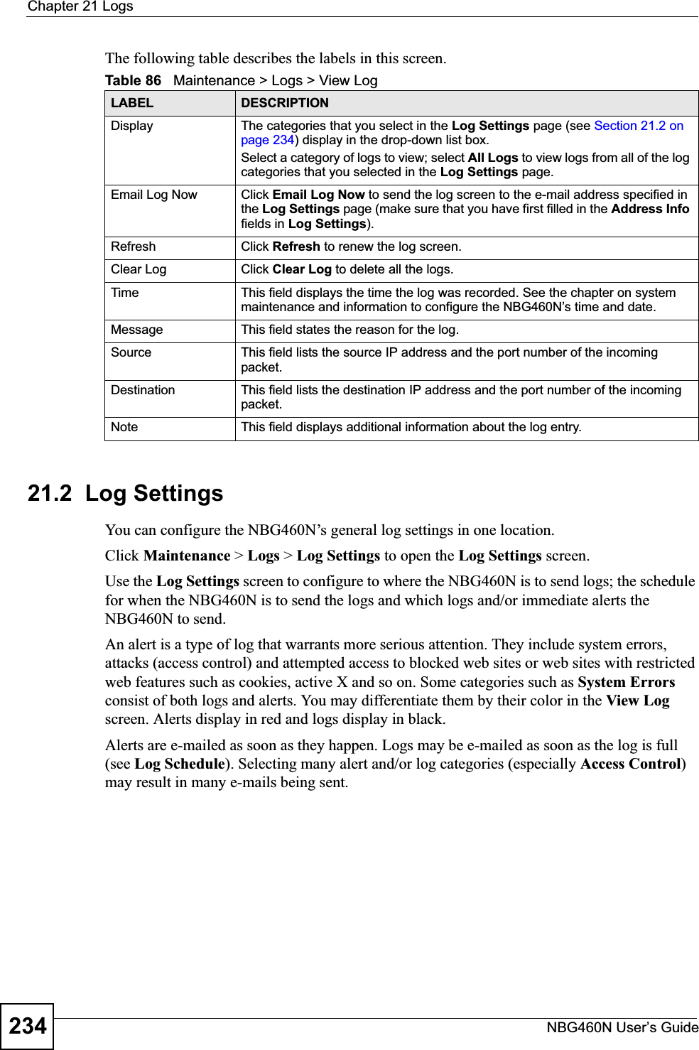
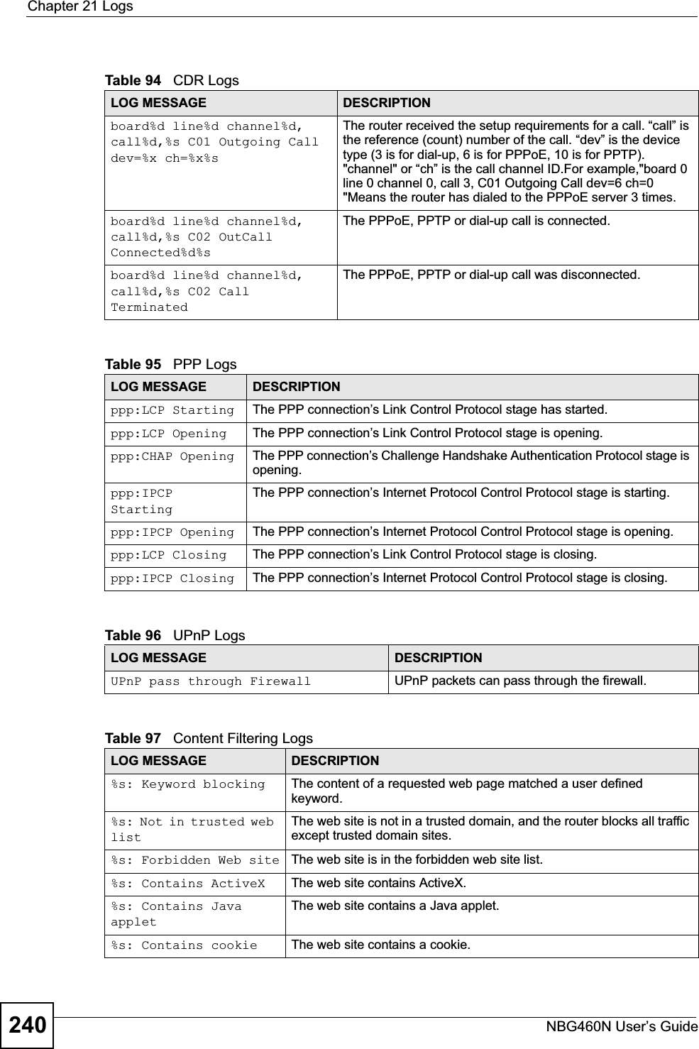
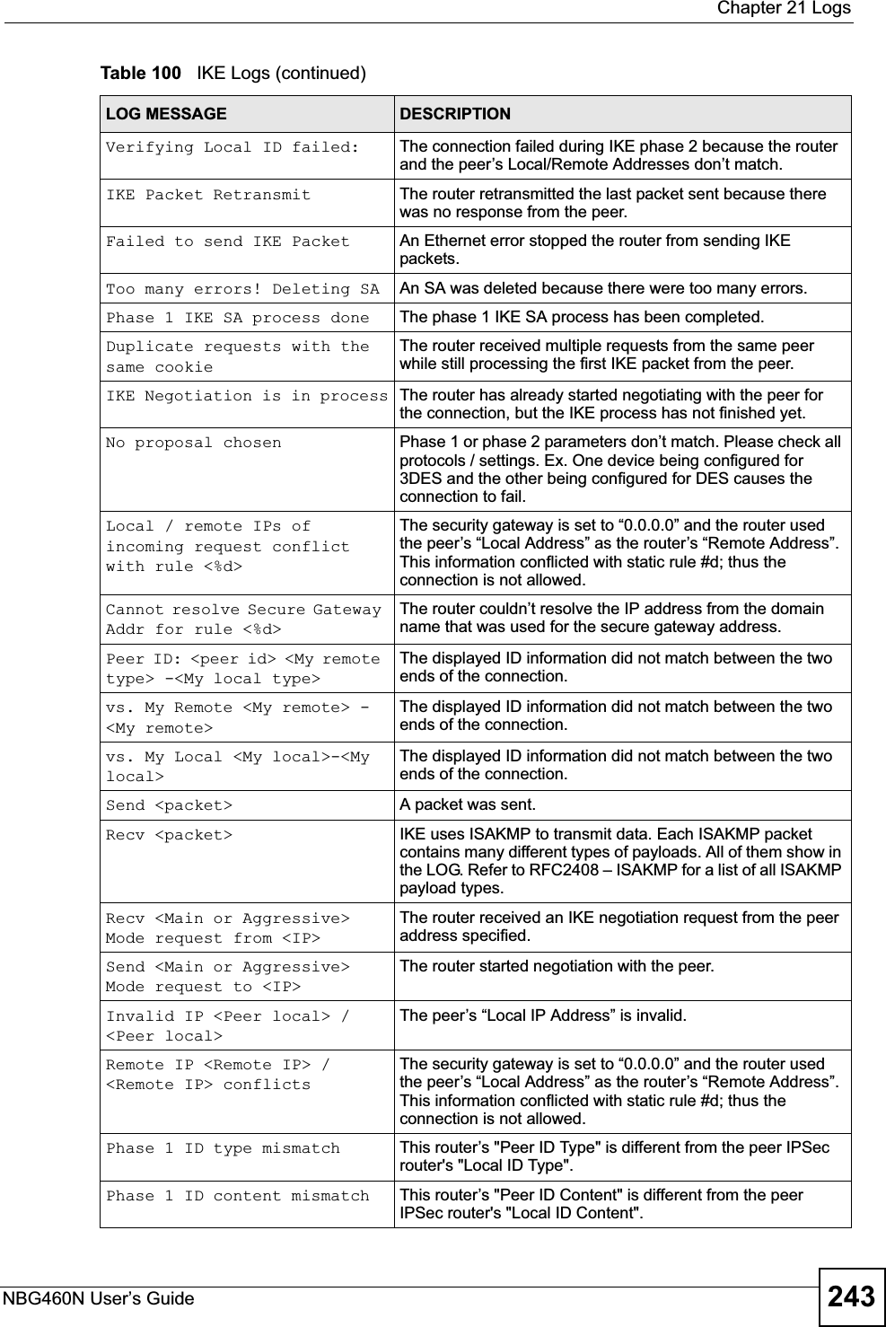
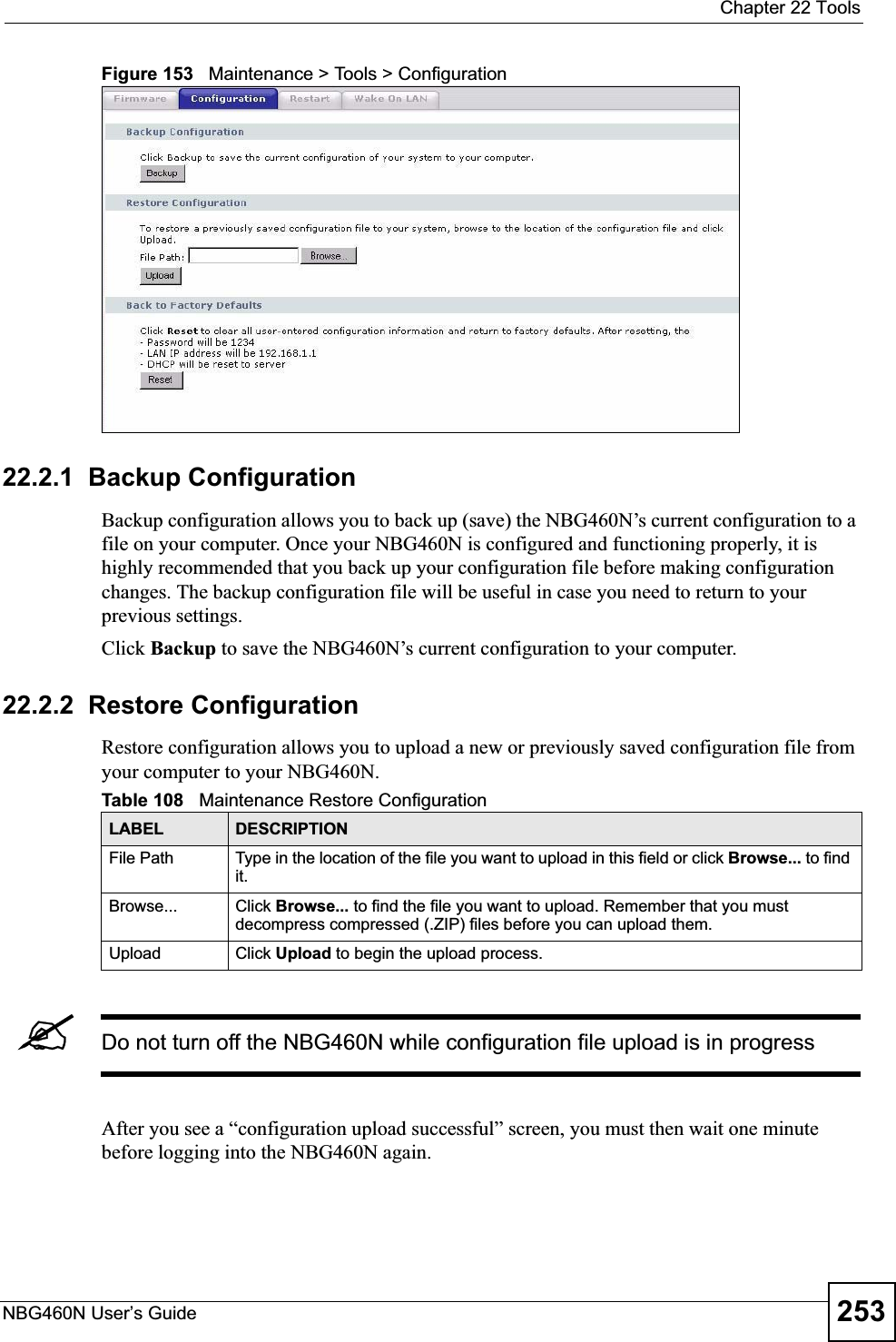
![Chapter 21 LogsNBG460N User’s Guide242teardrop UDP The firewall detected an UDP teardrop attack.teardrop ICMP (type:%d, code:%d)The firewall detected an ICMP teardrop attack. For type and code details, see Table 104 on page 247.illegal command TCP The firewall detected a TCP illegal command attack.NetBIOS TCP The firewall detected a TCP NetBIOS attack.ip spoofing - no routing entry [TCP | UDP | IGMP | ESP | GRE | OSPF]The firewall classified a packet with no source routing entry as an IP spoofing attack.ip spoofing - no routing entry ICMP (type:%d, code:%d)The firewall classified an ICMP packet with no source routing entry as an IP spoofing attack.vulnerability ICMP (type:%d, code:%d)The firewall detected an ICMP vulnerability attack. For type and code details, see Table 104 on page 247.traceroute ICMP (type:%d, code:%d)The firewall detected an ICMP traceroute attack. For type and code details, see Table 104 on page 247.Table 99 IPSec LogsLOG MESSAGE DESCRIPTIONDiscard REPLAY packet The router received and discarded a packet with an incorrect sequence number.Inbound packet authentication failedThe router received a packet that has been altered. A third party may have altered or tampered with the packet.Receive IPSec packet, but no corresponding tunnel existsThe router dropped an inbound packet for which SPI could not find a corresponding phase 2 SA.Rule <%d> idle time out, disconnectThe router dropped a connection that had outbound traffic and no inbound traffic for a certain time period. You can use the "ipsec timer chk_conn" CI command to set the time period. The default value is 2 minutes.WAN IP changed to <IP> The router dropped all connections with the “MyIP” configured as “0.0.0.0” when the WAN IP address changed.Table 100 IKE LogsLOG MESSAGE DESCRIPTIONActive connection allowed exceededThe IKE process for a new connection failed because the limit of simultaneous phase 2 SAs has been reached.Start Phase 2: Quick Mode Phase 2 Quick Mode has started.Verifying Remote ID failed: The connection failed during IKE phase 2 because the router and the peer’s Local/Remote Addresses don’t match.Table 98 Attack Logs (continued)LOG MESSAGE DESCRIPTION](https://usermanual.wiki/ZyXEL-Communications/X550NH.Users-manual-part3/User-Guide-939019-Page-42.png)
![Chapter 21 LogsNBG460N User’s Guide244No known phase 1 ID type foundThe router could not find a known phase 1 ID in the connection attempt.ID type mismatch. Local / Peer: <Local ID type/Peer ID type>The phase 1 ID types do not match.ID content mismatch The phase 1 ID contents do not match.Configured Peer ID Content: <Configured Peer ID Content>The phase 1 ID contents do not match and the configured "Peer ID Content" is displayed.Incoming ID Content: <Incoming Peer ID Content>The phase 1 ID contents do not match and the incoming packet's ID content is displayed.Unsupported local ID Type: <%d>The phase 1 ID type is not supported by the router.Build Phase 1 ID The router has started to build the phase 1 ID.Adjust TCP MSS to%d The router automatically changed the TCP Maximum Segment Size value after establishing a tunnel.Rule <%d> input idle time out, disconnectThe tunnel for the listed rule was dropped because there was no inbound traffic within the idle timeout period.XAUTH succeed! Username: <Username>The router used extended authentication to authenticate the listed username.XAUTH fail! Username: <Username>The router was not able to use extended authentication to authenticate the listed username.Rule[%d] Phase 1 negotiation mode mismatchThe listed rule’s IKE phase 1 negotiation mode did not match between the router and the peer.Rule [%d] Phase 1 encryption algorithm mismatchThe listed rule’s IKE phase 1 encryption algorithm did not match between the router and the peer.Rule [%d] Phase 1 authentication algorithm mismatchThe listed rule’s IKE phase 1 authentication algorithm did not match between the router and the peer.Rule [%d] Phase 1 authentication method mismatchThe listed rule’s IKE phase 1 authentication method did not match between the router and the peer.Rule [%d] Phase 1 key group mismatchThe listed rule’s IKE phase 1 key group did not match between the router and the peer.Rule [%d] Phase 2 protocol mismatchThe listed rule’s IKE phase 2 protocol did not match between the router and the peer.Rule [%d] Phase 2 encryption algorithm mismatchThe listed rule’s IKE phase 2 encryption algorithm did not match between the router and the peer.Rule [%d] Phase 2 authentication algorithm mismatchThe listed rule’s IKE phase 2 authentication algorithm did not match between the router and the peer.Rule [%d] Phase 2 encapsulation mismatchThe listed rule’s IKE phase 2 encapsulation did not match between the router and the peer.Rule [%d]> Phase 2 pfs mismatchThe listed rule’s IKE phase 2 perfect forward secret (pfs) setting did not match between the router and the peer.Table 100 IKE Logs (continued)LOG MESSAGE DESCRIPTION](https://usermanual.wiki/ZyXEL-Communications/X550NH.Users-manual-part3/User-Guide-939019-Page-44.png)
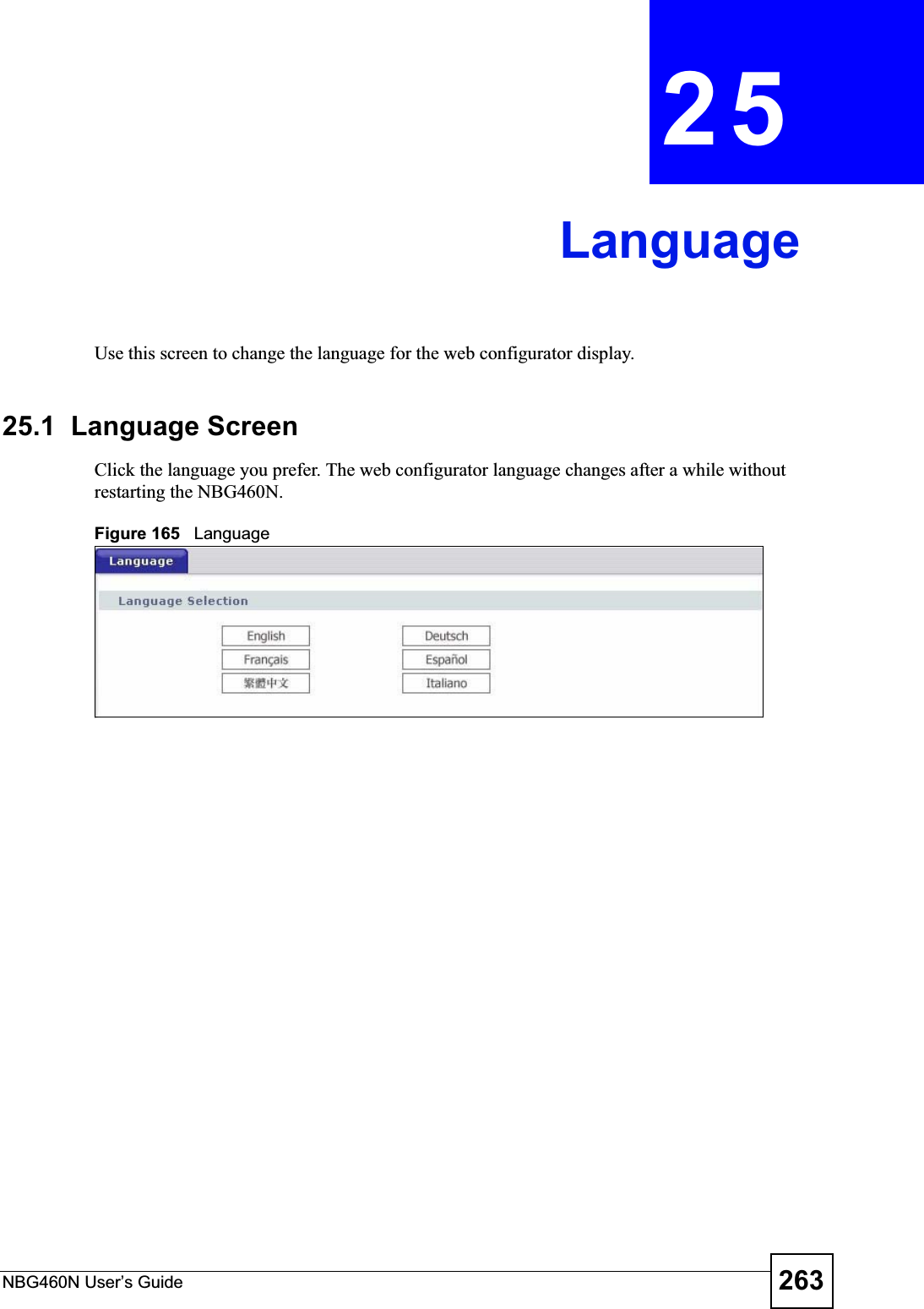
![Chapter 21 LogsNBG460N User’s Guide 245Rule [%d] Phase 1 ID mismatch The listed rule’s IKE phase 1 ID did not match between the router and the peer.Rule [%d] Phase 1 hash mismatchThe listed rule’s IKE phase 1 hash did not match between the router and the peer.Rule [%d] Phase 1 preshared key mismatchThe listed rule’s IKE phase 1 pre-shared key did not match between the router and the peer.Rule [%d] Tunnel built successfullyThe listed rule’s IPSec tunnel has been built successfully.Rule [%d] Peer's public key not foundThe listed rule’s IKE phase 1 peer’s public key was not found.Rule [%d] Verify peer's signature failedThe listed rule’s IKE phase 1verification of the peer’s signature failed.Rule [%d] Sending IKE request IKE sent an IKE request for the listed rule.Rule [%d] Receiving IKE requestIKE received an IKE request for the listed rule.Swap rule to rule [%d] The router changed to using the listed rule.Rule [%d] Phase 1 key length mismatchThe listed rule’s IKE phase 1 key length (with the AES encryption algorithm) did not match between the router and the peer.Rule [%d] phase 1 mismatch The listed rule’s IKE phase 1 did not match between the router and the peer.Rule [%d] phase 2 mismatch The listed rule’s IKE phase 2 did not match between the router and the peer.Rule [%d] Phase 2 key length mismatchThe listed rule’s IKE phase 2 key lengths (with the AES encryption algorithm) did not match between the router and the peer.Table 101 PKI LogsLOG MESSAGE DESCRIPTIONEnrollment successful The SCEP online certificate enrollment was successful. The Destination field records the certification authority server IP address and port.Enrollment failed The SCEP online certificate enrollment failed. The Destination field records the certification authority server’s IP address and port.Failed to resolve <SCEP CA server url>The SCEP online certificate enrollment failed because the certification authority server’s address cannot be resolved.Enrollment successful The CMP online certificate enrollment was successful. The Destination field records the certification authority server’s IP address and port.Enrollment failed The CMP online certificate enrollment failed. The Destination field records the certification authority server’s IP address and port.Failed to resolve <CMP CA server url>The CMP online certificate enrollment failed because the certification authority server’s IP address cannot be resolved.Rcvd ca cert: <subject name>The router received a certification authority certificate, with subject name as recorded, from the LDAP server whose IP address and port are recorded in the Source field.Table 100 IKE Logs (continued)LOG MESSAGE DESCRIPTION](https://usermanual.wiki/ZyXEL-Communications/X550NH.Users-manual-part3/User-Guide-939019-Page-45.png)


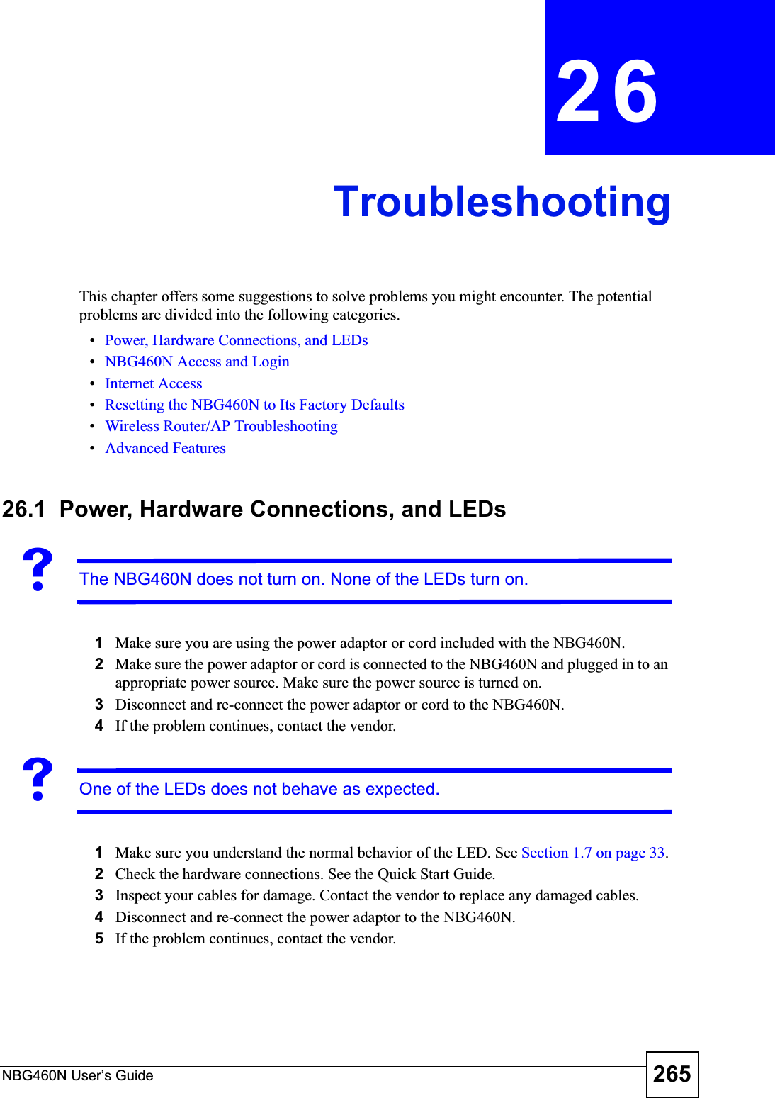
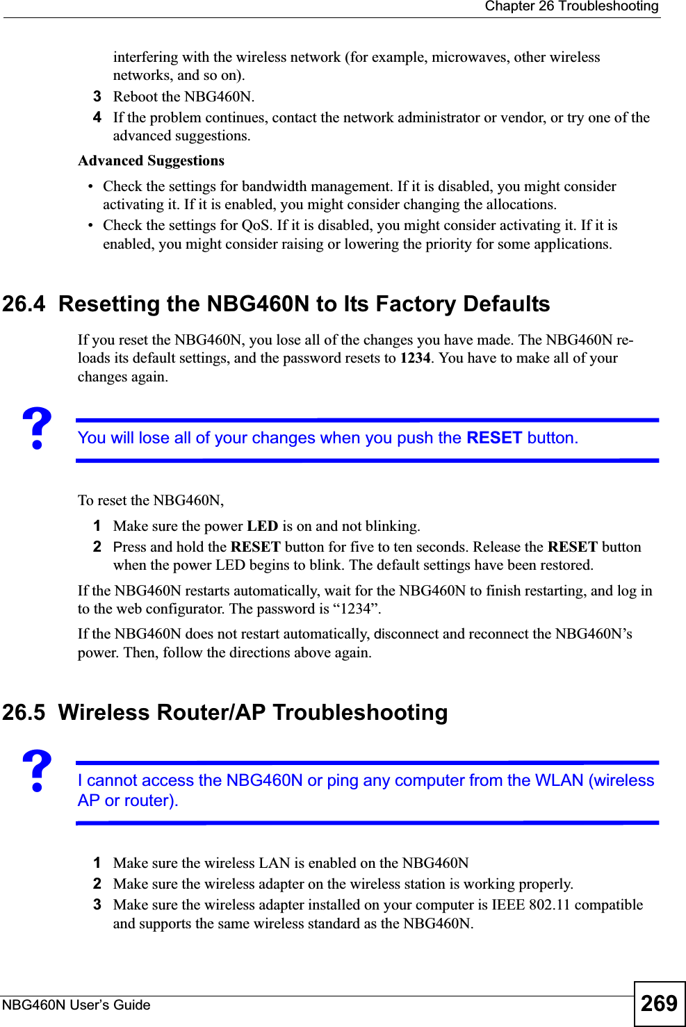
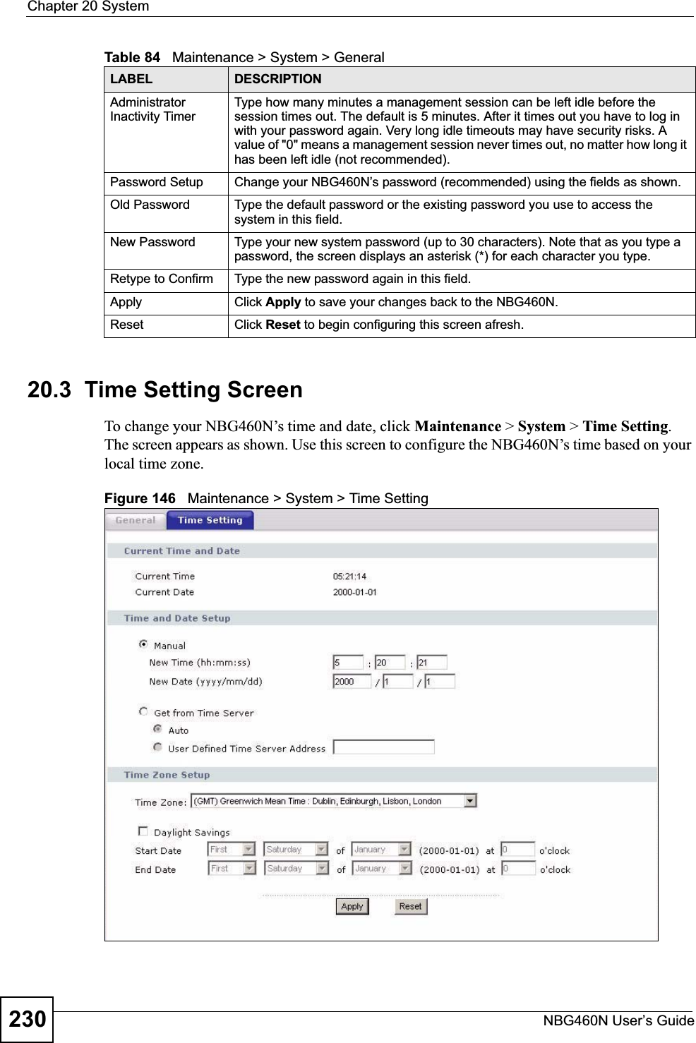
![Chapter 26 TroubleshootingNBG460N User’s Guide 2672Check the hardware connections, and make sure the LEDs are behaving as expected. See the Quick Start Guide. 3Make sure your Internet browser does not block pop-up windows and has JavaScripts and Java enabled. See Appendix B on page 279.4Make sure your computer is in the same subnet as the NBG460N. (If you know that there are routers between your computer and the NBG460N, skip this step.)• If there is a DHCP server on your network, make sure your computer is using a dynamic IP address. See Section 7.3 on page 102.• If there is no DHCP server on your network, make sure your computer’s IP address is in the same subnet as the NBG460N. See Section 7.3 on page 102.5Reset the device to its factory defaults, and try to access the NBG460N with the default IP address. See Section 7.3 on page 102.6If the problem continues, contact the network administrator or vendor, or try one of the advanced suggestions.Advanced Suggestions• Try to access the NBG460N using another service, such as Telnet. If you can access the NBG460N, check the remote management settings and firewall rules to find out why the NBG460N does not respond to HTTP.• If your computer is connected to the WA N port or is connected wirelessly, use a computer that is connected to a LAN/ETHERNET port.VI can see the Login screen, but I cannot log in to the NBG460N.1Make sure you have entered the password correctly. The default password is 1234. This field is case-sensitive, so make sure [Caps Lock] is not on. 2You cannot log in to the web configurator while someone is using Telnet to access the NBG460N. Log out of the NBG460N in the other session, or ask the person who is logged in to log out. 3Disconnect and re-connect the power adaptor or cord to the NBG460N. 4If this does not work, you have to reset the device to its factory defaults. See Section26.4 on page 269.VI cannot Telnet to the NBG460N.See the troubleshooting suggestions for I cannot see or access the Login screen in the web configurator. Ignore the suggestions about your browser.VI cannot use FTP to upload / download the configuration file. / I cannot use FTP to upload new firmware.](https://usermanual.wiki/ZyXEL-Communications/X550NH.Users-manual-part3/User-Guide-939019-Page-67.png)
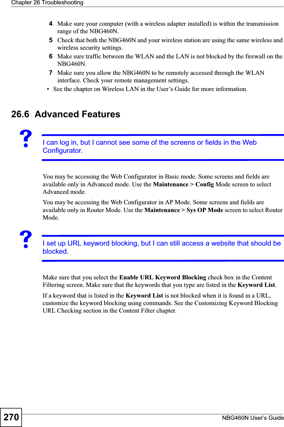
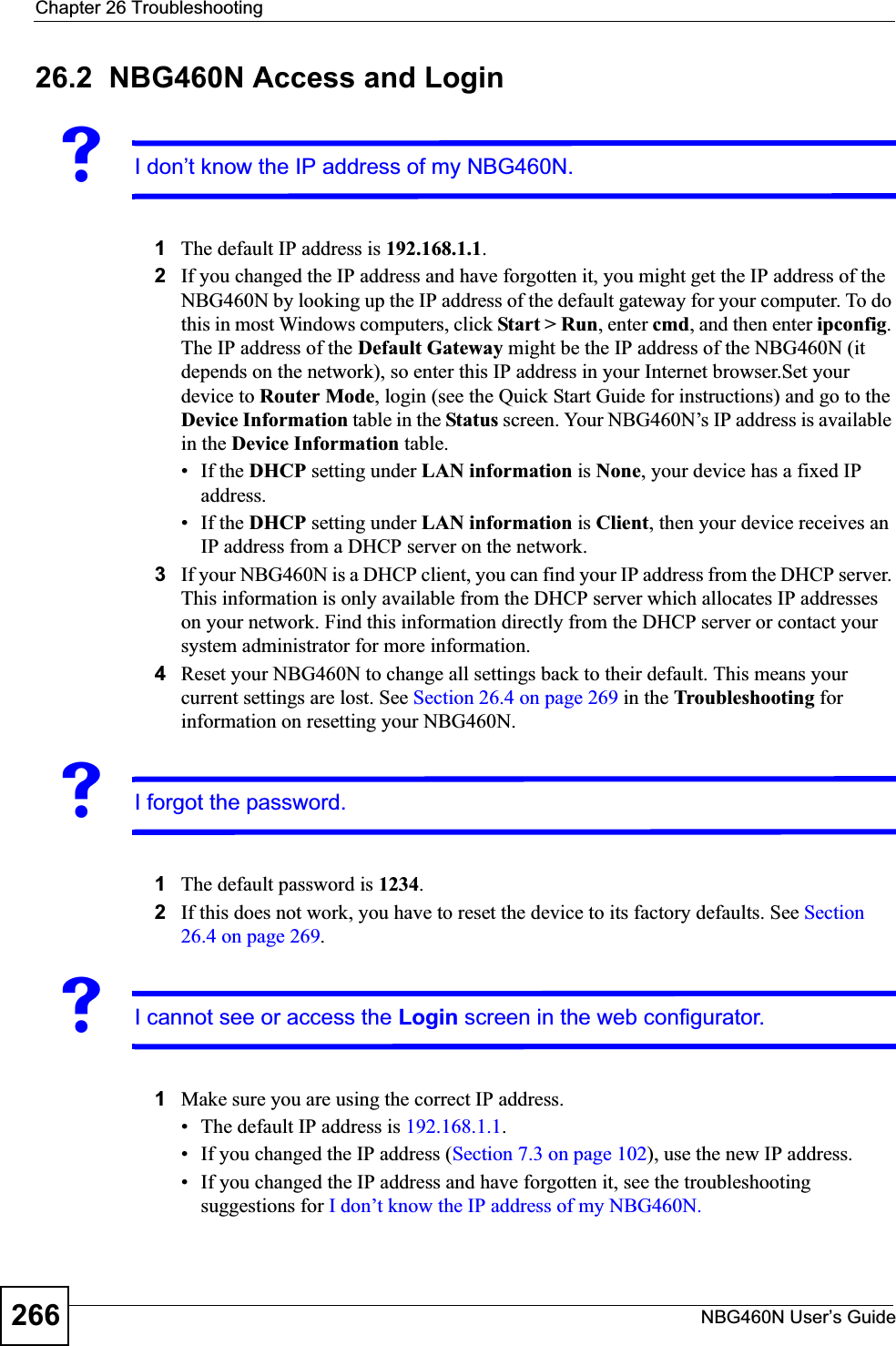
![Chapter 26 TroubleshootingNBG460N User’s Guide268See the troubleshooting suggestions for I cannot see or access the Login screen in the web configurator. Ignore the suggestions about your browser.26.3 Internet AccessVI cannot access the Internet.1Check the hardware connections, and make sure the LEDs are behaving as expected. See the Quick Start Guide.2Make sure you entered your ISP account information correctly in the wizard. These fields are case-sensitive, so make sure [Caps Lock] is not on.3If you are trying to access the Internet wirelessly, make sure the wireless settings in the wireless client are the same as the settings in the AP.4Disconnect all the cables from your device, and follow the directions in the Quick Start Guide again. 5Go to Maintenance > Sys OP Mode > General. Check your System Operation Mode setting.• Select Router if your device routes traffic between a local network and another network such as the Internet. • Select Access Point if your device bridges traffic between clients on the same network. 6If the problem continues, contact your ISP.VI cannot access the Internet anymore. I had access to the Internet (with the NBG460N), but my Internet connection is not available anymore.1Check the hardware connections, and make sure the LEDs are behaving as expected. See the Quick Start Guide and Section 1.7 on page 33.2Reboot the NBG460N.3If the problem continues, contact your ISP. VThe Internet connection is slow or intermittent.1There might be a lot of traffic on the network. Look at the LEDs, and check Section 1.7 on page 33. If the NBG460N is sending or receiving a lot of information, try closing some programs that use the Internet, especially peer-to-peer applications.2Check the signal strength. If the signal strength is low, try moving the NBG460N closer to the AP if possible, and look around to see if there are any devices that might be](https://usermanual.wiki/ZyXEL-Communications/X550NH.Users-manual-part3/User-Guide-939019-Page-68.png)