ZyXEL Communications X550NH Wireless Gigabit Router User Manual NBG334W User Guide
ZyXEL Communications Corporation Wireless Gigabit Router NBG334W User Guide
Contents
- 1. Users manual part1
- 2. Users manual part2
- 3. Users manual part3
- 4. Users manual part4
Users manual part4


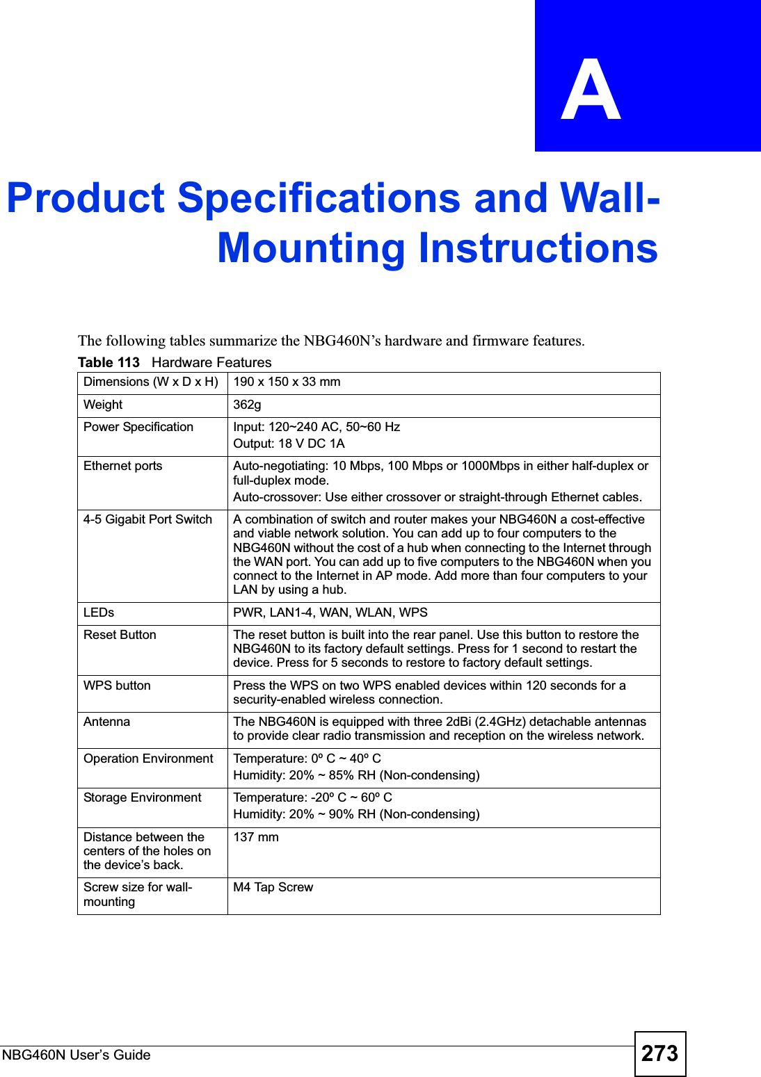
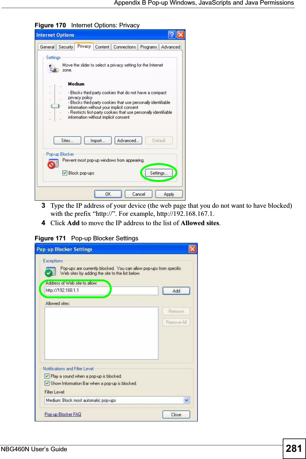

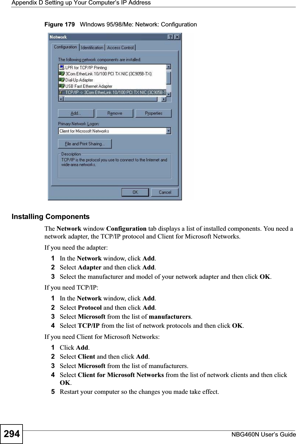
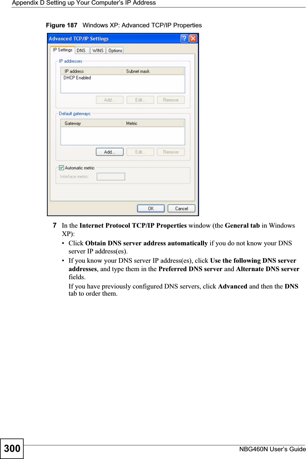
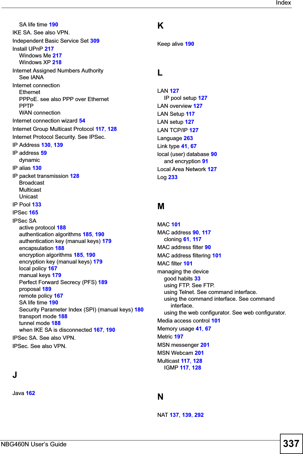
![Appendix D Setting up Your Computer’s IP AddressNBG460N User’s Guide 301Figure 188 Windows XP: Internet Protocol (TCP/IP) Properties8Click OK to close the Internet Protocol (TCP/IP) Properties window.9Click Close (OK in Windows 2000/NT) to close the Local Area Connection Properties window.10 Close the Network Connections window (Network and Dial-up Connections in Windows 2000/NT).11 Turn on your Prestige and restart your computer (if prompted).Verifying Settings1Click Start,All Programs,Accessories and then Command Prompt.2In the Command Prompt window, type "ipconfig" and then press [ENTER]. You can also open Network Connections, right-click a network connection, click Status and then click the Support tab.Macintosh OS 8/9 1Click the Apple menu, Control Panel and double-click TCP/IP to open the TCP/IPControl Panel.](https://usermanual.wiki/ZyXEL-Communications/X550NH.Users-manual-part4/User-Guide-939020-Page-31.png)
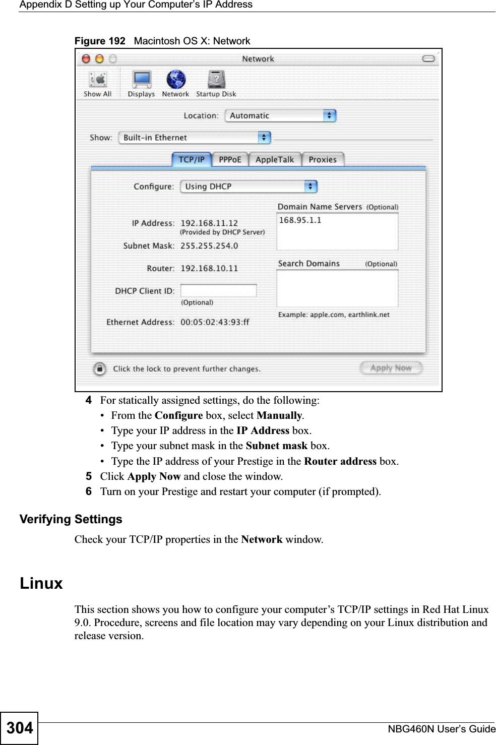
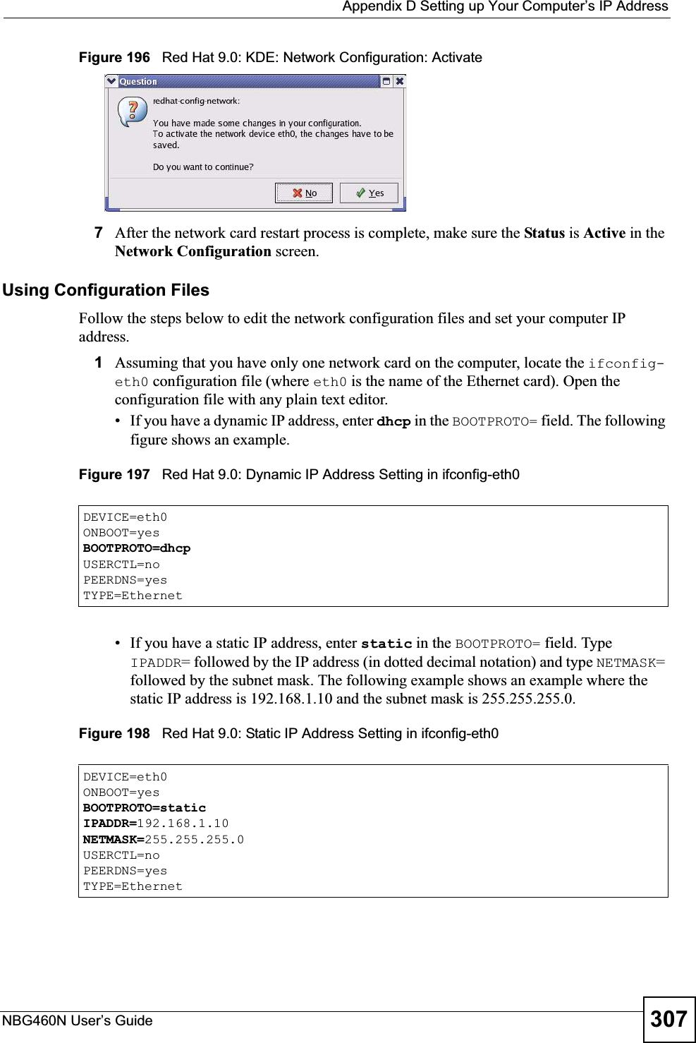
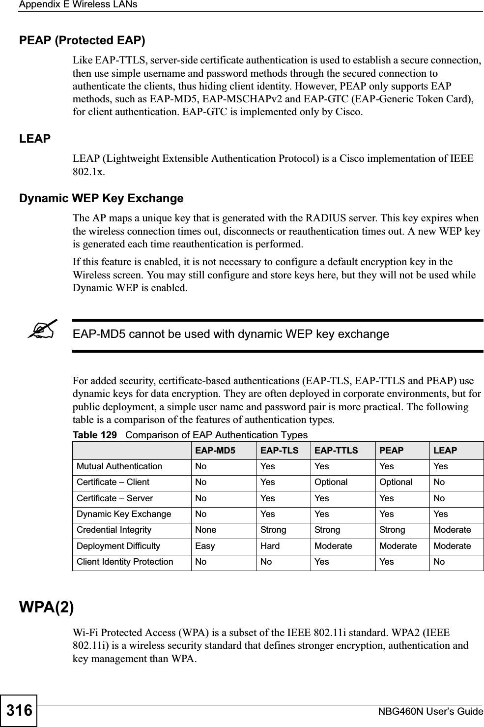
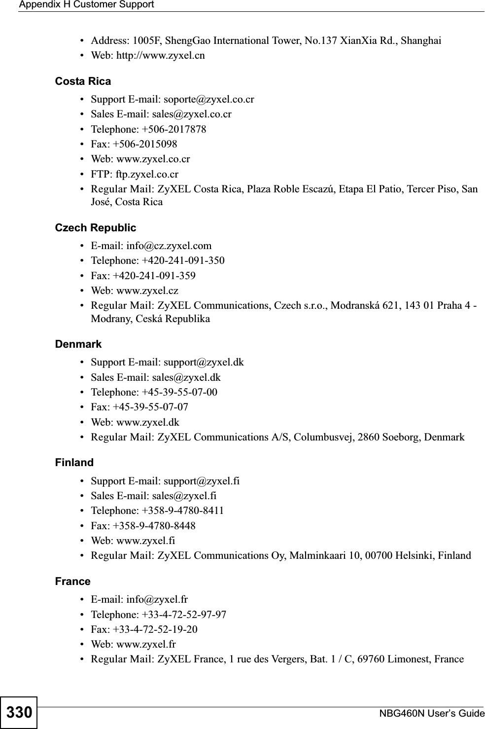
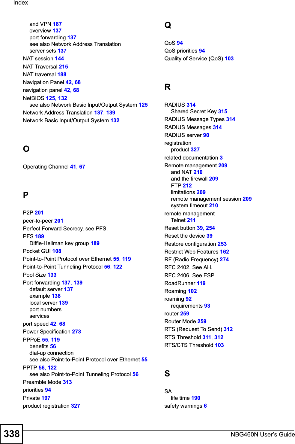
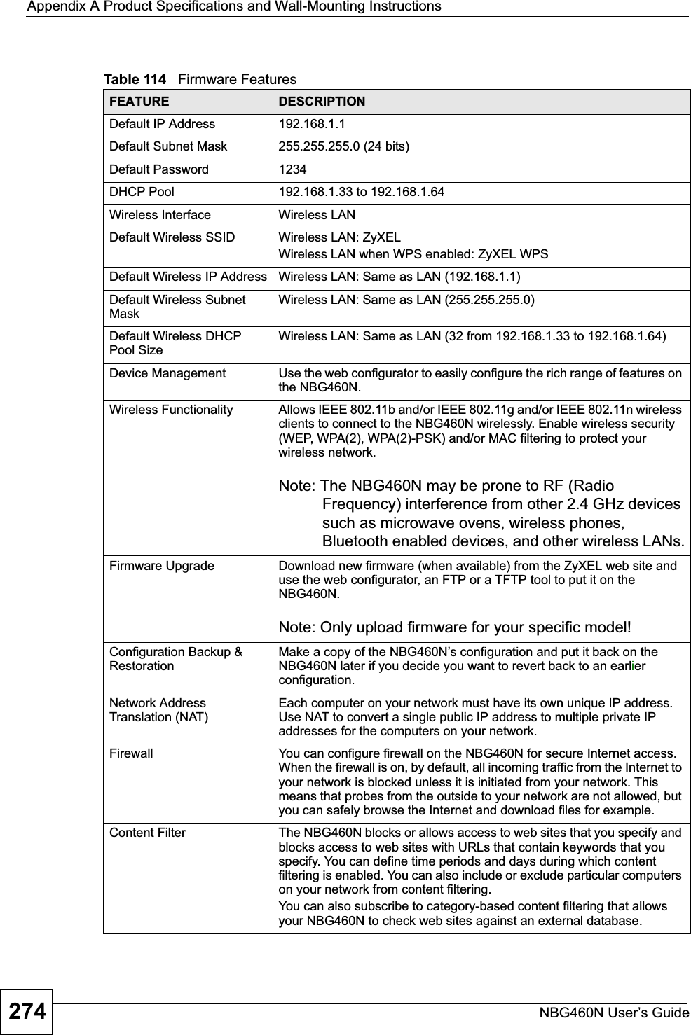
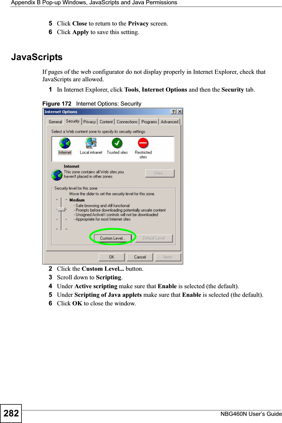
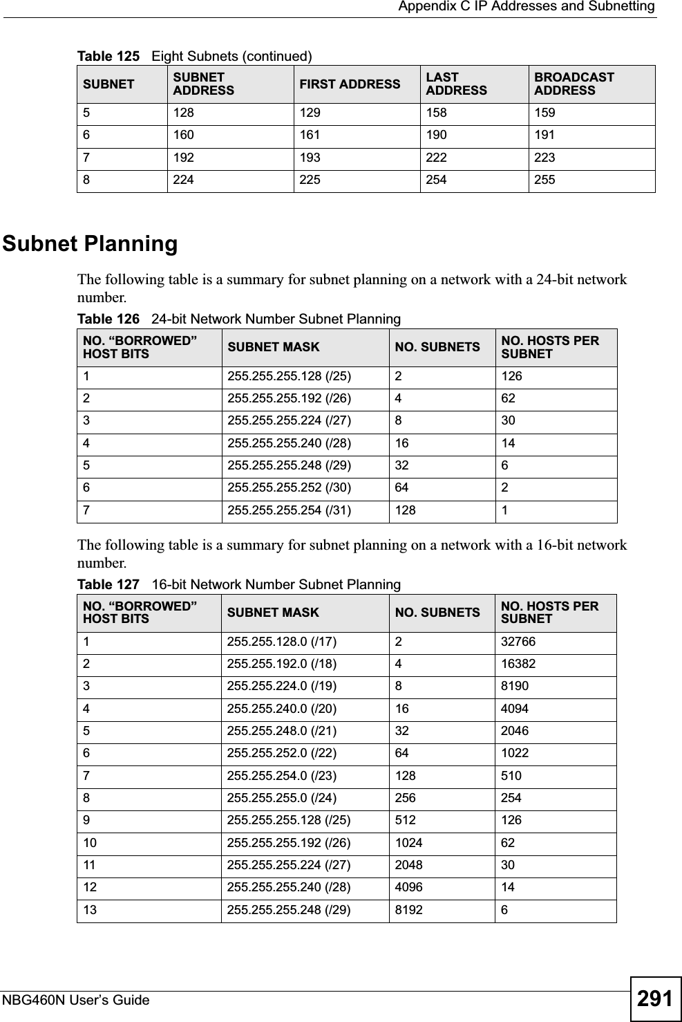
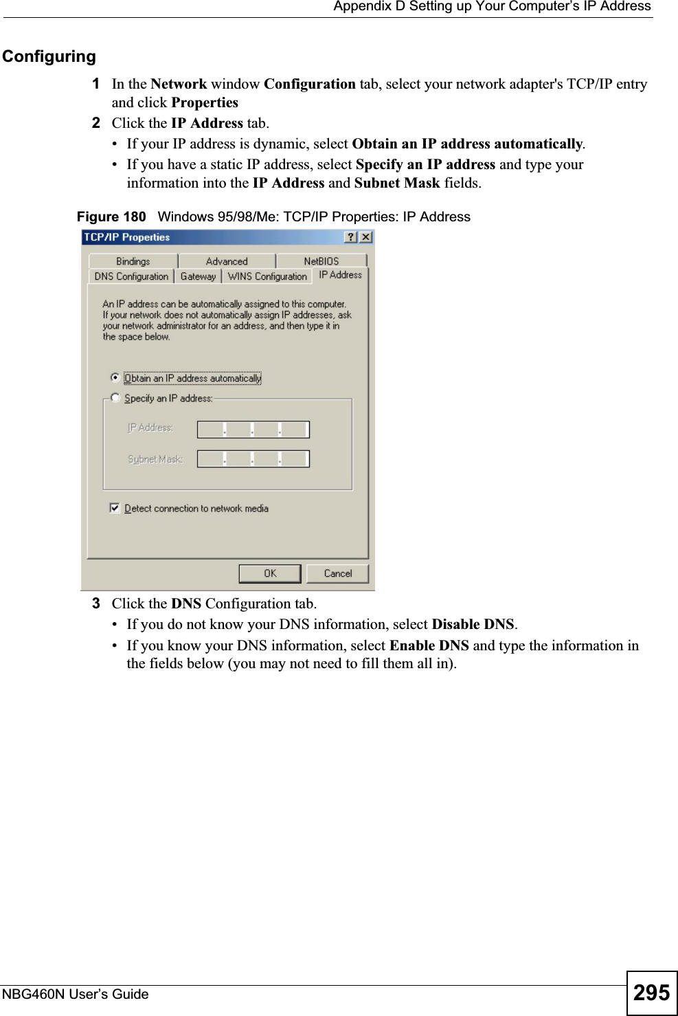
![Appendix D Setting up Your Computer’s IP AddressNBG460N User’s Guide3082If you know your DNS server IP address(es), enter the DNS server information in the resolv.conf file in the /etc directory. The following figure shows an example where two DNS server IP addresses are specified.Figure 199 Red Hat 9.0: DNS Settings in resolv.conf 3After you edit and save the configuration files, you must restart the network card. Enter./network restart in the /etc/rc.d/init.d directory. The following figure shows an example.Figure 200 Red Hat 9.0: Restart Ethernet Card 26.6.1 Verifying SettingsEnter ifconfig in a terminal screen to check your TCP/IP properties. Figure 201 Red Hat 9.0: Checking TCP/IP Properties nameserver 172.23.5.1nameserver 172.23.5.2[root@localhost init.d]# network restartShutting down interface eth0: [OK]Shutting down loopback interface: [OK]Setting network parameters: [OK]Bringing up loopback interface: [OK]Bringing up interface eth0: [OK][root@localhost]# ifconfig eth0 Link encap:Ethernet HWaddr 00:50:BA:72:5B:44 inet addr:172.23.19.129 Bcast:172.23.19.255 Mask:255.255.255.0 UP BROADCAST RUNNING MULTICAST MTU:1500 Metric:1 RX packets:717 errors:0 dropped:0 overruns:0 frame:0 TX packets:13 errors:0 dropped:0 overruns:0 carrier:0 collisions:0 txqueuelen:100 RX bytes:730412 (713.2 Kb) TX bytes:1570 (1.5 Kb) Interrupt:10 Base address:0x1000 [root@localhost]#](https://usermanual.wiki/ZyXEL-Communications/X550NH.Users-manual-part4/User-Guide-939020-Page-38.png)