ZyXEL Communications XMG3512-B10A Dual-Band Wireless AC/N VDSL2 Bonding Gateway with USB User Manual Book
ZyXEL Communications Corporation Dual-Band Wireless AC/N VDSL2 Bonding Gateway with USB Book
Contents
- 1. Users Manual-1
- 2. Users Manual-2
Users Manual-2
Chapter 20 Certificates
XMG3512-B10A User’s Guide
201
The following table describes the fields in this screen.
20.4.1 View Trusted CA Certificate
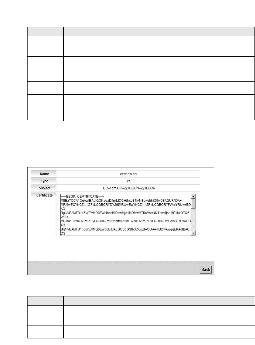
Click the View icon in the Trusted CA screen to open the following screen. Use this screen to view in-
depth information about the certification authority’s certificate.
Figure 126 Trusted CA: View
The following table describes the fields in this screen.
Table 95 Security > Certificates > Trusted CA
LABEL DESCRIPTION
Import
Certificate
Click this button to open a screen where you can save the certificate of a certification authority
that you trust to the XMG.
# This is the index number of the entry.
Name This field displays the name used to identify this certificate.
Subject This field displays information that identifies the owner of the certificate, such as Common Name
(CN), OU (Organizational Unit or department), Organization (O), State (ST) and Country (C). It is
recommended that each certificate have unique subject information.
Type This field displays general information about the certificate. ca means that a Certification
Authority signed the certificate.
Modify Click the View icon to open a screen with an in-depth list of information about the certificate (or
certification request).
Click the Remove button to delete the certificate (or certification request). You cannot delete a
certificate that one or more features is configured to use.
Table 96 Trusted CA: View
LABEL DESCRIPTION
Name This field displays the identifying name of this certificate.
Type This field displays general information about the certificate. ca means that a Certification
Authority signed the certificate.
Subject This field displays information that identifies the owner of the certificate, such as Common Name
(CN), Organizational Unit (OU), Organization (O) and Country (C).
Chapter 20 Certificates
XMG3512-B10A User’s Guide
202
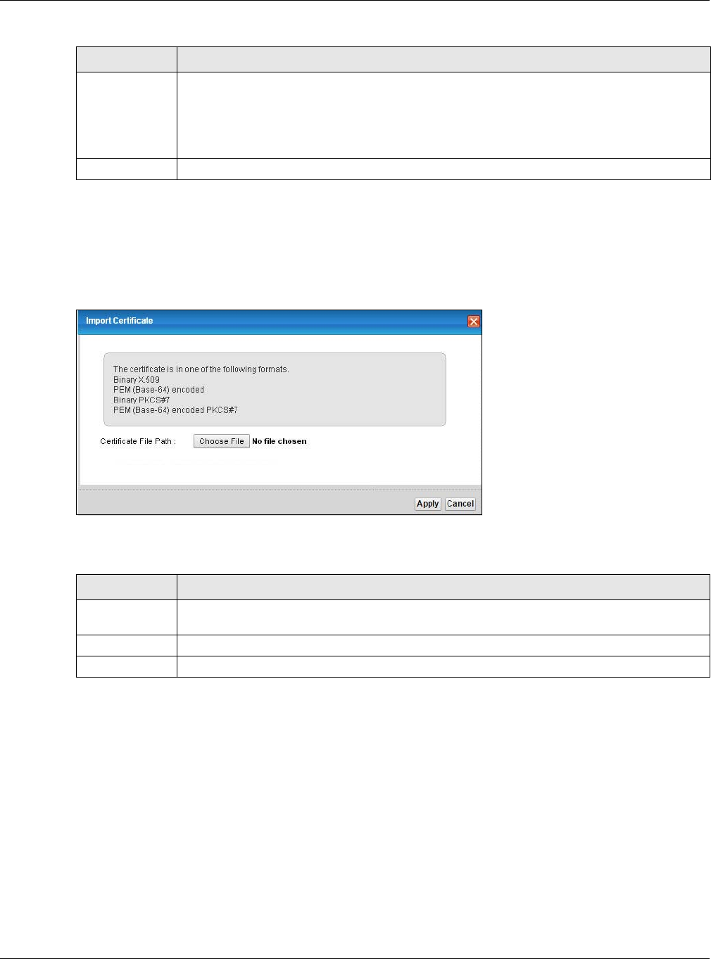
20.4.2 Import Trusted CA Certificate
Click the Import Certificate button in the Trusted CA screen to open the following screen. The XMG trusts
any valid certificate signed by any of the imported trusted CA certificates.
Figure 127 Trusted CA: Import Certificate
The following table describes the fields in this screen.
Certificate This read-only text box displays the certificate in Privacy Enhanced Mail (PEM) format. PEM uses
base 64 to convert the binary certificate into a printable form.
You can copy and paste the certificate into an e-mail to send to friends or colleagues or you
can copy and paste the certificate into a text editor and save the file on a management
computer for later distribution (via floppy disk for example).
Back Click Back to return to the previous screen.
Table 96 Trusted CA: View (continued)
LABEL DESCRIPTION
Table 97 Trusted CA: Import Certificate
LABEL DESCRIPTION
Certificate File
Path
Type in the location of the certificate you want to upload in this field or click Choose File to find
it.
Apply Click Apply to save your changes.
Cancel Click Cancel to exit this screen without saving.
XMG3512-B10A User’s Guide
203
CHAPTER 21
Log
21.1 Overview
The web configurator allows you to choose which categories of events and/or alerts to have the XMG
log and then display the logs or have the XMG send them to an administrator (as e-mail) or to a syslog
server.
21.1.1 What You Can Do in this Chapter
• Use the System Log screen to see the system logs (Section 21.2 on page 204).
• Use the Security Log screen to see the security-related logs for the categories that you select (Section
21.3 on page 204).
21.1.2 What You Need To Know
The following terms and concepts may help as you read this chapter.
Alerts and Logs
An alert is a type of log that warrants more serious attention. They include system errors, attacks (access
control) and attempted access to blocked web sites. Some categories such as System Errors consist of
both logs and alerts. You may differentiate them by their color in the View Log screen. Alerts display in
red and logs display in black.
Syslog Overview
The syslog protocol allows devices to send event notification messages across an IP network to syslog
servers that collect the event messages. A syslog-enabled device can generate a syslog message and
send it to a syslog server.
Syslog is defined in RFC 3164. The RFC defines the packet format, content and system log related
information of syslog messages. Each syslog message has a facility and severity level. The syslog facility
identifies a file in the syslog server. Refer to the documentation of your syslog program for details. The
following table describes the syslog severity levels.
Table 98 Syslog Severity Levels
CODE SEVERITY
0 Emergency: The system is unusable.
1 Alert: Action must be taken immediately.
2 Critical: The system condition is critical.
3 Error: There is an error condition on the system.
4 Warning: There is a warning condition on the system.
Chapter 21 Log
XMG3512-B10A User’s Guide
204
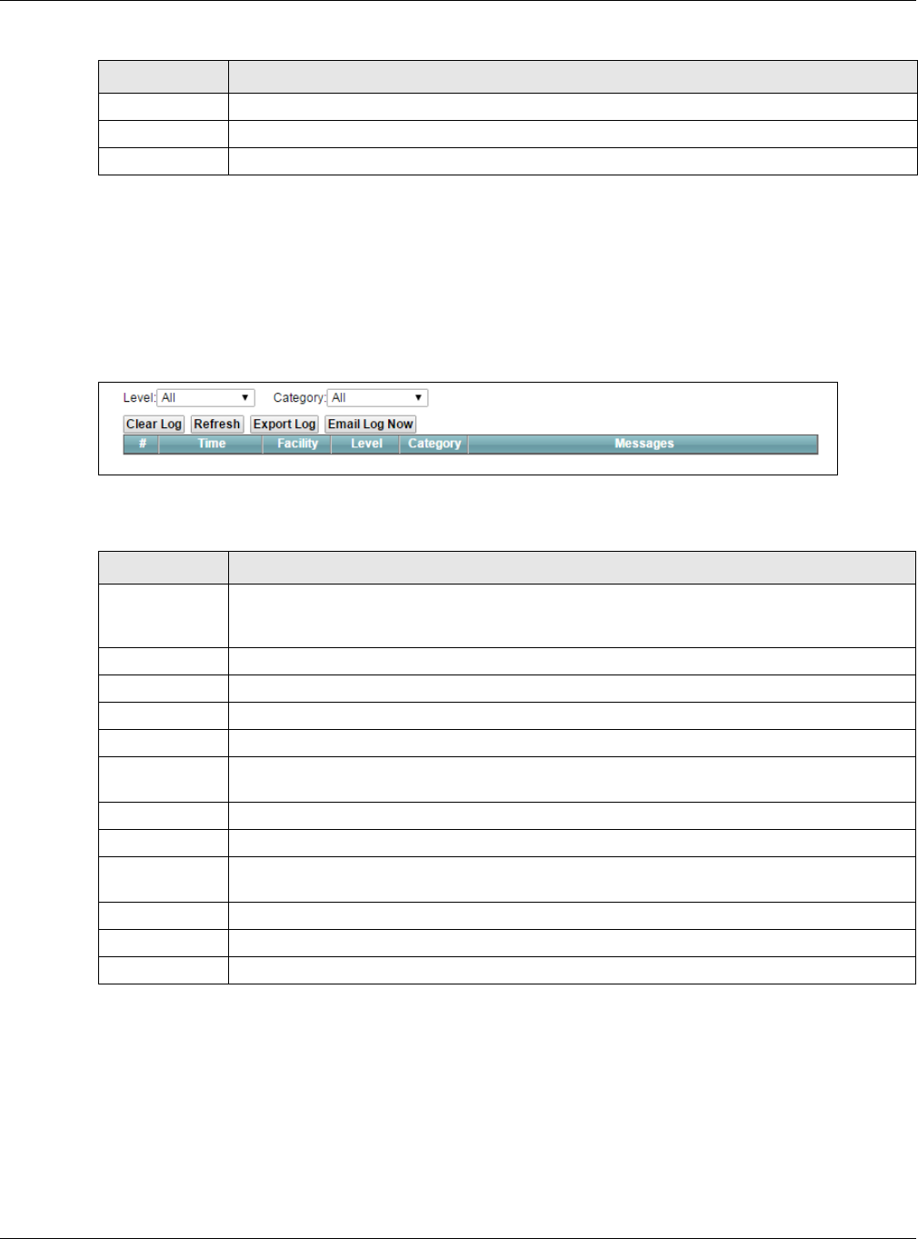
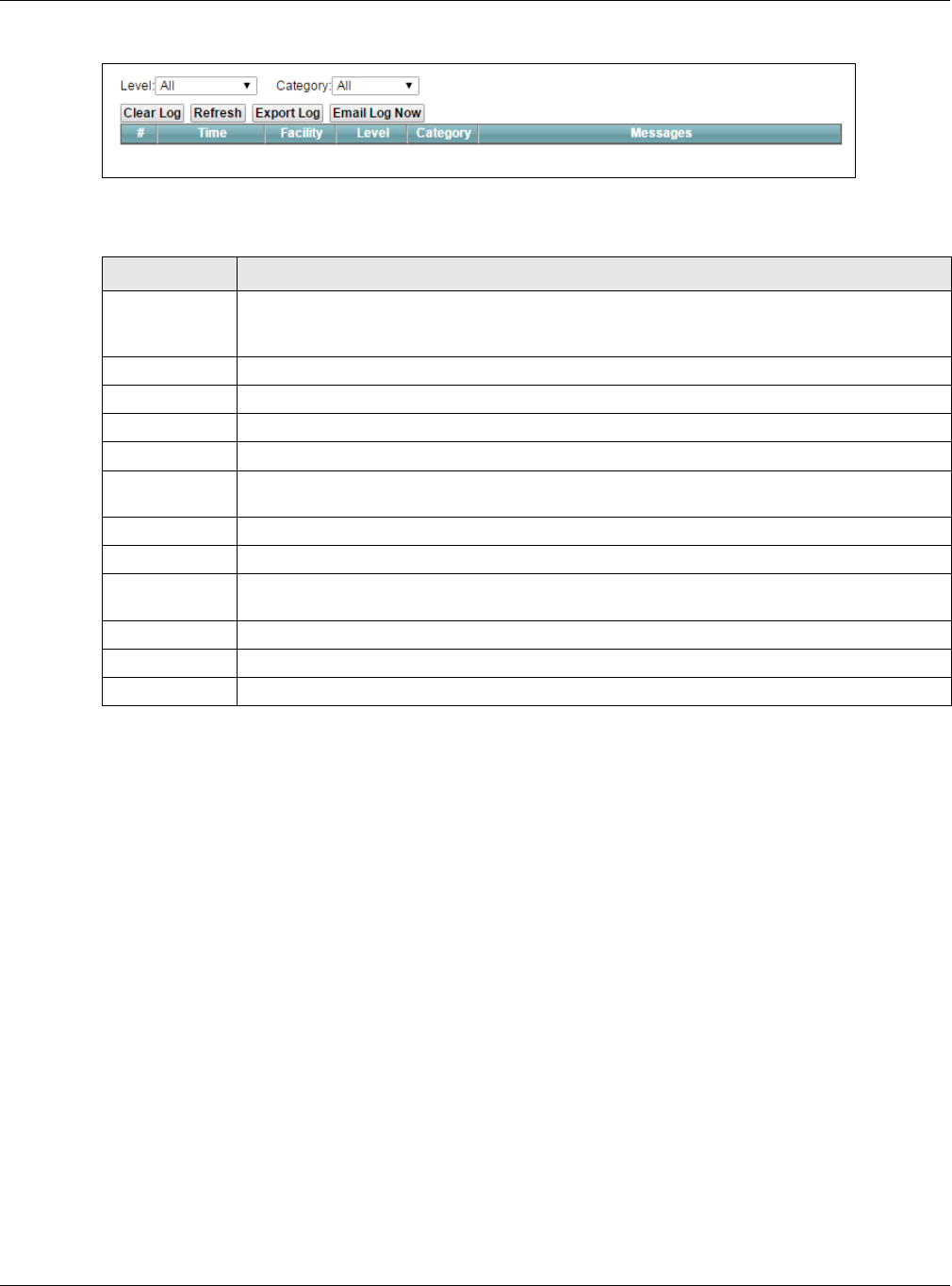
21.2 The System Log Screen
Use the System Log screen to see the system logs. Click System Monitor > Log to open the System Log
screen.
Figure 128 System Monitor > Log > System Log
The following table describes the fields in this screen.
21.3 The Security Log Screen
Use the Security Log screen to see the security-related logs for the categories that you select. Click
System Monitor > Log > Security Log to open the following screen.
5 Notice: There is a normal but significant condition on the system.
6 Informational: The syslog contains an informational message.
7 Debug: The message is intended for debug-level purposes.
Table 98 Syslog Severity Levels
CODE SEVERITY
Table 99 System Monitor > Log > System Log
LABEL DESCRIPTION
Level Select a severity level from the drop-down list box. This filters search results according to the
severity level you have selected. When you select a severity, the XMG searches through all logs
of that severity or higher.
Category Select the type of logs to display.
Clear Log Click this to delete all the logs.
Refresh Click this to renew the log screen.
Export Log Click this to export the selected log(s).
Email Log Now Click this to send the log file(s) to the E-mail address you specify in the Maintenance > Logs
Setting screen.
#This field is a sequential value and is not associated with a specific entry.
Time This field displays the time the log was recorded.
Facility The log facility allows you to send logs to different files in the syslog server. Refer to the
documentation of your syslog program for more details.
Level This field displays the severity level of the log that the device is to send to this syslog server.
Category This field displays the type of the log.
Messages This field states the reason for the log.
Chapter 21 Log
XMG3512-B10A User’s Guide
205
Figure 129 System Monitor > Log > Security Log
The following table describes the fields in this screen.
Table 100 System Monitor > Log > Security Log
LABEL DESCRIPTION
Level Select a severity level from the drop-down list box. This filters search results according to the
severity level you have selected. When you select a severity, the XMG searches through all logs
of that severity or higher.
Category Select the type of logs to display.
Clear Log Click this to delete all the logs.
Refresh Click this to renew the log screen.
Export Log Click this to export the selected log(s).
E-mail Log Now Click this to send the log file(s) to the E-mail address you specify in the Maintenance > Logs
Setting screen.
#This field is a sequential value and is not associated with a specific entry.
Time This field displays the time the log was recorded.
Facility The log facility allows you to send logs to different files in the syslog server. Refer to the
documentation of your syslog program for more details.
Level This field displays the severity level of the log that the device is to send to this syslog server.
Category This field displays the type of the log.
Messages This field states the reason for the log.
XMG3512-B10A User’s Guide
206
CHAPTER 22
Traffic Status
22.1 Overview
Use the Traffic Status screens to look at network traffic status and statistics of the WAN, LAN interfaces
and NAT.
22.1.1 What You Can Do in this Chapter
• Use the WAN screen to view the WAN traffic statistics (Section 22.2 on page 206).
• Use the LAN screen to view the LAN traffic statistics (Section 22.3 on page 207).
• Use the NAT screen to view the NAT status of the XMG’s client(s) (Section 22.4 on page 208)
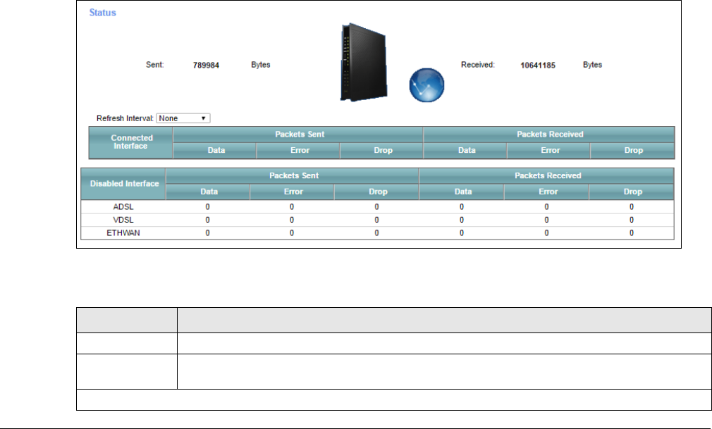
22.2 The WAN Status Screen
Click System Monitor > Traffic Status to open the WAN screen. The figure in this screen shows the number
of bytes received and sent on the XMG.
Figure 130 System Monitor > Traffic Status > WAN
The following table describes the fields in this screen.
Table 101 System Monitor > Traffic Status > WAN
LABEL DESCRIPTION
Refresh Interval Select how often you want the XMG to update this screen.
Connected
Interface
This shows the name of the WAN interface that is currently connected.
Packets Sent
Chapter 22 Traffic Status
XMG3512-B10A User’s Guide
207
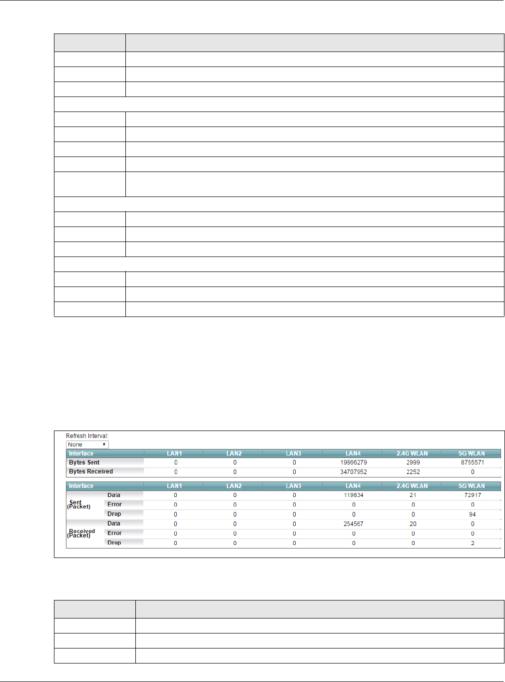
22.3 The LAN Status Screen
Click System Monitor > Traffic Status > LAN to open the following screen. The figure in this screen shows
the interface that is currently connected on the XMG.
Figure 131 System Monitor > Traffic Status > LAN
The following table describes the fields in this screen.
Data This indicates the number of transmitted packets on this interface.
Error This indicates the number of frames with errors transmitted on this interface.
Drop This indicates the number of outgoing packets dropped on this interface.
Packets Received
Data This indicates the number of received packets on this interface.
Error This indicates the number of frames with errors received on this interface.
Drop This indicates the number of received packets dropped on this interface.
Click more... to show more information. Click hide more to hide them.
Disabled
Interface
This shows the name of the WAN interface that is currently disconnected.
Packets Sent
Data This indicates the number of transmitted packets on this interface.
Error This indicates the number of frames with errors transmitted on this interface.
Drop This indicates the number of outgoing packets dropped on this interface.
Packets Received
Data This indicates the number of received packets on this interface.
Error This indicates the number of frames with errors received on this interface.
Drop This indicates the number of received packets dropped on this interface.
Table 101 System Monitor > Traffic Status > WAN (continued)
LABEL DESCRIPTION
Table 102 System Monitor > Traffic Status > LAN
LABEL DESCRIPTION
Refresh Interval Select how often you want the XMG to update this screen.
Interface This shows the LAN or WLAN interface.
Bytes Sent This indicates the number of bytes transmitted on this interface.
Chapter 22 Traffic Status
XMG3512-B10A User’s Guide
208
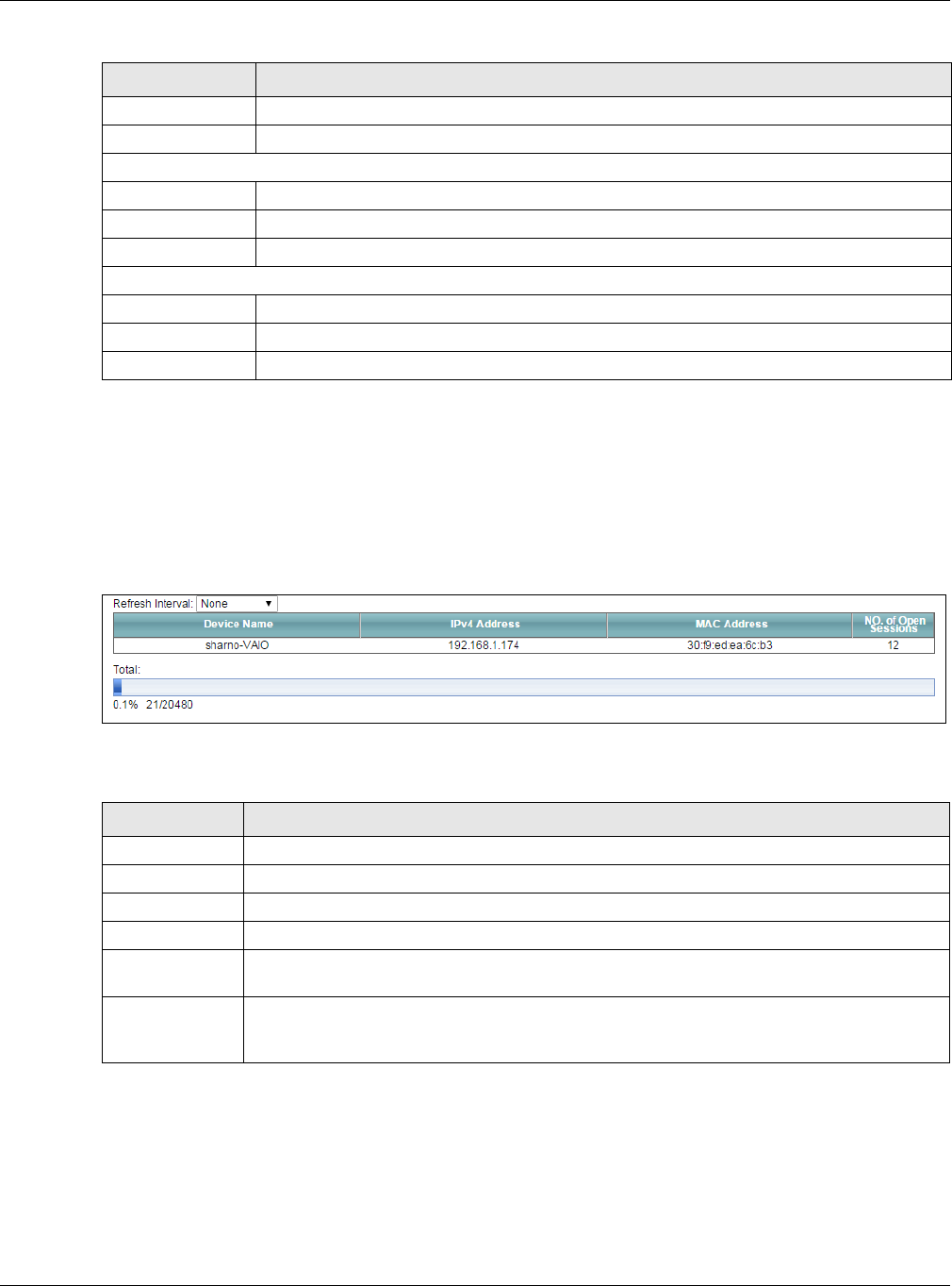
22.4 The NAT Status Screen
Click System Monitor > Traffic Status > NAT to open the following screen. The figure in this screen shows
the NAT session statistics for hosts currently connected on the XMG.
Figure 132 System Monitor > Traffic Status > NAT
The following table describes the fields in this screen.
Bytes Received This indicates the number of bytes received on this interface.
Interface This shows the LAN or WLAN interfaces.
Sent (Packets)
Data This indicates the number of transmitted packets on this interface.
Error This indicates the number of frames with errors transmitted on this interface.
Drop This indicates the number of outgoing packets dropped on this interface.
Received (Packets)
Data This indicates the number of received packets on this interface.
Error This indicates the number of frames with errors received on this interface.
Drop This indicates the number of received packets dropped on this interface.
Table 102 System Monitor > Traffic Status > LAN (continued)
LABEL DESCRIPTION
Table 103 System Monitor > Traffic Status > NAT
LABEL DESCRIPTION
Refresh Interval Select how often you want the XMG to update this screen.
Device Name This displays the name of the connected host.
IPv4 Address This displays the IPv4 address of the connected host.
MAC Address This displays the MAC address of the connected host.
No. of Open
Session
This displays the number of NAT sessions currently opened for the connected host.
Total This displays what percentage of NAT sessions the XMG can support is currently being used by
all connected hosts. You can also see the number of active NAT sessions and the maximum
number of NAT sessions the XMG can support.
XMG3512-B10A User’s Guide
209
CHAPTER 23
ARP Table
23.1 Overview
Address Resolution Protocol (ARP) is a protocol for mapping an Internet Protocol address (IP address) to
a physical machine address, also known as a Media Access Control or MAC address, on the local area
network.
An IP (version 4) address is 32 bits long. In an Ethernet LAN, MAC addresses are 48 bits long. The ARP
Table maintains an association between each MAC address and its corresponding IP address.
23.1.1 How ARP Works
When an incoming packet destined for a host device on a local area network arrives at the device, the
device's ARP program looks in the ARP Table and, if it finds the address, sends it to the device.
If no entry is found for the IP address, ARP broadcasts the request to all the devices on the LAN. The
device fills in its own MAC and IP address in the sender address fields, and puts the known IP address of
the target in the target IP address field. In addition, the device puts all ones in the target MAC field
(FF.FF.FF.FF.FF.FF is the Ethernet broadcast address). The replying device (which is either the IP address of
the device being sought or the router that knows the way) replaces the broadcast address with the
target's MAC address, swaps the sender and target pairs, and unicasts the answer directly back to the
requesting machine. ARP updates the ARP Table for future reference and then sends the packet to the
MAC address that replied.
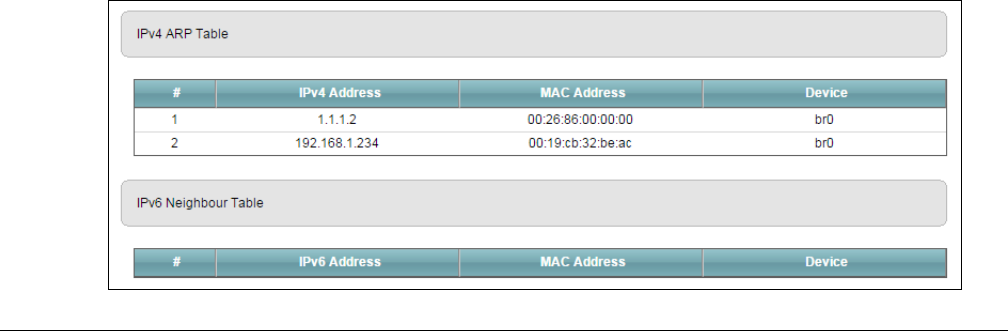
23.2 ARP Table Screen
Use the ARP table to view IP-to-MAC address mapping(s). To open this screen, click System Monitor >
ARP Table.
Figure 133 System Monitor > ARP Table

Chapter 23 ARP Table
XMG3512-B10A User’s Guide
210
The following table describes the labels in this screen.
Table 104 System Monitor > ARP Table
LABEL DESCRIPTION
# This is the ARP table entry number.
IPv4/IPv6
Address
This is the learned IPv4 or IPv6 address of a device connected to a port.
MAC Address This is the MAC address of the device with the listed IP address.
Device This is the type of interface used by the device.
XMG3512-B10A User’s Guide
211
CHAPTER 24
Routing Table
24.1 Overview
Routing is based on the destination address only and the XMG takes the shortest path to forward a
packet.
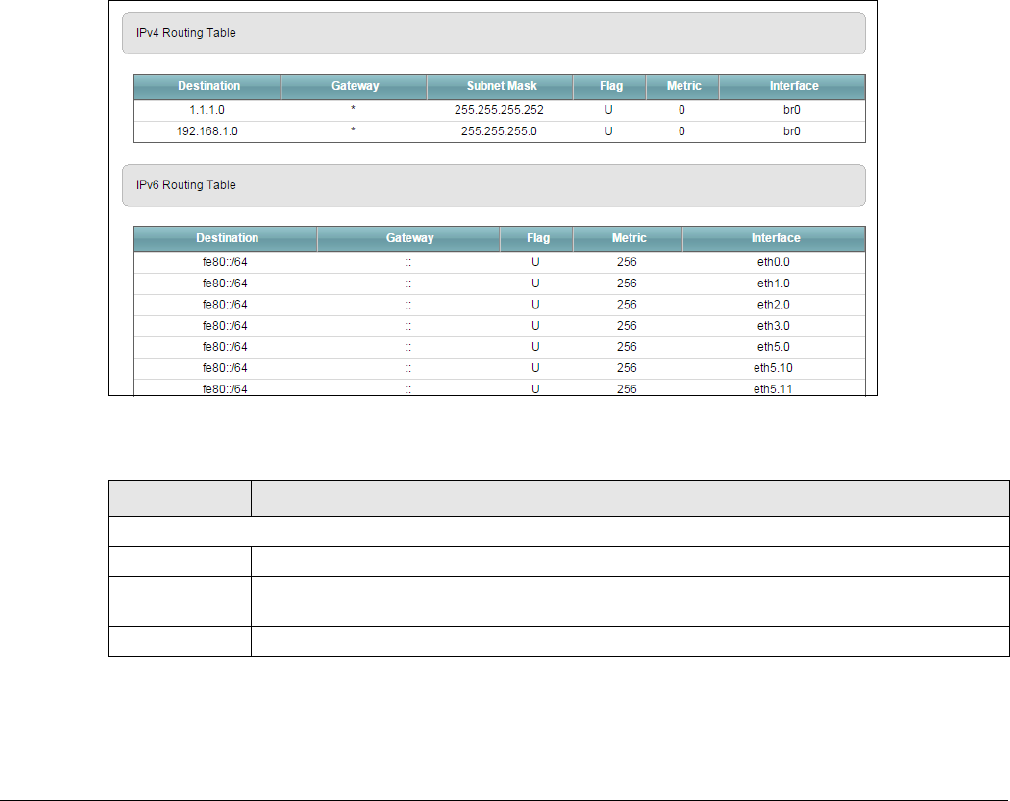
24.2 The Routing Table Screen
Click System Monitor > Routing Table to open the following screen.
Figure 134 System Monitor > Routing Table
The following table describes the labels in this screen.
Table 105 System Monitor > Routing Table
LABEL DESCRIPTION
IPv4/IPv6 Routing Table
Destination This indicates the destination IPv4 address or IPv6 address and prefix of this route.
Gateway This indicates the IPv4 address or IPv6 address of the gateway that helps forward this route’s
traffic.
Subnet Mask This indicates the destination subnet mask of the IPv4 route.
Chapter 24 Routing Table
XMG3512-B10A User’s Guide
212
Flag This indicates the route status.
U-Up: The route is up.
!-Reject: The route is blocked and will force a route lookup to fail.
G-Gateway: The route uses a gateway to forward traffic.
H-Host: The target of the route is a host.
R-Reinstate: The route is reinstated for dynamic routing.
D-Dynamic (redirect): The route is dynamically installed by a routing daemon or redirect.
M-Modified (redirect): The route is modified from a routing daemon or redirect.
Metric The metric represents the "cost of transmission". A router determines the best route for
transmission by choosing a path with the lowest "cost". The smaller the number, the lower the
"cost".
Interface This indicates the name of the interface through which the route is forwarded.
brx indicates a LAN interface where x can be 0~3 to represent LAN1 to LAN4 respectively.
ptm0 indicates a DSL WAN interface using IPoE, IPoA or in bridge mode.
ethx indicates an Ethernet WAN interface using IPoE or in bridge mode.
ppp0 indicates a WAN interface using PPPoE or PPPoA.
Table 105 System Monitor > Routing Table (continued)
LABEL DESCRIPTION
XMG3512-B10A User’s Guide
213
CHAPTER 25
Multicast Status
25.1 Overview
Use the Multicast Status screens to look at IGMP/MLD group status and traffic statistics.
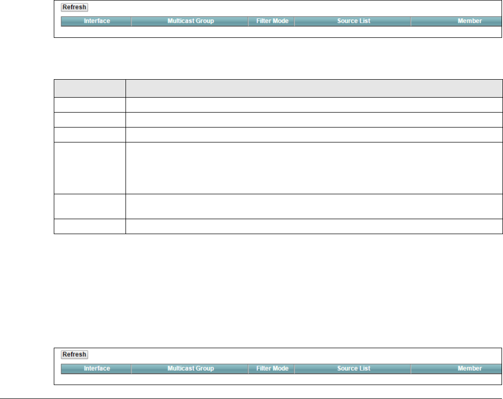
25.2 The IGMP Status Screen
Use this screen to look at the current list of multicast groups the XMG has joined and which ports have
joined it. To open this screen, click System Monitor > Multicast Status > IGMP Status.
Figure 135 System Monitor > Multicast Status > IGMP Status
The following table describes the labels in this screen.
25.3 The MLD Status Screen
Use this screen to look at the current list of multicast groups the XMG has joined and which ports have
joined it. To open this screen, click System Monitor > Multicast Status > MLD Status.
Figure 136 System Monitor > Multicast Status > MLD Status
Table 106 System Monitor > Multicast Status > IGMP Status
LABEL DESCRIPTION
Refresh Click this button to update the information on this screen.
Interface This field displays the name of an interface on the XMG that belongs to an IGMP multicast group.
Multicast Group This field displays the name of the IGMP multicast group to which the interface belongs.
Filter Mode INCLUDE means that only the IP addresses in the Source List get to receive the multicast group’s
traffic.
EXCLUDE means that the IP addresses in the Source List are not allowed to receive the multicast
group’s traffic but other IP addresses can.
Source List This is the list of IP addresses that are allowed or not allowed to receive the multicast group’s
traffic depending on the filter mode.
Member This is the list of the members of the multicast group.
Chapter 25 Multicast Status
XMG3512-B10A User’s Guide
214
The following table describes the labels in this screen.
Table 107 System Monitor > Multicast Status > MLD Status
LABEL DESCRIPTION
Refresh Click this button to update the status on this screen.
Interface This field displays the name of an interface on the XMG that belongs to an MLD multicast group.
Multicast Group This field displays the name of the MLD multicast group to which the interface belongs.
Filter Mode INCLUDE means that only the IP addresses in the Source List get to receive the multicast group’s
traffic.
EXCLUDE means that the IP addresses in the Source List are not allowed to receive the multicast
group’s traffic but other IP addresses can.
Source List This is the list of IP addresses that are allowed or not allowed to receive the multicast group’s
traffic depending on the filter mode.
Member This is the list of members in the multicast group.
XMG3512-B10A User’s Guide
215
CHAPTER 26
xDSL Statistics
26.1 The xDSL Statistics Screen
Use this screen to view detailed DSL statistics. Click System Monitor > xDSL Statistics to open the following
screen.
Figure 137 System Monitor > xDSL Statistics
The following table describes the labels in this screen.
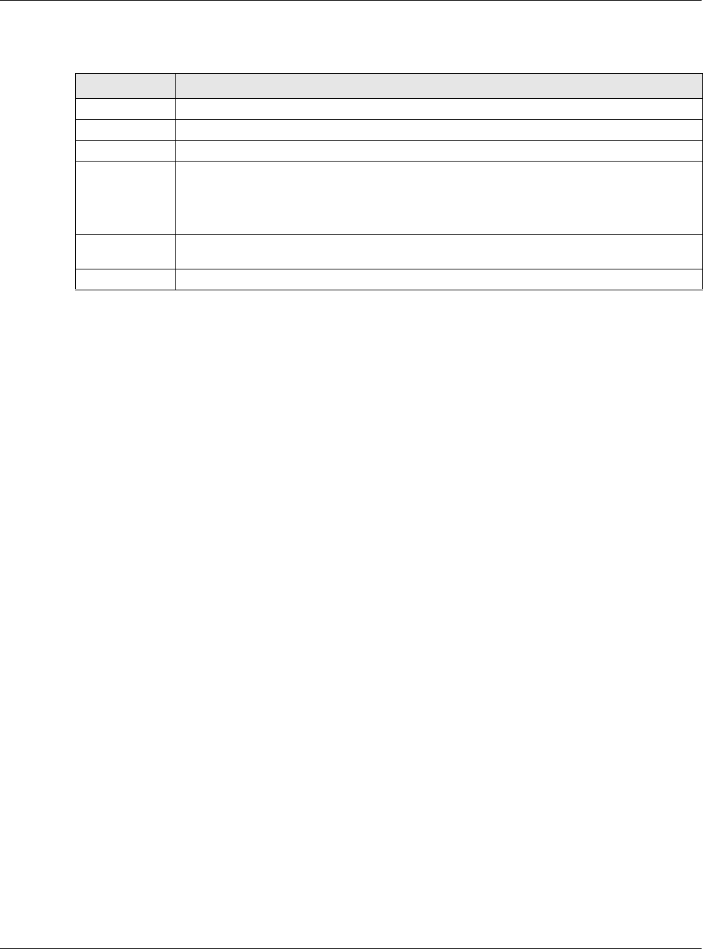
Table 108 Status > xDSL Statistics
LABEL DESCRIPTION
Refresh Interval Select the time interval for refreshing statistics.
Line Select which DSL line’s statistics you want to display.
xDSL Training
Status
This displays the current state of setting up the DSL connection.
Mode This displays the ITU standard used for this connection.
Traffic Type This displays the type of traffic the DSL port is sending and receiving. Inactive displays if the DSL
port is not currently sending or receiving traffic.
Link Uptime This displays how long the port has been running (or connected) since the last time it was
started.

Chapter 26 xDSL Statistics
XMG3512-B10A User’s Guide
216
xDSL Port Details
Upstream These are the statistics for the traffic direction going out from the port to the service provider.
Downstream These are the statistics for the traffic direction coming into the port from the service provider.
Line Rate These are the data transfer rates at which the port is sending and receiving data.
Actual Net Data
Rate
These are the rates at which the port is sending and receiving the payload data without
transport layer protocol headers and traffic.
Trellis Coding This displays whether or not the port is using Trellis coding for traffic it is sending and receiving.
Trellis coding helps to reduce the noise in ADSL transmissions. Trellis may reduce throughput but
it makes the connection more stable.
SNR Margin This is the upstream and downstream Signal-to-Noise Ratio margin (in dB). A DMT sub-carrier’s
SNR is the ratio between the received signal power and the received noise power. The signal-
to-noise ratio margin is the maximum that the received noise power could increase with the
system still being able to meet its transmission targets.
Actual Delay This is the upstream and downstream interleave delay. It is the wait (in milliseconds) that
determines the size of a single block of data to be interleaved (assembled) and then
transmitted. Interleave delay is used when transmission error correction (Reed- Solomon) is
necessary due to a less than ideal telephone line. The bigger the delay, the bigger the data
block size, allowing better error correction to be performed.
Transmit Power This is the upstream and downstream far end actual aggregate transmit power (in dBm).
Upstream is how much power the port is using to transmit to the service provider. Downstream is
how much port the service provider is using to transmit to the port.
Receive Power Upstream is how much power the service provider is receiving from the port. Downstream is
how much power the port is receiving from the service provider.
Actual INP Sudden spikes in the line’s level of external noise (impulse noise) can cause errors and result in
lost packets. This could especially impact the quality of multimedia traffic such as voice or
video. Impulse noise protection (INP) provides a buffer to allow for correction of errors caused
by error correction to deal with this. The number of DMT (Discrete Multi-Tone) symbols shows the
level of impulse noise protection for the upstream and downstream traffic. A higher symbol
value provides higher error correction capability, but it causes overhead and higher delay
which may increase error rates in received multimedia data.
Total Attenuation This is the upstream and downstream line attenuation, measured in decibels (dB). This
attenuation is the difference between the power transmitted at the near-end and the power
received at the far-end. Attenuation is affected by the channel characteristics (wire gauge,
quality, condition and length of the physical line).
Attainable Net
Data Rate
These are the highest theoretically possible transfer rates at which the port could send and
receive payload data without transport layer protocol headers and traffic.
xDSL Counters
Downstream These are the statistics for the traffic direction coming into the port from the service provider.
Upstream These are the statistics for the traffic direction going out from the port to the service provider.
FEC This is the number of Far End Corrected blocks.
CRC This is the number of Cyclic Redundancy Checks.
ES This is the number of Errored Seconds meaning the number of seconds containing at least one
errored block or at least one defect.
SES This is the number of Severely Errored Seconds meaning the number of seconds containing 30%
or more errored blocks or at least one defect. This is a subset of ES.
UAS This is the number of UnAvailable Seconds.
LOS This is the number of Loss Of Signal seconds.
LOF This is the number of Loss Of Frame seconds.
LOM This is the number of Loss of Margin seconds.
Table 108 Status > xDSL Statistics (continued)
LABEL DESCRIPTION
XMG3512-B10A User’s Guide
217
CHAPTER 27
System
27.1 Overview
In the System screen, you can name your XMG (Host) and give it an associated domain name for
identification purposes.
27.2 The System Screen
Click Maintenance > System to open the following screen.
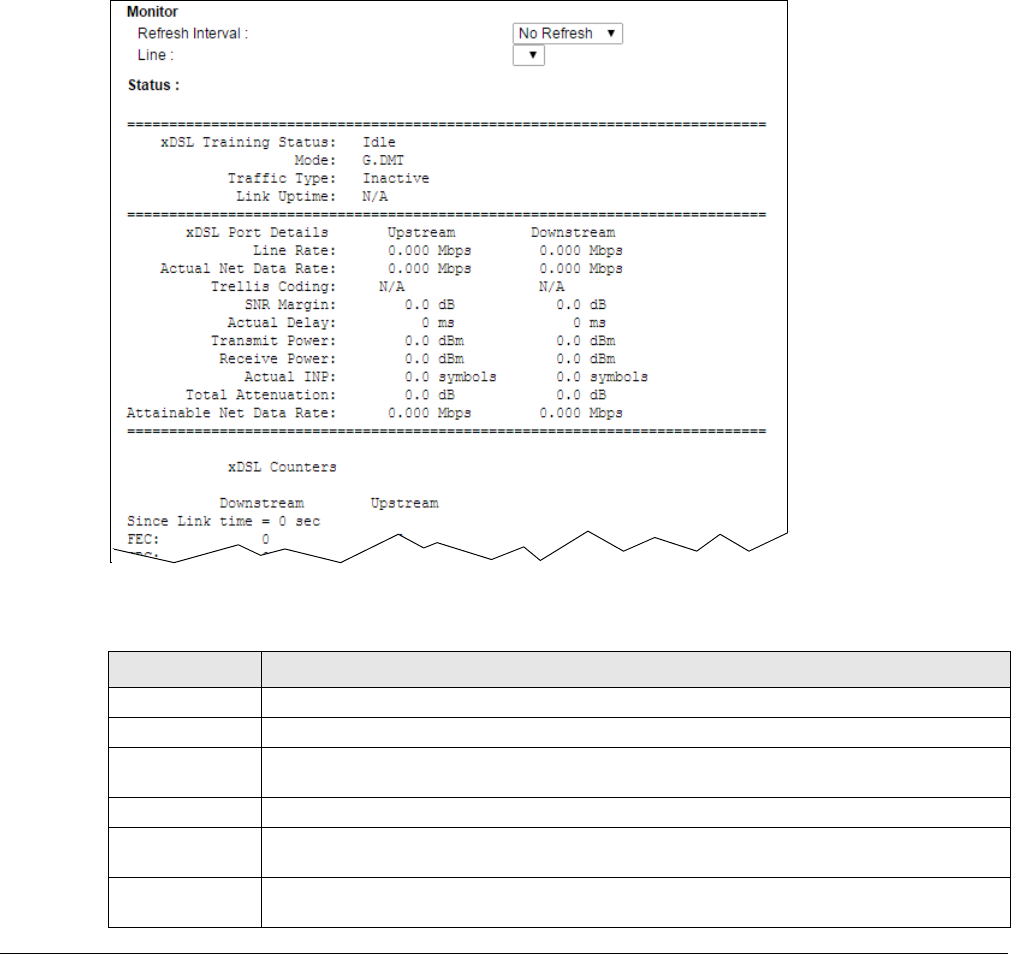
Figure 138 Maintenance > System
The following table describes the labels in this screen.
Table 109 Maintenance > System
LABEL DESCRIPTION
Host Name Type a hostname for your XMG. Enter a descriptive name of up to 16 alphanumeric characters,
not including spaces, underscores, and dashes.
Domain Name Type a Domain name for your host XMG.
Apply Click Apply to save your changes.
Cancel Click Cancel to abandon this screen without saving.
XMG3512-B10A User’s Guide
218
CHAPTER 28
User Account
28.1 Overview
In the User Account screen, you can view the settings of the “admin” and other user accounts that you
used to log in the XMG.
28.2 The User Account Screen
Click Maintenance > User Account to open the following screen.
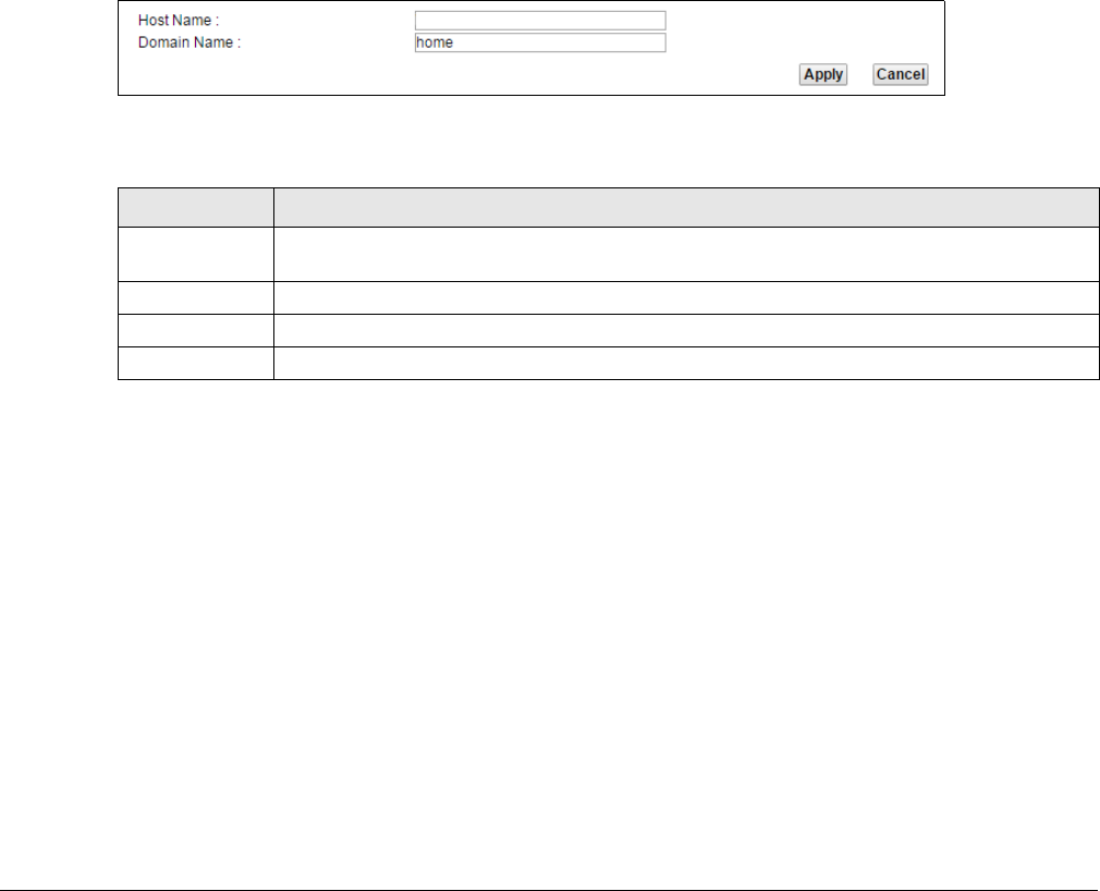
Figure 139 Maintenance > User Account
The following table describes the labels in this screen.
28.2.1 The User Account Add/Edit Screen
Click Add New Account or the Edit icon of an existing account in the Maintenance > User Account to
open the following screen.
Table 110 Maintenance > User Account
LABEL DESCRIPTION
Add New
Account
Click this button to add a new user account.
#This is the index number
User Name This field displays the name of the account used to log into the XMG web configurator.
Retry Times This field displays the number of times consecutive wrong passwords can be entered for this
account. 0 means there is no limit.
Idle Timeout This field displays the the length of inactive time before the XMG will automatically log the user
out of the web configurator.
Lock Period This field displays the length of time a user must wait before attempting to log in again after a
number of consecutive wrong passwords have been entered as defined in Retry Times.
Group This field displays whether this user has Administrator or User privleges.
Modify Click the Edit icon to configure the entry.
Click the Delete icon to remove the entry.
Chapter 28 User Account
XMG3512-B10A User’s Guide
219
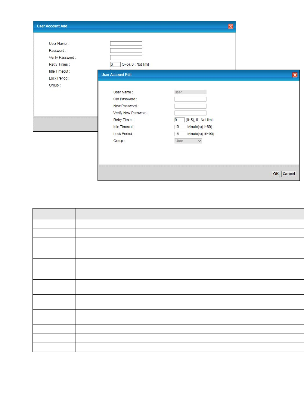
Figure 140 Maintenance > User Account > Add/Edit
The following table describes the labels in this screen.
Table 111 Maintenance > User Account > Add/Edit
LABEL DESCRIPTION
User Name Enter a new name for the account. This field displays the name of an existing account.
Old Password Type the default password or the existing password used to access the XMG web configurator.
Password/New
Password
Type your new system password (up to 256 characters). Note that as you type a password, the
screen displays a (*) for each character you type. After you change the password, use the new
password to access the XMG.
Verify Password/
Verify New
Password
Type the new password again for confirmation.
Retry Times Enter the number of times consecutive wrong passwords can be entered for this account. 0
means there is no limit.
Idle Timeout Enter the length of inactive time before the XMG will automatically log the user out of the web
configurator.
Lock Period Enter the length of time a user must wait before attempting to log in again after a number if
consecutive wrong passwords have been entered as defined in Retry Times.
Group Specify whether this user will have Administrator or User privleges.
OK Click OK to save your changes.
Cancel Click Cancel to exit this screen without saving.
XMG3512-B10A User’s Guide
220
CHAPTER 29
Remote Management
29.1 Overview
Remote management controls through which interface(s), which services can access the XMG.
Note: The XMG is managed using the Web Configurator.
29.2 The MGMT Services Screen
Use this screen to configure through which interface(s), which services can access the XMG. You can
also specify the port numbers the services must use to connect to the XMG. Click Maintenance >
Remote Management > MGMT Services to open the following screen.
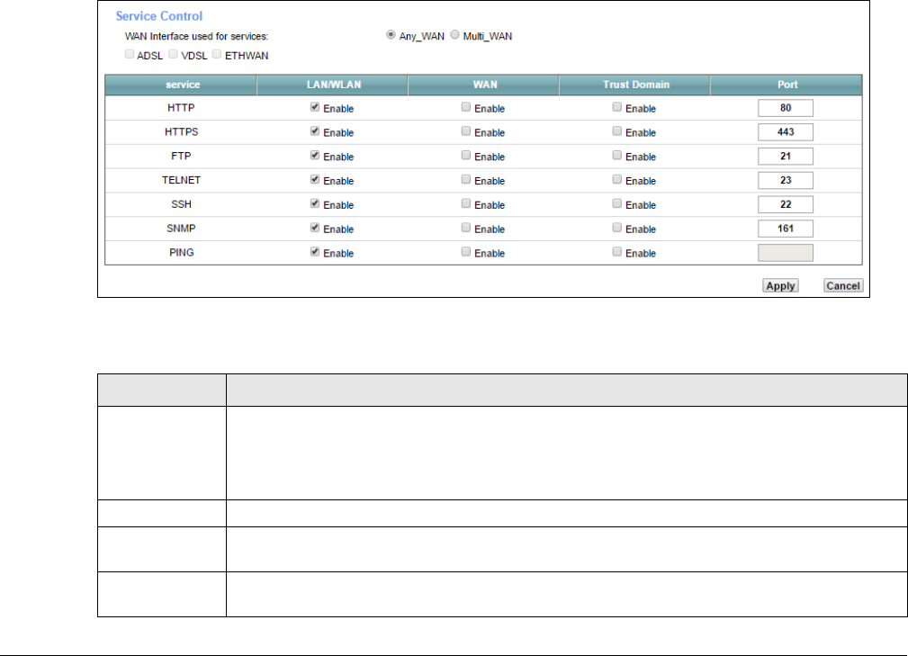
Figure 141 Maintenance > Remote Management > MGMT Services
The following table describes the fields in this screen.
Table 112 Maintenance > Remote Management > MGMT Services
LABEL DESCRIPTION
WAN Interface
used for services
Select Any_WAN to have the XMG automatically activate the remote management service
when any WAN connection is up.
Select Multi_WAN and then select one or more WAN connections to have the XMG activate the
remote management service when the selected WAN connections are up.
service This is the service you may use to access the XMG.
LAN/WLAN Select the Enable check box for the corresponding services that you want to allow access to the
XMG from the LAN/WLAN.
WAN Select the Enable check box for the corresponding services that you want to allow access to the
XMG from all WAN connections.
Chapter 29 Remote Management
XMG3512-B10A User’s Guide
221
29.3 The Trust Domain Screen
Use this screen to view a list of public IP addresses which are allowed to access the XMG through the
services configured in the Maintenance > Remote Management screen. Click Maintenance > Remote
Management > Trust Domain to open the following screen.
Note: If this list is empty, all public IP addresses can access the XMG from the WAN through
the specified services.
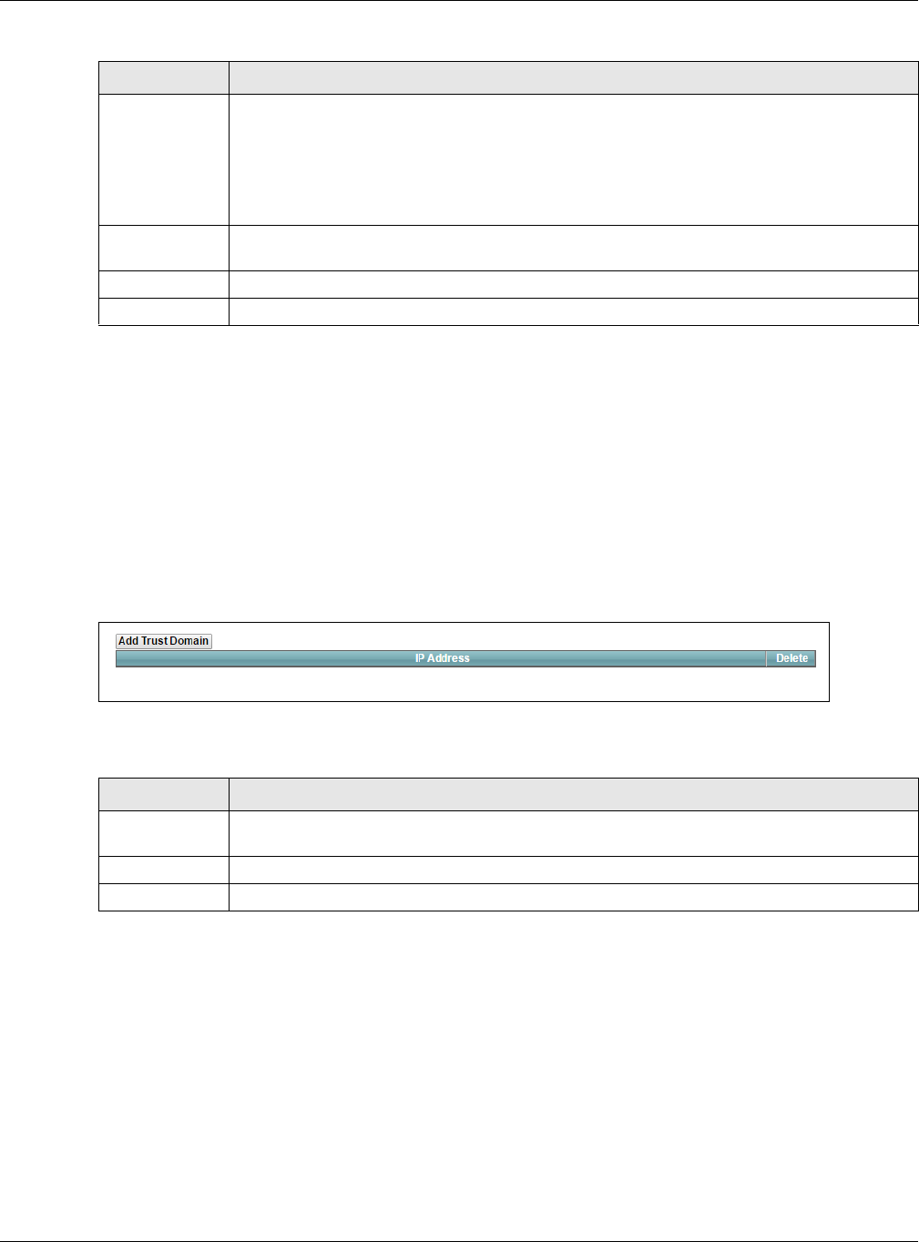
Figure 142 Maintenance > Remote Management > Trust Domain
The following table describes the fields in this screen.
29.3.1 The Add Trust Domain Screen
Use this screen to configure a public IP address which is allowed to access the XMG. Click the Add Trust
Domain button in the Maintenance > Remote Management > Turst Domain screen to open the following
screen.
Trust Domain Select the Enable check box for the corresponding services that you want to allow access to the
XMG from the trusted hosts configured in the Maintenance > Remote MGMT > Trust Domain
screen.
If you only want certain WAN connections to have access to the XMG using the corresponding
services, then clear WAN, select Trust Domain and configure the allowed IP address(es) in the
Trust Domain screen.
Port You may change the server port number for a service if needed, however you must use the
same port number in order to use that service for remote management.
Apply Click Apply to save your changes back to the XMG.
Cancel Click Cancel to restore your previously saved settings.
Table 112 Maintenance > Remote Management > MGMT Services (continued)
LABEL DESCRIPTION
Table 113 Maintenance > Remote Management > Trust Domain
LABEL DESCRIPTION
Add Trust
Domain
Click this to add a trusted host IP address.
IP Address This field shows a trusted host IP address.
Delete Click the Delete icon to remove the trust IP address.
Chapter 29 Remote Management
XMG3512-B10A User’s Guide
222
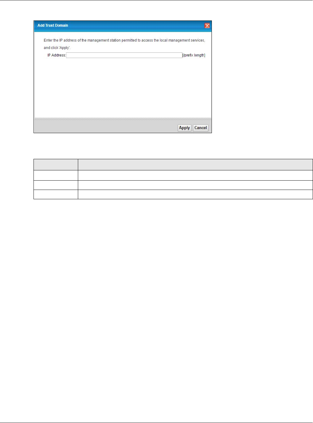
Figure 143 Maintenance > Remote Management > Trust Domain > Add Trust Domain
The following table describes the fields in this screen.
Table 114 Maintenance > Remote Management > Trust Domain > Add Trust Domain
LABEL DESCRIPTION
IP Address Enter a public IPv4 IP address which is allowed to access the service on the XMG from the WAN.
Apply Click Apply to save your changes back to the XMG.
Cancel Click Cancel to exit this screen without saving.
XMG3512-B10A User’s Guide
223
CHAPTER 30
SNMP
30.1 Overview
This chapter explains how to configure the SNMP settings on the XMG.
30.2 The SNMP Screen
Simple Network Management Protocol is a protocol used for exchanging management information
between network devices. Your XMG supports SNMP agent functionality, which allows a manager
station to manage and monitor the XMG through the network. The XMG supports SNMP version one
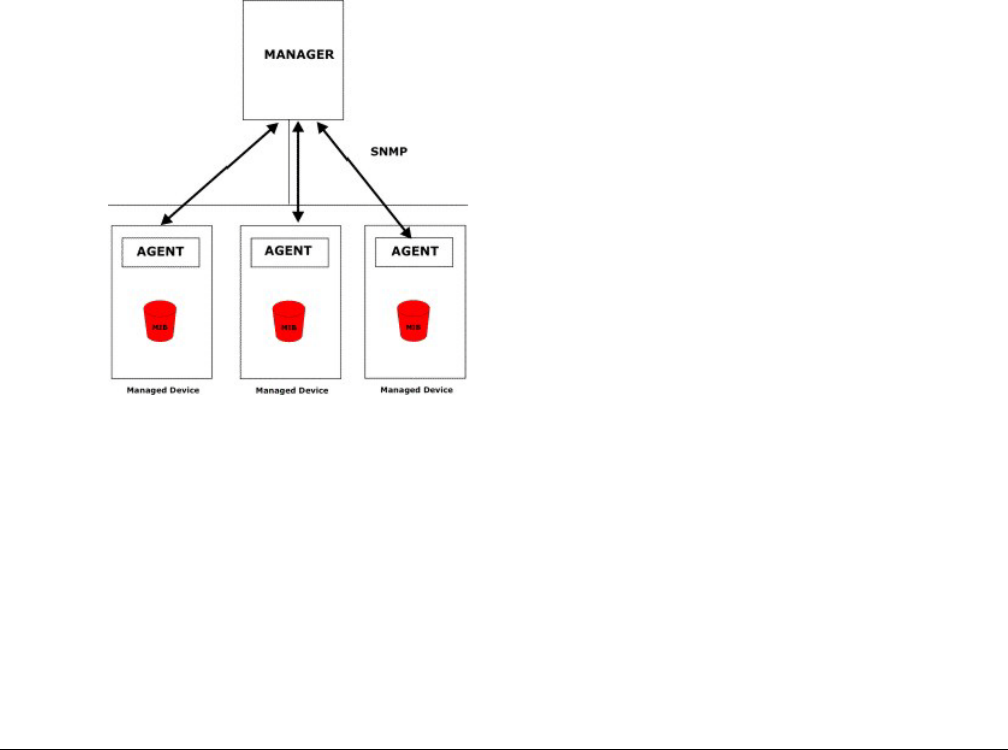
(SNMPv1) and version two (SNMPv2c). The next figure illustrates an SNMP management operation.
Figure 144 SNMP Management Model
An SNMP managed network consists of two main types of component: agents and a manager.
An agent is a management software module that resides in a managed device (the XMG). An agent
translates the local management information from the managed device into a form compatible with
SNMP. The manager is the console through which network administrators perform network management
functions. It executes applications that control and monitor managed devices.
The managed devices contain object variables/managed objects that define each piece of
information to be collected about a device. Examples of variables include such as number of packets
received, node port status etc. A Management Information Base (MIB) is a collection of managed
objects. SNMP allows a manager and agents to communicate for the purpose of accessing these
objects.
Chapter 30 SNMP
XMG3512-B10A User’s Guide
224
SNMP itself is a simple request/response protocol based on the manager/agent model. The manager
issues a request and the agent returns responses using the following protocol operations:
• Get - Allows the manager to retrieve an object variable from the agent.
• GetNext - Allows the manager to retrieve the next object variable from a table or list within an agent.
In SNMPv1, when a manager wants to retrieve all elements of a table from an agent, it initiates a Get
operation, followed by a series of GetNext operations.
• Set - Allows the manager to set values for object variables within an agent.
• Trap - Used by the agent to inform the manager of some events.
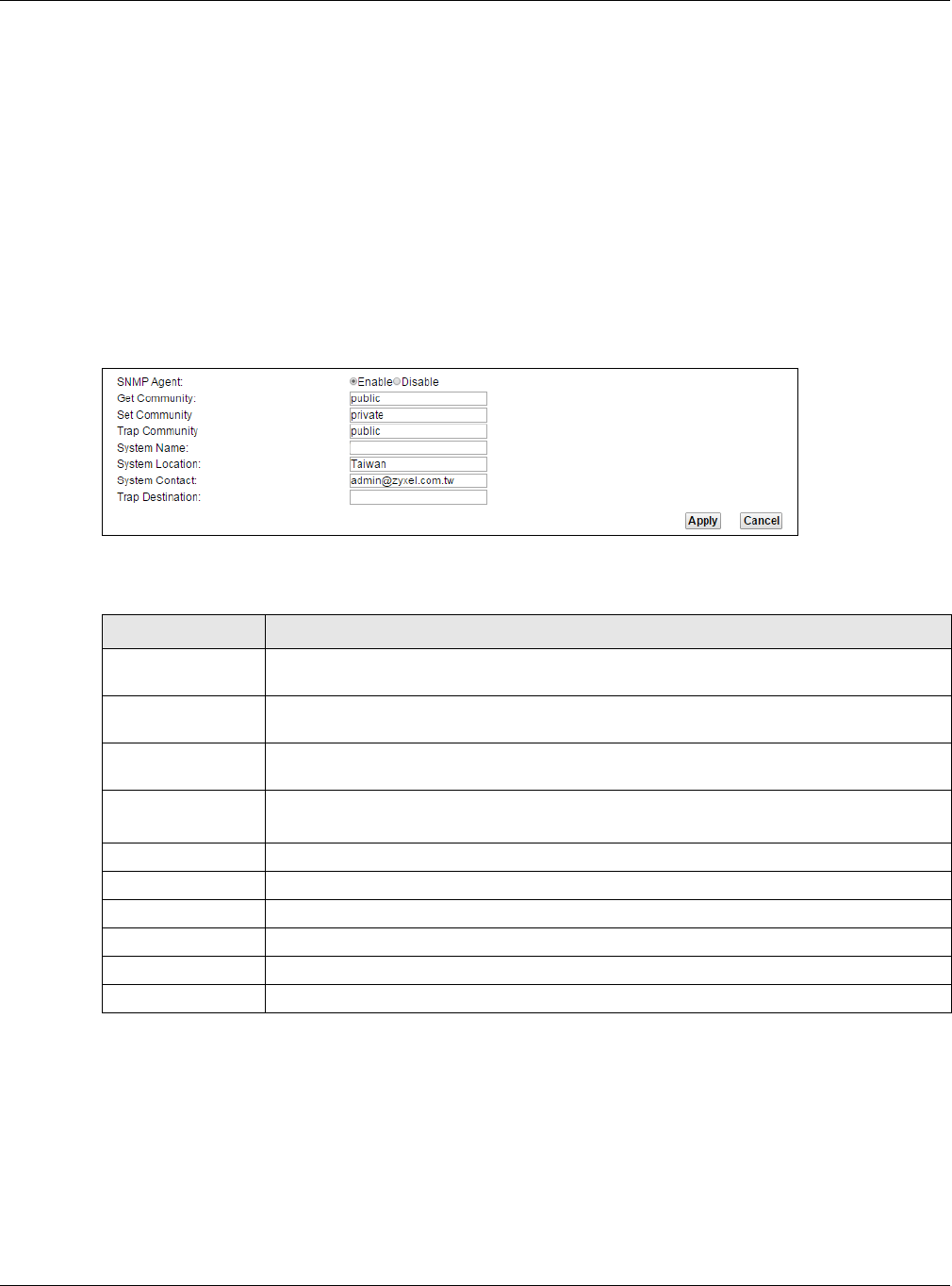
Click Maintenance > SNMP to open the following screen. Use this screen to configure the XMG SNMP
settings.
Figure 145 Maintenance > SNMP
The following table describes the fields in this screen.
Table 115 Maintenance > SNMP
LABEL DESCRIPTION
SNMP Agent Select Enable to let the XMG act as an SNMP agent, which allows a manager station to
manage and monitor the XMG through the network. Select Disable to turn this feature off.
Get Community Enter the Get Community, which is the password for the incoming Get and GetNext requests
from the management station.
Set Community Enter the Set community, which is the password for incoming Set requests from the
management station.
Trap Community Enter the Trap Community, which is the password sent with each trap to the SNMP manager.
The default is public and allows all requests.
System Name Enter the SNMP system name.
System Location Enter the SNMP system location.
System Contact Enter the SNMP system contact.
Trap Destination Type the IP address of the station to send your SNMP traps to.
Apply Click this to save your changes back to the XMG.
Cancel Click this to restore your previously saved settings.
XMG3512-B10A User’s Guide
225
CHAPTER 31
Time Settings
31.1 Overview
This chapter shows you how to configure system related settings, such as system time, password, name,
the domain name and the inactivity timeout interval.
31.2 The Time Screen
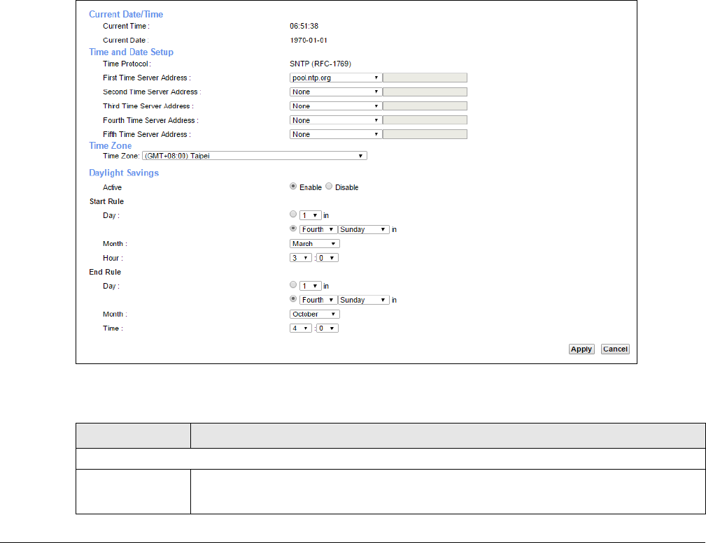
To change your XMG’s time and date, click Maintenance > Time. The screen appears as shown. Use this
screen to configure the XMG’s time based on your local time zone.
Figure 146 Maintenance > Time
The following table describes the fields in this screen.
Table 116 Maintenance > Time
LABEL DESCRIPTION
Current Date/Time
Current Time This field displays the time of your XMG.
Each time you reload this page, the XMG synchronizes the time with the time server.
Chapter 31 Time Settings
XMG3512-B10A User’s Guide
226
Current Date This field displays the date of your XMG.
Each time you reload this page, the XMG synchronizes the date with the time server.
Time and Date Setup
First ~ Fifth Time
Server Address
Select an NTP time server from the drop-down list box.
Otherwise, select Other and enter the IP address or URL (up to 29 extended ASCII characters
in length) of your time server.
Select None if you don’t want to configure the time server.
Check with your ISP/network administrator if you are unsure of this information.
Time Zone
Time zone Choose the time zone of your location. This will set the time difference between your time
zone and Greenwich Mean Time (GMT).
Daylight Savings Daylight Saving Time is a period from late spring to early fall when many countries set their
clocks ahead of normal local time by one hour to give more daytime light in the evening.
Active Select Enable if you use Daylight Saving Time.
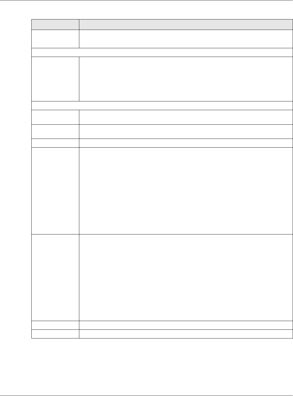
Start Rule Configure the day and time when Daylight Saving Time starts if you enabled Daylight Saving.
You can select a specific date in a particular month or a specific day of a specific week in a
particular month. The Hour field uses the 24 hour format. Here are a couple of examples:
Daylight Saving Time starts in most parts of the United States on the second Sunday of March.
Each time zone in the United States starts using Daylight Saving Time at 2 A.M. local time. So in
the United States, set the day to Second, Sunday, the month to March and the time to 2 in the
Hour field.
Daylight Saving Time starts in the European Union on the last Sunday of March. All of the time
zones in the European Union start using Daylight Saving Time at the same moment (1 A.M.
GMT or UTC). So in the European Union you would set the day to Last, Sunday and the month
to March. The time you select depends on your time zone. In Germany for instance, you
would select 2 in the Hour field because Germany's time zone is one hour ahead of GMT or
UTC (GMT+1).
End Rule Configure the day and time when Daylight Saving Time ends if you enabled Daylight Saving.
You can select a specific date in a particular month or a specific day of a specific week in a
particular month. The Time field uses the 24 hour format. Here are a couple of examples:
Daylight Saving Time ends in the United States on the first Sunday of November. Each time
zone in the United States stops using Daylight Saving Time at 2 A.M. local time. So in the United
States you would set the day to First, Sunday, the month to November and the time to 2 in the
Time field.
Daylight Saving Time ends in the European Union on the last Sunday of October. All of the
time zones in the European Union stop using Daylight Saving Time at the same moment (1
A.M. GMT or UTC). So in the European Union you would set the day to Last, Sunday, and the
month to October. The time you select depends on your time zone. In Germany for instance,
you would select 2 in the Time field because Germany's time zone is one hour ahead of GMT
or UTC (GMT+1).
Apply Click Apply to save your changes.
Cancel Click Cancel to restore your previously saved settings.
Table 116 Maintenance > Time (continued)
LABEL DESCRIPTION
XMG3512-B10A User’s Guide
227
CHAPTER 32
E-mail Notification
32.1 Overview
A mail server is an application or a computer that runs such an application to receive, forward and
deliver e-mail messages.
To have the XMG send reports, logs or notifications via e-mail, you must specify an e-mail server and the
e-mail addresses of the sender and receiver.
32.2 The E-mail Notification Screen
Click Maintenance > E-mail Notification to open the E-mail Notification screen. Use this screen to view,
remove and add mail server information on the XMG.
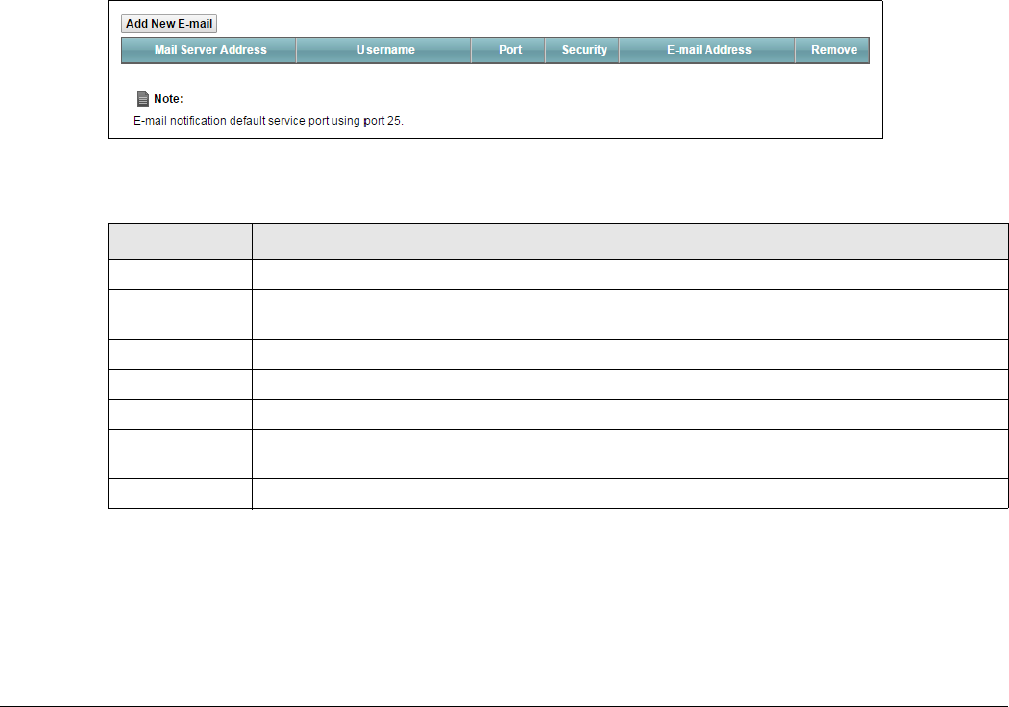
Figure 147 Maintenance > E-mail Notification
The following table describes the labels in this screen.
32.2.1 E-mail Notification Edit
Click the Add button in the E-mail Notification screen. Use this screen to configure the required
information for sending e-mail via a mail server.
Table 117 Maintenance > E-mail Notification
LABEL DESCRIPTION
Add New E-mail Click this button to create a new entry.
Mail Server
Address
This field displays the server name or the IP address of the mail server.
Username This field displays the user name of the sender’s mail account.
Port This field displays the port number of the mail server.
Security This field displays the protocol used for encryption.
E-mail Address This field displays the e-mail address that you want to be in the from/sender line of the e-mail
that the XMG sends.
Remove Click this button to delete the selected entry(ies).
Chapter 32 E-mail Notification
XMG3512-B10A User’s Guide
228
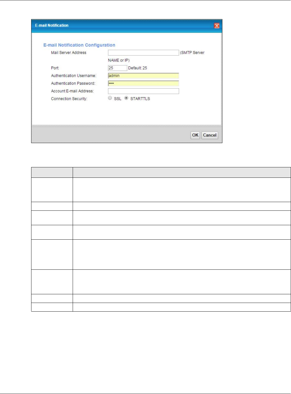
Figure 148 Email Notification > Add
The following table describes the labels in this screen.
Table 118 Email Notification > Add
LABEL DESCRIPTION
Mail Server
Address
Enter the server name or the IP address of the mail server for the e-mail address specified in the
Account Email Address field.
If this field is left blank, reports, logs or notifications will not be sent via e-mail.
Port Enter the same port number here as is on the mail server for mail traffic.
Authentication
Username
Enter the user name (up to 32 characters). This is usually the user name of a mail account you
specified in the Account Email Address field.
Authentication
Password
Enter the password associated with the user name above.
Account E-mail
Address
Enter the e-mail address that you want to be in the from/sender line of the e-mail notification
that the XMG sends.
If you activate SSL/TLS authentication, the e-mail address must be able to be authenticated by
the mail server as well.
Connection
Security
Select SSL to use Secure Sockets Layer (SSL) or Transport Layer Security (TLS) if you want
encrypted communications between the mail server and the XMG.
Select STARTTLS to upgrade a plain text connection to a secure connection using SSL/TLS.
OK Click this button to save your changes and return to the previous screen.
Cancel Click this button to exit this screen without saving.
XMG3512-B10A User’s Guide
229
CHAPTER 33
Log Setting
33.1 Overview
You can configure where the XMG sends logs and which logs and/or immediate alerts the XMG records
in the Logs Setting screen.
33.2 The Log Settings Screen
To change your XMG’s log settings, click Maintenance > Logs Setting. The screen appears as shown.
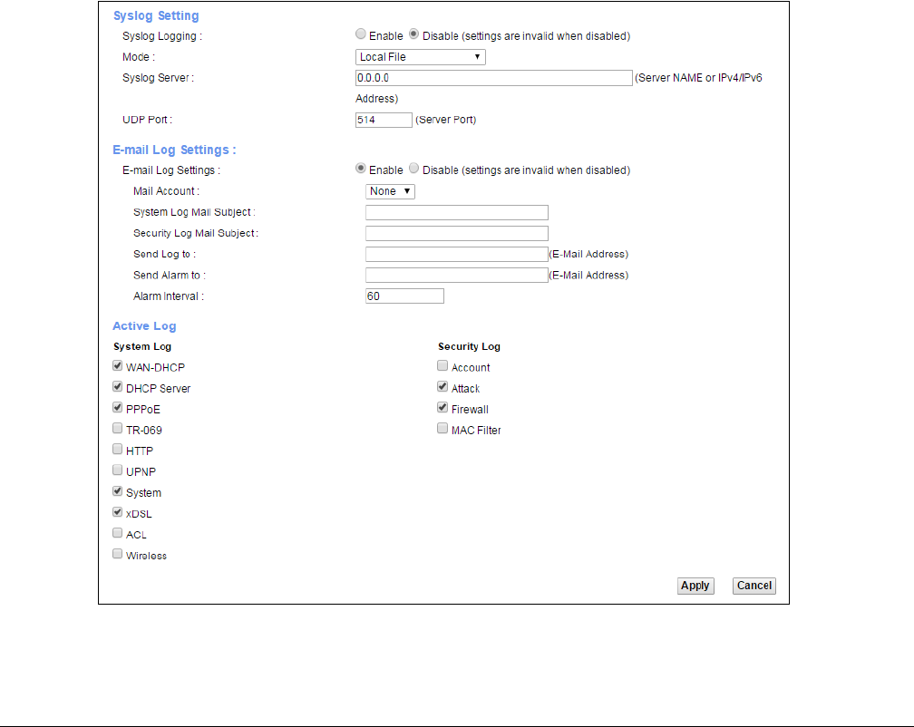
Figure 149 Maintenance > Logs Setting

Chapter 33 Log Setting
XMG3512-B10A User’s Guide
230
The following table describes the fields in this screen.
33.2.1 Example E-mail Log
An "End of Log" message displays for each mail in which a complete log has been sent. The following is
an example of a log sent by e-mail.
• You may edit the subject title.
• The date format here is Day-Month-Year.
• The date format here is Month-Day-Year. The time format is Hour-Minute-Second.
•"End of Log" message shows that a complete log has been sent.
Table 119 Maintenance > Logs Setting
LABEL DESCRIPTION
Syslog Setting
Syslog Logging The XMG sends a log to an external syslog server. Select Enable to enable syslog logging.
Mode Select the syslog destination from the drop-down list box.
If you select Remote, the log(s) will be sent to a remote syslog server. If you select Local File, the
log(s) will be saved in a local file. If you want to send the log(s) to a remote syslog server and
save it in a local file, select Local File and Remote.
Syslog Server Enter the server name or IP address of the syslog server that will log the selected categories of
logs.
UDP Port Enter the port number used by the syslog server.
E-mail Log Settings
E-mail Log
Settings
Select Enable to have the XMG send logs and alarm messages to the configured e-mail
addresses.
Mail Account This section is available only when you select Enable in the E-mail Log Settings field.
Select a mail account from which you want to send logs. You can configure mail accounts in
the Maintenance > E-mail Notification screen.
System Log Mail
Subject
Type a title that you want to be in the subject line of the system log e-mail message that the
XMG sends.
Security Log
Mail Subject
Type a title that you want to be in the subject line of the security log e-mail message that the
XMG sends.
Send Log to The XMG sends logs to the e-mail address specified in this field. If this field is left blank, the XMG
does not send logs via E-mail.
Send Alarm to Alerts are real-time notifications that are sent as soon as an event, such as a DoS attack, system
error, or forbidden web access attempt occurs. Enter the E-mail address where the alert
messages will be sent. Alerts include system errors, attacks and attempted access to blocked
web sites. If this field is left blank, alert messages will not be sent via E-mail.
Alarm Interval Specify how often the alarm should be updated.
Active Log
System Log Select the categories of system logs that you want to record.
Security Log Select the categories of security logs that you want to record.
Apply Click Apply to save your changes.
Cancel Click Cancel to restore your previously saved settings.

Chapter 33 Log Setting
XMG3512-B10A User’s Guide
231
Figure 150 E-mail Log Example
Subject:
Firewall Alert From
Date:
Fri, 07 Apr 2000 10:05:42
From:
user@zyxel.com
To:
user@zyxel.com
1|Apr 7 00 |From:192.168.1.1 To:192.168.1.255 |default policy |forward
| 09:54:03 |UDP src port:00520 dest port:00520 |<1,00> |
2|Apr 7 00 |From:192.168.1.131 To:192.168.1.255 |default policy |forward
| 09:54:17 |UDP src port:00520 dest port:00520 |<1,00> |
3|Apr 7 00 |From:192.168.1.6 To:10.10.10.10 |match |forward
| 09:54:19 |UDP src port:03516 dest port:00053 |<1,01> |
……………………………..{snip}…………………………………..
……………………………..{snip}…………………………………..
126|Apr 7 00 |From:192.168.1.1 To:192.168.1.255 |match |forward
| 10:05:00 |UDP src port:00520 dest port:00520 |<1,02> |
127|Apr 7 00 |From:192.168.1.131 To:192.168.1.255 |match |forward
| 10:05:17 |UDP src port:00520 dest port:00520 |<1,02> |
128|Apr 7 00 |From:192.168.1.1 To:192.168.1.255 |match |forward
| 10:05:30 |UDP src port:00520 dest port:00520 |<1,02> |
End of Firewall Log
XMG3512-B10A User’s Guide
232
CHAPTER 34
Firmware Upgrade
34.1 Overview
This chapter explains how to upload new firmware to your XMG. You can download new firmware
releases from your nearest Zyxel FTP site (or www.zyxel.com) to use to upgrade your device’s
performance.
Only use firmware for your device’s specific model. Refer to the label on
the bottom of your XMG.
34.2 The Firmware Screen
Click Maintenance > Firmware Upgrade to open the following screen. The upload process uses HTTP
(Hypertext Transfer Protocol) and may take up to two minutes. After a successful upload, the system will
reboot.
Do NOT turn off the XMG while firmware upload is in progress!
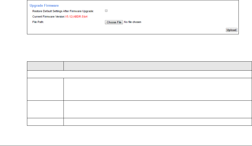
Figure 151 Maintenance > Firmware Upgrade
The following table describes the labels in this screen. After you see the firmware updating screen, wait
two minutes before logging into the XMG again.
Table 120 Maintenance > Firmware Upgrade
LABEL DESCRIPTION
Upgrade Firmware
Restore Default
Settings After
Firmware
Upgrade
Click the check box to have the XMG automatically reset itself after the new firmware is
uploaded.
Current
Firmware
Version
This is the present Firmware version and the date created.
File Path Type in the location of the file you wasnt to upload in this field or click Choose File to find it.
Chapter 34 Firmware Upgrade
XMG3512-B10A User’s Guide
233
Figure 152 Firmware Uploading
The XMG automatically restarts in this time causing a temporary network disconnect. In some operating
systems, you may see the following icon on your desktop.
Figure 153 Network Temporarily Disconnected
After two minutes, log in again and check your new firmware version in the Status screen.
Choose File Click this to find the .bin file you want to upload. Remember that you must decompress
compressed (.zip) files before you can upload them.
Upload Click this to begin the upload process. This process may take up to two minutes.
Table 120 Maintenance > Firmware Upgrade
LABEL DESCRIPTION
XMG3512-B10A User’s Guide
234
CHAPTER 35
Backup/Restore
35.1 Overview
The Backup/Restore screen allows you to backup and restore device configurations. You can also reset
your device settings back to the factory default.
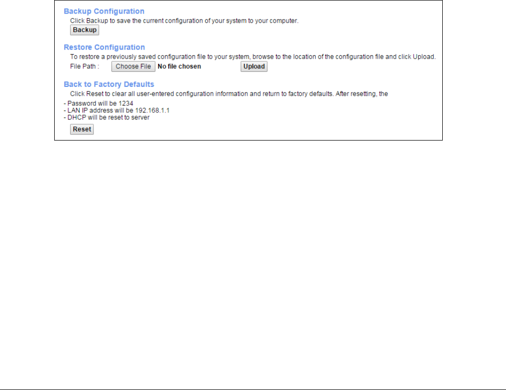
35.2 The Backup/Restore Screen
Click Maintenance > Backup/Restore. Information related to factory defaults, backup configuration,
and restoring configuration appears in this screen, as shown next.
Figure 154 Maintenance > Backup/Restore
Backup Configuration
Backup Configuration allows you to back up (save) the XMG’s current configuration to a file on your
computer. Once your XMG is configured and functioning properly, it is highly recommended that you
back up your configuration file before making configuration changes. The backup configuration file will
be useful in case you need to return to your previous settings.
Click Backup to save the XMG’s current configuration to your computer.
Chapter 35 Backup/Restore
XMG3512-B10A User’s Guide
235
Restore Configuration
Restore Configuration allows you to upload a new or previously saved configuration file from your
computer to your XMG.
Do not turn off the XMG while configuration file upload is in progress.
After the XMG configuration has been restored successfully, the login screen appears. Login again to
restart the XMG.
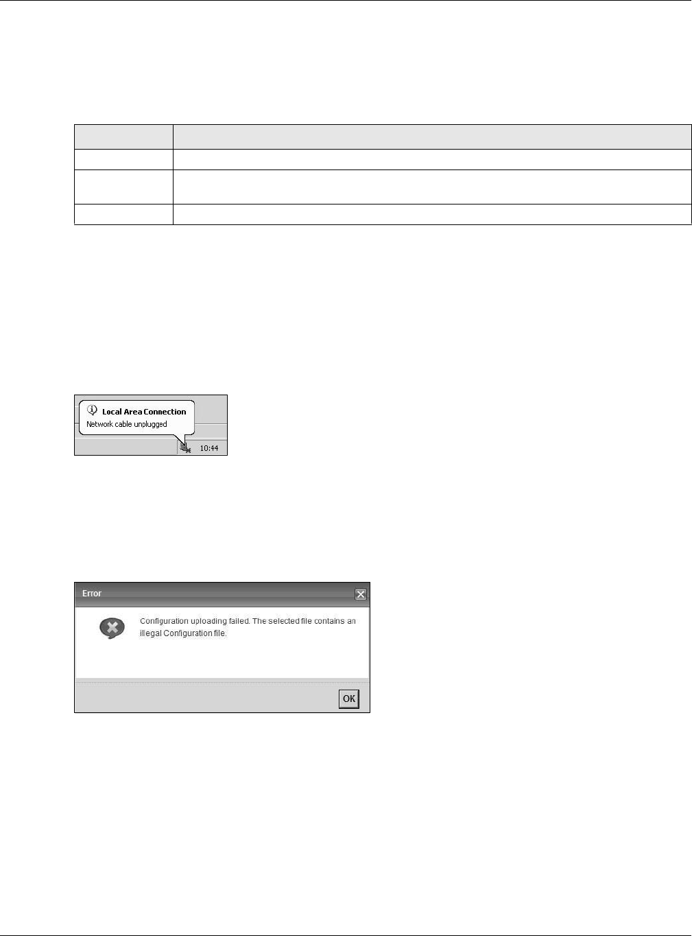
The XMG automatically restarts in this time causing a temporary network disconnect. In some operating
systems, you may see the following icon on your desktop.
Figure 155 Network Temporarily Disconnected
If you uploaded the default configuration file you may need to change the IP address of your computer
to be in the same subnet as that of the default device IP address (192.168.1.1).
If the upload was not successful, the following screen will appear. Click OK to go back to the
Configuration screen.
Figure 156 Configuration Upload Error
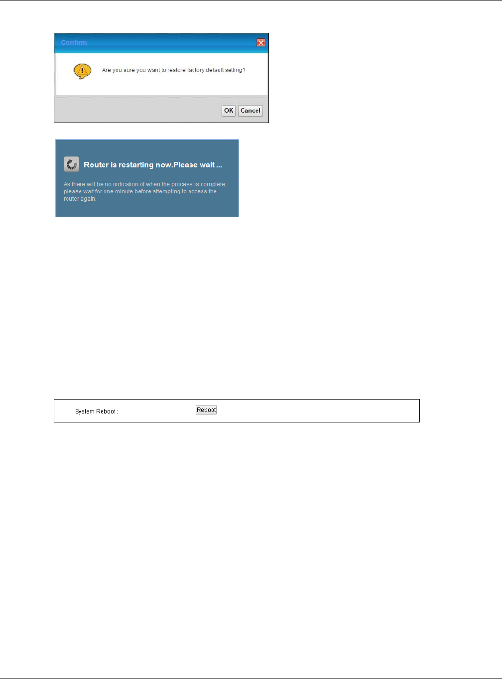
Reset to Factory Defaults
Click the Reset button to clear all user-entered configuration information and return the XMG to its
factory defaults. The following warning screen appears.
Table 121 Restore Configuration
LABEL DESCRIPTION
File Path Type in the location of the file you want to upload in this field or click Choose File to find it.
Choose File Click this to find the file you want to upload. Remember that you must decompress compressed
(.ZIP) files before you can upload them.
Upload Click this to begin the upload process.
Chapter 35 Backup/Restore
XMG3512-B10A User’s Guide
236
Figure 157 Reset Warning Message
Figure 158 Reset In Process Message
You can also press the RESET button on the rear panel to reset the factory defaults of your XMG. Refer to
Section 1.6 on page 20 for more information on the RESET button.
35.3 The Reboot Screen
System restart allows you to reboot the XMG remotely without turning the power off. You may need to
do this if the XMG hangs, for example.
Click Maintenance > Reboot. Click Reboot to have the XMG reboot. This does not affect the XMG's
configuration.
Figure 159 Maintenance > Reboot

XMG3512-B10A User’s Guide
237
CHAPTER 36
Diagnostic
36.1 Overview
The Diagnostic screens display information to help you identify problems with the XMG.
The route between a CO VDSL switch and one of its CPE may go through switches owned by
independent organizations. A connectivity fault point generally takes time to discover and impacts
subscriber’s network access. In order to eliminate the management and maintenance efforts, IEEE
802.1ag is a Connectivity Fault Management (CFM) specification which allows network administrators to
identify and manage connection faults. Through discovery and verification of the path, CFM can
detect, analyze and isolate connectivity faults in bridged LANs.
36.1.1 What You Can Do in this Chapter
• The Ping & TraceRoute & NsLookup screen lets you ping an IP address or trace the route packets take
to a host (Section 36.3 on page 238).
• The 802.1ag screen lets you perform CFM actions (Section 36.4 on page 238).
• The OAM Ping screen lets you send an ATM OAM (Operation, Administration and Maintenance)
packet to verify the connectivity of a specific PVC. (Section 36.5 on page 239).
36.2 What You Need to Know
The following terms and concepts may help as you read through this chapter.
How CFM Works
A Maintenance Association (MA) defines a VLAN and associated Maintenance End Point (MEP) ports
on the device under a Maintenance Domain (MD) level. An MEP port has the ability to send
Connectivity Check Messages (CCMs) and get other MEP ports information from neighbor devices’
CCMs within an MA.
CFM provides two tests to discover connectivity faults.
• Loopback test - checks if the MEP port receives its Loop Back Response (LBR) from its target after it
sends the Loop Back Message (LBM). If no response is received, there might be a connectivity fault
between them.
• Link trace test - provides additional connectivity fault analysis to get more information on where the
fault is. If an MEP port does not respond to the source MEP, this may indicate a fault. Administrators
can take further action to check and resume services from the fault according to the line
connectivity status report.
Chapter 36 Diagnostic
XMG3512-B10A User’s Guide
238
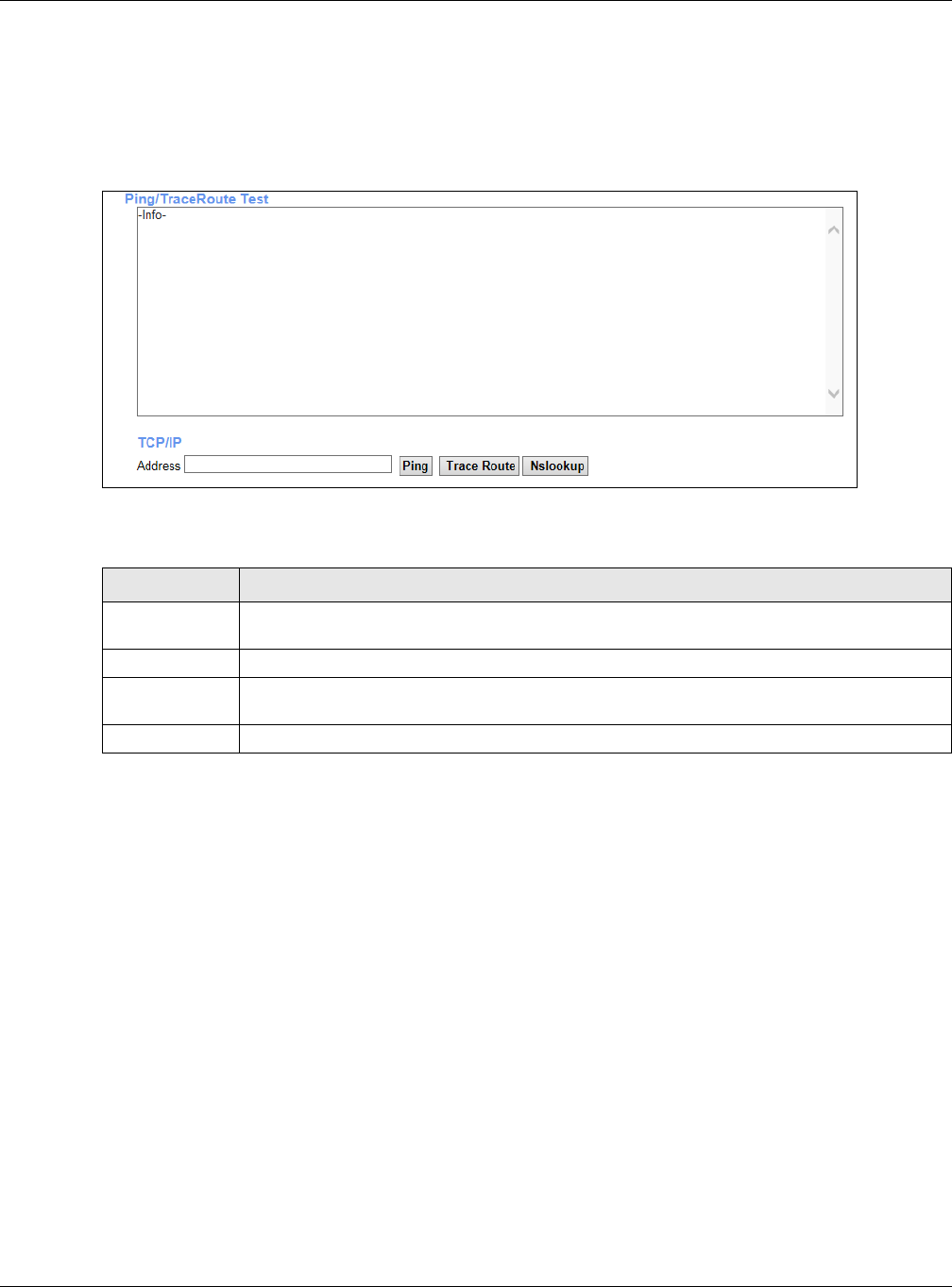
36.3 Ping & TraceRoute & NsLookup
Use this screen to ping, traceroute, or nslookup an IP address. Click Maintenance > Diagnostic >
Ping&TraceRoute&NsLookup to open the screen shown next.
Figure 160 Maintenance > Diagnostic > Ping & Traceroute & Nslookup
The following table describes the fields in this screen.
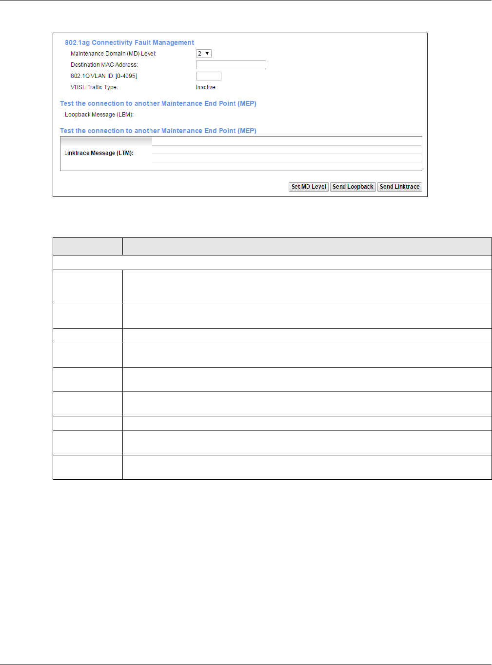
36.4 802.1ag
Click Maintenance > Diagnostic > 802.1ag to open the following screen. Use this screen to perform CFM
actions.
Table 122 Maintenance > Diagnostic > Ping & TraceRoute & NsLookup
LABEL DESCRIPTION
URL or IP
Address
Type the IP address of a computer that you want to perform ping, traceroute, or nslookup in
order to test a connection.
Ping Click this to ping the IP address that you entered.
TraceRoute Click this button to perform the traceroute function. This determines the path a packet takes to
the specified computer.
Nslookup Click this button to perform a DNS lookup on the IP address of a computer you enter.
Chapter 36 Diagnostic
XMG3512-B10A User’s Guide
239
Figure 161 Maintenance > Diagnostic > 802.1ag
The following table describes the fields in this screen.
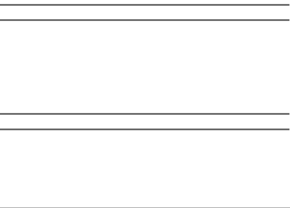
36.5 OAM Ping
Click Maintenance > Diagnostic > OAM Ping to open the screen shown next. Use this screen to perform
an OAM (Operation, Administration and Maintenance) F4 or F5 loopback test on a PVC. The XMG sends
an OAM F4 or F5 packet to the DSLAM or ATM switch and then returns it to the XMG. The test result then
displays in the text box.
Table 123 Maintenance > Diagnostic > 802.1ag
LABEL DESCRIPTION
802.1ag Connectivity Fault Management
Maintenance
Domain (MD)
Level
Select a level (0-7) under which you want to create an MA.
Destination
MAC Address
Enter the target device’s MAC address to which the XMG performs a CFM loopback test.
802.1Q VLAN ID Type a VLAN ID (0-4095) for this MA.
VDSL Traffic
Type
This shows whether the VDSL traffic is activated.
Loopback
Message (LBM)
This shows how many Loop Back Messages (LBMs) are sent and if there is any inorder or outorder
Loop Back Response (LBR) received from a remote MEP.
Linktrace
Message (LTM)
This shows the destination MAC address in the Link Trace Response (LTR).
Set MD Level Click this button to configure the MD (Maintenance Domain) level.
Send Loopback Click this button to have the selected MEP send the LBM (Loop Back Message) to a specified
remote end point.
Send Linktrace Click this button to have the selected MEP send the LTMs (Link Trace Messages) to a specified
remote end point.
Chapter 36 Diagnostic
XMG3512-B10A User’s Guide
240
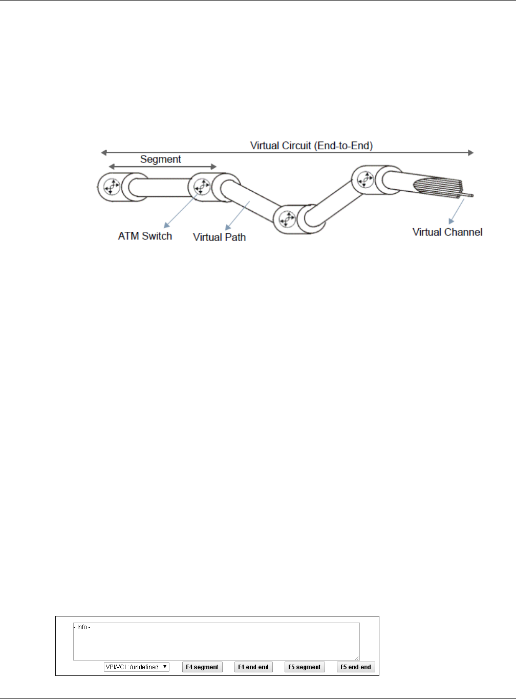
ATM sets up virtual circuits over which end systems communicate. The terminology for virtual circuits is as
follows:
Figure 162 Virtual Circuit Topology
Think of a virtual path as a cable that contains a bundle of wires. The cable connects two points and
wires within the cable provide individual circuits between the two points. In an ATM cell header, a VPI
(Virtual Path Identifier) identifies a link formed by a virtual path; a VCI (Virtual Channel Identifier)
identifies a channel within a virtual path. A series of virtual paths make up a virtual circuit.
F4 cells operate at the virtual path (VP) level, while F5 cells operate at the virtual channel (VC) level. F4
cells use the same VPI as the user data cells on VP connections, but use different predefined VCI values.
F5 cells use the same VPI and VCI as the user data cells on the VC connections, and are distinguished
from data cells by a predefinded Payload Type Identifier (PTI) in the cell header. Both F4 flows and F5
flows are bidirectional and have two types.
• segment F4 flows (VCI=3)
• end-to-end F4 flows (VCI=4)
• segment F5 flows (PTI=100)
• end-to-end F5 flows (PTI=101)
OAM F4 or F5 tests are used to check virtual path or virtual channel availability between two DSL
devices. Segment flows are terminated at the connecting point which terminates a VP or VC segment.
End-to-end flows are terminated at the end point of a VP or VC connection, where an ATM link is
terminated. Segment loopback tests allow you to verify integrity of a PVC to the nearest neighboring
ATM device. End-to-end loopback tests allow you to verify integrity of an end-to-end PVC.
Note: The DSLAM to which the XMG is connected must also support ATM F4 and/or F5 to use
this test.
Note: This screen is available only when you configure an ATM layer-2 interface.
Figure 163 Maintenance > Diagnostic > OAM Ping
• Virtual Channel (VC) Logical connections between ATM devices
• Virtual Path (VP) A bundle of virtual channels
• Virtual Circuits A series of virtual paths between circuit end points

Chapter 36 Diagnostic
XMG3512-B10A User’s Guide
241
The following table describes the fields in this screen.
Table 124 Maintenance > Diagnostic > OAM Ping
LABEL DESCRIPTION
Select a PVC on which you want to perform the loopback test.
F4 segment Press this to perform an OAM F4 segment loopback test.
F4 end-end Press this to perform an OAM F4 end-to-end loopback test.
F5 segment Press this to perform an OAM F5 segment loopback test.
F5 end-end Press this to perform an OAM F5 end-to-end loopback test.
XMG3512-B10A User’s Guide
242
CHAPTER 37
Troubleshooting
This chapter offers some suggestions to solve problems you might encounter. The potential problems are
divided into the following categories.
•Power, Hardware Connections, and LEDs
•XMG Access and Login
•Internet Access
•Wireless Internet Access
•USB Device Connection
•UPnP
37.1 Power, Hardware Connections, and LEDs
The XMG does not turn on. None of the LEDs turn on.
1Make sure the XMG is turned on.
2Make sure you are using the power adaptor or cord included with the XMG.
3Make sure the power adaptor or cord is connected to the XMG and plugged in to an appropriate
power source. Make sure the power source is turned on.
4Turn the XMG off and on.
5If the problem continues, contact the vendor.
One of the LEDs does not behave as expected.
1Make sure you understand the normal behavior of the LED. See Section 1.5 on page 18.
2Check the hardware connections.
3Inspect your cables for damage. Contact the vendor to replace any damaged cables.
4Turn the XMG off and on.
Chapter 37 Troubleshooting
XMG3512-B10A User’s Guide
243
5If the problem continues, contact the vendor.
37.2 XMG Access and Login
I forgot the IP address for the XMG.
1The default LAN IP address is 192.168.1.1.
2If you changed the IP address and have forgotten it, you might get the IP address of the XMG by looking
up the IP address of the default gateway for your computer. To do this in most Windows computers, click
Start > Run, enter cmd, and then enter ipconfig. The IP address of the Default Gateway might be the IP
address of the XMG (it depends on the network), so enter this IP address in your Internet browser.
3If this does not work, you have to reset the device to its factory defaults. See Section 1.6 on page 20.
I forgot the password.
1See the cover page for the default login names and associated passwords.
2If those do not work, you have to reset the device to its factory defaults. See Section 1.6 on page 20.
I cannot see or access the Login screen in the web configurator.
1Make sure you are using the correct IP address.
• The default IP address is 192.168.1.1.
• If you changed the IP address (Section 8.2 on page 112), use the new IP address.
• If you changed the IP address and have forgotten it, see the troubleshooting suggestions for I
forgot the IP address for the XMG.
2Check the hardware connections, and make sure the LEDs are behaving as expected. See Section 1.5
on page 18.
3Make sure your Internet browser does not block pop-up windows and has JavaScripts and Java
enabled.
4If it is possible to log in from another interface, check the service control settings for HTTP and HTTPS
(Maintenance > Remote MGMT).
5Reset the device to its factory defaults, and try to access the XMG with the default IP address. See
Section 1.6 on page 20.

Chapter 37 Troubleshooting
XMG3512-B10A User’s Guide
244
6If the problem continues, contact the network administrator or vendor, or try one of the advanced
suggestions.
Advanced Suggestions
• Make sure you have logged out of any earlier management sessions using the same user account
even if they were through a different interface or using a different browser.
• Try to access the XMG using another service, such as Telnet. If you can access the XMG, check the
remote management settings and firewall rules to find out why the XMG does not respond to HTTP.
I can see the Login screen, but I cannot log in to the XMG.
1Make sure you have entered the password correctly. See the cover page for the default login names
and associated passwords. The field is case-sensitive, so make sure [Caps Lock] is not on.
2You cannot log in to the web configurator while someone is using Telnet to access the XMG. Log out of
the XMG in the other session, or ask the person who is logged in to log out.
3Turn the XMG off and on.
4If this does not work, you have to reset the device to its factory defaults. See Section 37.1 on page 242.
I cannot Telnet to the XMG.
See the troubleshooting suggestions for I cannot see or access the Login screen in the web configurator.
Ignore the suggestions about your browser.
I cannot use FTP to upload / download the configuration file. / I cannot use FTP to upload new
firmware.
See the troubleshooting suggestions for I cannot see or access the Login screen in the web configurator.
Ignore the suggestions about your browser.
37.3 Internet Access
I cannot access the Internet.
1Check the hardware connections, and make sure the LEDs are behaving as expected. See the Quick
Start Guide and Section 1.5 on page 18.
Chapter 37 Troubleshooting
XMG3512-B10A User’s Guide
245
2Make sure you entered your ISP account information correctly in the Network Setting > Broadband
screen. These fields are case-sensitive, so make sure [Caps Lock] is not on.
3If you are trying to access the Internet wirelessly, make sure that you enabled the wireless LAN in the
XMG and your wireless client and that the wireless settings in the wireless client are the same as the
settings in the XMG.
4Disconnect all the cables from your device and reconnect them.
5If the problem continues, contact your ISP.
I cannot access the Internet through a DSL connection.
1Make sure you have the DSL WAN port connected to a telephone jack (or the DSL or modem jack on a
splitter if you have one).
2Make sure you configured a proper DSL WAN interface (Network Setting > Broadband screen) with the
Internet account information provided by your ISP and that it is enabled.
3Check that the LAN interface you are connected to is in the same interface group as the DSL
connection (Network Setting > Interface Grouping).
4If you set up a WAN connection using bridging service, make sure you turn off the DHCP feature in the
LAN screen to have the clients get WAN IP addresses directly from your ISP’s DHCP server.
I cannot connect to the Internet using a second DSL connection.
ADSL and VDSL connections cannot work at the same time. You can only use one type of DSL
connection, either ADSL or VDSL connection at one time.
I cannot connect to the Internet using an Ethernet connection.
1Make sure you have the Ethernet WAN port connected to a modem or router.
2Make sure you converted LAN port number four as WAN. Click Enable in Network Setting > Broadband >
Ethernet WAN screen.
3Make sure you configured a proper Ethernet WAN interface (Network Setting > Broadband screen) with
the Internet account information provided by your ISP and that it is enabled.
4Check that the LAN interface you are connected to is in the same interface group as the Ethernet WAN
connection (Network Setting > Interface Grouping).
5If you set up a WAN connection using bridging service, make sure you turn off the DHCP feature in the
LAN screen to have the clients get WAN IP addresses directly from your ISP’s DHCP server.
Chapter 37 Troubleshooting
XMG3512-B10A User’s Guide
246
I cannot access the XMG anymore. I had access to the XMG, but my connection is not available
anymore.
1Your session with the XMG may have expired. Try logging into the XMG again.
2Check the hardware connections, and make sure the LEDs are behaving as expected. See the Quick
Start Guide and Section 1.5 on page 18.
3Turn the XMG off and on.
4If the problem continues, contact your vendor.
37.4 Wireless Internet Access
What factors may cause intermittent or unstabled wireless connection? How can I solve this
problem?
The following factors may cause interference:
• Obstacles: walls, ceilings, furniture, and so on.
• Building Materials: metal doors, aluminum studs.
• Electrical devices: microwaves, monitors, electric motors, cordless phones, and other wireless devices.
To optimize the speed and quality of your wireless connection, you can:
• Move your wireless device closer to the AP if the signal strength is low.
• Reduce wireless interference that may be caused by other wireless networks or surrounding wireless
electronics such as cordless phones.
• Place the AP where there are minimum obstacles (such as walls and ceilings) between the AP and
the wireless client.
• Reduce the number of wireless clients connecting to the same AP simultaneously, or add additional
APs if necessary.
• Try closing some programs that use the Internet, especially peer-to-peer applications. If the wireless
client is sending or receiving a lot of information, it may have too many programs open that use the
Internet.
What is a Server Set ID (SSID)?
An SSID is a name that uniquely identifies a wireless network. The AP and all the clients within a wireless
network must use the same SSID.
Chapter 37 Troubleshooting
XMG3512-B10A User’s Guide
247
37.5 USB Device Connection
The XMG fails to detect my USB device.
1Disconnect the USB device.
2Reboot the XMG.
3If you are connecting a USB hard drive that comes with an external power supply, make sure it is
connected to an appropriate power source that is on.
4Re-connect your USB device to the XMG.
37.6 UPnP
When using UPnP and the XMG reboots, my computer cannot detect UPnP and refresh My
Network Places > Local Network.
1Disconnect the Ethernet cable from the XMG’s LAN port or from your computer.
2Re-connect the Ethernet cable.
The Local Area Connection icon for UPnP disappears in the screen.
Restart your computer.
248
PART III
Appendices
Appendices contain general information. Some information may not apply to your device.

XMG3512-B10A User’s Guide
249
APPENDIX A
Customer Support
In the event of problems that cannot be solved by using this manual, you should contact your vendor. If
you cannot contact your vendor, then contact a Zyxel office for the region in which you bought the
device.
See http://www.zyxel.com/homepage.shtml and also
http://www.zyxel.com/about_zyxel/zyxel_worldwide.shtml for the latest information.
Please have the following information ready when you contact an office.
Required Information
• Product model and serial number.
• Warranty Information.
• Date that you received your device.
• Brief description of the problem and the steps you took to solve it.
Corporate Headquarters (Worldwide)
Taiwan
• Zyxel Communications Corporation
• http://www.zyxel.com
Asia
China
• Zyxel Communications (Shanghai) Corp.
Zyxel Communications (Beijing) Corp.
Zyxel Communications (Tianjin) Corp.
• http://www.zyxel.cn
India
•Zyxel Technology India Pvt Ltd
• http://www.zyxel.in
Kazakhstan
•Zyxel Kazakhstan
• http://www.zyxel.kz

Appendix A Customer Support
XMG3512-B10A User’s Guide
250
Korea
• Zyxel Korea Corp.
• http://www.zyxel.kr
Malaysia
• Zyxel Malaysia Sdn Bhd.
• http://www.zyxel.com.my
Pakistan
• Zyxel Pakistan (Pvt.) Ltd.
• http://www.zyxel.com.pk
Philippines
• Zyxel Philippines
• http://www.zyxel.com.ph
Singapore
• Zyxel Singapore Pte Ltd.
• http://www.zyxel.com.sg
Taiwan
• Zyxel Communications Corporation
• http://www.zyxel.com/tw/zh/
Thailand
• Zyxel Thailand Co., Ltd
• http://www.zyxel.co.th
Vietnam
• Zyxel Communications Corporation-Vietnam Office
• http://www.zyxel.com/vn/vi
Europe
Austria
•Zyxel Deutschland GmbH
• http://www.zyxel.de
Belarus
•Zyxel BY
• http://www.zyxel.by

Appendix A Customer Support
XMG3512-B10A User’s Guide
251
Belgium
• Zyxel Communications B.V.
• http://www.zyxel.com/be/nl/
• http://www.zyxel.com/be/fr/
Bulgaria
•Zyxel България
• http://www.zyxel.com/bg/bg/
Czech Republic
• Zyxel Communications Czech s.r.o
• http://www.zyxel.cz
Denmark
• Zyxel Communications A/S
• http://www.zyxel.dk
Estonia
• Zyxel Estonia
• http://www.zyxel.com/ee/et/
Finland
• Zyxel Communications
• http://www.zyxel.fi
France
•Zyxel France
• http://www.zyxel.fr
Germany
•Zyxel Deutschland GmbH
• http://www.zyxel.de
Hungary
• Zyxel Hungary & SEE
• http://www.zyxel.hu
Italy
• Zyxel Communications Italy
• http://www.zyxel.it/

Appendix A Customer Support
XMG3512-B10A User’s Guide
252
Latvia
•Zyxel Latvia
• http://www.zyxel.com/lv/lv/homepage.shtml
Lithuania
•Zyxel Lithuania
• http://www.zyxel.com/lt/lt/homepage.shtml
Netherlands
• Zyxel Benelux
• http://www.zyxel.nl
Norway
• Zyxel Communications
• http://www.zyxel.no
Poland
• Zyxel Communications Poland
• http://www.zyxel.pl
Romania
• Zyxel Romania
• http://www.zyxel.com/ro/ro
Russia
• Zyxel Russia
• http://www.zyxel.ru
Slovakia
• Zyxel Communications Czech s.r.o. organizacna zlozka
• http://www.zyxel.sk
Spain
• Zyxel Communications ES Ltd
• http://www.zyxel.es
Sweden
• Zyxel Communications
• http://www.zyxel.se
Switzerland
•Studerus AG

Appendix A Customer Support
XMG3512-B10A User’s Guide
253
• http://www.zyxel.ch/
Turkey
• Zyxel Turkey A.S.
• http://www.zyxel.com.tr
UK
• Zyxel Communications UK Ltd.
• http://www.zyxel.co.uk
Ukraine
•Zyxel Ukraine
• http://www.ua.zyxel.com
Latin America
Argentina
• Zyxel Communication Corporation
• http://www.zyxel.com/ec/es/
Brazil
• Zyxel Communications Brasil Ltda.
• https://www.zyxel.com/br/pt/
Ecuador
• Zyxel Communication Corporation
• http://www.zyxel.com/ec/es/
Middle East
Israel
• Zyxel Communication Corporation
• http://il.zyxel.com/homepage.shtml
Middle East
• Zyxel Communication Corporation
• http://www.zyxel.com/me/en/

Appendix A Customer Support
XMG3512-B10A User’s Guide
254
North America
USA
• Zyxel Communications, Inc. - North America Headquarters
• http://www.zyxel.com/us/en/
Oceania
Australia
• Zyxel Communications Corporation
• http://www.zyxel.com/au/en/
Africa
South Africa
• Nology (Pty) Ltd.
• http://www.zyxel.co.za
XMG3512-B10A User’s Guide
255
APPENDIX B
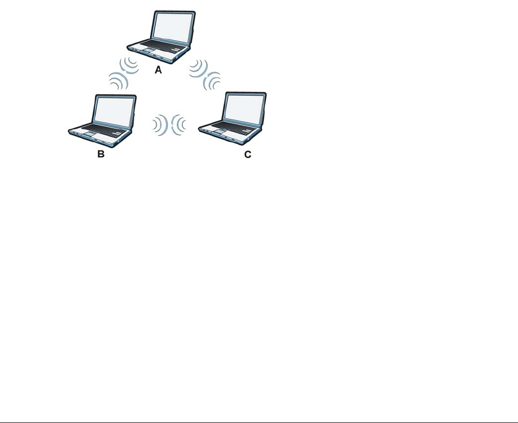
Wireless LANs
Wireless LAN Topologies
This section discusses ad-hoc and infrastructure wireless LAN topologies.
Ad-hoc Wireless LAN Configuration
The simplest WLAN configuration is an independent (Ad-hoc) WLAN that connects a set of computers
with wireless adapters (A, B, C). Any time two or more wireless adapters are within range of each other,
they can set up an independent network, which is commonly referred to as an ad-hoc network or
Independent Basic Service Set (IBSS). The following diagram shows an example of notebook computers
using wireless adapters to form an ad-hoc wireless LAN.
Figure 164 Peer-to-Peer Communication in an Ad-hoc Network
BSS
A Basic Service Set (BSS) exists when all communications between wireless clients or between a wireless
client and a wired network client go through one access point (AP).
Intra-BSS traffic is traffic between wireless clients in the BSS. When Intra-BSS is enabled, wireless client A
and B can access the wired network and communicate with each other. When Intra-BSS is disabled,
wireless client A and B can still access the wired network but cannot communicate with each other.
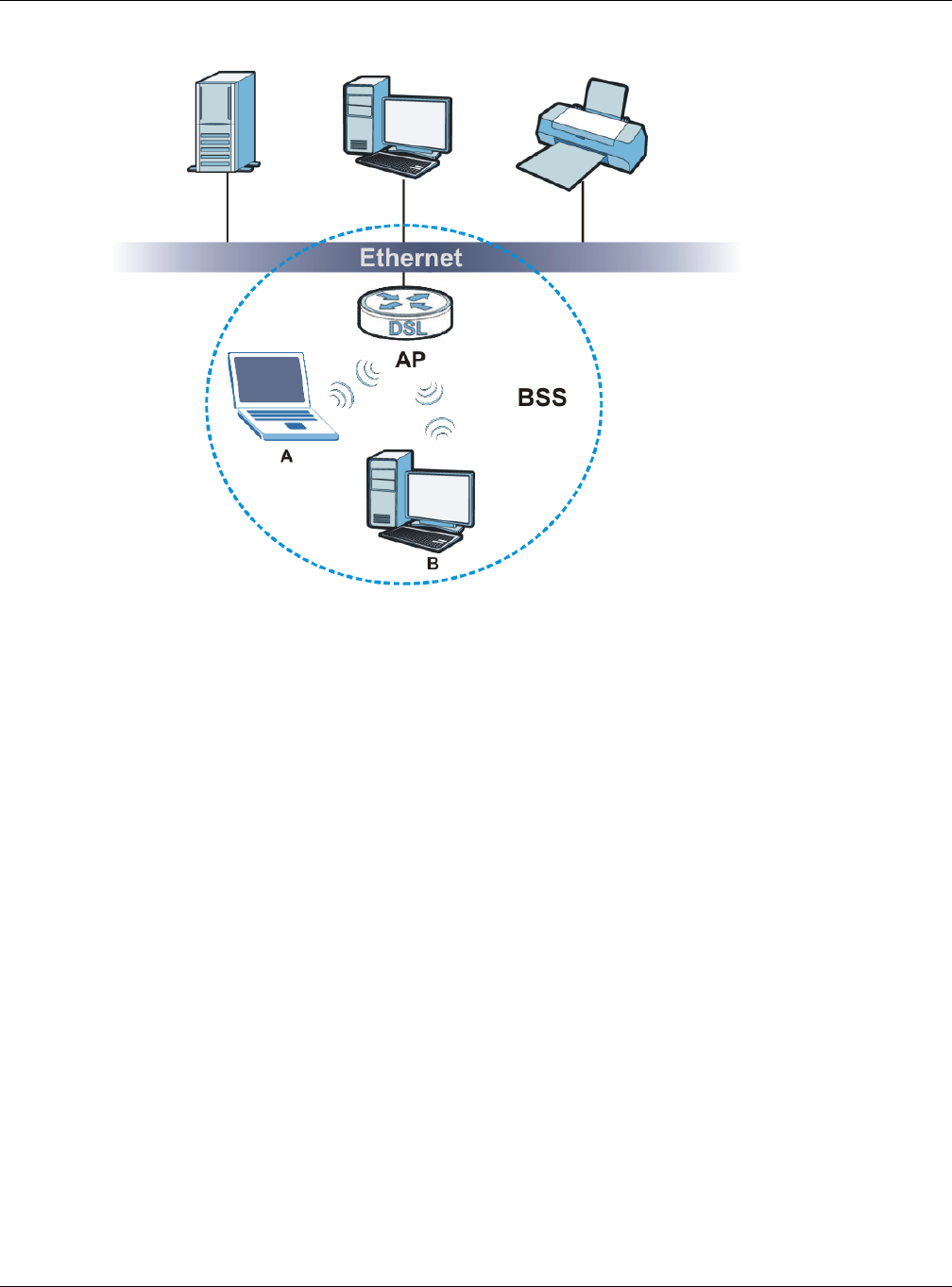
Appendix B Wireless LANs
XMG3512-B10A User’s Guide
256
Figure 165 Basic Service Set
ESS
An Extended Service Set (ESS) consists of a series of overlapping BSSs, each containing an access point,
with each access point connected together by a wired network. This wired connection between APs is
called a Distribution System (DS).
This type of wireless LAN topology is called an Infrastructure WLAN. The Access Points not only provide
communication with the wired network but also mediate wireless network traffic in the immediate
neighborhood.
An ESSID (ESS IDentification) uniquely identifies each ESS. All access points and their associated wireless
clients within the same ESS must have the same ESSID in order to communicate.
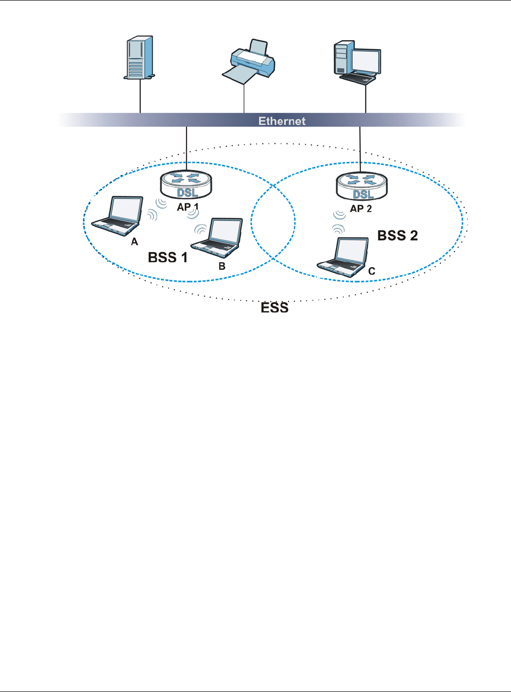
Appendix B Wireless LANs
XMG3512-B10A User’s Guide
257
Figure 166 Infrastructure WLAN
Channel
A channel is the radio frequency(ies) used by wireless devices to transmit and receive data. Channels
available depend on your geographical area. You may have a choice of channels (for your region) so
you should use a channel different from an adjacent AP (access point) to reduce interference.
Interference occurs when radio signals from different access points overlap causing interference and
degrading performance.
Adjacent channels partially overlap however. To avoid interference due to overlap, your AP should be
on a channel at least five channels away from a channel that an adjacent AP is using. For example, if
your region has 11 channels and an adjacent AP is using channel 1, then you need to select a channel
between 6 or 11.
RTS/CTS
A hidden node occurs when two stations are within range of the same access point, but are not within
range of each other. The following figure illustrates a hidden node. Both stations (STA) are within range
of the access point (AP) or wireless gateway, but out-of-range of each other, so they cannot "hear"
each other, that is they do not know if the channel is currently being used. Therefore, they are
considered hidden from each other.
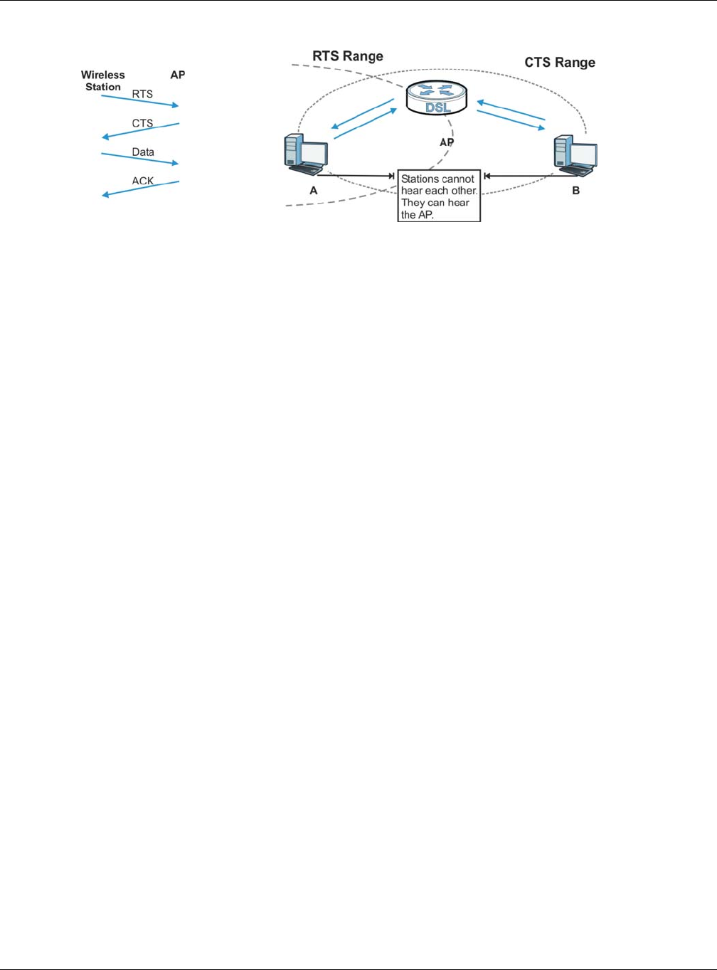
Appendix B Wireless LANs
XMG3512-B10A User’s Guide
258
Figure 167 RTS/CTS
When station A sends data to the AP, it might not know that the station B is already using the channel. If
these two stations send data at the same time, collisions may occur when both sets of data arrive at the
AP at the same time, resulting in a loss of messages for both stations.
RTS/CTS is designed to prevent collisions due to hidden nodes. An RTS/CTS defines the biggest size data
frame you can send before an RTS (Request To Send)/CTS (Clear to Send) handshake is invoked.
When a data frame exceeds the RTS/CTS value you set (between 0 to 2432 bytes), the station that wants
to transmit this frame must first send an RTS (Request To Send) message to the AP for permission to send
it. The AP then responds with a CTS (Clear to Send) message to all other stations within its range to notify
them to defer their transmission. It also reserves and confirms with the requesting station the time frame
for the requested transmission.
Stations can send frames smaller than the specified RTS/CTS directly to the AP without the RTS (Request
To Send)/CTS (Clear to Send) handshake.
You should only configure RTS/CTS if the possibility of hidden nodes exists on your network and the "cost"
of resending large frames is more than the extra network overhead involved in the RTS (Request To
Send)/CTS (Clear to Send) handshake.
If the RTS/CTS value is greater than the Fragmentation Threshold value (see next), then the RTS (Request
To Send)/CTS (Clear to Send) handshake will never occur as data frames will be fragmented before
they reach RTS/CTS size.
Note: Enabling the RTS Threshold causes redundant network overhead that could negatively
affect the throughput performance instead of providing a remedy.
Fragmentation Threshold
A Fragmentation Threshold is the maximum data fragment size (between 256 and 2432 bytes) that can
be sent in the wireless network before the AP will fragment the packet into smaller data frames.
A large Fragmentation Threshold is recommended for networks not prone to interference while you
should set a smaller threshold for busy networks or networks that are prone to interference.
If the Fragmentation Threshold value is smaller than the RTS/CTS value (see previously) you set then the
RTS (Request To Send)/CTS (Clear to Send) handshake will never occur as data frames will be
fragmented before they reach RTS/CTS size.
Appendix B Wireless LANs
XMG3512-B10A User’s Guide
259
IEEE 802.11g Wireless LAN
IEEE 802.11g is fully compatible with the IEEE 802.11b standard. This means an IEEE 802.11b adapter can
interface directly with an IEEE 802.11g access point (and vice versa) at 11 Mbps or lower depending on
range. IEEE 802.11g has several intermediate rate steps between the maximum and minimum data
rates. The IEEE 802.11g data rate and modulation are as follows:
Wireless Security Overview
Wireless security is vital to your network to protect wireless communication between wireless clients,
access points and the wired network.
Wireless security methods available on the XMG are data encryption, wireless client authentication,
restricting access by device MAC address and hiding the XMG identity.
The following figure shows the relative effectiveness of these wireless security methods available on your
XMG.
Note: You must enable the same wireless security settings on the XMG and on all wireless
clients that you want to associate with it.
IEEE 802.1x
In June 2001, the IEEE 802.1x standard was designed to extend the features of IEEE 802.11 to support
extended authentication as well as providing additional accounting and control features. It is
supported by Windows XP and a number of network devices. Some advantages of IEEE 802.1x are:
• User based identification that allows for roaming.
• Support for RADIUS (Remote Authentication Dial In User Service, RFC 2138, 2139) for centralized user
profile and accounting management on a network RADIUS server.
Table 125 IEEE 802.11g
DATA RATE (MBPS) MODULATION
1 DBPSK (Differential Binary Phase Shift Keyed)
2 DQPSK (Differential Quadrature Phase Shift Keying)
5.5 / 11 CCK (Complementary Code Keying)
6/9/12/18/24/36/48/54 OFDM (Orthogonal Frequency Division Multiplexing)
Table 126 Wireless Security Levels
SECURITY
LEVEL SECURITY TYPE
Least Secure
Most Secure
Unique SSID (Default)
Unique SSID with Hide SSID Enabled
MAC Address Filtering
WEP Encryption
IEEE802.1x EAP with RADIUS Server Authentication
Wi-Fi Protected Access (WPA)
WPA2

Appendix B Wireless LANs
XMG3512-B10A User’s Guide
260
• Support for EAP (Extensible Authentication Protocol, RFC 2486) that allows additional authentication
methods to be deployed with no changes to the access point or the wireless clients.
RADIUS
RADIUS is based on a client-server model that supports authentication, authorization and accounting.
The access point is the client and the server is the RADIUS server. The RADIUS server handles the following
tasks:
• Authentication
Determines the identity of the users.
•Authorization
Determines the network services available to authenticated users once they are connected to the
network.
• Accounting
Keeps track of the client’s network activity.
RADIUS is a simple package exchange in which your AP acts as a message relay between the wireless
client and the network RADIUS server.
Types of RADIUS Messages
The following types of RADIUS messages are exchanged between the access point and the RADIUS
server for user authentication:
• Access-Request
Sent by an access point requesting authentication.
• Access-Reject
Sent by a RADIUS server rejecting access.
• Access-Accept
Sent by a RADIUS server allowing access.
• Access-Challenge
Sent by a RADIUS server requesting more information in order to allow access. The access point sends
a proper response from the user and then sends another Access-Request message.
The following types of RADIUS messages are exchanged between the access point and the RADIUS
server for user accounting:
• Accounting-Request
Sent by the access point requesting accounting.
• Accounting-Response
Sent by the RADIUS server to indicate that it has started or stopped accounting.
In order to ensure network security, the access point and the RADIUS server use a shared secret key,
which is a password, they both know. The key is not sent over the network. In addition to the shared key,
password information exchanged is also encrypted to protect the network from unauthorized access.

Appendix B Wireless LANs
XMG3512-B10A User’s Guide
261
Types of EAP Authentication
This section discusses some popular authentication types: EAP-MD5, EAP-TLS, EAP-TTLS, PEAP and LEAP.
Your wireless LAN device may not support all authentication types.
EAP (Extensible Authentication Protocol) is an authentication protocol that runs on top of the IEEE 802.1x
transport mechanism in order to support multiple types of user authentication. By using EAP to interact
with an EAP-compatible RADIUS server, an access point helps a wireless station and a RADIUS server
perform authentication.
The type of authentication you use depends on the RADIUS server and an intermediary AP(s) that
supports IEEE 802.1x.
For EAP-TLS authentication type, you must first have a wired connection to the network and obtain the
certificate(s) from a certificate authority (CA). A certificate (also called digital IDs) can be used to
authenticate users and a CA issues certificates and guarantees the identity of each certificate owner.
EAP-MD5 (Message-Digest Algorithm 5)
MD5 authentication is the simplest one-way authentication method. The authentication server sends a
challenge to the wireless client. The wireless client ‘proves’ that it knows the password by encrypting the
password with the challenge and sends back the information. Password is not sent in plain text.
However, MD5 authentication has some weaknesses. Since the authentication server needs to get the
plaintext passwords, the passwords must be stored. Thus someone other than the authentication server
may access the password file. In addition, it is possible to impersonate an authentication server as MD5
authentication method does not perform mutual authentication. Finally, MD5 authentication method
does not support data encryption with dynamic session key. You must configure WEP encryption keys for
data encryption.
EAP-TLS (Transport Layer Security)
With EAP-TLS, digital certifications are needed by both the server and the wireless clients for mutual
authentication. The server presents a certificate to the client. After validating the identity of the server,
the client sends a different certificate to the server. The exchange of certificates is done in the open
before a secured tunnel is created. This makes user identity vulnerable to passive attacks. A digital
certificate is an electronic ID card that authenticates the sender’s identity. However, to implement EAP-
TLS, you need a Certificate Authority (CA) to handle certificates, which imposes a management
overhead.
EAP-TTLS (Tunneled Transport Layer Service)
EAP-TTLS is an extension of the EAP-TLS authentication that uses certificates for only the server-side
authentications to establish a secure connection. Client authentication is then done by sending
username and password through the secure connection, thus client identity is protected. For client
authentication, EAP-TTLS supports EAP methods and legacy authentication methods such as PAP, CHAP,
MS-CHAP and MS-CHAP v2.
PEAP (Protected EAP)
Like EAP-TTLS, server-side certificate authentication is used to establish a secure connection, then use
simple username and password methods through the secured connection to authenticate the clients,
thus hiding client identity. However, PEAP only supports EAP methods, such as EAP-MD5, EAP-MSCHAPv2

Appendix B Wireless LANs
XMG3512-B10A User’s Guide
262
and EAP-GTC (EAP-Generic Token Card), for client authentication. EAP-GTC is implemented only by
Cisco.
LEAP
LEAP (Lightweight Extensible Authentication Protocol) is a Cisco implementation of IEEE 802.1x.
Dynamic WEP Key Exchange
The AP maps a unique key that is generated with the RADIUS server. This key expires when the wireless
connection times out, disconnects or reauthentication times out. A new WEP key is generated each
time reauthentication is performed.
If this feature is enabled, it is not necessary to configure a default encryption key in the wireless security
configuration screen. You may still configure and store keys, but they will not be used while dynamic
WEP is enabled.
Note: EAP-MD5 cannot be used with Dynamic WEP Key Exchange
For added security, certificate-based authentications (EAP-TLS, EAP-TTLS and PEAP) use dynamic keys for
data encryption. They are often deployed in corporate environments, but for public deployment, a
simple user name and password pair is more practical. The following table is a comparison of the
features of authentication types.
WPA and WPA2
Wi-Fi Protected Access (WPA) is a subset of the IEEE 802.11i standard. WPA2 (IEEE 802.11i) is a wireless
security standard that defines stronger encryption, authentication and key management than WPA.
Key differences between WPA or WPA2 and WEP are improved data encryption and user
authentication.
If both an AP and the wireless clients support WPA2 and you have an external RADIUS server, use WPA2
for stronger data encryption. If you don't have an external RADIUS server, you should use WPA2-PSK
(WPA2-Pre-Shared Key) that only requires a single (identical) password entered into each access point,
wireless gateway and wireless client. As long as the passwords match, a wireless client will be granted
access to a WLAN.
If the AP or the wireless clients do not support WPA2, just use WPA or WPA-PSK depending on whether
you have an external RADIUS server or not.
Table 127 Comparison of EAP Authentication Types
EAP-MD5 EAP-TLS EAP-TTLS PEAP LEAP
Mutual Authentication No Yes Yes Yes Yes
Certificate – Client No Yes Optional Optional No
Certificate – Server No Yes Yes Yes No
Dynamic Key Exchange No Yes Yes Yes Yes
Credential Integrity None Strong Strong Strong Moderate
Deployment Difficulty Easy Hard Moderate Moderate Moderate
Client Identity Protection No No Yes Yes No

Appendix B Wireless LANs
XMG3512-B10A User’s Guide
263
Select WEP only when the AP and/or wireless clients do not support WPA or WPA2. WEP is less secure
than WPA or WPA2.
Encryption
WPA improves data encryption by using Temporal Key Integrity Protocol (TKIP), Message Integrity Check
(MIC) and IEEE 802.1x. WPA2 also uses TKIP when required for compatibility reasons, but offers stronger
encryption than TKIP with Advanced Encryption Standard (AES) in the Counter mode with Cipher block
chaining Message authentication code Protocol (CCMP).
TKIP uses 128-bit keys that are dynamically generated and distributed by the authentication server. AES
(Advanced Encryption Standard) is a block cipher that uses a 256-bit mathematical algorithm called
Rijndael. They both include a per-packet key mixing function, a Message Integrity Check (MIC) named
Michael, an extended initialization vector (IV) with sequencing rules, and a re-keying mechanism.
WPA and WPA2 regularly change and rotate the encryption keys so that the same encryption key is
never used twice.
The RADIUS server distributes a Pairwise Master Key (PMK) key to the AP that then sets up a key hierarchy
and management system, using the PMK to dynamically generate unique data encryption keys to
encrypt every data packet that is wirelessly communicated between the AP and the wireless clients. This
all happens in the background automatically.
The Message Integrity Check (MIC) is designed to prevent an attacker from capturing data packets,
altering them and resending them. The MIC provides a strong mathematical function in which the
receiver and the transmitter each compute and then compare the MIC. If they do not match, it is
assumed that the data has been tampered with and the packet is dropped.
By generating unique data encryption keys for every data packet and by creating an integrity
checking mechanism (MIC), with TKIP and AES it is more difficult to decrypt data on a Wi-Fi network than
WEP and difficult for an intruder to break into the network.
The encryption mechanisms used for WPA(2) and WPA(2)-PSK are the same. The only difference
between the two is that WPA(2)-PSK uses a simple common password, instead of user-specific
credentials. The common-password approach makes WPA(2)-PSK susceptible to brute-force password-
guessing attacks but it’s still an improvement over WEP as it employs a consistent, single, alphanumeric
password to derive a PMK which is used to generate unique temporal encryption keys. This prevent all
wireless devices sharing the same encryption keys. (a weakness of WEP)
User Authentication
WPA and WPA2 apply IEEE 802.1x and Extensible Authentication Protocol (EAP) to authenticate wireless
clients using an external RADIUS database. WPA2 reduces the number of key exchange messages from
six to four (CCMP 4-way handshake) and shortens the time required to connect to a network. Other
WPA2 authentication features that are different from WPA include key caching and pre-authentication.
These two features are optional and may not be supported in all wireless devices.
Key caching allows a wireless client to store the PMK it derived through a successful authentication with
an AP. The wireless client uses the PMK when it tries to connect to the same AP and does not need to go
with the authentication process again.
Pre-authentication enables fast roaming by allowing the wireless client (already connecting to an AP) to
perform IEEE 802.1x authentication with another AP before connecting to it.
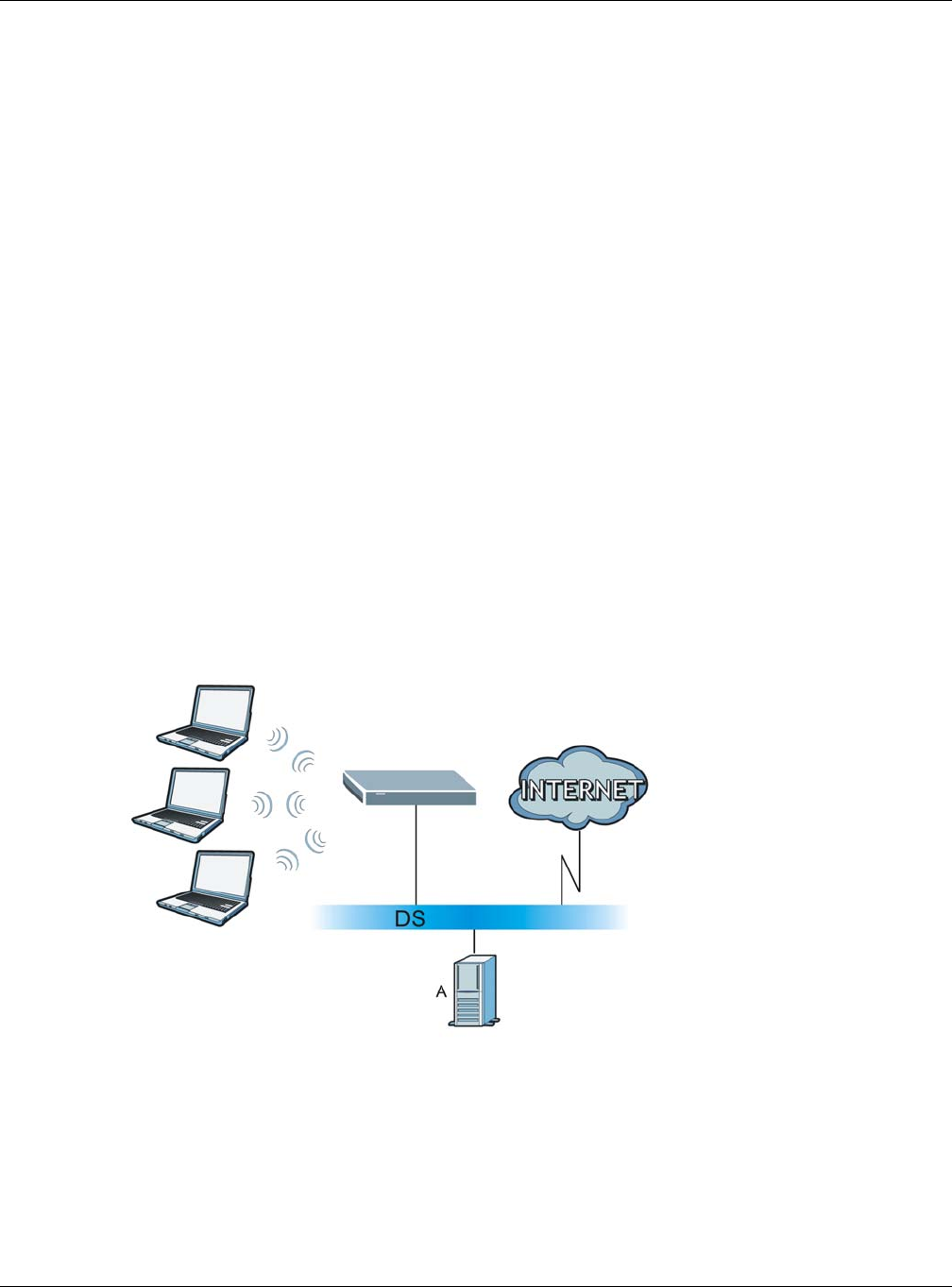
Appendix B Wireless LANs
XMG3512-B10A User’s Guide
264
Wireless Client WPA Supplicants
A wireless client supplicant is the software that runs on an operating system instructing the wireless client
how to use WPA. At the time of writing, the most widely available supplicant is the WPA patch for
Windows XP, Funk Software's Odyssey client.
The Windows XP patch is a free download that adds WPA capability to Windows XP's built-in "Zero
Configuration" wireless client. However, you must run Windows XP to use it.
WPA(2) with RADIUS Application Example
To set up WPA(2), you need the IP address of the RADIUS server, its port number (default is 1812), and the
RADIUS shared secret. A WPA(2) application example with an external RADIUS server looks as follows. "A"
is the RADIUS server. "DS" is the distribution system.
1The AP passes the wireless client's authentication request to the RADIUS server.
2The RADIUS server then checks the user's identification against its database and grants or denies
network access accordingly.
3A 256-bit Pairwise Master Key (PMK) is derived from the authentication process by the RADIUS server and
the client.
4The RADIUS server distributes the PMK to the AP. The AP then sets up a key hierarchy and management
system, using the PMK to dynamically generate unique data encryption keys. The keys are used to
encrypt every data packet that is wirelessly communicated between the AP and the wireless clients.
Figure 168 WPA(2) with RADIUS Application Example
WPA(2)-PSK Application Example
A WPA(2)-PSK application looks as follows.
1First enter identical passwords into the AP and all wireless clients. The Pre-Shared Key (PSK) must consist
of between 8 and 63 ASCII characters or 64 hexadecimal characters (including spaces and symbols).
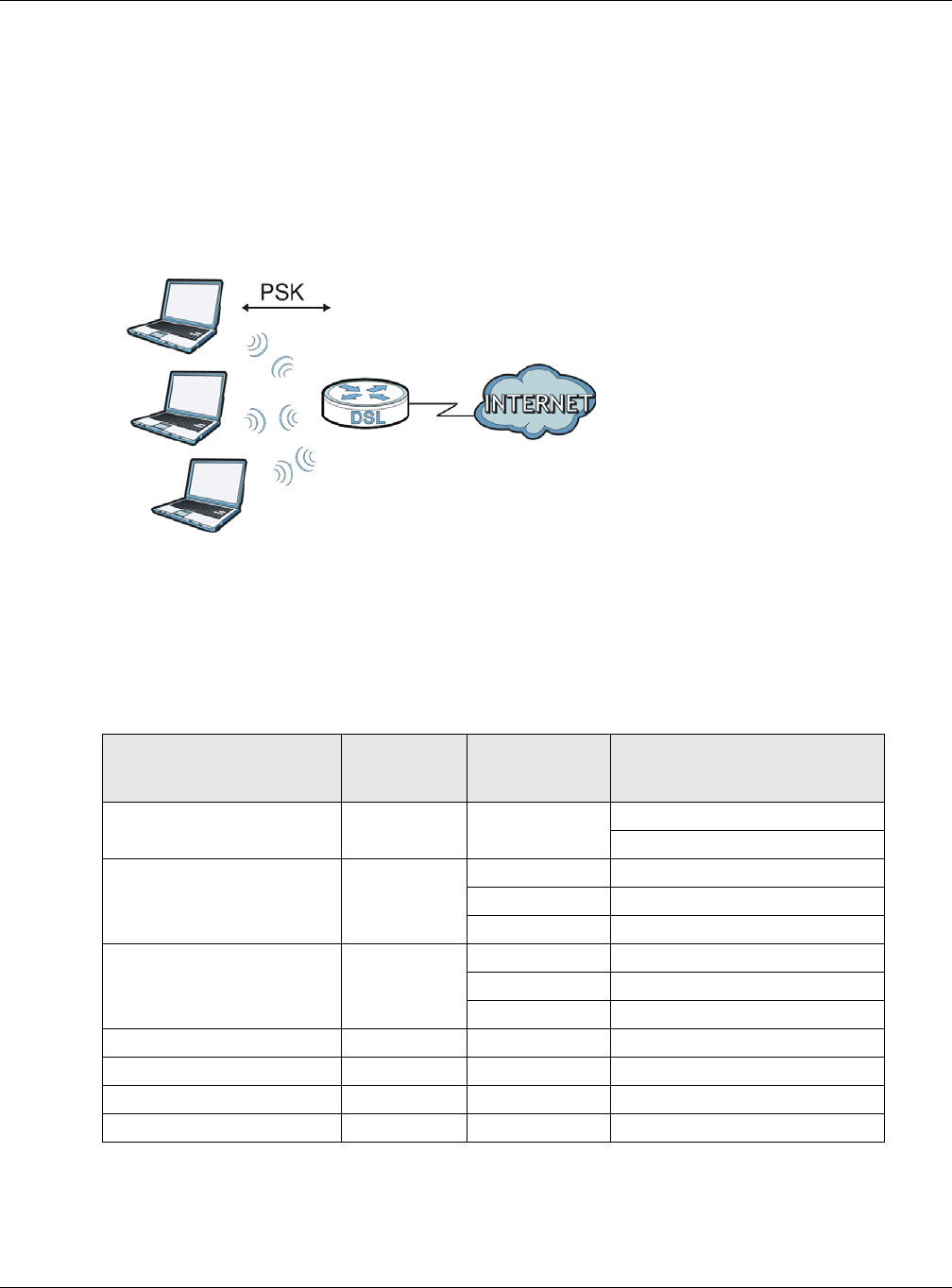
Appendix B Wireless LANs
XMG3512-B10A User’s Guide
265
2The AP checks each wireless client's password and allows it to join the network only if the password
matches.
3The AP and wireless clients generate a common PMK (Pairwise Master Key). The key itself is not sent over
the network, but is derived from the PSK and the SSID.
4The AP and wireless clients use the TKIP or AES encryption process, the PMK and information exchanged
in a handshake to create temporal encryption keys. They use these keys to encrypt data exchanged
between them.
Figure 169 WPA(2)-PSK Authentication
Security Parameters Summary
Refer to this table to see what other security parameters you should configure for each authentication
method or key management protocol type. MAC address filters are not dependent on how you
configure these security features.
Table 128 Wireless Security Relational Matrix
AUTHENTICATION METHOD/
KEY MANAGEMENT
PROTOCOL ENCRYPTION
METHOD ENTER MANUAL
KEY IEEE 802.1X
Open None No Disable
Enable without Dynamic WEP Key
Open WEP No Enable with Dynamic WEP Key
Yes Enable without Dynamic WEP Key
Yes Disable
Shared WEP No Enable with Dynamic WEP Key
Yes Enable without Dynamic WEP Key
Yes Disable
WPA TKIP/AES No Enable
WPA-PSK TKIP/AES Yes Disable
WPA2 TKIP/AES No Enable
WPA2-PSK TKIP/AES Yes Disable

Appendix B Wireless LANs
XMG3512-B10A User’s Guide
266
Antenna Overview
An antenna couples RF signals onto air. A transmitter within a wireless device sends an RF signal to the
antenna, which propagates the signal through the air. The antenna also operates in reverse by
capturing RF signals from the air.
Positioning the antennas properly increases the range and coverage area of a wireless LAN.
Antenna Characteristics
Frequency
An antenna in the frequency of 2.4GHz (IEEE 802.11b and IEEE 802.11g) or 5GHz (IEEE 802.11a) is needed
to communicate efficiently in a wireless LAN
Radiation Pattern
A radiation pattern is a diagram that allows you to visualize the shape of the antenna’s coverage area.
Antenna Gain
Antenna gain, measured in dB (decibel), is the increase in coverage within the RF beam width. Higher
antenna gain improves the range of the signal for better communications.
For an indoor site, each 1 dB increase in antenna gain results in a range increase of approximately 2.5%.
For an unobstructed outdoor site, each 1dB increase in gain results in a range increase of approximately
5%. Actual results may vary depending on the network environment.
Antenna gain is sometimes specified in dBi, which is how much the antenna increases the signal power
compared to using an isotropic antenna. An isotropic antenna is a theoretical perfect antenna that
sends out radio signals equally well in all directions. dBi represents the true gain that the antenna
provides.
Types of Antennas for WLAN
There are two types of antennas used for wireless LAN applications.
• Omni-directional antennas send the RF signal out in all directions on a horizontal plane. The coverage
area is torus-shaped (like a donut) which makes these antennas ideal for a room environment. With a
wide coverage area, it is possible to make circular overlapping coverage areas with multiple access
points.
• Directional antennas concentrate the RF signal in a beam, like a flashlight does with the light from its
bulb. The angle of the beam determines the width of the coverage pattern. Angles typically range
from 20 degrees (very directional) to 120 degrees (less directional). Directional antennas are ideal for
hallways and outdoor point-to-point applications.
Positioning Antennas
In general, antennas should be mounted as high as practically possible and free of obstructions. In
point-to–point application, position both antennas at the same height and in a direct line of sight to
each other to attain the best performance.

Appendix B Wireless LANs
XMG3512-B10A User’s Guide
267
For omni-directional antennas mounted on a table, desk, and so on, point the antenna up. For omni-
directional antennas mounted on a wall or ceiling, point the antenna down. For a single AP application,
place omni-directional antennas as close to the center of the coverage area as possible.
For directional antennas, point the antenna in the direction of the desired coverage area.

XMG3512-B10A User’s Guide
268
APPENDIX C
Services
The following table lists some commonly-used services and their associated protocols and port numbers.
•Name: This is a short, descriptive name for the service. You can use this one or create a different one,
if you like.
•Protocol: This is the type of IP protocol used by the service. If this is TCP/UDP, then the service uses the
same port number with TCP and UDP. If this is USER-DEFINED, the Port(s) is the IP protocol number, not
the port number.
•Port(s): This value depends on the Protocol.
•If the Protocol is TCP, UDP, or TCP/UDP, this is the IP port number.
•If the Protocol is USER, this is the IP protocol number.
•Description: This is a brief explanation of the applications that use this service or the situations in which
this service is used.

Appendix C Services
XMG3512-B10A User’s Guide
269
Table 129 Examples of Services
NAME PROTOCOL PORT(S) DESCRIPTION
AH (IPSEC_TUNNEL) User-Defined 51 The IPSEC AH (Authentication Header) tunneling
protocol uses this service.
AIM TCP 5190 AOL’s Internet Messenger service.
AUTH TCP 113 Authentication protocol used by some servers.
BGP TCP 179 Border Gateway Protocol.
BOOTP_CLIENT UDP 68 DHCP Client.
BOOTP_SERVER UDP 67 DHCP Server.
CU-SEEME TCP/UDP
TCP/UDP
7648
24032
A popular videoconferencing solution from White
Pines Software.
DNS TCP/UDP 53 Domain Name Server, a service that matches web
names (for instance www.zyxel.com) to IP numbers.
ESP (IPSEC_TUNNEL) User-Defined 50 The IPSEC ESP (Encapsulation Security Protocol)
tunneling protocol uses this service.
FINGER TCP 79 Finger is a UNIX or Internet related command that can
be used to find out if a user is logged on.
FTP TCP
TCP
20
21
File Transfer Protocol, a program to enable fast
transfer of files, including large files that may not be
possible by e-mail.
H.323 TCP 1720 NetMeeting uses this protocol.
HTTP TCP 80 Hyper Text Transfer Protocol - a client/server protocol
for the world wide web.
HTTPS TCP 443 HTTPS is a secured http session often used in e-
commerce.
ICMP User-Defined 1Internet Control Message Protocol is often used for
diagnostic purposes.
ICQ UDP 4000 This is a popular Internet chat program.
IGMP (MULTICAST) User-Defined 2Internet Group Multicast Protocol is used when
sending packets to a specific group of hosts.
IKE UDP 500 The Internet Key Exchange algorithm is used for key
distribution and management.
IMAP4 TCP 143 The Internet Message Access Protocol is used for e-
mail.
IMAP4S TCP 993 This is a more secure version of IMAP4 that runs over
SSL.
IRC TCP/UDP 6667 This is another popular Internet chat program.
MSN Messenger TCP 1863 Microsoft Networks’ messenger service uses this
protocol.
NetBIOS TCP/UDP
TCP/UDP
TCP/UDP
TCP/UDP
137
138
139
445
The Network Basic Input/Output System is used for
communication between computers in a LAN.
NEW-ICQ TCP 5190 An Internet chat program.
NEWS TCP 144 A protocol for news groups.

Appendix C Services
XMG3512-B10A User’s Guide
270
NFS UDP 2049 Network File System - NFS is a client/server distributed
file service that provides transparent file sharing for
network environments.
NNTP TCP 119 Network News Transport Protocol is the delivery
mechanism for the USENET newsgroup service.
PING User-Defined 1Packet INternet Groper is a protocol that sends out
ICMP echo requests to test whether or not a remote
host is reachable.
POP3 TCP 110 Post Office Protocol version 3 lets a client computer
get e-mail from a POP3 server through a temporary
connection (TCP/IP or other).
POP3S TCP 995 This is a more secure version of POP3 that runs over
SSL.
PPTP TCP 1723 Point-to-Point Tunneling Protocol enables secure
transfer of data over public networks. This is the
control channel.
PPTP_TUNNEL (GRE) User-Defined 47 PPTP (Point-to-Point Tunneling Protocol) enables
secure transfer of data over public networks. This is the
data channel.
RCMD TCP 512 Remote Command Service.
REAL_AUDIO TCP 7070 A streaming audio service that enables real time
sound over the web.
REXEC TCP 514 Remote Execution Daemon.
RLOGIN TCP 513 Remote Login.
ROADRUNNER TCP/UDP 1026 This is an ISP that provides services mainly for cable
modems.
RTELNET TCP 107 Remote Telnet.
RTSP TCP/UDP 554 The Real Time Streaming (media control) Protocol
(RTSP) is a remote control for multimedia on the
Internet.
SFTP TCP 115 The Simple File Transfer Protocol is an old way of
transferring files between computers.
SMTP TCP 25 Simple Mail Transfer Protocol is the message-
exchange standard for the Internet. SMTP enables
you to move messages from one e-mail server to
another.
SMTPS TCP 465 This is a more secure version of SMTP that runs over SSL.
SNMP TCP/UDP 161 Simple Network Management Program.
SNMP-TRAPS TCP/UDP 162 Traps for use with the SNMP (RFC:1215).
SQL-NET TCP 1521 Structured Query Language is an interface to access
data on many different types of database systems,
including mainframes, midrange systems, UNIX
systems and network servers.
SSDP UDP 1900 The Simple Service Discovery Protocol supports
Universal Plug-and-Play (UPnP).
SSH TCP/UDP 22 Secure Shell Remote Login Program.
STRM WORKS UDP 1558 Stream Works Protocol.
SYSLOG UDP 514 Syslog allows you to send system logs to a UNIX server.
Table 129 Examples of Services (continued)
NAME PROTOCOL PORT(S) DESCRIPTION

Appendix C Services
XMG3512-B10A User’s Guide
271
TACACS UDP 49 Login Host Protocol used for (Terminal Access
Controller Access Control System).
TELNET TCP 23 Telnet is the login and terminal emulation protocol
common on the Internet and in UNIX environments. It
operates over TCP/IP networks. Its primary function is
to allow users to log into remote host systems.
VDOLIVE TCP
UDP
7000
user-
defined
A videoconferencing solution. The UDP port number is
specified in the application.
Table 129 Examples of Services (continued)
NAME PROTOCOL PORT(S) DESCRIPTION

XMG3512-B10A User’s Guide
272
APPENDIX D
Legal Information
Copyright
Copyright © 2016 by ZyXEL Communications Corporation.
The contents of this publication may not be reproduced in any part or as a whole, transcribed, stored in a retrieval system, translated into any
language, or transmitted in any form or by any means, electronic, mechanical, magnetic, optical, chemical, photocopying, manual, or
otherwise, without the prior written permission of ZyXEL Communications Corporation.
Published by ZyXEL Communications Corporation. All rights reserved.
Disclaimer
ZyXEL does not assume any liability arising out of the application or use of any products, or software described herein. Neither does it convey any
license under its patent rights nor the patent rights of others. ZyXEL further reserves the right to make changes in any products described herein
without notice. This publication is subject to change without notice.
Regulatory Notice and Statement
UNITED STATES of AMERICA
The following information applies if you use the product within USA area.
FCC EMC Statement
• The device complies with Part 15 of FCC rules. Operation is subject to the following two conditions:
(1) This device may not cause harmful interference, and
(2) This device must accept any interference received, including interference that may cause undesired operation.
• Changes or modifications not expressly approved by the party responsible for compliance could void the user’s authority to operate the
device.
• This product has been tested and complies with the specifications for a Class B digital device, pursuant to Part 15 of the FCC Rules. These
limits are designed to provide reasonable protection against harmful interference in a residential installation. This device generates, uses, and
can radiate radio frequency energy and, if not installed and used according to the instructions, may cause harmful interference to radio
communications. However, there is no guarantee that interference will not occur in a particular installation.
• If this device does cause harmful interference to radio or television reception, which is found by turning the device off and on, the user is
encouraged to try to correct the interference by one or more of the following measures:
• Reorient or relocate the receiving antenna
• Increase the separation between the devices
• Connect the equipment to an outlet other than the receiver’s
• Consult a dealer or an experienced radio/TV technician for assistance
The following information applies if you use the product with RF function within USA area.
FCC Radiation Exposure Statement
• This device complies with FCC RF radiation exposure limits set forth for an uncontrolled environment.
• This transmitter must be at least 20 cm from the user and must not be co-located or operating in conjunction with any other antenna or
transmitter.
FCC Part 68 Statement
• This equipment complies with Part 68 of the FCC rules and the requirements adopted by the ACTA. On the back of this equipment is a label
that contains, among other information, a product identifier in the format US: 1RODL01AXMG3512. If requested, this number must be
provided to the telephone company.
• List all applicable certification jack Universal Service Order Codes (“USOC”) for the equipment.
USOC JACK: RJ14
• A plug and jack used to connect this equipment to the premises wiring and telephone network must comply with the applicable FCC Part 68
rules and requirements adopted by the ACTA. A compliant telephone cord and modular plug is provided with this product. It is designed to
be connected to a compatible modular jack that is also compliant. See installation instructions for details.

Appendix D Legal Information
XMG3512-B10A User’s Guide
273
• The REN is used to determine the number of devices that may be connected to a telephone line. Excessive RENs on a telephone line may
result in the devices not ringing in response to an incoming call. In most but not all areas, the sum of RENs should not exceed five (5.0). To be
certain of the number of devices that may be connected to a line, as determined by the total RENs, contact the local telephone company.
For products approved after July 23, 2001, the REN for this product is part of the product identifier that has the format US:AAAEQ##TXXXX. The
digits represented by ## are the REN without a decimal point (e.g., 03 is a REN of 0.3). For earlier products, the REN is separately shown on the
label.
• If this equipment US: 1RODL01AXMG3512 causes harm to the telephone network, the telephone company will notify you in advance that
temporary discontinuance of service may be required. But if advance notice isn't practical, the telephone company will notify the customer
as soon as possible. Also, you will be advised of your right to file a complaint with the FCC if you believe it is necessary.
• The telephone company may make changes in its facilities, equipment, operations or procedures that could affect the operation of the
equipment. If this happens the telephone company will provide advance notice in order for you to make necessary modifications to
maintain uninterrupted service.
• If trouble is experienced with this equipment US: 1RODL01AXMG3512, for repair or warranty information, please contact:
Company Name: ZyXEL Communication Inc.
Address: 1130 N Miller street Anaheim, CA 92806-2001, USA
TEL: 002 +1 714-6320882
FAX: 002 +1 714-6320858
• If the equipment is causing harm to the telephone network, the telephone company may request that you disconnect the equipment until
the problem is resolved.
• Connection to party line service is subject to state tariffs. Contact the state public utility commission, public service commission or
corporation commission for information.
• If your home has specially wired alarm equipment connected to the telephone line, ensure the installation of this US: 1RODL01AXMG3512
does not disable your alarm equipment. If you have questions about what will disable alarm equipment, consult your telephone company or
a qualified installer.
CANADA
The following information applies if you use the product within Canada area.
Industry Canada ICES statement
CAN ICES-3 (B)/NMB-3(B)
Industry Canada RSS-GEN & RSS-247 statement
• This device complies with Industry Canada license-exempt RSS standard(s). Operation is subject to the following two conditions: (1) this
device may not cause interference, and (2) this device must accept any interference, including interference that may cause undesired
operation of the device.
• This radio transmitter 2468C-XMG3512B10A has been approved by Industry Canada to operate with the antenna types listed below with the
maximum permissible gain and required antenna impedance for each antenna type indicated. Antenna types not included in this list,
having a gain greater than the maximum gain indicated for that type, are strictly prohibited for use with this device.
Antenna Information
If the product with 5G wireless function operating in 5150-5250 MHz and 5725-5850 MHz, the following attention must be paid.
• The device for operation in the band 5150-5250 MHz is only for indoor use to reduce the potential for harmful interference to co-channel
mobile satellite systems.
• For devices with detachable antenna(s), the maximum antenna gain permitted for devices in the band 5725-5850 MHz shall be such that the
equipment still complies with the e.i.r.p. limits specified for point-to-point and non-point-to-point operation as appropriate; and
• The worst-case tilt angle(s) necessary to remain compliant with the e.i.r.p. elevation mask requirement set forth in Section 6.2.2(3) of RSS 247
shall be clearly indicated.
If the produce with 5G wireless function operating in 5250-5350 MHz and 5470-5725 MHz , the following attention must be paid.
• For devices with detachable antenna(s), the maximum antenna gain permitted for devices in the bands 5250-5350 MHz and 5470-5725 MHz
shall be such that the equipment still complies with the e.i.r.p. limit
• Le présent appareil est conforme aux CNR d’Industrie Canada applicables aux appareils radio exempts de licence. L’exploitation est
autorisée aux deux conditions suivantes : (1) l’appareil ne doit pas produire de brouillage; (2) l’utilisateur de l’appareil doit accepter tout
brouillage radioélectrique subi, même si le brouillage est susceptible d’en compromettre le fonctionnement.
• Le présent émetteur radio 2468C-XMG3512B10A de modèle s'il fait partie du matériel de catégorieI) a été approuvé par Industrie Canada
pour fonctionner avec les types d'antenne énumérés ci-dessous et ayant un gain admissible maximal et l'impédance requise pour chaque
type d'antenne. Les types d'antenne non inclus dans cette liste, ou dont le gain est supérieur au gain maximal indiqué, sont strictement
interdits pour l'exploitation de l'émetteur.
Informations Antenne
Lorsque la fonction sans fil 5G fonctionnant en5150-5250 MHz and 5725-5850 MHz est activée pour ce produit , il est nécessaire de porter une
attention particulière aux choses suivantes
TYPE MANUFACTURER GAIN CONNECTOR
Dipole ACON -0.54 Ipex
TYPE FABRICANT GAIN CONNECTEUR
Dipole ACON -0.54 Ipex
Appendix D Legal Information
XMG3512-B10A User’s Guide
274
• Les dispositifs fonctionnant dans la bande 5150-5250 MHz sont réservés uniquement pour une utilisation à l’intérieur afin de réduire les risques
de brouillage préjudiciable aux systèmes de satellites mobiles utilisant les mêmes canaux;
• Pour les dispositifs munis d’antennes amovibles, le gain maximal d'antenne permis (pour les dispositifs utilisant la bande de 5 725 à 5 850 MHz)
doit être conforme à la limite de la p.i.r.e. spécifiée pour l'exploitation point à point et l’exploitation non point à point, selon le cas;
• Les pires angles d’inclinaison nécessaires pour rester conforme à l’exigence de la p.i.r.e. applicable au masque d’élévation, et énoncée à la
section 6.2.2 3) du CNR-247, doivent être clairement indiqués.
Lorsque la fonction sans fil 5G fonctionnant en 5250-5350 MHz et 5470-5725 MHz est activée pour ce produit , il est nécessaire de porter une
attention particulière aux choses suivantes
• Pour les dispositifs munis d’antennes amovibles, le gain maximal d'antenne permis pour les dispositifs utilisant les bandes de 5 250 à 5 350 MHz
et de 5 470 à 5 725 MHz doit être conforme à la limite de la p.i.r.e.
Industry Canada radiation exposure statement
This equipment complies with IC radiation exposure limits set forth for an uncontrolled environment. This equipment should be installed and
operated with a minimum distance of 20 cm between the radiator and your body.
Déclaration d’exposition aux radiations:
Cet équipement est conforme aux limites d’exposition aux rayonnements IC établies pour un environnement non contrôlé.Cet équipement doit
être installé et utilisé avec un minimum de 20 cm de distance entre la source de rayonnement et votre corps.
Industry Canada CS-03 statement
• This product meets the applicable Innovation, Science and Economic Development Canada technical specifications.
• The Ringer Equivalence Number (REN) indicates the maximum number of devices allowed to be connected to a telephone interface. The
termination of an interface may consist of any combination of devices subject only to the requirement that the sum of the RENs of all the
devices not exceed five.
Déclaration de conformité
• Le présent produit est conforme aux spécifications techniques applicables d'Innovation, Sciences et Développement économique Canada.
• L'indice d'équivalence de la sonnerie (IES) sert à indiquer le nombre maximal de dispositifs qui peuvent être raccordés à une interface
téléphonique. La terminaison d'une interface peut consister en une combinaison quelconque de dispositifs, à la seule condition que la
somme des IES de tous les dispositifs n'excède pas cinq.
EUROPEAN UNION
The following information applies if you use the product within the European Union.
Declaration of Conformity with Regard to EU Directive 1999/5/EC (R&TTE Directive)
• Compliance information for 2.4GHz and/or 5GHz wireless products relevant to the EU and other Countries following the EU Directive 1999/5/
EC (R&TTE).
• This device is restricted to indoor use only when operating in the 5150 to 5350 MHz frequency range.
Български
(Bulgarian)
С настоящото ZyXEL декларира, че това оборудване е в съответствие със съществените изисквания и другите
приложими разпоредбите на Директива 1999/5/ЕC.
Español
(Spanish)
Por medio de la presente ZyXEL declara que el equipo cumple con los requisitos esenciales y cualesquiera otras
disposiciones aplicables o exigibles de la Directiva 1999/5/CE.
Čeština
(Czech)
ZyXEL tímto prohlašuje, že tento zařízení je ve shodě se základními požadavky a dalšími příslušnými ustanoveními směrnice
1999/5/EC.
Dansk (Danish) Undertegnede ZyXEL erklærer herved, at følgende udstyr udstyr overholder de væsentlige krav og øvrige relevante krav i
direktiv 1999/5/EF.
Deutsch
(German)
Hiermit erklärt ZyXEL, dass sich das Gerät Ausstattung in Übereinstimmung mit den grundlegenden Anforderungen und den
übrigen einschlägigen Bestimmungen der Richtlinie 1999/5/EU befindet.
Eesti keel
(Estonian)
Käesolevaga kinnitab ZyXEL seadme seadmed vastavust direktiivi 1999/5/EÜ põhinõuetele ja nimetatud direktiivist
tulenevatele teistele asjakohastele sätetele.
Ελληνικά
(Greek)
ΜΕ ΤΗΝ ΠΑΡΟΥΣΑ ZyXEL ∆ΗΛΩΝΕΙ ΟΤΙ εξοπλισμός ΣΥΜΜΟΡΦΩΝΕΤΑΙ ΠΡΟΣ ΤΙΣ ΟΥΣΙΩ∆ΕΙΣ ΑΠΑΙΤΗΣΕΙΣ ΚΑΙ ΤΙΣ ΛΟΙΠΕΣ ΣΧΕΤΙΚΕΣ
∆ΙΑΤΑΞΕΙΣ ΤΗΣ Ο∆ΗΓΙΑΣ 1999/5/ΕC.
English Hereby, ZyXEL declares that this device is in compliance with the essential requirements and other relevant provisions of
Directive 1999/5/EC.
Français
(French)
Par la présente ZyXEL déclare que l'appareil équipements est conforme aux exigences essentielles et aux autres dispositions
pertinentes de la directive 1999/5/EC.
Hrvatski
(Croatian)
ZyXEL ovime izjavljuje da je radijska oprema tipa u skladu s Direktivom 1999/5/EC.

Appendix D Legal Information
XMG3512-B10A User’s Guide
275
National Restrictions
• This product may be used in all EU countries (and other countries following the EU Directive 1999/5/EC) without any limitation except for the
countries mentioned below:
• Ce produit peut être utilisé dans tous les pays de l’UE (et dans tous les pays ayant transposés la directive 1999/5/CE) sans aucune limitation,
excepté pour les pays mentionnés ci-dessous:
• Questo prodotto è utilizzabile in tutte i paesi EU (ed in tutti gli altri paesi che seguono le direttiva 1999/5/EC) senza nessuna limitazione,
eccetto per i paesii menzionati di seguito:
• Das Produkt kann in allen EU Staaten ohne Einschränkungen eingesetzt werden (sowie in anderen Staaten die der Richtlinie 1999/5/CE
folgen) mit Außnahme der folgenden aufgeführten Staaten:
In the majority of the EU and other European countries, the 2.4GHz and 5GHz bands have been made available for the use of wireless local area
networks (LANs). Later in this document you will find an overview of countries in which additional restrictions or requirements or both are
applicable. The requirements for any country may evolve. ZyXEL recommends that you check with the local authorities for the latest status of
their national regulations for both the 2.4GHz and 5GHz wireless LANs. The following countries have restrictions and/or requirements in addition to
those given in the table labeled “Overview of Regulatory Requirements for Wireless LANs”:.
Belgium
• The Belgian Institute for Postal Services and Telecommunications (BIPT) must be notified of any outdoor wireless link having a range
exceeding 300 meters. Please check http://www.bipt.be for more details.
• Draadloze verbindingen voor buitengebruik en met een reikwijdte van meer dan 300 meter dienen aangemeld te worden bij het Belgisch
Instituut voor postdiensten en telecommunicatie (BIPT). Zie http://www.bipt.be voor meer gegevens.
• Les liaisons sans fil pour une utilisation en extérieur d’une distance supérieure à 300 mètres doivent être notifiées à l’Institut Belge des services
Postaux et des Télécommunications (IBPT). Visitez http://www.ibpt.be pour de plus amples détails.
Denmark
• In Denmark, the band 5150 - 5350 MHz is also allowed for outdoor usage.
• I Danmark må frekvensbåndet 5150 - 5350 også anvendes udendørs.
Italy
• This product meets the National Radio Interface and the requirements specified in the National Frequency Allocation Table for Italy. Unless
this wireless LAN product is operating within the boundaries of the owner's property, its use requires a “general authorization.” Please check
http://www.sviluppoeconomico.gov.it/ for more details.
• Questo prodotto è conforme alla specifiche di Interfaccia Radio Nazionali e rispetta il Piano Nazionale di ripartizione delle frequenze in Italia.
Se non viene installato all 'interno del proprio fondo, l'utilizzo di prodotti Wireless LAN richiede una “Autorizzazione Generale”. Consultare
http://www.sviluppoeconomico.gov.it/ per maggiori dettagli.
Latvia
• The outdoor usage of the 2.4 GHz band requires an authorization from the Electronic Communications Office. Please check http://
www.esd.lv for more details.
• 2.4 GHz frekvenèu joslas izmantoðanai ârpus telpâm nepiecieðama atïauja no Elektronisko sakaru direkcijas. Vairâk informâcijas: http://
www.esd.lv.
Íslenska
(Icelandic)
Hér með lýsir, ZyXEL því yfir að þessi búnaður er í samræmi við grunnkröfur og önnur viðeigandi ákvæði tilskipunar 1999/5/
EC.
Italiano (Italian) Con la presente ZyXEL dichiara che questo attrezzatura è conforme ai requisiti essenziali ed alle altre disposizioni pertinenti
stabilite dalla direttiva 1999/5/CE.
Latviešu valoda
(Latvian)
Ar šo ZyXEL deklarē, ka iekārtas atbilst Direktīvas 1999/5/EK būtiskajām prasībām un citiem ar to saistītajiem noteikumiem.
Lietuvių kalba
(Lithuanian)
Šiuo ZyXEL deklaruoja, kad šis įranga atitinka esminius reikalavimus ir kitas 1999/5/EB Direktyvos nuostatas.
Magyar
(Hungarian)
Alulírott, ZyXEL nyilatkozom, hogy a berendezés megfelel a vonatkozó alapvetõ követelményeknek és az 1999/5/EK irányelv
egyéb elõírásainak.
Malti (Maltese) Hawnhekk, ZyXEL, jiddikjara li dan tagħmir jikkonforma mal-ħtiġijiet essenzjali u ma provvedimenti oħrajn relevanti li hemm
fid-Dirrettiva 1999/5/EC.
Nederlands
(Dutch)
Hierbij verklaart ZyXEL dat het toestel uitrusting in overeenstemming is met de essentiële eisen en de andere relevante
bepalingen van richtlijn 1999/5/EC.
Polski (Polish) Niniejszym ZyXEL oświadcza, że sprzęt jest zgodny z zasadniczymi wymogami oraz pozostałymi stosownymi postanowieniami
Dyrektywy 1999/5/EC.
Português
(Portuguese)
ZyXEL declara que este equipamento está conforme com os requisitos essenciais e outras disposições da Directiva 1999/5/
EC.
Română
(Romanian)
Prin prezenta, ZyXEL declară că acest echipament este în conformitate cu cerinţele esenţiale şi alte prevederi relevante
ale Directivei 1999/5/EC.
Slovenčina
(Slovak)
ZyXEL týmto vyhlasuje, že zariadenia spĺňa základné požiadavky a všetky príslušné ustanovenia Smernice 1999/5/EC.
Slovenščina
(Slovene)
ZyXEL izjavlja, da je ta oprema v skladu z bistvenimi zahtevami in ostalimi relevantnimi določili direktive 1999/5/EC.
Suomi (Finnish) ZyXEL vakuuttaa täten että laitteet tyyppinen laite on direktiivin 1999/5/EY oleellisten vaatimusten ja sitä koskevien direktiivin
muiden ehtojen mukainen.
Svenska
(Swedish)
Härmed intygar ZyXEL att denna utrustning står I överensstämmelse med de väsentliga egenskapskrav och övriga
relevanta bestämmelser som framgår av direktiv 1999/5/EC.
Norsk
(Norwegian)
Erklærer herved ZyXEL at dette utstyret er I samsvar med de grunnleggende kravene og andre relevante bestemmelser I
direktiv 1999/5/EF.

Appendix D Legal Information
XMG3512-B10A User’s Guide
276
Notes:
1. Although Norway, Switzerland and Liechtenstein are not EU member states, the EU Directive 1999/5/EC has also been implemented in
those countries.
2. The regulatory limits for maximum output power are specified in EIRP. The EIRP level (in dBm) of a device can be calculated by adding the
gain of the antenna used(specified in dBi) to the output power available at the connector (specified in dBm).
List of national codes
Safety Warnings
• Do not use this product near water, for example, in a wet basement or near a swimming pool.
• Do not expose your device to dampness, dust or corrosive liquids.
• Do not store things on the device.
• Do not obstruct the device ventilation slots as insufficient airflow may harm your device. For example, do not place the device in an
enclosed space such as a box or on a very soft surface such as a bed or sofa.
• Do not install, use, or service this device during a thunderstorm. There is a remote risk of electric shock from lightning.
• Connect ONLY suitable accessories to the device.
• Do not open the device or unit. Opening or removing covers can expose you to dangerous high voltage points or other risks. ONLY qualified
service personnel should service or disassemble this device. Please contact your vendor for further information.
• Make sure to connect the cables to the correct ports.
• Place connecting cables carefully so that no one will step on them or stumble over them.
• Always disconnect all cables from this device before servicing or disassembling.
• Do not remove the plug and connect it to a power outlet by itself; always attach the plug to the power adaptor first before connecting it to
a power outlet.
• Do not allow anything to rest on the power adaptor or cord and do NOT place the product where anyone can walk on the power adaptor
or cord.
• Please use the provided or designated connection cables/power cables/ adaptors. Connect it to the right supply voltage (for example,
110V AC in North America or 230V AC in Europe). If the power adaptor or cord is damaged, it might cause electrocution. Remove it from the
device and the power source, repairing the power adapter or cord is prohibited. Contact your local vendor to order a new one.
• Do not use the device outside, and make sure all the connections are indoors. There is a remote risk of electric shock from lightning.
• CAUTION: Risk of explosion if battery is replaced by an incorrect type, dispose of used batteries according to the instruction. Dispose them at
the applicable collection point for the recycling of electrical and electronic devices. For detailed information about recycling of this
product, please contact your local city office, your household waste disposal service or the store where you purchased the product.
• The following warning statements apply, where the disconnect device is not incorporated in the device or where the plug on the power
supply cord is intended to serve as the disconnect device,
- For permanently connected devices, a readily accessible disconnect device shall be incorporated external to the device;
- For pluggable devices, the socket-outlet shall be installed near the device and shall be easily accessible.
• The RJ-45 jacks are not used for telephone line connection.
• To reduce the risk of fire, use only No. 26 AWG or larger telecommunication line cord.
• Always disconnect all telephone lines from the wall outlet before servicing or disassembling this product.
• Les prises RJ-45 ne sont pas utilisés pour la connexion de la ligne téléphonique.
• Pour réduire les risques d'incendie n'utiliser que des câbles de type 26 AWG ou des câbles de connexion plus épais
• Ne pas utiliser ce produit près de l'eau, par exemple un sous-sol humide ou près d'une piscine.
• Évitez d'utiliser ce produit (autre qu'un type sans fil) pendant un orage. Il peut y avoir un risque de choc électrique de la foudre.
• Toujours débrancher toutes les lignes téléphoniques de la prise murale avant de réparer ou de démonter ce produit.
COUNTRY ISO 3166 2 LETTER CODE COUNTRY ISO 3166 2 LETTER CODE
Austria AT Liechtenstein LI
Belgium BE Lithuania LT
Bulgaria BG Luxembourg LU
Croatia HR Malta MT
Cyprus CY Netherlands NL
Czech Republic CZ Norway NO
Denmark DK Poland PL
Estonia EE Portugal PT
Finland FI Romania RO
France FR Serbia RS
Germany DE Slovakia SK
Greece GR Slovenia SI
Hungary HU Spain ES
Iceland IS Switzerland CH
Ireland IE Sweden SE
Italy IT Turkey TR
Latvia LV United Kingdom GB
Appendix D Legal Information
XMG3512-B10A User’s Guide
277
Environment Statement
ErP (Energy-related Products)
ZyXEL products put on the EU market in compliance with the requirement of the European Parliament and the Council published Directive 2009/
125/EC establishing a framework for the setting of ecodesign requirements for energy-related products (recast), so called as "ErP Directive
(Energy-related Products directive) as well as ecodesign requirement laid down in applicable implementing measures, power consumption has
satisfied regulation requirements which are:
• Network standby power consumption < 8W, and/or
• Off mode power consumption < 0.5W, and/or
• Standby mode power consumption < 0.5W.
(Wireless setting, please refer to "Wireless" chapter for more detail.)
European Union - Disposal and Recycling Information
The symbol below means that according to local regulations your product and/or its battery shall be disposed of separately from domestic
waste. If this product is end of life, take it to a recycling station designated by local authorities. At the time of disposal, the separate collection of
your product and/or its battery will help save natural resources and ensure that the environment is sustainable development.
Die folgende Symbol bedeutet, dass Ihr Produkt und/oder seine Batterie gemäß den örtlichen Bestimmungen getrennt vom Hausmüll entsorgt
werden muss. Wenden Sie sich an eine Recyclingstation, wenn dieses Produkt das Ende seiner Lebensdauer erreicht hat. Zum Zeitpunkt der
Entsorgung wird die getrennte Sammlung von Produkt und/oder seiner Batterie dazu beitragen, natürliche Ressourcen zu sparen und die Umwelt
und die menschliche Gesundheit zu schützen.
El símbolo de abajo indica que según las regulaciones locales, su producto y/o su batería deberán depositarse como basura separada de la
doméstica. Cuando este producto alcance el final de su vida útil, llévelo a un punto limpio. Cuando llegue el momento de desechar el
producto, la recogida por separado éste y/o su batería ayudará a salvar los recursos naturales y a proteger la salud humana y
medioambiental.
Le symbole ci-dessous signifie que selon les réglementations locales votre produit et/ou sa batterie doivent être éliminés séparément des ordures
ménagères. Lorsque ce produit atteint sa fin de vie, amenez-le à un centre de recyclage. Au moment de la mise au rebut, la collecte séparée
de votre produit et/ou de sa batterie aidera à économiser les ressources naturelles et protéger l'environnement et la santé humaine.
Il simbolo sotto significa che secondo i regolamenti locali il vostro prodotto e/o batteria deve essere smaltito separatamente dai rifiuti domestici.
Quando questo prodotto raggiunge la fine della vita di servizio portarlo a una stazione di riciclaggio. Al momento dello smaltimento, la raccolta
separata del vostro prodotto e/o della sua batteria aiuta a risparmiare risorse naturali e a proteggere l'ambiente e la salute umana.
Symbolen innebär att enligt lokal lagstiftning ska produkten och/eller dess batteri kastas separat från hushållsavfallet. När den här produkten når
slutet av sin livslängd ska du ta den till en återvinningsstation. Vid tiden för kasseringen bidrar du till en bättre miljö och mänsklig hälsa genom att
göra dig av med den på ett återvinningsställe.
Appendix D Legal Information
XMG3512-B10A User’s Guide
278
Environmental Product Declaration

Appendix D Legal Information
XMG3512-B10A User’s Guide
279
台灣
以下訊息僅適用於產品具有無線功能且銷售至台灣地區
• 第十二條 經型式認證合格之低功率射頻電機,非經許可,公司,商號或使用者均不得擅自變更頻率、加大功率或變更原設計之特性及功能。
• 第十四條 低功率射頻電機之使用不得影響飛航安全及干擾合法通信;經發現有干擾現象時,應立即停用,並改善至無干擾時方得繼續使用。
前項合法通信,指依電信法規定作業之無線電通信。 低功率射頻電機須忍受合法通信或工業、科學及醫療用電波輻射性電機設備之干擾。
• 無線資訊傳輸設備忍受合法通信之干擾且不得干擾合法通信;如造成干擾,應立即停用, 俟無干擾之虞,始得繼續使用。
• 無線資訊傳設備的製造廠商應確保頻率穩定性,如依製造廠商使用手冊上所述正常操作, 發射的信號應維持於操作頻帶中
以下訊息僅適用於產品操作於 5.25-5.35 秭赫頻帶內並銷售至台灣地區
• 在 5.25-5.35 秭赫頻帶內操作之無線資訊傳輸設備,限於室內使用。
以下訊息僅適用於產品屬於專業安裝並銷售至台灣地區
• 本器材須經專業工程人員安裝及設定,始得設置使用,且不得直接販售給一般消費者。
安全警告 - 為了您的安全,請先閱讀以下警告及指示 :
• 請勿將此產品接近水、火焰或放置在高溫的環境。
• 避免設備接觸 :
- 任何液體 - 切勿讓設備接觸水、雨水、高濕度、污水腐蝕性的液體或其他水份。
- 灰塵及污物 - 切勿接觸灰塵、污物、沙土、食物或其他不合適的材料。
• 雷雨天氣時,不要安裝,使用或維修此設備。有遭受電擊的風險。
• 切勿重摔或撞擊設備,並勿使用不正確的電源變壓器。
• 若接上不正確的電源變壓器會有爆炸的風險。
• 請勿隨意更換產品內的電池。
• 如果更換不正確之電池型式,會有爆炸的風險,請依製造商說明書處理使用過之電池。
• 請將廢電池丟棄在適當的電器或電子設備回收處。
• 請勿將設備解體。
• 請勿阻礙設備的散熱孔,空氣對流不足將會造成設備損害。
• 請插在正確的電壓供給插座 ( 如 : 北美 / 台灣電壓 110V AC,歐洲是 230V AC)。
• 假若電源變壓器或電源變壓器的纜線損壞,請從插座拔除,若您還繼續插電使用,會有觸電死亡的風險。
• 請勿試圖修理電源變壓器或電源變壓器的纜線,若有毀損,請直接聯絡您購買的店家,購買一個新的電源變壓器。
• 請勿將此設備安裝於室外,此設備僅適合放置於室內。
• 請勿隨一般垃圾丟棄。
• 請參閱產品背貼上的設備額定功率。
• 請參考產品型錄或是彩盒上的作業溫度。
• 產品沒有斷電裝置或者採用電源線的插頭視為斷電裝置的一部分,以下警語將適用 :
- 對永久連接之設備, 在設備外部須安裝可觸及之斷電裝置;
- 對插接式之設備, 插座必須接近安裝之地點而且是易於觸及的。
About the Symbols
Various symbols are used in this product to ensure correct usage, to prevent danger to the user and others, and to prevent property damage.
The meaning of these symbols are described below. It is important that you read these descriptions thoroughly and fully understand the
contents.
Appendix D Legal Information
XMG3512-B10A User’s Guide
280
Explanation of the Symbols
Viewing Certifications
Go to http://www.zyxel.com to view this product’s documentation and certifications.
ZyXEL Limited Warranty
ZyXEL warrants to the original end user (purchaser) that this product is free from any defects in material or workmanship for a specific period (the
Warranty Period) from the date of purchase. The Warranty Period varies by region. Check with your vendor and/or the authorized ZyXEL local
distributor for details about the Warranty Period of this product. During the warranty period, and upon proof of purchase, should the product
have indications of failure due to faulty workmanship and/or materials, ZyXEL will, at its discretion, repair or replace the defective products or
components without charge for either parts or labor, and to whatever extent it shall deem necessary to restore the product or components to
proper operating condition. Any replacement will consist of a new or re-manufactured functionally equivalent product of equal or higher value,
and will be solely at the discretion of ZyXEL. This warranty shall not apply if the product has been modified, misused, tampered with, damaged by
an act of God, or subjected to abnormal working conditions.
Note
Repair or replacement, as provided under this warranty, is the exclusive remedy of the purchaser. This warranty is in lieu of all other warranties,
express or implied, including any implied warranty of merchantability or fitness for a particular use or purpose. ZyXEL shall in no event be held
liable for indirect or consequential damages of any kind to the purchaser.
To obtain the services of this warranty, contact your vendor. You may also refer to the warranty policy for the region in which you bought the
device at http://www.zyxel.com/web/support_warranty_info.php.
Registration
Register your product online to receive e-mail notices of firmware upgrades and information at www.zyxel.com for global products, or at
www.us.zyxel.com for North American products.
Open Source Licenses
This product contains in part some free software distributed under GPL license terms and/or GPL like licenses. Open source licenses are provided
with the firmware package. You can download the latest firmware at www.zyxel.com. To obtain the source code covered under those Licenses,
please contact support@zyxel.com.tw to get it.
SYMBOL EXPLANATION
Alternating current (AC):
AC is an electric current in which the flow of electric charge periodically reverses direction.
Direct current (DC):
DC if the unidirectional flow or movement of electric charge carriers.
Earth; ground:
A wiring terminal intended for connection of a Protective Earthing Conductor.
Class II equipment:
The method of protection against electric shock in the case of class II equipment is either double insulation or
reinforced insulation.

Index
XMG3512-B10A User’s Guide
281
Index
A
ACL rule 185
activation
firewalls 182
media server 180
SIP ALG 158
SSID 89
Address Resolution Protocol 209
administrator password 23
antenna
directional 266
gain 266
omni-directional 266
AP (access point) 257
applications
Internet access 16
media server 179
activation 180
iTunes server 179
applications, NAT 162
ARP Table 209, 211
authentication 99, 100
RADIUS server 100
B
backup
configuration 234
Basic Service Set, See BSS 255
Basic Service Set, see BSS
blinking LEDs 19
Broadband 61
broadcast 81
BSS 102, 255
example 102

Index
XMG3512-B10A User’s Guide
282
C
CA 197, 261
Canonical Format Indicator See CFI
CCMs 237
certificate
factory default 198
Certificate Authority
See CA.
certificates 197
authentication 197
CA
creating 198
public key 197
replacing 198
storage space 198
Certification Authority 197
Certification Authority. see CA
certifications 276
viewing 280
CFI 81
CFM 237
CCMs 237
link trace test 237
loopback test 237
MA 237
MD 237
MEP 237
MIP 237
channel 257
interference 257
channel, wireless LAN 98
client list 116
configuration
backup 234
firewalls 182
reset 235
restoring 235
static route 77, 125, 127, 166
Connectivity Check Messages, see CCMs
contact information 249
copyright 272
CoS 145
CoS technologies 132
creating certificates 198
CTS (Clear to Send) 258

Index
XMG3512-B10A User’s Guide
283
CTS threshold 95, 99
customer support 249
D
data fragment threshold 95, 99
DDoS 182
default server address 157
Denials of Service, see DoS
DHCP 111, 123
DHCP option 43 68
DHCP option 60 67
DHCP option 61
DUID 67
IAD 67
Differentiated Services, see DiffServ 145
DiffServ 145
marking rule 145
digital IDs 197
disclaimer 272
DLNA 179
DMZ 157
DNS 111, 123
DNS server address assignment 81
Domain Name 163
Domain Name System, see DNS
Domain Name System. See DNS.
DoS 182
DS field 145
DS, dee differentiated services
DSCP 145
dynamic DNS 165
wildcard 165
Dynamic Host Configuration Protocol, see DHCP
dynamic WEP key exchange 262
DYNDNS wildcard 165
E
EAP Authentication 261
ECHO 163
e-mail

Index
XMG3512-B10A User’s Guide
284
log example 230
Encapsulation 77
MER 78
PPP over Ethernet 78
encapsulation
RFC 1483 78
encryption 101, 263
ESS 256
Extended Service Set IDentification 85, 90
Extended Service Set, See ESS 256
F
file sharing 17
filters
MAC address 91, 100
Finger 163
firewalls 181
add protocols 183
configuration 182
DDoS 182
DoS 182
LAND attack 182
Ping of Death 182
SYN attack 182
firmware 232
version 58
forwarding ports 150
fragmentation threshold 95, 99, 258
FTP 150, 163
G
General wireless LAN screen 84
H
hidden node 257
HTTP 163

Index
XMG3512-B10A User’s Guide
285
I
IBSS 255
IEEE 802.11g 259
IEEE 802.1Q 81
IGA 161
IGMP 81
multicast group list 213
version 81
ILA 161
Independent Basic Service Set
See IBSS 255
initialization vector (IV) 263
Inside Global Address, see IGA
Inside Local Address, see ILA
interface group 171
Internet
wizard setup 30
Internet access 16
wizard setup 30
Internet Protocol version 6 62
IP address 111
ping 238
WAN 62
IP Address Assignment 80
IP alias
NAT applications 163
IPv6 62
addressing 63, 82
prefix 63, 82
prefix delegation 64
prefix length 63, 82
iTunes server 179
L
LAN 110
client list 116
DHCP 111, 123
DNS 111, 123
IP address 111, 112
MAC address 116
status 59
subnet mask 111, 112
LAND attack 182

Index
XMG3512-B10A User’s Guide
286
LBR 237
limitations
wireless LAN 101
WPS 108
link trace 237
Link Trace Message, see LTM
Link Trace Response, see LTR
login 23
passwords 23
logs 203, 206, 213, 229
Loop Back Response, see LBR
loopback 237
LTM 237
LTR 237
M
MA 237
MAC address 92, 116
filter 91, 100
MAC authentication 91
Mac filter 188
Maintenance Association, see MA
Maintenance Domain, see MD
Maintenance End Point, see MEP
Management Information Base (MIB) 223
managing the device
good habits 15
Maximum Burst Size (MBS) 79
MBSSID 102
MD 237
media server 179
activation 180
iTunes server 179
MEP 237
MTU (Multi-Tenant Unit) 80
multicast 81
Multiple BSS, see MBSSID
multiplexing 78
LLC-based 79
VC-based 78
multiprotocol encapsulation 78

Index
XMG3512-B10A User’s Guide
287
N
NAT 149, 150, 151, 161
applications 162
IP alias 163
example 162
global 161
IGA 161
ILA 161
inside 161
local 161
outside 161
port forwarding 150
port number 163
services 163
SIP ALG 158
activation 158
NAT example 164
Network Address Translation, see NAT
Network Map 56
network map 26
NNTP 163
P
Pairwise Master Key (PMK) 263, 265
passwords 23
PBC 103
Peak Cell Rate (PCR) 79
Per-Hop Behavior, see PHB 145
PHB 145
PIN, WPS 104
example 105
Ping of Death 182
Point-to-Point Tunneling Protocol, see PPTP
POP3 163
port forwarding 150
ports 19
PPPoE 78
Benefits 78
PPTP 163
preamble 96, 99
preamble mode 103
prefix delegation 64

Index
XMG3512-B10A User’s Guide
288
PSK 263
Push Button Configuration, see PBC
push button, WPS 103
Q
QoS 131, 145
marking 132
setup 131
tagging 132
versus CoS 132
Quality of Service, see QoS
R
RADIUS 260
message types 260
messages 260
shared secret key 260
RADIUS server 100
reset 20, 235
restart 236
restoring configuration 235
RFC 1058. See RIP.
RFC 1389. See RIP.
RFC 1483 78
RFC 3164 203
RIP 129
router features 16
Routing Information Protocol. See RIP
RTS (Request To Send) 258
threshold 257, 258
RTS threshold 95, 99
S
security
wireless LAN 99
Security Log 204
Security Parameter Index, see SPI
service access control 220, 221

Index
XMG3512-B10A User’s Guide
289
Service Set 85, 90
Services 163
setup
firewalls 182
static route 77, 125, 127, 166
Simple Network Management Protocol, see SNMP
Single Rate Three Color Marker, see srTCM
SIP ALG 158
activation 158
SMTP 163
SNMP 163, 223, 224
agents 223
Get 224
GetNext 224
Manager 223
managers 223
MIB 223
network components 223
Set 224
Trap 224
versions 223
SNMP trap 163
SPI 182
srTCM 147
SSID 100
activation 89
MBSSID 102
static route 124, 129, 227
configuration 77, 125, 127, 166
example 124
static VLAN
status 56
firmware version 58
LAN 59
WAN 58
wireless LAN 59
status indicators 19
subnet mask 111
Sustained Cell Rate (SCR) 79
SYN attack 182
syslog
protocol 203
severity levels 203
system
firmware 232
version 58
passwords 23

Index
XMG3512-B10A User’s Guide
290
reset 20
status 56
LAN 59
WAN 58
wireless LAN 59
time 225
T
Tag Control Information See TCI
Tag Protocol Identifier See TPID
TCI
The 62
thresholds
data fragment 95, 99
RTS/CTS 95, 99
time 225
TPID 81
traffic shaping 79
trTCM 148
Two Rate Three Color Marker, see trTCM
U
unicast 81
Universal Plug and Play, see UPnP
upgrading firmware 232
UPnP 117
cautions 112
NAT traversal 111
USB features 17
V
Vendor ID 121
VID
Virtual Circuit (VC) 78
Virtual Local Area Network See VLAN
VLAN 80
Introduction 80
number of possible VIDs
priority frame

Index
XMG3512-B10A User’s Guide
291
static
VLAN ID 81
VLAN Identifier See VID
VLAN tag 81
W
Wake on LAN 121
WAN
status 58
Wide Area Network, see WAN 61
warranty 280
note 280
web configurator 23
login 23
passwords 23
WEP 101
WEP Encryption 87, 88
WEP encryption 86
WEP key 86
Wi-Fi Protected Access 262
wireless client WPA supplicants 264
wireless LAN 83, 97
authentication 99, 100
BSS 102
example 102
channel 98
encryption 101
example 98
fragmentation threshold 95, 99
limitations 101
MAC address filter 91, 100
MBSSID 102
preamble 96, 99
RADIUS server 100
RTS/CTS threshold 95, 99
security 99
SSID 100
activation 89
status 59
WEP 101
WPA 101
WPA-PSK 101
WPS 103, 105
example 106
limitations 108

Index
XMG3512-B10A User’s Guide
292
PIN 104
push button 103
wireless security 259
Wireless tutorial 38
wizard setup
Internet 30
WLAN
interference 257
security parameters 265
WPA 101, 262
key caching 263
pre-authentication 263
user authentication 263
vs WPA-PSK 263
wireless client supplicant 264
with RADIUS application example 264
WPA2 262
user authentication 263
vs WPA2-PSK 263
wireless client supplicant 264
with RADIUS application example 264
WPA2-Pre-Shared Key 262
WPA2-PSK 262, 263
application example 264
WPA-PSK 101, 262, 263
application example 264
WPS 103, 105
example 106
limitations 108
PIN 104
example 105
push button 103
Z
ZyXEL Family Safety page 193