ZyXEL Communications XMG3512-B10A Dual-Band Wireless AC/N VDSL2 Bonding Gateway with USB User Manual Book
ZyXEL Communications Corporation Dual-Band Wireless AC/N VDSL2 Bonding Gateway with USB Book
Contents
- 1. Users Manual-1
- 2. Users Manual-2
Users Manual-1
User’s Guide
Default Login Details
XMG3512-B10A
Dual-Band Wireless AC/N VDSL2 Bonding Gateway with USB
Copyright © 2016 Zyxel Communications Corporation
LAN IP Address http://192.168.1.1
Login admin, user
Password 1234
Version 1.10 Edition 1, 11/2016

XMG3512-B10A User’s Guide
2
IMPORTANT!
READ CAREFULLY BEFORE USE.
KEEP THIS GUIDE FOR FUTURE REFERENCE.
This is a User’s Guide for a system managing a series of products. Not all products support all features.
Menushots and graphics in this book may differ slightly from what you see due to differences in release
versions or your computer operating system. Every effort has been made to ensure that the information
in this manual is accurate.
Related Documentation
•Quick Start Guide
The Quick Start Guide shows how to connect the managed device
•More Information
Go to support.zyxel.com to find other information on the XMG.

Contents Overview
XMG3512-B10A User’s Guide
3
Contents Overview
User’s Guide ......................................................................................................................................14
Introducing the XMG ............................................................................................................................ 15
The Web Configurator ......................................................................................................................... 23
Quick Start ............................................................................................................................................. 30
Tutorials .................................................................................................................................................. 33
Technical Reference ........................................................................................................................55
Network Map and Status Screens ...................................................................................................... 56
Broadband ............................................................................................................................................ 61
Wireless ................................................................................................................................................... 83
Home Networking ............................................................................................................................... 110
Routing ................................................................................................................................................. 124
Quality of Service (QoS) .................................................................................................................... 131
Network Address Translation (NAT) ................................................................................................... 149
DNS ....................................................................................................................................................... 165
VLAN Group ........................................................................................................................................ 169
Interface Grouping ............................................................................................................................ 171
USB Service .......................................................................................................................................... 176
Firewall ................................................................................................................................................. 181
MAC Filter ............................................................................................................................................ 188
Parental Control ................................................................................................................................. 190
Scheduler Rule .................................................................................................................................... 195
Certificates .......................................................................................................................................... 197
Log ....................................................................................................................................................... 203
Traffic Status ....................................................................................................................................... 206
ARP Table ............................................................................................................................................ 209
Routing Table ...................................................................................................................................... 211
Multicast Status .................................................................................................................................. 213
xDSL Statistics ....................................................................................................................................... 215
System .................................................................................................................................................. 217
User Account ...................................................................................................................................... 218
Remote Management ....................................................................................................................... 220
SNMP .................................................................................................................................................... 223
Time Settings ........................................................................................................................................ 225
E-mail Notification .............................................................................................................................. 227
Log Setting .......................................................................................................................................... 229
Firmware Upgrade .............................................................................................................................. 232
Backup/Restore .................................................................................................................................. 234

Contents Overview
XMG3512-B10A User’s Guide
4
Diagnostic ........................................................................................................................................... 237
Troubleshooting .................................................................................................................................. 242
Appendices .....................................................................................................................................248
Index .................................................................................................................................................... 281

Table of Contents
XMG3512-B10A User’s Guide
5
Table of Contents
Contents Overview .............................................................................................................................3
Table of Contents.................................................................................................................................5
Part I: User’s Guide..........................................................................................14
Chapter 1
Introducing the XMG.........................................................................................................................15
1.1 Overview ......................................................................................................................................... 15
1.2 Ways to Manage the XMG ........................................................................................................... 15
1.3 Good Habits for Managing the XMG ...........................................................................................15
1.4 Applications for the XMG ............................................................................................................. 15
1.4.1 Internet Access ...................................................................................................................... 16
1.4.2 XMG’s USB Support ............................................................................................................... 17
1.5 LEDs (Lights) ..................................................................................................................................... 18
1.6 The RESET Button ............................................................................................................................. 20
1.7 Wireless Access ............................................................................................................................... 21
1.7.1 Using the WPS Button ............................................................................................................ 21
1.8 Wall Mounting ................................................................................................................................. 22
Chapter 2
The Web Configurator........................................................................................................................23
2.1 Overview ......................................................................................................................................... 23
2.1.1 Accessing the Web Configurator ....................................................................................... 23
2.2 Web Configurator Layout .............................................................................................................. 25
2.2.1 Title Bar ................................................................................................................................... 25
2.2.2 Navigation Panel .................................................................................................................. 26
Chapter 3
Quick Start..........................................................................................................................................30
3.1 Overview ......................................................................................................................................... 30
3.2 Quick Start Setup ............................................................................................................................ 30
Chapter 4
Tutorials...............................................................................................................................................33
4.1 Overview ......................................................................................................................................... 33
4.2 Setting Up an ADSL PPPoE Connection ....................................................................................... 33
4.3 Setting Up a Secure Wireless Network .......................................................................................... 36

Table of Contents
XMG3512-B10A User’s Guide
6
4.3.1 Configuring the Wireless Network Settings ......................................................................... 36
4.3.2 Using WPS ............................................................................................................................... 38
4.3.3 Without WPS ........................................................................................................................... 41
4.4 Setting Up Multiple Wireless Groups ............................................................................................. 42
4.5 Configuring Static Route for Routing to Another Network ........................................................ 45
4.6 Configuring QoS Queue and Class Setup ................................................................................... 47
4.7 Access the XMG Using DDNS ........................................................................................................ 51
4.7.1 Registering a DDNS Account on www.dyndns.org ........................................................... 51
4.7.2 Configuring DDNS on Your XMG ......................................................................................... 51
4.7.3 Testing the DDNS Setting ...................................................................................................... 52
4.8 Configuring the MAC Address Filter ............................................................................................. 52
4.9 Access Your Shared Files From a Computer ............................................................................... 53
Part II: Technical Reference...........................................................................55
Chapter 5
Network Map and Status Screens....................................................................................................56
5.1 Overview ......................................................................................................................................... 56
5.2 The Network Map Screen .............................................................................................................. 56
5.3 The Status Screen ........................................................................................................................... 58
Chapter 6
Broadband..........................................................................................................................................61
6.1 Overview ......................................................................................................................................... 61
6.1.1 What You Can Do in this Chapter ....................................................................................... 61
6.1.2 What You Need to Know ..................................................................................................... 62
6.1.3 Before You Begin ................................................................................................................... 64
6.2 The Broadband Screen .................................................................................................................. 65
6.2.1 Add/Edit Internet Connection .............................................................................................65
6.3 The Advanced Screen ................................................................................................................... 72
6.4 The Ethernet WAN Screen ............................................................................................................. 75
6.5 The 802.1x Screen ........................................................................................................................... 76
6.5.1 Modify 802.1X Settings .......................................................................................................... 77
6.6 Technical Reference ...................................................................................................................... 77
Chapter 7
Wireless...............................................................................................................................................83
7.1 Overview ......................................................................................................................................... 83
7.1.1 What You Can Do in this Chapter ....................................................................................... 83
7.1.2 What You Need to Know ..................................................................................................... 83
7.2 The General Screen ...................................................................................................................... 84

Table of Contents
XMG3512-B10A User’s Guide
7
7.2.1 No Security ............................................................................................................................. 86
7.2.2 Basic (WEP Encryption) ......................................................................................................... 86
7.2.3 More Secure (WPA(2)-PSK) .................................................................................................. 87
7.3 The Guest/More AP Screen ........................................................................................................... 88
7.3.1 Edit Guest/More AP ............................................................................................................. 89
7.4 MAC Authentication ...................................................................................................................... 91
7.5 The WPS Screen .............................................................................................................................. 92
7.6 The WMM Screen ............................................................................................................................ 94
7.7 The Others Screen .......................................................................................................................... 95
7.8 The Channel Status Screen ........................................................................................................... 96
7.9 Technical Reference ...................................................................................................................... 97
7.9.1 Wireless Network Overview .................................................................................................. 97
7.9.2 Additional Wireless Terms ..................................................................................................... 99
7.9.3 Wireless Security Overview ................................................................................................... 99
7.9.4 Signal Problems ................................................................................................................... 101
7.9.5 BSS ......................................................................................................................................... 102
7.9.6 MBSSID .................................................................................................................................. 102
7.9.7 Preamble Type .................................................................................................................... 103
7.9.8 WiFi Protected Setup (WPS) ...............................................................................................103
Chapter 8
Home Networking............................................................................................................................110
8.1 Overview ....................................................................................................................................... 110
8.1.1 What You Can Do in this Chapter ..................................................................................... 110
8.1.2 What You Need To Know ................................................................................................... 111
8.1.3 Before You Begin ................................................................................................................. 112
8.2 The LAN Setup Screen .................................................................................................................. 112
8.3 The Static DHCP Screen ............................................................................................................... 116
8.4 The UPnP Screen ........................................................................................................................... 117
8.4.1 Turning On UPnP in Windows 7 Example .......................................................................... 118
8.5 The Additional Subnet Screen ..................................................................................................... 120
8.6 The STB Vendor ID Screen ............................................................................................................ 121
8.7 The Wake on LAN Screen ............................................................................................................ 121
8.8 The TFTP Server Name Screen ..................................................................................................... 122
8.9 Technical Reference .................................................................................................................... 122
8.9.1 LANs, WANs and the XMG ................................................................................................. 122
8.9.2 DHCP Setup ......................................................................................................................... 123
8.9.3 DNS Server Addresses ......................................................................................................... 123
Chapter 9
Routing..............................................................................................................................................124
9.1 Overview ...................................................................................................................................... 124
9.2 The Routing Screen ...................................................................................................................... 124

Table of Contents
XMG3512-B10A User’s Guide
8
9.2.1 Add/Edit Static Route ......................................................................................................... 125
9.3 The DNS Route Screen ................................................................................................................. 126
9.3.1 The DNS Route Add Screen ............................................................................................... 127
9.4 The Policy Route Screen .............................................................................................................. 127
9.4.1 Add/Edit Policy Route ........................................................................................................ 129
9.5 RIP ............................................................................................................................................... 129
9.5.1 The RIP Screen ..................................................................................................................... 130
Chapter 10
Quality of Service (QoS)..................................................................................................................131
10.1 Overview .................................................................................................................................... 131
10.1.1 What You Can Do in this Chapter ................................................................................... 131
10.2 What You Need to Know ........................................................................................................... 132
10.3 The Quality of Service General Screen ................................................................................... 133
10.4 The Queue Setup Screen ........................................................................................................... 134
10.4.1 Adding a QoS Queue ...................................................................................................... 136
10.5 The Classification Setup Screen ................................................................................................ 137
10.5.1 Add/Edit QoS Class .......................................................................................................... 137
10.6 The QoS Shaper Setup Screen .................................................................................................. 141
10.6.1 Add/Edit a QoS Shaper ................................................................................................... 142
10.7 The QoS Policer Setup Screen ................................................................................................... 142
10.7.1 Add/Edit a QoS Policer ................................................................................................... 143
10.8 Technical Reference .................................................................................................................. 144
Chapter 11
Network Address Translation (NAT)................................................................................................149
11.1 Overview ..................................................................................................................................... 149
11.1.1 What You Can Do in this Chapter ................................................................................... 149
11.1.2 What You Need To Know ................................................................................................. 149
11.2 The Port Forwarding Screen ..................................................................................................... 150
11.2.1 Add/Edit Port Forwarding ................................................................................................ 152
11.3 The Applications Screen ............................................................................................................ 153
11.3.1 Add New Application ....................................................................................................... 154
11.4 The Port Triggering Screen ......................................................................................................... 154
11.4.1 Add/Edit Port Triggering Rule ..........................................................................................156
11.5 The DMZ Screen .......................................................................................................................... 157
11.6 The ALG Screen .......................................................................................................................... 158
11.7 The Address Mapping Screen ................................................................................................... 158
11.7.1 Add/Edit Address Mapping Rule ..................................................................................... 159
11.8 The Sessions Screen .................................................................................................................... 160
11.9 Technical Reference .................................................................................................................. 161
11.9.1 NAT Definitions ................................................................................................................... 161
11.9.2 What NAT Does ................................................................................................................. 161

Table of Contents
XMG3512-B10A User’s Guide
9
11.9.3 How NAT Works .................................................................................................................. 162
11.9.4 NAT Application ................................................................................................................ 162
Chapter 12
DNS....................................................................................................................................................165
12.1 Overview ..................................................................................................................................... 165
12.1.1 What You Can Do in this Chapter ................................................................................... 165
12.1.2 What You Need To Know ................................................................................................. 165
12.2 The DNS Entry Screen ................................................................................................................. 166
12.2.1 Add/Edit DNS Entry ........................................................................................................... 166
12.3 The Dynamic DNS Screen .......................................................................................................... 167
Chapter 13
VLAN Group......................................................................................................................................169
13.1 Overview ..................................................................................................................................... 169
13.1.1 What You Can Do in this Chapter ................................................................................... 169
13.2 The VLAN Group Screen ............................................................................................................ 169
13.2.1 Add/Edit a VLAN Group ...................................................................................................170
Chapter 14
Interface Grouping..........................................................................................................................171
14.1 Overview ..................................................................................................................................... 171
14.1.1 What You Can Do in this Chapter ................................................................................... 171
14.2 The Interface Grouping Screen ................................................................................................ 171
14.2.1 Interface Group Configuration ....................................................................................... 172
14.2.2 Interface Grouping Criteria ............................................................................................174
Chapter 15
USB Service.......................................................................................................................................176
15.1 Overview ..................................................................................................................................... 176
15.1.1 What You Can Do in this Chapter ................................................................................... 176
15.1.2 What You Need To Know ................................................................................................. 176
15.1.3 Before You Begin ............................................................................................................... 177
15.2 The File Sharing Screen .............................................................................................................. 177
15.2.1 The Add New User Screen ............................................................................................... 178
15.3 The Media Server Screen ........................................................................................................... 179
Chapter 16
Firewall..............................................................................................................................................181
16.1 Overview ..................................................................................................................................... 181
16.1.1 What You Can Do in this Chapter ................................................................................... 181
16.1.2 What You Need to Know ................................................................................................. 182
16.2 The Firewall Screen ..................................................................................................................... 182

Table of Contents
XMG3512-B10A User’s Guide
10
16.3 The Protocol Screen .................................................................................................................. 183
16.3.1 Add/Edit a Service ........................................................................................................... 184
16.4 The Access Control Screen ....................................................................................................... 185
16.4.1 Add/Edit an ACL Rule ..................................................................................................... 185
16.5 The DoS Screen ........................................................................................................................... 187
Chapter 17
MAC Filter .........................................................................................................................................188
17.1 Overview .................................................................................................................................... 188
17.2 The MAC Filter Screen ................................................................................................................ 188
Chapter 18
Parental Control...............................................................................................................................190
18.1 Overview ..................................................................................................................................... 190
18.2 The Parental Control Screen ..................................................................................................... 190
18.2.1 Add/Edit a Parental Control Profile ................................................................................ 191
Chapter 19
Scheduler Rule .................................................................................................................................195
19.1 Overview ..................................................................................................................................... 195
19.2 The Scheduler Rule Screen ........................................................................................................ 195
19.2.1 Add/Edit a Schedule ........................................................................................................ 195
Chapter 20
Certificates .......................................................................................................................................197
20.1 Overview ..................................................................................................................................... 197
20.1.1 What You Can Do in this Chapter ................................................................................... 197
20.2 What You Need to Know ........................................................................................................... 197
20.3 The Local Certificates Screen ................................................................................................... 197
20.3.1 Create Certificate Request ............................................................................................ 198
20.3.2 Load Signed Certificate .................................................................................................. 199
20.4 The Trusted CA Screen ............................................................................................................... 200
20.4.1 View Trusted CA Certificate ............................................................................................ 201
20.4.2 Import Trusted CA Certificate .......................................................................................... 202
Chapter 21
Log ....................................................................................................................................................203
21.1 Overview ..................................................................................................................................... 203
21.1.1 What You Can Do in this Chapter ................................................................................... 203
21.1.2 What You Need To Know ................................................................................................. 203
21.2 The System Log Screen .............................................................................................................. 204
21.3 The Security Log Screen ............................................................................................................. 204

Table of Contents
XMG3512-B10A User’s Guide
11
Chapter 22
Traffic Status .....................................................................................................................................206
22.1 Overview ..................................................................................................................................... 206
22.1.1 What You Can Do in this Chapter ................................................................................... 206
22.2 The WAN Status Screen .............................................................................................................. 206
22.3 The LAN Status Screen ............................................................................................................... 207
22.4 The NAT Status Screen ................................................................................................................ 208
Chapter 23
ARP Table..........................................................................................................................................209
23.1 Overview ..................................................................................................................................... 209
23.1.1 How ARP Works .................................................................................................................. 209
23.2 ARP Table Screen ....................................................................................................................... 209
Chapter 24
Routing Table....................................................................................................................................211
24.1 Overview ..................................................................................................................................... 211
24.2 The Routing Table Screen .......................................................................................................... 211
Chapter 25
Multicast Status ...............................................................................................................................213
25.1 Overview ..................................................................................................................................... 213
25.2 The IGMP Status Screen ............................................................................................................. 213
25.3 The MLD Status Screen ............................................................................................................... 213
Chapter 26
xDSL Statistics ...................................................................................................................................215
26.1 The xDSL Statistics Screen .......................................................................................................... 215
Chapter 27
System...............................................................................................................................................217
27.1 Overview ..................................................................................................................................... 217
27.2 The System Screen ...................................................................................................................... 217
Chapter 28
User Account....................................................................................................................................218
28.1 Overview .................................................................................................................................... 218
28.2 The User Account Screen .......................................................................................................... 218
28.2.1 The User Account Add/Edit Screen ................................................................................ 218
Chapter 29
Remote Management.....................................................................................................................220
29.1 Overview ..................................................................................................................................... 220

Table of Contents
XMG3512-B10A User’s Guide
12
29.2 The MGMT Services Screen ....................................................................................................... 220
29.3 The Trust Domain Screen ............................................................................................................ 221
29.3.1 The Add Trust Domain Screen ......................................................................................... 221
Chapter 30
SNMP .................................................................................................................................................223
30.1 Overview ..................................................................................................................................... 223
30.2 The SNMP Screen ........................................................................................................................ 223
Chapter 31
Time Settings.....................................................................................................................................225
31.1 Overview ..................................................................................................................................... 225
31.2 The Time Screen ......................................................................................................................... 225
Chapter 32
E-mail Notification ...........................................................................................................................227
32.1 Overview .................................................................................................................................. 227
32.2 The E-mail Notification Screen .................................................................................................. 227
32.2.1 E-mail Notification Edit .................................................................................................... 227
Chapter 33
Log Setting .......................................................................................................................................229
33.1 Overview .................................................................................................................................... 229
33.2 The Log Settings Screen ............................................................................................................. 229
33.2.1 Example E-mail Log ........................................................................................................... 230
Chapter 34
Firmware Upgrade...........................................................................................................................232
34.1 Overview ..................................................................................................................................... 232
34.2 The Firmware Screen .................................................................................................................. 232
Chapter 35
Backup/Restore ...............................................................................................................................234
35.1 Overview ..................................................................................................................................... 234
35.2 The Backup/Restore Screen ...................................................................................................... 234
35.3 The Reboot Screen ..................................................................................................................... 236
Chapter 36
Diagnostic.........................................................................................................................................237
36.1 Overview ..................................................................................................................................... 237
36.1.1 What You Can Do in this Chapter ................................................................................... 237
36.2 What You Need to Know ........................................................................................................... 237
36.3 Ping & TraceRoute & NsLookup ................................................................................................ 238

Table of Contents
XMG3512-B10A User’s Guide
13
36.4 802.1ag ........................................................................................................................................ 238
36.5 OAM Ping .................................................................................................................................... 239
Chapter 37
Troubleshooting................................................................................................................................242
37.1 Power, Hardware Connections, and LEDs ............................................................................... 242
37.2 XMG Access and Login ............................................................................................................. 243
37.3 Internet Access ........................................................................................................................... 244
37.4 Wireless Internet Access ............................................................................................................. 246
37.5 USB Device Connection ............................................................................................................ 247
37.6 UPnP ............................................................................................................................................. 247
Part III: Appendices......................................................................................248
Appendix A Customer Support ..................................................................................................... 249
Appendix B Wireless LANs............................................................................................................... 255
Appendix C Services....................................................................................................................... 268
Appendix D Legal Information ...................................................................................................... 272
Index.................................................................................................................................................281

14
PART I
User’s Guide

XMG3512-B10A User’s Guide
15
CHAPTER 1
Introducing the XMG
1.1 Overview
The XMG is an ADSL/VDSL2 bonding and high-performance wireless gateway that provides ultra-speed
VDSL Internet access for triple-play services and optimized HD IPTV services at home or office. This model
offers a Gigabit Ethernet (GbE) WAN with an interface using Small Form Factor Pluggable (SFP), Ethernet
or DSL port. The XMG offers 2.4G and 5G Wi-Fi networks that operate simultaneously, providing a simple
and unified network management. The XMG has one USB port for sharing files via a USB storage device.
The XMG is also backward compatible with ADSL, ADSL2 and ADSL2+.
Only use firmware for your XMG’s specific model. Refer to the label on
the bottom of your XMG.
1.2 Ways to Manage the XMG
Use any of the following methods to manage the XMG.
• Web Configurator. This is recommended for everyday management of the XMG using a (supported)
web browser.
1.3 Good Habits for Managing the XMG
Do the following things regularly to make the XMG more secure and to manage the XMG more
effectively.
• Change the password. Use a password that’s not easy to guess and that consists of different types of
characters, such as numbers and letters.
• Write down the password and put it in a safe place.
• Back up the configuration (and make sure you know how to restore it). Restoring an earlier working
configuration may be useful if the device becomes unstable or even crashes. If you forget your
password, you will have to reset the XMG to its factory default settings. If you backed up an earlier
configuration file, you would not have to totally re-configure the XMG. You could simply restore your
last configuration.
1.4 Applications for the XMG
Here are some example uses for which the XMG is well suited.
Chapter 1 Introducing the XMG
XMG3512-B10A User’s Guide
16
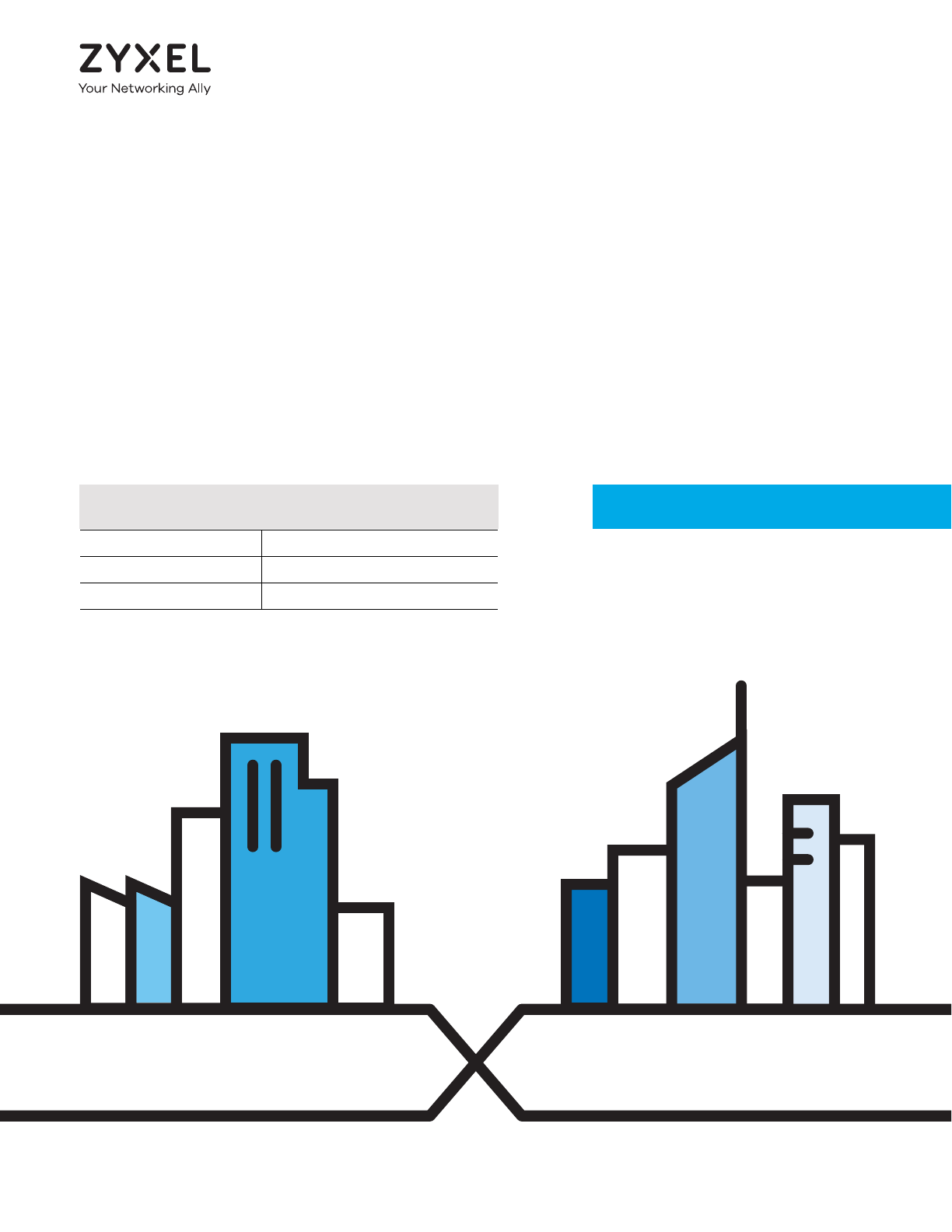
1.4.1 Internet Access
Computers can connect to the XMG’s LAN ports (or wirelessly).
You can also configure IP filtering on the XMG for secure Internet access. When the IP filter is on, all
incoming traffic from the Internet to your network is blocked by default unless it is initiated from your
network. This means that probes from the outside to your network are not allowed, but you can safely
browse the Internet and download files.
1.4.1.1 DSL
Your XMG provides shared Internet access by connecting the DSL port to the DSL or MODEM jack on a
splitter or your telephone jack. You can have multiple WAN services over one ADSL or VDSL. The XMG
cannot work in ADSL and VDSL mode at the same time.
Note: The ADSL and VDSL lines share the same WAN (layer-2) interfaces that you configure in
the XMG. Refer to Section 6.2 on page 65 for the Network Setting > Broadband screen.
Figure 1 XMG’s Internet Access Application
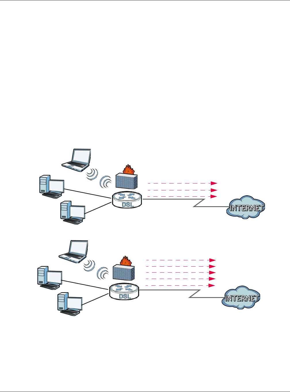
1.4.1.2 Ethernet WAN
If you prefer not to use a DSL line and you have another broadband modem or router (such as ADSL)
available, you can convert LAN port number four as a WAN port using the Network Setting > Broadband
> Ethernet WAN screen and then connect the LAN port to the broadband modem or router. This way,
you can access the Internet via an Ethernet connection and still use the QoS, Firewall and parental
control functions on the XMG.
ADSL / VDSL
WLAN
PPPoE
IPoE
Bridging
WAN
ADSL
IPoA
WAN
LAN
LAN
WLAN
A
A
PPPoA
IPoE
PPPoE
Bridging
Chapter 1 Introducing the XMG
XMG3512-B10A User’s Guide
17
Figure 2 XMG’s Internet Access Application: Ethernet WAN
1.4.1.3 SFP
If you prefer not to use the Ethernet or DSL line, your XMG also provides shared Internet access by
connecting the Small Form-Factor Pluggable (SFP) transceiver. SFP is also known as Fiber Optics
interface. The Gigabit Ethernet (GbE) WAN with SFP is a dual-personality design (GbE + Fiber) which
enables increased bandwidth and extended coverage. The XMG supports multiple VLANs over the SFP
WAN interface for triple play. To connect the SFP port use a Fiber Optic Module, also known as a mini-
GBIC transceiver, to a Switch or Router.
Figure 3 XMG’s Internet Access Application: Ethernet WAN
Note: You can only have Internet access through one of the ports (DSL, Ethernet or SFP) at a
time. Your XMG has WAN priority, and if you connect all ports simultaneously to a
successful internet access, only one WAN port interface will be active. The XMG will
prioritize SFP, then Ethernet, and last DSL.
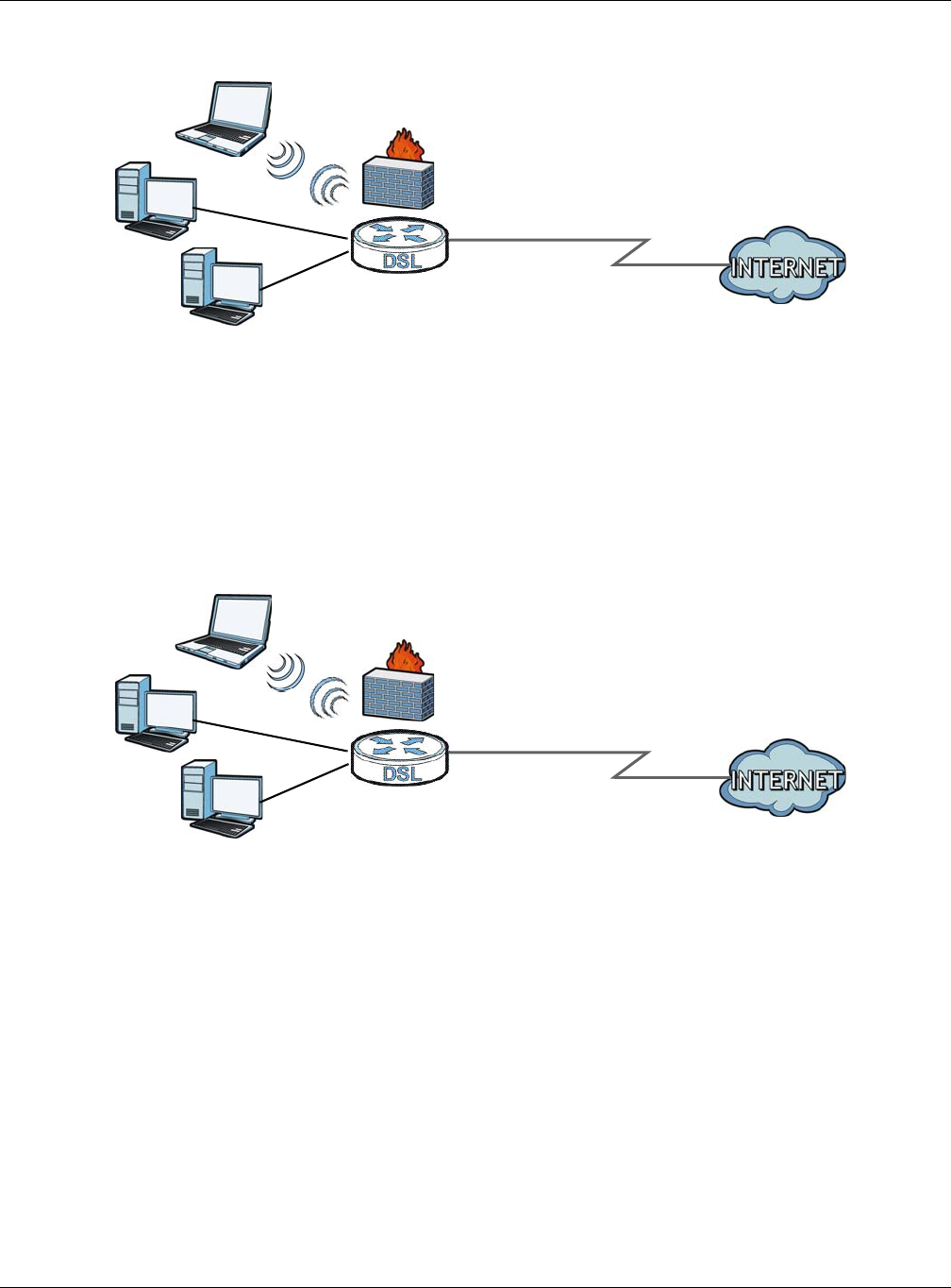
1.4.2 XMG’s USB Support
The USB port of the XMG is used for file-sharing and media server.
File Sharing
Use the built-in USB 2.0 port to share files on a USB memory stick or a USB hard drive (B). You can connect
one USB hard drive to the XMG at a time. Use FTP to access the files on the USB device.
Ethernet WAN
WAN
LAN
WLAN
SFP WAN
WAN
LAN
WLAN
Chapter 1 Introducing the XMG
XMG3512-B10A User’s Guide
18
Figure 4 USB File Sharing Application
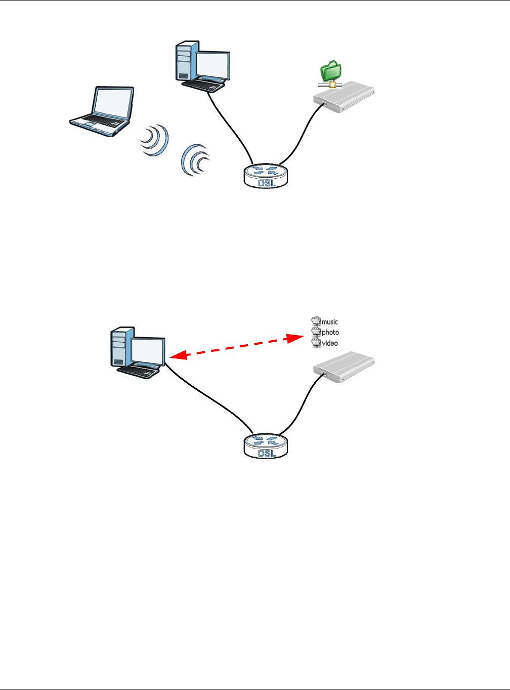
Media Server
You can also use the XMG as a media server. This lets anyone on your network play video, music, and
photos from a USB device (B) connected to the XMG’s USB port (without having to copy them to
another computer).
Figure 5 USB Media Server Application
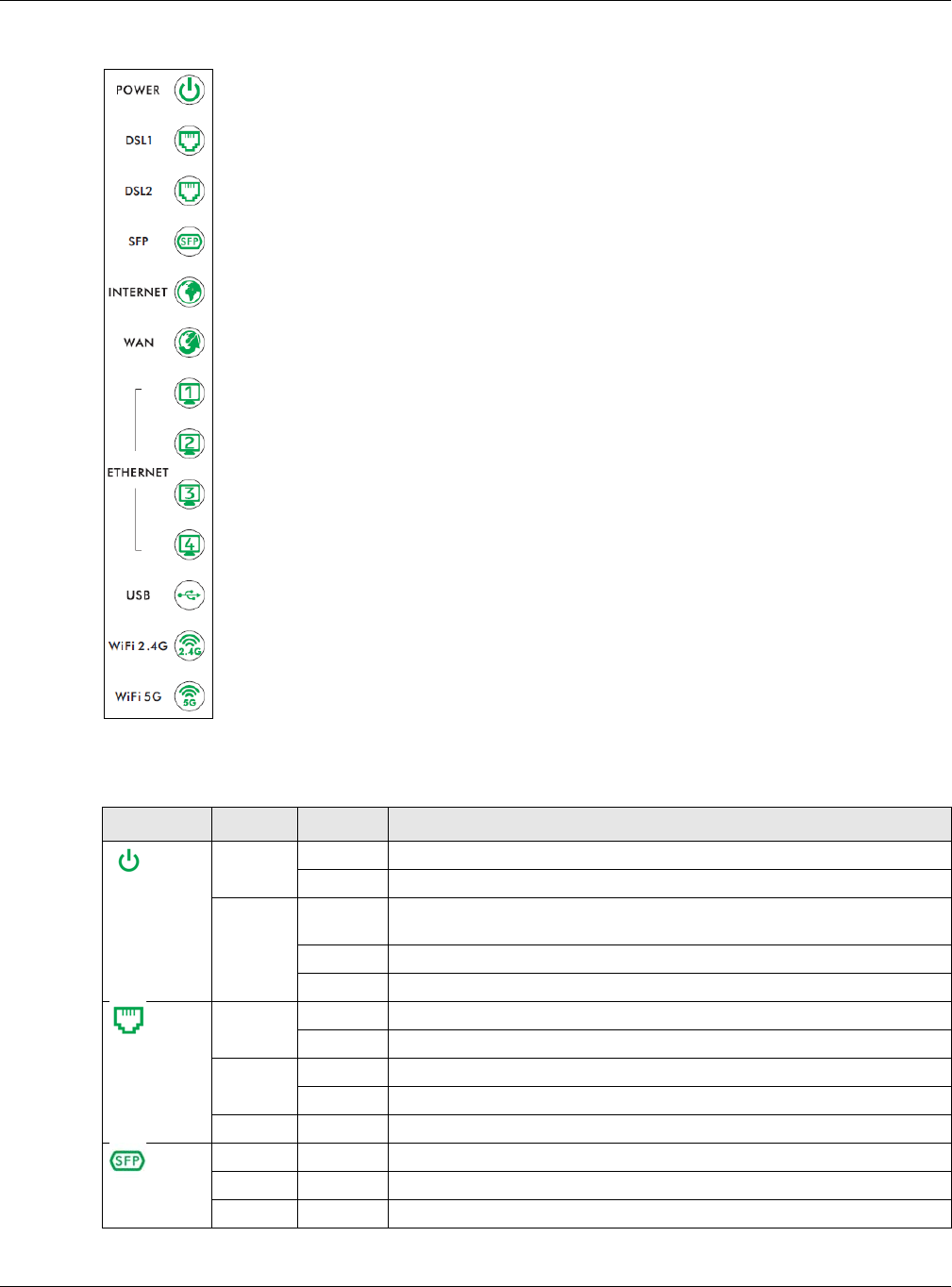
1.5 LEDs (Lights)
The following graphic displays the labels of the LEDs.
B
A
B
A
Chapter 1 Introducing the XMG
XMG3512-B10A User’s Guide
19
Figure 6 LEDs on the XMG
None of the LEDs are on if the XMG is not receiving power.
Table 1 LED Descriptions
LED COLOR STATUS DESCRIPTION
Power
Green On The XMG is receiving power and ready for use.
Blinking The XMG is self-testing.
Red On The XMG detected an error while self-testing, or there is a device
malfunction.
Blinking The XMG is upgrading its firmware.
Off The XMG is not receiving power.
DSL1
DSL2
Green On The ADSL line is up.
Blinking The XMG is initializing the ADSL line.
Amber On The VDSL line is up.
Blinking The XMG is initializing the VDSL line.
Off The DSL line is down.
SFP
Green On The XMG has a successful connection on the WAN.
Blinking The XMG is sending or receiving data to/from the WAN.
Off The XMG does not detect a SFP connection to the WAN.
Chapter 1 Introducing the XMG
XMG3512-B10A User’s Guide
20
1.6 The RESET Button
If you forget your password or cannot access the Web Configurator, you will need to use the RESET
button at the back of the device to reload the factory-default configuration file. This means that you will
lose all configurations that you had previously and the password will be reset to “1234”.
1Make sure the POWER LED is on (not blinking).
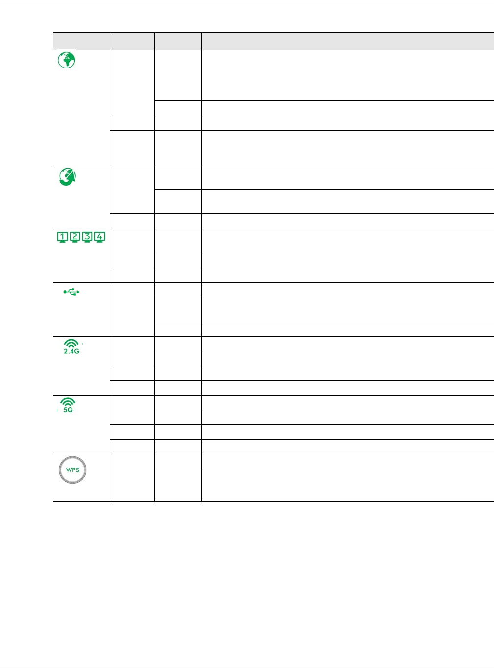
Internet
Green On The XMG has an IP connection but no traffic.
Your device has a WAN IP address (either static or assigned by a DHCP
server), PPP negotiation was successfully completed (if used) and the DSL
connection is up.
Blinking The XMG is sending or receiving IP traffic.
Off There is no Internet connection or the gateway is in bridged mode.
Red On The XMG attempted to make an IP connection but failed. Possible causes
are no response from a DHCP server, no PPPoE response, PPPoE
authentication failed.
WAN
Green On The XMG has a successful 10/100/1000 Mbps Ethernet connection on the
WAN.
Blinking The XMG is sending or receiving data to/from the WAN at 10/100/1000
Mbps.
Off There is no Ethernet connection on the WAN.
Ethernet 1~4
Green On The XMG has a successful 1000 Mbps Ethernet connection with a device on
the Local Area Network (LAN).
Blinking The XMG is sending or receiving data to/from the LAN at 1000 Mbps.
Off The XMG does not have an Ethernet connection with the LAN.
USB
Green On The XMG recognizes a USB connection through the USB slot.
Blinking The XMG is sending/receiving data to /from the USB device connected to
it.
Off The XMG does not detect a USB connection through the USB slot.
WiFi 2.4G
Green On The 2.4 GHz wireless network is activated.
Blinking The XMG is communicating with 2.4 GHz wireless clients.
Amber Blinking The XMG is setting up a WPS connection with a 2.4 GHz wireless client.
Off The 2.4 GHz wireless network is not activated.
WiFi 5G
Green On The 5 GHz wireless network is activated.
Blinking The XMG is communicating with 5 GHz wireless clients.
Amber Blinking The XMG is setting up a WPS connection with a 5 GHz wireless client.
Off The 5 GHz wireless network is not activated.
WPS
Amber On The 2.4 Ghz or 5 GHz wireless network and WPS are enabled.
Off Both 2.4 Ghz or 5 GHz wireless network and WPS are disabled.
Table 1 LED Descriptions (continued)
LED COLOR STATUS DESCRIPTION
Chapter 1 Introducing the XMG
XMG3512-B10A User’s Guide
21
2To set the device back to the factory default settings, press the RESET button for five seconds or until the
POWER LED begins to blink and then release it. When the POWER LED begins to blink, the defaults have
been restored and the device restarts.
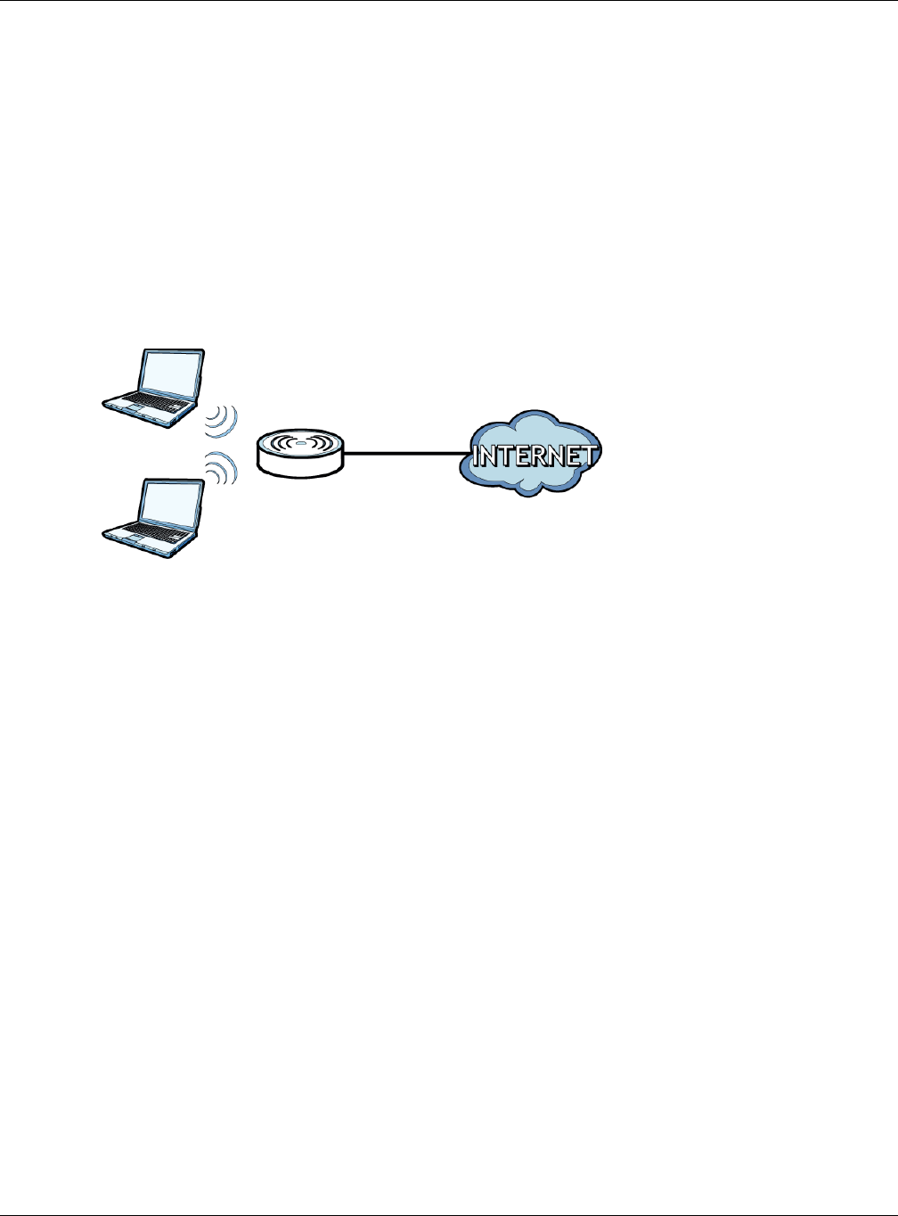
1.7 Wireless Access
The XMG is a wireless Access Point (AP) for wireless clients, such as notebook computers or PDAs and
iPads. It allows them to connect to the Internet without having to rely on inconvenient Ethernet cables.
You can configure your wireless network in either the built-in Web Configurator, or using the WPS button.
Figure 7 Wireless Access Example
1.7.1 Using the WPS Button
Once the WiFi LED turns green, the wireless network is active. If the wireless network is turned off, see
Section 7.2 on page 84 for how to enable the wireless network on the XMG.
You can also use the WPS button to quickly set up a secure wireless connection between the XMG and
a WPS-compatible client by adding one device at a time.
To activate WPS:
1Make sure the POWER LED is on and not blinking.
2Press the WPS button for five seconds and release it.
3Press the WPS button on another WPS-enabled device within range of the XMG. The WiFi LED flashes
orange while the XMG sets up a WPS connection with the other wireless device.
4Once the connection is successfully made, the WPS LED shines green.
The WPS LED turns off when the wireless network is off.
Chapter 1 Introducing the XMG
XMG3512-B10A User’s Guide
22
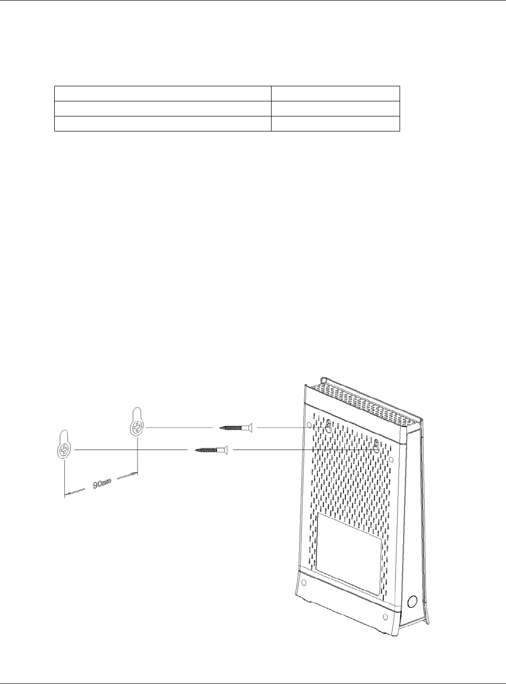
1.8 Wall Mounting
You may need screw anchors if mounting on a concrete or brick wall.
5Select a position free of obstructions on a wall strong enough to hold the weight of the device.
6Mark two holes on the wall at the appropriate distance apart for the screws.
Be careful to avoid damaging pipes or cables located inside the wall
when drilling holes for the screws.
7If using screw anchors, drill two holes for the screw anchors into the wall. Push the anchors into the full
depth of the holes, then insert the screws into the anchors. Do not insert the screws all the way in - leave
a small gap of about 0.5 cm.
If not using screw anchors, use a screwdriver to insert the screws into the wall. Do not insert the screws all
the way in - leave a gap of about 0.5 cm.
8Make sure the screws are fastened well enough to hold the weight of the XMG with the connection
cables.
9Align the holes on the back of the XMG with the screws on the wall. Hang the XMG on the screws.
Figure 8 Wall Mounting Example
Table 2 Wall Mounting Information
Distance between holes 90 mm
M4 Screws Two
Screw anchors (optional) Two
XMG3512-B10A User’s Guide
23
CHAPTER 2
The Web Configurator
2.1 Overview
The web configurator is an HTML-based management interface that allows easy XMG setup and
management via Internet browser. Use Internet Explorer 8.0 and later versions or Mozilla Firefox 3 and
later versions or Safari 2.0 and later versions.* The recommended screen resolution is 1024 by 768 pixels.
In order to use the web configurator you need to allow:
• Web browser pop-up windows from your XMG. Web pop-up blocking is enabled by default in
Windows XP SP (Service Pack) 2.
• JavaScript (enabled by default).
• Java permissions (enabled by default).
2.1.1 Accessing the Web Configurator
1Make sure your XMG hardware is properly connected (refer to the Quick Start Guide).
2Launch your web browser. If the XMG does not automatically re-direct you to the login screen, go to
http://192.168.1.1.
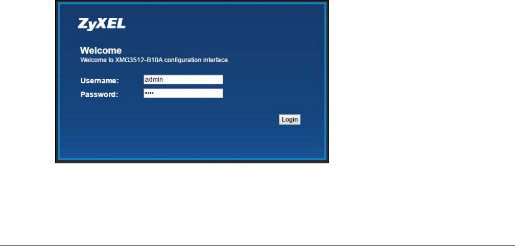
3A password screen displays. To access the administrative web configurator and manage the XMG, type
the default username admin/user and password 1234 in the password screen and click Login. If you
have changed the password, enter your password and click Login.
Figure 9
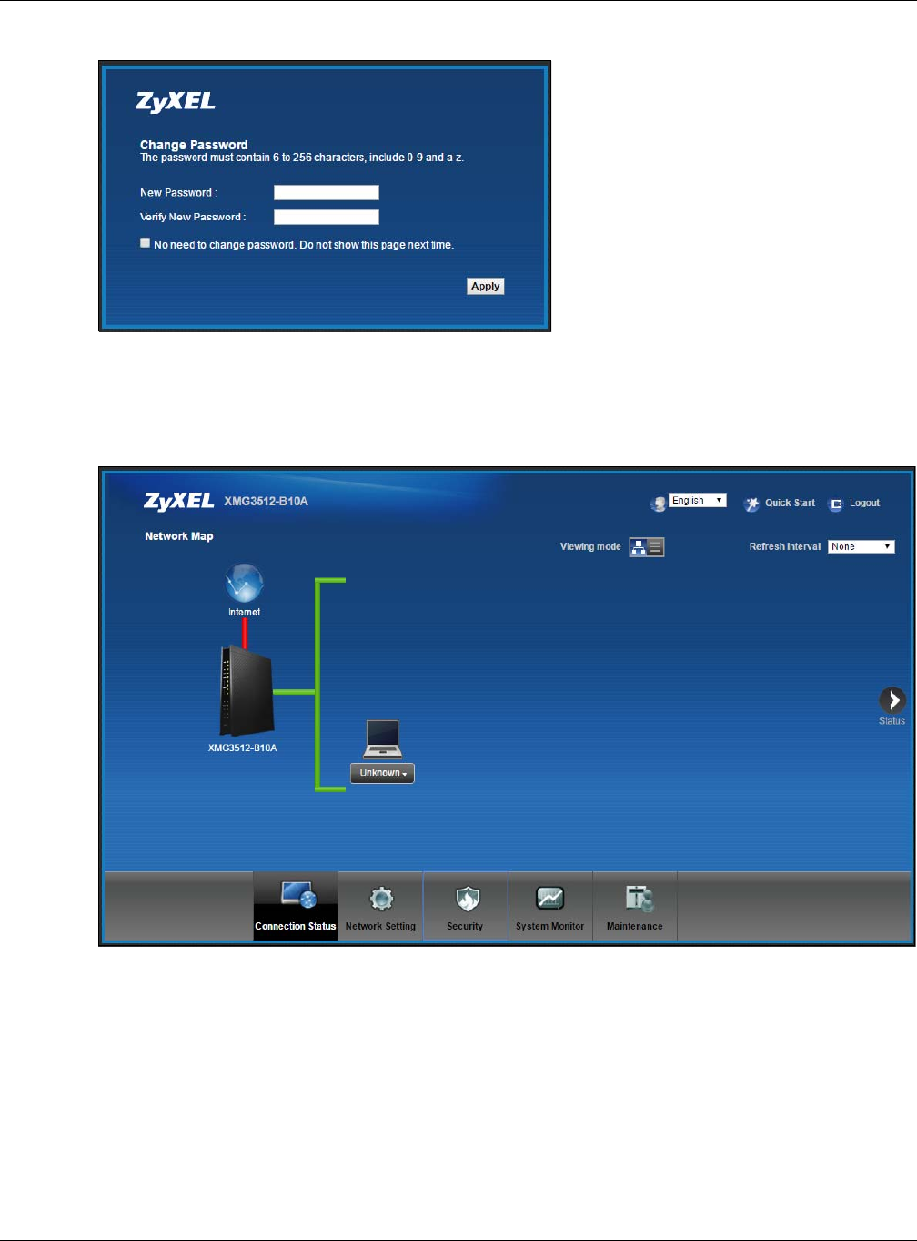
4The following screen displays if you have not yet changed your password. Enter a new password, retype
it to confirm and click Apply.
Chapter 2 The Web Configurator
XMG3512-B10A User’s Guide
24
Figure 10
5The Quick Start Wizard screen appears. You can configure basic Internet access, and wireless settings.
See Chapter 3 on page 30 for more information.
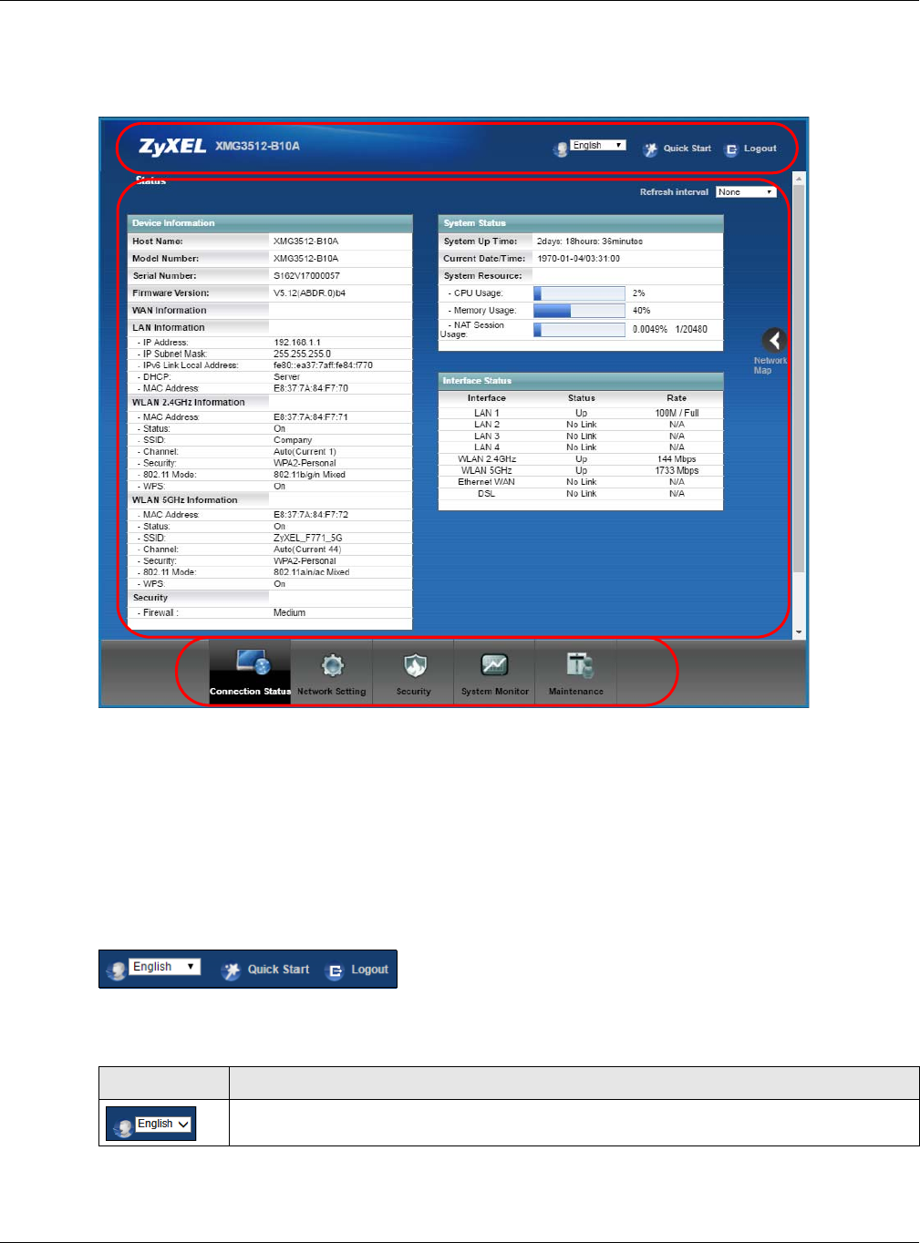
6After you finished or closed the Quick Start Wizard screen, the Network Map page appears.
Figure 11
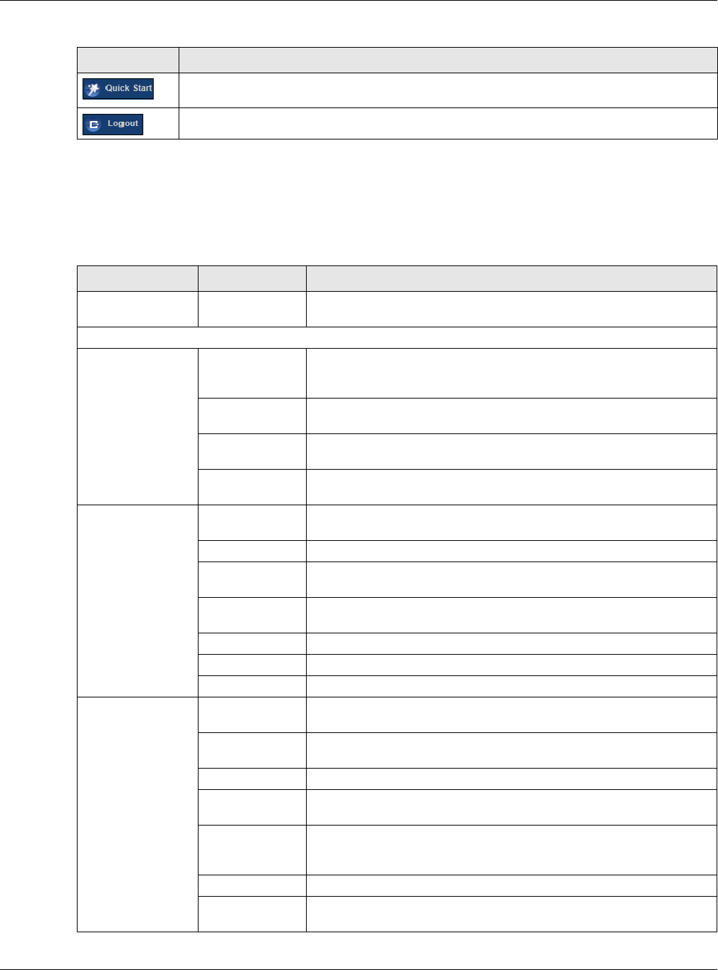
7Click Status to display the Status screen, where you can view the XMG’s interface and system
information.
Chapter 2 The Web Configurator
XMG3512-B10A User’s Guide
25
2.2 Web Configurator Layout
Figure 12
As illustrated above, the main screen is divided into these parts:
•A - title bar
•B - main window
•C - navigation panel
2.2.1 Title Bar
The title bar provides some icons in the upper right corner.
The icons provide the following functions.
A
B
C
Table 3 Web Configurator Icons in the Title Bar
ICON DESCRIPTION
Language: Select the language you prefer.
Chapter 2 The Web Configurator
XMG3512-B10A User’s Guide
26
2.2.2 Navigation Panel
Use the menu items on the navigation panel to open screens to configure XMG features. The following
tables describe each menu item.
Quick Start: Click this icon to open screens where you can configure the XMG’s time zone
Internet access, and wireless settings.
Logout: Click this icon to log out of the web configurator.
Table 3 Web Configurator Icons in the Title Bar
ICON DESCRIPTION
Table 4 Navigation Panel Summary
LINK TAB FUNCTION
Connection Status This screen shows the network status of the XMG and computers/devices
connected to it.
Network Setting
Broadband Broadband Use this screen to view and configure ISP parameters, WAN IP address
assignment, and other advanced properties. You can also add new
WAN connections.
Advanced Use this screen to enable or disable PTM over ADSL, Annex M/Annex J,
and DSL PhyR functions.
Ethernet WAN Use this screen to enable the fourth Ethernet LAN port to be an Ethernet
WAN port.
802.1x Use this screen to view and configure the IEEE 802.1x settings on the
XMG.
Wireless General Use this screen to configure the wireless LAN settings and WLAN
authentication/security settings.
Guest/More AP Use this screen to configure multiple BSSs on the XMG.
MAC
Authentication
Use this screen to block or allow wireless traffic from wireless devices of
certain SSIDs and MAC addresses to the XMG.
WPS Use this screen to configure and view your WPS (Wi-Fi Protected Setup)
settings.
WMM Use this screen to enable or disable Wi-Fi MultiMedia (WMM).
Others Use this screen to configure advanced wireless settings.
Channel Status Use this screen to scan wireless LAN channel noises and view the results.
Home
Networking LAN Setup Use this screen to configure LAN TCP/IP settings, and other advanced
properties.
Static DHCP Use this screen to assign specific IP addresses to individual MAC
addresses.
UPnP Use this screen to turn UPnP and UPnP NAT-T on or off.
Additional
Subnet
Use this screen to configure IP alias and public static IP.
STB Vendor ID Use this screen to configure the Vendor IDs of the connected Set Top Box
(STB) devices, which have the XMG automatically create static DHCP
entries for the STB devices when they request IP addresses.
Wake on LAN Use this screen to remotely turn on a device on the local network.
TFTP Server Name Configure a TFTP server name which is sent to clients using DHCP option
66.

Chapter 2 The Web Configurator
XMG3512-B10A User’s Guide
27
Routing Static Route Use this screen to view and set up static routes on the XMG.
DNS Route Use this screen to forward DNS queries for certain domain names through
a specific WAN interface to its DNS server(s).
Policy Route Use this screen to configure policy routing on the XMG.
RIP Use this screen to configure Routing Information Protocol to exchange
routing information with other routers.
QoS General Use this screen to enable QoS and traffic prioritizing. You can also
configure the QoS rules and actions.
Queue Setup Use this screen to configure QoS queues.
Classification
Setup
Use this screen to define a classifier.
Shaper Setup Use this screen to limit outgoing traffic rate on the selected interface.
Policer Setup Use this screen to configure QoS policers.
NAT Port Forwarding Use this screen to make your local servers visible to the outside world.
Applications Use this screen to configure servers behind the XMG.
Port Triggering Use this screen to change your XMG’s port triggering settings.
DMZ Use this screen to configure a default server which receives packets from
ports that are not specified in the Port Forwarding screen.
ALG Use this screen to enable or disable SIP ALG.
Address Mapping Use this screen to change your XMG’s address mapping settings.
Sessions Use this screen to configure the maximum number of NAT sessions each
client host is allowed to have through the XMG.
DNS DNS Entry Use this screen to view and configure DNS routes.
Dynamic DNS Use this screen to allow a static hostname alias for a dynamic IP address.
Vlan Group Vlan Group Use this screen to group and tag VLAN IDs to outgoing traffic from the
specified interface.
Interface
Grouping Interface
Grouping
Use this screen to map a port to a PVC or bridge group.
USB Service File Sharing Use this screen to enable file sharing via the XMG.
Media Server Use this screen to use the XMG as a media server.
Security
Firewall General Use this screen to configure the security level of your firewall.
Protocol Use this screen to add Internet services and configure firewall rules.
Access Control Use this screen to enable specific traffic directions for network services.
DoS Use this screen to activate protection against Denial of Service (DoS)
attacks.
MAC Filter MAC Filter Use this screen to block or allow traffic from devices of certain MAC
addresses to the XMG.
Parental
Control Parental Control Use this screen to block web sites with the specific URL.
Scheduler Rules Scheduler Rules Use this screen to configure the days and times when a configured
restriction (such as parental control) is enforced.
Certificates Local Certificates Use this screen to view a summary list of certificates and manage
certificates and certification requests.
Trusted CA Use this screen to view and manage the list of the trusted CAs.
Table 4 Navigation Panel Summary (continued)
LINK TAB FUNCTION

Chapter 2 The Web Configurator
XMG3512-B10A User’s Guide
28
System Monitor
Log System Log Use this screen to view the status of events that occurred to the XMG.
You can export or e-mail the logs.
Security Log Use this screen to view all security related events. You can select level
and category of the security events in their proper drop-down list
window.
Levels include:
•Emergency
•Alert
• Critical
• Error
• Warning
•Notice
• Informational
•Debugging
Categories include:
• Account
• Attack
•Firewall
• MAC Filter
Traffic Status WAN Use this screen to view the status of all network traffic going through the
WAN port of the XMG.
LAN Use this screen to view the status of all network traffic going through the
LAN ports of the XMG.
NAT Use this screen to view NAT statistics for connected hosts.
ARP table ARP table Use this screen to view the ARP table. It displays the IP and MAC address
of each DHCP connection.
Routing Table Routing Table Use this screen to view the routing table on the XMG.
Multicast Status IGMP Status Use this screen to view the status of all IGMP settings on the XMG.
MLD Status Use this screen to view the status of all MLD settings on the XMG.
xDSL Statistics xDSL Statistics Use this screen to view the XMG’s xDSL traffic statistics.
Maintenance
System System Use this screen to set Device name and Domain name.
User Account User Account Use this screen to change user password on the XMG.
Remote
Management MGMT Services Use this screen to enable specific traffic directions for network services.
Trust Domain Use this screen to view a list of public IP addresses which are allowed to
access the XMG through the services configured in the Maintenance >
Remote Management screen.
SNMP SNMP Use this screen to configure SNMP (Simple Network Management
Protocol) settings.
Time Time Use this screen to change your XMG’s time and date.
E-mail
Notification E-mail
Notification
Use this screen to configure up to two mail servers and sender addresses
on the XMG.
Log Setting Log Setting Use this screen to change your XMG’s log settings.
Firmware
Upgrade Firmware
Upgrade
Use this screen to upload firmware to your XMG.
Table 4 Navigation Panel Summary (continued)
LINK TAB FUNCTION

Chapter 2 The Web Configurator
XMG3512-B10A User’s Guide
29
Backup/Restore Backup/Restore Use this screen to backup and restore your XMG’s configuration
(settings) or reset the factory default settings.
Reboot Reboot Use this screen to reboot the XMG without turning the power off.
Diagnostic Ping&Traceroute
&Nslookup
Use this screen to identify problems with the DSL connection. You can
use Ping, TraceRoute, or Nslookup to help you identify problems.
802.1ag Use this screen to configure CFM (Connectivity Fault Management) MD
(maintenance domain) and MA (maintenance association), perform
connectivity tests and view test reports.
OAM Ping Use this screen to view information to help you identify problems with the
DSL connection.
Table 4 Navigation Panel Summary (continued)
LINK TAB FUNCTION
XMG3512-B10A User’s Guide
30
CHAPTER 3
Quick Start
3.1 Overview
Use the Quick Start screens to configure the XMG’s time zone, basic Internet access, and wireless
settings.
Note: See the technical reference chapters (starting on Chapter 4 on page 33) for
background information on the features in this chapter.
3.2 Quick Start Setup
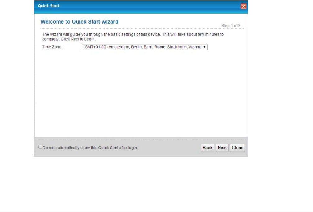
1The Quick Start Wizard appears automatically after login. Or you can click the Quick Start icon in the top
right corner of the web configurator to open the quick start screens. Select the time zone of your
location. Click Next.
Figure 13 Quick Start - Welcome
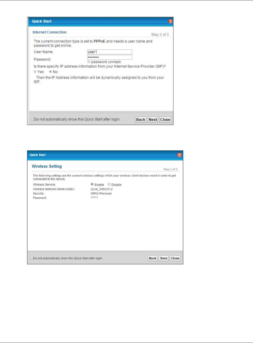
2Enter your Internet connection information in this screen. The screen and fields to enter may vary
depending on your current connection type. Click Next.
Chapter 3 Quick Start
XMG3512-B10A User’s Guide
31
Figure 14 Quick Start - Internet Connection
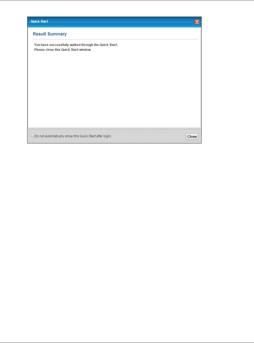
3Turn the wireless LAN on or off. If you keep it on, record the security settings so you can configure your
wireless clients to connect to the XMG. Click Save.
Figure 15 Quick Start - Wireless Setting
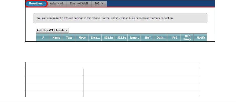
4Your XMG saves your settings and attempts to connect to the Internet. Click Close to complete the
setup.
Chapter 3 Quick Start
XMG3512-B10A User’s Guide
32
Figure 16 Quick Start - Result Summary
XMG3512-B10A User’s Guide
33
CHAPTER 4
Tutorials
4.1 Overview
This chapter shows you how to use the XMG’s various features.
•Setting Up an ADSL PPPoE Connection, see page 33
•Setting Up a Secure Wireless Network, see page 36
•Setting Up Multiple Wireless Groups, see page 42
•Configuring Static Route for Routing to Another Network, see page 45
•Configuring QoS Queue and Class Setup, see page 47
•Access the XMG Using DDNS, see page 51
•Configuring the MAC Address Filter, see page 52
•Access Your Shared Files From a Computer, see page 53
4.2 Setting Up an ADSL PPPoE Connection
This tutorial shows you how to set up an ADSL Internet connection using the Web Configurator.
If you connect to the Internet through an ADSL connection, use the information from your Internet
Service Provider (ISP) to configure the XMG. Be sure to contact your service provider for any information
you need to configure the Broadband screens.
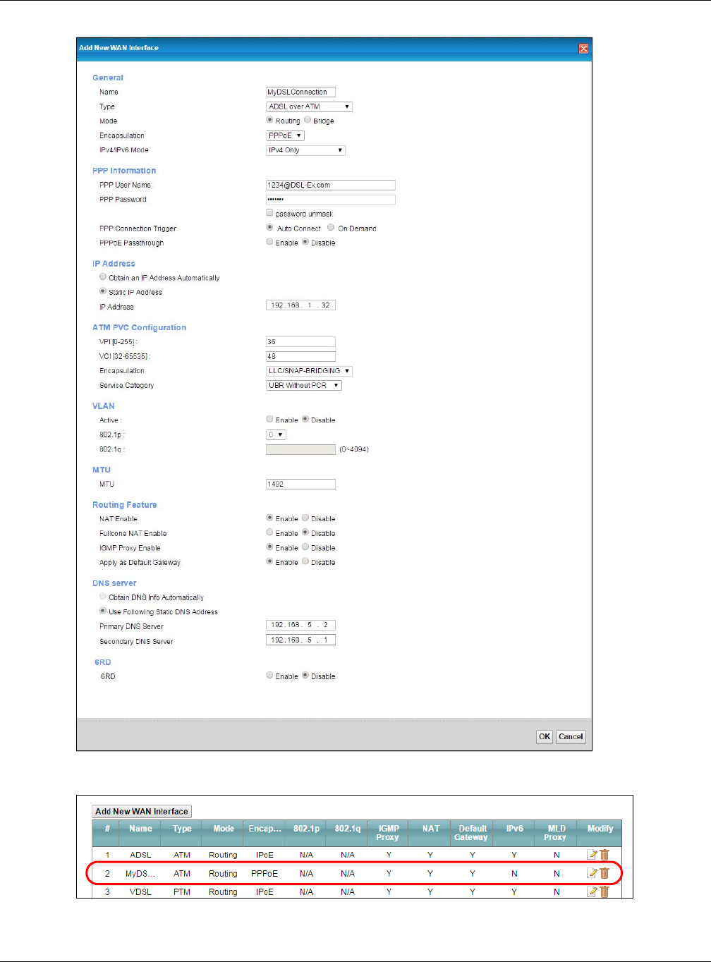
1Click Network Setting > Broadband to open the following screen. Click Add New WAN Interface.
2In this example, the DSL connection has the following information.
General
Name MyDSLConnection
Type ADSL over ATM
Connection Mode Routing
Encapsulation PPPoE

Chapter 4 Tutorials
XMG3512-B10A User’s Guide
34
3Select the Active check box. Enter the General and ATM PVC Configuration settings as provided above.
Set the Type to ADSL over ATM.
Choose the Encapsulation specified by your DSL service provider. For this example, the service provider
requires a username and password to establish Internet connection. Therefore, select PPPoE as the WAN
encapsulation type.
Set the IPv6/IPv4 Mode to IPv4 Only.
4Enter the account information provided to you by your DSL service provider.
5Configure this rule as your default Internet connection by selecting the Apply as Default Gateway check
box. Then select DNS as Static and enter the DNS server addresses provided to you, such as 192.168.5.2
(DNS server1)/192.168.5.1 (DNS server2).
6Leave the rest of the fields to the default settings.
7Click Apply to save your settings.
IPv6/IPv4 Mode IPv4
ATM PVC Configuration
VPI/VCI 36/48
Encapsulation Mode LLC/SNAP-Bridging
Service Category UBR Without PCR
Account Information
PPP User Name 1234@DSL-Ex.com
PPP Password ABCDEF!
PPPoE Service Name MyDSL
Static IP Address 192.168.1.32
Others Authentication Method: AUTO
PPPoE Passthrough: Disabled
NAT: Enabled
IGMP Multicast Proxy: Enabled
Apply as Default Gateway: Enabled
VLAN: Disabled
Chapter 4 Tutorials
XMG3512-B10A User’s Guide
35
8You should see a summary of your new DSL connection setup in the Broadband screen as follows.
Try to connect to a website to see if you have correctly set up your Internet connection. Be sure to
contact your service provider for any information you need to configure the WAN screens.
Chapter 4 Tutorials
XMG3512-B10A User’s Guide
36
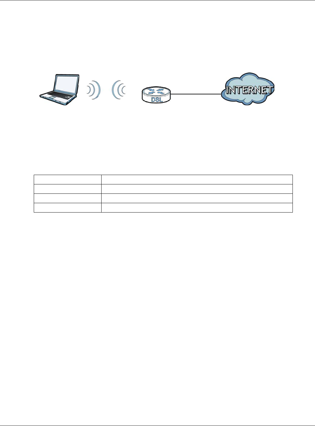
4.3 Setting Up a Secure Wireless Network
Thomas wants to set up a wireless network so that he can use his notebook to access the Internet. In this
wireless network, the XMG serves as an access point (AP), and the notebook is the wireless client. The
wireless client can access the Internet through the AP.
Thomas has to configure the wireless network settings on the XMG. Then he can set up a wireless
network using WPS (Section 4.3.2 on page 38) or manual configuration (Section 4.3.3 on page 41).
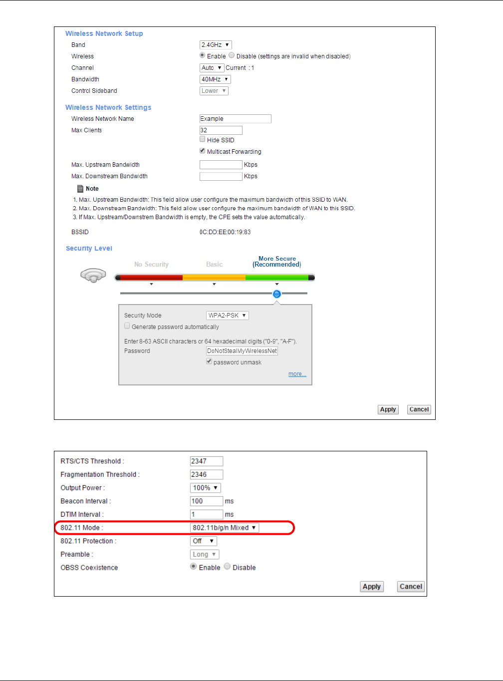
4.3.1 Configuring the Wireless Network Settings
This example uses the following parameters to set up a wireless network.
1Click Network Setting > Wireless to open the General screen. Select More Secure as the security level
and WPA2-PSK as the security mode. Configure the screen using the provided parameters (see
page 36). Click Apply.
SSID Example
Security Mode WPA2-PSK
Pre-Shared Key DoNotStealMyWirelessNetwork
802.11 Mode 802.11b/g/n Mixed
Chapter 4 Tutorials
XMG3512-B10A User’s Guide
37
2Go to the Wireless > Others screen and select 802.11b/g/n Mixed in the 802.11 Mode field. Click Apply.
Thomas can now use the WPS feature to establish a wireless connection between his notebook and the
XMG (see Section 4.3.2 on page 38). He can also use the notebook’s wireless client to search for the
XMG (see Section 4.3.3 on page 41).
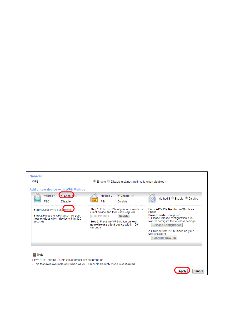
Chapter 4 Tutorials
XMG3512-B10A User’s Guide
38
4.3.2 Using WPS
This section shows you how to set up a wireless network using WPS. It uses the XMG as the AP and Zyxel
NWD210N as the wireless client which connects to the notebook.
Note: The wireless client must be a WPS-aware device (for example, a WPS USB adapter or
PCMCIA card).
There are two WPS methods to set up the wireless client settings:
•Push Button Configuration (PBC) - simply press a button. This is the easier of the two methods.
•PIN Configuration - configure a Personal Identification Number (PIN) on the XMG. A wireless client
must also use the same PIN in order to download the wireless network settings from the XMG.
Push Button Configuration (PBC)
1Make sure that your XMG is turned on and your notebook is within the cover range of the wireless signal.
2Make sure that you have installed the wireless client driver and utility in your notebook.
3In the wireless client utility, go to the WPS setting page. Enable WPS and press the WPS button for more
than five seconds (Start or WPS button).
4Push and hold the WPS button located on the XMG’s front panel for more than 5 seconds. Alternatively,
you may log into XMG’s web configurator and go to the Network Setting > Wireless > WPS screen.
Enable the WPS function for method 1 and click Apply. Then click the WPS button.
Note: Your XMG has a WPS button located on its front panel as well as a WPS button in its
configuration utility. Both buttons have exactly the same function: you can use one or
the other.
Note: It doesn’t matter which button is pressed first. You must press the second button within
two minutes of pressing the first one.
1
2
3
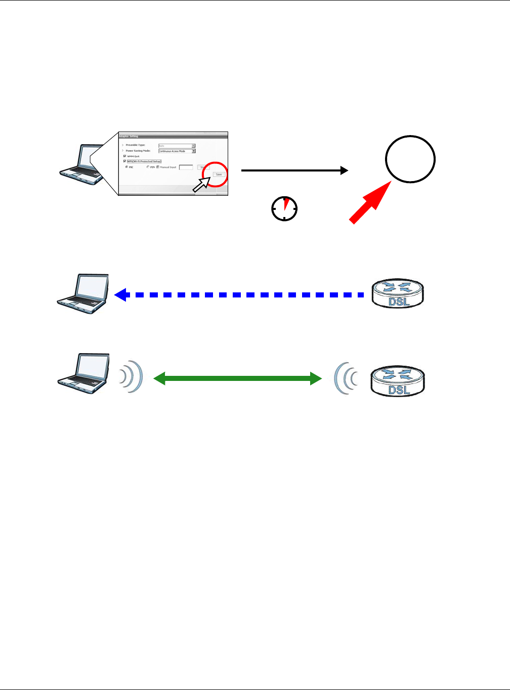
Chapter 4 Tutorials
XMG3512-B10A User’s Guide
39
The XMG sends the proper configuration settings to the wireless client. This may take up to two minutes.
The wireless client is then able to communicate with the XMG securely.
The following figure shows you an example of how to set up a wireless network and its security by
pressing a button on both XMG and wireless client.
Example WPS Process: PBC MethodZyxel
PIN Configuration
When you use the PIN configuration method, you need to use both the XMG’s web configurator and
the wireless client’s utility.
1Launch your wireless client’s configuration utility. Go to the WPS settings and select the PIN method to
get a PIN number.
2Log into XMG’s web configurator and go to the Network Setting > Wireless > WPS screen. Enable the
WPS function and click Apply.
Wireless Client VMG
SECURITY INFO
COMMUNICATION
WITHIN 2 MINUTES
Press and hold for
5 seconds
WLAN/
WPS
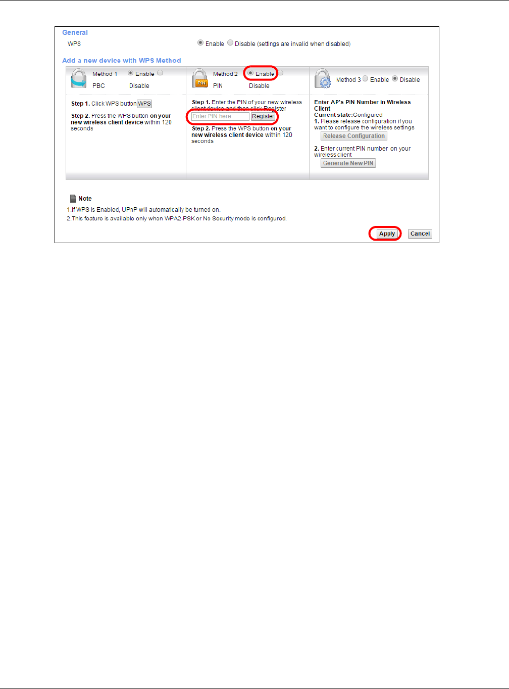
Chapter 4 Tutorials
XMG3512-B10A User’s Guide
40
3Enter the PIN number of the wireless client and click the Register button. Activate WPS function on the
wireless client utility screen within two minutes.
The XMG authenticates the wireless client and sends the proper configuration settings to the wireless
client. This may take up to two minutes. The wireless client is then able to communicate with the XMG
securely.
The following figure shows you how to set up a wireless network and its security on a XMG and a wireless
client by using PIN method.
1
2
3
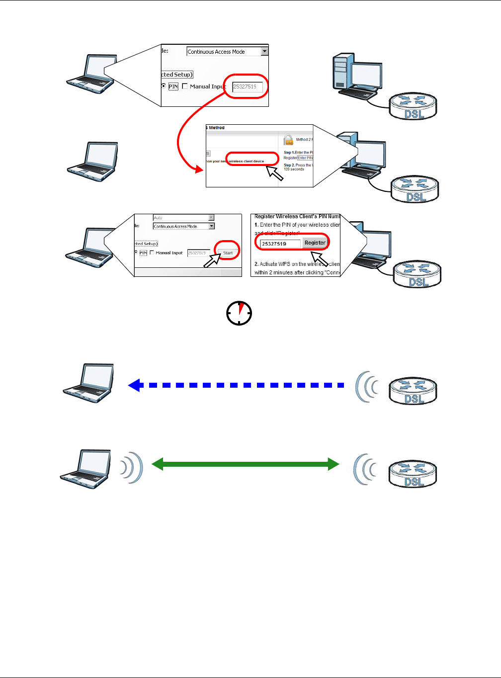
Chapter 4 Tutorials
XMG3512-B10A User’s Guide
41
Example WPS Process: PIN Method
4.3.3 Without WPS
Use the wireless adapter’s utility installed on the notebook to search for the “Example” SSID. Then enter
the “DoNotStealMyWirelessNetwork” pre-shared key to establish an wireless Internet connection.
Note: The XMG supports IEEE 802.11b and IEEE 802.11g wireless clients. Make sure that your
notebook or computer’s wireless adapter supports one of these standards.
Authentication by PIN
SECURITY INFO
WITHIN 2 MINUTES
Wireless Client
VMG
COMMUNICATION
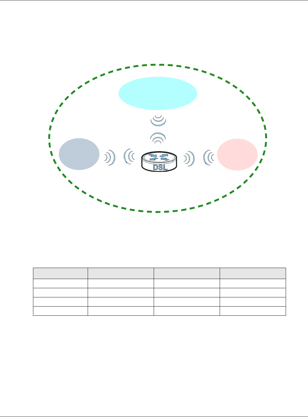
Chapter 4 Tutorials
XMG3512-B10A User’s Guide
42
4.4 Setting Up Multiple Wireless Groups
Company A wants to create different wireless network groups for different types of users as shown in the
following figure. Each group has its own SSID and security mode.
• Employees in Company A will use a general Company wireless network group.
• Higher management level and important visitors will use the VIP group.
• Visiting guests will use the Guest group, which has a different SSID and password.
Company A will use the following parameters to set up the wireless network groups.
1Click Network Setting > Wireless to open the General screen. Use this screen to set up the company’s
general wireless network group. Configure the screen using the provided parameters and click Apply.
COMPANY VIP GUEST
SSID Company VIP Guest
Security Level More Secure More Secure More Secure
Security Mode WPA2-PSK WPA2-PSK WPA2-PSK
Pre-Shared Key ForCompanyOnly 123456789 guest123
Company
VIP Guest
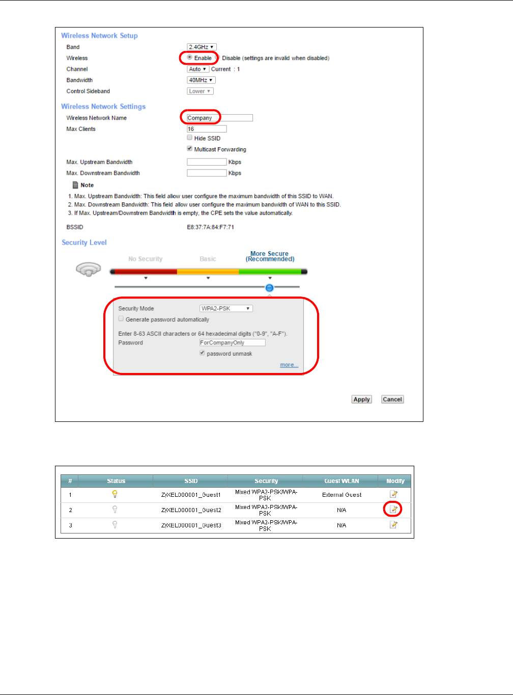
Chapter 4 Tutorials
XMG3512-B10A User’s Guide
43
2Click Network Setting > Wireless > Guest/More AP to open the following screen. Click the Edit icon to
configure the second wireless network group.
3Configure the screen using the provided parameters and click OK.
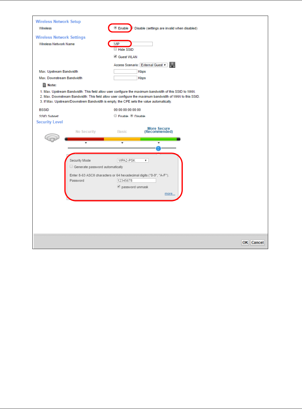
Chapter 4 Tutorials
XMG3512-B10A User’s Guide
44
4In the Guest/More AP screen, click the Edit icon to configure the third wireless network group.Configure
the screen using the provided parameters and click Apply.
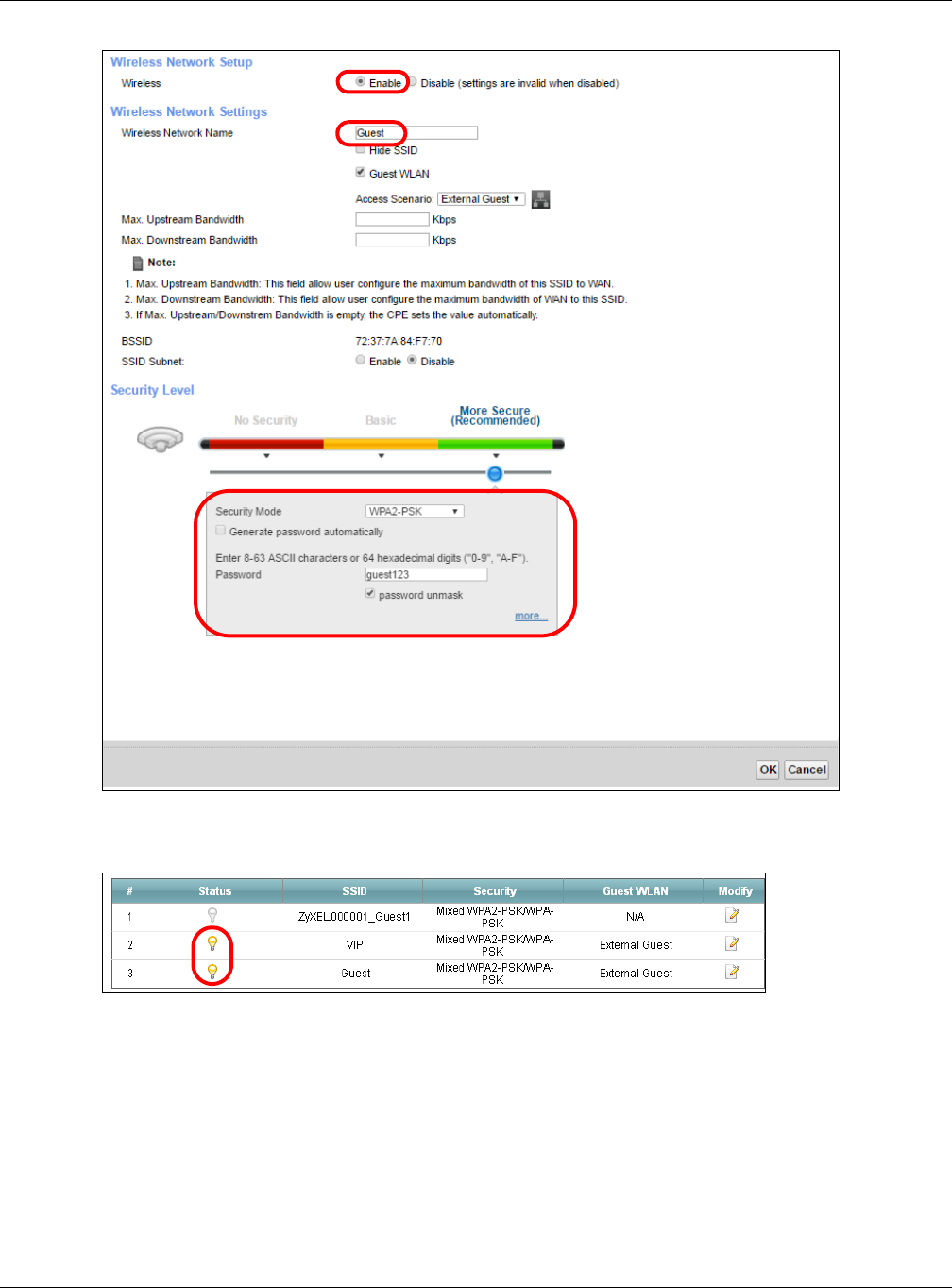
Chapter 4 Tutorials
XMG3512-B10A User’s Guide
45
5Check the status of VIP and Guest in the Guest/More AP screen. The yellow bulbs signify that the SSIDs
are active and ready for wireless access.
4.5 Configuring Static Route for Routing to Another
Network
In order to extend your Intranet and control traffic flowing directions, you may connect a router to the
XMG’s LAN. The router may be used to separate two department networks. This tutorial shows how to
configure a static routing rule for two network routings.
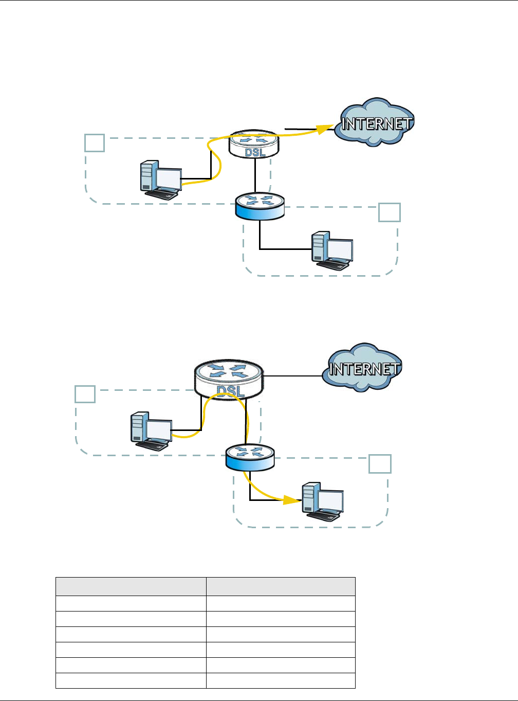
Chapter 4 Tutorials
XMG3512-B10A User’s Guide
46
In the following figure, router R is connected to the XMG’s LAN. R connects to two networks, N1
(192.168.1.x/24) and N2 (192.168.10.x/24). If you want to send traffic from computer A (in N1 network) to
computer B (in N2 network), the traffic is sent to the XMG’s WAN default gateway by default. In this
case, B will never receive the traffic.
You need to specify a static routing rule on the XMG to specify R as the router in charge of forwarding
traffic to N2. In this case, the XMG routes traffic from A to R and then R routes the traffic to B.
This tutorial uses the following example IP settings:
Table 5 IP Settings in this Tutorial
DEVICE / COMPUTER IP ADDRESS
The XMG’s WAN 172.16.1.1
The XMG’s LAN 192.168.1.1
IP Type IPv4
Use Interface VDSL/ppp1.1
A192.168.1.34
R’s N1 192.168.1.253
N2
B
N1
A
R
N2
B
N1
A
R
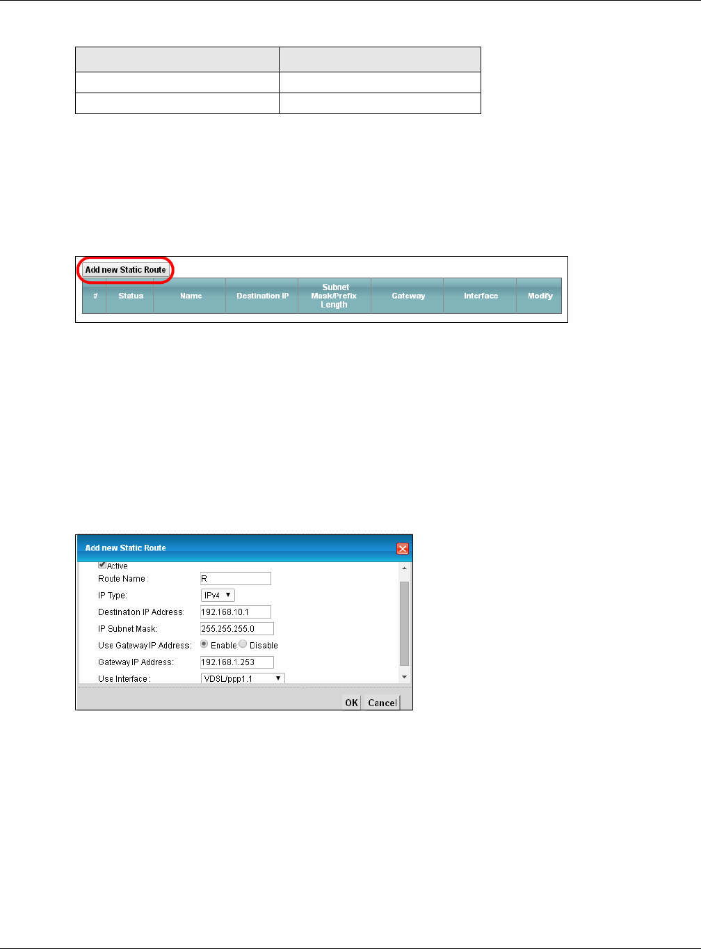
Chapter 4 Tutorials
XMG3512-B10A User’s Guide
47
To configure a static route to route traffic from N1 to N2:
1Log into the XMG’s Web Configurator in advanced mode.
2Click Network Setting > Routing.
3Click Add new Static Route in the Static Route screen.
4Configure the Static Route Setup screen using the following settings:
4a Select the Active check box. Enter the Route Name as R.
4b Set IP Type to IPv4.
4c Type 192.168.10.0 and subnet mask 255.255.255.0 for the destination, N2.
4d Select Enable in the Use Gateway IP Address field. Type 192.168.1.253 (R’s N1 address) in the
Gateway IP Address field.
4e Select VDSL/ppp1.1 as the Use Interface.
4a Click OK.
Now B should be able to receive traffic from A. You may need to additionally configure B’s firewall
settings to allow specific traffic to pass through.
4.6 Configuring QoS Queue and Class Setup
This section contains tutorials on how you can configure the QoS screen.
R’s N2 192.168.10.2
B192.168.10.33
Table 5 IP Settings in this Tutorial
DEVICE / COMPUTER IP ADDRESS
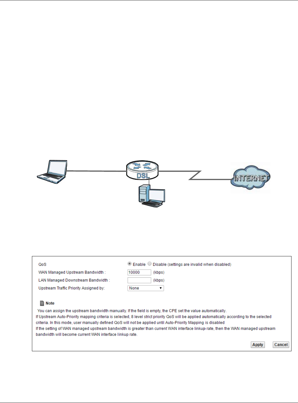
Chapter 4 Tutorials
XMG3512-B10A User’s Guide
48
Let’s say you are a team leader of a small sales branch office. You want to prioritize e-mail traffic
because your task includes sending urgent updates to clients at least twice every hour. You also upload
data files (such as logs and e-mail archives) to the FTP server throughout the day. Your colleagues use
the Internet for research, as well as chat applications for communicating with other branch offices.
In the following figure, your Internet connection has an upstream transmission bandwidth of 10,000 kbps.
For this example, you want to configure QoS so that e-mail traffic gets the highest priority with at least
5,000 kbps. You can do the following:
• Configure a queue to assign the highest priority queue (1) to e-mail traffic going to the WAN
interface, so that e-mail traffic would not get delayed when there is network congestion.
• Note the IP address (192.168.1.23 for example) and/or MAC address (AA:FF:AA:FF:AA:FF for example)
of your computer and map it to queue 7.
Note: QoS is applied to traffic flowing out of the XMG.
Traffic that does not match this class is assigned a priority queue based on the internal QoS mapping
table on the XMG.
QoS Example
1Click Network Setting > QoS > General and select Enable. Set your WAN Managed Upstream Bandwidth
to 10,000 kbps (or leave this blank to have the XMG automatically determine this figure). Click Apply.
Tutorial: Advanced > QoS
2Click Queue Setup > Add new Queue to create a new queue. In the screen that opens, check Active
and enter or select the following values:
•Name: E-mail
•Interface: WAN
10,000 kbps
DSL
Your computer
IP=192.168.1.23
A colleague’s computer
Other traffic: Automatic classifier
and/or
MAC=AA:FF:AA:FF:AA:FF
Email traffic: Highest priority
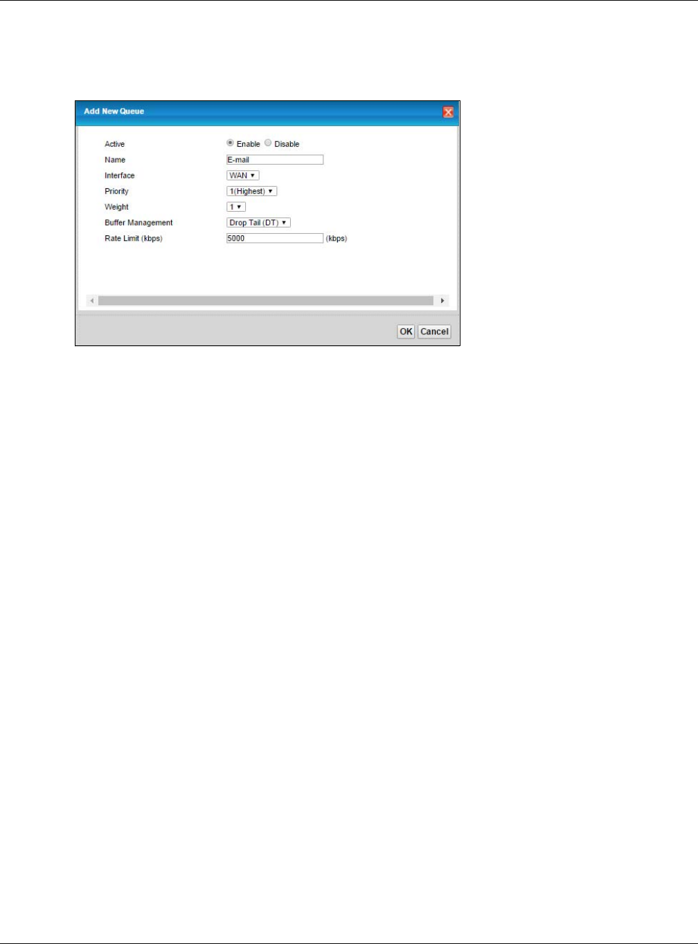
Chapter 4 Tutorials
XMG3512-B10A User’s Guide
49
•Priority: 1 (High)
•Weight: 8
•Rate Limit: 5,000 (kbps)
Tutorial: Advanced > QoS > Queue Setup
3Click Classification Setup > Add new Classification to create a new class. Check Active and follow the
settings as shown in the screen below.
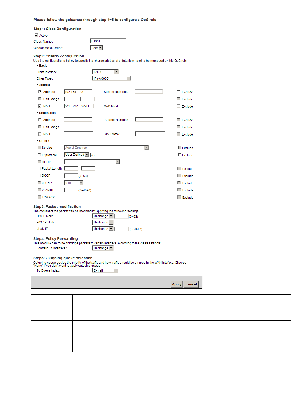
Chapter 4 Tutorials
XMG3512-B10A User’s Guide
50
Tutorial: Advanced > QoS > Class Setup
This maps e-mail traffic coming from port 25 to the highest priority, which you have created in the
previous screen (see the IP Protocol field). This also maps your computer’s IP address and MAC address
to the E-mail queue (see the Source fields).
Class Name Give a class name to this traffic, such as E-mail in this example.
From Interface This is the interface from which the traffic will be coming from. Select LAN1 for this example.
Ether Type Select IP to identify the traffic source by its IP address or MAC address.
IP Address Type the IP address of your computer - 192.168.1.23. Type the IP Subnet Mask if you know it.
MAC Address Type the MAC address of your computer - AA:FF:AA:FF:AA:FF. Type the MAC Mask if you know it.
To Queue Index Link this to an item in the Network Setting > QoS > Queue Setup screen, which is the E-mail queue
created in this example.
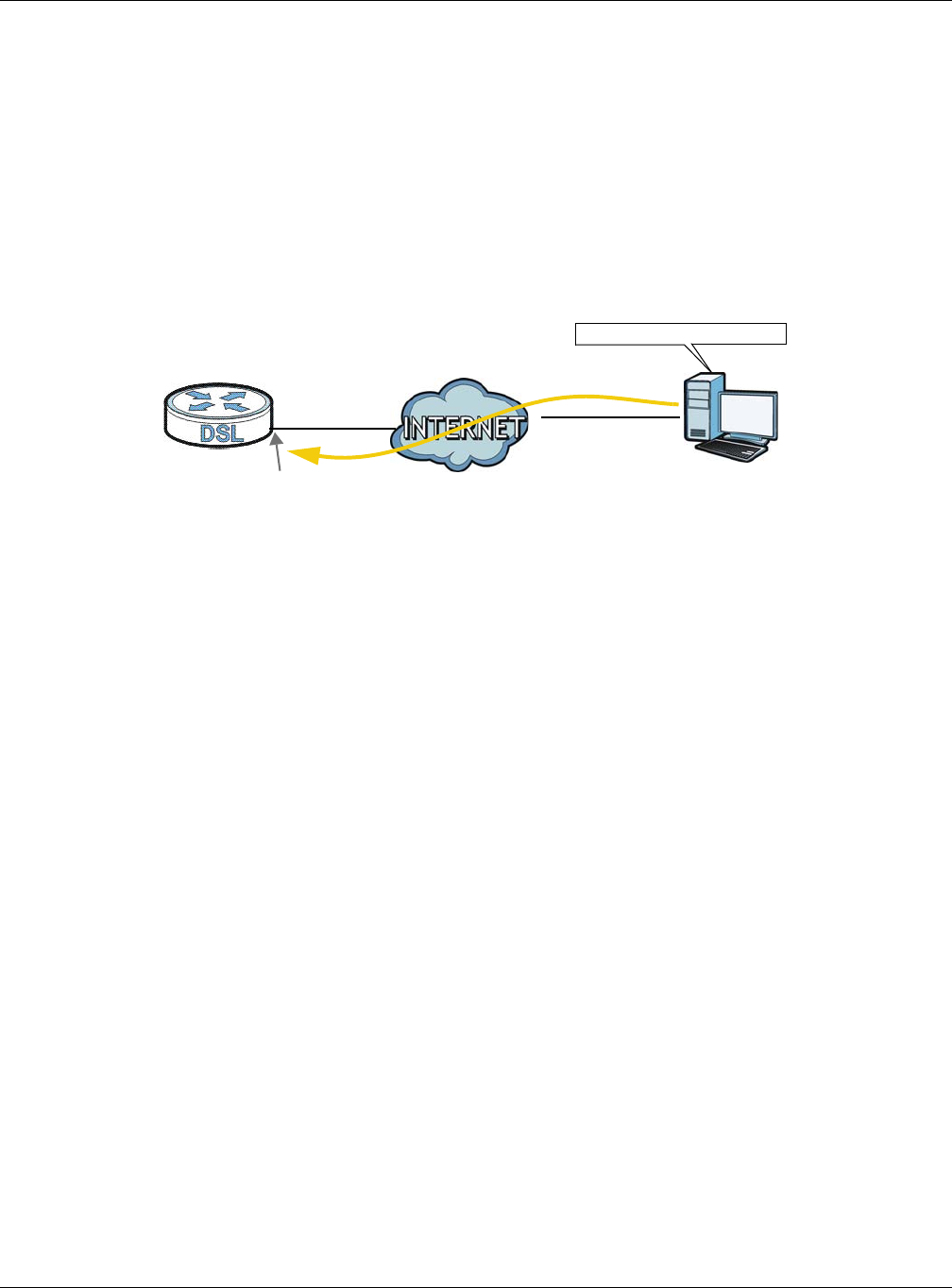
Chapter 4 Tutorials
XMG3512-B10A User’s Guide
51
4Verify that the queue setup works by checking Network Setting > QoS > Monitor. This shows the
bandwidth allotted to e-mail traffic compared to other network traffic.
4.7 Access the XMG Using DDNS
If you connect your XMG to the Internet and it uses a dynamic WAN IP address, it is inconvenient for you
to manage the device from the Internet. The XMG’s WAN IP address changes dynamically. Dynamic
DNS (DDNS) allows you to access the XMG using a domain name.
To use this feature, you have to apply for DDNS service at www.dyndns.org.
This tutorial covers:
•Registering a DDNS Account on www.dyndns.org
•Configuring DDNS on Your XMG
•Testing the DDNS Setting
Note: If you have a private WAN IP address, then you cannot use DDNS.
4.7.1 Registering a DDNS Account on www.dyndns.org
1Open a browser and type http://www.dyndns.org.
2Apply for a user account. This tutorial uses UserName1 and 12345 as the username and password.
3Log into www.dyndns.org using your account.
4Add a new DDNS host name. This tutorial uses the following settings as an example.
• Hostname: zyxelrouter.dyndns.org
• Service Type: Host with IP address
• IP Address: Enter the WAN IP address that your XMG is currently using. You can find the IP address on
the XMG’s Web Configurator Status page.
Then you will need to configure the same account and host name on the XMG later.
4.7.2 Configuring DDNS on Your XMG
Configure the following settings in the Network Setting > DNS > Dynamic DNS screen.
w.x.y.z a.b.c.d
http://zyxelrouter.dyndns.org
A
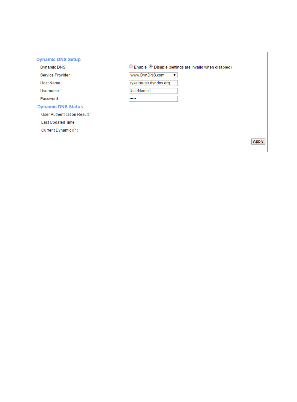
Chapter 4 Tutorials
XMG3512-B10A User’s Guide
52
•Select Enable Dynamic DNS.
•Select www.DynDNS.com as the service provider.
•Type zyxelrouter.dyndns.org in the Host Name field.
• Enter the user name (UserName1) and password (12345).
Click Apply.
4.7.3 Testing the DDNS Setting
Now you should be able to access the XMG from the Internet. To test this:
1Open a web browser on the computer (using the IP address a.b.c.d) that is connected to the Internet.
2Type http://zyxelrouter.dyndns.org and press [Enter].
3The XMG’s login page should appear. You can then log into the XMG and manage it.
4.8 Configuring the MAC Address Filter
Thomas noticed that his daughter Josephine spends too much time surfing the web and downloading
media files. He decided to prevent Josephine from accessing the Internet so that she can concentrate
on preparing for her final exams.
Josephine’s computer connects wirelessly to the Internet through the XMG. Thomas decides to use the
Security > MAC Filter screen to grant wireless network access to his computer but not to Josephine’s
computer.
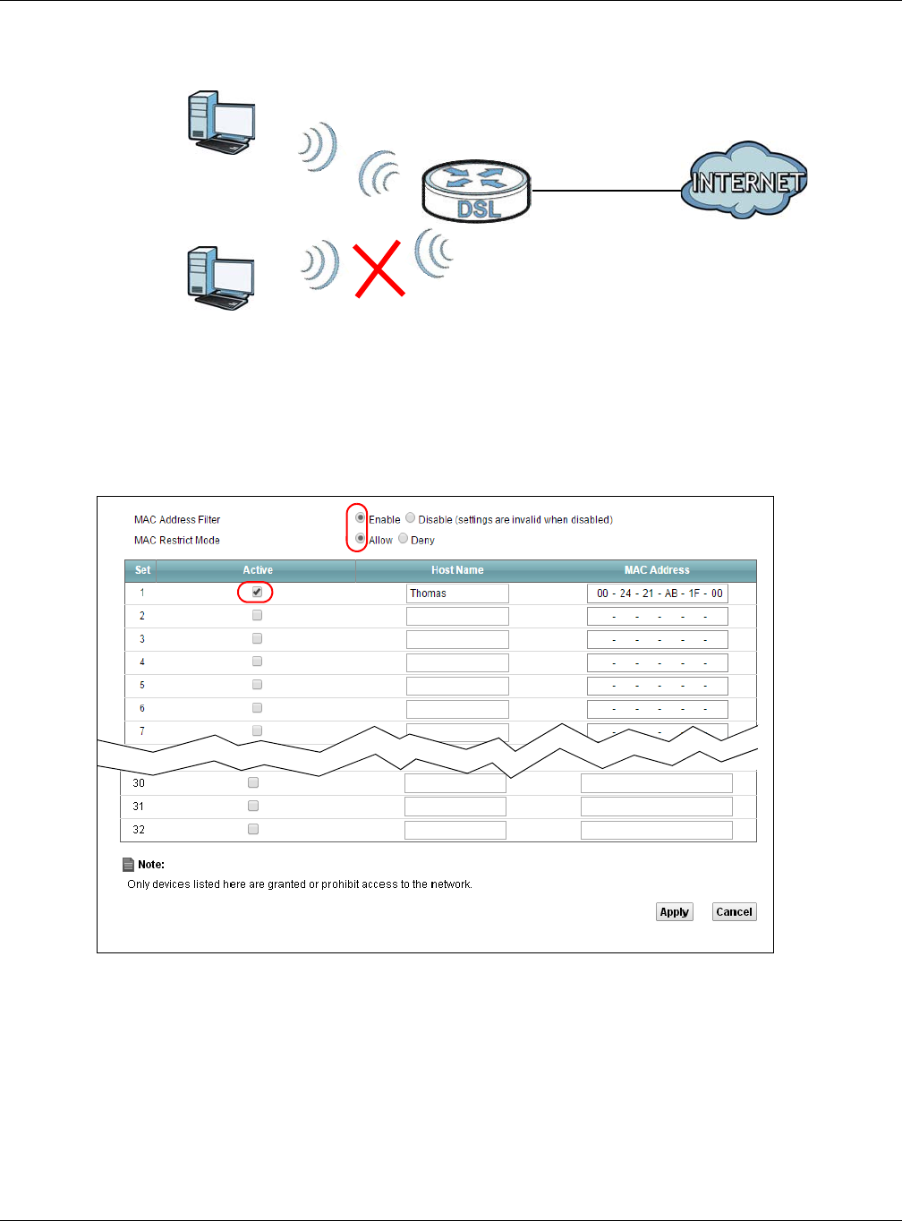
Chapter 4 Tutorials
XMG3512-B10A User’s Guide
53
1Click Security > MAC Filter to open the MAC Filter screen. Select the Enable check box to activate MAC
filter function.
2Select Active. Then enter the host name and MAC address of Thomas’ computer in this screen. Click
Apply.
Thomas can also grant access to the computers of other members of his family and friends. However,
Josephine and others not listed in this screen will no longer be able to access the Internet through the
XMG.
4.9 Access Your Shared Files From a Computer
Here is how to use an FTP program to access a file storage device connected to the XMG’s USB port.
Thomas
Josephine
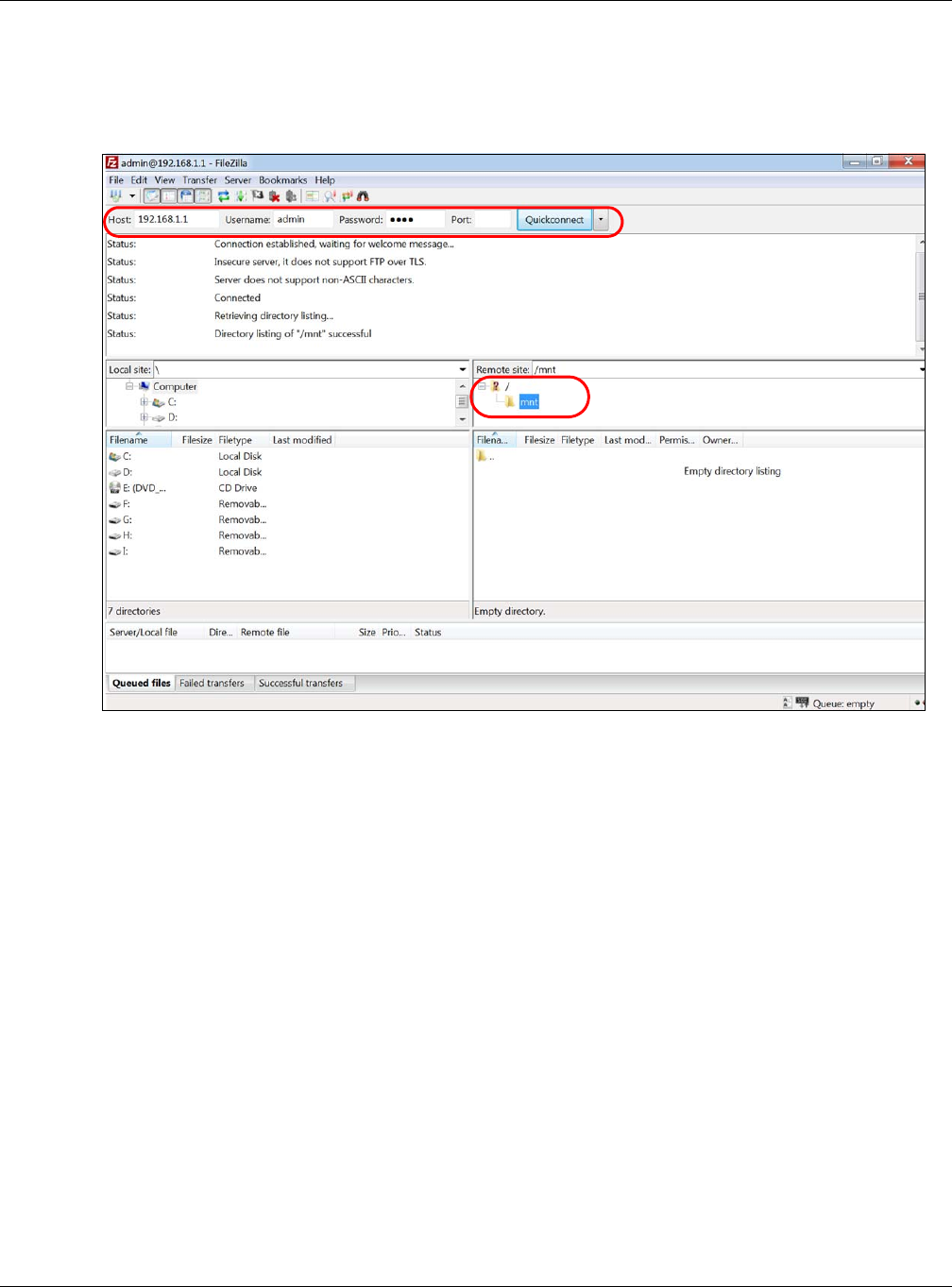
Chapter 4 Tutorials
XMG3512-B10A User’s Guide
54
Note: This example uses the FileZilla FTP program to browse your shared files.
1In FileZilla enter the IP address of the XMG (the default is 192.168.1.1), your account’s user name and
password and port 21 and click Quickconnect. A screen asking for password authentication appears.
File Sharing via Windows Expl orer
2Once you log in the USB device displays in the mnt folder.

55
PART II
Technical Reference

XMG3512-B10A User’s Guide
56
CHAPTER 5
Network Map and Status
Screens
5.1 Overview
After you log into the Web Configurator, the Network Map screen appears. This shows the network
connection status of the XMG and clients connected to it.
You can use the Status screen to look at the current status of the XMG, system resources, and interfaces
(LAN, WAN, and WLAN).
5.2 The Network Map Screen
Use this screen to view the network connection status of the device and its clients. A warning message
appears if there is a connection problem.
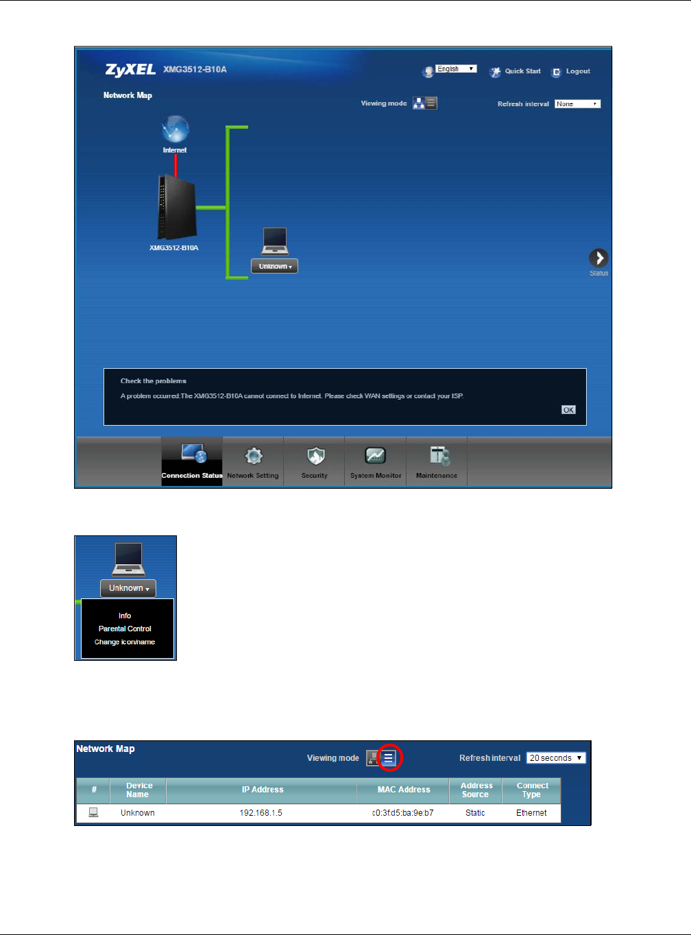
Chapter 5 Network Map and Status Screens
XMG3512-B10A User’s Guide
57
Figure 17
If you want to view information about a client, click the client’s name and Info. Click the IP address if
you want to change it. If you want to change the name or icon of the client, click Change name/icon.
If you prefer to view the status in a list, click List View in the Viewing mode selection box. You can
configure how often you want the XMG to update this screen in Refresh interval.
Figure 18
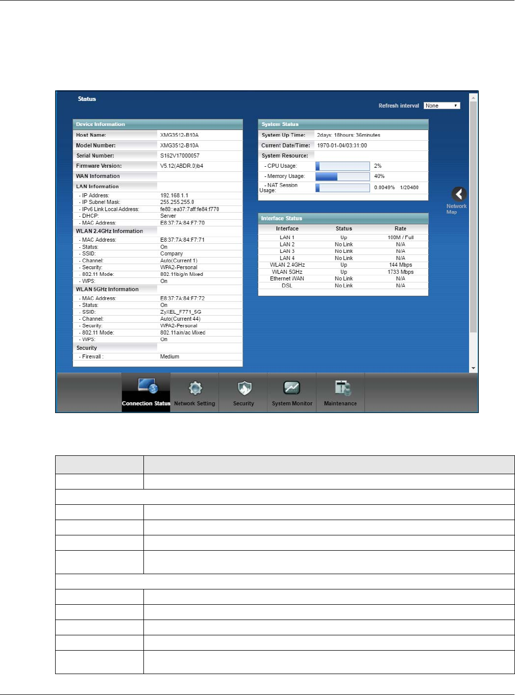
Chapter 5 Network Map and Status Screens
XMG3512-B10A User’s Guide
58
5.3 The Status Screen
Use this screen to view the status of the XMG. Click Status to open this screen.
Figure 19
Each field is described in the following table.
Table 6 Status Screen
LABEL DESCRIPTION
Refresh Interval Select how often you want the XMG to update this screen.
Device Information
Host Name This field displays the XMG system name. It is used for identification.
Model Number This shows the model number of your XMG.
Serial Number This field displays the serial number of the XMG.
Firmware
Version This is the current version of the firmware inside the XMG.
WAN Information (These fields display when you have a WAN connection.)
Encapsulation This field displays the current encapsulation method.
IP Address This field displays the current IP address of the XMG in the WAN.
IP Subnet Mask This field displays the current subnet mask in the WAN.
MAC Address This shows the WAN Ethernet adapter MAC (Media Access Control) Address of your XMG.
Primary DNS
server This field displays the first DNS server address assigned by the ISP.

Chapter 5 Network Map and Status Screens
XMG3512-B10A User’s Guide
59
Secondary DNS
server This field displays the second DNS server address assigned by the ISP.
DHCP This field displays whether the WAN interface is using a DHCP IP address or a static IP address.
Choices are:
Client - The WAN interface can obtain an IP address from a DHCP server.
None - The WAN interface is using a static IP address.
LAN Information
IP Address This is the current IP address of the XMG in the LAN.
IP Subnet Mask This is the current subnet mask in the LAN.
IPv6 Link Local
Address This field displays the current link-local address of the XMG for the LAN interface.
DHCP This field displays what DHCP services the XMG is providing to the LAN. The possible values
are:
Server - The XMG is a DHCP server in the LAN. It assigns IP addresses to other computers in the
LAN.
Relay - The XMG acts as a surrogate DHCP server and relays DHCP requests and responses
between the remote server and the clients.
Disable - The XMG is not providing any DHCP services to the LAN.
MAC Address This shows the LAN Ethernet adapter MAC (Media Access Control) Address of your XMG.
WLAN 2.4GHz/5GHz Information
MAC Address This shows the wireless adapter MAC (Media Access Control) Address of the wireless
interface.
Status This displays whether the WLAN is activated.
SSID This is the descriptive name used to identify the XMG in a wireless LAN.
Channel This is the channel number used by the wireless interface now.
Security This displays the type of security mode the wireless interface is using in the wireless LAN.
802.11 Mode This displays the type of 802.11 mode the wireless interface is using in the wireless LAN.
WPS This displays whether WPS is activated on the wireless interface.
Security
Firewall This displays the firewall’s current security level.
System Status
System Up Time This field displays how long the XMG has been running since it last started up. The XMG starts
up when you plug it in, when you restart it (Maintenance > Reboot), or when you reset it.
Current Date/
Time This field displays the current date and time in the XMG. You can change this in
Maintenance> Time Setting.
System Resource
CPU Usage This field displays what percentage of the XMG’s processing ability is currently used. When
this percentage is close to 100%, the XMG is running at full load, and the throughput is not
going to improve anymore. If you want some applications to have more throughput, you
should turn off other applications (for example, using QoS; see Chapter 10 on page 131).
Memory Usage This field displays what percentage of the XMG’s memory is currently used. Usually, this
percentage should not increase much. If memory usage does get close to 100%, the XMG is
probably becoming unstable, and you should restart the device. See Section 35.2 on page
234, or turn off the device (unplug the power) for a few seconds.
Table 6 Status Screen (continued)
LABEL DESCRIPTION
Chapter 5 Network Map and Status Screens
XMG3512-B10A User’s Guide
60
NAT Session
Usage This field displays what percentage of the XMG supported NAT sessions are currently being
used. This field also displays the number of active NAT sessions and the maximum number of
NAT sessions the XMG can support.
Interface Status
Interface This column displays each interface the XMG has.
Status This field indicates the interface’s use status.
For the LAN and Ethernet WAN interfaces, this field displays Up when using the interface and
NoLink when not using the interface.
For a WLAN interface, this field displays the enabled (Up) or disabled (Disable) state of the
interface.
For the DSL interface, this field displays Down (line down), Up (line up or connected), Drop
(dropping a call) if you're using PPPoE encapsulation, and NoLink when not using the
interface.
Rate For the Ethernet WAN and LAN interfaces, this displays the port speed and duplex setting.
For the DSL interface, it displays the downstream and upstream transmission rate.
For the WLAN interface, it displays the maximum transmission rate or N/A with WLAN
disabled.
Table 6 Status Screen (continued)
LABEL DESCRIPTION
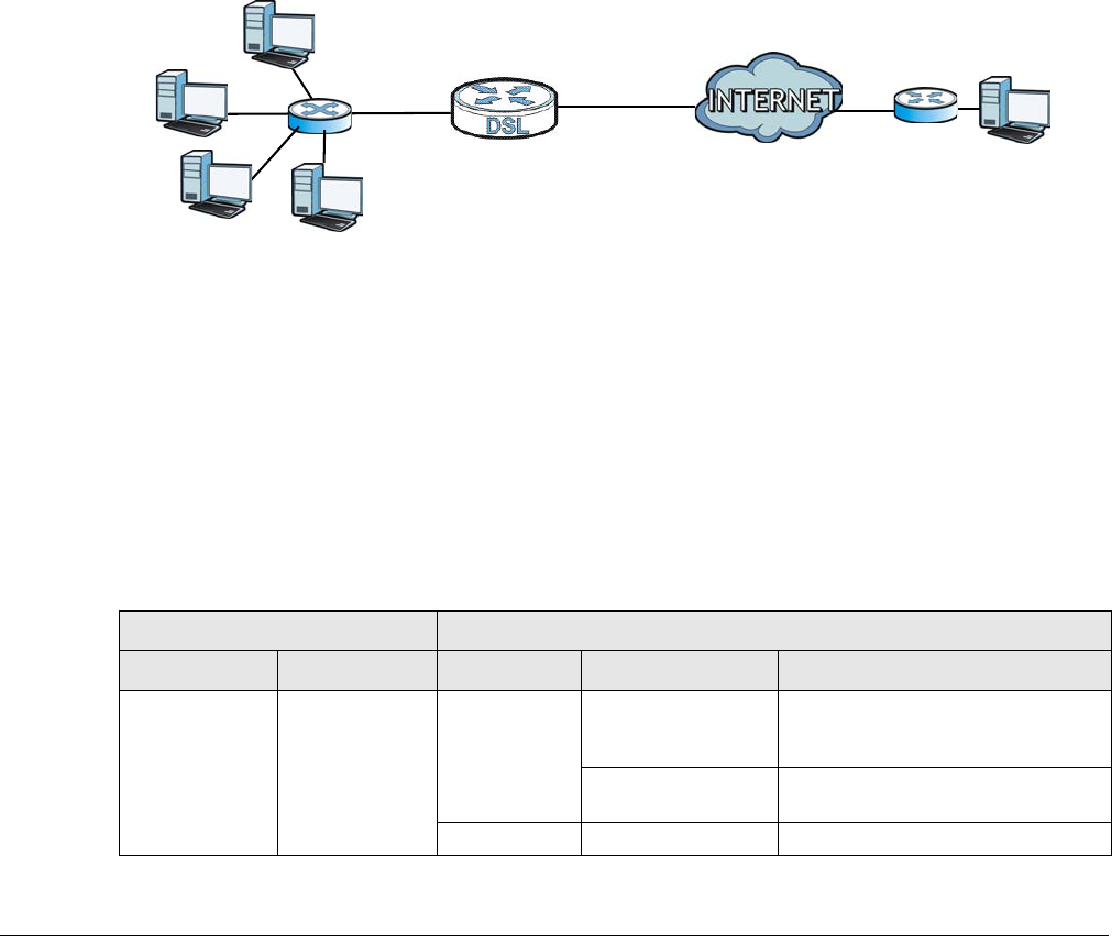
XMG3512-B10A User’s Guide
61
CHAPTER 6
Broadband
6.1 Overview
This chapter discusses the XMG’s Broadband screens. Use these screens to configure your XMG for
Internet access.
A WAN (Wide Area Network) connection is an outside connection to another network or the Internet. It
connects your private networks, such as a LAN (Local Area Network) and other networks, so that a
computer in one location can communicate with computers in other locations.
Figure 20 LAN and WAN
6.1.1 What You Can Do in this Chapter
• Use the Broadband screen to view, remove or add a WAN interface. You can also configure the WAN
settings on the XMG for Internet access (Section 6.2 on page 65).
• Use the Advanced screen to enable or disable PTM over ADSL, Annex M/Annex J, and DSL PhyR
functions (Section 6.3 on page 72).
• Use the Ethernet WAN screen to enable the fourth Ethernet LAN port to be an Ethernet WAN port
(Section 6.4 on page 75).
• Use the 802.1x screen to view and configure the IEEE 802.1X settings on the XMG (Section 6.5 on page
76).
WAN
Table 7 WAN Setup Overview
LAYER-2 INTERFACE INTERNET CONNECTION
CONNECTION DSL LINK TYPE MODE ENCAPSULATION CONNECTION SETTINGS
ADSL/VDSL over
PTM
N/A Routing PPPoE PPP information, IPv4/IPv6 IP address,
routing feature, DNS server, VLAN,
and MTU
IPoE IPv4/IPv6 IP address, routing feature,
DNS server, VLAN, and MTU
Bridge N/A VLAN
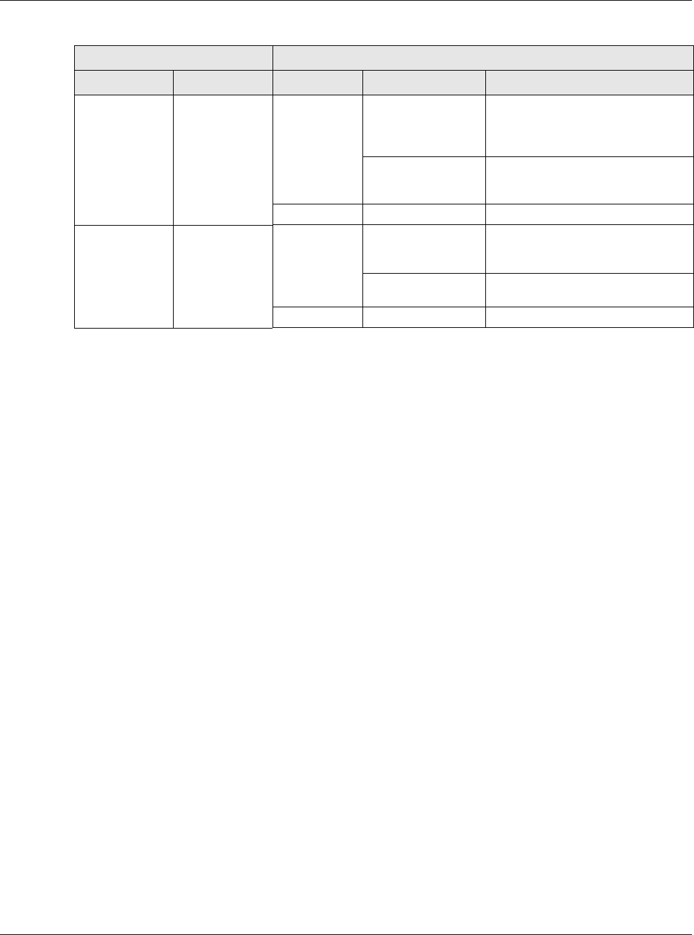
Chapter 6 Broadband
XMG3512-B10A User’s Guide
62
6.1.2 What You Need to Know
The following terms and concepts may help as you read this chapter.
WAN IP Address
The WAN IP address is an IP address for the XMG, which makes it accessible from an outside network. It is
used by the XMG to communicate with other devices in other networks. It can be static (fixed) or
dynamically assigned by the ISP each time the XMG tries to access the Internet.
If your ISP assigns you a static WAN IP address, they should also assign you the subnet mask and DNS
server IP address(es).
ATM
Asynchronous Transfer Mode (ATM) is a WAN networking technology that provides high-speed data
transfer. ATM uses fixed-size packets of information called cells. With ATM, a high QoS (Quality of Service)
can be guaranteed. ATM uses a connection-oriented model and establishes a virtual circuit (VC)
between Finding Out More
PTM
Packet Transfer Mode (PTM) is packet-oriented and supported by the VDSL2 standard. In PTM, packets
are encapsulated directly in the High-level Data Link Control (HDLC) frames. It is designed to provide a
low-overhead, transparent way of transporting packets over DSL links, as an alternative to ATM.
IPv6 Introduction
IPv6 (Internet Protocol version 6), is designed to enhance IP address size and features. The increase in
IPv6 address size to 128 bits (from the 32-bit IPv4 address) allows up to 3.4 x 1038 IP addresses. The XMG
can use IPv4/IPv6 dual stack to connect to IPv4 and IPv6 networks, and supports IPv6 rapid deployment
(6RD).
ADSL over ATM EoA Routing PPPoE/PPPoA ATM PVC configuration, PPP
information, IPv4/IPv6 IP address,
routing feature, DNS server, VLAN,
and MTU
IPoE/IPoA ATM PVC configuration, IPv4/IPv6 IP
address, routing feature, DNS server,
VLAN, and MTU
Bridge N/A ATM PVC configuration
Ethernet N/A Routing PPPoE PPP user name and password, WAN
IPv4/IPv6 IP address, routing feature,
DNS server, VLAN, and MTU
IPoE WAN IPv4/IPv6 IP address, NAT, DNS
server and routing feature
Bridge N/A VLAN
Table 7 WAN Setup Overview
LAYER-2 INTERFACE INTERNET CONNECTION
CONNECTION DSL LINK TYPE MODE ENCAPSULATION CONNECTION SETTINGS

Chapter 6 Broadband
XMG3512-B10A User’s Guide
63
IPv6 Addressing
The 128-bit IPv6 address is written as eight 16-bit hexadecimal blocks separated by colons (:). This is an
example IPv6 address 2001:0db8:1a2b:0015:0000:0000:1a2f:0000.
IPv6 addresses can be abbreviated in two ways:
• Leading zeros in a block can be omitted. So
2001:0db8:1a2b:0015:0000:0000:1a2f:0000 can be written as
2001:db8:1a2b:15:0:0:1a2f:0.
• Any number of consecutive blocks of zeros can be replaced by a double colon. A double
colon can only appear once in an IPv6 address. So
2001:0db8:0000:0000:1a2f:0000:0000:0015 can be written as
2001:0db8::1a2f:0000:0000:0015, 2001:0db8:0000:0000:1a2f::0015,
2001:db8::1a2f:0:0:15 or 2001:db8:0:0:1a2f::15.
IPv6 Prefix and Prefix Length
Similar to an IPv4 subnet mask, IPv6 uses an address prefix to represent the network address. An IPv6
prefix length specifies how many most significant bits (start from the left) in the address compose the
network address. The prefix length is written as “/x” where x is a number. For example,
2001:db8:1a2b:15::1a2f:0/32
means that the first 32 bits (2001:db8) is the subnet prefix.
IPv6 Subnet Masking
Both an IPv6 address and IPv6 subnet mask compose of 128-bit binary digits, which are divided into
eight 16-bit blocks and written in hexadecimal notation. Hexadecimal uses four bits for each character
(1 ~ 10, A ~ F). Each block’s 16 bits are then represented by four hexadecimal characters. For example,
FFFF:FFFF:FFFF:FFFF:FC00:0000:0000:0000.
IPv6 Rapid Deployment
Use IPv6 Rapid Deployment (6rd) when the local network uses IPv6 and the ISP has an IPv4 network.
When the XMG has an IPv4 WAN address and you set IPv4/IPv6 Mode to IPv4 Only, you can enable 6rd
to encapsulate IPv6 packets in IPv4 packets to cross the ISP’s IPv4 network.
The XMG generates a global IPv6 prefix from its IPv4 WAN address and tunnels IPv6 traffic to the ISP’s
Border Relay router (BR in the figure) to connect to the native IPv6 Internet. The local network can also
use IPv4 services. The XMG uses it’s configured IPv4 WAN IP to route IPv4 traffic to the IPv4 Internet.
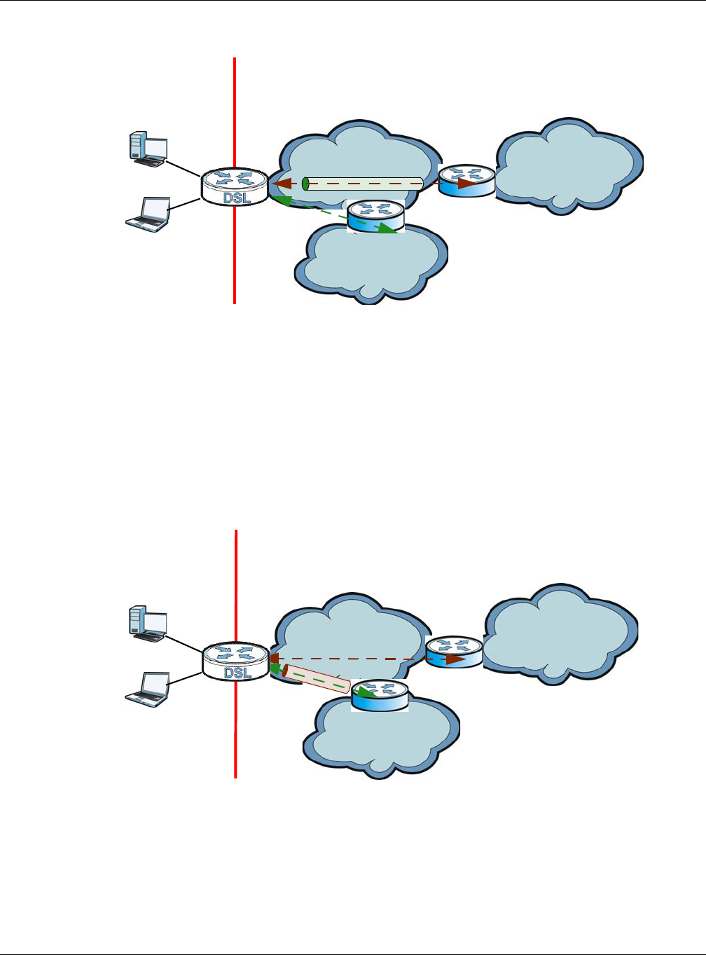
Chapter 6 Broadband
XMG3512-B10A User’s Guide
64
Figure 21 IPv6 Rapid Deployment
Dual Stack Lite
Use Dual Stack Lite when local network computers use IPv4 and the ISP has an IPv6 network. When the
XMG has an IPv6 WAN address and you set IPv4/IPv6 Mode to IPv6 Only, you can enable Dual Stack Lite
to use IPv4 computers and services.
The XMG tunnels IPv4 packets inside IPv6 encapsulation packets to the ISP’s Address Family Transition
Router (AFTR in the graphic) to connect to the IPv4 Internet. The local network can also use IPv6 services.
The XMG uses it’s configured IPv6 WAN IP to route IPv6 traffic to the IPv6 Internet.
Figure 22 Dual Stack Lite
6.1.3 Before You Begin
You need to know your Internet access settings such as encapsulation and WAN IP address. Get this
information from your ISP.
ISP (IPv4) IPv6 Internet
IPv4
IPv6
BR
IPv6 in IPv4
IPv4 Internet
IPv4
+
LAN
- IPv6
- IPv4
WAN
- IPv4
- IPv6 in IPv4
ISP (IPv6) IPv6 Internet
IPv6
AFTR
IPv4 in IPv6
IPv4 Internet
IPv6 IPv4
+
LAN
- IPv6
- IPv4
WAN
- IPv6
- IPv4 in IPv6

Chapter 6 Broadband
XMG3512-B10A User’s Guide
65
6.2 The Broadband Screen
Use this screen to change your XMG’s Internet access settings. Click Network Setting > Broadband from
the menu. The summary table shows you the configured WAN services (connections) on the XMG.
Figure 23 Network Setting > Broadband
The following table describes the labels in this screen.
6.2.1 Add/Edit Internet Connection
Click Add New WAN Interface in the Broadband screen or the Edit icon next to an existing WAN interface
to configure a WAN connection. The screen varies depending on the interface type, mode,
encapsulation, and IPv6/IPv4 mode you select.
Table 8 Network Setting > Broadband
LABEL DESCRIPTION
Add New WAN
Interface
Click this button to create a new connection.
# This is the index number of the entry.
Name This is the service name of the connection.
Type This shows whether it is an ATM, Ethernet or a PTM connection.
Mode This shows whether the connection is in routing or bridge mode.
Encapsulation This is the method of encapsulation used by this connection.
802.1p This indicates the 802.1p priority level assigned to traffic sent through this connection. This
displays N/A when there is no priority level assigned.
802.1q This indicates the VLAN ID number assigned to traffic sent through this connection. This displays
N/A when there is no VLAN ID number assigned.
IGMP Proxy This shows whether the XMG act as an IGMP proxy on this connection.
NAT This shows whether NAT is activated or not for this connection.
Default
Gateway
This shows whether the XMG use the WAN interface of this connection as the system default
gateway.
IPv6 This shows whether IPv6 is activated or not for this connection. IPv6 is not available when the
connection uses the bridging service.
MLD Proxy This shows whether Multicast Listener Discovery (MLD) is activated or not for this connection. MLD
is not available when the connection uses the bridging service.
Modify Click the Edit icon to configure the WAN connection.
Click the Delete icon to remove the WAN connection.
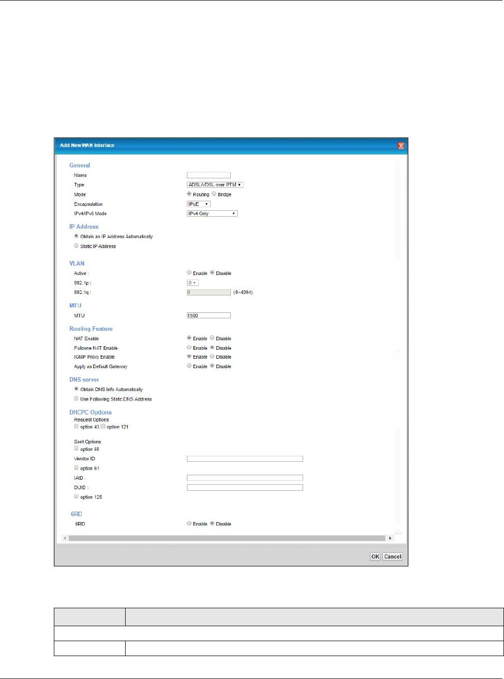
Chapter 6 Broadband
XMG3512-B10A User’s Guide
66
6.2.1.1 Routing Mode
Use Routing mode if your ISP give you one IP address only and you want multiple computers to share an
Internet account.
The following example screen displays when you select the ADSL/VDSL over ATM connection type,
Routing mode, and IPoE encapsulation. The screen varies when you select other interface type,
encapsulation, and IPv4/IPv6 mode.
Figure 24 Network Setting > Broadband > Add New WAN Interface/Edit (Routing Mode)
The following table describes the labels in this screen.
Table 9 Network Setting > Broadband > Add New WAN Interface/Edit (Routing Mode)
LABEL DESCRIPTION
General
Name Specify a descriptive name for this connection.

Chapter 6 Broadband
XMG3512-B10A User’s Guide
67
Type Select whether it is an ADSL/VDSL over PTM, ADSL over ATM connection or Ethernet.
Mode Select Routing if your ISP give you one IP address only and you want multiple computers to share
an Internet account.
Encapsulation Select the method of encapsulation used by your ISP from the drop-down list box. This option is
available only when you select Routing in the Mode field.
The choices depend on the connection type you selected. If your connection type is ADSL/VDSL
over PTM, the choices are PPPoE and IPoE. If your connection type is ADSL over ATM, the choices
are PPPoE, PPPoA, IPoE and IPoA. If your connection type is Ethernet, the choices are PPPoE and
IPoE.
IPv4/IPv6 Mode Select IPv4 Only if you want the XMG to run IPv4 only.
Select IPv4 IPv6 DualStack to allow the XMG to run IPv4 and IPv6 at the same time.
Select IPv6 Only if you want the XMG to run IPv6 only.
ATM PVC Configuration (These fields appear when the Type is set to ADSL over ATM.)
VPI The valid range for the VPI is 0 to 255. Enter the VPI assigned to you.
VCI The valid range for the VCI is 32 to 65535 (0 to 31 is reserved for local management of ATM
traffic). Enter the VCI assigned to you.
Encapsulation
Mode
Select the method of multiplexing used by your ISP from the drop-down list box. Choices are:
•LLC/SNAP-BRIDGING: In LCC encapsulation, bridged PDUs are encapsulated by identifying
the type of the bridged media in the SNAP header. This is available only when you select IPoE
or PPPoE in the Select DSL Link Type field.
•VC/MUX: In VC multiplexing, each protocol is carried on a single ATM virtual circuit (VC). To
transport multiple protocols, the XMG needs separate VCs. There is a binding between a VC
and the type of the network protocol carried on the VC. This reduces payload overhead
since there is no need to carry protocol information in each Protocol Data Unit (PDU)
payload.
•LLC/ENCAPSULATION: More than one protocol can be carried over the same VC. This is
available only when you select PPPoA in the Encapsulation field.
•LLC/SNAP-ROUTING: In LCC encapsulation, an IEEE 802.2 Logical Link Control (LLC) header is
prefixed to each routed PDU to identify the PDUs. The LCC header can be followed by an
IEEE 802.1a SubNetwork Attachment Point (SNAP) header. This is available only when you
select IPoA in the Encapsulation field.
Service
Category
Select UBR Without PCR or UBR With PCR for applications that are non-time sensitive, such as e-
mail.
Select CBR (Continuous Bit Rate) to specify fixed (always-on) bandwidth for voice or data traffic.
Select Non Realtime VBR (non real-time Variable Bit Rate) for connections that do not require
closely controlled delay and delay variation.
Select Realtime VBR (real-time Variable Bit Rate) for applications with bursty connections that
require closely controlled delay and delay variation.
IP Address (This is available only when you select IPv4 Only or IPv4 IPv6 DualStack in the IPv4/IPv6 Mode field.)
Obtain an IP
Address
Automatically
A static IP address is a fixed IP that your ISP gives you. A dynamic IP address is not fixed; the ISP
assigns you a different one each time you connect to the Internet. Select this if you have a
dynamic IP address.
DHCP
option 60/
Vendor ID
This field displays when editing an existing WAN interface. Type the class vender ID you want the
XMG to add in the DHCP Discovery packets that go to the DHCP server.
DHCP
option 61
IAD
This field displays when editing an existing WAN interface. Type the Identity Association Identifier
(IAD) you want the XMG to add in the DHCP Discovery packets that go to the DHCP server.
DHCP
option 61
DUID
This field displays when editing an existing WAN interface. Type the DHCP Unique Identifier (DUID)
you want the XMG to add in the DHCP Discovery packets that go to the DHCP server.
Table 9 Network Setting > Broadband > Add New WAN Interface/Edit (Routing Mode) (continued)
LABEL DESCRIPTION

Chapter 6 Broadband
XMG3512-B10A User’s Guide
68
DHCP
option 43
Enable
This field displays when editing an existing WAN interface. Type the vender specific information
you want the XMG to add in the DHCP Offer packets. The information is used, for example, for
configuring an ACS’s (Auto Configuration Server) URL.
Static IP Address Select this option If the ISP assigned a fixed IP address
IP Address Enter the static IP address provided by your ISP.
Subnet Mask Enter the subnet mask provided by your ISP.
Gateway IP
Address
Enter the gateway IP address provided by your ISP.
VLAN (These fields appear when the Type is set to ADSL/VDSL over PTM.)
Active Select this to enable VLAN on this WAN interface.
802.1p IEEE 802.1p defines up to 8 separate traffic types by inserting a tag into a MAC-layer frame that
contains bits to define class of service.
Select the IEEE 802.1p priority level (from 0 to 7) to add to traffic through this connection. The
greater the number, the higher the priority level.
802.1q Type the VLAN ID number (from 1 to 4094) for traffic through this connection.
MTU
MTU Size Enter the MTU (Maximum Transfer Unit) size for this traffic.
Routing Feature (This is available only when you select IPv4 Only or IPv4 IPv6 DualStack in the IPv4/IPv6 Mode field.)
NAT Enable Select this option to activate NAT on this connection.
Fullcone NAT
Enable
Select this option to enable full cone NAT on this connection. This field is available only when you
activate NAT. In full cone NAT, the XMG maps all outgoing packets from an internal IP address
and port to a single IP address and port on the external network. The XMG also maps packets
coming to that external IP address and port to the internal IP address and port.
IGMP Proxy
Enable
Internet Group Multicast Protocol (IGMP) is a network-layer protocol used to establish
membership in a Multicast group - it is not used to carry user data.
Select this option to have the XMG act as an IGMP proxy on this connection. This allows the XMG
to get subscribing information and maintain a joined member list for each multicast group. It can
reduce multicast traffic significantly.
Apply as Default
Gateway
Select this option to have the XMG use the WAN interface of this connection as the system
default gateway.
DNS Server (This is available only when you select IPv4 Only or IPv4 IPv6 DualStack in the IPv4/IPv6 Mode field.)
Select Obtain DNS Info Automically if you want the XMG to use the DNS server addresses
assigned by your ISP.
Select Use Following Static DNS Address if you want the XMG to use the DNS server addresses
you configure manually.
Primary DNS
Server
Enter the first DNS server address assigned by the ISP.
Secondary DNS
Server
Enter the second DNS server address assigned by the ISP.
Tunnel
The DS-Lite (Dual Stack Lite) fields display when you set the IPv4/IPv6 Mode field to IPv6 Only.
Enable Dual Stack Lite to let local computers use IPv4 through an ISP’s IPv6 network. See Dual Stack Lite on page 64
for more information.
Enable DS-Lite This is available only when you select IPv6 Only in the IPv4/IPv6 Mode field. Select Enable to let
local computers use IPv4 through an ISP’s IPv6 network.
DS-Lite Relay
Server IP
Specify the transition router’s IPv6 address.
Table 9 Network Setting > Broadband > Add New WAN Interface/Edit (Routing Mode) (continued)
LABEL DESCRIPTION

Chapter 6 Broadband
XMG3512-B10A User’s Guide
69
6RD
The 6RD (IPv6 rapid deployment) fields display when you set the IPv6/IPv4 Mode field to IPv4 Only. See IPv6 Rapid
Deployment on page 63 for more information.
6RD Select Enable to tunnel IPv6 traffic from the local network through the ISP’s IPv4 network.
Select Manually Configured if you have the IPv4 address of the relay server. Otherwise, select
Automatically configured by DHCPC to have the XMG detect it automatically through DHCP.
The Automatically configured by DHCPC option is configurable only when you set the method of
encapsulation to IPoE.
Service Provider
IPv6 Prefix
Enter an IPv6 prefix for tunneling IPv6 traffic to the ISP’s border relay router and connecting to the
native IPv6 Internet.
IPv4 Mask
Length
Enter the subnet mask number (1~32) for the IPv4 network.
Border Relay
IPv4 Address
When you select Manually Configured, specify the relay server’s IPv4 address in this field.
DHCPC Options (This is available only when you select IPv4 Only or IPv4 IPv6 DualStack in the IPv4/IPv6 Mode field.)
Request Options Select Option 43 to have the XMG automatically add vendor specific information in the DHCP
packets to request the vendor specific options from the DHCP server.
Select Option 121 to have the XMG push static routes to clients.
Sent Options
option 60 Select this and enter the device identity you want the XMG to add in the DHCP discovery
packets that go to the DHCP server.
Vendor ID Enter the Vendor Class Identifier, such as the type of the hardware or firmware.
option 61 Select this and enter any string that identifies the device.
IAID Enter the Identity Association Identifier (IAID) of the device, for example, the WAN connection
index number.
DUID Enter the hardware type, a time value and the MAC address of the device.
option 125 Select this to have the XMG automatically generate and add vendor specific parameters in the
DHCP discovery packets that go to the DHCP server.
IPv6 Address (This is available only when you select IPv4 IPv6 DualStack or IPv6 Only in the IPv4/IPv6 Mode field.)
Obtain an IPv6
Address
Automatically
Select Obtain an IPv6 Address Automatically if you want to have the XMG use the IPv6 prefix
from the connected router’s Router Advertisement (RA) to generate an IPv6 address.
Static IPv6
Address
Select Static IPv6 Address if you have a fixed IPv6 address assigned by your ISP. When you select
this, the following fields appear.
IPv6 Address Enter an IPv6 IP address that your ISP gave to you for this WAN interface.
Prefix Length Enter the address prefix length to specify how many most significant bits in an IPv6 address
compose the network address.
IPv6 Default
Gateway Enter the IP address of the next-hop gateway. The gateway is a router or switch on the same
segment as your XMG's interface(s). The gateway helps forward packets to their destinations.
IPv6 Routing Feature (This is available only when you select IPv4 IPv6 DualStack or IPv6 Only in the IPv4/IPv6 Mode
field. You can enable IPv6 routing features in the following section.)
MLD Proxy
Enable
Select this checkbox to have the XMG act as an MLD proxy on this connection. This allows the
XMG to get subscription information and maintain a joined member list for each multicast group.
It can reduce multicast traffic significantly.
Apply as Default
Gateway
Select this option to have the XMG use the WAN interface of this connection as the system
default gateway.
Table 9 Network Setting > Broadband > Add New WAN Interface/Edit (Routing Mode) (continued)
LABEL DESCRIPTION
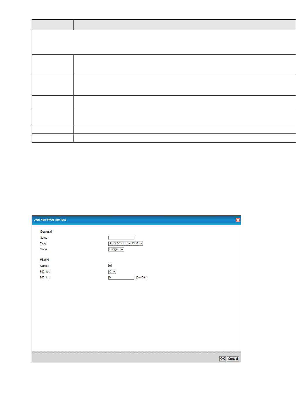
Chapter 6 Broadband
XMG3512-B10A User’s Guide
70
6.2.1.2 Bridge Mode
Click the Add new WAN Interface in the Network Setting > Broadband screen or the Edit icon next to the
connection you want to configure. Select Bridge as the encapsulation mode. The screen varies
depending on the interface type you select.
If you select ADSL/VDSL over PTM or Ethernet as the interface type, the following screen appears.
Figure 25 Network Setting > Broadband > Add New WAN Interface/Edit (ADSL/VDSL over PTM -Bridge
Mode)
IPv6 DNS Server
This is available only when you select IPv4 IPv6 DualStack or IPv6 Only in the IPv4/IPv6 Mode field. Configure the
IPv6 DNS server in the following section.
Obtain IPv6 DNS
Info
Automatically
Select Obtain IPv6 DNS Info Automatically to have the XMG get the IPv6 DNS server addresses
from the ISP automatically.
Use Following
Static IPv6 DNS
Address
Select Use Following Static IPv6 DNS Address to have the XMG use the IPv6 DNS server addresses
you configure manually.
Primary DNS
Server
Enter the first IPv6 DNS server address assigned by the ISP.
Secondary DNS
Server
Enter the second IPv6 DNS server address assigned by the ISP.
Apply Click Apply to save your changes back to the XMG.
Cancel Click Cancel to exit this screen without saving.
Table 9 Network Setting > Broadband > Add New WAN Interface/Edit (Routing Mode) (continued)
LABEL DESCRIPTION
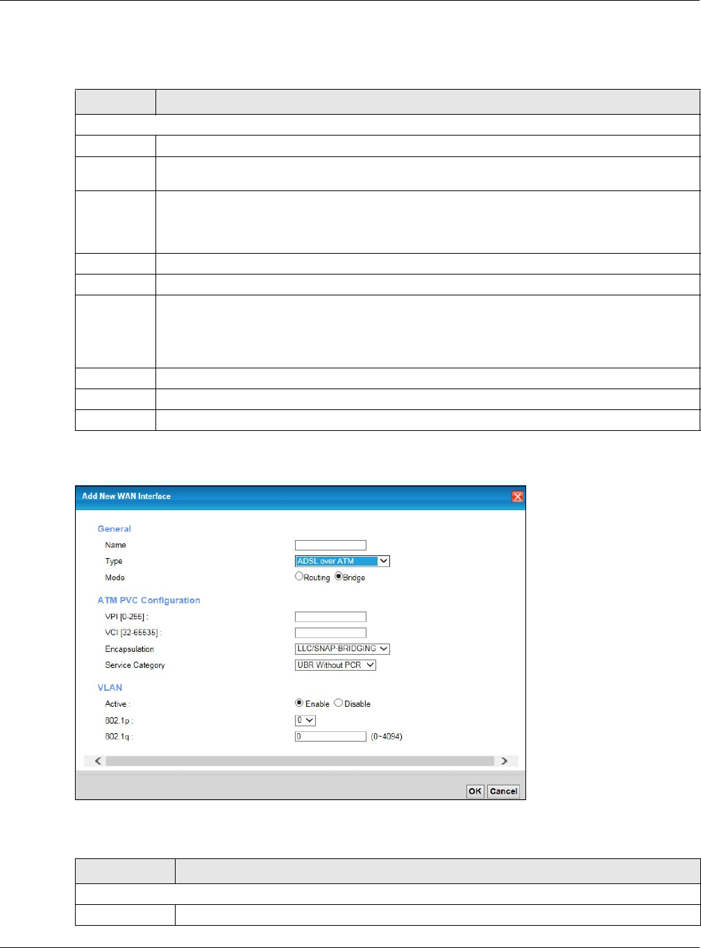
Chapter 6 Broadband
XMG3512-B10A User’s Guide
71
The following table describes the fields in this screen.
If you select ADSL over ATM as the interface type, the following screen appears.
Figure 26 Network Setting > Broadband > Add New WAN Interface/Edit (ADSL over ATM-Bridge Mode)
The following table describes the fields in this screen.
Table 10 Network Setting > Broadband > Add New WAN Interface/Edit (ADSL/VDSL over PTM -Bridge or
Ethernet Mode)
LABEL DESCRIPTION
General
Name Enter a service name of the connection.
Type Select ADSL/VDSL over PTM as the interface that you want to configure. The XMG uses the VDSL
technology for data transmission over the DSL port.
Mode Select Bridge when your ISP provides you more than one IP address and you want the connected
computers to get individual IP address from ISP’s DHCP server directly. If you select Bridge, you
cannot use routing functions, such as QoS, Firewall, DHCP server and NAT on traffic from the
selected LAN port(s).
VLAN This section is available only when you select ADSL/VDSL over PTM in the Type field.
Active Select Enable to enable VLAN on this WAN interface.
802.1p IEEE 802.1p defines up to 8 separate traffic types by inserting a tag into a MAC-layer frame that
contains bits to define class of service.
Select the IEEE 802.1p priority level (from 0 to 7) to add to traffic through this connection. The greater
the number, the higher the priority level.
802.1q Type the VLAN ID number (from 0 to 4094) for traffic through this connection.
OK Click OK to save your changes.
Cancel Click Cancel to exit this screen without saving.
Table 11 Network Setting > Broadband > Add New WAN Interface/Edit (ADSL over ATM-Bridge Mode)
LABEL DESCRIPTION
General
Name Enter a service name of the connection.

Chapter 6 Broadband
XMG3512-B10A User’s Guide
72
6.3 The Advanced Screen
Use the Advanced screen to enable or disable ADSL over PTM, Annex M, DSL PhyR, and SRA (Seamless
Rate Adaptation) functions. The XMG supports the PhyR retransmission scheme. PhyR is a retransmission
scheme designed to provide protection against noise on the DSL line. It improves voice, video and data
transmission resilience by utilizing a retransmission buffer.
Type Select ADSL over ATM as the interface that you want to configure. The XMG uses the ADSL
technology for data transmission over the DSL port.
Mode Select Bridge when your ISP provides you more than one IP address and you want the
connected computers to get individual IP address from ISP’s DHCP server directly. If you select
Bridge, you cannot use routing functions, such as QoS, Firewall, DHCP server and NAT on traffic
from the selected LAN port(s).
ATM PVC Configuration (These fields appear when the Type is set to ADSL over ATM.)
VPI The valid range for the VPI is 0 to 255. Enter the VPI assigned to you.
VCI The valid range for the VCI is 32 to 65535 (0 to 31 is reserved for local management of ATM
traffic). Enter the VCI assigned to you.
Encapsulation Select the method of multiplexing used by your ISP from the drop-down list box. Choices are:
• LLC/SNAP-BRIDGING: In LCC encapsulation, bridged PDUs are encapsulated by identifying the
type of the bridged media in the SNAP header. This is available only when you select IPoE or
PPPoE in the Encapsulation field.
• VC/MUX: In VC multiplexing, each protocol is carried on a single ATM virtual circuit (VC). To
transport multiple protocols, the XMG needs separate VCs. There is a binding between a VC and
the type of the network protocol carried on the VC. This reduces payload overhead since there
is no need to carry protocol information in each Protocol Data Unit (PDU) payload.
Service
Category
Select UBR Without PCR for applications that are non-time sensitive, such as e-mail.
Select CBR (Continuous Bit Rate) to specify fixed (always-on) bandwidth for voice or data traffic.
Select Non Realtime VBR (non real-time Variable Bit Rate) for connections that do not require
closely controlled delay and delay variation.
Select Realtime VBR (real-time Variable Bit Rate) for applications with bursty connections that
require closely controlled delay and delay variation.
VLAN This section is available only when you select ADSL/VDSL over PTM in the Type field.
Active Select Enable to enable VLAN on this WAN interface.
802.1p IEEE 802.1p defines up to 8 separate traffic types by inserting a tag into a MAC-layer frame that
contains bits to define class of service.
Select the IEEE 802.1p priority level (from 0 to 7) to add to traffic through this connection. The
greater the number, the higher the priority level.
802.1q Type the VLAN ID number (from 0 to 4094) for traffic through this connection.
OK Click OK to save your changes.
Cancel Click Cancel to exit this screen without saving.
Table 11 Network Setting > Broadband > Add New WAN Interface/Edit (ADSL over ATM-Bridge Mode)
LABEL DESCRIPTION
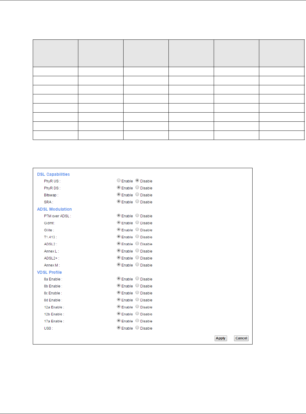
Chapter 6 Broadband
XMG3512-B10A User’s Guide
73
ITU-T G.993.2 standard defines a wide range of settings for various parameters, some of which are
encompassed in profiles as shown in the next table.
Click Network Setting > Broadband > Advanced to display the following screen.
Figure 27 Network Setting > Broadband > Advanced
Table 12 VDSL Profiles
PROFILE BANDWIDTH
(MHZ) NUMBER OF
DOWNSTREAM
CARRIERS
CARRIER
BANDWIDTH
(KHZ) POWER (DBM) MAX.
DOWNSTREAM
THROUGHPUT
(MBIT/S)
8a 8.832 2048 4.3125 17.5 50
8b 8.832 2048 4.3125 20.5 50
8c 8.5 1972 4.3125 11.5 50
8d 8.832 2048 4.3125 14.5 50
12a 12 2783 4.3125 14.5 68
12b 12 2783 4.3125 14.5 68
17a 17.664 4096 4.3125 14.5 100
30a 30 3479 8.625 14.5 200

Chapter 6 Broadband
XMG3512-B10A User’s Guide
74
The following table describes the labels in this screen.
Table 13 Network Setting > Broadband > Advanced
LABEL DESCRIPTION
PhyR US Enable or disable PhyR US (upstream) for upstream transmission to the WAN. PhyR US should be
enabled if data being transmitted upstream is sensitive to noise. However, enabling PhyR US can
decrease the US line rate. Enabling or disabling PhyR will require the CPE to retrain. For PhyR to
function, the DSLAM must also support PhyR and have it enabled.
PhyR DS Enable or disable PhyR DS (downstream) for downstream transmission from the WAN. PhyR DS
should be enabled if data being transmitted downstream is sensitive to noise. However,
enabling PhyR DS can decrease the DS line rate. Enabling or disabling PhyR will require the CPE
to retrain. For PhyR to function, the DSLAM must also support PhyR and have it enabled.
Bitswap Select Enable to allow the XMG to adapt to line changes when you are using G.dmt.
Bit-swapping is a way of keeping the line more stable by constantly monitoring and redistributing
bits between channels.
SRA Enable or disable Seamless Rate Adaption (SRA). Select Enable to have the XMG automatically
adjust the connection’s data rate according to line conditions without interrupting service.
ADSL
Modulation
PTM over ADSL: Select Enable to use PTM over ADSL. Since PTM has less overhead than ATM, some ISPs use this for
better performance.
G.dmt: ITU G.992.1 (better known as G.dmt) is an ITU standard for ADSL using discrete multitone
modulation. G.dmt full-rate ADSL expands the usable bandwidth of existing copper telephone
lines, delivering high-speed data communications at rates up to 8 Mbit/s downstream and 1.3
Mbit/s upstream.
G.lite : ITU G.992.2 (better known as G.lite) is an ITU standard for ADSL using discrete multitone
modulation. G.lite does not strictly require the use of DSL filters, but like all variants of ADSL
generally functions better with splitters.
T1.413 : ANSI T1.413 is a technical standard that defines the requirements for the single asymmetric
digital subscriber line (ADSL) for the interface between the telecommunications network and
the customer installation in terms of their interaction and electrical characteristics.
ADSL2 : It optionally extends the capability of basic ADSL in data rates to 12 Mbit/s downstream and,
depending on Annex version, up to 3.5 Mbit/s upstream (with a mandatory capability of ADSL2
transceivers of 8 Mbit/s downstream and 800 kbit/s upstream).
AnnexL : Annex L is an optional specification in the ITU-T ADSL2 recommendation G.992.3 titled Specific
requirements for a Reach Extended ADSL2 (READSL2) system operating in the frequency band
above POTS, therefore it is often referred to as Reach Extended ADSL2 or READSL2.The main
difference between this specification and commonly deployed Annex A is the maximum
distance that can be used. The power of the lower frequencies used for transmitting data is
boosted up to increase the reach of this signal up to 7 kilometers (23,000 ft).
ADSL2+ : ADSL2+ extends the capability of basic ADSL by doubling the number of downstream channels.
The data rates can be as high as 24 Mbit/s downstream and up to 1.4 Mbit/s upstream
depending on the distance from the DSLAM to the customer's premises.
AnnexM : Annex M is an optional specification in ITU-T recommendations G.992.3 (ADSL2) and G.992.5
(ADSL2+), also referred to as ADSL2 M and ADSL2+ M. This specification extends the capability of
commonly deployed Annex A by more than doubling the number of upstream bits. The data
rates can be as high as 12 or 24 Mbit/s downstream and 3 Mbit/s upstream depending on the
distance from the DSLAM to the customer's premises.
VDSL2 VDSL is a specification that supports wide deployment of voice, video, data and HDTV. The data
can be as high as on ADSL2+. It has a long reach performance, and unlike VDSL systems it is not
limited to short local loops.
VDSL Profile VDSL2 profiles differ in the width of the frequency band used to transmit the broadband signal.
Profiles that use a wider frequency band can deliver higher maximum speeds.
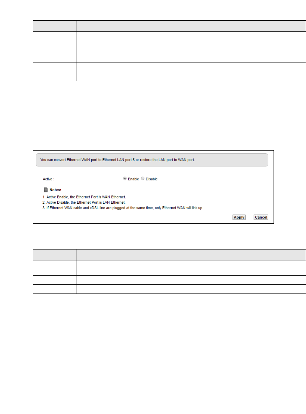
Chapter 6 Broadband
XMG3512-B10A User’s Guide
75
6.4 The Ethernet WAN Screen
You can enable the fourth Ethernet LAN port to be an Ethernet WAN port in the Ethernet WAN screen.
Click Network Setting > Broadband > Ethernet WAN to display the following screen.
Figure 28 Network Setting > Broadband > Ethernet WAN
The following table describes the labels in this screen.
8a, 8b, 8c, 8d,
12a, 12b, 17a,
30a, US0
The G.993.2 VDSL standard defines a wide range of profiles that can be used in different VDSL
deployment settings, such as in a central office, a street cabinet or a building.
The XMG must comply with at least one profile specified in G.993.2. but compliance with more
than one profile is allowed.
Apply Click Apply to save your changes back to the XMG.
Cancel Click Cancel to return to the previous configuration.
Table 13 Network Setting > Broadband > Advanced (continued)
LABEL DESCRIPTION
Table 14 Network Setting > Broadband > Ethernet WAN
LABEL DESCRIPTION
Active Select Enable to convert the fourth Ethernet LAN port to the Ethernet WAN port. Otherwise,
select Disable.
Apply Click Apply to save your changes back to the XMG.
Cancel Click Cancel to return to the previous configuration.
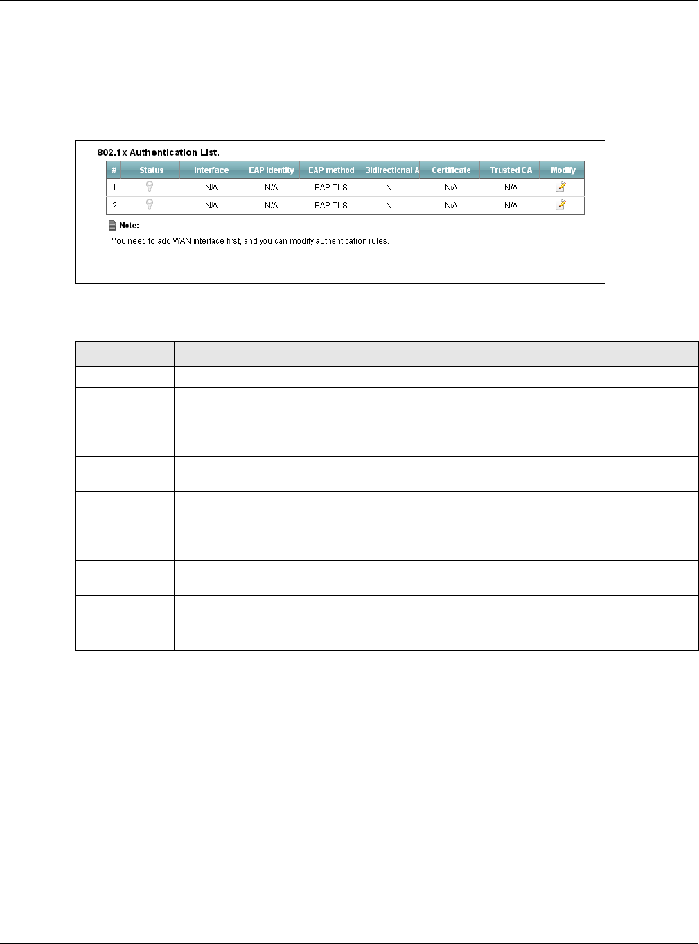
Chapter 6 Broadband
XMG3512-B10A User’s Guide
76
6.5 The 802.1x Screen
You can view and configure the 802.1X authentication settings in the 802.1x screen. Click Network
Setting > Broadband > 802.1x to display the following screen.
Figure 29 Network Setting > Broadband > 802.1x
The following table describes the labels in this screen.
Table 15 Network Setting > Broadband > 802.1x
LABEL DESCRIPTION
# This is the index number of the entry.
Status This field displays whether the authentication is active or not. A yellow bulb signifies that this
authentication is active. A gray bulb signifies that this authentication is not active.
Interface This is the interface that uses the authentication. This displays N/A when there is no interface
assigned.
EAP Identity This shows the EAP identity of the authentication. This displays N/A when there is no EAP identity
assigned.
EAP method This shows the EAP method used in the authentication. This displays N/A when there is no EAP
method assigned.
Bidirectional
Authentication
This shows whether bidirectional authentication is allowed.
Certificate This shows the certificate used for this authentication. This displays N/A when there is no
certificate assigned.
Trusted CA This shows the Trusted CA used for this authentication. This displays N/A when there is no Trusted
CA assigned.
Modify Click this icon to edit an item.
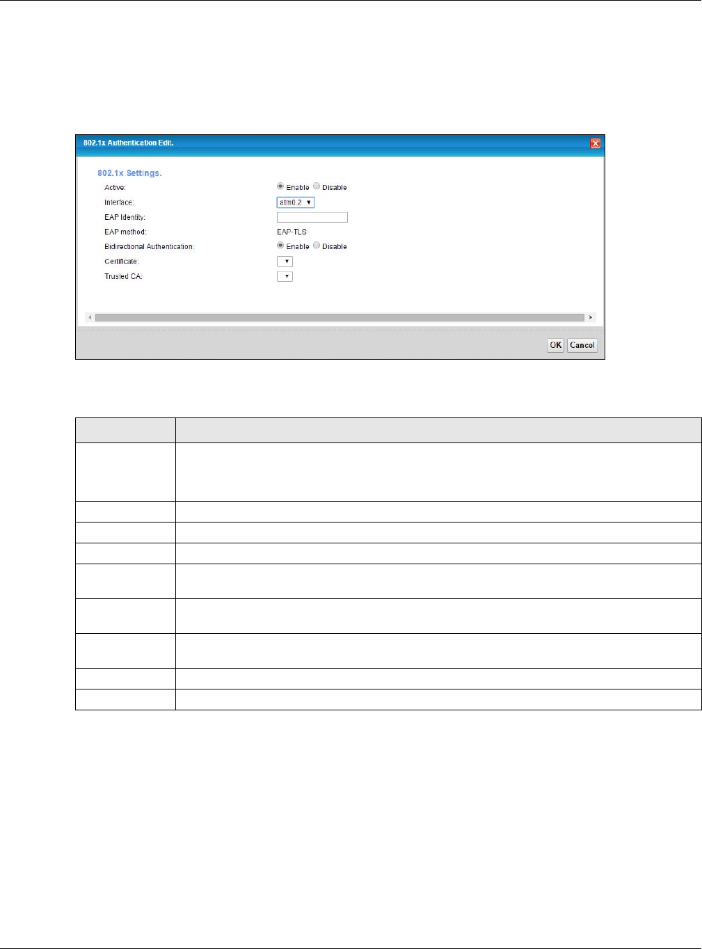
Chapter 6 Broadband
XMG3512-B10A User’s Guide
77
6.5.1 Modify 802.1X Settings
Use this screen to edit 802.1X authentication settings. Click the Edit icon next to the rule you want to edit.
The screen shown next appears.
Figure 30 Network Setting > Broadband > 802.1x > Modify
The following table describes the labels in this screen.
6.6 Technical Reference
The following section contains additional technical information about the XMG features described in this
chapter.
Encapsulation
Be sure to use the encapsulation method required by your ISP. The XMG can work in bridge mode or
routing mode. When the XMG is in routing mode, it supports the following methods.
Table 16 Network Setting > Broadband > 802.1x: Edit
LABEL DESCRIPTION
Active This field allows you to activate/deactivate the authentication.
Select this to enable the authentication. Clear this to disable this authentication without having
to delete the entry.
Interface Select an interface to which the authentication applies.
EAP Identity Enter the EAP identity of the authentication.
EAP method This is the EAP method used for this authentication.
Bidirectional
Authentication
Select Enable to allow bidirectional authentication.
Certificate Select the certificate you want to assign to the authentication. You need to import the
certificate in the Security > Certificates > Local Certificates screen.
Trusted CA Select the Trusted CA you want to assign to the authentication. You need to import the
certificate in the Security > Certificates > Trusted CA screen.
OK Click OK to save your changes.
Cancel Click Cancel to exit this screen without saving.

Chapter 6 Broadband
XMG3512-B10A User’s Guide
78
IP over Ethernet
IP over Ethernet (IPoE) is an alternative to PPPoE. IP packets are being delivered across an Ethernet
network, without using PPP encapsulation. They are routed between the Ethernet interface and the
WAN interface and then formatted so that they can be understood in a bridged environment. For
instance, it encapsulates routed Ethernet frames into bridged Ethernet cells.
PPP over ATM (PPPoA)
PPPoA stands for Point to Point Protocol over ATM Adaptation Layer 5 (AAL5). A PPPoA connection
functions like a dial-up Internet connection. The XMG encapsulates the PPP session based on RFC1483
and sends it through an ATM PVC (Permanent Virtual Circuit) to the Internet Service Provider’s (ISP)
DSLAM (digital access multiplexer). Please refer to RFC 2364 for more information on PPPoA. Refer to RFC
1661 for more information on PPP.
PPP over Ethernet (PPPoE)
Point-to-Point Protocol over Ethernet (PPPoE) provides access control and billing functionality in a
manner similar to dial-up services using PPP. PPPoE is an IETF standard (RFC 2516) specifying how a
personal computer (PC) interacts with a broadband modem (DSL, cable, wireless, etc.) connection.
For the service provider, PPPoE offers an access and authentication method that works with existing
access control systems (for example RADIUS).
One of the benefits of PPPoE is the ability to let you access one of multiple network services, a function
known as dynamic service selection. This enables the service provider to easily create and offer new IP
services for individuals.
Operationally, PPPoE saves significant effort for both you and the ISP or carrier, as it requires no specific
configuration of the broadband modem at the customer site.
By implementing PPPoE directly on the XMG (rather than individual computers), the computers on the
LAN do not need PPPoE software installed, since the XMG does that part of the task. Furthermore, with
NAT, all of the LANs’ computers will have access.
RFC 1483
RFC 1483 describes two methods for Multiprotocol Encapsulation over ATM Adaptation Layer 5 (AAL5).
The first method allows multiplexing of multiple protocols over a single ATM virtual circuit (LLC-based
multiplexing) and the second method assumes that each protocol is carried over a separate ATM virtual
circuit (VC-based multiplexing). Please refer to RFC 1483 for more detailed information.
Multiplexing
There are two conventions to identify what protocols the virtual circuit (VC) is carrying. Be sure to use the
multiplexing method required by your ISP.
VC-based Multiplexing
In this case, by prior mutual agreement, each protocol is assigned to a specific virtual circuit; for
example, VC1 carries IP, etc. VC-based multiplexing may be dominant in environments where dynamic
creation of large numbers of ATM VCs is fast and economical.
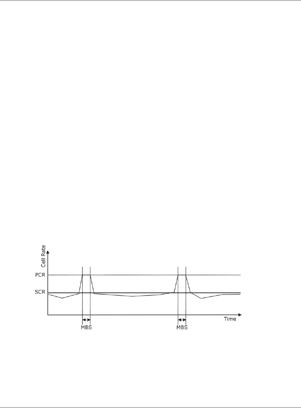
Chapter 6 Broadband
XMG3512-B10A User’s Guide
79
LLC-based Multiplexing
In this case one VC carries multiple protocols with protocol identifying information being contained in
each packet header. Despite the extra bandwidth and processing overhead, this method may be
advantageous if it is not practical to have a separate VC for each carried protocol, for example, if
charging heavily depends on the number of simultaneous VCs.
Traffic Shaping
Traffic Shaping is an agreement between the carrier and the subscriber to regulate the average rate
and fluctuations of data transmission over an ATM network. This agreement helps eliminate congestion,
which is important for transmission of real time data such as audio and video connections.
Peak Cell Rate (PCR) is the maximum rate at which the sender can send cells. This parameter may be
lower (but not higher) than the maximum line speed. 1 ATM cell is 53 bytes (424 bits), so a maximum
speed of 832Kbps gives a maximum PCR of 1962 cells/sec. This rate is not guaranteed because it is
dependent on the line speed.
Sustained Cell Rate (SCR) is the mean cell rate of each bursty traffic source. It specifies the maximum
average rate at which cells can be sent over the virtual connection. SCR may not be greater than the
PCR.
Maximum Burst Size (MBS) is the maximum number of cells that can be sent at the PCR. After MBS is
reached, cell rates fall below SCR until cell rate averages to the SCR again. At this time, more cells (up to
the MBS) can be sent at the PCR again.
If the PCR, SCR or MBS is set to the default of "0", the system will assign a maximum value that correlates
to your upstream line rate.
The following figure illustrates the relationship between PCR, SCR and MBS.
Figure 31 Example of Traffic Shaping
ATM Traffic Classes
These are the basic ATM traffic classes defined by the ATM Forum Traffic Management 4.0 Specification.
Constant Bit Rate (CBR)
Constant Bit Rate (CBR) provides fixed bandwidth that is always available even if no data is being sent.
CBR traffic is generally time-sensitive (doesn't tolerate delay). CBR is used for connections that

Chapter 6 Broadband
XMG3512-B10A User’s Guide
80
continuously require a specific amount of bandwidth. A PCR is specified and if traffic exceeds this rate,
cells may be dropped. Examples of connections that need CBR would be high-resolution video and
voice.
Variable Bit Rate (VBR)
The Variable Bit Rate (VBR) ATM traffic class is used with bursty connections. Connections that use the
Variable Bit Rate (VBR) traffic class can be grouped into real time (VBR-RT) or non-real time (VBR-nRT)
connections.
The VBR-RT (real-time Variable Bit Rate) type is used with bursty connections that require closely
controlled delay and delay variation. It also provides a fixed amount of bandwidth (a PCR is specified)
but is only available when data is being sent. An example of an VBR-RT connection would be video
conferencing. Video conferencing requires real-time data transfers and the bandwidth requirement
varies in proportion to the video image's changing dynamics.
The VBR-nRT (non real-time Variable Bit Rate) type is used with bursty connections that do not require
closely controlled delay and delay variation. It is commonly used for "bursty" traffic typical on LANs. PCR
and MBS define the burst levels, SCR defines the minimum level. An example of an VBR-nRT connection
would be non-time sensitive data file transfers.
Unspecified Bit Rate (UBR)
The Unspecified Bit Rate (UBR) ATM traffic class is for bursty data transfers. However, UBR doesn't
guarantee any bandwidth and only delivers traffic when the network has spare bandwidth. An example
application is background file transfer.
IP Address Assignment
A static IP is a fixed IP that your ISP gives you. A dynamic IP is not fixed; the ISP assigns you a different one
each time. The Single User Account feature can be enabled or disabled if you have either a dynamic or
static IP. However the encapsulation method assigned influences your choices for IP address and
default gateway.
Introduction to VLANs
A Virtual Local Area Network (VLAN) allows a physical network to be partitioned into multiple logical
networks. Devices on a logical network belong to one group. A device can belong to more than one
group. With VLAN, a device cannot directly talk to or hear from devices that are not in the same
group(s); the traffic must first go through a router.
In Multi-Tenant Unit (MTU) applications, VLAN is vital in providing isolation and security among the
subscribers. When properly configured, VLAN prevents one subscriber from accessing the network
resources of another on the same LAN, thus a user will not see the printers and hard disks of another user
in the same building.
VLAN also increases network performance by limiting broadcasts to a smaller and more manageable
logical broadcast domain. In traditional switched environments, all broadcast packets go to each and
every individual port. With VLAN, all broadcasts are confined to a specific broadcast domain.

Chapter 6 Broadband
XMG3512-B10A User’s Guide
81
Introduction to IEEE 802.1Q Tagged VLAN
A tagged VLAN uses an explicit tag (VLAN ID) in the MAC header to identify the VLAN membership of a
frame across bridges - they are not confined to the switch on which they were created. The VLANs can
be created statically by hand or dynamically through GVRP. The VLAN ID associates a frame with a
specific VLAN and provides the information that switches need to process the frame across the network.
A tagged frame is four bytes longer than an untagged frame and contains two bytes of TPID (Tag
Protocol Identifier), residing within the type/length field of the Ethernet frame) and two bytes of TCI (Tag
Control Information), starts after the source address field of the Ethernet frame).
The CFI (Canonical Format Indicator) is a single-bit flag, always set to zero for Ethernet switches. If a
frame received at an Ethernet port has a CFI set to 1, then that frame should not be forwarded as it is to
an untagged port. The remaining twelve bits define the VLAN ID, giving a possible maximum number of
4,096 VLANs. Note that user priority and VLAN ID are independent of each other. A frame with VID
(VLAN Identifier) of null (0) is called a priority frame, meaning that only the priority level is significant and
the default VID of the ingress port is given as the VID of the frame. Of the 4096 possible VIDs, a VID of 0 is
used to identify priority frames and value 4095 (FFF) is reserved, so the maximum possible VLAN
configurations are 4,094.
Multicast
IP packets are transmitted in either one of two ways - Unicast (1 sender - 1 recipient) or Broadcast (1
sender - everybody on the network). Multicast delivers IP packets to a group of hosts on the network -
not everybody and not just 1.
Internet Group Multicast Protocol (IGMP) is a network-layer protocol used to establish membership in a
Multicast group - it is not used to carry user data. IGMP version 2 (RFC 2236) is an improvement over
version 1 (RFC 1112) but IGMP version 1 is still in wide use. If you would like to read more detailed
information about interoperability between IGMP version 2 and version 1, please see sections 4 and 5 of
RFC 2236. The class D IP address is used to identify host groups and can be in the range 224.0.0.0 to
239.255.255.255. The address 224.0.0.0 is not assigned to any group and is used by IP multicast
computers. The address 224.0.0.1 is used for query messages and is assigned to the permanent group of
all IP hosts (including gateways). All hosts must join the 224.0.0.1 group in order to participate in IGMP.
The address 224.0.0.2 is assigned to the multicast routers group.
At start up, the XMG queries all directly connected networks to gather group membership. After that,
the XMG periodically updates this information.
DNS Server Address Assignment
Use Domain Name System (DNS) to map a domain name to its corresponding IP address and vice versa,
for instance, the IP address of www.zyxel.com is 204.217.0.2. The DNS server is extremely important
because without it, you must know the IP address of a computer before you can access it.
The XMG can get the DNS server addresses in the following ways.
1The ISP tells you the DNS server addresses, usually in the form of an information sheet, when you sign up.
If your ISP gives you DNS server addresses, manually enter them in the DNS server fields.
TPID
2 Bytes
User Priority
3 Bits
CFI
1 Bit
VLAN ID
12 Bits

Chapter 6 Broadband
XMG3512-B10A User’s Guide
82
2If your ISP dynamically assigns the DNS server IP addresses (along with the XMG’s WAN IP address), set
the DNS server fields to get the DNS server address from the ISP.
IPv6 Addressing
The 128-bit IPv6 address is written as eight 16-bit hexadecimal blocks separated by colons (:). This is an
example IPv6 address 2001:0db8:1a2b:0015:0000:0000:1a2f:0000.
IPv6 addresses can be abbreviated in two ways:
• Leading zeros in a block can be omitted. So 2001:0db8:1a2b:0015:0000:0000:1a2f:0000 can be
written as 2001:db8:1a2b:15:0:0:1a2f:0.
• Any number of consecutive blocks of zeros can be replaced by a double colon. A double colon can
only appear once in an IPv6 address. So 2001:0db8:0000:0000:1a2f:0000:0000:0015 can be
written as 2001:0db8::1a2f:0000:0000:0015, 2001:0db8:0000:0000:1a2f::0015,
2001:db8::1a2f:0:0:15 or 2001:db8:0:0:1a2f::15.
IPv6 Prefix and Prefix Length
Similar to an IPv4 subnet mask, IPv6 uses an address prefix to represent the network address. An IPv6
prefix length specifies how many most significant bits (start from the left) in the address compose the
network address. The prefix length is written as “/x” where x is a number. For example,
2001:db8:1a2b:15::1a2f:0/32
means that the first 32 bits (2001:db8) is the subnet prefix.

XMG3512-B10A User’s Guide
83
CHAPTER 7
Wireless
7.1 Overview
This chapter describes the XMG’s Network Setting > Wireless screens. Use these screens to set up your
XMG’s wireless connection.
7.1.1 What You Can Do in this Chapter
This section describes the XMG’s Wireless screens. Use these screens to set up your XMG’s wireless
connection.
• Use the General screen to enable the Wireless LAN, enter the SSID and select the wireless security
mode (Section 7.2 on page 84).
• Use the Guest/More AP screen to set up multiple wireless networks on your XMG (Section 7.3 on page
88).
• Use the MAC Authentication screen to allow or deny wireless clients based on their MAC addresses
from connecting to the XMG (Section 7.4 on page 91).
• Use the WPS screen to enable or disable WPS, view or generate a security PIN (Personal Identification
Number) (Section 7.5 on page 92).
• Use the WMM screen to enable Wi-Fi MultiMedia (WMM) to ensure quality of service in wireless
networks for multimedia applications (Section 7.6 on page 94).
• Use the Others screen to configure wireless advanced features, such as the RTS/CTS Threshold
(Section 7.7 on page 95).
• Use the Channel Status screen to scan wireless LAN channel noises and view the results (Section 7.8 on
page 96).
7.1.2 What You Need to Know
Wireless Basics
“Wireless” is essentially radio communication. In the same way that walkie-talkie radios send and
receive information over the airwowaves, wireless networking devices exchange information with one
another. A wireless networking device is just like a radio that lets your computer exchange information
with radios attached to other computers. Like walkie-talkies, most wireless networking devices operate
at radio frequency bands that are open to the public and do not require a license to use. However,
wireless networking is different from that of most traditional radio communications in that there a
number of wireless networking standards available with different methods of data encryption.
Finding Out More
See Section 7.9 on page 97 for advanced technical information on wireless networks.
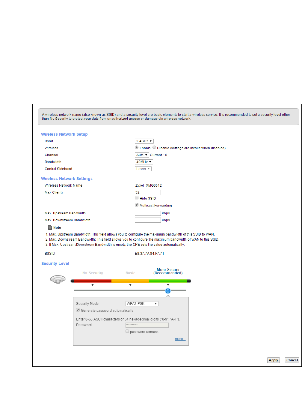
Chapter 7 Wireless
XMG3512-B10A User’s Guide
84
7.2 The General Screen
Use this screen to enable the Wireless LAN, enter the SSID and select the wireless security mode.
Note: If you are configuring the XMG from a computer connected to the wireless LAN and
you change the XMG’s SSID, channel or security settings, you will lose your wireless
connection when you press Apply to confirm. You must then change the wireless
settings of your computer to match the XMG’s new settings.
Click Network Setting > Wireless to open the General screen.
Figure 32 Network Setting > Wireless > General

Chapter 7 Wireless
XMG3512-B10A User’s Guide
85
The following table describes the general wireless LAN labels in this screen.
Table 17 Network Setting > Wireless > General
LABEL DESCRIPTION
Wireless Network Setup
Band This shows the wireless band which this radio profile is using. 2.4GHz is the frequency used by IEEE
802.11b/g/n wireless clients while 5GHz is used by IEEE 802.11a/ac wireless clients.
Wireless You can Enable or Disable the wireless LAN in this field.
Channel Use Auto to have the XMG automatically determine a channel to use.
Bandwidth Select whether the XMG uses a wireless channel width of 20MHz, 40MHz or 80MHz.
A standard 20MHz channel offers transfer speeds of up to 150Mbps whereas a 40MHz channel
uses two standard channels and offers speeds of up to 300 Mbps.
40MHz (channel bonding or dual channel) bonds two adjacent radio channels to increase
throughput. The wireless clients must also support 40 MHz. It is often better to use the 20 MHz
setting in a location where the environment hinders the wireless signal.
An 80MHz channel groups adjacent 40MHz channels into pairs to increase bandwidth even
higher.
Select 20MHz if you want to lessen radio interference with other wireless devices in your
neighborhood or the wireless clients do not support channel bonding.
Control
Sideband
This is available for some regions when you select a specific channel and set the Bandwidth field
to 40MHz. Set whether the control channel (set in the Channel field) should be in the Lower or
Upper range of channel bands.
Wireless Network Settings
Wireless
Network Name
(SSID)
The SSID (Service Set IDentity) identifies the service set with which a wireless device is associated.
Wireless devices associating to the access point (AP) must have the same SSID.
Enter a descriptive name (up to 32 English keyboard characters) for the wireless LAN.
Max Clients Specify the maximum number of clients that can connect to this network at the same time.
Hide SSID Select this check box to hide the SSID in the outgoing beacon frame so a station cannot obtain
the SSID through scanning using a site survey tool.
Multicast
Forwarding
Select this check box to allow the XMG to convert wireless multicast traffic into wireless unicast
traffic.
Max. Upstream
Bandwidth
Specify the maximum rate for upstream wireless traffic to the WAN from this WLAN in kilobits per
second (Kbps).
Max.
Downstream
Bandwidth
Specify the maximum rate for downstream wireless traffic to this WLAN from the WAN in kilobits
per second (Kbps).
BSSID This shows the MAC address of the wireless interface on the XMG when wireless LAN is enabled.
Security Level Select Basic (WEP) or More Secure (WPA(2)-PSK) to add security on this wireless network. The
wireless clients which want to associate to this network must have same wireless security settings
as the XMG. When you select to use a security, additional options appears in this screen.
Or you can select No Security to allow any client to associate this network without any data
encryption or authentication.
See the following sections for more details about this field.
Apply Click Apply to save your changes.
Cancel Click Cancel to restore your previously saved settings.
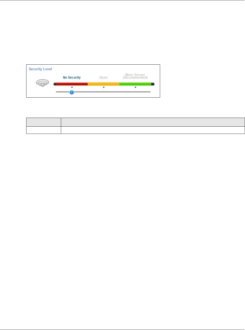
Chapter 7 Wireless
XMG3512-B10A User’s Guide
86
7.2.1 No Security
Select No Security to allow wireless stations to communicate with the access points without any data
encryption or authentication.
Note: If you do not enable any wireless security on your XMG, your network is accessible to
any wireless networking device that is within range.
Figure 33 Wireless > General: No Security
The following table describes the labels in this screen.
7.2.2 Basic (WEP Encryption)
WEP encryption scrambles the data transmitted between the wireless stations and the access points
(AP) to keep network communications private. Both the wireless stations and the access points must use
the same WEP key.
Note: WEP is extremely insecure. Its encryption can be broken by an attacker, using widely-
available software. It is strongly recommended that you use a more effective security
mechanism. Use the strongest security mechanism that all the wireless devices in your
network support. For example, use WPA-PSK or WPA2-PSK if all your wireless devices
support it, or use WPA or WPA2 if your wireless devices support it and you have a RADIUS
server. If your wireless devices support nothing stronger than WEP, use the highest
encryption level available.
Your XMG allows you to configure up to four 64-bit or 128-bit WEP keys but only one key can be enabled
at any one time.
Note: WEP is not available when you set the wireless band to 5GHz.
In order to configure and enable WEP encryption, click Network Setting > Wireless to display the General
screen, then select Basic as the security level.
Table 18 Wireless > General: No Security
LABEL DESCRIPTION
Security Level Choose No Security to allow all wireless connections without data encryption or authentication.
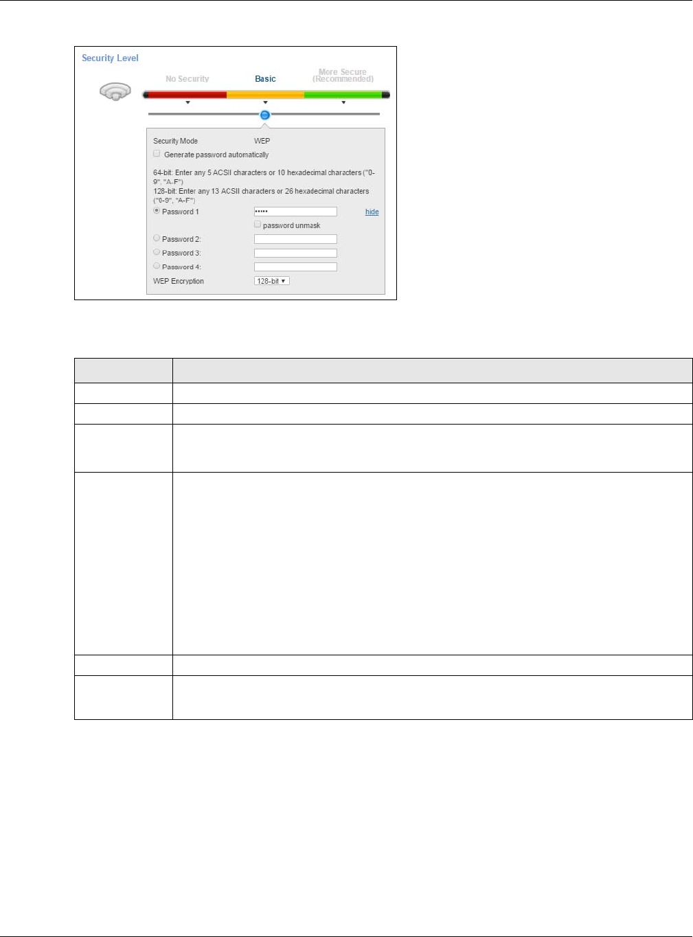
Chapter 7 Wireless
XMG3512-B10A User’s Guide
87
Figure 34 Wireless > General: Basic (WEP)
The following table describes the labels in this screen.
7.2.3 More Secure (WPA(2)-PSK)
The WPA-PSK security mode provides both improved data encryption and user authentication over
WEP. Using a Pre-Shared Key (PSK), both the XMG and the connecting client share a common password
in order to validate the connection. This type of encryption, while robust, is not as strong as WPA, WPA2
or even WPA2-PSK. The WPA2-PSK security mode is a newer, more robust version of the WPA encryption
standard. It offers slightly better security, although the use of PSK makes it less robust than it could be.
Note: WPA-PSK is not available if you enable WPS before you configure them.
Table 19 Wireless > General: Basic (WEP)
LABEL DESCRIPTION
Security Level Select Basic to enable WEP data encryption.
Security Mode This shows WEP when you set Security Level to Basic.
Generate
password
automatically
Select this option to have the XMG automatically generate a password. The password field will
not be configurable when you select this option.
Password 1~4 The password (WEP keys) are used to encrypt data. Both the XMG and the wireless stations must
use the same password (WEP key) for data transmission.
If you chose 64-bit WEP, then enter any 5 ASCII characters or 10 hexadecimal characters ("0-9",
"A-F").
If you chose 128-bit WEP, then enter 13 ASCII characters or 26 hexadecimal characters ("0-9", "A-
F").
You must configure at least one password, only one password can be activated at any one
time.
Select password unmask to display the entered password in plain text. Clear it to hide the
password to avoid shoulder surfing.
more.../hide Click more... to show more fields in this section. Click hide to hide them.
WEP Encryption Select 64-bit or 128-bit.
This dictates the length of the security key that the network is going to use.
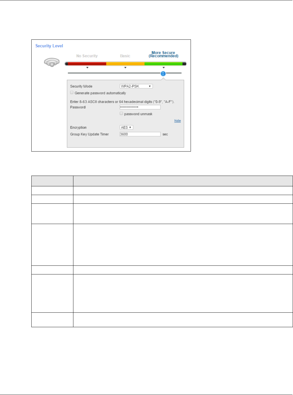
Chapter 7 Wireless
XMG3512-B10A User’s Guide
88
Click Network Setting > Wireless to display the General screen. Select More Secure as the security level.
Then select WPA-PSK or WPA2-PSK from the Security Mode list.
Figure 35 Wireless > General: More Secure: WPA(2)-PSK
The following table describes the labels in this screen.
7.3 The Guest/More AP Screen
This screen allows you to enable and configure multiple Basic Service Sets (BSSs) on the XMG.
Click Network Setting > Wireless > Guest/More AP. The following screen displays.
Table 20 Wireless > General: More Secure: WPA(2)-PSK
LABEL DESCRIPTION
Security Level Select More Secure to enable WPA(2)-PSK data encryption.
Security Mode Select WPA-PSK or WPA2-PSK from the drop-down list box.
Generate
password
automatically
Select this option to have the XMG automatically generate a password. The password field will
not be configurable when you select this option.
Password The encryption mechanisms used for WPA(2) and WPA(2)-PSK are the same. The only difference
between the two is that WPA(2)-PSK uses a simple common password, instead of user-specific
credentials.
If you did not select Generate password automatically, you can manually type a pre-shared key
from 8 to 64 case-sensitive keyboard characters. Select password unmask to display the entered
password in plain text. Clear it to hide the password to avoid shoulder surfing.
more.../hide Click more... to show more fields in this section. Click hide to hide them.
Encryption Select the encryption type (TKIP, AES or TKIP+AES) for data encryption.
Select TKIP if your wireless clients can all use TKIP.
Select AES if your wireless clients can all use AES.
Select TKIP+AES to allow the wireless clients to use either TKIP or AES.
Group Key
Update Timer
The Group Key Update Timer is the rate at which the RADIUS server sends a new group key out to
all clients.
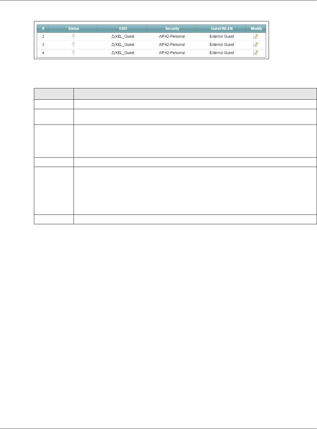
Chapter 7 Wireless
XMG3512-B10A User’s Guide
89
Figure 36 Network Setting > Wireless > Guest/More AP
The following table describes the labels in this screen.
7.3.1 Edit Guest/More AP
Use this screen to edit an SSID profile. Click the Edit icon next to an SSID in the Guest/More AP screen. The
following screen displays.
Table 21 Network Setting > Wireless > Guest/More AP
LABEL DESCRIPTION
# This is the index number of the entry.
Status This field indicates whether this SSID is active. A yellow bulb signifies that this SSID is active. A gray
bulb signifies that this SSID is not active.
SSID An SSID profile is the set of parameters relating to one of the XMG’s BSSs. The SSID (Service Set
IDentifier) identifies the Service Set with which a wireless device is associated.
This field displays the name of the wireless profile on the network. When a wireless client scans for
an AP to associate with, this is the name that is broadcast and seen in the wireless client utility.
Security This field indicates the security mode of the SSID profile.
Guest WLAN This displays if the guest WLAN function has been enabled for this WLAN.
If Home Guest displays, clients connecting to the same SSID can communicate with each other
directly.
If External Guest displays, clients are blocked from connecting to each other directly.
N/A displays if guest WLAN is disabled.
Modify Click the Edit icon to configure the SSID profile.
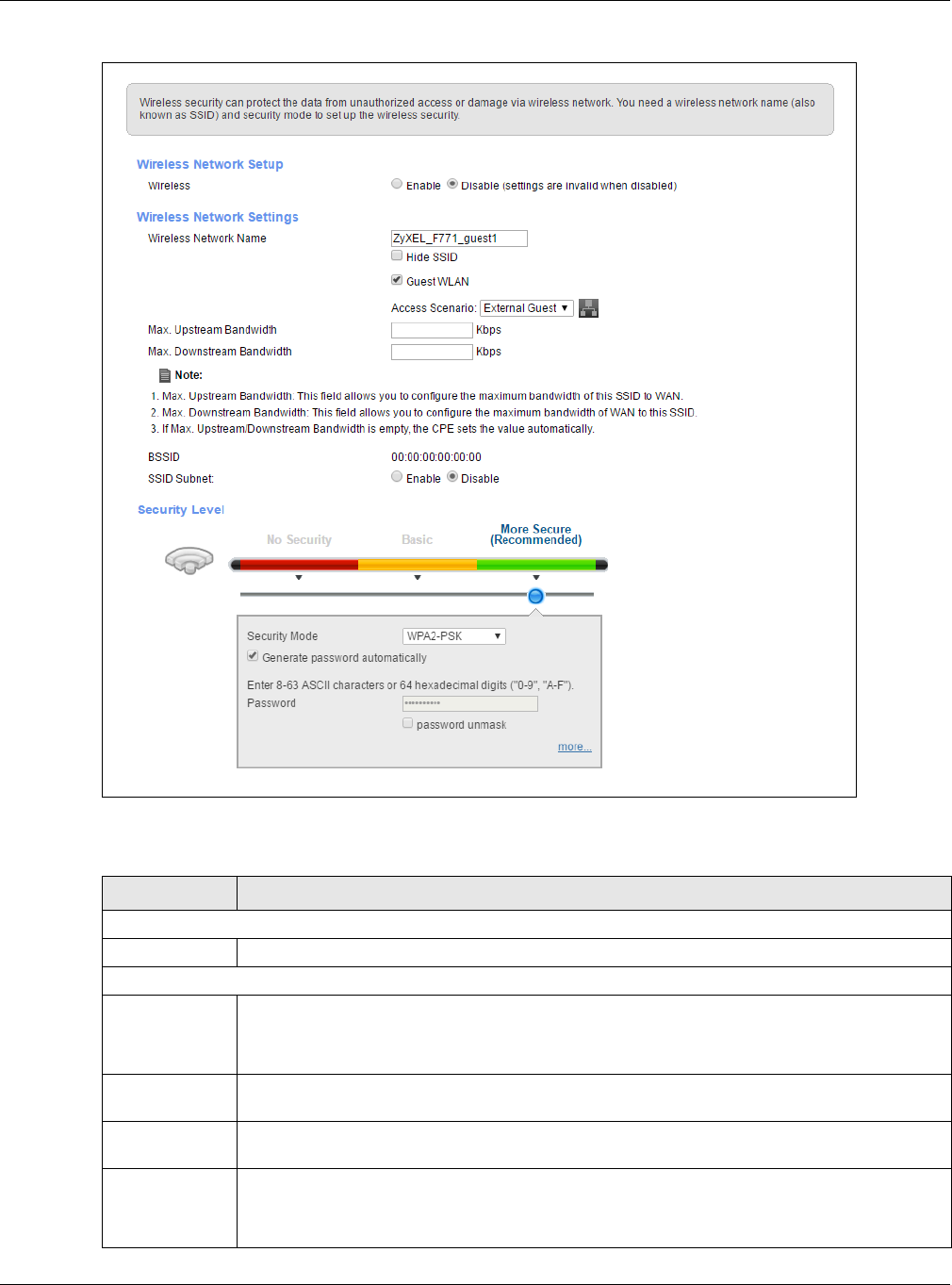
Chapter 7 Wireless
XMG3512-B10A User’s Guide
90
Figure 37 Network Setting > Wireless > Guest/More AP > Edit
The following table describes the fields in this screen.
Table 22 Network Setting > Wireless > Guest/More AP > Edit
LABEL DESCRIPTION
Wireless Network Setup
Wireless You can Enable or Disable the wireless LAN in this field.
Wireless Network Settings
Wireless
Network Name
(SSID)
The SSID (Service Set IDentity) identifies the service set with which a wireless device is associated.
Wireless devices associating to the access point (AP) must have the same SSID.
Enter a descriptive name (up to 32 English keyboard characters) for the wireless LAN.
Hide SSID Select this check box to hide the SSID in the outgoing beacon frame so a station cannot obtain
the SSID through scanning using a site survey tool.
Guest WLAN Select this to create Guest WLANs for home and external clients. Select the WLAN type in the
Access Scenario field.
Access Scenario If you select Home Guest, clients connecting to the same SSID can communicate with each
other directly.
If you select External Guest, clients are blocked from connecting to each other directly.

Chapter 7 Wireless
XMG3512-B10A User’s Guide
91
7.4 MAC Authentication
This screen allows you to configure the Zyxel Device to give exclusive access to specific devices (Allow)
or exclude specific devices from accessing the Zyxel Device (Deny). Every Ethernet device has a unique
MAC (Media Access Control) address. The MAC address is assigned at the factory and consists of six
pairs of hexadecimal characters, for example, 00:A0:C5:00:00:02. You need to know the MAC addresses
of the devices to configure this screen.
Max. Upstream
Bandwidth
Specify the maximum rate for upstream wireless traffic to the WAN from this WLAN in kilobits per
second (Kbps).
Max.
Downstream
Bandwidth
Specify the maximum rate for downstream wireless traffic to this WLAN from the WAN in kilobits
per second (Kbps).
BSSID This shows the MAC address of the wireless interface on the XMG when wireless LAN is enabled.
SSID Subnet Select Enable if you want the wireless network interface to assign DHCP IP addresses to the
associated wireless clients.
DHCP Start
Address Specify the first of the contiguous addresses in the DHCP IP address pool.
The XMG assigns IP addresses from this DHCP pool to wireless clients connecting to the SSID.
DHCP End
Address Specify the last of the contiguous addresses in the DHCP IP address pool.
SSID Subnet
Mask Specify the subnet mask of the XMG for the SSID subnet.
LAN IP
Address Specify the IP address of the XMG for the SSID subnet..
Security Level
Security Mode Select Basic (WEP) or More Secure (WPA(2)-PSK) to add security on this wireless network. The
wireless clients which want to associate to this network must have same wireless security settings
as the XMG. After you select to use a security, additional options appears in this screen.
Or you can select No Security to allow any client to associate this network without any data
encryption or authentication.
See Section 7.2.1 on page 86 for more details about this field.
Apply Click Apply to save your changes.
Cancel Click Cancel to exit this screen without saving.
Table 22 Network Setting > Wireless > Guest/More AP > Edit (continued)
LABEL DESCRIPTION
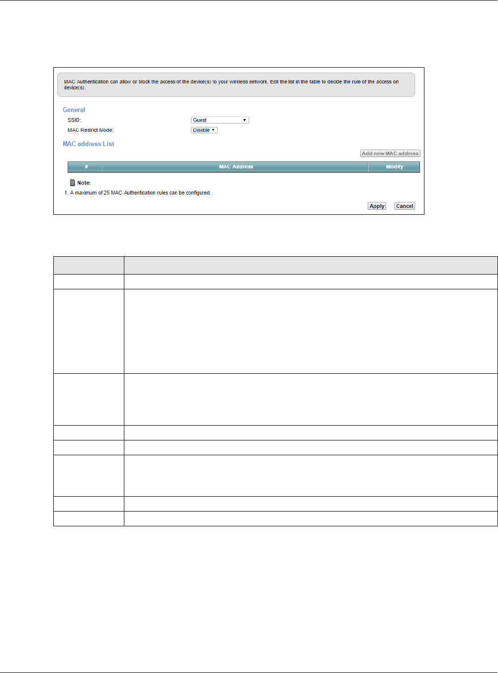
Chapter 7 Wireless
XMG3512-B10A User’s Guide
92
Use this screen to view your XMG’s MAC filter settings and add new MAC filter rules. Click Network
Setting > Wireless > MAC Authentication. The screen appears as shown.
Figure 38 Wireless > MAC Authentication
The following table describes the labels in this screen.
7.5 The WPS Screen
Use this screen to configure WiFi Protected Setup (WPS) on your XMG.
WPS allows you to quickly set up a wireless network with strong security, without having to configure
security settings manually. Set up each WPS connection between two devices. Both devices must
support WPS. See Section 7.9.8.3 on page 105 for more information about WPS.
Table 23 Wireless > MAC Authentication
LABEL DESCRIPTION
SSID Select the SSID for which you want to configure MAC filter settings.
MAC Restrict
Mode
Define the filter action for the list of MAC addresses in the MAC Address table.
Select Disable to turn off MAC filtering.
Select Deny to block access to the XMG. MAC addresses not listed will be allowed to access the
XMG.
Select Allow to permit access to the XMG. MAC addresses not listed will be denied access to the
XMG.
Add new MAC
address
Click this if you want to add a new MAC address entry to the MAC filter list below.
Enter the MAC addresses of the wireless devices that are allowed or denied access to the XMG
in these address fields. Enter the MAC addresses in a valid MAC address format, that is, six
hexadecimal character pairs, for example, 12:34:56:78:9a:bc.
#This is the index number of the entry.
MAC Address This is the MAC addresses of the wireless devices that are allowed or denied access to the XMG.
Modify Click the Edit icon and type the MAC address of the peer device in a valid MAC address format
(six hexadecimal character pairs, for example 12:34:56:78:9a:bc).
Click the Delete icon to delete the entry.
Apply Click Apply to save your changes.
Cancel Click Cancel to exit this screen without saving.
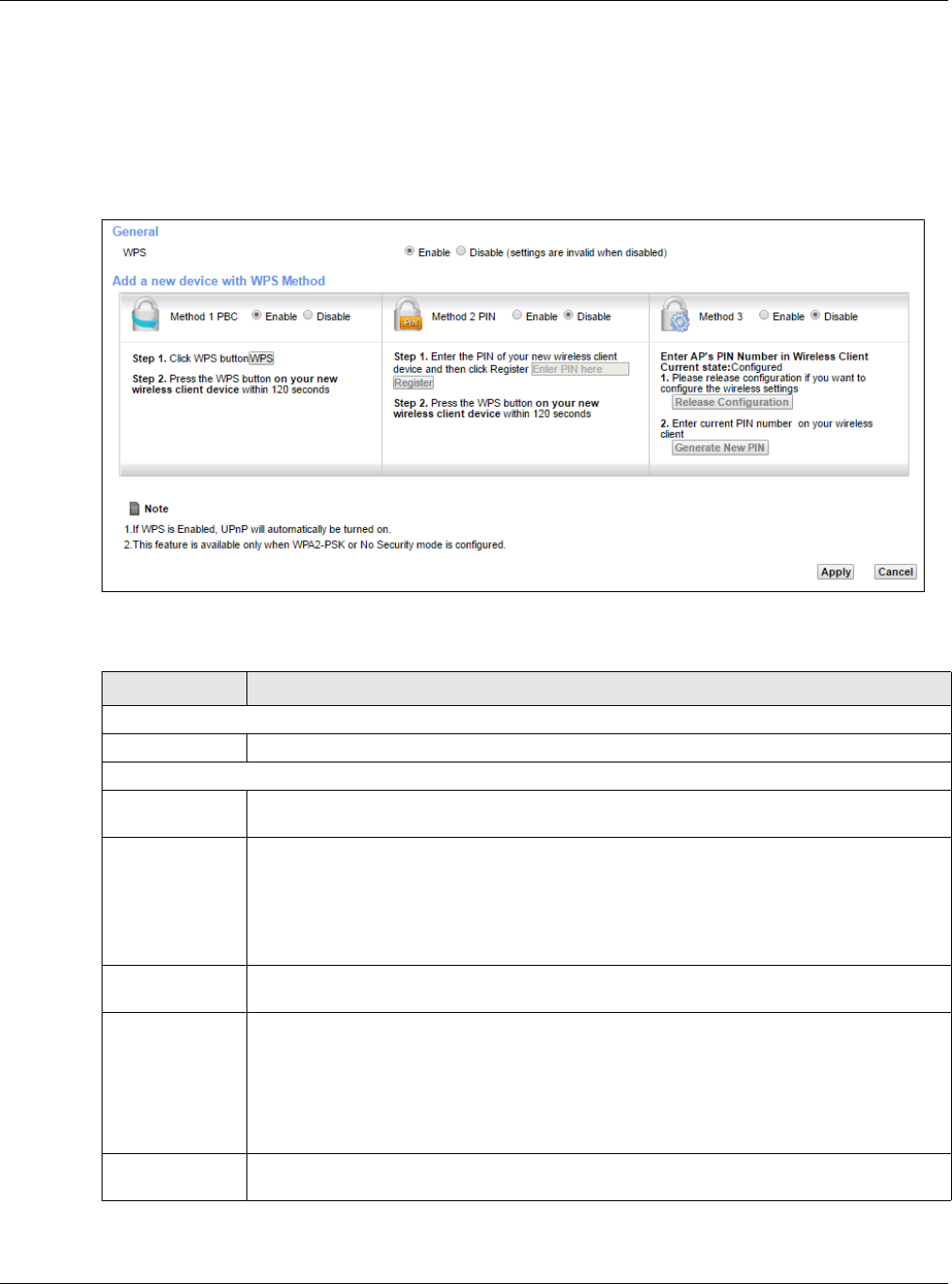
Chapter 7 Wireless
XMG3512-B10A User’s Guide
93
Note: The XMG applies the security settings of the SSID1 profile (see Section 7.2 on page 84). If
you want to use the WPS feature, make sure you have set the security mode of SSID1 to
WPA2-PSK or No Security.
Click Network Setting > Wireless > WPS. The following screen displays. Select Enable and click Apply to
activate the WPS function. Then you can configure the WPS settings in this screen.
Figure 39 Network Setting > Wireless > WPS
The following table describes the labels in this screen.
Table 24 Network Setting > Wireless > WPS
LABEL DESCRIPTION
General
WPS Select Enable to activate WPS on this XMG.
Add a new device with WPS Method
Method 1 Use this section to set up a WPS wireless network using Push Button Configuration (PBC). Select
Enable and click Apply to activate WPS method 1 on the XMG.
WPS Click this button to add another WPS-enabled wireless device (within wireless range of the
XMG) to your wireless network. This button may either be a physical button on the outside of
device, or a menu button similar to the WPS button on this screen.
Note: You must press the other wireless device’s WPS button within two minutes of
pressing this button.
Method 2 Use this section to set up a WPS wireless network by entering the PIN of the client into the XMG.
Select Enable and click Apply to activate WPS method 2 on the XMG.
Register Enter the PIN of the device that you are setting up a WPS connection with and click Register to
authenticate and add the wireless device to your wireless network.
You can find the PIN either on the outside of the device, or by checking the device’s settings.
Note: You must also activate WPS on that device within two minutes to have it
present its PIN to the XMG.
Method 3 Use this section to set up a WPS wireless network by entering the PIN of the XMG into the client.
Select Enable and click Apply to activate WPS method 3 on the XMG.
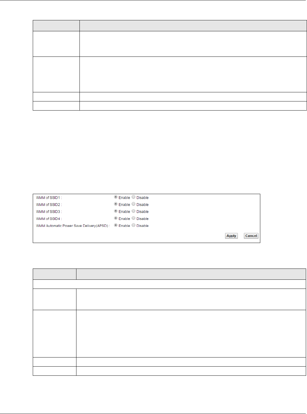
Chapter 7 Wireless
XMG3512-B10A User’s Guide
94
7.6 The WMM Screen
Use this screen to enable Wi-Fi MultiMedia (WMM) and WMM Power Save in wireless networks for
multimedia applications.
Click Network Setting > Wireless > WMM. The following screen displays.
Figure 40 Network Setting > Wireless > WMM
The following table describes the labels in this screen.
Release
Configuration The default WPS status is configured.
Click this button to remove all configured wireless and wireless security settings for WPS
connections on the XMG.
Generate
New PIN
Number
If this method has been enabled, the PIN (Personal Identification Number) of the XMG is shown
here. Enter this PIN in the configuration utility of the device you want to connect to using WPS.
The PIN is not necessary when you use WPS push-button method.
Click the Generate New PIN button to have the XMG create a new PIN.
Apply Click Apply to save your changes.
Cancel Click Cancel to restore your previously saved settings.
Table 24 Network Setting > Wireless > WPS (continued)
LABEL DESCRIPTION
Table 25 Network Setting > Wireless > WMM
LABEL DESCRIPTION
2.4GHz WMM Setup / 5GHz WMM Setup
WMM of SSID1~4 Select On to have the XMG automatically give the wireless network (SSIDx) a priority level
according to the ToS value in the IP header of packets it sends. WMM QoS (Wifi MultiMedia
Quality of Service) gives high priority to voice and video, which makes them run more smoothly.
WMM
Automatic
Power Save
Delivery(APSD)
Select this option to extend the battery life of your mobile devices (especially useful for small
devices that are running multimedia applications). The XMG goes to sleep mode to save power
when it is not transmitting data. The AP buffers the packets sent to the XMG until the XMG "wakes
up". The XMG wakes up periodically to check for incoming data.
Note: This works only if the wireless device to which the XMG is connected also
supports this feature.
Apply Click Apply to save your changes.
Cancel Click Cancel to restore your previously saved settings.
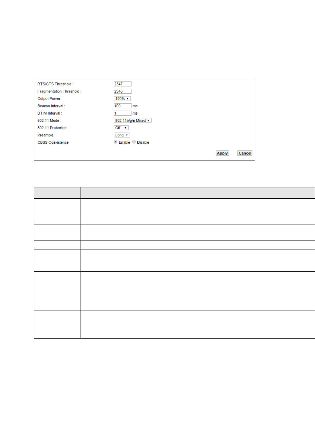
Chapter 7 Wireless
XMG3512-B10A User’s Guide
95
7.7 The Others Screen
Use this screen to configure advanced wireless settings. Click Network Setting > Wireless > Others. The
screen appears as shown.
See Section 7.9.2 on page 99 for detailed definitions of the terms listed in this screen.
Figure 41 Network Setting > Wireless > Others
The following table describes the labels in this screen.
Table 26 Network Setting > Wireless > Others
LABEL DESCRIPTION
RTS/CTS
Threshold
Data with its frame size larger than this value will perform the RTS (Request To Send)/CTS (Clear
To Send) handshake.
Enter a value between 0 and 2347.
Fragmentation
Threshold
This is the maximum data fragment size that can be sent. Enter a value between 256 and 2346.
Output Power Set the output power of the XMG. If there is a high density of APs in an area, decrease the
output power to reduce interference with other APs. Select one of the following: 20%, 40%,
60%, 80% or 100%.
Beacon Interval When a wirelessly networked device sends a beacon, it includes with it a beacon interval. This
specifies the time period before the device sends the beacon again.
The interval tells receiving devices on the network how long they can wait in low power mode
before waking up to handle the beacon. This value can be set from 50ms to 1000ms. A high
value helps save current consumption of the access point.
DTIM Interval Delivery Traffic Indication Message (DTIM) is the time period after which broadcast and
multicast packets are transmitted to mobile clients in the Power Saving mode. A high DTIM
value can cause clients to lose connectivity with the network. This value can be set from 1 to
255.

Chapter 7 Wireless
XMG3512-B10A User’s Guide
96
7.8 The Channel Status Screen
Use the Channel Status screen to scan wireless LAN channel noises and view the results. Click Network
Setting > Wireless > Channel Status. The screen appears as shown. Click Scan to scan the wireless LAN
channels. You can view the results in the Channel Scan Result section.
Note: The Scan button only works when the XMG uses 20MHz for the wireless channel width.
You can go to the Network Setting > Wireless > General screen, click the more link, and
then change the channel width setting in the Bandwidth field.
802.11 Mode Select 802.11b Only to allow only IEEE 802.11b compliant WLAN devices to associate with the
XMG.
Select 802.11g Only to allow only IEEE 802.11g compliant WLAN devices to associate with the
XMG.
Select 802.11n Only to allow only IEEE 802.11n compliant WLAN devices to associate with the
XMG.
Select 802.11b/g Mixed to allow either IEEE 802.11b or IEEE 802.11g compliant WLAN devices to
associate with the XMG. The transmission rate of your XMG might be reduced.
Select 802.11b/g/n Mixed to allow IEEE 802.11b, IEEE 802.11g or IEEE802.11n compliant WLAN
devices to associate with the XMG. The transmission rate of your XMG might be reduced.
802.11 Protection Enabling this feature can help prevent collisions in mixed-mode networks (networks with both
IEEE 802.11b and IEEE 802.11g traffic).
Select Auto to have the wireless devices transmit data after a RTS/CTS handshake. This helps
improve IEEE 802.11g performance.
Select Off to disable 802.11 protection. The transmission rate of your XMG might be reduced in a
mixed-mode network.
This field displays Off and is not configurable when you set 802.11 Mode to 802.11b Only.
Preamble Select a preamble type from the drop-down list box. Choices are Long or Short. See Section
7.9.7 on page 103 for more information.
This field is configurable only when you set 802.11 Mode to 802.11b.
OBSS
Coexistence
Select Enable to allow the coexistence of 20 MHz and 40 MHz Overlapping Basic Service Sets
(OBSS) in wireless local area networks. Select Disabled to disable this feature.
Apply Click Apply to save your changes.
Cancel Click Cancel to restore your previously saved settings.
Table 26 Network Setting > Wireless > Others (continued)
LABEL DESCRIPTION
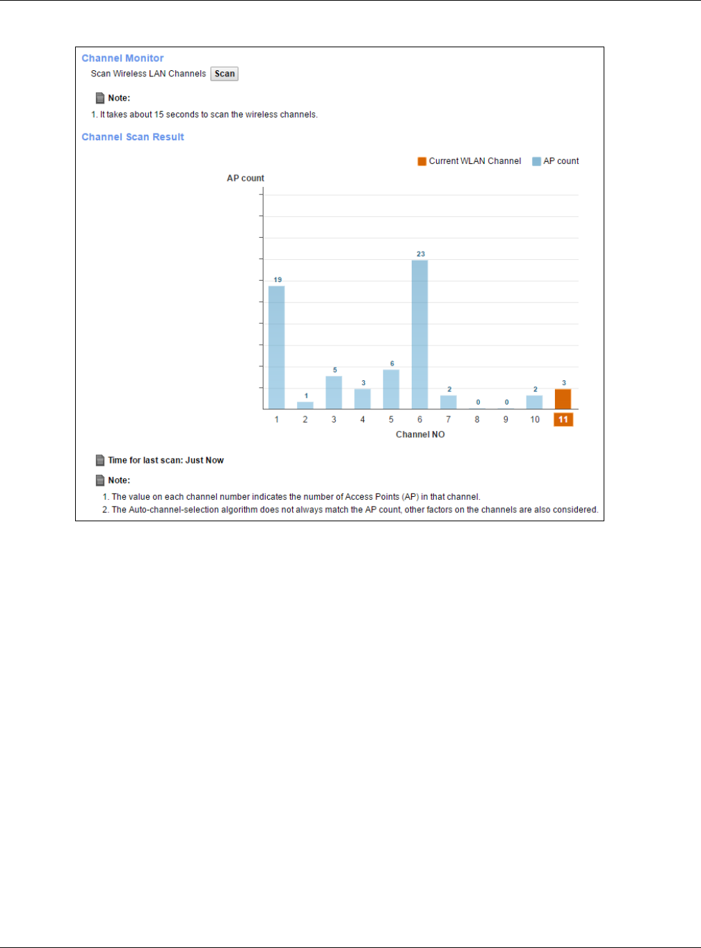
Chapter 7 Wireless
XMG3512-B10A User’s Guide
97
Figure 42 Network Setting > Wireless > Channel Status
7.9 Technical Reference
This section discusses wireless LANs in depth. For more information, see Appendix B on page 255.
7.9.1 Wireless Network Overview
Wireless networks consist of wireless clients, access points and bridges.
• A wireless client is a radio connected to a user’s computer.
• An access point is a radio with a wired connection to a network, which can connect with numerous
wireless clients and let them access the network.
• A bridge is a radio that relays communications between access points and wireless clients, extending
a network’s range.
Traditionally, a wireless network operates in one of two ways.
• An “infrastructure” type of network has one or more access points and one or more wireless clients.
The wireless clients connect to the access points.
• An “ad-hoc” type of network is one in which there is no access point. Wireless clients connect to one
another in order to exchange information.
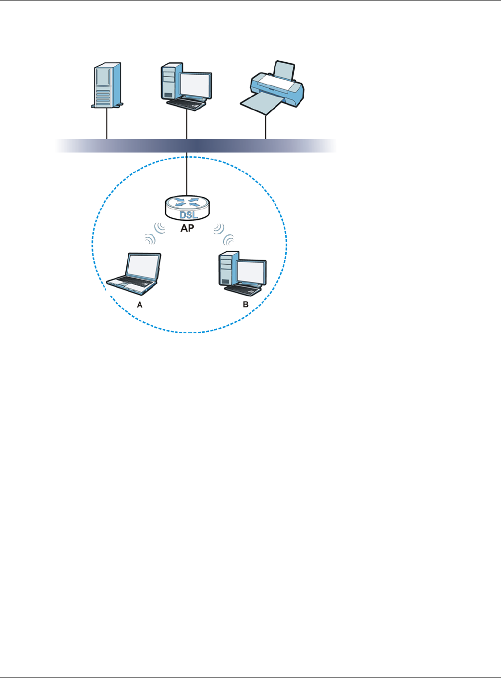
Chapter 7 Wireless
XMG3512-B10A User’s Guide
98
The following figure provides an example of a wireless network.
Figure 43 Example of a Wireless Network
The wireless network is the part in the blue circle. In this wireless network, devices A and B use the access
point (AP) to interact with the other devices (such as the printer) or with the Internet. Your XMG is the AP.
Every wireless network must follow these basic guidelines.
• Every device in the same wireless network must use the same SSID.
The SSID is the name of the wireless network. It stands for Service Set IDentifier.
• If two wireless networks overlap, they should use a different channel.
Like radio stations or television channels, each wireless network uses a specific channel, or frequency,
to send and receive information.
• Every device in the same wireless network must use security compatible with the AP.
Security stops unauthorized devices from using the wireless network. It can also protect the
information that is sent in the wireless network.
Radio Channels
In the radio spectrum, there are certain frequency bands allocated for unlicensed, civilian use. For the
purposes of wireless networking, these bands are divided into numerous channels. This allows a variety of
networks to exist in the same place without interfering with one another. When you create a network,
you must select a channel to use.
Since the available unlicensed spectrum varies from one country to another, the number of available
channels also varies.
Chapter 7 Wireless
XMG3512-B10A User’s Guide
99
7.9.2 Additional Wireless Terms
The following table describes some wireless network terms and acronyms used in the XMG’s Web
Configurator.
7.9.3 Wireless Security Overview
By their nature, radio communications are simple to intercept. For wireless data networks, this means
that anyone within range of a wireless network without security can not only read the data passing over
the airwaves, but also join the network. Once an unauthorized person has access to the network, he or
she can steal information or introduce malware (malicious software) intended to compromise the
network. For these reasons, a variety of security systems have been developed to ensure that only
authorized people can use a wireless data network, or understand the data carried on it.
These security standards do two things. First, they authenticate. This means that only people presenting
the right credentials (often a username and password, or a “key” phrase) can access the network.
Second, they encrypt. This means that the information sent over the air is encoded. Only people with
the code key can understand the information, and only people who have been authenticated are
given the code key.
These security standards vary in effectiveness. Some can be broken, such as the old Wired Equivalent
Protocol (WEP). Using WEP is better than using no security at all, but it will not keep a determined
attacker out. Other security standards are secure in themselves but can be broken if a user does not use
them properly. For example, the WPA-PSK security standard is very secure if you use a long key which is
difficult for an attacker’s software to guess - for example, a twenty-letter long string of apparently
random numbers and letters - but it is not very secure if you use a short key which is very easy to guess -
for example, a three-letter word from the dictionary.
Because of the damage that can be done by a malicious attacker, it’s not just people who have
sensitive information on their network who should use security. Everybody who uses any wireless network
should ensure that effective security is in place.
A good way to come up with effective security keys, passwords and so on is to use obscure information
that you personally will easily remember, and to enter it in a way that appears random and does not
include real words. For example, if your mother owns a 1970 Dodge Challenger and her favorite movie is
Table 27 Additional Wireless Terms
TERM DESCRIPTION
RTS/CTS Threshold In a wireless network which covers a large area, wireless devices are sometimes not
aware of each other’s presence. This may cause them to send information to the AP at
the same time and result in information colliding and not getting through.
By setting this value lower than the default value, the wireless devices must sometimes get
permission to send information to the XMG. The lower the value, the more often the
devices must get permission.
If this value is greater than the fragmentation threshold value (see below), then wireless
devices never have to get permission to send information to the XMG.
Preamble A preamble affects the timing in your wireless network. There are two preamble modes:
long and short. If a device uses a different preamble mode than the XMG does, it cannot
communicate with the XMG.
Authentication The process of verifying whether a wireless device is allowed to use the wireless network.
Fragmentation
Threshold
A small fragmentation threshold is recommended for busy networks, while a larger
threshold provides faster performance if the network is not very busy.

Chapter 7 Wireless
XMG3512-B10A User’s Guide
100
Vanishing Point (which you know was made in 1971) you could use “70dodchal71vanpoi” as your
security key.
The following sections introduce different types of wireless security you can set up in the wireless
network.
7.9.3.1 SSID
Normally, the XMG acts like a beacon and regularly broadcasts the SSID in the area. You can hide the
SSID instead, in which case the XMG does not broadcast the SSID. In addition, you should change the
default SSID to something that is difficult to guess.
This type of security is fairly weak, however, because there are ways for unauthorized wireless devices to
get the SSID. In addition, unauthorized wireless devices can still see the information that is sent in the
wireless network.
7.9.3.2 MAC Address Filter
Every device that can use a wireless network has a unique identification number, called a MAC
address.1 A MAC address is usually written using twelve hexadecimal characters2; for example,
00A0C5000002 or 00:A0:C5:00:00:02. To get the MAC address for each device in the wireless network,
see the device’s User’s Guide or other documentation.
You can use the MAC address filter to tell the XMG which devices are allowed or not allowed to use the
wireless network. If a device is allowed to use the wireless network, it still has to have the correct
information (SSID, channel, and security). If a device is not allowed to use the wireless network, it does
not matter if it has the correct information.
This type of security does not protect the information that is sent in the wireless network. Furthermore,
there are ways for unauthorized wireless devices to get the MAC address of an authorized device. Then,
they can use that MAC address to use the wireless network.
7.9.3.3 User Authentication
Authentication is the process of verifying whether a wireless device is allowed to use the wireless
network. You can make every user log in to the wireless network before using it. However, every device
in the wireless network has to support IEEE 802.1x to do this.
For wireless networks, you can store the user names and passwords for each user in a RADIUS server. This
is a server used in businesses more than in homes. If you do not have a RADIUS server, you cannot set up
user names and passwords for your users.
Unauthorized wireless devices can still see the information that is sent in the wireless network, even if they
cannot use the wireless network. Furthermore, there are ways for unauthorized wireless users to get a
valid user name and password. Then, they can use that user name and password to use the wireless
network.
1. Some wireless devices, such as scanners, can detect wireless networks but cannot use wireless networks. These
kinds of wireless devices might not have MAC addresses.
2. Hexadecimal characters are 0, 1, 2, 3, 4, 5, 6, 7, 8, 9, A, B, C, D, E, and F.
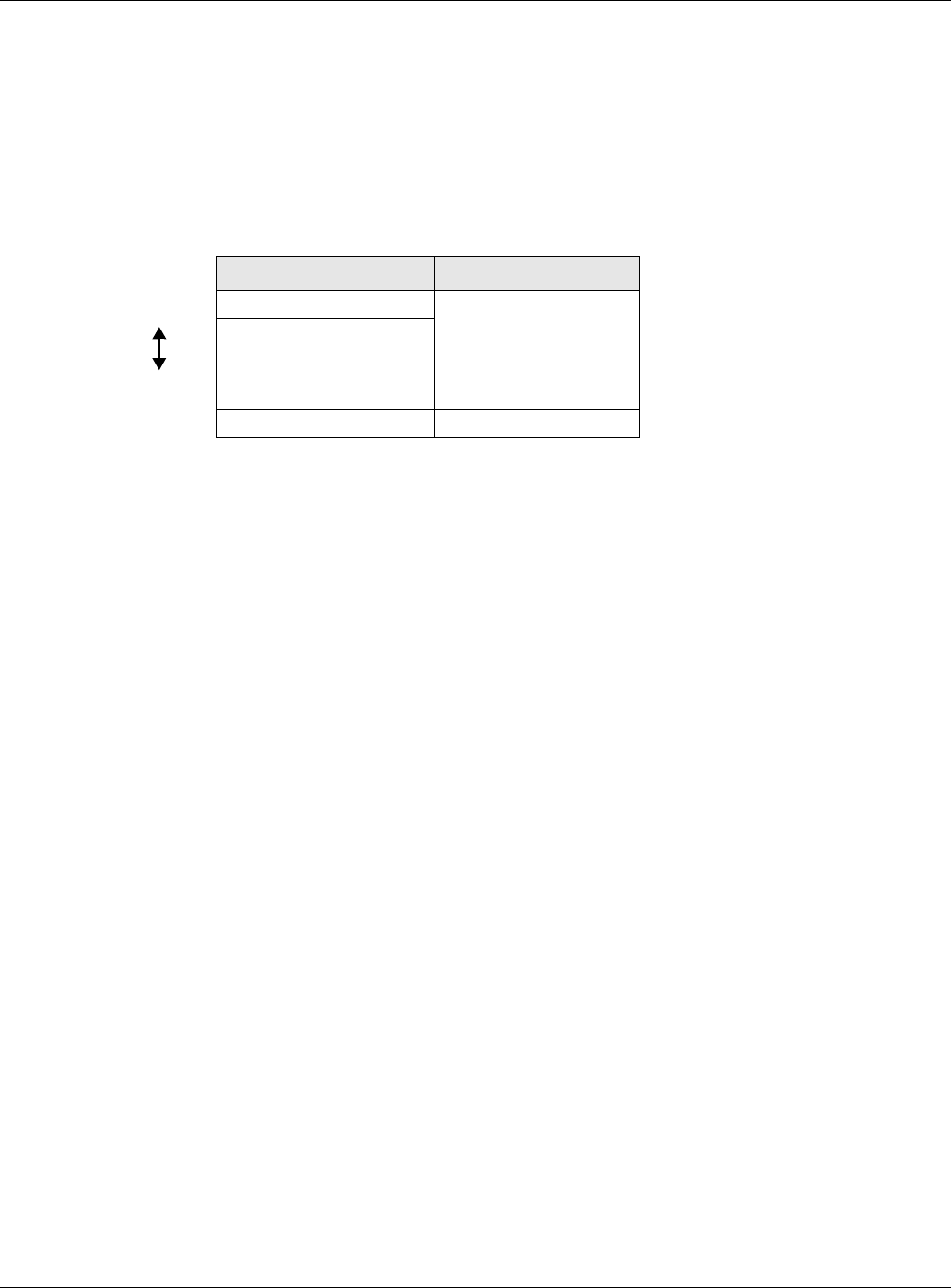
Chapter 7 Wireless
XMG3512-B10A User’s Guide
101
7.9.3.4 Encryption
Wireless networks can use encryption to protect the information that is sent in the wireless network.
Encryption is like a secret code. If you do not know the secret code, you cannot understand the
message.
The types of encryption you can choose depend on the type of authentication. (See Section 7.9.3.3 on
page 100 for information about this.)
For example, if the wireless network has a RADIUS server, you can choose WPA or WPA2. If users do not
log in to the wireless network, you can choose no encryption, Static WEP, WPA-PSK, or WPA2-PSK.
Usually, you should set up the strongest encryption that every device in the wireless network supports. For
example, suppose you have a wireless network with the XMG and you do not have a RADIUS server.
Therefore, there is no authentication. Suppose the wireless network has two devices. Device A only
supports WEP, and device B supports WEP and WPA. Therefore, you should set up Static WEP in the
wireless network.
Note: It is recommended that wireless networks use WPA-PSK, WPA, or stronger encryption.
The other types of encryption are better than none at all, but it is still possible for
unauthorized wireless devices to figure out the original information pretty quickly.
When you select WPA2 or WPA2-PSK in your XMG, you can also select an option (WPA compatible) to
support WPA as well. In this case, if some of the devices support WPA and some support WPA2, you
should set up WPA2-PSK or WPA2 (depending on the type of wireless network login) and select the WPA
compatible option in the XMG.
Many types of encryption use a key to protect the information in the wireless network. The longer the
key, the stronger the encryption. Every device in the wireless network must have the same key.
7.9.4 Signal Problems
Because wireless networks are radio networks, their signals are subject to limitations of distance,
interference and absorption.
Problems with distance occur when the two radios are too far apart. Problems with interference occur
when other radio waves interrupt the data signal. Interference may come from other radio
transmissions, such as military or air traffic control communications, or from machines that are
coincidental emitters such as electric motors or microwaves. Problems with absorption occur when
physical objects (such as thick walls) are between the two radios, muffling the signal.
Table 28 Types of Encryption for Each Type of Authentication
NO AUTHENTICATION RADIUS SERVER
Weakest No Security WPA
Static WEP
WPA-PSK
Strongest WPA2-PSK WPA2
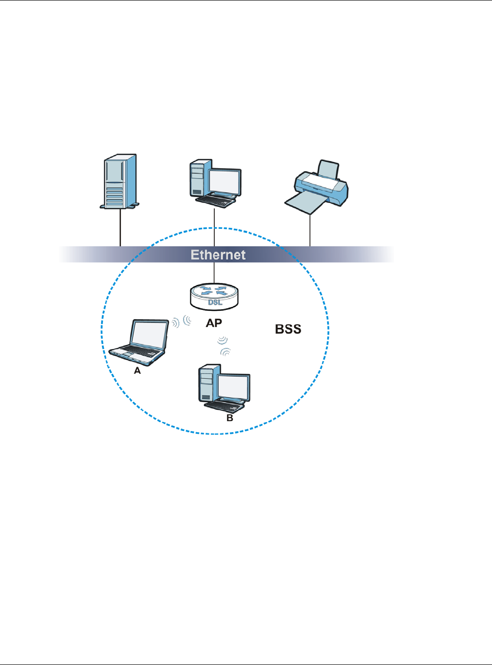
Chapter 7 Wireless
XMG3512-B10A User’s Guide
102
7.9.5 BSS
A Basic Service Set (BSS) exists when all communications between wireless stations or between a wireless
station and a wired network client go through one access point (AP).
Intra-BSS traffic is traffic between wireless stations in the BSS. When Intra-BSS traffic blocking is disabled,
wireless station A and B can access the wired network and communicate with each other. When Intra-
BSS traffic blocking is enabled, wireless station A and B can still access the wired network but cannot
communicate with each other.
Figure 44 Basic Service set
7.9.6 MBSSID
Traditionally, you need to use different APs to configure different Basic Service Sets (BSSs). As well as the
cost of buying extra APs, there is also the possibility of channel interference. The XMG’s MBSSID (Multiple
Basic Service Set IDentifier) function allows you to use one access point to provide several BSSs
simultaneously. You can then assign varying QoS priorities and/or security modes to different SSIDs.
Wireless devices can use different BSSIDs to associate with the same AP.
7.9.6.1 Notes on Multiple BSSs
• A maximum of eight BSSs are allowed on one AP simultaneously.
• You must use different keys for different BSSs. If two wireless devices have different BSSIDs (they are in
different BSSs), but have the same keys, they may hear each other’s communications (but not
communicate with each other).
• MBSSID should not replace but rather be used in conjunction with 802.1x security.

Chapter 7 Wireless
XMG3512-B10A User’s Guide
103
7.9.7 Preamble Type
Preamble is used to signal that data is coming to the receiver. Short and long refer to the length of the
synchronization field in a packet.
Short preamble increases performance as less time sending preamble means more time for sending
data. All IEEE 802.11 compliant wireless adapters support long preamble, but not all support short
preamble.
Use long preamble if you are unsure what preamble mode other wireless devices on the network
support, and to provide more reliable communications in busy wireless networks.
Use short preamble if you are sure all wireless devices on the network support it, and to provide more
efficient communications.
Use the dynamic setting to automatically use short preamble when all wireless devices on the network
support it, otherwise the XMG uses long preamble.
Note: The wireless devices MUST use the same preamble mode in order to communicate.
7.9.8 WiFi Protected Setup (WPS)
Your XMG supports WiFi Protected Setup (WPS), which is an easy way to set up a secure wireless
network. WPS is an industry standard specification, defined by the WiFi Alliance.
WPS allows you to quickly set up a wireless network with strong security, without having to configure
security settings manually. Each WPS connection works between two devices. Both devices must
support WPS (check each device’s documentation to make sure).
Depending on the devices you have, you can either press a button (on the device itself, or in its
configuration utility) or enter a PIN (a unique Personal Identification Number that allows one device to
authenticate the other) in each of the two devices. When WPS is activated on a device, it has two
minutes to find another device that also has WPS activated. Then, the two devices connect and set up
a secure network by themselves.
7.9.8.1 Push Button Configuration
WPS Push Button Configuration (PBC) is initiated by pressing a button on each WPS-enabled device, and
allowing them to connect automatically. You do not need to enter any information.
Not every WPS-enabled device has a physical WPS button. Some may have a WPS PBC button in their
configuration utilities instead of or in addition to the physical button.
Take the following steps to set up WPS using the button.
1Ensure that the two devices you want to set up are within wireless range of one another.
2Look for a WPS button on each device. If the device does not have one, log into its configuration utility
and locate the button (see the device’s User’s Guide for how to do this - for the XMG, see Section 7.6 on
page 94).
3Press the button on one of the devices (it doesn’t matter which). For the XMG you must press the WPS
button for more than five seconds.

Chapter 7 Wireless
XMG3512-B10A User’s Guide
104
4Within two minutes, press the button on the other device. The registrar sends the network name (SSID)
and security key through an secure connection to the enrollee.
If you need to make sure that WPS worked, check the list of associated wireless clients in the AP’s
configuration utility. If you see the wireless client in the list, WPS was successful.
7.9.8.2 PIN Configuration
Each WPS-enabled device has its own PIN (Personal Identification Number). This may either be static (it
cannot be changed) or dynamic (in some devices you can generate a new PIN by clicking on a button
in the configuration interface).
Use the PIN method instead of the push-button configuration (PBC) method if you want to ensure that
the connection is established between the devices you specify, not just the first two devices to activate
WPS in range of each other. However, you need to log into the configuration interfaces of both devices
to use the PIN method.
When you use the PIN method, you must enter the PIN from one device (usually the wireless client) into
the second device (usually the Access Point or wireless router). Then, when WPS is activated on the first
device, it presents its PIN to the second device. If the PIN matches, one device sends the network and
security information to the other, allowing it to join the network.
Take the following steps to set up a WPS connection between an access point or wireless router
(referred to here as the AP) and a client device using the PIN method.
1Ensure WPS is enabled on both devices.
2Access the WPS section of the AP’s configuration interface. See the device’s User’s Guide for how to do
this.
3Look for the client’s WPS PIN; it will be displayed either on the device, or in the WPS section of the client’s
configuration interface (see the device’s User’s Guide for how to find the WPS PIN - for the XMG, see
Section 7.5 on page 92).
4Enter the client’s PIN in the AP’s configuration interface.
5If the client device’s configuration interface has an area for entering another device’s PIN, you can
either enter the client’s PIN in the AP, or enter the AP’s PIN in the client - it does not matter which.
6Start WPS on both devices within two minutes.
7Use the configuration utility to activate WPS, not the push-button on the device itself.
8On a computer connected to the wireless client, try to connect to the Internet. If you can connect, WPS
was successful.
If you cannot connect, check the list of associated wireless clients in the AP’s configuration utility. If you
see the wireless client in the list, WPS was successful.
The following figure shows a WPS-enabled wireless client (installed in a notebook computer) connecting
to the WPS-enabled AP via the PIN method.
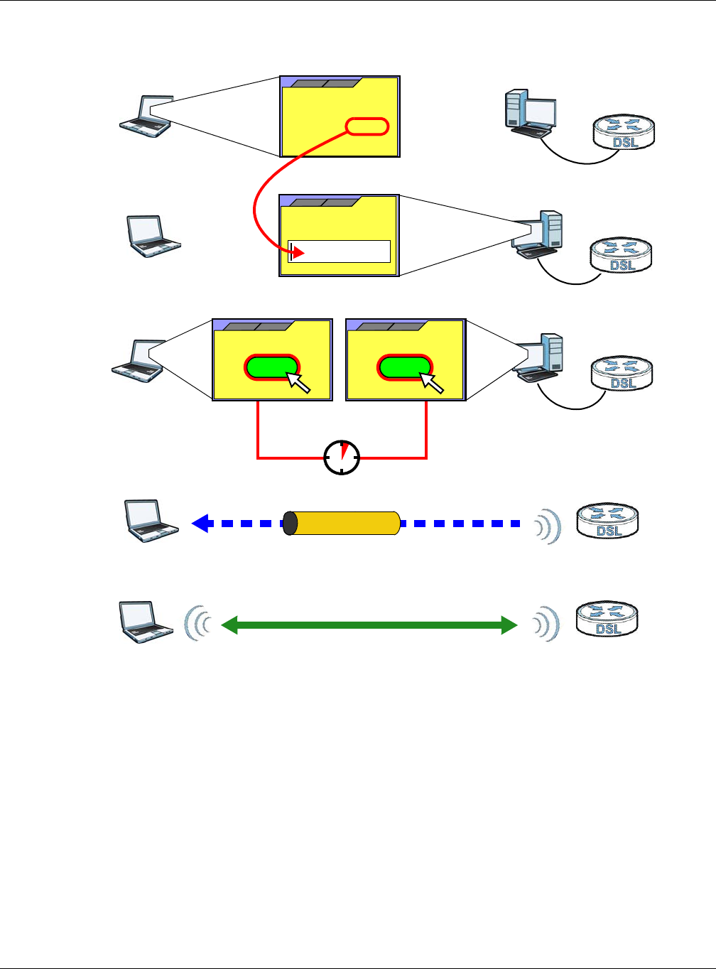
Chapter 7 Wireless
XMG3512-B10A User’s Guide
105
Figure 45 Example WPS Process: PIN Method
7.9.8.3 How WPS Works
When two WPS-enabled devices connect, each device must assume a specific role. One device acts
as the registrar (the device that supplies network and security settings) and the other device acts as the
enrollee (the device that receives network and security settings. The registrar creates a secure EAP
(Extensible Authentication Protocol) tunnel and sends the network name (SSID) and the WPA-PSK or
WPA2-PSK pre-shared key to the enrollee. Whether WPA-PSK or WPA2-PSK is used depends on the
standards supported by the devices. If the registrar is already part of a network, it sends the existing
information. If not, it generates the SSID and WPA(2)-PSK randomly.
The following figure shows a WPS-enabled client (installed in a notebook computer) connecting to a
WPS-enabled access point.
ENROLLEE
SECURE EAP TUNNEL
SSID
WPA(2)-PSK
WITHIN 2 MINUTES
COMMUNICATION
This device’s
WPS
Enter WPS PIN
WPS
from other device:
WPS PIN: 123456
WPS
START
WPS
START
REGISTRAR
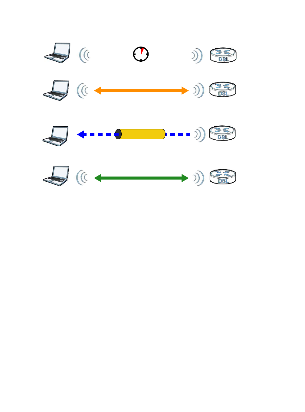
Chapter 7 Wireless
XMG3512-B10A User’s Guide
106
Figure 46 How WPS works
The roles of registrar and enrollee last only as long as the WPS setup process is active (two minutes). The
next time you use WPS, a different device can be the registrar if necessary.
The WPS connection process is like a handshake; only two devices participate in each WPS transaction.
If you want to add more devices you should repeat the process with one of the existing networked
devices and the new device.
Note that the access point (AP) is not always the registrar, and the wireless client is not always the
enrollee. All WPS-certified APs can be a registrar, and so can some WPS-enabled wireless clients.
By default, a WPS devices is “unconfigured”. This means that it is not part of an existing network and can
act as either enrollee or registrar (if it supports both functions). If the registrar is unconfigured, the security
settings it transmits to the enrollee are randomly-generated. Once a WPS-enabled device has
connected to another device using WPS, it becomes “configured”. A configured wireless client can still
act as enrollee or registrar in subsequent WPS connections, but a configured access point can no longer
act as enrollee. It will be the registrar in all subsequent WPS connections in which it is involved. If you
want a configured AP to act as an enrollee, you must reset it to its factory defaults.
7.9.8.4 Example WPS Network Setup
This section shows how security settings are distributed in an example WPS setup.
The following figure shows an example network. In step 1, both AP1 and Client 1 are unconfigured.
When WPS is activated on both, they perform the handshake. In this example, AP1 is the registrar, and
Client 1 is the enrollee. The registrar randomly generates the security information to set up the network,
since it is unconfigured and has no existing information.
SECURE TUNNEL
SECURITY INFO
WITHIN 2 MINUTES
COMMUNICATION
ACTIVATE
WPS
ACTIVATE
WPS
WPS HANDSHAKE
REGISTRARENROLLEE
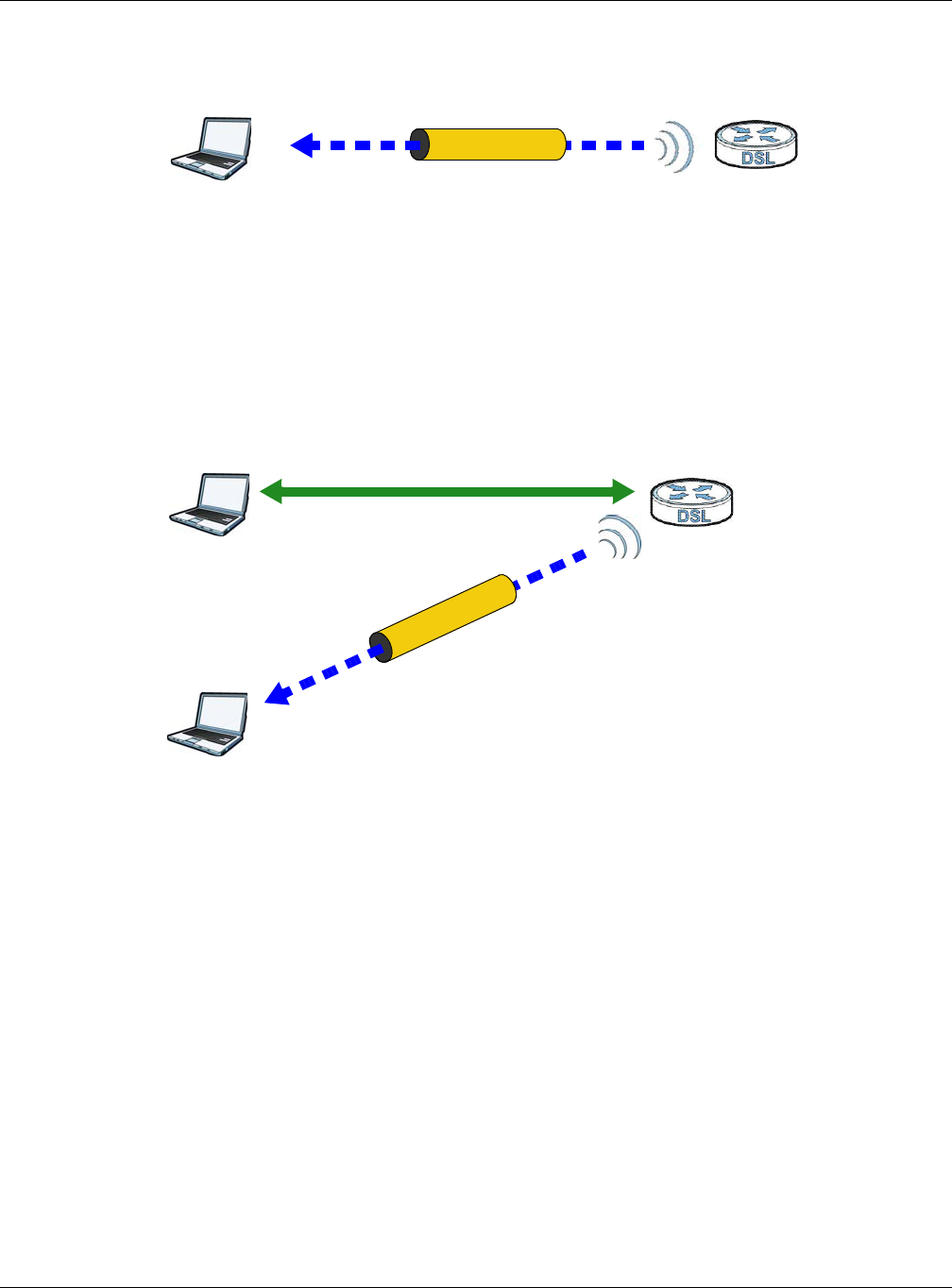
Chapter 7 Wireless
XMG3512-B10A User’s Guide
107
Figure 47 WPS: Example Network Step 1
In step 2, you add another wireless client to the network. You know that Client 1 supports registrar mode,
but it is better to use AP1 for the WPS handshake with the new client since you must connect to the
access point anyway in order to use the network. In this case, AP1 must be the registrar, since it is
configured (it already has security information for the network). AP1 supplies the existing security
information to Client 2.
Figure 48 WPS: Example Network Step 2
In step 3, you add another access point (AP2) to your network. AP2 is out of range of AP1, so you cannot
use AP1 for the WPS handshake with the new access point. However, you know that Client 2 supports
the registrar function, so you use it to perform the WPS handshake instead.
REGISTRARENROLLEE
SECURITY INFO
CLIENT 1 AP1
REGISTRAR
CLIENT 1 AP1
ENROLLEE
CLIENT 2
EXISTING CONNECTION
SECURITY INFO
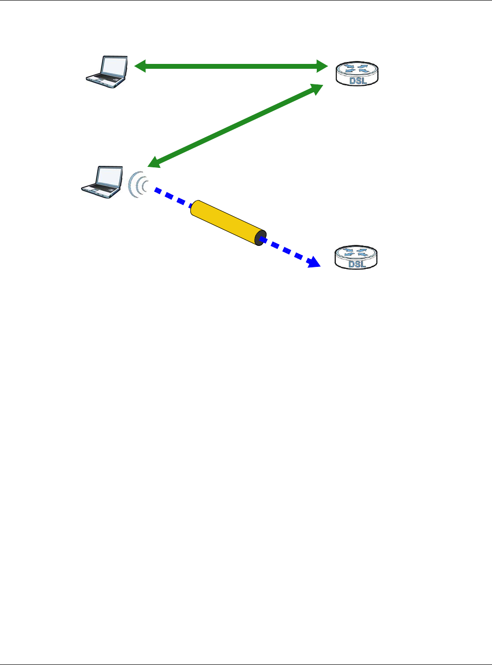
Chapter 7 Wireless
XMG3512-B10A User’s Guide
108
Figure 49 WPS: Example Network Step 3
7.9.8.5 Limitations of WPS
WPS has some limitations of which you should be aware.
• WPS works in Infrastructure networks only (where an AP and a wireless client communicate). It does
not work in Ad-Hoc networks (where there is no AP).
• When you use WPS, it works between two devices only. You cannot enroll multiple devices
simultaneously, you must enroll one after the other.
For instance, if you have two enrollees and one registrar you must set up the first enrollee (by pressing
the WPS button on the registrar and the first enrollee, for example), then check that it successfully
enrolled, then set up the second device in the same way.
• WPS works only with other WPS-enabled devices. However, you can still add non-WPS devices to a
network you already set up using WPS.
WPS works by automatically issuing a randomly-generated WPA-PSK or WPA2-PSK pre-shared key
from the registrar device to the enrollee devices. Whether the network uses WPA-PSK or WPA2-PSK
depends on the device. You can check the configuration interface of the registrar device to discover
the key the network is using (if the device supports this feature). Then, you can enter the key into the
non-WPS device and join the network as normal (the non-WPS device must also support WPA-PSK or
WPA2-PSK).
• When you use the PBC method, there is a short period (from the moment you press the button on one
device to the moment you press the button on the other device) when any WPS-enabled device
could join the network. This is because the registrar has no way of identifying the “correct” enrollee,
and cannot differentiate between your enrollee and a rogue device. This is a possible way for a
hacker to gain access to a network.
You can easily check to see if this has happened. WPS works between only two devices
simultaneously, so if another device has enrolled your device will be unable to enroll, and will not
have access to the network. If this happens, open the access point’s configuration interface and look
at the list of associated clients (usually displayed by MAC address). It does not matter if the access
CLIENT 1 AP1
REGISTRAR
CLIENT 2
EXISTING CONNECTION
SECURITY INFO
ENROLLEE
AP2
EXISTING CONNECTION

Chapter 7 Wireless
XMG3512-B10A User’s Guide
109
point is the WPS registrar, the enrollee, or was not involved in the WPS handshake; a rogue device
must still associate with the access point to gain access to the network. Check the MAC addresses of
your wireless clients (usually printed on a label on the bottom of the device). If there is an unknown
MAC address you can remove it or reset the AP.
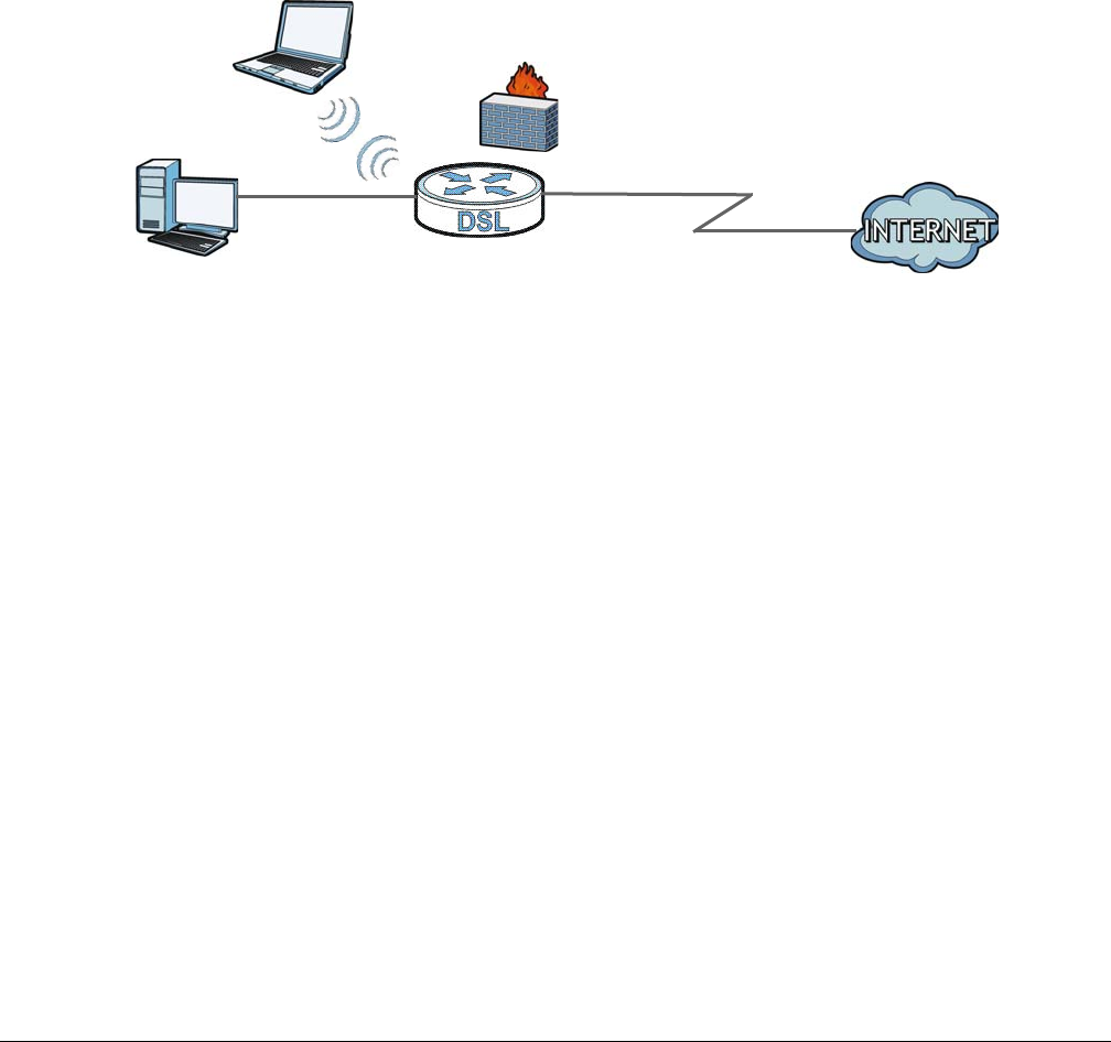
XMG3512-B10A User’s Guide
110
CHAPTER 8
Home Networking
8.1 Overview
A Local Area Network (LAN) is a shared communication system to which many networking devices are
connected. It is usually located in one immediate area such as a building or floor of a building.
Use the LAN screens to help you configure a LAN DHCP server and manage IP addresses.
8.1.1 What You Can Do in this Chapter
• Use the LAN Setup screen to set the LAN IP address, subnet mask, and DHCP settings of your XMG
(Section 8.2 on page 112).
• Use the Static DHCP screen to assign IP addresses on the LAN to specific individual computers based
on their MAC Addresses (Section 8.3 on page 116).
• Use the UPnP screen to enable UPnP and UPnP NAT traversal on the XMG (Section 8.4 on page 117).
• Use the Additional Subnet screen to configure IP alias and public static IP (Section 8.5 on page 120).
• Use the STB Vendor ID screen to configure the Vendor IDs of the connected Set Top Box (STB) devices,
which have the XMG automatically create static DHCP entries for the STB devices when they request
IP addresses (Section 8.6 on page 121).
• Use the Wake on LAN screen to remotely turn on a device on the network. (Section 8.7 on page 121).
• Use the TFTP Server Name screen to set a TFTP server address which is passed to the clients using DHCP
option 66. (Section 8.8 on page 122).
DSL
LAN

Chapter 8 Home Networking
XMG3512-B10A User’s Guide
111
8.1.2 What You Need To Know
8.1.2.1 About LAN
IP Address
IP addresses identify individual devices on a network. Every networking device (including computers,
servers, routers, printers, etc.) needs an IP address to communicate across the network. These
networking devices are also known as hosts.
Subnet Mask
Subnet masks determine the maximum number of possible hosts on a network. You can also use subnet
masks to divide one network into multiple sub-networks.
DHCP
A DHCP (Dynamic Host Configuration Protocol) server can assign your XMG an IP address, subnet mask,
DNS and other routing information when it's turned on.
DNS
DNS (Domain Name System) is for mapping a domain name to its corresponding IP address and vice
versa. The DNS server is extremely important because without it, you must know the IP address of a
networking device before you can access it.
RADVD (Router Advertisement Daemon)
When an IPv6 host sends a Router Solicitation (RS) request to discover the available routers, RADVD with
Router Advertisement (RA) messages in response to the request. It specifies the minimum and maximum
intervals of RA broadcasts. RA messages containing the address prefix. IPv6 hosts can be generated
with the IPv6 prefix an IPv6 address.
8.1.2.2 About UPnP
Identifying UPnP Devices
UPnP hardware is identified as an icon in the Network Connections folder (Windows XP). Each UPnP
compatible device installed on your network will appear as a separate icon. Selecting the icon of a
UPnP device will allow you to access the information and properties of that device.
NAT Traversal
UPnP NAT traversal automates the process of allowing an application to operate through NAT. UPnP
network devices can automatically configure network addressing, announce their presence in the
network to other UPnP devices and enable exchange of simple product and service descriptions. NAT
traversal allows the following:
• Dynamic port mapping
• Learning public IP addresses

Chapter 8 Home Networking
XMG3512-B10A User’s Guide
112
• Assigning lease times to mappings
Windows Messenger is an example of an application that supports NAT traversal and UPnP.
See the for more information on NAT.
Cautions with UPnP
The automated nature of NAT traversal applications in establishing their own services and opening
firewall ports may present network security issues. Network information and configuration may also be
obtained and modified by users in some network environments.
When a UPnP device joins a network, it announces its presence with a multicast message. For security
reasons, the XMG allows multicast messages on the LAN only.
All UPnP-enabled devices may communicate freely with each other without additional configuration.
Disable UPnP if this is not your intention.
UPnP and Zyxel
Zyxel has achieved UPnP certification from the Universal Plug and Play Forum UPnP™ Implementers
Corp. (UIC). Zyxel's UPnP implementation supports Internet Gateway Device (IGD) 1.0.
See Section 8.4.1 on page 118 for examples of installing and using UPnP.
Finding Out More
See Section 8.9 on page 122 for technical background information on LANs.
8.1.3 Before You Begin
Find out the MAC addresses of your network devices if you intend to add them to the DHCP Client List
screen.
8.2 The LAN Setup Screen
Use this screen to set the Local Area Network IP address and subnet mask of your XMG. Click Network
Setting > Home Networking to open the LAN Setup screen.
Follow these steps to configure your LAN settings.
1Enter an IP address into the IP Address field. The IP address must be in dotted decimal notation. This will
become the IP address of your XMG.
2Enter the IP subnet mask into the Subnet Mask field. Unless instructed otherwise it is best to leave this
alone, the configurator will automatically compute a subnet mask based upon the IP address you
entered.
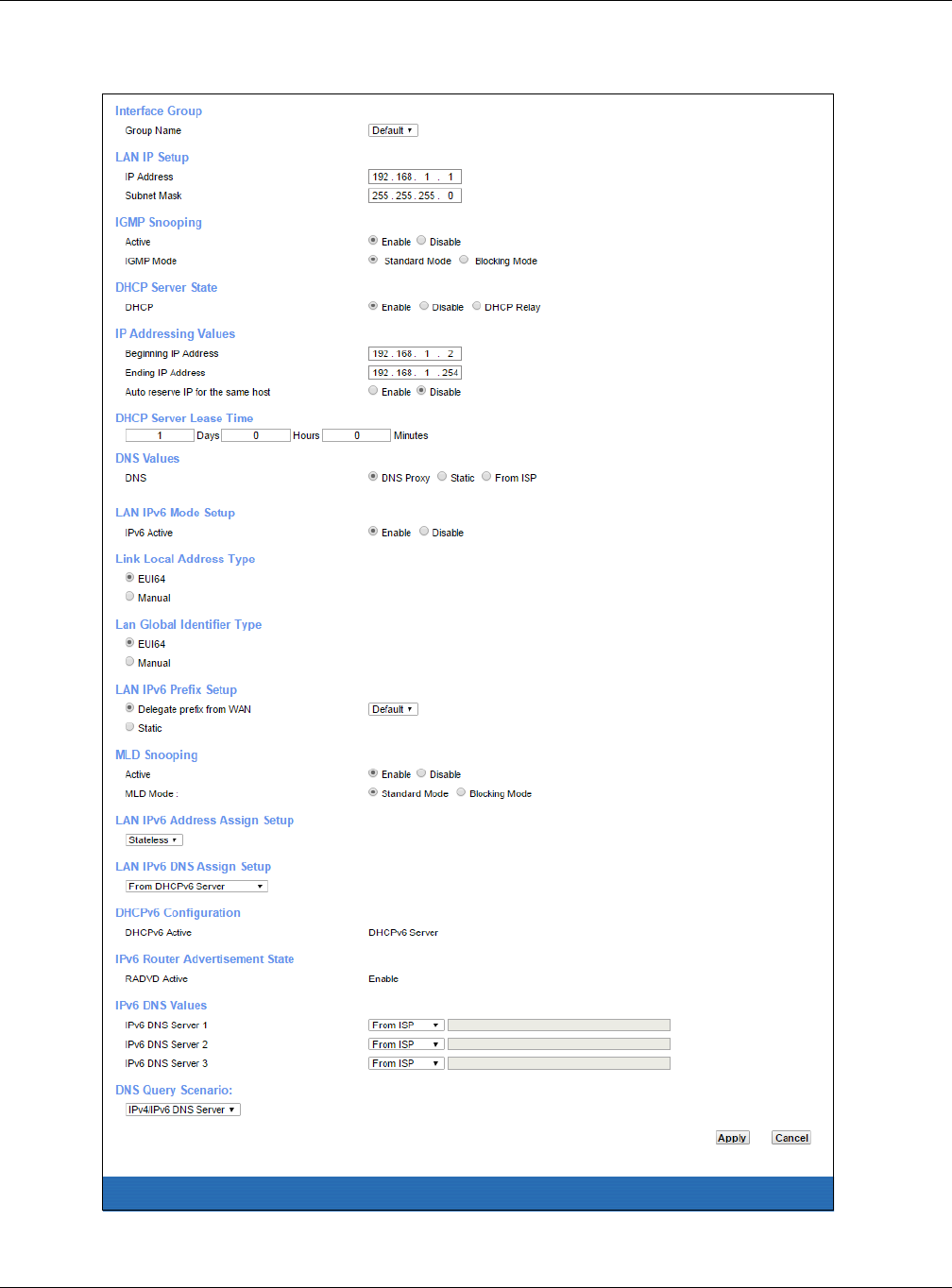
Chapter 8 Home Networking
XMG3512-B10A User’s Guide
113
3Click Apply to save your settings.
Figure 50 Network Setting > Home Networking > LAN Setup

Chapter 8 Home Networking
XMG3512-B10A User’s Guide
114
The following table describes the fields in this screen.
Table 29 Network Setting > Home Networking > LAN Setup
LABEL DESCRIPTION
Interface Group
Group Name Select the interface group name for which you want to configure LAN settings. See Chapter 14
on page 171 for how to create a new interface group.
LAN IP Setup
IP Address Enter the LAN IPv4 address you want to assign to your XMG in dotted decimal notation, for
example, 192.168.1.1 (factory default).
Subnet Mask Type the subnet mask of your network in dotted decimal notation, for example 255.255.255.0
(factory default). Your XMG automatically computes the subnet mask based on the IP Address
you enter, so do not change this field unless you are instructed to do so.
IGMP Snooping
Active Select Enable to allows the XMG to passively learn multicast group.
IGMP Select Standard Mode to allow the XMG to forward traffic only to ports that want to receive it.
Select Blocking Mode to allow the XMG to block unknown muticast adresses.
DHCP Server State
DHCP Select Enable to have the XMG act as a DHCP server or DHCP relay agent.
Select Disable to stop the DHCP server on the XMG.
Select DHCP Relay to have the XMG forward DHCP request to the DHCP server.
DHCP Relay
Server Address
This field is only available when you select DHCP Relay in the DHCP field.
IP Address Enter the IPv4 address of the actual remote DHCP server in this field.
IP Addressing
Values
This field is only available when you select Enable in the DHCP field.
Beginning IP
Address
This field specifies the first of the contiguous addresses in the IP address pool.
Ending IP
Address
This field specifies the last of the contiguous addresses in the IP address pool.
Auto reserve IP
for the same
host
Select Enable to have the XMG record DHCP IP addresses with the MAC addresses the IP
addresses are assigned to. The XMG assigns the same IP address to the same MAC address
when the host requests an IP address again through DHCP.
DHCP Server
Lease Time
This is the period of time DHCP-assigned addresses is used. DHCP automatically assigns IP
addresses to clients when they log in. DHCP centralizes IP address management on central
computers that run the DHCP server program. DHCP leases addresses, for a period of time,
which means that past addresses are “recycled” and made available for future reassignment to
other systems.
This field is only available when you select Enable in the DHCP field.
Days/Hours/
Minutes
Enter the lease time of the DHCP server.
DNS Values This field is only available when you select Enable in the DHCP field.
DNS Select From ISP if your ISP dynamically assigns DNS server information.
Select DNS Proxy if you have the DNS proxy service. The XMG redirects clients’ DNS queries to a
DNS server for resolving domain names.
Select Static if you have the IP address of a DNS server.
DNS Server 1/2 This field is only available when you select Static in the DNS field. Enter the first and second DNS
(Domain Name System) server IP addresses the XMG passes to the DHCP clients.

Chapter 8 Home Networking
XMG3512-B10A User’s Guide
115
LAN IPv6 Mode Setup
IPv6 Active Select Enable to activate the IPv6 mode and configure IPv6 settings on the XMG.
Link Local Address Type
EUI64 Select this to have the XMG generate an interface ID for the LAN interface’s link-local address
using the EUI-64 format.
Manual Select this to manually enter an interface ID for the LAN interface’s link-local address.
Lan Global Identifier Type
EUI64 Select this to have the XMG generate an interface ID using the EUI-64 format for its global
address .
Manual Select this to manually enter an interface ID for the LAN interface’s global IPv6 address.
LAN IPv6 Prefix Setup
Delegate prefix
from WAN
Select this option to automatically obtain an IPv6 network prefix from the service provider or an
uplink router.
Static Select this option to configure a fixed IPv6 address for the XMG’s LAN IPv6 address.
MLD Snooping Multicast Listener Discovery (MLD) allows an IPv6 switch or router to discover the presence of
MLD hosts who wish to receive multicast packets and the IP addresses of multicast groups the
hosts want to join on its network.
Active Select Enable to activate MLD Snooping on the XMG. This allows the XMG to check MLD packets
passing through it and learn the multicast group membership. It helps reduce multicast traffic.
MLD Mode Select Standard Mode to allow the XMG to forward MLD packets only to ports that want to
receive it.
Select MLD Mode to allow the XMG to block MLD packets for a specific multicast group.
LAN IPv6
Address Assign
Setup
Select how you want to obtain an IPv6 address:
•Stateless: The XMG uses IPv6 stateless autoconfiguration. RADVD (Router Advertisement
Daemon) is enabled to have the XMG send IPv6 prefix information in router advertisements
periodically and in response to router solicitations. DHCPv6 server is disabled.
•Stateful: The XMG uses IPv6 stateful autoconfiguration. The DHCPv6 server is enabled to have
the XMG act as a DHCPv6 server and pass IPv6 addresses to DHCPv6 clients.
•Stateless and Stateful: The XMG uses both IPv6 stateless and stateful autoconfiguration. The
LAN IPv6 clients can obtain IPv6 addresses either through router advertisements or through
DHCPv6.
LAN IPv6 DNS
Assign Setup
Select how the XMG provide DNS server and domain name information to the clients:
•From Router Advertisement: The XMG provides DNS information through router
advertisements.
•From DHCPv6 Server: The XMG provides DNS information through DHCPv6.
•From RA & DHCPv6 Server: The XMG provides DNS information through both router
advertisements and DHCPv6.
DHCPv6 Configuration
DHCPv6 Active This shows the status of the DHCPv6. DHCPv6 Server displays if you configured the XMG to act as
a DHCPv6 server which assigns IPv6 addresses and/or DNS information to clients.
IPv6 Router Advertisement State
RADVD Active This shows whether RADVD is enabled or not.
IPv6 DNS Values
IPv6 DNS Server
1-3
Select From ISP if your ISP dynamically assigns IPv6 DNS server information.
Select User-Defined if you have the IPv6 address of a DNS server. Enter the DNS server IPv6
addresses the XMG passes to the DHCP clients.
Select None if you do not want to configure IPv6 DNS servers.
Table 29 Network Setting > Home Networking > LAN Setup (continued)
LABEL DESCRIPTION
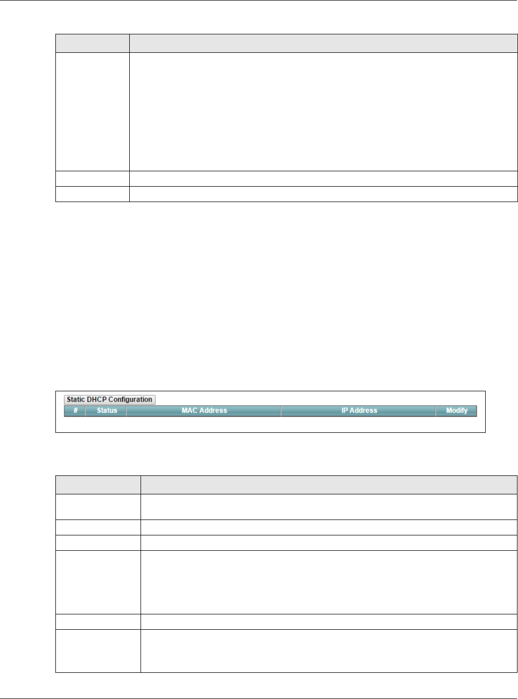
Chapter 8 Home Networking
XMG3512-B10A User’s Guide
116
8.3 The Static DHCP Screen
This table allows you to assign IP addresses on the LAN to specific individual computers based on their
MAC Addresses.
Every Ethernet device has a unique MAC (Media Access Control) address. The MAC address is assigned
at the factory and consists of six pairs of hexadecimal characters, for example, 00:A0:C5:00:00:02.
Use this screen to change your XMG’s static DHCP settings. Click Network Setting > Home Networking >
Static DHCP to open the following screen.
Figure 51 Network Setting > Home Networking > Static DHCP
The following table describes the labels in this screen.
DNS Query
Scenario
Select how the XMG handles clients’ DNS information requests.
•IPv4/IPv6 DNS Server: The XMG forwards the requests to both the IPv4 and IPv6 DNS servers
and sends clients the first DNS information it receives.
•IPv6 DNS Server Only: The XMG forwards the requests to the IPv6 DNS server and sends clients
the DNS information it receives.
•IPv4 DNS Server Only: The XMG forwards the requests to the IPv4 DNS server and sends clients
the DNS information it receives.
•IPv6 DNS Server First: The XMG forwards the requests to the IPv6 DNS server first and then the
IPv4 DNS server. Then it sends clients the first DNS information it receives.
•IPv4 DNS Server First: The XMG forwards the requests to the IPv4 DNS server first and then the
IPv6 DNS server. Then it sends clients the first DNS information it receives.
Apply Click Apply to save your changes.
Cancel Click Cancel to restore your previously saved settings.
Table 29 Network Setting > Home Networking > LAN Setup (continued)
LABEL DESCRIPTION
Table 30 Network Setting > Home Networking > Static DHCP
LABEL DESCRIPTION
Static DHCP
Configuration
Click this to add a new static DHCP entry.
# This is the index number of the entry.
Status This field displays whether the client is connected to the XMG.
MAC Address The MAC (Media Access Control) or Ethernet address on a LAN (Local Area Network) is
unique to your computer (six pairs of hexadecimal notation).
A network interface card such as an Ethernet adapter has a hardwired address that is
assigned at the factory. This address follows an industry standard that ensures no other
adapter has a similar address.
IP Address This field displays the IP address relative to the # field listed above.
Modify Click the Edit icon to have the IP address field editable and change it.
Click the Delete icon to delete a static DHCP entry. A window displays asking you to confirm
that you want to delete the selected entry.
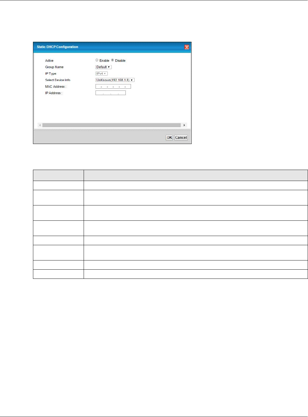
Chapter 8 Home Networking
XMG3512-B10A User’s Guide
117
If you click Static DHCP Configuration in the Static DHCP screen or the Edit icon next to a static DHCP
entry, the following screen displays.
Figure 52 Static DHCP: Static DHCP Configuration/Edit
The following table describes the labels in this screen.
8.4 The UPnP Screen
Universal Plug and Play (UPnP) is a distributed, open networking standard that uses TCP/IP for simple
peer-to-peer network connectivity between devices. A UPnP device can dynamically join a network,
obtain an IP address, convey its capabilities and learn about other devices on the network. In turn, a
device can leave a network smoothly and automatically when it is no longer in use.
See page 111 for more information on UPnP.
Table 31 Static DHCP: Static DHCP Configuration/Edit
LABEL DESCRIPTION
Active Select Enable to activate the connection between the client and the XMG.
Group Name Select the interface group name for which you want to configure static DHCP settings. See
Chapter 14 on page 171 for how to create a new interface group.
IP Type This field displays IPv4 for the type of the DHCP IP address. At the time of writing, it is not
allowed to select other type.
Select Device Info Select a device or computer from the drop-down list or select Manual Input to manually enter
a device’s MAC address and IP address in the following fields.
MAC Address If you select Manual Input, enter the MAC address of a computer on your LAN.
IP Address If you select Manual Input, enter the IP address that you want to assign to the computer on
your LAN with the MAC address that you will also specify.
OK Click OK to save your changes.
Cancel Click Cancel to exit this screen without saving.
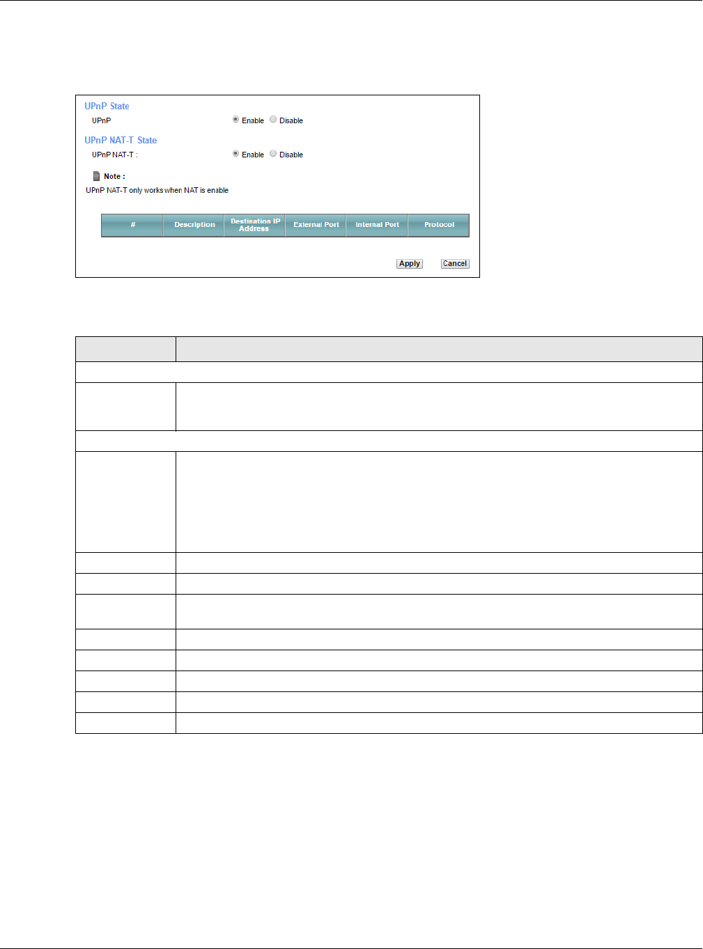
Chapter 8 Home Networking
XMG3512-B10A User’s Guide
118
Use the following screen to configure the UPnP settings on your XMG. Click Network Setting > Home
Networking > UPnP to display the screen shown next.
Figure 53 Network Setting > Home Networking > UPnP
The following table describes the labels in this screen.
8.4.1 Turning On UPnP in Windows 7 Example
This section shows you how to use the UPnP feature in Windows 7. UPnP server is installed in Windows 7.
Activate UPnP on the XMG.
Make sure the computer is connected to a LAN port of the XMG. Turn on your computer and the XMG.
1Click the start icon, Control Panel and then the Network and Sharing Center.
Table 32 Network Setting > Home Networking > UPnP
LABEL DESCRIPTION
UPnP State
UPnP Select Enable to activate UPnP. Be aware that anyone could use a UPnP application to open
the web configurator's login screen without entering the XMG's IP address (although you must
still enter the password to access the web configurator).
UPnP NAT-T State
UPnP NAT-T Select Enable to allow UPnP-enabled applications to automatically configure the XMG so that
they can communicate through the XMG by using NAT traversal. UPnP applications
automatically reserve a NAT forwarding port in order to communicate with another UPnP
enabled device; this eliminates the need to manually configure port forwarding for the UPnP
enabled application.
The table below displays the NAT port forwarding rules added automatically by UPnP NAT-T.
# This is the index number of the UPnP NAT-T connection.
Description This is the description of the UPnP NAT-T connection.
Destination IP
Address
This is the IP address of the other connected UPnP-enabled device.
External Port This is the external port number that identifies the service.
Internal Port This is the internal port number that identifies the service.
Protocol This is the transport layer protocol used for the service.
Apply Click Apply to save your changes.
Cancel Click Cancel to exit this screen without saving.
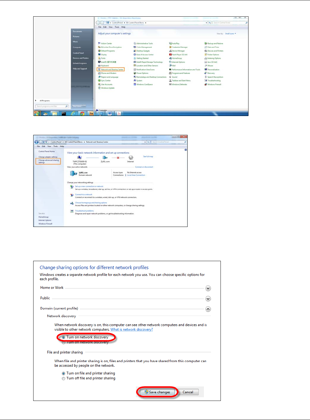
Chapter 8 Home Networking
XMG3512-B10A User’s Guide
119
2Click Change Advanced Sharing Settings.
3Select Turn on network discovery and click Save Changes. Network discovery allows your computer to
find other computers and devices on the network and other computers on the network to find your
computer. This makes it easier to share files and printers.
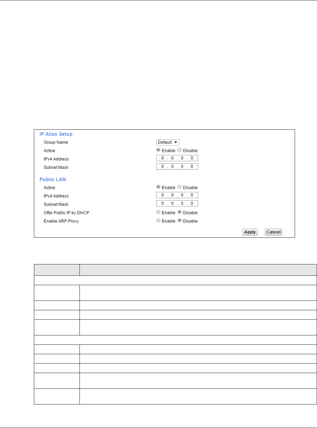
Chapter 8 Home Networking
XMG3512-B10A User’s Guide
120
8.5 The Additional Subnet Screen
Use the Additional Subnet screen to configure IP alias and public static IP.
IP alias allows you to partition a physical network into different logical networks over the same Ethernet
interface. The XMG supports multiple logical LAN interfaces via its physical Ethernet interface with the
XMG itself as the gateway for the LAN network. When you use IP alias, you can also configure firewall
rules to control access to the LAN's logical network (subnet).
If your ISP provides the Public LAN service, the XMG may use an LAN IP address that can be accessed
from the WAN.
Click Network Setting > Home Networking > Additional Subnet to display the screen shown next.
Figure 54 Network Setting > Home Networking > Additional Subnet
The following table describes the labels in this screen.
Table 33 Network Setting > Home Networking > Additional Subnet
LABEL DESCRIPTION
IP Alias Setup
Group Name Select the interface group name for which you want to configure the IP alias settings. See
Chapter 14 on page 171 for how to create a new interface group.
Active Select Enable to configure a LAN network for the XMG.
IPv4 Address Enter the IP address of your XMG in dotted decimal notation.
Subnet Mask Enter the subnet mask of your network in dotted decimal notation, for example 255.255.255.0
(factory default).
Public LAN
Active Select Enable to enable the Public LAN feature. Your ISP must support Public LAN and Static IP.
IPv4 Address Enter the public IP address provided by your ISP.
Subnet Mask Enter the public IPv4 subnet mask provided by your ISP.
Offer Public IP
by DHCP
Select Enable to enable the XMG to provide public IP addresses by DHCP server.
Enable ARP
Proxy
Select Enable to enable the ARP (Address Resolution Protocol) proxy.
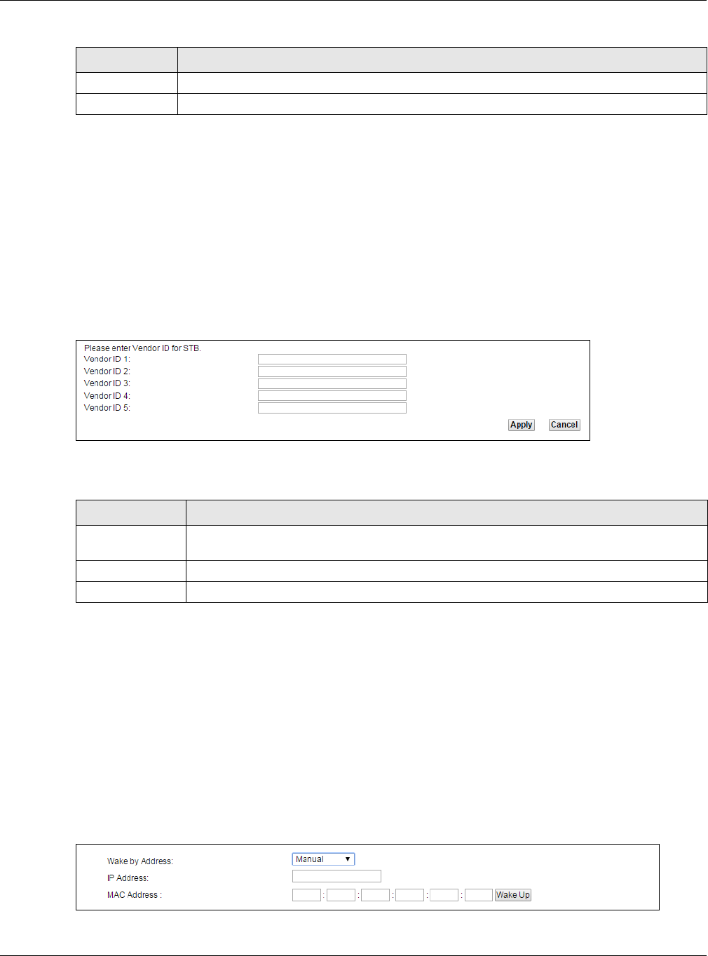
Chapter 8 Home Networking
XMG3512-B10A User’s Guide
121
8.6 The STB Vendor ID Screen
Set Top Box (STB) devices with dynamic IP addresses sometimes don’t renew their IP addresses before
the lease time expires. This could lead to IP address conflicts if the STB continues to use an IP address that
gets assigned to another device. Use this screen to configure the Vendor IDs of connected STBs, which
have the XMG automatically created static DHCP entries for them when they request IP addresses.
Click Network Setting > Home Networking > STB Vendor ID to open this screen.
Figure 55 Network Setting > Home Networking > STB Vendor ID
The following table describes the labels in this screen.
8.7 The Wake on LAN Screen
Use this screen to turn on a device on the LAN network. To use this feature, the remote device must also
support Wake On LAN.
You need to know the MAC address of the LAN device. It may be on a label on the device or in its
documentation.
Click Network Setting > Home Networking > Wake on LAN to open this screen.
Figure 56 Network Setting > Home Networking > Wake on LAN
Apply Click Apply to save your changes.
Cancel Click Cancel to exit this screen without saving.
Table 33 Network Setting > Home Networking > Additional Subnet (continued)
LABEL DESCRIPTION
Table 34 Network Setting > Home Networking > STB Vendor ID
LABEL DESCRIPTION
Vendor ID 1~5 These are STB’s Vendor Class Identifiers (DHCP option 60). A Vendor Class Identifier is usually
used to inform the DHCP server a DHCP client’s vendor and functionality.
Apply Click Apply to save your changes.
Cancel Click Cancel to exit this screen without saving.
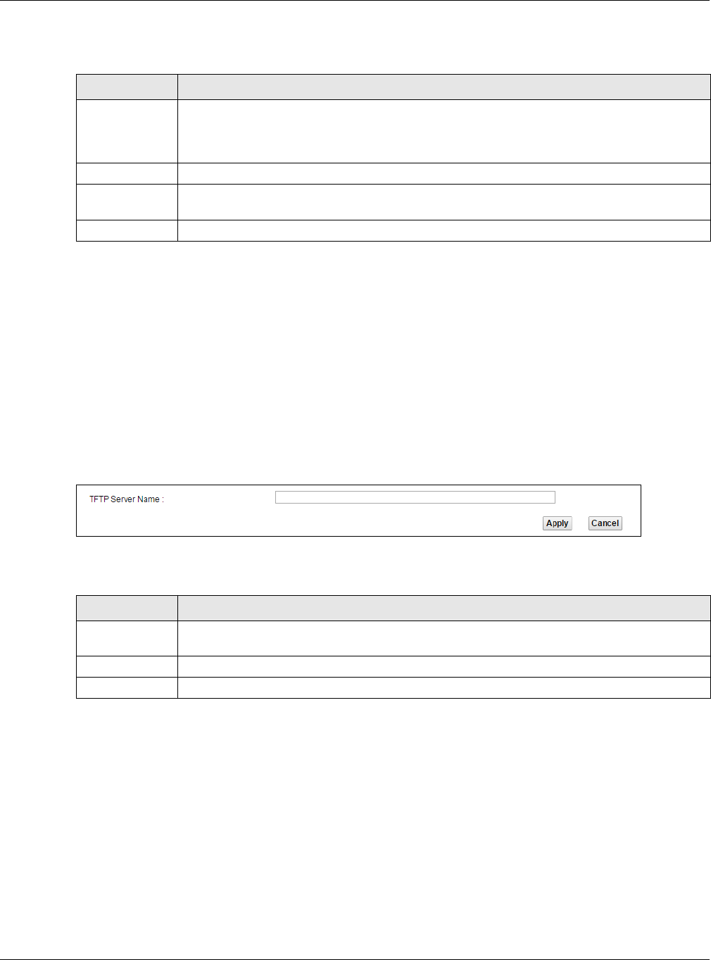
Chapter 8 Home Networking
XMG3512-B10A User’s Guide
122
The following table describes the labels in this screen.
8.8 The TFTP Server Name Screen
Use the TFTP Server Name screen to set the TFTP server address which is passed to the clients using DHCP
option 66. The DHCP clients in the XMG local network, such as STB devices that support the TFTP booting
mechanism, can then use the TFTP server address or domain name for initial system settings download.
RFC 2132 defines the option 66 open standard. DHCP option 66 carries the IP address or the domain
name of a single TFTP server.
Click Network Setting > Home Networking > TFTP Server Name to open this screen.
Figure 57 Network Setting > Home Networking > TFTP Server Name
The following table describes the labels in this screen.
8.9 Technical Reference
This section provides some technical background information about the topics covered in this chapter.
8.9.1 LANs, WANs and the XMG
The actual physical connection determines whether the XMG ports are LAN or WAN ports. There are two
separate IP networks, one inside the LAN network and the other outside the WAN network as shown
next.
Table 35 Network Setting > Home Networking > Wake on LAN
LABEL DESCRIPTION
Wake by
Address
Select Manual and enter the IP address or MAC address of the device to turn it on remotely. The
drop-down list also lists the IP addresses that can be found in the XMG’s ARP table. Select an IP
address and it will then automatically update the IP address and MAC address in the following
fields.
IP Address Enter the IPv4 IP address of the device to turn it on.
MAC Address Enter the MAC address of the device to turn it on. A MAC address consists of six hexadecimal
character pairs.
Wake up Click this to send a wake up packet to wake up the specified device.
Table 36 Network Setting > Home Networking > TFTP Server Name
LABEL DESCRIPTION
TFTP Server
Name
Enter the IP address or the domain name of a single TFTP server.
Apply Click Apply to save your changes.
Cancel Click Cancel to exit this screen without saving.
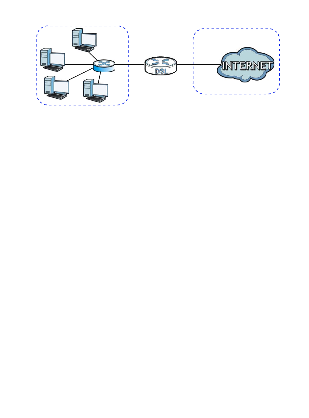
Chapter 8 Home Networking
XMG3512-B10A User’s Guide
123
Figure 58 LAN and WAN IP Addresses
8.9.2 DHCP Setup
DHCP (Dynamic Host Configuration Protocol, RFC 2131 and RFC 2132) allows individual clients to obtain
TCP/IP configuration at start-up from a server. You can configure the XMG as a DHCP server or disable it.
When configured as a server, the XMG provides the TCP/IP configuration for the clients. If you turn DHCP
service off, you must have another DHCP server on your LAN, or else the computer must be manually
configured.
IP Pool Setup
The XMG is pre-configured with a pool of IP addresses for the DHCP clients (DHCP Pool). See the product
specifications in the appendices. Do not assign static IP addresses from the DHCP pool to your LAN
computers.
8.9.3 DNS Server Addresses
DNS (Domain Name System) maps a domain name to its corresponding IP address and vice versa. The
DNS server is extremely important because without it, you must know the IP address of a computer
before you can access it. The DNS server addresses you enter when you set up DHCP are passed to the
client machines along with the assigned IP address and subnet mask.
There are two ways that an ISP disseminates the DNS server addresses.
• The ISP tells you the DNS server addresses, usually in the form of an information sheet, when you sign
up. If your ISP gives you DNS server addresses, enter them in the DNS Server fields in the DHCP Setup
screen.
• Some ISPs choose to disseminate the DNS server addresses using the DNS server extensions of IPCP (IP
Control Protocol) after the connection is up. If your ISP did not give you explicit DNS servers, chances
are the DNS servers are conveyed through IPCP negotiation. The XMG supports the IPCP DNS server
extensions through the DNS proxy feature.
Please note that DNS proxy works only when the ISP uses the IPCP DNS server extensions. It does not
mean you can leave the DNS servers out of the DHCP setup under all circumstances. If your ISP gives
you explicit DNS servers, make sure that you enter their IP addresses in the DHCP Setup screen.
WAN
LAN
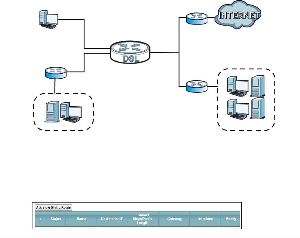
XMG3512-B10A User’s Guide
124
CHAPTER 9
Routing
9.1 Overview
The XMG usually uses the default gateway to route outbound traffic from computers on the LAN to the
Internet. To have the XMG send data to devices not reachable through the default gateway, use static
routes.
For example, the next figure shows a computer (A) connected to the XMG’s LAN interface. The XMG
routes most traffic from A to the Internet through the XMG’s default gateway (R1). You create one static
route to connect to services offered by your ISP behind router R2. You create another static route to
communicate with a separate network behind a router R3 connected to the LAN.
Figure 59 Example of Routing Topology
9.2 The Routing Screen
Use this screen to view and configure the static route rules on the XMG. Click Network Setting > Routing
> Static Route to open the following screen.
Figure 60 Network Setting > Routing > Static Route
WAN
R1
R2
A
R3
LAN
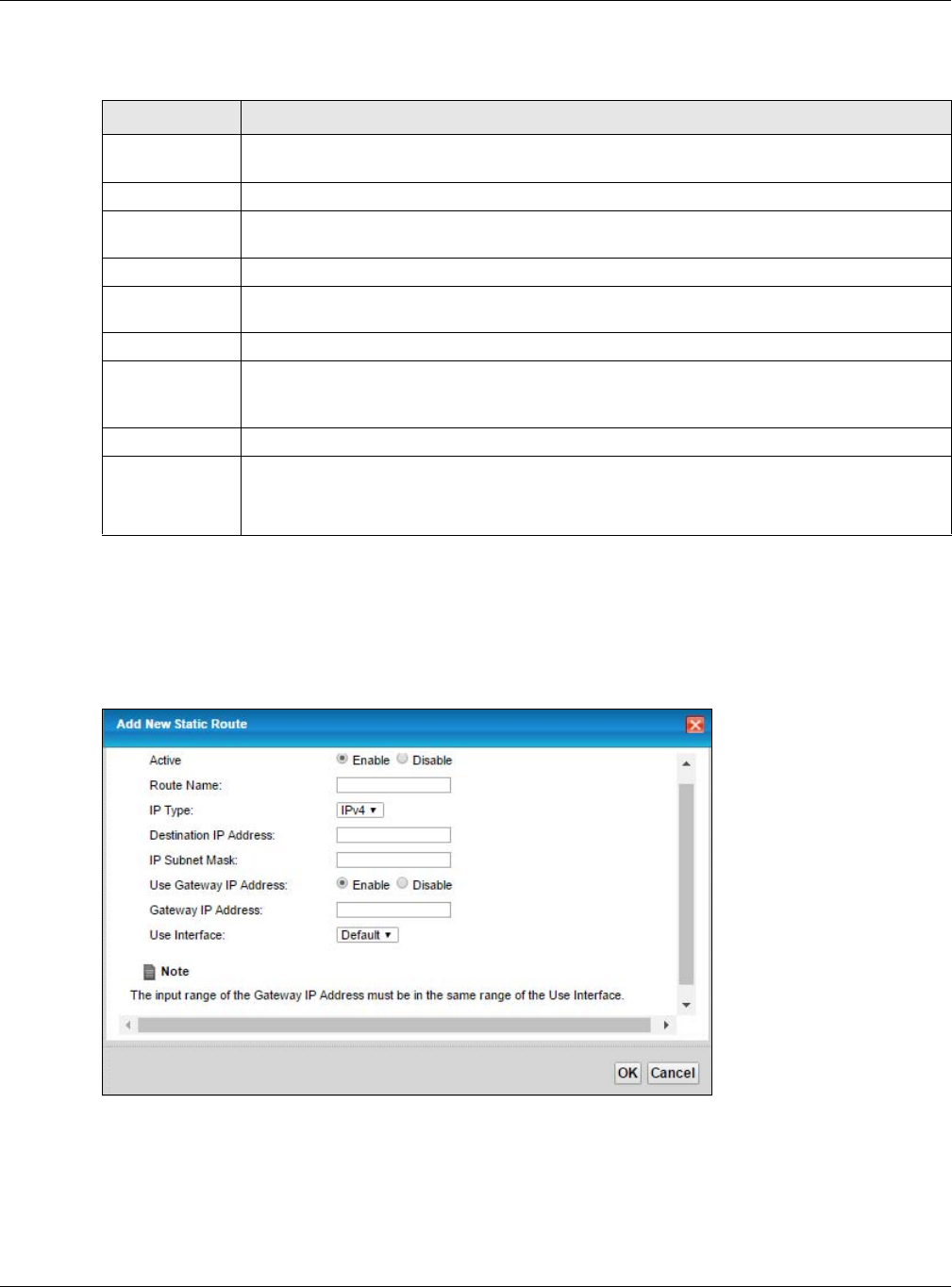
Chapter 9 Routing
XMG3512-B10A User’s Guide
125
The following table describes the labels in this screen.
9.2.1 Add/Edit Static Route
Use this screen to add or edit a static route. Click Add new static route in the Routing screen or the Edit
icon next to the static route you want to edit. The screen shown next appears.
Figure 61 Routing: Add/Edit
Table 37 Network Setting > Routing > Static Route
LABEL DESCRIPTION
Add new static
route
Click this to configure a new static route.
#This is the index number of the entry.
Status This field displays whether the static route is active or not. A yellow bulb signifies that this route is
active. A gray bulb signifies that this route is not active.
Name This is the name that describes or identifies this route.
Destination IP This parameter specifies the IP network address of the final destination. Routing is always based
on network number.
Subnet Mask This parameter specifies the IP network subnet mask of the final destination.
Gateway This is the IP address of the gateway. The gateway is a router or switch on the same network
segment as the device's LAN or WAN port. The gateway helps forward packets to their
destinations.
Interface This is the WAN interface used for this static route.
Modify Click the Edit icon to edit the static route on the XMG.
Click the Delete icon to remove a static route from the XMG. A window displays asking you to
confirm that you want to delete the route.
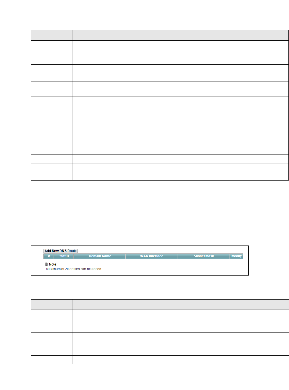
Chapter 9 Routing
XMG3512-B10A User’s Guide
126
The following table describes the labels in this screen.
9.3 The DNS Route Screen
Use this screen to view and configure DNS routes on the XMG. Click Network Setting > Routing > DNS
Route to open the following screen.
Figure 62 Network Setting > Routing > DNS Route
The following table describes the labels in this screen.
Table 38 Routing: Add/Edit
LABEL DESCRIPTION
Active This field allows you to activate/deactivate this static route.
Select Enable to activate the static route. Select Disable to deactivate this static route without
having to delete the entry.
Route Name Enter a descriptive name for the static route.
IP Type Select whether your IP type is IPv4 or IPv6.
Destination IP
Address
Enter the IPv4 or IPv6 network address of the final destination.
IP Subnet Mask If you are using IPv4 and need to specify a route to a single host, use a subnet mask of
255.255.255.255 in the subnet mask field to force the network number to be identical to the host
ID. Enter the IP subnet mask here.
Use Gateway IP
Address
The gateway is a router or switch on the same network segment as the device's LAN or WAN
port. The gateway helps forward packets to their destinations.
If you want to use the gateway IP address, select Enable.
Gateway IP
Address
Enter the IP address of the gateway.
Use Interface Select the WAN interface you want to use for this static route.
OK Click OK to save your changes.
Cancel Click Cancel to exit this screen without saving.
Table 39 Network Setting > Routing > DNS Route
LABEL DESCRIPTION
Add New DNS
Route
Click this to add a new DNS route.
#This is the index number of a DNS route.
Status This field displays whether the DNS route is active or not. A yellow bulb signifies that this DNS route
is active. A gray bulb signifies that this DNS route is not active.
Domain Name This is the host name or domain name of the DNS route entry.
WAN Interface This is the WAN connection through which the XMG forwards DNS requests for this domain name.
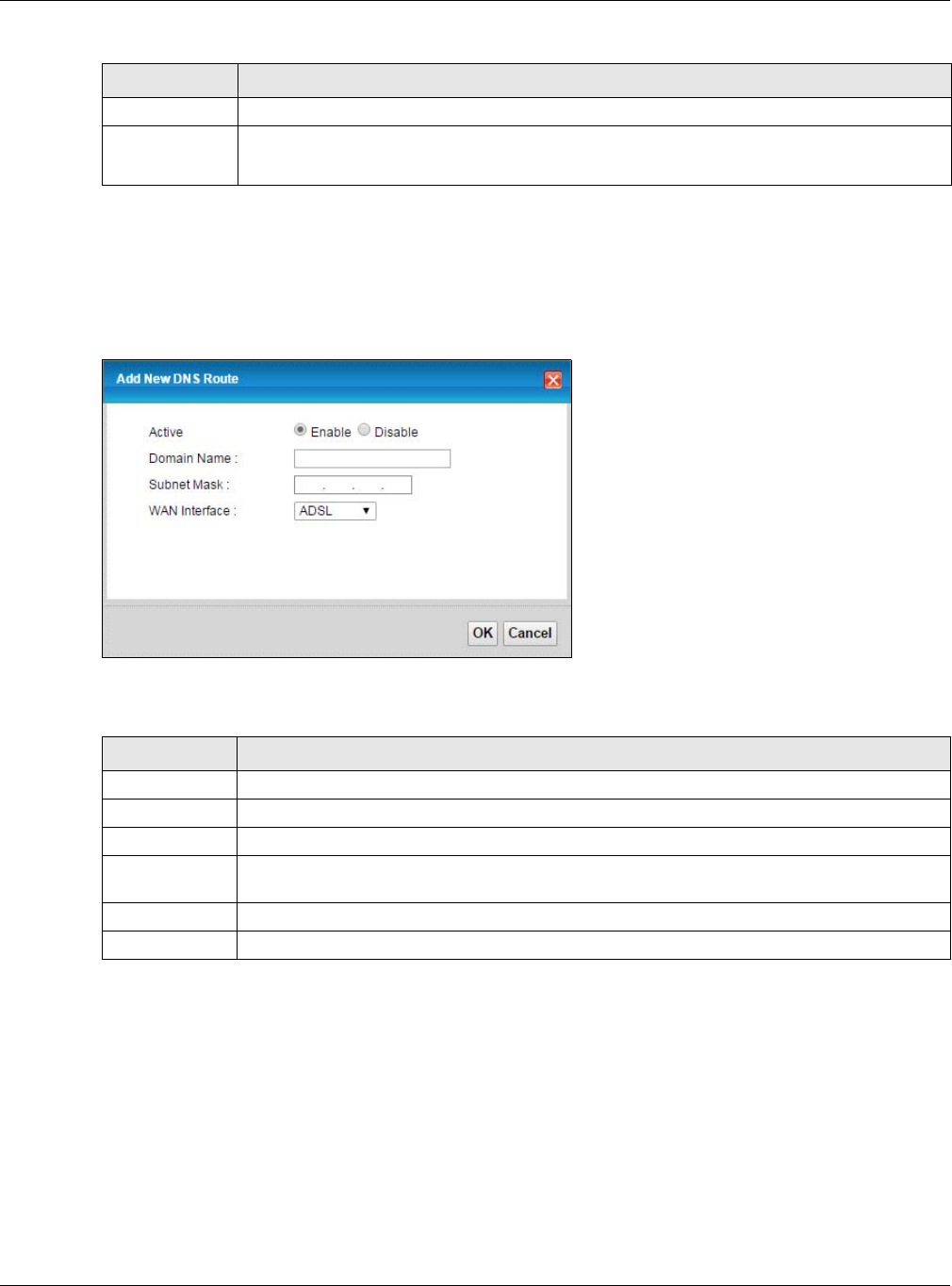
Chapter 9 Routing
XMG3512-B10A User’s Guide
127
9.3.1 The DNS Route Add Screen
You can manually add the XMG’s DNS route entry. Click Add New DNS Route in the Network Setting >
Routing > DNS Route screen. The screen shown next appears.
Figure 63 DNS Route Add
The following table describes the labels in this screen.
9.4 The Policy Route Screen
Traditionally, routing is based on the destination address only and the XMG takes the shortest path to
forward a packet. Policy route allows the XMG to override the default routing behavior and alter the
packet forwarding based on the policy defined by the network administrator. Policy-based routing is
applied to outgoing packets, prior to the normal routing.
You can use source-based policy forwarding to direct traffic from different users through different
connections or distribute traffic among multiple paths for load sharing.
Subnet Mask This is the subnet mask of the DNS route entry.
Modify Click the Edit icon to modify the DNS route.
Click the Delete icon to delete the DNS route.
Table 39 Network Setting > Routing > DNS Route (continued)
LABEL DESCRIPTION
Table 40 DNS Route Add
LABEL DESCRIPTION
Active Select to enable or disable this DNS route.
Domain Name Enter the domain name of the DNS route entry.
Subnet Mask Enter the subnet mask of the DNS route entry.
WAN Interface Select the WAN connection through which the XMG forwards DNS requests for this domain
name.
OK Click this to save your changes.
Cancel Click this to exit this screen without saving any changes.
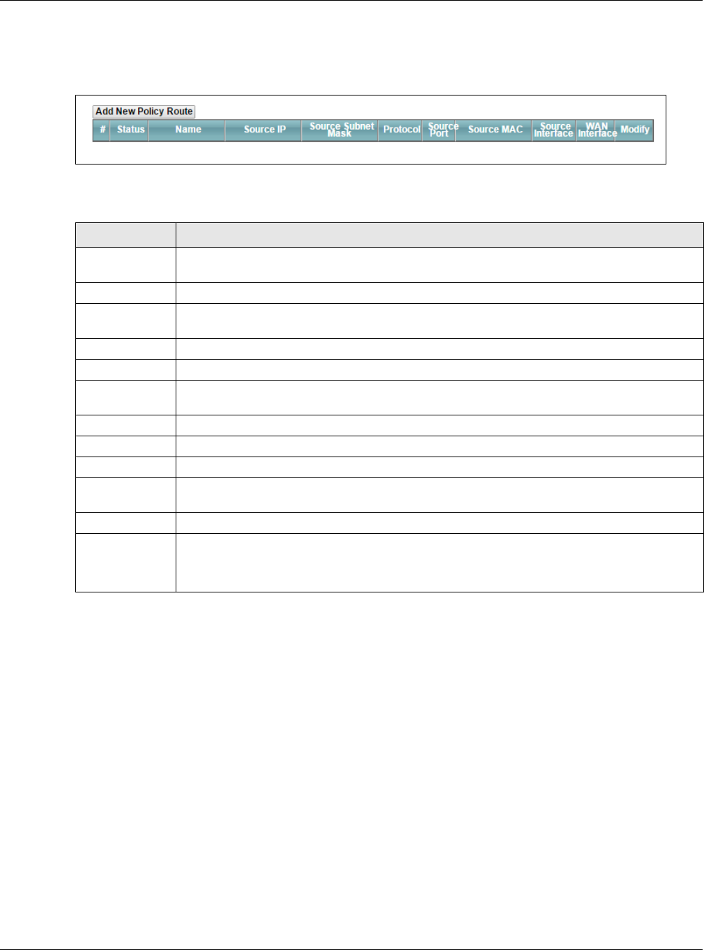
Chapter 9 Routing
XMG3512-B10A User’s Guide
128
The Policy Route screen let you view and configure routing policies on the XMG. Click Network Setting >
Routing > Policy Route to open the following screen.
Figure 64 Network Setting > Routing > Policy Route
The following table describes the labels in this screen.
Table 41 Network Setting > Routing >Policy Route
LABEL DESCRIPTION
Add New Policy
Route
Click this to create a new policy forwarding rule.
#This is the index number of the entry.
Status This field displays whether the DNS route is active or not. A yellow bulb signifies that this DNS route
is active. A gray bulb signifies that this DNS route is not active.
Name This is the name of the rule.
Source IP This is the source IP address.
Source Subnet
Mask
his is the source subnet mask address.
Protocol This is the transport layer protocol.
Source Port This is the source port number.
Source MAC This is the source MAC address.
Source
Interface
This is the interface from which the matched traffic is sent.
WAN Interface This is the WAN interface through which the traffic is routed.
Modify Click the Edit icon to edit this policy.
Click the Delete icon to remove a policy from the XMG. A window displays asking you to confirm
that you want to delete the policy.
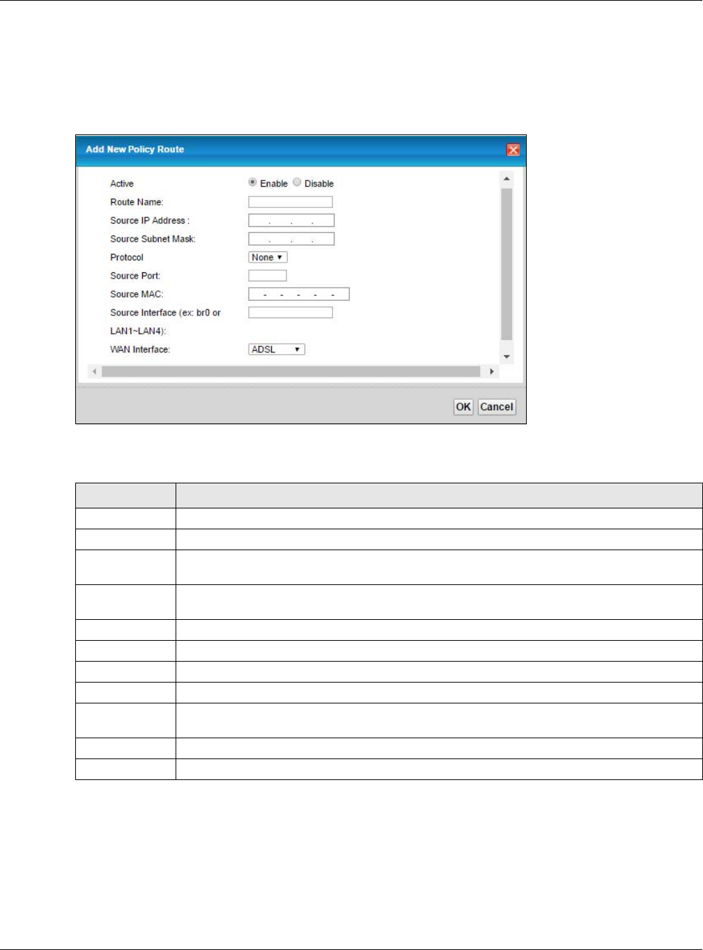
Chapter 9 Routing
XMG3512-B10A User’s Guide
129
9.4.1 Add/Edit Policy Route
Click Add New Policy Route in the Policy Route screen or click the Edit icon next to a policy. Use this
screen to configure the required information for a policy route.
Figure 65 Policy Route: Add/Edit
The following table describes the labels in this screen.
9.5 RIP
Routing Information Protocol (RIP, RFC 1058 and RFC 1389) allows a device to exchange routing
information with other routers.
Table 42 Policy Route: Add/Edit
LABEL DESCRIPTION
Active Select to enable or disable this policy route.
Route Name Enter a descriptive name of up to 8 printable English keyboard characters, not including spaces.
Source IP
Address
Enter the source IP address.
Source Subnet
Mask
Enter the source subnet mask address.
Protocol Select the transport layer protocol (TCP or UDP).
Source Port Enter the source port number.
Source MAC Enter the source MAC address.
Source Interface Type the name of the interface from which the matched traffic is sent.
WAN Interface Select a WAN interface through which the traffic is sent. You must have the WAN interface(s)
already configured in the Broadband screens.
OK Click OK to save your changes.
Cancel Click Cancel to exit this screen without saving.
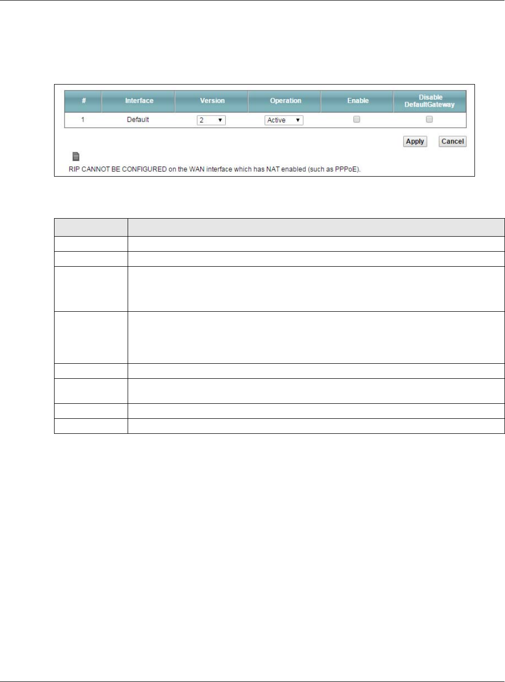
Chapter 9 Routing
XMG3512-B10A User’s Guide
130
9.5.1 The RIP Screen
Click Network Setting > Routing > RIP to open the RIP screen.
Figure 66 RIP
The following table describes the labels in this screen.
Table 43 RIP
LABEL DESCRIPTION
#This is the index of the interface in which the RIP setting is used.
Interface This is the name of the interface in which the RIP setting is used.
Version The RIP version controls the format and the broadcasting method of the RIP packets that the
XMG sends (it recognizes both formats when receiving). RIP version 1 is universally supported but
RIP version 2 carries more information. RIP version 1 is probably adequate for most networks,
unless you have an unusual network topology.
Operation Select Passive to have the XMG update the routing table based on the RIP packets received
from neighbors but not advertise its route information to other routers in this interface.
Select Active to have the XMG advertise its route information and also listen for routing updates
from neighboring routers.
Enable Select the check box to activate the settings.
Disable Default
Gateway
Select the check box to set the XMG to not send the route information to the default gateway.
Apply Click Apply to save your changes back to the XMG.
Cancel Click Cancel to restore your previously saved settings.

XMG3512-B10A User’s Guide
131
CHAPTER 10
Quality of Service (QoS)
10.1 Overview
Quality of Service (QoS) refers to both a network’s ability to deliver data with minimum delay, and the
networking methods used to control the use of bandwidth. Without QoS, all traffic data is equally likely
to be dropped when the network is congested. This can cause a reduction in network performance and
make the network inadequate for time-critical application such as video-on-demand.
Configure QoS on the XMG to group and prioritize application traffic and fine-tune network
performance. Setting up QoS involves these steps:
1Configure classifiers to sort traffic into different flows.
2Assign priority and define actions to be performed for a classified traffic flow.
The XMG assigns each packet a priority and then queues the packet accordingly. Packets assigned a
high priority are processed more quickly than those with low priority if there is congestion, allowing time-
sensitive applications to flow more smoothly. Time-sensitive applications include both those that require
a low level of latency (delay) and a low level of jitter (variations in delay) such as Voice over IP (VoIP) or
Internet gaming, and those for which jitter alone is a problem such as Internet radio or streaming video.
This chapter contains information about configuring QoS and editing classifiers.
10.1.1 What You Can Do in this Chapter
• Use the General screen to enable or disable QoS and set the upstream bandwidth (Section 10.3 on
page 133).
• Use the Queue Setup screen to configure QoS queue assignment (Section 10.4 on page 134).
• Use the Classification Setup screen to add, edit or delete QoS classifiers (Section 10.5 on page 137).
• Use the Shaper Setup screen to limit outgoing traffic transmission rate on the selected interface
(Section 10.6 on page 141).
• Use the Policer Setup screen to control incoming traffic transmission rate and bursts (Section 10.7 on
page 142).
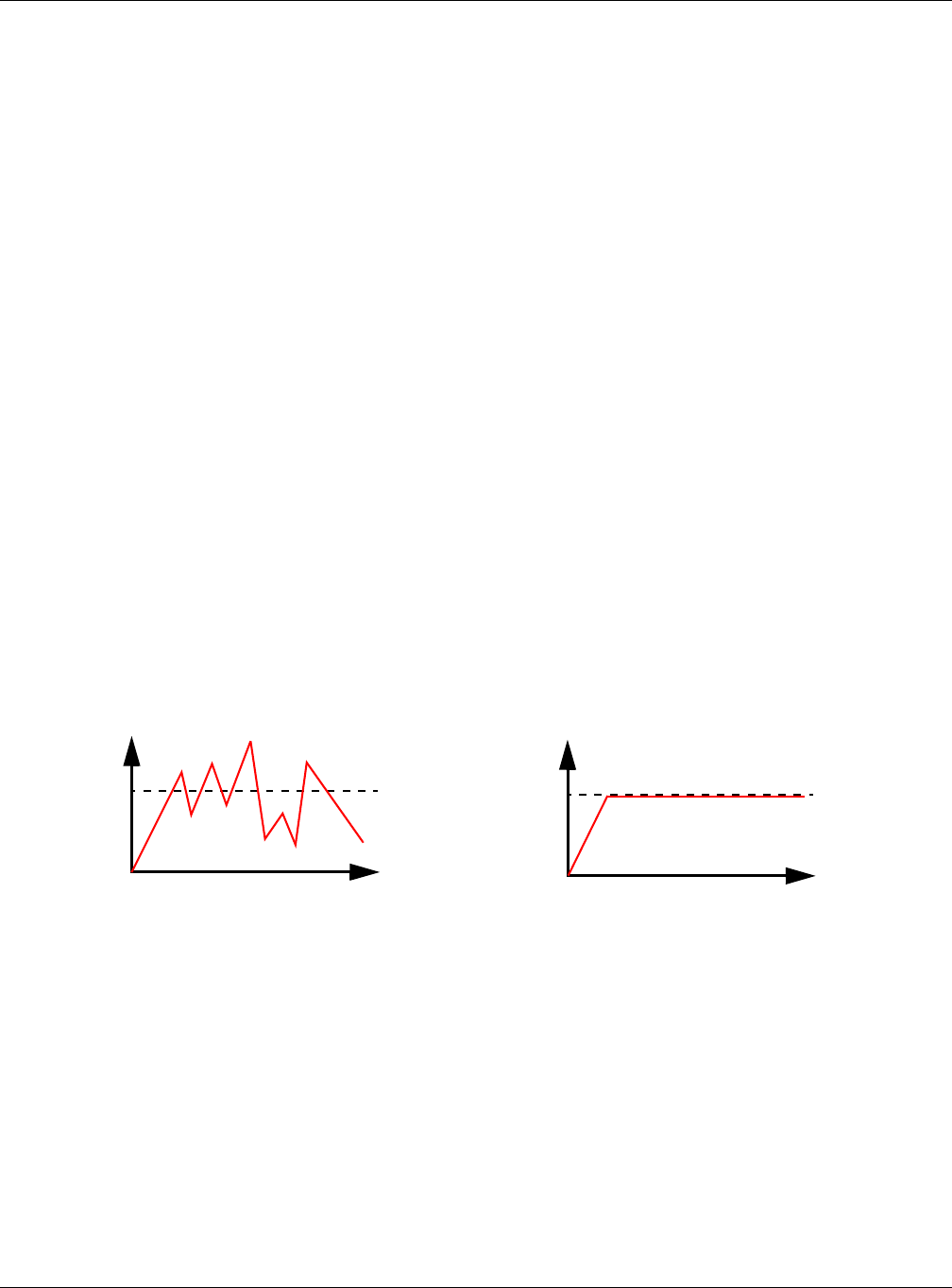
Chapter 10 Quality of Service (QoS)
XMG3512-B10A User’s Guide
132
10.2 What You Need to Know
The following terms and concepts may help as you read through this chapter.
QoS versus Cos
QoS is used to prioritize source-to-destination traffic flows. All packets in the same flow are given the
same priority. CoS (class of service) is a way of managing traffic in a network by grouping similar types of
traffic together and treating each type as a class. You can use CoS to give different priorities to different
packet types.
CoS technologies include IEEE 802.1p layer 2 tagging and DiffServ (Differentiated Services or DS). IEEE
802.1p tagging makes use of three bits in the packet header, while DiffServ is a new protocol and
defines a new DS field, which replaces the eight-bit ToS (Type of Service) field in the IP header.
Tagging and Marking
In a QoS class, you can configure whether to add or change the DSCP (DiffServ Code Point) value, IEEE
802.1p priority level and VLAN ID number in a matched packet. When the packet passes through a
compatible network, the networking device, such as a backbone switch, can provide specific
treatment or service based on the tag or marker.
Traffic Shaping
Bursty traffic may cause network congestion. Traffic shaping regulates packets to be transmitted with a
pre-configured data transmission rate using buffers (or queues). Your XMG uses the Token Bucket
algorithm to allow a certain amount of large bursts while keeping a limit at the average rate.
Traffic
Time
Traffic Rate
Traffic
Time
Traffic Rate
(Before Traffic Shaping) (After Traffic Shaping)
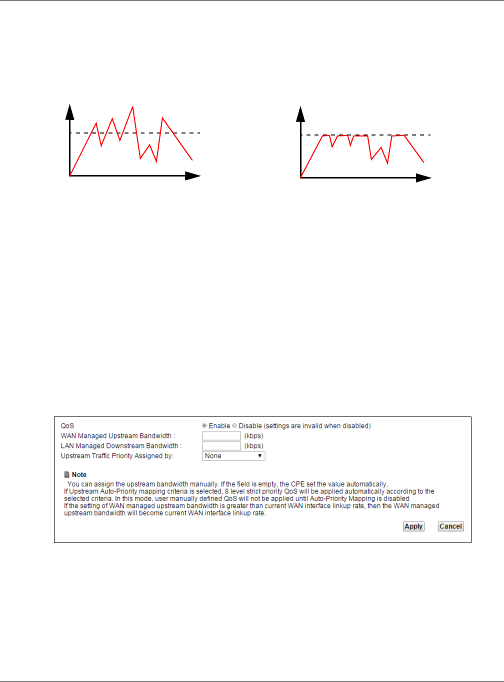
Chapter 10 Quality of Service (QoS)
XMG3512-B10A User’s Guide
133
Traffic Policing
Traffic policing is the limiting of the input or output transmission rate of a class of traffic on the basis of
user-defined criteria. Traffic policing methods measure traffic flows against user-defined criteria and
identify it as either conforming, exceeding or violating the criteria.
The XMG supports three incoming traffic metering algorithms: Token Bucket Filter (TBF), Single Rate Two
Color Maker (srTCM), and Two Rate Two Color Marker (trTCM). You can specify actions which are
performed on the colored packets. See Section 10.8 on page 144 for more information on each
metering algorithm.
10.3 The Quality of Service General Screen
Click Network Setting > QoS > General to open the screen as shown next.
Use this screen to enable or disable QoS and set the upstream bandwidth. See Section 10.1 on page 131
for more information.
Figure 67 Network Settings > QoS > General
Traffic
Time
Traffic Rate
Traffic
Time
Traffic Rate
(Before Traffic Policing) (After Traffic Policing)

Chapter 10 Quality of Service (QoS)
XMG3512-B10A User’s Guide
134
The following table describes the labels in this screen.
10.4 The Queue Setup Screen
Click Network Setting > QoS > Queue Setup to open the screen as shown next.
Use this screen to configure QoS queue assignment.
Table 44 Network Setting > QoS > General
LABEL DESCRIPTION
QoS Select the Enable check box to turn on QoS to improve your network performance.
WAN Managed
Upstream
Bandwidth
Enter the amount of upstream bandwidth for the WAN interfaces that you want to allocate using
QoS.
The recommendation is to set this speed to match the interfaces’ actual transmission speed. For
example, set the WAN interfaces’ speed to 100000 kbps if your Internet connection has an
upstream transmission speed of 100 Mbps.
You can set this number higher than the interfaces’ actual transmission speed. The XMG uses up
to 95% of the DSL port’s actual upstream transmission speed even if you set this number higher
than the DSL port’s actual transmission speed.
You can also set this number lower than the interfaces’ actual transmission speed. This will cause
the XMG to not use some of the interfaces’ available bandwidth.
If you leave this field blank, the XMG automatically sets this number to be 95% of the WAN
interfaces’ actual upstream transmission speed.
LAN Managed
Downstream
Bandwidth
Enter the amount of downstream bandwidth for the LAN interfaces (including WLAN) that you
want to allocate using QoS.
The recommendation is to set this speed to match the WAN interfaces’ actual transmission
speed. For example, set the LAN managed downstream bandwidth to 100000 kbps if you use a
100 Mbps wired Ethernet WAN connection.
You can also set this number lower than the WAN interfaces’ actual transmission speed. This will
cause the XMG to not use some of the interfaces’ available bandwidth.
If you leave this field blank, the XMG automatically sets this to the LAN interfaces’ maximum
supported connection speed.
Upstream Traffic
Priority Assigned
by
Select how the XMG assigns priorities to various upstream traffic flows.
•None: Disables auto priority mapping and has the XMG put packets into the queues
according to your classification rules. Traffic which does not match any of the classification
rules is mapped into the default queue with the lowest priority.
•Ethernet Priority: Automatically assign priority based on the IEEE 802.1p priority level.
•IP Precedence: Automatically assign priority based on the first three bits of the TOS field in the
IP header.
•Packet Length: Automatically assign priority based on the packet size. Smaller packets get
higher priority since control, signaling, VoIP, internet gaming, or other real-time packets are
usually small while larger packets are usually best effort data packets like file transfers.
Apply Click Apply to save your changes.
Cancel Click Cancel to restore your previously saved settings.
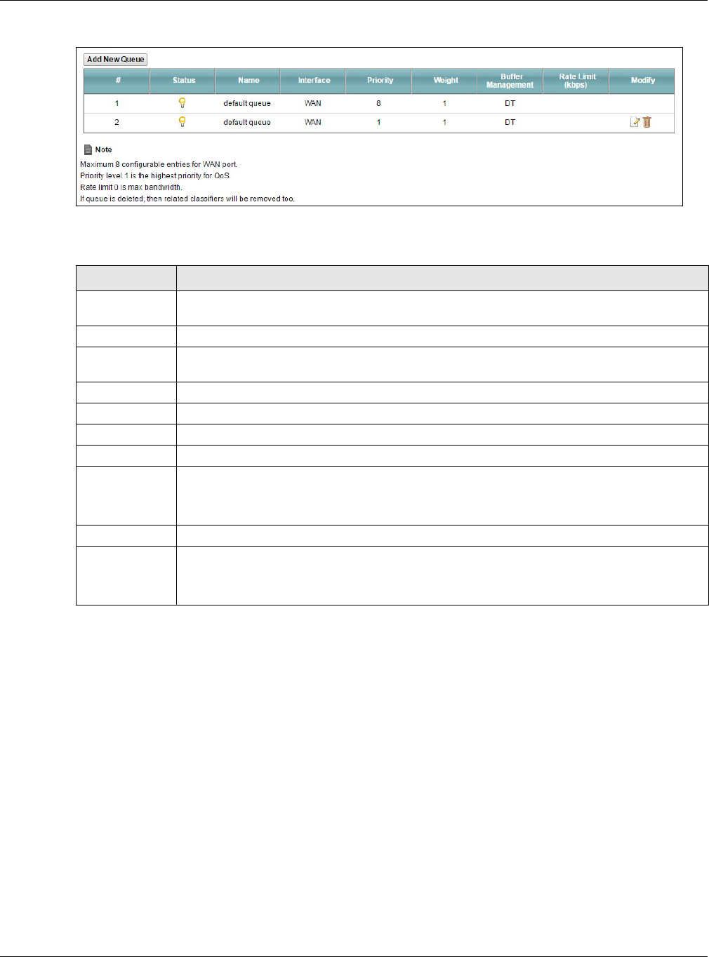
Chapter 10 Quality of Service (QoS)
XMG3512-B10A User’s Guide
135
Figure 68 Network Setting > QoS > Queue Setup
The following table describes the labels in this screen.
Table 45 Network Setting > QoS > Queue Setup
LABEL DESCRIPTION
Add New
Queue
Click this button to create a new queue entry.
#This is the index number of the entry.
Status This field displays whether the queue is active or not. A yellow bulb signifies that this queue is
active. A gray bulb signifies that this queue is not active.
Name This shows the descriptive name of this queue.
Interface This shows the name of the XMG’s interface through which traffic in this queue passes.
Priority This shows the priority of this queue.
Weight This shows the weight of this queue.
Buffer
Management
This shows the queue management algorithm used for this queue.
Queue management algorithms determine how the XMG should handle packets when it
receives too many (network congestion).
Rate Limit This shows the maximum transmission rate allowed for traffic on this queue.
Modify Click the Edit icon to edit the queue.
Click the Delete icon to delete an existing queue. Note that subsequent rules move up by one
when you take this action.
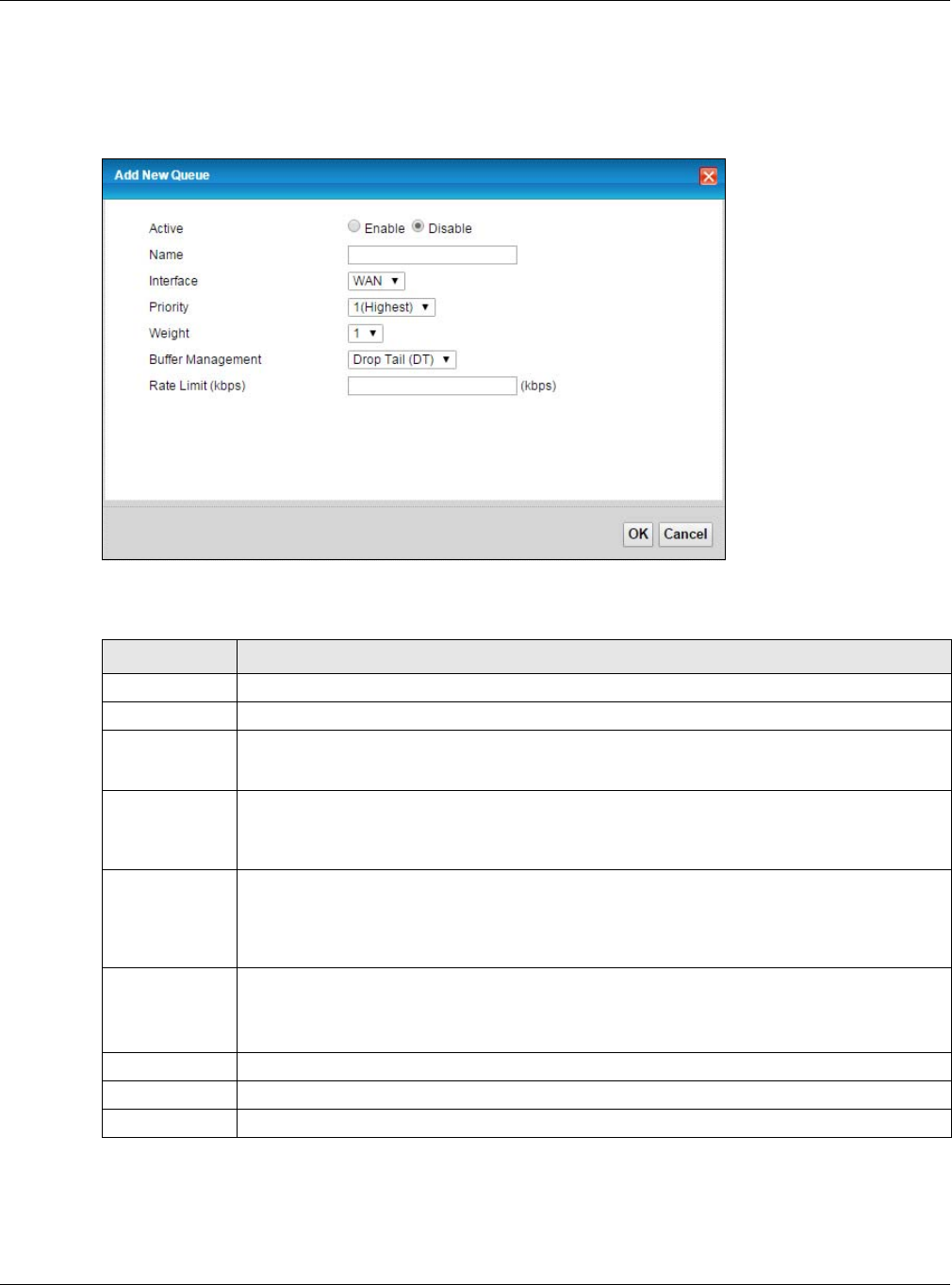
Chapter 10 Quality of Service (QoS)
XMG3512-B10A User’s Guide
136
10.4.1 Adding a QoS Queue
Click Add New Queue or the edit icon in the Queue Setup screen to configure a queue.
Figure 69 Queue Setup: Add
The following table describes the labels in this screen.
Table 46 Queue Setup: Add
LABEL DESCRIPTION
Active Select to enable or disable this queue.
Name Enter the descriptive name of this queue.
Interface Select the interface to which this queue is applied.
This field is read-only if you are editing the queue.
Priority Select the priority level (from 1 to 7) of this queue.
The smaller the number, the higher the priority level. Traffic assigned to higher priority queues
gets through faster while traffic in lower priority queues is dropped if the network is congested.
Weight Select the weight (from 1 to 8) of this queue.
If two queues have the same priority level, the XMG divides the bandwidth across the queues
according to their weights. Queues with larger weights get more bandwidth than queues with
smaller weights.
Buffer
Management
This field displays Drop Tail (DT). Drop Tail (DT) is a simple queue management algorithm that
allows the XMG buffer to accept as many packets as it can until it is full. Once the buffer is full,
new packets that arrive are dropped until there is space in the buffer again (packets are
transmitted out of it).
Rate Limit Specify the maximum transmission rate (in Kbps) allowed for traffic on this queue.
OK Click OK to save your changes.
Cancel Click Cancel to exit this screen without saving.
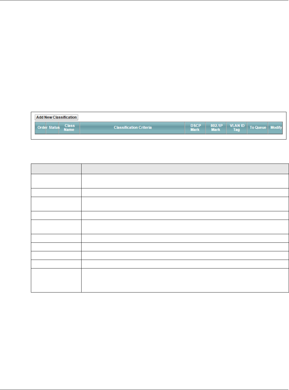
Chapter 10 Quality of Service (QoS)
XMG3512-B10A User’s Guide
137
10.5 The Classification Setup Screen
Use this screen to add, edit or delete QoS classifiers. A classifier groups traffic into data flows according
to specific criteria such as the source address, destination address, source port number, destination port
number or incoming interface. For example, you can configure a classifier to select traffic from the
same protocol port (such as Telnet) to form a flow.
You can give different priorities to traffic that the XMG forwards out through the WAN interface. Give
high priority to voice and video to make them run more smoothly. Similarly, give low priority to many
large file downloads so that they do not reduce the quality of other applications.
Click Network Setting > QoS > Classification Setup to open the following screen.
Figure 70 Network Setting > QoS > Classification Setup
The following table describes the labels in this screen.
10.5.1 Add/Edit QoS Class
Click Add New Classification in the Classification Setup screen or the Edit icon next to a classifier to open
the following screen.
Table 47 Network Setting > QoS > Classification Setup
LABEL DESCRIPTION
Add New
Classification
Click this to create a new classifier.
Order This is the index number of the entry. The classifiers are applied in order of their numbering.
Status This field displays whether the classifier is active or not. A yellow bulb signifies that this
classifier is active. A gray bulb signifies that this classifier is not active.
Class Name This is the name of the classifier.
Classification
Criteria
This shows criteria specified in this classifier, for example the interface from which traffic of
this class should come and the source MAC address of traffic that matches this classifier.
DSCP Mark This is the DSCP number added to traffic of this classifier.
802.1P Mark This is the IEEE 802.1p priority level assigned to traffic of this classifier.
VLAN ID Tag This is the VLAN ID number assigned to traffic of this classifier.
To Queue This is the name of the queue in which traffic of this classifier is put.
Modify Click the Edit icon to edit the classifier.
Click the Delete icon to delete an existing classifier. Note that subsequent rules move up by
one when you take this action.
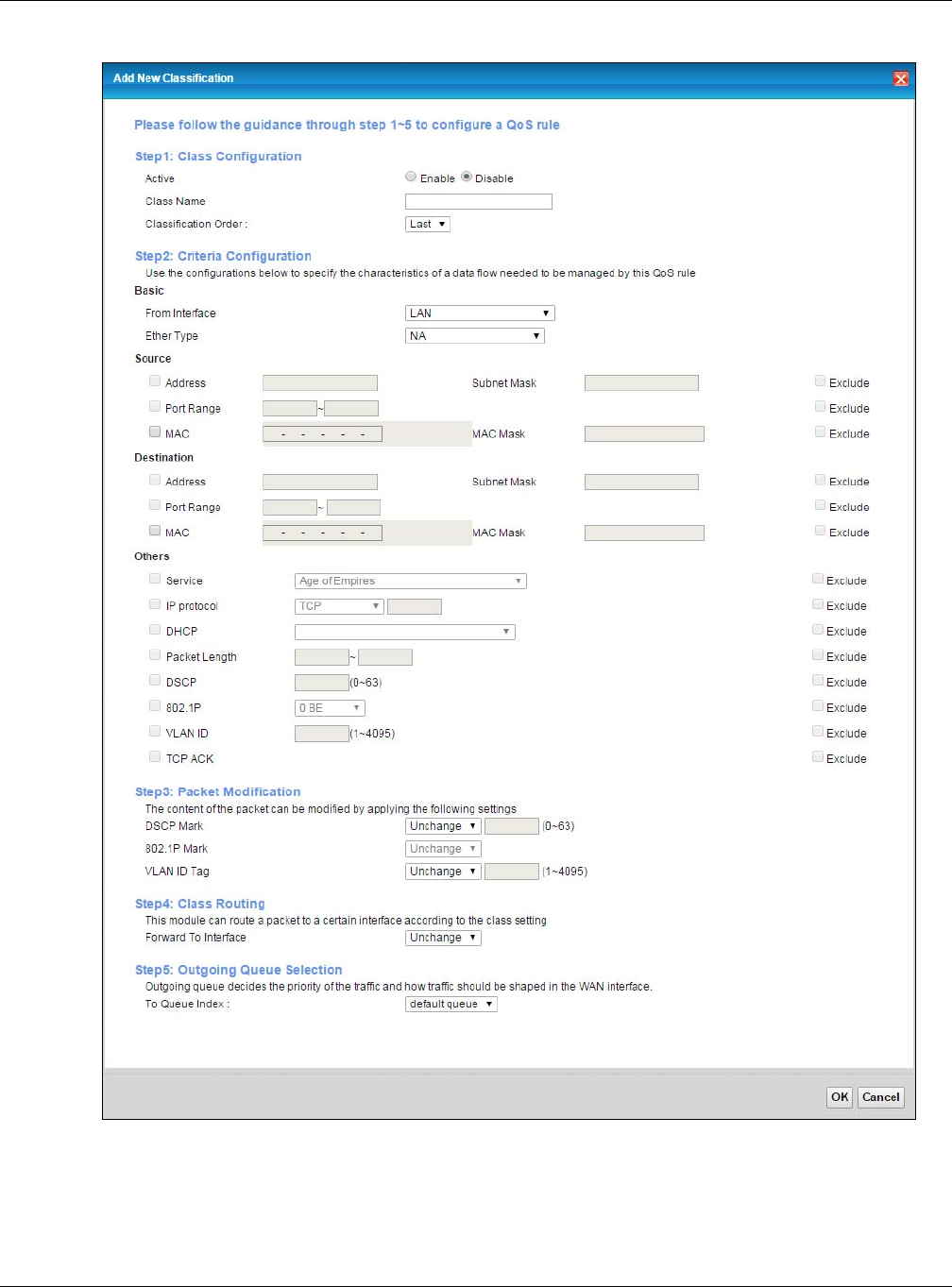
Chapter 10 Quality of Service (QoS)
XMG3512-B10A User’s Guide
138
Figure 71 Classification Setup: Add/Edit

Chapter 10 Quality of Service (QoS)
XMG3512-B10A User’s Guide
139
The following table describes the labels in this screen.
Table 48 Classification Setup: Add/Edit
LABEL DESCRIPTION
Step1: Class Configuration
Active Select to enable or disable this classifier.
Class Name Enter a descriptive name of up to 15 printable English keyboard characters, not including
spaces.
Classification
Order
Select an existing number for where you want to put this classifier to move the classifier to the
number you selected after clicking Apply.
Select Last to put this rule in the back of the classifier list.
Step2: Criteria Configuration
From Interface If you want to classify the traffic by an ingress interface, select an interface from the From
Interface drop-down list box.
Ether Type Select a predefined application to configure a class for the matched traffic.
If you select IP, you also need to configure source or destination MAC address, IP address, DHCP
options, DSCP value or the protocol type.
If you select 802.1Q, you can configure an 802.1p priority level.
Source
Address Select the check box and enter the source IP address in dotted decimal notation. A blank
source IP address means any source IP address.
Subnet Mask Enter the source subnet mask.
Port Range If you select TCP or UDP in the IP Protocol field, select the check box and enter the port
number(s) of the source.
MAC Select the check box and enter the source MAC address of the packet.
MAC Mask Type the mask for the specified MAC address to determine which bits a packet’s MAC address
should match.
Enter “f” for each bit of the specified source MAC address that the traffic’s MAC address should
match. Enter “0” for the bit(s) of the matched traffic’s MAC address, which can be of any
hexadecimal character(s). For example, if you set the MAC address to 00:13:49:00:00:00 and the
mask to ff:ff:ff:00:00:00, a packet with a MAC address of 00:13:49:12:34:56 matches this criteria.
Exclude Select this option to exclude the packets that match the specified criteria from this classifier.
Destination
Address Select the check box and enter the destination IP address in dotted decimal notation. A blank
source IP address means any source IP address.
Subnet Mask Enter the destination subnet mask.
Port Range If you select TCP or UDP in the IP Protocol field, select the check box and enter the port
number(s) of the destination.
MAC Select the check box and enter the destination MAC address of the packet.
MAC Mask Type the mask for the specified MAC address to determine which bits a packet’s MAC address
should match.
Enter “f” for each bit of the specified destination MAC address that the traffic’s MAC address
should match. Enter “0” for the bit(s) of the matched traffic’s MAC address, which can be of any
hexadecimal character(s). For example, if you set the MAC address to 00:13:49:00:00:00 and the
mask to ff:ff:ff:00:00:00, a packet with a MAC address of 00:13:49:12:34:56 matches this criteria.
Exclude Select this option to exclude the packets that match the specified criteria from this classifier.
Others

Chapter 10 Quality of Service (QoS)
XMG3512-B10A User’s Guide
140
Service This field is available only when you select IP in the Ether Type field.
This field simplifies classifier configuration by allowing you to select a predefined application.
When you select a predefined application, you do not configure the rest of the filter fields.
IP Protocol This field is available only when you select IP in the Ether Type field.
Select this option and select the protocol (service type) from TCP, UDP, ICMP or IGMP. If you
select User defined, enter the protocol (service type) number.
DHCP This field is available only when you select IP in the Ether Type field.
Select this option and select a DHCP option.
If you select Vendor Class ID (DHCP Option 60), enter the Vendor Class Identifier (Option 60) of
the matched traffic, such as the type of the hardware or firmware.
If you select Client ID (DHCP Option 61), enter the Identity Association IDentifier (IAD Option 61)
of the matched traffic, such as the MAC address of the device.
If you select User Class ID (DHCP Option 77), enter a string that identifies the user’s category or
application type in the matched DHCP packets.
If you select Vendor Specific Info (DHCP Option 125), enter the vendor specific information of the
matched traffic, such as the product class, model name, and serial number of the device.
IP Packet
Length This field is available only when you select IP in the Ether Type field.
Select this option and enter the minimum and maximum packet length (from 46 to 1500) in the
fields provided.
DSCP This field is available only when you select IP in the Ether Type field.
Select this option and specify a DSCP (DiffServ Code Point) number between 0 and 63 in the
field provided.
802.1P This field is available only when you select 802.1Q in the Ether Type field.
Select this option and select a priority level (between 0 and 7) from the drop-down list box.
"0" is the lowest priority level and "7" is the highest.
VLAN ID This field is available only when you select 802.1Q in the Ether Type field.
Select this option and specify a VLAN ID number.
TCP ACK This field is available only when you select IP in the Ether Type field.
If you select this option, the matched TCP packets must contain the ACK (Acknowledge) flag.
Exclude Select this option to exclude the packets that match the specified criteria from this classifier.
Step3: Packet Modification
DSCP Mark This field is available only when you select IP in the Ether Type field.
If you select Remark, enter a DSCP value with which the XMG replaces the DSCP field in the
packets.
If you select Unchange, the XMG keep the DSCP field in the packets.
802.1P Mark Select a priority level with which the XMG replaces the IEEE 802.1p priority field in the packets.
If you select Unchange, the XMG keep the 802.1p priority field in the packets.
VLAN ID Tag If you select Remark, enter a VLAN ID number with which the XMG replaces the VLAN ID of the
frames.
If you select Remove, the XMG deletes the VLAN ID of the frames before forwarding them out.
If you select Add, the XMG treat all matched traffic untagged and add a second VLAN ID.
If you select Unchange, the XMG keep the VLAN ID in the packets.
Table 48 Classification Setup: Add/Edit (continued)
LABEL DESCRIPTION
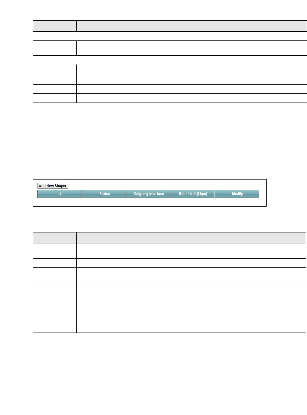
Chapter 10 Quality of Service (QoS)
XMG3512-B10A User’s Guide
141
10.6 The QoS Shaper Setup Screen
This screen shows that you can use the token bucket algorithm to allow a certain amount of large bursts
while keeping a limit for processing outgoing traffic at the average rate. Click Network Setting > QoS >
Shaper Setup. The screen appears as shown.
Figure 72 Network Setting > QoS > Shaper Setup
The following table describes the labels in this screen.
Step4: Class Routing
Forward to
Interface
Select a WAN interface through which traffic of this class will be forwarded out. If you select
Unchange, the XMG forward traffic of this class according to the default routing table.
Step5: Outgoing Queue Selection
To Queue Index Select a queue that applies to this class.
You should have configured a queue in the Queue Setup screen already.
OK Click OK to save your changes.
Cancel Click Cancel to exit this screen without saving.
Table 48 Classification Setup: Add/Edit (continued)
LABEL DESCRIPTION
Table 49 Network Setting > QoS > Shaper Setup
LABEL DESCRIPTION
Add New
Shaper
Click this to create a new entry.
#This is the index number of the entry.
Status This field displays whether the shaper is active or not. A yellow bulb signifies that this policer is
active. A gray bulb signifies that this shaper is not active.
Outgoing
Interface
This shows the name of the XMG's interface through which traffic in this shaper applies.
Rate Limit (kbps) This shows the average rate limit of traffic bursts for this shaper.
Modify Click the Edit icon to edit the shaper.
Click the Delete icon to delete an existing shaper. Note that subsequent rules move up by one
when you take this action.
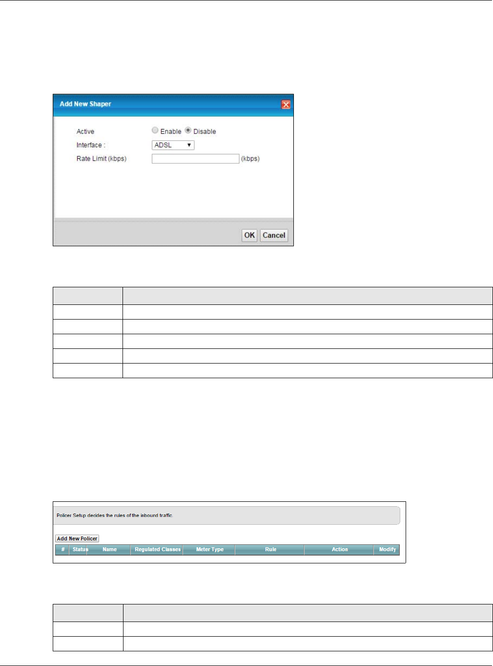
Chapter 10 Quality of Service (QoS)
XMG3512-B10A User’s Guide
142
10.6.1 Add/Edit a QoS Shaper
Click Add New Shaper in the Shaper Setup screen or the Edit icon next to a shaper to show the following
screen.
Figure 73 Shaper Setup: Add/Edit
The following table describes the labels in this screen.
10.7 The QoS Policer Setup Screen
Use this screen to view QoS policers that allow you to limit the transmission rate of incoming traffic and
apply actions, such as drop, pass, or modify the DSCP value for matched traffic. Click Network Setting >
QoS > Policer Setup. The screen appears as shown.
Figure 74 Network Setting > QoS > Policer Setup
The following table describes the labels in this screen.
Table 50 Shaper Setup: Add/Edit
LABEL DESCRIPTION
Active Select to enable or disable this shaper.
Interface Select the XMG's interface through which traffic in this shaper applies
Rate Limit Enter the average rate limit of traffic bursts for this shaper.
OK Click OK to save your changes.
Cancel Click Cancel to exit this screen without saving.
Table 51 Network Setting > QoS > Policer Setup
LABEL DESCRIPTION
Add new Policer Click this to create a new entry.
#This is the index number of the entry.
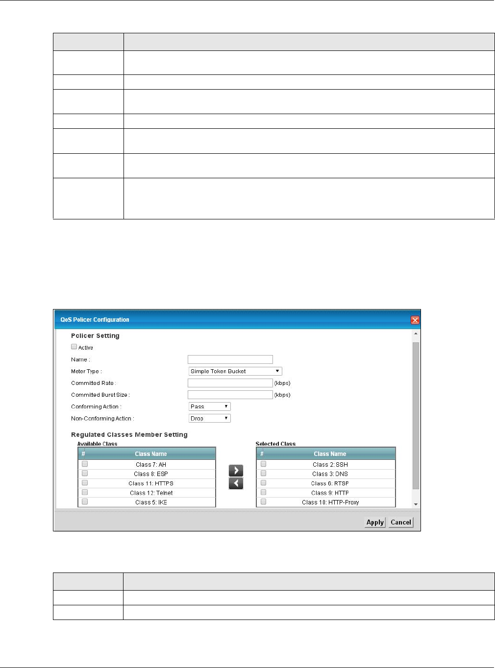
Chapter 10 Quality of Service (QoS)
XMG3512-B10A User’s Guide
143
10.7.1 Add/Edit a QoS Policer
Click Add New Policer in the Policer Setup screen or the Edit icon next to a policer to show the following
screen.
Figure 75 Policer Setup: Add/Edit
The following table describes the labels in this screen.
Status This field displays whether the policer is active or not. A yellow bulb signifies that this policer is
active. A gray bulb signifies that this policer is not active.
Name This field displays the descriptive name of this policer.
Regulated
Classes
This field displays the name of a QoS classifier
Meter Type This field displays the type of QoS metering algorithm used in this policer.
Rule These are the rates and burst sizes against which the policer checks the traffic of the member
QoS classes.
Action This shows the how the policer has the XMG treat different types of traffic belonging to the
policer’s member QoS classes.
Modify Click the Edit icon to edit the policer.
Click the Delete icon to delete an existing policer. Note that subsequent rules move up by one
when you take this action.
Table 51 Network Setting > QoS > Policer Setup (continued)
LABEL DESCRIPTION
Table 52 Policer Setup: Add/Edit
LABEL DESCRIPTION
Active Select to enable or disable this policer.
Name Enter the descriptive name of this policer.

Chapter 10 Quality of Service (QoS)
XMG3512-B10A User’s Guide
144
10.8 Technical Reference
The following section contains additional technical information about the XMG features described in this
chapter.
IEEE 802.1Q Tag
The IEEE 802.1Q standard defines an explicit VLAN tag in the MAC header to identify the VLAN
membership of a frame across bridges. A VLAN tag includes the 12-bit VLAN ID and 3-bit user priority.
The VLAN ID associates a frame with a specific VLAN and provides the information that devices need to
process the frame across the network.
Meter Type This shows the traffic metering algorithm used in this policer.
The Simple Token Bucket algorithm uses tokens in a bucket to control when traffic can be
transmitted. Each token represents one byte. The algorithm allows bursts of up to b bytes which is
also the bucket size.
The Single Rate Three Color Marker (srTCM) is based on the token bucket filter and identifies
packets by comparing them to the Committed Information Rate (CIR), the Committed Burst Size
(CBS) and the Excess Burst Size (EBS).
The Two Rate Three Color Marker (trTCM) is based on the token bucket filter and identifies
packets by comparing them to the Committed Information Rate (CIR) and the Peak Information
Rate (PIR).
Committed
Rate
Specify the committed rate. When the incoming traffic rate of the member QoS classes is less
than the committed rate, the device applies the conforming action to the traffic.
Committed
Burst Size
Specify the committed burst size for packet bursts. This must be equal to or less than the peak
burst size (two rate three color) or excess burst size (single rate three color) if it is also configured.
This is the maximum size of the (first) token bucket in a traffic metering algorithm.
Conforming
Action
Specify what the XMG does for packets within the committed rate and burst size (green-marked
packets).
•Pass: Send the packets without modification.
•DSCP Mark: Change the DSCP mark value of the packets. Enter the DSCP mark value to use.
Non-
Conforming
Action
Specify what the XMG does for packets that exceed the excess burst size or peak rate and burst
size (red-marked packets).
•Drop: Discard the packets.
•DSCP Mark: Change the DSCP mark value of the packets. Enter the DSCP mark value to use.
The packets may be dropped if there is congestion on the network.
Available Class
Selected Class
Select a QoS classifier to apply this QoS policer to traffic that matches the QoS classifier.
Highlight a QoS classifier in the Available Class box and use the > button to move it to the
Selected Class box.
To remove a QoS classifier from the Selected Class box, select it and use the < button.
OK Click OK to save your changes.
Cancel Click Cancel to exit this screen without saving.
Table 52 Policer Setup: Add/Edit
LABEL DESCRIPTION

Chapter 10 Quality of Service (QoS)
XMG3512-B10A User’s Guide
145
IEEE 802.1p specifies the user priority field and defines up to eight separate traffic types. The following
table describes the traffic types defined in the IEEE 802.1d standard (which incorporates the 802.1p).
DiffServ
QoS is used to prioritize source-to-destination traffic flows. All packets in the flow are given the same
priority. You can use CoS (class of service) to give different priorities to different packet types.
DiffServ (Differentiated Services) is a class of service (CoS) model that marks packets so that they
receive specific per-hop treatment at DiffServ-compliant network devices along the route based on the
application types and traffic flow. Packets are marked with DiffServ Code Points (DSCPs) indicating the
level of service desired. This allows the intermediary DiffServ-compliant network devices to handle the
packets differently depending on the code points without the need to negotiate paths or remember
state information for every flow. In addition, applications do not have to request a particular service or
give advanced notice of where the traffic is going.
DSCP and Per-Hop Behavior
DiffServ defines a new Differentiated Services (DS) field to replace the Type of Service (TOS) field in the IP
header. The DS field contains a 2-bit unused field and a 6-bit DSCP field which can define up to 64
service levels. The following figure illustrates the DS field.
DSCP is backward compatible with the three precedence bits in the ToS octet so that non-DiffServ
compliant, ToS-enabled network device will not conflict with the DSCP mapping.
The DSCP value determines the forwarding behavior, the PHB (Per-Hop Behavior), that each packet
gets across the DiffServ network. Based on the marking rule, different kinds of traffic can be marked for
different kinds of forwarding. Resources can then be allocated according to the DSCP values and the
configured policies.
Table 53 IEEE 802.1p Priority Level and Traffic Type
PRIORITY
LEVEL TRAFFIC TYPE
Level 7 Typically used for network control traffic such as router configuration messages.
Level 6 Typically used for voice traffic that is especially sensitive to jitter (jitter is the variations in
delay).
Level 5 Typically used for video that consumes high bandwidth and is sensitive to jitter.
Level 4 Typically used for controlled load, latency-sensitive traffic such as SNA (Systems Network
Architecture) transactions.
Level 3 Typically used for “excellent effort” or better than best effort and would include important
business traffic that can tolerate some delay.
Level 2 This is for “spare bandwidth”.
Level 1 This is typically used for non-critical “background” traffic such as bulk transfers that are
allowed but that should not affect other applications and users.
Level 0 Typically used for best-effort traffic.
DSCP (6 bits) Unused (2 bits)

Chapter 10 Quality of Service (QoS)
XMG3512-B10A User’s Guide
146
IP Precedence
Similar to IEEE 802.1p prioritization at layer-2, you can use IP precedence to prioritize packets in a layer-3
network. IP precedence uses three bits of the eight-bit ToS (Type of Service) field in the IP header. There
are eight classes of services (ranging from zero to seven) in IP precedence. Zero is the lowest priority
level and seven is the highest.
Automatic Priority Queue Assignment
If you enable QoS on the XMG, the XMG can automatically base on the IEEE 802.1p priority level, IP
precedence and/or packet length to assign priority to traffic which does not match a class.
The following table shows you the internal layer-2 and layer-3 QoS mapping on the XMG. On the XMG,
traffic assigned to higher priority queues gets through faster while traffic in lower index queues is
dropped if the network is congested.
Table 54 Internal Layer2 and Layer3 QoS Mapping
PRIORITY
QUEUE
LAYER 2 LAYER 3
IEEE 802.1P USER
PRIORITY
(ETHERNET
PRIORITY)
TOS (IP
PRECEDENCE) DSCP IP PACKET LENGTH
(BYTE)
0 1 0 000000
12
2 0 0 000000 >1100
3 3 1 001110
001100
001010
001000
250~1100
4 4 2 010110
010100
010010
010000
5 5 3 011110
011100
011010
011000
<250
6 6 4 100110
100100
100010
100000
5 101110
101000
7 7 6 110000
111000
7

Chapter 10 Quality of Service (QoS)
XMG3512-B10A User’s Guide
147
Token Bucket
The token bucket algorithm uses tokens in a bucket to control when traffic can be transmitted. The
bucket stores tokens, each of which represents one byte. The algorithm allows bursts of up to b bytes
which is also the bucket size, so the bucket can hold up to b tokens. Tokens are generated and added
into the bucket at a constant rate. The following shows how tokens work with packets:
• A packet can be transmitted if the number of tokens in the bucket is equal to or greater than the size
of the packet (in bytes).
• After a packet is transmitted, a number of tokens corresponding to the packet size is removed from
the bucket.
• If there are no tokens in the bucket, the XMG stops transmitting until enough tokens are generated.
• If not enough tokens are available, the XMG treats the packet in either one of the following ways:
In traffic shaping:
• Holds it in the queue until enough tokens are available in the bucket.
In traffic policing:
•Drops it.
• Transmits it but adds a DSCP mark. The XMG may drop these marked packets if the network is
overloaded.
Configure the bucket size to be equal to or less than the amount of the bandwidth that the interface
can support. It does not help if you set it to a bucket size over the interface’s capability. The smaller the
bucket size, the lower the data transmission rate and that may cause outgoing packets to be dropped.
A larger transmission rate requires a big bucket size. For example, use a bucket size of 10 kbytes to get
the transmission rate up to 10 Mbps.
Single Rate Three Color Marker
The Single Rate Three Color Marker (srTCM, defined in RFC 2697) is a type of traffic policing that identifies
packets by comparing them to one user-defined rate, the Committed Information Rate (CIR), and two
burst sizes: the Committed Burst Size (CBS) and Excess Burst Size (EBS).
The srTCM evaluates incoming packets and marks them with one of three colors which refer to packet
loss priority levels. High packet loss priority level is referred to as red, medium is referred to as yellow and
low is referred to as green.
The srTCM is based on the token bucket filter and has two token buckets (CBS and EBS). Tokens are
generated and added into the bucket at a constant rate, called Committed Information Rate (CIR).
When the first bucket (CBS) is full, new tokens overflow into the second bucket (EBS).
All packets are evaluated against the CBS. If a packet does not exceed the CBS it is marked green.
Otherwise it is evaluated against the EBS. If it is below the EBS then it is marked yellow. If it exceeds the
EBS then it is marked red.
The following shows how tokens work with incoming packets in srTCM:
• A packet arrives. The packet is marked green and can be transmitted if the number of tokens in the
CBS bucket is equal to or greater than the size of the packet (in bytes).
• After a packet is transmitted, a number of tokens corresponding to the packet size is removed from
the CBS bucket.

Chapter 10 Quality of Service (QoS)
XMG3512-B10A User’s Guide
148
• If there are not enough tokens in the CBS bucket, the XMG checks the EBS bucket. The packet is
marked yellow if there are sufficient tokens in the EBS bucket. Otherwise, the packet is marked red. No
tokens are removed if the packet is dropped.
Two Rate Three Color Marker
The Two Rate Three Color Marker (trTCM, defined in RFC 2698) is a type of traffic policing that identifies
packets by comparing them to two user-defined rates: the Committed Information Rate (CIR) and the
Peak Information Rate (PIR). The CIR specifies the average rate at which packets are admitted to the
network. The PIR is greater than or equal to the CIR. CIR and PIR values are based on the guaranteed
and maximum bandwidth respectively as negotiated between a service provider and client.
The trTCM evaluates incoming packets and marks them with one of three colors which refer to packet
loss priority levels. High packet loss priority level is referred to as red, medium is referred to as yellow and
low is referred to as green.
The trTCM is based on the token bucket filter and has two token buckets (Committed Burst Size (CBS)
and Peak Burst Size (PBS)). Tokens are generated and added into the two buckets at the CIR and PIR
respectively.
All packets are evaluated against the PIR. If a packet exceeds the PIR it is marked red. Otherwise it is
evaluated against the CIR. If it exceeds the CIR then it is marked yellow. Finally, if it is below the CIR then
it is marked green.
The following shows how tokens work with incoming packets in trTCM:
• A packet arrives. If the number of tokens in the PBS bucket is less than the size of the packet (in bytes),
the packet is marked red and may be dropped regardless of the CBS bucket. No tokens are removed
if the packet is dropped.
• If the PBS bucket has enough tokens, the XMG checks the CBS bucket. The packet is marked green
and can be transmitted if the number of tokens in the CBS bucket is equal to or greater than the size
of the packet (in bytes). Otherwise, the packet is marked yellow.

XMG3512-B10A User’s Guide
149
CHAPTER 11
Network Address Translation
(NAT)
11.1 Overview
This chapter discusses how to configure NAT on the XMG. NAT (Network Address Translation - NAT, RFC
1631) is the translation of the IP address of a host in a packet, for example, the source address of an
outgoing packet, used within one network to a different IP address known within another network.
11.1.1 What You Can Do in this Chapter
• Use the Port Forwarding screen to configure forward incoming service requests to the server(s) on your
local network (Section 11.2 on page 150).
• Use the Applications screen to forward incoming service requests to the server(s) on your local
network (Section 11.3 on page 153).
• Use the Port Triggering screen to add and configure the XMG’s trigger port settings (Section 11.4 on
page 154).
• Use the DMZ screen to configure a default server (Section 11.5 on page 157).
• Use the ALG screen to enable and disable the NAT and SIP (VoIP) ALG in the XMG (Section 11.6 on
page 158).
• Use the Address Mapping screen to configure the XMG's address mapping settings (Section 11.7 on
page 158).
• Use the Sessions screen to configure the XMG's maximum number of NAT sessions (Section 11.8 on
page 160).
11.1.2 What You Need To Know
Inside/Outside
Inside/outside denotes where a host is located relative to the XMG, for example, the computers of your
subscribers are the inside hosts, while the web servers on the Internet are the outside hosts.
Global/Local
Global/local denotes the IP address of a host in a packet as the packet traverses a router, for example,
the local address refers to the IP address of a host when the packet is in the local network, while the
global address refers to the IP address of the host when the same packet is traveling in the WAN side.

Chapter 11 Network Address Translation (NAT)
XMG3512-B10A User’s Guide
150
NAT
In the simplest form, NAT changes the source IP address in a packet received from a subscriber (the
inside local address) to another (the inside global address) before forwarding the packet to the WAN
side. When the response comes back, NAT translates the destination address (the inside global address)
back to the inside local address before forwarding it to the original inside host.
Port Forwarding
A port forwarding set is a list of inside (behind NAT on the LAN) servers, for example, web or FTP, that you
can make visible to the outside world even though NAT makes your whole inside network appear as a
single computer to the outside world.
Finding Out More
See Section 11.9 on page 161 for advanced technical information on NAT.
11.2 The Port Forwarding Screen
Use the Port Forwarding screen to forward incoming service requests to the server(s) on your local
network.
You may enter a single port number or a range of port numbers to be forwarded, and the local IP
address of the desired server. The port number identifies a service; for example, web service is on port 80
and FTP on port 21. In some cases, such as for unknown services or where one server can support more
than one service (for example both FTP and web service), it might be better to specify a range of port
numbers. You can allocate a server IP address that corresponds to a port or a range of ports.
The most often used port numbers and services are shown in Appendix C on page 268. Please refer to
RFC 1700 for further information about port numbers.
Note: Many residential broadband ISP accounts do not allow you to run any server processes
(such as a Web or FTP server) from your location. Your ISP may periodically check for
servers and may suspend your account if it discovers any active services at your
location. If you are unsure, refer to your ISP.
Configuring Servers Behind Port Forwarding (Example)
Let's say you want to assign ports 21-25 to one FTP, Telnet and SMTP server (A in the example), port 80 to
another (B in the example) and assign a default server IP address of 192.168.1.35 to a third (C in the
example). You assign the LAN IP addresses and the ISP assigns the WAN IP address. The NAT network
appears as a single host on the Internet.
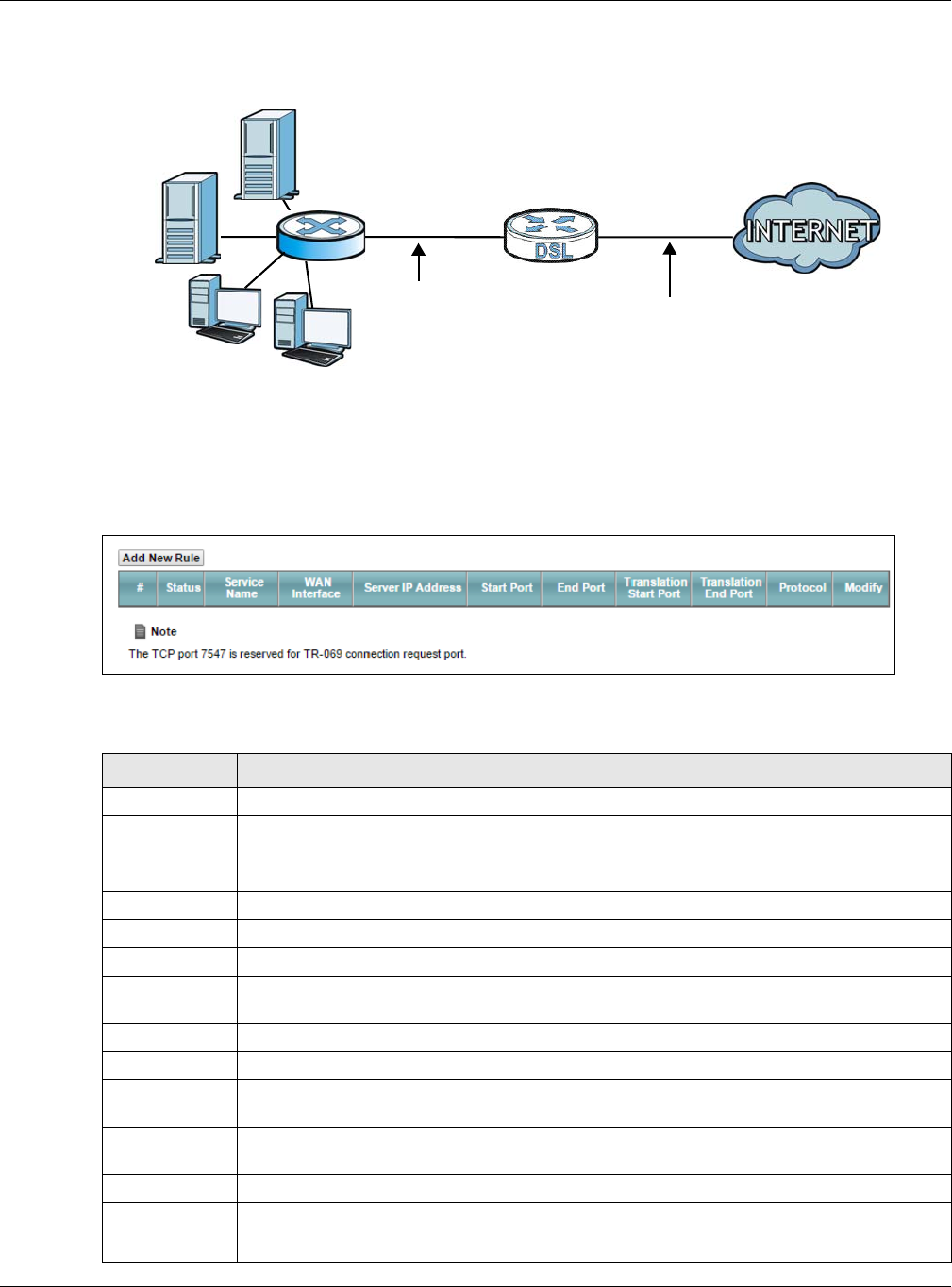
Chapter 11 Network Address Translation (NAT)
XMG3512-B10A User’s Guide
151
Figure 76 Multiple Servers Behind NAT Example
Click Network Setting > NAT > Port Forwarding to open the following screen.
See Appendix C on page 268 for port numbers commonly used for particular services.
Figure 77 Network Setting > NAT > Port Forwarding
The following table describes the fields in this screen.
Table 55 Network Setting > NAT > Port Forwarding
LABEL DESCRIPTION
Add New Rule Click this to add a new rule.
#This is the index number of the entry.
Status This field displays whether the NAT rule is active or not. A yellow bulb signifies that this rule is
active. A gray bulb signifies that this rule is not active.
Service Name This shows the service’s name.
WAN Interface This shows the WAN interface through which the service is forwarded.
Server IP
Address
This is the server’s IP address.
Start Port This is the first external port number that identifies a service.
End Port This is the last external port number that identifies a service.
Translation Start
Port
This is the first internal port number that identifies a service.
Translation End
Port
This is the last internal port number that identifies a service.
Protocol This shows the IP protocol supported by this virtual server, whether it is TCP, UDP, or TCP/UDP.
Modify Click the Edit icon to edit this rule.
Click the Delete icon to delete an existing rule.
A=192.168.1.33
D=192.168.1.36
C=192.168.1.3
B=192.168.1.34
WAN
LAN
192.168.1.1 IP Address assigned by ISP
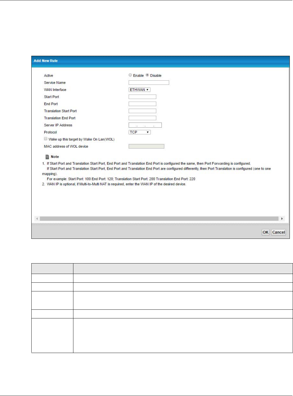
Chapter 11 Network Address Translation (NAT)
XMG3512-B10A User’s Guide
152
11.2.1 Add/Edit Port Forwarding
Click Add New Rule in the Port Forwarding screen or click the Edit icon next to an existing rule to open
the following screen.
Figure 78 Port Forwarding: Add/Edit
The following table describes the labels in this screen.
Table 56 Port Forwarding: Add/Edit
LABEL DESCRIPTION
Active Select to enable or disable the rule.
Service Name Enter a name to identify this rule using keyboard characters (A-Z, a-z, 1-2 and so on).
WAN Interface Select the WAN interface through which the service is forwarded.
You must have already configured a WAN connection with NAT enabled.
Start Port Enter the original destination port for the packets.
To forward only one port, enter the port number again in the End Port field.
To forward a series of ports, enter the start port number here and the end port number in the End
Port field.
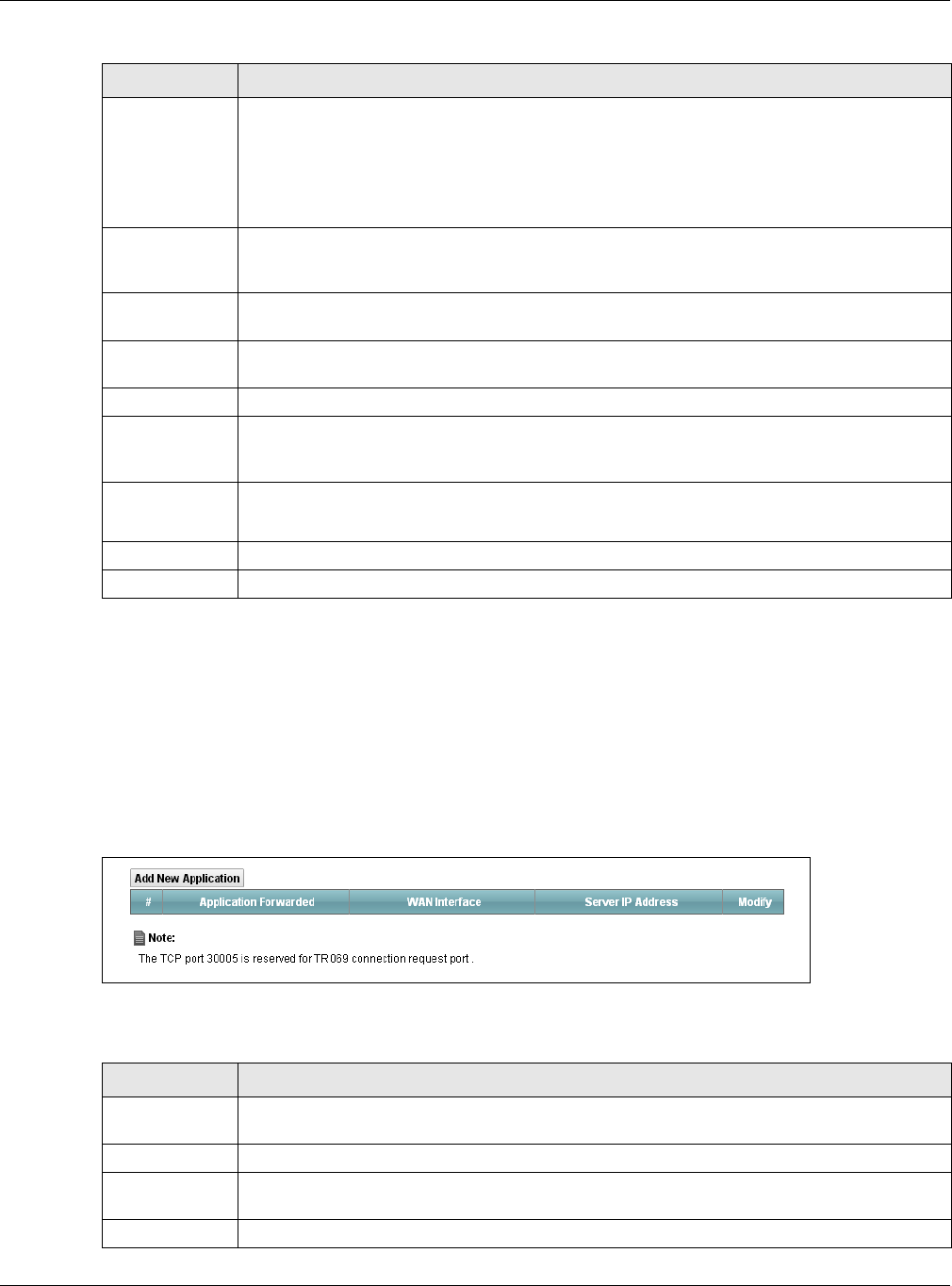
Chapter 11 Network Address Translation (NAT)
XMG3512-B10A User’s Guide
153
11.3 The Applications Screen
This screen provides a summary of all NAT applications and their configuration. In addition, this screen
allows you to create new applications and/or remove existing ones.
To access this screen, click Network Setting > NAT > Applications. The following screen appears.
Figure 79 Network Setting > NAT > Applications
The following table describes the labels in this screen.
End Port Enter the last port of the original destination port range.
To forward only one port, enter the port number in the Start Port field above and then enter it
again in this field.
To forward a series of ports, enter the last port number in a series that begins with the port
number in the Start Port field above.
Translation Start
Port
This shows the port number to which you want the XMG to translate the incoming port. For a
range of ports, enter the first number of the range to which you want the incoming ports
translated.
Translation End
Port
This shows the last port of the translated port range.
Server IP
Address
Enter the inside IP address of the virtual server here.
Protocol Select the protocol supported by this virtual server. Choices are TCP, UDP, or TCP/UDP.
Wake up this
target by Wake
On Lan (WOL)
Select this to allow the XMG’s network to remotely turn on a device in the network.
MAC address of
WOL device
Enter the MAC address of the device that will be turned on by an XMG’s network message.
A MAC address consists of six hexadecimal character pairs.
OK Click OK to save your changes.
Cancel Click Cancel to exit this screen without saving.
Table 56 Port Forwarding: Add/Edit (continued)
LABEL DESCRIPTION
Table 57 Network Setting > NAT > Applications
LABEL DESCRIPTION
Add New
Application
Click this to add a new NAT application rule.
#This is the index number of the entry.
Application
Forwarded
This field shows the type of application that the service forwards.
WAN Interface This field shows the WAN interface through which the service is forwarded.
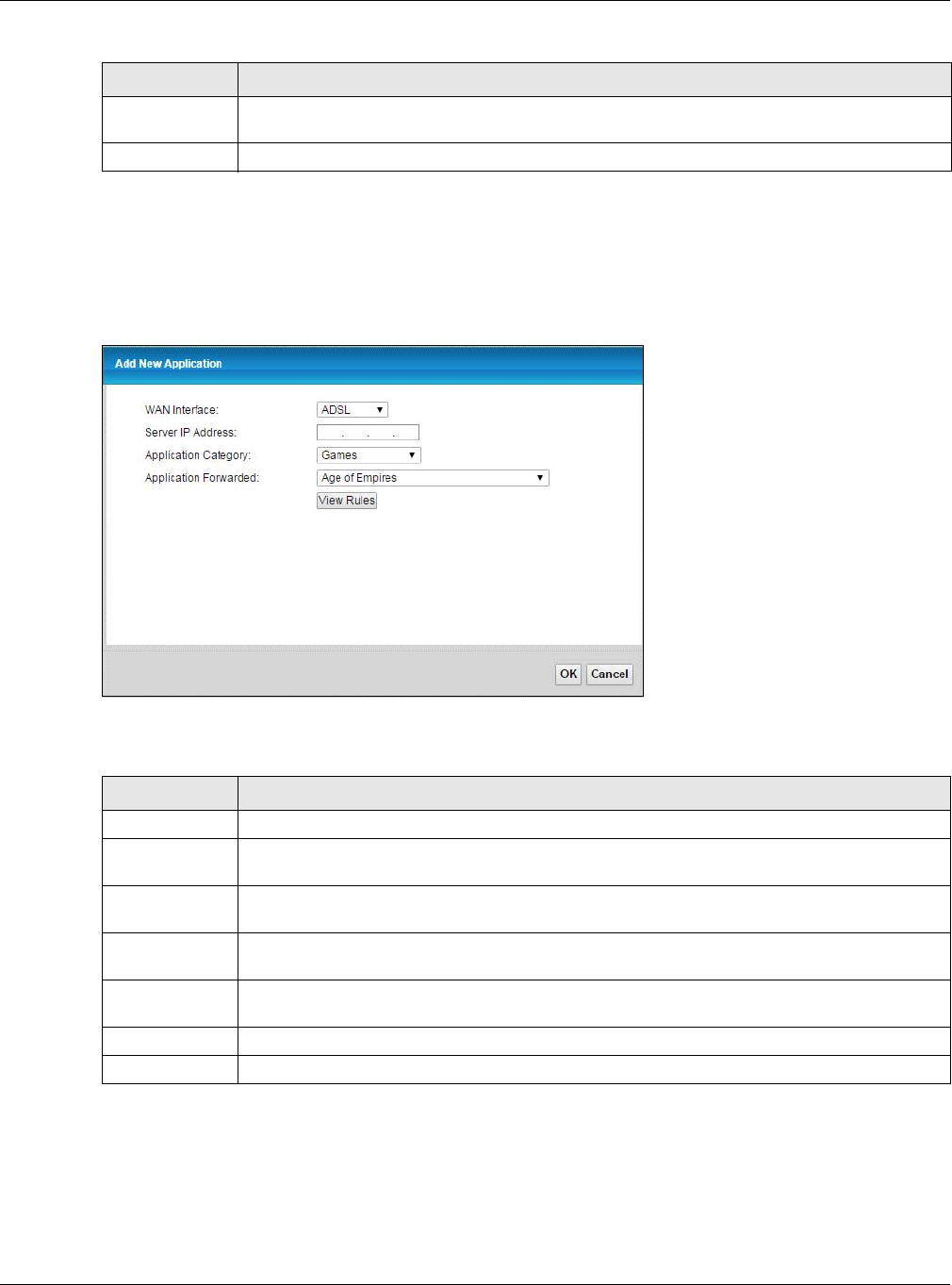
Chapter 11 Network Address Translation (NAT)
XMG3512-B10A User’s Guide
154
11.3.1 Add New Application
This screen lets you create new NAT application rules. Click Add New Application in the Applications
screen to open the following screen.
Figure 80 Network Setting > NAT > Applications: Add
The following table describes the labels in this screen.
11.4 The Port Triggering Screen
Some services use a dedicated range of ports on the client side and a dedicated range of ports on the
server side. With regular port forwarding you set a forwarding port in NAT to forward a service (coming in
Server IP
Address
This field displays the destination IP address for the service.
Modify Click the Delete icon to delete the rule.
Table 57 Network Setting > NAT > Applications (continued)
LABEL DESCRIPTION
Table 58 Network Setting > NAT > Applications: Add
LABEL DESCRIPTION
WAN Interface Select the WAN interface that you want to apply this NAT rule to.
Server IP
Address
Enter the inside IP address of the application here.
Application
Category
Select the category of the application from the drop-down list box.
Application
Forwarded
Select a service from the drop-down list box and the XMG automatically configures the
protocol, start, end, and map port number that define the service.
View Rules Click this to display the configuration of the service that you have chosen in Application
Fowarded.
OK Click OK to save your changes.
Cancel Click Cancel to exit this screen without saving.
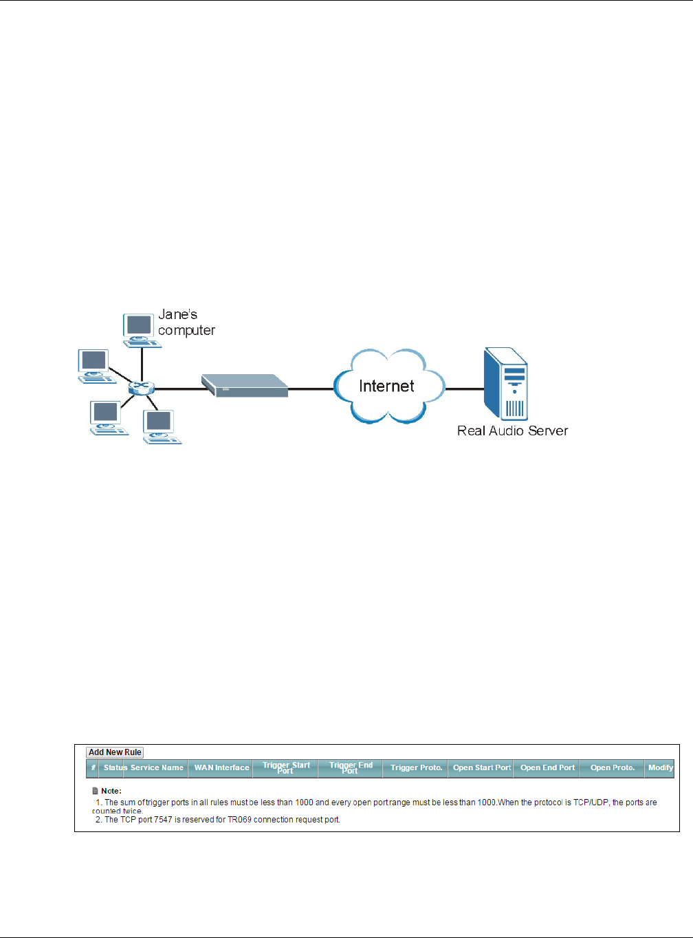
Chapter 11 Network Address Translation (NAT)
XMG3512-B10A User’s Guide
155
from the server on the WAN) to the IP address of a computer on the client side (LAN). The problem is that
port forwarding only forwards a service to a single LAN IP address. In order to use the same service on a
different LAN computer, you have to manually replace the LAN computer's IP address in the forwarding
port with another LAN computer's IP address.
Trigger port forwarding solves this problem by allowing computers on the LAN to dynamically take turns
using the service. The XMG records the IP address of a LAN computer that sends traffic to the WAN to
request a service with a specific port number and protocol (a "trigger" port). When the XMG's WAN port
receives a response with a specific port number and protocol ("open" port), the XMG forwards the traffic
to the LAN IP address of the computer that sent the request. After that computer’s connection for that
service closes, another computer on the LAN can use the service in the same manner. This way you do
not need to configure a new IP address each time you want a different LAN computer to use the
application.
For example:
Figure 81 Trigger Port Forwarding Process: Example
1Jane requests a file from the Real Audio server (port 7070).
2Port 7070 is a “trigger” port and causes the XMG to record Jane’s computer IP address. The XMG
associates Jane's computer IP address with the "open" port range of 6970-7170.
3The Real Audio server responds using a port number ranging between 6970-7170.
4The XMG forwards the traffic to Jane’s computer IP address.
5Only Jane can connect to the Real Audio server until the connection is closed or times out. The XMG
times out in three minutes with UDP (User Datagram Protocol) or two hours with TCP/IP (Transfer Control
Protocol/Internet Protocol).
Click Network Setting > NAT > Port Triggering to open the following screen. Use this screen to view your
XMG’s trigger port settings.
Figure 82 Network Setting > NAT > Port Triggering
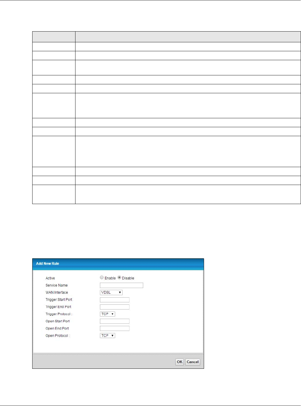
Chapter 11 Network Address Translation (NAT)
XMG3512-B10A User’s Guide
156
The following table describes the labels in this screen.
11.4.1 Add/Edit Port Triggering Rule
This screen lets you create new port triggering rules. Click Add new rule in the Port Triggering screen or
click a rule’s Edit icon to open the following screen.
Figure 83 Port Triggering: Add/Edit
Table 59 Network Setting > NAT > Port Triggering
LABEL DESCRIPTION
Add New Rule Click this to create a new rule.
#This is the index number of the entry.
Status This field displays whether the port triggering rule is active or not. A yellow bulb signifies that this
rule is active. A gray bulb signifies that this rule is not active.
Service Name This field displays the name of the service used by this rule.
WAN Interface This field shows the WAN interface through which the service is forwarded.
Trigger Start Port The trigger port is a port (or a range of ports) that causes (or triggers) the XMG to record the IP
address of the LAN computer that sent the traffic to a server on the WAN.
This is the first port number that identifies a service.
Trigger End Port This is the last port number that identifies a service.
Trigger Proto. This is the trigger transport layer protocol.
Open Start Port The open port is a port (or a range of ports) that a server on the WAN uses when it sends out a
particular service. The XMG forwards the traffic with this port (or range of ports) to the client
computer on the LAN that requested the service.
This is the first port number that identifies a service.
Open End Port This is the last port number that identifies a service.
Open Proto. This is the open transport layer protocol.
Modify Click the Edit icon to edit this rule.
Click the Delete icon to remove an existing rule.
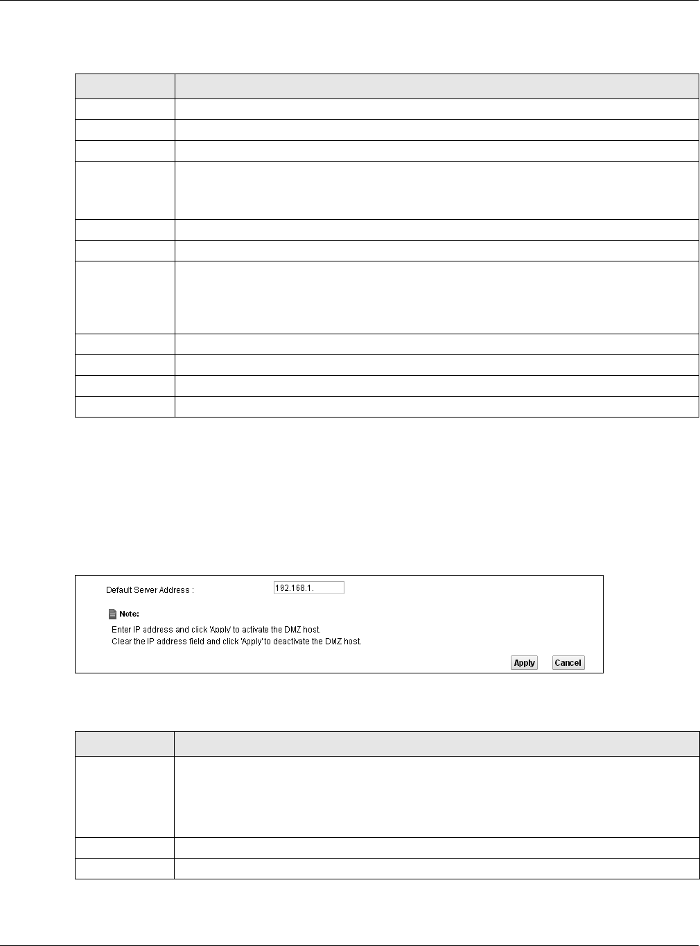
Chapter 11 Network Address Translation (NAT)
XMG3512-B10A User’s Guide
157
The following table describes the labels in this screen.
11.5 The DMZ Screen
In addition to the servers for specified services, NAT supports a default server IP address. A default server
receives packets from ports that are not specified in the NAT Port Forwarding Setup screen.
Figure 84 Network Setting > NAT > DMZ
The following table describes the fields in this screen.
Table 60 Port Triggering: Configuration Add/Edit
LABEL DESCRIPTION
Active Select to enable or disable this rule.
Service Name Enter a name to identify this rule using keyboard characters (A-Z, a-z, 1-2 and so on).
WAN Interface Select a WAN interface for which you want to configure port triggering rules.
Trigger Start Port The trigger port is a port (or a range of ports) that causes (or triggers) the XMG to record the IP
address of the LAN computer that sent the traffic to a server on the WAN.
Type a port number or the starting port number in a range of port numbers.
Trigger End Port Type a port number or the ending port number in a range of port numbers.
Trigger Protocol Select the transport layer protocol from TCP, UDP, or TCP/UDP.
Open Start Port The open port is a port (or a range of ports) that a server on the WAN uses when it sends out a
particular service. The XMG forwards the traffic with this port (or range of ports) to the client
computer on the LAN that requested the service.
Type a port number or the starting port number in a range of port numbers.
Open End Port Type a port number or the ending port number in a range of port numbers.
Open Protocol Select the transport layer protocol from TCP, UDP, or TCP/UDP.
OK Click OK to save your changes.
Cancel Click Cancel to exit this screen without saving.
Table 61 Network Setting > NAT > DMZ
LABEL DESCRIPTION
Default Server
Address
Enter the IP address of the default server which receives packets from ports that are not
specified in the NAT Port Forwarding screen.
Note: If you do not assign a Default Server Address, the XMG discards all packets
received for ports that are not specified in the NAT Port Forwarding screen.
Apply Click Apply to save your changes.
Cancel Click Cancel to restore your previously saved settings.
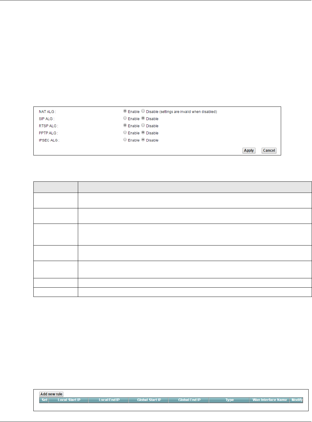
Chapter 11 Network Address Translation (NAT)
XMG3512-B10A User’s Guide
158
11.6 The ALG Screen
Some NAT routers may include a SIP Application Layer Gateway (ALG). A SIP ALG allows SIP calls to pass
through NAT by examining and translating IP addresses embedded in the data stream. When the XMG
registers with the SIP register server, the SIP ALG translates the XMG’s private IP address inside the SIP
data stream to a public IP address. You do not need to use STUN or an outbound proxy if your XMG is
behind a SIP ALG.
Use this screen to enable and disable the ALGs in the XMG. To access this screen, click Network Setting >
NAT > ALG.
Figure 85 Network Setting > NAT > ALG
The following table describes the fields in this screen.
11.7 The Address Mapping Screen
Ordering your rules is important because the XMG applies the rules in the order that you specify. When a
rule matches the current packet, the XMG takes the corresponding action and the remaining rules are
ignored.
Click Network Setting > NAT > Address Mapping to display the following screen.
Figure 86 Network Setting > NAT > Address Mapping
Table 62 Network Setting > NAT > ALG
LABEL DESCRIPTION
NAT ALG Enable this to make sure applications such as FTP and file transfer in IM applications work
correctly with port-forwarding and address-mapping rules.
SIP ALG Enable this to make sure SIP (VoIP) works correctly with port-forwarding and address-mapping
rules.
RTSP ALG Enable this to have the XMG detect RTSP traffic and help build RTSP sessions through its NAT. The
Real Time Streaming (media control) Protocol (RTSP) is a remote control for multimedia on the
Internet.
PPTP ALG Enable this to turn on the PPTP ALG on the XMG to detect PPTP traffic and help build PPTP
sessions through the XMG’s NAT.
IPSEC ALG Enable this to turn on the IPsec ALG on the XMG to detect IPsec traffic and help build IPsec
sessions through the XMG’s NAT.
Apply Click Apply to save your changes.
Cancel Click Cancel to restore your previously saved settings.
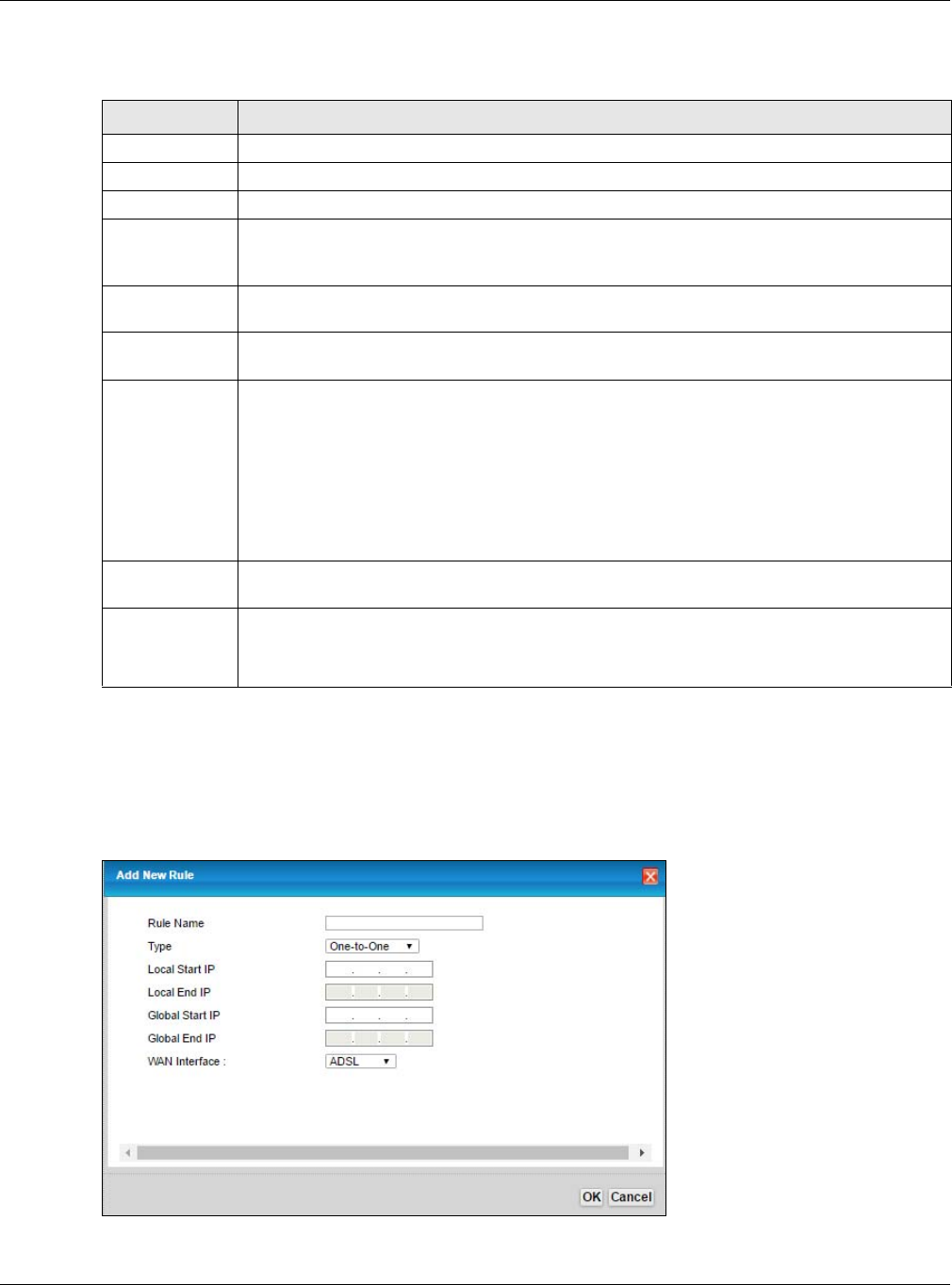
Chapter 11 Network Address Translation (NAT)
XMG3512-B10A User’s Guide
159
The following table describes the fields in this screen.
11.7.1 Add/Edit Address Mapping Rule
To add or edit an address mapping rule, click Add new rule or the rule’s edit icon in the Address
Mapping screen to display the screen shown next.
Figure 87 Address Mapping: Add/Edit
Table 63 Network Setting > NAT > Address Mapping
LABEL DESCRIPTION
Add new rule Click this to create a new rule.
Set This is the index number of the address mapping set.
Local Start IP This is the starting Inside Local IP Address (ILA).
Local End IP This is the ending Inside Local IP Address (ILA). If the rule is for all local IP addresses, then this field
displays 0.0.0.0 as the Local Start IP address and 255.255.255.255 as the Local End IP address. This
field is blank for One-to-One mapping types.
Global Start IP This is the starting Inside Global IP Address (IGA). Enter 0.0.0.0 here if you have a dynamic IP
address from your ISP. You can only do this for the Many-to-One mapping type.
Global End IP This is the ending Inside Global IP Address (IGA). This field is blank for One-to-One and Many-to-
One mapping types.
Type This is the address mapping type.
One-to-One: This mode maps one local IP address to one global IP address. Note that port
numbers do not change for the One-to-one NAT mapping type.
Many-to-One: This mode maps multiple local IP addresses to one global IP address. This is
equivalent to SUA (i.e., PAT, port address translation), the XMG's Single User Account feature that
previous routers supported only.
Many-to-Many: This mode maps multiple local IP addresses to shared global IP addresses.
Wan Interface
Name
This is the WAN interface to which the address mapping rule applies.
Modify Click the Edit icon to go to the screen where you can edit the address mapping rule.
Click the Delete icon to delete an existing address mapping rule. Note that subsequent address
mapping rules move up by one when you take this action.
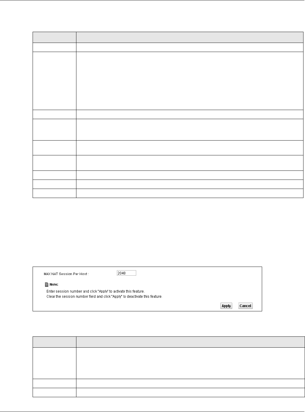
Chapter 11 Network Address Translation (NAT)
XMG3512-B10A User’s Guide
160
The following table describes the fields in this screen.
11.8 The Sessions Screen
Use this screen to limit the number of concurrent NAT sessions a client can use. Click Network Setting >
NAT > Sessions to display the following screen.
Figure 88 Network Setting > NAT > Sessions
The following table describes the fields in this screen.
Table 64 Address Mapping: Add/Edit
LABEL DESCRIPTION
Rule Name Enter a name to identify this rule using keyboard characters (A-Z, a-z, 1-2 and so on).
Type Choose the IP/port mapping type from one of the following.
One-to-One: This mode maps one local IP address to one global IP address. Note that port
numbers do not change for the One-to-one NAT mapping type.
Many-to-One: This mode maps multiple local IP addresses to one global IP address. This is
equivalent to SUA (i.e., PAT, port address translation), the XMG's Single User Account feature
that previous routers supported only.
Many-to-Many: This mode maps multiple local IP addresses to shared global IP addresses.
Local Start IP Enter the starting Inside Local IP Address (ILA).
Local End IP Enter the ending Inside Local IP Address (ILA). If the rule is for all local IP addresses, then this field
displays 0.0.0.0 as the Local Start IP address and 255.255.255.255 as the Local End IP address. This
field is blank for One-to-One mapping types.
Global Start IP Enter the starting Inside Global IP Address (IGA). Enter 0.0.0.0 here if you have a dynamic IP
address from your ISP. You can only do this for the Many-to-One mapping type.
Global End IP Enter the ending Inside Global IP Address (IGA). This field is blank for One-to-One and Many-to-
One mapping types.
WAN Interface Select a WAN interface to which the address mapping rule applies.
OK Click OK to save your changes.
Cancel Click Cancel to exit this screen without saving.
Table 65 Network Setting > NAT > Sessions
LABEL DESCRIPTION
MAX NAT
Session Per Host
Use this field to set a limit to the number of concurrent NAT sessions each client host can have.
If only a few clients use peer to peer applications, you can raise this number to improve their
performance. With heavy peer-to-peer application use, lower this number to ensure no single
client uses too many of the available NAT sessions.
Apply Click this to save your changes on this screen.
Cancel Click this to exit this screen without saving any changes.

Chapter 11 Network Address Translation (NAT)
XMG3512-B10A User’s Guide
161
11.9 Technical Reference
This part contains more information regarding NAT.
11.9.1 NAT Definitions
Inside/outside denotes where a host is located relative to the XMG, for example, the computers of your
subscribers are the inside hosts, while the web servers on the Internet are the outside hosts.
Global/local denotes the IP address of a host in a packet as the packet traverses a router, for example,
the local address refers to the IP address of a host when the packet is in the local network, while the
global address refers to the IP address of the host when the same packet is traveling in the WAN side.
Note that inside/outside refers to the location of a host, while global/local refers to the IP address of a
host used in a packet. Thus, an inside local address (ILA) is the IP address of an inside host in a packet
when the packet is still in the local network, while an inside global address (IGA) is the IP address of the
same inside host when the packet is on the WAN side. The following table summarizes this information.
NAT never changes the IP address (either local or global) of an outside host.
11.9.2 What NAT Does
In the simplest form, NAT changes the source IP address in a packet received from a subscriber (the
inside local address) to another (the inside global address) before forwarding the packet to the WAN
side. When the response comes back, NAT translates the destination address (the inside global address)
back to the inside local address before forwarding it to the original inside host. Note that the IP address
(either local or global) of an outside host is never changed.
The global IP addresses for the inside hosts can be either static or dynamically assigned by the ISP. In
addition, you can designate servers, for example, a web server and a telnet server, on your local
network and make them accessible to the outside world. If you do not define any servers (for Many-to-
One and Many-to-Many Overload mapping), NAT offers the additional benefit of firewall protection.
With no servers defined, your XMG filters out all incoming inquiries, thus preventing intruders from probing
your network. For more information on IP address translation, refer to RFC 1631, The IP Network Address
Translator (NAT).
Table 66 NAT Definitions
ITEM DESCRIPTION
Inside This refers to the host on the LAN.
Outside This refers to the host on the WAN.
Local This refers to the packet address (source or destination) as the packet travels on the LAN.
Global This refers to the packet address (source or destination) as the packet travels on the WAN.
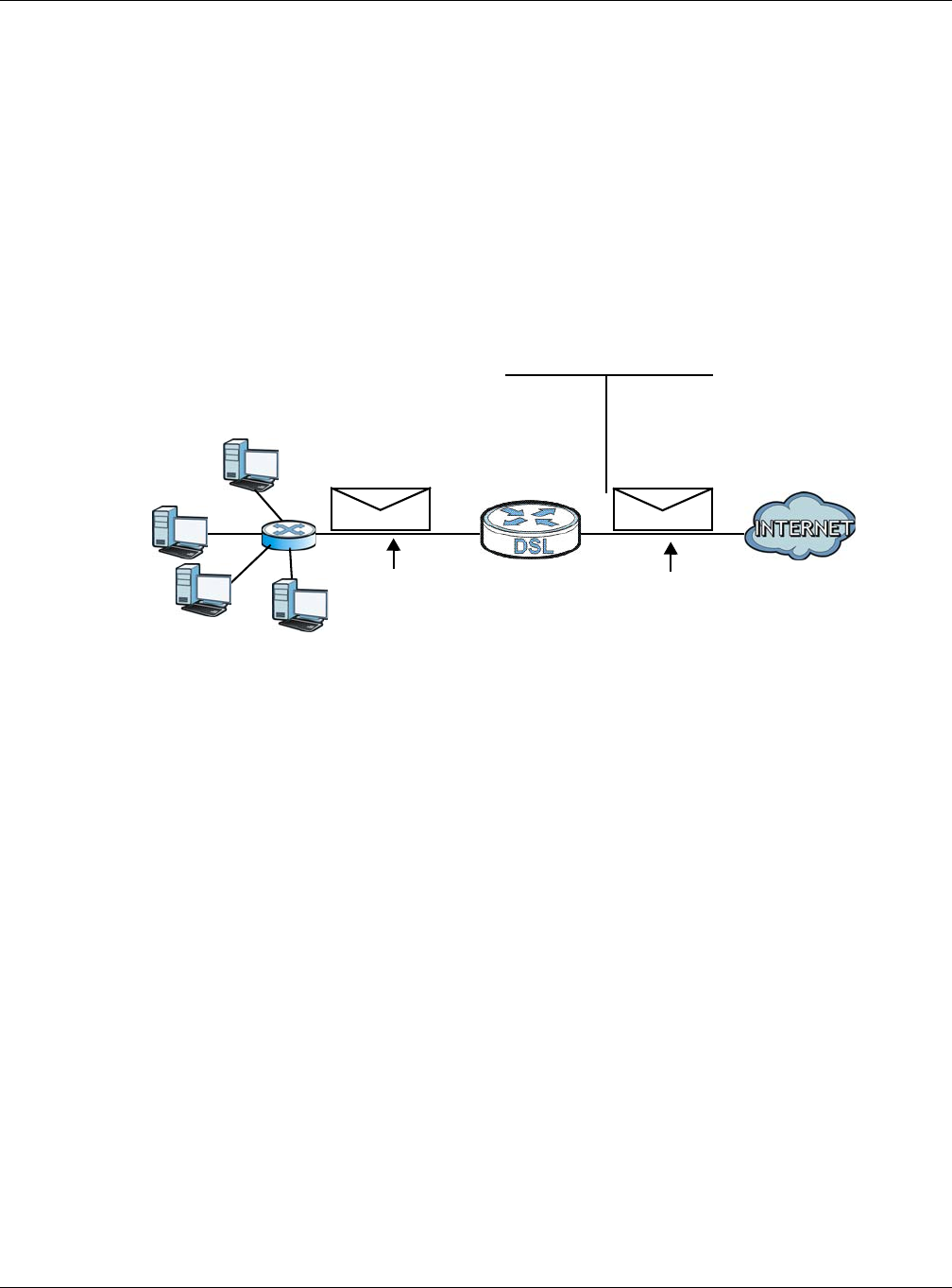
Chapter 11 Network Address Translation (NAT)
XMG3512-B10A User’s Guide
162
11.9.3 How NAT Works
Each packet has two addresses – a source address and a destination address. For outgoing packets,
the ILA (Inside Local Address) is the source address on the LAN, and the IGA (Inside Global Address) is
the source address on the WAN. For incoming packets, the ILA is the destination address on the LAN,
and the IGA is the destination address on the WAN. NAT maps private (local) IP addresses to globally
unique ones required for communication with hosts on other networks. It replaces the original IP source
address (and TCP or UDP source port numbers for Many-to-One and Many-to-Many Overload NAT
mapping) in each packet and then forwards it to the Internet. The XMG keeps track of the original
addresses and port numbers so incoming reply packets can have their original values restored. The
following figure illustrates this.
Figure 89 How NAT Works
11.9.4 NAT Application
The following figure illustrates a possible NAT application, where three inside LANs (logical LANs using IP
alias) behind the XMG can communicate with three distinct WAN networks.
192.168.1.13
192.168.1.10
192.168.1.11
192.168.1.12 SA
192.168.1.10
SA
IGA1
Inside Local
IP Address
192.168.1.10
192.168.1.11
192.168.1.12
192.168.1.13
Inside Global
IP Address
IGA 1
IGA 2
IGA 3
IGA 4
NAT Table
WAN
LAN
Inside Local
Address (ILA) Inside Global
Address (IGA)
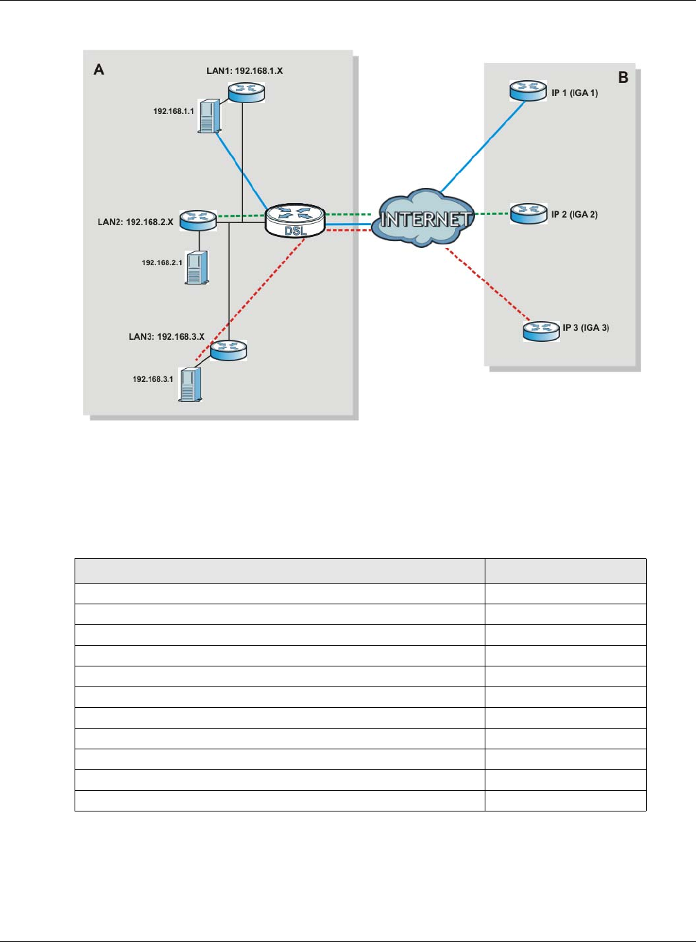
Chapter 11 Network Address Translation (NAT)
XMG3512-B10A User’s Guide
163
Figure 90 NAT Application With IP Alias
Port Forwarding: Services and Port Numbers
The most often used port numbers are shown in the following table. Please refer to RFC 1700 for further
information about port numbers. Please also refer to the Supporting CD for more examples and details
on port forwarding and NAT.
Port Forwarding Example
Let's say you want to assign ports 21-25 to one FTP, Telnet and SMTP server (A in the example), port 80 to
another (B in the example) and assign a default server IP address of 192.168.1.35 to a third (C in the
Table 67 Services and Port Numbers
SERVICES PORT NUMBER
ECHO 7
FTP (File Transfer Protocol) 21
SMTP (Simple Mail Transfer Protocol) 25
DNS (Domain Name System) 53
Finger 79
HTTP (Hyper Text Transfer protocol or WWW, Web) 80
POP3 (Post Office Protocol) 110
NNTP (Network News Transport Protocol) 119
SNMP (Simple Network Management Protocol) 161
SNMP trap 162
PPTP (Point-to-Point Tunneling Protocol) 1723
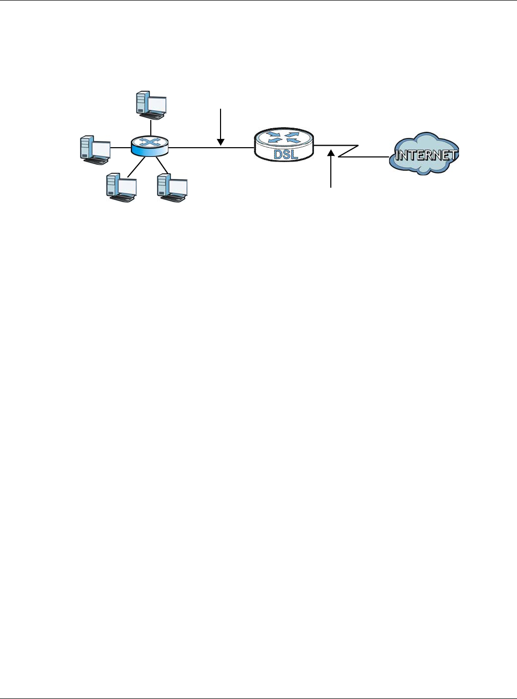
Chapter 11 Network Address Translation (NAT)
XMG3512-B10A User’s Guide
164
example). You assign the LAN IP addresses and the ISP assigns the WAN IP address. The NAT network
appears as a single host on the Internet.
Figure 91 Multiple Servers Behind NAT Example
D=192.168.1.36
192.168.1.1
IP address assigned by ISP
A=192.168.1.33
B=192.168.1.34
C=192.168.1.35

XMG3512-B10A User’s Guide
165
CHAPTER 12
DNS
12.1 Overview
DNS
DNS (Domain Name System) is for mapping a domain name to its corresponding IP address and vice
versa. The DNS server is extremely important because without it, you must know the IP address of a
machine before you can access it.
In addition to the system DNS server(s), each WAN interface (service) is set to have its own static or
dynamic DNS server list. You can configure a DNS static route to forward DNS queries for certain domain
names through a specific WAN interface to its DNS server(s). The XMG uses a system DNS server (in the
order you specify in the Broadband screen) to resolve domain names that do not match any DNS
routing entry. After the XMG receives a DNS reply from a DNS server, it creates a new entry for the
resolved IP address in the routing table.
Dynamic DNS
Dynamic DNS allows you to update your current dynamic IP address with one or many dynamic DNS
services so that anyone can contact you (in NetMeeting, CU-SeeMe, etc.). You can also access your
FTP server or Web site on your own computer using a domain name (for instance myhost.dhs.org, where
myhost is a name of your choice) that will never change instead of using an IP address that changes
each time you reconnect. Your friends or relatives will always be able to call you even if they don't know
your IP address.
First of all, you need to have registered a dynamic DNS account with www.dyndns.org. This is for people
with a dynamic IP from their ISP or DHCP server that would still like to have a domain name. The Dynamic
DNS service provider will give you a password or key.
12.1.1 What You Can Do in this Chapter
• Use the DNS Entry screen to view, configure, or remove DNS routes (Section 12.2 on page 166).
• Use the Dynamic DNS screen to enable DDNS and configure the DDNS settings on the XMG (Section
12.3 on page 167).
12.1.2 What You Need To Know
DYNDNS Wildcard
Enabling the wildcard feature for your host causes *.yourhost.dyndns.org to be aliased to the same IP
address as yourhost.dyndns.org. This feature is useful if you want to be able to use, for example,
www.yourhost.dyndns.org and still reach your hostname.
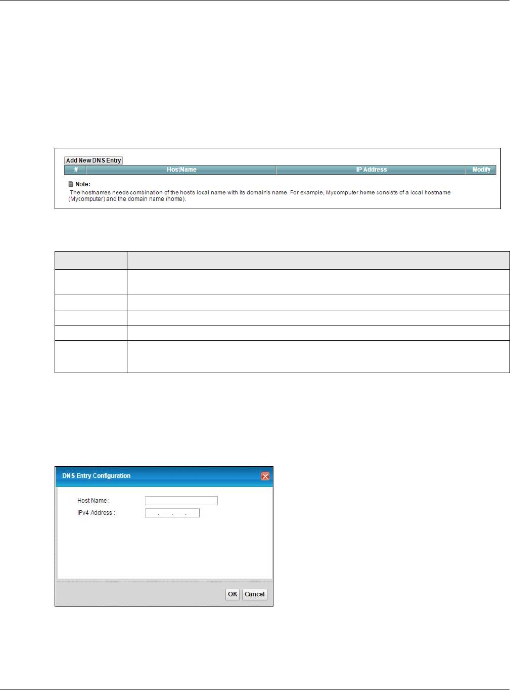
Chapter 12 DNS
XMG3512-B10A User’s Guide
166
If you have a private WAN IP address, then you cannot use Dynamic DNS.
12.2 The DNS Entry Screen
Use this screen to view and configure DNS routes on the XMG. Click Network Setting > DNS to open the
DNS Entry screen.
Figure 92 Network Setting > DNS > DNS Entry
The following table describes the fields in this screen.
12.2.1 Add/Edit DNS Entry
You can manually add or edit the XMG’s DNS name and IP address entry. Click Add New DNS Entry in
the DNS Entry screen or the Edit icon next to the entry you want to edit. The screen shown next appears.
Figure 93 DNS Entry: Add/Edit
Table 68 Network Setting > DNS > DNS Entry
LABEL DESCRIPTION
Add New DNS
Entry
Click this to create a new DNS entry.
#This is the index number of the entry.
Hostname This indicates the host name or domain name.
IP Address This indicates the IP address assigned to this computer.
Modify Click the Edit icon to edit the rule.
Click the Delete icon to delete an existing rule.
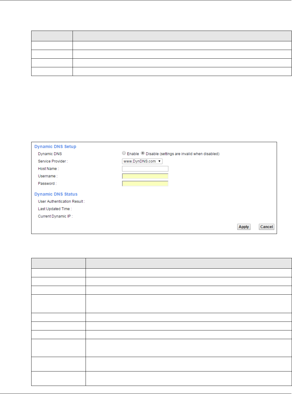
Chapter 12 DNS
XMG3512-B10A User’s Guide
167
The following table describes the labels in this screen.
12.3 The Dynamic DNS Screen
Use this screen to change your XMG’s DDNS. Click Network Setting > DNS > Dynamic DNS. The screen
appears as shown.
Figure 94 Network Setting > DNS > Dynamic DNS
The following table describes the fields in this screen.
Table 69 DNS Entry: Add/Edit
LABEL DESCRIPTION
Host Name Enter the host name of the DNS entry.
IPv4 Address Enter the IPv4 address of the DNS entry.
OK Click OK to save your changes.
Cancel Click Cancel to exit this screen without saving.
Table 70 Network Setting > DNS > > Dynamic DNS
LABEL DESCRIPTION
Dynamic DNS Setup
Dynamic DNS Select Enable to use dynamic DNS.
Service Provider Select your Dynamic DNS service provider from the drop-down list box.
Host Name Type the domain name assigned to your XMG by your Dynamic DNS provider.
You can specify up to two host names in the field separated by a comma (",").
Username Type your user name.
Password Type the password assigned to you.
Dynamic DNS Status
User
Authentication
Result
This shows Success if the account is correctly set up with the Dynamic DNS provider
account.
Last Updated Time This shows the last time the IP address the Dynamic DNS provider has associated with the
hostname was updated.
Current Dynamic
IP This shows the IP address your Dynamic DNS provider has currently associated with the
hostname.

Chapter 12 DNS
XMG3512-B10A User’s Guide
168
Apply Click Apply to save your changes.
Cancel Click Cancel to exit this screen without saving.
Table 70 Network Setting > DNS > > Dynamic DNS (continued)
LABEL DESCRIPTION
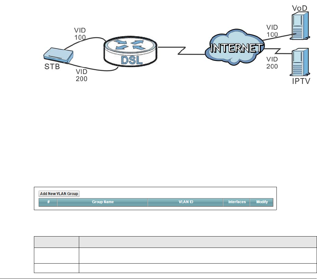
XMG3512-B10A User’s Guide
169
CHAPTER 13
VLAN Group
13.1 Overview
Virtual LAN IDs are used to identify different traffic types over the same physical link.
In the following example, the XMG (DSL) can use VLAN IDs (VID) 100 and 200 to identify Video-on-
Demand and IPTV traffic respectively coming from the two VoD and IPTV multicast servers. The XMG
(DSL) can also tag outgoing requests to these servers with these VLAN IDs.
Figure 95 VLAN Group Example
13.1.1 What You Can Do in this Chapter
Use these screens to group separate VLAN groups together to be treated as one VLAN group.
13.2 The VLAN Group Screen
Click Network Setting > Vlan Group to open the following screen.
Figure 96 Network Setting > Vlan Group
The following table describes the fields in this screen.
Table 71 Network Setting > Vlan Group
LABEL DESCRIPTION
Add New Vlan
Group
Click this button to create a new VLAN group.
#This is the index number of the VLAN group.
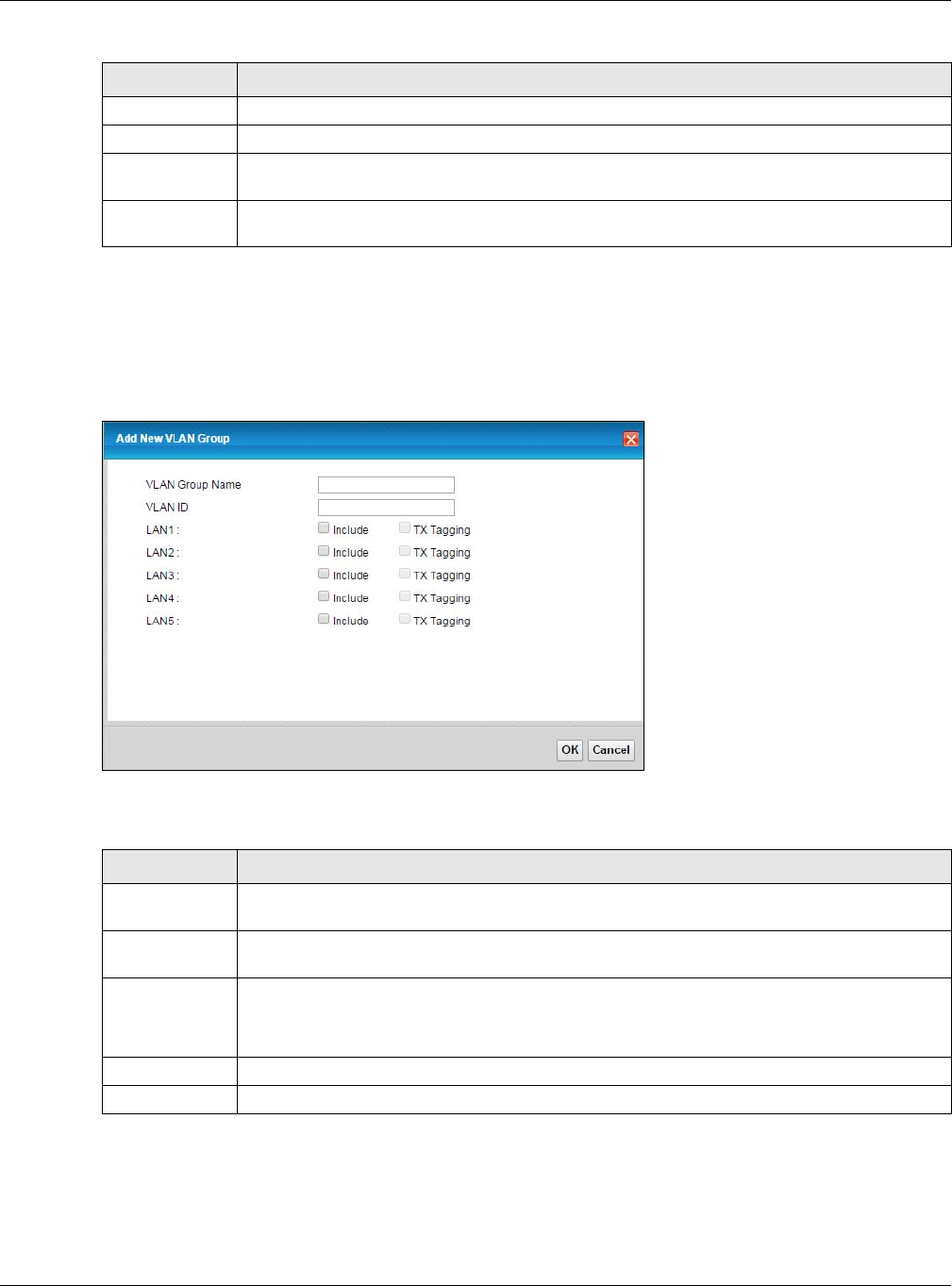
Chapter 13 VLAN Group
XMG3512-B10A User’s Guide
170
13.2.1 Add/Edit a VLAN Group
Click the Add New VLAN Group button in the Vlan Group screen to open the following screen. Use this
screen to create a new VLAN group.
Figure 97 Add/Edit VLAN Group
The following table describes the fields in this screen.
Group Name This shows the descriptive name of the VLAN group.
VLAN ID This shows the unique ID number that identifies the VLAN group.
Interfaces This shows the LAN ports included in the VLAN group and if traffic leaving the port will be tagged
with the VLAN ID.
Modify Click the Edit icon to change an existing VLAN group setting or click the Delete icon to remove
the VLAN group.
Table 71 Network Setting > Vlan Group (continued)
LABEL DESCRIPTION
Table 72 Add/Edit VLAN Group
LABEL DESCRIPTION
VLAN Group
Name
Enter a name to identify this group. You can enter up to 30 characters. You can use letters,
numbers, hyphens (-) and underscores (_). Spaces are not allowed.
VLAN ID Enter a unique ID number, from 1 to 4,094, to identify this VLAN group. Outgoing traffic is tagged
with this ID if Tx Tagging is selected below.
LAN Select Include to add the associated LAN interface to this VLAN group.
Select Tx Tagging to tag outgoing traffic from the associated LAN port with the VLAN ID number
entered above.
OK Click OK to save your changes back to the XMG.
Cancel Click Cancel to exit this screen without saving.
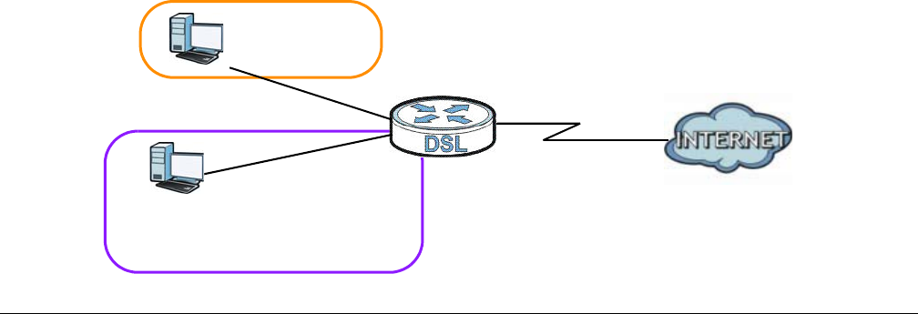
XMG3512-B10A User’s Guide
171
CHAPTER 14
Interface Grouping
14.1 Overview
By default, all LAN and WAN interfaces on the XMG are in the same group and can communicate with
each other. Create interface groups to have the XMG assign the IP addresses in different domains to
different groups. Each group acts as an independent network on the XMG. This lets devices connected
to an interface group’s LAN interfaces communicate through the interface group’s WAN or LAN
interfaces but not other WAN or LAN interfaces.
14.1.1 What You Can Do in this Chapter
The Interface Grouping screens let you create multiple networks on the XMG (Section 14.2 on page 171).
14.2 The Interface Grouping Screen
You can manually add a LAN interface to a new group. Alternatively, you can have the XMG
automatically add the incoming traffic and the LAN interface on which traffic is received to an
interface group when its DHCP Vendor ID option information matches one listed for the interface group.
Use the LAN screen to configure the private IP addresses the DHCP server on the XMG assigns to the
clients in the default and/or user-defined groups. If you set the XMG to assign IP addresses based on the
client’s DHCP Vendor ID option information, you must enable DHCP server and configure LAN TCP/IP
settings for both the default and user-defined groups. See Chapter 8 on page 110 for more information.
In the following example, the client that sends packets with the DHCP Vendor ID option set to MSFT 5.0
(meaning it is a Windows 2000 DHCP client) is assigned the IP address 192.168.2.2 and uses the WAN
VDSL_PoE/ppp0.1 interface.
Figure 98 Interface Grouping Application
Default: ETH 2~4
192.168.1.x/24
192.168.2.x/24
VDSL_PoE/ppp0.1
eth10.0
DHCP Vendor ID option: MSFT 5.0
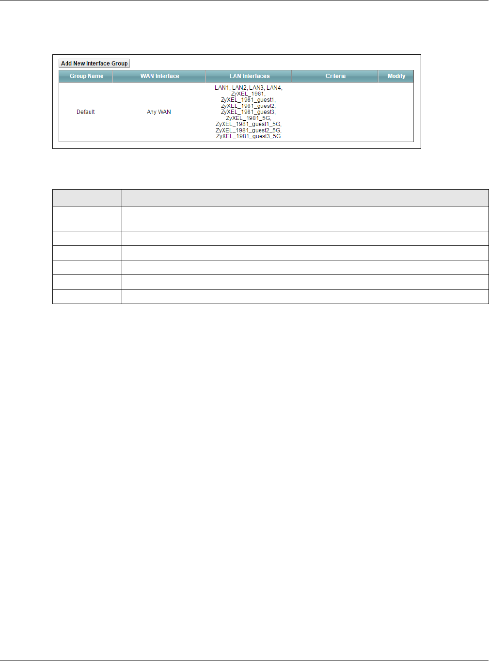
Chapter 14 Interface Grouping
XMG3512-B10A User’s Guide
172
Click Network Setting > Interface Grouping to open the following screen.
Figure 99 Network Setting > Interface Grouping
The following table describes the fields in this screen.
14.2.1 Interface Group Configuration
Click the Add New Interface Group button in the Interface Grouping screen to open the following
screen. Use this screen to create a new interface group.
Note: An interface can belong to only one group at a time.
Table 73 Network Setting > Interface Grouping
LABEL DESCRIPTION
Add New
Interface Group
Click this button to create a new interface group.
Group Name This shows the descriptive name of the group.
WAN Interface This shows the WAN interfaces in the group.
LAN Interfaces This shows the LAN interfaces in the group.
Criteria This shows the filtering criteria for the group.
Modify Click the Delete icon to remove the group.
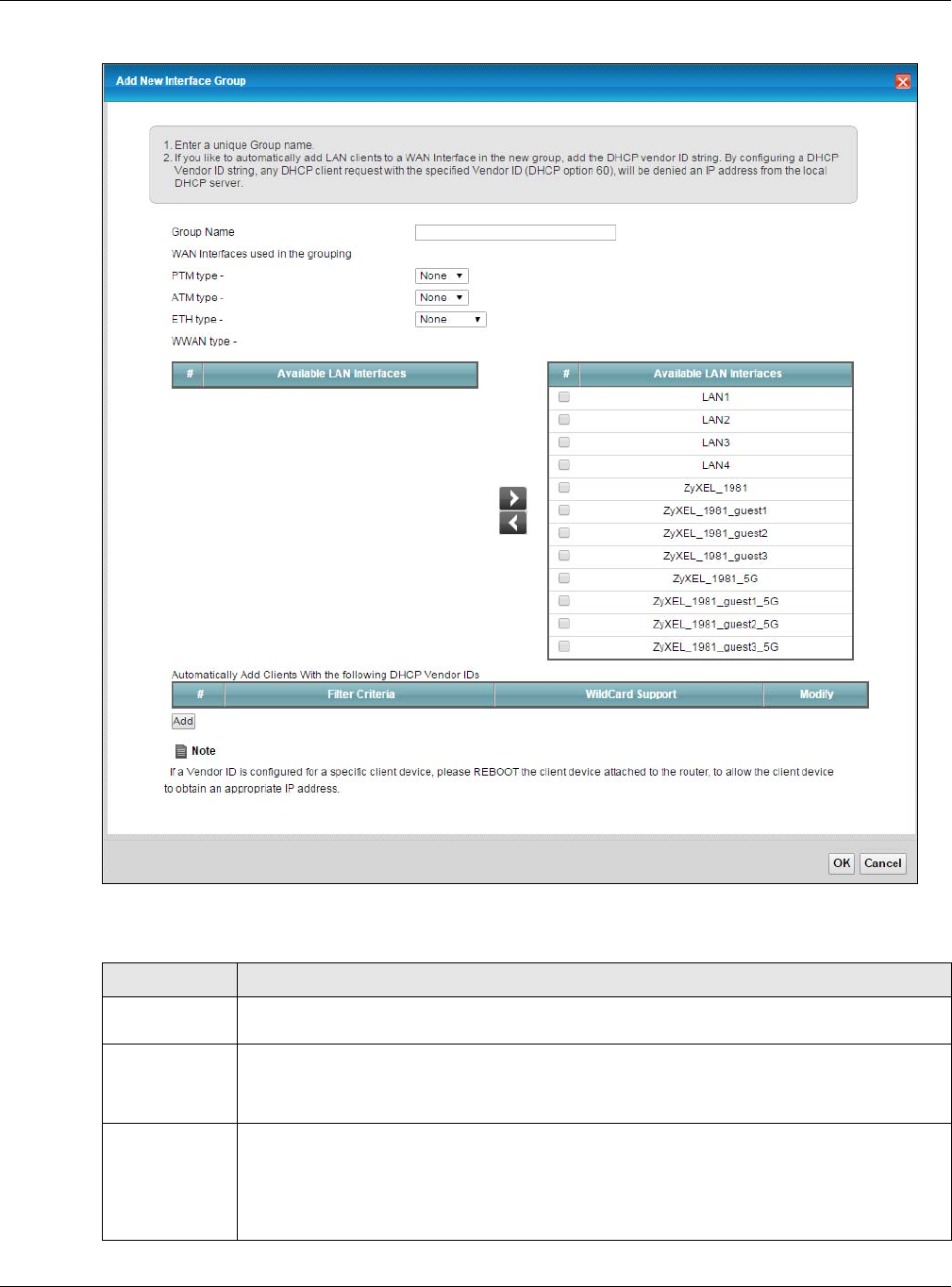
Chapter 14 Interface Grouping
XMG3512-B10A User’s Guide
173
Figure 100 Interface Group Configuration
The following table describes the fields in this screen.
Table 74 Interface Group Configuration
LABEL DESCRIPTION
Group Name Enter a name to identify this group. You can enter up to 30 characters. You can use letters,
numbers, hyphens (-) and underscores (_). Spaces are not allowed.
WAN Interfaces
used in the
grouping
Select the WAN interface this group uses. The group can have up to one PTM interface, up to
one ATM interface, up to one ETH interface, and and up to one WWAN interface.
Select None to not add a WAN interface to this group.
Grouped LAN
Interfaces
Available LAN
Interfaces
Select one or more LAN interfaces (Ethernet LAN, HPNA or wireless LAN) on the Available LAN
Interfaces list and use the left arrow to move them to the interface list on the left to add the
interfaces to this group.
To remove a LAN or wireless LAN interface from the interface list on the left, use the right-facing
arrow.
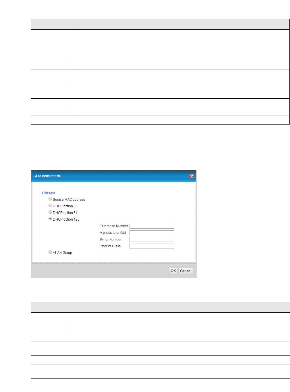
Chapter 14 Interface Grouping
XMG3512-B10A User’s Guide
174
14.2.2 Interface Grouping Criteria
Click the Add button in the Interface Grouping Configuration screen to open the following screen.
Figure 101 Interface Grouping Criteria
The following table describes the fields in this screen.
Automatically
Add Clients With
the following
DHCP Vendor
IDs
Click Add to identify LAN hosts to add to the interface group by criteria such as the type of the
hardware or firmware. See Section 14.2.2 on page 174 for more information.
#This shows the index number of the rule.
Filter Criteria This shows the filtering criteria. The LAN interface on which the matched traffic is received will
belong to this group automatically.
WildCard
Support
This shows if wildcard on DHCP option 60 is enabled.
Modify Click the Modify icon to edit this rule on the XMG.
OK Click OK to save your changes back to the XMG.
Cancel Click Cancel to exit this screen without saving.
Table 74 Interface Group Configuration (continued)
LABEL DESCRIPTION
Table 75 Interface Grouping Criteria
LABEL DESCRIPTION
Source MAC
Address
Select this option and enter the source MAC address of the packet.
DHCP Option 60 Select this option and enter the Vendor Class Identifier (Option 60) of the matched traffic, such
as the type of the hardware or firmware.
Enable
wildcard Select this option to be able to use wildcards in the Vendor Class Identifier configured for DHCP
option 60.
DHCP Option 61 Select this and enter the device identity of the matched traffic.
DHCP Option
125
Select this and enter vendor specific information of the matched traffic.
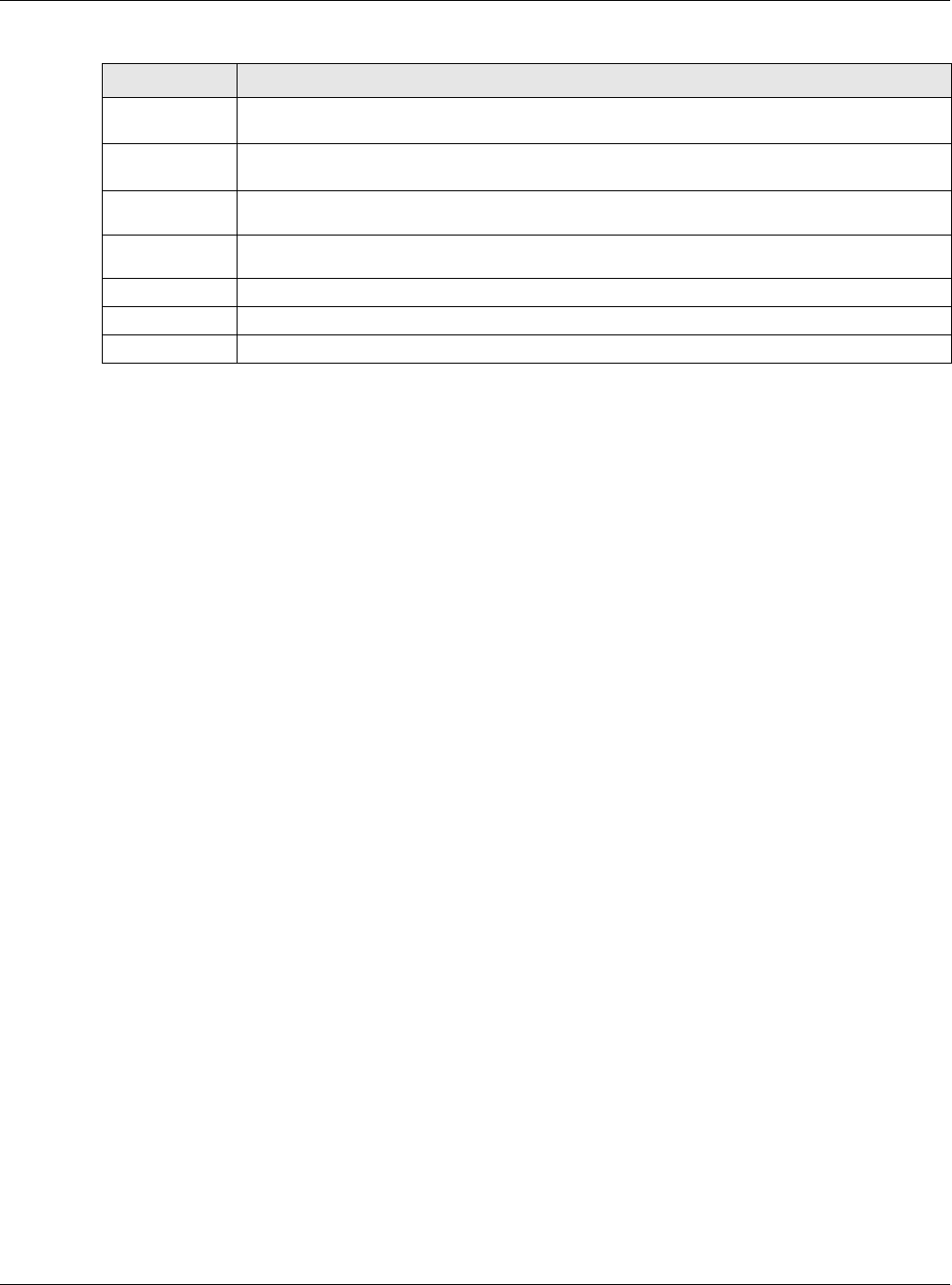
Chapter 14 Interface Grouping
XMG3512-B10A User’s Guide
175
Enterprise
Number Enter the vendor’s 32-bit enterprise number registered with the IANA (Internet Assigned Numbers
Authority).
Manufactur
er OUI Specify the vendor’s OUI (Organization Unique Identifier). It is usually the first three bytes of the
MAC address.
Serial
Number Enter the serial number of the device.
Product
Class Enter the product class of the device.
VLAN Group Select this and the VLAN group of the matched traffic from the drop-down list box.
OK Click OK to save your changes back to the XMG.
Cancel Click Cancel to exit this screen without saving.
Table 75 Interface Grouping Criteria (continued)
LABEL DESCRIPTION
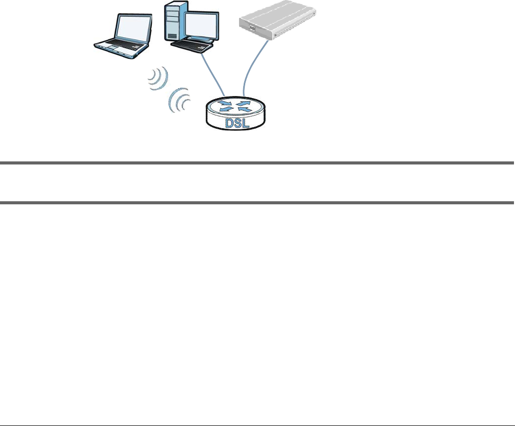
XMG3512-B10A User’s Guide
176
CHAPTER 15
USB Service
15.1 Overview
You can share files on a USB memory stick or hard drive connected to your XMG with users on your
network.
The following figure is an overview of the XMG’s file server feature. Computers A and B can access files
on a USB device (C) which is connected to the XMG.
Figure 102 File Sharing Overview
The XMG will not be able to join the workgroup if your local area network has restrictions set up
that do not allow devices to join a workgroup. In this case, contact your network administrator.
15.1.1 What You Can Do in this Chapter
• Use the File Sharing screen to enable file-sharing server (Section 15.1.3 on page 177).
• Use the Media Server screen to enable or disable the sharing of media files (Section 15.3 on page
179).
15.1.2 What You Need To Know
The following terms and concepts may help as you read this chapter.
A
BC

Chapter 15 USB Service
XMG3512-B10A User’s Guide
177
15.1.2.1 About File Sharing
Workgroup name
This is the name given to a set of computers that are connected on a network and share resources such
as a printer or files. Windows automatically assigns the workgroup name when you set up a network.
Shares
When settings are set to default, each USB device connected to the XMG is given a folder, called a
“share”. If a USB hard drive connected to the XMG has more than one partition, then each partition will
be allocated a share. You can also configure a “share” to be a sub-folder or file on the USB device.
File Systems
A file system is a way of storing and organizing files on your hard drive and storage device. Often
different operating systems such as Windows or Linux have different file systems. The file sharing feature
on your XMG supports File Allocation Table (FAT) and FAT32.
Common Internet File System
The XMG uses Common Internet File System (CIFS) protocol for its file sharing functions. CIFS compatible
computers can access the USB file storage devices connected to the XMG. CIFS protocol is supported
on Microsoft Windows, Linux Samba and other operating systems (refer to your systems specifications for
CIFS compatibility).
15.1.3 Before You Begin
Make sure the XMG is connected to your network and turned on.
1Connect the USB device to one of the XMG’s USB port. Make sure the XMG is connected to your
network.
2The XMG detects the USB device and makes its contents available for browsing. If you are connecting a
USB hard drive that comes with an external power supply, make sure it is connected to an appropriate
power source that is on.
Note: If your USB device cannot be detected by the XMG, see the troubleshooting for
suggestions.
15.2 The File Sharing Screen
Use this screen to set up file sharing through the XMG. The XMG’s LAN users can access the shared folder
(or share) from the USB device inserted in the XMG. To access this screen, click Network Setting > USB
Service > File Sharing.
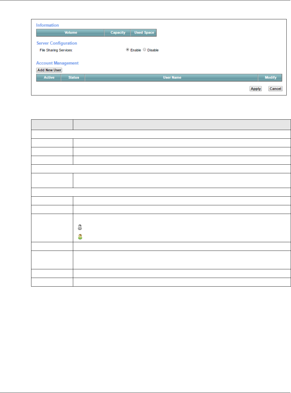
Chapter 15 USB Service
XMG3512-B10A User’s Guide
178
Figure 103 Network Setting > USB Service > File Sharing
Each field is described in the following table.
15.2.1 The Add New User Screen
Use this screen to create a user account that can access the secured shares on the USB device. To
access this screen, click the Add New User button in the Network Setting > USB Service > File Sharing
screen.
Table 76 Network Setting > USB Service > File Sharing
LABEL DESCRIPTION
Information
Volume This is the volume name the XMG gives to an inserted USB device.
Capacity This is the total available memory size (in megabytes) on the USB device.
Used Space This is the memory size (in megabytes) already used on the USB device.
Server Configuration
File Sharing
Services
Select Enable to activate file sharing through the XMG.
Account Management
Add New User Click this button to create a user account to access the secured shares.
Active Select this to allow the user to access the secured shares.
Status This field shows the status of the user.
: The user account is not activated for the share.
: The user account is activated for the share.
User Name This is the name of a user who is allowed to access the secured shares on the USB device.
Modify Click the Edit icon to modify the user account.
Click the Delete icon to remove the user account from the XMG.
Apply Click this to save your changes to the XMG.
Cancel Click this to restore your previously saved settings.
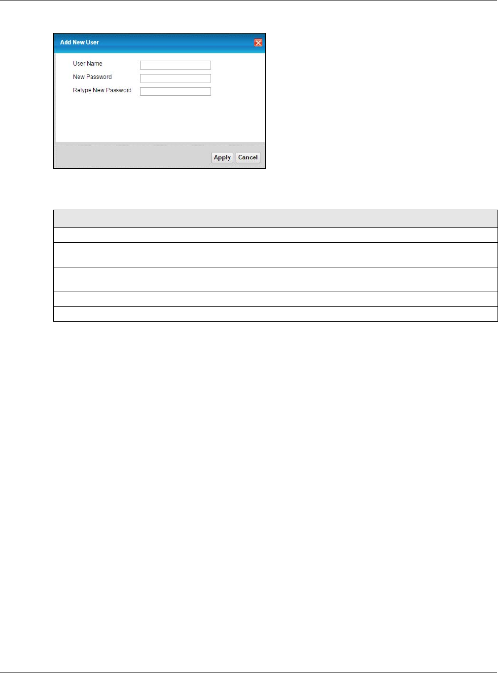
Chapter 15 USB Service
XMG3512-B10A User’s Guide
179
Figure 104 Network Setting > USB Service > File Sharing > Add new user
Each field is described in the following table.
15.3 The Media Server Screen
The media server feature lets anyone on your network play video, music, and photos from the USB
storage device connected to your XMG (without having to copy them to another computer). The XMG
can function as a DLNA-compliant media server. The XMG streams files to DLNA-compliant media
clients (like Windows Media Player). The Digital Living Network Alliance (DLNA) is a group of personal
computer and electronics companies that works to make products compatible in a home network.
The XMG media server enables you to:
• Publish all shares for everyone to play media files in the USB storage device connected to the XMG.
• Use hardware-based media clients like the DMA-2500 to play the files.
Note: Anyone on your network can play the media files in the published shares. No user name
and password or other form of security is used. The media server is enabled by default
with the video, photo, and music shares published.
To change your XMG’s media server settings, click Network Setting > USB Service > Media Server. The
screen appears as shown.
Table 77 Network Setting > USB Service > File Sharing > Add new user
LABEL DESCRIPTION
User Name Enter a user name. You can enter up to 16 characters. Only letters and numbers allowed.
New Password Enter the password used to access the secured share. The password must be 5 to 15 characters
long. Only letters and numbers are allowed. The password is case sensitive.
Retype New
Password
Retype the password that you entered above.
Apply Click this to save your changes to the XMG.
Cancel Click this to return to the previous screen without saving.
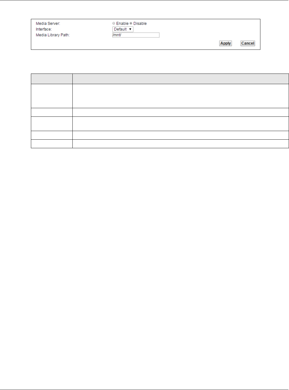
Chapter 15 USB Service
XMG3512-B10A User’s Guide
180
Figure 105 Network Setting > USB Service > Media Server
The following table describes the labels in this menu.
Table 78 Network Setting > USB Service > Media Server
LABEL DESCRIPTION
Media Server Select Enable to have the XMG function as a DLNA-compliant media server.
Enable the media server to let (DLNA-compliant) media clients on your network play media files
located in the shares.
Interface Select an interface on which you want to enable the media server function.
Media Library
Path
Enter the path clients use to access the media files on a USB storage device connected to the
XMG.
Apply Click Apply to save your changes.
Cancel Click Cancel to restore your previously saved settings.
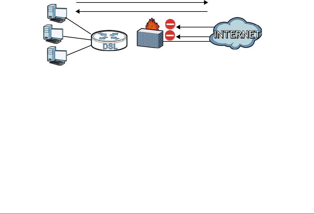
XMG3512-B10A User’s Guide
181
CHAPTER 16
Firewall
16.1 Overview
This chapter shows you how to enable and configure the XMG’s security settings. Use the firewall to
protect your XMG and network from attacks by hackers on the Internet and control access to it. By
default the firewall:
• allows traffic that originates from your LAN computers to go to all other networks.
• blocks traffic that originates on other networks from going to the LAN.
The following figure illustrates the default firewall action. User A can initiate an IM (Instant Messaging)
session from the LAN to the WAN (1). Return traffic for this session is also allowed (2). However other traffic
initiated from the WAN is blocked (3 and 4).
Figure 106 Default Firewall Action
16.1.1 What You Can Do in this Chapter
• Use the General screen to configure the security level of the firewall on the XMG (Section 16.2 on
page 182).
• Use the Protocol screen to add or remove predefined Internet services and configure firewall rules
(Section 16.3 on page 183).
• Use the Access Control screen to view and configure incoming/outgoing filtering rules (Section 16.4
on page 185).
• Use the DoS screen to activate protection against Denial of Service (DoS) attacks (.Section 16.5 on
page 187).
WAN
LAN
3
4
1
2
A

Chapter 16 Firewall
XMG3512-B10A User’s Guide
182
16.1.2 What You Need to Know
SYN Attack
A SYN attack floods a targeted system with a series of SYN packets. Each packet causes the targeted
system to issue a SYN-ACK response. While the targeted system waits for the ACK that follows the SYN-
ACK, it queues up all outstanding SYN-ACK responses on a backlog queue. SYN-ACKs are moved off the
queue only when an ACK comes back or when an internal timer terminates the three-way handshake.
Once the queue is full, the system will ignore all incoming SYN requests, making the system unavailable
for legitimate users.
DoS
Denials of Service (DoS) attacks are aimed at devices and networks with a connection to the Internet.
Their goal is not to steal information, but to disable a device or network so users no longer have access
to network resources. The XMG is pre-configured to automatically detect and thwart all known DoS
attacks.
DDoS
A DDoS attack is one in which multiple compromised systems attack a single target, thereby causing
denial of service for users of the targeted system.
LAND Attack
In a LAND attack, hackers flood SYN packets into the network with a spoofed source IP address of the
target system. This makes it appear as if the host computer sent the packets to itself, making the system
unavailable while the target system tries to respond to itself.
Ping of Death
Ping of Death uses a "ping" utility to create and send an IP packet that exceeds the maximum 65,536
bytes of data allowed by the IP specification. This may cause systems to crash, hang or reboot.
SPI
Stateful Packet Inspection (SPI) tracks each connection crossing the firewall and makes sure it is valid.
Filtering decisions are based not only on rules but also context. For example, traffic from the WAN may
only be allowed to cross the firewall in response to a request from the LAN.
16.2 The Firewall Screen
Use this screen to set the security level of the firewall on the XMG. Firewall rules are grouped based on
the direction of travel of packets to which they apply.
Click Security > Firewall to display the General screen.
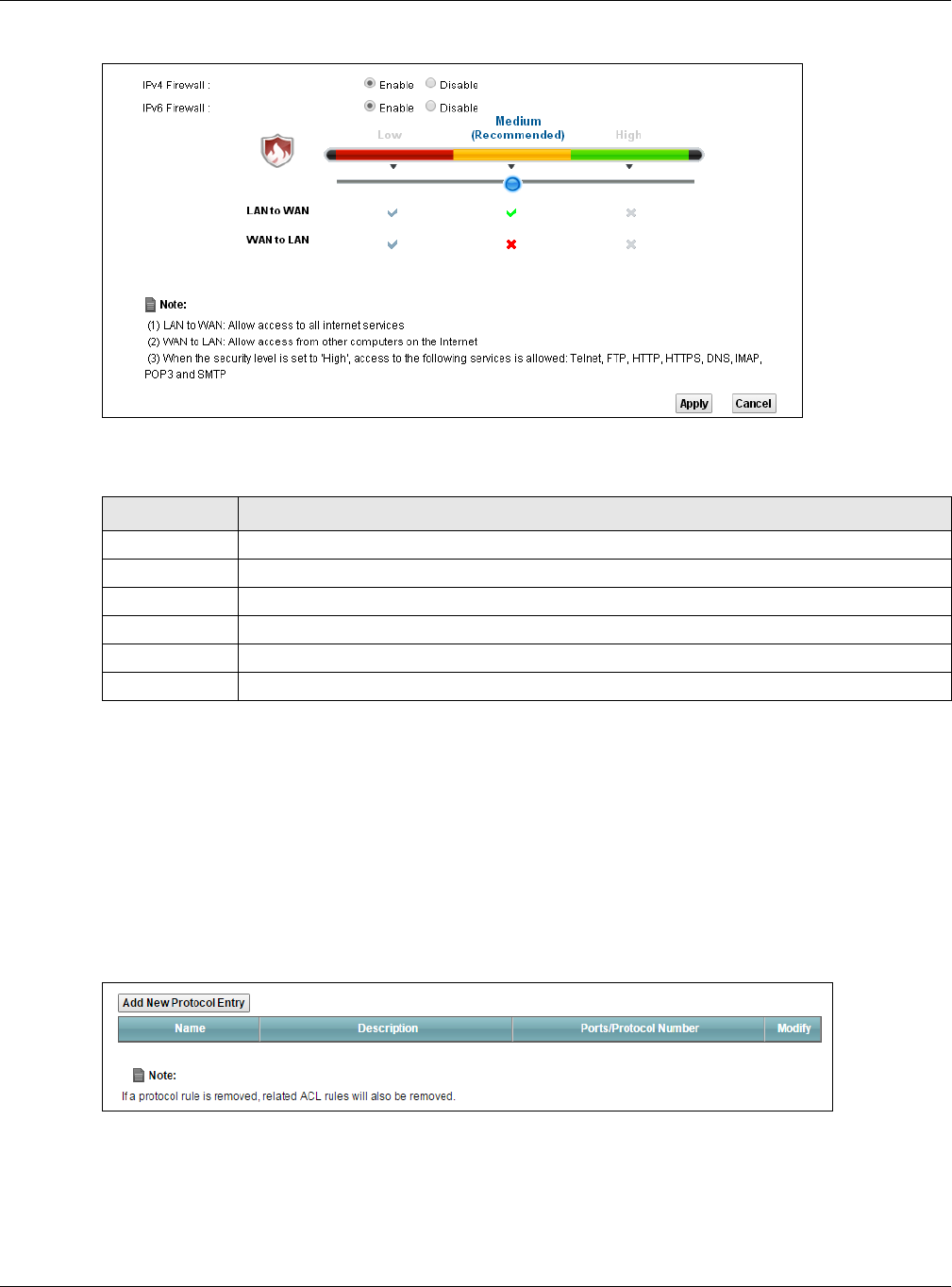
Chapter 16 Firewall
XMG3512-B10A User’s Guide
183
Figure 107 Security > Firewall > General
The following table describes the labels in this screen.
16.3 The Protocol Screen
You can configure customized services and port numbers in the Protocol screen. For a comprehensive
list of port numbers and services, visit the IANA (Internet Assigned Number Authority) website. See
Appendix C on page 268 for some examples.
Click Security > Firewall > Protocol to display the following screen.
Figure 108 Security > Firewall > Protocol
Table 79 Security > Firewall > General
LABEL DESCRIPTION
Firewall Select Enable to activate the firewall feature on the XMG.
Low Select Low to allow LAN to WAN and WAN to LAN packet directions.
Medium Select Medium to allow LAN to WAN but deny WAN to LAN packet directions.
High Select High to deny LAN to WAN and WAN to LAN packet directions.
Apply Click Apply to save your changes.
Cancel Click Cancel to restore your previously saved settings.
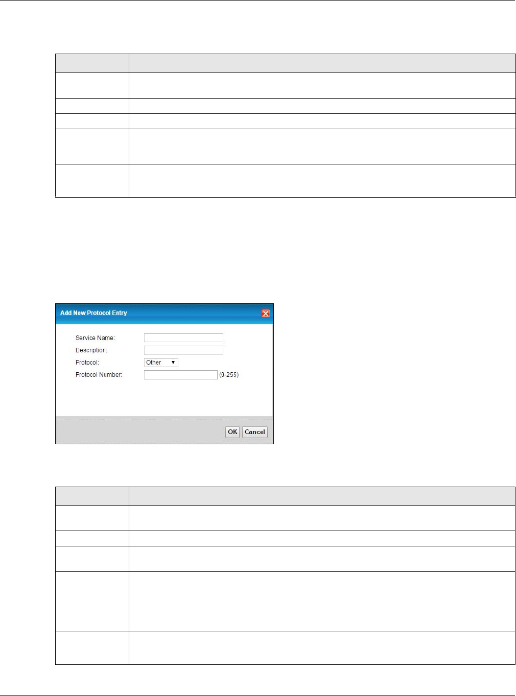
Chapter 16 Firewall
XMG3512-B10A User’s Guide
184
The following table describes the labels in this screen.
16.3.1 Add/Edit a Service
Use this screen to add a customized service rule that you can use in the firewall’s ACL rule configuration.
Click Add New Protocol Entry or the edit icon next to an existing service rule in the Protocol screen to
display the following screen.
Figure 109 Security > Firewall > Protocol: Add/Edit
The following table describes the labels in this screen.
Table 80 Security > Firewall > Protocol
LABEL DESCRIPTION
Add New
Protocol Entry
Click this to add a new service.
Name This is the name of your customized service.
Description This is the description of your customized service.
Ports/Protocol
Number
This shows the IP protocol (TCP, UDP, ICMP, or TCP/UDP) and the port number or range of ports
that defines your customized service. Other and the protocol number displays if the service uses
another IP protocol.
Modify Click the Edit icon to edit the entry.
Click the Delete icon to remove this entry.
Table 81 Security > Firewall > Protocol: Add/Edit
LABEL DESCRIPTION
Service Name Enter a unique name (up to 32 printable English keyboard characters, including spaces) for your
customized port.
Description Enter a description for your customized port.
Protocol Choose the IP protocol (TCP, UDP, ICMP, ICMPv6 or Other) that defines your customized port
from the drop-down list box. Select Other to be able to enter a protocol number.
Source/
Destination Port
These fields are displayed if you select TCP or UDP as the IP port.
Select Single to specify one port only or Range to specify a span of ports that define your
customized service. If you select Any, the service is applied to all ports.
Type a single port number or the range of port numbers that define your customized service.
Protocol
Number
This field is displayed if you select Other as the protocol.
Enter the protocol number of your customized port.
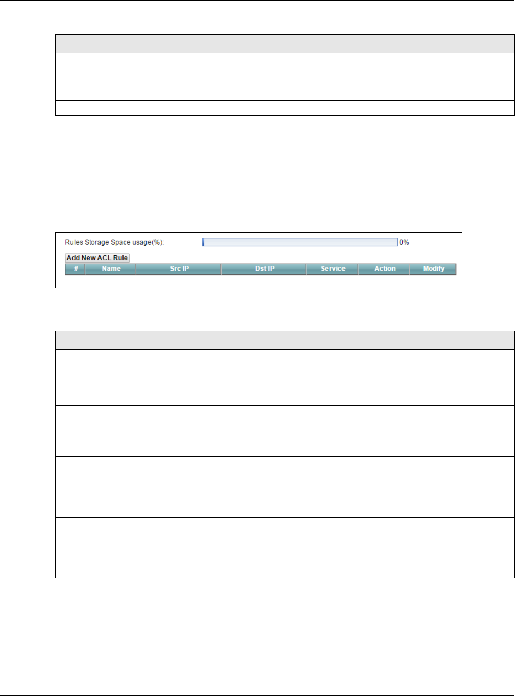
Chapter 16 Firewall
XMG3512-B10A User’s Guide
185
16.4 The Access Control Screen
Click Security > Firewall > Access Control to display the following screen. This screen displays a list of the
configured incoming or outgoing filtering rules.
Figure 110 Security > Firewall > Access Control
The following table describes the labels in this screen.
16.4.1 Add/Edit an ACL Rule
Click Add new ACL rule or the Edit icon next to an existing ACL rule in the Access Control screen. The
following screen displays.
ICMPv6 Type This field is displayed if you select ICMPv6 as the protocol.
Enter the type value for the ICMPv6 messages.
OK Click OK to save your changes.
Cancel Click Cancel to exit this screen without saving.
Table 81 Security > Firewall > Protocol: Add/Edit (continued)
LABEL DESCRIPTION
Table 82 Security > Firewall > Access Control
LABEL DESCRIPTION
Add New ACL
Rule
Click this to go to add a filter rule for incoming or outgoing IP traffic.
#This is the index number of the entry.
Name This displays the name of the rule.
Src IP This displays the source IP addresses to which this rule applies. Please note that a blank source
address is equivalent to Any.
Dst IP This displays the destination IP addresses to which this rule applies. Please note that a blank
destination address is equivalent to Any.
Service This displays the transport layer protocol that defines the service and the direction of traffic to
which this rule applies.
Action This field displays whether the rule silently discards packets (DROP), discards packets and sends a
TCP reset packet or an ICMP destination-unreachable message to the sender (REJECT) or allows
the passage of packets (ACCEPT).
Modify Click the Edit icon to edit the rule.
Click the Delete icon to delete an existing rule. Note that subsequent rules move up by one
when you take this action.
Click the Move To icon to change the order of the rule. Enter the number in the # field.
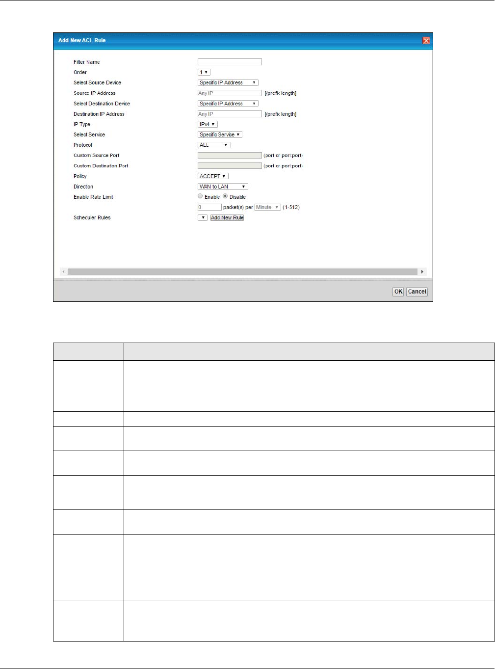
Chapter 16 Firewall
XMG3512-B10A User’s Guide
186
Figure 111 Access Control: Add/Edit
The following table describes the labels in this screen.
Table 83 Access Control: Add/Edit
LABEL DESCRIPTION
Filter Name Enter a descriptive name of up to 16 alphanumeric characters, not including spaces,
underscores, and dashes.
You must enter the filter name to add an ACL rule. This field is read-only if you are editing the
ACL rule.
Order Select the order of the ACL rule.
Select Source
Device
Select the source device to which the ACL rule applies. If you select Specific IP Address, enter
the source IP address in the field below.
Source IP
Address
Enter the source IP address.
Select
Destination
Device
Select the destination device to which the ACL rule applies. If you select Specific IP Address,
enter the destiniation IP address in the field below.
Destination IP
Address
Enter the destination IP address.
IP Type Select whether your IP type is IPv4 or IPv6.
Select Service Select the transport layer protocol that defines your customized port from the drop-down list
box. The specific protocol rule sets you add in the Security > Firewall > Service > Add screen
display in this list.
If you want to configure a customized protocol, select Specific Service.
Protocol This field is displayed only when you select Specific Protocol in Select Protocol.
Choose the IP port (TCP/UDP, TCP, UDP, ICMP, or ICMPv6) that defines your customized port from
the drop-down list box.
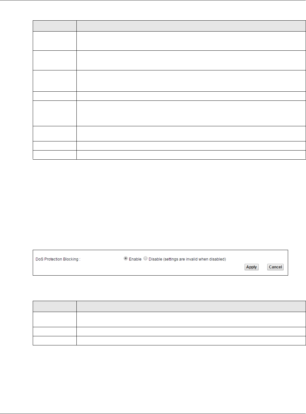
Chapter 16 Firewall
XMG3512-B10A User’s Guide
187
16.5 The DoS Screen
DoS (Denial of Service) attacks can flood your Internet connection with invalid packets and connection
requests, using so much bandwidth and so many resources that Internet access becomes unavailable.
Use the DoS screen to activate protection against DoS attacks. Click Security > Firewall > DoS to display
the following screen.
Figure 112 Security > Firewall > DoS
The following table describes the labels in this screen.
Custom Source
Port
This field is displayed only when you select Specific Protocol in Select Protocol.
Enter a single port number or the range of port numbers of the source.
Custom
Destination Port
This field is displayed only when you select Specific Protocol in Select Protocol.
Enter a single port number or the range of port numbers of the destination.
Policy Use the drop-down list box to select whether to discard (DROP), deny and send an ICMP
destination-unreachable message to the sender of (REJECT) or allow the passage of (ACCEPT)
packets that match this rule.
Direction Use the drop-down list box to select the direction of traffic to which this rule applies.
Enable Rate
Limit
Select Enable to set a limit on the upstream/downstream transmission rate for the specified
protocol.
Specify how many packets per minute or second the transmission rate is.
Scheduler Rules Select a schedule rule for this ACL rule form the drop-down list box. You can configure a new
schedule rule by click Add New Rule. This will bring you to the Security > Scheduler Rules screen.
Apply Click Apply to save your changes.
Cancel Click Cancel to exit this screen without saving.
Table 83 Access Control: Add/Edit (continued)
LABEL DESCRIPTION
Table 84 Security > Firewall > DoS
LABEL DESCRIPTION
DoS Protection
Blocking
Select Enable to enable protection against DoS attacks.
Apply Click Apply to save your changes.
Cancel Click Cancel to exit this screen without saving.
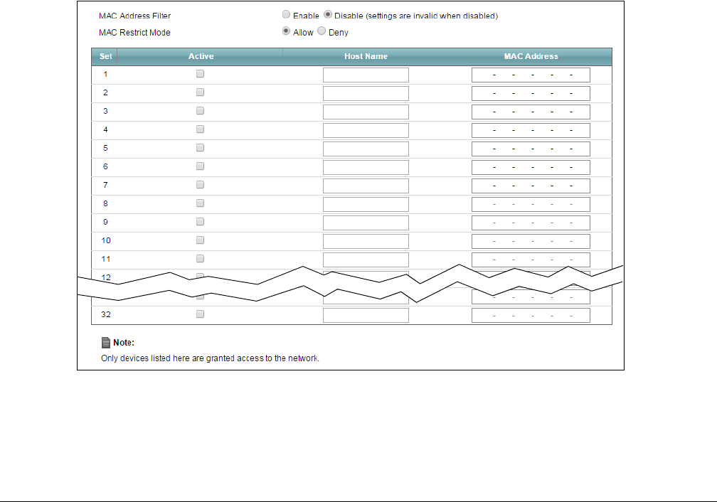
XMG3512-B10A User’s Guide
188
CHAPTER 17
MAC Filter
17.1 Overview
You can configure the XMG to permit access to clients based on their MAC addresses in the MAC Filter
screen. This applies to wired and wireless connections. Every Ethernet device has a unique MAC (Media
Access Control) address. The MAC address is assigned at the factory and consists of six pairs of
hexadecimal characters, for example, 00:A0:C5:00:00:02. You need to know the MAC addresses of the
devices to configure this screen.
17.2 The MAC Filter Screen
Use this screen to allow wireless and LAN clients access to the XMG. Click Security > MAC Filter. The
screen appears as shown.
Figure 113 Security > MAC Filter

Chapter 17 MAC Filter
XMG3512-B10A User’s Guide
189
The following table describes the labels in this screen.
Table 85 Security > MAC Filter
LABEL DESCRIPTION
MAC Address Filter Select Enable to activate the MAC filter function.
MAC Restrict Mode Select Allow to only permit the listed MAC addresses access to the XMG. Select Deny to
permit anyone access to the XMG except the listed MAC addresses.
Set This is the index number of the MAC address.
Active Select Active to enable the MAC filter rule. . The rule will not be applied if Active is not
selected.
Host Name Enter the host name of the wireless or LAN clients that are allowed access to the XMG.
MAC Address Enter the MAC addresses of the wireless or LAN clients that are allowed access to the XMG
in these address fields. Enter the MAC addresses in a valid MAC address format, that is, six
hexadecimal character pairs, for example, 12:34:56:78:9a:bc.
Apply Click Apply to save your changes.
Cancel Click Cancel to restore your previously saved settings.
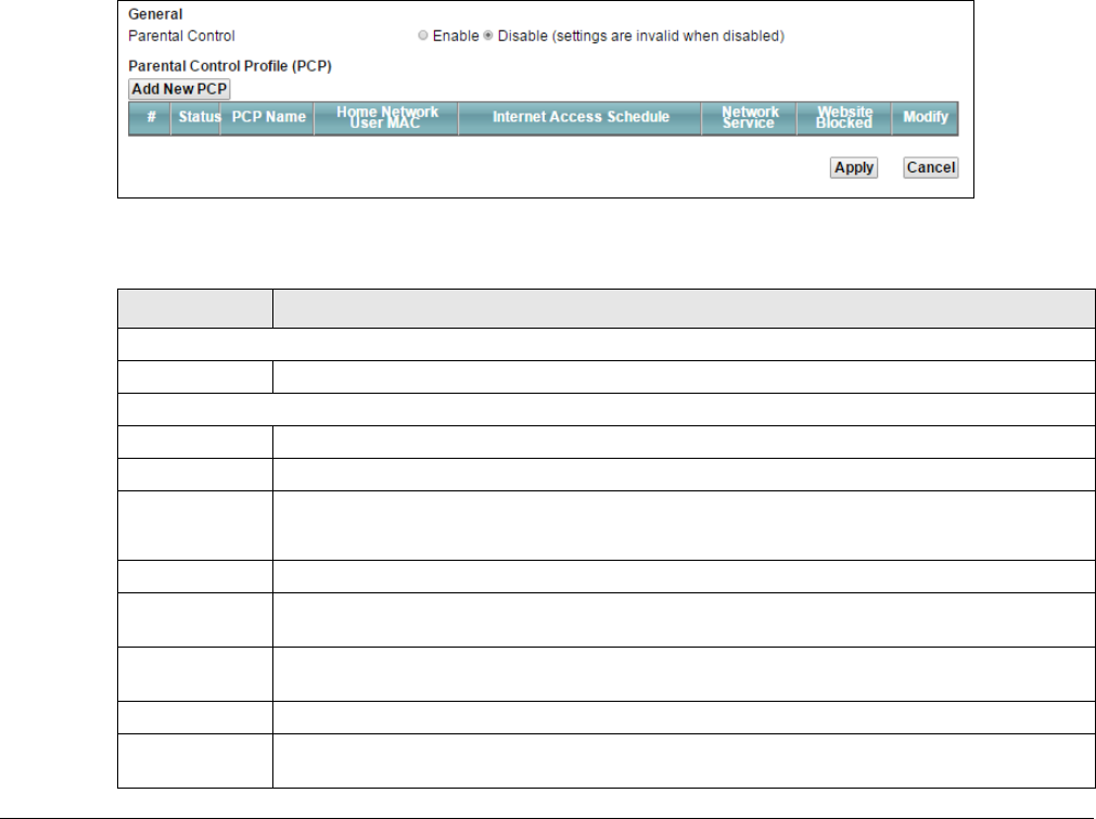
XMG3512-B10A User’s Guide
190
CHAPTER 18
Parental Control
18.1 Overview
Parental control allows you to block web sites with the specific URL. You can also define time periods
and days during which the XMG performs parental control on a specific user.
18.2 The Parental Control Screen
Use this screen to enable parental control, view the parental control rules and schedules.
Click Security > Parental Control to open the following screen.
Figure 114 Security > Parental Control
The following table describes the fields in this screen.
Table 86 Security > Parental Control
LABEL DESCRIPTION
General
Parental Control Select Enable to activate parental control.
Parental Control Profile (PCP)
Add New PCP Click this if you want to configure a new Parental Control Profile.
#This shows the index number of the rule.
Status This indicates whether the rule is active or not.
A yellow bulb signifies that this rule is active. A gray bulb signifies that this rule is not active.
PCP Name This shows the name of the rule.
Home Network
User MAC
This shows the MAC address of the LAN user’s computer to which this rule applies.
Internet Access
Schedule
This shows the day(s) and time on which parental control is enabled.
Network Service This shows whether the network service is configured. If not, None will be shown.
Website
Blocked
This shows whether the website block is configured. If not, None will be shown.
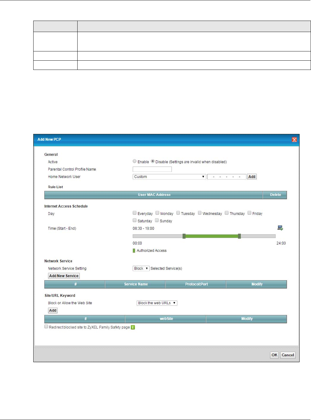
Chapter 18 Parental Control
XMG3512-B10A User’s Guide
191
18.2.1 Add/Edit a Parental Control Profile
Click Add New PCP in the Parental Control screen to add a new rule or click the Edit icon next to an
existing rule to edit it. Use this screen to configure a restricted access schedule and/or URL filtering
settings to block the users on your network from accessing certain web sites.
Figure 115 Parental Control Rule: Add/Edit Rule
Modify Click the Edit icon to go to the screen where you can edit the rule.
Click the Delete icon to delete an existing rule.
Apply Click Apply to save your changes.
Cancel Click Cancel to restore your previously saved settings.
Table 86 Security > Parental Control (continued)
LABEL DESCRIPTION

Chapter 18 Parental Control
XMG3512-B10A User’s Guide
192
The following table describes the fields in this screen.
Table 87 Parental Control Rule: Add/Edit
LABEL DESCRIPTION
General
Active Select to enable or disable this parental control rule.
Parental Control
Profile Name
Enter a descriptive name for the rule.
Home Network
User
Select the LAN user that you want to apply this rule to from the drop-down list box. If you select
Custom, enter the LAN user’s MAC address. If you select All, the rule applies to all LAN users.
Rule List In Home Network User, select Custom, enter the LAN user’s MAC address, then click the Add
icon to enter a computer MAC address for this PCP. Up to five are allowed. Click the Delete icon
to remove one.
Internet Access Schedule
Day Select check boxes for the days that you want the XMG to perform parental control.
Time Drag the time bar to define the time that the LAN user is allowed access (Authorized access) or
denied access (No access). Click the Add icon above the time bar to add a new time bar. Up
to three are allowed.
Network Service
Network Service
Setting
If you select Block, the XMG prohibits the users from viewing the Web sites with the URLs listed
below.
If you select Allow, the XMG blocks access to all URLs except ones listed below.
Add New
Service
Click this to show a screen in which you can add a new service rule. You can configure the
Service Name, Protocol, and Name of the new rule.
#This shows the index number of the rule.
Service Name This shows the name of the rule.
Protocol:Port This shows the protocol and the port of the rule.
Modify Click the Edit icon to go to the screen where you can edit the rule.
Click the Delete icon to delete an existing rule.
Site/URL Keyword
Block or Allow
the Web Site
If you select Block the Web URLs, the XMG prohibits the users from viewing the Web sites with the
URLs listed below.
If you select Allow the Web URLs, the XMG blocks access to all URLs except ones listed below.
Add Click Add to show a screen to enter the URL of web site or URL keyword to which the XMG blocks
or allows access.
#This shows the index number of the rule.
WebSite This shows the URL of web site or URL keyword to which the XMG blocks or allows access.
Modify Click the Edit icon to go to the screen where you can edit the rule.
Click the Delete icon to delete an existing rule.
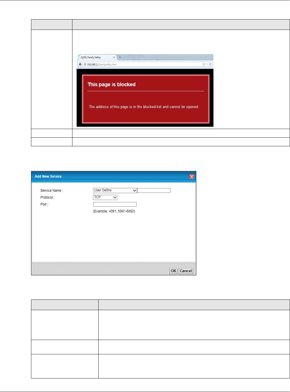
Chapter 18 Parental Control
XMG3512-B10A User’s Guide
193
Click Security > Parental Control > Add/Edit Rule > Add New Service to open the following screen.
Figure 117 Parental Control Rule: Add/Edit Rule > Add New Service
The following table describes the fields in this screen.
Redirect
blocked site to
Zyxel Family
Safety page
Select this to redirect users who access any blocked websites listed above to the Zyxel Family
Safety page as shown next.
Figure 116 Zyxel Family Safety Page Example
OK Click OK to save your changes.
Cancel Click Cancel to to exit this screen without saving.
Table 88 Parental Control Rule: Add/Edit Rule > Add New Service
LABEL DESCRIPTION
Service Name Select the name of the service. Otherwise, select User Define and manualy specify
the protocol and the port of the service.
If you have chosen a pre-defined service in the Service Name field, this field will not
be configurable.
Protocol Select the transport layer protocol used for the service. Choices are TCP, UDP, or TCP
& UDP.
Port Enter the port of the service.
If you have chosen a pre-defined service in the Service Name field, this field will not
be configurable.
Table 87 Parental Control Rule: Add/Edit (continued)
LABEL DESCRIPTION
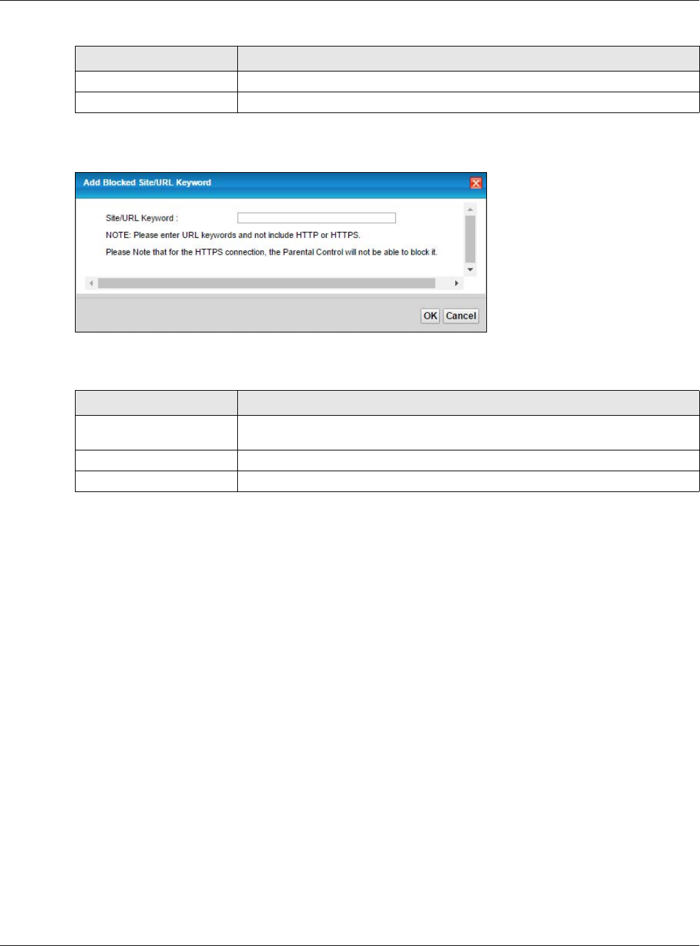
Chapter 18 Parental Control
XMG3512-B10A User’s Guide
194
Click Security > Parental Control > Add/Edit Rule > Add Keyword to open the following screen.
Figure 118 Parental Control Rule: Add/Edit Rule > Add Keyword
The following table describes the fields in this screen.
OK Click OK to save your changes.
Cancel Click Cancel to exit this screen without saving.
Table 89 Parental Control Rule: Add/Edit Rule > Add Keyword
LABEL DESCRIPTION
Site/URL Keyword Enter a keyword and click OK to have the XMG to block access to the website URLs
that contain the keyword
OK Click OK to save your changes.
Cancel Click Cancel to exit this screen without saving.
Table 88 Parental Control Rule: Add/Edit Rule > Add New Service
LABEL DESCRIPTION
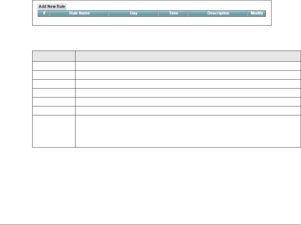
XMG3512-B10A User’s Guide
195
CHAPTER 19
Scheduler Rule
19.1 Overview
You can define time periods and days during which the XMG performs scheduled rules of certain
features (such as Firewall Access Control) in the Scheduler Rule screen.
19.2 The Scheduler Rule Screen
Use this screen to view, add, or edit time schedule rules.
Click Security > Scheduler Rule to open the following screen.
Figure 119 Security > Scheduler Rule
The following table describes the fields in this screen.
19.2.1 Add/Edit a Schedule
Click the Add New Rule button in the Scheduler Rule screen or click the Edit icon next to a schedule rule
to open the following screen. Use this screen to configure a restricted access schedule.
Table 90 Security > Scheduler Rule
LABEL DESCRIPTION
Add New Rule Click this to create a new rule.
#This is the index number of the entry.
Rule Name This shows the name of the rule.
Day This shows the day(s) on which this rule is enabled.
Time This shows the period of time on which this rule is enabled.
Description This shows the description of this rule.
Modify Click the Edit icon to edit the schedule.
Click the Delete icon to delete a scheduler rule.
Note: You cannot delete a scheduler rule once it is applied to a certain feature.
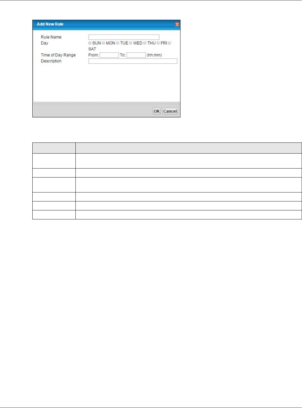
Chapter 19 Scheduler Rule
XMG3512-B10A User’s Guide
196
Figure 120 Scheduler Rule: Add/Edit
The following table describes the fields in this screen.
Table 91 Scheduler Rule: Add/Edit
LABEL DESCRIPTION
Rule Name Enter a name (up to 31 printable English keyboard characters, not including spaces) for this
schedule.
Day Select check boxes for the days that you want the XMG to perform this scheduler rule.
Time of Day
Range
Enter the time period of each day, in 24-hour format, during which the rule will be enforced.
Description Enter a description for this scheduler rule.
OK Click OK to save your changes.
Cancel Click Cancel to exit this screen without saving.
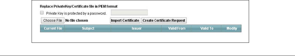
XMG3512-B10A User’s Guide
197
CHAPTER 20
Certificates
20.1 Overview
The XMG can use certificates (also called digital IDs) to authenticate users. Certificates are based on
public-private key pairs. A certificate contains the certificate owner’s identity and public key.
Certificates provide a way to exchange public keys for use in authentication.
20.1.1 What You Can Do in this Chapter
• Use the Local Certificates screen to generate certification requests and import the XMG's CA-signed
certificates (Section 20.4 on page 200).
• Use the Trusted CA screen to save the certificates of trusted CAs to the XMG (Section 20.4 on page
200).
20.2 What You Need to Know
The following terms and concepts may help as you read through this chapter.
Certification Authority
A Certification Authority (CA) issues certificates and guarantees the identity of each certificate owner.
There are commercial certification authorities like CyberTrust or VeriSign and government certification
authorities. The certification authority uses its private key to sign certificates. Anyone can then use the
certification authority's public key to verify the certificates. You can use the XMG to generate
certification requests that contain identifying information and public keys and then send the
certification requests to a certification authority.
20.3 The Local Certificates Screen
Click Security > Certificates to open the Local Certificates screen. This is the XMG’s summary list of
certificates and certification requests.
Figure 121 Security > Certificates > Local Certificates
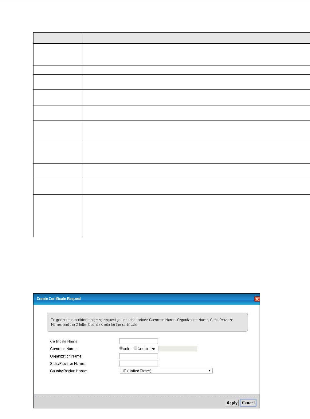
Chapter 20 Certificates
XMG3512-B10A User’s Guide
198
The following table describes the labels in this screen.
20.3.1 Create Certificate Request
Click Security > Certificates > Local Certificates and then Create Certificate Request to open the
following screen. Use this screen to have the XMG generate a certification request.
Figure 122 Create Certificate Request
Table 92 Security > Certificates > Local Certificates
LABEL DESCRIPTION
Private Key is
protected by a
password
Select the checkbox and enter the private key into the text box to store it on the XMG. The
private key should not exceed 63 ASCII characters (not including spaces).
Choose File Click this to find the certificate file you want to upload.
Import Certificate Click this button to save the certificate that you have enrolled from a certification authority
from your computer to the XMG.
Create Certificate
Request
Click this button to go to the screen where you can have the XMG generate a certification
request.
Current File This field displays the name used to identify this certificate. It is recommended that you give
each certificate a unique name.
Subject This field displays identifying information about the certificate’s owner, such as CN (Common
Name), OU (Organizational Unit or department), O (Organization or company) and C
(Country). It is recommended that each certificate have unique subject information.
Issuer This field displays identifying information about the certificate’s issuing certification authority,
such as a common name, organizational unit or department, organization or company and
country.
Valid From This field displays the date that the certificate becomes applicable. The text displays in red
and includes a Not Yet Valid! message if the certificate has not yet become applicable.
Valid To This field displays the date that the certificate expires. The text displays in red and includes an
Expiring! or Expired! message if the certificate is about to expire or has already expired.
Modify Click the View icon to open a screen with an in-depth list of information about the certificate
(or certification request).
For a certification request, click Load Signed to import the signed certificate.
Click the Remove icon to delete the certificate (or certification request). You cannot delete a
certificate that one or more features is configured to use.
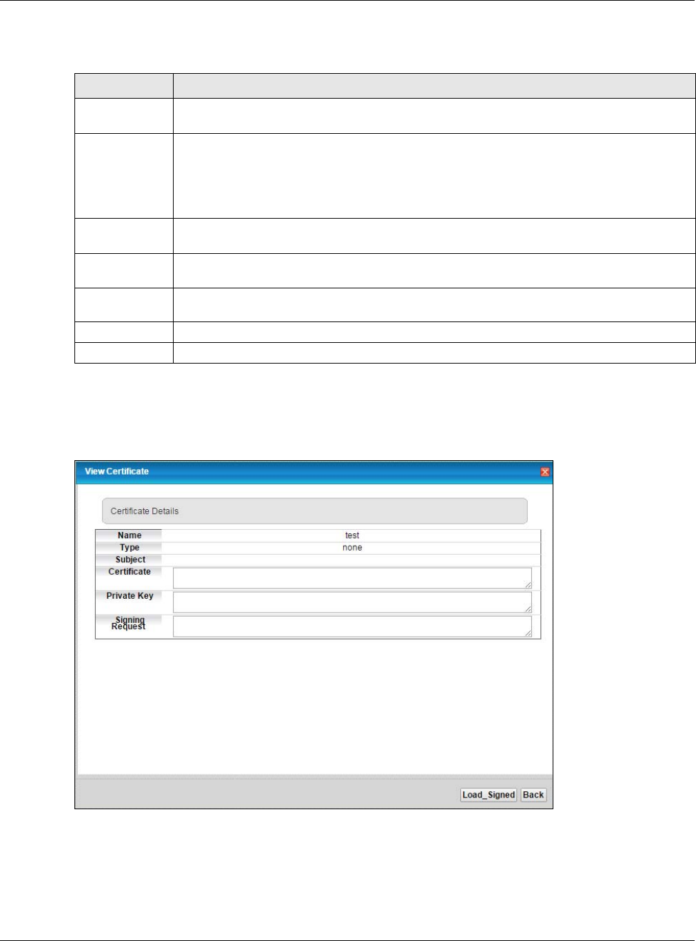
Chapter 20 Certificates
XMG3512-B10A User’s Guide
199
The following table describes the labels in this screen.
After you click Apply, the following screen displays to notify you that you need to get the certificate
request signed by a Certificate Authority. If you already have, click Load_Signed to import the signed
certificate into the XMG. Otherwise click Back to return to the Local Certificates screen.
Figure 123 Certificate Request Created
20.3.2 Load Signed Certificate
After you create a certificate request and have it signed by a Certificate Authority, in the Local
Certificates screen click the certificate request’s Load Signed icon to import the signed certificate into
the XMG.
Table 93 Create Certificate Request
LABEL DESCRIPTION
Certificate
Name
Type up to 63 ASCII characters (not including spaces) to identify this certificate.
Common Name Select Auto to have the XMG configure this field automatically. Or select Customize to enter it
manually.
Type the IP address (in dotted decimal notation), domain name or e-mail address in the field
provided. The domain name or e-mail address can be up to 63 ASCII characters. The domain
name or e-mail address is for identification purposes only and can be any string.
Organization
Name
Type up to 63 characters to identify the company or group to which the certificate owner
belongs. You may use any character, including spaces, but the XMG drops trailing spaces.
State/Province
Name
Type up to 32 characters to identify the state or province where the certificate owner is located.
You may use any character, including spaces, but the XMG drops trailing spaces.
Country/Region
Name
Select a country to identify the nation where the certificate owner is located.
Apply Click Apply to save your changes.
Cancel Click Cancel to exit this screen without saving.
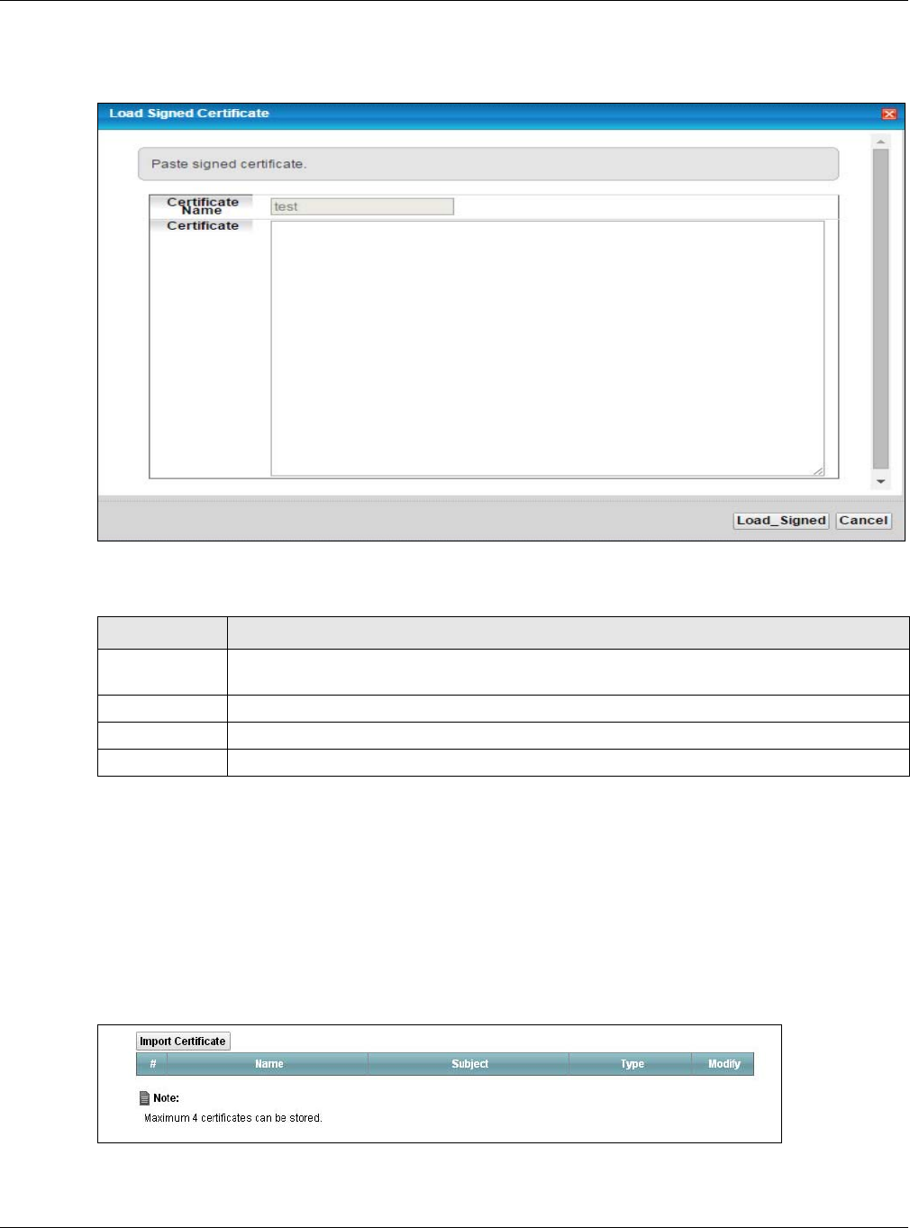
Chapter 20 Certificates
XMG3512-B10A User’s Guide
200
Note: You must remove any spaces from the certificate’s filename before you can import it.
Figure 124 Load Signed Certificate
The following table describes the labels in this screen.
20.4 The Trusted CA Screen
Click Security > Certificates > Trusted CA to open the following screen. This screen displays a summary list
of certificates of the certification authorities that you have set the XMG to accept as trusted. The XMG
accepts any valid certificate signed by a certification authority on this list as being trustworthy; thus you
do not need to import any certificate that is signed by one of these certification authorities.
Figure 125 Security > Certificates > Trusted CA
Table 94 Load Signed Certificate
LABEL DESCRIPTION
Certificate
Name
This is the name of the signed certificate.
Certificate Copy and paste the signed certificate into the text box to store it on the XMG.
Apply Click Apply to save your changes.
Cancel Click Cancel to exit this screen without saving.