abode systems IOTA abode iota User Manual Z1 20161229 IP Installation Guide
abode systems, inc abode iota Z1 20161229 IP Installation Guide
UserManual.wiki
>
abode systems
>
IOTA User Manual
Users Manual
Navigation menu
Upload a User Manual
Namespaces
Wiki Guide
HTML
PDF
Info
Views
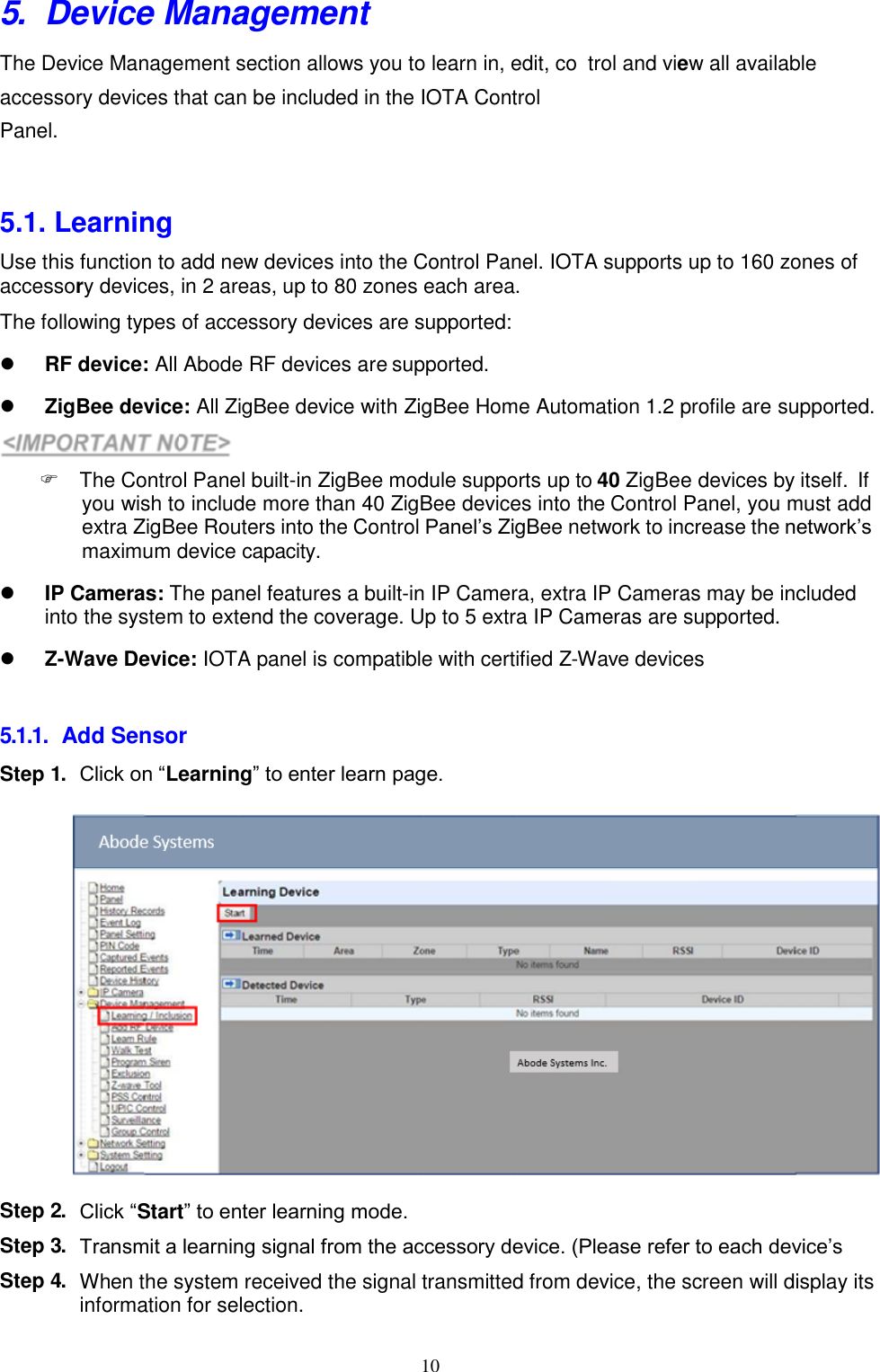
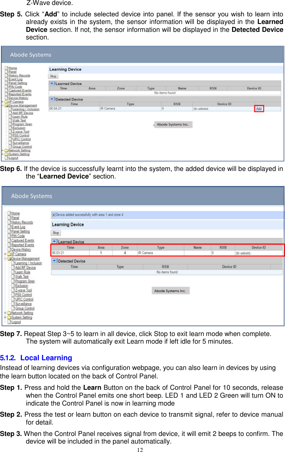
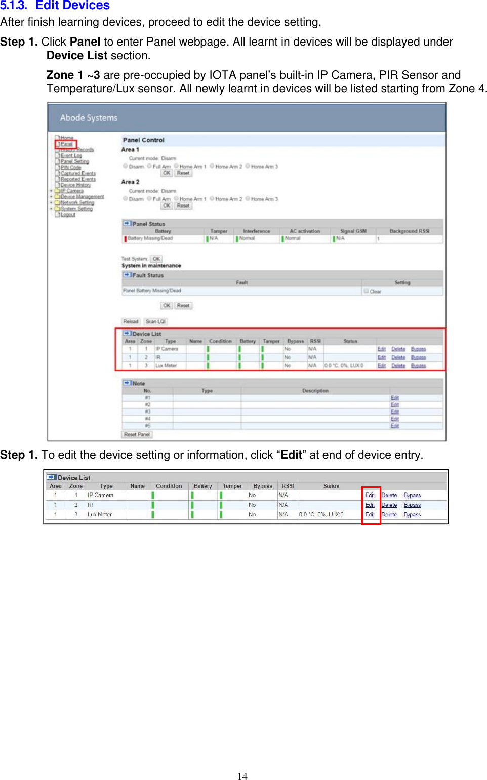
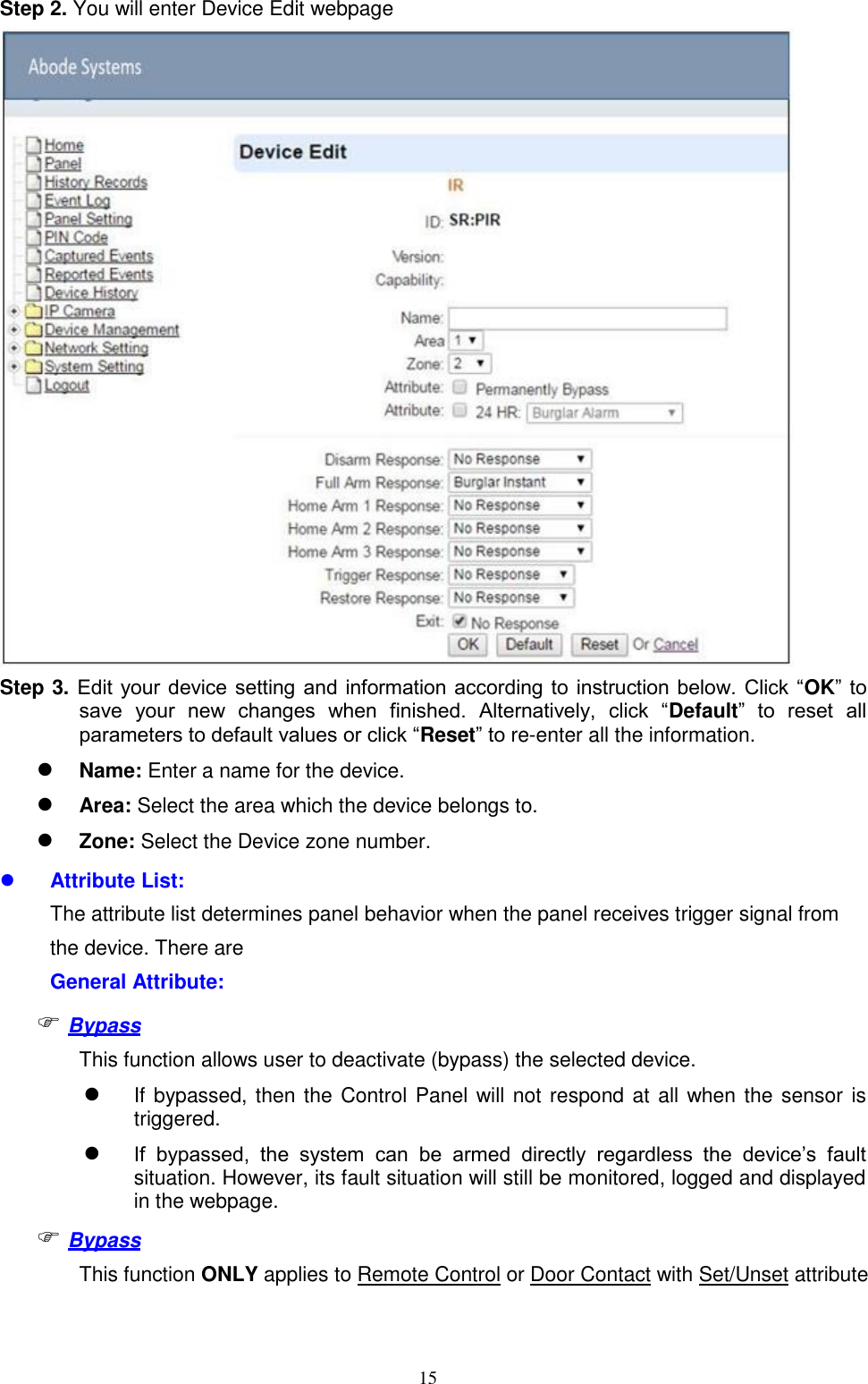
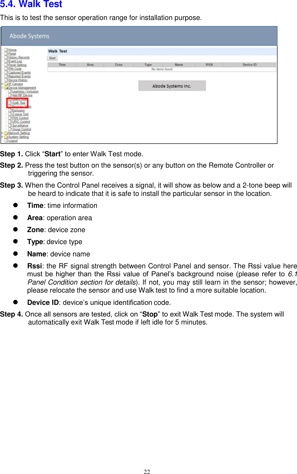
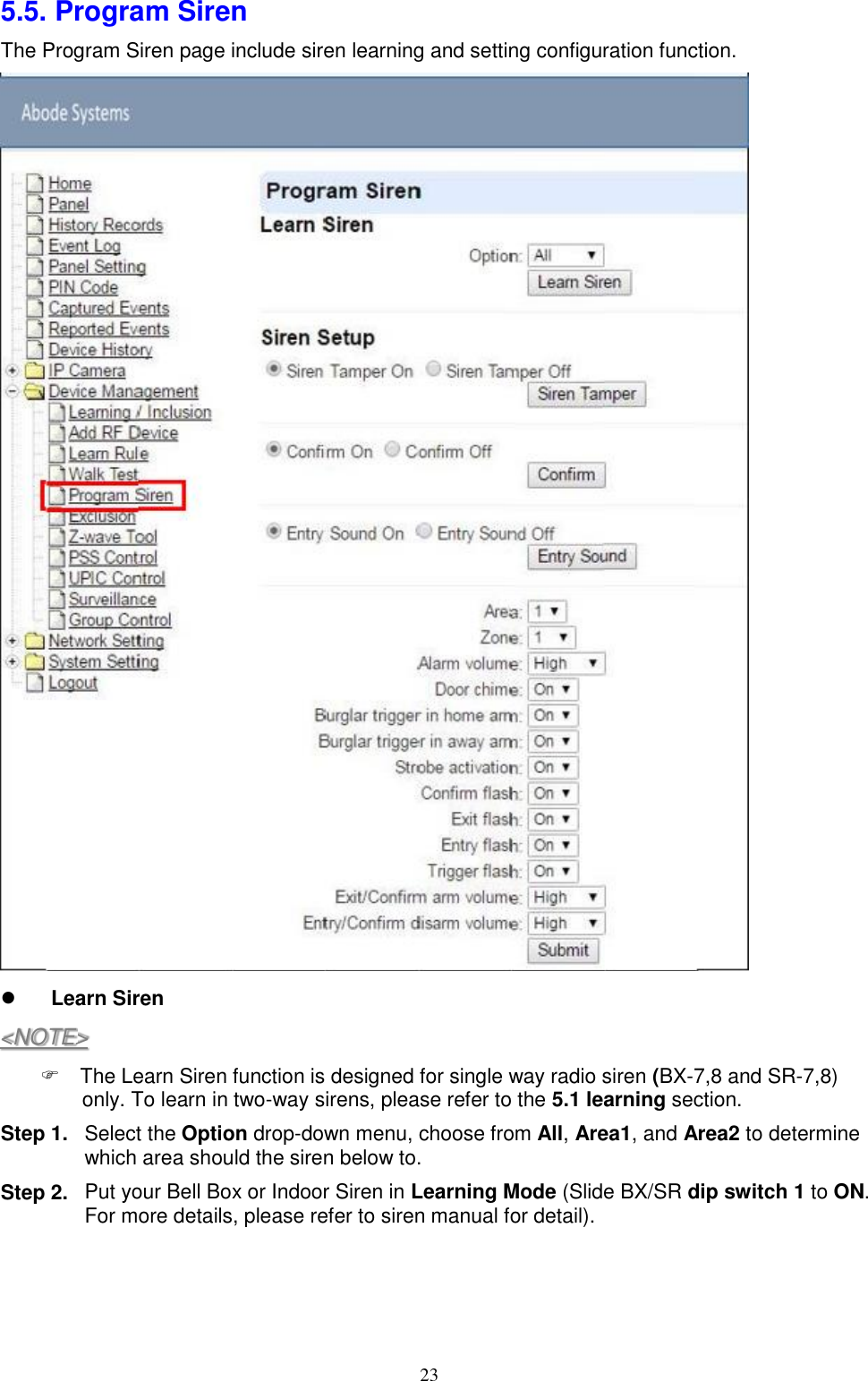
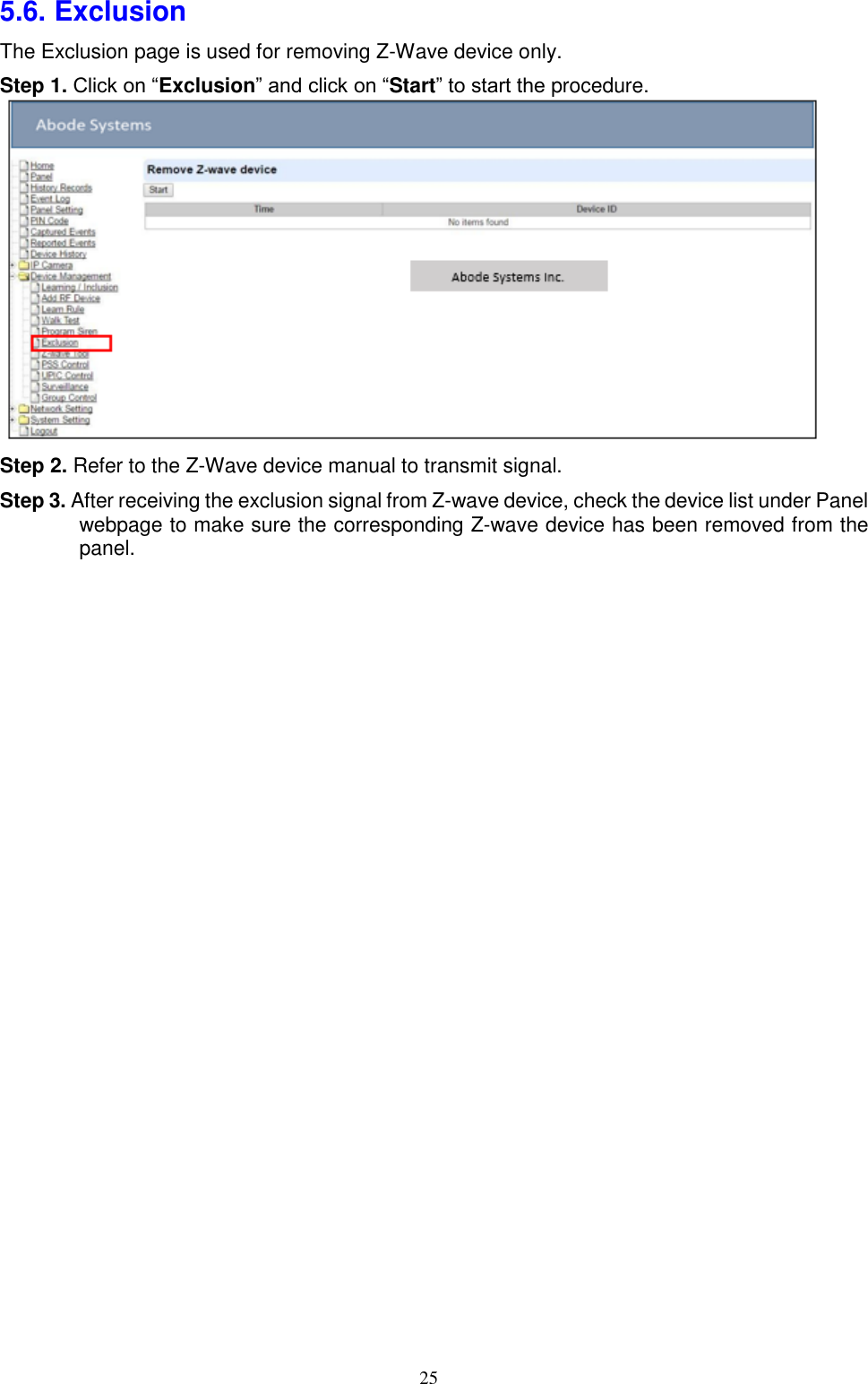
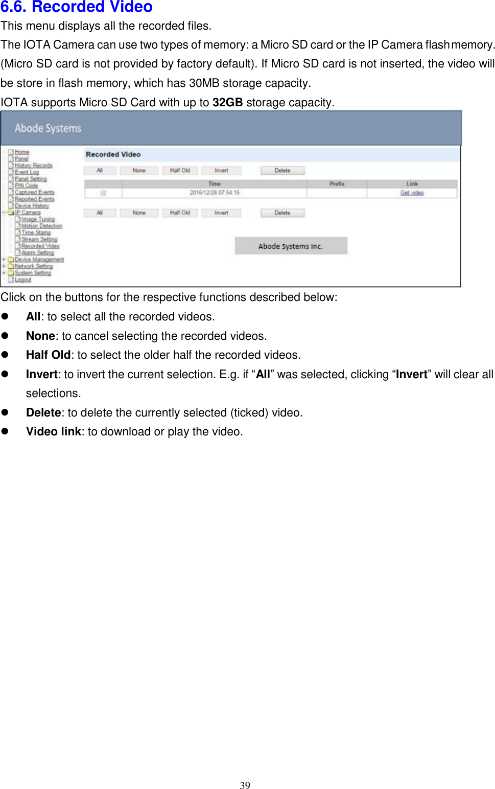
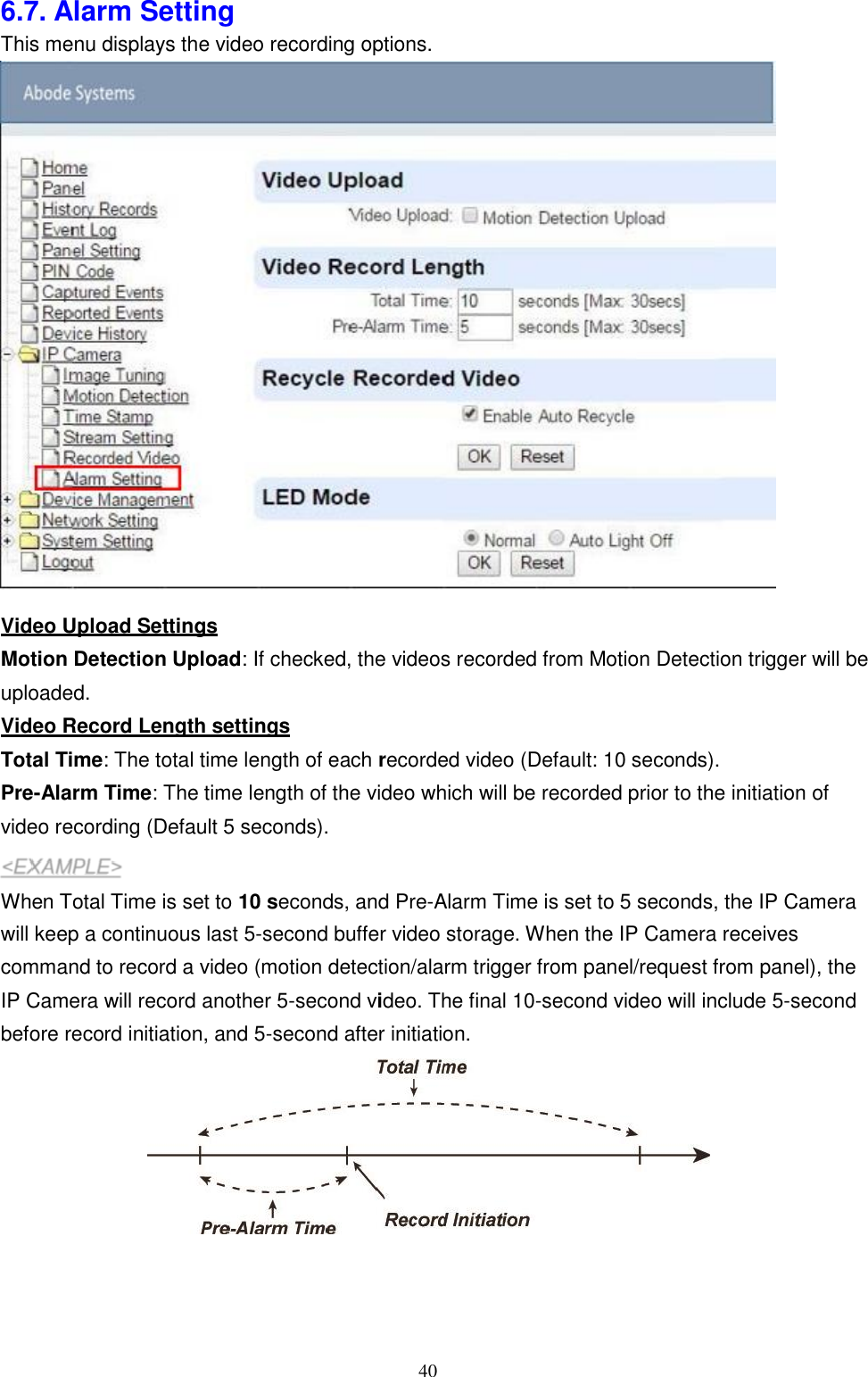
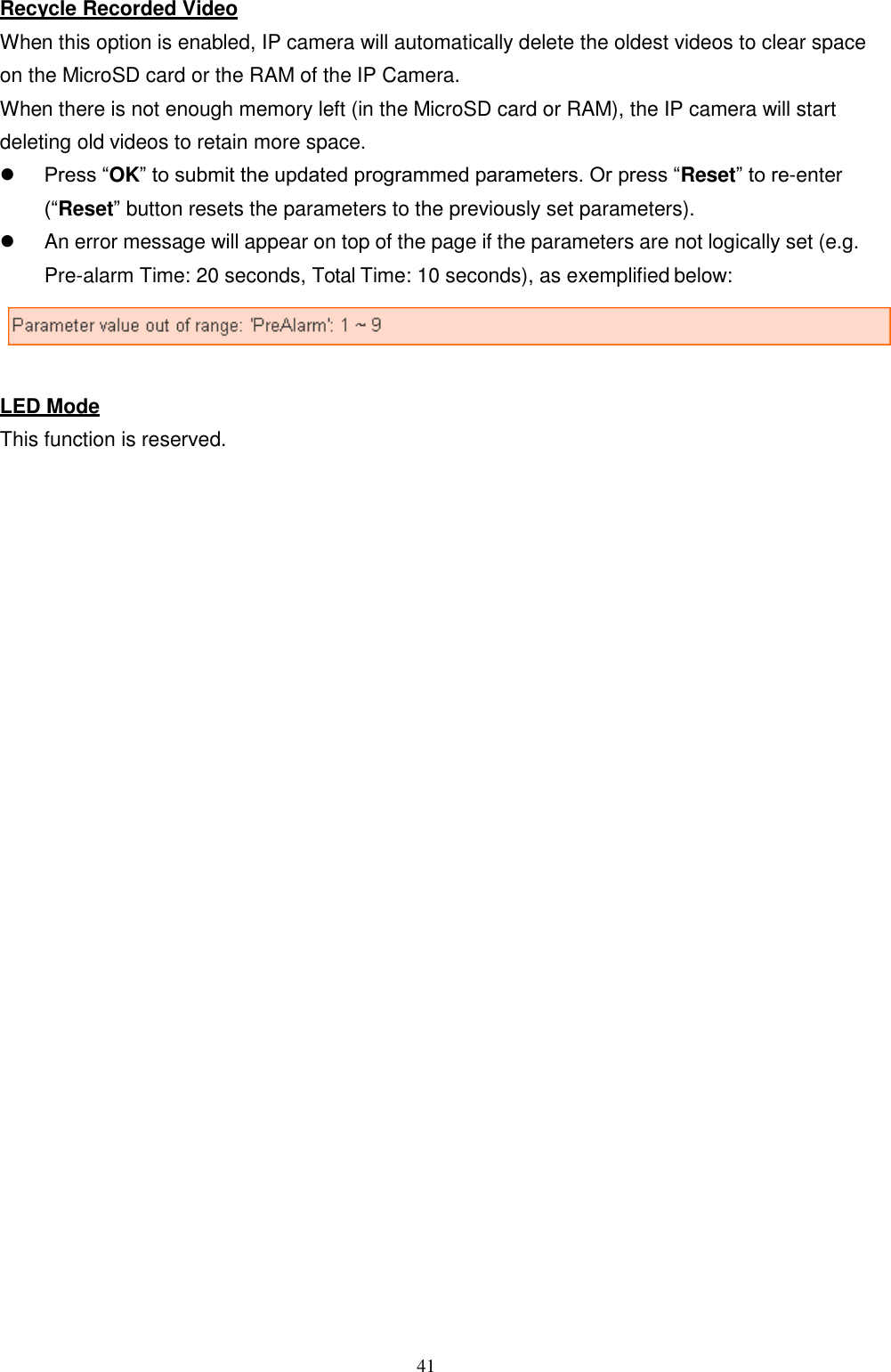
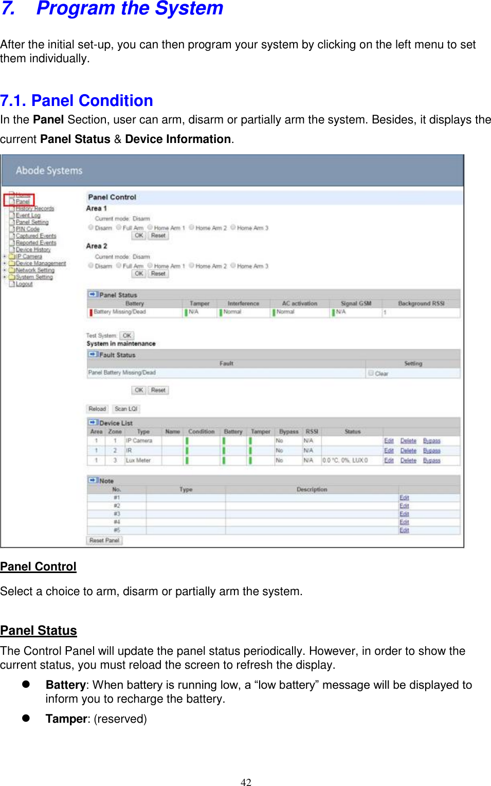
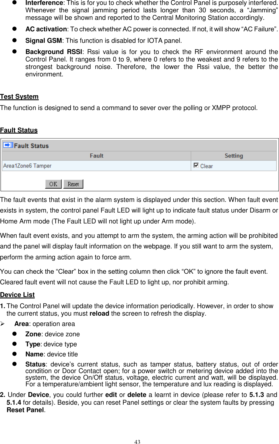
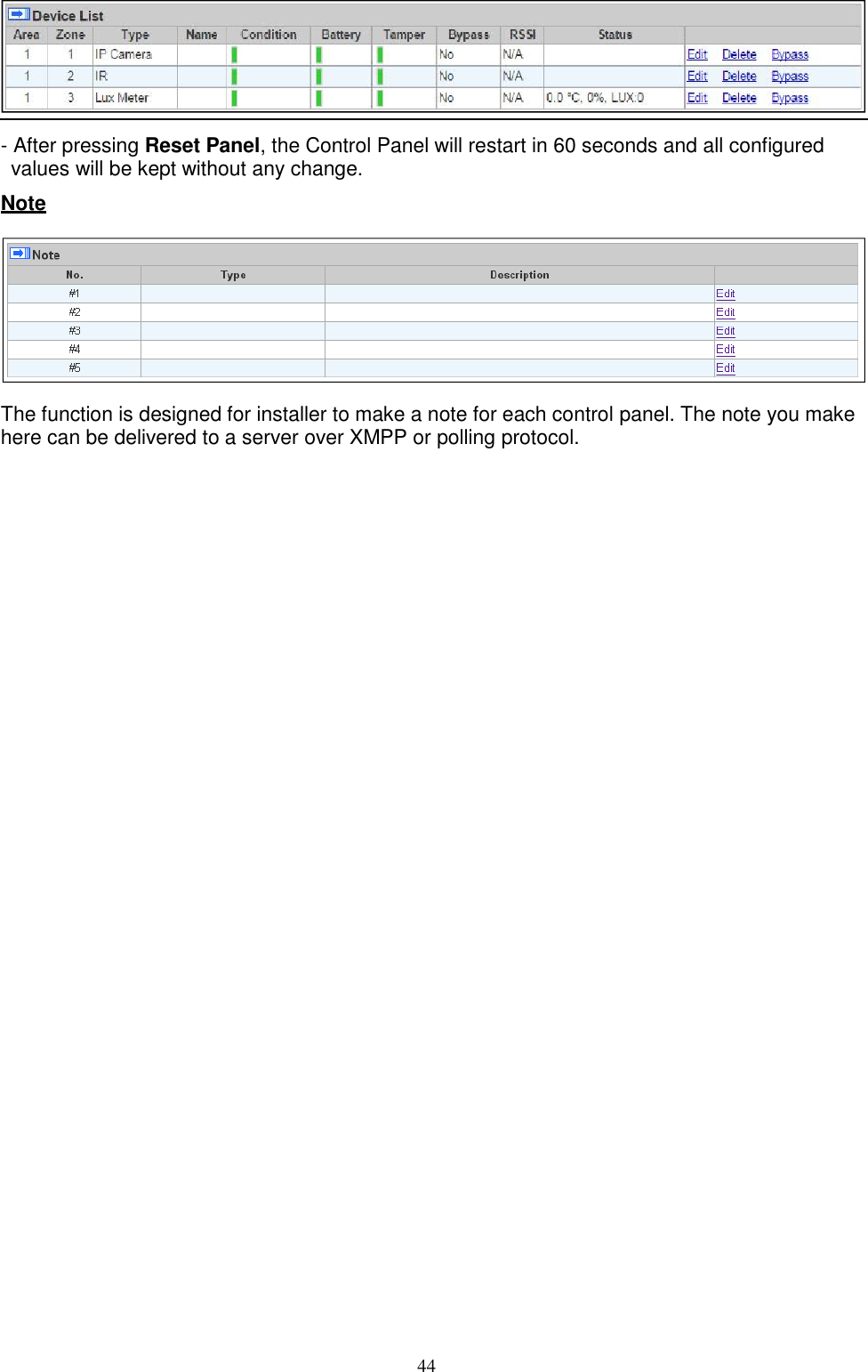
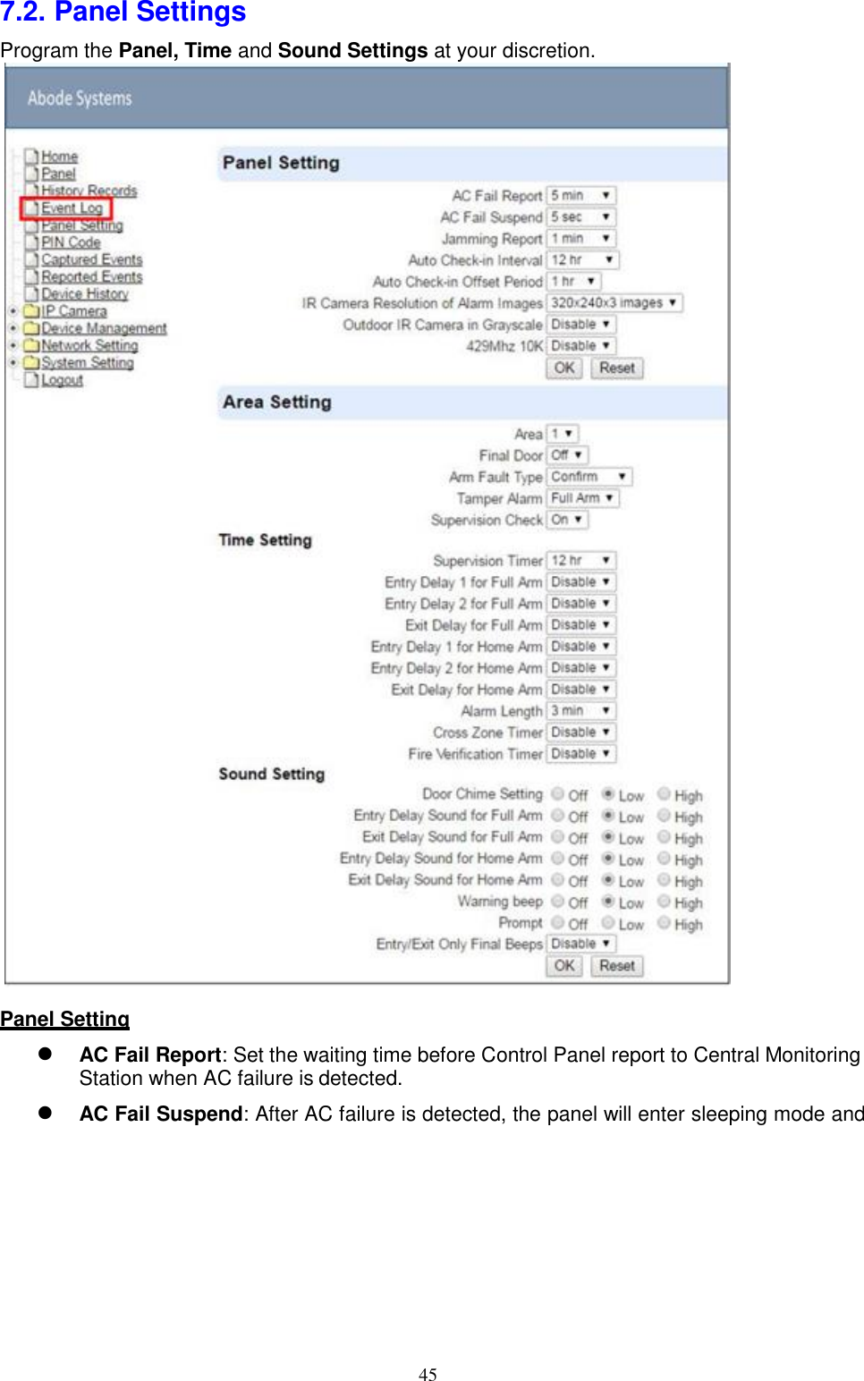
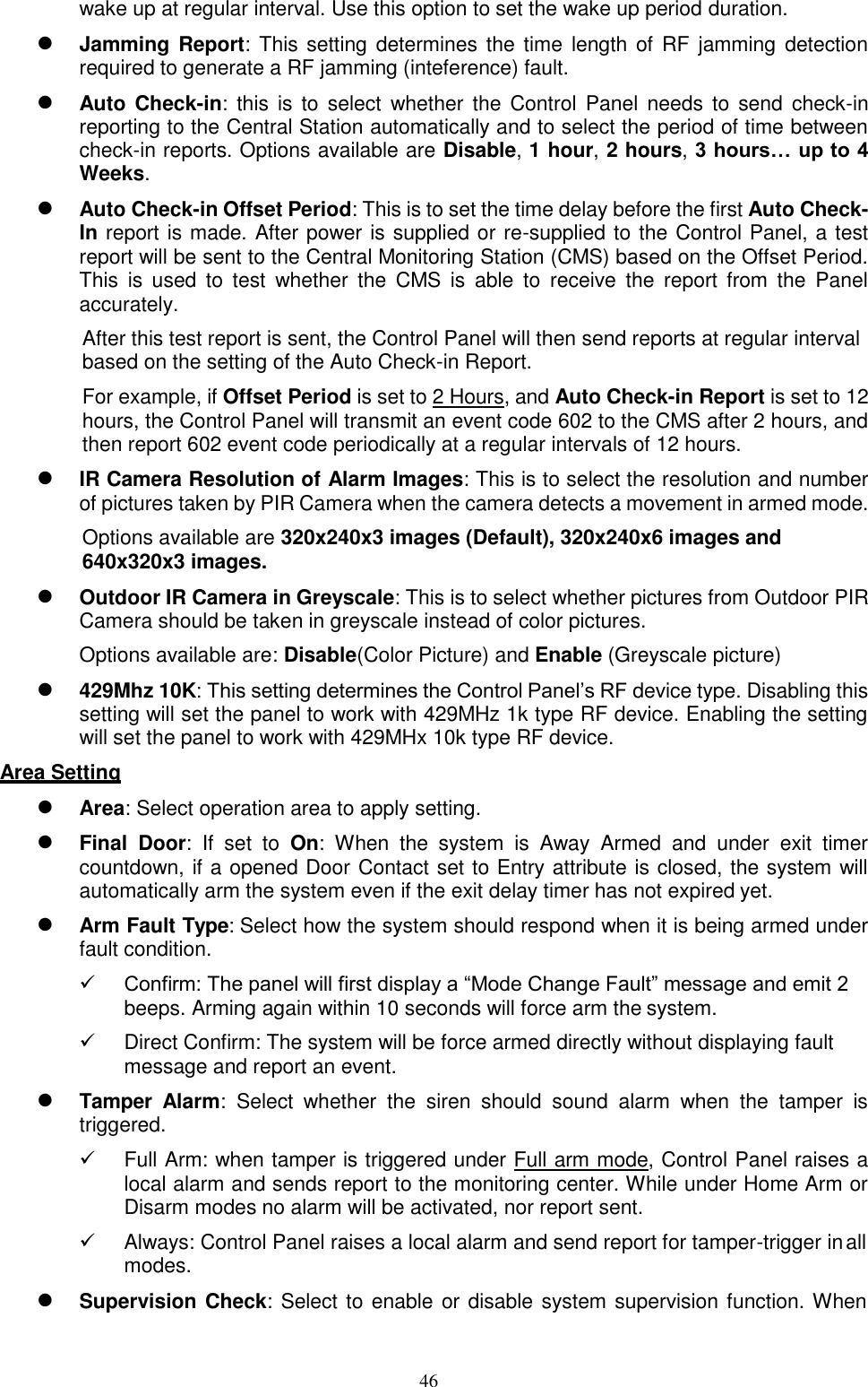
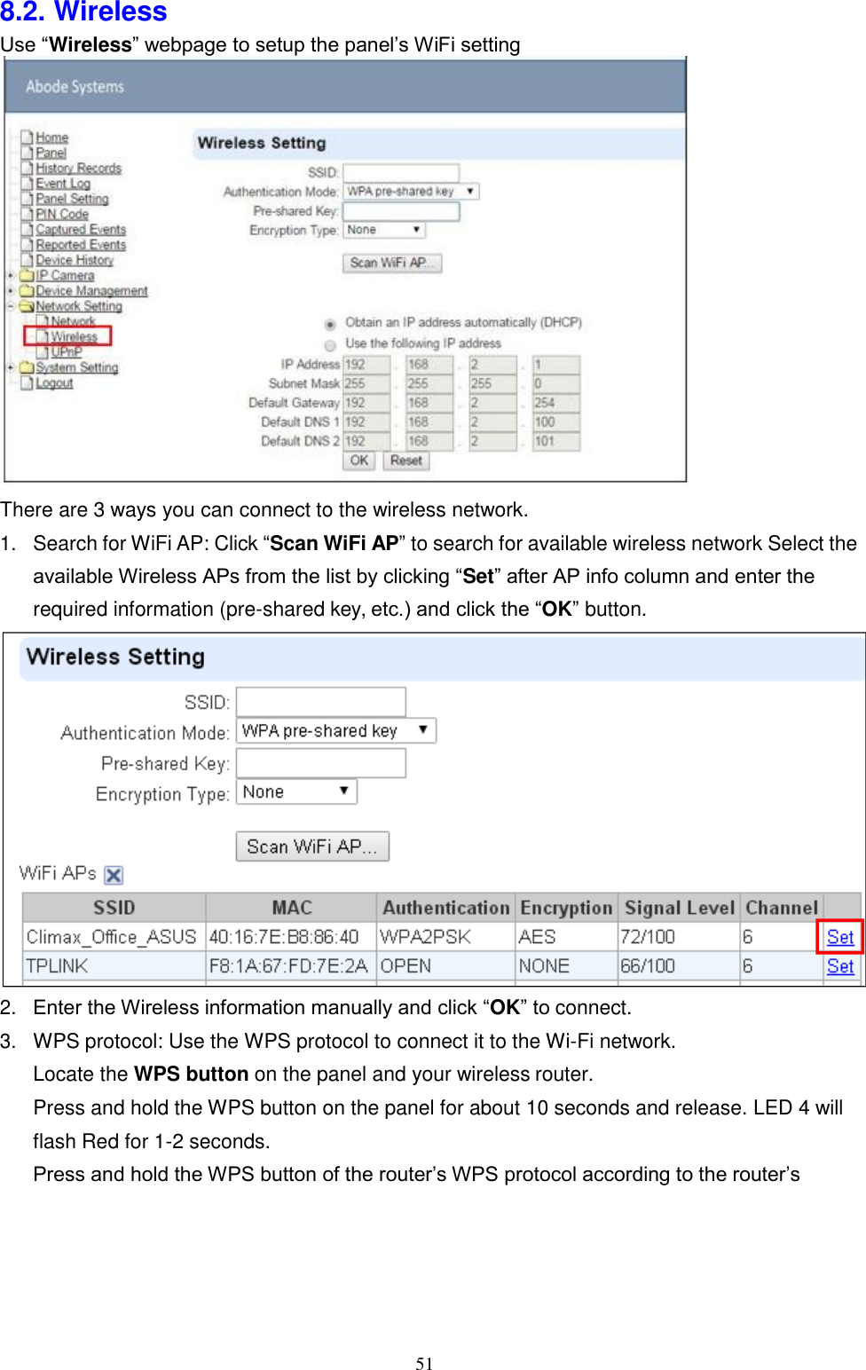
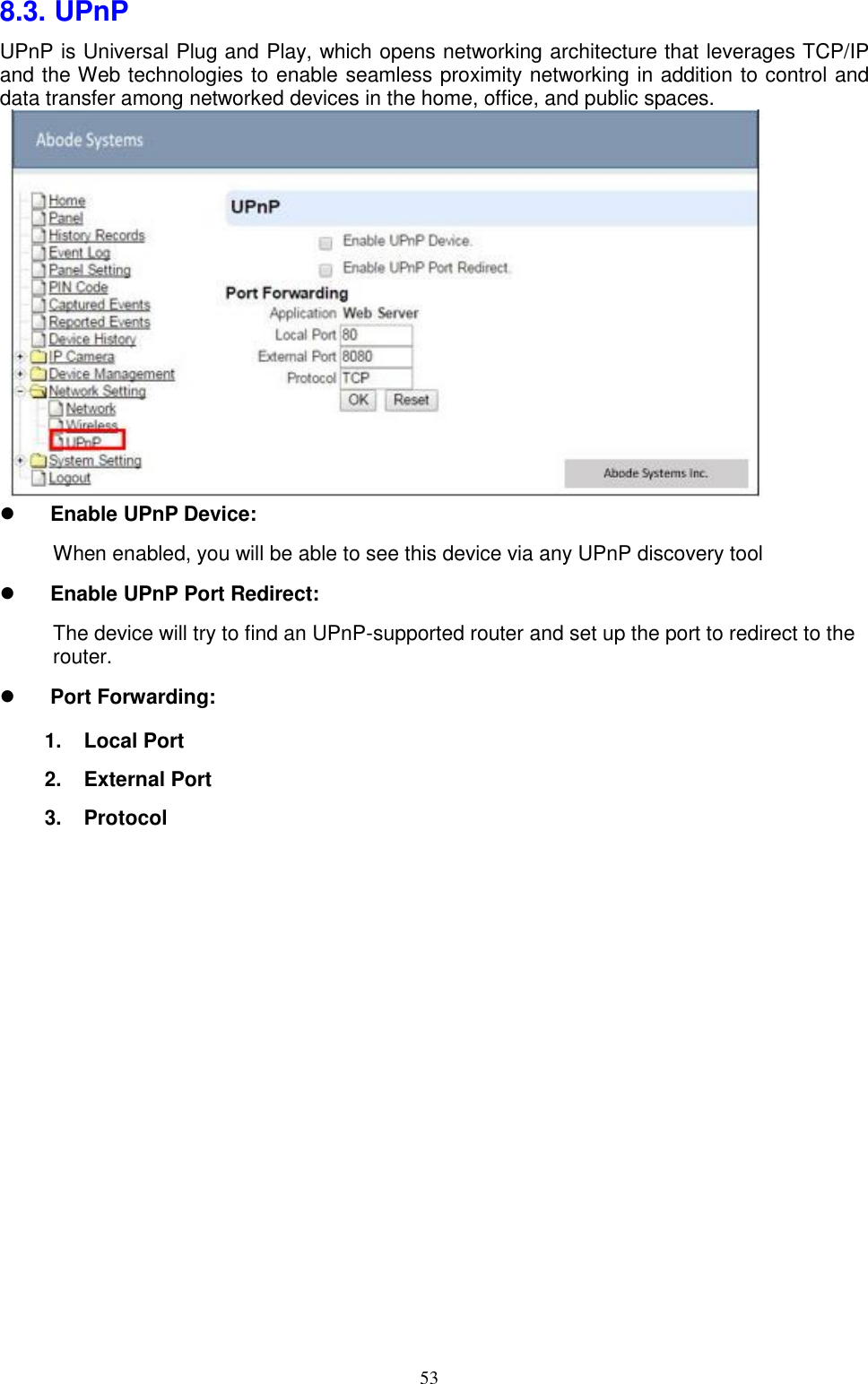
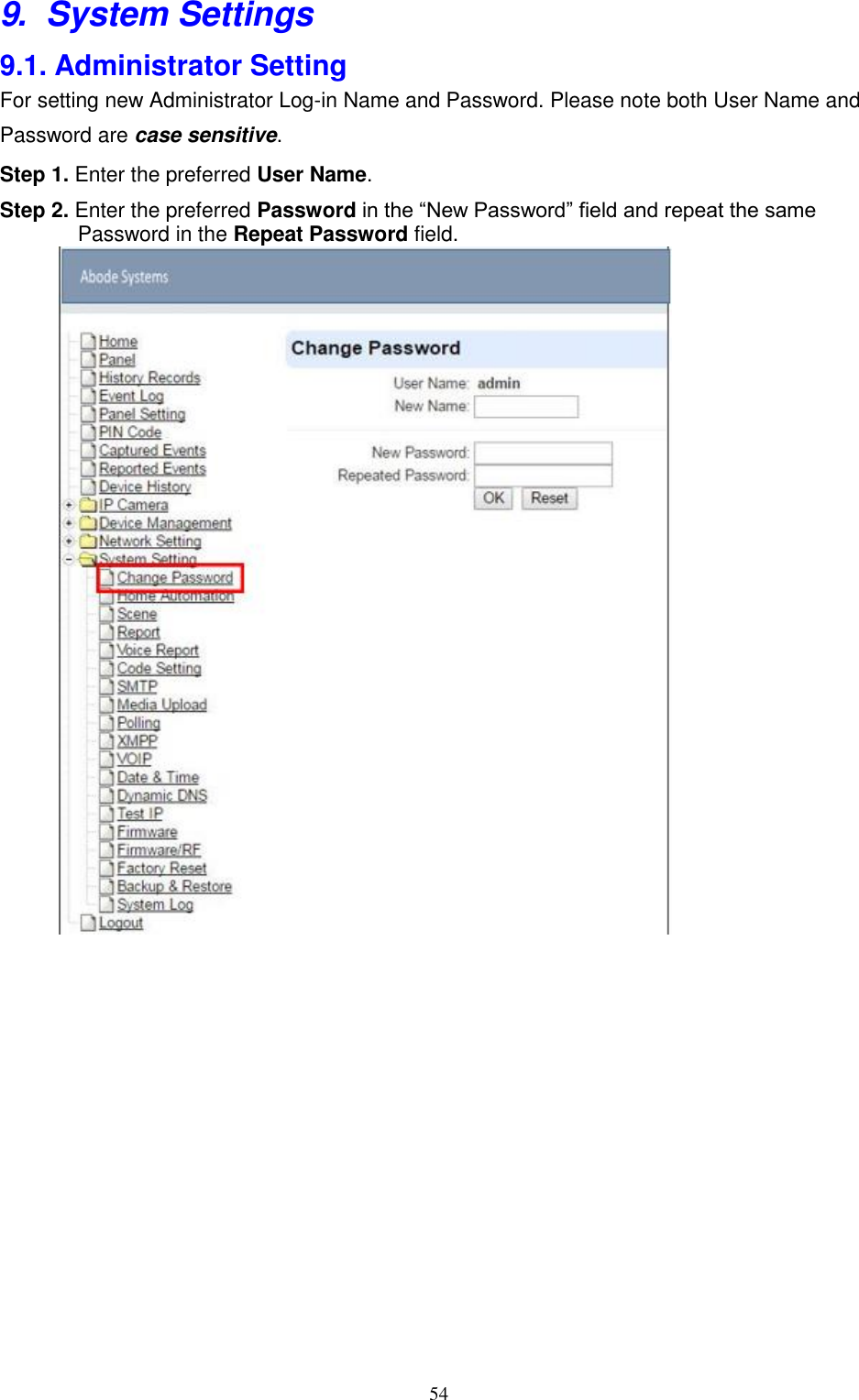
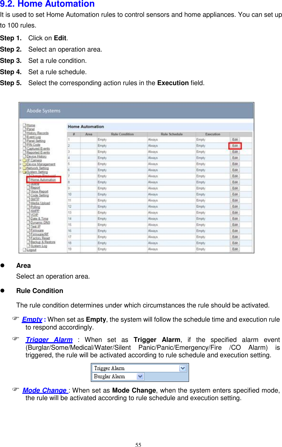
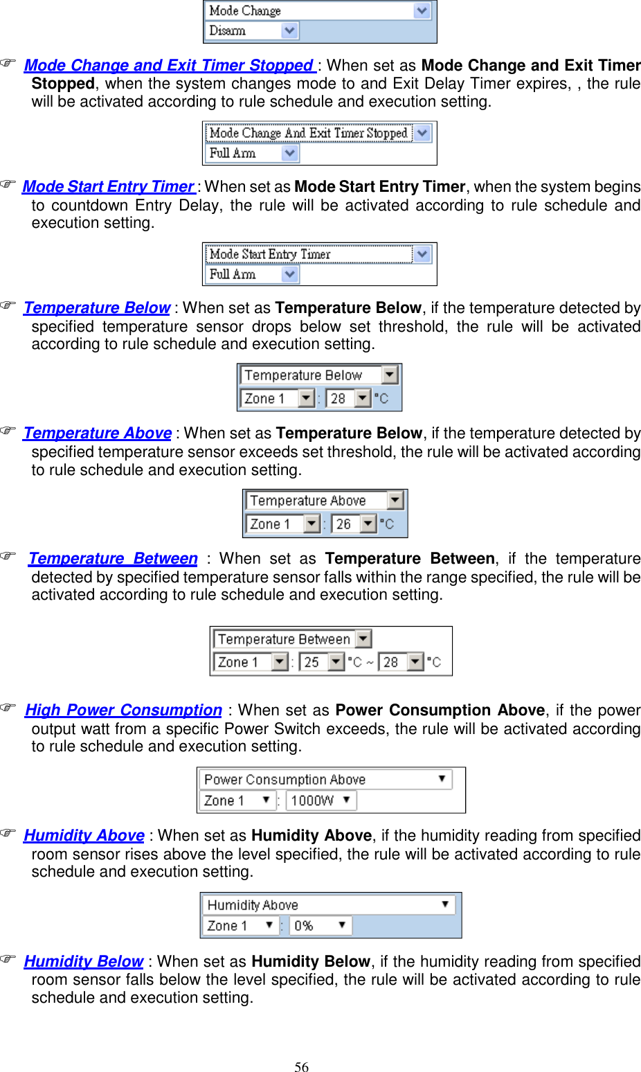
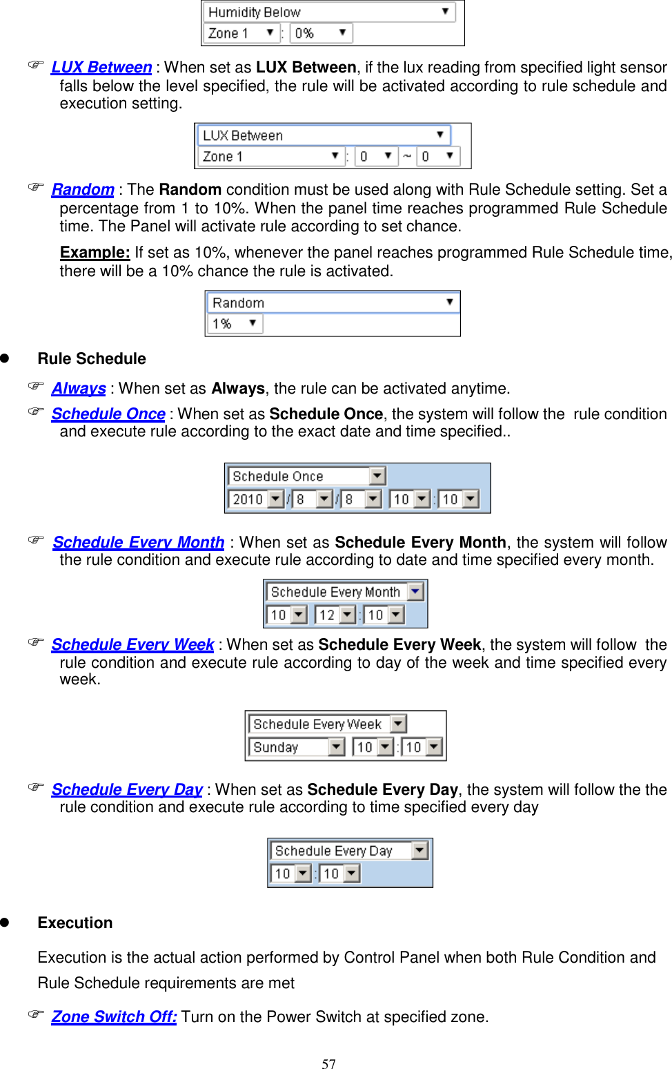
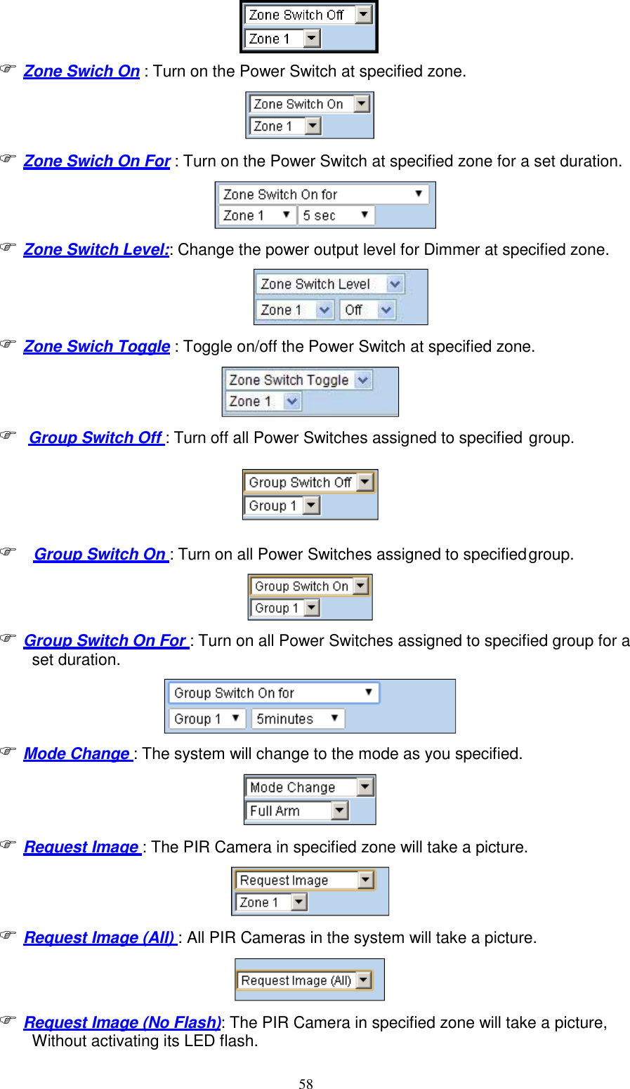
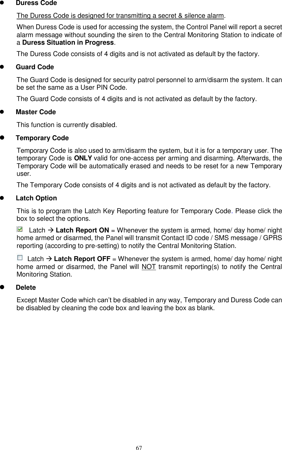
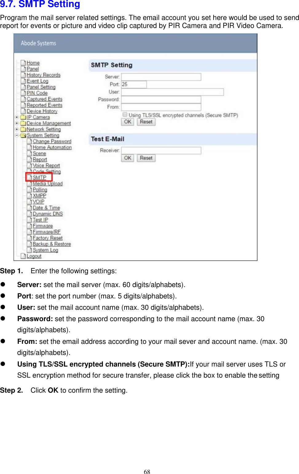
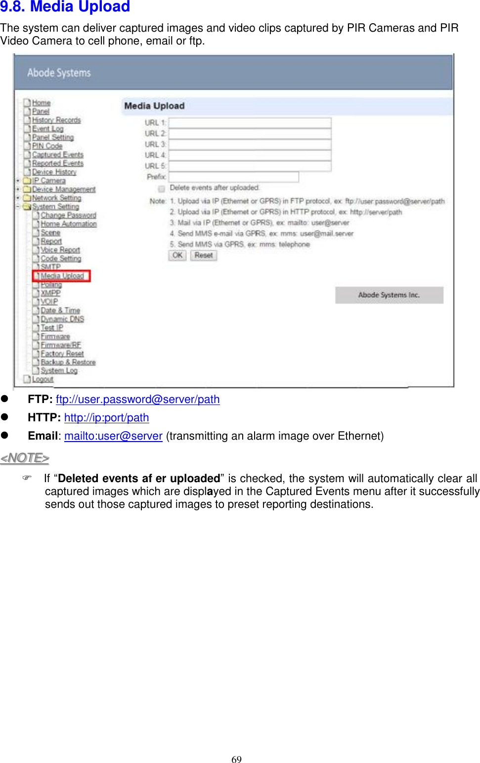
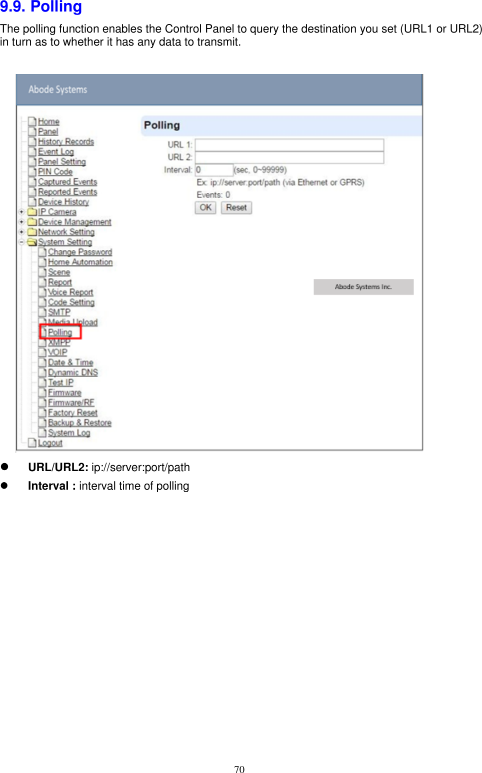
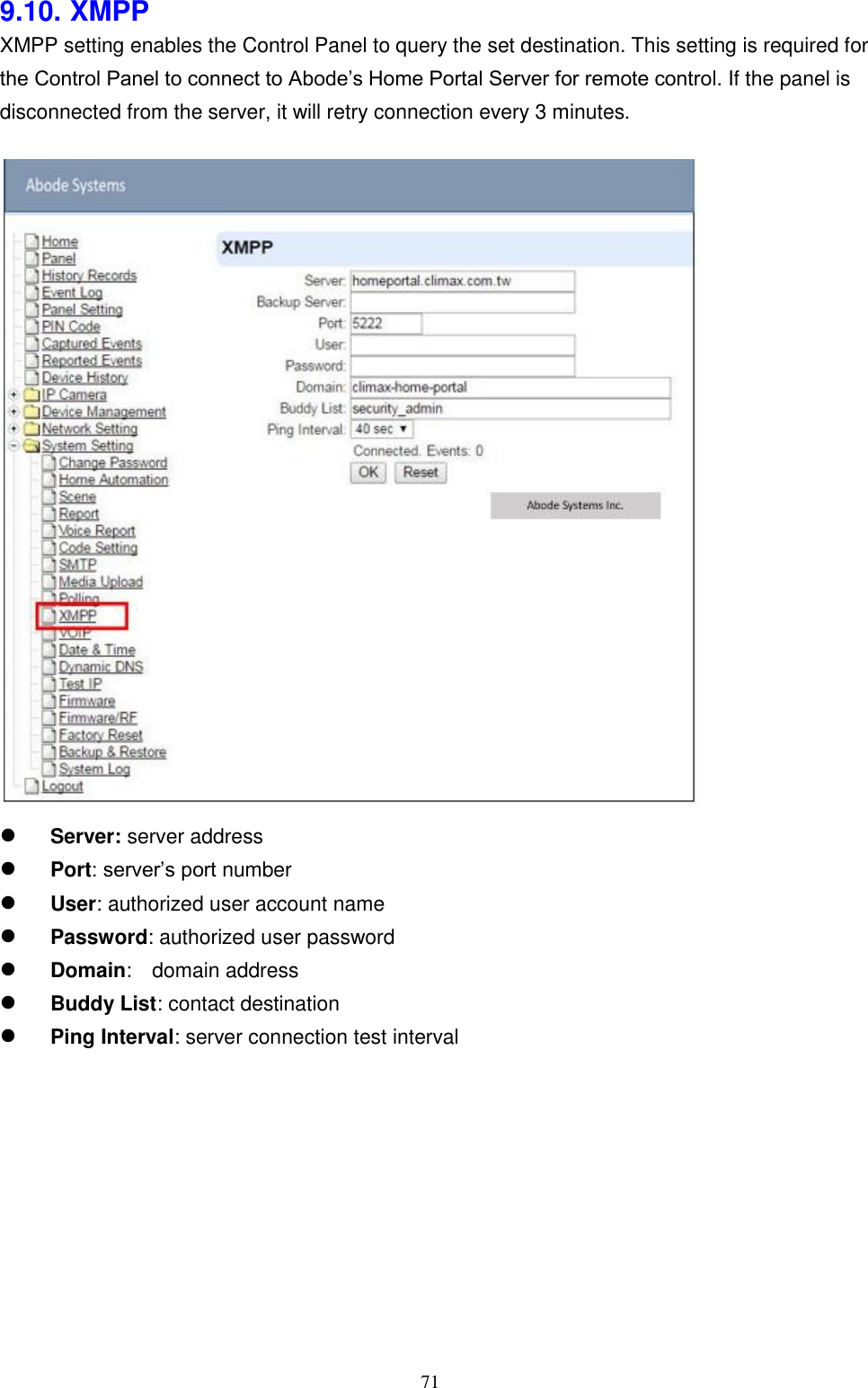
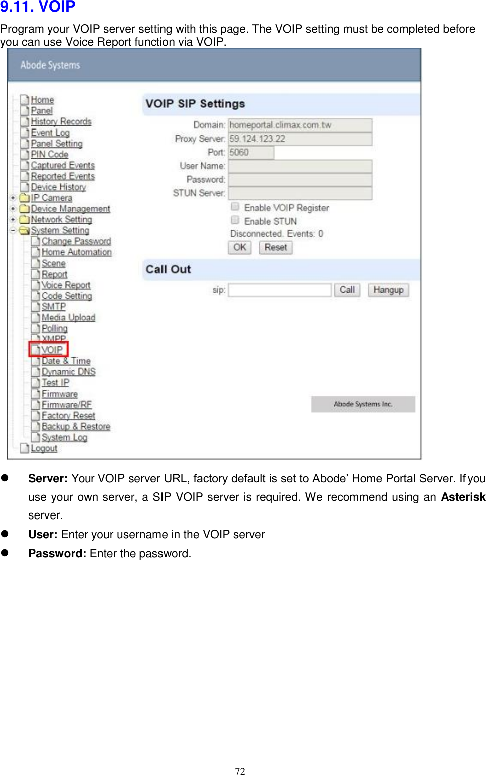
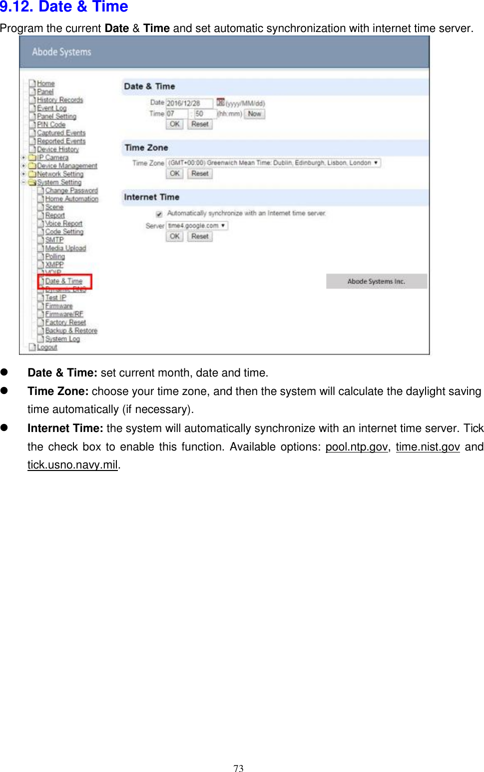
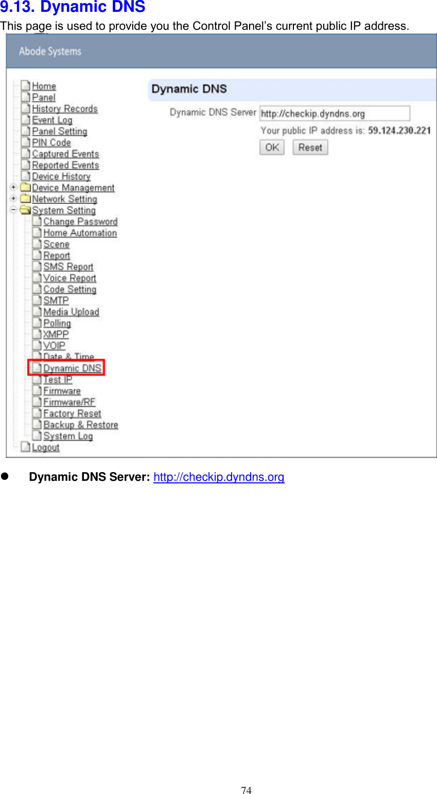
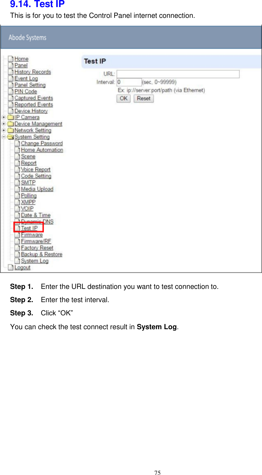
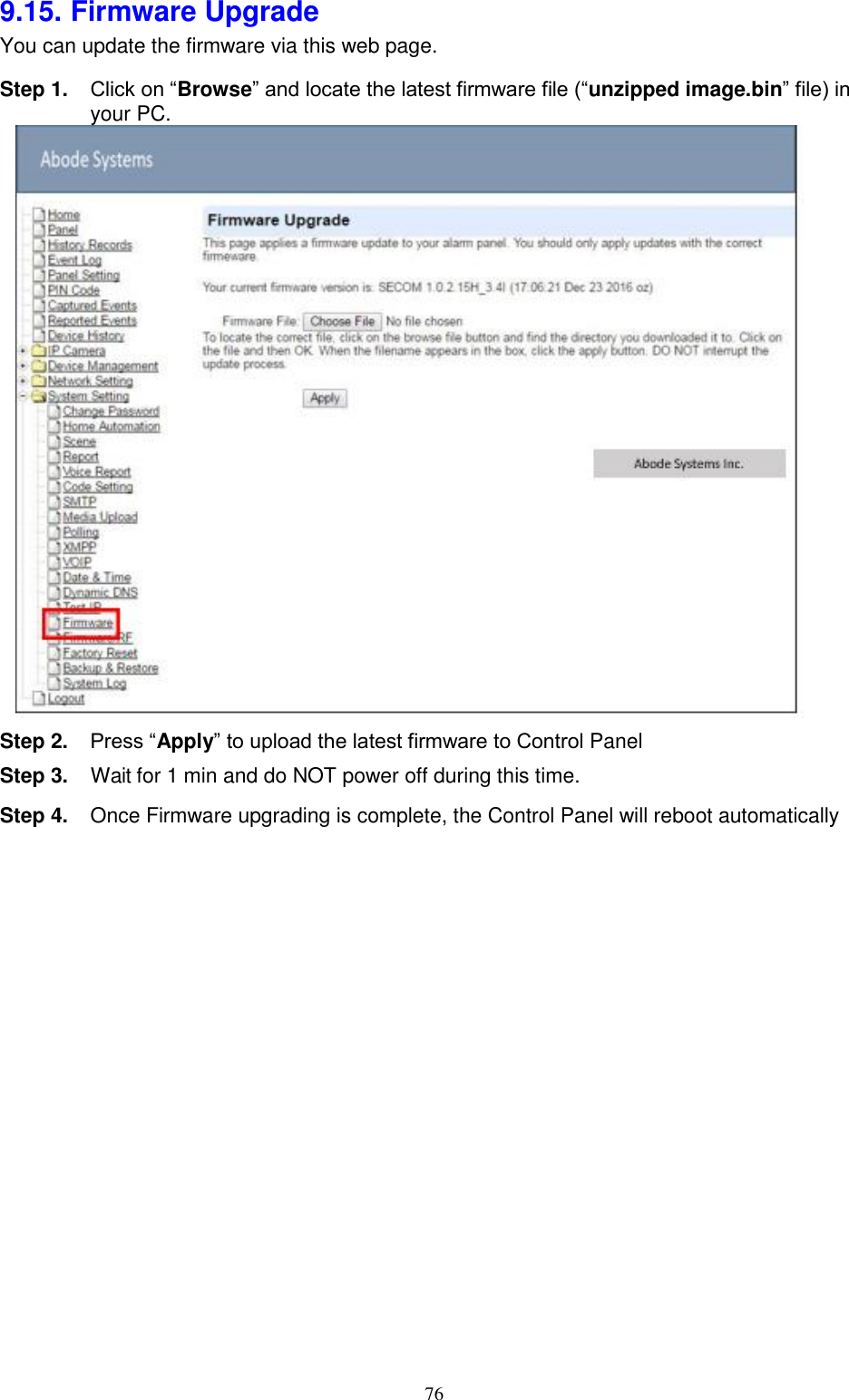
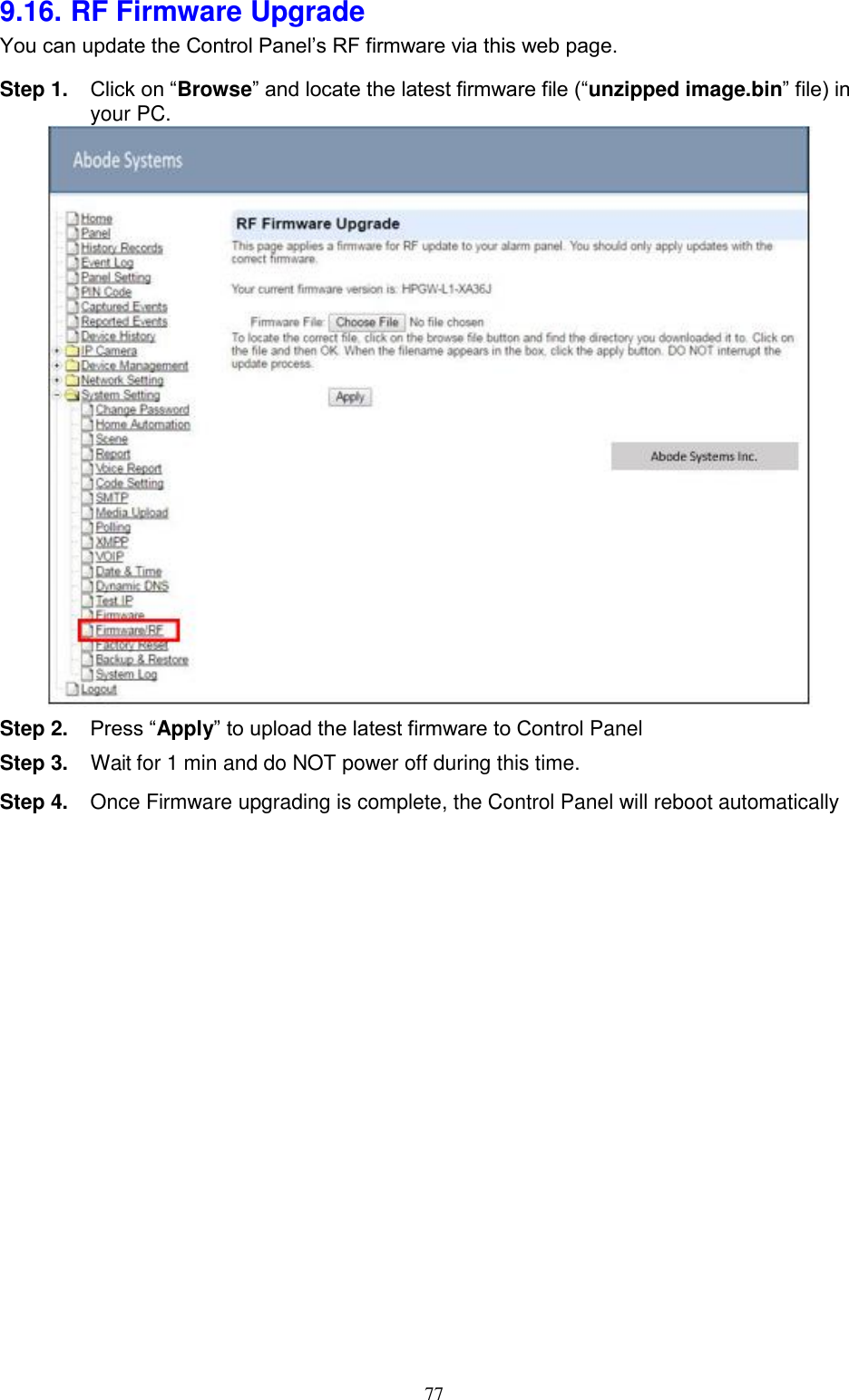
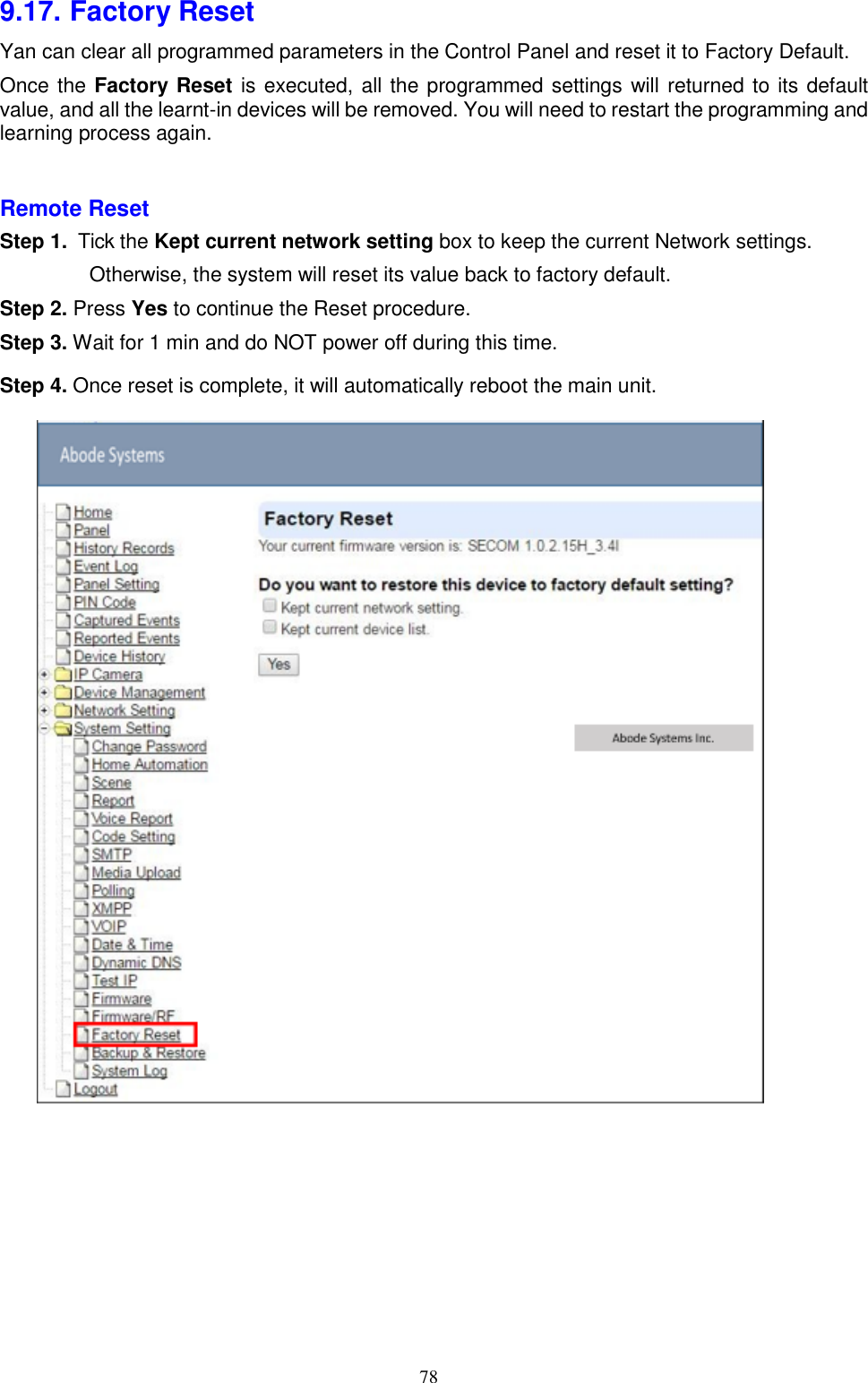
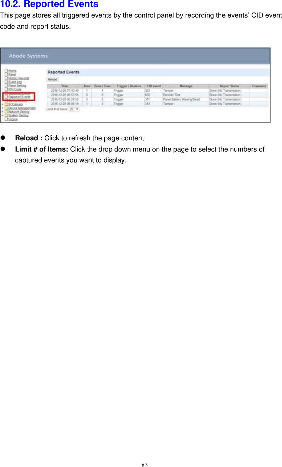
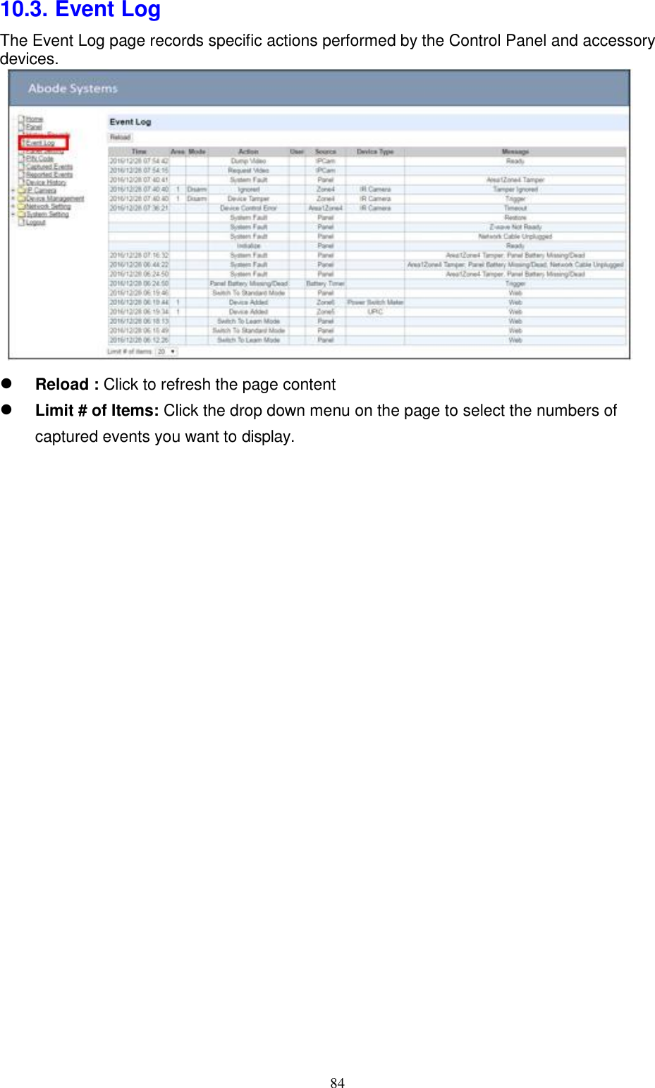
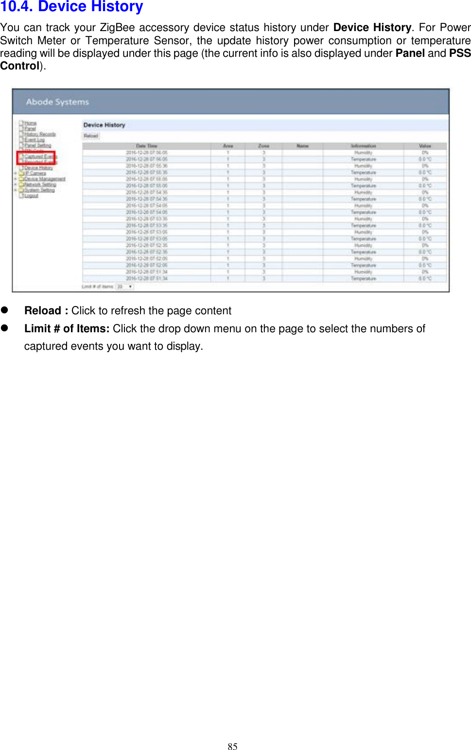
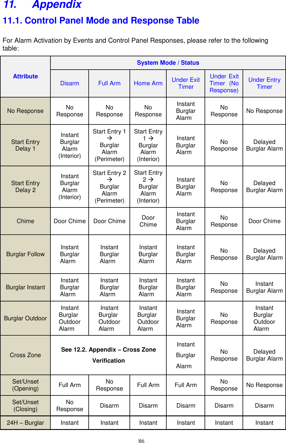
User Manual
Discussion / Help
Navigation