abode systems IOTA abode iota User Manual Z1 20161229 IP Installation Guide
abode systems, inc abode iota Z1 20161229 IP Installation Guide
Users Manual

Jan-21-2018

Table of Contents
1. INTRODUCTION 1
2. PANEL INFORMATION 2
2.1. PARTS IDENTIFICATION 2
2.2. THE POWER SUPPLY: 3
2.3. SYSTEM REQUIREMENTS: 3
3. GETTING STARTED 4
3.1. SYSTEM DEPLOYMENT 4
3.2. HARDWARE INSTALLATION 4
3.3. SOFTWARE INSTALLATION 5
4. CONNECTION TO PANEL WEBPAGE 8
5. DEVICE MANAGEMENT 10
5.1. LEARNING 10
5.2. ADD RF DEVICE 18
5.3. LEARN RULE 19
5.4. WALK TEST 21
5.5. PROGRAM SIREN 22
5.6. EXCLUSION 24
5.7. Z-WAVE TOOL 25
5.8. PSS CONTROL 26
5.9. UPIC CONTROL 27
5.10. SURVEILLANCE 28
5.11. GROUP CONTROL 29
6. IP CAMERA 30
6.1. IP CAMERA ATTRIBUTE SETTING 30
6.2. IMAGE TUNING 32
6.3. MOTION DETECTION 33
6.4. TIME STAMP 36
6.5. STREAM SETTING 37
6.6. RECORDED VIDEO 38
6.7. ALARM SETTING 39
7. PROGRAM THE SYSTEM 41
7.1. PANEL CONDITION 41
7.2. PANEL SETTINGS 44
7.3. PIN CODE 48

8. NETWORK SETTINGS 49
8.1. NETWORK 49
8.2. WIRELESS 50
8.3. UPNP 52
9. SYSTEM SETTINGS 53
9.1. ADMINISTRATOR SETTING 53
9.2. HOME AUTOMATION 54
9.3. SCENE 59
9.4. REPORTING 60
9.5. VOICE REPORT 63
9.6. CODE SETTINGS 65
9.7. SMTP SETTING 67
9.8. MEDIA UPLOAD 68
9.9. POLLING 69
9.10. XMPP 70
9.11. VOIP 71
9.12. DATE & TIME 72
9.13. DYNAMIC DNS 73
9.14. TEST IP 74
9.15. FIRMWARE UPGRADE 75
9.16. RF FIRMWARE UPGRADE 76
9.17. FACTORY RESET 77
9.18. BACKUP & RESTORE 79
9.19. SYSTEM LOG 80
10. EVENT & HISTORY 81
10.1. CAPTURED EVENTS 81
10.2. REPORTED EVENTS 82
10.3. EVENT LOG 83
10.4. DEVICE HISTORY 84
11. APPENDIX 85
11.1. CONTROL PANEL MODE AND RESPONSE TABLE 85
11.2. CROSS ZONE VERIFICATION 87
11.3. FIRE VERIFICATION 87
11.4. CONTACT-ID PROTOCOL & FORMAT 88
11.5. EVENT CODE 89

1
1. Introduction
IOTA is an IP security system Control Panel which integrates RF technology, Two-way voice
communication, VOIP, Home Automation and Video Monitoring features. The panel supports
built-in PIR sensor, IP Camera and temperature/ambient light sensor and is configured over Local
Area Network webpage. Refer to later chapters for information on setting up and configuring the
system over the webpage in more detail.
System Feature
Two-way voice communication with VOIP: Built-in microphone and speaker allows user to
make hands free voice call in case of emergency.
Ethernet and/or WiFi connection: Wifi connection provides backup to Ethernet to extend
system flexibility.
Voice Prompt Reminder: The panel plays voice prompts upon system mode change to
remind user the system status.
Built-in accessory devices:
IP Camera: The IP Camera provides video streaming and recording with resolution up
to
1920
x
1080p.
The
camera
lens
has
horizontal
coverage
of
127
∘
to
the
front.
PIR
Sensor:
The
PIR
sensor
detects
movement
in
a
110
∘
radius
to
the
front
up
to
7
meters range.
Temperature/Ambient Light Sensor: The sensor provides temperature and lux reading
to panel regularly.
2
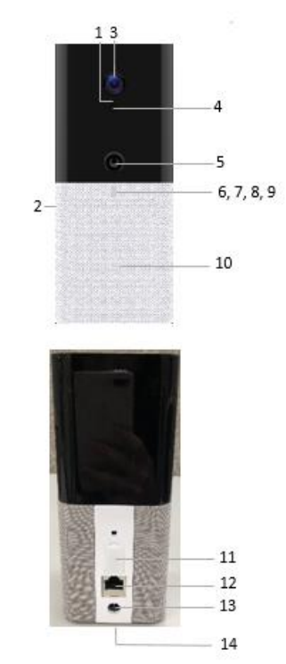
2. Panel Information
2.1. Parts Identification
1.
Light Sensor
2.
Microphone
3.
IP Camera
4.
IR Illuminator
5. PIR Sensor
6. LED 1 (Red/Green)
Red On – Area 1 in the Full Arm mode.
Red Flash – Area 1 in Home Arm mode.
Green On – System in learning mode.
Green Flash – System in Walk Test mode
7. LED 2 (Red/Green)
Red On – Area 2 in the Full Arm mode.
Red Flash – Area 2 in Home Arm mode.
Green On – System in learning mode.
Green Flash – System in Walk Test mode
8. LED 3 (Red/Amber)
Red On – Alarm in memory.
Red Flash – Alarming.
Amber On – System has fault.
9. LED 4 (Green/Red) (These LED colors may change)
Green On – Network Normal
Green Flash – IP Cam streaming.
Red ON – IP Cam under Privacy Mode
Red Flash 2~3 seconds – Activate WPS
Red Flash 3 times – WPS pairing successful
Red Flash 2 times – Enter/Exit Privacy Mode
Red Continuous Flash – No Network
10. Speaker
11. Micro SD, SIM card
12. Ethernet Jack
13. DC Power Jack
14. Battery Switch

3
2.2. The Power Supply:
An AC power adapter is required to connect to a wall outlet. Be sure only to use an adapter with
the appropriate AC voltage rating to prevent component damage. DC 12V 2A switching power
output adaptor is generally used to power the Control Panel for standard version.
Rechargeable Battery
In addition to the adapter, there is a rechargeable battery inside the Control Panel, which
serves as a backup in case of a power failure.
During normal operation, the AC power adapter is used to supply power to the Control Panel
and at the same time recharge the battery. Slide the Battery Switch to ON to activate and
charge the battery. It takes approximately 72 hours to fully charge the battery
The battery status information is displayed in the Panel section of local area webpage.
2.3. System Requirements:
The system requires a TCP/IP network environment for you to connect to the Control Panel for
system programming.
Hardware requirement for programming the panel vial LAN webpage:
Microsoft Windows 98, ME, NT4.0, 2000, XP, Windows 7 or 8 operating system.
Microsoft Internet Explorer 6.x, or later and Mozilla Firefox 3.0 compatible.
CD-ROM drive
CPU: Intel Pentium II 266MHz or above
Memory: 32MB (64MB recommended)
VGA resolution: 800x600 or above
4
3. Getting Started
Read this section of the manual to learn how to set up your Control Panel and program System
Settings over the Web page.
3.1. System Deployment
The Control Panel is designed to be place on desktop, follow guidelines below when planning
installation location:
The Control Panel requires Ethernet or WiFi connection.
The Control Panel should be installed at a location that is hidden from outside view.
Avoid mounting the Control Panel near large metal objects which may affect wireless radio
strength.
The Control Panel should be protected by sensors so that no intruder can reach the Control
Panel without first activating a sensor.
When using ZigBee routers to improve ZigBee network coverage, remember to use only
ZigBee Router with backup batteries for security sensors. If you use a Router without backup
battery for security sensors, the Router will be powered down in case of AC failure, and you
security sensors will lose connection with the ZigBee network.
Home Automation devices (Power Switches…etc) do not have this limit and can be used
with any Router.
3.2. Hardware Installation
Step 1. Connect the Ethernet cable to the Ethernet port on the panel.
Step 2. Connect the Power Adaptor to a Wall Outlet and the other end to the Control Panel. The
panel will power on. Slide the battery switch to ON position to activate and begin
charging the battery. The panel will enter normal operation after completing power on.
5
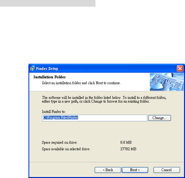
3.3. Software Installation
※ THIS INSTALLATION IS ONLY REQUIRED FOR FIRST TIME USER ※
1. RUNNING THE FINDER SOFTWARE
The Finder software is required for your computer to identify the control panel on the LAN. To
install the “Finder” software”
Step 1. Insert the supplied CD-ROM into your CD-ROM drive
Step 2. Find the Finder software in the CD-ROM.
Step 3. Double click on the Finder_v1.x to initiate the installation.
Step 4. Follow on screen instruction to complete installation
Step 5. Once complete, the Finder icon will be displayed on your desktop.
6
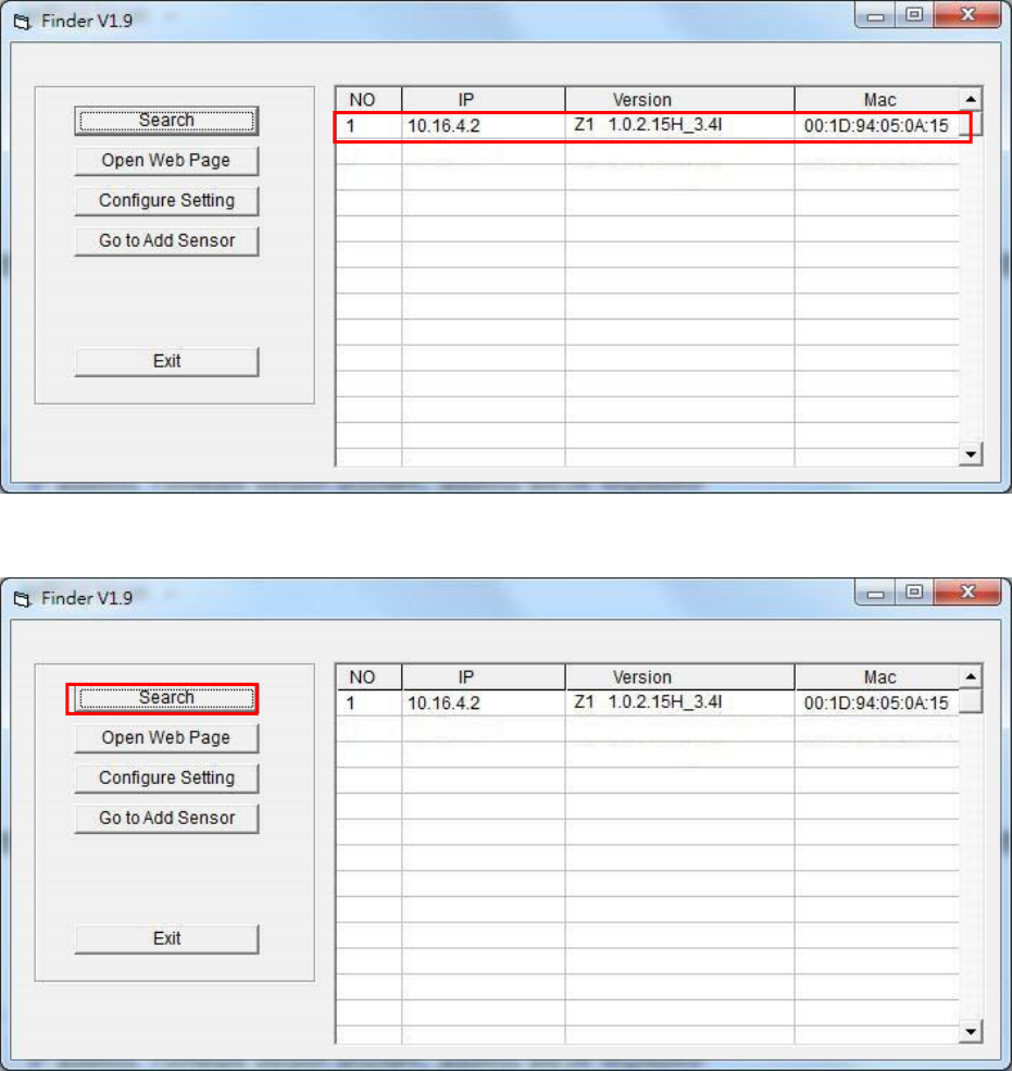
Step 6. Execute the Finder software. Finder will automatically search for control panel on the
LAN and display its information. If available, the panel’s LAN IP address, Firmware
version and MAC address will be displayed
Step 7. If the panel information is not displayed, check panel power and Ethernet connection and
click on “Search” to update the panel information.
7
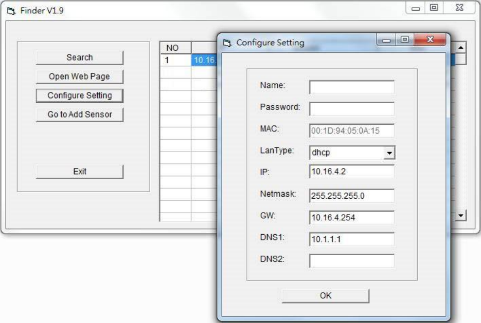
Step 8. (Optional)You can choose to edit the panel’s network setting by clicking on the panel
column, then click “Configure Setting”
The LanType is default to DHCP and does not require manual input of
IP/Netmask/Gateawy/DNS setting. If you wish to configure these setting manually,
change LanType to Static.
After finish changing network setting, enter the user name (default: admin) and
password (default:admin1234) then click OK to confirm. The user name and password
can be changed later in panel configuration webpage
Step 9. Click the panel information column and click on “Open Web Page”, or double click on
the panel column to link to the panel configuration webpage. Your default browser will
start automatically to connect to the LAN IP displayed in Finder.
8
4.
Connection to Panel Webpage
For first time setup, webpage connection is only available within 1 hour after the panel is
powered on; if the panel has been powered on for more than 1 hour. Webpage access will
be disabled. Reboot the panel to enable webpage function again.
Change default password after login to gain unrestricted webpage access.
Step 1. Select the Control Panel in the Finder software and click on “Open Webpage” to
connect to panel webpage.
Alternatively, enter the Control Panel IP address displayed in Finder into your
browser’s address section and proceed.
Step 2. Enter the User name & Password to proceed
Default user name: admin
Default password: cX+HsA*7F1
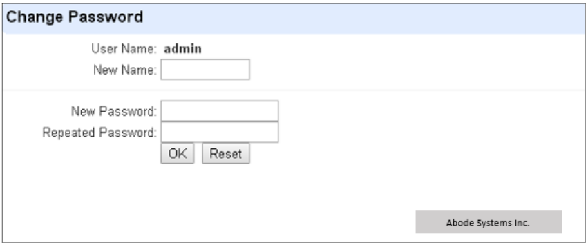
Step 3. You will enter change password page. Enter and repeat a new password (username
change is optional), take care that both username and password are case sensitive.
Click OK to confirm.
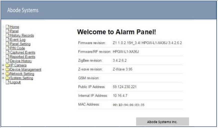
Step 4. Upon confirming new username and password. You will enter panel Welcome page.
The panel will prompt you to re login with new username and password.
Step 5. You will enter panel Welcome page. The Control Panel’s information will be displayed.
Click on the pages and folders on the left to access the Control Panel’s various
functions
9
The Welcome page displays current control panel firmware version information
according to different panel model and MAC address.
IMPORTANT NOTE
If the default login password is not changed, webpage access will be disabled 1 hour
after power on. Reboot the
webpage access. panel and
changed
password to allow unrestricted
10
R
O
5.
Device Management
The Device Management section allows you to learn in, edit, co
accessory devices that can be included in the IOTA Control
Panel.
trol and view all available
5.1.
Learning
Use this function to add new devices into the Control Panel. IOTA supports up to 160 zones of
accessory devices, in 2 areas, up to 80 zones each area.
The following types of accessory devices are supported:
RF device: All Abode RF devices are supported.
ZigBee device: All ZigBee device with ZigBee Home Automation 1.2 profile are supported.
The Control Panel built-in ZigBee module supports up to 40 ZigBee devices by itself. If
you wish to include more than 40 ZigBee devices into the Control Panel, you must add
extra ZigBee Routers into the Control Panel’s ZigBee network to increase the network’s
maximum device capacity.
IP Cameras: The panel features a built-in IP Camera, extra IP Cameras may be included
into the system to extend the coverage. Up to 5 extra IP Cameras are supported.
Z-Wave Device: IOTA panel is compatible with certified Z-Wave devices
5.1.1.
Add Sensor
Step 1.
Step 2.
Step 3.
Step 4.
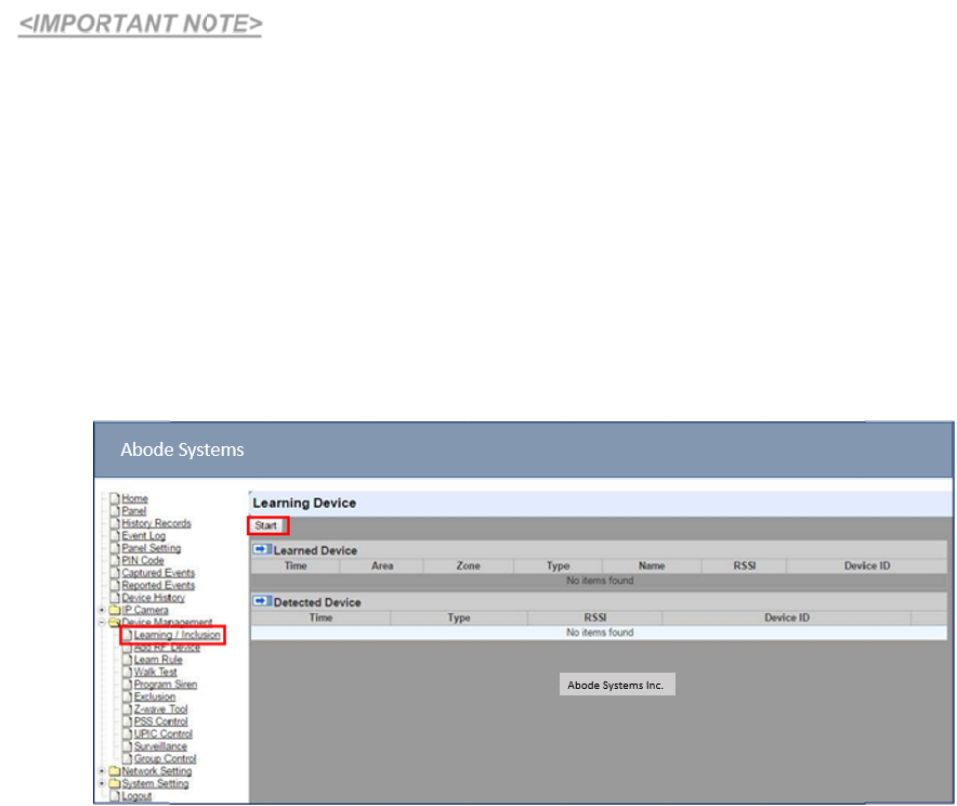
Click on “Learning” to enter learn page.
Click “Start” to enter learning mode.
Transmit a learning signal from the accessory device. (Please refer to each device’s
When the system received the signal transmitted from device, the screen will display its
information for selection.

11
It takes 5-10 seconds for the Control Panel to receive a learn code from ZigBee or
<NOTE>
12
Z-Wave device.
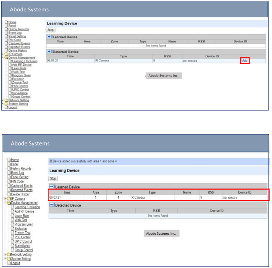
Step 5. Click “Add” to include selected device into panel. If the sensor you wish to learn into
already exists in the system, the sensor information will be displayed in the Learned
Device section. If not, the sensor information will be displayed in the Detected Device
section.
Step 6. If the device is successfully learnt into the system, the added device will be displayed in
the “Learned Device” section.
Step 7. Repeat Step 3~5 to learn in all device, click Stop to exit learn mode when complete.
The system will automatically exit Learn mode if left idle for 5 minutes.
5.1.2.
Local Learning
Instead of learning devices via configuration webpage, you can also learn in devices by using
the learn button located on the back of Control Panel.
Step 1. Press and hold the Learn Button on the back of Control Panel for 10 seconds, release
when the Control Panel emits one short beep. LED 1 and LED 2 Green will turn ON to
indicate the Control Panel is now in learning mode
Step 2. Press the test or learn button on each device to transmit signal, refer to device manual
for detail.
Step 3. When the Control Panel receives signal from device, it will emit 2 beeps to confirm. The
device will be included in the panel automatically.

13
Step 4. After finish learning all devices, press and hold the learn button for 1 second. The
Control Panel will emit 2 short beeps to indicate it has returned to normal mode. LED1
and LED 2 will dim.
Device learnt in via Local Learning will be assigned to Area 1 only, which is limited to 80
devices.
The Control Panel cannot enter learning mode when under Away Arm/Home Arm or
Walk Test mode. The Control Panel will emit 5 beeps to indicate error.
<NOTE>
14
5.1.3.
Edit Devices
After finish learning devices, proceed to edit the device setting.
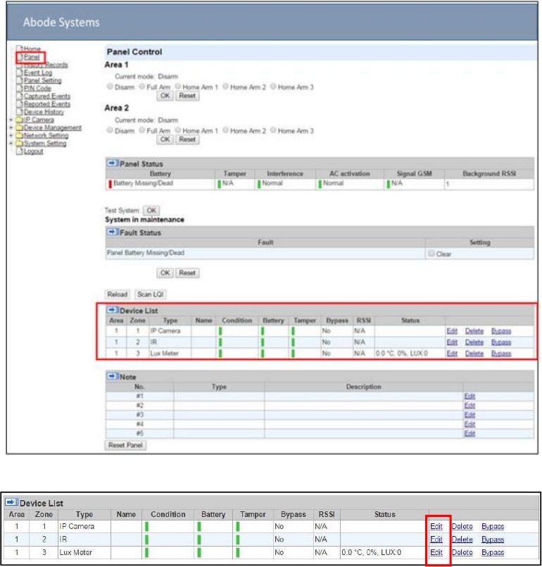
Step 1. Click Panel to enter Panel webpage. All learnt in devices will be displayed under
Device List section.
Zone 1 ~3 are pre-occupied by IOTA panel’s built-in IP Camera, PIR Sensor and
Temperature/Lux sensor. All newly learnt in devices will be listed starting from Zone 4.
Step 1. To edit the device setting or information, click “Edit” at end of device entry.
15
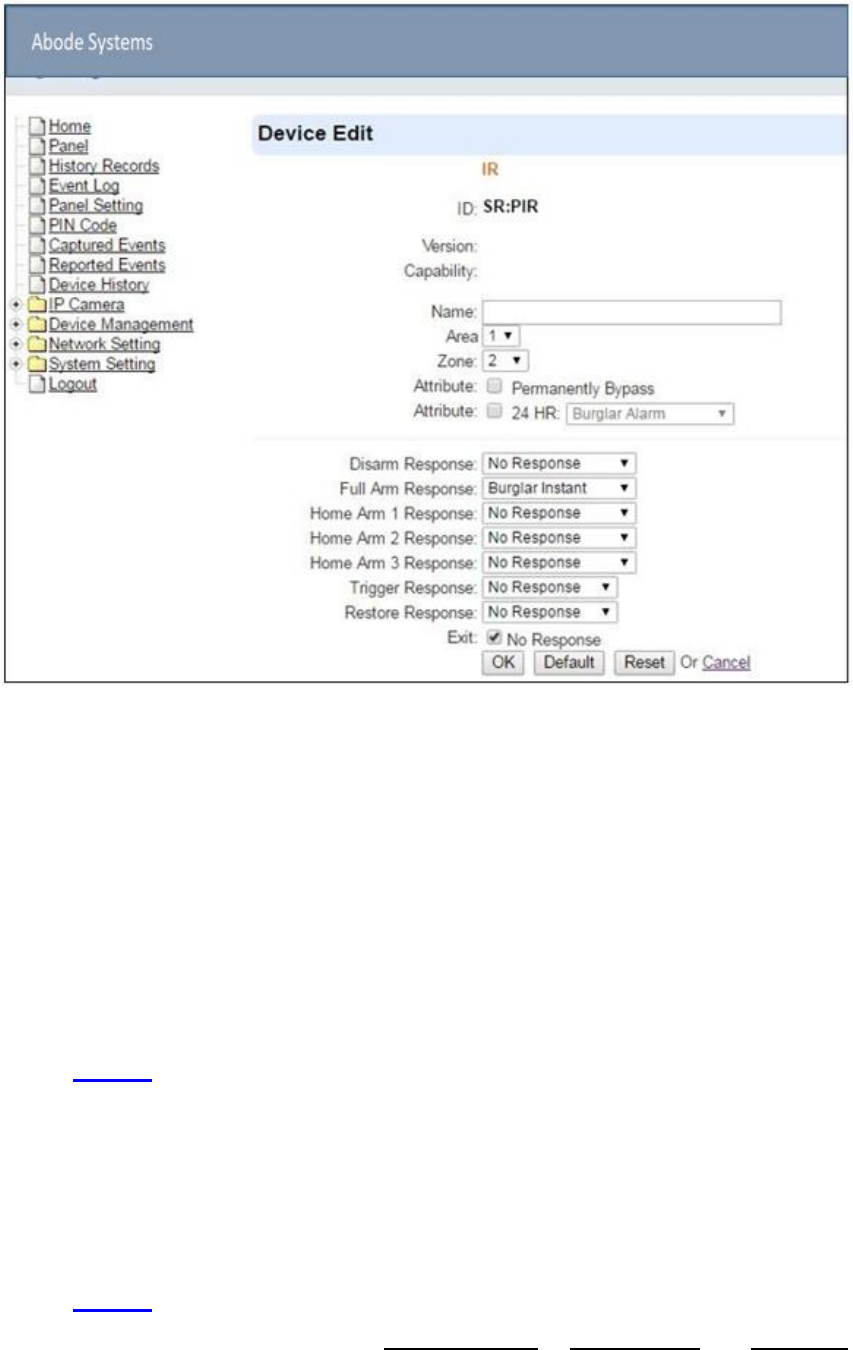
Step 2. You will enter Device Edit webpage
Step 3. Edit your device setting and information according to instruction below. Click “OK” to
save your new changes when finished. Alternatively, click “Default” to reset all
parameters to default values or click “Reset” to re-enter all the information.
Name: Enter a name for the device.
Area: Select the area which the device belongs to.
Zone: Select the Device zone number.
Attribute List:
The attribute list determines panel behavior when the panel receives trigger signal from
the device. There are
General Attribute:
Bypass
This function allows user to deactivate (bypass) the selected device.
If bypassed, then the Control Panel will not respond at all when the sensor is
triggered.
If bypassed, the system can be armed directly regardless the device’s fault
situation. However, its fault situation will still be monitored, logged and displayed
in the webpage.
Bypass
This function ONLY applies to Remote Control or Door Contact with Set/Unset attribute

16
enabled.
Latch Report ON: When the device is used to change system arm mode, the
Control Panel will report the arm/disarm action by the particular device.
Latch Report OFF: When the device is used to change system arm mode, the
Control Panel will not report the arm/disarm action by the particular device.
Set/Unset
This function is for Door Contact only. This function allows Door Contact to control
system mode.
Normal Close: The system will be armed when the Door Contact is opened, and
disarmed when Door Contact is closed.
Normal Open: The system will be armed when the Door Contact is closed, and
disarmed when Door Contact is open.
24HR
This function enables the device to activated selected alarm event whenever it is
triggered regardless of system mode. System mode response will be disabled if 24HR
attribute is enabled.
System Mode Attributes:
The System Mode Attributes determines system behavior under particular arming mode
when the sensor is triggered.
No Response
When a sensor with No Response is triggered, the Control Panel will not respond.
Start Entry Delay 1/ Start Entry Delay 2
When the system is under Full Arm or Home Arm mode, if a sensor with Start
Entry Delay 1/2 attribute is triggered, Control Panel will start an entry countdown
period to give enough time to disarm the system.
When the Control Panel is in the Disarm mode, if a sensor with Start Entry Delay
1/2 attribute is triggered, the Control Panel will immediately report a burglar interior
alarm (CID code: 132).
When the Control Panel is in the Full Arm mode, if a sensor with Start Entry Delay
1/2 attribute is triggered, the Entry Delay 1/2 timer starts counting down. If no
correct pin code is entered during the entry delay timer to disarm the system, the
Control Panel will report a burglar perimeter alarm (CID code:131) immediately
after entry delay timer 1/2 expires.
When the Control Panel is in the Home Arm 1/2/3 mode, if a sensor with Start
Entry Delay 1/2 attribute is triggered, the Entry Delay 1/2 timer starts counting
down. If no correct pin code is entered during the entry delay period to disam the
system, the Control Panel will report a burglar interior alarm (CID code: 132)
immediately after entry delay timer 1/2 expires.
Chime
When the system is in Arm/ Home Arm 1/ Home Arm 2/ Home Arm 3 mode, if a
sensor set to Chime is triggered, the Control Panel will sound a Door Chime (Ding-
Dong Sound).
Burglar Follow
When the system is in Full Arm or Home Arm mode, if a sensor set to

17
Burglar Follow is triggered, the Control Panel will report a burglar alarm
immediately.
When a Start Entry sensor is triggered and the system is under Entry Delay Timer
countdown, if a sensor set to Burglar Follow is triggered, the Control Panel will
wait until the Entry Delay Timer expires before activating a burglar alarm. If the
system is disarmed before the timer expires, the Control Panel will not activate
alarm.
Burglar Instant
When the system is under Full arm or Home Arm/ Disarm / Entry Time mode, if a
sensor set to Burglar Instant is triggered, the Control Panel will report a burglar
alarm immediately.
Burglar Outdoor
When the system is in Full Arm or Home Arm / Disarm / / Entry Time mode, if a
sensor set to Burglar Outdoor is triggered, the Control Panel will report a burglar
outdoor event immediately.
Cross Zone
See 12.2 Appendix – Cross Zone Verification for detail.
Apply Scene
This function is only available for Remote Keypad and Remote Control.
Select a Home Automation Scene number for a Remote Keypad or Remote
Control button. When the button is pressed, the Control Panel will execute the
actions programming in the Scene accordingly. For more information, please refer
to 8.3. Scene.
Home Automation Attributes:
The Home Automation Attributes allows a device to control Home Automation function.
Trigger Response
When the device is triggered, the Control Panel will activated selected Home
Automation Scene number. Please refer to 8.3. Scene webpage for detail.
Restore Response
When the device transmits restore signal after trigger, the Control Panel will
activate selected Home Automation Scene number.
Other Attributes:
Permanent Bypass
When checked, the panel will completely ignore all signal received from this
device. A bypassed device will not be able to trigger any response, including alarm
or fault from the Control Panel. All other attribute settings will be also be ignored.
Exit (No Response)
If checked, the panel will ignore trigger signal from this sensor during Exit Time
countdown. If deselected, the panel will activated burglar alarm and report
immediately when the sensor triggered during Exit Delay Timer.
24HR
18
A sensor set to 24HR attribute will ignore Disarm, Full Arm, Home are and Exit
response setting. The panel will activate selected alarm
triggered regardless of system mode under any time. when this Sensor is
Some devices have their own unique functions and w ll have its own attribute setting
which is not listed in t is section. Please refer to the device manual for its setting detail.
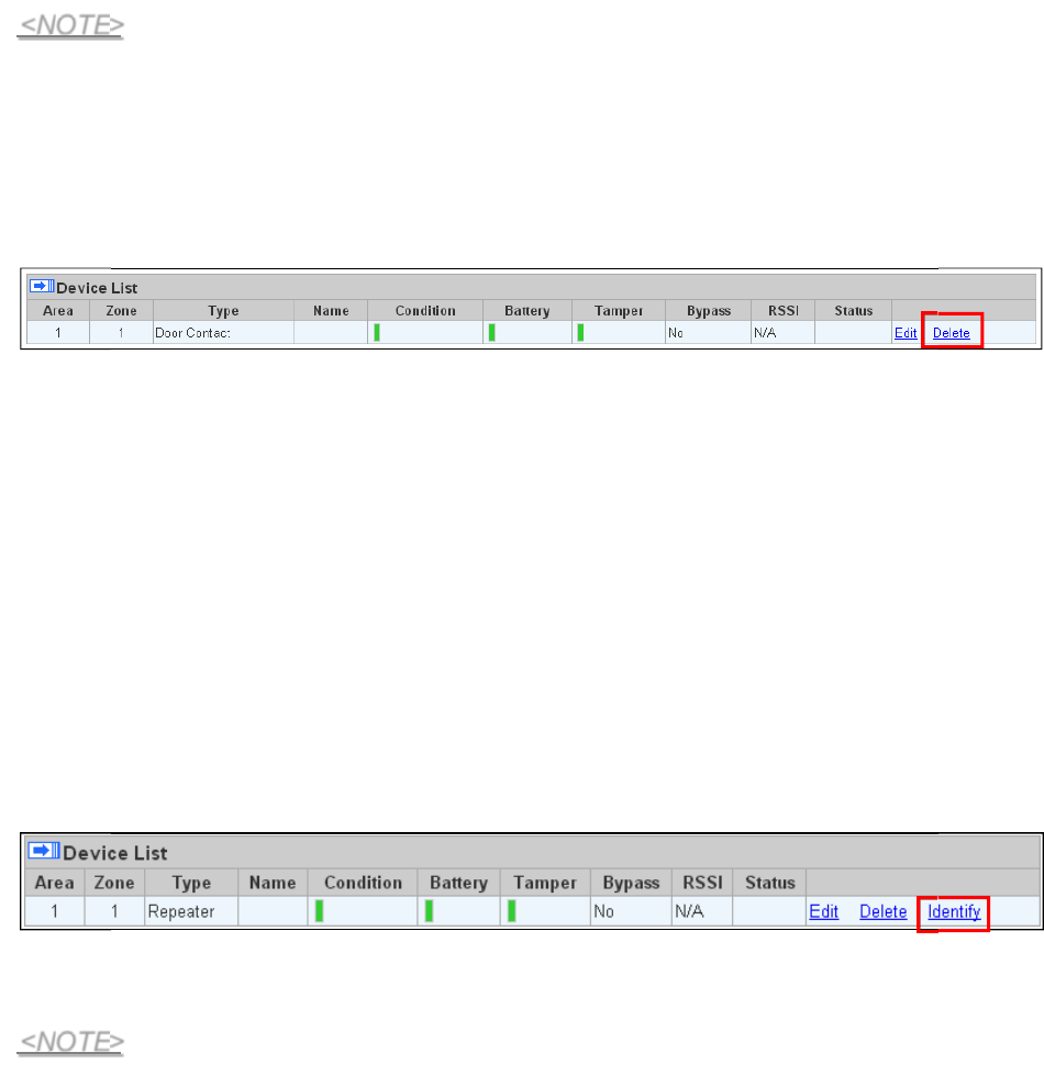
5.1.4.
Delete Devices
Step 1. To delete a sensor, click “Delete” under “Device List”
Step 2. A message “Delete
successfully. success” is displayed and the sensor you choose is deleted
5.1.5.
Identify ZigBee Device
The Identify functio
after learning.
is available for ZigBee device only, it can be used to locate ZigBee devices
For battery powered ZigBee devices, the identify function should be used within 1 minute after
pressing device button, or 3 minute after learning in the device. Otherwise due to ZigBee
network mechanisms, the device may not be able to receive signal successfully from panel. AC
powered ZigBee devices do not have such limits and you can use Identify function anytime.
Step 1.
Step 2.
Click “Identify” under the Device List after the device column entry.
If the ZigBee device receives signal successfully, the webpage will display a success
message and the ZigBee device LED indicator will flash 10 times to confirm.
If a timeout message is displayed on webpage, it means the device did not receive
signal from Control Panel, please check ZigBee devi e range from panel and make
sure to follow instruction above about Identifying battery powered ZigBee devices.
<NOTE>
<NOTE>
19
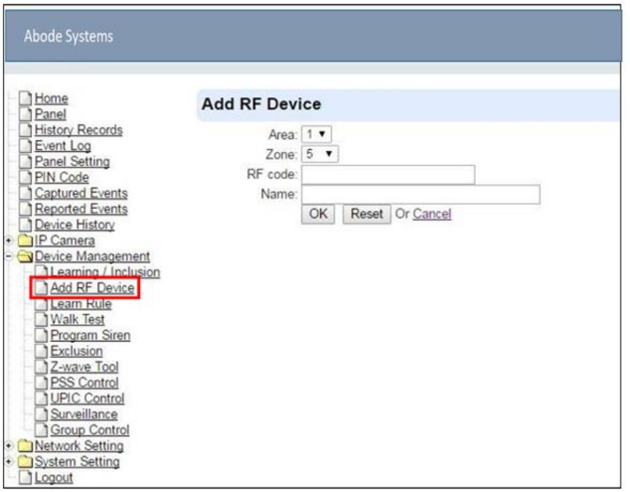
5.2.
Add RF Device
Besides learning, you can also add RF devices into the system by entering its RF code into the
system with Add RF Device function.
Step 1. Click Add RF Device.
Step 2. Select Area and Zone number for the device you wish to add into system.
Step 3. Enter the device RF code, and preferred device name (up to 31 characters)
Step 4. Press “OK” to save
Step 5. If the RF code you entered is valid, the device will be added into the system according
to the Area and Zone number. You do not need to learn the device as instructed in
5.1.1. Add Sensor.
20
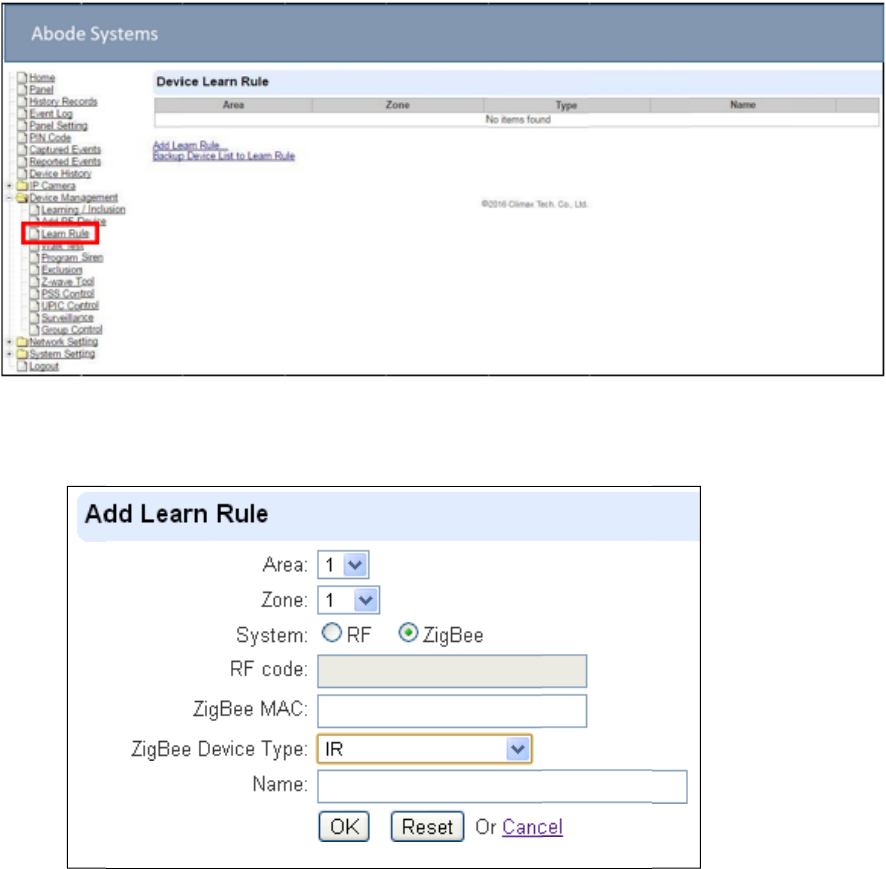
5.3.
Learn Rule
You can enter the sensor RF code or ZigBee MAC address manually to assign area and zone
number to this sensor. Sensors learned with pre-assigned rule will be put under the area and
zone number you specified. This function does not work with Z-Wave devices and IP Camera.
Step 1.
Step 2.
Step 3.
Step 4.
Step 5.
Step 6.
Step 7.
Step 8.
Step 9.
Step 10
Step 11.
Click Learn Rule.
You will see the Add Learn Rule menu.
Select Area and Zone number for this device.
Select RF or ZigBee.
Key in the RF code or ZigBee MAC info
For ZigBee device, select a ZigBee Device Type
Enter a preferred name for sensor (up to 31 letters or numbers).
Press “OK” to save.
If the process is successful, the screen will display “Updated Successfully.” You can
then check, edit or delete the rule under the Learn Rule menu.
Repeat the steps to add more rules.
Learn in the sensors you have entered rules for according to 5.1.1 Add Sensor.

21
Learn rule function is only used to pre-assign area and zone number to sensors before
learning. To add senor to control panel, you still need to follow the instruction in 5.1.1
Add Sensor to complete the learning process.
Backup Device List to Learn Rule
You can choose to import learn rule from current learnt in ZigBee devices
Step 1. Click “Backup Device List to Learn Rule”.
Step 2. Click OK to confirm.
Step 3. The Learn Rule page will be updated with new rules according to current ZigBee device
list information. Z-wave device and IP Camera will not be included.
22
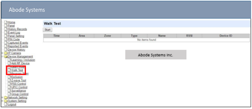
5.4.
Walk Test
This is to test the sensor operation range for installation purpose.
Step 1. Click “Start” to enter Walk Test mode.
Step 2. Press the test button on the sensor(s) or any button on the Remote Controller or
triggering the sensor.
Step 3. When the Control Panel receives a signal, it will show as below and a 2-tone beep will
be heard to indicate that it is safe to install the particular sensor in the location.
Time: time information
Area: operation area
Zone: device zone
Type: device type
Name: device name
Rssi: the RF signal strength between Control Panel and sensor. The Rssi value here
must be higher than the Rssi value of Panel’s background noise (please refer to 6.1
Panel Condition section for details). If not, you may still learn in the sensor; however,
please relocate the sensor and use Walk test to find a more suitable location.
Device ID: device’s unique identification code.
Step 4. Once all sensors are tested, click on “Stop” to exit Walk Test mode. The system will
automatically exit Walk Test mode if left idle for 5 minutes.
23
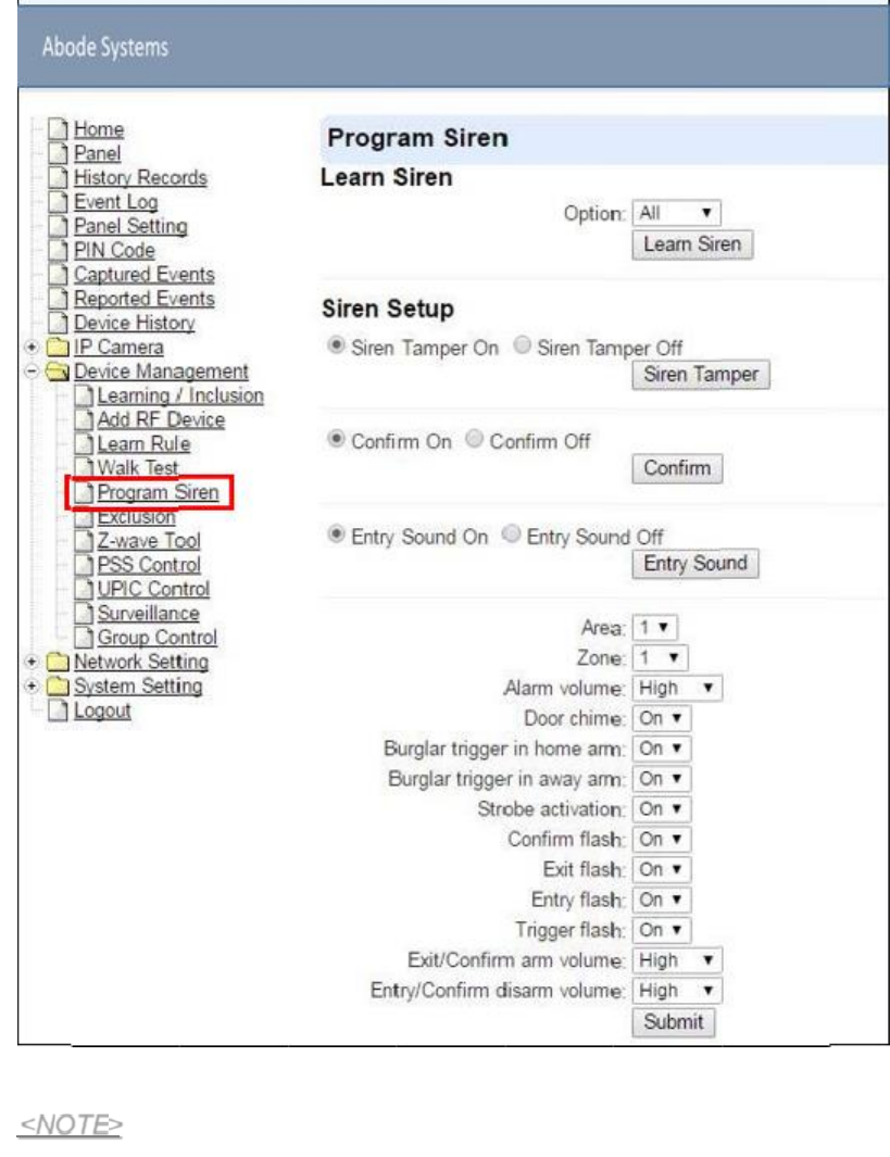
5.5.
Program Siren
The Program Siren page include siren learning and setting configuration function.
Learn Siren
Step 1.
Step 2.
The Learn Siren function is designed for single way radio siren (BX-7,8 and SR-7,8)
only. To learn in two-way sirens, please refer to the 5.1 learning section.
Select the Option drop-down menu, choose from All, Area1, and Area2 to determine
which area should the siren below to.
Put your Bell Box or Indoor Siren in Learning Mode (Slide BX/SR dip switch 1 to ON.
For more details, please refer to siren manual for detail).
<NOTE>

24
Step 3. Click Learn Siren to transmit learn code, refer to BX/SR manual to complete learning.
Siren Setup
Siren Tamper On/Off
You can enable/disable the siren’s tamper protection with this function. Sel
on or off the siren’s tamper function then click “Siren Tamper” to confirm.
ct to turn
When turned off, if siren tamper will be enable again automatically after one hour if not
turn on manually during the one hour period.
Confirm On/Off
When turned on the siren will emit confirmation beep when the control panel mode is
changed. When turned off, the siren will remain silent. Select
confirmation function, then click “Siren Tamper” to confirm.
Entry Sound On/Off
to turn on or off the
When turned on the siren will emit beeps during entry and exit timer. When turned off,
the siren will remain silent. Select to turn on or off the entry sound function, then click
“Siren Tamper” to confirm.
Siren Setting:
Choose to edit individual siren detail setting with the slide down menus. Refer to siren
manual for available options. After finish all settings, click “Submit” to confirm.
<NOTE>
25
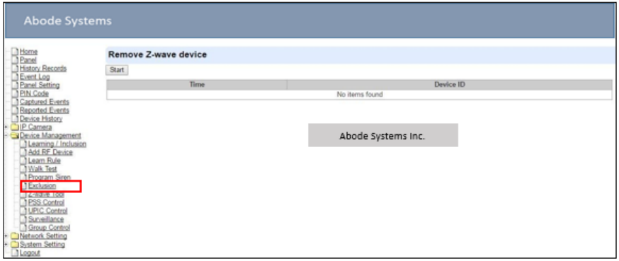
5.6.
Exclusion
The Exclusion page is used for removing Z-Wave device only.
Step 1. Click on “Exclusion” and click on “Start” to start the procedure.
Step 2. Refer to the Z-Wave device manual to transmit signal.
Step 3. After receiving the exclusion signal from Z-wave device, check the device list under Panel
webpage to make sure the corresponding Z-wave device has been removed from the
panel.
26
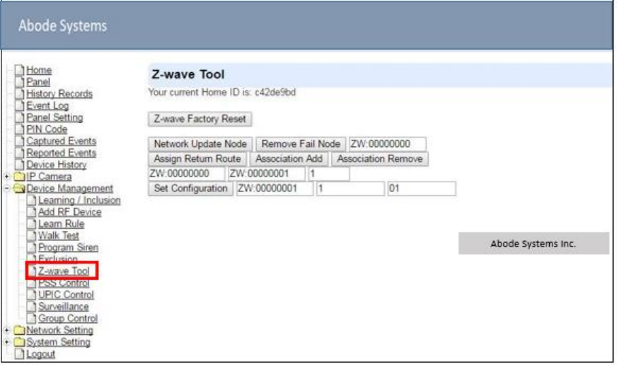
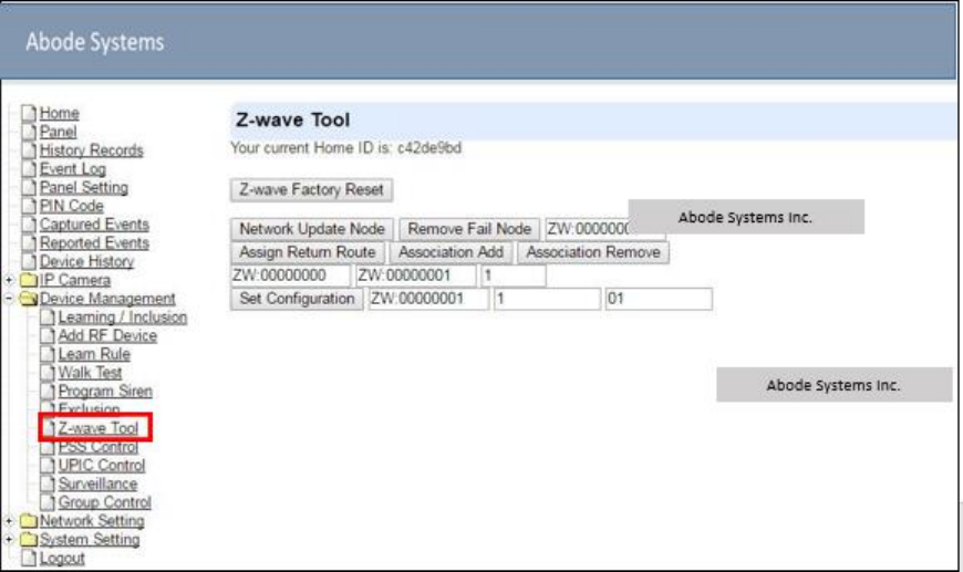
5.7.
Z-Wave Tool
The Z-wave Tool is used to reset Z-wave module to factory default and remove all Z-wave
devices, or change routing setting.
Step 1. Click ”Z-Wave Factory Reset”, the Z-Wave module is reset to factory default and all Z-
Wave devices will be removed automatically. The Control Panel Home ID will also be
changed automatically for a newly added Z-Wave device to recognize.
Step 2. The list of Z-Wave devices is still displayed in the Panel webpage. Please go to panel
webpage and remove all Z-wave devices.
Change Z-Wave Routing Setting
Use the other functions to configure your Z-Wave routing settings.
27
5.8.
PSS Control
This feature is designed to control/edit/delete Power Switches included in the panel.
Click Edit to edit attributes of power switches.
Click Delete to remove power switch from panel.
Click Switch On/Switch Off to turn on/off power switches. Or click Switch Toggle to toggle
between on/off status. For Power Switch Dimmer, you can also set its power output level
with the slide down menu.

28
5.9.
UPIC Control
UPIC Control webpage allows you to control UPIC IR Transmitter included iin Control Panel
Transmit IR Signal
Depending on the UPIC model number, select the function to be performed in the drop down
menu, then click “Setup UPIC” for the UPIC to transmit IR Signal.
UPIC5 LED Setup (UPIC5 only)
UPIC5 has 6 IR LEDs, a central one and 5 surrounding ones. The central LED will always
transmit IR signal when activated; besides the central LED, one of the 5 surrounding LEDs can
be selected to activate upon IR signal transmission to increase the IR signal coverage.
Step 1: Refer to the diagram on the webpage and UPIC5 manu l to determine which LED
should be used for signal transmission to ea h particular home appliance.
Step 2: Select the LED number from the drop down menu for each appliance type, then click
“Setup LED” to confirm. Please refer to UPIC5 manual for more information.
If “Air Conditioner” is set to LED 1, UPIC5 will transmit all Air Condition functions with
both Central LED and LED1.
If “TV” is set to LED 5, UPIC5 will transmit all Air Condition functions with both Central
LED and LED5.
<EXAMPLE>
29
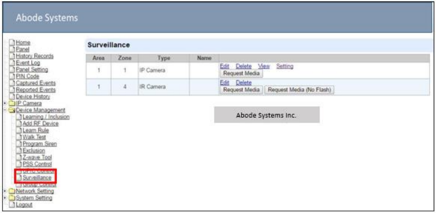
5.10.
Surveillance
The PIR Camera/Video Cameras and IP Cameras are listed under Surveillance for separate
control.
Click Edit to edit camera attributes.
Click Delete to remove device from panel.
Click Request Media to capture a picture or vide
PIR camera: A picture will be captured upon request
PIR Video Camera: A 10-second video will be recorded upon request
IP Camera: The IP Camera will record a video according to its video length setting
(Please refer to IP Camera manual for detail.)
For PIR Camera/Video Camera, you can choose to take the picture/video without
activating the camera’s flash.
Picture and video captured by PIR Camera and PIR Video Camera will be stored under the
Captured Event webpage. Video Recorded by IP Camera will be stored in the IP Camera
– Recorded Video page.
For IP Camera, click “View” or “Setting” to access configuration webpage for video
streaming or setting configuration.
30
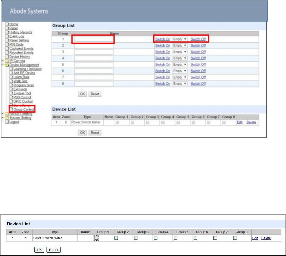
5.11.
Group Control
This feature is designed for you to edit a name of group, switch on or off a group of Power
Switches. You can also assign Power Switches to groups you desire.
5.11.1.
Group Control/Edit
Step 1. Specify a new name for a group.
Step 2. Click Switch On or Switch Off to turn on or off one group of power switches.
5.11.2 Device Edit/Delete
Step 1. Check on the groups you wish to assign the Power Switch. This is a multiple-choice field
and you can assign one Power Switch to multiple groups. Whenever one of the
assigned groups receives request to turn on/off, all Power Switches belonging to the
group will be activated accordingly.
Step 2. Click Edit to edit attributes of an added power switch or power switch meter or Delete to
delete this device.
31
6.
IP Camera
IOTA features a built-in IP Camera which can be programmed from the local area webpage.
6.1.
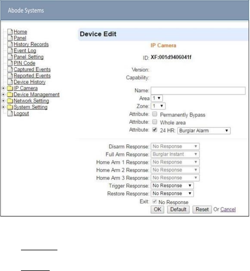
IP Camera Attribute Setting
The IP Camera is assigned to Zone 1 in the panel’s device list. Use the Edit Device function to
adjust the IP Camera Attribute Setting.
Edit the name, area, zone, and select attribute settings of the IP Camera.
Whole Area:
Unselected: The IP Camera will only record video when alarm is triggered by
sensor belonging to same area as the IP Camera
Selected: the IP Camera will also record video when alarm is triggered by
sensors belonging to different area.
Bypass: When an IP Camera is bypassed by the panel, the Panel will not
activate the IP Camera to record video when an alarm is triggered.
32
No Response: If set to No Response, the IP Camera will enter Privacy Mode
and will not provide image streaming or video recording function even when
alarm is activated.
If set to other response action such as Burglar Alarm or Start Entry, the IP
Camera will provide image streaming and video recording function under
selected mode.
Trigger Response: The Trigger Response function is currently disabled for IP
Camera.
33
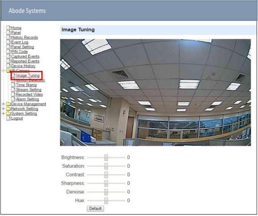
6.2.
Image Tuning
Click on “Image Tuning” to adjust video preferences according to the below parameters:
34
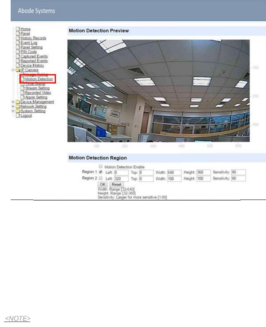
6.3.
Motion Detection
“Motion Detection” includes motion detection related setting options.
Check the box in front of “Motion Detection Enable” to de ermine whether the IP
Camera’s motion detection function should be activated.
The IP Camera can configure up to 2 customizable regions for motion detection. To activate
the motion detection region, check the box in front of “Region 1” or “Region 2”.
When motion is detected, the “Region 1” or “Region 2” text color will turn red for
approximately 3 seconds to indicate it has detected motion The IP Camera will report the
motion detection event according to Report setting and record the event in “Reported
Event” webpage. Refer to 5.6. Alarm Setting for setting video length.
If a Motion Detection is triggered, the IP Camera must complete video recording before a
second motion detection can be triggered again.
By default, “Region 1” is ticked and it detection coverage includes the whole camera
view.
If “Motion Detection Enable” is ticked but neither of “Region 1” or “Region 2” is ticked,
The IP Camera will not be able to detect any movement.
Please click the “OK” button for the changes to be effe tive.
<NOTE>
35
P
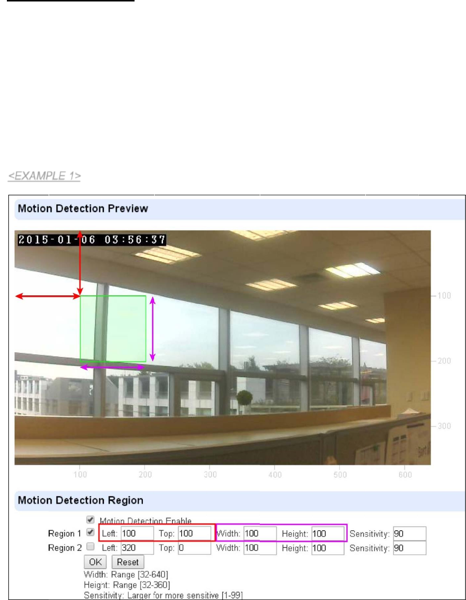
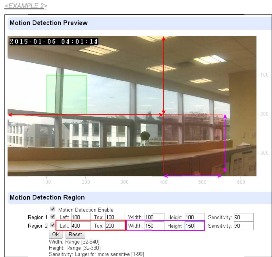
Motion Detection Region
You can choose the location, size and sensitivity of the motion detection region by adjusting
the parameters shown. The live feed has scales on the horizontal and the vertical axis for
you to refer to.
“Left” determines the horizontal starting point of the motion detection box. It starts from left
of the screen at 0 pixels, towards the right at 640 pixels.
“Top” determines the vertical starting point of the motion detection box. It starts from top of
the screen at 0 pixels, towards the bottom at 360 pixels.
“Width” determines the w dth of the box. The value of “Left” determines its starting point.
“Height” determines the height of the box. The value of “Top” determines its starting point.
The green box below is region of motion detection according to he set parameter:
The value 100 (pixels) of “Left” determines the horizontal starting position of the region for
detection.
The value 100 (pixels) of “Top” determines the vertical starting position of the region for
detection.
36
P
As shown, a value of 100 (pixels) are entered for both “Width” and “Height”, therefore a 100 by
100 motion detection region is determined.
The green box below is region 1 of motion detection according to the set parameter.
The red box below is region 2 of motion detection according to the set parameter. You can refer
to the horizontal and the vertical scales provided on the respective bottom and right side of the
live feed.
When confirmed, press “OK” to submit your adjusted parameter. Press “Reset” to re-enter
the parameters (“Reset” button resets the parameters to the previously set parameters).
<EXAM LE 2>
37
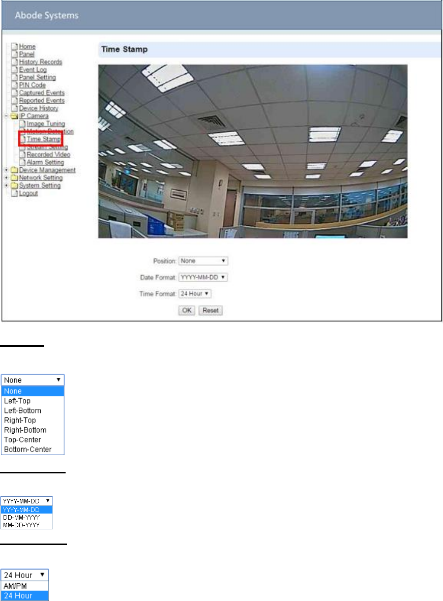
6.4.
Time Stamp
The “Tim Stamp” webpage is for you to edit the Time Stamp format on the video.
Position
The available options are:
Date Format
The available options are:
Time Format
The available options are:
Press “OK” to submit your adjusted parameters. Press “Reset” to re-select the parameters.
38
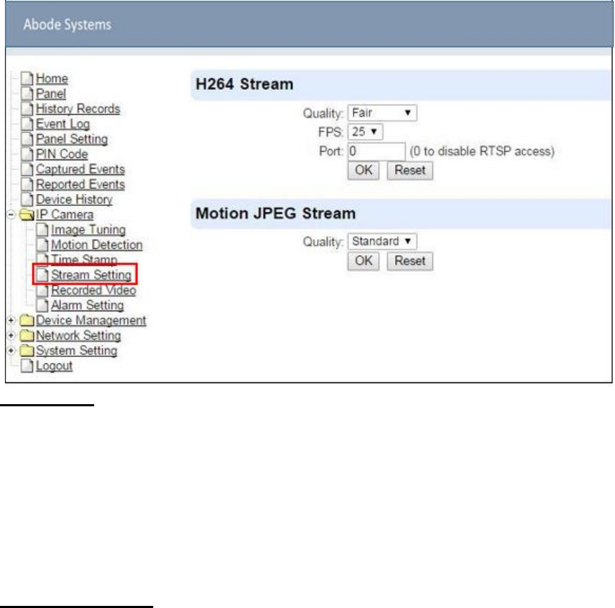
6.5.
Stream Setting
The “Stream Setting” webpage determines quality of video streaming, and the port to be used
when the IP Camera is access remotely via Port Forwarding.
H264 Stream
Quality adjusts the quality of the stream.
Frames Per Second (FPS) are adjustable. Increasing FPS improves the quality of the
live-stream. Click “OK” to confirm changes or click “Reset” to reset to the previously set
parameters.
Port: The port number for obtaining HD 1920 x 1080 resolution H264 video stream. The factory
default is set to 0 and H264 streaming is disabled. To enable H264 streaming, please set a port
number.
Motion JPEG Stream
Quality adjusts the quality of the stream.
MJPG streaming port is set to 80 and cannot be adjusted.
39
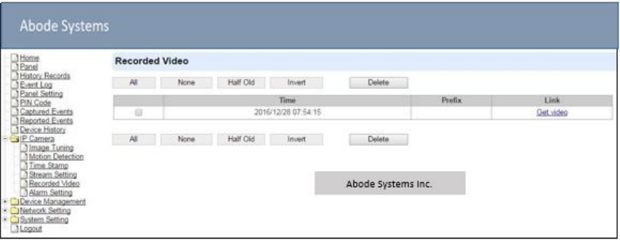
6.6.
Recorded Video
This menu displays all the recorded files.
The IOTA Camera can use two types of memory: a Micro SD card or the IP Camera flash memory.
(Micro SD card is not provided by factory default). If Micro SD card is not inserted, the video will
be store in flash memory, which has 30MB storage capacity.
IOTA supports Micro SD Card with up to 32GB storage capacity.
Click on the buttons for the respective functions described below:
All: to select all the recorded videos.
None: to cancel selecting the recorded videos.
Half Old: to select the older half the recorded videos.
Invert: to invert the current selection. E.g. if “All” was selected, clicking “Invert” will clear all
selections.
Delete: to delete the currently selected (ticked) video.
Video link: to download or play the video.
40
P
6.7.
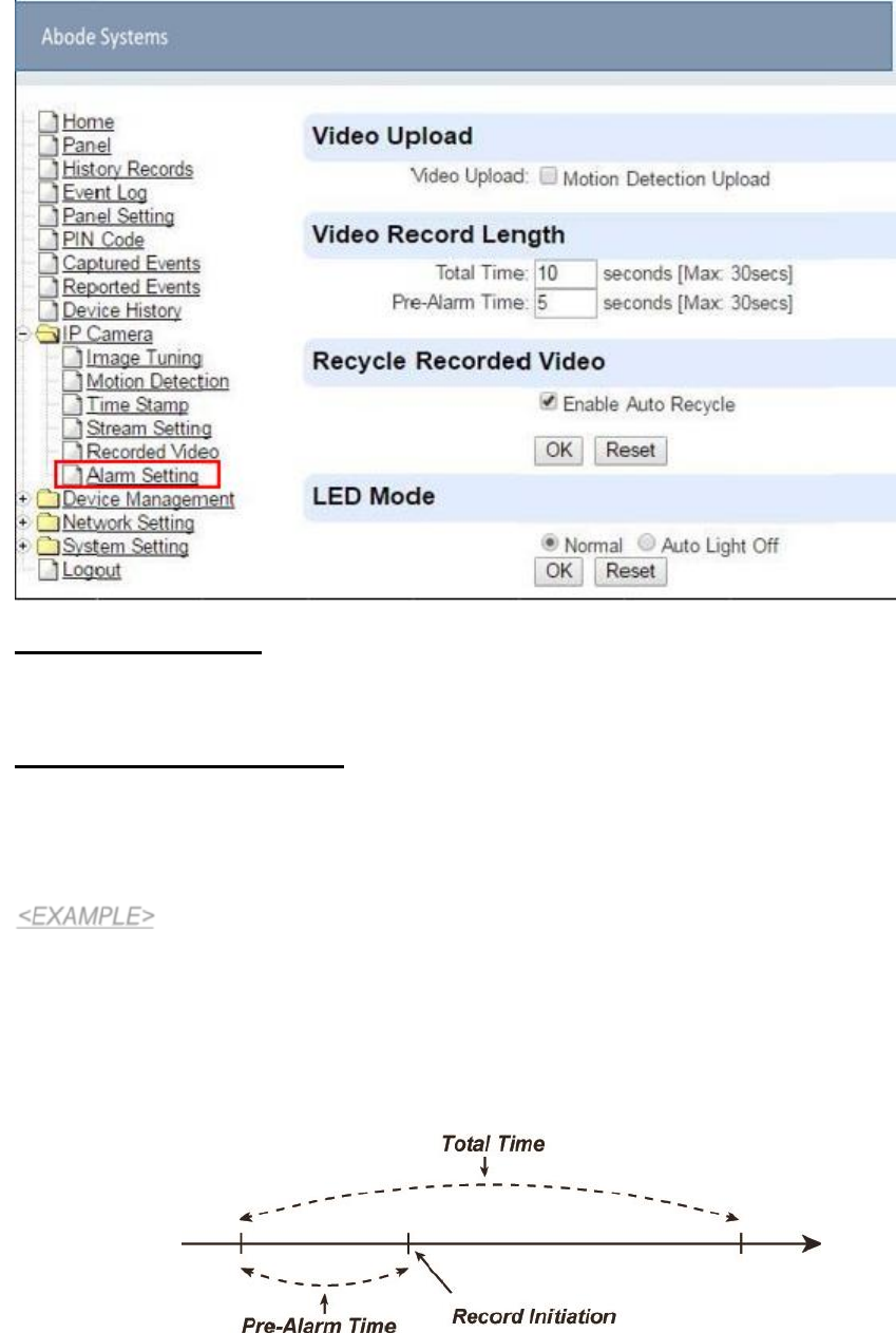
Alarm Setting
This menu displays the video recording options.
Video Upload Settings
Motion Detection Upload: If checked, the videos recorded from Motion Detection trigger will be
uploaded.
Video Record Length settings
Total Time: The total time length of each recorded video (Default: 10 seconds).
Pre-Alarm Time: The time length of the video which will be recorded prior to the initiation of
video recording (Default 5 seconds).
When Total Time is set to 10 seconds, and Pre-Alarm Time is set to 5 seconds, the IP Camera
will keep a continuous last 5-second buffer video storage. When the IP Camera receives
command to record a video (motion detection/alarm trigger from panel/request from panel), the
IP Camera will record another 5-second video. The final 10-second video will include 5-second
before record initiation, and 5-second after initiation.
41
Recycle Recorded Video
When this option is enabled, IP camera will automatically delete the oldest videos to clear space
on the MicroSD card or the RAM of the IP Camera.
When there is not enough memory left (in the MicroSD card or RAM), the IP camera will start
deleting old videos to retain more space.
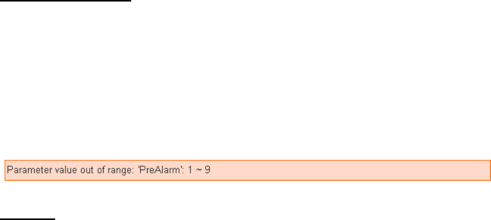
Press “OK” to submit the updated programmed parameters. Or press “Reset” to re-enter
(“Reset” button resets the parameters to the previously set parameters).
An error message will appear on top of the page if the parameters are not logically set (e.g.
Pre-alarm Time: 20 seconds, Total Time: 10 seconds), as exemplified below:
LED Mode
This function is reserved.
42
7.
Program the System
After the initial set-up, you can then program your system by clicking on the left menu to set
them individually.
7.1.
Panel Condition
In the Panel Section, user can arm, disarm or partially arm the system. Besides, it displays the
current Panel Status & Device Information.
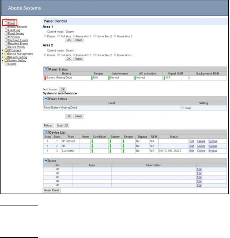
Panel Control
Select a choice to arm, disarm or partially arm the system.
Panel Status
The Control Panel will update the panel status periodically. However, in order to show the
current status, you must reload the screen to refresh the display.
Battery: When battery is running low, a “low battery” message will be displayed to
inform you to recharge the battery.
Tamper: (reserved)
43
Interference: This is for you to check whether the Control Panel is purposely interfered.
Whenever the signal jamming period lasts longer than 30 seconds, a “Jamming”
message will be shown and reported to the Central Monitoring Station accordingly.
AC activation: To check whether AC power is connected. If not, it will show “AC Failure”.
Signal GSM: This function is disabled for IOTA panel.
Background RSSI: Rssi value is for you to check the RF environment around the
Control Panel. It ranges from 0 to 9, where 0 refers to the weakest and 9 refers to the
strongest background noise. Therefore, the lower the Rssi value, the better the
environment.
Test System
The function is designed to send a command to sever over the polling or XMPP protocol.
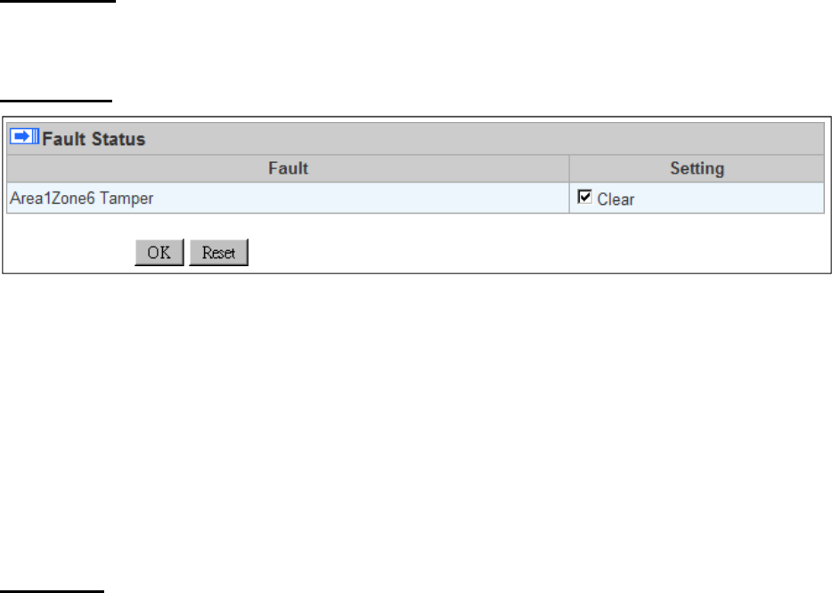
Fault Status
The fault events that exist in the alarm system is displayed under this section. When fault event
exists in system, the control panel Fault LED will light up to indicate fault status under Disarm or
Home Arm mode (The Fault LED will not light up under Arm mode).
When fault event exists, and you attempt to arm the system, the arming action will be prohibited
and the panel will display fault information on the webpage. If you still want to arm the system,
perform the arming action again to force arm.
You can check the “Clear” box in the setting column then click “OK” to ignore the fault event.
Cleared fault event will not cause the Fault LED to light up, nor prohibit arming.
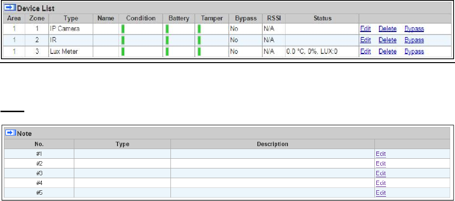
Device List
1.
The Control Panel will update the device information periodically. However, in order to show
the current status, you must reload the screen to refresh the display.
Area: operation area
Zone: device zone
Type: device type
Name: device title
Status: device’s current status, such as tamper status, battery status, out of order
condition or Door Contact open; for a power switch or metering device added into the
system, the device On/Off status, voltage, electric current and watt, will be displayed.
For a temperature/ambient light sensor, the temperature and lux reading is displayed.
2.
Under Device, you could further edit or delete a learnt in device (please refer to 5.1.3 and
5.1.4 for details). Beside, you can reset Panel settings or clear the system faults by pressing
Reset Panel.
44
- After pressing Reset Panel, the Control Panel will restart in 60 seconds and all configured
values will be kept without any change.
Note
The function is designed for installer to make a note for each control panel. The note you make
here can be delivered to a server over XMPP or polling protocol.
45
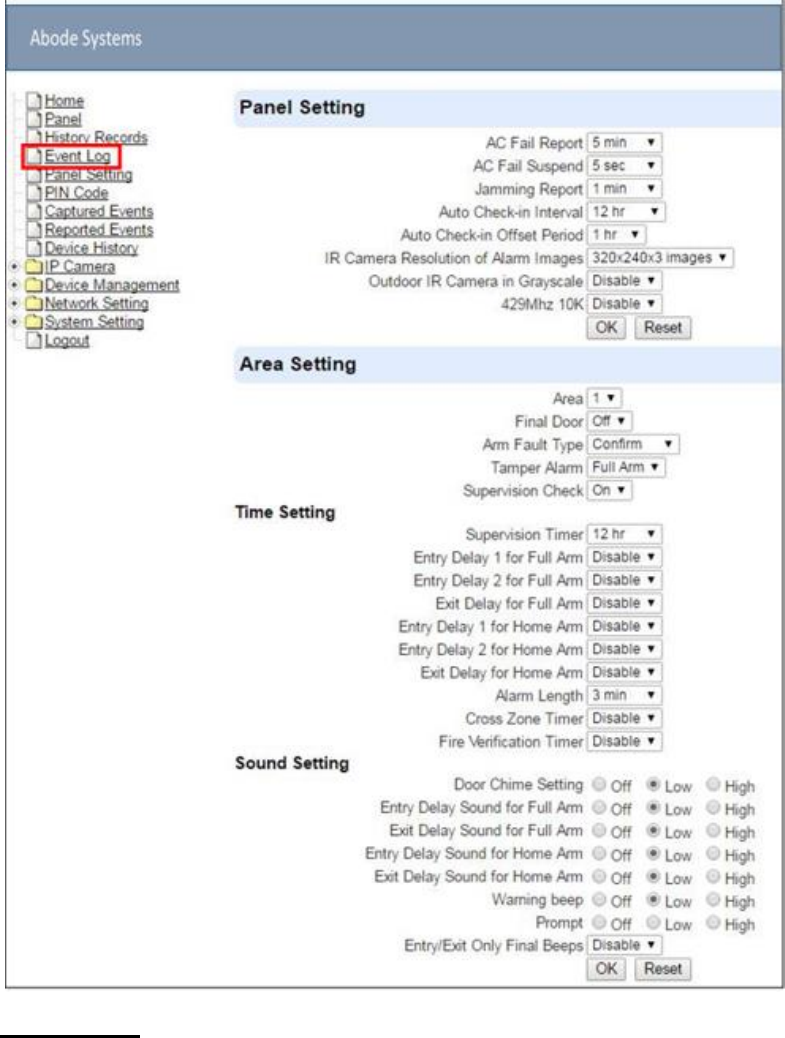
7.2.
Panel Settings
Program the Panel, Time and Sound Settings at your discretion.
Panel Setting
AC Fail Report: Set the waiting time before Control Panel report to Central Monitoring
Station when AC failure is detected.
AC Fail Suspend: After AC failure is detected, the panel will enter sleeping mode and

46
wake up at regular interval. Use this option to set the wake up period duration.
Jamming Report: This setting determines the time length of RF jamming detection
required to generate a RF jamming (inteference) fault.
Auto Check-in: this is to select whether the Control Panel needs to send check-in
reporting to the Central Station automatically and to select the period of time between
check-in reports. Options available are Disable, 1 hour, 2 hours, 3 hours… up to 4
Weeks.
Auto Check-in Offset Period: This is to set the time delay before the first Auto Check-
In report is made. After power is supplied or re-supplied to the Control Panel, a test
report will be sent to the Central Monitoring Station (CMS) based on the Offset Period.
This is used to test whether the CMS is able to receive the report from the Panel
accurately.
After this test report is sent, the Control Panel will then send reports at regular interval
based on the setting of the Auto Check-in Report.
For example, if Offset Period is set to 2 Hours, and Auto Check-in Report is set to 12
hours, the Control Panel will transmit an event code 602 to the CMS after 2 hours, and
then report 602 event code periodically at a regular intervals of 12 hours.
IR Camera Resolution of Alarm Images: This is to select the resolution and number
of pictures taken by PIR Camera when the camera detects a movement in armed mode.
Options available are 320x240x3 images (Default), 320x240x6 images and
640x320x3 images.
Outdoor IR Camera in Greyscale: This is to select whether pictures from Outdoor PIR
Camera should be taken in greyscale instead of color pictures.
Options available are: Disable(Color Picture) and Enable (Greyscale picture)
429Mhz 10K: This setting determines the Control Panel’s RF device type. Disabling this
setting will set the panel to work with 429MHz 1k type RF device. Enabling the setting
will set the panel to work with 429MHx 10k type RF device.
Area Setting
Area: Select operation area to apply setting.
Final Door: If set to On: When the system is Away Armed and under exit timer
countdown, if a opened Door Contact set to Entry attribute is closed, the system will
automatically arm the system even if the exit delay timer has not expired yet.
Arm Fault Type: Select how the system should respond when it is being armed under
fault condition.
Confirm: The panel will first display a “Mode Change Fault” message and emit 2
beeps. Arming again within 10 seconds will force arm the system.
Direct Confirm: The system will be force armed directly without displaying fault
message and report an event.
Tamper Alarm: Select whether the siren should sound alarm when the tamper is
triggered.
Full Arm: when tamper is triggered under Full arm mode, Control Panel raises a
local alarm and sends report to the monitoring center. While under Home Arm or
Disarm modes no alarm will be activated, nor report sent.
Always: Control Panel raises a local alarm and send report for tamper-trigger in all
modes.
Supervision Check: Select to enable or disable system supervision function. When

47
ON is selected, the Control Panel will monitor the accessory devices according to the
supervision signal received.
Time Setting
Supervision Timer: The Control Panel monitors accessory devices according to the
supervision signal transmitted regularly from the device. User this option to set a time
period for receiving supervision signals. If the Control Panel fails to receive supervision
signal from a device within this duration, it will consider the device out of order and report
the event accordingly.
Entry Delay 1 for Full Arm: Set Entry Delay Timer 1 for full arm mode. When a sensor
set to Start Entry Delay 1 is triggered under Full Arm mode, the control panel will begin
Entry Delay Timer countdown according to duration set with this option
If the Control Panel is disarmed before the Entry Delay Timer expires, the panel returns
to Disarm mode and no alarm is activated. If the Control Panel is not disarmed before
the Entry Delay Timer expires, the alarm will be activated and the panel will send report.
Entry Delay 2 for Full Arm: Set Entry Delay Timer 2 for full arm mode. When a sensor
set to Start Entry Delay 2 is triggered under Full Arm mode, the control panel will begin
Entry Delay Timer countdown according to duration set with this option
If the Control Panel is disarmed before the Entry Delay Timer expires, the panel returns
to Disarm mode and no alarm is activated. If the Control Panel is not disarmed before
the Entry Delay Timer expires, the alarm will be activated and the panel will send report.
Exit Delay for Full Arm: Set the Exit Delay Timer when entering Full Arm mode. When
the user changes system mode to Full Arm, the panel will begin Exit Delay Timer
Countdown and enter Full Arm mode when the timer expires. The user must leave area
protected by sensors before the timer expires, otherwise an alarm will be activated with
the sensor is triggered.
Entry Delay 1 for Home Arm: Set Entry Delay Timer 1 for Home Arm mode. When a
sensor set to Start Entry Delay 1 is triggered under Home Arm mode, the control panel
will begin Entry Delay Timer countdown according to duration set with this option
If the Control Panel is disarmed before the Entry Delay Timer expires, the panel returns
to Disarm mode and no alarm is activated. If the Control Panel is not disarmed before
the Entry Delay Timer expires, the alarm will be activated and the panel will send report.
Entry Delay 2 for Home Arm: Set Entry Delay Timer 2 for Home Arm mode. When a
sensor set to Start Entry Delay 2 is triggered under Home Arm mode, the control panel
will begin Entry Delay Timer countdown according to duration set with this option
If the Control Panel is disarmed before the Entry Delay Timer expires, the panel returns
to Disarm mode and no alarm is activated. If the Control Panel is not disarmed before
the Entry Delay Timer expires, the alarm will be activated and the panel will send report.
Alarm Length: Set the duration the external siren should sound when an alarm is
activated.
Sound Setting
Door Chime Setting: this function is available only when the attribute of Door Contact
(DC) and/or PIR detector (IR) is set as Door Chime.
The Control Panel sounds a Door Chime (Ding-Dong Sound) while the DC and/or IR is
activated in Disarm / Full / Home / Entry mode.
Entry Delay Sound for Full Arm: this is for you to decide whether the Control Panel
48
sounds count-down beeps and volume of beep during the entry delay time in the full
arm mode.
Exit Delay Sound for Full Arm: this is for you to decide whether the Control Panel
sounds count-down beeps and volume of beep during the exit delay timer in the full arm
mode.
Entry Delay Sound for Home Arm: this is for you to decide whether the Control Panel
sounds count-down beeps and volume of beep during the entry delay time in the home
arm mode.
Exit Delay Sound for Home Arm: this is for you to decide whether the Control Panel
sounds count-down beeps and volume of beep during the exit delay timer in the home
arm mode.
Warning beep: this is for you to decide whether the Control Panel will sound a warning
beep whenever a fault condition has been detected and displayed. The warning beep
will be silenced after the Fault message has been read by the user. When a new fault
condition is detected, it will then again emit a warning beep every 30 sec.
Entry/ Exit Only Final Beeps: This is for you to determine when the Control Panel
should start warning beep during Entry or Exit countdown timer. For example, if the
setting is set to 5 seconds, the Control Panel will only stat warning beep during the last
5 seconds of Entry or Exit countdown timer. When set to disable, the Control Panel will
sound warning beep during the entire Entry or Exit countdown timer.
49
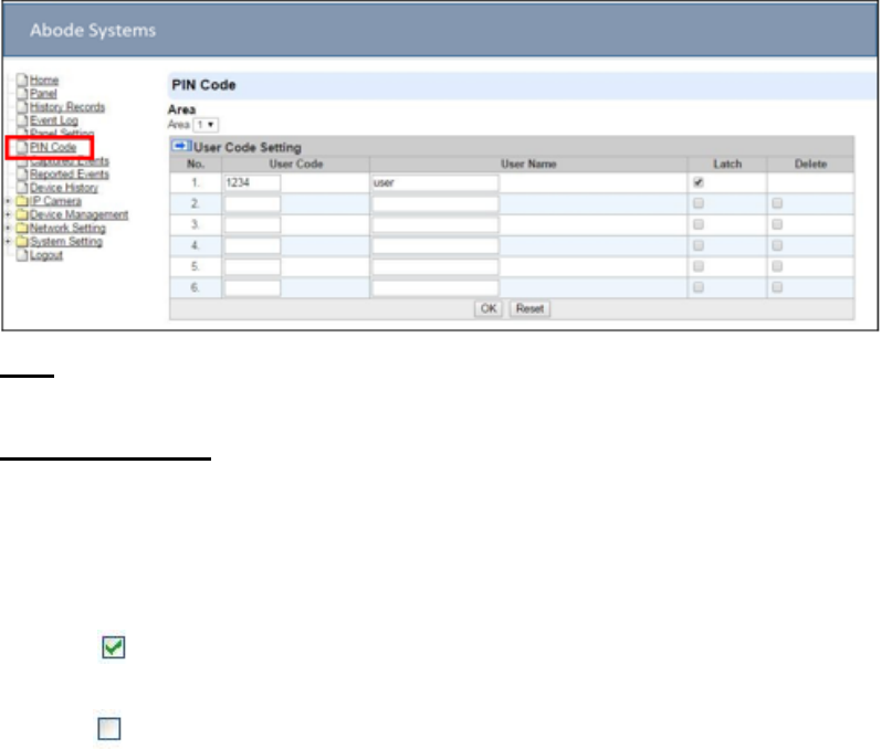
7.3.
PIN Code
The User PIN Codes are used by Remote Keypad accessory to control system mode remotely.
The 2 areas in the control panel each has 6 User PIN Codes available for setting. Each consists
of 4 digits (numeric number 0~9). User PIN code #1 for each Area is always activated factory
default.
User PIN #1 in Area 1 User PIN #1 in Area 2
Password: 1234 Password: 4321
Area
Area: Select the area for setting User PIN Code.
User Code Setting
User Code: Enter the 4-digit code in the field.
User Name: Enter a user name for easy recognition of system events. Up to 17
alphanumerical characters are allow for each user name.
Latch:
Latch Latch Report ON = Whenever the User PIN Code is used to change
system mode, the panel will report the event.
Latch Latch Report OFF = When the User PIN Code is used to change system
mode, the panel will not report the event.
Delete: Check the box if you want to delete selected user. User#1 in each area cannot
be deleted
After finish all setting, click OK to confirm change.
50
8.
Network Settings
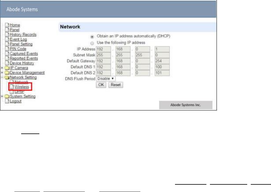
8.1.
Network
This is for you to program the Network for IP connection.
Obtain an IP address automatically (DHCP)
If DHCP is selected, the Network will obtain an IP address automatically with a valid
Network DHCP Server. Therefore, manual settings are not required.
This is only to be chosen if your Network environment supports DHCP. It will automatically
generate all information.
Use following IP address
You can also enter the Network information manually for IP Address, Subnet Mask, Default
Gateway, Default DNS 1 and Default DNS 2.
Please make sure that you have obtained all required values according to your Network
environment. Please contact your network administrator and/or internet service provider for
more information.
DNS Flush Period
You can set the system to clear current DNS resolution records for all entered URL settings
(Reporting, Upload, XMPP…etc.) after a set time period. The system will then resolve the
Domain Name again and acquire new IP address for the URL settings. This function is
disabled by default.
51
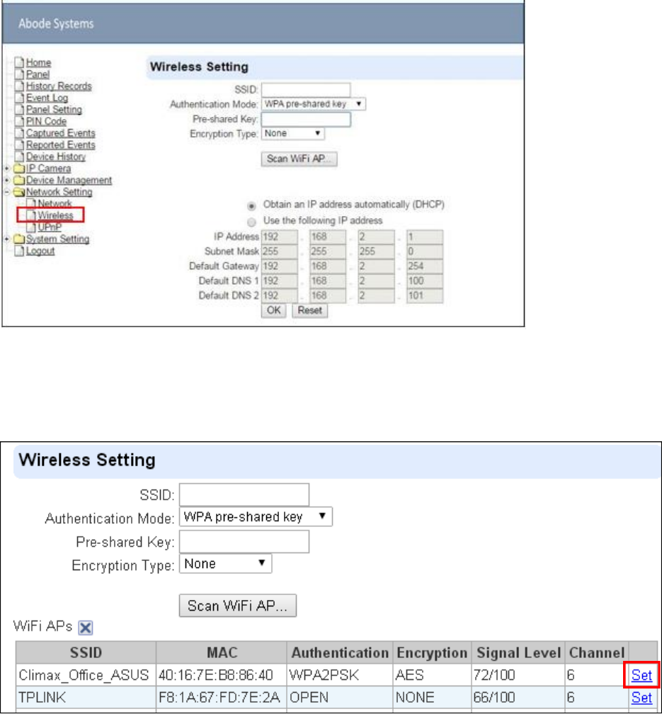
8.2.
Wireless
Use “Wireless” webpage to setup the panel’s WiFi setting
There are 3 ways you can connect to the wireless network.
1.
Search for WiFi AP: Click “Scan WiFi AP” to search for available wireless network Select the
available Wireless APs from the list by clicking “Set” after AP info column and enter the
required information (pre-shared key, etc.) and click the “OK” button.
2.
Enter the Wireless information manually and click “OK” to connect.
3.
WPS protocol: Use the WPS protocol to connect it to the Wi-Fi network.
Locate the WPS button on the panel and your wireless router.
Press and hold the WPS button on the panel for about 10 seconds and release. LED 4 will
flash Red for 1-2 seconds.
Press and hold the WPS button of the router’s WPS protocol according to the router’s
52
Instruction to start pairing.
When WPS pairing is successful, the LED 4 will flash Red 3 times.
53
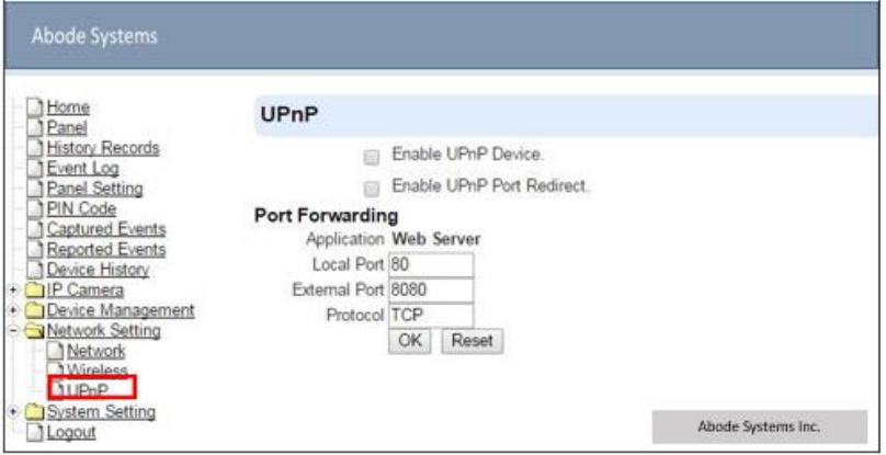
8.3.
UPnP
UPnP is Universal Plug and Play, which opens networking architecture that leverages TCP/IP
and the Web technologies to enable seamless proximity networking in addition to control and
data transfer among networked devices in the home, office, and public spaces.
Enable UPnP Device:
When enabled, you will be able to see this device via any UPnP discovery tool
Enable UPnP Port Redirect:
The device will try to find an UPnP-supported router and set up the port to redirect to the
router.
Port Forwarding:
1.
Local Port
2.
External Port
3.
Protocol
54
9.
System Settings
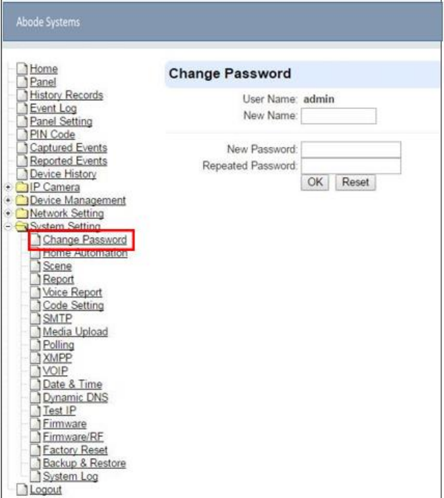
9.1.
Administrator Setting
For setting new Administrator Log-in Name and Password. Please note both User Name and
Password are case sensitive.
Step 1. Enter the preferred User Name.
Step 2. Enter the preferred Password in the “New Password” field and repeat the same
Password in the Repeat Password field.
55
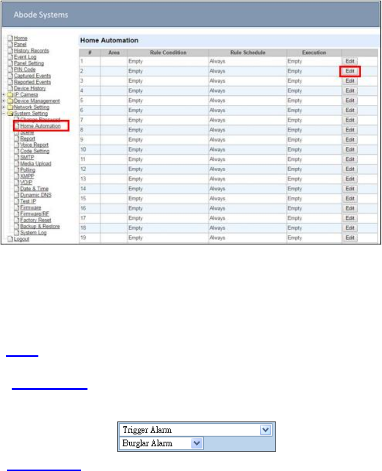
9.2.
Home Automation
It is used to set Home Automation rules to control sensors and home appliances. You can set up
to 100 rules.
Step 1. Click on Edit.
Step 2. Select an operation area.
Step 3. Set a rule condition.
Step 4. Set a rule schedule.
Step 5. Select the corresponding action rules in the Execution field.
Area
Select an operation area.
Rule Condition
The rule condition determines under which circumstances the rule should be activated.
Empty : When set as Empty, the system will follow the schedule time and execution rule
to respond accordingly.
Trigger Alarm : When set as Trigger Alarm, if the specified alarm event
(Burglar/Some/Medical/Water/Silent Panic/Panic/Emergency/Fire /CO Alarm) is
triggered, the rule will be activated according to rule schedule and execution setting.
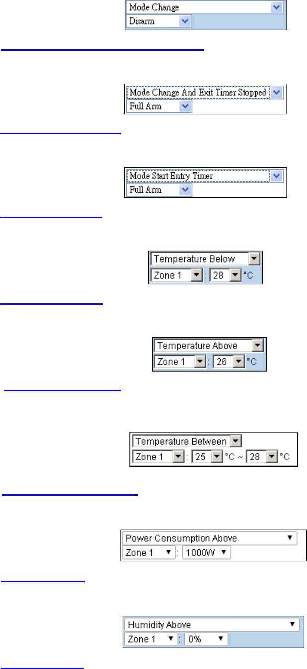
Mode Change : When set as Mode Change, when the system enters specified mode,
the rule will be activated according to rule schedule and execution setting.
56
Mode Change and Exit Timer Stopped : When set as Mode Change and Exit Timer
Stopped, when the system changes mode to and Exit Delay Timer expires, , the rule
will be activated according to rule schedule and execution setting.
Mode Start Entry Timer : When set as Mode Start Entry Timer, when the system begins
to countdown Entry Delay, the rule will be activated according to rule schedule and
execution setting.
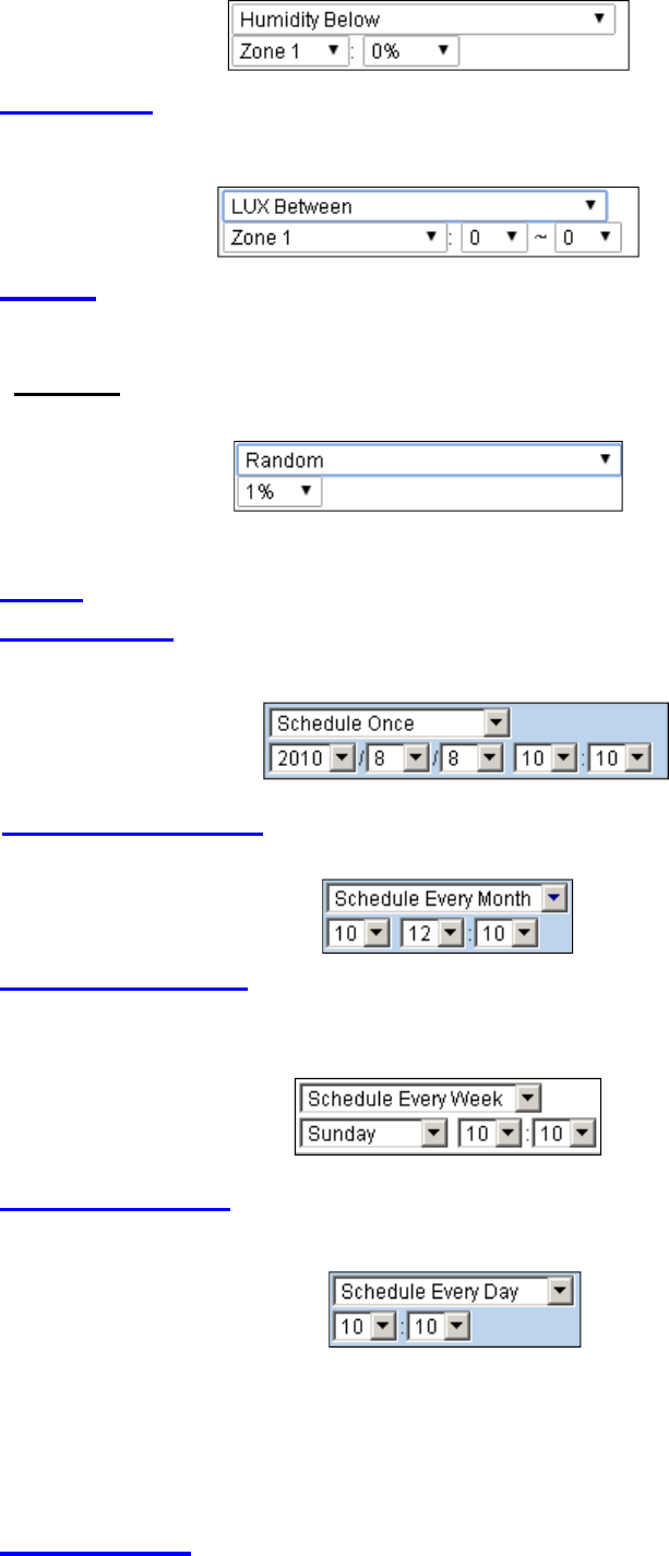
Temperature Below : When set as Temperature Below, if the temperature detected by
specified temperature sensor drops below set threshold, the rule will be activated
according to rule schedule and execution setting.
Temperature Above : When set as Temperature Below, if the temperature detected by
specified temperature sensor exceeds set threshold, the rule will be activated according
to rule schedule and execution setting.
Temperature Between : When set as Temperature Between, if the temperature
detected by specified temperature sensor falls within the range specified, the rule will be
activated according to rule schedule and execution setting.
High Power Consumption : When set as Power Consumption Above, if the power
output watt from a specific Power Switch exceeds, the rule will be activated according
to rule schedule and execution setting.
Humidity Above : When set as Humidity Above, if the humidity reading from specified
room sensor rises above the level specified, the rule will be activated according to rule
schedule and execution setting.
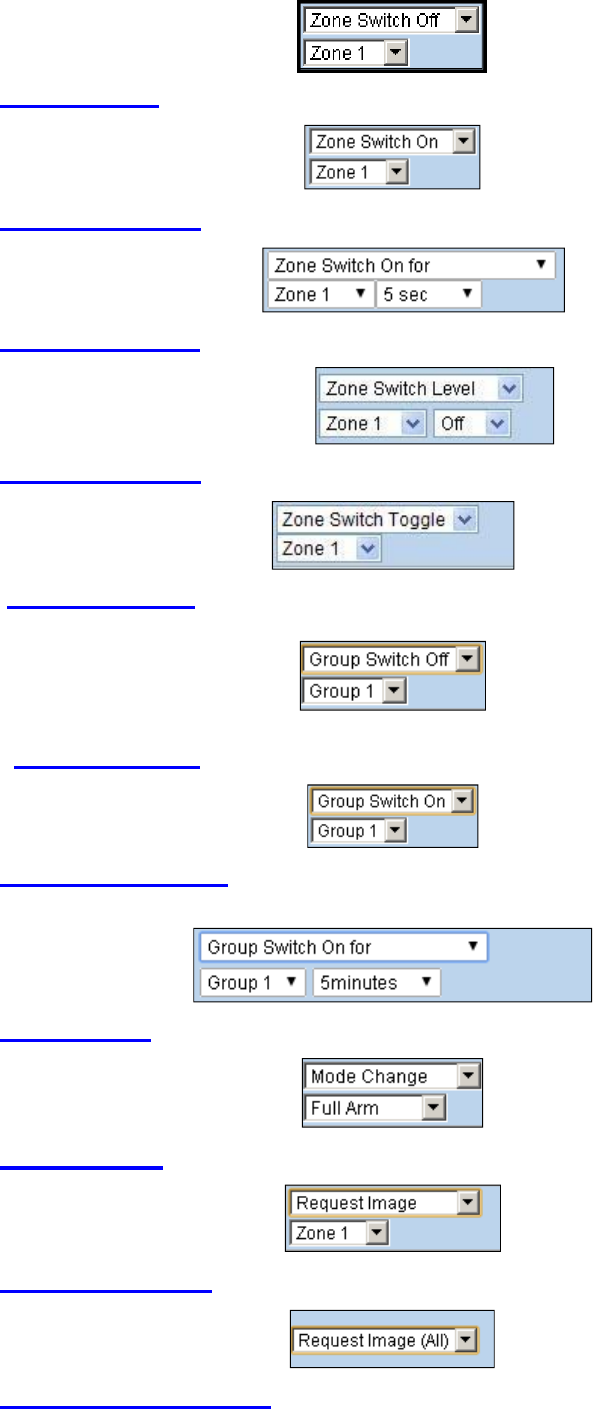
Humidity Below : When set as Humidity Below, if the humidity reading from specified
room sensor falls below the level specified, the rule will be activated according to rule
schedule and execution setting.
57
LUX Between : When set as LUX Between, if the lux reading from specified light sensor
falls below the level specified, the rule will be activated according to rule schedule and
execution setting.
Random : The Random condition must be used along with Rule Schedule setting. Set a
percentage from 1 to 10%. When the panel time reaches programmed Rule Schedule
time. The Panel will activate rule according to set chance.
Example: If set as 10%, whenever the panel reaches programmed Rule Schedule time,
there will be a 10% chance the rule is activated.
Rule Schedule
Always : When set as Always, the rule can be activated anytime.
Schedule Once : When set as Schedule Once, the system will follow the rule condition
and execute rule according to the exact date and time specified..
Schedule Every Month : When set as Schedule Every Month, the system will follow
the rule condition and execute rule according to date and time specified every month.
Schedule Every Week : When set as Schedule Every Week, the system will follow the
rule condition and execute rule according to day of the week and time specified every
week.
Schedule Every Day : When set as Schedule Every Day, the system will follow the the
rule condition and execute rule according to time specified every day
Execution
Execution is the actual action performed by Control Panel when both Rule Condition and
Rule Schedule requirements are met
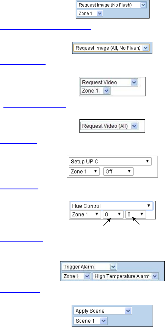
Zone Switch Off: Turn on the Power Switch at specified zone.
58
Zone Swich On : Turn on the Power Switch at specified zone.
Zone Swich On For : Turn on the Power Switch at specified zone for a set duration.
Zone Switch Level:: Change the power output level for Dimmer at specified zone.
Zone Swich Toggle : Toggle on/off the Power Switch at specified zone.
Group Switch Off : Turn off all Power Switches assigned to specified group.
Group Switch On : Turn on all Power Switches assigned to specified group.
Group Switch On For : Turn on all Power Switches assigned to specified group for a
set duration.
Mode Change : The system will change to the mode as you specified.
Request Image : The PIR Camera in specified zone will take a picture.
Request Image (All) : All PIR Cameras in the system will take a picture.
Request Image (No Flash): The PIR Camera in specified zone will take a picture,
Without activating its LED flash.
59
Request Image (All, No Flash) : All PIR Cameras in the system will take a picture
without activating LED Flash.
Request Video : The PIR Video Camera or IP Camera in specified zone will record a
video.
Request Video (All) : All PIR Video Cameras and IP Cameras in the system will
record a video.
Setup UPIC:: The UPIC and specified zone will transmit Off/Heat/Cool command to the
air conditioner as programmed.
Hue Control:: Adjust the hue and saturation of the Philips Hue at specified zone as
programmed.
Hue Saturation
Trigger Alarm: Choose to activate one of the following alarms: High Temperature Alarm,
Low Temperature Alarm, High Power Consumption Alarm, High Humidity Alarm and Low
Humidity Alarm
Apply Scene:: the system will execute preprogrammed Scene number. Please refer to
8.3. Scene for detail.
60
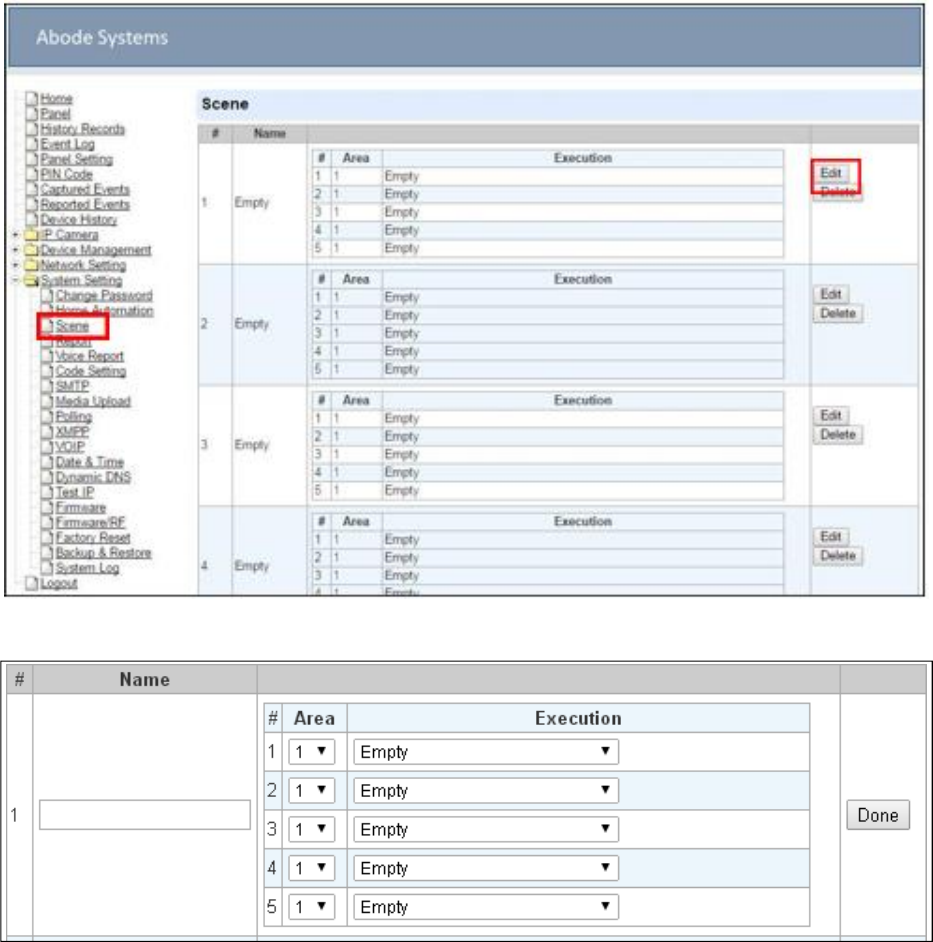
9.3.
Scene
The Scene setting allows you to customize a series of actions with your devices. The
programmed scene can be set to activated when a device is triggered. (See 5.1.3. Edit
Devices), or when a Home Automation Rule is executed. (See 8.2. Home Automation) For
example, you can set a scene to control multiple lightings, then set your Remote Control to
activate the scene, or set a Home Automation Rule to activate the scene.
Step 1. Click on Edit.
Step 2. Enter a name for the scene.
Step 3. Select an Area
Step 4. Select an action to be executed when the scene is activated. Refer to the Rule
Execution section in 8.2. Home Automation for detail.
Step 5. Repeat Step 2-3 to setup up to 5 executions for a scene.
Step 6. Click “Done”.
Step 7. Click “OK” at bottom of webpage to confirm the new scene setting.
61
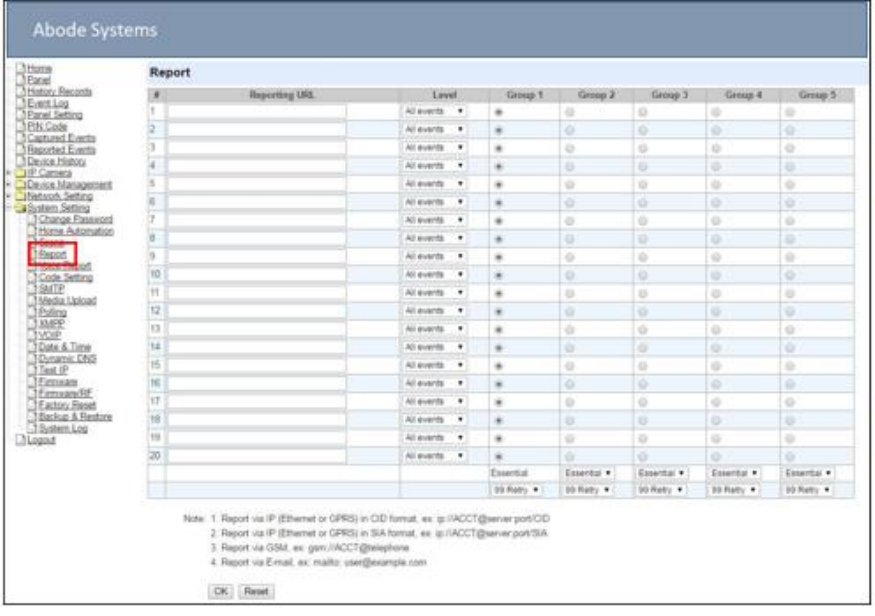
9.4.
Reporting
This is used for installer to set system event reporting parameters for panel to deliver report
when an event is generated.
Reporting URL
This is used for installer to program report destinations.
1
Abode CID protocol via IP
Format: ip://(Account Number)@(server ip):(port)/CID
Example: ip://1234@54.183.182.247:8080/CID
2
SIA DC-09 protocol via IP
Format: ip://(Account Number)@(server ip):(port)/SIA
Example: ip://1234@54.183.182.247:8080/SIA
3
SIA DC-09 protocol via IP with AES encryption
Format: ip//(Account Number)@(server ip):(port)/SIA/KEY/(128,196 or 256 bits Key)
Example:
ip://1234@54.183.182.247:8080/SIA/KEY/ 4A46321737F890F654D632103F86B4F3
4
SIA DC-09 protocol using CID event code via IP
Format: ip://(Account Number)@(server ip):(port)/CID_SIA
Example: ip://1234@54.183.182.247:8080/CID_SIA
5
SIA DC-09 protocol using CID event code via IP, with HEX encryption.
Format: ip//(Account Number)@(server ip):(port)/CID_SIA/KEY/(HEX)
Example:

62
ip://1234@54.183.182.247:8080/CID_SIA/KEY/4A46321737F890F654D632103F86B4
F3
6
CSV protocol via IP
Format: ip//(Account Number)@(server ip):(port)/CSV
Example: ip://1234@54.183.182.247:8080/CSV
7
CSV protocol via IP including username and password
Format: ip//(Account Number)@(server ip):(port)/CSV/User/Pasword
Example: ip://1234@54.183.182.247:8080/CSV/abcd/1357
8
CID protocol via GSM
Format: gsm://(Account Number)@(telephone number)
Example: gsm://1234@0987654321
9
Email
Format: mailto:user@example.com
Example: mailto:john@gmail.com
Level
Select a reporting condition:
All events: The system will report all events to this destination.
Alarm events: The system will only report alarm event to this destination.
Status events: The system will only report status event(non-alarm events) to this
destination.
Group
Select a group for your report destination The system will make report according to the
following principle:
Group with higher priority will be reported first: Ex: Group 1 Group 2 Group 3….
If reporting to the first destination in a group fails, the system will move on to the next
report destination in the group.
If reporting to one of the report destinations in a group is successful, the system will
consider reporting to this group successful and stop reporting to rest of the destinations
in the group. It will then move on to report to the next group.
If reporting to all destinations in a group fails, the system will retry report to group
according to retry times set below. If reporting is still unsuccessful after retries, the
system will move on to report the the next group according to Essential/Optional setting
below.
After completing a round of reporting (From Group 1 Group 2 ….. Group5), If there
is any group set as Essential which has not received report successfully, the system will
restart the reporting cycle to retry reporting until every group set as Essential is reported
successfully.
Essential/Optional
Essential: the system will report to all groups set as Essential. The system will never give
up trying to report to any group set as Essential until at least one of the
destinations in every Essential group successfully receives the report. Group 1
is always set as Essential and cannot be changed.

63
<NOTE>
Optional: The system will only report to group set as Optional when reporting to its
previous group fails. For example: if Group 3 is set is optional, the Control Panel
will only report to Group 3 if reporting to Group 2 fails.
1 Retry/ 3 Retry/ 5 Retry/ 10 Retry/ 99 Retry:
If reporting to all destinations in a group fails, the system will retry reporting to the group
according to the retries times set here.
When the panel is registered into Abode’s Home Portal Server, URL1 will be filled in
with Home Portal Server report information. Do not change the information once
registration is complete or reporting to Home Portal Server may encounter er or.
After registering the panel in Home Portal Server, if you wish to set more reporting
destination, the new report destination should be se to different group than URL1
otherwise it may not be able to receive report successfully.
64
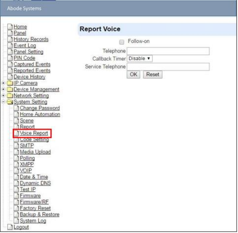
9.5.
Voice Report
IOTA panel is able to make voice call when an alarm is activated to establish two-way voice
communication with call recipients. Each two-way voice session lasts 3 minutes. At the last 30 &
10 secs of two way conversation, the panel will emit 1 short beep to alert the call recipient.
The panel will make voice report after the first successful alarm reporting. At least one
report destination must be programmed to use voice reporting function.
Warning: Voice reporting is not available when AC power failure is detected.
Follow-on
This function is currently reserved.
Telephone
Enter the VOIP call recipient in the field. The panel will make voice report after the first
alarm report is completed.
Callback Timer
Callback function only works when no call recipient is programmed. After activating alarm,

65
O
the panel will enter a waiting period for call back. Incoming call during this period will be
answered automatically to open two-way communication. The Callback time will end after
set waiting period has expired or after the incoming call has ended.
Service Telephone
This function is currently reserved.
VOIP setting must be programmed first before the Control Panel can m
via VOIP. Please refer to 8.11. VOIP for more information. ke report
<N TE>
66
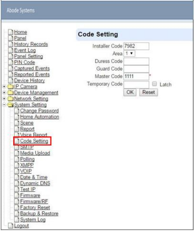
9.6.
Code Settings
The Duress Code, Master Code & Temporary Code adds the flexibility of different security level
for operation in Code Settings menu.
Step 1. Key in your preferred 4 digit Installer Code, Duress Code, Master Code, and/or
Temporary Code.
Step 2. You can also choose to have Latch Option On / Off for Temporary Code by tick the
Latch Option box and press OK to confirm the settings.
Installer Code
The Installer Code is used for SMS Remote Programming, when sending a remote
programming message, the user needs to enter Installer Code in the message to be able
to program the system. The default Installer code is: 7982.
Area
Each Area has different Duress Code, Master Code, and Temporary Code. Select the Area
to program the code setting in this area.

67
Duress Code
The Duress Code is designed for transmitting a secret & silence alarm.
When Duress Code is used for accessing the system, the Control Panel will report a secret
alarm message without sounding the siren to the Central Monitoring Station to indicate of
a Duress Situation in Progress.
The Duress Code consists of 4 digits and is not activated as default by the factory.
Guard Code
The Guard Code is designed for security patrol personnel to arm/disarm the system. It can
be set the same as a User PIN Code.
The Guard Code consists of 4 digits and is not activated as default by the factory.
Master Code
This function is currently disabled.
Temporary Code
Temporary Code is also used to arm/disarm the system, but it is for a temporary user. The
temporary Code is ONLY valid for one-access per arming and disarming. Afterwards, the
Temporary Code will be automatically erased and needs to be reset for a new Temporary
user.
The Temporary Code consists of 4 digits and is not activated as default by the factory.
Latch Option
This is to program the Latch Key Reporting feature for Temporary Code. Please click the
box to select the options.
Latch Latch Report ON = Whenever the system is armed, home/ day home/ night
home armed or disarmed, the Panel will transmit Contact ID code / SMS message / GPRS
reporting (according to pre-setting) to notify the Central Monitoring Station.
Latch Latch Report OFF = Whenever the system is armed, home/ day home/ night
home armed or disarmed, the Panel will NOT transmit reporting(s) to notify the Central
Monitoring Station.
Delete
Except Master Code which can’t be disabled in any way, Temporary and Duress Code can
be disabled by cleaning the code box and leaving the box as blank.
68
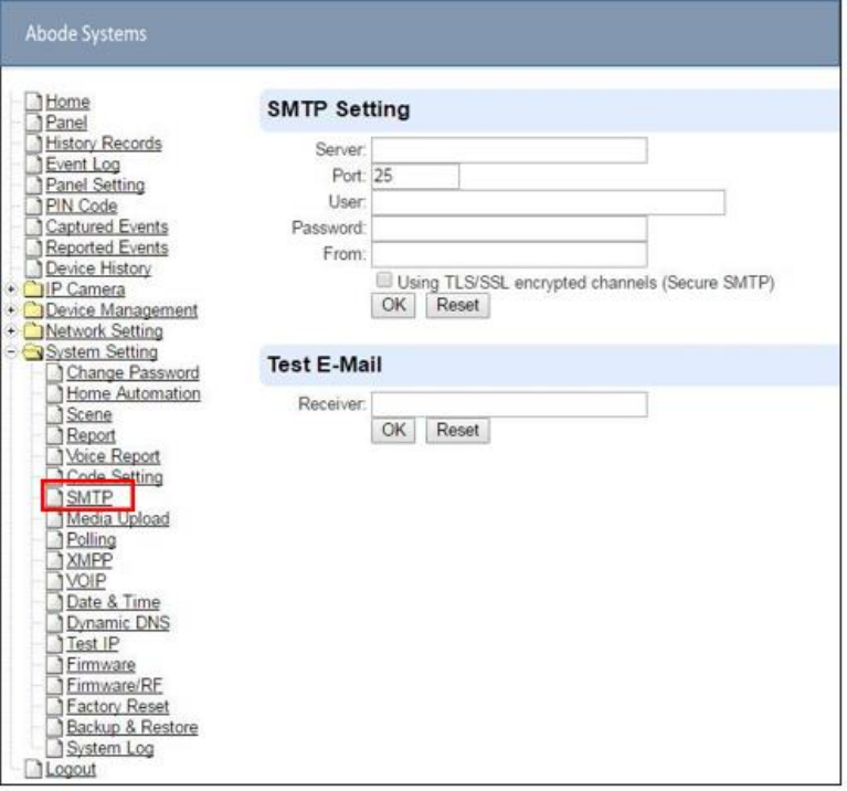
9.7.
SMTP Setting
Program the mail server related settings. The email account you set here would be used to send
report for events or picture and video clip captured by PIR Camera and PIR Video Camera.
Step 1. Enter the following settings:
Server: set the mail server (max. 60 digits/alphabets).
Port: set the port number (max. 5 digits/alphabets).
User: set the mail account name (max. 30 digits/alphabets).
Password: set the password corresponding to the mail account name (max. 30
digits/alphabets).
From: set the email address according to your mail sever and account name. (max. 30
digits/alphabets).
Using TLS/SSL encrypted channels (Secure SMTP):If your mail server uses TLS or
SSL encryption method for secure transfer, please click the box to enable the setting
Step 2. Click OK to confirm the setting.
69
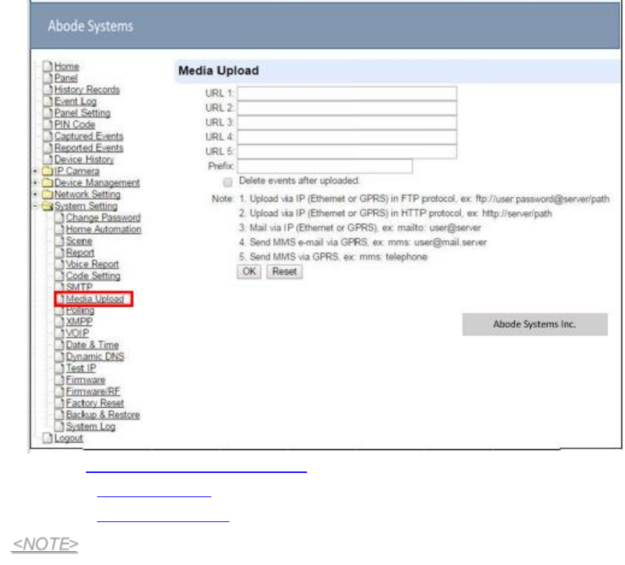
9.8.
Media Upload
The system can deliver captured images and video clips captured by PIR Cameras and PIR
Video Camera to cell phone, email or ftp.
FTP: ftp://user.password@server/path
HTTP: http://ip:port/path
Email: mailto:user@server (transmitting an alarm image over Ethernet)
If “Deleted events af er uploaded” is checked, the system will automatically clear all
captured images which are displayed in the Captured Events menu after it successfully
sends out those captured images to preset reporting destinations.
<NOTE>
70
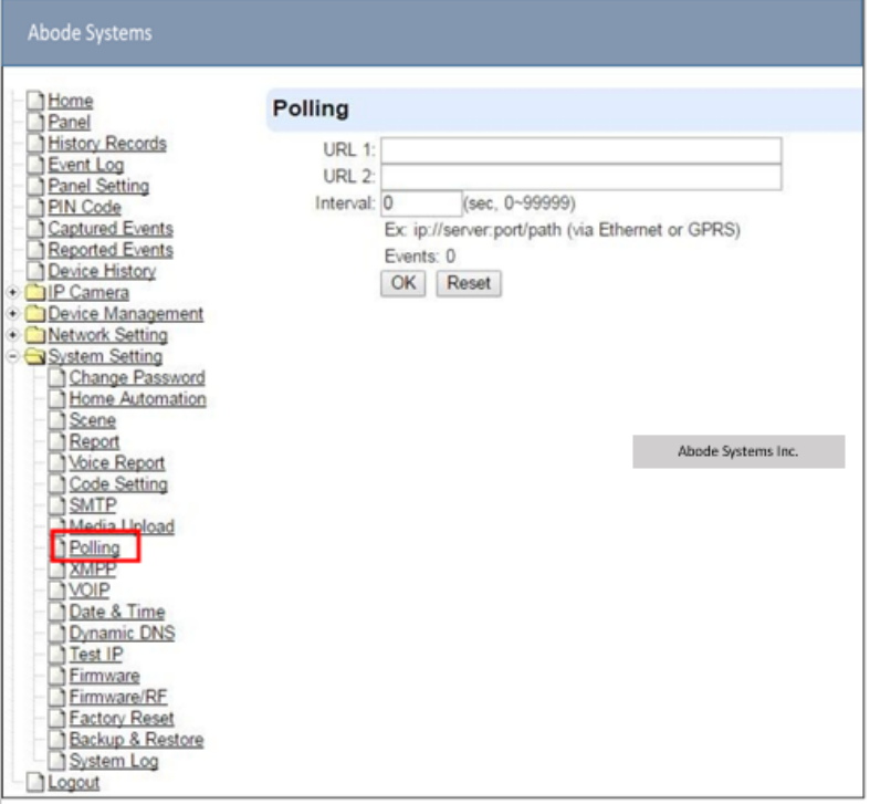
9.9.
Polling
The polling function enables the Control Panel to query the destination you set (URL1 or URL2)
in turn as to whether it has any data to transmit.
URL/URL2: ip://server:port/path
Interval : interval time of polling
71
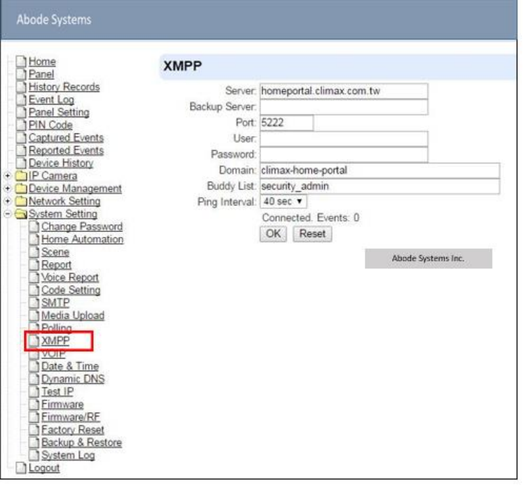
9.10.
XMPP
XMPP setting enables the Control Panel to query the set destination. This setting is required for
the Control Panel to connect to Abode’s Home Portal Server for remote control. If the panel is
disconnected from the server, it will retry connection every 3 minutes.
Server: server address
Port: server’s port number
User: authorized user account name
Password: authorized user password
Domain: domain address
Buddy List: contact destination
Ping Interval: server connection test interval
72
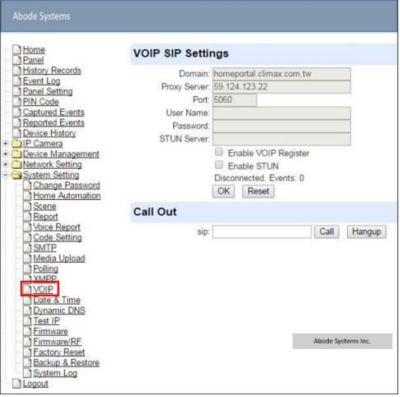
9.11.
VOIP
Program your VOIP server setting with this page. The VOIP setting must be completed before
you can use Voice Report function via VOIP.
Server: Your VOIP server URL, factory default is set to Abode’ Home Portal Server. If you
use your own server, a SIP VOIP server is required. We recommend using an Asterisk
server.
User: Enter your username in the VOIP server
Password: Enter the password.
73
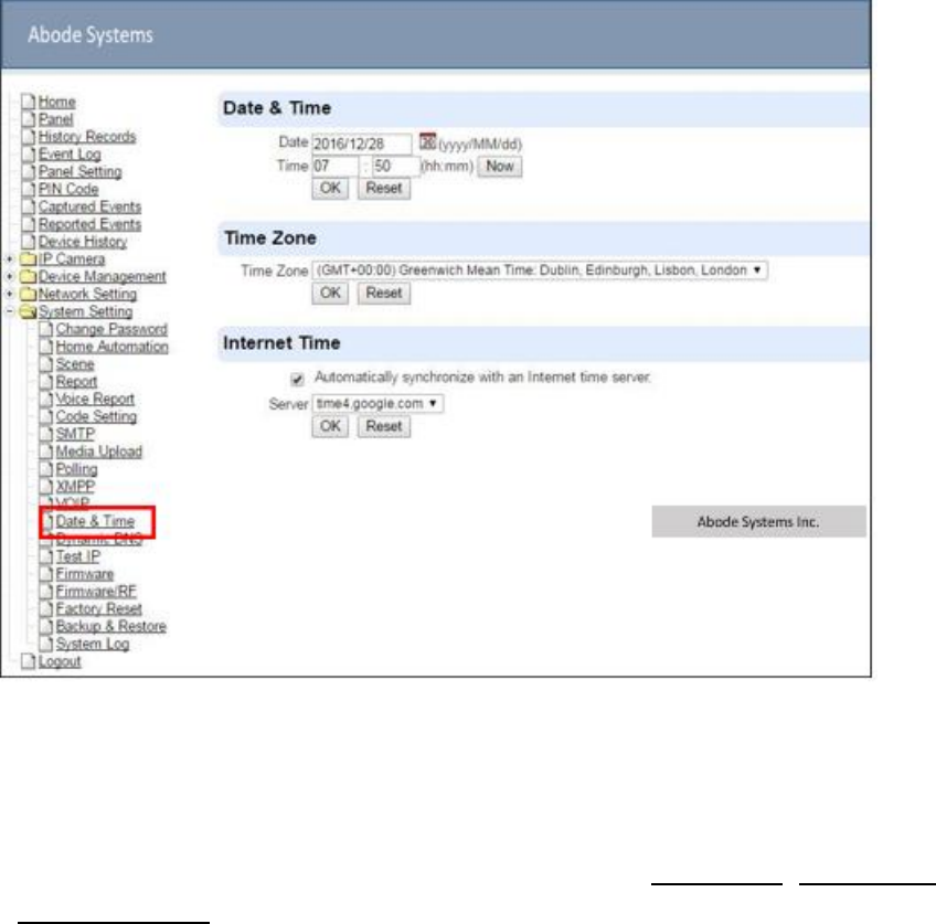
9.12.
Date & Time
Program the current Date & Time and set automatic synchronization with internet time server.
Date & Time: set current month, date and time.
Time Zone: choose your time zone, and then the system will calculate the daylight saving
time automatically (if necessary).
Internet Time: the system will automatically synchronize with an internet time server. Tick
the check box to enable this function. Available options: pool.ntp.gov, time.nist.gov and
tick.usno.navy.mil.
75
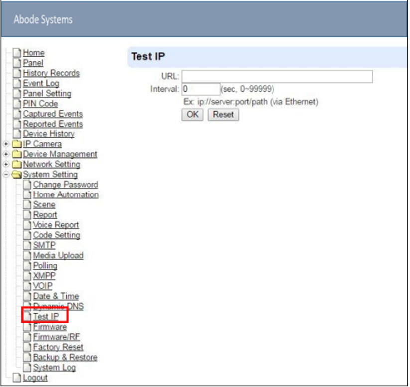
9.14.
Test IP
This is for you to test the Control Panel internet connection.
Step 1. Enter the URL destination you want to test connection to.
Step 2. Enter the test interval.
Step 3. Click “OK”
You can check the test connect result in System Log.
76
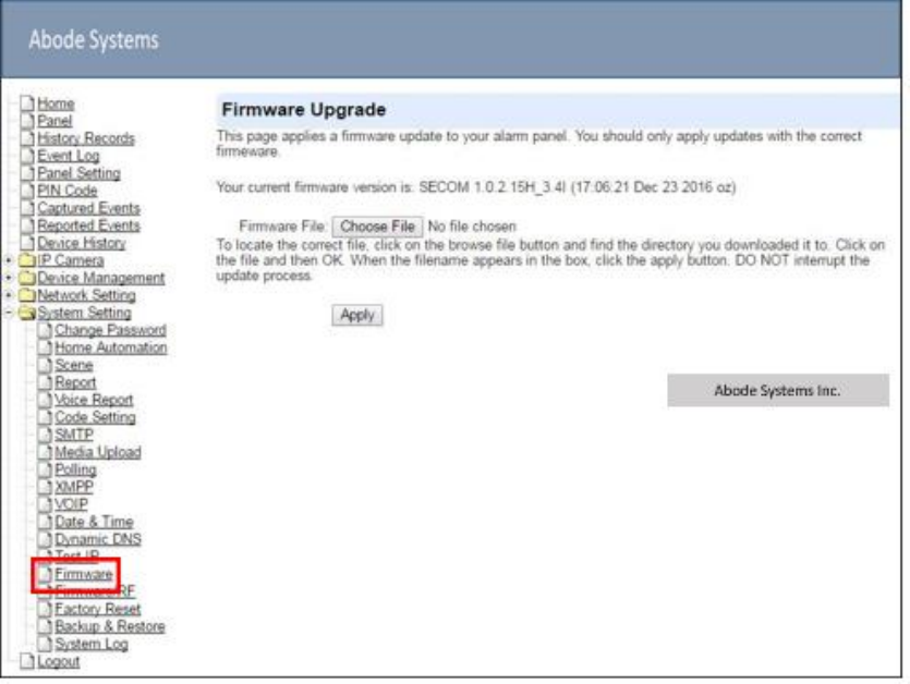
9.15.
Firmware Upgrade
You can update the firmware via this web page.
Step 1. Click on “Browse” and locate the latest firmware file (“unzipped image.bin” file) in
your PC.
Step 2. Press “Apply” to upload the latest firmware to Control Panel
Step 3. Wait for 1 min and do NOT power off during this time.
Step 4. Once Firmware upgrading is complete, the Control Panel will reboot automatically
77
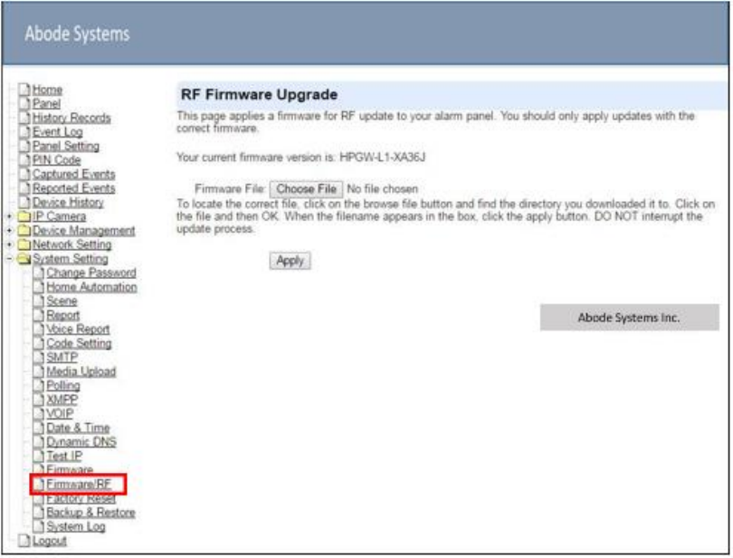
9.16.
RF Firmware Upgrade
You can update the Control Panel’s RF firmware via this web page.
Step 1. Click on “Browse” and locate the latest firmware file (“unzipped image.bin” file) in
your PC.
Step 2. Press “Apply” to upload the latest firmware to Control Panel
Step 3. Wait for 1 min and do NOT power off during this time.
Step 4. Once Firmware upgrading is complete, the Control Panel will reboot automatically
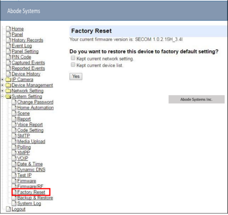
78
9.17.
Factory Reset
Yan can clear all programmed parameters in the Control Panel and reset it to Factory Default.
Once the Factory Reset is executed, all the programmed settings will returned to its default
value, and all the learnt-in devices will be removed. You will need to restart the programming and
learning process again.
Remote Reset
Step 1. Tick the Kept current network setting box to keep the current Network settings.
Otherwise, the system will reset its value back to factory default.
Step 2. Press Yes to continue the Reset procedure.
Step 3. Wait for 1 min and do NOT power off during this time.
Step 4. Once reset is complete, it will automatically reboot the main unit.
79
Local Reset
Step 1. Disconnect the AC adaptor, slide battery switch to OFF.
Step 2. Press and Hold the reset button and connect the AC adaptor to the Control Panel. All 3
LEDs will turn on for 10 seconds.
Step 3. Keep holding the reset button for 30 seconds then release. After 10 seconds, the
Control Panel will restart and all 3 LEDs will turn on.
Step 4. Wait for 10 seconds and all 3 LEDs will turn off to indicate factory reset is complete.
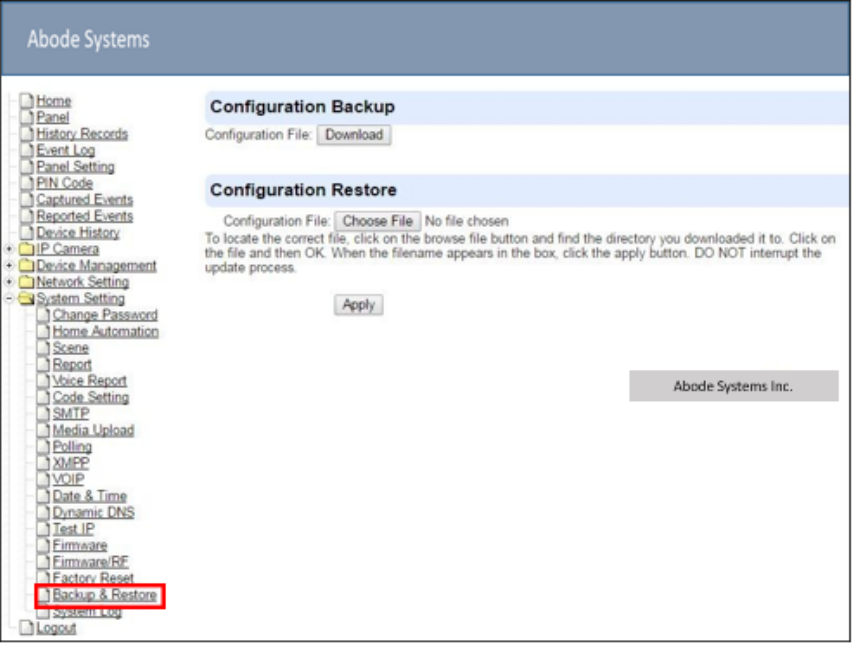
80
9.18.
Backup & Restore
Yan can backup all programmed parameters and save these programmed values into a file.
Besides, you also can restore pre-programmed settings.
9.18.1
Backup Data
Yan can backup all programmed data and save these programmed values into a file.
Step 1. Click Download configuration file.
Step 2. Click Download configuration file.
9.18.2
Restore Settings
Step 1. Click Browse, select a saved file.
Step 2. Click Apply to apply the pre-programmed values to the main unit.
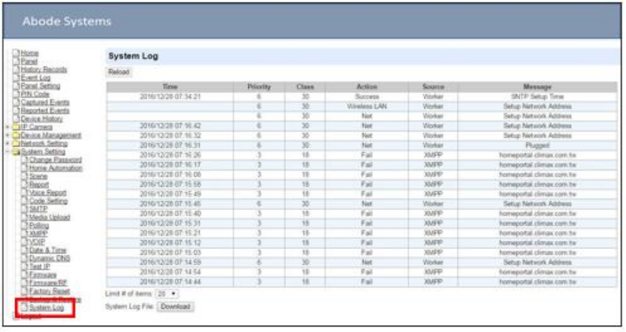
81
9.19.
System Log
The system log webpage logs the control panel’s detail system operation history.
System Log File Download” Click to download a detail log files into your computer for
more information.
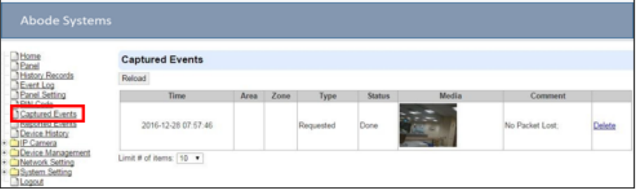
82
10.
Event & History
This section introduces event history of the system.
10.1.
Captured Events
This page stores all captured pictures and videos by PIR Camera and PIR Video Camera. When
a PIR Camera is triggered, it will take 3 pictures in quick succession, when a PIR Video Camera
is triggered, it will take a 10-second video clip. You can also request the PIR Camera to take a
picture and PIR Video Camera to take a 10-second video clip manually.
Captured events will be displayed in this page with their information for you to view. Simply click
on the picture or video to view them. You can also click Delete to delete the event.
Reload : Click to refresh the page content
Limit # of Items: Click the drop down menu on the page to select the numbers of
captured events you want to display.
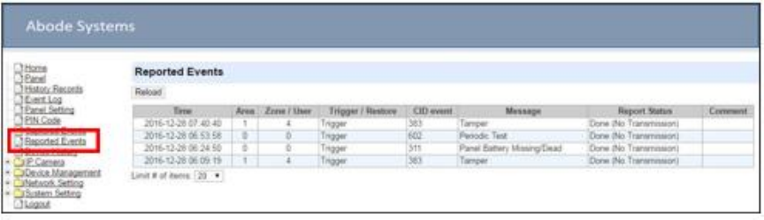
83
10.2.
Reported Events
This page stores all triggered events by the control panel by recording the events’ CID event
code and report status.
Reload : Click to refresh the page content
Limit # of Items: Click the drop down menu on the page to select the numbers of
captured events you want to display.
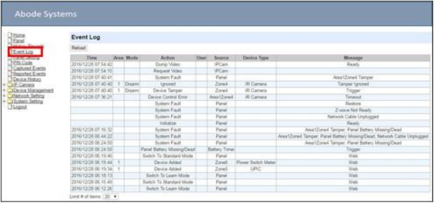
84
10.3.
Event Log
The Event Log page records specific actions performed by the Control Panel and accessory
devices.
Reload : Click to refresh the page content
Limit # of Items: Click the drop down menu on the page to select the numbers of
captured events you want to display.
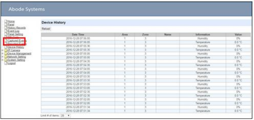
85
10.4.
Device History
You can track your ZigBee accessory device status history under Device History. For Power
Switch Meter or Temperature Sensor, the update history power consumption or temperature
reading will be displayed under this page (the current info is also displayed under Panel and PSS
Control).
Reload : Click to refresh the page content
Limit # of Items: Click the drop down menu on the page to select the numbers of
captured events you want to display.

86
11.
Appendix
11.1.
Control Panel Mode and Response Table
For Alarm Activation by Events and Control Panel Responses, please refer to the following
table:
Attribute
System Mode / Status
Disarm
Full Arm
Home Arm
Under Exit
Timer
Under Exit
Timer (No
Response)
Under Entry
Timer
No Response
No
Response
No
Response
No
Response
Instant
Burglar
Alarm
No
Response
No Response
Start Entry
Delay 1
Instant
Burglar
Alarm
(Interior)
Start Entry 1
Burglar
Alarm
(Perimeter)
Start Entry
1
Burglar
Alarm
(Interior)
Instant
Burglar
Alarm
No
Response
Delayed
Burglar Alarm
Start Entry
Delay 2
Instant
Burglar
Alarm
(Interior)
Start Entry 2
Burglar
Alarm
(Perimeter)
Start Entry
2
Burglar
Alarm
(Interior)
Instant
Burglar
Alarm
No
Response
Delayed
Burglar Alarm
Chime
Door Chime
Door Chime
Door
Chime
Instant
Burglar
Alarm
No
Response
Door Chime
Burglar Follow
Instant
Burglar
Alarm
Instant
Burglar
Alarm
Instant
Burglar
Alarm
Instant
Burglar
Alarm
No
Response
Delayed
Burglar Alarm
Burglar Instant
Instant
Burglar
Alarm
Instant
Burglar
Alarm
Instant
Burglar
Alarm
Instant
Burglar
Alarm
No
Response
Instant
Burglar Alarm
Burglar Outdoor
Instant
Burglar
Outdoor
Alarm
Instant
Burglar
Outdoor
Alarm
Instant
Burglar
Outdoor
Alarm
Instant
Burglar
Alarm
No
Response
Instant
Burglar
Outdoor
Alarm
Cross Zone
See 12.2. Appendix – Cross Zone
Verification
Instant
Burglar
Alarm
No
Response
Delayed
Burglar Alarm
Set/Unset
(Opening)
Full Arm
No
Response
Full Arm
Full Arm
No
Response
No Response
Set/Unset
(Closing)
No
Response
Disarm
Disarm
Disarm
Disarm
Disarm
24H – Burglar
Instant
Instant
Instant
Instant
Instant
Instant

87
P
P
a
s
m
m
N
V
d
n
a
n
m
s
s
m
m
N
Burglar
Alarm
Burglar
Alarm
Burglar
Alarm
Burglar
Alar
Burglar
Alarm
Burglar Alarm
24H – Smoke
Instant
Smoke
Alarm
Instant
Smoke
Alarm
Instant
Smoke
Alarm
Instant
Smoke
Alar
Instant
Smoke
Alarm
Instant
Smoke Alarm
24H – Medical
Instant
Medical
Alarm
Instant
Medical
Alarm
Instant
Medical
Alarm
Instant
Medical
Alar
Instant
Medical
Alarm
Instant
Medical
Alarm
24H – Fire
In tant Fire
Alarm
Instant Fire
Alarm
Instant Fire
Alarm
Instant Fire
Alar
Instant Fire
Alarm
In tant Fire
Alarm
24H – Water
Instant
Water
Alarm
Instant
Water Alarm
Instant
Water
Alarm
Instant
Water
Alar
Instant
W ter
Alarm
Instant Water
Alarm
24H – CO
Instant CO
Alarm
Instant CO
Alarm
Instant CO
Alarm
Instant CO
Alar
Instant CO
Alarm
Instant CO
Alarm
24H – Gas
Instant Gas
Alarm
Instant Gas
Alarm
Instant
Gas Alarm
Instant Gas
Alar
Insta t Gas
Alarm
In tant Gas
Alarm
24H – Heat
Instant Heat
Alarm
Instant Heat
Alarm
Instant
Heat Alarm
Instant eat
Alar
Instant
Heat Alarm
Instant Heat
Alarm
24H –
Silent anic
Instant
Silent Panic
Alarm
Instant Silent
Panic Alarm
Instant
Silent
Panic
Alarm
Instant
Silent Panic
Alar
Instant
Silent Panic
Alarm
Instant Silent
Panic Alarm
24H – anic
Instant
Panic Alarm
Instant Panic
Alarm
Instant
Panic
Alarm
Instant
Panic Alarm
Instant
Panic
Alarm
Instant Panic
Alarm
24H –
Emergency
Instant
E ergency
Alarm
Instant
Emergency
Alarm
Instant
Emergency
Alarm
Instant
Emergency
Alar
Instant
Emergency
Alarm
Instant
E ergency
Alarm
24H –
Emergency
(Quiet)
Instant
Silent
E ergency
Alarm
Instant Silent
Emergency
Alarm
Instant
Silent
Emergency
Alarm
Instant
Silent
Emergency
Alar
Instant
Silent
Emergency
Alarm
Instant Silent
E ergency
Alarm
24H – Fire with
Verific tion
See 12.3. Appendix – Fire erification
Trigger Scene
Trigger
Scene
umber
Trigger
Scene
Number
Trigger
Scene
Number
Trigger
Scene
Number
Trigger
Scene
Number
Trigger
Scene
umber
“Delayed Burglar Alarm” reponse means the Control Panel will waiit for the Entry Time
to expire. If the Enty Ti e expires without disarming the system, the Control Panel will
activate a Burglar Alarm after Entry Time expiry.
“Silent Panic Alarm”, “Silent Emergency Alarm” and "Burglar Outdoor Alarm” does
not activate any audible alarm. The Control Panel will re
without any warning sound. ort the alarm event silently
<NOTE>

88
11.2.
Cross Zone Verification
Cross Zone Verification is use to setup cross verification for intrusion sensors.
To use Cross Zone Verification, the following sensor and panel setting must be adjusted:
1
At least 1 intrusion sensor must be set to Cross Zone attribute.
2
The Cross Zone Timer option under Panel Setting webpage must be enabled.
Cross Zone Verification Rule
Cross Zone function does not activate under Exit and Entry Time.
When a sensor set to Cross Zone attribute is triggered, the panel begins to sound alarm,
counts down Cross Zone Timer and reports a Cross Zone First Trip event (CID 693).
If the Cross Zone Timer expires without any other sensor trigger, the panel reports Cross
Zone Trouble event (CID 378) when the timer expires.
If the same sensor is triggered again during Cross Zone Timers, the Cross Zone Timer
is reset and extended.
If another sensor is triggered during the timer:
The Panel report Burglar (CID 130) for both sensors.
If the newly triggered sensor is set to Cross Zone attribute, the Panel also report
Burglar Verified (CID 139) for this sensor.
The Cross Zone Timer is reset and extended.
When the Cross Zone Timer expires, the panel reports Cross Zone Timeout (CID
694).
11.3.
Fire Verification
Fire Verification is use to setup verification for Smoke Detector.
To use Fire Verification, the following sensor and panel setting must be adjusted:
1
At least 1 Smoke Detector must be set to 24 HR – Fire with Verification attribute.
2
The Fire Verification Timer option under Panel Setting webpage must be enabled.
Fire Verification Rule
When a Smoke Detector set to Fire Verification attribute is triggered, the panel begins to
sound alarm, counts down Fire Verification Timer and reports a Near Alarm event (CID 118).
Triggering any Smoke Detector with Fire Verification attribute (including the original
Some Detector) during Fire Verification Timer will prompt panel to report Smoke Alarm
event (CID 111), the timer will be reset and extended.
Triggering a regular Smoke Detector with Smoke attribute during the Fire Verification
Timer will prompt panel to report Smoke Alarm event (CID 111), the timer will not be
reset..
When the Fire Verification Timer expires, the panel reports Fire Verification Timeout
event (CID 695).

89
11.4.
Contact-ID Protocol & Format
Where
ACCT MT QXYZ GG C1C2C3
ACCT
=
4 Digit Account number (0-9, B-F)
MT
=
Message Type, 18H.
Q
=
Event qualifier, which gives specific
event information:
XYZ
=
Event code (3 Hex digits 0-9, B-F)
GG
=
Group, Partition number (00H), or
Area Number
-
00 = panel
-
01= area 1… ... xx= area xx
C1C2C3
=
1.
For devices: zone
2.
For Panel: code
C1C2C3 = Zone number
001, Zone 1
002, Zone 2
…………………..
XXX Zone XXX
C1C2C3 =
User PIN Code 1
001
User PIN Code 2
002
User PIN Code 3
003
User PIN Code 4
004
User PIN Code 5
005
User PIN Code 6
006
Temporary Code
997
Duress Code
998
000= Control Panel
90
11.5.
Event Code
100 – Medical
When a device set to Medical attribute is triggered.
101 – Personal emergency
When a device set to Personal Emergency attribute is triggered.
110 – Fire
When a device set to Fire attribute is triggered.
111 – Smoke
When the Smoke Detector (SD) set to Smoke Alarm is triggered.
When the Smoke Detector (SD) set to Fire Verification verifies an alarm during Fire
Verification Time.
118 – Near Alarm
When the Smoke Detector (SD) set to Fire Verification is triggered.
120 – Panic
When a device set to Panic attribute is pressed.
121 – Duress
When the Duress Code is entered to disarm or arm the system.
122 –Silent Panic
When a device set to Silent Panic is pressed.
130 – Burglar
Whenever a device set as Burglar Instant is triggered.
Whenever a device set as Burglar Instant is triggered under Disarm, Full Arm or
Home Arm mode.
131 – Burglar Perimeter
When a device set as Entry is triggered in Full Arm mode.
When a device set as Burglar Follow is triggered during Full Arm Entry Time and the
system is not disarmed before entry time expiry.
132 – Burglar Interior
When a device set at Entry is triggered in Home Arm mode.
When a device set as Burglar Follow is triggered during Home Arm Entry Time and
the system is not disarmed before entry time expiry.
136 – Burglar Outdoor
Whenever a device set at Burglar Outdoor is triggered.
137 – Panel Tamper/ Panel Tamper Restore
When the panel’s tamper protection is triggered.
When the panel’s tamper function is restored.
139 – Burglar Verified.
When a sensor set to Cross Zone attribute verifies an alarm.
147 – Sensor Supervision Failure/ Sensor Supervision Restore
When the panel fails to receive supervision signal from a device within preset
91
supervision timer.
When the panel receives signal again from sensor that previously failed supervision.
154 – Water leakage
When the Water Sensor connected to Door Contact set at Water (@W) is triggered.
158 – High Temperature Alarm
When high temperature alarm is triggered.
159 – Low Temperature Alarm
When low temperature alarm is triggered.
162 – CO Alarm
170 – High Power Consumption
When high power consumption alarm is triggered.
171 – High Humidity Alarm
When high humidity alarm is triggered.
172 – Low Humidity Alarm
When low humidity alarm is triggered.
301 – AC Failure/ AC Power Restore
When the AC power fails for more than 10 sec.
Restore from AC power failure.
302 – Low battery/ Battery Normal
When the battery voltage of the Panel is low.
When the panel battery restores voltage.
311 – Battery Disconnection/ Battery Reconnected
344 – Interference/ Interference problem solved
358 – Network Cable Unplugged
When the Ethernet cable is disconnected.
359 – GSM No Signal
When the panel loses GSM signal.
374 – Force Arm
When the system is armed with existing fault events
693 – Cross Zone Trouble
When Cross Zone Timer expires without alarm verification.
380 – Device AC Failure
When an AC power device loses AC power connection.
383 – Sensor Tamper/ Sensor Tamper Restore
When any sensor’s tamper protection is triggered.
When the sensor’s tamper function is restored.
384 – Sensor Low battery/ Sensor Battery Normal
When a device detects low battery voltage.
When a device’s low battery condition is restored.
92
400 – Arm/Disarm (by Remote Controller)
When the system is armed or disarmed by using the Remote Controller.
401 – Remote Arm/Disarm
When the system is armed or disarmed by SMS message or web access
407 – Disarm/Away Arm/Home Arm by Remote Keypad
408 – Set/Unset Arm/Disarm
When the DC set at Set\Unset is triggered.
456 - Partial Arm
When partially arm the system from Disarm to Home arm
570 – Device out of order/ Door Contact Not Closed
When any device is out of order after the preset exit delay time is reached
Door Contact is not closed after the preset exit delay time is reached.
602 – Periodic test report
When the control panel makes periodic Check-in reporting.
616 – Call Request
When the service call is activated by VST-809.
693 – Cross Zone First Trip
When a sensor set to Cross Zone is triggered to start Cross Zone Timers.
694 – Cross Zone Timeout
When Cross Zone Timer expires after the alarm has been verified.
693 – Fire Verification Timeout
When Fire Verification Timer expires.
93
Federal Communication Commission Interference Statement
This equipment has been tested and found to comply with the limits for a Class B digital device,
pursuant to Part 15, 22, 24, 27 of the FCC Rules. These limits are designed to provide reasonable
protection against harmful interference in a residential installation.
This equipment generates, uses and can radiate radio frequency energy and, if not installed and used in
accordance with the instructions, may cause harmful interference to radio communications. However,
there is no guarantee that interference will not occur in a particular installation. If this equipment does
cause harmful interference to radio or television reception, which can be determined by turning the
equipment off and on, the user is encouraged to try to correct the interference by one of the following
measures:
. Reorient or relocate the receiving antenna.
. Increase the separation between the equipment and receiver.
. Connect the equipment into an outlet on a circuit different from that to which the receiver is connected.
. Consult the dealer or an experienced radio/TV technician for help.
FCC Caution: To assure continued compliance, any changes or modifications not expressly approved
by the party responsible for compliance could void the user's authority to operate this equipment.
(Example - use only shielded interface cables when connecting to computer or peripheral devices).
FCC Radiation Exposure Statement
This equipment complies with FCC RF radiation exposure limits set forth for an uncontrolled
environment. This equipment should be installed and operated with a minimum distance of 20
centimeters between the radiator and your body.
This transmitter must not be co-located or operating in conjunction with any other antenna or
transmitter.
The antennas used for this transmitter must be installed to provide a separation distance of at least 20
cm from all persons and must not be co-located or operating in conjunction with any other antenna or
transmitter.