ads tec RAX1X2X Industrial Access Point User Manual Access Point EN V3 0 3 FCC
ads-tec GmbH Industrial Access Point Access Point EN V3 0 3 FCC
UserManual.wiki
>
ads tec
>
RAX1X2X User Manual
User Manual
Navigation menu
Upload a User Manual
Namespaces
Wiki Guide
HTML
PDF
Info
Views
User Manual
Discussion / Help
Navigation
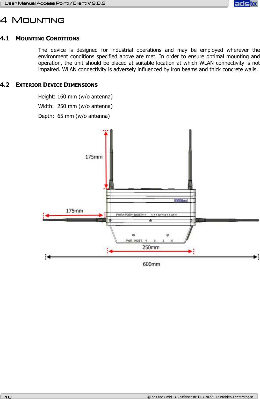
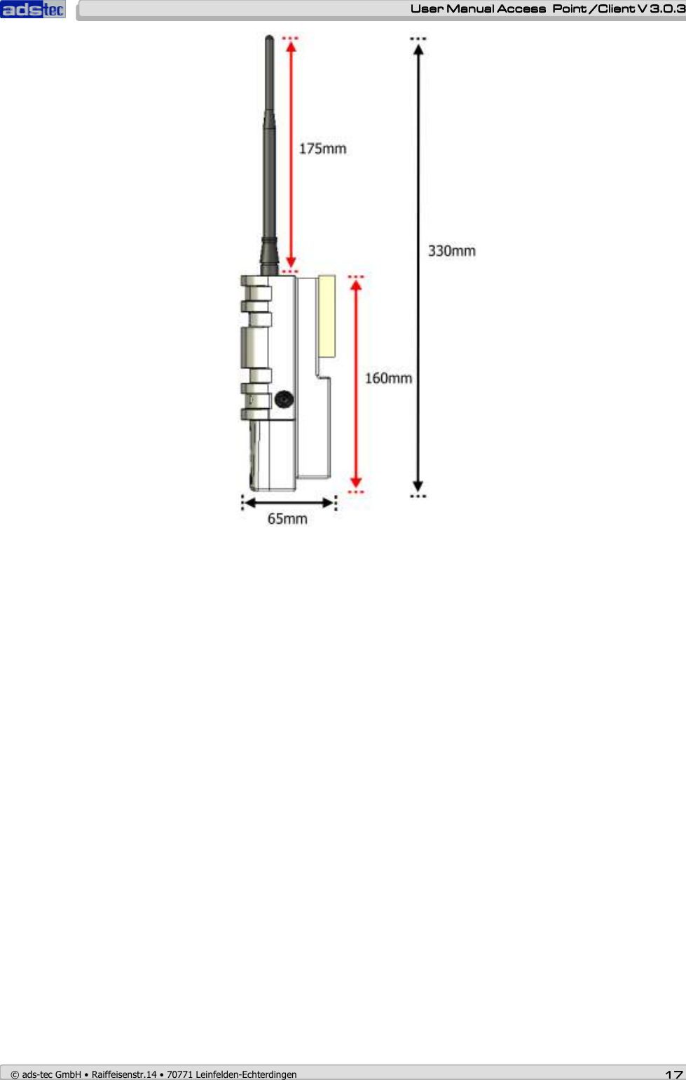
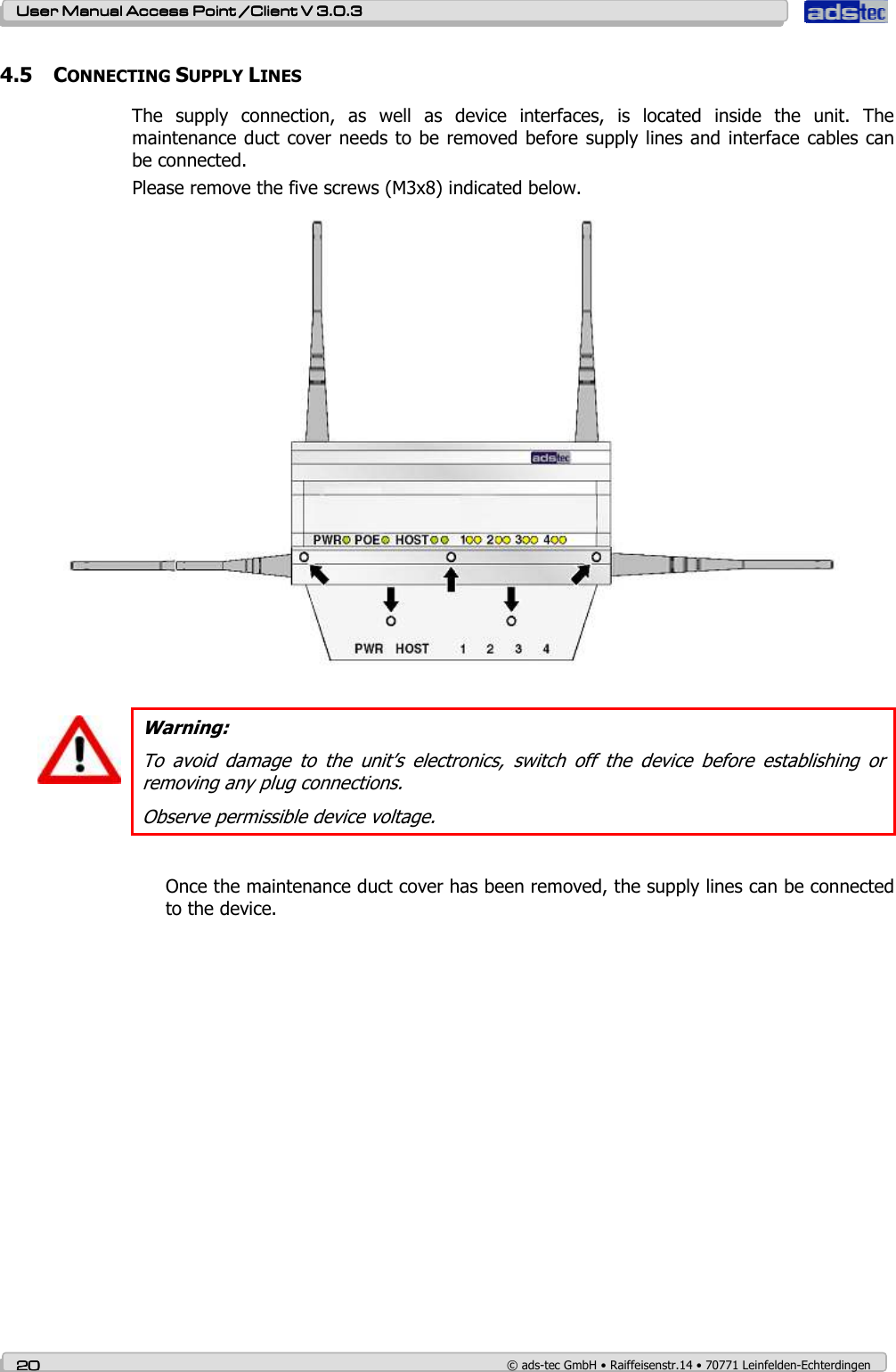
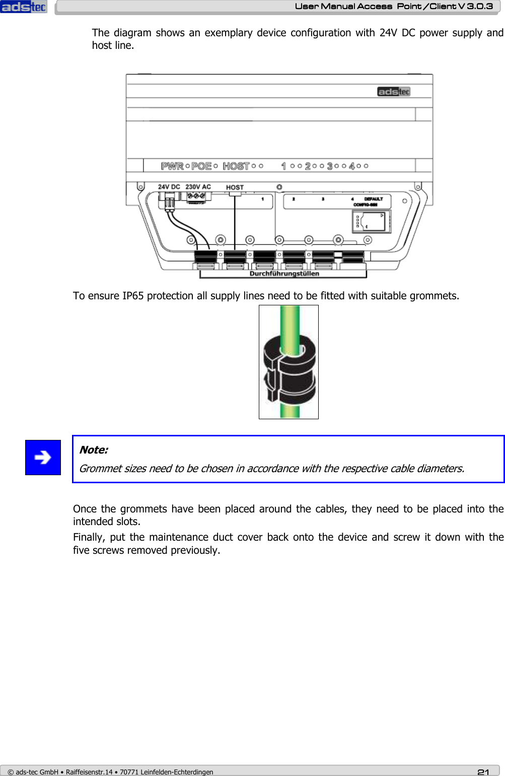
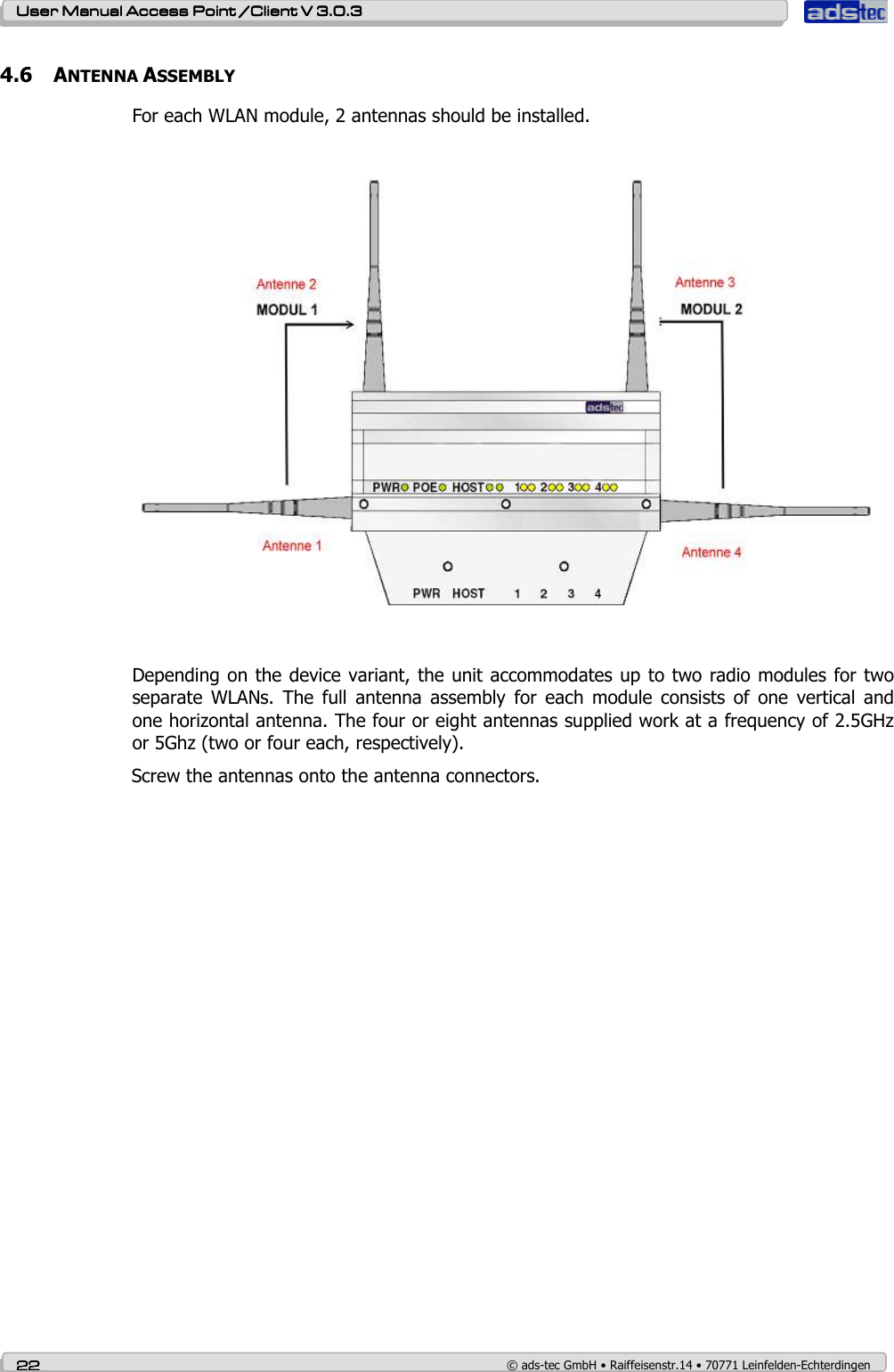
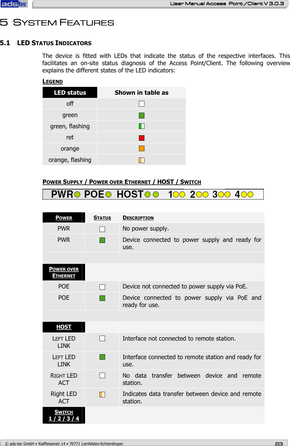


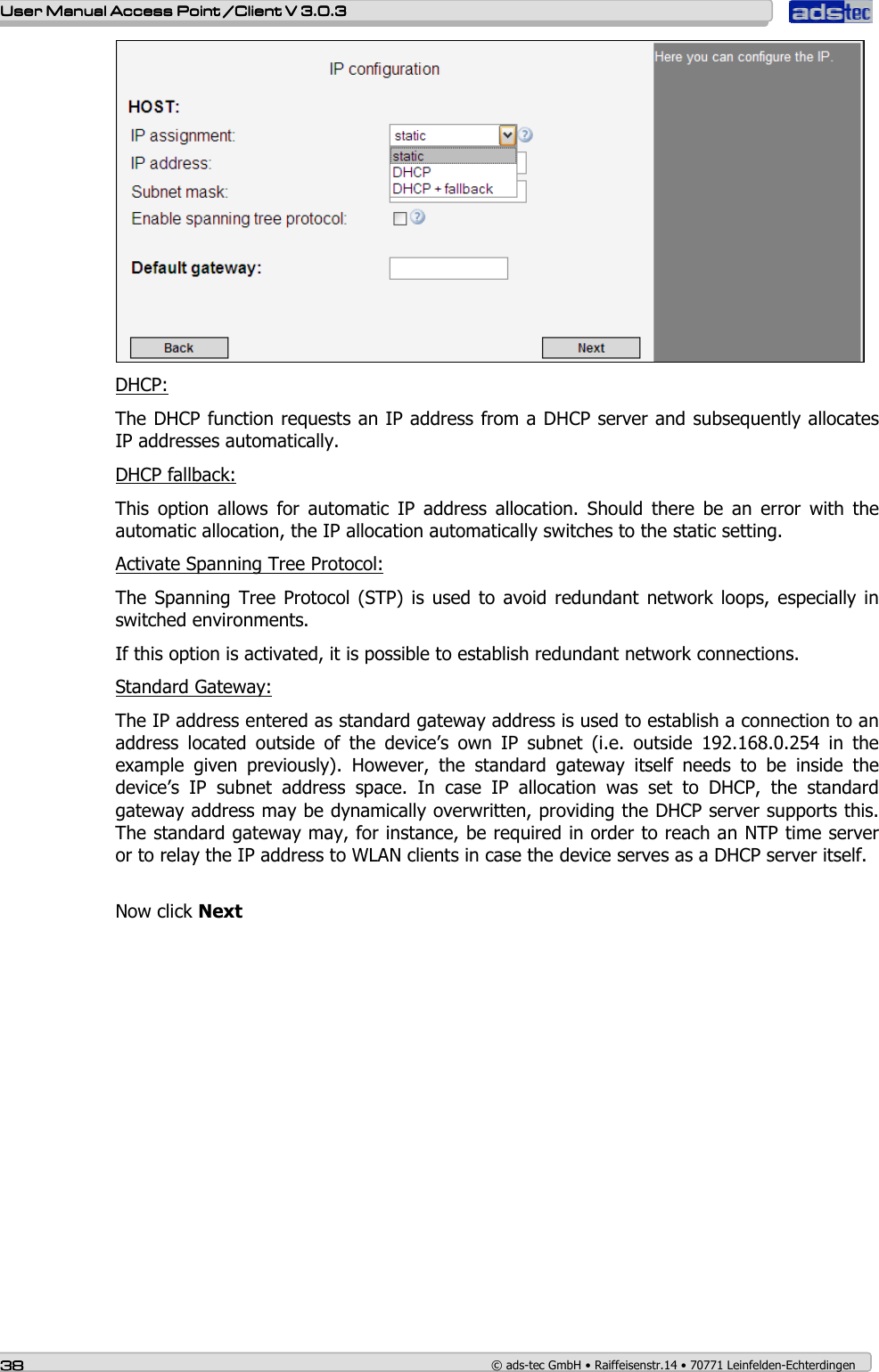
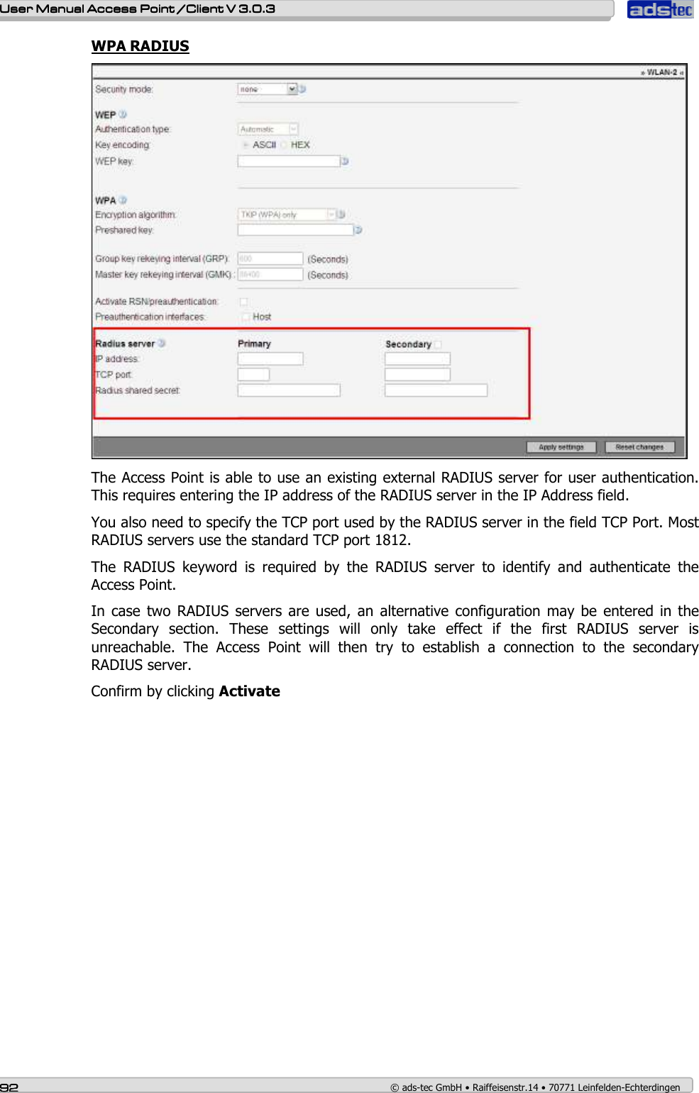
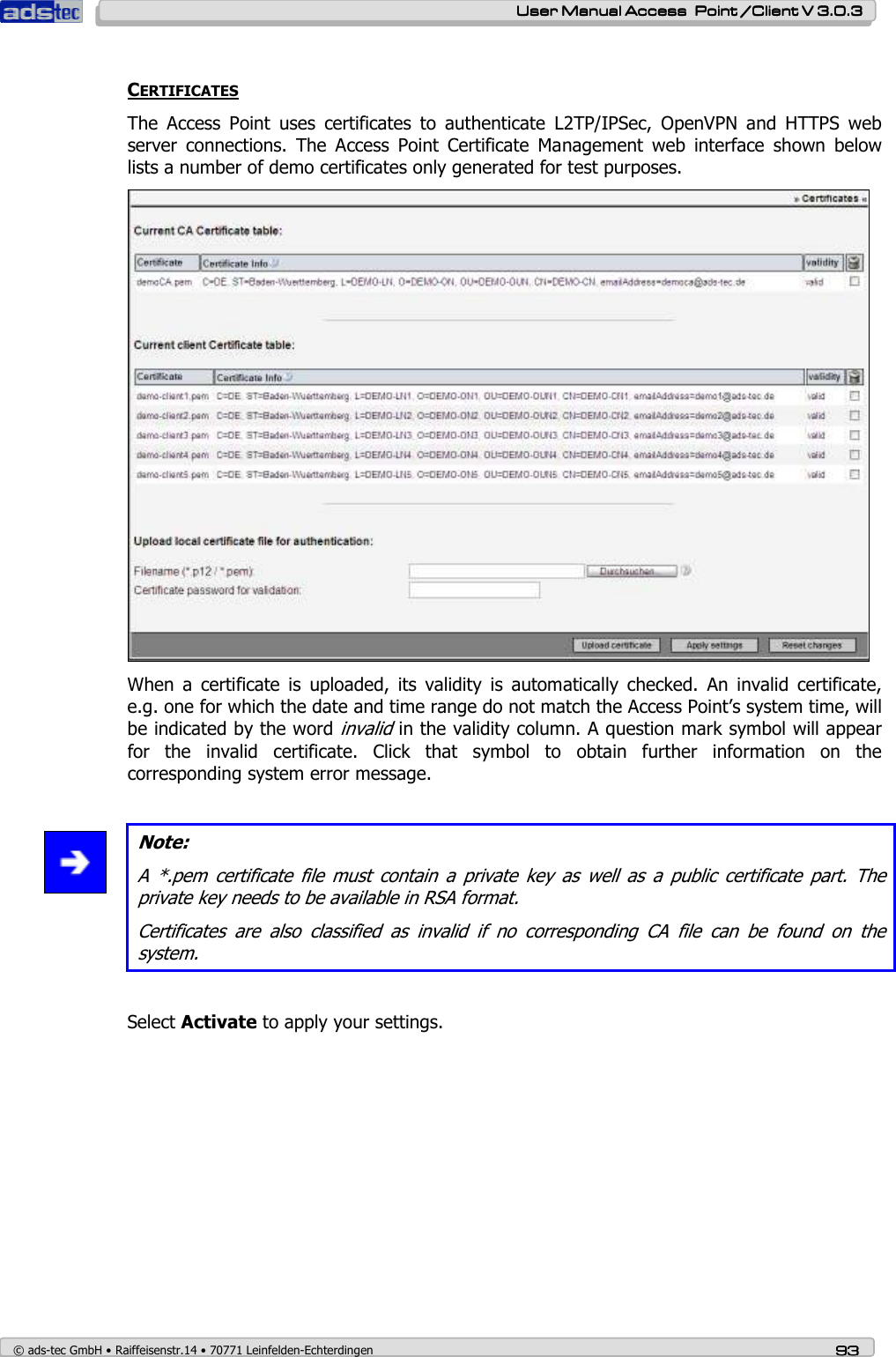
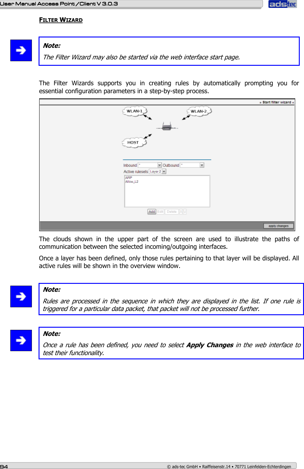
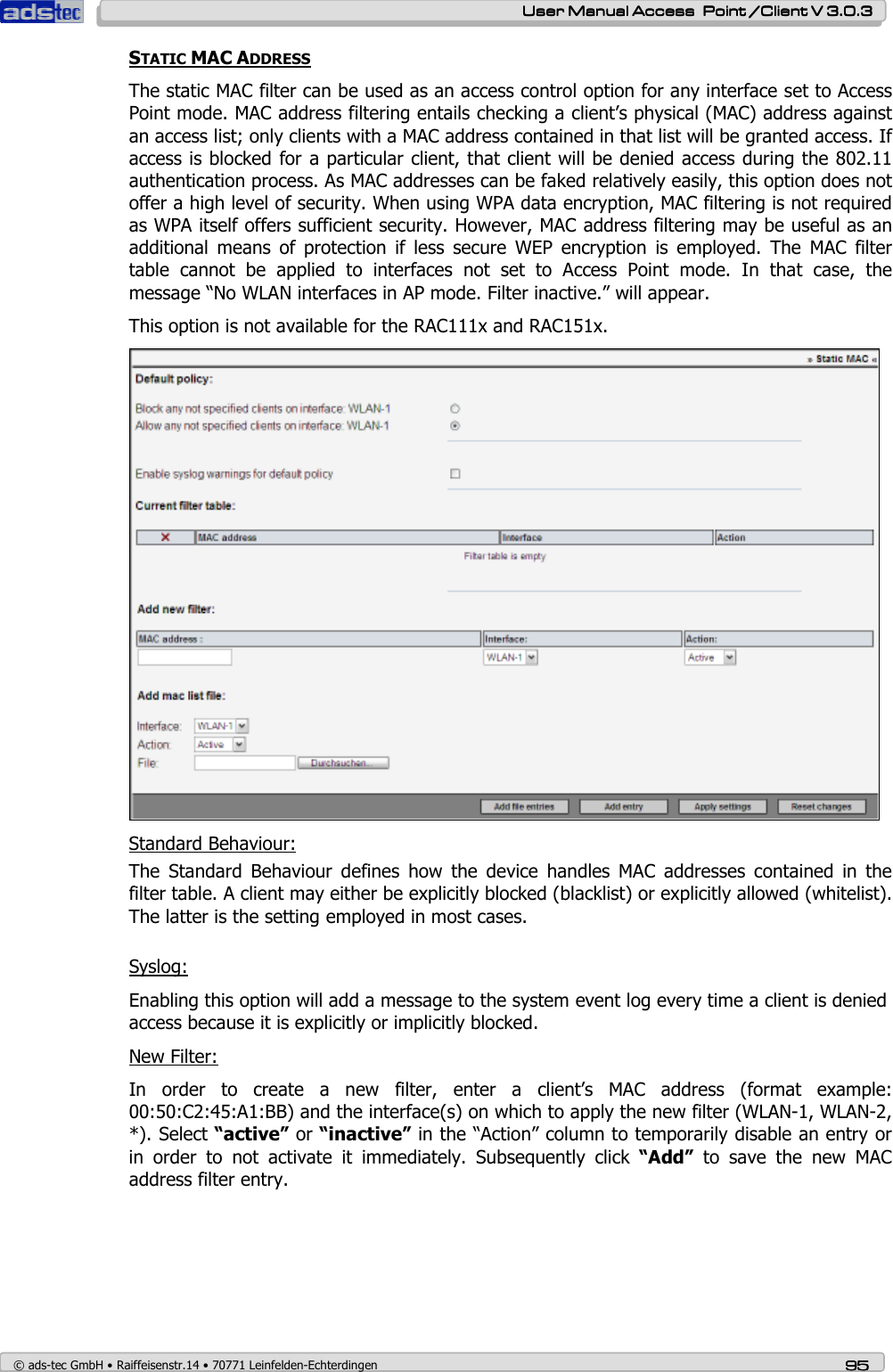
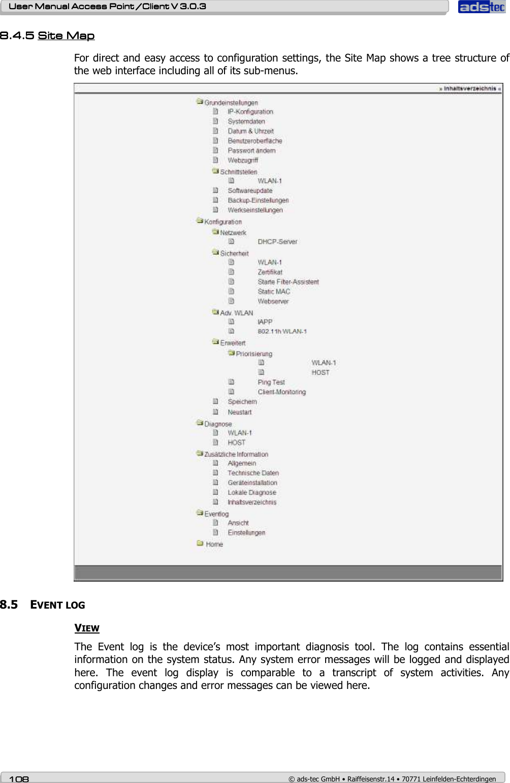
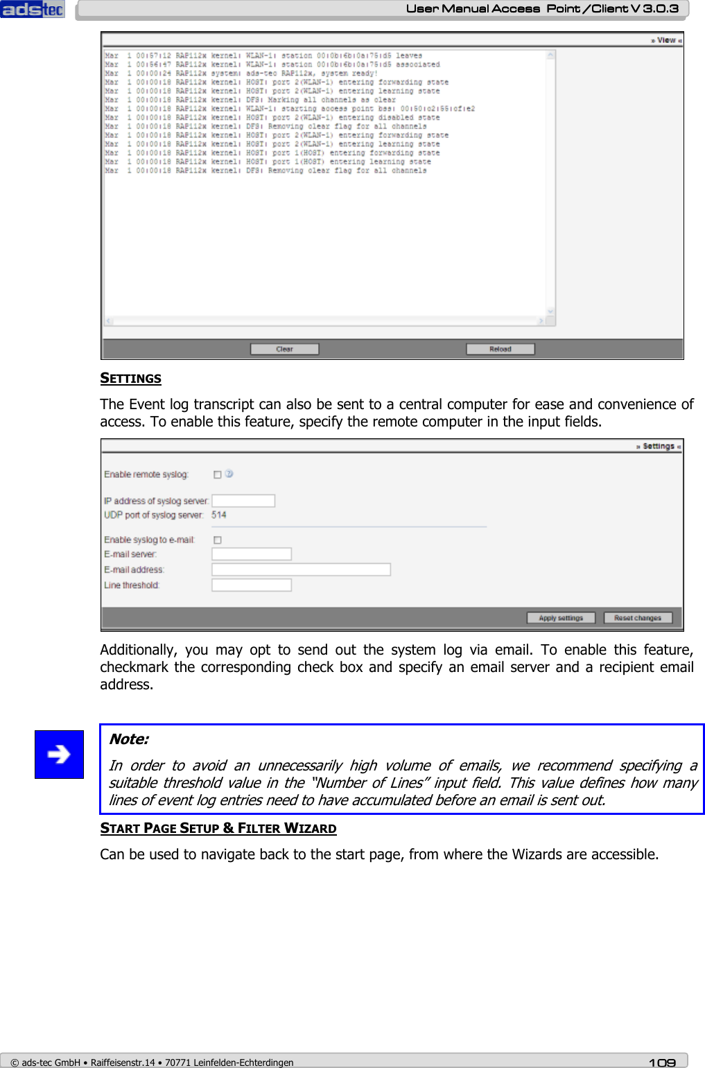
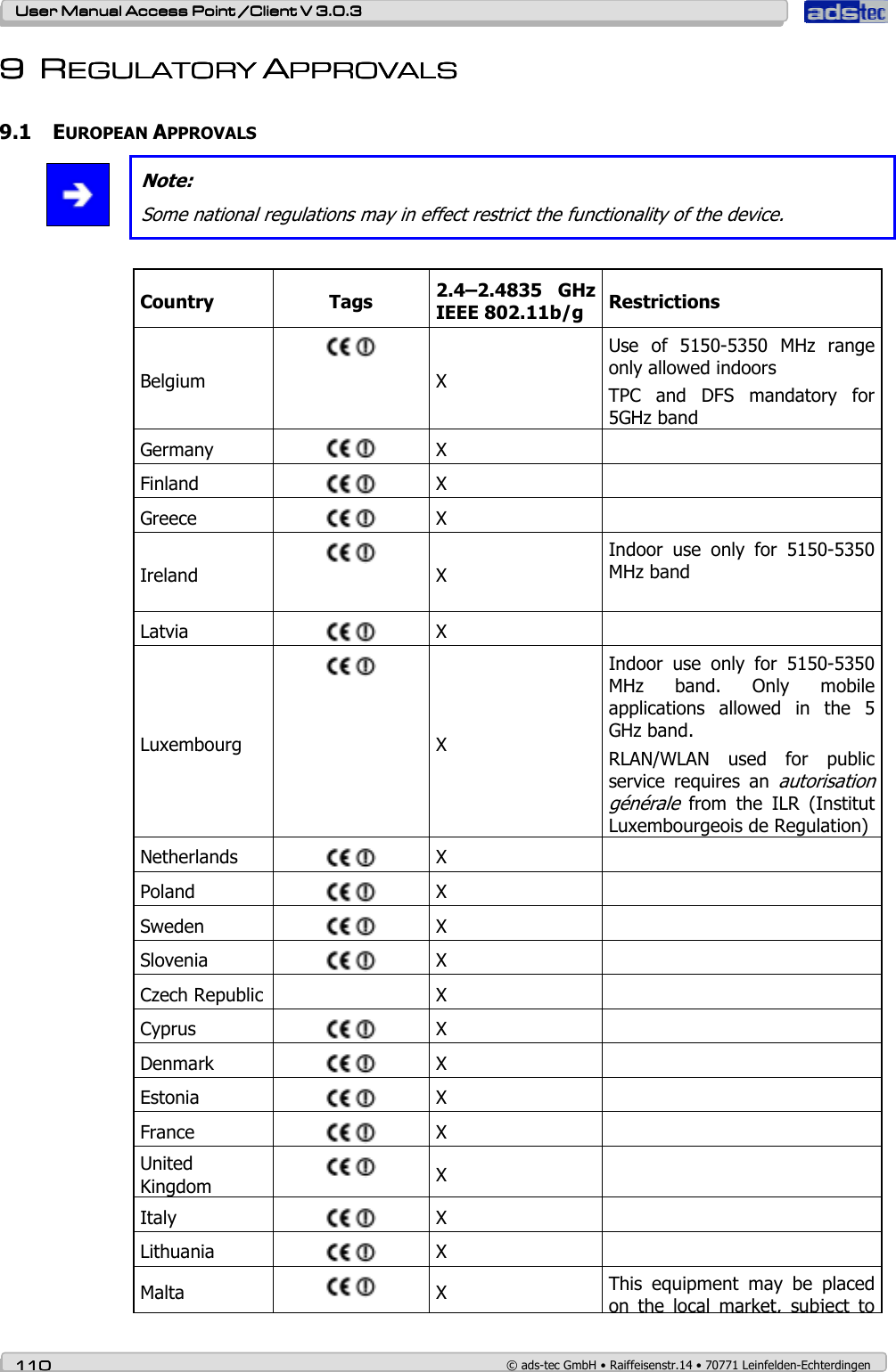
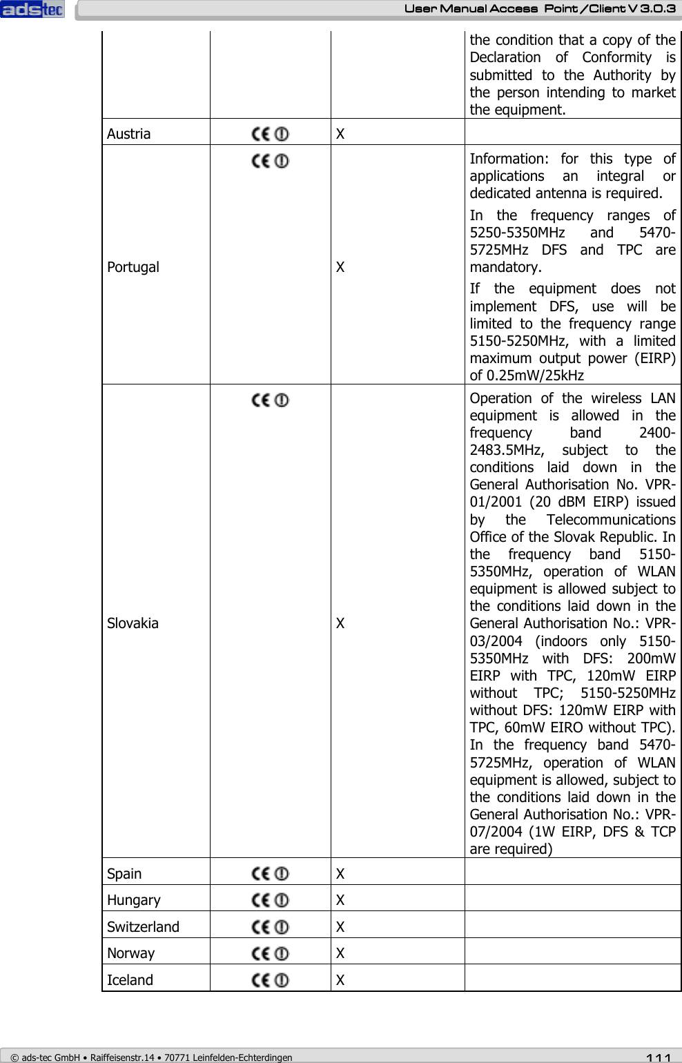
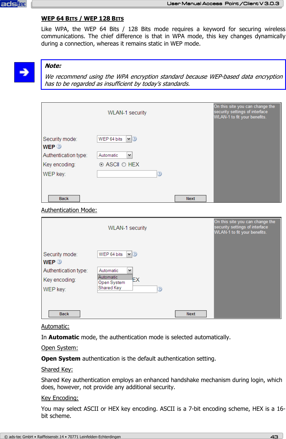
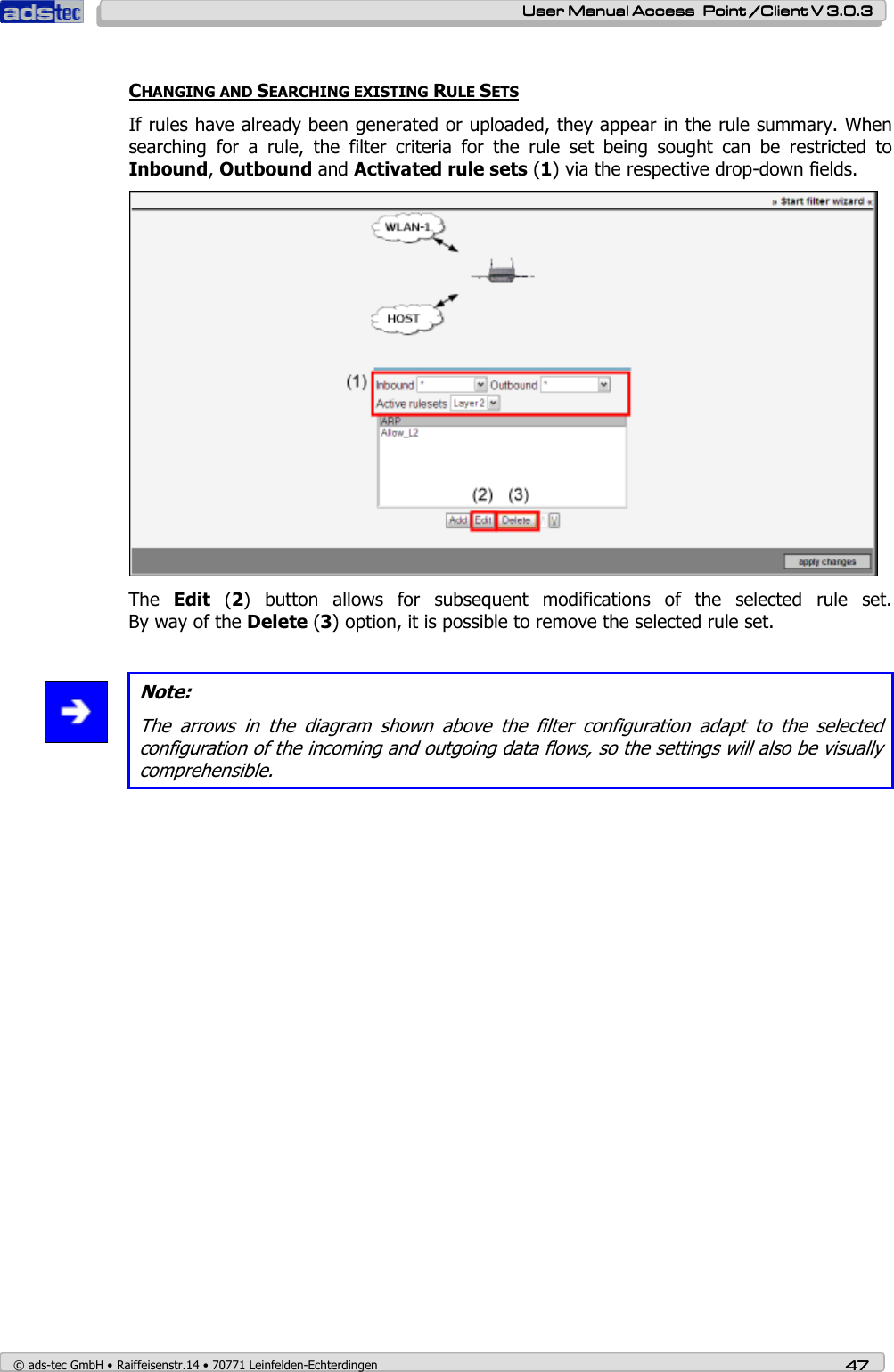
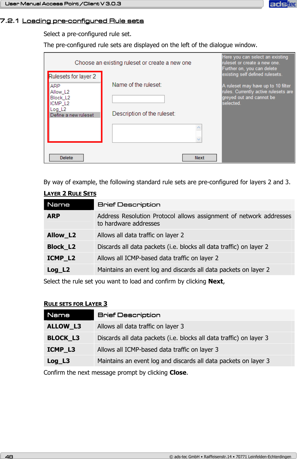
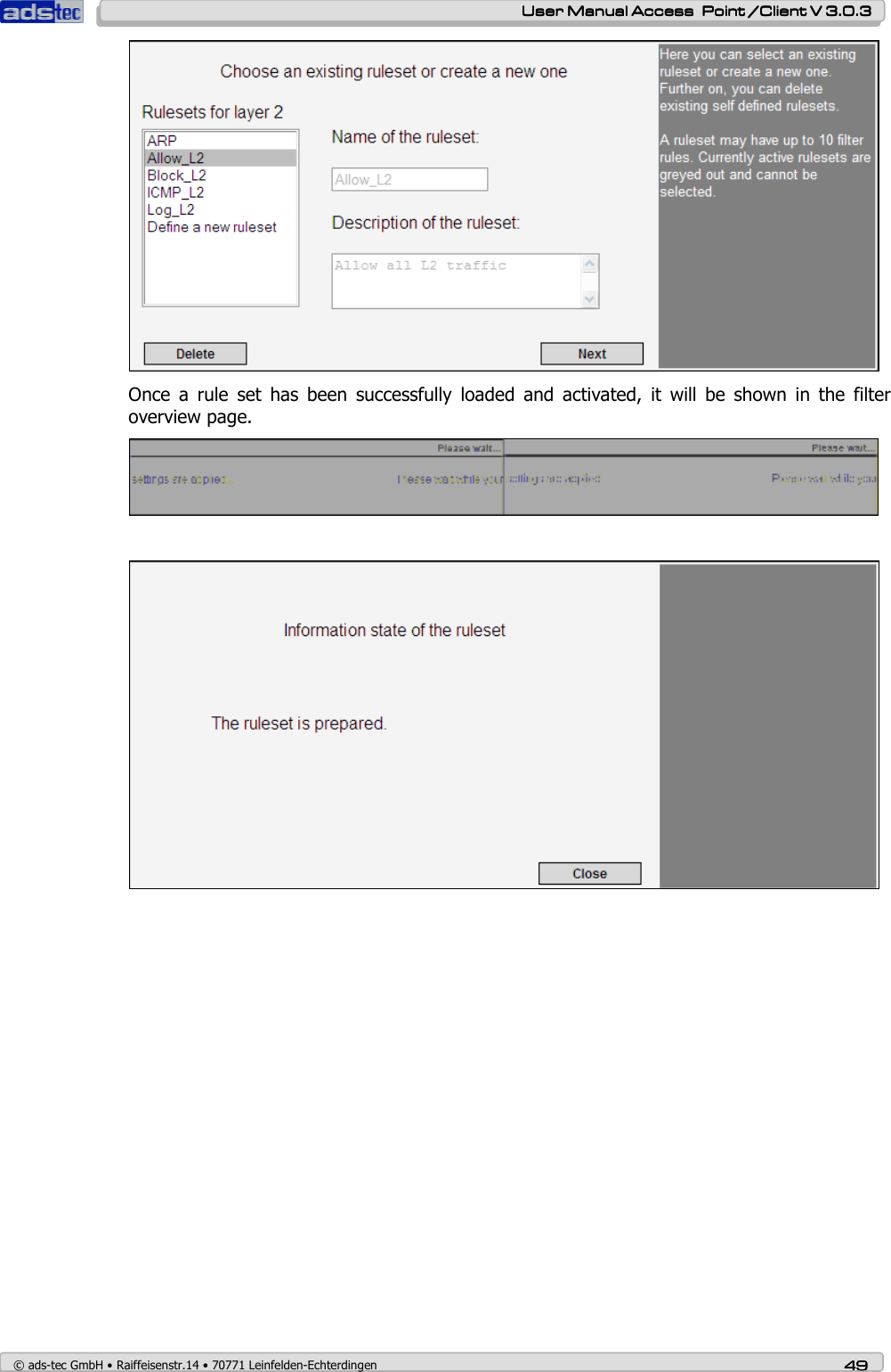
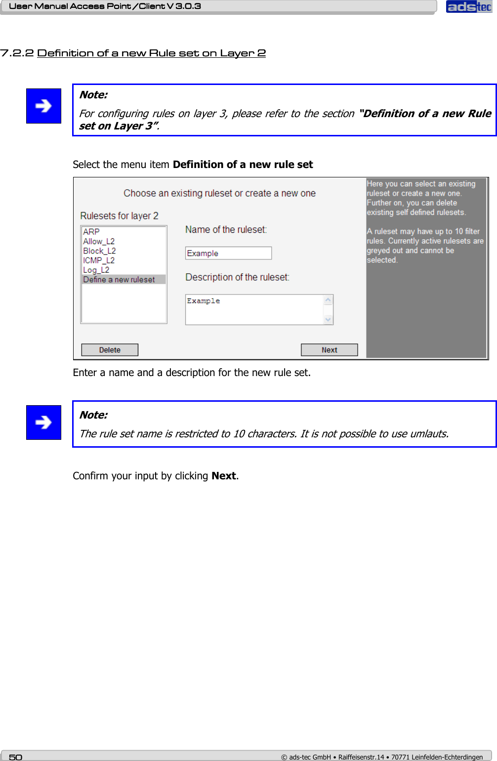
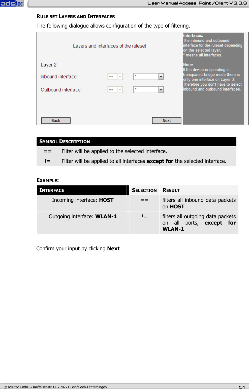
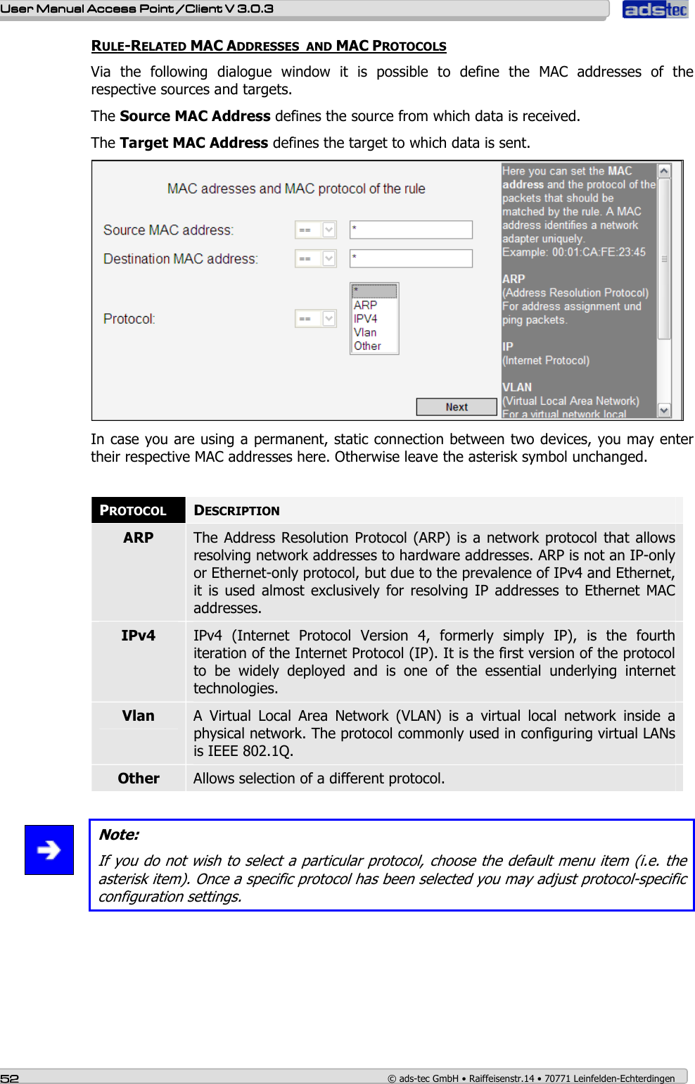
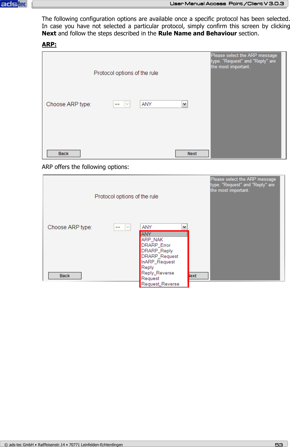
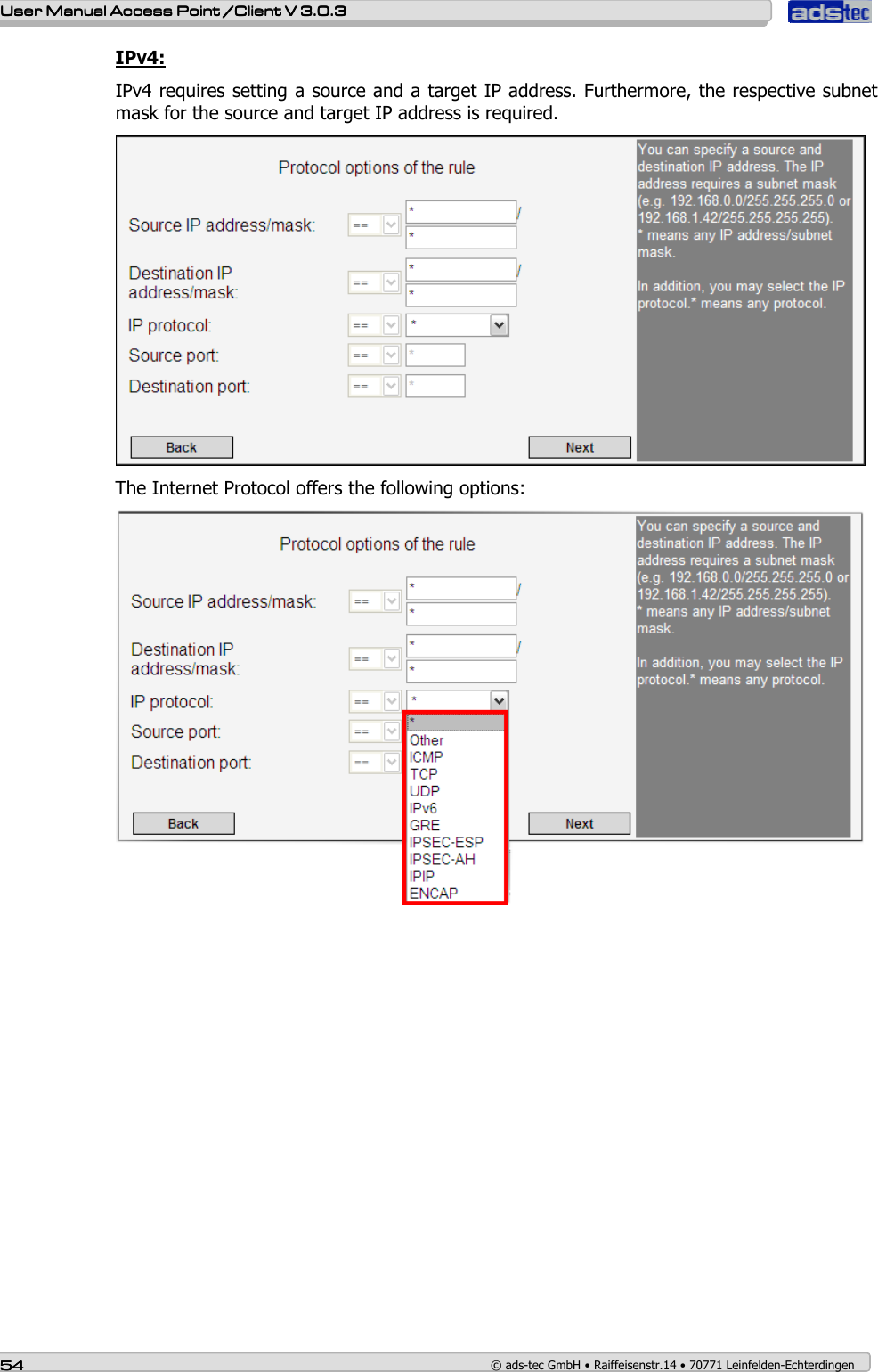
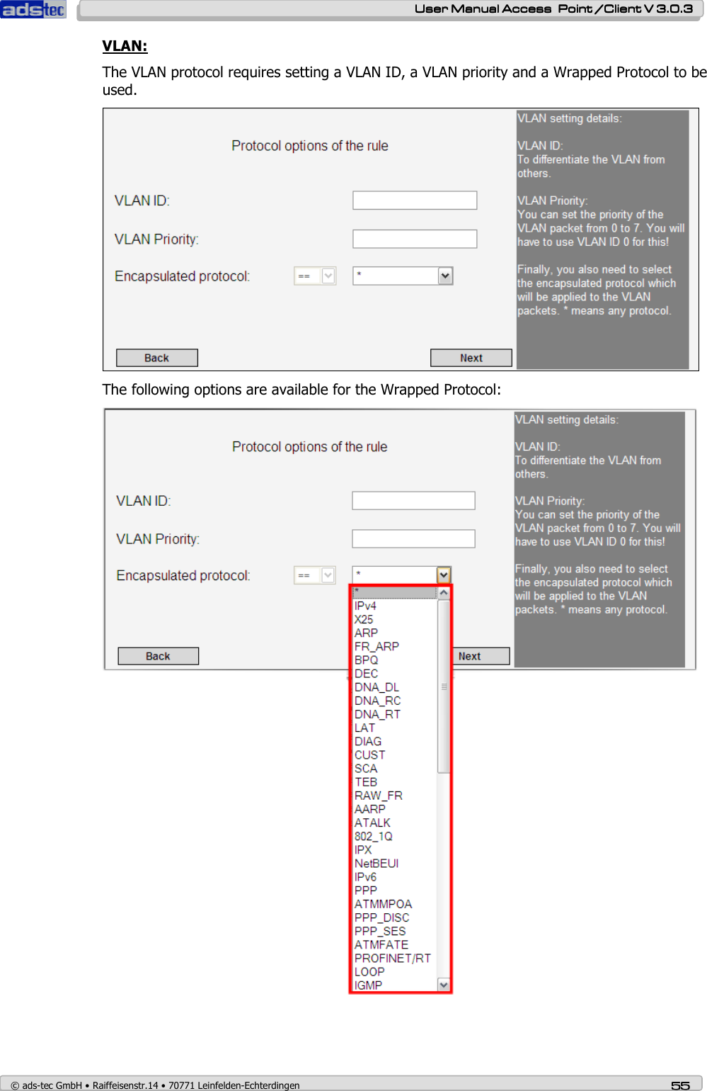
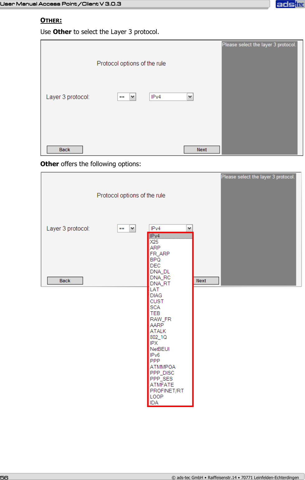
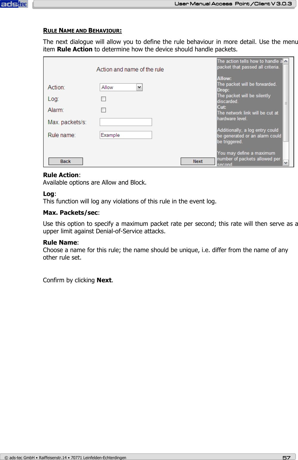
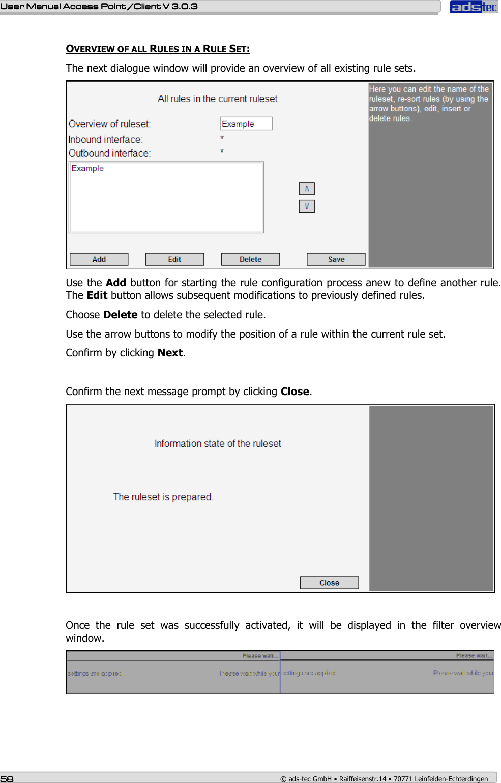
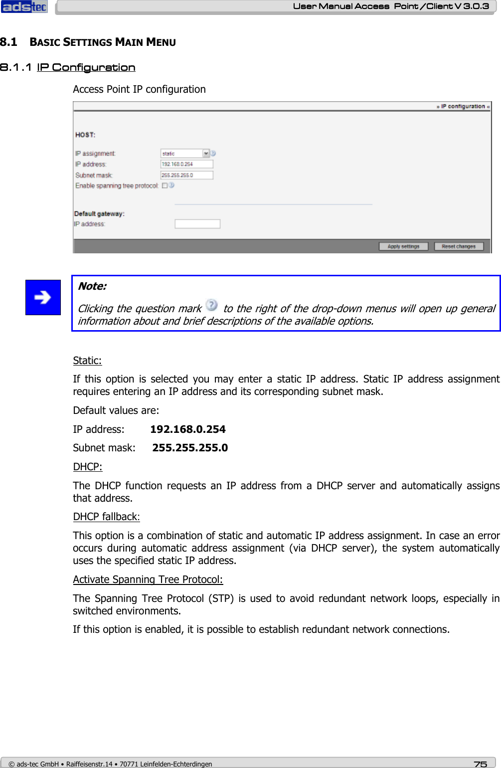
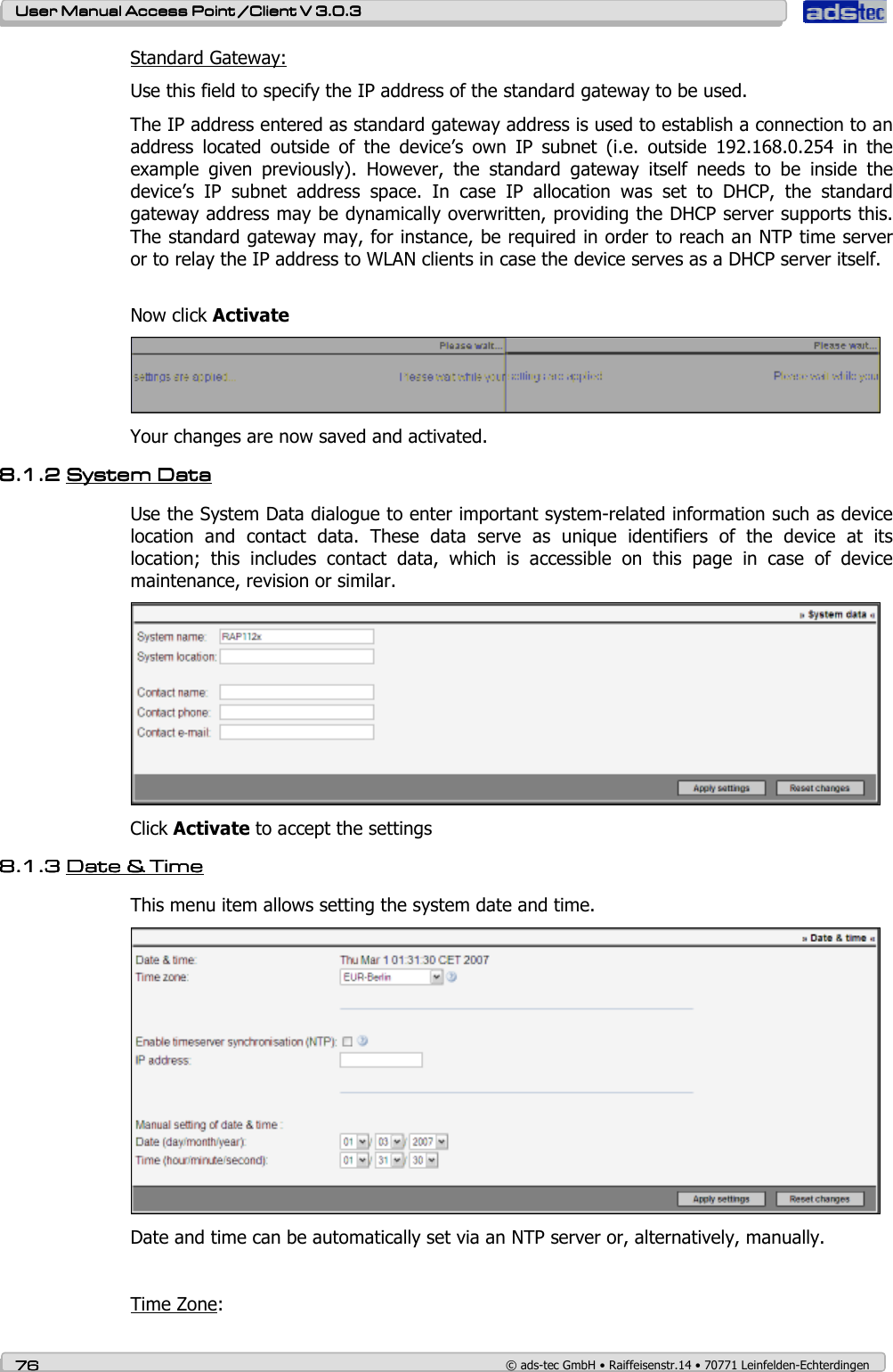
![User ManualUser ManualUser ManualUser Manual Access Point /Client V 3.0.3 Access Point /Client V 3.0.3 Access Point /Client V 3.0.3 Access Point /Client V 3.0.3 © ads-tec GmbH • Raiffeisenstr.14 • 70771 Leinfelden-Echterdingen 39393939 7.1.37.1.37.1.37.1.3 WLANWLANWLANWLAN----1 1 1 1 CCCConfigurationonfigurationonfigurationonfiguration The next dialogue is used to configure all relevant basic settings for WLAN operation. Access Point Mode OPERATING MODE: Use this option to switch between the two operating modes Access Point and Access Client. Note: The RAC (Access Client) does not offer an operating mode option. It is permanently set to Access Client mode. Access Point: In Access Point mode, the device serves as a network gateway for other wireless devices (clients). Access Client: In Access Client mode, the device tries to establish a connection to an Access Point in order to establish a connection with the network. NETWORK NAME (SSID): Use this option to assign a name to your wireless network. We recommend not using any names that allow conclusions with regard to your company, department or the type of data transmitted. Any clients that want to establish a connection with this Access Point need to know this network name. Default setting is: ads Note: The SSID may consist of a maximum of 32 characters. Valid characters are: a-z, A-Z, 0-9, valid special characters: . _ - ? $ @ ! { } [ ] ( ) + # ; , < > | : * ~ % $ & / =](https://usermanual.wiki/ads-tec/RAX1X2X/User-Guide-887254-Page-39.png)
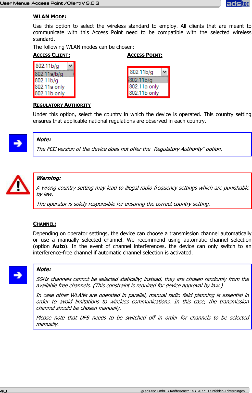
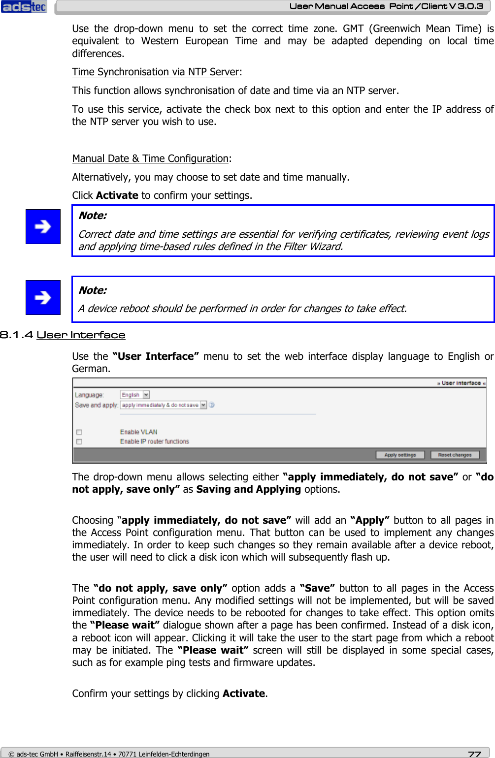
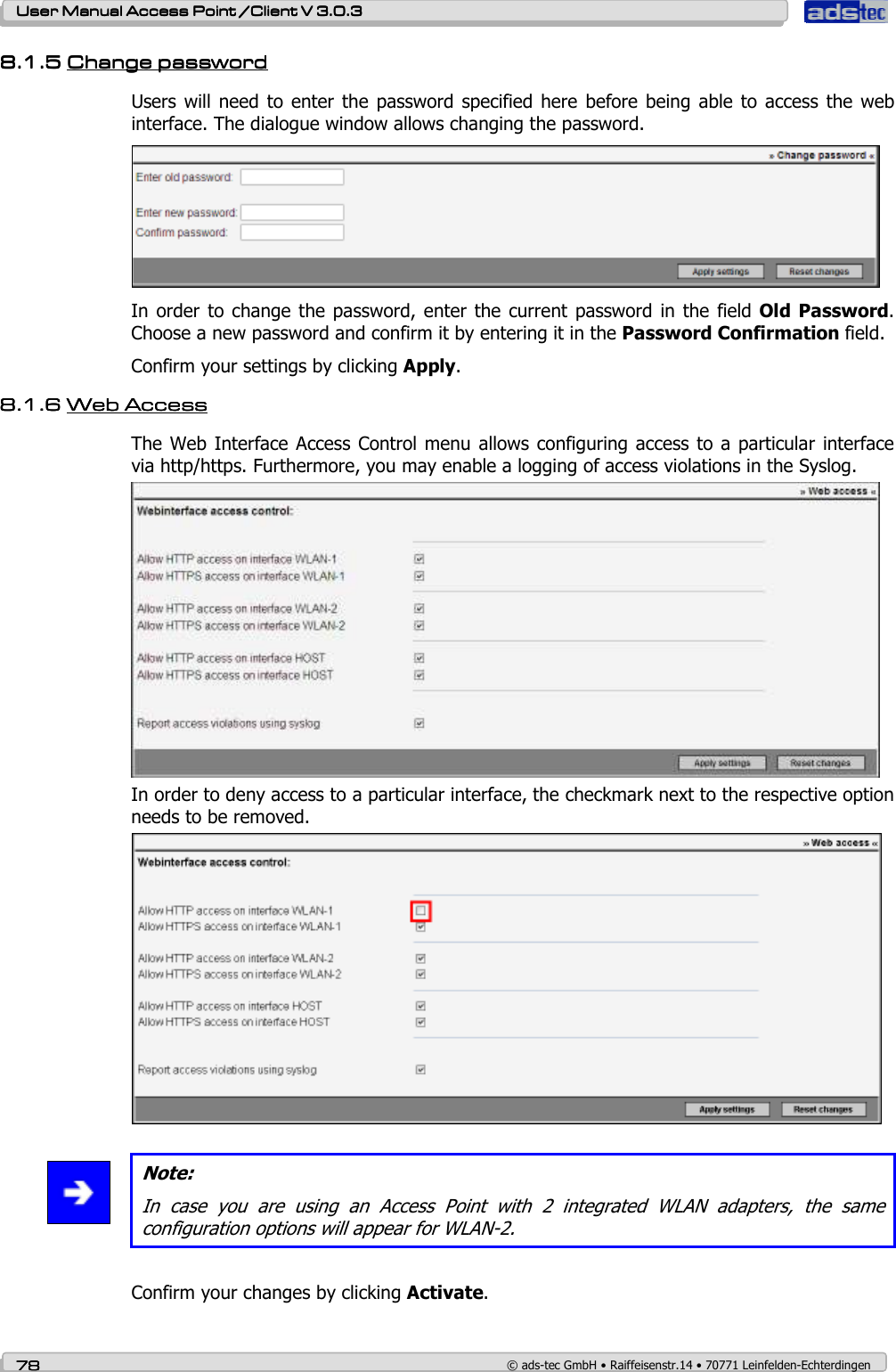
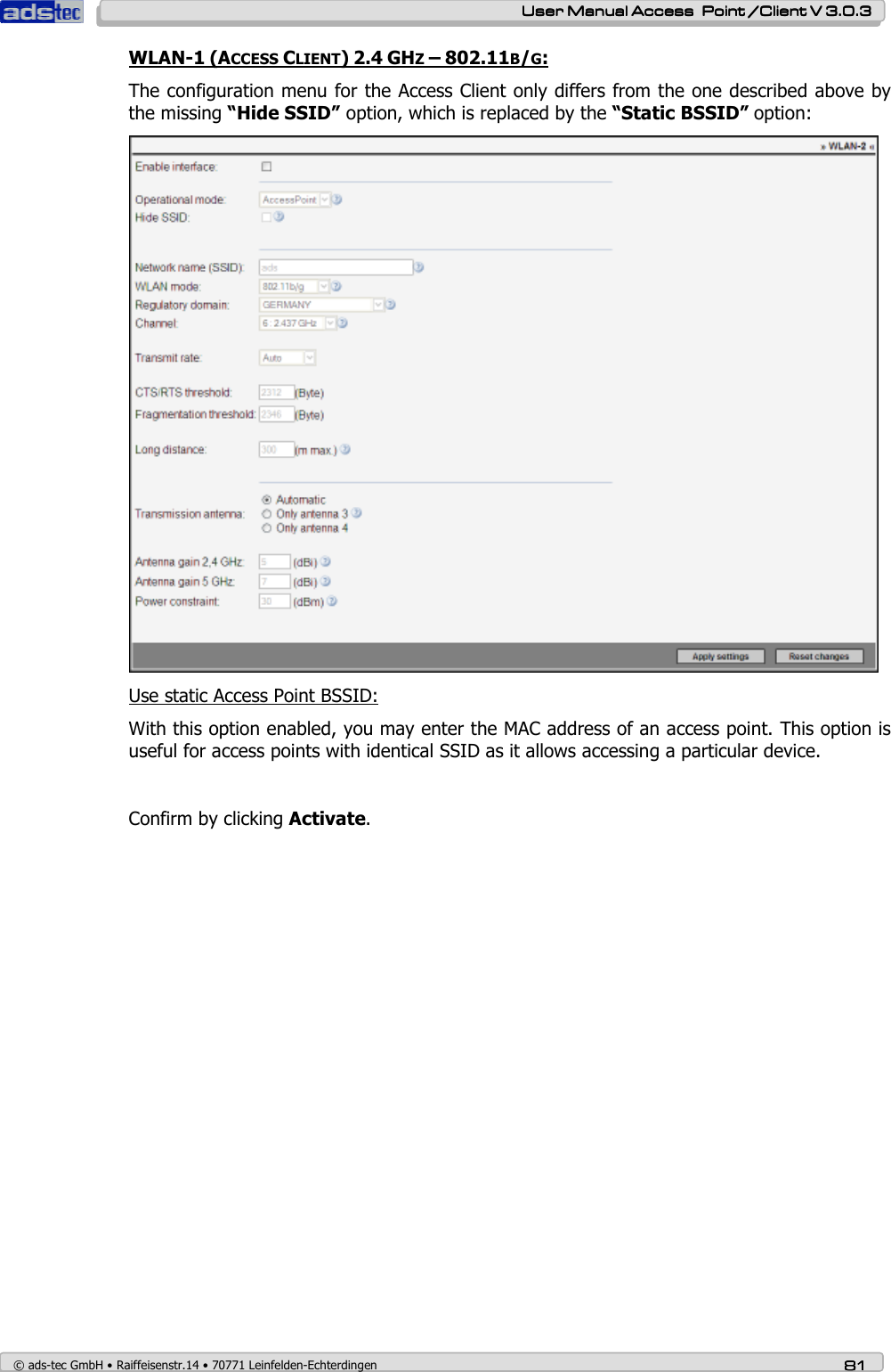
![User ManualUser ManualUser ManualUser Manual Access Point /Client V 3.0.3 Access Point /Client V 3.0.3 Access Point /Client V 3.0.3 Access Point /Client V 3.0.3 © ads-tec GmbH • Raiffeisenstr.14 • 70771 Leinfelden-Echterdingen 79797979 8.1.78.1.78.1.78.1.7 InterfacesInterfacesInterfacesInterfaces Use the Interfaces menu to configure the Access Point interfaces. Each interface offers individual configuration options that can be set to influence the interface behaviour. Furthermore, unused interfaces can be deactivated. Note: Some device variants offer a second WLAN interface. WLAN-1 (ACCESS POINT) 2.4GHZ-802.11B/G: Configure the LAN-in interface by setting the duplex mode. The Activate Interface check box needs to be enabled before any changes to the interface configuration are possible. Operating Mode: Switch / Available options: Access Point / Client (This option is not available for the RAC111x and RAC151x) Hide SSID: Activating this option will hide the SSID (network name) Network Name (SSID): The network identifier. Default value: ads. Maximum SSID length is 32 characters. Note: Valid characters are: a-z, A-Z, 0-9, Valid special characters: . _ - ? $ @ ! { } [ ] ( ) + # ; , < > | : * ~ % $ & / = WLAN Mode: Allows selection of particular WLAN transmission standard Regulatory Authority: Select the country in which the device is used. (This option is not available if you are using the FCC version of the device.)](https://usermanual.wiki/ads-tec/RAX1X2X/User-Guide-887254-Page-79.png)