ads tec RAX1X2X Industrial Access Point User Manual Access Point EN V3 0 3 FCC
ads-tec GmbH Industrial Access Point Access Point EN V3 0 3 FCC
ads tec >
User Manual
User Manual
Version 3.0.3
Access Point/Client
ads-tec GmbH
Raiffeisenstr.14
D-70771 Leinfelden-Echterdingen
Tel: +49 (0) 711 / 45894-0
Fax: +49 (0) 711 / 45894-990
mailbox@ads-tec.com
www.ads-tec.com

User Manual
User ManualUser Manual
User Manual Access Point /Client
Access Point /Client Access Point /Client
Access Point /Client V 3.0.3
V 3.0.3 V 3.0.3
V 3.0.3
2
22
2
© ads-tec GmbH • Raiffeisenstr.14 • 70771 Leinfelden-Echterdingen
HIGH RISK APPLICATION HAZARD NOTICE
Unless otherwise stated in the product documentation, the device is not provided with error-tolerance capabilities and cannot
therefore be deemed as being engineered, manufactured or setup to be compliant for implementation or for resale as an online
surveillance device in environments requiring safe, error-free performance, e.g. for implementation in nuclear power plants, aircraft
navigation, communication systems, or air traffic control, life saving and military facilities whereby possible device failures might
result in death, personal injuries, or serious physical and/or environmental damages (i.e. all applications involving high-risk hazard
factors).
This is therefore to state that neither ads-tec nor any ads-tec sub-supplier do not hereby undertake any warranty of fitness and/or
liability whatsoever, be it by express or by tacit consent, in as far as the suitability of the Firewall to high-risk application hazards is
concerned.
Copyright Notice
ads-tec GmbH
Raiffeisenstr.14
D-70771 Leinfelden-Echterdingen
Germany

User Manual
User ManualUser Manual
User Manual Access Point /Client V 3.0.3
Access Point /Client V 3.0.3 Access Point /Client V 3.0.3
Access Point /Client V 3.0.3
© ads-tec GmbH • Raiffeisenstr.14 • 70771 Leinfelden-Echterdingen
3
33
3
C
ONTENTS
A
BOUT US
.......................................................................................................................................... 6
1
N
OTES
..................................................................................................................................... 7
1.1
R
ELEVANT
U
NIT
D
OCUMENTATION
...................................................................................................... 7
1.2
D
ESCRIPTION OF THE WARNING SYMBOLS USED IN THIS GUIDE
................................................................... 7
1.3
D
ATA
,
I
MAGES
,
A
MENDMENTS AND
V
ARIATIONS
..................................................................................... 7
1.4
T
RADEMARKS
................................................................................................................................ 7
1.5
C
OPYRIGHT
.................................................................................................................................. 8
1.6
S
TANDARDS
.................................................................................................................................. 8
2
O
PERATING AND
S
AFETY
I
NSTRUCTIONS
........................................................................................ 9
2.1
S
AFETY
I
NSTRUCTIONS
.................................................................................................................... 9
2.2
U
NIT
O
PERATION
S
ITE
.................................................................................................................. 10
2.3
D
AMAGES DUE TO IMPROPER
U
SE
..................................................................................................... 10
2.4
W
ARRANTY
/
R
EPAIRS
................................................................................................................... 10
2.5
G
ENERAL
D
IRECTIONS FOR THE
5GH
Z
V
ERSION
(802.11
A
/
802.11
H)
ETSI .......................................... 10
2.6
WLAN
I
NSTRUCTIONS
.................................................................................................................. 12
3
I
NTRODUCTION
....................................................................................................................... 13
3.1
V
ARIANTS
.................................................................................................................................. 14
3.2
S
COPE OF
S
UPPLY
........................................................................................................................ 15
3.3
E
NVIRONMENTAL
C
ONDITIONS
......................................................................................................... 15
4
M
OUNTING
............................................................................................................................. 16
4.1
M
OUNTING
C
ONDITIONS
................................................................................................................ 16
4.2
E
XTERIOR
D
EVICE
D
IMENSIONS
....................................................................................................... 16
4.3
M
OUNTING
D
IAGRAM
.................................................................................................................... 18
4.4
D
EVICE
M
OUNTING
....................................................................................................................... 19
4.5
C
ONNECTING
S
UPPLY
L
INES
............................................................................................................ 20
4.6
A
NTENNA
A
SSEMBLY
..................................................................................................................... 22
5
S
YSTEM
F
EATURES
................................................................................................................... 23
5.1
LED
S
TATUS
I
NDICATORS
.............................................................................................................. 23
5.1.1
LED Status Indicators during Operation ..................................................................................... 25
5.1.2
Power Supply 24V DC ................................................................................................................ 28
5.1.3
Power Supply 110/230 VAC ....................................................................................................... 29
5.1.4
Power Supply PoE / HOST (IEEE 802.AF)................................................................................. 29
5.1.5
Fibre Optic Ethernet.................................................................................................................... 29
5.1.6
SIM Card Reader, ISO 7816-compatible .................................................................................... 30
6
I
NITIAL
D
EVICE
O
PERATIONS
.................................................................................................... 31

User Manual
User ManualUser Manual
User Manual Access Point /Client
Access Point /Client Access Point /Client
Access Point /Client V 3.0.3
V 3.0.3 V 3.0.3
V 3.0.3
4
44
4
© ads-tec GmbH • Raiffeisenstr.14 • 70771 Leinfelden-Echterdingen
6.1
F
IRST
-
TIME
C
ONFIGURATION
.......................................................................................................... 31
6.2
M
ANUAL
N
ETWORK
A
DAPTER
C
ONFIGURATION VIA
RJ45/
OPTICAL
C
ABLE
................................................... 31
6.3
WLAN
N
ETWORK
A
DAPTER
C
ONFIGURATION
...................................................................................... 33
6.4
F
IRST
-
TIME
C
ONFIGURATION VIA
W
EB
I
NTERFACE
................................................................................ 35
6.5
W
IRELESS
N
ETWORK
C
ONFIGURATION
............................................................................................... 36
6.6
E
STABLISHING A
W
IRELESS
N
ETWORK
C
ONNECTION
............................................................................. 36
7
A
CCESS
P
OINT
S
ETUP
W
IZARD
.................................................................................................. 37
7.1
F
IRST
-
TIME
C
ONFIGURATION USING THE
S
ETUP
W
IZARD
........................................................................ 37
7.1.1
Language Selection .................................................................................................................... 37
7.1.2
IP Configuration .......................................................................................................................... 37
7.1.3
WLAN-1 Configuration ................................................................................................................ 39
7.1.4
WLAN-1 Security......................................................................................................................... 41
7.1.5
Changing the Password.............................................................................................................. 44
7.2
C
ONFIGURATION USING THE
F
ILTER
W
IZARD
....................................................................................... 46
7.2.1
Loading pre-configured Rule sets............................................................................................... 48
7.2.2
Definition of a new Rule set on Layer 2 ...................................................................................... 50
7.2.3
Definition of a new Rule set on Layer 3 ...................................................................................... 60
8
A
CCESS
P
OINT
/C
LIENT
W
EB
I
NTERFACE
..................................................................................... 74
8.1
B
ASIC
S
ETTINGS
M
AIN
M
ENU
.......................................................................................................... 75
8.1.1
IP Configuration .......................................................................................................................... 75
8.1.2
System Data................................................................................................................................ 76
8.1.3
Date & Time ................................................................................................................................ 76
8.1.4
User Interface.............................................................................................................................. 77
8.1.5
Change password ....................................................................................................................... 78
8.1.6
Web Access ................................................................................................................................ 78
8.1.7
Interfaces .................................................................................................................................... 79
8.2
C
ONFIGURATION
.......................................................................................................................... 89
8.2.1
Network ....................................................................................................................................... 89
8.2.2
Security ....................................................................................................................................... 90
8.2.3
Adv. WLAN.................................................................................................................................. 97
8.2.4
Advanced .................................................................................................................................. 100
8.3
D
IAGNOSIS
............................................................................................................................... 104
8.4
A
DDITIONAL
I
NFORMATION
........................................................................................................... 106
8.4.1
General ..................................................................................................................................... 106
8.4.2
Technical Data .......................................................................................................................... 106
8.4.3
Device Mounting ....................................................................................................................... 107
8.4.4
Local Diagnosis......................................................................................................................... 107
8.4.5
Site Map .................................................................................................................................... 108

User Manual
User ManualUser Manual
User Manual Access Point /Client V 3.0.3
Access Point /Client V 3.0.3 Access Point /Client V 3.0.3
Access Point /Client V 3.0.3
© ads-tec GmbH • Raiffeisenstr.14 • 70771 Leinfelden-Echterdingen
5
55
5
8.5
E
VENT LOG
............................................................................................................................... 108
9
R
EGULATORY
A
PPROVALS
....................................................................................................... 110
9.1
E
UROPEAN
A
PPROVALS
................................................................................................................ 110
9.2
FCC-A
PPROVAL
......................................................................................................................... 112
9.3
D
IRECTIVES
.............................................................................................................................. 113
10
T
ECHNICAL
D
ETAILS
............................................................................................................... 114
10.1
V
ARIANTS
............................................................................................................................. 114
10.2
E
THERNET
D
ATA
T
RANSMISSION
................................................................................................. 114
10.3
R
ADIO
P
ROPERTIES
................................................................................................................. 115
10.4
P
OWER
S
UPPLY
...................................................................................................................... 115
10.5
C
ONFIGURATION
..................................................................................................................... 115
10.6
G
ENERAL
D
ATA
...................................................................................................................... 115
11
S
ERVICE AND
S
UPPORT
........................................................................................................... 116
11.1
ADS
-
TEC
S
UPPORT
................................................................................................................... 116
11.2
C
OMPANY
A
DDRESS
................................................................................................................. 116
User Manual
User ManualUser Manual
User Manual Access Point /Client
Access Point /Client Access Point /Client
Access Point /Client V 3.0.3
V 3.0.3 V 3.0.3
V 3.0.3
6
66
6
© ads-tec GmbH • Raiffeisenstr.14 • 70771 Leinfelden-Echterdingen
A
AA
A
BOUT US
BOUT USBOUT US
BOUT US
ads-tec GmbH
Raiffeisenstr. 14
D-70771 Leinfelden-Echterdingen
Tel: +49 (0) 711 / 45894-0
Fax: +49 (0) 711 / 45894-990
www.ads-tec.com
ads-tec GmbH provides large enterprises and globally active corporations with cutting edge
technology, up-to-date know-how and comprehensive services in the area of automation
technology, data processing technology and systems engineering.
ads-tec GmbH implements full automation solutions from planning to commissioning and is
specialized in handling and material handling technologies.
The data systems division develops and produces PC based solutions and offers a broad
range of industrial PCs, thin clients and embedded systems.
ads-tec is specialized in modifying and optimizing embedded operating systems and
develops software tools to complement its hardware platforms.
User Manual
User ManualUser Manual
User Manual Access Point /Client V 3.0.3
Access Point /Client V 3.0.3 Access Point /Client V 3.0.3
Access Point /Client V 3.0.3
© ads-tec GmbH • Raiffeisenstr.14 • 70771 Leinfelden-Echterdingen
7
77
7
1
11
1 N
NN
N
OTES
OTESOTES
OTES
1.1 R
ELEVANT
U
NIT
D
OCUMENTATION
The following documents are essential to unit setup and operation:
U
SER
M
ANUAL
(
THIS DOCUMENT
)
Contains information on mounting, placing into operation and operation of the unit, further
to technical data on unit hardware.
S
ERVICE
CD:
Contains the User Manual, the Assembly Guide, the Quick Install Guide and Tools.
Contains the Us er Manual, th e Assembly Gui de, the Quick I nstall Guide a nd Tool.
1.2 D
ESCRIPTION OF THE WARNING SYMBOLS USED IN THIS GUIDE
Warning:
The “Warning” symbol precedes warnings on uses or operations that might either lead to
personal injury and/or hazards, or to any hardware and software damages.
Note:
This Symbol indicates special notes, terms and/or conditions that strictly need to be
observed to ensure optimised and/or zero-defect operations. It also precedes tips and
suggestions for efficient unit implementation and software optimisation.
1.3 D
ATA
,
I
MAGES
,
A
MENDMENTS AND
V
ARIATIONS
The texts, data and images herein are not binding. The right to any subsequent amendment
and/or variation due to any technical and engineering progresses in the art whatsoever is
hereby reserved.
1.4 T
RADEMARKS
It is hereby notified that any software and/or hardware trademarks further to any company
brand names as mentioned in this User’s Guide are all strictly subject to the various
trademark, brand name and patent protection rights.
WINDOWS
®
, WINDOWS
®
CE and WINDOWS
®
CE.net™ are registered trademarks of
Microsoft Corp.
Citrix
®
and ICA
®
are registered trademarks of Citrix Systems Inc.
Intel
®
and Pentium
®
are registered trademarks of Intel Corp.
IBM
®
, PS/2
®
and VGA
®
are registered trademarks of IBM Corp.
CompactFlash™ and CF™ are registered trademarks of SanDisk Corp.
Any further additional trademarks and/or brand names herein, be they domestic or
international, are hereby duly acknowledged.
User Manual
User ManualUser Manual
User Manual Access Point /Client
Access Point /Client Access Point /Client
Access Point /Client V 3.0.3
V 3.0.3 V 3.0.3
V 3.0.3
8
88
8
© ads-tec GmbH • Raiffeisenstr.14 • 70771 Leinfelden-Echterdingen
1.5 C
OPYRIGHT
This User’s Guide inclusive of all the images it contains is entirely proprietary and subject to
copyright. Any irregular use of this Guide by third parties infringing copyright terms is thus
strictly forbidden. Reproduction, translation, as well as electronic and photographic image
storage and/or amendment processes, are subject to prior written authorisation directly by
M/s. ads-tec GmbH.
Any violation and infringement thereto will be held liable for compensation of all damages.
1.6 S
TANDARDS
This unit is compliant with the provisions and safety objectives of the following EU
Directives:
• This unit is compliant with the CE mark testing specification limits as defined in the
European test standards EN 55022 and EN 50082-2
• This unit is compliant to the DIN EN 60950 (VDE0805, IEC950) testing specification
limits on “Safety of Information Technology Equipment”
• This unit is compliant to the DIN EN 60068-2-6 (sinusoidal vibration) testing
specification limits
• This unit is compliant to the DIN EN 60068-2-27 (shock and bump) testing
specification limits
Note:
A corresponding declaration of conformity is available for competent authorities, care of
the Manufacturer. Said declaration can be viewed at all times upon request.
For full compliance to the legal requirements in force on electromagnetic compatibility, all
components and cables used for unit connection must also be compliant with said
regulations. It is therefore necessary to employ BUS and LAN cables featuring screened
plug connectors, to be strictly installed as per the instructions contained in the User
Manual.
User Manual
User ManualUser Manual
User Manual Access Point /Client V 3.0.3
Access Point /Client V 3.0.3 Access Point /Client V 3.0.3
Access Point /Client V 3.0.3
© ads-tec GmbH • Raiffeisenstr.14 • 70771 Leinfelden-Echterdingen
9
99
9
2
22
2 O
OO
O
PERATING AND
PERATING AND PERATING AND
PERATING AND
S
SS
S
AFETY
AFETY AFETY
AFETY
I
II
I
NSTRUCTIONS
NSTRUCTIONSNSTRUCTIONS
NSTRUCTIONS
The unit operates under electrical tension and implements supersensitive component parts.
Intervention by the User is required only for power supply line connection operations.
Should any further alterations be required, it is necessary to consult either with the
Manufacturer directly or with authorised service personnel accordingly. During said
connection operations, the unit must be completely powered down. Specific requirements
need to be met concerning the prevention of electrostatic discharge on component
construction parts during contact. If the unit is opened up by a non authorised individual,
the User may be subject to potential hazards and, warranty conditions are terminated.
General Instructions:
• This User’s Guide must be read and understood by all Uses and must be available
for consultation at all times
• Mounting, operation start-up and unit operation must only be conducted by
appropriately qualified and trained personnel
• All individuals and operators using the unit must strictly observe all safety and use
instructions as provided within the User’s Guide
• All regulations and prescriptions on accident prevention and safety in force at the
unit installation site must be strictly observed at all times
• This User’s Guide provides all the most important directions as required for safe and
security oriented operation
• Safe and optimised unit operations are subject to appropriate storage, proper
transport and handling, accurate unit setup, start-up and operation
Note:
Only original ads-tec firmware / software is allowed for any of the adjustments and
features described in this User’s Guide. Deployment of any firmware / software that has
not been released by ads-tec will terminate all warranty conditions.
2.1 S
AFETY
I
NSTRUCTIONS
Warning:
In order to prevent possible unit damages, all cable lines (power supply, interface cables)
must be hooked up strictly with the unit in power-OFF conditions.
Warning:
All unit mounting operations must be strictly conducted under safe, secure and zero-
potential conditions.
Note:
When handling parts and components susceptible to electrical discharge, please
accurately observe all the relevant safety provisions.
(DIN EN 61340-5-1 / DIN EN 61340-5-2)
User Manual
User ManualUser Manual
User Manual Access Point /Client
Access Point /Client Access Point /Client
Access Point /Client V 3.0.3
V 3.0.3 V 3.0.3
V 3.0.3
10
1010
10
© ads-tec GmbH • Raiffeisenstr.14 • 70771 Leinfelden-Echterdingen
2.2 U
NIT
O
PERATION
S
ITE
This unit is engineered for industrial application. It is necessary to ensure that specified
environmental conditions are maintained at all times. Unit implementation in non-specified
surroundings, i.e. onboard ships, in explosive atmospheres or at extreme heights, is
prohibited.
Warning:
For the prevention of water condensate accumulation, the unit should be turned ON only
when it reaches ambient temperature. This particularly applies when the unit is subject to
extreme temperature fluctuations and/or variations.
Avoid overheating during unit operations; the unit must not be exposed to direct sunlight
or any other direct light or heat sources.
Warning:
If the unit is operated in outdoor locations, a lightning conductor needs to be present
within capture range. Ensure that all incoming conductive systems are equipped with
equipotential bonding.
2.3 D
AMAGES DUE TO IMPROPER
U
SE
Should the service system have evident signs of damages incurred e.g. due to wrong
operation or storage conditions or due to improper unit use, the unit must be
decommissioned or scrapped. Ensure that it is protected against accidental start-up.
2.4 W
ARRANTY
/
R
EPAIRS
During the unit warranty period, any repairs thereto must strictly be conducted solely by the
manufacturer or by service personnel that has been duly authorised by the manufacturer.
2.5 G
ENERAL
D
IRECTIONS FOR THE
5GH
Z
V
ERSION
(802.11
A
/
802.11
H)
ETSI
• The unit is certified for use of the 5 GHz band in accordance with ETSI EN 301 893
V1.3.1. Users need to observe the following:
• Access Point as well as Access Client units make use of DFS and TPC as standard on all 5
GHz channels, in indoor as well as in outdoor configuration. This means that the devices
may always be operated at a maximum transmission power of 23 dBm or 30 dBm,
respectively.
Note:
Access Points must not switch off DFS in outdoor locations. Access Clients may switch off
DFS, though. This setting is turned off by default.
• 802.11a channels cannot be set to static values.
Note:
The lower 4 channels (non-DFS) can be set to static values if DFS is turned off. Turning
off DFS will however also make the features 60s Scan, 24h Scan and Radar Detection
unavailable.
User Manual
User ManualUser Manual
User Manual Access Point /Client V 3.0.3
Access Point /Client V 3.0.3 Access Point /Client V 3.0.3
Access Point /Client V 3.0.3
© ads-tec GmbH • Raiffeisenstr.14 • 70771 Leinfelden-Echterdingen
11
1111
11
• When activating the Access Point, the unit will perform an initial Radar Detection Scan
during which it will wait 60 seconds for a radar impulse on a randomly chosen channel.
Subsequently, it will start operating on this channel.
• The 60s Scan will be repeated every 24 hours and cause a temporary connection loss.
• If an Access Client detects a radar impulse during operation, the Access Point will be
notified of this via 802.11h. Triggered by this or its own detection of the impulse, the
Access Point will subsequently perform a channel switch to 802.11h. The connection loss
in this case is usually less than 80ms.
• The maximum permissible transmission power is different for each channel. Hence users
are required to correctly set the antenna amplification in case the standard antenna is
replaced!
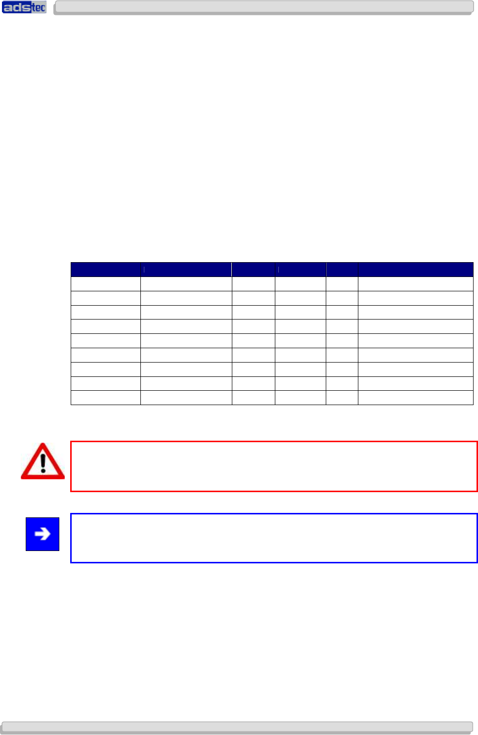
2.6 A
NTENNA
L
IST FOR USE IN
USA
AND
C
ANADA
/
FCC
• This antenna types can be used with the Access Points and Access Client in USA and
Canada. The antennas can be ordered at ads-tec GmbH. For the correct operation you
have to use an absorbability cabel for the different antenna types.
Ads-tec part number Ads-tec part description Antenna type Frequency band Gain absorbability
DZ-PCKO-11032-0 RAP Antenne 2,4 GHz SMA-R 5dBi Swivel 2,4 ~ 2,4835 GHz 5 dBi none
DZ-PCKO-11033-0 RAP Antenne 5 GHz SMA-R 7dBi Swivel 5,1 ~ 5,835 GHz 7 dBi none
DZ-PCKO-11034-0 RAP Antenne 2,4 GHz N-fem. 9 dBi Omni 2,4 ~ 2,4835 GHz 9 dBi none
DZ-PCKO-11034-1 RAP Antenne 2,4 GHz N-fem. 12 dBi Omni 2,4 ~ 2,4835 GHz 12 dBi none
DZ-PCKO-11035-0 RAP Antenne 2,4 GHz N-fem. 12 dBi Panel 2,4 ~ 2,4835 GHz 12 dBi none
DZ-PCKO-11035-1 RAP Antenne 2,4 GHz N-fem. 18 dBi Panel 2,4 ~ 2,4835 GHz 18 dBi minimum 20m
(it is a Ecoflex10*1 cable to use)
DZ-PCKO-11036-0 RAP Antenne 5 GHz N-fem. 12 dBi Omni 5,1 ~ 5,835 GHz 12 dBi minimum 14m
(it is a Ecoflex10*1 cable to use)
DZ-PCKO-11037-0 RAP Antenne 5 GHz N-fem. 12 dBi Panel 5,1 ~ 5,835 GHz 12 dBi minimum 20m
(it is a Ecoflex10*1 cable to use)
DZ-PCKO-11037-1 RAP Antenne 5 GHz N-fem. 20 dBi Panel 5,1 ~ 5,835 GHz 20 dBi minimum 37m
(it is a Ecoflex10*1 cable to use)
*1 It has at 2,4GHz 22.5dB/100m absorbability and at 5GHz 35.9dB/100m absorbability. Additional every plug has 0.5dB absorbability.
Warning:
Behalf of the correct operation you have use an absorbability element for the different
antenna types.
Note:
Also light wave conductor cable can be used. It is necessary to use terminating impedance
for the correct use.
User Manual
User ManualUser Manual
User Manual Access Point /Client
Access Point /Client Access Point /Client
Access Point /Client V 3.0.3
V 3.0.3 V 3.0.3
V 3.0.3
12
1212
12
© ads-tec GmbH • Raiffeisenstr.14 • 70771 Leinfelden-Echterdingen
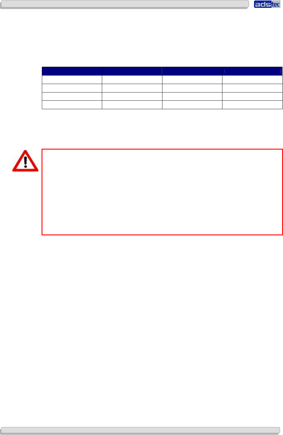
2.7 C
HANNEL
L
IST FOR USE IN
USA
AND
C
ANADA
/
FCC
• The following List showes the pool of available frequency and channles for the use in USA
and Canada. The customer can define between Indoor and Outdoor use. This option can
be selected by a checkbox in the web interface.
Frequency Channel Indoor use Outdoor use
2,4 GHz (2.400~2.483GHz) 1 – 11 X X
5 GHz (5.18~5.24GHz) 36,40,42,44,48 X
5 GHz (5.725~5.825GHz) 149 ,153,157,161,165 X
5 GHz (5.725~5.825GHz) 149 ,153,157,161,165 X
2.8 WLAN
I
NSTRUCTIONS
Warning:
These warnings need to be observed during operation:
•
The unit does not provide a „secure“ transmission medium
•
The units cannot be used to establish a real-time system
•
The units’ system behaviour is non-deterministic
•
MIN/MAX roaming period is not guaranteed
Setting the applicable regulatory authority as well as the respective antenna amplification
is solely the responsibility of the operator.
User Manual
User ManualUser Manual
User Manual Access Point /Client V 3.0.3
Access Point /Client V 3.0.3 Access Point /Client V 3.0.3
Access Point /Client V 3.0.3
© ads-tec GmbH • Raiffeisenstr.14 • 70771 Leinfelden-Echterdingen
13
1313
13
3
33
3 I
II
I
NTRODUCTION
NTRODUCTIONNTRODUCTION
NTRODUCTION
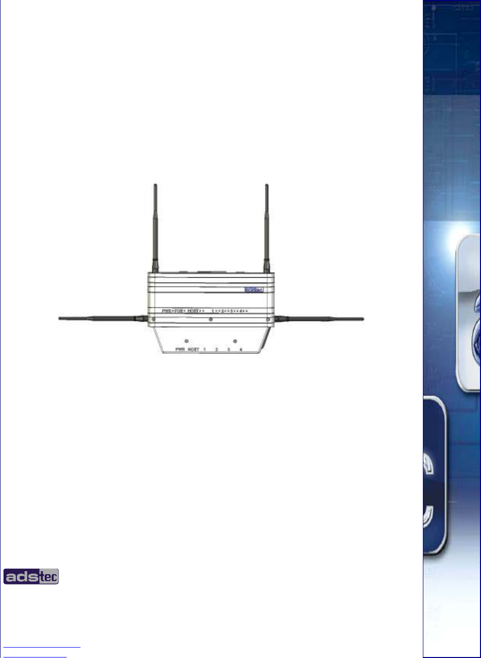
Reliable, stable and secure wireless LAN connections: employing state-of-the-art technology,
the industrial Rugged Access Point (RAP) provides
the
network interface for a variety of
applications, such as commissioning, mobile computing and data communication. The RAP
supports all applicable standards, including 802.11a/b/g, at a transmission frequency of 2.4
and 5 GHz. Industrial applications necessitate sturdy technology. Whether installed in a cold
store or in great heat – thanks to its extended temperature range, the RAP continues to
function. Furthermore, the RAP is MIL-certified, which means it passed one of the most
demanding shock and vibration tests – this guarantees utmost ruggedness.
Note:
In Case of Updates, it is possible that external Hyperlinks, which are used in this
Documentation, will not work properly or may be available under a different Hyperlink.The
Company ads-tec (also “ads-tec”) does not take over any kind of warranty or adhesion for
the functionality of Hyperlinks. Furthermore, ads tec does not take over any kind of
warranty or adhesion regarding the installation, use and the accuracy of all open SOURCE
software.
Note:
For the efficient online configuration of your ads tec devices, it is possible to download the
current version of the free Tool „IDA light “on the company`s homepage
http://www.ads-tec.de. The Tool offers you for example the possibility of defining
individual parameters or whole groups of parameters at a master device and to transfer
your settings to a limited selection and/or to all ads tec devices of same design and
version, without having to make these configurations time-consuming at each individual
device. You also have the possibility of assigning sequential IP addresses for your ads tec
devices.
With IDA light you can provide comfortably own groups of parameters according to your
specific requirements and modify them at any time.
Note:
This documentation always refers to both Access Point and Access Client, unless explicitly
stated otherwise.

User Manual
User ManualUser Manual
User Manual Access Point /Client
Access Point /Client Access Point /Client
Access Point /Client V 3.0.3
V 3.0.3 V 3.0.3
V 3.0.3
14
1414
14
© ads-tec GmbH • Raiffeisenstr.14 • 70771 Leinfelden-Echterdingen
3.1 V
ARIANTS
The device is available in 12 different variants.
Access Point RAP1110 RAP1111 RAP1210 RAP1211 RAP1120 RAP1121 RAP1220 RAP1221
1 WLAN Module X X X X
2 WLAN Modules X X X X
1xCU Ethernet Port (RJ45) X X X X
5xCU Ethernet Port (integrated switch) (RJ45)
1xOptical Ethernet Port X X X X
PoE (IEEE 802.3af) 48V DC X X X X
24 V DC X X X X
AC integrated 110-230 V AC X X X X
Client Mode available X X X X X X X X
Access Client RAC1110 RAC1111 RAC1510 RAC1511 RAC1120 RAC1121 RAC1220 RAC1221
1 WLAN Module X X X X
2 WLAN Modules X X X X
1xCU Ethernet Port X X X X
5xCU Ethernet Port (integrated switch) X X
1xOptical Ethernet Port X X
PoE (IEEE 802.3af) 48V DC X X X X X X
24 V DC X X X X
AC integrated 110-230 V AC X X X X
RJ45 (Registered Jack 45 = standardised jack) is an Ethernet standard frequently
used in telecommunication applications. Transmission method is equivalent to 10/100Mbits
half & full DUPLEX 100 BASE-TX.
Optical fibres are flexible optic media for controlled conduction of light. Contrarily to the
Ethernet standard, the fibre optic connection technology is insensitive to voltage
interference.
The plugs required for implementation are equivalent to the MTRJ Standard Multimode with
a 100Base-FX 100 Mbit⁄s Ethernet transmission via fibre optics.

User Manual
User ManualUser Manual
User Manual Access Point /Client V 3.0.3
Access Point /Client V 3.0.3 Access Point /Client V 3.0.3
Access Point /Client V 3.0.3
© ads-tec GmbH • Raiffeisenstr.14 • 70771 Leinfelden-Echterdingen
15
1515
15
3.2 S
COPE OF
S
UPPLY
Package contents need to be checked for integrity and completeness:
• 1 device
• 1 x two-pole COMBICON plugs (in case of 24V DC devices)
Manufacturer: Phoenix Contact
Item description/item short text: FMC 1,5 / 2-STF-3,5
• 1 x three-pole COMBICON plugs (in case of 230V AC devices)
Manufacturer: Phoenix Contact
Item description/item short text: MC 1,5 / 3-STF-3.81
• Four or eight antennas (depending on variant)
• Grommets / blanking plugs
• Installation kit with mounting plate and fasteners (fixed to device)
• Quick Install Guide / Quick Mount Guide
• GNU General Public License
• Service CD
3.3 E
NVIRONMENTAL
C
ONDITIONS
The unit can be put into operation and used under the following conditions. Failure to
observe any one of the specified data will immediately terminate all warranty conditions.
ads-tec cannot be held liable for any damages arising due to improper device or unit use
and handling.
• Permissible ambient temperature
during operation from -20°C to 55°C
during storage from -20°C to 60°C
• Humidity
during operation 10 to 85%, without condensate
during storage 10 to 85%, without condensate
• Vibration
during operation 1 G, 10 to 500 Hz
(DIN EN 60068-2-6)
Vibration certificate: MIL-STD-810F 514.5 C-2
5 to 500 Hz (01-01-2000)
• Shock
during operation 5 g, with a 30 ms half-cycle
(DIN EN 60068-2-29)
User Manual
User ManualUser Manual
User Manual Access Point /Client
Access Point /Client Access Point /Client
Access Point /Client V 3.0.3
V 3.0.3 V 3.0.3
V 3.0.3
16
1616
16
© ads-tec GmbH • Raiffeisenstr.14 • 70771 Leinfelden-Echterdingen
4
44
4 M
MM
M
OUNTING
OUNTINGOUNTING
OUNTING
4.1 M
OUNTING
C
ONDITIONS
The device is designed for industrial operations and may be employed wherever the
environment conditions specified above are met. In order to ensure optimal mounting and
operation, the unit should be placed at suitable location at which WLAN connectivity is not
impaired. WLAN connectivity is adversely influenced by iron beams and thick concrete walls.
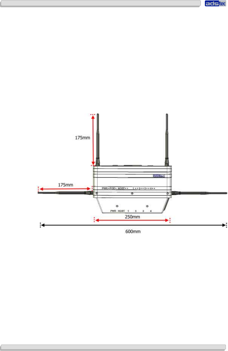
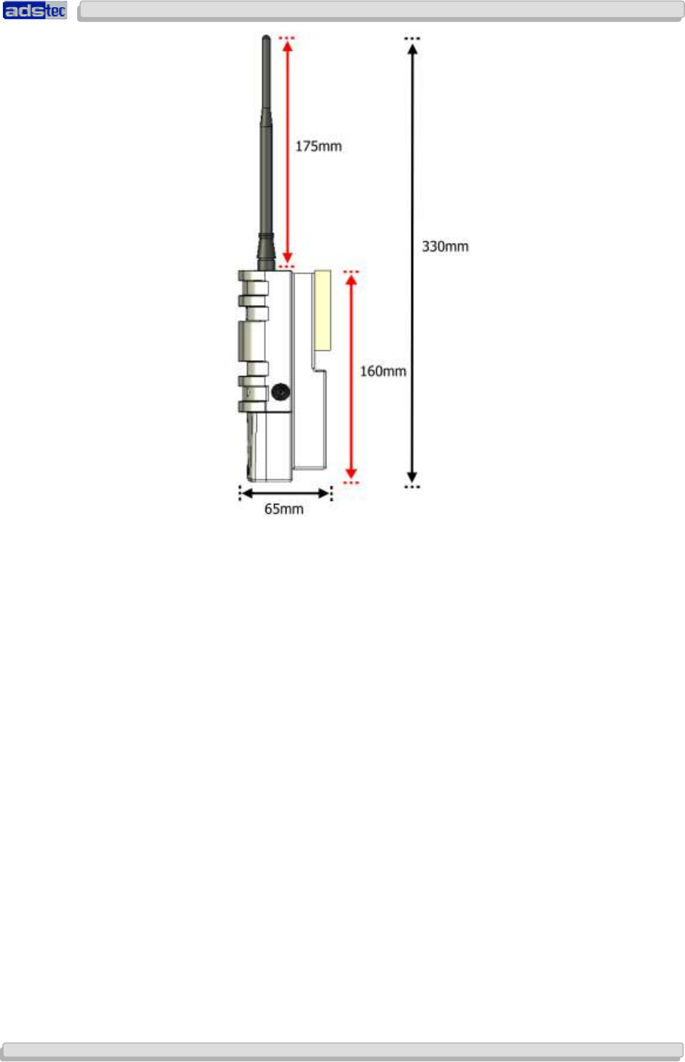
4.2 E
XTERIOR
D
EVICE
D
IMENSIONS
Height: 160 mm (w/o antenna)
Width: 250 mm (w/o antenna)
Depth: 65 mm (w/o antenna)
User Manual
User ManualUser Manual
User Manual Access Point /Client V 3.0.3
Access Point /Client V 3.0.3 Access Point /Client V 3.0.3
Access Point /Client V 3.0.3
© ads-tec GmbH • Raiffeisenstr.14 • 70771 Leinfelden-Echterdingen
17
1717
17
User Manual
User ManualUser Manual
User Manual Access Point /Client
Access Point /Client Access Point /Client
Access Point /Client V 3.0.3
V 3.0.3 V 3.0.3
V 3.0.3
18
1818
18
© ads-tec GmbH • Raiffeisenstr.14 • 70771 Leinfelden-Echterdingen
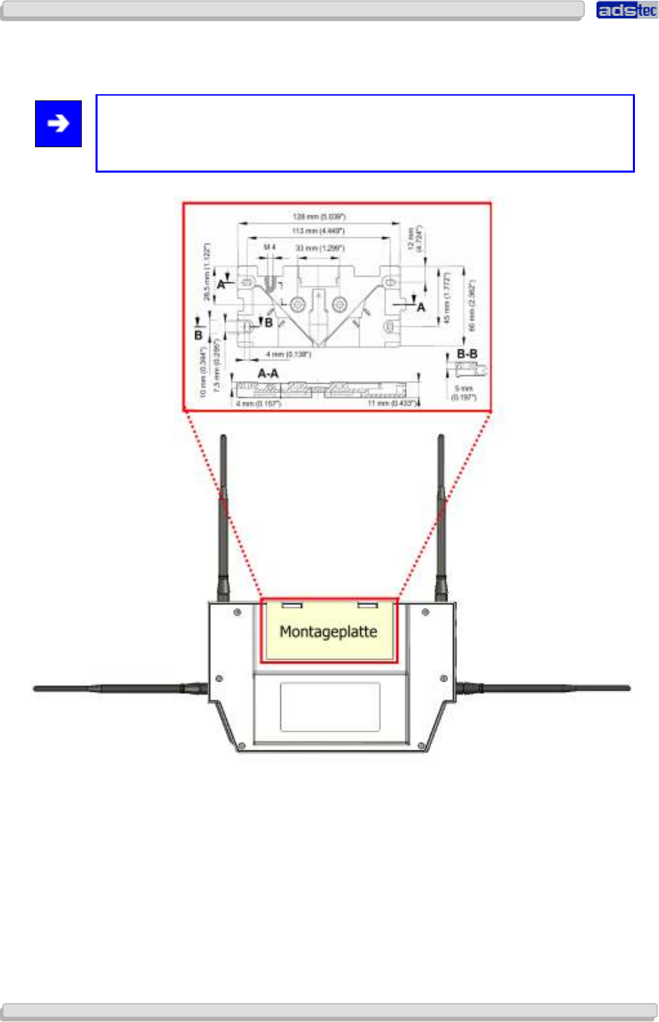
4.3 M
OUNTING
D
IAGRAM
Note:
The mounting diagram shown herein is not 1:1 scale.
Please refer to the Quick Install Guide for a 1:1 scale diagram.
User Manual
User ManualUser Manual
User Manual Access Point /Client V 3.0.3
Access Point /Client V 3.0.3 Access Point /Client V 3.0.3
Access Point /Client V 3.0.3
© ads-tec GmbH • Raiffeisenstr.14 • 70771 Leinfelden-Echterdingen
19
1919
19
4.4 D
EVICE
M
OUNTING
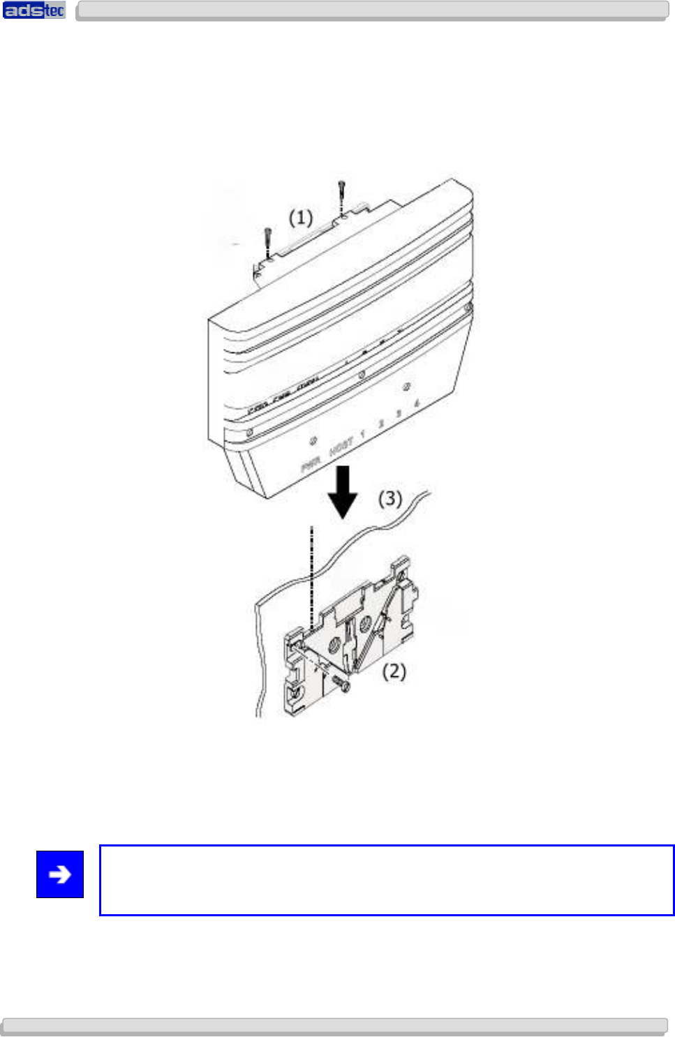
The mounting plate is pre-mounted to the device when delivered to the customer.
1) To install the device in the desired location, loosen the Allen screws (M4x12). (1)
2) Fix the mounting plate (w/o device) in the desired location. Ensure that the plate is held
by at least two opposing screws. (2)
3) Place the device onto the mounted fixture and make sure that device and fixture are flush
with each other. (3)
4) Secure the device inside the fixture using the previously removed Allen screws. (1)
Note:
Please ensure that the device is not mounted behind or next to another object as this may
impair the unit’s transmission performance and connectivity.
User Manual
User ManualUser Manual
User Manual Access Point /Client
Access Point /Client Access Point /Client
Access Point /Client V 3.0.3
V 3.0.3 V 3.0.3
V 3.0.3
20
2020
20
© ads-tec GmbH • Raiffeisenstr.14 • 70771 Leinfelden-Echterdingen
4.5 C
ONNECTING
S
UPPLY
L
INES
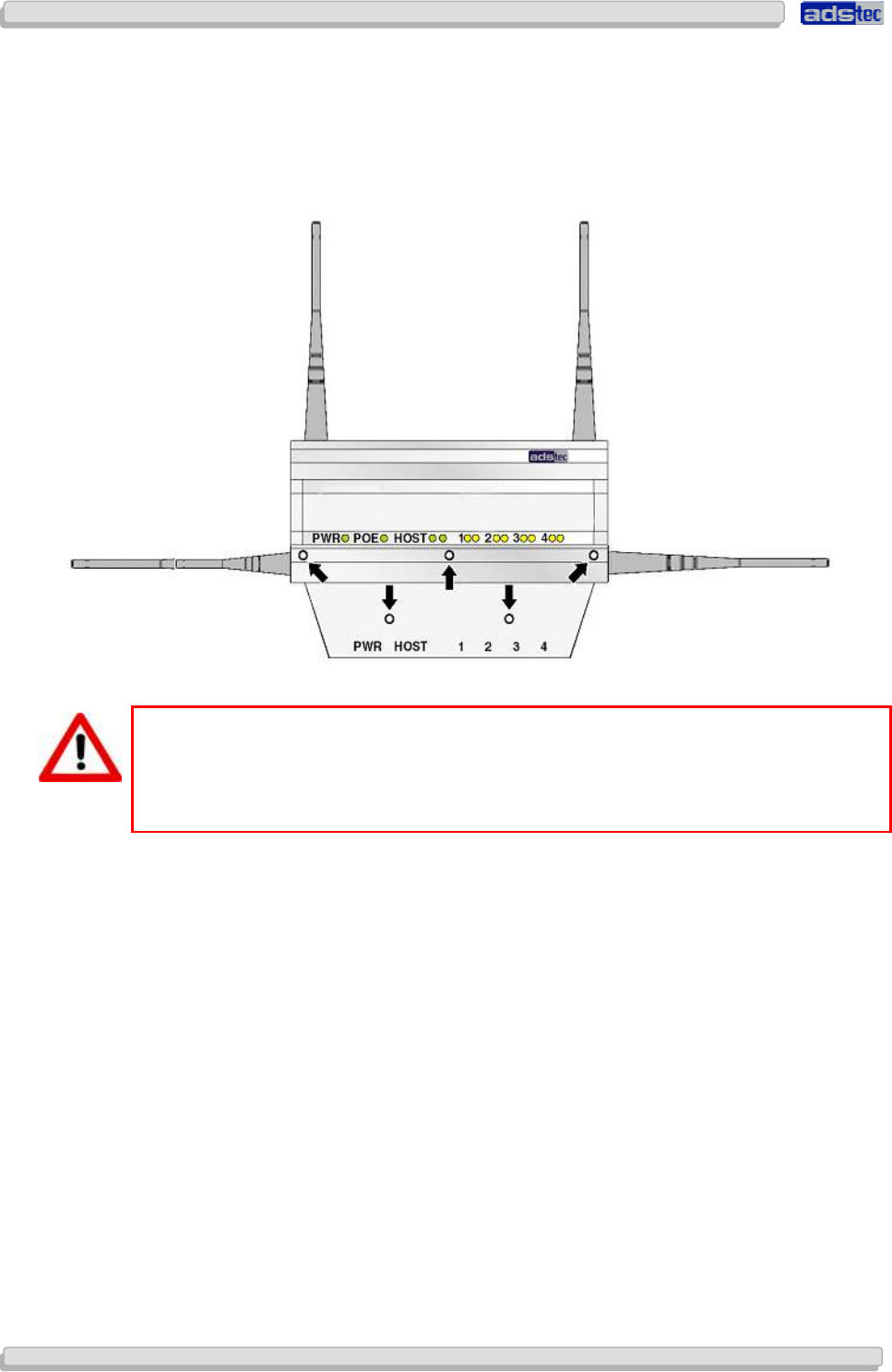
The supply connection, as well as device interfaces, is located inside the unit. The
maintenance duct cover needs to be removed before supply lines and interface cables can
be connected.
Please remove the five screws (M3x8) indicated below.
Warning:
To avoid damage to the unit’s electronics, switch off the device before establishing or
removing any plug connections.
Observe permissible device voltage.
Once the maintenance duct cover has been removed, the supply lines can be connected
to the device.
User Manual
User ManualUser Manual
User Manual Access Point /Client V 3.0.3
Access Point /Client V 3.0.3 Access Point /Client V 3.0.3
Access Point /Client V 3.0.3
© ads-tec GmbH • Raiffeisenstr.14 • 70771 Leinfelden-Echterdingen
21
2121
21
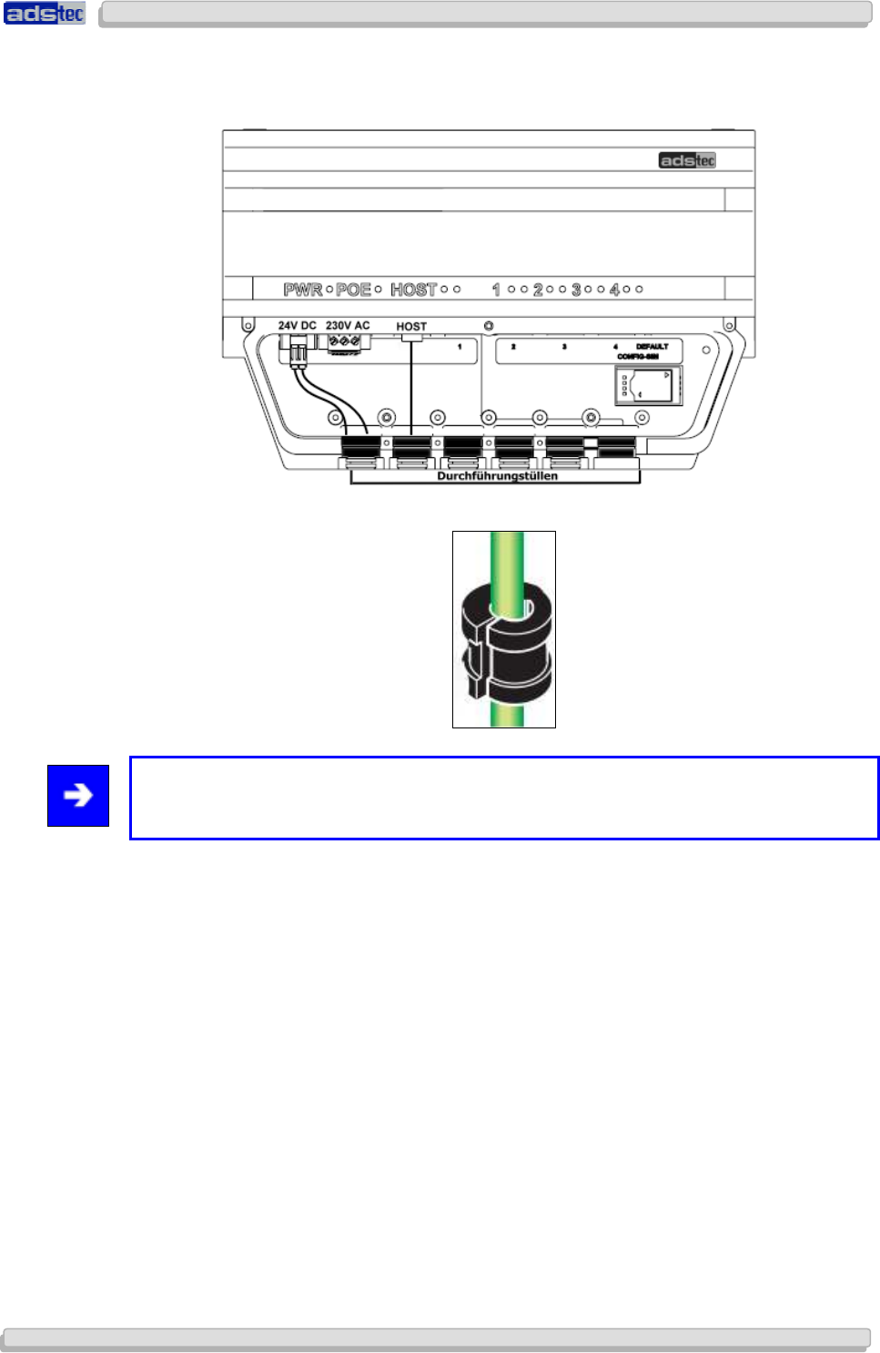
The diagram shows an exemplary device configuration with 24V DC power supply and
host line.
To ensure IP65 protection all supply lines need to be fitted with suitable grommets.
Note:
Grommet sizes need to be chosen in accordance with the respective cable diameters.
Once the grommets have been placed around the cables, they need to be placed into the
intended slots.
Finally, put the maintenance duct cover back onto the device and screw it down with the
five screws removed previously.
User Manual
User ManualUser Manual
User Manual Access Point /Client
Access Point /Client Access Point /Client
Access Point /Client V 3.0.3
V 3.0.3 V 3.0.3
V 3.0.3
22
2222
22
© ads-tec GmbH • Raiffeisenstr.14 • 70771 Leinfelden-Echterdingen
4.6 A
NTENNA
A
SSEMBLY
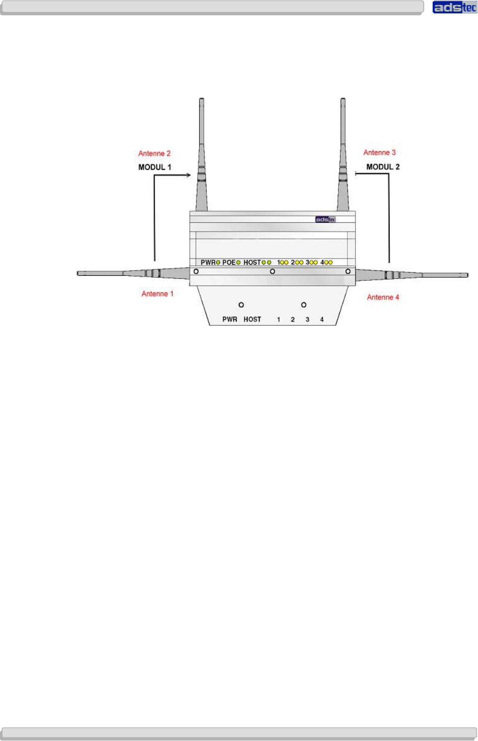
For each WLAN module, 2 antennas should be installed.
Depending on the device variant, the unit accommodates up to two radio modules for two
separate WLANs. The full antenna assembly for each module consists of one vertical and
one horizontal antenna. The four or eight antennas supplied work at a frequency of 2.5GHz
or 5Ghz (two or four each, respectively).
Screw the antennas onto the antenna connectors.
User Manual
User ManualUser Manual
User Manual Access Point /Client V 3.0.3
Access Point /Client V 3.0.3 Access Point /Client V 3.0.3
Access Point /Client V 3.0.3
© ads-tec GmbH • Raiffeisenstr.14 • 70771 Leinfelden-Echterdingen
23
2323
23
5
55
5 S
SS
S
Y
YY
YSTEM
STEMSTEM
STEM
F
FF
F
EATURES
EATURESEATURES
EATURES
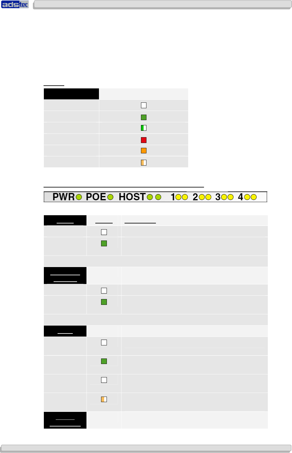
5.1 LED
S
TATUS
I
NDICATORS
The device is fitted with LEDs that indicate the status of the respective interfaces. This
facilitates an on-site status diagnosis of the Access Point/Client. The following overview
explains the different states of the LED indicators:
L
EGEND
LED status Shown in table as
off
green
green, flashing
ret
orange
orange, flashing
P
OWER
S
UPPLY
/
P
OWER OVER
E
THERNET
/
HOST
/
S
WITCH
P
OWER
S
TATUS
D
ESCRIPTION
PWR No power supply.
PWR Device connected to power supply and ready for
use.
P
OWER OVER
E
THERNET
POE Device not connected to power supply via PoE.
POE Device connected to power supply via PoE and
ready for use.
HOST
L
EFT
LED
LINK
Interface not connected to remote station.
L
EFT
LED
LINK
Interface connected to remote station and ready for
use.
R
IGHT
LED
ACT
No data transfer between device and remote
station.
Right LED
ACT Indicates data transfer between device and remote
station.
S
WITCH
1
/
2
/
3
/
4

User Manual
User ManualUser Manual
User Manual Access Point /Client
Access Point /Client Access Point /Client
Access Point /Client V 3.0.3
V 3.0.3 V 3.0.3
V 3.0.3
24
2424
24
© ads-tec GmbH • Raiffeisenstr.14 • 70771 Leinfelden-Echterdingen
L
EFT
LED
LINK
Interface not connected to remote station.
L
EFT
LED
LINK
Interface connected to remote station and ready for
use.
R
IGHT
LED
ACT
No data transfer between device and remote
station.
Right LED
ACT Indicates data transfer between device and remote
station.
User Manual
User ManualUser Manual
User Manual Access Point /Client V 3.0.3
Access Point /Client V 3.0.3 Access Point /Client V 3.0.3
Access Point /Client V 3.0.3
© ads-tec GmbH • Raiffeisenstr.14 • 70771 Leinfelden-Echterdingen
25
2525
25
5.1.1
5.1.15.1.1
5.1.1 LED Status Indicators during Operation
LED Status Indicators during OperationLED Status Indicators during Operation
LED Status Indicators during Operation
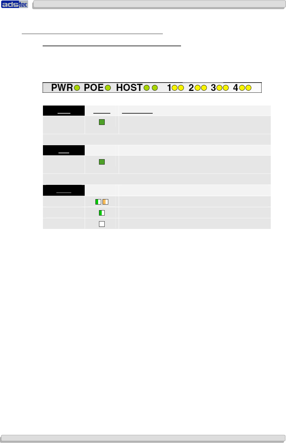
B
EHAVIOUR OF
S
TATUS
I
NDICATORS DURING
B
OOT
S
EQUENCE
The boot sequence is initiated as soon as the Access Point / Client is connected to a power
supply. The HOST indicator LEDs can be used to monitor the boot sequence. Please refer to
the following overview to verify the device boots correctly. The overview assumes that no
cable is connected to HOST / PoE.
PWR S
TATUS
D
ESCRIPTION
L+ Device is connected to power supply via POWER and
ready for use.
POE
L+ Device is connected to power supply via BACKUP and
ready for use.
HOST
LINK
/
ACT LED
S FLASH BRIEFLY ONCE
L
ED FLASHES SLOWLY
,
THEN QUICKLY
(20
X
)
LED
EXTINGUISHED
User Manual
User ManualUser Manual
User Manual Access Point /Client
Access Point /Client Access Point /Client
Access Point /Client V 3.0.3
V 3.0.3 V 3.0.3
V 3.0.3
26
2626
26
© ads-tec GmbH • Raiffeisenstr.14 • 70771 Leinfelden-Echterdingen
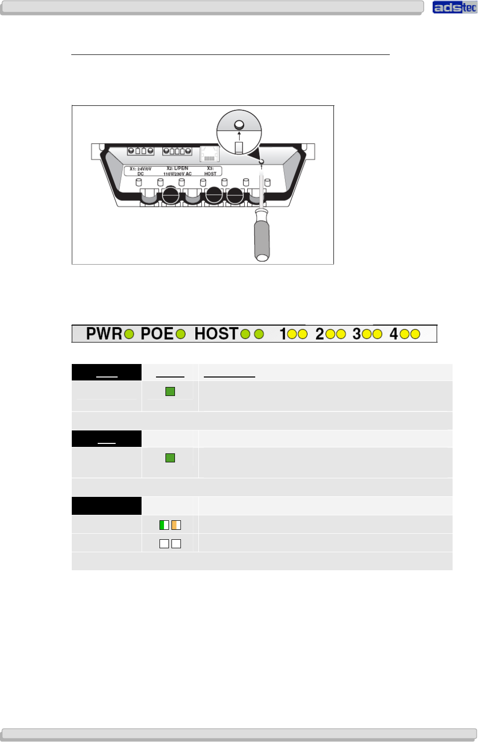
B
EHAVIOUR OR
S
TATUS
I
NDICATORS DURING
R
ESET TO
D
EFAULT
S
ETTINGS
The reset button located under the interface cover may be used to reset the Access Point /
Client to factory default settings at any time and without regard to the current device
configuration.
To reset device to default settings, press reset button and switch on the device. Keep reset
button pressed for approx. 20 seconds. Button may be released as soon as left HOST
indicator LED turns green. The following overview assumes that no cable is connected to
HOST / PoE. Please refer to the overview to monitor the reset to factory defaults.
PWR S
TATUS
D
ESCRIPTION
L+ Device is connected to power supply via POWER and
ready for use.
POE
L+ Device is connected to power supply via BACKUP and
ready for use.
HOST
LINK
/
ACT LED
S FLASH CONTINUOUSLY
LINK
/
ACT LED
S EXTINGUISHED
User Manual
User ManualUser Manual
User Manual Access Point /Client V 3.0.3
Access Point /Client V 3.0.3 Access Point /Client V 3.0.3
Access Point /Client V 3.0.3
© ads-tec GmbH • Raiffeisenstr.14 • 70771 Leinfelden-Echterdingen
27
2727
27
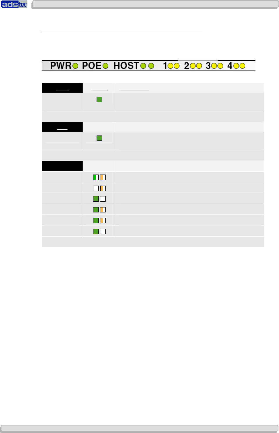
B
EHAVIOUR OF
S
TATUS
I
NDICATORS DURING
F
IRMWARE
U
PDATE
The web interface can be used to perform firmware updates. Once initiated, the actual
update may take several minutes to complete. Please refer to the following overview to
monitor the firmware update sequence.
PWR S
TATUS
D
ESCRIPTION
L+ Device is connected to power supply via POWER and
ready for use.
POE
L+ Device is connected to power supply via BACKUP and
ready for use.
HOST
LINK
/
ACT LED
S FLASH QUICKLY
LINK
/
ACT LINK
EXTINGUISHED
/
A
CT FLASHES
LINK
/
ACT
LINK
LIT UP
/
ACT
EXTINGUISHED
LINK
/
ACT
LINK
LIT UP
/
ACT
FLASHES SLOWLY
LINK
/
ACT
LINK
LIT UP
/
ACT
FLASHES QUICKLY
LINK
/
ACT
LINK
LIT UP
/
ACT
EXTINGUISHED
T
HE WEB INTERFACE MAY SUBSEQUENTLY BE STARTED BY SELECTING
“T
RY TO
R
ECONNECT
”
User Manual
User ManualUser Manual
User Manual Access Point /Client
Access Point /Client Access Point /Client
Access Point /Client V 3.0.3
V 3.0.3 V 3.0.3
V 3.0.3
28
2828
28
© ads-tec GmbH • Raiffeisenstr.14 • 70771 Leinfelden-Echterdingen
I
II
I
NTERFACE
NTERFACE NTERFACE
NTERFACE
O
OO
O
VERVIEW
VERVIEWVERVIEW
VERVIEW
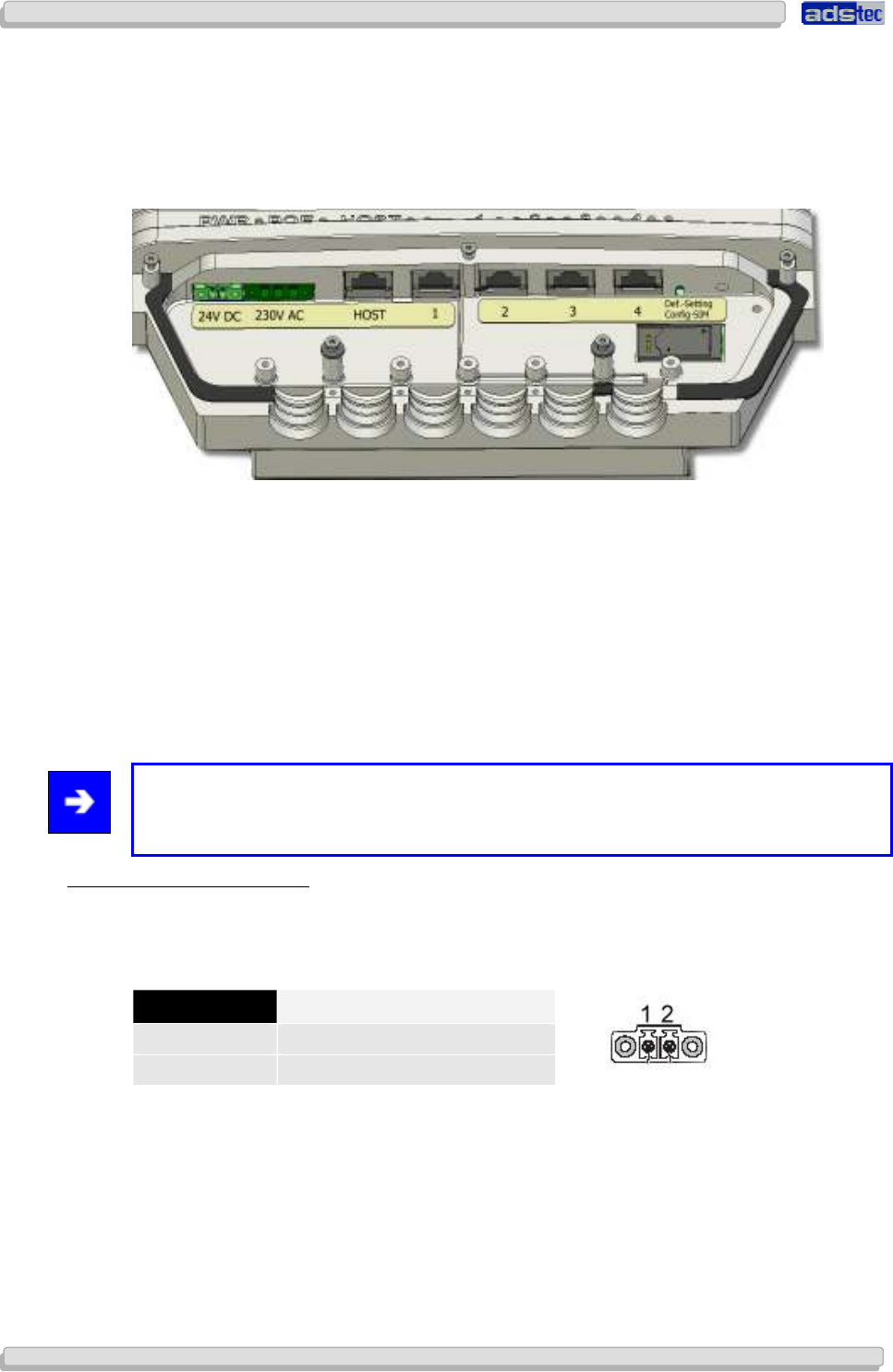
The following figure shows the available device interfaces. The exact interfaces may differ
depending on the device variant.
The device is equipped with the following interfaces:
1. Power 24V DC power supply (two-pole COMBICON plug)
2. Power 230V AC power supply (three-pole COMBICON plug)
3. HOST RJ45 (PoE) or Optical connector
4. SWITCH 4x RJ45 connector (optional feature for Access Client)
5. Default reset button
6. SIM card reader
Note:
Input voltages may be connected redundantly (i.e. Power 24V DC, Power 230V AC and
PoE via HOST).
5.1.2
5.1.25.1.2
5.1.2 Power Supply
Power Supply Power Supply
Power Supply 24V DC
24V DC24V DC
24V DC
A bushing terminal with threaded connector is used to establish the power supply connection
(diagram shows bushing inside device).
PIN NUMBER SIGNAL NAME
1 24V DC
2 0V DC
PIN 1: = L+ 24V DC power supply
PIN 2: = GND Ground
User Manual
User ManualUser Manual
User Manual Access Point /Client V 3.0.3
Access Point /Client V 3.0.3 Access Point /Client V 3.0.3
Access Point /Client V 3.0.3
© ads-tec GmbH • Raiffeisenstr.14 • 70771 Leinfelden-Echterdingen
29
2929
29
5.1.3
5.1.35.1.3
5.1.3 Power Supply
Power Supply Power Supply
Power Supply 110/230 VAC
110/230 VAC110/230 VAC
110/230 VAC
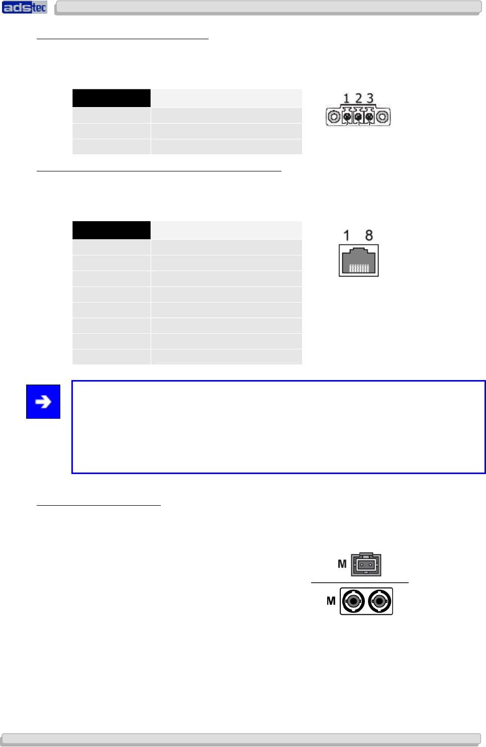
A bushing terminal with threaded connector is used to establish the power supply
connection (diagram shows bushing inside device).
PIN NUMBER SIGNAL NAME
1
110/230 V AC
2
PE
3
0 V DC
5.1.4
5.1.45.1.4
5.1.4 Power Supply
Power Supply Power Supply
Power Supply PoE / HOST (IEEE 802.AF)
PoE / HOST (IEEE 802.AF)PoE / HOST (IEEE 802.AF)
PoE / HOST (IEEE 802.AF)
Wire pairs 4/5 (positive pole) and 7/8 (negative pole) are used for power over Ethernet
functionality.
PIN NUMBER SIGNAL NAME
1
TX +
2
TX -
3
RX +
4
PoE/G
5
PoE/G
6
RX -
7
PoE/-48V
8
PoE/-48V
Note:
Transmission of 48V DC power supply is designed for a maximum feeding distance of 100
meters (approx. 330 ft.) in accordance with Ethernet specification requirements. The
connected devices may draw 350 mA of power; maximum supply power is 15.4 Watts.
For PoE power supply to be possible, all network hubs and switches need to be PoE-
compatible.
5.1.5
5.1.55.1.5
5.1.5 Fibre Optic
Fibre Optic Fibre Optic
Fibre Optic Ethernet
EthernetEthernet
Ethernet
The optical connection requires an MTRJ fibre optic connector.
Multimode cable, MTRJ connector to Duplex connector 62.5/125µm.
User Manual
User ManualUser Manual
User Manual Access Point /Client
Access Point /Client Access Point /Client
Access Point /Client V 3.0.3
V 3.0.3 V 3.0.3
V 3.0.3
30
3030
30
© ads-tec GmbH • Raiffeisenstr.14 • 70771 Leinfelden-Echterdingen
5.1.6
5.1.65.1.6
5.1.6 S
SS
SIM
IMIM
IM Card Reader
Card Reader Card Reader
Card Reader,
, ,
, ISO 7816
ISO 7816ISO 7816
ISO 7816-
--
-compatible
compatiblecompatible
compatible
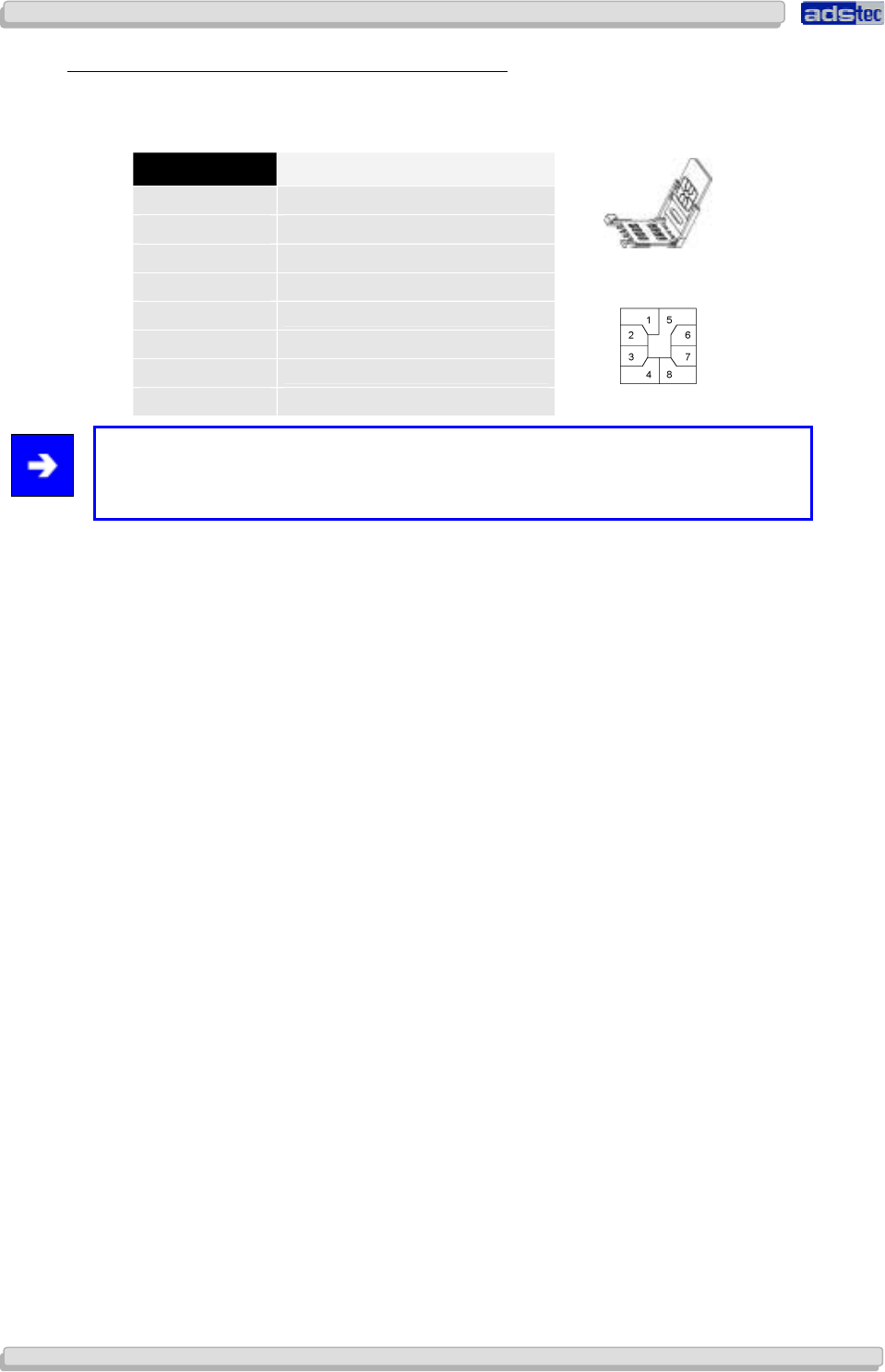
The SIM card reader is used for saving configuration data.
PIN NUMBER SIGNAL NAME
1
VCC 5 Volt
2
RESET
3
CLOCK
4
n/c
5
GND
6
n/c
7
I/O
8
n/c
Note:
Interface and supply connectors are located on the bottom of the device. Secure
plugs against slipping out.
User Manual
User ManualUser Manual
User Manual Access Point /Client V 3.0.3
Access Point /Client V 3.0.3 Access Point /Client V 3.0.3
Access Point /Client V 3.0.3
© ads-tec GmbH • Raiffeisenstr.14 • 70771 Leinfelden-Echterdingen
31
3131
31
6
66
6 I
II
I
N
NN
NITIAL
ITIAL ITIAL
ITIAL
D
DD
D
EVICE
EVICE EVICE
EVICE
O
OO
O
PERATIONS
PERATIONSPERATIONS
PERATIONS
6.1 F
IRST
-
TIME
C
ONFIGURATION
Warning:
First-time configuration of the device can only be performed via RJ45/optical interface
marked HOST.
AN RJ45 PATCH CABLE IS REQUIRED FOR FIRST-TIME CONFIGURATION.
Connection of 24V DC / PoE voltage supply
The device may be powered by a 24V DC (two-pole plug) voltage supply source or via a
PoE connection. The required COMBICON plugs are supplied with the device.
Connect the device to the appropriate voltage supply source.
Connection of RJ45 / optical network cable
For first-time device operations, a connection between the device and a PC via an
RJ45/optical network cable is strictly required.
Connect the device to a PC:
Device HOST connector <-> PC LAN adapter
6.2 M
ANUAL
N
ETWORK
A
DAPTER
C
ONFIGURATION VIA
RJ45/
OPTICAL
C
ABLE
Note:
The following directions and screenshots refers to settings in Windows XP
®
. The paths and
properties described herein may differ for other operating systems.
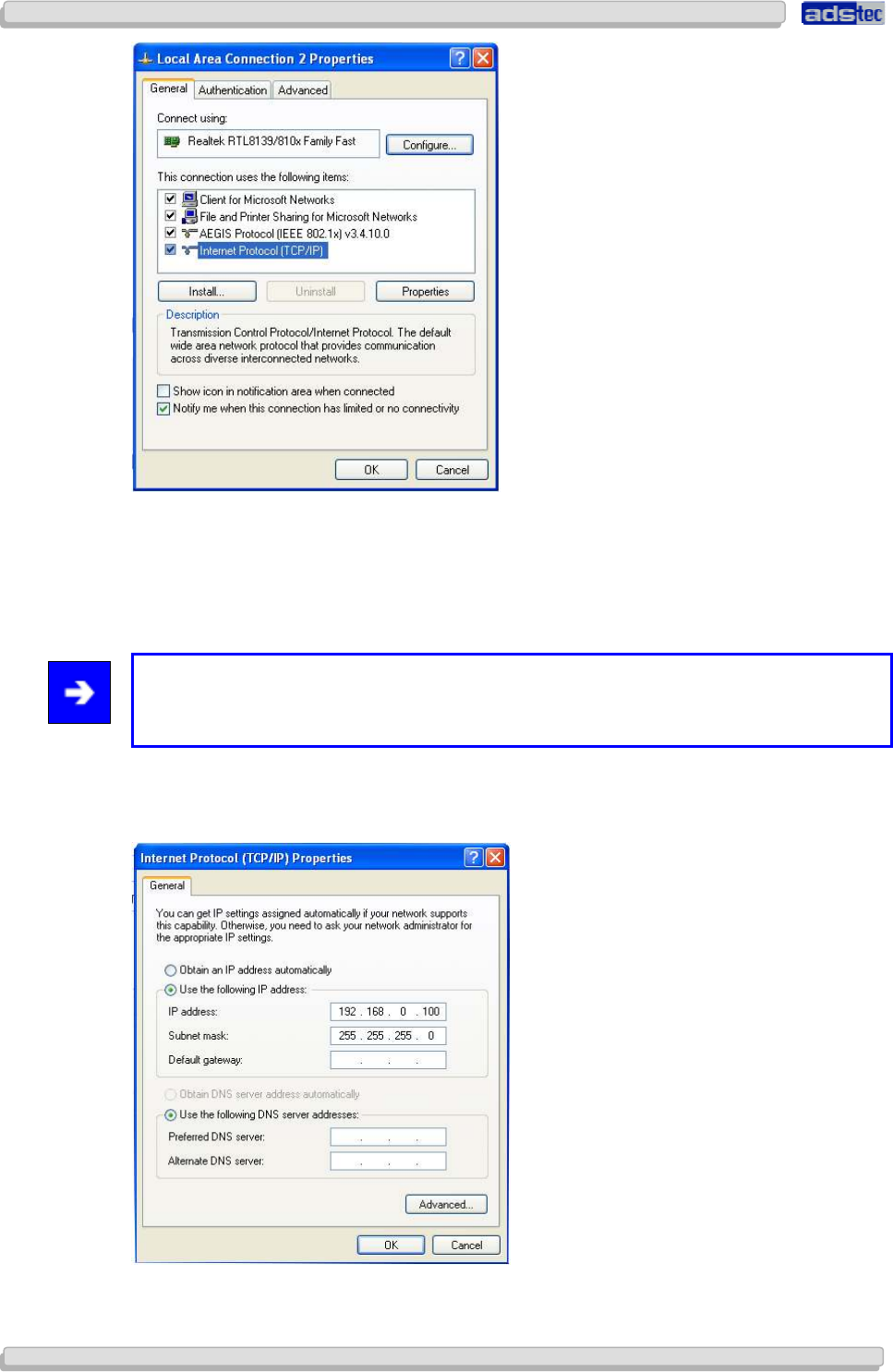
Open the Properties tab for the network adapter in use. The path is as follows:
Start> Control Panel > Network Connections > Local Area Connection >
Properties.
Select Internet Protocol (TCP/IP) in the dialogue window that comes up and then click
Properties.
User Manual
User ManualUser Manual
User Manual Access Point /Client
Access Point /Client Access Point /Client
Access Point /Client V 3.0.3
V 3.0.3 V 3.0.3
V 3.0.3
32
3232
32
© ads-tec GmbH • Raiffeisenstr.14 • 70771 Leinfelden-Echterdingen
Click to select: Use the following IP address
Access to the device is only possible when the following parameters are set as the static IP
address or if the computer is located in the same subnet space:
IP
ADDRESS
:
192.168.0.100
Note:
The last set of digits must be a number between 1 and 253. In the example, “100” was
chosen.
Once the IP address has been entered, the subnet mask address must be set as well.
Clicking directly into the field Subnet mask will automatically set the correct subnet mask.
S
UBNET MASK
:
255.255.255.0
You may now close the dialogue windows by clicking “OK”.
User Manual
User ManualUser Manual
User Manual Access Point /Client V 3.0.3
Access Point /Client V 3.0.3 Access Point /Client V 3.0.3
Access Point /Client V 3.0.3
© ads-tec GmbH • Raiffeisenstr.14 • 70771 Leinfelden-Echterdingen
33
3333
33
6.3 WLAN
N
ETWORK
A
DAPTER
C
ONFIGURATION
Follow the directions as given above to configure the WLAN network adapter. However, the
IP address parameter needs to be set to a different value. Enter the following IP address in
the Internet Protocol properties dialogue:
IP
A
DDRESS
:
192.168.0.200
Note:
The last set of digits must be a number between 1 and 253. In the example, “200” was
chosen.
C
ALLING UP THE
D
EVICE
W
EB
I
NTERFACE
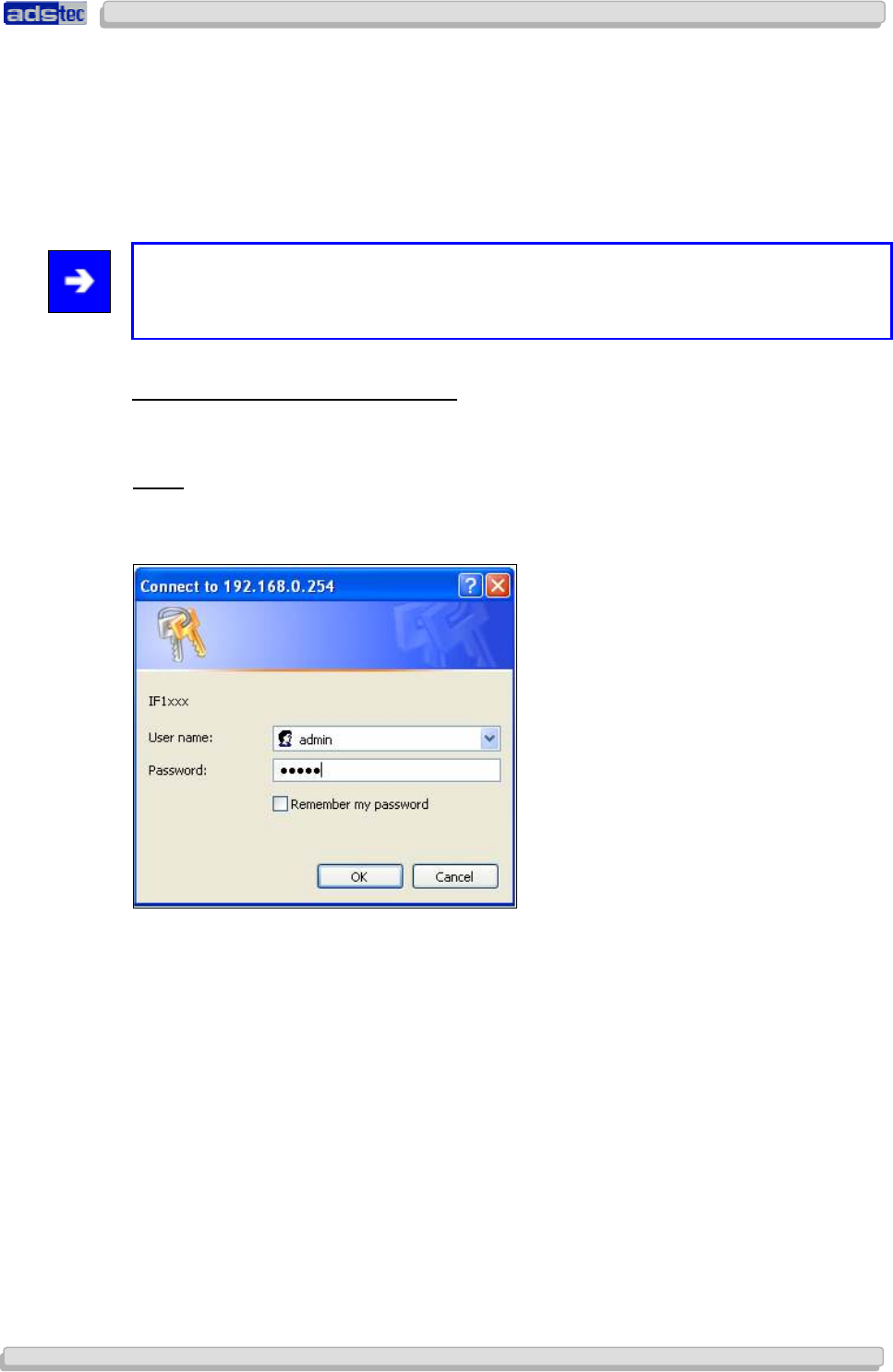
To access and open the device web interface, start up your web browser. In the browser’s
address bar, enter the following IP address then confirm with “Enter”.
Login
Once the IP address has been entered and confirmed, the login prompt appears. Enter the
default values in the login panel.
Factory default settings are as follows:
U
SER NAME
: admin
P
ASSWORD
: admin
Confirm your input by clicking OK. The device web interface will subsequently appear.
User Manual
User ManualUser Manual
User Manual Access Point /Client
Access Point /Client Access Point /Client
Access Point /Client V 3.0.3
V 3.0.3 V 3.0.3
V 3.0.3
34
3434
34
© ads-tec GmbH • Raiffeisenstr.14 • 70771 Leinfelden-Echterdingen
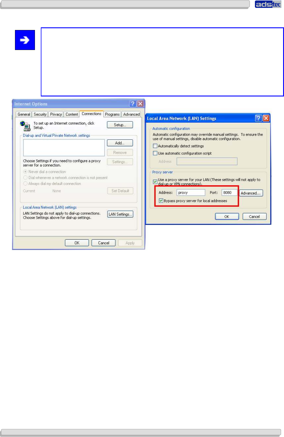
Note:
If the login prompt does not appear ensure that the device has been connected via a
RJ45/optical cable. Otherwise, connect the device to a PC (Device HOST connector <> PC
LAN adapter).
If there still is no connection to the firewall login prompt check your proxy and local
firewall settings. It is often the case that local subnet addresses (e.g. 192.168.x.x) are
diverted to a proxy server. In this case it is possible to select the “Bypass proxy server for
local addresses” check box and enter the address spaces in question.
User Manual
User ManualUser Manual
User Manual Access Point /Client V 3.0.3
Access Point /Client V 3.0.3 Access Point /Client V 3.0.3
Access Point /Client V 3.0.3
© ads-tec GmbH • Raiffeisenstr.14 • 70771 Leinfelden-Echterdingen
35
3535
35
6.4 F
IRST
-
TIME
C
ONFIGURATION VIA
W
EB
I
NTERFACE
A
CTIVATING
WLAN
M
ODULE
(
S
)
Go to the following web interface page to activate the WLAN module(s):
B
ASIC
S
ETTINGS
>I
NTERFACES
>WLAN
1/2
Depending on the actual device variant, the unit is equipped with one or two WLAN
modules. Activate the desired WLAN module by checking the Activate Interface check box
in the web interface.
WLAN
M
ODULE
C
ONFIGURATION
:
Operating Mode:
The device operating mode needs to be set. Available options are Access Point and Client.
Network Name (SSID)
The SSID is the visible name of the WLAN. The default setting is ads.
You may choose to set the SSID to any alphanumeric value.
WLAN Mode:
Select your preferred WLAN mode:
Warning:
Only use a WLAN mode that is supported by all of your WLAN devices.
Regulatory Authority:
Select your current location.
Note:
The FCC version of the device does not offer the “Regulatory Authority” option.
Warning:
Setting the applicable regulatory authority as well as the respective antenna amplification
is solely the responsibility of the operator.
Channel:
Default setting: Auto
The device automatically determines the best channel setting.
Saving Configuration Settings:
All changes need to be saved to be activated. To save the modified settings, select the
menu item:
Configuration> Save.
Click Save in the subsequent dialogue window. The current configuration will now be
transmitted and saved.
User Manual
User ManualUser Manual
User Manual Access Point /Client
Access Point /Client Access Point /Client
Access Point /Client V 3.0.3
V 3.0.3 V 3.0.3
V 3.0.3
36
3636
36
© ads-tec GmbH • Raiffeisenstr.14 • 70771 Leinfelden-Echterdingen
6.5 W
IRELESS
N
ETWORK
C
ONFIGURATION
Once again open up the properties panel located at:
Start> Control Panel > Network Connections
Right-click on your current wireless connection and then select Properties. Now click on
the tab Wireless Networks. In the Preferred Networks section on that tab, click the
button Add. Enter the following parameters:
Network Name SSID: (self-chosen non-default network name), or the default value ads
Network Authentication: Open
Data Encryption: Disabled
You may now close the dialogue windows by clicking “OK”.
6.6 E
STABLISHING A
W
IRELESS
N
ETWORK
C
ONNECTION
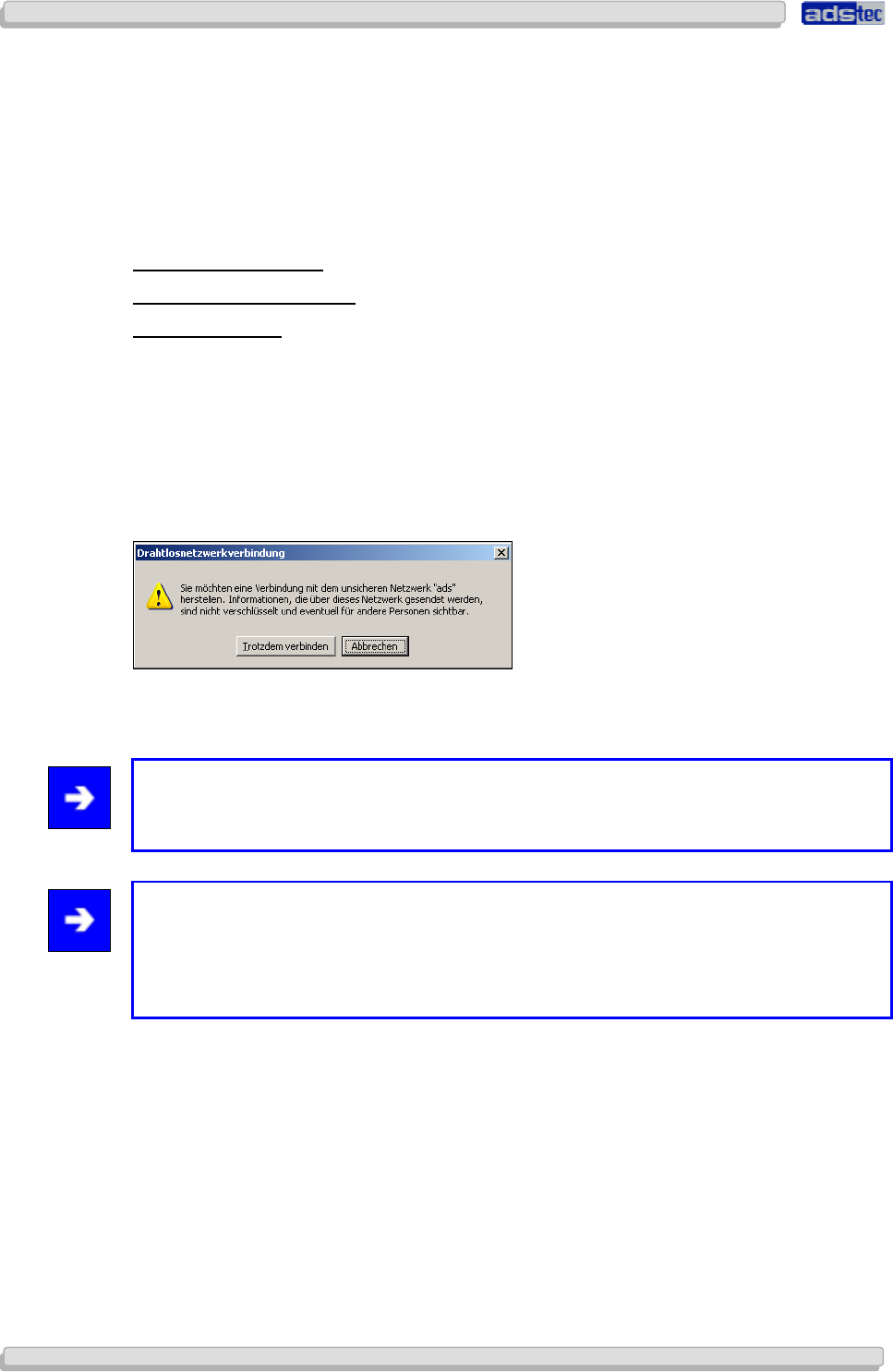
In order to establish a wireless connection to the device, click on the WLAN icon you’re your
taskbar. A window listing all available networks will appear. Select the wireless network with
the appropriate SSID (self-chosen or default name ads) and click on Connect. The
following warning dialogue will pop up:
In order to connect to the WLAN you need to select “Connect Anyway”. The computer will
now establish a wireless connection to the device.
Note:
In case you are unable to establish a connection to the device, we recommend resetting
the device to factory default settings.
Note:
The current configuration does not use date encryption to secure wireless communication
channels. We recommend using data encryption. Please refer to the chapter
Configuration>Security>WLAN 1/2 for details on how to activate and configure
encryption.
User Manual
User ManualUser Manual
User Manual Access Point /Client V 3.0.3
Access Point /Client V 3.0.3 Access Point /Client V 3.0.3
Access Point /Client V 3.0.3
© ads-tec GmbH • Raiffeisenstr.14 • 70771 Leinfelden-Echterdingen
37
3737
37
7
77
7 A
AA
A
CCE
CCECCE
CCESS
SS SS
SS
P
PP
P
OINT
OINT OINT
OINT
S
SS
S
ETUP
ETUPETUP
ETUP
W
WW
W
IZARD
IZARDIZARD
IZARD
7.1 F
IRST
-
TIME
C
ONFIGURATION USING THE
S
ETUP
W
IZARD
To perform a basic configuration, select the following under Quick Links:
S
TART
S
ETUP
W
IZARD
7.1.1
7.1.17.1.1
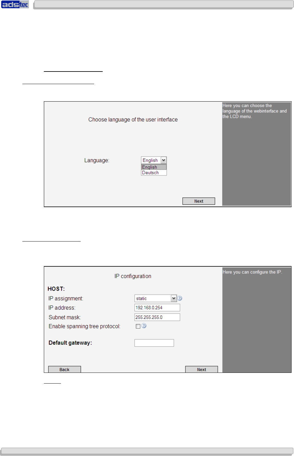
7.1.1 Language Selection
Language SelectionLanguage Selection
Language Selection
Via the dialogue window it is possible to set the user interface language.
The selected language is used for the overall web interface.
Confirm your choice by clicking: Next
7.1.2
7.1.27.1.2
7.1.2 IP
IPIP
IP C
C C
Configuration
onfigurationonfiguration
onfiguration
The IP configuration settings define the behaviour of the HOST interface. The IP address
may be assigned statically or automatically.
Static:
If this option is selected, it is possible to set a static IP address. Static IP allocation requires
entering the IP address and subnet mask.
Default values are:
IP address: 192.168.0.254
Subnet mask: 255.255.255.0
User Manual
User ManualUser Manual
User Manual Access Point /Client
Access Point /Client Access Point /Client
Access Point /Client V 3.0.3
V 3.0.3 V 3.0.3
V 3.0.3
38
3838
38
© ads-tec GmbH • Raiffeisenstr.14 • 70771 Leinfelden-Echterdingen
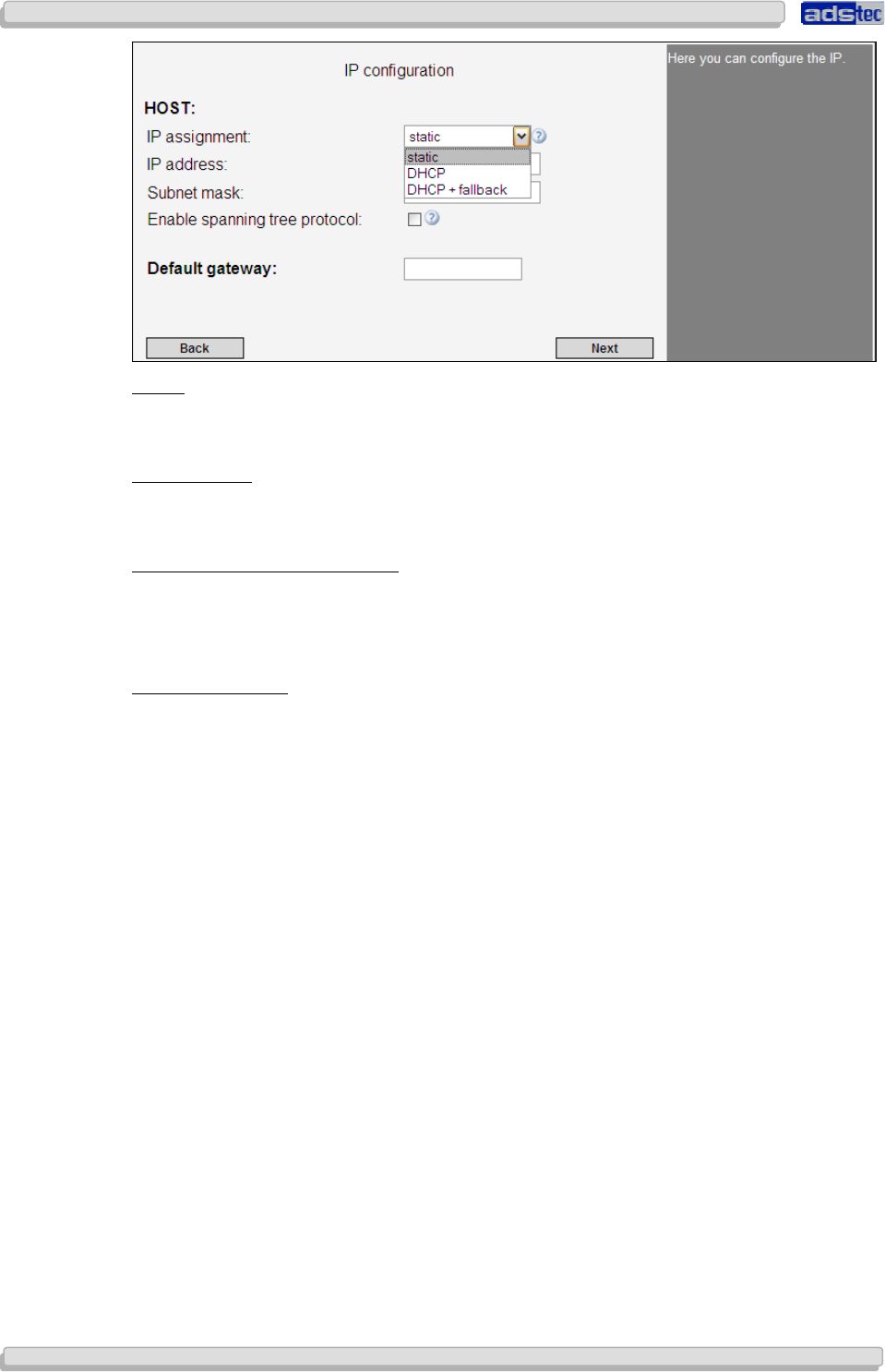
DHCP:
The DHCP function requests an IP address from a DHCP server and subsequently allocates
IP addresses automatically.
DHCP fallback:
This option allows for automatic IP address allocation. Should there be an error with the
automatic allocation, the IP allocation automatically switches to the static setting.
Activate Spanning Tree Protocol:
The Spanning Tree Protocol (STP) is used to avoid redundant network loops, especially in
switched environments.
If this option is activated, it is possible to establish redundant network connections.
Standard Gateway:
The IP address entered as standard gateway address is used to establish a connection to an
address located outside of the device’s own IP subnet (i.e. outside 192.168.0.254 in the
example given previously). However, the standard gateway itself needs to be inside the
device’s IP subnet address space. In case IP allocation was set to DHCP, the standard
gateway address may be dynamically overwritten, providing the DHCP server supports this.
The standard gateway may, for instance, be required in order to reach an NTP time server
or to relay the IP address to WLAN clients in case the device serves as a DHCP server itself.
Now click Next
User Manual
User ManualUser Manual
User Manual Access Point /Client V 3.0.3
Access Point /Client V 3.0.3 Access Point /Client V 3.0.3
Access Point /Client V 3.0.3
© ads-tec GmbH • Raiffeisenstr.14 • 70771 Leinfelden-Echterdingen
39
3939
39
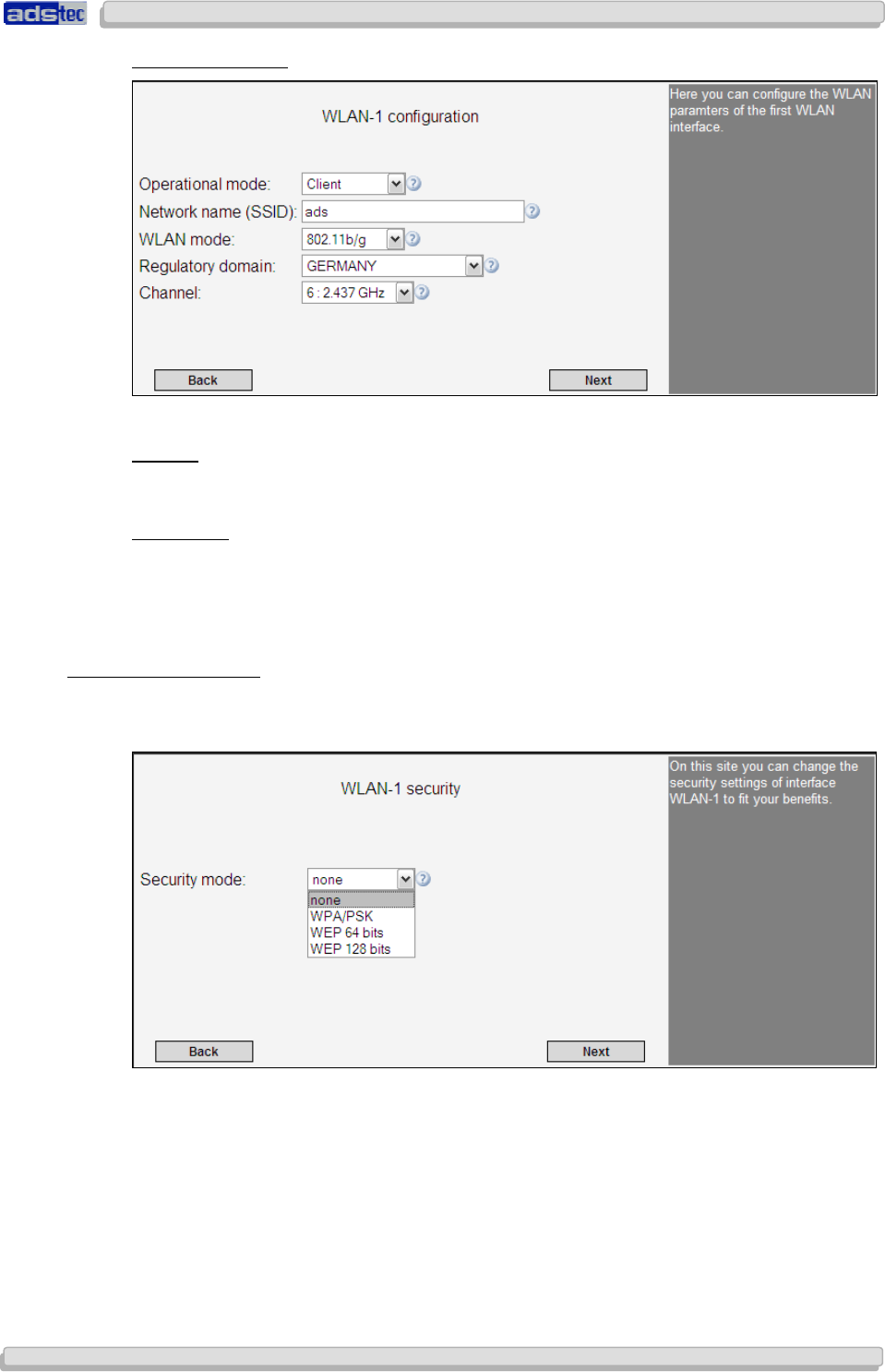
7.1.3
7.1.37.1.3
7.1.3 WLAN
WLANWLAN
WLAN-
--
-1
1 1
1 C
CC
Configuration
onfigurationonfiguration
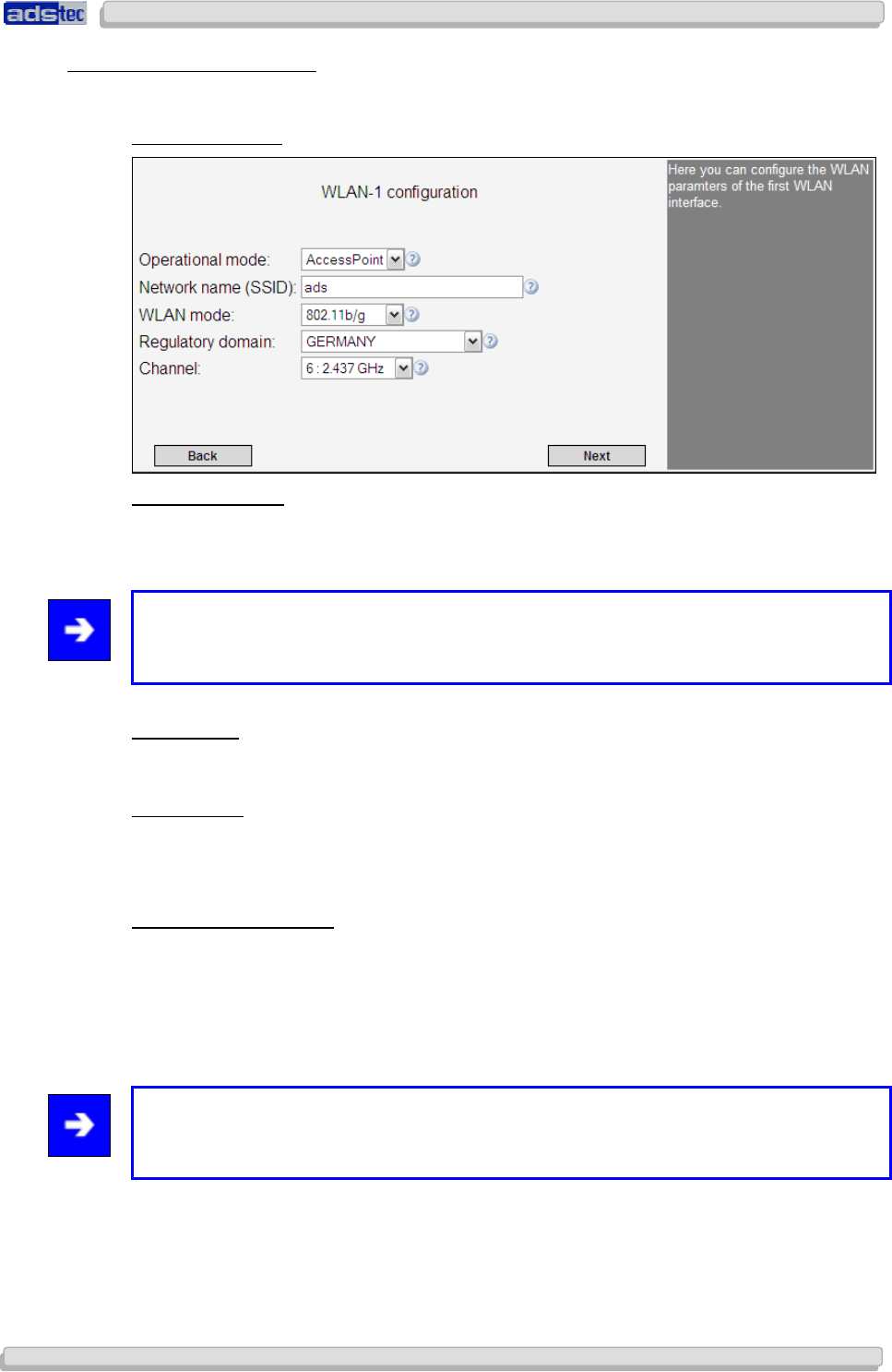
onfiguration
The next dialogue is used to configure all relevant basic settings for WLAN operation.
Access Point Mode
O
PERATING
M
ODE
:
Use this option to switch between the two operating modes Access Point and Access
Client.
Note:
The RAC (Access Client) does not offer an operating mode option. It is permanently set to
Access Client mode.
Access Point:
In Access Point mode, the device serves as a network gateway for other wireless devices
(clients).
Access Client:
In Access Client mode, the device tries to establish a connection to an Access Point in order
to establish a connection with the network.
N
ETWORK NAME
(SSID):
Use this option to assign a name to your wireless network. We recommend not using any
names that allow conclusions with regard to your company, department or the type of data
transmitted. Any clients that want to establish a connection with this Access Point need to
know this network name.
Default setting is: ads
Note:
The SSID may consist of a maximum of 32 characters. Valid characters are: a-z, A-Z, 0-9,
valid special characters: . _ - ? $ @ ! { } [ ] ( ) + # ; , < > | : * ~ % $ & / =
User Manual
User ManualUser Manual
User Manual Access Point /Client
Access Point /Client Access Point /Client
Access Point /Client V 3.0.3
V 3.0.3 V 3.0.3
V 3.0.3
40
4040
40
© ads-tec GmbH • Raiffeisenstr.14 • 70771 Leinfelden-Echterdingen
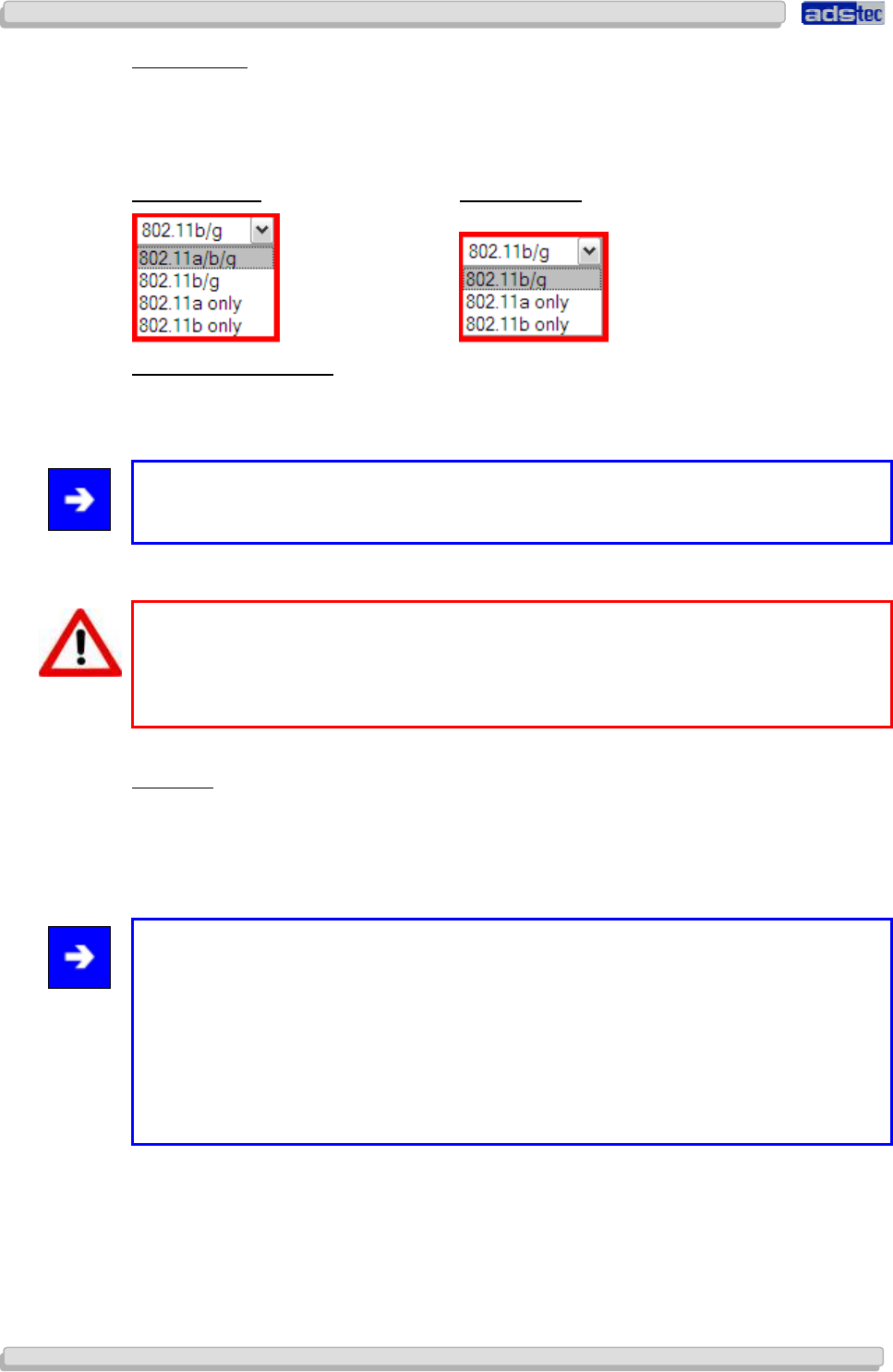
WLAN
M
ODE
:
Use this option to select the wireless standard to employ. All clients that are meant to
communicate with this Access Point need to be compatible with the selected wireless
standard.
The following WLAN modes can be chosen:
A
CCESS
C
LIENT
: A
CCESS
P
OINT
:
R
EGULATORY
A
UTHORITY
Under this option, select the country in which the device is operated. This country setting
ensures that applicable national regulations are observed in each country.
Note:
The FCC version of the device does not offer the “Regulatory Authority” option.
Warning:
A wrong country setting may lead to illegal radio frequency settings which are punishable
by law.
The operator is solely responsible for ensuring the correct country setting.
C
HANNEL
:
Depending on operator settings, the device can choose a transmission channel automatically
or use a manually selected channel. We recommend using automatic channel selection
(option Auto). In the event of channel interferences, the device can only switch to an
interference-free channel if automatic channel selection is activated.
Note:
5GHz channels cannot be selected statically; instead, they are chosen randomly from the
available free channels. (This constraint is required for device approval by law.)
In case other WLANs are operated in parallel, manual radio field planning is essential in
order to avoid limitations to wireless communications. In this case, the transmission
channel should be chosen manually.
Please note that DFS needs to be switched off in order for channels to be selected
manually.
User Manual
User ManualUser Manual
User Manual Access Point /Client V 3.0.3
Access Point /Client V 3.0.3 Access Point /Client V 3.0.3
Access Point /Client V 3.0.3
© ads-tec GmbH • Raiffeisenstr.14 • 70771 Leinfelden-Echterdingen
41
4141
41
Access Client Mode
Client Mode differs with regards to the following additional configuration settings:
Outdoor:
This option must be activated if the unit is operated outdoors. Activating this function will
turn off all channels that may legally not be used outdoors.
Disable DFS:
Activating this option will turn off DFS on the 5GHz band. All channels that can be used
without DFS may then be selected manually. This option must not be activated if the unit is
operated outdoors.
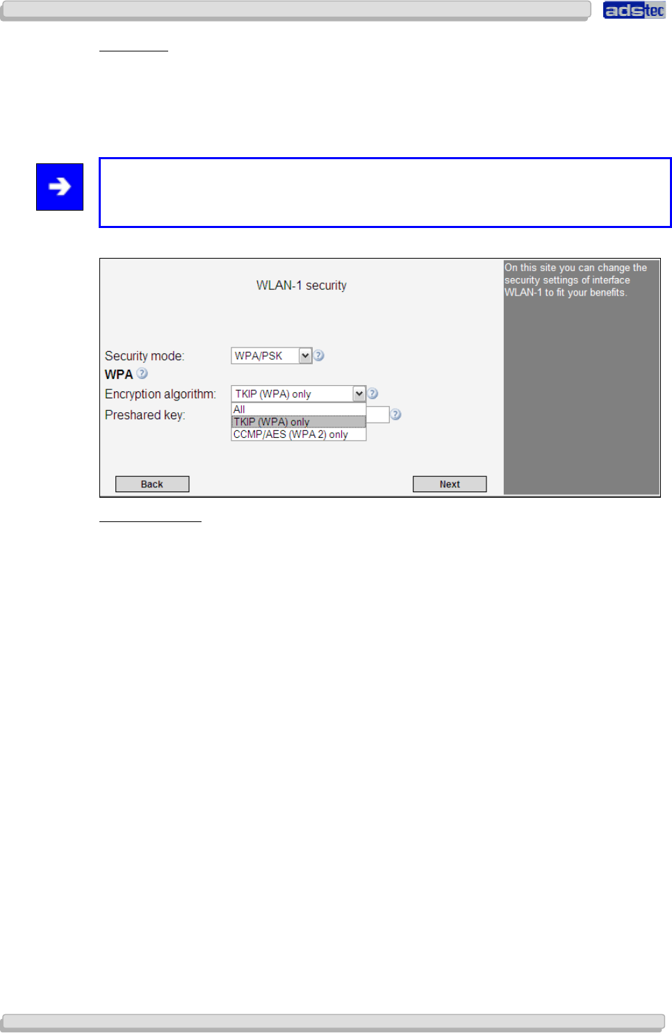
7.1.4
7.1.47.1.4
7.1.4 WLAN
WLANWLAN
WLAN-
--
-1
1 1
1 Security
SecuritySecurity
Security
Use the WLAN security option to configure the applicable security standards for your WLAN.
The following modes can be selected:
User Manual
User ManualUser Manual
User Manual Access Point /Client
Access Point /Client Access Point /Client
Access Point /Client V 3.0.3
V 3.0.3 V 3.0.3
V 3.0.3
42
4242
42
© ads-tec GmbH • Raiffeisenstr.14 • 70771 Leinfelden-Echterdingen
WPA/PSK
WPA/PSK mode secures communications by requiring a keyword and employing a particular
data encryption method. The keyword (Pre-Shared Key) may contain a minimum of 8 and a
maximum of 63 characters. Rather than actual words, we recommend using alphanumeric
combinations of letters and numbers in order to ensure optimal security.
Note:
Pre-Shared Key specifications: 8-63 characters; valid are all characters between ASCII
code 32 and 116
Data Encryption:
You may choose to either use all data encryption methods or select a particular method.
Please note that WPA 2 encryption requires that all network access points and clients
support the WPA 2 standard.
User Manual
User ManualUser Manual
User Manual Access Point /Client V 3.0.3
Access Point /Client V 3.0.3 Access Point /Client V 3.0.3
Access Point /Client V 3.0.3
© ads-tec GmbH • Raiffeisenstr.14 • 70771 Leinfelden-Echterdingen
43
4343
43
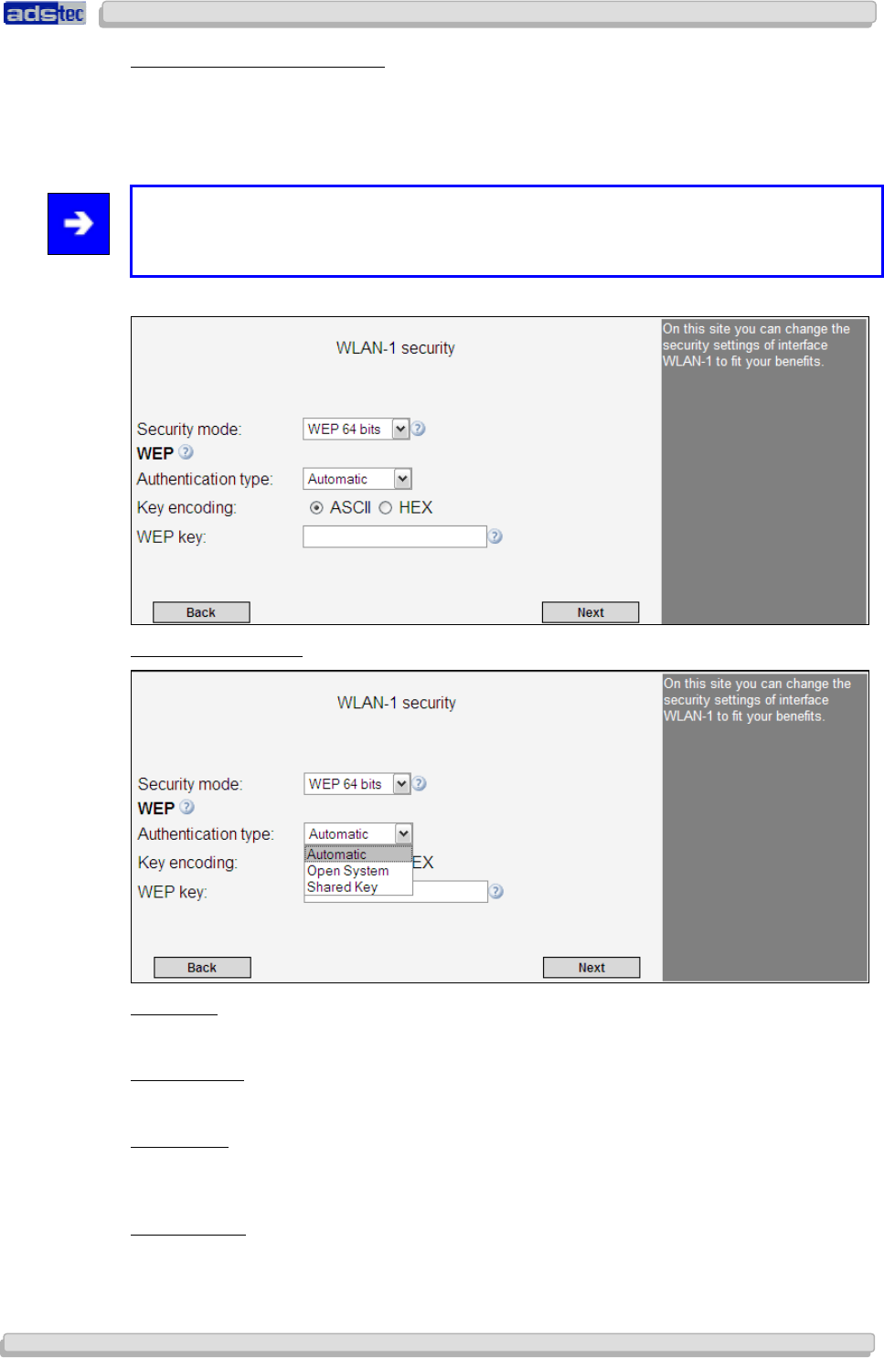
WEP
64
B
ITS
/
WEP
128
B
ITS
Like WPA, the WEP 64 Bits / 128 Bits mode requires a keyword for securing wireless
communications. The chief difference is that in WPA mode, this key changes dynamically
during a connection, whereas it remains static in WEP mode.
Note:
We recommend using the WPA encryption standard because WEP-based data encryption
has to be regarded as insufficient by today’s standards.
Authentication Mode:
Automatic:
In Automatic mode, the authentication mode is selected automatically.
Open System:
Open System authentication is the default authentication setting.
Shared Key:
Shared Key authentication employs an enhanced handshake mechanism during login, which
does, however, not provide any additional security.
Key Encoding:
You may select ASCII or HEX key encoding. ASCII is a 7-bit encoding scheme, HEX is a 16-
bit scheme.
User Manual
User ManualUser Manual
User Manual Access Point /Client
Access Point /Client Access Point /Client
Access Point /Client V 3.0.3
V 3.0.3 V 3.0.3
V 3.0.3
44
4444
44
© ads-tec GmbH • Raiffeisenstr.14 • 70771 Leinfelden-Echterdingen
WEP Key:
WEP key length is limited to 5 characters in ASCII encoding mode. Using HEX encoding,
keys with a length of up to 10 characters may be chosen. Rather than actual words, we
recommend using alphanumeric combinations of letters and numbers in order to ensure
optimal security.
Confirm by clicking Next
7.1.5
7.1.57.1.5
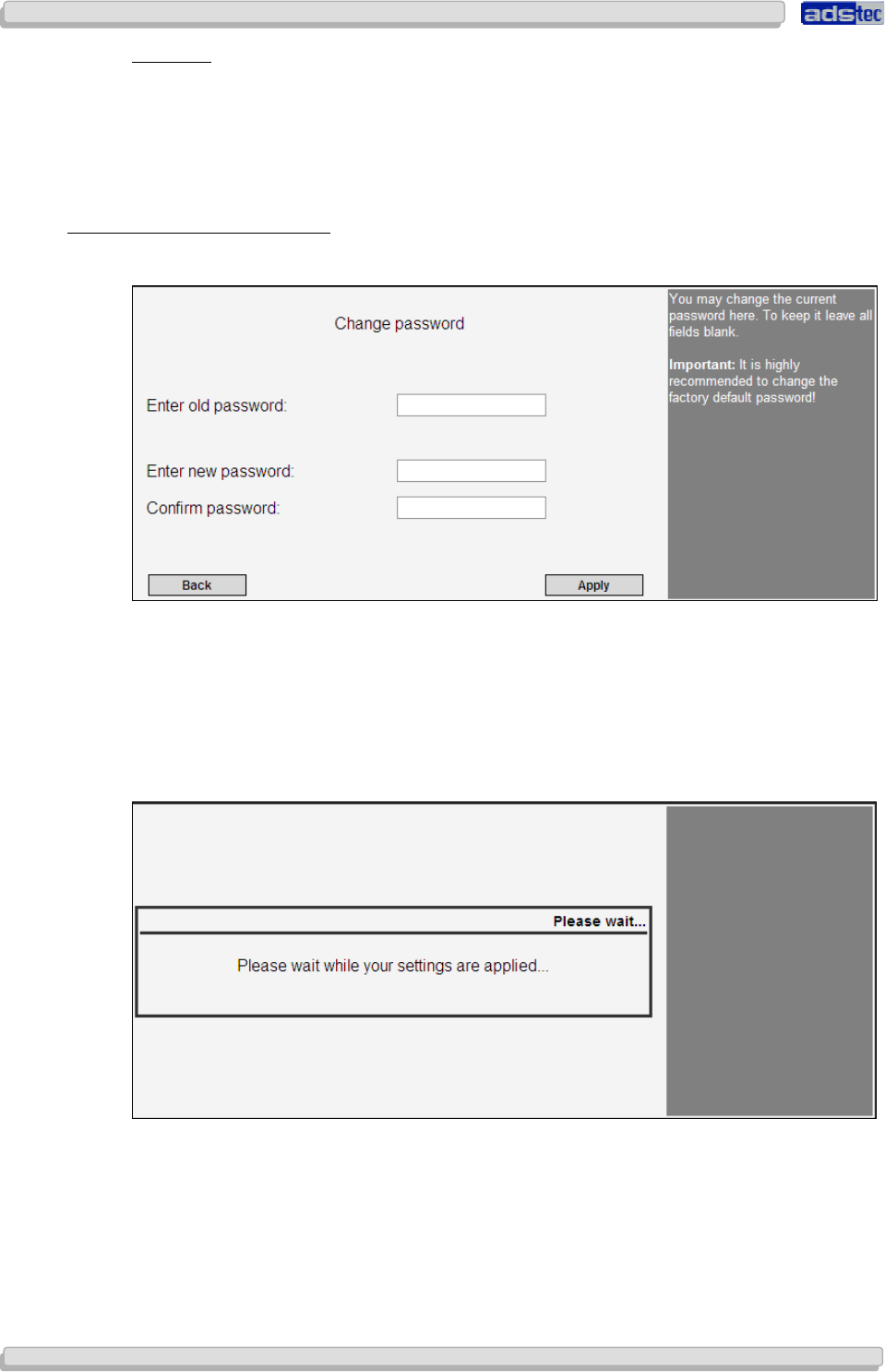
7.1.5 Changing the Password
Changing the PasswordChanging the Password
Changing the Password
Use this dialogue to change the device password.
In order to change the password, enter the current password in the field Old Password.
Choose a new password and confirm it by entering it in the next two fields (New Password
and Password Confirmation). Leave all fields empty in case you have not set a password.
Subsequently click on the Apply button.
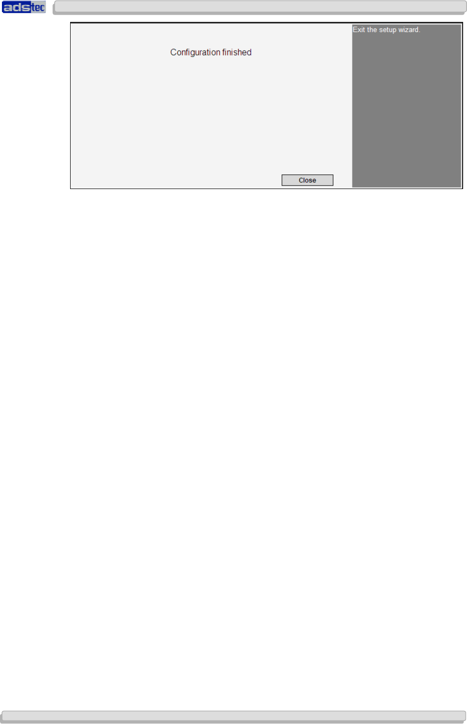
Your settings are being saved…
The Setup Wizard is now complete.
User Manual
User ManualUser Manual
User Manual Access Point /Client V 3.0.3
Access Point /Client V 3.0.3 Access Point /Client V 3.0.3
Access Point /Client V 3.0.3
© ads-tec GmbH • Raiffeisenstr.14 • 70771 Leinfelden-Echterdingen
45
4545
45
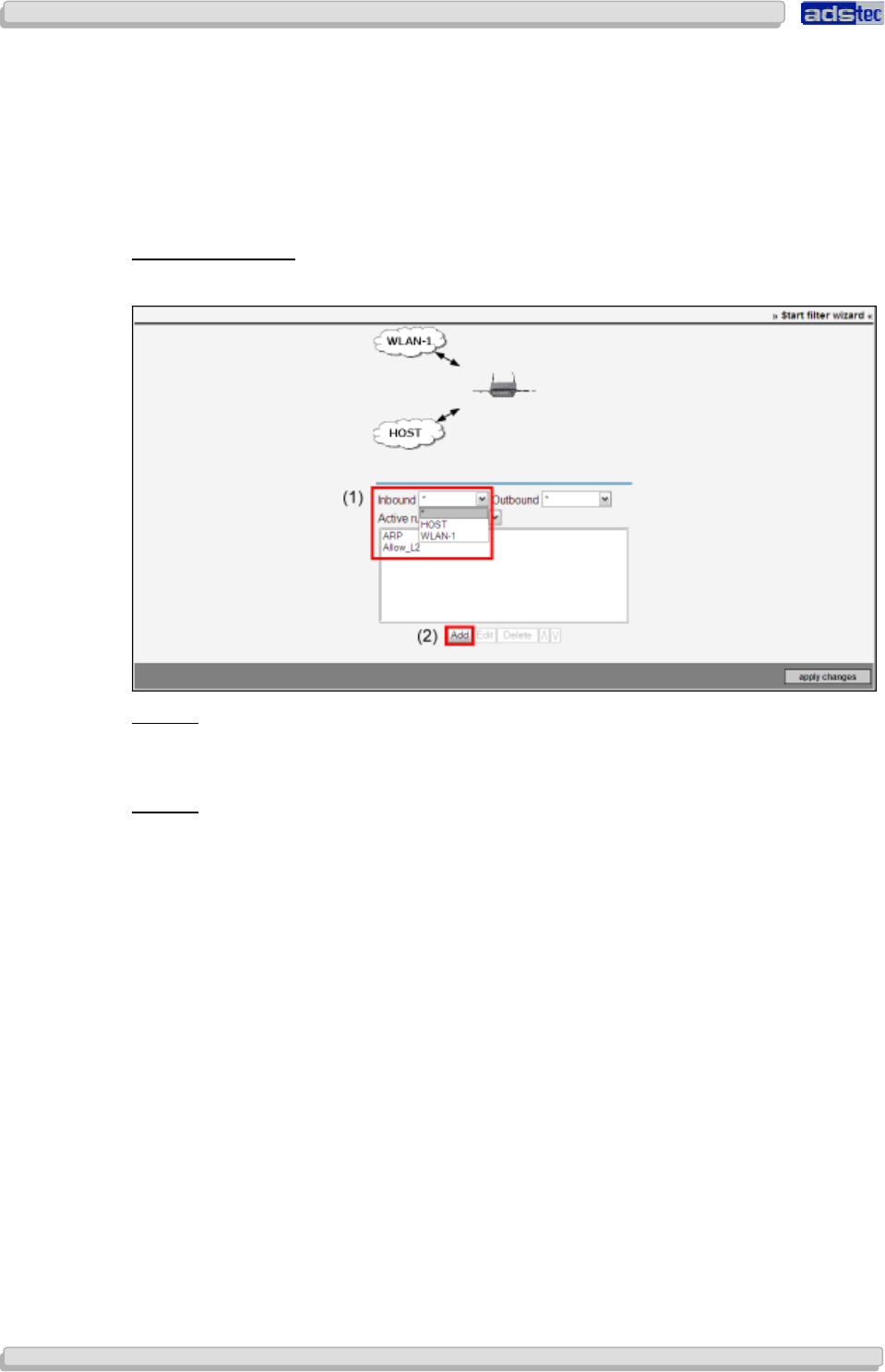
User Manual
User ManualUser Manual
User Manual Access Point /Client
Access Point /Client Access Point /Client
Access Point /Client V 3.0.3
V 3.0.3 V 3.0.3
V 3.0.3
46
4646
46
© ads-tec GmbH • Raiffeisenstr.14 • 70771 Leinfelden-Echterdingen
7.2 C
ONFIGURATION USING THE
F
ILTER
W
IZARD
Filters may be configured using the Filter Wizard.
The Filter Wizard is accessible via the Configuration > Security > Filter Wizards path.
The initial Filter Wizard page allows adding new rule sets as well as editing existing sets.
A
DDING A
R
ULE SET
:
In order to add a rule set, you first need to select a Layer (1).
Layer 2:
This layer corresponds to MAC filtering. Selecting this option enables filtering MAC address-
based filtering.
Layer 3:
This layer allows IP address-based filtering.
Click Add (2) to create/add a new or pre-configured rule set for the selected layer.
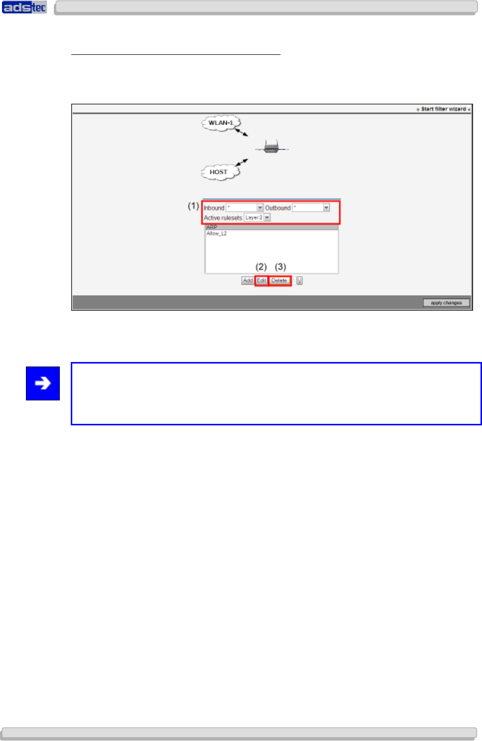
User Manual
User ManualUser Manual
User Manual Access Point /Client V 3.0.3
Access Point /Client V 3.0.3 Access Point /Client V 3.0.3
Access Point /Client V 3.0.3
© ads-tec GmbH • Raiffeisenstr.14 • 70771 Leinfelden-Echterdingen
47
4747
47
C
HANGING AND
S
EARCHING EXISTING
R
ULE
S
ETS
If rules have already been generated or uploaded, they appear in the rule summary. When
searching for a rule, the filter criteria for the rule set being sought can be restricted to
Inbound, Outbound and Activated rule sets (1) via the respective drop-down fields.
The Edit (2) button allows for subsequent modifications of the selected rule set.
By way of the Delete (3) option, it is possible to remove the selected rule set.
Note:
The arrows in the diagram shown above the filter configuration adapt to the selected
configuration of the incoming and outgoing data flows, so the settings will also be visually
comprehensible.
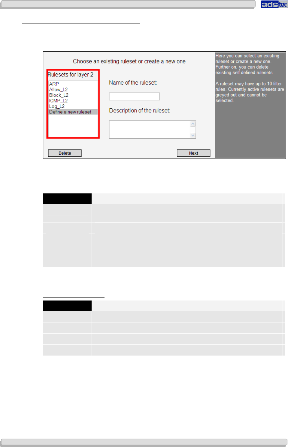
User Manual
User ManualUser Manual
User Manual Access Point /Client
Access Point /Client Access Point /Client
Access Point /Client V 3.0.3
V 3.0.3 V 3.0.3
V 3.0.3
48
4848
48
© ads-tec GmbH • Raiffeisenstr.14 • 70771 Leinfelden-Echterdingen
7.2.1
7.2.17.2.1
7.2.1 L
LL
Loading pre
oading preoading pre
oading pre-
--
-configured Rule sets
configured Rule setsconfigured Rule sets
configured Rule sets
Select a pre-configured rule set.
The pre-configured rule sets are displayed on the left of the dialogue window.
By way of example, the following standard rule sets are pre-configured for layers 2 and 3.
L
AYER
2
R
ULE
S
ETS
Name
NameName
Name
Brief Description
Brief DescriptionBrief Description
Brief Description
ARP Address Resolution Protocol allows assignment of network addresses
to hardware addresses
Allow_L2 Allows all data traffic on layer 2
Block_L2 Discards all data packets (i.e. blocks all data traffic) on layer 2
ICMP_L2 Allows all ICMP-based data traffic on layer 2
Log_L2 Maintains an event log and discards all data packets on layer 2
Select the rule set you want to load and confirm by clicking Next,
R
ULE SETS FOR
L
AYER
3
Name
NameName
Name
Brief Description
Brief DescriptionBrief Description
Brief Description
ALLOW_L3 Allows all data traffic on layer 3
BLOCK_L3 Discards all data packets (i.e. blocks all data traffic) on layer 3
ICMP_L3 Allows all ICMP-based data traffic on layer 3
Log_L3 Maintains an event log and discards all data packets on layer 3
Confirm the next message prompt by clicking Close.
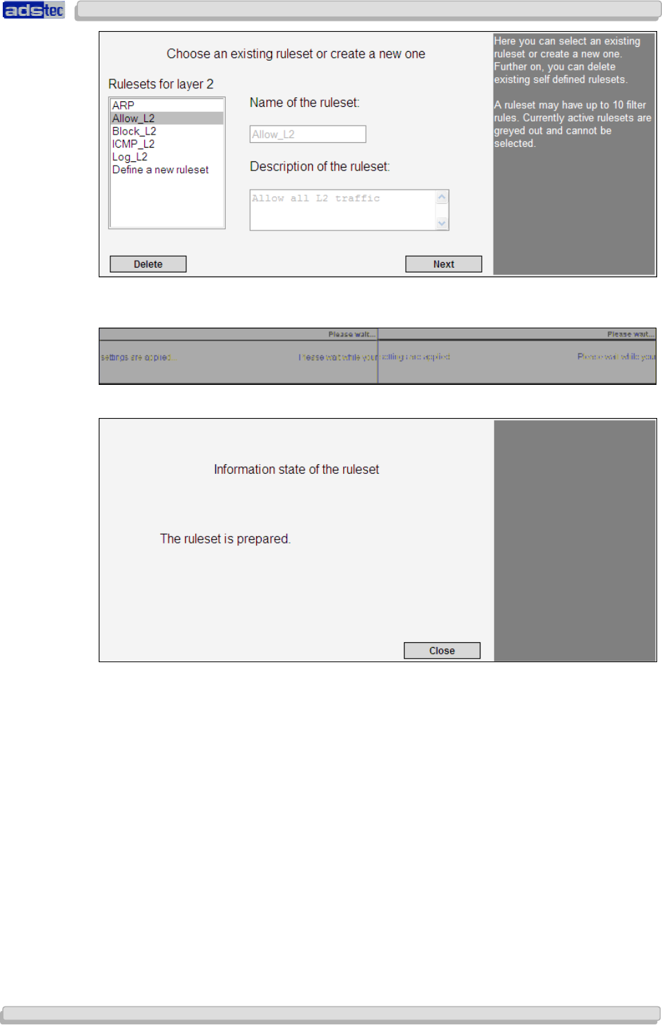
User Manual
User ManualUser Manual
User Manual Access Point /Client V 3.0.3
Access Point /Client V 3.0.3 Access Point /Client V 3.0.3
Access Point /Client V 3.0.3
© ads-tec GmbH • Raiffeisenstr.14 • 70771 Leinfelden-Echterdingen
49
4949
49
Once a rule set has been successfully loaded and activated, it will be shown in the filter
overview page.
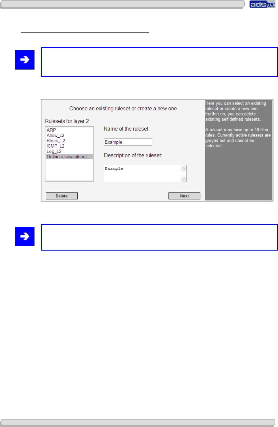
User Manual
User ManualUser Manual
User Manual Access Point /Client
Access Point /Client Access Point /Client
Access Point /Client V 3.0.3
V 3.0.3 V 3.0.3
V 3.0.3
50
5050
50
© ads-tec GmbH • Raiffeisenstr.14 • 70771 Leinfelden-Echterdingen
7.2.2
7.2.27.2.2
7.2.2 Definition of a new Rule set on Layer 2
Definition of a new Rule set on Layer 2Definition of a new Rule set on Layer 2
Definition of a new Rule set on Layer 2
Note:
For configuring rules on layer 3, please refer to the section “Definition of a new Rule
set on Layer 3”.
Select the menu item Definition of a new rule set
Enter a name and a description for the new rule set.
Note:
The rule set name is restricted to 10 characters. It is not possible to use umlauts.
Confirm your input by clicking Next.
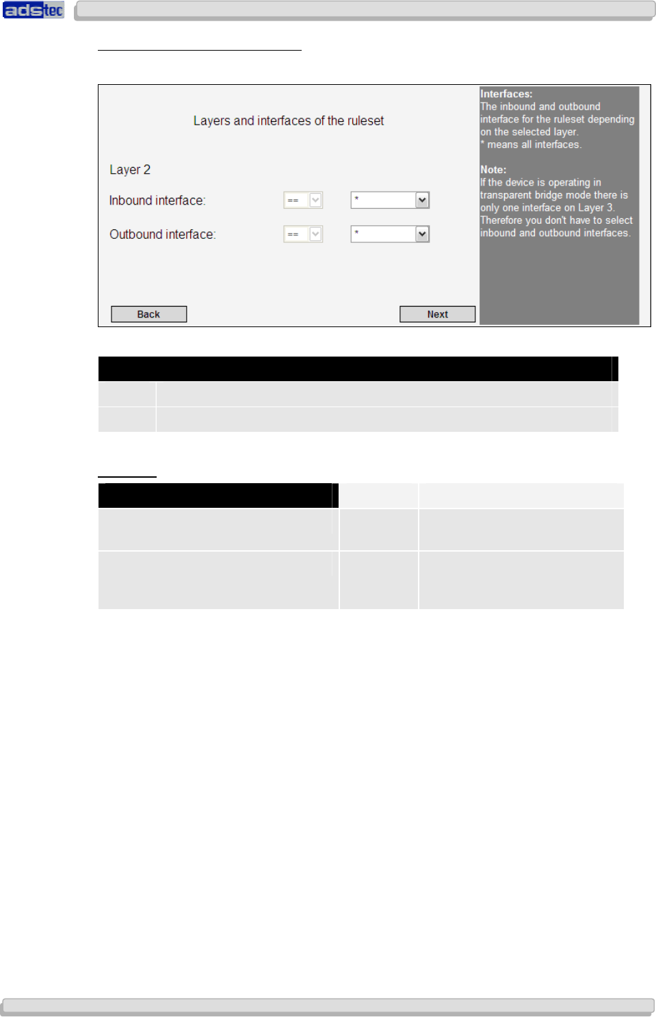
User Manual
User ManualUser Manual
User Manual Access Point /Client V 3.0.3
Access Point /Client V 3.0.3 Access Point /Client V 3.0.3
Access Point /Client V 3.0.3
© ads-tec GmbH • Raiffeisenstr.14 • 70771 Leinfelden-Echterdingen
51
5151
51
R
ULE SET
L
AYERS AND
I
NTERFACES
The following dialogue allows configuration of the type of filtering.
S
YMBOL
D
ESCRIPTION
== Filter will be applied to the selected interface.
!= Filter will be applied to all interfaces except for the selected interface.
E
XAMPLE
:
I
NTERFACE
S
ELECTION
R
ESULT
Incoming interface: HOST == filters all inbound data packets
on HOST
Outgoing interface: WLAN-1 != filters all outgoing data packets
on all ports, except for
WLAN-1
Confirm your input by clicking Next
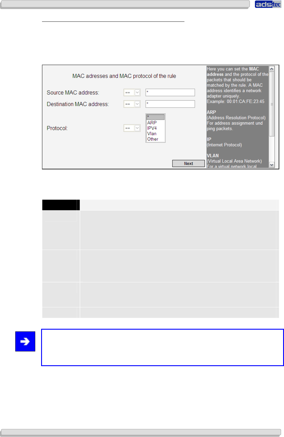
User Manual
User ManualUser Manual
User Manual Access Point /Client
Access Point /Client Access Point /Client
Access Point /Client V 3.0.3
V 3.0.3 V 3.0.3
V 3.0.3
52
5252
52
© ads-tec GmbH • Raiffeisenstr.14 • 70771 Leinfelden-Echterdingen
R
ULE
-R
ELATED
MAC
A
DDRESSES AND
MAC
P
ROTOCOLS
Via the following dialogue window it is possible to define the MAC addresses of the
respective sources and targets.
The Source MAC Address defines the source from which data is received.
The Target MAC Address defines the target to which data is sent.
In case you are using a permanent, static connection between two devices, you may enter
their respective MAC addresses here. Otherwise leave the asterisk symbol unchanged.
P
ROTOCOL
D
ESCRIPTION
ARP The Address Resolution Protocol (ARP) is a network protocol that allows
resolving network addresses to hardware addresses. ARP is not an IP-only
or Ethernet-only protocol, but due to the prevalence of IPv4 and Ethernet,
it is used almost exclusively for resolving IP addresses to Ethernet MAC
addresses.
IPv4 IPv4 (Internet Protocol Version 4, formerly simply IP), is the fourth
iteration of the Internet Protocol (IP). It is the first version of the protocol
to be widely deployed and is one of the essential underlying internet
technologies.
Vlan A Virtual Local Area Network (VLAN) is a virtual local network inside a
physical network. The protocol commonly used in configuring virtual LANs
is IEEE 802.1Q.
Other Allows selection of a different protocol.
Note:
If you do not wish to select a particular protocol, choose the default menu item (i.e. the
asterisk item). Once a specific protocol has been selected you may adjust protocol-specific
configuration settings.
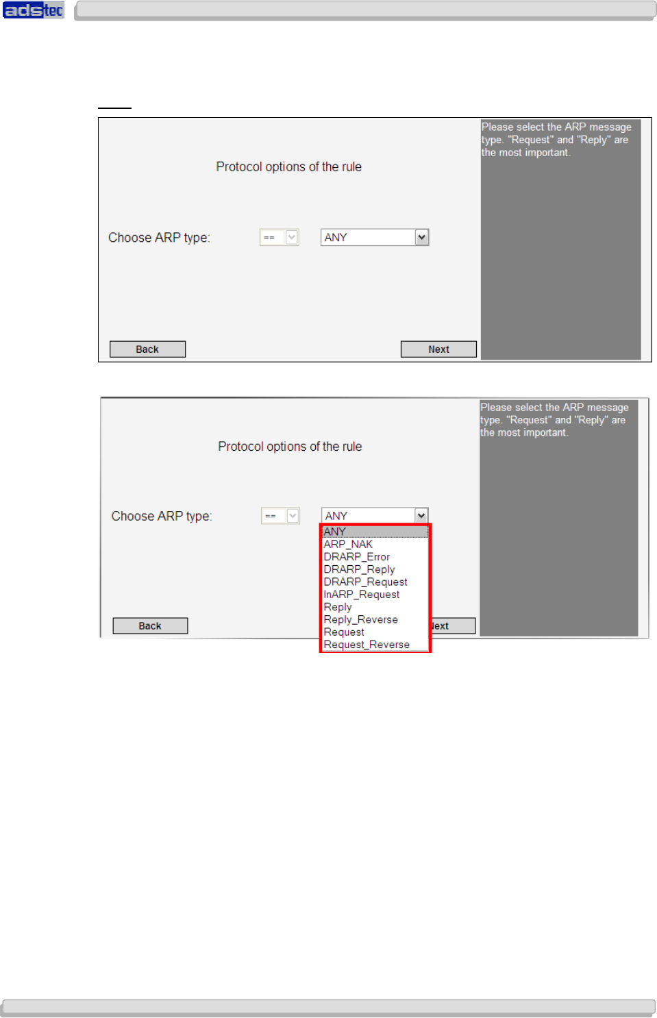
User Manual
User ManualUser Manual
User Manual Access Point /Client V 3.0.3
Access Point /Client V 3.0.3 Access Point /Client V 3.0.3
Access Point /Client V 3.0.3
© ads-tec GmbH • Raiffeisenstr.14 • 70771 Leinfelden-Echterdingen
53
5353
53
The following configuration options are available once a specific protocol has been selected.
In case you have not selected a particular protocol, simply confirm this screen by clicking
Next and follow the steps described in the Rule Name and Behaviour section.
ARP:
ARP offers the following options:
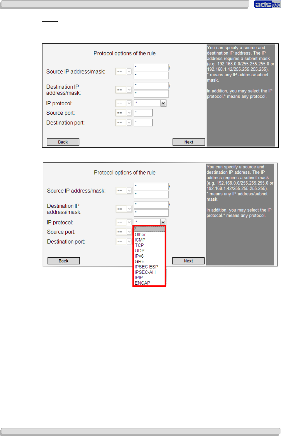
User Manual
User ManualUser Manual
User Manual Access Point /Client
Access Point /Client Access Point /Client
Access Point /Client V 3.0.3
V 3.0.3 V 3.0.3
V 3.0.3
54
5454
54
© ads-tec GmbH • Raiffeisenstr.14 • 70771 Leinfelden-Echterdingen
IP
V
4:
IPv4 requires setting a source and a target IP address. Furthermore, the respective subnet
mask for the source and target IP address is required.
The Internet Protocol offers the following options:

User Manual
User ManualUser Manual
User Manual Access Point /Client V 3.0.3
Access Point /Client V 3.0.3 Access Point /Client V 3.0.3
Access Point /Client V 3.0.3
© ads-tec GmbH • Raiffeisenstr.14 • 70771 Leinfelden-Echterdingen
55
5555
55
VLAN:
The VLAN protocol requires setting a VLAN ID, a VLAN priority and a Wrapped Protocol to be
used.
The following options are available for the Wrapped Protocol:
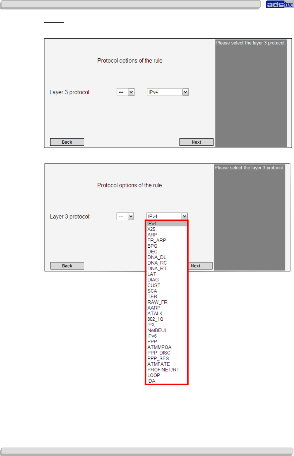
User Manual
User ManualUser Manual
User Manual Access Point /Client
Access Point /Client Access Point /Client
Access Point /Client V 3.0.3
V 3.0.3 V 3.0.3
V 3.0.3
56
5656
56
© ads-tec GmbH • Raiffeisenstr.14 • 70771 Leinfelden-Echterdingen
O
THER
:
Use Other to select the Layer 3 protocol.
Other offers the following options:
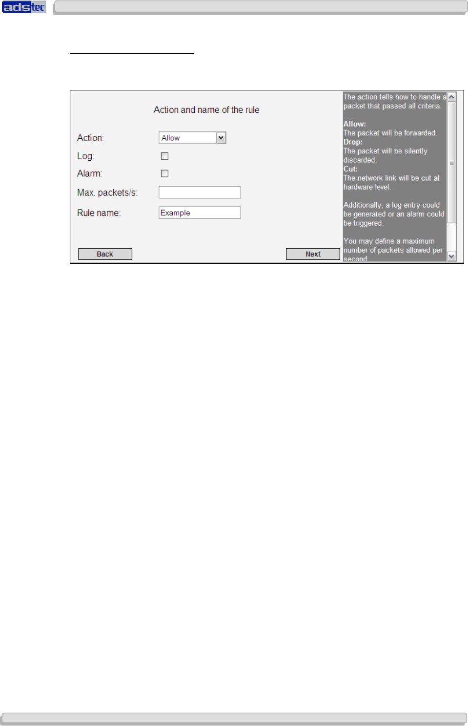
User Manual
User ManualUser Manual
User Manual Access Point /Client V 3.0.3
Access Point /Client V 3.0.3 Access Point /Client V 3.0.3
Access Point /Client V 3.0.3
© ads-tec GmbH • Raiffeisenstr.14 • 70771 Leinfelden-Echterdingen
57
5757
57
R
ULE
N
AME AND
B
EHAVIOUR
:
The next dialogue will allow you to define the rule behaviour in more detail. Use the menu
item Rule Action to determine how the device should handle packets.
Rule Action:
Available options are Allow and Block.
Log:
This function will log any violations of this rule in the event log.
Max. Packets/sec:
Use this option to specify a maximum packet rate per second; this rate will then serve as a
upper limit against Denial-of-Service attacks.
Rule Name:
Choose a name for this rule; the name should be unique, i.e. differ from the name of any
other rule set.
Confirm by clicking Next.
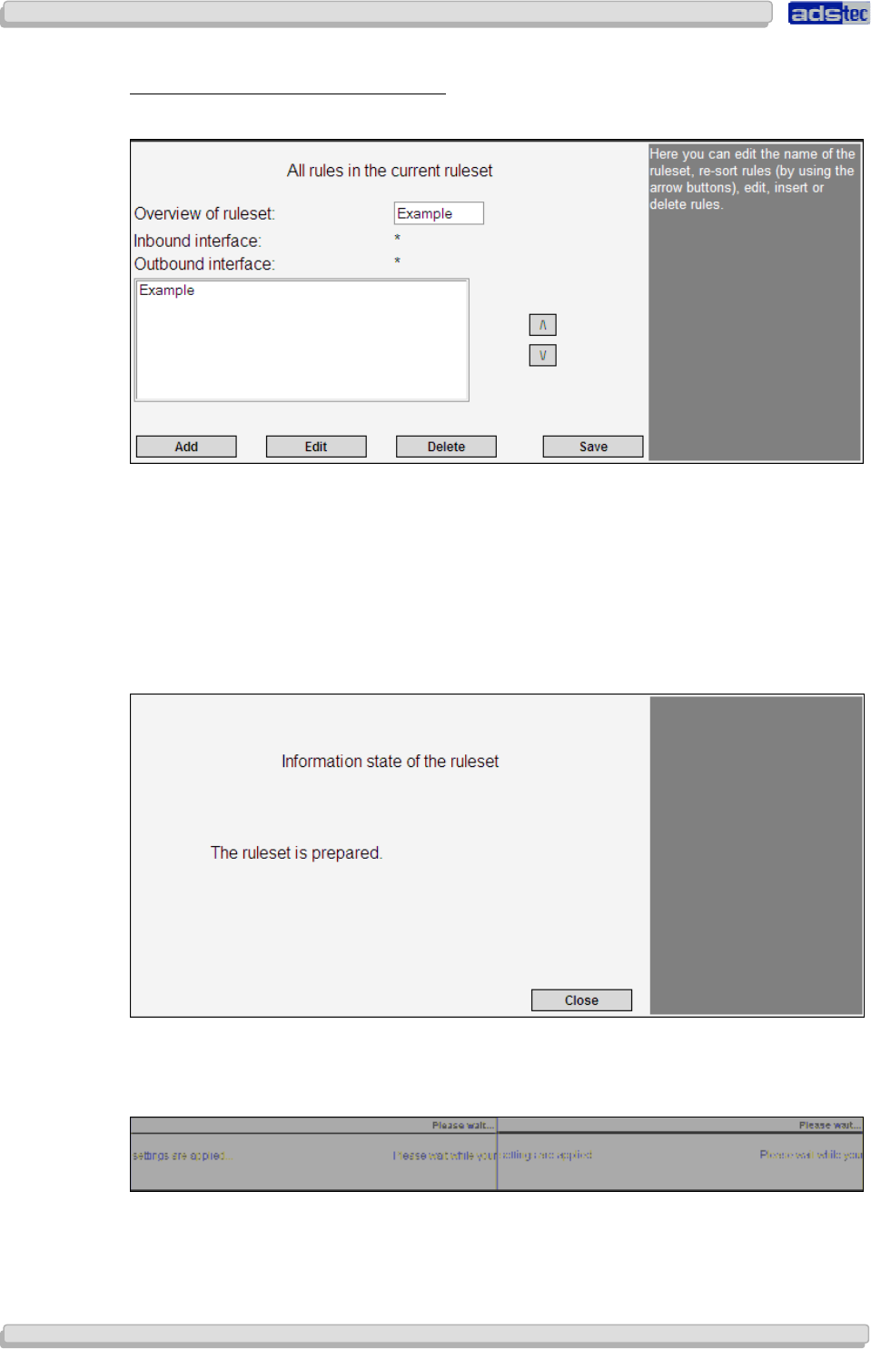
User Manual
User ManualUser Manual
User Manual Access Point /Client
Access Point /Client Access Point /Client
Access Point /Client V 3.0.3
V 3.0.3 V 3.0.3
V 3.0.3
58
5858
58
© ads-tec GmbH • Raiffeisenstr.14 • 70771 Leinfelden-Echterdingen
O
VERVIEW OF ALL
R
ULES IN A
R
ULE
S
ET
:
The next dialogue window will provide an overview of all existing rule sets.
Use the Add button for starting the rule configuration process anew to define another rule.
The Edit button allows subsequent modifications to previously defined rules.
Choose Delete to delete the selected rule.
Use the arrow buttons to modify the position of a rule within the current rule set.
Confirm by clicking Next.
Confirm the next message prompt by clicking Close.
Once the rule set was successfully activated, it will be displayed in the filter overview
window.
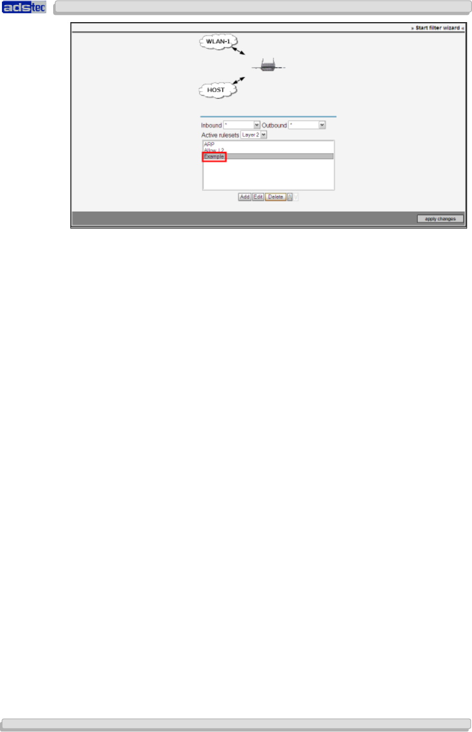
User Manual
User ManualUser Manual
User Manual Access Point /Client V 3.0.3
Access Point /Client V 3.0.3 Access Point /Client V 3.0.3
Access Point /Client V 3.0.3
© ads-tec GmbH • Raiffeisenstr.14 • 70771 Leinfelden-Echterdingen
59
5959
59
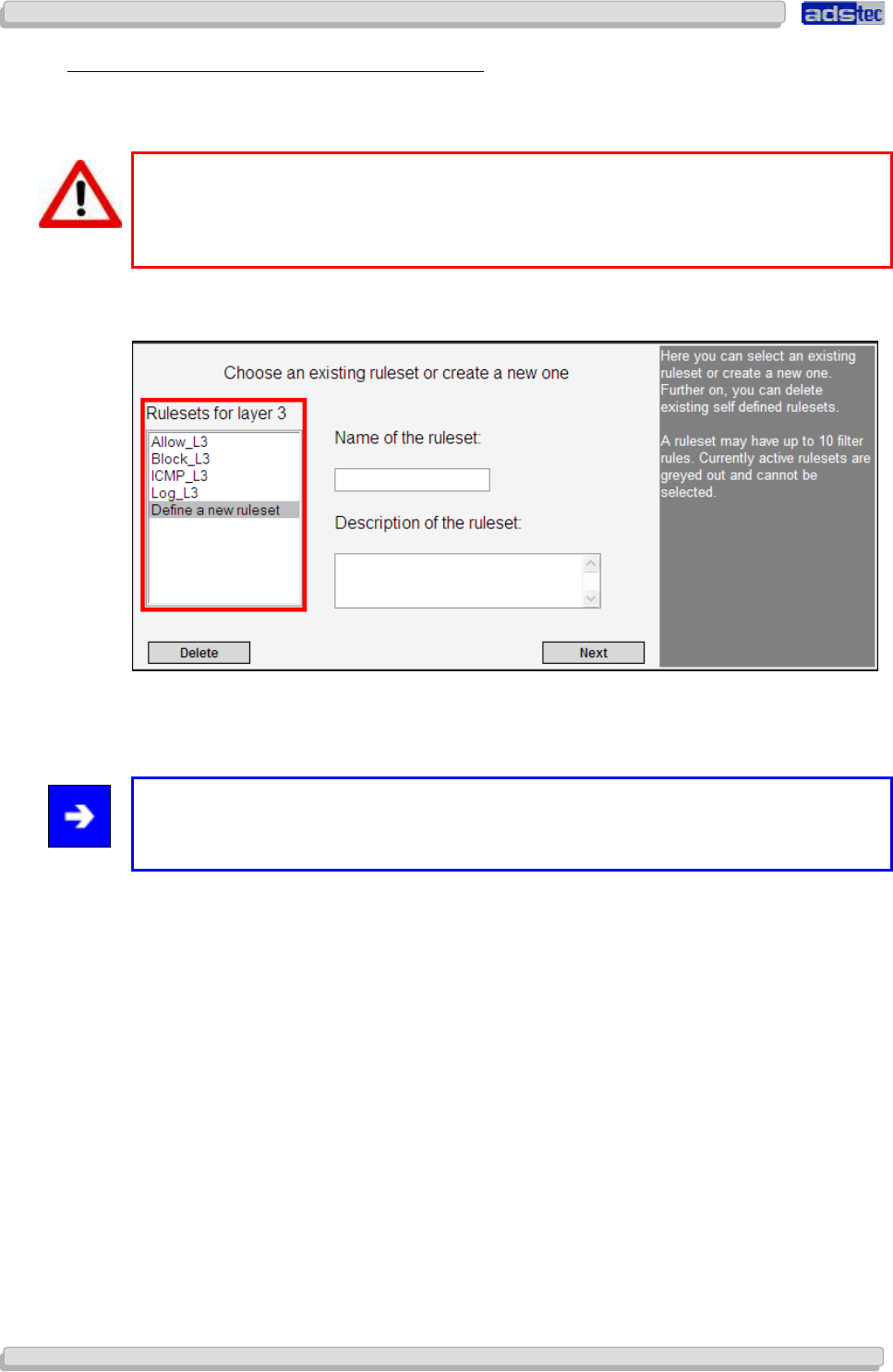
User Manual
User ManualUser Manual
User Manual Access Point /Client
Access Point /Client Access Point /Client
Access Point /Client V 3.0.3
V 3.0.3 V 3.0.3
V 3.0.3
60
6060
60
© ads-tec GmbH • Raiffeisenstr.14 • 70771 Leinfelden-Echterdingen
7.2.3
7.2.37.2.3
7.2.3
Definition of a new Rule set on Layer
Definition of a new Rule set on Layer Definition of a new Rule set on Layer
Definition of a new Rule set on Layer 3
33
3
The configuration of rule sets for filter layer 3 will be described on the following pages.
Warning:
Before configuring a rule set on layer 3, ensure the option check box “Activate IP
Router Functionality”, located at the path Basic Settings
User Interface. is
checked. Confirm any modifications to this setting by selecting “Activate”.
To begin the configuration, choose the option Layer 3 in the Filter Wizard main menu.
Click the Add button and subsequently select Definition of a new Rule Set.
Then assign a name and a description to the new rule set.
Note:
Use a different name for each rule set if possible. Do not use umlauts as they will lead to
error messages.
Confirm by clicking Next.
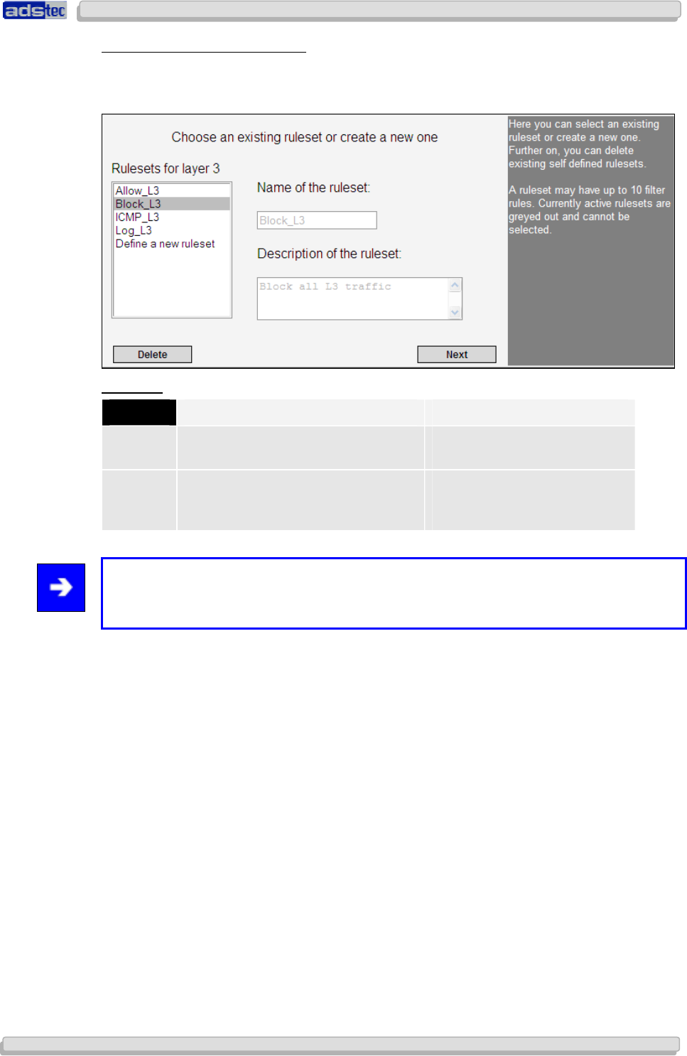
User Manual
User ManualUser Manual
User Manual Access Point /Client V 3.0.3
Access Point /Client V 3.0.3 Access Point /Client V 3.0.3
Access Point /Client V 3.0.3
© ads-tec GmbH • Raiffeisenstr.14 • 70771 Leinfelden-Echterdingen
61
6161
61
R
ULE SET
L
AYER AND
I
NTERFACES
On layer 3, you may choose to use the following filter criteria: LAN/VPN/Service
Select the port to filter and configure the filtering mode.
E
XAMPLE
:
S
YMBOL
I
NTERFACE
A
CTION
== Incoming interface: HOST filters all inbound data packets
on HOST
!= Outgoing interface: WLAN-2 filters all outgoing data
packets on all ports, except
for WLAN-2
Note:
If you do not wish to filter particular ports, choose the default menu item (i.e. the asterisk
item).
Confirm your input by clicking Next.
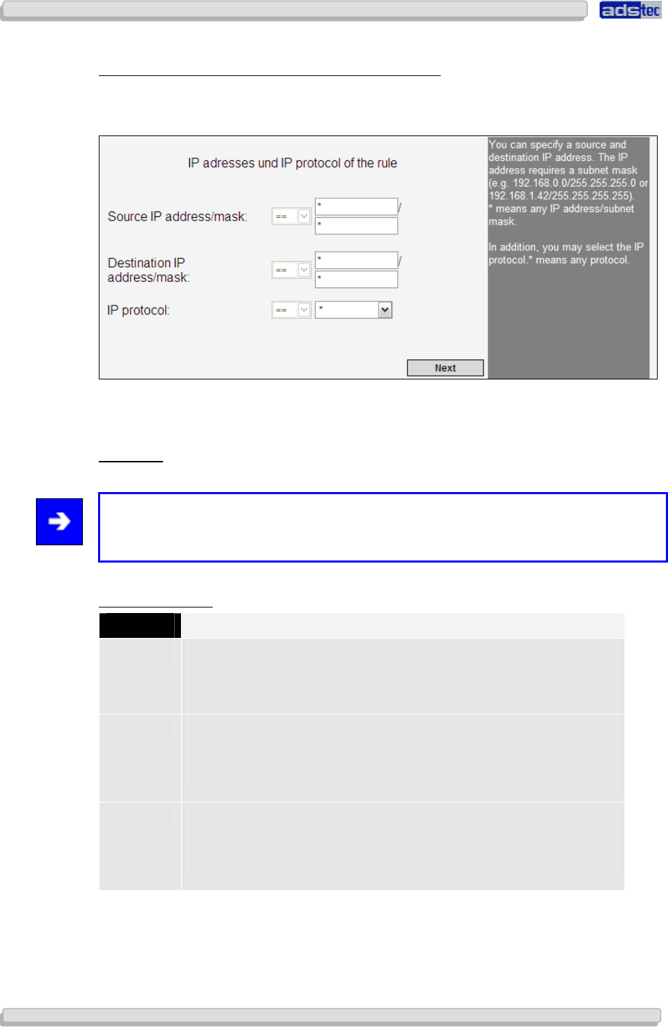
User Manual
User ManualUser Manual
User Manual Access Point /Client
Access Point /Client Access Point /Client
Access Point /Client V 3.0.3
V 3.0.3 V 3.0.3
V 3.0.3
62
6262
62
© ads-tec GmbH • Raiffeisenstr.14 • 70771 Leinfelden-Echterdingen
R
ULE
-
RELATED
I
NTERNET
P
ROTOCOLS AND
IP
A
DDRESSES
The Source IP Address defines the source from which data is received.
The Target IP Address defines the target to which data is sent.
In case you are using a permanent, static connection between two devices, you may enter
their respective IP addresses here. You also need to enter a valid subnet mask for each IP
address.
Example: IP Address: 192.168.0.0 / Subnet mask: 255.255.255.0
Note:
Once a specific protocol has been selected you may adjust protocol-specific configuration
settings.
Internet Protocols:
P
ROTOCOL
D
ESCRIPTION
TCP The Transmission Control Protocol (TCP) is a protocol defining the
way in which streams of bytes are exchanged between computers. All
current operating systems support TCP and employ it for exchanging
data with other computers.
UDP The User Datagram Protocol (UDP) is a minimal message-oriented
network protocol that belongs to the transport layer of the Internet
Protocol Suite. UDP is used to allow application-to-application
communication via the internet.
ICMP Like TCP and UDP, the Internet Control Message Protocol (ICMP) uses
the Internet Protocol (IP) and is hence also part of the Internet
Protocol Suite. It is chiefly used by networked computers' operating
systems to send error and information messages.
The following overview shows the configuration options available for each protocol.
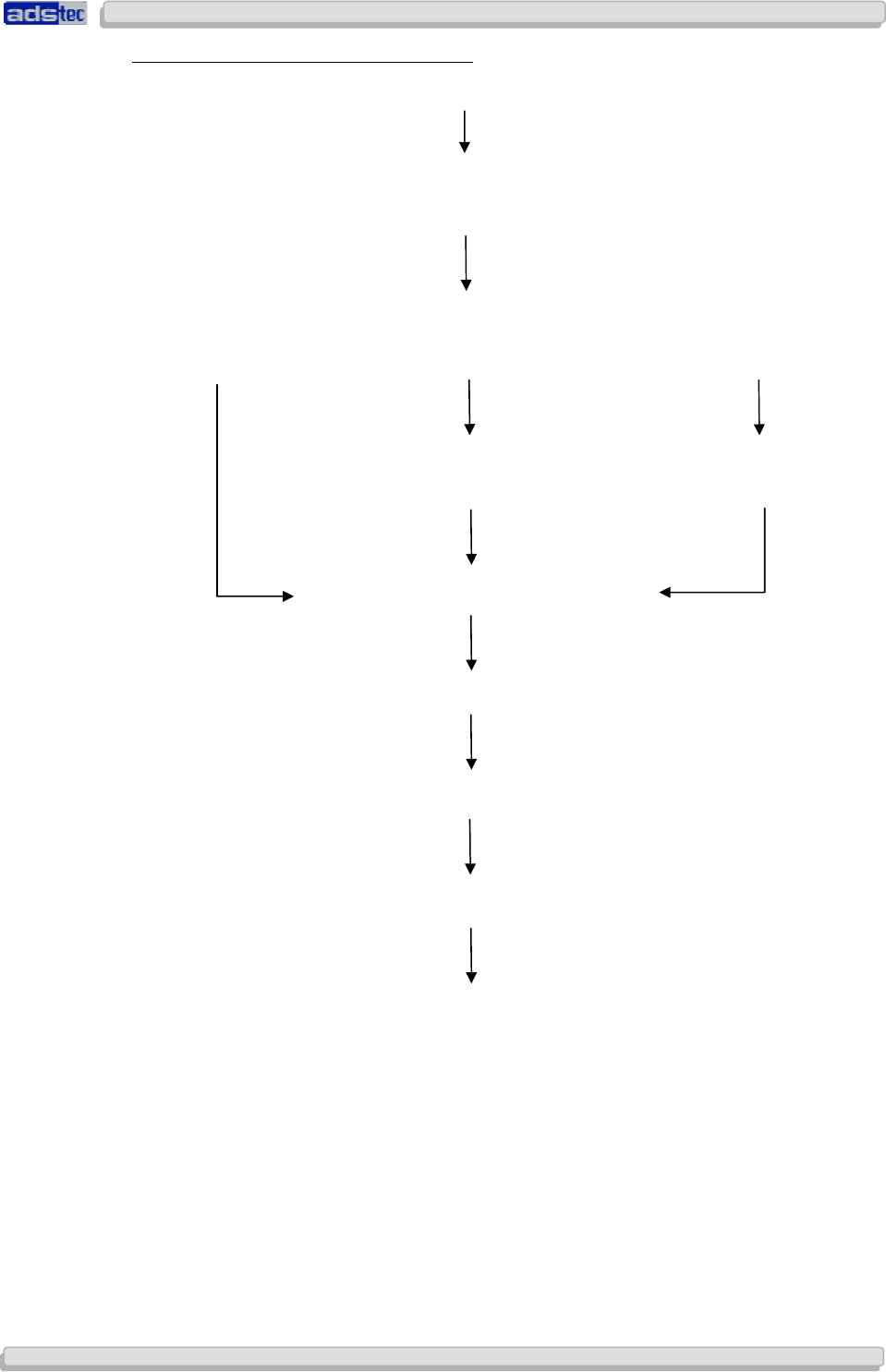
User Manual
User ManualUser Manual
User Manual Access Point /Client V 3.0.3
Access Point /Client V 3.0.3 Access Point /Client V 3.0.3
Access Point /Client V 3.0.3
© ads-tec GmbH • Raiffeisenstr.14 • 70771 Leinfelden-Echterdingen
63
6363
63
M
ENU
O
VERVIEW
L
AYER
3
S
ELECTION
TCP
Layer 3 TCP
Rule-related Internet Protocol options
e.g. selection:
*
UDP/TCP connection control
Auto Stateless Stateful
Check rule state settings / bit is set Rule state settings / bit
is set
Rule name and behaviour
Overview of all rules in rule set
Rule set time settings
Rule set status information
Filter rules start page
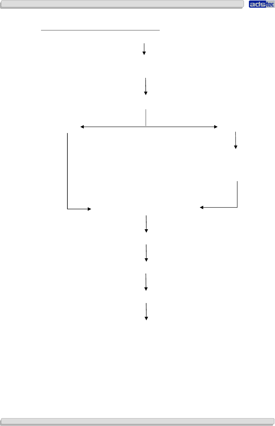
User Manual
User ManualUser Manual
User Manual Access Point /Client
Access Point /Client Access Point /Client
Access Point /Client V 3.0.3
V 3.0.3 V 3.0.3
V 3.0.3
64
6464
64
© ads-tec GmbH • Raiffeisenstr.14 • 70771 Leinfelden-Echterdingen
M
MM
M
EN
ENEN
ENU
U U
U
O
OO
O
VERVIEW
VERVIEW VERVIEW
VERVIEW
L
LL
L
AYER
AYER AYER
AYER
3
33
3
S
SS
S
ELECTION
ELECTION ELECTION
ELECTION
UDP
UDPUDP
UDP
Layer 3 UDP
Rule-related Internet Protocol options
e.g. selection:
*
UDP/TCP connection control
Auto
Stateful
Rule state settings / bit is
set
Rule name and behaviour
Overview of all rules in rule set
Rule set time settings
Rule set status information
Filter rules start page

User Manual
User ManualUser Manual
User Manual Access Point /Client V 3.0.3
Access Point /Client V 3.0.3 Access Point /Client V 3.0.3
Access Point /Client V 3.0.3
© ads-tec GmbH • Raiffeisenstr.14 • 70771 Leinfelden-Echterdingen
65
6565
65
M
MM
M
EN
ENEN
ENU
U U
U
O
OO
O
VERVIEW
VERVIEW VERVIEW
VERVIEW
L
LL
L
AYER
AYER AYER
AYER
3
33
3
S
SS
S
ELECTION
ELECTION ELECTION
ELECTION
ICMP
ICMPICMP
ICMP
Layer 3 ICMP
Rule-related Internet Protocol options
e.g. selection:
*
UDP/TCP connection control
Auto
Rule name and behaviour
Overview of all rules in rule set
Rule set time settings
Rule set status information
Filter rules start page
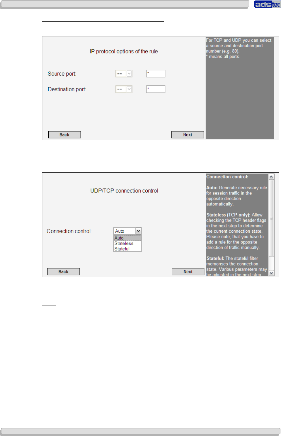
User Manual
User ManualUser Manual
User Manual Access Point /Client
Access Point /Client Access Point /Client
Access Point /Client V 3.0.3
V 3.0.3 V 3.0.3
V 3.0.3
66
6666
66
© ads-tec GmbH • Raiffeisenstr.14 • 70771 Leinfelden-Echterdingen
E
XEMPLARY
C
ONFIGURATION
–
S
ELECTION
TCP:
If TCP has been selected, the wizard will guide you through the following menus:
You may define source/target ports for TCP and UDP connections. In case you do not wish
to define such ports, select Next.
A connection control may be configured for the TC protocol. Available options are Auto,
Stateless and Stateful.
A
UTO
If Auto is selected, clicking Next will take you to the Rule Name and Behaviour menu.
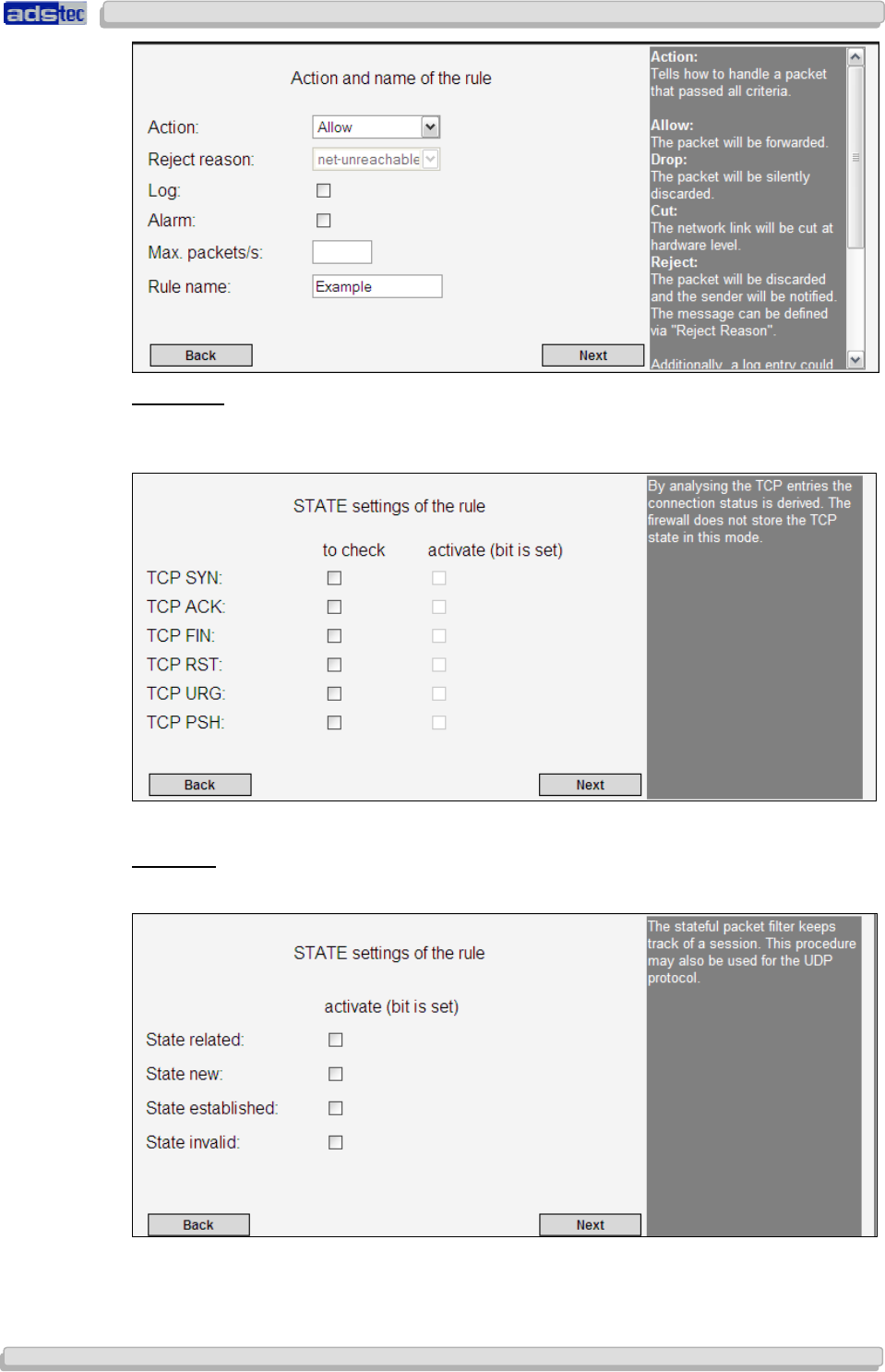
User Manual
User ManualUser Manual
User Manual Access Point /Client V 3.0.3
Access Point /Client V 3.0.3 Access Point /Client V 3.0.3
Access Point /Client V 3.0.3
© ads-tec GmbH • Raiffeisenstr.14 • 70771 Leinfelden-Echterdingen
67
6767
67
S
TATELESS
:
With this option activated, the TCP headers containing information on the connection status
will be analysed.
S
TATEFUL
:
The stateful packet filter monitors all session-related connection information.
State Related: Data packet is assigned to existing data connection, e.g. for
establishing an FTP feedback channel.
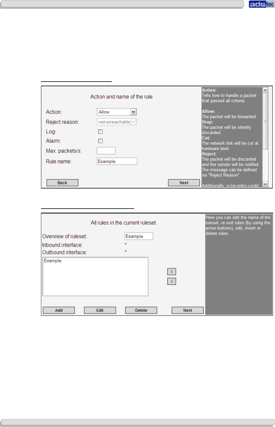
User Manual
User ManualUser Manual
User Manual Access Point /Client
Access Point /Client Access Point /Client
Access Point /Client V 3.0.3
V 3.0.3 V 3.0.3
V 3.0.3
68
6868
68
© ads-tec GmbH • Raiffeisenstr.14 • 70771 Leinfelden-Echterdingen
State New: Data packet establishes a new data connection, e.g. TCP with SYN
flag.
State Established: Data packet belongs directly to specific data connection, e.g. TCP
data without SYN flag.
State Invalid: Data packets for which the firewall could not determine a valid
connection state.
R
ULE
N
AME AND
B
EHAVIOUR
Confirm your input by clicking Next.
O
VERVIEW OF ALL
R
ULES IN
R
ULE
S
ET
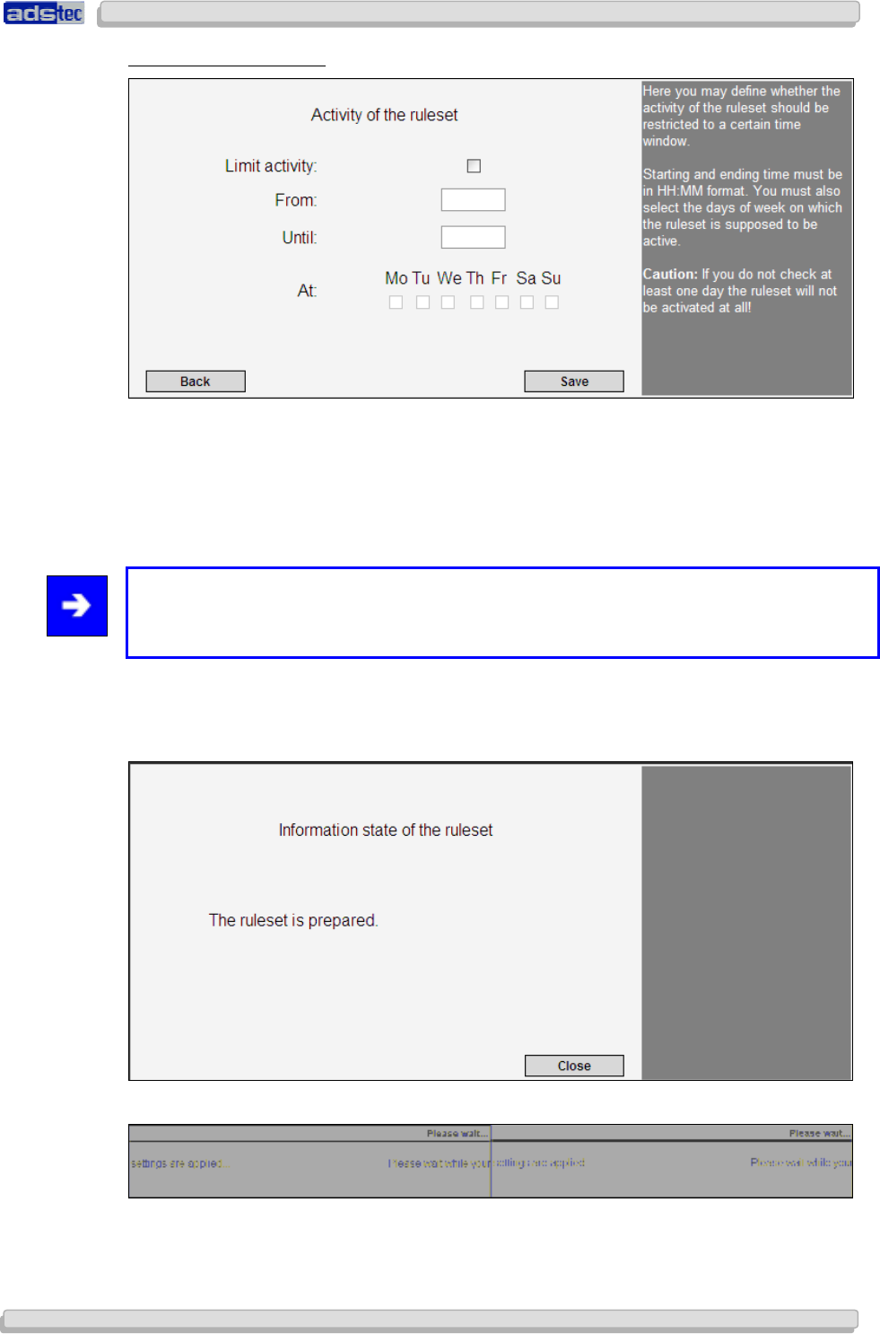
User Manual
User ManualUser Manual
User Manual Access Point /Client V 3.0.3
Access Point /Client V 3.0.3 Access Point /Client V 3.0.3
Access Point /Client V 3.0.3
© ads-tec GmbH • Raiffeisenstr.14 • 70771 Leinfelden-Echterdingen
69
6969
69
R
ULE
S
ET
T
IME
S
ETTINGS
Activate the check box by clicking the empty box if you would like to use this function. Enter
a start and an end time in the format: HH:MM. The start time needs to be lower than the
end time.
Furthermore, you will need to specify the days of the week on which to activate the
function.
Note:
At least one day of the week needs to be specified, otherwise the rule is invalid and will not
be applied.
Complete the configuration by clicking Save.
Confirm the next message prompt by clicking Close.
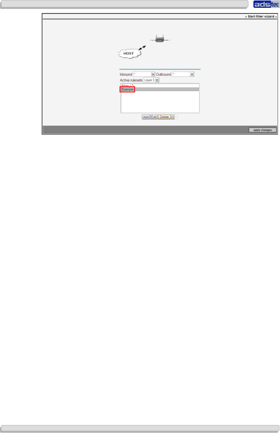
User Manual
User ManualUser Manual
User Manual Access Point /Client
Access Point /Client Access Point /Client
Access Point /Client V 3.0.3
V 3.0.3 V 3.0.3
V 3.0.3
70
7070
70
© ads-tec GmbH • Raiffeisenstr.14 • 70771 Leinfelden-Echterdingen
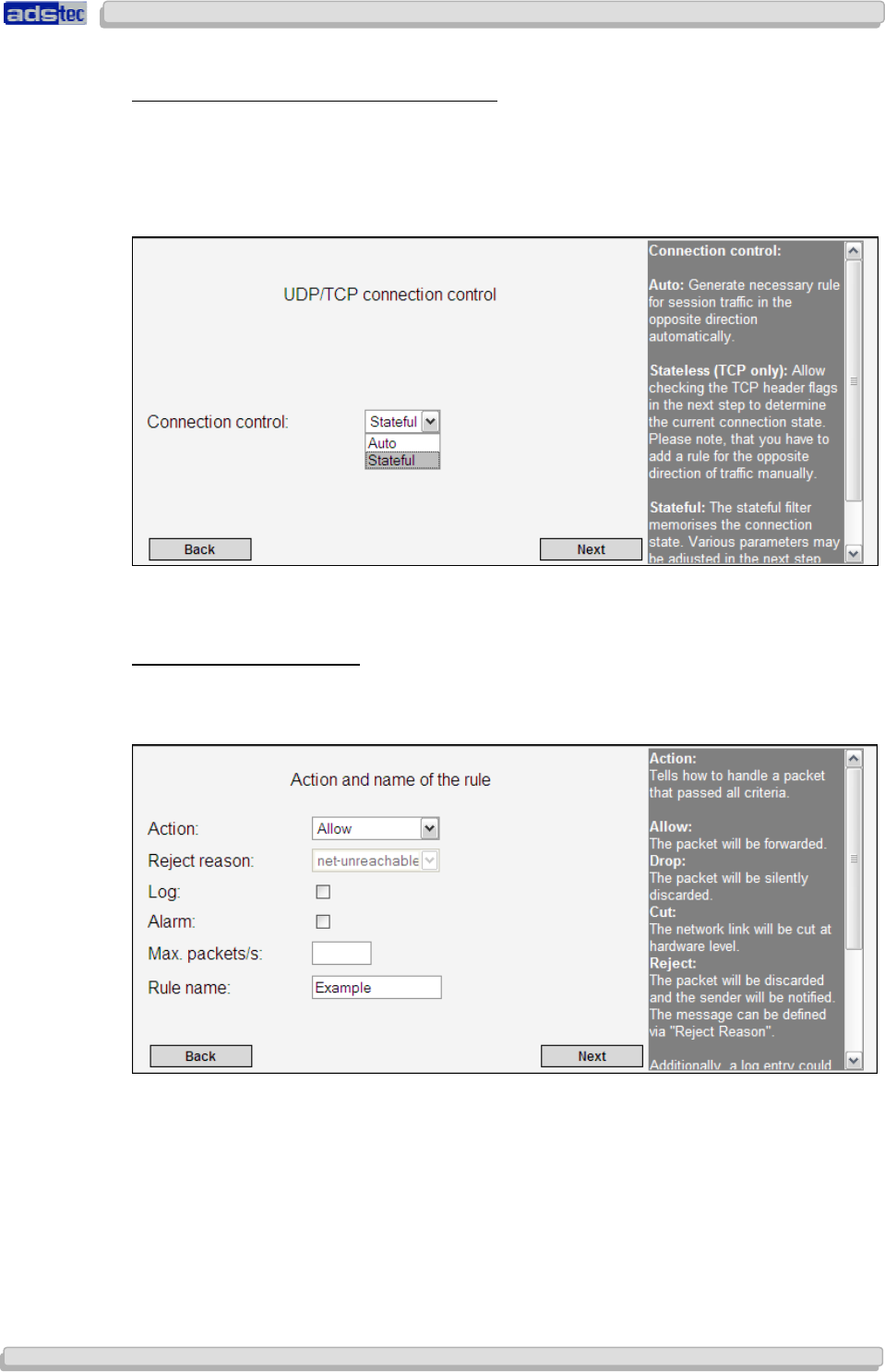
User Manual
User ManualUser Manual
User Manual Access Point /Client V 3.0.3
Access Point /Client V 3.0.3 Access Point /Client V 3.0.3
Access Point /Client V 3.0.3
© ads-tec GmbH • Raiffeisenstr.14 • 70771 Leinfelden-Echterdingen
71
7171
71
R
ULE
-
RELATED
I
NTERNET
P
ROTOCOL
O
PTIONS
Stateful filtering stores the state of a connection.
Auto: function disabled
Stateful: function enabled; offers further configuration options
Confirm by clicking Next
R
ULE
N
AME AND
B
EHAVIOUR
The next dialogue will allow you to define the Rule Behaviour in more detail.
Use the menu item Rule Action to determine how the device should handle packets.
Rule Action:
Available options are Allow and Block.
Reason for Rejection:
This allows you to define a reason for packet rejection. In case a rule is violated, the sender
will be notified, giving this reason as an explanation.
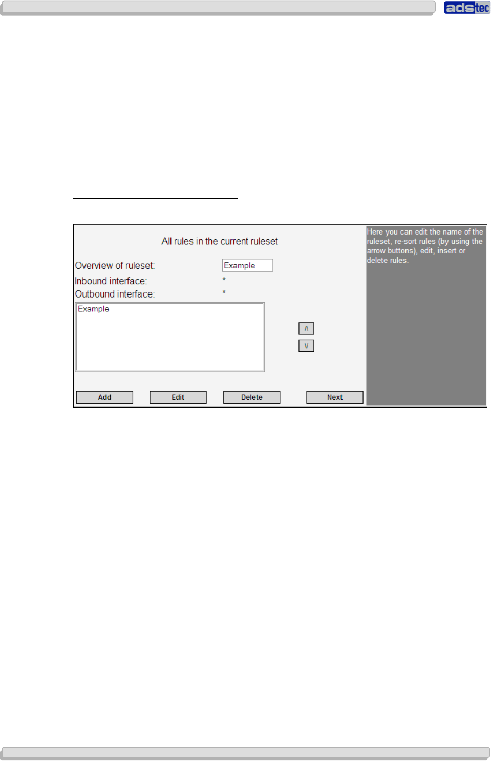
User Manual
User ManualUser Manual
User Manual Access Point /Client
Access Point /Client Access Point /Client
Access Point /Client V 3.0.3
V 3.0.3 V 3.0.3
V 3.0.3
72
7272
72
© ads-tec GmbH • Raiffeisenstr.14 • 70771 Leinfelden-Echterdingen
Log:
The Log function enables logging of events.
Max. Packets/sec:
Use this option to specify a maximum packet rate per second at which packets may pass the
device.
Rule Name:
Choose a name for this rule; the name should be unique, i.e. differ from the name of any
other rule set.
Confirm by clicking Next.
O
VERVIEW OF ALL
R
ULES IN
R
ULE SET
The next dialogue window provides an overview of all existing rule sets.
Use the Add button for starting the rule configuration process anew to define another rule.
The Edit button allows subsequent modifications to previously defined rules.
Choose Delete to delete the selected rule.
Use the arrow buttons to modify the position of a rule within the current rule set.
Confirm by clicking Next.
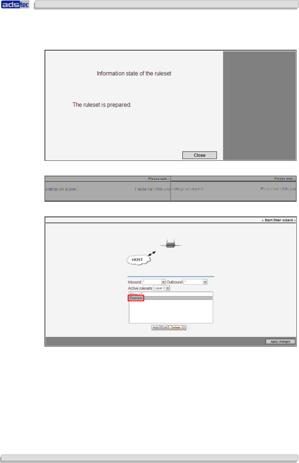
User Manual
User ManualUser Manual
User Manual Access Point /Client V 3.0.3
Access Point /Client V 3.0.3 Access Point /Client V 3.0.3
Access Point /Client V 3.0.3
© ads-tec GmbH • Raiffeisenstr.14 • 70771 Leinfelden-Echterdingen
73
7373
73
Complete the configuration by clicking Save.
Confirm the next message prompt by clicking Close.
Once a rule set has been successfully loaded and activated, it will be shown in the filter
overview page.
This completes the first-time configuration using the configuration wizards.
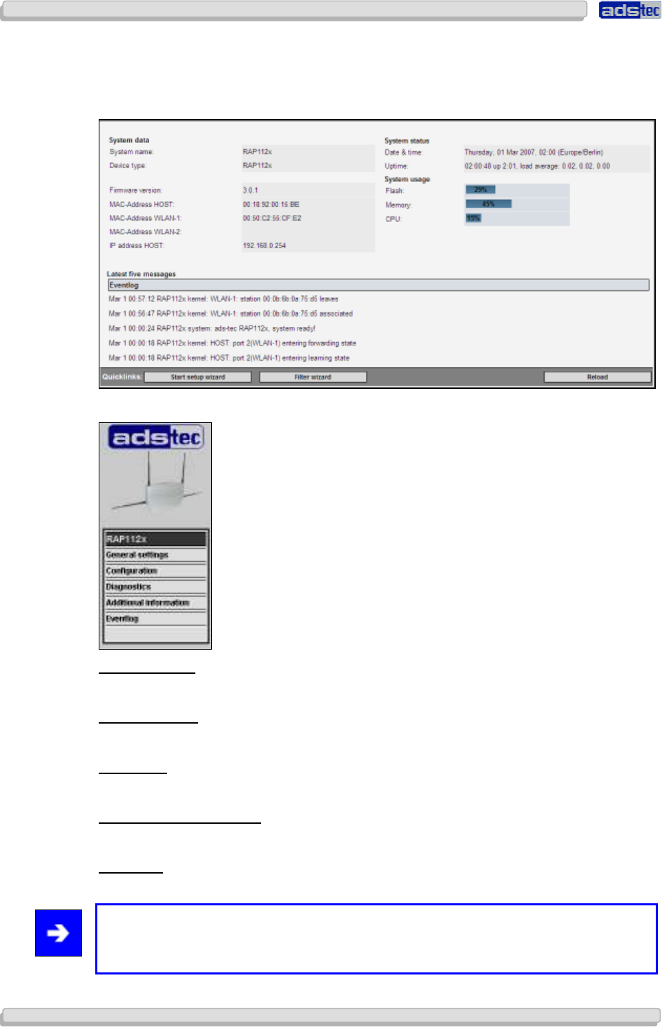
User Manual
User ManualUser Manual
User Manual Access Point /Client
Access Point /Client Access Point /Client
Access Point /Client V 3.0.3
V 3.0.3 V 3.0.3
V 3.0.3
74
7474
74
© ads-tec GmbH • Raiffeisenstr.14 • 70771 Leinfelden-Echterdingen
8
88
8 A
AA
A
CCESS
CCESS CCESS
CCESS
P
PP
P
OINT
OINTOINT
OINT
/C
/C/C
/C
LIENT
LIENT LIENT
LIENT
W
WW
W
EB
EBEB
EB
I
II
I
NTERFACE
NTERFACENTERFACE
NTERFACE
The start page of the web interface displays all important Access Point parameters at a
glance. Individual settings are directly accessible via hyperlinks on the start page.
The Access Point web interface is subdivided into five main categories.
BASIC
S
ETTINGS
For adjusting basic Access Point settings
C
ONFIGURATION
Configures specific Access Point functions and features
D
IAGNOSIS
Indicates the current interface status
A
DDITIONAL
I
NFORMATION
Contains general device information
E
VENT LOG
Event log display and configuration
Note:
In case you did not use the configuration wizards, you may refer to the following
documentation to configure settings manually.
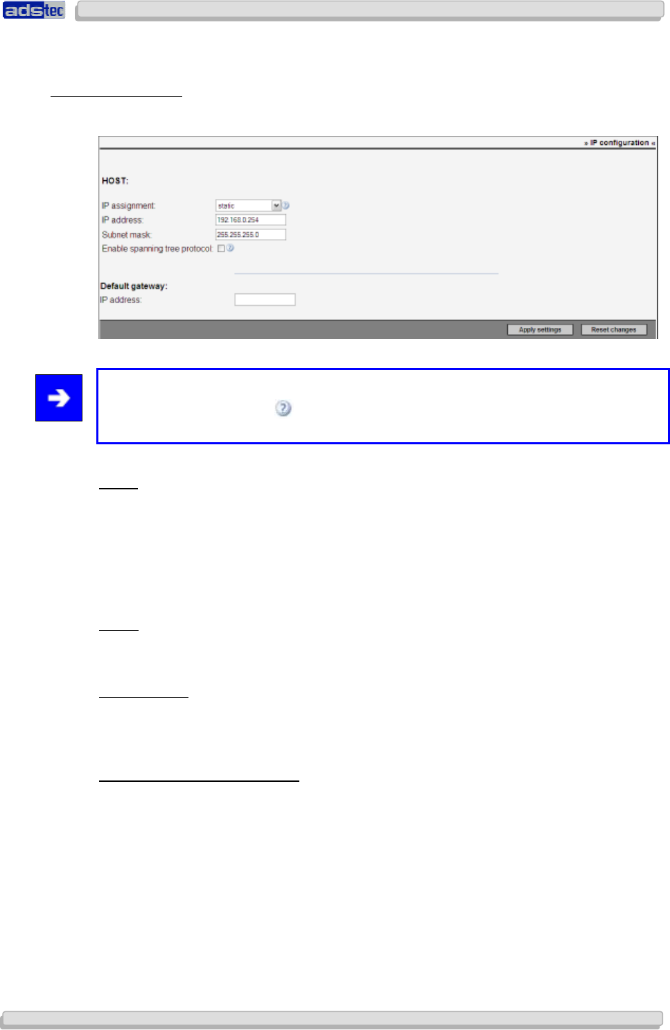
User Manual
User ManualUser Manual
User Manual Access Point /Client V 3.0.3
Access Point /Client V 3.0.3 Access Point /Client V 3.0.3
Access Point /Client V 3.0.3
© ads-tec GmbH • Raiffeisenstr.14 • 70771 Leinfelden-Echterdingen
75
7575
75
8.1 B
ASIC
S
ETTINGS
M
AIN
M
ENU
8.1.1
8.1.18.1.1
8.1.1 IP
IPIP
IP Configuration
Configuration Configuration
Configuration
Access Point IP configuration
Note:
Clicking the question mark to the right of the drop-down menus will open up general
information about and brief descriptions of the available options.
Static:
If this option is selected you may enter a static IP address. Static IP address assignment
requires entering an IP address and its corresponding subnet mask.
Default values are:
IP address: 192.168.0.254
Subnet mask: 255.255.255.0
DHCP:
The DHCP function requests an IP address from a DHCP server and automatically assigns
that address.
DHCP fallback:
This option is a combination of static and automatic IP address assignment. In case an error
occurs during automatic address assignment (via DHCP server), the system automatically
uses the specified static IP address.
Activate Spanning Tree Protocol:
The Spanning Tree Protocol (STP) is used to avoid redundant network loops, especially in
switched environments.
If this option is enabled, it is possible to establish redundant network connections.
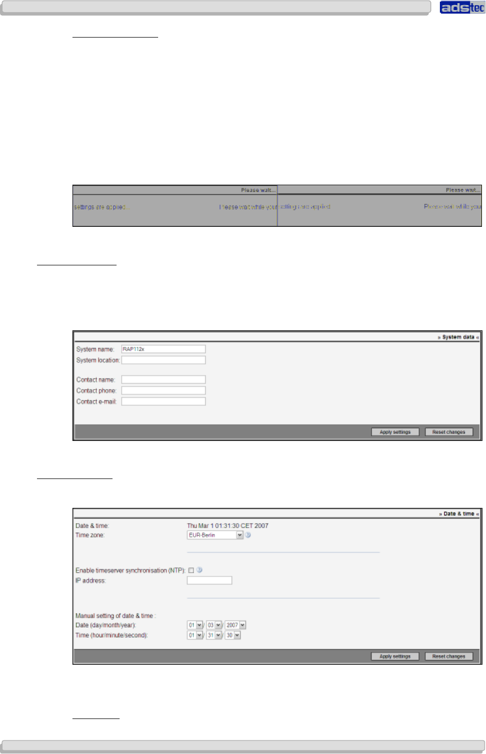
User Manual
User ManualUser Manual
User Manual Access Point /Client
Access Point /Client Access Point /Client
Access Point /Client V 3.0.3
V 3.0.3 V 3.0.3
V 3.0.3
76
7676
76
© ads-tec GmbH • Raiffeisenstr.14 • 70771 Leinfelden-Echterdingen
Standard Gateway:
Use this field to specify the IP address of the standard gateway to be used.
The IP address entered as standard gateway address is used to establish a connection to an
address located outside of the device’s own IP subnet (i.e. outside 192.168.0.254 in the
example given previously). However, the standard gateway itself needs to be inside the
device’s IP subnet address space. In case IP allocation was set to DHCP, the standard
gateway address may be dynamically overwritten, providing the DHCP server supports this.
The standard gateway may, for instance, be required in order to reach an NTP time server
or to relay the IP address to WLAN clients in case the device serves as a DHCP server itself.
Now click Activate
Your changes are now saved and activated.
8.1.2
8.1.28.1.2
8.1.2 System
SystemSystem
System
D
DD
Dat
atat
ata
aa
a
Use the System Data dialogue to enter important system-related information such as device
location and contact data. These data serve as unique identifiers of the device at its
location; this includes contact data, which is accessible on this page in case of device
maintenance, revision or similar.
Click Activate to accept the settings
8.1.3
8.1.38.1.3
8.1.3 Dat
DatDat
Date
e e
e &
&&
& Time
Time Time
Time
This menu item allows setting the system date and time.
Date and time can be automatically set via an NTP server or, alternatively, manually.
Time Zone:
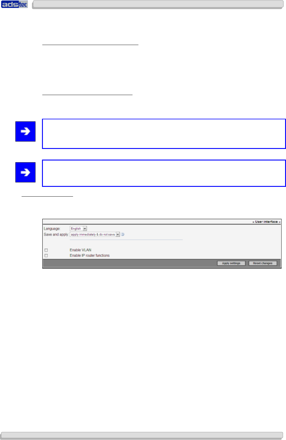
User Manual
User ManualUser Manual
User Manual Access Point /Client V 3.0.3
Access Point /Client V 3.0.3 Access Point /Client V 3.0.3
Access Point /Client V 3.0.3
© ads-tec GmbH • Raiffeisenstr.14 • 70771 Leinfelden-Echterdingen
77
7777
77
Use the drop-down menu to set the correct time zone. GMT (Greenwich Mean Time) is
equivalent to Western European Time and may be adapted depending on local time
differences.
Time Synchronisation via NTP Server:
This function allows synchronisation of date and time via an NTP server.
To use this service, activate the check box next to this option and enter the IP address of
the NTP server you wish to use.
Manual Date & Time Configuration:
Alternatively, you may choose to set date and time manually.
Click Activate to confirm your settings.
Note:
Correct date and time settings are essential for verifying certificates, reviewing event logs
and applying time-based rules defined in the Filter Wizard.
Note:
A device reboot should be performed in order for changes to take effect.
8.1.4
8.1.48.1.4
8.1.4 User Interface
User InterfaceUser Interface
User Interface
Use the “User Interface” menu to set the web interface display language to English or
German.
The drop-down menu allows selecting either “apply immediately, do not save” or “do
not apply, save only” as Saving and Applying options.
Choosing “apply immediately, do not save” will add an “Apply” button to all pages in
the Access Point configuration menu. That button can be used to implement any changes
immediately. In order to keep such changes so they remain available after a device reboot,
the user will need to click a disk icon which will subsequently flash up.
The “do not apply, save only” option adds a “Save” button to all pages in the Access
Point configuration menu. Any modified settings will not be implemented, but will be saved
immediately. The device needs to be rebooted for changes to take effect. This option omits
the “Please wait” dialogue shown after a page has been confirmed. Instead of a disk icon,
a reboot icon will appear. Clicking it will take the user to the start page from which a reboot
may be initiated. The “Please wait” screen will still be displayed in some special cases,
such as for example ping tests and firmware updates.
Confirm your settings by clicking Activate.
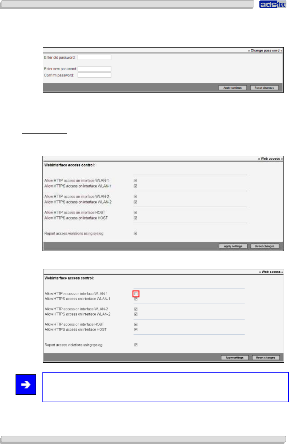
User Manual
User ManualUser Manual
User Manual Access Point /Client
Access Point /Client Access Point /Client
Access Point /Client V 3.0.3
V 3.0.3 V 3.0.3
V 3.0.3
78
7878
78
© ads-tec GmbH • Raiffeisenstr.14 • 70771 Leinfelden-Echterdingen
8.1.5
8.1.58.1.5
8.1.5 Cha
ChaCha
Chan
nn
nge password
ge passwordge password
ge password
Users will need to enter the password specified here before being able to access the web
interface. The dialogue window allows changing the password.
In order to change the password, enter the current password in the field Old Password.
Choose a new password and confirm it by entering it in the Password Confirmation field.
Confirm your settings by clicking Apply.
8.1.6
8.1.68.1.6
8.1.6 Web
WebWeb
Web Access
Access Access
Access
The Web Interface Access Control menu allows configuring access to a particular interface
via http/https. Furthermore, you may enable a logging of access violations in the Syslog.
In order to deny access to a particular interface, the checkmark next to the respective option
needs to be removed.
Note:
In case you are using an Access Point with 2 integrated WLAN adapters, the same
configuration options will appear for WLAN-2.
Confirm your changes by clicking Activate.
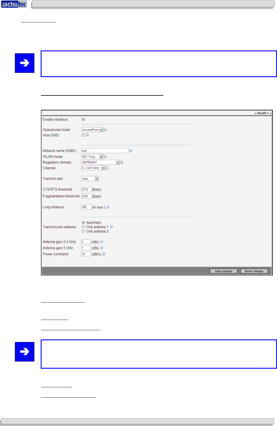
User Manual
User ManualUser Manual
User Manual Access Point /Client V 3.0.3
Access Point /Client V 3.0.3 Access Point /Client V 3.0.3
Access Point /Client V 3.0.3
© ads-tec GmbH • Raiffeisenstr.14 • 70771 Leinfelden-Echterdingen
79
7979
79
8.1.7
8.1.78.1.7
8.1.7 Interfaces
InterfacesInterfaces
Interfaces
Use the Interfaces menu to configure the Access Point interfaces. Each interface offers
individual configuration options that can be set to influence the interface behaviour.
Furthermore, unused interfaces can be deactivated.
Note:
Some device variants offer a second WLAN interface.
WLAN-1
(A
CCESS
P
OINT
)
2.4GH
Z
-802.11
B
/
G
:
Configure the LAN-in interface by setting the duplex mode.
The Activate Interface check box needs to be enabled before any changes to the interface
configuration are possible.
Operating Mode: Switch / Available options: Access Point / Client (This option is not
available for the RAC111x and RAC151x)
Hide SSID: Activating this option will hide the SSID (network name)
Network Name (SSID): The network identifier. Default value: ads. Maximum SSID length is
32 characters.
Note:
Valid characters are: a-z, A-Z, 0-9, Valid special characters: . _ - ? $ @ ! { } [ ] ( ) + # ; ,
< > | : * ~ % $ & / =
WLAN Mode: Allows selection of particular WLAN transmission standard
Regulatory Authority: Select the country in which the device is used. (This option is not
available if you are using the FCC version of the device.)
User Manual
User ManualUser Manual
User Manual Access Point /Client
Access Point /Client Access Point /Client
Access Point /Client V 3.0.3
V 3.0.3 V 3.0.3
V 3.0.3
80
8080
80
© ads-tec GmbH • Raiffeisenstr.14 • 70771 Leinfelden-Echterdingen
Channel: Allows specifying a particular transmission channel or selecting automatic channel
selection.
Transmission Rate: Automatic or manual selection of the Mbit rate.
CTS/RTS Threshold: The Access Point will be notified of any packets exceeding the value
specified here. The Access Point will keep the channel open for the packet in question.
Fragmentation Threshold: In case a packet exceeds the value specified here, that packet will
be fragmented for transmission, i.e. it will be divided into multiple smaller packet units.
Note:
The Fragmentation Threshold option cannot be used if WPA encryption is activated.
Long Range: In case the physical distance that needs to be bridged between two devices is
relatively large, this option allows increasing the timeout value by specifying the distance (in
metres). With an increased timeout value, the Access Point will wait longer for a reply from
a remote station.
Transmission Antenna:
This option allows specifying whether the device should choose the transmission antenna
automatically. Alternatively, the antenna may be specified manually.
Antenna Amplification: Enable the Antenna Amplification option to increase the output
power. The maximum output power may however be limited by national guidelines and
regulations.
Example: A 10dbi antenna is used in combination with a 3db cable. The Antenna
Amplification to be entered in this case is 7dbi.
Power Restriction:
This option allows limiting the Access Point transmission power to the value specified. This
value will be conveyed to all clients that can access the Access Point.
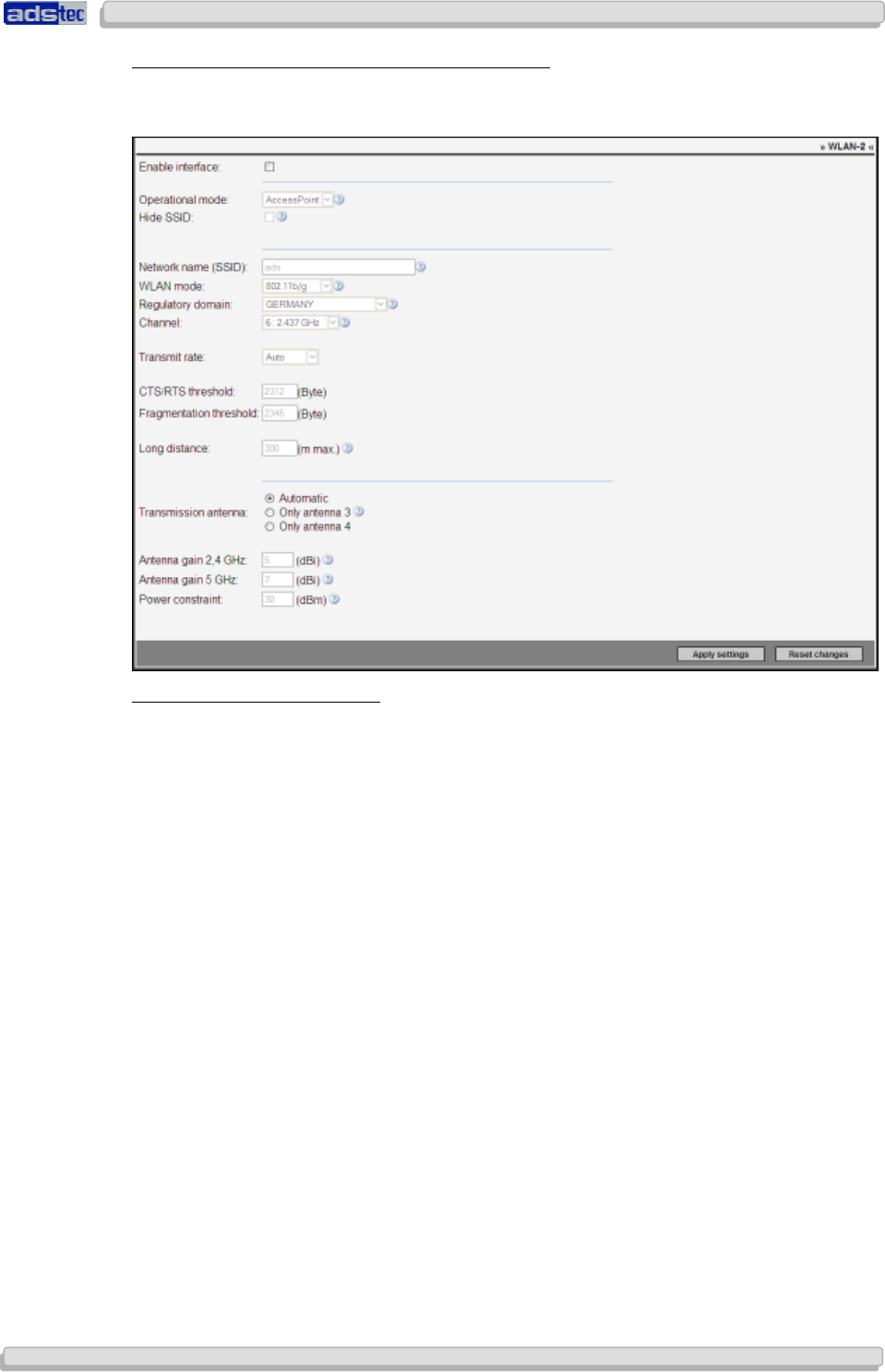
User Manual
User ManualUser Manual
User Manual Access Point /Client V 3.0.3
Access Point /Client V 3.0.3 Access Point /Client V 3.0.3
Access Point /Client V 3.0.3
© ads-tec GmbH • Raiffeisenstr.14 • 70771 Leinfelden-Echterdingen
81
8181
81
WLAN-1
(A
CCESS
C
LIENT
)
2.4
GH
Z
–
802.11
B
/
G
:
The configuration menu for the Access Client only differs from the one described above by
the missing “Hide SSID” option, which is replaced by the “Static BSSID” option:
Use static Access Point BSSID:
With this option enabled, you may enter the MAC address of an access point. This option is
useful for access points with identical SSID as it allows accessing a particular device.
Confirm by clicking Activate.
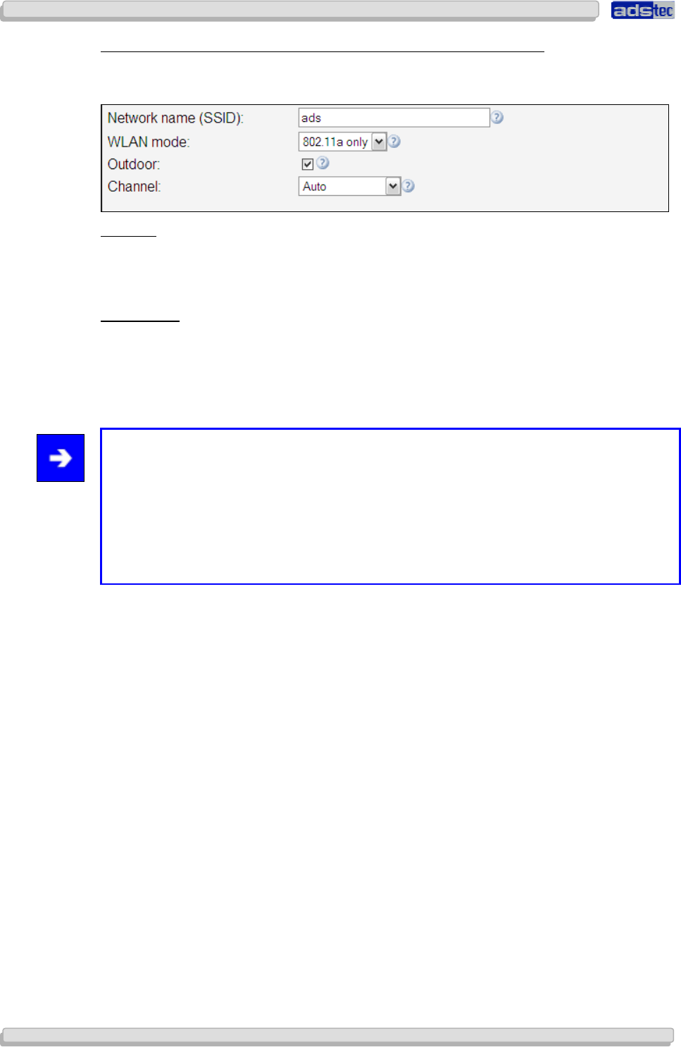
User Manual
User ManualUser Manual
User Manual Access Point /Client
Access Point /Client Access Point /Client
Access Point /Client V 3.0.3
V 3.0.3 V 3.0.3
V 3.0.3
82
8282
82
© ads-tec GmbH • Raiffeisenstr.14 • 70771 Leinfelden-Echterdingen
WLAN-1
(A
CCESS
P
OINT
&
A
CCESS
C
LIENT
)
5
GH
Z
–
802.11
A
(ETSI):
In case WLAN Mode is set to 802.11a, or 802.11a/b/g for the Client, some available options
differ:
Outdoor:
This option must be activated if the device is operated outdoors. Some of the 5GHz band
channels may not be used outdoors. Activating this function will turn off all such channels.
This option is not required for the Access Client.
Disable DFS:
Providing the Access Point is
not
operated outdoors, DFS may be disabled. Channels 36, 40,
44 and 48 may then also be configured manually. Furthermore, activating this option will
reduce the maximum transmission power. In Client mode, DFS may also be disabled
outdoors.
Note:
In Client mode, DFS is disabled per default. The radar scan during data transmissions may
create strong interferences with the client, which subsequently need to be analysed as
radar impulses. This frequently causes a high CPU load as well as faulty radar detections.
This means that in Client mode, DFS should only be enabled if the higher Client
transmission power of 23dB is exceeded and 30dBm are required to establish a stable
connection. In Client mode, the presence of another 5GHz device in the vicinity may also
cause significant interferences if DFS is enabled.
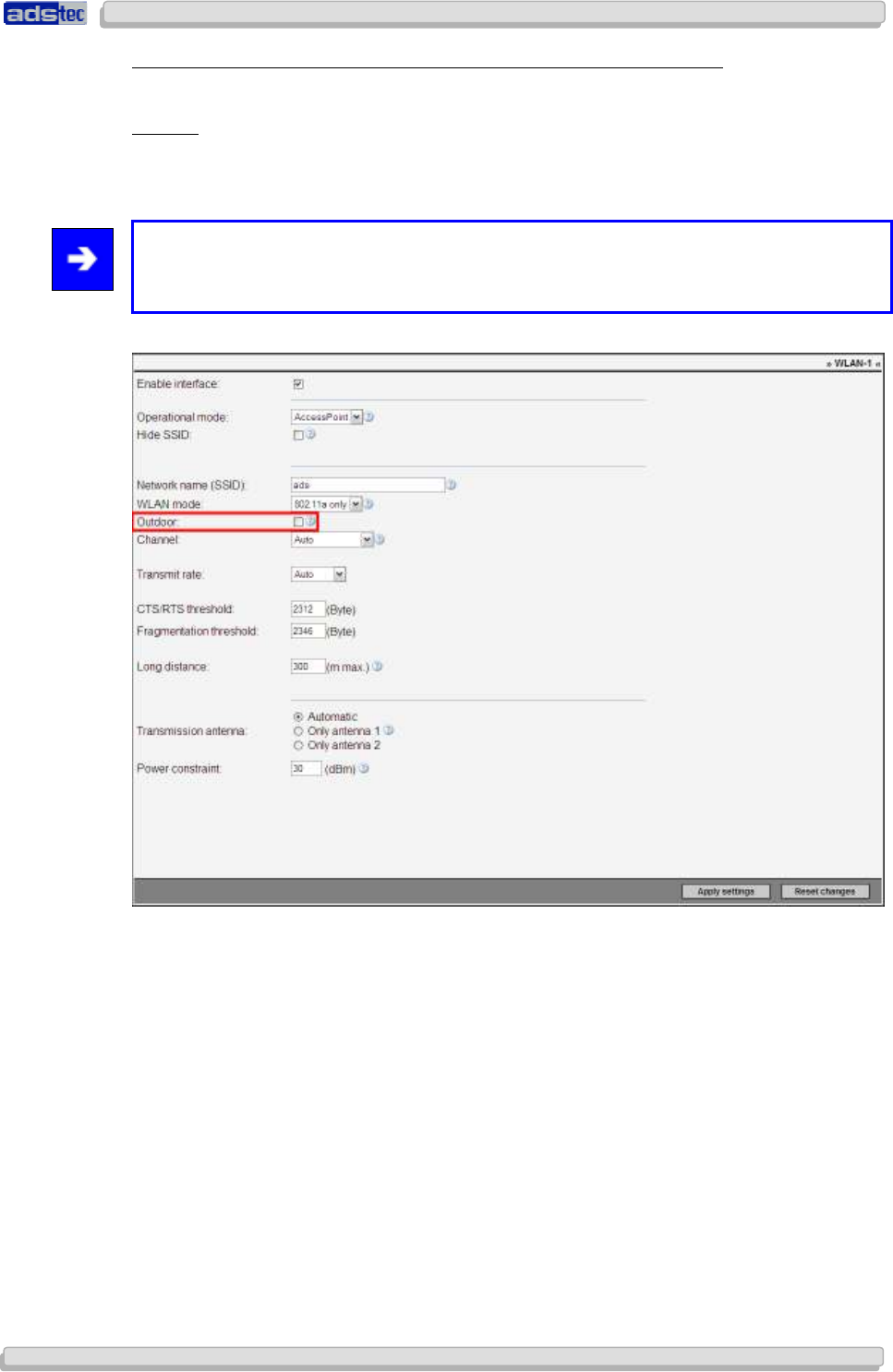
User Manual
User ManualUser Manual
User Manual Access Point /Client V 3.0.3
Access Point /Client V 3.0.3 Access Point /Client V 3.0.3
Access Point /Client V 3.0.3
© ads-tec GmbH • Raiffeisenstr.14 • 70771 Leinfelden-Echterdingen
83
8383
83
WLAN-1
(A
CCESS
P
OINT
&
A
CCESS
C
LIENT
)
2.4
GH
Z
–
802.11
A
(FCC):
The FCC version of the device offers the following additional interface configuration options:
Outdoor:
This option must be activated if the device is operated outdoors. It will turn off all channels
that may legally not be used outdoors.
Note:
DFS and TPC are disabled in this case. Compared to the A version, the 802.11b/g (FCC)
version merely offers the Directional Antenna setting as an additional option.
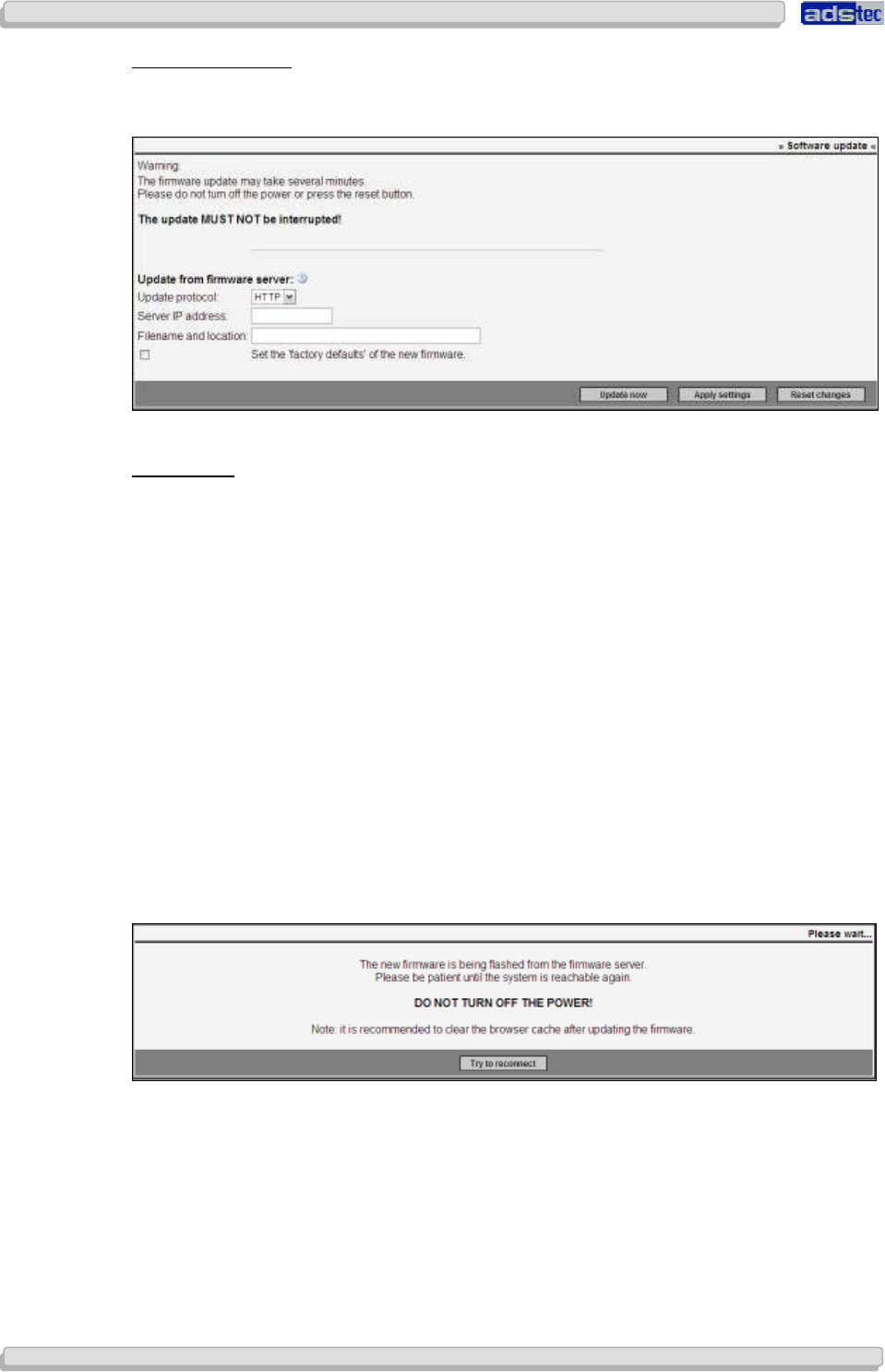
User Manual
User ManualUser Manual
User Manual Access Point /Client
Access Point /Client Access Point /Client
Access Point /Client V 3.0.3
V 3.0.3 V 3.0.3
V 3.0.3
84
8484
84
© ads-tec GmbH • Raiffeisenstr.14 • 70771 Leinfelden-Echterdingen
S
OFTWARE
U
PDATE
:
The menu item Software Update allows updating the device firmware. You may choose one
of three options to update the firmware:
You may update the firmware via an FTP, a TFTP or an HTTP server.
P
ROCEDURE
:
1) Save the new firmware file in a folder of your choice on your workstation PC.
2) Start the desired server service or use a freeware program such as tfpd32 (available on
the ads-tec service CD) in order to perform a firmware update. Please mind local firewall
settings to ensure communication with the device is not blocked.
3) Under Browse, enter the path of the folder in which the new firmware is located.
Confirm by clicking OK.
4) Before initiating the update process, it is recommended to enable the option to adopt
the factory settings of the new firmware.
5) Enter the IP address in the field Server IP Address.
6) The file name, including its path with all required subfolders, is specified under File
Name and Location.
7) Before initiating the update process, you may opt to adopt the factory settings of the
new firmware.
8) Start the update process.
During the firmware update, the following dialogue window will be displayed:
Once the Link LED turns green and the ACT LED is extinguished, you may click the button
Try to reconnect. The Access Point will then try to access the web interface. If the update
was successful the Software Update screen will appear.
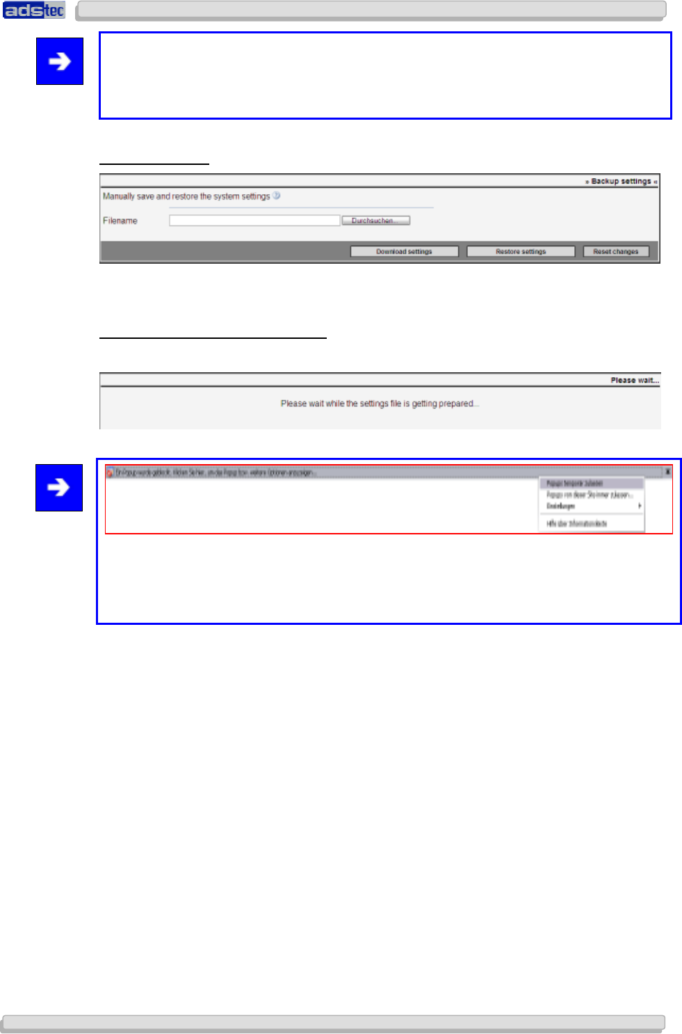
User Manual
User ManualUser Manual
User Manual Access Point /Client V 3.0.3
Access Point /Client V 3.0.3 Access Point /Client V 3.0.3
Access Point /Client V 3.0.3
© ads-tec GmbH • Raiffeisenstr.14 • 70771 Leinfelden-Echterdingen
85
8585
85
Note:
Abortion of the update process, e.g. due to a power failure, may damage the device
and/or its firmware. In this case, the device needs to be sent in to the manufacturer for
repair.
B
ACKUP
S
ETTINGS
The Backup Settings menu allows saving and restoring the device configuration.
S
AVING THE
D
EVICE
C
ONFIGURATION
:
To save the configuration to a file, click Save Settings
Note:
In case a popup blocker is enabled, it should be set to temporarily accept the following
page. In Internet Explorer, select the option “Temporarily allow popups” in the dialogue
appearing below the URL bar. When using a different browser, select an equivalent option.
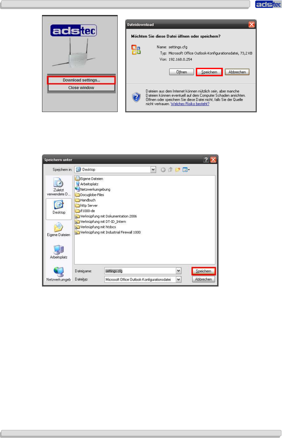
User Manual
User ManualUser Manual
User Manual Access Point /Client
Access Point /Client Access Point /Client
Access Point /Client V 3.0.3
V 3.0.3 V 3.0.3
V 3.0.3
86
8686
86
© ads-tec GmbH • Raiffeisenstr.14 • 70771 Leinfelden-Echterdingen
Select Save Settings The following popup window appears
You will be prompted to save the file settings.cfg .
Select Save, then choose a file location and click Save again.
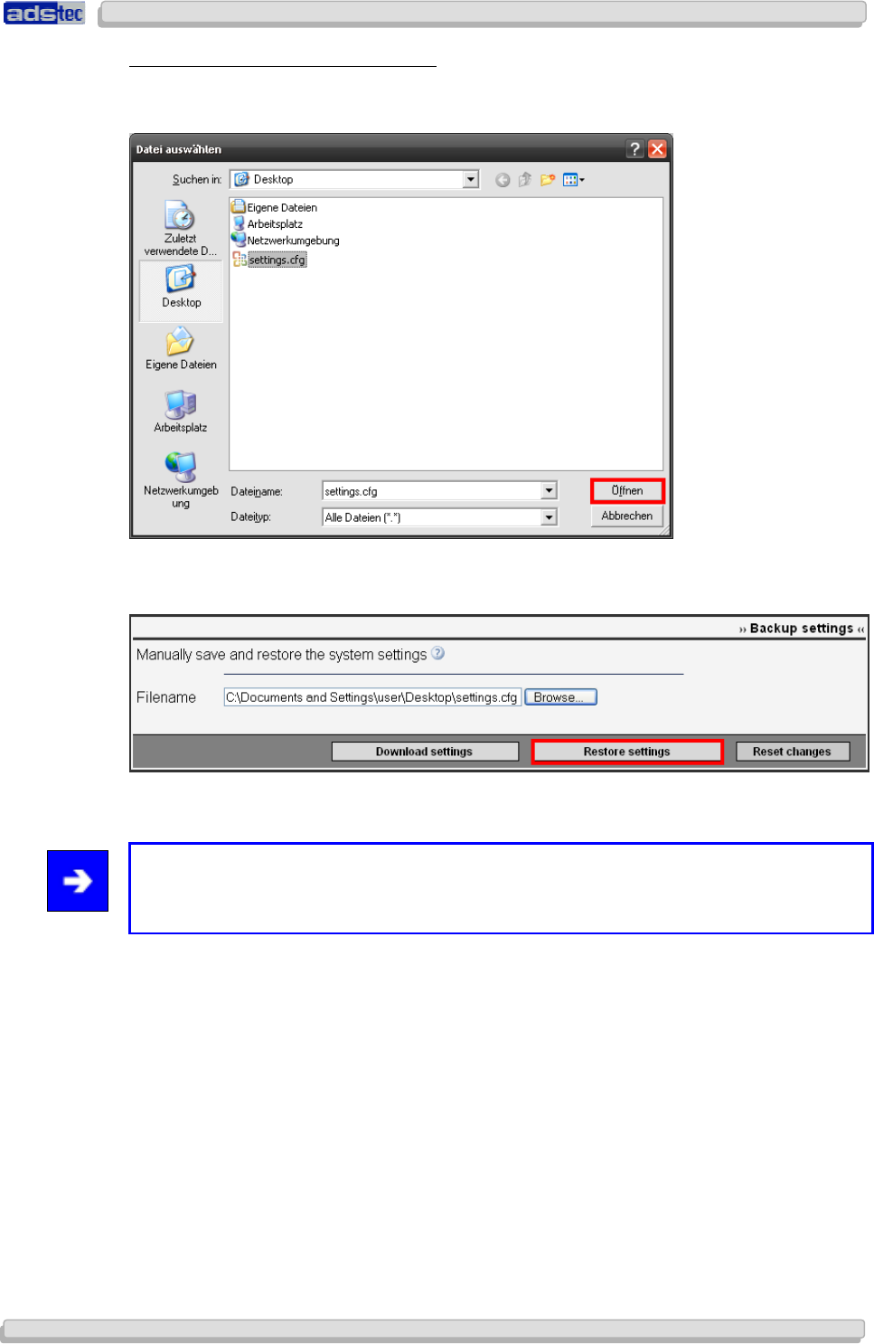
User Manual
User ManualUser Manual
User Manual Access Point /Client V 3.0.3
Access Point /Client V 3.0.3 Access Point /Client V 3.0.3
Access Point /Client V 3.0.3
© ads-tec GmbH • Raiffeisenstr.14 • 70771 Leinfelden-Echterdingen
87
8787
87
R
ESTORING A
D
EVICE
C
ONFIGURATION
:
To restore your saved settings, click Browse and select the file settings.cfg (unless you
saved your settings under a different file name).
Confirm by clicking Open.
Then click the button Restore Settings.
Reboot the device to load and apply the restored settings.
Note:
Version 1.x and 2.x configuration files (file extension .dat) are no longer supported in
version 3.x.
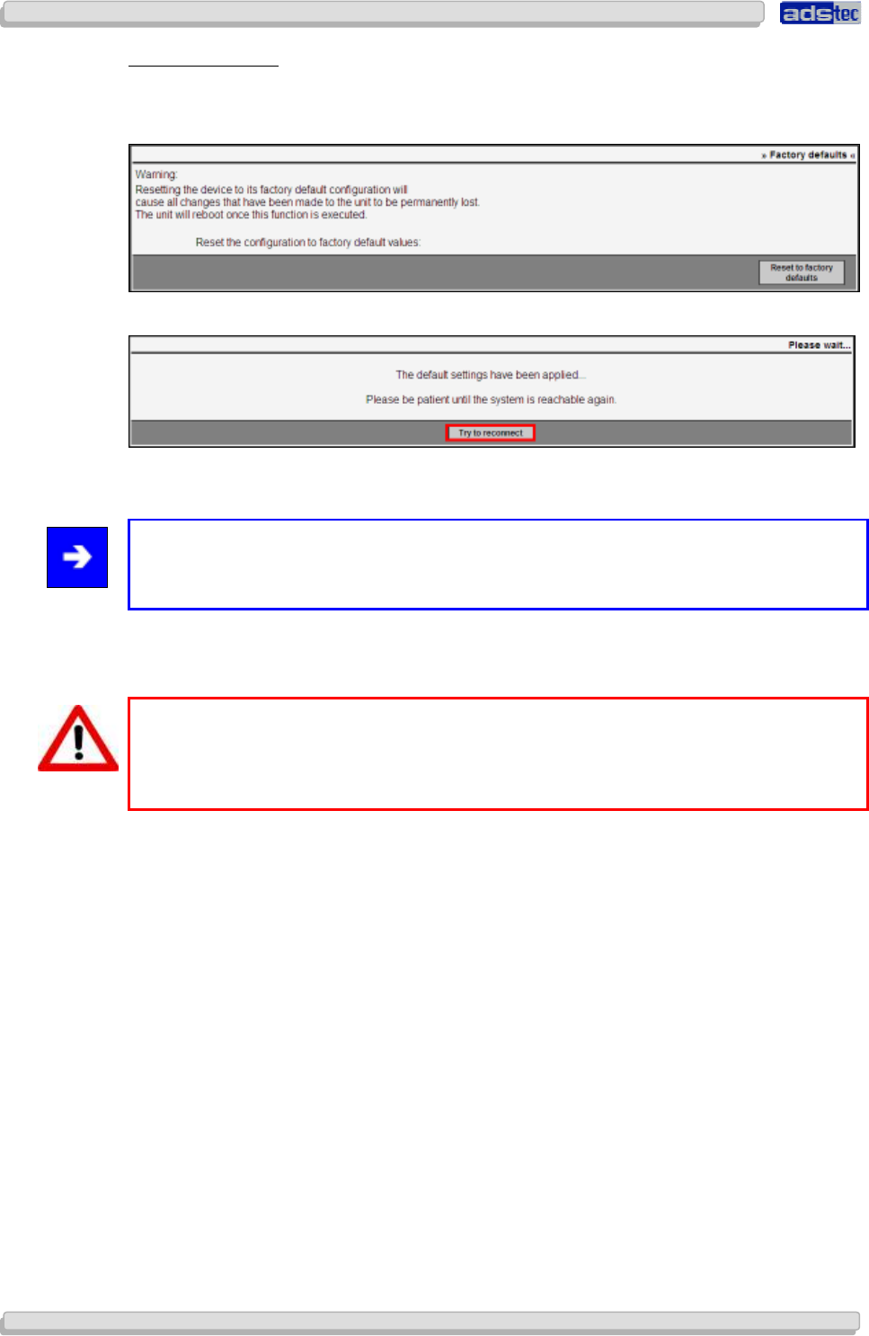
User Manual
User ManualUser Manual
User Manual Access Point /Client
Access Point /Client Access Point /Client
Access Point /Client V 3.0.3
V 3.0.3 V 3.0.3
V 3.0.3
88
8888
88
© ads-tec GmbH • Raiffeisenstr.14 • 70771 Leinfelden-Echterdingen
F
ACTORY
S
ETTINGS
This menu item allows resetting the device to its factory settings.
Clicking the button Restore Factory Settings will load the device’s default settings.
The following dialogue window will be displayed while factory settings are being restored.
Subsequently click the button Try to reconnect.
Note:
The button will only work if the IP address to be restored is identical to the pre-configured
IP address.
The Access Point will now try to access the web interface. If the update was successful the
web interface will appear.
Warning:
This option will reset all configuration settings. All user-defined filter rules will be
discarded. If you are unable to access the web interface after resetting the device to
factory settings you may need to adapt the IP address of your PC.
The following default settings will be restored:
• IP address: 192.168.0.254
• User name: admin
• Password: admin
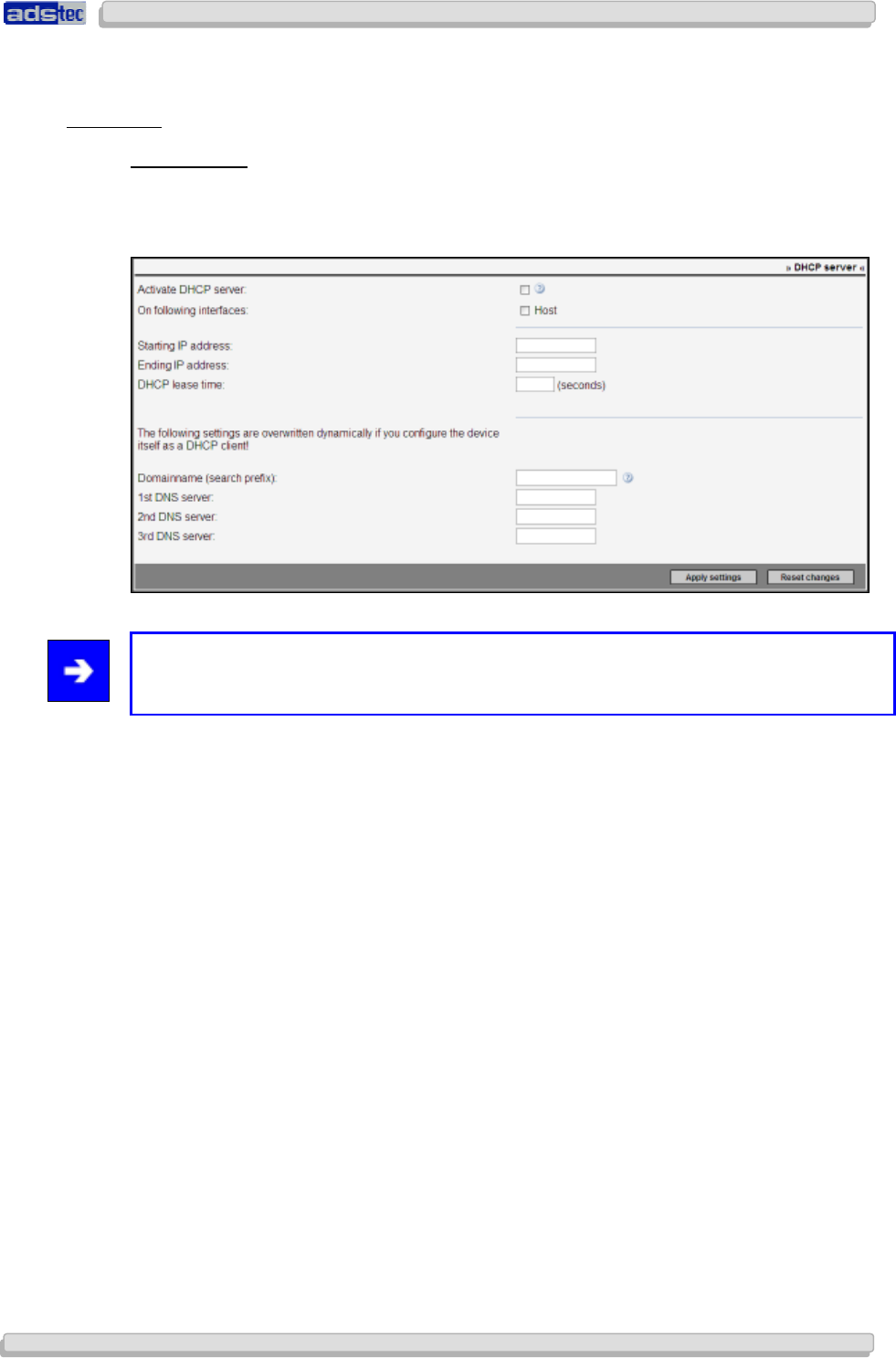
User Manual
User ManualUser Manual
User Manual Access Point /Client V 3.0.3
Access Point /Client V 3.0.3 Access Point /Client V 3.0.3
Access Point /Client V 3.0.3
© ads-tec GmbH • Raiffeisenstr.14 • 70771 Leinfelden-Echterdingen
89
8989
89
8.2 C
ONFIGURATION
8.2.1
8.2.18.2.1
8.2.1 Net
NetNet
Netwo
wowo
work
rkrk
rk
DHCP
S
ERVER
The integrated DHCP server can be used to automatically assign IP addresses. It is however
disabled by default and may be enabled by checkmarking the Activate DHCP Server
option.
Note:
The IP address of the interface itself needs to be within the IP address range!
The interfaces to be covered by the DHCP server can be specified in more detail by means
of the options available in the for the following interfaces section. This allows setting the
pool range individually for each interface.
In addition to IP addresses, the DHCP server can, in server operation, also forward a domain
lookup prefix as well as up to three DNS server addresses. This information is passed on to
DHCP clients. The device employs its own internal DNS service for temporary query storage.
If the Access Point itself operates as a DHCP client, rather than having a static IP address,
the DHCP server used in that case will overwrite these data.
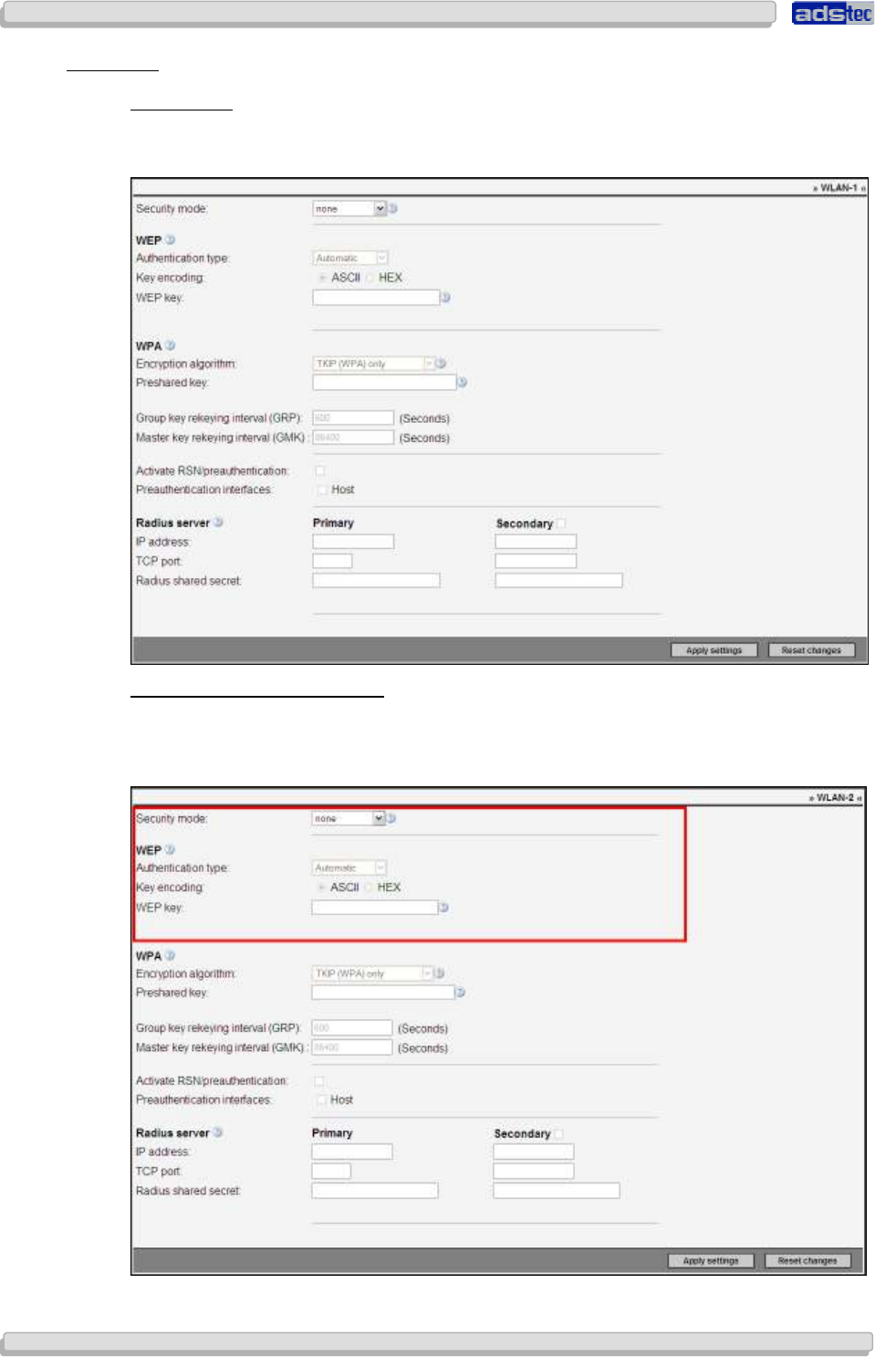
User Manual
User ManualUser Manual
User Manual Access Point /Client
Access Point /Client Access Point /Client
Access Point /Client V 3.0.3
V 3.0.3 V 3.0.3
V 3.0.3
90
9090
90
© ads-tec GmbH • Raiffeisenstr.14 • 70771 Leinfelden-Echterdingen
8.2.2
8.2.28.2.2
8.2.2 Security
SecuritySecurity
Security
WLAN
1
/
2
The WLAN security menu allows configuring the security standard for the wireless network.
The following modes are available:
WEP
64
B
ITS
/
WEP
128
B
ITS
Like WPA, the WEP 64 Bits / 128 Bits mode requires a keyword for securing wireless
communications. The chief difference is that in WPA mode, this key changes dynamically
during a connection, whereas it remains static in WEP mode.
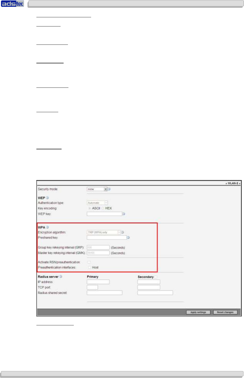
User Manual
User ManualUser Manual
User Manual Access Point /Client V 3.0.3
Access Point /Client V 3.0.3 Access Point /Client V 3.0.3
Access Point /Client V 3.0.3
© ads-tec GmbH • Raiffeisenstr.14 • 70771 Leinfelden-Echterdingen
91
9191
91
A
UTHENTICATION
M
ODE
:
Automatic:
In Automatic mode, the authentication mode is selected automatically.
Open System:
Open System authentication is the default authentication setting.
Shared Key:
Shared Key authentication employs an enhanced handshake mechanism during login, which
does, however, not provide any additional security.
Key Encoding:
You may select ASCII or HEX key encoding. ASCII is a 7-bit encoding scheme, HEX is a 16-
bit scheme.
WEP Key:
WEP key length is limited to 5 characters in ASCII encoding mode. Using HEX encoding,
keys with a length of up to 10 characters may be chosen. Rather than actual words, we
recommend using alphanumeric combinations of letters and numbers in order to ensure
optimal security.
WPA/PSK
WPA/PSK mode secures communications by requiring a keyword and employing a particular
data encryption method. The keyword (Pre-Shared Key) may contain a minimum of 8 and a
maximum of 63 characters. Rather than actual words, we recommend using alphanumeric
combinations of letters and numbers in order to ensure optimal security.
Data Encryption:
You may choose to either use all data encryption methods or select a particular method.
Please note that WPA 2 encryption requires that all network access points and clients
support the WPA 2 standard.
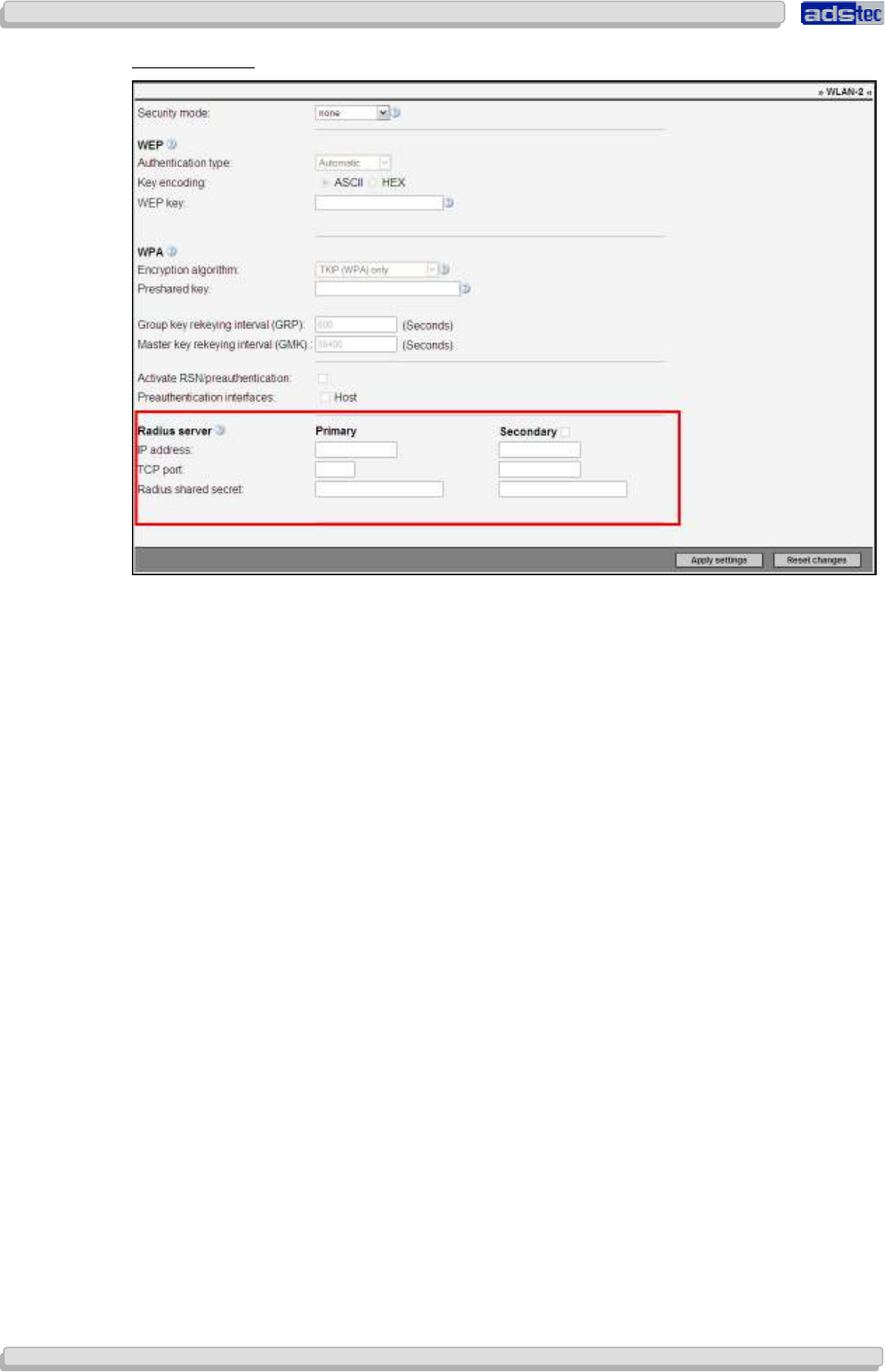
User Manual
User ManualUser Manual
User Manual Access Point /Client
Access Point /Client Access Point /Client
Access Point /Client V 3.0.3
V 3.0.3 V 3.0.3
V 3.0.3
92
9292
92
© ads-tec GmbH • Raiffeisenstr.14 • 70771 Leinfelden-Echterdingen
WPA
RADIUS
The Access Point is able to use an existing external RADIUS server for user authentication.
This requires entering the IP address of the RADIUS server in the IP Address field.
You also need to specify the TCP port used by the RADIUS server in the field TCP Port. Most
RADIUS servers use the standard TCP port 1812.
The RADIUS keyword is required by the RADIUS server to identify and authenticate the
Access Point.
In case two RADIUS servers are used, an alternative configuration may be entered in the
Secondary section. These settings will only take effect if the first RADIUS server is
unreachable. The Access Point will then try to establish a connection to the secondary
RADIUS server.
Confirm by clicking Activate
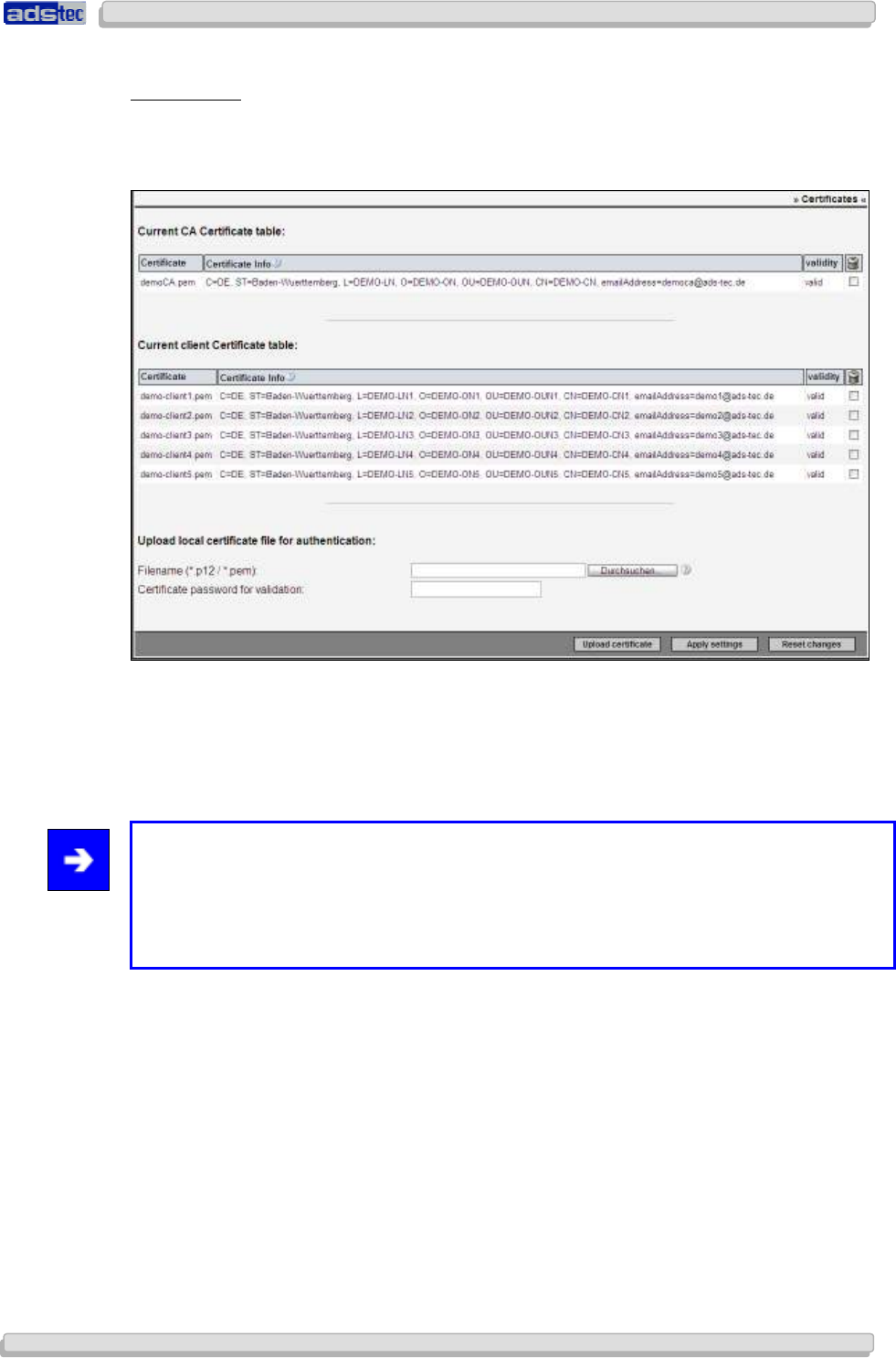
User Manual
User ManualUser Manual
User Manual Access Point /Client V 3.0.3
Access Point /Client V 3.0.3 Access Point /Client V 3.0.3
Access Point /Client V 3.0.3
© ads-tec GmbH • Raiffeisenstr.14 • 70771 Leinfelden-Echterdingen
93
9393
93
C
ERTIFICATES
The Access Point uses certificates to authenticate L2TP/IPSec, OpenVPN and HTTPS web
server connections. The Access Point Certificate Management web interface shown below
lists a number of demo certificates only generated for test purposes.
When a certificate is uploaded, its validity is automatically checked. An invalid certificate,
e.g. one for which the date and time range do not match the Access Point’s system time, will
be indicated by the word
invalid
in the validity column. A question mark symbol will appear
for the invalid certificate. Click that symbol to obtain further information on the
corresponding system error message.
Note:
A *.pem certificate file must contain a private key as well as a public certificate part. The
private key needs to be available in RSA format.
Certificates are also classified as invalid if no corresponding CA file can be found on the
system.
Select Activate to apply your settings.
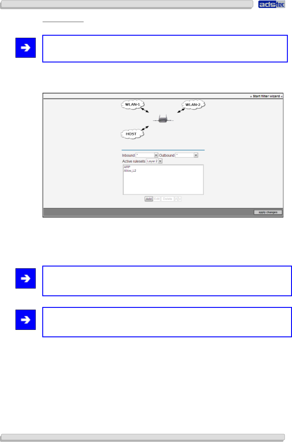
User Manual
User ManualUser Manual
User Manual Access Point /Client
Access Point /Client Access Point /Client
Access Point /Client V 3.0.3
V 3.0.3 V 3.0.3
V 3.0.3
94
9494
94
© ads-tec GmbH • Raiffeisenstr.14 • 70771 Leinfelden-Echterdingen
F
ILTER
W
IZARD
Note:
The Filter Wizard may also be started via the web interface start page.
The Filter Wizards supports you in creating rules by automatically prompting you for
essential configuration parameters in a step-by-step process.
The clouds shown in the upper part of the screen are used to illustrate the paths of
communication between the selected incoming/outgoing interfaces.
Once a layer has been defined, only those rules pertaining to that layer will be displayed. All
active rules will be shown in the overview window.
Note:
Rules are processed in the sequence in which they are displayed in the list. If one rule is
triggered for a particular data packet, that packet will not be processed further.
Note:
Once a rule has been defined, you need to select Apply Changes in the web interface to
test their functionality.
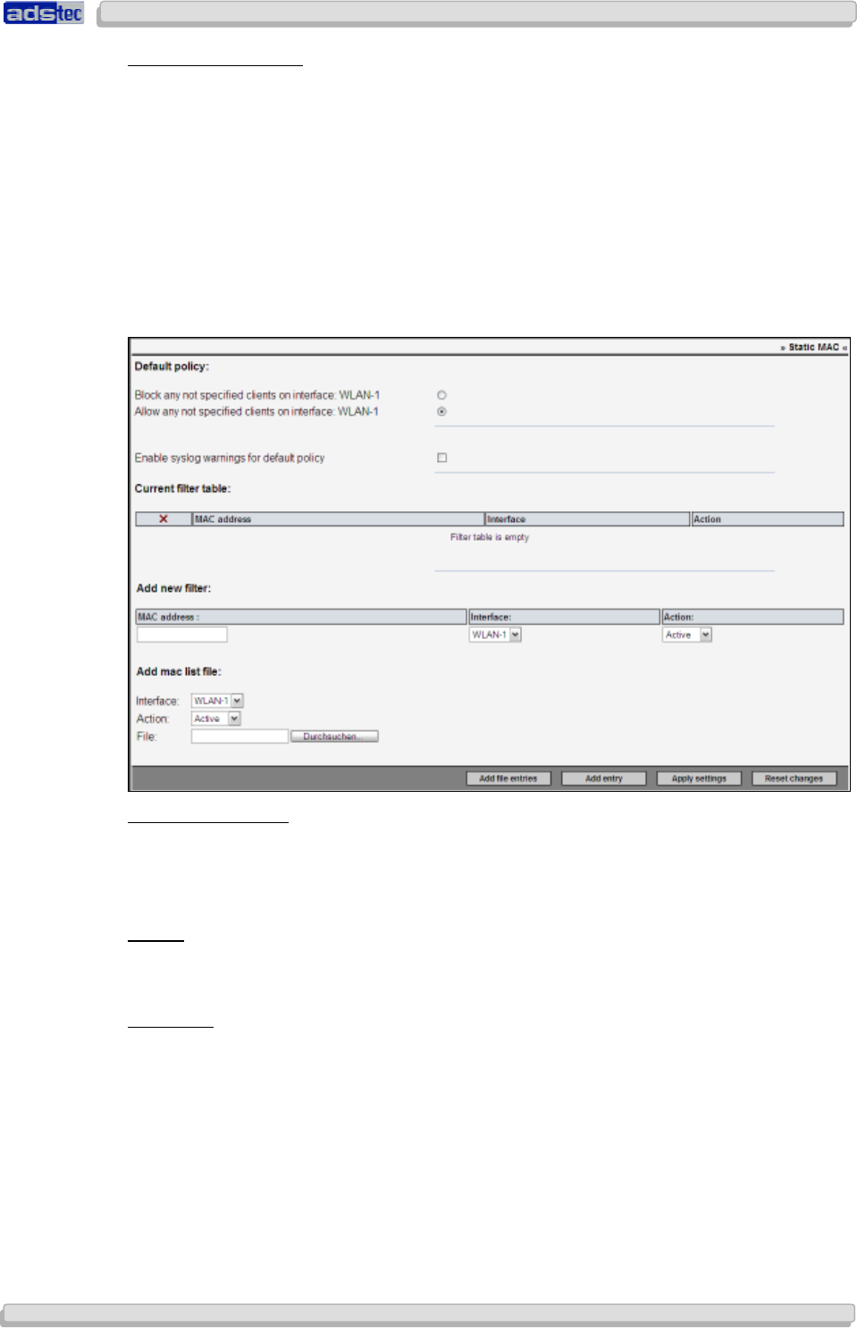
User Manual
User ManualUser Manual
User Manual Access Point /Client V 3.0.3
Access Point /Client V 3.0.3 Access Point /Client V 3.0.3
Access Point /Client V 3.0.3
© ads-tec GmbH • Raiffeisenstr.14 • 70771 Leinfelden-Echterdingen
95
9595
95
S
TATIC
MAC
A
DDRESS
The static MAC filter can be used as an access control option for any interface set to Access
Point mode. MAC address filtering entails checking a client’s physical (MAC) address against
an access list; only clients with a MAC address contained in that list will be granted access. If
access is blocked for a particular client, that client will be denied access during the 802.11
authentication process. As MAC addresses can be faked relatively easily, this option does not
offer a high level of security. When using WPA data encryption, MAC filtering is not required
as WPA itself offers sufficient security. However, MAC address filtering may be useful as an
additional means of protection if less secure WEP encryption is employed. The MAC filter
table cannot be applied to interfaces not set to Access Point mode. In that case, the
message “No WLAN interfaces in AP mode. Filter inactive.” will appear.
This option is not available for the RAC111x and RAC151x.
Standard Behaviour:
The Standard Behaviour defines how the device handles MAC addresses contained in the
filter table. A client may either be explicitly blocked (blacklist) or explicitly allowed (whitelist).
The latter is the setting employed in most cases.
Syslog:
Enabling this option will add a message to the system event log every time a client is denied
access because it is explicitly or implicitly blocked.
New Filter:
In order to create a new filter, enter a client’s MAC address (format example:
00:50:C2:45:A1:BB) and the interface(s) on which to apply the new filter (WLAN-1, WLAN-2,
*). Select “active” or “inactive” in the “Action” column to temporarily disable an entry or
in order to not activate it immediately. Subsequently click “Add” to save the new MAC
address filter entry.
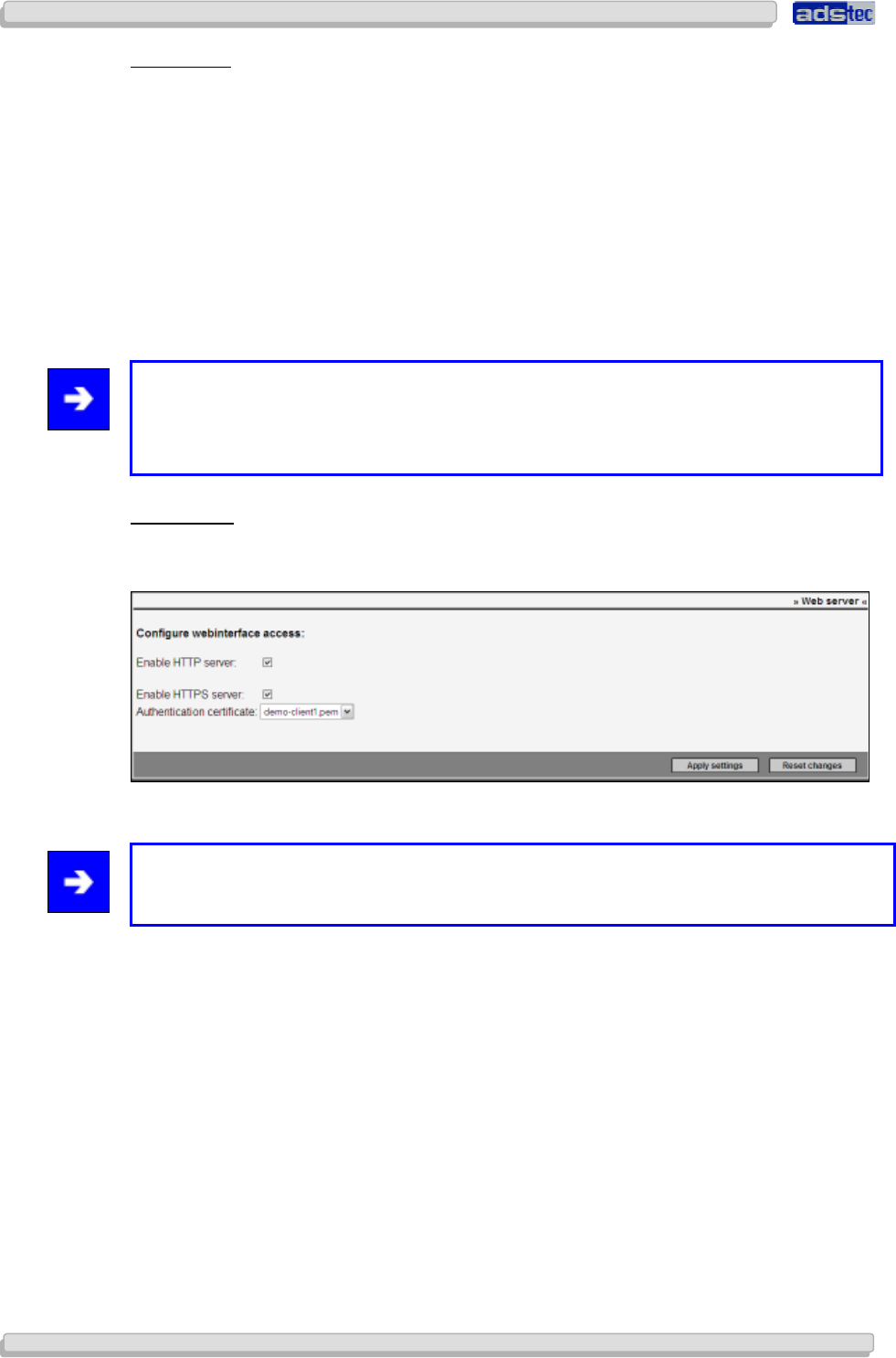
User Manual
User ManualUser Manual
User Manual Access Point /Client
Access Point /Client Access Point /Client
Access Point /Client V 3.0.3
V 3.0.3 V 3.0.3
V 3.0.3
96
9696
96
© ads-tec GmbH • Raiffeisenstr.14 • 70771 Leinfelden-Echterdingen
MAC list file:
If you wish to configure multiple MAC addresses at once, it may be helpful to use a text file
with a list of MAC addresses, rather than entering each address individually. A MAC list file
must contain one MAC address per line, for example:
00:50:C2:48:A1:00
00:50:C2:48:A1:02
00:50:C2:48:A1:01
Additionally, you need to select the corresponding interface and specify whether all MAC
addresses loaded this way are to be set to “active” or “inactive”. The list of MAC
addresses is then added to the existing filter entries. The system’s MAC address filter list is
limited to a maximum of 500 entries.
Note:
An extensive list takes longer to process – each entry requires approximately 1 second.
This time will also be required during the device boot sequence when all configuration
settings are loaded.
W
EB
S
ERVER
Use the Web Server Access Control menu to configure access to the Access Point web
interface via the HTTP and HTTPS protocols.
The Access Point’s integrated web server will subsequently be accessible through the
enabled protocol interfaces.
Note:
For optimal security, an individual certificate should be assigned to each Access Point.
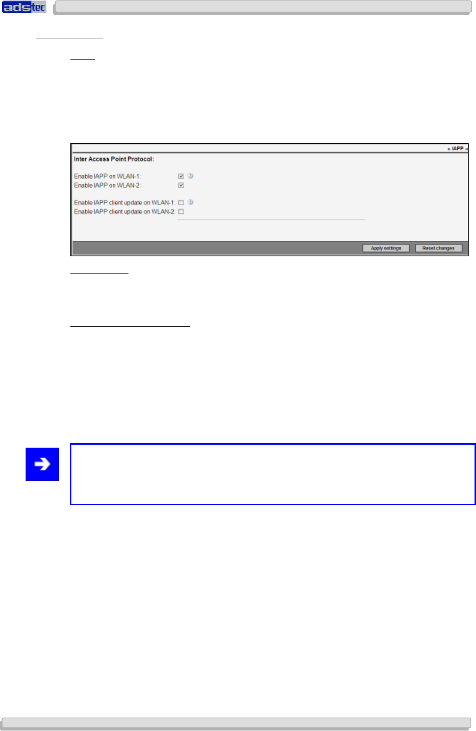
User Manual
User ManualUser Manual
User Manual Access Point /Client V 3.0.3
Access Point /Client V 3.0.3 Access Point /Client V 3.0.3
Access Point /Client V 3.0.3
© ads-tec GmbH • Raiffeisenstr.14 • 70771 Leinfelden-Echterdingen
97
9797
97
8.2.3
8.2.38.2.3
8.2.3 Adv.
Adv.Adv.
Adv.
WLAN
WLANWLAN
WLAN
IAPP
The IAPP is employed to exchange control and additional information between Access
Points. For instance, an AP sends an IAPP notification to all other APs in the same network
whenever a new client logs into the network. All other APs may then remove that client from
their table of logged-in clients. Regardless of this setting, an LLC Xid packet, originally also
defined as part of the IAPP, will be transmitted in any case whenever a client logs into the
network.
Activate IAPP
This option enables IAPP broadcasts and reception of IAPP messages on Access Points.
Activate IAPP Client Update
This option enables a special ads-tec extension of the IAP protocol. This extension will, at a
1 second interval, send the 802.11 beacon information via the Ethernet as an IAPP
broadcast. ads-tec clients are able to receive these messages and can thus obtain
information about all APs in the network, independent of whether these APs are already
visible to the client through a wireless connection. This information is particularly useful for
automatic channel resolution in the 5 GHz band when using fast roaming.
Hence, this option is only useful when fast roaming is employed.
Note:
The IAPP (Inter-Access Point Protocol) was defined in the IEEE 802.11f recommendation.
It was only defined as a trial use recommendation and withdrawn in 2006. Consequently,
IAPP is not a standardised protocol.
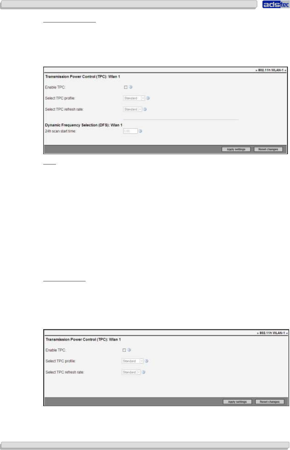
User Manual
User ManualUser Manual
User Manual Access Point /Client
Access Point /Client Access Point /Client
Access Point /Client V 3.0.3
V 3.0.3 V 3.0.3
V 3.0.3
98
9898
98
© ads-tec GmbH • Raiffeisenstr.14 • 70771 Leinfelden-Echterdingen
802.11
H
WLAN-1
802.11h is an extension of the IEEE 802.11 WLAN standard, introduced to avoid, particularly
in Europe, interference with satellite and radar systems employing the 5 GHz band. The
standard consists of two chief components: DFS (Dynamic Frequency Selection) and TPC
(Transmission Power Control). DFS settings for this device can be configured on the
standard WLAN configuration page.
TPC:
The objective of Transmission Power Control is to reduce the device’s average transmission
power as much as possible. TPC is always active when a 5 GHz channel is used – it cannot
be turned off in such cases. By default, TPC is not active in the 2.4 GHz band, but it may be
enabled if desired.
Power Profiles:
• Standard: Optimises transmission power for a data rate of 48 MBit/s.
• Max. Power: Optimises transmission power for a data rate of 54 MBit/s.
• Min. Power: Optimises transmission power for a data rate of 11/12 MBit/s.
TPC Update Rate:
Clients moving quickly should use the higher update rate in order to prevent connection
losses. The lower rate may be used for static connections.
DFS Scan Time:
DFS requires the WLAN to be deactivated once every 24 hours in order to scan all available
channels for radar signals (this process takes at least one minute). To avoid occurrence of
this obligatory connection loss at critical times, you may specify a particular time at which to
perform the DFS radar scan.
( FCC-Version )

User Manual
User ManualUser Manual
User Manual Access Point /Client V 3.0.3
Access Point /Client V 3.0.3 Access Point /Client V 3.0.3
Access Point /Client V 3.0.3
© ads-tec GmbH • Raiffeisenstr.14 • 70771 Leinfelden-Echterdingen
99
9999
99
Note:
The FCC version of the device does not offer the DFS option.
Warning:
In order to ensure the system time and date settings are correct, you need to specify an
NTP server!
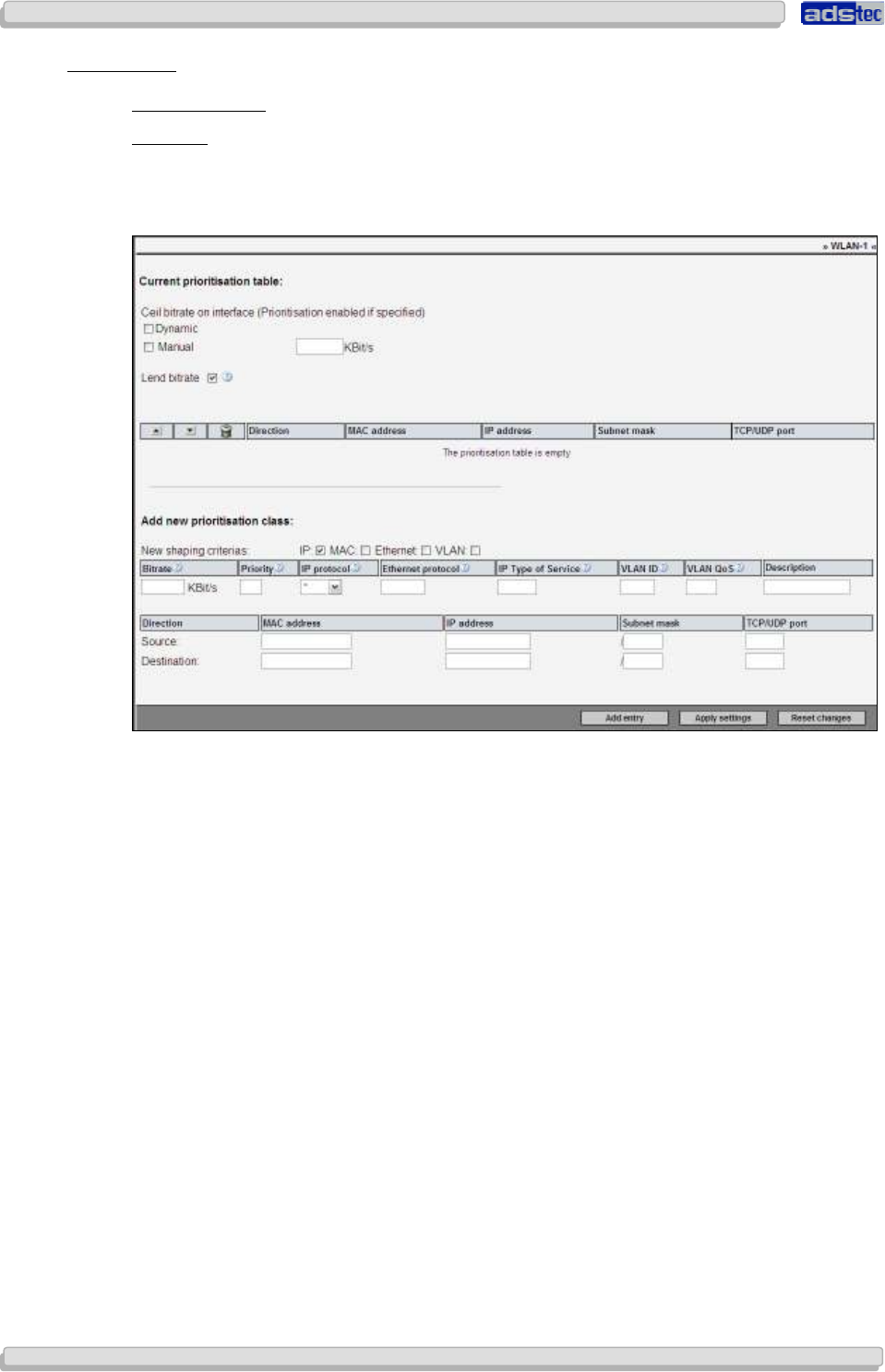
User Manual
User ManualUser Manual
User Manual Access Point /Client
Access Point /Client Access Point /Client
Access Point /Client V 3.0.3
V 3.0.3 V 3.0.3
V 3.0.3
100
100100
100
© ads-tec GmbH • Raiffeisenstr.14 • 70771 Leinfelden-Echterdingen
8.2.4
8.2.48.2.4
8.2.4 Advanced
AdvancedAdvanced
Advanced
P
RIORITISATION
WLAN-1
The integrated prioritisation feature allows a more nuanced handling of data streams
between interfaces. Particular data packets can be preferred by assigned a higher priority to
them; furthermore, the bandwidth of specific protocols can be restricted.
The prioritisation feature is enabled by entering a maximum bit rate and at least one priority
class. For instance, if the Ethernet infrastructure as a maximum bandwidth of 50Mbit/sec the
maximum bit rate of 50000kbit/s should be entered.
Not all priority class criteria can be combined with each other. For example, IP cannot be
selected in conjunction with VLAN due to the underlying protocol architectures and
principles.
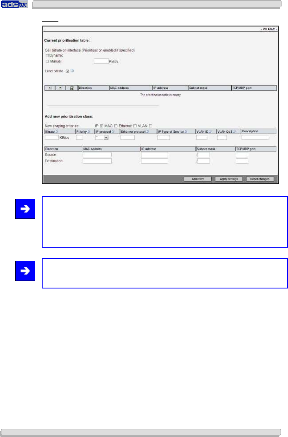
User Manual
User ManualUser Manual
User Manual Access Point /Client V 3.0.3
Access Point /Client V 3.0.3 Access Point /Client V 3.0.3
Access Point /Client V 3.0.3
© ads-tec GmbH • Raiffeisenstr.14 • 70771 Leinfelden-Echterdingen
101
101101
101
HOST
Note:
In order to prioritise a particular data stream, you need to create at least two classes. The
first is assigned the lowest priority value in the Priority field and thus specifies the preferred
data traffic. The second class represents the remaining stream of data and should get a
reduced bit rate value. This ensures sufficient bandwidth is available to the prioritised data
traffic of the first priority class.
Note:
In the Priority input field, a low numeric value stands for a short Ethernet packet latency,
while a high value represents a longer latency period.
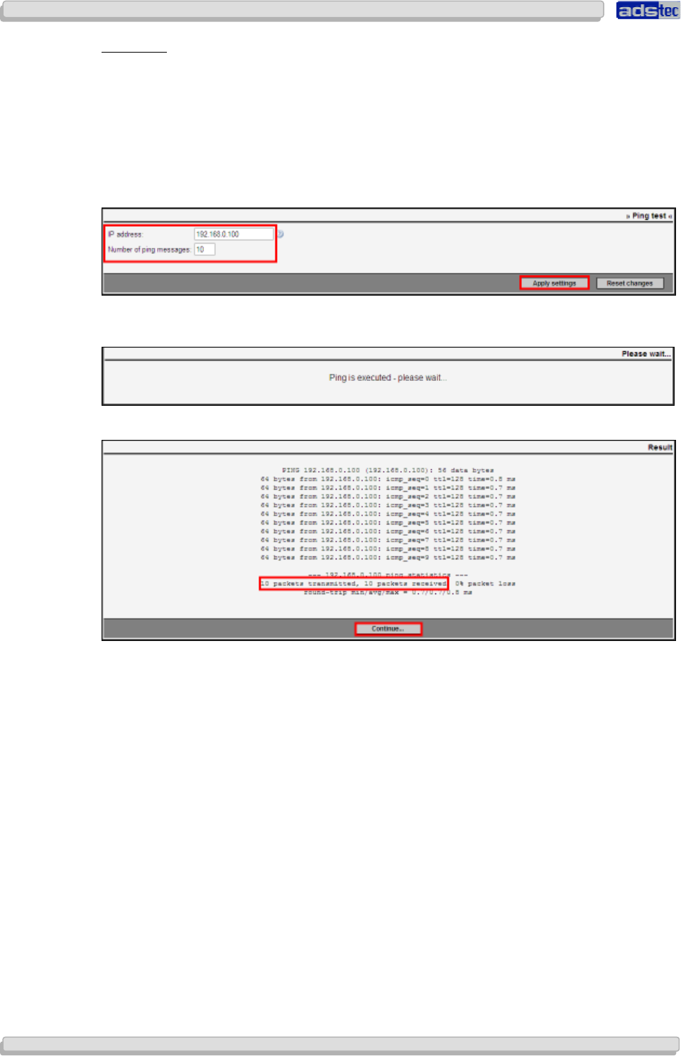
User Manual
User ManualUser Manual
User Manual Access Point /Client
Access Point /Client Access Point /Client
Access Point /Client V 3.0.3
V 3.0.3 V 3.0.3
V 3.0.3
102
102102
102
© ads-tec GmbH • Raiffeisenstr.14 • 70771 Leinfelden-Echterdingen
P
ING
T
EST
The Ping test can be used to test whether a particular remote station is reachable across the
network. The test will send the an Echo-Request packet to the target address and analyses
the data received as reply.
Specify the remote station to be checked by entering its IP address in the corresponding
field. Additionally, the number of packets to send needs to be specified. It is limited to a
maximum of 10 packets.
Clicking Activate will start the Ping Test.
After a short time, an overview showing the course and the result of the Ping Test will
appear. The overview shows the status of all packets that were sent and received.
Click Next to end the Ping Test.
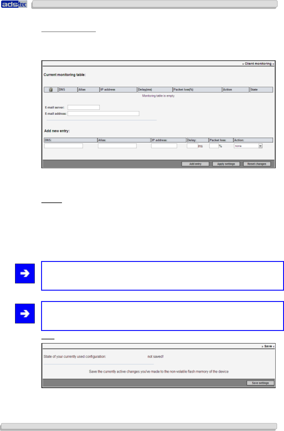
User Manual
User ManualUser Manual
User Manual Access Point /Client V 3.0.3
Access Point /Client V 3.0.3 Access Point /Client V 3.0.3
Access Point /Client V 3.0.3
© ads-tec GmbH • Raiffeisenstr.14 • 70771 Leinfelden-Echterdingen
103
103103
103
C
LIENT
M
ONITORING
The integrated Client Monitoring feature allows monitoring network participants and their
reachability. All clients to be monitored need to be added to the monitoring table; their
reachability will be checked by means of periodic ICMP messages.
An action can be triggered by any monitored client in the event of a loss of connection to
that client. This action may for instance consist of an email being sent to a supervisor or
similar.
Action:
up/down WLAN-1/2
With this option selected the WLAN adapter will be shut down in case the Ethernet
participant can no longer be reached via ICMP. When monitoring the AP’s gateway via ICMP
messages, the AP is only able to detect that its uplink is lost. The WLAN interface the shuts
down and thus kicks out all connected clients. Otherwise, a client may log in to the network
via the AP in question although that AP does not have sufficient connectivity. In that case,
the client should use a different AP to connect to the network.
Note:
The current time of all ICMP replies may be checked by calling up a tooltip on a symbolic LED
in the status field.
Note:
An email notification is sent out each time a status changes, providing valid entries are
specified in the Email Server and Email Address fields.
S
AVE
Any configuration changes can be saved to the Flash memory by clicking the Save button.
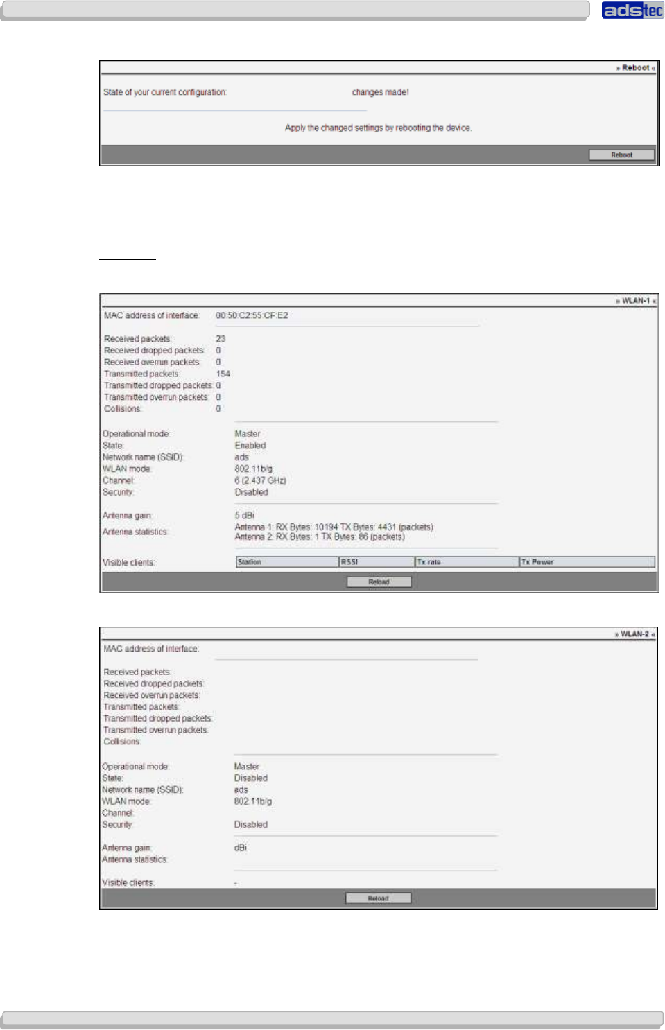
User Manual
User ManualUser Manual
User Manual Access Point /Client
Access Point /Client Access Point /Client
Access Point /Client V 3.0.3
V 3.0.3 V 3.0.3
V 3.0.3
104
104104
104
© ads-tec GmbH • Raiffeisenstr.14 • 70771 Leinfelden-Echterdingen
R
EBOOT
Clicking Reboot will reboot the Access Point.
8.3 D
IAGNOSIS
WLAN-1
View: Access Point Mode
View: Access Client Mode
The WLAN-1 interface status display indicates data traffic and relevant traffic information.
Click Reload to update the information on this page.

User Manual
User ManualUser Manual
User Manual Access Point /Client V 3.0.3
Access Point /Client V 3.0.3 Access Point /Client V 3.0.3
Access Point /Client V 3.0.3
© ads-tec GmbH • Raiffeisenstr.14 • 70771 Leinfelden-Echterdingen
105
105105
105
HOST
Based on the indicated data, the behaviour of sent and received packets can be monitored.
Click reload to update the information on this page.
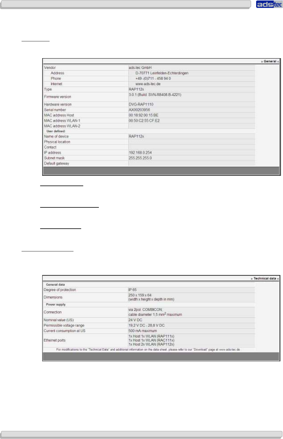
User Manual
User ManualUser Manual
User Manual Access Point /Client
Access Point /Client Access Point /Client
Access Point /Client V 3.0.3
V 3.0.3 V 3.0.3
V 3.0.3
106
106106
106
© ads-tec GmbH • Raiffeisenstr.14 • 70771 Leinfelden-Echterdingen
8.4 A
DDITIONAL
I
NFORMATION
8.4.1
8.4.18.4.1
8.4.1 General
GeneralGeneral
General
The menu item General displays basic information about the device.
1)M
ANUFACTURER
:
This field shows all relevant contact data for the device manufacturer ads-tec GmbH.
2)D
EVICE
I
NFORMATION
:
This section lists all relevant device data, such as type, firmware and hardware version, etc.
3)U
SER
-D
EFINED
:
All user-defined device data is shown in this section.
8.4.2
8.4.28.4.2
8.4.2 Techni
TechniTechni
Technical
cal cal
cal Dat
DatDat
Data
aa
a
The Technical Data screen lists general operating data, including details on the permissible
power supply.
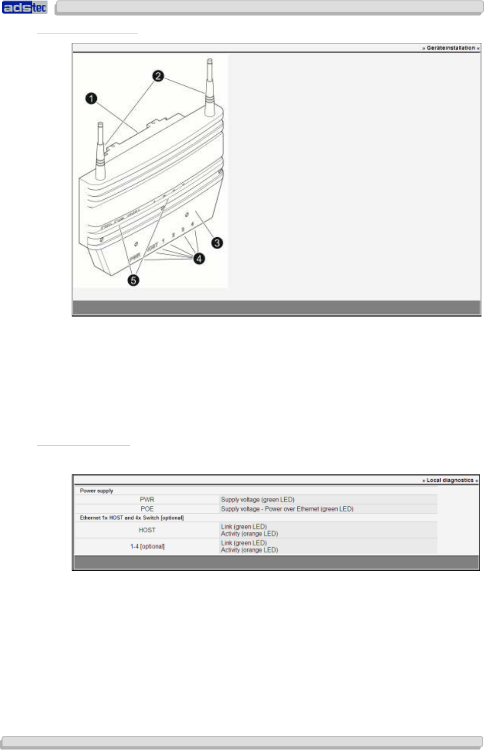
User Manual
User ManualUser Manual
User Manual Access Point /Client V 3.0.3
Access Point /Client V 3.0.3 Access Point /Client V 3.0.3
Access Point /Client V 3.0.3
© ads-tec GmbH • Raiffeisenstr.14 • 70771 Leinfelden-Echterdingen
107
107107
107
8.4.3
8.4.38.4.3
8.4.3 Device
Device Device
Device Mounting
MountingMounting
Mounting
1) Mounting plate (for mounting the Access Point to the installation site)
2) Antenna
3) Maintenance Duct Cover
4) Interfaces
5) Status indicators
8.4.4
8.4.48.4.4
8.4.4 Loc
LocLoc
Loca
aa
al Diagnosis
l Diagnosisl Diagnosis
l Diagnosis
The Local Diagnosis screen lists the LED indicator behaviour for different system states.
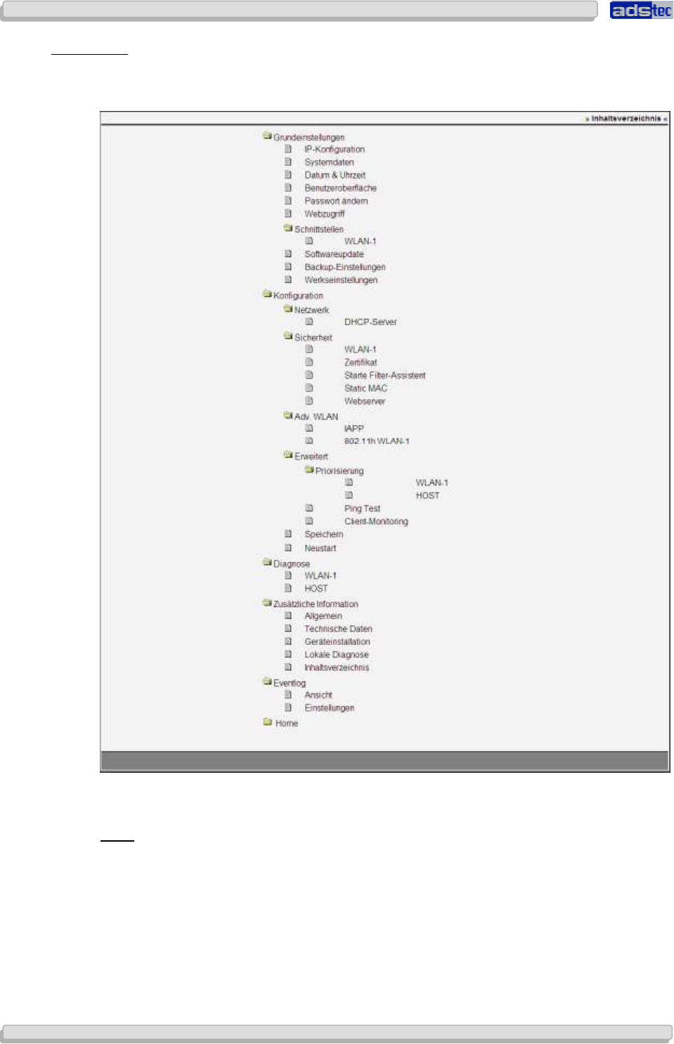
User Manual
User ManualUser Manual
User Manual Access Point /Client
Access Point /Client Access Point /Client
Access Point /Client V 3.0.3
V 3.0.3 V 3.0.3
V 3.0.3
108
108108
108
© ads-tec GmbH • Raiffeisenstr.14 • 70771 Leinfelden-Echterdingen
8.4.5
8.4.58.4.5
8.4.5 Site Map
Site MapSite Map
Site Map
For direct and easy access to configuration settings, the Site Map shows a tree structure of
the web interface including all of its sub-menus.
8.5 E
VENT LOG
V
IEW
The Event log is the device’s most important diagnosis tool. The log contains essential
information on the system status. Any system error messages will be logged and displayed
here. The event log display is comparable to a transcript of system activities. Any
configuration changes and error messages can be viewed here.
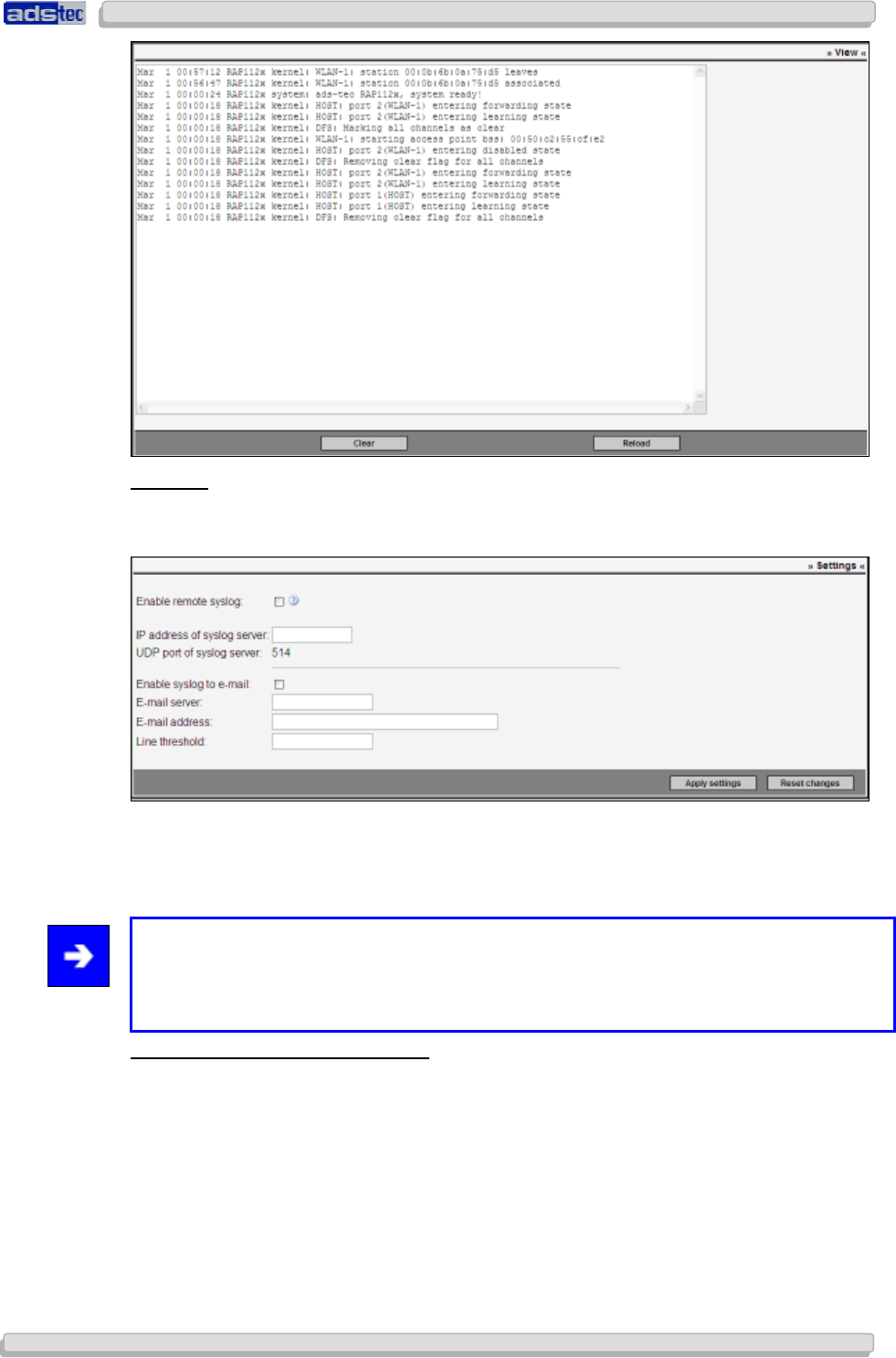
User Manual
User ManualUser Manual
User Manual Access Point /Client V 3.0.3
Access Point /Client V 3.0.3 Access Point /Client V 3.0.3
Access Point /Client V 3.0.3
© ads-tec GmbH • Raiffeisenstr.14 • 70771 Leinfelden-Echterdingen
109
109109
109
S
ETTINGS
The Event log transcript can also be sent to a central computer for ease and convenience of
access. To enable this feature, specify the remote computer in the input fields.
Additionally, you may opt to send out the system log via email. To enable this feature,
checkmark the corresponding check box and specify an email server and a recipient email
address.
Note:
In order to avoid an unnecessarily high volume of emails, we recommend specifying a
suitable threshold value in the “Number of Lines” input field. This value defines how many
lines of event log entries need to have accumulated before an email is sent out.
S
TART
P
AGE
S
ETUP
&
F
ILTER
W
IZARD
Can be used to navigate back to the start page, from where the Wizards are accessible.
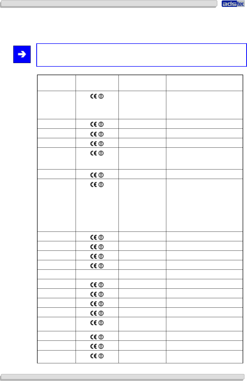
User Manual
User ManualUser Manual
User Manual Access Point /Client
Access Point /Client Access Point /Client
Access Point /Client V 3.0.3
V 3.0.3 V 3.0.3
V 3.0.3
110
110110
110
© ads-tec GmbH • Raiffeisenstr.14 • 70771 Leinfelden-Echterdingen
9
99
9 R
RR
R
EGULATORY
EGULATORY EGULATORY
EGULATORY
A
AA
A
PPROVALS
PPROVALSPPROVALS
PPROVALS
9.1 E
UROPEAN
A
PPROVALS
Note:
Some national regulations may in effect restrict the functionality of the device.
Country Tags 2.4–2.4835 GHz
IEEE 802.11b/g Restrictions
Belgium
X
Use of 5150-5350 MHz range
only allowed indoors
TP
C and DFS mandatory for
5GHz band
Germany X
Finland X
Greece X
Ireland
X
Indoor use only for 5150-
5350
MHz band
Latvia X
Luxembourg
X
Indoor use only for 5150-
5350
MHz band. Only mobile
applications allowed in the 5
GHz band.
RLAN/WLAN used for public
service requires an
autorisation
générale
from the ILR (Institut
Luxembourgeois de Regulation)
Netherlands X
Poland X
Sweden X
Slovenia X
Czech Republic
X
Cyprus X
Denmark X
Estonia X
France X
United
Kingdom
X
Italy X
Lithuania X
Malta X This equipment may be placed
on the local market,
subject to
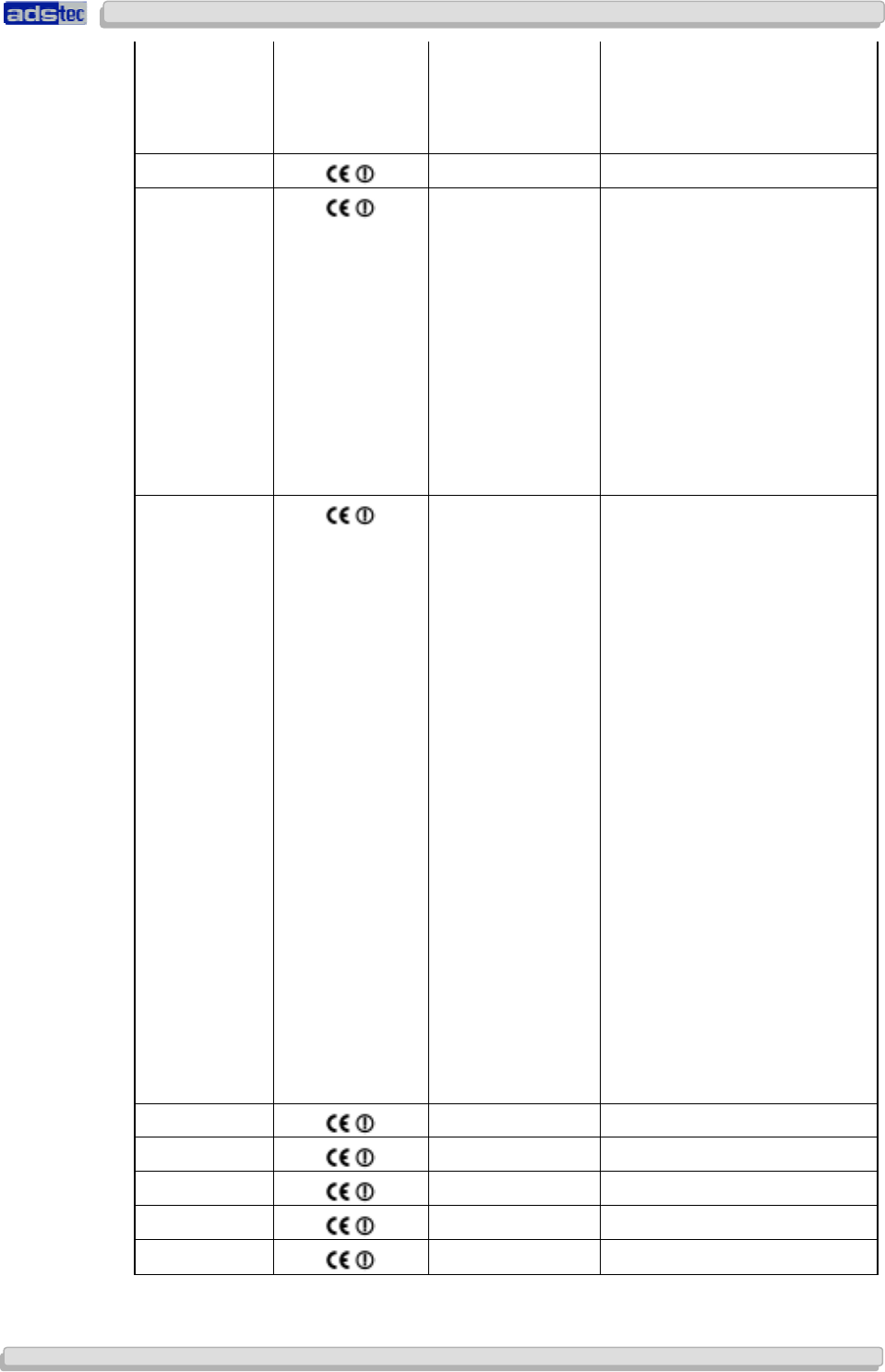
User Manual
User ManualUser Manual
User Manual Access Point /Client V 3.0.3
Access Point /Client V 3.0.3 Access Point /Client V 3.0.3
Access Point /Client V 3.0.3
© ads-tec GmbH • Raiffeisenstr.14 • 70771 Leinfelden-Echterdingen
111
111111
111
the condition
that a copy of the
Declaration of Conformity is
submitted to the
Authority by
the person intending to market
the equipment.
Austria X
Portugal
X
Information: for this type of
applications an integral or
dedicated antenna is required.
In the frequency ranges
of
5250-5350MHz and 5470-
5725MHz DFS and TPC are
mandatory.
If the equipment does not
implement DFS, use will be
limited to the frequency range
5150-5250MHz, with a limited
maximum output power (EIRP)
of 0.25mW/25kHz
Slovakia
X
O
peration of the wireless LAN
equipment is allowed in the
frequency band 2400-
2483.5MHz, subject to the
conditions laid down in the
General Authorisation No. VPR-
01/2001 (20 dBM EIRP) issued
by the Telecommunications
Office of the Slovak Republic
. In
the frequency band 5150-
5350MHz,
operation of WLAN
equipment is allowed
subject to
the conditions laid down in the
General Authorisation No.: VPR-
03/2004 (indoors only 5150-
5350MHz
with DFS: 200mW
EIRP with TPC, 120mW EIRP
without TPC; 5150-5250MHz
without DFS: 120mW EIRP with
TPC, 60mW EIRO without TPC)
.
In the frequency band 5470-
5725MHz,
operation of WLAN
equipment is allowed, subject to
the conditions laid down in the
General Authorisation No.: VPR-
07/2004 (1W EIRP, DFS & TCP
are required)
Spain X
Hungary X
Switzerland X
Norway X
Iceland X
User Manual
User ManualUser Manual
User Manual Access Point /Client
Access Point /Client Access Point /Client
Access Point /Client V 3.0.3
V 3.0.3 V 3.0.3
V 3.0.3
112
112112
112
© ads-tec GmbH • Raiffeisenstr.14 • 70771 Leinfelden-Echterdingen
9.2 FCC-A
PPROVAL
This device complies with Part 15 of the FCC Rules and with RSS-210 of Industry Canada.
Operation is subject to the following two conditions:
(1) this device may not cause harmful interference, and
(2) this device must accept any interference received, including interference that may cause
undesired operation.
This equipment has been tested and found to comply with the limits for a Class B digital
device, pursuant to Part 15 of the FCC Rules. These limits are designed to provide
reasonable protection against harmful interference in a residential installation. This
equipment generates uses and can radiate radio frequency energy and, if not installed and
used in accordance with the instructions, may cause harmful interference to radio
communications. However, there is no guarantee that interference will not occur in a
particular installation. If this equipment does cause harmful interference to radio or
television reception, which can be determined by turning the equipment off and on, the user
is encouraged to try to correct the interference by one or more of the following measures:
Reorient or relocate the receiving antenna.
Increase the separation between the equipment and receiver.
Connect the equipment into an outlet on a circuit different from that to which the receiver is
connected.
Consult the dealer or an experienced radio/TV technician for help.
Warning:
Changes or modifications made to this equipment not expressly approved by ads-tec
GmbH may void the FCC authorization operate this equipment.
Special Note:
This equipment complies with FCC radiation exposure limits set forth for an uncontrolled
environment. This equipment should be installed and operated with minimum distance of
20cmbetween the radiator and your body. This transmitter must not be co-located or
operating in conjunction with any other antenna or transmitter.

User Manual
User ManualUser Manual
User Manual Access Point /Client V 3.0.3
Access Point /Client V 3.0.3 Access Point /Client V 3.0.3
Access Point /Client V 3.0.3
© ads-tec GmbH • Raiffeisenstr.14 • 70771 Leinfelden-Echterdingen
113
113113
113
9.3 D
IRECTIVES
RAP 1120, RAP 1121, RAP 1220,
RAP 1220, RAP 1221,
RAC 1110, RAC 1111, RAC 1510, RAC1511
as manufactured by ads-tec GmbH conform to the regulations of the following EU directives:
99/5/EC
Directive of the European Parliament and of the Council on radio equipment and
telecommunications terminal equipment and the mutual recognition of their conformity.
Conformity to the basic requirements of this directive is demonstrated by conformity to the
following norms:
EN 60950
Safety of information technology equipment
EN 301489-1
Electromagnetic Compatibility (EMC) standard for radio equipment and services
EN 301489-17
Specific requirements for broadband data transmission systems and for equipment in local
high-performance radio networks (HIPERLAN)
EN 300328
Electromagnetic compatibility and Radio spectrum Matters (ERM), Wideband Transmission
systems
EN 301893
Broadband Radio Access Networks (BRAN) - 5 GHz high performance RLAN
EN 50371
Generic Standard to Demonstrate the Compliance of Low Power Electronic and Electrical
Apparatus with the Basic Restrictions Related to Human Exposure to Electromagnetic Fields
(10 MHz - 300 GHz)
1999/519/EC
European Council recommendation on the limitation of exposure of the general public to
electromagnetic fields (0 Hz to 300 GHz)
Any devices connected to the system need to fulfil all applicable safety regulations. In
accordance with the above EU directives, a copy of the EU declaration of conformity is kept
at the following address at the disposal of the competent authority:
ads-tec GmbH Raiffeisenstraße 14
70771 Leinfelden-Echterdingen / Oberaichen
This declaration confirms conformity with the aforementioned directives and guidelines. It
does not constitute a warranty of performance.

User Manual
User ManualUser Manual
User Manual Access Point /Client
Access Point /Client Access Point /Client
Access Point /Client V 3.0.3
V 3.0.3 V 3.0.3
V 3.0.3
114
114114
114
© ads-tec GmbH • Raiffeisenstr.14 • 70771 Leinfelden-Echterdingen
10
1010
10 T
TT
T
ECHNI
ECHNIECHNI
ECHNICAL
CAL CAL
CAL
D
DD
D
ETAILS
ETAILSETAILS
ETAILS
10.1 V
ARIANTS
The device is available in different variants.
Access Point RAP1110 RAP1111 RAP1210 RAP1211 RAP1120 RAP1121 RAP1220 RAP1221
1 WLAN Module X X X X
2 WLAN Modules X X X X
1xCU Ethernet Port (RJ45) X X X X
5xCU Ethernet Port (integrated switch) (RJ45)
1xOptical Ethernet Port X X X X
PoE (IEEE 802.3af) 48V DC X X X X
24 V DC X X X X
AC integrated 110-230 V AC X X X X
Client Mode available X X X X X X X X
Access Client RAC1110 RAC1111 RAC1510 RAC1511 RAC1120 RAC1121 RAC1220 RAC1221
1 WLAN Module X X X X
2 WLAN Modules X X X X
1xCU Ethernet Port X X X X
5xCU Ethernet Port (integrated switch) X X
1xOptical Ethernet Port X X
PoE (IEEE 802.3af) 48V DC X X X X X X
24 V DC X X X X
AC integrated 110-230 V AC X X X X
10.2 E
THERNET
D
ATA
T
RANSMISSION
HOST Ethernet plug RJ45 or optical fibre (MTRJ)
Transmission rate Ethernet 10/100 Mbit/s
Optional Switch 4x RJ45 with 10/100 Mbit/s

User Manual
User ManualUser Manual
User Manual Access Point /Client V 3.0.3
Access Point /Client V 3.0.3 Access Point /Client V 3.0.3
Access Point /Client V 3.0.3
© ads-tec GmbH • Raiffeisenstr.14 • 70771 Leinfelden-Echterdingen
115
115115
115
10.3 R
ADIO
P
ROPERTIES
Frequency range 2.412 to 2.483 GHz
5.15 to 5.34 GHz
5.47 to 5.725 GHz
Radio channels 13 for 802.11b/g
19 for 802.11a
Transmission bandwidth 802.11b (11 Mbit/s)
802.11g (54 Mbit/s)
802.11a (54 Mbit/s)
802.11h (54 Mbit/s)
Max. transmission power 20 dBM EIRP, 17dBm with R-SMA connector
Modulation 802.11b: DSSS
802.11g: OFDM
802.11a/h: OFDM
Impedance 50 Ohm
Polarity Vertical / Horizontal
Antennas 2x R-SMA connectors per radio module
10.4 P
OWER
S
UPPLY
Voltage 24 V DC
110/230 V AC
PoE 48VDC over RJ45
Power input max. 500mA
10.5 C
ONFIGURATION
Software Web-based Interface (German/English) via HTTP or HTTPS,
password-protected
10.6 G
ENERAL
D
ATA
Exterior dim. w/o antenna 250 mm x 160 mm x 65 mm (W x H x D)
Exterior dim. w/ 2 antennas 425 mm x 335 mm x 65 mm (W x H x D)
Exterior dim. w/ 4 antennas 600 mm x 335 mm x 65 mm (W x H x D)
Weight approx. 1 kg
Protection Class IP65

User Manual
User ManualUser Manual
User Manual Access Point /Client
Access Point /Client Access Point /Client
Access Point /Client V 3.0.3
V 3.0.3 V 3.0.3
V 3.0.3
116
116116
116
© ads-tec GmbH • Raiffeisenstr.14 • 70771 Leinfelden-Echterdingen
11
1111
11 S
SS
S
ERVICE
ERVICEERVICE
ERVICE A
A A
AND
ND ND
ND
S
SS
S
UPPORT
UPPORTUPPORT
UPPORT
ads-tec and appointed partner companies offer you comprehensive maintenance and
support services, ensuring quick and competent support should you have any questions or
concerns with regard to ads-tec products and equipment.
ads-tec products may also be provided and installed by partner companies. Such devices
may have customised configurations. Should any questions arise with regard to such specific
settings and software installations, please contact the system supplier in question as ads-tec
will not be able to reply to such questions.
ads-tec does not provide support services for any device or unit that was not bought directly
from ads-tec. In any such case, maintenance and support is provided solely by the partner
company that supplied the device or unit.
11.1
ADS
-
TEC
S
UPPORT
The ads-tec support team is available for inquiries by direct customers between 8:30am and
5:00pm, Monday to Friday. The support team can be reached via phone, fax or email.
Tel: +49 (0) 711 / 45894-500
Fax: +49 (0) 711 / 45894-990
Email: info@ads-tec.com
11.2 C
OMPANY
A
DDRESS
ads-tec
Automation Daten- und Systemtechnik GmbH
Raiffeisenstraße 14
70771 Leinfelden-Echterdingen
Germany
Tel: +49 (0) 711 / 45894-0
Fax: +49 (0) 711 / 45894-990
Email: info@ads-tec.de
Web: www.ads-tec.de
Glossar