Autodesk Auto CAD For Macintosh 2012 Command Reference Guide CADmac
User Manual: autodesk AutoCAD for Macintosh - 2012 - Command Reference Guide Free User Guide for Autodesk AutoCAD Software, Manual
Open the PDF directly: View PDF ![]() .
.
Page Count: 1582 [warning: Documents this large are best viewed by clicking the View PDF Link!]
- Contents
- Introduction
- Commands
- Commands
- 3D Commands
- A Commands
- B Commands
- C Commands
- CAL
- Understand Syntax of Expressions
- Format Feet and Inches
- Format Angles
- Use Points and Vectors
- Use AutoLISP Variables
- Use System Variables in Calculations
- Convert Units of Measurement
- Use Standard Numeric Functions
- Calculate a Vector from Two Points
- Calculate the Length of a Vector
- Obtain a Point by Cursor
- Obtain the Last-Specified Point
- Use Snap Modes in Arithmetic Expressions
- Convert Points Between UCS and WCS
- Calculate a Point on a Line
- Rotate a Point About an Axis
- Obtain an Intersection Point
- Calculate a Distance
- Obtain a Radius
- Obtain an Angle
- Calculate a Normal Vector
- Use Shortcut Functions
- CHAMFER
- CHAMFEREDGE
- CHANGE
- CHPROP
- CIRCLE
- CLASSICGROUP
- CLEANSCREENON
- CLEANSCREENOFF
- CLOSE
- CLOSEALL
- COLOR
- COMMANDLINE
- COMMANDLINEHIDE
- COMPILE
- CONE
- CONSTRAINTBAR
- CONSTRAINTSETTINGS
- CONTENT
- CONTENTCLOSE
- CONVERT
- CONVTOMESH
- CONVTONURBS
- CONVTOSOLID
- CONVTOSURFACE
- COPY
- COPYBASE
- COPYCLIP
- COPYHIST
- CUI
- CUTCLIP
- CVADD
- CVHIDE
- CVREBUILD
- CVREMOVE
- CVSHOW
- CYLINDER
- CAL
- D Commands
- DBLIST
- DCALIGNED
- DCANGULAR
- DCCONVERT
- DCDIAMETER
- DCDISPLAY
- DCFORM
- DCHORIZONTAL
- DCLINEAR
- DCRADIUS
- DCVERTICAL
- DDEDIT
- DDPTYPE
- DELAY
- DELCONSTRAINT
- DIM and DIM1
- DIMALIGNED
- DIMANGULAR
- DIMARC
- DIMBASELINE
- DIMBREAK
- DIMCENTER
- DIMCONSTRAINT
- DIMCONTINUE
- DIMDIAMETER
- DIMDISASSOCIATE
- DIMEDIT
- DIMINSPECT
- DIMJOGGED
- DIMJOGLINE
- DIMLINEAR
- DIMORDINATE
- DIMOVERRIDE
- DIMRADIUS
- DIMREASSOCIATE
- DIMREGEN
- DIMROTATED
- DIMSPACE
- DIMSTYLE
- DIMTEDIT
- DIST
- DISTANTLIGHT
- DIVIDE
- DONUT
- DRAGMODE
- DRAWINGRECOVERY
- DRAWINGRECOVERYHIDE
- DRAWORDER
- DSETTINGS
- DVIEW
- DXBIN
- E Commands
- F Commands
- G Commands
- H Commands
- I Commands
- J Commands
- L Commands
- M Commands
- MASSPROP
- MATBROWSERCLOSE
- MATBROWSEROPEN
- MATCHCELL
- MATCHPROP
- MATERIALASSIGN
- MATERIALS
- MATERIALSCLOSE
- MEASURE
- MEASUREGEOM
- MESH
- MESHCAP
- MESHCOLLAPSE
- MESHCREASE
- MESHEXTRUDE
- MESHMERGE
- MESHREFINE
- MESHSMOOTH
- MESHSMOOTHLESS
- MESHSMOOTHMORE
- MESHSPIN
- MESHSPLIT
- MESHUNCREASE
- MINSERT
- MIRROR
- MIRROR3D
- MLEADER
- MLEADERALIGN
- MLEADERCOLLECT
- MLEADEREDIT
- MLEADERSTYLE
- MLEDIT (-MLEDIT)
- MLINE
- MODEL
- MOVE
- MREDO
- MSPACE
- MTEDIT
- MTEXT
- MULTIPLE
- MVIEW
- MVSETUP
- N Commands
- O Commands
- OBJECTSCALE
- OFFSET
- OFFSETEDGE
- OOPS
- OPEN
- OPTIONS
- Application Preferences Dialog Box
- General Tab (Application Preferences Dialog Box)
- Cursor & Selection Tab (Application Preferences Dialog Box)
- Units & Guides Tab (Application Preferences Dialog Box)
- Look & Feel Tab (Application Preferences Dialog Box)
- Application Tab (Application Preferences Dialog Box)
- Document Settings Tab (Application Preferences Dialog Box)
- Select Alternate Font Dialog Box
- Default Scale List Dialog Box
- Application Preferences Dialog Box
- ORTHO
- OSNAP
- OVERKILL
- P Commands
- Q Commands
- R Commands
- S Commands
- SAVE
- SAVEAS
- SAVEIMG
- SCALE
- SCALELISTEDIT
- SCRIPT
- SECTION
- SECTIONPLANE
- SECTIONPLANEJOG
- SECTIONPLANESETTINGS
- SECTIONPLANETOBLOCK
- SELECT
- SELECTSIMILAR
- SETVAR
- SHADEMODE
- SHAPE
- SHOWPALETTES
- SKETCH
- SLICE
- SNAP
- SOLDRAW
- SOLID
- SOLIDEDIT
- SOLPROF
- SOLVIEW
- SPELL
- SPHERE
- SPLINE
- SPLINEDIT
- SPOTLIGHT
- STATUS
- STLOUT
- STRETCH
- STYLE
- STYLESMANAGER
- SUBTRACT
- SURFBLEND
- SURFEXTEND
- SURFFILLET
- SURFNETWORK
- SURFOFFSET
- SURFPATCH
- SURFSCULPT
- SURFTRIM
- SURFUNTRIM
- SWEEP
- T Commands
- U Commands
- V Commands
- W Commands
- X Commands
- Z Commands
- Commands
- Command Modifiers
- System Variables
- System Variables
- 3D System Variables
- A System Variables
- B System Variables
- C System Variables
- CAMERADISPLAY
- CANNOSCALE
- CANNOSCALEVALUE
- CCONSTRAINTFORM
- CDATE
- CECOLOR
- CELTSCALE
- CELTYPE
- CELWEIGHT
- CENTERMT
- CETRANSPARENCY
- CHAMFERA
- CHAMFERB
- CHAMFERC
- CHAMFERD
- CHAMMODE
- CIRCLERAD
- CLASSICKEYS
- CLAYER
- CLEANSCREENSTATE
- CLISTATE
- CMATERIAL
- CMDACTIVE
- CMDDIA
- CMDECHO
- CMDINPUTHISTORYMAX
- CMDNAMES
- CMLEADERSTYLE
- CMLJUST
- CMLSCALE
- CMLSTYLE
- COLORSCHEME
- COMPASS
- CONSTRAINTBARDISPLAY
- CONSTRAINTBARMODE
- CONSTRAINTINFER
- CONSTRAINTNAMEFORMAT
- CONSTRAINTRELAX
- CONSTRAINTSOLVEMODE
- CONTENTSTATE
- COPYMODE
- CPLOTSTYLE
- CPROFILE
- CROSSINGAREACOLOR
- CSHADOW
- CTAB
- CTABLESTYLE
- CULLINGOBJ
- CULLINGOBJSELECTION
- CURSORSIZE
- CVPORT
- D System Variables
- DATE
- DBLCLKEDIT
- DBMOD
- DEFAULTGIZMO
- DEFAULTLIGHTING
- DEFAULTLIGHTINGTYPE
- DEFLPLSTYLE
- DEFPLSTYLE
- DELOBJ
- DEMANDLOAD
- DIASTAT
- DIMADEC
- DIMALT
- DIMALTD
- DIMALTF
- DIMALTRND
- DIMALTTD
- DIMALTTZ
- DIMALTU
- DIMALTZ
- DIMANNO
- DIMAPOST
- DIMARCSYM
- DIMASSOC
- DIMASZ
- DIMATFIT
- DIMAUNIT
- DIMAZIN
- DIMBLK
- DIMBLK1
- DIMBLK2
- DIMCEN
- DIMCLRD
- DIMCLRE
- DIMCLRT
- DIMCONSTRAINTICON
- DIMDEC
- DIMDLE
- DIMDLI
- DIMDSEP
- DIMEXE
- DIMEXO
- DIMFRAC
- DIMFXL
- DIMFXLON
- DIMGAP
- DIMJOGANG
- DIMJUST
- DIMLDRBLK
- DIMLFAC
- DIMLIM
- DIMLTEX1
- DIMLTEX2
- DIMLTYPE
- DIMLUNIT
- DIMLWD
- DIMLWE
- DIMPOST
- DIMRND
- DIMSAH
- DIMSCALE
- DIMSD1
- DIMSD2
- DIMSE1
- DIMSE2
- DIMSOXD
- DIMSTYLE
- DIMTAD
- DIMTDEC
- DIMTFAC
- DIMTFILL
- DIMTFILLCLR
- DIMTIH
- DIMTIX
- DIMTM
- DIMTMOVE
- DIMTOFL
- DIMTOH
- DIMTOL
- DIMTOLJ
- DIMTP
- DIMTSZ
- DIMTVP
- DIMTXSTY
- DIMTXT
- DIMTXTDIRECTION
- DIMTZIN
- DIMUPT
- DIMZIN
- DISPLAYVIEWCUBEIN2D
- DISPLAYVIEWCUBEIN3D
- DISPSILH
- DISTANCE
- DIVMESHBOXHEIGHT
- DIVMESHBOXLENGTH
- DIVMESHBOXWIDTH
- DIVMESHCONEAXIS
- DIVMESHCONEBASE
- DIVMESHCONEHEIGHT
- DIVMESHCYLAXIS
- DIVMESHCYLBASE
- DIVMESHCYLHEIGHT
- DIVMESHPYRBASE
- DIVMESHPYRHEIGHT
- DIVMESHPYRLENGTH
- DIVMESHSPHEREAXIS
- DIVMESHSPHEREHEIGHT
- DIVMESHTORUSPATH
- DIVMESHTORUSSECTION
- DIVMESHWEDGEBASE
- DIVMESHWEDGEHEIGHT
- DIVMESHWEDGELENGTH
- DIVMESHWEDGESLOPE
- DIVMESHWEDGEWIDTH
- DONUTID
- DONUTOD
- DRAGMODE
- DRAGP1
- DRAGP2
- DRAGVS
- DRAWORDERCTL
- DRSTATE
- DTEXTED
- DWGCHECK
- DWGCODEPAGE
- DWGNAME
- DWGPREFIX
- DWGTITLED
- DYNCONSTRAINTMODE
- DYNDIGRIP
- DYNDIVIS
- DYNINFOTIPS
- DYNMODE
- DYNPICOORDS
- DYNPIFORMAT
- DYNPIVIS
- DYNPROMPT
- DYNTOOLTIPS
- E System Variables
- F System Variables
- G System Variables
- GEOMARKERVISIBILITY
- GFANG
- GFCLR1
- GFCLR2
- GFCLRLUM
- GFCLRSTATE
- GFNAME
- GFSHIFT
- GRIDDISPLAY
- GRIDMAJOR
- GRIDMODE
- GRIDSTYLE
- GRIDUNIT
- GRIPBLOCK
- GRIPCOLOR
- GRIPCONTOUR
- GRIPDYNCOLOR
- GRIPHOT
- GRIPHOVER
- GRIPMULTIFUNCTIONAL
- GRIPOBJLIMIT
- GRIPS
- GRIPSIZE
- GRIPSUBOBJMODE
- GRIPTIPS
- GROUPDISPLAYMODE
- GROUPLAYERDELETABLE
- GROUPSONTOP
- GTAUTO
- GTDEFAULT
- GTLOCATION
- H System Variables
- HALOGAP
- HANDLES
- HELPPREFIX
- HIDEPRECISION
- HIDETEXT
- HIGHLIGHT
- HPANG
- HPANNOTATIVE
- HPASSOC
- HPBACKGROUNDCOLOR
- HPBOUND
- HPBOUNDRETAIN
- HPCOLOR
- HPDLGMODE
- HPDOUBLE
- HPDRAWORDER
- HPGAPTOL
- HPINHERIT
- HPISLANDDETECTION
- HPISLANDDETECTIONMODE
- HPLAYER
- HPMAXAREAS
- HPMAXLINES
- HPNAME
- HPOBJWARNING
- HPORIGIN
- HPORIGINMODE
- HPQUICKPREVIEW
- HPQUICKPREVTIMEOUT
- HPSCALE
- HPSEPARATE
- HPSPACE
- HPTRANSPARENCY
- I System Variables
- L System Variables
- LARGEOBJECTSUPPORT
- LASTANGLE
- LASTPOINT
- LASTPROMPT
- LATITUDE
- LAYEREVAL
- LAYEREVALCTL
- LAYERMANAGERSTATE
- LAYERNOTIFY
- LAYLOCKFADECTL
- LAYOUTCREATEVIEWPORT
- LAYOUTREGENCTL
- LEGACYCTRLPICK
- LENSLENGTH
- LIGHTGLYPHDISPLAY
- LIGHTINGUNITS
- LIGHTSINBLOCKS
- LIMCHECK
- LIMMAX
- LIMMIN
- LINEARBRIGHTNESS
- LINEARCONTRAST
- LOCALE
- LOCALROOTPREFIX
- LOFTANG1
- LOFTANG2
- LOFTMAG1
- LOFTMAG2
- LOFTNORMALS
- LOFTPARAM
- LOGEXPBRIGHTNESS
- LOGEXPCONTRAST
- LOGEXPDAYLIGHT
- LOGEXPMIDTONES
- LOGEXPPHYSICALSCALE
- LOGFILEMODE
- LOGFILENAME
- LOGFILEPATH
- LOGINNAME
- LONGITUDE
- LTSCALE
- LUNITS
- LUPREC
- LWDEFAULT
- LWDISPLAY
- LWUNITS
- M System Variables
- N System Variables
- O System Variables
- P System Variables
- PALETTEICONSTATE
- PAPERSPACEVISOR
- PAPERUPDATE
- PARAMETERCOPYMODE
- PDMODE
- PDSIZE
- PEDITACCEPT
- PELLIPSE
- PERIMETER
- PERSPECTIVE
- PERSPECTIVECLIP
- PFACEVMAX
- PICKADD
- PICKAUTO
- PICKBOX
- PICKDRAG
- PICKFIRST
- PICKSTYLE
- PLATFORM
- PLINECONVERTMODE
- PLINEGEN
- PLINETYPE
- PLINEWID
- PLOTOFFSET
- PLOTROTMODE
- PLOTTRANSPARENCYOVERRIDE
- PLQUIET
- POLARADDANG
- POLARANG
- POLARDIST
- POLARMODE
- POLYSIDES
- POPUPS
- PREVIEWCREATIONTRANSPARENCY
- PREVIEWEFFECT
- PREVIEWFACEEFFECT
- PREVIEWFILTER
- PREVIEWTYPE
- PRODUCT
- PROGRAM
- PROJECTNAME
- PROJMODE
- PROXYGRAPHICS
- PROXYNOTICE
- PROXYSHOW
- PROXYWEBSEARCH
- PSLTSCALE
- PSOLHEIGHT
- PSOLWIDTH
- PSTYLEMODE
- PSTYLEPOLICY
- PSVPSCALE
- PUCSBASE
- Q System Variables
- R System Variables
- S System Variables
- SAVEFIDELITY
- SAVEFILE
- SAVEFILEPATH
- SAVENAME
- SAVETIME
- SCREENSIZE
- SELECTIONANNODISPLAY
- SELECTIONAREA
- SELECTIONAREAOPACITY
- SELECTIONCYCLING
- SELECTIONPREVIEW
- SELECTSIMILARMODE
- SHADEDGE
- SHADEDIF
- SHADOWPLANELOCATION
- SHORTCUTMENU
- SHORTCUTMENUDURATION
- SHOWALLUSEDLAYERSGROUP
- SHOWEMPTYGROUPS
- SHOWGROUPS
- SHOWHIST
- SHOWPAGESETUPFORNEWLAYOUTS
- SHOWPALETTESTATE
- SHOWUNRECONCILEDLAYERSGROUP
- SHOWVPOVERRIDESGROUP
- SHOWXREFGROUPS
- SHOWXREFLAYERS
- SHPNAME
- SIGWARN
- SKETCHINC
- SKPOLY
- SKTOLERANCE
- SKYSTATUS
- SMOOTHMESHCONVERT
- SMOOTHMESHGRID
- SMOOTHMESHMAXFACE
- SMOOTHMESHMAXLEV
- SNAPANG
- SNAPBASE
- SNAPISOPAIR
- SNAPMODE
- SNAPSTYL
- SNAPTYPE
- SNAPUNIT
- SOLIDCHECK
- SOLIDHIST
- SORTENTS
- SPACEPAN
- SPACEPANTIMEOUT
- SPLDEGREE
- SPLFRAME
- SPLINESEGS
- SPLINETYPE
- SPLKNOTS
- SPLMETHOD
- SPLPERIODIC
- STATUSBAR
- SUBOBJSELECTIONMODE
- SUNSTATUS
- SURFACEASSOCIATIVITY
- SURFACEASSOCIATIVITYDRAG
- SURFACEAUTOTRIM
- SURFACEMODELINGMODE
- SURFTAB1
- SURFTAB2
- SURFTYPE
- SURFU
- SURFV
- SYSCODEPAGE
- T System Variables
- TABLEINDICATOR
- TARGET
- TBSHOWSHORTCUTS
- TDCREATE
- TDINDWG
- TDUCREATE
- TDUPDATE
- TDUSRTIMER
- TDUUPDATE
- TEMPOVERRIDES
- TEMPPREFIX
- TEXTED
- TEXTEVAL
- TEXTFILL
- TEXTOUTPUTFILEFORMAT
- TEXTQLTY
- TEXTSIZE
- TEXTSTYLE
- THICKNESS
- TILEMODE
- TIMEZONE
- TOOLSETSSTATE
- TOOLTIPMERGE
- TOOLTIPSIZE
- TOOLTIPTRANSPARENCY
- TRACKPATH
- TRANSPARENCYDISPLAY
- TREEDEPTH
- TREEMAX
- TRIMMODE
- TSPACEFAC
- TSPACETYPE
- TSTACKALIGN
- TSTACKSIZE
- U System Variables
- V System Variables
- VIEWCTR
- VIEWDIR
- VIEWMODE
- VIEWSIZE
- VIEWTWIST
- VISRETAIN
- VPCONTROL
- VPCOORDDISPLAY
- VPLAYEROVERRIDES
- VPLAYEROVERRIDESMODE
- VPMAXIMIZEDSTATE
- VPROTATEASSOC
- VSACURVATUREHIGH
- VSACURVATURELOW
- VSACURVATURETYPE
- VSADRAFTANGLEHIGH
- VSADRAFTANGLELOW
- VSAZEBRACOLOR1
- VSAZEBRACOLOR2
- VSAZEBRADIRECTION
- VSAZEBRASIZE
- VSAZEBRATYPE
- VSBACKGROUNDS
- VSEDGECOLOR
- VSEDGEJITTER
- VSEDGELEX
- VSEDGEOVERHANG
- VSEDGES
- VSEDGESMOOTH
- VSFACECOLORMODE
- VSFACEHIGHLIGHT
- VSFACEOPACITY
- VSFACESTYLE
- VSHALOGAP
- VSHIDEPRECISION
- VSINTERSECTIONCOLOR
- VSINTERSECTIONEDGES
- VSINTERSECTIONLTYPE
- VSISOONTOP
- VSLIGHTINGQUALITY
- VSMATERIALMODE
- VSMAX
- VSMIN
- VSMONOCOLOR
- VSOBSCUREDCOLOR
- VSOBSCUREDEDGES
- VSOBSCUREDLTYPE
- VSOCCLUDEDCOLOR
- VSOCCLUDEDEDGES
- VSOCCLUDEDLTYPE
- VSSHADOWS
- VSSILHEDGES
- VSSILHWIDTH
- VTDURATION
- VTENABLE
- VTFPS
- W System Variables
- X System Variables
- Z System Variables
- System Variables
- Index

AutoCAD 2012 for Mac
Command Reference Guide
July 2011
©2011 Autodesk, Inc. All Rights Reserved. Except as otherwise permitted by Autodesk, Inc., this publication, or parts thereof, may not
be reproduced in any form, by any method, for any purpose.
Certain materials included in this publication are reprinted with the permission of the copyright holder.
Trademarks
The following are registered trademarks or trademarks of Autodesk, Inc., and/or its subsidiaries and/or affiliates in the USA and other countries:
3DEC (design/logo), 3December, 3December.com, 3ds Max, Algor, Alias, Alias (swirl design/logo), AliasStudio, Alias|Wavefront (design/logo),
ATC, AUGI, AutoCAD, AutoCAD Learning Assistance, AutoCAD LT, AutoCAD Simulator, AutoCAD SQL Extension, AutoCAD SQL Interface,
Autodesk, Autodesk Envision, Autodesk Intent, Autodesk Inventor, Autodesk Map, Autodesk MapGuide, Autodesk Streamline, AutoLISP, AutoSnap,
AutoSketch, AutoTrack, Backburner, Backdraft, Built with ObjectARX (logo), Burn, Buzzsaw, CAiCE, Civil 3D, Cleaner, Cleaner Central, ClearScale,
Colour Warper, Combustion, Communication Specification, Constructware, Content Explorer, Dancing Baby (image), DesignCenter, Design
Doctor, Designer's Toolkit, DesignKids, DesignProf, DesignServer, DesignStudio, Design Web Format, Discreet, DWF, DWG, DWG (logo), DWG
Extreme, DWG TrueConvert, DWG TrueView, DXF, Ecotect, Exposure, Extending the Design Team, Face Robot, FBX, Fempro, Fire, Flame, Flare,
Flint, FMDesktop, Freewheel, GDX Driver, Green Building Studio, Heads-up Design, Heidi, HumanIK, IDEA Server, i-drop, ImageModeler, iMOUT,
Incinerator, Inferno, Inventor, Inventor LT, Kaydara, Kaydara (design/logo), Kynapse, Kynogon, LandXplorer, Lustre, MatchMover, Maya,
Mechanical Desktop, Moldflow, Moonbox, MotionBuilder, Movimento, MPA, MPA (design/logo), Moldflow Plastics Advisers, MPI, Moldflow
Plastics Insight, MPX, MPX (design/logo), Moldflow Plastics Xpert, Mudbox, Multi-Master Editing, Navisworks, ObjectARX, ObjectDBX, Open
Reality, Opticore, Opticore Opus, Pipeplus, PolarSnap, PortfolioWall, Powered with Autodesk Technology, Productstream, ProjectPoint, ProMaterials,
RasterDWG, RealDWG, Real-time Roto, Recognize, Render Queue, Retimer,Reveal, Revit, Showcase, ShowMotion, SketchBook, Smoke, Softimage,
Softimage|XSI (design/logo), Sparks, SteeringWheels, Stitcher, Stone, StudioTools, ToolClip, Topobase, Toxik, TrustedDWG, ViewCube, Visual,
Visual LISP, Volo, Vtour, Wire, Wiretap, WiretapCentral, XSI, and XSI (design/logo).
All other brand names, product names or trademarks belong to their respective holders.
Disclaimer
THIS PUBLICATION AND THE INFORMATION CONTAINED HEREIN IS MADE AVAILABLE BY AUTODESK, INC. "AS IS." AUTODESK, INC. DISCLAIMS
ALL WARRANTIES, EITHER EXPRESS OR IMPLIED, INCLUDING BUT NOT LIMITED TO ANY IMPLIED WARRANTIES OF MERCHANTABILITY OR
FITNESS FOR A PARTICULAR PURPOSE REGARDING THESE MATERIALS.
Published by:
Autodesk, Inc.
111 McInnis Parkway
San Rafael, CA 94903, USA
Contents
Chapter 1 Introduction . . . . . . . . . . . . . . . . . . . . . . . . . . . . 1
Introduction . . . . . . . . . . . . . . . . . . . . . . . . . . . . . . . . 1
Using AutoCAD for Mac Documentation . . . . . . . . . . . . . . 1
Using This Reference . . . . . . . . . . . . . . . . . . . . . . . . . 1
Executing Commands . . . . . . . . . . . . . . . . . . . . . 2
References to Other Sections . . . . . . . . . . . . . . . . . . 5
Chapter 2 Commands . . . . . . . . . . . . . . . . . . . . . . . . . . . . . 7
Commands . . . . . . . . . . . . . . . . . . . . . . . . . . . . . . . . . 7
3D Commands . . . . . . . . . . . . . . . . . . . . . . . . . . . . 7
3D . . . . . . . . . . . . . . . . . . . . . . . . . . . . . . . . 7
3DALIGN . . . . . . . . . . . . . . . . . . . . . . . . . . . 18
3DARRAY . . . . . . . . . . . . . . . . . . . . . . . . . . . 20
3DCONFIG (-3DCONFIG) . . . . . . . . . . . . . . . . . . 22
3DDISTANCE . . . . . . . . . . . . . . . . . . . . . . . . . 25
3DEDITBAR . . . . . . . . . . . . . . . . . . . . . . . . . . 25
3DFACE . . . . . . . . . . . . . . . . . . . . . . . . . . . . 30
3DFORBIT . . . . . . . . . . . . . . . . . . . . . . . . . . . 32
3DMESH . . . . . . . . . . . . . . . . . . . . . . . . . . . . 35
3DMOVE . . . . . . . . . . . . . . . . . . . . . . . . . . . 36
3DORBIT . . . . . . . . . . . . . . . . . . . . . . . . . . . 40
3DORBITCTR . . . . . . . . . . . . . . . . . . . . . . . . . 43
3DOSNAP . . . . . . . . . . . . . . . . . . . . . . . . . . . 44
iii
3DPAN . . . . . . . . . . . . . . . . . . . . . . . . . . . . . 45
3DPOLY . . . . . . . . . . . . . . . . . . . . . . . . . . . . 46
3DROTATE . . . . . . . . . . . . . . . . . . . . . . . . . . 48
3DSCALE . . . . . . . . . . . . . . . . . . . . . . . . . . . 50
3DSWIVEL . . . . . . . . . . . . . . . . . . . . . . . . . . . 54
3DZOOM . . . . . . . . . . . . . . . . . . . . . . . . . . . 54
A Commands . . . . . . . . . . . . . . . . . . . . . . . . . . . . 55
ABOUT . . . . . . . . . . . . . . . . . . . . . . . . . . . . 55
ACISIN . . . . . . . . . . . . . . . . . . . . . . . . . . . . . 56
ACISOUT . . . . . . . . . . . . . . . . . . . . . . . . . . . 56
ADDSELECTED . . . . . . . . . . . . . . . . . . . . . . . . 57
ALIGN . . . . . . . . . . . . . . . . . . . . . . . . . . . . . 58
AMECONVERT . . . . . . . . . . . . . . . . . . . . . . . . 61
ANALYSISCURVATURE . . . . . . . . . . . . . . . . . . . . 62
ANALYSISDRAFT . . . . . . . . . . . . . . . . . . . . . . . 63
ANALYSISOPTIONS . . . . . . . . . . . . . . . . . . . . . . 64
ANALYSISZEBRA . . . . . . . . . . . . . . . . . . . . . . . 67
ANNORESET . . . . . . . . . . . . . . . . . . . . . . . . . . 68
ANNOUPDATE . . . . . . . . . . . . . . . . . . . . . . . . 69
APERTURE . . . . . . . . . . . . . . . . . . . . . . . . . . . 69
APPLOAD . . . . . . . . . . . . . . . . . . . . . . . . . . . 70
ARC . . . . . . . . . . . . . . . . . . . . . . . . . . . . . . 74
AREA . . . . . . . . . . . . . . . . . . . . . . . . . . . . . . 83
ARRAY . . . . . . . . . . . . . . . . . . . . . . . . . . . . . 86
ARRAYCLOSE . . . . . . . . . . . . . . . . . . . . . . . . . 89
ARRAYEDIT . . . . . . . . . . . . . . . . . . . . . . . . . . 90
ARRAYPATH . . . . . . . . . . . . . . . . . . . . . . . . . . 96
ARRAYPOLAR . . . . . . . . . . . . . . . . . . . . . . . . 100
ARRAYRECT . . . . . . . . . . . . . . . . . . . . . . . . . 103
ARX . . . . . . . . . . . . . . . . . . . . . . . . . . . . . 105
ATTACH . . . . . . . . . . . . . . . . . . . . . . . . . . . 106
ATTDEF . . . . . . . . . . . . . . . . . . . . . . . . . . . 106
ATTDISP . . . . . . . . . . . . . . . . . . . . . . . . . . . 114
ATTEDIT . . . . . . . . . . . . . . . . . . . . . . . . . . . 115
ATTEXT (-ATTEXT) . . . . . . . . . . . . . . . . . . . . . 121
ATTIPEDIT . . . . . . . . . . . . . . . . . . . . . . . . . . 122
ATTREDEF . . . . . . . . . . . . . . . . . . . . . . . . . . 123
ATTSYNC . . . . . . . . . . . . . . . . . . . . . . . . . . . 123
AUDIT . . . . . . . . . . . . . . . . . . . . . . . . . . . . 124
AUTOCOMPLETE . . . . . . . . . . . . . . . . . . . . . . 125
AUTOCONSTRAIN . . . . . . . . . . . . . . . . . . . . . . 126
B Commands . . . . . . . . . . . . . . . . . . . . . . . . . . . . 127
BASE . . . . . . . . . . . . . . . . . . . . . . . . . . . . . 127
BATTMAN . . . . . . . . . . . . . . . . . . . . . . . . . . 127
BATTORDER . . . . . . . . . . . . . . . . . . . . . . . . . 135
BCLOSE . . . . . . . . . . . . . . . . . . . . . . . . . . . 136
iv | Contents
BEDIT . . . . . . . . . . . . . . . . . . . . . . . . . . . . 137
BHATCH . . . . . . . . . . . . . . . . . . . . . . . . . . . 141
BLEND . . . . . . . . . . . . . . . . . . . . . . . . . . . . 141
BLIPMODE . . . . . . . . . . . . . . . . . . . . . . . . . . 142
BLOCK . . . . . . . . . . . . . . . . . . . . . . . . . . . . 143
BMPOUT . . . . . . . . . . . . . . . . . . . . . . . . . . . 149
BOUNDARY . . . . . . . . . . . . . . . . . . . . . . . . . 149
BOX . . . . . . . . . . . . . . . . . . . . . . . . . . . . . 152
BREAK . . . . . . . . . . . . . . . . . . . . . . . . . . . . 155
BREP . . . . . . . . . . . . . . . . . . . . . . . . . . . . . 157
BROWSER . . . . . . . . . . . . . . . . . . . . . . . . . . 158
BSAVE . . . . . . . . . . . . . . . . . . . . . . . . . . . . 158
BSAVEAS . . . . . . . . . . . . . . . . . . . . . . . . . . . 159
C Commands . . . . . . . . . . . . . . . . . . . . . . . . . . . 161
CAL . . . . . . . . . . . . . . . . . . . . . . . . . . . . . . 161
CHAMFER . . . . . . . . . . . . . . . . . . . . . . . . . . 182
CHAMFEREDGE . . . . . . . . . . . . . . . . . . . . . . . 186
CHANGE . . . . . . . . . . . . . . . . . . . . . . . . . . . 187
CHPROP . . . . . . . . . . . . . . . . . . . . . . . . . . . 190
CIRCLE . . . . . . . . . . . . . . . . . . . . . . . . . . . . 191
CLASSICGROUP . . . . . . . . . . . . . . . . . . . . . . . 194
CLEANSCREENON . . . . . . . . . . . . . . . . . . . . . . 196
CLEANSCREENOFF . . . . . . . . . . . . . . . . . . . . . 196
CLOSE . . . . . . . . . . . . . . . . . . . . . . . . . . . . 197
CLOSEALL . . . . . . . . . . . . . . . . . . . . . . . . . . 197
COLOR . . . . . . . . . . . . . . . . . . . . . . . . . . . . 198
COMMANDLINE . . . . . . . . . . . . . . . . . . . . . . . 206
COMMANDLINEHIDE . . . . . . . . . . . . . . . . . . . . 206
COMPILE . . . . . . . . . . . . . . . . . . . . . . . . . . . 207
CONE . . . . . . . . . . . . . . . . . . . . . . . . . . . . 207
CONSTRAINTBAR . . . . . . . . . . . . . . . . . . . . . . 210
CONSTRAINTSETTINGS . . . . . . . . . . . . . . . . . . . 212
CONTENT . . . . . . . . . . . . . . . . . . . . . . . . . . 216
CONTENTCLOSE . . . . . . . . . . . . . . . . . . . . . . 220
CONVERT . . . . . . . . . . . . . . . . . . . . . . . . . . 220
CONVTOMESH . . . . . . . . . . . . . . . . . . . . . . . 221
CONVTONURBS . . . . . . . . . . . . . . . . . . . . . . . 222
CONVTOSOLID . . . . . . . . . . . . . . . . . . . . . . . 223
CONVTOSURFACE . . . . . . . . . . . . . . . . . . . . . 225
COPY . . . . . . . . . . . . . . . . . . . . . . . . . . . . . 228
COPYBASE . . . . . . . . . . . . . . . . . . . . . . . . . . 230
COPYCLIP . . . . . . . . . . . . . . . . . . . . . . . . . . 231
COPYHIST . . . . . . . . . . . . . . . . . . . . . . . . . . 232
CUI . . . . . . . . . . . . . . . . . . . . . . . . . . . . . . 232
CUTCLIP . . . . . . . . . . . . . . . . . . . . . . . . . . . 240
CVADD . . . . . . . . . . . . . . . . . . . . . . . . . . . . 241
Contents | v
CVHIDE . . . . . . . . . . . . . . . . . . . . . . . . . . . 242
CVREBUILD . . . . . . . . . . . . . . . . . . . . . . . . . 243
CVREMOVE . . . . . . . . . . . . . . . . . . . . . . . . . 246
CVSHOW . . . . . . . . . . . . . . . . . . . . . . . . . . 247
CYLINDER . . . . . . . . . . . . . . . . . . . . . . . . . . 248
D Commands . . . . . . . . . . . . . . . . . . . . . . . . . . . 251
DBLIST . . . . . . . . . . . . . . . . . . . . . . . . . . . . 251
DCALIGNED . . . . . . . . . . . . . . . . . . . . . . . . . 251
DCANGULAR . . . . . . . . . . . . . . . . . . . . . . . . 253
DCCONVERT . . . . . . . . . . . . . . . . . . . . . . . . 256
DCDIAMETER . . . . . . . . . . . . . . . . . . . . . . . . 256
DCDISPLAY . . . . . . . . . . . . . . . . . . . . . . . . . 257
DCFORM . . . . . . . . . . . . . . . . . . . . . . . . . . . 258
DCHORIZONTAL . . . . . . . . . . . . . . . . . . . . . . 259
DCLINEAR . . . . . . . . . . . . . . . . . . . . . . . . . . 260
DCRADIUS . . . . . . . . . . . . . . . . . . . . . . . . . . 262
DCVERTICAL . . . . . . . . . . . . . . . . . . . . . . . . 263
DDEDIT . . . . . . . . . . . . . . . . . . . . . . . . . . . 264
DDPTYPE . . . . . . . . . . . . . . . . . . . . . . . . . . . 266
DELAY . . . . . . . . . . . . . . . . . . . . . . . . . . . . 268
DELCONSTRAINT . . . . . . . . . . . . . . . . . . . . . . 268
DIM and DIM1 . . . . . . . . . . . . . . . . . . . . . . . . 269
DIMALIGNED . . . . . . . . . . . . . . . . . . . . . . . . 272
DIMANGULAR . . . . . . . . . . . . . . . . . . . . . . . . 274
DIMARC . . . . . . . . . . . . . . . . . . . . . . . . . . . 278
DIMBASELINE . . . . . . . . . . . . . . . . . . . . . . . . 280
DIMBREAK . . . . . . . . . . . . . . . . . . . . . . . . . . 282
DIMCENTER . . . . . . . . . . . . . . . . . . . . . . . . . 283
DIMCONSTRAINT . . . . . . . . . . . . . . . . . . . . . . 284
DIMCONTINUE . . . . . . . . . . . . . . . . . . . . . . . 286
DIMDIAMETER . . . . . . . . . . . . . . . . . . . . . . . 289
DIMDISASSOCIATE . . . . . . . . . . . . . . . . . . . . . 290
DIMEDIT . . . . . . . . . . . . . . . . . . . . . . . . . . . 291
DIMINSPECT . . . . . . . . . . . . . . . . . . . . . . . . . 293
DIMJOGGED . . . . . . . . . . . . . . . . . . . . . . . . . 296
DIMJOGLINE . . . . . . . . . . . . . . . . . . . . . . . . 298
DIMLINEAR . . . . . . . . . . . . . . . . . . . . . . . . . 299
DIMORDINATE . . . . . . . . . . . . . . . . . . . . . . . 304
DIMOVERRIDE . . . . . . . . . . . . . . . . . . . . . . . . 306
DIMRADIUS . . . . . . . . . . . . . . . . . . . . . . . . . 307
DIMREASSOCIATE . . . . . . . . . . . . . . . . . . . . . . 308
DIMREGEN . . . . . . . . . . . . . . . . . . . . . . . . . 310
DIMROTATED . . . . . . . . . . . . . . . . . . . . . . . . 311
DIMSPACE . . . . . . . . . . . . . . . . . . . . . . . . . . 313
DIMSTYLE . . . . . . . . . . . . . . . . . . . . . . . . . . 314
DIMTEDIT . . . . . . . . . . . . . . . . . . . . . . . . . . 350
vi | Contents
DIST . . . . . . . . . . . . . . . . . . . . . . . . . . . . . 352
DISTANTLIGHT . . . . . . . . . . . . . . . . . . . . . . . 354
DIVIDE . . . . . . . . . . . . . . . . . . . . . . . . . . . . 356
DONUT . . . . . . . . . . . . . . . . . . . . . . . . . . . 358
DRAGMODE . . . . . . . . . . . . . . . . . . . . . . . . . 359
DRAWINGRECOVERY . . . . . . . . . . . . . . . . . . . . 360
DRAWINGRECOVERYHIDE . . . . . . . . . . . . . . . . . 362
DRAWORDER . . . . . . . . . . . . . . . . . . . . . . . . 362
DSETTINGS . . . . . . . . . . . . . . . . . . . . . . . . . 363
DVIEW . . . . . . . . . . . . . . . . . . . . . . . . . . . . 385
DXBIN . . . . . . . . . . . . . . . . . . . . . . . . . . . . 393
E Commands . . . . . . . . . . . . . . . . . . . . . . . . . . . . 393
EATTEDIT . . . . . . . . . . . . . . . . . . . . . . . . . . 393
EDGE . . . . . . . . . . . . . . . . . . . . . . . . . . . . . 398
EDGESURF . . . . . . . . . . . . . . . . . . . . . . . . . . 399
Edit PGP . . . . . . . . . . . . . . . . . . . . . . . . . . . 401
ELEV . . . . . . . . . . . . . . . . . . . . . . . . . . . . . 401
ELLIPSE . . . . . . . . . . . . . . . . . . . . . . . . . . . . 402
ERASE . . . . . . . . . . . . . . . . . . . . . . . . . . . . 406
EXPLODE . . . . . . . . . . . . . . . . . . . . . . . . . . 407
EXPORT . . . . . . . . . . . . . . . . . . . . . . . . . . . 410
EXTEND . . . . . . . . . . . . . . . . . . . . . . . . . . . 410
EXTERNALREFERENCES . . . . . . . . . . . . . . . . . . . 414
EXTERNALREFERENCESCLOSE . . . . . . . . . . . . . . . 423
EXTRUDE . . . . . . . . . . . . . . . . . . . . . . . . . . 423
F Commands . . . . . . . . . . . . . . . . . . . . . . . . . . . . 428
FIELD . . . . . . . . . . . . . . . . . . . . . . . . . . . . . 428
FILL . . . . . . . . . . . . . . . . . . . . . . . . . . . . . 431
FILLET . . . . . . . . . . . . . . . . . . . . . . . . . . . . 432
FILLETEDGE . . . . . . . . . . . . . . . . . . . . . . . . . 436
FIND . . . . . . . . . . . . . . . . . . . . . . . . . . . . . 437
FLATSHOT . . . . . . . . . . . . . . . . . . . . . . . . . . 440
FREESPOT . . . . . . . . . . . . . . . . . . . . . . . . . . 444
FREEWEB . . . . . . . . . . . . . . . . . . . . . . . . . . . 447
G Commands . . . . . . . . . . . . . . . . . . . . . . . . . . . 450
GCCOINCIDENT . . . . . . . . . . . . . . . . . . . . . . 450
GCCOLLINEAR . . . . . . . . . . . . . . . . . . . . . . . 452
GCCONCENTRIC . . . . . . . . . . . . . . . . . . . . . . 453
GCEQUAL . . . . . . . . . . . . . . . . . . . . . . . . . . 454
GCFIX . . . . . . . . . . . . . . . . . . . . . . . . . . . . 455
GCHORIZONTAL . . . . . . . . . . . . . . . . . . . . . . 456
GCPARALLEL . . . . . . . . . . . . . . . . . . . . . . . . 457
GCPERPENDICULAR . . . . . . . . . . . . . . . . . . . . 458
GCSMOOTH . . . . . . . . . . . . . . . . . . . . . . . . . 459
GCSYMMETRIC . . . . . . . . . . . . . . . . . . . . . . . 460
GCTANGENT . . . . . . . . . . . . . . . . . . . . . . . . 462
Contents | vii
GCVERTICAL . . . . . . . . . . . . . . . . . . . . . . . . 463
GEOMCONSTRAINT . . . . . . . . . . . . . . . . . . . . . 464
GRADIENT . . . . . . . . . . . . . . . . . . . . . . . . . . 466
GRID . . . . . . . . . . . . . . . . . . . . . . . . . . . . . 467
GROUP . . . . . . . . . . . . . . . . . . . . . . . . . . . . 468
GROUPEDIT . . . . . . . . . . . . . . . . . . . . . . . . . 470
H Commands . . . . . . . . . . . . . . . . . . . . . . . . . . . 471
HATCH . . . . . . . . . . . . . . . . . . . . . . . . . . . . 471
HATCHEDIT . . . . . . . . . . . . . . . . . . . . . . . . . 496
HATCHGENERATEBOUNDARY . . . . . . . . . . . . . . . 500
HATCHSETBOUNDARY . . . . . . . . . . . . . . . . . . . 501
HATCHSETORIGIN . . . . . . . . . . . . . . . . . . . . . 501
HATCHTOBACK . . . . . . . . . . . . . . . . . . . . . . . 502
HELIX . . . . . . . . . . . . . . . . . . . . . . . . . . . . 503
HELP . . . . . . . . . . . . . . . . . . . . . . . . . . . . . 505
HIDE . . . . . . . . . . . . . . . . . . . . . . . . . . . . . 506
HIDEOBJECTS . . . . . . . . . . . . . . . . . . . . . . . . 507
HIDEPALETTES . . . . . . . . . . . . . . . . . . . . . . . . 508
I Commands . . . . . . . . . . . . . . . . . . . . . . . . . . . . 508
ID . . . . . . . . . . . . . . . . . . . . . . . . . . . . . . . 508
IMAGE . . . . . . . . . . . . . . . . . . . . . . . . . . . . 509
IMAGEADJUST (-IMAGEADJUST) . . . . . . . . . . . . . . 512
IMAGEATTACH . . . . . . . . . . . . . . . . . . . . . . . 513
IMAGECLIP . . . . . . . . . . . . . . . . . . . . . . . . . 516
IMAGEQUALITY . . . . . . . . . . . . . . . . . . . . . . . 517
IMPORT . . . . . . . . . . . . . . . . . . . . . . . . . . . 518
IMPRINT . . . . . . . . . . . . . . . . . . . . . . . . . . . 518
INSERT . . . . . . . . . . . . . . . . . . . . . . . . . . . . 519
INTERFERE . . . . . . . . . . . . . . . . . . . . . . . . . . 526
INTERSECT . . . . . . . . . . . . . . . . . . . . . . . . . . 531
ISOLATEOBJECTS . . . . . . . . . . . . . . . . . . . . . . 532
ISOPLANE . . . . . . . . . . . . . . . . . . . . . . . . . . 533
J Commands . . . . . . . . . . . . . . . . . . . . . . . . . . . . 534
JOIN . . . . . . . . . . . . . . . . . . . . . . . . . . . . . 534
JPGOUT . . . . . . . . . . . . . . . . . . . . . . . . . . . 536
L Commands . . . . . . . . . . . . . . . . . . . . . . . . . . . . 537
LAYER . . . . . . . . . . . . . . . . . . . . . . . . . . . . 537
LAYERCLOSE . . . . . . . . . . . . . . . . . . . . . . . . . 555
LAYERP . . . . . . . . . . . . . . . . . . . . . . . . . . . . 555
LAYERPMODE . . . . . . . . . . . . . . . . . . . . . . . . 556
LAYFRZ . . . . . . . . . . . . . . . . . . . . . . . . . . . . 556
LAYISO . . . . . . . . . . . . . . . . . . . . . . . . . . . . 557
LAYLCK . . . . . . . . . . . . . . . . . . . . . . . . . . . 559
LAYMCH . . . . . . . . . . . . . . . . . . . . . . . . . . . 559
LAYMCUR . . . . . . . . . . . . . . . . . . . . . . . . . . 560
LAYMRG (-LAYMRG) . . . . . . . . . . . . . . . . . . . . 561
viii | Contents
LAYOFF . . . . . . . . . . . . . . . . . . . . . . . . . . . . 562
LAYOUT . . . . . . . . . . . . . . . . . . . . . . . . . . . 563
LAYULK . . . . . . . . . . . . . . . . . . . . . . . . . . . 566
LAYUNISO . . . . . . . . . . . . . . . . . . . . . . . . . . 566
LEADER . . . . . . . . . . . . . . . . . . . . . . . . . . . 567
LENGTHEN . . . . . . . . . . . . . . . . . . . . . . . . . 570
LIGHT . . . . . . . . . . . . . . . . . . . . . . . . . . . . 572
LIMITS . . . . . . . . . . . . . . . . . . . . . . . . . . . . 573
LINE . . . . . . . . . . . . . . . . . . . . . . . . . . . . . 573
LINETYPE . . . . . . . . . . . . . . . . . . . . . . . . . . 575
LIST . . . . . . . . . . . . . . . . . . . . . . . . . . . . . 581
LIVESECTION . . . . . . . . . . . . . . . . . . . . . . . . 582
LOAD . . . . . . . . . . . . . . . . . . . . . . . . . . . . . 582
LOFT . . . . . . . . . . . . . . . . . . . . . . . . . . . . . 583
LOGFILEOFF . . . . . . . . . . . . . . . . . . . . . . . . . 592
LOGFILEON . . . . . . . . . . . . . . . . . . . . . . . . . 592
LTSCALE . . . . . . . . . . . . . . . . . . . . . . . . . . . 593
LWEIGHT . . . . . . . . . . . . . . . . . . . . . . . . . . 593
M Commands . . . . . . . . . . . . . . . . . . . . . . . . . . . 597
MASSPROP . . . . . . . . . . . . . . . . . . . . . . . . . . 597
MATBROWSERCLOSE . . . . . . . . . . . . . . . . . . . . 601
MATBROWSEROPEN . . . . . . . . . . . . . . . . . . . . 601
MATCHCELL . . . . . . . . . . . . . . . . . . . . . . . . . 605
MATCHPROP . . . . . . . . . . . . . . . . . . . . . . . . 605
MATERIALASSIGN . . . . . . . . . . . . . . . . . . . . . . 609
MATERIALS . . . . . . . . . . . . . . . . . . . . . . . . . 610
MATERIALSCLOSE . . . . . . . . . . . . . . . . . . . . . . 610
MEASURE . . . . . . . . . . . . . . . . . . . . . . . . . . 611
MEASUREGEOM . . . . . . . . . . . . . . . . . . . . . . . 613
MESH . . . . . . . . . . . . . . . . . . . . . . . . . . . . . 617
MESHCAP . . . . . . . . . . . . . . . . . . . . . . . . . . 629
MESHCOLLAPSE . . . . . . . . . . . . . . . . . . . . . . . 630
MESHCREASE . . . . . . . . . . . . . . . . . . . . . . . . 631
MESHEXTRUDE . . . . . . . . . . . . . . . . . . . . . . . 632
MESHMERGE . . . . . . . . . . . . . . . . . . . . . . . . 635
MESHREFINE . . . . . . . . . . . . . . . . . . . . . . . . . 636
MESHSMOOTH . . . . . . . . . . . . . . . . . . . . . . . 637
MESHSMOOTHLESS . . . . . . . . . . . . . . . . . . . . . 638
MESHSMOOTHMORE . . . . . . . . . . . . . . . . . . . . 639
MESHSPIN . . . . . . . . . . . . . . . . . . . . . . . . . . 640
MESHSPLIT . . . . . . . . . . . . . . . . . . . . . . . . . . 641
MESHUNCREASE . . . . . . . . . . . . . . . . . . . . . . 643
MINSERT . . . . . . . . . . . . . . . . . . . . . . . . . . . 643
MIRROR . . . . . . . . . . . . . . . . . . . . . . . . . . . 647
MIRROR3D . . . . . . . . . . . . . . . . . . . . . . . . . . 649
MLEADER . . . . . . . . . . . . . . . . . . . . . . . . . . 651
Contents | ix
MLEADERALIGN . . . . . . . . . . . . . . . . . . . . . . . 654
MLEADERCOLLECT . . . . . . . . . . . . . . . . . . . . . 655
MLEADEREDIT . . . . . . . . . . . . . . . . . . . . . . . . 656
MLEADERSTYLE . . . . . . . . . . . . . . . . . . . . . . . 658
MLEDIT (-MLEDIT) . . . . . . . . . . . . . . . . . . . . . 667
MLINE . . . . . . . . . . . . . . . . . . . . . . . . . . . . 668
MODEL . . . . . . . . . . . . . . . . . . . . . . . . . . . . 670
MOVE . . . . . . . . . . . . . . . . . . . . . . . . . . . . 671
MREDO . . . . . . . . . . . . . . . . . . . . . . . . . . . 672
MSPACE . . . . . . . . . . . . . . . . . . . . . . . . . . . 673
MTEDIT . . . . . . . . . . . . . . . . . . . . . . . . . . . 673
MTEXT . . . . . . . . . . . . . . . . . . . . . . . . . . . . 674
MULTIPLE . . . . . . . . . . . . . . . . . . . . . . . . . . 699
MVIEW . . . . . . . . . . . . . . . . . . . . . . . . . . . . 700
MVSETUP . . . . . . . . . . . . . . . . . . . . . . . . . . 703
N Commands . . . . . . . . . . . . . . . . . . . . . . . . . . . 708
NAVVCUBE . . . . . . . . . . . . . . . . . . . . . . . . . 708
NEW . . . . . . . . . . . . . . . . . . . . . . . . . . . . . 711
O Commands . . . . . . . . . . . . . . . . . . . . . . . . . . . 711
OBJECTSCALE . . . . . . . . . . . . . . . . . . . . . . . . 711
OFFSET . . . . . . . . . . . . . . . . . . . . . . . . . . . . 715
OFFSETEDGE . . . . . . . . . . . . . . . . . . . . . . . . . 718
OOPS . . . . . . . . . . . . . . . . . . . . . . . . . . . . . 719
OPEN . . . . . . . . . . . . . . . . . . . . . . . . . . . . . 720
OPTIONS . . . . . . . . . . . . . . . . . . . . . . . . . . . 724
ORTHO . . . . . . . . . . . . . . . . . . . . . . . . . . . . 742
OSNAP . . . . . . . . . . . . . . . . . . . . . . . . . . . . 743
OVERKILL . . . . . . . . . . . . . . . . . . . . . . . . . . 744
P Commands . . . . . . . . . . . . . . . . . . . . . . . . . . . . 749
PAGESETUP . . . . . . . . . . . . . . . . . . . . . . . . . 749
PAGESETUPEDIT . . . . . . . . . . . . . . . . . . . . . . . 761
PALETTEICONOFF . . . . . . . . . . . . . . . . . . . . . . 762
PALETTEICONON . . . . . . . . . . . . . . . . . . . . . . 762
PAN . . . . . . . . . . . . . . . . . . . . . . . . . . . . . . 763
PARAMETERS (-PARAMETERS) . . . . . . . . . . . . . . . 766
PASTECLIP . . . . . . . . . . . . . . . . . . . . . . . . . . 766
PEDIT . . . . . . . . . . . . . . . . . . . . . . . . . . . . 767
PFACE . . . . . . . . . . . . . . . . . . . . . . . . . . . . 781
PLAN . . . . . . . . . . . . . . . . . . . . . . . . . . . . . 782
PLANESURF . . . . . . . . . . . . . . . . . . . . . . . . . 784
PLINE . . . . . . . . . . . . . . . . . . . . . . . . . . . . . 785
PLOT . . . . . . . . . . . . . . . . . . . . . . . . . . . . . 792
PLOTSTAMP . . . . . . . . . . . . . . . . . . . . . . . . . 800
PLOTSTYLE . . . . . . . . . . . . . . . . . . . . . . . . . 808
PNGOUT . . . . . . . . . . . . . . . . . . . . . . . . . . . 814
POINT . . . . . . . . . . . . . . . . . . . . . . . . . . . . 815
x | Contents
POINTLIGHT . . . . . . . . . . . . . . . . . . . . . . . . . 816
POLYGON . . . . . . . . . . . . . . . . . . . . . . . . . . 821
POLYSOLID . . . . . . . . . . . . . . . . . . . . . . . . . 823
PRESSPULL . . . . . . . . . . . . . . . . . . . . . . . . . . 827
PREVIEW . . . . . . . . . . . . . . . . . . . . . . . . . . . 828
PROJECTGEOMETRY . . . . . . . . . . . . . . . . . . . . 829
PROPERTIES . . . . . . . . . . . . . . . . . . . . . . . . . 831
PROPERTIESCLOSE . . . . . . . . . . . . . . . . . . . . . 843
PSETUPIN . . . . . . . . . . . . . . . . . . . . . . . . . . 844
PSPACE . . . . . . . . . . . . . . . . . . . . . . . . . . . . 845
PUBLISH . . . . . . . . . . . . . . . . . . . . . . . . . . . 845
PURGE . . . . . . . . . . . . . . . . . . . . . . . . . . . . 849
PYRAMID . . . . . . . . . . . . . . . . . . . . . . . . . . 851
Q Commands . . . . . . . . . . . . . . . . . . . . . . . . . . . 853
QDIM . . . . . . . . . . . . . . . . . . . . . . . . . . . . 853
QLEADER . . . . . . . . . . . . . . . . . . . . . . . . . . 854
QNEW . . . . . . . . . . . . . . . . . . . . . . . . . . . . 860
QSAVE . . . . . . . . . . . . . . . . . . . . . . . . . . . . 860
QTEXT . . . . . . . . . . . . . . . . . . . . . . . . . . . . 861
QUICKVIEW . . . . . . . . . . . . . . . . . . . . . . . . . 861
QUIT . . . . . . . . . . . . . . . . . . . . . . . . . . . . . 864
R Commands . . . . . . . . . . . . . . . . . . . . . . . . . . . . 864
RAY . . . . . . . . . . . . . . . . . . . . . . . . . . . . . . 864
RECOVER . . . . . . . . . . . . . . . . . . . . . . . . . . 866
RECTANG . . . . . . . . . . . . . . . . . . . . . . . . . . 866
REDEFINE . . . . . . . . . . . . . . . . . . . . . . . . . . 868
REDO . . . . . . . . . . . . . . . . . . . . . . . . . . . . . 868
REDRAW . . . . . . . . . . . . . . . . . . . . . . . . . . . 869
REDRAWALL . . . . . . . . . . . . . . . . . . . . . . . . . 869
REFCLOSE . . . . . . . . . . . . . . . . . . . . . . . . . . 870
REFEDIT . . . . . . . . . . . . . . . . . . . . . . . . . . . 871
REFSET . . . . . . . . . . . . . . . . . . . . . . . . . . . . 876
REGEN . . . . . . . . . . . . . . . . . . . . . . . . . . . . 877
REGENALL . . . . . . . . . . . . . . . . . . . . . . . . . . 877
REGENAUTO . . . . . . . . . . . . . . . . . . . . . . . . . 878
REGION . . . . . . . . . . . . . . . . . . . . . . . . . . . 879
RENAME . . . . . . . . . . . . . . . . . . . . . . . . . . . 880
RENDER . . . . . . . . . . . . . . . . . . . . . . . . . . . 882
RENDERENVIRONMENT . . . . . . . . . . . . . . . . . . 893
RENDEROUTPUTSIZE . . . . . . . . . . . . . . . . . . . . 894
RENDERWIN . . . . . . . . . . . . . . . . . . . . . . . . . 896
RESETBLOCK . . . . . . . . . . . . . . . . . . . . . . . . . 897
RESETPALETTES . . . . . . . . . . . . . . . . . . . . . . . 897
RESUME . . . . . . . . . . . . . . . . . . . . . . . . . . . 898
REVCLOUD . . . . . . . . . . . . . . . . . . . . . . . . . 898
REVERSE . . . . . . . . . . . . . . . . . . . . . . . . . . . 900
Contents | xi
REVOLVE . . . . . . . . . . . . . . . . . . . . . . . . . . . 900
REVSURF . . . . . . . . . . . . . . . . . . . . . . . . . . . 905
ROTATE . . . . . . . . . . . . . . . . . . . . . . . . . . . 907
ROTATE3D . . . . . . . . . . . . . . . . . . . . . . . . . . 909
RSCRIPT . . . . . . . . . . . . . . . . . . . . . . . . . . . 911
RULESURF . . . . . . . . . . . . . . . . . . . . . . . . . . 912
S Commands . . . . . . . . . . . . . . . . . . . . . . . . . . . . 914
SAVE . . . . . . . . . . . . . . . . . . . . . . . . . . . . . 914
SAVEAS . . . . . . . . . . . . . . . . . . . . . . . . . . . . 914
SAVEIMG . . . . . . . . . . . . . . . . . . . . . . . . . . . 916
SCALE . . . . . . . . . . . . . . . . . . . . . . . . . . . . 916
SCALELISTEDIT . . . . . . . . . . . . . . . . . . . . . . . 918
SCRIPT . . . . . . . . . . . . . . . . . . . . . . . . . . . . 920
SECTION . . . . . . . . . . . . . . . . . . . . . . . . . . . 921
SECTIONPLANE . . . . . . . . . . . . . . . . . . . . . . . 923
SECTIONPLANEJOG . . . . . . . . . . . . . . . . . . . . . 926
SECTIONPLANESETTINGS . . . . . . . . . . . . . . . . . . 927
SECTIONPLANETOBLOCK . . . . . . . . . . . . . . . . . 934
SELECT . . . . . . . . . . . . . . . . . . . . . . . . . . . . 937
SELECTSIMILAR . . . . . . . . . . . . . . . . . . . . . . . 941
SETVAR . . . . . . . . . . . . . . . . . . . . . . . . . . . . 943
SHADEMODE . . . . . . . . . . . . . . . . . . . . . . . . 943
SHAPE . . . . . . . . . . . . . . . . . . . . . . . . . . . . 944
SHOWPALETTES . . . . . . . . . . . . . . . . . . . . . . . 945
SKETCH . . . . . . . . . . . . . . . . . . . . . . . . . . . 945
SLICE . . . . . . . . . . . . . . . . . . . . . . . . . . . . . 946
SNAP . . . . . . . . . . . . . . . . . . . . . . . . . . . . . 952
SOLDRAW . . . . . . . . . . . . . . . . . . . . . . . . . . 954
SOLID . . . . . . . . . . . . . . . . . . . . . . . . . . . . 955
SOLIDEDIT . . . . . . . . . . . . . . . . . . . . . . . . . . 956
SOLPROF . . . . . . . . . . . . . . . . . . . . . . . . . . . 973
SOLVIEW . . . . . . . . . . . . . . . . . . . . . . . . . . . 975
SPELL . . . . . . . . . . . . . . . . . . . . . . . . . . . . . 980
SPHERE . . . . . . . . . . . . . . . . . . . . . . . . . . . . 986
SPLINE . . . . . . . . . . . . . . . . . . . . . . . . . . . . 988
SPLINEDIT . . . . . . . . . . . . . . . . . . . . . . . . . . 993
SPOTLIGHT . . . . . . . . . . . . . . . . . . . . . . . . . 997
STATUS . . . . . . . . . . . . . . . . . . . . . . . . . . . 1001
STLOUT . . . . . . . . . . . . . . . . . . . . . . . . . . . 1003
STRETCH . . . . . . . . . . . . . . . . . . . . . . . . . . 1004
STYLE . . . . . . . . . . . . . . . . . . . . . . . . . . . . 1006
STYLESMANAGER . . . . . . . . . . . . . . . . . . . . . 1011
SUBTRACT . . . . . . . . . . . . . . . . . . . . . . . . . 1011
SURFBLEND . . . . . . . . . . . . . . . . . . . . . . . . 1013
SURFEXTEND . . . . . . . . . . . . . . . . . . . . . . . . 1015
SURFFILLET . . . . . . . . . . . . . . . . . . . . . . . . . 1016
xii | Contents
SURFNETWORK . . . . . . . . . . . . . . . . . . . . . . 1018
SURFOFFSET . . . . . . . . . . . . . . . . . . . . . . . . 1019
SURFPATCH . . . . . . . . . . . . . . . . . . . . . . . . . 1021
SURFSCULPT . . . . . . . . . . . . . . . . . . . . . . . . 1023
SURFTRIM . . . . . . . . . . . . . . . . . . . . . . . . . 1024
SURFUNTRIM . . . . . . . . . . . . . . . . . . . . . . . . 1026
SWEEP . . . . . . . . . . . . . . . . . . . . . . . . . . . 1027
T Commands . . . . . . . . . . . . . . . . . . . . . . . . . . . 1030
TABLE . . . . . . . . . . . . . . . . . . . . . . . . . . . . 1030
TABLEDIT . . . . . . . . . . . . . . . . . . . . . . . . . . 1038
TABLEEXPORT . . . . . . . . . . . . . . . . . . . . . . . 1038
TABSURF . . . . . . . . . . . . . . . . . . . . . . . . . . 1039
TARGETPOINT . . . . . . . . . . . . . . . . . . . . . . . 1040
TEXT . . . . . . . . . . . . . . . . . . . . . . . . . . . . 1044
TEXTEDIT . . . . . . . . . . . . . . . . . . . . . . . . . . 1051
TEXTTOFRONT . . . . . . . . . . . . . . . . . . . . . . . 1051
THICKEN . . . . . . . . . . . . . . . . . . . . . . . . . . 1052
TIFOUT . . . . . . . . . . . . . . . . . . . . . . . . . . . 1053
TIME . . . . . . . . . . . . . . . . . . . . . . . . . . . . 1054
TINSERT . . . . . . . . . . . . . . . . . . . . . . . . . . 1055
TOLERANCE . . . . . . . . . . . . . . . . . . . . . . . . 1057
TOOLSETS . . . . . . . . . . . . . . . . . . . . . . . . . 1063
TOOLSETSCLOSE . . . . . . . . . . . . . . . . . . . . . . 1063
TORUS . . . . . . . . . . . . . . . . . . . . . . . . . . . 1063
TRANSPARENCY . . . . . . . . . . . . . . . . . . . . . . 1065
TREESTAT . . . . . . . . . . . . . . . . . . . . . . . . . . 1066
TRIM . . . . . . . . . . . . . . . . . . . . . . . . . . . . 1067
U Commands . . . . . . . . . . . . . . . . . . . . . . . . . . . 1071
U . . . . . . . . . . . . . . . . . . . . . . . . . . . . . . 1071
UCS . . . . . . . . . . . . . . . . . . . . . . . . . . . . . 1072
UCSICON . . . . . . . . . . . . . . . . . . . . . . . . . . 1078
UCSMAN . . . . . . . . . . . . . . . . . . . . . . . . . . 1081
UNDEFINE . . . . . . . . . . . . . . . . . . . . . . . . . 1088
UNDO . . . . . . . . . . . . . . . . . . . . . . . . . . . 1089
Undocumented Command or System Variable . . . . . . 1091
UNGROUP . . . . . . . . . . . . . . . . . . . . . . . . . 1091
UNION . . . . . . . . . . . . . . . . . . . . . . . . . . . 1092
UNISOLATEOBJECTS . . . . . . . . . . . . . . . . . . . . 1094
UNITS . . . . . . . . . . . . . . . . . . . . . . . . . . . . 1095
UPDATEFIELD . . . . . . . . . . . . . . . . . . . . . . . 1100
UPDATETHUMBSNOW . . . . . . . . . . . . . . . . . . . 1100
UPLOADTOWS . . . . . . . . . . . . . . . . . . . . . . . 1101
V Commands . . . . . . . . . . . . . . . . . . . . . . . . . . . 1104
VIEW . . . . . . . . . . . . . . . . . . . . . . . . . . . . 1104
VIEWPLOTDETAILS . . . . . . . . . . . . . . . . . . . . 1106
VIEWRES . . . . . . . . . . . . . . . . . . . . . . . . . . 1108
Contents | xiii
VISUALSTYLES (-VISUALSTYLES) . . . . . . . . . . . . . 1109
VPCLIP . . . . . . . . . . . . . . . . . . . . . . . . . . . 1109
VPLAYER . . . . . . . . . . . . . . . . . . . . . . . . . . 1110
VPMAX . . . . . . . . . . . . . . . . . . . . . . . . . . . 1113
VPMIN . . . . . . . . . . . . . . . . . . . . . . . . . . . 1113
VPOINT . . . . . . . . . . . . . . . . . . . . . . . . . . . 1114
VPORTS . . . . . . . . . . . . . . . . . . . . . . . . . . . 1115
VSCURRENT . . . . . . . . . . . . . . . . . . . . . . . . 1124
VSSAVE . . . . . . . . . . . . . . . . . . . . . . . . . . . 1125
W Commands . . . . . . . . . . . . . . . . . . . . . . . . . . 1125
WBLOCK . . . . . . . . . . . . . . . . . . . . . . . . . . 1125
WEBLIGHT . . . . . . . . . . . . . . . . . . . . . . . . . 1130
WEDGE . . . . . . . . . . . . . . . . . . . . . . . . . . . 1133
WHOHAS . . . . . . . . . . . . . . . . . . . . . . . . . . 1135
WIPEOUT . . . . . . . . . . . . . . . . . . . . . . . . . . 1136
X Commands . . . . . . . . . . . . . . . . . . . . . . . . . . . 1137
XATTACH . . . . . . . . . . . . . . . . . . . . . . . . . . 1137
XBIND . . . . . . . . . . . . . . . . . . . . . . . . . . . 1141
XCLIP . . . . . . . . . . . . . . . . . . . . . . . . . . . . 1144
XEDGES . . . . . . . . . . . . . . . . . . . . . . . . . . . 1145
XLINE . . . . . . . . . . . . . . . . . . . . . . . . . . . . 1146
XOPEN . . . . . . . . . . . . . . . . . . . . . . . . . . . 1149
XPLODE . . . . . . . . . . . . . . . . . . . . . . . . . . 1149
XREF . . . . . . . . . . . . . . . . . . . . . . . . . . . . 1151
Z Commands . . . . . . . . . . . . . . . . . . . . . . . . . . . 1153
ZOOM . . . . . . . . . . . . . . . . . . . . . . . . . . . 1153
Chapter 3 Command Modifiers . . . . . . . . . . . . . . . . . . . . . . 1159
Command Modifiers . . . . . . . . . . . . . . . . . . . . . . . . . . 1159
Coordinate Filters (Command Modifier) . . . . . . . . . . . . . 1159
Direct Distance Entry (Command Modifier) . . . . . . . . . . . 1160
FROM (Command Modifier) . . . . . . . . . . . . . . . . . . . 1160
MTP (Command Modifier) . . . . . . . . . . . . . . . . . . . . 1161
TRACKING (Command Modifier) . . . . . . . . . . . . . . . . 1161
Object Snaps (Command Modifier) . . . . . . . . . . . . . . . 1162
Selection Modes (Command Modifier) . . . . . . . . . . . . . . 1163
Chapter 4 System Variables . . . . . . . . . . . . . . . . . . . . . . . . 1165
System Variables . . . . . . . . . . . . . . . . . . . . . . . . . . . . 1165
3D System Variables . . . . . . . . . . . . . . . . . . . . . . . 1165
3DOSMODE . . . . . . . . . . . . . . . . . . . . . . . . 1165
3DSELECTIONMODE . . . . . . . . . . . . . . . . . . . . 1166
A System Variables . . . . . . . . . . . . . . . . . . . . . . . . 1167
ACADLSPASDOC . . . . . . . . . . . . . . . . . . . . . . 1167
ACADPREFIX . . . . . . . . . . . . . . . . . . . . . . . . 1167
xiv | Contents
ACADVER . . . . . . . . . . . . . . . . . . . . . . . . . . 1168
ACISOUTVER . . . . . . . . . . . . . . . . . . . . . . . . 1168
AFLAGS . . . . . . . . . . . . . . . . . . . . . . . . . . . 1168
ANGBASE . . . . . . . . . . . . . . . . . . . . . . . . . . 1169
ANGDIR . . . . . . . . . . . . . . . . . . . . . . . . . . 1169
ANNOALLVISIBLE . . . . . . . . . . . . . . . . . . . . . 1170
ANNOAUTOSCALE . . . . . . . . . . . . . . . . . . . . . 1170
ANNOTATIVEDWG . . . . . . . . . . . . . . . . . . . . . 1171
APBOX . . . . . . . . . . . . . . . . . . . . . . . . . . . 1172
APERTURE . . . . . . . . . . . . . . . . . . . . . . . . . 1172
APPAUTOLOAD . . . . . . . . . . . . . . . . . . . . . . 1173
ARRAYEDITSTATE . . . . . . . . . . . . . . . . . . . . . 1173
AREA . . . . . . . . . . . . . . . . . . . . . . . . . . . . 1174
ARRAYTYPE . . . . . . . . . . . . . . . . . . . . . . . . . 1174
ATTDIA . . . . . . . . . . . . . . . . . . . . . . . . . . . 1175
ATTIPE . . . . . . . . . . . . . . . . . . . . . . . . . . . 1175
ATTMODE . . . . . . . . . . . . . . . . . . . . . . . . . 1176
ATTMULTI . . . . . . . . . . . . . . . . . . . . . . . . . 1176
ATTREQ . . . . . . . . . . . . . . . . . . . . . . . . . . . 1177
AUDITCTL . . . . . . . . . . . . . . . . . . . . . . . . . 1177
AUNITS . . . . . . . . . . . . . . . . . . . . . . . . . . . 1177
AUPREC . . . . . . . . . . . . . . . . . . . . . . . . . . . 1178
AUTOCOMPLETEDELAY . . . . . . . . . . . . . . . . . . 1178
AUTOCOMPLETEMODE . . . . . . . . . . . . . . . . . . 1179
AUTOSNAP . . . . . . . . . . . . . . . . . . . . . . . . . 1180
B System Variables . . . . . . . . . . . . . . . . . . . . . . . . 1181
BACKZ . . . . . . . . . . . . . . . . . . . . . . . . . . . 1181
BINDTYPE . . . . . . . . . . . . . . . . . . . . . . . . . 1181
BLIPMODE . . . . . . . . . . . . . . . . . . . . . . . . . 1182
BLOCKEDITLOCK . . . . . . . . . . . . . . . . . . . . . 1182
BLOCKEDITOR . . . . . . . . . . . . . . . . . . . . . . . 1183
BTMARKDISPLAY . . . . . . . . . . . . . . . . . . . . . . 1183
C System Variables . . . . . . . . . . . . . . . . . . . . . . . . 1183
CAMERADISPLAY . . . . . . . . . . . . . . . . . . . . . . 1183
CANNOSCALE . . . . . . . . . . . . . . . . . . . . . . . 1184
CANNOSCALEVALUE . . . . . . . . . . . . . . . . . . . 1184
CCONSTRAINTFORM . . . . . . . . . . . . . . . . . . . 1185
CDATE . . . . . . . . . . . . . . . . . . . . . . . . . . . 1185
CECOLOR . . . . . . . . . . . . . . . . . . . . . . . . . 1185
CELTSCALE . . . . . . . . . . . . . . . . . . . . . . . . . 1186
CELTYPE . . . . . . . . . . . . . . . . . . . . . . . . . . 1186
CELWEIGHT . . . . . . . . . . . . . . . . . . . . . . . . 1187
CENTERMT . . . . . . . . . . . . . . . . . . . . . . . . . 1187
CETRANSPARENCY . . . . . . . . . . . . . . . . . . . . . 1188
CHAMFERA . . . . . . . . . . . . . . . . . . . . . . . . . 1189
CHAMFERB . . . . . . . . . . . . . . . . . . . . . . . . . 1189
Contents | xv
CHAMFERC . . . . . . . . . . . . . . . . . . . . . . . . . 1189
CHAMFERD . . . . . . . . . . . . . . . . . . . . . . . . . 1190
CHAMMODE . . . . . . . . . . . . . . . . . . . . . . . . 1190
CIRCLERAD . . . . . . . . . . . . . . . . . . . . . . . . . 1190
CLASSICKEYS . . . . . . . . . . . . . . . . . . . . . . . . 1191
CLAYER . . . . . . . . . . . . . . . . . . . . . . . . . . . 1191
CLEANSCREENSTATE . . . . . . . . . . . . . . . . . . . 1191
CLISTATE . . . . . . . . . . . . . . . . . . . . . . . . . . 1192
CMATERIAL . . . . . . . . . . . . . . . . . . . . . . . . 1192
CMDACTIVE . . . . . . . . . . . . . . . . . . . . . . . . 1192
CMDDIA . . . . . . . . . . . . . . . . . . . . . . . . . . 1193
CMDECHO . . . . . . . . . . . . . . . . . . . . . . . . . 1194
CMDINPUTHISTORYMAX . . . . . . . . . . . . . . . . . 1194
CMDNAMES . . . . . . . . . . . . . . . . . . . . . . . . 1194
CMLEADERSTYLE . . . . . . . . . . . . . . . . . . . . . 1195
CMLJUST . . . . . . . . . . . . . . . . . . . . . . . . . . 1195
CMLSCALE . . . . . . . . . . . . . . . . . . . . . . . . . 1196
CMLSTYLE . . . . . . . . . . . . . . . . . . . . . . . . . 1196
COLORSCHEME . . . . . . . . . . . . . . . . . . . . . . 1196
COMPASS . . . . . . . . . . . . . . . . . . . . . . . . . . 1197
CONSTRAINTBARDISPLAY . . . . . . . . . . . . . . . . . 1197
CONSTRAINTBARMODE . . . . . . . . . . . . . . . . . . 1198
CONSTRAINTINFER . . . . . . . . . . . . . . . . . . . . 1199
CONSTRAINTNAMEFORMAT . . . . . . . . . . . . . . . 1200
CONSTRAINTRELAX . . . . . . . . . . . . . . . . . . . . 1200
CONSTRAINTSOLVEMODE . . . . . . . . . . . . . . . . 1201
CONTENTSTATE . . . . . . . . . . . . . . . . . . . . . . 1201
COPYMODE . . . . . . . . . . . . . . . . . . . . . . . . 1202
CPLOTSTYLE . . . . . . . . . . . . . . . . . . . . . . . . 1202
CPROFILE . . . . . . . . . . . . . . . . . . . . . . . . . . 1203
CROSSINGAREACOLOR . . . . . . . . . . . . . . . . . . 1203
CSHADOW . . . . . . . . . . . . . . . . . . . . . . . . . 1203
CTAB . . . . . . . . . . . . . . . . . . . . . . . . . . . . 1204
CTABLESTYLE . . . . . . . . . . . . . . . . . . . . . . . 1204
CULLINGOBJ . . . . . . . . . . . . . . . . . . . . . . . . 1204
CULLINGOBJSELECTION . . . . . . . . . . . . . . . . . 1205
CURSORSIZE . . . . . . . . . . . . . . . . . . . . . . . . 1206
CVPORT . . . . . . . . . . . . . . . . . . . . . . . . . . 1206
D System Variables . . . . . . . . . . . . . . . . . . . . . . . . 1207
DATE . . . . . . . . . . . . . . . . . . . . . . . . . . . . 1207
DBLCLKEDIT . . . . . . . . . . . . . . . . . . . . . . . . 1207
DBMOD . . . . . . . . . . . . . . . . . . . . . . . . . . . 1208
DEFAULTGIZMO . . . . . . . . . . . . . . . . . . . . . . 1209
DEFAULTLIGHTING . . . . . . . . . . . . . . . . . . . . 1211
DEFAULTLIGHTINGTYPE . . . . . . . . . . . . . . . . . 1211
DEFLPLSTYLE . . . . . . . . . . . . . . . . . . . . . . . . 1212
xvi | Contents
DEFPLSTYLE . . . . . . . . . . . . . . . . . . . . . . . . 1212
DELOBJ . . . . . . . . . . . . . . . . . . . . . . . . . . . 1213
DEMANDLOAD . . . . . . . . . . . . . . . . . . . . . . . 1214
DIASTAT . . . . . . . . . . . . . . . . . . . . . . . . . . 1215
DIMADEC . . . . . . . . . . . . . . . . . . . . . . . . . . 1215
DIMALT . . . . . . . . . . . . . . . . . . . . . . . . . . . 1216
DIMALTD . . . . . . . . . . . . . . . . . . . . . . . . . . 1216
DIMALTF . . . . . . . . . . . . . . . . . . . . . . . . . . 1217
DIMALTRND . . . . . . . . . . . . . . . . . . . . . . . . 1217
DIMALTTD . . . . . . . . . . . . . . . . . . . . . . . . . 1217
DIMALTTZ . . . . . . . . . . . . . . . . . . . . . . . . . 1218
DIMALTU . . . . . . . . . . . . . . . . . . . . . . . . . . 1218
DIMALTZ . . . . . . . . . . . . . . . . . . . . . . . . . . 1219
DIMANNO . . . . . . . . . . . . . . . . . . . . . . . . . 1220
DIMAPOST . . . . . . . . . . . . . . . . . . . . . . . . . 1220
DIMARCSYM . . . . . . . . . . . . . . . . . . . . . . . . 1221
DIMASSOC . . . . . . . . . . . . . . . . . . . . . . . . . 1221
DIMASZ . . . . . . . . . . . . . . . . . . . . . . . . . . . 1222
DIMATFIT . . . . . . . . . . . . . . . . . . . . . . . . . . 1223
DIMAUNIT . . . . . . . . . . . . . . . . . . . . . . . . . 1223
DIMAZIN . . . . . . . . . . . . . . . . . . . . . . . . . . 1224
DIMBLK . . . . . . . . . . . . . . . . . . . . . . . . . . . 1224
DIMBLK1 . . . . . . . . . . . . . . . . . . . . . . . . . . 1226
DIMBLK2 . . . . . . . . . . . . . . . . . . . . . . . . . . 1226
DIMCEN . . . . . . . . . . . . . . . . . . . . . . . . . . 1227
DIMCLRD . . . . . . . . . . . . . . . . . . . . . . . . . . 1227
DIMCLRE . . . . . . . . . . . . . . . . . . . . . . . . . . 1228
DIMCLRT . . . . . . . . . . . . . . . . . . . . . . . . . . 1228
DIMCONSTRAINTICON . . . . . . . . . . . . . . . . . . 1228
DIMDEC . . . . . . . . . . . . . . . . . . . . . . . . . . 1229
DIMDLE . . . . . . . . . . . . . . . . . . . . . . . . . . 1229
DIMDLI . . . . . . . . . . . . . . . . . . . . . . . . . . . 1230
DIMDSEP . . . . . . . . . . . . . . . . . . . . . . . . . . 1230
DIMEXE . . . . . . . . . . . . . . . . . . . . . . . . . . . 1231
DIMEXO . . . . . . . . . . . . . . . . . . . . . . . . . . 1231
DIMFRAC . . . . . . . . . . . . . . . . . . . . . . . . . . 1231
DIMFXL . . . . . . . . . . . . . . . . . . . . . . . . . . . 1232
DIMFXLON . . . . . . . . . . . . . . . . . . . . . . . . . 1232
DIMGAP . . . . . . . . . . . . . . . . . . . . . . . . . . 1232
DIMJOGANG . . . . . . . . . . . . . . . . . . . . . . . . 1233
DIMJUST . . . . . . . . . . . . . . . . . . . . . . . . . . 1233
DIMLDRBLK . . . . . . . . . . . . . . . . . . . . . . . . 1234
DIMLFAC . . . . . . . . . . . . . . . . . . . . . . . . . . 1234
DIMLIM . . . . . . . . . . . . . . . . . . . . . . . . . . . 1235
DIMLTEX1 . . . . . . . . . . . . . . . . . . . . . . . . . 1235
DIMLTEX2 . . . . . . . . . . . . . . . . . . . . . . . . . 1236
Contents | xvii
DIMLTYPE . . . . . . . . . . . . . . . . . . . . . . . . . 1236
DIMLUNIT . . . . . . . . . . . . . . . . . . . . . . . . . 1236
DIMLWD . . . . . . . . . . . . . . . . . . . . . . . . . . 1237
DIMLWE . . . . . . . . . . . . . . . . . . . . . . . . . . 1237
DIMPOST . . . . . . . . . . . . . . . . . . . . . . . . . . 1238
DIMRND . . . . . . . . . . . . . . . . . . . . . . . . . . 1238
DIMSAH . . . . . . . . . . . . . . . . . . . . . . . . . . 1239
DIMSCALE . . . . . . . . . . . . . . . . . . . . . . . . . 1239
DIMSD1 . . . . . . . . . . . . . . . . . . . . . . . . . . . 1240
DIMSD2 . . . . . . . . . . . . . . . . . . . . . . . . . . . 1241
DIMSE1 . . . . . . . . . . . . . . . . . . . . . . . . . . . 1241
DIMSE2 . . . . . . . . . . . . . . . . . . . . . . . . . . . 1241
DIMSOXD . . . . . . . . . . . . . . . . . . . . . . . . . 1242
DIMSTYLE . . . . . . . . . . . . . . . . . . . . . . . . . 1242
DIMTAD . . . . . . . . . . . . . . . . . . . . . . . . . . 1243
DIMTDEC . . . . . . . . . . . . . . . . . . . . . . . . . . 1244
DIMTFAC . . . . . . . . . . . . . . . . . . . . . . . . . . 1244
DIMTFILL . . . . . . . . . . . . . . . . . . . . . . . . . . 1244
DIMTFILLCLR . . . . . . . . . . . . . . . . . . . . . . . 1245
DIMTIH . . . . . . . . . . . . . . . . . . . . . . . . . . . 1245
DIMTIX . . . . . . . . . . . . . . . . . . . . . . . . . . . 1246
DIMTM . . . . . . . . . . . . . . . . . . . . . . . . . . . 1246
DIMTMOVE . . . . . . . . . . . . . . . . . . . . . . . . 1247
DIMTOFL . . . . . . . . . . . . . . . . . . . . . . . . . . 1247
DIMTOH . . . . . . . . . . . . . . . . . . . . . . . . . . 1248
DIMTOL . . . . . . . . . . . . . . . . . . . . . . . . . . 1248
DIMTOLJ . . . . . . . . . . . . . . . . . . . . . . . . . . 1248
DIMTP . . . . . . . . . . . . . . . . . . . . . . . . . . . 1249
DIMTSZ . . . . . . . . . . . . . . . . . . . . . . . . . . . 1249
DIMTVP . . . . . . . . . . . . . . . . . . . . . . . . . . . 1250
DIMTXSTY . . . . . . . . . . . . . . . . . . . . . . . . . 1250
DIMTXT . . . . . . . . . . . . . . . . . . . . . . . . . . 1251
DIMTXTDIRECTION . . . . . . . . . . . . . . . . . . . . 1251
DIMTZIN . . . . . . . . . . . . . . . . . . . . . . . . . . 1251
DIMUPT . . . . . . . . . . . . . . . . . . . . . . . . . . 1252
DIMZIN . . . . . . . . . . . . . . . . . . . . . . . . . . . 1253
DISPLAYVIEWCUBEIN2D . . . . . . . . . . . . . . . . . 1253
DISPLAYVIEWCUBEIN3D . . . . . . . . . . . . . . . . . 1254
DISPSILH . . . . . . . . . . . . . . . . . . . . . . . . . . 1254
DISTANCE . . . . . . . . . . . . . . . . . . . . . . . . . 1255
DIVMESHBOXHEIGHT . . . . . . . . . . . . . . . . . . . 1255
DIVMESHBOXLENGTH . . . . . . . . . . . . . . . . . . 1256
DIVMESHBOXWIDTH . . . . . . . . . . . . . . . . . . . 1257
DIVMESHCONEAXIS . . . . . . . . . . . . . . . . . . . . 1257
DIVMESHCONEBASE . . . . . . . . . . . . . . . . . . . . 1258
DIVMESHCONEHEIGHT . . . . . . . . . . . . . . . . . . 1259
xviii | Contents
DIVMESHCYLAXIS . . . . . . . . . . . . . . . . . . . . . 1260
DIVMESHCYLBASE . . . . . . . . . . . . . . . . . . . . . 1261
DIVMESHCYLHEIGHT . . . . . . . . . . . . . . . . . . . 1262
DIVMESHPYRBASE . . . . . . . . . . . . . . . . . . . . . 1262
DIVMESHPYRHEIGHT . . . . . . . . . . . . . . . . . . . 1263
DIVMESHPYRLENGTH . . . . . . . . . . . . . . . . . . . 1264
DIVMESHSPHEREAXIS . . . . . . . . . . . . . . . . . . . 1264
DIVMESHSPHEREHEIGHT . . . . . . . . . . . . . . . . . 1265
DIVMESHTORUSPATH . . . . . . . . . . . . . . . . . . . 1266
DIVMESHTORUSSECTION . . . . . . . . . . . . . . . . . 1266
DIVMESHWEDGEBASE . . . . . . . . . . . . . . . . . . . 1267
DIVMESHWEDGEHEIGHT . . . . . . . . . . . . . . . . . 1268
DIVMESHWEDGELENGTH . . . . . . . . . . . . . . . . . 1268
DIVMESHWEDGESLOPE . . . . . . . . . . . . . . . . . . 1269
DIVMESHWEDGEWIDTH . . . . . . . . . . . . . . . . . 1270
DONUTID . . . . . . . . . . . . . . . . . . . . . . . . . 1270
DONUTOD . . . . . . . . . . . . . . . . . . . . . . . . . 1271
DRAGMODE . . . . . . . . . . . . . . . . . . . . . . . . 1271
DRAGP1 . . . . . . . . . . . . . . . . . . . . . . . . . . 1272
DRAGP2 . . . . . . . . . . . . . . . . . . . . . . . . . . 1272
DRAGVS . . . . . . . . . . . . . . . . . . . . . . . . . . 1273
DRAWORDERCTL . . . . . . . . . . . . . . . . . . . . . 1273
DRSTATE . . . . . . . . . . . . . . . . . . . . . . . . . . 1274
DTEXTED . . . . . . . . . . . . . . . . . . . . . . . . . . 1274
DWGCHECK . . . . . . . . . . . . . . . . . . . . . . . . 1275
DWGCODEPAGE . . . . . . . . . . . . . . . . . . . . . . 1275
DWGNAME . . . . . . . . . . . . . . . . . . . . . . . . . 1276
DWGPREFIX . . . . . . . . . . . . . . . . . . . . . . . . 1276
DWGTITLED . . . . . . . . . . . . . . . . . . . . . . . . 1276
DYNCONSTRAINTMODE . . . . . . . . . . . . . . . . . 1277
DYNDIGRIP . . . . . . . . . . . . . . . . . . . . . . . . . 1277
DYNDIVIS . . . . . . . . . . . . . . . . . . . . . . . . . 1278
DYNINFOTIPS . . . . . . . . . . . . . . . . . . . . . . . 1279
DYNMODE . . . . . . . . . . . . . . . . . . . . . . . . . 1279
DYNPICOORDS . . . . . . . . . . . . . . . . . . . . . . . 1280
DYNPIFORMAT . . . . . . . . . . . . . . . . . . . . . . . 1281
DYNPIVIS . . . . . . . . . . . . . . . . . . . . . . . . . . 1281
DYNPROMPT . . . . . . . . . . . . . . . . . . . . . . . . 1282
DYNTOOLTIPS . . . . . . . . . . . . . . . . . . . . . . . 1282
E System Variables . . . . . . . . . . . . . . . . . . . . . . . . 1283
EDGEMODE . . . . . . . . . . . . . . . . . . . . . . . . 1283
ELEVATION . . . . . . . . . . . . . . . . . . . . . . . . . 1283
ERHIGHLIGHT . . . . . . . . . . . . . . . . . . . . . . . 1284
ERRNO . . . . . . . . . . . . . . . . . . . . . . . . . . . 1284
ERSTATE . . . . . . . . . . . . . . . . . . . . . . . . . . 1285
EXPERT . . . . . . . . . . . . . . . . . . . . . . . . . . . 1285
Contents | xix
EXPLMODE . . . . . . . . . . . . . . . . . . . . . . . . . 1286
EXTMAX . . . . . . . . . . . . . . . . . . . . . . . . . . 1287
EXTMIN . . . . . . . . . . . . . . . . . . . . . . . . . . 1287
EXTNAMES . . . . . . . . . . . . . . . . . . . . . . . . . 1287
F System Variables . . . . . . . . . . . . . . . . . . . . . . . . 1288
FACETERDEVNORMAL . . . . . . . . . . . . . . . . . . . 1288
FACETERDEVSURFACE . . . . . . . . . . . . . . . . . . . 1289
FACETERGRIDRATIO . . . . . . . . . . . . . . . . . . . . 1289
FACETERMAXEDGELENGTH . . . . . . . . . . . . . . . 1290
FACETERMAXGRID . . . . . . . . . . . . . . . . . . . . 1291
FACETERMESHTYPE . . . . . . . . . . . . . . . . . . . . 1291
FACETERMINUGRID . . . . . . . . . . . . . . . . . . . . 1292
FACETERMINVGRID . . . . . . . . . . . . . . . . . . . . 1292
FACETERPRIMITIVEMODE . . . . . . . . . . . . . . . . . 1293
FACETERSMOOTHLEV . . . . . . . . . . . . . . . . . . . 1293
FACETRATIO . . . . . . . . . . . . . . . . . . . . . . . . 1294
FACETRES . . . . . . . . . . . . . . . . . . . . . . . . . . 1295
FIELDDISPLAY . . . . . . . . . . . . . . . . . . . . . . . 1295
FIELDEVAL . . . . . . . . . . . . . . . . . . . . . . . . . 1296
FILEDIA . . . . . . . . . . . . . . . . . . . . . . . . . . . 1296
FILLETRAD . . . . . . . . . . . . . . . . . . . . . . . . . 1297
FILLETRAD3D . . . . . . . . . . . . . . . . . . . . . . . 1297
FILLMODE . . . . . . . . . . . . . . . . . . . . . . . . . 1298
FONTALT . . . . . . . . . . . . . . . . . . . . . . . . . . 1298
FONTMAP . . . . . . . . . . . . . . . . . . . . . . . . . 1299
FRAME . . . . . . . . . . . . . . . . . . . . . . . . . . . 1299
FRAMESELECTION . . . . . . . . . . . . . . . . . . . . . 1300
FRONTZ . . . . . . . . . . . . . . . . . . . . . . . . . . . 1300
FULLPLOTPATH . . . . . . . . . . . . . . . . . . . . . . 1301
G System Variables . . . . . . . . . . . . . . . . . . . . . . . . 1301
GEOMARKERVISIBILITY . . . . . . . . . . . . . . . . . . 1301
GFANG . . . . . . . . . . . . . . . . . . . . . . . . . . . 1302
GFCLR1 . . . . . . . . . . . . . . . . . . . . . . . . . . . 1302
GFCLR2 . . . . . . . . . . . . . . . . . . . . . . . . . . . 1303
GFCLRLUM . . . . . . . . . . . . . . . . . . . . . . . . . 1303
GFCLRSTATE . . . . . . . . . . . . . . . . . . . . . . . . 1303
GFNAME . . . . . . . . . . . . . . . . . . . . . . . . . . 1304
GFSHIFT . . . . . . . . . . . . . . . . . . . . . . . . . . 1305
GRIDDISPLAY . . . . . . . . . . . . . . . . . . . . . . . 1305
GRIDMAJOR . . . . . . . . . . . . . . . . . . . . . . . . 1306
GRIDMODE . . . . . . . . . . . . . . . . . . . . . . . . . 1306
GRIDSTYLE . . . . . . . . . . . . . . . . . . . . . . . . . 1307
GRIDUNIT . . . . . . . . . . . . . . . . . . . . . . . . . 1307
GRIPBLOCK . . . . . . . . . . . . . . . . . . . . . . . . 1307
GRIPCOLOR . . . . . . . . . . . . . . . . . . . . . . . . 1308
GRIPCONTOUR . . . . . . . . . . . . . . . . . . . . . . 1308
xx | Contents
GRIPDYNCOLOR . . . . . . . . . . . . . . . . . . . . . . 1309
GRIPHOT . . . . . . . . . . . . . . . . . . . . . . . . . . 1309
GRIPHOVER . . . . . . . . . . . . . . . . . . . . . . . . 1309
GRIPMULTIFUNCTIONAL . . . . . . . . . . . . . . . . . 1310
GRIPOBJLIMIT . . . . . . . . . . . . . . . . . . . . . . . 1310
GRIPS . . . . . . . . . . . . . . . . . . . . . . . . . . . . 1311
GRIPSIZE . . . . . . . . . . . . . . . . . . . . . . . . . . 1311
GRIPSUBOBJMODE . . . . . . . . . . . . . . . . . . . . . 1311
GRIPTIPS . . . . . . . . . . . . . . . . . . . . . . . . . . 1312
GROUPDISPLAYMODE . . . . . . . . . . . . . . . . . . . 1313
GROUPLAYERDELETABLE . . . . . . . . . . . . . . . . . 1313
GROUPSONTOP . . . . . . . . . . . . . . . . . . . . . . 1314
GTAUTO . . . . . . . . . . . . . . . . . . . . . . . . . . 1314
GTDEFAULT . . . . . . . . . . . . . . . . . . . . . . . . 1315
GTLOCATION . . . . . . . . . . . . . . . . . . . . . . . 1316
H System Variables . . . . . . . . . . . . . . . . . . . . . . . . 1316
HALOGAP . . . . . . . . . . . . . . . . . . . . . . . . . 1316
HANDLES . . . . . . . . . . . . . . . . . . . . . . . . . . 1317
HELPPREFIX . . . . . . . . . . . . . . . . . . . . . . . . 1317
HIDEPRECISION . . . . . . . . . . . . . . . . . . . . . . 1317
HIDETEXT . . . . . . . . . . . . . . . . . . . . . . . . . 1318
HIGHLIGHT . . . . . . . . . . . . . . . . . . . . . . . . 1318
HPANG . . . . . . . . . . . . . . . . . . . . . . . . . . . 1319
HPANNOTATIVE . . . . . . . . . . . . . . . . . . . . . . 1319
HPASSOC . . . . . . . . . . . . . . . . . . . . . . . . . . 1319
HPBACKGROUNDCOLOR . . . . . . . . . . . . . . . . . 1320
HPBOUND . . . . . . . . . . . . . . . . . . . . . . . . . 1320
HPBOUNDRETAIN . . . . . . . . . . . . . . . . . . . . . 1321
HPCOLOR . . . . . . . . . . . . . . . . . . . . . . . . . 1321
HPDLGMODE . . . . . . . . . . . . . . . . . . . . . . . 1322
HPDOUBLE . . . . . . . . . . . . . . . . . . . . . . . . . 1322
HPDRAWORDER . . . . . . . . . . . . . . . . . . . . . . 1323
HPGAPTOL . . . . . . . . . . . . . . . . . . . . . . . . . 1324
HPINHERIT . . . . . . . . . . . . . . . . . . . . . . . . . 1324
HPISLANDDETECTION . . . . . . . . . . . . . . . . . . 1324
HPISLANDDETECTIONMODE . . . . . . . . . . . . . . . 1325
HPLAYER . . . . . . . . . . . . . . . . . . . . . . . . . . 1325
HPMAXAREAS . . . . . . . . . . . . . . . . . . . . . . . 1326
HPMAXLINES . . . . . . . . . . . . . . . . . . . . . . . . 1326
HPNAME . . . . . . . . . . . . . . . . . . . . . . . . . . 1326
HPOBJWARNING . . . . . . . . . . . . . . . . . . . . . . 1327
HPORIGIN . . . . . . . . . . . . . . . . . . . . . . . . . 1327
HPORIGINMODE . . . . . . . . . . . . . . . . . . . . . . 1328
HPQUICKPREVIEW . . . . . . . . . . . . . . . . . . . . 1328
HPQUICKPREVTIMEOUT . . . . . . . . . . . . . . . . . 1329
HPSCALE . . . . . . . . . . . . . . . . . . . . . . . . . . 1329
Contents | xxi
HPSEPARATE . . . . . . . . . . . . . . . . . . . . . . . . 1329
HPSPACE . . . . . . . . . . . . . . . . . . . . . . . . . . 1330
HPTRANSPARENCY . . . . . . . . . . . . . . . . . . . . . 1330
I System Variables . . . . . . . . . . . . . . . . . . . . . . . . . 1331
ICONSIZE . . . . . . . . . . . . . . . . . . . . . . . . . . 1331
IMAGEFRAME . . . . . . . . . . . . . . . . . . . . . . . 1331
IMAGEHLT . . . . . . . . . . . . . . . . . . . . . . . . . 1332
IMPLIEDFACE . . . . . . . . . . . . . . . . . . . . . . . 1332
INDEXCTL . . . . . . . . . . . . . . . . . . . . . . . . . 1333
INETLOCATION . . . . . . . . . . . . . . . . . . . . . . 1333
INPUTHISTORYMODE . . . . . . . . . . . . . . . . . . . 1333
INSBASE . . . . . . . . . . . . . . . . . . . . . . . . . . . 1334
INSNAME . . . . . . . . . . . . . . . . . . . . . . . . . . 1335
INSUNITS . . . . . . . . . . . . . . . . . . . . . . . . . . 1335
INSUNITSDEFSOURCE . . . . . . . . . . . . . . . . . . . 1336
INSUNITSDEFTARGET . . . . . . . . . . . . . . . . . . . 1338
INTELLIGENTUPDATE . . . . . . . . . . . . . . . . . . . 1339
INTERFERECOLOR . . . . . . . . . . . . . . . . . . . . . 1340
INTERFEREOBJVS . . . . . . . . . . . . . . . . . . . . . . 1340
INTERFEREVPVS . . . . . . . . . . . . . . . . . . . . . . 1341
INTERSECTIONCOLOR . . . . . . . . . . . . . . . . . . 1341
INTERSECTIONDISPLAY . . . . . . . . . . . . . . . . . . 1342
ISAVEBAK . . . . . . . . . . . . . . . . . . . . . . . . . . 1342
ISAVEPERCENT . . . . . . . . . . . . . . . . . . . . . . . 1343
ISOLINES . . . . . . . . . . . . . . . . . . . . . . . . . . 1343
L System Variables . . . . . . . . . . . . . . . . . . . . . . . . 1343
LARGEOBJECTSUPPORT . . . . . . . . . . . . . . . . . . 1343
LASTANGLE . . . . . . . . . . . . . . . . . . . . . . . . . 1344
LASTPOINT . . . . . . . . . . . . . . . . . . . . . . . . . 1344
LASTPROMPT . . . . . . . . . . . . . . . . . . . . . . . . 1345
LATITUDE . . . . . . . . . . . . . . . . . . . . . . . . . 1345
LAYEREVAL . . . . . . . . . . . . . . . . . . . . . . . . . 1345
LAYEREVALCTL . . . . . . . . . . . . . . . . . . . . . . . 1346
LAYERMANAGERSTATE . . . . . . . . . . . . . . . . . . 1347
LAYERNOTIFY . . . . . . . . . . . . . . . . . . . . . . . 1347
LAYLOCKFADECTL . . . . . . . . . . . . . . . . . . . . . 1348
LAYOUTCREATEVIEWPORT . . . . . . . . . . . . . . . . 1349
LAYOUTREGENCTL . . . . . . . . . . . . . . . . . . . . 1350
LEGACYCTRLPICK . . . . . . . . . . . . . . . . . . . . . 1351
LENSLENGTH . . . . . . . . . . . . . . . . . . . . . . . . 1352
LIGHTGLYPHDISPLAY . . . . . . . . . . . . . . . . . . . 1352
LIGHTINGUNITS . . . . . . . . . . . . . . . . . . . . . . 1352
LIGHTSINBLOCKS . . . . . . . . . . . . . . . . . . . . . 1353
LIMCHECK . . . . . . . . . . . . . . . . . . . . . . . . . 1353
LIMMAX . . . . . . . . . . . . . . . . . . . . . . . . . . 1354
LIMMIN . . . . . . . . . . . . . . . . . . . . . . . . . . . 1354
xxii | Contents
LINEARBRIGHTNESS . . . . . . . . . . . . . . . . . . . . 1355
LINEARCONTRAST . . . . . . . . . . . . . . . . . . . . . 1355
LOCALE . . . . . . . . . . . . . . . . . . . . . . . . . . . 1355
LOCALROOTPREFIX . . . . . . . . . . . . . . . . . . . . 1356
LOFTANG1 . . . . . . . . . . . . . . . . . . . . . . . . . 1356
LOFTANG2 . . . . . . . . . . . . . . . . . . . . . . . . . 1357
LOFTMAG1 . . . . . . . . . . . . . . . . . . . . . . . . . 1357
LOFTMAG2 . . . . . . . . . . . . . . . . . . . . . . . . . 1357
LOFTNORMALS . . . . . . . . . . . . . . . . . . . . . . 1358
LOFTPARAM . . . . . . . . . . . . . . . . . . . . . . . . 1358
LOGEXPBRIGHTNESS . . . . . . . . . . . . . . . . . . . 1359
LOGEXPCONTRAST . . . . . . . . . . . . . . . . . . . . 1359
LOGEXPDAYLIGHT . . . . . . . . . . . . . . . . . . . . 1360
LOGEXPMIDTONES . . . . . . . . . . . . . . . . . . . . 1360
LOGEXPPHYSICALSCALE . . . . . . . . . . . . . . . . . 1361
LOGFILEMODE . . . . . . . . . . . . . . . . . . . . . . . 1361
LOGFILENAME . . . . . . . . . . . . . . . . . . . . . . . 1362
LOGFILEPATH . . . . . . . . . . . . . . . . . . . . . . . 1362
LOGINNAME . . . . . . . . . . . . . . . . . . . . . . . . 1362
LONGITUDE . . . . . . . . . . . . . . . . . . . . . . . . 1363
LTSCALE . . . . . . . . . . . . . . . . . . . . . . . . . . 1363
LUNITS . . . . . . . . . . . . . . . . . . . . . . . . . . . 1364
LUPREC . . . . . . . . . . . . . . . . . . . . . . . . . . . 1364
LWDEFAULT . . . . . . . . . . . . . . . . . . . . . . . . 1365
LWDISPLAY . . . . . . . . . . . . . . . . . . . . . . . . . 1365
LWUNITS . . . . . . . . . . . . . . . . . . . . . . . . . . 1365
M System Variables . . . . . . . . . . . . . . . . . . . . . . . . 1366
MATBROWSERSTATE . . . . . . . . . . . . . . . . . . . . 1366
MAXACTVP . . . . . . . . . . . . . . . . . . . . . . . . . 1366
MAXSORT . . . . . . . . . . . . . . . . . . . . . . . . . 1367
MBUTTONPAN . . . . . . . . . . . . . . . . . . . . . . . 1367
MEASUREINIT . . . . . . . . . . . . . . . . . . . . . . . 1368
MEASUREMENT . . . . . . . . . . . . . . . . . . . . . . 1368
MENUECHO . . . . . . . . . . . . . . . . . . . . . . . . 1369
MENUNAME . . . . . . . . . . . . . . . . . . . . . . . . 1369
MESHTYPE . . . . . . . . . . . . . . . . . . . . . . . . . 1369
MIRRHATCH . . . . . . . . . . . . . . . . . . . . . . . . 1370
MIRRTEXT . . . . . . . . . . . . . . . . . . . . . . . . . 1370
MLEADERSCALE . . . . . . . . . . . . . . . . . . . . . . 1371
MSLTSCALE . . . . . . . . . . . . . . . . . . . . . . . . . 1372
MTEXTCOLUMN . . . . . . . . . . . . . . . . . . . . . . 1372
MTEXTFIXED . . . . . . . . . . . . . . . . . . . . . . . . 1373
MTJIGSTRING . . . . . . . . . . . . . . . . . . . . . . . 1373
MYDOCUMENTSPREFIX . . . . . . . . . . . . . . . . . . 1374
N System Variables . . . . . . . . . . . . . . . . . . . . . . . . 1374
NAVVCUBEDISPLAY . . . . . . . . . . . . . . . . . . . . 1374
Contents | xxiii
NAVVCUBELOCATION . . . . . . . . . . . . . . . . . . . 1375
NAVVCUBEOPACITY . . . . . . . . . . . . . . . . . . . . 1375
NAVVCUBEORIENT . . . . . . . . . . . . . . . . . . . . 1376
NAVVCUBESIZE . . . . . . . . . . . . . . . . . . . . . . 1376
NOMUTT . . . . . . . . . . . . . . . . . . . . . . . . . . 1377
NORTHDIRECTION . . . . . . . . . . . . . . . . . . . . 1377
O System Variables . . . . . . . . . . . . . . . . . . . . . . . . 1378
OBJECTISOLATIONMODE . . . . . . . . . . . . . . . . . 1378
OBSCUREDCOLOR . . . . . . . . . . . . . . . . . . . . . 1378
OBSCUREDLTYPE . . . . . . . . . . . . . . . . . . . . . 1379
OFFSETDIST . . . . . . . . . . . . . . . . . . . . . . . . 1380
OFFSETGAPTYPE . . . . . . . . . . . . . . . . . . . . . . 1381
OPMSTATE . . . . . . . . . . . . . . . . . . . . . . . . . 1381
ORTHOMODE . . . . . . . . . . . . . . . . . . . . . . . 1382
OSMODE . . . . . . . . . . . . . . . . . . . . . . . . . . 1382
OSNAPCOORD . . . . . . . . . . . . . . . . . . . . . . . 1383
OSNAPNODELEGACY . . . . . . . . . . . . . . . . . . . 1384
OSNAPZ . . . . . . . . . . . . . . . . . . . . . . . . . . . 1384
OSOPTIONS . . . . . . . . . . . . . . . . . . . . . . . . 1385
P System Variables . . . . . . . . . . . . . . . . . . . . . . . . 1386
PALETTEICONSTATE . . . . . . . . . . . . . . . . . . . . 1386
PAPERSPACEVISOR . . . . . . . . . . . . . . . . . . . . . 1386
PAPERUPDATE . . . . . . . . . . . . . . . . . . . . . . . 1387
PARAMETERCOPYMODE . . . . . . . . . . . . . . . . . 1387
PDMODE . . . . . . . . . . . . . . . . . . . . . . . . . . 1388
PDSIZE . . . . . . . . . . . . . . . . . . . . . . . . . . . 1389
PEDITACCEPT . . . . . . . . . . . . . . . . . . . . . . . 1389
PELLIPSE . . . . . . . . . . . . . . . . . . . . . . . . . . 1390
PERIMETER . . . . . . . . . . . . . . . . . . . . . . . . . 1390
PERSPECTIVE . . . . . . . . . . . . . . . . . . . . . . . . 1390
PERSPECTIVECLIP . . . . . . . . . . . . . . . . . . . . . 1391
PFACEVMAX . . . . . . . . . . . . . . . . . . . . . . . . 1391
PICKADD . . . . . . . . . . . . . . . . . . . . . . . . . . 1392
PICKAUTO . . . . . . . . . . . . . . . . . . . . . . . . . 1392
PICKBOX . . . . . . . . . . . . . . . . . . . . . . . . . . 1393
PICKDRAG . . . . . . . . . . . . . . . . . . . . . . . . . 1393
PICKFIRST . . . . . . . . . . . . . . . . . . . . . . . . . 1394
PICKSTYLE . . . . . . . . . . . . . . . . . . . . . . . . . 1394
PLATFORM . . . . . . . . . . . . . . . . . . . . . . . . . 1395
PLINECONVERTMODE . . . . . . . . . . . . . . . . . . . 1395
PLINEGEN . . . . . . . . . . . . . . . . . . . . . . . . . 1396
PLINETYPE . . . . . . . . . . . . . . . . . . . . . . . . . 1396
PLINEWID . . . . . . . . . . . . . . . . . . . . . . . . . 1397
PLOTOFFSET . . . . . . . . . . . . . . . . . . . . . . . . 1397
PLOTROTMODE . . . . . . . . . . . . . . . . . . . . . . 1398
PLOTTRANSPARENCYOVERRIDE . . . . . . . . . . . . . 1398
xxiv | Contents
PLQUIET . . . . . . . . . . . . . . . . . . . . . . . . . . 1399
POLARADDANG . . . . . . . . . . . . . . . . . . . . . . 1399
POLARANG . . . . . . . . . . . . . . . . . . . . . . . . . 1400
POLARDIST . . . . . . . . . . . . . . . . . . . . . . . . . 1400
POLARMODE . . . . . . . . . . . . . . . . . . . . . . . . 1401
POLYSIDES . . . . . . . . . . . . . . . . . . . . . . . . . 1402
POPUPS . . . . . . . . . . . . . . . . . . . . . . . . . . . 1402
PREVIEWCREATIONTRANSPARENCY . . . . . . . . . . . 1402
PREVIEWEFFECT . . . . . . . . . . . . . . . . . . . . . . 1403
PREVIEWFACEEFFECT . . . . . . . . . . . . . . . . . . . 1403
PREVIEWFILTER . . . . . . . . . . . . . . . . . . . . . . 1404
PREVIEWTYPE . . . . . . . . . . . . . . . . . . . . . . . 1404
PRODUCT . . . . . . . . . . . . . . . . . . . . . . . . . 1405
PROGRAM . . . . . . . . . . . . . . . . . . . . . . . . . 1405
PROJECTNAME . . . . . . . . . . . . . . . . . . . . . . . 1405
PROJMODE . . . . . . . . . . . . . . . . . . . . . . . . . 1406
PROXYGRAPHICS . . . . . . . . . . . . . . . . . . . . . 1406
PROXYNOTICE . . . . . . . . . . . . . . . . . . . . . . . 1407
PROXYSHOW . . . . . . . . . . . . . . . . . . . . . . . . 1407
PROXYWEBSEARCH . . . . . . . . . . . . . . . . . . . . 1408
PSLTSCALE . . . . . . . . . . . . . . . . . . . . . . . . . 1408
PSOLHEIGHT . . . . . . . . . . . . . . . . . . . . . . . . 1409
PSOLWIDTH . . . . . . . . . . . . . . . . . . . . . . . . 1409
PSTYLEMODE . . . . . . . . . . . . . . . . . . . . . . . 1410
PSTYLEPOLICY . . . . . . . . . . . . . . . . . . . . . . . 1410
PSVPSCALE . . . . . . . . . . . . . . . . . . . . . . . . . 1411
PUCSBASE . . . . . . . . . . . . . . . . . . . . . . . . . 1411
Q System Variables . . . . . . . . . . . . . . . . . . . . . . . . 1411
QTEXTMODE . . . . . . . . . . . . . . . . . . . . . . . . 1411
R System Variables . . . . . . . . . . . . . . . . . . . . . . . . 1412
RASTERDPI . . . . . . . . . . . . . . . . . . . . . . . . . 1412
RASTERPERCENT . . . . . . . . . . . . . . . . . . . . . . 1412
RASTERPREVIEW . . . . . . . . . . . . . . . . . . . . . . 1413
RASTERTHRESHOLD . . . . . . . . . . . . . . . . . . . . 1413
REBUILD2DCV . . . . . . . . . . . . . . . . . . . . . . . 1413
REBUILD2DDEGREE . . . . . . . . . . . . . . . . . . . . 1414
REBUILD2DOPTION . . . . . . . . . . . . . . . . . . . . 1414
REBUILDDEGREEU . . . . . . . . . . . . . . . . . . . . . 1415
REBUILDDEGREEV . . . . . . . . . . . . . . . . . . . . . 1415
REBUILDOPTIONS . . . . . . . . . . . . . . . . . . . . . 1416
REBUILDU . . . . . . . . . . . . . . . . . . . . . . . . . 1416
REBUILDV . . . . . . . . . . . . . . . . . . . . . . . . . 1417
RECOVERAUTO . . . . . . . . . . . . . . . . . . . . . . 1417
REFEDITNAME . . . . . . . . . . . . . . . . . . . . . . . 1418
REGENMODE . . . . . . . . . . . . . . . . . . . . . . . . 1418
RE-INIT . . . . . . . . . . . . . . . . . . . . . . . . . . . 1419
Contents | xxv
REMEMBERFOLDERS . . . . . . . . . . . . . . . . . . . . 1419
RENDERUSERLIGHTS . . . . . . . . . . . . . . . . . . . 1420
REPORTERROR . . . . . . . . . . . . . . . . . . . . . . . 1420
ROAMABLEROOTPREFIX . . . . . . . . . . . . . . . . . 1421
RTDISPLAY . . . . . . . . . . . . . . . . . . . . . . . . . 1421
S System Variables . . . . . . . . . . . . . . . . . . . . . . . . 1422
SAVEFIDELITY . . . . . . . . . . . . . . . . . . . . . . . 1422
SAVEFILE . . . . . . . . . . . . . . . . . . . . . . . . . . 1422
SAVEFILEPATH . . . . . . . . . . . . . . . . . . . . . . . 1423
SAVENAME . . . . . . . . . . . . . . . . . . . . . . . . . 1423
SAVETIME . . . . . . . . . . . . . . . . . . . . . . . . . 1423
SCREENSIZE . . . . . . . . . . . . . . . . . . . . . . . . 1424
SELECTIONANNODISPLAY . . . . . . . . . . . . . . . . 1424
SELECTIONAREA . . . . . . . . . . . . . . . . . . . . . . 1425
SELECTIONAREAOPACITY . . . . . . . . . . . . . . . . . 1425
SELECTIONCYCLING . . . . . . . . . . . . . . . . . . . 1425
SELECTIONPREVIEW . . . . . . . . . . . . . . . . . . . . 1426
SELECTSIMILARMODE . . . . . . . . . . . . . . . . . . . 1426
SHADEDGE . . . . . . . . . . . . . . . . . . . . . . . . . 1427
SHADEDIF . . . . . . . . . . . . . . . . . . . . . . . . . 1428
SHADOWPLANELOCATION . . . . . . . . . . . . . . . . 1428
SHORTCUTMENU . . . . . . . . . . . . . . . . . . . . . 1429
SHORTCUTMENUDURATION . . . . . . . . . . . . . . . 1429
SHOWALLUSEDLAYERSGROUP . . . . . . . . . . . . . . 1430
SHOWEMPTYGROUPS . . . . . . . . . . . . . . . . . . . 1430
SHOWGROUPS . . . . . . . . . . . . . . . . . . . . . . . 1431
SHOWHIST . . . . . . . . . . . . . . . . . . . . . . . . . 1431
SHOWPAGESETUPFORNEWLAYOUTS . . . . . . . . . . . 1432
SHOWPALETTESTATE . . . . . . . . . . . . . . . . . . . 1432
SHOWUNRECONCILEDLAYERSGROUP . . . . . . . . . . 1433
SHOWVPOVERRIDESGROUP . . . . . . . . . . . . . . . 1433
SHOWXREFGROUPS . . . . . . . . . . . . . . . . . . . . 1434
SHOWXREFLAYERS . . . . . . . . . . . . . . . . . . . . 1434
SHPNAME . . . . . . . . . . . . . . . . . . . . . . . . . 1435
SIGWARN . . . . . . . . . . . . . . . . . . . . . . . . . . 1435
SKETCHINC . . . . . . . . . . . . . . . . . . . . . . . . 1435
SKPOLY . . . . . . . . . . . . . . . . . . . . . . . . . . . 1436
SKTOLERANCE . . . . . . . . . . . . . . . . . . . . . . . 1436
SKYSTATUS . . . . . . . . . . . . . . . . . . . . . . . . . 1436
SMOOTHMESHCONVERT . . . . . . . . . . . . . . . . . 1437
SMOOTHMESHGRID . . . . . . . . . . . . . . . . . . . . 1438
SMOOTHMESHMAXFACE . . . . . . . . . . . . . . . . . 1438
SMOOTHMESHMAXLEV . . . . . . . . . . . . . . . . . . 1439
SNAPANG . . . . . . . . . . . . . . . . . . . . . . . . . . 1439
SNAPBASE . . . . . . . . . . . . . . . . . . . . . . . . . 1440
SNAPISOPAIR . . . . . . . . . . . . . . . . . . . . . . . . 1440
xxvi | Contents
SNAPMODE . . . . . . . . . . . . . . . . . . . . . . . . . 1440
SNAPSTYL . . . . . . . . . . . . . . . . . . . . . . . . . 1441
SNAPTYPE . . . . . . . . . . . . . . . . . . . . . . . . . 1441
SNAPUNIT . . . . . . . . . . . . . . . . . . . . . . . . . 1442
SOLIDCHECK . . . . . . . . . . . . . . . . . . . . . . . . 1442
SOLIDHIST . . . . . . . . . . . . . . . . . . . . . . . . . 1442
SORTENTS . . . . . . . . . . . . . . . . . . . . . . . . . 1443
SPACEPAN . . . . . . . . . . . . . . . . . . . . . . . . . 1444
SPACEPANTIMEOUT . . . . . . . . . . . . . . . . . . . . 1444
SPLDEGREE . . . . . . . . . . . . . . . . . . . . . . . . . 1445
SPLFRAME . . . . . . . . . . . . . . . . . . . . . . . . . 1445
SPLINESEGS . . . . . . . . . . . . . . . . . . . . . . . . . 1446
SPLINETYPE . . . . . . . . . . . . . . . . . . . . . . . . 1446
SPLKNOTS . . . . . . . . . . . . . . . . . . . . . . . . . 1447
SPLMETHOD . . . . . . . . . . . . . . . . . . . . . . . . 1447
SPLPERIODIC . . . . . . . . . . . . . . . . . . . . . . . . 1448
STATUSBAR . . . . . . . . . . . . . . . . . . . . . . . . . 1448
SUBOBJSELECTIONMODE . . . . . . . . . . . . . . . . . 1449
SUNSTATUS . . . . . . . . . . . . . . . . . . . . . . . . . 1451
SURFACEASSOCIATIVITY . . . . . . . . . . . . . . . . . 1452
SURFACEASSOCIATIVITYDRAG . . . . . . . . . . . . . . 1452
SURFACEAUTOTRIM . . . . . . . . . . . . . . . . . . . . 1453
SURFACEMODELINGMODE . . . . . . . . . . . . . . . . 1453
SURFTAB1 . . . . . . . . . . . . . . . . . . . . . . . . . . 1454
SURFTAB2 . . . . . . . . . . . . . . . . . . . . . . . . . . 1454
SURFTYPE . . . . . . . . . . . . . . . . . . . . . . . . . . 1455
SURFU . . . . . . . . . . . . . . . . . . . . . . . . . . . 1455
SURFV . . . . . . . . . . . . . . . . . . . . . . . . . . . . 1455
SYSCODEPAGE . . . . . . . . . . . . . . . . . . . . . . . 1456
T System Variables . . . . . . . . . . . . . . . . . . . . . . . . 1456
TABLEINDICATOR . . . . . . . . . . . . . . . . . . . . . 1456
TARGET . . . . . . . . . . . . . . . . . . . . . . . . . . . 1457
TBSHOWSHORTCUTS . . . . . . . . . . . . . . . . . . . 1457
TDCREATE . . . . . . . . . . . . . . . . . . . . . . . . . 1457
TDINDWG . . . . . . . . . . . . . . . . . . . . . . . . . 1458
TDUCREATE . . . . . . . . . . . . . . . . . . . . . . . . 1458
TDUPDATE . . . . . . . . . . . . . . . . . . . . . . . . . 1458
TDUSRTIMER . . . . . . . . . . . . . . . . . . . . . . . . 1459
TDUUPDATE . . . . . . . . . . . . . . . . . . . . . . . . 1459
TEMPOVERRIDES . . . . . . . . . . . . . . . . . . . . . . 1459
TEMPPREFIX . . . . . . . . . . . . . . . . . . . . . . . . 1460
TEXTED . . . . . . . . . . . . . . . . . . . . . . . . . . . 1460
TEXTEVAL . . . . . . . . . . . . . . . . . . . . . . . . . 1461
TEXTFILL . . . . . . . . . . . . . . . . . . . . . . . . . . 1461
TEXTOUTPUTFILEFORMAT . . . . . . . . . . . . . . . . 1462
TEXTQLTY . . . . . . . . . . . . . . . . . . . . . . . . . 1462
Contents | xxvii
TEXTSIZE . . . . . . . . . . . . . . . . . . . . . . . . . . 1463
TEXTSTYLE . . . . . . . . . . . . . . . . . . . . . . . . . 1463
THICKNESS . . . . . . . . . . . . . . . . . . . . . . . . . 1463
TILEMODE . . . . . . . . . . . . . . . . . . . . . . . . . 1464
TIMEZONE . . . . . . . . . . . . . . . . . . . . . . . . . 1464
TOOLSETSSTATE . . . . . . . . . . . . . . . . . . . . . . 1469
TOOLTIPMERGE . . . . . . . . . . . . . . . . . . . . . . 1469
TOOLTIPSIZE . . . . . . . . . . . . . . . . . . . . . . . . 1470
TOOLTIPTRANSPARENCY . . . . . . . . . . . . . . . . . 1470
TRACKPATH . . . . . . . . . . . . . . . . . . . . . . . . 1470
TRANSPARENCYDISPLAY . . . . . . . . . . . . . . . . . 1471
TREEDEPTH . . . . . . . . . . . . . . . . . . . . . . . . . 1472
TREEMAX . . . . . . . . . . . . . . . . . . . . . . . . . . 1472
TRIMMODE . . . . . . . . . . . . . . . . . . . . . . . . . 1473
TSPACEFAC . . . . . . . . . . . . . . . . . . . . . . . . . 1473
TSPACETYPE . . . . . . . . . . . . . . . . . . . . . . . . 1474
TSTACKALIGN . . . . . . . . . . . . . . . . . . . . . . . 1474
TSTACKSIZE . . . . . . . . . . . . . . . . . . . . . . . . 1475
U System Variables . . . . . . . . . . . . . . . . . . . . . . . . 1475
UCS2DDISPLAYSETTING . . . . . . . . . . . . . . . . . . 1475
UCS3DPARADISPLAYSETTING . . . . . . . . . . . . . . . 1476
UCS3DPERPDISPLAYSETTING . . . . . . . . . . . . . . . 1476
UCSAXISANG . . . . . . . . . . . . . . . . . . . . . . . . 1477
UCSBASE . . . . . . . . . . . . . . . . . . . . . . . . . . 1477
UCSDETECT . . . . . . . . . . . . . . . . . . . . . . . . 1478
UCSFOLLOW . . . . . . . . . . . . . . . . . . . . . . . . 1478
UCSICON . . . . . . . . . . . . . . . . . . . . . . . . . . 1479
UCSNAME . . . . . . . . . . . . . . . . . . . . . . . . . 1479
UCSORG . . . . . . . . . . . . . . . . . . . . . . . . . . 1480
UCSORTHO . . . . . . . . . . . . . . . . . . . . . . . . . 1480
UCSSELECTMODE . . . . . . . . . . . . . . . . . . . . . 1481
UCSVIEW . . . . . . . . . . . . . . . . . . . . . . . . . . 1481
UCSVP . . . . . . . . . . . . . . . . . . . . . . . . . . . 1481
UCSXDIR . . . . . . . . . . . . . . . . . . . . . . . . . . 1482
UCSYDIR . . . . . . . . . . . . . . . . . . . . . . . . . . 1482
UNDOCTL . . . . . . . . . . . . . . . . . . . . . . . . . 1483
UNDOMARKS . . . . . . . . . . . . . . . . . . . . . . . 1483
UNITMODE . . . . . . . . . . . . . . . . . . . . . . . . . 1484
UPDATETHUMBNAIL . . . . . . . . . . . . . . . . . . . 1484
USERI1-5 . . . . . . . . . . . . . . . . . . . . . . . . . . 1485
USERR1-5 . . . . . . . . . . . . . . . . . . . . . . . . . . 1485
USERS1-5 . . . . . . . . . . . . . . . . . . . . . . . . . . 1486
V System Variables . . . . . . . . . . . . . . . . . . . . . . . . 1486
VIEWCTR . . . . . . . . . . . . . . . . . . . . . . . . . . 1486
VIEWDIR . . . . . . . . . . . . . . . . . . . . . . . . . . 1486
VIEWMODE . . . . . . . . . . . . . . . . . . . . . . . . 1487
xxviii | Contents
VIEWSIZE . . . . . . . . . . . . . . . . . . . . . . . . . . 1487
VIEWTWIST . . . . . . . . . . . . . . . . . . . . . . . . 1488
VISRETAIN . . . . . . . . . . . . . . . . . . . . . . . . . 1488
VPCONTROL . . . . . . . . . . . . . . . . . . . . . . . . 1489
VPCOORDDISPLAY . . . . . . . . . . . . . . . . . . . . . 1489
VPLAYEROVERRIDES . . . . . . . . . . . . . . . . . . . . 1490
VPLAYEROVERRIDESMODE . . . . . . . . . . . . . . . . 1490
VPMAXIMIZEDSTATE . . . . . . . . . . . . . . . . . . . 1491
VPROTATEASSOC . . . . . . . . . . . . . . . . . . . . . 1491
VSACURVATUREHIGH . . . . . . . . . . . . . . . . . . . 1492
VSACURVATURELOW . . . . . . . . . . . . . . . . . . . 1492
VSACURVATURETYPE . . . . . . . . . . . . . . . . . . . 1492
VSADRAFTANGLEHIGH . . . . . . . . . . . . . . . . . . 1493
VSADRAFTANGLELOW . . . . . . . . . . . . . . . . . . 1494
VSAZEBRACOLOR1 . . . . . . . . . . . . . . . . . . . . . 1494
VSAZEBRACOLOR2 . . . . . . . . . . . . . . . . . . . . . 1495
VSAZEBRADIRECTION . . . . . . . . . . . . . . . . . . . 1495
VSAZEBRASIZE . . . . . . . . . . . . . . . . . . . . . . . 1496
VSAZEBRATYPE . . . . . . . . . . . . . . . . . . . . . . . 1496
VSBACKGROUNDS . . . . . . . . . . . . . . . . . . . . . 1497
VSEDGECOLOR . . . . . . . . . . . . . . . . . . . . . . 1497
VSEDGEJITTER . . . . . . . . . . . . . . . . . . . . . . . 1498
VSEDGELEX . . . . . . . . . . . . . . . . . . . . . . . . 1499
VSEDGEOVERHANG . . . . . . . . . . . . . . . . . . . . 1500
VSEDGES . . . . . . . . . . . . . . . . . . . . . . . . . . 1500
VSEDGESMOOTH . . . . . . . . . . . . . . . . . . . . . 1502
VSFACECOLORMODE . . . . . . . . . . . . . . . . . . . 1502
VSFACEHIGHLIGHT . . . . . . . . . . . . . . . . . . . . 1503
VSFACEOPACITY . . . . . . . . . . . . . . . . . . . . . . 1503
VSFACESTYLE . . . . . . . . . . . . . . . . . . . . . . . 1504
VSHALOGAP . . . . . . . . . . . . . . . . . . . . . . . . 1505
VSHIDEPRECISION . . . . . . . . . . . . . . . . . . . . . 1505
VSINTERSECTIONCOLOR . . . . . . . . . . . . . . . . . 1506
VSINTERSECTIONEDGES . . . . . . . . . . . . . . . . . 1506
VSINTERSECTIONLTYPE . . . . . . . . . . . . . . . . . . 1507
VSISOONTOP . . . . . . . . . . . . . . . . . . . . . . . . 1508
VSLIGHTINGQUALITY . . . . . . . . . . . . . . . . . . . 1509
VSMATERIALMODE . . . . . . . . . . . . . . . . . . . . 1509
VSMAX . . . . . . . . . . . . . . . . . . . . . . . . . . . 1510
VSMIN . . . . . . . . . . . . . . . . . . . . . . . . . . . 1510
VSMONOCOLOR . . . . . . . . . . . . . . . . . . . . . . 1511
VSOBSCUREDCOLOR . . . . . . . . . . . . . . . . . . . 1511
VSOBSCUREDEDGES . . . . . . . . . . . . . . . . . . . . 1512
VSOBSCUREDLTYPE . . . . . . . . . . . . . . . . . . . . 1512
VSOCCLUDEDCOLOR . . . . . . . . . . . . . . . . . . . 1514
VSOCCLUDEDEDGES . . . . . . . . . . . . . . . . . . . 1515
Contents | xxix
VSOCCLUDEDLTYPE . . . . . . . . . . . . . . . . . . . . 1516
VSSHADOWS . . . . . . . . . . . . . . . . . . . . . . . . 1518
VSSILHEDGES . . . . . . . . . . . . . . . . . . . . . . . 1518
VSSILHWIDTH . . . . . . . . . . . . . . . . . . . . . . . 1520
VTDURATION . . . . . . . . . . . . . . . . . . . . . . . 1520
VTENABLE . . . . . . . . . . . . . . . . . . . . . . . . . 1521
VTFPS . . . . . . . . . . . . . . . . . . . . . . . . . . . . 1522
W System Variables . . . . . . . . . . . . . . . . . . . . . . . . 1522
WHIPARC . . . . . . . . . . . . . . . . . . . . . . . . . . 1522
WINDOWAREACOLOR . . . . . . . . . . . . . . . . . . . 1523
WORLDUCS . . . . . . . . . . . . . . . . . . . . . . . . 1523
WORLDVIEW . . . . . . . . . . . . . . . . . . . . . . . . 1523
WRITESTAT . . . . . . . . . . . . . . . . . . . . . . . . . 1524
X System Variables . . . . . . . . . . . . . . . . . . . . . . . . 1524
XCLIPFRAME . . . . . . . . . . . . . . . . . . . . . . . . 1524
XDWGFADECTL . . . . . . . . . . . . . . . . . . . . . . 1525
XEDIT . . . . . . . . . . . . . . . . . . . . . . . . . . . . 1526
XFADECTL . . . . . . . . . . . . . . . . . . . . . . . . . 1526
XLOADCTL . . . . . . . . . . . . . . . . . . . . . . . . . 1527
XLOADPATH . . . . . . . . . . . . . . . . . . . . . . . . 1527
XREFCTL . . . . . . . . . . . . . . . . . . . . . . . . . . 1528
XREFNOTIFY . . . . . . . . . . . . . . . . . . . . . . . . 1528
XREFSTATE . . . . . . . . . . . . . . . . . . . . . . . . . 1528
XREFTYPE . . . . . . . . . . . . . . . . . . . . . . . . . 1529
Z System Variables . . . . . . . . . . . . . . . . . . . . . . . . 1529
ZOOMFACTOR . . . . . . . . . . . . . . . . . . . . . . . 1529
ZOOMWHEEL . . . . . . . . . . . . . . . . . . . . . . . 1530
Index . . . . . . . . . . . . . . . . . . . . . . . . . . . . . . 1531
xxx | Contents

Introduction
Introduction
The Command Reference, a comprehensive guide to AutoCAD for Mac®
commands, lists all AutoCAD for Mac commands in alphabetical order.
In addition to the command listings, the Command Reference covers several
topics in the appendixes: command aliases, system variables, dimension
variables, utilities, standard libraries, graphical database objects, and Unicode
fonts.
Using AutoCAD for Mac Documentation
In addition to this Command Reference, several other resources are available to
help you learn and use AutoCAD for Mac. The complete documentation set for
AutoCAD for Mac is online. You can access it from the Help menu.
NOTE For the latest documentation corrections and additions, refer to the Readme
file.
Using This Reference
The Command Reference provides detailed information on all commands,
command options, and system variables. The explanations reflect the default
AutoCAD for Mac system variable settings and the default prototype drawing.
If you change system variable settings, the prompts on your screen might differ
from what you see here. For example, the setting of the FILEDIA (page 1296)
1
1

system variable governs whether you work in a dialog box or at the command
prompt when you use certain commands. See appendix B, “System Variables”.
Executing Commands
The process of executing a command begins by starting the command, using
one of several methods. For some commands, such as REGEN (page 877) , no
further action is required. For other commands, you must respond by providing
additional information or actions in order to complete the command.
As you work with commands, note that right-clicking in the drawing area
either acts as Enter or displays a shortcut menu. You can control this behavior
in the Application Preferences dialog box or with the SHORTCUTMENU (page
1429) system variable.
Starting Commands
You can start a command by doing one of the following:
■Select the command from a menu, tool set, status bar, or shortcut menu.
■Enter the command name or command alias at the Command prompt
and press ENTER or SPACEBAR.
In this Command Reference, near the beginning of each command description
is a command access section, listing the specific ways you can start that
command. For example, following is the command access section for the PAN
(page 763) command:
Menu: View ➤ Pan ➤ Realtime
Toolbar: Status bar
Shortcut menu: With no objects selected, right-click in the drawing area,
and choose Pan.
Command entry: pan (or 'pan for transparent use)
The availability of certain shortcut menus depends on the current setting of
the SHORTCUTMENU (page 1429) system variable. The instructions in the
command access sections assume that you have made the indicated menu
available.
You can exit a command at any time by pressing ESC.
2 | Chapter 1 Introduction
Using Transparent Commands
In many cases, you can start a command while using another command. The
command you start is called a transparent command. For example, to turn
on the grid while drawing a line, you can start the GRID (page 467) command
transparently by preceding the command with an apostrophe. Two right angle
brackets (>>) precede prompts for transparent commands.
Command: line
Specify first point: 'grid
>>Specify grid spacing(X) or
[ON/OFF/Snap/Major/aDaptive/Limits/Follow/Aspect] <current>:
on
Resuming LINE command
Specify first point:
In the Command Reference, the command access sections identify commands
that you can use transparently.
Suppressing Dialog Boxes
Many commands provide both command prompt and dialog box interfaces.
In most cases, when both a command prompt and dialog box interface are
available, the command prompt version is preceded with a hyphen character.
For example, the command prompt version of ATTDEF (page 106) is -ATTDEF.
You can also control the display of file dialog boxes through the FILEDIA
(page 1296) system variable. See appendix B, “System Variables”.
Responding to Prompts
If a command does not immediately execute, AutoCAD for Mac either displays
a dialog box or displays command prompts requesting more information.
Command prompts are structured as follows:
Command: commandname
Current settings: Setting1 Setting2 Setting3
Instructional text [Option1/oPtion2/opTion3/...] <default
option or value>:
The optional current value line displays the current settings for the command
or for system variables related to the command. The succeeding prompts
identify the type of input required to complete the command and, when
applicable, list the available options in straight brackets and a default option
or value in angle brackets. In some cases, AutoCAD for Mac determines default
Introduction | 3
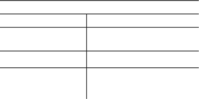
options and values based on the option or value that you last specified, or
based on the settings of certain system variables.
Typically, the first word of a prompt indicates the type of action you can take.
Most command prompts begin with the wordenter, select, or specify. These
words indicate how you can respond to the prompt.
Terminology in command prompts
You can...If the prompt starts with...
Select objects on the screen using your pointing
device.
Select
Enter text at the command prompt.Enter
Use your pointing device or enter text at the
command prompt to select a point location on
the screen.
Specify
Selecting Options at the Command Prompt
To select one of the options contained within the straight brackets, you can
enter the entire option name or only the capitalized letters, and then press
Enter or Spacebar. To select the default option enclosed in angle brackets (<>),
if available, press Enter or Spacebar.
You can also choose command options from a shortcut menu by right-clicking
in the drawing area while the command is active. The options available at the
command prompt appear in the shortcut menu. For information about how
to enable or disable this shortcut menu, see “Shortcut Menus” in the User's
Guide .
Entering Data at the Command Prompt
Some prompts ask you to enter data, rather than (or as an alternative to)
choosing an option. To do so, enter the text at the command prompt and
press Enter or Spacebar. However, be aware that when the command prompt
requests an object name, Spacebar inserts a space at the command prompt
rather than acting as Enter. This allows for the support of extended symbol
names.
Just as default command options are often provided, prompts may include
default values, enclosed in angle brackets (<>), when data is requested. For
4 | Chapter 1 Introduction
example, the POLYGON (page 821) command displays the following prompt,
suggesting 4 as the number of sides for your polygon:
Command: polygon
Enter number of sides <4>:
To accept the default value, press Enter or Spacebar.
Using Wild-Card Characters at the Command Prompt
When the prompt directions ask for a name list, such as a block name, variable
name, named view, and so on, you can use wild-card characters to specify
names. See the table in “Filter and Sort the List of Layers” in the User's Guide.
Repeating Commands
If no command is active, you can repeat the previous command by pressing
Enter or Spacebar or by right-clicking in the drawing area and choosing the
Repeat Command Name option from the shortcut menu.
Accessing Recently Used Commands
You can access the six most recently used commands from a shortcut menu
by right-clicking in the command window and choosing Recent Commands.
References to Other Sections
At the end of most command descriptions, you'll find a section called “See
Also.” This section includes references to chapters in other AutoCAD for Mac
guides and other AutoCAD for Mac commands and system variables related
to the current command.
Introduction | 5
6
Commands
Commands
You can start a command by using one of the following methods:
■Click the command name on a menu, status bar, or shortcut menu.
■Enter the command name or command alias at the Command prompt and
press Enter or Spacebar.
The acad.pgp file lists the command aliases.
To access the acad.pgp, on the Tools menu, click Customize ➤ Edit Command
Aliases (PGP).
In this Command Reference, near the beginning of each command description
is a command access section that lists the specific ways you can start that
command.
3D Commands
3D
Creates 3D polyface mesh objects in common geometric shapes that can be
hidden, shaded, or rendered.
List of Prompts
The following prompts are displayed.
2
7
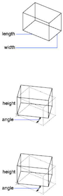
Enter an option [Box (page ?)/Cone (page ?)/DIsh (page
?)/DOme (page ?)/Mesh (page ?)/Pyramid (page ?)/Sphere
(page ?)/Torus (page ?)/Wedge (page ?)]:
Box
Creates a 3D box polyface mesh.
Corner of Box Sets the first corner of the box.
Length of Box Sets the first corner of the box.
Width
Specifies the width of the box. Enter a distance or specify a point relative to
the corner point of the box.
Height of Box Specifies the height of the box. Enter a distance or specify a
point relative to the corner point of the box.
Rotation Angle Rotates the box about the first corner specified. If you enter
0, the box remains orthogonal to the current X and Y axes.
Copy Creates a rotated copy of the box.
8 | Chapter 2 Commands
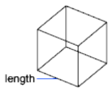
Reference Aligns the box with other objects in the drawing or relative to an
angle you specify. The base point for the rotation is the first corner of the box.
■Reference Angle:Defines a reference angle by specifying two points or
an angle from the X axis on the XY plane. For example, you can rotate the
box to align two specified points on the box with a point on another object.
After defining a reference angle, specify a point for the reference angle to
align with. The box then rotates around the first corner relative to the
angle of rotation specified for the reference angle.
If you enter 0 as a reference angle, the new angle determines the rotation
of the box.
■New Angle:
Specify a point relative to the base point. The base point for the rotation
is the first corner of the box. The box rotates by the angle between the
reference angle and the new angle. If you want to align the box with
another object, specify two points on the target object to define the new
angle of rotation for the box.
If the reference angle of rotation is 0, the box rotates the angular distance
entered relative to the first corner of the box.
Cube
Creates a cube using the length for the width and height of the box.
Center Point for Base
Radius for Base
Radius for Top
Specify rotation angle of box about the Z axis or [Reference]: Specify an angle
or enter r
Rotation Angle Rotates the cube about the first corner of the box. If you enter
0, the box remains orthogonal to the current X and Y axes.
Copy Creates a rotated copy of the cube.
Reference Aligns the box with other objects in the drawing or relative to an
angle you specify. The base point for the rotation is the first corner of the box.
Commands | 9
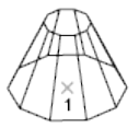
Specify the reference angle <0>: Specify a point, enter an angle, or press Enter
You can define a reference angle by specifying two points or an angle from
the X axis on the XY plane. For example, you can rotate the box to align two
specified points on the box with a point on another object. After defining a
reference angle, specify a point for the reference angle to align with. The box
then rotates around the first corner relative to the angle of rotation specified
for the reference angle.
If you enter 0 as a reference angle, the new angle alone determines the rotation
of the box.
Specify the new angle: Specify a point or enter an angle
To specify the new angle of rotation, specify a point relative to the base point.
The base point for the rotation is the first corner of the box. The box rotates
the angular distance between the reference angle and the new angle. If you
want to align the box with another object, specify two points on the target
object to define the new angle of rotation for the box.
If the reference angle of rotation is 0, the box rotates the angular distance
entered relative to the first corner point of the box.
Cone
Creates a cone-shaped polygon mesh.
Specify center point for base of cone: Specify a point (1)
Specify radius for base of cone or [Diameter]: Specify a distance or enter d
Radius for Base
Defines the base of the cone by its radius.
Specify radius for top of cone or [Diameter] <0>: Specify a distance, enter d, or
press Enter
10 | Chapter 2 Commands
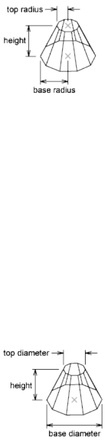
Radius for Top Defines the top of the cone by its radius. A value of 0 produces
a cone. A value greater than 0 produces a truncated cone.
Specify height of cone: Specify a distance
Enter number of segments for surface of cone <16>: Enter a value greater than
1 or press Enter
Diameter for Top Defines the top of the cone by its diameter. A value of 0
produces a cone. A value greater than 0 produces a truncated cone.
Specify diameter for top of cone <0>: Specify a distance or press Enter
Specify height of cone: Specify a distance
Enter number of segments for surface of cone <16>: Enter a value greater than
1 or press Enter
Diameter for Base
Defines the base of the cone by its diameter.
Specify diameter for base of cone: Specify a distance
Specify radius for top of cone or [Diameter] <0>: Specify a distance, enter d, or
press Enter
Radius for Top Defines the top of the cone by its radius. A value of 0 produces
a cone. A value greater than 0 produces a truncated cone.
Specify height of cone: Specify a distance
Commands | 11
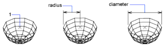
Enter number of segments for surface of cone <16>: Enter a value greater than
1 or press Enter
Diameter for Top Defines the top of the cone by its diameter. A value of 0
produces a cone. A value greater than 0 produces a truncated cone.
Specify diameter for top of cone <0>: Specify a distance
Specify height of cone: Specify a distance
Enter number of segments for surface of cone <16>: Enter a value greater than
1 or press Enter
Dish
Creates the lower half of a spherical polygon mesh.
Specify center point of dish: Specify a point (1)
Specify radius of dish or [Diameter]: Specify a distance or enter d
Radius Defines the dish by its radius.
Enter number of longitudinal segments for surface of dish <16>: Enter a value
greater than 1 or press Enter
Enter number of latitudinal segments for surface of dish <8>: Enter a value
greater than 1 or press Enter
Diameter Defines the dish by its diameter.
Specify diameter of dish: Specify a distance
Enter number of longitudinal segments for surface of dish <16>: Enter a value
greater than 1 or press Enter
Enter number of latitudinal segments for surface of dish <8>: Enter a value
greater than 1 or press Enter
Dome
Creates the upper half of a spherical polygon mesh.
Specify center point of dome: Specify a point (1)
Specify radius of dome or [Diameter]: Specify a distance or enter d
Radius Defines the dome by its radius.
12 | Chapter 2 Commands
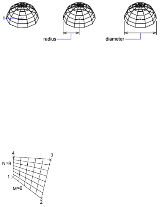
Enter number of longitudinal segments for surface of dome: Enter a value greater
than 1 or press Enter
Enter number of latitudinal segments for surface of dome <8>: Enter a value
greater than 1 or press Enter
Diameter Defines the dome by its diameter.
Specify diameter of dome: Specify a distance
Enter number of longitudinal segments for surface of dome <16>: Enter a value
greater than 1 or press Enter
Enter number of latitudinal segments for surface of dome <8>: Enter a value
greater than 1 or press Enter
Mesh
Creates a planar mesh whose M and N sizes determine the number of lines
drawn in each direction along the mesh. The M and N directions are similar
to the X and Y axes of an XY plane.
Specify first corner point of mesh: Specify a point (1)
Specify second corner point of mesh: Specify a point (2)
Specify third corner point of mesh: Specify a point (3)
Specify fourth corner point of mesh: Specify a point (4)
Enter mesh size in the M direction: Enter a value between 2 and 256
Enter mesh size in the N direction: Enter a value between 2 and 256
Commands | 13
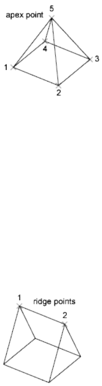
Pyramid
Creates a pyramid or a tetrahedron.
Specify first corner point for base of pyramid: Specify a point (1)
Specify second corner point for base of pyramid: Specify a point (2)
Specify third corner point for base of pyramid: Specify a point (3)
Specify fourth corner point for base of pyramid or [Tetrahedron]: Specify a
point (4) or enter t
Fourth Corner Point
Defines the fourth corner point of the base of a pyramid.
Specify apex point of pyramid or [Ridge/Top]: Specify a point (5) or enter an
option
The Z value of the point specified determines the height for the pyramid's
apex, top, or ridge line.
Apex Point Defines the top of the pyramid as a point (apex).
Ridge Defines the top of the pyramid as a ridge line. The two endpoints must
lie in the same direction as the base points to prevent a self-intersecting
wireframe.
Specify first ridge end point of pyramid: Specify a point (1)
Specify second ridge end point of pyramid: Specify a point (2)
14 | Chapter 2 Commands
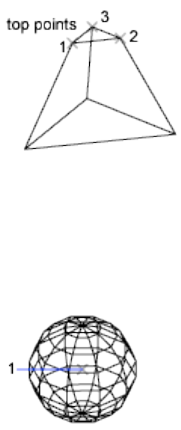
Top Defines the top of the pyramid as a rectangle. If the top points cross, they
create a self-intersecting polygon mesh.
Specify first corner point for top of pyramid: Specify a point
Specify second corner point for top of pyramid: Specify a point
Specify third corner point for top of pyramid: Specify a point
Specify fourth corner point for top of pyramid: Specify a point
Tetrahedron
Creates a tetrahedral polygon mesh.
Specify apex point of tetrahedron or [Top]: Specify a point or enter t
Apex Point Defines the top of the tetrahedron as a point (apex).
Top Defines the top of the tetrahedron as a triangle. If the top points cross,
they create a self-intersecting polygon mesh.
Specify first corner point for top of tetrahedron: Specify a point (1)
Specify second corner point for top of tetrahedron: Specify a point (2)
Specify third corner point for top of tetrahedron: Specify a point (3)
Sphere
Creates a spherical polygon mesh.
Specify center point of sphere: Specify a point (1)
Specify radius of sphere or [Diameter]: Specify a distance or enter d
Radius Defines the sphere by its radius.
Enter number of longitudinal segments for surface of sphere <16>: Enter a
value greater than 1 or press Enter
Commands | 15
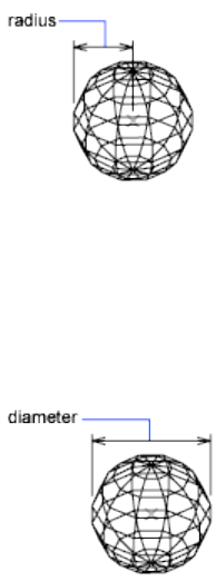
Enter number of latitudinal segments for surface of sphere <16>: Enter a value
greater than 1 or press Enter
Diameter Defines the sphere by its diameter.
Specify diameter of sphere: Specify a distance
Enter number of longitudinal segments for surface of sphere <16>: Enter a
value greater than 1 or press Enter
Enter number of latitudinal segments for surface of sphere <16>: Enter a value
greater than 1 or press Enter
Torus
Creates a toroidal polygon mesh that is parallel to the XY plane of the current
UCS.
Specify center point of torus: Specify a point (1)
Specify radius of torus or [Diameter]: Specify a distance or enter d
The radius of the torus is measured from its center point to its outside edge,
not to the center of the tube.
Radius of Torus
Radius Defines the torus by its radius.
16 | Chapter 2 Commands
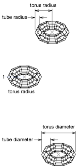
Specify radius of tube or [Diameter]: Specify a distance or enter d
Diameter of Torus
Defines the torus by its diameter.
Specify diameter of torus: Specify a distance
Specify radius of tube or [Diameter]: Specify a distance or enter d
Radius of Tube
Defines the tube by its radius.
Enter number of segments around tube circumference <16>: Enter a value
greater than 1 or press Enter
Enter number of segments around torus circumference <16>: Enter a value
greater than 1 or press Enter
The radius of the tube of the torus is measured from the center of the tube to
the outside edge of the tube.
Diameter of Tube
Defines the tube by its diameter.
Specify diameter of tube: Specify a distance
Enter number of segments around tube circumference <16>: Enter a value
greater than 1 or press Enter
Commands | 17
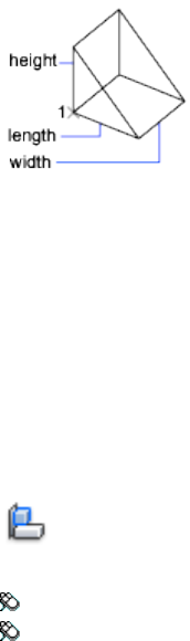
Enter number of segments around torus circumference <16>: Enter a value
greater than 1 or press Enter
Wedge
Creates a right-angle, wedge-shaped polygon mesh with a sloped face tapering
along the X axis.
Specify corner point of wedge: Specify a point (1)
Specify length of wedge: Specify a distance
Specify width of wedge: Specify a distance
Specify height of wedge: Specify a distance
Specify rotation angle of wedge about the Z axis: Specify an angle
The base point for the rotation is the corner point of the wedge. If you enter
0, the wedge remains orthogonal to the current UCS plane. Enter c to create
a rotated copy of the wedge.
See also:
Create Custom Mesh (Legacy)
3DALIGN
Aligns objects with other objects in 2D and 3D.
Access Methods
Button
Menu: Modify ➤ 3D Operations ➤ 3D Align
Toolbar: Modeling tool set ➤ Copy tool group ➤ 3D Align
18 | Chapter 2 Commands
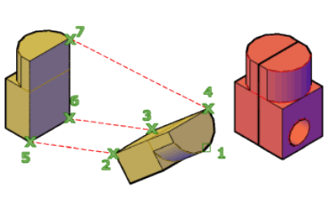
Summary
You can specify one, two, or three points for the source object. Then, you can
specify one, two, or three points for the destination.
List of Prompts
The following prompts are displayed.
Select objects: Select the objects to align and press Enter
Specify source plane and orientation . . .
The selected object is moved and rotated so that the base points, and the X
and Y axes of the source and destination align in 3D space. 3DALIGN works
with dynamic UCS (DUCS), so you can dynamically drag the selected objects
and align them with the face of a solid object.
Specify base point or [Copy]: Specify a point or enter c to create a copy
The base point of the source object will be moved to the base point of the
destination.
Specify second point or [Continue] <C>: Specify a point on the object’s
X axis, or press Enter to skip forward to specifying destination points
The second point specifies a new X axis direction within a plane parallel to
the XY plane of the current UCS. If you press Enter instead of specifying a
second point, the X and Y axes are assumed to be parallel with the X and Y
axes of the current UCS.
Specify third point or [Continue] <C>: Specify a point on the object’s
positive XY plane, or press Enter to skip forward to specifying destination points
The third point fully specifies the orientation of the X and Y axes of the source
object that will be aligned with the destination plane.
Specify destination plane and orientation . . .
Specify first destination point: Specify a point
This point defines the destination of the base point of the source object.
Commands | 19
Specify second source point or [eXit] <X>: Specify a point for the X
axis of the destination or press Enter
The second point specifies a new X axis direction for the destination within
a plane parallel to the XY plane of the current UCS. If you press Enter instead
of specifying a second point, the X and Y axes of the destination are assumed
to be parallel with the X and Y axes of the current UCS.
Specify third destination point or [eXit] <X>: Specify a point for
the destination’s positive XY plane, or press Enter
The third point fully specifies the orientation of the X and Y axes of the
destination plane.
NOTE
If the destination is a plane on an existing solid object, you can define the
destination plane with a single point by turning on dynamic UCS.
See also:
Align Objects
3DARRAY
Maintains legacy behavior for creating nonassociative, 3D rectangular or polar
arrays.
Access Methods
Button
Menu: Modify ➤ 3D Operations ➤ 3D Array
Toolbar: Modeling tool set ➤ Copy tool group ➤ 3D Array
Summary
3DARRAY functionality has been replaced with the enhanced ARRAY (page
86) command, which allows you to create associative or nonassociative, 2D
or 3D, rectangular, path, or polar arrays. 3DARRAY maintains legacy behavior.
20 | Chapter 2 Commands
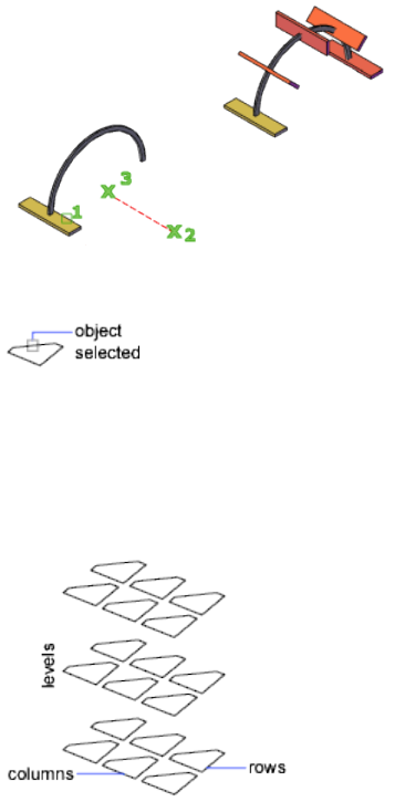
For 3D rectangular arrays, in addition to columns and rows, you also specify
the number of levels in the Z direction. For 3D polar arrays, you specify the
axis of rotation with any two points in space.
The entire selection set is treated as a single element in the array.
List of Prompts
The following prompts are displayed.
Enter type of array [Rectangular (page ?)/Polar (page ?)]
<R>: Enter an option or press Enter
Rectangular Array
Copies objects in a matrix of rows (X axis), columns (Y axis), and levels (Z
axis). An array must have at least two rows or two columns or two levels.
Specifying one row requires that more than one column be specified, and vice
versa. Specifying one level creates a two-dimensional array.
Positive values generate the array along the positive X, Y, and Z axes. Negative
values generate the array along the negative X, Y, and Z axes.
Commands | 21

Polar Array
Copies objects about an axis of rotation.
The specified angle determines how far the objects are arrayed about the axis
of rotation. A positive number produces a counterclockwise array rotation. A
negative number produces a clockwise array rotation.
Entering y or pressing Enter rotates each array element.
See also:
Array Objects
3DCONFIG (-3DCONFIG)
Sets options that affect 3D display performance.
Summary
Enter -3dconfig at the Command prompt to use this command.
List of Prompts
The following prompts are displayed.
Enter option [Dynamic tessellation (page ?)/General options
(page ?)/acceLeration (page ?)/Plot emulation (page
?)/eXit] <Adaptive degradation>:
Dynamic Tessellation
Sets the options that determine the smoothness of the objects in a drawing.
Objects are drawn using many short lines (or triangles when drawing spheres).
These lines are called tessellation lines. Objects in your drawing appear smoother
when you use more tessellation lines.
22 | Chapter 2 Commands
Surface Tessellation Determines the amount of detail for surfaces in your
drawing. A higher setting provides more detail but uses more tessellation lines
and more memory.
Curve Tessellation Determines the amount of detail for curves in your
drawing. A higher setting provides more detail but uses more tessellation lines
and more memory.
Number of Tessellations to Cache Configures your system according to
memory and performance requirements. The 3D cache always stores at least
one tessellation. When this option is set to 1, the tessellation for all viewports
is the same; some objects in the drawing may be regenerated as you zoom in
and out. Setting this option to 2 or more is useful when you have more than
one viewport with different views. Increasing the number requires more
memory.
General Options
Sets performance-related options that are not hardware dependent.
Discard Back Faces Discards back faces when drawing objects. You cannot
see the effect of discarding back faces on some objects, such as spheres, because
you cannot see the back face even when it is present. The effect of discarding
back faces is visible on objects such as those that don't have a top. Discarding
back faces enhances performance.
Transparency Quality Adjusts the transparency quality. At the Low setting,
a screen-door effect achieves transparency without sacrificing speed. At the
Medium setting, the default in software mode, blending improves image
quality. The High setting, the default in hardware mode, produces an image
free of visual artifacts at the cost of drawing speed. Materials must also be
turned on for transparency to be visible.
The General Options prompt is redisplayed.
Acceleration
Specifies whether to use software or hardware acceleration in 3D.
If you select Hardware, you can also specify whether geometry acceleration
are turned on or off.
Hardware Specifies hardware acceleration. The hardware graphics card
performs most of the drawing tasks in 3D to increase performance.
■Driver Name. You can select a driver from a list of available
hardware-accelerated drivers found in the Drv directory. If you want to use
a hardware driver from another vendor, it must be supported by the Heidi®
Graphics System.
Commands | 23
■Enhanced 3D Performance. Enables a more efficient use of the
graphic card when working with 3D objects.
NOTE
If you experience problems with precision, turn this option off.
■
■Smooth display. Controls the status of the full screen anti-aliasing
effect. This option removes the jagged effect on the display of diagonal
line and curved edges.
■Advanced material effects. Controls the status of the advanced
materials effect on screen.
■Gooch hardware shader. Enables the use of Gooch shading. With
this option on the details of a 3D object are shown by softening the
contrast between lighted areas and shadowed areas by using warm and
cool colors as a substitute to light and dark colors.
■Per-pixel lighting. Enables the computation of colors for individual
pixels. With this option on the 3D objects and lighting effects appear
smoother in the viewport.
■Full shadow display. Enables shadows to be displayed in the
viewport.
NOTE
Enhanced 3D performance effect must be turned on.
■Texture compression. Enables the use of texture compression to
reduce the amount of video memory required to open and display a
drawing that contains materials with images or has attached images.
NOTE
With this option turned on, the time it takes to load the images might
increase the first time that they are accessed, and there is a reduction
in the quality of the images when they are displayed in the viewport
or plotted.
Software Feature is not supported and is provided for scripting compatibility
only.
Plot Emulation
Feature is not supported and is provided for scripting compatibility only.
24 | Chapter 2 Commands

See also:
Control Performance
3DDISTANCE
Starts the interactive 3D view and makes objects appear closer or farther away.
Access Methods
Menu: View ➤ Camera ➤ Adjust Distance
Shortcut menu: Start any 3D navigation command, right-click in the drawing
area, and click Other Navigation Modes ➤ Adjust Distance (4).
Summary
3DDISTANCE changes the cursor to a line with one arrow pointing up and
one pointing down. Click and drag the cursor vertically toward the top of the
screen to move the camera closer to the objects, making them appear larger.
Click and drag the cursor vertically toward the bottom of the screen to move
the camera away from the objects, making them appear smaller.
See also:
Use 3D Navigation Tools
3DEDITBAR
Reshapes splines and NURBS surfaces, including their tangency properties.
Summary
Several grips are available for moving a point and changing the magnitude
and direction of tangents at specific points on splines, and in the U, V , and
W directions on NURBS surfaces.
Commands | 25
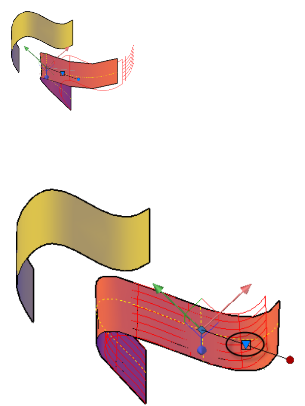
The Grips on the Gizmo
The 3D Edit Bar gizmo includes three grips:
■Triangle grip. Specifies the method for reshaping the selected object.
■Square grip. Reshapes the selected object by moving the base point or
changing the tangent direction at the base point. Use the three axes to
restrict the movement option to a specified axis. Similarly, the three squares
that touch the square grip restrict the movement option to the specified
planes.
26 | Chapter 2 Commands
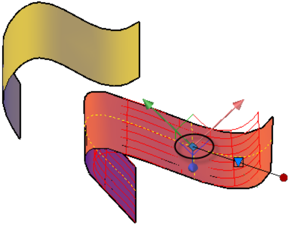
■Tangent arrow grip. Changes the magnitude of the tangent at the base point.
For example, lengthening the tangent arrow grip flattens the curvature of
the surface at the point of tangency. The tangent arrow points in the
direction of one of the surface’s U, V, or W axes, depending on the tangent
direction specified in 3D Edit Bar Shortcut Menu (page 29).
Commands | 27
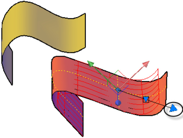
List of Prompts
The following prompts are displayed.
Select a NURBS surface or curve to edit Specifies the object to be modified.
Valid objects include lines, arcs, circles, ellipses and elliptical arcs, polylines,
helixes, splines, and NURBS surfaces. Objects other than surfaces can be
converted to splines.
Select point on curve or Select point on NURBS surface Specifies a base point
on the selected curve or NURBS surface. Changes to the selected object are
relative to this point.
Base point Specifies a new base point on the curve or NURBS surface.
Displacement Specifies a new base point by projecting the absolute coordinates
entered onto the selected curve or surface, when possible.
Undo Cancels the previous change without exiting the command.
Exit Cancels the current operation and returns to the previous prompt, or it
exits the command.
28 | Chapter 2 Commands
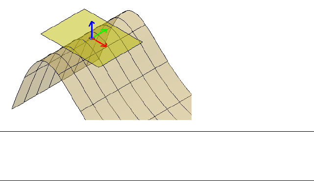
See also:
Modify Splines
Edit NURBS Surfaces
3D Edit Bar Shortcut Menu
Displays options to set the location of the base point, constraints, and
tangency.
Access Methods
Shortcut menu: Right-click on the 3D Edit Bar gizmo.
Summary
The 3D Edit Bar shortcut menu displays several options depending on whether
a spline or a NURBS surface is selected, where you click, and which editing
method, move or tangent, is current.
The illustration displays an imaginary UV plane in yellow that is tangent to
the surface, and contains the base point. It displays the U axis in red, the V
axis in green, and W axis, which is normal to the surface, in blue.
NOTE By default, the orientation of the 3D Edit Bar gizmo is aligned with the
World Coordinate System, but its alignment can be changed using the shortcut
menu. To align the axes with the U, V, and W axes of a NURBS surface, choose
Align Gizmo With > Object.
Commands | 29

List of Options
The following options are displayed.
Move Point Location Reshapes the selected object by moving the base point.
Move Tangent Direction Reshapes the selected object by changing the slope
of the tangent at the base point.
U Tangent Direction Locates the tangent arrow grip on the U axis. Changes
to the tangency are constrained to the UW plane.
V Tangent Direction Locates the tangent arrow grip on the V axis. Changes
to the tangency are constrained to the VW plane.
Normal Tangent Direction Locates the tangent arrow grip on the W axis,
which is normal to the surface at the base point. Changes to the tangency are
constrained to the UW plane.
Set Constraint Sets whether the change in tangency or point location is
constrained to a specific axis or major plane.
■X, Y or Z. Restricts the change to the specified World Coordinate System
(WCS) axis.
■XY, YZ, or XZ. Restricts the change to the specified World Coordinate
System (WCS) plane.
Relocate Base Point Specifies a new base point on the curve or NURBS surface.
Align Gizmo With Reorients the gizmo to align with the WCS or UCS, or
with a selected face or object.
See also:
Modify Splines
Edit NURBS Surfaces
3DFACE
Creates a three-sided or four-sided surface in 3D space.
Access Methods
Menu: Draw ➤ 3D Modeling ➤ Meshes ➤ 3D Face
30 | Chapter 2 Commands

Summary
After entering the last two points for a 3D face, the command repeats
automatically using the these two points as the first two points of the next
3D face. For example:
List of Prompts
The following prompts are displayed.
Specify first point (page 31) or [Invisible (page 31)]: Specify
a point (1) or enter i
First Point Defines the start point for the 3D surface. After entering the first
point, enter the remaining points in a natural clockwise or counterclockwise
order to create a normal 3D face. If you locate all four points on the same
plane, a planar face is created that is similar to a region object. When you
shade or render the object, planar faces are filled.
Invisible Controls which edges of a 3D face are visible, allowing for accurate
modeling of objects with holes. Entering i or invisible before the first point
of an edge makes the edge invisible.
The invisible specification must precede any object snap modes, XYZ filters,
or coordinate input for that edge. You can create a 3D face in which all edges
are invisible. Such a face is a phantom; it does not appear in wireframe
presentations but can hide material in line drawings. 3D faces do appear in
shaded renderings.
You can combine 3D faces to model complex 3D surfaces.
Commands | 31
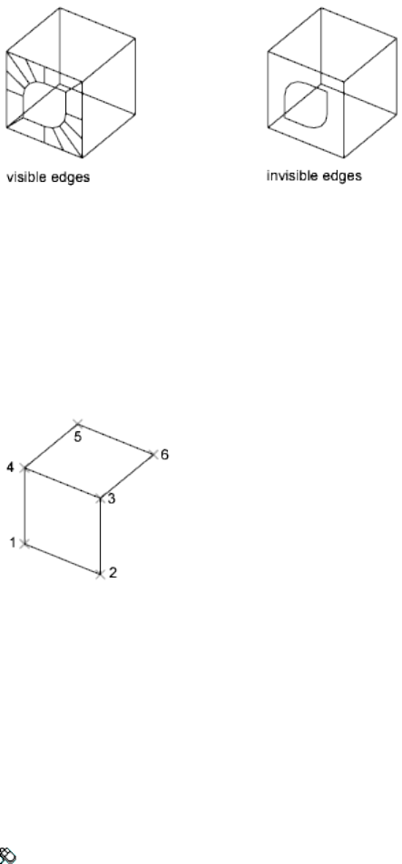
Specify second point or [Invisible]: Specify a point (2) or enter i
Specify third point or [Invisible] <exit>: Specify a point (3), enter
i, or press Enter
Specify fourth point or [Invisible] <create three-sided face>:
Specify a point (4), enter i, or press Enter
The Third Point and Fourth Point prompts are repeated until you press Enter.
Specify points 5 and 6 at these repeating prompts. When you finish entering
points, press Enter.
See also:
Create Custom Mesh (Legacy)
3DFORBIT
Rotates the view in 3D space without constraining roll.
Access Methods
Menu: View ➤ Orbit ➤ Free Orbit
Pointing device: Press Shift-Ctrl and click the mouse wheel to temporarily
enter 3DFORBIT mode.
32 | Chapter 2 Commands

Shortcut menu: Start any 3D navigation command, right-click in the drawing
area, and click Other Navigation Modes ➤ Free Orbit (2).
Summary
Selecting one of more objects before starting this command limits the display
to those objects only.
While the command is active, right-click to display additional options from
a shortcut menu.
3DFORBIT activates a 3D Free Orbit view in the current viewport. If the user
coordinate system (UCS) icon is on, a shaded 3D UCS icon representing the
current UCS appears in the 3D Orbit view. You can view your entire drawing
or select one or more objects before starting the command.
The 3D Free Orbit view displays an arcball, which is a circle divided into four
quadrants by smaller circles. When the Enable Orbit Auto Target option is
deselected in the shortcut menu, the target of the view stays stationary. The
camera location, or point of view, moves around the target. The center of the
arcball, not the center of the objects you’re viewing, is the target point. Unlike
3DORBIT (page 40), 3DFORBIT does not constrain the change in view to
prevent roll, the rotation of the view about an axis orthogonal to the plane
of your screen.
NOTE You cannot edit objects while the 3DFORBIT command is active.
Moving your cursor over different parts of the arcball changes the cursor icon,
indicating the direction in which the view rotates. See 3D Free Orbit Cursor
Icons (page 34).
While the command is active, you can access additional 3DORBIT options
from a shortcut menu by right-clicking in the drawing area. See 3D Orbit
Shortcut Menu (page 41).
TIP While in 3D Orbit mode, you can temporarily enter 3D Free Orbit mode by
pressing and holding the Shift key.
See also:
Use 3D Navigation Tools
Commands | 33
3D Free Orbit Cursor Icons
While using 3D Free Orbit, the cursor changes as it is moved to indicate how
the model will be orbited when clicking and dragging.
View rotation is determined by the placement and appearance of the cursor
as follows:
Sphere Encircled by Two Lines When you move the cursor inside the arcball,
it changes to a small sphere encircled by two lines. If you click and drag in
the drawing area you can move freely around the objects. It works as if your
cursor is grabbing a sphere surrounding the objects and dragging it around
the target point. You can drag horizontally, vertically, and diagonally using
this method.
Circular Arrow When you move the cursor outside the arcball, it becomes a
circular arrow. Clicking outside the arcball and dragging the cursor around
the arcball causes the view to move around an axis that extends through the
center of the arcball, perpendicular to the screen. This is called a roll.
Horizontal Ellipse When you move the cursor over one of the small circles
on the left or right side of the arcball, it becomes a horizontal ellipse. Clicking
and dragging from either of these points rotates the view around the vertical
or Y axis through the middle of the arcball.
Vertical Ellipse When you move the cursor over one of the small circles on
the top or bottom of the arcball, it becomes a vertical ellipse. Clicking and
dragging from either of these points rotates the view around the horizontal
or X axis through the middle of the arcball.
34 | Chapter 2 Commands
See also:
3D Navigation Tools
3DMESH
Creates a free-form polygon mesh.
Summary
The mesh density controls the number of facets, and is defined in terms of a
matrix of M and N vertices, similar to a grid consisting of columns and rows.
3DMESH is a legacy method for creating mesh, designed primarily for operation
under program control rather than by manual entry.
To take advantage of smoothing, creasing, and refinement capabilities, use
the MESH (page 617) command.
List of Prompts
The following prompts are displayed.
Size of mesh in M direction Sets the M direction value. Enter a value between
2 and 256.
Size of mesh in N direction Sets the N direction value. Enter a value between
2 and 256.
M times N equals the number of vertices that you must specify.
Location for vertex (0, 0) Sets the coordinate location of the vertex. Enter a
2D or 3D coordinate.
Commands | 35
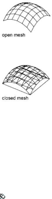
The location of each vertex in the mesh is defined by m and n, the row and
column indices of the vertex. Defining vertices begins with vertex (0,0). You
must supply the coordinate locations for each vertex in row m before specifying
vertices in row m + 1.
Vertices may be any distance from each other. The M and N orientation of a
mesh depends on the position of its vertices.
3DMESH polygon meshes are always open in both M and N directions. You
can close a mesh with PEDIT (page 767).
See also:
Create Custom Mesh (Legacy)
3DMOVE
In a 3D view, displays the 3D Move gizmo to aid in moving 3D objects a
specified distance in a specified direction.
Access Methods
Menu: Modify ➤ 3D Operations ➤ 3D Move
Summary
With the 3D Move gizmo, you can move selected objects and subobjects freely
or constrain the movement to an axis or plane.
36 | Chapter 2 Commands
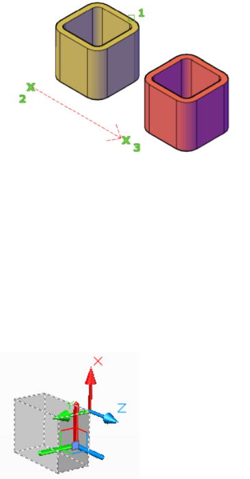
If the default gizmo (DEFAULTGIZMO (page 1209)) is 3D Move, the 3D Move
gizmo is displayed whenever you select an object in a view with a 3D visual
style. If you are working in a viewport with 2D Wireframe set as the visual
style, 3DMOVE temporarily changes the visual style to 3D Wireframe for the
duration of the command.
The 3D Move gizmo is displayed at the center of the selected 3D object or
objects by default. You can use the shortcut menu to change its location.
You can also align the 3D Move gizmo with the plane of a face or object by
using the Align Gizmo With ➤ Face option on the shortcut menu. The
direction of the move operation is then constrained relative to this work plane.
When the 3D Move gizmo is displayed, the 3D Move Gizmo shortcut menu
(page 39) offers options for aligning, moving, or changing to another gizmo.
List of Prompts
The following prompts are displayed.
Select objects Selects the 3D objects you want to move. When you have
selected the objects, press Enter.
Commands | 37
When you have selected an object, the gizmo is displayed. You can constrain
the movement by clicking one of the following locations on the gizmo:
■Move along an axis. Click an axis to constrain the movement to that
axis.
■Move along a plane. Click the area between the axes to constrain the
movement to that plane.
Stretch point When you are specifying the move using the gizmo, sets the
new location of the selected objects. Drag and click to move the objects
dynamically.
Copy When you are specifying the move using the gizmo, creates a copy of
the selected objects instead of moving them. You can make multiple copies
by continuing to specify locations.
Base point Specifies the base point of the 3D objects you want to move.
■Second point. Specifies where the 3D object or objects will be dragged.
You can also move the cursor to indicate a direction and then enter a
distance.
Displacement Specifies a relative distance and direction for the placement of
the selected 3D objects using coordinate values that you enter at the command
prompt.
See also:
Move 3D Objects
38 | Chapter 2 Commands
3D Move Gizmo Shortcut Menu
Displays options to set the constraint of a 3D object, switch gizmos, and move
or align the gizmo.
Access Methods
Shortcut menu: Right-click the 3D Move gizmo
List of Options
The following options are displayed.
Move Activates the 3D Move gizmo.
Rotate Activates the 3D Rotate gizmo.
Scale Activates the 3D Scale gizmo.
Set Constraint Sets whether the change is constrained to a specific axis.
■X, Y or Z. Restricts the change to the designated axis.
■XY, YX, or ZX. Restricts the change to a plane that is defined by the
selected axes.
Relocate Gizmo Moves the gizmo to the point you specify.
Align Gizmo With Sets the alignment for the change. Options include:
■World UCS
■Current UCS
■Face
Custom Gizmo Allows you to define the current gizmo by specifying one,
two, or three points, or an object.
Commands | 39
Respect Dynamic UCS When relocating the gizmo, as you move the cursor,
temporarily aligns the XY plane of the UCS with the faces or edges.
See also:
Move 3D Objects
3DORBIT
Rotates the view in 3D space, but constrained to horizontal and vertical orbit
only.
Access Methods
Button
Menu: View ➤ Orbit ➤ Constrained Orbit
Pointing device: Press Shift and click the mouse wheel to temporarily enter
3D Orbit mode.
Shortcut menu: Start any 3D navigation command, right-click in the drawing
area, and click Other Navigations Modes ➤ Constrained Orbit (1).
Toolbar: Status bar (expanded) ➤ 3D Orbit
Summary
Selecting one of more objects before starting this command limits the display
to those objects only.
While the command is active, right-click to display additional options from
a shortcut menu.
3DORBIT activates a 3D Orbit view in the current viewport. You can view
your entire drawing or select one or more objects before starting the command.
When 3DORBIT is active, the target of the view stays stationary and the camera
location, or point of view, moves around the target. However, it appears as if
the 3D model is turning as the mouse cursor is dragged In this way, you can
specify any view of the model.
The 3D Orbit cursor icon appears. If you drag the cursor horizontally, the
camera moves parallel to the XY plane of the world coordinate system (WCS).
If you drag the cursor vertically, the camera moves along the Z axis.
40 | Chapter 2 Commands

NOTE You cannot edit objects while the 3DORBIT command is active.
While the command is active, you can access additional 3DORBIT options
from a shortcut menu by right-clicking in the drawing area. See 3D Orbit
Shortcut Menu (page 41).
See also:
Use 3D Navigation Tools
3D Orbit Shortcut Menu
When the 3DORBIT command (or any 3D navigation command or mode) is
active, you can access the options on the 3D Orbit shortcut menu. To access
the 3D Orbit shortcut menu, right-click in the 3D Orbit view.
Current Mode: Current
Displays the current mode.
Other Navigation Modes
Choose one of the following 3D navigation modes:
■Constrained Orbit (1). Constrains orbiting to the XY plane or the Z
direction.
■Free Orbit (2). Allows orbiting in any direction, without being constrained
to the XY plane or the Z direction. See 3DFORBIT (page 32).
■Adjust Distance (4). Simulates moving the camera closer to the object
or farther away. See 3DDISTANCE (page 25).
■Swivel (5). Changes the cursor to an arched arrow and simulates the
effect of swiveling the camera. See 3DSWIVEL (page 54).
■Zoom (8). Changes the cursor to a magnifying glass with plus (+) and
minus (-) sign and simulates moving the camera closer to an object or
farther away. Works like the Adjust Distance option. See 3DZOOM (page
54).
■Pan (9). Changes the cursor to a hand cursor and moves the view in the
direction that you drag. See 3DPAN (page 45).
Commands | 41
TIP
You can switch to any mode by using the shortcut menu or by entering
the number displayed after its name.
Enable Orbit Auto Target
Keeps the target point on the objects you are viewing rather than on the center
of the viewport. This feature is turned on by default.
Zoom Window
Changes the cursor to a window icon so that you can select a specific area to
zoom in on. When the cursor changes, click a starting point and end point
to define the zoom window. The drawing is zoomed in and focused on the
area you selected.
Zoom Extents
Centers the view and sizes it to display all objects.
Zoom Previous
Displays the previous view.
Parallel
Displays objects so that two parallel lines in a drawing never converge. The
shapes in your drawing always remain the same and do not appear distorted
when they are closer.
Perspective
Displays objects in perspective so that all parallel lines converge at one point.
Objects appear to recede into the distance, and parts of the objects appear
larger and closer to you. The shapes are somewhat distorted when the object
is very close. This view correlates more closely to what your eyes see. See
PERSPECTIVE (page 1390).
Reset View
Resets the view back to the view that was current when you first started
3DORBIT.
42 | Chapter 2 Commands
Preset Views
Displays a list of predefined views such as Top, Bottom, and SW Isometric.
Choose a view from the list to change the current view of your model.
Named Views
Displays a list of named views in the drawing. Choose a named view from the
list to change the current view of your model.
Visual Styles
Provides methods for shading objects. For more information about visual
styles, see Use a Visual Style to Display Your Model.
The options are the same as the options in VSCURRENT (page 1124).
Visual Aids
Provides aids to visualizing the objects.
■Compass. Draws a 3D sphere composed of three lines representing the
X, Y, and Z axes.
■Grid. Displays a two-dimensional array of lines similar to graph paper.
This grid is oriented along the X and Y axes.
NOTE Before starting 3DORBIT (page 40), you can use the GRID (page 467)
command to set system variables that control the grid display. The number of
major grid lines corresponds to the value you set using the Grid Spacing option
of the GRID command, which is stored in the GRIDUNIT (page 1307) system
variable. Ten horizontal lines and ten vertical lines are drawn between the
major lines.
■UCS Icon. Displays a shaded 3D UCS icon. Each axis is labeled X, Y, or Z.
The X axis is red, the Y axis is green, and the Z axis is blue.
See also:
3D Navigation Tools
3DORBITCTR
Sets the center of rotation in 3D Orbit view.
Commands | 43
Summary
Starts 3D Orbit view and uses a center of rotation that you specify with your
pointing device. If you specify a point outside the current view, 3DORBITCTR
ignores the specified point and uses the default center of rotation.
3DORBITCTR overrides the AutoTarget option in the 3DORBIT (page 40)
command.
See also:
Use 3D Navigation Tools
3DOSNAP
Sets the object snap modes for 3D objects.
Access Methods
Menu: Tools ➤ Drafting Settings
Shortcut menu: Press Option while right-clicking in the drawing area and
click 3D Osnap ➤ Osnap Settings.
Toolbar: Status bar (expanded) ➤ 3D Object Snap
Summary
Displays the 3D Object Snap tab of the Drafting Settings dialog box (page 364).
You can also set the 3D object snap settings with the 3DOSMODE (page 1165)
system variable.
NOTE
Because 3D object snaps can slow performance, select only the object snaps
you need.
See also:
Create Solids and Surfaces from Lines and Curves
Create Solids
Create Surfaces
Modify Surfaces
44 | Chapter 2 Commands
Use Grips to Modify Solids and Surfaces
Snap to Locations on Objects (Object Snaps)
-3DOSNAP
Uses command prompts to set running object snap modes for 3D objects.
List of Prompts
The following prompts are displayed.
Enter List of Object Snap Modes Specify one or more object snap modes by
entering the first four characters of the name. If you enter more than one,
separate the names with commas.
■ZVERtex. Snaps to a vertex or a control vertex.
■ZMIDpoint. Snaps to the midpoint on a face edge.
■ZCENter. Snaps to the center of a face.
■ZKNOt. Snaps to a spline knot.
■ZPERpendicular. Snaps to a perpendicular face (planar faces only).
■ZNEAr. Snaps to an object nearest to face.
■ZNONe. Turns off all 3D object snaps.
See the 3D Object Snaps tab of the Drafting Settings dialog box (page 364) for
more information.
3DPAN
When a drawing is in a Perspective view, starts the interactive 3D view and
enables you to drag the view horizontally and vertically.
Access Methods
Menu: View ➤ Pan ➤ Realtime
Shortcut menu: Start any 3D navigation command, right-click in the drawing
area, and click Other Navigation Modes ➤ Pan (9).
Toolbar: Status bar ➤ Pan
Commands | 45

Summary
Moves in the direction that you drag. You can drag the view vertically,
horizontally, or diagonally. 3DPAN changes the cursor to a hand cursor.
You can view your entire drawing or select objects before entering 3DPAN.
See also:
Use 3D Navigation Tools
3DPOLY
Creates a 3D polyline.
Access Methods
Button
Menu: Draw ➤ 3D Polyline
Toolbar: Modeling tool set ➤ Open Shapes tool group (expanded) ➤
3D Polyline
Summary
A 3D polyline is a connected sequence of straight line segments created as a
single object. 3D polylines can be non-coplanar; however, they cannot include
arc segments.
46 | Chapter 2 Commands

List of Prompts
The following prompts are displayed.
Specify start point of polyline: Specify a point (1)
Specify endpoint of line (page 47) or [Undo (page 47)]: Specify
a point or enter an option
Specify endpoint of line or [Undo]: Specify a point or enter an option
Specify endpoint of line or [Close (page 47)/Undo]: Specify a
point or enter an option
Endpoint of Line Draws a straight line from the previous point to the specified
new point. The prompt is repeated until you press Enter to end the command.
Undo Deletes the last line created. You can continue drawing from the previous
point.
Close Draws a closing line from the endpoint back to the first point, and then
ends the command. To be closed, a 3D polyline must contain at least two
lines.
See also:
Draw Polylines
Commands | 47
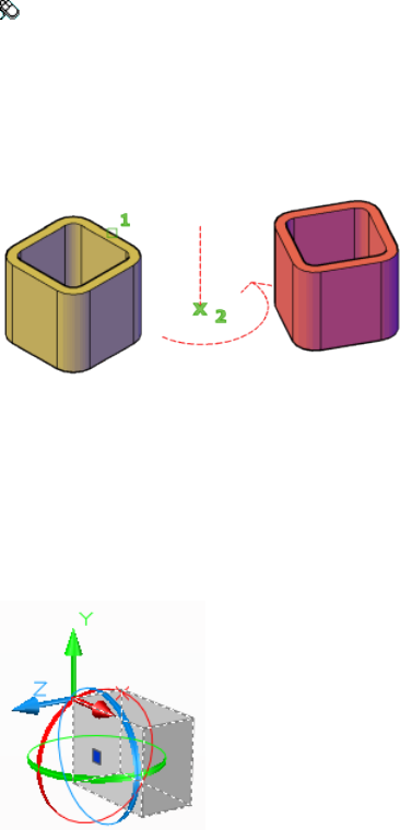
3DROTATE
In a 3D view, displays the 3D Rotate gizmo to aid in revolving 3D objects
around a base point.
Access Methods
Menu: Modify ➤ 3D Operations ➤ 3D Rotate
Summary
With the 3D Rotate gizmo, you can rotate selected objects and subobjects
freely or constrain the rotation to an axis.
If you are working in a viewport with 2D Wireframe set as the visual style,
3DROTATE temporarily changes the visual style to 3D Wireframe for the
duration of the command.
The 3D Rotate gizmo is displayed at the center of the selected object or objects
by default. You can adjust the axis of rotation by using the shortcut menu to
change the location of the gizmo.
When the 3D Rotate gizmo is displayed, the 3D Rotate Gizmo shortcut menu
(page 49) offers options for aligning, moving, or changing to another gizmo.
48 | Chapter 2 Commands
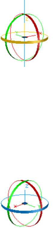
List of Prompts
The following prompts are displayed.
Select objects Specifies the objects that you want to rotate.
Base point Sets the center point of the rotation.
Pick a rotation axis On the 3D Scale gizmo, specifies the axis of rotation.
Move the mouse until the axis path you want to select turns yellow, then click
to select it.
Specify angle start point or type an angle Sets the relative start point of the
rotation. You can also enter an angle value.
Specify angle end point Rotates the object about the specified axis. Click to
end the rotation.
See also:
Rotate 3D Objects
3D Rotate Gizmo Shortcut Menu
Displays options to set the constraint of a 3D object, switch gizmos, and move
or align the gizmo.
Commands | 49
Access Methods
Shortcut menu: Right-click the 3D Rotate gizmo
List of Options
The following options are displayed.
Move Activates the 3D Move gizmo.
Rotate Activates the 3D Rotate gizmo.
Scale Activates the 3D Scale gizmo.
Set Constraint Sets whether the change is constrained to a specific axis.
■X, Y or Z. Restricts the change to the designated axis.
Relocate Gizmo Moves the gizmo to the point you specify.
Align Gizmo With Sets the alignment for the change. Options include:
■World UCS
■Current UCS
■Face
Custom Gizmo Allows you to define the current gizmo by specifying one,
two, or three points, or an object.
Respect Dynamic UCS When relocating the gizmo, as you move the cursor,
temporarily aligns the XY plane of the UCS with the faces or edges.
See also:
Rotate 3D Objects
3DSCALE
In a 3D view, displays the 3D Scale gizmo to aid in resizing 3D objects.
Access Methods
Summary
With the 3D Scale gizmo, you can resize selected objects and subobjects along
an axis or plane, or resize the objects uniformly.
50 | Chapter 2 Commands
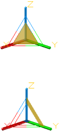
When the 3D Scale gizmo is displayed, the 3D Scale Gizmo shortcut menu
(page 52) offers options for aligning, moving, or changing to another gizmo.
List of Prompts
The following prompts are displayed.
Select objects Specifies the objects to be scaled.
Specify base point Specifies the base point for the scaling.
Pick a scale axis or plane Specifies whether the object is scaled uniformly or
only along a specific axis or plane. You have the following choices:
■Scale uniformly. Click the area closest to the vertex of the 3D Scale
gizmo. The interior region of all axes of the gizmo is highlighted.
■Constrain the scale to a plane. Click between the parallel lines between
the axes that define the plane. This option is only available for meshes,
not solids or surfaces.
■Constrain the scale to an axis. Click the axis. This option is only
available for meshes, not solids or surfaces.
Commands | 51
Specify scale factor Specifies the amount of change. Drag to dynamically
modify the size of the selected objects or enter a scale value. For example,
enter 2 to double the size of the selection.
Copy Creates and scales a copy of the selected objects.
Reference Sets a scale based on a ratio.
■Reference length. Sets the relative amount that represents the current
size in the scale ratio.
■New Length. Sets the relative value used to calculate the new size. For
example, if the reference length is 1 and the new length is 3, the size of
the selected objects is tripled.
■Points. Specifies the relative value used to calculate the new size based
on two points that you specify.
See also:
Scale 3D Objects
3D Scale Gizmo Shortcut Menu
Displays options to set the constraint of a 3D object, switch gizmos, and move
or align the gizmo.
52 | Chapter 2 Commands

Access Methods
Shortcut menu: Right-click the 3D Scale gizmo
List of Options
The following menu options are displayed when you right-click the 3D Scale
gizmo.
Move Activates the 3D Move gizmo.
Rotate Activates the 3D Rotate gizmo.
Scale Activates the 3D Scale gizmo.
Set Constraint Sets whether the change is constrained to a specific axis.
■X, Y or Z. Restricts the change to the designated axis.
■XY, YX, or ZX. Restricts the change to a plane that is defined by the
selected axes.
■XYZ. Applies the scaling uniformly to all axes.
NOTE
Unlike most other objects, mesh objects support non-uniform scale.
Relocate Gizmo Moves the gizmo to the point you specify.
Align Gizmo With Sets the alignment for the change. Options include:
■World UCS
■Current UCS
■Face
Custom Gizmo Allows you to define the current gizmo by specifying one,
two, or three points, or an object.
Respect Dynamic UCS When relocating the gizmo, as you move the cursor,
temporarily aligns the XY plane of the UCS with the faces or edges.
See also:
Use Gizmos to Modify Objects
Commands | 53
3DSWIVEL
Changes the target of the view in the direction that you drag.
Access Methods
Menu: View ➤ Camera ➤ Swivel
Shortcut menu: Start any 3D navigation command, right-click in the drawing
area, and click Other Navigation Modes ➤ Swivel (5).
Summary
Simulates panning with a camera in the direction that you drag. The target
of the view changes. You can swivel the view along the XY plane or along the
Z axis.
See also:
Use 3D Navigation Tools
3DZOOM
Zooms in and out in a perspective view.
Access Methods
Menu: View ➤ Zoom
Pointing device: Scroll the mouse wheel to zoom in and out.
Shortcut menu: Start any 3D navigation command, right-click in the drawing
area, and click Other Navigation Modes ➤ Zoom (8).
Toolbar: Status bar ➤ Zoom
Summary
Zooming in a perspective view simulates moving the camera closer to the
target or farther away. Objects appear closer or farther away, but the position
of the camera does not change.
54 | Chapter 2 Commands

List of Prompts
The following prompts are displayed in a perspective view.
Press Esc or Enter to exit, or right-click to display
shortcut-menu.
Enter option [All (page 55)/Extents (page 55)/Window (page
55)/Previous (page 55)/Object] <real time (page 55)>:
All Zooms to display the entire drawing.
Extents Zooms to display the drawing extents and results in the largest possible
display of all the objects
Window Zooms to display an area specified by two points of a rectangular
window.
Previous Zooms to display the previous view.
Object Zooms to display one or more selected objects as large as possible and
in the center of the view.
Real Time Using the pointing device, zooms interactively.
See also:
Specify 3D Views
A Commands
ABOUT
Displays information about AutoCAD for Mac.
Access Methods
Menu: AutoCAD ➤ About AutoCAD
Command entry: 'about for transparent use
Summary
Copyright information and product information is displayed. Product
information includes the version number and service pack, serial number,
Commands | 55
license type and expiration date, and the text of the license agreement. You
can save the product information as a text file.
See also:
Start a Drawing
ACISIN
Imports an ACIS (SAT) file and creates 3D solid, body, or region objects.
Access Methods
Menu: Insert ➤ ACIS File
Summary
The Select ACIS File box is displayed. Select the file to import in the File Name
list. The SAT (ASCII) ACIS file is imported into the drawing.
NOTE ACISIN imports SAT files up to ACIS version 7.0.
See also:
Import ACIS SAT Files
ACISOUT
Exports a body object, solid, or region to an ACIS file.
Summary
Selected objects that are not solids or regions are ignored, and the Create ACIS
File dialog box is displayed. Enter the name of the file you want to create. The
selected objects are exported to an ASCII file.
NOTE When exchanging SAT files to earlier versions of AutoCAD, you need to set
the ACISOUTVER (page 1168) system variable to the ACIS version used for that
release. For example, to export SAT files to AutoCAD R14, set ACISOUTVER to 16.
56 | Chapter 2 Commands
See also:
Export ACIS SAT Files
ADDSELECTED
Creates a new object based on the object type and general properties of a
selected object.
Access Methods
Shortcut menu: Select a single object, right-click, and choose Add Selected.
Summary
Differs from COPY by duplicating only the general properties (page 833) of an
object. For example, creating an object based on a selected circle adopts the
general properties of the circle, such as its color and layer, but prompts you
for the new circle’s center point and radius.
With the ADDSELECTED command, you can create a new object with the
same object type as a selected object. Certain objects have special properties
that are supported in addition to its general properties, as shown in the
following table.
Special properties supported by ADDSELECTEDObject type
Gradient name, Color 1, Color 2, Gradient Angle,
Centered
Gradient
Text Style, HeightText, MText, Attribute Defini-
tion
Dim Style, Dim ScaleDimensions (Linear, Aligned,
Radial, Diametric, Angular, Arc
Length, and Ordinate)
Dim StyleTolerance
Dim Style, Dim ScaleLeader
Commands | 57
Special properties supported by ADDSELECTEDObject type
Multileader Style, Overall ScaleMultileader
Table StyleTable
Pattern, Scale, RotationHatch
NameBlock Reference, External Ref-
erence
NameUnderlays (Image)
List of Prompts
The following prompt is displayed.
Select object: Use an object selection method
The prompts vary by object type.
See also:
Copy, Array, Offset, or Mirror Objects
ALIGN
Aligns objects with other objects in 2D and 3D.
Access Methods
Button
Menu: Modify ➤ 3D Operations ➤ Align
Toolbar: Drafting tool set ➤ Move/Rotate/Scale tool group (expanded)
➤ Align
58 | Chapter 2 Commands
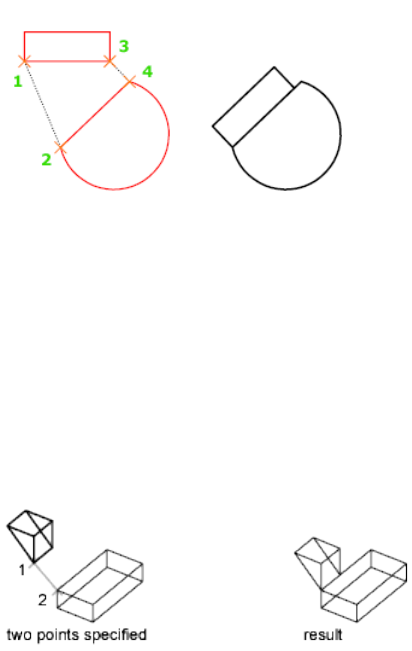
Summary
Either one, two, or three pairs of source points and definition points can be
specified to move, rotate, or tilt the selected objects, aligning them with points
on another object.
List of Prompts
The following prompts are displayed.
Select objects: Select the objects to align and press Enter
Specify either one (page 59), two (page 59), or three pairs (page 60) of source
points and definition points to align the selected objects.
ALIGN Using One Pair of Points When you select only one source point and
destination point pair, the selected objects move in 2D or 3D from the source
point (1) to the destination point (2).
ALIGN Using Two Pairs of Points When you select two point pairs, you can
move, rotate, and scale the selected objects in 2D or 3D to align with other
objects.
Commands | 59
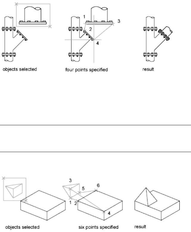
The first set of source and destination points defines the base point for the
alignment (1, 2). The second set of points defines the angle of rotation (3, 4).
After you enter the second set of points, you are prompted to scale the object.
The distance between the first and second destination points (2, 4) is used as
the reference length to which the object is scaled. Scaling is available only
when you are aligning objects using two point pairs.
NOTE
If you use two source and destination points to perform a 3D alignment on
non-perpendicular working planes, you get unpredictable results.
ALIGN Using Three Pairs of Points When you select three point pairs, you
can move and rotate the selected objects in 3D to align with other objects.
The selected objects move from the source point (1) to the destination point
(2).
The selected object is rotated (1 and 3) so that it aligns with the destination
object (2 and 4).
The selected object is then rotated again (3 and 5) so that it aligns with the
destination object (4 and 6).
60 | Chapter 2 Commands
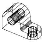
See also:
Align Objects
AMECONVERT
Converts AME solid models to AutoCAD solid objects.
Summary
The objects you select must be Advanced Modeling Extension (AME) Release
2 or 2.1 regions or solids. All other objects are ignored.
Because of increased accuracy in the new solid modeler, AME models may
look slightly different after conversion. This difference is noticeable where
the previous version of the solid modeler identified the surfaces of two different
shapes as so close as to be considered in the same plane. The new solid
modeler's finer tolerance may interpret these surfaces as being slightly offset.
This phenomenon is most apparent with aligned features such as fillets,
chamfers, and through-holes.
Holes might become blind holes when the new modeler, with its much finer
approximation capability, interprets what was once a through-hole as being
slightly less wide than the solid. Typically, the length of the remaining solid
material is the difference between the tolerance of the previous modeler and
that of the new modeler.
Likewise, updated fillets or chamfers can occasionally be placed slightly below
the surface, creating a hole through the solid, leaving the original shape
unaltered. Also, drawing fillets or chamfers slightly above the original surface
creates an uneven transition between the solid and the fillet or chamfer.
See also:
Use Render with Other Applications
Commands | 61
ANALYSISCURVATURE
Displays a color gradient onto a surface to evaluate different aspects of its
curvature.
Access Methods
Button
Toolbar: Modeling tool set ➤ Analysis tool group ➤ Surface Analysis
flyout ➤ Curvature Analysis
Summary
Allows you to visualize Gaussian, minimum, maximum, and mean U and V
surface curvature. Maximum curvature and a positive Gaussian value display
as green; minimum curvature and a negative Gaussian value display as blue.
Positive Gaussian curvature means that the surface is shaped like a bowl.
Negative Gaussian curvature means the surface is shaped like a saddle (as
shown below). Mean curvature and a zero Gaussian value means that the
surface is flat in at least one direction (planes, cylinders, and cones have zero
Gaussian curvature).
To change the curvature analysis display settings, use the Curvature tab (page
65) of the Analysis Options dialog box (page 64).
See also:
Analyze the Curvature of a NURBS Surface
62 | Chapter 2 Commands
ANALYSISDRAFT
Displays a color gradient onto a 3D model to evaluate whether there is
adequate space between a part and its mold.
Access Methods
Button
Toolbar: Modeling tool set ➤ Analysis tool group ➤ Surface Analysis
flyout ➤ Draft Analysis
Summary
The color spectrum shows draft angle changes within a specified range. The
maximum draft angle displays as red, and the minimum draft angle displays
as blue.
If the surface is parallel to the construction plane with surface normals facing
in the same direction as the current UCS, the draft angle is 90.0. When
perpendicular, it is 0. If the surface is parallel to the current UCS with surface
normals facing in the opposite direction than the current UCS, the draft
angle is -90.0.
To change the draft analysis display settings, use the Draft Angle tab (page
66) of the Analysis Options dialog box (page 64).
See also:
Use the Draft Analysis Tool
Commands | 63
ANALYSISOPTIONS
Sets the display options for zebra, curvature, and draft analysis.
Access Methods
Button
Toolbar: Modeling tool set ➤ Analysis tool group ➤ Surface Analysis
flyout ➤ Analysis Options
Summary
The Analysis Options dialog box (page 64) is displayed.
See also:
Analyze Surfaces
Analysis Options Dialog Box
Sets the display options for zebra, curvature, and draft analysis.
List of Tabs
The Analysis Options dialog box contains the following tabs:
■Zebra (page 64)
■Curvature (page 65)
■Draft Angle (page 66)
See also:
Analyze Surfaces
Zebra Tab (Analysis Options Dialog Box)
Changes the display settings for the ANALYSISZEBRA command.
64 | Chapter 2 Commands
List of Options
The following options are displayed.
Select Objects to Analyze
Prompts you to select the surface objects to analyze. When you are done
selecting objects, press Enter to return to the dialog box.
Stripe Display
Stripe Direction
Specifies the display angle. (VSAZEBRADIRECTION (page 1495)) This option is
only available when Type is set to Cylinder. If you are using the Chrome Ball
type, change the stripe directions with the VSAZEBRADIRECTION (page 1495)
system variable.
Type
Sets analysis display type. (VSAZEBRATYPE (page 1496))
Size
Sets the width of the zebra stripes. (VSAZEBRASIZE (page 1496))
Color 1
Sets the first color for zebra stripes. (VSAZEBRACOLOR1 (page 1494))
Color 2
Sets the second color for zebra stripes. (VSAZEBRACOLOR2 (page 1495))
Clear Zebra Analysis
Removes the zebra display from all objects in the current drawing.
See also:
Analyze Surfaces
Curvature Tab (Analysis Options Dialog Box)
Changes the display settings for the ANALYSISCURVATURE command.
List of Options
The following options are displayed.
Commands | 65
Select objects to analyze
Prompts you to select the surface objects to analyze. When you are done
selecting objects, press Enter to return to the dialog box.
Color Mapping
Display Style
Specifies the display for color mapping (VSACURVATURETYPE (page 1492)
system variable).
Enter the maximum curvature value (VSACURVATUREHIGH (page 1492)
system variable). When the surface curvature reaches this value, it displays as
green.
Enter the minimum curvature value (VSACURVATURELOW (page 1492) system
variable). When the surface curvature reaches this value, it displays as blue.
Auto Range
Calculates the curvature range so that 80% of the values are within the high
and low range (VSACURVATUREHIGH (page 1492) and VSACURVATURELOW
(page 1492) system variables).
Max Range
Calculates the maximum and minimum ranges of all objects selected for
curvature analysis (VSACURVATUREHIGH (page 1492) and VSACURVATURELOW
(page 1492) system variables).
Clear Curvature Analysis
Removes the curvature analysis display from all objects in the current drawing.
See also:
Analyze Surfaces
Draft Angle Tab (Analysis Options Dialog Box)
Changes the display settings for the ANALYSISDRAFT command.
List of Options
The following options are available.
66 | Chapter 2 Commands
Select objects to analyze
Prompts you to select the surface objects to analyze. When you are done
selecting objects, press Enter to return to the dialog box.
Color Mapping
Maps green to the highest draft angle, red to the medium draft angle, and
blue to the lowest draft angle.
Angle Sets the value for the high and low draft angles. The draft angle is the
angle in degrees between the surface normal and the UCS plane.
Enter a value for the highest angle allowed (VSADRAFTANGLEHIGH (page
1493)). When the object’s angle reaches this value, it displays in green.
Displays the average value of the high and low angles. When the object’s angle
reaches this value, it displays in red.
Enter a value for the lowest angle allowed (VSADRAFTANGLELOW (page 1494)).
When the object’s angle reaches this value, it displays in blue.
Clear Draft Angle Analysis
Removes the curvature analysis display from all objects in the current drawing.
See also:
Analyze Surfaces
ANALYSISZEBRA
Projects stripes onto a 3D model to analyze surface continuity.
Access Methods
Button
Toolbar: Modeling tool set ➤ Analysis tool group ➤ Surface Analysis
flyout ➤ Zebra Analysis
Summary
The way the stripes line up where two surfaces meet, helps analyze the
tangency and curvature of the intersection.
Commands | 67
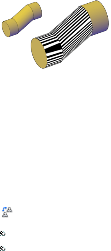
In this example, the surface continuity is G0 because the surface edges are
coincident, but they are not tangent and they have different curvatures. The
fact that the stripes are not aligned shows that the surfaces are not tangent.
To change the zebra analysis display settings, use the Zebra Analysis tab (page
64) of the Analysis Options dialog box (page 64).
See also:
Analyze Surface Continuity with Zebra Analysis
ANNORESET
Resets the locations of all alternate scale representations of the selected
annotative objects.
Access Methods
Button
Toolbar: Annotation tool set ➤ Annotation Scaling tool group ➤ Sync
Scale Positions
Menu: Modify ➤ Annotative Object Scale ➤ Synchronize
Multiple-Scale Positions
Shortcut menu: Select an annotative object. Right-click and choose
Annotative Object Scale ➤ Synchronize Multiple-Scale Positions.
68 | Chapter 2 Commands

Summary
The location of each scale representation of an annotative object can be
adjusted using grips. For each selected annotative object, all alternate scale
representations are returned to the location of the object’s current scale
representation.
See also:
Add and Modify Scale Representations
ANNOUPDATE
Updates existing annotative objects to match the current properties of their
styles.
Summary
When a non-annotative text object is updated to an annotative text style, the
object becomes annotative and supports the current . If the text style has a
fixed Paper Height, the object is set to that height. If the text style’s Paper
Height is set to 0, the size of the text does not change. The Paper Height value
is inferred by dividing the model height by the current annotation scale.
If an annotative object is updated to a non-annotative style, the object becomes
non-annotative and any alternate are removed.
See also:
Work with Annotative Styles
APERTURE
Controls the size of the object snap target box.
Access Methods
Command entry: aperture (or 'aperture for transparent use)
Commands | 69

Summary
Object snap applies only to objects inside or crossing the object snap target
box. The APBOX (page 1172) system variable controls whether the object snap
target box is displayed. The number of pixels you enter using APERTURE
controls the size of the object snap box. The higher the number, the larger
the target box.
You can also change this setting in the Application Preferences dialog box,
Cursor & Selection tab.
APERTURE controls the object snap target box, not the pickbox displayed at
the Select Objects prompt. The object selection pickbox is controlled by the
PICKBOX (page 1393) system variable.
APPLOAD
Loads and unloads applications and defines which applications to load at
startup.
Access Methods
Menu: Tools ➤ Load Application
Summary
The Startup Suite option loads the specified applications each time the product
first starts. Application files can be dragged from the files list, or from any
application with dragging capabilities.
The Load/Unload Applications dialog box is displayed (page 71).
See also:
Overview of AutoLISP Automatic Loading
70 | Chapter 2 Commands
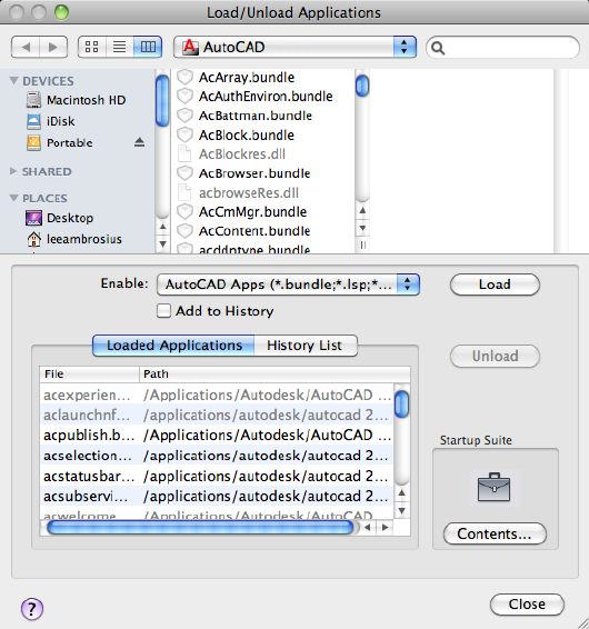
Load/Unload Applications Dialog Box
Loads and unloads applications and defines which applications to load at
startup.
Summary
Loads and unloads applications and specifies applications to be loaded at
startup.
List of Options
The following options are displayed.
The options at the top of this dialog box are derived from the standard file
selection dialog box (page 720). Following are descriptions of the additional
options provided by the Load/Unload Applications dialog box:
Commands | 71
Load Loads or reloads the applications that are currently selected either in
the files list or on the History List tab. Load is unavailable until you select a
file that you can load. ObjectARX and DBX applications are loaded
immediately, but LSP and FAS applications are queued and then loaded when
you close the Load/Unload Applications dialog box.
If you select a file that is already loaded, Load reloads the application when
applicable. You cannot reload ObjectARX applications. In this case, you must
first unload the ObjectARX application and then load it again. The Load option
is also available from a shortcut menu by right-clicking a file on the History
List tab.
Loaded Applications
Displays an alphabetical list (by file name) of currently loaded applications.
LISP routines are displayed in this list only if you loaded them in the
Load/Unload Applications dialog box.
You can drag files into this list from the files list or from any application with
dragging capabilities, such as Finder.
You can also unload certain applications from this list. See the Unload option
for details. Files that you cannot unload are not available for selection.
History List
Displays an alphabetical list (by file name) of applications that you previously
loaded with Add To History selected. If Add To History is not selected when
you drag files into this list, the dragged files are loaded but not added to the
history list.
You can drag files into this list from the files list, or from any application with
dragging capabilities, such as Finder.
You can load and remove applications from this list, but to unload applications,
you must use the Loaded Applications tab. See the Load, Unload, and Remove
options.
Add to History
Adds any applications that you load to the history list.
Unload/Remove
Unloads the selected applications or removes them from the History List.
Unload is available only when a file is selected on the Loaded Applications
tab. Remove is available only when you select a file on the History List tab.
LISP applications cannot be unloaded, nor can ObjectARX applications that
are not registered for unloading.
72 | Chapter 2 Commands

NOTE
Remove does not unload the selected application. The Remove option is also
available from a shortcut menu by right-clicking an application on the History
List tab.
Startup Suite
Contains a list of applications that are loaded each time you start AutoCAD
for Mac.
You can drag application files from the files list, or from any application with
dragging capabilities such as Finder, into the Startup Suite area to add them
to the Startup Suite.
You cannot add applications that you load with the AutoCAD for Mac web
browser to the Startup Suite.
Contents
Displays the Startup Suite dialog box (page 73). You can also add files to the
Startup Suite by clicking the Startup Suite icon or by right-clicking an
application on the History List tab and clicking Add to Startup Suite on the
shortcut menu.
Status Line
Displays messages that indicate the status of loading and unloading operations.
See also:
Overview of AutoLISP Automatic Loading
Startup Suite Dialog Box
Adds and removes application files from the Startup Suite. These are the
applications that are loaded each time you start AutoCAD for Mac
Commands | 73
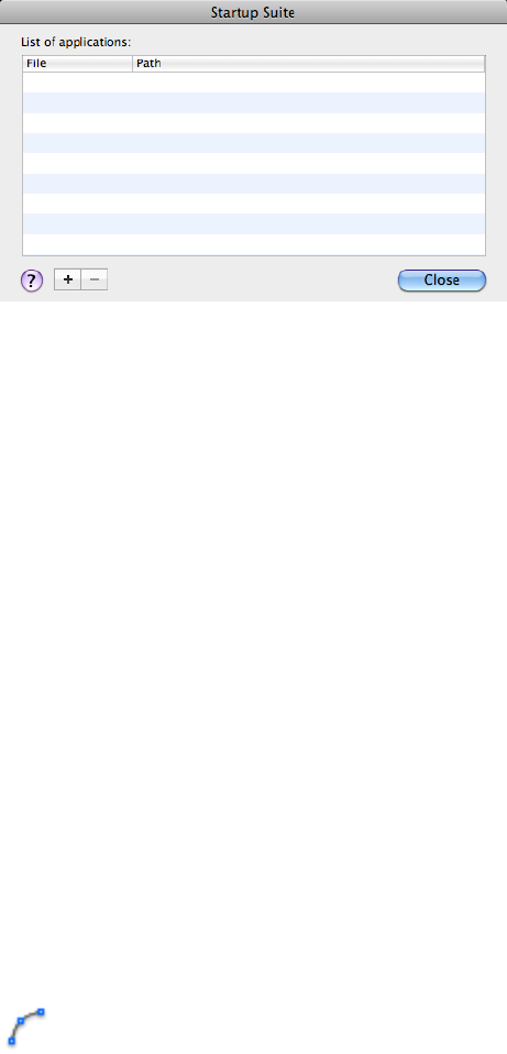
List of Options
The following options are displayed.
List of Applications
Displays an alphabetical list (by file name) of the application files to load at
startup.
Add
Displays the Add File to Startup Suite dialog box. You can use this dialog box
to select files to add to the startup suite.
Remove
Removes selected files from the Startup Suite.
See also:
Overview of AutoLISP Automatic Loading
ARC
Creates an arc.
Access Methods
Button
74 | Chapter 2 Commands

Toolbar: Drafting tool set ➤ Open Shapes tool group ➤ Arc flyout
Menu: Draw ➤ Arc
Summary
To create an arc, you can specify combinations of center, endpoint, start point,
radius, angle, chord length, and direction values.
For example:
The distance between the start point and the center determines the radius.
The endpoint is determined by a line from the center that passes through the
third point.
The resulting arc is always created counterclockwise from the start point.
The distance between the start point and the center determines the radius.
The other end of the arc is determined by specifying an included angle that
uses the center of the arc as the vertex.
The resulting arc is always created counterclockwise from the start point.
Commands | 75
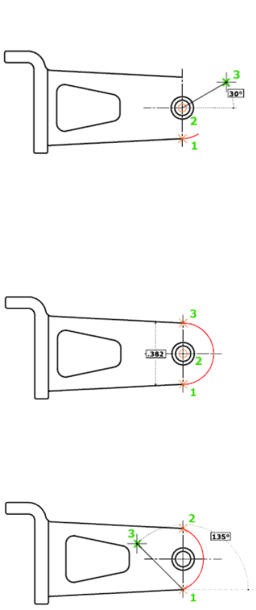
The distance between the start point and the center determines the radius.
The other end of the arc is determined by specifying the length of a chord
between the start point and the endpoint of the arc.
The resulting arc is always created counterclockwise from the start point.
The included angle between the endpoints of the arc determines the center
and the radius of the arc.
The tangent direction can be specified either by locating a point on the desired
tangent line, or by entering an angle. You can determine which endpoint
controls the tangent by changing the order in which you specify the two
endpoints.
76 | Chapter 2 Commands
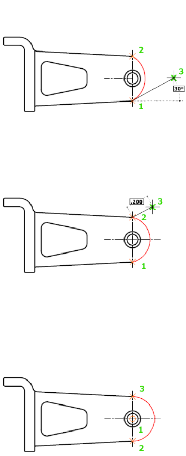
The direction of the bulge of the arc is determined by the order in which you
specify its endpoints. You can specify the radius either by entering it or by
specifying a point at the desired radius distance.
The distance between the start point and the center determines the radius.
The endpoint is determined by a line from the center that passes through the
third point.
The resulting arc is always created counterclockwise from the start point.
The distance between the start point and the center determines the radius.
The other end of the arc is determined by specifying an included angle that
uses the center of the arc as the vertex.
Commands | 77
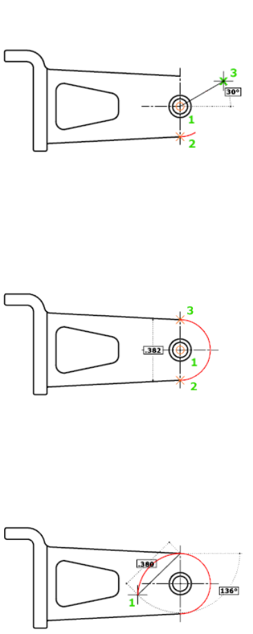
The resulting arc is always created counterclockwise from the start point.
The distance between the start point and the center determines the radius.
The other end of the arc is determined by specifying the length of a chord
between the start point and the endpoint of the arc.
The resulting arc is always created counterclockwise from the start point.
Immediately after you create a line or an arc, you can start an arc that is
tangent at an endpoint by starting the ARC command and pressing ENTER at
the Specify Start Point prompt. You need to specify only the endpoint of the
arc.
78 | Chapter 2 Commands
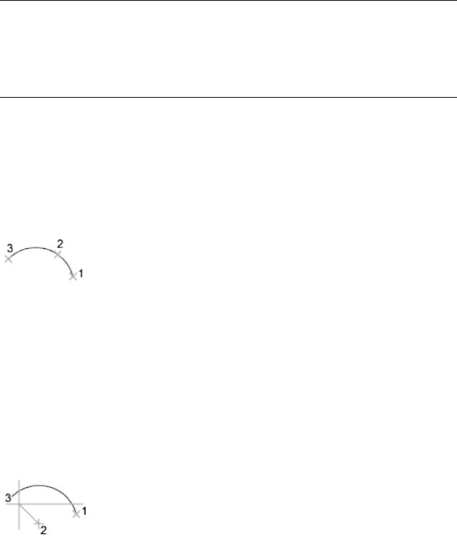
List of Prompts
The following prompts are displayed.
Specify start point (page ?)of arc or [Center (page ?)]:
Specify a point, enter c, or press Enter to start tangent to last line,
arc, or polyline (page ?)
Start Point
Specifies the starting point of the arc.
NOTE
If you press Enter without specifying a point, the endpoint of the last drawn
line or arc is used and you are immediately prompted to specify the endpoint
of the new arc. This creates an arc tangent to the last drawn line, arc, or
polyline.
Specify second point of arc or [Center/End]:
Second Point
Draws an arc using three specified points on the arc's circumference. The first
point is the start point (1). The third point is the endpoint (3). The second
point (2) is a point on the circumference of the arc.
Specify end point of arc: Specify a point (3)
You can specify a three-point arc either clockwise or counterclockwise.
Center
Specifies the center of the circle of which the arc is a part.
Specify center point of arc:
Specify end point of arc or [Angle/chord Length]:
End Point Using the center point (2), draws an arc counterclockwise from the
start point (1) to an endpoint that falls on an imaginary ray drawn from the
center point through the third point (3).
Commands | 79
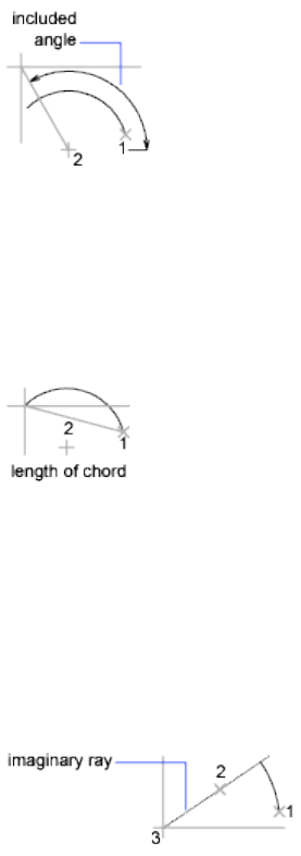
The arc does not necessarily pass through this third point, as shown in the
illustration.
Angle Draws an arc counterclockwise from the start point (1) using a center
point (2) with a specified included angle. If the angle is negative, a clockwise
arc is drawn.
Specify included angle: Specify an angle
Chord Length Draws either a minor or a major arc based on the distance of
a straight line between the start point and endpoint.
If the chord length is positive, the minor arc is drawn counterclockwise from
the start point. If the chord length is negative, the major arc is drawn
counterclockwise.
Specify length of chord: Specify a length
End
Specifies the endpoint of the arc.
Specify end point of arc:
Specify center point of arc or [Angle/Direction/Radius]:
Center Point Draws an arc counterclockwise from the start point (1) to an
endpoint that falls on an imaginary ray drawn from the center point (3)
through the second point specified (2).
80 | Chapter 2 Commands
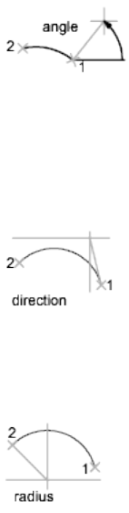
Angle Draws an arc counterclockwise from the start point (1) to an endpoint
(2), with a specified included angle. If the angle is negative, a clockwise arc is
drawn.
Specify included angle: Enter an angle in degrees or specify an angle by moving
the pointing device counterclockwise
Direction Begins the arc tangent to a specified direction. It creates any arc,
major or minor, clockwise or counterclockwise, beginning with the start point
(1), and ending at an endpoint (2). The direction is determined from the start
point.
Specify tangent direction for the start point of arc:
Radius Draws the minor arc counterclockwise from the start point (1) to the
endpoint (2). If the radius is negative, the major arc is drawn.
Specify radius of arc:
Center
Specifies the center of the circle of which the arc is a part.
Specify center point of arc:
Specify start point of arc:
Specify end point of arc or [Angle/chord Length]:
End Point Draws an arc counterclockwise from the start point (2) to an
endpoint that falls on an imaginary ray drawn from the center point (1)
through a specified point (3).
Commands | 81
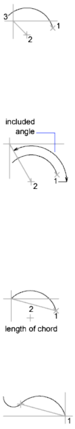
Angle Draws an arc counterclockwise from the start point (2) using a center
point (1) with a specified included angle. If the angle is negative, a clockwise
arc is drawn.
Specify included angle:
Chord Length Draws either a minor or a major arc based on the distance of
a straight line between the start point and endpoint.
If the chord length is positive, the minor arc is drawn counterclockwise from
the start point. If the chord length is negative, the major arc is drawn
counterclockwise.
Specify length of chord:
Tangent to Last Line, Arc, or Polyline
Draws an arc tangent to the last line, arc, or polyline drawn when you press
ENTER at the first prompt.
Specify end point of arc: Specify a point (1)
See also:
Draw Arcs
82 | Chapter 2 Commands
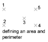
AREA
Calculates the area and perimeter of objects or of defined areas.
Summary
Several commands are available to provide area information including AREA,
MEASUREGEOM (page 613), and MASSPROP (page 597). Alternatively, use
BOUNDARY (page 149) to create a closed polyline or region. Then use LIST
(page 581) or the Properties Inspector (page 832) to find the area.
List of Prompts
The following prompts are displayed.
Specify first corner point (page ?) or [Object (page ?)/Add
Area (page ?)/Subtract Area (page ?)] <Object>: Select an option
The area and perimeter of the specified object displays at the Command prompt
and in the tooltip.
Specify Corner Points
Calculates the area and perimeter defined by specified points. All points must
lie in a plane parallel to the XY plane of the current user coordinate system
(UCS).
A rubberband line from the first specified point to the cursor is displayed.
Once the second point is specified, a line segment and a polygon with green
fill are displayed.
Continue to specify points to define a polygon and then press Enter to
complete the definition of the perimeter. The area to be calculated is
highlighted in green.
If you do not close the polygon, the area is calculated as if a line were drawn
from the last point entered to the first. When the perimeter is calculated, that
line length is added.
Commands | 83
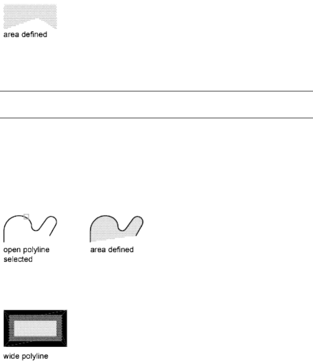
Object
Calculates the area and perimeter of a selected object. You can calculate the
area of circles, ellipses, splines, polylines, polygons, regions, and 3D solids.
NOTE 2D solids (created with the SOLID (page 955) command) do not have an
area reported.
Select object:
If you select an open polyline, the area is calculated as if a line were drawn
from the last point entered to the first. When the perimeter is calculated that
line length is ignored.
The centerline of a wide polyline is used to make area and perimeter
calculations.
The centerline of a wide polyline is used to make area and perimeter (or length)
calculations.
Add Area
Turns on Add mode and keeps a running balance of the total area as you
continue to define areas. You can use the Add Area option to calculate
individual areas and perimeters of defined areas and objects and the total area
of all defined areas and objects.
You can also select to specify the points. A rubberband line from the first
specified point to the cursor is displayed
84 | Chapter 2 Commands
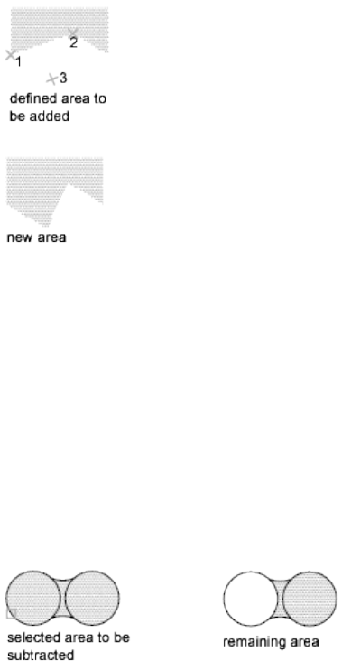
Specify points to define a polygon (3). The area to be added is highlighted in
green. Press Enter. AREA calculates the area and perimeter and returns the
total area of all the areas defined by selecting points or objects since Add mode
was turned on.
If you do not close the polygon, the area is calculated as if a line were drawn
from the last point entered to the first. When the perimeter is calculated, that
line length is added.
Subtract Area
Similar to the Add Area option, but subtracts areas and perimeters. You can
use the Subtract Area option to subtract a specified area from a total area.
You can also specify the area to be subtracted with points. A rubberband line
from the first specified point to the cursor is displayed.
The specified area to be subtracted is highlighted in red.
The total area and perimeter displays at the Command prompt and in the
tooltip.
See also:
Obtain Area and Mass Properties Information
Commands | 85
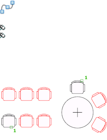
ARRAY
Creates copies of objects arranged in a 2D or 3D pattern.
Access Methods
Button
Menu: Modify ➤ Array.
Toolbar: Drafting tool set ➤ Copy tool group ➤ Array flyout
Summary
You can create copies of objects in a regularly spaced rectangular, polar, or
path array.
The DELOBJ (page 1213) system variable controls whether the source objects of
the array are deleted or retained after the array is created.
If you enter -array at the Command prompt, options are displayed (page 87).
List of Prompts
The following prompts are displayed.
Select objects: Use an object selection method
Enter array type [Rectangular (page 86)/PAth (page 86)/POlar
(page 87)] <Rectangular>: Enter an option or press Enter
Rectangular (ARRAYRECT (page 103))
Distributes object copies into any combination of rows, columns, and levels.
Path (ARRAYPATH (page 96))
86 | Chapter 2 Commands
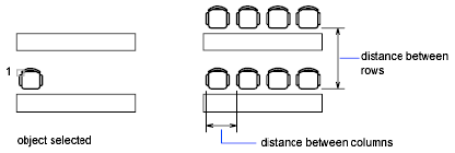
Evenly distributes object copies along a path or a portion of a path.
Polar (ARRAYPOLAR (page 100))
Evenly distributes object copies in a circular pattern around a center point or
axis of rotation.
See also:
Array Objects
-ARRAY
Maintains legacy command line behavior for creating nonassociative, 2D
rectangular or polar arrays.
List of Prompts
The following prompts are displayed.
Select objects: Use an object selection method
Enter the type of array [Rectangular (page ?)/Polar (page
?)] <current>: Enter an option or press Enter
Rectangular
Creates an array of rows and columns of copies of the selected objects.
Enter the number of rows (---) <1>:Enter a nonzero integer or press Enter
Enter the number of columns (|||) <1>:Enter a nonzero integer or press Enter
If you specify one row, you must specify more than one column and vice
versa.
The selected object, or cornerstone element, is assumed to be in the lower-left
corner, and generates the array up and to the right.
The specified distance between the rows and columns includes the
corresponding lengths of the object to be arrayed.
Enter the distance between rows or specify unit cell (---):
Commands | 87
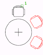
To add rows downward, specify a negative value for the distance between
rows. ARRAY skips the next prompt if you specify two points for the opposite
corners of a rectangle.
Specify the distance between columns (|||):
To add columns to the left, specify a negative value for the distance between
columns. Rectangular arrays are constructed along a baseline defined by the
current snap rotation. This angle is normally 0, so the rows and columns are
orthogonal with respect to the X and Y drawing axes. The Rotate option of
the SNAP (page 952) command changes the angle and creates a rotated array.
The SNAPANG (page 1439) system variable stores the snap rotation angle.
If you specify a large number of rows and columns for the array, it might take
a while to create the copies. By default, the maximum number of array
elements that you can generate in one command is 100,000. The limit is set
by the MAXARRAY setting in the registry. To reset the limit to 200,000, for
example, enter (setenv "MaxArray" "200000") at the Command prompt.
Polar
Creates an array by copying the selected objects around a specified center
point.
Specify center point of array or [Base]: Specify a point or enter b to specify a new
base point
Center Point Creates an array defined by a center point.
Base Specifies a new reference (base) point relative to the selected objects that
will remain at a constant distance from the center point of the array as the
objects are arrayed.
Enter the number of items in the array: Enter a positive integer or press Enter
If you enter a value for the number of items, you must specify either the angle
to fill or the angle between items. If you press ENTER (and do not provide the
number of items), you must specify both.
88 | Chapter 2 Commands

Specify the angle to fill (+=ccw, -=cw) <360>: Enter a positive integer for a
counterclockwise rotation or a negative integer for a clockwise rotation
You can enter 0 for the angle to fill only if you specify the number of items.
If you specify an angle to fill without providing the number of items, or if
you specify the number of items and enter 0 as the angle to fill or press Enter,
the following prompt is displayed:
Angle between items: Specify an angle
If you specified the number of items and entered 0 as the angle to fill or pressed
Enter, ARRAY prompts for a positive or negative value to indicate the direction
of the array:
Angle between items (+=ccw, -=cw): Enter a positive integer for a counterclockwise
rotation or a negative integer for a clockwise rotation
ARRAY determines the distance from the array's center point to a reference
point on the last object selected. The reference point used is the center point
of a circle or arc, the insertion base point of a block or shape, the start point
of text, and one endpoint of a line or trace.
Rotate arrayed objects? <Y>: Enter y or n, or press Enter
In a polar array, the reference point of the last object in the selection set is
used for all objects. If you defined the selection set by using window or crossing
selection, the last object in the selection set is arbitrary. Removing an object
from the selection set and adding it back forces that object to be the last object
selected. You can also make the selection set into a block and replicate it.
See also:
Array Objects
ARRAYCLOSE
Saves or discards changes made to an array’s source objects and exits the array
editing state.
Access Methods
Toolbar: Edit Array visor ➤ Discard Changes/Save Changes
Shortcut menu: Right-click in drawing area and click Close Array Edit Session
➤ Discard Changes/Save Changes
Commands | 89

Summary
The Source option of ARRAYEDIT (page 90) activates an editing state in which
you can edit the source objects of a selected array item.
List of Prompts
The following prompts are displayed.
Save changes to array [Yes (page ?)/No (page ?)] <Yes>:
Enter an option
Save Changes
Saves all changes made to the source object or to a replacement item of the
array.
Discard Changes
Discards any changes made; the source object or replacement item in the array
is returned to its original state.
See also:
Array Objects
ARRAYEDIT
Edits associative array objects and their source objects.
Access Methods
Menu: Modify ➤ Object ➤ Array
Toolbar: <current> Array visor ➤ Edit Source
Shortcut menu: Select an associative array. Right-click and choose Array
➤ Edit Array.
Summary
Modify associative arrays by editing the array properties, editing source objects,
or replacing items with other objects.
When you edit source objects, an editing state is activated. Save or discard
changes (ARRAYCLOSE (page 89)) to exit the editing state.
90 | Chapter 2 Commands
When you select a single associative array object, one of the following visors
is displayed:
■Path Array visor (page 93)
■Polar Array visor (page 94)
■Rectangular Array visor (page 95)
List of Prompts
The following prompt is displayed.
Select array: Use an object selection method
The array type determines the remaining prompts.
For rectangular arrays:
Enter an option [Source (page ?)/REPlace (page ?)/Base
point (page ?)/Rows (page ?)/Columns (page ?)/Levels (page
?)/RESet (page ?)/eXit (page ?)] <eXit>:
For path arrays:
Enter an option [Source/REPlace/Method (page ?)/Base
point/Items (page ?)/Rows/Levels/Align items (page ?)/Z
direction (page ?)/RESet/eXit] <eXit>:
For polar arrays:
Enter an option [Source/REPlace/Base point/Items/Angle between
(page ?)/Fill angle (page ?)/Rows/Levels/ROTate items (page
?)/RESet/eXit] <eXit>:
Source
Activates an editing state in which you can edit the source objects (or
replacement source objects) for a selected item.
All changes (including the creation of new objects) are instantly applied to
all items that reference the same source objects.
While the editing state is active, an Edit Array contextual tab is displayed on
the ribbon and automatic saving is disabled. Save or discard changes (ARRAYC-
LOSE (page 89)) to exit the editing state.
When the source objects are modified, the changes are dynamically reflected
on the array block.
Replace
Replaces the source objects for selected items or for all items referencing the
original source objects.
Replacement Objects Selects the new source objects.
Commands | 91
Base Point Specifies a base point for the replacement objects.
Item in Array Selects the item whose source objects are to be replaced, and
continues to prompt for additional items.
■Source objects. Replaces the original set of source objects in the array,
which updates all items that have not been previously replaced.
Base Point
Redefines the base point of the array.
Path arrays are repositioned relative to the new base point.
Rows
Specifies the number and spacing of rows, and the incremental elevation
between them.
Expression Derives a value using a mathematical formula or equation.
Total Specifies the total distance between the first and last rows.
Columns (Rectangular Arrays)
Specifies the number and spacing of columns.
Expression (page 92)
Total Specifies the total distance between the first and last columns.
Levels
Specifies the number and spacing of levels.
Expression (page 92)
Total Specifies the total distance between the first and last levels.
Method (Path Arrays)
Controls how to distribute items when the path or number of items is edited.
■Divide. Redistributes items to divide evenly along the length of the path.
■Measure. Maintains current spacing when the path is edited, or when
the number of items is edited through grips or the Properties palette. When
the number of items is edited using ARRAYEDIT, you are prompted to
redefine the distribution method.
Items (Path and Polar Arrays)
Specifies the number of items in the array.
For path arrays whose Method property is set to Measure, you are prompted
to redefine the distribution method. The same prompts are available from
ARRAYPATH (page 96).
92 | Chapter 2 Commands

Align Items (Path Arrays)
Specifies whether to align each item to be tangent to the path direction.
Alignment is relative to the orientation of the first item (ARRAYPATH,
Orientation option).
Z Direction (Path Arrays)
Controls whether to maintain the original Z direction of the items or to
naturally bank the items along a 3D path.
Angle Between (Polar Arrays)
Specifies the angle between items.
Expression (page 92)
Fill Angle (Polar Arrays)
Specifies the angle between the first and last item in the array.
Expression (page 92)
Rotate Items (Polar Arrays)
Controls whether items are rotated as they are arrayed.
Reset
Restores erased items and removes any item overrides.
Exit
Exits the command.
See also:
Edit Associative Arrays
Path Array Visor
Modifies the properties of an associative path array, such as base point, array
method, and Z direction.
Summary
The Path Array visor is displayed when you select an associative array created
with the Path option. The options on this visor can also be accessed using the
ARRAYEDIT (page 90) command from the Command prompt.
Commands | 93
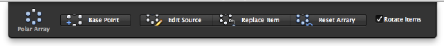
List of Options
The following options are displayed.
Base Point
Redefines the base point of the array.
Array Method
Controls how to distribute items when the path or number of items is edited.
Edit Source
Activates an editing state in which you can edit the source objects (or
replacement source objects) for a selected item.
Replace Item
Replaces the source objects for selected items or for all items referencing the
original source objects.
Reset Array
Restores erased items and removes any item overrides.
Rotate Items
Controls whether items are rotated as they are arrayed.
Align Items
Specifies whether to align each item to be tangent to the path direction.
Alignment is relative to the orientation of the first item.
Z Direction
Controls whether to maintain the original Z direction of the items or to
naturally bank the items along a 3D path.
See also:
Edit Associative Arrays
Polar Array Visor
Modifies the properties of an associative polar array, such as base point and
item rotation.
94 | Chapter 2 Commands
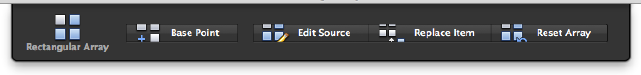
Summary
The Polar Array visor is displayed when you select an associative array created
with the Polar option. The options on this visor can also be accessed using
the ARRAYEDIT (page 90) command from the Command prompt.
List of Options
The following options are displayed.
Base Point
Redefines the base point of the array.
Edit Source
Activates an editing state in which you can edit the source objects (or
replacement source objects) for a selected item.
Replace Item
Replaces the source objects for selected items or for all items referencing the
original source objects.
Reset Array
Restores erased items and removes any item overrides.
Rotate Items
Controls whether items are rotated as they are arrayed.
See also:
Edit Associative Arrays
Rectangular Array Visor
Modifies the properties of an associative rectangular array, such as base point
and source item.
Summary
The Rectangular Array visor is displayed when you select an associative array
created with the Rectangular option. The options on this visor can also be
Commands | 95
accessed using the ARRAYEDIT (page 90) command from the Command
prompt.
List of Options
The following options are displayed.
Base Point
Redefines the base point of the array.
Edit Source
Activates an editing state in which you can edit the source objects (or
replacement source objects) for a selected item.
Replace Item
Replaces the source objects for selected items or for all items referencing the
original source objects.
Reset Array
Restores erased items and removes any item overrides.
Align Item
Specifies whether to align each item to be tangent to the path direction.
Alignment is relative to the orientation of the first item.
See also:
Edit Associative Arrays
ARRAYPATH
Evenly distributes object copies along a path or a portion of a path.
Access Methods
Button
Menu: Modify ➤ Array ➤ Path Array
Command entry: Drafting tool set ➤ Copy tool group ➤ Array flyout
➤ Path Array
Summary
This command is equivalent to the Path option in ARRAY (page 86).
96 | Chapter 2 Commands

The path can be a line, polyline, 3D polyline, spline, helix, arc, circle, or ellipse.
List of Prompts
The following prompts are displayed.
Select objects: Use an object selection method
Select path curve (page ?): Use an object selection method
Enter number of items (page ?) along path or [Orientation
(page 97)/Expression (page 98)] <Orientation>: Specify the number
of items or enter an option
Specify base point (page ?) or [Key point (page 98)] <end
of path curve>: Specify a base point or enter an option
Specify direction to align with path or [2Points/Normal]
<current>: Press Enter or select and option
Specify the distance between items (page ?) along path or
[Divide (page 99)/Total (page 99)/Expression (page 98)]
<Divide evenly along path>: Specify a distance or enter an option
Press Enter to accept or [ASsociative (page ?)/Base
point/Items (page ?)/Rows (page ?)/Levels (page ?)/Align
items (page ?)/Z direction (page ?)/eXit (page ?)]<eXit>:
Press Enter or select an option
Path Curve
Specifies the object to use for the path of the array. Select a line, polyline, 3D
polyline, spline, helix, arc, circle, or ellipse.
Number of Items
Specifies the number of items in the array.
Orientation Controls whether the selected objects are reoriented (rotated)
relative to the starting direction of the path before being moved to the start
point of the path.
■2 Points. Specifies two points to define the direction to be aligned with
the starting direction of the path.
Commands | 97
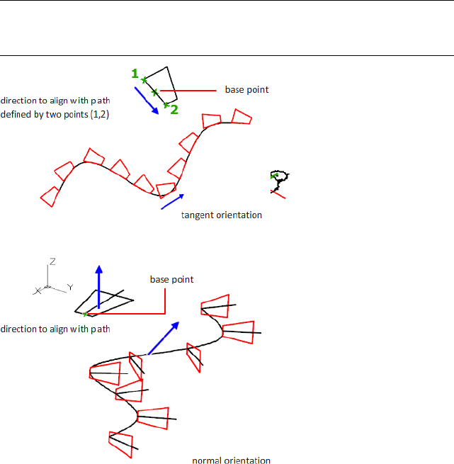
■Normal. Objects are aligned to be normal to the starting direction of the
path.
NOTE The Align Items (page ?) option controls the whether to maintain the
starting orientation or continue reorienting items along the path, relative to the
starting orientation.
Expression Derives a value using a mathematical formula or equation.
Base Point
Specifies a base point for the array.
Key Point For associative arrays, specifies a valid constraint point (or key point)
on the source objects to use as the base point. If you edit the source objects
of the resulting array, the base point of the array remains coincident with the
key point of the source objects.
Distance Between Items
Specifies the distance between items.
98 | Chapter 2 Commands
Divide Divides items evenly along the entire length of the path.
Total Specifies the total distance between the first and last items.
Expression (page 98)
Associative
Specifies whether to create items in the array as an associative array object,
or as independent objects.
■Yes. Contains array items in a single array object, similar to a block. This
allows you to quickly propagate changes by editing the properties and
source objects of the array.
■No. Creates array items as independent objects. Changes to one item do
not affect the other items.
Items
Edits the number of items in the array.
If the Method property is set to Measure, you are prompted to redefine the
distribution method (Distance Between Items (page ?), Divide (page 99), and
Total (page 99) options).
Rows
Specifies the number and spacing of rows in the array, and the incremental
elevation between them.
Expression (page 98)
Total Specifies the total distance between the first and last rows.
Levels
Specifies the number and spacing of levels in the array.
Expression (page 98)
Total Specifies the total distance between the first and last levels.
Align Items
Specifies whether to align each item to be tangent to the path direction.
Alignment is relative to the first item’s orientation (Orientation (page 97)
option).
Commands | 99
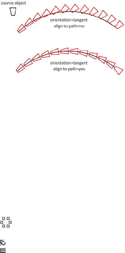
Z Direction
Controls whether to maintain the items’ original Z direction or to naturally
bank the items along a 3D path.
Exit
Exits the command.
See also:
Create Path Arrays
ARRAYPOLAR
Evenly distributes object copies in a circular pattern around a center point or
axis of rotation.
Access Methods
Button
Menu: Modify ➤ Array ➤ Polar Array
Command entry: Drafting tool set ➤ Copy tool group ➤ Array flyout
➤ Polar Array
Summary
This command is equivalent to the Polar option in ARRAY (page 86).
Creates an array by copying the selected objects around a specified center
point or axis of rotation.
100 | Chapter 2 Commands
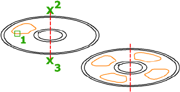
List of Prompts
The following prompts are displayed.
Select objects: Use an object selection method
Specify center point (page ?) of array or [Base point (page
?)/Axis of rotation (page ?)]: Specify a center point, or enter an
option
Enter number of items (page ?) or [Angle between (page
?)/Expression (page 101)] <last count>: Specify the number of items or
enter an option
Specify the angle to fill (page ?) (+=ccw, -=cw) or
[Expression]: Enter a fill angle or enter an option
Press Enter to accept or [ASsociative (page ?)/Base
point/Items/Angle between/Fill angle/ROWs (page ?)/Levels
(page ?)/ROTate items (page ?)/eXit (page ?)]<eXit>: Press
Enter or select an option
Center Point
Specifies the point around which to distribute the array items. The axis of
rotation is the Z axis of the current UCS.
Base Point
Specifies a base point for the array.
Key Point For associative arrays, specifies a valid constraint (or key point) on
the source objects to use as the base point. If you edit the source objects of
the resulting array, the base point of the array remains coincident with the
key point of the source objects.
Axis of Rotation
Specifies a custom axis of rotation defined by two specified points.
Items
Specifies the number of items in the array.
Expression Derives a value using a mathematical formula or equation.
Commands | 101

NOTE When defining the fill angle in an expression, the (+ or -) mathematical
symbol in the resultant value does not affect the direction of the array.
Angle Between
Specifies the angle between items.
Expression (page 101)
Fill Angle
Specifies the angle between the first and last item in the array.
Expression (page 101)
Associative
Specifies whether to create items in the array as an associative array object,
or as independent objects.
■Yes. Contains array items in a single array object, similar to a block. This
allows you to quickly propagate changes by editing the properties and
source objects of the array.
■No. Creates array items as independent objects. Changes to one item do
not affect the other items.
Rows
Edits the number and spacing of rows in the array, and the incremental
elevation between them.
Expression (page 101)
Total Sets the total distance between the first and last rows.
Levels
Specifies the number and spacing of levels in the array.
Expression (page 101)
Total Specifies the total distance between the first and last levels.
Rotate Items
Controls whether items are rotated as they are arrayed.
Exit
Exits the command.
See also:
Create Polar Arrays
102 | Chapter 2 Commands
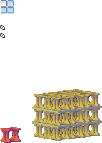
ARRAYRECT
Distributes object copies into any combination of rows, columns, and levels.
Access Methods
Button
Menu: Modify ➤ Array ➤ Rectangular Array
Toolbar: Drafting tool set ➤ Copy tool group ➤ Array flyout ➤
Rectangular Array
Summary
This command is equivalent to the Rectangular option in ARRAY (page 86).
Creates an array of rows and columns of copies of the selected object.
List of Prompts
The following prompts are displayed.
Select objects: Use an object selection method
Specify opposite corner for number of items (page ?) or
[Base point (page ?)/Angle (page ?)/Count (page 104)]
<Count>: Enter an option or press Enter
Press Enter to accept or [ASsociative (page ?)/Base
point/Rows (page ?)/Columns (page ?)/Levels (page ?)/eXit
(page ?)] <eXit>: Press Enter or select an option
Items
Specifies the number of items in the array. Use the preview grid to specify a
point that reflects the desired configuration.
Commands | 103
Count Specifies the row and column values individually.
■Expression (page 104)
Space Items
Specifies the row and column spacing. Use the preview grid to specify a point
that reflects the desired configuration.
Spacing Specifies the row and column spacing individually.
■Expression (page 104)
Base Point
Specifies a base point for the array.
Key Point For associative arrays, specifies a valid constraint (or key point) on
the source objects to use as the base point. If you edit the source objects of
the resulting array, the base point of the array remains coincident with the
key point of the source objects.
Angle
Specifies the angle of rotation for the row axis. The row and column axes
remain orthogonal to each other. For associative arrays, you can later edit the
individual row and column angles.
You can change the measurement conventions for angles using UNITS (page
1095). The ANGBASE (page 1169) and ANGDIR (page 1169) system variables affect
the angle of arrays.
Associative
Specifies whether to create items in the array as an associative array object,
or as independent objects.
■Yes. Contains array items in a single array object, similar to a block. This
allows you to quickly propagate changes by editing the properties and
source objects of the array.
■No. Creates array items as independent objects. Changes to one item do
not affect the other items.
Rows
Edits the number and spacing of rows in the array, and the incremental
elevation between them.
Expression Derives a value using a mathematical formula or equation.
Total Sets the total distance between the first and last rows.
Columns
Edits the number and spacing of columns.
104 | Chapter 2 Commands
Expression (page 104)
Total Specifies the total distance between the first and last columns.
Levels
Specifies the number and spacing of levels.
Expression (page 104)
Total Specifies the total distance between the first and last levels.
Exit
Exits the command.
See also:
Create Rectangular Arrays
ARX
Loads, unloads, and provides information about ObjectARX applications.
List of Prompts
The following prompts are displayed.
Enter an option [Files (page ?)/Groups (page ?)/Commands
(page ?)/CLasses (page ?)/Services (page ?)/Load (page
?)/Unload (page ?)]:
Files
Lists the currently loaded ObjectARX applications, which can be third-party
programs or internal applications such as Render.
Groups
Causes the specified group of commands to be the first group searched when
resolving the names of AutoCAD commands.
Commands
Lists the AcEd-registered commands (AcEd-registered commands are described
in the ObjectARX Developer's Guide).
Classes
Displays a class hierarchy of C++ classes derived from objects registered in the
system.
Services
Lists the names of all registered services.
Commands | 105

Load
Displays the ObjectARX/DBX File dialog box (a standard file selection dialog
box). This option loads the specified ObjectARX application.
Unload
Unloads the specified ObjectARX application.
Enter ARX/DBX file name to unload:
See also:
Overview of ObjectARX
ATTACH
Inserts an external reference or raster image in the current drawing.
Access Methods
Menu: File ➤ Attach
Summary
The Select Reference File dialog box (a standard file selection dialog box (page
720)) is displayed. To select multiple DWG files for attach, set the Files of Type
to Drawing. You can select one file only for all other file formats.
See also:
Attach and Detach Referenced Drawings
Attach Raster Image Files
ATTDEF
Creates an attribute definition for storing data in a block.
Access Methods
Button
106 | Chapter 2 Commands

Toolbar: Drafting tool set ➤ Block tool group ➤ Define Attributes
Menu: Draw ➤ Block ➤ Define Attributes
Summary
The Attribute Definition dialog box (page 107) is displayed.
If you enter -attdef at the Command prompt, options are displayed (page
111).
An attribute is an object that is created and included with a block definition.
Attributes can store data such as part numbers, product names, and so on.
See also:
Define Block Attributes
Attribute Definition Dialog Box
Defines the mode; attribute tag, prompt, and value; insertion point; and text
settings for an attribute.
Commands | 107
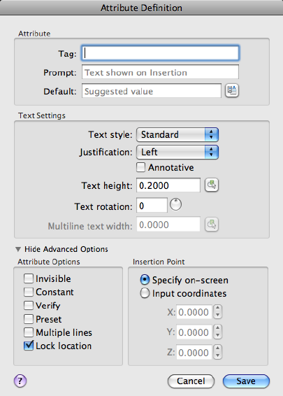
List of Options
The following options are displayed.
Attribute
Sets attribute data.
Tag
Identifies each occurrence of an attribute in the drawing. Enter the attribute
tag using any combination of characters except spaces. Lowercase letters are
automatically changed to uppercase.
Prompt
Specifies the prompt that is displayed when you insert a block containing this
attribute definition. If you do not enter a prompt, the attribute tag is used as
a prompt. If you select Constant in the Attribute Options area under Advanced
Options, the Prompt option is not available.
108 | Chapter 2 Commands

Default
Specifies the default attribute value.
Insert Field Button
Displays the Field dialog box (page 429). You can insert a field as all or part of
the value for an attribute.
This button is available when you are not creating a multiline attribute. If you
are creating a multiline attribute, right-click in the multiline in-place text
editor and choose Field.
Multiline Editor Button
When Multiple Line mode is selected, displays an in-place text editor with a
text formatting toolbar and ruler. Depending on the setting of the ATTIPE
(page 1175) system variable, the Text Formatting toolbar displayed is either the
abbreviated version, or the full version.
For more information, see the In-Place Text Editor (page 675).
NOTE Several options in the full In-Place Text Editor are grayed out to preserve
compatibility with single-line attributes.
Text Settings
Sets the justification, style, height, and rotation of the attribute text.
Text Style
Specifies a predefined text style for the attribute text. Currently loaded text
styles are displayed. To load or create a text style, see STYLE (page 1006).
Justification
Specifies the justification of the attribute text. See TEXT (page 1044) for a
description of the justification options.
Annotative
Specifies that the attribute is annotative. If the block is annotative, the attribute
will match the orientation of the block. Click the information icon to learn
more about annotative objects.
Text Height
Specifies the height of the attribute text. Enter a value, or choose Height to
specify a height with your pointing device. The height is measured from the
origin to the location you specify. If you select a text style that has fixed height
(anything other than 0.0), or if you select Align in the Justification list, the
Height option is not available.
Commands | 109
Text Rotation
Specifies the rotation angle of the attribute text. Enter a value, or choose
Rotation to specify a rotation angle with your pointing device. The rotation
angle is measured from the origin to the location you specify. If you select
Align or Fit in the Justification list, the Rotation option is not available.
Multiline Text Width
Specifies the maximum length of the lines of text in a multiple-line attribute
before wrapping to the next line. A value of 0.000 means that there is no
restriction on the length of a line of text.
Not available for single-line attributes.
Advanced Options
Contains options to set the behavior and insertion position for the attribute.
Attribute Options
Sets options for attribute values associated with a block when you insert the
block in a drawing.
The default values are stored in the AFLAGS (page 1168) system variable.
Changing the AFLAGS setting affects the default mode for new attribute
definitions and does not affect existing attribute definitions.
Invisible
Specifies that attribute values are not displayed or printed when you insert
the block. ATTDISP (page 114) overrides Invisible mode.
Constant
Gives attributes a fixed value for block insertions.
Verify
Prompts you to verify that the attribute value is correct when you insert the
block.
Preset
Sets the attribute to its default value when you insert a block containing a
preset attribute.
Lock Position
Locks the location of the attribute within the block reference. When unlocked,
the attribute can be moved relative to the rest of the block using grip editing,
and multiline attributes can be resized.
110 | Chapter 2 Commands

Multiple Lines
Specifies that the attribute value can contain multiple lines of text. When this
option is selected, you can specify a boundary width for the attribute.
NOTE In a dynamic block, an attribute's position must be locked for it to be
included in an action's selection set.
Insertion Point
Specifies the location for the attribute. Enter coordinate values or select Specify
On-screen and use the pointing device to specify the placement of the attribute
in relation to the objects that it will be associated with.
Specify On-Screen
Displays a Start Point prompt when the dialog box closes. Use the pointing
device to specify the placement of the attribute in relation to the objects that
it will be associated with.
Input Coordinates
Specifies the coordinates to use for the attribute’s insertion point.
X
Specifies the X coordinate of the attribute's insertion point.
Y
Specifies the Y coordinate of the attribute's insertion point.
Z
Specifies the Z coordinate of the attribute's insertion point.
See also:
Define Block Attributes
-ATTDEF
List of Prompts
The following prompts are displayed.
Current attribute modes (page ?): Invisible=current
Constant=current Verify=current Preset=current Lock position=current
Annotative =current Multiple line =current
Commands | 111

Enter an option to change
[Invisible/Constant/Verify/Preset/Lock
position/Annotative/Multiple lines] <done>:
Enter attribute tag name (page ?): Enter any characters except spaces
or exclamation points
Enter attribute value (page ?): Enter the appropriate text or press
Enter (this prompt is displayed only if you turned on Constant mode)
Enter attribute prompt (page ?): Enter the text for the prompt line or
press Enter (this prompt is not displayed if you turned on Constant mode)
Enter default attribute value (page ?): Enter the appropriate text
or press Enter (this prompt is not displayed if you turned on Constant mode)
Specify location of multiline attribute (page ?): Specify a
point (this prompt is displayed only if you turned on Multiple line mode)
Specify opposite corner (page ?): Specify a point or enter an option
(this prompt is displayed only if you turned on Multiple line mode)
Attribute Modes
The current value line indicates the current settings for each attribute mode
(either Y for on or N for off). Entering i, c, v, p, l, a, or m toggles the modes
on or off. Press Enter when you have finished adjusting the mode settings.
The AFLAGS (page 1168) system variable stores the current mode settings and
can be used to set the default modes.
Invisible Specifies that attribute values are displayed when you insert the
block. ATTDISP (page 114) overrides Invisible mode.
Constant Gives attributes a fixed value for block insertions.
Verify Prompts for verification that the attribute value is correct when you
insert the block.
Preset Sets the attribute to its default value when you insert a block containing
a preset attribute.
Lock Position Locks the location of the attribute within the block reference.
When unlocked, the attribute can be moved relative to the rest of the block
using grip editing, and multiline attributes can be resized.
NOTE
In a dynamic block, an attribute's position must be locked for it to be included
in an action's selection set.
Annotative Specifies that the attribute is annotative.
112 | Chapter 2 Commands

Multiple Lines Specifies that the attribute value can contain multiple lines
of text. When this option is selected, you can specify a boundary width for
the attribute.
Attribute Tag Name
Specifies the attribute tag, which identifies each occurrence of an attribute in
the drawing. The tag can contain any characters except spaces or exclamation
marks (!). Lowercase letters are automatically changed to uppercase.
Attribute Prompt
Specifies the prompt that is displayed when you insert a block containing this
attribute definition. If you press Enter, the attribute tag is used as the prompt.
If you turn on Constant mode, this prompt is not displayed.
NOTE
For single-line attributes, you can enter up to 256 characters. If you need
leading blanks in the prompt or the default value, start the string with a
backslash (\). To make the first character a backslash, start the string with two
backslashes.
Default Attribute Value
Specifies the default attribute value. The default attribute value appears when
a block is inserted into your drawing. A default value is not required. If you
turn on Constant mode, the Attribute Value prompt is displayed instead.
When Multiple Line mode is off, -ATTDEF then displays the same prompts as
the TEXT command, using the attribute tag instead of requesting a text string.
Current text style: "Standard" Text height: 0.2000
Specify start point of text or [Justify/Style]: Enter an option or press Enter
Specify paper text height <current>: Specify a height, or press Enter
The Specify Paper Text Height prompt is displayed only if the current text
style is annotative.
For a description of each option, see TEXT (page 1044).
NOTE
For single-line attributes, you can enter up to 256 characters. If you need
leading blanks in the prompt or the default value, start the string with a
backslash (\). To make the first character a backslash, start the string with two
backslashes.
Commands | 113

When Multiple Line mode is on, -ATTDEF then displays several of the prompts
used by the MTEXT command. For a description of each option, see MTEXT
(page 674).
Attribute Value (Constant Mode)
Specifies the value for a constant attribute. This prompt is displayed only if
you turn on Constant mode.
ATTDEF then displays the same prompts as the TEXT command, using the
attribute tag instead of requesting a text string. For a description of each
option, see TEXT (page 1044).
When Multiple Line mode is on, -ATTDEF then displays several of the prompts
used by the MTEXT command. For a description of each option, see MTEXT
(page 674).
Location of Multiline Attribute (Multiple Line Mode)
Specifies the first corner of the bounding box for the multiple-line text. This
location is used as the starting point for the attribute.
Opposite Corner (Multiple Line Mode)
As you drag the pointing device to specify the opposite corner, a rectangle is
displayed to show the location and width of the multiple-line text. The arrow
within the rectangle indicates the direction of the text flow.
See also:
Define Block Attributes
ATTDISP
Controls the visibility overrides for all block attributes in a drawing.
Access Methods
Menu: View ➤ Display ➤ Attribute Display
Command entry: 'attdisp for transparent use
114 | Chapter 2 Commands
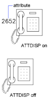
Summary
The drawing is regenerated after you change the visibility settings unless RE-
GENAUTO (page 878), which controls automatic regeneration, is off. The current
visibility of attributes is stored in the ATTMODE (page 1176) system variable.
List of Prompts
The following prompts are displayed.
Enter attribute visibility setting [Normal (page 115)/ON (page
115)/OFF (page 115)] <current>:
Normal Restores the visibility settings of each attribute. Visible attributes are
displayed. Invisible attributes are not displayed.
On Makes all attributes visible, overriding the original visibility settings.
Off Makes all attributes invisible, overriding the original visibility settings.
See also:
Define Block Attributes
ATTEDIT
Changes attribute information in a block.
Commands | 115
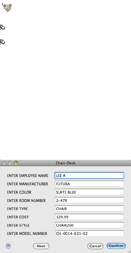
Access Methods
Button
Toolbar: Drafting tool set ➤ Block tool group ➤ Edit Attributes flyout
➤ Single
Menu: Modify ➤ Object ➤ Attribute ➤ Single
Summary
The Edit Attributes dialog box (page 116) is displayed to edit attribute values
for a specific block.
If you enter -attedit at the Command prompt, options are displayed (page
118) to edit attribute values and properties independent of a block.
See also:
Attach Data to Blocks (Block Attributes)
Edit Attributes Dialog Box
Changes attribute information in a block.
116 | Chapter 2 Commands
Summary
To change attribute properties such as position, height, and style, use
-ATTEDIT.
List of Options
The following options are displayed.
Block Name
Indicates the name of the selected block. The value of each attribute contained
in the block is displayed in this dialog box.
List of Attributes
Displays the first eight attributes contained in the block. Edit the attribute
values. If the block contains additional attributes, click Prev or Next to navigate
through the list. You cannot edit attribute values on locked layers.
Multiple-line attributes display the In-Place Text Editor (page 675) with the
Text Formatting toolbar and the ruler. Depending on the setting of the ATTIPE
(page 1175) system variable, the Text Formatting toolbar displayed is either the
abbreviated version, or the full version.
To use a field as the value, right-click and click Insert Field on the shortcut
menu to display the Insert Field dialog box (page 429).
Prev
Displays the previous eight attribute values. Previous is available only if the
selected block contains more than eight attributes and you used Next to display
the additional attributes.
Next
Displays the next eight attribute values. If the block contains no additional
attributes, Next is unavailable.
See also:
Attach Data to Blocks (Block Attributes)
Commands | 117
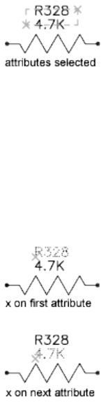
-ATTEDIT
List of Prompts
If you enter -attedit at the Command prompt, the following prompts are
displayed.
Edit attributes one at a time? [Yes (page ?)/No (page ?)]
<Y>: Enter y or press Enter to edit attributes one at a time, or enter n to edit
attributes globally
The following prompts filter the attributes to be changed based on attribute
tag, current value, or object selection.
Yes
Edits attributes one at a time. Attributes to be edited one at a time must be
visible and parallel to the current UCS.
Attribute values are case sensitive.
The first attribute in the selection set is marked with an X. You can change
any properties of the attribute you select.
Enter an option [Value/Position/Height/Angle/Style/Layer/Color/Next] <N>:
Enter the property to change, or press Enter for the next attribute
If the original attribute was defined with aligned or fit text, the prompt does
not include Angle. The Height option is omitted for aligned text. For each of
the options except Next, ATTEDIT prompts for a new value. The X remains
on the current attribute until you move to the next attribute.
118 | Chapter 2 Commands
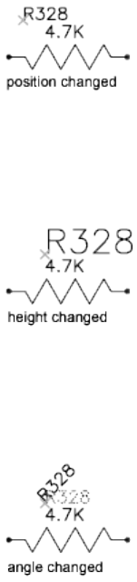
Value
Changes or replaces an attribute value.
Enter type of value modification [Change/Replace]: Enter c or r or press Enter
Change Modifies a few characters of the attribute value.
Either string can be null. The ? and * characters are interpreted literally, not
as wild-card characters.
Replace Substitutes a new attribute value for the entire attribute value.
If you press Enter, the attribute value is empty (null).
Position
Changes the text insertion point.
If the attribute is aligned, ATTEDIT prompts for both ends of a new text
baseline.
Height
Changes the text height.
When you specify a point, the height becomes the distance between the
specified point and the start point of the text.
Angle
Changes the rotation angle.
If you specify a point, the text is rotated along an imaginary line between the
specified point and the start point of the text.
Commands | 119
Style
Changes the style setting.
Layer
Changes the layer.
Color
Changes the color.
You can enter a color from the AutoCAD Color Index (a color name or
number), a true color, or a color from a color book.
You can enter a color name, a color number between 1 and 255, or bylayer
or byblock.
True Color Specifies a true color to be used for the selected object.
Color Book Specifies a color from a loaded color book to be used for the
selected object.
If you enter a color book name, you are prompted to enter the color name in
the color book, such as PANTONE® 573.
Next
Moves to the next attribute in the selection set. If there are no more attributes,
ATTEDIT ends.
No
Edits more than one attribute at a time. Global editing applies to both visible
and invisible attributes.
Editing attributes globally limits you to replacing a single text string with
another text string. If you edit attributes one at a time, you can edit any or
all of the attributes.
Yes Edits only visible attributes.
Attribute values are case sensitive. To select empty (null) attributes, which
normally are not visible and cannot be selected, enter a backslash (\).
Select the attribute you want to change.
Either string can be empty (null). The ? and * characters are interpreted literally,
not as wild-card characters.
120 | Chapter 2 Commands
No Edits attributes whether they are visible or not. Changes to attributes are
not reflected immediately. The drawing is regenerated at the end of the
command unless REGENAUTO (page 878), which controls automatic
regeneration, is off.
Attribute values are case sensitive. To select empty (null) attributes, which
normally are not visible, enter a backslash (\).
The attributes that match the specified block name, attribute tag, and attribute
value are selected.
Either string can be empty (null). The ? and * characters are interpreted literally,
not as wild-card characters.
See also:
Modify Blocks
ATTEXT (-ATTEXT)
Extracts attribute data, informational text associated with a block, into a file.
List of Prompts
Enter extraction type or enable object selection [Cdf (page
121)/Sdf (page 121)/Dxf (page 122)/Objects (page 122)] <C>: Enter
an option or press Enter
CDF: Comma-Delimited File Generates a file containing one record for each
block reference in the drawing. Commas separate the fields of each record.
Single quotation marks enclose the character fields.
In the Select Template File dialog box, enter the name of an existing attribute
extraction template file.
In the Create Extract File dialog box, enter the name for the output file. The
extract file's file name extension is .txt for CDF or SDF format.
SDF: Space-Delimited File Generates a file containing one record for each
block reference in the drawing. The fields of each record have a fixed width;
therefore, field separators or character string delimiters are not used.
In the Select Template File dialog box, enter the name of an existing attribute
extraction template file.
In the Create Extract File dialog box, enter the name for the output file. The
extract file's file name extension is .txt for CDF or SDF format.
Commands | 121
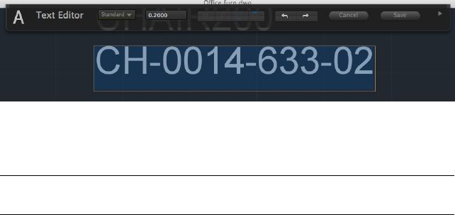
DXF: Drawing Interchange File Produces a subset of the AutoCAD Drawing
Interchange File format containing only block reference, attribute, and
end-of-sequence objects. DXF-format extraction requires no template. The file
name extension .dxx distinguishes the output file from normal DXF files.
In the Create Extract File dialog box, enter the name for the output file. The
extract file's file name extension is .dxx for DXF format.
Objects Selects objects whose attributes you want to extract.
See also:
Attach Data to Blocks (Block Attributes)
ATTIPEDIT
Changes the textual content of an attribute within a block.
Summary
If you select a single-line attribute, displays the In-Place Text Editor (page 675)
without the ruler. Right-click to display options. Selecting a multiple-line
attribute displays the In-Place Text Editor (page 675) with the ruler.
Depending on the setting of the ATTIPE (page 1175) system variable, the
right-click menu changes the formatting and editing operations available for
compatibility with previous AutoCAD for Mac releases.
NOTE Not all MTEXT formatting options are available for multiline attributes even
with the full In-Place Editor.
List of Prompts
The following prompts are displayed.
Select attribute to edit: Select an attribute within a block
122 | Chapter 2 Commands

See also:
Modify a Block Attribute Definition
ATTREDEF
Redefines a block and updates associated attributes.
Summary
New attributes assigned to existing block references use their default values.
Old attributes in the new block definition retain their old values. Any old
attributes that are not included in the new block definition are deleted.
WARNING
ATTREDEF removes any format or property changes made with the ATTEDIT
or EATTEDIT commands. It also deletes any extended data associated with
the block, and might affect dynamic blocks and blocks created by third-party
applications.
List of Prompts
The following prompts are displayed.
Enter the name of the block you wish to redefine:
Select objects for new block:
Select objects:
Insertion base point of new block: Specify a point
See also:
Modify a Block Attribute Definition
ATTSYNC
Updates block references with new and changed attributes from a specified
block definition.
Commands | 123
Access Methods
Button
Toolbar: Drafting tool set ➤ Block tool group (expanded) ➤ Synchronize
Attributes
Summary
You are prompted for the names of blocks you want to update with the current
attributes defined for the blocks.
Use this command to update all instances of a block containing attributes
that was redefined using the BLOCK or BEDIT commands. ATTSYNC does not
change any values assigned to attributes in existing blocks.
NOTE Use the ATTREDEF command to redefine and update blocks in one
command.
Entering ? displays a list of all block definitions in the drawing. Enter the
name of the block you want to update.
Pressing ENTER allows you to use your pointing device to select the block
whose attributes you want to update.
If a block you specify does not contain attributes or does not exist, an error
message is displayed, and you are prompted to specify another block.
WARNING ATTSYNC removes any format or property changes made with the
ATTEDIT or EATTEDIT commands. It also deletes any extended data associated
with the block, and might affect dynamic blocks and blocks created by third-party
applications.
See also:
Modify a Block Attribute Definition
AUDIT
Evaluates the integrity of a drawing and corrects some errors.
124 | Chapter 2 Commands
Summary
For the current space, Audit places objects for which it reports errors in the
Previous selection set. If the AUDITCTL system variable is set to 1, a text file
with an .adt file extension is created that describes the problems and the action
taken.
For easy access, AUDIT places all objects for which it reports errors in the
Previous selection set. However, editing commands affect only the objects
that belong to the current paper space or model space.
If you set the AUDITCTL (page 1177) system variable to 1, AUDIT creates a text
file describing problems and the action taken and places this report in the
same folder as the current drawing, with the file extension .adt.
If a drawing contains errors that AUDIT cannot fix, use RECOVER (page 866)
to retrieve the drawing and correct its errors.
See also:
Repair a Damaged Drawing File
AUTOCOMPLETE
Controls what types of automated keyboard features are available at the
Command prompt.
Access Methods
Shortcut menu: Right-click within the Command Line ➤ AutoComplete
Summary
Entering a command or system variable at the Command prompt is assisted
with several features that list or complete the commands and system variables
as they are being typed. The AUTOCOMPLETE command controls which of
the features are turned on.
List of Prompts
The following prompts are displayed.
Append Controls whether commands and system variables are automatically
completed as you type.
Commands | 125
List Controls whether a list of valid commands and system variables is
displayed as you type.
Icon Controls whether the corresponding icon for a command is displayed
in the list. The same icon is used for all system variables.
System variables Controls whether system variables are also included with
the Append and List features.
Delay Sets a time delay in seconds before the Append and List features take
effect.
On Enables the operation of the AutoComplete features that are currently
turned on.
Off Suppresses the operation of the AutoComplete features without changing
their settings.
See also:
The Command Line
Enter Commands on the Command Line
AUTOCONSTRAIN
Applies geometric constraints to a selection set of objects based on orientation
of the objects relative to one another.
Access Methods
Button
Toolbar: Drafting tool set ➤ Parametric tool group ➤ Auto
Menu: Parametric ➤ AutoConstrain
Summary
You can apply geometric constraints to a selection set of geometry within the
specified tolerance set using the AutoConstrain tab in the Constraint Settings
dialog box (page 212).
Specify the Settings option to change the types of constraints applied, the
order in which they are applied, and the applicable tolerances.
126 | Chapter 2 Commands
The Settings option displays the Constraint Settings dialog box with the
Autoconstrain tab (page ?) selected.
See also:
Apply or Remove Geometric Constraints
B Commands
BASE
Sets the insertion base point for the current drawing.
Access Methods
Button
Toolbar: Drafting tool set ➤ Block tool group (expanded) ➤ Set Base
Point
Menu: Draw ➤ Block ➤ Base
Command entry: base (or 'base for transparent use)
Summary
The base point is expressed as coordinates in the current UCS. When you
insert or externally reference the current drawing into other drawings, this
base point is used as the insertion base point.
See also:
Insert Blocks
BATTMAN
Manages the attributes for a selected block definition.
Commands | 127
Access Methods
Button
Toolbar: Drafting tool set ➤ Block tool group (expanded) ➤ Manage
Attributes
Menu: Modify ➤ Object ➤ Attribute ➤ Block Attribute Manager
Summary
The Block Attribute Manager (page 128) is displayed.
If the current drawing does not contain any blocks with attributes, a message
is displayed.
This command controls all attribute properties and settings of a selected block
definition. Any changes to the attributes in a block definition are reflected in
the block references.
See also:
Modify a Block Attribute Definition
Block Attribute Manager
Manages the attribute definitions for blocks in the current drawing.
128 | Chapter 2 Commands
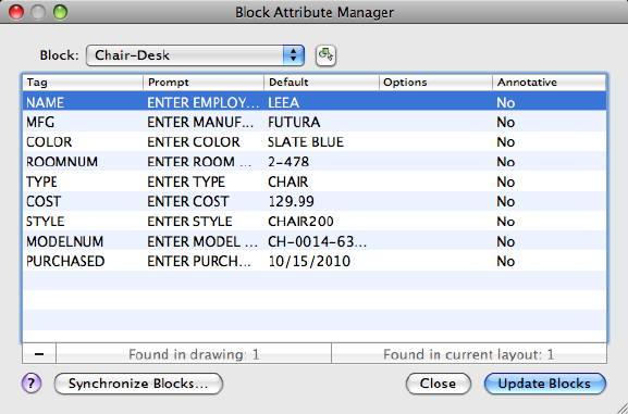
Summary
You can edit the attribute definitions in blocks, remove attributes from blocks,
and change the order in which you are prompted for attribute values when
inserting a block.
Attributes of the selected block are displayed in the attribute list. By default,
Tag, Prompt, Default, Mode, and Annotative attribute properties are displayed
in the attribute list. For each selected block, a description below the attribute
list identifies the number of its instances in the current drawing and in the
current layout.
You can specify which attribute properties you want displayed in the list by
right-clicking over the attribute headers and choosing the ones to display.
Double-click an attribute to display the Attribute Editor dialog box (page 130),
where you can modify attribute properties.
List of Options
The following options are displayed.
Select Block
You can use your pointing device to select a block from the drawing area.
When you choose Select Block, the dialog box closes until you select a block
from the drawing or you cancel by pressing ESC.
Commands | 129
If you modify attributes of a block and then select a new block before you
save the attribute changes you made, you are prompted to save the changes
before selecting another block.
Block
Lists all block definitions in the current drawing that have attributes. Select
the block whose attributes you want to modify.
List of Attributes
Displays the properties of each attribute in the selected block.
Remove
Removes the selected attribute from the block definition. If Synchronize Blocks
is clicked and then Synchronize is clicked in the Synchronize Blocks dialog
box, the attribute is removed from all instances of the block in the current
drawing.
Found in Drawing
Reports the total number of instances of the selected block in the current
drawing.
Found in Current Layout
Reports the number of instances of the selected block in the current model
space or layout.
Synchronize Blocks
Updates all instances of the selected block with the attribute properties
currently defined. This does not affect any values assigned to attributes in
each block.
Update Blocks Applies the changes made and closes the dialog box open.
See also:
Modify a Block Attribute Definition
Attribute Editor Dialog Box
Allows you to edit attributes for a block definition.
130 | Chapter 2 Commands
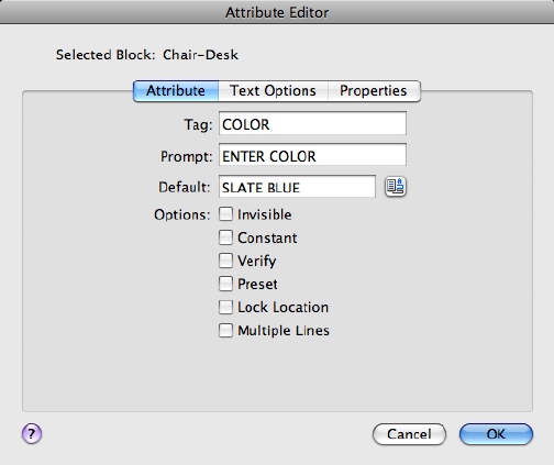
Summary
The Attribute Editor dialog box contains the following tabs:
■Attribute (page ?)
■Text Options
■Properties (page ?)
List of Options
The following options are displayed.
Block Name
Displays the name of the block whose attributes are to be edited.
Attribute Tab (Attribute Editor Dialog Box)
Defines how a value is assigned to an attribute and whether or not the assigned
value is visible in the drawing area, and sets the string that prompts users to
enter a value. The Attribute tab also displays the tag name that identifies the
attribute.
Tag
Sets the identifier assigned to the attribute.
Commands | 131
Prompt
Sets the text for the prompt that is displayed when you insert the block.
Default
Sets the default value assigned to the attribute when you insert the block.
Options
Mode options determine whether and how attribute text appears.
Invisible
Displays or hides the attribute in the drawing area. If selected, hides the
attribute value in the drawing area. If cleared, displays the attribute value.
Constant
Identifies whether the attribute is set to its default value. You cannot change
this property. If a check mark is shown in the check box, the attribute is set
to its default value and cannot be changed. If the check box is empty, you
can assign a value to the attribute.
Verify
Turns value verification on and off. If selected, prompts you to verify the
values you assign to the attribute when inserting a new instance of the block.
If this option is cleared, verification is not performed.
Preset
Turns default value assignment on and off. If selected, sets the attribute to its
default value when the block is inserted. If cleared, ignores the attribute's
default value and prompts you to enter a value when inserting the block.
Lock Location Locks the location of the attribute within the block reference.
When unlocked, the attribute can be moved relative to the rest of the block
using grip editing, and multiline attributes can be resized.
Multiple Lines
Indicates whether the attribute was defined as a Multiple Lines attribute and
can contain multiple lines of text.
Text Options Tab (Attribute Editor Dialog Box)
Sets the properties that define the way an attribute's text is displayed in the
drawing. Change the color of attribute text on the Properties tab.
132 | Chapter 2 Commands
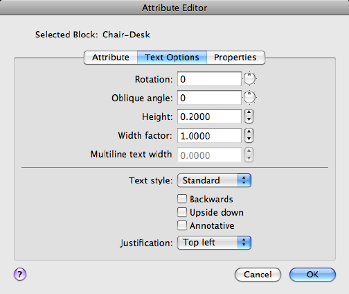
Rotation
Specifies the rotation angle of the attribute text.
Oblique Angle
Specifies the angle that attribute text is slanted away from its vertical axis.
Height
Specifies the height of the attribute text.
Width Factor
Sets the character spacing for attribute text. Entering a value less than 1.0
condenses the text. Entering a value greater than 1.0 expands it.
Multiline Text Width Specifies the maximum length of the lines of text in
a multiple-line attribute before wrapping to the next line. A value of 0.000
means that there is no restriction on the length of a line of text. Not available
for single-line attributes.
Text Style
Specifies the text style for attribute text. Default values for this text style are
assigned to the text properties displayed in this dialog box.
Backwards
Specifies whether or not the text is displayed backwards.
Commands | 133

Upside Down
Specifies whether or not the text is displayed upside down.
Annotative
Specifies that the attribute is annotative.
Justification
Specifies how attribute text is justified.
Properties Tab (Attribute Editor Dialog Box)
Defines the layer that the attribute is on and the color, lineweight, and linetype
for the attribute's line. If the drawing uses plot styles, you can assign a plot
style to the attribute using the Properties tab.
Layer
Specifies the layer that the attribute is on.
Linetype
Specifies the linetype of attribute text.
Color
Specifies the attribute's text color.
Lineweight
134 | Chapter 2 Commands
Specifies the lineweight of attribute text.
Changes you make to this option are not displayed if the LWDISPLAY (page
1365) system variable is off.
Plot Style
Specifies the plot style of the attribute.
If the current drawing uses color-dependent plot styles, the Plot Style list is
not available.
See also:
Modify a Block Attribute Definition
BATTORDER
Specifies the order of attributes for a block.
Summary
Displays the Attribute Order dialog box (page 135), which controls the order
in which attributes are listed and prompted for when you insert or edit a block
reference. You can only use the BATTORDER command in the Block Editor
(page 139).
See also:
Attach Data to Blocks (Block Attributes)
Attribute Order Dialog Box
Specifies the order in which attributes are listed and prompted for when you
insert or edit a block reference.
Commands | 135
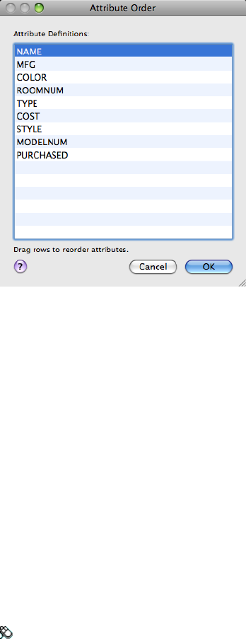
List of Options
The following options are displayed.
Attribute Definitions
Lists the attribute definitions in the current block.
Drag an attribute definition up or down in the list to reorder it.
See also:
Attach Data to Blocks (Block Attributes)
BCLOSE
Closes the Block Editor.
Access Methods
Toolbar: Block Editor visor ➤ Close
136 | Chapter 2 Commands
Summary
Closes the Block Editor (page 139). If you have modified the block definition
since it was last saved, you are prompted to save or discard the changes.
See also:
Define Blocks
Modify Blocks
BEDIT
Opens the block definition in the Block Editor.
Access Methods
Button
Toolbar: Drafting tool set ➤ Block tool group (expanded) ➤ Edit
Menu: Tools ➤ Block Editor
Shortcut menu: Select a block reference. Right-click in the drawing area.
Click Block Editor.
Summary
The Edit Block Definition dialog box (page 138) is displayed. Select a block
definition to edit or enter a name for a new block definition to create, then
click Edit Block to open the Block Editor (page 139).
When the BLOCKEDITLOCK (page 1182) system variable is set to 1, the Block
Editor cannot be opened.
The Block Editor is a separate environment for creating and changing block
definitions for the current drawing. You can also use it to add dynamic
behavior to blocks.
See also:
Define Blocks
Modify Blocks
Commands | 137
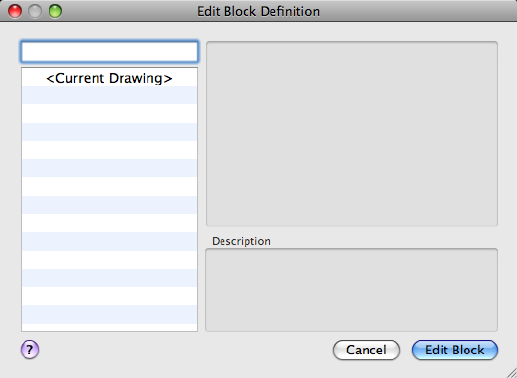
Edit Block Definition Dialog Box
Select from a list of block definitions that are saved in the drawing to edit in
the Block Editor. You can also enter a name for a new block definition to
create in the Block Editor.
Summary
When you click Edit Block, the Edit Block Definition dialog box closes, and
the Block Editor is displayed.
■If you selected a block definition from the list, that block definition is
displayed and is available for editing in the Block Editor.
■If you entered a name for a new block definition, the Block Editor is
displayed, and you can start adding objects to the block definition.
List of Options
The following options are displayed.
Block to create or edit
Specifies the name of the block to edit or create in the Block Editor. If you
select <Current Drawing>, the current drawing is opened in the Block Editor.
Name List
138 | Chapter 2 Commands
Displays a list of block definitions that are saved in the current drawing. When
you select a block definition from the list, the name is displayed in the Name
box.
When you click Edit Block, this block definition is opened in the Block Editor.
When you select <Current Drawing>, the current drawing is opened in the
Block Editor.
Preview
Displays a preview of the selected block definition. A lightning bolt icon
indicates that the block is a dynamic block.
Description
Displays the description of the selected block definition.
See also:
Define Blocks
Modify Blocks
Block Editor
The Block Editor contains a special authoring area in which you can draw and
edit geometry as you would in the drawing area.
Summary
You use the Block Editor to define the objects and behavior for a block
definition.
The following commands are used for editing blocks and are available only
in the Block Editor:
■BATTORDER (page 135)
■BCLOSE (page 136)
■BSAVE (page 158)
■BSAVEAS (page 159)
When the BLOCKEDITLOCK (page 1182) system variable is set to 1, the Block
Editor cannot be opened.
Commands | 139
Block Editor Visor
Provides tools for adding attributes to the block open for edit, save changes
to a block, and close the Block Editor.
Define Attribute (ATTDEF (page 106))
Creates an attribute definition for storing data in a block.
Save (BSAVE (page 158))
Saves the current block definition.
Save New (BSAVEAS (page 159))
Saves a copy of the current block definition under a new name.
Close (BCLOSE (page 136))
Closes the Block Editor.
See also:
Define Blocks
Modify Blocks
-BEDIT
Summary
If you select a block in a drawing and enter -bedit at the Command prompt,
the selected block is opened in the Block Editor (page 139). If nothing is selected,
the following prompt is displayed:
List of Prompts
The following prompts are displayed
Enter block name (page ?) or [?(page ?)]: Enter a name or ?
Block Name
Specifies the name of a block saved in the current drawing to open in the
Block Editor or specifies the name of a new block to create.
?—List Previously Defined Blocks
Lists the block names in the text window.
Enter block(s) to list <*>: Enter a name list or press Enter
140 | Chapter 2 Commands
See also:
Define Blocks
Modify Blocks
BHATCH
Fills an enclosed area or selected objects with a hatch pattern or gradient fill.
Summary
The BHATCH command has been renamed to HATCH.
See also:
Overview of Hatch Patterns and Fills
BLEND
Creates a spline in the gap between two selected lines or curves.
Access Methods
Button
Toolbar: Drafting tool set ➤ Modify tool group ➤ Blend
Menu: Modify ➤ Blend
Summary
Select each object near an endpoint. The shape of the resulting spline depends
on the specified continuity. The lengths of the selected objects remain
unchanged.
Commands | 141
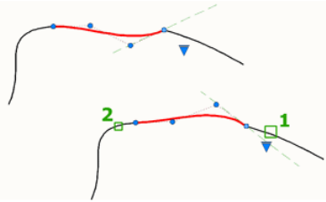
Valid objects include lines, arcs, elliptical arcs, helixes, open polylines, and
open splines.
List of Prompts
The following prompts are displayed.
Select first object or [CONtinuity]: Select a line or open curve near the end where
the spline should start
Select second object: Select another line or open curve near the end where the spline
should end
Continuity
Specify one of two types of blends.
Tangent Creates a degree 3 spline with tangency (G1) continuity to the selected
objects at their endpoints.
Smooth Creates a degree 5 spline with curvature (G2) continuity to the selected
objects at their endpoints.
If you use the Smooth option, do not switch the display from control vertices
to fit points. This action changes the spline to degree 3, which will change
shape of the spline.
See also:
Draw Splines
BLIPMODE
Controls the display of marker blips.
Obsolete
142 | Chapter 2 Commands
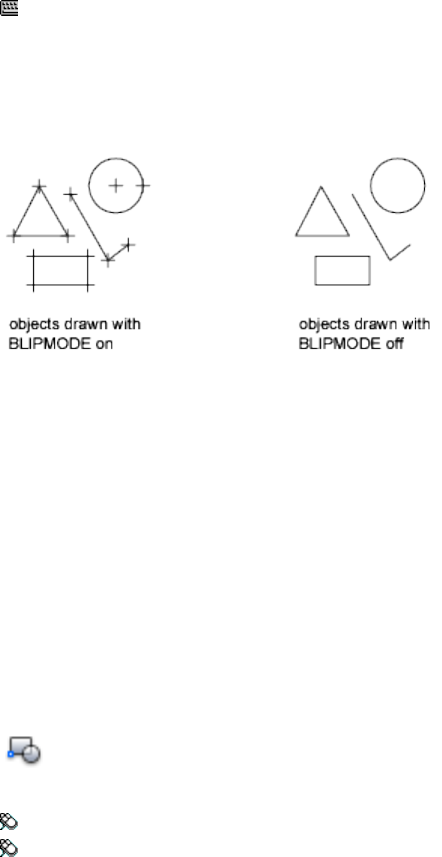
Access Methods
Command entry: 'blipmode for transparent use
Summary
When Blip mode is on, a temporary mark in the shape of a plus sign (+) appears
where you specify a point. BLIPMODE is off by default.
To remove marker blips, use REDRAW (page 869), REGEN (page 877), ZOOM
(page 1153), PAN (page 763), or other commands that redraw or regenerate the
drawing.
See also:
Customize Object Selection
BLOCK
Creates a block definition from selected objects.
Access Methods
Button
Toolbar: Drafting tool set ➤ Block tool group ➤ Create
Menu: Draw ➤ Block ➤ Make
Summary
The Define Block dialog box (page 144) is displayed.
Commands | 143
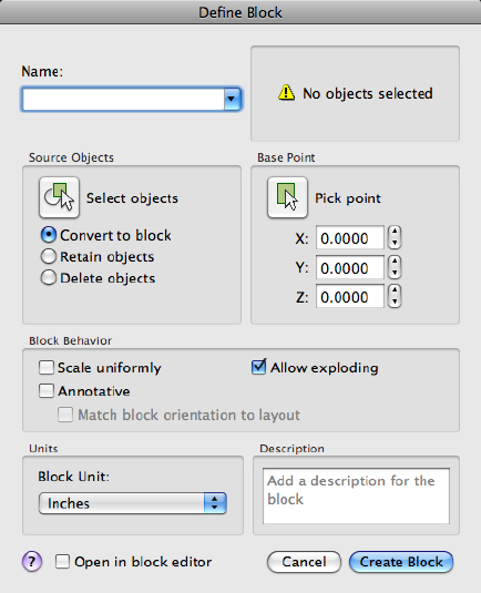
If you enter -block at the Command prompt, options are displayed (page
147).
You create a block definition by selecting objects, specifying an insertion
point, and giving it a name.
See also:
Define Blocks
Define Block Dialog Box
Defines and names a block.
List of Options
The following options are displayed.
144 | Chapter 2 Commands
Name
Names the block. The name can have up to 255 characters and can include
letters, numbers, blank spaces, and any special character not used by the
operating system or the program for other purposes.
The block name and definition are saved in the current drawing.
Preview
If an existing block is selected under Name, displays a preview of the block.
Source Objects
Specifies the objects to include in the new block and whether to retain or
delete the selected objects or convert them to a block instance after you create
the block.
Specify On-Screen
Prompts you to specify the objects when the dialog box is closed.
Select Objects
Closes the Block Definition dialog box temporarily while you select the objects
for the block. When you finish selecting objects, press Enter to return to the
dialog box.
Convert to Block
Converts the selected objects to a block instance in the drawing after you
create the block.
Retain Objects
Retains the selected objects as distinct objects in the drawing after you create
the block.
Delete Objects
Deletes the selected objects from the drawing after you create the block.
Objects Selected
Displays the number of selected objects.
Base Point
Specifies an insertion base point for the block. The default value is 0,0,0.
Specify On-Screen
Prompts you to specify the base point when the dialog box is closed.
Pick Insertion Base Point
Commands | 145
Temporarily closes the dialog box so that you can specify an insertion base
point in the current drawing.
X
Specifies the X coordinate value.
Y
Specifies the Y coordinate value.
Z
Specifies the Z coordinate value.
Block Behavior
Specifies the behavior of the block.
Scale Uniformly
Specifies whether or not the block reference is prevented from being
non-uniformly scaled.
Annotative
Specifies that the block is annotative.
Match Block Orientation to Layout
Specifies that the orientation of the block references in paper space viewports
matches the orientation of the layout. This option is unavailable if the
Annotative option is cleared.
Allow Exploding
Specifies whether or not the block reference can be exploded.
Units
Specifies units for the block.
Block Unit
Specifies the insertion units for the block reference.
Description
Specifies the text description of the block.
Open in Block Editor
Opens the current block definition in the Block Editor (page 139) when the
dialog box is closed.
146 | Chapter 2 Commands
See also:
Define Blocks
-BLOCK
If you enter -block at the Command prompt, the following prompts are
displayed.
List of Prompts
The following prompts are displayed.
Enter block name (page ?) or [?(page ?)]: Enter a name or ?
Block Name
Names the block. The name can have up to 255 characters and can include
letters, numbers, blank spaces, and any special character not used by the
operating system and the program for other purposes if the system variable
EXTNAMES (page 1287) is set to 1.
If you enter the name of an existing block, you are prompted as follows:
Redefine Block Reference By redefining a block, you automatically update
all references to that block. Attributes attached to existing block references
remain unchanged in the drawing. However, new insertions of the block do
not prompt for attributes unless the attribute definitions are included in the
new block definition.
Use the ATTREDEF (page 123) command to update the attributes of an existing
block insert.
Specify Insertion Base Point The point specified as the base point is used
for subsequent insertions of the block. Typically, a base point is the center of
the block or its lower-left corner. The base point is also the point about which
you can rotate the block during insertion. A block with 0 rotation is oriented
according to the UCS in effect when it was created. Entering a 3D point inserts
the block at a specific elevation. Omitting the Z coordinate uses the current
elevation.
■Annotative:
Enter a to create an annotative block.
Commands | 147
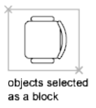
If you enter yes, the block becomes annotative.
Match Orientation to Layout in Paper Space Viewports If you enter yes,
the block’s orientation in paper space viewports will match the orientation
of the layout.
Select Objects If you specify the insertion base point, you are prompted to
select the objects.
The program defines a block using the objects selected, the insertion base
point, and the name provided, and then erases the selected objects from the
drawing. You can restore the deleted objects by entering the OOPS (page 719)
command immediately after BLOCK.
The insertion base point becomes the origin of the block's coordinate system,
which is parallel to the UCS in effect at the time that you define the block.
When you insert the block into a drawing, its coordinate system is aligned
parallel to the current UCS. Thus, you can insert a block at any orientation
in space by setting the UCS first.
?—List Previously Defined Blocks
Lists the block names in the text window.
Enter Blocks to List In the list, external references (xrefs) are indicated with
the notation Xref: resolved.
In addition, externally dependent blocks (blocks in an xref) are indicated with
the notation xdep: XREFNAME, where xrefname is the name of an externally
referenced drawing. The following terms are used in the list:
■User Blocks: Number of user-defined blocks in the list.
■External References: Number of xrefs in the list.
■Dependent Blocks: Number of externally dependent blocks in the list.
■Unnamed Blocks: Number of unnamed (anonymous) blocks in the drawing.
See also:
Define Blocks
148 | Chapter 2 Commands
BMPOUT
Saves selected objects to a file in device-independent bitmap format.
Summary
The Create Raster File dialog box (a standard file selection dialog box (page
720)) is displayed. Enter the file name in the dialog box.
A bitmap file that contains the objects you select is created. The file reflects
what is displayed on the screen. Light glyphs that are displayed in the drawing
appear in the new file, even if the Plot Glyph property of the lights is set to
No.
NOTE When the FILEDIA (page 1296) system variable is set to 0 (Off), Command
prompts are displayed.
See also:
Export Raster Files
BOUNDARY
Creates a region or a polyline from an enclosed area.
Access Methods
Button
Toolbar: Drafting tool set ➤ Closed Shapes tool group (expanded) ➤
Boundary
Menu: Draw ➤ Boundary
Summary
The Boundary Creation dialog box (page 150) is displayed.
If you enter -boundary at the Command prompt, options are displayed (page
151).
Commands | 149
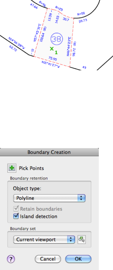
Each point that you specify identifies the surrounding objects and creates a
separate region or polyline.
See also:
Create and Combine Areas (Regions)
Boundary Creation Dialog Box
Defines the object type, boundary set, and island detection method for creating
a region or polyline using a specified point within an area enclosed by objects.
150 | Chapter 2 Commands
List of Options
The following options are displayed.
Pick Points
Determines a boundary from existing objects that form an enclosed area
around the specified point.
Boundary Retention
Defines the type of boundary object that will be created from the enclosed
area and how enclosed areas are detected.
Object Type Controls the type of the new boundary object. boundary creates
the boundary as a region or a polyline object.
Retain Boundaries Controls whether the objects created are retained after
the dialog box is closed.
Island Detection Controls whether boundary detects internal closed
boundaries, called islands.
Boundary Set
Defines the set of objects boundary analyzes when defining a boundary from
a specified point.
Current Viewport Defines the boundary set from everything in the current
viewport extents. Selecting this option discards any current boundary set.
New Prompts you to select the objects that define the boundary set. boundary
includes only the objects that can be used to create a region or closed polyline
when it constructs the new boundary set.
For more information about the options in this dialog box, see HATCH (page
471).
See also:
Create and Combine Areas (Regions)
-BOUNDARY
If you enter -boundary at the Command prompt, the following prompts are
displayed.
Specify internal point (page 152) or [Advanced options (page
152)]: Specify a point or enter a
Commands | 151

Internal Point
Creates a region or polyline from existing objects that form an enclosed area.
Specify a point inside the area.
Advanced Options
Sets the method BOUNDARY uses to create the boundary.
Enter an option [Boundary set/Island detection/Object type]:
Enter an option or press Enter to return to the previous prompt
Boundary Set Defines the set of objects boundary analyzes when it creates
a boundary from a specified point. For information about defining a boundary
set at the Command prompt, see the HATCH (page 471) Command prompt
option.
Island Detection Specifies whether boundary uses objects within the
outermost boundary as boundary objects. For information about specifying
island detection at the Command prompt, see the HATCH (page 471) Command
prompt option.
Object Type Specifies the type of object that boundary creates.
■Region
■Polyline
See also:
Create and Combine Areas (Regions)
BOX
Creates a 3D solid box.
Access Methods
Button
Toolbar: Modeling tool set ➤ Solids - Create tool group ➤ Solid
Primitives flyout ➤ Box
Menu: Draw ➤ 3D Modeling ➤ Box
152 | Chapter 2 Commands
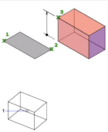
List of Prompts
The following prompts are displayed.
Specify first corner or [Center (page ?)]: Specify a point or enter
c for center
Specify other corner or [Cube (page ?)/Length (page ?)]:
Specify the other corner of the box or enteran option
If the other corner of the box is specified with a Z value that differs from the
first corner, then no height prompt is displayed.
Specify height or [2Point (page ?)] <default>: Specify the height
or enter 2P for the 2 Point option
Entering a positive value draws the height along the positive Z axis of the
current UCS. Entering a negative value draws the height along the negative
Z axis.
The base of the box is always drawn parallel to the XY plane of the current
UCS (work plane). The height of the box is specified in the Z-axis direction.
You can enter both positive and negative values for the height.
Center
Creates the box by using a specified center point.
Cube Creates a box with sides of equal length.
Commands | 153
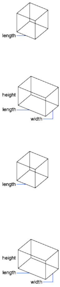
Length Creates a box with length, width, and height values you specify. The
length corresponds to the X axis, the width to the Y axis, and the height to
the Z axis.
Cube
Creates a box with sides of equal length.
Length
Creates a box with length, width, and height values you specify. If you enter
values, the length corresponds to the X axis, the width to the Y axis, and the
height to the Z axis. If you pick a point to specify the length, you also specify
the rotation in the XY plane.
2Point
Specifies that the height of the box is the distance between the two specified
points.
154 | Chapter 2 Commands
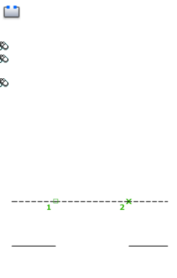
See also:
Create a Solid Box
BREAK
Breaks the selected object between two points.
Access Methods
Button
Toolbar: Drafting tool set ➤ Modify tool group (expanded) ➤ Break
Toolbar: Drafting tool set ➤ Modify tool group (expanded) ➤ Break at
Point
Menu: Modify ➤ Break
Summary
You can create a gap between two specified points on an object, breaking it
into two objects. If the points are off of an object, they are automatically
projected on to the object. break is often used to create space for a block or
text.
List of Prompts
The following prompts are displayed.
Select object: Use an object selection method, or specify the first break point
(1) on an object
Commands | 155
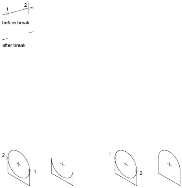
The prompts that are displayed next depend on how you select the object. If
you select the object by using your pointing device, the program both selects
the object and treats the selection point as the first break point. At the next
prompt, you can continue by specifying the second point or overriding the
first point.
Specify second break point or [First point]: Specify the second
break point (2) or enter f
Second Break Point Specifies the second point to use to break the object.
First Point Overrides the original first point with the new point that you
specify.
Specify first break point:
Specify second break point:
The portion of the object is erased between the two points that you specify.
If the second point is not on the object, the nearest point on the object is
selected; therefore, to break off one end of a line, arc, or polyline, specify the
second point beyond the end to be removed.
To split an object in two without erasing a portion, enter the same point for
both the first and second points. You can do this by entering @ to specify the
second point.
Lines, arcs, circles, polylines, ellipses, splines, donuts, and several other object
types can be split into two objects or have one end removed.
The program converts a circle to an arc by removing a piece of the circle
starting counterclockwise from the first to the second point.
156 | Chapter 2 Commands
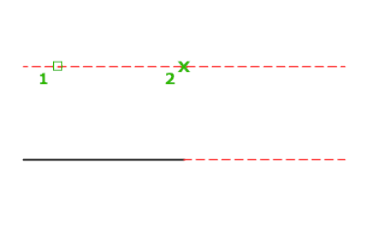
You can also break selected objects at a single point with the Break at Point
tool.
Valid objects include lines, open polylines, and arcs. Closed objects such as
circles cannot be broken at a single point.
See also:
Break and Join Objects
BREP
Removes the history from 3D solids and composite solids, and associativity
from surfaces.
Summary
When a solid loses the history of the original parts from which it was created,
the original parts can no longer be selected and modified. BREP also removes
surface associativity. When a surface loses associativity it loses any
mathematical expressions or information about how the surface was created.
Commands | 157
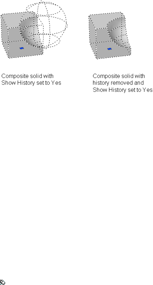
See also:
Display Original Forms of Composite Solids
BROWSER
Launches the default web browser defined in your system's registry.
Summary
Pressing Enter displays your web browser, which automatically connects to
the location you specify. Because browser does not append “http://” to web
locations, you can specify an FTP or file location to your default web browser.
See also:
Get Started with Internet Access
BSAVE
Saves the current block definition.
Access Methods
Toolbar: Block Editor visor ➤ Save
158 | Chapter 2 Commands

Summary
Saves changes to the current block definition.
You can only use the BSAVE command in the Block Editor (page 139).
See also:
Create Blocks Within a Drawing
BSAVEAS
Saves a copy of the current block definition under a new name.
Access Methods
Toolbar: Block Editor visor ➤ Save As
Summary
Displays the Save Block Definition As dialog box (page 159).
You can only use the BSAVEAS command in the Block Editor (page 139).
See also:
Create Blocks Within a Drawing
Save Block Definition As Dialog Box
Saves a copy of the current block definition under a new name.
Commands | 159
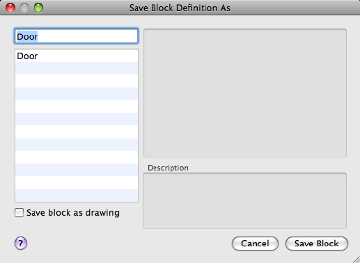
List of Options
The following options are displayed.
Block Name
Specifies a new name under which to save a copy of the current block
definition.
Save Block as Drawing Saves the geometry in the Block Editor as a drawing
file. Selecting an existing drawing file on disk overwrites the file. By default,
the block name specified is used as the drawing file name.
Block List
Displays a list of block definitions that are saved in the current drawing.
Preview
Displays a preview of the selected block definition.
Description
Displays the description saved with the block definition.
See also:
Create Blocks Within a Drawing
160 | Chapter 2 Commands

C Commands
CAL
Evaluates mathematical and geometric expressions.
Access Methods
Command entry: 'cal for transparent use
Summary
CAL is an online geometry calculator that evaluates point (vector), real, or
integer expressions. The expressions can access existing geometry using the
object snap functions such as CEN, END, and INS.
You can insert AutoLISP® variables into the arithmetic expression and assign
the value of the expression back to an AutoLISP variable.
You can use these arithmetic and vector expressions in any command that
expects points, vectors, or numbers.
See also:
Use the Command Line Calculator
Understand Syntax of Expressions
CAL evaluates expressions according to standard mathematical rules of
precedence:
■Expressions in parentheses first, starting with the innermost set
■Operators in standard order: exponents first, multiplication and division
second, and addition and subtraction last
■Operators of equal precedence from left to right
Commands | 161
Numeric Expressions
Numeric expressions are real integer numbers and functions combined with
the operators in the following table.
Numeric operators
OperationOperator
Groups expressions( )
Indicates exponentiation^
Multiplies, divides* , /
Adds, subtracts+, -
The following are examples of numeric expressions:
3
3 + 0.6
(5.8^2) + PI
Vector Expressions
A vector expression is a collection of points, vectors, numbers, and functions
combined with the operators in the following table.
Vector operators
OperationOperator
Groups expressions( )
Determines the vector product of vectors (as a vector)&
[a,b,c]&[x,y,z] = [ (b*z) - (c*y) , (c*x) - (a*z) , (a*y) - (b*x) ]
Determines the scalar product of vectors (as a real number)*
[a,b,c]*[x,y,z] = ax + by + cz
162 | Chapter 2 Commands
Vector operators
OperationOperator
Multiplies, divides a vector by a real number*, /
a*[x,y,z] = [a*x,a*y,a*z]
Adds, subtracts vectors (points)+ , -
[a,b,c] + [x,y,z] = [a+x,b+y,c+z]
The following are examples of vector expressions:
A+[1,2,3] provides the point located [1,2,3] units relative to point A.
The expression
[2<45<45] + [2<45<0] - [1.02, 3.5, 2]
adds two points and subtracts a third point. The first two points are expressed
in spherical coordinates.
See also:
Use the Command Line Calculator
Format Feet and Inches
Enter feet and inches using the following format:
feet'-inches" or feet' inches" or feet'inches"
You can separate feet, inches, and fractional inches with a dash, a space, or
nothing. You can use any of the following syntax cases to enter valid feet-inch
formatted values:
■5' or 60”
■5'-9” or 5' 9” or 5'9”
■5'-1/2” or 5' 1/2” or 5'1/2”
■5'-9-1/2” or 5' 9-1/2” or 5'9-1/2”
■5'-9 1/2” or 5' 9 1/2” or 5'9 1/2”
To designate inches for linear calculations, entering double quotes (“) is
optional. For example, instead of entering 5'9-1/2”, you could enter 5'9-1/2.
Commands | 163

WARNING With imperial units, CAL interprets a minus or a dash (-) as a unit
separator rather than a subtraction operation. To specify subtraction, include at
least one space before or after the minus sign. For example, to subtract 9” from
5', enter 5' -9” rather than 5'-9”.
See also:
Use the Command Line Calculator
Format Angles
The default units for angles are decimal degrees. Enter angles using the
following format:
<degrees>d<minutes>'<seconds>”
You must enter 0d when entering an angle that is less than 1 degree (minutes
and seconds only). You can omit the minutes or seconds if they are zero.
Enter a number followed by r to enter angles in radians. Enter a number
followed by g to enter angles in grads.
The following examples show ways of entering angles:
5d10'20"
0d10'20"
124.6r
14g
Angles entered in any format are converted to decimal degrees.
Pi radians is equal to 180 degrees, and 100 grads is equal to 90 degrees.
See also:
Use the Command Line Calculator
Use Points and Vectors
Both points and vectors are pairs or triples of real numbers. A point defines a
location in space, but a vector defines a direction (or translation) in space.
164 | Chapter 2 Commands
Some CAL functions, such as pld and plt, return a point. Other functions,
such as nor and vec, return a vector.
Formatting Points and Vectors
A point or vector is a set of three real expressions enclosed in brackets ([ ]):
[r1,r2,r3]
The notation p1, p2, and so forth designates points. The notation v1, v2, and
so forth designates vectors. In drawings, points are displayed as dots, and
vectors are displayed as lines with arrows.
CAL supports points expressed in all formats.
Point formats
Point formatCoordinate system
[dist<angle]Polar
[dist<angle,z]Cylindrical
[dist<angle1<angle2]Spherical
Uses the @ prefix [@x,y,z]Relative
Uses the * prefix [*x,y,z]WCS (instead of UCS)
You can omit the following components of a point or vector: coordinate values
of zero and a comma immediately preceding the right bracket (]).
The following are valid points:
[1,2] is the same as [1,2,0]
[,,3] is the same as [0,0,3]
[ ] is the same as [0,0,0]
In the following example, the point is entered in the relative spherical
coordinate system with respect to the (WCS). The distance is 1+2=3; the angles
are 10+20=30 degrees and 45 degrees, 20 minutes.
[ *1+2<10+20<45d20"]
Commands | 165
The following is a valid point that contains arithmetic expressions as its
components:
[2*(1.0+3.3),0.4-1.1,2*1.4]
The following example uses the Endpoint object snap and the vector [2,0,3]
to calculate a point that is offset from a selected endpoint:
end + [2,,3]
The calculated point is offset 2 units in the X direction and 3 units in the Z
direction relative to the selected endpoint.
See also:
Use the Command Line Calculator
Use AutoLISP Variables
You can use AutoLISP variables within arithmetic expressions. The variables
must be one of the following types: real, integer, or 2D or 3D point (vector).
This example defines a point located 5 units in the X direction and 1 unit in
the Y direction from the point stored in AutoLISP variable A.
A+[5,1]
If you enter an AutoLISP variable with a name containing a character with
special meaning in CAL, such as +, -, *, or /, enclose the variable name in
apostrophes ('), for example:
'number-of-holes'
Assigning Values to AutoLISP Variables
To assign a value to an AutoLISP variable, precede the arithmetic expression
with the variable name and the equal sign (=). Later, you can use the value of
this variable for other calculations.
This example saves the values of two expressions in AutoLISP variables P1 and
R1.
Command: cal
>> Expression: P1=cen+[1,0]
>> Select entity for CEN snap: Select a circle or an arc
Command: cal
166 | Chapter 2 Commands
>> Expression: R1=dist(end,end)/3
>> Select entity for END snap: Select an object with an endpoint
This example uses the values of variables P1 and R1:
Command: circle
Specify center point for circle or [3P/2P/Ttr (tangent tangent
radius)]: 'cal
>> Expression: P1+[0,1]
Specify radius of circle or [Diameter] <last>: 'cal
>> Expression: R1+0.5
See also:
Use the Command Line Calculator
Use System Variables in Calculations
You can use the getvar function to read the value of a system variable.
The syntax is
getvar(variable_name)
The following example uses getvar to obtain the point that is the center of
the view in the current viewport.
getvar(viewctr)
With this method, you can also access the user system variables, USERI1-5
and USERR1-5. For example, to retrieve the value stored in USERR2, enter the
following:
getvar(userr2)
See also:
Use the Command Line Calculator
Convert Units of Measurement
The cvunit function converts either a number or a point from one unit of
measurement to another. See the acad.unt file for a list of units that you can
convert. The syntax is
Commands | 167
cvunit(value, from_unit, to_unit)
The following example converts the value 1 from inches to centimeters:
cvunit(1,inch,cm)
See also:
Use the Command Line Calculator
Use Standard Numeric Functions
CAL supports the standard numeric functions in the following table.
Numeric functions
DescriptionFunction
Sine of the anglesin(angle)
Cosine of the anglecos(angle)
Tangent of the angletang(angle)
Arcsine of the number; the number must be between -1 and 1asin(real)
Arccosine of the number; the number must be between -1 and 1acos(real)
Arctangent of the numberatan(real)
Natural log of the numberln(real)
Base-10 log of the numberlog(real)
Natural exponent of the numberexp(real)
Base-10 exponent of the numberexp10(real)
Square of the numbersqr(real)
168 | Chapter 2 Commands
Numeric functions
DescriptionFunction
Square root of the number; the number must be nonnegativesqrt(real)
Absolute value of the numberabs(real)
Number rounded to the nearest integerround(real)
Integer portion of the numbertrunc(real)
Angles in radians converted to degrees; for example, r2d(pi) converts
the pi radians to 180 degrees
r2d(angle)
Angles in degrees converted to radians; for example, d2r(180) con-
verts 180 degrees to radians and returns the value of pi
d2r(angle)
The constant pipi
See also:
Use the Command Line Calculator
Calculate a Vector from Two Points
The functions vec and vec1 calculate a vector from two points.
vec(p1,p2) Provides the vector from point p1 to point p2.
vec1(p1,p2) Provides the unit vector from point p1 to point p2.
The following example uses CAL to move selected objects 3 units in the
direction from the center of one selected circle to the center of another selected
circle:
Command: move
Select objects
Specify base point or displacement: 'cal
>> Expression: 3*vec1(cen,cen)
Select entity for CEN snap: Specify a circle or an arc
Commands | 169

Specify second point of displacement or <use first point as
displacement>: Specify a point or press Enter
The following examples illustrate the meaning of vector and point calculations.
Examples of vector and point calculations
MeaningExpression
Determines vector translation from point a to point b.vec(a,b)
Determines unit vector direction from point a to point b.vec1(a,b)
Determines vector of length L in the direction from point a to
point b.
L*vec1(a,b)
Determines point b, which is a translation of the point a
through vector v.
a+v
Determines point b located 5 units away from point a at an
angle of 20 degrees. Note that [5<20] is a vector in polar co-
ordinates.
a+[5<20]
See also:
Use the Command Line Calculator
Calculate the Length of a Vector
The abs function calculates the length of a vector.
abs(v) Calculates the length of vector v, a nonnegative real number.
In spherical coordinates (dist<ang<ang), the dist is the length of the vector.
The following example calculates the length of the vector [1,2,3]:
abs([1,2,3])
See also:
Use the Command Line Calculator
170 | Chapter 2 Commands
Obtain a Point by Cursor
To enter a point using the pointing device, use the cur function. The program
prompts you to specify a point and uses the coordinate values of the point in
the expression. The point coordinate values are expressed in terms of the
current UCS. The cur function sets the value of the LASTPOINT (page 1344)
system variable.
The following example adds the vector [3.6,2.4,0]—the result of 1.2*[3,2]—to
the point you select. This expression produces a point that is offset from the
selected point.
cur+1.2*[3,2]
See also:
Use the Command Line Calculator
Obtain the Last-Specified Point
Use the character in the expression to obtain the coordinate of the last point,
as shown in the following example:
Command: line
Specify first point: 'cal
>> Expression: cen+[0,1]
>> Select entity for CEN snap: Select a circle or an arc
Specify next point or [Close/Undo]: 'cal
>> Expression: +3*vec1(cen,cen)
The first point of the line is 1 unit in the Y direction from the center of the
first selected circle. The second point of the line is 3 units away from the first
point. The direction of the line is from the center of the first selected circle
to the center of the second selected circle.
See also:
Use the Command Line Calculator
Commands | 171

Use Snap Modes in Arithmetic Expressions
You can use Snap modes as parts of arithmetic expressions. The program
prompts you to select an object and returns the coordinate of the appropriate
snap point. Using arithmetic expressions with Snap modes greatly simplifies
entering coordinates relative to other objects.
When you use these Snap modes, enter only the three-character name. For
example, when you use the Center Snap mode, enter cen. CAL Snap modes
set the value of the LASTPOINT (page 1344) system variable.
CAL Snap modes
Snap modeAbbreviation
ENDPOINTEND
INSERTINS
INTERSECTIONINT
MIDPOINTMID
CENTERCEN
NEARESTNEA
NODENOD
QUADRANTQUA
PERPENDICULARPER
TANGENTTAN
The following example uses the Center and Endpoint Snap modes in a CAL
expression:
(cen+end)/2
172 | Chapter 2 Commands
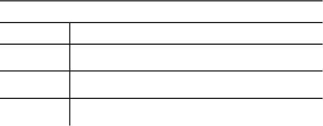
CAL prompts for a circle or arc and an object. It then determines the midpoint
between the center of the circle or arc and the end of the selected object.
Using the Midpoint Snap mode, in the following example CAL prompts for
an object and returns a point 1 unit in the Y direction from the midpoint of
the selected object:
mid+[,1]
The following example uses the Endpoint Snap mode to calculate the centroid
of a triangle defined by three endpoints:
(end+end+end)/3
See also:
Use the Command Line Calculator
Convert Points Between UCS and WCS
Normally, the program assumes all coordinates to be relative to the current
UCS. The following functions convert points between UCS and WCS.
w2u(p1) Converts point p1 expressed in the WCS to the current UCS.
u2w(p1) Converts point p1 expressed in the current UCS to the WCS.
You can use w2u to find the WCS origin in terms of the current UCS:
w2u([0,0,0])
Filtering the X,Y, and Z Components of a Point or Vector
The following functions filter the X, Y, and Z components of a point or vector.
Point-filter functions
DescriptionFunction
X and Y components of a point; Z component is set to 0.0xyof(p1)
X and Z components of a point; Y component is set to 0.0xzof(p1)
Y and Z components of a point; X component is set to 0.0yzof(p1)
Commands | 173
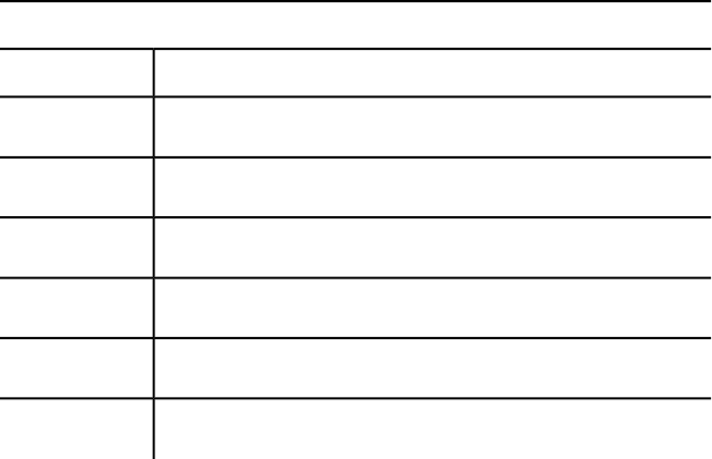
Point-filter functions
DescriptionFunction
X component of a point; Y and Z components are set to 0.0xof(p1)
Y component of a point; X and Z components are set to 0.0yof(p1)
Z component of a point; X and Y components are set to 0.0zof(p1)
X component of a pointrxof(p1)
Y component of a pointryof(p1)
Z component of a pointrzof(p1)
The following example provides the Z component of a point expressed in
spherical coordinates:
zof([2<45<45])
The following example provides a point whose X and Y coordinate values are
taken from point a and the Z coordinate value from point b:
xyof(a)+zof(b)
See also:
Use the Command Line Calculator
Calculate a Point on a Line
The plt and pld functions return a point on a given line. You can specify the
location of the point on the line either by its distance from the first point or
parametrically by a t parameter.
pld(p1,p2,dist) Calculates a point on the line passing through points p1 and
p2. The parameter dist defines the distance of the point from the point p1.
plt(p1,p2,t) Calculates a point on the line passing through points p1 and p2.
The parameter t defines the parametric location of the point on the line.
174 | Chapter 2 Commands
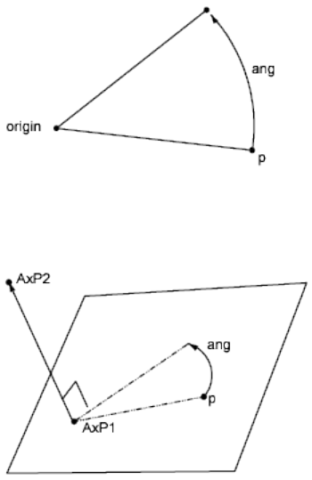
The following are examples of the parameter t:
If t=0 the point is p1
If t=0.5 the point is the midpoint between p1 and p2
If t=1 the point is p2
See also:
Use the Command Line Calculator
Rotate a Point About an Axis
The rot function rotates a point about an axis and returns the resulting point.
rot(p,origin,ang) Rotates point p through angle ang about the Z axis passing
through the point origin, as shown in the following example:
rot(p,AxP1,AxP2,ang) Rotates point p through an angle ang about the axis
passing through points AxP1 and AxP2, as shown in the following example.
The axis is oriented from the first point to the second point.
Commands | 175
See also:
Use the Command Line Calculator
Obtain an Intersection Point
The ill and ilp functions determine intersection points.
ill(p1,p2,p3,p4) Determines the intersection point between two lines (p1,p2)
and (p3,p4). All points are considered three-dimensional.
ilp(p1,p2,p3,p4,p5) Determines the intersection point between a line (p1,p2)
and a plane passing through three points (p3,p4,p5).
See also:
Use the Command Line Calculator
Calculate a Distance
dist(p1,p2) Determines the distance between two points, p1 and p2. This is
the same as the vector expression abs(p1-p2).
dpl(p,p1,p2) Determines the shortest distance between point p and the line
passing through points p1 and p2.
dpp(p,p1,p2,p3) Determines the distance from a point p to a plane defined
by three points (p1,p2,p3).
dist(p1,p2) Determines the distance between two points, p1 and p2. This is
the same as the vector expression abs(p1-p2).
176 | Chapter 2 Commands
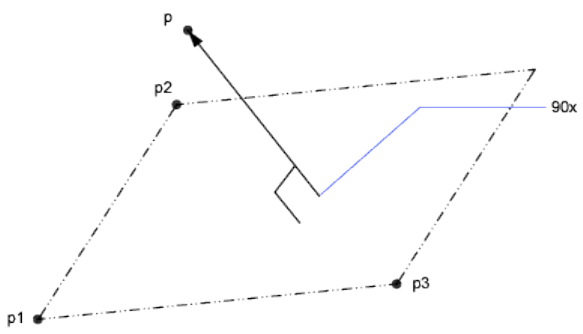
The following example returns half the distance between the centers of two
selected objects:
dist(cen,cen)/2
The following example finds the distance between the point 3,2,4 and a plane
you define by selecting three endpoints:
dpp([3,2,4],end, end, end)
See also:
Use the Command Line Calculator
Obtain a Radius
The rad function determines the radius of a selected object.
rad Determines the radius of a selected object. The object can be a circle, an
arc, or a 2D polyline arc segment.
The following example uses rad with the CIRCLE (page 191) command. The
radius of the new circle is two-thirds of the radius of the selected polyline arc
segment:
Command: circle
Specify center point for circle or [3P/2P/Ttr (tangent tangent radius)]: cen
of Select the circle
Specify radius of circle or [Diameter] <last>: 'cal
>> Expression: 2/3*rad
Commands | 177
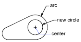
>> Select circle, arc or polyline segment for RAD function: Select the circle
See also:
Use the Command Line Calculator
Obtain an Angle
The ang function determines the angle between two lines. Angles are measured
counterclockwise with respect to either the X axis, in the two-dimensional
case, or to a user-specified axis, in the three-dimensional case.
ang(v) Determines the angle between the X axis and vector v. The vector v is
considered 2D, projected on the XY plane of the current UCS.
ang(p1,p2) Determines the angle between the X axis and the line (p1,p2),
oriented from p1 to p2. The points are considered 2D, projected on the XY
plane of the current UCS.
ang(apex,p1,p2) Determines the angle between lines (apex,p1) and (apex,p2).
The points are considered 2D, projected on the XY plane of the current UCS.
ang(apex,p1,p2,p) Determines the angle between lines (apex,p1) and (apex,p2).
The lines are considered 3D. The last parameter, point p, is used to define the
orientation of the angle. The angle is measured counterclockwise with respect
to the axis going from apex to p.
The following examples show how angles are measured.
178 | Chapter 2 Commands
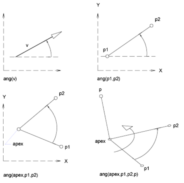
You can determine the angle between the two sides of a triangle using the
ang function, as shown in the following example:
Command: cal
>> Expression: ang(end,end,end)
Select the apex of the angle, and then select the two opposite vertices.
See also:
Use the Command Line Calculator
Calculate a Normal Vector
The nor function calculates the unit normal vector (a vector perpendicular
to a line or plane), not a point. The vector defines the direction of the normal,
Commands | 179
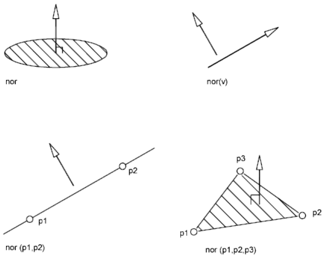
not a location in space. You can add this normal vector to a point to obtain
another point.
nor Determines the three-dimensional unit normal vector of a selected circle,
arc, or polyline arc segment. This normal vector is the Z coordinate of the
object coordinate system (OCS) of the selected object.
nor(v) Determines the two-dimensional unit normal vector to vector v. Both
vectors are considered 2D, projected on the XY plane of the current UCS. The
orientation of the resulting normal vector points to the left of the original
vector v.
nor(p1,p2) Determines the 2D unit normal vector to line p1,p2. The line is
oriented from p1 to p2. The orientation of the resulting normal vector points
to the left from the original line (p1,p2).
nor(p1,p2,p3) Determines the 3D unit normal vector to a plane defined by
the three points p1, p2, and p3. The orientation of the normal vector is such
that the given points go counterclockwise with respect to the normal.
The following illustrations show how normal vectors are calculated:
180 | Chapter 2 Commands
The following example sets the view direction perpendicular to a selected
object. The program displays the object in plan view and does not distort the
object by the parallel projection.
Command: vpoint
Current view direction: VIEWDIR=current
Specify a view point or [Rotate] <display compass and tripod>:
'cal
>> Expression: nor
>> Select circle, arc or polyline for NOR function:
See also:
Use the Command Line Calculator
Use Shortcut Functions
The functions in the table are shortcuts for commonly used expressions that
combine a function with the Endpoint Snap mode.
Shortcut functions
DescriptionShortcut forFunction
Distance between two endpointsdist(end,end)dee
Intersection of two lines defined by four en-
dpoints
ill(end,end,end,end)ille
Midpoint between two endpoints(end+end)/2mee
Unit vector in the XY plane and normal to
two endpoints
nor(end,end)nee
Point at a distance along a line determined
by two endpoints (see pld)
pld(d,end,end)pldee (d)
Point at a parametric location on a line de-
termined by two endpoints (see plt)
plt(t,end,end)pltee (t)
Commands | 181
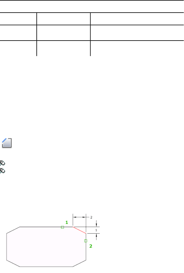
Shortcut functions
DescriptionShortcut forFunction
Vector from two endpointsvec(end,end)vee
Unit vector from two endpointsvec1(end,end)vee1
See also:
Use the Command Line Calculator
CHAMFER
Bevels the edges of objects.
Access Methods
Button
Toolbar: Drafting tool set ➤ Modify tool group ➤ Chamfer
Menu: Modify ➤ Chamfer
Summary
The distances and angles that you specify are applied in the order that you
select the objects.
You can chamfer lines, polylines, rays, and xlines.
182 | Chapter 2 Commands
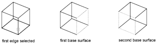
You can also chamfer 3D solids and surfaces. If you select a mesh to chamfer,
you can choose to convert it to a solid or surface before completing the
operation.
List of Prompts
The following prompts are displayed.
(TRIM mode) Current chamfer Dist1 = current, Dist2 = current
Select first line (page ?) or [Undo (page ?)/Polyline (page
?)/Distance (page ?)/Angle (page ?)/Trim (page ?)/mEthod
(page ?)/Multiple (page ?)/eXpression (page 185)]: Use an
object selection method or enter an option
First Line
Specifies the first of two edges required to define a 2D chamfer, or the edge
of a 3D solid to chamfer.
If you select lines or polylines, their lengths adjust to accommodate the
chamfer line. You can hold down Shift while selecting the objects to override
the current chamfer distances with a value of 0.
If the selected objects are line segments of a 2D polyline, they must be adjacent
or separated by no more than one segment. If they're separated by another
polyline segment, CHAMFER deletes the segment that separates them and
replaces it with the chamfer.
If you select an edge on a 3D solid, you must indicate which one of the two
surfaces adjacent to the edge is the base surface.
Enter Surface Selection Option Entering o or pressing Enter sets the selected
surface as the base surface. Entering n selects either of the two surfaces adjacent
to the selected edge.
After you select the base surface and the chamfer distances, select the edges
of the base surface to chamfer. You can select edges individually or all the
edges at once.
Edge Selects an individual edge to chamfer.
Commands | 183
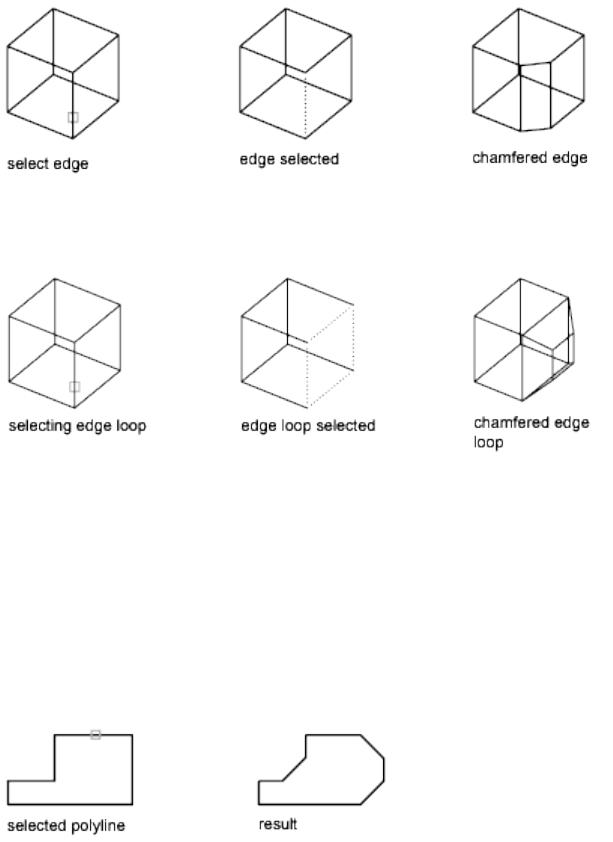
Loop Switches to Edge Loop mode.
Edge Loop Selects all edges on the base surface.
Undo
Reverses the previous action in the command.
Polyline
Chamfers an entire 2D polyline.
The intersecting polyline segments are chamfered at each vertex of the polyline.
Chamfers become new segments of the polyline.
If the polyline includes segments that are too short to accommodate the
chamfer distance, those segments are not chamfered.
Distance
Sets the distance of the chamfer from the endpoint of the selected edge.
If you set both distances to zero, CHAMFER extends or trims the two lines so
they end at the same point.
184 | Chapter 2 Commands
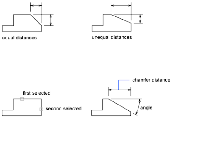
Angle
Sets the chamfer distances using a chamfer distance for the first line and an
angle for the second line.
Trim
Controls whether CHAMFER trims the selected edges to the chamfer line
endpoints.
NOTE Trim sets the TRIMMODE (page 1473) system variable to 1; No Trim sets
TRIMMODE to 0.
If the TRIMMODE system variable is set to 1, CHAMFER trims the intersecting
lines to the endpoints of the chamfer line. If the selected lines do not intersect,
CHAMFER extends or trims them so that they do. If TRIMMODE is set to 0,
the chamfer is created without trimming the selected lines.
Method
Controls whether CHAMFER uses two distances or a distance and an angle to
create the chamfer.
Multiple
Chamfers the edges of more than one set of objects.
Expression
Controls the chamfer distance with a mathematical expression. See Constrain
a Design with Formulas and Equations for a list of operators and functions
allowed.
See also:
Create Chamfers
Commands | 185

CHAMFEREDGE
Bevels the edges of 3D solids and surfaces.
Access Methods
Button
Toolbar: Modeling tool set ➤ Solids - Edit tool group ➤ Chamfer Edge
Menu: Modify ➤ Solid Editing ➤ Chamfer Edges
Summary
You can select more than one edge at a time, as long as they belong to the
same face. Enter a value for the chamfer distance or click and drag the chamfer
grips.
List of Prompts
Select an Edge Selects a single solid or surface edge to chamfer.
Distance 1 Sets the distance of the first chamfer edge from the selected edge.
The default value is 1.
Distance 2 Sets the distance of the second chamfer edge from the selected
edge. The default value is 1.
Loop Chamfers all edges on a single face. For any edge, there are two possible
loops. After selecting a loop edge you are prompted to Accept the current
selection or choose the Next loop.
186 | Chapter 2 Commands
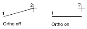
Expression Enter a formula or equation to specify the chamfer distance with
a mathematical expression. See Constrain a Design with Formulas and
Equations.
See also:
Modify Edges on 3D Objects
Create Chamfers
CHANGE
Changes the properties of existing objects.
List of Prompts
The following prompts are displayed
Select objects (page ?):
Specify change point (page ?) or [Properties (page ?)]:
Specify a new point, or press Enter to enter new values
Specify Objects
If you select lines and other changeable objects in the same selection set, you
get varying results depending on the object selection sequence. The easiest
way to use CHANGE is to select only lines in a selection set or select only
objects other than lines in a selection set.
Except for zero-thickness lines, the objects selected must be parallel to the
current user coordinate system (UCS).
Change Point or Values
Changes the selected objects. The result depends on the type of objects you
select.
Lines Moves the endpoints of the selected lines that are closest to the change
point to the new point, unless Ortho mode is on. If Ortho mode is on, the
selected lines are modified so that they become parallel to either the X or the
Y axis; their endpoints are not moved to the specified coordinate.
Commands | 187
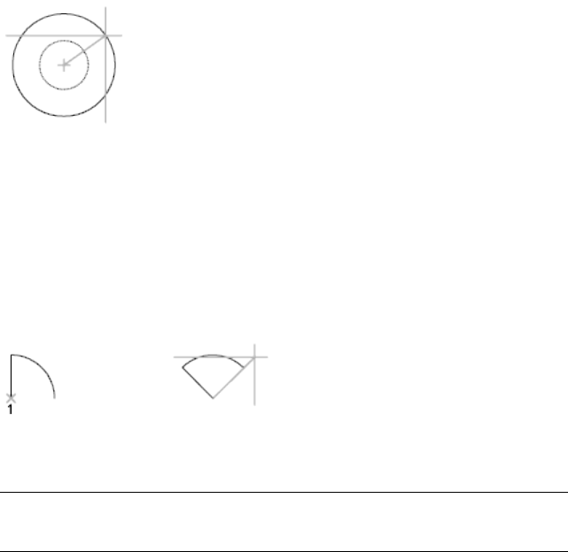
Circles Changes the circle radius. If you selected more than one circle, the
prompt is repeated for the next circle.
Text Changes text location and other properties.
Specify New Text Insertion Point Relocates the text.
Attribute Definitions Changes the text and text properties of an attribute
that is not part of a block.
Blocks Changes the location or rotation of a block.
Specifying a new location relocates the block. Pressing Enter leaves the block
in its original location.
Properties
Modifies properties of existing objects.
NOTE
The Plotstyle option is displayed only when you are using named plot styles.
You can change several properties at a time. The Enter Property to Change
prompt is redisplayed after each option is completed.
Color Changes the color of the selected objects.
For example, to change a color to red, enter red or 1. If you enter bylayer,
the object assumes the color of the layer on which it is located. If you enter
byblock, the object inherits the color of the block of which it is a component.
■True Color. Specifies a true color to be used for the selected object. The
integer values range from 0 to 255 seperated by commas.
■Color Book. Specifies a color from a loaded color book to be used for the
selected object.
Elev Changes the Z-axis elevation of 2D objects.
188 | Chapter 2 Commands

You can change the elevation of an object only if all its points have the same
Z value.
Layer Changes the layer of the selected objects.
Ltype Changes the linetype of the selected objects.
If the new linetype is not loaded, the program tries to load it from the standard
linetype library file, acad.lin. If this procedure fails, use LINETYPE (page 575)
to load the linetype.
Ltscale Changes the linetype scale factor of the selected objects.
Lweight Changes the lineweight of the selected objects. Lineweight values
are predefined values. If you enter a value that is not a predefined value, the
closest predefined lineweight is assigned to the selected objects.
Thickness Changes the Z-direction thickness of 2D objects.
Changing the thickness of a 3D polyline, dimension, or layout viewport object
has no effect.
Transparency Changes the transparency level of selected objects.
Set the transparency to ByLayer or ByBlock, or enter a value from 0 to 90.
Material Changes the material of the selected objects if a material is attached.
Annotative Changes the Annotative property of the selected objects.
Commands | 189

See also:
Display and Change the Properties of Objects
CHPROP
Changes the properties of an object.
List of Prompts
The following prompts are displayed.
Select objects:
Enter property to change [Color (page ?)/LAyer (page
?)/LType (page ?)/ltScale (page ?)/LWeight (page
?)/Thickness (page ?)/TRansparency (page ?)/Material (page
?)/Annotative (page ?)]:
NOTE
The Plotstyle option is displayed only when you are using named plot styles.
If you select several objects with different values for the property you want
to change, varies is displayed as the current value.
Color
Changes the color of the selected objects.
For example, to change a color to red, enter red or 1. If you enter bylayer,
the object assumes the color of the layer on which it is located. If you enter
byblock, the object inherits the color of the block of which it is a component.
True Color Specifies a true color to be used for the selected object.
Color Book Specifies a color from a loaded color book to be used for the
selected object.
Layer
Changes the layer of the selected objects.
Ltype
Changes the linetype of the selected objects.
If the new linetype is not loaded, the program tries to load it from the standard
linetype library file, acad.lin. If this procedure fails, use LINETYPE (page 575)
to load the linetype.
190 | Chapter 2 Commands
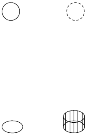
Ltscale
Changes the linetype scale factor of the selected objects.
Lweight
Changes the lineweight of the selected objects. Lineweight values are
predefined values. If you enter a value that is not a predefined value, the
closest predefined lineweight is assigned to the selected objects.
Thickness
Changes the Z-direction thickness of 2D objects.
Changing the thickness of a 3D polyline, dimension, or layout viewport object
has no effect.
Transparency
Changes the transparency level of selected objects.
Set the transparency to ByLayer or ByBlock, or enter a value from 0 to 90.
Material
Changes the material of the selected objects if a material is attached.
Annotative
Changes the Annotative property of the selected objects.
See also:
Display and Change the Properties of Objects
CIRCLE
Creates a circle.
Commands | 191
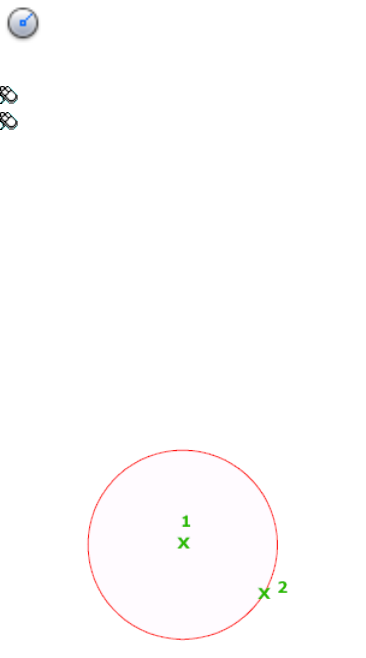
Access Methods
Button
Toolbar: Drafting tool set ➤ Closed Shapes tool group ➤ Circle flyout
Menu: Draw ➤ Circle ➤ Center, Radius
List of Prompts
The following prompts are displayed.
Specify center point (page ?) for circle or [3P (page ?)/2P
(page ?)/Ttr (tan tan radius) (page ?)]: Specify a point or enter
an option
Center Point
Draws a circle based on a center point and a diameter or a radius.
Radius Defines the radius of the circle. Enter a value, or specify a point.
For example:
Diameter Defines the diameter of the circle. Enter a value, or specify a second
point.
For example:
192 | Chapter 2 Commands
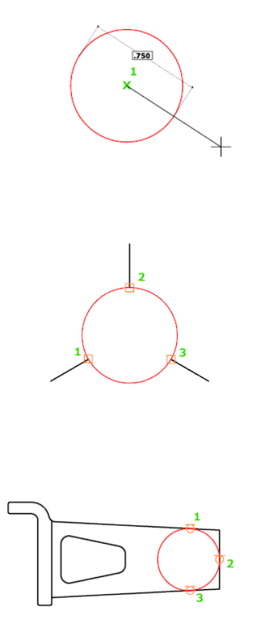
3P (Three Points)
Draws a circle based on three points on the circumference.
For example:
Tan, Tan, Tan
Creates a circle tangent to three objects.
For example:
2P (Two Points)
Draws a circle based on two endpoints of the diameter.
For example:
Commands | 193
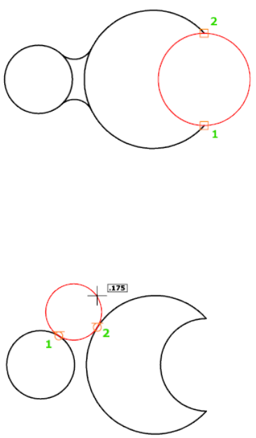
TTR (Tangent, Tangent, Radius)
Draws a circle with a specified radius tangent to two objects.
Sometimes more than one circle matches the specified criteria. The program
draws the circle of the specified radius whose tangent points are closest to the
selected points.
For example:
See also:
Draw Circles
CLASSICGROUP
Creates and manages saved sets of objects called groups.
List of Prompts
The following prompts are displayed.
Enter a group option [?(page ?)/Order (page ?)/Add (page
?)/Remove (page ?)/Explode (page ?)/REName (page ?)/Se-
194 | Chapter 2 Commands
lectable (page ?)/Create (page ?)] <Create>: Enter an option or
press Enter
?—List Groups
Lists names and descriptions of groups defined in the drawing.
Order
Changes the numerical order of objects within a group. Reordering is useful
when creating tool paths. For example, you can change the cut order for the
horizontal and vertical lines of a tool path pattern.
Position Number Specifies the position number of the object to reorder. To
reorder a range of objects, specify the first object's position number.
Reverse Order Reverses the order of all members in a group.
Add
Adds objects to a group.
Remove
Removes objects from a group.
If you remove all the group's objects, the group remains defined. You can
remove the group definition from the drawing by using the Explode option.
Explode
Deletes a group definition by exploding the group into its component objects.
Ungroup
Removes the group name and the association of objects in the group.
Rename
Assigns a new name to an existing group.
Selectable
Specifies whether a group is selectable. When a group is selectable, selecting
one object in the group selects the whole group. Objects on locked or frozen
layers are not selected.
Create
Creates a group.
Group names can be up to 31 characters long and can include letters, numbers,
and special characters dollar sign ($), hyphen (-), and underscore (_) but not
spaces. The name is converted to uppercase characters.
See also:
Group Objects
Commands | 195

CLEANSCREENON
Clears the screen of the menu bar and all palettes.
Access Methods
Button
Menu: View ➤ Clean Screen
Command entry: Cmd-0
Toolbar: Status bar ➤ Clean Screen
Summary
The screen displays only the drawing area.
Use CLEANSCREENOFF (page 196) to restore the display of interface items that
were hidden by CLEANSCREENON.
See also:
Set Up the Drawing Area
CLEANSCREENOFF
Restores the state of the display before CLEANSCREENON was used.
Access Methods
Button
Menu: View ➤ Clean Screen
Command entry: Cmd-0
Toolbar: Status bar ➤ Clean Screen
196 | Chapter 2 Commands

Summary
Restores the state of the display before CLEANSCREENON (page 196) was used.
Use CLEANSCREENON (page 196) to clear the screen of most user interface
elements.
See also:
Set Up the Drawing Area
CLOSE
Closes the current drawing.
Access Methods
Menu: File ➤ Close
Summary
The current drawing is closed. If you modified the drawing since it was last
saved, you are prompted to save or discard the changes.
You can close a file that has been opened in read-only mode if you have made
no changes or if you are willing to discard changes. To save changes to a
read-only file, you must use the SAVEAS (page 914) command.
See also:
Open a Drawing
CLOSEALL
Closes all currently open drawings.
Summary
All open drawings are closed. A message box is displayed for each unsaved
drawing, in which you can save any changes to the drawing before closing it.
Commands | 197

See also:
Open a Drawing
COLOR
Sets the color for new objects.
Access Methods
Menu: Format ➤ Color
Command entry: 'color for transparent use
Summary
The Color Palette dialog box (page 198) is displayed.
If you enter -color at the Command prompt, options are displayed (page 205).
See also:
Set the Current Color
Color Palette Dialog Box
Defines the color of objects.
Summary
You can select from the 255 AutoCAD Color Index (ACI) colors, true colors,
and Color Book colors.
List of Tabs
The following tabs are displayed.
■Index Color (page 199)
■True Color (page 200)
■Color Books (page 203)
198 | Chapter 2 Commands
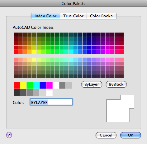
See also:
Set the Current Color
Index Color Tab (Color Palette Dialog Box)
Specifies color settings using the 255 AutoCAD Color Index (ACI) colors.
List of Options
The following options are displayed.
AutoCAD Color Index (ACI) Palettes Specifies a color from the AutoCAD
Color Index. If you hover over a color, the number of the color and its red,
green, blue value are displayed below the palette. Click a color to select it, or
enter the color number or name in the Color box.
The large palette displays colors 10 through 249.
The second palette displays colors 1 through 9; these colors have names as
well as numbers.
The third palette displays colors 250 through 255; these colors are shades of
gray.
Commands | 199

Index Color Indicates the ACI color number when you hover over a color.
Red, Green, Blue Indicates the RGB color value when you hover over a color.
Bylayer
Specifies that new objects assume the color assigned to the layer on which
you create them. When BYLAYER is selected, the color of the current layer is
displayed in the Old and New color swatches.
Byblock
Specifies that new objects use the default color (white or black, depending on
your background color) until you group the objects into a block and insert
the block. When you insert the block into a drawing, the objects in the block
inherit the current Color setting.
NOTE The BYLAYER and BYBLOCK options do not apply to the LIGHT (page 572)
command.
Color
Specifies a color name, BYLAYER or BYBLOCK color, or an AutoCAD Color
Index (ACI) number of 1 through 255. The New color swatch shows the most
recently selected color.
Old Color Swatch
Displays the previously selected color.
New Color Swatch
Displays the currently selected color.
See also:
Set the Current Color
True Color Tab (Color Palette Dialog Box)
Specifies color settings using true colors.
200 | Chapter 2 Commands
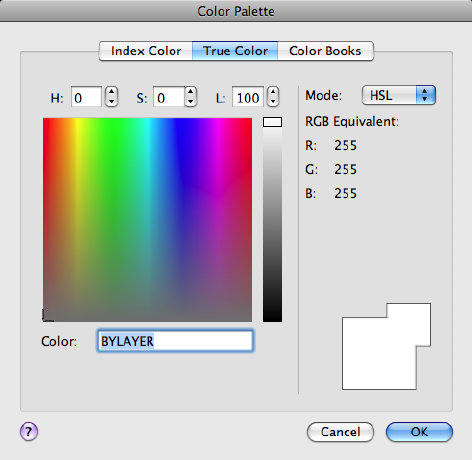
Summary
Specifies color settings using true colors (24-bit color) with either the Hue,
Saturation, and Luminance (HSL) color model or the Red, Green, and Blue
(RGB) color model. Over sixteen million colors are available when using true
color functionality. The options available on the True Color tab are dependent
on whether the HSL or RGB color model is specified.
List of Options
The following options are displayed.
HSL Color Model
Specifies the HSL color model for selecting colors.
Hue, saturation, and luminance are properties of colors. By manipulating the
values of these properties, you can specify a wide range of colors.
Hue (H)
Specifies the hue of a color. Hues represent a specific wavelength of light
within the visible spectrum. To specify a hue, use the color spectrum or specify
a value in the Hue box. Adjusting this value affects the RGB value. Valid hue
values are from 0 to 360 degrees.
Commands | 201
Saturation (S)
Specifies the purity of a color. High saturation causes a color to look more
pure while low saturation causes a color to look washed-out. To specify color
saturation, use the color spectrum or specify a value in the Saturation box.
Adjusting this value affects the RGB value. Valid saturation values are from 0
to 100%.
Luminance (L)
Specifies the brightness of a color. To specify color luminance, use the color
slider or specify a value in the Luminance box. Valid luminance values are
from 0 to 100%. A value of 0% represents the color black, 100% represents
white, and 50% represents the optimal brightness for the color. Adjusting this
value also affects the RGB value.
Color Spectrum Specifies the hue and purity of a color. To specify a hue,
move the crosshairs from side to side over the color spectrum. To specify color
saturation, move the crosshairs from top to bottom over the color spectrum.
Color Slider Specifies the brightness of a color. To specify color luminance,
adjust the bar on the color slider or specify a value in the Luminance box.
RGB Color Model
Specifies the RGB color model for selecting colors. The options available on
the True Color tab are dependent on whether the HSL or RGB color model is
specified.
Colors can be broken down into components of red, green, and blue. The
values specified for each component represent the intensity of the red, green,
and blue components. The combination of these values can be manipulated
to create a wide range of colors.
Red (R)
Specifies the red component of a color. Adjust the slider on the color bar or
specify a value from 1 to 255 in the Red box. If this value is adjusted, it will
be reflected in the HSL color mode values.
Green (G)
Specifies the green component of a color. Adjust the slider on the color bar
or specify a value from 1 to 255 in the Green box. If this value is adjusted, it
will be reflected in the HSL color mode values.
Blue (B)
202 | Chapter 2 Commands
Specifies the blue component of a color. Adjust the slider on the color bar or
specify a value from 1 to 255 in the Blue box. If this value is adjusted, it will
be reflected in the HSL color mode values.
Color
Specifies the RGB color value. This option is updated when changes are made
to HSL or RGB options. You can also edit the RGB value directly using the
following format: 000,000,000.
True Color Stored as RGB
Indicates the value for each RGB color component.
Old Color Swatch
Displays the previously selected color.
New Color Swatch
Displays the currently selected color.
See also:
Set the Current Color
Color Books Tab (Color Palette Dialog Box)
Specifies colors using third-party color books or user-defined color books.
Commands | 203
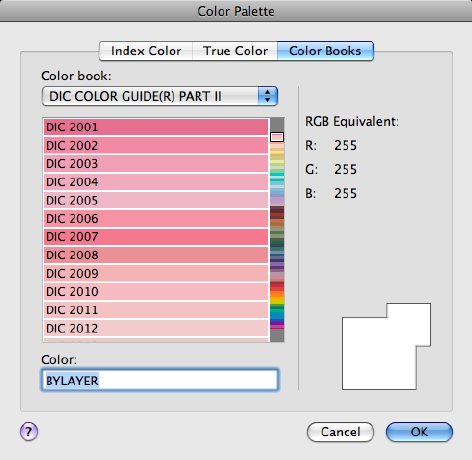
Summary
Once a color book is selected, the Color Books tab displays the name of the
selected color book.
List of Options
The following options are displayed.
Color Book
Specifies the color book to be used when selecting colors.
The list consists of all the color books that are found in the Color Book
Locations specified in the Application References dialog box, Application tab.
Displays the pages of the selected color book and the colors and color names
on each page. Color books containing up to ten colors per page are supported.
If a color book is not paginated, the colors are organized into pages containing
seven colors per page. To view color book pages, select an area on the color
slider or use the up and down arrows to browse.
RGB Equivalent Indicates the value for each RGB color component.
Color
204 | Chapter 2 Commands

Indicates the currently selected color book color. You can search for a specific
color in a color book by entering the number of the color swatch and pressing
Tab. This action updates the New color swatch with the requested color
number. If the specified color is not found in the color book, the closest
number match is displayed.
Old Color Swatch
Displays the previously selected color.
New Color Swatch
Displays the currently selected color.
See also:
Set the Current Color
-COLOR
If you enter -color at the Command prompt, the following prompts are
displayed.
Enter default object color [Truecolor (page 206)/COlorbook
(page 206)] <BYLAYER>: Enter a color, enter t, enter co, or press Enter
You can enter a color from the AutoCAD Color Index (a color name or
number), a true color, or a color from a color book.
You can enter the color number (1 through 255) or the color name (the names
for the first seven colors). For example, you can specify the color red by
entering the ACI number 1 or the ACI name red.
You can also enter bylayer or byblock. If you enter byblock, all new objects
are drawn in the default color (white or black, depending on your background
color) until they are grouped into a block. When you insert the block in a
drawing, the objects in the block inherit the current setting of COLOR.
WARNING
If you used a mixture of color methods to draw the objects that make up a
block, inserting that block or changing its color produces complex results.
If you enter bylayer, new objects assume the color assigned to the layer on
which you create them. See the LAYER (page 537) command for information
about assigning a color to a layer.
Commands | 205

List of Prompts
The following prompts are displayed.
True Color Specifies a true color to be used for the selected object. Enter three
integer values from 0 to 255 separated by commas to specify a true color
Color Book Specifies a color from a loaded color book to be used for the
selected object. Enter the name of a color book that has been installed.
If you enter a color book name, you are prompted to enter the color name in
the color book.
See also:
Set the Current Color
COMMANDLINE
Displays the Command Line window.
Access Methods
Menu: Tools ➤ Palettes ➤ Command Line
Menu: Window ➤ Command Line
Command entry: Cmd-3
Summary
Displays the command line when it has been hidden.
You can display commands, system variables, options, messages, and prompts
in a dockable and resizable window called the Command Line.
See also:
The Command Line
COMMANDLINEHIDE
Hides the Command Line window.
206 | Chapter 2 Commands

Access Methods
Menu: Tools ➤ Palettes ➤ Command Line
Menu: Window ➤ Command Line
Command entry: Cmd-3
Summary
Hides the Command Line. When the Command Line is hidden, you can still
enter commands with dynamic prompts turned on.
See also:
The Command Line
COMPILE
Compiles shape files and PostScript font files into SHX files.
Summary
The Select Shape or Font File dialog box (a standard file selection dialog box
(page 720)) is displayed. Enter the SHP or PFB file name in the dialog box. The
compiled file is assigned this name with the file extension .shx.
See also:
Overview of Shape Files
CONE
Creates a 3D solid cone.
Access Methods
Button
Toolbar: Modeling tool set ➤ Solids - Create tool group ➤ Solid
Primitives ➤ Cone
Commands | 207
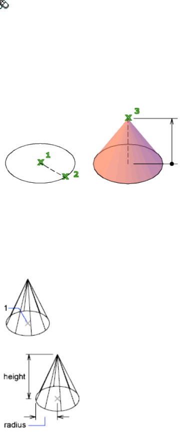
Menu: Draw ➤ 3D Modeling ➤ Cone
Summary
Creates a 3D solid with a circular or elliptical base that tapers symmetrically
to a point or to a circular or elliptical planar face. You can control the
smoothness of 3D curved solids, such as a cone, in a shaded or hidden visual
style with the FACETRES system variable.
Use the Top Radius option to create a cone frustum.
Initially, the default base radius is not set to any value. During a drawing
session, the default value for the base radius is always the previously entered
base radius value for any solid primitive.
List of Prompts
The following prompts are displayed.
208 | Chapter 2 Commands
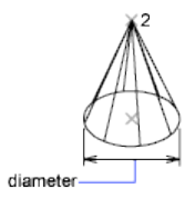
Specify center point of base or [3P (page ?)/2P (page ?)/Ttr
(page ?)/Elliptical (page ?)]: Specify a point (1) or enter an option
Specify base radius or [Diameter (page 209)] <default>: Specify
a base radius, enter d to specify a diameter, or press Enter to specify the default
base radius value
Specify height or [2Point (page 209)/Axis endpoint (page
209)/Top radius (page 209)] <default>: Specify a height, enter an option,
or press Enter to specify the default height value
Center Point of Base
2Point Specifies that the height of the cone is the distance between the two
specified points.
Axis Endpoint Specifies the endpoint location for the cone axis. The axis
endpoint is the top point of the cone or the center point of the top face of
the cone frustum (Top Radius option). The axis endpoint can be located
anywhere in 3D space. The axis endpoint defines the length and orientation
of the cone.
Top Radius Specifies the top radius of the cone, creating a cone frustum.
Initially, the default top radius is not set to any value. During a drawing session,
the default value for the top radius is always the previously entered top radius
value for any solid primitive.
Diameter Specifies the diameter for the base of the cone.
Initially, the default diameter is not set to any value. During a drawing session,
the default value for the diameter is always the previously entered diameter
value for any solid primitive.
3P (Three Points)
Defines the base circumference and base plane of the cone by specifying three
points.
■2Point (page 209)
■Axis Endpoint (page 209)
Commands | 209

■Top Radius (page 209)
2P (Two Points)
Defines the base diameter of the cone by specifying two points.
■2Point (page 209)
■Axis Endpoint (page 209)
■Top Radius (page 209)
TTR (Tangent, Tangent, Radius)
Defines the base of the cone with a specified radius tangent to two objects.
Sometimes, more than one base matches the specified criteria. The program
draws the base of the specified radius whose tangent points are closest to the
selected points.
■2Point (page 209)
■Axis Endpoint (page 209)
■Top Radius (page 209)
Elliptical
Specifies an elliptical base for the cone.
Center Creates the base of the cone by using a specified center point.
■2Point (page 209)
■Axis Endpoint (page 209)
■Top Radius (page 209)
See also:
Create a Solid Cone
CONSTRAINTBAR
Displays or hides the geometric constraints on an object.
Access Methods
Button
210 | Chapter 2 Commands

Toolbar: Modeling tool set ➤ Parametric tool group ➤ Constraint
Display flyout ➤ Show Geometric Constraints
Menu: Parametric ➤ Constraints Bars ➤ Select Objects
Summary
Select an object to highlight the relevant geometric constraints.
Constraint bars can be shown for all or any selection set of constrained
geometries.
The selection preview behavior for constraint bars is as follows:
■Placing the cursor over an icon on a constraint bar highlights related
geometry.
■Placing the cursor over a constrained object (while constraint bars are
displayed) highlights the constraint icons associated with the selected
object.
The CONSTRAINTBARMODE (page 1198) system variable or the CONSTRAINT-
SETTINGS (page 212) command controls the display of geometric constraints
on constraint bars, when constraint bar are displayed.
List of Prompts
The following prompts are displayed.
Select objects: Select objects with constraint bars
Enter an option [Show (page ?)/Hide (page ?)/Reset (page
?)] <Show>:Enter the appropriate value to show or hide constraint bars in the
drawing.
Show
Displays constraint bars for the selected objects with geometric constraints
applied to them.
Hide
Hides constraint bars for the selected objects with geometric constraints applied
to them.
Reset
Displays constraint bars for all objects with geometric constraints applied to
them and resets them to their default locations relative to their associated
parameters.
Commands | 211

See also:
Display and Verify Geometric Constraints
CONSTRAINTSETTINGS
Controls the display of geometric constraints on constraint bars.
Access Methods
Menu: Parametric ➤ Constraint Settings
Summary
The Constraint Settings dialog box (page 212) is displayed.
See also:
Overview of Constraints
Constraint Settings Dialog Box
Allows you to control the geometric constraints, dimensional constraints, and
autoconstrain settings.
212 | Chapter 2 Commands
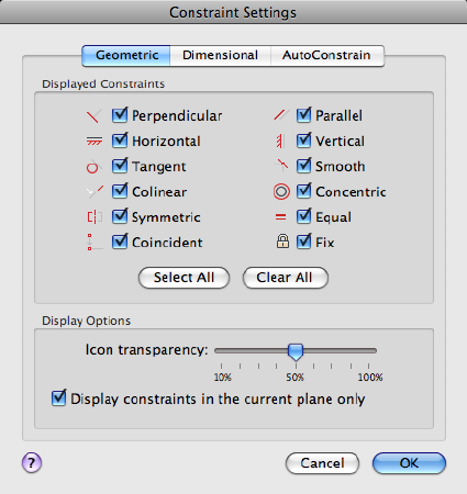
List of Options
The following options are displayed.
The Constraint Settings dialog box includes the following:
■Geometric Tab (page ?)
■Dimensional Tab (page ?)
■Autoconstrain Tab (page ?)
Geometric Tab
Controls the display of constraint types on constraint bars.
Infer Geometric Constraints Infers geometric constraints when creating and
editing geometry.
Displayed Constraints Controls the display of constraint bars or constraint
point markers for objects in the drawing editor.
For example, you can hide the display of constraint bars for Horizontal and
Vertical constraints.
Select All Selects the geometric constraint types.
Clear All Clears the selected geometric constraint types.
Commands | 213
Display Constraints in the Current Plane Displays constraint bars for
geometrically constrained objects only on the current plane.
Icon Transparency Sets the transparency level of constraint bars in a drawing.
Show Constraint Bars After Applying Constraints to Selected Objects
Displays relevant constraint bars after you apply a constraint manually or
when you use the AUTOCONSTRAIN (page 126) command.
Temporarily Display Constraint Bars When Objects Are Selected
Temporarily displays the constraint bars of the selected objects.
Dimensional Tab
Sets preferences in behavior when displaying dimensional constraints.
Dimensional Constraint Format Sets the display of the dimensional name
format and lock icon.
Dimension Name Format Specifies the format for the text displayed when
dimensional constraints are applied.
Set the name format to display: Name, Value, or Name and Expression.
For example: Width=Length/2
Show Lock Icon for Annotational Constraints Displays a lock icon against
an object that has an annotational constraint applied (DIMCONSTRAINTICON
(page 1228) system variable).
Show Hidden Dynamic Constraints for Selected Objects Displays dynamic
constraints that have been set to hide when selected.
Autoconstrain Tab
Controls the constraints that are applied to a selection set, and the order in
which they are applied when using the AUTOCONSTRAIN (page 126) command.
The following conditions are checked before multiple geometric constraints
are applied:
■Are the objects perpendicular or tangential to each other within the
tolerances specified in the AutoConstrain tab?
■Do they also intersect within the specified tolerances?
If the first condition is met, then tangent and perpendicular constraints are
always applied if the check boxes are cleared.
If you select the additional check boxes, then the distance tolerance is
considered for intersecting objects. If the objects do not intersect but the
nearest distance between them is within the distance tolerance specified, then
the constraint will be applied even if the check boxed are selected.
214 | Chapter 2 Commands
Autoconstrain Headings
■Applied — Controls the constraints that are applied when applying
constraints to multiple objects.
■Constraint Type — Controls the type of constraint applied to objects.
Tolerances Sets the acceptable tolerance values to determine whether a
constraint can be applied.
■Distance — Distance tolerance are applied to coincident, concentric,
tangent, and collinear constraints.
■Angle — Angular tolerance are applied to horizontal, vertical, parallel,
perpendicular, tangent, and collinear constraints.
Tangent Objects Must Share an Intersection Point Specifies that two curves
must share a common point (as specified within the distance tolerance) for
the tangent constraint to be applied.
Perpendicular Objects Must Share an Intersection Point Specifies that lines
must intersect or the endpoint of one line must be coincident with the other
line or endpoint of the line as specified within the distance tolerance.
See also:
Overview of Constraints
+CONSTRAINTSETTINGS
Controls the tab that is displayed by default when the Constraint Settings
dialog box is invoked.
Tab DisplayedTab Index
Geometric tab0
Dimensional tab1
AutoConstrain tab2
See also:
Overview of Constraints
Commands | 215

CONTENT
Opens the Content palette.
Access
Button
Toolbar: Drafting tool set ➤ Block Tool group (expanded) ➤ Content
Palette
Menu: Tools ➤ Palettes ➤ Content
Menu: Window ➤ Content
Command entry: Cmd-2
Summary
The Content palette (page 216) allows you to insert blocks from the current
drawing or a custom library of blocks. You create libraries to access and
organize your blocks. Blocks that you use frequently can be added to the
Favorites library.
See also:
The Content Palette
Content Palette
Allows you to access and insert your blocks stored in libraries.
216 | Chapter 2 Commands

List of Options
The following options are displayed.
Libraries List
Displays the available libraries. Select a library to insert blocks from or select
Manage Libraries to display the Manage Content Libraries dialog box (page
218). The following libraries are available by default:
■Favorites - Blocks that you have selected as favorites from the Blocks list.
■Blocks in Current Drawing - Lists the blocks in the current drawing
that you can create new inserts from.
Manage Content Libraries
Displays the Manage Content Libraries dialog box (page 218) in which you
create and manage content of libraries.
Blocks List
Displays the blocks in the library selected from the Libraries list.
Click a block from the list to insert it in the current drawing. If you right-click
in the Blocks list, one of two shortcut menus is displayed. The Blocks List
shortcut menu (page 218) is displayed when you right-click an empty area of
the Blocks list, while the Block shortcut menu (page 218) is displayed when
you right-click over a block thumbnail.
Filter Blocks List
Filters the blocks displayed in the Blocks list. Click the ‘X’ in the text box to
clear the current filter.
Commands | 217
Enter a text string to control which blocks are displayed in the Blocks list.
Only the names of the blocks that contain the text string are displayed in the
Blocks list.
Blocks List Shortcut Menu
The following options are available when you right-click in an empty area of
the Blocks list:
■Small Thumbnails - Small thumbnails for the blocks in the current
library are displayed in the Blocks list.
■Medium Thumbnails - Medium thumbnails for the blocks in the current
library are displayed in the Blocks list.
■Large Thumbnails - Large thumbnails for the blocks in the current
library are displayed in the Blocks list.
■Manage Libraries - Displays the Manage Content Libraries dialog box
(page 218).
Block Shortcut Menu
The following options are available when you right-click a block thumbnail
in the Blocks list:
■Insert in Drawing - Starts the insertion of the block in the current
drawing.
■Add to Favorites - Adds the block to the Favorites content library.
■Thumbnail Size - Controls the size of the thumbnails displayed in the
Blocks list: small, medium, or large.
■Remove - Removes the selected block from the current content library.
■Manage Libraries - Displays the Manage Content Libraries dialog box
(page 218).
See also:
The Content Palette
Manage Content Libraries Dialog Box
Allows you to create and manage the blocks in a library.
218 | Chapter 2 Commands
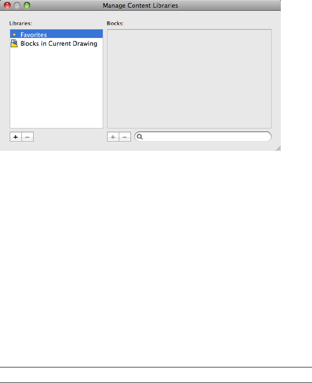
List of Options
The following options are displayed.
Libraries List
Lists the available libraries. The Favorites library is available by default. Select
a library to manage the blocks contained in the library in the Blocks list.
Double-click the name of a library to rename it.
Create Library (+) Creates a new library and prompts you to enter a name in
an in-place editor.
Delete Library (-) Removes the selected library from the Libraries list.
Blocks List
Lists the blocks contained in the selected library.
Add Block (+) Displays the Open File Dialog (a standard navigation dialog
box) in which you select a drawing (DWG) or drawing template (DWT) file
to add to the selected library.
NOTE Hold down the Command key to select more than one file.
Delete Library (-) Removes the selected block from the library.
Filter Blocks List Filters the blocks displayed in the Blocks list. Click the ‘X’
in the text box to clear the current filter. Enter a text string to control which
blocks are displayed in the Blocks list. Only the names of the blocks that
contain the text string are displayed in the Blocks list.
See also:
The Content Palette
Commands | 219

CONTENTCLOSE
Closes the Content palette.
Summary
Closes the Content palette that is displayed with the CONTENT (page 216)
command.
See also:
The Content Palette
CONVERT
Optimizes 2D polylines and associative hatches created in AutoCAD Release
13 or earlier.
Sumary
Hatches are not updated automatically when a drawing from a previous release
is opened in Release 14 or later. Information about the rotation of a hatch
pattern may not be updated properly if you have changed the UCS since
creating the hatch. When updating hatches with CONVERT, it is recommended
that you use the Select option so that you can check your results.
In most cases, you do not need to update polylines with CONVERT. By default,
the PLINETYPE (page 1396) system variable specifies that polylines are updated
automatically when you open an older drawing. Polylines may be created in
the old format by third-party applications, and they may be contained in an
older drawing that was inserted as a block and then exploded.
NOTE
Polylines containing curve-fit or splined segments always retain the old format,
as do polylines that store extended object data on their vertices. Editing
commands make no distinction between the two formats.
List of Prompts
The following prompts are displayed.
220 | Chapter 2 Commands

Enter type of objects to convert [Hatch (page 221)/Polyline
(page 221)/All (page 221)] <All>: Enter h for hatches, p for polylines, or
a for both
Hatch Converts all hatches in the drawing.
Polyline Converts all polylines in the drawing.
All Converts all polylines and hatches in the drawing.
See also:
Use Drawings from Different Versions and Applications
CONVTOMESH
Converts 3D objects such as polygon meshes, surfaces, and solids to mesh
objects.
Access Methods
Menu: Modify ➤ Surface Editing ➤ Convert to Mesh
Summary
Take advantage of the detailed modeling capabilities of 3D mesh by converting
objects such as 3D solids and surfaces to mesh.
Use this method to convert 3D faces (3DFACE) and legacy polygonal and
polyface meshes (from AutoCAD 2009 and earlier). You can also convert 2D
objects such as regions and closed polylines.
Commands | 221
The level of smoothness upon conversion depends on the mesh type setting
(FACETERMESHTYPE (page 1291) system variable). If the mesh type is not set
to be optimized, the converted object is not smoothed.
To convert mesh objects to 3D surfaces or solids, use CONVTOSOLID (page
223) or CONVTOSURFACE (page 225) commands.
Objects That Can Be Converted to Mesh
Object type
3D solids
3D surfaces
3D faces
Polyface and polygon meshes (legacy)
Regions
Closed polylines
See also:
Create Meshes by Conversion
CONVTONURBS
Converts 3D solids and surfaces into NURBS surfaces.
Access Methods
Menu: Modify ➤ Surface Editing ➤ Convert to NURBS
Summary
Converts solids and procedural surfaces to NURBS surfaces.
222 | Chapter 2 Commands
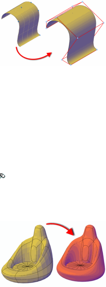
To convert meshes to NURBS surfaces, convert them to a solid or surface first
with CONVTOSOLID (page 223) or CONVTOSURFACE (page 225) and then
convert them to NURBS surfaces.
See also:
Create NURBS Surfaces
CONVTOSOLID
Converts 3D meshes and polylines and circles with thickness to 3D solids.
Access Methods
Menu: Modify ➤ 3D Operations ➤ Convert to Solid
Summary
Take advantage of the solid modeling capabilities available for 3D solids. When
you convert mesh, you can specify whether the converted objects are smoothed
or faceted, and whether the faces are merged.
Commands | 223
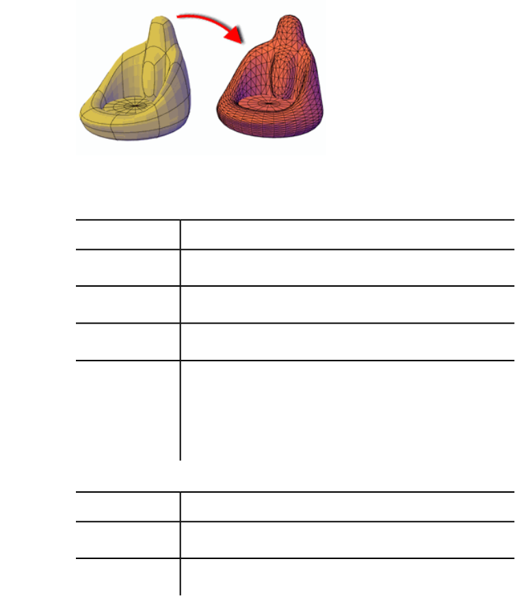
The smoothness and number of faces of the resulting 3D solid are controlled
by the SMOOTHMESHCONVERT (page 1437) system variable. Whereas the
previous example shows a conversion to a smooth, optimized 3D solid, the
following example shows a conversion to a faceted 3D solid in which the faces
are not merged, or optimized.
The following tables list the objects that can be converted to solid objects and
some limitations on their conversion.
Objects that Can Be Converted to 3D Solids
Required propertiesObject
Encloses a volume with no gaps between edges (watertight)Mesh
Closed, uniform-width, with thicknessPolyline
Closed, zero-width, with thicknessPolyline
Encloses a volume with no gaps between edges (such as a revolved
surface that is capped at both ends or closed mesh objects that
Surface
were converted to surfaces). If the surfaces enclose a watertight
area, you can also convert to a solid with the SURFSCULPT (page
1023) command.
Limitations on Conversion to Solid Objects
DescriptionObject
Cannot contain zero-width vertices.Polyline
Cannot contain segments of variable width.Polyline
224 | Chapter 2 Commands
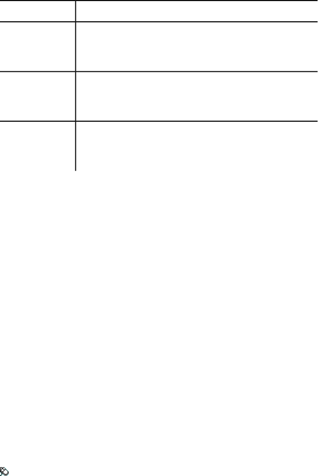
DescriptionObject
Cannot be a planar surface with contiguous edges or an exploded
3D solid box into six regions. However, you cannot convert those
separate objects back to a solid with CONVTOSOLID.
Separate objects
that simulate a
closed surface
Cannot convert separate objects unless they enclose a volume
without gaps. If the surfaces enclose a watertight area, you can
convert to a solid with the SURFSCULPT (page 1023) command.
Planar surfaces
with contiguous
edges
Cannot convert separate objects (in this case, regions) with the
CONVTOSOLID command. You can, however, convert them to a
solid with the SURFSCULPT (page 1023) command.
Exploded 3D solid
You can select the objects to convert before you start the command.
The DELOBJ (page 1213) system variable controls whether the geometry used
to create 3D objects is automatically deleted when the new object is created
or whether you are prompted to delete the objects.
List of Prompts
The following prompts are displayed.
Select objects Specifies one or more objects to convert to 3D solid objects.
You can select objects with thickness or mesh objects.
If one or more objects in the selection set are invalid for the command, you
will be prompted again to select objects.
See also:
Create 3D Solids from Objects
CONVTOSURFACE
Converts objects to 3D surfaces.
Access Methods
Menu: Modify ➤ 3D Operations ➤ Convert to Surface
Commands | 225
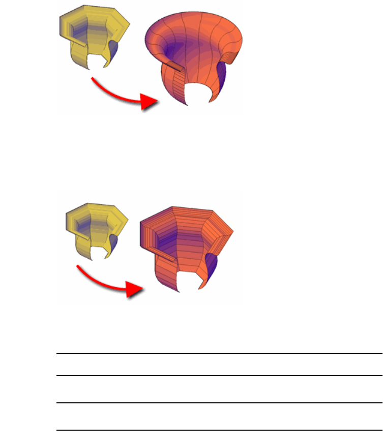
Summary
As you convert objects to surfaces, you can specify whether the resulting object
is smooth or faceted.
When you convert a mesh, the smoothness and number of faces of the
resulting surface are controlled by the SMOOTHMESHCONVERT (page 1437)
system variable. Whereas the previous example shows a conversion to a
smooth, optimized surface, the following example shows a conversion to a
faceted surface in which the faces are not merged, or optimized.
With the CONVTOSURFACE command, you can convert the following objects
into surfaces:
Objects That Can Be Converted to 3D Surfaces
Objects
2D solids
3D solids
Regions
226 | Chapter 2 Commands
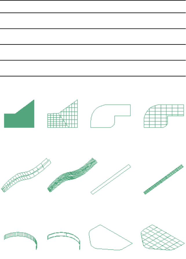
Objects
Open, zero-width polylines with thickness
Lines with thickness
Arcs with thickness
Mesh objects
Planar 3D faces
objects converted to surfaces
You can select the objects to convert before you start the command.
Commands | 227
NOTE You can create surfaces from 3D solids with curved faces, such as a cylinder,
with the EXPLODE (page 407) command.
The DELOBJ (page 1213) system variable controls whether the geometry used
to create 3D objects is automatically deleted when the new object is created
or whether you are prompted to delete the objects.
List of Prompts
The following prompts are displayed.
Select objects Specifies one or more objects to convert to surfaces.
If one or more objects in the selection set are invalid for the command, you
will be prompted again to select objects.
See also:
Convert Objects to Procedural Surfaces
COPY
Copies objects a specified distance in a specified direction.
Access Methods
Button
Toolbar: Drafting tool set ➤ Copy tool group ➤ Copy
Menu: Modify ➤ Copy
Shortcut menu: Select the objects to copy, and right-click in the drawing
area. Click Copy Selection.
228 | Chapter 2 Commands
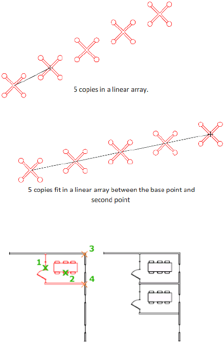
Summary
With the COPYMODE (page 1202) system variable, you can control whether
multiple copies are created automatically.
List of Prompts
The following prompts are displayed.
Select objects: Use an object selection method and press Enter when you
finish
Specify base point or [Displacement/mOde/Multiple]
<Displacement>: Specify a base point or enter an option
Specify second point or [Array] <use first point as
displacement>: Specify a second point or enter an option
Commands | 229
Displacement
Specifies a relative distance and direction using coordinates.
The two points you specify define a vector that indicates how far from the
original the copied objects are to be placed and in what direction.
If you press Enter at the Specify Second Point prompt, the first point is
interpreted as a relative X,Y,Z displacement. For example, if you specify 2,3
for the base point and press Enter at the next prompt, the objects are copied
2 units in the X direction and 3 units in the Y direction from their current
location.
Mode
Controls whether the command repeats automatically (COPYMODE (page
1202) system variable).
Single Creates a single copy of selected objects and ends the command.
Multiple Overrides the Single mode setting. The COPY command is set to
repeat automatically for the duration of the command.
Array
Arranges a specified number of copies in a linear array.
Number of Items to Array Specifies the number of items in the array,
including the original selection set.
Second Point Determines a distance and direction for the array relative to
the base point. By default, the first copy in the array is positioned at the
specified displacement. The remaining copies are positioned in a linear array
beyond that point using the same incremental displacement.
Fit Positions the final copy in the array at the specified displacement. The
other copies are fit in a linear array between the original selection set and the
final copy.
See also:
Copy Objects
COPYBASE
Copies selected objects to the Clipboard along with a specified base point.
230 | Chapter 2 Commands
Access Methods
Menu: Edit ➤ Copy with Base Point
Shortcut menu: End any active commands, right-click in the drawing area,
and choose Clipboard ➤ Copy with Base Point.
Summary
The selected objects are copied to the Clipboard.
■Use PASTECLIP (page 766) to move the copied objects from the Clipboard
to a location in the same document or to another document.
■When you paste an object copied with COPYBASE, it is placed relative to
the specified base point.
See also:
Cut, Copy, and Paste with the Clipboard
COPYCLIP
Copies selected objects to the Clipboard.
Access Methods
Menu: Edit ➤ Copy
Shortcut menu: End any active commands, right-click in the drawing area,
and choose Clipboard ➤ Copy.
Command entry: Cmd-C
Summary
COPYCLIP copies all objects you select to the Clipboard. You can paste the
contents of the Clipboard into a document or drawing.
NOTE If the cursor is in the drawing area, the selected objects are copied to the
Clipboard. If the cursor is on the command line or in the text window, the selected
text is copied to the Clipboard.
When you copy objects to the Clipboard, information is stored in all available
formats. When you paste the Clipboard contents into a drawing, the format
Commands | 231

that retains the most information is used. You can also use Copy and Paste
to transfer objects between drawings.
See also:
Cut, Copy, and Paste with the Clipboard
COPYHIST
Copies the text in the command line history to the Clipboard.
Summary
The text is copied to the Clipboard.
See also:
View and Edit Within the Command History
CUI
Manages the customized user interface elements in the product.
Access Methods
Menu: Tools ➤ Customize ➤ Interface (CUI)
Summary
The Customize dialog box is displayed.
You use the Customize dialog box to customize the menu bar and Tool Sets
palette. For information about customizing the different user interface elements
found in the Customize dialog box, see Customize the User Interface in the
Customization Guide.
See also:
Understand User Interface Customization
232 | Chapter 2 Commands
Customize Dialog Box
Manages customized user interface elements for the menu bar and Tool Sets
palette.
List of Tabs
The Customize User Interface Editor includes the following tabs:
■Commands (page 233)
■Menus (page 236)
■Tool Sets (page 237)
For more information, see Customize the User Interface in the Customization
Guide.
List of Options
The following options are displayed.
Reset to Default
Resets the commands and user interface elements back to their initial installed
default settings.
See also:
Understand User Interface Customization
Commands Tab (Customize Dialog Box)
Creates and manages the available commands that can be added to menus
and tool sets.
Commands | 233
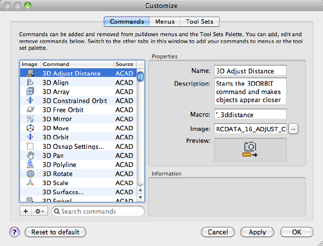
List of Options
The following options are displayed.
Commands List
Displays all the standard and custom commands available.
■Image - Thumbnail of the current image assigned to the command.
■Command - Name of the command. Displayed on the menu bar when
the command is assigned to a menu or in a tooltip when the command is
assigned to a tool group on the Tool Sets palette.
■Source - Name of the customization group that the command is stored
in.
Create New Command (+) Adds a new command to the Commands list that
can be added to the user interface.
A custom command can be used to start a core AutoCAD for Mac command
or one defined by a third party. Commands can also contain AutoLISP code.
234 | Chapter 2 Commands
Options Displays a menu which allows you to manage existing commands
in the Commands list.
■Duplicate - Creates a copy of the command currently selected in the
Commands list. Duplicating a command allows you to modify an existing
command without changing the original one.
■Delete - Removes the selected command from the Commands list.
Commands that are currently assigned to a menu or Workflow cannot be
deleted.
NOTE
There is no way to undo the removal of a command, be sure to selected
the correct command before you click Delete.
Filter Commands List Filters the commands displayed in the Commands list.
Click the ‘X’ in the text box to clear the current filter.
Enter a text string to control which commands are displayed in the Commands
list. Only the names of the commands that contain the text string are displayed
in the Commands list.
Properties
Displays the properties and values that define the selected command in the
Command list.
Name Displays the name of the command. The name you enter is the label
or tooltip name displayed in the program.
Description Displays the description for the command. The description you
enter is displayed in a tooltip.
Macro Displays the macro assigned to the command. Enter a new or change
the existing macro for the command.
Image Specifies the raster image to use for the command when it is added to
a tool set.
Preview Displays a thumbnail of the image currently assigned to the command.
Information
Displays some basic information about the field that currently has cursor focus
under Properties.
See also:
Customize Commands
Commands | 235
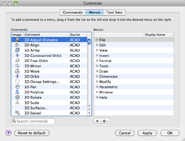
Menus Tab (Customize Dialog Box)
Creates and manages the menus and menu items on the Mac OS menu bar.
List of Options
The following options are displayed.
Commands List
Displays a list of the standard and custom commands that can be added to
menus and tool sets. You must be on the Commands tab (page 233) if you want
to create or edit a command.
Drag the command to the location in the menu you want it positioned and
drop it. The location of the command is indicated by the horizontal bar. If
you hover over a menu or sub-menu while dragging a command, the menu
or sub-menu will expand after a short interval.
Filter Commands List Filters the commands displayed in the Commands list.
Click the ‘X’ in the text box to clear the current filter.
236 | Chapter 2 Commands
Enter a text string to control which commands are displayed in the Commands
list. Only the names of the commands that contain the text string are displayed
in the Commands list.
Menus List
Lists the menus available on the Mac OS menu bar. Expand a menu to see the
commands and sub-menus that are assigned to the menu.
Create New Element(+) Displays a menu which allows you to create a new
menu or sub-menu.
■Add Menu - Creates a new parent menu that is displayed directly on the
Mac OS menu bar.
■Add Sub-menu - Creates a new sub-menu that is used to organize related
commands on a menu.
Options Displays a menu which allows you to manage the commands and
sub-menus in a menu.
■Insert Separator - Adds a new separator after the selected command or
sub-menu in the Menus list. When inserted, a solid horizontal line is
displayed in the menu when displayed from the Mac OS menu bar.
■Duplicate - Creates a copy of the command, sub-menu, or separator
currently selected in the Menus list.
■Delete - Removes the selected command, sub-menu, or separator from
the Menus list.
See also:
Customize Menus
Tool Sets Tab (Customize Dialog Box)
Creates and manages the tools in the Workflow palette.
Commands | 237
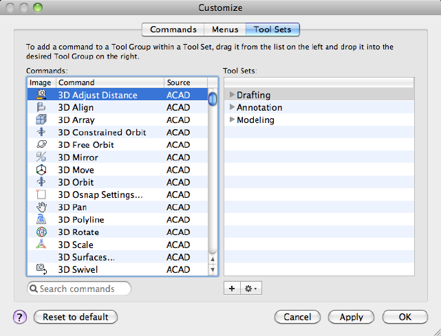
List of Options
The following options are displayed.
Commands List
Displays a list of the standard and custom commands that can be added to
menus and tool sets. You must be on the Commands tab (page 233) if you want
to create or edit a command.
Drag the command to the location in the menu you want it positioned and
drop it. The location of the command is indicated by the horizontal bar. If
you hover over a menu or sub-menu while dragging a command, the menu
or sub-menu will expand after a short interval.
Filter Commands List Filters the commands displayed in the Commands list.
Click the ‘X’ in the text box to clear the current filter.
Enter a text string to control which commands are displayed in the Commands
list. Only the names of the commands that contain the text string are displayed
in the Commands list.
238 | Chapter 2 Commands
Tool Sets List
Lists the tool sets available on the Tool Sets palette. Expand a tool set to see
the commands, tool groups, and drop-downs (also known as flyouts) that are
assigned to the tool set.
Right-click over a tool set in the list and choose Specify Tool Set Image to
display the Specify Tool Set Image dialog box (page 240). The image assigned
appears next to the tool set name in the Tool Sets list on the Tool Sets palette.
Create New Element(+) Displays a menu which allows you to create a new
tool set, tool group, or drop-down.
■Add Tool Set - Creates a new tool set that can be accessed from the Tool
Sets palette. Only one tool set can be displayed at a time on the Tool Sets
palette.
You do not add commands directly to a tool set, but to a tool group under
a tool set.
■Add Tool Group - Creates a new tool group that is used to organize
related commands in a tool set.
Tool groups are collapsed by default, and display the commands and
drop-downs above the separator in the tool group. Commands and
drop-downs below the separator are hidden until the discolsure triangle
for the tool group is clicked on the Tool Sets palette. Click the Lock icon
on a tool group’s title bar to keep it expanded.
■Add Drop-down - Creates a new drop-down (of flyout) that is used to
group related commands into a single button on a tool group.
Options Displays a menu which allows you to manage the tool groups,
commands, and drop-downs in a tool set.
■Insert Separator - Adds a new separator after the selected command or
drop-down in the Tool Sets list. When inserted, a solid horizontal line is
displayed in the tool group or drop-down. A separator on a tool group
controls which commands and drop-downs are displayed by default or are
only available when the tool group is expanded.
■Duplicate - Creates a copy of the selected tool group, command,
drop-down, or separator currently selected in the Tool Sets list.
■Delete - Removes the selected tool group, command, drop-down, or
separator from the Tool Sets list.
See also:
Customize Tool Sets
Commands | 239
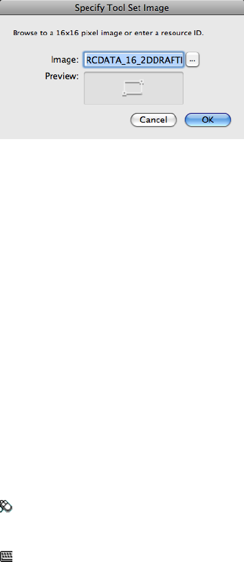
Specify Tool Set Image Dialog Box
Assigns an external image or internal resource to a tool set.
List of Options
The following options are displayed.
Image Displays the name of the resource or external image file that is assigned
to the tool set.
Click […] to display the Select an Image File dialog box and specify the external
image to assign to the tool set.
Preview Displays a thumbnail of the selected image.
See also:
Customize Tool Sets
CUTCLIP
Copies selected objects to the Clipboard and removes them from the drawing.
Access Methods
Menu: Edit ➤ Cut
Shortcut menu: End any active commands, right-click in the drawing area,
and choose Clipboard ➤ Cut.
Command entry: Cmd-X
240 | Chapter 2 Commands
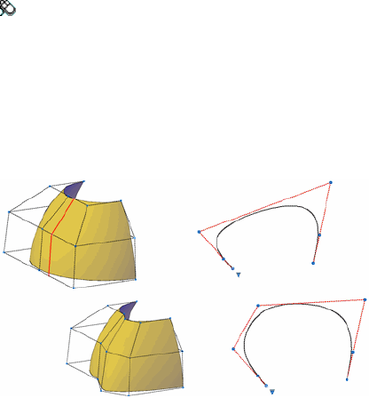
Summary
CUTCLIP copies selected objects to the Clipboard, removing them from the
drawing.
You can paste the contents of the Clipboard into a document (see PASTECLIP
(page 766)).
When you want to use objects from a drawing file in another application, you
can cut these objects to the Clipboard and then paste them into another
application. You can also use Cut and Paste to transfer objects between
drawings.
See also:
Cut, Copy, and Paste with the Clipboard
CVADD
Adds control vertices to NURBS surfaces and splines.
Access Methods
Menu: Modify ➤ Surface Editing ➤ NURBS Surface Editing ➤
Add CV
Summary
Adds control vertices in the U or V direction, or adds points directly on a
surface or spline. This illustration shows a row of control vertices added in
the V direction.
Commands | 241

List of Prompts
The following prompts are displayed.
Select a NURBS surface or curve to add control vertices. Select a valid
NURBS surface or curve and press Enter.
Point Select a valid NURBS surface or curve and press Enter.
Insert Knots Turns off the display of control vertices and allows you to place
a point directly on a surface. This option only displays if you select a surface;
it does not display for splines.
Insert Edit Point Turns off the display of control vertices and allows you
to place a point directly on a spline. This option only displays if you select a
spline; it does not display for surfaces.
Direction Specifies whether to add control vertices in the U or V direction.
This option only displays if you select a surface; it does not display for splines.
See also:
Edit NURBS Surfaces
CVHIDE
Turns off the display of control vertices for all NURBS surfaces and curves.
Access Methods
Menu: Modify ➤ Surface Editing ➤ NURBS Surface Editing ➤
Hide CV
Summary
Turns off the CV display for all NURBS objects.
242 | Chapter 2 Commands

See also:
Edit NURBS Surfaces
CVREBUILD
Rebuilds the shape of NURBS surfaces and curves.
Access Methods
Menu: Modify ➤ Surface Editing ➤ NURBS Surface Editing
➤ Rebuild
Summary
If you have difficulties editing the control vertices or there are too many
control vertices, you can rebuild a surface or curve with less control vertices
in the U or V direction. CVREBUILD also allows you to change the degree of
the surface or curve.
Commands | 243

If you select a surface, the Rebuild Surface dialog box (page 244) is displayed.
If you select a spline, the Rebuild Curve dialog box (page 245) is displayed.
See also:
Edit NURBS Surfaces
Rebuild Surface Dialog Box
Rebuilds the CV hull of a NURBS surface.
Summary
Reshapes a NURBS surface by rebuilding the CV hull.
List of Options
The following options are displayed.
Control Vertices Count
Specifies the number of control vertices in the U and V directions.
In U Direction
Specifies the number of control vertices in the U direction. (REBUILDU (page
1416) system variable)
In V Direction
Specifies the number of control vertices in the V direction. (REBUILDV (page
1417) system variable)
Degree
Specifies the number of control vertices available per span. The higher the
number, the more complex the surface.
244 | Chapter 2 Commands
In U Direction
Specifies the degree of the NURBS surface in the U direction. (REBUILDDE-
GREEU (page 1415) system variable)
In V Direction
Specifies the degree of the NURBS surface in the V direction. (REBUILDDE-
GREEV (page 1415) system variable)
Options
Specifies the build options. (REBUILDOPTIONS (page 1416) system variable)
Delete Input Geometry
Specifies whether the original surface is retained along with the rebuilt surface.
(REBUILDOPTIONS (page 1416) system variable)
Retrim Previously Trimmed Surface
Specifies whether trimmed areas from the original surface are applied to the
rebuilt surface. (REBUILDOPTIONS (page 1416) system variable)
Maximum Deviation
Displays the maximum deviation between the original surface and the new
one.
See also:
Rebuild NURBS Surfaces and Curves
Rebuild Curve Dialog Box
Rebuilds the shape of a NURBS curve.
Summary
Changes the number of control vertices and the degree of a NURBS curve.
Rebuilding the curve changes its shape.
List of Options
The following options are displayed.
Curve Geometry Details
Control Vertices Count
Commands | 245
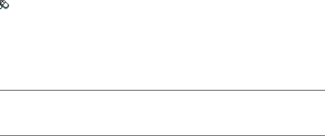
Specifies the number of control vertices. (REBUILD2DCV (page 1413) system
variable)
Degree
Specifies the degree of the NURBS curve. (REBUILD2DDEGREE (page 1414) system
variable)
Options
Specifies the build options. (REBUILDOPTIONS (page 1416) system variable)
Delete input geometry
Specifies whether the original curve is retained along with the rebuilt curve.
(REBUILD2DOPTION (page 1414) system variable)
Maximum Deviation
Displays the maximum deviation between the original curve and the new
one.
See also:
Rebuild NURBS Surfaces and Curves
CVREMOVE
Removes control vertices from NURBS surfaces and curves.
Access Methods
Menu: Modify ➤ Surface Editing ➤ NURBS Surface Editing ➤
Remove CV
Summary
Removes control vertices in the U or V direction. This illustration shows a row
of control vertices deleted in the V direction.
NOTE
The minimum number of control vertices that you can have on a surface or
curve is two in any direction. If you try to remove more, an error displays.
246 | Chapter 2 Commands
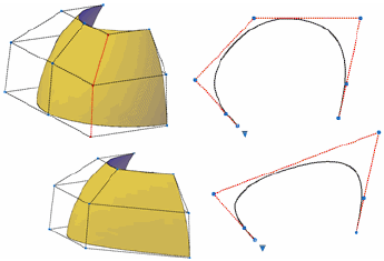
List of Prompts
The following prompts are displayed.
Select a NURBS surface or curve to remove control vertices Select a
valid NURBS surface or curve and press Enter.
Point Specifies a valid NURBS surface or curve and press Enter.
Remove Knots Turns off the display of control vertices and allows you to
remove a point directly from the surface. This option only displays if you
select a surface; it does not display for splines.
Remove Edit Point Turns off the display of control vertices and allows you
to remove a point directly from the spline. This option only displays if you
select a spline, it does not display for surfaces.
Direction Specifies whether to remove control vertices in the U direction.
This option only displays if you have selected a surface; it does not display
for splines.
See also:
Edit NURBS Surfaces
CVSHOW
Displays the control vertices for specified NURBS surfaces or curves.
Commands | 247
Access Methods
Menu: Modify ➤ Surface Editing ➤ NURBS Surface Editing ➤
Show CV
Summary
Prompts you to select the NURBS surfaces and curves whose control vertices
you want to display. Non-NURBS surfaces do not have control vertices. You
can convert objects to NURBS surfaces with the CONVTONURBS command.
See also:
Edit NURBS Surfaces
CYLINDER
Creates a 3D solid cylinder.
Access Methods
Button
Toolbar: Modeling tool set ➤ Solids - Create tool group ➤ Cylinder
Menu: Draw ➤ 3D Modeling ➤ Cylinder
248 | Chapter 2 Commands
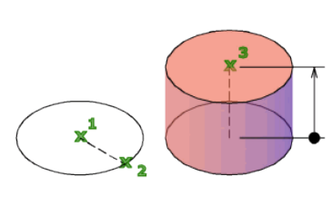
Summary
In the illustration, the cylinder was created using a center point (1), a point
on the radius (2), and a point for the height (3). The base of the cylinder is
always on a plane parallel with the workplane. You can control the smoothness
of curved 3D solids, such as a cylinder, in a shaded or hidden visual style with
the FACETRES system variable.
During a drawing session, the default value for the base radius is always the
previously entered base radius value.
List of Prompts
The following prompts are displayed.
Specify center point of base or [3P (page ?)/2P (page ?)/Ttr
(page ?)/Elliptical (page ?)]: Specify a center point or enter an option
Specify base radius or [Diameter (page ?)] <default>: Specify
a base radius, or enter d to specify a diameter, or press Enter to specify the default
base radius value
Specify height or [2Point/Axis endpoint] <default>: Specify a
height, enter an option, or press Enter to specify the default height value
3P (Three Points)
Defines the base circumference and base plane of the cylinder by specifying
three points.
2Point Specifies that the height of the cylinder is the distance between the
two specified points.
Axis Endpoint Specifies the endpoint location for the cylinder axis. This
endpoint is the center point of the top face of the cylinder. The axis endpoint
can be located anywhere in 3D space. The axis endpoint defines the length
and orientation of the cylinder.
Commands | 249
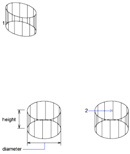
2P (Two Points)
Defines the base diameter of the cylinder by specifying two points.
■2Point
■Axis endpoint
TTR (Tangent, Tangent, Radius)
Defines the base of the cylinder with a specified radius tangent to two objects.
Sometimes more than one base matches the specified criteria. The program
draws the base of the specified radius whose tangent points are closest to the
selected points.
■2Point
■Axis endpoint
Elliptical
Specifies an elliptical base for the cylinder.
Center Creates the base of the cylinder by using a specified center point.
■2Point
■Axis endpoint
Diameter
Specifies the diameter for the base of the cylinder.
■2Point
■Axis endpoint
250 | Chapter 2 Commands
See also:
Create a Solid Cylinder
D Commands
DBLIST
Lists database information for each object in the drawing.
Summary
The text window displays information about each object in the current
drawing. The program pauses when the window fills with information. Press
Enter to resume output, or press Esc to cancel.
See also:
Display and Change the Properties of Objects
DCALIGNED
Constrains the distance between two points on different objects.
Access Methods
Button
Toolbar: Drafting tool set ➤ Parametric tool group ➤ Dimensional
Contraints flyout ➤ Aligned
Menu: Parametric ➤ Dimensional Constraints ➤ Aligned
Toolbar:
Summary
This command is equivalent to the Aligned option in DIMCONSTRAINT (page
284).
Commands | 251

The following table outlines the valid constraint objects and points:
CharacteristicsValid Objects or Points
Line ■When a line or an arc is selected, the
distance between the endpoints of the
object is constrained.
Polyline segment
Arc
Two constraint points on objects ■When a line and a constraint point are
selected, the distance between the
Line and constraint point
Two lines point and the closest point on the line
is constrained.
■When two lines are selected, the lines
are made parallel and the distance
between them is constrained.
For example,
List of Prompts
The following prompts are displayed.
Specify first contraint point (page ?) or [Object (page
?)/Point & line (page ?)/2Lines (page ?)] <Object>: Pick a
constraint point or select an object, a point and a line, or two lines to be constrained
Constraint Point
Specifies a constraint point for the object.
First Constraint Point Specifies the first point of the object to be constrained.
Second Constraint Point Specifies the second point of the object to be
constrained.
252 | Chapter 2 Commands

Dimension Line Location Determines where the dimension line is located
on the constrained object.
Object
Selects an object instead of a constraint point.
Dimension Line Location Determines where the dimension line is located
on the constrained object.
Point & Line
Selects a point and a line object. The aligned constraint controls the distance
between a point and the closest point on a line.
Constraint Point Constraint Point (page ?)
Line Selects a line object.
Dimension Line Location Determines where the dimension line is located
on the constrained object.
2Lines
Selects two line objects. The lines are made parallel and the aligned constraint
controls the distance between the two lines.
First Line Select the first line to be constrained.
Second Line to Make Parallel Select the second line to constrain the distance
between the two selected lines.
Dimension Line Location Determines where the dimension line is located
on the constrained object.
See also:
Apply Dimensional Constraints
DCANGULAR
Constrains the angle between line or polyline segments, the angle swept out
by an arc or a polyline arc segment, or the angle between three points on
objects.
Access Methods
Button
Commands | 253
Toolbar: Drafting tool set ➤ Parametric tool group ➤ Dimensional
Contraints flyout ➤ Angular
Menu: Parametric ➤ Dimensional Constraints ➤ Angular
Summary
This command is equivalent to the Angular option in DIMCONSTRAINT (page
284).
When you enter or edit an angle value that is either negative or is greater than
360 degrees, the number entered is stored for the expression (for example,
390), but the value displayed is based on the formatting of the units (for
example, 30 if decimal degrees).
When an expression with variables evaluates to greater than 360 or less than
-360, the constraint value is displayed in the Parameters Manager based on
the units of the drawing.
The following table outlines the valid constraint objects and points:
CharacteristicsValid Objects or Points
Pair of lines ■When two lines are selected, the angle
between the lines is constrained. The
Pair of polyline segment
initial value always defaults to a value
less than 180 degrees.
Three constraint points
Arc
■When three constraint points are spe-
cified, the following applies:
■First point — angle vertex
■Second and third points — end-
points of the angle
■When an arc is selected, a three-point
angular constraint is created. The angle
vertex is at the center of the arc and
the angle endpoints of the arc are at
the endpoints of the arc.
For example,
254 | Chapter 2 Commands
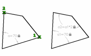
List of Prompts
The following prompts are displayed.
Select first line (page ?) or arc (page ?) or [3Point (page
?)] <3Point>: Pick a line, or an arc, or three points to be constrained
Line
Selects a line object.
First Line Specifies the first line to be constrained.
Second Line Specifies the second line to be constrained.
Dimension Line Location Determines where the dimension line is located
on the constrained object.
Arc
Selects an arc and constrains the angle.
Dimension Line Location Determines where the dimension line is located
on the constrained object.
3Point
Selects three valid constraint points on the object.
Angle Vertex Specifies the angle vertex, which is at the center point of the
constraint.
First Angle Constraint Point Specifies the first angle endpoint of the arc.
Second Angle Constraint Point Specifies the second angle endpoint of the
arc.
Dimension Line Location Determines where the dimension line is located
on the constrained object.
Commands | 255
See also:
Apply Dimensional Constraints
DCCONVERT
Converts associative dimensions to dimensional constraints.
Summary
This command is equivalent to the Convert option in DIMCONSTRAINT (page
284).
Objects other than associative dimensions are ignored and filtered from the
selection set.
List of Prompts
The following prompts are displayed.
Select associative dimensions to convert: Select the associative
dimensions to be converted to dimensional constraints
See also:
Apply Dimensional Constraints
DCDIAMETER
Constrains the diameter of a circle or an arc.
Access Methods
Button
Toolbar: Drafting tool set ➤ Parametric tool group ➤ Dimensional
Contraints flyout ➤ Diameter
Menu: Parametric ➤ Dimensional Constraints ➤ Diameter
256 | Chapter 2 Commands

Summary
This command is equivalent to the Diameter option in DIMCONSTRAINT
(page 284).
The following table outlines the valid contraint objects and points:
CharacteristicsValid Objects or Points
Circle ■Constrains the diameter of the circle or
arc.
Arc
For example,
List of Prompts
The following prompts are displayed.
Select arc or circle: Select an arc or a circle to be constrained
Dimension Line Location
Determines where the dimension line is located on the constrained object.
See also:
Apply Dimensional Constraints
DCDISPLAY
Displays or hides the dynamic constraints associated with a selection set of
objects.
Commands | 257

Access Methods
Button
Toolbar: Drafting tool set ➤ Parametric tool group ➤ Contraint Display
flyout ➤ Show Dynamic Constraints
Menu: Parametric ➤ Dynamic Dimensions ➤ Select Objects
List of Prompts
The following prompts are displayed.
Select objects: Select objects to display or hide the dimensional constraints
Enter an option [Show (page ?)/Hide (page ?)] <Show>: Enter
the appropriate value to show or hide dynamic constraints for the selection set of
objects
Show
Displays the dynamic dimensional constraints for any selection set of objects.
Hide
Hides the dynamic dimensional constraints for any selection set of objects.
See also:
Control the Display of Dimensional Constraints
DCFORM
Specifies whether the dimensional constraint being created is dynamic or
annotational.
Summary
This command is equivalent to the Form option in DIMCONSTRAINT (page
284).
Setting the value for this command defines the Constraint Form property of
the object.
258 | Chapter 2 Commands
List of Prompts
The following prompts are displayed.
Enter constraint form [Annotational (page ?)/Dynamic (page
?)] <Dynamic>: Select a constraint form
Annotational
Applies annotational dimensional constraints to objects.
Dynamic
Applies dynamic dimensional constraints to objects.
See also:
Apply Dimensional Constraints
DCHORIZONTAL
Constrains the X distance between points on an object, or between two points
on different objects.
Access Methods
Button
Toolbar: Drafting tool set ➤ Parametric tool group ➤ Dimensional
Contraints flyout ➤ Horizontal
Menu: Parametric ➤ Dimensional Constraints ➤ Horizontal
Summary
This command is equivalent to the Horizontal option in DIMCONSTRAINT
(page 284).
The following table outlines the valid contraint objects and points:
CharacteristicsValid Objects or Points
Line ■When a line or an arc is selected, the
horizontal distance between the end-
points of the object is constrained.
Polyline segment
Arc
Commands | 259

CharacteristicsValid Objects or Points
Two constraint points on objects
For example,
List of Prompts
The following prompts are displayed.
Specify first constraint point (page ?) or [Object (page
?)] <Object>: Pick a constraint point or select an object
Constraint Point
Specifies a constraint point for the object.
First Constraint Point Specifies the first point of the object to be constrained.
Second Constraint Point Specifies the second point of the object to be
constrained.
Dimension Line Location Determines where the dimension line is located
on the constrained object.
Object
Selects an object instead of a constraint point.
See also:
Apply Dimensional Constraints
DCLINEAR
Creates a horizontal, vertical, or rotated constraint based on the locations of
the extension line origins and the dimension line.
260 | Chapter 2 Commands
Access Methods
Button
Toolbar: Drafting tool set ➤ Parametric tool group ➤ Dimensional
Contraints flyout ➤ Linear
Summary
This command is equivalent to the Linear option in DIMCONSTRAINT (page
284).
The following table outlines the valid contraint objects and points:
CharacteristicsValid Objects or Points
Line ■When a line or an arc is selected, the
horizontal or vertical distance between
Polyline segment
the endpoints of the object is con-
strained.
Arc
Two constraint points on objects
When a line or an arc is selected, the horizontal or vertical distance between
the endpoints of the object is constrained.
List of Prompts
The following prompts are displayed.
Specify first constraint point (page ?) or [Object (page
?)] <Object>: Pick a constraint point or select an object
Constraint Point
Specifies a constraint point for the object.
First Constraint Point Specifies the first point of the object to be constrained.
Second Constraint Point Specifies the second point of the object to be
constrained.
Dimension Line Location Determines where the dimension line is located
on the constrained object.
Object
Selects an object instead of a constraint point.
Commands | 261
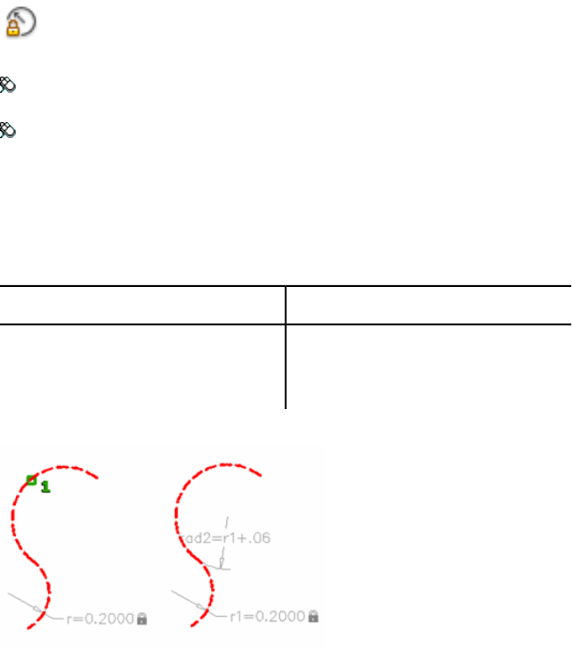
See also:
Apply Dimensional Constraints
DCRADIUS
Constrains the radius of a circle or an arc.
Access Methods
Button
Toolbar: Drafting tool set ➤ Parametric tool group ➤ Dimensional
Constraints flyout ➤ Radius
Menu: Parametric ➤ Dimensional Constraints ➤ Radius
Summary
This command is equivalent to the Radius option in DIMCONSTRAINT (page
284).
The following table outlines the valid constraint objects and points:
CharacteristicsValid Objects or Points
Circle ■Constrains the radius of the circle or
arc.
Arc
For example,
262 | Chapter 2 Commands
List of Prompts
The following prompts are displayed.
Select arc or circle: Select an arc or a circle to be constrained
Dimension Line Location
Determines where the dimension line is located on the constrained object.
See also:
Apply Dimensional Constraints
DCVERTICAL
Constrains the Y distance between points on an object, or between two points
on different objects.
Access Methods
Button
Toolbar: Drafting tool set ➤ Parametric tool group ➤ Dimensional
Contraints flyout ➤ Vertical
Menu: Parametric ➤ Dimensional Constraints ➤ Vertical
Summary
This command is equivalent to the Vertical option in DIMCONSTRAINT (page
284).
The following table outlines the valid contraint objects and points:
CharacteristicsValid Objects or Points
Line ■When a line or an arc is selected, the
vertical distance between the endpoints
of the object is constrained.
Polyline segment
Arc
Two constraint points on objects
For example,
Commands | 263
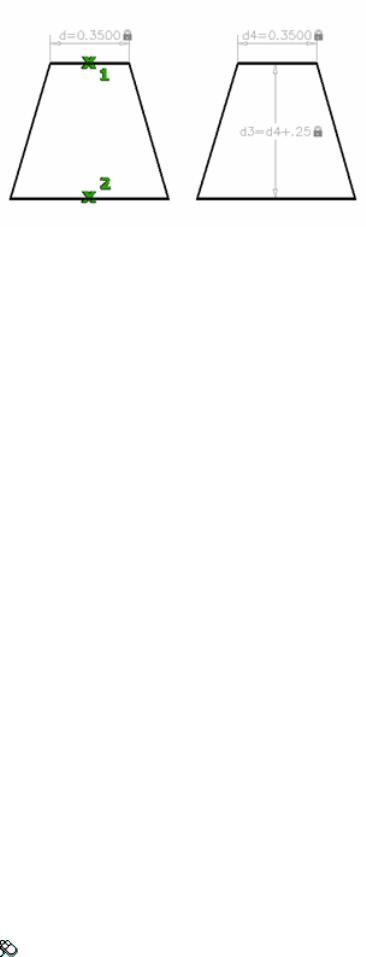
List of Prompts
The following prompts are displayed.
Specify first constraint point (page ?) or [Object (page
?)] <Object>: Pick a constraint point or select an object
Constraint Point
Specifies a constraint point for the object.
First Constraint Point Specifies the first point of the object to be constrained.
Second Constraint Point Specifies the second point of the object to be
constrained.
Dimension Line Location Determines where the dimension line is located
on the constrained object.
Object
Selects an object instead of a constraint point.
See also:
Apply Dimensional Constraints
DDEDIT
Edits single-line text, dimension text, attribute definitions, and feature control
frames.
Access Methods
Menu: Modify ➤ Object ➤ Text ➤ Edit
264 | Chapter 2 Commands
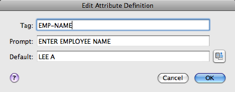
Shortcut menu: Select a text object, right-click in the drawing area, and
click Edit.
Pointing device: Double-click a text object.
List of Prompts
The following prompts are displayed.
Select an annotation object or [Undo]:
Object Selection Displays the appropriate editing method for the type of text
you select:
■Text created using TEXT (page 1044) displays the In-Place Text Editor (page
675) without the Text Formatting toolbar and the ruler.
■Text created using MTEXT (page 674) displays the In-Place Text Editor (page
675).
■Attribute definitions (not part of a block definition) display the Edit Attrib-
ute Definition dialog box (page 265).
■Feature control frames display the Geometric Tolerance dialog box (page
1058).
DDEDIT repeats the prompt until you press Enter to end the command.
Undo Returns the text or attribute definition to its previous value. You can
use this option immediately after editing.
See also:
Change Text
Edit Attribute Definition Dialog Box
Edits an attribute text object.
Commands | 265
List of Options
The following options are displayed.
Tag
Specifies the attribute tag, which identifies the attribute in the drawing. The
tag can contain exclamation marks (!). The case change is not immediately
displayed in the tag field.
Prompt
Specifies the attribute prompt that is displayed when you insert a block
containing this attribute definition.
Default
Specifies the default attribute value.
To use a field as the value, right-click and click Insert Field on the shortcut
menu to display the Insert Field dialog box (page 429).
See also:
Change Text
DDPTYPE
Specifies the display style and size of point objects.
Access Methods
Button
Toolbar: Drafting tool set ➤ Open Shapes tool group (expanded) ➤
Point Style
Menu: Format ➤ Point Style
Command entry: 'ddptype for transparent use
Summary
The Point Style dialog box (page 267) is displayed.
266 | Chapter 2 Commands
See also:
Draw Reference Points
Point Style Dialog Box
Shows the current point style and size. Change the point style by selecting an
icon.
List of Options
The following options are displayed.
Point Size
Sets the point display size. The value you enter can be relative to the screen
or in absolute units. The point display size is stored in the PDSIZE (page 1389)
system variable. Subsequent point objects that you draw use the new value.
Set Size Relative to Screen Sets the point display size as a percentage of the
screen size. The point display does not change when you zoom in or out.
Set Size in Absolute Units Sets the point display size as the actual units you
specify under Point Size. Points are displayed larger or smaller when you zoom
in or out.
Commands | 267

Point Style
Specifies the image used to display point objects. The point style is stored in
the PDMODE (page 1388) system variable.
See also:
Draw Reference Points
DELAY
Provides a timed pause within a script.
Access Methods
Command entry: 'delay for transparent use
Summary
Specifies the duration of a pause. Entering delay 1000 in your script delays
the start of execution of the next command for about one second. The longest
delay available is 32767, which is slightly less than 33 seconds.
See also:
Overview of Command Scripts
DELCONSTRAINT
Removes all geometric and dimensional constraints from a selection set of
objects.
Access Methods
Button
Toolbar: Drafting tool set ➤ Parametric tool group (expanded) ➤ Delete
Menu: Parametric ➤ Delete Constraints
268 | Chapter 2 Commands
Summary
The number of constraints removed are displayed on the command line.
Removes all geometric and dimensional constraints from the selected objects.
See also:
Modify Objects with Dimensional Constraints Applied
DIM and DIM1
Accesses Dimensioning mode commands.
Summary
The Dim prompt indicates that you're in Dimensioning mode, in which you
can use a special set of dimensioning commands (page ?). (DIM and DIM1
are provided only for compatibility with previous releases.)
Use DIM to remain in Dimensioning mode after you have used a dimensioning
command. Use DIM1 to execute a dimensioning command and immediately
return to the Command prompt. To exit Dimensioning mode, enter e or exit,
or press Esc.
List of Prompts
The following prompts are displayed.
Dim: Enter a Dimensioning mode command
Dimensioning Mode Commands
The following commands are available at the DIM prompt.
Dimensioning mode commands
DescriptionCommand
Exits Dimensioning mode and returns to the Command prompt. You
can also press Esc to exit Dimensioning mode.
EXIT
Redraws the current viewport.REDRAW
Changes the current text style.STYLE
Commands | 269
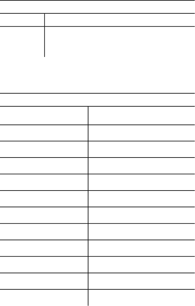
Dimensioning mode commands
DescriptionCommand
Erases the most recently created dimension objects and cancels any
new dimension system variable setting. When you exit Dimensioning
mode, UNDO reverses the effects of the entire dimensioning session.
UNDO or U
The following table shows which AutoCAD for Mac commands are equivalent
to the rest of the Dimensioning mode commands. For information about these
Dimensioning mode commands, see the equivalent AutoCAD for Mac
command.
Dimensioning mode command equivalents
Equivalent
command
Dimensioning mode
command
DIMALIGNED (page 272)ALIGNED
DIMANGULAR (page 274)ANGULAR
DIMBASELINE (page 280)BASELINE
DIMCENTER (page 283)CENTER
DIMCONTINUE (page 286)CONTINUE
DIMDIAMETER (page 289)DIAMETER
DIMEDIT (page 291) HomeHOMETEXT
DIMLINEAR (page 299) HorizontalHORIZONTAL
LEADER (page 567)LEADER
DIMJOGGED (page 296)JOG
DIMEDIT (page 291) NewNEWTEXT
270 | Chapter 2 Commands
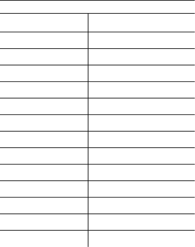
Dimensioning mode command equivalents
Equivalent
command
Dimensioning mode
command
DIMEDIT (page 291) ObliqueOBLIQUE
DIMORDINATE (page 304)ORDINATE
DIMOVERRIDE (page 306)OVERRIDE
DIMRADIUS (page 307)RADIUS
-DIMSTYLE (page 314) RestoreRESTORE
DIMLINEAR (page 299) RotatedROTATED
-DIMSTYLE (page 314) SaveSAVE
-DIMSTYLE (page 314) StatusSTATUS
DIMTEDIT (page 350)TEDIT
DIMEDIT (page 291) RotateTROTATE
-DIMSTYLE (page 314) ApplyUPDATE
-DIMSTYLE (page 314) VariablesVARIABLES
DIMLINEAR (page 299) VerticalVERTICAL
See also:
Overview of Dimensioning
Commands | 271

DIMALIGNED
Creates an aligned linear dimension.
Access Methods
Button
Toolbar: Annotation tool set ➤ Dimensions tool group ➤ Aligned
Menu: Dimension ➤ Aligned
Summary
Creates a linear dimension that is aligned with the origin points of the
extension lines.
List of Prompts
The following prompts are displayed.
Specify first extension line origin (page 272) or <select ob-
ject (page 273)>: Specify a point for manual extension lines, or press Enter
for automatic extension lines
After you specify either manual or automatic extension lines, the following
prompt is displayed:
Specify dimension line location (page 273)or [Mtext (page
273)/Text (page 274)/Angle (page 274)]: Specify a point or enter an option
Extension Line Origin Specifies the first extension line origin (1). You are
prompted to specify the second one.
272 | Chapter 2 Commands
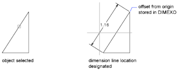
Object Selection Automatically determines the origin points of the first and
second extension lines after you select an object.
For polylines and other explodable objects, only the individual line and arc
segments are dimensioned. You cannot select objects in a nonuniformly scaled
block reference.
If you select a line or an arc, its endpoints are used as the origins of the
extension lines. The extension lines are offset from the endpoints by the
distance specified in Offset from Origin on the Lines and Arrows tab of the
New, Modify, and Override Dimension Style dialog boxes (see DIMSTYLE
(page 314)). This value is stored in the DIMEXO (page 1231) system variable.
If you select a circle, the endpoints of its diameter are used as the origins of
the extension line. The point used to select the circle defines the origin of the
first extension line.
Dimension Line Location Specifies the placement of the dimension line and
determines the direction to draw the extension lines. After you specify the
location, the DIMALIGNED command ends.
Mtext Displays the In-Place Text Editor (page 675), which you can use to edit
the dimension text. The generated measurement is represented with angle
brackets (< >). To add a prefix or a suffix to the generated measurement, enter
the prefix or suffix before or after the angle brackets. Use control codes and
Unicode character strings to enter special characters or symbols. See Control
Codes and Special Characters (page 1049).
To edit or replace the generated measurement, delete the angle brackets, enter
the new dimension text, and then click OK. If alternate units are not turned
on in the dimension style, you can display them by entering square brackets
([ ]). For more information, see Select and Modify Objects.
The current dimension style determines the appearance of the generated
measurements.
Commands | 273
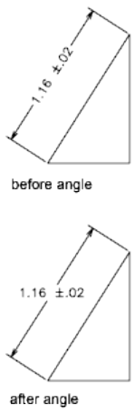
Text Customizes the dimension text at the command prompt. The generated
dimension measurement is displayed within angle brackets.
Enter the dimension text, or press Enter to accept the generated measurement.
To include the generated measurement, use angle brackets (< >) to represent
the generated measurement. If alternate units are not turned on in the
dimension style, you can display alternate units by entering square brackets
([ ]).
Dimension text properties are set on the Text tab of the New, Modify, and
Override Dimension Style dialog boxes.
Angle Changes the angle of the dimension text.
See also:
Create Aligned Dimensions
DIMANGULAR
Creates an angular dimension.
274 | Chapter 2 Commands
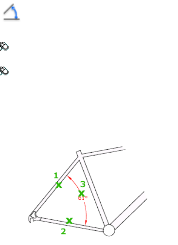
Access Methods
Button
Toolbar: Annotation tool set ➤ Dimensions tool group ➤ Dimensions
flyout ➤ Angular
Menu: Dimension ➤ Angular
Summary
Measures the angle between selected objects or 3 points. Objects that can be
selected include arcs, circles, and lines, among others.
List of Prompts
The following prompts are displayed.
Select arc (page 275), circle (page 276), line (page 276), or
<specify vertex (page 276)>: Select an arc, circle, or line, or press Enter
to create the angular dimension by specifying three points
After you define the angle to dimension, the following prompt is displayed:
Specify dimension arc line location (page 277) or [Mtext (page
277)/Text (page 277)/Angle (page 277)/Quadrant (page 278)]:
Arc Selection Uses points on the selected arc as the defining points for a
three-point angular dimension. The center of the arc is the angle vertex. The
arc endpoints become the origin points of the extension lines.
Commands | 275
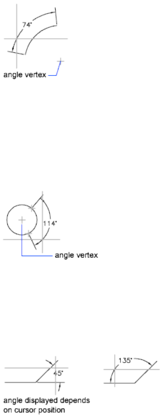
The dimension line is drawn as an arc between the extension lines. The
extension lines are drawn from the angle endpoints to the intersection of the
dimension line.
Circle Selection Uses the selection point (1) as the origin of the first extension
line. The center of the circle is the angle vertex.
The second angle endpoint is the origin of the second extension line and does
not have to lie on the circle.
Line Selection Defines the angle using two lines.
The program determines the angle by using each line as a vector for the angle
and the intersection of the lines for the angle vertex. The dimension line spans
the angle between the two lines. If the dimension line does not intersect the
lines being dimensioned, extension lines are added as needed to extend one
or both lines. The arc is always less than 180 degrees.
Three-Point Specification Creates a dimension based on three points you
specify.
The angle vertex can be the same as one of the angle endpoints. If you need
extension lines, the endpoints are used as origin points.
276 | Chapter 2 Commands
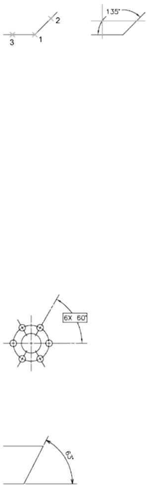
The dimension line is drawn as an arc between the extension lines. The
extension lines are drawn from the angle endpoints to the intersection of the
dimension line.
Dimension Arc Line Location Specifies the placement of the dimension line
and determines the direction to draw the extension lines.
Mtext Displays the In-Place Text Editor, which you can use to edit the
dimension text. To add a prefix or a suffix, enter the prefix or suffix text before
or after the generated measurement. Use control codes and Unicode character
strings to enter special characters or symbols. See Control Codes and Special
Characters (page 1049).
For more information, see Select and Modify Objects.
The current dimension style determines the appearance of the generated
measurements.
Text Customizes the dimension text at the Command prompt. The generated
dimension measurement is displayed within angle brackets.
To include the generated measurement, use angle brackets (< >) to represent
the generated measurement.
Dimension text properties are set on the Text tab of the New, Modify, and
Override Dimension Style dialog boxes.
Angle Changes the angle of the dimension text.
Commands | 277
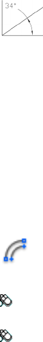
Quadrant Specifies the quadrant that the dimension should be locked to.
When quadrant behavior is on, the dimension line is extended past the
extension line when the dimension text is positioned outside of the angular
dimension.
See also:
Create Angular Dimensions
DIMARC
Creates an arc length dimension.
Access Methods
Button
Toolbar: Annotation tool set ➤ Dimensions tool group ➤ Dimensions
flyout ➤ Arc Length
Menu: Dimension ➤ Arc Length
List of Prompts
The following prompts are displayed.
Select arc or polyline arc segment: Use an object selection method
Specify arc length dimension location (page 279) or [Mtext
(page 279)/Text (page 279)/Angle (page 279)/Partial (page
279)/Leader (page 279)]: Specify a point or enter an option
Arc length dimensions measure the distance along an arc or polyline arc
segment. The extension lines of an arc length dimension can be orthogonal
or radial. An arc symbol is displayed either above or preceding the dimension
text.
278 | Chapter 2 Commands
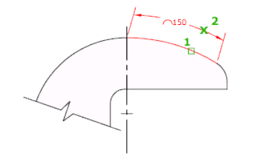
Arc Length Dimension Location Specifies the placement of the dimension
line and determines the direction of the extension lines.
Mtext Displays the In-Place Text Editor, which you can use to edit the
dimension text. Use control codes and Unicode character strings to enter
special characters or symbols. See Control Codes and Special Characters (page
1049).
If alternate units are not turned on in the dimension style, you can display
them by entering square brackets ([]). For more information, see Select and
Modify Objects.
The current dimension style determines the appearance of the generated
measurements.
Text Customizes the dimension text at the Command prompt. The generated
dimension measurement is displayed within angle brackets.
To include the generated measurement, use angle brackets (< >) to represent
the generated measurement. If alternate units are not turned on in the
dimension style, you can display alternate units by entering square brackets
([ ]).
Dimension text properties are set on the Text tab of the New, Modify, and
Override Dimension Style dialog boxes.
Angle Changes the angle of the dimension text.
Partial Reduces the length of the arc length dimension.
Leader Adds a leader object. This option is displayed only if the arc (or arc
segment) is greater than 90 degrees. The leader is drawn radially, pointing
towards the center of the arc being dimensioned.
No Leader Cancels the Leader option before the leader is created.
To remove a leader, delete the arc length dimension and recreate it without
the leader option.
Commands | 279
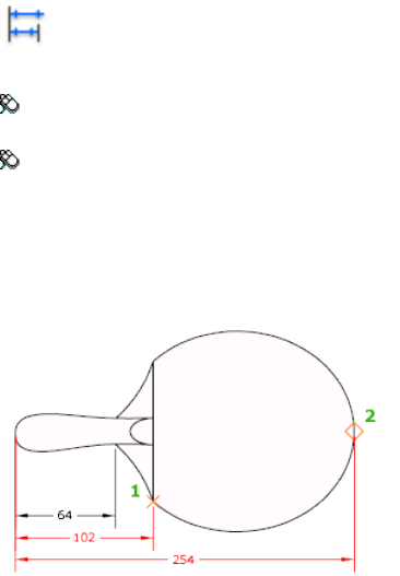
See also:
Create Arc Length Dimensions
DIMBASELINE
Creates a linear, angular, or ordinate dimension from the baseline of the
previous or selected dimension.
Access Methods
Button
Toolbar: Annotation tool set ➤ Dimensions tool group ➤ Continue
flyout ➤ Baseline
Menu: Dimension ➤ Baseline
Summary
The default spacing between baseline dimensions can be set from the
Dimension Style Manager, Lines tab, Baseline Spacing (DIMDLI (page 1230)
system variable).
If no dimension was created in the current session, you are prompted to select
a linear, ordinate, or angular dimension to use as the base for the baseline
dimension.
List of Prompts
The following prompts are displayed.
280 | Chapter 2 Commands
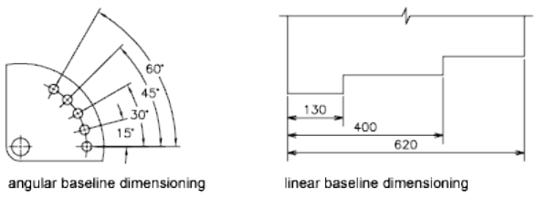
Select base dimension: Select a linear, ordinate, or angular dimension
Otherwise, the program skips this prompt and uses the dimension object that
was last created in the current session. If the base dimension is linear or
angular, the following prompt is displayed:
Specify a second extension line origin (page 281) or [Undo
(page 281)/Select (page 282)] <Select>: Specify a point, enter an option,
or press Enter to select a base dimension
If the base dimension is ordinate, the following prompt is displayed:
Specify feature location (page 281) or [Undo/Select] <Select>:
To end the command, press Enter twice, or press Esc. The current dimension
style determines the appearance of the text.
Second Extension Line Origin By default, the first extension line of the base
dimension is used as the extension line origin for the baseline dimension. To
override this default behavior, explicitly select the base dimension; the
extension line origin becomes the extension line of the base dimension closest
to the pick point of the selection. When you select a second point, the baseline
dimension is drawn and the Specify a Second Extension Line Origin prompt
is redisplayed. To end the command, press Esc. To select another linear,
ordinate, or angular dimension to use as the basis for the baseline dimension,
press Enter.
Feature Location Uses the endpoint of the base dimension as the endpoint
for the baseline dimension; you are prompted for the next feature location.
When you select a feature location, the baseline dimension is drawn and the
Specify Feature Location prompt is redisplayed. To select another linear,
ordinate, or angular dimension to use as the basis for the baseline dimension,
press Enter.
Undo Undoes the last baseline dimension entered during this command
session.
Commands | 281

Select Prompts you to select a linear, ordinate, or angular dimension to use
as the base for the baseline dimension.
See also:
Create Baseline and Continued Dimensions
DIMBREAK
Breaks or restores dimension and extension lines where they cross other objects.
Access Methods
Button
Toolbar: Annotation tool set ➤ Dimensions tool group ➤ Break
Dimension
Menu: Dimension ➤ Dimension Break
Summary
Dimension breaks can be added to linear, angular, and ordinate dimensions,
among others.
List of Prompts
The following prompts are displayed.
Select a dimension to add/remove break or [Multiple (page
283)]: Select a dimension, or enter m and press Enter
After you select a dimension, the following prompt is displayed:
Select object to break dimension or [Auto (page 283)/Manual
(page 283)/Remove (page 283)] <Auto>: Select an object that intersects the
dimension or extension lines of the selected dimension, enter an option, or press
Enter
After you select an object to break the dimension with, the following prompt
is displayed:
Select object to break dimension: Select an object that passes through
the dimension or press Enter to end the command
282 | Chapter 2 Commands
NOTE
Dimension breaks can be added to dimensions for objects that do not intersect
the dimension or extension lines using the by Manual option.
Multiple Specifies multiple dimensions to add breaks to or remove breaks
from.
Auto Places dimension breaks automatically at all the intersection points of
the objects that intersect the selected dimension. Any dimension break created
using this option is updated automatically when the dimension or an
intersecting object is modified.
When a new object is drawn over the top of a dimension that has any
dimension breaks, no new dimension breaks are automatically applied at the
intersecting points along the dimension object. To add the new dimension
breaks, must be run the command again.
Remove Removes all dimension breaks from the selected dimensions.
Manual Places a dimension break manually. You specify two points on the
dimension or extension lines for the location of the break. Any dimension
break that is created using this option is not updated if the dimension or
intersecting objects are modified. You can only place a single manual
dimension break at a time with this option.
See also:
Break a Dimension Line
DIMCENTER
Creates the center mark or the centerlines of circles and arcs.
Access Methods
Button
Toolbar: Annotation tool set ➤ Dimensions tool group ➤ Center Mark
Menu: Dimension ➤ Center Mark
Commands | 283
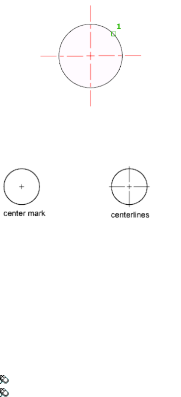
Summary
The default sizes of the center mark components can be set from the Dimension
Style Manager, Symbols and Arrows tab, Center Marks (DIMCEN system
variable).
You can choose between center marks and centerlines and specify their size
when you set up the dimension style. See DIMSTYLE (page 314). You can also
change center mark settings using the DIMCEN (page 1227) system variable.
See also:
Create Radial Dimensions
DIMCONSTRAINT
Applies dimensional constraints to selected objects or points on objects, or
converts associative dimensions to dimensional constraints.
Access Methods
Toolbar: Drafting tool set ➤ Parametric tool group
Menu: Parametric ➤ Dimensional Constraints ➤ Aligned
284 | Chapter 2 Commands
Summary
Applies a dimensional constraint to a selected object or converts an associative
dimension to a dimensional constraint.
NOTE
The L option (last object drawn) is not allowed in the DIMCONSTRAINT
command as the constraint behavior is dependent on where you pick the
object.
The following table outlines the valid constraint points for an object.
Valid Constraint PointsObjects
Endpoints, MidpointLine
Center, Endpoints, MidpointArc
EndpointsSpline
CenterEllipse, Circle
Endpoints, midpoints of line and arc subob-
jects, center of arc subobjects
Polyline
Insertion pointBlock, Xref, Text, Mtext, Attribute, Table
After you specify the dimensional constraint type, you can either enter an
expression value or accept the default (constraintname=value).
You can apply a dimensional constraint from a drop-down list, or you can
convert an existing dimension into a dimensional constraint.
The DIMCONSTRAINT command gives the same options as the following
commands:
Linear (DCLINEAR (page 260))
Creates a horizontal, vertical, or rotated constraint based on the locations of
the extension line origins and the dimension line.
Horizontal (DCHORIZONTAL (page 259))
Constrains the X distance between points on an object, or between two points
on different objects.
Commands | 285
Vertical (DCVERTICAL (page 263))
Constrains the Y distance between points on an object, or between two points
on different objects.
Aligned (DCALIGNED (page 251))
Constrains the distance between two points on different objects.
Angular (DCANGULAR (page 253))
Constrains the angle between line or polyline segments, the angle swept out
by an arc or a polyline arc segment, or the angle between three points on
objects.
Radius (DCRADIUS (page 262))
Constrains the radius of a circle or an arc.
Diameter (DCDIAMETER (page 256))
Constrains the diameter of a circle or an arc.
Form (DCFORM (page 258))
Specifies whether the dimensional constraint being created is dynamic or
annotational.
Convert (DCCONVERT (page 256))
Converts associative dimensions to dimensional constraints.
See also:
Apply Dimensional Constraints
DIMCONTINUE
Creates a dimension that starts from an extension line of a previously created
dimension.
Access Methods
Button
Toolbar: Annotation tool set ➤ Dimensions tool group ➤ Continue
flyout ➤ Continue
Menu: Dimension ➤ Continue
286 | Chapter 2 Commands
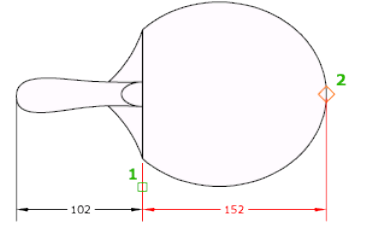
Summary
Automatically continues creating additional dimensions from the last linear,
angular, or ordinate dimension created, or from a selected extension line. The
dimension lines are lined up automatically.
If no dimension was created in the current session, you are prompted to select
a linear, ordinate, or angular dimension to use as the base for the continued
dimension.
List of Prompts
The following prompts are displayed.
Select continued dimension: Select a linear, ordinate, or angular dimension
Otherwise, the program skips this prompt and uses the dimension object that
was last created in the current session. If the base dimension is linear or
angular, the following prompt is displayed:
Specify a second extension line origin (page 288) or [Undo
(page 288)/Select (page 288)] <Select>: Specify a point, enter an option,
or press Enter to select a base dimension
If the base dimension is ordinate, the following prompt is displayed:
Specify feature location (page 288) or [Undo/Select] <Select>:
To end the command, press Enter twice, or press Esc. The current dimension
style determines the appearance of the text.
Commands | 287
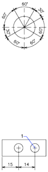
Second Extension Line Origin Uses the second extension line origin of the
continued dimension for the first extension line origin of the next dimension.
The current dimension style determines the appearance of the text.
After you select a continued dimension, the Specify a Second Extension Line
Origin prompt is redisplayed. To end the command, press Esc. To select another
linear, ordinate, or angular dimension to use as the basis for the continued
dimension, press Enter.
Select continued dimension: Select a linear, ordinate, or angular dimension
Select a base dimension, or press Esc to end the command.
Feature Location Uses the endpoint of the base dimension as the endpoint
for the continued dimension; you are prompted for the next feature location.
When you select a feature location, the continued dimension is drawn and
the Specify Feature Location prompt is redisplayed. To end the command,
press Esc. To select another linear, ordinate, or angular dimension to use as
the basis for the continued dimension, press Enter.
Select continued dimension: Select a linear, ordinate, or angular dimension
Select a base dimension, or press Esc to end the command.
Undo Undoes the last continued dimension entered during the command
session.
Select Prompts you to select a linear, ordinate, or angular dimension to use
as the continued dimension. After you select a continued dimension, the
Specify a Second Extension Line Origin prompt or the Specify Feature Location
prompt is redisplayed. To end the command, press Esc.
288 | Chapter 2 Commands
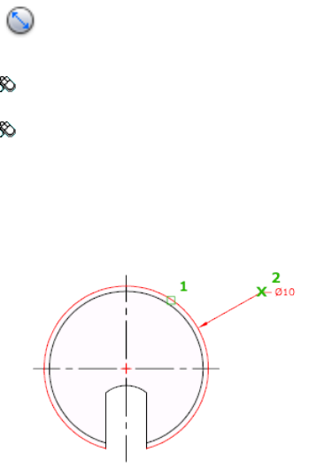
See also:
Create Baseline and Continued Dimensions
DIMDIAMETER
Creates a diameter dimension for a circle or an arc.
Access Methods
Button
Toolbar: Annotation tool set ➤ Dimensions tool group ➤ Dimension
flyout ➤ Diameter
Menu: Dimension ➤ Diameter
Summary
Measures the diameter of a selected circle or arc, and displays the dimension
text with a diameter symbol in front of it. You can use grips to easily reposition
the resulting diameter dimension.
List of Prompts
The following prompts are displayed.
Select arc or circle:
Specify dimension line location (page 290) or [Mtext (page
290)/Text (page 290)/Angle (page 290)]: Specify a point or enter an option
Commands | 289
Dimension Line Location Determines the angle of the dimension line and
the location of the dimension text. If the dimension is placed off of an arc
resulting in the dimension pointing outside the arc, AutoCAD for Mac
automatically draws an arc extension line.
Mtext Displays the In-Place Text Editor, which you can use to edit the
dimension text. Use control codes and Unicode character strings to enter
special characters or symbols. See Control Codes and Special Characters (page
1049).
If alternate units are not turned on in the dimension style, you can display
them by entering square brackets ([]). For more information, see Select and
Modify Objects.
The current dimension style determines the appearance of the dimension text.
Text Customizes the dimension text at the Command prompt. The generated
dimension measurement is displayed within angle brackets.
To include the generated measurement, use angle brackets (< >) to represent
the generated measurement. If alternate units are not turned on in the
dimension style, you can display alternate units by entering square brackets
([ ]).
Dimension text properties are set on the Text tab of the New, Modify, and
Override Dimension Style dialog boxes.
Angle Changes the angle of the dimension text.
See also:
Create Radial Dimensions
DIMDISASSOCIATE
Removes associativity from selected dimensions.
Summary
DIMDISASSOCIATE filters the selection set to include only associative
dimensions that are not on locked layers, and that are not in a different space
than the current space (for example, if model space is active, associative
dimensions in paper space are excluded). DIMDISASSOCIATE then disassociates
these dimensions and reports the number of dimensions that are filtered out
and the number that are disassociated.
290 | Chapter 2 Commands
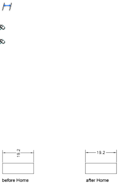
See also:
Change Dimension Associativity
DIMEDIT
Edits dimension text and extension lines.
Access Methods
Button
Toolbar: Annotation tool set ➤ Dimensions tool group (expanded) ➤
Oblique
Menu: Dimension ➤ Oblique
Summary
Rotates, modifies, or restores dimension text. Changes the oblique angle of
extension lines. The companion command that moves text and the dimension
line is DIMTEDIT (page 350).
List of Prompts
The following prompts are displayed.
Enter type of dimension editing [Home (page 291)/New (page
291)/Rotate (page 292)/Oblique (page 292)] <Home>: Enter an option
or press Enter
Home Moves rotated dimension text back to its default position.
The selected dimension text is returned to its default position and rotation as
specified in its dimension style.
New Changes dimension text using the In-Place Text Editor (page 675).
Commands | 291
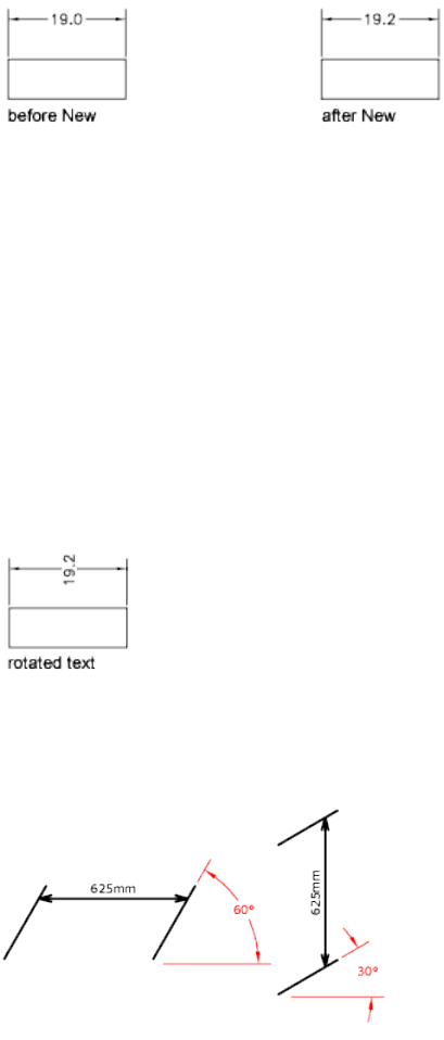
The generated measurement is represented with angle brackets (< >). Use
control codes and Unicode character strings to enter special characters or
symbols. See Control Codes and Special Characters (page 1049).
To edit or replace the generated measurement, delete the angle brackets, enter
the new dimension text, and then choose OK. If alternate units are not turned
on in the dimension style, you can display them by entering square brackets
([ ]). For more information, see Select and Modify Objects.
Rotate Rotates dimension text. This option is similar to the Angle option of
DIMTEDIT (page 350).
Entering 0 places the text in its default orientation, which is determined by
the vertical and horizontal text settings on the Text tab of the New, Modify,
and Override Dimension Style dialog boxes. See DIMSTYLE (page 314). The
DIMTIH (page 1245) and DIMTOH (page 1248) system variables control this
orientation.
Oblique
The Oblique option is useful when extension lines conflict with other features
of the drawing. The oblique angle is measured from the X axis of the UCS.
292 | Chapter 2 Commands
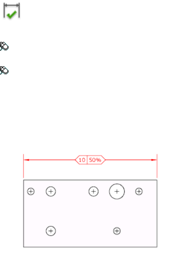
See also:
Modify Dimension Text
DIMINSPECT
Adds or removes inspection information for a selected dimension.
Access Methods
Button
Toolbar: Annotation tool set ➤ Dimensions tool group ➤ Inspect
Dimension
Menu: Dimension ➤ Inspection
Summary
Inspection dimensions specify how frequently manufactured parts should be
checked to ensure that the dimension value and tolerances of the parts are
within the specified range.
The Inspection Dimension dialog box (page 294) is displayed and allows you
to add or remove inspection dimensions from an existing dimension.
Inspection dimensions allow you to effectively communicate how frequently
manufactured parts should be checked to ensure that the dimension value
and tolerances of the parts are within the specified range.
If you enter -diminspect at the Command prompt, options are displayed
(page 295).
Commands | 293

See also:
Convert Dimensions into Inspection Dimensions
Inspection Dimension Dialog Box
Allows you to add or remove an inspection dimension from selected
dimensions.
Summary
Use the Shape and Inspection Label/Rate settings to the appearance of the
frame of the inspection dimension and the inspection rate value.
List of Options
The following options are displayed.
Select Dimensions
Specifies the dimensions that an inspection dimension should be added to or
removed from.
Remove Inspection
Removes the inspection dimension from the selected dimension.
Shape
Controls the shape of the frame that is drawn around the label, dimension
value, and inspection rate of the inspection dimension.
294 | Chapter 2 Commands
Round
Creates a frame with semi-circles on the two ends; the fields within the frame
are separated by vertical lines.
Angular
Creates a frame with lines that form a 90-degree angle on the two ends; the
fields within the frame are separated by vertical lines.
None
Specifies that no frame is drawn around the values; the fields are not separated
by vertical lines.
Label/Inspection Rate
Specifies the label text and inspection rate for an inspection dimension.
Label
Turns the display of the label field on and off.
Label Value
Specifies the label text.
The label is displayed in the leftmost section of the inspection dimension
when the Label check box is selected.
Inspection Rate
Turns the display of the rate field on and off.
Inspection Rate Value
Specifies how frequently a part should be inspected.
The value is expressed as a percentage, and the valid range is 0 to 100. The
inspection rate is displayed in the rightmost section of the inspection
dimension when the Inspection Rate check box is selected.
See also:
Convert Dimensions into Inspection Dimensions
-DIMINSPECT
List of Prompts
The following prompts are displayed.
Commands | 295

Add inspection data (page ?) or [Remove (page ?)] <Add>:
Enter an option or press Enter
Add
Adds an inspection dimension to the selected dimensions.
Round Creates a frame with semi-circles on the two ends; the fields within
the frame are separated by vertical lines.
Angular Creates a frame with lines that form a 90-degree angle on the two
ends; the fields within the frame are separated by vertical lines.
None Specifies that no frame is drawn around the values; the fields are not
separated by vertical lines.
None No label is displayed with the inspection dimension.
Remove
Removes the inspection dimension from the selected dimensions.
See also:
Convert Dimensions into Inspection Dimensions
DIMJOGGED
Creates jogged dimensions for circles and arcs.
Access Methods
Button
Toolbar: Annotation tool set ➤ Dimensions tool group ➤ Dimension
flyout ➤ Jogged
Menu: Dimension ➤ Jogged
Summary
DIMJOGGED measures the radius of the selected object and displays the
dimension text with a radius symbol in front of it. The origin point of the
dimension line can be specified at any convenient location.
NOTE Jogged radius dimensions are also called foreshortened radius dimensions.
296 | Chapter 2 Commands
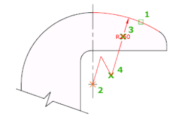
Creates jogged radius dimensions when the center of an arc or circle is located
off the layout and cannot be displayed in its true location. The origin point
of the dimension can be specified at a more convenient location called the
center location override.
List of Prompts
The following prompts are displayed.
Select arc or circle: Select an arc, circle, or polyline arc segment
Specify center location override: Specify a point
Accepts a new center point for a jogged radius dimension that takes the place
of the true center point of the arc or circle.
Specify dimension line location (page 297) or [Mtext (page
297)/Text (page 297)/Angle (page 298)]: Specify a point or enter an option
Dimension Line Location Determines the angle of the dimension line and
the location of the dimension text. If the dimension is placed off of an arc
resulting in the dimension pointing outside the arc, AutoCAD for Mac
automatically draws an arc extension line.
Mtext Displays the In-Place Text Editor, which you can use to edit the
dimension text. Use control codes and Unicode character strings to enter
special characters or symbols. See Control Codes and Special Characters (page
1049).
If alternate units are not turned on in the dimension style, you can display
them by entering square brackets ([ ]). For more information, see Select and
Modify Objects.
The current dimension style determines the appearance of the generated
measurements.
Text Customizes the dimension text at the Command prompt. The generated
dimension measurement is displayed within angle brackets.
Commands | 297
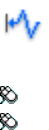
To include the generated measurement, use angle brackets (< >) to represent
the generated measurement. If alternate units are not turned on in the
dimension style, you can display alternate units by entering square brackets
([ ]).
Dimension text properties are set on the Text tab of the New, Modify, and
Override Dimension Style dialog boxes.
Angle Changes the angle of the dimension text.
Also determines the angle of the dimension line and the location of the
dimension text.
Specify Jog Location Locates the middle point of the jog. The transverse angle
of the jog is determined by the Dimension Style Manager.
See also:
Create Radial Dimensions
DIMJOGLINE
Adds or removes a jog line on a linear or aligned dimension.
Access Methods
Button
Toolbar: Annotation tool set ➤ Dimensions tool group ➤ Jog Line
Menu: Dimension ➤ Jogged Linear
Summary
Jog lines in a dimension indicate a break in the objects being dimensioned.
The dimension value represents the actual distance, rather than the measured
distance in the drawing.
298 | Chapter 2 Commands
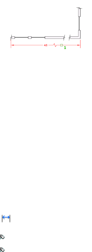
List of Prompts
The following prompts are displayed.
Select dimension to add jog (page 299) or [Remove (page 299)]:
Select a linear or aligned dimension
Add Jog Specifies the linear or aligned dimension to which to add a jog. You
are prompted for the location of the jog.
Press Enter to place the jog at the midpoint between the dimension text and
the first extension line or the midpoint of the dimension line based on the
location of the dimension text
Remove Specifies the linear or aligned dimension from which to remove the
jog.
See also:
Dimension Jog
DIMLINEAR
Creates a linear dimension.
Access Methods
Button
Toolbar: Annotation tool set ➤ Dimensions tool group ➤ Dimension
flyout ➤ Linear Dimension
Menu: Dimension ➤ Linear
Commands | 299
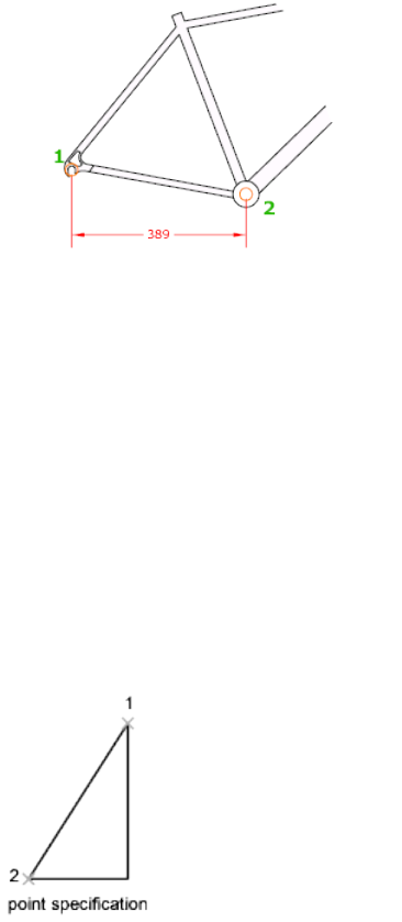
Summary
Creates a linear dimension with a horizontal, vertical, or rotated dimension
line. This command replaces the DIMHORIZONTAL and DIMVERTICAL
commands.
List of Prompts
The following prompts are displayed.
Specify first extension line origin (page ?) or <select ob-
ject (page ?)>: Specify a point or press Enter to select an object to
dimension
After you specify the extension line origin points or the object to dimension,
the following prompt is displayed:
Specify dimension line location (page ?) or [Mtext (page
?)/Text (page ?)/Angle (page ?)/Horizontal (page ?)/Ver-
tical (page ?)/Rotated (page ?)]: Specify a point or enter an option
First Extension Line Origin
Prompts for the origin point of the second extension line after you specify
the origin point of the first.
300 | Chapter 2 Commands
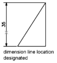
Dimension Line Location
Uses the point you specify to locate the dimension line and determines the
direction to draw the extension lines. After you specify the location, the
dimension is drawn.
Mtext
Displays the In-Place Text Editor, which you can use to edit the dimension
text. Use control codes and Unicode character strings to enter special characters
or symbols. See Control Codes and Special Characters (page 1049).
If alternate units are not turned on in the dimension style, you can display
them by entering square brackets ([ ]). For more information about formatting
dimension text, see Select and Modify Objects.
The current dimension style determines the appearance of the generated
measurements.
Text
Customizes the dimension text at the Command prompt. The generated
dimension measurement is displayed within angle brackets.
To include the generated measurement, use angle brackets (< >) to represent
the generated measurement. If alternate units are not turned on in the
dimension style, you can display alternate units by entering square brackets
([ ]).
Dimension text properties are set on the Text tab of the New, Modify, and
Override Dimension Style dialog boxes.
Angle
Changes the angle of the dimension text.
Commands | 301
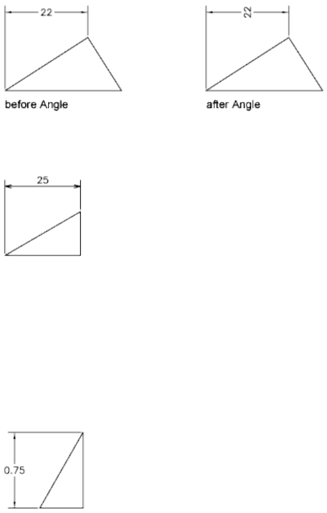
Horizontal
Creates horizontal linear dimensions.
Dimension Line Location Uses the point you specify to locate the dimension
line.
■Mtext (page ?)
■Text (page ?)
■Angle (page ?)
Vertical
Creates vertical linear dimensions.
Dimension Line Location Dimension Line Location (page ?)
■Mtext (page ?)
■Text (page ?)
■Angle (page ?)
Rotated
Creates rotated linear dimensions.
302 | Chapter 2 Commands

Object Selection
Automatically determines the origin points of the first and second extension
lines after you select an object.
For polylines and other explodable objects, only the individual line and arc
segments are dimensioned. You cannot select objects in a non-uniformly
scaled block reference.
If you select a line or an arc, the line or arc endpoints are used as the origins
of the extension lines. The extension lines are offset from the endpoints by
the distance you specify in Offset from Origin in the Lines and Arrows tab of
the New, Modify, and Override Dimension Style dialog boxes. See DIMSTYLE
(page 314). This value is stored in the DIMEXO (page 1231) system variable.
If you select a circle, the diameter endpoints are used as the origins of the
extension line. When the point used to select the circle is close to the north
or south quadrant point, a horizontal dimension is drawn. When the point
used to select the circle is close to the east or west quadrant point, a vertical
dimension is drawn.
See also:
Create Linear Dimensions
Commands | 303
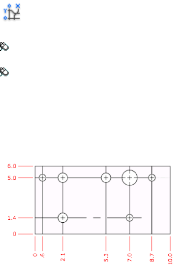
DIMORDINATE
Creates ordinate dimensions.
Access Methods
Button
Toolbar: Annotation tool set ➤ Dimensions tool group ➤ Dimension
flyout ➤ Ordinate
Menu: Dimension ➤ Ordinate
Summary
Ordinate dimensions measure the horizontal or vertical distance from an
origin point called the datum to a feature, such as a hole in a part. These
dimensions prevent escalating errors by maintaining accurate offsets of the
features from the datum.
List of Prompts
The following prompts are displayed.
Specify feature location: Specify a point or snap to an object
Specify leader endpoint (page 304) or [Xdatum (page 305)/Ydatum
(page 305)/Mtext (page 305)/Text (page 305)/Angle (page 305)]:
Specify a point or enter an option
Leader Endpoint Specification Uses the difference between the feature
location and the leader endpoint to determine whether it is an X or a Y
ordinate dimension. If the difference in the Y ordinate is greater, the dimension
measures the X ordinate. Otherwise, it measures the Y ordinate.
304 | Chapter 2 Commands
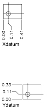
Xdatum Measures the X ordinate and determines the orientation of the leader
line and dimension text. The Leader Endpoint prompt is displayed, where you
can specify the endpoint.
Ydatum Measures the Y ordinate and determines the orientation of the leader
line and dimension text. The Leader Endpoint prompts are displayed, where
you can specify the endpoint.
Mtext Displays the In-Place Text Editor, which you can use to edit the
dimension text. Use control codes and Unicode character strings to enter
special characters or symbols. See Control Codes and Special Characters (page
1049).
If alternate units are not turned on in the dimension style, you can display
them by entering square brackets ([ ]). For more information about formatting
dimension text, see Select and Modify Objects.
The current dimension style determines the appearance of the generated
measurements.
Text Customizes the dimension text at the Command prompt. The generated
dimension measurement is displayed within angle brackets.
To include the generated measurement, use angle brackets (< >) to represent
the generated measurement. If alternate units are not turned on in the
dimension style, you can display alternate units by entering square brackets
([ ]).
Dimension text properties are set on the Text tab of the New, Modify, and
Override Dimension Style dialog boxes.
Angle Changes the angle of the dimension text.
Commands | 305
See also:
Create Ordinate Dimensions
DIMOVERRIDE
Controls overrides of system variables used in selected dimensions.
Access Methods
Button
Toolbar: Annotation tool set ➤ Dimensions tool group (expanded)
➤ Override
Menu: Dimension ➤ Override
Summary
Overrides a specified dimensioning system variable for selected dimensions,
or clears the overrides of selected dimension objects, returning them to the
settings defined by their dimension style.
List of Prompts
The following prompts are displayed.
Enter dimension variable name to override (page 306) or [Clear
overrides (page 306)]: Enter the name of a dimension variable, or enter c
Dimension Variable Name to Override Overrides the value of the
dimensioning system variable you specify.
Clear Overrides Clears any overrides on selected dimensions.
The dimension objects return to the settings defined by their dimension style.
See also:
Override a Dimension Style
306 | Chapter 2 Commands
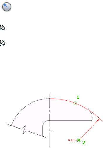
DIMRADIUS
Creates a radius dimension for a circle or an arc.
Access Methods
Button
Toolbar: Annotation tool set ➤ Dimensions tool group ➤ Dimension
flyout ➤ Radius
Menu: Dimension ➤ Radius
Summary
Measures the radius of a selected circle or arc and displays the dimension text
with a radius symbol in front of it. You can use grips to reposition the resulting
radius dimension easily.
List of Prompts
The following prompts are displayed.
Select arc or circle:
Specify dimension line location (page 307) or [Mtext (page
308)/Text (page 308)/Angle (page 308)]: Specify a point or enter an option
Dimension Line Location Determines the angle of the dimension line and
the location of the dimension text. If the dimension is placed off of an arc
resulting in the dimension pointing outside the arc, AutoCAD for Mac
automatically draws an arc extension line.
Commands | 307
Mtext Displays the In-Place Text Editor, which you can use to edit the
dimension text. Use control codes and Unicode character strings to enter
special characters or symbols. See Control Codes and Special Characters (page
1049).
If alternate units are not turned on in the dimension style, you can display
them by entering square brackets ([ ]). For more information about formatting
dimension text, see Select and Modify Objects.
The current dimension style determines the appearance of the generated
measurements.
Text Customizes the dimension text at the Command prompt. The generated
dimension measurement is displayed within angle brackets.
To include the generated measurement, use angle brackets (< >) to represent
the generated measurement. If alternate units are not turned on in the
dimension style, you can display alternate units by entering square brackets
([ ]).
Dimension text properties are set on the Text tab of the New, Modify, and
Override Dimension Style dialog boxes.
Angle Changes the angle of the dimension text.
See also:
Create Radial Dimensions
DIMREASSOCIATE
Associates or reassociates selected dimensions to objects or points on objects.
Access Methods
Button
Toolbar: Annotation tool set ➤ Dimensions tool group ➤ Reassociate
Dimension
Menu: Dimension ➤ Reassociate Dimensions
308 | Chapter 2 Commands

Summary
Each selected dimension is highlighted in turn, and prompts for association
points appropriate for the selected dimension are displayed.
A marker is displayed for each association point prompt.
■If the definition point of the current dimension is not associated to a
geometric object, the marker appears as an X
■If the definition point is associated, the marker appears as an X inside a
box.
NOTE
The marker disappears if you pan or zoom.
List of Prompts
The following prompts are displayed.
Select dimensions to reassociate...
Select objects or [Disassociated]: Select the dimension objects to
reassociate or press Dto select all disassociated dimensions.
Press Esc to terminate the command without losing the changes that were
already specified. Use UNDO (page 1089) to restore the previous state of the
changed dimensions.
The prompts for the different types of dimensions are:
Linear Specify first extension line origin or [Select object] <next>: Specify an
object snap location, enter s and select a geometric object, or press Enter to skip to
the next prompt
Specify second extension line origin <next>: Specify an object snap location, or
press Enter to skip to the next dimension object, if any
Aligned Specify first extension line origin or [Select object] <next>: Specify an
object snap location, enter s and select a geometric object, or press Enter to skip to
the next prompt
Specify second extension line origin <next>: Specify an object snap location, or
press Enter to skip to the next dimension object, if any
Angular (Three Point) Specify angle vertex or [Select arc or circle] <next>:
Specify an object snap location, enter s and select an arc or a circle, or press Enter
to skip to the next prompt
Specify first angle endpoint <next>: Specify an object snap location or press Enter
to skip to the next prompt
Commands | 309

Specify second angle endpoint <next>: Specify an object snap location or press
Enter to skip to the next dimension object, if any
Angular (Two Line) Select first line <next>: Select a line, or press Enter to skip
to the next prompt
Select second line <next>: Select another line, or press Enter to skip to the next
dimension object, if any
Diameter Select arc or circle <next>: Select an arc or a circle, or press Enter to
skip to the next dimension object, if any
Leader Specify leader association point <next>: Specify an object snap location,
or press Enter to skip to the next dimension object, if any
Ordinate Specify feature location <next>: Specify an object snap location, or
press Enter to skip to the next dimension object, if any
Radius Select arc or circle <next>: Select an arc or a circle, or press Enter to skip
to the next dimension object, if any
NOTE DIMREASSOCIATE does not change the setting of DIMLFAC (page 1234) in
a dimension. Use DIMOVERRIDE (page 306) to clear dimension linear factors in
legacy drawings.
See also:
Change Dimension Associativity
DIMREGEN
Updates the locations of all associative dimensions.
Summary
The locations of all associative dimensions in the current drawing are updated.
Associative dimensions need to be updated manually with DIMREGEN in the
following cases:
■After panning or zooming with a wheel mouse in a layout with model
space active; update associative dimensions created in paper space.
■After opening a drawing containing external references that are
dimensioned in the current drawing; update associative dimensions if the
associated external reference geometry has been modified.
310 | Chapter 2 Commands

NOTE After opening a drawing that has been modified with a previous version,
the association between dimensions and objects or points may need to be updated.
You can use the DIMREASSOCIATE (page 308) command to reassociate modified
dimensions with the objects or points that they dimension.
See also:
Associative Dimensions
DIMROTATED
Creates a rotated linear dimension.
Summary
Creates a linear dimension with a rotated dimension line.
List of Prompts
The following prompts are displayed.
Specify angle of dimension line <0>: Specify an angle or press Enter
to accept the default value
Specify first extension line origin (page ?) or <select ob-
ject (page ?)>: Specify a point or press Enter to select an object to
dimension
After you specify the extension line origin points or the object to dimension,
the following prompt is displayed:
Specify dimension line location (page ?) or [Mtext (page
?)/Text (page ?)/Angle (page ?)]: Specify a point or enter an option
First Extension Line Origin
Prompts for the origin point of the second extension line after you specify
the origin point of the first.
Dimension Line Location
Uses the point you specify to locate the dimension line and determines the
direction to draw the extension lines. After you specify the location, the
dimension is drawn.
Commands | 311
Mtext
Displays the In-Place Text Editor, which you can use to edit the dimension
text. Use control codes and Unicode character strings to enter special characters
or symbols. See Control Codes and Special Characters (page 1049).
If alternate units are not turned on in the dimension style, you can display
them by entering square brackets ([ ]). For more information about formatting
dimension text, see Select and Modify Objects.
The current dimension style determines the appearance of the generated
measurements.
Text
Customizes the dimension text at the Command prompt. The generated
dimension measurement is displayed within angle brackets.
To include the generated measurement, use angle brackets (< >) to represent
the generated measurement. If alternate units are not turned on in the
dimension style, you can display alternate units by entering square brackets
([ ]).
Dimension text properties are set on the Text tab of the New, Modify, and
Override Dimension Style dialog boxes.
Angle
Changes the angle of the dimension text.
Object Selection
Automatically determines the origin points of the first and second extension
lines after you select an object.
For polylines and other explodable objects, only the individual line and arc
segments are dimensioned. You cannot select objects in a non-uniformly
scaled block reference.
If you select a line or an arc, the line or arc endpoints are used as the origins
of the extension lines. The extension lines are offset from the endpoints by
the distance you specify in Offset from Origin in the Lines and Arrows tab of
the New, Modify, and Override Dimension Style dialog boxes. See DIMSTYLE
(page 314). This value is stored in the DIMEXO (page 1231) system variable.
If you select a circle, the location of the origins for the extension lines is
calculated based on the center of the circle and the angle of the rotated
dimension line.
See also:
Create Linear Dimensions
312 | Chapter 2 Commands
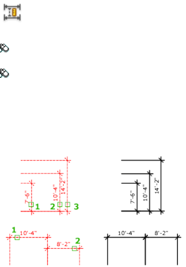
DIMSPACE
Adjusts the spacing between linear dimensions or angular dimensions.
Access Methods
Button
Toolbar: Annotation tool set ➤ Dimensions tool group ➤ Adjust
Dimension Space
Menu: Dimension ➤ Dimension Space
Summary
The spacing between parallel dimension lines is made equal. You can also
make the dimension lines of a series of linear or angular dimensions line up
by using a spacing value of 0.
Spacing is applied only to parallel linear dimensions or to angular dimensions
that share a common vertex.
List of Prompts
The following prompts are displayed.
Select base dimension: Select a parallel linear or angular dimension
Select dimensions to space: Select a parallel linear or angular dimension
to equally space from the base dimension and press Enter
Enter value (page 314) or [Auto (page 314)] <Auto>: Specify a
spacing distance or press Enter
Commands | 313

Enter Spacing Value Applies a spacing value to the selected dimensions from
the base dimension. For example, if you enter a value of 0.5000, all selected
dimensions will be separated by a distance of 0.5000.
You can use a spacing value of 0 (zero) to align the dimension lines of selected
linear and angular dimensions end to end.
Auto Calculates the spacing distance automatically based on the text height
specified in the dimension style of the selected base dimension. The resulting
spacing value is twice the height of the dimension text.
See also:
Adjust Dimension Spacing
DIMSTYLE
Creates and modifies dimension styles.
Access Methods
Menu: Format ➤ Dimension Style
Summary
The Dimension Style Manager (page 314) is displayed.
A dimension style is a named collection of dimension settings that control
the appearance of dimensions. You create dimension styles to specify the
format of dimensions quickly, and to ensure that dimensions conform to
standards.
If you enter -dimstyle at the Command prompt, options are displayed (page
347).
See also:
Use Dimension Styles
Dimension Style Manager
Creates new styles, sets the current style, modifies styles, sets overrides on the
current style, and compares styles.
314 | Chapter 2 Commands
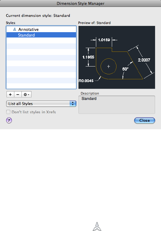
List of Options
The following options are displayed.
Current Dimension Style
Displays the name of the dimension style that is current. The default dimension
style is STANDARD. The current style is applied to dimensions you create.
Styles
Lists dimension styles in the drawing. The current style is highlighted.
Right-click in the list to display a shortcut menu with options to set the current
style, rename styles, and delete styles. You cannot delete a style that is current
or in use in the current drawing. A icon before the style name indicates
that the style is annotative.
Unless you select Don't List Styles in Xrefs, dimension styles are displayed in
externally referenced drawings using the syntax for externally referenced
named objects. (See “Overview of External References”.) Although you cannot
change, rename, or make current externally referenced dimension styles, you
can create new styles based on them.
The item selected in List controls the dimension styles displayed.
Commands | 315
New
Displays the Create New Dimension Style dialog box (page 317), in which you
can define a new dimension style.
Delete
Deletes the dimension style selected in the Styles list. A style that is being used
in the drawing cannot be deleted.
Options
Manages the dimension styles in the list.
Set Current Sets the style selected under Styles to current. The current style
is applied to dimensions you create.
Modify Displays the Modify Dimension Styles dialog box (page 318), in which
you can modify dimension styles. Dialog box options are identical to those
in the New Dimension Style dialog box.
Override Displays the Override Current Style dialog box (page 318), in which
you can set temporary overrides to dimension styles. Dialog box options are
identical to those in the New Dimension Style dialog box. Overrides are
displayed as unsaved changes under the dimension style in the Styles list.
Compare Displays the Compare Dimension Styles dialog box (page 346), in
which you can compare two dimension styles or list all the properties of one
dimension style.
Rename Edits the name of the style selected in the list.
List
Controls the display of styles in the Styles list. Select All Styles if you want to
see all dimension styles in a drawing. Select Styles in Use if you want to see
only the dimension styles currently used by dimensions in the drawing.
Don’t List Styles in Xrefs
When selected, suppresses display of dimension styles in externally referenced
drawings in the Styles list.
Preview
Shows a graphic representation of the style selected in the Styles list.
Description
Describes the style selected in the Styles list relative to the current style. If the
description is longer than the space provided, you can click in the pane and
use arrow keys to scroll down.
See also:
Use Dimension Styles
316 | Chapter 2 Commands
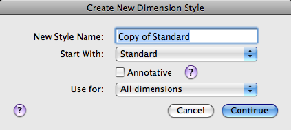
Create New Dimension Style Dialog Box
Names the new dimension style, sets the style on which to start the new one,
and indicates the dimension types to which you want the new style to apply.
List of Options
The following options are displayed.
New Style Name
Specifies the new dimension style name.
Start With
Sets a style to use as a basis for the new one. For the new style, you change
only the properties that differ from the properties you start with.
Annotative
Specifies that the dimension style is annotative. Click the information icon
to learn more about annotative objects.
Use For
Creates a dimension substyle that applies only to specific dimension types.
For example, you could create a version of the STANDARD dimension style
to be used only for diameter dimensions.
Continue
Displays the New Dimension Style dialog box (page 318), in which you define
the new dimension style properties.
See also:
Use Dimension Styles
Commands | 317
New, Modify, and Override Dimension Style Dialog
Boxes
Set properties for dimension styles.
Summary
When you choose Continue in the Create New Dimension Style dialog box,
the New Dimension Style dialog box is displayed. You define the properties
for the new style in this dialog box. The dialog box initially displays the
properties of the dimension style that you selected to start the new style in
the Create New Dimension Style dialog box.
Choosing either Modify or Override in the Dimension Style Manager displays
the Modify Dimension Style or the Override Dimension Style dialog box. The
content of these dialog boxes is identical to the New Dimension Style dialog
box, although you are modifying or overriding an existing dimension style
rather than creating a new one.
The sample image on each tab displays the effects of each option.
List of Tabs
■Lines (page 319)
■Symbols and Arrows (page 323)
■Text (page 327)
■Fit (page 331)
■Primary Units (page 336)
■Alternate Units (page 339)
■Tolerances (page 342)
See also:
Use Dimension Styles
Lines Tab
Sets the format and properties for dimension lines, extension lines, arrowheads,
and center marks.
318 | Chapter 2 Commands
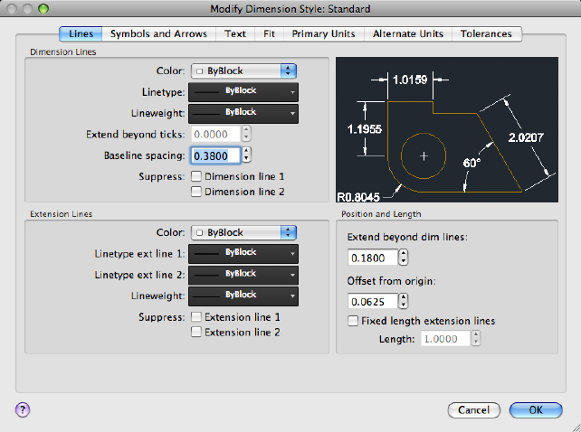
Summary
Sets the dimension line properties.
List of Options
The following options are displayed.
Dimension Lines
Color
Displays and sets the color for the dimension line. If you click Select Color
(at the bottom of the Color list), the Color Palette dialog box (page 198) is
displayed. You can also enter a color name or number. (DIMCLRD (page 1227)
system variable)
Linetype
Sets the linetype of the dimension line. (DIMLTYPE (page 1236) system variable)
Lineweight
Sets the lineweight of the dimension line. (DIMLWD (page 1237) system variable)
Extend Beyond Ticks
Commands | 319

Specifies a distance to extend the dimension line past the extension line when
you use oblique, architectural, tick, integral, and no marks for arrowheads.
(DIMDLE (page 1229) system variable)
Baseline Spacing
Sets the spacing between the dimension lines of a baseline dimension. Enter
a distance. For information about baseline dimensions, see DIMBASELINE
(page 280). (DIMDLI (page 1230) system variable)
Suppress
Suppresses display of dimension lines. Dimension Line 1 suppresses the first
dimension line; Dimension Line 2 suppresses the second dimension line. (
DIMSD1 (page 1240) and DIMSD2 (page 1241) system variables)
Extension Lines
Controls the appearance of the extension lines.
Color
Sets the color for the extension line. If you click Select Color (at the bottom
of the Color list), the Select Color dialog box (page 198) is displayed. You can
also enter a color name or number. (DIMCLRE (page 1228) system variable.)
Linetype Ext Line 1
320 | Chapter 2 Commands
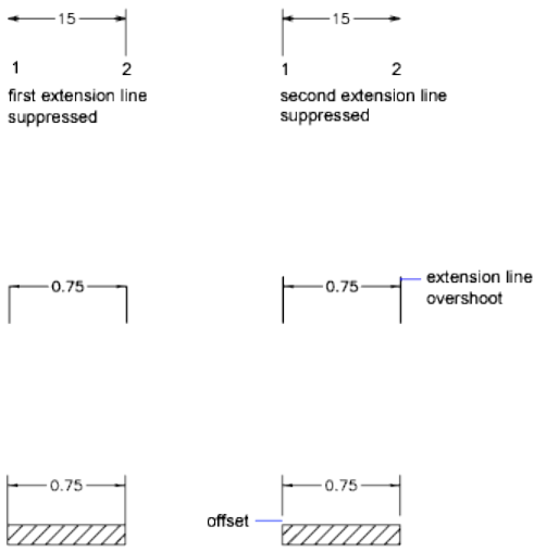
Sets the linetype of the first extension line. (DIMLTEX1 (page 1235) system
variable)
Linetype Ext Line 2
Sets the linetype of the second extension line. (DIMLTEX2 (page 1236) system
variable)
Lineweight
Sets the lineweight of the extension line. (DIMLWE (page 1237) system variable)
Suppress
Suppresses the display of extension lines. Extension Line 1 suppresses the first
extension line; Extension Line 2 suppresses the second extension line. ( DIMSE1
(page 1241) and DIMSE2 (page 1241) system variables)
Extend Beyond Dim Lines
Specifies a distance to extend the extension lines above the dimension line.
(DIMEXE (page 1231) system variable)
Offset From Origin
Sets the distance to offset the extension lines from the points on the drawing
that define the dimension. ( DIMEXO (page 1231) system variable)
Fixed Length Extension Lines
Enables fixed length extension lines. (DIMFXLON (page 1232) system variable)
Length
Commands | 321
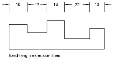
Sets the total length of the extension lines starting from the dimension line
toward the dimension origin. (DIMFXL (page 1232) system variable)
Preview
Displays sample dimension images that show the effects of changes you make
to dimension style settings.
See also:
Use Dimension Styles
Symbols and Arrows Tab
Sets the format and placement for arrowheads, center marks, arc length
symbols, and jogged radius dimensions.
322 | Chapter 2 Commands
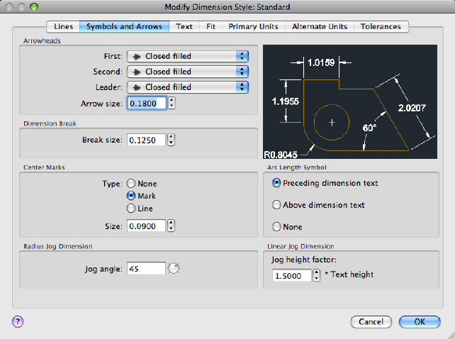
Summary
Controls the appearance of the dimension arrowheads.
List of Options
The following options are displayed.
Arrowheads
First
Sets the arrowhead for the first dimension line. When you change the first
arrowhead type, the second arrowhead automatically changes to match it.
(DIMBLK1 (page 1226) system variable)
To specify a user-defined arrowhead block, select User Arrow. The Select
Custom Arrow Block dialog box is displayed. Select the name of a user-defined
arrowhead block. (The block must be in the drawing.)
Second
Sets the arrowhead for the second dimension line. (DIMBLK2 (page 1226) system
variable)
Commands | 323

To specify a user-defined arrowhead block, select User Arrow. The Select
Custom Arrow Block dialog box is displayed. Select the name of a user-defined
arrowhead block. (The block must be in the drawing.)
Leader
Sets the arrowhead for the leader line. (DIMLDRBLK (page 1234) system variable)
To specify a user-defined arrowhead block, select User Arrow. The Select
Custom Arrow Block dialog box is displayed. Select the name of a user-defined
arrowhead block. (The block must be in the drawing.)
Arrow Size
Displays and sets the size of arrowheads. (DIMASZ (page 1222) system variable)
NOTE Annotative blocks cannot be used as custom arrowheads for dimensions
or leaders.
Dimension Break
Controls the gap width of dimension breaks.
Break Size
Displays and sets the size of the gap used for dimension breaks.
Center Marks
Controls the appearance of center marks and centerlines for diameter and
radial dimensions. The DIMCENTER (page 283), DIMDIAMETER (page 289), and
DIMRADIUS (page 307) commands use center marks and centerlines. For
DIMDIAMETER and DIMRADIUS, the center mark is drawn only if you place
the dimension line outside the circle or arc.
Type
Sets the type of center mark or line to use.
None
Creates no center mark or centerline. The value is stored as 0 in the DIMCEN
system variable.
Mark
Creates a center mark. The size of the center mark is stored as a positive value
in the DIMCEN (page 1227) system variable.
Line
Creates a centerline. The size of the centerline is stored as a negative value in
the DIMCEN system variable.
324 | Chapter 2 Commands
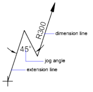
Size
Displays and sets the size of the center mark or centerline. (DIMCEN system
variable)
Radius Jog Dimension
Controls the display of jogged (zigzag) radius dimensions.
Jogged radius dimensions are often created when the center point of a circle
or arc is located off the page.
Jog Angle
Determines the angle of the transverse segment of the dimension line in a
jogged radius dimension. (DIMJOGANG (page 1233) system variable)
Arc Length Symbol
Controls the display of the arc symbol in an arc length dimension. (DIMARC-
SYM (page 1221) system variable)
Preceding Dimension Text
Places arc length symbols before the dimension text. (DIMARCSYM (page 1221)
system variable)
Above Dimension Text
Places arc length symbols above the dimension text. (DIMARCSYM (page 1221)
system variable)
None
Suppresses the display of arc length symbols. (DIMARCSYM (page 1221) system
variable)
Commands | 325
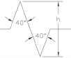
Linear Jog Dimension
Controls the display of the jog for linear dimensions.
Jog lines are often added to linear dimensions when the actual measurement
is not accurately represent by the dimension. Typically the actual measurement
is smaller than the desired value.
Jog Height Factor
Determines the height of the of the jog, which is determined by the distance
between the two vertices of the angles that make up the jog.
Preview
Displays sample dimension images that show the effects of changes you make
to dimension style settings.
See also:
Use Dimension Styles
Text Tab
Sets the format, placement, and alignment of dimension text.
326 | Chapter 2 Commands
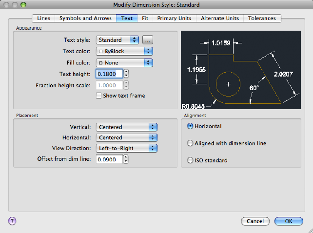
List of Options
The following options are displayed.
Text Appearance
Controls the dimension text format and size.
Text Style
Lists the available text styles.
Text Style Button
Displays the Text Style Dialog Box (page 1006) where you can create or modify
text styles. (DIMTXSTY system variable)
Text Color
Sets the color for the dimension text. If you click Select Color (at the bottom
of the Color list), the Color Palette dialog box (page 198) is displayed. You can
also enter color name or number. (DIMCLRT (page 1228) system variable)
Fill Color
Sets the color for the text background in dimensions. If you click Select Color
(at the bottom of the Color list), the Color Palette dialog box (page 198) is
Commands | 327
displayed. You can also enter color name or number. (DIMTFILL (page 1244)
and DIMTFILLCLR (page 1245) system variables)
Text Height
Sets the height of the current dimension text style. Enter a value in the text
box. If a fixed text height is set in the Text Style (that is, the text style height
is greater than 0), that height overrides the text height set here. If you want
to use the height set on the Text tab, make sure the text height in the Text
Style is set to 0. (DIMTXT (page 1251) system variable)
Fraction Height Scale
Sets the scale of fractions relative to dimension text. This option is available
only when Fractional is selected as the Unit Format on the Primary Units tab.
The value entered here is multiplied by the text height to determine the height
of dimension fractions relative to dimension text. ( DIMTFAC (page 1244) system
variable)
Show Text Frame
When selected, draws a frame around dimension text. Selecting this option
changes the value stored in the DIMGAP (page 1232) system variable to a
negative value.
Placement
Controls the placement of dimension text.
Vertical
Controls the vertical placement of dimension text in relation to the dimension
line. ( DIMTAD (page 1243) system variable)
Vertical position options include the following:
■Centered: Centers the dimension text between the two parts of the
dimension line.
■Above: Places the dimension text above the dimension line. The distance
from the dimension line to the baseline of the lowest line of text is the
current text gap. See the Offset from Dim Line option.
■Outside: Places the dimension text on the side of the dimension line farthest
away from the first defining point.
■JIS: Places the dimension text to conform to a Japanese Industrial Standards
(JIS) representation.
■Below: Places the dimension text under the dimension line. The distance
from the dimension line to the baseline of the lowest line of text is the
current text gap. See the Offset from Dim Line option.
328 | Chapter 2 Commands
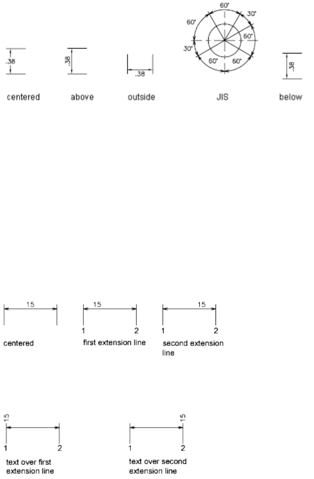
Horizontal
Controls the horizontal placement of dimension text along the dimension
line, in relation to the extension lines. (DIMJUST (page 1233) system variable)
Horizontal position options include the following:
■Centered: Centers the dimension text along the dimension line between
the extension lines.
■At Ext Line 1: Left-justifies the text with the first extension line along the
dimension line. The distance between the extension line and the text is
twice the arrowhead size plus the text gap value. See Arrowheads and Offset
from Dim Line.
■At Ext Line 2: Right-justifies the text with the second extension line along
the dimension line. The distance between the extension line and the text
is twice the arrowhead size plus the text gap value. See Arrowheads and
Offset from Dim Line.
■Over Ext Line 1: Positions the text over or along the first extension line.
■Over Ext Line 2: Positions the text over or along the second extension line.
Commands | 329
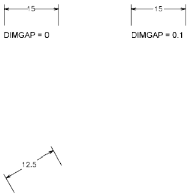
View Direction
Controls the dimension text viewing direction. (DIMTXTDIRECTION (page
1251) system variable)
View Direction includes the following options:
■Left-to-Right: Places the text to enable reading from left to right.
■Right-to-Left: Places the text to enable reading from right to left.
Offset from Dim Line
Sets the current text gap, which is the distance around the dimension text
when the dimension line is broken to accommodate the dimension text.
This value is also used as the minimum length required for dimension line
segments.
Text is positioned inside the extension lines only if the resulting segments are
at least as long as the text gap. Text above or below the dimension line is
placed inside only if the arrowheads, dimension text, and a margin leave
enough room for the text gap. ( DIMGAP (page 1232) system variable)
Alignment
Controls the orientation (horizontal or aligned) of dimension text whether it
is inside or outside the extension lines. (DIMTIH (page 1245) and DIMTOH (page
1248) system variables)
Horizontal
Places text in a horizontal position.
Aligned with Dimension Line
Aligns text with the dimension line.
ISO Standard
Aligns text with the dimension line when text is inside the extension lines,
but aligns it horizontally when text is outside the extension lines.
330 | Chapter 2 Commands
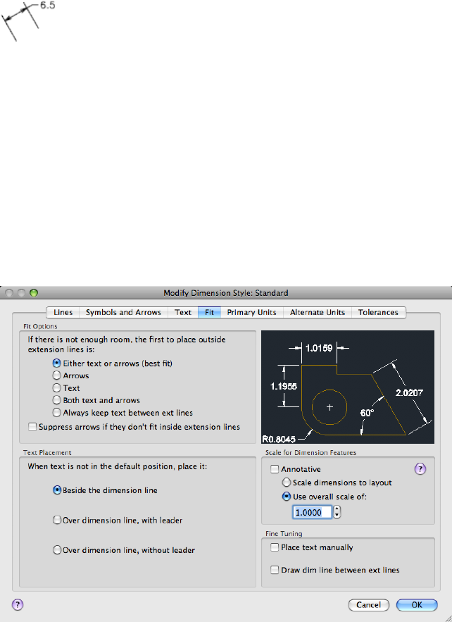
Preview
Displays sample dimension images that show the effects of changes you make
to dimension style settings.
See also:
Use Dimension Styles
Fit Tab
Controls the placement of dimension text, arrowheads, leader lines, and the
dimension line.
List of Options
The following options are displayed.
Commands | 331
Fit Options
Controls the placement of text and arrowheads based on the space available
between the extension lines.
When space is available, text and arrowheads are placed between the extension
lines. Otherwise, text and arrowheads are placed according to the Fit options.
(DIMATFIT (page 1223), DIMTIX (page 1246), and DIMSOXD (page 1242) system
variables)
Either Text or Arrows (Best Fit)
Moves either the text or the arrowheads outside the extension lines based on
the best fit (DIMATFIT (page 1223) system variable).
■When enough space is available for text and arrowheads, places both
between the extension lines. Otherwise, either the text or the arrowheads
are moved based on the best fit.
■When enough space is available for text only, places text between the
extension lines and places arrowheads outside the extension lines.
■When enough space is available for arrowheads only, places them between
the extension lines and places text outside the extension lines.
■When space is available for neither text nor arrowheads, places them both
outside the extension lines.
Arrows
Moves arrowheads outside the extension lines first, then text (DIMATFIT (page
1223) system variable).
■When enough space is available for text and arrowheads, places both
between the extension lines.
■When space is available for arrowheads only, places them between the
extension lines and places text outside them.
■When not enough space is available for arrowheads, places both text and
arrowheads outside the extension lines.
Text
332 | Chapter 2 Commands
Moves text outside the extension lines first, then arrowheads (DIMATFIT (page
1223) system variable).
■When space is available for text and arrowheads, places both between the
extension lines.
■When space is available for text only, places the text between the extension
lines and places arrowheads outside them.
■When not enough space is available for text, places both text and
arrowheads outside the extension lines.
Both Text and Arrows
When not enough space is available for text and arrowheads, moves both
outside the extension lines (DIMATFIT (page 1223) system variable).
Always Keep Text Between Ext Lines
Always places text between extension lines. (DIMTIX (page 1246) system variable)
Suppress Arrows If They Don't Fit Inside Extension Lines
Suppresses arrowheads if not enough space is available inside the extension
lines. (DIMSOXD (page 1242) system variable)
Text Placement
Sets the placement of dimension text when it is moved from the default
position, that is, the position defined by the dimension style. ( DIMTMOVE
(page 1247) system variable)
Beside the Dimension Line
If selected, moves the dimension line whenever dimension text is moved.
(DIMTMOVE (page 1247) system variable)
Commands | 333
Over the Dimension Line, with Leader
If selected, dimension lines are not moved when text is moved. If text is moved
away from the dimension line, a leader line is created connecting the text to
the dimension line. The leader line is omitted when text is too close to the
dimension line. (DIMTMOVE (page 1247) system variable)
Over the Dimension Line, Without Leader
If selected, dimension lines are not moved when text is moved. Text that is
moved away from the dimension line is not connected to the dimension line
with a leader. (DIMTMOVE (page 1247) system variable)
Scale for Dimension Features
Sets the overall dimension scale value or the paper space scaling.
Annotative
Specifies that the dimension is annotative. Click the information icon to learn
more about annotative objects.
Scale Dimensions To Layout
Determines a scale factor based on the scaling between the current model
space viewport and paper space. (DIMSCALE system variable)
When you work in paper space, but not in a model space viewport, or when
TILEMODE (page 1464) is set to 1, the default scale factor of 1.0 is used or the
DIMSCALE system variable.
Use Overall Scale Of
Sets a scale for all dimension style settings that specify size, distance, or spacing,
including text and arrowhead sizes. This scale does not change dimension
measurement values. (DIMSCALE (page 1239) system variable)
Fine Tuning
Provides additional options for placing dimension text.
Place Text Manually
334 | Chapter 2 Commands
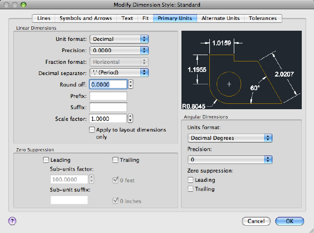
Ignores any horizontal justification settings and places the text at the position
you specify at the Dimension Line Location prompt. (DIMUPT (page 1252)
system variable)
Draw Dim Line Between Ext Lines
Draws dimension lines between the measured points even when the
arrowheads are placed outside the measured points. (DIMTOFL (page 1247)
system variable)
Preview
Displays sample dimension images that show the effects of changes you make
to dimension style settings.
See also:
Use Dimension Styles
Primary Units Tab
Sets the format and precision of primary dimension units and sets prefixes
and suffixes for dimension text.
Commands | 335
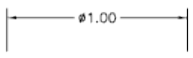
List of Options
The following options are displayed.
Linear Dimensions
Sets the format and precision for linear dimensions.
Unit Format
Sets the current units format for all dimension types except Angular. (DIM-
LUNIT (page 1236) system variable)
The relative sizes of numbers in stacked fractions are based on the DIMTFAC
(page 1244) system variable (in the same way that tolerance values use this
system variable).
Precision
Displays and sets the number of decimal places in the dimension text. (DIM-
DEC (page 1229) system variable)
Fraction Format
Sets the format for fractions. (DIMFRAC (page 1231) system variable)
Decimal Separator
Sets the separator for decimal formats. (DIMDSEP (page 1230) system variable)
Round Off
Sets rounding rules for dimension measurements for all dimension types
except Angular. If you enter a value of 0.25, all distances are rounded to the
nearest 0.25 unit. If you enter a value of 1.0, all dimension distances are
rounded to the nearest integer. The number of digits displayed after the decimal
point depends on the Precision setting. (DIMRND system variable)
Prefix
Includes a prefix in the dimension text. You can enter text or use control
codes to display special symbols. For example, entering the control code %%c
displays the diameter symbol. When you enter a prefix, it overrides any default
prefixes such as those used in diameter and radius dimensioning. (DIMPOST
(page 1238) system variable)
If you specify tolerances, the prefix is added to the tolerances as well as to the
main dimension.
For more information, see Control Codes and Special Characters (page 1049).
336 | Chapter 2 Commands
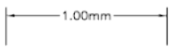
Suffix
Includes a suffix in the dimension text. You can enter text or use control codes
to display special symbols. For example, entering the text mm results in
dimension text similar to that shown in the illustration. When you enter a
suffix, it overrides any default suffixes. (DIMPOST (page 1238) system variable)
If you specify tolerances, the suffix is added to the tolerances as well as to the
main dimension.
For more information, see Control Codes and Special Characters (page 1049).
Scale Factor Sets a scale factor for linear dimension measurements. It is
recommended that you do not change this value from the default value of
1.00. For example, if you enter 2, the dimension for a 1-inch line is displayed
as two inches. The value does not apply to angular dimensions and is not
applied to rounding values or to plus or minus tolerance values. (DIMLFAC
(page 1234) system variable)
Apply to Layout Dimension Only Applies the measurement scale factor only
to dimensions created in layout viewports. Except when using nonassociative
dimensions, this setting should remain unchecked. (DIMLFAC (page 1234) system
variable)
Zero Suppression
Controls the suppression of leading and trailing zeros and of feet and inches
that have a value of zero. (DIMZIN (page 1253) system variable)
Zero suppression settings also affect real-to-string conversions performed by
the AutoLISP® rtos and angtos functions.
Leading
Suppresses leading zeros in all decimal dimensions. For example, 0.5000
becomes .5000. Select leading to enable display of dimension distances less
than one unit in sub units.
Sub-units factor
Sets the number of sub units to a unit. It is used to calculate the dimension
distance in a sub unit when the distance is less than one unit. For example,
enter 100 if the suffix is m and the sub-unit suffix is to display in cm.
Sub-unit suffix
Commands | 337
Includes a suffix to the dimension value sub unit. You can enter text or use
control codes to display special symbols. For example, enter cm for .96m to
display as 96cm.
Trailing
Suppresses trailing zeros in all decimal dimensions. For example, 12.5000
becomes 12.5, and 30.0000 becomes 30.
0 Feet
Suppresses the feet portion of a feet-and-inches dimension when the distance
is less than one foot. For example, 0'-6 1/2" becomes 6 1/2".
0 Inches
Suppresses the inches portion of a feet-and-inches dimension when the
distance is an integral number of feet. For example, 1'-0" becomes 1'.
Angular Dimensions
Displays and sets the current angle format for angular dimensions.
Units Format
Sets the angular units format. (DIMAUNIT (page 1223) system variable)
Precision
Sets the number of decimal places for angular dimensions. DIMADEC (page
1215) system variable)
Zero Suppression
Controls the suppression of leading and trailing zeros. (DIMAZIN (page 1224)
system variable)
Leading
Suppresses leading zeros in angular decimal dimensions. For example, 0.5000
becomes .5000.
You can also display dimension distances less than one unit in sub units.
Trailing
Suppresses trailing zeros in angular decimal dimensions. For example, 12.5000
becomes 12.5, and 30.0000 becomes 30.
Preview
Displays sample dimension images that show the effects of changes you make
to dimension style settings.
338 | Chapter 2 Commands
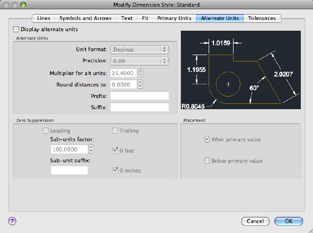
See also:
Use Dimension Styles
Alternate Units Tab
Specifies display of alternate units in dimension measurements and sets their
format and precision.
List of Options
The following options are displayed.
Display Alternate Units
Adds alternate measurement units to dimension text. Sets the DIMALT (page
1216) system variable to 1.
Alternate Units
Displays and sets the current alternate units format for all dimension types
except Angular.
Unit Format
Commands | 339
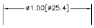
Sets the unit format for alternate units. (DIMALTU (page 1218) system variable)
The relative sizes of numbers in stacked fractions are based on DIMTFAC (page
1244) (in the same way that tolerance values use this system variable).
Precision
Sets the number of decimal places for alternate units. (DIMALTD (page 1216)
system variable)
Multiplier for Alt Units
Specifies the multiplier used as the conversion factor between primary and
alternate units. For example, to convert inches to millimeters, enter 25.4. The
value has no effect on angular dimensions, and it is not applied to the rounding
value or the plus or minus tolerance values. (DIMALTF (page 1217) system
variable)
Round Distances To
Sets rounding rules for alternate units for all dimension types except Angular.
If you enter a value of 0.25, all alternate measurements are rounded to the
nearest 0.25 unit. If you enter a value of 1.0, all dimension measurements are
rounded to the nearest integer. The number of digits displayed after the decimal
point depends on the Precision setting. (DIMALTRND (page 1217) system
variable)
Prefix
Includes a prefix in the alternate dimension text. You can enter text or use
control codes to display special symbols. For example, entering the control
code %%c displays the diameter symbol. (DIMAPOST (page 1220) system
variable)
For more information, see Control Codes and Special Characters (page 1049).
Suffix
Includes a suffix in the alternate dimension text. You can enter text or use
control codes to display special symbols. For example, entering the text cm
results in dimension text similar to that shown in the illustration. When you
enter a suffix, it overrides any default suffixes. (DIMAPOST (page 1220) system
variable)
For more information, see Control Codes and Special Characters (page 1049).
340 | Chapter 2 Commands
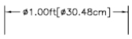
Zero Suppression
Controls the suppression of leading and trailing zeros and of feet and inches
that have a value of zero. (DIMALTZ (page 1219) system variable)
Leading
Suppresses leading zeros in all decimal dimensions. For example, 0.5000
becomes .5000.
Sub-units factor
Sets the number of sub units to a unit. It is used to calculate the dimension
distance in a sub unit when the distance is less than one unit. For example,
enter 100 if the suffix is m and the sub-unit suffix is to display in cm.
Sub-unit suffix
Includes a suffix to the dimension value sub unit. You can enter text or use
control codes to display special symbols. For example, enter cm for .96m to
display as 96cm.
Trailing
Suppresses trailing zeros in all decimal dimensions. For example, 12.5000
becomes 12.5, and 30.0000 becomes 30.
0 Feet
Suppresses the feet portion of a feet-and-inches dimension when the distance
is less than 1 foot. For example, 0'-6 1/2" becomes 6 1/2".
0 Inches
Suppresses the inches portion of a feet-and-inches dimension when the
distance is an integral number of feet. For example, 1'-0" becomes 1'.
Placement
Controls the placement of alternate units in dimension text.
After Primary Value
Places alternate units after the primary units in dimension text.
Below Primary Value
Places alternate units below the primary units in dimension text.
Commands | 341
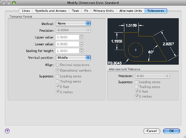
Preview
Displays sample dimension images that show the effects of changes you make
to dimension style settings.
See also:
Use Dimension Styles
Tolerances Tab
Specifies the display and format of dimension text tolerances.
List of Options
The following options are displayed.
Tolerance Format
Controls the tolerance format.
Method
342 | Chapter 2 Commands
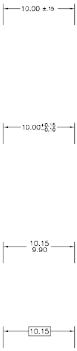
Sets the method for calculating the tolerance. (DIMTOL (page 1248) system
variable)
■None: Does not add a tolerance. The DIMTOL (page 1248) system variable is
set to 0.
■Symmetrical: Adds a plus/minus expression of tolerance in which a single
value of variation is applied to the dimension measurement. A
plus-or-minus sign appears after the dimension. Enter the tolerance value
in Upper Value. The DIMTOL (page 1248) system variable is set to 1. The
DIMLIM (page 1235) system variable is set to 0.
■Deviation: Adds a plus/minus tolerance expression. Different plus and
minus values of variation are applied to the dimension measurement. A
plus sign (+) precedes the tolerance value entered in Upper Value, and a
minus sign (-) precedes the tolerance value entered in Lower Value. The
DIMTOL (page 1248) system variable is set to 1. The DIMLIM (page 1235) system
variable is set to 0.
■Limits: Creates a limit dimension. A maximum and a minimum value are
displayed, one over the other. The maximum value is the dimension value
plus the value entered in Upper Value. The minimum value is the
dimension value minus the value entered in Lower Value. The DIMTOL
(page 1248) system variable is set to 0. TheDIMLIM (page 1235) system variable
is set to 1.
■Basic: Creates a basic dimension, which displays a box around the full
extents of the dimension. The distance between the text and the box is
stored as a negative value in the DIMGAP (page 1232) system variable.
Precision
Commands | 343
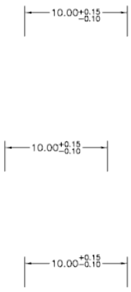
Sets the number of decimal places. (DIMTDEC (page 1244) system variable)
Upper Value
Sets the maximum or upper tolerance value. When you select Symmetrical in
Method, this value is used for the tolerance. (DIMTP (page 1249) system variable)
Lower Value
Sets the minimum or lower tolerance value. (DIMTM (page 1246) system variable)
Scaling for Height
Sets the current height for the tolerance text. The ratio of the tolerance height
to the main dimension text height is calculated and stored in the DIMTFAC
(page 1244) system variable.
Vertical Position
Controls text justification for symmetrical and deviation tolerances.
■Top: Aligns the tolerance text with the top of the main dimension text.
When you select this option, the DIMTOLJ (page 1248) system variable is set
to 2.
■Middle: Aligns the tolerance text with the middle of the main dimension
text. When you select this option, the DIMTOLJ system variable is set to
1.
■Bottom: Aligns the tolerance text with the bottom of the main dimension
text. When you select this option, the DIMTOLJ system variable is set to
0.
Align
Controls the alignment of upper and lower tolerance values when stacked
Decimal Separators
344 | Chapter 2 Commands
Values are stacked by their decimal separators.
Operational Symbols
Values are stacked by their operational symbols.
Suppress
Controls the suppression of leading and trailing zeros and of feet and inches
that have a value of zero. (DIMTZIN (page 1251) system variable)
Zero suppression settings also affect real-to-string conversions performed by
the AutoLISP®rtos and angtos functions.
Leading Zeros
Suppresses leading zeros in all decimal dimensions. For example, 0.5000
becomes .5000.
Trailing Zeros
Suppresses trailing zeros in all decimal dimensions. For example, 12.5000
becomes 12.5, and 30.0000 becomes 30.
0 Feet
Suppresses the feet portion of a feet-and-inches dimension when the distance
is less than 1 foot. For example, 0'-6 1/2" becomes 6 1/2".
0 Inches
Suppresses the inches portion of a feet-and-inches dimension when the
distance is an integral number of feet. For example, 1'-0" becomes 1'.
Alternate Unit Tolerance
Formats alternate tolerance units.
Precision
Displays and sets the number of decimal places. (DIMALTTD (page 1217) system
variable)
Suppress
Controls the suppression of leading and trailing zeros and of feet and inches
that have a value of zero. (DIMALTTZ (page 1218) system variable)
Leading Zeros
Suppresses leading zeros in all decimal dimensions. For example, 0.5000
becomes .5000.
Trailing Zeros
Commands | 345
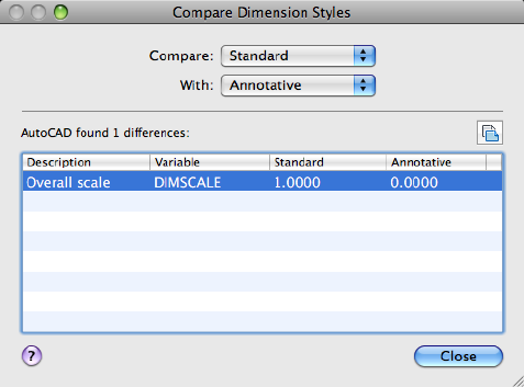
Suppresses trailing zeros in all decimal dimensions. For example, 12.5000
becomes 12.5, and 30.0000 becomes 30.
0 Feet
Suppresses the feet portion of a feet-and-inches dimension when the distance
is less than 1 foot. For example, 0'-6 1/2" becomes 6 1/2".
0 Inches
Suppresses the inches portion of a feet-and-inches dimension when the
distance is an integral number of feet. For example, 1'-0" becomes 1'.
Preview
Displays sample dimension images that show the effects of changes you make
to dimension style settings.
See also:
Use Dimension Styles
Compare Dimension Styles Dialog Box
Compares the properties of two dimension styles or displays all properties of
one style.
346 | Chapter 2 Commands
Summary
You can output the results of the comparison to the Clipboard, and then paste
to other applications.
List of Options
The following options are displayed.
Compare
Specifies the first dimension style for the comparison.
With
Specifies the second dimension style for the comparison. If you set the second
style to <none> or to the same style as the first, all the properties of the
dimension style are displayed.
Comparison results are displayed automatically under the following headings:
■Description of the dimension style property
■System variable that controls the property
■System variable values of style properties that differ for each dimension
style
Results
Displays the results of the dimension style comparison. If you compare two
different styles, the properties that differ are displayed. If you set the second
style to <none> or to the same style as the first, all the properties of the
dimension style are displayed.
Copy to Clipboard button
Copies the results of the comparison to the Clipboard. You can then paste the
results to other applications, such as word processors and spreadsheets.
See also:
Use Dimension Styles
-DIMSTYLE
Creates and modifies dimension styles.
Commands | 347
Summary
You can save or restore dimensioning system variables to a selected dimension
style.
List of Prompts
The following prompts are displayed.
Current dimension style: <current> Annotative: <current>
Enter a dimension style option
[ANnotative (page ?)/Save (page ?)/Restore (page ?)/STatus
(page ?)/Variables (page ?)/Apply (page ?)/?(page ?)]
<Restore>: Enter an option or press Enter
Annotative
Creates an annotative dimension style.
Save
Saves the current settings of dimensioning system variables to a dimension
style.
Name Saves the current settings of dimensioning system variables to a new
dimension style using the name you enter. The new dimension style becomes
the current one.
If you enter the name of an existing dimension style, the following prompts
are displayed:
That name is already in use, redefine it? <N>: Enter y or press Enter
If you enter y, associative dimensions that use the redefined dimension style
are regenerated.
To display the differences between the dimension style name you want to
save and the current style, enter a tilde (~) followed by the style name at the
Enter Name for New Dimension Style prompt. Only settings that differ are
displayed, with the current setting in the first column, and the setting of the
compared style in the second column.
?—List Dimension Styles Lists the named dimension styles in the current
drawing.
Restore
Restores dimensioning system variable settings to those of a selected dimension
style.
Name Makes the dimension style you enter the current dimension style.
To display the differences between the dimension style name you want to
restore and the current style, enter a tilde (~) followed by the style name at
348 | Chapter 2 Commands
the Enter Dimension Style Name prompt. Only settings that differ are
displayed, with the current setting in the first column, and the setting of the
compared style in the second column. After the differences are displayed, the
previous prompt returns.
?—List Dimension Styles Lists the named dimension styles in the current
drawing.
Select Dimension Makes the dimension style of the selected object the current
dimension style.
Status
Displays the current values of all dimension system variables.
Variables
Lists the dimension system variable settings of a dimension style or selected
dimensions without modifying the current settings.
Name Lists the settings of dimension system variables for the dimension style
name you enter.
To display the differences between a particular dimension style and the current
style, enter a tilde (~) followed by the style name at the Enter Dimension Style
Name prompt. Only settings that differ are displayed, with the current setting
in the first column, and the setting of the compared style in the second
column.
?—List Dimension Styles Lists the named dimension styles in the current
drawing.
Select Dimension Lists the dimension style and any dimension overrides for
the dimension object you select.
Apply
Applies the current dimensioning system variable settings to selected
dimension objects, permanently overriding any existing dimension styles
applied to these objects.
The dimension line spacing between existing baseline dimensions is not
updated (see the DIMDLI (page 1230) system variable); dimension text variable
settings do not update existing leader text.
?—List Dimension Styles
Lists the named dimension styles in the current drawing.
See also:
Use Dimension Styles
Commands | 349
DIMTEDIT
Moves and rotates dimension text and relocates the dimension line.
Access Methods
Button
Toolbar: Annotation tool set ➤ Dimensions tool group (expanded) ➤
Text Angle
Toolbar: Annotation tool set ➤ Dimensions tool group (expanded) ➤
Left Justify, Center Justify, Right Justify
Menu: Dimension ➤ Align Text ➤ Angle
Summary
The companion command that edits the dimension text and changes the
extension line angle is DIMEDIT.
List of Prompts
The following prompts are displayed.
Select dimension: Select a dimension object
You are prompted for the new location of the dimension text.
Specify new location for dimension text (page 350) or [Left
(page 350)/Right (page 351)/Center (page 351)/Home (page
351)/Angle (page 352)]: Specify a point or enter an option
Location for Dimension Text Updates the location of the dimension text
dynamically as you drag it. To determine whether text appears above, below,
or in the middle of the dimension line, use the Text tab in the New, Modify,
and Override Dimension Style dialog box.
Left Left-justifies the dimension text along the dimension line.
This option works only with linear, radius, and diameter dimensions.
350 | Chapter 2 Commands

Right Right-justifies the dimension text along the dimension line.
This option works only with linear, radius, and diameter dimensions.
Center Centers the dimension text on the dimension line.
This option works only with linear, radius, and diameter dimensions.
Home Moves the dimension text back to its default position.
For example:
Commands | 351
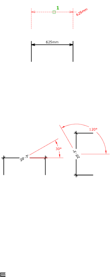
Angle Changes the angle of the dimension text.
The center point of the text does not change. If the text moves or the
dimension is regenerated, the orientation set by the text angle is retained.
Entering an angle of 0 degrees puts the text in its default orientation.
The text angle is measured from the X axis of the UCS.
See also:
Modify Dimension Text
DIST
Measures the distance and angle between two points.
Access Method
Command entry: 'dist for transparent use
352 | Chapter 2 Commands
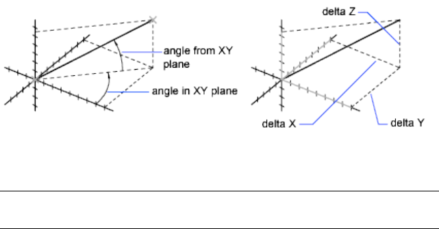
Summary
In general, the DIST command reports 3D distances in model space and 2D
distances on a layout in paper space.
In model space, changes in X, Y, and Z component distances and angles are
measured in 3D relative to the current UCS.
In paper space, distances are normally reported in 2D paper space units.
However, when using object snaps on model space objects that are displayed
in a single viewport, distances are reported as 2D model space distances
projected onto a plane parallel to your screen.
List of Prompts
The following prompts are displayed.
Specify first point: Specify a point
Specify second point or <Multiple points>: Specify a second point
The distance is displayed in the current units format.
DIST assumes the current elevation for the first or second point if you omit
the Z coordinate value.
NOTE When using the DIST command for 3D distances, it is recommended that
you switch to model space.
Multiple Points If you specify multiple points, a running total of the distance
based on the existing line segments and the current rubberband line is
displayed in the tooltip. A dynamic dimension is also displayed. The distance
is updated as you move the cursor.
See also:
Obtain Distances, Angles, and Point Locations
Commands | 353
DISTANTLIGHT
Creates a distant light.
Access Methods
Button
Toolbar: Modeling tool set ➤ Lights tool group (expanded) ➤ Distant
Light
Menu: View ➤ Render ➤ Light ➤ New Distant Light
List of Prompts
The following prompts are displayed.
Specify light direction FROM <0,0,0> or [Vector]: Specify a point
or enterv
Specify light direction TO <1,1,1>: Specify a point
If you enter the Vector option, the following prompt is displayed:
Specify vector direction <0.0000,-0.0100,1.0000>: Enter a vector
After you specify the light direction and if the LIGHTINGUNITS system variable
is set to 0, the following prompt is displayed:
Enter an option to change [Name (page ?)/Intensity (page
?)/Status (page ?)/shadoW (page ?)/Color (page ?)/eXit]
<eXit>:
If the LIGHTINGUNITS system variable is set to 1 or 2, the following prompt
is displayed:
Enter an option to change [Name (page ?)/Intensity factor
(page ?)/Status (page ?)/Photometry (page ?)/shadoW (page
?)/filterColor (page ?)/eXit] <eXit>:
NOTE
When the LIGHTINGUNITS system variable is set to 1 or 2, the Attenuation
option has no affect on the creation of the light. It is only maintained for
scripting compatibility.
354 | Chapter 2 Commands
Name
Specifies the name of the light. You can use uppercase and lowercase letters,
numbers, spaces, hyphens (-), and underscores (_) in the name. The maximum
length is 256 characters.
Intensity/Intensity Factor
Sets the intensity or brightness of the light. The range is 0.00 to the maximum
value that is supported by your system.
Status
Turns the light on and off. If lighting is not enabled in the drawing, this setting
has no effect.
Photometry
Photometry is available when the LIGHTINGUNITS system variable is set to
1 or 2. Photometry is the measurement of the luminous intensities of visible
light sources.
In photometry, luminous intensity is a measure of the perceived power emitted
by a light source in a particular direction. Luminous flux is the perceived
power per unit of solid angle. The total luminous flux is the perceived power
emitted in all directions. Luminance is the total luminous flux incident on a
surface, per unit area.
Intensity Enter an intensity value in candelas, the perceived power in a
luminous flux value, or illuminance value for the total luminous flux incident
on a surface.
■Candela (symbol: cd) is the SI unit of luminous intensity (perceived power
emitted by a light source in a particular direction). Cd/Sr
■Lux (symbol: lx) is the SI unit of illuminance. Lm/m^2
■Foot-candle (symbol: fc) is the American unit of illuminance. Lm/ft^2
Enter f to specify the perceived power in a luminous flux value.
If you enter i, you can specify the intensity of the light based on an
illuminance value.
The illuminance value can be specified in either lux or foot-candles. Enter d
to specify a distance to use to calculate illuminance.
Color Specify the color of the light based on a color name or a Kelvin
temperature. Enter ? to display a list of color names.
Enter a text string using wild card characters to display a partial listing of color
names, or an asterick (*) to display all the possible choices.
If you enter k, you can specify the color of the light based on a Kelvin
temperature value.
Commands | 355
Shadow
Makes the light cast shadows.
Off Turns off display and calculation of shadows for the light. Turning shadows
off increases performance.
Sharp Displays shadows with sharp edges. Use this option to increase
performance.
Soft Mapped Displays realistic shadows with soft edges.
Specifies the amount of memory that should be used to calculate the shadow
map.
Specifies the softness to use to calculate the shadow map.
Color/Filter Color
Controls the color of the light.
True Color Specifies a True Color. Enter in the format R,G,B (red, green, blue).
Index Specifies an ACI (AutoCAD Color Index) color.
HSL Specifies an HSL (hue, saturation, luminance) color.
Color Book Specifies a color from a color book.
See also:
Use Distant Lights
DIVIDE
Creates evenly spaced point objects or blocks along the length or perimeter
of an object.
Access Methods
Button
Toolbar: Drafting tool set ➤ Open Shapes tool group (expanded) ➤
Point flyout ➤ Divide
Menu: Draw ➤ Point ➤ Divide
356 | Chapter 2 Commands
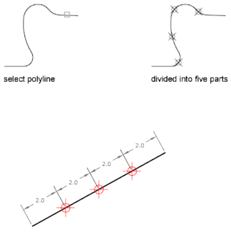
List of Prompts
The following prompts are displayed.
Select object to divide: Use an object selection method
Enter number of segments (page ?) or [Block (page ?)]: Enter
a value from 2 through 32,767, or enter b
Number of Segments
Places point objects at equal intervals along the selected objects.
Use DDPTYPE (page 266) to set the style and size of all point objects in a
drawing.
Block
Places blocks at equal intervals along the selected object. If the block has
variable attributes, these attributes are not included.
Yes Specifies that the X axes of the inserted blocks be tangent to, or collinear
with, the divided object at the dividing points.
No Aligns the blocks according to their normal orientation.
The illustration shows an arc divided into five equal parts using a block
consisting of a vertically oriented ellipse.
Commands | 357
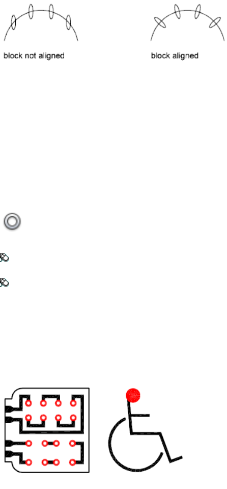
See also:
Divide an Object into Equal Segments
DONUT
Creates a filled circle or a wide ring.
Access Methods
Button
Toolbar: Drafting tool set ➤ Closed Shapes tool group (expanded) ➤
Donut
Menu: Draw ➤ Donut
Summary
A donut consists of two arc polylines that are joined end-to-end to create a
circular shape. The width of the polylines is determined by the specified inside
and outside diameters. To create solid-filled circles, specify an inside diameter
of zero.
358 | Chapter 2 Commands
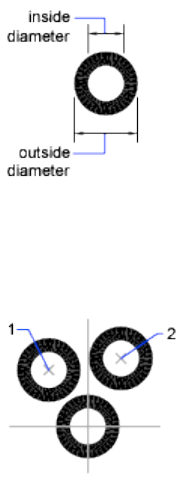
List of Prompts
The following prompts are displayed.
Specify inside diameter of donut <current>: Specify a distance or press
Enter
If you specify an inside diameter of 0, the donut is a filled circle.
Specify outside diameter of donut <current>: Specify a distance or
press Enter
Specify center of donut or <exit>: Specify a point (1) or press Enter
to end the command
The location of the donut is set based on the center point. After you specify
the diameters, you are prompted for the locations at which to draw donuts.
A donut is drawn at each point specified (2). How the interior of a donut is
filled depends on the current setting of the FILL (page 431) command.
See also:
Draw Donuts
DRAGMODE
Controls the way dragged objects are displayed.
Commands | 359

Access Method
Command entry: 'dragmode for transparent use
List of Prompts
The following prompts are displayed.
Enter new value [ON (page 360)/OFF (page 360)/Auto (page 360)]
<current>: Enter an option or press Enter
On Permits dragging, but you must enter drag where appropriate in a drawing
or editing command to initiate dragging.
Off Ignores all dragging requests, including those embedded in menu items.
Auto Turns on dragging for every command that supports it. Dragging is
performed whenever it is possible. Entering drag each time is not necessary.
See also:
Set Up the Drawing Area
DRAWINGRECOVERY
Displays a list of drawing files that can be recovered after a program or system
failure.
Access Methods
Menu: Help ➤ Recover Files
360 | Chapter 2 Commands
Summary
Opens the Files Recovered dialog box (page 361).
See also:
Recover from a System Failure
Files Recovered Dialog Box
Displays a list of all drawing files that were open at the time of a program or
system failure.
Summary
You can preview and open each drawing or backup file to choose which one
should be saved as the primary DWG file.
List of Options
The following options are displayed.
Backup Files
Displays the drawings that may need to be recovered after a program or system
failure. A top-level drawing node contains a set of files associated with each
drawing. If available, up to four files are displayed including
■The recovered drawing file saved at the time of a program failure (DWG)
■The automatic save file, also called the “autosave” file (SV$)
■The drawing backup file (BAK)
■The original drawing file (DWG)
Once a drawing or backup file is opened and saved, the corresponding top-level
drawing node is removed from the Backup Files area.
Preview
Displays a thumbnail preview of the currently selected drawing or backup file.
Click the arrows below the current thumbnail preview to cycle through the
previews of all the drawing or backup files that can be recovered.
Shortcut Menu Options
Right-click a drawing node, drawing or backup file, or a blank area in the
Backup Files area to display a shortcut menu with relevant options.
Commands | 361
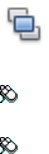
Reveal in Finder Opens Finder to the location of the selected drawing or
backup file.
Select All Selects all the drawing or backup files that can be recovered.
Select None Deselects all the currently selected drawing or backup files.
Select Most Recent Selects the most recent drawing or backup files that can
be recovered. All other files are deselected.
Delete File Moves the selected file to the Trash. Applies to SV$ or BAK files
only.
Show this screen after crash
Specifies whether the Files Recovered dialog box is displayed the next time
AutoCAD for Mac is started after a program or system failure.
See also:
Recover from a System Failure
DRAWINGRECOVERYHIDE
Closes the Files Recovered dialog box.
See also:
Recover from a System Failure
DRAWORDER
Changes the draw order of images and other objects.
Access Methods
Button
Toolbar: Drafting tool set ➤ Move/Rotate/Scale tool group (expanded)
➤ Draw Order flyout
Menu: Tools ➤ Draw Order ➤ Bring to Front
Shortcut menu: Select an object, right-click, and then click Draw Order.
362 | Chapter 2 Commands
Summary
Use the DRAWORDERCTL system variable to control the default display
behavior of overlapping objects. In addition, the TEXTTOFRONT command
brings all text and dimensions in a drawing in front of other objects, and the
HATCHTOBACK command sends all hatch objects behind other objects.
List of Prompts
The following prompts are displayed.
Select objects: Use an object selection method
Enter object ordering option [Above objects (page 363)/Under
objects (page 363)/Front (page 363)/Back (page 363)] <Back>:
Enter an option or press Enter
Above Objects Moves the selected object above the specified reference objects.
Under Objects Moves the selected objects below the specified reference objects.
Front Moves the selected objects to the top of the order of objects in the
drawing.
Back Moves the selected objects to the bottom of the order of objects in the
drawing.
When you change the draw order (display and plotting order) of multiple
objects, the relative draw order of the selected objects is maintained.
By default, when you create new objects from existing ones (for example,
FILLET or PEDIT), the new objects are assigned the draw order of the original
object you selected first. By default, while you edit an object (for example,
MOVE or STRETCH), the object is displayed on top of all objects in the drawing.
When you are finished editing, your drawing is partially regenerated so that
the object is displayed according to its correct draw order. This can result in
some edit operations taking slightly longer. You can use DRAWORDERCTL
(page 1273) to change the default draw order settings.
See also:
Control How Overlapping Objects Are Displayed
DSETTINGS
Sets grid and snap, polar and object snap tracking, object snap modes, and
Dynamic Input.
Commands | 363

Access Methods
Menu: Tools ➤ Drafting Settings
Shortcut menu: Right-click Snap Mode, Grid Display, Polar Tracking, Object
Snap, Object Snap Tracking, or Dynamic Input on the status bar. Choose
Settings.
Summary
The Drafting Settings dialog box (page 364) is displayed.
See also:
Use Precision Tools
Drafting Settings Dialog Box
Specifies drafting settings organized for drawing aids.
Summary
The following categories are available.
■Snap and Grid (page ?)
■Polar Tracking (page ?)
■Object Snap (page ?)
■3D Object Snap (page ?)
■Dynamic Input (page ?)
List of Options
The following options are displayed.
Snap and Grid Tab (Drafting Settings Dialog Box)
Specifies Snap and Grid settings.
364 | Chapter 2 Commands
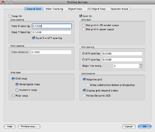
Snap On
Turns Snap mode on or off. You can also turn Snap mode on or off by clicking
Snap on the status bar, by pressing F9, or by using the SNAPMODE (page 1440)
system variable.
Snap Spacing
Controls an invisible, rectangular grid of snap locations that restricts cursor
movement to specified X and Y intervals.
Snap X Spacing
Specifies the snap spacing in the X direction. The value must be a positive real
number. (SNAPUNIT (page 1442) system variable)
Snap Y Spacing
Specifies the snap spacing in the Y direction. The value must be a positive real
number. (SNAPUNIT (page 1442) system variable)
Equal X and Y Spacing
Commands | 365
Forces the X and Y spacing to the same values for snap spacing and for grid
spacing. The snap spacing intervals can be different from the grid spacing
intervals.
Polar Spacing
Controls the PolarSnap™ increment distance.
Polar Distance
Sets the snap increment distance when PolarSnap is selected under Snap Type
& Style. If this value is 0, the PolarSnap distance assumes the value for Snap
X Spacing. The Polar Distance setting is used in conjunction with polar tracking
and/or object snap tracking. If neither tracking feature is enabled, the Polar
Distance setting has no effect. (POLARDIST (page 1400) system variable)
Snap Type
Sets the snap style and snap type.
Grid Snap
Sets the snap type to Grid. When you specify points, the cursor snaps along
vertical or horizontal grid points. (SNAPTYPE (page 1441) system variable)
Rectangular Snap:
Sets the snap style to standard Rectangular snap mode. When the snap type
is set to Grid snap and Snap mode is on, the cursor snaps to a rectangular snap
grid. (SNAPSTYL (page 1441) system variable)
Isometric Snap
Sets the snap style to Isometric snap mode. When the snap type is set to Grid
snap and Snap mode is on, the cursor snaps to an isometric snap grid.
(SNAPSTYL (page 1441) system variable)
PolarSnap
Sets the snap type to Polar. When Snap mode is on and you specify points
with polar tracking turned on, the cursor snaps along polar alignment angles
set on the Polar Tracking tab relative to the starting polar tracking point.
(SNAPTYPE (page 1441) system variable)
Grid On
Turns the grid on or off. You can also turn grid mode on or off by clicking
Grid on the status bar, by pressing Fn-F7, or by using the GRIDMODE (page
1306) system variable.
Grid Style
Sets the grid style in 2D contexts. You can also set grid style by using the
GRIDSTYLE (page 1307) system variable.
366 | Chapter 2 Commands

Dot Grid in 2D Model Space
Sets the grid style to dotted grid for 2D model space. (GRIDSTYLE (page 1307)
system variable)
Dot Grid in Paper Space
Sets the grid style to dotted grid for sheet and layout. (GRIDSTYLE (page 1307)
system variable)
Grid Spacing
Controls the display of a grid that helps you visualize distances.
NOTE The limits of the grid are controlled by the LIMITS (page 573) command
and the GRIDDISPLAY (page 1305) system variable.
Grid X Spacing
Specifies the grid spacing in the X direction. If this value is 0, the grid assumes
the value set for Snap X Spacing. (GRIDUNIT (page 1307) system variable)
Grid Y Spacing
Specifies the grid spacing in the Y direction. If this value is 0, the grid assumes
the value set for Snap Y Spacing. (GRIDUNIT (page 1307) system variable)
Major Line Every
Specifies the frequency of major grid lines compared to minor grid lines. Grid
lines rather than grid dots are displayed when GRIDSTYLE (page 1307) is set to
0. (GRIDMAJOR (page 1306) system variable)
Grid Behavior
Controls the appearance of the grid lines that are displayed when GRIDSTYLE
(page 1307) is set to 0.
Adaptive Grid
Limits the density of the grid when zoomed out. (GRIDDISPLAY (page 1305)
system variable)
Allow Subdivision Below Grid Spacing:
Generates additional, more closely spaced grid lines when zoomed in. The
frequency of these grid lines is determined by the frequency of the major grid
lines. (GRIDDISPLAY (page 1305) and GRIDMAJOR (page 1306) system variables)
Display Grid Beyond Limits
Displays the grid beyond the area specified by the LIMITS (page 573) command.
(GRIDDISPLAY (page 1305) system variable)
Follow Dynamic UCS
Commands | 367
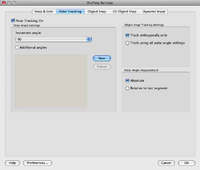
Changes the grid plane to follow the XY plane of the dynamic UCS. (GRID-
DISPLAY (page 1305) system variable)
Polar Tracking Tab (Drafting Settings Dialog Box)
Controls the AutoTrack settings.
Polar Tracking On
Turns polar tracking on and off. You can also turn polar tracking on or off by
pressing F10 or by using the AUTOSNAP (page 1180) system variable.
Polar Angle Settings
Sets the alignment angles for polar tracking. (POLARANG (page 1400) system
variable)
Increment Angle
Sets the polar increment angle used to display polar tracking alignment paths.
You can enter any angle, or select a common angle of 90, 45, 30, 22.5, 18, 15,
10, or 5 degrees from the list. (POLARANG (page 1400) system variable)
Additional Angles
368 | Chapter 2 Commands

Makes any additional angles in the list available for polar tracking. The
Additional Angles check box is also controlled by the POLARMODE (page 1401)
system variable, and the list of additional angles is also controlled by the PO-
LARADDANG (page 1399) system variable.
NOTE
Additional angles are absolute, not incremental.
List of Angles
If Additional Angles is selected, lists the additional angles that are available.
To add new angles, click New. To remove existing angles, click Delete.
(POLARADDANG system variable)
New
Adds up to 10 additional polar tracking alignment angles.
NOTE Before adding fractional angles, you must set the AUPREC (page 1178) system
variable to the appropriate decimal precision to avoid undesired rounding. For
example, if the value of AUPREC is 0 (the default value), all fractional angles you
enter are rounded to the nearest whole number.
Delete
Deletes selected additional angles.
Object Snap Tracking Settings
Sets options for object snap tracking.
Track Orthogonally Only
Displays only orthogonal (horizontal/vertical) object snap tracking paths for
acquired object snap points when object snap tracking is on. (POLARMODE
system variable)
Track Using All Polar Angle Settings
Applies polar tracking settings to object snap tracking. When you use object
snap tracking, the cursor tracks along polar alignment angles from acquired
object snap points. (POLARMODE system variable)
NOTE
Clicking Polar and Otrack on the status bar also turns polar tracking and object
snap tracking on and off.
Polar Angle Measurement
Sets the basis by which polar tracking alignment angles are measured.
Absolute
Commands | 369
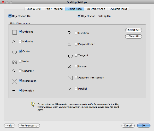
Bases polar tracking angles on the current user coordinate system (UCS).
Relative to Last Segment
Bases polar tracking angles on the last segment drawn.
Object Snap Tab (Drafting Settings Dialog Box)
Controls running object snap settings. With running object snap settings, also
called Osnap, you can specify a snap point at an exact location on an object.
When more than one option is selected, the selected snap modes are applied
to return a point closest to the center of the aperture box. Press TAB to cycle
through the options.
Object Snap On
Turns running object snaps on and off. The object snaps selected under Object
Snap Modes are active while object snap is on. (OSMODE (page 1382) system
variable)
Object Snap Tracking On
Turns object snap tracking on and off. With object snap tracking, the cursor
can track along alignment paths based on other object snap points when
370 | Chapter 2 Commands
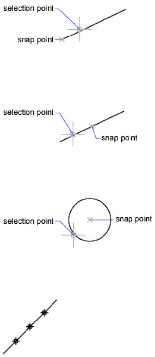
specifying points in a command. To use object snap tracking, you must turn
on one or more object snaps. (AUTOSNAP (page 1180) system variable)
Object Snap Modes
Lists object snaps that you can turn on as running object snaps.
Endpoint
Snaps to the closest endpoint of an arc, elliptical arc, line, multiline, polyline
segment, spline, region, or ray, or to the closest corner of a trace, solid, or 3D
face.
Midpoint
Snaps to the midpoint of an arc, ellipse, elliptical arc, line, multiline, polyline
segment, region, solid, spline, or xline.
Center
Snaps to the center of an arc, circle, ellipse, or elliptical arc.
Node
Snaps to a point object, dimension definition point, or dimension text origin.
Quadrant
Commands | 371
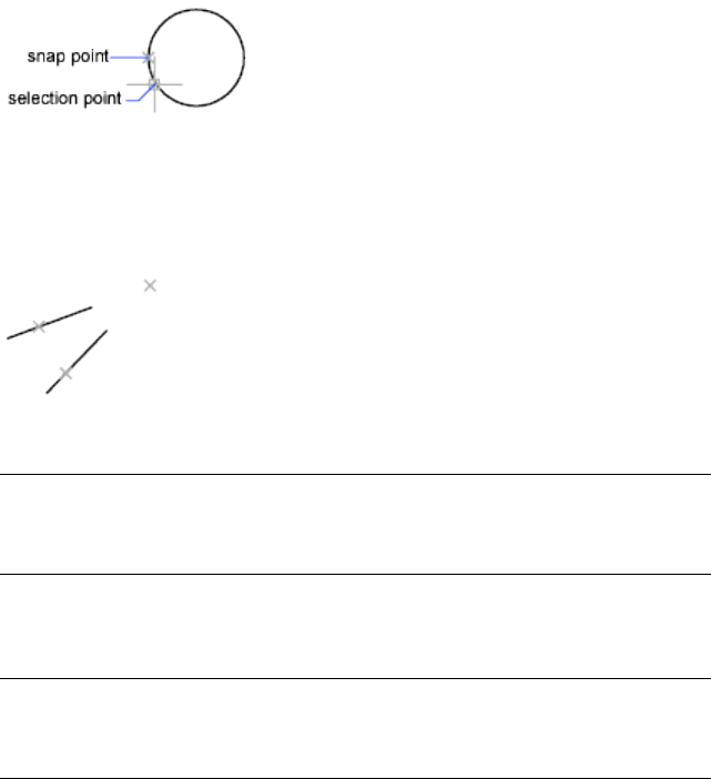
Snaps to a quadrant point of an arc, circle, ellipse, or elliptical arc.
Intersection
Snaps to the intersection of an arc, circle, ellipse, elliptical arc, line, multiline,
polyline, ray, region, spline, or xline. Extended Intersection is not available
as a running object snap.
Intersection and Extended Intersection do not work with edges or corners of
3D solids.
NOTE
You might get varying results if you have both the Intersection and Apparent
Intersection running object snaps turned on at the same time.
Extension
Causes a temporary extension line or arc to be displayed when you pass the
cursor over the endpoint of objects, so you can specify points on the extension.
NOTE
When working in perspective view, you cannot track along the extension line
of an arc or elliptical arc.
Insertion
Snaps to the insertion point of an attribute, a block, a shape, or text.
Perpendicular
Snaps to a point perpendicular to an arc, circle, ellipse, elliptical arc, line,
multiline, polyline, ray, region, solid, spline, or xline.
Deferred Perpendicular snap mode is automatically turned on when the object
you are drawing requires that you complete more than one perpendicular
snap. You can use a line, arc, circle, polyline, ray, xline, multiline, or 3D solid
edge as an object from which to draw a perpendicular line. You can use
372 | Chapter 2 Commands
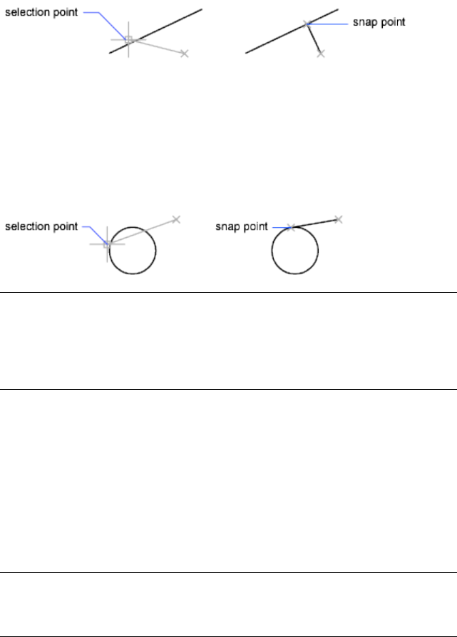
Deferred Perpendicular to draw perpendicular lines between such objects.
When the aperture box passes over a Deferred Perpendicular snap point, an
AutoSnap tooltip and marker are displayed.
Tangent
Snaps to the tangent of an arc, circle, ellipse, elliptical arc, or spline. Deferred
Tangent snap mode is automatically turned on when the object you are
drawing requires that you complete more than one tangent snap. You can use
Deferred Tangent to draw a line or xline that is tangent to arcs, polyline arcs,
or circles. When the aperture box passes over a Deferred Tangent snap point,
a marker and an AutoSnap tooltip are displayed.
NOTE
When you use the From option in conjunction with the Tangent snap mode
to draw objects other than lines from arcs or circles, the first point drawn is
tangent to the arc or circle in relation to the last point selected in the drawing
area.
Nearest
Snaps to the nearest point on an arc, circle, ellipse, elliptical arc, line, multiline,
point, polyline, ray, spline, or xline.
Apparent Intersection
Snaps to the visual intersection of two objects that are not in the same plane
but may appear to intersect in the current view.
Extended Apparent Intersection is not available as a running object snap.
Apparent and Extended Apparent Intersection do not work with edges or
corners of 3D solids.
NOTE
You might get varying results if you have both the Intersection and Apparent
Intersection running object snaps turned on at the same time.
Commands | 373

Parallel
Constrains a line segment, polyline segment, ray or xline to be parallel to
another linear object. After you specify the first point of a linear object, specify
the parallel object snap. Unlike other object snap modes, you move the cursor
and hover over another linear object until the angle is acquired. Then, move
the cursor back toward the object that you are creating. When the path of the
object is parallel to the previous linear object, an alignment path is displayed,
which you can use to create the parallel object.
NOTE
Turn off ORTHO mode before using the parallel object snap. Object snap
tracking and polar snap are turned off automatically during a parallel object
snap operation. You must specify the first point of a linear object before using
the parallel object snap.
Select All
Turns on all object snap modes.
Clear All
Turns off all object snap modes.
3D Object Snap Tab (Drafting Settings Dialog Box)
Controls running object snap settings for 3D objects. With running object
snap settings, also called Osnap, you can specify a snap point at an exact
location on an object. When more than one option is selected, the selected
snap modes are applied to return a point closest to the center of the aperture
box. Press TAB to cycle through the options.
374 | Chapter 2 Commands
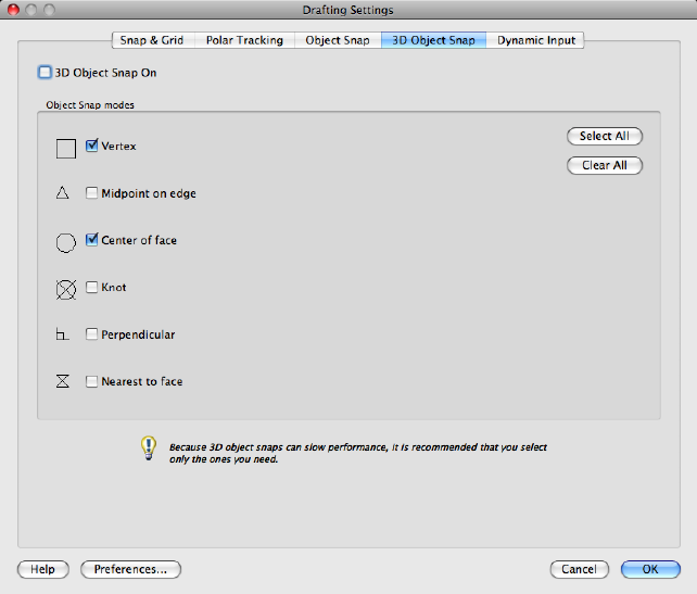
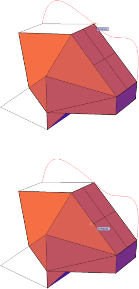
Midpoint on Edge
Snaps to the midpoint of a face edge.
Center of Face
376 | Chapter 2 Commands
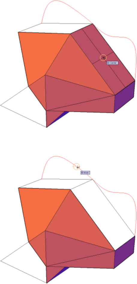
Snaps to the center of a face.
Knot
Snaps to a knot on a spline.
Commands | 377
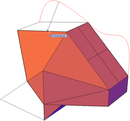
Perpendicular
Snaps to a point perpendicular to a face.
Nearest to Face
Snaps to a point that is nearest to a 3D object face.
378 | Chapter 2 Commands
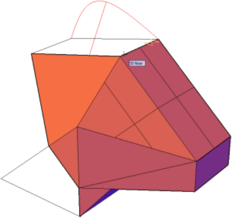
Select All
Turns on all 3D object snap modes.
Clear All
Turns off all 3D object snap modes.
Dynamic Input Tab (Drafting Settings Dialog Box)
Controls pointer input, dimension input, dynamic prompting, and the
appearance of drafting tooltips.
Commands | 379
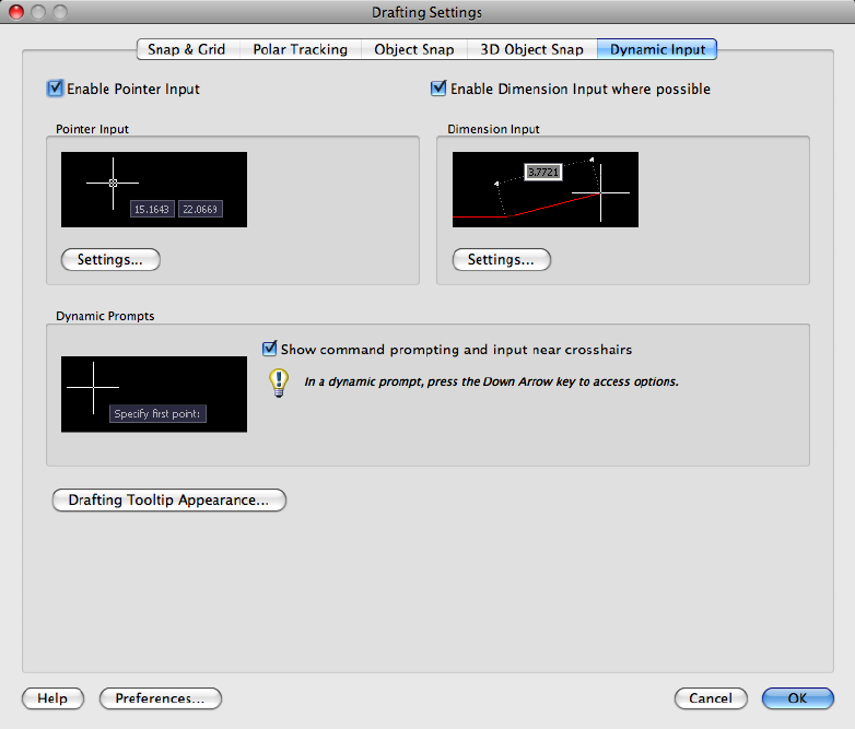
Enable Pointer Input
Turns on pointer input. When pointer input and dimensional input are both
turned on, dimensional input supersedes pointer input when it is available.
(DYNMODE (page 1279) system variable)
Pointer Input
Displays the location of the crosshairs as coordinate values in a tooltip near
the cursor. When a command prompts you for a point, you can enter
coordinate values in the tooltip instead of in the Command window.
Preview Area
Shows an example of pointer input.
Settings
380 | Chapter 2 Commands
Displays the Pointer Input Settings dialog box (page 382).
Enable Dimension Input where Possible
Turns on dimensional input. Dimensional input is not available for some
commands that prompt for a second point. (DYNMODE (page 1279) system
variable)
Dimension Input
Displays a dimension with tooltips for distance value and angle value when
a command prompts you for a second point or a distance. The values in the
dimension tooltips change as you move the cursor. You can enter values in
the tooltip instead of on the command line.
Preview Area
Shows an example of dimensional input.
Settings
Displays the Dimension Input Settings dialog box (page 383).
Dynamic Prompts
Displays prompts in a tooltip near the cursor when necessary in order to
complete the command. You can enter values in the tooltip instead of on the
command line.
Preview Area
Shows an example of dynamic prompts.
Show Command Prompting and Command Input near Crosshairs
Displays prompts in Dynamic Input tooltips. (DYNPROMPT (page 1282) system
variable)
Show Additional Tips with Command Prompting
Controls whether tips for using Shift and Ctrl for grip manipulation are
displayed. (DYNINFOTIPS (page 1279) system variable)
Drafting Tooltip Appearance
Displays the Tooltip Appearance dialog box. (page 384)
See also:
Use Precision Tools
Commands | 381
Pointer Input Settings Dialog Box
Controls the settings of pointer input tooltips.
List of Options
The following options are displayed.
Format
Controls coordinate format in the tooltips that are displayed when pointer
input is turned on.
Polar Format
Displays the tooltip for the second or next point in polar coordinate format.
Enter a comma (,) to change to Cartesian format. (DYNPIFORMAT (page 1281)
system variable)
Cartesian Format
Displays the tooltip for the second or next point in Cartesian coordinate
format. Enter an angle symbol (<) to change to polar format. (DYNPIFORMAT
(page 1281) system variable)
Relative Coordinates
Displays the tooltip for the second or next point in relative coordinate format.
Enter a pound sign (#) to change to absolute format. (DYNPICOORDS (page
1280) system variable)
Absolute Coordinates
Displays the tooltip for the second or next point in absolute coordinate format.
Enter an at sign ( ) to change to relative format. Note that you cannot use the
direct distance method when this option is selected. (DYNPICOORDS (page
1280) system variable)
Visibility
Controls when pointer input is displayed. (DYNPIVIS (page 1281) system variable)
As Soon As I Type Coordinate Data
When pointer input is turned on, displays tooltips only when you start to
enter coordinate data. (DYNPIVIS (page 1281) system variable)
When a Command Asks for a Point
When pointer input is turned on, displays tooltips whenever a command
prompts you for a point. (DYNPIVIS (page 1281) system variable)
382 | Chapter 2 Commands
Always—Even When Not in a Command
Always displays tooltips when pointer input is turned on. (DYNPIVIS (page
1281) system variable)
See also:
Use Dynamic Input
Dimension Input Settings Dialog Box
Controls the settings of dimension input tooltips.
List of Options
The following options are displayed.
Visibility
Controls which tooltips are displayed during grip stretching when dimensional
input is turned on. (DYNDIVIS (page 1278) system variable)
Show Only 1 Dimension Input Field at a Time
Displays only the length change dimensional input tooltip when you are using
grip editing to stretch an object. (DYNDIVIS (page 1278) system variable)
Show 2 Dimension Input Fields at a Time
Displays the length change and resulting dimensional input tooltips when
you are using grip editing to stretch an object. (DYNDIVIS (page 1278) system
variable)
Show the Following Dimension Input Fields Simultaneously
When you are using grip editing to stretch an object, displays the dimensional
input tooltips that are selected below. (DYNDIVIS (page 1278) and DYNDIGRIP
(page 1277) system variables)
Resulting Dimension
Displays a length dimensional tooltip that is updated as you move the grip.
Length Change
Displays the change in length as you move the grip.
Absolute Angle
Displays an angle dimensional tooltip that is updated as you move the grip.
Commands | 383
Angle Change
Displays the change in the angle as you move the grip.
Arc Radius
Displays the radius of an arc, which is updated as you move the grip.
See also:
Use Dynamic Input
Tooltip Appearance Dialog Box
Controls the appearance of tooltips.
Summary
Use the TOOLTIPMERGE (page 1469) system variable to combine drafting tooltips
into a single tooltip.
For more information about tooltips, see Set Interface Options.
List of Options
The following options are displayed.
Previews
Displays an example of the current tooltip appearance settings.
Size
Specifies a size for tooltips. The default size is 0. Use the slider to make tooltips
larger or smaller.
Transparency
Controls the transparency of tooltips. The lower the setting, the less transparent
the tooltip. A value of 0 sets the tooltip to opaque.
Apply To
Specifies whether the settings apply to all drafting tooltips or only to Dynamic
Input tooltips. (DYNTOOLTIPS (page 1282) system variable)
Override OS Settings for All Drafting Tooltips
Applies the settings to all tooltips, overriding the settings in the operating
system.
Use Settings Only for Dynamic Input Tooltips
384 | Chapter 2 Commands
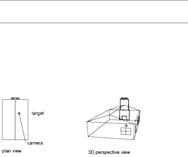
Applies the settings only to the drafting tooltips used in Dynamic Input.
See also:
Use Dynamic Input
DVIEW
Defines parallel projection or perspective views by using a camera and target.
Summary
NOTE Transparent ZOOM (page 1153) and PAN (page 763) are not available in
DVIEW. When you define a perspective view, ZOOM, PAN, transparent ZOOM
and PAN are not available while that view is current.
List of Prompts
The following prompts are displayed.
Select objects (page ?) or <use >.DVIEWBLOCK (page ?)
Enter option
[CAmera (page ?)/TArget (page ?)/Distance (page ?)/POints
(page ?)/PAn (page ?)/Zoom (page ?)/TWist (page ?)/CLip
(page ?)/Hide (page ?)/Off (page ?)/Undo (page ?)]: Spe-
cify a point (page ?) with your pointing device, or enter an option
Object Selection
Specifies objects to use in the preview image as you change views. Selecting
too many objects slows image dragging and updating.
DVIEWBLOCK
If you press Enter at the Select Objects prompt, DVIEWBLOCK displays a
preview image. You can create your own DVIEWBLOCK block in a 1 unit by
Commands | 385
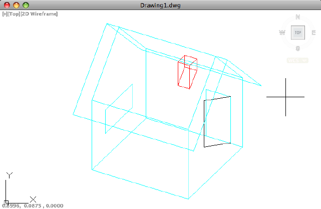
1 unit by 1 unit area, with its origin at the lower-left corner. The following
illustration shows an example of using the default DVIEWBLOCK to set the
view (moving the graphics cursor adjusts the view).
Point Specification
Rolls the view under the camera. The point you select with your pointing
device is a start point for the dragging operation. Your viewing direction
changes about the target point as you move the pointing device.
The angles must be positive. The direction angle indicates the front of the
view, and the magnitude angle determines how far the view rolls.
Camera
Specifies a new camera position by rotating the camera about the target point.
Two angles determine the amount of rotation.
Camera Location Sets the camera's position based on the specified point.
Enter Angle from the XY Plane Sets the camera's position at an angle above
or below the XY plane. An angle of 90 degrees looks down from above, and
an angle of -90 looks up from below. A camera angle of 0 degrees places the
camera parallel to the XY plane of the user coordinate system (UCS).
Toggle (Angle In) Switches between two angle input modes. Entering an angle
at the Command prompt locks the cursor movement so you see only the
positions available for that angle. Toggle unlocks the cursor movement for
the angle, and you can use the cursor to rotate the camera.
386 | Chapter 2 Commands
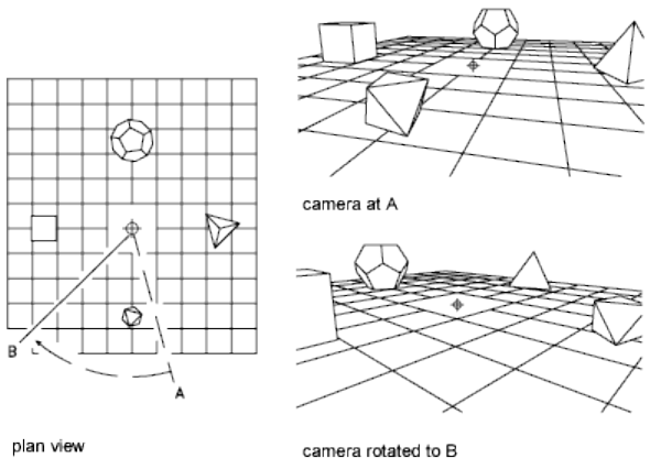
Enter Angle in XY Plane from X Axis Sets the position at an angle in the
XY plane relative to the X axis of the current UCS. This angle measures from
-180 to 180 degrees. A rotation angle of 0 degrees looks down the X axis of
the UCS toward the origin.
The illustration shows the camera rotating to the left from its initial position,
leaving its angle from the XY plane unchanged.
Toggle (Angle From) Switches between two angle input modes. Entering an
angle at the Command prompt locks the cursor movement so you see only
the positions available for that angle. Toggle unlocks the cursor movement
for the angle, and you can use the cursor to rotate the camera.
Target
Specifies a new position for the target by rotating it around the camera. The
effect is like turning your head to see different parts of the drawing from one
vantage point. Two angles determine the amount of rotation.
Enter Angle from the XY Plane Enter Angle from the XY Plane (page 386)
Toggle (Angle In) Toggle (Angle In) (page 386)
Enter Angle in XY Plane from X Axis Enter Angle in XY Plane from X Axis
(page 387)The illustration shows the effect of moving the target point from
left to right, leaving its angle from the XY plane unchanged.
Commands | 387
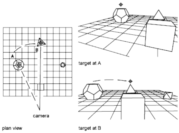
Toggle (Angle From) Toggle (Angle From) (page 387)
Distance
Moves the camera in or out along the line of sight relative to the target. This
option turns on perspective viewing, which causes objects farther from the
camera to appear smaller than those closer to the camera. A special perspective
icon replaces the coordinate system icon. You are prompted for the new
camera-to-target distance.
A slider bar along the top of the drawing area is labeled from 0x to 16x, with
1x representing the current distance. Moving the slider bar to the right
increases the distance between camera and target. Moving it to the left
decreases that distance. To turn off perspective viewing, click the Off option
from the main DVIEW prompt.
If the target and camera points are close together, or if you specify a
long-focal-length lens, you might see very little of your drawing when you
specify a new distance. If you see little or none of your drawing, try the
maximum scale value (16x) or enter a large distance. To magnify the drawing
without turning perspective viewing on, use the Zoom option of DVIEW.
388 | Chapter 2 Commands
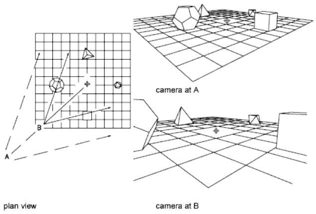
The illustration shows the effect of moving the camera along the line of sight
relative to the target, where the field of view remains constant.
Points
Locates the camera and target points using X,Y,Z coordinates. You can use
XYZ point filters.
To help you define a new line of sight, a rubber-band line is drawn from the
current camera position to the crosshairs. You are prompted for a new camera
location.
A rubber-band line connects the target point to the crosshairs to help you
place the camera relative to the target. The illustration shows the change in
view as you swap the camera and target points. Lens and distance settings are
the same in each case.
Commands | 389
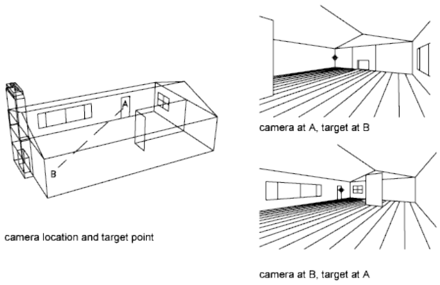
For information about entering direction and magnitude angles, see Point
Specification.
Pan
Shifts the image without changing the level of magnification.
Zoom
If perspective viewing is off, dynamically increases or decreases the apparent
size of objects in the current viewport.
A slider bar along the top of the drawing area is labeled from 0x to 16x, with
1x representing the current scale. Moving the slider bar to the right increases
the scale. Moving it to the left decreases the scale.
If perspective viewing is on, Zoom adjusts the camera lens length, which
changes the field of view and causes more or less of the drawing to be visible
at a given camera and target distance. The default lens length is 50mm,
simulating what you'd see with a 35mm camera and a 50mm lens. Increasing
the lens length is similar to switching to a telephoto lens. Decreasing the lens
length widens the field of view, as with a wide-angle lens.
A slider bar along the top of the drawing area is labeled from 0x to 16x, with
1x representing the current lens length. Moving the slider bar to the right
increases the lens length. Moving it to the left decreases the lens length.
390 | Chapter 2 Commands
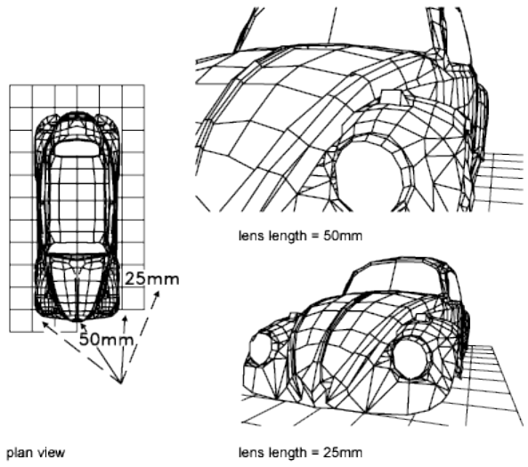
Twist
Twists or tilts the view around the line of sight. The twist angle is measured
counterclockwise, with 0 degrees to the right.
Clip
Clips the view, obscuring portions of the drawing that are behind or in front
of the front clipping plane. The front and back clipping planes are invisible
walls that you can position perpendicular to the line of sight between the
camera and target.
Back Obscures objects located behind the back clipping plane.
■Distance from Target. Positions the back clipping plane and turns on
back clipping. A positive distance places the clipping plane between the
target and the camera. A negative distance places it beyond the target. You
can use the slider bar to drag the clipping plane.
■On. Turns on back clipping at the current clipping distance.
■Off. Turns off back clipping.
Commands | 391
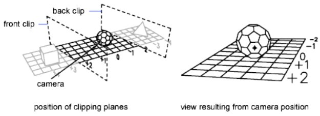
Front Obscures objects located between the camera and the front clipping
plane.
■Distance from Target.Positions the front clipping plane and turns on
front clipping. A positive distance places the clipping plane between the
target and the camera. A negative distance places it beyond the target. You
can use the slider bar to drag the clipping plane.
■Eye. Positions the front clipping plane at the camera.
■On. Turns on front clipping. This option is available only when perspective
viewing is off.
■Off. Turns off front clipping. This option is available only when perspective
viewing is off.
Off Turns off front and back clipping. If perspective viewing is on, front
clipping remains on at the camera position.
Hide
Suppresses hidden lines on the selected objects to aid in visualization. Circles,
solids, traces, regions, wide polyline segments, 3D faces, polygon meshes, and
the extruded edges of objects with nonzero thickness are considered to be
opaque surfaces that hide objects.This hidden line suppression is quicker than
that performed by HIDE (page 506), but it cannot be plotted.
Off
Turns off perspective viewing. The Distance option turns on perspective
viewing.
Undo
Reverses the effects of the last DVIEW action. You can undo multiple DVIEW
operations.
See also:
Specify 3D Views
392 | Chapter 2 Commands

DXBIN
Imports an AutoCAD DXB (drawing interchange binary) file.
Access Methods
Menu: Insert ➤ Drawing Exchange Binary
Summary
AutoCAD DXB files contain only 2D vectors in binary format with 16-bit
integer precision. These vectors are imported as line objects, and they assume
the current layer and object properties.
The Select DXB File dialog box (a standard file selection dialog box (page 720))
is displayed. Enter the name of the file to import.
See also:
DXF and DXB Files
E Commands
EATTEDIT
Edits attributes in a block reference.
Access Methods
Button
Toolbar: Drafting tool set ➤ Block tool group ➤ Edit Attributes flyout
➤ Multiple
Menu: Modify ➤ Object ➤ Attribute ➤ Single
Summary
Edits the values, text options, and properties of each attribute in a block.
Commands | 393
List of Prompts
The following prompts are displayed.
Select a block:
After you select a block with attributes, the Enhanced Attribute Editor (page
394) is displayed.
See also:
Modify a Block Attribute Definition
Enhanced Attribute Editor
Lists the attributes in a selected block instance and displays the properties of
each attribute.
Summary
The Enhanced Attribute Editor contains the following tabs:
■Attribute (page ?)
■Text Options (page ?)
■Properties (page ?)
List of Options
The following options are displayed.
Block
Name of the block whose attributes you are editing.
Tag
Tag identifying the attribute.
Select Block
Temporarily closes the dialog box while you select a block with your pointing
device.
Attribute Tab (Enhanced Attribute Editor)
Displays the tag, prompt, and value assigned to each attribute. You can change
only the attribute value.
394 | Chapter 2 Commands
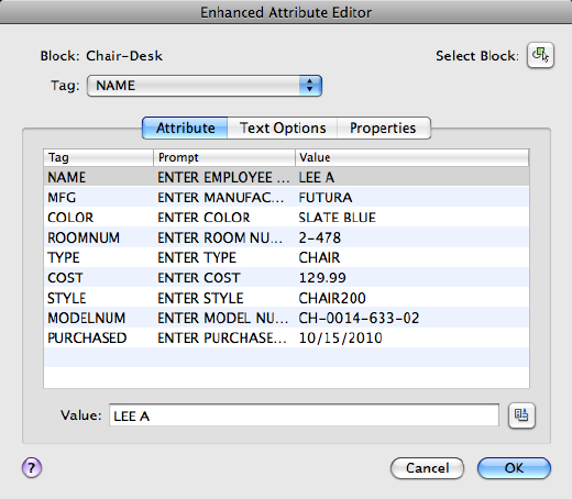
List
Lists the attributes in the selected block instance and displays the tag, prompt,
and value for each attribute.
Value
Assigns a new value to the selected attribute.
Single-line attributes include a button to insert a field. When clicked, the Field
dialog box (page 429) is displayed.
Multiple-line attributes include a button with an ellipsis. Click to open the
In-Place Text Editor (page 675) with the ruler. Depending on the setting of the
ATTIPE (page 1175) system variable, the Attribute Editor visor displayed is either
the abbreviated version, or the full version
Text Options Tab (Enhanced Attribute Editor)
Sets the properties that define the way an attribute's text is displayed in the
drawing. Change the color of attribute text on the Properties tab.
Commands | 395
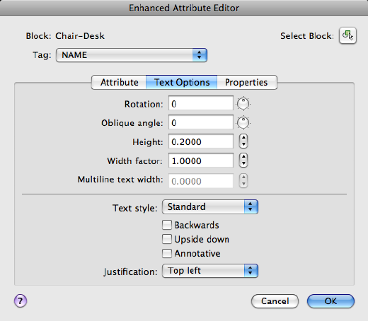
Rotation
Specifies the rotation angle of the attribute text.
Oblique Angle
Specifies the angle that the attribute text is slanted away from its vertical axis.
Not available for multiple-line attributes.
Height
Specifies the height of the attribute text.
Width Factor
Sets the character spacing for the attribute text. Entering a value less than 1.0
condenses the text. Entering a value greater than 1.0 expands it.
Multiline Text Width
Specifies the maximum length of the lines of text in a multiple-line attribute
before wrapping to the next line. A value of 0.000 means that there is no
restriction on the length of a line of text. Not available for single-line attributes.
Text Style
Specifies the text style for the attribute text. Default values for this text style
are assigned to the text properties displayed in this dialog box.
396 | Chapter 2 Commands
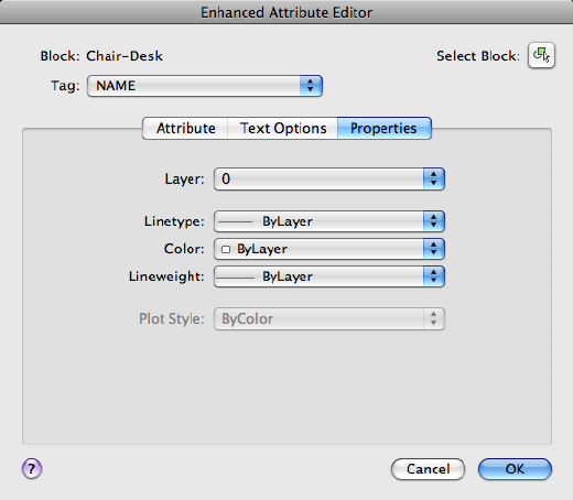
Backwards
Specifies whether or not the attribute text is displayed backwards. Not available
for multiple-line attributes.
Upside Down
Specifies whether or not the attribute text is displayed upside down. Not
available for multiple-line attributes.
Annotative
Specifies that the attribute is annotative. Click the information icon to learn
more about annotative objects.
Justification
Specifies how the attribute text is justified (left-, center-, or right-justified).
Properties Tab (Enhanced Attribute Editor)
Defines the layer that the attribute is on and the lineweight, linetype, and
color for the attribute text. If the drawing uses plot styles, you can assign a
plot style to the attribute using the Properties tab.
Layer
Specifies the layer that the attribute is on.
Commands | 397
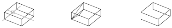
Linetype
Specifies the linetype of the attribute.
Color
Specifies the color of the attribute.
Lineweight
Specifies the lineweight of the attribute.
Changes you make to this option are not displayed if the LWDISPLAY (page
1365) system variable is off.
Plot Style
Specifies the plot style of the attribute.
If the current drawing uses color-dependent plot styles, the Plot Style list is
not available.
See also:
Modify a Block Attribute Definition
EDGE
Changes the visibility of 3D face edges.
Summary
This command only affects objects created using the 3DFACE command.
List of Prompts
The following prompts are displayed.
Specify edge of 3D face to toggle visibility or [Display]:
Edge of 3D face to toggle visibility
Controls the visibility of the edges you select.
398 | Chapter 2 Commands
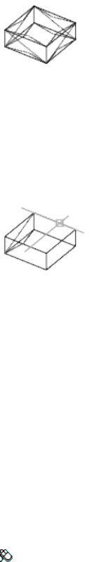
If the edges of one or more 3D faces are collinear, the program alters the
visibility of each collinear edge.
Display
Selects invisible edges of 3D faces so that you can redisplay them.
All Selects the hidden edges of all 3D faces in the drawing and displays them.
If you want to make the edges of the 3D faces visible once again, use the Edge
option. You must select each edge with your pointing device to display it.
AutoSnap™ markers and Snaptips are automatically displayed, indicating the
apparent snap locations on each invisible edge.
Select Selects hidden edges of a partially visible 3D face and displays them.
If you want to make the edges of the 3D faces visible once again, use the Edge
option. You must select each edge with your pointing device to display it.
AutoSnap markers and Snaptips are automatically displayed, indicating the
apparent snap locations on each invisible edge.
See also:
Modify 3D Subobjects
EDGESURF
Creates a mesh between four contiguous edges or curves.
Access Methods
Menu: Draw ➤ 3D Modeling ➤ Meshes ➤ Edge Mesh
Commands | 399
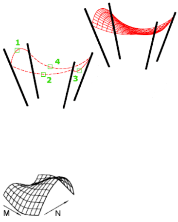
Summary
Select four adjoining edges that define the mesh. The edges can be lines, arcs,
splines, or open polylines. The edges must touch at their endpoints to form
a single, closed loop.
You can select the four edges in any order. The first edge (SURFTAB1 (page
1454)) determines the M direction of the generated mesh, which extends from
the endpoint closest to the selection point to the other end. The two edges
that touch the first edge form the N edges (SURFTAB2 (page 1454)) of the mesh.
The MESHTYPE (page 1369) system variable sets which type of mesh is created.
Mesh objects are created by default. Set the variable to 0 to create legacy
polyface or polygon mesh.
List of Prompts
The following prompts are displayed.
Object 1 for surface edge Specifies the first edge to be used as a boundary.
Object 2 for surface edge Specifies the second edge to be used as a boundary.
Object 3 for surface edge Specifies the third edge to be used as a boundary.
Object 4 for surface edge Specifies the final edge to be used as a boundary.
See also:
Create Meshes from Other Objects
400 | Chapter 2 Commands
Edit PGP
Opens the Program Parameters (PGP) text file that defines command
abbreviations
Access Methods
Button
Menu: Tools ➤ Customize ➤ Edit Command Aliases (PGP)
Summary
Commands can have abbreviated names called command aliases that you can
enter at the Command prompt. Command aliases are defined in the PGP file.
If you edit the PGP file while the program is running, enter RE-INIT and then
a value of 16 to use the revised file. You can also restart the program to reload
the file automatically.
See also:
Enter Commands on the Command Line
ELEV
Sets elevation and extrusion thickness of new objects.
Access Methods
Command entry: 'elev for transparent use
Summary
The ELEV command sets the default Z value for new objects above or below
the XY plane of the current UCS. This value is stored in the ELEVATION system
variable.
NOTE Generally, it is recommended that you leave the elevation set to zero and
control the XY plane of the current UCS with the UCS (page 1072) command.
Commands | 401
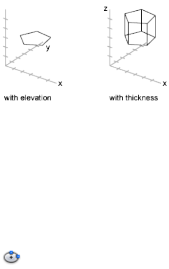
ELEV controls only new objects; it does not affect existing objects. The
elevation is reset to 0.0 whenever you change the coordinate system to the
world coordinate system (WCS).
List of Prompts
The following prompts are displayed.
Specify New Default Elevation The current elevation is the default Z value
for new objects when you specify only X and Y values for a 3D point.
The elevation setting is the same for all viewports regardless of their user
coordinate systems (UCS definitions). New objects are created at the specified
Z value relative to the current UCS in the viewport.
Specify New Default Thickness The thickness sets the distance to which a
2D object is extruded above or below its elevation. A positive value is extruded
along the positive Z axis; a negative value is extruded along the negative Z
axis.
See also:
Control the User Coordinate System (UCS)
ELLIPSE
Creates an ellipse or an elliptical arc.
Access Methods
Button
402 | Chapter 2 Commands

Toolbar: Drafting tool set ➤ Closed Shapes tool group ➤ Ellipse flyout
➤ Center
Menu: Draw ➤ Ellipse ➤ Center
Summary
The first two points of the ellipse determine the location and length of the
first axis. The third point determines the distance between the center of the
ellipse and the end point of the second axis.
List of Prompts
The following prompts are displayed.
Specify axis endpoint (page ?) of ellipse or [Arc (page
?)/Center (page ?)/Isocircle (page ?)]: Specify a point or enter
an option
Axis Endpoint
Defines the first axis by its two endpoints. The angle of the first axis determines
the angle of the ellipse. The first axis can define either the major or the minor
axis of the ellipse.
Distance to Other Axis Defines the second axis using the distance from the
midpoint of the first axis to the endpoint of the second axis (3).
Rotation Creates the ellipse by appearing to rotate a circle about the first axis.
Commands | 403
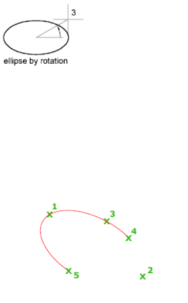
Move the crosshairs around the center of the ellipse and click. If you enter a
value, the higher the value, the greater the eccentricity of the ellipse. Entering
0 defines a circular ellipse.
Arc
Creates an elliptical arc.
The angle of the first axis determines the angle of the elliptical arc. The first
axis can define either the major or the minor axis depending on its size.
The first two points of the elliptical arc determine the location and length of
the first axis. The third point determines the distance between the center of
the elliptical arc and the endpoint of the second axis. The fourth and fifth
points are the start and end angles.
Axis Endpoint Defines the start point of the first axis.
Rotation Defines the major to minor axis ratio of the ellipse by rotating a
circle about the first axis. The higher the value from 0 through 89.4 degrees,
the greater the ratio of minor to major axis. Values between 89.4 degrees and
90.6 degrees are invalid because the ellipse would otherwise appear as a straight
line. Multiples of these angle values result in a mirrored effect every 90 degrees.
Start Angle Defines the first endpoint of the elliptical arc. The Start Angle
option toggles from Parameter mode to Angle mode. The mode controls how
the ellipse is calculated.
404 | Chapter 2 Commands
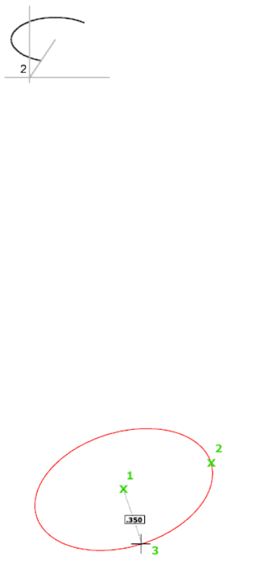
Parameter Requires the same input as Start Angle, but creates the elliptical
arc using the following parametric vector equation:
p(u) = c + a * cos(u) + b * sin(u)
where c is the center of the ellipse and a and b are its major and minor axes,
respectively.
■End Parameter: Defines the end angle of the elliptical arc by using a
parametric vector equation. The Start Parameter option toggles from Angle
mode to Parameter mode. The mode controls how the ellipse is calculated.
■Angle: Defines the end angle of the elliptical arc. The Angle option toggles
from Parameter mode to Angle mode. The mode controls how the ellipse
is calculated.
■Included Angle: Defines an included angle beginning at the start angle.
Center
Creates an ellipse using a center point, the endpoint of the first axis, and the
length of the second axis. You can specify the distances by clicking a location
at the desired distance or by entering a value for the length.
Distance to Other Axis Defines the second axis as the distance from the center
of the ellipse, or midpoint of the first axis, to the point you specify.
Rotation Creates the ellipse by appearing to rotate a circle about the first axis.
Move the crosshairs around the center of the ellipse and click. If you enter a
value, the higher the value, the greater the eccentricity of the ellipse. Entering
0 defines a circle.
Commands | 405
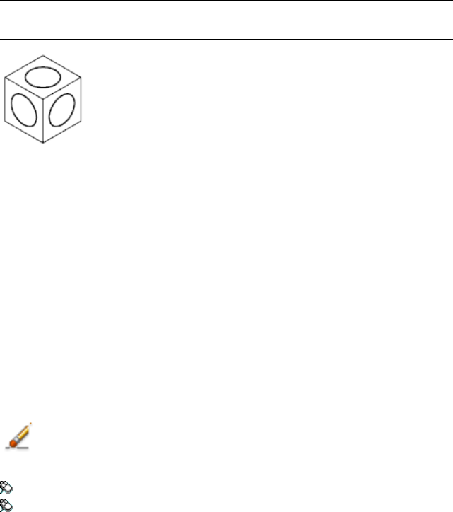
Isocircle
Creates an isometric circle in the current isometric drawing plane.
NOTE The Isocircle option is available only when you set the Style option of SNAP
(page 952) to Isometric.
Radius Creates a circle using a radius you specify.
Diameter Creates a circle using a diameter you specify.
Specify diameter of isocircle: Specify a distance
See also:
Draw Ellipses
ERASE
Removes objects from a drawing.
Access Methods
Button
Toolbar: Drafting tool set ➤ Explode and Erase tool group ➤ Erase
Menu: Modify ➤ Erase
Shortcut menu: Select the objects to erase, right-click in the drawing area,
and click Erase.
Summary
You can erase selected objects from the drawing. This method does not move
objects to the Clipboard, where they can then be pasted to another location.
If you are working with 3D objects, you can also erase subobjects such as faces,
meshes, and vertices.
406 | Chapter 2 Commands
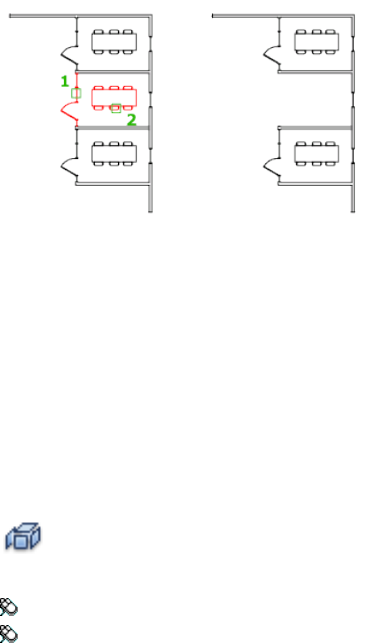
Instead of selecting objects to erase, you can enter an option, such as L to
erase the last object drawn, p to erase the previous selection set, or ALL to
erase all objects. You can also enter ? to get a list of all options.
See also:
Erase Objects
EXPLODE
Breaks a compound object into its component objects.
Access Methods
Button
Toolbar: Drafting tool set ➤ Explode and Erase tool group ➤ Explode
Menu: Modify ➤ Explode
Summary
Explodes a compound object when you want to modify its components
separately. Objects that can be exploded include blocks, polylines, and regions,
among others.
Commands | 407
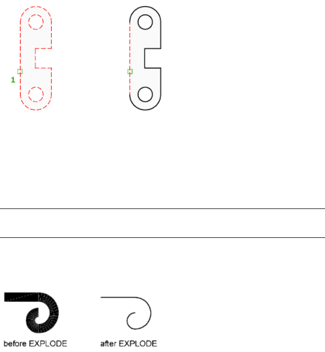
The color, linetype, and lineweight of any exploded object might change.
Other results differ depending on the type of compound object you're
exploding. See the following list of objects that can be exploded and the results
for each.
To explode objects and change their properties at the same time, use XPLODE
(page 1149).
NOTE If you're using a script or an ObjectARX® function, you can explode only
one object at a time.
2D and Lightweight Polyline Discards any associated width or tangent
information. For wide polylines, the resulting lines and arcs are placed along
the center of the polyline.
3D Polyline Explodes into line segments. Any linetype assigned to the 3D
polyline is applied to each resulting line segment.
3D Solid Explodes planar faces into regions. Nonplanar faces explode into
surfaces.
Annotative Objects Explodes the current scale representation into its
constituent parts which are no longer annotative. Other scale representations
are removed.
Arc If within a nonuniformly scaled block, explodes into elliptical arcs.
408 | Chapter 2 Commands
Block Removes one grouping level at a time. If a block contains a polyline or
a nested block, exploding the block exposes the polyline or nested block object,
which must then be exploded to expose its individual objects.
Blocks with equal X, Y, and Z scales explode into their component objects.
Blocks with unequal X, Y, and Z scales (nonuniformly scaled blocks) might
explode into unexpected objects.
When nonuniformly scaled blocks contain objects that cannot be exploded,
they are collected into an anonymous block (named with a “*E” prefix) and
referenced with the nonuniform scaling. If all the objects in such a block
cannot be exploded, the selected block reference will not be exploded. Body,
3D Solid, and Region entities in a nonuniformly scaled block cannot be
exploded.
Exploding a block that contains attributes deletes the attribute values and
redisplays the attribute definitions.
Blocks inserted with MINSERT (page 643) and external references (xrefs) and
their dependent blocks cannot be exploded.
Body Explodes into a single-surface body (nonplanar surfaces), regions, or
curves.
Circle If within a nonuniformly scaled block, explodes into ellipses.
Leaders Explodes into lines, splines, solids (arrow heads), block inserts (arrow
heads, annotation blocks), multiline text, or tolerance objects, depending on
the leader.
Mesh Objects Explodes each face into a separate 3D face object. Color and
materials assignments are retained.
Multiline Text Explodes into text objects.
Multiline Explodes into lines and arcs.
Polyface Mesh Explodes one-vertex meshes into a point object. Two-vertex
meshes explode into a line. Three-vertex meshes explode into 3D faces.
Region Explodes into lines, arcs, or splines.
See also:
Disassociate Compound Objects (Explode)
Commands | 409
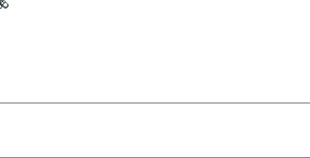
EXPORT
Saves the objects in a drawing to a different file format.
Access Methods
Menu: File ➤ Export
Summary
The Export Data dialog box (a standard file selection dialog box (page 720)) is
displayed.
If you do not see the file format that you need in the Files of Type drop-down
list, also check the PLOT command for other file types, including PDF.
NOTE
The Export Data dialog box records the last used file format selection and
stores it for use during the current drawing session and between drawing
sessions.
The following output types are available:
■ACIS (*.sat): ACIS solid object file (see ACISOUT (page 56))
■Bitmap (*.bmp): Device-independent bitmap file (see BMPOUT (page 149))
■Block (*.dwg): Drawing file (see WBLOCK (page 1125))
■DXX Extract (*.dxx): Attribute extract DXF™ file (see -ATTEXT (page 121))
■Encapsulated PS (*.eps): Encapsulated PostScript file
■Lithography (*.stl): Solid object stereolithography file (see STLOUT (page
1003))
■PDF Files (*.pdf): Portable Document file (see PLOT (page 792))
See also:
Export Drawings to Other File Formats
EXTEND
Extends objects to meet the edges of other objects.
410 | Chapter 2 Commands
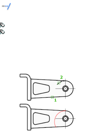
Access Methods
Button
Toolbar: Drafting tool set ➤ Modify tool group ➤ Extend
Menu: Modify ➤ Extend
Summary
To extend objects, first select the boundaries. Then press Enter and select the
objects that you want to extend. To use all objects as boundaries, press Enter
at the first Select Objects prompt.
List of Prompts
The following prompts are displayed.
Current settings: Projection = current, Edge = current
Select boundary edges...
Select objects (page ?) or <select all>: Select one or more objects
and press Enter, or press Enter to select all displayed objects
Select object to extend (page ?) or shift-select to trim
(page ?) or [Fence (page ?)/Crossing (page ?)/Project
(page ?)/Edge (page ?)/Undo (page ?)]: Select objects to extend,
or hold down Shift and select an object to trim, or enter an option
Boundary Object Selection
Uses the selected objects to define the boundary edges to which you want to
extend an object.
Object to Extend
Specifies the objects to extend. Press Enter to end the command.
Commands | 411
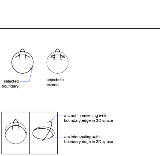
Shift-Select to Trim
Trims the selected objects to the nearest boundary rather than extending
them. This is an easy method to switch between trimming and extending.
Fence
Selects all objects that cross the selection fence. The selection fence is a series
of temporary line segments that you specify with two or more fence points.
The selection fence does not form a closed loop.
Crossing
Selects objects within and crossing a rectangular area defined by two points.
NOTE
Some crossing selections of objects to be extended are ambiguous. EXTEND
resolves the selection by following along the rectangular crossing window in
a clockwise direction from the first point to the first object encountered.
Project
Specifies the projection method used when extending objects.
None Specifies no projection. Only objects that intersect with the boundary
edge in 3D space are extended.
UCS Specifies projection onto the XY plane of the current user coordinate
system (UCS). Objects that do not intersect with the boundary objects in 3D
space are extended.
412 | Chapter 2 Commands
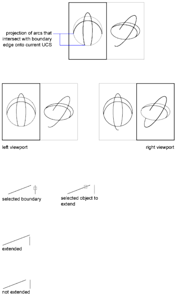
View Specifies projection along the current view direction.
Edge
Extends the object to another object's implied edge, or only to an object that
actually intersects it in 3D space.
Extend Extends the boundary object along its natural path to intersect another
object or its implied edge in 3D space.
No Extend Specifies that the object is to extend only to a boundary object
that actually intersects it in 3D space.
Commands | 413

Undo
Reverses the most recent changes made by EXTEND.
See also:
Trim or Extend Objects
EXTERNALREFERENCES
Opens the Reference Manager palette.
Access Methods
Menu: Insert ➤ References Manager
Summary
The EXTERNALREFERENCES command opens the Reference Manager palette
(page 414) when the palette is closed.
NOTE The FILEDIA (page 1296) system variable is ignored when attaching files from
the Reference Manager palette.
See also:
Attach and Detach Referenced Drawings
Reference Manager Palette
Manage external references attached to the current drawing.
414 | Chapter 2 Commands
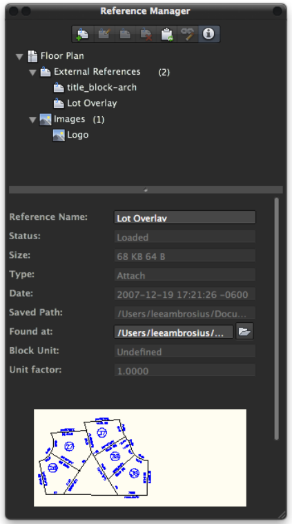
Summary
The Reference Manager palette organizes, displays, and manages referenced
files, such as DWG files (xrefs) and raster images.
The Reference Manager palette contains a toolbar along the top. You can
right-click over the files list to display a shortcut menu that allows you to
attach or manage an attached external reference. Click the Show Details button
on the toolbar to view details and thumbnail preview for the selected external
reference.
Commands | 415
See also:
Attach and Detach Referenced Drawings
Reference Manager Palette Toolbar
Use the toolbar at the top of the Reference Manager palette to attach a drawing
and to refresh the status of a referenced file.
List of Options
The following options are displayed.
Attach Reference
Displays the Select Reference File dialog box. Select the file format you want
to attach and then the file you want to attach to the drawing.
You can attach the following reference file types:
■DWG files. Starts the XATTACH (page 1137) command.
■Raster images files. Starts the IMAGEATTACH (page 513) command.
Edit Reference
Opens the selected file reference for edit in the current drawing window.
(REFEDIT (page 871) command)
Toggle References State
Unloads the selected file reference or reloads the file reference if it is currently
unloaded.
Detach Referenced File
Detaches the selected file reference from the drawing.
Refresh Content
Synchronizes the status of the selected file reference with the data in memory.
Relink File
Displays the Select <Reference Type> File to Relink dialog box where you can
update the location of the selected file reference.
Show Details
Displays the Details and Preview panel (page 420) which displays a thumbnail
preview and details for the selected file reference.
416 | Chapter 2 Commands
See also:
Attach and Detach Referenced Drawings
File References Panel Shortcut Menus
When working in the File References panel, there are several shortcut menus
that can be displayed when you right-click on a file reference or an empty
area. The following tables show the shortcut menu items that you are presented
under certain conditions.
Current Drawing File Selected
When the current drawing file is selected, the top node in the tree, the shortcut
menu presents the following functions:
DescriptionMenu Item
Displays the thumbnail preview and details for the selected
file reference.
Show Details
Opens the drawing in a new drawing window as read-only.Open a Copy
Opens Finder and displays the location where the current
drawing file is stored.
Reveal in Finder
Displays the Print dialog box.Print
Reloads all file referenced files attached to the current drawing.
(Unavailable if no file references are attached.)
Reload
Closes the drawing file. If changes were made, you are
prompted to save or discard them before the drawing can be
closed.
Close File
Commands | 417
No File Reference Selected
When no file reference is selected, the shortcut menu presents the following
functions:
DescriptionMenu Item
Displays the Select Reference File dialog box.Attach Reference
Reloads all file referenced files attached to the current drawing.
(Unavailable if no file references are attached.)
Reload All References
File Reference Selected
When you select a file reference, the shortcut menu presents the following
functions:
Reference StatusDescriptionMenu Item
Available only for file refer-
ences with a Loaded status -
Zooms to the location of the file refer-
ence attachment in the drawing so it is
fully displayed in the drawing area.
Show in Model
Unavailable when Unloaded,
Not Found or Unresolved.
Available only for DWG file
references with a Loaded
Opens the selected file reference for
edit in the current drawing window.
Edit Xref in
Place
status - Unavailable when
Unloaded, Not Found or Un-
resolved.
Available only for file refer-
ences with a Loaded status -
Opens the selected file reference in the
default editor (specified by the operat-
ing system).
Open File
Unavailable when Unloaded,
Not Found or Unresolved.
Always available - status has
no affect on this function.
Displays the thumbnail preview and
details for the selected file reference.
Show Details
Available only for file refer-
ences with a Loaded status -
Opens Finder and displays the location
where the file reference is stored.
Reveal in Finder
418 | Chapter 2 Commands
Reference StatusDescriptionMenu Item
Unavailable when Unloaded,
Not Found or Unresolved.
Always available for DWG file
references - status has no af-
fect on this function.
Switches the selected DWG file refer-
ence to the Attach attachment type.
Attach
Always available for DWG file
references - status has no af-
fect on this function.
Switches the selected DWG file refer-
ence to the Overlay attachment type.
Overlay
Always available - status has
no affect on this function.
Unloads the selected file references.Unload
Always available - status has
no affect on this function.
Reloads the selected file reference.Reload
Always available - status has
no affect on this function.
Displays the Select <Reference Type>
File to Relink dialog box dialog box
where you can update the location of
the selected file reference.
Relink File
Available only for DWG file
references with a Loaded
Binds the selected DWG reference to
the current drawing. Xref-dependent
Bind
status - Unavailable whennamed objects are changed from
Unloaded, Not Found or Un-
resolved.
blockname|definitionname to block-
name$n$definitionname syntax. In this
manner, unique named objects are
created for all xref-dependent definition
tables bound to the current drawing.
Available only for DWG file
references with a Loaded
Binds the DWG reference to the current
drawing in a way similar to detaching
Bind-Insert
status - Unavailable whenand inserting the reference drawing.
Unloaded, Not Found or Un-
resolved.
Rather than being renamed using
blockname$n$definitionname syntax,
xref-dependent named objects are
stripped of the xref name. As with insert-
Commands | 419
Reference StatusDescriptionMenu Item
ing drawings, no name-incrementing
occurs if a local named object shares
the same name as a bound xref-depend-
ent named object. The bound xref-de-
pendent named object assumes the
properties of the locally defined named
object.
Available for all file references
types.
Detaches the selected file reference.Detach
See also:
Attach and Detach Referenced Drawings
Details and Preview Panel
The Details and Preview panel, located below the File References panel, allows
you to get information about the file reference in AutoCAD for Mac and
information about the file on disk.
420 | Chapter 2 Commands
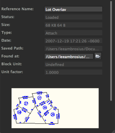
List of Options
The following options are displayed.
Details
Each file reference shares a common set of properties. Referenced images,
display additional properties specific to the file type. The common set of details
displayed for each file reference is name, status, file size, file type, creation
date, saved path, and found at path. Some of the properties can be edited.
Reference Name Displays the file reference name. This property is editable
for all file reference types.
Status Shows whether the file reference is loaded, unloaded or not found.
This property cannot be edited.
Size Shows the file size of the selected file reference. The size is not displayed
for file references that are not found. This property cannot be edited.
Type Indicates whether the file reference is an attachment or overlay, or the
type of raster image file. This property cannot be edited.
However, if the file reference is a DWG, the property can be toggled from the
File Reference panel.
Commands | 421
Date Displays the last date the file reference was modified. This date is not
displayed if the file reference is not found. This property cannot be edited.
Saved Path Shows the saved path of the selected file reference (this is not
necessarily where the file reference is found). This property cannot be edited.
Found At Displays the full path of the currently selected file reference. This
is where the referenced file is actually found and is not necessarily the same
as the saved path. Clicking the Open button displays the Open dialog box
where you can select a different path or file name. You can also type directly
into the path field. These changes are stored to the Saved Path property if the
new path is valid.
DWG Specific Properties
If you select a referenced DWG (xref), additional properties are displayed.
None of the added image properties can be edited.
Block Unit Specifies the INSUNITS (page 1335) value for the inserted block.
Unit factor Displays the unit scale factor, which is calculated based on the
INSUNITS (page 1335) value of the block and the drawing units.
Image Specific Properties
If you select a referenced image, additional properties are displayed. None of
the added image properties can be edited.
Color System Displays the color system.
Color Depth The amount of information that is stored in each pixel of a raster
image. Higher color depth values produce smoother degrees of shading.
Pixel Width The width of the raster image measured in pixels.
Pixel Height The height of the raster image measured in pixels.
Resolution The width and height resolution in dots per inch (dpi).
Default Size The width and height of the raster image measured in AutoCAD
for Mac units.
Thumbnail Preview
The thumbnail preview displays a small image of the file reference that was
selected from the File References panel. If there is no preview available, the
text “Preview not available” is displayed in the center of the pane.
See also:
Attach and Detach Referenced Drawings
422 | Chapter 2 Commands

EXTERNALREFERENCESCLOSE
Closes the Reference Manager palette.
Summary
The EXTERNALREFERENCESCLOSE command closes the Reference Managers
palette when currently displayed.
See also:
Attach and Detach Referenced Drawings
EXTRUDE
Creates a 3D solid or surface by extending the dimensions of an object.
Access Methods
Button
Toolbar: Modeling tool set ➤ Solids - Create tool group ➤ Extrude
Menu: Draw ➤ 3D Modeling ➤ Extrude
Summary
When extruded, open curves create surfaces and closed curves create solids or
surfaces, depending on the specified mode. For surfaces, use the SURFACEMOD-
ELINGMODE (page 1453) system variable to control whether the surface use a
NURBS surface or a procedural surface. Use the SURFACEASSOCIATIVITY (page
1452) system variable to control whether procedural surfaces are associative. To
extrude meshes, use the MESHEXTRUDE (page 632) command.
Commands | 423
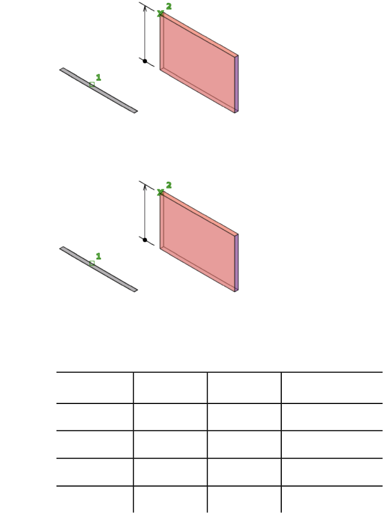
You can extrude either an open or closed object to create a 3D surface or solid.
If you extrude a surface, you will create a regular surface or a NURBS surface
depending on how the SURFACEMODELINGMODE (page 1453) system variable
is set. To extrude meshes, use the MESHEXTRUDE (page 632) command.
The DELOBJ (page 1213) system variable controls whether the object(s) and path
(if selected) are automatically deleted when the solid or surface is created or
whether you are prompted to delete the object(s) and path.
You can use the following objects and subobjects with EXTRUDE:
Objects That Can Be Extruded or Used as Paths
CommentsCan be extru-
sion path?
Can be ex-
truded?
Object type
X3D faces
XXArcs
XXCircles
XXEllipses
424 | Chapter 2 Commands
CommentsCan be extru-
sion path?
Can be ex-
truded?
Object type
XXElliptical arcs
XHelixes
XXLines
XMeshes: faces
XXMeshes: edges
2D polylines with crossing
segments cannot be ex-
truded.
XX2D Polylines
Thickness and width are
ignored.
The extrusion extends
from the center line.
XX3D Polylines
XRegions
X2D Solids
XX3D Solids: edges
X3D Solids: faces
XXSplines: 2D and 3D
XXSurfaces: edges
XXSurfaces: planar
and non-planar
Commands | 425
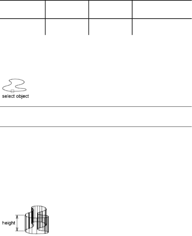
CommentsCan be extru-
sion path?
Can be ex-
truded?
Object type
XTraces
List of Prompts
The following prompts are displayed.
Objects to Extrude Specifies the objects to extrude.
NOTE
Select face and edge subobjects by pressing Ctrl while you select them.
Mode Controls whether the extruded object is a solid or a surface. Surfaces
are extruded as either NURBS surfaces or procedural surfaces, depending on
the SURFACEMODELINGMODE (page 1453) system variable.
Height of extrusion Extrudes objects along the positive Z axis of the object's
coordinate system if you enter a positive value. If you enter a negative value,
the objects are extruded along the negative Z axis. Objects do not have to be
parallel to the same plane. If all objects are on a common plane, the objects
are extruded in the direction of the normal of the plane.
By default, planar objects are extruded in the direction of the object’s normal.
Direction Specifies the length and direction of the extrusion with two specified
points. (The direction cannot be parallel to the plane of the sweep curve
created by the extrusion.)
■Start point of direction. Specifies the first point in the direction vector.
■End point of direction. Specifies the second point in the direction
vector.
426 | Chapter 2 Commands
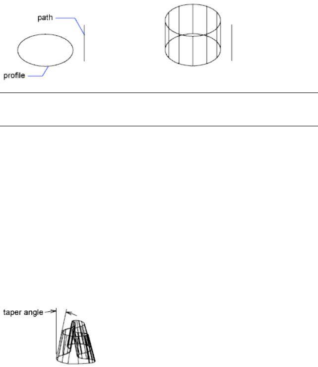
Path Specifies the extrusion path based on a selected object. The path is moved
to the centroid of the profile. Then the profile of the selected object is extruded
along the chosen path to create solids or surfaces.
NOTE
Select face and edge subobjects by pressing Ctrl while you select them.
The path should not lie on the same plane as the object, nor should the path
have areas of high curvature.
The extrusion starts from the plane of the object and maintains its orientation
relative to the path.
If the path contains segments that are not tangent, the program extrudes the
object along each segment and then miters the joint along the plane bisecting
the angle formed by the segments. If the path is closed, the object should lie
on the miter plane. This allows the start and end sections of the solid to match
up. If the object is not on the miter plane, the object is rotated until it is on
the miter plane.
Objects with multiple loops are extruded so that all of the loops appear on
the same plane at the end section of the extruded solid.
Taper angle Specifies the taper angler for the extrusion.
Positive angles taper in from the base object. Negative angles taper out. The
default angle, 0, extrudes a 2D object perpendicular to its 2D plane. All selected
objects and loops are tapered to the same value.
Specifying a large taper angle or a long extrusion height can cause the object
or portions of the object to taper to a point before reaching the extrusion
height.
Commands | 427
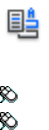
Individual loops of a region are always extruded to the same height.
When an arc is part of a tapered extrusion, the angle of the arc remains
constant, and the radius of the arc changes.
■Angle of taper. Specifies the taper between -90 and +90 degrees.
■Specify two points. Specifies the taper angle based on two specified
points. The taper angle is the distance between the two specified points.
Drag the cursor horizontally to specify and preview the taper angle. You can
also drag the cursor to adjust and preview the height of the extrusion. The
dynamic input origin should be placed on the extruded shape, on the
projection of the point to the shape.
When you select the extruded object, the position of the taper grip is the
correspondent point of the dynamic input origin on the top face of the
extrusion.
Expression Enter a formula or equation to specify the extrusion height. See
Constrain a Design with Formulas and Equations.
See also:
Extrude Objects
F Commands
FIELD
Creates a multiline text object with a field that can be updated automatically
as the field value changes.
Access Methods
Button
Toolbar: Annotation tool set ➤ Fields tool group ➤ Insert Field
Menu: Insert ➤ Field
Shortcut menu: Right-click while editing text in an in-place text editor, and
click Insert Field.
428 | Chapter 2 Commands
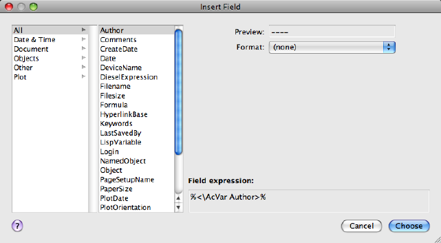
Summary
Fields can be inserted in any kind of text except tolerances. The FIELDEVAL
system variable and the UPDATEFIELD command determine how fields are
updated.
The Insert Field dialog box (page 429) is displayed.
See also:
Use Fields in Text
Insert Field Dialog Box
Inserts a field in the drawing.
Summary
The options available change based on the selected field category and field
name.
List of Options
The following options are displayed.
Field Category Sets the types of fields to be listed under Field Names (for
example, Date & Time, Document, and Objects).
Commands | 429
Field Names Lists the fields that are available in a category. Select a field name
to display the options available for that field.
Field Value Displays the current value of the field, or displays an empty string
(----) if the field value is invalid.
The label for this item changes with the field name. For example, when
Filename is selected in the Field Names list, the label is Filename and the value
is the name of the current drawing file. The label is Property for object fields.
Exception: when a date field is selected, the selected date format is displayed;
for example, M/d/yyyy.
Format List Lists options for display of the value of the field. For example,
date fields can display the name of the day or not, and text strings can be
uppercase, lowercase, first capital, or title case. The value displayed in the
Fields dialog box reflects the format that you select.
Field Expression Displays the expression that underlies the field. The field
expression cannot be edited, but you can learn how fields are constructed by
reading this area.
Options for Fields in the Objects Field Category
Named Object Type/Object Type When NamedObject is selected in Field
Names, lists the types of named objects in the drawing. When Object is
selected, displays the type of object selected. Use the Select Object button to
temporarily close the dialog box and select an object in the drawing.
Property/Name When NamedObject is selected in Field Names, lists the names
of all the objects in the drawing of the selected type. When Object is selected
in Field Names, lists the properties of the selected object that are available as
fields. When a block with attributes is selected, the attribute names are
displayed in the list of properties.
Formula
When Formula is selected in Field Names, provides a place for creating a
formula to insert in text or in a table cell.
Average/Sum/Count When Formula is selected in Field Names, closes the
Field dialog box temporarily while you specify table cells. The result is
appended to the formula.
Cell When Formula is selected in Field Names, closes the Field dialog box
temporarily while you specify a table cell. The cell address is appended to the
formula.
Precision Specifies precision for fields based on the selected format. Select
Current Precision to use the current setting of the LUPREC (page 1364) system
variable.
430 | Chapter 2 Commands
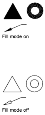
Additional Format Displays the Additional Format dialog box (page 1034).
See also:
Use Fields in Text
FILL
Controls the filling of objects such as hatches, 2D solids, and wide polylines.
List of Prompts
The following prompts are displayed.
Enter mode [ON (page 431)/OFF (page 431)] <current>: Enter on or
off, or press Enter
On Turns on Fill mode. For the filling of a 3D object to be visible, its extrusion
direction must be parallel to the current viewing direction, and hidden lines
must not be suppressed.
Off Turns off Fill mode. Only the outlines of objects are displayed and plotted.
Changing Fill mode affects existing objects after the drawing is regenerated.
The display of lineweights is not affected by the Fill mode setting.
See also:
Control the Display of Polylines, Hatches, Gradient Fills, Lineweights, and
Text
Commands | 431
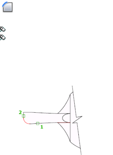
FILLET
Rounds and fillets the edges of objects.
Access Methods
Button
Toolbar: Drafting tool set ➤ Modify tool group ➤ Fillet
Menu: Modify ➤ Fillet
Summary
In the example, an arc is created that is tangent to both of the selected lines.
The lines are trimmed to the ends of the arc. To create a sharp corner instead,
enter a radius of zero.
You can fillet arcs, circles, ellipses, elliptical arcs, lines, polylines, rays, splines,
and xlines.
You can also fillet 3D solids and surfaces. If you select a mesh object for
filleting, you can choose to convert the mesh to a solid or surface and continue
the operation.
List of Prompts
The following prompts are displayed.
Current settings: Mode = current, Radius = current
Select first object (page ?) or [Undo (page ?)/Polyline
(page ?)/Radius (page ?)/Trim (page ?)/Multiple (page
?)]: Use an object selection method or enter an option
432 | Chapter 2 Commands
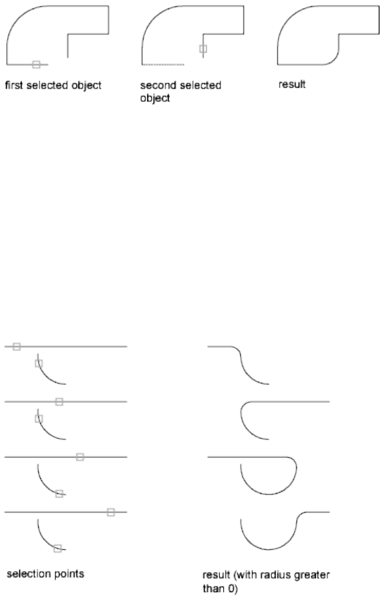
First Object
Selects the first of two objects required to define a 2D fillet or selects the edge
of a 3D solid to round or fillet the edge.
Select second object or shift-select to apply corner: Use an object selection method
or hold down Shift and select an object to create a sharp corner
If you select lines, arcs, or polylines, their lengths adjust to accommodate the
fillet arc. You can hold down Shift while selecting the objects to override the
current fillet radius with a value of 0.
If the selected objects are straight line segments of a 2D polyline, they can be
adjacent or separated by one other segment. If they are separated by another
polyline segment, FILLET deletes the segment that separates them and replaces
it with the fillet.
More than one fillet can exist between arcs and circles. Select the objects close
to where you want the endpoints of the fillet.
FILLET does not trim circles; the fillet arc meets the circle smoothly.
Commands | 433
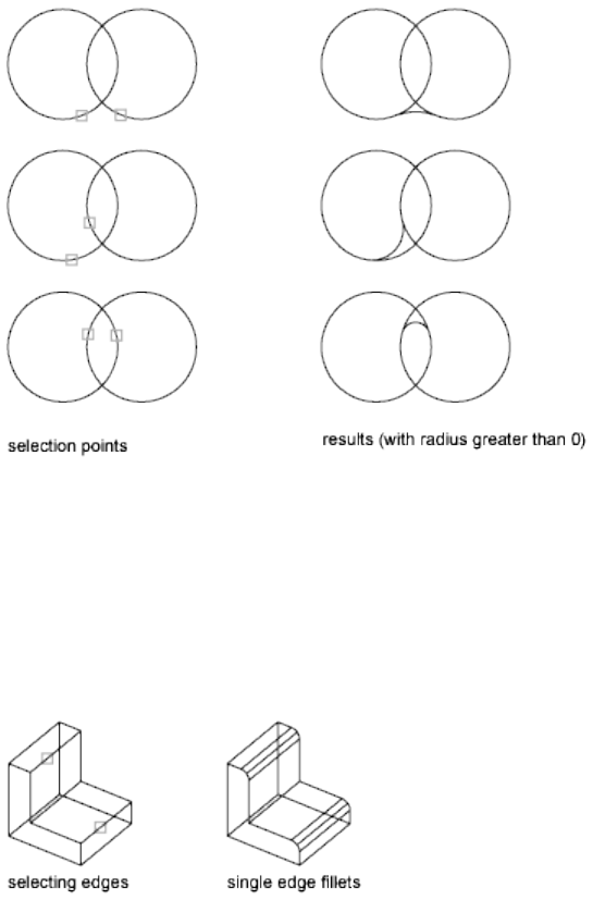
If you select a 3D solid, you can select multiple edges, but you must select the
edges individually.
Enter fillet radius <current>: Specify a distance or press Enter
Select an edge or [Chain/Loop/Radius]: Select edge(s), enter c, l, or r
Edge
Selects a single edge. You can continue to select single edges until you press
Enter.
If you select three or more edges that converge at a vertex to form the corner
of a box, FILLET computes a vertex blend that is part of a sphere if the three
incident fillets have the same radii.
Chain
Changes from selection of single edges to selection of sequential tangent edges,
called a chain selection.
434 | Chapter 2 Commands
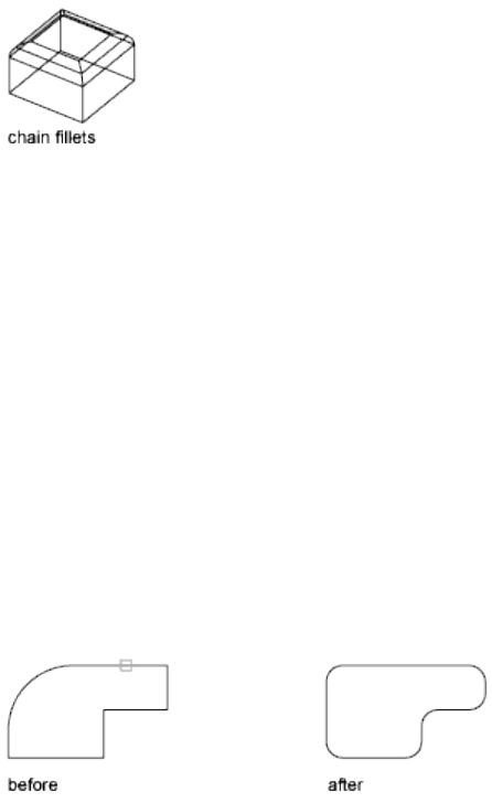
Edge Chain Selects a tangential sequence of edges when you select a single
edge. For example, if you select an edge on the top of a 3D solid box, FILLET
also selects the other tangential edges on the top.
Edge Switches to a single-edge selection mode.
Loop
Specifies a loop of edges on the face of a solid. For any edge, there are two
possible loops. After selecting a loop edge, you are prompted to Accept the
current selection, or choose the Next loop.
Radius
Defines the radius of the rounded edge.
Undo
Reverses the previous action in the command.
Polyline
Inserts fillet arcs at each vertex of a 2D polyline where two line segments meet.
Select 2D polyline:
If one arc segment separates two line segments that converge as they approach
the arc segment, FILLET removes the arc segment and replaces it with a fillet
arc.
Radius
Defines the radius of the fillet arc.
The value you enter becomes the current radius for subsequent FILLET
commands. Changing this value does not affect existing fillet arcs.
Trim
Controls whether FILLET trims the selected edges to the fillet arc endpoints.
Commands | 435
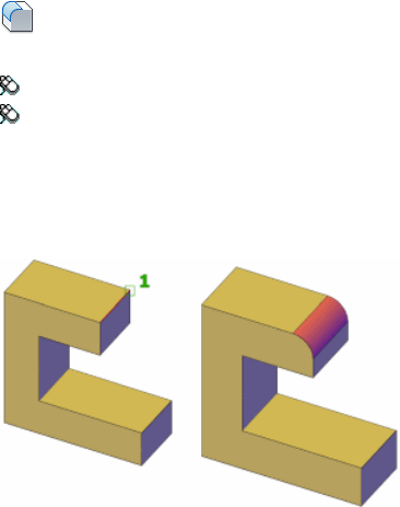
Multiple
Rounds the edges of more than one set of objects.
See also:
Create Fillets
FILLETEDGE
Rounds and fillets the edges of solid objects.
Access Methods
Button
Toolbar: Modeling tool set ➤ Solids - Edit tool group ➤ Fillet Edge
Menu: Modify ➤ Solid Editing ➤ Fillet Edges
Summary
You can select more than one edge. Enter a value for the fillet radius or click
and drag the fillet grip.
List of Prompts
The following prompts are displayed.
Select an Edge Specifies one or more edges on the same solid body to fillet.
After pressing Enter, you can drag the fillet grip to specify a radius, or use the
Radius option.
436 | Chapter 2 Commands

Chain Specifies more than one edge when the edges are tangent to one
another.
Loop Specifies a loop of edges on the face of a solid. For any edge, there are
two possible loops. After selecting a loop edge you are prompted to Accept the
current selection or choose the Next loop.
Radius Specifies a radius value.
See also:
Create Fillets
Modify Edges on 3D Objects
FIND
Finds the text that you specify, and can optionally replace it with other text.
Access Methods
Button
Toolbar: Annotation tool set ➤ Text tool group ➤ Find Text
Menu: Edit ➤ Find
Shortcut menu: With no commands active, right-click in the drawing area
and click Find.
Summary
The Find and Replace dialog box (page 437) is displayed.
See also:
Find and Replace Text
Find and Replace Dialog Box - FIND
Specifies the text you want to find, replace, or select and controls the scope
and results of the search.
Commands | 437
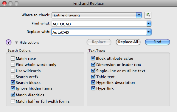
List of Options
The following options are displayed.
Where to Check
Specifies whether to search the entire drawing, the current layout, or the
currently-selected object. If an object is already selected, then Selected Objects
is the default value. If no object is selected, then Entire Drawing is the default
value. You can use the Select Objects button to temporarily close the dialog
box and create or modify the selection set.
Find What
Specifies the text string you want to find. Enter a text string, including any
wild-card characters, or choose one of the six most recently used strings from
the list.
For more information on wild-card searches, see Find and Replace Text in the
User’s Guide.
Replace With
Specifies the text string you want to use to replace the found text. Enter a
string, or choose one of the most recently used strings from the list.
Select Objects Button
Closes the dialog box temporarily so that you can select objects in your
drawing. Press Enter to return to the dialog box.
When you select objects, Where to Check displays Selected Objects by default.
438 | Chapter 2 Commands
Replace
Replaces found text with the text that you enter in Replace With and moves
to the next instance of the found text if one exists.
Replace All
Finds all instances of the text that you enter in Find What and replaces it with
the text in Replace With.
The Where to Check setting controls whether to find and replace text in the
entire drawing or text in the currently selected object or objects.
Find
Finds the text that you enter in Find What. The first text object that matches
the search criteria is zoomed to. Once you find the first instance of the text,
the Find option acts like a Find Next, which you can use to find the next text
object.
Search Options
Defines the type of objects and words to be found.
Match Case
Includes the case of the text in Find What as part of the search criteria.
Find Whole Words Only
Finds only whole words that match the text in Find What. For example, if
you select Find Whole Words Only and search for “Front Door,” FIND does
not locate the text string “Front Doormat.”
Use Wildcards
Allows the use of wild-card characters in searches.
For more information on wild-card searches, see Find and Replace Text in the
User’s Guide.
Search XRefs
Includes text in externally referenced files in search results.
Search Blocks
Includes text in blocks in search results.
Ignore Hidden Items
Ignores hidden items in search results. Hidden items include text on layers
that are frozen or turned off, text in block attributes created in invisible mode,
and text in visibility states within dynamic blocks.
Commands | 439

Match Diacritics
Matches diacritical marks, or accents, in search results.
Match Half or Full Width Forms
Matches half- and full-width characters in search results.
Text Types
Specifies the type of text objects you want to include in the search. By default,
all options are selected.
Block Attribute Value
Includes block attribute text values in search results.
Dimension or Leader Text
Includes dimension and leader object text in search results.
Single-Line or Multiline Text
Includes text objects such as single-line and multiline text in search results.
Table Text
Includes text found in AutoCAD for Mac table cells in search results.
Hyperlink Description
Includes text found in hyperlink descriptions in search results.
Hyperlink
Includes hyperlink URLs in search results.
See also:
Find and Replace Text
FLATSHOT
Creates a 2D representation of all 3D objects based on the current view.
Access Methods
Button
440 | Chapter 2 Commands
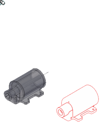
Toolbar: Modeling tool set ➤ Section tool group ➤ Flatshot
Summary
The Flatshot dialog box (page 441) is displayed.
The edges of all 3D solids, surfaces, and meshes are projected line-of-sight
onto a plane parallel to the viewing plane. The 2D representations of these
edges are inserted as a block on the XY plane of the UCS. This block can be
exploded for additional changes.
See also:
Create a Flattened View
Flatshot Dialog Box
Creates a 2D representation of all 3D objects based on the current view.
Commands | 441
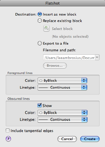
Summary
The edges of all 3D solids and surfaces are projected line-of-sight onto a plane
parallel to the viewing plane. The 2D representations of these edges are inserted
as a block on the XY plane of the UCS. This block can be exploded for
additional changes. The result can also be saved as a separate drawing file.
List of Options
The following options are displayed.
Destination
Controls where the flattened representation is created.
Insert As New Block
Specifies to insert the flattened representation as a block in the current drawing.
Replace Existing Block
Replaces an existing block in the drawing with the newly created block.
Select Block
442 | Chapter 2 Commands
Closes the dialog box temporarily while you select the block you are replacing
in the drawing. When you finish selecting the block, press Enter to re-display
the Flatshot dialog box.
Block Selected / No Block Selected
Indicates whether a block has been selected.
Export to a File
Saves the block to an external file.
Foreground Lines
Contains controls for setting the color and linetype of lines that are not
obscured in the flattened view.
Color
Sets the color of lines that are not obscured in the flattened view.
Linetype
Sets the linetype of lines that are not obscured in the flattened view.
Obscured Lines
Controls whether lines that are obscured in the drawing are displayed in the
flattened view, and sets the color and linetype of these obscured lines.
Show
Controls whether obscured lines are shown in the flattened representation.
When selected, the 2D flattened representation displays lines hidden by other
objects.
Color
Sets the color of lines that lie behind geometry in the flattened view.
Linetype
Sets the linetype of lines that lie behind geometry in the flattened view.
Include Tangential Lines
Creates silhouette edges for curved surfaces.
Create
Creates the flattened view.
See also:
Create a Flattened View
Commands | 443

FREESPOT
Creates free spotlight which is similar to a spotlight without a specified target.
List of Options
The following options are displayed.
Specify source location <0,0,0>: Enter coordinate values or use the
pointing device
If the LIGHTINGUNITS system variable is set to 0, the following prompt is
displayed:
Enter an option to change [Name (page ?)/Intensity (page
?)/Status (page ?)/Hotspot (page ?)/Falloff (page
?)/shadoW (page ?)/Attenuation (page ?)/Color (page
?)/eXit] <eXit>:
If the LIGHTINGUNITS system variable is set to 1 or 2, the following prompt
is displayed:
Enter an option to change [Name (page ?)/Intensity factor
(page ?)/Photometry (page ?)/Status (page ?)/Hotspot (page
?)/Falloff (page ?)/shadoW (page ?)/filterColor (page
?)/eXit] <eXit>:
NOTE
When the LIGHTINGUNITS system variable is set to 1 or 2, the Attenuation
option has no affect on the creation of the light. It is only maintained for
scripting compatibility.
Name
Specifies the name of the light. You can use uppercase and lowercase letters,
numbers, spaces, hyphens (-), and underscores (_) in the name. The maximum
length is 256 characters.
Intensity/Intensity Factor
Sets the intensity or brightness of the light. The range is 0.00 to the maximum
value that is supported by your system.
Hotspot
Specifies the angle that defines the brightest cone of light, which is known to
lighting designers as the beam angle. This value can range from 0 to 160
degrees or the equivalent values based on AUNITS (page 1177).
444 | Chapter 2 Commands
Falloff
Specifies the angle that defines the full cone of light, which is also known as
the field angle. This value can range from 0 to 160 degrees. The default is 50
degrees or the equivalent values based on AUNITS (page 1177). The falloff angle
must be greater than or equal to the hotspot angle.
Status
Turns the light on and off. If lighting is not enabled in the drawing, this setting
has no effect.
Photometry
Photometry is available when the LIGHTINGUNITS system variable is set to
1 or 2. Photometry is the measurement of the luminous intensities of visible
light sources.
In photometry, luminous intensity is a measure of the perceived power emitted
by a light source in a particular direction. Luminous flux is the perceived
power per unit of solid angle. The total luminous flux for a lamp is the
perceived power emitted in all directions. Luminance is the total luminous
flux incident on a surface, per unit area.
Intensity Enter an intensity value in candelas, the perceived power in a
luminous flux value, or illuminance value for the total luminous flux incident
on a surface.
■Candela (symbol: cd) is the SI unit of luminous intensity (perceived power
emitted by a light source in a particular direction). Cd/Sr
■Lux (symbol: lx) is the SI unit of illuminance. Lm/m^2
■Foot-candle (symbol: fc) is the American unit of illuminance. Lm/ft^2
Enter f to specify the perceived power in a luminous flux value.
If you enter i, you can specify the intensity of the light based on an
illuminance value.
The illuminance value can be specified in either lux or foot-candles. Enter d
to specify a distance to use to calculate illuminance.
Color Specify the color of the light based on a color name or a Kelvin
temperature. Enter ? to display a list of color names.
Enter a text string using wild card characters to display a partial listing of color
names, or an asterisk (*) to display all the possible choices.
If you enter k, you can specify the color of the light based on a Kelvin
temperature value.
Shadow
Makes the light cast shadows.
Commands | 445
Off Turns off display and calculation of shadows for the light. Turning shadows
off increases performance.
Sharp Displays shadows with sharp edges. Use this option to increase
performance.
Soft Mapped Displays realistic shadows with soft edges.
Map Size Specifies the amount of memory that should be used to calculate
the shadow map.
Softness Specifies the softness that should be used to calculate the shadow
map.
Soft Sampled Displays realistic shadows with softer shadows (penumbra)
based on extended light sources.
Specify the shape of the shadow by entering s and then the dimensions of
the shape. (For example, the radius of the sphere or the length and width of
a rectangle.)
Specify the sample size by entering a.
Specify the visibility of the shape by for the shadow by entering v.
Attenuation
Enter an option to change [attenuation Type/Use limits/attenuation start
Limit/attenuation End limit/eXit]<eXit>:
Attenuation Type Controls how light diminishes over distance. The farther
away an object is from a spotlight, the darker the object appears. Attenuation
is also known as decay.
■None. Sets no attenuation. Objects far from the spotlight are as bright as
objects close to the light.
■Inverse Linear. Sets attenuation to be the inverse of the linear distance
from the light. For example, at a distance of 2 units, light is half as strong
as at the spotlight; at a distance of 4 units, light is one quarter as strong.
The default value for inverse linear is half the maximum intensity.
■Inverse Squared. Sets attenuation to be the inverse of the square of the
distance from the light. For example, at a distance of 2 units, light is one
quarter as strong as at the spotlight; at a distance of 4 units, light is one
sixteenth as strong.
Use Limits Specifies whether to use limits or not.
Attenuation Start Limit Specifies the point where light starts as an offset
from the center of the light. The default is 0.
446 | Chapter 2 Commands

Attenuation End Limit Specifies the point where light ends as an offset from
the center of the light. No light is cast beyond this point. Setting an end limit
increases performance where the effect of lighting is so minimal that the
calculations are wasted processing time.
Color/Filter Color
Controls the color of the light.
True Color Specifies a True Color. Enter in the format R,G,B (red, green, blue).
Index Specifies an ACI (AutoCAD Color Index) color.
HSL Specifies an HSL (hue, saturation, luminance) color.
Color Book Specifies a color from a color book.
See also:
Use Spotlights
FREEWEB
Creates a free web light which is similar to a web light without a specified
target.
List of Prompts
The following prompts are displayed.
Specify source location <0,0,0>: Enter coordinate values or use the
pointing device
Enter an option to change [Name (page ?)/Intensity factor
(page ?)/Status (page ?)/Photometry (page ?)/weB (page
?)/shadoW (page ?)/filterColor (page ?)/eXit] <eXit>:
NOTE
The LIGHTINGUNITS system variable must be set to a value other than 0 to
create and use freeweb lights.
Name
Specifies the name of the light. You can use uppercase and lowercase letters,
numbers, spaces, hyphens (-), and underscores (_) in the name. The maximum
length is 256 characters.
Commands | 447
Intensity Factor
Sets the intensity or brightness of the light. The range is 0.00 to the maximum
value that is supported by your system.
Status
Turns the light on and off. If lighting is not enabled in the drawing, this setting
has no effect.
Photometry
Photometry is available when the LIGHTINGUNITS system variable is set to
1 or 2. Photometry is the measurement of the luminous intensities of visible
light sources.
In photometry, luminous intensity is a measure of the perceived power emitted
by a light source in a particular direction. Luminous flux is the perceived
power per unit of solid angle. The total luminous flux for a lamp is the
perceived power emitted in all directions. Luminance is the total luminous
flux incident on a surface, per unit area.
Intensity Enter an intensity value in candelas, the perceived power in a
luminous flux value, or illuminance value for the total luminous flux incident
on a surface.
■Candela (symbol: cd) is the SI unit of luminous intensity (perceived power
emitted by a light source in a particular direction). Cd/Sr
■Lux (symbol: lx) is the SI unit of illuminance. Lm/m^2
■Foot-candle (symbol: fc) is the American unit of illuminance. Lm/ft^2
Enter f to specify the perceived power in a luminous flux value.
If you enter i, you can specify the intensity of the light based on an
illuminance value.
The illuminance value can be specified in either lux or foot-candles. Enter d
to specify a distance to use to calculate illuminance.
Color Specify the color of the light based on a color name or a Kelvin
temperature. Enter ? to display a list of color names.
Enter a text string using wild card characters to display a partial listing of color
names, or an asterisk (*) to display all the possible choices.
If you enter k, you can specify the color of the light based on a Kelvin
temperature value.
Web
Specifies the intensity for a light at points on a spherical grid.
File Specifies which web file to use to define the properties of the web. Web
files have the file extension .ies.
448 | Chapter 2 Commands
X Specifies the X rotation for the web.
Y Specifies the Y rotation for the web.
Z Specifies the Z rotation for the web.
Shadow
Makes the light cast shadows.
Off Turns off display and calculation of shadows for the light. Turning shadows
off increases performance.
Sharp Displays shadows with sharp edges. Use this option to increase
performance.
Soft Mapped Displays realistic shadows with soft edges.
Specifies the amount of memory to use to calculate the shadow map.
Softness Specifies the softness that should be used to calculate the shadow
map.
Soft Sampled Displays realistic shadows with softer shadows (penumbra)
based on extended light sources.
Specify the shape of the shadow by entering s and then the dimensions of
the shape. (For example, the radius of the sphere or the length and width of
a rectangle.)
Specify the sample size by entering a.
Specify the visibility of the shape by for the shadow by entering v.
Filter Color
Controls the color of the light.
True Color Specifies a True Color. Enter in the format R,G,B (red, green, blue).
Index Specifies an ACI (AutoCAD Color Index) color.
HSL Specifies an HSL (hue, saturation, luminance) color.
Color Book Specifies a color from a color book.
See also:
Overview of Weblights
Commands | 449
G Commands
GCCOINCIDENT
Constrains two points together or a point to a curve (or an extension of a
curve).
Access Methods
Button
Toolbar: Drafting tool set ➤ Parametric tool group ➤ Geometric
Constraints flyout ➤ Coincident
Menu: Parametric ➤ Geometric Constraints ➤ Coincident
Summary
This command is equivalent to the Coincident option in GEOMCONSTRAINT
(page 464).
A constraint point on an object can be made coincident with an object or a
constraint point on another object.
Following are the valid constraint objects and points:
■Line
■Polyline segment
■Circle
■Arc
■Polyline arc
■Ellipse
■Spline
■Two valid constraint points
The constraint points on objects vary based on object types. For example, you
can constrain midpoints and endpoints of a line.
The second selected point or object is made coincident to the first.
450 | Chapter 2 Commands
List of Prompts
The following prompts are displayed.
Select first point (page ?) or [Object (page ?)/Autocon-
strain (page ?)] <Object>: Select a constraint point, or an object, or
enterato apply constraints to selected objects
Point
Specifies a point to be constrained.
First Point Specifies the first point of the object to be constrained.
Second Point Specifies the second point of the object to be constrained.
Object
Selects an object to be constrained.
Point Point (page ?)
Multiple Picks successive points to coincide with the first object. The Multiple
option is displayed when you use the Object option to select the first object.
Autoconstrain
Selects multiple objects. Coincident constraints are applied to selected objects
with unconstrained points that are coincident to each other.
The number of constraints applied is displayed at the Command prompt.
When a coincident constraint is applied between a point and an arc or line,
the point can lie on the line or arc or the extension of the line or arc.
See also:
Apply or Remove Geometric Constraints
Commands | 451
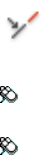
GCCOLLINEAR
Causes two or more line segments to lie along the same line.
Access Methods
Button
Toolbar: Drafting tool set ➤ Parametric tool group ➤ Geometric
Constraints flyout ➤ Collinear
Menu: Parametric ➤ Geometric Constraints ➤ Collinear
Summary
This command is equivalent to the Collinear option in GEOMCONSTRAINT
(page 464).
Following are the valid constraint objects and points:
■Line
■Polyline segment
■Ellipse
■Multiline text
List of Prompts
The following prompts are displayed.
Select first object (page ?) or [Multiple (page ?)]: Select
an object or entermto select multiple points or objects
Object
Selects an object to be constrained.
First object Selects the first object to be constrained.
Second object Selects the second object to be constrained.
The second selected line is made collinear with the first line.
Multiple
Picks successive points or objects to be made collinear with the first object.
452 | Chapter 2 Commands

See also:
Apply or Remove Geometric Constraints
GCCONCENTRIC
Constrains two arcs, circles, or ellipses to the same center point.
Access Methods
Button
Toolbar: Drafting tool set ➤ Parametric tool group ➤ Geometric
Constraints flyout ➤ Concentric
Menu: Parametric ➤ Geometric Constraints ➤ Concentric
Summary
This command is equivalent to the Concentric option in GEOMCONSTRAINT
(page 464).
Following are the valid constraint objects and points:
■Circle
■Arc
■Polyline arc
■Ellipse
List of Prompts
The following prompts are displayed.
Select first object (page ?): Select a circle, arc, or ellipse
Object
Selects an object to be constrained.
First object Selects the first circle, arc, or ellipse to be constrained.
Second object Selects the second circle, arc, or ellipse to be constrained.
The second selected object is made concentric with the first object.
Commands | 453
See also:
Apply or Remove Geometric Constraints
GCEQUAL
Resizes selected arcs and circles to the same radius, or selected lines to the
same length.
Access Methods
Button
Toolbar: Drafting tool set ➤ Parametric tool group ➤ Geometric
Constraints flyout ➤ Equal
Menu: Parametric ➤ Geometric Constraints ➤ Equal
Summary
This command is equivalent to the Equal option in GEOMCONSTRAINT (page
464).
Following are the valid constraint objects and points:
■Line
■Polyline segment
■Circle
■Arc
■Polyline arc
List of Prompts
The following prompts are displayed.
Select first object (page ?) or [Multiple (page ?)]: Select
an object or entermto select multiple objects
Object
Selects an object to be constrained.
First object Selects the first object to be constrained.
Second object Selects the second object to be made equal with the first object.
454 | Chapter 2 Commands
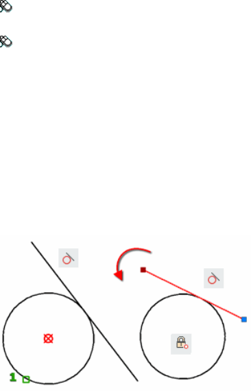
Use the Multiple option to make two or more objects equal.
Multiple
Picks successive objects to be made equal with the first object.
See also:
Apply or Remove Geometric Constraints
GCFIX
Locks points and curves in position.
Access Methods
Toolbar: Drafting tool set ➤ Parametric tool group ➤ Geometric
Constraints flyout ➤ Fix
Menu: Parametric ➤ Geometric Constraints ➤ Fix
Summary
This command is equivalent to the Fix option in GEOMCONSTRAINT (page
464).
When you apply the Fix constraint to a point on an object, you lock the node
in place. You can move the object around the locked node.
When you apply the Fix constraint to an object, the object is locked and
cannot be moved.
For example,
Using the Fix constraint, you lock the center of the circle. The circle stays
locked even if you stretch the line.
Commands | 455
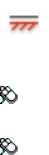
Following are the valid constraint objects and points:
■Line
■Polyline segment
■Circle
■Arc
■Polyline arc
■Ellipse
■Spline
See also:
Apply or Remove Geometric Constraints
GCHORIZONTAL
Causes lines or pairs of points to lie parallel to the X axis of the current
coordinate system.
Access Methods
Button
Toolbar: Drafting tool set ➤ Parametric tool group ➤ Geometric
Constraints flyout ➤ Horizontal
Menu: Parametric ➤ Geometric Constraints ➤ Horizontal
Summary
This command is equivalent to the Horizontal option in GEOMCONSTRAINT
(page 464).
You can select different constraint points on the same object or different
objects.
The following are the valid constraint objects and points:
■Line
■Polyline segment
■Ellipse
456 | Chapter 2 Commands
■Multiline text
■Two valid constraint points
List of Prompts
The following prompts are displayed.
Select an object or [2Points (page ?)] <2Points>: Select an
object or two constraint points
2Points
Selects two constraint points instead of an object.
The second selected point on an object is made horizontal to the first selected
point.
See also:
Apply or Remove Geometric Constraints
GCPARALLEL
Causes selected lines to lie parallel to each other.
Access Methods
Button
Toolbar: Drafting tool set ➤ Parametric tool group ➤ Geometric
Constraints flyout ➤ Parallel
Menu: Parametric ➤ Geometric Constraints ➤ Parallel
Commands | 457

Summary
This command is equivalent to the Parallel option in GEOMCONSTRAINT
(page 464).
The second selected object is made parallel to the first.
Following are the valid constraint objects and points:
■Line
■Polyline segment
■Ellipse
■Multiline text
See also:
Apply or Remove Geometric Constraints
GCPERPENDICULAR
Causes selected lines to lie 90 degrees to one another.
Access Methods
Button
Toolbar: Drafting tool set ➤ Parametric tool group ➤ Geometric
Constraints flyout ➤ Perpendicular
Menu: Parametric ➤ Geometric Constraints ➤ Perpendicular
Summary
This command is equivalent to the Perpendicular option in GEOMCON-
STRAINT (page 464).
Lines do not have to intersect to be perpendicular.
The second selected object is made perpendicular to the first.
Following are the valid constraint objects and points:
■Line
■Polyline segment
458 | Chapter 2 Commands
■Ellipse
■Multiline text
See also:
Apply or Remove Geometric Constraints
GCSMOOTH
Constrains a spline to be contiguous and maintain G2 continuity with another
spline, line, arc, or polyline.
Access Methods
Button
Toolbar: Drafting tool set ➤ Parametric tool group ➤ Geometric
Constraints flyout ➤ Smooth
Menu: Parametric ➤ Geometric Constraints ➤ Smooth
Summary
This command is equivalent to the Smooth option in GEOMCONSTRAINT
(page 464).
Following are the valid constraint objects and points:
■Spline, line
■Polyline segment
■Arc
■Polyline arc
The splines are updated to be contiguous with one another.
NOTE Endpoints of the curves to which you apply the smooth constraints are
made coincident.
List of Prompts
The following prompts are displayed.
Commands | 459

Select first spline curve (page ?): Select a spline object
Curve
Selects an endpoint of a curve.
First Spline Curve Selects the first spline curve to be constrained.
Second Curve Selects the second curve to be made continuous with the first
spline curve.
The first object selected must be a spline. The second selected object is made
G2 continuous with the first spline.
See also:
Apply or Remove Geometric Constraints
GCSYMMETRIC
Causes selected objects to become symmetrically constrained about a selected
line.
Access Methods
Button
Toolbar: Drafting tool set ➤ Parametric tool group ➤ Geometric
Constraints flyout ➤ Symmetric
Menu: Parametric ➤ Geometric Constraints ➤ Symmetric
460 | Chapter 2 Commands

Summary
This command is equivalent to the Symmetric option in GEOMCONSTRAINT
(page 464).
For lines, the line’s angle is made symmetric (and not the endpoints). For arcs
and circles, the center and radius are made symmetric (not the endpoints of
the arc).
Following are the valid constraint objects and points:
■Line
■Polyline segment
■Circle
■Arc
■Polyline arc
■Ellipse
NOTE You must have an axis around which you will constrain the objects or points
to be symmetrical. This is referred to as the symmetry line.
List of Prompts
The following prompts are displayed.
Select first object (page ?) or [2Points (page ?)]
<2Points>: Select an object or two constrained points
Object
Selects an object to be constrained.
First Object Selects the first object to be made symmetrical.
Second Object Selects the second object to be made symmetrical.
Symmetric Line Specifies the axis in which the objects and points are made
to be symmetrical.
For example,
Commands | 461
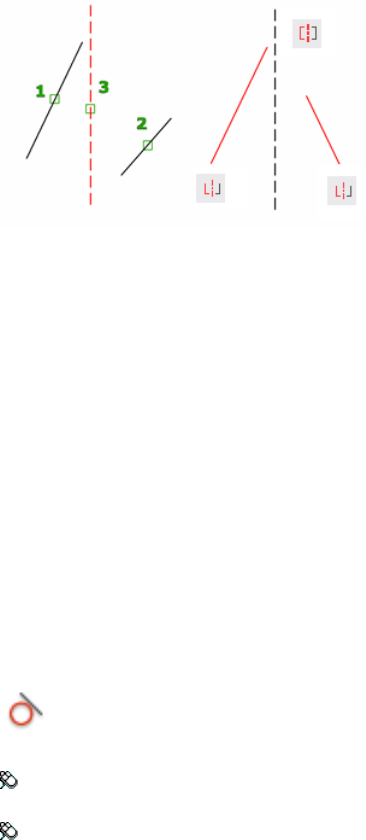
2Points
Selects two points and a symmetry line.
First Point Selects the first point to be made symmetrical.
Second Point Selects the second point to be made symmetrical.
Select Symmetric Line Select Symmetric Line (page 461)
See also:
Apply or Remove Geometric Constraints
GCTANGENT
Constrains two curves to maintain a point of tangency to each other or their
extensions.
Access Methods
Button
Toolbar: Drafting tool set ➤ Parametric tool group ➤ Geometric
Constraints flyout ➤ Tangent
Menu: Parametric ➤ Geometric Constraints ➤ Tangent
Summary
This command is equivalent to the Tangent option in GEOMCONSTRAINT
(page 464).
462 | Chapter 2 Commands

Following are the valid constraint objects and points:
■Line
■Polyline segment
■Circle, arc, polyline arc, ellipse
■Combination of circles, arcs, or ellipses
A circle can be tangent to a line even if the circle does not touch the line. A
curve can be tangent to another even if they do not physically share a point.
For example,
See also:
Apply or Remove Geometric Constraints
GCVERTICAL
Causes lines or pairs of points to lie parallel to the Y axis of the current
coordinate system.
Access Methods
Button
Toolbar: Drafting tool set ➤ Parametric tool group ➤ Geometric
Constraints flyout ➤ Vertical
Menu: Parametric ➤ Geometric Constraints ➤ Vertical
Commands | 463

Summary
This command is equivalent to the Vertical option in GEOMCONSTRAINT
(page 464).
Following are the valid constraint objects and points:
■Line
■Polyline segment
■Ellipse
■Multiline text
■Two valid constraint points
You can select different constraint points on the same object or two separate
objects.
List of Prompts
The following prompts are displayed.
Select an object or [2Points (page ?)] <2Points>: Select an
object or two constraint points
2Points
Selects two constraint points instead of an object.
The second selected point on an object is made vertical to the first selected
point.
See also:
Apply or Remove Geometric Constraints
GEOMCONSTRAINT
Applies or persists geometric relationships between objects or points on objects.
Access Methods
Menu: Parametric ➤ Geometric Constraints
464 | Chapter 2 Commands
Summary
When you apply a geometric constraint to a pair of objects, the order in which
the objects are selected and the point on which each object is selected can
affect how the objects are positioned relative to each other.
The following table outlines the valid constraint points for an object.
Valid Constraint PointsObjects
Endpoints, midpointLine
Center, endpoints, midpointArc
EndpointsSpline
CenterCircle
Center, major and minor axesEllipse
Endpoints, midpoints of line and arc subob-
jects, center of arc subobjects
Polyline
Insertion pointXref, attribute, table
Insertion point, nested entitiesBlock
Insertion point, alignment pointText, multiline text
The following commands are equivalent to each GEOMCONSTRAINT option:
Horizontal (GCHORIZONTAL (page 456))
Causes lines or pairs of points to lie parallel to the X axis of the current
coordinate system.
Vertical (GCVERTICAL (page 463))
Causes lines or pairs of points to lie parallel to the Y axis of the current
coordinate system.
Perpendicular (GCPERPENDICULAR (page 458))
Causes selected lines to lie 90 degrees to one another.
Parallel (GCPARALLEL (page 457))
Commands | 465
Causes selected lines to lie parallel to each other.
Tangent (GCTANGENT (page 462))
Constrains two curves to maintain a point of tangency to each other or their
extensions.
Smooth (GCSMOOTH (page 459))
Constrains a spline to be contiguous and maintain G2 continuity with another
spline, line, arc, or polyline.
Coincident (GCCOINCIDENT (page 450))
Constrains two points together or a point to a curve (or an extension of a
curve).
Concentric (GCCONCENTRIC (page 453))
Constrains two arcs, circles, or ellipses to the same center point.
Collinear (GCCOLLINEAR (page 452))
Causes two or more line segments to lie along the same line.
Symmetric (GCSYMMETRIC (page 460))
Causes selected objects to become symmetrically constrained about a selected
line.
Equal (GCEQUAL (page 454))
Resizes selected arcs and circles to the same radius, or selected lines to the
same length.
Fix (GCFIX (page 455))
Locks points and curves in position.
See also:
Apply or Remove Geometric Constraints
GRADIENT
Fills an enclosed area or selected objects with a gradient fill.
Access Methods
Button
Toolbar: Drafting tool set ➤ Closed Shapes tool group ➤ Gradient
466 | Chapter 2 Commands
Menu: Draw ➤ Gradient
Summary
The Gradient visor (page 486) or Hatch and Gradient dialog box (page 472) is
displayed.
A gradient fill creates a smooth transition between one or two colors.
See also:
Choose a Hatch Pattern or Fill
GRID
Displays a grid pattern in the current viewport.
Access Methods
Menu: Tools ➤ Drafting Settings
Toolbar: Status bar ➤ Grid
List of Prompts
The following prompts are displayed.
Specify grid spacing(X) (page 468) or [ON (page 468)/OFF (page
468)/Snap (page 468)/Major (page 468)/aDaptive (page 468)/Limits
(page 468)/Follow (page 468)/Aspect (page 468)] <current>: Specify
a value or enter an option
Commands | 467
Grid Spacing (X) Sets the grid to the specified value. Entering x after the
value sets the grid spacing to the specified value multiplied by the snap
interval.
On Turns on the grid using the current spacing.
Off Turns off the grid.
Snap Sets the grid spacing to the snap interval specified by the SNAP (page
952) command.
Major Specifies the frequency of major grid lines compared to minor grid
lines. Grid lines rather than grid dots are displayed in any visual style except
2D Wireframe. (GRIDMAJOR (page 1306) system variable)
Adaptive Controls the density of grid lines when zoomed in or out.
■Adaptive Behavior. Limits the density of grid lines or dots when zoomed
out. This setting is also controlled by the GRIDDISPLAY (page 1305) system
variable.
■Allow Subdivision Below Grid Spacing. If turned on, generates
additional, more closely spaced grid lines or dots when zoomed in. The
frequency of these grid lines is determined by the frequency of the major
grid lines.
Limits Displays the grid beyond the area specified by the LIMITS (page 573)
command.
Follow Changes the grid plane to follow the XY plane of the dynamic UCS.
This setting is also controlled by the GRIDDISPLAY (page 1305) system variable.
Aspect Changes the grid spacing in the X and Y directions, which can have
different values.
Entering x following either value defines it as a multiple of the snap interval
rather than the drawing units.
The Aspect option is not available when the current snap style is Isometric.
See also:
Adjust Grid and Grid Snap
GROUP
Creates saved sets of objects called groups.
468 | Chapter 2 Commands

Access Methods
Menu: Tools ➤ Group
Summary
If you enter -group at the Command prompt, options are displayed (page
469).
List of Prompts
The following prompts are displayed.
Select objects or [Name/Description]: Select objects to add to the new
group or enter an option
Name Specifies the group name. Group names can be up to 31 characters long
and can include letters, numbers, and the special characters dollar sign ($),
hyphen (-), and underscore (_) but not spaces. The name is converted to
uppercase characters.
Description Specifies the description for the group. You can use up to 64
characters for a description.
See also:
Group Objects
-GROUP
Creates and manages saved sets of objects called groups.
List of Prompts
The following prompts are displayed.
Enter a group option [?óList Groups (page ?)/Order (page
?)/Add (page ?)/Remove (page ?)/Explode (page ?)/REName
(page ?)/Selectable (page ?)/Create (page ?)] <Create>:
Enter an option or press Enter
?—List Groups
Lists names and descriptions of groups defined in the drawing.
Commands | 469
Order
Changes the numerical order of objects within a group. Reordering is useful
when creating tool paths. For example, you can change the cut order for the
horizontal and vertical lines of a tool path pattern.
Position Number Specifies the position number of the object to reorder. To
reorder a range of objects, specify the first object's position number.
Reverse Order Reverses the order of all members in a group.
Add
Adds objects to a group.
Remove
Removes objects from a group.
If you remove all the group's objects, the group remains defined. You can
remove the group definition from the drawing by using the Explode option.
Explode
Deletes a group definition by exploding the group into its component objects.
Rename
Assigns a new name to an existing group.
Selectable
Specifies whether a group is selectable. When a group is selectable, selecting
one object in the group selects the whole group. Objects on locked or frozen
layers are not selected.
Create
Creates a group.
Group names can be up to 31 characters long and can include letters, numbers,
and special characters dollar sign ($), hyphen (-), and underscore (_) but not
spaces. The name is converted to uppercase characters.
See also:
Group Objects
GROUPEDIT
Adds and removes objects from the selected group, or renames a selected
group.
470 | Chapter 2 Commands
Summary
For existing groups, add or remove objects; or rename a group.
The following prompts are displayed.
Select group or [Name]:
In the drawing area, select a group or enter the name of a group. If a selected
object is not included in a group, you are prompted again.
List of Options
When a group is selected, the following options are displayed.
Enter an option [Add objects (page 471)/Remove objects (page
471)/REName (page 471)]:
Add Objects Select objects to add to the current group.
Remove Objects Select grouped objects to remove from the current group.
Rename Name or rename the current group.
See also:
Group Objects
H Commands
HATCH
Fills an enclosed area or selected objects with a hatch pattern, solid fill, or
gradient fill.
Access Methods
Button
Toolbar: Drafting tool set ➤ Closed Shapes tool group ➤ Hatch
Menu: Draw ➤ Hatch
Commands | 471
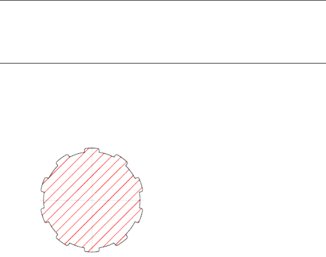
Summary
The Hatch visor (page 484) or Hatch and Gradient dialog box (page 472) is
displayed.
If you enter -hatch at the Command prompt, options are displayed (page
490).
NOTE To prevent the creation of an enormous number of hatch lines, the
maximum number of hatch lines created in a single hatch operation is limited.
This limit prevents memory and performance problems. However, you can change
the maximum number of hatch lines with the HPMAXLINES (page 1326) system
variable.
Choose from several methods to specify the boundaries of a hatch.
■Specify a point in an area that is enclosed by objects.
■Select objects that enclose an area.
■Specify boundary points using the -HATCH Draw option.
See also:
Overview of Hatch Patterns and Fills
Hatch and Gradient Dialog Box
Defines the boundaries, pattern, or fill properties, and other parameters for
hatches and fills.
472 | Chapter 2 Commands
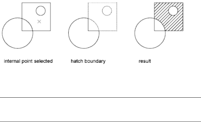
List of Options
The dialog box includes the following:
■Hatch tab (page 476)
■Gradient tab (page 479)
■More Options section (page 481)
■Add: Pick Points (page ?)
■Add: Select Objects (page ?)
■Remove Boundaries (page ?)
■Recreate Boundary (page ?)
■View Selections (page ?)
■Display Boundary Objects (page ?)
■Options (page ?)
■Preview (page ?)
Add: Pick Points
Determines a boundary from existing objects that form an enclosed area
around the specified point.
If you turn on Island Detection, objects that enclose areas within the outermost
boundary are detected as islands. How HATCH detects objects using this option
depends on which island detection method is specified.
NOTE Red circles are displayed at unconnected endpoints of boundary objects
to identify gaps in the hatch boundary. These circles are temporary and can be
removed with REDRAW (page 869) or REGEN (page 877).
Add: Select Objects
Determines a boundary from selected objects that form an enclosed area.
Commands | 473
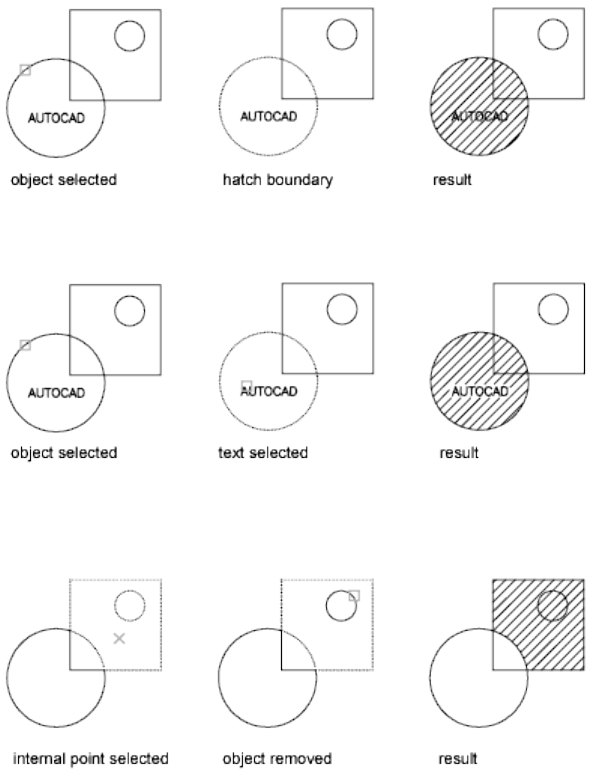
Interior objects are not automatically detected. You must select the objects
within the selected boundary to hatch or fill those objects according to the
current island detection style.
Each time you click Add: Select Objects, HATCH clears the previous selection
set.
Remove Boundaries
Removes from the boundary definition any of the objects that were added
previously.
Recreate Boundary
Creates a polyline or region around the selected hatch or fill, and optionally
associates the hatch object with it.
474 | Chapter 2 Commands

View Selections
Displays the currently defined boundaries with the current hatch or fill settings.
This option is available only when a boundary has been defined.
Display Boundary Objects
Selects the objects that form the boundaries of the selected associative hatch
object. Use the displayed grips to modify the hatch boundaries.
NOTE This option is available only in the Hatch Edit dialog box (page 497) and
replaces the View Selections option.
When you select an associative hatch, a single, circular grip called the control
grip is displayed. No boundary grips are displayed because the boundaries of
an associative hatch can be modified only by changing its associated boundary
objects. Use the Select Boundary Objects option to select and grip-edit the
boundary objects.
To modify the boundaries of a nonassociative hach, you modify the boundaries
of the hatch object itself. Thus, when you select a nonassociative hatch, both
the control grip and the boundary grips are displayed.
Options
Controls several commonly used hatch or fill options.
Annotative Specifies that the hatch is annotative. This property automates
the process of scaling annotations so that they plot or display at the correct
size on the paper. (HPANNOTATIVE (page 1319) system variable)
Associative Specifies that the hatch or fill is associative. A hatch or fill that
is associative is updated when you modify its boundary objects. (HPASSOC
(page 1319) system variable)
Separate Hatches Controls whether a single hatch object or multiple hatch
objects are created when several separate closed boundaries are specified.
(HPSEPARATE (page 1329) system variable)
Draw Order Assigns a draw order to a hatch or fill. You can place a hatch or
fill behind all other objects, in front of all other objects, behind the hatch
boundary, or in front of the hatch boundary. (HPDRAWORDER (page 1323)
system variable)
Layer Assigns new hatch objects to the specified layer, overriding the current
layer. Select Use Current to use the current layer. (HPLAYER (page 1325) system
variable)
Transparency Sets the transparency level for new hatch or fills, overriding
the current object transparency. Select Use Current to use the current object
transparency setting. (HPTRANSPARENCY (page 1330) system variable)
Commands | 475
Inherit Properties Hatches or fills specified boundaries using the hatch or fill
properties of a selected hatch object.
After selecting the hatch object whose properties you want the hatch to inherit,
right-click in the drawing area and use the options on the shortcut menu to
switch between the Select Objects and Pick Internal Point options.
The HPINHERIT (page 1324) system variable controls whether the hatch origin
of the resulting hatch is determined by HPORIGIN (page 1327) or by the source
object.
Preview
Displays the currently defined boundaries with the current hatch or fill settings.
Click in the drawing area or press Esc to return to the dialog box. Right-click
or press Enter to accept the hatch or fill.
More Options
Expands the dialog box to display more options (page 481).
See also:
Overview of Hatch Patterns and Fills
Hatch Tab (Hatch and Gradient Dialog Box)
Defines the appearance of the hatch pattern to be applied.
476 | Chapter 2 Commands

List of Options
The following options are displayed.
Type and Pattern
Specifies the hatch’s type, pattern, color, and background color.
Type
Specifies whether to create a predefined, user-defined, or custom hatch pattern.
Predefined patterns are stored in the acad.pat or acadiso.pat files supplied with
the program.
User-defined patterns are based on the current linetype in your drawing. A
custom pattern is a pattern that is defined in any custom PAT files that you
have added to the search path.
Pattern
Displays a selection of ANSI, ISO, and other industry-standard hatch patterns.
Select SOLID to create solid fill. The Pattern option is available only when
Type is set to Predefined. (HPNAME (page 1326) system variable)
[…] Button
Commands | 477
Displays the Hatch Library (page 487), in which you can preview images for
all predefined patterns.
Hatch Color
Overrides the current color with a specified color for hatch patterns and solid
fills. (HPCOLOR (page 1321) system variable)
Background Color
Specifies the background color for new hatch objects. Choose None to turn
off the background color. (HPBACKGROUNDCOLOR (page 1320) system variable)
Swatch
Displays a preview of the selected pattern. Click the swatch to display the
Hatch Library (page 487).
Custom Pattern
Lists the available custom patterns. The most recently used custom patterns
appear at the top of the list. The Custom Pattern option is available only when
Type is set to Custom. (HPNAME (page 1326) system variable)
[…] Button
Displays the Hatch Library (page 487), in which you can preview images for
all custom patterns.
Angle and Scale
Specifies an angle and scale for the selected hatch pattern.
Angle
Specifies an angle for the hatch pattern relative to the X axis of the current
UCS. (HPANG (page 1319) system variable)
Scale
Expands or contracts a predefined or custom pattern. This option is available
only when Type is set to Predefined or Custom. (HPSCALE (page 1329) system
variable)
Double
For user-defined patterns, draws a second set of lines at 90 degrees to the
original lines, creating a crosshatch. This option is available only when Type
is set to User Defined. (HPDOUBLE (page 1322) system variable)
Relative to Paper Space
478 | Chapter 2 Commands
Scales the hatch pattern relative to paper space units. This allows you to display
hatch patterns at a scale that is appropriate for your named layout. This option
is available only from a named layout.
Spacing
Specifies the spacing of lines in a user-defined pattern. This option is available
only when Type is set to User Defined. (HPSPACE (page 1330) system variable)
ISO Pen Width
Scales an ISO predefined pattern based on the selected pen width. This option
is available only when Type is set to Predefined and Pattern is set to one of
the available ISO patterns.
Hatch Origin
Controls the starting location of hatch pattern generation. Some hatches,
such as brick patterns, are meant to be aligned with a point on the hatch
boundary. By default, all hatch origins correspond to the current UCS origin.
Use Current Origin
Uses the hatch origin point stored in the HPORIGIN (page 1327) system variable.
Specified Origin
Assigns a new hatch origin using the following options.
Click to Set New Origin
Specifies the new hatch origin point directly.
Default to Boundary Extents
Calculates a new origin based on the rectangular extents of the boundary for
the hatch object. Choices include each of the four corners of the extents and
its center. (HPORIGINMODE (page 1328) system variable)
Store as Default Origin
Stores the value of the new hatch origin in the HPORIGIN system variable.
See also:
Overview of Hatch Patterns and Fills
Gradient Tab (Hatch and Gradient Dialog Box)
Defines the appearance of the gradient fill to be applied.
Commands | 479
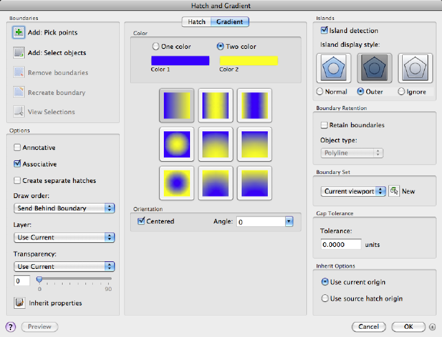
List of Options
The following options are displayed.
Color
Specifies whether to fill the hatch boundary with a monochormatic or
two-color blend.
One Color
Specifies a fill that uses a smooth transition between a color and a specified
tint (the color mixed with white) or between a color and a specified shade
(the color mixed with black). (GFCLRSTATE (page 1303) system variable)
Two Color
Specifies a fill that uses a smooth transition between two colors. (GFCLRSTATE
(page 1303) system variable)
Color Swatches
Specifies the colors for the gradient fill (either one color or two colors). Click
the Browse button […] to display the Color Palette dialog box (page 198), where
480 | Chapter 2 Commands
you can select an AutoCAD Color Index (ACI) color, true color, or color book
color. (GFCLR1 (page 1302) and GFCLR2 (page 1303) system variables)
Shade and Tint Slider
Specifies the tint (the selected color mixed with white) or shade (the selected
color mixed with black) of a color to be used for a gradient fill of one color.
(GFCLRLUM (page 1303) system variable)
Gradient Patterns
Displays fixed patterns for gradient fills. These patterns include linear sweep,
spherical, and parabolic.
Orientation
Specifies the angle of the gradient and whether it is symmetrical.
Centered
Specifies a symmetrical gradient configuration. If this option is not selected,
the gradient fill is shifted up and to the left, creating the illusion of a light
source to the left of the object. (GFSHIFT (page 1305) system variable)
Angle
Specifies the angle of the gradient fill. The specified angle is relative to the
current UCS. This option is independent of the angle specified for hatch
patterns. (GFANG (page 1302) system variable)
See also:
Overview of Hatch Patterns and Fills
More Options (Hatch and Gradient Dialog Box)
Controls the operation of islands and boundaries.
List of Options
The following options are displayed.
Islands
Specifies the method used to hatch or fill boundaries within the outermost
boundary.
Island Detection
Controls whether internal closed boundaries, called islands, are detected.
(HPISLANDDETECTIONMODE (page 1325) system variable)
Commands | 481
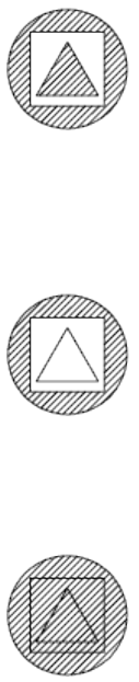
Normal
Hatches or fills inward from the outer boundary. If an internal island is
encountered, hatching or filling is turned off until another island within the
island is encountered. (HPISLANDDETECTION (page 1324) system variable)
Outer (Recommended)
Hatches or fills inward from the outer boundary. This option hatches or fills
only the specified area and leaves the internal islands unaffected. (HPISLAND-
DETECTION (page 1324) system variable)
Ignore
Ignores all internal objects and hatches or fills through them. (HPISLANDDE-
TECTION (page 1324) system variable)
The Normal, Outer, and Ignore options are also available from a shortcut
menu by right-clicking in the drawing area while you specify points or select
objects to define your boundaries.
Boundary Retention
Specifies whether to create an object that encloses the hatch.
Retain Boundaries
Creates an object that encloses each hatch object. (HPBOUNDRETAIN (page
1321) system variable)
482 | Chapter 2 Commands
Object Type
Controls the type of the new boundary object. The resulting boundary object
can be either a polyline or a region object. This option is available only when
Retain Boundaries is selected. (HPBOUND (page 1320) system variable)
For more information about regions, see Create and Combine Areas (Regions).
Boundary Set
Defines the set of objects analyzed when defining a boundary from a specified
point. The selected boundary set has no effect when you use Select Objects
to define a boundary.
By default, when you use the Add: Pick Point option to define a boundary,
HATCH analyzes all objects in the current viewport extents. By redefining the
boundary set, you can disregard certain objects when defining boundaries
without having to hide or remove those objects. For large drawings, redefining
the boundary set can also produce the boundary faster because HATCH
examines fewer objects.
Current Viewport Defines the boundary set from all objects within the extents
of the current viewport.
Existing Set Defines the boundary set from the objects selected with the New
option.
New
Specifies a limited set of objects for evaluation by the pick point when creating
the hatch.
Gap Tolerance
Sets the maximum size of gaps that can be ignored when objects are used as
a hatch boundary. The default value, 0, specifies that the objects must enclose
the area with no gaps.
Enter a value, in drawing units, from 0 to 5000 to set the maximum size of
gaps that can be ignored when the objects serve as a hatch boundary. Any
gaps equal to or smaller than the value you specify are ignored, and the
boundary is treated as closed. ( HPGAPTOL (page 1324) system variable)
Inherit Options
Controls whether to inherit the hatch origin when you create a hatch with
the Inherit Properties option. (HPINHERIT (page 1324) system variable)
Use Current Origin Uses the current hatch origin setting.
Use Source Hatch Origin Uses the hatch origin of the source hatch.
Commands | 483

See also:
Overview of Hatch Patterns and Fills
Hatch Visor
Defines the boundaries, pattern or fill properties, and other parameters for
hatch and fills.
Summary
The Hatch visor is displayed when you start the HATCH command, select a
pattern or fill from the Hatch Library palette, or select an existing hatch object
with a pattern or fill in a drawing.
List of Options
The following options are displayed.
Pattern
Displays a preview image of the current hatch pattern.
Click the preview image to display the Hatch Library palette and select a new
pattern to use.
Properties
Hatch Color Overrides the current color for solid fills and hatch patterns.
(HPCOLOR (page 1321) system variable)
Background Color Specifies the color for hatch pattern backgrounds. Not
available when using the Solid pattern. (HPBACKGROUNDCOLOR (page 1320)
system variable)
Angle Specifies an angle for the hatch or fill relative to the X axis of the current
UCS. Valid values are from 0 to 359. (HPANG (page 1319) system variable)
Scale Expands or contracts a predefined or custom hatch pattern. This option
is available only when Hatch Type is set to Pattern. (HPSCALE (page 1329) system
variable)
484 | Chapter 2 Commands
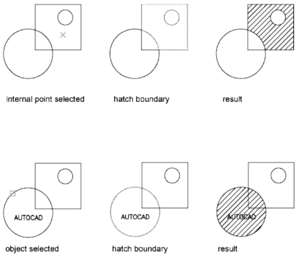
Pick Points
Determines the boundary to hatch or fill from existing objects that form an
enclosed area around a specified point.
Select Boundary
Determines the boundary to hatch or fill from selected objects that form an
enclosed area.
When you use the Select Boundary option, HATCH does not automatically
detect interior objects. You must select the objects within the selected boundary
to hatch or fill those objects according to the current island detection style.
Right-click and choose Settings to change the current island detection style.
Remove Boundary
Removes from the boundary definition any of the objects that were previously
added. Option is only available after a boundary has been defined.
Create Boundary
Creates a polyline or region around the selected hatch or fill, and optionally
associates the hatch object with it. Option is only available when modifying
an existing hatch object.
Create Separated Hatches
Controls whether a single hatch object or multiple hatch objects are created
when several separate closed boundaries are specified. (HPSEPARATE (page
1329) system variable)
Commands | 485
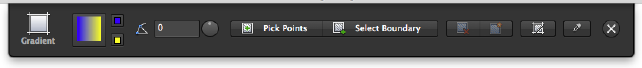
Match Hatch Properties
Sets the properties of a hatch with a selected hatch object.
Exit the Hatch Editor and Close the Visor
Quits the current command and closes the Hatch visor.
See also:
Overview of Hatch Patterns and Fills
Gradient Visor
Defines the boundaries, pattern or fill properties, and other parameters for
gradient fills.
Summary
The Gradient visor is displayed when you start the GRADIENT command,
select a gradient pattern from the Hatch Library palette, or select an existing
gradient fill in a drawing.
List of Options
The following options are displayed.
Pattern
Displays a preview image of the current gradient pattern.
Click the preview image to display the Hatch Library palette and select a new
gradient pattern to use.
Properties
Gradient Color 1 Specifies the first of two gradient colors. (GFCLR1 (page 1302)
system variable)
Gradient Color 2 Specifies the second gradient color. (GFCLR2 (page 1303)
system variable)
Angle Specifies an angle for the hatch or fill relative to the X axis of the current
UCS. Valid values are from 0 to 359. (HPANG (page 1319) system variable)
486 | Chapter 2 Commands
Pick Points
Determines the boundary to hatch or fill from existing objects that form an
enclosed area around a specified point.
Select Boundary
Determines the boundary to hatch or fill from selected objects that form an
enclosed area.
When you use the Select Boundary option, interior objects are not
automatically detected. You must select the objects within the selected
boundary to hatch or fill those objects according to the current island detection
style. Right-click and choose Settings to change the current island detection
style.
Remove Boundary
Removes from the boundary definition any of the objects that were previously
added. Option is only available after a boundary has been defined.
Create Boundary
Creates a polyline or region around the selected hatch or fill, and optionally
associates the hatch object with it. Option is only available when modifying
an existing hatch object.
Create Separated Hatches
Controls whether a single hatch object or multiple hatch objects are created
when several separate closed boundaries are specified. (HPSEPARATE (page
1329) system variable)
Match Hatch Properties
Sets the properties of a hatch with a selected hatch object.
Exit the Hatch Editor and Close the Visor
Quits the current command and closes the Gradient visor.
See also:
Overview of Hatch Patterns and Fills
Hatch Library
Displays preview images for all predefined and custom patterns, and gradient
fill patterns.
Commands | 487
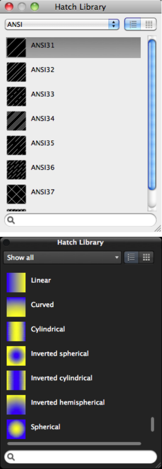
The Hatch Library can be displayed as a dialog box when using the Hatch and
Gradient dialog box, or as a palette from the Hatch or Gradient visors.
488 | Chapter 2 Commands
The Hatch Library can be displayed as a dialog box when using the Hatch and
Gradient dialog box, or as a palette from the Hatch or Gradient visors.
Summary
Organizes patterns into five categories, with patterns listed alphabetically.
Click an image to select a pattern.
List of Options
The following options are displayed.
Pattern Category
Lists the pattern categories used to group related hatch and gradient patterns.
The following categories are listed:
■Show All. Shows all patterns in all categories.
■ANSI. Displays all ANSI patterns shipped with the program.
■ISO. Displays all ISO patterns shipped with the program.
■Other Predefined. Displays all patterns other than ANSI and ISO shipped
with the program.
■Custom. Displays a list of custom PAT files that you have added to the
Support File Search Path of the program.
■Gradient. Displays all gradient patterns.
Add Patterns Loads a PAT file into the Hatch Library.
Find in Finder Displays the PAT file in Finder that contains the selected
pattern in the Pattern list.
Pattern List
Displays a list of all available patterns based on the selected pattern category.
List/Icon View
Toggles the view of the pattern previews between List and Icon only. List view
displays a small preview image and the name of the pattern.
Search
Filters the Pattern list based on the entered text string. Click 'X' to clear the
current text string.
See also:
Overview of Hatch Patterns and Fills
Commands | 489
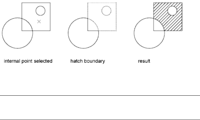
-HATCH
Uses command prompts to fill an enclosed area or selected objects with a
hatch pattern, solid fill, or gradient fill.
List of Prompts
The following prompts are displayed.
Specify internal point (page ?) or [Properties (page
?)/Select objects (page ?)/draW boundary (page ?)/remove
Boundaries (page ?)/Advanced (page ?)/DRaw order (page
?)/Origin (page ?)/ANnotative (page ?)/hatch COlor (page
?)/LAyer (page ?)/Transparency (page ?)]: Specify a point or
enter an option
Internal Point
Determines a boundary from existing objects that form an enclosed area
around the specified point.
Pick Internal Point While specifying internal points, you can right-click in
the drawing area at any time to display a shortcut menu that contains several
options.
If you turn on Island Detection, objects that enclose areas within the outermost
boundary are detected as islands. How HATCH detects objects using this option
depends on which island detection method is specified.
NOTE Red circles are displayed at unconnected endpoints of boundary objects
to identify gaps in the hatch boundary. These circles are temporary and can be
removed with REDRAW (page 869) or REGEN (page 877).
Properties
Specifies new hatch pattern properties to apply.
490 | Chapter 2 Commands
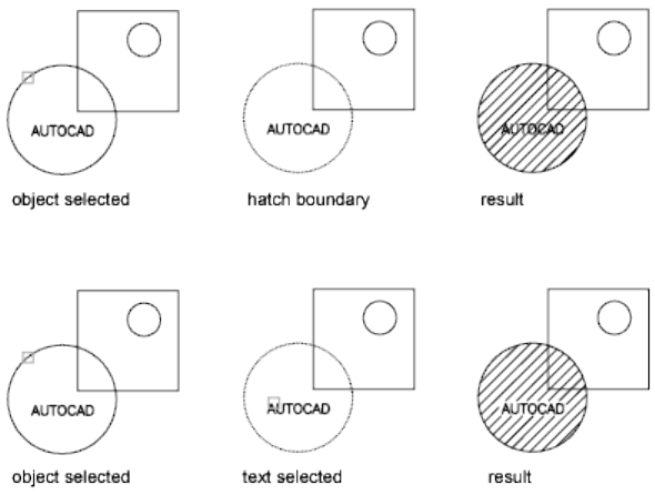
Pattern Name—Predefined or Custom Specifies a predefined pattern in the
acad.pat or acadiso.pat file or a custom pattern in its own PAT file.
Enter the pattern name followed by an optional hatch style code. Precede the
pattern name with an asterisk (*) to fill the area with individual lines instead
of a hatch object.
?—List Pattern Names Lists and describes the hatch patterns defined in the
acad.pat file.
Solid Specifies a solid fill and redisplays the first HATCH prompt, where you
can define a boundary.
User Defined Specifies a user-defined pattern. Enter u, followed by an optional
hatch style code. Precede the u with an asterisk (*) to fill the area with
individual lines instead of a hatch object.
Double Hatch Area Specifies a second set of lines to be drawn at 90 degrees
to the original lines.
Select Objects
Determines a boundary from selected objects that form an enclosed area.
Select Objects Interior objects are not automatically detected. You must select
the objects within the selected boundary to hatch or fill those objects according
to the current island detection style.
Each time you click Select Objects, HATCH clears the previous selection set.
Commands | 491

While selecting objects, you can right-click at any time in the drawing area
to display a shortcut menu. You can undo the last selection or all selections,
change the selection method, change the island detection style, or preview
the hatch or fill.
Draw Boundary
Uses specified points to define the boundary of a hatch or fill.
The options that are available as you specify points are also available in PLINE
(page 785). When you complete the polyline boundary, press Enter. You can
then create additional polyline boundaries, or press Enter to twice to apply
the hatch.
NOTE
To enclose an area completely, use the Close option. Do not make the first
and last points coincident.
Remove Boundaries
Removes from the boundary definition any of the objects that were previously
added.
Select Objects Removes objects from the boundary definition.
Add Boundaries Adds objects to the boundary definition.
Advanced
Sets the method used to create the hatch boundary.
Boundary Set
Specifies a limited set of objects, called a boundary set, for evaluation by the
pick point of the hatch
New Creates a boundary set from the selected objects.
Everything Creates a boundary set from everything visible in the current
viewport. Selecting this option discards any current boundary set and uses
everything visible in the drawing or in the current viewport.
Retain Boundary
Creates an object that encloses each hatch object.
Island Detection
Specifies whether to use objects within the outermost boundary as boundary
objects.
Specifying no island detection prompts for the ray casting method.
Nearest Runs a line from the point you specify to the nearest object and then
traces the boundary in a counterclockwise direction.
492 | Chapter 2 Commands
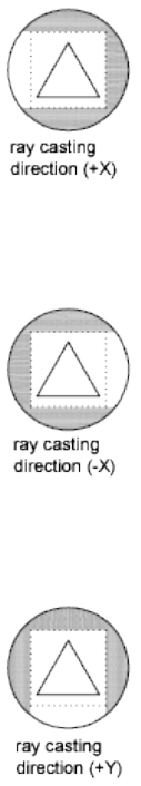
+X Runs a line in the positive X direction from the point you specify to the
first object encountered and then traces the boundary in a counterclockwise
direction.
-X Runs a line in the negative X direction from the point you specify to the
first object encountered and then traces the boundary in a counterclockwise
direction.
+Y Runs a line in the positive Y direction from the point you specify to the
first object encountered and then traces the boundary in a counterclockwise
direction.
-Y Runs a line in the negative Y direction from the point you specify to the
first object encountered and then traces the boundary in a counterclockwise
direction.
Commands | 493
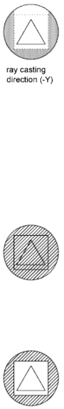
Angle Runs a line at the specified angle from the point you specify to the first
object encountered and then traces the boundary in a counterclockwise
direction.
Style
Specifies the method used to hatch or fill objects within the outermost hatch
boundary. If you have selected no internal objects, a hatching style has no
effect. Because you can define a precise set of boundaries, it's often best to use
the Normal style.
Ignore Ignores all internal objects and hatches or fills through them.
Outer (Recommended) Hatches or fills inward from the outer boundary.
HATCH turns hatching or filling off if it encounters an internal island. This
option hatches or fills only the outermost level of the structure and leaves the
internal structure blank.
Normal Hatches or fills inward from the outer boundary. If HATCH encounters
an internal island, it turns off hatching or filling until it encounters another
island within the island.
494 | Chapter 2 Commands
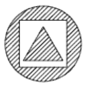
Associativity
Specifies that the new hatch pattern is updated when its boundaries are
modified.
A new hatch pattern's associativity is set by the HPASSOC (page 1319) system
variable. Changing the associativity setting here also changes the setting in
the HPASSOC system variable.
Gap Tolerance
Sets the maximum size of gaps that can be ignored when objects are used as
a hatch boundary. The default value, 0, specifies that the objects must enclose
the area with no gaps.
Any gaps equal to or smaller than the value you specify in the gap tolerance
are ignored, and the boundary is treated as closed.
Separate Hatches
Controls whether the command creates a single hatch object or multiple hatch
objects when several separate closed boundaries are specified.
Draw Order
Assigns the draw order to a hatch or fill. You can place a hatch or fill behind
all other objects, in front of all other objects, behind the hatch boundary, or
in front of the hatch boundary.
Origin
Controls the starting location of hatch pattern generation. Some hatches,
such as brick patterns, are meant to be aligned with a point on the hatch
boundary. By default, all hatch origins correspond to the current UCS origin.
Use Current Origin Sets the value of the HPORIGINMODE (page 1328) system
variable. The last 5 options listed below correspond to the values 1-5.
Set New Origin Specifies the new hatch origin point directly.
Default to Boundary Extents Calculates a new origin based on the rectangular
extents of the hatch. Choices include each of the four corners of the extents
and its center. You can also store the value of the new hatch origin in the
HPORIGIN (page 1327) system variable.
Commands | 495

Annotative
Specifies that the hatch is annotative. This property automates the process of
scaling annotations so that they plot or display at the correct size on the paper.
Hatch Color
Overrides the current color with a specified color for hatch patterns and solid
fills. The color value is stored in the HPCOLOR (page 1321) system variable.
When Hatch Type is set to Pattern, you can also specify a new background
color. The background color value is stored in the HPBACKGROUNDCOLOR
(page 1320) system variable.
To set the hatch color back to the current color for objects, enter “.” or Use
Current. To turn off the background color, enter “.” or none.
Default Object Color Enter the color number (1 through 255) or the color
name (the names for the first seven colors). For example, you can specify the
color red by entering the ACI (AutoCAD Color Index) number 1 or the ACI
name red. You can also set the hatch color to ByLayer or ByBlock.
Truecolor Specify an RGB color expressed as values from 0 to 255, such as
210,155,95.
Colorbook Specify a custom color from a color book installed on your system.
Layer
Assigns new hatch objects to the specified layer, overriding the current layer.
Enter Use Current or “.” to use the current layer. (HPLAYER (page 1325) system
variable)
Transparency
Sets the transparency level for new hatches or fills, overriding the current
object transparency. Enter Use Current or “.” to use the current object
transparency setting. (HPTRANSPARENCY (page 1330) system variable)
See also:
Overview of Hatch Patterns and Fills
HATCHEDIT
Modifies an existing hatch or fill.
Access Methods
Menu: Modify ➤ Object ➤ Hatch
496 | Chapter 2 Commands

Toolbar: Select a hatch or gradient fill to edit its properties on the Hatch
or Gradient visor.
Shortcut menu: Select a hatch or gradient fill to edit. Right-click in the
drawing area and click Hatch Edit.
Pointing device: Double-click a hatch or gradient fill.
Summary
Modifies hatch-specific properties, such as pattern, scale, and angle for an
existing hatch or fill.
If you enter -hatchedit at the Command prompt, the associated options are
displayed (page 498) in the command line.
List of Options
The following options are displayed.
Select hatch object: Use an object selection method
The Hatch Edit dialog box (page 497) is displayed.
See also:
Modify Hatches and Fills
Hatch Edit Dialog Box
Modifies hatch-specific properties, such as pattern, scale and angle for an
existing hatch or fill.
Summary
The options in the Hatch Edit dialog box are the same as the options for the
Hatch and Gradient dialog box (page 472). Certain options are available only
when creating hatches.
See also:
Modify Hatches and Fills
Commands | 497
-HATCHEDIT
Uses command prompts to modify hatch-specific properties, such as pattern,
scale, and angle for an existing hatch or fill.
List of Prompts
The following prompts are displayed.
Select hatch object:
Enter hatch option [DIsassociate (page ?)/Style (page
?)/Properties (page ?)/DRaw order (page ?)/ADd boundaries
(page ?)/Remove boundaries (page ?)/recreate Boundary (page
?)/ASsociate (page ?)/separate Hatches (page ?)/Origin
(page ?)/ANnotative (page ?)/hatch COlor (page ?)/LAyer
(page ?)/Transparency (page ?)] <Properties>: Enter an option
or press Enter
Disassociate
Removes the associative quality from an associative hatch or fill.
Style
Specifies the method used to hatch or fill boundaries within the outermost
boundary.
Ignore Ignores all internal objects and hatches or fills through them.
Outer (Recommended) Hatches or fills inward from the outer boundary.
HATCH turns hatching or filling off if it encounters an internal island. This
option hatches or fills only the outermost level of the structure and leaves the
internal structure blank.
Normal Hatches or fills inward from the outer boundary. If HATCH encounters
an internal island, it turns off hatching or filling until it encounters another
island within the island.
Properties
Specifies new hatch properties for the selected hatch. For an explanation of
setting pattern and fill properties at the Command prompt, see -HATCH (page
490).
Draw Order
Assigns a draw order to a hatch or fill. You can place a hatch or fill behind all
other objects, in front of all other objects, behind the hatch boundary, or in
front of the hatch boundary. (HPDRAWORDER (page 1323) system variable)
498 | Chapter 2 Commands
Add Boundaries
Modifies the boundaries of a hatch or fill by adding boundaries.
For more information, see Add: Pick Points (page ?) or Add: Select Objects
(page ?).
Remove Boundaries
Modifies the boundaries of a hatch or fill by removing boundaries.
For more information, see Remove Boundaries (page ?).
Recreate Boundary
Creates a polyline or region around the selected hatch or fill, and optionally
associates the hatch object with it.
For more information, see Recreate Boundary (page ?).
Associate
Specifies that the hatch or fill is associative. A hatch or fill that is associative
is updated when you modify its boundary objects.
Specify Internal Point Determines a boundary from existing objects that
form an enclosed area around the specified point, and associates the selected
hatch with the boundary objects.
Select Objects Determines a boundary from selected objects that form an
enclosed area, and associates the selected hatch with the boundary objects.
Separate Hatches
Controls whether a single hatch object or multiple hatch objects are created
when several separate closed boundaries are specified.
Origin
Controls the starting location of hatch pattern generation. Some hatches,
such as brick patterns, are meant to be aligned with a point on the hatch
boundary. By default, all hatch origins correspond to the current UCS origin.
Use Current Origin Sets the value of the HPORIGINMODE (page 1328) system
variable. The last 5 options listed below correspond to the values 1-5.
Set New Origin Specifies the new hatch origin point directly.
Default to Boundary Extents Calculates a new origin based on the rectangular
extents of the hatch. Choices include each of the four corners of the extents
and its center. You can also store the value of the new hatch origin in the
HPORIGIN (page 1327) system variable.
Annotative
Specifies that the hatch is annotative. This property automates the process of
scaling annotations so that they plot or display at the correct size on the paper.
Commands | 499
Hatch Color
Overrides the current color with a specified color for hatch patterns and solid
fills. The color value is stored in the HPCOLOR (page 1321) system variable.
When Hatch Type is set to Pattern, you can also specify a new background
color. The background color value is stored in the HPBACKGROUNDCOLOR
(page 1320) system variable.
To set the hatch color back to the current color for objects, enter “.” or Use
Current. To turn off the background color, enter “.” or none.
Default object color Enter the color number (1 through 255) or the color
name (the names for the first seven colors). For example, you can specify the
color red by entering the ACI (AutoCAD Color Index) number 1 or the ACI
name red. You can also set the hatch color to ByLayer or ByBlock.
Truecolor Specify an RGB color expressed as values from 0 to 255, such as
210,155,95.
Colorbook Specify a custom color from a color book installed on your system.
Layer
Assigns new hatch objects to the specified layer, overriding the current layer.
Enter Use Current or “.” to use the current layer.
Transparency
Sets the transparency level for new hatches or fills, overriding the current
object transparency. Enter Use Current or “.” to use the current object
transparency setting.
See also:
Modify Hatches and Fills
HATCHGENERATEBOUNDARY
Creates a non-associated polyline around a selected hatch.
Access Methods
Shortcut menu: Select a hatch object. Right-click and choose Generate
Boundary.
Summary
Creates a new non-associative polyline boundary around the selected hatch.
500 | Chapter 2 Commands
List of Prompts
The following prompts are displayed.
Select hatch objects: Use an object selection method and press Enter.
See also:
Set Property Overrides for Hatches and Fills
Control How Overlapping Objects Are Displayed
HATCHSETBOUNDARY
Redefines a selected hatch or fill to conform to a different closed boundary.
Access Methods
Shortcut menu: Select a hatch object. Right-click and choose Set Boundary.
Summary
Trims a selected hatch to within a selected boundary or geometry.
List of Prompts
The following prompts are displayed.
Select hatch object: Select hatch object to be trimmed.
Select objects to be used for the new boundary: Select the new
boundary or geometry and press Enter.
See also:
Set Property Overrides for Hatches and Fills
Control How Overlapping Objects Are Displayed
HATCHSETORIGIN
Controls the starting location of hatch pattern generation for a selected hatch.
Commands | 501
Access Methods
Shortcut menu: Select a hatch object. Right-click and choose Set Origin.
Summary
Controls the hatch origin location point for solid and gradient hatches. You
can select and change multiple hatch objects and change their hatch origin
for multiple hatches at the same time.
List of Prompts
The following prompts are displayed.
Select hatch object: Select the hatch object.
Select new hatch origin: Click inside the hatch to change the origin point.
See also:
Set Property Overrides for Hatches and Fills
Control How Overlapping Objects Are Displayed
HATCHTOBACK
Sets the draw order for all hatches in the drawing to be behind all other objects.
Access Methods
Button
Toolbar: Drafting tool set ➤ Move/Rotate/Scale tool group (expanded)
➤ Draw Order flyout ➤ Send Hatches to Back
Menu: Tools ➤ Draw Order ➤ Send Hatches to Back
Summary
Selects all hatches in the drawing, including hatch patterns, solid fills, and
gradient fills, and sets their draw order to be behind all other objects. Hatch
objects on locked layers are also modified.
502 | Chapter 2 Commands
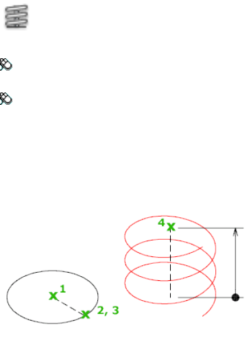
See also:
Set Property Overrides for Hatches and Fills
Control How Overlapping Objects Are Displayed
HELIX
Creates a 2D spiral or 3D spring.
Access Methods
Button
Toolbar: Modeling tool set ➤ Open Shapes tool group (expanded) ➤
Helix
Menu: Draw ➤ Helix
Summary
Use a helix as a sweep path for the SWEEP (page 1027) command to create
springs, threads, and circular stairways.
Initially, the default base radius is set to 1. During a drawing session, the
default value for the base radius is always the previously entered base radius
value for any solid primitive or helix.
The default value for the top radius is always the value of the base radius.
The base radius and top radius cannot both be set to 0.
Commands | 503
List of Prompts
The following prompts are displayed.
Number of turns = 3 (default)
Twist = CCW (default)
Specify center point of base: Specify a point
Specify base radius or [Diameter (page ?)] <1.0000>: Specify
a base radius, enter d to specify the diameter, or press Enter to specify the default
base radius value
Specify top radius or [Diameter (page ?)] <1.0000>: Specify a
top radius, enter d to specify the diameter, or press Enter to specify the default top
radius value
Specify helix height or [Axis endpoint (page ?)/Turns (page
?)/turn Height (page ?)/tWist (page ?)] <1.0000>: Specify a
helix height, or enter an option
Diameter (Base)
Specifies the diameter of the base of the helix.
Specify diameter <2.0000>: Specify a diameter or press Enter to specify the default
value
Initially, the default base diameter is set to 2. During a drawing session, the
default value for the base diameter is always the previously entered base
diameter value.
Diameter (Top)
Specifies the diameter of the top of the helix.
Specify diameter <2.0000>: Specify a diameter or press Enter to specify the default
value
The default value for the top diameter is always the value of the base diameter.
Axis Endpoint
Specifies the endpoint location for the helix axis. The axis endpoint can be
located anywhere in 3D space. The axis endpoint defines the length and
orientation of the helix.
Specify axis endpoint: Specify a point
Turns
Specifies the number of turns (revolutions) for the helix. The number of turns
for a helix cannot exceed 500.
504 | Chapter 2 Commands

Initially, the default value for the number of turns is three. During a drawing
session, the default value for the number of turns is always the previously
entered number of turns value.
Enter number of turns: Enter a number
Turn Height
Specifies the height of one complete turn within the helix.
The number of turns in the helix will automatically update accordingly when
a turn height value is specified. If the number of turns for the helix has been
specified, you cannot enter a value for the turn height.
Specify distance between turns <default>: Enter a number to specify the height
for each turn in the helix
Twist
Specifies whether the helix is drawn in the clockwise (CW) or the
counterclockwise (CCW) direction. The default value for the helix twist is
CCW.
Enter twist direction of helix [CW/CCW] <CCW>: Specify a twist direction for
the helix
See also:
Draw Helixes
HELP
Displays Help.
Access Methods
Menu: Help ➤ AutoCAD Help
Command entry: Cmd-/ or Fn-F1 (or 'help for transparent use)
Summary
Executing the HELP command while a command is active displays Help for
that command. You can also click the Help icon that appears on the right side
of the command line when a command is active. Clicking the Help button in
a dialog box displays Help for that dialog box.
Commands | 505

See also:
Access and Search the Product Help
HIDE
Regenerates a 3D wireframe model with hidden lines suppressed.
Access Methods
Menu: View ➤ Hide
Summary
When you use VPOINT (page 1114), DVIEW (page 385), or VIEW (page 1104) to
create a 3D view of your 2D drawing, a wireframe is displayed in the current
viewport. All lines are present, including those hidden by other objects. HIDE
eliminates the hidden lines from the screen.
HIDE considers the following to be opaque surfaces that hide objects: circles,
solids, traces, text, regions, wide polyline segments, 3D faces, polygon meshes,
and the extruded edges of objects with nonzero thickness.
If they are extruded, circles, solids, traces, and wide polyline segments are
treated as solid objects with top and bottom faces. You cannot use HIDE on
objects whose layers have been frozen; however, you can use HIDE on objects
whose layers have been turned off.
To hide text created with MTEXT or TEXT, the HIDETEXT (page 1318) system
variable must be set to 1 or the text must be assigned a thickness value.
When using the HIDE command, if the INTERSECTIONDISPLAY (page 1342)
system variable is on, face-to-face intersections of 3D surfaces are displayed
as polylines.
The 3D Hidden visual style does not honor the setting of
INTERSECTIONDISPLAY.
506 | Chapter 2 Commands
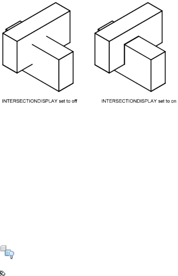
If the DISPSILH (page 1254) system variable is on, HIDE displays 3D solid objects
with silhouette edges only. It won't show the internal edges produced by
objects that have facets.
If the HIDETEXT system variable is off, HIDE ignores text objects when
producing the hidden view. Text objects are always displayed regardless of
whether they are obscured by other objects, and objects obscured by text
objects are unaffected.
See also:
Use a Visual Style to Display Your Model
HIDEOBJECTS
Hides selected objects.
Access Methods
Button
Menu: Tools ➤ Isolate ➤ Hide Objects
Shortcut menu: Right-click in the drawing area and click Isolate ➤ Hide
Objects.
Commands | 507

Summary
Temporarily hides selected objects in the current view. All other objects are
visible.
List of Prompts
The following prompt is displayed.
Select objects: Use an object selection method
See also:
Control the Display of Objects
HIDEPALETTES
Hides all currently displayed palettes, including the command window.
Access Methods
Command entry: Tab
Summary
Hides all currently displayed palettes such as the Command Line, Layers, and
Properties Inspector.
See also:
Specify the Behavior of Palettes
I Commands
ID
Displays the UCS coordinate values of a specified location.
Access Methods
Menu: Tools ➤ Inquiry ➤ ID Point
508 | Chapter 2 Commands

Command entry: 'id for transparent use
Summary
ID lists the X, Y, and Z values of the specified point and stores the coordinate
of the specified point as the last point. You can reference the last point by
entering @ at the next prompt that requests a point.
List of Prompts
The following prompts are displayed.
Specify Point: Use the pointing device to specify a point
The UCS coordinate values of the location are displayed at the Command
prompt.
If you snap to an object in 3D space, the Z coordinate value is the same as
that of the selected feature of the object.
See also:
Obtain Distances, Angles, and Point Locations
IMAGE
Displays the Reference Manager palette.
Access Methods
Menu: File ➤ Attach
Menu: Insert ➤ Reference Manager
Summary
The Reference Manager palette (page 414) is displayed.
If you enter -image at the Command prompt, options are displayed (page
510).
See also:
Attach Raster Images
Commands | 509
-IMAGE
Attaches a raster image to the drawing.
List of Prompts
The following prompts are displayed.
Enter image option [?(page ?)/Detach (page ?)/Path (page
?)/Reload (page ?)/Unload (page ?)/Attach (page ?)]
<Attach>: Enter an option or press Enter
?—List Images
Lists the images by name in alphabetical order, the number of times each is
attached to the drawing, and the path where the image is stored. Images are
listed in alphabetical order, regardless of the setting of the MAXSORT (page
1367) system variable.
Detach
Detaches the named image from the drawing, marks it for deletion, and erases
all occurrences of the image.
Path
Updates the path name (including file name) associated with a particular
image. This option is useful if you change the location of an image file, rename
the file, or replace an old image file with a new file; for instance, you can
update image01.png and save it as image02.png.
If you enter an asterisk (*), the following prompt is displayed:
Old path: Lists the current path name for each image
Enter New path: Enter the new path name for the specified image
Reload
Reloads the selected images, making that information available for display
and plotting.
Unload
Removes image data from working memory so that the images are not
displayed, thus improving performance. All information associated with the
image remains stored with the drawing. The image frame of each attached
image remains visible.
Attach
Attaches a new image or a copy of an attached image to the current drawing.
The Select Image File dialog box (a standard file selection dialog box) is
displayed.
510 | Chapter 2 Commands
The file name without the extension is assigned as the image name. Image
names can include up to 255 characters and contain letters, digits, spaces, and
any special characters not used by the operating system or this program. If
the file name is not a valid name for a nongraphical object, the Substitute
Image Name dialog box is displayed. A valid image name is generated from
the file name and an underscore and number are appended to the name.
If a definition with the same name and path exists in the drawing, the
following prompts are displayed and the image is inserted as a copy:
Image file name has already been loaded.
Use IMAGE Reload to update its definition.
Specify insertion point <0,0>: Specify an insertion point
Base image size: Width: current width, Height: current height, current unit
Specify scale factor: Enter a value or press Enter
Specify rotation angle <0>: Enter a value or press Enter
If the FILEDIA (page 1296) system variable is set to 0, the following prompt is
displayed instead of the dialog box:
Enter image file name to attach <last>: Enter an image name
The last image name attached to the drawing during the current session is the
default. To avoid errors when entering an image name, it is recommended
that you specify both the image name and the file name as follows:
imagename=path name/long file name.bmp
or
imagename="path name/long file name.bmp"
If you enter a valid image name without a file extension, the program searches
for the file in this order: first, an existing image definition in the drawing,
and second, an image file in the folders in order of the search path. The
program searches for all the image files with the specified name, regardless of
extension, and uses the first name found. If no image name or image file is
found, the message “Image Not Found” is displayed and the prompt is repeated.
To specify a long file name that does not conform to this program's naming
rules, enter the name as follows:
"imagename=filename"
You can use a dialog box to search for image files but still enter the
imagename=filename convention at the Command prompt. Enter a tilde (~) at
Commands | 511

the Enter Image File Name to Attach prompt. If you press Esc after the dialog
box opens, the Enter Image Name prompt is displayed.
See also:
Attach Raster Images
IMAGEADJUST (-IMAGEADJUST)
Controls the image display of the brightness, contrast, and fade values of
images.
Access Methods
Menu: Modify ➤ Object ➤ Image ➤ Adjust
List of Prompts
The following prompts are displayed.
If you select a single image, the default values for Brightness, Contrast, and
Fade are the current property settings of the image. If you select multiple
images, the default values for Brightness, Contrast, and Fade are 50, 50, and
0, respectively.
Contrast Controls the contrast, and indirectly, the fading effect of the image.
The greater the value, the more each pixel is forced to its primary or secondary
color.
Brightness Controls the brightness, and indirectly the contrast, of the image.
The greater the value, the brighter the image and the more pixels that become
white when you increase contrast.
Fade Controls the fading effect of the image. The greater the value, the more
the image blends with the current background color. A value of 100 blends
the image completely into the background. Changing the screen background
color causes the image to fade to the new color. In plotting, the background
color for fade is white.
See also:
Change Raster Image Brightness, Contrast, and Fade
512 | Chapter 2 Commands

IMAGEATTACH
Inserts a reference to an image file.
Access Methods
Menu: Insert ➤ Raster Image Reference
Summary
When you attach an image file, you link that referenced file to the current
drawing. Any changes to the referenced file are displayed in the current
drawing when it is opened or reloaded.
The Select Reference File dialog box (a standard file selection dialog box (page
720)) is displayed. Once you select an image file, the Attach Image dialog box
(page 513) is displayed.
See also:
Attach Raster Images
Attach Image Dialog Box
Locates, inserts, names, and defines the parameters and details of attached
images.
Commands | 513
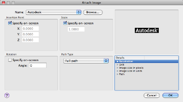
List of Options
The following options are displayed.
Name
Identifies the image you have selected to attach.
Browse
Opens the Select Reference File dialog (a standard file selection dialog box
(page 720)).
Preview
Displays the image that you have selected to attach.
Insertion Point
Specifies the insertion point for the selected image file. Specify On-Screen is
the default. The default insertion point is 0,0,0.
Specify On-Screen Directs input at the Command prompt or the pointing
device. If Specify On-Screen is cleared, enter the insertion point in X, Y, and
Z.
X Sets the X coordinate value.
Y Sets the Y coordinate value.
Z Sets the Z coordinate value.
Scale
Specifies the scale factor of the selected image.
514 | Chapter 2 Commands
If INSUNITS (page 1335) is set to “unitless” or if the image does not contain
resolution information, the scale factor becomes the image width in AutoCAD
units. If INSUNITS has a value such as millimeters, centimeters, inches, or
feet, and the image has resolution information, the scale factor is applied after
the true width of the image in AutoCAD units is determined.
Specify On-Screen Allows you to input at the Command prompt or the
pointing device. If Specify On-Screen is cleared, enter a value for the scale
factor. The default scale factor is 1.
Scale Factor Field Enter a value for the scale factor. The default scale factor
is 1.
Rotation
Specifies the rotation angle of the selected image.
Specify On-Screen If Specify On-Screen is selected, you may wait until you
exit the dialog box to rotate the object with your pointing device or enter a
rotation angle value at the Command prompt.
Angle If Specify On-Screen is cleared, enter the rotation angle value in the
dialog box. The default rotation angle is 0.
Path Type
Select the full (absolute) path, the relative path to the image file, or No Path,
the name of the image file (the image file must be located in the same folder
as the current drawing file).
Details
Displays details about the selected image file.
Resolution Displays the number of horizontal and vertical pixels per the
current unit measurement in AutoCAD for Mac.
Unit Displays the current AutoCAD for Mac unit.
Image Size in Pixels Displays the width and height of the raster image
measured in pixels.
Image Size in Units Displays the width and height of the raster image
measured in AutoCAD for Mac units.
Path
■Found In. Displays the path where the image file is located.
■Saved Path. Displays the path that is saved with the drawing when the
image file is attached. The path is dependent upon the Path Type setting.
Commands | 515

See also:
Attach Raster Images
IMAGECLIP
Crops the display of a selected image to a specified boundary.
Access Methods
Menu: Modify ➤ Clip ➤ Image
Summary
The clipping boundary determines the portion of a raster image that is hidden,
either outside or inside the boundary. The visibility of the clipping boundary
is controlled by the IMAGEFRAME (page 1331) system variable. The boundary
you specify must be in a plane parallel to the image object.
List of Prompts
The following prompts are displayed.
On
Turns on clipping and displays the image clipped to the previously defined
boundary.
Off
Turns off clipping and displays the entire image and frame.
If you reclip the image while clipping is turned off, clipping is automatically
turned back on. You are prompted to delete the old boundary even when
clipping is turned off and the clipping boundary is not visible.
Delete
Removes a predefined clipping boundary and redisplays the full original image.
New Boundary
Defines a rectangular or polygonal clipping boundary, or generates a polygonal
clipping boundary from a polyline.
NOTE
You can only create a new clipping boundary for a selected IMAGE underlay
after the old boundary is deleted.
516 | Chapter 2 Commands
Select Polyline Defines the boundary with the selected polyline. The polyline
can be open but must consist of straight line segments and cannot intersect
itself.
Polygonal Defines a polygonal clipping boundary with three or more points
that you specify for the vertices of a polygon.
Rectangular Defines a rectangular boundary with the points that you specify
for opposite corners.
Invert Clip Inverts the mode of the clipping boundary: objects are clipped
either outside the boundary or inside the boundary.
See also:
Clip Raster Images
IMAGEQUALITY
Controls the display quality of images.
Access Methods
Menu: Modify ➤ Object ➤ Image ➤ Quality
Summary
The quality setting affects display performance; high-quality images take
longer to display. Changing the setting updates the display immediately
without causing a regeneration of the drawing.
NOTE
Images are always plotted using a high-quality setting.
List of Prompts
The following prompts are displayed.
High Produces a high-quality display of the image.
Draft Produces a lower-quality display of the image.
Commands | 517

See also:
Improve the Display Speed of Raster Images
IMPORT
Imports files of different formats into the current drawing.
Access Methods
Menu: File ➤ Import
Summary
You can import data files, other than DWG files, that were created with other
applications into the current drawing. The import process translates data into
the corresponding DWG file data.
The Import File dialog box (a standard file selection dialog box (page 720)) is
displayed.
In Files of type, select the file format to import. In File Name, select the file
name to import. The file is imported into the drawing. The following formats
are available for import:
■ACIS (*.sat): ACIS solid object files (see ACISIN (page 56))
If FILEDIA (page 1296) = 0, the following prompt is displayed:
Enter import file name: Enter path and file name
See also:
Import Other File Formats
IMPRINT
Imprints 2D geometry on a 3D solid or surface, creating additional edges on
planar faces.
Access Methods
Menu: Modify ➤ Solid Editing ➤ Imprint Edges
518 | Chapter 2 Commands
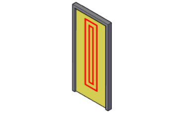
Summary
2D geometry located on a face or the intersection of a 3D solid with a face
can be combined with that face to create additional edges. These edges can
provide a visual effect, and can be pressed and pulled to create indentations
and extrusions.
The object to be imprinted must intersect one or more faces on the selected
solid in order for imprinting to be successful. Imprinting is limited to the
following objects: arcs, circles, lines, 2D and 3D polylines, ellipses, splines,
regions, bodies, and 3D solids.
List of Prompts
The following prompts are displayed.
Select a 3D solid or surface Specifies a 3D solid or surface object to be
imprinted.
Select an object to imprint Specifies an object that intersects the 3D object
you selected.
Delete the source object Specifies whether to remove the object whose shape
served as the imprint outline.
See also:
Add Edges and Faces to Solids
INSERT
Inserts a block or drawing into the current drawing.
Commands | 519
Access Methods
Button
Toolbar: Drafting tool set ➤ Block tool group ➤ Insert
Menu: Insert ➤ Block
Summary
The Insert Block dialog box (page 520) is displayed.
If you enter -insert at the Command prompt, options are displayed (page
523).
A good practice is to insert a block from a block library. A block library can
be a drawing file that stores related block definitions or it can be a folder that
contains related drawing files, each of which can be inserted as a block. With
either method, blocks are standardized and accessible to multiple users.
See also:
Insert Blocks
Insert Dialog Box
Specifies the name and position of the block or drawing to insert.
520 | Chapter 2 Commands
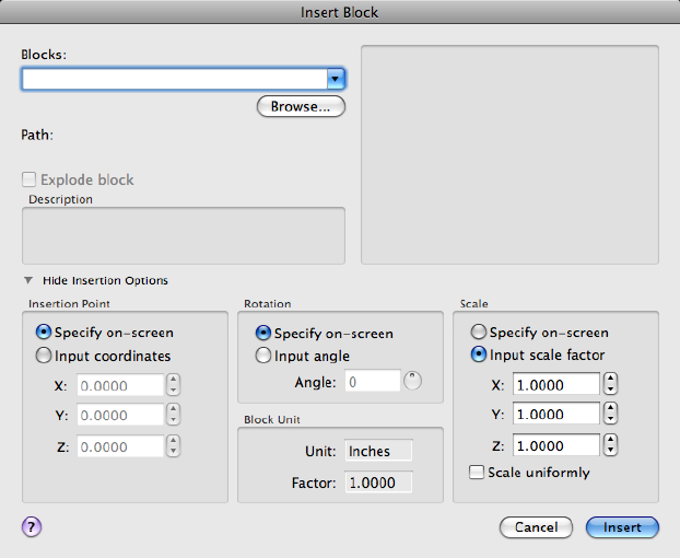
Summary
The position of the inserted block depends on the orientation of the UCS.
Name
Specifies the name of a block to insert, or the name of a file to insert as a block.
Browse
Opens the Select Drawing File dialog box (a standard file selection dialog box)
where you can select a block or drawing file to insert.
Path
Specifies the path to the block.
Explode Block
Explodes the block and inserts the individual parts of the block. When Explode
is selected, you can specify a uniform scale factor only.
Commands | 521

Component objects of a block drawn on layer 0 remain on that layer. Objects
having color BYBLOCK are white. Objects with linetype BYBLOCK have the
CONTINUOUS linetype.
Description Displays the description that was saved with the block.
Preview
Displays a preview of the specified block to insert. A lightning bolt icon in
the lower-right corner of the preview indicates that the block is dynamic. A
icon indicates that the block is annotative.
Show\Hide Insertion Options
Expands or collapses the Insertion Options section to allow you to specify the
insertion point, rotation and scale for the block reference being created.
Insertion Point
Specifies the insertion point for the block.
Specify On-Screen
Specifies the insertion point of the block using the pointing device.
X
Sets the X coordinate value.
Y
Sets the Y coordinate value.
Z
Sets the Z coordinate value.
Scale
Specifies the scale for the inserted block. Specifying negative values for the X,
Y, and Z scale factors inserts a mirror image of a block.
Specify On-Screen
Specifies the scale of the block using the pointing device.
X
Sets the X scale factor.
522 | Chapter 2 Commands
Y
Sets the Y scale factor.
Z
Sets the Z scale factor.
Uniform Scale
Specifies a single scale value for X, Y, and Z coordinates.
Rotation
Specifies the rotation angle for the inserted block in the current UCS.
Specify On-Screen
Specifies the rotation of the block using the pointing device.
Angle
Sets a rotation angle for the inserted block.
Block Unit
Displays information about the block units.
Unit
Specifies the INSUNITS (page 1335) value for the inserted block.
Factor
Displays the unit scale factor, which is calculated based on the INSUNITS
(page 1335) value of the block and the drawing units.
See also:
Insert Blocks
-INSERT
Inserts a block or drawing into the current drawing.
List of Prompts
The following prompts are displayed.
Commands | 523

Enter block name (page ?) or [?(page ?)] <last>: Enter a name,
enter ?,enter ~, or press Enter
Units: <INSUNITS (page 1335) specified for inserted block> Conversion:
<conversion scale>
Specify insertion point (page ?) or [Basepoint (page
?)/Scale (page ?)/X(page ?)/Y(page ?)/Z(page ?)/Rotate
(page ?)]: Specify a point or enter an option
Block Name
Entering a tilde (~) displays the Select Drawing File dialog box (a standard file
selection dialog box).
You can control block insertion behavior in response to the Enter Block Name
prompt by following the listed examples.
■Inserting Exploded Blocks: Preceding the name of the block with an asterisk
(*) explodes the block and inserts the individual parts of it. The block
definition is not added to the drawing.
■Updating a Block Path: If you enter a block name without a path name,
INSERT searches the current drawing data for an existing block definition
by that name. You can replace an existing block definition with an external
file by entering the following at the Enter Block Name prompt:
block name=file name
■Updating a Block Definition: If you make changes to a block file that is
inserted in your drawing and you want to change the existing block
definition without creating a new block insertion, enter the following at
the Specify Insertion Point prompt (following the Enter Block Name
prompt):
block name=
If you enter = after the block name, the following prompt is displayed:
Block "current" already exists. Redefine it? [Yes/No] <No>: Entery, enter n,
or press Enter
If you choose to redefine the block, the existing block definition is replaced
with the new block definition. The drawing is regenerated, and the new
definition is applied to all existing insertions of the block definition. Press
Esc when prompted for the insertion point if you do not want to insert a
new block into the drawing.
NOTE Grouped objects in an inserted drawing are inserted as unnamed groups.
You can list unnamed groups with the GROUP command.
524 | Chapter 2 Commands
?—List Block Names
Lists the blocks currently defined in the drawing.
Insertion Point
Specifies a location for the block or drawing.
Scale Factor All X and Y dimensions of the block or drawing are multiplied
by the X and Y scale factors. The block or drawing is rotated by the specified
angle, using the insertion point as the center of rotation.
Corner Defines the X and Y scale factors at the same time, using the insertion
point and another point as the corners of a box. The X and Y dimensions of
the box become the X and Y scale factors. The insertion point is the first
corner.
XYZ Sets X, Y, and Z scale factors.
■X Scale Factor: Defines X, Y, and Z scale factors for the block or drawing.
■Corner: Defines the X and Y scales at the same time, using the insertion
point and another point as the corners of a box, and then defines the Z
scale.
Basepoint
Temporarily drops the block in the drawing where it is currently positioned
and allows you to specify a new base point for the block reference as it is
dragged into position. This does not affect the actual base point defined for
the block reference.
Scale
Sets the scale factor for the X, Y, and Z axes. The scale for the Z axis is the
absolute value of the specified scale factor.
X
Sets the X scale factor.
Y
Sets the Y scale factor.
Z
Sets the Z scale factor.
Rotate
Sets the angle of insertion for the block.
See also:
Insert Blocks
Commands | 525
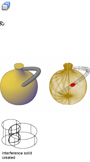
INTERFERE
Creates a temporary 3D solid from the interferences between two sets of
selected 3D solids.
Access Methods
Button
Menu: Modify ➤ 3D Operations ➤ Interference Checking
Summary
Interferences are highlighted with a temporary 3D solid that represents the
intersecting volume. You can also choose to retain the overlapping volumes.
If you define a single selection set, INTERFERE checks all the solids in the set
against one another. If you define two selection sets, INTERFERE checks the
solids in the first selection set against those in the second selection set. If you
include the same 3D solid in both selection sets, INTERFERE considers the 3D
solid part of the first selection set and ignores it in the second selection set.
526 | Chapter 2 Commands
Pressing Enter starts the interference testing of pairs of 3D solids and displays
the Interference Checking dialog box (page 528).
If you enter -interfere at the Command prompt, options are displayed (page
530).
List of Prompts
The following prompts are displayed.
First set of objects Specifies a set of objects to be checked. If you do not select
a second set of objects, all objects in this selection set are checked against each
other.
■Second set of objects (page 527)
■Nested selection (page 527)
■Settings (page 527)
Second set of objects Specifies an additional set of objects to be compared
against the first set of objects. If you select the same object twice, the object
is handled as part of the first selection set.
■Second set of objects (page 527)
■Nested selection (page 527)
■Check first set. Initiates interference checking for only the first selection
set and displays the Interference Checking dialog box.
■Check. Initiates interference checking for both sets of objects and displays
the Interference Checking dialog box.
Nested selection Provides access to individual solid objects that are nested in
blocks and xrefs.
■Select nested objects. Specifies which nested objects to include in the
selection set.
■Exit. Restores normal object selection (not nested).
Settings Displays the Interference Settings dialog box (page 528).
See also:
Check 3D Models for Interferences
Commands | 527
Interference Settings Dialog Box
Controls the display of interference objects
List of Options
The following options are displayed.
Interference Objects
Specifies the visual style and color for interference objects.
Visual Style
Specifies the visual style for interference objects (INTERFEREOBJVS (page 1340)).
Color
Specifies the color for interference objects (INTERFERECOLOR (page 1340)).
Highlight Interfering Pair
Highlights the interfering pair of solids.
Highlight Interference
Highlights the interference objects created from the interfering pair.
Viewport
Specifies the viewport display while checking for interferences.
Visual Style
Specifies the visual style for the viewport while checking for interferences
(INTERFEREVPVS (page 1341)).
See also:
Check 3D Models for Interferences
Interference Checking Dialog Box
Cycles through, zooms, and deletes or retains interference objects.
528 | Chapter 2 Commands
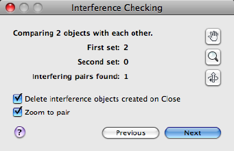
List of Options
The following options are displayed.
Interfering Objects
Displays the number of interferences found between each set during the IN-
TERFERE (page 526) command.
First Set
Displays the number of objects selected in the first set.
Second Set
Displays the number of objects selected in the second set.
Interfering Pairs Found
Displays the number of interferences found among the selected objects.
Zoom
Closes the dialog box and starts the ZOOM (page 1153) command.
Pan
Closes the dialog box and starts the PAN (page 763) command.
3D Orbit
Closes the dialog box and starts the 3DORBIT (page 40) command.
Delete Interference Objects Created on Close
Deletes the interference objects when the dialog box is closed.
Zoom to Pair
Zooms to interference objects while using Previous and Next.
Previous
Highlights the previous interference object.
Commands | 529
Next
Highlights the next interference object.
Close
Closes the dialog box and deletes the interference objects if that option is
selected.
See also:
Check 3D Models for Interferences
-INTERFERE
Summary
INTERFERE highlights all interfering 3D solids and displays the number of
objects selected and the number of interfering pairs.
If you define a single selection set, INTERFERE checks all the solids in the set
against one another. If you define two selection sets, INTERFERE checks the
solids in the first selection set against those in the second selection set. If you
include the same 3D solids in both selection sets, INTERFERE considers the
3D solid part of the first selection set and ignores it in the second selection
set.
List of Prompts
The following prompts are displayed.
Check for interferences between 2 sets of objects or within
1 set of objects...
Select first set of objects or [Nested selection (page ?)]:
Use an object selection method or enter an option
Select second set of objects or [Nested selection (page
?)/checK current] <checK>: Use an object selection method, enter n, or
press Enter to check for interferences
Create Interference Objects Creates and highlights new 3D solids on the
current layer that are the intersections of the interfering pairs of 3D solids.
If there are more than two interfering 3D solids, it may not be clear which
pairs are interfering if all the interfering 3D objects are highlighted at once.
■Zoom to pairs of interfering objects
530 | Chapter 2 Commands
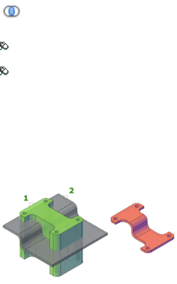
Next Pair Cycles through the interfering pairs of 3D solids.
Nested Selection
Allows you to select individual solid objects that are nested in blocks and
xrefs.
See also:
Check 3D Models for Interferences
INTERSECT
Creates a 3D solid, surface, or 2D region from overlapping solids, surfaces, or
regions.
Access Methods
Button
Toolbar: Modeling tool set ➤ Solids - Edit tool group ➤ Booleans flyout
➤ Intersect
Menu: Modify ➤ Solid Editing ➤ Intersect
Summary
With INTERSECT, you can create a 3D solid from the common volume of two
or more existing 3D solids, surfaces, or regions. If you select a mesh, you can
convert it to a solid or surface before completing the operation.
You can extrude 2D profiles and then intersect them to create a complex
model efficiently.
Commands | 531
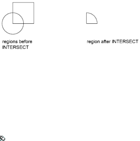
The selection set can contain regions, solids, and surfaces that lie in any
number of arbitrary planes. INTERSECT divides the selection set into subsets
and tests for intersections within each subset. The first subset contains all the
solids and surfaces in the selection set. The second subset contains the first
selected region and all subsequent coplanar regions. The third subset contains
the next region that is not coplanar with the first region and all subsequent
coplanar regions, and so on until all regions belong to a subset.
See also:
Create Composite Objects
ISOLATEOBJECTS
Displays selected objects across layers; unselected objects are hidden.
Access Methods
Menu: Tools ➤ Isolate ➤ Isolate Objects
Shortcut menu: Right-click in the drawing area and click Isolate ➤ Isolate
Objects.
Summary
Displays selected objects in the current view. All other objects are temporarily
hidden.
List of Prompts
The following prompt is displayed.
Select objects: Use an object selection method
532 | Chapter 2 Commands
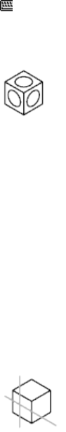
See also:
Control the Display of Objects
ISOPLANE
Specifies the current isometric plane.
Access Methods
Command entry: 'isoplane for transparent use
Summary
The isometric plane affects the cursor movement keys only when Snap mode
is on and the snap style is Isometric. If the snap style is Isometric, Ortho mode
uses the appropriate axis pair even if Snap mode is off. The current isometric
plane also determines the orientation of isometric circles drawn by ELLIPSE
(page 402).
You can cycle through the isometric planes by pressing Fn-F5 (or F5).
List of Prompts
The following prompts are displayed.
Enter isometric plane setting [Left (page 533)/Top (page
533)/Right (page 534)] <Top>: Enter an option or press Enter
Left
Selects the left-hand plane, defined by the 90-degree and 150-degree axis pair.
Top
Commands | 533
Selects the top face of the cube, called the top plane, defined by the 30-degree
and 150-degree axis pair.
Right
Selects the right-hand plane, defined by the 90-degree and 30-degree axis pair.
See also:
Set Isometric Grid and Snap
J Commands
JOIN
Joins the endpoints of linear and curved objects to create a single object.
Access Methods
Button
Toolbar: Drafting tool set ➤ Modify tool group (expanded) ➤ Join
Menu: Modify ➤ Join
Summary
Combines a series of finite linear and open curved objects at their common
endpoints to create a single 2D or 3D object. The type of object that results
depends on the types of objects selected, the type of object selected first, and
whether the objects are coplanar.
534 | Chapter 2 Commands
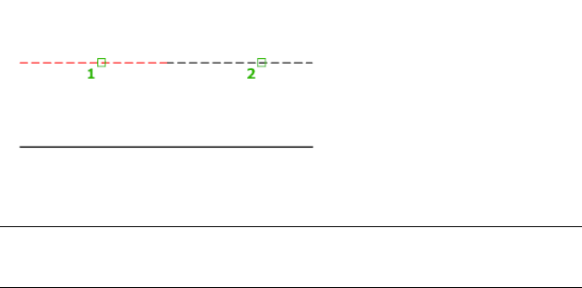
You can join objects in different planes if the source object is a spline or a 3D
polyline. Each type of object has additional restrictions.
NOTE
Construction lines, rays, and closed objects cannot be joined.
List of Prompts
The following prompts are displayed.
Select source object or multiple objects to join at once:
Select lines, polylines, 3D polylines, arcs, elliptical arcs, helixes, or splines.
Source Object
Specifies a single source object to which you can join other objects. Press Enter
after selecting the source object to begin selecting the objects to join. The
following rules apply for each type of source object:
Line Only line objects can be joined to the source line. The line objects must
all be collinear, but can have gaps between them.
Polyline Lines, polylines, and arcs can be joined to the source polyline. All
objects must be contiguous and coplanar. The resulting object is a single
polyline.
3D Polyline Any linear or curved object can be joined to the source 3D
polyline. All the objects must be contiguous, but can be noncoplanar. The
resulting object is either a single 3D polyline or a single spline, depending on
whether you are joining to a linear or a curved object respectively.
Arc Only arcs can be joined to the source arc. All the arc objects must have
the same radius and center point, but can have gaps between them. The arcs
are joined in a counterclockwise direction starting from the source arc.
The Close option converts the source arc into a circle.
Commands | 535
Elliptical Arc Only elliptical arcs can be joined to the source elliptical arc.
The elliptical arcs must be coplanar and have the same major and minor axes,
but can have gaps between them. The elliptical arcs are joined counterclockwise
starting from the source elliptical arc.
The Close option converts the source elliptical arc into an ellipse.
Helix Any linear or curved object can be joined to the source helix. All objects
must be contiguous, but can be noncoplanar. The resulting object is a single
spline.
Spline Any linear or curved object can be joined to the source spline. All
objects must be contiguous, but can be noncoplanar. The resulting object is
a single spline.
Multiple Objects to Join at Once
Joins multiple objects without specifying a source object. The rules and
resulting object types are as follows:
■A line object results from joining collinear lines. The lines can have gaps
between their endpoints.
■An arc or circle object results from joining coplanar arcs with the same
center point and radius. The arcs can have gaps between their endpoints.
Lengthening occurs in a counterclockwise direction. A circle object results
if the joined arcs form a complete circle.
■A spline object results from joining splines, elliptical arcs, or helixes
together, or to other objects. The objects can be noncoplanar.
■A polyline object results from joining coplanar lines, arcs, polylines, or 3D
polylines.
■A 3D polyline results from joining noncoplanar objects other than curved
objects.
See also:
Break and Join Objects
JPGOUT
Saves selected objects to a file in JPEG file format.
536 | Chapter 2 Commands
Summary
The Create Raster File dialog box (a standard file selection dialog box (page
720)) is displayed. Enter the file name in the dialog box.
List of Prompts
The following prompts are displayed.
Select objects or <all objects and viewports>: Press Enter to
select all objects and viewports or use an object selection method and press Enter
A JPEG file is created that contains the objects you select. Shade Plot options
are preserved in the file when you use this command.
Light glyphs that are displayed in the drawing appear in the new file, even if
the Plot Glyph property of the lights is set to No.
NOTE When the FILEDIA (page 1296) system variable is set to 0 (Off), command
prompts are displayed.
See also:
Export Raster Files
L Commands
LAYER
Manages layers and layer properties.
Access Methods
Menu: Format ➤ Layer
Command entry: 'layer for transparent use
Summary
The Layers Palette (page 538) is displayed.
If you enter -layer at the Command prompt, options are displayed (page 551).
Commands | 537
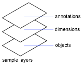
Use layers to control the visibility of objects and to assign properties such as
color and linetype. Objects on a layer normally assume the properties of that
layer. However, you can override any layer property of an object. For example,
if an object’s color property is set to BYLAYER, the object displays the color
of that layer. If the object’s color is set to Red, the object displays as red,
regardless of the color assigned to that layer.
See also:
Use Layers to Manage Complexity
Layers Palette
Displays a list of the layers in the drawing and their properties.
538 | Chapter 2 Commands
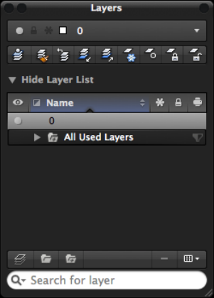
Summary
You can add, delete, and rename layers, change their properties, set property
overrides for layout viewports, or add layer descriptions and apply changes
in realtime.
When switching layouts or when activating a viewport on named (paper space)
layout, the Layers palette is updated and displays the current state of the layer
properties in the current space.
List of Options
The following options are displayed.
Layer Drop-down
Displays the current layer and its color, along with some of its common
properties. Click the drop-down list to adjust a layer’s On/Off, Lock/Unlock,
or Thaw/Freeze state. You can also select a layer to set it current.
Toolbar
Make Current Sets the current layer to that of a selected object. (See LAYMCUR
(page 560))
Layer Match Changes the layer of a selected object to match the destination
layer. (See LAYMCH (page 559))
Commands | 539
Previous Layer Undoes the last change or set of changes made to layer settings.
(See LAYERP (page 555))
Isolate Layer Hides or locks all layers except those of the selected objects. (See
LAYISO (page 557))
Unisolate Layer Restores all layers that were hidden or locked with the LAYISO
command. (See LAYUNISO (page 566))
Freeze Layer Freezes the layer of selected objects. (See LAYFRZ (page 556))
Layer Off Turns off the layer of a selected object. (See LAYOFF (page 562))
Lock Layer Locks the layer of a selected object. (See LAYLCK (page 559))
Unlock Layer Unlocks the layer of a selected object. (See LAYULK (page 566))
Show/Hide Layer List
Displays or hides the Layer list which you use to modify the properties of the
layers in the current drawing.
Layer List
Displays the layers and layer groups in the current drawing and their properties.
Click in the columns for a layer to change its properties.
Status Indicates the status of the layer: layer in use, empty layer, or current
layer.
Object Selection Indicates if the layer is assigned to an object that is currently
selected. Objects must be selected when no command is active.
Visibility Indicates if the layer is on and off. When a layer is on, it is visible
and available for plotting. When a layer is off, it is invisible and not plotted,
even if Plot is on.
Description Text string that describes the layer.
Name Displays the name of the layer.
Press Fn-F2 to enter a new name or click over the name when the layer is
highlighted.
Freeze Indicates if the layer is frozen or thawed.
Layers can be frozen in all layouts and viewports, including the Model layout.
You can freeze layers to speed up ZOOM (page 1153), PAN (page 763), and many
other operations; improve object selection performance; and reduce
regeneration time for complex drawings.
Objects on frozen layers are not displayed, plotted, hidden, rendered, or
regenerated.
540 | Chapter 2 Commands
Freeze the layers you want to be invisible for long periods. If you plan to switch
visibility settings frequently, use the On/Off property to avoid regenerating
the drawing. You can freeze a layer in all viewports, in the current layout
viewport, or in new layout viewports as they are created.
Lock Indicates if the layer is locked or unlocked. Objects on a locked layer
cannot be modified.
Lineweight Displays the lineweight associated with the layer. Clicking the
lineweight name displays a drop-down list with the available lineweights.
Linetype Displays the linetype associated with the layer. Clicking the linetype
name displays a drop-down list with the loaded linetypes. Choose Other at
the bottom of the drop-down list to display the Select Linetype dialog box
(page 550).
Transparency Controls the visibility of all objects on the selected layer. When
transparency is applied to individual objects, the objects’ transparency property
overrides the transparency setting of the layer. Drag the slider to adjust the
transparency of objects on the layer.
Plot (Print) Indicates if the objects on layer should be plotted or not.
If you turn off plotting for a layer, the objects on that layer are still displayed.
Layers that are off or frozen are not plotted, regardless of the Plot setting.
Plot Style Displays the plot style associated with the layer. If you are working
with color-dependent plot styles (the PSTYLEPOLICY (page 1410) system variable
is set to 1), you cannot change the plot style associated with a layer. Clicking
the plot style name displays a drop-down list with the available plot styles.
New VP Freeze Freezes the layer in new viewports created on a named (paper
space) layout.
For example, freezing the DIMENSIONS layer in all new viewports restricts
the display of dimensions on that layer in any newly created named layout
viewports but does not affect the DIMENSIONS layer in existing viewports. If
you later create a viewport that requires dimensions, you can override the
default setting by changing the current viewport setting.
VP Freeze (not available on the Model layout) Freezes the layer in the current
named (paper space) layout viewport. You can freeze or thaw layers in the
current viewport without affecting layer visibility in other viewports.
VP Freeze overrides the Thaw setting for a layer in the drawing. That is, you
can freeze a layer in the current viewport if it's thawed in the drawing, but
you can't thaw a layer in the current viewport if it's frozen or off in the
drawing. A layer is not visible when it is set to Off or Frozen in the drawing.
Commands | 541
VP Color (not available on the Model layout) Sets an override for the color
associated with the selected layer for the active named (paper space) layout
viewport.
VP Lineweight (not available on the Model layout) Sets an override for the
lineweight associated with the selected layer for the active named (paper space)
layout viewport.
VP Linetype (not available on the Model layout) Sets an override for the
linetype associated with the selected layer for the active named (paper space)
layout viewport.
VP Transparency (not available on the Model layout) Sets an override for
transparency associated with the selected layer for the active named (paper
space) layout viewport.
VP Plot Style (not available on the Model layout) Sets an override for the
plot style associated with the selected layer for the active named (paper space)
layout viewport. Override settings are not visible in the viewport or plotted
when the visual style in the drawing is set to Conceptual or Realistic. If you
are working with color-dependent plot styles (the PSTYLEPOLICY (page 1410)
system variable is set to 1), you cannot set a plot style override.
Layer List - Column Heading Label Shortcut Menu
Display All Layer Colors Toggles the display of the White color swatch in
the Color column of the Layer list.
Optimize All Columns Changes the width of all columns to maximize display
of the column content.
Optimize Column Changes the width of a column to maximize display of
the column content.
Restore All Columns to Defaults Restores all columns to their default display
and width settings.
Layer List - Layer Item Shortcut Menu
Make Active Sets the selected layer as the current layer. (See CLAYER (page
1191) system variable)
Layer Status Toggles the Freeze, Lock, Freeze in New Viewports, or Prints layer
status of the selected layers. The Isolate option isolates the selected layers in
the drawing. All layers except those selected, are turned off and locked. (See
LAYISO (page 557))
Remove Viewport Overrides For (not available on the Model layout)
Removes the layer property overrides assigned to all layers in the drawing or
only for the selected layers in the current viewport only or in all viewports.
542 | Chapter 2 Commands

Rename Renames the selected layer.
Delete Deletes the selected layer from the drawing. You can delete only
unreferenced layers. Referenced layers include layers 0 and DEFPOINTS, layers
containing objects (including objects in block definitions), the current layer,
and xref-dependent layers.
NOTE Be careful about deleting layers if you are working on a drawing in a shared
project or one based on a set of layering standards.
Duplicate Layer Creates a new layer based on the selected layer. The new
layer inherits all properties and statuses of the selected layer.
Combine with Layer Displays the Choose a Layer dialog box (page 549) which
allows you to merge the selected layers to a specified layer. After the layers are
merged, the selected layers are removed from the drawing. (See -LAYMRG
(page 561))
Create Group from Layers Creates a new layer group and adds the selected
layers as references of the layer group.
Move to Group Displays the Choose a Group dialog box (page 548) which
allows you to add the selected layers as references to a specified layer group.
Remove From Group Removes the selected layers from the layer group.
Group Similar Layers Displays the New Dynamic Group dialog box (page
546) and defines a rule for each of the layer's properties. Name the new dynamic
group or modify the rules for the new dynamic group before creating the
dynamic group.
New Layer Creates a new layer. The layer list displays a layer named Layer1.
You can edit the name immediately. The new layer inherits the properties of
the currently selected layer in the layer list (color, on or off state, and so on).
New Group Creates a new layer group. The layer list displays a layer group
named Group1. You can edit the name immediately.
New Dynamic Group Displays the New Dynamic Group dialog box (page
546) and allows you to create a layer group that contains all the layers based
on the layer properties specified.
Select All Layers Selects all layers displayed in the list view.
Select All Others Selects all other layers in the list view except the current
selected layers.
Commands | 543
Layer List - Layer Group Item Shortcut Menu
Edit Group (Applies to dynamic layer groups only) Displays the New
Dynamic Group dialog box and allows you to modify the groups rules.
Group Layer Status Toggles the Visibility, Freeze, or Lock, Freeze in New
Viewports, or Prints layer status of the selected layers. The Isolate option
isolates the selected layers in the drawing. All layers except those selected, are
turned off and locked. (See LAYISO (page 557))
Rename Group Renames the selected layer group.
Delete Group Deletes the selected layer group. You have the option to delete
just the layer group, or the layer group and the layers that the group references.
The GROUPLAYERDELETABLE (page 1313) system variable controls the removal
behavior of layers referenced by a layer group when it is being deleted.
Duplicate Group Creates a new layer group based on the selected layer group.
The new layer group inherits the references to all the layers of the selected
layer group.
Merge Group Layers Displays the Choose a Layer dialog box (page 549) which
allows you to merge the layers in the selected layer group to a specified layer.
After the layers are merged, the selected layers are removed from the drawing.
(See -LAYMRG (page 561))
Convert to Group Creates a layer group from the selected dynamic layer
group. When new layers are added or changed, they are no longer
automatically added to or removed from the group based on their properties.
New Layer Creates a new layer. The layer list displays a layer named Layer1.
You can edit the name immediately. The new layer inherits the properties of
the currently selected layer in the layer list (color, on or off state, and so on).
New Group Creates a new layer group. The layer list displays a layer group
named Group1. You can edit the name immediately.
New Dynamic Group Displays the New Dynamic Group dialog box and allows
you to create a layer group that contains all the layers based on the layer
properties specified.
Select Layers in Group Selects all the layers in the selected layer group.
New Layer
Creates a new layer. The layer list displays a layer named Layer1. You can edit
the name immediately. The new layer inherits the properties of the currently
selected layer in the layer list (color, on or off state, and so on).
544 | Chapter 2 Commands

New Layer Group
Creates a new layer group. The layer list displays a layer group named Group1.
You can edit the name immediately.
New Dynamic Layer Group
Displays the New Dynamic Group dialog box and allows you to create a layer
group that contains all the layers based on the layer properties specified.
Delete Selected (-)
Deletes the selected layers or layer groups.
You can delete only unreferenced layers. Referenced layers include layers 0
and DEFPOINTS, layers containing objects (including objects in block
definitions), the current layer, and xref-dependent layers.
NOTE Be careful about deleting layers or layer groups if you are working on a
drawing in a shared project or one based on a set of layering standards.
Display Settings
Displays a menu of options that controls the display of layer groups, layers,
and column headers in the Layer list.
Show Layer Groups Toggles the display of all layer groups. (See SHOWGROUPS
(page 1431))
■Show Groups on Top. Displays all layer groups sorted at the top of the
Layer list. (See GROUPSONTOP (page 1314))
■Show Groups on Bottom. Displays all layer groups sorted at the bottom
of the Layer list. (See GROUPSONTOP (page 1314))
Show Empty Groups Toggles the display of empty layer groups. (See
SHOWEMPTYGROUPS (page 1430))
Show Xref Layers Toggles the display of all layers in attached external
references (xrefs). (See SHOWXREFLAYERS (page 1434))
Show Automatic Groups Toggles the display of layer groups that are populated
dynamically by the product.
■All Used Layers. Toggles the display of the All Used Layers layer group.
This layer group dynamically updates to list all the layers that do not
currently have any objects on them. (See SHOWALLUSEDLAYERSGROUP
(page 1430))
■External References. Toggles the display of the Xref layer group. This
layer group dynamically updates to list all attached external references
(xrefs) as nested layer groups and their layers. Show Xref Layers must be
enabled before this layer group can be displayed. (See SHOWXREFGROUPS
(page 1434))
Commands | 545
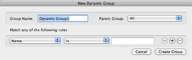
■Layers with Overrides. Toggles the display of the Viewport Overrides
layer group. This layer group dynamically updates to list all the layers in
the active layout viewport that contain property overrides. (See SHOWV-
POVERRIDESGROUP (page 1433))
■Unreconciled Layers. Toggles the display of the Unreconciled Layers
layer group. This layer group dynamically updates to list all the layers that
have not been reconciled. (See SHOWUNRECONCILEDLAYERSGROUP
(page 1433))
View Options Toggles the display of the column headings, and provides
options to automatically adjust the size of all or the selected column to its
maximum width in the Layer list.
Search for Layer
Filters the Layer list by name quickly as you enter characters. This filter is not
saved when you close the Layers palette.
See also:
Work with Layers
New Dynamic Group Dialog Box
Groups layers based on the criteria you select.
Summary
When a dynamic layer group is added to the Layers palette (page 538), layers
that match the rules are displayed in the Layer list under the layer group when
expanded.
546 | Chapter 2 Commands
List of Options
The following options are displayed.
Group Name
Provides a space to enter a name for the layer group.
Parent Group
Displays a list of all the layer groups that the new dynamic layer group can
be nested under.
Rules
Displays the properties of layers. You can use one or more properties to define
the layer group. For example, you can define a layer group that displays all
layers that are either Red or Blue and in use. To include more than one color,
linetype, or lineweight, add another rule and select a different setting.
Name Use wild-card characters in the edit field to filter layer names. For
example, enter *mech* to include all layers with the letters mech in the name.
All the wild-card characters are listed in the table in Filter and Sort the List of
Layers in the User's Guide.
Freeze State Selects Frozen or Thawed layers.
Viewport Visibility Selects Visible (On) or Hidden (Off) layers.
Lock State Selects Locked or Unlocked layers.
Plot State Selects Plotting or Non-plotting layers.
Color Selects layers that match or do not match the selected color. Choose
Select Color to display the Color Palette dialog box (page 198).
Linetype Selects layers that match or do not match the selected linetype.
Choose Manage to display the Select Linetype dialog box (page 550).
Lineweight Selects layers that match or do not match the selected lineweight.
Choose Manage to display the Lineweight Settings dialog box.
Transparency Selects layers that match or do not match the specified
transparency. Drag the slider to specify a transparency level.
Plot Style (Applies to drawings that use named plot styles) Selects layers
that match or do not match the selected named plot style.
New VP Freeze State Selects Frozen or Thawed layers in new viewports.
Viewport Color Selects layers that have a color override, and match or do not
match the selected color. Choose Select Color to display the Color Palette
dialog box (page 198).
Commands | 547
Viewport Freeze State Selects Frozen or Thawed layers in the current viewport.
Viewport Linetype Selects layers that have a linetype override, and match or
do not match the selected linetype. Choose Manage to display the Select
Linetype dialog box (page 550).
Viewport Lineweight Selects layers that have a lineweight override, and
match or do not match the selected lineweight. Choose Manage to display
the Lineweight Settings dialog box.
Viewport Transparency Selects layers that have a transparency override, and
match or do not match the specified transparency. Drag the slider to specify
a transparency level.
Viewport Plot Style (Applies to drawings that use named plot styles) Selects
layers that have a plot style override, and match or do not match the selected
named plot style.
Layer Selects Used or Not-Used layers in Model space or a viewport.
Remove Rule
Removes a single rule or a grouping of rules.
Create Rule Group
Creates an And grouping of rules. Grouping rules allows you to make complex
filters.
Add Rule
Adds a new rule. Use the new set of controls to specify the layer properties
and conditions for the rule.
Create Group
Adds the new dynamic group to the Layers palette.
See also:
Work with Layers
Choose a Group Dialog Box
Adds references of the selected layers to a specified layer group.
548 | Chapter 2 Commands
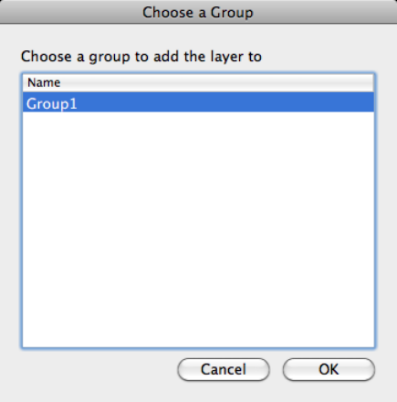
List of Options
The following options are displayed.
Choose a group to add the layer to
Lists the available layer groups in the current drawing that you can add the
selected layers to.
See also:
Work with Layers
Choose a Layer Dialog Box
Merges selected layers to a specified layer.
Commands | 549
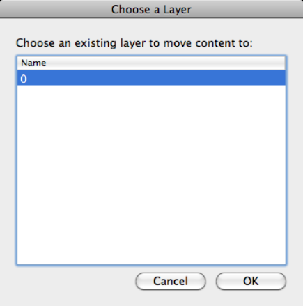
List of Options
The following options are displayed.
Choose an existing layer to move content to
Lists the available layers in the current drawing that you can merge the selected
layers with from the Layers palette. All objects on the selected layers from the
Layers palette are moved to the specified layer and then the layers are removed
from the drawing.
See also:
Work with Layers
Select Linetype Dialog Box
Displays linetypes available in the current drawing.
550 | Chapter 2 Commands
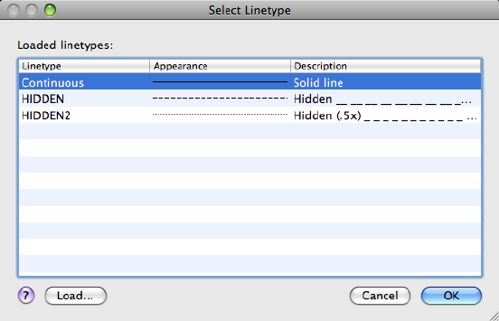
List of Options
The following options are displayed.
Loaded Linetypes
Displays the list of linetypes loaded in the current drawing.
Load
Displays the Load or Reload Linetypes dialog box (page 578), in which you can
load selected linetypes into the drawing and add them to the list of linetypes.
See also:
Work with Layers
-LAYER
Manages layers and layer properties.
List of Prompts
The following prompts are displayed.
Current layer: <"current">
Enter an option [?(page ?)/Make (page ?)/Set (page ?)/New
(page ?)/Rename (page ?)/ON (page ?)/OFF (page ?)/Color
Commands | 551

(page ?)/Ltype (page ?)/LWeight (page ?)/TRansparency
(page ?)/MATerial (page ?)/Plot (page ?)/PStyle (page
?)/Freeze (page ?)/Thaw (page ?)/LOck (page ?)/Unlock
(page ?)/stAte (page ?)/Description (page ?)/rEconcile
(page ?)]:
NOTE
The Pstyle option is available only when you are using named plot styles.
?—List Layers
Displays a list of the currently defined layers, showing their names, states,
color numbers, linetypes, lineweights, and whether they are externally
dependent layers.
Make
Creates a layer and makes it current. New objects are drawn on the current
layer.
If no layer exists for the name you enter, a new layer with that name is created.
The new layer is on and assumes the following properties by default: color
number 7, the CONTINUOUS linetype, and a lineweight of DEFAULT.
If the layer exists but is turned off, it is turned on.
Set
Specifies a new current layer but does not create the layer if it does not already
exist. If the layer exists but is turned off, it is turned on and made current. A
frozen layer cannot be made current.
New
Creates layers. You can create two or more layers by entering names separated
by commas.
Rename
Renames an existing layer.
On
Makes selected layers visible and available for plotting.
Off
Makes selected layers invisible and excludes them from plotting.
Color
Changes the color associated with a layer. Enter a color name or a number
from 1 through 255.
True Color Specifies a true color to be used for the selected object. Enter three
integer values from 0 to 255 separated by commas to specify a true color.
552 | Chapter 2 Commands
Color Book Specifies a color from a loaded color book, guide, or set to use for
the selected object. Enter the name of a color book that has been installed,
such as "DIC COLOR GUIDE(R)$DIC 43".
The color is assigned to the layer or layers, and the layers are turned on. To
assign a color but turn off the layer, precede the color with a minus sign (-).
Ltype
Changes the linetype associated with a layer.
Lweight
Changes the lineweight associated with a layer.
If you enter a valid lineweight, the current lineweight is set to the new value.
If you enter a lineweight that is not valid, the current lineweight is set to the
nearest fixed lineweight value. If you would like to plot an object with a
custom width not found in the list of fixed lineweight values, you can use the
Plot Style Table Editor to customize plotted lineweights.
Transparency
Changes the transparency level associated with a layer. Enter a value from 0
to 90.
After specifying a transparency value, the following prompt is displayed:
Enter name list of layer(s) for transparency specified value% <0>: Enter the names
of the layers to which to apply this transparency level, or press Enter to apply it to
the current layer only
Material
Attaches a material to a layer. The material must be available in the drawing
before it can be assigned to a layer.
Plot
Controls whether visible layers are plotted. If a layer is set to plot but is
currently frozen or turned off, the layer is not plotted.
Pstyle
Sets the plot style assigned to a layer. This option is not available if you are
using color-dependent plot styles in the current drawing (the PSTYLEPOLICY
(page 1410) system variable is set to 1).
If you select a plot style other than NORMAL, the following prompt is
displayed:
Enter name list of layer(s) for plot style current <current>: Enter the names of the
layers to use this plot style, or press Enter to apply the style to the current layer only
Commands | 553
Freeze
Freezes layers, making them invisible and excluding them from regeneration
and plotting.
Thaw
Thaws frozen layers, making them visible and available for regeneration and
plotting.
Lock
Locks layers, preventing editing of objects on those layers.
Unlock
Unlocks selected locked layers, permitting editing of objects on those layers.
State
Saves and restores the state and property settings of the layers in a drawing.
?—List Named Layer States Lists the named layer state (LAS) files in the
support path for the drawing.
Save Saves the state and properties settings of the layers in a drawing under
a specified layer state name. When saving a layer state, you specify which
layer settings are affected when the layer state is later restored.
Restore Restores the state and property settings of all layers to previously
saved settings. Restores only those layer state and property settings that were
selected when the layer state was saved.
Edit Changes the saved layer settings for a specified layer state. When the
layer state is restored, the specified settings are used.
Name Changes the name of a saved layer state.
Delete Removes a saved layer state.
Import Loads a previously exported layer state (LAS) file, or layers states from
a file (DWG, DWT) into the current drawing. Additional layers may be created
as a result of importing a layer state file.
Export Saves a selected named layer state to a layer state (LAS) file.
Description
Sets the description property value of the existing layer.
A warning prompt is displayed when you enter a description to a layer with
an existing description.
Reconcile
Sets the unreconciled property of an unreconciled layer.
? - Name List of Layers Displays a list of all unreconciled layers.
554 | Chapter 2 Commands
See also:
Use Layers to Manage Complexity
LAYERCLOSE
Closes the Layers palette.
Summary
Closes the Layers palette if it is open.
See also:
Work with Layers
LAYERP
Undoes the last change or set of changes made to layer settings.
Access Methods
Button
Toolbar: Layers palette ➤ Previous Layer
Menu: Format ➤ Layer Tools ➤ Layer Previous
Summary
Undoes changes you have made to layer settings such as color or linetype. If
settings are restored, a message is displayed: “Restored previous layer states.”
When you use Layer Previous, it undoes the most recent change using the
Layers palette or -LAYER command. Every change you make to layer settings
is tracked and can be undone by Layer Previous.
LAYERP (Layer Previous) does not undo the following changes:
■Renamed layers: If you rename a layer and change its properties, Layer
Previous restores the original properties but not the original name.
Commands | 555
■Deleted layers: If you delete or purge a layer, using Layer Previous does not
restore it.
■Added layers: If you add a new layer to a drawing, using Layer Previous does
not remove it.
See also:
Change Layer Settings and Layer Properties
LAYERPMODE
Turns on and off the tracking of changes made to layer settings.
Summary
When Layer Previous mode is on, changes made to layers are tracked. When
Layer Previous mode is off, changes made to layers are no longer tracked.
See also:
Change Layer Settings and Layer Properties
LAYFRZ
Freezes the layer of selected objects.
Access Methods
Button
Toolbar: Layers palette ➤ Freeze Layer
Menu: Format ➤ Layer Tools ➤ Layer Freeze
Summary
Objects on frozen layers are invisible. In large drawings, freezing unneeded
layers speeds up operations involving display and regeneration. In a layout,
you can freeze layers in individual layout viewports.
556 | Chapter 2 Commands
List of Prompts
The following prompts are displayed.
Current settings: Viewports=current, Block nesting level=current
Select an object on a layer to be frozen (page ?) or [Set-
tings (page ?)/Undo (page ?)]: Select an object or enter s or u
Layer <layer name> has been frozen.
Select an Object on a Layer to be Frozen
Specifies the layer to be frozen.
Layer “<layer name>” has been frozen.
Settings
Displays settings for viewports and block definitions. The setting you choose
persists from session to session.
Enter setting type for [Viewports/Block selection]:
Viewports Displays settings for viewports.
In paper space viewport use [Freeze/Vpfreeze] <Vpfreeze>: Enterf to freeze objects
in all viewports orv to freeze an object in the current viewport only
Block Selection Displays settings for block definitions.
■Block. If a selected object is nested in a block, freezes the layer of that
block. If a selected object is nested in an xref, freezes the layer of the object.
■Entity. Freezes the layers of selected objects even if they are nested in an
xref or a block.
■None. If a block or an xref is selected, freezes the layer containing that
block or xref.
Undo
Cancels the previous layer selection.
See also:
Use Layers to Manage Complexity
LAYISO
Hides or locks all layers except those of the selected objects.
Commands | 557
Access Methods
Button
Toolbar: Layers palette ➤ Isolate Layer
Menu: Format ➤ Layer Tools ➤ Layer Isolate
Summary
All layers except the layers of the selected objects are either turned off, frozen
in the current layout viewport, or locked, depending on the current setting.
The layers that remain visible and unlocked are called isolated.
List of Prompts
The following prompts are displayed.
Current setting: <current settings>
Select objects on the layer(s) to be isolated or [Settings]:
Select objects or enters
Select Objects on the Layer(s) to be Isolated
After selecting one or more objects, all layers except the layers of the selected
objects are either turned off, frozen in the current layout viewport, or locked,
depending on the current setting. The layers that remain visible and unlocked
are termed isolated.
NOTE Locked layers are faded by default. You can specify the percent of the fading
from the Lock option in this command. You can later change the value with the
LAYLOCKFADECTL (page 1348) system variable.
If you make changes to layers within a session and you want to restore the
layers to the state they were in immediately before you entered the LAYISO
command, use the LAYUNISO (page 566) command.
Settings
Controls whether layers are turned off, frozen in the current layout viewports,
or locked.
Off Turns off or freezes all layers except the layers of the selected objects.
Vpfreeze In a layout, freezes all but the selected layers in the current layout
viewport only. Other layout viewports in the drawing are unchanged.
If not in a layout, all other layers are turned off instead.
558 | Chapter 2 Commands

Off Turns off all but the selected layers in all viewports.
Lock and Fade
Locks all layers except the layers of the selected objects, and sets the fading for
locked layers.
See also:
Use Layers to Manage Complexity
LAYLCK
Locks the layer of a selected object.
Access Methods
Button
Toolbar: Layers palette ➤ Lock Layer
Menu: Format ➤ Layer Tools ➤ Layer Lock
Summary
Using this command, you can prevent objects on a layer from being
accidentally modified. You can also fade the objects on a locked layer using
the LAYLOCKFADECTL system variable.
See also:
Prevent Objects from Being Selected
LAYMCH
Changes the layer of a selected object to match the destination layer.
Access Methods
Button
Commands | 559

Toolbar: Layers palette ➤ Layer Match
Menu: Format ➤ Layer Tools ➤ Layer Match
List of Prompts
The following prompts are displayed.
Select objects to be changed: Select an object to change its layer
Select object on destination layer (page 560) or [Name (page
560)]: Select an object or enter nto open the Change to Layer dialog box
Select Object on Destination Layer Select an object on the destination layer.
Name Displays the Change to Layer dialog box (page 560).
If you create an object on the wrong layer, you can change its layer to the one
you want using LAYMCH.
See also:
Use Layers to Manage Complexity
Change to Layer Dialog Box
Displays a list of layers to choose as the destination layer. You can also create
a new destination layer.
List of Options
The following options are displayed.
Current Layer Displays the currently selected layer. Create a new layer name
by entering a name.
Destination Layer list Displays a list of layers in the drawing.
See also:
Use Layers to Manage Complexity
LAYMCUR
Sets the current layer to that of a selected object.
560 | Chapter 2 Commands
Access Methods
Button
Toolbar: Layers palette ➤ Make Current
Menu: Format ➤ Layer Tools ➤ Make Object’s Layer Current
Summary
You can change the current layer by selecting an object on that layer. This is
a convenient alternative to specifying the layer name in the Layers palette.
See also:
Use Layers to Manage Complexity
LAYMRG (-LAYMRG)
Merges selected layers into a target layer, removing the previous layers from
the drawing.
Summary
You can reduce the number of layers in a drawing by merging them. Objects
on merged layers are moved to the target layer, and the original layers are
purged from the drawing.
If you enter laymrg or -laymrg at the Command prompt, options are dis-
played (page 561).
See also:
Use Layers to Manage Complexity
-LAYMRG
Summary
The layer you selected to merge into the target layer is deleted.
Commands | 561

List of Prompts
The following prompts are displayed.
Select object on layer to merge (page ?)or [Name (page
?)]: Select an object or enter nto select a layer from a list of layers
After you selected the layer(s) to merge, the following prompt is displayed:
Select object on target layer (page ?)or [Name (page ?)]:
Select an object or enter nto select a target layer from a list of layers
Select Object on Layer to Merge
Select an object on the destination layer.
Name
Displays a list of layers, where you can select layers to merge.
Select Object on Target Layer
Select an object on the target layer.
Name
Displays a list of layers onto which you can merge the selected object or layer.
See also:
Use Layers to Manage Complexity
LAYOFF
Turns off the layer of a selected object.
Access Methods
Toolbar: Layers palette ➤ Layer Off
Menu: Format ➤ Layer Tools ➤ Layer Off
Summary
Turning off the layer of a selected object makes that object invisible. This
command is useful if you need an unobstructed view when working in a
drawing or if you don’t want to plot details such as reference lines.
List of Prompts
The following prompts are displayed.
562 | Chapter 2 Commands
Current settings: Viewports=current, Block nesting level=current
Select an object on the layer to be turned off (page ?)or
[Settings (page ?)/Undo (page ?)]: Select an object, enter s, or enter
u
Select an Object on the Layer to be Turned Off
Selects one or more objects whose layers you want to turn off.
Settings
Displays the Viewports and Block Definition setting types. The setting you
choose persists from session to session.
Viewports Displays the Viewports setting types.
Returns the following prompt:
■Vpfreeze: In paper space, freezes the layer selected in the current
viewport.
■Off: In paper space, turns off selected layers in all viewports.
Block Selection Displays the Block Selection setting types, where you can
freeze layers of selected objects.
■Block: Turns off the layers of selected objects. If a selected object is nested
in a block, the layer containing that block is turned off. If a selected object
is nested in an xref, the layer of the object is turned off.
■Entity: Turns off layers of selected objects even if they are nested in an
xref or a block.
■None: Turns off the layers of selected objects. If a block or an xref is
selected, the layer containing that block or xref is turned off.
Undo
Cancels the previous layer selection.
See also:
Use Layers to Manage Complexity
LAYOUT
Creates and modifies drawing layouts.
Commands | 563
Access Methods
Menu: Insert ➤ Layout ➤ New Layout
Menu: Insert ➤ Layout ➤ Layout from Template
Toolbar: Status bar ➤ Layout drop-down ➤ Create New Layout
List of Prompts
The following prompts are displayed.
Enter layout option [Copy (page 564)/Delete (page 564)/New
(page 564)/Template (page 564)/Rename (page 564)/SAveas (page
564)/Set (page 565)/?(page 565)] <set>:
NOTE
Many of these options are available by right-clicking a layout tab name.
Copy Copies a layout. If you do not provide a name, the new layout assumes
the name of the copied layout with an incremental number in parentheses.
Delete Deletes a layout. The most current layout is the default.
The Model layout cannot be deleted. To remove all the geometry from the
Model layout, you must select all geometry and use the ERASE (page 406)
command.
New Creates a new layout. Up to 255 layouts can be created in a single drawing.
Layout names must be unique. Layout names can be up to 255 characters long
and are not case sensitive.
Template Creates a new layout based on an existing layout in a template
(DWT), drawing (DWG), or drawing interchange (DXF) file. If the FILEDIA
(page 1296) system variable is set to 1, a standard file selection dialog box (page
720) is displayed for selecting a DWT, DWG, or DXF file. After you select a file,
the Insert Layouts dialog box is displayed, which lists the layouts saved in the
selected file. After you select a layout, the layout and all objects from the
specified template or drawing file are inserted into the current drawing.
Rename Renames a layout. The last current layout is used as the default for
the layout to rename.
Layout names must be unique. Layout names can be up to 255 characters long
and are not case sensitive.
Saveas Saves a layout as a drawing template(DWT) file without saving any
unreferenced symbol table and block definition information. You can then
use the template to create new layouts in your drawings without having to
564 | Chapter 2 Commands
eliminate unnecessary information. See “Reuse Layouts and Layout Settings”
in the User's Guide.
The last current layout is used as the default for the layout to save as a template.
If the FILEDIA (page 1296) system variable is set to 1, a standard file selection
dialog box is displayed in which you can specify the template file in which
to save the layout.
The default layout template directory is specified in the Application Preferences
dialog box.
Set Makes a layout current.
?—List Layouts Lists all the layouts defined in the drawing.
See also:
Create Multiple-View Drawing Layouts (Paper Space)
Layout Visor
Create new layouts, and modify the page setup settings for and print the
current layout.
Summary
The Layout visor is displayed when you switch to a named layout and the
PAPERSPACEVISOR (page 1386) system variable is set to 1.
List of Options
The following options are displayed.
New Viewport
Creates and controls layout viewports. (MVIEW (page 700) command)
Edit Page Setup
Edits the page setup settings for the current layout. (PAGESETUPEDIT (page
761) command)
Commands | 565
Print Layout
Outputs the current layout to a printer or file. (PLOT (page 792) command)
Close the Visor
Closes the Layout visor. The visor is not displayed when switching named
layouts until the PAPERSPACEVISOR (page 1386) system variable is set back to
1.
See also:
Work on a Named Layout
LAYULK
Unlocks the layer of a selected object.
Access Methods
Button
Toolbar: Layers palette ➤ Unlock Layer
Menu: Format ➤ Layer Tools ➤ Layer Unlock
Summary
When you move the cursor over objects on locked layers, the locked icon is
displayed.
You can select an object on a locked layer and unlock that layer without
specifying the name of the layer. Objects on unlocked layers can be selected
and modified.
See also:
Prevent Objects from Being Selected
LAYUNISO
Restores all layers that were hidden or locked with the LAYISO command.
566 | Chapter 2 Commands
Access Methods
Button
Toolbar: Layers palette ➤ Unisolate Layer
Menu: Format ➤ Layer Tools ➤ Layer Unisolate
Summary
Reverses the effects of the previous LAYISO command. Any additional changes
made to layer settings after you use the LAYISO command will be retained.
LAYUNISO restores layers to the state they were in just before you entered the
LAYISO (page 557) command. Changes to layer settings after LAYISO is used
are retained when you enter the LAYUNISO command. If LAYISO was not
used, LAYUNISO does not restore any layers.
NOTE You can also restore layers to their previous layer state by using the LAYERP
(page 555) command as long as you have not made any changes to layer settings.
See also:
Use Layers to Manage Complexity
LEADER
Creates a line that connects annotation to a feature.
Summary
It is recommended that you use the workflow available through the MLEADER
(page 651) command to create leader objects.
List of Prompts
The following prompts are displayed.
Specify leader start point:
Specify next point:
A leader line segment is drawn and prompts for points and options are
displayed.
Commands | 567

Specify next point (page ?) or [Annotation (page ?)/Format
(page ?)/Undo (page ?)] <Annotation>: Specify a point, enter an
option, or press Enter
Point Specification
Draws a leader line segment to the point specified and continues to prompt
you for points and options.
Annotation
Inserts an annotation at the end of the leader line. The annotation can be
single or multiple lines of text, a feature control frame containing geometric
tolerances, or a block.
If you press Enter at the Annotation prompt without entering text first, the
following options are displayed:
Tolerance Creates a feature control frame containing geometric tolerances
using the Geometric Tolerance dialog box (see TOLERANCE (page 1057)).
You can create datum indicators and basic dimension notation in these dialog
boxes. After you specify the geometric tolerance, LEADER ends.
Copy Copies text, a multiline text object, a feature control frame with
geometric tolerances, or a block and connects the copy to the end of the leader
line. The copy is associated with the leader line, meaning that if the copied
object moves, the end of the leader line moves with it. The display of the hook
line depends on the object copied.
The value of the current text gap (see DIMSTYLE (page 314) or the DIMGAP
(page 1232) system variable) determines where the text and multiline text objects
are inserted. Blocks or feature control frames with geometric tolerances are
attached to the end of the leader line.
Block Inserts a block at the end of the leader line. The prompts are the same
as for INSERT (page 519). The block reference is inserted at an offset from the
end of the leader line and is associated to the leader line, meaning that if the
block moves, the end of the leader line moves with it. No hook line is
displayed.
568 | Chapter 2 Commands
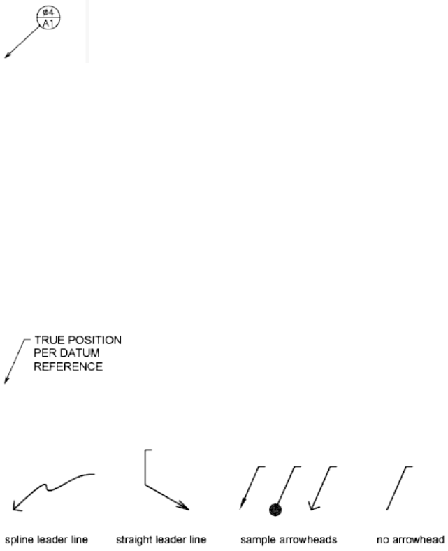
None Ends the command without adding any annotation to the leader line.
Mtext Creates text using the In-Place Text Editor (page 675) when you specify
an insertion point and a second point for the text boundary.
Enter the characters for the text. Enclose format strings for prefixes and suffixes
in angle brackets (< >). Enclose format strings for alternate units in square
brackets ([ ]). For more information about adding a prefix or suffix, see “Control
the Display of Dimension Units” in the User's Guide.
The units settings and the current text style determine how the text is
displayed. The multiline text is vertically centered and horizontally aligned
according to the X axis direction of the last two vertices of the leader line.
The text is offset from the hook line by the distance specified under Offset
from Dim Line on the Text tab of the New, Modify, or Override Dimension
Style dialog box (page 318). If the offset specified is negative, the multiline text
is enclosed in a box as a basic dimension.
Format
Controls the way the leader is drawn and whether it has an arrowhead.
Spline Draws the leader line as a spline. The vertices of the leader line are the
control points, each of equal unit weight.
Straight Draws the leader line as a set of straight line segments.
Arrow Draws an arrowhead at the start point of the leader line.
None Draws a leader line with no arrowhead at the start point.
Commands | 569
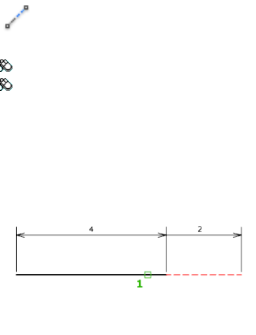
Undo
Undoes the last vertex point on the leader line. The previous prompt is
displayed.
See also:
Create Leaders
Modify Leaders Using Grips
LENGTHEN
Changes the length of objects and the included angle of arcs.
Access Methods
Button
Toolbar: Drafting tool set ➤ Modify tool group ➤ Lengthen
Menu: Modify ➤ Lengthen
Summary
You can specify changes as a percentage, an increment, or as a final length or
angle. LENGTHEN is an alternative to using TRIM or EXTEND.
List of Prompts
The following prompts are displayed.
570 | Chapter 2 Commands
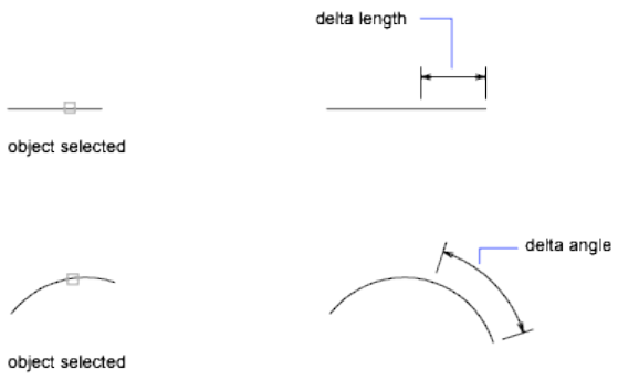
Select an object (page ?) or [DElta (page ?)/Percent (page
?)/Total (page ?)/DYnamic (page ?)]: Select one object or enter an
option
Object Selection
Displays the length and, where applicable, the included angle of the object.
LENGTHEN does not affect closed objects. The extrusion direction of the
selected object need not be parallel to the Z axis of the current user coordinate
system (UCS).
Delta
Changes the length of an object by a specified increment, measured from the
endpoint that is closest to the selection point. Delta also changes the angle
of an arc by a specified increment, measured from the endpoint that is closest
to the selection point. A positive value extends the object; a negative value
trims it.
Delta Length Changes the length of the object by the specified increment.
Angle Changes the included angle of the selected arc by the specified angle.
Percent
Sets the length of an object by a specified percentage of its total length.
Total
Sets the length of a selected object by specifying the total absolute length from
the fixed endpoint. Total also sets the included angle of a selected arc by a
specified total angle.
Commands | 571

Total Length Lengthens the object to the specified value from the endpoint
that is closest to the selection point.
Angle Sets the included angle of the selected arc.
Dynamic
Turns on Dynamic Dragging mode. You change the length of a selected object
by dragging one of its endpoints. The other end remains fixed.
See also:
Resize or Reshape Objects
LIGHT
Creates a light.
List of Prompts
Depending on the type of light you specify, the prompts that are displayed
are identical to the prompts in the POINTLIGHT (page 816), SPOTLIGHT (page
997), WEBLIGHT (page 1130), TARGETPOINT (page 1040), FREESPOT (page 444),
FREEWEB (page 447) or DISTANTLIGHT (page 354) command.
See also:
Guidelines for Lighting
572 | Chapter 2 Commands
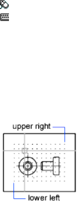
LIMITS
Sets and controls the limits of the grid display in the current Model or named
layout.
Access Methods
Menu: Format ➤ Drawing Limits
Command entry: 'limits for transparent use
List of Prompts
The following prompts are displayed.
Specify lower left corner (page 573)or [ON (page 573)/OFF (page
573)] <current>: Specify a point, enter on or off, or press Enter
Lower-Left Corner Specifies the lower-left corner for the grid limits.
On Turns on limits checking. When limits checking is on, you cannot enter
points outside the grid limits. Because limits checking tests only points that
you enter, portions of objects such as circles can extend outside the grid limits.
Off Turns off limits checking but maintains the current values for the next
time you turn on limits checking.
See also:
Adjust Grid and Grid Snap
LINE
Creates straight line segments.
Commands | 573
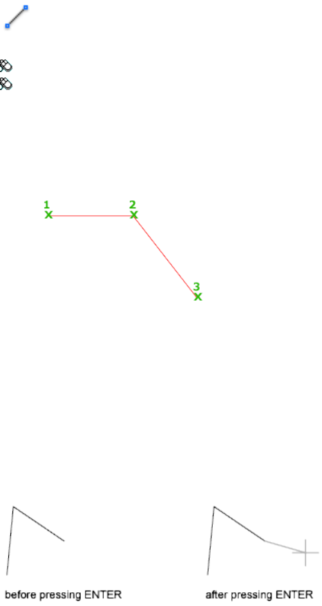
Access Methods
Button
Toolbar: Drafting tool set ➤ Open Shapes tool group ➤ Line
Menu: Draw ➤ Line
Summary
With LINE, you can create a series of contiguous line segments. Each segment
is a line object that can be edited separately.
List of Prompts
The following prompts are displayed.
Specify first point: Specify a point or press Enter to continue (page
574) from the last drawn line or arc
Specify next point or [Close (page 575)/Undo (page 575)]:
Continue Continues a line from the endpoint of the most recently drawn
line.
If the most recently drawn object is an arc, its endpoint defines the starting
point of the line, and the line is drawn tangent to the arc.
574 | Chapter 2 Commands
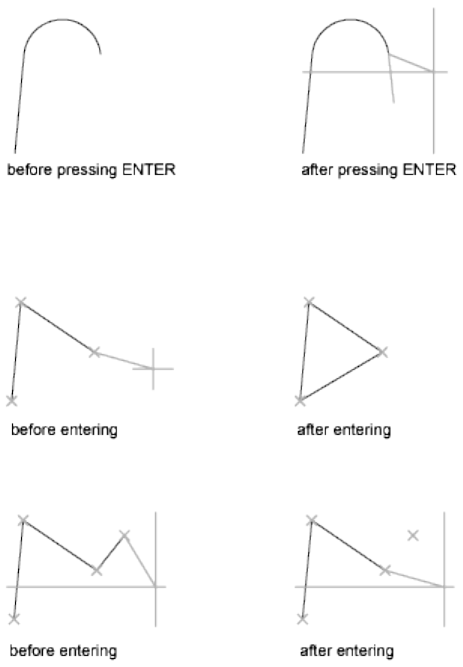
Close Ends the last line segment at the beginning of the first line segment,
which forms a closed loop of line segments. You can use Close after you have
drawn a series of two or more segments.
Undo Erases the most recent segment of a line sequence.
Entering u more than once backtracks through line segments in the order you
created them.
See also:
Draw Lines
LINETYPE
Loads, sets, and modifies linetypes.
Commands | 575
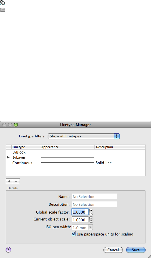
Access Methods
Menu: Format ➤ Linetype
Command entry: 'linetype for transparent use
Summary
The Linetype Manager (page 576) is displayed.
If you enter -linetype at the Command prompt, options are displayed (page
579).
See also:
Work with Linetypes
Linetype Manager
Loads linetypes and sets the current linetype.
576 | Chapter 2 Commands

List of Options
The following options are displayed.
Linetype Filters
Determines which linetypes to display in the linetype list. You can filter
linetypes based on whether they are xref-dependent, or whether they are
referenced by objects.
List of Linetypes
Displays the loaded linetypes according to the option specified in Linetype
Filters. To quickly select all or clear all linetypes, right-click in the linetype
list to display the shortcut menu.
Current Indicates which linetype is current.
Double-click a linetype to set it as the current linetype. Setting the current
linetype to BYLAYER means that an object assumes the linetype that is assigned
to a particular layer. Setting the linetype to BYBLOCK means that an object
assumes the CONTINUOUS linetype until it is grouped into a block. Whenever
the block is inserted, all objects inherit the block's linetype. The CELTYPE
(page 1186) system variable stores the linetype name.
Linetype Displays names of loaded linetypes. To rename a linetype, select it
and then click it again and enter a new name. BYLAYER, BYBLOCK,
CONTINUOUS, and xref-dependent linetypes cannot be renamed.
Appearance Displays a sample of selected linetypes.
Description Displays descriptions of the linetypes, which can be edited in
the Details area.
Load (+)
Displays the Load or Reload Linetypes dialog box (page 578), in which you can
load into the drawing selected linetypes from the acad.lin file and add them
to the linetype list.
Delete (-)
Deletes selected linetypes from the drawing. You can delete only unused
linetypes. The BYLAYER, BYBLOCK, and CONTINUOUS linetypes cannot be
deleted.
NOTE Be careful about deleting linetypes if you are working on a drawing in a
shared project or one based on a set of layering standards. The deleted linetype
definition remains stored in the acad.lin or acadiso.lin file and can be reloaded.
Details
Provides alternative access to properties and additional settings.
Commands | 577
Name
Displays the selected linetype name, which can be edited.
Description
Displays the description of the selected linetype, which can be edited.
Global Scale Factor
Displays the global scale factor for all linetypes. (LTSCALE (page 593) system
variable)
Current Object Scale
Sets linetype scale for newly created objects. The resulting scale is the global
scale factor multiplied by the object's scale factor. (CELTSCALE (page 1186)
system variable)
ISO Pen Width
Sets the linetype scale to one of a list of standard ISO values. The resulting
scale is the global scale factor multiplied by the object's scale factor.
Use Paper Space Units for Scaling
Scales linetypes in paper space and model space identically. Useful when
working with multiple viewports. (PSLTSCALE (page 1408) system variable)
See also:
Work with Linetypes
Load or Reload Linetypes Dialog Box
Loads a linetype whose definition exists in a linetype library (LIN) file.
578 | Chapter 2 Commands
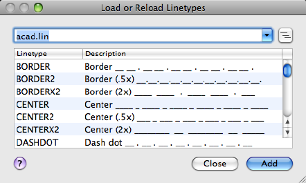
Summary
The acad.lin file contains the standard linetypes.
List of Options
The following options are displayed.
File Name
Displays the name of the current LIN file. You can enter the name of another
LIN file or click the File button to select a file from the Select Linetype File
dialog box.
Browse
Displays the Select Linetype File dialog box, in which you can select a different
linetype (LIN) file.
Available Linetypes
Displays the linetypes available to load. To select or clear all of the linetypes
on the list, right-click and choose Select All or Clear All.
See also:
Work with Linetypes
-LINETYPE
Loads, sets, and modifies linetypes.
Commands | 579
List of Prompts
The following prompts are displayed.
Enter an option [?(page 580)/Create (page 580)/Load (page
580)/Set (page 580)]:
?—List Linetypes Displays the Select Linetype File dialog box (a standard file
selection dialog box). After you select an LIN file, the linetypes available in
the file are listed.
Create Creates a new linetype and stores it in an LIN file.
The Create or Append Linetype File dialog box (a standard file selection dialog
box) is displayed. Specify the file to which you want the linetype added.
You cannot create complex linetypes with LINETYPE. For more information,
see Custom Linetypes in the Customization Guide.
Descriptive Text Enter a linetype description up to 47 characters long. The
description can be a comment or a series of underscores, dots, dashes, and
spaces to show a simple representation of the linetype pattern.
Linetype Pattern Enter a pattern definition as a series of numbers separated
by commas. Enter positive values to specify lengths of dashes, and enter
negative values to specify lengths of spaces. Use a zero to represent a dot.
The “A” in the pattern definition prompt specifies the pattern alignment used
at the ends of individual lines, circles, and arcs. Only A-type alignment is
supported. With A-type alignment, lines and arcs are guaranteed to start and
end with a dash. The A is automatically included in the definition. If you use
a text editor to create a linetype, you must enter a at the beginning of the
definition.
After creating a linetype, you must load it to make it accessible.
Load Loads a linetype whose definition exists in a file. The acad.lin file contains
the standard linetypes.
The Select Linetype File dialog box (a standard file selection dialog box) is
displayed. Enter or select the file in which the linetype you want to load is
stored.
Set Sets the current linetype for objects that will be drawn subsequently. You
can control the linetype of objects individually or by layer.
The linetype you enter becomes the current linetype. All new objects are drawn
with this linetype, regardless of the current layer. If the linetype you request
580 | Chapter 2 Commands

is not loaded, the program searches for its definition in the acad.lin file. If the
linetype is neither loaded nor in acad.lin, the program displays a message and
returns you to the Command prompt.
Enter ? to list all loaded linetype names. If you enter bylayer, new objects
inherit the linetype associated with the layer on which the object is drawn.
If you enter byblock, new objects are drawn using the CONTINUOUS linetype
until they are grouped into a block. Whenever you insert that block, the objects
inherit the linetype of the block.
See also:
Work with Linetypes
LIST
Displays property data for selected objects.
Access Methods
Menu: Tools ➤ Inquiry ➤ List
Summary
You can use LIST to display and then copy the properties of selected objects
to a text file.
The text window displays the object type, object layer, and the X,Y,Z position
relative to the current user coordinate system (UCS) and whether the object
is in model space or paper space.
LIST also reports the following information:
■Color, linetype, lineweight, and transparency information, if these
properties are not set to BYLAYER.
■The thickness of an object, if it is nonzero.
■Elevation (Z coordinate information).
■Extrusion direction (UCS coordinates), if the extrusion direction differs
from the Z axis (0,0,1) of the current UCS.
■Additional information related to the specific object type. For example,
for dimensional constraint objects, LIST displays the constraint type
(annotation or dynamic), reference type (yes or no), name, expression,
and value.
Commands | 581
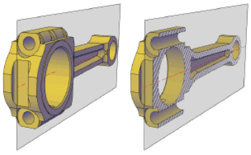
See also:
Display and Change the Properties of Objects
LIVESECTION
Turns on live sectioning for a selected section object.
Access Methods
Shortcut menu: Select a section plane object. Right-click and choose Activate
Live Sectioning.
Summary
When turned on, the cross sections of 3D objects intersected by the section
object are displayed. Live sectioning only works with objects that were created
with SECTIONPLANE.
List of Prompts
The following prompts are displayed.
Select section object Turns on live sectioning for the section object you select.
See also:
Use Live Section to Adjust the Cross Section
LOAD
Makes shapes available for use by the SHAPE command.
582 | Chapter 2 Commands
Summary
The Select Shape File dialog box (a standard file selection dialog box (page
720)) is displayed. Enter the shape file name, or select a file name from the list.
You must load a shape (SHP) file the first time you need it; it is loaded
automatically thereafter. The shape file must be available each time you edit
the drawing.
See also:
Overview of Shape Files
LOFT
Creates a 3D solid or surface in the space between several cross sections.
Access Methods
Button
Toolbar: Modeling tool set ➤ Solids - Create tool group ➤ Loft
Menu: Draw ➤ 3D Modeling ➤ Loft
Summary
Creates a 3D solid or surface by specifying a series of cross sections. The cross
sections define the shape of the resulting solid or surface. You must specify
at least two cross sections.
Loft cross sections can be open or closed, planar or non-planar, and can also
be edge subobjects. Open cross sections create surfaces and closed cross sections
create solids or surfaces, depending on the specified mode.
Commands | 583
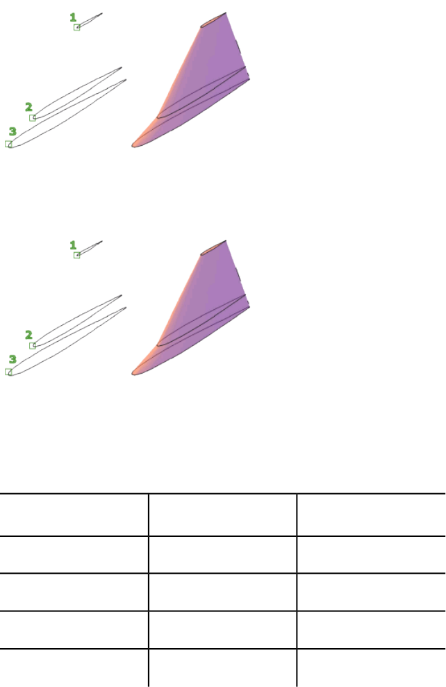
Loft profiles can be open or closed, planar or non-planar, and can also be edge
subobjects. Use the mode option to select whether to create a surface or a
solid.
When creating surfaces, use SURFACEMODELINGMODE (page 1453) to control
whether the surface is a NURBS surface or a procedural surface. Use SURFACE-
ASSOCIATIVITY (page 1452) to control whether procedural surfaces are
associative.
You can use the following objects and subobjects with LOFT:
Objects That Can Be
Used as Guides
Objects That Can Be
Used as a Loft Path
Objects That Can Be
Used as Cross Sections
2D splineSpline2D polyline
2D solid
3D splineHelix2D spline
ArcArcArc
584 | Chapter 2 Commands
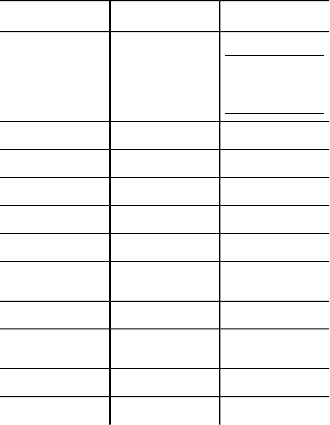
Objects That Can Be
Used as Guides
Objects That Can Be
Used as a Loft Path
Objects That Can Be
Used as Cross Sections
2D polylineCircleCircle
NOTE
2D polylines can be used
as guides if they contain
only 1 segment.
Edge subobjectsEdge subobjectsEdge sub-objects
3D polylineEllipseEllipse
Elliptical arcElliptical arcElliptical arc
2D polylineHelix
LineLineLine
Planar or non-planar face of
solid
Planar or non-planar surface
3D polylinePoints (first and last cross
section only)
Region
Trace
To automatically delete the cross sections, guides, and paths, use DELOBJ
(page 1213). If surface associativity (page 1452) is on, DELOBJ is ignored and the
originating geometry is not deleted.
List of Prompts
The following prompts are displayed.
Commands | 585
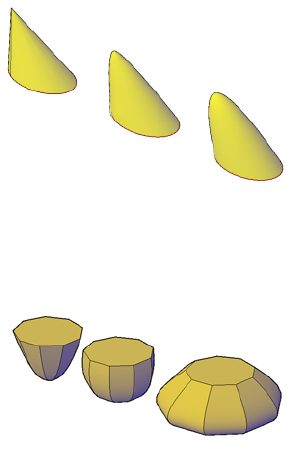
Cross Sections in Lofting Order Specifies open or closed curves in the order
in which the surface or solid will pass through them.
Point If you select the Point option, you must also select a closed curve.
Join Multiple Curves Joins multiple, end-to-end curves as one cross section.
Mode Controls whether the lofted object is a solid or a surface.
Options
■Guides (page ?)
■Path (page ?)
■Cross sections only (page ?)
■Settings (page ?)
Continuity This option only displays if the LOFTNORMALS (page 1358) system
variable is set to 1 (smooth fit). Specifies whether the continuity is G0, G1, or
G2 where the surfaces meet.
Bulge Magnitude This option only displays if the LOFTNORMALS (page 1358)
system variable is set to 1 (smooth fit). Specifies a bulge magnitude value for
objects that have a continuity of G1 or G2.
Guides
Specifies guide curves that control the shape of the lofted solid or surface. You
can use guide curves to control how points are matched up on corresponding
586 | Chapter 2 Commands
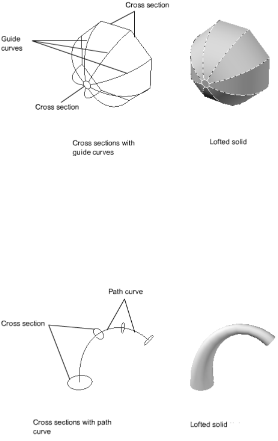
cross sections to prevent undesired results, such as wrinkles in the resulting
solid or surface.
■Intersects each cross section
■Starts on the first cross section
■Ends on the last cross section
Select any number of guide curves for the lofted surface or solid and press
Enter.
Path
Specifies a single path for the lofted solid or surface.
The path curve must intersect all planes of the cross sections.
Commands | 587
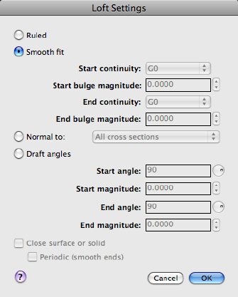
Cross Sections Only
Creates lofted objects without using guides or paths.
Settings
Displays the Loft Settings dialog box (page 588).
See also:
Create a Solid or Surface by Lofting
Loft Settings Dialog Box
Controls the contour of a lofted surface at its cross sections. Also allows you
to close the surface or solid.
List of Options
The following options are displayed.
Ruled
Specifies that the solid or surface is ruled (straight) between the cross sections
and has sharp edges at the cross sections. (LOFTNORMALS (page 1358) system
variable)
588 | Chapter 2 Commands
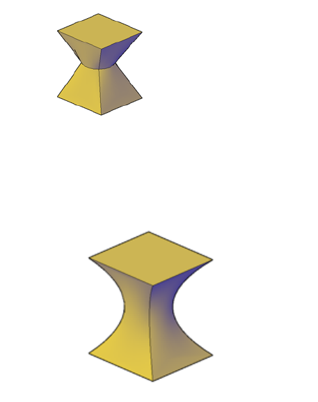
Smooth Fit
Specifies that a smooth solid or surface is drawn between the cross sections
and has sharp edges at the start and end cross sections. (LOFTNORMALS (page
1358) system variable)
Start Continuity
Sets the tangency and curvature of the first cross section.
Start Bulge Magnitude
Sets the size of the curve of the first cross section.
End Continuity
Sets the tangency and curvature of the last cross section.
End Bulge Magnitude
Sets the size of the curve of the last cross section.
Normal To
Controls the surface normal of the solid or surface where it passes through
the cross sections. (LOFTNORMALS (page 1358) system variable)
Start Cross Section Specifies that the surface normal is normal to the start
cross section.
Commands | 589
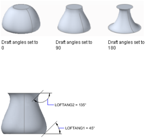
End Cross Section Specifies that the surface normal is normal to the end cross
section.
Start and End Cross Sections Specifies that the surface normal is normal to
both the start and end cross sections.
All Cross Sections Specifies that the surface normal is normal to all cross
sections.
Draft Angles
Controls the draft angle and magnitude of the first and last cross sections of
the lofted solid or surface. The draft angle is the beginning direction of the
surface. 0 is defined as outward from the plane of the curve. (LOFTNORMALS
(page 1358) system variable)
The following illustration shows the affect of using a different draft angle for
the first and last cross sections of a lofted solid. The first cross section is
assigned a draft angle of 45 degrees, while the last cross section is assigned a
draft angle of 135 degrees.
You can also use the draft angle handle to adjust the draft angle (triangular
grip) and magnitude (circular grip).
590 | Chapter 2 Commands

Start Angle
Specifies the draft angle for the start cross section. (LOFTANG1 (page 1356)
system variable)
Start Magnitude
Controls the relative distance of the surface from the start cross section in the
direction of the draft angle before the surface starts to bend toward the next
cross section. (LOFTMAG1 (page 1357) system variable)
End Angle
Specifies the draft angle for the end cross section. (LOFTANG2 (page 1357) system
variable)
End Magnitude
Controls the relative distance of the surface from the end cross section in the
direction of the draft angle before the surface starts to bend toward the previous
cross section. (LOFTMAG2 (page 1357) system variable)
Close Surface or Solid
Closes and opens a surface or solid. When using this option, the cross sections
should form a torus-shaped pattern so that the lofted surface or solid can form
a closed tube. (LOFTPARAM (page 1358) system variable)
Commands | 591
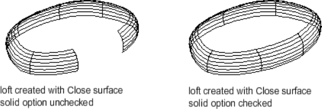
Periodic (Smooth Ends)
Creates a smooth, closed surface whose seam will not kink if it is reshaped.
This option is only available if the loft is ruled or smooth fit and the Close
Surface or solid option is selected.
See also:
Create a Solid or Surface by Lofting
LOGFILEOFF
Closes the command history log file opened by LOGFILEON.
Summary
The program stops recording the text window contents and closes the log file.
Each drawing saves a log file (with the extension .log) that may need periodic
deletion as the number of log files continues to grow.
See also:
View and Edit Within the Command History
LOGFILEON
Writes the contents of the command history to a file.
592 | Chapter 2 Commands
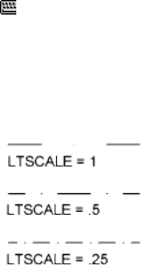
Summary
The contents of the text window are recorded in the log file until you exit the
program or use the LOGFILEOFF (page 592) command.
Each drawing saves a log file (with the extension .log) that may need periodic
deletion as the number of log files continues to grow.
See also:
View and Edit Within the Command History
LTSCALE
Sets the global linetype scale factor.
Access Methods
Command entry: 'ltscale for transparent use
Summary
Use LTSCALE to change the scale factor of linetypes for all objects in a drawing.
Changing the linetype scale factor causes the drawing to be regenerated.
See also:
Control Linetype Scale
LWEIGHT
Sets the current lineweight, lineweight display options, and lineweight units.
Commands | 593
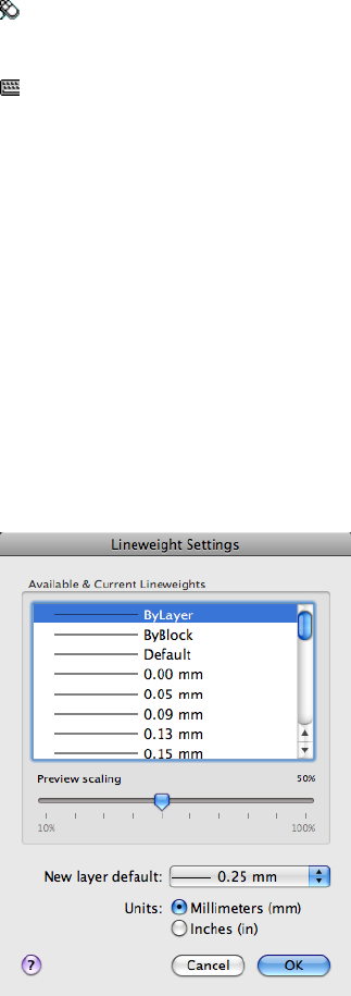
Access Methods
Menu: Format ➤ Lineweight
Shortcut menu: Right-click Show/Hide Lineweight on the status bar and
choose Settings.
Command entry: 'lweight for transparent use
Summary
The Lineweight Settings dialog box (page 594) is displayed.
If you enter -lweight at the Command prompt, options are displayed (page
596).
See also:
Overview of Lineweights
Lineweight Settings Dialog Box
Sets the current lineweight, sets the lineweight units, controls the display and
display scale of lineweights, and sets the DEFAULT lineweight value for layers.
594 | Chapter 2 Commands

Summary
For a table of valid lineweights, see Overview of Lineweights in the User's
Guide.
List of Options
The following options are displayed.
Units
Specifies whether lineweights are displayed in millimeters or inches. You can
also set Units for Listing by using the LWUNITS (page 1365) system variable.
Millimeters (mm)
Specifies lineweight values in millimeters.
Inches (in.)
Specifies lineweight values in inches.
Default
Controls the DEFAULT lineweight for layers. The initial DEFAULT lineweight
is 0.01 inches or 0.25 mm. (LWDEFAULT system variable)
Lineweights
Displays the available lineweight values and shows which lineweight is current.
The current lineweight is shown highlighted in the list.
Lineweight values consist of standard settings including BYLAYER, BYBLOCK,
and DEFAULT. The DEFAULT value is set by the LWDEFAULT (page 1365) system
variable, which has an initial value of 0.01 inches or 0.25 mm. All new layers
use the default setting. The lineweight value of 0 plots at the thinnest
lineweight available on the specified plotting device and is displayed at one
pixel wide in model space.
NOTE Use the LWDISPLAY (page 1365) system variable or toggle the Show/Hide
Lineweights button on the status bar to display lineweights in the drawing area.
Regeneration time increases with lineweights that are represented by more than
one pixel. This option does not affect how objects are plotted.
Preview Scaling
Controls the display scale of lineweights on the Model layout. On the Model
layout, lineweights are displayed in pixels. Lineweights are displayed using a
pixel width in proportion to the real-world unit value at which they plot. If
you are using a high-resolution monitor, you can adjust the lineweight display
Commands | 595
scale to better display different lineweight widths. The Lineweight list reflects
the current display scale.
Objects with lineweights that are displayed with a width of more than one
pixel may increase regeneration time. If you want to optimize performance
when working in the Model layout, set the lineweight display scale to the
minimum value or turn off lineweight display altogether.
See also:
Overview of Lineweights
-LWEIGHT
Sets the current lineweight, lineweight display options, and lineweight units.
List of Prompts
The following prompts are displayed.
Current lineweight: current
Enter default lineweight (page 596) for new objects or [?
(page 596)]: Enter a valid lineweight or enter ?
The current lineweight value is displayed; if the value is not BYLAYER,
BYBLOCK or DEFAULT, the value is displayed in millimeters or inches.
Default Lineweight Sets the current default lineweight. Lineweight values
consist of fixed settings, including BYLAYER, BYBLOCK, and DEFAULT. Values
are calculated in either inches or millimeters; millimeters are the default. If
you enter a valid lineweight value, the current default lineweight is set to the
new value. If you enter any other value, the default is set to the nearest valid
value.
To plot an object with a lineweight that is not found in the list of fixed
lineweight values, you can use plot styles to control plotted lineweights. See
Control Plotted Lineweight and Linetype in the User's Guide. The DEFAULT
value is set by the LWDEFAULT system variable and has an initial value of
0.01 inches or 0.25 mm. The lineweight value of 0 plots at the thinnest
lineweight available on the specified plotting device and is displayed at a value
of one pixel in model space.
?—List Lineweights Displays a list of valid lineweight values in the current
lineweight units.
596 | Chapter 2 Commands

NOTE
If you save a drawing using the AutoCAD Release 14, or earlier, format, the
drawing preview displays lineweights even though the drawing saved in the
earlier format does not display lineweights.
See also:
Overview of Lineweights
M Commands
MASSPROP
Calculates the mass properties of regions or 3D solids.
Access Methods
Menu: Tools ➤ Inquiry ➤ Region/Mass Properties
Summary
Refer to the Help system for a complete list of definitions for each of the region
or mass properties computed.
List of Prompts
The following prompts are displayed.
Select objects: Use an object selection method
If you select multiple regions, only those that are coplanar with the first
selected region are accepted.
MASSPROP displays the mass properties in the text window, and then asks if
you want to write the mass properties to a text file (.mpr).
The properties that MASSPROP displays depend on whether the selected objects
are regions, and whether the selected regions are coplanar with the XY plane
of the current user coordinate system (UCS), or 3D solids. For a list of the
parameters that control the MASSPROP units, see Calculations Based on the
Current UCS (page ?).
Commands | 597
Regions
The following table shows the mass properties that are displayed for all regions.
Mass properties for all regions
DescriptionMass property
The surface area of solids or the enclosed area of regions.Area
The total length of the inside and outside loops of a region. The peri-
meter of a solid is not calculated.
Perimeter
The two coordinates that define the bounding box. For regions that
are coplanar with the XY plane of the current user coordinate system,
Bounding box
the bounding box is defined by the diagonally opposite corners of a
rectangle that encloses the region. For regions that are not coplanar
with the XY plane of the current UCS, the bounding box is defined
by the diagonally opposite corners of a 3D box that encloses the re-
gion.
A 2D or 3D coordinate that is the center of area for regions. For regions
that are coplanar with the XY plane of the current UCS, this coordinate
Centroid
is a 2D point. For regions that are not coplanar with the XY plane of
the current UCS, this coordinate is a 3D point.
If the regions are coplanar with the XY plane of the current UCS, the additional
properties shown in the following table are displayed.
Additional mass properties for coplanar regions
DescriptionMass property
A value used when computing the distributed loads, such as fluid
pressure on a plate, or when calculating the forces inside a bending
Moments of iner-
tia
or twisting beam. The formula for determining area moments of inertia
is
area_moments_of_inertia = area_of_interest * radius2
The area moments of inertia has units of distance to the fourth power.
598 | Chapter 2 Commands
Additional mass properties for coplanar regions
DescriptionMass property
Property used to determine the forces causing the motion of an object.
It is always calculated with respect to two orthogonal planes. The for-
mula for product of inertia for the YZ plane and XZ plane is
Products of iner-
tia
product_of_inertiaYZ,XZ = mass * distcentroid_to_YZ * distcentroid_to_XZ
This XY value is expressed in mass units times the length squared.
Another way of indicating the moments of inertia of a 3D solid. The
formula for the radii of gyration is
Radii of gyration
gyration_radii = (moments_of_ inertia/body_mass)1/2
Radii of gyration are expressed in distance units.
Calculations that are derived from the products of inertia and that
have the same unit values. The moment of inertia is highest through
Principal mo-
ments and
a certain axis at the centroid of an object. The moment of inertia isX,Y,Z directions
about centroid lowest through the second axis that is normal to the first axis and that
also passes through the centroid. A third value included in the results
is somewhere between the high and low values.
3D Solids
The following table shows the mass properties that are displayed for solids.
Mass properties for solids
DescriptionMass property
The measure of inertia of a body. Because a density of one is used,
mass and volume have the same value.
Mass
The amount of 3D space that a solid encloses.Volume
The diagonally opposite corners of a 3D box that encloses the solid.Bounding box
A 3D point that is the center of mass for solids. A solid of uniform
density is assumed.
Centroid
Commands | 599
Mass properties for solids
DescriptionMass property
The mass moments of inertia, which is used when computing the force
required to rotate an object about a given axis, such as a wheel rotating
about an axle. The formula for mass moments of inertia is
Moments of iner-
tia
mass_moments_of_inertia = object_mass * radiusaxis
2
Mass moments of inertia unit is mass (grams or slugs) times the dis-
tance squared.
Property used to determine the forces causing the motion of an object.
It is always calculated with respect to two orthogonal planes. The for-
mula for product of inertia for the YZ plane and XZ plane is
Products of iner-
tia
product_of_inertiaYZ,XZ = mass * distcentroid_to_YZ * distcentroid_to_XZ
This XY value is expressed in mass units times the length squared.
Another way of indicating the moments of inertia of a solid. The for-
mula for the radii of gyration is
Radii of gyration
gyration_radii = (moments_of_inertia/body_mass)1/2
Radii of gyration are expressed in distance units.
Calculations that are derived from the products of inertia and that
have the same unit values. The moment of inertia is highest through
Principal mo-
ments and
a certain axis at the centroid of an object. The moment of inertia isX,Y,Z directions
about centroid lowest through the second axis that is normal to the first axis and that
also passes through the centroid. A third value included in the results
is somewhere between the high and low values.
Calculations Based on the Current UCS
The following table shows the parameters that control the units in which
mass properties are calculated.
Parameters that control MASSPROP units
Used to calculateParameter
Mass of solidsDENSITY
Volume of solidsLENGTH
600 | Chapter 2 Commands
Parameters that control MASSPROP units
Used to calculateParameter
Area of regions and surface area of solidsLENGTH*LENGTH
Bounding box, radii of gyration, centroid, and
perimeter
LENGTH*LENGTH*LENGTH
Moments of inertia, products of inertia, and
principal moments
DENSITY*LENGTH*LENGTH
See also:
Obtain Area and Mass Properties Information
MATBROWSERCLOSE
Closes the Materials Browser.
Summary
This command closes the Materials Browser (page 602).
See also:
Browse Material Library
MATBROWSEROPEN
Opens the Materials Browser.
Access Methods
Button
Toolbar: Modeling tool set ➤ Materials tool group ➤ Material Browser
Commands | 601
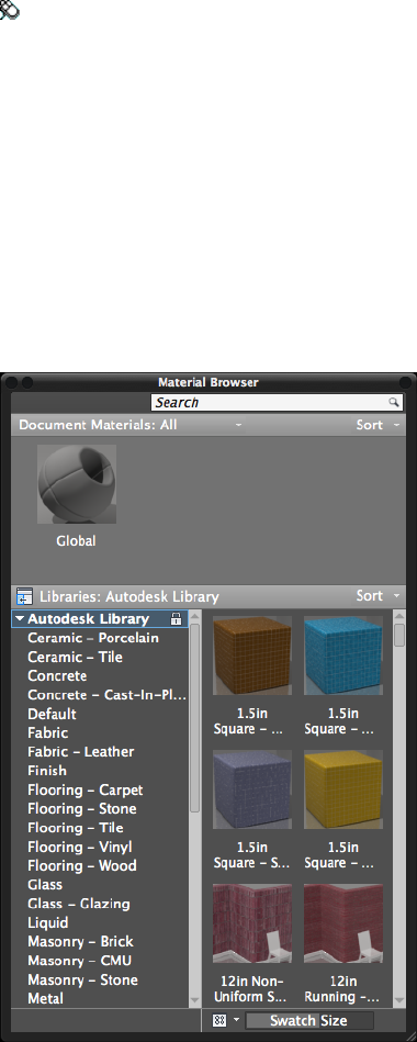
Summary
You can also manage your material libraries in the Materials Browser. It also
allows you search and sort materials in all open libraries and in the drawing.
List of Prompts
The following prompts are displayed.
Search Searches for material appearances in multiple libraries.
Document Materials Displays the materials saved with the open drawing.
Use the drop-down list on the left to filter which materials are displayed in
the list. The following filters and options are available:
■Show All. Display all materials in the current drawing. (Default option)
■Show Applied. Display only the materials being used in the current
drawing.
■Show Selected. Display only the materials applied to the selected objects
in the current drawing.
■Show Unused. Display only the materials that are not used in the current
drawing.
■Purge All Unused. Removes all unused materials from current drawing.
The Sort drop-down controls the order in which document materials are
displayed. The following sort options are available:
■By Name. Lists materials alphabetically by name. (Default option)
■By Type. Lists materials according to the type of material that it was
created from.
■By Material Color. Lists materials by their assigned color. The color
might not be the same that is displayed in the material swatch preview.
Show/Hide Library Tree Controls the visibility of the library tree.
Libraries Displays the selected library name.
The library tree displays the libraries and the categories of materials in each
available library. Select a library or category to display the associated materials
in the Materials list.
■Autodesk Libray. A standard system library which contains the Autodesk
Materials provided by Autodesk for use by all applications.
■My Materials. A special user library which stores the collection of
user-defined materials. It cannot be renamed.
Commands | 603
The Sort drop-down controls the order in which materials in the library are
displayed. The following sort options are available:
■By Name. Lists materials in the selected library alphabetically by name.
(Default option)
■By Type. Lists materials in the selected library according to the type of
material that it was created from.
■By Category. Lists materials in the selected library according to the
category of material it was added to. (Default option)
■By Material Color. Lists materials in the selected library by their assigned
color. The color might not be the same that is displayed in the material
swatch preview.
Materials List Displays the materials in the selected library or category.
The Sort drop-down controls the order in which materials are displayed. The
following sort options are available:
■By Name. Lists materials alphabetically by name. (Default option)
■By Category. Lists materials by their assigned category.
■By Type. Lists materials by the type of material that it was created from.
■By Material Color. Lists materials by their assigned color. The color
might not be the same that is displayed in the material swatch preview.
View Controls the details view display of the library content. The following
view options are available:
■Grid View. All materials are represented by a thumbnail and the name
of the material below. (Default option)
■List View. All materials are displayed in a grid with thumbnail, name,
type, and category in columns.
■Text View. All materials are displayed in a grid with name, type, and
category in columns. No thumbnail is displayed.
Swatch Size Adjusts the size of the swatches.
See also:
Browse Material Library
604 | Chapter 2 Commands

MATCHCELL
Applies the properties of a selected table cell to other table cells.
Access Methods
Button
Toolbar: With a table and table cell selected, on the Table Cell visor, click
Match Cell.
Summary
All the properties of the source cell are copied to the destination cells except
for the cell type: text or block.
List of Prompts
The following prompts are displayed.
Select source cell: Click inside a cell in a table whose properties you want
to copy
Select destination cell: Click inside table cells to copy properties from the
source cell, and right-click or press Enter or Esc to exit
See also:
Add Text and Blocks to Tables
MATCHPROP
Applies the properties of a selected object to other objects.
Access Methods
Menu: Modify ➤ Match Properties
Command entry: painter (or 'matchprop for transparent use)
Commands | 605
Summary
The types of properties that can be applied include color, layer, linetype,
linetype scale, lineweight, plot style, transparency, and other specified
properties.
List of Prompts
The following prompts are displayed.
Current active settings: Currently selected matchprop settings
Select destination object(s) or [Settings]: Enter s or select one
or more objects to copy properties to
Destination Object(s) Specifies the objects to which you want to copy the
properties of the source object.
Settings Displays the Match Properties Settings dialog box (page 606), in which
you can control which object properties to copy to the destination objects.
By default, all object properties are selected for copying.
See also:
Copy Properties Between Objects
Match Properties Settings Dialog Box
Specifies the properties that are copied from the select source object to the
destination objects.
606 | Chapter 2 Commands
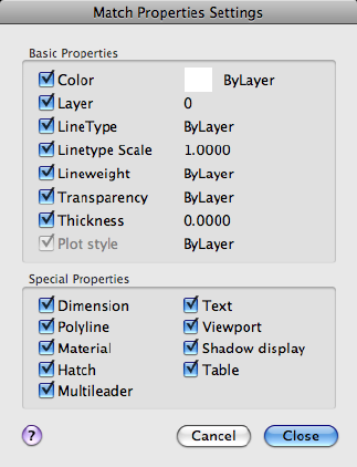
Summary
Specifies which basic properties and special properties to copy from the source
object to the destination objects.
List of Options
The following options are displayed.
Basic Properties
Color
Changes the color of the destination object to that of the source object.
Available for all objects.
Layer
Changes the layer of the destination object to that of the source object.
Available for all objects.
Linetype
Changes the linetype of the destination object to that of the source object.
Available for all objects except attributes, hatches, multiline text, points, and
viewports.
Linetype Scale
Commands | 607
Changes the linetype scale factor of the destination object to that of the source
object. Available for all objects except attributes, hatches, multiline text,
points, and viewports.
Lineweight
Changes the lineweight of the destination object to that of the source object.
Available for all objects.
Transparency
Changes the transparency of the of the destination object to that of the source
object. Available for all objects.
Thickness
Changes the thickness of the destination object to that of the source object.
Available only for arcs, attributes, circles, lines, points, 2D polylines, regions,
and text.
Plot Style
Changes the plot style of the destination object to that of the source object.
If you are working in color-dependent plot style mode ( PSTYLEPOLICY (page
1410) is set to 1), this option is unavailable. Available for all objects, except those
with the Jitter edge modifier applied.
Special Properties
Dimension
In addition to basic object properties, changes the dimension style and
annotative properties of the destination object to that of the source object.
Available only for dimension, leader, and tolerance objects.
Polyline
In addition to basic object properties, changes the width and linetype
generation properties of the destination polyline to those of the source
polyline. The fit/smooth property and the elevation of the source polyline are
not transferred to the destination polyline. If the source polyline has variable
width, the width property is not transferred to the destination polyline.
Material
In addition to basic object properties, changes the material applied to the
object. If the source object does not have a material assigned and the
destination object does, the material is removed from the destination object.
Text
608 | Chapter 2 Commands
In addition to basic object properties, changes the text style and annotative
properties of the destination object to that of the source object. Available only
for single-line and multiline text objects.
Viewport
In addition to basic object properties, changes the following properties of the
destination paper space viewport to match those of the source viewport: on/off,
display locking, standard or custom scale, shade plot, snap, grid, and UCS
icon visibility and location.
The settings for clipping and for UCS per viewport and the freeze/thaw state
of the layers are not transferred to the destination object.
Shadow Display
In addition to basic object properties, changes the shadow display. The object
can cast shadows, receive shadows, or both, or it can ignore shadows.
Hatch
In addition to basic object properties, changes the hatch properties (including
its annotative properties) of the destination object to that of the source object.
To match the hatch origin, use Inherit Properties in HATCH or HATCHEDIT.
Available only for hatch objects.
Table
In addition to basic object properties, changes the table style of the destination
object to that of the source object. Available only for table objects.
Multileader
In addition to basic object properties, changes the multileader style and
annotative properties of the destination object to that of the source object.
Available only for multileader objects.
See also:
Copy Properties Between Objects
MATERIALASSIGN
Uses the current material defined in the CMATERIAL system variable.
List of Prompts
The following prompts are displayed.
Commands | 609
Select objects: Pick one or more objects
Select objects or [Undo]: Press Enter to exit the command
See also:
Browse Material Library
MATERIALS
Opens the Materials Browser.
Access Methods
Button
Toolbar: Modeling tool set ➤ Materials tool group ➤ Material Browser
Menu: View ➤ Render ➤ Materials Browser
Summary
The Materials Browser (page 602) is displayed.
The Materials Browser allows you navigate and manage your materials. You
can organize, sort, search, and select materials for use in your drawing.
See also:
Browse Material Library
MATERIALSCLOSE
Closes the Materials Browser.
Summary
Closes the Materials Browser (page 602).
See also:
Browse Material Library
610 | Chapter 2 Commands
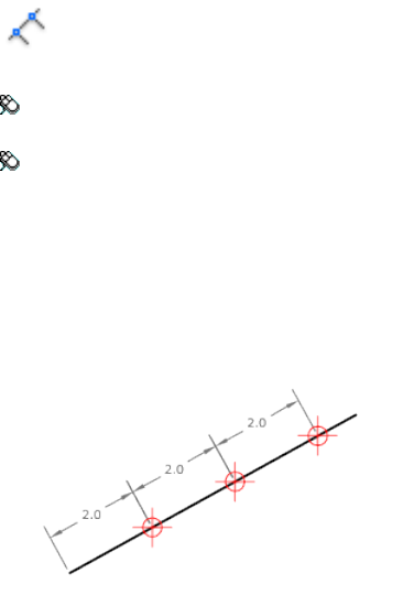
MEASURE
Creates point objects or blocks at measured intervals along the length or
perimeter of an object.
Access Methods
Button
Toolbar: Drafting tool set ➤ Open Shapes tool group (expanded) ➤
Point flyout ➤ Measure
Menu: Draw ➤ Point ➤ Measure
Summary
The resulting points or blocks are always located on the selected object and
their orientation is parallel to the XY plane of the UCS.
Use DDPTYPE to set the style and size of all point objects in a drawing.
The points or blocks are placed in the Previous selection set, so you can select
them all by entering p at the next Select Objects prompt. You can use the
Node object snap to draw an object by snapping to the point objects. You can
then remove the points by entering erase previous.
List of Prompts
The following prompts are displayed.
Select object to measure:
Specify length of segment (page 612) or [Block (page 612)]:
Specify a distance or enter b
Commands | 611
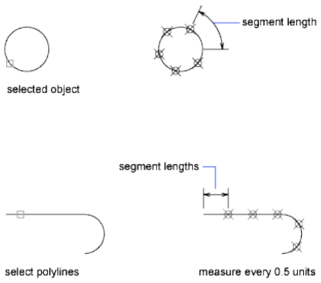
Length of Segment Places point objects at the specified interval along the
selected object, starting at the endpoint closest to the point you used to select
the object.
Measurement of closed polylines starts at their initial vertex (the first one
drawn).
Measurement of circles starts at the angle from the center set as the current
snap rotation angle. If the snap rotation angle is 0, then the measurement of
the circle starts to the right of center, on its circumference.
The illustration shows how MEASURE marks 0.5-unit distances along a
polyline, with the PDMODE (page 1388) system variable set to 35.
Block Places blocks at a specified interval along the selected object.
Align Block With Object
■Yes. The block is rotated about its insertion point so that its horizontal
lines are aligned with, and drawn tangent to, the object being measured.
■No. The block is always inserted with a 0 rotation angle.
After you specify the segment length, the block is inserted at the specified
interval. If the block has variable attributes, these attributes are not included.
See also:
Specify Measured Intervals on Objects
612 | Chapter 2 Commands
MEASUREGEOM
Measures the distance, radius, angle, area, and volume of selected objects or
sequence of points.
Access Methods
Button
Toolbar: Drafting tool set ➤ Utilities tool group ➤ Measure flyout ➤
Distance
Menu: Tools ➤ Inquiry ➤ Distance
Summary
The MEASUREGEOM command performs many of the same calculations as
the following commands:
■AREA (page 83)
■DIST (page 352)
■MASSPROP (page 597)
List of Prompts
The following prompts are displayed.
Enter an option [Distance (page ?)/Radius (page ?)/Angle (page ?)/ARea
(page ?)/Volume (page ?)] <Distance>: Specify Distance, Radius, Angle, Area,
or Volume
Information displays at the Command prompt and in the tooltip in the current
units format.
Distance
Measures the distance between specified points. The following display at the
Command prompt and in the tooltip:
■The current UCS X axis
■Distance in X direction (Delta X)
■Distance in Y direction (Delta Y)
Commands | 613

Multiple Points A running total of distance based on existing line segments
and the current rubber-band line is calculated. The total updates as you move
the cursor and displays in the tooltip.
If you enter Arc, Length, or Undo Options for Selecting Polylines (page ?)
display.
Radius
Measures the radius and diameter of a specified arc or circle.
Angle
Measures the angle of a specified arc, circle, line, or vertex.
Arc Measures the angle of an arc.
Circle Measures a specified angle within a circle. The angle updates as you
move the cursor.
Line Measures the angle between two lines.
Vertex Measures the angle of a vertex.
Area
Measures the area and perimeter of an object or defined area.
NOTE
MEASUREGEOM cannot calculate the area of a self-intersecting object.
Specify Corner Points Calculates the area and perimeter defined by specified
points.
If you enter Arc, Length, or Undo, Options for Selecting Polylines (page ?)
display.
Add Area Turns on Add mode and keeps a running total of area as
you define areas. You can use the Add Area option to calculate the
■Individual areas of defined areas and objects
■Individual perimeters of defined areas and objects
■Total area of all defined areas and objects
■Total perimeter of all defined areas and objects
Subtract Area Subtracts a specified area from the total area. The total area and
perimeter displays at the Command prompt and in the tooltip.
Volume
Measures the volume of an object or a defined area.
Object Measures the volume of an object or defined area.
614 | Chapter 2 Commands
You can select a 3D solids or 2D objects. If you select a 2D object you must
specify a height for that object.
If you define an object by specifying points, you must specify at least three
points to define a polygon. All must lie on a plane parallel to the XY plane of
the UCS. If you do not close the polygon, an area will be calculated as if a line
existed between the first and last points entered.
If you enter Arc, Length, or Undo Options for Selecting Polylines (page ?)
display.
Add Volume Turns on Add mode and keeps a running total of volume as you
define areas.
Subtract Volume Turns on Subtract mode and subtracts a specified volume
from the total volume.
Options for Selecting Polylines
You can select polylines when using the Distance, Area, and Volume options.
Arc Adds arc segments to the polyline.
Endpoint of Arc Draws an arc segment. The arc segment is tangent to the
previous segment of the polyline.
Angle Specifies the included angle of the arc segment from the start point.
Entering a positive number creates counterclockwise arc segments. Entering
a negative number creates clockwise arc segments.
■Endpoint of Arc (page ?)
Radius Specifies the radius of the arc segment.
Center Specifies the center of the arc segment.
■Endpoint of Arc (page ?)
■Angle (page ?)
Length Specifies the chord length of the arc segment. If the previous segment
is an arc, the new arc segment is drawn tangent to the previous arc segment.
Close Draws an arc segment from the last point specified to the starting point,
creating a closed polyline. At least two points must be specified to use this
option.
Direction Specifies a starting direction for the arc segment.
■Endpoint of Arc (page ?)
Half width Specifies the width from the center of a wide polyline segment to
one of its edges.
Commands | 615
The starting half-width becomes the default ending half-width. The ending
half-width becomes the uniform half-width for all subsequent segments until
you change the half-width again. The starting and ending points of wide line
segments are at the center of the line.
Typically, the intersections of adjacent wide polyline segments are beveled.
No beveling is performed for nontangent arc segments or very acute angles
or when a dot-dash linetype is used.
Radius Specifies the radius of the arc segment.
■Endpoint of Arc (page ?)
■Angle (page ?)
Second Pt Specifies the second point and endpoint of a three-point arc.
■Endpoint of Arc (page ?)
Width Specifies the width of the next arc segment.
The starting width becomes the default ending width. The ending width
becomes the uniform width for all subsequent segments until you change the
width again. The starting and ending points of wide line segments are at the
center of the line.
Typically, the intersections of adjacent wide polyline segments are beveled.
No beveling is performed for nontangent arc segments, very acute angles, or
when a dot-dash linetype is used.
Length Draws a line segment of a specified length at the same angle as the
previous segment. If the previous segment is an arc, the new line segment is
drawn tangent to that arc segment.
Undo Removes the most recent arc segment added to the polyline.
Close Draws an arc segment from the last point specified to the starting point,
creating a closed polyline. At least two points must be specified to use this
option.
See also:
Obtain Distances, Angles, and Point Locations
Obtain Area and Mass Properties Information
616 | Chapter 2 Commands

MESH
Creates a 3D mesh primitive object such as a box, cone, cylinder, pyramid,
sphere, wedge, or torus.
Access Methods
Menu: Draw ➤ 3D Modeling ➤ Meshes ➤ Primitives ➤ Box
Summary
The basic mesh forms, known as mesh primitives, are the equivalent of the
primitive forms for 3D solids.
You can reshape mesh objects by smoothing, creasing, refining, and splitting
faces. You can also drag edges, faces, and vertices to mold the overall form.
NOTE By default, new mesh primitives are created with no smoothness. To change
the default smoothness, enter mesh at the Command prompt. Specify the Settings
option before you specify the type of mesh primitive you want to create.
List of Prompts
The following prompts are displayed.
Select primitive [Box (page ?)/Cone (page ?)/CYlinder (page
?)/Pyramid (page ?)/Sphere (page ?)/Wedge (page ?)/Torus
(page ?)/SEttings (page ?)]
Box
Creates a 3D mesh box.
Specify the length of the sides.
Commands | 617
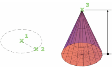
First corner / Corner Sets the first corner of the mesh box.
■Other corner. Sets the opposite corner of the mesh box.
■Cube (page 618)
■Length (page 618)
Center Sets the center of the mesh box.
■Corner. Sets the opposite corner of the mesh box.
■Cube (page 618)
■Length (page 618)
Cube Sets all edges of the box to be of equal length.
■Length (page 618)
Length Sets the length of the mesh box along the X axis.
■Width (page 618) (not available for cubes)
Width Sets the width of the mesh box along the Y axis.
■Height (page 618)
■2Point (height) (page 618)
Height Sets the height of the mesh box along the Z axis.
2Point (height) Sets the height based on the distance between two points:
■First point. Sets the first point of a two-point distance.
■Second point. Sets the second point of a two-point distance.
Cone
Creates a 3D mesh with a circular or elliptical base that tapers symmetrically
to a point or to a planar face.
618 | Chapter 2 Commands
Specify the diameter and height.
Center point of base Sets the center point of the base of the mesh cone.
■Base radius (page 620)
■Diameter (page 620)
3P (three points) Sets the location, size, and plane of the mesh cone by
specifying three points:
■First point. Sets the first point on the circumference of the mesh cone
base.
■Second point. Sets a second point on the circumference of the mesh
cone base.
■Third point. Sets the size and planar rotation of the mesh cone base.
Height (page 620)■
■2Point (height) (page 620)
■Axis endpoint (page 621)
■Top radius (page 621)
2P (diameter) Defines the base diameter of the mesh cone based on two
points:
■First endpoint of diameter. Sets the first location on the circumference
of the mesh cone base.
■Second endpoint of diameter. Determines the general location and
size of the mesh cone base by setting the endpoint of the diameter.
■Height (page 620)
■2Point (height) (page 620)
■Axis endpoint (page 621)
■Top radius (page 621)
Ttr (tangent, tangent, radius) Defines the base of the mesh cone with a
specified radius that is tangent to two objects:
■Point on object for first tangent. Sets a point on an object to serve
as the first tangent point.
■Point on object for second tangent. Sets a point on an object to serve
as the second tangent point.
■Radius of circle. Sets the radius of the mesh cone base.
Height (page 620)■
Commands | 619
■2Point (height) (page 620)
■Axis endpoint (page 621)
■Top radius (page 621)
If the specified criteria can produce multiple results, the closest tangent
points are used.
Elliptical Specifies an elliptical base for the mesh cone.
■Endpoint of first axis. Sets the start point for the first axis of the mesh
cone base and then specifies the other axis endpoints:
■Other endpoint of first axis. Sets the first axis endpoint.
■Endpoint of second axis. Sets the second axis endpoint
■Center. Specifies the method for creating an elliptical mesh cone base
that starts with the center point of the base:
■Center point. Sets the center of the mesh cone base.
■Distance to first axis. Sets the radius of the first axis.
■Endpoint of second axis. Sets the endpoint of the second axis.
Base radius Sets the radius of the mesh cone base.
■Height (page 620)
■2Point (height) (page 620)
■Axis endpoint (page 621)
■Top radius (page 621)
Diameter Sets the diameter for the base of the cone.
■Height (page 620)
■2Point (height) (page 620)
■Axis endpoint (page 621)
■Top radius (page 621)
Height Sets the height of the mesh cone along an axis that is perpendicular
to the plane of the base.
2Point (height) Defines the height of the mesh cone by specifying the distance
between two points:
■First point. Sets the first point of a two-point distance.
620 | Chapter 2 Commands
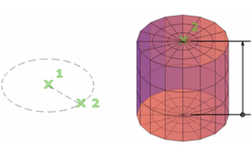
■Second point. Sets the second point of a two-point distance.
Axis endpoint Sets the location of the top point of the cone or the center of
the top face of a cone frustum. The orientation of the axis endpoint can be
anywhere in 3D space.
Top radius Specifies the top radius of the cone, creating a cone frustum.
■Height (page 620)
■2Point (height) (page 620)
■Axis endpoint (page 621)
Cylinder
Creates a 3D mesh cylinder.
Specify the size of the base and height.
Center point of base Sets the center point of the mesh cylinder base.
■Base Radius (page 622)
■Diameter (page 622)
3P (three points) Sets the location, size, and plane of the mesh cylinder by
specifying three points:
■First point. Sets the first point on the circumference of the mesh cylinder
base.
■Second point. Sets a second point on the circumference of the mesh
cylinder base.
■Third point. Sets the size and planar rotation of the mesh cylinder base.
Height (page 623)■
■2Point (height) (page 622)
■Axis endpoint (page 623)
Commands | 621
2P (diameter) Sets the diameter of the mesh cylinder base by specifying two
points:
■First endpoint of diameter. Sets the first point on the diameter of the
mesh cylinder base.
■Second endpoint of diameter. Sets the second point on the diameter
of the mesh cylinder base.
■Height (page 623)
■2Point (height) (page 622)
■Axis endpoint (page 623)
2Point (height) Defines the height of the mesh cylinder by specifying the
distance between two points:
■First point. Sets the first point of a two-point distance.
■Second point. Sets the second point of a two-point distance.
Ttr (tangent, tangent, radius) Defines the base of the mesh cylinder with a
specified radius that is tangent to two objects. If the specified criteria can
produce multiple results, the closest tangent points are used.
■Point on object for first tangent. Sets a point on an object to serve
as the first tangent point.
■Point on object for second tangent. Sets a point on an object to serve
as the second tangent point.
■Radius of circle. Sets the radius of the mesh cylinder base.
Height (page 623)■
■2Point (height) (page 622)
■Axis endpoint (page 623)
Base Radius Sets the radius of the mesh cylinder base.
■Height (page 623)
■2Point (height) (page 622)
■Axis endpoint (page 623)
Diameter Sets the diameter for the base of the cylinder.
■Height (page 623)
■2Point (height) (page 622)
■Axis endpoint (page 623)
622 | Chapter 2 Commands
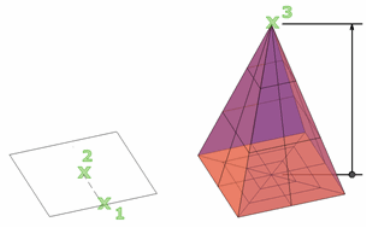
Height Sets the height of the mesh cylinder along an axis that is perpendicular
to the plane of the base.
Axis endpoint Sets the location of the top face of the cylinder. The orientation
of the axis endpoint can be anywhere in 3D space.
Elliptical Specifies an elliptical base for the mesh cylinder.
■Endpoint of first axis. Sets the start point for the first axis of the mesh
cone base.
■Other endpoint of first axis. Sets the first axis endpoint.
■Endpoint of second axis. Sets the second axis endpoint.
■Center. Specifies the method for creating an elliptical mesh cone base
that starts with the center point of the base.
■Center point. Sets the center of the mesh cone base.
■Distance to first axis. Sets the radius of the first axis.
■Endpoint of second axis. Sets the endpoint of the second axis.
Pyramid
Creates a 3D mesh pyramid.
Specify the diameter and height.
Center point of base Sets the center point of the mesh pyramid base.
■Base radius (page 624)
■Inscribed (page 624)
Edge Sets the length of the one edge of the mesh pyramid base, as indicated
by two points that you specify:
■First endpoint of edge. Sets the first location of the edge of the mesh
pyramid.
Commands | 623
■Second endpoint of edge. Sets the second location of the edge of the
mesh pyramid.
■Height (page 624)
■2Point (height) (page 624)
■Axis endpoint (page 624)
■Top radius (page 624)
Sides Sets the number of sides for the mesh pyramid. Enter a positive value
from 3-32.
■Center point of base (page 623)
■Edge (page 623)
■Sides. Resets the number of sides for the mesh pyramid.
Base radius Sets the radius of the mesh pyramid base.
■Height (page 624)
■2Point (height) (page 624)
■Axis endpoint (page 624)
■Top radius (page 624)
Inscribed Specifies that the base of the mesh pyramid is inscribed, or drawn
within, the base radius.
■Base radius (page 624)
■Circumscribed (page 625)
Height Sets the height of the mesh pyramid along an axis that is perpendicular
to the plane of the base.
2Point (height) Defines the height of the mesh cylinder by specifying the
distance between two points:
■First point. Sets the first point of a two-point distance.
■Second point. Sets the second point of a two-point distance.
Axis endpoint Sets the location of the top point of the pyramid or the center
of the top face of a pyramid frustum. The orientation of the axis endpoint
can be anywhere in 3D space.
Top radius Specifies the top radius of the mesh pyramid, creating a pyramid
frustum.
■Height (page 624)
624 | Chapter 2 Commands
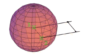
■2Point (height) (page 624)
■Axis endpoint (page 624)
Circumscribed Specifies that the base of the pyramid is circumscribed, or is
drawn around, the base radius.
■Base radius (page 624)
■Inscribed (page 624)
Sphere
Creates a 3D mesh sphere.
Specify the size of the sphere (diameter or radius).
Center point Sets the center point of the sphere.
■Radius. Creates a mesh sphere based on a specified radius.
■Diameter. Creates a mesh sphere based on a specified diameter.
3P (three points) Sets the location, size, and plane of the mesh sphere by
specifying three points:
■First point. Sets the first point on the circumference of the mesh sphere.
■Second point. Sets a second point on the circumference of the mesh
sphere.
■Third point. Sets the size and planar rotation of the mesh sphere.
2P (diameter) Sets the diameter of the mesh sphere by specifying two points:
■First endpoint of diameter. Sets the first point on the diameter of the
mesh sphere.
■Second endpoint of diameter. Sets the opposite point on the diameter
of the mesh sphere.
Commands | 625
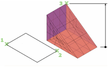
Ttr (tangent, tangent, radius) Defines a mesh sphere with a specified radius
that is tangent to two objects:
■Point on object for first tangent. Sets a point on an object to serve
as the first tangent point.
■Point on object for second tangent. Sets a point on an object to serve
as the second tangent point.
■Radius of circle. Sets the radius of the mesh sphere.
If the specified criteria can produce multiple results, the closest tangent points
are used.
Wedge
Creates a 3D mesh wedge.
Specify the length and width of the base and the height.
First corner Sets the first corner of the mesh wedge base.
■Other corner. Sets the opposite corner of the mesh wedge base, located
on the X,Y plane.
■Height (page 627)
■2Point (height) (page 627)
■Cube (page 627)
■Length (page 627)
Center Sets the center point of the mesh wedge base.
■Corner. Sets one corner of the mesh wedge base.
Height (page 627)■
■2Point (height) (page 627)
■Cube (page 627)
626 | Chapter 2 Commands
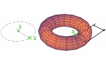
■Length (page 627)
Cube Sets all edges of the mesh wedge base to be of equal length.
■Length (page 627)
Length Sets the length of the mesh wedge base along the X axis.
■Width (page 627) (not available for Cube)
Width Sets the width of the mesh box along the Y axis.
■Height (page 627)
■2Point (height) (page 627)
Height Sets the height of the mesh wedge. Enter a positive value to draw the
height along the positive Z axis of the current UCS. Enter a negative value to
draw the height along the negative Z axis.
2Point (height) Defines the height of the mesh wedge by specifying the
distance between two points:
■First point. Sets the first point of a two-point distance.
■Second point. Sets the second point of a two-point distance.
Torus
Creates a 3D mesh primitive torus.
Specify two values: the size of the tube and the distance from the center of
the torus to the center of the tube.
Center point Sets the center point of the mesh torus.
■Radius (torus) (page 628)
■Diameter (torus) (page 629)
Commands | 627
3P (three points) Sets the location, size, and rotation of the mesh torus by
specifying three points. The path of the tube passes through the specified
points:
■First point. Sets the first point on the path of the tube.
■Second point. Sets the second point on the path of the tube.
■Third point. Sets the third point on the path of the tube.
Tube radius (page 629)■
■2Point (tube radius) (page 629)
■Diameter (tube) (page 629)
2P (torus diameter) Sets the diameter of the mesh torus by specifying two
points. The diameter is calculated from the center point of the torus to the
center point of the tube.
■First endpoint of diameter. Sets the first point used to specify the torus
diameter distance.
■Second endpoint of diameter. Sets the second point used to specify
the torus diameter distance.
■Tube radius (page 629)
■2Point (tube radius) (page 629)
■Diameter (tube) (page 629)
Ttr (tangent, tangent, radius) Defines a mesh torus radius that is tangent to
two objects. The specified tangent points are projected into the current UCS:
■Point on object for first tangent. Sets a point on an object to serve
as the first tangent point.
■Point on object for second tangent. Sets a point on an object to serve
as the second tangent point.
■Radius of circle. Sets the radius of the mesh torus.
If the specified criteria can produce multiple results, the closest tangent points
are used.
Radius (torus) Sets the radius of the mesh torus, measured from the center
point of the torus to the center point of the tube.
■Tube radius (page 629)
■2Point (tube radius) (page 629)
■Diameter (tube) (page 629)
628 | Chapter 2 Commands

Diameter (torus) Sets the diameter of the mesh torus, measured from the
center point of the torus to the center point of the tube.
■Tube radius (page 629)
■2Point (tube radius) (page 629)
■Diameter (tube) (page 629)
Tube radius Sets the radius of the profile that is swept around the mesh torus
path.
2Point (tube radius) Sets the radius of the profile of the tube based on the
distance between two points that you specify:
■First point. Sets the first point of a two-point distance.
■Second point. Sets the second point of a two-point distance.
Tube diameter Sets the diameter of the profile of the mesh torus tube.
Settings
Modifies the smoothness and tessellation values for the new mesh object.
Level of smoothness Sets the initial degree of smoothness, or roundness, to
be applied to the mesh. Enter 0 to eliminate smoothness. Enter a positive
integer up to 4 for increased degrees of smoothness. The value is retained for
the current drawing session.
This smoothness value is limited by the value of SMOOTHMESHMAXLEV
(page 1439).
Tessellation Enter a tessellation values (the number of faces) for each
dimension of a mesh primitive option.
See also:
Create 3D Mesh Primitives
MESHCAP
Creates a mesh face that connects open edges.
Access Methods
Menu: Modify ➤ Mesh Editing ➤ Close Hole
Commands | 629
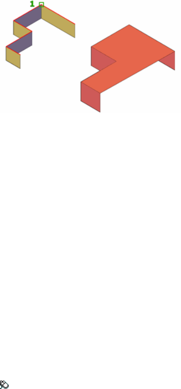
Summary
You can close gaps in mesh objects by selecting the edges of the surrounding
mesh faces. For best results, the faces should be on the same plane.
List of Prompts
The following prompts are displayed.
Select connecting mesh edges to create a new mesh face Specifies which
mesh edges form the boundary for the closure. Click the edges to select them.
Select edges or [CHain]
Edges Selects individual edges and adds them to the selection set.
Chain Selects contiguous edges of mesh objects connected end-to-end.
See also:
Create and Close Mesh Gaps
MESHCOLLAPSE
Merges the vertices of selected mesh faces or edges.
Access Methods
Menu: Modify ➤ Mesh Editing ➤ Collapse Face or Edge
630 | Chapter 2 Commands
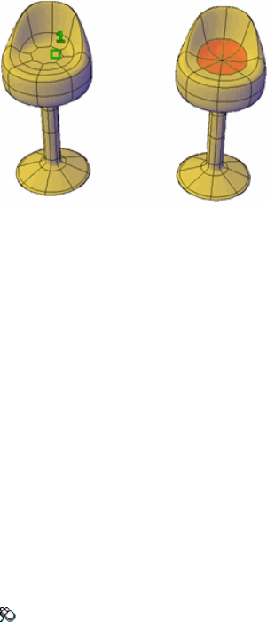
Summary
You can cause the vertices of surrounding mesh faces to converge at the center
of a selected edge or face. The shapes of surrounding faces change to
accommodate the loss of one or more vertices.
List of Prompts
The following prompts are displayed.
Select mesh face or edge to collapse Specifies a mesh edge or a face whose
midpoint becomes the point of convergence for the surrounding faces. Click
a single mesh edge or face.
See also:
Modify Mesh Faces
MESHCREASE
Sharpens the edges of selected mesh subobjects.
Access Methods
Menu: Modify ➤ Mesh Editing ➤ Crease
Summary
You can sharpen, or crease, the edges of mesh objects. Creasing deforms mesh
faces and edges that are adjacent to the selected subobject. Creases added to
mesh that has no smoothness are not apparent until the mesh is smoothed.
Commands | 631

You can also apply creases to mesh subobjects by changing the crease type
and crease level in the Properties Inspector palette (page 832).
List of Prompts
The following prompts are displayed.
Select mesh subobjects to crease Specifies the mesh subobjects to crease.
Click mesh faces, edges, and vertices to crease their associated edges. Press
Shift+click to remove a subobject from the selection set.
■Crease value (page 632)
■Always (page 632)
Crease value Sets highest smoothing level at which the crease is retained. If
the smoothing level exceeds this value, the crease is also smoothed.
Enter a value of 0 to remove an existing crease.
Always Specifies that the crease is always retained, even if the object or
subobject is smoothed or refined. A crease value of -1 is the same as Always.
See also:
Add Creases to Mesh
MESHEXTRUDE
Extends a mesh face into 3D space.
Access Methods
Menu: Modify ➤ Mesh Editing ➤ Extrude Face
632 | Chapter 2 Commands
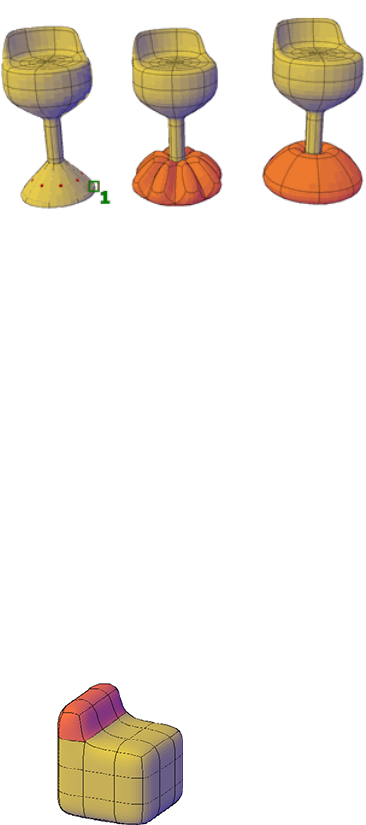
Summary
When you extrude, or extend, a mesh face, you can specify several options to
determine the shape of the extrusion. You can also determine whether
extruding multiple mesh faces results in joined or separate extrusions.
List of Prompts
The following prompts are displayed.
Mesh face(s) to extrude Specifies the mesh faces to extrude. Click one or
more faces to select them.
■Height of extrusion (page 634)
■Direction (page 634)
■Path (page 634)
■Taper angle (page 634)
Setting (Available only when you start the command before selecting faces)
Sets the style for extruding multiple adjacent mesh faces.
■Join adjacent mesh faces when extruding Specifies whether adjacent
mesh faces are extruded singly or as a unit. (The difference between the
two options is not always apparent on a mesh that has not been smoothed.)
■Yes. Extrudes all adjacent faces as a unit.
■No. Extrudes each adjacent face separately.
Commands | 633
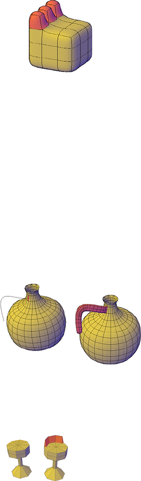
Height of extrusion Extrudes mesh faces along the Z axis. Enter a positive
value to extrude the face along the positive Z axis. Enter a negative value to
extrude along the negative Z axis. Multiple mesh faces do not need to be
parallel to the same plane.
Direction Specifies the length and direction of the extrusion. (The direction
cannot be parallel to the plane of the sweep curve created by the extrusion.)
■Start point of direction. Specifies the first point in the direction vector.
■End point of direction. Specifies the second point in the direction
vector.
Path Specifies an object, such as a line or spline, that determines the path and
length of the extrusion. The outline of the mesh face is swept along the path.
The new orientation of the swept mesh face is perpendicular to the endpoint
of the path.
The path should not lie on the same plane as the mesh face or have areas of
high curvature. For extrusions that adhere closely to the curved path, use a
spline, not an arced polyline, as the path.
Taper angle Sets an angle of taper for an extrusion.
634 | Chapter 2 Commands
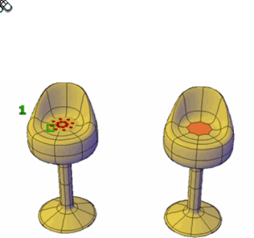
Positive angles taper inward from the base mesh face. Negative angles taper
outward. The default angle, 0, extrudes the face perpendicular to the plane of
the mesh.
If the adjacent faces are not set to be joined, the faces that are selected for
extrusion are tapered to the same value. However, for joined extrusions, the
taper is applied only to the portion of the extrusion that is not adjacent to
another extruded face.
Specifying a large taper angle or a long extrusion height can cause the object
or portions of the object to taper to a point before reaching the extrusion
height.
■Angle of taper. Sets an angle between -90 and +90 degrees.
■Specify two points. Sets the taper angle to be the distance between two
specified points.
See also:
Modify Mesh Faces
MESHMERGE
Merges adjacent faces into a single face.
Access Methods
Menu: Modify ➤ Mesh Editing ➤ Merge Face
Summary
You can merge two or more adjacent mesh faces to form a single face.
Commands | 635
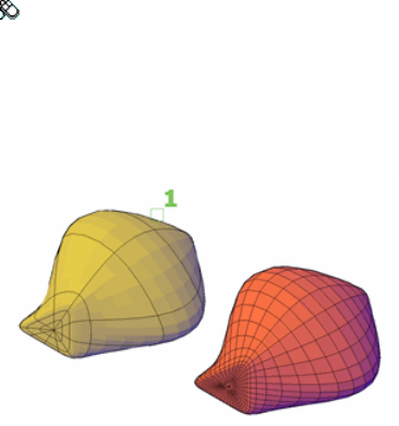
The merge operation is performed only on mesh faces that are adjacent. Other
types of subobjects are removed from the selection set.
Merging mesh faces that wrap a corner can have unintended results when you
try to edit the mesh or convert it to other types of solid objects. For example,
the mesh might no longer be watertight. For best results, restrict mesh merging
to faces that are on the same plane.
List of Prompts
The following prompts are displayed.
Select adjacent faces to merge Specifies the mesh faces to combine. Click
each face to select it.
See also:
Modify Mesh Faces
MESHREFINE
Multiplies the number of faces in selected mesh objects or faces.
Access Methods
Menu: Modify ➤ Mesh Editing ➤ Refine Mesh
Summary
Refining a mesh object increases the number of editable faces, providing
additional control over fine modeling details. To preserve program memory,
you can refine specific faces instead of the entire object.
636 | Chapter 2 Commands
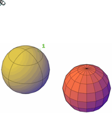
Refining an object resets the smoothing level that was assigned to the object
to 0 (zero). This level of smoothness becomes the new baseline for the object.
That is, the smoothness level can no longer be decreased beyond that level.
Refining a subobject does not reset the smoothing level.
List of Prompts
The following prompts are displayed.
Mesh object or face subobjects to refine Specifies 3D mesh objects or mesh
faces to be refined. Press Ctrl+click to isolate a specific face.
See also:
Refine Mesh Objects or Subobjects
MESHSMOOTH
Converts 3D objects such as polygon meshes, surfaces, and solids to mesh
objects.
Access Methods
Menu: Draw ➤ 3D Modeling ➤ Meshes ➤ Smooth Mesh
Summary
Take advantage of the detailed modeling capabilities of 3D mesh by converting
objects such as 3D solids and surfaces to mesh.
Use this method to convert 3D faces (3DFACE) and legacy polygonal and
polyface meshes (from AutoCAD 2009 and earlier). You can also convert 2D
objects such as regions and closed polylines.
Commands | 637

The level of smoothness upon conversion depends on the mesh type setting
(FACETERMESHTYPE (page 1291) system variable). If the mesh type is not set
to be optimized, the converted object is not smoothed.
To convert mesh objects to 3D surfaces or solids, use CONVTOSOLID (page
223) or CONVTOSURFACE (page 225) commands.
Objects That Can Be Converted to Mesh
Object type
3D solids
3D surfaces
3D faces
Polyface and polygon meshes (legacy)
Regions
Closed polylines
See also:
Create Meshes by Conversion
MESHSMOOTHLESS
Decreases the level of smoothness for mesh objects by one level.
Access Methods
Menu: Modify ➤ Mesh Editing ➤ Smooth Less
Summary
Decrease the smoothness of selected mesh objects by one level. You can only
decrease the smoothness of objects whose level of smoothness is 1 or higher.
You cannot decrease the smoothness level of objects that have been refined.
638 | Chapter 2 Commands
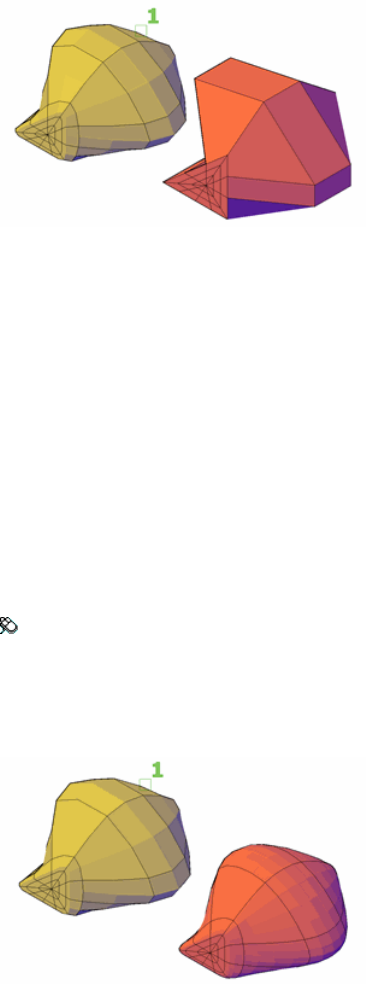
You can decrease the smoothness of multiple objects. If the selected objects
have different levels of smoothness, their respective levels are decreased by
one. If the selection set contains ineligible objects, those objects can be filtered
out.
See also:
Change Mesh Smoothness Levels
MESHSMOOTHMORE
Increases the level of smoothness for mesh objects by one level.
Access Methods
Menu: Modify ➤ Mesh Editing ➤ Smooth More
Summary
Smoothing increases the number of facets in the mesh, resulting in a rounder
object.
Commands | 639
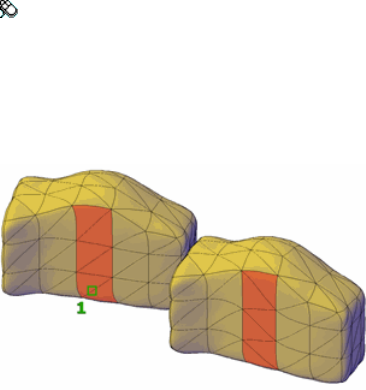
Facets are the underlying components of each mesh face. You can increase
the smoothness level up to the value of SMOOTHMESHMAXLEV (page 1439)
as long as the number of faces does not exceed the value in the
SMOOTHMESHMAXFACE (page 1438) system variable. If you select multiple
objects with differing levels of smoothness, their respective levels are increased
by one.
You can only smooth mesh objects. However, you have the option of
converting some types of objects to mesh during the smoothing operation.
You can also filter out ineligible objects that you do not want to convert. For
a list of objects that can be converted, see MESHSMOOTH (page 637).
See also:
Change Mesh Smoothness Levels
MESHSPIN
Spins the adjoining edge of two triangular mesh faces.
Access Methods
Menu: Modify ➤ Mesh Editing ➤ Spin Triangle Face
Summary
You can rotate the edge that joins two triangular mesh faces to modify the
shapes of the faces. The edge shared by the selected faces spins to intersect
the apex of each face.
640 | Chapter 2 Commands

NOTE You can use MESHSPLIT (page 641) to divide a rectangular face into two
triangular faces. If you plan to spin the edge between the triangular faces, use the
Vertex option to ensure that the split extends precisely from one vertex to the
other.
List of Prompts
The following prompts are displayed.
First triangular mesh face to spin Specifies one of two faces to be modified.
Click a triangular mesh face.
Second adjacent triangular mesh face to spin Specifies the second of two
faces to be modified. Click a triangular mesh face that is next to the first
selected face.
See also:
Modify Mesh Faces
MESHSPLIT
Splits a mesh face into two faces.
Access Methods
Menu: Modify ➤ Mesh Editing ➤ Split Face
Summary
Split a face to add more definition to an area without having to refine it.
Because you specify the start and endpoint of the split, this method provides
greater control over the location of the split.
Commands | 641
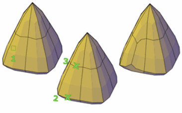
For more precision in the placement of the split, you can specify that the split
starts or ends at a vertex. The Vertex option is useful for creating two triangular
faces from a rectangular face. It provides the precision you need if you later
want to spin the new edge using MESHSPIN (page 640).
List of Prompts
The following prompts are displayed:
Face to split In the drawing area, specifies which mesh face to split.
■First split point on face edge. Sets the location on an edge of the mesh
face to start the split.
■Second split point on face edge. Sets a second location on an edge
of the mesh face to define the path of the split.
■Vertex
Vertex Limits the first endpoint of the split to a mesh vertex.
■First vertex for the split. Specifies a vertex on a mesh face.
Second split point on face edge. Sets the second location on an
edge of the mesh face to define the path of the split.
■
■Vertex. Limits the second endpoint so that it can only intersect with
a vertex.
■Second vertex for the split. Specifies a second vertex on the
same mesh face.
See also:
Modify Mesh Faces
642 | Chapter 2 Commands
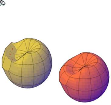
MESHUNCREASE
Removes the crease from selected mesh faces, edges, or vertices.
Access Methods
Menu: Modify ➤ Mesh Editing ➤ Uncrease
Summary
Restore smoothness to an edge that has been creased.
You can also remove a selected crease in the Crease area of Properties Inspector
(page 832) by changing the Type value to None when a face on a mesh is
selected.
List of Prompts
The following prompt is displayed:
Select crease to remove Specifies which creased edges to smooth. You do not
need to press Ctrl to select a creased subobject.
See also:
Add Creases to Mesh
MINSERT
Inserts multiple instances of a block in a rectangular array.
Commands | 643

Summary
Options at the insertion point preset the scale and rotation of a block before
you specify its position. Presetting is useful for dragging a block using a scale
factor and a rotation other than 1 or 0. If you enter one of the options, respond
to the prompts by specifying a distance for the scale options or an angle for
rotation.
Blocks inserted using MINSERT cannot be exploded.
You cannot use MINSERT with annotative blocks.
List of Prompts
The following prompts are displayed.
Enter block name or [?]: Enter a name, enter ? to list the currently defined
blocks in the drawing, or enter ~ to display the Select Drawing File dialog box
NOTE You cannot precede the name of a block with an asterisk to explode the
block's objects during insertion, as you can with INSERT (page 519).
Specify insertion point (page ?) or [Basepoint (page
?)/Scale (page ?)/X(page ?)/Y(page ?)/Z(page ?)/Rotate
(page ?)]: Specify a point or enter an option
Insertion Point
Specifies a location for the blocks.
Enter X scale factor, specify opposite corner, or [Corner/XYZ] <1>: Enter a
value, enter an option, or press Enter
X Scale Factor Sets X and Y scale factors.
Specify Rotation Angle The rotation angle sets the angle of the individual
block inserts and also sets the angle of the entire array.
Number of Rows/Columns Specifies the number of rows and columns in the
array.
Distance Between Rows Specifies the distance (in units) between rows. You
can use the pointing device to specify the distance between rows, or specify
two points to define a box whose width and height represent the distance
between rows and between columns.
Distance Between Columns Specifies the distance (in units) between columns.
644 | Chapter 2 Commands
Corner Sets the scale factor by using the block insertion point and the opposite
corner.
■Specify Rotation Angle (page 644)
■Number of Rows/Columns (page 644)
■Distance Between Rows (page 644)
■Distance Between Columns (page 644)
XYZ Sets X, Y, and Z scale factors.
■X Scale Factor (page 644)
■Corner (page 645)
■Specify Rotation Angle (page 644)
■Number of Rows/Columns (page 644)
■Distance Between Rows (page 644)
■Distance Between Columns (page 644)
Basepoint
Temporarily drops the block in the drawing where it is currently positioned
and allows you to specify a new base point for the block reference as it is
dragged into position. This does not affect the actual base point defined for
the block reference.
Scale
Sets the scale factor for the X, Y, and Z axes. The scale for the Z axis is the
absolute value of the specified scale factor.
■XYZ (page 645)
■Specify Rotation Angle (page 644)
■Number of Rows/Columns (page 644)
■Distance Between Rows (page 644)
■Distance Between Columns (page 644)
X
Sets the X scale factor.
■Specify Rotation Angle (page 644)
■Number of Rows/Columns (page 644)
■Distance Between Rows (page 644)
■Distance Between Columns (page 644)
Commands | 645
Y
Sets the Y scale factor.
■Specify Rotation Angle (page 644)
■Number of Rows/Columns (page 644)
■Distance Between Rows (page 644)
■Distance Between Columns (page 644)
Z
Sets the Z scale factor.
■Specify Rotation Angle (page 644)
■Number of Rows/Columns (page 644)
■Distance Between Rows (page 644)
■Distance Between Columns (page 644)
Rotate
Sets the angle of insertion for both the individual blocks and the entire array.
■Specify Rotation Angle (page 644)
■X Scale Factor (page 644)
■Number of Rows/Columns (page 644)
■Distance Between Rows (page 644)
■Distance Between Columns (page 644)
■Corner (page 645)
■XYZ (page 645)
Preview Scale
Sets the scale factor for the X, Y, and Z axes to control the display of the block
as it is dragged into position.
■X Scale Factor (page 644)
■Corner (page 645)
■XYZ (page 645)
Preview X
Sets the scale factor for the X axis to control the display of the block as it is
dragged into position.
■X Scale Factor (page 644)
646 | Chapter 2 Commands
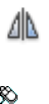
■Corner (page 645)
■XYZ (page 645)
Preview Y
Sets the scale factor for the Y axis to control the display of the block as it is
dragged into position.
■X Scale Factor (page 644)
■Corner (page 645)
■XYZ (page 645)
Preview Z
Sets the scale factor for the Z axis to control the display of the block as it is
dragged into position.
■X Scale Factor (page 644)
■Corner (page 645)
■XYZ (page 645)
Preview Rotate
Sets the rotation angle of the block as it is dragged into position.
■X Scale Factor (page 644)
■Corner (page 645)
■XYZ (page 645)
See also:
Insert Blocks
MIRROR
Creates a mirrored copy of selected objects.
Access Methods
Button
Toolbar: Drafting tool set ➤ Copy tool group ➤ Mirror
Commands | 647
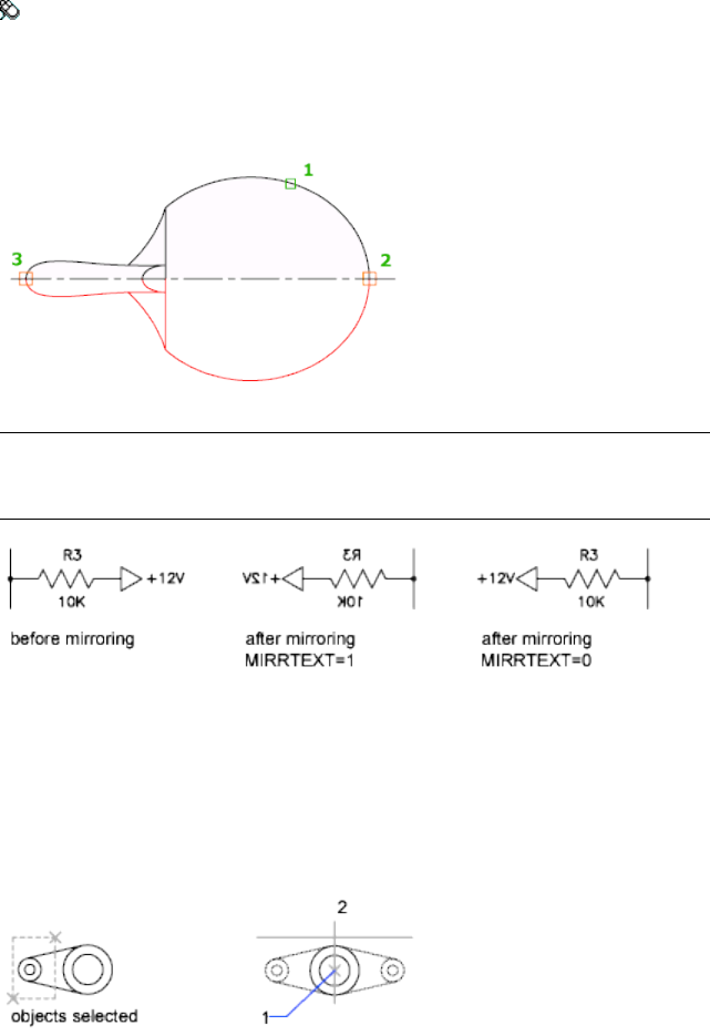
Menu: Modify ➤ Mirror
Summary
You can create objects that represent half of a drawing, select them, and mirror
them across a specified line to create the other half.
NOTE By default, when you mirror a text object, the direction of the text is not
changed. Set the MIRRTEXT (page 1370) system variable to 1 if you do want the
text to be reversed.
List of Prompts
The following prompts are displayed.
Select objects: Use an object selection method and press Enter to finish
Specify first point of mirror line: Specify a point
Specify second point of mirror line: Specify a point
The two specified points become the endpoints of a line about which the
selected objects are mirrored. For mirroring in 3D, this line defines a mirroring
648 | Chapter 2 Commands
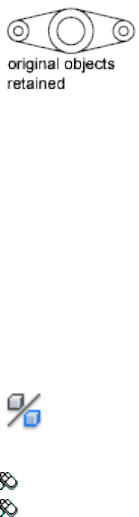
plane perpendicular to the XY plane of the user coordinate system (UCS)
containing the mirror line.
Erase source objects? [Yes/No] <N>: Enteryorn, or press Enter
Yes Places the mirrored image into the drawing and erases the original objects.
No Places the mirrored image into the drawing and retains the original objects.
See also:
Mirror Objects
MIRROR3D
Creates a mirrored copy of selected objects across a mirroring plane.
Access Methods
Button
Toolbar: Modeling tool set ➤ Copy tool group ➤ 3D Mirror
Menu: Modify ➤ 3D Operations ➤ 3D Mirror
Summary
It is recommended that you use the gizmos available through the 3DMOVE
(page 36), 3DROTATE (page 48), and 3DSCALE (page 50) commands to
manipulate 3D objects. For more information about using gizmos, see Use
Gizmos to Modify Objects.
For example:
Commands | 649
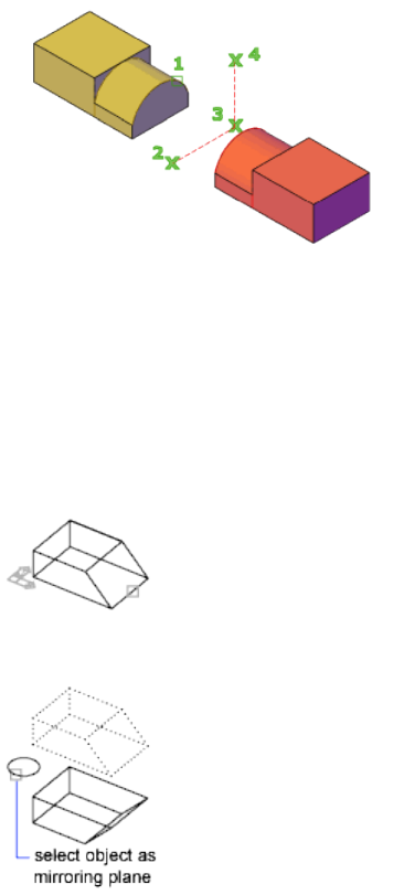
List of Prompts
The following prompts are displayed.
Select objects: Use an object selection method and press Enter to finish
Specify first point of mirror plane (3 points) or [Object
(page 650)/Last (page 650)/Zaxis (page 650)/View (page
651)/XY/YZ/ZX (page 651)/3points (page 651)] <3points>: Enter an
option, specify a point, or press Enter
Object Uses the plane of a selected planar object as the mirroring plane.
Delete Source Objects If you enter y, the reflected object is placed into the
drawing and the original objects are deleted. If you enter n or press Enter, the
reflected object is placed into the drawing and the original objects are retained.
Last Mirrors the selected objects about the last defined mirroring plane.
Z Axis Defines the mirroring plane by a point on the plane and a point normal
to the plane.
650 | Chapter 2 Commands
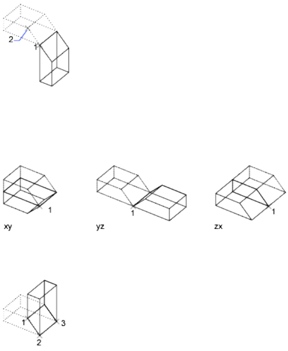
View Aligns the mirroring plane with the viewing plane of the current viewport
through a point.
XY/YZ/ZX Aligns the mirroring plane with one of the standard planes (XY,
YZ, or ZX) through a specified point.
3 Points Defines the mirroring plane by three points. If you select this option
by specifying a point, the First Point on Mirror Plane prompt is not displayed.
See also:
Mirror Objects
MLEADER
Creates a multileader object.
Commands | 651
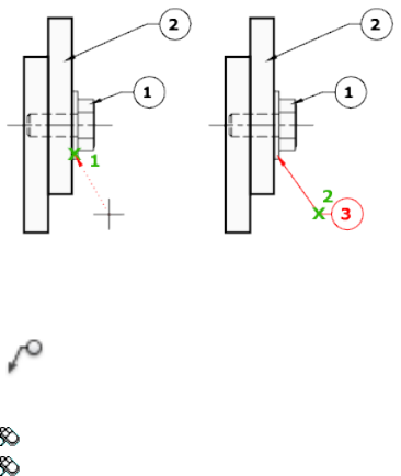
Access Methods
Button
Toolbar: Annotation tool set ➤ Leaders tool group ➤ Multileader
Menu: Dimension ➤ Multileader
Summary
A multileader object typically consists of an arrowhead, a horizontal landing,
a leader line or curve, and either a multiline text object or a block.
Multileaders can be created arrowhead first (page ?), leader landing first (page
?), or content first (page ?). If a multileader style has been used, then the
multileader can be created from that specified style.
List of Prompts
The following prompts are displayed.
Specify leader arrowhead location (page ?) or [leader Landing
first (page ?)/Content first (page ?)/Options (page ?)]
<Options>:
Leader Arrowhead First
Specifies a location for the arrowhead of the multileader object.
Specify Leader Landing Location Sets placement of the leader landing for
the new multileader object.
If you exit the command at this point, then no text is associated with the
multileader object.
652 | Chapter 2 Commands
Leader Landing First
Specifies a location for the landing line of the multileader object.
Specify Leader Arrowhead Location Sets placement of the arrowhead for
the new multileader object.
If you exit the command at this point, then no text is associated with the
multileader line.
Content First
Specifies a location for the text or block associated with the multileader object.
Point Selection Sets placement for the text box for the text label associated
with the multileader object. When you finish entering your text, click OK or
click outside the text box.
If you choose End at this point, then no landing line is associated with the
multileader object.
Options
Specifies options for placing the multileader object.
Leader Type Specifies a straight, spline, or no leader line.
■Straight.
■Spline.
■None.
Leader Landing Changes the distance of the horizontal landing line
■Yes.
■No.
If you choose No at this point, then no landing line is associated with the
multileader object.
Content Type Specifies the type of content that will be used for the
multileader.
■Block (page 653)
■Mtext (page 654)
■None (page 654)
Block Specifies a block within your drawing to associate with the new
multileader.
■Enter block name.
Commands | 653
Mtext Specifies that multiline text is included with the multileader.
■Enter the multiline text.
None Specifies no content type.
Maxpoints Specifies a maximum number of points for the new leader line.
■Enter the maximum points for leader line.
■None.
First Angle Constrains the angle of the first point in the new leader line.
■Enter first angle constraint.
■None.
Second Angle Constrains the second angle in the new leader line.
■Enter second angle constraint.
■None.
See also:
Create and Modify Leaders
MLEADERALIGN
Aligns and spaces selected multileader objects.
Access Methods
Button
Toolbar: Annotation tool set ➤ Leaders tool group ➤ Align Leaders
Menu: Modify ➤ Object ➤ Multileader ➤ Align
Summary
After multileaders have been selected, specify the multileader to which all
others are aligned.
654 | Chapter 2 Commands
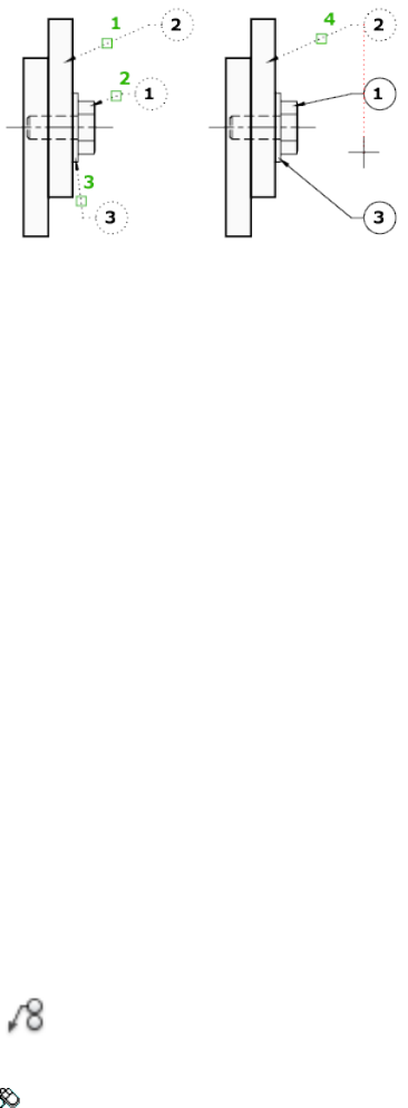
List of Prompts
The following prompts are displayed.
Select multileader to align to or [Options (page ?)]:
Options
Specifies options for aligning and spacing the selected multileaders.
Distribute Spaces content evenly between two selected points.
Make Leader Segments Parallel Places content so that each of the last leader
segments in the selected multileaders are parallel.
Specify Spacing Specifies spacing between the extents of the content of
selected multileaders.
Use Current Spacing Uses the current spacing between multileader content.
See also:
Create and Modify Leaders
MLEADERCOLLECT
Organizes selected multileaders that contain blocks into rows or columns, and
displays the result with a single leader.
Access Methods
Button
Toolbar: Annotation tool set ➤ Leaders tool group ➤ Collect Leaders
Commands | 655
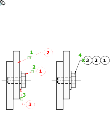
Menu: Modify ➤ Object ➤ Multileader ➤ Collect
Summary
After you select multileaders, you can specify their placement.
For example:
List of Prompts
The following prompts are displayed.
Specify collected multileader location (page 656) or [Vertical
(page 656)/Horizontal (page 656)/Wrap (page 656)]
Specify Collected Multileader Location Specifies the point for placing the
multileader collection in the upper-left corner of the collection.
Vertical Places the multileader collection in one or more columns.
Horizontal Places the multileader collection in one or more rows.
Wrap Specifies a width for a wrapped multileader collection.
■Specify wrap width.
■Number. Specifies a maximum number of blocks per row in the
multileader collection.
See also:
Create and Modify Leaders
MLEADEREDIT
Adds leader lines to, or removes leader lines from, a multileader object.
656 | Chapter 2 Commands
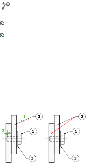
Access Methods
Button
Toolbar: Annotation tool set ➤ Leaders tool group ➤ Add Leader,
Remove Leader
Menu: Modify ➤ Object ➤ Multileader ➤ Add Leader
Pointing device: Hover over Landing grip and choose Add Leader; hover
over leader endpoint grip and choose Remove Leader
List of Prompts
The following prompts are displayed.
Specify leader arrowhead location (page 657) or [Remove Leaders
(page 657)]
Add Leader
Adds a leader line to a selected multileader object. The new leader line is added
to the left or right of the selected multileader, depending on the location of
the cursor.
Remove Leaders Removes a leader line from a selected multileader object.
For example:
Commands | 657
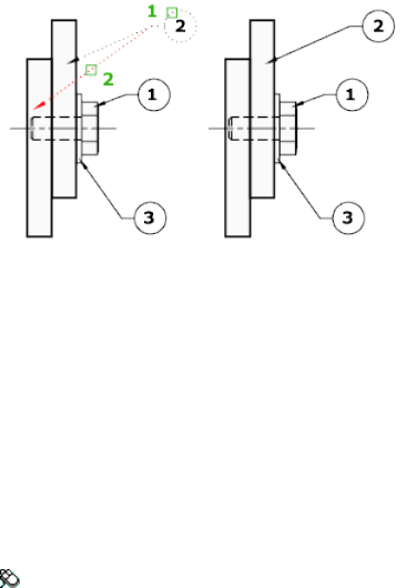
See also:
Create and Modify Leaders
MLEADERSTYLE
Creates and modifies multileader styles.
Access Methods
Menu: Format ➤ Multileader Style
Summary
The Multileader Style Manager (page 658) is displayed.
See also:
Work with Leader Styles
Multileader Style Manager
Creates and modifies styles that you can use to create multileader objects
658 | Chapter 2 Commands
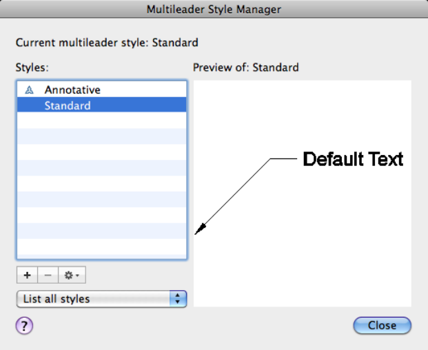
Summary
Sets the current multileader style and creates, modifies, and deletes multileader
styles.
The appearance of multileaders is controlled by multileader styles. These styles
specify formatting for landing lines, leader lines, arrowheads, and content.
List of Options
The following options are displayed.
Current Multileader Style
Displays the name of the multileader style that is applied to multileaders you
create. The default multileader style is Standard.
Styles
Displays a list of multileader styles. The current style is highlighted.
Commands | 659
List
Controls the contents of the Styles list. Click All Styles to display all multileader
styles available in the drawing. Click Styles In Use to display only the
multileader styles that are referenced by multileaders in the current drawing.
Preview Of
Displays a preview image of the style that is selected in the Styles list.
New (+)
Displays the Create New Multileader Style dialog box, in which you can define
new multileader styles.
Delete (-)
Deletes the multileader style selected in the Styles list. A style that is being
used in the drawing cannot be deleted.
Options
Manages the multileader styles in the list.
Set Current Sets the multileader style selected in the Styles list as the current
style. All new multileaders are created using this multileader style.
Modify Displays the Modify Multileader Style dialog box, in which you can
modify multileader styles.
Rename Edits the name of the style selected in the list.
See also:
Work with Leader Styles
Modify Multileader Style Dialog Box
Modifies an existing multileader style.
660 | Chapter 2 Commands
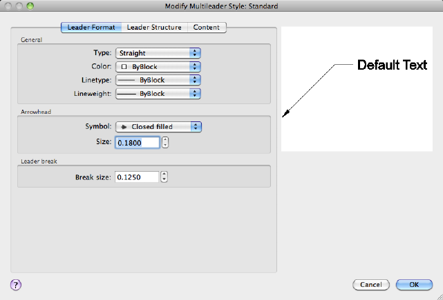
Summary
Controls the general appearance of the multileader.
List of Options
The following options are displayed.
Preview
Displays a preview image of the style being modified.
List of Tabs
The following tabs are displayed.
■Leader Format Tab (page 662)
■Leader Structure Tab (page 663)
■Content Tab (page 664)
See also:
Work with Leader Styles
Commands | 661
Leader Format Tab
Controls the formatting of the leader lines and arrowheads for the multileader.
General
Controls the general settings of the arrowheads.
Type
Determines the type of leader line. You can choose a straight leader, a spline,
or no leader line.
Color
Determines the color of the leader line.
Linetype
Determines the linetype of the leader line.
Lineweight
Determines the lineweight of the leader line.
Arrowhead
Controls the appearance of the multileader arrowheads.
Symbol
Sets the arrowhead symbol for the multileader.
Size
Displays and sets the size of arrowheads.
Leader Break
Controls the settings used when adding a dimension break to a multileader.
Break Size
Displays and sets the break size used for the DIMBREAK command when the
multileader is selected.
See also:
Work with Leader Styles
662 | Chapter 2 Commands
Leader Structure Tab
Controls the number of leader points, landing size, and scale for the
multilieader.
Constrain
Controls the constraints of the multileader.
Maximum Leader Points
Specifies a maximum number of points for the leader line.
First Segment Angle
Specifies the angle of the first point in the leader line.
Second Segment Angle
Specifies the angle of the second point in the multileader landing line.
Landing
Controls the landing settings of the multileader.
Automatically Include
Attaches a horizontal landing line to the multileader content.
Set Distance
Determines the fixed distance for the multileader landing line.
Scale
Controls the scaling of the multileader.
Annotative
Specifies that the multileader is annotative.
Scale to Layout
Determines a scaling factor for the multileader based on the scaling in the
model space and paper space viewports.
Specify Scale
Specifies the scale for the multileader.
See also:
Work with Leader Styles
Commands | 663
Content Tab
Controls the type of content attached to the multileader.
Multileader Type
Determines whether the multileader contains text or a block.
MText: Text Options
Controls the appearance of the text for the multileader.
Default Text
Sets default text for the multileader content. The [...] button launches the
MTEXT In Place Editor.
Text Style
Lists the available text styles.
Text Style Button
Displays the Text Style dialog box (page 1006) where you can create or modify
text styles.
Text Angle
Specifies the rotation angle of the multileader text.
Text Color
Specifies the color of the multileader text.
Text Height
Specifies the height of the multileader text.
Left Justify
Specifies that the multileader text is always left justified.
Frame Text
Frames the multileader text content with a text box.
Control the separation between the text and frame by modifying the Landing
Gap setting.
Mtext: Leader Connection
Controls the leader connection settings of the multileader.
Attachment
Specifies how the multiline text should be attached to the multileader.
664 | Chapter 2 Commands
Horizontal
Inserts the leader to the left or right of the text content. A horizontal
attachment includes a landing line between the text and the leader.
Left Controls the attachment of the landing line to the multileader text when
the text is to the right of the leader.
Right Controls the attachment of the landing line to the multileader text
when the text is to the left of the leader.
Landing Gap Specifies the distance between the landing line and the
multileader text.
Extend Leader to Text Extends the landing line to end at the edge of the text
line where the leader is attached, not at the edge of the multiline text box.
The length of the multiline text box is determined by the length of the longest
line of text, not the length of the bounding box.
Vertical
Inserts the leader at the top or bottom of the text content. A vertical
attachment does not include a landing line between the text and the leader.
Top Attaches the leader to the top center of the text content. Click the
drop-down to insert an overline between the leader attachment and the text
content.
Bottom Attaches the leader to the bottom of the text content. Click the
drop-down to insert an underline between the leader attachment and the text
content.
Landing Gap Specifies the distance between the landing line and the
multileader text.
Block: Block Options
Controls the properties of block content in a multileader object.
Source block
Specifies the block used for multileader content.
Attachment
Specifies the way the block is attached to the multileader object. You can
attach the block by specifying the insertion point of the block or the center
point of the block.
Color
Commands | 665
Specifies the color of the multileader block content. The Block color control
in the MLEADERSTYLE Content tab only takes effect if the object color
included in the block is set to ByBlock.
Scale
Specifies the scale of the block upon insertion. For example, if the block is a
1 inch square and the scale specified is 0.5000, then the block is inserted as a
1/2 inch square.
See also:
Work with Leader Styles
Create New Multileader Style Dialog Box
Specifies a name for the new multileader style and specifies the existing
multileader style on which the new multileader style will be based.
List of Options
The following options are displayed.
New Style Name
Names the new multileader style.
Start With
Specifies an existing multileader style whose settings are the default for the
new multileader style.
Annotative
Specifies that the multileader object is annotative.
Continue
Displays the Multileader Style Manager (page 658), in which you define the
new multileader style.
See also:
Work with Leader Styles
666 | Chapter 2 Commands

MLEDIT (-MLEDIT)
Edits multiline intersections, breaks, and vertices.
Access Methods
Menu: Modify ➤ Object ➤ Multiline
Summary
If you enter -mledit at the Command prompt, options are displayed (page
667).
See also:
Modify Multilines
-MLEDIT
Edits multiline intersections, breaks, and vertices.
List of Prompts
The following prompts are displayed.
CC Creates a closed-cross intersection between two multilines.
OC Creates an open-cross intersection between two multilines. Breaks are
inserted in all elements of the first multiline and only the outside elements
of the second multiline.
MC Creates a merged-cross intersection between two multilines. The order in
which you select the multilines is not important.
CT Creates a closed-tee intersection between two multilines. The first multiline
is trimmed or extended to its intersection with the second multiline.
OT Creates an open-tee intersection between two multilines. The first multiline
is trimmed or extended to its intersection with the second multiline.
MT Creates a merged-tee intersection between two multilines.The multiline
is trimmed or extended to its intersection with the other multiline.
Commands | 667
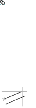
CJ Creates a corner joint between multilines. The multilines are trimmed or
extended to their intersection.
AV Adds a vertex to a multiline.
DV Deletes a vertex from a multiline.
CS Creates a visual break in a selected element of a multiline.
CA Creates a visual break through the entire multiline.
WA Rejoins multiline segments that have been cut.
See also:
Modify Multilines
MLINE
Creates multiple parallel lines.
Access Methods
Menu: Draw ➤ Multiline
List of Prompts
The following prompts are displayed.
Specify start point (page ?) or [Justification (page
?)/Scale (page ?)/STyle (page ?)]: Specify a point or enter an option
Start Point
Specifies the next vertex of the multiline.
If you create a multiline with two or more segments, the prompt includes the
Close option.
Next Point Draws a multiline segment to the specified point using the current
multiline style and continues to prompt for points.
668 | Chapter 2 Commands
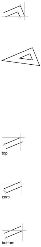
Undo Undoes the last vertex point on the multiline.
Close Closes the multiline by joining the last segments with the first segments.
Justification
Determines how the multiline is drawn between the points you specify.
■Top (page 669)
■Zero (page 669)
■Bottom (page 669)
Top Draws the multiline below the cursor, so that the line with the most
positive offset is at the specified points.
Zero Draws the multiline with its origin centered at the cursor, so that the
element with an offset of 0.0 is at the specified points.
Bottom Draws the multiline above the cursor, so that the line with the most
negative offset is at the specified points.
Commands | 669
Scale
Controls the overall width of the multiline. This scale does not affect linetype
scale.
The scale factor is based on the width established in the multiline style
definition. A scale factor of 2 produces a multiline twice as wide as the style
definition. A negative scale factor flips the order of the offset line—the smallest
on top when the multiline is drawn from left to right. A negative scale value
also alters the scale by the absolute value. A scale factor of 0 collapses the
multiline into a single line.
Style
Specifies a style to use for the multiline.
■Style Name (page 670)
■? (page 670)
Style Name Specifies the name of a style that has already been loaded or that's
defined in a multiline library (MLN) file you've created.
?—List Styles Lists the loaded multiline styles.
See also:
Draw Multiline Objects
MODEL
Switches from a named (paper space) layout to the Model layout.
Access Methods
When a viewing a layout, enter model at the command prompt or click the
Model tab below the drawing window.
Toolbar: Status bar ➤ Quick View ➤ Model
Toolbar: Status bar ➤ Layout drop down ➤ Model
670 | Chapter 2 Commands
Summary
On the Model layout, you can create drawings in model space. The Model
layout automatically sets the TILEMODE (page 1464) system variable to 1, and
you can create model viewports to display various views of your drawing.
Once you have completed your drawing, you can choose a named (paper
space) layout to begin designing a layout environment from which to plot.
For possible performance gains when you switch between layouts or between
the Model and named layouts, use the LAYOUTREGENCTL (page 1350) system
variable to control how the display list is updated.
See also:
Work with Model Space and Paper Space
MOVE
Moves objects a specified distance in a specified direction.
Access Methods
Button
Toolbar: Drafting tool set ➤ Move/Rotate/Scale tool group ➤ Move
Menu: Modify ➤ Move
Shortcut menu: Select the objects to move. Right-click in the drawing area
and click Move.
Summary
Use coordinates, grid snaps, object snaps, and other tools to move objects
with precision.
Commands | 671

List of Prompts
The following prompts are displayed.
Select objects:
Specify base point or [Displacement]:
Specify second point or <use first point as displacement>:
The two points you specify define a vector that indicates how far the selected
objects are to be moved and in what direction.
If you press Enter at the Specify Second Point prompt, the first point is
interpreted as a relative X,Y,Z displacement. For example, if you specify 2,3
for the base point and press Enter at the next prompt, the objects move 2
units in the X direction and 3 units in the Y direction from their current
position.
Displacement Enter coordinates to represent a vector
The coordinate values that you enter specify a relative distance and direction.
See also:
Move Objects
MREDO
Reverses the effects of several previous UNDO or U commands.
List of Prompts
The following prompts are displayed.
Enter number of actions (page 673) or [All (page 673)/Last
(page 673)]:
672 | Chapter 2 Commands
Number of Actions Reverses the specified number of actions.
All Reverses all previous actions.
Last Reverses only the last action.
See also:
Correct Mistakes
MSPACE
In a layout, switches from paper space to model space in a layout viewport.
Access Methods
Pointing device: Double-click over a viewport on a named layout.
Double-click outside of a viewport on a named layout to return to paper space.
Summary
Commands operate in either model space or paper space. You use model space
(the Model layout) to do drafting and design work and to create
two-dimensional drawings or three-dimensional models. You use paper space
(a named layout) to create a finished layout of a drawing for plotting.
When you are in a layout, you can enter mspace at the Command prompt
to make the last viewport in the layout current, and then work in model space
in that viewport within the layout.
See also:
Work with Model Space and Paper Space
MTEDIT
Edits multiline text.
Access Methods
Pointing device: Double-click a multiline text object.
Commands | 673
Summary
Displays either the Text Editor visor and the In-Place Text Editor to modify
the formatting or content of the selected multiline text object.
The In-Place Text Editor (page 675) is displayed.
See also:
Change Multiline Text
MTEXT
Creates a multiline text object.
Access Methods
Button
Toolbar: Annotation tool set ➤ Text tool group ➤ Multiline flyout ➤
Multiline Text
Menu: Draw ➤ Text ➤ Multiline Text
Summary
You can create several paragraphs of text as a single multiline text (mtext)
object. With the built-in editor, you can format the text appearance, columns,
and boundaries.
After you specify the point for the opposite corner the Text Editor visor (page
679) is displayed which contains text formatting options.
If you specify one of the other options, or if you enter -mtext at the Command
prompt, MTEXT bypasses the In-Place Text editor and displays additional
Command prompts (page 692).
See also:
Overview of Multiline Text
Symbols and Special Characters (page 696)
674 | Chapter 2 Commands

In-Place Text Editor
Creates or modifies single or multiline text objects.
Summary
You can import or paste text from other files to use in multiline text, set tabs,
adjust paragraph and line spacing and alignment, and create and modify
columns.
The In-Place Text Editor includes
■Text Editor visor (page 679)
■Paragraph dialog box (page 681)
■Column Settings dialog box (page 684)
■Background Mask dialog box (page 686)
■Columns menu (page 683)
When a table cell is selected for editing, the In-Place Text Editor displays
column letters and row numbers.
NOTE
Not all options available when creating single-line text.
List of Options
The following options are displayed.
Text Editor Shortcut Menu
Select All Selects all the text in the text editor.
Commands | 675
Clipboard Contains options to Cut, Copy, and Paste text to or from the
clipboard. The Paste Special option allows you to paste without character or
paragraph formatting.
Insert Field Displays the Insert Field dialog box (page 429).
Symbol Displays a list of available symbols. You can also select a Non-breaking
space and open the Characters dialog box for additional symbols.
Import Text Displays the Select File dialog box (a standard file selection dialog
box (page 720)). Select any file that is in ASCII or RTF format. Imported text
retains its original character formatting and style properties, but you can edit
and format the imported text in the editor. After you select a text file to import,
you can replace either selected text or all text, or append the inserted text to
text selected within the text boundary. The file size for imported text is limited
to 32 KB. (Not available for single-line text.)
The editor automatically sets the text color to BYLAYER. When black characters
are inserted and the background color is black, the editor automatically changes
to white or the current color.
Paragraph Alignment Sets alignment for the multiline text object. You can
choose to align your text to the left, center, or right. You can justify your text,
or align the first and last characters of your text with the margins of your
mtext box, or center each line of text within the margins of your mtext box.
Spaces entered at the end of a line are included as part of the text and affect
the justification of the line. (Not available for single-line text.)
Paragraph Displays options for paragraph formatting. See the Paragraph dialog
box (page 681). (Not available for single-line text.)
Bullets and Lists Displays the options for numbering lists. (Not available for
single-line text.)
Displays options for creating lists. (Not available for table cells.) The list is
indented to align with the first selected paragraph.
■Off: When selected, removes letters, numbers, and bullets from selected
text that has list formatting applied. Indentation is not changed.
■Lettered: Applies list formatting that uses letters with periods for the items
in the list. If the list has more items than the alphabet has letters, the
sequence continues by using double letters.
■Numbered: Applies list formatting that uses numbers with periods for the
items in the list.
■Bulleted: Applies list formatting that uses bullets for the items in the list.
676 | Chapter 2 Commands
■Restart: Starts a new letter or number sequence in list formatting. If the
selected items are in the middle of a list, unselected items below them also
become part of the new list.
■Continue: Adds the selected paragraphs to the last list above and continues
the sequence. If list items rather than paragraphs are selected, unselected
items below the selected items continue the sequence.
■Allow Auto-list: Applies list formatting as you type. The following characters
can be used as punctuation after letters and numbers and cannot be used
as bullets: period (.), comma (,), close parenthesis ()), close angle bracket
(>), close square bracket (]), and close curly bracket (}).
■Use Tab Delimiter Only: Limits the Allow Auto-list and Allow Bullets and
Lists options. List formatting is applied to text only when the space after
the letter, number, or bullet character was created by Tab, not Space.
■Allow Bullets and Lists: When this option is selected, list formatting is
applied to all plain text in the multiline text object that looks like a list.
Text that meets the following criteria is considered to be a list. The line
begins with (1) one or more letters or numbers or a symbol, followed by
(2) punctuation after a letter or number, (3) a space created by pressing
Tab, and (4) some text before the line is ended by Enter or Shift+Enter.
When you clear the check mark, any list formatting in the multiline text
object is removed and the items are converted to plain text. Allow Auto-list
is turned off, and all the Bullets and Lists options are unavailable except
Allow Bullets and Lists.
Columns Displays options for columns. See the Columns menu (page 683).
(Not available for single-line text.)
Find and Replace Displays the Find and Replace dialog box (page 687).
Change Case Changes the case of selected text. Options are Uppercase and
Lowercase.
AutoCAPS Converts all new and imported text to uppercase. AutoCAPS does
not affect existing text. To change the case of existing text, select the text and
right-click. Click Change Case.
Character Set Displays a menu of code pages. Select a code page to apply it
to the selected text. (Not available for single-line text.)
Combine Paragraphs Combines selected paragraphs into a single paragraph
and replaces each paragraph return with a space. (Not available for single-line
text.)
Commands | 677

Remove Formatting Removes character formatting for selected characters,
paragraph formatting for a selected paragraph, or all formatting from a selected
paragraph. (Not available for single-line text.)
Background Mask Displays the Background Mask dialog box (page 686). (Not
available for table cells and single-line text.)
Stack Creates stacked text, for example, fractions, if the selected text contains
stack characters. Also, unstacks text if stacked text is selected. When the stack
characters, carat (^), forward slash (/), and pound sign (#), are used, the text
to the left of the stack character is stacked on top of the text to the right.
By default, text that contains a carat converts to left-justified tolerance values.
Text that contains the forward slash converts to center-justified fractional
numbers; the slash is converted to a horizontal bar the length of the longer
text string. Text that contains the pound sign converts to a fraction separated
by a diagonal bar the height of the two text strings. The characters above the
diagonal fraction bar are bottom-right aligned; the characters beneath the
diagonal bar are top-left aligned.
Editor Settings Displays a list of options for the text editor. See Editor Settings
(page ?) for more information.
Editor Settings
Provides options for changing the behavior of the text editor and provides
additional editing options. Options are specific to the Editor Settings menu
and are not available elsewhere in the text editor.
NOTE Some options may not be available depending on what you are editing.
Always Display As WYSIWYG (What You See Is What You Get) Controls
display of the In-Place Text Editor and the text within it. When unchecked,
the drawing view is zoomed and rotated if need so the text that would
otherwise be difficult to read (if it is very small, very large, or is rotated) is
displayed at a legible size and is oriented horizontally so that you can easily
read and edit it.
When this option is checked, the MTEXTFIXED (page 1373) system variable will
be set to 0. Otherwise, MTEXTFIXED will be set to 2.
Show Ruler Controls the display of the ruler.
Opaque Background When selected, makes the background of the editor
opaque. (Not available for table cells.)
Check Spelling Determines whether As-You-Type spell checking is on or off.
678 | Chapter 2 Commands
Check Spelling Settings Displays the Check Spelling Settings dialog box (page
984), where you can specify text options that will be checked for spelling errors
within your drawing.
Text Highlight Color Specifies the highlight color when text is selected.
See also:
Overview of Multiline Text
Text Editor Visor
Formats the text of the current multiline text object.
List of Options
The following options are displayed.
Text Editor Visor - Row 1
Style Options
Applies a text style to the multiline text object. The Standard text
style is active by default.
Style
Sets the character height in drawing units for new text or changes
the height of selected text. If the current text style has no fixed height,
Text Height
the text height is the value stored in the TEXTSIZE (page 1463) system
variable. A multiline text object can contain characters of various
heights.
Formatting Options
Turns bold formatting on and off for new or selected text. This option
is available only for characters using TrueType fonts.
Bold
Turns italic formatting on and off for new or selected text. This option
is available only for characters using TrueType fonts.
Italic
Turns underlining on and off for new or selected text.Underline
Commands | 679
Turns overline on and off for new or selected text.Overline
Editor Options
Undoes actions in the text editor, including changes to either text
content or text formatting.
Undo
Redoes actions in the text editor, including changes to either text
content or text formatting.
Redo
Closes the text editor and changes are ignored.Cancel
Closes the text editor and saves your changes.Save
Displays the second row of the visor which contains additional
formatting options.
More Options
Text Editor Visor - Row 2
Additional Formatting Options
Specifies a font for new text or changes the font of selected text.
TrueType fonts are listed by font family name. AutoCAD for Mac
Font
compiled shape (SHX) fonts are listed by the name of the file in which
the fonts are stored. Custom fonts and third-party fonts are displayed
in the editor with Autodesk-supplied proxy fonts.
Specifies a color for new text or changes the color of selected text.Color
Paragraph Options
Displays the MText Justification menu with nine alignment options
available. Top Left is the default. See the Paragraph dialog box
(page 681) for a list of additional options.
MText Justification
680 | Chapter 2 Commands
Insert Options
Inserts a symbol or a nonbreaking space at the cursor position. You
can also insert symbols manually. See Symbols and Special Characters
(page 696).
Insert Symbols
Commonly used symbols are listed on the submenu, along with their
control code or Unicode string. Click Other to display the Character
dialog box, which contains the entire character set for each font
available on your system. When you have selected the character that
you want to use, click Insert to place the character in the text editor.
Close the Characters dialog box when you are done inserting special
characters.
Symbols are not supported in vertical text.
Displays the Insert Field dialog box (page 429), where you can select
a field to insert in the text. When the dialog box closes, the current
value of the field is displayed in the text.
Insert Field
Tools Options
Displays the Find and Replace dialog box (page 687).Find and Replace
See also:
Overview of Multiline Text
Paragraph Dialog Box
Sets indentation for paragraphs and the first lines of paragraphs.
Commands | 681
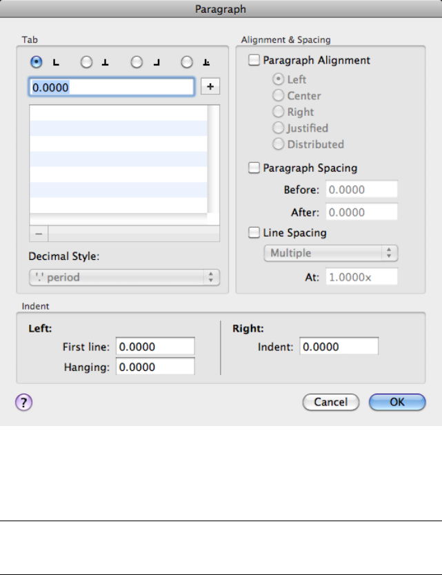
Summary
Specifies tab stops, indents, controls paragraph alignment, paragraph spacing,
and paragraph line spacing.
NOTE Not all of the new options for paragraph and paragraph line spacing are
supported in AutoCAD 2007 and previous releases. See MTEXT Paragraph and
Paragraph Line Spacing in Previous Releases in the User’s Guide.
List of Options
The following options are displayed.
Tab
Specifies the tab stops and decimal styles to use for the paragraph.
682 | Chapter 2 Commands
Tab Stops
Displays tab setting options, including adding and removing tabs. Options
include setting left, center, right, and decimal tabs. You can also set tabs from
the Tab selection button on the In-Place Editor’s ruler.
Decimal style
Sets the decimal style based on current user locale. Options include setting
the decimal style as period, comma, and space. This setting is preserved with
the drawing even if the locale setting is changed.
Indent
Controls the left and right indents for the paragraph.
Left
Sets the indent value for the first line or hanging indent to the selected or
current paragraphs.
Right
Applies the indent to the entire selected or current paragraph.
Alignment & Spacing
Defines the alignment and spacing for the paragraph.
Paragraph Alignment
Sets the alignment properties for the current or selected paragraphs.
Paragraph Spacing
Specifies the spacing before or after the current or selected paragraphs. The
distance between two paragraphs is determined by the total of the after
paragraph spacing value of the upper paragraph and the before paragraph
spacing value of the lower paragraph.
Line Spacing
Sets the spacing between individual lines in the current or selected paragraphs.
See also:
Overview of Multiline Text
Columns Menu
Allows you to format an mtext object into multiple columns.
Commands | 683
Summary
You can specify column and gutter width, height, and number of columns.
You can edit column width and height with grip-editing.
To create multiple columns you always start with a single column. Depending
on the column mode you choose, you have two different methods for creating
and manipulating columns – static mode or dynamic mode.
List of Options
The following options are displayed.
No Columns Specifies no columns for the current mtext object.
Dynamic Columns Sets dynamic columns mode to the current mtext object.
Dynamic columns are text driven. Adjusting columns affects text flow and
text flow causes columns to be added or removed. Auto height or Manual
height options are available.
Static Columns Sets static columns mode to the current mtext object. You
can specify the total width and height of the mtext object, and the number
of columns. All the columns share the same height and are aligned at both
sides.
Insert Column Break Alt+Enter Inserts a manual column break.
Column Settings Displays Column Settings dialog box (page 684).
See also:
Overview of Multiline Text
Column Settings Dialog Box
Displays options for setting up columns such as the type, number of columns,
height, and width, and gutter size.
684 | Chapter 2 Commands
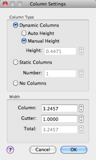
List of Options
The following options are displayed.
Column Type
Lists choices for the type of columns you want to create.
Height
Displays the height of the multiline text object when Auto Height with
Dynamic or Static Columns is selected.
Number
Sets the number of columns. This is only active when you select Static
Columns.
Width
Displays and specifies control column and gutter width values. The gutter
value is five times the default multiline text height.
Commands | 685
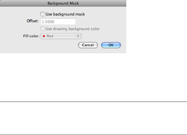
Also displays the total width value of the multiline text object.
See also:
Overview of Multiline Text
Background Mask Dialog Box
Controls using an opaque background behind multiline text.
List of Options
The following options are displayed.
Use Background Mask
Puts an opaque background behind the text.
NOTE
When you apply a background mask to mtext multiple columns only the
column areas will be masked. The space between the columns commonly
referred to as gutters will be unmasked.
Offset
Specifies the margin around the text for the opaque background. The value
is based on the text height. A factor of 1.0 exactly fits the multiline text object.
A factor of 1.5 extends the background by 0.5 times the text height.
Use Background Drawing Color
Provides a background that is the same color as the background of the drawing.
Fill Color
Specifies the color for the background.
Color
686 | Chapter 2 Commands
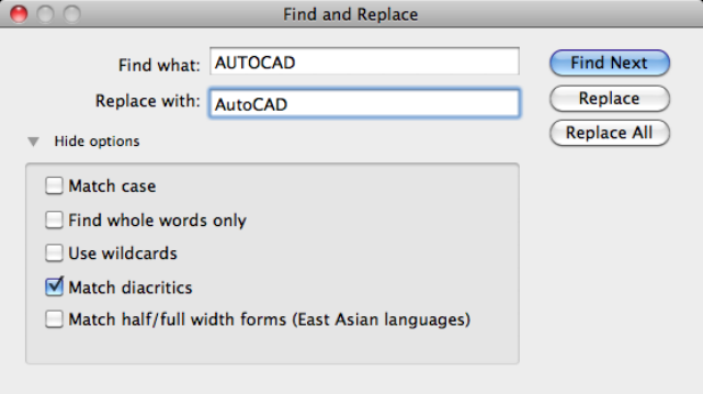
Specifies a color for the opaque background. You can select one of the colors
in the list or click Select Color to open the Color Palette dialog box (page 198).
See also:
Overview of Multiline Text
Find and Replace Dialog Box - MTEXT
Searches for specified text strings and replaces them with new text.
Access Methods
Shortcut menu: Select the Find and Replace icon in the text editor or from
the MTEXT shortcut menu
List of Options
The following options are displayed.
Find What
Provides a space for you to type the text you want to find.
Replace With
Provides a space for you to type the text you want to replace the text you
typed in Find What.
Commands | 687
Find Next
Finds the next instance of the text specified in Find What.
Replace
Finds the next instance of the text specified in Find What and replaces it with
the text in Replace With.
Replace All
Finds all instances of the text specified in Find What and replaces it with the
text in Replace With.
Hide Options
Specifies advanced find options.
Match Case Finds only text with uppercase and lowercase characters as
specified in Find What.
The case of all characters in the text string must match the case of the text in
Find What. When this option is cleared, a match is found for specified text
strings regardless of case.
Match Whole Word Only Finds only whole words specified in Find What.
Text that is part of another word is ignored. When this option is cleared, a
match is found for text strings, whether they are single words or parts of other
words.
Use Wildcards Allows the use of wildcard characters in searches.
For more information on wildcard searches, see Find and Replace Text.
Match Diacritics Matches diacritical marks, or accents, in search results.
Match Half/Full Width Forms (East Asian Languages) Matches half- and
full-width characters in search results.
See also:
Overview of Multiline Text
Stack Properties Dialog Box
Edits the text, stack type, alignment, and size of stacked text.
688 | Chapter 2 Commands
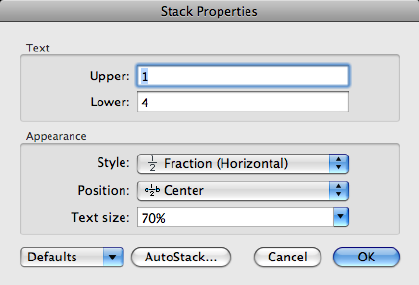
Summary
To open the Stack Properties dialog box, select the stacked text, right-click,
and click Stack Properties on the shortcut menu.
You can edit the upper and lower text separately. The Appearance options
control the stack style, position, and text size of the stacked text.
List of Options
The following options are displayed.
Text
Changes the upper and lower numbers of a stacked fraction.
Upper
Edits the number in the upper part or first half of a stacked fraction.
Lower
Edits the number in the lower part or second half of a stacked fraction.
Appearance
Edits the style, position, or text size of a stacked fraction.
Style
Specifies a style format for stacked text: horizontal fraction, diagonal fraction,
tolerance, and decimal.
Fraction (Horizontal) Stacks the selected text with the first number on top
of the second number separated by a horizontal line.
Fraction (Diagonal) Stacks the selected text with the first number on top of
the second number separated by a diagonal line.
Commands | 689

NOTE
Releases of AutoCAD earlier than AutoCAD 2000 do not support diagonal
fractions. If a multiline text object contains diagonal fractions, the fractions
are converted to horizontal fractions when you save the drawing to
pre-AutoCAD 2000 releases. Diagonal fractions are restored when the drawing
is re-opened in AutoCAD 2000 or a later release. If a single multiline text object
contains both horizontal and diagonal fractions, all fractions are converted
to diagonal fractions when the drawing is reopened in AutoCAD 2000 or a
later release.
Tolerance Stacks the selected text with the first number on top of the second
number. There is no line between the numbers.
Decimal A variation of the Tolerance style that aligns the decimal point of
both the upper and lower numbers of selected text.
Position
Specifies how fractions are aligned. Center alignment is the default. All stacked
text in an object uses the same alignment.
Top Aligns the top of the fraction with the top of the text line.
Center Centers the fraction vertically at the center of the text line.
Bottom Aligns the bottom of the fraction with the text baseline.
Text Size
Controls the size of the stacked text as a percentage of the size of the current
text style (from 25 to 125 percent).
Defaults
Saves the new settings as defaults or restores the previous default values to
the current stacked text.
AutoStack Button
Displays the AutoStack Properties dialog box (page 691). AutoStack only stacks
numeric characters immediately before and after the carat, slash, and pound
characters. To stack nonnumeric characters, or text that includes spaces, select
the text and choose Stack from the text editor shortcut menu.
See also:
Overview of Multiline Text
690 | Chapter 2 Commands
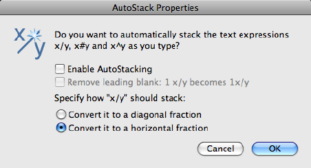
AutoStack Properties Dialog Box
Sets the defaults for automatically stacking characters.
Access Methods
Shortcut menu: Select stacked text in the text editor. Right-click and click
Stack Properties on the shortcut menu. In the Stack Properties dialog box,
click AutoStack.
List of Options
The following options are displayed.
Enable AutoStacking
Automatically stacks numeric characters entered before and after the carat,
slash, or pound character. For example, if you type 1#3 followed by a
nonnumeric character or space, the text is automatically stacked as a diagonal
fraction.
Remove Leading Blank
Removes blanks between a whole number and a fraction.
Convert It to a Diagonal Fraction
Converts the slash character to a diagonal fraction when AutoStack is on.
Convert It to a Horizontal Fraction
Converts the slash character to a horizontal fraction when AutoStack is on.
Commands | 691

NOTE
Whether AutoStack is on or off, the pound character is always converted to a
diagonal fraction, and the carat character is always converted to a tolerance
format.
See also:
Overview of Multiline Text
-MTEXT
Creates a multiline text object.
List of Prompts
The following prompts are displayed.
Specify first corner.
Specify opposite corner (page ?) or [Height (page ?)/Justify
(page ?)/Line spacing (page ?)/Rotation (page ?)/Style
(page ?)/Width (page ?)/Columns (page ?)].
Opposite Corner
As you drag the pointing device to specify the opposite corner, a rectangle is
displayed to show the location and size of the multiline text object. Arrows
within the rectangle indicate the direction of the paragraph's text flow.
Height
Specifies the text height to use for multiline text characters.
■Specify Height.
The Specify Height prompt is displayed only if the current text style is not
annotative.
■Specify Paper Text Height.
The Specify Paper Text Height prompt is displayed only if the current text
style is annotative.
The default height, if nonzero, is the height of the current style; otherwise, it
is the height stored in the TEXTSIZE (page 1463) system variable. Character
height is calculated in drawing units. Changing the height updates the value
stored in TEXTSIZE (page 1463).
692 | Chapter 2 Commands
Justify
Determines both text justification and text flow, for new or selected text, in
relation to the text boundary. The current justification is applied to new text.
The text is justified within the specified rectangle based on the justification
setting and one of nine justification points on the rectangle. The justification
point is based on the first point used to specify the rectangle. Text is center-,
left-, or right-justified with respect to the left and right text boundaries. Spaces
entered at the end of a line are included as part of the text and affect the
justification of the line. Text flow controls whether text is aligned from the
middle, the top, or the bottom of the paragraph with respect to the top and
bottom text boundaries.
Enter justification [TL/TC/TR/ML/MC/MR/BL/BC/BR] <TL>.
Justify Options
MeaningOption
Top LeftTL
Top CenterTC
Top RightTR
Middle LeftML
Middle CenterMC
Middle RightMR
Bottom LeftBL
Bottom CenterBC
Bottom RightBR
The following illustrations show each justification option.
Commands | 693
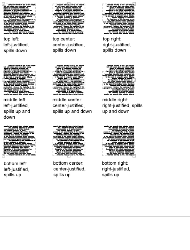
Line Spacing
Specifies line spacing for the multiline text object. Line spacing is the vertical
distance between the bottom (or baseline) of one line of text and the bottom
of the next line of text.
NOTE
Exact spacing is recommended when you use MTEXT to create a table. Use a
smaller text height than the specified line spacing to ensure that text does
not overlap.
At Least Adjusts lines of text automatically based on the height of the largest
character in the line. When At Least is selected, lines of text with taller
characters have added space between lines.
Distance Sets the line spacing to an absolute value measured in drawing units.
Valid values must be between 0.0833 (0.25x) and 1.3333 (4x).
694 | Chapter 2 Commands
Exactly Forces the line spacing to be the same for all lines of text in the
multiline text object. Spacing is based on the text height of the object or text
style.
Spacing Factor Sets the line spacing to a multiple of single-line spacing.
Single spacing is 1.66 times the height of the text characters. You can enter a
spacing factor as a number followed by x to indicate a multiple of single
spacing. For example, specify single spacing by entering 1x, or specify double
spacing by entering 2x.
Rotation
Specifies the rotation angle of the text boundary.
■Specify rotation angle.
If you use the pointing device to specify a point, the rotation angle is
determined by the angle between the X axis and the line defined by the most
recently entered point (default 0,0,0) and the specified point.
The previous prompt is redisplayed until you specify the opposite corner of
the text boundary.
Style
Specifies the text style to use for multiline text.
Style Name Specifies a text style name. Text styles can be defined and saved
using the STYLE (page 1006) command.
?—List Styles Lists text style names and characteristics.
The previous prompt is redisplayed until you specify the opposite corner of
the text boundary.
Width
Specifies the width of the text boundary.
If you use the pointing device to specify a point, the width is calculated as
the distance between the start point and the specified point. Words within
each line of the multiline text object wrap to fit the width of the text boundary.
If you specify a width of 0, word wrap is turned off and the width of the
multiline text object is as wide as the longest line of text. You can end a line
of text at a specific point by typing the text and pressing Enter. To end the
command, press Enter at the MTEXT prompt.
Columns
Specifies the column options for an mtext object.
Static Specifies the total column width, the number of columns, the gutter
width (the space between the columns), and the height of columns.
Commands | 695
Dynamic Specifies column width, gutter width and column height. Dynamic
columns are text driven. Adjusting columns affect text flow and text flow
causes columns to be added or removed.
No columns Sets no column mode to current mtext object.
The default column setting is stored in the MTEXTCOLUMN (page 1372) system
variable.
See also:
Overview of Multiline Text
Symbols and Special Characters
You can include special characters and symbols by entering a control code or
a Unicode string.
With the In-Place Text Editor (page 675), you can right-click and click Symbol
on the shortcut menu.
NOTE
Symbols are not supported in vertical text.
Unicode strings and control codes
ResultUnicode StringsControl Codes
Degree symbol (°)\U+00B0%%d
Tolerance symbol ( )
\U+00B1%%p
Diameter symbol ( )
\U+2205%%c
696 | Chapter 2 Commands
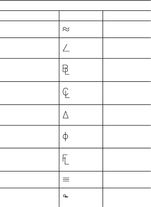
To insert the following text symbols, click Symbol on the expanded Text
Formatting toolbar or enter the appropriate Unicode string:
Text symbols and Unicode strings
Unicode StringSymbolName
\U+2248Almost equal
\U+2220Angle
\U+E100Boundary line
\U+2104Centerline
\U+0394Delta
\U+0278Electrical phase
\U+E101Flow line
\U+2261Identity
\U+E200Initial length
Commands | 697
Text symbols and Unicode strings
Unicode StringSymbolName
\U+E102Monument line
\U+2260Not equal
\U+2126Ohm
\U+03A9Omega
\U+214APlate/property line
\U+2082Subscript 2
\U+00B2Squared
\U+00B3Cubed
These text symbols are available in the following True Type (TTF) and SHX
fonts:
■Simplex*
■Romans*
■gdt*
■amgdt*
■Isocp
698 | Chapter 2 Commands

■Isocp2
■Isocp3
■Isoct
■Isoct2
■Isoct3
■Isocpeur (TTF only)*
■Isocpeur italic (TTF only)
■Isocteur (TTF only)
■Isocteur italic (TTF only)
* These fonts also include the Initial Length symbol used for arc length
dimensions.
See also:
Overview of Multiline Text
MULTIPLE
Repeats the next command until canceled.
Summary
The command that you enter is repeated until you press Esc. Because
MULTIPLE repeats only the command name, any parameters must be specified
each time.
MULTIPLE does not repeat commands that display dialog boxes.
NOTE You cannot use MULTIPLE as an argument to the AutoLISP® command
function.
See also:
Enter Commands on the Command Line
Commands | 699

MVIEW
Creates and controls layout viewports.
Access Methods
Toolbar: Layout visor ➤ New Viewport
Shortcut menu: Right-click the drawing area when a named layout is current
and click New Viewport.
Summary
In a layout, you can create as many viewports as you want, but only up to 64
viewports can be active at one time (see MAXACTVP (page 1366)). Objects in
model space are visible only in active viewports. Viewports that are not active
are blank. Use the On and Off options to control whether viewports are active.
List of Prompts
The following prompts are displayed.
Specify corner of viewport (page ?)or [ON (page ?)/OFF
(page ?)/Fit (page ?)/Shadeplot (page ?)/Lock (page
?)/Object (page ?)/Polygonal (page ?)/Restore (page
?)/LAyer (page ?)/2(page ?)/3(page ?)/4(page ?)].
Corner of Viewport
Specifies the first corner of a rectangular viewport.
On
Makes a selected viewport active. An active viewport displays objects in model
space. The MAXACTVP system variable controls the maximum number of
viewports that can be active at one time. If your drawing contains more
viewports than the number specified in MAXACTVP, you must turn one off
to make another one active.
Off
Makes a selected viewport inactive. Objects in model space are not displayed
in an inactive viewport.
Fit
Creates one viewport that fills the layout to the edges of the printable area.
When the paper background and printable area are turned off, the viewport
fills the display.
700 | Chapter 2 Commands
Shadeplot
Specifies how viewports in named (paper space) layouts are plotted.
As Displayed Specifies that a viewport is plotted the same way it is displayed.
Wireframe Specifies that a viewport is plotted wireframe regardless of the
current display.
Hidden Specifies that a viewport is plotted with hidden lines removed
regardless of the current display.
All Visual Styles Specifies that a viewport is plotted using the specified visual
style.
All Render Presets Specifies that a viewport is plotted using the specified
render preset.
Lock
Prevents the zoom scale factor in the selected viewport from being changed
when working in model space.
Object
Specifies a closed polyline, ellipse, spline, region, or circle to convert into a
viewport. The polyline you specify must be closed and contain at least three
vertices. It can be self-intersecting, and it can contain an arc as well as line
segments.
Polygonal
Creates an irregularly shaped viewport using specified points.
Arc Adds arc segments to the polygonal viewport.
For a description of the options for creating arc segments, see the Arc option
in PLINE (page 785).
Close Closes the boundary. If you press Enter after specifying at least three
points, the boundary is closed automatically.
Length Draws a line segment of a specified length at the same angle as the
previous segment. If the previous segment is an arc, the new line segment is
drawn tangent to that arc segment.
Commands | 701
Undo Removes the most recent line or arc segment added to the polygonal
viewport.
Restore
Restores viewport configurations saved with the VPORTS (page 1115) command.
■Enter Viewport Configuration Name.
■?
First Corner Positions and sizes new viewports using the window selection
method; the viewports are fit into the selected area.
Fit Sizes the viewports to fill the drawing area.
Layer
Resets layer property overrides for the selected viewport to their global layer
properties.
■Reset Viewport Layer Property Overrides Back To Global
Properties. Enter Y to remove all layer property overrides.
■Select Viewports.
2
Divides the specified area horizontally or vertically into two viewports of equal
size.
■Enter Viewport Arrangement.
First Corner Positions and sizes new viewports using the window selection
method; the viewports are fit into the selected area.
Fit Sizes the viewports to fill the drawing area.
3
Divides the specified area into three viewports.
The Horizontal and Vertical options split the specified area into thirds. The
other options split the area into three viewports: one large viewport and two
702 | Chapter 2 Commands
smaller ones. The Above, Below, Left, and Right options specify where the
larger viewport is placed.
■First Corner (page 702)
■Fit (page 702)
4
Divides the specified area horizontally and vertically into four viewports of
equal size.
■First Corner (page 702)
■Fit (page 702)
See also:
Create and Modify Layout Viewports
MVSETUP
Sets up the specifications of a drawing.
Summary
When you enter mvsetup, the prompts displayed depend on whether you
are on the Model layout (model space) (page 704) or on a named layout (paper
space) (page 704).
Commands | 703
See also:
Create and Modify Layout Viewports
MVSETUP on the Model Layout
The Model layout is most useful for plotting multiple views of a drawing
within a single border.
On the Model layout, you set the units type, drawing scale factor, and paper
size at the Command prompt using MVSETUP. Using the settings you provide,
a rectangular border is drawn at the grid limits.
List of Prompts
When the TILEMODE (page 1464) system variable is on (the default), the
following prompt are displayed:
Enable paper space? [No/Yes] <Y>: Enternor press Enter
Pressing Enter turns off TILEMODE and proceeds as described in the following
section, Using MVSETUP on a Layout Tab. (page 704)
Entering n displays the following prompt:
Enter units type
[Scientific/Decimal/Engineering/Architectural/Metric]: Enter
an option
A list of available units and prompts for the scale factor and paper size are
displayed.
Enter the scale factor: Enter a value
Enter the paper width: Enter a value
Enter the paper height: Enter a value
A bounding box is drawn and the command ends.
See also:
Create and Modify Layout Viewports
MVSETUP on a Named Layout
On a named layout, you can insert one of several predefined title blocks into
the drawing and create a set of layout viewports within the title block.
704 | Chapter 2 Commands
You can specify a global scale as the ratio between the scale of the title block
in the layout and the drawing on the Model layout.
To easily specify all layout page settings and prepare your drawing for plotting,
you can also use the Page Setup Manager.
List of Prompts
When the TILEMODE (page 1464) system variable is off, or when you enter y
or press Enter at the Enable Paper Space prompt, the following prompts are
displayed:
Enter an option [Align (page ?)/Create (page ?)/Scale
viewports (page ?)/Options (page ?)/Title block (page
?)/Undo (page ?)]: Enter an option or press Enter to end the command
Align
Pans the view in a viewport so that it aligns with a base point in another
viewport. The current viewport is the viewport that the other point moves to.
Angled Pans the view in a viewport in a specified direction.
The next two prompts specify the distance and angle from the base point to
the second point.
Horizontal Pans the view in one viewport until it aligns horizontally with a
base point in another viewport. This option should be used only if the two
viewports are oriented horizontally. Otherwise, the view might be panned
outside the limits of the viewport.
Vertical Alignment Pans the view in one viewport until it aligns vertically
with a base point in another viewport. This option should be used only if the
two viewports are oriented vertically. Otherwise, the view might be panned
outside the limits of the viewport.
Rotate View Rotates the view in a viewport about a base point.
Undo Reverses operations performed in the current MVSETUP session.
Create
Creates viewports.
Delete Objects
Deletes existing viewports.
Create Viewports
Displays options for creating viewports.
Layout Number to Load Controls creation of viewports.
Entering 0 or pressing Enter creates no viewports.
Commands | 705
Entering 1 creates a single viewport whose size is determined by the following
prompts.
Entering 2 creates four viewports by dividing a specified area into quadrants.
You are prompted for the area to be divided and the distance between the
viewports.
The viewing angle for each quadrant is set as shown in the table.
ViewQuadrant
Top (XY plane of UCS)Upper-left
SE isometric viewUpper-right
Front (XZ plane of UCS)Lower-left
Right side (YZ plane of UCS)Lower-right
Entering 3 defines a matrix of viewports along the X and Y axes. Specifying
points at the next two prompts defines the rectangular area of the drawing
that contains the viewport configuration. If you have inserted a title block,
the Specify First Corner prompt also includes an option for selecting a default
area.
If you enter more than one viewport in each direction, the following prompts
are displayed:
Specify distance between viewports in X direction <0.0>: Specify a distance
Specify distance between viewports in Y direction <0.0>: Specify a distance
The array of viewports is inserted into the defined area.
Redisplay Redisplays the list of viewport layout options.
Undo
Reverses operations performed in the current MVSETUP session.
Scale Viewports
Adjusts the zoom scale factor of the objects displayed in the viewports. The
zoom scale factor is a ratio between the scale of the border in paper space and
the scale of the drawing objects displayed in the viewports.
Interactively Selects one viewport at a time and displays the following prompts
for each:
For example, for an engineering drawing at a scale of 1:4, or quarter scale,
enter 1 for paper space units and 4 for model space units.
706 | Chapter 2 Commands
Uniform Sets the same scale factor for all viewports.
Options
Sets the MVSETUP preferences before you change your drawing.
Layer Specifies a layer on which to insert the title block.
Limits Specifies whether to reset the grid limits to the drawing extents after
a title block has been inserted.
Units Specifies whether the sizes and point locations are translated to inch
or millimeter paper units.
Xref Specifies whether the title block is inserted or externally referenced.
Title Block
Prepares paper space, orients the drawing by setting the origin, and creates a
drawing border and a title block.
Delete Objects
Deletes objects from paper space.
Origin
Relocates the origin point for this sheet.
Undo
Reverses operations performed in the current MVSETUP session.
Insert
Displays title block options.
Title Block to Load Inserts a border and a title block. Entering 0 or pressing
Enter inserts no border. Entering 1 through 13 creates a standard border of
the appropriate size. The list includes ANSI and DIN/ISO standard sheets.
Add Adds title block options to the list. Selecting this option prompts you to
enter the title block description to be displayed in the list and the name of a
drawing to insert.
A line similar to the following example is added after the last entry in the
mvsetup.dfs default file:
A/E (24 x 18in),arch-b.dwg,(1.12 0.99 0.00),(18.63 17.02 0.00),in
The last field of the line specifies whether the title block has been created in
inches or in millimeters. The units field allows title blocks created in either
unit system to be changed by setting the unit type using the Options option.
You can also add title blocks that have variable attributes.
Delete Removes entries from the list.
Redisplay Redisplays the list of title block options.
Commands | 707
Undo
Reverses operations performed in the current MVSETUP session.
See also:
Create and Modify Layout Viewports
N Commands
NAVVCUBE
Indicates the current viewing direction. Dragging or clicking the ViewCube
tool rotates the scene.
Access Methods
Menu: View ➤ Display ➤ ViewCube ➤ On
Toolbar: Status bar ➤ ViewCube
Summary
Click the ViewCube tool to rotate and fill the window with the entire model
or an object selected in the view. The Home button displayed near the
ViewCube tool rotates the model to a three-fourths view or a user-defined
view while performing a fit-to-view. Use the ViewCube menu to define the
Home view for the model.
List of Prompts
The following prompts are displayed.
Enter an option [ON (page 708)/OFF (page 708)/Properties (page
708)] <ON>:
On Displays the ViewCube tool.
Off Turns off the display of the ViewCube tool.
Settings Displays the ViewCube Settings dialog box (page 709), in which you
can control the appearance and location of the ViewCube.
708 | Chapter 2 Commands
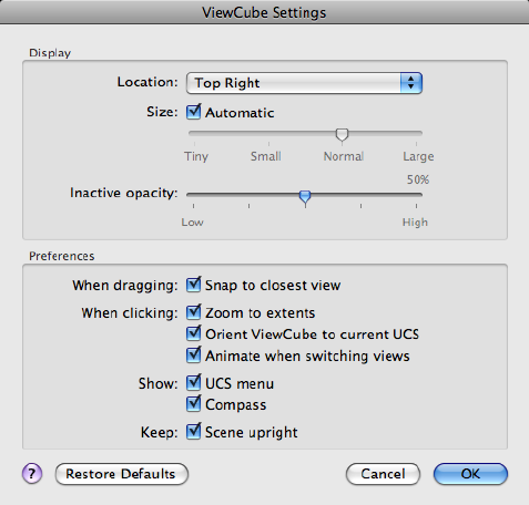
See also:
Use ViewCube Tool
ViewCube Settings Dialog Box
Controls the display properties of the ViewCube tool.
List of Options
The following options are displayed.
Display
Location
Identifies the corner in a viewport where the ViewCube tool is displayed.
(NAVVCUBELOCATION (page 1375) system variable)
Size
Specifies the size of the ViewCube tool.
(NAVVCUBESIZE (page 1376) system variable)
Commands | 709
Select Automatic to have the size of the ViewCube tool adjust based on the
current size of the active viewport, zoom factor of the active layout, or drawing
window.
Inactive Opacity
Controls the opacity of the ViewCube tool when inactive.
(NAVVCUBEOPACITY (page 1375) system variable)
When Dragging
Snap to Closest View
Specifies if the current view is adjusted to the closest preset view when
changing the view by dragging the ViewCube tool.
When Clicking
Zoom to Extents
Specifies if the model is forced to fit the current viewport after a view change.
Orient ViewCube to Current UCS
Controls whether the ViewCube tool reflects the current UCS or WCS.
(NAVVCUBEORIENT (page 1376) system variable)
Animate When Switching Views
Controls the use of smooth view transitions when switching between views.
Show
UCS Menu Controls the display of the UCS drop-down menu below the
ViewCube tool.
Compass Controls whether the compass is displayed below the ViewCube
tool. The North direction indicated on the compass is the value defined by
the NORTHDIRECTION system variable.
Keep
Scene Upright Specifies whether the viewpoint of the model can be turned
upside-down.
Restore Defaults
Applies the default settings for the ViewCube tool.
See also:
Use ViewCube Tool
710 | Chapter 2 Commands

NEW
Creates a new drawing.
Access Methods
Menu: File ➤ New
Summary
If the FILEDIA system variable is set to 0 instead of 1, a Command prompt is
displayed (page 711).
See also:
Overview of Starting a New Drawing
NEW Command Prompt
Summary
Enter a tilde (~) at the prompt to display the Select Template dialog box (a
standard file selection dialog box (page 720)).
List of Prompts
The following prompts are displayed.
Enter template file name or [. (for none)] <current>: Enter a
name, enter a period (.), or press Enter
See also:
Overview of Starting a New Drawing
O Commands
OBJECTSCALE
Adds or deletes supported scales for annotative objects.
Commands | 711

Access Methods
Button
Toolbar: Annotation tool set ➤ Annotation Scaling tool group ➤
Add/Delete Scales
Menu: Modify ➤ Annotative Object Scale ➤ Add/Delete Scales
Shortcut menu: Select an annotative object. Right-click in the drawing area
and click Annotative Object Scale ➤ Add/Delete Scales.
Command entry: 'objectscale for transparent use
Summary
An annotative object can support several annotation scales for views at different
scales. You can add or delete scales from the list of scales assigned to the
selected annotative objects.
If you enter objectscale, you are prompted to select annotative objects.
The Annotation Object Scale List dialog box (page 712) is displayed.
If you enter -objectscale at the Command prompt, options are displayed
(page 715).
See also:
Set Annotation Scale
Annotation Object Scale List Dialog Box
Adds or deletes supported scales for the selected annotative object.
712 | Chapter 2 Commands
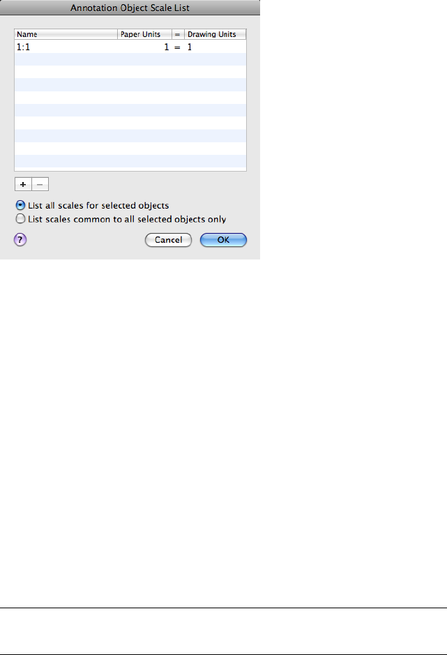
List of Options
The following options are displayed.
Object Scale List
Displays the list of scales supported by the selected object.
List all scales for selected objects
Specifies that all scales supported by the selected objects are displayed in the
Object Scale List.
List scales common to all selected objects only
Specifies that only the supported scales that are common to all selected objects
are displayed in the Object Scale List.
Add (+)
Displays the Add Scales to Object Dialog Box (page 714).
Delete (-)
Removes the selected scale from the scale list.
NOTE
The current scale or scales referenced by objects or views cannot be deleted.
Commands | 713

See also:
Scale Views in Layout Viewports
Add Scales to Object Dialog Box
Adds a new scale to the selected annotative object.
List of Options
The following option is displayed.
Scale List
Displays the list of scales that can be added to the selected annotative object.
Multiple scales can be selected by holding down the Shift or Command key
while selecting the scales.
Use the SCALELISTEDIT (page 918) command to add custom scales to this list.
See also:
Scale Views in Layout Viewports
714 | Chapter 2 Commands
-OBJECTSCALE
List of Prompts
The following prompts are displayed.
Select annotative objects: Use an object selection method
Enter an option [Add (page ?)/Delete (page ?)/?(page 715)]
<Add>: Enter a or d or press Enter
Add
Adds an annotation scale to the selected annotative objects.
When created, an annotative object supports one annotation scale: the current
annotation scale. However, an annotative object can be updated to support
additional annotation scales for views at different scales.
■Enter named scale to add.
■? (page 715)
? Displays the list of scales in the scale list.
Delete
Removes a specified current annotation scale from the selected objects.
If an annotative object supports a single scale, that scale cannot be deleted
from the object.
■Enter named scale to delete.
■? (page 715)
? Displays the union of all scales of the selected objects.
See also:
Scale Views in Layout Viewports
OFFSET
Creates concentric circles, parallel lines, and parallel curves.
Commands | 715
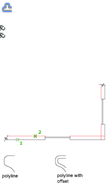
Access Methods
Button
Toolbar: Drafting tool set ➤ Copy tool group ➤ Offset
Menu: Modify ➤ Offset
Summary
You can offset an object at a specified distance or through a point. After you
offset objects, you can trim and extend them as an efficient method to create
drawings containing many parallel lines and curves.
The OFFSET command repeats for convenience. To exit the command, press
Enter.
List of Prompts
The following prompts are displayed.
Current settings: Erase source = current Layer = current
OFFSETGAPTYPE = current
Specify Offset Distance (page ?) or [Through (page ?)/Erase
(page ?)/Layer (page ?)] <current>: Specify a distance, enter an option,
or press Enter
716 | Chapter 2 Commands
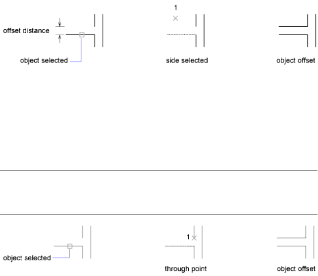
Offset Distance
Creates an object at a specified distance from an existing object.
Exit Exits the OFFSET command.
Multiple Enters the Multiple offset mode, which repeats the offset operation
using the current offset distance.
Undo Reverses the previous offset.
Through
Creates an object passing through a specified point.
NOTE
For best results when you offset a polyline with corners, specify the through
point near the midpoint of a line segment, not near a corner.
■Exit (page 717)
■Multiple (page 717)
■Undo (page 717)
Erase
Erases the source object after it is offset.
Layer
Determines whether offset objects are created on the current layer or on the
layer of the source object.
See also:
Offset an Object
Commands | 717
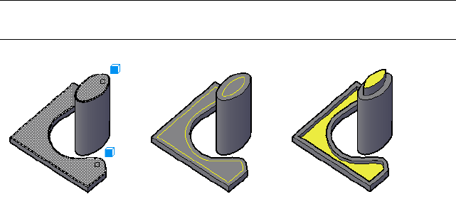
OFFSETEDGE
Creates a closed polyline or spline object that is offset at a specified distance
from the edges of a selected planar face on a 3D solid or surface.
Summary
You can offset the edges of a planar face on a 3D solid or surface. The result
is a closed polyline or spline that is located on the same plane as the selected
face or surface, and can be inside or outside the original edges.
TIP You can use the resulting object with PRESSPULL (page 827) or EXTRUDE (page
423) to create new solids.
List of Prompts
The following prompts are displayed.
Corner = current
Select face: Select a planar face on a 3D solid or surface
Specify through point or [Distance/Corner] <current>: Specify a
point, or enter an option
Through Point
Creates an offset object that passes through the specified point. This point is
always projected line-of-sight onto the plane of the selected face.
Distance
Creates an offset object at a specified distance from the edges of the selected
face.
Specify distance: <current> Enter the offset distance, or press Enter to accept
the current distance.
718 | Chapter 2 Commands
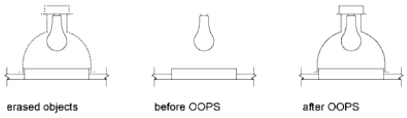
Specify point on side to offset Specify a point location to determine whether
the offset distance is applied inside or outside the edges of the face.
Corner
Specifies the type of corners on the offset object when it is created outside the
edges of the selected face.
Sharp Creates sharp corners between offset linear segments.
Rounded Creates rounded corners between offset linear segments, using a
radius that is equal to the offset distance.
See also:
Offset an Object
Add Facets to Faces on Solids and Surfaces
OOPS
Restores erased objects.
Summary
OOPS restores objects erased by the last ERASE (page 406) command.
You can also use OOPS after BLOCK (page 143) or WBLOCK (page 1125) because
these commands can erase the selected objects after creating a block.
You cannot use OOPS to restore objects on a layer that has been removed with
the PURGE (page 849) command.
See also:
Erase Objects
Commands | 719

OPEN
Opens an existing drawing file.
Access Methods
Menu: File ➤ Open
Summary
The Select File dialog box (a standard file selection dialog box (page 720)) is
displayed.
When FILEDIA (page 1296) is set to 0 (zero), OPEN displays a Command prompt
(page 723).
See also:
Open a Drawing
Standard File Selection Dialog Boxes
Several commands display standard file selection dialog boxes, in which you
can navigate through the files and folders on a local and network drive. While
each dialog box may vary slightly, the following is a list of common options.
720 | Chapter 2 Commands
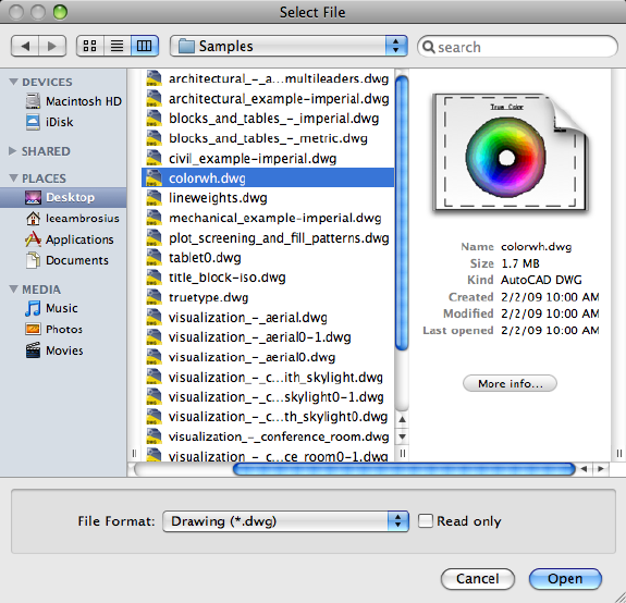
List of Options
The following options are displayed.
Task Pane
Provides access to categories that represent locations files might be stored in;
devices, shared and predefined places, and media. You can reorder the items
under a category by dragging them to a new position. To add a new item to
Places, drag a folder from the list. Changes to Places affect all standard file
selection dialog boxes.
Devices
Lists the local storage devices attached to your computer.
Shared
Lists the network location paths added to your computer.
Commands | 721
Places
Lists a number of predefined, user added, or Smart folders that are dependent
on your user profile.
Documents Displays the contents of the Documents folder for the current user
profile.
Desktop Displays the contents of your desktop.
Search For
Lists the files that you most recently searched for.
Media
Lists folders related to media located on your computer, such as photos or
movies.
Back
Returns to the previous file location.
Forward
Returns you to the file location before Back was clicked.
Views
Controls the appearance of the icons for the files and folders in the current
place, specifies whether to show a preview image when a file is selected.
Icon Displays each file or folder as an icon. The icons used are determined by
the operating system, or a thumbnail preview of the contents of a file might
be used.
List Displays a list of the files and folders. Folders can be expanded to show
the hierarchy of the files or folders they contain.
Column Displays a multi-column list with each column representing a folder
in the hierarchy of the contents on your computer. When a file is selected, a
preview and details of the file are displayed in the next available column.
Where
Displays the current folder or drive. Click the dropdown arrow to view the
hierarchy of the folder path, and to navigate to a previous folder, drive, or
recent place. The REMEMBERFOLDERS system variable controls whether the
last used paths in each standard file selection dialog box are stored across
sessions.
722 | Chapter 2 Commands
Search
Allows you to search for a file or folder located on the computer using
Spotlight. Search results can be saved as Smart folders under Places in the Task
Pane.
Files List
Displays the files and folders in the current place. Use the Views buttons to
control navigation behavior, and how files and folders are listed.
File Format
When you are opening or saving files, File Format specifies the format of the
files you can select for open or in which the file is saved.
Read Only
WIndicates if the file should be opened as read-only. You cannot save changes
to the file using the original file name.
Open/Save
Depending on the purpose of the specific file selection dialog box, opens or
saves the selected file or enters the path of the selected folder in the previous
dialog box..
New Folder
Creates a new folder in the current place using a name that you specify.
See also:
Save a Drawing
OPEN Command Prompt
Opens an existing drawing file.
When FILEDIA (page 1296) is set to 0 (zero), OPEN displays the following
Command prompt.
Enter name of drawing to open:
Enter ~ (tilde) at the prompt to ignore FILEDIA and display the Select File
dialog box, a standard file selection dialog box.
See also:
Open a Drawing
Commands | 723

OPTIONS
Customizes the program settings.
Access Methods
Menu: AutoCAD 2012 ➤ Preferences
Shortcut menu: With no commands active and no objects selected,
right-click in the drawing area. Click Preferences.
Summary
The Application Preferences dialog box (page 724) is displayed.
See also:
Set Up the Drawing Area
Application Preferences Dialog Box
Customizes the program settings.
List of Tabs
The Application Preferences dialog box includes the following tabs:
■General (page 725)
■Cursor & Selection (page 727)
■Units & Guides (page 730)
■Look & Feel (page 732)
■Application (page 734)
■Document Settings (page 739)
See also:
Set Up the Drawing Area
724 | Chapter 2 Commands
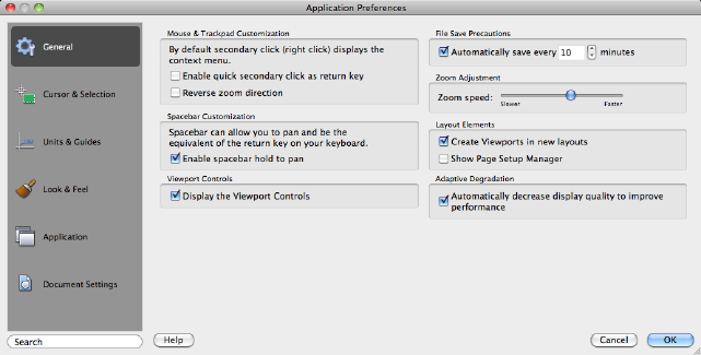
General Tab (Application Preferences Dialog Box)
Controls the behavior of program features.
List of Options
The following options are displayed.
Mouse & Trackpad Customization
Controls the behavior of the mouse or trackpad.
Enable Quick Secondary Click as Return Key Controls right-click behavior.
A quick click is the same as pressing Enter. A longer click displays a shortcut
menu. You can set the duration of the longer click in milliseconds.
(DBLCLKEDIT (page 1207) system variable)
Reverse Zoom Direction Toggles the direction of transparent zoom operations
when you scroll the middle mouse wheel. (ZOOMWHEEL (page 1530) system
variable)
Spacebar Customization
Controls the behavior of the spacebar when pressed or held.
Enable Spacebar Hold to Pan Toggles if you can hold down the Spacebar to
enable panning. (SPACEPAN (page 1444) system variable)
Viewport Controls
Controls the display of the menus in the upper-left corner of all viewports.
Commands | 725

Display the Viewport Controls Controls whether the menus for viewport
tools, views, and visual styles that are located in the upper-left corner of every
viewport are displayed. (VPCONTROL (page 1489) system variable)
File Save Precautions
Assists in avoiding data loss.
Automatic Save
Saves your drawing automatically at the intervals you specify. You can specify
the location of all Autosave files by using the SAVEFILEPATH (page 1423) system
variable.SAVEFILE (page 1422) (read-only) stores the name of the Autosave file.
NOTE Automatic save is disabled when the Block Editor (page 139) is open.
Minutes Between Saves: When Automatic Save is on, specifies how often the
drawing is saved.
(SAVETIME (page 1423) system variable)
Zoom Adjustment
Controls thezoom behavior of the input device.
Zoom Speed Controls how much the magnification changes when the mouse
wheel is rolled forward or backward, or you single swipe on Magic Mouse or
a trackpad. (ZOOMFACTOR (page 1529) system variable)
Layout Elements
Controls the tasks that the program performs when a new layout is created.
Create Viewports in New Layouts Creates a single viewport automatically
when you create a new layout. (LAYOUTCREATEVIEWPORT (page 1349) system
variable)
Show Page Setup Manager Displays the Page Setup Manager the first time
you click a named (paper space) layout. Use this dialog box to set options
related to paper and print settings. (SHOWPAGESETUPFORNEWLAYOUTS
(page 1432) system variable)
Adaptive Degradation
Controls settings related to configuration of the graphics display system.
Automatically decrease display quality to improve performance Controls
whether adaptive degradation is on or off. With adaptive degradation on, if
performance goes below a specified level, effects are disabled or reduced to
maintain an acceptable level of performance.
See also:
Set Up the Drawing Area
726 | Chapter 2 Commands
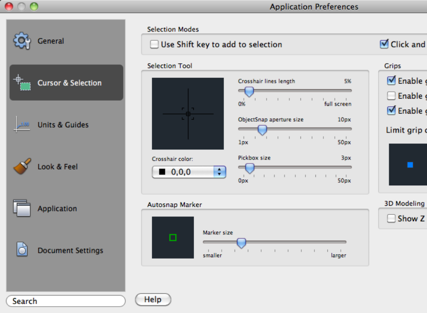
Cursor & Selection Tab (Application Preferences
Dialog Box)
Controls the appearance and behavior of the cursor and selection.
List of Options
The following options are displayed.
Selection Modes
Controls the selection of objects in the drawing area.
Use Shift Key to Add to Selection Controls whether subsequent selections
replace the current selection set or add to it.
Commands | 727
To clear a selection set quickly, draw a selection window in a blank area of
the drawing. (PICKADD (page 1392) system variable)
Click and Drag to Start Selection Controls the method of drawing a selection
window.
If this option is cleared, you can draw a selection window by selecting two
separate points with the pointing device. (PICKDRAG (page 1393) system variable)
Selection Tool
Controls the appearance of the cursor in the drawing area.
Preview Shows a representation of how the crosshair, ObjectSnap aperture,
and pickbox will appear in the drawing area.
Crosshair Color Controls the color of the crosshair, ObjectSnap aperture, and
pickbox in the drawing area. Automatic is the default color.
When set to Automatic, the actual color applied changes between white and
black based on the background color of the drawing area.
Crosshair Lines Length Determines the size of the crosshairs as a percentage
of the screen size.
Valid settings range from 1 to 100 percent. When set to 100, the crosshairs
are full-screen and the ends of the crosshairs are never visible. When less than
100, the ends of the crosshairs may be visible when the cursor is moved to
one edge of the screen. (CURSORSIZE (page 1206) system variable)
ObjectSnap Aperture Size Sets the display size for the object snap target box,
in pixels.
Aperture size determines how close to a snap point you can be before the
magnet locks the aperture box to the snap point. Values range from 1 to 50
pixels. (APERTURE (page 69) system variable)
Pickbox Size Sets the object selection target height, in pixels. (PICKBOX (page
1393) system variable)
Autosnap Marker
Controls the appearance of the Autosnap Marker.
Marker Size Sets the display size for the AutoSnap marker.
Grips
Grips are small squares displayed on an object after it has been selected.
Enable Grips Controls the display of grips on selected objects. You can edit
an object with grips by selecting a grip and using the shortcut menu. Displaying
grips in a drawing significantly affects performance. Clear this option to
optimize performance. (GRIPS (page 1311) system variable)
728 | Chapter 2 Commands
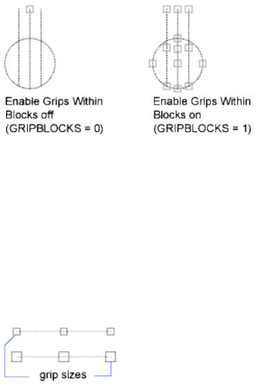
Enable Grips with Blocks Controls the display of grip tips and Ctrl-cycling
tooltips. (GRIPBLOCK (page 1307) system variable)
Enable Grips Tips Controls the display of grip tips and Ctrl-cycling tooltips.
This option has no effect on standard objects. (GRIPTIPS (page 1312) system
variable)
Limit Grip Display To N Selected Objects Suppresses the display of grips
when the selection set includes more than the specified number of objects.
The valid range is 1 to 32,767. The default setting is 100. (GRIPOBJLIMIT (page
1310) system variable)
Grip Size Sets the size of the grip box in pixels. (GRIPSIZE (page 1311) system
variable)
3D Modeling Dynamic Input
Controls dynamic input in 3D.
Show Z Field for Pointer Input Displays a field for the Z coordinate when
using dynamic input.
See also:
Set Up the Drawing Area
Commands | 729
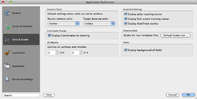
Units & Guides Tab (Application Preferences
Dialog Box)
Controls the units used when inserting blocks or referencing objects, and
which drafting guides are enabled.
List of Options
The following options are displayed.
Insertion Scale
Controls the default scale for inserting blocks and drawings into a drawing.
Source Content Units Sets source content units value when INSUNITS is set
to 0.
If Unspecified-Unitless is selected, the object is not scaled when inserted.
(INSUNITSDEFSOURCE (page 1336) system variable)
Target Drawing Units Sets target drawing units value when INSUNITS is set
to 0. (INSUNITSDEFTARGET (page 1338) system variable)
Coordinate Display
Controls the display of the coordinates display.
Display Coordinates on Drawing Toggles the coordinates display in the
lower-right corner of the drawing area. (VPCOORDDISPLAY (page 1489) system
variable)
3D Objects
Controls the number of isolines to display for surfaces and meshes.
730 | Chapter 2 Commands
U Size Sets the surface density for PEDIT Smooth in the M direction and the
U isolines density on surface objects. (SURFU (page 1455) system variable)
V Size Sets the surface density for PEDIT Smooth in the N direction and the
V isolines density on surface objects. (SURFV (page 1455) system variable)
AutoTrack Settings
Controls the settings that relate to AutoTrack™ behavior, which is available
when polar tracking or object snap tracking is turned on (see DSETTINGS
(page 363)).
Display Polar Tracking Vector Displays a vector along specified angles when
polar tracking is on. With polar tracking, you can draw lines along angles.
Polar angles are 90-degree divisors, such as 45, 30, and 15 degrees. (TRACK-
PATH (page 1470) system variable = 2)
In a 3D view, a polar tracking vector parallel to the Z axis of the UCS is also
displayed, and the tooltip displays +Z or -Z for the angle depending on the
direction along the Z axis.
Display Full-screen Tracking Vector Tracking vectors are construction lines
from which you can draw objects at specific angles or in specific relationships
to other objects. If this option is selected, alignment vectors are displayed as
infinite lines. (TRACKPATH system variable = 1)
Display AutoTrack Tooltip Controls the display of the AutoSnap marker,
tooltip, and magnet. (AUTOSNAP (page 1180) system variable)
Drawing Scale
Defines the default scales used by the program.
Default Scales List Displays the Default Scale List dialog box (page 741). Use
this dialog box to manage the default list of scales displayed in several dialog
boxes associated with layout viewports and printing. You can delete all custom
scales and restore the default list of scales.
Fields
Sets preferences related to fields.
Display Background of Fields Controls whether fields are displayed with a
gray background.
When this option is cleared, fields are displayed with the same background
as any text. (FIELDDISPLAY (page 1295) system variable)
See also:
Set Up the Drawing Area
Commands | 731
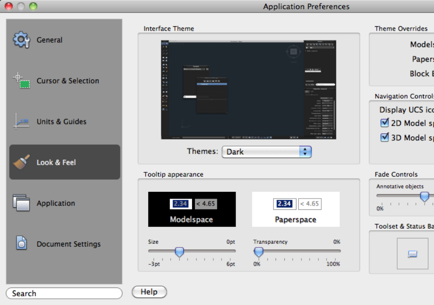
Look & Feel Tab (Application Preferences Dialog
Box)
Controls the appearance of the program user interface.
List of Options
The following options are displayed.
Interface Theme
Defines the color scheme for the user interface.
Themes Controls which theme to apply to elements such as the status bar,
palettes, and the drawing windows. You can choose from a Dark or Light
theme.
732 | Chapter 2 Commands
Tooltip Appearance
Controls the appearance of drafting tooltips.
Size Specifies a size for tooltips. The default size is 0. Use the slider to make
tooltips larger or smaller.
Transparency Controls the transparency of tooltips. The lower the setting,
the less transparent the tooltip. A value of 0 sets the tooltip to opaque.
Interface Overrides
Overrides used to fine tune the colors applied to the background of the drawing
area.
Model Space Specifies the background color of the drawing area when the
Model layout is active. Choose a color or Select Color to specify one of the
non-standard colors.
Paper Space Specifies the background color of the drawing area when a named
(paper space) layout is active.
Block Editor Specifies the background color of the drawing area when the
Block Editor environment is active.
Navigation Controls
Controls the display of the ViewCube and the UCS icon.
Display UCS Icon in Controls when the UCS icon should be displayed in a
viewport.
■2D Model Space - Display UCS icon when the 2D Wireframe visual style
is current.
■3D Model Space - Display UCS icon when a 3D visual style is current.
Display ViewCube in Controls when the ViewCube tool should be displayed
in a viewport.
■2D Model Space - Display the ViewCube tool when the 2D Wireframe
visual style is current.
■3D Model Space - Display the ViewCube tool when a 3D visual style is
current.
ViewCube Settings
Displays the ViewCube Settings dialog box (page 709).
Fade Controls
Controls the fading intensity value for annotative objects and xrefs.
Commands | 733
Annotative Objects Specifies the fading intensity value for objects during
in-place reference editing. Objects that are not being edited are displayed at
a lesser intensity. (XFADECTL (page 1526) system variable)
With in-place reference editing, you can edit a block reference or external
reference from within the current drawing. The valid range is 0 through 90
percent.
Xrefs Controls the dimming for all DWG xref objects. (XDWGFADECTL (page
1525) system variable)
This option only affects the display on the screen. It does not affect plotting
or plot preview.
Tool Set & Status Bar Icons
Controls the size of the icons used in parts of the user interface.
Icon Size Specifies the size of the icons displayed on the Tool Sets palette and
status bar. (ICONSIZE (page 1331) system variable)
See also:
Set Up the Drawing Area
Application Tab (Application Preferences Dialog
Box)
Lists the folders in which the program searches for support, driver, menu, and
other files. Also lists optional, user-defined settings such as which dictionary
to use for checking spelling.
734 | Chapter 2 Commands
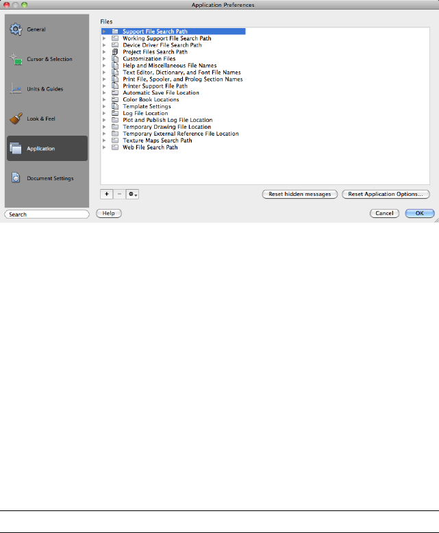
List of Options
The following options are displayed.
Support File Search Path
Specifies the folders in which the program should look for text fonts,
customization files, plug-ins, drawings to insert, linetypes, and hatch patterns
that are not in the current folder.
Working Support File Search Path
Displays the active directories that the program searches for support files
specific to your system. The list is read-only and displays valid paths from the
Support Files Search Path that exist within the current directory structure and
network mappings.
Device Driver File Search Path
Specifies the search path for device drivers for the video display, pointing
devices, printers, and plotters.
WARNING Do NOT remove DRV path and always add paths as secondary paths.
Project Files Search Path
Specifies a project name for the drawing. The project name corresponds to a
search path for external reference (xref) files associated with the project. You
can create any number of project names with associated folders, but each
drawing can have only one project name.
Customization Files
Specifies the names and locations of various types of files.
Commands | 735
Main Customization File Specifies the default location of the main
customization file (acad.cuix).
Custom Icon Location Specifies the location for custom icons referenced by
your customization files.
Command Aliases Specifies the location of the PGP file that should be loaded
when AutoCAD for Mac is started.
Help and Miscellaneous File Names
Specifies the names and locations of various types of files.
Help File Specifies the location of the local Help file. (HELPPREFIX (page 1317)
system variable)
Default Internet Location Specifies the default Internet location used by the
BROWSER (page 158) command.
Configuration File Specifies the location of the configuration file used to
store hardware device driver information.
Text Editor, Dictionary, and Font File Names
Specifies a number of optional settings.
Alternate Font File Specifies the alternate font to be used when the specified
font file cannot be located. ( FONTALT (page 1298) system variable)
If you click Browse, the Alternate Font dialog box (page 740) is displayed, from
which you can choose an available font.
Font Mapping File Specifies the font mapping file to be used. ( FONTMAP
(page 1299) system variable)
Print File, Spooler, and Prolog Section Names
Specifies settings related to plotting.
Plot File Name for Legacy Plotting Scripts Specifies a default name for the
temporary plot files used with plotting scripts created with AutoCAD Release
14 or earlier. The default name is the drawing name plus the .plt file extension.
The default name used with AutoCAD 2000 and later drawings is the drawing
name-layout name plus the .plt file name extension. Some plotting device
drivers, however, use a different plot file extension.
Print Spool Executable Specifies the application to use for print spooling.
You can enter the executable file name as well as any command line arguments
you want to use. For example, you can enter myspool.bat %s to spool print
files to myspool.bat and have a unique print file name automatically generated.
736 | Chapter 2 Commands
PostScript Prolog Section Name Present for legacy reasons only. Autodesk
has dropped active support of PostScript and the PSIN, PSOUT, and PSPROLOG
commands.
Printer Support File Path
Specifies search path settings for printer support files.
Print Spooler File Location Specifies the path for print spool files.
Printer Configuration Search Path Specifies the path for printer configuration
files.
Printer Description File Search Path Specifies the path for files with a .pmp
file extension, or printer description files.
Plot Style Table Search Path Specifies the path for files with an .stb or .ctb
extension, or plot style table files (both named plot style tables and
color-dependent plot style tables).
Automatic Save File Location
Specifies the path for the file created when you select Automatically Save on
the General tab. (SAVEFILEPATH (page 1423) system variable)
Color Book Locations
Specifies the path for color book files that can be used when specifying colors
in the Color Palette dialog box (page 198). You can define multiple folders for
each path specified. This option is saved with the user profile.
Template Settings
Specifies the drawing template settings.
Drawing Template File Location Specifies the path to locate drawing template
files used by the Select Template dialog box.
Default Template File Name for QNEW Specifies the drawing template file
used by the QNEW (page 860) command.
Log File Location
Specifies the path for the log file created when you select Maintain a Log File
on the Open and Save tab. (LOGFILEPATH (page 1362) system variable)
Plot and Publish Log File Location
Specifies the path for the log file that is created when you use the PLOT (page
792) command.
Temporary Drawing File Location
Specifies the location to store temporary files. This program creates temporary
files and then deletes them when you exit the program. If you plan to run the
program from a write-protected folder (for example, if you are working on a
Commands | 737
network or opening files from a CD), specify an alternate location for your
temporary files. The folder you specify must not be write-protected.
A character limit of 255 for the combined file name and path length of
temporary files is used.
The TEMPPREFIX (page 1460) system variable (read-only) stores the current
location of temporary drawing files.
Temporary External Reference File Location
Creates a path for storing temporary copies of demand-loaded xref files.
(XLOADPATH (page 1527) system variable)
Texture Maps Search Path
Specifies the folders to search for rendering texture maps.
Web File Search Path
Specifies the folders to search for photometric web files.
Add
Adds a search path for the selected folder.
Remove
Removes the selected search path or file.
Options
Edits or changes the order of a selected path.
Change Path Displays the Browse for Folder or Select a File dialog box,
depending on what you selected in the Files list.
Move Item Up Moves the selected search path above the preceding search
path.
Move Item Down Moves the selected search path below the following search
path.
Set as Current Makes the selected project or spelling dictionary current.
Reset Hidden Messages
Resets the display of all message boxes that you marked to not display again
or to always use a specified option in them.
Reset Application Options
Displays the Reset Application Options dialog box. Click Restart AutoCAD to
restore the program defaults.
Before the program is reset, many of the files that you can customize are backed
up to an archive file with the naming convention of Settings Backup <Date>
<Time>.tgz. The archive file is saved to /Users/<user name>/Library/Application
Support/Autodesk.
738 | Chapter 2 Commands
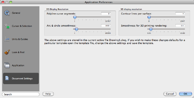
The archive contains many of the customization files located in the following
folders:
■/Users/<user name>/Library/Application Support/Autodesk/local/AutoCAD 2012
■/Users/<user name>/Library/Application Support/Autodesk/roaming/AutoCAD
2012
See also:
Set Up the Drawing Area
Document Settings Tab (Application Preferences
Dialog Box)
Controls the display settings for a drawing.
List of Options
The following options are displayed.
2D Display Resolution
Controls the display of 2D objects.
Polyline Curve Segments
Sets the number of line segments to be generated for each spline-fit polyline
generated by the Spline option of the PEDIT command. (SPLINESEGS (page
1446) system variable)
Commands | 739
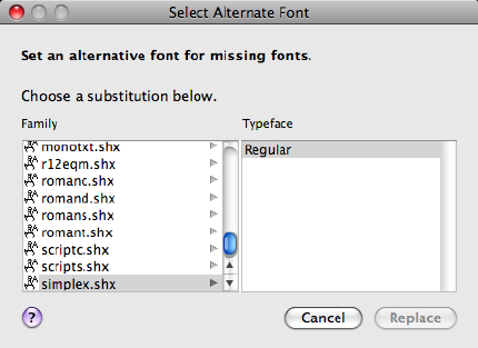
Arc & Circle Smoothness
Sets the resolution for objects in the current viewport. (VIEWRES (page 1108)
command)
3D Display Resolution
Controls the display of 3D objects.
Contour Lines per Surface
Specifies the number of contour lines per surface on objects. (ISOLINES (page
1343) system variable)
Smoothness for 3D Printing and Rendering
Adjusts the smoothness of shaded and rendered objects and objects with
hidden lines removed. (FACETRES (page 1295) system variable)
See also:
Set Up the Drawing Area
Select Alternate Font Dialog Box
Specifies the location of the font file to use if the original font cannot be
located and an alternate font is not specified in the font mapping file.
Access Methods
Pointing device: Application Preferences dialog box, Application tab
740 | Chapter 2 Commands

Summary
You can also set the location of Alternate Font File by using the FONTALT
(page 1298) system variable.
If you do not specify an alternate font, when you open a drawing containing
fonts that cannot be located, a dialog box is displayed in which you specify
a font to use for each missing font.
List of Options
The following options are displayed.
Font Name
Lists the font family name for all registered TrueType fonts and all SHX fonts
in the Fonts folder.
Font Style
Specifies font character formatting, such as italic, bold, or regular. If the missing
font is a Big Font, this option changes to Big Font and lists all available
Asian-language Big Font files.
See also:
Substitute Fonts
Default Scale List Dialog Box
Controls the default list of scales stored in the registry.
Access Methods
Pointing device: Application Preferences dialog box, Units & Guides tab
Summary
When the scale list in a drawing is reset, the list is restored to the default list
of scales defined in the Default Scale List dialog box.
NOTE To control the list of scales for the current drawing, use the SCALELISTEDIT
(page 918) command. After you add a new scale to the default scale list in the
registry, you can use the Reset button in the Edit Drawing Scales dialog box to
add the new scale to your drawing.
Commands | 741
List of Options
The following options are displayed.
Scale List
Metric Displays the default list of metric scales.
Imperial Displays the default list of imperial scales.
If a scale name is duplicated, but has a different value, a number is appended
to the name.
Add
Creates a new scale in the scale list.
Press Tab to move between the fields of the scale being edited.
Delete
Removes the selected scale from the scale list.
Options
Manages items in the scale list.
Edit Edits the selected scale in-place in the scale list.
Press Tab to move between the fields of the scale being edited.
Reset Deletes all custom scales and restores the default list of scales defined
in AutoCAD for Mac.
See also:
Scale Views in Layout Viewports
ORTHO
Constrains cursor movement to the horizontal or vertical direction.
Access Methods
Menu: Tools ➤ Drafting Settings
Toolbar: Status bar ➤ Ortho
Command entry: F8
Command entry: 'ortho for transparent use
742 | Chapter 2 Commands
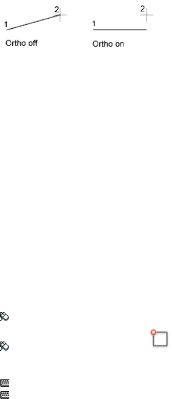
Summary
In the illustration, a line is drawn using Ortho mode. Point 1 is the first point
specified, and point 2 is the position of the cursor when the second point is
specified.
Ortho mode is used when you specify an angle or distance by means of two
points using a pointing device. In Ortho mode, cursor movement is constrained
to the horizontal or vertical direction relative to the UCS.
Horizontal is defined as being parallel to the X axis of the UCS and vertical
as being parallel to the Y axis.
In a 3D view, ORTHO is additionally defined as being parallel to the Z axis of
the UCS, and the tooltip displays +Z or -Z for the angle depending on the
direction along the Z axis.
See also:
Use Orthogonal Locking (Ortho Mode)
OSNAP
Sets running object snap modes.
Access Methods
Menu: Tools ➤ Drafting Settings
Toolbar: Status bar ➤ Osnap
Shortcut menu: Press Shift while right-clicking in the drawing area and
choose Osnap Settings.
Command entry: F3
Command entry: 'osnap for transparent use
Summary
The Object Snap tab of the Drafting Settings dialog box (page 364) is displayed.
Commands | 743
If you enter -osnap at the Command prompt, the following prompts are
displayed.
List of Prompts
The following prompts are displayed.
Current osnap modes: current
Enter list of object snap modes (page ?): Enter names of object
snap modes separated with commas, or enternoneoroff
Object Snap Modes
Specify one or more object snap modes by entering the first three characters
of the name. If you enter more than one name, separate the names with
commas.
TANgentCENterENDpoint
NEArestNODeMIDpoint
PARallelQUAdrantINTersection
INSertionEXTension
PERpendicularAPParent Intersection
For a description of each of these object snap modes, see the Object Snaps tab
of the Drafting Settings dialog box (page 364).
QUIck Snaps to the first snap point found. Quick must be used in conjunction
with other object snap modes.
NONe Turns off object snap modes.
See also:
Use Object Snaps
OVERKILL
Removes duplicate or overlapping lines, arcs, and polylines. Also, combines
partially overlapping or contiguous ones.
744 | Chapter 2 Commands

Access Methods
Button
Toolbar: Drafting tool set ➤ Explode tool set ➤ Delete Duplicate Objects
Menu: Modify ➤ Delete Duplicate Objects
Summary
Displays the Delete Duplicate Objects dialog box (page 745).
Removes redundant geometry.
■Duplicate copies of objects are deleted
■Arcs drawn over portions of circles are deleted
■Lines, partially overlapping, drawn at the same angle are combined into
a single line
■Duplicate line or arc segments overlapping polyline segments are deleted
If you enter -overkill at the Command prompt, options are displayed.
See also:
Erase Objects
Delete Duplicate Objects Dialog Box
Removes duplicate geometry as well as overlapping lines, arcs, and polylines.
Also, combines partially overlapping or contiguous ones.
Commands | 745
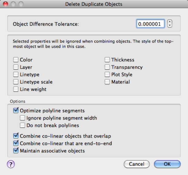
List of Prompts
Object Difference Tolerance
Controls the precision with which OVERKILL makes numeric comparisons.
If this value is 0, the two objects being compared must match before OVERKILL
modifies or deletes one of them.
Ignore Object Property:
Use these settings to determine which object properties are ignored during
comparison.
Color Object color is ignored.
Layer Object layers are ignored.
Linetype Object linetypes are ignored.
Linetype Scale Object linetype scale is ignored.
Lineweight Object lineweight is ignored.
746 | Chapter 2 Commands
Thickness Object thickness is ignored.
Transparency Object transparency is ignored.
Plot style Object plot style is ignored.
Material Object material is ignored.
Options
Use these settings to control how OVERKILL deals with lines, arcs, and
polylines.
Optimize polyline segments When selected, individual line and arc segments
within selected polylines are examined. Duplicate vertices and segments are
removed.
Also, OVERKILL compares individual polyline segments with completely
separate line and arc segments. If a polyline segment duplicates a line or arc
object, one of them is deleted.
If this option is not selected, polylines are compared as discreet objects and
two sub-options are not selectable.
■Ignore polyline segment width. Ignores segment width, while
optimizing polyline segments.
■Do not break polylines. Polyline objects are unchanged.
Combine co-linear objects that partially overlap Overlapping objects are
combined into single objects.
Combine co-linear objects when aligned end-to-end Objects that have
common endpoints are combined into single objects.
Maintain associative objects Associative objects are not deleted or modified.
See also:
Erase Objects
-OVERKILL
Removes duplicate or overlapping lines, arcs, and polylines. Also, combines
partially overlapping or contiguous ones.
List of Prompts
The following prompts are displayed.
Commands | 747
Select objects: Use an object selection method
Enter an option to change [Ignore (page 748)/tOlerance (page
748)/optimize Plines (page 748)/combine parTial overlap (page
748)/combine Endtoend (page 749)/Associativity (page 749)]
<done>:
List of Options
Ignore
Ignores one or more of the following properties during object comparison
■None
■All
■Color
■LAyer
■Ltype
■Ltscale
■LWeight
■Thickness
■TRansparency
■plotStyle
■Material
Tolerance Defines the value within which OVERKILL makes numeric
comparisons for determining object duplication.
Optimize Polylines Optimize segments within plines [segment wiDth/Break
polyline/Yes/No] <Yes>:
■Segment Width: ignore polyline segment width
■Break Polyline: maintains polylines when optimizing polyline segments
■Yes: Enabled by default. Honors polylines as discreet objects and deletes
non-polyline objects that overlap polylines.
■No: Forces OVERKILL to examine polyline segments individually. Polyline
segments may be deleted as duplicates of non-polyline objects.
Combine Partial Overlap Overlapping objects area combined into single
objects.
748 | Chapter 2 Commands

Combine End to End Objects that have common endpoints are combined
into single objects.
Associativity Associative objects are not deleted or modified.
See also:
Erase Objects
P Commands
PAGESETUP
Controls the page layout, plotting device, paper size, and other settings for
each new layout.
Access Methods
Menu: File ➤ Page Setup Manager
Toolbar: Status bar ➤ Quick View. In the Quick View dialog box,
right-click a layout and click Page Setup.
Summary
The Page Setup Manager (page 749) is displayed.
A page setup is a collection of plot device and other settings that determine
the appearance and format of your final output. These settings are stored in
the drawing file and can be modified and applied to other layouts.
See also:
Specify Page Setup Settings
Page Setup Manager
Specifies the page setup for the current layout or drawing sheet.
Commands | 749

Summary
You can also create named page setups, modify existing ones, or import page
setups from other drawings.
List of Options
The following options are displayed.
Current Layout
Lists the current layout to which the page setup will be applied.
Page Setups
Displays the current page setup, sets a different page setup as current, creates
a new page setup, modifies an existing page setup, and imports page setups
from other drawings.
750 | Chapter 2 Commands
Current Page Setup
Indicated by a triangle to the left of the page setup name.
Page Setup List
Lists the page setups that are available to apply to the current layout.
The list includes the named and default layout page setups that are available
in the drawing. Double-click the column to the left of a page setup in this list
to set it as the current page setup for the current layout or double-click in the
Page Setups column to rename a page setup.
Create a New Page Setup (+)
Displays the New Page Setup dialog box (page 752), in which you can enter a
name for the new page setup and specify the page setup to use as a starting
point.
Delete the Selected Page Setup (-) Removes the selected page setup.
A page setup assigned to a layout or is the default page setup for a layout
cannot be removed.
Settings
Allows you to manage and import page setups.
Edit
Displays the Page Setup dialog box (page 753) in which you can modify the
settings for the selected page setup.
Set Current Sets the selected page setup as the current page setup for the
current layout.
You cannot set the current layout as the current page setup.
Rename Allows you to change the name of the selected page setup.
You cannot rename the default page setups for a named layout.
Delete Removes the selected page setup.
A page setup assigned to a layout or is the default page setup for a layout
cannot be removed.
Import
Displays the Select Page Setup From File dialog box (a standard file selection
dialog box), in which you can select a drawing format (DWG), DWT, or
drawing interchange format (DXF)™ file from which to import one or more
page setups.
Commands | 751
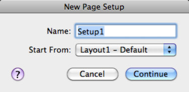
If you select DWT as the file type, the Template folder opens automatically
in the Select Page Setup From File dialog box. When you click Open, the Import
Page Setups dialog box (page 759) is displayed.
Details
Displays information about the selected page setup.
Device Name
Displays the name of the output device specified in the currently selected page
setup.
Printer
Displays the type of output device specified in the currently selected page
setup.
Page Size
Displays the paper size and orientation specified in the currently selected page
setup.
Where Displays the physical location of the output device specified in the
currently selected page setup.
Description
Displays descriptive text about the output device specified in the currently
selected page setup.
See also:
Specify Page Setup Settings
New Page Setup Dialog Box
Specifies a name for the new page setup, as well as the page setup to use as a
starting point.
752 | Chapter 2 Commands
List of Options
The following options are displayed.
New Page Setup Name
Specifies the name for the new page setup.
Start From
Specifies a page setup to use as a starting point for the new page setup. When
you click Continue, the Page Setup dialog box (page 753) is displayed with the
settings of the selected page setup, which you can modify as necessary.
<Default Output Device> Specifies that the default output device is set as the
printer in the new page setup.
See also:
Specify Page Setup Settings
Page Setup Dialog Box
Specifies page layout and plotting device settings.
Commands | 753
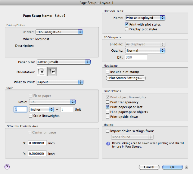
Summary
The Page Setup dialog box is displayed in the following cases:
■When you create a new page setup through the Page Setup Manager (page
749)
■When you modify an existing page setup through the Page Setup Manager
(page 749)
■When you modify an existing page setup through the Print dialog box
The page setup settings that you specify are stored with the layout and can
be applied to other layouts or imported into other drawings.
List of Options
The following options are displayed.
754 | Chapter 2 Commands

Page Setup Name
Displays the name of the current page setup.
Printer/Plotter
Specifies a configured output device to use when printing layouts.
Printer Lists the available system printers from which you can select to print
the current layout.
Where Displays the physical location of the output device specified in the
currently selected page setup.
Description Displays descriptive text about the output device specified in the
currently selected page setup.
Paper Size
Displays standard paper sizes that are available for the selected plotting device.
If the selected plotter does not support the layout's selected paper size, a
warning is displayed, and you can select the plotter's default paper size or a
custom paper size.
Orientation
Specifies the orientation of the drawing on the paper for plotters that support
landscape or portrait orientation.
Portrait
Orients and plots the drawing so that the short edge of the paper represents
the top of the page.
Landscape
Orients and plots the drawing so that the long edge of the paper represents
the top of the page.
NOTE The orientation of plots is also affected by the PLOTROTMODE (page 1398)
system variable.
What to Print
Specifies the area of the drawing to be plotted.
Display Plots the view in the current viewport in the current layout.
Extents Plots the portion of the current space of the drawing that contains
objects. All geometry in the current layout is plotted. The drawing may be
regenerated to recalculate the extents before plotting.
Window Plots any portion of the drawing that you specify. When you specify
the two corners of the area to plot, the Window button becomes available.
Commands | 755

Click the Window button to use the pointing device to specify the two corners
of the area to be plotted, or enter coordinate values.
Model/Layout Views Plots a view that was previously saved with the -VIEW
(page 1104) command.
Layout/Limits When plotting a layout, plots everything within the printable
area of the specified paper size, with the origin calculated from 0,0 in the
layout.
When plotting from the Model layout, plots the entire drawing area that is
defined by the grid limits. If the current viewport does not display a plan view,
this option has the same effect as the Extents option.
Scale
Controls the relative size of drawing units to plotted units.
NOTE If the Layout option is specified in What to Print, the layout is plotted at
1:1 regardless of the setting specified in Scale.
Fit to Paper Scales the plot to fit within the selected paper size and displays
the custom scale factor in the Scale, Inch =, and Units boxes.
Scale Defines the exact scale for the output. Custom defines a user-defined
scale. You can create a custom scale by entering the number of inches (or
millimeters) equal to the number of drawing units.
NOTE You can modify the list of scales with SCALELISTEDIT (page 918).
Inch(es) =/mm = Specifies the number of inches or millimeters equal to the
specified number of units.
Inch/mm Specifies inches or mm for display of units. The default is based on
the paper size and changes each time a new paper size is selected.
Unit Specifies the number of units equal to the specified number of inches
or millimeters.
Scale Lineweights Scales lineweights in proportion to the plot scale.
Lineweights normally specify the line width of output objects and are output
with the line width size regardless of the scale.
Offset for Printable Area
Specifies an offset of the plot area relative to the lower-left corner of the
printable area or to the edge of the paper, depending on the value of the
PLOTOFFSET (page 1397) system variable.
756 | Chapter 2 Commands
The printable area of a drawing sheet is defined by the selected output device
and is represented by a dashed line in a layout. When you change to another
output device, the printable area may change.
You can offset the geometry on the paper by entering a positive or negative
value in the X and Y offset boxes. The plotter unit values are in inches or
millimeters on the paper.
Center on Page Automatically calculates the X and Y offset values to center
the plot on the paper.
X Specifies the plot origin in the X direction relative to the value of
PLOTOFFSET.
Y Specifies the plot origin in the Y direction relative to the value of
PLOTOFFSET.
More/Fewer Options
Expands or collapses the dialog box to show or hide additional output options.
Plot Style Table
Sets the plot style table to use with the page setup.
Name Displays a list of available plot style tables.
Print with Plot Styles Specifies whether plot styles applied to objects and
layers are printed.
Display Plot Styles Controls whether the properties of plot styles assigned to
objects are displayed on the screen.
3D Viewports
Specifies how shaded and rendered viewports are plotted and determines their
resolution levels and dots per inch (dpi).
Shading Specifies how views are plotted. To specify this setting for a viewport
on a layout tab, select the viewport and then, on the Mac OS menu bar click
Tools ➤ Palettes ➤ Properties.
From the Model layout, you can select from the following options:
■As Displayed: Plots objects the way they are displayed on the screen.
■Legacy Wireframe: Plots objects in wireframe regardless of the way they
are displayed on the screen.
■Legacy Hidden: Plots objects with hidden lines removed regardless of
the way they are displayed on the screen.
■Conceptual: Plots objects with the Conceptual visual style applied
regardless of the way the objects are displayed on the screen.
Commands | 757
■Hidden: Plots objects with the Hidden visual style applied regardless of
the way the objects are displayed on the screen.
■Realistic: Plots objects with the Realistic visual style applied regardless
of the way the objects are displayed on the screen.
■Shaded: Plots objects with Shaded visual style applied regardless of the
way the objects are displayed on the screen.
■Shaded with Edges: Plots objects with Shaded with Edges visual style
applied regardless of the way the objects are displayed on the screen.
■Shades of Gray: Plots objects with Shades of Gray visual style applied
regardless of the way the objects are displayed on the screen.
■Sketchy: Plots objects with Sketchy visual style applied regardless of the
way the objects are displayed on the screen.
■Wireframe: Plots objects with the Wireframe visual style applied
regardless of the way the objects are displayed on the screen.
■X-ray: Plots objects with x-ray visual style applied regardless of the way
the objects are displayed on the screen.
Quality Specifies the resolution at which shaded viewports are plotted.
You can select from the following options:
■Draft: Sets rendered and shaded model space views to be plotted as
wireframe.
■Preview: Sets rendered and shaded model space views to be plotted at
one quarter of the current device resolution, to a maximum of 150 dpi.
■Normal: Sets rendered and shaded model space views to be plotted at one
half of the current device resolution, to a maximum of 300 dpi.
■Presentation: Sets rendered and shaded model space views to be plotted
at the current device resolution, to a maximum of 600 dpi.
■Maximum: Sets rendered and shaded model space views to be plotted at
the current device resolution with no maximum.
■Custom: Sets rendered and shaded model space views to be plotted at the
resolution setting that you specify in the DPI box, up to the current device
resolution.
DPI Specifies the dots per inch for shaded and rendered views, up to the
maximum resolution of the current plotting device.
Plot Stamp
Controls the placement of a plot stamp on each layout and/or logs it to a file.
758 | Chapter 2 Commands
Plot stamp settings are specified in the Plot Stamp Settings dialog box (page
801), in which you can specify the information that you want applied to the
plot stamp, such as drawing name, date and time, plot scale, and so on.
Include Plot Stamp Turns on plot stamping for the layout.
Plot Stamp Settings Displays the Plot Stamp Settings dialog box when Include
Plot Stamp is selected.
Print Options
Specifies options for lineweights, transparency, and the order in which objects
are plotted.
Print Object Lineweights Specifies whether lineweights assigned to objects
and layers are printed.
Print Transparency Specifies whether object transparency is printed. This
option should only be used when printing drawings with transparent objects.
Print Paper Space Last Prints model space geometry first. Paper space geometry
is usually printed before model space geometry.
Hide Paper Space Objects Specifies whether the HIDE (page 506) operation
applies to objects in the paper space viewport. This option is available only
from a named (paper space) layout. This setting is reflected in the output, but
not in the display of the layout.
Print Upside Down Orients and prints the drawing upside-down.
Sharing
Allows you to import settings from a PC3 file.
Import Device Settings From Enables importing of settings from a PC3 file.
PC3 Files List Lists the available PC3 files that you can select from to import
print settings file.
The program looks in the location specified by the value in Printer Support
File Path ➤ Printer Configuration Search Path under Application in the Ap-
plication Preferences dialog box (page 724).
See also:
Specify Page Setup Settings
Import Page Setups Dialog Box
Displays the page setups in the selected drawing that are available to import.
Commands | 759
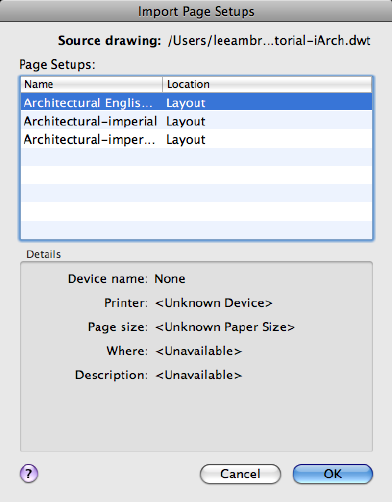
Summary
List of Options
The following options are displayed.
Source Drawing
Displays the source drawing that contains the listed page setups that are
available to import.
Page Setups
Lists the page setups that are available to import and their location in the
source drawing. Selected page setups are imported into the current drawing
when you click OK.
When you import page setups into a page setup overrides file for a sheet set,
only page setups with Plot Area set to Layout or Extents are listed.
Name Specifies the name of the page setup available to import.
Location Specifies the location (Model or named layout) of the page setup in
the drawing from which you are importing the page setup.
760 | Chapter 2 Commands

Details
Displays information about the selected page setup.
Device Name
Displays the name of the plot device specified in the currently selected page
setup.
Printer
Displays the type of output device specified in the currently selected page
setup.
Page Size
Displays the paper size and orientation specified in the currently selected page
setup.
Where
Displays the physical location of the output device specified in the currently
selected page setup.
Description
Displays descriptive text about the output device specified in the currently
selected page setup.
See also:
Specify Page Setup Settings
PAGESETUPEDIT
Edits the page setup settings for the current layout, Model or named.
Access Methods
Toolbar: Layout visor ➤ Edit Page Setup
Shortcut menu: Right-click the drawing area when a named layout is current
and click Edit Page Setup.
Summary
The Page Setup dialog box is displayed.
Commands | 761

See also:
Specify Page Setup Settings
PALETTEICONOFF
Restores the display of all palettes collapsed by PALETTEICONON.
Access Methods
Menu: Tools ➤ Palettes ➤ Show Palettes as Icons
Menu: Window ➤ Show Full Palettes
Toolbar: On a palette, in the upper-right corner, click the Collapse as
Icons/Show as Palettes button
Shortcut menu: Right-click the palette bar and choose Show as Palettes
See also:
Specify the Behavior of Palettes
PALETTEICONON
Collapses all open palettes, except command line and status bar, to a small
bar displayed along the left or right side of the screen.
Access Methods
Menu: Tools ➤ Palettes ➤ Show Palettes as Icons
Menu: Window ➤ Show Palettes as Icons
Toolbar: On a palette, in the upper-right corner, click the Collapse as
Icons/Show as Palettes button
Shortcut menu: Right-click the title bar of a palette and choose Collapse as
Icons (Left), Collapse as Icons (Right)
Summary
All open palettes with the exception of the command line and status bar are
collapsed to an icon state. While icon state is active, each additional palette
opened is added to the palette bar that is displayed along the left or right side
of the screen.
762 | Chapter 2 Commands
Click a button on the bar to display the associated palette. The palette will
remain open until you click the button again or click a different button on
the palette bar. Use the PALETTEICONOFF (page 762) command to return to
palette state.
See also:
Specify the Behavior of Palettes
PAN
Moves the view planar to the screen.
Access Methods
Menu: View ➤ Pan ➤ Realtime
Toolbar: Status bar ➤ Pan
Shortcut menu: With no objects selected, right-click in the drawing area
and click Pan.
Summary
You can pan the drawing display in real time (page 764).
List of Prompts
The following prompts are displayed.
Press Esc or Enter to exit, or right-click to display a
shortcut menu (page 765).
If you enter -pan at the Command prompt, PAN displays command prompts
(page 764), and you can specify a displacement to pan the drawing display.
Position the cursor at the start location and press the mouse button down.
Drag the cursor to the new location. You can also press the mouse scroll wheel
or middle button down and drag the cursor to pan.
See also:
Pan or Zoom a View
Commands | 763
Panning in Real Time
As a view is being panned, the cursor updates to let you know when you have
reached the extents of the drawing.
Summary
The cursor changes to a hand cursor. By holding down the pick button on
the pointing device, you lock the cursor to its current location relative to the
viewport coordinate system. The drawing display is moved in the same
direction as the cursor.
When you reach a logical extent (edge of the drawing space), a bar is displayed
on the hand cursor on that edge. Depending on whether the logical extent is
at the top, bottom, or side of the drawing, the bar is either horizontal (top or
bottom) or vertical (left or right side).
When you release the pick button, panning stops. You can release the pick
button, move the cursor to another location in the drawing, and then press
the pick button again to pan the display from that location.
To stop panning at any time, press Enter or Esc.
See also:
Pan or Zoom a View
-PAN
Moves the view planar to the screen by specifying a distance and direction
the view should be moved in.
List of Prompts
The following prompts are displayed.
Specify base point or displacement: Specify a point
764 | Chapter 2 Commands
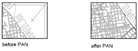
You can specify a single point, indicating the relative displacement of the
drawing with respect to the current location, or (more commonly) you can
specify two points, in which case the displacement is computed from the first
point to the second point.
If you press Enter, the drawing is moved by the amount you specified in the
Specify Base Point or Displacement prompt. For example, if you specify 2,2
at the first prompt and press Enter at the second prompt, the drawing is moved
2 units in the X direction and 2 units in the Y direction. If you specify a point
at the Specify Second Point prompt, the location of the first point is moved
to the location of the second point.
You cannot use PAN transparently during VPOINT (page 1114) or DVIEW (page
385), or while another ZOOM (page 1153), PAN, or VIEW (page 1104) command is
in progress.
See also:
Pan or Zoom a View
Pan Shortcut Menu
Pan and Zoom shortcut menu allows for switching between navigation tools
and cancelling the current navigation tool.
To access the Pan shortcut menu, right-click in the drawing area while PAN
is active.
List of Options
The following options are displayed.
Exit Cancels PAN or ZOOM.
Pan Switches to PAN.
Zoom Switches to ZOOM in real time.
Commands | 765

3D Orbit Switches to 3DORBIT.
Zoom Window Zooms to display an area specified by a rectangular window.
Zoom Original Restores the original view.
Zoom Extents Zooms to display the drawing extents.
See also:
Pan or Zoom a View
PARAMETERS (-PARAMETERS)
Manages all dimensional constraint parameters, reference parameters, and
user variables in the current drawing from the Command prompt.
List of Prompts
The following prompts are displayed.
Enter a parameter option [New/Edit/Rename/Delete/? - List
Parameters ]:
NOTE You cannot use the -PARAMETERS command in the Block Editor (page 139).
New Creates a user variable.
Edit Edits the expression of the specified user variable.
Rename Renames the user variable.
Delete Removes the user variable from the list.
? — List Parameters Lists available user variables in the drawing.
See also:
Add Constraints to Geometry
PASTECLIP
Pastes objects from the Clipboard into the current drawing.
766 | Chapter 2 Commands
Access Methods
Menu: Edit ➤ Paste
Shortcut menu: With no command active, right-click in the drawing area,
and click Clipboard ➤ Paste
Command entry: Cmd-V
Summary
If the Clipboard contains ASCII text, the text is inserted as a multiline text
(mtext) object using the MTEXT (page 674) defaults. A spreadsheet is inserted
as a table object.
When you copy objects to the Clipboard, information is stored in all available
formats. When you paste the Clipboard contents into a drawing, the format
that retains the most information is used. You can also use Copy and Paste
to transfer objects between drawings.
NOTE If the cursor is in the drawing area, PASTECLIP behaves as described. If the
cursor is at the Command prompt, text from the Clipboard is pasted at the current
prompt.
See also:
Cut, Copy, and Paste with the Clipboard
PEDIT
Edits polylines and 3D polygon meshes.
Access Methods
Menu: Modify ➤ Object ➤ Polyline
Shortcut menu: Select a polyline to edit. Right-click in the drawing area
and click Polyline Edit.
Summary
Common uses for PEDIT include joining 2D polylines, converting lines and
arcs into 2D polylines, and converting polylines into curves that approximate
B-splines (spline-fit polylines).
Commands | 767

List of Prompts
The following prompts are displayed.
Select polyline or [MULTIPLE (page 699)]: Use an object selection
method or enter m
The remaining prompts depend on whether you have selected a 2D polyline
(page 769), a 3D polyline (page 776), or 3D polygon mesh (page 779).
If the selected object is a line, arc, or a spline, the following prompt is
displayed:
Object selected is not a polyline.
Do you want it to turn into one? <Y>: Enter y or n, or press Enter
If you enter y, the object is converted into a single-segment 2D polyline that
you can edit. You can use this operation to join lines and arcs into a polyline.
Before the selected spline is converted to a polyline, the following prompt is
displayed:
Specify a precision <10>: Enter a new precision value or press Enter
The precision value determines how accurately the resulting polyline is to fit
to the source spline. Valid value is an integer between 0 and 99.
NOTE A high precision value may cause performance problems.
The PLINECONVERTMODE (page 1395) system variable determines whether
the polylines are created with linear or arc segments. When the PEDITACCEPT
(page 1389)system variable is set to 1, this prompt is suppressed, and the selected
object is automatically converted to a polyline.
The conversion in both PEDIT and SPLINEDIT will obey the DELOBJ (page
1213) system variable.
See also:
Modify Polylines
Multiple Selection (PEDIT)
Enables selection for more than one object.
If the selection set includes lines, arcs, or splines, the following prompt is
displayed:
768 | Chapter 2 Commands
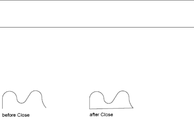
List of Prompts
The following prompts are displayed.
Convert Lines, Arcs and Splines to polylines [Yes/No]? <Y>:
Enter yor n or press Enter
Specify a precision for spline conversion <10>: Enter a new
precision value or press Enter
The entered precision value affects all splines in the selection set. The precision
value is an integer between 0 and 99.
2D Polyline Selection (PEDIT)
If you select a 2D polyline, the following prompt is displayed:
List of Prompts
The following prompts are displayed.
Enter an option [Close/Join/Width/Edit
vertex/Fit/Spline/Decurve/Ltype gen/Reverse/Undo]: Enter an option
or press Enter to end the command
NOTE
You can select a single arc or line segment, also called a subobject, within a
polyline by pressing the Ctrl key when you click over it.
If the polyline you select is a closed polyline, Open replaces the Close option
in the prompt. You can edit a 2D polyline if its normal is parallel to and in
the same direction as the Z axis of the current UCS.
Close
Creates the closing segment of the polyline, connecting the last segment with
the first. The polyline is considered open unless you close it using the Close
option.
Commands | 769

Open
Removes the closing segment of the polyline. The polyline is considered closed
unless you open it using the Open option.
Join
Adds lines, arcs, or polylines to the end of an open polyline and removes the
curve fitting from a curve-fit polyline. For objects to join the polyline, their
endpoints must touch unless you use the Multiple option at the first PEDIT
prompt. In this case, you can join polylines that do not touch if the fuzz
distance is set to a value large enough to include the endpoints.
Jointype
Sets the method of joining selected polylines.
Extend Joins the selected polylines by extending or trimming the segments
to the nearest endpoints.
Add Joins the selected polylines by adding a straight segment between the
nearest endpoints.
Both Joins the selected polylines by extending or trimming if possible.
Otherwise joins the selected polylines by adding a straight segment between
the nearest endpoints.
Width
Specifies a new uniform width for the entire polyline.
You can use the Width option of the Edit Vertex option to change the starting
and ending widths of a segment.
Edit Vertex
Marks the first vertex of the polyline by drawing an X on the screen. If you
have specified a tangent direction for this vertex, an arrow is also drawn in
that direction.
770 | Chapter 2 Commands
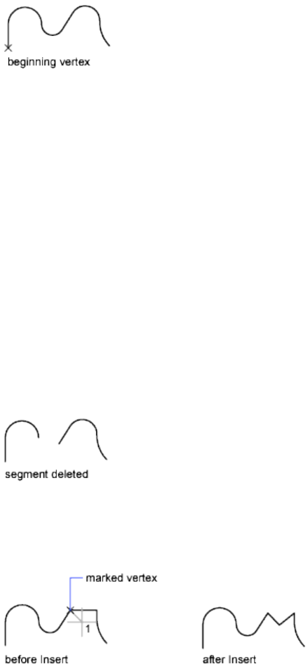
Next
Moves the X marker to the next vertex. The marker does not wrap around
from the end to the start of the polyline even if the polyline is closed.
Previous
Moves the X marker to the previous vertex. The marker does not wrap around
from the start to the end of the polyline even if the polyline is closed.
Break
Saves the location of the marked vertex while you move the X marker to any
other vertex.
If one of the specified vertices is at an end of the polyline, the result is one
truncated polyline. If both specified vertices are at endpoints of the polyline,
or if just one vertex is specified and it is at an endpoint, you cannot use Break.
■Next (page ?)
■Previous (page ?)
Go Deletes any segments and vertices between the two vertices you specify
and returns to Edit Vertex mode.
Exit Exits Break and returns to Edit Vertex mode.
Insert
Adds a new vertex to the polyline after the marked vertex.
Commands | 771

Move
Moves the marked vertex.
Regen
Regenerates the polyline.
Straighten
Saves the location of the marked vertex while you move the X marker to any
other vertex.
If you want to remove an arc segment that connects two straight segments of
a polyline and then extend the straight segments until they intersect, use the
FILLET (page 432) command with a fillet radius of 0.
Next Moves the X marker to the next vertex.
Previous Moves the X marker to the previous vertex.
Go Deletes any segments and vertices between the two vertices you select,
replaces them with single straight line segments, and returns to Edit Vertex
mode. If you specify only one vertex by entering go without moving the X
marker, the segment following that vertex is straightened if it is an arc.
Exit Exits Straighten and returns to Edit Vertex mode.
772 | Chapter 2 Commands

Tangent
Attaches a tangent direction to the marked vertex for use later in curve fitting.
Width
Changes the starting and ending widths for the segment that immediately
follows the marked vertex.
You must regenerate the polyline to display the new width.
Exit
Exits Edit Vertex mode.
Fit
Creates an arc-fit polyline, a smooth curve consisting of arcs joining each pair
of vertices. The curve passes through all vertices of the polyline and uses any
tangent direction you specify.
Spline
Uses the vertices of the selected polyline as the control points, or frame, of a
curve approximating a B-spline. This curve, called a spline-fit polyline, passes
through the first and last control points unless the original polyline was closed.
The curve is pulled toward the other points but does not necessarily pass
through them. The more control points you specify in a particular part of the
frame, the more pull they exert on the curve. Quadratic and cubic spline-fit
polylines can be generated.
Commands | 773

Spline-fit polylines are very different from the curves produced by the Fit
option. Fit constructs pairs of arcs that pass through every control point. Both
of these curves are different from true B-splines produced with the SPLINE
(page 988) command.
If the original polyline included arc segments, they are straightened when the
spline's frame is formed. If the frame has width, the resulting spline tapers
smoothly from the width of the first vertex to the width of the last vertex. All
intermediate width information is ignored. Once spline-fit, the frame, if
displayed, is shown with zero width and CONTINUOUS linetype. Tangent
specifications on control point vertices have no effect on spline-fitting.
When a spline-fit curve is fit to a polyline, the spline-fit curve's frame is stored
so that it can be recalled by a subsequent decurving. You can turn a spline-fit
curve back into its frame polyline by using the PEDIT Decurve option. This
option works on fit curves in the same manner as it does on splines.
Most editing commands act the same when applied to spline-fit polylines or
fit curves.
■MOVE (page 671), ERASE (page 406), COPY (page 228), MIRROR (page 647),
ROTATE (page 907), and SCALE (page 916) operate on both the spline curve
and its frame, whether the frame is visible or not.
■EXTEND (page 410) changes the frame by adding a new vertex where the
initial or final line of the frame intersects the boundary geometry.
■BREAK (page 155) and TRIM (page 1067) generate a polyline with only the fit
spline, which is consistent with fit curves, where the curve fitting is
permanent.
■EXPLODE (page 407) deletes the frame and generates lines and arcs to
approximate the spline-fit polyline.
■OFFSET (page 715) generates a polyline with only the fit spline, which is
consistent with its behavior with fit curves.
■DIVIDE (page 356), MEASURE (page 611), and the Object option of AREA
(page 83) and HATCH (page 471) see only the fit spline, not the frame.
■STRETCH (page 1004) refits the spline to the stretched frame after a spline
is stretched.
774 | Chapter 2 Commands
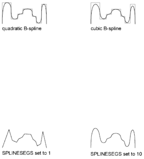
The Join option of PEDIT decurves the spline and discards the spline
information of the original and any added polylines. Once the Join operation
is complete, you can fit a new spline to the resulting polyline.
The Edit Vertex options of PEDIT have the following effect:
■The Next and Previous options move the X marker only to points on the
frame of the spline, whether visible or not.
■The Break option discards the spline.
■The Insert, Move, Straighten, and Width options automatically refit the
spline.
■The Tangent option has no effect on splines.
Object snap uses only the spline-fit curve itself, not the frame. If you want to
snap to the frame control points, use PEDIT to recall the polyline frame first.
The SPLINETYPE (page 1446) system variable controls the type of spline curve
approximated. Setting SPLINETYPE to 5 approximates a quadratic B-spline.
Setting SPLINETYPE to 6 approximates a cubic B-spline.
You can examine or change the fineness or coarseness of the spline
approximation with the SPLINESEGS (page 1446) system variable, or you can
use AutoLISP®. The default value is 8. If you set the value higher, a greater
number of line segments are drawn and the approximation to the ideal spline
becomes more precise. The generated spline occupies more space in the drawing
file and takes longer to generate.
If you set SPLINESEGS to a negative value, the program generates segments
using the absolute value of the setting and then applies a fit-type curve to
those segments. Fit-type curves use arcs as the approximating segments. Using
arcs yields a smoother generated curve when few segments are specified, but
the curve can take longer to generate.
Commands | 775

To change the number of segments used to fit an existing spline, change
SPLINESEGS and respline the curve. You do not have to decurve it first.
Decurve
Removes extra vertices inserted by a fit or spline curve and straightens all
segments of the polyline. Retains tangent information assigned to the polyline
vertices for use in subsequent fit curve requests. If you edit a spline-fit polyline
with a command such as BREAK (page 155) or TRIM (page 1067), you cannot use
the Decurve option.
Ltype Gen
Generates the linetype in a continuous pattern through the vertices of the
polyline. When turned off, this option generates the linetype starting and
ending with a dash at each vertex. Ltype Gen does not apply to polylines with
tapered segments.
Reverse
Reverses the order of vertices of the polyline. Use this option to reverse the
direction of objects that use linetypes with included text. For example,
depending on the direction in which a polyline was created, the text in the
linetype might be displayed upside down.
Undo
Reverses operations as far back as the beginning of the PEDIT session.
3D Polyline Selection (PEDIT)
If you select a 3D polyline, the following prompt is displayed:
List of Prompts
The following prompts are displayed.
Enter an option [Close/Join/Edit vertex/Spline
curve/Decurve/Reverse/Undo]: Enter an option or press Enter
If the polyline you select is closed, Open replaces the Close option in the
prompt.
776 | Chapter 2 Commands
Close
Creates the closing segment of the polyline, connecting the last segment with
the first. The polyline is considered open unless you close it with Close.
Open
Removes the closing segment of the polyline. The polyline is considered closed
unless you open it with Open.
Join
Joins an open curve to the 3D polyline. The curve can be on a different plane,
but must be contiguous with the 3D polyline.
Edit Vertex
Performs various editing tasks on one vertex of the polyline and segments
that follow it.
Next
Moves the X marker to the next vertex. The marker does not wrap around
from the end to the start of the polyline, even if the polyline is closed.
Previous
Moves the X marker to the previous vertex. The marker does not wrap around
from the start to the end of the polyline, even if the polyline is closed.
Break
Saves the location of the marked vertex while you move the X marker to any
other vertex.
■Next (page ?)
■Previous (page ?)
Go Deletes any segments and vertices between the two vertices you specify
and returns to Edit Vertex mode.
Exit Exits Break and returns to Edit Vertex mode.
If one of the specified vertices is at an end of the polyline, the polyline is
truncated. If both specified vertices are at endpoints of the polyline, or if just
one vertex is specified and it is at an endpoint, you cannot use Break mode.
Insert
Adds a new vertex to the polyline after the marked vertex.
Move
Moves the marked vertex.
Regen
Regenerates the polyline.
Commands | 777
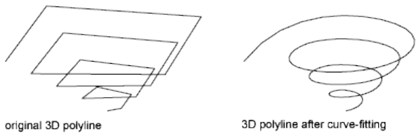
Straighten
Saves the location of the marked vertex while you move the X marker to any
other vertex.
Next Moves the X marker to the next vertex.
Previous Moves the X marker to the previous vertex.
Go Deletes any segments and vertices between the two vertices you select,
replaces them with single straight line segments, and returns to Edit Vertex
mode. If you specify only one vertex by entering go without moving the X
marker, the segment following that vertex is made straight if it is an arc.
Exit Exits Straighten and returns to Edit Vertex mode.
To remove an arc segment that connects two straight segments of a polyline
and then to extend the straight segments until they intersect, use the FILLET
(page 432) command with a fillet radius of 0.
Exit
Exits Edit Vertex mode.
Spline Curve
Fits a 3D B-spline curve to its control points. The SPLFRAME (page 1445) system
variable controls the accuracy and display of the control points for the 3D
B-spline, whose curves can be approximated only by line segments. Negative
values for spline segments are ignored.
Decurve
Removes extra vertices inserted by a fit or spline curve and straightens all
segments of the polyline. Retains tangent information assigned to the polyline
vertices for use in subsequent fit curve requests. If you edit a spline-fit polyline
with a command such as BREAK (page 155) or TRIM (page 1067), you cannot use
the Decurve option.
Reverse
Reverses the order of vertices of the polyline. Use this option to reverse the
direction of objects that use linetypes with included text. For example,
778 | Chapter 2 Commands
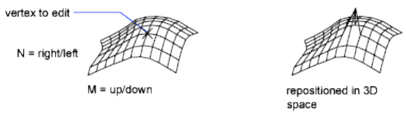
depending on the direction in which a polyline was created, the text in the
linetype might be displayed upside down.
Undo
Reverses operations as far back as the beginning of the PEDIT session.
3D Polygon Mesh Selection (PEDIT)
If you select a polygon mesh, the following prompt is displayed:
List of Prompts
The following prompts are displayed.
Enter an option [Edit vertex/Smooth
surface/Desmooth/Mclose/Nclose/Undo]: Enter an option or press Enter
to end the command
Mclose and Nclose are replaced by Mopen and Nopen if the polygon mesh is
currently closed in the M or N direction.
Edit Vertex
Edits individual vertices of a polygon mesh that can be seen as a rectangular
M by N array, where M and N are the dimensions specified in 3DMESH (page
35). The SURFTAB1 (page 1454) and SURFTAB2 (page 1454) system variables store
M and N values for RULESURF (page 912), TABSURF (page 1039), REVSURF (page
905), and EDGESURF (page 399).
Pressing Enter accepts the current default, which is either Next or Previous.
Next Moves the X marker to the next vertex. The marker does not wrap around
from the end to the start of the mesh, even if the mesh is closed.
Previous Moves the X marker to the previous vertex. The marker does not
wrap around from the start to the end of the mesh, even if the mesh is closed.
Commands | 779
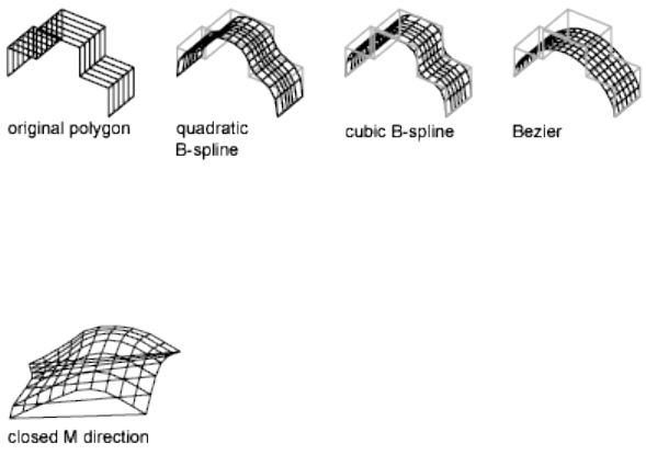
Left Moves the X marker to the previous vertex in the N direction. The marker
does not wrap around from the start to the end of the mesh, even if the mesh
is closed.
Right Moves the X marker to the next vertex in the N direction. The marker
does not wrap around from the end to the start of the mesh, even if the mesh
is closed.
Up Moves the X marker to the next vertex in the M direction. The marker
does not wrap around from the end to the start of the mesh, even if the mesh
is closed.
Down Moves the X marker to the previous vertex in the M direction. The
marker does not wrap around from the start to the end of the mesh, even if
the mesh is closed.
Move Repositions the vertex and moves the editing mark.
Regen Regenerates the polygon mesh.
Exit Exits Edit Vertex mode.
Smooth Surface
Fits a smooth surface. The SURFTYPE (page 1455) system variable controls the
type of surface this option fits. The types of surfaces include quadratic B-spline,
cubic B-spline, and Bezier.
Desmooth
Restores the original control-point polygon mesh.
Mclose
Closes the M-direction polylines if the polygon mesh is open in the M direction.
780 | Chapter 2 Commands
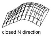
Mopen
Opens the M-direction polylines if the polygon mesh is closed in the M
direction.
Nclose
Closes the N-direction polylines if the polygon mesh is open in the N direction.
Nopen
Opens the N-direction polylines if the polygon mesh is closed in the N
direction.
Undo
Reverses operations as far back as the beginning of the PEDIT session.
PFACE
Creates a 3D polyface mesh vertex by vertex.
List of Prompts
The following prompts are displayed.
Specify location for vertex (page ?) 1: Specify a point
Specify location for vertex 2 or <define faces (page ?)>:
Specify a point or press Enter
Specify location for vertex nor <define faces>: Specify a point
or press Enter
Vertex Location
You specify all vertices used in the mesh. The vertex numbers displayed in
the prompts are the numbers used to reference each vertex. The prompt is
repeated until you press Enter. If you press Enter on a blank line, you are
prompted for the vertices to be assigned to each face.
Define Faces
Vertex Number You define each face by entering vertex numbers for all the
vertices of that face. The mesh is drawn after you have defined the last face
and pressed Enter after the prompt.
Commands | 781

To make an edge invisible, you can enter a negative vertex number for the
beginning vertex of the edge.
You can create polygons with any number of edges. PFACE automatically
breaks them into multiple face objects with the appropriate invisible edges.
Faces with one or two vertices behave like point or line objects without the
special properties of Point Display modes or linetypes. You can use them to
embed wireframe images within a mesh. Use Endpoint object snap to snap to
a face composed of one or two vertices. All object snap modes that apply to
line objects work with visible edges of polyface meshes. You cannot use PEDIT
(page 767) to edit polyface meshes.
Color Faces created with PFACE adopt the current layer and color. Unlike
polyline vertices, polyface mesh faces can be created with layer and color
properties different from their parent object.
You can enter a color from the AutoCAD Color Index (a color name or
number), a true color, or a color from a color book.
Layer Faces created with PFACE adopt the current layer and color. Unlike
polyline vertices, polyface mesh faces can be created with layer and color
properties different from their parent object. Layer visibility behaves normally
on faces of a polyface mesh. However, if you create a polyface mesh on a
frozen layer, the program does not generate any of its faces, including those
on non-frozen layers.
See also:
Create Custom Mesh (Legacy)
PLAN
Displays an orthographic view of the XY plane of a specified user coordinate
system.
Access Methods
Menu: View ➤ 3D Views ➤ Plan View ➤ World UCS
782 | Chapter 2 Commands
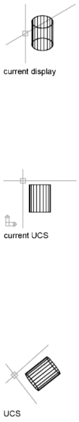
List of Options
The following options are displayed.
Current UCS Regenerates a plan view of the display so that the drawing extents
fit in the current viewport of the current UCS.
UCS Changes to a plan view of a previously saved UCS and regenerates the
display.
Enter name of UCS or [?]: Enter a name or enter ? to list all UCSs in the drawing
If you enter ? at the prompt, the following prompt is displayed:
Enter UCS name(s) to list <*>: Enter a name or enter * to list all UCSs in the
drawing
World Regenerates a plan view of the display so that the drawing extents fit
on the screen of the world coordinate system.
Commands | 783
See also:
Change to a View of the XY Plane
PLANESURF
Creates a planar surface.
Access Methods
Button
Toolbar: Modeling tool set ➤ Surfaces - Create tool group ➤ Planar
Surface
Menu: Draw ➤ 3D Modeling ➤ Planar Surface
Summary
You can create a planar surface by selecting closed objects or by specifying
the opposite corners of a rectangular surface. Supports pick-first selection and
generates a planar surface out of a closed profile. When you specify the corners
of the surface through the command, the surface is created parallel to the
work plane.
784 | Chapter 2 Commands
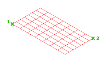
The SURFU (page 1455) and SURFV (page 1455) system variables control the number
of lines displayed on the surface.
List of Prompts
The following prompts are displayed.
Specify first corner or [Object]: Specify the first point for the planar
surface
Specify other corner: Specify second point (other corner) for the planar
surface
Object
Creates a planar or trimmed surface by object selection. You can select one
closed object or multiple objects that form a closed area.
Similar to the REGION (page 879) command, valid objects include: line, circle,
arc, ellipse, elliptical arc, 2D polyline, planar 3D polyline, and planar spline.
The DELOBJ (page 1213) system variable controls whether the object(s) you
select are automatically deleted when the surface is created or whether you
are prompted to delete the object(s).
See also:
Overview of Creating Surfaces
Convert Objects to Procedural Surfaces
PLINE
Creates a 2D polyline, a single object that is composed of line and arc segments.
Commands | 785
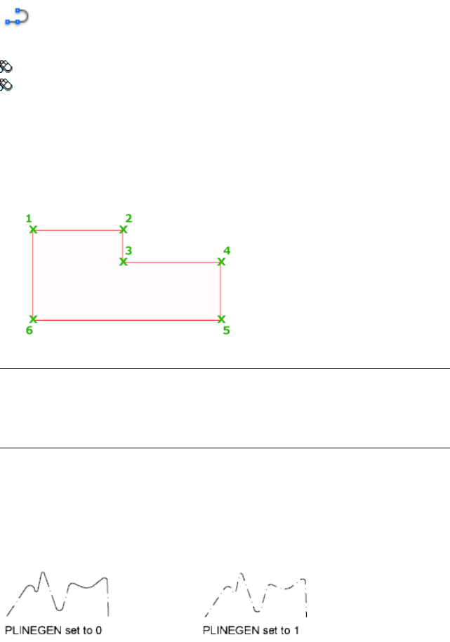
Access Methods
Button
Toolbar: Drafting tool set ➤ Open Shapes tool group ➤ Polyline
Menu: Draw ➤ Polyline
Summary
A 2D polyline is a connected sequence of segments created as a single planar
object. You can create straight line segments, arc segments, or a combination
of the two.
NOTE
A temporary plus-shaped marker displays at the first point. This marker can
be useful when you create long and complicated polylines. It is removed when
you complete the polyline.
The PLINEGEN (page 1396) system variable controls the linetype pattern display
around and the smoothness of the vertices of a 2D polyline. Setting PLINEGEN
to 1 generates new polylines in a continuous pattern around the vertices of
the completed polyline. Setting PLINEGEN to 0 starts and ends the polyline
with a dash at each vertex. PLINEGEN does not apply to polylines with tapered
segments.
786 | Chapter 2 Commands
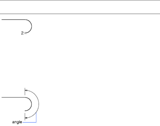
List of Prompts
The following prompts are displayed.
Specify start point: Specify a point
Current line-width is <current>
Specify next point (page 785) or [Arc (page ?)/Close (page
?)/Halfwidth (page ?)/Length (page ?)/Undo (page ?)/Width
(page ?)]: Specify a point or enter an option
Next Point
Draws a line segment. The previous prompt is repeated.
Arc
Adds arc segments to the polyline.
Specify endpoint of arc or
[Angle/CEnter/CLose/Direction/Halfwidth/Line/Radius/Second
pt/Undo/Width]: Specify a point (2) or enter an option
NOTE For the Center option of the PLINE command, enter ce; for the Center
object snap, enter cen or center.
Endpoint of Arc
Draws an arc segment. The arc segment is tangent to the previous segment of
the polyline. The previous prompt is repeated.
Angle
Specifies the included angle of the arc segment from the start point.
Specify included angle:
Entering a positive number creates counterclockwise arc segments. Entering
a negative number creates clockwise arc segments.
Commands | 787
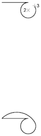
Specify endpoint of arc or [Center/Radius]: Specify a point or enter an option
Endpoint of Arc Specifies the endpoint and draws the arc segment.
Center Specifies the center of the arc segment.
Specify center point of arc:
Radius Specifies the radius of the arc segment.
Specify radius of arc: Specify a distance
Specify direction of chord for arc <current>: Specify a point or press Enter
Center
Specifies the center of the arc segment.
Specify center point of arc: Specify a point (2)
Specify endpoint of arc or [Angle/Length]: Specify a point (3) or enter an option
Endpoint of Arc Specifies the endpoint and draws the arc segment.
Angle Specifies the included angle of the arc segment from the start point.
Specify included angle:
Length Specifies the chord length of the arc segment. If the previous segment
is an arc, the new arc segment is drawn tangent to the previous arc segment.
Specify length of chord:
Close
Draws an arc segment from the last point specified to the starting point,
creating a closed polyline. At least two points must be specified to use this
option.
Direction
Specifies a starting direction for the arc segment.
Specify the tangent direction from the start point of arc: Specify a point (2)
Specify endpoint of arc: Specify a point (3)
788 | Chapter 2 Commands
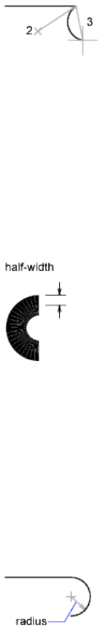
Halfwidth
Specifies the width from the center of a wide polyline segment to one of its
edges.
Specify starting half-width <current>: Enter a value or press Enter
Specify ending half-width <starting width>: Enter a value or press Enter
The starting half-width becomes the default ending half-width. The ending
half-width becomes the uniform half-width for all subsequent segments until
you change the half-width again. The starting and ending points of wide line
segments are at the center of the line.
Typically, the intersections of adjacent wide polyline segments are beveled.
No beveling is performed for nontangent arc segments or very acute angles
or when a dot-dash linetype is used.
Line
Exits the Arc option and returns to the initial PLINE command prompts.
Radius
Specifies the radius of the arc segment.
Specify radius of arc: Specify a distance
Specify endpoint of arc or [Angle]: Specify a point or enter a
Endpoint of Arc Specifies the endpoint and draws the arc segment.
Angle Specifies the included angle for the arc segment.
Specify included angle:
Commands | 789
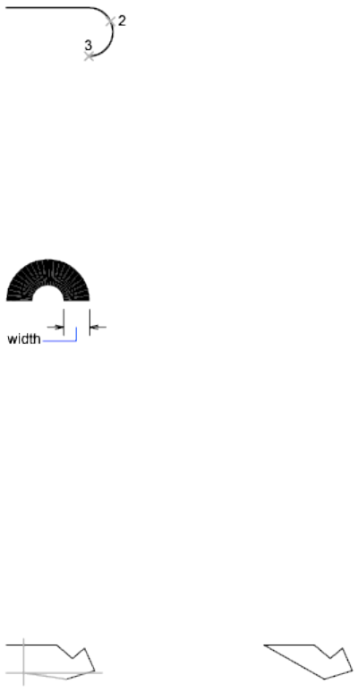
Specify direction of chord for arc <current>: Specify an angle or press Enter
Second Pt
Specifies the second point and endpoint of a three-point arc.
Specify second point on arc: Specify a point (2)
Specify end point of arc: Specify a point (3)
Undo
Removes the most recent arc segment added to the polyline.
Width
Specifies the width of the next arc segment.
Specify starting width <current>: Enter a value or press Enter
Specify ending width <starting width>: Enter a value or press Enter
The starting width becomes the default ending width. The ending width
becomes the uniform width for all subsequent segments until you change the
width again. The starting and ending points of wide line segments are at the
center of the line.
Typically, the intersections of adjacent wide polyline segments are beveled.
No beveling is performed for nontangent arc segments, very acute angles, or
when a dot-dash linetype is used.
Close
Draws a line segment from the last point specified to the starting point,
creating a closed polyline. At least two points must be specified to use this
option.
790 | Chapter 2 Commands
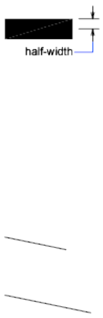
Halfwidth
Specifies the width from the center of a wide polyline line segment to one of
its edges.
Specify starting half-width <current>: Enter a value or press Enter
Specify ending half-width <current>: Enter a value or press Enter
The starting half-width becomes the default ending half-width. The ending
half-width becomes the uniform half-width for all subsequent segments until
you change the half-width again. The starting and ending points of wide line
segments are at the center of the line.
Typically, the intersections of adjacent wide polyline segments are beveled.
No beveling is performed for nontangent arc segments or very acute angles
or when a dot-dash linetype is used.
Length
Draws a line segment of a specified length at the same angle as the previous
segment. If the previous segment is an arc, the new line segment is drawn
tangent to that arc segment.
Specify length of line: Specify a distance
Undo
Removes the most recent line segment added to the polyline.
Width
Specifies the width of the next line segment.
Specify starting width <current>: Enter a value or press Enter
Specify ending width <starting width>: Enter a value or press Enter
Commands | 791
The starting width becomes the default ending width. The ending width
becomes the uniform width for all subsequent segments until you change the
width again. The starting and ending points of wide line segments are at the
center of the line.
Typically, the intersections of adjacent wide polyline segments are beveled.
No beveling is performed for nontangent arc segments or very acute angles
or when a dot-dash linetype is used.
See also:
Draw Polylines
PLOT
Outputs a drawing to a printer or file.
Access Methods
Menu: File ➤ Print
Toolbar: Layout visor ➤ Print Layout
Toolbar: Status bar ➤ Quick View. In the Quick View window, right-click
a layout and click Print.
Shortcut menu: Right-click the drawing area when a named layout is current
and click Print Layout
Summary
The Print dialog box (page 793) is displayed. Click OK to begin printing with
the current settings.
If you enter -plot at the Command prompt, options are displayed (page 796).
A drawing file, drawing template file, xref, or block definition that was created
with or modified by an educational version will always be printed with the
following plot stamp: PRODUCED BY AN AUTODESK EDUCATIONAL
PRODUCT.
792 | Chapter 2 Commands
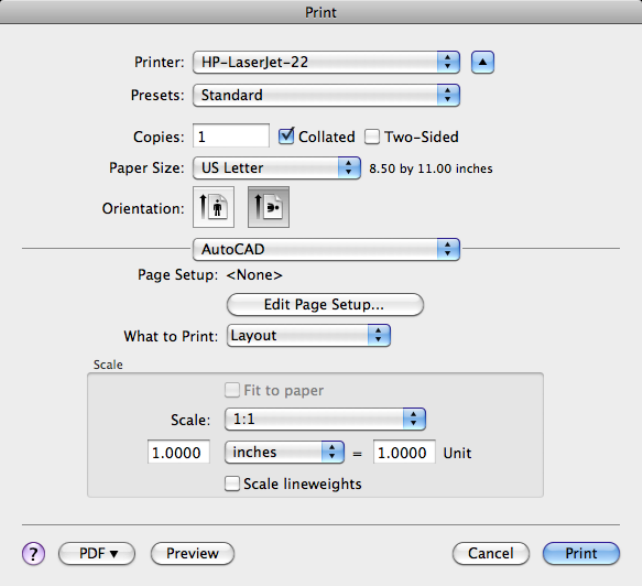
See also:
Overview of Plotting
Print Dialog Box
Specifies device and media settings, and plots your drawing.
Summary
You can display more options by clicking the Show Advanced Settings button
to the right of the Printer drop-down list.
Printing allows you to output a single layout at a time. If you want to print
more than one layout at a time, use the PUBLISH command.
Commands | 793
List of Options
The following options are displayed.
Printer
Specifies an output device to use when printing layouts.
If the selected output device does not support the layout's selected paper size,
a warning is displayed and you can select the device's default paper size or a
custom paper size.
Click the disclosure triangle to the right of the Printer drop-down list to expand
the Print dialog box. When the dialog box is expanded, additional settings
are available that allow you to control the printing of the layout.
Presets
Specifies the named print preset to use for printing the current layout.
Print presets store the following information:
■Number of Copies
■Collated
■Two-sided
■Paper size
■Orientation
Copies
Specifies the number of copies to print. This option is not available when you
print to an electronic file, such as a PDF file.
Collated
Controls if multi-page prints should be collated.
Two-sided
Controls if multi-page prints should be printed on both sides of a page.
List of Options - Single Layout
The following options are available when printing a layout.
Paper Size
Displays standard paper sizes that are available for the selected output device.
If no output device is selected, the full standard paper size list is displayed and
available for selection.
Orientation
Specifies the orientation of the drawing on the paper for plotters that support
landscape or portrait orientation. The paper icon represents the media
794 | Chapter 2 Commands

orientation of the selected paper. The letter icon represents the orientation of
the drawing on the page.
NOTE Drawing orientation is also affected by the PLOTROTMODE (page 1398)
system variable.
Print Options
Specifies which advanced print settings should be used for printing. Select
AutoCAD to use the page setup assigned to the layout. See the Mac OS Help
documentation for information on the other options.
Page Setup
Lists the named page setup assigned to the layout and allows you to edit the
page setup settings for the layout.
Name Displays the name of the assigned page setup.
Edit Page Setup Displays the Page Setup dialog box in which you can edit
the page setup settings for the layout.
What to Print
Specifies the area of the drawing to be plotted.
Display Outputs the view in the current viewport in the current layout.
Extents Outputs the portion of the current space of the drawing that contains
objects. All geometry in the current layout is outputted. The drawing may be
regenerated to recalculate the extents before outputting.
Model/Layout Views Outputs a view that was previously saved with the
-VIEW (page 1104) command.
Window Outputs any portion of the drawing that you specify. When you
specify the two corners of the area to output, the Window button becomes
available.
Click the Window button to use the pointing device to specify the two corners
of the area to be outputted, or enter coordinate values.
Layout/Limits When outputting a layout, everything within the printable
area of the specified paper size, with the origin calculated from 0,0 in the
layout.
When outputting from the Model layout, the entire drawing area that is
defined by the grid limits. If the current viewport does not display a plan view,
this option has the same effect as the Extents option.
Scale
Controls the relative size of drawing units to plotted units.
Commands | 795

NOTE If the Layout option is specified in What to Print, the layout is plotted at
1:1 regardless of the setting specified in Scale.
Fit to Paper Scales the plot to fit within the selected paper size and displays
the custom scale factor in the Scale, Inch =, and Units boxes.
Scale Defines the exact scale for the output. Custom defines a user-defined
scale. You can create a custom scale by entering the number of inches (or
millimeters) equal to the number of drawing units.
NOTE You can modify the list of scales with SCALELISTEDIT (page 918).
Inch(es) =/mm = Specifies the number of inches or millimeters equal to the
specified number of units.
Inch/mm Specifies inches or mm for display of units. The default is based on
the paper size and changes each time a new paper size is selected.
Unit Specifies the number of units equal to the specified number of inches
or millimeters.
Scale Lineweights Scales lineweights in proportion to the plot scale.
Lineweights normally specify the line width of output objects and are output
with the line width size regardless of the scale.
PDF
Lists options for printing to an electronic file. Some of the available options
allow you to create PDF and PostScript files.
Preview
Displays the drawing as it will appear when printed on paper. (See PREVIEW
(page 828) command)
Exit the print preview and return to the Print dialog box to complete the print.
See also:
Overview of Plotting
-PLOT
Plots a drawing to a plotter, printer, or file in the command line.
If you enter -plot at the Command prompt, the following prompts are
displayed.
796 | Chapter 2 Commands
List of Prompts
The following prompts are displayed.
Detailed plot configuration [Yes (page ?)/No (page ?)]
<No>: Enter yor n or press Enter
No
Indicates that you do not want a detailed plot configuration for this plot.
Enter a layout name or [?] <current>:
Enter a page setup name < >:
Enter an output device name or [?] <current>:
Write the plot to a file [Yes/No] <current>:
Enter file name: <dwgname-layoutname.plt>:
Save changes to layout [Yes/No] <No>:
Proceed with Plot [Yes/No] <Y>:
For information about these prompts, see the description for Yes.
Yes
Specifies detailed page settings for the Model layout or layout you are plotting.
Enter a layout name or [?] <current>: Specify the name of the layout tab you want
to plot
Enter an output device name or [?] <current>: Specify the name of the output
device to which you want to plot the Model tab or layout tab you selected
If you enter a new device name without an extension, the program assumes
that the device is a PC3 file (Autodesk® HDI plotter configuration file). If no
PC3 file is found, the program searches for a Windows system printer with
that device name.
Enter paper size or [?] <current>: Specify the paper size to use for the plot or enter
? to view the actual list of paper sizes defined for the plotter driver
You must specify a paper size exactly as it is defined by the plotter driver.
Enter paper units [Inches/Millimeters] <current>:
The Enter Paper Units prompt is not displayed if you are plotting a raster
image, such as a BMP or TIFF file, because the size of the plot is assumed to
be in pixels.
Enter drawing orientation [Portrait/Landscape] <current>:
Commands | 797
Portrait Orients and plots the drawing so that the short edge of the paper
represents the top of the page.
Landscape Orients and plots the drawing so that the long edge of the paper
represents the top of the page.
Plot upside down [Yes/No] <No>:
Orients and plots the drawing upside down.
Enter plot area [Display/Extents/Limits/Layout/View/Window] <current>:
Display Plots the view in the current viewport on the Model layout or the
current view in the layout, depending on which tab you select to plot.
Extents Plots all of the objects in the current viewport, except objects on
frozen layers. From a layout, plots all the geometry in paper space. The drawing
may be regenerated to recalculate the extents before plotting.
If you plot the drawing's extents with a perspective view active and the camera
position is within the drawing extents, this option has the same effect as the
Display option.
Limits Plots the drawing area defined by the grid limits. Available only when
the Model tab is selected.
Layout Plots everything within the printable area of the specified paper size,
with the origin calculated from 0,0 in the layout. Available only when a layout
tab is selected.
View Plots a view saved previously with the VIEW (page 1104) command. You
can select a named view from the list provided. If there are no saved views in
the drawing, this option is unavailable.
Window Plots any portion of the drawing you specify. This option prompts
you to specify the corners of the window.
Enter lower left corner of window: Specify a point
Enter upper right corner of window: Specify a point
Enter plot scale (Plotted Inches = Drawing Units) or [Fit] <current>: Specify the
scale of the plot
Plotted Inches = Drawing Units Calculates the plot scale based on the inches
or millimeters to drawing units that you specify. You can also enter a real
number as a fraction (for example, you can enter 1=2 or .5).
Fit Calculates the scale to fit the area on the sheet of paper.
798 | Chapter 2 Commands

The default scale setting is 1:1 when you are plotting a layout, unless you
modified and saved the setting. The default setting is Fit when plotting a
Model tab.
Enter plot offset (x, y) or [Center] <current>: Specify the plot offset in either the
X or Y direction, or enter c to center the plot on the paper
Plot with plot styles [Yes/No] <current>: Specify whether to plot using the plot
styles applied to objects and defined in the plot style table
If you specify Yes to plot with plot styles, the following prompt is displayed:
Enter plot style table name or [?] (enter . for none) <current>: Enter a plot style
table name, ? to view plot style tables, or . (period) for none
All style definitions with different property characteristics are stored in the
current plot style table and can be attached to the geometry. This setting
replaces pen mapping in earlier releases of the program.
Plot with lineweights [Yes/No] <current>:
Scale lineweights with plot scale [Yes/No] <current>:
NOTE The Scale Lineweights with Plot Scale prompt is displayed only when you
plot from a layout tab. Settings for the shaded plotting type are available only
when you plot from the Model layout. To control shaded plotting settings of
viewports in a layout, use the Shadeplot option of the -vports command when
you create a viewport.
Enter shade plot setting [As displayed/Wireframe/Hidden/Visual
styles/Rendered] <As displayed>: Enter a shade plot option
Specifies how model space views are plotted.
As Displayed Specifies that a model space view is plotted the same way it is
displayed.
Wireframe Specifies that a model space view is plotted in wireframe regardless
of display.
Hidden Specifies that a model space view is plotted with hidden lines removed
regardless of display.
Rendered Specifies that model space view plots are rendered regardless of
display.
Write the plot to a file [Yes/No] <current>: Enteryif you want to write the plotted
drawing to a file, or press Enter to plot to an output device
If you specify Yes, the following prompt is displayed:
Commands | 799
Enter file name: <dwgname-layoutname.plt>: Enter a file name
Save changes to page setup? Or set shade plot quality? [Yes/No/Quality] <No>:
If you enter y, the current settings in the Page Setup dialog box are saved. If
you enter q, you are prompted for the shaded plotting quality and are given
the option of providing a custom dpi. Then you are prompted to save the
page setup with the added quality settings.
Enter shade plot quality
[Draft/Preview/Normal/pResentation/Maximum/Custom] <Normal>: Enterc
if you want to specify a dpi, or to use a preset dpi, specify a different quality option
Enter custom dpi <150>:
Save changes to page setup [Yes/No]? <No>:
Plot paper space first [Yes/No] <current>:
Paper space geometry is usually plotted before model space geometry. If you
enter n, the model space geometry is plotted first, and paper space geometry
is plotted last. This option is available only if you are plotting from a layout
tab.
Hide paperspace objects? [Yes/No] <No>:
Specifies whether the Hide operation applies to objects in the paper space
viewport. This option is available only from a layout tab.
Proceed with plot [Yes/No] <Y>:
See also:
Overview of Plotting
PLOTSTAMP
Places a plot stamp on a specified corner of each drawing and logs it to a file.
Summary
The Plot Stamp Settings dialog box (page 801) is displayed.
If you enter -plotstamp at the Command prompt, options are displayed
(page 806).
800 | Chapter 2 Commands
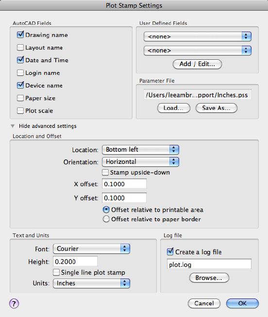
See also:
Set Options for Plotted Objects
Plot Stamp Settings Dialog Box
Specifies the information for the plot stamp.
List of Options
The following options are displayed.
Commands | 801

AutoCAD Fields
Specifies the drawing information you want applied to the plot stamp. The
selected fields are separated by commas and a space.
Drawing Name
Includes the drawing name and path in the plot stamp information.
Layout Name
Includes the name of the layout in the plot stamp information.
Date and Time
Includes the date and time in the plot stamp information.
NOTE
A plot stamp uses the current date and time format setting of the operating
system. Plot stamp specifically uses the short date style for dates.
Login Name
Includes the user login name in the plot stamp information.
The user login name is contained in the LOGINNAME system variable.
Device Name
Includes the current plotting device name in the plot stamp information.
Paper Size
Includes the paper size for the currently configured plotting device in the plot
stamp information.
Plot Scale
Includes the plot scale in the plot stamp information.
User Defined Fields
Provides text that can optionally be plotted, logged, or both plotted and logged
at plot time. The selected value in each user-defined list will be plotted.
For example, you might populate one list with media types or prices and the
other with job names. If the user-defined value is set to <none>, then no
user-defined information is plotted
Add/Edit
Displays the Add User Defined Fields dialog box (page 805), where you can
add, edit, or delete user-defined fields.
802 | Chapter 2 Commands
Parameter File
Stores plot stamp information in a file with a .pss extension. Multiple users
can access the same file and stamp their plots based on company standard
settings.
Two PSS files are provided, Mm.pss and Inches.pss, which are located in the
Support folder. The initial default plot stamp parameter file name is determined
by the regional settings of the operating system when the program is installed.
Path
Specifies the location of the plot stamp parameter file.
Load
Displays the Plotstamp Parameter File Name dialog box (a standard file
selection dialog box) in which you can specify the location of the parameter
file you want to use.
Save As
Saves the current plot stamp settings in a new parameter file.
Show/Hide Advanced Settings
Expands or collapses the Advanced Settings section towhich contains
placement and text options for the plot stamp.
Location and Offset
Determines the plot stamp location, the orientation of the plot stamp, and
the offset you want to apply relative to either the printable area or the paper
border.
Location
Indicates the area where you want to place the plot stamp. Selections include
Top Left, Bottom Left (default), Bottom Right, and Top Right. The location is
relative to the image orientation of the drawing on the page.
Orientation
Indicates the rotation of the plot stamp in relation to the specified page. The
options are Horizontal and Vertical for each of the locations (for example,
Top Left Horizontal and Top Left Vertical).
Stamp Upside-Down
Rotates the plot stamp upside down.
X Offset
Commands | 803
Determines the X offset value that is calculated from either the corner of the
paper or the corner of the printable area, depending on which setting you
specify. If you specify Offset Relative to Paper Border, the offset value is
calculated so that the plot stamp information fits within the paper size.
Y Offset
Determines the Y offset value that is calculated from either the corner of the
paper or the corner of the printable area, depending on which setting you
specify. If you specify Offset Relative to Paper Border, the offset value is
calculated so that the plot stamp information fits within the paper size.
Offset Relative to Printable Area
Calculates the offset values that you specify from the corner of the printable
area of the paper (not the corner of the paper).
Offset Relative to Paper Border
Calculates the offset values that you specify from the corner of the paper (not
the corner of the printable area of the paper).
Text and Units
Determines the font, height, and number of lines you want to apply to the
plot stamp text.
Font
Specifies the TrueType font you want to apply to the text used for the plot
stamp information.
Height
Specifies the text height you want to apply to the plot stamp information.
Single Line Plot Stamp
Places the plot stamp information in a single line of text. The plot stamp
information can consist of up to two lines of text, but the placement and
offset values you specify must accommodate text wrapping and text height.
If this option is cleared, plot stamp text is wrapped after the third field.
Units
Specifies the units to use to calculate the height of the text: inches, millimeters,
and pixels.
804 | Chapter 2 Commands
Log File
Writes the plot stamp information to a log file instead of, or in addition to,
stamping the current plot. If plot stamping is turned off, the log file can still
be created.
Create a Log File
Writes the plot stamp information to a log file. The default log file is plot.log,
and it is located in the main application folder.
You can specify a different file name and path. After the initial plot.log file is
created, the plot stamp information in each succeeding plotted drawing is
added to this file. Each drawing's plot stamp information is a single line of
text. The plot stamp log file can be placed on a network drive and shared by
multiple users. Plot stamp information from each user is appended to the
plot.log file.
Log File Name
Specifies the file name for the log file you are creating. Enter a new file name
if you do not want to use the default file name, plot.log.
Browse
Lists the currently saved plot stamp log files. You can choose to overwrite an
existing plot stamp log file with the currently specified plot stamp information,
and then to save this file.
See also:
Set Options for Plotted Objects
Add User Defined Fields Dialog Box
Create and mange user-defined fields.
Summary
User-defined fields are created and edited using the User Defined Fields dialog
box, which is displayed when you choose the Add/Edit button in the Plot
Stamp dialog box.
List of Options
The following options are displayed.
Fields
Commands | 805
Lists the available user-defined fields.
Double-click the text of a user-defined field to edit the value.
Add (+)
Adds an editable user-defined field.
Delete (-)
Deletes the selected user-defined field.
See also:
Set Options for Plotted Objects
-PLOTSTAMP
Places a plot stamp on a specified corner of each drawing and logs it to a file.
If you enter -plotstamp at the Command prompt, the following prompts
are displayed. The settings in the PSS file are displayed as defaults for each
prompt.
You can use -PLOTSTAMP as part of a plotting script to modify plot stamp
information for a drawing.
LIst of Prompts
The following prompts are displayed.
Enter an option [On (page 806)/OFF (page 806)/Fields (page
806)/User fields (page 807)/Log file (page 807)/LOCation (page
807)/Text properties (page 807)/UNits (page 808)]:
On Turns on the plot stamp for the current drawing.
OFF Turns off the plot stamp for the current drawing.
Fields Specifies the plot stamp field information you want to apply to the
current plot stamp.
Stamp drawing name? [Yes/No] <Yes>:
Stamp layout name? [Yes/No] <Yes>:
Stamp date and time? [Yes/No] <Yes>:
Stamp login name? [Yes/No] <Yes>:
Stamp plot device name? [Yes/No] <Yes>:
Stamp paper size? [Yes/No] <Yes>:
806 | Chapter 2 Commands
Stamp plot scale? [Yes/No] <Yes>:
User Fields Specifies the user-defined fields you want to apply to the current
plot stamp.
Enter User field 1 <>: Enter any user-defined field
Enter User field 2 <>: Enter any user-defined field
Log File Specifies writing the current plot stamp information to a log file
rather than applying this information to the current plotted drawing. The
default log file is plot.log, unless you specify another file path.
Write plot stamp to log file? [Yes/No] <Yes>:
Enter log file path <plot.log>:
Location Determines the location of the plot stamp on the page based on
offset, orientation, and relationship to either the printable area or the border
of the paper.
Location selections include and are relative to the printable area or the border
of the paper, depending on what you specify at the prompt.
Enter stamp location [TL/TR/BL/BR] <BL>:
■TL: Top Left
■TR: Top Right
■BL: Bottom Left
■BR: Bottom Right
Text orientation indicates the rotation angle of the plot stamp in relation to
the page.
Enter text orientation [Horizontal/Vertical] <Horizontal>:
■Horizontal: Plot stamp will be horizontal relative to the page.
■Vertical: Plot stamp will be vertical relative to the page.
Stamp upside-down [Yes/No] <No>:
Specify plot stamp offset <0.1000,0.1000>:
Specifying an offset relative to the paper border calculates the offset values
that you specify from the corner of the paper. Specifying an offset relative to
the printable area calculates the offset values that you specify from the corner
of the printable area.
Specify offset relative to [paper Border/printable Area] <printable Area>:
Text Properties Determines the font name and text height for the current
plot stamp text. You can also specify to place the text on one line or to wrap
Commands | 807

the text to two lines. The placement and offset values you specify for this plot
stamp must accommodate the text wrapping and the text height.
Enter font name <>: Enter a font name
Enter text height <0.1500>: Enter a value
Place plot stamp on single line? [Yes/No] <No >:
Units Specifies the units used to measure X offset, Y offset, and height. You
can define units using inches, millimeters, or pixels.
Enter measurement units [Inches/Millimeters/Pixels] <Inches>:
See also:
Set Options for Plotted Objects
PLOTSTYLE
Create and edit plot style files.
Access Methods
Menu: Format ➤ Plot Style
Summary
Displays the Edit Plot Style Table dialog box (page 808).
If you enter -plotstyle at the Command prompt, options are displayed (page
814).
See also:
Use Plot Styles to Control Plotted Objects
Edit Plot Style Table Dialog Box
Create or edit plot style table files.
808 | Chapter 2 Commands
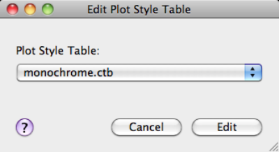
List of Options
The following options are displayed.
Plot Style Table Displays a list of the available plot style files that can be
edited. A plot style is a collection of property settings used in plotting. Along
with selecting a plot style to edit from the list, you can also select one of the
following:
■Reveal in Finder. Opens Finder to the folder that contains the listed
plot styles. The location in which AutoCAD for Mac locates plot styles can
be changed under Printer Support File Path ➤ Plot Style Table Search Path
on the Application tab of the Application Preferences dialog box (OPTIONS
(page 724) command).
■New. Displays the Plot Style Table Editor (page 809) with the default
properties for a new plot style. The type of new plot style created depends
on the type of plot style being used in the current drawing.
Edit Displays the Plot Style Table Editor with the properties of the selected
plot style.
See also:
Use Plot Styles to Control Plotted Objects
Plot Style Table Editor
Edits the properties of a plot style table file.
Commands | 809
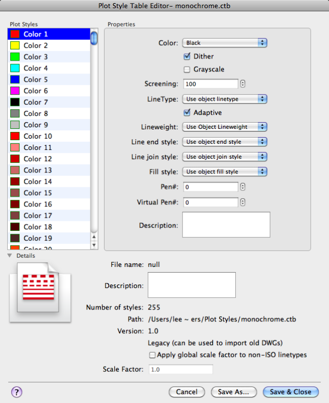
Summary
Lists all of the plot styles in the plot style table and their settings.
Plot styles are displayed in columns from left to right. The first plot style in a
named plot style table is NORMAL and represents an object's default properties
(no plot style applied). You cannot modify or delete the NORMAL style.
810 | Chapter 2 Commands
List of Options
The following options are displayed.
Plot Styles
Displays the names of plot styles in named plot style tables. Plot styles in
named plot style tables can be changed. Plot style names in color-dependent
plot style tables are tied to object color and cannot be changed. The program
accepts up to 255 characters for style names.
Add Style (+)
Adds a new plot style to a named plot style table.
The plot style is based on Normal, which uses an object's properties and doesn't
apply any overrides by default. You must specify the overrides you want to
apply after you create the new plot style. You cannot add a new plot style to
a color-dependent plot style table; a color-dependent plot style table has 255
plot styles mapped to color. You also cannot add a plot style to a named plot
style table that has a translation table.
Delete Style (-)
Deletes the selected style from a named plot style table.
Objects assigned this plot style retain the plot style assignment but plot as
Normal because the plot style is no longer defined in the plot style table. You
cannot delete a plot style from a named plot style table that has a translation
table, or from a color-dependent plot style table.
Color
Specifies the plotted color for an object. The default setting for plot style color
is Use Object Color. If you assign a plot style color, the color overrides the
object's color at plot time.
You can choose Select Color to display the Color Palette dialog box (page 198)
and select one of the 255 AutoCAD Color Index (ACI) colors, a true color, or
a color from a color book. The color you specify is displayed in the plot style
color list as Custom Color. If the plot device does not support the color you
specify, it plots the nearest available color or, in the case of monochrome
devices, black.
Dithering
Enables dithering. A plotter uses dithering to approximate colors with dot
patterns, giving the impression of plotting more colors than available in the
AutoCAD Color Index (ACI). If the plotter does not support dithering, the
dithering setting is ignored.
Dithering is usually turned off in order to avoid false line typing that results
from dithering of thin vectors. Turning off dithering also makes dim colors
Commands | 811
more visible. When you turn off dithering, the program maps colors to the
nearest color, resulting in a smaller range of colors when plotting.
Grayscale
Converts the object's colors to grayscale if the plotter supports grayscale. If
you clear Convert to Grayscale, the RGB values are used for object colors.
Dithering is available whether you use the object's color or assign a plot style
color.
Screening
Specifies a color intensity setting that determines the amount of ink placed
on the paper while plotting. Selecting 0 reduces the color to white. Selecting
100 displays the color at its full intensity. The Dithering option must be
selected for screening.
Linetype
Displays a list with a sample and a description of each linetype. If you assign
a plot style linetype, the linetype overrides the object's linetype at plot time.
Adaptive
Adjusts the scale of the linetype to complete the linetype pattern.
If you do not select Adaptive, the line might end in the middle of a pattern.
Turn off Adaptive if linetype scale is important. Turn on Adaptive if complete
linetype patterns are more important than correct linetype scaling.
Lineweight
Displays a sample of the lineweight as well as its numeric value. You can
specify the numeric value of each lineweight in millimeters.
If you assign a plot style lineweight, the lineweight overrides the object's
lineweight when it is plotted.
Edit Lineweights Modifies the widths values of existing lineweights.
Displays the Edit Lineweights dialog box.
There are 28 lineweights available to apply to plot styles in plot style tables.
If the lineweight you need does not exist in the list of lineweights stored in
the plot style table, you can edit an existing lineweight. You cannot add or
delete lineweights from the list in the plot style table.
Line End Style
If you assign a line end style, the line end style overrides the object's line end
style at plot time.
Line Join Style
If you assign a line join style, the line join style overrides the object's line join
style at plot time.
812 | Chapter 2 Commands
Fill Style
If you assign a fill style, the fill style overrides the object's fill style at plot
time.
Pen#
Specifies a pen to use when plotting objects that use this plot style. Available
pens range from 1 to 32. If plot style color is set to Use Object Color, or you
are editing a plot style in a color-dependent plot style table, the value is set
to Automatic.
If you specify 0, the field updates to read Automatic. The program determines
the pen of the closest color to the object you are plotting using the information
specified as part of the plotter.
Virtual Pen#
Specifies a virtual pen number between 1 and 255. Many non-pen plotters
can simulate pen plotters using virtual pens. For many devices, you can
program the pen's width, fill pattern, end style, join style, and color/screening
from the front panel on the plotter.
Enter 0 or Automatic to specify that the program should make the virtual pen
assignment from the AutoCAD Color Index.
The virtual pen setting in a plot style is used only by non-pen plotters and
only if they are configured for virtual pens. If this is the case, all the other
style settings are ignored and only the virtual pen is used. If a non-pen plotter
is not configured for virtual pens, then the virtual and physical pen
information in the plot style is ignored and all the other settings are used.
Description
Provides a description for each plot style.
Details
Displays additional information and properties of the plot style being edited.
File name Displays the name of the plot style file.
Description Provides a description for the plot style file.
Number of Styles Lists the number of plot styles contained in the plot style
file.
Path Displays the path in which the plot style file is stored.
Version Displays the file format version of the plot style file.
Apply Global Scale Factor to Non-ISO Linetypes Scales all the non-ISO
linetypes and fill patterns in the plot styles of objects controlled by this plot
style table.
Commands | 813
Scale Factor Specifies the amount to scale non-ISO linetypes and fill patterns.
Save As
Displays the Save dialog box and saves the plot style table to a new name.
See also:
Use Plot Styles to Control Plotted Objects
-PLOTSTYLE
Lists all available plotstyles in the current drawing and to set a plotstyle current.
List of Prompts
The following prompts are displayed.
Current plot style is "current"
Enter an option [?/Current]:
?—List Plot Styles Lists the plot styles in the attached plot style table.
Current Specifies the plot style to use for new objects.
See also:
Use Plot Styles to Control Plotted Objects
PNGOUT
Saves selected objects to a file in a Portable Network Graphics format.
Summary
The Create Raster File dialog box (a standard file selection dialog box (page
720)) is displayed. Enter the file name in the dialog box.
List of Prompts
The following prompts are displayed.
Select objects or <all objects and viewports>: Press Enter to
select all objects and viewports or use an object selection method and press Enter
814 | Chapter 2 Commands
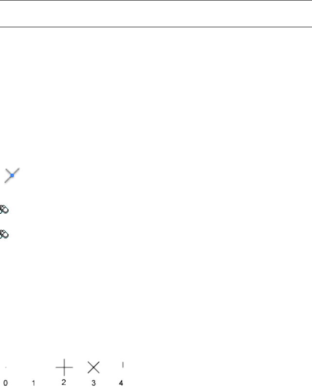
A Portable Network Graphics file is created that contains the objects you select.
The file reflects what is displayed on the screen. Light glyphs that are displayed
in the drawing appear in the new file, even if the Plot Glyph property of the
lights is set to No.
NOTE When the FILEDIA (page 1296) system variable is set to 0 (Off), prompts are
displayed at the Command prompt.
See also:
Export Raster Files
POINT
Creates a point object.
Access Methods
Button
Toolbar: Drafting tool set ➤ Open Shapes tool group (expanded) ➤
Point flyout ➤ Multiple Points
Menu: Draw ➤ Point ➤ Single
Summary
Points can act as nodes to which you can snap objects. You can specify a full
three-dimensional location for a point. The current elevation is assumed if
you omit the Z coordinate value.
The PDMODE (page 1388) and PDSIZE (page 1389) system variables control the
appearance of point objects. PDMODE values 0, 2, 3, and 4 specify a figure to
draw through the point. A value of 1 specifies that nothing is displayed.
Specifying the value 32, 64, or 96 selects a shape to draw around the point,
in addition to the figure drawn through it:
Commands | 815
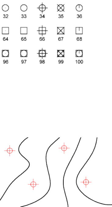
PDSIZE controls the size of the point figures, except for PDMODE values 0
and 1. A setting of 0 generates the point at 5 percent of the drawing area
height. A positive PDSIZE value specifies an absolute size for the point figures.
A negative value is interpreted as a percentage of the viewport size.
After you change PDMODE and PDSIZE, the appearance of existing points
changes the next time the drawing is regenerated.
You can use MEASURE and DIVIDE to create points along an object. Use
DDPTYPE to specify point size and styles easily.
List of Prompts
Specify a point: Specify a point in the drawing
See also:
Draw Reference Points
POINTLIGHT
Creates a point light that radiates light in all directions from its location.
816 | Chapter 2 Commands

Access Methods
Button
Toolbar: Modeling tool set ➤ Lights tool group ➤ Point Light
Menu: View ➤ Render ➤ Light ➤ New Point Light
Summary
Use point lights for general lighting effects.
List of Prompts
The following prompts are displayed.
Specify source location <0,0,0>: Enter coordinate values or use the
pointing device
If the LIGHTINGUNITS system variable is set to 0, the following prompt is
displayed:
Enter an option to change [Name (page ?)/Intensity (page
?)/Status (page ?)/shadoW (page ?)/Attenuation (page
?)/Color (page ?)/eXit (page ?)] <eXit>:
If the LIGHTINGUNITS system variable is set to 1 or 2, the following prompt
is displayed:
Enter an option to change [Name (page ?)/Intensity factor
(page ?)/Status (page ?)/Photometry (page ?)/shadoW (page
?)/Attenuation (page ?)/filterColor (page ?)/eXit (page
?)] <eXit>:
NOTE
When the LIGHTINGUNITS system variable is set to 1 or 2, the Attenuation
option has no affect on the creation of the light. It is only maintained for
scripting compatibility.
Name
Specifies the name of the light. You can use uppercase and lowercase letters,
numbers, spaces, hyphens (-), and underscores (_) in the name. The maximum
length is 256 characters.
Enter light name:
Commands | 817
Intensity/Intensity Factor
Sets the intensity or brightness of the light. The range is 0.00 to the maximum
value that is supported by your system.
Enter intensity (0.00-max float) <1.0000>:
Status
Turns the light on and off. If lighting is not enabled in the drawing, this setting
has no effect
Enter status [oN/oFf] <On>:
Photometry
Photometry is available when the LIGHTINGUNITS system variable is set to
1 or 2. Photometry is the measurement of the luminous intensities of visible
light sources.
In photometry, luminous intensity is a measure of the perceived power emitted
by a light source in a particular direction. Luminous flux is the perceived
power per unit of solid angle. The total luminous flux for a is the perceived
power emitted in all directions. Luminance is the total luminous flux incident
on a surface, per unit area.
Enter a photometric option to change [Intensity/Color/eXit] <I>:
Intensity Enter intensity (Cd) or enter an option [Flux/Illuminance]
<1500.0000>:
Enter an intensity value in candelas, the perceived power in a luminous flux
value, or illuminance value for the total luminous flux incident on a surface.
■Candela (symbol: cd) is the SI unit of luminous intensity (perceived power
emitted by a light source in a particular direction). Cd/Sr
■Lux (symbol: lx) is the SI unit of illuminance. Lm/m^2
■Foot-candle (symbol: fc) is the American unit of illuminance. Lm/ft^2
Enter f to specify the perceived power in a luminous flux value.
Enter Flux (Lm) <18849.5556>:
If you enter i, you can specify the intensity of the light based on an
illuminance value.
Enter Illuminance ("Lx"|"Fc") or enter an option [Distance] <1500.0000>:
The illuminance value can be specified in either lux or foot-candles. Enter d
to specify a distance to use to calculate illuminance.
Enter Distance <1.0000>:
Color Enter color name or enter an option [?/Kelvin] <D65White>:
818 | Chapter 2 Commands
Specify the color of the light based on a color name or a Kelvin temperature.
Enter ? to display a list of color names.
Enter color name(s) to list <*>:
Enter a text string using wild card characters to display a partial listing of color
names, or an asterisk (*) to display all the possible choices.
If you enter k, you can specify the color of the light based on a Kelvin
temperature value.
Enter Kelvin temperature <3600.0000>:
Exit Exits the command option.
Shadow
Makes the light cast shadows.
Enter shadow settings [Off/Sharp/soFtmapped/softsAmpled] <Sharp>:
Off Turns off display and calculation of shadows for the light. Turning shadows
off increases performance.
Sharp Displays shadows with sharp edges. Use this option to increase
performance.
Soft Mapped Displays realistic shadows with soft edges.
Enter map size [64/128/256/512/1024/2048/4096] <256>:
Specifies the amount of memory to use to calculate the shadow map.
Enter softness (1-10) <1>:
Specifies the softness to use to calculate the shadow map.
Soft Sampled Displays realistic shadows with softer shadows (penumbra)
based on extended light sources.
Enter an option to change [Shape/sAmples/Visible/eXit]<eXit> :
Specify the shape of the shadow by entering s and then the dimensions of
the shape. (For example, the radius of the sphere or the length and width of
a rectangle.)
Enter shape [Linear, Disk, Rect, Sphere,Cylinder] <Sphere>:
Specify the sample size by entering a.
Enter Shadow Sample <16.0000>:
Specify the visibility of the shape by for the shadow by entering v.
Enter Shape Visibility [Yes/No]<No>:
Attenuation
Enter an option to change [attenuation Type/Use limits/attenuation start
Limit/attenuation End limit/eXit]<eXit>:
Commands | 819
Attenuation Type Controls how light diminishes over distance. The farther
away an object is from a point light, the darker the object appears. Attenuation
is also known as decay.
Enter attenuation type [None/Inverse linear/inverse Squared] <Inverse linear>:
■None. Sets no attenuation. Objects far from the point light are as bright
as objects close to the light.
■Inverse Linear. Sets attenuation to be the inverse of the linear distance
from the light. For example, at a distance of 2 units, light is half as strong
as at the point light; at a distance of 4 units, light is one quarter as strong.
The default value for inverse linear is half the maximum intensity.
■Inverse Squared. Sets attenuation to be the inverse of the square of the
distance from the light. For example, at a distance of 2 units, light is one
quarter as strong as at the point light; at a distance of 4 units, light is one
sixteenth as strong.
Use Limits Specifies whether to use limits or not.
Limits [oN/oFf] <Off>:
Attenuation Start Limit Specifies the point where light starts as an offset
from the center of the light. The default is 0.
Specify start limit offset <1.0000>:
Attenuation End Limit Specifies the point where light ends as an offset from
the center of the light. No light is cast beyond this point. Setting an end limit
increases performance where the effect of lighting is so minimal that the
calculations are wasted processing time.
Specify end limit offset <10.0000>:
Color/Filter Color
Controls the color of the light.
Enter true color (R,G,B) or enter an option [Index
color/Hsl/colorBook]<255,255,255>:
True Color Specifies a True Color. Enter in the format R,G,B (red, green, blue).
Index Specifies an ACI (AutoCAD Color Index) color.
Enter color name or number (1-255):
HSL Specifies an HSL (hue, saturation, luminance) color.
Enter HSL color (H,S,L) <0,0,100>:
Color Book Specifies a color from a color book.
Enter Color Book name:
820 | Chapter 2 Commands
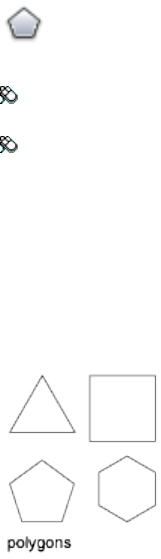
Exit
Exits the command.
See also:
Use Point Lights
POLYGON
Creates an equilateral closed polyline.
Access Methods
Button
Toolbar: Drafting tool set ➤ Closed Shapes tool group (expanded) ➤
Polygon
Menu: Draw ➤ Polygon
List of Prompts
The following prompts are displayed.
Enter number of sides <current>: Enter a value between 3 and 1024 or press
Enter
Specify center of polygon (page ?) or [Edge (page ?)]: Specify
a point (1) or enter e
Center of Polygon
Defines the center of the polygon.
Enter an option [Inscribed in circle/Circumscribed about circle] <current>:
Enterior cor press Enter
Commands | 821

Inscribed in Circle Specifies the radius of a circle on which all vertices of the
polygon lie.
Specify radius of circle: Specify a point (2) or enter a value
Specifying the radius with your pointing device determines the rotation and
size of the polygon. Specifying the radius with a value draws the bottom edge
of the polygon at the current snap rotation angle.
Circumscribed about Circle Specifies the distance from the center of the
polygon to the midpoints of the edges of the polygon.
Specify radius of circle: Specify a distance
Specifying the radius with your pointing device determines the rotation and
size of the polygon. Specifying the radius with a value draws the bottom edge
of the polygon at the current snap rotation angle.
Edge
Defines a polygon by specifying the endpoints of the first edge.
Specify first endpoint of edge: Specify a point (1)
Specify second endpoint of edge: Specify a point (2)
822 | Chapter 2 Commands
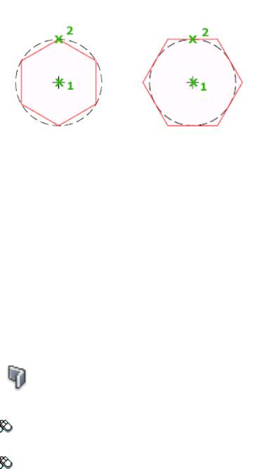
You can specify the different parameters of the polygon including the number
of sides. The difference between the inscribed and circumscribed options is
shown.
See also:
Draw Rectangles and Polygons
POLYSOLID
Creates a 3D wall-like polysolid.
Access Methods
Button
Toolbar: Modeling tool set ➤ Solids - Create tool group ➤ Solid
Primitives flyout ➤ Polysolid
Menu: Draw ➤ 3D Modeling ➤ Polysolid
Summary
You can create walls with straight and curved segments of constant height
and width.
Commands | 823
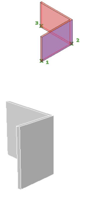
With the POLYSOLID command, you can convert an existing line, 2D polyline,
arc, or circle to a solid with a rectangular profile. A polysolid can have curved
segments, but the profile is always rectangular by default.
You can draw a solid with POLYSOLID just as you would a polyline. The
PSOLWIDTH (page 1409) system variable sets the default width for the solid.
The PSOLHEIGHT (page 1409) system variable sets the default height for the
solid.
List of Prompts
The following prompts are displayed.
Specify start point or [Object (page ?)/Height (page
?)/Width (page ?)/Justify (page ?)] <Object>: Specify a start
point for the profile of the solid, press Enter to specify an object to convert to a
solid, or enter an option
824 | Chapter 2 Commands
Specify the next point (page ?) or [Arc (page ?)/Undo (page
?)]: Specify the next point for the profile of the solid, or enter an option
Object
Specifies an object to convert to a solid. You can convert:
■Line
■Arc
■2D polyline
■Circle
Select object: Select an object to convert to a solid
Height
Specifies the height of the solid. The default height is set to the current
PSOLHEIGHT (page 1409) setting.
Specify height <default>: Specify a value for the height, or press Enter to specify
the default value
The specified height value will update the PSOLHEIGHT (page 1409) setting.
Width
Specifies the width of the solid. The default width is set to the current PSOL-
WIDTH (page 1409) setting.
Specify width <current>: Specify a value for the width by entering a value or
specifying two points, or press Enter to specify the current width value
The specified width value will update the PSOLWIDTH (page 1409) setting.
Justify
Sets the width and height as the solid to be left, right, or center justified when
defining the profile with the command. The justification is based on the
starting direction of the first segment of the profile.
Enter justification [Left/Center/Right] <Center>: Enter an option for the
justification or press Enter to specify center justification
Next Point
Specify the next point or [Arc/Close/Undo]: Specify the next point for the profile
of the solid, enter an option, or press Enter to end the command
Arc Adds an arc segment to the solid. The default starting direction of the arc
is tangent to the last drawn segment. You can specify a different starting
direction with the Direction option.
Commands | 825
Specify endpoint of arc or [Close/Direction/Line/Second point/Undo]: Specify
an endpoint or enter an option
■Close. Closes the solid by creating a line or arc segment from the last point
specified to the starting point of the solid. At least two points must be
specified to use this option.
■Direction. Specifies a starting direction for the arc segment.
Specify the tangent direction from the start point of arc: Specify a point
Specify endpoint of arc: Specify a point
■Line. Exits the Arc option and returns to the initial POLYSOLID command
prompts.
■Second Point. Specifies the second point and endpoint of a three-point
arc segment.
Specify second point on arc: Specify a point
Specify end point of arc: Specify a point
■Undo. Removes the most recent arc segment added to the solid.
Close Closes the solid by creating a line or arc segment from the last point
specified to the starting point of the solid. At least three points must be
specified to use this option.
Undo Removes the most recent arc segment added to the solid.
Arc
Adds an arc segment to the solid. The default starting direction of the arc is
tangent to the last drawn segment. You can specify a different starting direction
with the Direction option.
Specify endpoint of arc or [Close/Direction/Line/Second point/Undo]: Specify
an endpoint or enter an option
Close Closes the solid by creating a linear or arc segment from the last vertex
to the start of the solid.
Direction Specifies a starting direction for the arc segment.
Specify the tangent direction from the start point of arc: Specify a point
Specify endpoint of arc: Specify a point
Line Exits the Arc option and returns to the initial POLYSOLID command
prompts.
Second Point Specifies the second point and endpoint of a three-point arc
segment.
Specify second point on arc: Specify a point
826 | Chapter 2 Commands
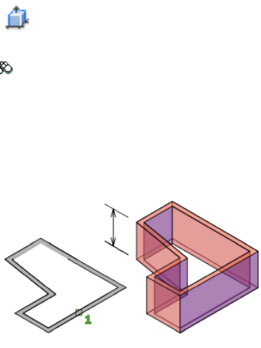
Specify end point of arc: Specify a point
Undo Removes the most recent arc segment added to the solid.
Undo
Removes the most recent segment added to the solid.
See also:
Create a Polysolid
PRESSPULL
Presses or pulls bounded areas.
Access Methods
Button
Toolbar: Modeling tool set ➤ Solids - Create tool group ➤ Presspull
Summary
Press or pull a bounded area by clicking inside the area, and then moving the
cursor or entering a value to specify the extrusion distance.
The command repeats automatically until you press Esc, Enter, or the spacebar.
List of Prompts
The following prompts are displayed.
Commands | 827

Click inside bounded areas to press or pull Click inside a bounded area, and
then drag and click to specify the extrusion distance. You can also enter a
value for the distance.
See also:
Press or Pull Bounded Areas
PREVIEW
Displays the drawing as it will be printed.
Summary
The preview is based on the current print configuration, as defined by the
settings in the Page Setup dialog box (page 753). It shows exactly how the
drawing will look when printed, including lineweights, fill patterns, and other
print options.
NOTE An output device must be assigned to the layout before a preview can be
generated.
The toolbar along the top of the Preview window allows you to view different
areas of the print, search for text, and copy a selected area to the Clipboard.
Preview Window Toolbar (Mac OS X Lion)
Provides options in the Preview window.
Zoom Reduces or enlarges the preview image. Click (-) to reduce the preview
image and (+) to enlarge the preview image.
Move Moves the preview image planar to the screen.
Text Allows you to select text objects. (Not available in AutoCAD for Mac)
Select Creates a selection window in the preview image that allows you to
copy part of the preview to the Clipboard.
View Controls the view type to use when previewing multi-pages.
Search Allows you to search for a text string in the preview. (Not available in
AutoCAD for Mac)
Preview Window Toolbar (Mac OS X Snow Leopard)
Provides options in the Preview window.
Previous Displays the previous page in a multi-page preview.
828 | Chapter 2 Commands
Next Displays the next page in a multi-page preview.
Zoom Reduces or enlarges the preview image. Click (-) to reduce the preview
image and (+) to enlarge the preview image.
Move Moves the preview image planar to the screen.
Text Allows you to select text objects. (Not available in AutoCAD for Mac)
Select Creates a selection window in the preview image that allows you to
copy part of the preview to the Clipboard.
Sidebar Displays a secondary pane that contains thumbnails for multi-page
previews.
Search Allows you to search for a text string in the preview. (Not available in
AutoCAD for Mac)
See also:
Preview a Plot
PROJECTGEOMETRY
Projects points, lines, or curves onto a 3D solid or surface from different
directions.
Summary
By projecting geometry you can do on of the following:
■Project points or curves onto a 3D solid or surface.
■Project and trim a selected 3D solid or surface.
To trim the surface, set the SURFACEAUTOTRIM (page 1453) system variable to
1.
You can project any curve (line, arc, circle, ellipse, 2D polyline, 2D spline-fit
polyline, 2D curve-fit polyline, 3D polyline, 3D spline-fit polyline, spline, or
helix) onto any type of surface or solid.
List of Prompts
The following prompts are displayed.
Project to UCS
Commands | 829
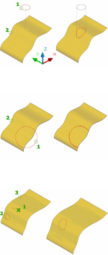
Projects the geometry along the positive or negative Z axis of the current UCS.
Project to View
Projects the geometry based on the current view.
Project to Two Points
Projects the geometry along a path between two points.
See also:
Trim and Untrim Surfaces
830 | Chapter 2 Commands

PROPERTIES
Controls properties of existing objects.
Access Methods
Menu: Modify ➤ Properties
Shortcut menu: Select the objects whose properties you want to view or
modify, right-click in the drawing area, and click Properties.
Summary
The Properties Inspector palette (page 832) is displayed and lists the properties
of the selected objects.
When more than one object is selected, only those properties common to all
selected objects are displayed.
When no objects are selected, only the current settings of general properties
are displayed.
You can also view or modify properties of third-party application objects that
are based on AutoCAD application programming interface (API) standards.
There are several general properties (page 833) common to all objects. All other
object properties are specific to the type of object.
See also:
Display and Change the Properties of Objects
Commands | 831
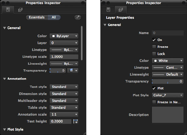
Properties Inspector Palette
Displays the properties of the selected object or set of objects.
Layer PropertiesCurrent Properties
Summary
When more than one object is selected, only those properties common to all
selected objects are displayed. When no objects are selected, only the current
settings of general properties are displayed.
You can specify a new value to modify any property that can be changed.
Click the value and use one of the following methods:
■Enter a new value.
■Click the down arrow a the right and select a value from the list.
■Click the Pick Point button to use the pointing device to change a
coordinate value.
■Click the […] button and change the property value in a dialog box.
■Select or clear a check box to toggle a property on or off.
■Drag a slider left or right.
832 | Chapter 2 Commands
List of Options
The following options are displayed.
Current Displays the properties for the current drawing or selected objects.
Layer Displays the properties for the layer selected in the Layer list of the
Layers palette.
Object Type Displays the type of objects that are selected and filters which
objects you are modifying.
Essentials Displays the most commonly edited or viewed properties for the
current drawing or selected objects.
All Displays all the properties associated with the current drawing or the
selected objects.
Match Properties Applies the properties of a selected object to other objects.
Drawing/Objects/Layer Properties Displays a list of available properties that
can currently be edited. The list of properties show is based on the following
conditions:
■No objects selected in the current drawing. Drawing specific properties are
displayed.
■Objects selected in the current drawing. Properties common to all selected
objects are displayed.
■Layer selected from the Layer list in the Layers palette. Layer properties
are displayed.
See also:
Display and Change the Properties of Objects
General Properties of Objects
Each graphical object in a drawing shares a common set of properties known
as the general properties.
Summary
The following general properties are common to most objects and custom
objects (third-party application objects based on AutoCAD API standards).
Commands | 833
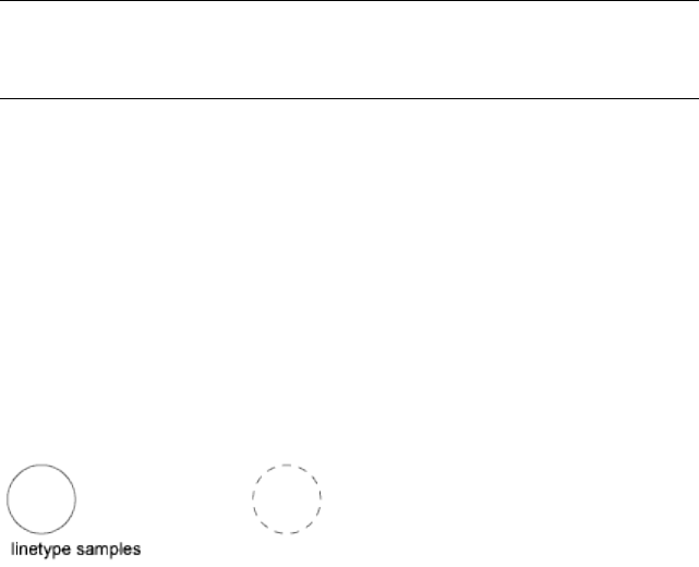
NOTE
Layers or objects that are assigned property overrides in viewports display a
ByLayer (VP) value and a background color for applicable properties.
List of Options
The following options are displayed.
Color Specifies the color for objects. Selecting Select Color in the color list
allows you to define the color of objects by selecting from the 255 AutoCAD
Color Index (ACI) colors, true colors, and color book colors (see COLOR (page
198)).
Layer Specifies the current layer of the object. The list shows all layers in the
current drawing (see LAYER (page 537)).
Linetype Specifies the current linetype of the object. The list shows all
linetypes in the current drawing (see LINETYPE (page 575)).
Linetype Scale Specifies the linetype scale factor of the object (see LTSCALE
(page 593)).
Plot Style Lists NORMAL, BYLAYER, BYBLOCK, plus any plot styles contained
in the current plot style table (see PLOTSTYLE (page 808)).
Lineweight Specifies the lineweight of the object. The list shows all available
lineweights in the current drawing (see LWEIGHT (page 593)).
Hyperlink Attaches a hyperlink to a graphical object. If a description has been
assigned to the hyperlink, the description is displayed. If no description has
been assigned, the URL is displayed (see HYPERLINK).
Transparency Specifies the transparency of the object (see TRANSPARENCY
(page 1065)).
Thickness Sets the current 3D thickness. This property does not apply to all
objects (see CHPROP (page 190)).
834 | Chapter 2 Commands
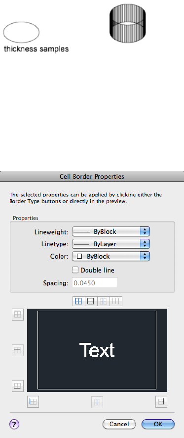
See also:
Display and Change the Properties of Objects
Cell Border Properties Dialog Box
Sets the properties of the borders of table cells.
Commands | 835

Access Methods
Pointing device: With a table cell selected and the Properties Inspector
palette open, click All. Under the Cell section, click the button to the right of
the Border Style field.
List of Options
The following options are displayed.
Properties
Controls the properties of the borders of the selected table cells.
Lineweight
Sets the lineweight to be used for borders that are displayed. If you use a heavy
lineweight, you may have to change the cell margins.
Linetype
Sets the linetype to be used for borders that are displayed.
Color
Sets the color to be used for borders that are displayed.
Double Line
When checked, a double line border will be added to the selected cells.
Spacing
Determines the spacing of double-line borders. The default value is .1800.
Preview
Displays a preview of how the borders of the selected table will look.
NOTE
Linetypes will not display in the preview.
All Borders
Applies the border properties settings to all borders of the selected table cells.
Outside Borders
Applies the border properties settings to the outside borders of the selected
table cells.
Inside Borders
836 | Chapter 2 Commands
Applies the border properties settings to the inside borders of the selected
table cells.
No Borders
Applies the border properties settings to none of the borders of the selected
table cells.
Top Border Applies the border properties setting to the top borders of the
selected table cells.
Inside Horizontal Border Applies the border properties setting to the inside
horizontal borders of the selected table cells.
Bottom Border Applies the border properties setting to the bottom borders
of the selected table cells.
Left Border Applies the border properties setting to the left borders of the
selected table cells.
Inside Vertical Border Applies the border properties setting to the inside
vertical border of the selected table cells.
Right Border Applies the border properties setting to the right border of the
selected table cells.
See also:
Display and Change the Properties of Objects
Lighting Properties
Sets the properties of the lights.
Summary
Different properties area available depending on the lighting units (standard
or photometric) and lighting type (Spotlight (page 997), Pointlight (page 816),
or Weblight (page 1130)). Other lighting types such as Freespot (page 444), Tar-
getpoint (page 1040), and Freeweb (page 447) display similar properties. By
right-clicking on a light and clicking Properties, the Lighting category of the
Properties Inspector palette (page 832) is displayed.
List of Options
The following options are displayed.
Commands | 837
General Properties
The following property settings are available:
Name Specifies the name of the light.
Type (Light Distribution) Specifies the type of light. Determines the
distribution of light from the . The type of lighting can be changed after the
light has been added to the drawings.
■Spotlight - Default value for Spotlight and Freespot lights.
■Point - Default for Pointlight and Targetpoint lights.
■Web - Default for Weblight and Freeweb lights.
On/Off Status Indicates whether the light is on or off.
Shadows Indicates if the light is casting a shadow.
Hotspot Angle (Spotlight and Freespot only) Specifies the angle of the
brightest cone of light.
Falloff Angle (Spotlight and Freespot only) Specifies the outer extremity of
the light, where it meets the darkness.
Intensity Factor Magnifies the effect of the skylight.
Filter Color Specifies the secondary color of the light. Represents the color of
a physical filter over the lamp. Default color is white.
When lighting is set to photometric units this represents a secondary color
filter on the light. When lighting is set to generic lighting this represents the
total color of the light.
Plot Glyph Allows the ability to plot the drawing with the glyphs on.
Photometric Properties
The following property settings are available:
Lamp Color Specifies the inherent color of the light in Kelvin temperature
or standard.
Resulting Color Reports the final color of the light. This is determined by a
combination of the Lamp Color and the Filter Color. (Read-only)
Intensity Method Specifies the value in which light intensity should be
measured.
■Intensity (Candela). Specifies the number of candelas (cd) is the SI unit
of luminous intensity (perceived power emitted by a light source in a
particular direction).
838 | Chapter 2 Commands
■Flux (Lumen). Represents the rate of total energy leaving the lamp. It is
specified in lumens (SI and American). Mathematically, the flux is the
integral of the luminous intensity over the sphere. The calculation of flux
depends on the distribution of intensities. For a point light with constant
intensity, the flux is simply the product of the intensity and the solid angle
of a sphere: 4 Pi * Intensity. For a spot light, the flux is the product of the
intensity and the solid angle of the hotspot cone, plus the incremental
solid angle of the fall-off region. For a weblight, there isn’t any analytical
formula. The flux is obtained by numerically integrating the intensities
provided in the web file.
■Illuminance (Foot-candles). Represents the energy per area arriving at
a surface (Area-flux-density). It is specified in lux (SI) and foot-candles
(American). For a near light, because the light rays are diverging, you have
to talk about the illuminance at a specific distance from the lamp. So this
requires an extra control to specify this distance and an additional
affordance in the viewport to show the distance.
Lamp Intensity Specifies the brightness of a lamp. More specifically, it
represents the luminous intensity, or power in a particular direction.
Intensity Factor Magnifies the effect of the skylight.
Resulting Intensity Reports the final brightness of the light. This is determined
by the product of the Lamp Intensity and the Intensity factor. (Read-only)
PhotometricWeb
The following property settings are available for Web and Freeweb lights:
Web File Specifies the data file describing the intensity distribution of the
light.
Web Offsets
Under the Web offsets panel, the following property settings are available
under the Weblight and Freeweb types of lights:
Rotate X Specifies a rotational offset of the web about the optical X axis.
Rotate Y Specifies a rotational offset of the web about the optical Y axis.
Rotate Z Specifies a rotational offset of the web about the optical Z axis.
Geometry
Under the Geometry panel, the following property settings are available:
Position X Specifies the X coordinate position of the light.
Position Y Specifies the Y coordinate position of the light.
Commands | 839
Position Z Specifies the Z coordinate position of the light.
Target X Specifies the X coordinate target position of the light. (Spotlight,
Targetpoint, and Weblight only)
Target Y Specifies the Y coordinate target position of the light. (Spotlight,
Targetpoint, and Weblight only)
Target Z Specifies the Z coordinate target position of the light. (Spotlight,
Targetpoint, and Weblight only)
Targeted Specifies if the light displays a target grip for orienting the light.
Disabled is the default for Freespot, Pointlight, and Freeweb. Enabled is the
default for Spotlight, Targetpoint, and Weblight.
Attenuation
In the real world, the intensity of light diminishes over distance. Objects far
from the light source appear darker than objects near the source. This effect
is known as attenuation. Attenuation is available under standard lighting
workflow only. Under the Attenuation panel the following property settings
are available:
Type Controls how light diminishes over distance. The farther away an object
is from a spotlight, the darker the object appears. Attenuation is also known
as decay.
■Inverse Linear (Standard lights only). Sets attenuation to be the inverse of
the linear distance from the light. For example, at a distance of 2 units,
light is half as strong as at the point light; at a distance of 4 units, light is
one quarter as strong. The default value for inverse linear is half the
maximum intensity.
■Inverse Square (Photometric lights). Sets attenuation to be the inverse of
the square of the distance from the light. For example, at a distance of 2
units, light is one quarter as strong as at the spotlight; at a distance of 4
units, light is one sixteenth as strong.
■None (Standard lights only). Sets no attenuation. Objects far from the
point light are as bright as objects close to the light.
Use Limits Specifies whether to use limits. The default is No. (Standard lights
only)
Rendered Shadow Details
Under the Rendered Shadow Details panel, the following property settings
are available:
840 | Chapter 2 Commands
Type Specifies the type of shadow cast by the light.
■Soft (shadow map). Sets the type to Soft. This selection activates additional
options for Map size and Softness.
■Sharp (default). Sets the rendered shadow to sharp.
■Soft (sampled). Sets attenuation to be the inverse of the square of the
distance from the light. For example, at a distance of 2 units, light is one
quarter as strong as at the spotlight; at a distance of 4 units, light is one
sixteenth as strong.
Map Size Specifies the size of the shadow map. (Soft shadow map type only)
Softness Specifies the softness or fuzziness of the shadow-mapped shadow.
(Soft shadow map type only)
Samples Specifies the number of shadow rays for the light. (Soft sampled type
only)
Visible in Render Specifies whether the light shape is actually rendered. The
default is No. (Soft sampled type only)
Shape Specifies the shape of the lamp bulb. For the Spotlight distribution type
selection under the General panel, options are Rectangle (default) and Disk.
For Point and Web types the options are Linear, Rectangle, Disk, Cylinder and
Sphere (default). (Soft sampled type only)
Length Specifies spacial dimension of shadow shape for the length of the
shadow. (Soft sampled type only)
Width Specifies spacial dimension of shape for the width of the shadow. (Soft
sampled type only)
Radius Specifies spacial radius dimension of the shape selection of disk,
cylinder, or sphere. (Soft sampled type only)
See also:
Control Light Properties
Sun & Sky Properties
Sets the properties of the sun and sky.
Commands | 841
List of Options
The following options are displayed.
Sun - Sun Angle
Source Vector Displays the coordinates of the direction of the sun. This setting
is read-only.
Date and Time Displays the current date and time setting.
Longitude Displays the longitude of the current location. You can enter a
value or select a location on the map. (LONGITUDE (page 1363) system variable)
The valid range is -180 to +180 as a floating point number.
Latitude Sets the latitude of the current location. You can enter a value or
select a location on the map. (LATITUDE (page 1345) system variable)
The valid range is -90 and +90 as a floating point number.
Daylight Saving Displays the current setting for daylight saving time.
Azimuth Displays the angle of the sun along the horizon clockwise from due
north. This setting is read-only.
Altitude Displays the angle of the sun vertically from the horizon. The
maximum is 90 degrees, or directly overhead. This setting is read-only.
Display Sun Light Turns the sun on and off. If lighting is not enabled in the
drawing, this setting has no effect.
Intensity Factor Sets the intensity or brightness of the sun. The range is from
0 (no light) to maximum. The higher the number, the brighter the light.
Color Controls the color of the light.
Cast Shadows Turns display and calculation of shadows for the sun on and
off. Turning shadows off increases performance.
Sun - Sun Disk Appearance
Disk Scale Specifies the scale of the sun disk (1.0 = correct size).
Glow Intensity Specifies the intensity of the sun glow. Values are 0.0-25.0.
Disk Intensity Specifies the intensity of the sun disk. Values are 0.0-25.0.
Sky
Display Sky Determines if the sky illumination is computed at render time.
This has no impact on the viewport illumination or the background. It simply
makes the sky available as a gathered light source for rendering. Note this does
not control the background.
842 | Chapter 2 Commands
Intensity Factor Provides a way to magnify the effect of the skylight. Values
are 0.0-MAX. [1.0] is default.
Haze Determines the magnitude of scattering effects in the atmosphere. Values
are 0.0-15.0. [0.0] is default.
Sky - Sky Horizon
Height Determines the absolute position of the ground plane relative to world
zero. This parameter represents a world-space length and should be formatted
in the current length unit. Values are -10.0 to +10.0 [0.0] is default.
Blur Determines the amount of blurring between ground plane and sky. Values
are 0-10. [.1] is default.
Ground Color Determines the color of the ground plane.
Sky - Advanced Sky
Night Color Specifies the color of the night sky.
Aerial Perspective Specifies if aerial perspective is applied. Values are On/Off.
Visibility Distance Specifies the distance at which 10% haze occlusion results.
Values are 0.0-MAX.
Rendered Shadow Details
Type Displays the setting for shadow type. This setting is read-only when
display of shadows is turned off. The selections are Sharp, Soft (mapped) which
display the Map size option and Soft (area) which displays the Samples option.
Soft (area) is the only option for the sun in photometric workflow
(LIGHTINGUNITS = 1 or 2).
Samples Specifies the number of samples to take on the solar disk. This setting
is read-only when display of shadows is turned off. Values are 0-1000.
Softness Displays the setting for the appearance of the edges of shadows. This
setting is read-only when display of shadows is turned off. Values are 1-10.
See also:
Sun and Sky Simulation
PROPERTIESCLOSE
Closes the Properties Inspector palette.
Commands | 843
Summary
The Properties Inspector palette closes.
See also:
Display and Change the Properties of Objects
PSETUPIN
Imports a user-defined page setup into a new drawing layout.
Summary
The Select Page Setup From File dialog box (a standard file selection dialog
box (page 720)) is displayed in which you can select the drawing (.dwg), template
(.dwt), or drawing interchange format (.dxf) file whose page setups you want
to import.
If FILEDIA (page 1296) is set to 0 (zero) and you enter -psetupin at the
Command prompt, PSETUPIN displays command prompts (page 844).
When you select the drawing file that you want to use, the Import Page Setups
dialog box (page 759) is displayed.
See also:
Specify Page Setup Settings
-PSETUPIN
If you enter -psetupin at the Command prompt, the following prompts are
displayed.
Enter file name: Enter the name of the drawing file that contains the pagesetup
to import
Enter user defined page setup to import or [?]: Enter the name
of the page setup to import
See also:
Specify Page Setup Settings
844 | Chapter 2 Commands
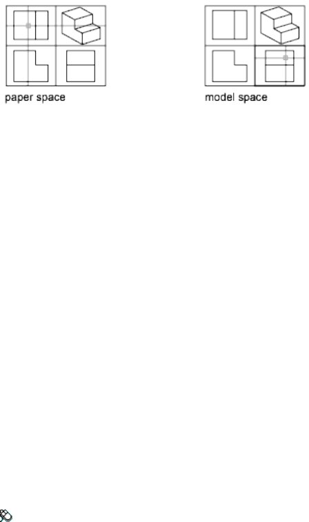
PSPACE
In a layout, switches from model space in a viewport to paper space.
Summary
The program switches from model space to paper space when you are working
on a named (paper space) layout.
On the named layout, use paper space to create a finished layout of a drawing
for printing. As part of designing your layout, you create layout viewports,
which are windows containing different views of the model. By switching
from paper space to model space (see MSPACE (page 673)), you can edit the
model and views within the current layout viewport.
You can make a viewport current by double-clicking inside it. You can switch
to paper space by double-clicking an area of the paper space layout that is not
within a viewport.
You can also switch between layouts by using the Layouts drop-down list or
QuickView on the status bar.
See also:
Work in Model Space
Work on a Named Layout
PUBLISH
Publishes a set of drawings to PDF files or printers.
Access Methods
Menu: File ➤ Batch Publish
Commands | 845
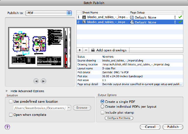
Summary
The Batch Publish dialog box (page 846) is displayed. You can assemble a
collection of drawings, and create a PDF file or hardcopy of the selected
drawings. PDF files can be viewed with a PDF viewer.
See also:
Overview of Publishing
Batch Publish Dialog Box
Specifies drawing sheets that you can assemble, reorder, and publish as a
multi-sheet drawing set.
Summary
You can publish the drawing set to a PDF file or send it to the printer named
in the page setup for hardcopy output.
846 | Chapter 2 Commands
List of Options
The following options are displayed.
Publish To:
Defines how to layouts should be published. You can publish to either a PDF
file (an electronic drawing set) or to the printer specified in the page setup (a
paper drawing set).
PDF Indicates that the layouts should be published to a PDF file.
Printer from Page Setup Indicates that the output device given for each
layout's page setup will be used.
Preview
Displays a preview of the selected layout in the Sheet list. Click the Next and
Previous buttons to preview another layout in the Sheet list.
Sheet List
Contains the list of drawing sheets to be included for publishing. Click the
page setup column to change the sheet’s settings. Use the shortcut menu to
add sheets or make other changes to the list.
Sheet Name Combines the drawing name and the layout name with a dash
(-). Drawing sheet names must be unique within a single PDF file.
Page Setup Displays the named page setup for the sheet. You can change the
page setup by clicking the page setup name and selecting another page setup
from the list. Only Model page setups can be applied to Model sheets, and
only named layout page setups can be applied to named layout sheets.
Status Displays the status of the sheet when it is loaded to the list of sheets.
Manage Sheet List
Adds and removes layouts from the Sheet list.
Add Sheets (+) Displays the Select Drawings dialog box (a standard file selec-
tion dialog box (page 720)), in which you can select drawings to add to the list
of sheets. The layout names from those files are extracted, and one sheet is
added to the list for each Model and named layout in the drawing. You can
use the Add Content list to specify to extract the Model layout only, named
layouts only, or both.
The initial sheet names are constructed from the base drawing name and the
layout name or the word Model separated by a dash (-).
Remove Sheets (-)
Deletes the selected sheets from the list.
Commands | 847
Add Open Drawings
Adds the Model layout and all named layouts from the drawings that are
currently open.
Sheet List Shortcut Menu
The following options are available when you right-click a sheet:
Move to Top Moves the selected sheets to the top of the list.
Move Up Moves the selected sheets up one position in the list.
Move Down Moves the selected sheets down one position in the list.
Move to Bottom Moves the selected sheets to the bottom of the list.
Sheet Details
Displays the following information about the selected sheet: status, source
drawing, drawing location, layout name, plot device, plot size, plot scale, and
page setup details.
Printer from Page Setup Options
The following options are specific to publishing to a printer.
Number of Copies Specifies the number of copies to publish.
Include Plot Stamp Places a plot stamp on a specified corner of each drawing
and logs it to a file. Click Configure Plot Stamp to display the Plot Stamp
Settings dialog box (page 801), and specify the content and look of the plot
stamp.
PDF Options
The following options are specific to publishing to a PDF file.
Show/Hide Advanced Options
Displays additional options that are available when publishing to PDF files.
Location
Specifies the location to save the PDF file to and display the PDF when
publishing is complete.
Use Predefined Save Location Specify the default location to save the PDF
files to. When publishing to a single PDF file, you can specify the location of
the file after clicking Publish as well.
Open when Complete When publishing completes, the PDF file will open
in a viewer application.
848 | Chapter 2 Commands
Output Options
Specifies how the layouts should be output for PDF files and if a plot stamp
is included on each layout.
Create a Single PDF A multi-sheet PDF file is created that contains all the
layouts in the Sheet list.
Create individual PDFs per Layout A single PDF file is created for each layout
in the Sheet list.
Include Plot Stamp Places a plot stamp on a specified corner of each drawing
and logs it to a file. Click Configure Plot Stamp to display the Plot Stamp
Settings dialog box (page 801), and specify the content and look of the plot
stamp.
Publish
Starts the publishing operation.
To display information about the published sheets, including any errors or
warnings, click the Plotting Details Report message balloon to displays the
Print Details dialog box (page 1106). This information is also saved to the Plot
and Publish log file.
See also:
Overview of Publishing
PURGE
Removes unused items, such as block definitions and layers, from the drawing.
Summary
Entering purge or -purge at the Command prompt displays options related
to removing unused named objects and some empty geometric objects (page
850).
Unused named objects can be removed from the current drawing. These
include block definitions, dimension styles, groups, layers, linetypes, and text
styles. Zero-length geometry and empty text objects can also be removed.
Commands | 849

NOTE
The PURGE command will not remove unnamed objects (zero-length geometry
or empty text and mtext objects) from blocks or locked layers.
See also:
Erase Objects
-PURGE
Removes unused named objects, such as block definitions and layers, from
the drawing at the Command prompt.
Summary
Allows you to remove unused named objects from a drawing at the Command
prompt. You can only remove one level of reference at a time. Repeat the
command until there are no unreferenced, named objects.
NOTE
The PURGE command will not remove unnamed objects (zero-length geometry
or empty text and mtext objects) from blocks or locked layers.
List of Prompts
The following prompts are displayed.
Type of Unused Objects to Purge
Deletes unused applications from blocks, dimension styles, groups, layers,
linetypes, materials, multileader styles, plot styles, shapes, text styles, multiline
styles, table styles, visual styles, regapps, zero-length geometry, empty text
objects, or all.
Enter Name (s) to Purge Enter an object name of * to list the objects.
Verify Each Name to Be Purged? Enter y to verify each name.
See also:
Erase Objects
850 | Chapter 2 Commands
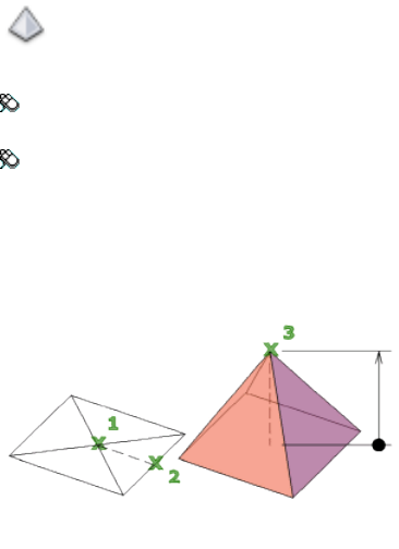
PYRAMID
Creates a 3D solid pyramid.
Access Methods
Button
Toolbar: Modeling tool set ➤ Solids - Create tool group ➤ Solid
Primitives flyout ➤ Pyramid
Menu: Draw ➤ 3D Modeling ➤ Pyramid
Summary
By default, a pyramid is defined by the center of the base point, a point on
the middle of the edge, and another point that determines the height.
Initially, the default base radius is not set to any value. During a drawing
session, the default value for the base radius is always the previously entered
base radius value for any solid primitive.
Use the Top Radius option to create a pyramid frustum.
List of Prompts
The following prompts are displayed.
Edge Specifies the length of one edge of the base of the pyramid; you pick
two points.
Specify first endpoint of edge: Specify a point
Specify second endpoint of edge: Specify a point
Commands | 851
Sides Specifies the number of sides for the pyramid. You can enter a number
from 3 to 32.
Specify number of sides <default>: Specify a diameter or press Enter to specify
the default value
Initially, the number of sides for the pyramid is set to 4. During a drawing
session, the default value for the number of sides is always the previously
entered value for the number of sides.
Inscribed Specifies that the base of the pyramid is inscribed within (drawn
within) the base radius of the pyramid.
Circumscribed Specifies that the pyramid is circumscribed around (drawn
around) the base radius of the pyramid.
2Point Specifies that the height of the pyramid is the distance between two
specified points.
Specify first point: Specify a point
Specify second point: Specify a point
Axis Endpoint Specifies the endpoint location for the pyramid axis. This
endpoint is the top of the pyramid. The axis endpoint can be located anywhere
in 3D space. The axis endpoint defines the length and orientation of the
pyramid.
Specify axis endpoint: Specify a point
Top Radius Specifies the top radius of the pyramid, creating a pyramid frustum.
Specify top radius: Enter a value
Initially, the default top radius is not set to any value. During a drawing session,
the default value for the top radius is always the previously entered top radius
value for any solid primitive.
Specify height or [2Point (Two Points)/Axis Endpoint] <default>: Specify a
height, enter an option, or press Enter to specify the default height value
■2Point. Specifies that the height of the pyramid is the distance between
two specified points.
Specify first point: Specify a point
Specify second point: Specify a point
■Axis Endpoint. Specifies the endpoint location for the pyramid axis. This
endpoint is the top of the pyramid. The axis endpoint can be located
anywhere in 3D space. The axis endpoint defines the length and orientation
of the pyramid.
Specify axis endpoint: Specify a point
852 | Chapter 2 Commands
See also:
Create a Solid Pyramid
Q Commands
QDIM
Creates a series of dimensions quickly from selected objects.
Access Methods
Button
Toolbar: Annotation tool set ➤ Dimensions tool group ➤ Quick
Dimension
Menu: Dimension ➤ Quick Dimension
Summary
This command is particularly useful for creating a series of baseline or
continued dimensions, or for dimensioning a series of circles and arcs.
List of Prompts
The following prompts are displayed.
Select geometry to dimension: Select the objects you want to dimension
or the dimensions you want to edit and press Enter
Specify dimension line position, or [Continuous (page
853)/Staggered (page 853)/Baseline (page 853)/Ordinate (page
854)/Radius (page 854)/Diameter (page 854)/datumPoint (page
854)/Edit (page 854)/seTtings (page 854)] <current>: Enter an option
or press Enter
Continuous Creates a series of continued dimensions.
Staggered Creates a series of staggered dimensions.
Baseline Creates a series of baseline dimensions.
Commands | 853
Ordinate Creates a series of ordinate dimensions.
Radius Creates a series of radial dimensions.
Diameter Creates a series of diameter dimensions.
Datum Point Sets a new datum point for baseline and ordinate dimensions.
Edit Edits a series of dimensions. You are prompted to add or remove points
from existing dimensions.
Settings Sets the default object snap for specifying extension line origins.
See also:
Overview of Dimensioning
QLEADER
Creates a leader and leader annotation.
Summary
It is recommended that you use the workflow available through the MLEADER
(page 651) command to create leader objects.
You can use QLEADER to
■Specify leader annotation and annotation format
■Set the location where leaders attach to multiline text annotation
■Limit the number of leader points
■Constrain the angle of the first and second leader segments
You can use the Leader Settings dialog box (page 855) to customize the
command so that it prompts you for the number of leader points and the
annotation type suited to your drawing needs.
If associative dimensioning is turned on with DIMASSOC, the leader start
point can be associated with a location on an object. If the object is relocated,
the arrowhead remains attached to the object and the leader line stretches,
but the text or feature control frame remains in place.
List of Prompts
The following prompts are displayed.
854 | Chapter 2 Commands
Specify first leader point, or [Settings] <Settings>: Specify
the first leader point, or press Enter to specify leader settings
First Leader Point
The Number of Points setting on the Leader Line & Arrow tab of the Leader
Settings dialog box (page 855) determines the number of leader points you are
prompted to specify.
Width If you set the text width value to 0.00, the width of the multiline text
is unlimited.
Tolerance If Tolerance is selected on the Annotation tab, the Geometric Tol-
erance dialog box (page 1058) is displayed. Use the dialog box to create the
tolerance feature control frame.
Enter block name or [?]: Enter the name, or enter ? to display a list of blocks defined
in the drawing
Insertion Point For a description of the insertion options, see INSERT Com-
mand Line (page 523).
Settings
Displays the Leader Settings dialog box (page 855).
See also:
Create Leaders
Modify Leaders Using Grips
Leader Settings Dialog Box
Creates a leader and leader annotation.
Summary
Customizes the QLEADER command and sets properties for leaders and leader
annotations.
The Leader Settings dialog box includes the following tabs: Annotation (page
?), Leader Line & Arrow (page ?), Attachment (page ?)
List of Tabs
The following tabs are displayed.
Commands | 855
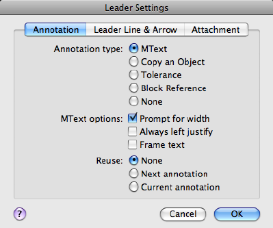
Annotation Tab (Leader Settings Dialog Box)
Annotation Type
Sets the leader annotation type. The type you select changes the QLEADER
leader annotation prompt.
MText
Prompts you to create multiline text (mtext) annotation.
Copy an Object
Prompts you to copy a multiline text, single-line text, tolerance, or block
reference object and connects the copy to the end of the leader line. The copy
is associated with the leader line, meaning that if the copied object moves,
the end of the leader line moves with it. The display of the hook line depends
on the object copied.
Tolerance
Displays the Tolerance dialog box, which you can use to create a feature control
frame to attach to the leader.
Block Reference
Prompts you to insert a block reference. The block reference is inserted at an
offset from the end of the leader line and is associated to the leader line,
meaning that if the block moves, the end of the leader line moves with it. No
hook line is displayed.
None
Creates a leader with no annotation.
856 | Chapter 2 Commands
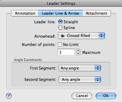
MText Options
The options are available only when the multiline text annotation type is
selected.
Prompt for Width
Prompts you to specify the width of the multiline text annotation.
Always Left Justify
Left-justifies the multiline text annotation, regardless of leader location.
Frame Text
Places a frame around multiline text annotation.
Annotation Reuse
Sets options for reusing leader annotation.
None
Does not reuse leader annotation.
Reuse Next
Reuses the next annotation you create for all subsequent leaders.
Reuse Current
Reuses current annotation. This option is automatically selected when you
reuse annotation after selecting Reuse Next.
Leader Line & Arrow Tab (Leader Settings Dialog Box)
Commands | 857
Leader Line
Sets the leader line format.
Straight
Creates straight-line segments between the points you specify.
Spline
Creates a spline object using the leader points you specify as control points.
Arrowhead
Defines the leader arrowhead. The arrowheads are also available for dimension
lines (DIMSTYLE (page 314) command). If you select User Arrow, a list of blocks
in the drawing is displayed.
Number of Points
Sets the number of leader points that QLEADER prompts you to specify before
prompting for the leader annotation. For example, if you set the points to 3,
QLEADER automatically prompts you to specify the annotation after you
specify two leader points. Set the number to one more than the number of
leader segments you want to create.
If you set the option to No Limit, QLEADER prompts for leader points until
you press Enter.
Angle Constraints
Sets angle constraints for the first and second leader lines.
First Segment
Sets the angle of the first leader segment.
Second Segment
Sets the angle of the second leader segment.
Attachment Tab (Leader Settings Dialog Box)
Sets the attachment location for leader lines and multiline text annotation.
This tab is available only when Mtext is selected on the Annotation tab.
858 | Chapter 2 Commands
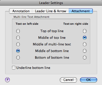
Top of Top Line
Attaches the leader line at the top of the top multiline text line.
Middle of Top Line
Attaches the leader line at the middle of the top multiline text line.
Middle of Multiline Text
Attaches the leader line at the middle of the multiline text.
Middle of Bottom Line
Attaches the leader line at the middle of the bottom multiline text line.
Bottom of Bottom Line
Attaches the leader line at the bottom of the bottom multiline text line.
Underline Bottom Line
Underlines the bottom multiline text line.
See also:
Create Leaders
Modify Leaders Using Grips
Commands | 859

QNEW
Starts a new drawing from a selected drawing template file.
Summary
QNEW creates a new drawing from the default drawing template file and
folder path specified in Default Template File Name for QNEW in the
Application section of the Application Preferences dialog box.
When a default drawing template file is set to None or is not specified, QNEW
displays the Select Template File dialog box (a standard file selection dialog
box (page 720)).
If the system variable, FILEDIA, is set to 0 instead of 1, a Command prompt
(page 711) is displayed.
See also:
Use a Drawing Template File
QSAVE
Saves the current drawing using the specified default file format.
Access Methods
Menu: File ➤ Save
Summary
If the drawing is named, the program saves the drawing and does not request
a new file name. Use the SAVEAS (page 914) command if you need to save a
drawing with a different name. If the drawing is read-only, use the SAVEAS
command to save the changed file under a different name.
If the drawing is unnamed, the Save Drawing As dialog box (see SAVEAS (page
914)) is displayed and the drawing is saved with the file name and format you
specify.
860 | Chapter 2 Commands
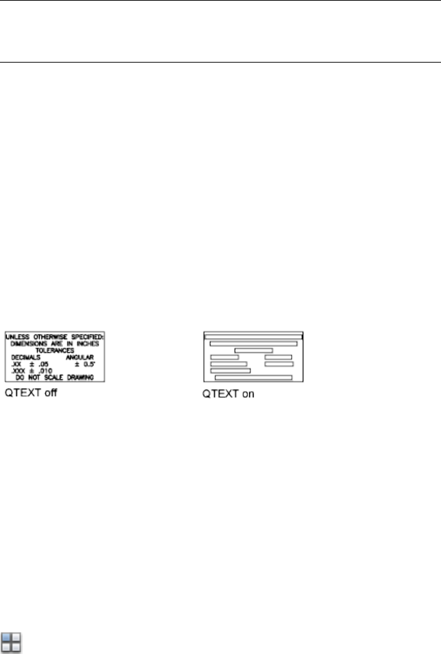
NOTE
The file format specified in the Application tab of the Application Preferences
dialog box is used when saving a drawing with this command.
See also:
Save a Drawing
QTEXT
Controls the display and plotting of text and attribute objects.
Summary
When QTEXT (Quick Text) is on, each text and attribute object is displayed
as a bounding box around the text object. Turning QTEXT mode on reduces
the time it takes the program to redraw and regenerate drawings that contain
many text objects.
See also:
Control the Display of Polylines, Hatches, Gradient Fills, Lineweights, and
Text
QUICKVIEW
Displays a list of all open drawings, and the layouts contained in the current
drawing or the selected drawing when more than one drawing is open.
Access
Button
Commands | 861
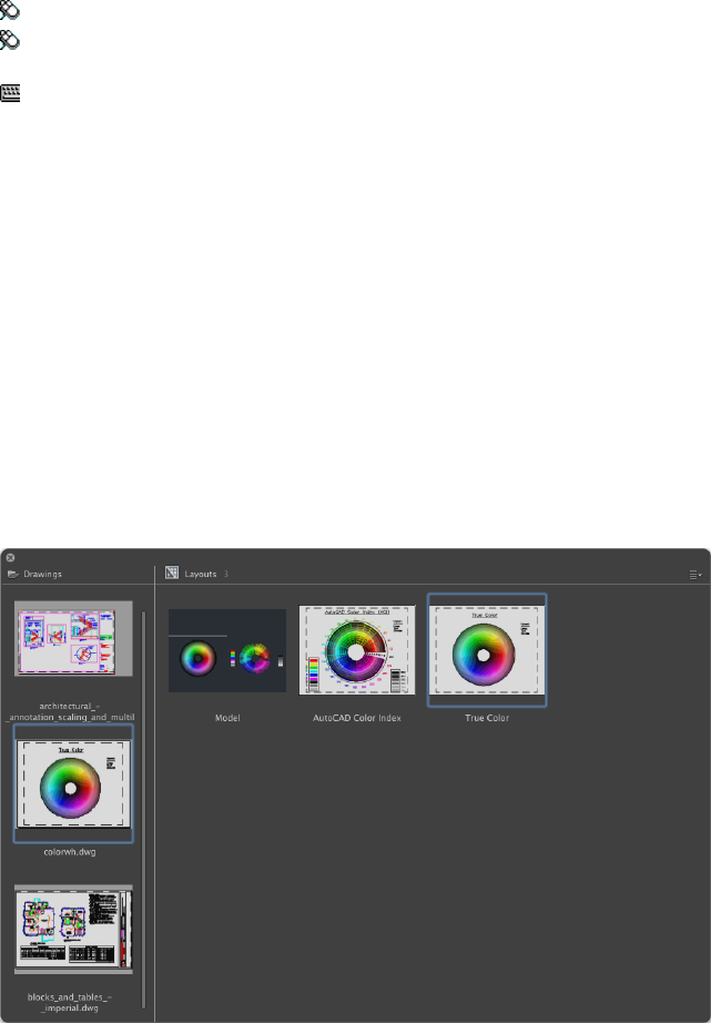
Toolbar: Status bar ➤ Show Drawings & Layouts
Toolbar: Status bar ➤ Model/Layout drop-down ➤ Show Drawings &
Layouts
Command entry: Cmd-.
Summary
Displays the QuickView dialog box.
Drawing previews are displayed vertically along the left, while the layout
previews of the selected drawing are displayed on the right. The preview for
Model is always located in the top-left of the layout previews.
See also:
Switch Between Layouts in the Current Drawing
QuickView Dialog Box
Displays a list of all open drawings and the layouts in the current drawing.
862 | Chapter 2 Commands
List of Options
The following options are displayed.
Drawing List
Displays a list of all open drawings.
Double-clicking a thumbnail to set that drawing current. You can also
right-click a thumbnail to display a shortcut menu of additional file
management options. The following items are on the Drawing shortcut menu:
■Save. - Saves the drawing using its current name and location.
■Close <drawing>. - Closes the drawing. You are prompted to save changes
if the drawing has been changed since it was last saved.
■Close All. - Closes all open drawings. You are prompted to save any
drawings that have been changed before they are closed.
■Duplicate. - Allows you to create a copy of the drawing. The Save Drawing
As dialog box is displayed (see SAVEAS (page 914)).
■Create New Layout. - Adds a new layout to the drawing. The
Create/Duplicate Layout dialog box is displayed. Enter a name for the new
layout.
Layouts List
Displays a list of all layouts in the current drawings.
Double-clicking a thumbnail switch to that layout. You can also right-click a
thumbnail to display a shortcut menu of additional layout management
options. The following items are on the Layout shortcut menu:
■Rename. - Allows you to change the name of the layout. The Model layout
cannot be renamed.
■Duplicate. - Creates a copy of the selected layout. The Create/Duplicate
Layout dialog box is displayed. Enter a name for the new layout.
■Delete. - Removes the layout from the drawing.
■Duplicate. - Allows you to create a copy of the drawing. The Save Drawing
As dialog box is displayed (see SAVEAS (page 914)).
■Create New Layout. - Adds a new layout to the drawing. The
Create/Duplicate Layout dialog box is displayed. Enter a name for the new
layout.
■Print. - Allows you to output the layout to hardcopy or PDF. The Print
dialog box (page 793) is displayed when a single layout is selected or the
Commands | 863

Batch Publish dialog box (page 846) is displayed when more than one layout
is selected.
■Edit Page Setup. - Allows you to modify the current page setup settings
for the layout. The Page Setup dialog box (page 753) is displayed.
■Page Setup Manager. - Allows you to manage the output settings for
the layout. The Page Setup Manager (page 749) is displayed.
See also:
Switch Between Layouts in the Current Drawing
QUIT
Exits the program.
Access Methods
Menu: AutoCAD ➤ Quit AutoCAD
Summary
Quits the program if there have been no changes since the drawing was last
saved. If the drawing has been modified, you are prompted to save or discard
the changes before quitting.
You can quit a file that has been opened in read-only mode if you have made
no modifications or if you are willing to discard them. To save modifications
to a read-only drawing, use the SAVEAS (page 914) command to save the
drawing under another name.
See also:
Start a Drawing
R Commands
RAY
Creates a line that starts at a point and continues to infinity.
864 | Chapter 2 Commands
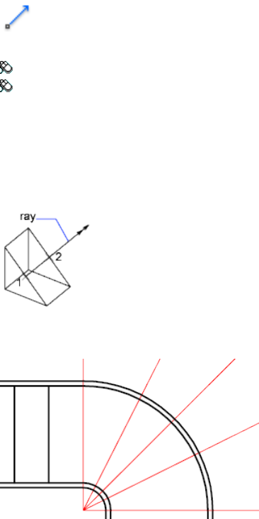
Access Methods
Button
Toolbar: Drafting tool set ➤ Open Shapes tool group (expanded) ➤ Ray
Menu: Draw ➤ Ray
Summary
The ray is extended to the edge of the display in the direction defined by the
starting point and the through point. The prompt for a through point is
redisplayed so you can create multiple rays. Press Enter to end the command.
Lines that extend to infinity in one direction, known as rays, can be used as
references for creating other objects.
List of Prompts
The following prompts are displayed.
Specify start point: Specify a point (1)
Specify through point: Specify a point for the ray to pass through (2)
See also:
Draw Construction Lines (and Rays)
Commands | 865
RECOVER
Repairs and then opens a damaged drawing file.
Summary
The program extracts as much material as it can from the damaged file. Files
that can be recovered include DWG and DWT files. Performing a recover on
a DXF file will only open the file.
In the Select File dialog box (a standard file selection dialog box (page 720)),
enter the drawing file name or select the damaged drawing file. Results are
displayed in the text window.
When FILEDIA (page 1296) is set to 0 (zero), RECOVER displays the following
command prompt.
Enter ~ (tilde) at the prompt to ignore FILEDIA and display the Select File
dialog box.
See also:
Repair a Damaged Drawing File
RECTANG
Creates a rectangular polyline.
Access Methods
Button
Toolbar: Drafting tool set ➤ Closed Shapes tool group ➤ Rectangle
Menu: Draw ➤ Rectangle
Summary
With this command, you can specify the rectangle parameters (length, width,
rotation) and control the type of corners (fillet, chamfer, or square).
866 | Chapter 2 Commands
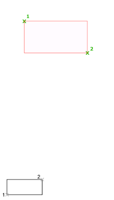
List of Prompts
The following prompts are displayed.
Current settings: Rotation = 0
Specify first corner point (page ?) or [Chamfer (page
?)/Elevation (page ?)/Fillet (page ?)/Thickness (page
?)/Width (page ?)]: Specify a point or enter an option
First Corner Point
Specifies a corner point of the rectangle.
Other Corner Point Creates a rectangle using the specified points as diagonally
opposite corners.
Area Creates a rectangle using the area and either a length or a width. If the
Chamfer or Fillet option is active, the area includes the effect of the chamfers
or fillets on the corners of the rectangle.
Dimensions Creates a rectangle using length and width values.
Rotation Creates a rectangle at a specified rotation angle.
Chamfer
Sets the chamfer distances for the rectangle.
Elevation
Specifies the elevation of the rectangle.
Fillet
Specifies the fillet radius of the rectangle.
Commands | 867

Thickness
Specifies the thickness of the rectangle.
Width
Specifies the polyline width of the rectangle to be drawn.
See also:
Draw Rectangles and Polygons
REDEFINE
Restores AutoCAD internal commands overridden by UNDEFINE.
Summary
If a command has been undefined, you can still use it if you precede the
command name with a period. Enter the name of an AutoCAD command
turned off by the UNDEFINE (page 1088) command.
See also:
Use Built-in Commands in Macros
REDO
Reverses the effects of previous UNDO or U command.
Access Methods
Menu: Edit ➤ Redo
Shortcut menu: With no command active and no objects selected, right-click
in the drawing area and click Redo.
Command entry: Cmd-Y
Summary
REDO reverses the effects of a single UNDO (page 1089) or U (page 1071) command.
REDO must immediately follow the U or UNDO command.
868 | Chapter 2 Commands

See also:
Correct Mistakes
REDRAW
Refreshes the display in the current viewport.
Access Methods
Menu: View ➤ Redraw
Command entry: 'redraw for transparent use
Summary
Removes temporary graphics left by some operations in the current viewport.
To remove stray pixels, use the REGEN (page 877) command.
See also:
Erase Objects
REDRAWALL
Refreshes the display in all viewports.
Access Methods
Command entry: 'redrawall for transparent use
Summary
Removes temporary graphics left by some operations in all viewports. To
remove stray pixels, use the REGENALL (page 877) command.
See also:
Erase Objects
Commands | 869
REFCLOSE
Saves back or discards changes made during in-place editing of a reference,
either an xref or a block definition.
Access Methods
Toolbar: Reference Editor visor ➤ Save
Toolbar: Reference Editor visor ➤ Discard Changes
Summary
If you save or discard changes with REFCLOSE, you can still use the UNDO
(page 1089) command to return to the reference editing session. If you have
made unwanted changes to an xref and already saved back the changes, use
UNDO to undo the unwanted changes; then use REFCLOSE to save back
changes and restore the xref to its original state.
NOTE When you edit and save xrefs in place in a drawing, the preview image for
the original reference drawing is no longer available unless you open and save the
drawing again.
List of Prompts
The following prompts are displayed.
Enter option [Save/Discard reference changes] <Save>:
Save Saves back to the xref source drawing or to the block definition in the
current drawing all changes made to objects in the working set. If you remove
an object from the working set and save changes, the object is deleted from
the reference and added to the current drawing.
NOTE If the file format of the xref source drawing is AutoCAD Release 14 or earlier,
the file is saved in AutoCAD 2010 file format. The file format is not changed for
xref source drawings in AutoCAD 2000 or later formats.
Discard Reference Changes Discards the working set; the source drawing or
block definition is returned to its original state. Any changes you make to
objects in the current drawing (not in the xref or block) are not discarded. If
you delete any object that is not in the working set, the object is not restored
even if you choose to discard changes.
See also:
Save Back Edited Referenced Drawings and Blocks
870 | Chapter 2 Commands
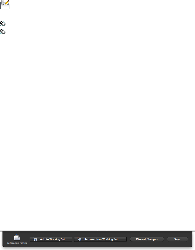
REFEDIT
Edits an xref or a block definition directly within the current drawing.
Access Methods
Button
Menu: Tools ➤ Edit Xref In-place
Toolbar: External Reference visor ➤ Edit Reference in Place
Summary
The objects that you select from the selected xref or block are temporarily
extracted and made available for editing in the current drawing. The set of
extracted objects is called the working set, which can be modified and then
saved back to update the xref or block definition.
List of Prompts
The following prompts are displayed.
Select reference: Select an xref or a block in the current drawing
The Reference Editor dialog box (page 872) is displayed. After the xref or block
definition is opened for edit in the in-place editor, the Reference Editor visor
(page 871) is displayed.
If you enter -refedit at the Command prompt, options are displayed (page
875).
See also:
Edit Selected Objects in Referenced Drawings and Blocks
Reference Editor Visor
Manages the working set of objects that are edited in a reference.
Commands | 871
List of Options
The following options are displayed.
Add to Working Set
Adds objects to the current working set while editing an xref or a block
definition in-place. (REFSET (page 876))
Remove From Working Set
Removes objects from the current working set while editing an xref or a block
definition in-place. (REFSET (page 876))
Discard Changes
Discards the changes made to an xref or a block definition. (REFCLOSE (page
870))
Save
Saves back the changes made to an xref or a block definition. (REFCLOSE (page
870))
See also:
Edit Selected Objects in Referenced Drawings and Blocks
Reference Edit Dialog Box
Specifies the reference to edit.
Summary
To select a reference to edit, select an object in the reference. If you select an
object that is part of one or more nested references, the nested references are
displayed in the dialog box.
872 | Chapter 2 Commands
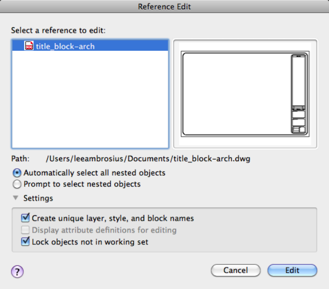
List of Options
The following options are displayed.
Select a Reference to Edit
Displays the reference selected for in-place editing and any references nested
within the selected reference.
Nested references are displayed only if the selected object is part of a nested
reference. If multiple references are displayed, choose a specific xref or block
to modify. Only one reference can be edited in place at a time.
Preview
Displays a preview image of the currently selected reference.
The preview image displays the reference as it was last saved in the drawing.
The reference preview image is not updated when changes are saved back to
the reference.
Commands | 873
Path
Displays the file location of the selected reference. If the selected reference is
a block, no path is displayed.
Nested Objects
Specifies how the selection of nested objects should be handled.
Automatically Select All Nested Objects
Controls whether nested objects are included automatically in the reference
editing session.
If this option is checked, all the objects in the selected reference will be
automatically included in the reference editing session.
Prompt to Select Nested Objects
Controls whether nested objects must be selected individually in the reference
editing session.
If this option is checked, after you close the Reference Edit dialog box and
enter the reference edit state, you are prompted to select the specific objects
in the reference that you want to edit.
Select nested objects: Select objects within the reference that you want to edit
Settings
Provides options for editing references.
Create Unique Layer, Style, and Block Names
Controls whether layers and other named objects extracted from the reference
are uniquely altered.
If selected, named objects in xrefs are altered (names are prefixed with $#$),
similar to the way they are altered when you bind xrefs. If cleared, the names
of layers and other named objects remain the same as in the reference drawing.
Named objects that are not altered to make them unique assume the properties
of those in the current host drawing that share the same name.
Display Attribute Definitions for Editing
Controls whether all variable attribute definitions in block references are
extracted and displayed during reference editing.
If Display Attribute Definitions for Editing is selected, the attributes (except
constant attributes) are made invisible, and the attribute definitions are
available for editing along with the selected reference geometry. When changes
are saved back to the block reference, the attributes of the original reference
remain unchanged. The new or altered attribute definitions affect only
subsequent insertions of the block; the attributes in existing block instances
are not affected. Xrefs and block references without definitions are not affected
by this option.
874 | Chapter 2 Commands
Lock Objects Not in Working Set
Locks all objects not in the working set. This prevents you from accidentally
selecting and editing objects in the host drawing while in a reference editing
state.
The behavior of locked objects is similar to objects on a locked layer. If you
try to edit locked objects, they are filtered from the selection set.
See also:
Edit Selected Objects in Referenced Drawings and Blocks
-REFEDIT
Edits an xref or a block definition directly within the current drawing.
List of Prompts
The following prompts are displayed.
Select reference: Select an xref or block in the current drawing
Select nesting level [OK/Next] <Next>: Enter an option or press Enter
OK
Accepts the currently highlighted reference for in-place reference editing.
If you are editing a block reference with attributes, you can enter y to display
the attribute definitions and make them available for editing. The attributes
are made invisible, and the attribute definitions are available for editing along
with the selected reference geometry. When changes are saved back to the
block reference, the attributes of the original reference remain unchanged.
The new or altered attribute definitions affect only subsequent insertions of
the block; the attributes in existing block instances are not affected.
All Objects in the selected reference will be automatically included in the
reference editing session.
Nested After you close the Reference Edit dialog box and enter the reference
edit state, you are prompted to select the specific objects in the reference that
you want to edit.
Next
Advances through the reference and nested references available for selection.
The currently selected reference is highlighted.
Commands | 875
A working set is formed with the objects you have selected for editing. The
working set includes objects that can be saved back to update the xref or block
definition. When you save back changes, changes made to the objects in the
reference file are saved without actually opening the reference drawing or
recreating the block. The working set is visually distinct from the rest of the
current drawing: all objects in the current drawing, except objects in the
working set, appear faded. The XFADECTL (page 1526) system variable controls
the fading of objects while you edit a reference in place.
You can select objects in xrefs for editing even if they are on a locked layer in
the reference file. When a reference object is part of the working set, you can
unlock the object's layer and make changes to the object. Only the changes
made to the object are saved back to the reference file; the xref layer remains
locked in the reference file.
NOTE
Objects outside of the working set are not faded unless the visual style is set
to 2D Wireframe during in-place reference editing.
See also:
Edit Selected Objects in Referenced Drawings and Blocks
REFSET
Adds or removes objects from a working set during in-place editing of a
reference, either an xref or a block definition.
Access Methods
Toolbar: Reference Editor visor ➤ Add to Working Set
Toolbar: Reference Editor visor ➤ Remove from Working Set
Summary
Objects that are part of the working set are visually distinct from other objects
in the current drawing. All objects in the current drawing, except objects in
the working set, appear faded.
List of Prompts
The following prompts are displayed.
876 | Chapter 2 Commands
Transfer objects between the Refedit working set and host
drawing...
Enter an option [Add/Remove] <Add>: Enter an option or press Enter
Add Adds objects to the working set.
An object that is part of the working set is added to the reference when changes
are saved back, and the object is removed from the current drawing.
Remove Removes objects from the working set.
An object that is removed from the working set is removed from the reference
when changes are saved back; the object is also removed from the current
drawing.
See also:
Use the Working Set to Edit Referenced Drawings and Blocks
REGEN
Regenerates the entire drawing from the current viewport.
Access Methods
Menu: View ➤ Regen
Summary
REGEN regenerates the entire drawing and recomputes the screen coordinates
for all objects in the current viewport. It also reindexes the drawing database
for optimum display and object selection performance.
See also:
Control the Display of Polylines, Hatches, Gradient Fills, Lineweights, and
Text
REGENALL
Regenerates the drawing and refreshes all viewports.
Commands | 877

Access Methods
Menu: View ➤ Regen All
Summary
REGENALL regenerates the entire drawing and recomputes the screen
coordinates for all objects in all viewports. It also reindexes the drawing
database for optimum display and object selection performance.
See also:
Control the Display of Polylines, Hatches, Gradient Fills, Lineweights, and
Text
REGENAUTO
Controls automatic regeneration of a drawing.
Access Methods
Command entry: 'regenauto for transparent use
List of Prompts
The following prompts are displayed.
Enter mode [ON (page 878)/OFF (page 878)] <current>: Enter on or off,
or press Enter
On Regenerates the drawing immediately if any suppressed regenerations exist
in the queue and continues to regenerate automatically whenever you perform
an action that requires regeneration.
Off Inhibits regeneration of the drawing until you use the REGEN (page 877)
or REGENALL (page 877) command, or set REGENAUTO to on.
If you perform an action that requires a regeneration and that action is
irrevocable (such as thawing layers), the following message is displayed:
Regen queued
If you perform an action that requires a regeneration and that action is
revocable, the following message is displayed:
About to regen—proceed?
878 | Chapter 2 Commands
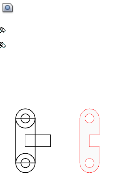
If you click OK, the drawing is regenerated. If you click Cancel, the last action
is cancelled and the drawing is not regenerated.
See also:
Control the Display of Polylines, Hatches, Gradient Fills, Lineweights, and
Text
REGION
Converts an object that encloses an area into a region object.
Access Methods
Button
Toolbar: Drafting tool set ➤ Closed Shapes tool group (expanded) ➤
Region
Menu: Draw ➤ Region
Summary
Regions are two-dimensional areas you create from closed shapes or loops.
Closed polylines, lines, and curves are valid selections. Curves include circular
arcs, circles, elliptical arcs, ellipses, and splines.
You can combine several regions into a single, complex region.
Closed 2D and exploded planar 3D polylines in the selection set are converted
to separate regions and then converts polylines, lines, and curves to form
Commands | 879

closed planar loops (outer boundaries and holes of a region). If more than two
curves share an endpoint, the resulting region might be arbitrary.
The boundary of the region consists of end-connected curves where each point
shares only two edges. All intersections and self-intersecting curves are rejected.
If a selected polyline has been smoothed by either the Spline or Fit option of
PEDIT (page 767), the resulting region contains the line or arc geometry of the
smoothed polyline. The polyline is not converted to a spline object.
REGION deletes the original objects after converting them to regions unless
the system variable DELOBJ (page 1213) is set to 0. If the original objects were
hatched, hatch associativity is lost. To restore associativity, rehatch the region.
See also:
Create and Combine Areas (Regions)
RENAME
Changes the names assigned to items such as layers and dimension styles.
Access Methods
Menu: Format ➤ Rename
Summary
Named objects are categories of items such as layers, dimension styles, table
styles, text styles, and so on. It is strongly recommended that you create
standard naming conventions for them and save them in drawing template
files.
The Rename dialog box (page 881) is displayed.
If you enter -rename at the Command prompt, options are displayed (page
881).
See also:
Resolve Name Conflicts in External References
880 | Chapter 2 Commands
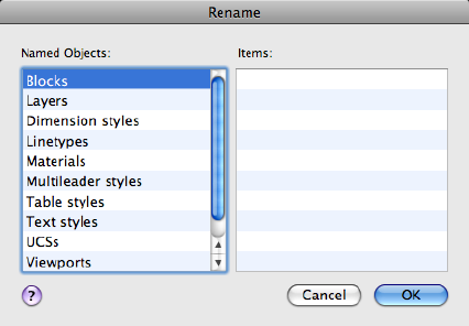
Rename Dialog Box
Changes the names assigned to named objects such as layers and dimension
styles.
List of Options
The following options are displayed.
Named Objects
Lists named objects in a drawing by category.
Items
Displays items of the type specified in Named Objects.
See also:
Resolve Name Conflicts in External References
-RENAME
Changes the names assigned to named objects from the Command prompt.
List of Prompts
The following prompts are displayed.
Commands | 881
Enter object type to rename
[Block/Dimstyle/LAyer/LType/Material/multileadeRstyle/Plotstyle/textStyle/Tablestyle/Ucs/VIew/VPort]:
Enter a named object type to rename an object
Enter old object name: Enter the old name
Enter new object name: Enter the new name
See also:
Resolve Name Conflicts in External References
RENDER
Creates a photorealistic or realistically shaded image of a 3D solid or surface
model.
Access Methods
Button
Toolbar: Modeling tool set ➤ Render tool group ➤ Render
Menu: View ➤ Render ➤ Render
Summary
The RENDER command begins the rendering process and displays the rendered
image in the Render Window (page 883).
882 | Chapter 2 Commands

By default, all objects in the current view in the drawing are rendered. If a
named view is not specified, the current view is rendered.
If you enter -render at the Command prompt, options are displayed (page
890).
See also:
Render 3D Objects for Realism
Render Window
Displays rendered output of the current model
Commands | 883
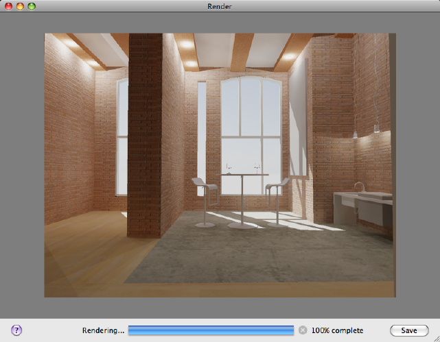
Summary
From the Render Window, you can
■Save the image to a file.
■Monitor the progress of the current rendering.
List of Options
The following options are displayed.
Image Pane
Primary output target of the renderer.
Progress Meter
Displays the overall progress of the current rendering.
Clicking the X icon next to the progress meter, or by pressing Esc to cancel
the current rendering.
Save
Displays the Render Output File dialog box (page 885) where you can save the
image to disk.
884 | Chapter 2 Commands
See also:
Save a Rendered Image
Render Output File Dialog Box
Saves a rendering to a raster image file.
Summary
The Render Output File dialog box is a standard file selection dialog boxes.
You specify the file name of the image you want to save and the output file
format. In this dialog box, you can only choose from raster image output file
formats.
The file formats for saving your rendered images to include the following:
List of Options
The following options are displayed.
BMP (*.bmp) BMP files are still-image bitmap files in the Windows bitmap
(.bmp) format.
Clicking Save after choosing this format displays the BMP Image Options
dialog box (page 886).
PCX (*.pcx) PCX files are relatively simple files that provide minimum
compression using run length encoding (RLE).
Clicking Save after choosing this format displays the PCX Image Options
dialog box (page 887).
TGA (*.tga) The Targa (TGA) format supports up to 32-bit true color. This
format is typically used as a true color format to render still images.
Clicking Save after choosing this format displays the Targa Image Options
dialog box (page 887).
TIF (*.tif) TIF (Tagged Image File) format is a multiplatform bitmap format.
TIF is a common choice if you plan to send your output to a print service
bureau or import the image into a page-layout program.
Clicking Save after choosing this format displays the TIFF Image Options
dialog box (page 888).
JPEG (*.jpg) JPEG (.jpeg or .jpg) files follow the standards set by the Joint
Photography Experts Group. These files use a variable compression method
Commands | 885
that is called lossy compression because of the loss of image quality as you
increase the compression. However, the JPEG compression scheme is extremely
good and you can sometimes compress the file up to 200:1 without severe
loss of image quality. JPEG is consequently a popular format for posting image
files on the Internet for minimum file size and minimum download time.
Clicking Save after choosing this format displays the JPEG Image Options
dialog box (page 889).
PNG (*.png) PNG (Portable Network Graphics) is a still-image file format
developed for use with the Internet and World Wide Web. PNG is a format
that generates a compressed image without any loss of quality, unlike the loss
of quality found in JPEG files.
Clicking Save after choosing this format displays the PNG Image Options
dialog box (page 889).
See also:
Save a Rendered Image
BMP Image Options Dialog Box
Options used when saving a rendering to a BMP image file.
Summary
When BMP is chosen as the output format, the BMP Image Options dialog
box is displayed.
List of Options
The following options are displayed.
Color
Monochrome Creates a 2-bit black and white image.
8 Bits (256 Grayscale) Creates an 8-bit grayscale image using 256 shades of
gray.
8 Bits (256 Colors) Renders a smaller, 8-bit color image from a palette of 256
colors.
24 Bits (16.7 Million Colors) Renders a larger, true color (24-bit) file.
886 | Chapter 2 Commands
See also:
Save a Rendered Image
PCX Image Options Dialog Box
Options used when saving a rendering to a PCX image file.
Summary
When PCX is chosen as the output format, the PCX Image Options dialog
box is displayed.
List of Options
The following options are displayed.
Color
Monochrome Creates a 2-bit black and white image.
8 Bits (256 Grayscale) Creates an 8-bit grayscale image using 256 shades of
gray.
8 Bits (256 Colors) Renders a smaller, 8-bit color image from a palette of 256
colors.
See also:
Save a Rendered Image
Targa Image Options Dialog Box
Options used when saving a rendering to a TGA image file.
Summary
When TGA is chosen as the output format, the Targa Image Options dialog
box is displayed.
List of Options
The following options are displayed.
Commands | 887
Color
8 Bits (256 Grayscale) Creates an 8-bit grayscale image using 256 shades of
gray.
8 Bits (256 Colors) Renders a smaller, 8-bit color image from a palette of 256
colors.
24 Bits (16.7 Million Colors) Creates a 24 bit color image that uses a 16.7
million color palette.
32 Bits (24 Bits + Alpha) Creates a 24 bit color image that includes an 8 bit
alpha channel. Alpha is a type of data, found in 32-bit image files, that assigns
transparency to the pixels in the image.
Bottom Up
Saves the image from bottom to top.
See also:
Save a Rendered Image
TIFF Image Options Dialog Box
Options used when saving a rendering to a TIFF image file.
Summary
When TIF is chosen as the output format, the TIFF Image Options dialog box
is displayed.
List of Options
The following options are displayed.
Color
Monochrome Creates a 2-bit black and white image.
8 Bits (256 Grayscale) Creates an 8-bit grayscale image using 256 shades of
gray.
8 Bits (256 Colors) Renders a smaller, 8-bit color image from a palette of 256
colors.
24 Bits (16.7 Million Colors) Creates a 24 bit color image that uses a 16.7
million color palette.
888 | Chapter 2 Commands
32 Bits (24 Bits + Alpha) Creates a 24 bit color image that includes an 8 bit
alpha channel. Alpha is a type of data, found in 32-bit image files, that assigns
transparency to the pixels in the image.
Compressed
Applies lossless compression to the file.
Dots Per Inch
Sets the dots per inch (dpi) for the saved image. This setting does not change
the resolution of the final image, but can affect the way it prints in documents.
See also:
Save a Rendered Image
JPEG Image Options Dialog Box
Options used when saving a rendering to a JPEG image file.
Summary
When JPG is chosen as the output format, the JPEG Image Options dialog box
is displayed.
List of Options
The following options are displayed.
Image Control
Quality Sets the level of quality: the higher the quality, the larger the file size.
In general, files compressed with the slider set to Best have compression ratios
between 5:1 and 15:1.
File Size Sets the size of file you want: the larger the file, the higher the quality.
See also:
Save a Rendered Image
PNG Image Options Dialog Box
Options used when saving a rendering to a PNG image file.
Commands | 889
Summary
When PNG is chosen as the output format, the PNG Image Options dialog
box is displayed.
List of Options
The following options are displayed.
Color
Monochrome Creates a 2-bit black and white image.
8 Bits (256 Grayscale) Creates an 8-bit grayscale image using 256 shades of
gray.
8 Bits (256 Colors) Renders a smaller, 8-bit color image from a palette of 256
colors.
16 Bits (65,536 Grayscale) Creates a grayscale 16-bit image that uses 65,536
shades of gray.
24 Bits (16.7 Million Colors) Creates a larger, true color (24-bit) file.
32 Bits (24 Bits + Alpha) Creates a 24 bit color image that includes an 8 bit
alpha channel. Alpha is a type of data, found in 32-bit image files, that assigns
transparency to the pixels in the image.
Progressive
Provides faster display in Web browsers.
Dots Per Inch
Sets the dots per inch (dpi) for the saved image. This setting does not change
the resolution of the final image, but can affect the way it prints in documents.
See also:
Save a Rendered Image
-RENDER
Creates a photorealistic or realistically shaded image of a 3D solid or surface
model from the Command prompt.
List of Prompts
The following prompts are displayed.
890 | Chapter 2 Commands
Specify render preset [Draft (page ?)/Low (page ?)/Medium
(page ?)/High (page ?)/Presentation (page ?)/Other (page
?)] <Medium>: Enter an option or press Enter
Specify render destination [Render Window (page ?)/Viewport
(page ?)] <Render Window>: Enter an option or press Enter
Draft
Draft is the lowest level standard render preset. This setting
is intended for very fast, test renderings where anti-aliasing is bypassed and
sample filtering is very low.
This render preset produces very low quality rendering, but results in the
fastest rendering speed.
Low
The Low render preset provides better quality than the
Draft preset. Anti-aliasing is bypassed but sample filtering is improved.
Raytracing is also active, by default, so better quality shading occurs.
This preset is best used for test rendering that requires better quality than
Draft.
Medium
You can expect much better sample filtering and
anti-aliasing is active when you use the Medium render preset. Raytracing is
active with increased reflection depth settings when compared to the Low
render preset.
This preset offers a good balance between quality and render speed.
Commands | 891
High
The High we preset matches the Medium preset settings
with regards to anti-aliasing, but sample filtering and raytracing is improved.
Due to the improved sample filtering and raytracing, rendered images take
longer to process, but the image quality is much better.
Presentation
The Presentation render preset is used for high quality,
photo-realistic rendered images and takes the longest to process. Sample
filtering and raytracing is further improved.
Since this preset is used for final renderings, global illumination settings are
commonly used in conjunction.
Other
The Other option allows you to specify a custom render preset if one or more
are present.
?—List Custom Render Presets Lists all the custom render presets that are
stored with the model. Only custom render presets are listed.
Render Window
The image will be displayed in the render window when processing in
complete.
Output Width/Height The output width and height values designate how
wide and how tall the rendered image is going to be. Both values are measured
in pixels.
Save rendering to a file You can save the image to one of the following file
formats: BMP, TGA, TIF, PCX, JPG, or PNG.
If you accept the default value of No, the Render Window is displayed and
the image is rendered. Answering Yes results in another prompt:
Viewport
If you choose Viewport, anything that is currently displayed in the viewport
gets rendered.
892 | Chapter 2 Commands
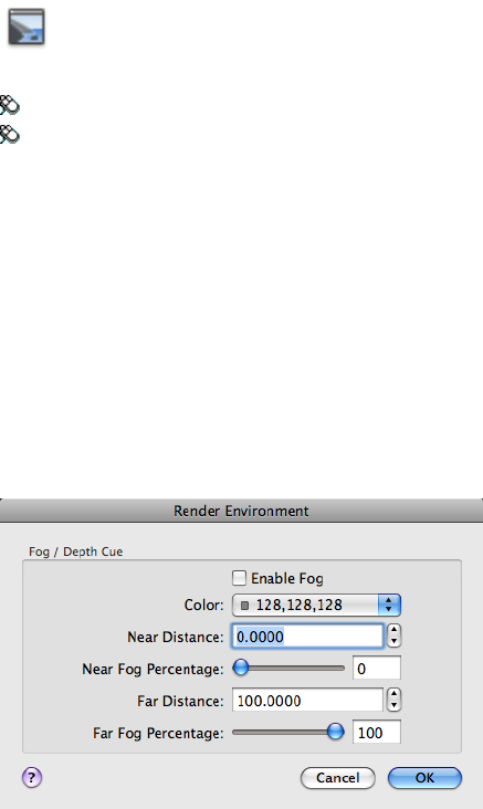
See also:
Render Views, Selected Objects, or Cropped Content
RENDERENVIRONMENT
Controls visual cues for the apparent distance of objects.
Access Methods
Button
Toolbar: Modeling tool set ➤ Render tool group ➤ Render Environment
Menu: View ➤ Render ➤ Render Environment
Summary
The Render Environment dialog box (page 893) is displayed.
See also:
Control the Rendering Environment
Render Environment Dialog Box
Defines the cues for distance between objects and the current viewing direction.
Commands | 893
Summary
Fog and depth cueing are atmospheric effects that cause objects to appear to
fade as they increase in distance from the camera. Fog uses a white color while
depth cueing uses black.
List of Options
The following options are displayed.
Fog and Depth Cue
Enable Fog Turns fog on and off without affecting the other settings in the
dialog box.
Color Specifies the color of the fog.
Near Distance Specifies the distance from the camera where the fog begins.
It is specified as a percentage of the distance to the far clipping plane. The
Near Distance setting cannot be greater than the Far Distance setting.
Far Distance Specifies the distance from the camera where the fog ends.
It is specified as a percentage of the distance to the far clipping plane. The Far
Distance setting cannot be less than the Near Distance setting.
Near Fog Percentage Specifies the opacity of the fog at the near distance.
Far Fog Percentage Specifies the opacity of the fog at the far distance.
See also:
Control the Rendering Environment
RENDEROUTPUTSIZE
Specifies the image size to create when rendering a 3D model.
Summary
Displays the Output Size dialog box (page 895).
If you enter -renderoutputsize at the Command prompt, options are dis-
played (page 896).
See also:
Save a Rendered Image
894 | Chapter 2 Commands

Output Size Dialog Box
Sets the output image size when rendering a 3D model.
List of Options
The following options are displayed.
Output Image Size (Pixels) List of commonly used output sizes. Choose
Custom to specify the output width and height for the image.
Width (Pixels) Sets the width resolution of the output image, in pixels.
The valid range for the width is 8 to 4096.
Height (Pixels) Sets the height resolution of the output image, in pixels.
The valid range for the height is 8 to 4096.
Aspect Ratio Sets the aspect ratio, the ratio of width to height, of the rendered
image.
Changing this value changes the Height value to maintain the correct
dimensions for the active resolution. The image aspect value is always expressed
as a multiplier value.
Lock Aspect Ratio Locks the aspect ratio when using a custom output
resolution.
When it is locked, the Width and Height spinners are locked to each other;
adjusting one alters the other to maintain the aspect-ratio value. When
unlocked, changes to either Width or Height affects only the Aspect Ratio
setting.
Commands | 895
NOTE
In viewports, the camera's frustum changes to reflect the image aspect ratio
you set in the Output Size dialog box. This change takes place when you exit
the dialog box.
See also:
Save a Rendered Image
-RENDEROUTPUTSIZE
Specifies the image size to create when rendering a 3D model.
List of Prompts
The following prompts are displayed:
Enter render output width: Enter a width and press Enter
Enter render output height: Enter a height and press Enter
The valid range for the width and height is 8 to 4096.
See also:
Save a Rendered Image
RENDERWIN
Displays the Render window without starting a rendering operation.
Access Methods
Button
Toolbar: Modeling tool set ➤ Render tool group (expanded) ➤ Show
Render Window
896 | Chapter 2 Commands

Summary
The Render window (page 883) is displayed, but a rendering of the current
drawing is not initiated.
If the drawing was previously rendered, you can view and save the rendered
image.
See also:
Basics of Rendering
RESETBLOCK
Resets one or more dynamic block references to the default values of the block
definition.
Access Methods
Shortcut menu: Select a dynamic block reference in a drawing. Right-click
in the drawing area and click Reset Block.
See also:
Work with Dynamic Blocks in Drawings
RESETPALETTES
Resets all palettes to their default placement settings.
Summary
Menu: Window ➤ Reset Palettes
Summary
The Reset Palettes message box is displayed. Resetting palettes closes and
restarts AutoCAD for Mac.
List of Options
The following prompts are displayed.
Commands | 897

Reset Palettes Closes and restarts AutoCAD for Mac. After AutoCAD for Mac
restarts, the placement of all palettes is reset to their default settings.
See also:
Specify the Behavior of Palettes
RESUME
Continues an interrupted script.
Access Methods
Command entry: 'resume for transparent use
Summary
You can interrupt a macro script that is running by pressing Esc or Backspace.
Any error encountered while processing input from a script file causes the
script to be suspended. If a script is suspended while the program is active,
you can use RESUME to continue the script.
See also:
Create Command Scripts
REVCLOUD
Creates a revision cloud using a polyline.
Access Methods
Button
Toolbar: Drafting tool set ➤ Closed Shapes tool group (expanded) ➤
Revision Cloud
Menu: Draw ➤ Revision Cloud
898 | Chapter 2 Commands
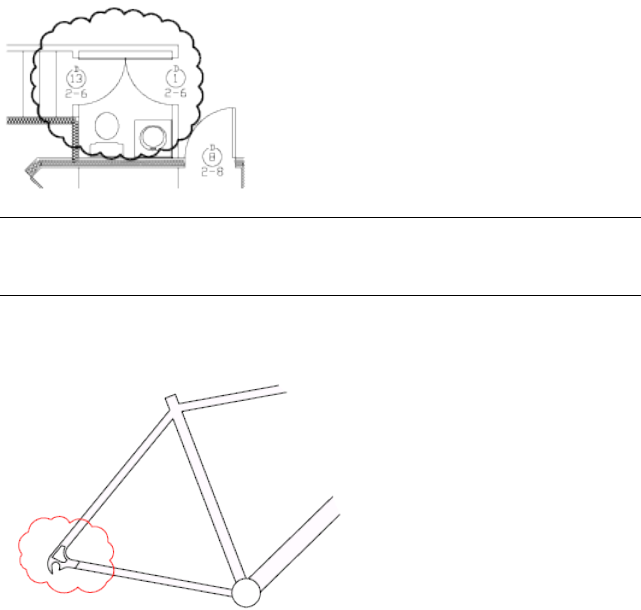
Summary
NOTE REVCLOUD stores the last used arc length in the system registry. This value
is multiplied by DIMSCALE (page 1239) to provide consistency when the program
is used with drawings that have different scale factors.
You can create a new revision cloud by dragging your cursor, or you can
convert a closed object such as an ellipse or polyline into a revision cloud.
Use revision clouds to highlight parts of a drawing that are being reviewed.
The resulting object is a polyline.
List of Prompts
The following prompts are displayed.
Minimum arc length: 0.5000 Maximum arc length: 0.5000
Specify start point or [Arc length/Object/Style] <Object>:
Drag to draw the revision cloud, enter an option, or press Enter
Arc Length Specifies the length of the arcs in a revision cloud.
The maximum arc length cannot be set to more than three times the minimum
arc length.
Object Specifies an object to be converted to a revision cloud.
Commands | 899
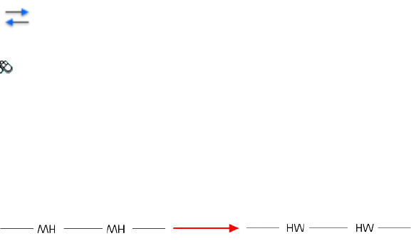
Style Specifies the style of the revision cloud.
See also:
Create Revision Clouds
REVERSE
Reverses the vertices of selected lines, polylines, splines, and helixes, which
is useful for linetypes with included text, or wide polylines with differing
beginning and ending widths.
Access Methods
Button
Toolbar: Drafting tool set ➤ Modify tool group (expanded) ➤ Reverse
Summary
Vertices of selected objects are reversed.
For example, when a linetype with text is specified with relative rotation in
a LIN file, the text in the linetype might be displayed upside down. Reversing
the vertices of the object changes the orientation of the text.
The REVERSE command does not change the orientation of text where rotation
is specified as upright. For more information, see Text in Custom Linetypes.
See also:
Modify Polylines
REVOLVE
Creates a 3D solid or surface by sweeping an object around an axis.
900 | Chapter 2 Commands
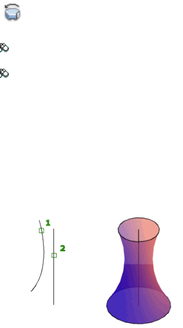
Access Methods
Button
Toolbar: Modeling tool set ➤ Solids - Create tool group ➤ Solid Creation
flyout ➤ Revolve
Menu: Draw ➤ 3D Modeling ➤ Revolve
Summary
Open profiles create surfaces and closed profiles can create either a solid or a
surface. The MOde option controls is a solid of surface is created. When
creating a surface, SURFACEMODELINGMODE (page 1453) system variable
controls if a procedural or NURBS surface is created.
When the Solid tab is active, the REVOLVE (page 900) command creates a solid.
Conversely, when the Surface tab is active, it creates a surface (either procedural
or NURBS depending on how the SURFACEMODELINGMODE (page 1453) system
variable is set).
When the Solid tab is active, the REVOLVE (page 900) command creates a solid.
Conversely, when the Surface tab is active, it creates a surface (either procedural
or NURBS depending on how the SURFACEMODELINGMODE (page 1453) system
variable is set).
Commands | 901
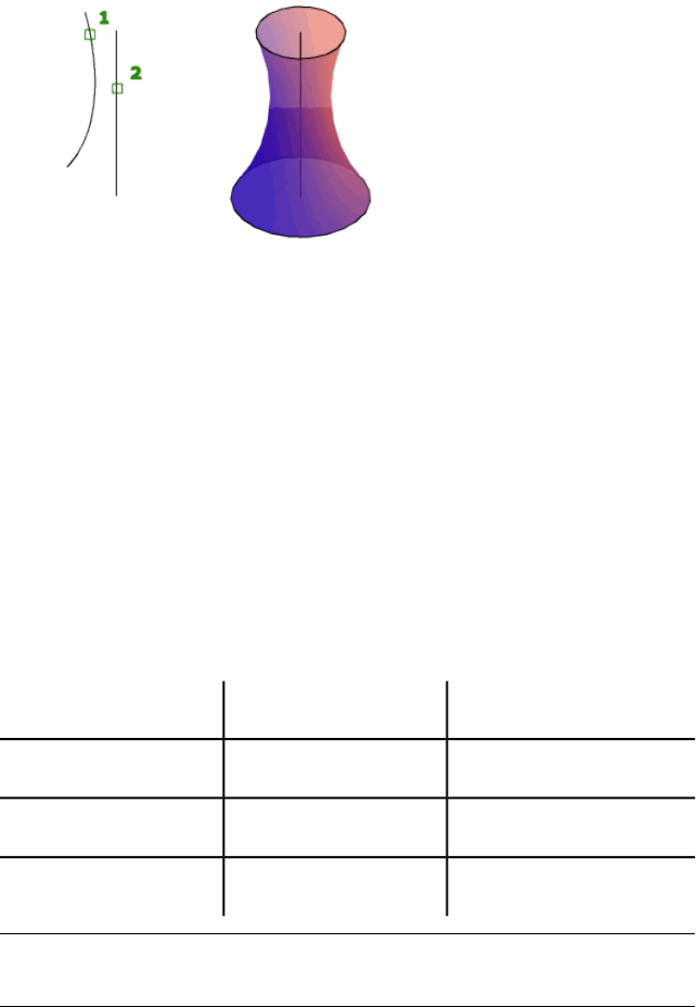
Revolve path and profile curves can be:
■Open or closed
■Planar or non-planar
■Solid and surface edges
■A single object (to extrude multiple lines, convert them to a single object
with the JOIN (page 534) command)
■A single region (to extrude multiple regions, convert them to a single object
with the REGION (page 879) command)
To automatically delete the profile, use the DELOBJ (page 1213) system variable.
If associativity (page 1452) is on, the DELOBJ system variable is ignored and the
originating geometry is not deleted.
Objects That Can Be Revolved
2D solidsElliptical arcsSurfaces
Traces2D and 3D splinesSolids
Ellipses2D and 3D polylinesArcs
RegionsCircles
NOTE
Select face and edge subobjects by pressing Ctrl while you select them.
902 | Chapter 2 Commands
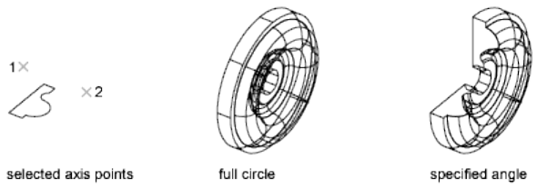
You cannot revolve objects contained within a block or objects that will
self-intersect. REVOLVE ignores the width of a polyline and revolves from the
center of the path of the polyline.
The right-hand rule determines the positive direction of rotation. For more
information, see Understand the UCS in 3D.
List of Prompts
The following prompts are displayed.
Objects to Revolve Specifies the objects to be revolved about an axis.
Mode Controls whether the revolve action creates a solid or a surface. Surfaces
are extended as either NURBS surfaces or procedural surfaces, depending on
the SURFACEMODELINGMODE (page 1453) system variable.
Axis Start Point Specifies the first point of the axis of revolution. The positive
axis direction is from the first to the second point.
Axis Endpoint Sets the endpoint for the axis of revolution.
Start Angle Specifies an offset for the revolution from the plane of the object
being revolved.
Drag your cursor to specify and preview the start angle of the object.
Angle of Revolution Specifies how far the selected object revolves about the
axis.
A positive angle revolves the objects in a counterclockwise direction. A negative
angle revolves the objects in a clockwise direction. You can also drag the cursor
to specify and preview the angle of revolution.
Object Specifies an existing object to be used as an axis. The positive axis
direction is from the closest to the farthest endpoint of this object.
Commands | 903
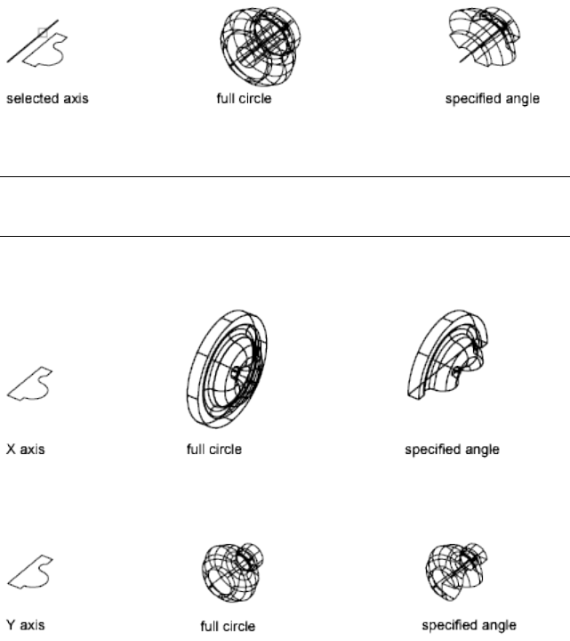
You can use lines, linear polyline segments, and linear edges of solids or
surfaces as an axis.
NOTE
Select an edge subobject by pressing Ctrl while you select an edge.
X (Axis) Sets the positive X axis of the current UCS as the positive axis
direction.
Y (Axis) Sets the positive Y axis of the current UCS as the positive axis
direction.
Z (Axis) Sets the positive Z axis of the current UCS as the positive axis
direction.
Reverse Changes the direction of the revolve; similar to entering a - (minus)
angle value. The revolved object on the right shows a spline revolved at the
same angle as the object on the left, but using the reverse option.
904 | Chapter 2 Commands
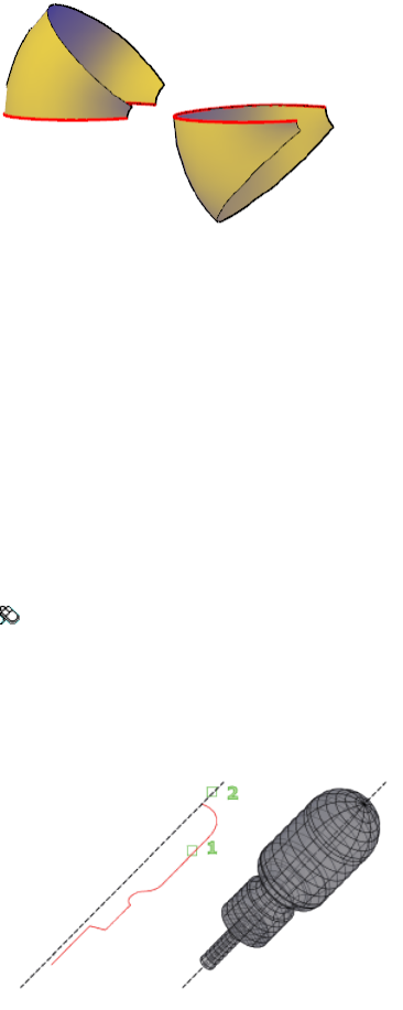
Expression Enter a formula or equation to specify the revolve angle. See
Constrain a Design with Formulas and Equations.
See also:
Create a Solid or Surface by Revolving
REVSURF
Creates a mesh by revolving a profile about an axis.
Access Methods
Menu: Draw ➤ 3D Modeling ➤ Meshes ➤ Revolved Meshes
Summary
Select a line, arc, circle, or 2D or 3D polyline to sweep in a circular path around
a selected axis.
The MESHTYPE (page 1369) system variable sets which type of mesh is created.
Mesh objects are created by default. Set the variable to 0 to create legacy
polyface or polygon mesh.
Commands | 905
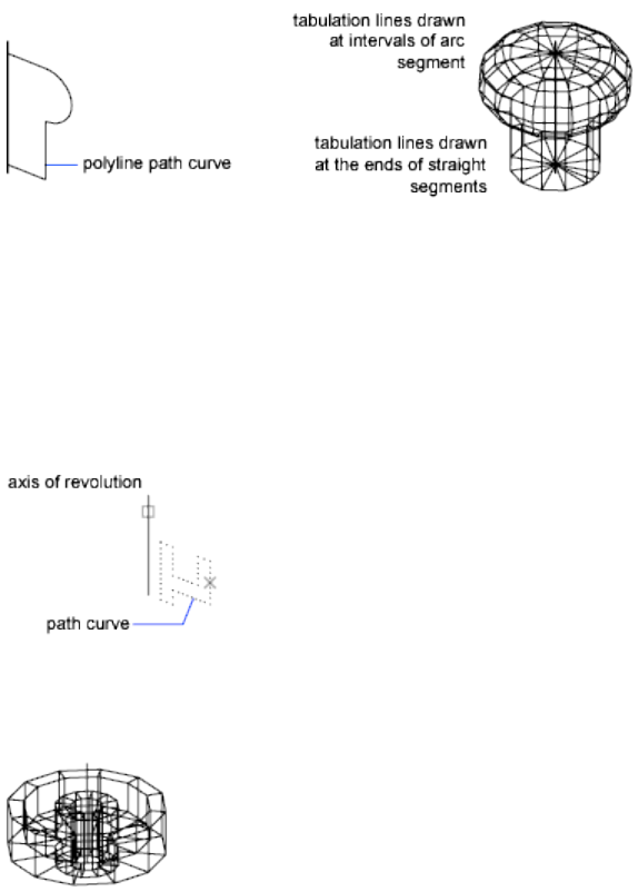
The density of the generated mesh is controlled by the SURFTAB1 (page 1454)
and SURFTAB2 (page 1454) system variables. SURFTAB1 specifies the number of
tabulation lines that are drawn in the direction of revolution. If the path curve
is a line, arc, circle, or spline-fit polyline, SURFTAB2 specifies the number of
tabulation lines that are drawn to divide it into equal-sized intervals. If the
path curve is a polyline that has not been spline fit, tabulation lines are drawn
at the ends of straight segments, and each arc segment is divided into the
number of intervals specified by SURFTAB2.
List of Prompts
The following prompts are displayed.
Current wire frame density: SURFTAB1=current SURFTAB2=current
Object to revolve Select a line, arc, circle, or 2D or 3D polyline.
Object that defines axis of revolution Select a line or open 2D or 3D polyline.
The axis direction cannot be parallel to the plane of the original object.
The path curve is swept about the selected axis to define the mesh. The path
curve defines the N direction of the mesh. Selecting a circle or a closed polyline
as the path curve closes the mesh in the N direction.
906 | Chapter 2 Commands
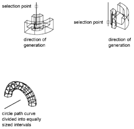
The vector from the first to the last vertex of the polyline determines the
rotation axis. Any intermediate vertices are ignored. The axis of revolution
determines the M direction of the mesh.
Start Angle If set to a nonzero value, starts the mesh of revolution at an offset
from the generating path curve.
Specifying a start angle starts the mesh of revolution at an offset from the
generating path curve.
Included Angle Specifies how far about the axis of revolution the mesh
extends. The included angle is the distance through which the path curve is
swept.
Entering an included angle that is less than a full circle prevents the circle
from closing.
The point you use to select the axis of revolution affects the direction of
revolution. The mesh in the following example was created by specifying a
start angle of 0 degrees and an included angle of 90 degrees.
See also:
Create Meshes from Other Objects
ROTATE
Rotates objects around a base point.
Commands | 907
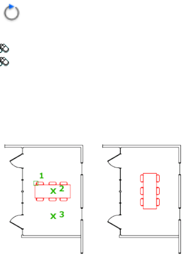
Access Methods
Button
Toolbar: Drafting tool set ➤ Move/Rotate/Scale tool group ➤ Rotate
Menu: Modify ➤ Rotate
Shortcut menu: Select the objects to rotate. Right-click in the drawing area
and click Rotate.
Summary
You can rotate selected objects around a base point to an absolute angle.
List of Prompts
The following prompts are displayed.
Current positive angle in UCS: ANGDIR=current ANGBASE=current
Select objects: Use an object selection method and press Enter when you
finish
Specify base point: Specify a point
Specify rotation angle (page 908) or [Copy (page 908)/Reference
(page 908)]: Enter an angle, specify a point, enter c, or enter r
Rotation Angle Determines how far an object rotates around the base point.
The axis of rotation passes through the specified base point and is parallel to
the Z axis of the current UCS.
Copy Creates a copy of the selected objects for rotation.
Reference Rotates objects from a specified angle to a new, absolute angle.
908 | Chapter 2 Commands
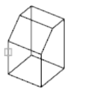
When you rotate a viewport object, the borders of the viewport remain parallel
to the edges of the drawing area.
See also:
Rotate Objects
ROTATE3D
Moves objects about a 3D axis.
Summary
It is recommended that you use the gizmos available through the 3DMOVE
(page 36) and 3DROTATE (page 48) commands to manipulate 3D objects. For
more information about using gizmos, see Use Gizmos to Modify Objects.
List of Prompts
The following prompts are displayed.
Select objects: Use an object selection method and press Enter when you
finish
Specify first point on axis or define axis by [Object (page
?)/Last (page ?)/View (page ?)/Xaxis/Yaxis/Zaxis (page
?)/2points (page ?)]: Specify a point, enter an option, or press Enter
Object
Aligns the axis of rotation with an existing object.
Line
Aligns the axis of rotation with the line selected.
Rotation Angle Rotates the object about the selected axis the specified amount
from the current orientation.
Reference Specifies the reference angle and the new angle.
Commands | 909
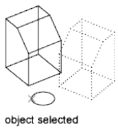
The difference between the starting angle and the ending angle is the computed
rotation angle.
Circle
Aligns the axis of rotation with the 3D axis of the circle (perpendicular to the
plane of the circle and passing through the center of the circle).
■Rotation Angle (page 909)
■Reference (page 909)
Arc
Aligns the axis of rotation with the 3D axis of the arc (perpendicular to the
plane of the arc and passing through the center of the arc).
■Rotation Angle (page 909)
■Reference (page 909)
2D Polyline Segment
Aligns the axis of rotation with a segment of the polyline. Treats a straight
segment as a line segment. Treats an arc segment as an arc.
■Rotation Angle (page 909)
■Reference (page 909)
Last
Uses the last axis of rotation.
■Rotation Angle (page 909)
■Reference (page 909)
View
Aligns the axis of rotation with the viewing direction of the current viewport
that passes through the selected point.
■Rotation Angle (page 909)
910 | Chapter 2 Commands
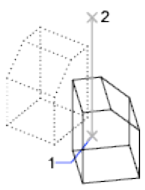
■Reference (page 909)
X Axis, Y Axis, Z Axis
Aligns the axis of rotation with one of the axes (X, Y, or Z) that pass through
the selected point.
■Rotation Angle (page 909)
■Reference (page 909)
2 Points
Uses two points to define the axis of rotation.
■Rotation Angle (page 909)
■Reference (page 909)
See also:
Rotate Objects
RSCRIPT
Repeats a script file.
Summary
RSCRIPT is useful for demonstrations that repeat a script; for example, a script
that must run over and over during a trade show or in a showroom.
If RSCRIPT is the last line in a script file, the file runs continuously until
interrupted by Esc.
Commands | 911
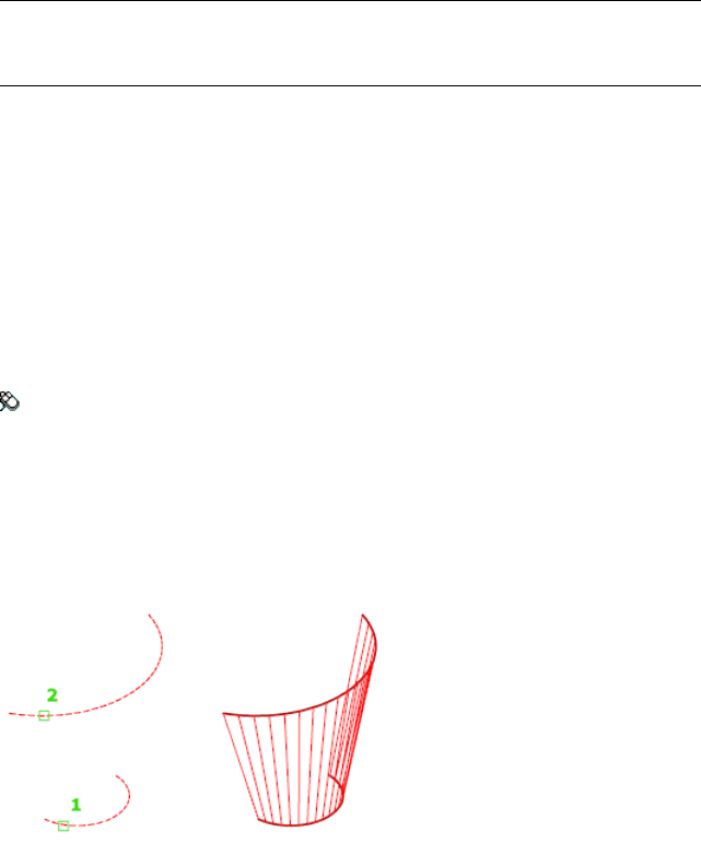
NOTE Consider turning off UNDO (page 1089) and any log files if you anticipate
running the script over a long period; otherwise, these log files continue to grow
and take up increasing amounts of disk space.
See also:
Create Command Scripts
RULESURF
Creates a mesh that represents the surface between two lines or curves.
Access Methods
Menu: Draw ➤ 3D Modeling ➤ Meshes ➤ Ruled Mesh
Summary
Select two edges that define the mesh. The edges can be lines, arcs, splines,
circles, or polylines. If one of the edges is closed, then the other edge must
also be closed. You can also use a point as one edge for either an open or a
closed curve.
The MESHTYPE (page 1369) system variable sets which type of mesh is created.
Mesh objects are created by default. Set the variable to 0 to create legacy
polyface or polygon mesh.
For closed curves, the selection does not matter. If the curve is a circle, the
ruled mesh begins at the 0-degree quadrant point, as determined by the current
X axis plus the current value of the SNAPANG (page 1439) system variable. For
closed polylines, the ruled mesh starts at the last vertex and proceeds backward
along the segments of the polyline. Creating a ruled mesh between a circle
912 | Chapter 2 Commands
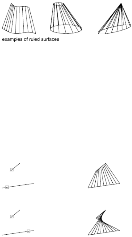
and a closed polyline can be confusing. Substituting a closed semicircular
polyline for the circle might be preferable.
The ruled mesh is constructed as a 2 by N polygon mesh. RULESURF places
half the mesh vertices at equal intervals along one defining curve, and the
other half at equal intervals along the other curve. The number of intervals
is specified by the SURFTAB1 (page 1454) system variable. It is the same for each
curve; therefore, the distance between the vertices along the two curves differs
if the curves are of different lengths.
The N direction of the mesh is along the boundary curves. If both boundaries
are closed, or if one is closed and the other is a point, the resulting polygon
mesh is closed in the N direction and N equals SURFTAB1. If both boundaries
are open, N equals SURFTAB1 + 1, because division of a curve into n parts
requires n + 1 tabulations.
The 0,0 vertex of the mesh is the endpoint of the first selected curve nearest
the point you used to select that curve.
Selecting objects at the same ends creates a polygon mesh.
Selecting objects at opposite ends creates a self-intersecting polygon mesh.
List of Prompts
The following prompts are displayed.
Commands | 913

First defining curve Specifies an object and start point for the new mesh
object.
Second defining curve Specifies an object and start point for the sweep of
the new mesh object.
See also:
Create Meshes from Other Objects
S Commands
SAVE
Saves the drawing under the current file name or a specified name.
Obsolete. The SAVE command is functionally identical to the QSAVE (page
860) command. The Save option on the File menu is QSAVE.
Summary
The Save Drawing As dialog box (a standard file selection dialog box (page
720)) is displayed. Save the drawing under the current file name, or enter a
different file name to save a copy of the drawing under that name.
If the drawing is read-only, use the SAVEAS (page 914) command to save changes
under a different file name.
See also:
Save a Drawing
SAVEAS
Saves a copy of the current drawing under a new file name.
Access Methods
Menu: File ➤ Save As
914 | Chapter 2 Commands
Summary
The Save Drawing As standard file selection dialog box (page 720) is displayed.
Enter a file name and type. Saving a drawing to any DXF™ format affects
performance.
See Save Drawings to Previous Drawing File Formats for a description of the
limitations that result from saving to an earlier version.
The file is saved with the specified file name. If the drawing is already named,
the drawing is saved with the new file name. If you save the file as a drawing
template, the template options (page 915) are displayed, where you can set the
units of measurement and provide a description for the template.
When FILEDIA (page 1296) is set to 0 (zero), SAVEAS displays command prompts
(page 916).
See also:
Save a Drawing
Template Options
Summary
When a drawing is saved as a drawing template, you are prompted for the
measurement to use when a new drawing is created from the drawing template
and a description for the template.
List of Prompts
The following prompts are displayed.
Enter template measurement [English/Metric] <current>: Entereormto
specify the measurement to assign to the template and press Enter
Enter a template description: Enter a description and press Enter
See also:
Save a Drawing
Commands | 915

SAVEAS Command Prompts
Saves a copy of the current drawing under a new file name.
List of Prompts
The following prompts are displayed.
Current file format: current
Enter file format
[2000(LT2000)/2004(LT2004)2007(LT2007)/2010(LT2010)/DXF/Template]
<2010>:
Enter an option or press Enter
Save drawing as <current>: Enter a name or press Enter
See also:
Save a Drawing
SAVEIMG
Saves a rendered image to a file.
Summary
The Render Output File dialog box (page 885) is displayed.
NOTE
SAVEIMG is not available if the current rendering device does not support
scan-line images.
See also:
Save a Rendered Image
SCALE
Enlarges or reduces selected objects, keeping the proportions of the object the
same after scaling.
916 | Chapter 2 Commands
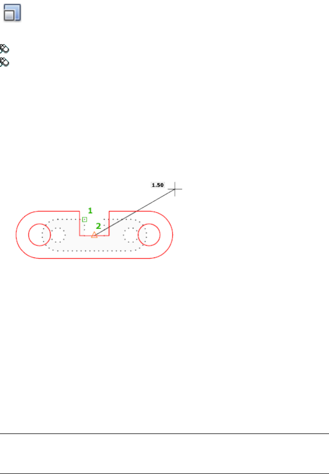
Access Methods
Button
Toolbar: Drafting tool set ➤ Move/Rotate/Scale tool group ➤ Scale
Menu: Modify ➤ Scale
Shortcut menu: Select the objects to scale. Right-click in the drawing area
and click Scale.
Summary
To scale an object, specify a base point and a scale factor. The base point acts
as the center of the scaling operation and remains stationary. A scale factor
greater than 1 enlarges the object. A scale factor between 0 and 1 shrinks the
object.
List of Prompts
The following prompts are displayed.
Select objects: Use an object selection method and press Enter when you
finish
Specify base point: Specify a point
The base point you specify identifies the point that remains in the same
location as the selected objects change size (and thus move away from the
stationary base point).
NOTE When you use the SCALE command with annotative objects, the position
or location of the object is scaled relative to the base point of the scale operation,
but the size of the object is not changed.
Commands | 917
Specify scale factor (page 918) or [Copy (page 918)/Reference
(page 918)]: Specify a scale, enter c, or enter r
Scale Factor Multiplies the dimensions of the selected objects by the specified
scale. A scale factor greater than 1 enlarges the objects. A scale factor between
0 and 1 shrinks the objects. You can also drag the cursor to make the object
larger or smaller.
Copy Creates a copy of the selected objects for scaling.
Reference Scales the selected objects based on a reference length and a specified
new length.
See also:
Resize or Reshape Objects
SCALELISTEDIT
Controls the list of scales available for layout viewports, page layouts, and
plotting.
Access Methods
Button
Toolbar: Annotation tool set ➤ Annotation Scaling tool group ➤ Scale
List
Menu: Format ➤ Scale List
Command entry: 'scalelistedit for transparent use
Summary
Displays a list of predefined scales used throughout the program. This list can
be easily modified to display only the scales you need.
The Edit Scale List dialog box (page 919) is displayed.
If you enter -scalelistedit at the Command prompt, options are displayed
(page 920).
918 | Chapter 2 Commands
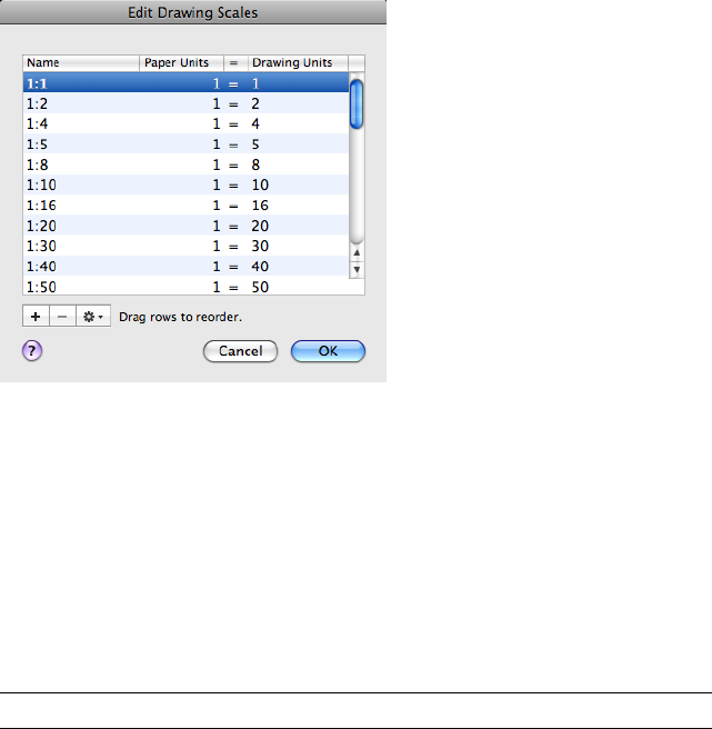
See also:
Scale Views in Layout Viewports
Edit Drawing Scales Dialog Box
Controls the list of scales available for layout viewports, page layouts, and
plotting.
List of Options
The following options are displayed.
Scale List Displays the list of currently defined scales. Also displays temporary
scales that are imported when xrefs are attached. If a scale name is duplicated,
but has a different value, a number is appended to the name.
Add Creates a new scale in the scale list.
Press Tab to move between the fields of the scale being edited.
Delete Removes the selected scale from the scale list.
NOTE You cannot delete a scale that is referenced by an annotative object.
Options
Manages items in the scale list.
Edit Edits the selected scale in-place in the scale list.
Press Tab to move between the fields of the scale being edited.
Commands | 919
NOTE
You cannot edit temporary scales.
Reset Deletes all custom scales and unused scales and restores the default list
of scales.
See also:
Scale Views in Layout Viewports
-SCALELISTEDIT
Controls the list of scales available for layout viewports, page layouts, and
plotting.
List of Prompts
The following prompts are displayed.
Enter option [?/Add/Delete/Reset/Exit] <Add>: Enter an option or
press Enter
? Displays a list of defined scales.
Add Adds a new scale to the scale list. Enter a ratio in the format n:m, where
n is the number of paper units and m is the number of drawing units
Delete Removes a specified scale. If a scale is current or supported by an
annotative object, it cannot be deleted.
Reset Deletes all custom scales as a result and restores the default list of scales.
See also:
Scale Views in Layout Viewports
SCRIPT
Executes a sequence of commands from a script file.
Access Methods
Command entry: 'script for transparent use
920 | Chapter 2 Commands
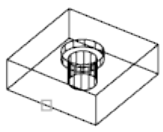
Summary
A script is a text file with an .scr file extension. Each line of the script file
contains a command that can be completed at the Command prompt,
including alternative versions of commands that normally display dialog
boxes.
The Select Script File dialog box (a standard file selection dialog box (page
720)) is displayed. Enter the file name of a script to run that script.
When FILEDIA (page 1296) is set to 0 (zero), SCRIPT displays the following
command prompt.
See also:
Overview of Command Scripts
SECTION
Uses the intersection of a plane and solids, surfaces, or mesh to create a region.
Summary
The SECTION command creates a region object that represents a 2D cross
section of 3D objects, including 3D solids, surfaces, and meshes.
This method does not have the live sectioning capabilities that are available
for section plane objects that are created using the SECTIONPLANE (page 923)
command.
List of Prompts
The following prompts are displayed.
Select objects Selects one or more 3D objects. Selecting several objects creates
separate regions for each object.
Commands | 921
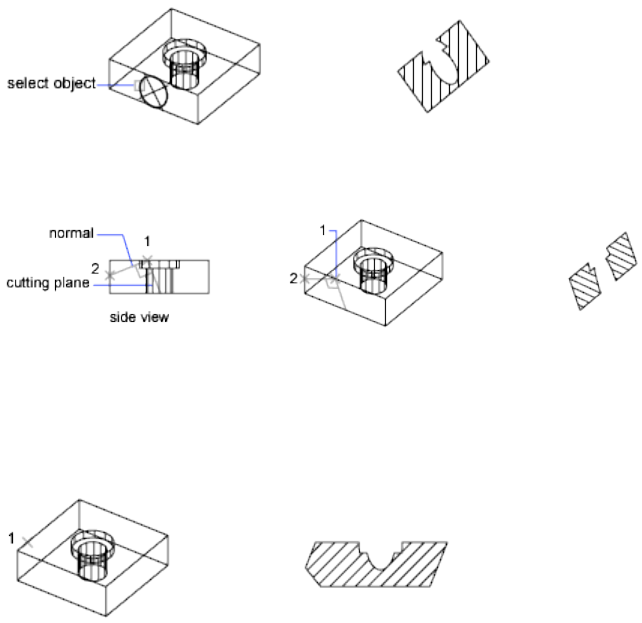
Specify the first point on the sectioning plane using one of the following
methods:
■Object (page 922)
■Z Axis (page 922)
■View (page 922)
■XY (page 923)
■YZ (page 923)
■ZX (page 923)
■3points (page 923)
Object Aligns the sectioning plane with a circle, ellipse, circular or elliptical
arc, 2D spline, or 2D polyline segment.
Z Axis Defines the sectioning plane by specifying a point on the sectioning
plane and another point on the Z axis, or normal, of the plane.
■Point on the section plane. Sets the first point on the plane.
■Point on the Z-axis (normal) of the plane. Specifies a point that
defines the axis that is perpendicular to the plane.
View Aligns the sectioning plane with the viewing plane of the current view.
922 | Chapter 2 Commands
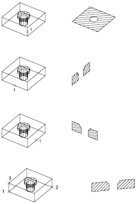
XY Aligns the sectioning plane with the XY plane of the current UCS.
YZ Aligns the sectioning plane with the YZ plane of the current UCS.
ZX Aligns the sectioning plane with the ZX plane of the current UCS.
3points Uses three points to define the sectioning plane:
See also:
Create Section Objects
SECTIONPLANE
Creates a section object that acts as a cutting plane through 3D objects.
Commands | 923
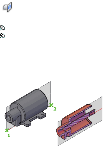
Access Methods
Button
Toolbar: Modeling tool set ➤ Section tool group ➤ Section Plane
Menu: Draw ➤ 3D Modeling ➤ Section Plane
Summary
Section plane objects create sections of 3D solids, surfaces, and meshes. Use
live sectioning with section plane objects to analyze a model, and save sections
as blocks for use in layouts.
List of Options
The following options are displayed.
Face or Any Point to Locate Section Line Specifies a face to establish the
plane of the section object.
Alternatively, you can select any point on the screen that is not on a face to
create a section object independent of the solid or surface. The first point
establishes a point around which the section object rotates.
■Through point. Sets a second point that defines the plane of the section
object.
Draw section Defines the section object with multiple points to create a
section line with jogs.
This option creates a section object in the Section Boundary state with live
sectioning turned off.
924 | Chapter 2 Commands

Orthographic Aligns the section object to an orthographic orientation relative
to the UCS.
A section object that contains all 3D objects is created with the specified
orientation relative to the UCS (not the current view). This option creates a
section object in the Section Plane state with live sectioning turned on.
■Align section to. Sets the position of the section object to align with
one of the following UCS orientations that you specify:
■Front
■Back
■Top
■Bottom
Commands | 925
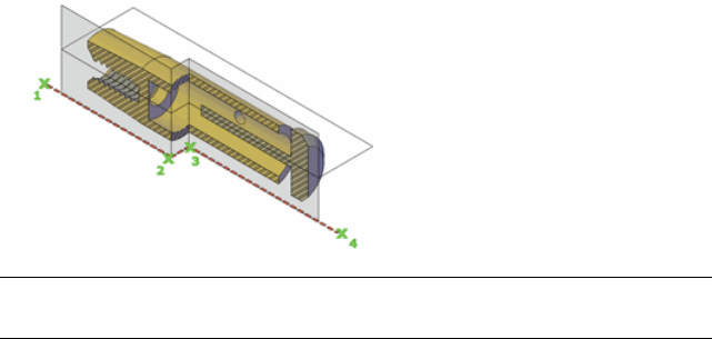
■Left
■Right
See also:
Create Section Objects
SECTIONPLANEJOG
Adds a jogged segment to a section object.
Access Methods
Ribbon: Mesh Modeling tab ➤ Section panel ➤ Section Plane Jog
Shortcut menu: Select a section plane. Right-click in the drawing area and
click Add Jog to Section.
Summary
You can insert a jog, or angle, into a section object as you create it. The jog is
created on the section line. The jogged segment is created at a 90-degree angle
to the section line.
NOTE The SECTIONPLANEJOG command was previously called JOGSECTION.
Entering jogsection at the Command prompt runs SECTIONPLANE JOG.
List of Prompts
The following prompts are displayed.
Select section object Specifies which section line to modify.
926 | Chapter 2 Commands

Point on the section line to add jog Specifies the location of the jog.
See also:
Add Jogs to a Section
SECTIONPLANESETTINGS
Sets display options for the selected section plane.
Access Methods
Button
Toolbar: Modeling tool set ➤ Section tool group (expanded) ➤ Section
Plane Settings
Shortcut menu: Select a live section object. Right-click in the drawing area
and click Live Section Settings.
Summary
The Section Settings dialog box (page 927) is displayed.
See also:
Set Section Object States and Properties
Section Settings Dialog Box
Sets display options for section planes.
Commands | 927
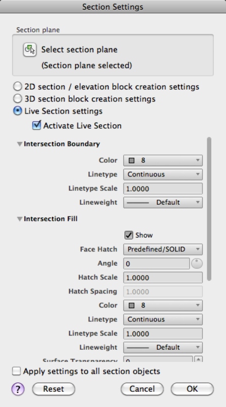
List of Options
The following options are displayed.
Section Plane
If a section plane has not been selected, specifies a selection plane to be
modified.
Select Section Plane Temporarily closes the Section Settings dialog box so
that you can select a section object in the drawing area.
Setting Type
Specifies which setting types are displayed in the properties list.
2D Section / Elevation Block Creation Settings
Determines how a 2D section from a 3D object is displayed when generated.
3D Section Block Creation Settings
Determines how a 3D object is displayed when generated.
Live Section Settings
Determines how sectioned objects are displayed in the drawing when live
sectioning is turned on.
Activate Live Section
Turns on live sectioning for the selected section object.
Properties
Sets the properties to be applied to the new section block.
Intersection Boundary Sets the appearance of line segments that outline the
intersection surface of the section object plane.
■Color. Sets the color of the intersection boundary.
■Layer. Sets the layer. Select an existing layer, or select
<Component_Name>*LayerByObject* to split the block component onto
a separate layer. If you want to add a customized prefix or suffix to the
*LayerByObject* name, click New Layer Name Settings to open the New
Layer Name dialog box (page 932). (2D and 3D section blocks only)
■Linetype. Sets the linetype to be ByLayer, ByBlock, or a type that you
specify.
■Linetype Scale. Sets the scale of the linetype.
■Plot Style. Displays the current plot style. (2D and 3D section blocks
only)
Commands | 929
■Lineweight. Sets whether the lineweight is ByLayer, ByBlock, matches
the default, or has a unique value.
■Division Lines. Sets whether division lines are displayed. (2D section
blocks only)
■Show. Sets whether the intersection boundary is displayed. (3D section
blocks only)
Intersection Fill Sets the optional fill that is displayed inside the boundary
area of the cut surface where the section object intersects the 3D object.
■Show. Sets whether the intersection fill is displayed.
■Face Hatch. Sets the hatch pattern to be used for the face of the cut
surface. To select a pattern from a list, click Select Hatch Pattern Type.
■Angle. Sets the hatch angle.
■Hatch Scale. Sets the hatch scale.
■Hatch Spacing. Sets the distance between hatch lines.
■Color. Sets the color of the intersection fill.
■Layer. Sets the layer. Select an existing layer, or select
<Component_Name>*LayerByObject* to split the block component onto
a separate layer. If you want to add a customized prefix or suffix to the
*LayerByObject* name, click New Layer Name Settings to open the New
Layer Name dialog box (page 932). (2D and 3D section blocks only.)
■Lineweight. Sets whether the lineweight is ByLayer, ByBlock, matches
the default, or has a unique value.
■Linetype Scale. Sets the scale of the linetype.
■Plot Style. Displays the current plot style. (2D and 3D section blocks
only)
■Lineweight. Sets whether the lineweight is ByLayer, ByBlock, matches
the default, or has a unique value.
■Surface Transparency. Sets the percentage of transparency for the
intersection fill. (Live Section only)
Background Lines Controls the display of background lines. (2D and 3D
section blocks only)
■Show. Sets whether the component is displayed. (2D section blocks only)
■Hidden Line. Sets whether hidden lines (lines that are behind other lines
in the 3D view) are displayed. (2D section blocks only)
■Color. Sets the color of the component.
930 | Chapter 2 Commands
■Layer. Sets the layer of the component. Select an existing layer, or select
<Component_Name>*LayerByObject* to split the block component onto
a separate layer. If you want to add a customized prefix or suffix to the
*LayerByObject* name, click New Layer Name Settings to open the New
Layer Name dialog box (page 932).
■Linetype. Sets the linetype to be ByLayer, ByBlock, or Continuous.
■Linetype Scale. Sets the scale of the linetype.
■Plot Style. Displays the current plot style.
■Lineweight. Sets whether the lineweight is ByLayer, ByBlock, matches
the default, or has a unique value.
Cut-away Geometry Sets properties for the cut-away objects.
■Show. Sets whether the component is displayed.
■Hidden Line. Sets whether hidden lines (lines that are behind other lines
in the 3D view) are displayed. (2D section blocks only)
■Color. Sets the color of the cutaway geometry.
■Layer. Sets the layer of the cutaway geometry. Select an existing layer, or
select <Component_Name>*LayerByObject* to split the block component
onto a separate layer. If you want to add a customized prefix or suffix to
the *LayerByObject* name, click New Layer Name Settings to open the
New Layer Name dialog box (page 932). (2D and 3D section blocks only)
■Linetype. Sets the linetype to be ByLayer, ByBlock, or Continuous.
■Linetype Scale. Sets the scale of the linetype.
■Plot Style. Displays the current plot style. (2D and 3D section blocks
only)
■Lineweight. Sets whether the lineweight is ByLayer, ByBlock, matches
the default, or has a unique value.
■Face Transparency. Sets the percentage of transparency of the face
created where the live section object interfaces with the 3D objects. (Live
Section only)
■Edge Transparency. Sets the percentage of transparency of the edges
of the foreground lines. (Live Section only)
Curve Tangency Lines Controls the inclusion of curved lines that are tangent
to the section plane. (2D section blocks only)
■Show. Sets whether the curve tangency lines are displayed.
■Color. Sets the color of the curve tangency lines.
Commands | 931
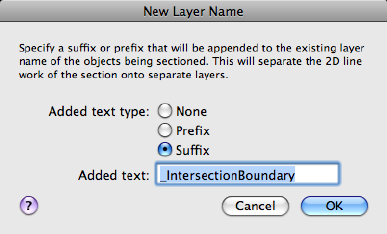
■Layer. Sets the layer of the curve tangency lines. Select an existing layer,
or select <Component_Name>*LayerByObject* to split the block component
onto a separate layer. If you want to add a customized prefix or suffix to
the *LayerByObject* name, click New Layer Name Settings to open the
New Layer Name dialog box (page 932).
■Linetype. Sets the linetype to be ByLayer, ByBlock, or Continuous.
■Linetype Scale. Sets the scale of the linetype.
■Plot Style. Displays the current plot style.
■Lineweight. Sets whether the lineweight is ByLayer, ByBlock, matches
the default, or has a unique value.
Apply Settings to All Section Objects
When selected, applies all the settings to all section objects in the drawing.
When cleared, applies settings to the current section object only.
Reset
Resets all settings in the dialog box to their default values.
See also:
Set Section Object States and Properties
New Layer Name Dialog Box
Adds a custom prefix or suffix to layer names to help organize components
of a section block
932 | Chapter 2 Commands
Access Methods
Pointing device: In the Section Settings dialog box (page 927), Layer list,
click New Layer Name Settings.
Summary
By default, all section block geometry is placed on Layer 0 (zero). However,
you can specify suffix or prefix labels to help organize section block
components, such as intersection boundaries and fill. When the section block
is inserted, the section block components are placed on new layers whose
name combines the name of the layer that contains the sectioned object and
the prefix or suffix you specify. If the section plane includes objects on two
or more layers, two or more new object layers are created.
For example, suppose you create a suffix called “_kitchen” and then select
*ObjectByLayer*_kitchen in the Section Settings dialog box, under Intersection
Boundary. If you create a section block that bisects objects on the Walls and
Cabinetry layers, two new layers are created to contain the block geometry
for intersection boundaries: Walls_kitchen and Cabinetry_kitchen.
You can then easily modify the appearance of a set of block components by
changing their properties. If a property such as Color is set as an object override
in the Section Settings dialog box, you can change the property in that
location. If the property is set to ByLayer, you can change it in the Layers
palette (page 538).
List of Options
The following options are displayed.
Added Text Type Specifies whether or how identifying text is added to the
layer name for the section block component.
■None. No additional text is added to the layer name. The section block
geometry is placed on the same layer as the original geometry.
■Prefix. If the Layer property is specified as *ObjectByLayer* in the Section
Settings dialog box, the label is added in front of the layer name.
■Suffix. If the Layer property is specified as *ObjectByLayer* in the Section
Settings dialog box, the label is added to the end of the layer name.
Added Text
Specifies identifying text to be added to the name of the layer that contains
the component geometry when the section block is inserted.
Commands | 933
See also:
Set Section Object States and Properties
SECTIONPLANETOBLOCK
Saves selected section planes as 2D or 3D blocks.
Access Methods
Shortcut menu: Select a live section object. Right-click in the drawing area
and click Generate 2D/3D Section.
Summary
The Generate Section /Elevation dialog box (page 934) is displayed.
See also:
Save Sections as Blocks, Drawings, or Tools
Generate Section /Elevation Dialog Box
Saves 2D and 3D sections as blocks.
934 | Chapter 2 Commands
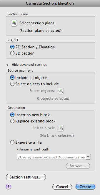
Summary
Specifies the display settings for the cross sections that you save and reuse.
List of Options
The following options are displayed.
Section Plane
Select Section Plane Closes the dialog box so that you can select a section
plane to modify or save as a block.
2D/3D
2D Section/Elevation
Commands | 935
Creates and saves or inserts a block that represents a 2D cross section.
3D Section
Creates and saves or inserts a cutaway 3D block.
Hide/Show Advanced Settings
Controls the display of the Source Geometry, Destination, and Section Settings
options.
Source Geometry
Include All Objects
Includes all 3D objects (3D solids, surfaces, and regions) in the drawing,
including objects in xrefs and blocks.
Select Objects to Include
Specifies that you will manually select the 3D objects (3D solids, surfaces,
meshes, and regions) from which to generate a section.
Select Objects
Closes the dialog box temporarily while you select the objects for the section.
When you finish selecting objects, press Enter to redisplay the Generate
Section/Elevation dialog box.
Objects Selected
Indicates the number of objects selected.
Destination
Insert as New Block Inserts the generated section as a block in the current
drawing.
Replace Existing Block Replaces an existing block in the drawing with the
newly generated section.
Select Block
Closes the dialog box temporarily while you select the block to be replaced
in the drawing. When you finish selecting the block, press Enter to redisplay
the Generate Section/Elevation dialog box.
Export to a File Saves the section to an external file.
Filename and Path
Specifies a file name and path where the section will be saved.
Section Settings
Opens the Section Settings dialog box (page 927).
936 | Chapter 2 Commands
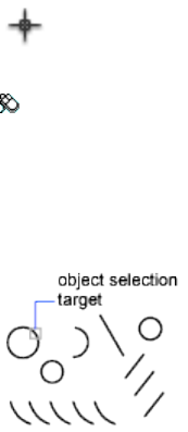
Create
Creates the section.
See also:
Create Section Objects
SELECT
Places selected objects in the Previous selection set.
Access Methods
Button
Toolbar: Drafting tool set ➤ Selection tool group ➤ Select
Summary
A small box, called the object selection target or pickbox, replaces the crosshairs
on the graphics cursor.
At the Select Objects prompt in a subsequent command, use the Previous
option to retrieve the previous selection set.
You can also press and hold the Ctrl key to select original individual forms
that are part of composite solids or vertices, edges, and faces on 3D solids.
You can select one of these subobjects, or create a selection set of more than
one subobject. Your selection set can include more than one type of subobject.
To view all options, enter ? at the Command prompt.
Commands | 937
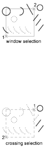
List of Prompts
The following prompts are displayed.
Select objects: Use an object selection method
Expects a point or
Window (page 938)/Last (page 938)/Crossing (page 938)/BOX (page
938)/ALL (page 939)/Fence (page 939)/WPolygon (page 939)/CPolygon
(page 939)/Group (page 940)/Add (page 940)/Remove (page
940)/Multiple (page 940)/Previous (page 940)/Undo (page 940)/AUto
(page 940)/SIngle (page 940)/SUbobject (page 941)/Object (page
941)
Select objects: Specify a point or enter an option
Window Selects all objects completely inside a rectangle defined by two points.
Specifying the corners from left to right creates a window selection. (Specifying
the corners from right to left creates a crossing selection.)
Last Selects the most recently created visible object. The object must be in
the current space, that is, model space or paper space, and its layer must not
be set to frozen or off.
Crossing Selects objects within and crossing an area defined by two points.
A crossing selection is displayed as dashed or otherwise highlighted to
differentiate it from window selection.
Box Selects all objects inside or crossing a rectangle specified by two points.
If the rectangle's points are specified from right to left, Box is equivalent to
Crossing. Otherwise, Box is equivalent to Window.
938 | Chapter 2 Commands
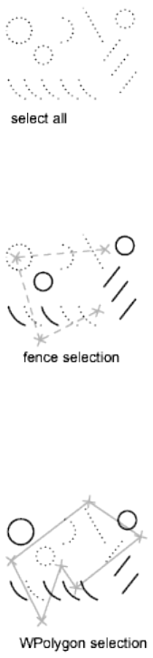
All Selects all objects in either model space or the current layout, except those
objects on frozen or on locked layers.
Fence Selects all objects crossing a selection fence. The Fence method is similar
to CPolygon except that that the fence is not closed, and a fence can cross
itself. Fence is not affected by the PICKADD (page 1392) system variable.
WPolygon Selects objects completely inside a polygon defined by points. The
polygon can be any shape but cannot cross or touch itself. The last segment
of the polygon is drawn so that it is closed at all times. WPolygon is not
affected by the PICKADD (page 1392) system variable.
CPolygon Selects objects within and crossing a polygon defined by specifying
points. The polygon can be any shape but cannot cross or touch itself. The
last segment of the polygon is drawn so that it is closed at all times. CPolygon
is not affected by the PICKADD (page 1392) system variable.
Commands | 939
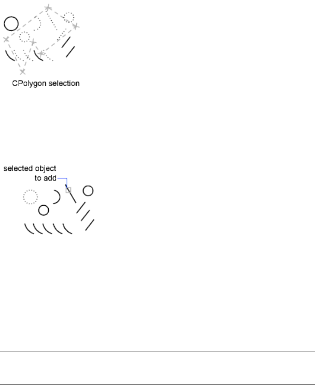
Group Selects all objects within a specified group.
Add Switches to the Add method: selected objects can be added to the selection
set by using any of the object selection methods. Auto and Add are the default
methods.
Remove Switches to the Remove method: objects can be removed from the
current selection set using any object selection method. An alternative to
Remove mode is to hold down Shift while selecting single objects or use the
Automatic option.
Multiple Selects objects individually without highlighting them during object
selection. This speeds up object selection for highly complex objects.
Previous Selects the most recent selection set. The Previous selection set is
cleared by operations that delete objects from the drawing.
NOTE
The Previous selection set is ignored if you switch spaces.
Undo Cancels the selection of the object most recently added to the selection
set.
Auto Switches to automatic selection: pointing to an object selects the object.
Pointing to a blank area inside or outside an object forms the first corner of
a box defined by the Box method. Auto and Add are the default methods.
Single Switches to the Single method: selects the first object or set of objects
designated rather than continuing to prompt for further selections.
940 | Chapter 2 Commands
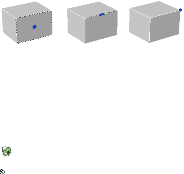
Subobject Allows you to select original individual forms that are part of
composite solids or vertices, edges, and faces on 3D solids. You can select one
of these subobjects, or create a selection set of more than one subobject. Your
selection set can include more than one type of subobject.
Pressing and holding the Ctrl key is the same as selecting the SELECT
command’s Subobject option.
Object Ends the ability to select subobjects. Allows you to use object selection
methods.
See also:
Select Objects Individually
SELECTSIMILAR
Adds similar objects to the selection set based on selected objects.
Access Methods
Button
Toolbar: Drafting tool set ➤ Selection tool group ➤ Select Similar
Shortcut menu: Select the object that you want to use as the template object
to select similar objects. Right-click in the drawing area and click Select Similar.
Summary
Selects similar objects of the same type based on specified matching properties,
such as the color or block name.
Commands | 941
List of Prompts
The following prompt is displayed.
Select objects or [SEttings]: Use an object selection method and press
Enter
The Settings option displays the Select Similar Settings dialog box.
See also:
Select Objects by Properties
Select Similar Settings Dialog Box
Controls which properties must match for an object of the same type to be
selected.
List of Options
The following options are displayed.
Color Considers objects with matching colors to be similar.
Layer Considers objects on matching layers to be similar.
Linetype Considers objects with matching linetypes to be similar.
Linetype scale Considers objects with matching linetype scales to be similar.
Lineweight Considers objects with matching lineweights to be similar.
Plot style Considers objects with matching plot styles to be similar.
Object style Considers objects with matching styles (such as text styles,
dimension styles, and table styles) to be similar.
Name Considers referenced objects (such as blocks, xrefs, and images) with
matching names to be similar.
See also:
Select Objects by Properties
942 | Chapter 2 Commands

SETVAR
Lists or changes the values of system variables.
Access Methods
Menu: Tools ➤ Inquiry ➤ Set Variable
Command entry: 'setvar for transparent use
List of Prompts
The following prompts are displayed.
Enter variable name (page 943) or [?(page 943)] <current>: Enter
a variable name, enter ?, or press Enter
Variable Name Specifies the name of the system variable you want to set.
You can also change the value of system variables at the Command prompt
by entering the name of the variable and its new value.
?—List Variables Lists all system variables in the drawing and their current
settings.
See also:
Enter Commands on the Command Line
SHADEMODE
Starts the VSCURRENT command.
See also:
Use a Visual Style to Display Your Model
-SHADEMODE
List of Prompts
The following prompts are displayed.
Commands | 943
Enter option [2D wireframe (page 944)/3D wireframe (page
944)/Hidden (page 944)/Flat (page 944)/Gouraud (page
944)/fLat+edges (page 944)/gOuraud+edges (page 944)] <current>:
2D Wireframe Displays the objects using lines and curves to represent the
boundaries. Raster and OLE objects, linetypes, and lineweights are visible.
3D Wireframe Displays the objects using lines and curves to represent the
boundaries. Material colors that you have applied to the objects are shown.
Hidden Displays the objects using 3D wireframe representation and hides
lines representing back faces.
Flat Shaded Shades the objects between the polygon faces. The objects appear
flatter and less smooth than Gouraud-shaded objects. Materials that you have
applied to the objects show when the objects are flat shaded.
Gouraud Shaded Shades the objects and smooths the edges between polygon
faces. This gives the objects a smooth, realistic appearance. Materials that you
have applied to the objects show when the objects are Gouraud shaded.
Flat Shaded, Edges On Combines the Flat Shaded and Wireframe options.
The objects are flat shaded with the wireframe showing through.
Gouraud Shaded, Edges On Combines the Gouraud Shaded and Wireframe
options. The objects are Gouraud shaded with the wireframe showing through.
See also:
SHAPE
Inserts a shape from a shape file that has been loaded using LOAD.
List of Prompts
The following prompts are displayed.
Enter shape name (page 944) or [?(page 945)]: Enter a name, or enter
?
Shape Name Loads the shape.
If a shape belongs to an external reference (xref) attached to the current
drawing, the shape file is identified as externally dependent. Externally
dependent shapes cannot be used in the current drawing unless they are
reloaded.
944 | Chapter 2 Commands
?—List Shapes Lists shapes and the files in which the shapes are defined.
If you enter an asterisk (*), the program lists shape names.
See also:
Overview of Shape Files
SHOWPALETTES
Restores the display of hidden palettes.
Access Methods
Command entry: Tab
Summary
Restores the state of the display and position of palettes hidden by HIDE-
PALETTES (page 508).
Press Tab to switch between HIDEPALETTES and SHOWPALETTES.
NOTE
If a palette was manually turned back on, it is not affected by SHOWPALETTES
(even if it was manually closed again)
See also:
Specify the Behavior of Palettes
SKETCH
Creates a series of freehand line segments.
Summary
Sketching is useful for creating irregular boundaries or for tracing with a
digitizer. Specify the object type (line, polyline, or spline), increment, and
tolerance before sketching.
Commands | 945
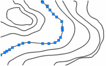
List of Prompts
The following prompts are displayed.
Specify Sketch (page 946) or [Type (page 946)/Increment (page
946)/toLerance (page 946)]:
Sketch Creates a sketch.
Type Specifies the object type for the sketch line. (SKPOLY (page 1436) system
variable)
■Line (page 573)
■Polyline (page 785)
■Spline (page 988)
Increment Defines the length of each freehand line segment. You must move
the pointing device a distance greater than the increment value to generate
a line. (SKETCHINC (page 1435) system variable)
Tolerance For Splines, specifies how closely the spline’s curve fits to the
freehand sketch. (SKTOLERANCE (page 1436) system variable)
See also:
Draw Freehand Sketches
SLICE
Creates new 3D solids and surfaces by slicing, or dividing, existing objects.
946 | Chapter 2 Commands
Access Methods
Button
Toolbar: Modeling tool set ➤ Solids - Edit tool group (expanded) ➤
Slice
Menu: Modify ➤ 3D Operations ➤ Slice
Summary
The cutting plane is defined with 2 or 3 points, by specifying a major plane
of the UCS, or by selecting a surface object (but not a mesh). Either one or
both sides of the sliced 3D solids can be retained.
The sliced objects retain the layer and color properties of the original solids.
However, the resulting solid or surface objects do not retain a history of the
original objects.
Objects that Can Be Used in a Slice Operation
Objects that can be used as cutting planesObjects that can be sliced
Surfaces3D solids
CirclesSurfaces
Ellipses
Circular or elliptical arcs
2D splines
Commands | 947
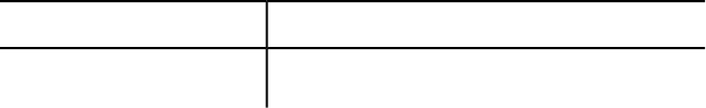
Objects that can be used as cutting planesObjects that can be sliced
3D polyline segments
List of Prompts
The following prompts are displayed.
Objects to slice Specifies the 3D solid or surface object that you want to slice.
If you select a mesh object, you can choose to convert it to a 3D solid or surface
before completing the slice operation.
■Start point of slicing plane (page 948)
■Planar object (page 948)
■Surface (page 949)
■Z axis (page 949)
■View (page 950)
■XY (page 950)
■YZ (page 950)
■ZX (page 951)
■3points (page 951)
Start point of slicing plane Sets the first of two points that define the angle
of the slicing plane. The slicing plane is perpendicular to the XY plane of the
current UCS.
■Second point on plane. Sets the second of two points on the slicing
plane.
■Point on desired side (page 951)
■Keep both sides (page 952)
Planar object Aligns the cutting plane with a plane that contains a selected
circle, ellipse, circular or elliptical arc, 2D spline, or 2D polyline segment.
948 | Chapter 2 Commands
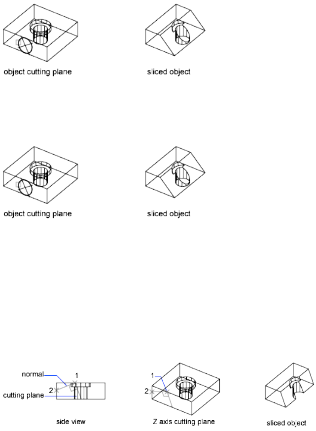
■Select a circle, ellipse, arc, 2D-spline, or 2D-polyline. Specifies the
object to use for alignment.
Surface Aligns the cutting plane with a surface.
■Select a surface. Specifies a surface to be used for alignment.
NOTE You cannot select meshes created with the EDGESURF (page 399),
REVSURF (page 905), RULESURF (page 912), and TABSURF (page 1039) commands.
■Point on desired side (page 951)
■Keep both sides (page 952)
Z axis Defines the cutting plane by specifying a point on the plane and another
point on the Z axis (normal) of the plane.
■Specify a point on the section plane. Sets a point on the slicing plane.
■Specify a point on the Z-axis (normal) of the plane. Specifies a
point that defines the axis that is perpendicular to the slicing plane.
Commands | 949
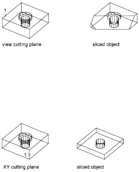
■Point on desired side (page 951)■
■Keep both sides (page 952)
View Aligns the cutting plane with the current viewport's viewing plane.
Specifying a point defines the location of the cutting plane.
■Specify a point on the current view plane. Sets a point on the object
to start the slice.
■Point on desired side (page 951)■
■Keep both sides (page 952)
XY Aligns the cutting plane with the XY plane of the current user coordinate
system (UCS). Specifying a point defines the location of the cutting plane.
■Point on the XY-plane. Sets the location of the slice.
■Point on desired side (page 951)■
■Keep both sides (page 952)
YZ Aligns the cutting plane with the YZ plane of the current UCS. Specifying
a point defines the location of the cutting plane.
950 | Chapter 2 Commands
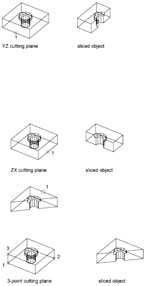
■Point on the YZ-plane. Sets the location of the slice.
ZX Aligns the cutting plane with the ZX plane of the current UCS. Specifying
a point defines the location of the cutting plane.
■Point on the ZX-plane. Sets the location of the slice.
If a single object is sliced into more than two objects, one solid or surface
is created from the objects on one side of the plane and another solid or
surface is created from the objects on the other side.
3points Defines the cutting plane using three points.
Point on desired side Uses a point to determine which side of the sliced solids
your drawing retains. The point cannot lie on the cutting plane.
Commands | 951
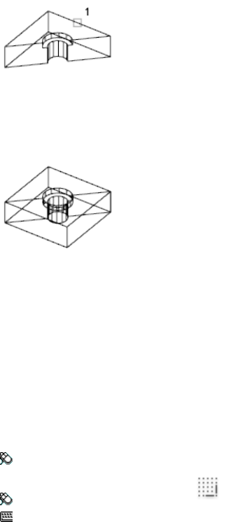
Keep both sides Retains both sides of the sliced solids. Slicing a single solid
into two pieces creates two solids from the pieces on either side of the plane.
SLICE never creates more than two new composite solids for each selected
solid.
See also:
Create 3D Solids or Surfaces by Slicing
SNAP
Restricts cursor movement to specified intervals.
Access Methods
Menu: Tools ➤ Drafting Settings
Toolbar: Status bar ➤ Snap
Command entry: snap or ‘snap for transparent use
List of Prompts
The following prompts are displayed.
Specify snap spacing (page ?) or [ON (page ?)/OFF (page
?)/Aspect (page ?)/Style (page ?)/Type (page ?)] <current>:
Specify a distance, enter an option, or press Enter
Snap Spacing
Activates Snap mode with the value you specify.
952 | Chapter 2 Commands
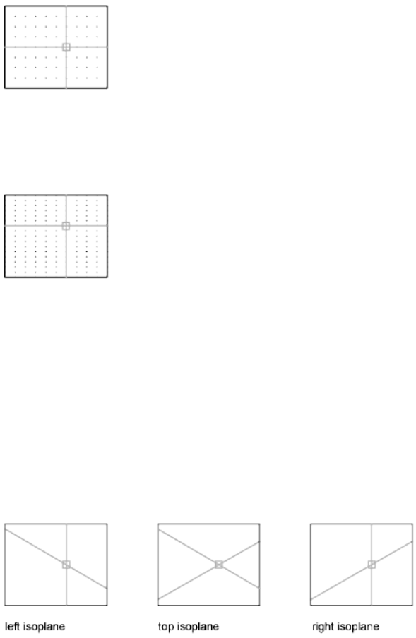
On
Activates Snap mode using the current settings of the snap grid.
Off
Turns off Snap mode but retains the current settings.
Aspect
Specifies different spacing in the X and Y directions.
Style
Specifies the format of the snap grid, which is Standard or Isometric.
Standard
Sets a rectangular snap grid that is parallel to the XY plane of the current UCS.
X and Y spacing may differ.
Spacing Specifies the overall spacing of the snap grid.
Aspect Specifies the horizontal and vertical spacing of the snap grid separately.
Isometric
Sets an isometric snap grid, in which the snap locations are initially at
30-degree and 150-degree angles. Isometric snap cannot have different Aspect
values. The lined grid does not follow the isometric snap grid.
Commands | 953

ISOPLANE (page 533) determines whether the crosshairs lie in the top isometric
plane (30- and 150-degree angles), the left isoplane (90- and 150-degree angles),
or the right isoplane (30- and 90-degree angles).
Type
Specifies the snap type, polar or rectangular. This setting is also controlled by
the SNAPTYPE (page 1441) system variable.
Polar
Sets the polar angle increment.
(POLARANG (page 1400) system variable)
Grid Sets the snap to Grid. When you specify points, the cursor snaps along
vertical or horizontal grid points.
See also:
Adjust Grid and Grid Snap
SOLDRAW
Generates profiles and sections in layout viewports created with SOLVIEW.
Access Methods
Menu: Draw ➤ 3D Modeling ➤ Setup ➤ Drawing
Summary
After using SOLVIEW, visible and hidden lines representing the silhouette
and edges of solids in the viewport are created and then projected to a plane
perpendicular to the viewing direction.
List of Prompts
The following prompts are displayed.
Select viewports to draw ...
Select objects: Select the viewports to be drawn
SOLDRAW can only be used in viewports that have been created with SOLVIEW
(page 975).
Visible and hidden lines representing the silhouette and edges of solids in the
viewport are created and then projected to a plane perpendicular to the viewing
954 | Chapter 2 Commands
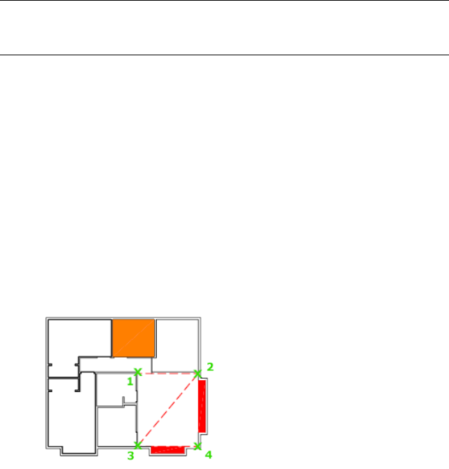
direction. Silhouettes and edges are generated for all solids and portions of
solids behind the cutting plane. For sectional views, cross-hatching is created
using the current values of the HPNAME (page 1326), HPSCALE (page 1329), and
HPANG (page 1319) system variables.
Any existing profiles and sections in the selected viewport are deleted, and
new ones are generated. All layers, except those required to display the profile
or section, are frozen in each viewport.
WARNING Do not place permanent drawing information on the view name-VIS,
view name-HID, and view name-HAT layers. The information stored on these layers
is deleted and updated when SOLDRAW is run.
To undo a viewport drawn by SOLDRAW, you must use the Back option of
UNDO (page 1089).
See also:
Create a Flattened View
SOLID
Creates solid-filled triangles and quadrilaterals.
Summary
For example:
2D solids are filled only when the FILLMODE (page 1298) system variable is on
(1) and the viewing direction is orthogonal to the 2D solid.
Commands | 955
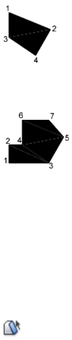
List of Prompts
The following prompts are displayed.
First point Sets the first point in the 2D solid.
Second point Sets the first edge of the 2D solid.
Third point Sets the corner that is opposite the second point.
Fourth point or <exit> The fourth point is diagonally opposite the first point.
Pressing Enter at the Fourth Point prompt creates a filled triangle. Specifying
a fifth point creates a quadrilateral area.
Specifying successive third and fourth points creates further connected triangles
and four-sided polygons in a single solid object.
See also:
Create Solid-Filled Areas
SOLIDEDIT
Edits faces and edges of 3D solid objects.
Access Methods
Button
956 | Chapter 2 Commands

Toolbar: Modeling tool set ➤ Solids - Edit tool group (expanded)
Summary
You can extrude, move, rotate, offset, taper, copy, delete, and assign colors
and materials to faces. You can also copy and assign colors to edges. You can
imprint, separate, shell, clean, and check the validity of the entire 3D solid
object (body).
You cannot use SOLIDEDIT with mesh objects. However, if you select a closed
mesh object, you will be prompted to convert it to a 3D solid.
List of Prompts
The following prompts are displayed.
Enter a solids editing option [Face/Edge/Body/Undo/Exit]
<eXit>:
Face
Face
Edits selected 3D solid faces by extruding, moving, rotating, offsetting, tapering,
deleting, copying, or changing their color.
Enter a face editing option [Extrude (page 957)/Move (page 961)/Rotate (page
962)/Offset (page 964)/Taper (page 965)/Delete (page 966)/Copy (page 966)/coLor
(page 967)/mAterial (page 967)/ Undo (page ?)/eXit (page ?)]:
Face: Extrude
Extrude Extends a 3D solid face in the X, Y, or Z direction. You can change
the shape of the object by moving its faces.
Entering a positive value extrudes the face outward; entering a positive taper
angle bevels the edges to the face. The Path option extrudes the face along a
selected line or curve. For major changes along a curve, consider using the
Sweep command.
Commands | 957
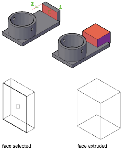
■Select faces. Specifies which faces to modify.
■Undo (page 958)
■Remove (page 958)
Remove Removes previously selected faces from the selection set.
■Remove faces. Removes the selected face from the solid object.
■Undo (page 958)
■Add (page 959)
■All (page 959)
Undo Cancels the selection of the faces you added most recently to the
selection set and redisplays the prompt.
958 | Chapter 2 Commands
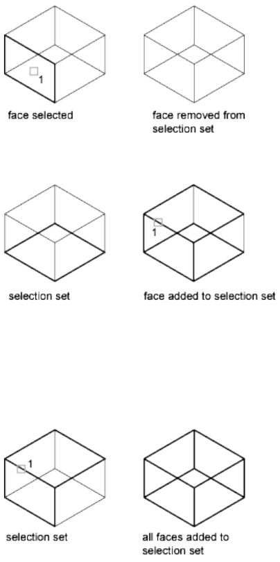
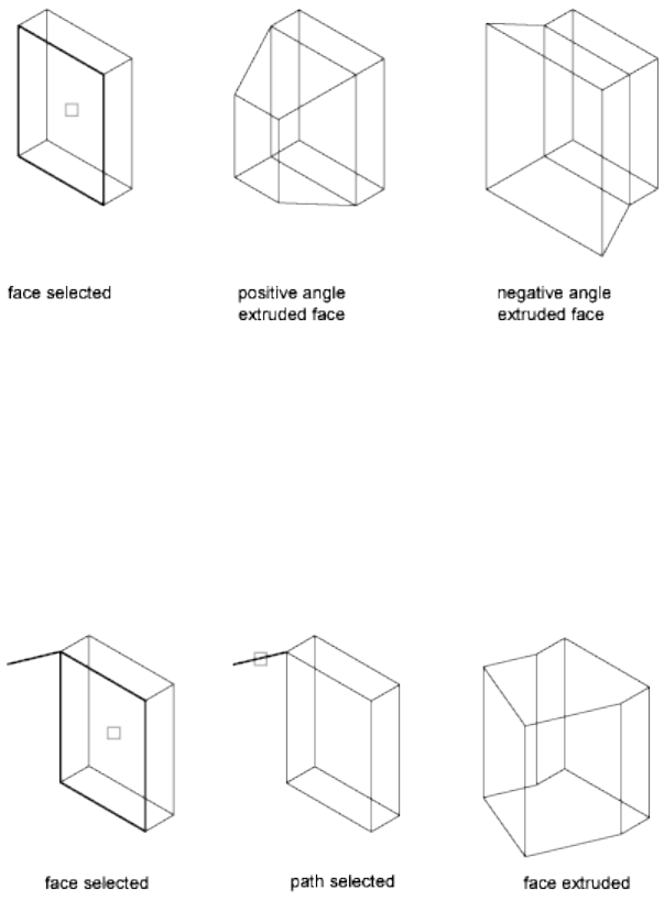
Height of extrusion Sets the direction and distance of the extrusion. Entering
a positive value extrudes the face in the direction of its normal. Entering a
negative value extrudes the face in the direction opposite to its normal.
■Angle of taper for extrusion. Specify an angle between -90 and +90
degrees.
Tapering the selected face with a positive angle tapers the face in, and a
negative angle tapers the face out. The default angle, 0, extrudes the face
perpendicular to its plane. All selected faces in the selection set are tapered
to the same value. If you specify a large taper angle or height, you can
cause the face to taper to a point before it reaches the extrusion height.
Path Sets a path for the extrusion path based on a specified line or curve. All
the profiles of the selected face are extruded along the chosen path to create
the extrusion.
■Select an extrusion path.
960 | Chapter 2 Commands

Lines, circles, arcs, ellipses, elliptical arcs, polylines, or splines can be paths.
The path should not lie on the same plane as the face, nor should it have
areas of high curvature.
The extruded face starts from the plane of the profile and ends on a plane
perpendicular to the path at the path's endpoint. One of the endpoints of
the path should be on the plane of the profile; if not, the path is moved
to the center of the profile.
If the path is a spline, the path should be perpendicular to the plane of
the profile and at one of the endpoints of the path. If not, the profile is
rotated to be perpendicular to the spline path. If one of the endpoints of
the spline is on the plane of the face, the face is rotated about the point;
otherwise, the spline path is moved to the center of the profile and the
profiles are rotated about its center.
If the path contains segments that are not tangent, the object is extruded
along each segment and then the joint along the plane is mitred, bisecting
the angle formed by the segments. If the path is closed, the profile lies on
the miter plane. This allows the start and end sections of the solid to match
up. If the profile is not on the miter plane, the path is rotated until it is
on the miter plane.
Face: Move
Move Moves the selected face on a 3D solid object to a specified height or
distance. You can select multiple faces at one time.
■Select faces (page 962)
■Undo. Cancels selection of the faces that you selected most recently.
■Remove (page 958)
■All (page 959)
You can change the shape of the object by moving its faces. This option is
recommended for minor adjustments.
Commands | 961
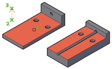
Select faces Specifies the face to be moved.
■Base point of displacement. Sets the base point for the move. If you
specify a single point, usually entered as a coordinate, and then press Enter,
the coordinate is used as the new location.
■Second point of displacement. Sets a displacement vector that indicates
how far the selected face is moved and in what direction.
Face: Rotate
Rotate Rotates one or more faces or a collection of features on a solid about
a specified axis.
You can change the shape of the object by rotating its faces. This option is
recommended for minor adjustments.
■Select faces (rotate) (page 962)
■Undo. Cancels selection of the faces that you selected most recently.
■Remove (page 958)
■All (page 959)
Select faces (rotate) Rotates the face according to the specified angle and axis.
In the drawing area, select one or more faces.
■Axis point (page 962)
■Axis by object (page 963)
■View (page 963)
■Xaxis, Yaxis, Zaxis (page 964)
■2Point (page 962)
Axis point, 2Point Sets two points to define the axis of rotation.
962 | Chapter 2 Commands
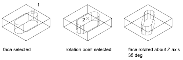
Pressing Enter at the main Rotate prompt displays the following prompts.
Specifying a point at the main prompt skips the prompt for the first point:
■First point on the rotation axis. Sets the first point on the axis of
revolution.
■Second point on the rotation axis. Sets the second point on the axis.
Rotation angle (page 964)■
■Reference (page 964)
Axis by object Aligns the axis of rotation with an existing object. You can
select the following objects:
■Line: Aligns the axis with the selected line.
■Circle: Aligns with the 3D axis of the circle (perpendicular to the plane of
the circle and passing through the center of the circle).
■Arc: Aligns with the 3D axis of the arc (perpendicular to the plane of the
arc and passing through the center of the arc).
■Ellipse: Aligns with the 3D axis of the ellipse (perpendicular to the plane
of the ellipse and passing through the center of the ellipse).
■2D polyline: Aligns with the 3D axis formed by the polyline start points
and endpoints.
■3D polyline: Aligns with the 3D axis formed by the polyline start points
and endpoints.
■Spline: Aligns with the 3D axis formed by the spline's start points and
endpoints.
View Aligns the axis of rotation with the viewing direction of the current
viewport that passes through the selected point.
■Origin of rotation (page 964)
Commands | 963

■Rotation angle (page 964)■
■Reference (page 964)
Xaxis, Yaxis, Zaxis Aligns the axis of rotation with the axis (X, Y, or Z) that
passes through the selected point.
■Origin of rotation
■Rotation angle (page 964)■
■Reference (page 964)
Origin of rotation Sets the point of rotation.
■Rotation angle (page 964)
■Reference (page 964)
Rotation angle Rotates the object about the selected axis the specified amount
from the current orientation.
Reference Specifies the reference angle and the new angle.
■Reference (starting) angle. Sets the start point for the angle.
■Ending angle. Sets the endpoint for the angle. The difference between
the starting angle and the ending angle is the computed rotation angle.
Face: Offset
Offset Offsets faces equally by a specified distance or through a specified point.
A positive value increases the size or volume of the solid. A negative value
decreases the size or volume of the solid.
■Select faces (offset) (page 964)
■Undo (page 958)
■Remove (page 958)
■All (page 959)
A positive value increases the size of the 3D solid, a negative value decreases
the size. Adjacent faces are stretched but maintain their angles relative to the
offset face.
Select faces (offset) Specifies the faces you want to offset.
NOTE
The size of holes inside a solid object that is offset decreases as the volume of
the solid increases.
964 | Chapter 2 Commands

■Specify the offset distance. Sets a positive value to increase the size of
the solid or a negative value to decrease the size of the solid.
Face: Taper
Taper Tapers faces on a 3D solid at a specified angle. The rotation of the taper
angle is determined by the selection sequence of the base point and second
point along the selected vector.
A positive angle tapers the face in, and a negative angle tapers the face out.
The default angle, 0, extrudes the face perpendicular to its plane. All selected
faces in the selection set are tapered to the same value.
■Select faces (taper) (page 966)
■Undo (page 958)
Commands | 965
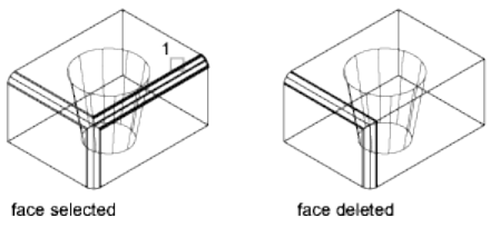
■Remove (page 958)
■All (page 959)
Select faces (taper) Specifies the faces to be tapered and then sets the slope
of the taper.
■Base point. Sets the first point for determining the plane.
■Another point along the axis of tapering. Sets the orientation of
the axis that determines the direction of the taper.
■Taper angle. Specify an angle between -90 and +90 degrees to set the
slope of the taper from the axis.
Face: Delete
Delete Deletes or removes faces, including fillets and chamfers.
Use this option to remove and later modify filleted and chamfered edges. The
face is not deleted if the change results in a non-valid 3D solid.
■Select faces (copy) (page 967)
■Undo. Cancels the selection of the faces that you selected most recently.
■Remove (page 958)
■All (page 959)
Select faces (delete) Specifies the face to be removed. The face must be in a
location that can be filled by surrounding faces after it is removed.
Face: Copy
Copy Copies faces as a region or a body. If you specify two points, SOLIDEDIT
uses the first point as a base point and places a single copy relative to the base
point. If you specify a single point (usually entered as a coordinate) and then
press Enter, SOLIDEDIT uses the coordinate as the new location.
966 | Chapter 2 Commands
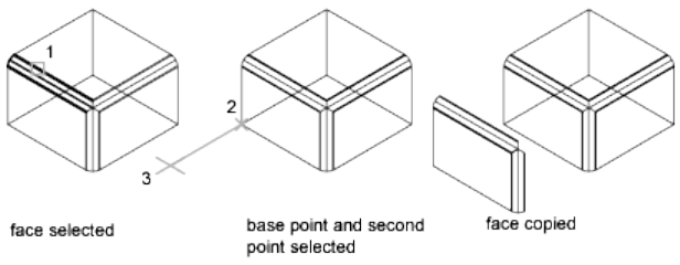
Creates a new object with the original orientation and profile of the face. The
result can be used as a reference to create a new 3D solid.
■Select faces (copy) (page 967)
■Undo. Cancels the selection of the faces that you selected most recently.
■Remove (page 958)
■All (page 959)
Select faces (copy) Specifies the face to be copied.
■Base point or displacement. Sets the first point to determine the
distance and direction for the placement of the copied face (displacement).
■Second point of displacement. Sets the second displacement point.
Face: Color
Color Changes the color of faces.
Colored faces can be used to highlight details within a complex 3D solid
model.
■Select faces (color) (page 967)
■Undo. Cancels the selection of the faces that you selected most recently.
■Remove (page 958)
■All (page 959)
Select faces (color) Specifies the faces to be modified. The Color Palette dialog
box (page 198) is displayed.
Face: Material
Material Assigns a material to selected faces.
■Select faces (material) (page 968)
■Undo. Cancels the selection of the faces that you selected most recently.
Commands | 967
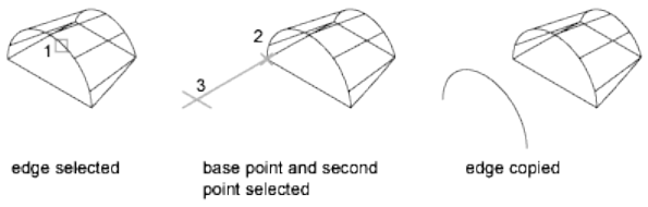
■Remove (page 958)
■All (page 959)
Select faces (material) Specifies the faces to be modified. The Color Palette
dialog box (page 198) is displayed.
■Enter new material name. Enter the name of the material to be
assigned to the selected face. (The name of a material can be found by
opening the Materials window and selecting the material swatch to display
the name in the Name field.)
■ByLayer. Assigns the material based on the layer assignment.
Face: Undo
Reverses actions as far back as the beginning of the SOLIDEDIT session.
Face: Exit
Exits the face-editing options and displays the Enter a Solids Editing Option
prompt.
Edge
Edge
Edits 3D solid objects by changing the color of or copying individual edges.
Enter an edge editing option [Copy (page ?)/coLor (page ?)/Undo (page
?)/eXit (page ?)] <eXit>:
Edge: Copy
Copies selected edges on a 3D solid as 2D arcs, circles, ellipses, lines, or splines.
Retains the angle of the edge and allows you to make modifications and
extensions, and create new geometry based on the extracted edge.
Provides a method for making modifications, extensions, and new 3D solids
based on the extracted edge.
■Select Edges (copy) (page 969)
968 | Chapter 2 Commands
■Undo (page 969)
■Remove (page 969)
Select Edges (copy) Specifies the edges to copy. Press Ctrl+click to select the
edge. Then set the displacement:
■Base point of displacement. Sets the first point for determining where
the new object is placed.
■Second point of displacement. Sets the relative direction and distance
for the new object.
Undo Cancels selection of the edges you added most recently to the selection
set. The previous prompt is displayed. If all edges have been removed, the
following prompt is displayed:
Remove Removes previously selected edges from the selection set. The prompt
is redisplayed.
■Remove edges. Removes the edges you select from the current selection
set.
■Undo (page 969)
■Add (page 969)
Add Adds edges to the selection set.
■Select Edges (copy) (page 969)
■Undo (page 969)
■Remove (page 969)
Edge: Color
Changes the color of individual edges on a 3D solid object.
■Select edges (color) (page 969)
■Undo (page 969)
■Remove (page 969)
Select edges (color)
Colored edges can be used to highlight intersections, interferences, or critical
clearances.
Press Ctrl+click to select the edge.
Edge: Undo
Reverses actions as far back as the beginning of the SOLIDEDIT session.
Commands | 969

Edge: Exit
Exits the face-editing options and displays the Enter a Solids Editing Option
prompt.
Body
Body
Edits the entire solid object by imprinting other geometry on the solid,
separating the solid into individual solid objects, shelling, cleaning, or checking
the selected solid.
Enter a body editing option [Imprint (page ?)/seParate solids (page ?)/Shell
(page ?)/cLean (page ?)/Check (page ?)/Undo (page ?)/eXit (page ?)]
<eXit>:
Body: Imprint
Imprints an object on the selected solid. The object to be imprinted must
intersect one or more faces on the selected solid in order for imprinting to be
successful. Imprinting is limited to the following objects: arcs, circles, lines,
2D and 3D polylines, ellipses, splines, regions, bodies, and 3D solids.
■Select a 3D solid. Specifies the 3D solid to be imprinted.
■Select an object to imprint. Specifies an object that overlaps the first
selection.
■Delete the source object. Specifies whether the object to imprint is
removed when the operation is complete.
Body: Separate Solids
Separates 3D solid objects with disjointed volumes (sometimes called lumps)
into independent 3D solid objects. Combining discrete solid objects using a
union operation (UNION) can result in disjointed volumes.
970 | Chapter 2 Commands

A union or subtract operation can result in a single 3D solid that consists of
more than one continuous volume. You can separate these volumes into
independent 3D solids.
NOTE
Separating solids does not separate Boolean objects that form a single volume.
Select a 3D solid Specifies the 3D solid object to separate. Press Ctrl+click to
select the edge.
Body: Shell
Shelling creates a hollow, thin wall with a specified thickness. You can specify
a constant wall thickness for all the faces. You can also exclude faces from the
shell by selecting them. A 3D solid can have only one shell. New faces are
created by offsetting existing ones outside their original positions.
It is recommended that you create a copy of a 3D solid before converting it
into a shell. That way if you need to make significant modification, use the
original version and shell it again.
Select a 3D solid (shell) Specifies a 3D solid.
■Remove faces. Specifies the face subobjects to be removed when the
object is shelled.
■Undo. Reverses the last action.
Commands | 971

■Add. Press Ctrl+click an edge to indicate which faces to retain.
■All. Temporarily selects all faces for removal. You can then use Add to
add the faces you want to retain.
Enter the shell offset distance Sets the size of the offset. Specify a positive
value to create a shell to the inside perimeter of the solid. Specify a negative
value to create a shell on the outside perimeter of the solid.
Body: Clean
Removes shared edges or vertices having the same surface or curve definition
on either side of the edge or vertex. Removes all redundant edges, vertices,
and unused geometry. Does not remove imprinted edges.
In unusual circumstances, this option removes shared edges or vertices having
the same surface or curve definition on either side of the edge or vertex.
Select a 3D solid (clean) Specifies a 3D solid object that you want to clean.
Body: Check
Validates the 3D solid object as a valid solid, independent of the SOLIDCHECK
(page 1442) setting.
■Select a 3D object (check). Specifies the 3D solid object to be validated.
If the object is valid, the following prompt is displayed:
This object is a valid ShapeManager solid.
This option is used as a debugging tool to compare stages in a highly complex
3D solid model.
Body: Undo
Undoes the editing action.
Body: Exit
Exits the face-editing options and displays the Enter a Solids Editing Option
prompt.
972 | Chapter 2 Commands

Undo
Undo
Undoes the editing action.
Exit
Exit
Exits the SOLIDEDIT command.
See also:
Clean and Check 3D Solids
SOLPROF
Creates 2D profile images of 3D solids for display in a layout viewport.
Access Methods
Menu: Draw ➤ 3D Modeling ➤ Setup ➤ Profile
Summary
The selected 3D solids are projected onto a 2D plane parallel with the current
layout viewport. The resulting 2D objects are generated on separate layers for
hidden and visible lines and are displayed only in that viewport.
List of Prompts
The following prompts are displayed.
Select objects: Use an object selection method
Display hidden profile lines on separate layer? [Yes (page
973)/No (page 974)] <Y>: Enteryorn, or press Enter
Yes Generates only two blocks: one for the visible lines and one for the hidden
lines of the entire selection set. When you generate hidden lines, solids can
partially or completely hide other solids. The visible profile block is drawn in
the BYLAYER linetype, and the hidden profile block is drawn in the HIDDEN
linetype (if loaded). The visible and hidden profile blocks are placed on
uniquely named layers using the following naming conventions:
PV-viewport handle for the visible profile layer
Commands | 973
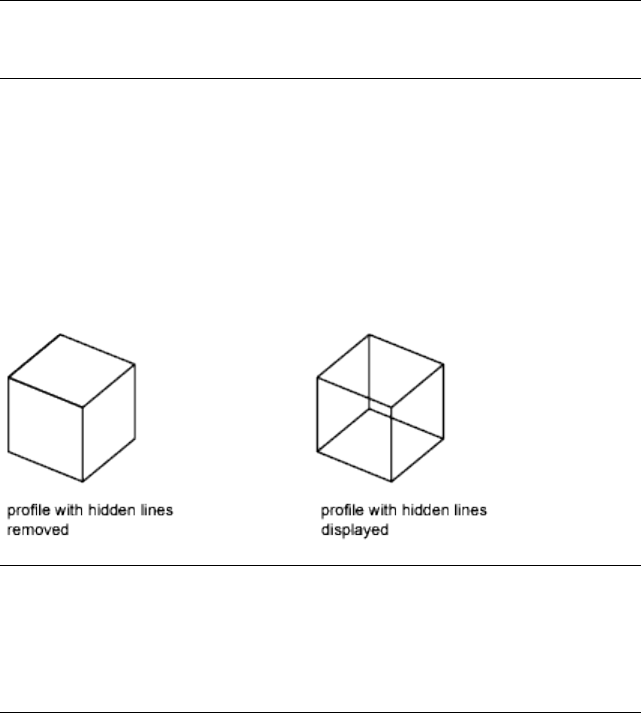
PH-viewport handle for the hidden profile layer
For example, if you create a profile in a viewport whose handle is 4B, the
blocks containing the visible lines are inserted on layer PV-4B, and the block
containing the hidden lines (if requested) is inserted on layer PH-4B. If these
layers do not exist, the command creates them. If the layers do exist, the
blocks are added to the information already on the layers.
NOTE To determine the handle of a viewport, select the viewport while in paper
space and use the LIST (page 581) command. Choose a layout tab to move from
model space to paper space.
SOLPROF does not change the display of layers; if you want to view only the
profile lines that you have created, turn off the layer containing the original
solid (usually the current layer).
No Treats all profile lines as visible lines and creates a block for the profile
lines of each selected solid. All profile lines for each solid in the selection set
are generated, even if a solid is partially or completely obscured by another
solid. The visible profile blocks are drawn in the same linetype as the original
solid and placed on a uniquely named layer using the naming convention
described under the Yes option.
NOTE Solids that overlap each other (share some common volume) produce
dangling edges if you request hidden-line removal. This happens because the
edges must be broken at the point where they enter another solid to separate
them into visible and hidden portions. You can eliminate dangling edges by
combining the overlapping solids (using UNION (page 1092)) before generating a
profile.
Yes Creates the profile lines with 2D objects.
The 3D profile is projected onto a plane normal to the viewing direction and
passing through the origin of the UCS. SOLPROF cleans up the 2D profile by
eliminating lines that are parallel to the viewing direction and by converting
arcs and circles that are viewed on edge into lines.
974 | Chapter 2 Commands
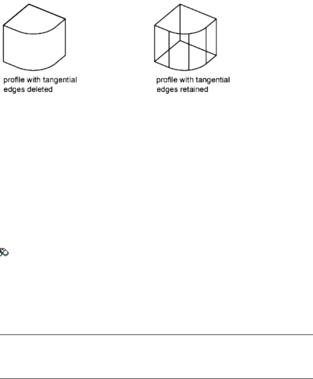
No Creates the profile lines with 3D objects.
The next prompt determines whether tangential edges are displayed. A
tangential edge is the transition line between two tangent faces. It's the
imaginary edge at which two faces meet and are tangent. For example, if you
fillet the edge of a box, tangential edges are created where the cylindrical face
of the fillet blends into the planar faces of the box. Tangential edges are not
shown for most drafting applications.
See also:
Create a Flattened View
SOLVIEW
Creates orthographic views, layers, and layout viewports automatically for 3D
solids.
Access Methods
Menu: Draw ➤ 3D Modeling ➤ Setup ➤ View
Summary
This command automates the manual process of creating views, layers, and
layout viewports for 3D models. For ongoing work, it is recommended that
you create drawing template (DWT) files customized for 3D.
NOTE
SOLVIEW must be run on a layout tab. If the Model tab is current, the last
active layout tab is made current.
Commands | 975

List of Prompts
The following prompts are displayed.
Enter an option [Ucs (page ?)/Ortho (page ?)/Auxiliary
(page ?)/Section (page ?)]: Enter an option or press Enter to exit
the command
SOLVIEW places the viewport objects on the VPORTS layer, which it creates
if it does not already exist. The view-specific information that is saved with
each viewport you create is used by SOLDRAW (page 954) to generate the final
drawing view.
SOLVIEW creates layers that SOLDRAW uses to place the visible lines and
hidden lines for each view, view name-VIS, view name-HID, view name-HAT,
and a layer where you can place dimensions that are visible in individual
viewports, view name-DIM.
WARNING The information stored on these layers is deleted and updated when
you run SOLDRAW (page 954). Do not place permanent drawing information on
these layers.
UCS
Creates a profile view relative to a user coordinate system. If no viewports
exist in your drawing, the UCS option is a good way to create an initial
viewport from which other views can be created. All other SOLVIEW options
require an existing viewport.
You have the option of using the current UCS or a previously saved one as
the profile plane. The viewport projection is created parallel to the XY plane
of the UCS with the X axis facing right and the Y axis upward.
976 | Chapter 2 Commands

Named Uses the XY plane of a named UCS to create a profile view.
Enter the name of the UCS you want to use and the scale of your view. Entering
a scale is equivalent to zooming your viewport by a factor relative to paper
space.
The center is based on the current model space extents.
World Uses the XY plane of the WCS to create a profile view.
Enter the name of the UCS you want to use and the scale of your view. Entering
a scale is equivalent to zooming your viewport by a factor relative to paper
space.
The center is based on the current model space extents.
?—List Named UCSs Lists the names of existing user coordinate systems. The
list is filtered using the wild-card combinations you enter (wild-card characters
accepted by the UCS command are valid).
Current Uses the XY plane of the current UCS to create a profile view.
Enter the name of the UCS you want to use and the scale of your view. Entering
a scale is equivalent to zooming your viewport by a factor relative to paper
space.
The center is based on the current model space extents.
Commands | 977
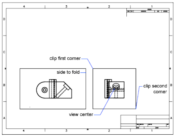
Ortho
Creates a folded orthographic view from an existing view.
Once you select the side of the viewport you want to use for projecting the
new view, a rubber-band line perpendicular to the side of the viewport helps
you locate the center of the new view.
Auxiliary
Creates an auxiliary view from an existing view. An auxiliary view is one that
is projected onto a plane perpendicular to one of the orthographic views and
inclined in the adjacent view.
978 | Chapter 2 Commands
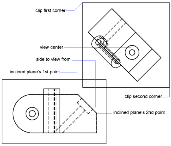
Two points define the inclined plane used for the auxiliary projection. Both
points must be located in the same viewport.
A rubber-band line perpendicular to the inclined plane helps you select the
center of the new viewport.
Section
Creates a drafting sectional view of solids, complete with cross-hatching. When
you use SOLDRAW (page 954) on a sectional view created with this option, it
creates a temporary copy of the solids and uses SLICE (page 946) to perform
the operation at the cutting plane that you define. SOLDRAW then generates
a profile of the visible half of the solids and discards the original copy. Finally
SOLDRAW sections the solids. Solids not crossing the cutting plane are
generated as full profiles. Because drafting standards recommend not drawing
hidden lines in sectional views, SOLVIEW freezes the View Name-HID layer.
Commands | 979

In the original viewport, specify two points to define the sectioning plane.
Define the viewing side by specifying a point on one side of the cutting plane.
Enter the scale of the new view. Entering a scale is equivalent to zooming your
viewport by a factor relative to paper space. The default value is a 1:1 scale,
which is equivalent to zoom 1.0xp.
At the next prompt, specify the center of the new viewport. If you accepted
the default scale (by pressing Enter), a rubber-band line perpendicular to the
sectioning plane helps you locate the center of the new view. Otherwise, you
can place the view anywhere.
See also:
Create a Flattened View
SPELL
Checks spelling in a drawing.
Access Methods
Button
980 | Chapter 2 Commands
Toolbar: Annotation tool set ➤ Text tool group ➤ Check Spelling
Menu: Tools ➤ Spelling
Toolbar: Text
Command entry: 'spell for transparent use
Summary
When you enter spell at the Command prompt, the Check Spelling dialog
box (page 981) is displayed. Select the Start button to begin the spelling check.
If Check Spelling is set to Entire Drawing, spelling is checked on the Model
layout, then on named (paper space) layouts. If a flagged word is identified,
the drawing area highlights and zooms to that word.
NOTE
Invisible text such as text on hidden layers, and hidden block attributes is not
checked. Non-uniformly scaled blocks and objects not on the supported
annotation scale are also not checked.
See also:
Check Spelling
Check Spelling Dialog Box
Displays the spelling checker dialog box that picks and displays the wrongly
spelt words and suggests alternate words.
Commands | 981
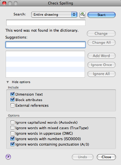
Summary
Checks the spelling in single-line text, multiline text, multileader text, text
within block attributes, text within xrefs, and text added to dimensions.
In block attributes, only the attribute values are checked. The spelling in text
objects within block references and nested block references is checked, but
spell checking in block definitions is performed only if the associated block
reference has been selected.
List of Options
The following options are displayed.
Search
Displays the areas you want checked for spelling.
982 | Chapter 2 Commands
Select Objects
Limits the spelling check to the selected single-line text, multiline text,
dimension text, multileader text, text within block attributes, and text within
xrefs.
Not in Dictionary
Displays the word identified as misspelled.
Suggestions
Displays a list of suggested replacement words from the current dictionary.
You can select another replacement word from the list, or edit or enter a
replacement word in the top Suggestions text area.
Start
Starts checking text for spelling errors.
Change
Replaces the current word with the word in the Suggestions box.
Change All
Replaces the current word in all selected text objects in the spell check area.
Add Word
Adds the current word to the current custom dictionary. The maximum word
length is 63 characters.
Ignore Once
Skips the current word.
Ignore All
Skips all remaining words that match the current word.
Undo
Reverses the previous check spelling action or series of actions, including
Ignore, Ignore All, Change, Change All, and Add Word.
Show/Hide Options
Controls the display of advanced search options.
Include
Dimension Text
Searches dimension text.
Block Attributes
Searches block attributes text for spelling errors.
External References
Commands | 983
Specifies to search external references for spelling errors.
Options
Ignore Capitalized Words
Specifies to ignore capitalized words.
Ignore Words with Mixed Cases
Specifies to ignore words that contain uppercase and lowercase letters.
Ignore Words in Uppercase
Specifies to ignore words that are in all uppercase.
Ignore Words with Numbers
Specifies to ignore words that include numbers.
Ignore Words Containing Punctuation
Specifies to ignore words that contain punctuation.
See also:
Check Spelling
Check Spelling Settings Dialog Box
Provides options to change the way the default behavior of the spelling checker
in the In-place Text editor.
984 | Chapter 2 Commands
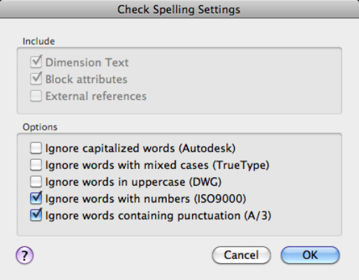
Summary
Specifies specific text options that will be checked in your drawing.
List of Options
The following options are displayed.
Include
Dimension Text
Searches dimension text.
Block Attributes
Searches block attributes text for spelling errors.
External References
Specifies to search external references for spelling errors.
Options
Ignore Capitalized Words
Specifies to ignore capitalized words.
Ignore Words with Mixed Cases
Specifies to ignore words that contain uppercase and lowercase letters.
Commands | 985

Ignore Words in Uppercase
Specifies to ignore words that are in all uppercase.
Ignore Words with Numbers
Specifies to ignore words that include numbers.
Ignore Words Containing Punctuation
Specifies to ignore words that contain punctuation.
See also:
Check Spelling
SPHERE
Creates a 3D solid sphere.
Access Methods
Button
Toolbar: Modeling tool set ➤ Solids - Create tool group ➤ Solid
Primitives flyout ➤ Sphere
Menu: Draw ➤ 3D Modeling ➤ Sphere
Summary
You can create a sphere by specifying a center point and a point on the radius.
You can control the smoothness of curved 3D solids, such as a sphere, in a
shaded or hidden visual style with the FACETRES system variable.
986 | Chapter 2 Commands
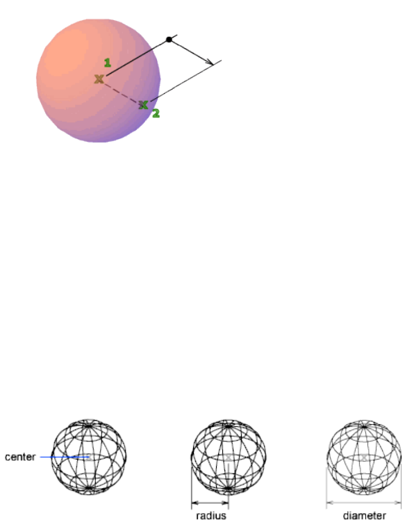
List of Prompts
The following prompts are displayed.
Specify center point (page ?) or [3P (page ?)/2P (page
?)/Ttr (page ?)]: Specify a point or enter an option
Center Point
Specifies the center point of the sphere.
When you specify the center point, the sphere is positioned so that its central
axis is parallel to the Z axis of the current user coordinate system (UCS).
Latitudinal lines are parallel to the XY plane.
Radius Defines the radius of the sphere.
Diameter Defines the diameter of the sphere.
3P (Three Points)
Defines the circumference of the sphere by specifying three points anywhere
in 3D space. The three specified points also define the plane of the
circumference.
2P (Two Points)
Defines the circumference of the sphere by specifying two points anywhere
in 3D space. The plane of the circumference is defined by the Z value of the
first point.
Commands | 987
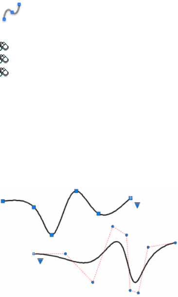
TTR (Tangent, Tangent, Radius)
Defines the sphere with a specified radius tangent to two objects. The specified
tangency points are projected onto the current UCS.
See also:
Create a Solid Sphere
SPLINE
Creates a smooth curve that passes through or near a set of fit points, or that
is defined by the vertices in a control frame.
Access Methods
Button
Toolbar: Drafting tool set ➤ Open Shapes tool group ➤ Spline
Menu: Draw ➤ Spline ➤ Fit Points
Menu: Draw ➤ Spline ➤ Control Vertices
Summary
SPLINE creates curves called nonuniform rational B-splines (NURBS), referred to
as splines for simplicity.
Splines are defined either with fit points, or with control vertices. By default,
fit points coincide with the spline, while control vertices define a control frame.
Control frames provide a convenient method to shape the spline. Each method
has its advantages.
988 | Chapter 2 Commands
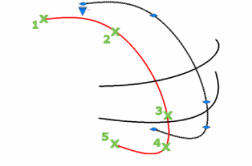
To display or hide the control vertices and control frame, select or deselect
the spline, or use CVSHOW (page 247) and CVHIDE (page 242).
For splines created with control vertices, you can display the control frame
by selecting the spline.
List of Prompts
The prompts that display depend on whether you create a spline with fit
points or with control vertices.
For splines created with the fit point method:
Specify first point or [Method (page ?)/Degree (page
992)/Object (page ?)]:
For splines created with the control vertices method:
Specify first point or [Method (page ?)/Knots (page 991)/Ob-
ject (page ?)]:
First Point
Specifies the first point of the spline, either the first fit point or the first control
vertex, depending on the current method.
Method
Controls whether the spline is created with fit points or with control vertices.
(SPLMETHOD (page 1447) system variable)
Fit Creates a degree 3 (cubic) B-spline by specifying fit points that the spline
must pass through. When the tolerance value is greater than 0, the spline
must be within the specified tolerance distance from each point.
Changing the Method updates the SPLMETHOD (page 1447) system variable.
Control Vertices Creates a spline by specifying control vertices. Use this
method to create splines of degree 1 (linear), degree 2 (quadratic), degree 3
Commands | 989

(cubic), and so on up to degree 10. Adjusting the shape of a spline by moving
control vertices often provides better results than moving fit points.
This is the preferred method if you are creating geometry to use with 3D
NURBS surfaces.
Object
Converts 2D or 3D quadratic or cubic spline-fit polylines to equivalent splines.
The original polyline is retained or discarded depending on the setting of the
DELOBJ (page 1213) system variable.
Next Point
Creates additional spline segments until you press Enter.
Undo
Removes the last specified point.
Close
Closes the spline by defining the last point to be coincident with the first. By
default, closed splines are periodic, maintaining curvature continuity (C2)
along the entire loop.
990 | Chapter 2 Commands
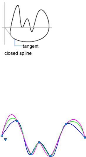
Options for Splines with Fit Points
The following options are specific to the fit point method.
Knots Specifies the knot parameterization, one of several computational methods
that determines how the component curves between successive fit points
within a spline are blended. (SPLKNOTS (page 1447) system variable)
■Chord (or Chord-Length method). Spaces the knots connecting each
component curve to be proportional to the distances between each
associated pair of fit points. An example is the green curve in the
illustration.
■Square Root (or Centripetal method). Spaces the knots connecting each
component curve to be proportional to the square root of the distance
between each associated pair of fit points. This method usually produces
“gentler” curves. An example is the blue curve in the illustration.
■Uniform (or Equidistant method). Spaces the knots of each component
curve to be equal, regardless of the spacing of the fit points. This method
often produces curves that overshoot the fit points. An example is the
magenta curve in the illustration.
Start Tangency Specifies a tangent condition on the starting point of the
spline.
Commands | 991
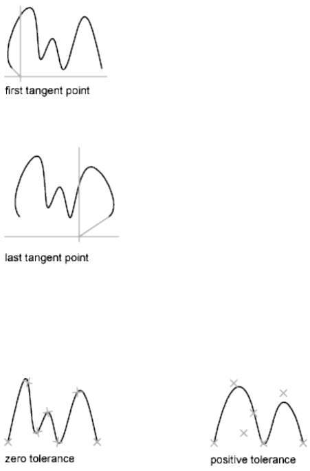
End Tangency Specifies a tangent condition on the ending point of the spline.
Tolerance Specifies the distance by which the spline is allowed to deviate
from the specified fit points. A tolerance value of 0 requires the resulting spline
to pass directly through the fit points. The tolerance value applies to all fit
points except the starting and ending fit points, which always have a tolerance
of 0.
Options for Splines with Control Vertices
The following option is specific to the control vertices (CV) method.
(SPLMETHOD (page 1447) system variable)
Degree Sets the polynomial degree of the resulting spline. Use this option to
create splines of degree 1 (linear), degree 2 (quadratic), degree 3 (cubic), and
so on up to degree 10.
See also:
Draw Splines
992 | Chapter 2 Commands
SPLINEDIT
Modifies the parameters of a spline or converts a spline-fit polyline to a spline.
Access Methods
Menu: Modify ➤ Object ➤ Spline
Shortcut menu: Select a spline to edit. Right-click in the drawing area and
click Spline.
Summary
Modifies the data that defines a spline, such as the number and weight of
control vertices, the fit tolerance, and the starting and ending tangents.
NOTE
SPLINEDIT automatically converts spline-fit polylines to splines even if you
immediately exit SPLINEDIT after selecting the spline-fit polyline.
The data that defines a spline is represented in one of two formats: as a control
frame or as fit points. The format can change depending on how the spline
was originally created, the options selected from the grip menus, or the options
used in SPLINEDIT.
You can change any of following data:
■Control frame data consists of control vertices, the polynomial degree of
the spline, and the weights assigned to each control vertex.
■Fit data consists of fit points, knot parameterization, the fit tolerance, and
the tangents at the endpoints of the spline.
NOTE
Switching from displaying control vertices to fit points automatically changes
the selected spline to degree 3. Splines originally created using higher-degree
equations will likely change shape as a result. In addition, if the spline was
created using a positive tolerance value, the fit points will be relocated to the
knots on the spline, and the tolerance value is reset to 0.
List of Prompts
The following prompts are displayed.
Select spline:
Commands | 993
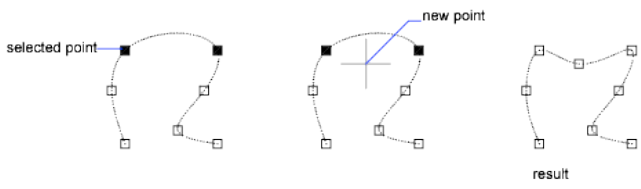
Enter an option [Close (page ?)/Join (page ?)/Fit data
(page ?)/Edit Vertex (page ?)/convert to Polyline (page
?)/Reverse (page ?)/Undo (page ?)] <eXit>:
Close/Open
One of the following options displays, depending on whether the selected
spline is open or closed. An open spline has two endpoints, while a closed
spline forms a loop.
Close Closes an open spline by defining the last point to be coincident with
the first. By default, closed splines are periodic, maintaining curvature
continuity (C2) along the entire curve.
Open Opens a closed spline by removing the final curve segment between
the first and last points specified when the spline was originally created.
Join
Combines a selected spline with other splines, lines, polylines, and arcs at
coincident endpoints to form a larger spline. Objects are joined with kinks at
the points where they are joined (C0 continuity).
Fit Data
Edits fit point data using the following options:
Enter a fit data option [Add (page ?)/Close (page ?)Delete (page ?)/Kink
(page ?)/Move (page ?)/Purge (page ?)/Tangents (page ?)/toLerance (page
?)/eXit (page ?)] <eXit>:
Add
Adds fit points to the spline.
After selecting a fit point, specify a new fit point to be added to the spline in
the direction of the next fit point, which is automatically highlighted.
If you select the last fit point on an open spline, the new fit point is added to
the end of the spline.
If you select the first fit point on an open spline, you have the option of
specifying whether the new fit point is added before or after the first point.
994 | Chapter 2 Commands
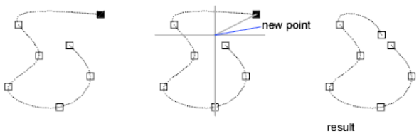
Close/Open
One of the following options displays, depending on whether the selected
spline is open or closed. An open spline has two endpoints, while a closed
spline forms a loop.
Close Closes an open spline by defining the last point to be coincident with
the first. By default, closed splines are periodic, maintaining curvature
continuity (C2) along the entire curve.
Open Opens a closed spline by removing the final curve segment between
the first and last points specified when the spline was originally created.
Delete
Removes selected fit points from a spline.
Kink
Adds a knot and fit point at the specified location on the spline, which does
not maintain tangent or curvature continuity at that point.
Move
Moves fit points to new locations.
New Location Moves the selected fit point to the specified location.
Next Selects the next fit point.
Previous Selects the previous fit point.
Select Point Select any fit point on the spline.
Purge
Replaces the fit data from the spline with control vertices.
Tangents
Changes the starting and ending tangents of a spline. Specify a point to
establish a tangent direction. You can use object snaps such as Perpendicular
or Parallel.
If the spline is closed, the prompt becomes Specify Tangent or [System
Default].
Commands | 995
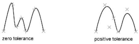
The System Default option calculates the default end tangents.
Tolerance
Refits the spline to the existing fit points using the new tolerance value.
Exit
Returns to the previous prompt.
Edit Vertex
Edits control frame data using the following options:
Enter a vertex editing option [Add (page ?)/Delete (page ?)/Elevate order
(page ?)/Move (page ?)/Weight (page ?)/eXit (page ?)] <eXit>:
Add
Adds a new control vertex at the point you specify that is located between
two existing control vertices.
Delete
Removes a selected control vertex.
Elevate Order
Increases the polynomial order (degree plus one) of the spline. This results in
increasing the number of control vertices across the spline.
The maximum value is 26.
Move
Relocates a selected control vertex.
■New Location (page 995)
■Next (page 995)
■Previous (page 995)
■Select Point (page 995)
Weight
Changes the weight of a specified control vertex.
996 | Chapter 2 Commands

New Weight Recalculates the spline based on the new weight value for the
specified control vertex. A larger value pulls the spline closer to the control
vertex.
■Next (page 995)
■Previous (page 995)
■Select Point (page 995)
Exit
Returns to the previous prompt.
Convert to Polyline
Converts the spline to a polyline.
The precision value determines how closely the resulting polyline matches
the spline. Valid values are any integer between 0 and 99.
NOTE
A high precision value will decrease performance.
The PLINECONVERTMODE (page 1395) system variable determines whether
the polylines are created with linear or arc segments.
The DELOBJ (page 1213) system variable determines whether the original spline
is retained.
Reverse
Reverses the direction of the spline. This option is intended primarily for
third-party applications.
Undo
Cancels the last action.
Exit
Returns to the Command prompt.
See also:
Modify Splines
SPOTLIGHT
Creates a spotlight that emits a directional cone of light.
Commands | 997

Access Methods
Button
Toolbar: Modeling tool set ➤ Lights tool group ➤ Spotlight
Menu: View ➤ Render ➤ Light ➤ New Spotlight
Summary
A spotlight distribution casts a focused beam of light like a flashlight, a follow
spot in a theater, or a headlight.
List of Prompts
The following prompts are displayed.
Specify source location <0,0,0>: Enter coordinate values or use the
pointing device
Specify target location <1,1,1>: Enter coordinate values or use the
pointing device
If the LIGHTINGUNITS system variable is set to 0, the following prompt is
displayed:
Enter an option to change [Name (page ?)/Intensity (page
?)/Status (page ?)/Hotspot (page ?)/Falloff (page
?)/shadoW (page ?)/Attenuation (page ?)/Color (page
?)/eXit (page ?)] <eXit>:
If the LIGHTINGUNITS system variable is set to 1 or 2, the following prompt
is displayed:
Enter an option to change [Name (page ?)/Intensity factor
(page ?)/Photometry (page ?)/Status (page ?)/Hotspot (page
?)/Falloff (page ?)/shadoW (page ?)/Attenuation (page
?)/filterColor (page ?)/eXit (page ?)] <eXit>:
NOTE
When the LIGHTINGUNITS system variable is set to 1 or 2, the Attenuation
option has no affect on the creation of the light. It is only maintained for
scripting compatibility.
Name
Specifies the name of the light. You can use uppercase and lowercase letters,
numbers, spaces, hyphens (-), and underscores (_) in the name.
998 | Chapter 2 Commands
Intensity/Intensity Factor
Sets the intensity or brightness of the light. The range is 0.00 to the maximum
value that is supported by your system.
Hotspot
Specifies the angle that defines the brightest cone of light, which is known to
lighting designers as the beam angle. This value can range from 0 to 160
degrees or the equivalent values based on AUNITS (page 1177).
Falloff
Specifies the angle that defines the full cone of light, which is also known as
the field angle. This value can range from 0 to 160 degrees. The default is 50
degrees or the equivalent values based on AUNITS (page 1177). The falloff angle
must be greater than or equal to the hotspot angle.
Status
Turns the light on and off.
Photometry
Photometry is the measurement of the luminous intensities of visible light
sources. Photometry is available when the LIGHTINGUNITS system variable
is set to 1 or 2.
In photometry, luminous intensity is a measure of the perceived power emitted
by a light source in a particular direction. Luminous flux is the perceived
power per unit of solid angle. The total luminous flux for a lamp is the
perceived power emitted in all directions. Luminance is the total luminous
flux incident on a surface, per unit area.
Intensity Enter an intensity value in candelas, the perceived power in a
luminous flux value, or illuminance value for the total luminous flux incident
on a surface.
■Candela (symbol: cd) is the SI unit of luminous intensity (perceived power
emitted by a light source in a particular direction). Cd/Sr
■Lux (symbol: lx) is the SI unit of illuminance. Lm/m^2
■Foot-candle (symbol: fc) is the American unit of illuminance. Lm/ft^2
Enter f to specify the perceived power in a luminous flux value.
If you enter i, you can specify the intensity of the light based on an
illuminance value.
The illuminance value can be specified in either lux or foot-candles. Enter d
to specify a distance to use to calculate illuminance.
Color Specify the color of the light based on a color name or a Kelvin
temperature. Enter ? to display a list of color names.
Commands | 999
Enter a text string using wild card characters to display a partial listing of color
names, or an asterisk (*) to display all the possible choices.
If you enter k, you can specify the color of the light based on a Kelvin
temperature value.
Shadow
Makes the light cast shadows.
Off Turns off display and calculation of shadows for the light. Turning shadows
off increases performance.
Sharp Displays shadows with sharp edges. Use this option to increase
performance.
Soft Mapped Displays realistic shadows with soft edges.
■Map Size. Specifies the amount of memory to use to calculate the shadow
map.
■Softness. Specifies the softness to use to calculate the shadow map.
Soft Sampled Displays realistic shadows with softer shadows (penumbra)
based on extended light sources.
Specify the shape of the shadow by entering s and then the dimensions of
the shape. (For example, the radius of the sphere or the length and width of
a rectangle.)
Specify the sample size by entering a.
Specify the visibility of the shape by for the shadow by entering v.
Attenuation
Attenuation Type Controls how light diminishes over distance. The farther
away an object is from a spotlight, the darker the object appears. Attenuation
is also known as decay.
■None. Sets no attenuation. Objects far from the spotlight are as bright as
objects close to the light.
■Inverse Linear. Sets attenuation to be the inverse of the linear distance
from the light. For example, at a distance of 2 units, light is half as strong
as at the spotlight; at a distance of 4 units, light is one quarter as strong.
The default value for inverse linear is half the maximum intensity.
■Inverse Squared. Sets attenuation to be the inverse of the square of the
distance from the light. For example, at a distance of 2 units, light is one
quarter as strong as at the spotlight; at a distance of 4 units, light is one
sixteenth as strong.
Use Limits Specifies whether to use limits.
1000 | Chapter 2 Commands

Attenuation Start Limit Specifies the point where light starts as an offset
from the center of the light. The default is 0.
Attenuation End Limit Specifies the point where light ends as an offset from
the center of the light. No light is cast beyond this point. Setting an end limit
increases performance where the effect of lighting is so minimal that the
calculations are wasted processing time.
Color/Filter Color
Controls the color of the light.
True Color Specifies a True Color. Enter in the format R,G,B (red, green, blue).
Index Specifies an ACI (AutoCAD Color Index) color.
HSL Specifies an HSL (hue, saturation, luminance) color.
Color Book Specifies a color from a color book.
Exit
Exits the command.
See also:
Use Spotlights
STATUS
Displays drawing statistics, modes, and extents.
Access Methods
Menu: Tools ➤ Inquiry ➤ Status
Command entry: 'status for transparent use
Summary
All coordinates and distances are displayed by STATUS in the format specified
by UNITS (page 1095).
STATUS reports the number of objects in the current drawing. This includes
graphical objects such as arcs and polylines, and nongraphical objects such
as layers and linetypes, and block definitions.
Commands | 1001
In addition to overall drawing statistics and settings, the amount of installed
memory free on your system, the amount of disk space available, and the
amount of free space in the swap file are also listed.
When used at the DIM prompt, STATUS reports the values and descriptions
of all dimensioning system variables.
In addition, STATUS displays the following information.
List of Options
The following options are displayed.
Model or Paper Space Limits Are Displays the grid limits defined by LIMITS
(page 573). The first line shows the XY coordinate of the limit's lower-left corner,
stored in the LIMMIN (page 1354) system variable. The second line shows the
XY coordinate of the limit's upper-right corner, stored in the LIMMAX (page
1354) system variable. The notation Off to the right of the Y coordinate value
indicates that limits checking is set to 0.
Model or Paper Space Uses Displays the drawing extents, which includes all
objects in the database and can exceed the grid limits. The first line shows the
XY coordinate of the lower-left corner of the extents. The second line shows
the XY coordinate of the upper-right corner. The notation Over to the right
of the Y coordinate value indicates that the drawing extends outside the grid
limits.
Display Shows Lists the portion of the drawing extents visible in the current
viewport. The first line shows the XY coordinate of the display's lower-left
corner. The second line shows the XY coordinate of the upper-right corner.
Insertion Base Is Specifies the point used when the drawing is inserted into
another drawing as a block. (INSBASE (page 1334) system variable)
Snap Resolution Is Sets the snap spacing for the current viewport. (SNAPUNIT
(page 1442) system variable)
Grid Spacing Is Specifies the grid spacing (X and Y) for the current viewport.
(GRIDUNIT (page 1307) system variable)
Current Space Shows whether model space or paper space is active.
Current Layout Displays “Model” or the name of the current layout.
Current Layer Sets the current layer. (CLAYER (page 1191) system variable)
Current Color Sets the color of new objects. (CECOLOR (page 1185) system
variable)
1002 | Chapter 2 Commands
Current Linetype Sets the linetype of new objects. (CELTYPE (page 1186) system
variable)
Current Material Sets the material of new objects. (CMATERIAL (page 1192)
system variable)
Current Lineweight Sets the lineweight of new objects. (CELWEIGHT (page
1187) system variable)
Current Plot Style Sets the current plot style of new objects. (CPLOTSTYLE
(page 1202) system variable)
Current Elevation Stores the current elevation of new objects relative to the
current UCS. (ELEVATION (page 1283) system variable)
Thickness Sets the current 3D thickness. (THICKNESS (page 1463) system
variable)
Fill, Grid, Ortho, Qtext, Snap, Tablet Shows whether these modes are on or
off.
Object Snap Modes Lists the running object snap modes. (OSNAP (page 743))
See also:
Obtain General Drawing Information
STLOUT
Stores solids in an ASCII or binary file.
Summary
The FACETRES (page 1295) system variable determines how the solid is
triangulated. A higher value creates a finer mesh that more accurately
represents the model. This also results in a much larger file.
Select solids or watertight meshes
You can select blocks or external references (xrefs) that contain solids or
watertight meshes. Only solids and watertight meshes of the selected blocks
of xrefs are included in the STL file. All other geometry is discarded.
Create a binary STL file? [Yes/No] <Yes>: To create a STL file,
enteryor press Enter. To create an ASCII file, entern
The Create STL File Dialog Box (page 1004) displays.
Commands | 1003
The file is created with the .stl file name extension. The STL file format is
compatible with stereolithography apparatus (SLA). The solid data is transferred
to the SLA as a faceted representation of the model. The facets consist of a set
of triangles (with outward pointing normals) that approximate the faces of
the model. From the faceted data, the SLA workstation produces a set of
contours that defines a series of layers representing the part to be built.
See also:
Stereolithograph Files
Create STL File Dialog Box
Saves a drawing as an STL file.
Summary
The STL file format is preferred by 3D printing service providers. If you have
prepared your drawing for 3D printing, you save it with the STLOUT command.
See also:
Stereolithograph Files
STRETCH
Stretches objects crossed by a selection window or polygon.
Access Methods
Button
Toolbar: Drafting tool set ➤ Move/Rotate/Scale tool group ➤ Stretch
Menu: Modify ➤ Stretch
Summary
Objects that are partially enclosed by a crossing window are stretched. Objects
that are completely enclosed within the crossing window, or that are selected
1004 | Chapter 2 Commands
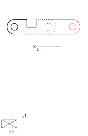
individually, are moved rather than stretched. Several objects such as circles,
ellipses, and blocks, cannot be stretched.
List of Prompts
The following prompts are displayed.
Select objects to stretch by crossing-window or
crossing-polygon...
Select objects: Use the cpolygon option or the crossing object selection method,
and press Enter. Individually selected objects and objects that are completely enclosed
by the crossing selection are moved rather than stretched.
STRETCH moves only the vertices and endpoints that lie inside the crossing
selection, leaving those outside unchanged. STRETCH does not modify 3D
solids, polyline width, tangent, or curve-fitting information.
Base Point
Specify base point or [Displacement] <last displacement>: Specify a base point
or enter displacement coordinates
Specify second point or <use first point as displacement>: Specify a second point,
or press Enter to use the previous coordinates as a displacement
Displacement
Specify displacement <last value>: Enter displacement values for X,Y (and
optionally Z)
Commands | 1005
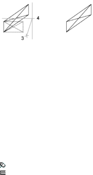
If you enter a second point, the objects are stretched the vector distance from
the base point to the second point. If you press Enter at the Specify Second
Point of Displacement prompt, the first point is treated as an X,Y,Z
displacement.
See also:
Resize or Reshape Objects
STYLE
Creates, modifies, or specifies text styles.
Access Methods
Menu: Format ➤ Text Style
Command entry: 'style for transparent use
Summary
The Text Style dialog box (page 1006) is displayed.
If you enter -style at the Command prompt, options are displayed (page 1010).
You can specify the current text style to determine the appearance of all new
text. A text style includes the font, size, obliquing angle, orientation, and
other text characteristics.
See also:
Overview of Text Styles
Text Style Dialog Box
Creates, modifies, or specifies text styles.
1006 | Chapter 2 Commands
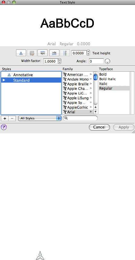
Summary
Creates, modifies, or sets named text styles.
List of Options
The following options are displayed.
Preview
Displays sample text that changes dynamically as you change fonts and modify
the effects.
Effects
Modifies characteristics of the font, such as its height, width factor, and
obliquing angle and whether it is displayed upside down, backwards, or
vertically aligned.
Annotative ( )
Specifies that the text is annotative. Click the information icon to learn more
about the annotative objects.
Match Text Orientation to Layout
Commands | 1007

Specifies that the orientation of the text in paper space viewports matches the
orientation of the layout. This option is available when the Annotative option
is selected.
Upside Down
Displays the characters upside down.
Backwards
Displays the characters backwards.
Vertical
Displays the characters aligned vertically. Vertical is available only if the
selected font supports dual orientation. Vertical orientation is not available
for TrueType fonts.
Text Height Changes the size of the text. This option is available when the
Annotative option is cleared.
Paper Text Height
Sets the text height based on the value you enter. Entering a height greater
than 0.0 sets the text height for this style automatically. If you enter 0.0, the
text height defaults to the last text height used, or the value stored in the
drawing template file.
TrueType fonts might be displayed at a smaller height than SHX fonts with
the same height setting.
If the Annotative option is selected, the value entered sets the text height in
paper space.
See “Set Text Height” for more information.
Width Factor
Sets the character spacing. Entering a value less than 1.0 condenses the text.
Entering a value greater than 1.0 expands it.
Angle
Sets the obliquing angle of the text. Entering a value between -85 and 85
italicizes the text.
NOTE
TrueType fonts using the effects described in this section might appear bold
on the screen. Onscreen appearance has no effect on plotted output. Fonts
are plotted as specified by applied character formatting.
1008 | Chapter 2 Commands

Styles
Displays the list of styles in the drawing.
Style names can be up to 255 characters long. They can contain letters,
numbers, and the special characters dollar sign ($), underscore (_), and hyphen
(-).
Family List
Lists the font family name for all registered TrueType fonts and all compiled
shape (SHX) fonts in the Fonts folder.
When you select a name from the list, the program reads the file for the
specified font. The file's character definitions are loaded automatically unless
the file is already in use by another text style. You can define several styles
that use the same font. For more information, see “Assign Text Fonts”.
Typeface
Specifies font character formatting, such as italic, bold, or regular.
When a SHX font fuile is selected from the Family list, you can select a Big
Font file name from the Asian Set list.
Asian Set
Lists the available Big Font files when an SXH file is selected from the Family
list. Select None if you do not want to use a Bif Font.
New (+)
Adds a new text style to the Styles list and automatically supplies the name “
stylen” (where n is the number of the supplied style) for the current settings.
You can accept the default or enter a name and close the Text Style dialog
box to apply the current style settings to the new style name.
Delete (-)
Removes the selected text style.
NOTE
You cannot remove text styles that are in use by an annotation object or style.
Style List Filter
The drop-down list specifies whether all styles or only the styles in use are
displayed in the styles list.
Family Filter
Filters the fonts listed in the Family list.
See also:
Overview of Text Styles
Commands | 1009
-STYLE
Creates, modifies, or specifies text styles.
List of Prompts
The following prompts are displayed.
Enter name of text style (page 1010) or [?(page 1010)] <current>:
Enter a style name, enter ?, or press Enter
Text Style Name Specifies the text style name. To define a style that uses Big
Fonts, you can use long file names that do not contain commas. Commas are
used to separate SHX files and Big Font files for defining a Big Font file.
Enter a TrueType font family name or an SHX font file name. If you do not
enter a file name extension, this program searches for an SHX file. If the file
is not located, Windows substitutes the first located registered TrueType font.
All long file names except those containing commas are accepted at the
prompt. The comma is reserved for the Big Font naming convention: an SHX
file followed by a comma (,), followed by the Big Font file name. A space is
interpreted as part of the font name, not as a carriage return.
If you enter annotative, you are prompted to create an annotative text style.
Tilde (~) Displays the Select Font File dialog box.
In the Select Font File dialog box, valid types include SHX and TTF. The
character definitions of the selected font file are loaded automatically unless
the file is already in use by another text style. You can define several styles
that use the same font file.
Match Text Orientation to Layout If you enter yes the current text style
orientation in paper space viewports matches the layout.
Height of Text If you enter a height of 0.0, you are prompted for the text
height each time you enter text using this style. Entering a height greater than
0.0 sets the Text Height (Non annotative), entering a height greater than 0.0
sets the Paper Text Height (Annotative), for this style.
Width Factor Entering a value less than 1.0 condenses the text. Entering a
value greater than 1.0 expands it.
Obliquing Angle Entering a value between -85 and 85 obliques the text.
Vertical Vertical is available only if the selected font supports dual orientation.
?—List Text Styles Lists the text styles available in the drawing.
1010 | Chapter 2 Commands

At the Enter Text Style(s) to List prompt, entering the name of a style displays
the name, font file, height, width factor, obliquing angle, and generation of
the style and exits the command. Entering an asterisk (*) or pressing Enter
displays the height, width factor, obliquing angle, and generation (whether
text is drawn backwards, upside-down, vertically, or normally) of each style,
and then exits the command.
See also:
Overview of Text Styles
STYLESMANAGER
Displays the folder in Finder that contains the plot style files used when
plotting or publishing a drawing.
Access Methods
Menu: File ➤ Plot Styles
Summary
The location in which AutoCAD for Mac locates plot styles can be changed
under Printer Support File Path ➤ Plot Style Table Search Path on the
Application tab of the Application Preferences dialog box (OPTIONS (page
724) command).
Double-click a plot style (STB or CTB) file in Finder to start the Plot Style Table
Editor (page 809).
See also:
Manage Plot Style Tables
SUBTRACT
Combines selected 3D solids or 2D regions by subtraction.
Commands | 1011
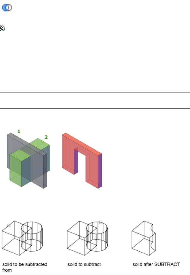
Access Methods
Button
Toolbar: Modeling tool set ➤ Solids - Edit tool group ➤ Booleans flyout
➤ Subtract
Summary
With SUBTRACT, you can create a 3D solid by subtracting one set of existing
3D solids from another, overlapping set. You can create a 2D region object by
subtracting one set of existing region objects from another, overlapping set.
You can select only regions for use with this command.
NOTE Using SUBTRACT with 3D surfaces is not recommended. Use the SURFTRIM
(page 1024) command instead.
Select the objects that you want to keep, press Enter, then select the objects
that you want to subtract.
Objects in the second selection set are subtracted from objects in the first
selection set. A single new 3D solid, surface, or region is created.
1012 | Chapter 2 Commands
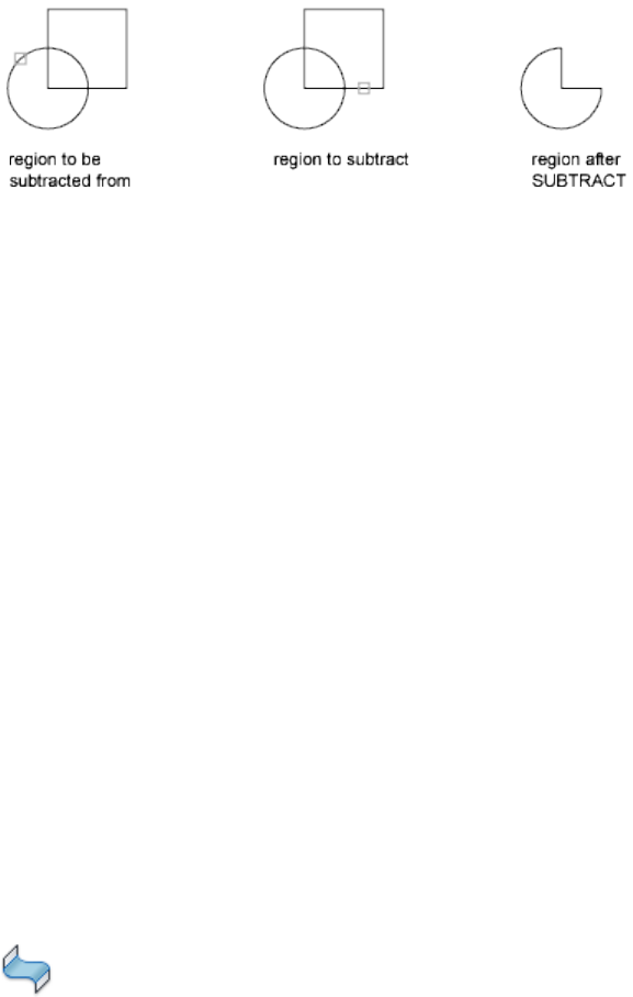
Objects in the second selection set are subtracted from objects in the first
selection set. A single new region is created.
You can only subtract regions from other regions that are on the same plane.
However, you can perform simultaneous SUBTRACT actions by selecting sets
of regions on different planes. The program then produces separate subtracted
regions on each plane. Regions for which there are no other selected coplanar
regions are rejected.
You cannot use SUBTRACT with mesh objects. However, if you select a mesh
object, you will be prompted to convert it to a 3D solid or surface.
List of Prompts
The following prompts are displayed.
Select objects (to subtract from) Specifies the 3D solids, surfaces, or regions
to be modified by subtraction.
Select objects (to subtract) Specifies the 3D solids, surfaces, or regions to
subtract.
See also:
Create Composite Objects
SURFBLEND
Creates a continuous blend surface between two existing surfaces.
Access Methods
Button
Commands | 1013
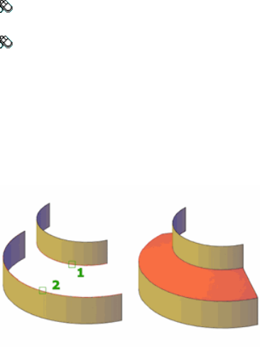
Toolbar: Modeling tool set ➤ Surfaces - Create tool group ➤ Surface
Blend
Menu: Draw ➤ 3D Modeling ➤ Surfaces ➤ Blend
Summary
When you blend two surfaces together, you specify surface continuity and
bulge magnitude.
Set SURFACEASSOCIATIVITY (page 1452) to 1 to create a relationship between
the blend surface and the originating curves.
List of Prompts
The following prompts are displayed.
Select Surface Edge
Selects an edge subobject or a surface or region (not the surface itself) as the
first and second edges.
Chain
Selects contiguous, connected, edges.
Continuity
Measures how smoothly surfaces flow into each other. The default is G0. Select
a value or use the grip to change the continuity.
1014 | Chapter 2 Commands
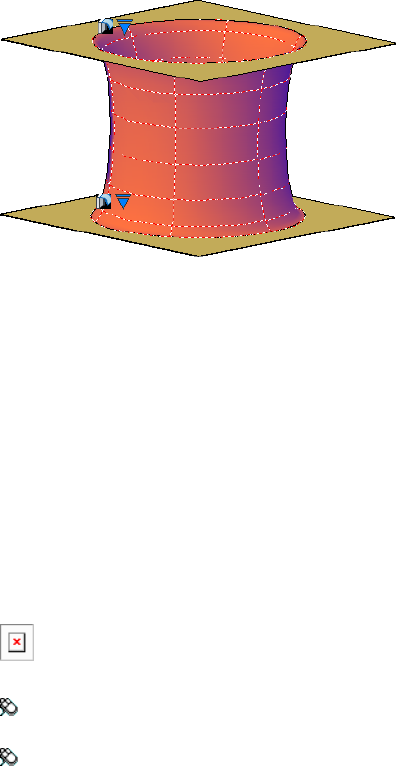
Bulge Magnitude
Sets the roundness of the blend surface edge where it meets the originating
surface. The default is 0.5. Valid values are between 0 and 1.
See also:
Blend a Surface
SURFEXTEND
Lengthens a surface by a specified distance.
Access Methods
Button
Toolbar: Modeling tool set ➤ Surfaces - Edit tool group (expanded) ➤
Surface Extend
Menu: Draw ➤ 3D Modeling ➤ Surfaces ➤ Extend
Summary
The extension surface can be merged (part of the original surface) or appended
(creating a second surface adjacent to the original surface).
Commands | 1015
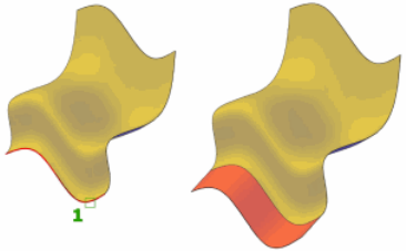
List of Prompts
The following prompts are displayed.
Specify Extension Distance Specifies the extension length.
Expression Enter a formula or equation to specify the length of the surface
extension. See Constrain a Design with Formulas and Equations.
Modes
■Extend - Extrudes the surface in a way that tries to mimic and continue
the shape of the surface.
■Stretch - Extrudes the surface without trying to mimic and continue the
shape of the surface.
Creation Type
■Merge - Extends the surface the specified distance without creating a new
surface.
■Append - Creates a new extension surface that is adjacent to the original
surface. If the originating surface is a NURBS surface, the new extension
surface will also be a NURBS surface.
See also:
Extend a Surface
SURFFILLET
Creates a filleted surface between two other surfaces.
1016 | Chapter 2 Commands

Access Methods
Button
Toolbar: Modeling tool set ➤ Surfaces - Edit tool group ➤ Surface Fillet
Menu: Draw ➤ 3D Modeling ➤ Surfaces ➤ Fillet
Summary
The fillet surface has a constant radius profile and is tangent to the original
surfaces. The original surfaces are automatically trimmed to connect the edges
of the fillet surface.
List of Prompts
The following prompts are displayed.
First and Second Surface or Region Specifies the first and second surfaces or
regions.
Radius Specifies fillet radius. Use the Fillet grip or enter a value to change the
radius. You cannot enter a value that is smaller than the gap between the
surfaces. If no radius value is entered, the FILLETRAD3D (page 1297) system
variable value is used.
Trim Surface Trims the original surfaces or regions to the edges of the fillet
surface.
Expression Enter a formula or equation to specify the fillet radius. See
Constrain a Design with Formulas and Equations.
Commands | 1017
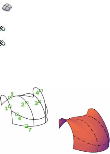
See also:
Fillet a Surface
SURFNETWORK
Creates a surface in the space between several curves in the U and V directions
(including surface and solid edge subobjects).
Access Methods
Button
Toolbar: Modeling tool set ➤ Surfaces - Create tool group ➤ Surface
Network
Menu: Draw ➤ 3D Modeling ➤ Surfaces ➤ Network
Summary
A network surface can be created between a network of curves or between the
edges of other 3D surfaces or solids.
The surface will be dependent on the curves or edges from which it was created
if the SURFACEASSOCIATIVITY (page 1452) system variable is set to 1.
List of Prompts
The following prompts display:
1018 | Chapter 2 Commands

Select Curves or Surface Edges in the First Direction Select a network
of open curves, open surface edges, or region edges (not the surfaces or regions)
for the U or V direction.
Select Curves or Surface Edges in the Second Direction Select a network
of open curves, open surface edges, or region edges (not the surfaces or regions)
for the U or V direction.
Bulge Magnitude Sets the roundness of the network surface edge where it
meets the originating surface. Valid values are between 0 and 1. The default
is 0.5. This option displays only if a lofting edge belongs to a 3D solid or
surface (not a curve).
See also:
Create Network Surfaces
SURFOFFSET
Creates a parallel surface a specified distance from the original surface.
Access Methods
Button
Toolbar: Modeling tool set ➤ Surfaces - Create tool group (expanded)
➤ Surface Offset
Menu: Draw ➤ 3D Modeling ➤ Surfaces ➤ Offset
Summary
Reverse the direction of the offset with the Flip Direction option.
Commands | 1019
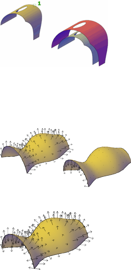
List of Prompts
The following prompts display.
Specify Offset Distance Specifies the distance between the offset surface and
the original surface.
Flip Direction Reverses the offset direction shown by the arrows.
Both Sides Offsets the surface in both directions (creates two new surfaces in
instead of one).
Solid Creates a solid from the offset. This is similar to the THICKEN (page 1052)
command.
1020 | Chapter 2 Commands
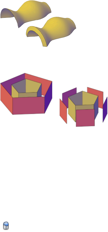
Connect Connects multiple offset surfaces, if the original surfaces are
connected.
Expression Enter a formula or equation to specify the distance of the surface
offset. See Constrain a Design with Formulas and Equations.
See also:
Offset a Surface
SURFPATCH
Creates a new surface by fitting a cap over a surface edge that forms a closed
loop.
Access Methods
Button
Commands | 1021
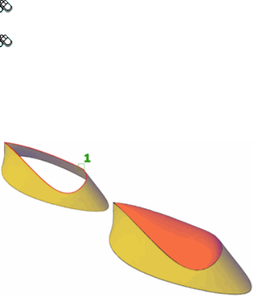
Toolbar: Modeling tool set ➤ Surfaces - Create tool group ➤ Surface
Patch
Menu: Draw ➤ 3D Modeling ➤ Surfaces ➤ Patch
Summary
You can also add an additional curve over the closed loop to constrain and
guide the patch surface.
When you create a patch surface, you can specify surface continuity and bulge
magnitude. If the SURFACEASSOCIATIVITY (page 1452) system variable is set
to 1, associativity is maintained between the patch surface and the originating
edges or curves.
List of Prompts
The following prompts are displayed.
Select Surface Edges (page 1022) to patch or [Chain (page
1022)/Curves (page 1022)] <CUrves>:
Surface Edges Selects individual surface edges and adds them to the selection
set.
Chain Selects contiguous edges of connected but separate surface objects.
Curves Selects curves rather than edges.
Select one or more closed surface edges (not the surface itself), a chain of edges,
or one or more curves. You cannot choose both edges and curves at the same
time.
List of Options
Once you have defined the surface edges to patch, the following options are
displayed.
1022 | Chapter 2 Commands

Press Enter to accept the patch surface or [Continuity (page
1023)/Bulge Magnitude (page 1023)/Guides (page 1023)]:
Continuity Measures how smoothly surfaces flow into each other. The default
is G0. See Understand Surface Continuity and Bulge Magnitude. Select a value
or use the grip to change the continuity.
Bulge Magnitude For best results, enter a value between 0 and 1 to set the
roundness of the patch surface edge where it meets the originating surface.
The default is 0.5.
Guides Uses additional guide curves to shape the patch surface. Guide curves
can be curves or points.
See also:
Patch a Surface
SURFSCULPT
Trims and combines surfaces that bound a watertight area to create a solid.
Access Methods
Button
Toolbar: Modeling tool set ➤ Surfaces - Create tool group (expanded)
➤ Surface Sculpt
Menu: Modify ➤ Surface Editing ➤ Sculpt
Summary
The SURFSCULPT command automatically combines and trims a collection
of surfaces that enclose a watertight area to create a solid.
Commands | 1023
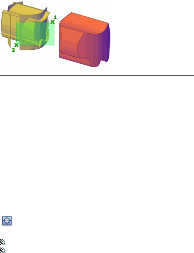
NOTE
The area enclosed by the surfaces must be watertight and the surfaces must
have a continuity of G0 or the SURFSCULPT command cannot complete.
The SURFSCULPT command also works with solid and mesh objects. If you
are working with meshes, the operation uses the SMOOTHMESHCONVERT
(page 1437) setting.
See also:
Convert a Group of Surfaces to a 3D Solid
SURFTRIM
Trims portions of a surface where it meets another surface or type of geometry.
Access Methods
Button
Toolbar: Modeling tool set ➤ Surfaces - Edit tool group ➤ Surface Trim
Menu: Modify ➤ Surface Editing ➤ Trim
Summary
Trims portions of a surface where it meets or bisects a curve, region, or another
surface.
1024 | Chapter 2 Commands
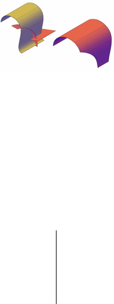
If the SURFACEASSOCIATIVITY (page 1452) system variable is set to 1, the
trimmed surface updates whenever the trimming edges are modified.
List of Prompts
The following prompts are displayed.
Select Surfaces or Regions to Trim Select one or more surfaces or regions
to trim.
Select Cutting Curves, Surfaces, or Regions The curves that can be used
as a trimming edge includes lines, arc, circles, ellipses, 2D polylines, 2D spline
fit polylines, 2D curve fit polylines, 3D polylines, 3D spline-fit polylines,
splines, and helixes. You can also use surfaces and regions as trimming
boundaries.
Select Area to Trim Select one or more regions on a surface to remove.
Extend Controls whether the cutting surface is trimmed to meet the edge of
the trimmed surface.
Projection Direction The cutting geometry is projected onto the surface.
Controls the projection angle as follows:
Automatic ■When trimming a surface or region in plan, parallel view
(for example, the default Top, Front, and Right view), the
cutting geometry is projected onto the surface in the view
direction.
■When trimming a surface or region with a planar curve in
an angled parallel or perspective view, the cutting geometry
is projected onto the surface in a direction perpendicular
to the curve plane.
Commands | 1025
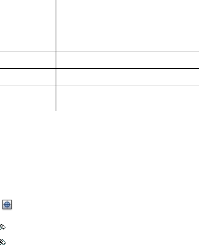
■When trimming a surface or region with a 3D curve in an
angled, parallel or perspective view (for example, the default
perspective view), the cutting geometry is projected onto
the surface in a direction parallel to the Z direction of the
current UCS.
Projects the geometry based on the current view.View
Projects the geometry in the +Z and -Z axis of the current UCS.UCS
The surface will only be trimmed if the cutting curve lies on the
surface.
None
See also:
Trim and Untrim Surfaces
SURFUNTRIM
Replaces surface areas removed by the SURFTRIM command.
Access Methods
Button
Toolbar: Modeling tool set ➤ Surfaces - Edit tool group (expanded) ➤
Surface Untrim
Menu: Modify ➤ Surface Editing ➤ Untrim
Summary
If the trimmed edge is dependent on another surface edge that has also been
trimmed, you may not be able to fully restore the trimmed area.
1026 | Chapter 2 Commands
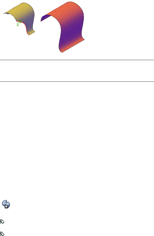
NOTE
SURFUNTRIM does not restore areas removed by the SURFAUTOTRIM system
variable and PROJECTGEOMETRY.
List of Prompts
The following prompts are displayed.
Select Edges on Surfaces to Un-Trim [SURface] Select the edges of trimmed
areas to replace or enter SUR to untrim surfaces.
Select Surfaces to Un-Trim Select a surface to replace all trimmed areas.
See also:
Trim and Untrim Surfaces
SWEEP
Creates a 3D solid or surface by sweeping a 2D or 3D object or subobject along
a path.
Access Methods
Button
Toolbar: Modeling tool set ➤ Solids - Create tool group ➤ Solid Creation
flyout ➤ Sweep
Menu: Draw ➤ 3D Modeling ➤ Sweep
Commands | 1027
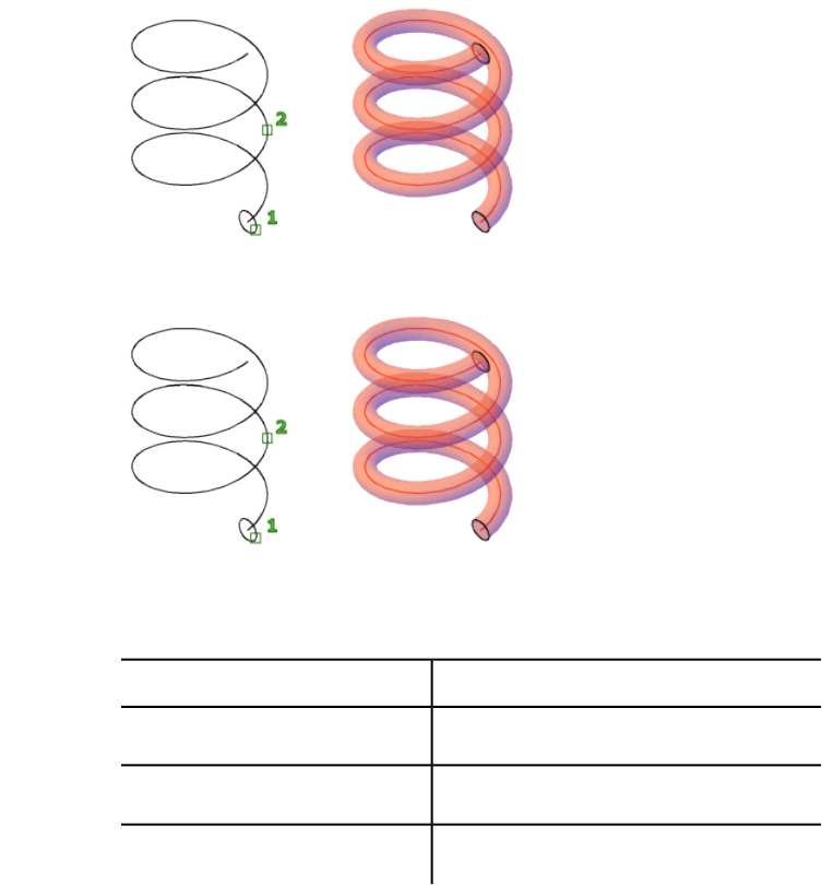
Summary
Creates a solid or surface by sweeping an open or closed, planar or non-planar
curve (profile) along an open or closed path. Open curves create surfaces and
closed curves create solids or surfaces, depending on the specified mode.
The sweep object is automatically aligned to the path object. Use SUR-
FACEMODELINGMODE (page 1453) to set whether SWEEP creates a or a .
The sweep object is automatically aligned to the path object.
You can use the following objects and paths when creating a swept solid or
surface:
Objects for sweeping
Objects that Can Be Used as a Sweep PathObjects that Can Be Swept
2D and 3D splines2D and 3D splines
2D and 3D polylines2D polylines
Solid, surface and mesh edge subobjects2D solids
1028 | Chapter 2 Commands
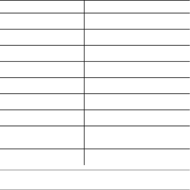
Objects that Can Be Used as a Sweep PathObjects that Can Be Swept
Helices3D solid face subobjects
ArcsArcs
CirclesCircles
EllipsesEllipses
Elliptical arcsElliptical arcs
LinesLines
Regions
Solid, surface and mesh edge subob-
jects
Trace
NOTE
Select face and edge subobjects by pressing Ctrl while you select them.
To automatically delete the original geometry used to create the object, use
the DELOBJ (page 1213) system variable. For associative surfaces (page 1452), the
DELOBJ system variable is ignored and the originating geometry is not deleted.
List of Prompts
The following prompts are displayed.
Objects to Sweep Specifies an object to use as the sweep profile.
Sweep Path Specifies the sweep path based on the object you select.
Mode Controls whether the sweep action creates a solid or a surface. Surfaces
are swept as either NURBS surfaces or procedural surfaces, depending on the
SURFACEMODELINGMODE (page 1453) system variable.
Commands | 1029
Alignment Specifies whether the profile is aligned to be normal to the tangent
direction of the sweep path.
NOTE
If the profile is not perpendicular (normal) to the tangent of the start point
of the path, then the profile automatically aligns. Enter No at the alignment
prompt to prevent this.
Base Point Specifies a base point for the objects to be swept.
Scale Specifies a scale factor for a sweep operation. The scale factor is uniformly
applied to the objects that are swept from the start to the end of the sweep
path.
■Reference. Scales the selected objects based on the length you reference
by picking points or entering values.
Twist Sets a twist angle for the objects being swept. The twist angle specifies
the amount of rotation along the entire length of the sweep path.
■Bank. Specifies whether the curve(s) being swept will naturally bank
(rotate) along a 3D sweep path (3D polyline, spline, or helix).
See also:
Create a Solid or Surface by Sweeping
T Commands
TABLE
Creates an empty table object.
Access Methods
Button
Toolbar: Annotation tool set ➤ Tables tool group ➤ Table
Menu: Draw ➤ Table
1030 | Chapter 2 Commands
Summary
A table is a compound object that contains data in rows and columns. It can
be created from an empty table or a table style. When you create a table, the
number of columns and rows created is determined by the two points picked
to define the size of the table.
If you enter -table at the Command prompt, options are displayed (page 1036).
List of Prompts
The following prompts are displayed.
Specify first corner: Specify a point for the first corner of the table
Specify second corner: Specify the opposite corner of the table
See also:
Create and Modify Tables
Manage Cell Content Dialog Box
Displays the content of the selected cell.
Commands | 1031
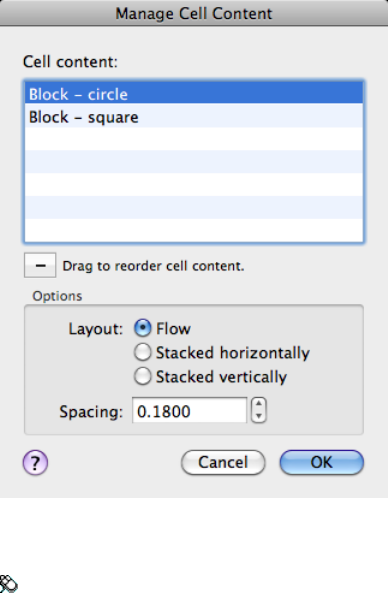
Access Methods
Toolbar: Table Cell visor (expanded) ➤ Manage Cell Contents
List of Options
The following options are displayed.
Cell Content
Lists all text and/or blocks in the selected cell in order of appearance. Text is
indicated with the label Table Cell Text. Blocks are indicated with Block
preceding the name of the block.
Delete (-)
Removes the selected content from the table cell.
Options
Changes the direction and spacing of the content in the cell.
Layout
Changes the direction in which cell content will appear.
Flow
1032 | Chapter 2 Commands
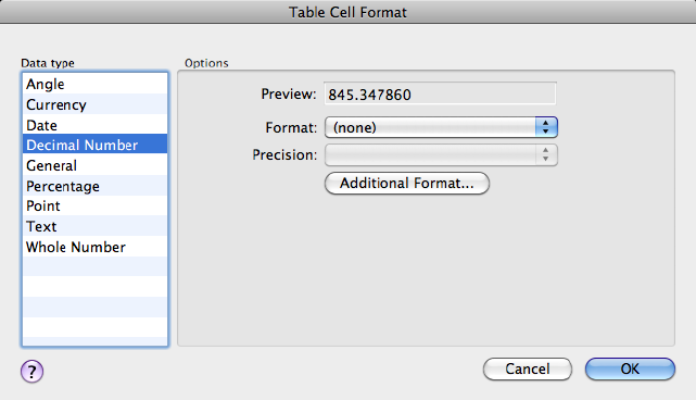
Places cell content based on the width of the cell.
Stacked Horizontally
Places cell content horizontally, regardless of cell width.
Stacked Vertically
Places cell content vertically, regardless of cell height.
Spacing
Determines the spacing between text and/or blocks within the cell.
See also:
Create and Modify Tables
Table Cell Format Dialog Box
The options displayed here change based on the selected data type and format
you select.
List of Options
The following options are displayed.
Data Type Displays a list of data types (Angle, Date, Decimal Number, and
so on) that you can format for table rows.
Commands | 1033
Preview Displays a preview of the option you selected in the Format list.
Format Depending on the data type you select, displays a list of relevant
format types. For example, if you selected Angle as the data type, options such
as Decimal Degrees, Grads, Radians, and so on are displayed.
Precision For Angle, Decimal Number, and Points data types only, sets the
precision for applicable formats. For example, if you select Angle as the data
type and Radians as the format type, options such as Current Precision, 0.0r,
0.00r, 0.000r, and so on are displayed.
List Separator For a Point data type only, displays a list of options (comma,
semicolon, or colon) that you can use to separate list items.
Symbol For Currency data types only, displays a list of currency symbols that
you can use.
Append Symbol In Currency data types, places the currency symbol after the
number. In the Percentage data types, places the percent symbol after the
number.
Negative Numbers For Currency data types only, lists options for displaying
negative numbers.
X, Y, and Z Coordinates For a Point data type only, filters X, Y, or Z
coordinates.
Additional Format For Angle, Decimal Number, Point, and Whole Number
data types only, opens the Additional Format dialog box (page 1034), where you
set additional formatting options for table cells.
Examples For the Date data type only, displays a list of date display options
for the date option you selected in the Format field. Click a date in the Format
field to see an example.
Additional Format Dialog Box
Provides additional formatting options for fields and table cells.
1034 | Chapter 2 Commands
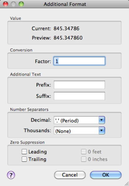
List of Options
The following options are displayed.
Value
Displays the value in base drawing units, and reflects the value as it will appear
once the conversion factor and other settings are applied.
Conversion
Specifies the conversion factor to use on the current value. The default is 1
for no conversion.
Additional Text
Specifies a prefix or a suffix for the value.
Number Separators
Specifies a decimal separator and the formatting for numbers over 1000.
Commands | 1035
Decimal Specifies the separator for decimal values. Select a period, a comma,
or a space.
Thousands Inserts a comma to group thousands in a field value.
Zero Suppression
Controls the suppression of leading and trailing zeros, and of feet and inches
that have a value of zero.
Leading Suppresses leading zeros in all decimal values. For example, 0.5000
becomes .5000.
Trailing Suppresses trailing zeros in all decimal values. For example, 12.5000
becomes 12.5, and 30.0000 becomes 30.
0 Feet Suppresses the feet portion of a feet-and-inches value when the distance
is less than one foot. For example, 0'-6 1/2" becomes 6 1/2".
0 Inches Suppresses the inches portion of a feet-and-inches value when the
distance is an integral number of feet. For example, 1'-0" becomes 1'.
-TABLE
Creates an empty table object.
List of Prompts
The following prompts are displayed.
Current table style: "Standard" Cell width: 2.5000 Cell
height: 1 line(s)
Enter number of columns (page ?) or [Auto (page ?)/from
Style (page ?)] <5>:
Number of Columns
Specifies the number of columns.
Number of Rows
Specifies the number of rows.
Insertion Point Specifies the location of the upper-left corner of the table. If
the table style sets the direction of the table to read from the bottom up, the
insertion point is the lower-left corner of the table.
Width Specifies a width for the table columns.
Height Specifies a height for the table rows.
1036 | Chapter 2 Commands
Style Specifies a table style for the table. The specified table style must contain
a starting table.
Auto Specifies a size and a location for the table. When this option is selected,
you can set the number of columns or the column width, but not both. The
number of rows and the row height depend on the size of the window you
specify.
First Corner Specifies the location of the upper-left corner of the table. If the
table style sets the direction of the table to read from the bottom up, the
insertion point is the lower-left corner of the table.
Height Specifies a height for the table rows.
Auto
Specifies a size and a location for the table.
Number of Rows Specifies the number of rows.
From Style
Specifies a table style for creating the table. You can use the pointing device
or enter coordinate values at the Command prompt. The specified table style
must contain a starting table.
Insertion Point Specifies the location of the upper-left corner of the table. If
the table style sets the direction of the table to read from the bottom up, the
insertion point is the lower-left corner of the table.
Style Specifies a table style for the table.
Entering [?] displays a list of table styles available in your drawing.
Rows Specifies the number of rows you want to add to the table stored in the
specified table style. The rows are added to the rows already in the specified
table.
Columns Specifies the number of columns you want to add to the table stored
in the specified table style. The columns are added to the columns already in
the specified table.
Options
Specifies special formatting options that can be inserted in the table.
Label Text Retains rows with a cell type of Label found in the table style’s
starting table.
The cell type is set in the Properties Inspector palette. The Header and Title
cell styles use the Label cell type by default.
Data Text Retains rows with a cell type of Data found in the table style’s
starting table.
Commands | 1037
The cell type is set in the Properties Inspector palette. The Data cell style uses
the Data cell type property by default.
Formulas Retains formulas found in the specified table style’s starting table.
Fields Retains fields found in the specified table style’s starting table. For more
information, see Use Fields in Text.
Blocks Retains blocks found in the specified table style’s starting table.
Cell Style Overrides Retains cell style overrides found in the specified table
style’s starting table.
See also:
Create and Modify Tables
TABLEDIT
Edits text in a table cell.
Access Methods
Pointing device: Double-click inside a table cell.
Pick a table cell: Click inside a table cell, and edit or format the text
See also:
Add Text and Blocks to Tables
TABLEEXPORT
Exports data from a table object in CSV file format.
Summary
A standard file selection dialog box is displayed. Table data is exported in the
comma-separated (CSV) file format. All formatting of the table and its text is
lost.
See also:
Create and Modify Tables
1038 | Chapter 2 Commands

TABSURF
Creates a mesh from a line or curve that is swept along a straight path.
Access Methods
Menu: Draw ➤ 3D Modeling ➤ Meshes ➤ Tabulated Mesh
Summary
Select a line, arc, circle, ellipse, or polyline to sweep in a straight path. Then
select a line or polyline to determine the first and last points of a vector that
indicates the direction and length of the polygon mesh.
The MESHTYPE (page 1369) system variable sets which type of mesh is created.
Mesh objects are created by default. Set the variable to 0 to create legacy
polyface or polygon mesh.
For polygon meshes, TABSURF constructs a 2 by n mesh, where n is determined
by the SURFTAB1 (page 1454) system variable. The M direction of the mesh is
always 2 and lies along the direction vector. The N direction lies along the
path curve. If the path curve is a line, arc, circle, ellipse, or spline-fit polyline,
tabulation lines are drawn that divide the path curve into intervals of equal
size set by SURFTAB1. If the path curve is a polyline that has not been spline
fit, tabulation lines are drawn at the ends of straight segments, and each arc
segment is divided into intervals set by SURFTAB1.
Commands | 1039
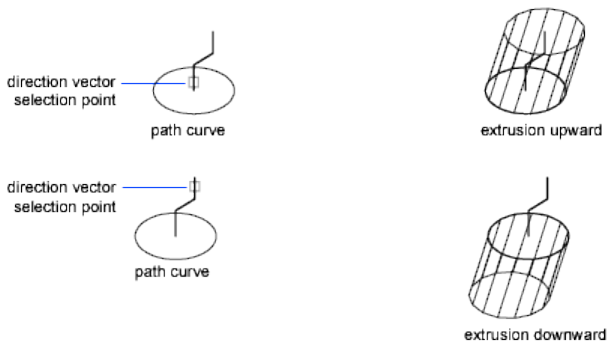
List of Prompts
The following prompts are displayed.
Object for path curve Specifies which object is swept along the path.
The path curve defines the approximated surface of the polygon mesh. It can
be a line, arc, circle, ellipse, or 2D or 3D polyline. The mesh is drawn starting
at the point on the path curve closest to the selection point.
Object for direction vector. Specifies a line or open polyline that defines the
direction of the sweep.
Only the first and last points on a polyline are considered, and intermediate
vertices are ignored. The direction vector indicates the direction and length
of the shape to be extruded. The end selected on the polyline or line determines
the direction of the extrusion. The original path curve is drawn with wide
lines to help you visualize how the direction vector dictates the construction
of a tabulated mesh.
See also:
Create Meshes from Other Objects
TARGETPOINT
Creates a target point light.
1040 | Chapter 2 Commands

List of Prompts
The following prompts are displayed.
Specify source location <0,0,0>: Enter coordinate values or use the
pointing device
Specify target location <0,0,-10>: Enter coordinate values or use the
pointing device
If the LIGHTINGUNITS system variable is set to 0, the following prompt is
displayed:
Enter an option to change [Name (page ?)/Intensity (page
?)/Status (page ?)/shadoW (page ?)/Attenuation (page
?)/Color (page ?)/eXit (page ?)] <eXit>:
If the LIGHTINGUNITS system variable is set to 1 or 2, the following prompt
is displayed:
Enter an option to change [Name (page ?)/Intensity factor
(page ?)/Status (page ?)/Photometry (page ?)/shadoW (page
?)/Attenuation (page ?)/filterColor (page ?)/eXit (page
?)] <eXit>:
NOTE
When the LIGHTINGUNITS system variable is set to 1 or 2, the Attenuation
option has no affect on the creation of the light. It is only maintained for
scripting compatibility.
Name
Specifies the name of the light.
Intensity/Intensity Factor
Sets the intensity or brightness of the light.
Status
Turns the light on and off.
Photometry
Photometry is available when the LIGHTINGUNITS system variable is set to
1 or 2. Photometry is the measurement of the luminous intensities of visible
light sources.
In photometry, luminous intensity is a measure of the perceived power emitted
by a light source in a particular direction. Luminous flux is the perceived
power per unit of solid angle. The total luminous flux for a lamp is the
perceived power emitted in all directions. Luminance is the total luminous
flux incident on a surface, per unit area.
Commands | 1041
Intensity Enter an intensity value in candelas, the perceived power in a
luminous flux value, or illuminance value for the total luminous flux incident
on a surface.
■Candela (symbol: cd) is the SI unit of luminous intensity (perceived power
emitted by a light source in a particular direction). Cd/Sr
■Lux (symbol: lx) is the SI unit of illuminance. Lm/m^2
■Foot-candle (symbol: fc) is the American unit of illuminance. Lm/ft^2
Enter f to specify the perceived power in a luminous flux value.
If you enter i, you can specify the intensity of the light based on an
illuminance value.
The illuminance value can be specified in either lux or foot-candles. Enter d
to specify a distance to use to calculate illuminance.
Color Specify the color of the light based on a color name or a Kelvin
temperature.
Enter ? to display a list of color names. Enter a text string using wild card
characters to display a partial listing of color names, or an asterisk (*) to display
all the possible choices.
If you enter k, you can specify the color of the light based on a Kelvin
temperature value.
Exit Exits the command.
Shadow
Makes the light cast shadows.
Off Turns off the display and calculation of shadows for the light. Turning
shadows off increases performance.
Sharp Displays shadows with sharp edges. Use this option to increase
performance.
Soft Mapped Displays realistic shadows with soft edges.
Map Size Specifies the amount of memory that should be used to calculate
the shadow map.
Softness Specifies the softness to use to calculate the shadow map.
Soft Sampled Displays realistic shadows with softer shadows (penumbra)
based on extended light sources.
Shape Specify the shape of the shadow by entering s and then the dimensions
of the shape. (For example, the radius of the sphere or the length and width
of a rectangle.)
1042 | Chapter 2 Commands
Attenuation
Attenuation Type Controls how light diminishes over distance. The farther
away an object is from a point light, the darker the object appears. Attenuation
is also known as decay.
■None. Sets no attenuation. Objects far from the point light are as bright
as objects close to the light.
■Inverse Linear. Sets attenuation to be the inverse of the linear distance
from the light. For example, at a distance of 2 units, light is half as strong
as at the point light; at a distance of 4 units, light is one quarter as strong.
The default value for inverse linear is half the maximum intensity.
■Inverse Squared. Sets attenuation to be the inverse of the square of the
distance from the light. For example, at a distance of 2 units, light is one
quarter as strong as at the point light; at a distance of 4 units, light is one
sixteenth as strong.
Use Limits Specifies whether to use limits or not.
Attenuation Start Limit Specifies the point where light starts as an offset
from the center of the light.
Attenuation End Limit Specifies the point where light ends as an offset from
the center of the light. No light is cast beyond this point. Setting an end limit
increases performance where the effect of lighting is so minimal that the
calculations are wasted processing time.
Color/Filter Color
Controls the color of the light.
True Color Specifies a True Color. Enter in the format R,G,B (red, green, blue).
Index Specifies an ACI (AutoCAD Color Index) color.
HSL Specifies an HSL (hue, saturation, luminance) color.
Color Book Specifies a color from a color book.
Exit
Exits the command.
See also:
Use Point Lights
Commands | 1043
TEXT
Creates a single-line text object.
Access Methods
Button
Toolbar: Annotation tool set ➤ Text tool group ➤ Multiline Text flyout
➤ Single Line
Menu: Draw ➤ Text ➤ Single Line Text
Summary
You can use single-line text to create one or more lines of text, where each
text line is an independent object that you can move, format, or otherwise
modify. Right-click in the text box to select options on the shortcut menu.
If TEXT was the last command entered, pressing Enter at the Specify Start
Point of Text prompt skips the prompts for paper height and rotation angle.
The text that you enter in the text box is placed directly beneath the previous
line of text. The point that you specified at the prompt is also stored as the
insertion point of the text.
When creating text, you can click anywhere in a drawing to create a new text
block. You can also use the keyboard to move among text blocks (for example:
for new text created using the TEXT (page 1044) command, you can navigate
through text groups by pressing Tab or Shift+Tab, or edit a group of text lines
by pressing Alt and clicking each text object.)
NOTE
Text that would otherwise be difficult to read (if it is very small, very large, or
is rotated) is displayed at a legible size and is oriented horizontally so that you
can easily read and edit it.
You can enter special characters and format text by entering Unicode strings
(page 1049) and control codes (page 1049).
Use -TEXT to honor the TEXTEVAL system variable (page 1050).
1044 | Chapter 2 Commands
List of Prompts
The following prompts are displayed.
Current text style: <current> Current text height: <current>
Annotative: <current>
Specify start point (page ?) of text or [Justify (page
?)/Style (page ?)]: Specify a point or enter an option
Start Point
Specifies a start point for the text object. Enter text in the In-Place Text Editor
for single-line text.
The SpecifyHeight prompt is displayed only if the current text style is not
annotative and does not have a fixed height.
The Specify Paper Text Height prompt is displayed only if the current text
style is annotative.
Justify
Controls justification of the text.
You can also enter any of these options at the Specify Start Point of Text
prompt.
Align Specifies both text height and text orientation by designating the
endpoints of the baseline.
The size of the characters adjusts in proportion to their height. The longer
the text string, the shorter the characters.
Fit Specifies that text fits within an area and at an orientation defined with
two points and a height. Available for horizontally oriented text only.
Commands | 1045
The height is the distance in drawing units that the uppercase letters extend
from the baseline. Designated text height is the distance between the start
point and a point you specify. The longer the text string, the narrower the
characters. The height of the characters remains constant.
Center Aligns text from the horizontal center of the baseline, which you
specify with a point.
The rotation angle specifies the orientation of the text baseline with respect
to the center point. You can designate the angle by specifying a point. The
text baseline runs from the start point toward the specified point. If you specify
a point to the left of the center point, the text is drawn upside down.
Middle Aligns text at the horizontal center of the baseline and the vertical
center of the height you specify. Middle-aligned text does not rest on the
baseline.
The Middle option differs from the MC option in that it uses the midpoint of
all text, including descenders. The MC option uses the midpoint of the height
of uppercase letters.
Right Right-justifies the text at the baseline, which you specify with a point.
TL (Top Left) Left-justifies text at a point specified for the top of the text.
Available for horizontally oriented text only.
TC (Top Center) Centers text at a point specified for the top of the text.
Available for horizontally oriented text only.
1046 | Chapter 2 Commands
TR (Top Right) Right-justifies text at a point specified for the top of the text.
Available for horizontally oriented text only.
ML (Middle Left) Left-justifies text at a point specified for the middle of the
text. Available for horizontally oriented text only.
MC (Middle Center) Centers the text both horizontally and vertically at the
middle of the text. Available for horizontally oriented text only.
The MC option differs from the Middle option in that it uses the midpoint of
the height of uppercase letters. The Middle option uses the midpoint of all
text, including descenders.
MR (Middle Right) Right-justifies text at a point specified for the middle of
the text. Available for horizontally oriented text only.
BL (Bottom Left) Left-justifies text at a point specified for the baseline.
Available for horizontally oriented text only.
BC (Bottom Center) Centers text at a point specified for the baseline. Available
for horizontally oriented text only.
BR (Bottom Right) Right-justifies text at a point specified for the baseline.
Available for horizontally oriented text only.
Commands | 1047
Style
Specifies the text style, which determines the appearance of the text characters.
Text you create uses the current text style.
Entering ? lists the current text styles, associated font files, height, and other
parameters.
See also:
Create Single-Line Text
Text Shortcut Menu
Displays options available for creating and modifying single-line text.
List of Options
The following options are displayed.
Opaque Background When checked, makes the background of the editor
opaque.
Insert Field Displays the Insert Field dialog box (page 429), where you can
select a field to insert in the text.
Find and Replace Displays the Replace dialog box (page 687).
Select All Selects all the text in the single-line text object.
Change Case Changes the case of selected text.
See also:
Create Single-Line Text
1048 | Chapter 2 Commands

Special Unicode Characters
When entering text, you can create special characters, including the degree
symbol, plus/minus tolerance symbol, and the diameter symbol, by entering
the following Unicode character strings.
List of Options
The following options are displayed.
\U+00B0 Degrees symbol (°)
\U+00B1 Tolerance symbol ( )
\U+2205 Diameter symbol ( )
See “Unicode Font Descriptions” in the Customization Guide.
See also:
Create Single-Line Text
Control Codes and Special Characters
Summary
In addition to using Unicode characters for entering special characters, you
can also overscore text, underscore text, or insert a special character by
including control information in the text string. Use a pair of percent signs
to introduce each control sequence.
You can use this control code with standard AutoCAD for Mac text fonts and
Adobe PostScript fonts.
List of Options
The following options are displayed.
%%nnn Draws character number nnn.
You can use these control codes with standard AutoCAD for Mac text fonts
only:
%%o Toggles overscoring on and off.
Commands | 1049
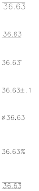
%%u Toggles underscoring on and off.
%%d Draws degrees symbol (°).
%%p Draws plus/minus tolerance symbol ( ).
%%c Draws circle diameter dimensioning symbol (ý).
%%% Draws a single percent sign (%). This is valid for the TEXT command
only.
Overscoring and underscoring can be in effect at the same time. Both turn off
automatically at the end of the text string.
You can use the %%nnn control sequence to display special characters using
the PostScript fonts.
See also:
Create Single-Line Text
TEXT and the TEXTEVAL System Variable
Summary
Entering -text at the Command prompt displays the same prompts as the
TEXT command. Unlike the TEXT command, -TEXT checks the setting of the
TEXTEVAL (page 1461) system variable. When the TEXTEVAL system variable
1050 | Chapter 2 Commands

is set to 1, AutoLISP® expressions are evaluated when the -TEXT command
ends. AutoLISP expressions that are entered using this method must begin
with an exclamation point or left parenthesis.
The TEXT command checks the setting of the TEXTEVAL system variable
setting only if it is used in a script or AutoLISP expression and all the TEXT
command prompts are included within the script or AutoLISP expression.
See also:
Create Single-Line Text
TEXTEDIT
Edits a selected multiline or single-line text object, or the text in a dimension
object.
Summary
Displays the in-place text editor, and accepts your changes to the selected
multiline text, single-line text, or dimension object.
List of Prompts
The following prompt is displayed.
Select an annotation object: Select a text, mtext, or dimension object
See also:
Change Text
TEXTTOFRONT
Brings text and dimensions in front of all other objects in the drawing.
Access Methods
Button
Commands | 1051

Toolbar: Drafting tool set ➤ Move/Rotate/Scale tool group (expanded)
➤ Draw Order flyout ➤ Bring Text to Front, Bring Dimensions to Front
Menu: Tools ➤ Draw Order ➤ Bring Text and Dimensions to
Front ➤ Text and Dimension Objects
List of Prompts
The following prompts are displayed.
Bring to front: [Text/Dimensions/Both] <Both>: Enter an option or
press Enter
Text Brings all text in front of all other objects in the drawing.
Dimensions Brings all dimensions in front of all other objects in the drawing.
Both Brings all text and dimensions in front of all other objects in the drawing.
NOTE
Text and dimensions that are contained within blocks and xrefs cannot be
brought to the front apart from the containing object. Also, text in multileaders
and tables are not supported.
See also:
Control How Overlapping Objects Are Displayed
THICKEN
Converts a surface into a 3D solid with a specified thickness.
Access Methods
Button
Toolbar: Modeling tool set ➤ Solids - Edit (expanded) ➤ Thicken
Menu: Modify ➤ 3D Operations ➤ Thicken
1052 | Chapter 2 Commands
Summary
A useful technique for modeling a complex 3D curved solid is to first create
a surface and then convert it to a 3D solid by thickening it.
Initially, the default thickness value is zero. During a drawing session, the
default value for the thickness is the previously entered thickness value.
The DELOBJ (page 1213) system variable controls whether the object(s) you
select are automatically deleted when the surface is created or whether you
are prompted to delete the object(s).
If you select a mesh face to thicken, you can choose to convert the mesh object
to a solid or surface before completing the operation.
List of Options
The following prompts are displayed.
Surfaces to thicken Specifies one or more surfaces to thicken into solids.
Thickness Sets the height of the thickened object.
See also:
Create 3D Solids from Objects
TIFOUT
Saves selected objects to a file in TIFF file format.
Summary
The Create Raster File dialog box (a standard file selection dialog box (page
720)) is displayed. Enter the file name in the dialog box.
List of Prompts
The following prompts are displayed.
Select objects or <all objects and viewports>: Press Enter to
select all objects and viewports or use an object selection method and press Enter
A TIFF file is created that contains the objects you select. The file reflects what
is displayed on the screen.
Commands | 1053

NOTE When the FILEDIA (page 1296) system variable is set to 0 (Off), command
prompts are displayed.
See also:
Export Raster Files
TIME
Displays the date and time statistics of a drawing.
Access Methods
Menu: Tools ➤ Inquiry ➤ Time
Command entry: 'time for transparent use
Summary
The Total Editing Time cannot be reset or stopped. Plotting time is not included
in the total editing time, nor is the viewing time if the drawing is not saved.
The Elapsed Timer controls are separate and can be started, stopped, and reset.
List of Prompts
The following prompts are displayed.
Current time (page 1054): Wednesday, December 31, 2003
9:54:51:406 AM
Times for this drawing:
Created (page 1054): Friday, December 12, 2003 1:21:36:203 AM
Last Updated (page 1055): Wednesday, December 31, 2003
9:49:19:208 AM
Total Editing Time (page 1055): 0 days 06:44:10.520
Elapsed Timer (page 1055) (on): 0 days 00:07:05.312
Next Automatic Save In (page 1055): 0 days 01:59:15.570
Enter option [Display (page 1055)/On (page 1055)/OFF (page
1055)/Reset (page 1055)]: Enter an option or press Enter
Current Time Displays the current date and time to the nearest millisecond
using a 24-hour clock.
Created Displays the date and time that the current drawing was created.
1054 | Chapter 2 Commands

Last Updated Displays the date and time of the latest update of the current
drawing. This date and time is initially the drawing creation time. The time
is revised whenever the drawing file is saved.
Total Editing Time Displays the time spent editing the current drawing. This
timer is updated by the program and cannot be reset or stopped. Plotting time
is not included in the total editing time. If you quit the editing session without
saving the drawing, the time you spent in the editing session is not added to
the accumulated editing time.
Elapsed Timer Runs as another timer while the program is running. You can
turn it on and off or reset it whenever you like.
Next Automatic Save In Indicates the time remaining until the next automatic
save. You can set the time interval using OPTIONS (page 724) or the SAVETIME
(page 1423) system variable.
Display Repeats the display with updated times.
On Starts the user elapsed timer if it was off.
Off Stops the user elapsed timer.
Reset Resets the user elapsed timer to 0 days 00:00:00.000.
See also:
Obtain General Drawing Information
TINSERT
Inserts a block in a table cell.
Access Methods
Toolbar: With a table and table cell selected, click Insert Block on the
Table Cell visor.
Summary
The Insert a Block in a Table Cell dialog box (page 1056) is displayed.
See also:
Add Content to Tables
Commands | 1055

Insert Block in Table Cell Dialog Box
Specifies options for inserting a block in a table cell.
List of Options
The following options are displayed.
Name Specifies the block reference to insert.
Browse Displays the Select Drawing File dialog box. Select the drawing file to
insert as a block reference.
Path Displays the location of the drawing file selected in the Select Drawing
File dialog box.
Scale
Specifies the scale for the block reference. Enter a value or select AutoFit to
scale the block to fit in the selected cell.
AutoFit Controls if the block reference should be scaled to fit in the select
table cell, or if the height and width of the table cell should be adjusted to fit
the block reference being inserted.
Rotation Angle
Specifies a rotation angle for the block.
Overall Cell Alignment
Specifies alignment for the block in the table cell. The block is middle-, top-,
or bottom-aligned with respect to the top and bottom borders of the cell. The
1056 | Chapter 2 Commands
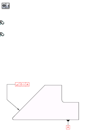
block is center-, left-, or right-aligned with respect to the left and right borders
of the cell.
See also:
Add Content to Tables
TOLERANCE
Creates geometric tolerances contained in a feature control frame.
Access Methods
Button
Toolbar: Annotation tool set ➤ Dimensions tool group (expanded) ➤
Tolerance
Menu: Dimension ➤ Tolerance
Summary
The Geometric Tolerance dialog box (page 1058) is displayed.
Geometric tolerances show acceptable deviations of form, profile, orientation,
location, and runout. Feature control frames can be created with leader lines
using TOLERANCE, LEADER, or QLEADER.
See also:
Overview of Geometric Tolerances
Commands | 1057
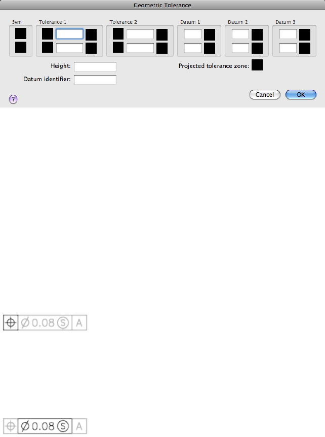
Geometric Tolerance Dialog Box
Specifies the symbols and values for a feature control frame.
Summary
After you select geometric characteristic symbols, the Geometric Tolerance
dialog box closes and the following prompt is displayed:
Enter tolerance location: Specify a location
The feature control frame is placed at the specified location.
List of Prompts
The following prompts are displayed.
Sym
Displays the geometric characteristic symbol, which you select from the
Symbol dialog box (page 1060). The dialog box is displayed when you select one
of the Sym boxes.
Tolerance 1
Creates the first tolerance value in the feature control frame. The tolerance
value indicates the amount by which the geometric characteristic can deviate
from a perfect form. You can insert a diameter symbol before the tolerance
value and a material condition symbol after it.
First Box
1058 | Chapter 2 Commands
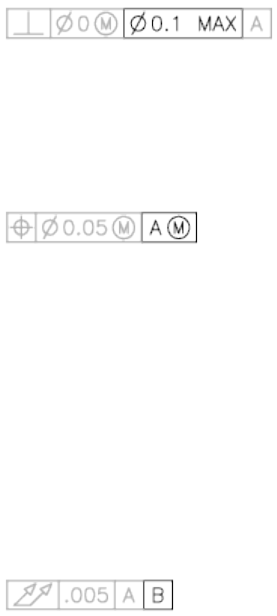
Inserts a diameter symbol in front of the tolerance value. Click the box to
insert the diameter symbol.
Second Box
Creates the tolerance value. Enter a value in the box.
Third Box
Displays the Material Condition dialog box (page 1062), in which you select a
modifying symbol. These symbols act as modifiers to the geometric
characteristic and the tolerance value of features that can vary in size.
The symbol is inserted into the MC box for the first tolerance value in the
Geometric Tolerance dialog box.
Tolerance 2
Creates the second tolerance value in the feature control frame. Specify the
second tolerance value in the same way as the first.
Datum 1
Creates the primary datum reference in the feature control frame. The datum
reference can consist of a value and a modifying symbol. A datum is a
theoretically exact geometric reference used to establish the tolerance zone
for a feature.
First Box
Creates the datum reference value.
Second Box
Displays the Material Condition dialog box (page 1062), in which you select a
modifying symbol. These symbols act as modifiers to the datum reference.
The symbol is inserted into the MC box for the primary datum reference in
the Geometric Tolerance dialog box.
Datum 2
Creates the secondary datum reference in the feature control frame in the
same way as the primary datum reference.
Commands | 1059
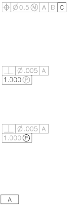
Datum 3
Creates the tertiary datum reference in the feature control frame in the same
way as the primary datum reference.
Height
Creates a projected tolerance zone value in the feature control frame. A
projected tolerance zone controls the variation in height of the extended
portion of a fixed perpendicular part and refines the tolerance to that specified
by positional tolerances.
Projected Tolerance Zone
Inserts a projected tolerance zone symbol after the projected tolerance zone
value.
Datum Identifier
Creates a datum-identifying symbol consisting of a reference letter. A datum
is a theoretically exact geometric reference from which you can establish the
location and tolerance zones of other features. A point, line, plane, cylinder,
or other geometry can serve as a datum.
See also:
Overview of Geometric Tolerances
Symbol Dialog Box
Displays the geometric characteristic symbols for location, orientation, form,
profile, and runout.
1060 | Chapter 2 Commands
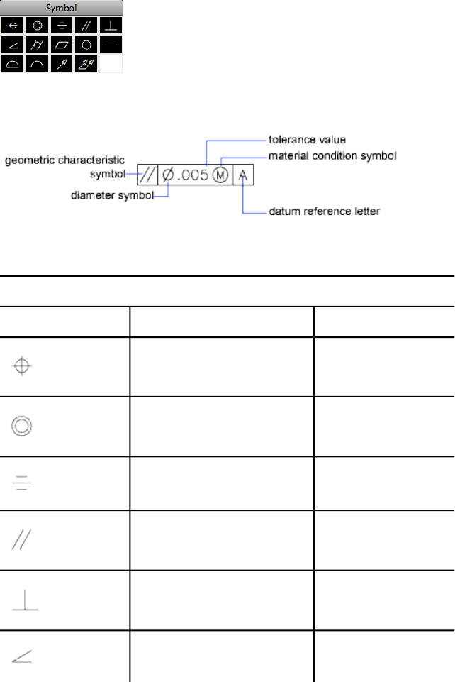
Summary
The symbol is inserted into the Sym text box in the Geometric Tolerance
dialog box (page 1058). The following table describes the symbols.
Geometric characteristic symbols
TypeCharacteristicSymbol
LocationPosition
LocationConcentricity or coaxiality
LocationSymmetry
OrientationParallelism
OrientationPerpendicularity
OrientationAngularity
Commands | 1061

Geometric characteristic symbols
TypeCharacteristicSymbol
FormCylindricility
FormFlatness
FormCircularity or roundness
FormStraightness
ProfileProfile of a surface
ProfileProfile of a line
RunoutCircular runout
RunoutTotal runout
See also:
Overview of Geometric Tolerances
Material Condition Dialog Box
Specifies a modifying symbol. These symbols act as modifiers to the geometric
characteristic and the tolerance value of features that can vary in size.
1062 | Chapter 2 Commands
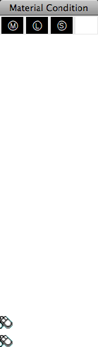
Summary
The symbol is inserted into the MC box for the first or second tolerance value
in the Geometric Tolerance dialog box (page 1058).
See also:
Overview of Geometric Tolerances
TOOLSETS
Opens the Tool Sets palette.
Access Methods
Menu: Tools ➤ Palettes ➤ Tool Sets
Menu: Window ➤ Tool Sets
See also:
The Tool Sets Palette
TOOLSETSCLOSE
Closes the Tool Sets palette.
See also:
The Tool Sets Palette
TORUS
Creates a donut-shaped 3D solid.
Commands | 1063
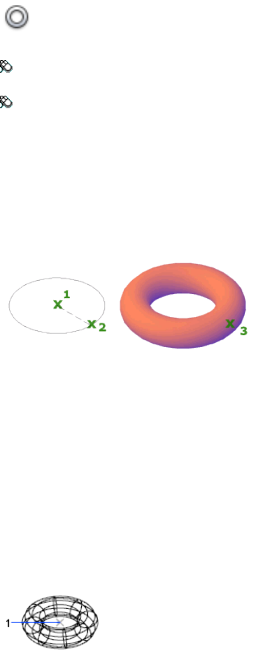
Access Methods
Button
Toolbar: Modeling tool set ➤ Solids - Create tool group ➤ Solid
Primitives flyout ➤ Torus
Menu: Draw ➤ 3D Modeling ➤ Torus
Summary
You can create a torus by specifying the center, then the radius or diameter
of the torus, and then the radius or diameter of the tube that surrounds the
torus. You can control the smoothness of curved 3D solids, such as a torus,
in a shaded or hidden visual style with the FACETRES system variable.
List of Prompts
The following prompts are displayed.
Specify center point or [3P (page ?)/2P (page ?)/TTR (page
?)]: Specify a point (1) or enter an option
When you specify the center point, the torus is positioned so that its central
axis is parallel to the Z axis of the current user coordinate system (UCS). The
torus is parallel to and bisected by the XY plane of the current workplane.
Specify radius (page ?) or [diameter (page ?)] <default>:
Specify a distance or enter d
1064 | Chapter 2 Commands
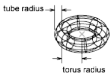
3P (Three Points)
Defines the circumference of the torus with three points that you specify. The
three specified points also define the plane of the circumference.
2P (Two Points)
Defines the circumference of the torus with two points that you specify. The
plane of the circumference is defined by the Z value of the first point.
TTR (Tangent, Tangent, Radius)
Defines the torus with a specified radius tangent to two objects. The specified
tangency points are projected onto the current UCS.
Radius
Defines the radius of the torus: the distance from the center of the torus to
the center of the tube. A negative radius creates a solid shaped like an American
football.
Radius Defines the radius of the tube.
Diameter Defines the diameter of the tube.
Diameter
Defines the diameter of the torus.
■Radius (page 1065)
■Diameter (page 1065)
See also:
Create a Solid Torus
TRANSPARENCY
Controls whether background pixels in an image are transparent or opaque.
Commands | 1065

Access Methods
Menu: Modify ➤ Object ➤ Image ➤ Transparency
List of Prompts
The following prompts are displayed.
Select image(s):
Enter transparency mode [ON/OFF] <current>: Enter an option or press
Enter
On Turns transparency on so that objects beneath the image are visible.
Off Turns transparency off so that objects beneath the image are not visible.
See also:
Modify Color and Transparency for Bitonal Raster Images
TREESTAT
Displays information about the drawing's current spatial index.
Access Methods
Command entry: 'treestat for transparent use
Summary
The program indexes objects in a region by recording their positions in space.
The result is called a spatial index. The spatial index is tree structured and has
branching nodes to which objects are attached. The index has two major
branches. The paper space branch is called a quad-tree and treats objects as
two-dimensional. The model space branch is called an oct-tree and treats
objects as either two- or three-dimensional. The model space branch can also
be changed to a quad-tree when you are working on two-dimensional drawings.
TREESTAT displays information about each branch. The most important
information is in the first two lines of the report—number of nodes, number
of objects, maximum depth of the branch, and average number of objects per
node.
If REDRAW (page 869) and object selection are very slow, you can improve
their performance. For example, if there are 50 megabytes of memory available
1066 | Chapter 2 Commands
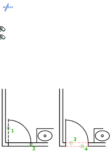
and the current drawing has 50,000 objects with only 1,000 nodes in the index
tree, increase the TREEDEPTH (page 1472) value to improve performance.
Each node consumes about 80 bytes of memory. The fewer objects per node
of the oct-tree, the better the performance.
See also:
Increase Performance with Large Referenced Drawings
TRIM
Trims objects to meet the edges of other objects.
Access Methods
Button
Toolbar: Drafting tool set ➤ Modify tool group ➤ Trim
Menu: Modify ➤ Trim
Summary
To trim objects, select the boundaries. Then press Enter and select the objects
that you want to trim. To use all objects as boundaries, press Enter at the first
Select Objects prompt.
List of Prompts
The following prompts are displayed.
Commands | 1067
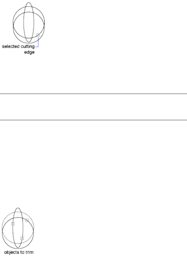
Current settings: Projection = current, Edge = current
Select cutting edges...
Select objects or <select all>: Select one or more objects and press
Enter, or press Enter to select all displayed objects
Select the objects that define the cutting edges to which you want to trim an
object, or press Enter to select all displayed objects as potential cutting edges.
TRIM projects the cutting edges and the objects to be trimmed onto the XY
plane of the current user coordinate system (UCS).
NOTE
To select cutting edges that include blocks, you can use only the single
selection, Crossing, Fence, and Select All options.
Select object to trim (page ?) or shift-select to extend
(page ?) or [Fence (page ?)/Crossing (page ?)/Project
(page ?)/Edge (page ?)/eRase (page ?)/Undo (page ?)]:
Select an object to trim, hold down Shift and select an object to extend it instead,
or enter an option
Specify an object selection method to select the objects to trim. If more than
one trim result is possible, the location of the first selection point determines
the result.
Object to Trim
Specifies the object to trim.
1068 | Chapter 2 Commands
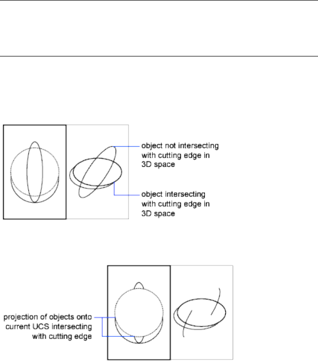
Shift-Select to Extend
Extends the selected objects rather than trimming them. This option provides
an easy method to switch between trimming and extending.
Fence
Selects all objects that cross the selection fence. The selection fence is a series
of temporary line segments that you specify with two or more fence points.
The selection fence does not form a closed loop.
Crossing
Selects objects within and crossing a rectangular area defined by two points.
NOTE
Some crossing selections of objects to be trimmed are ambiguous. TRIM resolves
the selection by following along the rectangular crossing window in a clockwise
direction from the first point to the first object encountered.
Project
Specifies the projection method used when trimming objects.
None Specifies no projection. The command trims only objects that intersect
with the cutting edge in 3D space.
UCS Specifies projection onto the XY plane of the current UCS. The command
trims objects that do not intersect with the cutting edge in 3D space.
Commands | 1069
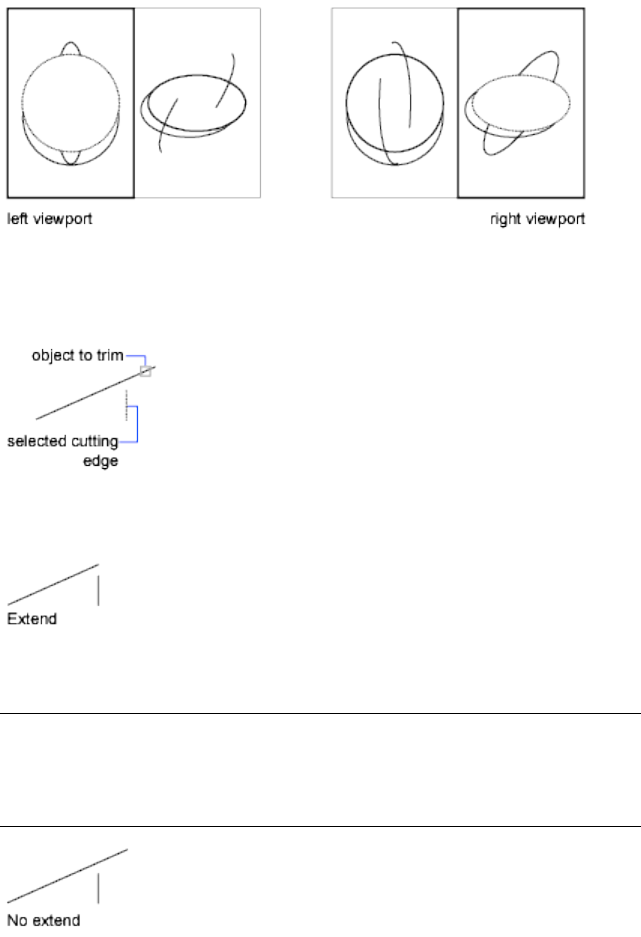
View Specifies projection along the current view direction. The command
trims objects that intersect the boundary in the current view.
Edge
Determines whether an object is trimmed at another object's extrapolated
edge or only to an object that intersects it in 3D space.
Extend Extends the cutting edge along its natural path to intersect an object
in 3D space.
No Extend Specifies that the object is trimmed only at a cutting edge that
intersects it in 3D space.
NOTE
When trimming hatches, do not set Edge to Extend. If you do, gaps in the
trim boundaries will not be bridged when trimming hatches, even when the
gap tolerance is set to a correct value.
1070 | Chapter 2 Commands

Erase
Deletes selected objects. This option provides a convenient method to erase
unneeded objects without leaving the TRIM command.
Undo
Reverses the most recent change made by TRIM.
See also:
Trim or Extend Objects
U Commands
U
Reverses the most recent operation.
Access Methods
Menu: Edit ➤ Undo
Shortcut menu: With no command active and no objects selected, right-click
in the drawing area and click Undo.
Command entry: Cmd-Z
Summary
You can enter u as many times as you wish, backing up one step at a time,
until the drawing is as it was when you began the current editing session.
When an operation cannot be undone, the command name is displayed but
no action is performed. Operations external to the current drawing, such as
plotting or writing to a file, cannot be undone.
If you changed modes or used transparent commands during a command,
their effects are undone, along with the effects of the main command.
The U command is equivalent to entering undo 1.
See also:
Correct Mistakes
Commands | 1071
UCS
Sets the origin and orientation of the current UCS.
Access Methods
Button
Toolbar: Drafting tool set ➤ Coordinates tool group ➤ World UCS
Menu: Tools ➤ New UCS
Shortcut menu: Right-click the UCS icon and click an option.
Summary
The UCS is the active coordinate system that establishes the XY plane (work
plane) and Z-axis direction for drawing and modeling. Control the UCS origin
and orientation to make drawing more convenient as you specify points, enter
coordinates, and work with drawing aids, such as Ortho mode and the grid.
A UCS can be stored with a viewport if the UCSVP (page 1481) system variable
is set to 1 for that viewport.
List of Prompts
The following prompts are displayed.
Specify Origin of UCS (page ?) or [Face (page ?)/NAmed
(page ?)/OBject (page ?)/Previous (page ?)/View (page
?)/World (page ?)/X/Y/Z (page ?)/ZAxis (page ?)] <World>:
Specify Origin of UCS
Shifts the user coordinate system origin point (0,0,0) to facilitate entering
absolute coordinates, creating ordinate dimensions, or setting the work plane
in 3D.
Defines a new UCS using one, two, or three points:
■If you specify a single point, the origin of the current UCS shifts without
changing the orientation of the X, Y, and Z axes.
■If you specify a second point, the UCS rotates to pass the positive X axis
through this point.
■If you specify a third point, the UCS rotates around the new X axis to
define the positive Y axis.
1072 | Chapter 2 Commands
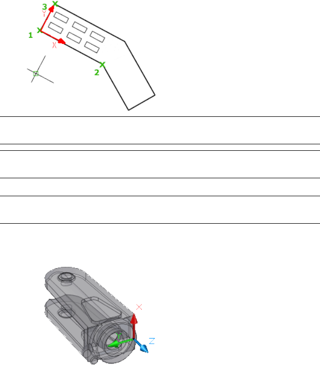
The three points specify an origin point, a point on the positive X axis, and
a point on the positive XY plane.
NOTE If you do not specify a Z coordinate value when entering a coordinate, the
current Z value is used.
TIP You can also select and drag the UCS icon origin grip directly to a new location,
or choose Move Origin Only from the origin grip menu.
Face
TIP You can also select and drag the UCS icon (or choose Move And Align from
the origin grip menu) to dynamically align the UCS with faces.
Dynamically aligns the UCS to a face on a 3D object.
Move the cursor over a face to see a preview of how the UCS will be aligned.
Next Locates the UCS on either the adjacent face or the back face of the
selected edge.
Xflip Rotates the UCS 180 degrees around the X axis.
Yflip Rotates the UCS 180 degrees around the Y axis.
Accept Accepts the changes and places the UCS.
Commands | 1073

Named
Saves or restores named UCS definitions.
TIP
You can also right-click the UCS icon and click Named UCS to save or restore
named UCS definitions.
Restore
Restores a saved UCS definition so that it becomes the current UCS.
Name Specifies the name of the UCS definition to restore.
?—List UCS definitions Lists details about the specified UCS definitions.
Save
Saves the current UCS to a specified name.
Name Specifies the name for the UCS definition.
Delete
Removes the specified UCS definition from the list of saved definitions.
If you delete a UCS definition that is currently active, the UCS stays in place
but is listed as NO NAME.
?—List UCS Definitions
Lists saved UCS definitions showing the origin and X, Y, and Z axes for each
saved UCS definition relative to the current UCS. Enter an asterisk to list all
UCS definitions. If the current UCS is the same as the WCS (World Coordinate
System), it is listed as WORLD. If it is custom, but unnamed, it is listed as NO
NAME.
Object
Aligns the UCS to a selected 2D or 3D object. The UCS can be aligned with
any object type except xlines and 3D polylines.
Move the cursor over an object to see a preview of how the UCS will align,
and click to place the UCS. In most cases, the UCS origin will be located at
the endpoint that is nearest to the specified point, the X axis will align to an
edge or tangent to a curve, and the Z axis will align perpendicular to the
object.
1074 | Chapter 2 Commands
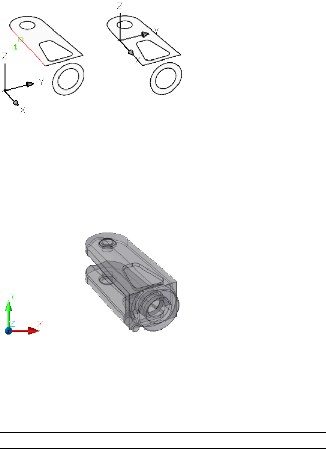
Previous
Restores the previous UCS.
You can steps back through the last 10 UCS settings in the current session.
UCS settings are stored independently for model space and paper space.
View
Aligns the XY plane of the UCS to a plane perpendicular to your viewing
direction. The origin point remains unchanged, but the X and Y axes become
horizontal and vertical.
World
Aligns the UCS with the world coordinate system (WCS).
The WCS is a fixed Cartesian coordinate system. All objects are defined by
their WCS coordinates, and the WCS and the UCS are coincident in a new
drawing. However, it is usually more convenient to create and edit objects
based on the UCS, which can be customized to suit your drawing or modeling
needs.
TIP You can also click the UCS icon and choose World from the origin grip menu.
X, Y, Z
Rotates the current UCS about a specified axis.
Point your right thumb in the positive direction of the X axis and curl your
fingers. Your fingers indicate the positive rotation direction about the axis.
Commands | 1075
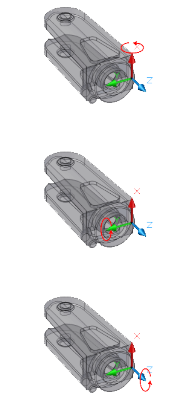
Point your right thumb in the positive direction of the Y axis and curl your
fingers. Your fingers indicate the positive rotation direction about the axis.
Point your right thumb in the positive direction of the Z axis and curl your
fingers. Your fingers indicate the positive rotation direction about the axis.
You can define any UCS by specifying an origin and one or more rotations
around the X, Y, or Z axis.
1076 | Chapter 2 Commands
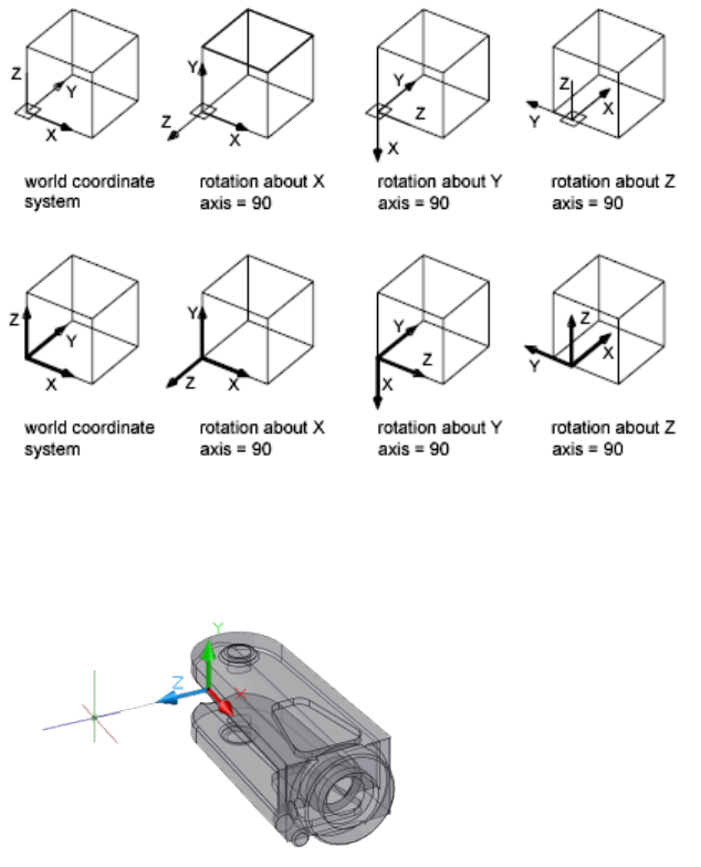
Z Axis
Aligns the UCS to a specified positive Z axis.
The UCS origin is moved to the first point and its positive Z axis passes through
the second point.
Object Aligns the Z axis tangent to the endpoint that is nearest to the specified
point. The positive Z axis points away from the object.
Apply
Applies the current UCS setting to a specified viewport or all active viewports
when other viewports have a different UCS saved in the viewport. (UCSVP
(page 1481) system variable).
Viewport Applies the current UCS to the specified viewport and ends the UCS
command.
Commands | 1077
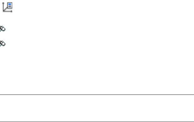
All Applies the current UCS to all active viewports.
See also:
Work with the User Coordinate System (UCS)
UCSSELECTMODE (page 1481)
UCSICON
Controls the visibility, placement, appearance, and selectability of the UCS
icon.
Access Methods
Button
Toolbar: Drafting tool set ➤ Coordinates tool group (expanded) ➤ UCS
Icon Properties
Menu: View ➤ Display ➤ UCS Icon ➤ Properties
Summary
The UCS icon indicates the location and orientation of the current UCS. You
can manipulate the UCS icon using grips. This is controlled by the UCSSELECT-
MODE (page 1481) system variable.
NOTE
If the location of the UCS origin is not visible in a viewport, the UCS icon is
displayed in the lower-left corner of the viewport instead.
Different coordinate system icons are displayed in paper space and model
space. In model space, you can choose between 2D and 3D icon display styles
(see the Properties (page 1080) option):
■2D. The letter W appears in the Y portion of the icon if the UCS is the
same as the WCS (world coordinate system). If the UCS is rotated so that
the Z axis lies in a plane parallel to the viewing plane—that is, if the XY
plane is edge-on to the viewer—the 2D UCS icon is replaced by a broken
pencil icon.
1078 | Chapter 2 Commands
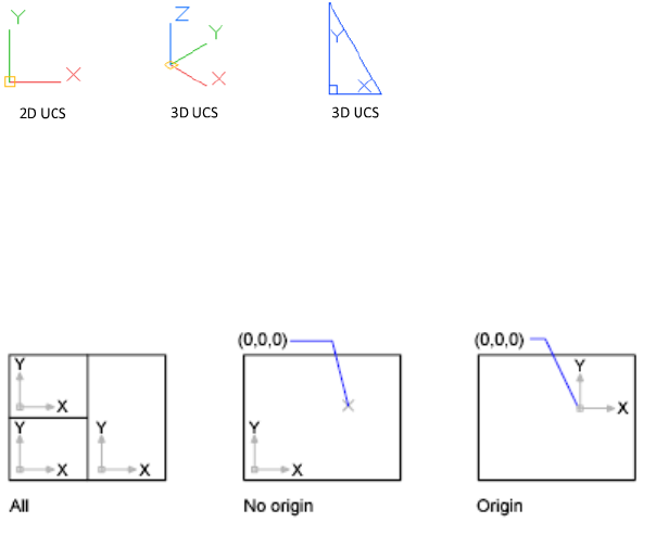
■3D. A square is displayed in the XY plane at the origin if the current UCS
is the same as the WCS, and you are viewing the UCS from above (the
positive Z direction). The square is missing if you are viewing the UCS
from below. The Z axis is solid when viewed from above the XY plane and
dashed when viewed from below the XY plane.
List of Prompts
The following prompts are displayed.
Enter an option [ON (page 1079)/OFF (page 1079)/All (page
1079)/Noorigin (page 1079)/ORigin (page 1079)/Selectable (page
1079)/Properties (page 1080)]<current>: Enter an option or press Enter
On Displays the UCS icon.
Off Turns off display of the UCS icon.
All Applies changes to the icon in all active viewports. Otherwise, UCSICON
affects only the current viewport.
No Origin Displays the icon at the lower-left corner of the viewport regardless
of the location of the UCS origin.
Origin Displays the icon at the origin (0,0,0) of the current UCS. If the origin
is out of view, it is displayed at the lower-left corner of the viewport.
Selectable Controls whether the UCS icon is selectable and can be manipulated
with grips.
Commands | 1079
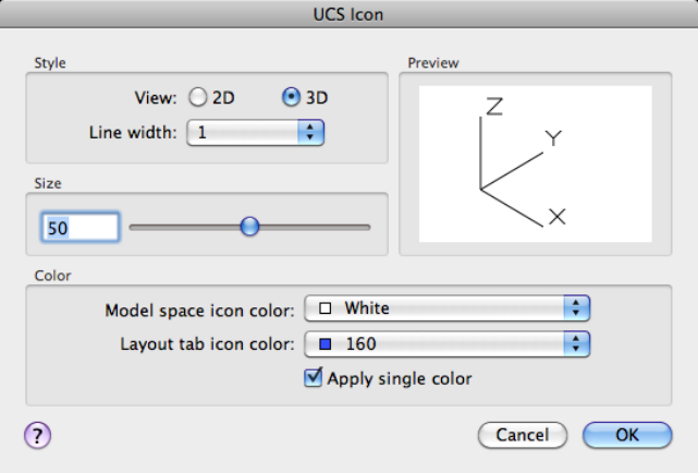
Properties Displays the UCS Icon dialog box (page 1080), in which you can
control the style, visibility, and location of the UCS icon.
See also:
Control the Display of the User Coordinate System Icon
UCS Icon Dialog Box
Controls the style, visibility, and location of the UCS icon.
List of Options
The following options are displayed.
Style
Specifies display of either the 2D or the 3D UCS icon and its appearance.
2D
Displays a 2D icon without a representation of the Z axis.
3D
Displays a 3D icon.
1080 | Chapter 2 Commands
Line Width
Controls the line width of the UCS icon if the 3D UCS icon is selected.
Preview
Displays a preview of the UCS icon in model space.
Size
Controls the size of the UCS icon as a percentage of viewport size. The default
value is 50, and the valid range is from 5 to 95. Note that the size of the UCS
icon is proportional to the size of the viewport in which it is displayed.
Color
Controls the colors of the UCS icon in model space viewports and in layout
tabs.
Model Space Icon Color
Controls the color of the UCS icon in model space viewports.
Layout Tab Icon Color
Controls the UCS icon color in layout tabs.
Apply Single Color Applies the selected Model space icon color to all axes of
the 2D UCS icon.
See also:
Control the Display of the User Coordinate System Icon
UCSMAN
Manages UCS definitions.
Access Methods
Button
Toolbar: Drafting tool set ➤ Coordinates tool group (expanded) ➤
Named UCS
Menu: Tools ➤ Named UCS
Commands | 1081
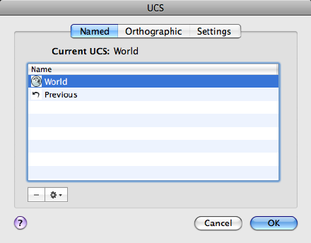
Summary
The UCS dialog box (page 1082) is displayed.
See also:
Work with the User Coordinate System (UCS)
UCS Dialog Box
Controls the UCS and UCS icon settings for viewports.
Summary
Lists, renames, and restores user coordinate system (UCS) definitions, and
controls UCS and UCS icon settings for viewports.
List of Tabs
The UCS dialog box includes the following tabs:
■Named (page ?)
■Orthographic (page ?)
■Settings (page ?)
Named Tab (UCS Dialog Box)
Lists UCS definitions and sets the current UCS.
1082 | Chapter 2 Commands
Current UCS
Displays the name of the current UCS. If the UCS has not been saved and
named, it is listed as UNNAMED.
UCS Names List
Lists the coordinate systems defined in the current drawing. If there are
multiple viewports and multiple unnamed UCS settings, the list includes only
the unnamed UCS of the current viewport. Unnamed UCS definitions that
are locked to other viewports (UCSVP (page 1481) system variable = 1) are not
listed in the current viewport. A pointer indicates the current UCS.
UNNAMED is always the first entry if the current UCS is unnamed. World is
always listed and cannot be renamed or deleted. If you define other coordinate
systems for the active viewport during the current editing session, a Previous
entry is next. You can step back through these coordinate systems by selecting
Previous and Set Current repeatedly.
To add a UCS name to this list, use the Save option of the UCS (page 1072)
command.
Delete (-) Deletes a named UCS. You cannot delete the World or Previous
UCS.
Options
Manages the selected UCS in the dialog box.
Set Current Restores the selected coordinate system.
Rename Renames a customized UCS. You cannot rename the World UCS.
Details Displays the UCS Details dialog box (page 1087), which displays UCS
coordinate data.
Changes the UCS to one of the orthographic UCS settings.
Commands | 1083
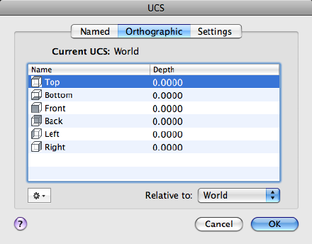
Current UCS
Displays the name of the current UCS. If the UCS has not been saved and
named, it is listed as UNNAMED.
Orthographic UCS Names
Lists the six orthographic coordinate systems defined in the current drawing.
The orthographic coordinate systems are defined relative to the UCS specified
in the Relative To list.
■Name. Specifies the name of the orthographic coordinate system.
■Depth. Specifies the distance between the XY plane of the orthographic
UCS and a parallel plane that passes through the origin of the coordinate
system specified by the UCSBASE (page 1477) system variable. The parallel
plane of the UCSBASE coordinate system can be an XY, YZ, or XZ plane.
NOTE You can specify the depth or a new origin for the selected orthographic
UCS. See Depth option.
Relative To
Specifies the base coordinate system for defining the orthographic UCSs. By
default, WCS is the base coordinate system.
Whenever you change the Relative To setting, the origin of the selected
orthographic UCS is restored to its default position.
If you save an orthographic coordinate system in a drawing as part of a
viewport configuration, or if you select a setting in Relative To other than
1084 | Chapter 2 Commands
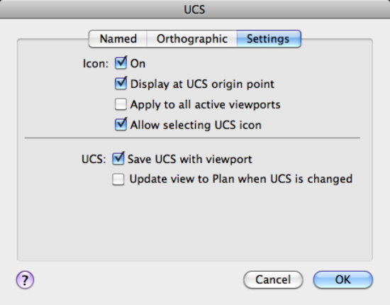
World, the orthographic coordinate system name changes to UNNAMED to
distinguish it from the predefined orthographic coordinate system.
Options
Manages the selected UCS in the dialog box.
Set Current Restores the selected coordinate system.
Reset Restores the origin of the selected orthographic coordinate system. The
origin is restored to its default location (0,0,0) relative to the specified base
coordinate system.
Depth Specifies the distance between the XY plane of the orthographic UCS
and a parallel plane that passes through the origin of the coordinate system.
In the Orthographic UCS Depth dialog box, enter a value or choose the Select
New Origin button to use the pointing device to specify a new depth or a new
origin.
Details Displays the UCS Details dialog box (page 1087), which displays UCS
coordinate data.
Settings Tab (UCS Dialog Box)
Displays and modifies UCS icon settings and UCS settings saved with a
viewport.
Commands | 1085
Icon
Specifies the UCS icon display settings for the current viewport.
On
Displays the UCS icon in the current viewport.
Display at UCS Origin Point
Displays the UCS icon at the origin of the current coordinate system in the
current viewport. If this option is cleared, or if the origin of the coordinate
system is not visible in the viewport, the UCS icon is displayed at the lower-left
corner of the viewport.
Apply to All Active Viewports
Applies the UCS icon settings to all active viewports in the current drawing.
Allow Selecting UCS Icon
Controls whether the UCS icon is highlighted when the cursor moves over it
and whether you can click to select it and access the UCS icon grips.
UCS
Specifies UCS behavior when the UCS setting is updated.
Save UCS with Viewport
Saves the coordinate system setting with the viewport (UCSVP (page 1481) system
variable). If this option is cleared, the viewport reflects the UCS of the viewport
that is current.
Update View to Plan When UCS Is Changed
Restores Plan view when the coordinate system in the viewport is changed.
(UCSFOLLOW (page 1478) system variable)
See also:
Work with the User Coordinate System (UCS)
Orthographic UCS Depth Dialog Box
Specifies the depth for an orthographic UCS.
Access Methods
Shortcut menu: On the Orthographic tab, click Options ➤ Depth.
1086 | Chapter 2 Commands
List of Options
The following options are displayed.
<Name> Depth
Specifies the distance between the XY plane of the orthographic UCS and a
parallel plane that passes through the origin of the coordinate system.
Select New Origin
Temporarily closes the dialog box so that you can use the pointing device to
specify a new depth location in the drawing.
To reset the origin of the selected orthographic UCSs to the default location
(0,0,0), click Options ➤ Reset.
See also:
Work with the User Coordinate System (UCS)
UCS Details Dialog Box
Displays information about the origin and axes of the selected UCS.
Access Methods
Shortcut menu: On the Named or Orthographic tab, click Options ➤
Details.
Summary
By default, the origin and the values for the X, Y, and Z axes are calculated
relative to the world coordinate system.
List of Options
The following options are displayed.
Name
Displays the name of the current named UCS.
Origin
Displays the UCS origin relative to the UCS selected in Relative To.
X Axis
Commands | 1087
Displays the values for the X axis relative to the UCS selected in Relative To.
Y Axis
Displays the values for the Y axis relative to the UCS selected in Relative To.
Z Axis
Displays the values for the Z axis relative to the UCS selected in Relative To.
Relative To
Sets a base coordinate system for calculating the values for Origin, X Axis, Y
Axis, and Z Axis. (UCSBASE (page 1477) system variable)
See also:
Work with the User Coordinate System (UCS)
UNDEFINE
Allows an application-defined command to override an internal command.
List of Prompts
The following prompts are displayed.
Enter command name:
Enter a command name to suppress that command. The suppressed command
name can then be redefined to perform some other function.
You can undefine only built-in AutoCAD commands. You cannot undefine
commands defined by AutoLISP®. This includes ObjectARX™ application
commands registered by acedDefun(). You also cannot undefine external
commands and aliases defined in the acad.pgp file.
If an AutoLISP or ObjectARX application has redefined a command with the
same name as a built-in AutoCAD command, the application-defined command
is active.
You can restore an undefined command with REDEFINE (page 868).
You can always access a built-in AutoCAD command by preceding the
command name with a period (.).
ObjectARX application commands that are registered by acedRegCmd can
be accessed by preceding the command name with a period (.), followed by
1088 | Chapter 2 Commands

the command's group name, followed by another period (.). For example, the
MTEXT command can be accessed with .acad_mtext.mtext.
To determine command names and groups of an ObjectARX application, use
the ARX (page 105) command, and choose the Commands option to see a
listing of all currently loaded ObjectARX commands and their group names.
See also:
Use Built-in Commands in Macros
UNDO
Reverses the effect of commands.
Summary
UNDO displays the command or system variable name at the Command
prompt to indicate that you have stepped past the point where the command
was used.
NOTE
UNDO has no effect on some commands and system variables, including those
that open, close, or save a window or a drawing, display information, change
the graphics display, regenerate the drawing, or export the drawing in a
different format.
List of Prompts
The following prompts are displayed.
Enter the number (page ?) of operations to undo or [Auto
(page ?)/Control (page ?)/BEgin/End (page ?)/Mark/Back
(page ?)]: Enter a positive number, enter an option, or press Enter to undo
a single operation
Number
Undoes the specified number of preceding operations. The effect is the same
as entering u multiple times.
Auto
Groups the commands in a macro, such as a menu macro, into a single action,
making them reversible by a single U (page 1071) command.
Commands | 1089

UNDO Auto is not available if the Control option has turned off or limited
the UNDO feature.
Control
Limits or turns off UNDO.
All Turns on the full UNDO command.
None Turns off the U and UNDO commands and discards any UNDO
command information saved earlier in the editing session. The Undo button
on the Standard toolbar is unavailable.
The Auto, Begin, and Mark options are not available when None or One is in
effect. If you attempt to use UNDO while it is turned off, the following prompt
is displayed:
Enter an UNDO control option [All/None/One/Combine/Layer] <All>:
One Limits UNDO to a single operation.
The Auto, Begin, and Mark options are not available when None or One is in
effect. The main prompt for the UNDO command changes to show that only
a Control option or a single step of the UNDO command is available when
the One option is in effect.
Combine Controls whether multiple, consecutive zoom and pan commands
are combined as a single operation for undo and redo operations.
NOTE
Pan and zoom commands that are started from the menu are not combined,
and always remain separate actions.
Layer Controls whether the layer dialog operations are combined as a single
undo operation.
Begin, End
Groups a sequence of actions into a set. After you enter the Begin option, all
subsequent actions become part of this set until you use the End option.
Entering undo begin while a group is already active ends the current set and
begins a new one. UNDO and U treat grouped actions as a single action.
If you enter undo begin without undo end, using the Number option
undoes the specified number of commands but does not back up past the
begin point. If you want to go back to before the begin point, you must use
the End option, even if the set is empty. The same applies to the U command.
A mark placed by the Mark option disappears inside an UNDO group.
1090 | Chapter 2 Commands

Mark, Back
Mark places a mark in the undo information. Back undoes all the work done
back to this mark. If you undo one operation at a time, you are informed when
you reach the mark.
You can place as many marks as necessary. Back moves back one mark at a
time, removing the mark. If no mark is found, Back displays the following
prompt:
This will undo everything. OK? <Y>: Enteryornor press Enter
Enter y to undo all commands entered in the current session. Enter n to ignore
the Back option.
When you use the Number option to undo multiple actions, UNDO stops if
it encounters a mark.
See also:
Correct Mistakes
Undocumented Command or System Variable
This command or system variable is not documented in the Help system for
one of several reasons, including
■It is obsolete, but included in the product to maintain legacy script
compatibility
■It was included for testing purposes and has limited or no functionality
Use Search to find additional information about the feature in which you are
interested, and the documented commands and system variables associated
with it.
UNGROUP
Disassociates the objects from a group.
Access Methods
Menu: Tools ➤ Ungroup
Commands | 1091

Summary
UNGROUP removes all objects from the current group.
The following prompts are displayed.
Select group or [Name]:
If a group contains sub-groups, you are prompted to Accept to ungroup the
current selection or choose Next to cycle through the groups in the selection
set.
See also:
Edit Groups
UNION
Combines selected 3D solids, surfaces, or 2D regions by addition.
Access Methods
Button
Ribbon:
Toolbar: Modeling tool set ➤ Solids - Edit tool group ➤ Booleans flyout
➤ Union
Summary
You can combine two or more 3D solids, surfaces, or 2D regions into a single,
composite 3D solid, surface, or region. You must select the same type of objects
to combine.
1092 | Chapter 2 Commands
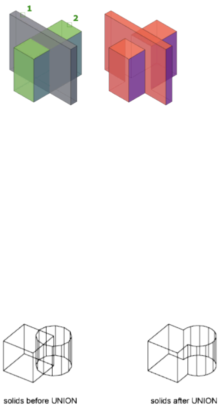
Using the Union Command with Surfaces
Although you can use the UNION command with surfaces, it will cause the
surface to lose associativity. Instead, it is recommended that you use the surface
editing commands:
■SURFBLEND (page 1013)
■SURFFILLET (page 1016)
■SURFPATCH (page 1021)
Using the Union Command with Solids and Regions
The selection set can contain objects that lie in any number of arbitrary planes.
For mixed object types, selection sets are divided into subsets that are joined
separately. Solids are grouped in the first subset. The first selected region and
all subsequent coplanar regions are grouped in the second set, and so on.
The resulting composite solid includes the volume enclosed by all of the
selected solids. Each of the resulting composite regions encloses the area of
all regions in a subset.
Commands | 1093
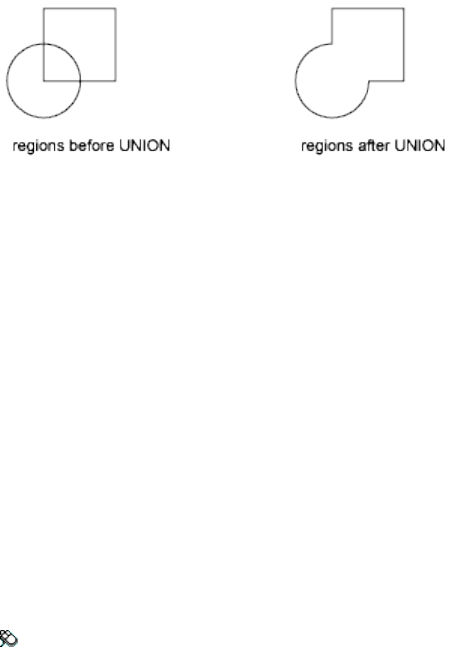
You cannot use UNION with mesh objects. However, if you select a mesh
object, you will be prompted to convert it to a 3D solid or surface.
List of Prompts
The following prompt is displayed.
Select objects Select the 3D solids, surfaces, or regions to be combined.
See also:
Create Composite Objects
UNISOLATEOBJECTS
Displays previously hidden objects.
Access Methods
Menu: Tools ➤ Isolate ➤ End Object Isolation
Shortcut menu: Right-click in the drawing area and click Isolate ➤ End
Object Isolation.
Summary
Displays objects previously hidden with the ISOLATEOBJECTS (page 532) or
HIDEOBJECTS (page 507) command.
See also:
Control the Display of Objects
1094 | Chapter 2 Commands

UNITS
Controls coordinate and angle display formats and precision.
Access Methods
Menu: Format ➤ Units
Command entry: 'units for transparent use
Summary
The format, precision, and other conventions to be used in displaying
coordinates, distances, and angles are set and saved in drawing template files.
These settings can also be changed in the current drawing file.
The Drawing Units dialog box (page 1095) is displayed.
If you enter -units at the Command prompt, options are displayed (page 1098).
See also:
Determine the Units of Measurement
Drawing Units Dialog Box
Controls the displayed precision and format for coordinates and angles.
Commands | 1095
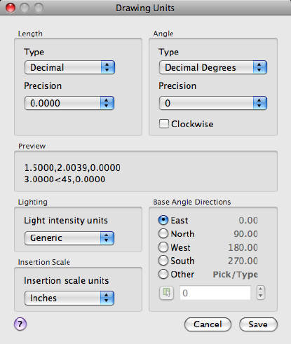
List of Options
The following options are displayed.
Length
Specifies the current unit of measurement and the precision for the current
units.
Type
Sets the current format for units of measure. The values include Architectural,
Decimal, Engineering, Fractional, and Scientific. The Engineering and
Architectural formats produce feet-and-inches displays and assume that each
drawing unit represents one inch. The other formats can represent any
real-world unit.
Precision
Sets the number of decimal places or fractional size displayed for linear
measurements.
1096 | Chapter 2 Commands

Angle
Specifies the current angle format and the precision for the current angle
display.
Type
Sets the current angle format.
Precision
Sets the precision for the current angle display.
The following conventions are used for the various angle measures: decimal
degrees appear as decimal numbers, grads appear with a lowercase g suffix,
and radians appear with a lowercase r suffix. The degrees/minutes/seconds
format uses d for degrees, ' for minutes, and " for seconds; for example:
123d45'56.7"
Surveyor's units show angles as bearings, using N or S for north or south,
degrees/minutes/seconds for how far east or west the angle is from direct north
or south, and E or W for east or west; for example:
N 45d0'0" E
The angle is always less than 90 degrees and is displayed in the
degrees/minutes/seconds format. If the angle is precisely north, south, east,
or west, only the single letter representing the compass point is displayed.
Clockwise
Calculates positive angles in the clockwise direction. The default direction for
positive angles is counterclockwise.
When prompted for an angle, you can point in the desired direction or enter
an angle regardless of the setting specified for Clockwise.
Preview
Displays an example of the current settings for units and angles.
Lighting
Controls the unit of measurement for the intensity of photometric lights in
the current drawing.
NOTE
In order to create and use photometric lights, a unit other than Generic must
be specified from the list of options. If Insertion Scale is set to Unitless, a
warning message is displayed informing you that the rendered output might
not be as expected.
Commands | 1097

Insertion Scale
Controls the unit of measurement for blocks and drawings that are inserted
into the current drawing. A block or a drawing that is created with units that
are different from the units specified with this option is scaled when inserted.
The insertion scale is the ratio of the units used in the source block or drawing
and the units used in the target drawing. Select Unitless to insert the block
without scaling it to match the specified units.
NOTE
In the Application Preferences dialog box, Units & Guides tab, the Source
Content Units and Target Drawing Units settings are used when, either in the
source block or the target drawing, Insertion Scale is set to Unitless.
Base Angle Directions
Sets the direction of the zero angle. The following options affect the entry of
angles, the display format, and the entry of polar, cylindrical, and spherical
coordinates.
East Specifies the compass direction east (the default).
North Specifies the compass direction north.
West Specifies the compass direction west.
South Specifies the compass direction south.
Other Specifies a direction different from the points of the compass.
Angle Specifies a value for the zero angle when Other is selected.
Pick an Angle Button Defines the zero angle in the graphics area based on
the angle of an imaginary line that connects any two points you specify with
the pointing device.
See also:
Determine the Units of Measurement
-UNITS
Controls coordinate and angle display formats and precision.
List of Prompts
The following prompts are displayed.
1098 | Chapter 2 Commands
Report formats: (Examples)
1. Scientific 1.55E+01
2. Decimal 15.50
3. Engineering 1'-3.50"
4. Architectural 1'-3 1/2"
5. Fractional 15 1/2
Enter choice, 1 to 5 <current>: Enter a value (1-5) or press Enter
The following prompt for decimal precision is displayed if you specify the
scientific, decimal, or engineering format:
Enter number of digits to right of decimal point (0 to 8)
<current>: Enter a value (0-8) or press Enter
The following prompt for the denominator of the smallest fraction is displayed
if you specify the architectural or fractional format.
Enter denominator of smallest fraction to display
(1, 2, 4, 8, 16, 32, 64, 128, or 256) <current>: Enter a value (1,
2, 4, 8, 16, 32, 64, 128, or 256) or press Enter
The next prompt is for angle formats and precision:
Systems of angle measure: (Examples)
1. Decimal degrees 45.0000
2. Degrees/minutes/seconds 45d0'0"
3. Grads 50.0000g
4. Radians 0.7854r
5. Surveyor's units N 45d0'0" E
Enter choice, 1 to 5 <current>: Enter a value (1-5) or press Enter
Enter number of fractional places for display of angles (0
to 8) <current>: Enter a value (0-8) or press Enter
The next prompt is for the direction for angle 0:
Direction for angle 0:
East 3 o'clock = 0
North 12 o'clock = 90
West 9 o'clock = 180
South 6 o'clock = 270
Enter direction for angle 0 <current>: Enter a value or press Enter
The default direction for 0 degrees is to the east quadrant, or 3 o'clock. The
default direction for positive angular measurement is counterclockwise.
Measure angles clockwise? [Yes/No] <current>: Enter y or n or press
Enter
Commands | 1099
See also:
Determine the Units of Measurement
UPDATEFIELD
Manually updates fields in selected objects in the drawing.
Access Methods
Button
Toolbar: Annotation tool set ➤ Fields tool group ➤ Update Fields
Menu: Tools ➤ Update Fields
Shortcut menu: With any text command active and a field selected,
right-click and click Update Field.
Summary
You can update a field manually when you want to see the latest value. With
Date fields, you must update them manually, they never update automatically.
See also:
Update Fields
UPDATETHUMBSNOW
Manually updates thumbnail previews for named views, drawings, and layouts.
Summary
The UPDATETHUMBNAIL (page 1484) system variable controls how the
thumbnail previews are updated. The UPDATETHUMBSNOW command
updates the following:
■Sheets, sheet views, and model space views thumbnails in the Sheet Set
Manager
■Quick View images
1100 | Chapter 2 Commands
NOTE
The thumbnail previews displayed in the Sheet Set Manager are not available
in AutoCAD for Mac. This command is made available for use in mixed
environments.
See also:
Switch Between Open Drawings
UPLOADTOWS
Uploads the current drawing file to AutoCAD WS.
Access Methods
Menu: File ➤ Upload Drawing Online
Summary
If you are not logged into AutoCAD WS, the Login to AutoCAD WS dialog
box (page 1101) is displayed prior to the drawing file being uploaded.
The Upload Complete dialog box is displayed when the drawing file is
successfully uploaded.
NOTE Prior to uploading a drawing file, you need to log into AutoCAD WS. If you
do not have an account, click the First Time User? Create an Account link and
follow the on screen instructions.
For additional information and tutorials on how to use AutoCAD WS, see
www.autocadws.com.
See also:
Use AutoCAD WS for Drawing File Collaboration
Login to AutoCAD WS Dialog Box
Allows you to log in to AutoCAD WS and upload the current drawing file.
Commands | 1101
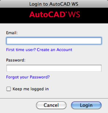
List of Options
The following options are displayed.
Email
Enter the e-mail address associated with your AutoCAD WS account.
First Time User? Create an Account
Launches your default Web browser and displays the Create an AutoCAD WS
Account page on www.autocadws.com.
Password
Enter the password for your account.
Forgot Your Password?
Launches your default Web browser and displays the AutoCAD WS Home
page where you can request the password for your account.
Keep Me Logged In
The account information you enter is retained for the next time you go to
upload a drawing to AutoCAD WS.
Login
Logs you into AutoCAD WS and begins the upload process for the drawing.
See also:
Use AutoCAD WS for Drawing File Collaboration
1102 | Chapter 2 Commands
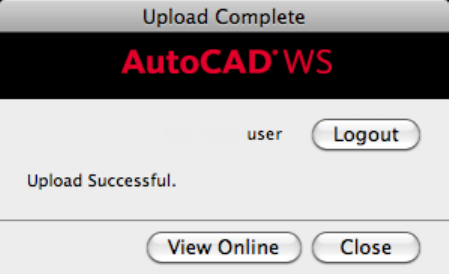
Upload Complete Dialog Box
Displays the current status of the drawing being uploaded to AutoCAD WS.
List of Options
The following options are displayed.
User Name
Displays the user name of the account currently logged in.
Logout
Logs the current user out and displays the Login to AutoCAD WS dialog box
(page 1101).
Upload Status
Displays the current status of the drawing being uploaded: Upload Successful,
Upload Failed, or Uploading.
View Online
Launches your default Web browser and displays the AutoCAD WS website
(www.autocadws.com).
See also:
Use AutoCAD WS for Drawing File Collaboration
Commands | 1103

V Commands
VIEW
Saves and restores named model space views, layout views, and preset views.
Summary
The options are displayed at the Command prompt, options are displayed
(page 1104). If you enter -view at the Command prompt, the options are
displayed at the Command prompt as well.
NOTE
The VIEW command cannot be used transparently.
See also:
Save and Restore Views
-VIEW
List of Prompts
The following prompts are displayed.
Enter an option [?(page 1104)/Delete (page 1104)/Orthographic
(page 1104)/Restore (page 1105)/Save (page 1105)/sEttings (page
1105)/Window (page 1106)]:
?—List Views The list includes the name of each specified view and the space
in which it was defined. M designates model space, and P designates paper
space.
Delete Deletes one or more named views.
Orthographic Restores the predefined orthographic view you specify to the
current viewport.
1104 | Chapter 2 Commands
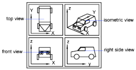
The view orientation of the specified orthographic view is based on the UC-
SBASE (page 1477) system variable, which is set to the world coordinate system
by default. When one of the orthographic views is restored, the program zooms
to the extents in the current viewport.
Restore Restores the view you specify to the current viewport. If a UCS setting
was saved with the view, it is also restored.
The center point and magnification of the saved view are also restored. If you
restore a model space view while working in paper space, you are prompted
to select a viewport in which to restore that view.
Select the viewport by clicking its border. The viewport you select must be on
and active. The program switches to model space and restores the view in the
selected viewport.
If you restore a paper space view while working in model space in a layout
tab, the program switches to paper space and restores the view. You can't
restore a paper space view if you are working in the Model tab.
Save Saves the display in the current viewport using the name you supply.
The current value of the UCSVIEW (page 1481) system variable is displayed when
you save a view. To change the setting and turn this option on or off, use the
UCS option of VIEW.
Settings Specifies various settings for the VIEW command.
Background Specifies background the for view. Backgrounds are visible in a
3D visual style only.
Categorize Specifies a category for the named view.
Layer Snapshot Saves the current layer visibility settings with the new named
view.
Live Section For model views only, specifies the live section applied when
the view is restored.
Commands | 1105
UCS Determines whether the current UCS and elevation settings are saved
when a view is saved. (UCSVIEW (page 1481) system variable)
Visual Style Sets or updates a visual style for a view.
Window Saves a portion of the current display as a view.
Restoring such a view may display objects outside the window you specified
because the shape of the window may differ from that of the viewport in
which you are restoring the view. However, plotting the view plots only the
objects inside the window, not the entire viewport display.
See also:
Save and Restore Views
VIEWPLOTDETAILS
Displays information about completed print and publish jobs.
Summary
The Print Details dialog box (page 1106) is displayed.
You can view detailed information about all completed print jobs, or just the
errors that have occurred. You can also copy the information displayed in the
dialog box to the Clipboard.
See also:
Overview of Plotting
Print Details Dialog Box
Displays information about plotting and publishing jobs that have been
completed in the current session.
1106 | Chapter 2 Commands
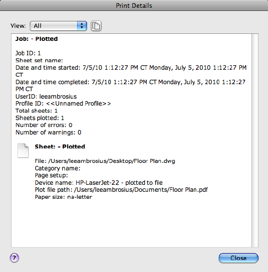
List of Options
The following options are displayed.
View
Specifies what is displayed. You can also right-click in the details area and
click View Errors Only or View All to change this setting.
All Displays information about all completed print and publish jobs and sheets
within those jobs.
Errors Lists errors that have occurred as jobs were printed or published.
Copy to Clipboard
Copies all highlighted text to the Clipboard.
Details Area
Lists details of completed print and publish jobs.
Commands | 1107
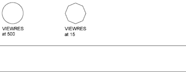
See also:
Overview of Plotting
VIEWRES
Sets the resolution for objects in the current viewport.
Summary
The model is regenerated.
VIEWRES controls the appearance of circles, arcs, splines, and arced polylines
using short vectors. The greater the number of vectors, the smoother the
appearance of the circle or arc. For example, if you create a very small circle
and then zoom in, it might appear to be a polygon. Using VIEWRES to increase
the zoom percentage and regenerate the drawing updates and smooths the
circle's appearance.
NOTE
Increasing the zoom percentage in VIEWRES may increase the time it takes
to regenerate the drawing.
When a named (paper space) layout is made current for the first time and a
default viewport is created in the layout, the viewing resolution for this initial
viewport is the same as the viewing resolution for the Model layout viewport.
The VIEWRES setting is saved in the drawing. To change the default for new
drawings, consider specifying the VIEWRES setting in the template files on
which you base your new drawings.
See also:
Change Views
1108 | Chapter 2 Commands
VISUALSTYLES (-VISUALSTYLES)
Creates and modifies visual styles from the command line.
List of Prompts
The following prompts are displayed.
Enter an option [set Current (page ?)/Saveas (page ?)/Rename
(page ?)/Delete (page ?)/?(page ?)]:
Set Current
These options are the same as the options in VSCURRENT (page 1124).
Save As
Saves the visual style with the name you specify.
NOTE
You must be in model space to save a visual style. If you enter a name that is
already in use for a visual style, you can either replace the existing visual style
or enter a different name.
Rename
Renames a visual style.
Delete
Deletes a visual style.
?—List Visual Styles
Lists the visual styles in the drawing.
See also:
Use a Visual Style to Display Your Model
VPCLIP
Clips layout viewport objects and reshapes the viewport border.
Access Methods
Menu: Modify ➤ Clip ➤ Viewport
Shortcut menu: Select the viewport to clip. Right-click in the drawing area
and choose Viewport Clip.
Commands | 1109
Summary
You can either select an existing object to designate as the new boundary, or
specify the points of a new boundary. The new boundary does not clip the
old boundary, it redefines it.
List of Prompts
The following prompts are displayed.
Clipping Object Specifies an object to act as a clipping boundary. Objects
that are valid as clipping boundaries include closed poly-lines, circles, ellipses,
closed splines, and regions.
Polygonal Draws a clipping boundary. You can draw line segments or arc
segments by specifying points. The following prompt is displayed:
The descriptions of the Next Point, Arc, Close, Length, and Undo options
match the descriptions of the corresponding options in the PLINE (page 785)
command.
Delete Deletes the clipping boundary of a selected viewport. This option is
available only if the selected viewport has already been clipped. If you clip a
viewport that has been previously clipped, the original clipping boundary is
deleted, and the new clipping boundary is applied.
See also:
Create and Modify Layout Viewports
VPLAYER
Sets layer visibility within viewports.
List of Prompts
The following prompts are displayed.
Enter an option [?(page ?)/Color (page ?)/Ltype (page
?)/LWeight (page ?)/PStyle (page ?)/TRansparency (page
?)/Freeze (page ?)/Thaw (page ?)/Reset (page ?)/Newfrz
(page ?)/Vpvisdflt (page ?)]:
In the Model layout, the VPLAYER command has two options.
Enter an option [Newfrz (page ?)/Vpvisdflt (page ?)]:
1110 | Chapter 2 Commands
?—List Frozen Layers
Displays the names of frozen layers in a selected viewport.
Color
Changes the color associated with a layer.
True Color Specifies a true color to use for the selected object.
Color Book Specifies a color from a loaded color book to use for the selected
object.
All Applies the changes in all viewports.
Select Applies the changes in selected viewports.
Current Applies the changes in the current viewport only.
Ltype
Changes the linetype associated with a layer.
■All (page 1111)
■Select (page 1111)
■Current (page 1111)
Lweight
Changes the lineweight associated with a layer.
If you enter a lineweight that is not valid, the current lineweight is set to the
nearest fixed lineweight value.
■All (page 1111)
■Select (page 1111)
■Current (page 1111)
Pstyle
Sets the plot style assigned to a layer. This option is not available if you are
using color-dependent plot styles in the current drawing (the PSTYLEPOLICY
(page 1410) system variable is set to 1). See Use Plot Styles to Control Plotted
Objects in the User’s Guide.
■All (page 1111)
■Select (page 1111)
■Current (page 1111)
Commands | 1111
Transparency
Changes the transparency level associated with a layer.
■All (page 1111)
■Select (page 1111)
■Current (page 1111)
Freeze
Freezes a layer or set of layers in one or more viewports. Objects on frozen
layers are not displayed, regenerated, or plotted.
■All (page 1111)
■Select (page 1111)
■Current (page 1111)
Thaw
Thaws layers in specific viewports.
■All (page 1111)
■Select (page 1111)
■Current (page 1111)
Reset
Sets the visibility of layers in specified viewports to their current default setting.
■All (page 1111)
■Select (page 1111)
■Current (page 1111)
Newfrz (New Freeze)
Creates new layers that are frozen in all viewports.
Vpvisdflt (Viewport Visibility Default)
Thaws or freezes the specified layers in subsequently created viewports.
See also:
Freeze Specified Layers in a Layout Viewport
1112 | Chapter 2 Commands
VPMAX
Expands the current layout viewport for editing.
Access Methods
Toolbar: Status bar ➤ Maximize Viewport
Pointing device: Viewport Control menu (+) ➤ Maximize Viewport
Shortcut menu: Select a named layout viewport to maximize. Right-click
and click Maximize Viewport.
Pointing device: Double-click a named layout viewport.
Summary
The viewport is expanded to fill the screen and switched to model space for
editing.
See also:
Access Model Space from a Layout Viewport
VPMIN
Restores the current layout viewport.
Access Methods
Toolbar: Status bar ➤ Minimize Viewport
Pointing device: Viewport Control menu (+) ➤ Restore Layout
Shortcut menu: Select a named layout viewport to maximize. Right-click
and click Minimize Viewport.
Pointing device: Double-click outside of the maximized viewport.
Summary
The center point and magnification are returned to the settings that were in
effect before the viewport was maximized.
Commands | 1113
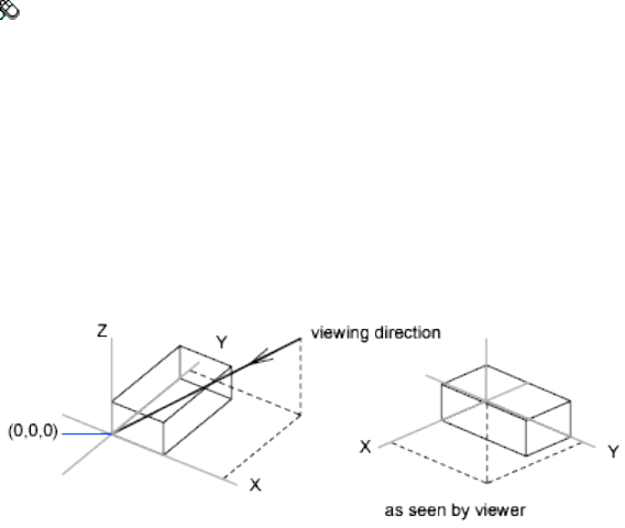
See also:
Access Model Space from a Layout Viewport
VPOINT
Sets the viewing direction for a 3D visualization of the drawing.
Access Methods
Menu: View ➤ 3D Views ➤ Viewpoint
List of Prompts
The following prompts are displayed.
Specify a view point (page 1114) or [Rotate (page 1114)] <display
compass and tripod (page 1115)>: Specify a point, enter r, or press Enter
to display a compass and axis tripod
View Point Creates a vector that defines a direction from which the drawing
can be viewed. The view defined is as if the viewer is looking from the point
back at the origin (0,0,0).
Rotate Specifies a new viewing direction using two angles.
■Enter angle in XY plane from X axis.
The first angle is specified with respect to the X axis, in the XY plane.
■Enter angle from XY plane.
The second angle is specified up or down from the XY plane.
1114 | Chapter 2 Commands

Compass and Axis Tripod Displays a compass and axis tripod, which you
use to define a viewing direction in the viewport.
The compass is a two-dimensional representation of a globe. The center point
is the north pole (0,0,n), the inner ring is the equator (n,n,0), and the entire
outer ring is the south pole (0,0,-n).
As you move the crosshairs, the axis tripod rotates to conform to the viewing
direction indicated on the compass. To select a viewing direction, move your
pointing device to a location on the globe and click.
See also:
Define a 3D View with Coordinate Values or Angles
VPORTS
Creates multiple viewports in model space or paper space.
Access Methods
Menu: View ➤ Viewports ➤ New Viewports, Named Viewports
Shortcut menu: Right-click the drawing area when a named layout is current
and click Viewports ➤ Named Viewports, New Viewports
Commands | 1115
Summary
The Viewports dialog box (page 1116) is displayed.
If you enter -vports at the Command prompt, options are displayed (page
1119).
See also:
Set Model Space Viewports
Viewports Dialog Box
Creates new viewport configurations, or names and saves a model space
viewport configuration.
Summary
The options available depend on whether you are configuring model space
viewports (on the Model layout) or layout viewports (on a named (paper space)
layout).
List of Options
The following options are displayed.
New Viewports Tab—Model Space (Viewports Dialog Box)
Setup options for 2D and 3D views, and default view settings can be specified.
In model space, viewport configurations can be saved by name.
1116 | Chapter 2 Commands
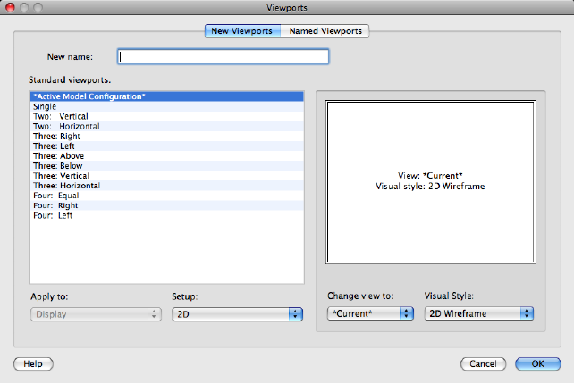
New Name
Specifies a name for the new model space viewport configuration. If you do
not enter a name, the viewport configuration is applied but not saved. If a
viewport configuration is not saved, it cannot be used in a layout.
Standard Viewports
Lists and sets the standard viewport configurations, including CURRENT,
which is the current configuration.
Preview
Displays a preview of the viewport configuration you select and the default
views assigned to each individual viewport in the configuration.
Apply To
Applies the model space viewport configuration to the entire display or to the
current viewport.
■Display: Applies the viewport configuration to the entire Model tab display.
■Current Viewport: Applies the viewport configuration to the current viewport
only.
Setup
Commands | 1117
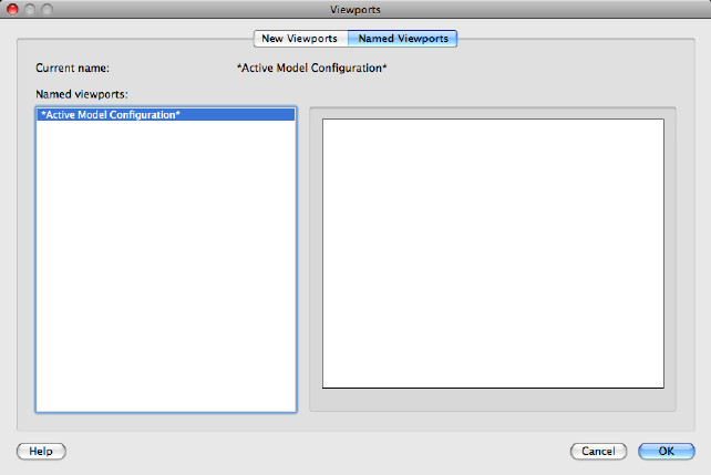
Specifies either a 2D or a 3D setup. When you select 2D, the new viewport
configuration is initially created with the current view in all of the viewports.
When you select 3D, a set of standard orthogonal 3D views is applied to the
viewports in the configuration.
Change View To
Replaces the view in the selected viewport with the view you select from the
list. You can choose a named view, or if you have selected 3D setup, you can
select from the list of standard views. Use the Preview area to see the choices.
Visual Style
Applies a visual style to the viewport. All available visual styles are displayed.
Named Viewports Tab—Model Space (Viewports Dialog Box)
Lists all saved model viewport configurations in the drawing.
Previously saved arrangements of viewports can be restored by name. These
viewport configurations can be defined in custom drawing template (DWT)
files for convenient access.
Current Name
Displays the name of the current viewport configuration.
1118 | Chapter 2 Commands
New Viewports Tab—Layouts (Viewports Dialog Box)
Standard Viewports Displays a list of standard viewport configurations and
configures layout viewports.
Preview Displays a preview of the viewport configuration you select and the
default views assigned to each individual viewport in the configuration.
Viewport Spacing
Specifies the spacing you want to apply between the layout viewports you are
configuring.
Setup Specifies either a 2D or a 3D setup. When you select 2D, the new
viewport configuration is initially created with the current view in all of the
viewports. When you select 3D, a set of standard orthogonal 3D views is
applied to the viewports in the configuration.
Change View To Replaces the view in the selected viewport with the view
you select from the list. You can choose a named view, or if you have selected
3D setup, you can select from the list of standard views.
Named Viewports Tab—Layouts (Viewports Dialog Box)
Displays any saved and named model space viewport configurations for you
to use in the current layout. You cannot save and name a layout viewport
configuration.
See also:
Set Model Space Viewports
-VPORTS
Creates multiple viewports in model space or paper space.
Summary
The command prompts available depend on whether you are configuring
model viewports (page 1120) (on the Model tab) or layout viewports (page 1121)
(on a layout tab).
See also:
Set Model Space Viewports
Commands | 1119
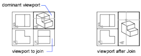
-VPORTS - Model Space Viewports
Creates multiple viewports in model space.
Summary
The number and layout of active viewports and their associated settings are
called viewport configurations.
List of Prompts
The following prompts are displayed.
Enter an option [Save (page 1120)/Restore (page 1120)/Delete
(page 1120)/Join (page 1120)/Single (page 1120)/?(page 1121)/2(page
1121)/3(page 1121)/4(page 1121)] <3>: Enter an option
Save Saves the current viewport configuration using a specified name.
Restore Restores a previously saved viewport configuration.
Delete Deletes a named viewport configuration.
Join Combines two adjacent model viewports into one larger viewport.
The two model viewports must share a common edge of the same length. The
resulting viewport inherits the view of the dominant viewport.
Single Returns the drawing to a single viewport view, using the view from the
current viewport.
1120 | Chapter 2 Commands
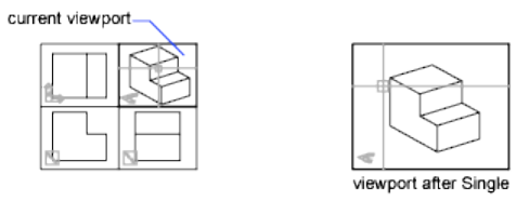
?—List Viewport Configurations Displays the identification numbers and
screen positions of the active viewports.
The lower-left and upper-right corners of the viewport define its location. For
these corners, values between 0.0,0.0 (for the lower-left corner of the drawing
area) and 1.0,1.0 (for the upper-right corner) are used. The current viewport
is listed first.
2 Divides the current viewport in half.
3 Divides the current viewport into three viewports.
The Horizontal and Vertical options split the area into thirds. The Above,
Below, Left, and Right options specify where the larger viewport is placed.
4 Divides the current viewport into four viewports of equal size.
See also:
Set Model Space Viewports
-VPORTS - Layout Viewports
Creates multiple viewports in named (paper space) layouts.
Access Methods
Shortcut menu: Right-click in drawing area when a named layout is current
and click Viewports ➤ 1 Viewport, 2 Viewports, 3 Viewports, 4 Viewports,
Polygonal Viewport, Object, Join
Summary
The number and layout of active viewports and their associated settings are
called viewport configurations.
Commands | 1121
List of Prompts
The following prompts are displayed.
Specify corner of viewport or [ON (page 1122)/OFF (page 1122)/Fit
(page 1122)/Shadeplot (page 1122)/Lock (page 1122)/Object (page
1122)/Polygonal (page 1122)/Restore (page 1123)/LAyer (page 1123)/2
(page 1123)/3(page 1123)/4(page 1123)] <Fit>: Specify a point or enter
an option
On Turns on a viewport, making it active and making its objects visible.
Off Turns off a viewport. When a viewport is off, its objects are not displayed,
and you cannot make that viewport current.
Fit Creates one viewport that fills the available display area. The actual size
of the viewport depends on the dimensions of the paper space view.
Shadeplot Specifies how viewports in layouts are plotted.
■As Displayed: Plots the same way it is displayed
■Wireframe: Plots wireframe regardless of display
■Hidden: Plots with hidden lines removed regardless of display
■Visual Styles: Plots using the specified visual style; all visual styles in the
drawing are listed as options whether in use or not
■Render Presets: Plots using the specified render preset; all render presets are
listed as options
Lock Locks the current viewport. This is similar to layer locking.
Object Creates a non-rectangular layout viewport from a closed polyline,
ellipse, spline, region, or circle. The polyline you specify must be closed and
contain at least three vertices. It can be self-intersecting, and it can contain
arcs as well as line segments.
It is important to create layout viewports on their own layer. When you are
ready to plot, you can turn off the layer and plot the layout without plotting
the boundaries of the layout viewports.
Polygonal Creates a non-rectangular layout viewport defined by a series of
line and arc segments.
The descriptions of the Next Point, Arc, Close, Length, and Undo options
match the descriptions of the corresponding options in the PLINE (page 785)
command.
1122 | Chapter 2 Commands
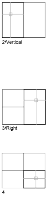
It is important to create layout viewports on their own layer. When you are
ready to plot, you can turn off the layer and plot the layout without plotting
the boundaries of the layout viewports.
Restore Restores a previously saved viewport configuration.
Layer Resets layer property overrides for the selected viewport to their global
layer properties.
2 Divides the current viewport in half.
3 Divides the current viewport into three viewports.
Horizontal and Vertical split the area into thirds. The other options create one
large viewport in half the available area and two smaller ones in the other
half. Above, Below, Left, and Right specify where the larger viewport is placed.
4 Divides the current viewport into four viewports of equal size.
See also:
Create and Modify Layout Viewports
Commands | 1123

VSCURRENT
Sets the visual style in the current viewport.
List of Prompts
The following prompts are displayed.
Enter an option [2dwireframe (page 1124)/Wireframe (page
1124)/Hidden (page 1124)/Realistic (page 1124)/Conceptual (page
1124)/Shaded (page 1124)/shaded with Edges (page 1124)/shades of
Gray (page 1124)/SKetchy (page 1124)/X-ray (page 1124)/Other (page
1125)] <2dwireframe>:
NOTE
To display lighting from point lights, distant lights, spotlights, or the sun, set
the visual style to Realistic, Conceptual, or a custom visual style with shaded
objects.
2D Wireframe
Wireframe Displays the objects using lines and curves to represent the
boundaries. Displays a shaded 3D UCS icon. You can set the COMPASS system
variable to 1 to view the compass.
Hidden Displays the objects using 3D wireframe representation and hides
lines representing back faces.
Realistic Shades the objects and smooths the edges between polygon faces.
Materials that you have attached to the objects are displayed.
Conceptual Shades the objects and smooths the edges between polygon faces.
Shading uses a transition between cool and warm colors. The effect is less
realistic, but it can make the details of the model easier to see.
Shaded Produces a smooth shaded model.
Shaded with Edges Produces a smooth shaded model with visible edges.
Shades of Gray Produces a gray color effect by using the monocolor face color
mode.
Sketchy Produces a hand-sketched effect by using the overhang and jitter.
X-ray Changes the opacity of faces to make the whole scene partially
transparent.
1124 | Chapter 2 Commands
Other Displays the following prompt:
Enter a visual style name [?]: Enter the name of a visual style in the current drawing,
or enter ? to display a list of names and repeat the prompt
See also:
Use a Visual Style to Display Your Model
VSSAVE
Saves a visual style.
List of Prompts
The following prompts are displayed.
Save current visual style as or [?]
Enter a name or enter ? to list all the visual styles in the drawing.
NOTE
You must be in model space to save a visual style. If you enter a name that is
already in use for a visual style, you can either replace the existing visual style
or enter a different name.
See also:
Use a Visual Style to Display Your Model
W Commands
WBLOCK
Saves selected objects or converts a block to a specified drawing file.
Access Methods
Button
Commands | 1125

Toolbar: Drafting tool set ➤ Block tool group (expanded) ➤ Write Block
Summary
The Write Block dialog box (page 1126) is displayed.
Entering -wblock at the Command prompt displays a standard file selection
dialog box in which to specify a name for the new drawing file, followed by
command prompts (page 1129). If FILEDIA (page 1296) is set to 0, the standard
file selection dialog box is suppressed.
See also:
Create Drawing Files for Use as Blocks
Write Block Dialog Box
Saves objects or converts a block to a file.
1126 | Chapter 2 Commands
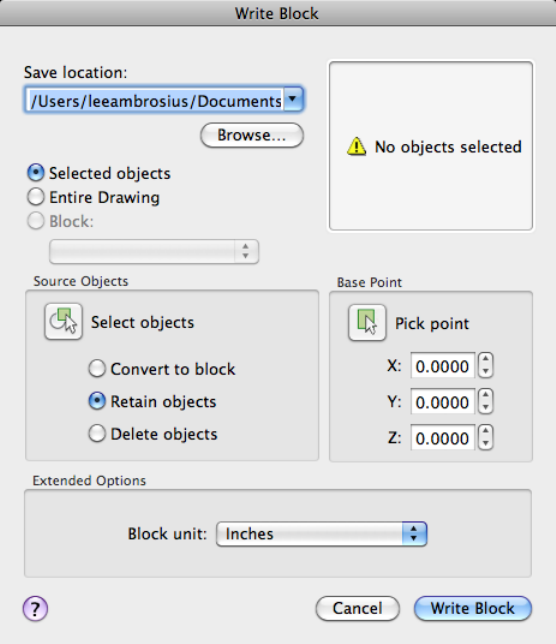
Summary
The Write Block dialog box displays different default settings depending on
whether nothing is selected, a single block is selected, or objects other than
blocks are selected.
List of Options
The following options are displayed.
Save Location
Specifies the new name and location of the file and the units of measurement
to be used when the block is inserted.
File Name and Path
Commands | 1127
Specifies a file name and path where the block or objects will be saved.
Browse
Displays a standard file selection dialog box (page 720).
Preview
Displays a preview of the objects selected to be written to a drawing file.
Creation
Specifies blocks and objects, saves them as a file, and specifies insertion points.
Selected Objects
Selects objects to save as a file. Specify a base point and select objects below.
Entire Drawing
Selects current drawing to save as another file.
Block
Specifies an existing block to save as a file. Select a name from the list.
Source Objects
Sets the effect of block creation on objects used to create a block.
Select Objects Button
Temporarily closes the dialog box so that you can select one or more objects
to save to the file.
Convert to Block
Converts the selected object or objects to a block in the current drawing after
saving them as a file.
Retain objects
Retains the selected objects in the current drawing after saving them as a file.
Delete objects
Deletes the selected objects from the current drawing after saving them as a
file.
Base Point
Specifies a base point for the block. The default value is 0,0,0.
Pick Point
Temporarily closes the dialog box so that you can specify an insertion base
point in the current drawing.
1128 | Chapter 2 Commands
X
Specifies the X coordinate value for the base point.
Y
Specifies the Y coordinate value for the base point.
Z
Specifies the Z coordinate value for the base point.
Extended Options
Blocks Unit
Specifies the unit value to be used for automatic scaling when the new file is
inserted as a block in a drawing that uses different units. Select Unitless if you
do not want to automatically scale the drawing when you insert it. See IN-
SUNITS (page 1335).
See also:
Create Drawing Files for Use as Blocks
-WBLOCK
Saves selected objects or converts a block to a specified drawing file.
Summary
If FILEDIA (page 1296) is set to 1, entering -wblock at the Command prompt
displays a standard file selection dialog box in which to specify a name for
the new drawing file. If FILEDIA is set to 0, entering -wblock at the Command
prompt displays a prompt. The new drawing is saved in the file format that
is specified in Save As on the Open and Save tab in the Options dialog box.
After the file is created, the selected objects are deleted from the drawing. You
can use OOPS (page 719) to restore the objects.
In the new drawing, the world coordinate system (WCS) is set parallel to the
user coordinate system (UCS).
List of Prompts
The following prompts are displayed.
Enter name of output file:
Enter name of existing block or
Commands | 1129

[= (block=output file)/* (whole drawing)] <define new
drawing>:
Existing Block Writes that block to a file. You cannot enter the name of an
external reference (xref) or one of its dependent blocks.
= Specifies that the existing block and the output file have the same name.
* Writes the entire drawing to the new output file, except for unreferenced
symbols. Model space objects are written to model space, and paper space
objects are written to paper space.
See also:
Create Drawing Files for Use as Blocks
WEBLIGHT
Creates a web light.
Access Methods
Button
Toolbar: Modeling tool set ➤ Lights tool group (expanded) ➤ Weblight
List of Prompts
The following prompts are displayed.
Specify source location <0,0,0>: Enter coordinate values or use the
pointing device
Specify target location <1,1,1>: Enter coordinate values or use the
pointing device
1130 | Chapter 2 Commands

Enter an option to change [Name (page ?)/Intensity factor
(page ?)/Status (page ?)/Photometry (page ?)/weB (page
?)/shadoW (page ?)/filterColor (page ?)/eXit (page ?)]
<eXit>:
NOTE
The LIGHTINGUNITS system variable must be set to a value other than 0 to
create and use weblights.
Name
Specifies the name of the light.
Intensity Factor
Sets the intensity or brightness of the light.
Status
Turns the light on and off. If lighting is not enabled in the drawing, this setting
has no effect.
Photometry
Photometry is available when the LIGHTINGUNITS system variable is set to
1 or 2. Photometry is the measurement of the luminous intensities of visible
light sources.
In photometry, luminous intensity is a measure of the perceived power emitted
by a light source in a particular direction. Luminous flux is the perceived
power in per unit of solid angle. The total luminous flux for a lamp is the
perceived power emitted in all directions. Luminance is the total luminous
flux incident on a surface, per unit area.
Intensity Enter an intensity value in candelas, the perceived power in a
luminous flux value, or illuminance value for the total luminous flux incident
on a surface.
■Candela (symbol: cd) is the SI unit of luminous intensity (perceived power
emitted by a light source in a particular direction). Cd/Sr
■Lux (symbol: lx) is the SI unit of illuminance. Lm/m^2
■Foot-candle (symbol: fc) is the American unit of illuminance. Lm/ft^2
Enter f to specify the perceived power in a luminous flux value.
If you enter i, you can specify the intensity of the light based on an
illuminance value.
The illuminance value can be specified in either lux or foot-candles. Enter d
to specify a distance to use to calculate illuminance.
Commands | 1131
Color Specify the color of the light based on a color name or a Kelvin
temperature. Enter ? to display a list of color names.
Enter a text string using wild card characters to display a partial listing of color
names, or an asterisk (*) to display all the possible choices.
If you enter k, you can specify the color of the light based on a Kelvin
temperature value.
Exit Exits the command.
Web
Specifies the intensity for a light at points on a spherical grid.
File Specifies which web file to use to define the properties of the web. Web
files have the file extension .ies.
X Specifies the X rotation for the web.
Y Specifies the Y rotation for the web.
Z Specifies the Z rotation for the web.
Shadow
Makes the light cast shadows.
Off Turns off the display and calculation of shadows for the light. Use this
option to increase performance.
Sharp Displays shadows with sharp edges. Use this option to increase
performance.
Soft Mapped Displays realistic shadows with soft edges.
Map Size Specifies the amount of memory to use to calculate the shadow
map.
Softness Specifies the softness to use to calculate the shadow map.
Soft Sampled Displays realistic shadows with softer shadows (penumbra)
based on extended light sources.
Specify the shape of the shadow by entering s and then the dimensions of
the shape. (For example, the radius of the sphere or the length and width of
a rectangle.)
Specify the sample size by entering a.
Specify the visibility of the shape by for the shadow by entering v.
Filter Color
Controls the color of the light.
True Color Specifies a True Color. Enter in the format R,G,B (red, green, blue).
1132 | Chapter 2 Commands
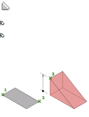
Index Specifies an ACI (AutoCAD Color Index) color.
HSL Specifies an HSL (hue, saturation, luminance) color.
Color Book Specifies a color from a color book.
Exit
Exits the command.
See also:
Overview of Weblights
WEDGE
Creates a 3D solid wedge.
Access Methods
Button
Toolbar: Modeling tool set ➤ Solids - Create tool group ➤ Solid Primitive
flyout ➤ Weblight
Menu: Draw ➤ 3D Modeling ➤ Wedge
Summary
The direction of the taper is always in the positive X-axis direction of the UCS.
Commands | 1133
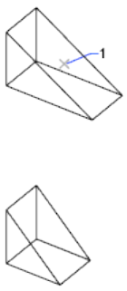
List of Prompts
The following prompts are displayed.
Specify first corner or [Center (page ?)]: Specify a point or enter
c for center
Specify other corner or [Cube (page ?)/Length (page ?)]:
Specify the other corner of the wedge or enteran option
If the other corner of the wedge is specified with a Z value that differs from
the first corner, then no height prompt is displayed.
Specify height or [2Point (page ?)] <default>: Specify the height
or enter 2P for the 2 Point option
Entering a positive value draws the height along the positive Z axis of the
current UCS. Entering a negative value draws the height along the negative
Z axis.
Center
Creates the wedge by using a specified center point.
Cube Creates a wedge with sides of equal length.
Length Creates a wedge with length, width, and height values you specify.
The length corresponds to the X axis, the width to the Y axis, and the height
to the Z axis. If you pick a point to specify the length, you also specify the
rotation in the XY plane.
1134 | Chapter 2 Commands
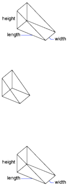
Cube
Creates a wedge with sides of equal length.
Length
Creates a wedge with length, width, and height values you specify. The length
corresponds to the X axis, the width to the Y axis, and the height to the Z
axis.
2Point
Specifies that the height of the wedge is the distance between the two specified
points.
See also:
Create a Solid Wedge
WHOHAS
Displays ownership information for opened drawing files.
Summary
You can use WHOHAS to track which users have certain drawing files open.
Commands | 1135
After you select a file, the ownership information is displayed at the Command
prompt. The information includes the current user's computer name, login
ID, and full name (if available) and the date and time the drawing file was
opened.
NOTE
Similar information is displayed automatically when you try to open a drawing
file that another user has already opened.
The information displayed by WHOHAS is stored in a temporary DWL (drawing
lock) file. A DWL file is deleted when the file is closed.
See also:
Open a Drawing
WIPEOUT
Creates a wipeout object, and controls whether wipeout frames are displayed
in the drawing.
Access Methods
Button
Toolbar: Drafting tool set ➤ Closed Shapes tool group (expanded) ➤
Wipeout
Menu: Draw ➤ Wipeout
Summary
Creates a polygonal area that masks underlying objects with the current
background color. The wipeout area is bounded by a frame that you can turn
on for editing and turn off for plotting.
1136 | Chapter 2 Commands
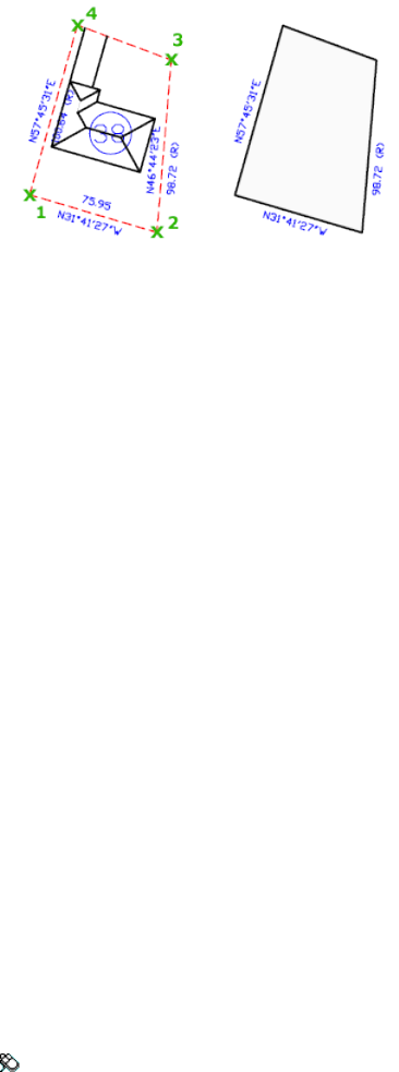
List of Prompts
The following prompts are displayed.
Specify first point (page 1137) or [Frames (page 1137)/Polyline
(page 1137)] <Polyline>.
First Point Determines the polygonal boundary of the wipeout object from
a series of points.
Frames Determines whether the edges of all wipeout objects are displayed or
hidden.
Polyline Determines the polygonal boundary of the wipeout objects from a
selected polyline.
Erase Polyline Enter y to erase the polyline that was used to create the wipeout
object. Enter n to retain the polyline.
See also:
Create a Blank Area to Cover Objects
X Commands
XATTACH
Inserts DWG files as an external reference (xref).
Access Methods
Menu: Insert ➤ DWG Reference
Commands | 1137
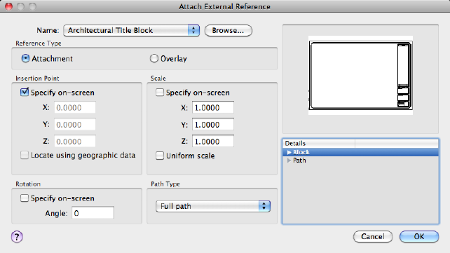
Summary
When you attach a drawing file as an xref, you link that referenced drawing
to the current drawing. Any changes to the referenced drawing are displayed
in the current drawing when it is opened or reloaded.
The Select Reference File dialog box (a standard file selection dialog box (page
720)) is displayed. After you select the DWG files, the Attach External Reference
dialog box (page 1138) is displayed.
After the files are attached, you can adjust and clip the xref through the Ex-
ternal Reference visor (page 1140).
See also:
Attach Drawing References (Xrefs)
Attach External Reference Dialog Box
Attaches drawings as an external reference (xref).
Summary
If you attach a drawing that contains an attached xref, the attached xref
appears in the current drawing. You can select multiple DWG files to attach.
Like blocks, attached xrefs can be nested. If another person is currently editing
the xref, the attached drawing is based on the most recently saved version.
1138 | Chapter 2 Commands
List of Options
The following options are displayed.
Name
Identifies the DWG you have selected to attach.
Browse
Displays the Select Reference File dialog box (a standard file selection dialog
box (page 720)), in which you can select a new external reference for the current
drawing.
Reference Type
Specifies whether the external reference is an attachment or an overlay. Unlike
an xref that is an attachment, an overlay is ignored when the drawing to
which it is attached is then attached as an xref to another drawing.
See Attach Drawing References (Xrefs) and Nest and Overlay Referenced
Drawings.
Preview
Displays the DWG you have selected to attach.
Insertion Point
Specify On-Screen Allows you to input at the Command prompt or the
pointing device.
X Sets the X coordinate value.
Y Sets the Y coordinate value.
Z Sets the Z coordinate value.
Scale
Specify On-screen Allows you to input at the Command prompt or the
pointing device.
X Sets the X scale factor.
Y Sets the Y scale factor.
Z Sets the Z scale factor.
Uniform Scale Sets the Y and X scale factors as the same as Z.
Rotation
Specify on-screen If Specify On-Screen is selected, you may wait until you
exit the dialog box to rotate the object with your pointing device or at the
Command prompt.
Commands | 1139

Angle If Specify On-Screen is cleared, enter the rotation angle value in the
dialog box.
Path Type
Select the full (absolute) path, the relative path to the external reference file,
or No Path, the name of the external reference (the file must be located in the
same folder as the current drawing file).
Details
Displays block and path information about the external reference being
attached.
Block Displays information about the block in the drawing.
■Unit. Displays the specified INSUNITS (page 1335) value for the inserted
block.
■Factor. Displays the unit scale factor, which is calculated based on the
INSUNITS (page 1335) value of the block and the drawing units.
Path Displays the external reference file paths.
■Found In. Displays the path where the external reference file is located.
■Saved Path. Displays the path that is saved with the drawing when the
external reference is attached. The path is dependent upon the Path Type
setting.
See also:
Attach External References
External Reference Visor
Displays options for attaching external references.
Summary
The External Reference visor is displayed when you select an external reference.
List of Options
The following options are displayed.
1140 | Chapter 2 Commands
Edit Reference in Place
Edits the selected xref directly within the current drawing window. (REFEDIT
(page 871))
Open Reference in New Window
Opens the selected drawing reference (xref) in a new window. (XOPEN (page
1149))
Create Clipping Boundary
Crops the display of the selected external reference to a specified boundary.
(XCLIP (page 1144))
Delete the Clipping Boundary
Removes the clipping boundary from the selected external reference. (XCLIP
(page 1144))
Show/Hide Reference Manager
Opens or closes the Reference Manager palette. (EXTERNALREFERENCES (page
414))
See also:
Attach Drawing References (Xrefs)
XBIND
Binds one or more definitions of named objects in an xref to the current
drawing.
Access Methods
Menu: Modify ➤ Object ➤ External Reference ➤ Bind
Summary
The Bind External Definitions dialog box (page 1142) is displayed.
If you enter -xbind at the Command prompt, options are displayed (page
1143).
NOTE The Bind option of XREF binds the xref file. Use XBIND for individual
dependent definitions.
Commands | 1141
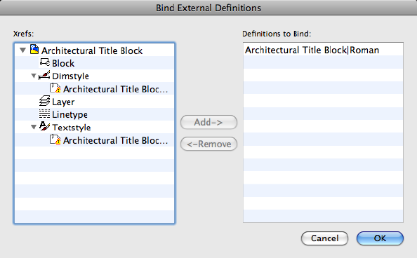
See also:
Archive Drawings That Contain Referenced Drawings (Bind)
Bind External Definitions Dialog Box
Adds xref-dependent named objects (such as blocks, dimension styles, layers,
linetypes, and text styles) to your drawing.
List of Options
The following options are displayed.
Xrefs
Lists the xrefs currently attached to the drawing. Selecting an xref
(double-clicking) displays the named object definitions in the attached xref.
Definitions to Bind
Lists the xref-dependent named object definitions to bind to the host drawing.
Add
Moves the named object definitions selected in the Xrefs list into the
Definitions to Bind list.
Remove
1142 | Chapter 2 Commands
Moves the xref-dependent named object definition selected in the Definitions
to Bind list back to its xref-dependent definition table.
See also:
Archive Drawings That Contain Referenced Drawings (Bind)
-XBIND
Binds one or more definitions of named objects in an xref to the current
drawing.
List of Prompts
The following prompts are displayed.
Enter symbol type to bind [Block/Dimstyle/LAyer/LType/Style]:
Enter an option
Depending on the option, you are prompted for a xref-dependent named
object (symbol) such as a block, dimension style, layer, linetype, or text style.
Enter dependent Symbol name(s): Enter a name list or * to bind all
xref-dependent named objects (symbols) from that definition table
The name you specify must be the full name, including the vertical bar
character ( | ).
The xref-dependent named objects you specify are added to your drawing.
You can manipulate them as you would any other named object. The vertical
bar character ( | ) from each xref-dependent named object is replaced with a
number (usually 0) between two dollar signs ($).
If you specify a layer whose associated linetype is not CONTINUOUS, XBIND
also binds the referenced linetype. If you apply XBIND to a block, any block,
dimension style, layer, linetype, or text style that's referenced by objects in
the block is also bound. If the block contains an xref, XBIND binds that xref
and all its dependent named objects.
See also:
Archive Drawings That Contain Referenced Drawings (Bind)
Commands | 1143

XCLIP
Crops the display of a selected external reference or block reference to a
specified boundary.
Access Methods
Menu: Modify ➤ Clip ➤ Xref
Shortcut menu: Select an xref. Right-click in the drawing area and click
Clip Xref.
Summary
The clipping boundary determines the portion of an xref or block instance
that is hidden, either outside or inside the boundary. The visibility of the
clipping boundary is controlled by the XCLIPFRAME (page 1524) system variable.
List of Options
The following options are displayed.
On
Displays the clipped portion of the external reference or block in the current
drawing.
Off
Displays all of the geometry of the external reference or block in the current
drawing, ignoring the clipping boundary.
Clipdepth
Sets the front and back clipping planes on an xref or block. Objects outside
the volume defined by the boundary and the specified depth are not displayed.
Regardless of the current UCS, the clip depth is applied parallel to the clipping
boundary.
Front Clip Point Creates a clipping plane passing through and perpendicular
to the clipping boundary.
Distance Creates a clipping plane the specified distance from and parallel to
the clipping boundary.
Remove Removes both the front and back clipping planes.
Delete
Removes a clipping boundary for the selected xref or block. To temporarily
turn off a clipping boundary, use the Off option. Delete erases the clipping
1144 | Chapter 2 Commands

boundary and the clipdepth. The ERASE (page 406) command cannot be used
to delete clipping boundaries.
Generate Polyline
Automatically draws a polyline coincident with the clipping boundary. The
polyline assumes the current layer, linetype, lineweight, and color settings.
Use this option when you want to modify the current clipping boundary using
PEDIT (page 767) and then redefine the clipping boundary with the new
polyline. To see the entire xref while redefining the boundary, use the Off
option.
New Boundary
Defines a rectangular or polygonal clipping boundary, or generates a polygonal
clipping boundary from a polyline.
Select Polyline Defines the boundary with the selected polyline. The polyline
can be open but must consist of straight line segments and cannot intersect
itself.
Polygonal Defines a polygonal clipping boundary with three or more points
that you specify for the vertices of a polygon.
Rectangular Defines a rectangular boundary with the points that you specify
for opposite corners.
Invert Clip Inverts the mode of the clipping boundary: objects are clipped
either outside the boundary or inside the boundary.
NOTE You can only create a new clipping boundary for a selected XREF underlay
when the old boundary is deleted.
See also:
Clip External References and Blocks
XEDGES
Creates wireframe geometry from the edges of a 3D solid, surface, mesh, region,
or subobject.
Access Methods
Button
Commands | 1145
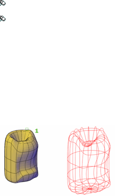
Toolbar: Modeling tool set ➤ Solids - Edit tool group (expanded) ➤
Extract Edges
Menu: Modify ➤ 3D Operations ➤ Extract Edges
Summary
With the XEDGES command, you can create wireframe geometry by extracting
all the edges from the following objects:
■3D solids
■3D solid history subobjects
■Meshes
■Regions
■Surfaces
■Subobjects (edges and faces)
Press and hold Ctrl to select faces, edges and component objects, repeating if
necessary. Objects such as lines, arcs, splines, or 3D polylines are created along
the edges of the selected objects or subobjects.
See also:
Create Wireframe Models
XLINE
Creates a line of infinite length.
1146 | Chapter 2 Commands
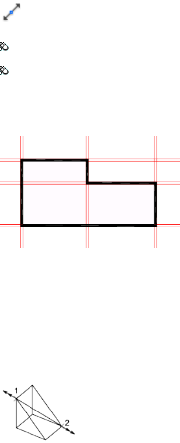
Access Methods
Button
Toolbar: Drafting tool set ➤ Open Shapes tool group (expanded) ➤
Construction Line
Menu: Draw ➤ Construction Line
Summary
Lines that extend to infinity, such as xlines, can be used to create construction
and reference lines, and for trimming boundaries.
List of Prompts
The following prompts are displayed.
Specify a point (page ?) or [Hor (page ?)/Ver (page ?)/Ang
(page ?)/Bisect (page ?)/Offset (page ?).
Point
Specifies the location of the infinite line using two points through which it
passes.
The xline is created through the specified point.
Commands | 1147
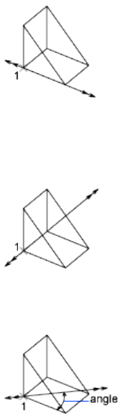
Hor
Creates a horizontal xline passing through a specified point.
The xline is created parallel to the X axis.
Ver
Creates a vertical xline passing through a specified point.
The xline is created parallel to the Y axis.
Ang
Creates an xline at a specified angle.
Angle of Xline Specifies the angle at which to place the line.
Reference Specifies the angle from a selected reference line. The angle is
measured counterclockwise from the reference line.
Bisect
Creates an xline that passes through the selected angle vertex and bisects the
angle between the first and second line.
The xline lies in the plane determined by the three points.
1148 | Chapter 2 Commands
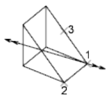
Offset
Creates an xline parallel to another object.
Offset Distance Specifies the distance the xline is offset from the selected
object.
Through Creates an xline offset from a line and passing through a specified
point.
See also:
Draw Construction Lines (and Rays)
XOPEN
Opens a selected drawing reference (xref) in a new window.
Summary
Opens a selected drawing reference in a separate window for editing.
See also:
Edit a Referenced Drawing in a Separate Window
XPLODE
Breaks a compound object into its component objects.
Summary
Reports how many objects were selected and, of those, how many objects
cannot be exploded.
Commands | 1149
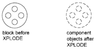
List of Prompts
The following prompts are displayed.
Enter an option [Individually (page ?)/Globally (page ?)].
Individually
Applies changes to the selected objects one at a time. The following prompt
is displayed for each object.
All Sets the color, linetype, lineweight, and layer of the component objects
after you explode them. The prompts associated with the Color, Linetype,
Lineweight, and Layer options are displayed.
Color Sets the color of the objects after you explode them.
■Enter bylayer to inherit the color of the exploded object's layer.
■Enter byblock to inherit the color of the exploded object.
■Enter t for a true color to be used for the selected object.
■Enter co for a color from a loaded color book to be used for the selected
object.
Layer Sets the layer of the component objects after you explode them. The
default option is to inherit the current layer rather than the layer of the
exploded object.
LType Sets the linetype of the component objects after you explode them.
Enter bylayer to inherit the linetype of the exploded object's layer.
Enter byblock to inherit the linetype of the exploded object.
LWeight Sets the lineweight of the component objects after you explode
them.
Inherit from Parent Block Sets the color, linetype, lineweight, and layer of
the component objects to that of the exploded object if the component objects'
color, linetype, and lineweight are BYBLOCK and the objects are drawn on
layer 0.
1150 | Chapter 2 Commands
Explode Breaks a compound object into its component objects exactly as the
EXPLODE (page 407) command does.
Globally
Applies changes to all the selected objects.
See also:
Disassemble a Block Reference (Explode)
XREF
Starts the EXTERNALREFERENCES command.
Summary
The Reference Manager palette (page 414) is displayed.
If you enter -xref at the Command prompt, options are displayed (page 1151).
See also:
Attach and Detach Referenced Drawings
ERHIGHLIGHT (page 1284)
-XREF
List of Prompts
The following prompts are displayed.
Enter an Option
?—List Xrefs Lists the DWG reference name, path, and type and the number
of DWG references currently attached to your drawing.
Bind Converts a specified DWG reference into a block, making it a permanent
part of the drawing.
The xref-dependent named objects, such as layer names, of the former xref
are added to your drawing. In each xref-dependent named object, the vertical
bar (|) is replaced with three new characters: a number (usually 0) between
two dollar signs ($). The number is increased if the same name already exists
in the current drawing.
Commands | 1151
Detach Detaches one or more DWG references from your drawing, erasing
all instances of a specified xref and marking the xref definition for deletion
from the definition table. Only the xrefs attached or overlaid directly to the
current drawing can be detached; nested xrefs cannot be detached.
Path Displays and edits the path name associated with a particular DWG
reference. This option is useful if you change the location of or rename the
drawing file associated with the xref.
Unload Unloads the selected DWG references.
A marker is left in place of the xref so that it can be reloaded later.
Reload Reloads one or more DWG references. This option reloads and displays
the most recently saved version of that drawing.
If the program encounters an error while reloading, it ends XREF and undoes
the entire reloading sequence.
Overlay Displays the Enter Name of File to Overlay dialog box (a standard
file selection dialog box). If you reference a drawing that contains an overlaid
xref, the overlaid xref does not appear in the current drawing.
Unlike blocks and attached xrefs, overlaid xrefs cannot be nested. If another
person is currently editing the xref file, the program overlays the most recently
saved version.
If the xref you specify is not already overlaid, a new xref is crated, using the
name of the referenced file.
If FILEDIA is set to 0, the following prompt is displayed:
Enter Name of File to Overlay.
You can enter a tilde (~) to display a dialog box.
Attach Displays the Select Reference File dialog box. See XATTACH (page 1137).
If you reference a drawing that contains an attached xref, the attached xref
appears in the current drawing. Like blocks, attached xrefs can be nested. If
another person is currently editing the xref file, the most recently saved version
is attached.
Specify Insertion Point
Specify a point or enter an option
Scale Sets the scale factor. All X and Y dimensions of the xref are multiplied
by the X and Y scale factors. The xref is rotated by the specified angle, using
the insertion point as the center of rotation.
X, Y, and Z Sets X, Y, and Z scale factors.
■X Scale Factor. Defines X, Y, and Z scale factors for the xref.
1152 | Chapter 2 Commands
■Corner. Defines the X and Y scales at the same time, using the insertion
point and another point as the corners of a box, and then defines the Z
scale.
Rotate Sets the angle of insertion for the xref.
PScale Sets the scale factor for the X, Y, and Z axes to control the display of
the xref as it is dragged into position.
PX, PY, and PZ Sets the X, Y, and Z axes to control the display of the xref as
it is dragged into position.
PRotate Sets the rotation angle of the xref as it is dragged into position.
See also:
Attach, Update, and Bind External References
Z Commands
ZOOM
Increases or decreases the magnification of the view in the current viewport.
Access Methods
Menu: View ➤ Zoom ➤ Realtime
Toolbar: Status bar ➤ Zoom
Shortcut menu: With no objects selected, right-click in the drawing area
and choose Zoom to zoom in real time.
Summary
You can change the magnification of a view by zooming in and out, which
is similar to zooming in and out with a camera. Using ZOOM does not change
the absolute size of objects in the drawing. It changes only the magnification
of the view.
In a perspective view, ZOOM displays the 3DZOOM (page 54) prompts.
Commands | 1153
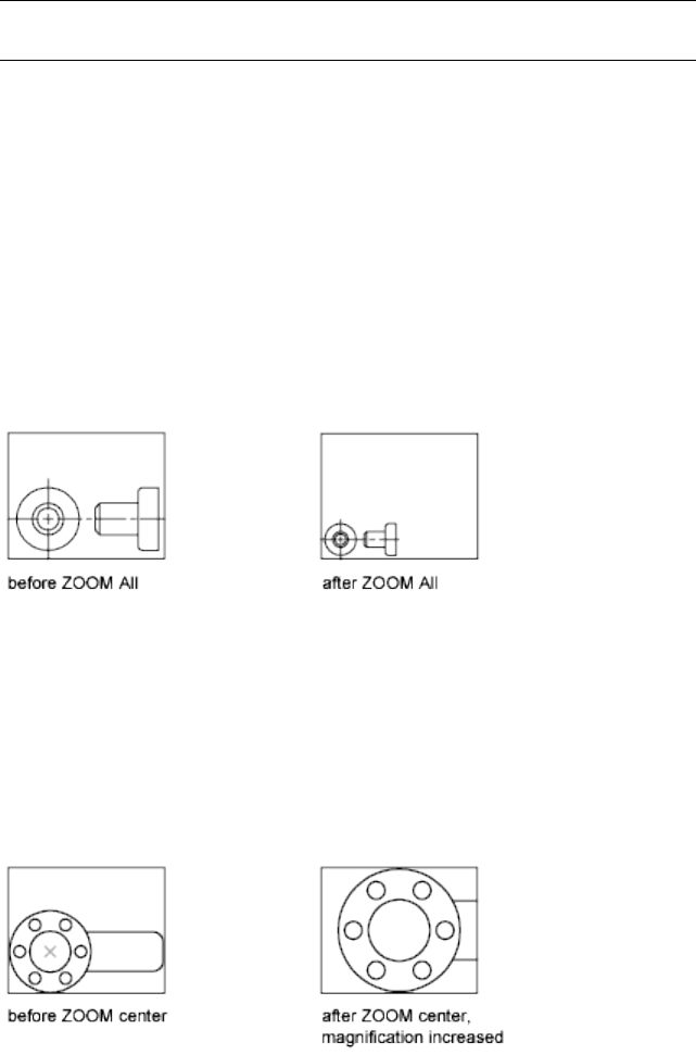
NOTE You cannot use ZOOM transparently during VPOINT (page 1114) or DVIEW
(page 385) or while ZOOM, PAN (page 763), or VIEW (page 1104) is in progress.
List of Prompts
The following prompts are displayed.
Specify corner of window, enter a scale factor (nX or nXP),
or
[All (page 1154)/Center (page 1154)/Dynamic (page 1155)/Extents
(page 1155)/Previous (page 1155)/Scale (page 1156)/Window (page
1156)/Object (page 1157)] <real time (page 1157)>
All Zooms to display all visible objects and visual aids.
Adjusts the magnification of the drawing area to accommodate the extents
of all visible objects in the drawing, or visual aids such as the grid limits (the
LIMITS (page 573) command), whichever is larger.
In the illustration on the right, the grid limits are set to a larger area than the
extents of the drawing.
Because it always regenerates the drawing, you cannot use ZOOM All
transparently.
Center Zooms to display a view defined by a center point and a magnification
value or a height. A smaller value for the height increases the magnification.
A larger value decreases the magnification. Not available in perspective
projection.
1154 | Chapter 2 Commands

Dynamic Pans and zooms using a rectangular view box. The view box
represents your view, which you can shrink or enlarge and move around the
drawing. Positioning and sizing the view box pans or zooms to fill the viewport
with the view inside the view box. Not available in perspective projection.
■To change the size of the view box, click, resize it, and click again to accept
the new size of the view box.
■To pan with the view box, drag it to the location you want and press Enter.
Extents Zooms to display the maximum extents of all objects.
The extents of each object in the model are calculated and used to determine
how the model should fill the window.
Previous Zooms to display the previous view. You can restore up to 10 previous
views.
Commands | 1155
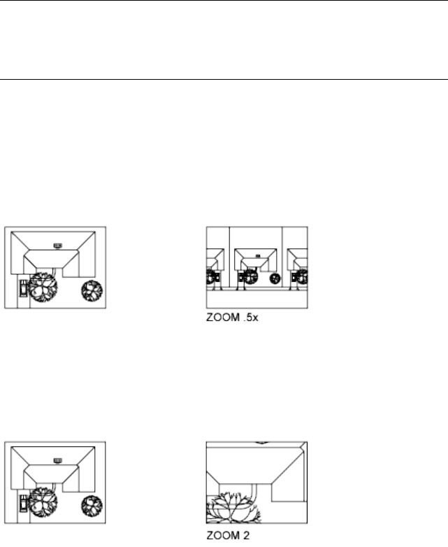
NOTE
If you change the visual style, the view is changed. If you enter ZOOM Previous,
it restores the previous view, which is shaded differently but not zoomed
differently.
Scale Zooms to change the magnification of a view using a scale factor.
■Enter a value followed by x to specify the scale relative to the current view.
■Enter a value followed by xp to specify the scale relative to paper space
units.
For example, entering .5x causes each object to be displayed at half its current
size on the screen.
Entering .5xp displays model space at half the scale of paper space units. You
can create a layout with each viewport displaying objects at a different scale.
Enter a value to specify the scale relative to the grid limits of the drawing.
(This option is rarely used.) For example, entering 2 displays objects at twice
the size they would appear if you were zoomed to the limits of the drawing.
Window Zooms to display an area specified by a rectangular window.
With the cursor, you can define an area of the model to fill the entire window.
1156 | Chapter 2 Commands

Object Zooms to display one or more selected objects as large as possible and
in the center of the view. You can select objects before or after you start the
ZOOM command.
Real Time Zooms interactively to change the magnification of the view.
The cursor changes to a magnifying glass with plus (+) and minus (-) signs.
See Zoom Shortcut Menu (page 1157) for a description of the options that are
available while zooming in real time.
Holding down the pick button at the midpoint of the window and moving
vertically to the top of the window zooms in to 100%. Conversely, holding
the pick button down at the midpoint of the window and moving vertically
to the bottom of the window zooms out by 100%.
When you reach the zoom-in limit, the plus sign in the cursor disappears,
indicating that you can no longer zoom in. When you reach the zoom-out
limit, the minus sign in the cursor disappears, indicating that you can no
longer zoom out.
When you release the pick button, zooming stops. You can release the pick
button, move the cursor to another location in the drawing, and then press
the pick button again and continue to zoom the display from that location.
To exit zooming, press Enter or Esc.
See also:
Pan or Zoom a View
Zoom Shortcut Menu
Shortcut menu allows you to switch between pan and different zoom options.
Commands | 1157
Summary
When the ZOOM command is active, you can exit ZOOM or switch to PAN
(page 763) or 3DORBIT (page 40) using the options on the Zoom shortcut
menu. To access the Zoom shortcut menu, right-click in the drawing area
while ZOOM is active.
List of Options
The following options are displayed.
Exit Cancels ZOOM or PAN.
Pan Switches to PAN.
Zoom Switches to ZOOM in real time.
3D Orbit Switches to 3DORBIT.
Zoom Window Zooms to display an area specified by a rectangular window.
Zoom Object Zooms to display one or more selected objects as large as possible
and in the center of the drawing area.
Zoom Original Restores the original view.
Zoom Extents Zooms to display the drawing extents.
See also:
Pan or Zoom a View
1158 | Chapter 2 Commands

Command Modifiers
Command Modifiers
You can use command modifiers to help you locate points or select objects
while a command is in progress. Use the Coordinate Filter, Direct Distance
Entry, From, MTP, and Tracking command modifiers at any prompt that requires
point specification. Use the Selection Mode command modifiers at any prompt
that requires object selection.
Coordinate Filters (Command Modifier)
Combines X, Y, and Z values from different points to specify a single point
Command entry: Enter .x, .y, .xy, .xz, or .yz
At any prompt for locating a point, you can enter point filters to specify a single
coordinate by extracting the X, Y, and Z values of several points. In the following
example, the start point for the line has a coordinate constructed from the X
value of the midpoint of the first object you select, with the Y and Z values of
the midpoint of the second object you select.
Command: line
Specify first point: .x
of mid
of Select an object
of (need YZ) mid
of Select another object
To point: Specify a point
3
1159
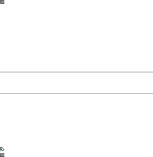
See also:
Combine Coordinate Values (Coordinate Filters)
Direct Distance Entry (Command Modifier)
Locates the next point at a specified distance in the direction of your cursor
Command entry: At a prompt to locate a point, enter a numeric value
With direct distance entry, you can quickly specify a point relative to the last
point you entered. At any prompt for a point location, you move the cursor
first to specify the direction, and then enter a numeric distance.
In the following example, the second point for the line will be located 5 units
toward the direction of the cursor. The direct distance that you enter is
measured along the path from the last point to the current location of the
cursor. This feature is usually used with Ortho or Snap mode turned on.
Command: line
Specify first point: Specify a point
Specify next point: Move the cursor in the desired direction and enter 5
NOTE
The direct distance entry method is not available while you are using temporary
override keys for Ortho, object snap tracking, or polar tracking.
See also:
Enter Direct Distances
FROM (Command Modifier)
Locates a point offset from a reference point within a command.
Toolbar: Object Snap
Command entry: At a prompt to locate a point, enter from
Base Point: Specify a point to use as a base point
of <offset>: Enter a relative offset
At a prompt for locating a point, enter from, and then enter a temporary
reference or base point from which you can specify an offset to locate the next
1160 | Chapter 3 Command Modifiers
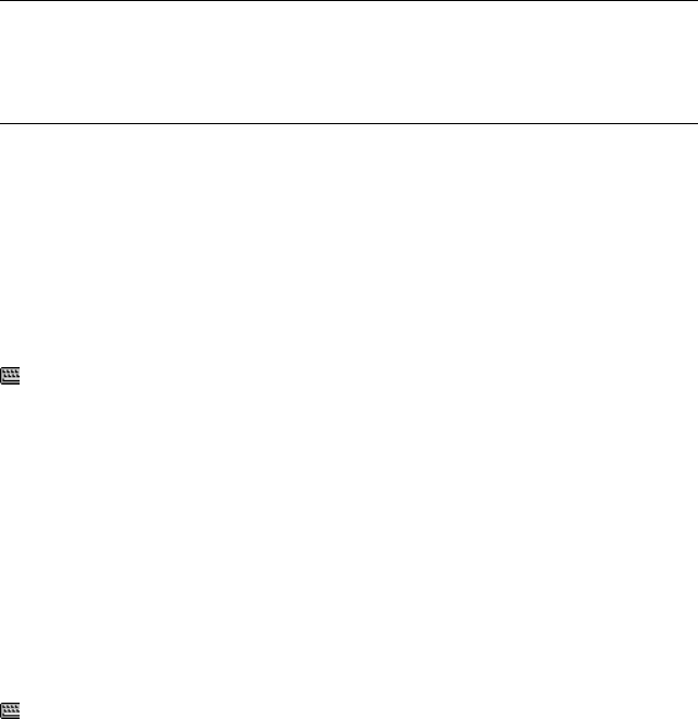
point. Enter the offset location from this base point as a relative coordinate,
or use direct distance entry (page 1160).
NOTE
You cannot use this method during dragging in commands such as MOVE
and COPY. Specifying an absolute coordinate, either by keyboard entry or
with a pointing device, cancels the FROM command.
See also:
Offset from Temporary Reference Points
MTP (Command Modifier)
Locates the midpoint between two points.
Command entry: At a prompt to locate a point, enter mtp
The midpoint between two points (MTP) command modifier can be used with
running object snaps or object snap overrides. (OSNAP (page 743) command)
At any Command prompt to locate a point, enter mtp or m2p.
First point of mid: Specify a point
Second point of mid: Specify a second point
TRACKING (Command Modifier)
Locates a point from a series of temporary points.
Command entry: At a prompt to locate a point, enter tracking
Tracking turns on Ortho mode and can be used with Snap mode.
At any prompt to locate a point, enter tracking, track, or tk.
First tracking point: Specify a location or distance
Next point (Press ENTER to end tracking): Specify a second location
or distance
Tracking specifies a series of temporary points, each offset from the previous
one. Thus, you specify a new point location from a series of directions and
distances. To determine the location of each temporary point, you can use
direct distance entry (page 1160). First move the cursor to specify the direction,
and then enter a numeric distance.
Command Modifiers | 1161

Alternatively, tracking can establish a new point by combining the X and Y
values of two specified points. You can specify these two points in any order,
depending on the cursor direction after the first point. Direct distance entry
specifies a distance in the direction of the current location of your cursor.
Coordinate filters (page 1159) combine X, Y, and Z values from different points
into a single point. Relative coordinate entry locates a point relative to the
last point entered.
You can also access tracking by holding down SHIFT and right-clicking to
display the object snap shortcut menu.
See also:
Track to Offset Point Locations (Tracking)
Object Snaps (Command Modifier)
Specifies a precise point at a location on an object.
Command entry: Within a command, at a prompt to locate a point, specify
an object snap
When you specify an object snap, the cursor snaps to the specified point on
an object closest to the center of the cursor. By default, a marker and a tooltip
are displayed when you move the cursor over the object snap location on an
object.
Specify a Single Object Snap
If you specify a single object snap, it stays in effect only for the next point
you specify.
You can specify an object snap with any of the following methods:
■Enter a object snap by typing its name. To see a list of valid object snaps,
refer to the OSNAP (page 743) command or the Drafting Settings Dialog
Box (page 364).
■Click an object snap from the Object Snap toolbar.
■Click an object snap from the Object Snap shortcut menu. You can diisplay
this shortcut menu by pressing SHIFT while you right-click.
1162 | Chapter 3 Command Modifiers

Use Running Object Snaps
Using the OSNAP (page 743) or DSETTINGS (page 363) commands, you can
specify a set of running object snaps. Running object snaps are one or more
object snaps that remain in effect as you work.
■To turn running object snaps on and off, click the OSNAP button on the
status bar or press F3.
■Press TAB to cycle through the object snap possibilities before you specify
the point.
■To turn off running object snaps for the next point only, specify the None
object snap.
Selection Modes (Command Modifier)
Controls how you create selection sets
Command entry: At a prompt to select objects, enter one of the valid selection
modes described in the SELECT command
The selection mode you enter remains active only for the current Select Objects
prompt.
See also:
Select Objects
Command Modifiers | 1163
1164
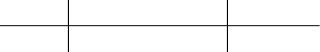
System Variables
System Variables
AutoCAD for Mac® stores the values for its operating environment and some
of its commands in system variables. You can examine any system variable and
change any writable system variable directly at the command prompt by entering
the system variable name or by using the SETVAR command or the AutoLISP®
getvar and setvar functions. Many system variables are also accessible through
dialog box options
3D System Variables
3DOSMODE
Controls the settings for the 3D object snaps.
IntegerType:
RegistrySaved in:
11Initial value:
Controls which 3D object snaps are enabled. The setting is stored as a bitcode
using the sum of the following values:
Shortcut KeysDescriptionValue
Enables all 3D object snaps0
4
1165
ZNONDisables all 3D object snaps1
ZVERSnaps to a vertex or a control vertex2
ZMIDSnaps to the midpoint on a face edge4
ZCENSnaps to the center of a face8
ZKNOSnaps to a spline or surface knot16
ZPERSnaps to a perpendicular face (planar faces
only)
32
ZNEASnaps to an object nearest to a face64
Turns on all 3D object snaps126
To specify more than one object snap, enter the sum or their values. For
example, entering 6 specifies the vertex (2) and midpoint (4) object snaps.
Entering 126 turns on all 3D object snaps.
3DSELECTIONMODE
Controls the selection precedence of both visually and physically overlapping
objects when using 3D visual styles.
IntegerType:
RegistrySaved in:
1Initial value:
Use legacy 3D selection precedence.0
Use line-of-sight 3D selection precedence for selecting 3D solids
and surfaces. Also, a defining object associated with a surface is
given selection precedence with this setting.
1
3DSELECTIONMODE has no effect when selecting 3D solids if they are
displayed as 2D or 3D wireframes.
1166 | Chapter 4 System Variables

See also:
Select Objects Individually
A System Variables
ACADLSPASDOC
Controls whether the acad.lsp file is loaded into every drawing or just the first
drawing opened in a session.
IntegerType:
RegistrySaved in:
0Initial value:
Loads acad.lsp into just the first drawing opened in a session0
Loads acad.lsp into every drawing opened1
See also:
AutoLISP and Visual LISP
ACADPREFIX
Stores the directory path, if any, specified by the ACAD environment variable,
with path separators appended if necessary.
(Read-only)
StringType:
Not-savedSaved in:
VariesInitial value:
See also:
Set Up the Drawing Area
System Variables | 1167

ACADVER
Stores the AutoCAD version number.
(Read-only)
StringType:
Not-savedSaved in:
VariesInitial value:
This variable differs from the DXF file $ACADVER header variable, which
contains the drawing database level number.
See also:
Customize the Drawing Environment
ACISOUTVER
Controls the ACIS version of SAT files created using the ACISOUT command.
IntegerType:
Not-savedSaved in:
70Initial value:
ACISOUT only supports a value of 15 through 18, 20, 21, 30, 31, 40, 50, 60,
and 70.
See also:
Export ACIS SAT Files
AFLAGS
Sets options for attributes.
IntegerType:
Not-savedSaved in:
16Initial value:
The value is the sum of the following:
No attribute mode selected0
1168 | Chapter 4 System Variables
Invisible1
Constant2
Verify4
Preset8
Lock position in block16
Multiple lines32
See also:
Define Block Attributes
ANGBASE
Sets the base angle to 0 with respect to the current UCS.
RealType:
DrawingSaved in:
0.0000Initial value:
See also:
Create Angular Dimensions
ANGDIR
Sets the direction of positive angles.
IntegerType:
DrawingSaved in:
0Initial value:
System Variables | 1169
Angle values are measured from angle 0 relative to the orientation of the
current UCS.
Counterclockwise0
Clockwise1
See also:
Create Angular Dimensions
ANNOALLVISIBLE
Hides or displays annotative objects that do not support the current annotation
scale.
IntegerType:
DrawingSaved in:
1Initial value:
Only annotative objects that support the current annotation scale
are displayed
0
All annotative objects are displayed1
The ANNOALLVISIBLE setting is saved individually for model space and each
layout.
NOTE When ANNOALLVISIBLE is set to 1, annotative objects that support more
than one scale will only display one scale representation.
See also:
Display Annotative Objects
ANNOAUTOSCALE
Updates annotative objects to support the annotation scale when the
annotation scale is changed.
1170 | Chapter 4 System Variables
IntegerType:
RegistrySaved in:
-4Initial value:
When the value is negative, the autoscale functionality is turned off, but the
settings are maintained:
Newly set annotation scale is not added to annotative objects.0
Adds the newly set annotation scale to annotative objects that sup-
port the current scale except for those on layers that are turned off,
frozen, locked or that are set to Viewport > Freeze.
1
Adds the newly set annotation scale to annotative objects that sup-
port the current scale except for those on layers that are turned off,
frozen, or that are set to Viewport > Freeze.
2
Adds the newly set annotation scale to annotative objects that sup-
port the current scale except for those on layers that are locked.
3
Adds the newly set annotation scale to all annotative objects that
support the current scale.
4
See also:
Set Annotation Scale
ANNOTATIVEDWG
Specifies whether or not the drawing will behave as an annotative block when
inserted into another drawing.
IntegerType:
DrawingSaved in:
0Initial value:
Nonannotative0
Annotative1
System Variables | 1171
NOTE
The ANNOTATIVEDWG system variable becomes read-only if the drawing
contains annotative objects.
See also:
Create Annotative Blocks and Attributes
APBOX
Turns the display of the AutoSnap aperture box on or off.
IntegerType:
RegistrySaved in:
0Initial value:
The aperture box is displayed in the center of the crosshairs when you snap
to an object.
Off0
On1
See also:
Set Visual Aids for Object Snaps (AutoSnap)
APERTURE
Sets the display size for the object snap target box, in pixels.
IntegerType:
RegistrySaved in:
10Initial value:
This system variable has the same name as a command. Use the SETVAR
command to access this system variable.
Enter a value (1-50). The higher the number, the larger the target box.
You can also change this setting on the Application Preferences dialog box,
Cursor & Selection tab (page 727).
1172 | Chapter 4 System Variables
APERTURE controls the object snap target box, not the pickbox displayed at
the Select Objects prompt. The object selection pickbox is controlled by the
PICKBOX (page 1393) system variable.
See also:
Use Object Snaps
APPAUTOLOAD
Controls when plug-in applications are loaded.
BitcodeType:
User-settingsSaved in:
14Initial value:
Do not load plug-in applications at any time0
Display all messages when loading plug-in applications1
Load plug-in applications at startup2
Load plug-in applications when a new drawing is opened4
Load plug-in applications when they appear in the plug-ins folder8
See also:
Install and Uninstall Plug-In Applications
ARRAYEDITSTATE
Indicates whether the drawing is in the array editing state, which is activated
while editing an associative array’s source objects.
(Read-only)
IntegerType:
Not-savedSaved in:
System Variables | 1173

0Initial value:
Off0
On1
See also:
Edit Associative Arrays
AREA
Stores the last area computed by the AREA command.
(Read-only)
RealType:
Not-savedSaved in:
0.0000Initial value:
This system variable has the same name as a command.
Use the SETVAR command to access this system variable.
See also:
Obtain Area and Mass Properties Information
ARRAYTYPE
Specifies the default array type.
IntegerType:
RegistrySaved in:
0Initial value:
Rectangular array0
Path array1
Polar array2
1174 | Chapter 4 System Variables
See also:
Work with Arrays
ATTDIA
Controls whether the INSERT command uses a dialog box for attribute value
entry.
IntegerType:
RegistrySaved in:
0Initial value:
Issues Command prompts0
Uses a dialog box1
See also:
Insert Blocks
ATTIPE
Controls if all formatting options are available with the in-place editor for
modifying multiline attributes.
IntegerType:
RegistrySaved in:
0Initial value:
Limited formatting options with the in-place editor0
Full formatting options with the in-place editor1
Use the limited formatting options with the in-place editor when modifying
multiline attributes for best compatibility with releases prior to AutoCAD
2008.
See also:
Define Block Attributes
System Variables | 1175
ATTMODE
Controls display of attributes.
IntegerType:
DrawingSaved in:
1Initial value:
Off: Makes all attributes invisible0
Normal: Retains current visibility of each attribute; visible attributes
are displayed; invisible attributes are not
1
On: Makes all attributes visible2
See also:
Define Block Attributes
ATTMULTI
Controls whether multiline attributes can be created.
IntegerType:
RegistrySaved in:
1Initial value:
Turns off all access methods for creating multiline attributes. They
can still be viewed and edited.
0
Turns on all access methods for creating multiline attributes.1
See also:
Define Block Attributes
1176 | Chapter 4 System Variables
ATTREQ
Controls whether INSERT uses default attribute settings during insertion of
blocks.
IntegerType:
RegistrySaved in:
1Initial value:
Assumes the defaults for the values of all attributes0
Turns on prompts or a dialog box for attribute values, as specified
by ATTDIA (page 1175)
1
See also:
Insert Blocks
AUDITCTL
Controls whether AUDIT creates an audit report (ADT) file.
IntegerType:
RegistrySaved in:
0Initial value:
Prevents writing of ADT files0
Writes ADT files1
See also:
Repair a Damaged Drawing File
AUNITS
Sets units for angles.
IntegerType:
DrawingSaved in:
System Variables | 1177
0Initial value:
Decimal degrees0
Degrees/minutes/seconds1
Gradians2
Radians3
Surveyor's units4
See also:
Set the Unit Format Conventions
AUPREC
Sets the display precision for angular units and coordinates.
IntegerType:
DrawingSaved in:
0Initial value:
However, the internal precision of angular values and and coordinates is always
maintained, regardless of the display precision. AUPREC does not affect the
display precision of dimension text (see DIMSTYLE (page 314)).
Valid values are integers from 0 to 8.
See also:
Set the Unit Format Conventions
AUTOCOMPLETEDELAY
Controls the amount of time that elapses before automated keyboard features
display at the Command prompt.
IntegerType:
DrawingSaved in:
1178 | Chapter 4 System Variables
0.3Initial value:
The time delay setting in the AUTOCOMPLETEMODE (page 1179) system variable
must be turned on for AUTOCOMPLETEDELAY to have an effect.
Valid values are real numbers from 0 to 10, which represent seconds.
See also:
The Command Line
Enter Commands on the Command Line
AUTOCOMPLETEMODE
Controls what types of automated keyboard features are available at the
Command prompt.
IntegerType:
DrawingSaved in:
15Initial value:
The setting is stored as a bitcode using the sum of the following values:
Turns off all automated keyboard features when typing at the
Command prompt
0
Turns on any automated keyboard features when typing at the
Command prompt
1
Automatically appends suggestions as each keystroke is entered
after the third keystroke
2
Displays a list of suggestions as keystrokes are entered4
Displays the icon of the command or system variable, if available8
Excludes the display of system variables16
See also:
The Command Line
Enter Commands on the Command Line
System Variables | 1179
AUTOSNAP
Controls the display of the AutoSnap marker, tooltip, and magnet.
IntegerType:
RegistrySaved in:
63Initial value:
Also turns on polar and object snap tracking, and controls the display of polar
tracking, object snap tracking, and Ortho mode tooltips. The setting is stored
as a bitcode using the sum of the following values:
Turns off the AutoSnap marker, tooltips, and magnet. Also turns off
polar tracking, object snap tracking, and tooltips for polar tracking,
object snap tracking, and Ortho mode
0
Turns on the AutoSnap marker1
Turns on the AutoSnap tooltips2
Turns on the AutoSnap magnet4
Turns on polar tracking8
Turns on object snap tracking16
Turns on tooltips for polar tracking, object snap tracking, and Ortho
mode
32
See also:
Set Visual Aids for Object Snaps (AutoSnap)
1180 | Chapter 4 System Variables

B System Variables
BACKZ
Stores the back clipping plane offset from the target plane for the current
viewport, in drawing units.
(Read-only)
RealType:
DrawingSaved in:
0.0000Initial value:
Meaningful only if clipping is specified in DVIEW (page 385). If there are several
cameras, the value is the last back clipping plane that you set current. The
distance of the back clipping plane from the camera point can be found by
subtracting BACKZ from the camera-to-target distance.
See also:
Create a 3D Dynamic View (DVIEW)
BINDTYPE
Controls how xref names are handled when binding xrefs or editing xrefs in
place.
IntegerType:
Not-savedSaved in:
0Initial value:
Traditional binding behavior ("xref1|one" becomes "xref$0$one")0
Insert-like behavior ("xref1|one" becomes "one")1
See also:
Archive Drawings That Contain Referenced Drawings (Bind)
System Variables | 1181
BLIPMODE
Controls whether marker blips are visible.
IntegerType:
RegistrySaved in:
0Initial value:
Obsolete
Marker blips have been removed from the product.
This system variable has the same name as the BLIPMODE command. Use the
SETVAR (page 943) command to access this system variable.
Turns off marker blips0
Turns on marker blips1
See also:
Erase Objects
BLOCKEDITLOCK
Disallows opening of the Block Editor and editing of block definitions.
IntegerType:
RegistrySaved in:
0Initial value:
When BLOCKEDITLOCK is set to 1, double-clicking a block in a drawing opens
the Properties Inspector. If the block contains attributes, double-clicking the
block opens the Enhanced Attribute Editor.
Specifies that the Block Editor can be opened0
Specifies that the Block Editor cannot be opened1
See also:
Create and Modify Blocks
1182 | Chapter 4 System Variables
BLOCKEDITOR
Indicates whether or not the Block Editor is open.
(Read-only)
IntegerType:
Not-savedSaved in:
0Initial value:
Indicates that the Block Editor is not open0
Indicates that the Block Editor is open1
See also:
Create and Modify Blocks
BTMARKDISPLAY
Controls whether or not value set markers are displayed for dynamic block
references.
IntegerType:
RegistrySaved in:
1Initial value:
Specifies that value set markers are not displayed0
Specifies that value set markers are displayed1
See also:
C System Variables
CAMERADISPLAY
Turns the display of camera objects on or off.
System Variables | 1183

IntegerType:
DrawingSaved in:
0Initial value:
Camera objects can only be created with the Windows releases of AutoCAD
.
Camera glyphs are not displayed0
Camera glyphs are displayed1
See also:
Specify 3D Views
CANNOSCALE
Sets the name of the current annotation scale for the current space.
StringType:
DrawingSaved in:
1:1Initial value:
You can only enter a named scale that exists in the drawing’s named scale
list.
See also:
Set Annotation Scale
CANNOSCALEVALUE
Returns the value of the current annotation scale.
(Read-only)
RealType:
DrawingSaved in:
1.0000Initial value:
See also:
Set Annotation Scale
1184 | Chapter 4 System Variables
CCONSTRAINTFORM
Controls whether annotational or dynamic constraints are applied to objects.
IntegerType:
RegistrySaved in:
0Initial value:
Dynamic0
Annotational1
When this system variable is set to 0, dynamic constraints are created, by
default, when you use the DIMCONSTRAINT (page 284) command.
See also:
Apply Dimensional Constraints
CDATE
Stores the current date and time in decimal format.
(Read-only)
RealType:
Not-savedSaved in:
VariesInitial value:
The date and time displays in a decimal format starting with the year. After
the decimal point, CDATE displays the time using a 24-hour clock. For
example, the ninth day of February in the year 2006 at 3:05 pm displays as
20060209.150500.
See also:
Obtain General Drawing Information
CECOLOR
Sets the color of new objects.
StringType:
System Variables | 1185
DrawingSaved in:
BYLAYERInitial value:
Valid values include the following:
■BYLAYER or BYBLOCK
■AutoCAD Color Index (ACI): integer values from 1 to 255, or a color name
from the first seven colors
■True Colors: RGB or HSL values from 000 to 255 in the form
"RGB:130,200,240"
■Color Books: Text from standard PANTONE or custom color books, the
DIC color guide, or RAL color sets, for example "DIC COLOR GUIDE(R)$DIC
43"
See also:
Change the Color of an Object
CELTSCALE
Sets the current object linetype scaling factor.
RealType:
DrawingSaved in:
1.0000Initial value:
Sets the linetype scaling for new objects relative to the LTSCALE (page 593)
command setting. A line created with CELTSCALE = 2 in a drawing with
LTSCALE set to 0.5 would appear the same as a line created with CELTSCALE
= 1 in a drawing with LTSCALE = 1.
See also:
Control Linetype Scale
CELTYPE
Sets the linetype of new objects.
StringType:
DrawingSaved in:
BYLAYERInitial value:
1186 | Chapter 4 System Variables

See also:
Set the Current Linetype
CELWEIGHT
Sets the lineweight of new objects.
IntegerType:
DrawingSaved in:
-1Initial value:
Sets the lineweight to "BYLAYER."-1
Sets the lineweight to "BYBLOCK."-2
Sets the lineweight to "DEFAULT." "DEFAULT" is controlled by the
LWDEFAULT (page 1365) system variable.
-3
Other valid values entered in hundredths of millimeters include 0, 5, 9, 13,
15, 18, 20, 25, 30, 35, 40, 50, 53, 60, 70, 80, 90, 100, 106, 120, 140, 158, 200,
and 211.
All values must be entered in hundredths of millimeters. (Multiply a value by
2540 to convert values from inches to hundredths of millimeters.)
See also:
Set the Current Lineweight
CENTERMT
Controls how grips stretch multiline text that is centered horizontally.
IntegerType:
RegistrySaved in:
0Initial value:
System Variables | 1187
CENTERMT does not apply to stretching multiline text by using the ruler in
the In-Place Text Editor.
When you move a corner grip in centered multiline text, the center
grip moves in the same direction, and the grip on the opposite side
remains in place
0
When you move a corner grip in centered multiline text, the center
grip stays in place, and both sets of side grips move in the direction
of the stretch
1
See also:
Change Multiline Text
CETRANSPARENCY
Sets the transparency level for new objects.
StringType:
DrawingSaved in:
ByLayerInitial value:
Transparency value determined by layerByLayer
Transparency value determined by blockByBlock
Fully opaque (not transparent)0
Transparency value defined as a percentage1-90
To change the transparency of existing objects, use the Properties Inspector
or Layers palette.
NOTE
Transparency is limited to 90 percent to avoid confusion with layers that are
turned off or frozen.
The transparency level for new hatch objects is controlled by the
HPTRANSPARENCY system variable.
1188 | Chapter 4 System Variables
See also:
Display and Change the Properties of Objects
CHAMFERA
Sets the first chamfer distance when CHAMMODE is set to 0.
RealType:
DrawingSaved in:
0.0000Initial value:
See also:
Create Chamfers
CHAMFERB
Sets the second chamfer distance when CHAMMODE is set to 0.
RealType:
DrawingSaved in:
0.0000Initial value:
See also:
Create Chamfers
CHAMFERC
Sets the chamfer length when CHAMMODE is set to 1.
RealType:
DrawingSaved in:
0.0000Initial value:
See also:
Create Chamfers
System Variables | 1189

CHAMFERD
Sets the chamfer angle when CHAMMODE is set to 1.
RealType:
DrawingSaved in:
0.0000Initial value:
See also:
Create Chamfers
CHAMMODE
Sets the input method for CHAMFER
IntegerType:
Not-savedSaved in:
0Initial value:
Requires two chamfer distances0
Requires a chamfer length and an angle1
See also:
Create Chamfers
CIRCLERAD
Sets the default circle radius.
RealType:
Not-savedSaved in:
0.0000Initial value:
A zero indicates no default.
See also:
Draw Circles
1190 | Chapter 4 System Variables

CLASSICKEYS
Sets the behavior of the AutoCAD for Mac shortcut keys.
SwitchType:
RegistrySaved in:
0Initial value:
To copy, press Cmd-C0
To cancel, press Cmd-C1
See also:
Set Interface Options
CLAYER
Sets the current layer.
StringType:
DrawingSaved in:
0Initial value:
See also:
Change Layer Settings and Layer Properties
CLEANSCREENSTATE
Indicates whether the clean screen state is on or off.
(Read-only)
IntegerType:
Not-savedSaved in:
0Initial value:
Off0
On1
System Variables | 1191

See also:
CLISTATE
Indicates whether the Command Line is open or closed.
(Read-only)
IntegerType:
Not-savedSaved in:
1Initial value:
Closed0
Open1
See also:
CMATERIAL
Sets the material of new objects.
StringType:
DrawingSaved in:
BYLAYERInitial value:
Valid values are BYLAYER, BYBLOCK, and the name of a material in the
drawing.
See also:
Browse Material Library
CMDACTIVE
Indicates whether an ordinary command, transparent command, script, or
dialog box is active.
(Read-only)
IntegerType:
Not-savedSaved in:
1192 | Chapter 4 System Variables

VariesInitial value:
The setting is stored as a bitcode using the sum of the following values:
No active command0
Ordinary command is active1
Transparent command is active2
Script is active4
Dialog box is active8
Not used16
AutoLISP is active (only visible to an ObjectARX-defined command)32
ObjectARX command is active64
See also:
Enter Commands on the Command Line
CMDDIA
Controls the display of the In-Place Text Editor for the LEADER and QLEADER
commands.
IntegerType:
RegistrySaved in:
1Initial value:
Off0
On1
System Variables | 1193

See also:
Create and Modify Leaders
CMDECHO
Controls whether prompts and input are echoed during the AutoLISP command
function.
IntegerType:
Not-savedSaved in:
1Initial value:
Turns off echoing0
Turns on echoing1
See also:
AutoLISP
CMDINPUTHISTORYMAX
Sets the maximum number of previous input values that are stored for a
prompt in a command.
IntegerType:
RegistrySaved in:
20Initial value:
Display of the history of user input is controlled by the INPUTHISTORYMODE
(page 1333) system variable.
See also:
CMDNAMES
Displays the names of the active and transparent commands.
(Read-only)
StringType:
1194 | Chapter 4 System Variables

Not-savedSaved in:
""Initial value:
For example, LINE'ZOOM indicates that the ZOOM command is being used
transparently during the LINE command.
This variable is designed for use with programming interfaces such as AutoLISP
and DIESEL.
The following is a simple example that demonstrates how to use DIESEL to
display the current command at the status line.
Command: modemacro
New value for MODEMACRO, or . for none <"">: $(getvar,
cmdnames)
For additional information, see “Introduction to Programming Interfaces” in
the Customization Guide.
See also:
Enter Commands on the Command Line
CMLEADERSTYLE
Sets the name of the current multileader style.
StringType:
DrawingSaved in:
StandardInitial value:
See also:
Work with Leader Styles
CMLJUST
Specifies multiline justification.
IntegerType:
DrawingSaved in:
0Initial value:
Top0
System Variables | 1195

Zero (Middle)1
Bottom2
See also:
Modify Multilines
CMLSCALE
Controls the overall width of a multiline.
RealType:
DrawingSaved in:
1.0000 (imperial) or 20.0000 (metric)Initial value:
A scale factor of 2.0 produces a multiline twice as wide as the style definition.
A zero scale factor collapses the multiline into a single line. A negative scale
factor flips the order of the offset lines (that is, the smallest or most negative
is placed on top when the multiline is drawn from left to right).
See also:
Modify Multilines
CMLSTYLE
Sets the multiline style that governs the appearance of the multiline.
StringType:
DrawingSaved in:
StandardInitial value:
See also:
Modify Multilines
COLORSCHEME
Stores the current color scheme used by the program.
1196 | Chapter 4 System Variables
IntegerType:
RegistrySaved in:
0Initial value:
Dark0
Light1
See also:
Interface Themes and Background Color
COMPASS
Controls whether the 3D compass is on or off in the current viewport.
IntegerType:
Not-savedSaved in:
0Initial value:
Turns off the 3D compass0
Turns on the 3D compass1
See also:
Use 3D Navigation Tools
CONSTRAINTBARDISPLAY
Controls the display of constraint bars after you apply constraints and when
you select geometrically constrained drawings.
BitcodeType:
RegistrySaved in:
3Initial value:
Does not display constraint bars for selected
objects after applying geometric constraints
0
System Variables | 1197
NOTE Constraint bars will always be dis-
played when CONSTRAINTBAR = Showall,
even if you set the value of the CON-
STRAINTBARDISPLAY system variable to 0.
Displays constraint bars for selected objects
after applying constraints
1
Temporarily displays constraint bars for the
selected geometrically constrained objects
2
Bits 1 and 2 are both turned on3
See also:
Apply or Remove Geometric Constraints
CONSTRAINTBARMODE
Controls the display of geometrical constraints on constraint bars.
BitcodeType:
RegistrySaved in:
4095Initial value:
Horizontal1
Vertical2
Perpendicular4
Parallel8
Tangent16
Smooth32
Coincident64
1198 | Chapter 4 System Variables

Concentric128
Colinear256
Symmetric512
Equal1024
Fix2048
For example, set CONSTRAINTBARMODE to 12 (8+4) to display parallel and
perpendicular constraints on the constraint bars.
Set CONSTRAINTBARMODE to 4095 to display constraint bars for all constraint
types.
See also:
Apply or Remove Geometric Constraints
CONSTRAINTINFER
Controls whether the geometric constraints are inferred while drawing and
editing geometry.
BitcodeType:
RegistrySaved in:
0Initial value:
Geometric constraints are not inferred0
Geometric constraints are inferred1
See also:
Infer Geometric Constraints
System Variables | 1199
CONSTRAINTNAMEFORMAT
Controls the text format for dimensional constraints.
IntegerType:
RegistrySaved in:
2Initial value:
Name (for example, Width)0
Value (for example, 4.0000)1
Expression (for example, width = 4.0000)2
NOTE
The CONSTRAINTNAMEFORMAT system variable is also applicable to the
block constraint parameters in the Block Editor.
See also:
Apply Dimensional Constraints
CONSTRAINTRELAX
Indicates whether constraints are enforced or relaxed when editing an object.
(Read-only)
IntegerType:
Not-savedSaved in:
0Initial value:
Maintains constraints0
Relaxes constraints1
See also:
Modify Objects with Geometric Constraints Applied
1200 | Chapter 4 System Variables
CONSTRAINTSOLVEMODE
Controls constraint behavior when applying or editing constraints.
BitcodeType:
RegistrySaved in:
1Initial value:
Does not retain the size of the geometry
when a constraint is applied or modified
0
Retains the size of the geometry when a
constraint is applied or modified
1
When the CONSTRAINTSOLVEMODE is set to 0, resizing a constrained line
may result in unpredictable behavior.
See also:
Modify Objects with Geometric Constraints Applied
CONTENTSTATE
Indicates whether the Content palette is open or closed.
(Read-only)
IntegerType:
Not-savedSaved in:
VariesInitial value:
Closed0
Open1
See also:
The Content Palette
System Variables | 1201

COPYMODE
Controls whether the COPY command repeats automatically.
IntegerType:
RegistrySaved in:
0Initial value:
Sets the COPY command to repeat automatically0
Sets the COPY command to create a single copy1
See also:
Copy Objects
CPLOTSTYLE
Controls the current plot style for new objects.
StringType:
DrawingSaved in:
ByColorInitial value:
If the current drawing you are working in is in color-dependent mode,
CPLOTSTYLE is read-only and has a value of BYCOLOR. If the current drawing
is in named plot styles mode, CPLOTSTYLE can be set to the following values
(BYLAYER is the default):
"BYLAYER"
"BYBLOCK"
"NORMAL"
"USER DEFINED"
See also:
Overview of Plot Styles
1202 | Chapter 4 System Variables

CPROFILE
Displays the name of the current profile.
(Read-only)
StringType:
RegistrySaved in:
<<Unnamed Profile>>Initial value:
See also:
Set Interface Options
CROSSINGAREACOLOR
Controls the color of the selection area during crossing selection.
IntegerType:
RegistrySaved in:
100Initial value:
The valid range is 1 to 255. The SELECTIONAREA (page 1425) system variable
must be on.
See also:
Customize Object Selection
CSHADOW
Sets the shadow display property for a 3D object.
IntegerType:
DrawingSaved in:
0Initial value:
To be visible, shadows must be turned on in the visual style that is applied to
the viewport.
Casts and receives shadows0
Casts shadows1
System Variables | 1203
Receives shadows2
Ignores shadows3
See also:
Display Backgrounds and Shadows
CTAB
Returns the name of the current layout in the drawing.
StringType:
DrawingSaved in:
ModelInitial value:
Provides a means for the user to determine which layout is active.
See also:
Set Model Space Viewports
CTABLESTYLE
Sets the name of the current table style.
StringType:
DrawingSaved in:
StandardInitial value:
See also:
Work with Table Styles
CULLINGOBJ
Controls whether 3D subobjects that are hidden from view can be highlighted
or selected.
IntegerType:
1204 | Chapter 4 System Variables
RegistrySaved in:
1Initial value:
No subobject culling0
■Rolling over 3D objects highlights all 3D subobjects, including hidden subob-
jects.
■Selecting 3D objects by dragging selects all 3D subobjects, including hidden
subobjects.
Apply subobject culling1
■Rolling over 3D objects highlights only the subobjects that are normal in the
current view.
■Selecting 3D objects by dragging selects only the subobjects that are normal
in the current view.
See also:
Cycle Through and Filter Subobjects
CULLINGOBJSELECTION
Controls whether 3D objects that are hidden from view can be highlighted
or selected.
IntegerType:
RegistrySaved in:
0Initial value:
No object culling0
■Rolling over 3D objects highlights all 3D objects, including hidden objects.
■Selecting 3D objects by dragging selects all 3D objects, including hidden ob-
jects.
Apply object culling1
■Rolling over 3D objects highlights only the objects that are normal in the
current view.
System Variables | 1205

■Selecting 3D objects by dragging selects only the objects that are normal in
the current view.
See also:
Cycle Through and Filter Subobjects
CURSORSIZE
Determines the size of the crosshairs as a percentage of the screen size.
IntegerType:
RegistrySaved in:
5Initial value:
Valid settings range from 1 to 100 percent. When set to 100, the crosshairs
are full-screen and the ends of the crosshairs are never visible. When less than
100, the ends of the crosshairs may be visible when the cursor is moved to
one edge of the screen.
See also:
Set Up the Drawing Area
CVPORT
Displays the identification number of the current viewport.
IntegerType:
DrawingSaved in:
2Initial value:
You can change this value, which changes the current viewport, if the
following conditions are met:
■The identification number you specify is that of an active viewport.
■A command in progress has not locked cursor movement to that viewport.
■Tablet mode is off.
See also:
Select and Use the Current Viewport
1206 | Chapter 4 System Variables
D System Variables
DATE
Stores the current date and time in Modified Julian Date format.
(Read-only)
RealType:
Not-savedSaved in:
VariesInitial value:
This value is represented as a Modified Julian Date (MJD), which is the Julian
day number and decimal fraction of a day in the format:
<Julian day number>.<Decimal fraction of a day>
The Modified Julian Date, conventionally called UT1, is a worldwide scientific
standard that assigns day numbers beginning at an essentially arbitrary date
and time of 12:00 a.m. on 1 January 4713 B.C. (B.C.E.). With this system, 4
July 1997 at 2:29:58 p.m. corresponds to 2450634.60387736, and 1 January
1998 at 12:00 noon corresponds to 2450815.50000000.
You can compute differences in date and time by subtracting the numbers
returned by DATE. To extract the seconds since midnight from the value
returned by DATE, use AutoLISP expressions:
(setq s (getvar "DATE"))
(setq seconds (* 86400.0 (- s (fix s))))
Because your computer clock provides the date and time, the DATE system
variable returns a true Julian date only if the system clock is set to UTC/Zulu
(Greenwich Mean Time). TDCREATE (page 1457) and TDUPDATE (page 1458) have
the same format as DATE, but their values represent the creation time and
last update time of the current drawing.
See also:
Obtain General Drawing Information
DBLCLKEDIT
Controls the double click editing behavior in the drawing area.
System Variables | 1207
IntegerType:
RegistrySaved in:
1Initial value:
The system variable can accept the values of On and Off in place of 1 and 0.
Disabled0
Enabled1
See also:
Modify Objects
DBMOD
Indicates the drawing modification status.
(Read-only)
IntegerType:
Not-savedSaved in:
0Initial value:
The setting is stored as a bitcode using the sum of the following values:
Object database modified1
Database variable modified4
Window modified8
View modified16
Field modified32
The DBMOD value is reset to 0 when you save the drawing.
See also:
Save a Drawing
1208 | Chapter 4 System Variables
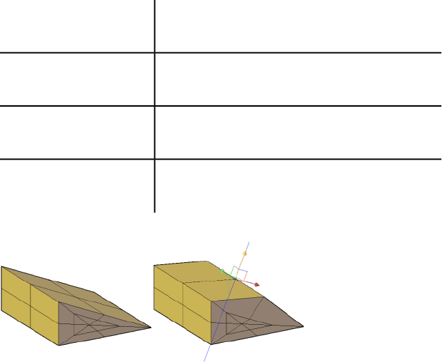
DEFAULTGIZMO
Sets the 3D Move, 3D Rotate, or 3D Scale gizmo as the default during subobject
selection.
IntegerType:
Not-savedSaved in:
0Initial value:
The 3D Move gizmo is displayed by default when an ob-
ject is selected in a 3D visual style.
0
The 3D Rotate gizmo is displayed by default when an
object is selected in a 3D visual style.
1
The 3D Scale gizmo is displayed by default when an ob-
ject is selected in a 3D visual style.
2
No gizmo is displayed by default when an object is selec-
ted in a 3D visual style.
3
Set this variable to display the gizmo you use most often by default.
With the 3D Move gizmo, you can restrict the movement of selected objects
along an X, Y, or Z axis, or within a specified plane. To specify the movement
limitations, hover the cursor over the gizmo until the axis or plane is
highlighted.
With the 3D Rotate gizmo, you can restrict the rotation of selected objects
about an X, Y, or Z axis. To specify the rotation axis, hover the cursor over
the gizmo until the axis line is displayed in red and the revolution path is
highlighted in yellow.
System Variables | 1209
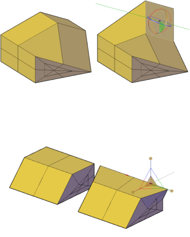
With the 3D Scale gizmo, you can resize selected objects uniformly, resize
them along an X, Y, or Z axis, or resize them along a specified plane. To specify
the scale limitations, hover the cursor over the gizmo. Highlight the solid area
between the axes for uniform resizing. Highlight the double lines between
the axes to specify resizing along a plane. Highlight an axis to specify resizing
along an axis.
No gizmo is displayed by default when an object is selected in a 3D visual
style.
1210 | Chapter 4 System Variables
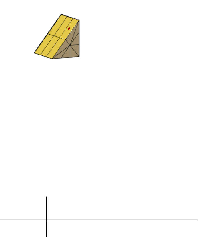
See also:
Use the Gizmos
DEFAULTLIGHTING
Turns on and off default lighting in place of other lighting.
IntegerType:
DrawingSaved in:
1Initial value:
Default lighting is provided by a set of distant lights that follow the view
direction. When default lighting is on, the sun and other lights do not cast
light, even if they are turned on. The setting of this system variable is
viewport-specific.
Default lighting is automatically turned off when point lights, spot-
lights, distant lights, or the sun are on
0
Default lighting only is turned on1
See also:
Overview of Lighting
DEFAULTLIGHTINGTYPE
Specifies the type of default lighting, old or new.
System Variables | 1211

IntegerType:
DrawingSaved in:
1Initial value:
The default lighting provided in AutoCAD 2006 and earlier releases used one
distant light. The new default lighting uses two distant lights to illuminate
more of the model and also adjusts ambient light. The setting of this system
variable is viewport-specific.
Old type of default lighting0
New type of default lighting1
See also:
Overview of Lighting
DEFLPLSTYLE
Specifies the default plot style for all layers in a drawing when opening a
drawing that was created in a release prior to AutoCAD 2000, or for Layer 0
when creating a new drawing from scratch without using a drawing template.
StringType:
RegistrySaved in:
ByColorInitial value:
When the drawing is opened and PSTYLEPOLICY (page 1410) is set to 1
(color-dependent plot style mode), DEFLPLSTYLE is read-only and has a value
of “BYCOLOR.” If PSTYLEPOLICY is set to 0 (named plot style mode) when
the drawing is opened, DEFLPLSTYLE is writable and has a default value of
“NORMAL.”
See also:
Overview of Plot Styles
DEFPLSTYLE
Specifies the default plot style for new objects in a drawing when opening a
drawing that was created in a release prior to AutoCAD 2000, or when creating
a new drawing from scratch without using a drawing template.
1212 | Chapter 4 System Variables
StringType:
RegistrySaved in:
ByColorInitial value:
When the drawing is opened and PSTYLEPOLICY (page 1410) is set to 1
(color-dependent plot style mode), DEFPLSTYLE is read-only and has a value
of “BYCOLOR.” If PSTYLEPOLICY is set to 0 (named plot style mode),
DEFPLSTYLE is writable and has a default value of “BYLAYER.”
See also:
Overview of Plot Styles
DELOBJ
Controls whether geometry used to create other objects is retained or deleted.
IntegerType:
RegistrySaved in:
3Initial value:
If the SURFACEASSOCIATIVITY (page 1452) system variable is set to 1, the
DELOBJ setting is ignored.
All defining geometry is retained.0
Deletes profile curves, including those used with the EXTRUDE (page
423), SWEEP (page 1027), REVOLVE (page 900), and LOFT (page 583)
1
commands. Removes all defining geometry for CONVTOSOLID
(page 223), CONVTOSURFACE (page 225), CONVTONURBS (page
222), and CONVTOMESH (page 221) commands. Cross sections used
with the LOFT command are also deleted.
Deletes all defining geometry, including paths and guide curves
used with the SWEEP and LOFT commands.
2
Deletes all defining geometry, including paths and guide curves
used with the SWEEP and LOFT commands if the action results in a
3
solid object. Removes all defining geometry for CONVTOSOLID,
CONVTOSURFACE, CONVTONURBS, and CONVTOMESH com-
mands.
System Variables | 1213
Displays prompts to delete profile curves, including those used with
the EXTRUDE, SWEEP, REVOLVE, and LOFT commands. Prompts to
remove cross sections used with the LOFT command.
-1
The original geometry for CONVTOSOLID, CONVTOSURFACE, and
CONVTOMESH commands is removed without prompting.
Displays prompts to delete all defining geometry, including paths
and guide curves used with the SWEEP and LOFT commands.
-2
The original geometry for CONVTOSOLID, CONVTOSURFACE, and
CONTOMESH commands is removed without prompting.
Displays prompts to delete all defining geometry if the resulting
entities are a surface of any type. Deletes all original geometry res-
-3
ulting in a solid entity, original geometry for CONVTOSOLID,
CONVTOSURFACE, CONVTONURBS, and CONVTOMESH commands
is removed without prompting
See also:
Create and Combine Areas (Regions)
Create Solids and Surfaces from Lines and Curves
DEMANDLOAD
Specifies if and when to demand-load certain applications.
IntegerType:
RegistrySaved in:
3Initial value:
If you set this system variable to 0, third-party applications and some AutoCAD
commands cannot function.
Turns off demand-loading.0
Demand-loads the source application when you open a drawing
that contains custom objects. This setting does not demand-load
the application when you invoke one of the application's commands.
1
1214 | Chapter 4 System Variables
Demand-loads the source application when you invoke one of the
application's commands. This setting does not demand-load the
application when you open a drawing that contains custom objects.
2
Demand-loads the source application when you open a drawing
that contains custom objects or when you invoke one of the applic-
ation's commands
3
See also:
Overview of Demand Loading
DIASTAT
Stores the exit method of the most recently used dialog box.
(Read-only)
IntegerType:
Not-savedSaved in:
0Initial value:
Cancel0
OK1
NOTE
The DIASTAT system variable does not apply to standard file selection dialog
boxes, such as the Select File and the Save Drawing As dialog boxes.
See also:
Switch Between Dialog Boxes and the Command Line
DIMADEC
Controls the number of precision places displayed in angular dimensions.
IntegerType:
DrawingSaved in:
System Variables | 1215
0Initial value:
Angular dimensions display the number of decimal places specified
by DIMDEC (page 1229).
-1
Specifies the number of decimal places displayed in angular dimen-
sions (independent of DIMDEC)
0-8
See also:
Create Angular Dimensions
DIMALT
Controls the display of alternate units in dimensions.
SwitchType:
DrawingSaved in:
OffInitial value:
See also DIMALTD (page 1216), DIMALTF (page 1217), DIMALTTD (page 1217),
DIMALTTZ (page 1218), DIMALTZ (page 1219), and DIMAPOST (page 1220).
Disables alternate unitsOff
Enables alternate unitsOn
See also:
Control the Display of Dimension Units
DIMALTD
Controls the number of decimal places in alternate units.
IntegerType:
DrawingSaved in:
2 (imperial) or 3 (metric)Initial value:
If DIMALT is turned on, DIMALTD sets the number of digits displayed to the
right of the decimal point in the alternate measurement.
1216 | Chapter 4 System Variables
See also:
Control the Display of Dimension Units
DIMALTF
Controls the multiplier for alternate units.
RealType:
DrawingSaved in:
25.4000 (imperial) or 0.0394 (metric)Initial value:
If DIMALT is turned on, DIMALTF multiplies linear dimensions by a factor to
produce a value in an alternate system of measurement. The initial value
represents the number of millimeters in an inch.
See also:
Control the Display of Dimension Units
DIMALTRND
Rounds off the alternate dimension units.
RealType:
DrawingSaved in:
0.0000Initial value:
See also:
Control the Display of Dimension Units
DIMALTTD
Sets the number of decimal places for the tolerance values in the alternate
units of a dimension.
IntegerType:
DrawingSaved in:
2 (imperial) or 3 (metric)Initial value:
System Variables | 1217
See also:
Control the Display of Dimension Units
DIMALTTZ
Controls suppression of zeros in tolerance values.
IntegerType:
DrawingSaved in:
0Initial value:
Suppresses zero feet and precisely zero inches0
Includes zero feet and precisely zero inches1
Includes zero feet and suppresses zero inches2
Includes zero inches and suppresses zero feet3
To suppress leading or trailing zeros, add the following values to one of the
preceding values:
Suppresses leading zeros4
Suppresses trailing zeros8
See also:
Control the Display of Dimension Units
DIMALTU
Sets the units format for alternate units of all dimension substyles except
Angular.
IntegerType:
DrawingSaved in:
1218 | Chapter 4 System Variables
2Initial value:
Scientific1
Decimal2
Engineering3
Architectural (stacked)4
Fractional (stacked)5
Architectural6
Fractional7
System Format8
See also:
Control the Display of Dimension Units
DIMALTZ
Controls the suppression of zeros for alternate unit dimension values.
IntegerType:
DrawingSaved in:
0Initial value:
DIMALTZ values 0-3 affect feet-and-inch dimensions only.
Suppresses zero feet and precisely zero inches0
Includes zero feet and precisely zero inches1
Includes zero feet and suppresses zero inches2
System Variables | 1219
Includes zero inches and suppresses zero feet3
Suppresses leading zeros in decimal dimensions (for example, 0.5000
becomes .5000)
4
Suppresses trailing zeros in decimal dimensions (for example,
12.5000 becomes 12.5)
8
Suppresses both leading and trailing zeros (for example, 0.5000
becomes .5)
12
See also:
Control the Display of Dimension Units
DIMANNO
Indicates whether or not the current dimension style is annotative.
(Read-only)
IntegerType:
DrawingSaved in:
0Initial value:
Nonannotative0
Annotative1
See also:
Create Annotative Dimensions and Tolerances
DIMAPOST
Specifies a text prefix or suffix (or both) to the alternate dimension
measurement for all types of dimensions except angular.
StringType:
DrawingSaved in:
1220 | Chapter 4 System Variables
""Initial value:
For instance, if the current units are Architectural, DIMALT (page 1216) is on,
DIMALTF (page 1217) is 25.4 (the number of millimeters per inch), DIMALTD
(page 1216) is 2, and DIMAPOST is set to "mm", a distance of 10 units would be
displayed as 10"[254.00mm].
To turn off an established prefix or suffix (or both), set it to a single period
(.).
See also:
Control the Display of Dimension Units
DIMARCSYM
Controls display of the arc symbol in an arc length dimension.
IntegerType:
DrawingSaved in:
0Initial value:
Places arc length symbols before the dimension text0
Places arc length symbols above the dimension text1
Suppresses the display of arc length symbols2
See also:
Create Arc Length Dimensions
DIMASSOC
Controls the associativity of dimension objects and whether dimensions are
exploded.
IntegerType:
DrawingSaved in:
System Variables | 1221
2Initial value:
Creates exploded dimensions. There is no association between the
various elements of the dimension. The lines, arcs, arrowheads, and
text of a dimension are drawn as separate objects.
0
Creates non-associative dimension objects. The elements of the di-
mension are formed into a single object. If one of the definition
points of the dimension moves, the dimension is updated.
1
Creates associative dimension objects. The elements of the dimension
are formed into a single object, and one or more definition points
2
of the dimension are coupled with association points on geometric
objects. If the association point on the geometric object moves, the
dimension location, orientation, and value are updated.
DIMASSOC is not stored in a dimension style.
Drawings saved in a format previous to AutoCAD 2002 retain the setting of
the DIMASSOC system variable. When the drawing is reopened in AutoCAD
2002 or later, the dimension associativity setting is restored.
See also:
Associative Dimensions
DIMASZ
Controls the size of dimension line and leader line arrowheads. Also controls
the size of hook lines.
RealType:
DrawingSaved in:
0.1800 (imperial) or 2.5000 (metric)Initial value:
Multiples of the arrowhead size determine whether dimension lines and text
should fit between the extension lines. DIMASZ is also used to scale arrowhead
blocks if set by DIMBLK (page 1224). DIMASZ has no effect when DIMTSZ (page
1249) is other than zero.
See also:
Customize Arrowheads
1222 | Chapter 4 System Variables
DIMATFIT
Determines how dimension text and arrows are arranged when space is not
sufficient to place both within the extension lines.
IntegerType:
DrawingSaved in:
3Initial value:
Places both text and arrows outside extension lines0
Moves arrows first, then text1
Moves text first, then arrows2
Moves either text or arrows, whichever fits best3
A leader is added to moved dimension text when DIMTMOVE (page 1247) is
set to 1.
See also:
Fit Dimension Text Within Extension Lines
DIMAUNIT
Sets the units format for angular dimensions.
IntegerType:
DrawingSaved in:
0Initial value:
Decimal degrees0
Degrees/minutes/seconds1
Gradians2
Radians3
System Variables | 1223
See also:
Create Angular Dimensions
DIMAZIN
Suppresses zeros for angular dimensions.
IntegerType:
DrawingSaved in:
0Initial value:
Displays all leading and trailing zeros0
Suppresses leading zeros in decimal dimensions (for example, 0.5000
becomes .5000)
1
Suppresses trailing zeros in decimal dimensions (for example,
12.5000 becomes 12.5)
2
Suppresses leading and trailing zeros (for example, 0.5000 becomes
.5)
3
See also:
Suppress Zeros in Dimensions
DIMBLK
Sets the arrowhead block displayed at the ends of dimension lines.
StringType:
DrawingSaved in:
""Initial value:
To return to the default, closed-filled arrowhead display, enter a single period
(.). Arrowhead block entries and the names used to select them in the New,
Modify, and Override Dimension Style dialog boxes are shown below. You
can also enter the names of user-defined arrowhead blocks.
1224 | Chapter 4 System Variables
NOTE blocks cannot be used as custom arrowheads for dimensions or leaders.
closed filled""
dot"_DOT"
dot small"_DOTSMALL"
dot blank"_DOTBLANK"
origin indicator"_ORIGIN"
origin indicator 2"_ORIGIN2"
open"_OPEN"
right angle"_OPEN90"
open 30"_OPEN30"
closed"_CLOSED"
dot small blank"_SMALL"
none"_NONE"
oblique"_OBLIQUE"
box filled"_BOXFILLED"
box"_BOXBLANK"
closed blank"_CLOSEDBLANK"
datum triangle filled"_DATUMFILLED"
System Variables | 1225
datum triangle"_DATUMBLANK"
integral"_INTEGRAL"
architectural tick"_ARCHTICK"
See also:
Customize Arrowheads
DIMBLK1
Sets the arrowhead for the first end of the dimension line when DIMSAH is
on.
StringType:
DrawingSaved in:
""Initial value:
To return to the default, closed-filled arrowhead display, enter a single period
(.). For a list of arrowheads, see DIMBLK.
NOTE blocks cannot be used as custom arrowheads for dimensions or leaders.
See also:
Customize Arrowheads
DIMBLK2
Sets the arrowhead for the second end of the dimension line when DIMSAH
is on.
StringType:
DrawingSaved in:
""Initial value:
To return to the default, closed-filled arrowhead display, enter a single period
(.). For a list of arrowhead entries, see DIMBLK.
NOTE blocks cannot be used as custom arrowheads for dimensions or leaders.
1226 | Chapter 4 System Variables

See also:
Customize Arrowheads
DIMCEN
Controls drawing of circle or arc center marks and centerlines by the
DIMCENTER, DIMDIAMETER, and DIMRADIUS commands.
RealType:
DrawingSaved in:
0.0900 (imperial) or 2.5000 (metric)Initial value:
For DIMDIAMETER and DIMRADIUS, the center mark is drawn only if you
place the dimension line outside the circle or arc.
No center marks or lines are drawn0
Centerlines are drawn<0
Center marks are drawn>0
The absolute value specifies the size of the center mark or centerline.
The size of the centerline is the length of the centerline segment that extends
outside the circle or arc. It is also the size of the gap between the center mark
and the start of the centerline.
The size of the center mark is the distance from the center of the circle or arc
to the end of the center mark.
See also:
Create Radial Dimensions
DIMCLRD
Assigns colors to dimension lines, arrowheads, and dimension leader lines.
IntegerType:
DrawingSaved in:
0Initial value:
System Variables | 1227
Also controls the color of leader lines created with the LEADER command.
Color numbers are displayed in the Color Palette dialog box. For BYBLOCK,
enter 0. For BYLAYER, enter 256.
See also:
Control Dimension Lines
DIMCLRE
Assigns colors to extension lines, center marks, and centerlines.
IntegerType:
DrawingSaved in:
0Initial value:
Color numbers are displayed in the Color Palette dialog box. For BYBLOCK,
enter 0. For BYLAYER, enter 256.
See also:
Override a Dimension Style
DIMCLRT
Assigns colors to dimension text.
IntegerType:
DrawingSaved in:
0Initial value:
The color can be any valid color number.
See also:
Control the Appearance of Dimension Text
DIMCONSTRAINTICON
Displays the lock icon next to the text for dimensional constraints.
BitcodeType:
1228 | Chapter 4 System Variables
RegistrySaved in:
3Initial value:
Does not display the lock icon next to the
text for dimensional constraints
0
Displays the icon for dynamic constraints1
Displays the icon for annotational con-
straints
2
Displays the icon for dynamic and annota-
tional constraints
3
See also:
Apply Dimensional Constraints
DIMDEC
Sets the number of decimal places displayed for the primary units of a
dimension.
IntegerType:
DrawingSaved in:
4 (imperial) or 2 (metric)Initial value:
The precision is based on the units or angle format you have selected. Specified
value is applied to angular dimensions when DIMADEC (page 1215) is set to -1.
See also:
Control the Display of Dimension Units
DIMDLE
Sets the distance the dimension line extends beyond the extension line when
oblique strokes are drawn instead of arrowheads.
RealType:
DrawingSaved in:
System Variables | 1229
0.0000Initial value:
See also:
Control Dimension Lines
DIMDLI
Controls the spacing of the dimension lines in baseline dimensions.
RealType:
DrawingSaved in:
0.3800 (imperial) or 3.7500 (metric)Initial value:
Each dimension line is offset from the previous one by this amount, if
necessary, to avoid drawing over it. Changes made with DIMDLI are not
applied to existing dimensions.
See also:
Control Dimension Lines
DIMDSEP
Specifies a single-character decimal separator to use when creating dimensions
whose unit format is decimal.
Single-characterType:
DrawingSaved in:
. (imperial) or , (metric)Initial value:
When prompted, enter a single character at the Command prompt. If
dimension units is set to Decimal, the DIMDSEP character is used instead of
the default decimal point. If DIMDSEP is set to NULL (default value, reset by
entering a period), the decimal point is used as the dimension separator.
See also:
Control the Display of Dimension Units
1230 | Chapter 4 System Variables
DIMEXE
Specifies how far to extend the extension line beyond the dimension line.
RealType:
DrawingSaved in:
0.1800 (imperial) or 1.2500 (metric)Initial value:
See also:
Control Extension Lines
DIMEXO
Specifies how far extension lines are offset from origin points.
RealType:
DrawingSaved in:
0.0625 (imperial) or 0.6250 (metric)Initial value:
With fixed-length extension lines, this value determines the minimum offset.
See also:
Control Extension Lines
DIMFRAC
Sets the fraction format when DIMLUNIT is set to 4 (Architectural) or 5
(Fractional).
IntegerType:
DrawingSaved in:
0Initial value:
Horizontal stacking0
Diagonal stacking1
Not stacked (for example, 1/2)2
System Variables | 1231
See also:
Control the Display of Fractions
DIMFXL
Sets the total length of the extension lines starting from the dimension line
toward the dimension origin.
RealType:
DrawingSaved in:
1.0000Initial value:
See also:
Control Extension Lines
DIMFXLON
Controls whether extension lines are set to a fixed length.
SwitchType:
DrawingSaved in:
OffInitial value:
When DIMFXLON is on, extension lines are set to the length specified by
DIMFXL.
See also:
Control Extension Lines
DIMGAP
Sets the distance around the dimension text when the dimension line breaks
to accommodate dimension text.
RealType:
DrawingSaved in:
0.0900 (imperial) or 0.6250 (metric)Initial value:
1232 | Chapter 4 System Variables

Also sets the gap between annotation and a hook line created with the LEADER
command. If you enter a negative value, DIMGAP places a box around the
dimension text.
DIMGAP is also used as the minimum length for pieces of the dimension line.
When the default position for the dimension text is calculated, text is
positioned inside the extension lines only if doing so breaks the dimension
lines into two segments at least as long as DIMGAP. Text placed above or
below the dimension line is moved inside only if there is room for the
arrowheads, dimension text, and a margin between them at least as large as
DIMGAP: 2 * (DIMASZ (page 1222) + DIMGAP).
See also:
Control the Location of Dimension Text
DIMJOGANG
Determines the angle of the transverse segment of the dimension line in a
jogged radius dimension.
RealType:
DrawingSaved in:
45Initial value:
Jogged radius dimensions are often created when the center point is located
off the page. Valid settings range is 5 to 90.
See also:
Create Radial Dimensions
DIMJUST
Controls the horizontal positioning of dimension text.
IntegerType:
DrawingSaved in:
0Initial value:
Positions the text above the dimension line and center-justifies it
between the extension lines
0
System Variables | 1233
Positions the text next to the first extension line1
Positions the text next to the second extension line2
Positions the text above and aligned with the first extension line3
Positions the text above and aligned with the second extension line4
See also:
Control the Location of Dimension Text
DIMLDRBLK
Specifies the arrow type for leaders.
StringType:
DrawingSaved in:
""Initial value:
To return to the default, closed-filled arrowhead display, enter a single period
(.). For a list of arrowhead entries, see DIMBLK (page 1224).
NOTE blocks cannot be used as custom arrowheads for dimensions or leaders.
See also:
Overview of Leader Objects
DIMLFAC
Sets a scale factor for linear dimension measurements.
RealType:
DrawingSaved in:
1.0000Initial value:
All linear dimension distances, including radii, diameters, and coordinates,
are multiplied by DIMLFAC before being converted to dimension text. Positive
1234 | Chapter 4 System Variables

values of DIMLFAC are applied to dimensions in both model space and paper
space; negative values are applied to paper space only.
DIMLFAC applies primarily to nonassociative dimensions (DIMASSOC set 0
or 1). For nonassociative dimensions in paper space, DIMLFAC must be set
individually for each layout viewport to accommodate viewport scaling.
DIMLFAC has no effect on angular dimensions, and is not applied to the
values held in DIMRND (page 1238), DIMTM (page 1246), or DIMTP (page 1249).
See also:
Set the Scale for Dimensions
DIMLIM
Generates dimension limits as the default text.
SwitchType:
DrawingSaved in:
OffInitial value:
Setting DIMLIM to On turns DIMTOL off.
Dimension limits are not generated as default textOff
Dimension limits are generated as default textOn
See also:
Display Lateral Tolerances
DIMLTEX1
Sets the linetype of the first extension line.
StringType:
DrawingSaved in:
""Initial value:
The value is BYLAYER, BYBLOCK, or the name of a linetype.
System Variables | 1235

See also:
Control Extension Lines
DIMLTEX2
Sets the linetype of the second extension line.
StringType:
DrawingSaved in:
""Initial value:
The value is BYLAYER, BYBLOCK, or the name of a linetype.
See also:
Control Extension Lines
DIMLTYPE
Sets the linetype of the dimension line.
StringType:
DrawingSaved in:
""Initial value:
The value is BYLAYER, BYBLOCK, or the name of a linetype.
See also:
Control Dimension Lines
DIMLUNIT
Sets units for all dimension types except Angular.
IntegerType:
DrawingSaved in:
2Initial value:
Scientific1
1236 | Chapter 4 System Variables
Decimal2
Engineering3
Architectural (always displayed stacked)4
Fractional (always displayed stacked)5
System Format6
See also:
Control the Display of Dimension Units
DIMLWD
Assigns lineweight to dimension lines.
EnumType:
DrawingSaved in:
-2Initial value:
Default (the LWDEFAULT (page 1365) value)-3
BYBLOCK-2
BYLAYER-1
The integer represents 1/100th of a mm.
See also:
Control Dimension Lines
DIMLWE
Assigns lineweight to extension lines.
System Variables | 1237
EnumType:
DrawingSaved in:
-2Initial value:
Default (the LWDEFAULT (page 1365) value)-3
BYBLOCK-2
BYLAYER-1
The integer represents 1/100th of a mm.
See also:
Control Extension Lines
DIMPOST
Specifies a text prefix or suffix (or both) to the dimension measurement.
StringType:
DrawingSaved in:
NoneInitial value:
For example, to establish a suffix for millimeters, set DIMPOST to mm; a
distance of 19.2 units would be displayed as 19.2 mm.
If tolerances are turned on, the suffix is applied to the tolerances as well as to
the main dimension.
Use <> to indicate placement of the text in relation to the dimension value.
For example, enter <>mm to display a 5.0 millimeter radial dimension as
"5.0mm". If you entered mm <>, the dimension would be displayed as "mm
5.0". Use the <> mechanism for angular dimensions.
See also:
Control the Display of Dimension Units
DIMRND
Rounds all dimensioning distances to the specified value.
1238 | Chapter 4 System Variables

RealType:
DrawingSaved in:
0.0000Initial value:
For instance, if DIMRND is set to 0.25, all distances round to the nearest 0.25
unit. If you set DIMRND to 1.0, all distances round to the nearest integer.
Note that the number of digits edited after the decimal point depends on the
precision set by DIMDEC. DIMRND does not apply to angular dimensions.
See also:
Round Off Dimension Values
DIMSAH
Controls the display of dimension line arrowhead blocks.
SwitchType:
DrawingSaved in:
OffInitial value:
Use arrowhead blocks set by DIMBLK (page 1224)Off
Use arrowhead blocks set by DIMBLK1 (page 1226) and DIMBLK2
(page 1226)
On
See also:
Customize Arrowheads
DIMSCALE
Sets the overall scale factor applied to dimensioning variables that specify
sizes, distances, or offsets.
RealType:
DrawingSaved in:
1.0000Initial value:
Also affects the leader objects with the LEADER command.
System Variables | 1239
Use MLEADERSCALE (page 1371) to scale multileader objects created with the
MLEADER (page 651) command.
A reasonable default value is computed based on the scaling between
the current model space viewport and paper space. If you are in
0.0
paper space or model space and not using the paper space feature,
the scale factor is 1.0.
A scale factor is computed that leads text sizes, arrowhead sizes,
and other scaled distances to plot at their face values.
>0
DIMSCALE does not affect measured lengths, coordinates, or angles.
Use DIMSCALE to control the overall scale of dimensions. However, if the
current dimension style is annotative, DIMSCALE is automatically set to zero
and the dimension scale is controlled by the CANNOSCALE (page 1184) system
variable. DIMSCALE cannot be set to a non-zero value when using annotative
dimensions.
See also:
Set the Scale for Dimensions
DIMSD1
Controls suppression of the first dimension line and arrowhead.
SwitchType:
DrawingSaved in:
OffInitial value:
When turned on, suppresses the display of the dimension line and arrowhead
between the first extension line and the text.
First dimension line is not suppressedOff
First dimension line is suppressedOn
See also:
Control Dimension Lines
1240 | Chapter 4 System Variables

DIMSD2
Controls suppression of the second dimension line and arrowhead.
SwitchType:
DrawingSaved in:
OffInitial value:
When turned on, suppresses the display of the dimension line and arrowhead
between the second extension line and the text.
Second dimension line is not suppressedOff
Second dimension line is suppressedOn
See also:
Control Dimension Lines
DIMSE1
Suppresses display of the first extension line.
SwitchType:
DrawingSaved in:
OffInitial value:
Extension line is not suppressedOff
Extension line is suppressedOn
See also:
Control Extension Lines
DIMSE2
Suppresses display of the second extension line.
SwitchType:
System Variables | 1241
DrawingSaved in:
OffInitial value:
Extension line is not suppressedOff
Extension line is suppressedOn
See also:
Control Extension Lines
DIMSOXD
Suppresses arrowheads if not enough space is available inside the extension
lines.
SwitchType:
DrawingSaved in:
OffInitial value:
Arrowheads are not suppressedOff
Arrowheads are suppressedOn
If not enough space is available inside the extension lines and DIMTIX (page
1246) is on, setting DIMSOXD to On suppresses the arrowheads. If DIMTIX is
off, DIMSOXD has no effect.
See also:
Control Dimension Lines
DIMSTYLE
Stores the name of the current dimension style.
(Read-only)
StringType:
DrawingSaved in:
Standard (imperial) or ISO-25 (metric)Initial value:
1242 | Chapter 4 System Variables
This system variable has the same name as a command. Use the SETVAR
command to access this system variable. The DIMSTYLE system variable is
read-only; to change the current dimension style, use the DIMSTYLE command.
See also:
Apply a New Dimension Style to Existing Dimensions
DIMTAD
Controls the vertical position of text in relation to the dimension line.
IntegerType:
DrawingSaved in:
0 (imperial) or 1 (metric)Initial value:
Centers the dimension text between the extension lines.0
Places the dimension text above the dimension line except when
the dimension line is not horizontal and text inside the extension
1
lines is forced horizontal ( DIMTIH (page 1245) = 1). The distance from
the dimension line to the baseline of the lowest line of text is the
current DIMGAP (page 1232) value.
Places the dimension text on the side of the dimension line farthest
away from the defining points.
2
Places the dimension text to conform to Japanese Industrial Stand-
ards (JIS).
3
Places the dimension text below the dimension line.4
See also:
Control the Location of Dimension Text
System Variables | 1243
DIMTDEC
Sets the number of decimal places to display in tolerance values for the primary
units in a dimension.
IntegerType:
DrawingSaved in:
4 (imperial) or 2 (metric)Initial value:
This system variable has no effect unless DIMTOL is set to On. The default for
DIMTOL is Off.
See also:
Display Lateral Tolerances
DIMTFAC
Specifies a scale factor for the text height of fractions and tolerance values
relative to the dimension text height, as set by DIMTXT.
RealType:
DrawingSaved in:
1.0000Initial value:
For example, if DIMTFAC is set to 1.0, the text height of fractions and
tolerances is the same height as the dimension text. If DIMTFAC is set to
0.7500, the text height of fractions and tolerances is three-quarters the size
of dimension text.
See also:
Set the Scale for Dimensions
DIMTFILL
Controls the background of dimension text.
IntegerType:
DrawingSaved in:
1244 | Chapter 4 System Variables
0Initial value:
No background0
The background color of the drawing1
The background specified by DIMTFILLCLR (page 1245)2
See also:
Control the Appearance of Dimension Text
DIMTFILLCLR
Sets the color for the text background in dimensions.
IntegerType:
DrawingSaved in:
0Initial value:
Color numbers are displayed in the Color Palette dialog box. For BYBLOCK,
enter 0. For BYLAYER, enter 256.
See also:
Control the Appearance of Dimension Text
DIMTIH
Controls the position of dimension text inside the extension lines for all
dimension types except Ordinate.
SwitchType:
DrawingSaved in:
On (imperial) or Off (metric)Initial value:
Aligns text with the dimension lineOff
Draws text horizontallyOn
System Variables | 1245

See also:
Control the Location of Dimension Text
DIMTIX
Draws text between extension lines.
SwitchType:
DrawingSaved in:
OffInitial value:
For linear and angular dimensions, dimension text is placed inside
the extension lines if there is sufficient room.
Off
Draws dimension text between the extension lines even if it would
ordinarily be placed outside those lines. For radius and diameter
On
dimensions, DIMTIX on always forces the dimension text outside
the circle or arc.
See also:
Fit Dimension Text Within Extension Lines
DIMTM
Sets the minimum (or lower) tolerance limit for dimension text when DIMTOL
or DIMLIM is on.
RealType:
DrawingSaved in:
0.0000Initial value:
DIMTM accepts signed values. If DIMTOL is on and DIMTP and DIMTM are
set to the same value, a tolerance value is drawn.
If DIMTM and DIMTP values differ, the upper tolerance is drawn above the
lower, and a plus sign is added to the DIMTP value if it is positive.
For DIMTM, the program uses the negative of the value you enter (adding a
minus sign if you specify a positive number and a plus sign if you specify a
negative number).
1246 | Chapter 4 System Variables
See also:
Display Lateral Tolerances
DIMTMOVE
Sets dimension text movement rules.
IntegerType:
DrawingSaved in:
0Initial value:
Moves the dimension line with dimension text0
Adds a leader when dimension text is moved1
Allows text to be moved freely without a leader2
See also:
Modify Dimension Text
DIMTOFL
Controls whether a dimension line is drawn between the extension lines even
when the text is placed outside.
SwitchType:
DrawingSaved in:
Off (imperial) or On (metric)Initial value:
For radius and diameter dimensions, a dimension line is drawn inside the
circle or arc when the text, arrowheads, and leader are placed outside.
Does not draw dimension lines between the measured points when
arrowheads are placed outside the measured points
Off
Draws dimension lines between the measured points even when
arrowheads are placed outside the measured points
On
System Variables | 1247

See also:
Fit Dimension Text Within Extension Lines
DIMTOH
Controls the position of dimension text outside the extension lines.
SwitchType:
DrawingSaved in:
On (imperial) or Off (metric)Initial value:
Aligns text with the dimension lineOff
Draws text horizontallyOn
See also:
Fit Dimension Text Within Extension Lines
DIMTOL
Appends tolerances to dimension text.
SwitchType:
DrawingSaved in:
OffInitial value:
Setting DIMTOL to on turns DIMLIM off.
See also:
Display Lateral Tolerances
DIMTOLJ
Sets the vertical justification for tolerance values relative to the nominal
dimension text.
IntegerType:
DrawingSaved in:
1248 | Chapter 4 System Variables

1 (imperial) or 0 (metric)Initial value:
This system variable has no effect unless DIMTOL is set to On. The default for
DIMTOL is Off.
Bottom0
Middle1
Top2
See also:
Display Lateral Tolerances
DIMTP
Sets the maximum (or upper) tolerance limit for dimension text when DIMTOL
or DIMLIM is on.
RealType:
DrawingSaved in:
0.0000Initial value:
DIMTP accepts signed values. If DIMTOL is on and DIMTP and DIMTM are
set to the same value, a tolerance value is drawn.
If DIMTM and DIMTP values differ, the upper tolerance is drawn above the
lower and a plus sign is added to the DIMTP value if it is positive.
See also:
Set the Scale for Dimensions
DIMTSZ
Specifies the size of oblique strokes drawn instead of arrowheads for linear,
radius, and diameter dimensioning.
RealType:
DrawingSaved in:
System Variables | 1249

0.0000Initial value:
Draws arrowheads.0
Draws oblique strokes instead of arrowheads. The size of the oblique
strokes is determined by this value multiplied by the DIMSCALE
(page 1239) value.
>0
See also:
Customize Arrowheads
DIMTVP
Controls the vertical position of dimension text above or below the dimension
line.
RealType:
DrawingSaved in:
0.0000Initial value:
The DIMTVP value is used when DIMTAD is off. The magnitude of the vertical
offset of text is the product of the text height and DIMTVP. Setting DIMTVP
to 1.0 is equivalent to setting DIMTAD to on. The dimension line splits to
accommodate the text only if the absolute value of DIMTVP is less than 0.7.
See also:
Control the Location of Dimension Text
DIMTXSTY
Specifies the text style of the dimension.
StringType:
DrawingSaved in:
StandardInitial value:
See also:
Control the Appearance of Dimension Text
1250 | Chapter 4 System Variables
DIMTXT
Specifies the height of dimension text, unless the current text style has a fixed
height.
RealType:
DrawingSaved in:
0.1800 (imperial) or 2.5000 (metric)Initial value:
See also:
Control the Appearance of Dimension Text
DIMTXTDIRECTION
Specifies the reading direction of the dimension text.
IntegerType:
DrawingSaved in:
0Initial value:
Displays dimension text in a Left-to-Right reading style0
Displays dimension text in a Right-to-Left reading style1
See also:
Control the Appearance of Dimension Text
DIMTZIN
Controls the suppression of zeros in tolerance values.
IntegerType:
DrawingSaved in:
0 (imperial) or 8 (metric)Initial value:
Values 0-3 affect feet-and-inch dimensions only.
Suppresses zero feet and precisely zero inches0
System Variables | 1251
Includes zero feet and precisely zero inches1
Includes zero feet and suppresses zero inches2
Includes zero inches and suppresses zero feet3
Suppresses leading zeros in decimal dimensions (for example, 0.5000
becomes .5000)
4
Suppresses trailing zeros in decimal dimensions (for example,
12.5000 becomes 12.5)
8
Suppresses both leading and trailing zeros (for example, 0.5000
becomes .5)
12
See also:
Display Lateral Tolerances
DIMUPT
Controls options for user-positioned text.
SwitchType:
DrawingSaved in:
OffInitial value:
Cursor controls only the dimension line locationOff
Cursor controls both the text position and the dimension line loca-
tion
On
See also:
Control the Location of Dimension Text
1252 | Chapter 4 System Variables
DIMZIN
Controls the suppression of zeros in the primary unit value.
IntegerType:
DrawingSaved in:
0 (imperial) or 8 (metric)Initial value:
Values 0-3 affect feet-and-inch dimensions only:
Suppresses zero feet and precisely zero inches0
Includes zero feet and precisely zero inches1
Includes zero feet and suppresses zero inches2
Includes zero inches and suppresses zero feet3
Suppresses leading zeros in decimal dimensions (for example, 0.5000
becomes .5000)
4
Suppresses trailing zeros in decimal dimensions (for example,
12.5000 becomes 12.5)
8
Suppresses both leading and trailing zeros (for example, 0.5000
becomes .5)
12
DIMZIN also affects real-to-string conversions performed by the AutoLISP rtos
and angtos functions.
See also:
Suppress Zeros in Dimensions
DISPLAYVIEWCUBEIN2D
Controls the display of the ViewCube tool when the 2D Wireframe visual style
is applied to a viewport.
IntegerType:
System Variables | 1253
RegistrySaved in:
1Initial value:
Off. Do not display the ViewCube tool when the 2D Wireframe
visual style is applied
0
On. Display the ViewCube tool when the 2D Wireframe visual style
is applied
1
See also:
Use ViewCube Tool
DISPLAYVIEWCUBEIN3D
Controls the display of the ViewCube tool when a 3D visual style is applied
to a viewport.
IntegerType:
RegistrySaved in:
1Initial value:
Off. Do not display the ViewCube tool when a 3D visual style is ap-
plied
0
On. Display the ViewCube tool when a 3D visual style is applied1
See also:
Use ViewCube Tool
DISPSILH
Controls display of silhouette edges of 3D solid objects in a 2D Wireframe or
3D Wireframe visual style.
IntegerType:
DrawingSaved in:
1254 | Chapter 4 System Variables

0Initial value:
Off. Do not display silhouette edges0
On. Display silhouette edges1
When turned on, DISPSILH also suppresses the mesh displayed when using
the HIDE command in the 2D Wireframe visual style.
Use the REGEN command to display the results.
See also:
Control the Display of Edges
DISTANCE
Stores the distance computed by the DIST command.
(Read-only)
RealType:
Not-savedSaved in:
0.0000Initial value:
See also:
Obtain Distances, Angles, and Point Locations
DIVMESHBOXHEIGHT
Sets the number of subdivisions for the height of a mesh box along the Z axis.
IntegerType:
User-settingsSaved in:
3Initial value:
System Variables | 1255
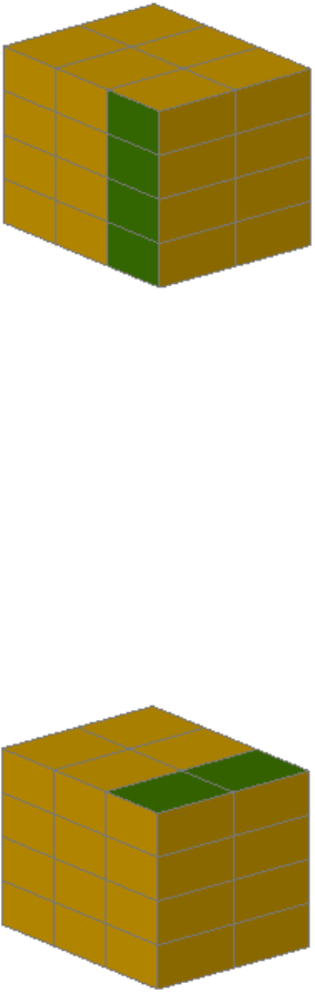
This setting affects new mesh boxes that are created with the MESH (page 617)
command.
See also:
Create a Mesh Box
DIVMESHBOXLENGTH
Sets the number of subdivisions for the length of a mesh box along the X axis.
IntegerType:
User-settingsSaved in:
3Initial value:
This setting affects new mesh boxes that are created with the MESH (page 617)
command.
1256 | Chapter 4 System Variables
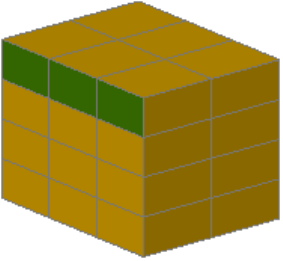
See also:
Create a Mesh Box
DIVMESHBOXWIDTH
Sets the number of subdivisions for the width of a mesh box along the Y axis.
IntegerType:
User-settingsSaved in:
3Initial value:
This setting affects new mesh boxes that are created with the MESH (page 617)
command.
See also:
Create a Mesh Box
DIVMESHCONEAXIS
Sets the number of subdivisions around the perimeter of the mesh cone base.
IntegerType:
User-settingsSaved in:
8Initial value:
System Variables | 1257

This setting affects new mesh cones that are created with the MESH (page 617)
command.
See also:
Create a Mesh Cone
DIVMESHCONEBASE
Sets the number of subdivisions between the perimeter and the center point
of the mesh cone base.
IntegerType:
User-settingsSaved in:
3Initial value:
1258 | Chapter 4 System Variables
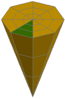

This setting affects new mesh cylinders that are created with the MESH (page
617) command.
See also:
Create a Mesh Cylinder
DIVMESHCYLBASE
Sets the number of radial subdivisions from the center of the mesh cylinder
base to its perimeter.
IntegerType:
User-settingsSaved in:
3Initial value:
System Variables | 1261
This setting affects new mesh cylinders that are created with the MESH (page
617) command.
See also:
Create a Mesh Cylinder
DIVMESHCYLHEIGHT
Sets the number of subdivisions between the base and the top of the mesh
cylinder.
IntegerType:
User-settingsSaved in:
3Initial value:
This setting affects new mesh cylinders that are created with the MESH (page
617) command.
See also:
Create a Mesh Cylinder
DIVMESHPYRBASE
Sets the number of radial subdivisions between the center of the mesh pyramid
base and its perimeter.
IntegerType:
1262 | Chapter 4 System Variables
User-settingsSaved in:
3Initial value:
This setting affects new mesh pyramids that are created with the MESH (page
617) command.
See also:
Create a Mesh Pyramid
DIVMESHPYRHEIGHT
Sets the number of subdivisions between the base and the top of the mesh
pyramid.
IntegerType:
User-settingsSaved in:
3Initial value:
System Variables | 1263
This setting affects new mesh pyramids that are created with the MESH (page
617) command.
See also:
Create a Mesh Pyramid
DIVMESHPYRLENGTH
Sets the number of subdivisions along each dimension of a mesh pyramid
base.
IntegerType:
User-settingsSaved in:
3Initial value:
This setting affects new mesh pyramids that are created with the MESH (page
617) command.
See also:
Create a Mesh Pyramid
DIVMESHSPHEREAXIS
Sets the number of radial subdivisions around the axis endpoint of the mesh
sphere.
IntegerType:
User-settingsSaved in:
1264 | Chapter 4 System Variables
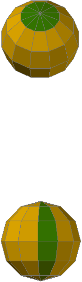
12Initial value:
This setting affects new mesh spheres that are created with the MESH (page
617) command.
See also:
Create a Mesh Sphere
DIVMESHSPHEREHEIGHT
Sets the number of subdivisions between the two axis endpoints of the mesh
sphere.
IntegerType:
User-settingsSaved in:
6Initial value:
This setting affects new mesh spheres that are created with the MESH (page
617) command.
System Variables | 1265
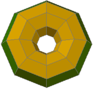
See also:
Create a Mesh Sphere
DIVMESHTORUSPATH
Sets the number of subdivisions in the path that is swept by the profile of a
mesh torus.
IntegerType:
User-settingsSaved in:
8Initial value:
This setting affects new mesh tori that are created with the MESH (page 617)
command.
See also:
Create a Mesh Torus
DIVMESHTORUSSECTION
Sets the number of subdivisions in the profile that sweeps the path of a mesh
torus.
IntegerType:
User-settingsSaved in:
8Initial value:
1266 | Chapter 4 System Variables
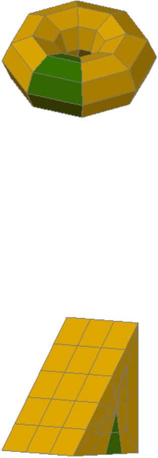
This setting affects new mesh tori that are created with the MESH (page 617)
command.
See also:
Create a Mesh Torus
DIVMESHWEDGEBASE
Sets the number of subdivisions between the midpoint of the perimeter of
triangular dimension of the mesh wedge.
IntegerType:
User-settingsSaved in:
3Initial value:
This setting affects new mesh wedges that are created with the MESH (page
617) command.
System Variables | 1267
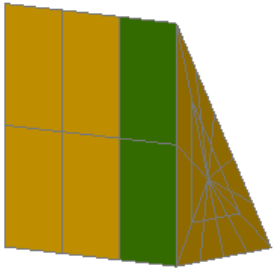
See also:
Create a Mesh Wedge
DIVMESHWEDGEHEIGHT
Sets the number of subdivisions for the height of the mesh wedge along the
Z axis.
IntegerType:
User-settingsSaved in:
3Initial value:
This setting affects new mesh wedges that are created with the MESH (page
617) command.
See also:
Create a Mesh Wedge
DIVMESHWEDGELENGTH
Sets the number of subdivisions for the length of a mesh wedge along the X
axis.
IntegerType:
User-settingsSaved in:
4Initial value:
1268 | Chapter 4 System Variables
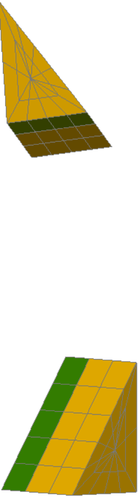
This setting affects new mesh wedges that are created with the MESH (page
617) command.
See also:
Create a Mesh Wedge
DIVMESHWEDGESLOPE
Sets the number of subdivisions in the slope that extends from the apex of
the wedge to the edge of the base.
IntegerType:
User-settingsSaved in:
3Initial value:
System Variables | 1269
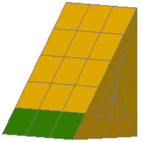
This setting affects new mesh wedges that are created with the MESH (page
617) command.
See also:
Create a Mesh Wedge
DIVMESHWEDGEWIDTH
Sets the number of subdivisions for the width of the mesh wedge along the
Y axis.
IntegerType:
User-settingsSaved in:
3Initial value:
This setting affects new mesh wedges that are created with the MESH (page
617) command.
See also:
Create a Mesh Wedge
DONUTID
Sets the default for the inside diameter of a donut.
RealType:
Not-savedSaved in:
1270 | Chapter 4 System Variables

0.5000Initial value:
See also:
Draw Donuts
DONUTOD
Sets the default for the outside diameter of a donut.
RealType:
Not-savedSaved in:
1.0000Initial value:
The value must be nonzero. If DONUTID is larger than DONUTOD, the two
values are swapped by the next command.
See also:
Draw Donuts
DRAGMODE
Controls the display of objects being dragged.
IntegerType:
RegistrySaved in:
2Initial value:
This system variable has the same name as a command. Use the SETVAR
command to access this system variable.
When it is on, the image of an object is displayed as you drag it to another
location. With some computer configurations, dragging can be
time-consuming. Use DRAGMODE to suppress dragging.
Does not display an outline of the object as you drag it0
Displays the outline of the object as you drag it only if you enter
drag at the Command prompt after selecting the object to drag
1
Auto; always displays an outline of the object as you drag it2
System Variables | 1271
See also:
Set Up the Drawing Area
DRAGP1
When hardware acceleration is used, controls how many vectors the system
draws when you drag objects within a 2D viewport before it checks for a new
input sample from the mouse.
IntegerType:
RegistrySaved in:
5000Initial value:
A larger number results in more graphical vectors being displayed as objects
are dragged. For best performance, it is recommended that you use hardware
acceleration rather than software acceleration. DRAGP1 has no effect when
dragging objects in a 3D viewport.
See also:
Set Up the Drawing Area
DRAGP2
When software acceleration is used, controls how many vectors the system
draws when you drag objects within a 2D viewport before it checks for a new
input sample from the mouse.
(Read-only)
IntegerType:
RegistrySaved in:
10Initial value:
Not supported on Mac OS and is provided for scripting compatibility with the
Windows releases of AutoCAD.
See also:
Set Up the Drawing Area
1272 | Chapter 4 System Variables
DRAGVS
Sets the visual style that is displayed while creating 3D solid and mesh
primitives and extruded solids, surfaces, and meshes.
StringType:
DrawingSaved in:
""Initial value:
You can enter a period (.) to specify the current visual style. DRAGVS can only
be set to a visual style that is saved in the drawing.
DRAGVS has no effect when the current viewport's visual style is set to 2D
Wireframe.
The visual style specified for DRAGVS cannot be removed with the PURGE
(page 849) command.
See also:
Create a Solid Box
DRAWORDERCTL
Controls the default display behavior of overlapping objects when they are
created or edited.
IntegerType:
DrawingSaved in:
3Initial value:
Turns off the default draw order of overlapping objects: after objects
are edited, regardless of their draw order, the objects are displayed
0
on top until a drawing is regenerated (REGEN) or reopened. This
setting also turns off draw order inheritance: new objects that are
created from another object using the commands listed below are
not assigned the draw order of the original object. Use this setting
to improve the speed of editing operations in large drawings. The
commands that are affected by inheritance are BREAK, FILLET,
HATCH, HATCHEDIT, EXPLODE, TRIM, JOIN, PEDIT, and OFFSET.
Turns on the default draw order of objects: after objects are edited,
they are automatically displayed according to the correct draw order.
1
System Variables | 1273
Turns on draw order inheritance: new objects created from another
object using the commands listed above are assigned the draw order
of the original object.
2
Provides full draw order display. Turns on the correct draw order of
objects, and turns on draw order inheritance.
3
NOTE
Full draw order display may slow some editing operations.
See also:
Control How Overlapping Objects Are Displayed
DRSTATE
Indicates whether the Files Recovered dialog box is open or closed.
(Read-only)
IntegerType:
Not-savedSaved in:
VariesInitial value:
Closed0
Open1
See also:
Recover from a System Failure
DTEXTED
Specifies the user interface displayed for editing single-line text.
IntegerType:
RegistrySaved in:
2Initial value:
1274 | Chapter 4 System Variables
Obsolete command. Replaced by the TEXTED (page 1460) system variable.
See also:
Create Single-Line Text
DWGCHECK
Checks drawings for potential problems when opening them.
IntegerType:
RegistrySaved in:
1Initial value:
If a drawing that you try to open has a potential problem, you are
warned before the drawing is opened.
0
If a drawing that you try to open has a potential problem, or if it
was saved by an application other than one released by Autodesk
or based on RealDWG, you are warned before the drawing is opened.
1
If a drawing that you try to open has a potential problem, you are
notified at the Command prompt.
2
If a drawing that you try to open has a potential problem, you are
notified at the Command prompt. If the drawing has a potential
3
problem and the drawing was saved by an application other than
one released by Autodesk or based on RealDWG, you are warned
before the drawing is opened.
See also:
Open a Drawing
DWGCODEPAGE
Stores the same value as SYSCODEPAGE (for compatibility reasons).
(Read-only)
StringType:
System Variables | 1275
Not-savedSaved in:
VariesInitial value:
See also:
Use Unicode and Big Fonts
DWGNAME
Stores the name of the current drawing.
(Read-only)
StringType:
Not-savedSaved in:
Drawing1.dwgInitial value:
If a new drawing has not been saved yet, DWGNAME defaults to Drawing1.dwg.
Additional new drawings are named Drawing2.dwg, Drawing3.dwg, and so on.
The location of the saved drawing file is stored in DWGPREFIX (page 1276).
See also:
Save a Drawing
DWGPREFIX
Stores the drive and folder prefix for the drawing.
(Read-only)
StringType:
Not-savedSaved in:
VariesInitial value:
See also:
Save a Drawing
DWGTITLED
Indicates whether the current drawing has been named.
1276 | Chapter 4 System Variables
(Read-only)
IntegerType:
Not-savedSaved in:
0Initial value:
Drawing has not been named0
Drawing has been named1
See also:
Save a Drawing
DYNCONSTRAINTMODE
Displays hidden dimensional constraints when constrained objects are selected.
IntegerType:
RegistrySaved in:
1Initial value:
Keeps constraints hidden when an object
is selected
0
Displays hidden constraints when dimen-
sionally constrained objects are selected
1
NOTE This system variable takes effect when dynamic constraints are hidden (see
DCDISPLAY (page 257)).
See also:
Control the Display of Dimensional Constraints
DYNDIGRIP
Controls which dynamic dimensions are displayed during grip stretch editing.
BitcodeType:
RegistrySaved in:
System Variables | 1277
31Initial value:
The DYNDIVIS system variable must be set to 2, which displays all dynamic
dimensions.
The setting is stored as a bitcode using the sum of the following values:
None0
Resulting dimension1
Length change dimension2
Absolute angle dimension4
Angle change dimension8
Arc radius dimension16
The DYNMODE (page 1279) system variable turns Dynamic Input features on
and off.
See also:
Use Dynamic Input
DYNDIVIS
Controls how many dynamic dimensions are displayed during grip stretch
editing.
IntegerType:
RegistrySaved in:
1Initial value:
DYNDIGRIP controls which dynamic dimensions are displayed during grip
stretch editing.
Only the first dynamic dimension in the cycle order0
Only the first two dynamic dimensions in the cycle order1
1278 | Chapter 4 System Variables
All dynamic dimensions, as controlled by the DYNDIGRIP (page
1277) system variable
2
The DYNMODE (page 1279) system variable turns Dynamic Input features on
and off.
See also:
Use Dynamic Input
DYNINFOTIPS
Controls whether tips are displayed for using Shift and Ctrl when editing with
grips.
IntegerType:
RegistrySaved in:
1Initial value:
When dynamic input is turned on and you select a grip, a tip at the cursor
lists the available grip options that you can cycle through using Shift or Ctrl..
Hide the Shift and Ctrl tips0
Display the Shift and Ctrl tips1
This setting is on the Dynamic Input tab in the Drafting Settings dialog box
(page 364).
See also:
Use Object Grips
DYNMODE
Turns Dynamic Input features on and off.
IntegerType:
RegistrySaved in:
3Initial value:
System Variables | 1279

When all features are on, the context governs what is displayed.
When DYNMODE is set to a negative value, the Dynamic Input features are
not turned on, but the setting is stored. Press the Dynamic Input button in
the status bar to set DYNMODE to the corresponding positive value.
All Dynamic Input features, including dynamic prompts, off0
Pointer input on1
Dimensional input on2
Both pointer input and dimensional input on3
If dynamic prompts are on (DYNPROMPT (page 1282) is set to 1), they are
displayed when DYNMODE is set to 1, 2, or 3.
When dimensional input is turned on (DYNMODE = 2 or 3), the program
switches to pointer input when you enter a comma or an angle bracket (<),
or when you select multiple grip points.
When DYNMODE is set to 1, 2, or 3, you can turn off all features temporarily
by holding down the temporary override key, Fn-F12.
Settings are on the Dynamic Input tab in the Drafting Settings dialog box
(page 364).
See also:
Use Dynamic Input
DYNPICOORDS
Controls whether pointer input uses relative or absolute format for coordinates.
SwitchType:
RegistrySaved in:
0Initial value:
Relative0
Absolute1
1280 | Chapter 4 System Variables
The DYNMODE (page 1279) system variable turns Dynamic Input features on
and off.
See also:
Use Dynamic Input
DYNPIFORMAT
Controls whether pointer input uses polar or Cartesian format for coordinates.
SwitchType:
RegistrySaved in:
0Initial value:
This setting applies only to a second or next point.
Polar0
Cartesian1
The DYNMODE (page 1279) system variable turns Dynamic Input features on
and off.
See also:
Use Dynamic Input
DYNPIVIS
Controls when pointer input is displayed.
IntegerType:
RegistrySaved in:
1Initial value:
Only when you type at a prompt for a point0
Automatically at a prompt for a point1
Always2
System Variables | 1281
The DYNMODE (page 1279) system variable turns Dynamic Input features on
and off.
See also:
Use Dynamic Input
DYNPROMPT
Controls display of prompts in Dynamic Input tooltips.
IntegerType:
RegistrySaved in:
1Initial value:
Off0
On1
The DYNMODE (page 1279) system variable turns Dynamic Input features on
and off. When DYNMODE is set to 0 (off), prompts are not displayed regardless
of the DYNPROMPT setting.
See also:
Use Dynamic Input
DYNTOOLTIPS
Controls which tooltips are affected by tooltip appearance settings.
SwitchType:
RegistrySaved in:
1Initial value:
Only Dynamic Input value fields0
All drafting tooltips1
1282 | Chapter 4 System Variables
See also:
Use Dynamic Input
E System Variables
EDGEMODE
Controls how the TRIM and EXTEND commands determine cutting and
boundary edges.
IntegerType:
RegistrySaved in:
0Initial value:
Uses the selected edge without any extensions0
Extends or trims the selected object to an imaginary extension of
the cutting or boundary edge
1
Lines, arcs, elliptical arcs, rays, and polylines are objects eligible for natural
extension. The natural extension of a line or ray is an unbounded line (xline),
an arc is a circle, and an elliptical arc is an ellipse. A polyline is broken down
into its line and arc components, which are extended to their natural
boundaries.
See also:
Trim or Extend Objects
ELEVATION
Stores the current elevation of new objects relative to the current UCS.
RealType:
DrawingSaved in:
0.0000Initial value:
System Variables | 1283

See also:
Overview of the User Coordinate System (UCS)
Enter 3D Coordinates
ERHIGHLIGHT
Controls whether reference names or reference objects are highlighted when
their counterparts are selected in the Reference Manager palette or in the
drawing window.
IntegerType:
RegistrySaved in:
1Initial value:
Referenced objects are not highlighted.0
Referenced objects are highlighted.1
See also:
Attach Drawing References (Xrefs)
ERRNO
Displays the number of the appropriate error code when an AutoLISP function
call causes an error that AutoCAD detects.
(Read-only)
IntegerType:
Not-savedSaved in:
0Initial value:
AutoLISP applications can inspect the current value of ERRNO with (getvar
"errno").
The ERRNO system variable is not always cleared to zero. Unless it is inspected
immediately after an AutoLISP function has reported an error, the error that
its value indicates may be misleading. This variable is always cleared when
starting or opening a drawing.
See the AutoLISP Developer's Guide for more information.
1284 | Chapter 4 System Variables
See also:
Overview of AutoLISP
ERSTATE
Indicates whether the Reference Manager palette is open or closed.
(Read-only)
IntegerType:
Not-savedSaved in:
VariesInitial value:
Closed0
Open1
See also:
Attach Drawing References (Xrefs)
EXPERT
Controls whether certain prompts are issued.
IntegerType:
Not-savedSaved in:
0Initial value:
Issues all prompts normally.0
Suppresses “About to regen, proceed?” and “Really want to turn
the current layer off?” (-LAYER (page 537))
1
Suppresses the preceding prompts and “Block already defined. Re-
define it?” (-BLOCK (page 143)) and “A drawing with this name
2
already exists. Overwrite it?” (SAVE (page 914) or WBLOCK (page
1125)).
System Variables | 1285

Suppresses the preceding prompts and those issued by the LINETYPE
(page 575) Command prompt (-LINETYPE) if you try to load a linetype
3
that's already loaded or create a new linetype in a file that already
defines that linetype.
Suppresses the preceding prompts and those issued by UCS (page
1072) Save and VPORTS (page 1115) Save if the name you supply already
exists.
4
Suppresses the prompt, “That name is already in Use, redefine it?”
issued by the -DIMSTYLE (page 314) Save option when you supply
the name of an existing dimension style.
5
Suppresses the same prompt issued by the -SCALELISTEDIT (page
918) Add option.
When a prompt is suppressed by EXPERT, the operation in question is
performed as though you entered y at the prompt. Setting EXPERT can affect
scripts, menu macros, AutoLISP, and the command functions.
See also:
Switch Between Dialog Boxes and the Command Line
EXPLMODE
Controls whether the EXPLODE command supports nonuniformly scaled
(NUS) blocks.
IntegerType:
Not-savedSaved in:
1Initial value:
Does not explode NUS blocks0
Explodes NUS blocks1
See also:
Disassemble a Block Reference (Explode)
1286 | Chapter 4 System Variables
EXTMAX
Stores the upper-right point of the drawing extents.
(Read-only)
3D-pointType:
DrawingSaved in:
VariesInitial value:
Expands outward as new objects are drawn; shrinks only with ZOOM All or
ZOOM Extents. Reported in world coordinates for the current space.
See also:
Magnify a View (Zoom)
EXTMIN
Stores the lower-left point of the drawing extents.
(Read-only)
3D-pointType:
DrawingSaved in:
VariesInitial value:
Expands outward as new objects are drawn; shrinks only with ZOOM All or
ZOOM Extents. Reported in world coordinates for the current space.
See also:
Magnify a View (Zoom)
EXTNAMES
Sets the parameters for named object names (such as linetypes and layers)
stored in definition tables.
IntegerType:
DrawingSaved in:
System Variables | 1287

1Initial value:
Uses AutoCAD R14 parameters, which limit names to 31 characters
in length. Names can include the letters A to Z, the numerals 0 to
0
9, and the special characters dollar sign ($), underscore (_), and
hyphen (-).
Uses AutoCAD 2000 (and later releases) parameters. Names can be
up to 255 characters in length, and can include the letters A to Z,
1
the numerals 0 to 9, spaces, and any special characters not used by
the operating system and AutoCAD for Mac for other purposes.
See also:
Resolve Name Conflicts in External References
F System Variables
FACETERDEVNORMAL
Sets the maximum angle between the surface normal and contiguous mesh
faces.
RealType:
User-settingsSaved in:
40Initial value:
This setting affects mesh that is converted from another object using the
MESHSMOOTH (page 637) command. (For a complete list of objects that can
be converted to mesh, see Objects That Can Be Converted to Mesh (page ?).)
Use this setting to retain visual consistency between mesh objects that have
the same shape but different sizes. You can enter any non-negative number
between 0 (zero) and 180. Lowering the value increases the density in areas
of high curvature and decreases density in flatter areas.
Lowering the value might increase the drawing file size, and should be saved
for larger objects with high FACETERDEVSURFACE (page 1289) settings. Avoid
lowering this value for objects with small details such as holes or fillets.
1288 | Chapter 4 System Variables

NOTE
The value of this system variable reflects the value for objects with no
smoothness.
See also:
Create Meshes by Conversion
FACETERDEVSURFACE
Sets how closely the converted mesh object adheres to the original shape of
the solid or surface.
RealType:
User-settingsSaved in:
0.001Initial value:
This setting affects mesh that is converted from another object using the
MESHSMOOTH (page 637) command. (For a complete list of objects that can
be converted to mesh, see Objects That Can Be Converted to Mesh (page ?).)
You can enter any non-negative number, including 0 (zero). Smaller values
result in a higher number of faces, more accurate meshes with less deviation
from the object surface, and slower performance. Set the value to 0 to turn
off the option.
NOTE
The value of this system variable reflects the value for objects with no
smoothness.
See also:
Create Meshes by Conversion
FACETERGRIDRATIO
Sets the maximum aspect ratio for the mesh subdivisions that are created for
solids and surfaces converted to mesh.
RealType:
User-settingsSaved in:
0.0000Initial value:
System Variables | 1289

This setting affects mesh that is converted from another object using the
MESHSMOOTH (page 637) command. (For a complete list of objects that can
be converted to mesh, see Objects That Can Be Converted to Mesh (page ?).)
Permissible values range from 0 to 100, and set the height/width ratio of the
face. Use this variable to prevent long, thin faces that can result from
cylindrical object conversions. Smaller values result in more, better-formed
faces, but can affect performance. Set this value to 0 to turn it off.
If the value you enter is less than 1, the ratio calculation is based on 1/n. For
example, if you enter 0.2, the variable value is 1/0.2 = 5.
NOTE The value of this system variable reflects the value for objects with no
smoothness.
See also:
Create Meshes by Conversion
FACETERMAXEDGELENGTH
Sets the maximum length of edges for mesh objects that are created by
conversion from solids and surfaces.
RealType:
User-settingsSaved in:
0.0000Initial value:
You can use any non-negative number, including 0 (zero). A value of 0 (zero)
does not restrict the length an edge can be when a surface or solid is converted
to a mesh.
This setting affects mesh that is converted from another object using the
MESHSMOOTH (page 637) command. (For a complete list of objects that can
be converted to mesh, see Objects That Can Be Converted to Mesh (page ?).)
NOTE The value of this system variable reflects the value for objects with no
smoothness.
See also:
Create Meshes by Conversion
1290 | Chapter 4 System Variables
FACETERMAXGRID
Sets the maximum number of U and V grid lines for solids and surfaces
converted to mesh.
IntegerType:
User-settingsSaved in:
4096Initial value:
This setting affects mesh that is converted from another object using the
MESHSMOOTH (page 637) command. (For a complete list of objects that can
be converted to mesh, see Objects That Can Be Converted to Mesh (page ?).)
Permissible values range from 0 to 4096.
NOTE The value of this system variable reflects the value for objects with no
smoothness.
See also:
Create Meshes by Conversion
FACETERMESHTYPE
Sets the type of mesh to be created.
IntegerType:
User-settingsSaved in:
0Initial value:
Objects are converted to an optimized mesh object type with fewer
faces
0
Faces are mostly quadrilateral1
Faces are mostly triangular2
This setting affects mesh that is converted from another object using the
MESHSMOOTH (page 637) command. (For a complete list of objects that can
be converted to mesh, see Objects That Can Be Converted to Mesh (page ?).)
System Variables | 1291

See also:
Create Meshes by Conversion
FACETERMINUGRID
Sets the minimum number of U grid lines for solids and surfaces that are
converted to mesh.
IntegerType:
User-settingsSaved in:
0Initial value:
This setting affects mesh that is converted from another object using the
MESHSMOOTH (page 637) command. (For a complete list of objects that can
be converted to mesh, see Objects That Can Be Converted to Mesh (page ?).)
Permissible values range from 0 to 1023. Setting 0 (zero) turns off the setting.
The value of this system variable cannot exceed the value of FACETERMAX-
GRID (page 1291)/FACETERMINVGRID (page 1292).
NOTE The value of this system variable reflects the value for objects with no
smoothness.
See also:
Create Meshes by Conversion
FACETERMINVGRID
Sets the minimum number of V grid lines for solids and surfaces that are
converted to mesh.
IntegerType:
User-settingsSaved in:
0Initial value:
This setting affects mesh that is converted from a 3D solid or surface object
using the MESHSMOOTH (page 637) command. (For a complete list of objects
that can be converted to mesh, see Objects That Can Be Converted to Mesh
(page ?).)
1292 | Chapter 4 System Variables
Permissible values range from 0 to 1023. Setting 0 (zero) turns off the setting.
The value of this system variable cannot exceed the value of FACETERMAX-
GRID (page 1291)/FACETERMINUGRID (page 1292).
NOTE The value of this system variable reflects the value for objects with no
smoothness.
See also:
Create Meshes by Conversion
FACETERPRIMITIVEMODE
Specifies whether the smoothness settings for objects that are converted to a
mesh.
BitcodeType:
User-settingsSaved in:
1Initial value:
Applies settings from the FACETERSMOOTHLEV system variable to the
converted object.
0
Applies settings from the DIVMESH* system variables to the converted
object.
1
This setting affects a mesh that is converted from a primitive 3D solid object
(such as box or cone) using the MESHSMOOTH (page 637) command. (For a
complete list of objects that can be converted to mesh, see Objects That Can
Be Converted to Mesh (page ?).)
See also:
Create Meshes by Conversion
FACETERSMOOTHLEV
Sets the default level of smoothness for objects that are converted to mesh.
IntegerType:
User-settingsSaved in:
System Variables | 1293
1Initial value:
Does not smooth the object after conversion-1 or any negat-
ive number
Does not smooth the object after conversion0
Applies smoothness level 1 after conversion1
Applies smoothness level 2 after conversion2
Applies smoothness level 3 after conversion3
This variable sets the default level of smoothness that is applied to mesh that
is created as a result of conversion from another object with the MESHSMOOTH
(page 637) command.
The value cannot be greater than the value of SMOOTHMESHMAXLEV (page
1439).
Mesh objects that are created under the following circumstances are always
created without smoothness, and are not affected by this system variable:
■Mesh created using REVSURF (page 905), TABSURF (page 1039), RULESURF
(page 912), or EDGESURF (page 399)
■Mesh created using MESHSMOOTH when the type of mesh is set to be
quadrilateral or triangular (FACETERMESHTYPE (page 1291))
For a complete list of objects that can be converted to mesh, see Objects That
Can Be Converted to Mesh (page ?).
See also:
Create Meshes by Conversion
FACETRATIO
Controls the aspect ratio of faceting for cylindrical and conic solids.
IntegerType:
Not-savedSaved in:
1294 | Chapter 4 System Variables
0Initial value:
Creates an N by 1 mesh for cylindrical and conic solids0
Creates an N by M mesh for cylindrical and conic solids1
A setting of 1 increases the density of the mesh to improve the quality of
rendered and shaded models.
The faceting is visible only in the 2D Wireframe visual style.
See also:
Create 3D Solid Primitives
FACETRES
Adjusts the smoothness of shaded and rendered objects and objects with
hidden lines removed.
RealType:
DrawingSaved in:
0.5000Initial value:
Valid values are from 0.01 to 10.0.
See also:
Balance Mesh Density for Smooth Geometry
FIELDDISPLAY
Controls whether fields are displayed with a gray background.
IntegerType:
RegistrySaved in:
1Initial value:
The background is not plotted.
Fields are displayed with no background0
System Variables | 1295
Fields are displayed with a gray background1
See also:
Update Fields
FIELDEVAL
Controls how fields are updated.
IntegerType:
DrawingSaved in:
31Initial value:
The setting is stored as a bitcode using the sum of the following values:
Not updated0
Updated on open1
Updated on save2
Updated on plot4
Not used8
Updated on regeneration16
NOTE The Date field is updated by UPDATEFIELD (page 1100), but it is not updated
automatically based on the setting of the FIELDEVAL system variable.
See also:
Update Fields
FILEDIA
Suppresses display of file navigation dialog boxes.
1296 | Chapter 4 System Variables

IntegerType:
RegistrySaved in:
1Initial value:
Does not display dialog boxes. You can still request a file dialog box
to appear by entering a tilde (~) in response to the command's
prompt. The same is true for AutoLISP and ObjectARX.
0
Displays dialog boxes. However, if a script or AutoLISP/ObjectARX™
program is active, an ordinary prompt is displayed.
1
See also:
Switch Between Dialog Boxes and the Command Line
FILLETRAD
Stores the current fillet radius for 2D objects.
RealType:
DrawingSaved in:
0.0000Initial value:
If you use the FILLET (page 432) command to change the radius of a 2D fillet,
the value of this system variable changes to match.
See also:
Create Fillets
FILLETRAD3D
Stores the current fillet radius for 3D objects.
RealType:
DrawingSaved in:
1.0000Initial value:
Stores the default radius for 3D solid and surface fillets created with the FIL-
LETEDGE (page 436) and SURFFILLET (page 1016) commands. If you change the
radius while using the FILLETEDGE or SURFFILLET commands, the FILLETRAD
system variable does not update to this new value.
System Variables | 1297
See also:
Fillet a Surface
Modify Edges on 3D Objects
FILLMODE
Specifies whether hatches and fills, 2D solids, and wide polylines are filled in.
IntegerType:
DrawingSaved in:
1Initial value:
Objects are not filled0
Objects are filled1
See also:
Control the Display of Polylines, Hatches, Gradient Fills, Lineweights, and
Text
FONTALT
Specifies the alternate font to be used when the specified font file cannot be
located.
StringType:
RegistrySaved in:
simplex.shxInitial value:
When a drawing file with a defined text style is opened and an alternate font
is not specified, the Alternate Font dialog box is displayed.
See also:
Substitute Fonts
1298 | Chapter 4 System Variables
FONTMAP
Specifies the font mapping file to be used.
StringType:
RegistrySaved in:
acad.fmpInitial value:
A font mapping file contains one font mapping per line; the original font used
in the drawing and the font to be substituted for it are separated by a semicolon
(;). For example, to substitute the Times TrueType font for the Roman font,
the line in the mapping file would read as follows:
romanc.shx;times.ttf
If FONTMAP does not point to a font mapping file, if the FMP file is not found,
or if the font file name specified in the FMP file is not found, the font defined
in the style is used. If the font in the style is not found, a font is substituted
according to the substitution rules.
FONTMAP affects the creation, editing, and display of all text objects.
See also:
Substitute Fonts
FRAME
Turns the display of frames on and off for all external references and raster
images.
IntegerType:
DrawingSaved in:
3Initial value:
The FRAME setting overrides the individual XCLIPFRAME (page 1524) and IM-
AGEFRAME (page 1331) settings.
The frame is not visible and it is not plotted.0
The frame temporarily reappears during selection preview or object
selection.
Displays and plots the frame.1
System Variables | 1299
Displays but does not plot the frame.2
The individual setting varies for all external references in the current
drawing (raster images and clipped xrefs all have different frame
settings).
3
See also:
Show and Hide Raster Image Boundaries
Update Referenced Drawing Attachments
FRAMESELECTION
Controls whether the frame of a raster image or clipped xref can be selected.
IntegerType:
RegistrySaved in:
1Initial value:
Hidden frames cannot be selected.0
Hidden frames can be selected.1
NOTE The PREVIEWFILTER (page 1404) system variable may prevent the frame from
redisplaying during selection preview, but the frame can still be selected.
See also:
Clip External References and Blocks
Show and Hide Raster Image Boundaries
FRONTZ
Stores the front clipping plane offset from the target plane for the current
viewport, in drawing units.
(Read-only)
RealType:
DrawingSaved in:
1300 | Chapter 4 System Variables
0.0000Initial value:
The front clipping and front clip not at eye bitcodes in VIEWMODE (page 1487)
are on. The FRONTZ value is the last front clipping plane value set current
with the DVIEW command. The distance of the front clipping plane from the
camera point is found by subtracting FRONTZ from the camera-to-target
distance.
See also:
Create a 3D Dynamic View (DVIEW)
FULLPLOTPATH
Controls whether the full path of the drawing file is sent to the plot spooler.
IntegerType:
RegistrySaved in:
1Initial value:
Sends the drawing file name only0
Sends the full path of the drawing file1
See also:
Print or Plot Drawings
G System Variables
GEOMARKERVISIBILITY
Controls the visibility of geographic markers.
IntegerType:
DrawingSaved in:
1Initial value:
Geographic marker is not visible0
System Variables | 1301

Geographic marker is visible1
GFANG
Specifies the angle of a gradient fill.
RealType:
Not-savedSaved in:
0Initial value:
Valid values range from 0 to less than 360 (degrees). Negative values and values
equal to or greater than 360 are accepted, but they are converted to the
equivalent value between 0 and 360.
See also:
Choose a Hatch Pattern or Fill
GFCLR1
Specifies the color for a one-color gradient fill or the first color for a two-color
gradient fill.
StringType:
Not-savedSaved in:
"Blue"Initial value:
Valid values include the following:
■AutoCAD Color Index (ACI): integer values from 1 to 255, or a color name
from the first seven colors
■True Colors: RGB or HSL values from 000 to 255 in the form
"RGB:130,200,240"
■Color Books: Text from standard color books, guides, or sets, for example
"DIC COLOR GUIDE(R)$DIC 43"
See also:
Choose a Hatch Pattern or Fill
1302 | Chapter 4 System Variables
GFCLR2
Specifies the second color for a two-color gradient fill.
StringType:
Not-savedSaved in:
"Yellow"Initial value:
Valid values include the following:
■AutoCAD Color Index (ACI): integer values from 1 to 255, or a color name
from the first seven colors
■True Colors: RGB or HSL values from 000 to 255 in the form
"RGB:130,200,240"
■Color Books: Text from standard color books, guides, or sets, for example
"DIC COLOR GUIDE(R)$DIC 43"
See also:
Choose a Hatch Pattern or Fill
GFCLRLUM
Controls the tint or shade level in a one-color gradient fill.
RealType:
Not-savedSaved in:
1.0000Initial value:
A tint gradient transitions toward white and a shade gradient transitions
toward black. Valid values range from 0.0 (darkest) to 1.0 (lightest).
See also:
Choose a Hatch Pattern or Fill
GFCLRSTATE
Specifies whether a gradient fill uses one color or two colors.
IntegerType:
Not-savedSaved in:
System Variables | 1303

0Initial value:
Two-color gradient fill0
One-color gradient fill1
See also:
Choose a Hatch Pattern or Fill
GFNAME
Specifies the pattern of a gradient fill.
IntegerType:
Not-savedSaved in:
1Initial value:
Linear1
Cylindrical2
Inverted cylindrical3
Spherical4
Hemispherical5
Curved6
Inverted spherical7
Inverted hemispherical8
Inverted curved9
See also:
Choose a Hatch Pattern or Fill
1304 | Chapter 4 System Variables
GFSHIFT
Specifies whether the pattern in a gradient fill is centered or is shifted up and
to the left.
IntegerType:
Not-savedSaved in:
0Initial value:
Centered0
Shifted up and to the left1
See also:
Choose a Hatch Pattern or Fill
GRIDDISPLAY
Controls the display behavior and display limits of the grid.
BitcodeType:
DrawingSaved in:
2Initial value:
The setting is stored as a bitcode using the sum of the following values:
Restricts the grid to the area specified by the LIMITS command0
Does not restrict the grid to the area specified by the LIMITS com-
mand
1
Turns on adaptive grid display, which limits the density of the grid
when zoomed out
2
If the grid is set to adaptive display and when zoomed in, generates
additional, more closely spaced grid lines in the same proportion
as the intervals of the major grid lines
4
Changes the grid plane to follow the XY plane of the dynamic UCS.8
System Variables | 1305
NOTE
Setting 4 is ignored unless setting 2 is specified.
See also:
Adjust Grid and Grid Snap
GRIDMAJOR
Controls the frequency of major grid lines compared to minor grid lines.
IntegerType:
DrawingSaved in:
5Initial value:
Valid values range from 1 to 100.
Grid lines are displayed in any visual style.
See also:
Adjust Grid and Grid Snap
GRIDMODE
Specifies whether the grid is turned on or off.
IntegerType:
DrawingSaved in:
1Initial value:
Turns the grid off0
Turns the grid on1
See also:
Adjust Grid and Grid Snap
1306 | Chapter 4 System Variables
GRIDSTYLE
Controls the style of grid displayed for 2D model space, Block Editor, 3D
parallel projection, 3D perspective projection, and Sheet and Layout tabs.
IntegerType:
RegistrySaved in:
0Initial value:
The setting is stored as an integer using the sum of the following values:
Displays lined grid for 2D model space, Block Editor, 3D parallel
projection, 3D perspective projection, and Sheet and Layout.
0
Displays dotted grid for 2D model space.1
Displays dotted grid for Block Editor.2
Displays dotted grid for Sheet and Layout.4
See also:
Adjust Grid and Grid Snap
GRIDUNIT
Specifies the grid spacing (X and Y) for the current viewport.
2D-pointType:
DrawingSaved in:
0.5000,0.5000 (imperial) or 10,10 (metric)Initial value:
See also:
Adjust Grid and Grid Snap
GRIPBLOCK
Controls the display of grips in blocks.
IntegerType:
System Variables | 1307

RegistrySaved in:
0Initial value:
Assigns a grip only to the insertion point of the block0
Assigns grips to objects within the block1
See also:
Control Grips in Blocks
GRIPCOLOR
Controls the color of unselected grips.
IntegerType:
RegistrySaved in:
150Initial value:
The valid range is 1 to 255.
See also:
Use Object Grips
GRIPCONTOUR
Controls the color of the grip contour.
IntegerType:
RegistrySaved in:
251Initial value:
The valid range is 1 to 255.
See also:
Use Object Grips
1308 | Chapter 4 System Variables
GRIPDYNCOLOR
Controls the color of custom grips for dynamic blocks.
IntegerType:
RegistrySaved in:
140Initial value:
The valid range is 1 to 255.
See also:
Work with Dynamic Blocks in Drawings
GRIPHOT
Controls the color of selected grips.
IntegerType:
RegistrySaved in:
12Initial value:
The valid range is 1 to 255.
See also:
Use Object Grips
GRIPHOVER
Controls the fill color of an unselected grip when the cursor pauses over it.
IntegerType:
RegistrySaved in:
11Initial value:
The valid range is 1 to 255.
See also:
Use Object Grips
System Variables | 1309
GRIPMULTIFUNCTIONAL
Specifies the access methods for multi-functional grip options.
BitcodeType:
RegistrySaved in:
3Initial value:
Access to multi-functional grips is disabled0
Access multi-functional grips with Ctrl-cycling and the Hot Grip
shortcut menu
1
Access multi-functional grips with the dynamic menu and the Hot
Grip shortcut menu
2
Access multi-functional grips with Ctrl-cycling, the dynamic menu,
and the Hot Grip shortcut menu
3
See also:
Choose a Method to Modify Objects
Use Object Grips
GRIPOBJLIMIT
Suppresses the display of grips when the selection set includes more than the
specified number of objects.
IntegerType:
RegistrySaved in:
100Initial value:
The valid range is 0 to 32,767. For example, when set to 1, grips are suppressed
when more than one object is selected. When set to 0, grips are always
displayed.
See also:
Use Object Grips
1310 | Chapter 4 System Variables

GRIPS
Controls the display of grips on selected objects.
IntegerType:
RegistrySaved in:
2Initial value:
Hides grips0
Displays grips1
Displays additional midpoint grips on polyline segments2
To adjust the size of the grips and the effective selection area used by the
cursor when you snap to a grip, use GRIPSIZE (page 1311).
See also:
Use Object Grips
GRIPSIZE
Sets the size of the grip box in pixels.
IntegerType:
RegistrySaved in:
5Initial value:
The valid range is 1 to 255.
See also:
Use Object Grips
GRIPSUBOBJMODE
Controls whether grips are automatically selected (made “hot”) when
subobjects are selected.
BitcodeType:
System Variables | 1311
RegistrySaved in:
1Initial value:
Does not turn grips hot when subobjects are selected.0
Turns the face, edge, or vertex grips hot when subobjects of 3D ob-
jects (solid, surface, or mesh) are selected.
1
Turns the grips hot when subobjects of 2D polyline objects (line or
arc segments) are selected.
2
Turns the grips hot when subobjects of3
■3D objects (faces, edges, or vertices) are selected
■2D polyline objects (line or arc segments) are selected
Setting this system variable to 1 is especially helpful for quickly modifying
groups of faces, edges, and vertices on mesh objects.
See also:
Use Grips to Edit 3D Solids and Surfaces
Choose a Method to Modify Objects
GRIPTIPS
Controls the display of grip tips when the cursor hovers over grips on dynamic
blocks and custom objects that support grip tips.
IntegerType:
RegistrySaved in:
1Initial value:
Turns off the display of grip tips.0
Turns on the display of grip tips.1
See also:
Use Object Grips
1312 | Chapter 4 System Variables
Choose a Method to Modify Objects
GROUPDISPLAYMODE
Controls the display and grips on groups, when group selection is on.
IntegerType:
RegistrySaved in:
2Initial value:
Displays grips on all objects in the selected group0
Displays a single grip at the center of the grouped objects1
Displays the group bounding box with a single grip at the center2
Group selection is enabled by setting the PICKSTYLE (page 1394) system variable
to 1 or 3.
See also:
Select Objects in Groups
GROUPLAYERDELETABLE
Controls what happens to the layers referenced by a layer group when the
group is deleted.
IntegerType:
RegistrySaved in:
0Initial value:
Layers referenced by a layer group are not
removed from the drawing when the group
is deleted.
0
You are prompted on how to handle the
deletion of layers referenced by the layer
group being deleted.
1
System Variables | 1313
When deleting the referenced layers, you
will be prompted on how to handle layers
that contain objects on them.
See also:
The Layers Palette
GROUPSONTOP
Controls how layer groups are sorted in the Layers palette.
IntegerType:
RegistrySaved in:
0Initial value:
Layers and layer groups are sorted together
and alphanumerically by name
0
Layers and layer groups are sorted separ-
ately, layer groups appear at the top of the
Layers list
1
Layers and layer groups are sorted separ-
ately, layer groups appear at the bottom of
the Layers list
2
See also:
The Layers Palette
GTAUTO
Controls whether 3D gizmos are automatically displayed when you select
objects before you start a command in a viewport with a 3D visual style.
IntegerType:
RegistrySaved in:
1314 | Chapter 4 System Variables

1Initial value:
Gizmos are not displayed automatically when you select objects
before starting a command.
0
Gizmos are displayed automatically after you create a selection set.1
This system variable affects the display of the 3D Move, 3D Rotate, and 3D
Scale gizmos. Gizmos were previously known as “grip tools.”
See also:
Use the Gizmos
GTDEFAULT
Controls whether the 3D Move, 3D Rotate, or 3D Scale operation starts
automatically when you start the MOVE, ROTATE, or SCALE command in a
viewport with a 3D visual style.
IntegerType:
RegistrySaved in:
0Initial value:
Does not automatically start the 3DMOVE (page 36), 3DROTATE
(page 48), or 3DSCALE (page 50) commands when the MOVE (page
0
671), ROTATE (page 907), or SCALE (page 916) commands are started
in a 3D view.
Automatically starts the 3DMOVE, 3DROTATE, or 3DSCALE com-
mands when the MOVE, ROTATE, or SCALE commands are started
in a 3D view.
1
See also:
Use the Gizmos
System Variables | 1315
GTLOCATION
Controls the initial location of the 3D Move, 3D Rotate, or 3D Scale gizmo
when you select objects before you start a command in a viewport with a 3D
visual style.
IntegerType:
RegistrySaved in:
1Initial value:
Places the 3D Move, 3D Rotate, or 3D Scale gizmo at the same
location as the UCS icon. The gizmo orientation is aligned with the
current UCS.
0
Places the 3D Move, 3D Rotate, or 3D Scale gizmo at the geometric
center of the selection set.
1
This system variable affects the display of the 3D Move, 3D Rotate, and 3D
Scale gizmos. Gizmos were previously known as “grip tools.”
See also:
Use the Gizmos
H System Variables
HALOGAP
Specifies a gap to be displayed where an object is hidden by another object.
IntegerType:
DrawingSaved in:
0Initial value:
The value is specified as a percent of one unit and is independent of the zoom
level.
HALOGAP is available only in 2D views. In 3D views, the VSHALOGAP (page
1505) system variable is used.
1316 | Chapter 4 System Variables
See also:
Use a Visual Style to Display Your Model
HANDLES
Reports whether object handles can be accessed by applications.
(Read-only)
IntegerType:
DrawingSaved in:
OnInitial value:
Because handles can no longer be turned off, has no effect except to preserve
the integrity of scripts.
See also:
Overview of Command Scripts
HELPPREFIX
Sets the file path for the Help system.
StringType:
RegistrySaved in:
VariesInitial value:
See also:
Set Up the Drawing Area
Application Tab (Application Preferences Dialog Box) (page 734)
HIDEPRECISION
Controls the accuracy of hides and shades.
IntegerType:
Not-savedSaved in:
0Initial value:
System Variables | 1317
Hides can be calculated in double precision or single precision. Setting
HIDEPRECISION to 1 produces more accurate hides by using double precision,
but this setting also uses more memory and can affect performance, especially
when hiding solids.
Single precision; uses less memory0
Double precision; uses more memory1
See also:
Shade a Model and Use Edge Effects
HIDETEXT
Specifies whether text objects created by the TEXT or MTEXT command are
processed during a HIDE command.
SwitchType:
DrawingSaved in:
OnInitial value:
Text is not hidden and does not hide other objectsOff
Text is hidden but does not hide other objectsOn
See also:
Shade a Model and Use Edge Effects
HIGHLIGHT
Controls object highlighting; does not affect objects selected with grips.
IntegerType:
Not-savedSaved in:
1Initial value:
Turns off object selection highlighting0
1318 | Chapter 4 System Variables
Turns on object selection highlighting1
See also:
Customize Object Selection
HPANG
Sets the angle for new hatch patterns.
RealType:
Not-savedSaved in:
0.0000Initial value:
See also:
Overview of Hatch Patterns and Fills
HPANNOTATIVE
Controls whether a new hatch pattern is annotative.
IntegerType:
DrawingSaved in:
0Initial value:
Nonannotative0
Annotative1
See also:
Overview of Scaling Annotations
HPASSOC
Controls whether hatches and fills are associative.
IntegerType:
System Variables | 1319
RegistrySaved in:
1Initial value:
Hatches and fills are not associated with their defining boundary
objects
0
Hatches and fills are associated with their defining boundary objects
and are updated when the boundary objects change
1
See also:
Specify Hatch and Fill Areas
HPBACKGROUNDCOLOR
Controls the background color for hatch patterns.
StringType:
DrawingSaved in:
NoneInitial value:
Valid values include the following:
■“None” or “.” for no background color
■AutoCAD Color Index (ACI): integer values from 1 to 255, or a color name
from the first seven colors
■True Colors: RGB or HSL values from 000 to 255 in the form
"RGB:130,200,240"
■Color Books: Text from standard color books, guides, or sets, for example
"DIC COLOR GUIDE(R)$DIC 43"
See also:
Set Property Overrides for Hatches and Fills
HPBOUND
Controls the object type created by HATCH and BOUNDARY.
IntegerType:
Not-savedSaved in:
1320 | Chapter 4 System Variables
1Initial value:
Creates a region0
Creates a polyline1
A polyline or region object is created only if the HPBOUNDRETAIN system
variable is turned on.
See also:
Specify Hatch and Fill Areas
HPBOUNDRETAIN
Controls whether boundary objects are created for new hatches and fills.
IntegerType:
DrawingSaved in:
0Initial value:
Does not create boundary objects0
Creates boundary objects according to the HPBOUND system vari-
able
1
See also:
Specify Hatch and Fill Areas
HPCOLOR
Sets a default color for new hatches.
StringType:
DrawingSaved in:
use currentInitial value:
Valid values include the following:
■“.” to use the current color set in the CECOLOR system variable
System Variables | 1321

■ByLayer or ByBlock
■AutoCAD Color Index (ACI): integer values from 1 to 255, or a color name
from the first seven colors
■True Colors: RGB or HSL values from 000 to 255 in the form
"RGB:130,200,240"
■Color Books: Text from standard color books, guides, or sets, for example
"DIC COLOR GUIDE(R)$DIC 43"
Values other than the “.” (use current) value override the current color
(CECOLOR).
See also:
Set Property Overrides for Hatches and Fills
HPDLGMODE
Controls the display of the Hatch and Gradient dialog box and the Hatch Edit
dialog box.
IntegerType:
User-settingsSaved in:
2Initial value:
Hatch and Gradient dialog box is not displayed for HATCH and
GRADIENT unless Settings is entered at the Command prompt.
0 or 2
Hatch and Gradient dialog box is displayed for HATCH and GRADI-
ENT.
1
See also:
Overview of Hatch Patterns and Fills
HPDOUBLE
Specifies hatch pattern doubling for user-defined patterns.
IntegerType:
Not-savedSaved in:
1322 | Chapter 4 System Variables
0Initial value:
Doubling specifies a second set of lines drawn at 90 degrees to the original
lines.
Turns off hatch pattern doubling0
Turns on hatch pattern doubling1
See also:
Choose a Hatch Pattern or Fill
HPDRAWORDER
Controls the draw order of hatches and fills.
IntegerType:
Not-savedSaved in:
3Initial value:
Controls whether hatch and fill objects are displayed in front or behind all
other objects, or in front or behind their associated boundaries.
None. The hatch or fill is not assigned a draw order.0
Send to back. The hatch or fill is sent to the back of all other objects.1
Bring to front. The hatch or fill is brought to the front of all other
objects.
2
Send behind boundary. The hatch or fill is sent behind the hatch’s
boundary objects.
3
Bring in front of boundary. The hatch or fill is brought in front of
the hatch’s boundary objects.
4
See also:
Set Property Overrides for Hatches and Fills
System Variables | 1323

HPGAPTOL
Treats a set of objects that almost enclose an area as a closed hatch boundary.
RealType:
RegistrySaved in:
0.0000Initial value:
The default value, 0, specifies that the objects enclose the area, with no gaps.
Enter a value, in drawing units, from 0 to 5000 to set the maximum size of
gaps that can be ignored when the objects serve as a hatch boundary.
See also:
Specify Hatch and Fill Areas
HPINHERIT
Controls whether to inherit the hatch origin when using the Inherit Properties
option in HATCH and HATCHEDIT.
IntegerType:
DrawingSaved in:
0Initial value:
The hatch origin is taken from HPORIGIN0
The hatch origin is taken from the source hatch object1
See also:
Modify Hatch Alignment, Scale, and Rotation
HPISLANDDETECTION
Controls how islands within the hatch boundary are treated.
IntegerType:
DrawingSaved in:
1324 | Chapter 4 System Variables
1Initial value:
Normal. Hatches islands within islands.0
Outer. Hatches only areas outside of islands.1
Ignore. Hatches everything within the boundaries.2
An island is an enclosed area within the area to be hatched.
See also:
Specify Hatch and Fill Areas
HPISLANDDETECTIONMODE
Controls whether internal closed boundaries, called islands, are detected.
IntegerType:
DrawingSaved in:
1Initial value:
Off0
.
On (recommended). Hatches or ignores islands according to HPIS-
LANDDETECTION.
1
See also:
Specify Hatch and Fill Areas
HPLAYER
Specifies a default layer for new hatches and fills.
StringType:
DrawingSaved in:
use currentInitial value:
System Variables | 1325
Values other than the “.” (use current) value override the current layer
(CELAYER).
See also:
Set Property Overrides for Hatches and Fills
HPMAXAREAS
Sets the maximum number of enclosed areas that a single hatch object can
have and still automatically switch between solid and pattern hatches during
zoom operations.
RealType:
RegistrySaved in:
100Initial value:
Valid values are from 0 to10,000,000.
See also:
Control the Scale of Hatch Patterns
HPMAXLINES
Sets the maximum number of hatch lines that are generated in a hatch
operation.
RealType:
RegistrySaved in:
1000000Initial value:
Valid values are from 100 to10,000,000.
See also:
Control the Scale of Hatch Patterns
HPNAME
Sets the default hatch pattern name.
StringType:
1326 | Chapter 4 System Variables
Not-savedSaved in:
ANSI31 (imperial) or ANGLE (metric)Initial value:
Valid names can contain up to 34 characters without spaces. The value ""
indicates that there is no default. Enter a period (.) to reset HPNAME to the
default value.
See also:
Choose a Hatch Pattern or Fill
HPOBJWARNING
Sets the number of hatch boundary objects that can be selected before
displaying a warning message.
IntegerType:
RegistrySaved in:
10000Initial value:
The maximum value can vary, but is significantly larger than 100000000 (one
hundred million).
See also:
Control the Scale of Hatch Patterns
HPORIGIN
Sets the hatch origin point for new hatch patterns relative to the current user
coordinate system.
2D-pointType:
DrawingSaved in:
0.0000,0.0000Initial value:
See also:
Control the Hatch Origin Point
System Variables | 1327
HPORIGINMODE
Controls how the default hatch origin point is determined.
IntegerType:
RegistrySaved in:
0Initial value:
Uses HPORIGIN0
Uses the bottom-left corner of the rectangular extents of the hatch
boundaries
1
Uses the bottom-right corner of the rectangular extents of the hatch
boundaries
2
Uses the top-right corner of the rectangular extents of the hatch
boundaries
3
Uses the top-left corner of the rectangular extents of the hatch
boundaries
4
Uses the center of the rectangular extents of the hatch boundaries5
See also:
Control the Hatch Origin Point
HPQUICKPREVIEW
Controls whether a hatch preview is displayed when specifying a hatch area.
SwitchType:
User-settingsSaved in:
0Initial value:
No preview0 or OFF
Quick preview1 or ON
1328 | Chapter 4 System Variables

See also:
Specify Hatch and Fill Areas
HPQUICKPREVTIMEOUT
Sets the maximum time for a hatch preview to generate before the preview is
automatically cancelled.
IntegerType:
RegistrySaved in:
2Initial value:
If the specified duration is reached, and the preview is not complete, the
preview is cancelled, but the command remains active.
The duration is measured in seconds. Valid values range from 1 to 300.
NOTE The HPQUICKPREVIEW (page 1328) system variable controls whether a preview
is generated when using the HATCH (page 471) command.
See also:
Specify Hatch and Fill Areas
HPSCALE
Sets the hatch pattern scale factor.
RealType:
Not-savedSaved in:
1.0000Initial value:
See also:
Control the Scale of Hatch Patterns
HPSEPARATE
Controls whether a single hatch object or separate hatch objects are created
when operating on several closed boundaries.
System Variables | 1329

IntegerType:
RegistrySaved in:
0Initial value:
A single hatch object is created0
Separate hatch objects are created1
See also:
Specify Hatch and Fill Areas
HPSPACE
Sets the hatch pattern line spacing for user-defined patterns.
RealType:
Not-savedSaved in:
1.0000Initial value:
See also:
Control the Scale of Hatch Patterns
HPTRANSPARENCY
Sets the default transparency for new hatches and fills.
StringType:
DrawingSaved in:
use currentInitial value:
Valid values include “use current” (or “.”), ByLayer, ByBlock, and integer values
from 0 to 90. The higher the value, the more transparent the hatch.
Values other than “use current” or “.” override the current transparency
(CETRANSPARENCY (page 1188)).
Changing this value does not affect existing hatch objects.
See also:
Set Property Overrides for Hatches and Fills
1330 | Chapter 4 System Variables
I System Variables
ICONSIZE
Controls the size of the icons displayed on the Tool Sets palette and status
bar.
IntegerType:
RegistrySaved in:
16Initial value:
Valid values are from 16 to 32.
See also:
The Tool Sets Palette
The Status Bar
IMAGEFRAME
Controls whether image frames are displayed and plotted.
IntegerType:
DrawingSaved in:
1Initial value:
The FRAME (page 1299) system variable overrides the IMAGEFRAME setting.
Use the IMAGEFRAME system variable after the FRAME system variable to
reset the image frame settings.
The image frame is not diplayed or plotted.0
The frame temporarily reappears during selection preview or object
selection.
Displays and plots the image frame.1
Displays but does not plot the image frame.2
See also:
Show and Hide Raster Image Boundaries
System Variables | 1331
IMAGEHLT
Controls whether the entire raster image or only the raster image frame is
highlighted.
IntegerType:
RegistrySaved in:
0Initial value:
Highlights only the raster image frame0
Highlights the entire raster image1
See also:
Improve the Display Speed of Raster Images
IMPLIEDFACE
Controls the detection of implied faces.
IntegerType:
RegistrySaved in:
1Initial value:
Implied faces cannot be detected.0
Implied faces can be detected.1
An implied face is a closed area that creates a boundary by intersecting or
overlapping a face on a 3D solid object.
This variable affects the ability to use implied faces when you press Ctrl-Shift-E
and drag the area inside the boundary to create an extrusion dynamically.
This variable must be set to 1 if you want to select and modify implied faces.
See also:
Press or Pull Bounded Areas
1332 | Chapter 4 System Variables
INDEXCTL
Controls whether layer and spatial indexes are created and saved in drawing
files.
IntegerType:
DrawingSaved in:
0Initial value:
To receive the maximum benefit of demand loading, it is recommended that
you save any drawings that are used as xrefs with layer and spatial indexes
No indexes are created0
Layer index is created1
Spatial index is created2
Layer and spatial indexes are created3
See also:
Work with Layer and Spatial Indexes
INETLOCATION
Stores the Internet location used by the BROWSER command.
StringType:
RegistrySaved in:
http://www.autodesk.comInitial value:
See also:
Get Started with Internet Access
INPUTHISTORYMODE
Controls the content and location of the user input history.
BitcodeType:
System Variables | 1333

RegistrySaved in:
15Initial value:
The setting is stored as a bitcode using the sum of the following values:
No history of recent input is displayed.0
History of recent input is displayed at the command line or in a dy-
namic prompt tooltip. Access with the Up Arrow and Down Arrow
keys at the Command prompt, or at an input prompt.
1
History of recent input for the current command is displayed in the
shortcut menu under Recent Input.
2
History of recent input for all commands in the current session is
displayed in the shortcut menu under Recent Input.
4
Markers for recent input of point locations are displayed. Use the
arrow keys at the Command prompt for specifying a point location.
8
See also:
The Command Line
Work with Shortcut Menus
INSBASE
Stores the insertion base point set by BASE, which gets expressed as a UCS
coordinate for the current space.
3D-pointType:
DrawingSaved in:
0.0000,0.0000,0.0000Initial value:
See also:
Insert Blocks
1334 | Chapter 4 System Variables
INSNAME
Sets a default block name for the INSERT command.
StringType:
Not-savedSaved in:
""Initial value:
The name must conform to symbol naming conventions. Returns "" if no
default is set. Enter a period (.) to set no default.
See also:
Insert Blocks
INSUNITS
Specifies a drawing-units value for automatic scaling of blocks, images, or xrefs
when inserted or attached to a drawing.
IntegerType:
DrawingSaved in:
1 (imperial) or 4 (metric)Initial value:
NOTE The INSUNITS setting is ignored when inserting annotative blocks into a
drawing.
Unspecified (No units)0
Inches1
Feet2
Miles3
Millimeters4
Centimeters5
Meters6
System Variables | 1335
Kilometers7
Microinches8
Mils9
Yards10
Angstroms11
Nanometers12
Microns13
Decimeters14
Dekameters15
Hectometers16
Gigameters17
Astronomical Units18
Light Years19
Parsecs20
See also:
Insert Blocks
INSUNITSDEFSOURCE
Sets source content units value when INSUNITS is set to 0.
IntegerType:
1336 | Chapter 4 System Variables
RegistrySaved in:
1Initial value:
Valid range is 0 to 20.
Unspecified (No units)0
Inches1
Feet2
Miles3
Millimeters4
Centimeters5
Meters6
Kilometers7
Microinches8
Mils9
Yards10
Angstroms11
Nanometers12
Microns13
Decimeters14
Dekameters15
Hectometers16
System Variables | 1337

Gigameters17
Astronomical Units18
Light Years19
Parsecs20
See also:
Insert Blocks
INSUNITSDEFTARGET
Sets target drawing units value when INSUNITS is set to 0.
IntegerType:
RegistrySaved in:
1Initial value:
Valid range is 0 to 20.
Unspecified (No units)0
Inches1
Feet2
Miles3
Millimeters4
Centimeters5
Meters6
Kilometers7
1338 | Chapter 4 System Variables
Microinches8
Mils9
Yards10
Angstroms11
Nanometers12
Microns13
Decimeters14
Dekameters15
Hectometers16
Gigameters17
Astronomical Units18
Light Years19
Parsecs20
See also:
Insert Blocks
INTELLIGENTUPDATE
Controls the graphics refresh rate.
IntegerType:
RegistrySaved in:
20Initial value:
System Variables | 1339
The default value is 20 frames per second. If you encounter problems related
to graphics generation or timing, turn off the variable by setting it to 0.
INTELLIGENTUPDATE works by suppressing the graphics update until the
timer expires. Subsequent updates reset the timer.
The performance improvement significantly affects updates for scripts and
AutoLISP graphics. Those using regular AutoCAD commands will not see a
noticeable difference in performance.
See also:
Set Interface Options
INTERFERECOLOR
Sets the color for interference objects.
StringType:
DrawingSaved in:
1Initial value:
Valid values include BYLAYER, BYBLOCK, a color name, and integers from 0
to 255.
Valid values for True Colors are a string of integers each from 0 to 255 separated
by commas and preceded by RGB. The True Color setting is entered as follows:
RGB:000,000,000
If you have a color book installed, you can specify any colors that are defined
in the book.
See also:
Check 3D Models for Interferences
INTERFEREOBJVS
Sets the visual style for interference objects.
StringType:
DrawingSaved in:
RealisticInitial value:
INTERFEREOBJVS can only be set to a visual style that is saved in the drawing.
1340 | Chapter 4 System Variables
The visual style specified for INTERFEREOBJVS cannot be removed with the
PURGE (page 849) command.
See also:
Check 3D Models for Interferences
INTERFEREVPVS
Specifies the visual style for the viewport during interference checking.
StringType:
DrawingSaved in:
WireframeInitial value:
INTERFEREVPVS can only be set to a visual style that is saved in the drawing.
The visual style specified for INTERFEREVPVS cannot be removed with the
PURGE (page 849) command.
See also:
Check 3D Models for Interferences
INTERSECTIONCOLOR
Controls the color of polylines at the intersection of 3D surfaces when the
visual style is set to 2D Wireframe.
Value 0 designates ByBlock, value 256 designates ByLayer, and value 257
designates ByEntity. Values 1-255 designate an AutoCAD Color Index (ACI)
color. True Colors and Color Book colors are also available.
The INTERSECTIONCOLOR setting is visible only if INTERSECTIONDISPLAY
(page 1342) is turned on and if the HIDE (page 506) command is used.
See also:
Control the Display of Edges
System Variables | 1341
INTERSECTIONDISPLAY
Controls the display of polylines at the intersection of 3D surfaces when the
visual style is set to 2D Wireframe.
SwitchType:
DrawingSaved in:
OffInitial value:
Turns off the display of intersection polylinesOff
Turns on the display of intersection polylinesOn
See also:
Control the Display of Edges
ISAVEBAK
Improves the speed of incremental saves, especially for large drawings.
IntegerType:
RegistrySaved in:
1Initial value:
ISAVEBAK controls the creation of a backup file (BAK). In the operating system,
copying the file data to create a BAK file for large drawings takes a major
portion of the incremental save time.
No BAK file is created (even for a full save)0
A BAK file is created1
WARNING
In some cases (such as a power failure in the middle of a save), it's possible
that drawing data can be lost.
See also:
Set Interface Options
1342 | Chapter 4 System Variables
ISAVEPERCENT
Determines the amount of wasted space tolerated in a drawing file.
IntegerType:
RegistrySaved in:
50Initial value:
The value of ISAVEPERCENT is an integer between 0 and 100. The default
value of 50 means that the estimate of wasted space within the file does not
exceed 50 percent of the total file size. Wasted space is eliminated by periodic
full saves. When the estimate exceeds 50 percent, the next save will be a full
save. This resets the wasted space estimate to 0. If ISAVEPERCENT is set to 0,
every save is a full save.
See also:
Set Up the Drawing Area
ISOLINES
Specifies the number of contour lines displayed on the curved surfaces of 3D
solids.
IntegerType:
DrawingSaved in:
4Initial value:
Valid settings range from 0 to 2047.
See also:
Create Solids
L System Variables
LARGEOBJECTSUPPORT
Controls large object size limit support when you open and save drawings.
IntegerType:
System Variables | 1343

RegistrySaved in:
0Initial value:
Use legacy object size limits from AutoCAD 2009 and prior0
Use AutoCAD 2010 object size limits1
See also:
Save a Drawing
LASTANGLE
Stores the end angle of the last arc entered relative to the XY plane of the
current UCS for the current space.
(Read-only)
RealType:
Not-savedSaved in:
0.0000Initial value:
See also:
Draw Arcs
LASTPOINT
Stores the last point specified, expressed as UCS coordinates for the current
space.
3D-pointType:
Not-savedSaved in:
0.0000,0.0000,0.0000Initial value:
You can reference the last point specified by entering the @ symbol at a point
prompt. This is equivalent to entering @0,0,0.
See also:
Overview of Coordinate Entry
1344 | Chapter 4 System Variables
LASTPROMPT
Stores the last string echoed to the Command prompt.
(Read-only)
StringType:
Not-savedSaved in:
""Initial value:
This string is identical to the last line seen at the Command prompt and
includes any user input.
See also:
Enter Commands on the Command Line
LATITUDE
Specifies the latitude of the drawing model in decimal format.
RealType:
DrawingSaved in:
37.7950Initial value:
The default is the latitude of San Francisco, California. The valid range is -90
to +90. Positive values represent north latitudes.
This value is affected by the settings of the LUPREC system variable.
This value is not affected by the settings of the AUNITS and AUPREC system
variables.
See also:
Specify Units and Unit Formats
LAYEREVAL
Specifies whether the layer list is evaluated for new layers when added to the
drawing or to attached xrefs.
IntegerType:
DrawingSaved in:
0Initial value:
System Variables | 1345
The setting is stored in an integer using one of the following values:
Off0
Detects when new xref layers have been added in the drawing1
Detects when new layers have been added in the drawing and xrefs2
NOTE LAYEREVALCTL (page 1346) overrides the LAYEREVAL and LAYERNOTIFY (page
1347) setvars when LAYEREVALCTL = 0. It acts like a global off (but not a global on).
There is no effect even if LAYEREVALCTL is turned on if LAYERNOTIFY = 0 or
LAYEREVAL = 0. LAYEREVALCTL must be set to 1 for LAYERNOTIFY and LAYEREVAL
to function correctly.
See also:
LAYEREVALCTL (page 1346)
LAYERNOTIFY (page 1347)
LAYEREVALCTL
Controls the overall Unreconciled New Layer filter list in Layers palette which
is evaluated for new layers.
IntegerType:
User-settingsSaved in:
1Initial value:
This system variable also affects whether the new layer notification is displayed
or not.
Disables the evaluation and notification of new layers0
Enables the evaluation of new layers on LAYEREVAL settings in DWG
file
1
1346 | Chapter 4 System Variables
NOTE LAYEREVALCTL overrides the LAYEREVAL (page 1345) and LAYERNOTIFY (page
1347) setvars when LAYEREVALCTL = 0. It acts like a global off (but not a global on).
There is no effect even if LAYEREVALCTL is turned on if LAYERNOTIFY = 0 or
LAYEREVAL = 0. LAYEREVALCTL must be set to 1 for LAYERNOTIFY and LAYEREVAL
to function correctly.
See also:
LAYEREVAL (page 1345)
LAYERNOTIFY (page 1347)
LAYERMANAGERSTATE
Indicates whether the Layers palette is open or closed.
(Read-only)
IntegerType:
Not-savedSaved in:
VariesInitial value:
Closed0
Open and collapsed1
Open and expanded2
See also:
Change Layer Settings and Layer Properties
LAYERNOTIFY
Specifies when an alert displays when unreconciled new layers are found.
BitcodeType:
DrawingSaved in:
0Initial value:
Off0
System Variables | 1347
Plot1
Open2
Load/Reload/Attach for xrefs4
Restore layer state8
Save16
Insert32
NOTE LAYEREVALCTL (page 1346) overrides the LAYEREVAL (page 1345) and
LAYERNOTIFY setvars when LAYEREVALCTL = 0. It acts like a global off (but not a
global on). There is no effect even if LAYEREVALCTL is turned on if LAYERNOTIFY
= 0 or LAYEREVAL = 0. LAYEREVALCTL must be set to 1 for LAYERNOTIFY and
LAYEREVAL to function correctly.
See also:
LAYEREVAL (page 1345)
LAYERNOTIFY (page 1347)
LAYLOCKFADECTL
Controls the amount of fading for objects on locked layers.
IntegerType:
RegistrySaved in:
50Initial value:
Fades the objects on locked layers to contrast them with objects on unlocked
layers and reduces the visual complexity of a drawing. Objects on locked layers
are still visible for reference and for object snapping.
1348 | Chapter 4 System Variables
The range for controlling the fading for objects on locked layers is from -90
to 90.
Locked layers are not faded0
When the value is positive, controls the percent of fading up to 90
percent
>0
When the value is negative, locked layers are not faded, but the
value is saved for switching to that value by changing the sign
<0
NOTE
The fading value is limited to 90 percent to avoid confusion with layers that
are turned off or frozen.
See also:
Use Layers to Manage Complexity
LAYOUTCREATEVIEWPORT
Controls whether a viewport is created automatically on each new layout
added to a drawing.
IntegerType:
RegistrySaved in:
1Initial value:
Newly created layouts do not include any viewports.0
System Variables | 1349
A single layout viewport is created with each new layout.1
See also:
Work on a Named Layout
LAYOUTREGENCTL
Specifies how the display list is updated in the Model layout and named
layouts.
IntegerType:
RegistrySaved in:
2Initial value:
For each layout, the display list is updated either by regenerating the drawing
when you switch to that layout or by saving the display list to memory and
regenerating only the modified objects when you switch to that layout.
Changing the LAYOUTREGENCTL setting can improve performance.
The drawing is regenerated each time you switch tabs.0
For the Model layout and the last named layout made current, the
display list is saved to memory and regenerations are suppressed
1
when you switch between layouts. For all other layouts, regenera-
tions still occur when you switch to that layout.
The drawing is regenerated the first time you switch to each layout.
For the remainder of the drawing session, the display list is saved
2
to memory and regenerations are suppressed when you switch to
those layouts
The performance gain achieved by changing the LAYOUTREGENCTL setting
is dependent on several factors, including the drawing size and type, the
objects contained in the drawing, the amount of available memory, and the
effect of other open drawings or applications. When LAYOUTREGENCTL is
set to 1 or 2, the amount of additional memory used is the size of the Model
layout's display list multiplied by the number of viewports in each layout for
which the display list is saved.
1350 | Chapter 4 System Variables
If LAYOUTREGENCTL is set to 1 or 2 and performance seems slow in general
or when you switch between layouts for which the display list is saved, consider
changing to a setting of 0 or 1 to find the optimal balance for your work
environment.
Regardless of the LAYOUTREGENCTL setting, if you redefine a block or undo
a layout switch, the drawing is regenerated the first time you switch to any
layout that contains saved viewports.
See also:
Work on a Named Layout
LEGACYCTRLPICK
Specifies the keys for selection cycling and the behavior for Ctrl-click.
IntegerType:
RegistrySaved in:
2Initial value:
Ctrl-click is used to select subobjects (faces, edges, and vertices) on
3D solids, surfaces, and meshes.
0
Ctrl-click is used to cycle through overlapping objects. Disallows
using Ctrl-click to select subobjects on 3D solids, surfaces, and
meshes.
1
Ctrl-click is used to select subobjects (faces, edges, and vertices) on
3D solids, surfaces, and meshes when SUBOBJSELECTIONMODE
2
(page 1449) is set to 0.If SUBOBJSELECTIONMODE is set to 1, 2, 3, or
4, it is not necessary to hold down the Ctrl key to select subobjects.If
you hold down the Ctrl key when SUBOBJSELECTIONMODE is set
to 1, 2, 3, or 4, the subobject filter is turned off until the Ctrl key is
released.
See also:
Select Objects Individually
SUBOBJSELECTIONMODE (page 1449)
Cycle Through and Filter Subobjects
System Variables | 1351

LENSLENGTH
Stores the length of the lens (in millimeters) used in perspective viewing.
RealType:
DrawingSaved in:
50.0000Initial value:
See also:
Define a Perspective Projection (DVIEW)
LIGHTGLYPHDISPLAY
Turns on and off the display of light glyphs.
IntegerType:
DrawingSaved in:
1Initial value:
When this system variable is set to Off, the glyphs that represent lights in the
drawing are not displayed.
A light glyph is a symbolic representation of a point lights and spotlights.
Off0
On1
See also:
Control the Display of Lights
LIGHTINGUNITS
Controls whether generic or photometric lights are used, and specifies the
lighting units for the drawing.
IntegerType:
DrawingSaved in:
2Initial value:
1352 | Chapter 4 System Variables
When this system variable is set to 1 or 2, photometric lighting is enabled;
otherwise standard (generic) lighting is used.
No lighting units are used and standard (generic) lighting is enabled.0
American lighting units (foot-candles) are used and photometric
lighting is enabled.
1
International lighting units (lux) are used and photometric lighting
is enabled.
2
See also:
Standard and Photometric Lighting Workflow
LIGHTSINBLOCKS
Controls whether lights contained in blocks are used when rendering.
IntegerType:
DrawingSaved in:
1Initial value:
By default, this system variable is turned on. When this system variable is off,
lights in blocks do not affect 3D objects in the current viewport when
rendering. Some previous versions of AutoCAD did not support rendering
lights in blocks.
Lights in blocks are disabled0 (Off)
Lights in blocks are enabled1 (On)
See also:
Incorporate Luminaire Objects
LIMCHECK
Controls the creation of objects outside the grid limits.
System Variables | 1353

IntegerType:
DrawingSaved in:
0Initial value:
Objects can be created outside the limits0
Objects cannot be created outside the limits1
See also:
Adjust Grid and Grid Snap
LIMMAX
Stores the upper-right grid limits for the current space, expressed as world
coordinates.
2D-pointType:
DrawingSaved in:
12.0000,9.0000 (imperial) or 420.0000,297.0000 (metric)Initial value:
LIMMAX is read-only when paper space is active and the paper background
or printable area is displayed.
See also:
Adjust Grid and Grid Snap
LIMMIN
Stores the lower-left grid limits for the current space, expressed as a world
coordinate.
2D-pointType:
DrawingSaved in:
0.0000,0.0000Initial value:
LIMMIN is read-only when paper space is active and the paper background
or printable area is displayed.
See also:
Adjust Grid and Grid Snap
1354 | Chapter 4 System Variables
LINEARBRIGHTNESS
Controls the brightness level of the viewport when using default lighting or
generic lights.
IntegerType:
DrawingSaved in:
0Initial value:
Controls the brightness level of the viewport when standard lighting is enabled
(LIGHTINGUNITS system variable is set to 0). Valid settings are integers from
-10 to 10. The brightness level in photometric lighting can be controlled by
the LOGEXPBRIGHTNESS systems variable.
See also:
Standard and Photometric Lighting Workflow
LINEARCONTRAST
Controls the contrast level of the viewport when using default lighting or
generic lights.
IntegerType:
DrawingSaved in:
0Initial value:
Controls the contrast level of the viewport when standard lighting is enabled
(LIGHTINGUNITS system variable is set to 0). Valid settings are integers from
-10 to 10. The contrast level in photometric lighting can be controlled by
LOGEXPCONTRAST.
See also:
Standard and Photometric Lighting Workflow
LOCALE
Displays a code that indicates the current locale.
(Read-only)
StringType:
Not-savedSaved in:
System Variables | 1355
Varies by country/regionInitial value:
This code appears as a three-letter abbreviation returned by the operating
system.
See also:
Specify Search Paths and File Locations
Organize Program and Support Files
LOCALROOTPREFIX
Stores the full path to the root folder where local customizable files were
installed.
(Read-only)
StringType:
RegistrySaved in:
VariesInitial value:
The Template and Textures folders are in this location, and you can add any
customizable files that you do not want to roam on the network. See ROAM-
ABLEROOTPREFIX (page 1421) for the location of the roamable files.
See also:
Overview of File Organization
LOFTANG1
Sets the draft angle through the first cross section in a loft operation.
RealType:
DrawingSaved in:
90Initial value:
The 0 direction is measured outward from the curve on the plane of the curve.
The positive direction is measured toward the next cross section. Valid values
include 0 to less than 360.
See also:
Create a Solid or Surface by Lofting
1356 | Chapter 4 System Variables
LOFTANG2
Sets the draft angle through the last cross section in a loft operation.
RealType:
DrawingSaved in:
90Initial value:
The 0 direction is measured outward from the curve on the plane of the curve.
The positive direction is measured toward the previous cross section. Valid
values include 0 to less than 360.
See also:
Create a Solid or Surface by Lofting
LOFTMAG1
Sets the magnitude of the draft angle through the first cross section in a loft
operation.
RealType:
DrawingSaved in:
0.0000Initial value:
Controls how soon the surface starts bending back toward the next cross
section.
See also:
Create a Solid or Surface by Lofting
LOFTMAG2
Sets the magnitude of the draft angle through the last cross section in a loft
operation.
RealType:
DrawingSaved in:
0.0000Initial value:
Controls how soon the surface starts bending back toward the next cross
section.
System Variables | 1357
See also:
Create a Solid or Surface by Lofting
LOFTNORMALS
Controls the normals of a lofted object where it passes through cross sections.
IntegerType:
DrawingSaved in:
1Initial value:
This setting is ignored when specifying a path or guide curves.
Ruled0
Smooth Fit1
Start cross section2
End cross section3
Start and End cross sections4
All cross sections5
Use draft angle and magnitude6
See also:
Create a Solid or Surface by Lofting
LOFTPARAM
Controls the shape of lofted solids and surfaces.
BitcodeType:
DrawingSaved in:
7Initial value:
1358 | Chapter 4 System Variables
The setting is stored as a bitcode using the sum of the following values:
No twist (minimizes the twist between cross sections)1
Align direction (aligns the start to end direction of each cross section
curve)
2
Simplify (produces simple solids and surfaces, such as a cylinder or
plane, instead of spline solids and surfaces)
4
Close (closes the surface or solid between the first and the last cross
sections)
8
See also:
Create a Solid or Surface by Lofting
LOGEXPBRIGHTNESS
Controls the brightness level of the viewport when using photometric lighting.
RealType:
DrawingSaved in:
65.0Initial value:
Controls the brightness level of the viewport when photometric lighting is
enabled (LIGHTINGUNITS (page 1352) system variable is set to 1 or 2). Valid
range is from 0.0 to 200.0. The brightness level in standard lighting can be
controlled by the LINEARBRIGHTNESS (page 1355) systems variable.
See also:
Standard and Photometric Lighting Workflow
LOGEXPCONTRAST
Controls the contrast level of the viewport when using photometric lighting.
RealType:
DrawingSaved in:
50.0Initial value:
System Variables | 1359
Controls the contrast level of the viewport when photometric lighting is
enabled (LIGHTINGUNITS (page 1352) system variable is set to 1 or 2). Valid
range is from 0.0 to 100.0. The contrast level in standard lighting can be
controlled by the LINEARCONTRAST (page 1355) systems variable.
See also:
Standard and Photometric Lighting Workflow
LOGEXPDAYLIGHT
Controls if the exterior daylight flag is enabled when using photometric
lighting.
IntegerType:
DrawingSaved in:
2Initial value:
When this system variable is off, exterior daylight is turned off when
photometric lighting is enabled (LIGHTINGUNITS (page 1352) system variable
is set to 1 or 2). When on, the exposure control algorithm in the rendering
acts as if there is an extremely bright light source in the scene. Therefore, the
default setting of “Auto” is tied directly to the sun setting. Under special
circumstances, it may be desirable to manually set this variable due to
extremely bright artificial light sources or, conversely, due to a sun-lit scene
that it is illuminated only by a small amount of directly visible sunlight.
Off0
On1
Auto, current sun status is used2
See also:
Standard and Photometric Lighting Workflow
LOGEXPMIDTONES
Controls the mid tones level of the viewport when using photometric lighting.
1360 | Chapter 4 System Variables
RealType:
DrawingSaved in:
1.0Initial value:
Controls the mid tones level of the viewport when photometric lighting is
enabled (LIGHTINGUNITS (page 1352) system variable is set to 1 or 2). Valid
range from 0.01 to 20.0.
See also:
Standard and Photometric Lighting Workflow
LOGEXPPHYSICALSCALE
Controls the relative brightness of self-illuminated materials in a photometric
environment.
RealType:
DrawingSaved in:
1500.0000Initial value:
This global scale factor is used to adjust the relative brightness of
self-illuminated materials in a photometric environment. Valid values range
from 0.001 to 200000.
See also:
Standard and Photometric Lighting Workflow
LOGFILEMODE
Specifies whether the contents of the command history are written to a log
file.
IntegerType:
RegistrySaved in:
0Initial value:
Log file is not maintained0
Log file is maintained1
System Variables | 1361
See also:
Set Interface Options
LOGFILENAME
Specifies the path and name of the command history log file for the current
drawing.
(Read-only)
StringType:
DrawingSaved in:
VariesInitial value:
The initial value varies depending on the name of the current drawing and
the installation folder.
See also:
Set Interface Options
LOGFILEPATH
Specifies the path for the command history log files for all drawings in a
session.
StringType:
RegistrySaved in:
VariesInitial value:
You can also specify the path by using the OPTIONS command. The initial
value is based on the installation folder.
See also:
Set Interface Options
LOGINNAME
Displays the current user’s login name and is saved with the file properties
statistics of DWG and related files.
(Read-only)
1362 | Chapter 4 System Variables
StringType:
Not-savedSaved in:
VariesInitial value:
See also:
Open a Drawing
LONGITUDE
Specifies the longitude of the drawing model in decimal format.
RealType:
DrawingSaved in:
-122.3940Initial value:
The default is the longitude of San Francisco, California. The valid range is
-180 to +180. Positive values represent east longitudes.
This value is affected by the settings of the LUPREC system variable.
This value is not affected by the settings of the AUNITS and AUPREC system
variables.
See also:
Specify Units and Unit Formats
LTSCALE
Sets the global linetype scale factor.
RealType:
DrawingSaved in:
1.0000Initial value:
The linetype scale factor cannot equal zero. This system variable has the same
name as a command. Use the SETVAR command to access this system variable.
See also:
Control Linetype Scale
System Variables | 1363
LUNITS
Sets linear units.
IntegerType:
DrawingSaved in:
2Initial value:
Scientific1
Decimal2
Engineering3
Architectural4
Fractional5
See also:
Set the Unit Format Conventions
LUPREC
Sets the display precision for linear units and coordinates.
IntegerType:
DrawingSaved in:
4Initial value:
However, the internal precision of distance, area, and volume values, and
linear coordinates is always maintained, regardless of the display precision.
LUPREC does not affect the display precision of dimension text (see DIMSTYLE
(page 314)).
Valid values are integers from 0 to 8.
See also:
Set the Unit Format Conventions
1364 | Chapter 4 System Variables

LWDEFAULT
Sets the value for the default lineweight.
EnumType:
RegistrySaved in:
25Initial value:
The default lineweight can be set to any valid lineweight value in hundredths
of millimeters, including: 0, 5, 9, 13, 15, 18, 20, 25, 30, 35, 40, 50, 53, 60, 70,
80, 90, 100, 106, 120, 140, 158, 200, and 211.
All values must be entered in hundredths of millimeters. (Multiply a value by
2540 to convert values from inches to hundredths of millimeters.)
See also:
Overview of Lineweights
LWDISPLAY
Controls whether the lineweights of objects are displayed.
IntegerType:
DrawingSaved in:
OFFInitial value:
This setting is controlled separately for model space and for all paper space
layouts.
Lineweights are not displayedOFF
Lineweights are displayedON
See also:
Display Lineweights
LWUNITS
Controls whether lineweight units are displayed in inches or millimeters.
System Variables | 1365
IntegerType:
RegistrySaved in:
1Initial value:
Inches0
Millimeters1
See also:
Display Lineweights
M System Variables
MATBROWSERSTATE
Indicates whether the Materials Browser is open or closed.
SwitchType:
User-settingsSaved in:
0Initial value:
Materials Browser is closed.0
Materials Browser is open.1
See also:
Browse Material Library
MAXACTVP
Sets the maximum number of viewports that can be active at one time in a
layout.
IntegerType:
DrawingSaved in:
64Initial value:
1366 | Chapter 4 System Variables

MAXACTVP has no effect on the number of viewports that are plotted.
See also:
Turn Layout Viewports On or Off
MAXSORT
Sets the maximum number of symbol names or block names sorted by listing
commands.
IntegerType:
RegistrySaved in:
1000Initial value:
If the total number of items exceeds this value, no items are sorted.
The value of MAXSORT is an integer between 0 and 32767.
See also:
Create and Use Blocks (Symbols)
MBUTTONPAN
Controls the behavior of the middle button or wheel on the pointing device.
IntegerType:
RegistrySaved in:
1Initial value:
Supports the action defined in the customization file0
Supports panning when you hold and drag the button or wheel1
See also:
Set Up the Drawing Area
System Variables | 1367
MEASUREINIT
Controls whether a drawing you start from scratch uses imperial or metric
default settings.
IntegerType:
RegistrySaved in:
Varies by country/regionInitial value:
Specifically, MEASUREINIT controls which hatch pattern and linetype files
are used. The Drawing1.dwg that opens when you start the program is a drawing
that is started from scratch.
Imperial; uses the hatch pattern file and linetype file designated by
the ANSIHatch and ANSILinetype registry settings
0
Metric; uses the hatch pattern file and linetype file designated by
the ISOHatch and ISOLinetype registry settings
1
See also:
Overview of Starting a New Drawing
MEASUREMENT
Controls whether the current drawing uses imperial or metric hatch pattern
and linetype files.
IntegerType:
DrawingSaved in:
0 (imperial) or 1 (metric)Initial value:
Imperial; uses the hatch pattern file and linetype file designated by
the ANSIHatch and ANSILinetype registry settings
0
Metric; uses the hatch pattern file and linetype file designated by
the ISOHatch and ISOLinetype registry settings
1
See also:
Overview of Starting a New Drawing
1368 | Chapter 4 System Variables
MENUECHO
Sets menu echo and prompt control bits.
IntegerType:
Not-savedSaved in:
0Initial value:
The value is the sum of the following:
Suppresses echo of menu items (^P in a menu item toggles echoing)1
Suppresses display of system prompts during menu2
Disables ^P toggle of menu echoing4
Displays input/output strings; debugging aid for DIESEL macros8
See also:
Create Macros
MENUNAME
Stores the customization file name, including the path for the file name.
(Read-only)
StringType:
RegistrySaved in:
customization_file_nameInitial value:
See also:
User Interface Customization
MESHTYPE
Controls the type of mesh that is created by REVSURF, TABSURF, RULESURF
and EDGESURF.
BitcodeType:
System Variables | 1369
DrawingSaved in:
1Initial value:
Creates legacy polygon or polyface mesh when you use REVSURF (page 905),
TABSURF (page 1039), RULESURF (page 912), or EDGESURF (page 399)
0
Creates full-featured mesh objects when you use REVSURF, TABSURF, RULE-
SURF, or EDGESURF (recommended)
1
This option does not affect mesh created using the 3DMESH (page 35) and
PFACE (page 781) commands.
See also:
Create Meshes from Other Objects
MIRRHATCH
Controls how MIRROR reflects hatch patterns.
IntegerType:
DrawingSaved in:
0Initial value:
Retains hatch pattern direction0
Mirrors the hatch pattern direction1
See also:
Mirror Objects
MIRRTEXT
Controls how MIRROR reflects text.
IntegerType:
DrawingSaved in:
1370 | Chapter 4 System Variables
0Initial value:
Retains text direction0
Mirrors the text1
See also:
Mirror Objects
MLEADERSCALE
Sets the overall scale factor applied to multileader objects.
RealType:
DrawingSaved in:
1.0000Initial value:
Use DIMSCALE (page 1239) to scale leader objects created with the LEADER
(page 567) command.
A reasonable default value is computed based on the scaling between
the current model space viewport and paper space. If you are in
0.0
paper space or model space and not using the paper space feature,
the scale factor is 1.0.
A scale factor is computed that leads text sizes, arrowhead sizes,
and other scaled distances to plot at their face values.
>0
MLEADERSCALE does not affect measured lengths, coordinates, or angles.
When MLEADERSCALE is set to 0, and the current multileader style is not
annotative, the overall multileader scale of multileader objects created in paper
space viewports is determined by the viewport scale. When the current
multileader style is annotative, the MLEADERSCALE value is set to 0. Changes
to the MLEADERSCALE value are ignored and the value is reset to 0.
See also:
Create and Modify Leaders
System Variables | 1371
MSLTSCALE
Scales linetypes displayed on the model tab by the annotation scale.
IntegerType:
DrawingSaved in:
1Initial value:
Linetypes displayed on the Model tab are not scaled by the annota-
tion scale
0
Linetypes displayed on the Model tab are scaled by the annotation
scale
1
NOTE
MSLTSCALE is set to 0 when you open drawings created in AutoCAD 2007
and earlier.
See also:
Display Annotative Objects
MTEXTCOLUMN
Sets the default column setting for an mtext object.
IntegerType:
RegistrySaved in:
2Initial value:
No column.0
Dynamic columns with auto height.1
Dynamic column with manual height.2
See also:
Create and Edit Columns in Multiline Text
1372 | Chapter 4 System Variables

MTEXTFIXED
Sets the display size and orientation of multiline text in the In-Place Text
Editor.
IntegerType:
RegistrySaved in:
2Initial value:
Changes to this system variable affect the Always Display as WYSIWYG setting
of the In-Place Text Editor.
Zooms the drawing to the extents of the multiline text object's
bounding box when the text in the In-Place Text Editor is difficult
0 or 1
to read (very small or large, or is rotated). The displayed text does
not represent the text object's final size and position.
If the text object is rotated, the drawing view is temporarily rotated
to match the orientation of the text object while it is being edited.
Smooth view transitions are used when the drawing view is zoomed
or rotated.
The text within the In-Place Text Editor is displayed at its actual size
and position. The display of the drawing is not zoomed or rotated,
which might make it difficult to edit very small or large text objects.
2
If the text object is rotated, the text object and not the drawing
view is temporarily rotated while it is being edited.
See also:
Overview of Multiline Text
MTJIGSTRING
Sets the content of the sample text displayed at the cursor location when the
MTEXT command is started.
StringType:
RegistrySaved in:
"abc"Initial value:
System Variables | 1373
The text string is displayed in the current text size and font. You can enter
any string of up to ten letters or numbers or enter a period (.) to display no
sample text.
See also:
Overview of Multiline Text
MYDOCUMENTSPREFIX
Stores the full path to the Documents folder for the user currently logged on.
(Read-only)
StringType:
RegistrySaved in:
VariesInitial value:
See also:
Specify Search Paths, File Names, and File Locations
N System Variables
NAVVCUBEDISPLAY
Controls the display of the ViewCube tool in the current visual style and the
current viewport.
IntegerType:
DrawingSaved in:
3Initial value:
ViewCube is not displayed in 2D and 3D visual styles0
ViewCube is displayed in 3D visual styles, but not in 2D visual styles1
ViewCube is displayed in 2D visual styles, but not in 3D visual styles2
ViewCube is displayed in both 2D and 3D visual styles3
1374 | Chapter 4 System Variables
See also:
Use ViewCube Tool
NAVVCUBELOCATION
Identifies the corner in a viewport where the ViewCube tool is displayed.
IntegerType:
RegistrySaved in:
0Initial value:
Upper-right0
Upper-left1
Lower-left2
Lower-right3
See also:
Use ViewCube Tool
NAVVCUBEOPACITY
Controls the opacity of the ViewCube tool when inactive.
IntegerType:
RegistrySaved in:
50Initial value:
Valid values are from 0 to 100 percent. When set to 100, the ViewCube tool
appears fully opaque against the drawing window and obscures all objects
under it in the viewport. When set to less than 100, the ViewCube tool fades
into the drawing window, which results in the objects under it to appear less
obscured. If set to 0, the ViewCube tool is not displayed in the viewport unless
the cursor is positioned over top of the ViewCube tool location.
System Variables | 1375
See also:
Use ViewCube Tool
NAVVCUBEORIENT
Controls whether the ViewCube tool reflects the current UCS or WCS.
IntegerType:
RegistrySaved in:
1Initial value:
ViewCube tool is oriented to reflect WCS0
ViewCube tool is oriented to reflect the current UCS1
See also:
Use ViewCube Tool
NAVVCUBESIZE
Specifies the size of the ViewCube tool.
IntegerType:
RegistrySaved in:
4Initial value:
Small0
Normal1
Large2
Tiny3
Automatic; the size of the ViewCube tool is scaled up or down based
on the size of the active viewport, zoom factor of the active layout,
or drawing window
4
1376 | Chapter 4 System Variables
See also:
Use ViewCube Tool
NOMUTT
Suppresses the message display (muttering) when it wouldn't normally be
suppressed.
ShortType:
Not-savedSaved in:
0Initial value:
Displaying messages is the normal mode, but message display is suppressed
during scripts, AutoLISP routines, and so on.
Resumes normal muttering behavior0
Suppresses muttering indefinitely1
See also:
Set Interface Options
NORTHDIRECTION
Specifies the angle of the sun from north.
RealType:
DrawingSaved in:
0.0000Initial value:
This value is affected by the settings of the AUNITS and AUPREC system
variables.
NOTE
The angle is interpreted in the context of the world coordinate system (WCS).
This value is completely separate from surveyor angular units, which are always
set relative to the current UCS.
System Variables | 1377

See also:
Guidelines for Lighting
O System Variables
OBJECTISOLATIONMODE
Controls whether hidden objects remain hidden between drawing sessions.
IntegerType:
User-settingsSaved in:
0Initial value:
OJBECTISOLATIONMODE controls whether objects that are hidden using the
ISOLATEOBJECTS (page 532) or HIDEOBJECTS (page 507) command remain
hidden after saving and reopening the drawing.
Isolated/hidden objects are temporary for current drawing session0
Isolated/hidden objects persist between drawing sessions1
See also:
Control the Display of Objects
OBSCUREDCOLOR
Specifies the color of obscured lines.
IntegerType:
DrawingSaved in:
257Initial value:
Value 0 designates ByBlock, value 256 designates ByLayer, and value 257
designates ByEntity. Values 1-255 designate an AutoCAD Color Index (ACI).
An obscured line is a hidden line made visible by changing its color and
linetype. OBSCUREDCOLOR is available only in 2D views. In 3D views, the
VSOBSCUREDCOLOR (page 1511) system variable is used.
1378 | Chapter 4 System Variables
The OBSCUREDCOLOR setting is visible only if the OBSCUREDLTYPE (page
1379) system variable is turned on by setting it to a value other than 0.
See also:
Control the Display of Edges
OBSCUREDLTYPE
Specifies the linetype of obscured lines.
IntegerType:
DrawingSaved in:
0Initial value:
An obscured line is a hidden line made visible by changing its color and
linetype. OBSCUREDLTYPE is available only in 2D views. In 3D views, the
VSOBSCUREDLTYPE (page 1512) system variable is used.
Obscured linetypes are independent of zoom level, unlike regular linetypes.
The linetype values are defined as follows:
Off0
Solid1
Dashed2
Dotted3
Short Dash4
Medium Dash5
Long Dash6
System Variables | 1379
Double Short Dash7
Double Medium Dash8
Double Long Dash9
Medium Long Dash10
Sparse Dot11
See also:
Control the Display of Edges
OFFSETDIST
Sets the default offset distance.
RealType:
Not-savedSaved in:
-1.0000Initial value:
Offsets an object through a specified point<0
Sets the default offset distance
0
See also:
Offset an Object
1380 | Chapter 4 System Variables
OFFSETGAPTYPE
Controls how potential gaps between segments are treated when polylines
are offset.
IntegerType:
RegistrySaved in:
0Initial value:
Extends line segments to their projected intersections.0
Fillets line segments at their projected intersections. The radius of
each arc segment is equal to the offset distance.
1
Chamfers line segments at their projected intersections. The perpen-
dicular distance from each chamfer to its corresponding vertex on
the original object is equal to the offset distance.
2
See also:
Offset an Object
OPMSTATE
Indicates whether the Properties Inspector palette is open or closed.
(Read-only)
IntegerType:
Not-savedSaved in:
0Initial value:
Closed0
Open1
See also:
Display and Change the Properties of Objects
System Variables | 1381
ORTHOMODE
Constrains cursor movement to the perpendicular.
IntegerType:
DrawingSaved in:
0Initial value:
When ORTHOMODE is turned on, the cursor can move only horizontally or
vertically relative to the UCS and the current grid rotation angle
Turns off Ortho mode0
Turns on Ortho mode1
See also:
Use Orthogonal Locking (Ortho Mode)
OSMODE
Sets running object snaps
IntegerType:
RegistrySaved in:
4133Initial value:
The setting is stored as a bitcode using the sum of the following values:
NONe0
ENDpoint1
MIDpoint2
CENter4
NODe8
QUAdrant16
1382 | Chapter 4 System Variables
INTersection32
INSertion64
PERpendicular128
TANgent256
NEArest512
Clears all object snaps1024
APParent Intersection2048
EXTension4096
PARallel8192
To specify more than one object snap, enter the sum of their values. For
example, entering 3 specifies the Endpoint (bitcode 1) and Midpoint (bitcode
2) object snaps. Entering 16383 specifies all object snaps.
When object snaps are switched off using the Osnap button on the status bar,
a bitcode of 16384 (0x4000) is returned, in addition to the normal value of
OSMODE. With this additional value, developers can distinguish this mode
from Object Snap modes that have been turned off from within the Drafting
Settings dialog box. Setting this bit toggles running object snaps off. Setting
OSMODE to a value with this bit off toggles running object snaps on.
See also:
Use Object Snaps
OSNAPCOORD
Controls whether coordinates entered on the command line will override
running object snaps.
IntegerType:
System Variables | 1383
RegistrySaved in:
2Initial value:
Running object snap settings override keyboard coordinate entry0
Keyboard entry overrides object snap settings1
Keyboard entry overrides object snap settings except in scripts2
See also:
Set Visual Aids for Object Snaps (AutoSnap)
OSNAPNODELEGACY
Controls whether the Node object snap can be used to snap to multiline text
objects.
IntegerType:
RegistrySaved in:
0Initial value:
The number and location of nodes on a multiline text object snap depends
on the vertical and horizontal justification of the multiline text object.
Node object snap can be used with multiline text objects0
Node object snap ignores multiline text objects1
See also:
Change Multiline Text
OSNAPZ
Controls whether object snaps are automatically projected onto a plane parallel
to the XY plane of the current UCS at the current elevation.
IntegerType:
Not-savedSaved in:
1384 | Chapter 4 System Variables

0Initial value:
Osnap uses the Z-value of the specified point0
Osnap substitutes the Z-value of the specified point with the eleva-
tion (ELEV (page 401)) set for the current UCS
1
See also:
Use Object Snaps
OSOPTIONS
Automatically suppresses object snaps on hatch objects and geometry with
negative Z values when using a dynamic UCS.
BitcodeType:
RegistrySaved in:
3Initial value:
The setting is stored as a bitcode using the sum of the following values:
Object snaps operate on hatch objects, and on geometry with
negative Z values when using a dynamic UCS
0
Object snaps ignore hatch objects1
Object snaps ignore geometry with negative Z values during use of
a dynamic UCS
2
See also:
Use Object Snaps
System Variables | 1385
P System Variables
PALETTEICONSTATE
Indicates whether palettes are in icon state.
(Read-only)
IntegerType:
RegistrySaved in:
0Initial value:
Palettes are expanded, not as icons0
Palettes are collapsed as icons and displayed along the left side of
the screen
1
Palettes are collapsed as icons and displayed along the right side of
the screen
2
See also:
Specify the Behavior of Palettes
PAPERSPACEVISOR
Controls the display of the Layout visor when switching to a named layout.
IntegerType:
RegistrySaved in:
1Initial value:
Hidden0
Displayed1
See also:
Work on a Named Layout
1386 | Chapter 4 System Variables

PAPERUPDATE
Controls the display of a warning dialog box when attempting to print a layout
with a paper size different from the paper size specified by the default for the
plotter configuration file.
IntegerType:
RegistrySaved in:
0Initial value:
Displays a warning dialog box if the paper size specified in the layout
is not supported by the plotter
0
Sets paper size to the configured paper size of the plotter configur-
ation file
1
See also:
Set Paper Size
PARAMETERCOPYMODE
Controls how constraints and referenced user parameters are handled when
constrained objects are copied between drawings, Model space and layouts,
and block definitions.
IntegerType:
RegistrySaved in:
1Initial value:
Parameters and their values apply to the current space only. Model space,
individual paper space layouts, and various block definitions in the block
editor cannot access each other's parameters. Several commands, including
PASTECLIP (page 766) and EXPLODE (page 407), can introduce dimensional
constraints and constraint parameters into an environment where referenced
user parameters are no longer accessible or are in conflict.
System Variables | 1387
The PARAMETERCOPYMODE system variable provides several options for
handling these situations.
Do not copy any dimensional constraints
or constraint parameters. Constraints are
removed from copied objects.
0
Copy dimensional constraints and constraint
parameters. Always replace expressions with
1
numerical constants. Rename dimensional
parameters if there is a naming conflict.
Copy dimensional constraints, constraint
parameters, and user parameters. Reference
2
existing user parameters when available,
otherwise replace expressions with numer-
ical constants.
Copy dimensional constraints, constraint
parameters, and user parameters. Reference
3
existing user parameters when available,
otherwise create any missing user paramet-
ers. Change missing referenced dimensional
constraints into user parameters.
Copy all dimensional constraints, constraint
parameters, and expressions. Rename the
4
parameters of copied objects if conflicts in
value occurs for copied parameters.
See also:
Apply Dimensional Constraints
PDMODE
Controls how point objects are displayed.
IntegerType:
DrawingSaved in:
1388 | Chapter 4 System Variables

0Initial value:
For information about values to enter, see the POINT (page 815) command.
See also:
Divide an Object into Equal Segments
PDSIZE
Sets the display size for point objects.
RealType:
DrawingSaved in:
0.0000Initial value:
Creates a point at 5 percent of the drawing area height0
Specifies an absolute size>0
Specifies a percentage of the viewport size<0
See also:
Divide an Object into Equal Segments
PEDITACCEPT
Suppresses display of the Object Selected Is Not a Polyline prompt in PEDIT.
IntegerType:
RegistrySaved in:
0Initial value:
The prompt is followed by “Do you want it to turn into one?” Entering y
converts the selected object to a polyline. When the prompt is suppressed,
the selected object is automatically converted to a polyline.
The prompt is displayed0
The prompt is suppressed1
System Variables | 1389
See also:
Modify Polylines
PELLIPSE
Controls the ellipse type created with ELLIPSE.
IntegerType:
DrawingSaved in:
0Initial value:
Creates a true ellipse object.0
Creates a polyline representation of an ellipse1
See also:
Draw Ellipses
PERIMETER
Stores the last perimeter value computed by the AREA or LIST command.
(Read-only)
RealType:
Not-savedSaved in:
0.0000Initial value:
Also stores perimeter values computed by DBLIST (page 251)
PERSPECTIVE
Specifies whether the current viewport displays a perspective view.
IntegerType:
DrawingSaved in:
VariesInitial value:
Perspective view turned off0
1390 | Chapter 4 System Variables
Perspective view turned on1
Perspective views are available only in model space, and only with 3D visual
styles.
NOTE
PERSPECTIVE is set to 0 when the drawing file or DXF file is saved to a file
format earlier than AutoCAD 2007.
See also:
Define a Perspective Projection (DVIEW)
PERSPECTIVECLIP
Determines the location of eyepoint clipping.
RealType:
RegistrySaved in:
5.0000Initial value:
The value determines where the eye point clipping occurs as a percentage.
Values can range between 0.01 and 10.0. If you select a small value, the z-values
of objects will be compressed at the target view and beyond. If you select a
value such as 0.5%, the clipping will appear very close to the eyepoint of the
view. In some extreme cases it might be appropriate to use 0.1%, but it is
recommended to change the setting to a higher value such as 5%.
See also:
Define a Perspective Projection (DVIEW)
PFACEVMAX
Sets the maximum number of vertices per face.
(Read-only)
IntegerType:
Not-savedSaved in:
4Initial value:
System Variables | 1391
This system variable affects only legacy polyface meshes such as those created
by PFACE (page 781).
See also:
Create Custom Mesh (Legacy)
PICKADD
Controls whether subsequent selections replace the current selection set or
add to it.
IntegerType:
User-settingsSaved in:
2Initial value:
Turns off PICKADD. The objects and subobjects most recently selec-
ted become the selection set. Previously selected objects and subob-
0
jects are removed from the selection set. Add more objects or sub-
objects to the selection set by pressing SHIFT while selecting.
Turns on PICKADD. Each object and subobject selected, either indi-
vidually or by windowing, is added to the current selection set. To
1
remove objects or subobjects from the set, press SHIFT while select-
ing.
Turns on PICKADD. Each object and subobject selected, either indi-
vidually or by windowing, is added to the current selection set. To
2
remove objects or subobjects from the set, press SHIFT while select-
ing. Keeps objects selected after the SELECT (page 937) command
ends.
See also:
Select Multiple Objects
PICKAUTO
Controls automatic windowing for object selection.
IntegerType:
1392 | Chapter 4 System Variables
RegistrySaved in:
1Initial value:
Window selection is disabled.0
Selects a clicked object or begins a selection window (for either a
window or crossing selection) when the cursor is not on an object.
1
Selects a clicked object or begins a selection window whether the
cursor is on an object or not.
2
For PICKAUTO settings 0 and 1, object selection occurs when the mouse
button is pressed. For PICKAUTO setting 2, object selection occurs when the
mouse button is released.
See also:
Select Multiple Objects
PICKBOX
Sets the object selection target height, in pixels.
IntegerType:
RegistrySaved in:
3Initial value:
NOTE
When PICKBOX is set to 0, selection previewing of objects is not available.
See also:
Select Objects Individually
PICKDRAG
Controls the method of drawing a selection window.
IntegerType:
RegistrySaved in:
System Variables | 1393

2Initial value:
Create a selection window using two points. Click once to begin a
selection window, click again to complete the selection.
0
Create a selection window clicking and dragging. Release the mouse
button to complete the selection.
1
Create a selection window using either of the methods above.2
See also:
Select Multiple Objects
PICKFIRST
Controls whether you select objects before (noun-verb selection) or after you
issue a command.
IntegerType:
RegistrySaved in:
1Initial value:
Turns off PICKFIRST; you select objects after you issue a command0
Turns on PICKFIRST; you select objects before you issue a command1
See also:
Customize Object Selection
PICKSTYLE
Controls the use of group selection and associative hatch selection.
IntegerType:
RegistrySaved in:
1394 | Chapter 4 System Variables
1Initial value:
No group selection or associative hatch selection0
Group selection1
Associative hatch selection2
Group selection and associative hatch selection3
See also:
Select Objects in Groups
PLATFORM
Indicates which platform is in use.
(Read-only)
StringType:
Not-savedSaved in:
VariesInitial value:
See also:
Set Interface Options
PLINECONVERTMODE
Specifies the fit method used in converting splines to polylines.
IntegerType:
RegistrySaved in:
0Initial value:
Polylines are created with linear segments0
Polylines are created with arc segments1
System Variables | 1395
See also:
Modify Splines
PLINEGEN
Sets how linetype patterns generate around the vertices of a 2D polyline.
IntegerType:
DrawingSaved in:
0Initial value:
Does not apply to polylines with tapered segments.
Generates polylines to start and end with a dash at each vertex0
Generates the linetype in a continuous pattern around the vertices
of the polyline
1
See also:
Display Linetypes on Short Segments and Polylines
PLINETYPE
Specifies whether optimized 2D polylines are used.
IntegerType:
RegistrySaved in:
2Initial value:
PLINETYPE controls both the creation of new polylines with the PLINE
command and the conversion of existing polylines in drawings from previous
releases.
Polylines in older drawings are not converted when opened; PLINE
creates old-format polylines
0
Polylines in older drawings are not converted when opened; PLINE
creates optimized polylines
1
1396 | Chapter 4 System Variables
Polylines in AutoCAD Release 14 or older drawings are converted
when opened; PLINE creates optimized polylines
2
For more information on the two formats, see the CONVERT (page 220)
command.
PLINETYPE also controls the polyline type created with the following
commands: BOUNDARY (page 149) (when object type is set to Polyline),
DONUT (page 358), PEDIT (page 767) (when selecting a line or arc), POLYGON
(page 821), and SKETCH (page 945) (when SKPOLY (page 1436) is set to 1).
See also:
Draw Polylines
PLINEWID
Stores the default polyline width.
RealType:
DrawingSaved in:
0.0000Initial value:
See also:
Draw Polylines
PLOTOFFSET
Controls whether the plot offset is relative to the printable area or to the edge
of the paper.
IntegerType:
RegistrySaved in:
0Initial value:
Sets the plot offset relative to the printable area.0
Sets the plot offset relative to the edge of the paper1
System Variables | 1397
See also:
Adjust the Plot Offset of a Layout
PLOTROTMODE
Controls the orientation of plots.
IntegerType:
RegistrySaved in:
2Initial value:
Rotates the effective plotting area so the corner with the Rotation
icon aligns with the paper at the lower left for 0, top left for 90, top
0
right for 180, and lower right for 270. X and Y origin offsets are
calculated relative to the lower-left corner.
Aligns the lower-left corner of the effective plotting area with the
lower-left corner of the paper.
1
Works the same as 0 value except that the X and Y origin offsets
are calculated relative to the rotated origin position.
2
See also:
Select a Printer or Plotter
PLOTTRANSPARENCYOVERRIDE
Controls whether object transparency is plotted.
IntegerType:
User-settingsSaved in:
1Initial value:
Does not plot object transparency0
Uses the setting specified in the Page Setup or the Plot dialog boxes1
1398 | Chapter 4 System Variables
Plots object transparency2
Setting the PLOTTRANSPARENCYOVERRIDE system variable to 0 or 2 overrides
the Print Transparency option in the Page Setup dialog box.
WARNING
Because this system variable can affect global plot performance, it is strongly
advised that you leave the value set to 1 and manage plot transparency when
plotting.
See also:
Work with Object Properties
PLQUIET
Controls the display of optional plot-related dialog boxes and nonfatal errors
for scripts.
IntegerType:
RegistrySaved in:
0Initial value:
Displays plot dialog boxes and nonfatal errors0
Logs nonfatal errors and doesn't display plot-related dialog boxes1
See also:
Switch Between Dialog Boxes and the Command Line
POLARADDANG
Stores additional angles for polar tracking and polar snap.
StringType:
RegistrySaved in:
""Initial value:
System Variables | 1399
You can add up to 10 angles. Each angle can be separated with semicolons (;).
The AUNITS system variable sets the format for display of angles.Unlike
POLARANG, POLARADDANG angles do not result in multiples of their values.
The bit value for the POLARMODE system variable must have 4 turned on for
POLARADDANG to have an effect.
When using fractions of an angle, set the AUPREC system variable (angular
precision) to a higher value. Otherwise, the POLARADDANG value will be
rounded off.
See also:
Use Polar Tracking and PolarSnap
POLARANG
Sets the polar angle increment.
RealType:
RegistrySaved in:
90Initial value:
Values are 90, 45, 30, 22.5, 18, 15,10, and 5.
See also:
Use Polar Tracking and PolarSnap
POLARDIST
Sets the snap increment when the SNAPTYPE is set to 1 (PolarSnap).
RealType:
RegistrySaved in:
0.0000Initial value:
See also:
Use Polar Tracking and PolarSnap
1400 | Chapter 4 System Variables
POLARMODE
Controls settings for polar and object snap tracking.
IntegerType:
RegistrySaved in:
0Initial value:
The setting is stored as a bitcode using the sum of the following values:
Polar angle measurements
Measure polar angles based on current UCS (absolute)0
Measure polar angles from selected objects (relative)1
Object snap tracking
Track orthogonally only0
Use polar tracking settings in object snap tracking2
Use additional polar tracking angles
No0
Yes4
Acquire object snap tracking points
Acquire automatically0
Press SHIFT to acquire8
NOTE In a 3D view, a tracking vector parallel to the Z axis of the UCS is also
displayed, and the tooltip displays +Z and -Z for the angle depending on the
direction along the Z axis.
See also:
Use Polar Tracking and PolarSnap
System Variables | 1401

POLYSIDES
Sets the default number of sides for the POLYGON command.
IntegerType:
Not-savedSaved in:
4Initial value:
The range is 3 to 1024.
See also:
Draw Rectangles and Polygons
POPUPS
Displays the status of the currently configured display driver.
(Read-only)
IntegerType:
Not-savedSaved in:
1Initial value:
Does not support dialog boxes and the menu bar0
Supports these features1
See also:
Set Interface Options
PREVIEWCREATIONTRANSPARENCY
Controls the transparency of the preview generated while using SURFBLEND,
SURFPATCH, SURFFILLET, FILLETEDGE, CHAMFEREDGE, and LOFT.
IntegerType:
RegistrySaved in:
60Initial value:
Valid values range from 0 to 90, where 0 is the lowest transparency value
(opaque) and 90 is the highest transparency value.
1402 | Chapter 4 System Variables

See also:
Create Surfaces from Other Surfaces
PREVIEWEFFECT
Specifies the visual effect used for previewing selection of objects.
IntegerType:
RegistrySaved in:
2Initial value:
Dashed lines (the default display for selected objects)0
Thickened lines1
Dashed and thickened lines2
See also:
Customize Object Selection
PREVIEWFACEEFFECT
Specifies the visual effect used for previewing selection of face subobjects.
IntegerType:
RegistrySaved in:
1Initial value:
No highlight effect for face0
Highlight face with texture fill1
See also:
Customize Object Selection
System Variables | 1403
PREVIEWFILTER
Excludes specified object types from selection previewing.
BitcodeType:
RegistrySaved in:
7Initial value:
The setting is stored as a bitcode using the sum of the following values:
Excludes nothing0
Excludes objects on locked layers1
Excludes objects in xrefs2
Excludes tables4
Excludes multiline text objects8
Excludes hatch objects16
Excludes objects in groups32
See also:
Customize Object Selection
PREVIEWTYPE
Controls the view to use for the drawing thumbnail.
IntegerType:
DrawingSaved in:
0Initial value:
Use last saved view0
Use Home view1
1404 | Chapter 4 System Variables
See also:
Save a Drawing
PRODUCT
Returns the product name.
(Read-only)
StringType:
Not-savedSaved in:
"AutoCAD"Initial value:
See also:
Set Interface Options
PROGRAM
Returns the program name.
(Read-only)
StringType:
Not-savedSaved in:
"acad"Initial value:
See also:
Set Interface Options
PROJECTNAME
Assigns a project name to the current drawing.
StringType:
DrawingSaved in:
""Initial value:
Used when an xref or image file is not found in its original path. The project
name points to a section in the registry that can contain one or more search
paths for each project name defined. Project names and their search directories
are created from the Application tab of the Application Preferences dialog box.
System Variables | 1405
Project names make it easier for users to manage xrefs and images when
drawings are exchanged between customers, or if users have different drive
mappings to the same location on a server.
If the xref or image file is not found at the original path, the project paths
associated with the project name are searched. If the xref or image file is not
found there, the folders defined under Support File Search Path in the
Application Preferences dialog box are searched.
See also:
Set Paths to Externally Referenced Drawings
PROJMODE
Sets the current Projection mode for trimming or extending.
IntegerType:
RegistrySaved in:
1Initial value:
True 3D mode (no projection)0
Project to the XY plane of the current UCS1
Project to the current view plane2
See also:
Trim or Extend Objects
PROXYGRAPHICS
Specifies whether images of proxy objects are saved in the drawing.
IntegerType:
DrawingSaved in:
1Initial value:
Does not save image with the drawing; a bounding box is displayed
instead
0
1406 | Chapter 4 System Variables
Saves image with the drawing1
See also:
Work with Custom and Proxy Objects
PROXYNOTICE
Displays a notice when a proxy is created.
IntegerType:
RegistrySaved in:
1Initial value:
A proxy is created when you open a drawing containing custom objects created
by an application that is not present. A proxy is also created when you issue
a command that unloads a custom object's parent application.
No proxy warning is displayed0
Proxy warning is displayed1
See also:
Work with Custom and Proxy Objects
PROXYSHOW
Controls the display of proxy objects in a drawing.
IntegerType:
RegistrySaved in:
1Initial value:
Proxy objects are not displayed0
Graphic images are displayed for all proxy objects
1
Only the bounding box is displayed for all proxy objects
2
System Variables | 1407
Graphic images are not displayed for all proxy objects
See also:
Work with Custom and Proxy Objects
PROXYWEBSEARCH
Specifies how the program checks for object enablers.
IntegerType:
RegistrySaved in:
0Initial value:
Object enablers allow you to display and use custom objects in drawings even
when the ObjectARX application that created them is unavailable.
Prevents checking for object enablers0
Checks for object enablers only if a live Internet connection is present1
See also:
Work with Custom and Proxy Objects
PSLTSCALE
Controls the linetype scaling of objects displayed in paper space viewports.
IntegerType:
DrawingSaved in:
1Initial value:
No special linetype scaling. Linetype dash lengths are based on the
drawing units of the space (model or paper) in which the objects
were created. Scaled by the global LTSCALE (page 593) factor.
0
Viewport scaling governs linetype scaling. If TILEMODE (page 1464)
is set to 0, dash lengths are based on paper space drawing units,
1
even for objects in model space. In this mode, viewports can have
varying magnifications, yet display linetypes identically. For a specific
1408 | Chapter 4 System Variables

linetype, the dash lengths of a line in a viewport are the same as
the dash lengths of a line in paper space. You can still control the
dash lengths with LTSCALE
When you change PSLTSCALE or use a command such as ZOOM (page 1153)
with PSLTSCALE set to 1, objects in viewports are not automatically regenerated
with the new linetype scale. Use the REGEN (page 877) or REGENALL (page
877) command to update the linetype scales in each viewport.
See also:
Scale Linetypes in Layout Viewports
PSOLHEIGHT
Controls the default height for a swept solid object created with the
POLYSOLID command.
RealType:
DrawingSaved in:
4.0000 (imperial) or 80.0000 (metric)Initial value:
The value reflects the last entered height value when using the POLYSOLID
(page 823) command. You cannot enter 0 as the value.
See also:
Create a 3D Solid from a Polyline
PSOLWIDTH
Controls the default width for a swept solid object created with the POLYSOLID
command.
RealType:
DrawingSaved in:
0.2500 (imperial) or 5.0000 (metric)Initial value:
The value reflects the last entered height value when using the POLYSOLID
(page 823) command. You cannot enter 0 as the value.
System Variables | 1409

See also:
Create a 3D Solid from a Polyline
PSTYLEMODE
Indicates whether the current drawing is in a Color-Dependent or Named Plot
Style mode.
(Read-only)
IntegerType:
DrawingSaved in:
1Initial value:
Uses named plot style tables in the current drawing0
Uses color-dependent plot style tables in the current drawing1
See also:
Overview of Plot Styles
PSTYLEPOLICY
Controls the plot style mode, Color-Dependent or Named, that is used when
opening a drawing that was created in a release prior to AutoCAD 2000 or
when creating a new drawing from scratch without using a drawing template.
IntegerType:
RegistrySaved in:
1Initial value:
Drawing is set to use named plot styles. The plot style for new ob-
jects is set to the default defined in DEFPLSTYLE (page 1212). The plot
0
style for new layers is set to the default defined in DEFLPLSTYLE
(page 1212).
Drawing is set to use color-dependent plot styles. The plot style for
an object is based on the object’s color.
1
1410 | Chapter 4 System Variables
See also:
Overview of Plot Styles
PSVPSCALE
Sets the view scale factor for all newly created viewports.
RealType:
DrawingSaved in:
0.0000Initial value:
The view scale factor is defined by comparing the ratio of units in paper space
to the units in newly created model space viewports. The view scale factor
you set is used with the VPORTS command. A value of 0 means the scale factor
is Scaled to Fit. A scale must be a positive real value.
See also:
Scale Views in Layout Viewports
PUCSBASE
Stores the name of the UCS that defines the origin and orientation of
orthographic UCS settings in paper space only.
StringType:
DrawingSaved in:
""Initial value:
See also:
Overview of the User Coordinate System (UCS)
Q System Variables
QTEXTMODE
Controls how text is displayed.
System Variables | 1411

IntegerType:
DrawingSaved in:
0Initial value:
Turns off Quick Text mode; displays characters0
Turns on Quick Text mode; displays a box in place of text1
See also:
Control the Display of Polylines, Hatches, Gradient Fills, Lineweights, and
Text
R System Variables
RASTERDPI
Controls paper size and plot scaling when changing from dimensional to
dimensionless output devices, or vice versa.
IntegerType:
RegistrySaved in:
300Initial value:
Converts millimeters or inches to pixels, or vice versa. Accepts an integer
between 100 and 32,767 as a valid value.
See also:
Plot Files to Other Formats
RASTERPERCENT
Sets the maximum percentage of available virtual memory that is allowed for
plotting a raster image.
IntegerType:
RegistrySaved in:
20Initial value:
1412 | Chapter 4 System Variables

See also:
Plot Files to Other Formats
RASTERPREVIEW
Controls whether BMP preview images are saved with the drawing.
IntegerType:
RegistrySaved in:
1Initial value:
No preview image is created0
Preview image created1
See also:
Save a Drawing
RASTERTHRESHOLD
Specifies a raster threshold in megabytes.
IntegerType:
RegistrySaved in:
20Initial value:
If the plotted raster image exceeds this threshold, the availability of system
memory is checked. The plot is aborted if the image is too big for the available
memory.
See also:
Plot Files to Other Formats
REBUILD2DCV
Sets the number of control vertices when rebuilding a spline.
IntegerType:
System Variables | 1413
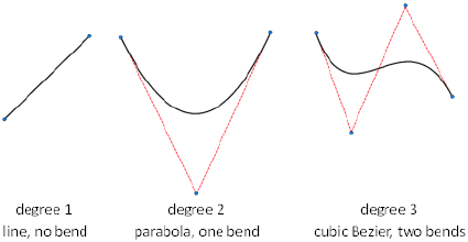
RegistrySaved in:
6Initial value:
Valid values are from 2 to 32767.
See also:
CVREBUILD (page 243)
Rebuild NURBS Surfaces and Curves
REBUILD2DDEGREE
Sets the global degree when rebuilding a spline.
IntegerType:
RegistrySaved in:
3Initial value:
Valid values are 1 to 11.
A curve with a degree of 1 is a straight line and a curve with a degree of 2 has
one bend. A Bezier curve has a degree of 3. Higher degrees create more complex
curves, but require computations.
See also:
CVREBUILD (page 243)
Rebuild NURBS Surfaces and Curves
REBUILD2DOPTION
Controls whether to delete the original curve when rebuilding a spline.
1414 | Chapter 4 System Variables
SwitchType:
RegistrySaved in:
1Initial value:
Retains original curve0
Deletes original curve1
See also:
CVREBUILD (page 243)
Rebuild NURBS Surfaces and Curves
REBUILDDEGREEU
Sets the degree in the U direction when rebuilding a NURBS surface.
IntegerType:
RegistrySaved in:
3Initial value:
Valid values are 2to 11.
See also:
CVREBUILD (page 243)
Rebuild NURBS Surfaces and Curves
REBUILDDEGREEV
Sets the degree in the V direction when rebuilding a NURBS surface.
IntegerType:
RegistrySaved in:
3Initial value:
Valid values are 2 to 11.
See also:
CVREBUILD (page 243)
Rebuild NURBS Surfaces and Curves
System Variables | 1415
REBUILDOPTIONS
Controls deletion and trimming options when rebuilding a NURBS surface.
IntegerType:
RegistrySaved in:
1Initial value:
When you use CVREBUILD:Value
The original surface is not deleted and trimmed areas are not applied to
the rebuilt object.
0
The original surface is deleted and trimmed areas are not applied to the
rebuilt object.
1
The original surface is not deleted and trimmed areas are applied to the
rebuilt object.
2
The original surface is deleted and trimmed areas are applied to the re-
built object.
3
See also:
CVREBUILD (page 243)
Rebuild NURBS Surfaces and Curves
REBUILDU
Sets the number of grid lines in the U direction when rebuilding a NURBS
surface.
IntegerType:
RegistrySaved in:
6Initial value:
Valid values are 2 to 32767 to increase or decrease the number of grid lines
in the U direction used to rebuild the NURBS surface.
1416 | Chapter 4 System Variables

See also:
CVREBUILD (page 243)
Rebuild NURBS Surfaces and Curves
REBUILDV
Sets the number of grid lines in the V direction when rebuilding a NURBS
surface.
IntegerType:
RegistrySaved in:
6Initial value:
Valid values are 2 to 32767 to increase or decrease the number of grid lines
in the V direction used to rebuild the NURBS surface.
See also:
CVREBUILD (page 243)
Rebuild NURBS Surfaces and Curves
RECOVERAUTO
Controls the display of recovery notifications before or after opening a
damaged drawing file.
BitcodeType:
RegistrySaved in:
0Initial value:
Displays a task dialog to recover damaged files while opening a
drawing that needs recovery. The task dialog interrupts any running
scripts.
0
Automatically recovers the damaged files, opens the drawing, and
displays a task dialog with the information of the recovered files. If
a script is running, the task dialog is suppressed.
1
System Variables | 1417
Automatically recovers the damaged files and opens the drawing
without displaying any task dialog. The information of the recovered
files is displayed at the command prompt.
2
See also:
Repair a Damaged Drawing File
REFEDITNAME
Displays the name of the reference being edited.
(Read-only)
StringType:
Not-savedSaved in:
""Initial value:
See also:
Edit Selected Objects in Referenced Drawings and Blocks
REGENMODE
Controls automatic regeneration of the drawing.
IntegerType:
DrawingSaved in:
1Initial value:
Turns off the REGENAUTO (page 878) command0
Turns on the REGENAUTO (page 878) command1
See also:
Control the Display of Polylines, Hatches, Gradient Fills, Lineweights, and
Text
1418 | Chapter 4 System Variables
RE-INIT
Reinitializes the acad.pgp file.
IntegerType:
Not-savedSaved in:
0Initial value:
The setting is stored as a bitcode using the sum of the following values:
Not used1
Not used2
Not used4
Not used8
PGP file reinitialization (reload)16
See also:
Digitizing Tablets
REMEMBERFOLDERS
Controls the default path displayed in standard file selection dialog boxes.
IntegerType:
RegistrySaved in:
1Initial value:
Restores the behavior of AutoCAD 2000 and previous releases. When
you start the program by double-clicking a shortcut icon, if a Start
0
In path is specified in the icon properties, that path is used as the
default for all standard file selection dialog boxes.
The default path in each standard file selection dialog box is the last
path used in that dialog box. The Start In folder specified for the
AutoCAD shortcut icon is not used.
1
System Variables | 1419
See also:
Open a Drawing
RENDERUSERLIGHTS
Controls whether to override the setting for viewport lighting during rendering.
IntegerType:
RegistrySaved in:
1Initial value:
Provides a way of overriding the DEFAULTLIGHTING (page 1211) system variable
for rendering while retaining the setting for working in a viewport.
The current lights in the viewport are used in the rendered scene,
either default lights or user lights, as specified by the DEFAULTLIGHT-
ING system variable.
0
Overrides the setting for the DEFAULTLIGHTING system variable.
Only user lights are rendered.
1
REPORTERROR
Controls whether an error report can be sent to Autodesk if the program closes
unexpectedly.
IntegerType:
RegistrySaved in:
1Initial value:
Error reports help Autodesk diagnose problems with the software.
The Error Report message is not displayed, and no report can be
sent to Autodesk.
0
The Error Report message is displayed, and an error report can be
sent to Autodesk.
1
An error report can be sent through the operating system if REPORTERROR
is set to 0 and the operating system supports error reporting.
1420 | Chapter 4 System Variables

See also:
Recover from a System Failure
ROAMABLEROOTPREFIX
Stores the full path to the root folder where roamable customizable files were
installed.
(Read-only)
StringType:
RegistrySaved in:
VariesInitial value:
If you are working on a network that supports roaming, when you customize
files that are in your roaming profile they are available to you regardless of
which machine you are currently using.
See also:
Overview of File Organization
RTDISPLAY
Controls the display of raster images during Realtime ZOOM or PAN.
IntegerType:
RegistrySaved in:
1Initial value:
Displays raster image content0
Displays outline only1
See also:
Pan or Zoom a View
System Variables | 1421
S System Variables
SAVEFIDELITY
Controls whether the drawing is saved with visual fidelity.
BitcodeType:
RegistrySaved in:
1Initial value:
The setting is stored as a bitcode using the sum of the following values:
Saved without visual fidelity.0
Annotation objects assigned annotative scales are saved to separate
layers for each scale used. Only affects drawings when saving to
AutoCAD 2007 or earlier file formats.
1
See also:
Save a Drawing
Save with Visual Fidelity for Annotative Objects
SAVEFILE
Stores the current automatic save file name.
(Read-only)
StringType:
RegistrySaved in:
VariesInitial value:
See also:
Set Up the Drawing Area
1422 | Chapter 4 System Variables

SAVEFILEPATH
Specifies the path to the directory for all automatic save files for the current
session.
StringType:
RegistrySaved in:
VariesInitial value:
You can also change the path in the Application Preferences dialog box.
See also:
Set Up the Drawing Area
SAVENAME
Displays the file name and directory path of the most recently saved drawing.
(Read-only)
StringType:
Not-savedSaved in:
""Initial value:
See also:
Obtain General Drawing Information
SAVETIME
Sets the automatic save interval, in minutes.
IntegerType:
RegistrySaved in:
10Initial value:
Turns off automatic saving.0
Saves the drawing at intervals specified by the nonzero integer
automatically
>0
The value of SAVETIME is an integer between 0 and 600.
System Variables | 1423

The SAVETIME timer starts as soon as you make a change to a drawing. It is
reset and restarted by a manual QSAVE (page 860), SAVE (page 914), or SAVEAS
(page 914). The current drawing is saved to the path specified by the SAVEFILE-
PATH (page 1423) system variable. The file name is stored in the SAVEFILE (page
1422) system variable.
See also:
Set Up the Drawing Area
SCREENSIZE
Stores current viewport size in pixels (X and Y).
(Read-only)
2D-pointType:
Not-savedSaved in:
VariesInitial value:
See also:
Switch Between Layouts in the Current Drawing
SELECTIONANNODISPLAY
Controls whether alternate scale representations are temporarily displayed in
a dimmed state when an annotative object is selected.
IntegerType:
RegistrySaved in:
1Initial value:
Off0
On1
The dimming intensity is controlled by the XFADECTL (page 1526) system
variable.
See also:
Display Annotative Objects
1424 | Chapter 4 System Variables

SELECTIONAREA
Controls the display of effects for selection areas.
IntegerType:
RegistrySaved in:
1Initial value:
Selection areas are created by the Window, Crossing, WPolygon, and CPolygon
options of SELECT (page 937).
Off0
On1
See also:
Customize Object Selection
SELECTIONAREAOPACITY
Controls the transparency of the selection area during window and crossing
selection.
IntegerType:
RegistrySaved in:
25Initial value:
The valid range is 0 to 100. The lower the setting, the more transparent the
area. A value of 100 makes the area opaque. The SELECTIONAREA (page 1425)
system variable must be on.
See also:
Customize Object Selection
SELECTIONCYCLING
Turns selection cycling on and off.
IntegerType:
RegistrySaved in:
System Variables | 1425
0Initial value:
Off0
On1
See also:
Select Objects Individually
Use 3D Subobject Grips
Modify 3D Subobjects
SELECTIONPREVIEW
Controls the display of selection previewing.
BitcodeType:
RegistrySaved in:
3Initial value:
Objects are highlighted when the pickbox cursor rolls over them. This selection
previewing indicates that the object would be selected if you clicked. The
setting is stored as a bitcode using the sum of the following values:
Off0
On when no commands are active1
On when a command prompts for object selection2
See also:
Customize Object Selection
SELECTSIMILARMODE
Controls which properties must match for an object of the same type to be
selected with SELECTSIMILAR.
1426 | Chapter 4 System Variables
BitcodeType:
User-settingsSaved in:
130Initial value:
The default value is 130. Objects of the same type are considered similar if
they are on the same layer, and, for referenced objects, have the same name.
The setting is stored as a bitcode using the sum of the following values:
Object type0
Color1
Layer2
Linetype4
Linetype scale8
Lineweight16
Plot style32
Object style (such as text styles, dimension styles, and table styles)64
Name (for referenced objects, such as blocks, xrefs, and images)128
See also:
Select Objects by Properties
SHADEDGE
Controls the shading of edges.
IntegerType:
DrawingSaved in:
3Initial value:
Faces shaded, edges not highlighted0
System Variables | 1427
Faces shaded, edges drawn in background color1
Faces not filled, edges in object color2
Faces in object color, edges in background color3
See also:
Use a Visual Style to Display Your Model
SHADEDIF
Sets the ratio of diffuse reflective light to ambient light.
IntegerType:
DrawingSaved in:
70Initial value:
The ratio is a percentage of diffuse reflective light when SHADEDGE (page 1427)
is set to 0 or 1.
See also:
Use a Visual Style to Display Your Model
SHADOWPLANELOCATION
Controls the location of an invisible ground plane used to display shadows.
RealType:
DrawingSaved in:
0.0000Initial value:
The value is a location on the current Z axis. The ground plane is invisible,
but it casts and receives shadows. Objects that are located below the ground
plane are shadowed by it. The ground plane is used when the VSSHADOWS
(page 1518) system variable is set to display either full shadows or ground
shadows.
See also:
Display Backgrounds and Shadows
1428 | Chapter 4 System Variables
SHORTCUTMENU
Controls whether Default, Edit, and Command mode shortcut menus are
available in the drawing area.
IntegerType:
RegistrySaved in:
11Initial value:
The setting is stored as a bitcode using the sum of the following values:
Disables all Default, Edit, and Command mode shortcut menus,
restoring AutoCAD Release 14 behavior.
0
Enables Default mode shortcut menus.1
Enables Edit mode shortcut menus.2
Enables Command mode shortcut menus whenever a command is
active.
4
Enables Command mode shortcut menus only when command
options are currently available at the Command prompt.
8
Enables the display of a shortcut menu when the right button on
the pointing device is held down long enough.
16
NOTE When this system variable is set to a value greater than 15, the SHORTCUT-
MENUDURATION (page 1429) system variable determines the length of time that
the right button on the pointing device must be held down to display a shortcut
menu.
See also:
Set Up the Drawing Area
SHORTCUTMENUDURATION
Specifies how long the right button on a pointing device must be pressed to
display a shortcut menu in the drawing area.
System Variables | 1429
IntegerType:
RegistrySaved in:
250Initial value:
The value is expressed in milliseconds, and the valid range is 100 to 10,000.
If the right button is held down for the same or longer duration than the value
of this system variable, a shortcut menu is displayed.
If the right button is held down for a shorter duration, the result is the same
as if you press the Enter or Return key.
NOTE The SHORTCUTMENU (page 1429) system variable must be set to a value
greater than 15 for this system variable to take effect.
See also:
Control the Drawing Area Interface
SHOWALLUSEDLAYERSGROUP
Controls the visibility of the dynamic All Used Layers layer group in the Layers
palette.
IntegerType:
RegistrySaved in:
1Initial value:
Not displayed0
Displayed1
See also:
The Layers Palette
SHOWEMPTYGROUPS
Controls the visibility of empty dynamic layer groups in the Layers palette.
IntegerType:
RegistrySaved in:
1430 | Chapter 4 System Variables
0Initial value:
Not displayed0
Displayed1
See also:
The Layers Palette
SHOWGROUPS
Controls the visibility of layer groups in the Layers list of the Layers palette.
IntegerType:
RegistrySaved in:
1Initial value:
Not displayed0
Displayed1
See also:
The Layers Palette
SHOWHIST
Controls the Show History property for solids in a drawing.
IntegerType:
DrawingSaved in:
1Initial value:
Sets the Show History property to No (read-only) for all solids.
Overrides the individual Show History property settings for solids.
0
You cannot view the original objects that were used to create the
solid.
System Variables | 1431
Does not override the individual Show History property settings for
solids.
1
Displays the history of all solids by overriding the individual Show
History property settings for solids. You can view the original objects
that were used to create the solid.
2
See also:
Display Original Forms of Composite Solids
SHOWPAGESETUPFORNEWLAYOUTS
Specifies whether the Page Setup Manager is displayed when a new layout is
created.
IntegerType:
RegistrySaved in:
0Initial value:
Do not display the Page Setup Manager when a new layout is cre-
ated
0
Display the Page setup Manager when a new layout is created1
See also:
Use a Page Setup to Specify Plot Settings
SHOWPALETTESTATE
Indicates whether palettes were hidden by the HIDEPALETTES command or
restored by the SHOWPALETTES command.
(Read-only)
IntegerType:
RegistrySaved in:
1432 | Chapter 4 System Variables

1Initial value:
Indicates that there are palettes hidden by the HIDEPALETTES
command
0
Indicates that all palettes hidden by the HIDEPALETTES command
were restored by the SHOWPALETTES command
1
See also:
Control the Drawing Area Interface
SHOWUNRECONCILEDLAYERSGROUP
Controls the visibility of the dynamic Unreconciled Layers layer group in the
Layers palette.
IntegerType:
RegistrySaved in:
1Initial value:
Not displayed0
Displayed1
See also:
The Layers Palette
SHOWVPOVERRIDESGROUP
Controls the visibility of the dynamic Viewport Overrides layer group in the
Layers palette when focus is in a viewport on a layout.
IntegerType:
RegistrySaved in:
1Initial value:
Not displayed0
System Variables | 1433
Displayed1
See also:
The Layers Palette
SHOWXREFGROUPS
Controls the visibility of layer groups that are saved in an attached external
reference (xref) in the Layers palette.
IntegerType:
RegistrySaved in:
1Initial value:
Not displayed0
Displayed1
See also:
The Layers Palette
SHOWXREFLAYERS
Controls the visibility of layers saved in an attached external reference (xref)
in the Layers palette.
IntegerType:
RegistrySaved in:
0Initial value:
Not displayed0
Displayed1
See also:
The Layers Palette
1434 | Chapter 4 System Variables

SHPNAME
Sets a default shape name that must conform to symbol- naming conventions.
StringType:
Not-savedSaved in:
""Initial value:
If no default is set, it returns "". Enter a period (.) to set no default.
See also:
Shape Descriptions
SIGWARN
Controls whether a warning is presented when a file with an attached digital
signature is opened.
IntegerType:
RegistrySaved in:
1Initial value:
If the system variable is on and you open a file with a valid signature, the
digital signature status is displayed. If the variable is off and you open a file,
the digital signature status is displayed only if a signature is invalid.
Warning is not presented if a file has a valid signature0
Warning is presented1
SKETCHINC
Sets the record increment for the SKETCH command.
RealType:
DrawingSaved in:
0.1000 (imperial) or 1.0000 (metric)Initial value:
See also:
Draw Freehand Sketches
System Variables | 1435

SKPOLY
Determines whether the SKETCH command generates lines, polylines, or
splines.
IntegerType:
DrawingSaved in:
0Initial value:
Generates lines0
Generates polylines1
Generates splines2
See also:
Draw Freehand Sketches
SKTOLERANCE
Determines how closely the spline fits to the freehand sketch.
RealType:
DrawingSaved in:
0.5Initial value:
Valid values are between 0 and 1.
See also:
Draw Freehand Sketches
SKYSTATUS
Determines if the sky illumination is computed at render time.
IntegerType:
DrawingSaved in:
0Initial value:
1436 | Chapter 4 System Variables
This has no impact on the viewport illumination or the background. It only
makes the sky available as a gathered light source for rendering.
Sky off0
Sky background1
Sky background and illumination2
See also:
Sun and Sky Simulation
SMOOTHMESHCONVERT
Sets whether mesh objects that you convert to 3D solids or surfaces are
smoothed or faceted, and whether their faces are merged.
BitcodeType:
User-settingsSaved in:
0Initial value:
Creates a smooth model. Coplanar faces are optimized, or merged.0
Creates a smooth model. Original mesh faces are retained in the converted object.1
Creates a model with flattened faces. Coplanar faces are optimized, or merged.2
Creates a model with flattened faces. Original mesh faces are retained in the
converted object.
3
This system variable sets the default value for operations that use CONVTOSOL-
ID (page 223) and CONVTOSURFACE (page 225) commands.
See also:
Create 3D Solids from Objects
System Variables | 1437
SMOOTHMESHGRID
Sets the maximum level of smoothness at which the underlying mesh facet
grid is displayed on 3D mesh objects.
IntegerType:
User-settingsSaved in:
3Initial value:
Never displays the underlying mesh facet grid0
Displays the facet grid for smoothing levels 0 and 11
Displays the facet grid for smoothing levels 2 and lower2
Displays the facet grid for smoothing levels 3 and lower3
Displays the facet grid for smoothing levels 4 and lower4
Use this variable to help visualize smooth surfaces. By setting limits, you can
simplify the display of the underlying facet grid when you work with extremely
dense mesh objects.
You can enter any number, depending on the number of smoothing levels
you expect. This variable does not affect the smoothing level of the mesh. Its
value cannot exceed the value of SMOOTHMESHMAXLEV.
If the VSLIGHTINGQUALITY (page 1509) system variable is 0, this system variable
is ignored and all smoothness levels are displayed as faceted.
See also:
Change Mesh Smoothness Levels
SMOOTHMESHMAXFACE
Sets the maximum number of faces permitted for mesh objects.
IntegerType:
User-settingsSaved in:
1000000Initial value:
1438 | Chapter 4 System Variables
The initial value of this system variable is adjusted for best performance based
on your system configuration. Permissible values are from 108 to 16,000,000.
Use this limit to prevent creating extremely dense meshes that might affect
program performance.
See also:
Change Mesh Smoothness Levels
SMOOTHMESHMAXLEV
Sets the maximum smoothness level for mesh objects.
IntegerType:
User-settingsSaved in:
4Initial value:
Permissible values are from 1 to 255. The recommended range is 1-5. Use this
limit to prevent creating extremely dense meshes that might affect program
performance.
See also:
Change Mesh Smoothness Levels
SNAPANG
Sets the snap and grid rotation angle for the current viewport relative to the
current UCS.
RealType:
DrawingSaved in:
0.0000Initial value:
When SNAPANG is set to a value other than 0, the lined grid will not display.
See also:
Adjust Grid and Grid Snap
System Variables | 1439

SNAPBASE
Sets the snap and grid origin point for the current viewport relative to the
current UCS.
2D-pointType:
DrawingSaved in:
0.0000,0.0000Initial value:
See also:
Adjust Grid and Grid Snap
SNAPISOPAIR
Controls the isometric plane for the current viewport.
IntegerType:
DrawingSaved in:
0Initial value:
Left0
Top1
Right2
See also:
Set Isometric Grid and Snap
SNAPMODE
Turns the Snap mode on and off.
IntegerType:
DrawingSaved in:
0Initial value:
Snap off0
1440 | Chapter 4 System Variables
Snap on for the current viewport1
See also:
Adjust Grid and Grid Snap
SNAPSTYL
Sets the snap style for the current viewport.
IntegerType:
DrawingSaved in:
0Initial value:
Standard (rectangular snap)0
Isometric snap1
See also:
Adjust Grid and Grid Snap
SNAPTYPE
Sets the type of snap for the current viewport.
IntegerType:
RegistrySaved in:
0Initial value:
Grid, or standard snap.0
PolarSnap. Snaps along polar angle increments. Use PolarSnap with
polar and object snap tracking.
1
See also:
Adjust Grid and Grid Snap
System Variables | 1441
SNAPUNIT
Sets the snap spacing for the current viewport.
2D-pointType:
DrawingSaved in:
0.5000,0.5000 (imperial) or 10.0000,10.0000 (metric)Initial value:
If SNAPSTYL is set to 1, the X value of SNAPUNIT is adjusted automatically
to accommodate the isometric snap.
Changes to this system variable are not reflected in the grid until the display
is refreshed.
See also:
Adjust Grid and Grid Snap
SOLIDCHECK
Turns 3D solid validation on and off for the current session.
IntegerType:
Not-savedSaved in:
1Initial value:
Off0
On1
See also:
Clean and Check 3D Solids
SOLIDHIST
Controls whether new composite solids retain a history of their original
components.
IntegerType:
DrawingSaved in:
1Initial value:
1442 | Chapter 4 System Variables
When set to 1, all subsequently created composite solids retain a history of
the original component objects. These component objects can be accessed to
modify the solids
Sets the History property to None for new solids. No history is re-
tained.
0
Sets the History property to Record for new solids. Solids retain a
history of their original objects.
1
See also:
Display Original Forms of Composite Solids
SORTENTS
Controls object sorting in support of draw order for several operations.
IntegerType:
DrawingSaved in:
127Initial value:
The setting is stored as a bitcode using the sum of the following values:
Turns off all object sorting0
Sorts for object selection1
Sorts for object snaps2
Obsolete, has no effect4
Obsolete, has no effect8
Sorts for REGEN commands16
Sorts for plotting32
Obsolete, has no effect64
System Variables | 1443

See also:
Control How Overlapping Objects Are Displayed
SPACEPAN
Controls whether pressing and holding the Spacebar starts the PAN command
transparently.
IntegerType:
RegistrySaved in:
1Initial value:
PAN command does not start transparently when the Spacebar is
held.
0
PAN command starts transparently after the Spacebar is held for
the duration specified in the SPACEPANTIMEOUT system variable.
1
See also:
Pan or Zoom a View
SPACEPANTIMEOUT
Sets the duration that the Spacebar must be held down before the PAN
command is started transparently.
IntegerType:
RegistrySaved in:
250Initial value:
Duration is measured in milliseconds. Valid range is 100 to 1000.
See also:
Pan or Zoom a View
1444 | Chapter 4 System Variables
SPLDEGREE
Stores the last-used degree setting for splines and sets the default degree setting
for the SPLINE command when specifying control vertices.
(Read-only)
IntegerType:
Not-savedSaved in:
3Initial value:
Enter a value from 1 to 5.
NOTE SPLDEGREE defaults to 3 when AutoCAD for Mac starts.
See also:
Modify Polylines
SPLFRAME
Controls the display of helixes and smoothed mesh objects.
IntegerType:
DrawingSaved in:
0Initial value:
0■Does not display the control polygon for helixes.
■Displays smoothed mesh objects if they have been smoothed.
■Does not display the invisible edges of 3D faces or polyface meshes.
1■Displays the control polygon for helixes.
■Displays unsmoothed mesh objects, even if they have been smoothed.
■Displays the edges of 3D faces and polyface meshes.
NOTE To control the display for splines, use the CVSHOW (page 247) and the
CVHIDE (page 242) commands.
System Variables | 1445

See also:
Overview of Creating Meshes
SPLINESEGS
Sets the number of line segments to be generated for each spline-fit polyline
generated by the Spline option of the PEDIT command.
IntegerType:
DrawingSaved in:
8Initial value:
Enter a non-zero integer between -32768 to 32767. If you set SPLINESEGS to
a negative value, segments are generated using the absolute value of the setting
and then a fit-type curve is applied to those segments. Fit-type curves use arcs
as the approximating segments. Using arcs yields a smoother generated curve
when few segments are specified, but the curve can take longer to generate.
See also:
Modify Polylines
SPLINETYPE
Sets the type of curve generated by the Spline option of the PEDIT command.
IntegerType:
DrawingSaved in:
6Initial value:
Quadratic B-spline5
Cubic B-spline6
See also:
Modify Polylines
1446 | Chapter 4 System Variables
SPLKNOTS
Stores the default knot option for the SPLINE command when specifying fit
points.
IntegerType:
Not-savedSaved in:
0Initial value:
Chord distance0
Square root of chord distance1
Uniform distance2
NOTE
SPLKNOTS always defaults to 0 when AutoCAD for Mac starts.
See also:
Modify Splines
SPLMETHOD
Stores whether the default method used for the SPLINE command is fit points
or control vertices.
IntegerType:
Not-savedSaved in:
0Initial value:
Create splines using fit points0
Create splines using control vertices1
NOTE
SPLMETHOD always defaults to 0 when AutoCAD for Mac starts.
System Variables | 1447
See also:
Draw Splines
SPLPERIODIC
Controls whether closed splines and NURBS surfaces are generated with
periodic properties to maintain the smoothest continuity at the closure point
or seam.
IntegerType:
User-settingsSaved in:
1Initial value:
Creates closed splines and NURBS surfaces with the method used
in AutoCAD for Mac 2011 and earlier releases.
0
Creates periodic closed splines and closed NURBS surfaces, for
the smoothest (C2) continuity. (Recommended)
1
See also:
Draw Splines
STATUSBAR
Controls the display of the status bar.
IntegerType:
RegistrySaved in:
1Initial value:
Hides the status bar0
Shows the status bar1
See also:
The Status Bar
1448 | Chapter 4 System Variables
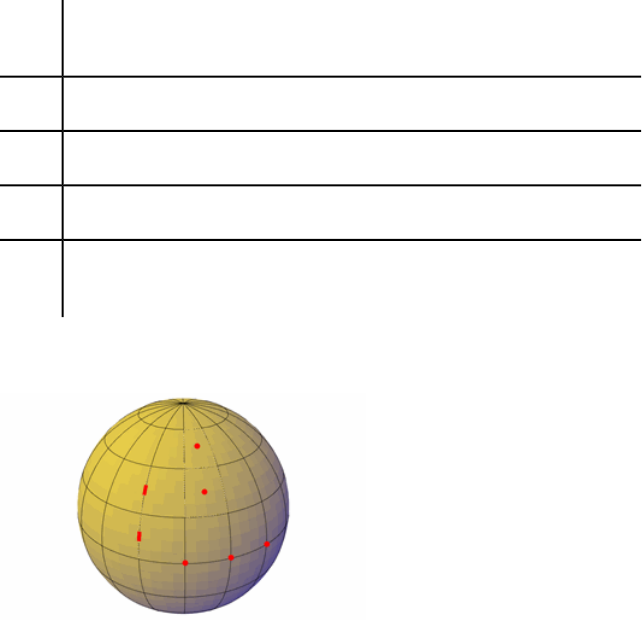
SUBOBJSELECTIONMODE
Filters whether faces, edges, vertices or solid history subobjects are highlighted
when you roll over them.
IntegerType:
Not-savedSaved in:
0Initial value:
In busy 3D environments with many objects, it can be helpful to filter certain
subobjects out of the selection highlighting.
When subobject filtering is off, press Ctrl+click to select a face, edge, vertex or
a history subobject. (Shift-F1)
0
Only vertices are available for selection (Shift-F2)1
Only edges are available for selection. (Shift-F3)2
Only faces are available for selection. (Shift-F4)3
Only history subobjects of compound objects are available for selection. (Shift-
F5)
4
Turn off subobject filtering if you want to select the entire object. You can
also press Ctrl-click to select faces, edges, and vertices.
When filtering is set for vertices, you cannot select faces, edges, or history
subobjects.
System Variables | 1449
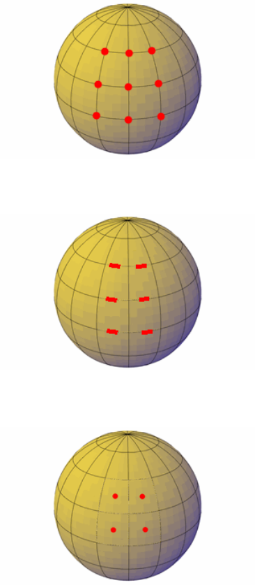
When filtering is set for edges, you cannot select faces, vertices, or history
subobjects.
When filtering is set for faces, you cannot select edges, vertices, or history
subobjects.
When filtering is set for history subobjects, you can only select the wireframe
representations of portions of objects removed during a union, subtract, or
intersect operation.
1450 | Chapter 4 System Variables
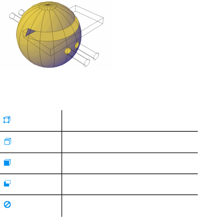
Subobject Selection Filter Cursors
When a subobject selection filter is set, the following images are displayed
next to the cursor:
Vertex filtering is on
Edge filtering is on
Face filtering is on
History subobject filtering is on
Subobject not eligible for selection
See also:
Cycle Through and Filter Subobjects
LEGACYCTRLPICK (page 1351)
SUNSTATUS
Turns on and off the lighting effects of the sun in the current viewport.
IntegerType:
DrawingSaved in:
System Variables | 1451
0Initial value:
Only the lights from sources other than the sun affect the view in the current
viewport.
Off0
On1
See also:
Sun and Sky Simulation
SURFACEASSOCIATIVITY
Controls whether surfaces maintain a relationship with the objects from which
they were created.
IntegerType:
DrawingSaved in:
1Initial value:
When associativity is on, surfaces automatically adjust to modifications made
to other, related surfaces.
Surfaces are created with no associativity to other surfaces0
Surfaces are created with associativity to other surfaces1
When set to 1, the DELOBJ (page 1213) system variable is ignored. Defining
geometry are not deleted when an associative surface is created.
See also:
Create Associative Surfaces
SURFACEASSOCIATIVITYDRAG
Sets the dragging preview behavior of associative surfaces.
SwitchType:
1452 | Chapter 4 System Variables
RegistrySaved in:
1Initial value:
Controls the preview behavior of surfaces and any associated surfaces when
a selected surface is dragged. Disabling the preview can increase performance.
Displays no preview. The display refreshes after dragging is com-
plete.
0
Previews only the movement of the first associated surface. All other
associated surfaces do not move until after dragging is complete.
1
Previews the movement of all associated surfaces.2
See also:
Create Associative Surfaces
SURFACEAUTOTRIM
Controls whether surfaces are automatically trimmed when you project
geometry onto them.
IntegerType:
RegistrySaved in:
0Initial value:
Surfaces are not trimmed when you project geometry onto them.0
Surfaces are automatically trimmed to geometry that is projected
using PROJECTGEOMETRY (page 829).
1
See also:
Trim and Untrim Surfaces
SURFACEMODELINGMODE
Controls whether surfaces are created as procedural surfaces or NURBS surfaces.
System Variables | 1453
SwitchType:
Not-savedSaved in:
0Initial value:
Creates a procedural surface when creating surfaces.0
Creates a NURBS surface when creating surfaces.1
See also:
Create Solids and Surfaces from Lines and Curves
Create Surfaces
SURFTAB1
Sets the number of tabulations to be generated for the RULESURF and TABSURF
commands.
IntegerType:
DrawingSaved in:
6Initial value:
Also sets the mesh density in the M direction for the REVSURF and EDGESURF
commands.
See also:
Construct Meshes from Other Objects
SURFTAB2
Sets the mesh density in the N direction for the REVSURF and EDGESURF
commands.
IntegerType:
DrawingSaved in:
6Initial value:
See also:
Construct Meshes from Other Objects
1454 | Chapter 4 System Variables

SURFTYPE
Controls the type of surface-fitting to be performed by the Smooth option of
the PEDIT command.
IntegerType:
DrawingSaved in:
6Initial value:
Quadratic B-spline surface5
Cubic B-spline surface6
Bezier surface8
See also:
Modify Polylines
SURFU
Sets the surface density for PEDIT Smooth in the M direction and the U isolines
density on surface objects.
IntegerType:
DrawingSaved in:
6Initial value:
Valid values are 0 through 200. Meshes are always created with a minimum
surface density of 2.
See also:
Modify Polylines
SURFV
Sets the surface density for PEDIT Smooth in the N direction and the V isolines
density on surface objects.
IntegerType:
System Variables | 1455
DrawingSaved in:
6Initial value:
Valid values are 0 through 200. Meshes are always created with a minimum
surface density of 2.
See also:
Modify Polylines
SYSCODEPAGE
Indicates the system code page, which is determined by the operating system.
(Read-only)
StringType:
Not-savedSaved in:
VariesInitial value:
To change the code page, see Help for your operating system.
See also:
Use Unicode and Big Fonts
T System Variables
TABLEINDICATOR
Controls the display of row numbers and column letters when the In-Place
Text Editor is open for editing a table cell.
IntegerType:
RegistrySaved in:
1Initial value:
Off0
On1
1456 | Chapter 4 System Variables

See also:
Create and Modify Tables
TARGET
Stores the location (as a UCS coordinate) of the target point for the current
viewport.
(Read-only)
3D-pointType:
DrawingSaved in:
0.0000,0.0000,0.0000Initial value:
See also:
Overview of Parallel and Perspective Views
TBSHOWSHORTCUTS
Specifies if shortcut keys are displayed in tooltips.
StringType:
RegistrySaved in:
yesInitial value:
Display shortcut keysno
Do not display shortcut keysyes
TDCREATE
Stores the local time and date the drawing was created.
(Read-only)
RealType:
DrawingSaved in:
VariesInitial value:
System Variables | 1457
See also:
Add Identifying Information to Drawings
TDINDWG
Stores the total editing time, which is the total elapsed time between saves of
the current drawing.
(Read-only)
RealType:
DrawingSaved in:
VariesInitial value:
The format is:
<number of days>.<decimal fraction of a day>
To compute the number of seconds, multiply the decimal fraction in
TDINDWG by 86400 seconds.
See also:
Add Identifying Information to Drawings
TDUCREATE
Stores the universal time and date that the drawing was created.
(Read-only)
RealType:
DrawingSaved in:
VariesInitial value:
See also:
Add Identifying Information to Drawings
TDUPDATE
Stores the local time and date of the last update/save.
(Read-only)
1458 | Chapter 4 System Variables
RealType:
DrawingSaved in:
VariesInitial value:
See also:
Add Identifying Information to Drawings
TDUSRTIMER
Stores the user-elapsed timer.
(Read-only)
RealType:
DrawingSaved in:
VariesInitial value:
See also:
Add Identifying Information to Drawings
TDUUPDATE
Stores the universal time and date of the last update or save.
(Read-only)
RealType:
DrawingSaved in:
VariesInitial value:
See also:
Add Identifying Information to Drawings
TEMPOVERRIDES
Turns temporary override keys on and off.
IntegerType:
RegistrySaved in:
1Initial value:
System Variables | 1459
A temporary override key is a key that you can hold down to temporarily turn
on or turn off one of the drawing aids that are set in the Drafting Settings
dialog box; for example, Ortho mode, object snaps, or Polar mode.
Off0
On1
See also:
Override Object Snap Settings
TEMPPREFIX
Contains the directory name (if any) configured for placement of temporary
files, with a path separator appended.
(Read-only)
StringType:
Not-savedSaved in:
VariesInitial value:
You can modify the location from the Application Preferences dialog box,
Application tab, Files section, under Temporary Drawing File Location.
See also:
Specify Search Paths, File Names, and File Locations
TEXTED
Specifies the user interface displayed for editing single-line text.
IntegerType:
RegistrySaved in:
2Initial value:
Displays the In-Place Text Editor when creating or editing single-line
text.
0
Displays the Edit Text dialog box when editing single-line text.1
1460 | Chapter 4 System Variables
Displays the In-Place Text Editor when creating or editing single-line
text. Repeats the command automatically.
2
See also:
Change Single-Line Text
TEXTEVAL
Controls how text strings entered with TEXT (using scripts or AutoLISP) or
with -TEXT are evaluated.
IntegerType:
Not-savedSaved in:
0Initial value:
All responses to prompts for text strings and attribute values are
taken literally.
0
All text starting from an opening parenthesis [(] or an exclamation
mark [!] is evaluated as an AutoLISP expression, as for nontextual
input.
1
The TEXT (page 1044) command takes all input literally regardless of the setting
of TEXTEVAL unless it is executed completely with a script or AutoLISP
expression. The -TEXT command honors the setting of TEXTEVAL.
See also:
Create Single-Line Text
TEXTFILL
Controls the filling of TrueType fonts while printing.
IntegerType:
RegistrySaved in:
1Initial value:
Displays text as outlines0
System Variables | 1461
Displays text as filled images1
See also:
Use TrueType Fonts
TEXTOUTPUTFILEFORMAT
Provides Unicode options for log files.
IntegerType:
DrawingSaved in:
0Initial value:
ANSI format0
UTF-8 (Unicode)1
UTF-16LE (Unicode)2
UTF-16BE (Unicode)3
See also:
Share Drawing Files Internationally
TEXTQLTY
Sets the resolution tessellation fineness of text outlines.
IntegerType:
Not-savedSaved in:
50Initial value:
Sets the resolution tessellation fineness of text outlines for TrueType fonts
while plotting and rendering. 0 represents no effort to refine the smoothness
of the text; 100 represents a maximum effort to smooth text characters. Lower
values decrease resolution and increase plotting speed. Higher values increase
resolution and decrease plotting speed.
1462 | Chapter 4 System Variables
Sets the resolution of TrueType fonts while plotting. Use integer values from
0 to 100. Lower values decrease resolution and increase plotting speed. Higher
values increase resolution and decrease plotting speed.
See also:
Use TrueType Fonts
TEXTSIZE
Sets the default height for new text objects drawn with the current text style.
RealType:
DrawingSaved in:
0.2000 (imperial) or 2.5000 (metric)Initial value:
TEXTSIZE has no effect if the current text style has a fixed height.
See also:
Set Text Height
TEXTSTYLE
Sets the name of the current text style.
StringType:
DrawingSaved in:
StandardInitial value:
See also:
Overview of Text Styles
THICKNESS
Sets the current 3D thickness.
RealType:
DrawingSaved in:
0.0000Initial value:
System Variables | 1463
See also:
Add 3D Thickness to Objects
TILEMODE
Makes the Model tab or the last layout tab current.
IntegerType:
DrawingSaved in:
1Initial value:
Makes the last active layout tab (paper space) active0
Makes the Model tab active1
See also:
Set Model Space Viewports
TIMEZONE
Sets the time zone for the sun in the drawing.
EnumType:
DrawingSaved in:
-8000Initial value:
The values in the table are expressed as hours and minutes away from
Greenwich Mean Time. The geographic location you set also sets the time
zone.
International Date Line West-12000
Midway Island, Samoa-11000
Hawaii-10000
Alaska-9000
1464 | Chapter 4 System Variables
Pacific Time (US & Canada), Tijuana-8000
Arizona-7000
Chihuahua, La Paz, Mazatlan-7000
Mountain Time (US & Canada)-7000
Arizona-7001
Mazatlan-7002
Central America-6000
Central Time (US & Canada)-6001
Guadalajara, Mexico City, Monterrey-6002
Saskatchewan-6003
Eastern Time (US & Canada)-5000
Indiana (East)-5001
Bogota, Lima, Quito-5002
Atlantic Time (Canada)-4000
Caracas, La Paz-4001
Santiago-4002
Newfoundland-3300
Brasilia-3000
System Variables | 1465

Buenos Aires, Georgetown-3001
Greenland-3002
Mid-Atlantic-2000
Azores-1000
Cape Verde Is.-1001
Universal Coordinated Time0
Greenwich Mean Time1
Casablanca, Monrovia2
Amsterdam, Berlin, Bern, Rome, Stockholm+1000
Brussels, Madrid, Copenhagen, Paris+1001
Belgrade, Bratislava, Budapest, Ljubljana, Prague+1002
Sarajevo, Skopje, Warsaw, Zagreb+1003
West Central Africa+1004
Athens, Beirut, Istanbul, Minsk+2000
Bucharest+2001
Cairo+2002
Harare, Pretoria+2003
Helsinki, Kyiv, Sofia, Talinn, Vilnius+2004
1466 | Chapter 4 System Variables

Jerusalem+2005
Moscow, St. Petersburg, Volograd+3000
Kuwait, Riyadh+3001
Baghdad+3002
Nairobi+3003
Tehran+3300
Abu Dhabi, Muscat+4000
Baku, Tbilisi, Yerevan+4001
Kabul+4300
Ekaterinburg+5000
Islamabad, Karachi, Tashkent+5001
Chennai, Kolkata, Mumbai, New Delhi+5300
Kathmandu+5450
Almaty, Novosibirsk+6000
Astana, Dhaka+6001
Sri Jayawardenepura+6002
Rangoon+6300
Bangkok, Hanoi, Jakarta+7000
System Variables | 1467

Krasnoyarsk+7001
Beijing, Chongqing, Hong Kong, Urumqi+8000
Kuala Lumpur, Singapore+8001
Taipei+8002
Irkutsk, Ulaan Bataar+8003
Perth+8004
Osaka, Sapporo, Tokyo+9000
Seoul+9001
Yakutsk+9002
Adelaide+9300
Darwin+9301
Canberra, Melbourne, Sydney+10000
Guam, Port Moresby+10001
Brisbane+10002
Hobart+10003
Vladivostok+10004
Magadan, Solomon Is., New Caledonia+11000
Auckland, Wellington+12000
1468 | Chapter 4 System Variables
Fiji, Kamchatka, Marshall Is.+12001
Nuku’alofa+13000
See also:
Specify Units and Unit Formats
TOOLSETSSTATE
Indicates whether the Tool Sets palette is open or closed.
(Read-only)
IntegerType:
Not-savedSaved in:
1Initial value:
Closed0
Open1
See also:
The Tool Sets Palette
TOOLTIPMERGE
Combines drafting tooltips into a single tooltip.
SwitchType:
RegistrySaved in:
0Initial value:
Off0
On1
System Variables | 1469
See also:
Set Interface Options
TOOLTIPSIZE
Sets the display size for drafting tooltips, and for automatic completion text
at the Command prompt.
IntegerType:
RegistrySaved in:
0Initial value:
Valid range is -3 to 6. Greater values result in larger drafting tooltips, and
larger automatic completion text at the Command prompt. Negative values
represent smaller sizes than the default.
See also:
Use Dynamic Input
TOOLTIPTRANSPARENCY
Sets the transparency for drafting tooltips.
IntegerType:
RegistrySaved in:
0Initial value:
Valid range is 0 to 100. When a value of 0 is used, the drafting tooltip is fully
opaque. The greater the value entered, the more transparent the drafting
tooltip will appear.
See also:
Parts of the User Interface
TRACKPATH
Controls the display of polar and object snap tracking alignment paths.
IntegerType:
1470 | Chapter 4 System Variables
RegistrySaved in:
0Initial value:
Displays full-screen polar and object snap tracking paths0
Displays full-screen polar tracking path; displays object snap tracking
path only between the alignment point and the From point to the
cursor location
1
Displays full-screen object snap tracking path; does not display polar
tracking path
2
Does not display polar tracking path; displays object snap tracking
path only between the alignment point and the From point to the
cursor location
3
See also:
Use Polar Tracking and PolarSnap
TRANSPARENCYDISPLAY
Controls whether the object transparency is displayed.
IntegerType:
RegistrySaved in:
1Initial value:
Object transparency is not displayed0
Object transparency is displayed1
See also:
Control the Display Properties of Certain Objects
System Variables | 1471
TREEDEPTH
Specifies the maximum depth, that is, the number of times the tree-structured
spatial index can divide into branches.
IntegerType:
DrawingSaved in:
3020Initial value:
Suppresses the spatial index entirely, eliminating the performance
improvements it provides in working with large drawings. This set-
ting assures that objects are always processed in database order.
0
Turns on spatial indexing. An integer of up to five digits is valid. The
first three digits refer to model space, and the remaining two digits
refer to paper space.
>0
Treats model space objects as 2D (Z coordinates are ignored), as is
always the case with paper space objects. Such a setting is appropri-
<0
ate for 2D drawings and makes more efficient use of memory without
loss of performance
NOTE
You cannot use TREEDEPTH transparently.
See also:
Work with Layer and Spatial Indexes
TREEMAX
Limits memory consumption during drawing regeneration by limiting the
number of nodes in the spatial index (oct-tree).
IntegerType:
RegistrySaved in:
10000000Initial value:
By imposing a fixed limit with TREEMAX, you can load drawings created on
systems with more memory than your system and with a larger TREEDEPTH
(page 1472) than your system can handle. These drawings, if left unchecked,
1472 | Chapter 4 System Variables

have an oct-tree large enough to eventually consume more memory than is
available to your computer. TREEMAX also provides a safeguard against
experimentation with inappropriately high TREEDEPTH (page 1472) values.
The initial default for TREEMAX is 10000000 (10 million), a value high enough
to effectively disable TREEMAX as a control for TREEDEPTH (page 1472). The
value to which you should set TREEMAX depends on your system's available
RAM. You get about 15,000 oct-tree nodes per megabyte of RAM.
If you want an oct-tree to use up to, but no more than, 2 megabytes of RAM,
set TREEMAX to 30000 (2 x 15,000). If the program runs out of memory
allocating oct-tree nodes, restart, set TREEMAX to a smaller number, and try
loading the drawing again.
The program might occasionally run into the limit you set with TREEMAX.
Follow the resulting prompt instructions. Your ability to increase TREEMAX
depends on your computer's available memory.
See also:
Work with Layer and Spatial Indexes
TRIMMODE
Controls whether selected edges for chamfers and fillets are trimmed.
IntegerType:
RegistrySaved in:
1Initial value:
Leaves selected edges intact0
Trims selected edges to the endpoints of chamfer lines and fillet arcs1
See also:
Create Chamfers
TSPACEFAC
Controls the multiline text line-spacing distance measured as a factor of text
height.
System Variables | 1473

RealType:
Not-savedSaved in:
1.0000Initial value:
Valid values are 0.25 to 4.0.
See also:
Specify the Line Spacing Within Multiline Text
TSPACETYPE
Controls the type of line spacing used in multiline text.
IntegerType:
RegistrySaved in:
1Initial value:
At Least adjusts line spacing based on the tallest characters in a line. Exactly
uses the specified line spacing, regardless of individual character sizes.
At Least1
Exactly2
See also:
Specify the Line Spacing Within Multiline Text
TSTACKALIGN
Controls the vertical alignment of stacked text.
IntegerType:
DrawingSaved in:
1Initial value:
Bottom aligned0
Center aligned1
1474 | Chapter 4 System Variables
Top aligned2
See also:
Create Stacked Characters Within Multiline Text
TSTACKSIZE
Controls the percentage of stacked text fraction height relative to selected
text's current height.
IntegerType:
DrawingSaved in:
70Initial value:
Valid values are from 25 to 125.
See also:
Create Stacked Characters Within Multiline Text
U System Variables
UCS2DDISPLAYSETTING
Displays the UCS icon when the 2D Wireframe visual style is current.
IntegerType:
RegistrySaved in:
1Initial value:
Off. The UCS icon is not displayed when the 2D Wireframe visual
style is current.
0
On. The UCS icon is displayed when the 2D Wireframe visual style
is current.
1
NOTE The UCSICON (page 1078) command must also be set to ON to display the
UCS icon.
System Variables | 1475
See also:
The UCS Icon
Control the Display of the User Coordinate System Icon
UCS3DPARADISPLAYSETTING
Displays the UCS icon when perspective view is off and a 3D visual style is
current.
IntegerType:
RegistrySaved in:
1Initial value:
Off. The UCS icon is not displayed when perspective is turned off
and a 3D visual style is current.
0
On. The UCS icon is displayed when perspective is turned off and
a 3D visual style is current.
1
NOTE The UCSICON (page 1078) command must also be set to ON to display the
UCS icon.
See also:
The UCS Icon
Control the Display of the User Coordinate System Icon
UCS3DPERPDISPLAYSETTING
Displays the UCS icon when perspective view is on and a 3D visual style is
current.
IntegerType:
RegistrySaved in:
1Initial value:
Off. The UCS icon is not displayed when perspective is turned on
and a 3D visual style is current.
0
1476 | Chapter 4 System Variables
On. The UCS icon is displayed when perspective is turned on and
a 3D visual style is current.
1
NOTE The UCSICON (page 1078) command must also be set to ON to display the
UCS icon.
See also:
The UCS Icon
Control the Display of the User Coordinate System Icon
UCSAXISANG
Stores the default angle when rotating the UCS around one of its axes using
the X, Y, or Z option of the UCS command.
IntegerType:
RegistrySaved in:
90Initial value:
Its value must be entered as an angle in degrees (valid values are: 5, 10, 15,
18, 22.5, 30, 45, 90, 180).
See also:
Work with the User Coordinate System (UCS)
UCSBASE
Stores the name of the UCS that defines the origin and orientation of
orthographic UCS settings.
StringType:
DrawingSaved in:
""Initial value:
Valid values include any named UCS.
See also:
Overview of the User Coordinate System (UCS)
System Variables | 1477
UCSDETECT
Controls whether dynamic UCS acquisition is active or not.
IntegerType:
RegistrySaved in:
1Initial value:
Not active0
Active1
See also:
Use the Dynamic UCS with Solid Models
UCSFOLLOW
Generates a plan view whenever you change from one UCS to another.
IntegerType:
DrawingSaved in:
0Initial value:
The UCSFOLLOW setting is saved separately for each viewport. If UCSFOLLOW
is on for a particular viewport, a plan view is generated in that viewport
whenever you change coordinate systems.
Once the new UCS has been established, you can use DVIEW (page 385), PLAN
(page 782), VIEW (page 1104), or VPOINT (page 1114) to change the view of the
drawing. It will change to a plan view again the next time you change
coordinate systems.
UCS does not affect the view0
Any UCS change causes a change to the plan view of the new UCS
in the current viewport
1
The setting of UCSFOLLOW is maintained separately for paper space and
model space and can be accessed in either, but the setting is ignored while in
paper space (it is always treated as if set to 0). Although you can define a
1478 | Chapter 4 System Variables
non-world UCS in paper space, the view remains in plan view to the world
coordinate system.
See also:
Overview of the User Coordinate System (UCS)
UCSICON
Displays the UCS icon for the current viewport or layout.
IntegerType:
DrawingSaved in:
3Initial value:
This system variable has the same name as a command. Use the SETVAR
command to access this system variable.
The setting is stored as a bitcode using the sum of the following values:
No icon is displayed0
On; the icon is displayed in the lower-left corner of the current
viewport or layout
1
Origin; if the icon is on, the icon is displayed at the UCS origin, if
possible
2
The setting of this system variable is viewport and layout specific.
See also:
Control the Display of the User Coordinate System Icon
UCSNAME
Stores the name of the current coordinate system for the current viewport in
the current space.
(Read-only)
StringType:
DrawingSaved in:
System Variables | 1479

Returns a null string if the current UCS is unnamed.
See also:
Overview of the User Coordinate System (UCS)
UCSORG
Stores the origin point of the current coordinate system for the current
viewport in the current space.
(Read-only)
3D-pointType:
DrawingSaved in:
0.0000,0.0000,0.0000Initial value:
This value is always stored as a world coordinate.
See also:
Overview of the User Coordinate System (UCS)
Assign UCS Definitions to Viewports
UCSORTHO
Determines whether the related orthographic UCS setting is restored
automatically when an orthographic view is restored.
IntegerType:
RegistrySaved in:
1Initial value:
Specifies that the UCS setting remains unchanged when an ortho-
graphic view is restored
0
Specifies that the related orthographic UCS setting is restored
automatically when an orthographic view is restored
1
See also:
Overview of the User Coordinate System (UCS)
1480 | Chapter 4 System Variables
UCSSELECTMODE
Controls whether the UCS icon can be selected and manipulated with grips.
IntegerType:
RegistrySaved in:
1Initial value:
The UCS icon is not selectable.0
The UCS icon is selectable.1
See also:
Overview of the User Coordinate System (UCS)
UCSVIEW
Determines whether the current UCS is saved with a named view.
IntegerType:
RegistrySaved in:
1Initial value:
Does not save current UCS with a named view0
Saves current UCS whenever a named view is created1
See also:
Save and Restore Views
UCSVP
Determines whether the UCS in viewports remains fixed or changes to reflect
the UCS of the current viewport.
IntegerType:
DrawingSaved in:
1Initial value:
System Variables | 1481

The setting of this system variable is viewport specific.
Unlocked; UCS reflects the UCS of the current viewport0
Locked; UCS stored in viewport, and is independent of the UCS of
the current viewport
1
See also:
Assign UCS Definitions to Viewports
UCSXDIR
Stores the X direction of the current UCS for the current viewport in the
current space.
(Read-only)
3D-pointType:
DrawingSaved in:
1.0000,0.0000,0.0000Initial value:
The setting of this system variable is viewport specific.
See also:
Overview of the User Coordinate System (UCS)
UCSYDIR
Stores the Y direction of the current UCS for the current viewport in the current
space.
(Read-only)
3D-pointType:
DrawingSaved in:
0.0000,1.0000,0.0000Initial value:
The setting of this system variable is viewport specific.
See also:
Overview of the User Coordinate System (UCS)
1482 | Chapter 4 System Variables

UNDOCTL
Indicates the state of the Auto, Control, and Group options of the UNDO
command.
(Read-only)
IntegerType:
Not-savedSaved in:
53Initial value:
The setting is stored as a bitcode using the sum of the following values:
UNDO is turned off0
UNDO is turned on1
Only one command can be undone2
Auto is turned on4
A group is currently active8
Zoom and pan operations are grouped as a single action16
Layer property operations are grouped as a single action32
See also:
Correct Mistakes
UNDOMARKS
Stores the number of marks placed in the UNDO control stream by the Mark
option.
(Read-only)
IntegerType:
Not-savedSaved in:
0Initial value:
The Mark and Back options are not available if a group is currently active.
System Variables | 1483

See also:
Correct Mistakes
UNITMODE
Controls the display format for units.
IntegerType:
DrawingSaved in:
0Initial value:
By default, the format for displaying measured values differs slightly from the
format used for entering them. (You cannot include spaces when entering
measured values.)
Displays fractional, feet-and-inches, and surveyor's angles in “report”
format using spaces as delimiters
0
Displays fractional, feet-and-inches, and surveyor's angles in “input”
format without including spaces and, in some cases, substituting
dashes for spaces
1
See also:
Specify Units and Unit Formats
UPDATETHUMBNAIL
Controls updating of the thumbnail previews for views and layouts.
BitcodeType:
DrawingSaved in:
15Initial value:
The setting is stored as a bitcode using the sum of the following values:
Does not update previews0
Updates previews for model space views1
1484 | Chapter 4 System Variables
Updates previews for layout views2
Updates previews for layouts4
Updates previews when layouts or views are created, modified, or
restored
8
Updates previews when the drawing is saved16
See also:
Set Interface Options
USERI1-5
Provides storage and retrieval of integer values.
IntegerType:
DrawingSaved in:
0Initial value:
There are five system variables: USERI1, USERI2, USERI3, USERI4, and USERI5.
See also:
DIESEL Expressions in Menu Macros
USERR1-5
Provides storage and retrieval of real numbers.
RealType:
DrawingSaved in:
0.0000Initial value:
There are five system variables: USERR1, USERR2, USERR3, USERR4, and
USERR5.
See also:
DIESEL Expressions in Menu Macros
System Variables | 1485
USERS1-5
Provides storage and retrieval of text string data.
StringType:
Not-savedSaved in:
""Initial value:
There are five system variables: USERS1, USERS2, USERS3, USERS4, and USERS5.
See also:
DIESEL Expressions in Menu Macros
V System Variables
VIEWCTR
Stores the center of view in the current viewport.
(Read-only)
3D-pointType:
DrawingSaved in:
VariesInitial value:
Expressed as a UCS coordinate.
See also:
Pan or Zoom a View
VIEWDIR
Stores the viewing direction in the current viewport, expressed in UCS
coordinates.
(Read-only)
3D-vectorType:
DrawingSaved in:
0.0000,0.0000,1.0000Initial value:
This describes the camera point as a 3D offset from the target point.
1486 | Chapter 4 System Variables
See also:
Change to a View of the XY Plane
VIEWMODE
Stores the View mode for the current viewport.
(Read-only)
IntegerType:
DrawingSaved in:
0Initial value:
The setting is stored as a bitcode using the sum of the following values:
Turned off.0
Perspective view active.1
Front clipping on2
Back clipping on.4
UCS Follow mode on.8
Front clip not at eye. If on, the front clip distance ( FRONTZ (page
1300)) determines the front clipping plane. If off, FRONTZ is ignored,
16
and the front clipping plane is set to pass through the camera point
(vectors behind the camera are not displayed). This flag is ignored
if the front-clipping bit (2) is off.
See also:
Save and Restore Views
VIEWSIZE
Stores the height of the view displayed in the current viewport, measured in
drawing units.
System Variables | 1487

(Read-only)
RealType:
DrawingSaved in:
VariesInitial value:
See also:
Save and Restore Views
VIEWTWIST
Stores the view rotation angle for the current viewport measured relative to
the WCS.
(Read-only)
RealType:
DrawingSaved in:
0.0000Initial value:
See also:
Rotate Views in Layout Viewports
VISRETAIN
Controls the properties of xref-dependent layers.
IntegerType:
DrawingSaved in:
1Initial value:
Controls visibility, color, linetype, lineweight, and plot styles.
The layer table, as stored in the reference drawing (xref), takes pre-
cedence. Changes made to xref-dependent layers in the current
0
drawing are valid in the current session only and are not saved with
the drawing. When the current drawing is reopened, the layer table
is reloaded from the reference drawing, and the current drawing
reflects all of those layer property settings.
1488 | Chapter 4 System Variables
Xref-dependent layer changes made in the current drawing take
precedence. Layer settings are saved with the current drawing's
layer table and persist from session to session.
1
See also:
Attach Drawing References (Xrefs)
VPCONTROL
Controls whether the menus for viewport tools, views, and visual styles that
are located in the upper-left corner of every viewport are displayed.
IntegerType:
RegistrySaved in:
ON (or 1)Initial value:
Hides viewport controls.OFF (or 0)
Displays viewport controls.ON (or 1)
See also:
Viewport Label Menus
VPCOORDDISPLAY
Controls whether the current coordinates value of the crosshair cursor are
displayed in the lower-right corner of the active viewport.
IntegerType:
RegistrySaved in:
1Initial value:
Off0
On1
System Variables | 1489
See also:
Parts of the User Interface
VPLAYEROVERRIDES
Indicates if there are any layers with viewport (VP) property overrides for the
current layout viewport.
(Read-only)
IntegerType:
DrawingSaved in:
0Initial value:
Current viewport does not have any associated layer property
overrides
0
Current viewport has associated layer property overrides1
See also:
Override Layer Properties in Viewports
VPLAYEROVERRIDESMODE
Controls whether layer property overrides for layout viewports are displayed
and plotted.
IntegerType:
RegistrySaved in:
1Initial value:
Layer property overrides are not displayed in layout viewports or
plotted
0
Layer property overrides are displayed in layout viewports and
plotted
1
1490 | Chapter 4 System Variables
See also:
Override Layer Properties in Viewports
VPMAXIMIZEDSTATE
Indicates whether the viewport is maximized or not.
(Read-only)
IntegerType:
Not-savedSaved in:
0Initial value:
The maximized viewport state is canceled if you start the PLOT command.
Not maximized0
Maximized1
See also:
Access Model Space from a Layout Viewport
VPROTATEASSOC
Controls whether the view within a viewport is rotated with the viewport
when the viewport is rotated.
IntegerType:
RegistrySaved in:
1Initial value:
When a viewport is rotated, the view inside is not rotated.0
When a viewport is rotated, the view inside is rotated to match the
rotation of the viewport.
1
NOTE
After rotating a viewport, VPROTATEASSOC is set to 0 for a new viewport
created in the same layout.
System Variables | 1491
See also:
Rotate Views in Layout Viewports
VSACURVATUREHIGH
Sets the value at which a surface displays as green during curvature analysis
(ANALYSISCURVATURE (page 62)).
RealType:
DrawingSaved in:
1Initial value:
The default value for this system variable is 1.
See also:
ANALYSISOPTIONS (page 64)
ANALYSISOPTIONS - Curvature Tab (page 65)
VSACURVATURELOW
Sets the value at which a surface displays as blue during curvature analysis
(ANALYSISCURVATURE (page 62)).
RealType:
DrawingSaved in:
-1Initial value:
The default value for this system variable is -1.
See also:
ANALYSISOPTIONS (page 64)
ANALYSISOPTIONS - Curvature Tab (page 65)
VSACURVATURETYPE
Controls which type of curvature analysis is used with the (ANALYSIS-
CURVATURE (page 62)).
IntegerType:
1492 | Chapter 4 System Variables
DrawingSaved in:
0Initial value:
Gaussian curvature (evaluates areas of high and low curvature)0
Mean curvature (evaluates the mean curvature of the U and V sur-
face curvature values)
1
Maximum curvature (evaluates the maximum curvature of the U
and V surface curvature values)
2
Minimum curvature (evaluates the minimum curvature of the U
and V surface curvature values)
3
See also:
ANALYSISOPTIONS (page 64)
ANALYSISOPTIONS - Curvature Tab (page 65)
VSADRAFTANGLEHIGH
Sets the value at which a model displays as green during draft analysis (ANA-
LYSISDRAFT (page 63)).
RealType:
DrawingSaved in:
3Initial value:
Draft angle is the angle in degrees between the surface normal and the UCS
plane. High value is set by this system variable.
Surface is parallel to the UCS with surface normal facing the
opposite direction as the construction plane
-90
Surface is perpendicular to the construction plane0
Surface is parallel to the construction plane with surface normal
facing the same direction as the UCS
90
System Variables | 1493
See also:
ANALYSISOPTIONS (page 64)
ANALYSISOPTIONS - Draft Analysis Tab (page 66)
VSADRAFTANGLELOW
Sets the value at which a model displays as blue during draft analysis (ANA-
LYSISDRAFT (page 63)).
RealType:
DrawingSaved in:
-3Initial value:
Draft angle is the angle in degrees between the surface normal and the UCS
plane. Low value set by this system variable.
Surface is parallel to the UCS with surface normal facing the
opposite direction as the construction plane.
-90
Surface is perpendicular to the construction plane.0
Surface is parallel to the construction plane with surface normal
facing the same direction as the UCS.
90
See also:
ANALYSISOPTIONS (page 64)
ANALYSISOPTIONS - Draft Analysis Tab (page 66)
VSAZEBRACOLOR1
Sets the first color of the zebra stripes displayed during zebra analysis
(ANALYSISZEBRA).
StringType:
DrawingSaved in:
RGB: 255, 255, 255Initial value:
Values 1-255 designate an AutoCAD Color Index (ACI) color.
1494 | Chapter 4 System Variables

Values for RGB True Color are represented as a comma-separated string of
integers 000 to 255. The default value is RGB:255,255,255.
NOTE
When a color book is installed, any colors defined in the book can be used.
See also:
ANALYSISOPTIONS (page 64)
ANALYSISOPTIONS - Zebra Analysis Tab (page 64)
VSAZEBRACOLOR2
Sets the second (contrasting) color of the zebra stripes displayed during zebra
analysis (ANALYSISZEBRA).
StringType:
DrawingSaved in:
RGB: 0, 0, 0Initial value:
Values 1-255 designate an AutoCAD Color Index (ACI) color.
Values for RGB True Color are represented as a comma-separated string of
integers 000 to 255. The default value is RGB:0,0,0.
NOTE
When a color book is installed, any colors defined in the book can be used.
See also:
ANALYSISOPTIONS (page 64)
ANALYSISOPTIONS - Zebra Analysis Tab (page 64)
VSAZEBRADIRECTION
Controls whether zebra stripes display horizontally, vertically, or at an angle
during zebra analysis (ANALYSISBRA).
IntegerType:
DrawingSaved in:
System Variables | 1495
90Initial value:
Horizontal0
Vertical90
NOTE
Enter a value between 0 and 90 degrees to set Zebra stripes at an angle.
See also:
ANALYSISOPTIONS (page 64)
ANALYSISOPTIONS - Zebra Analysis Tab (page 64)
VSAZEBRASIZE
Controls the width of the zebra stripes displayed during zebra analysis
(ANALYSISZEBRA).
IntegerType:
DrawingSaved in:
45Initial value:
Valid values are from 1 to 100.
See also:
ANALYSISOPTIONS (page 64)
ANALYSISOPTIONS - Zebra Analysis Tab (page 64)
VSAZEBRATYPE
Sets the type of zebra display when using zebra analysis (ANALYSISZEBRA).
IntegerType:
DrawingSaved in:
1Initial value:
Chrome Ball0
1496 | Chapter 4 System Variables
Cylinder1
See also:
ANALYSISOPTIONS (page 64)
ANALYSISOPTIONS - Zebra Analysis Tab (page 64)
VSBACKGROUNDS
Controls whether backgrounds are displayed in the visual style applied to the
current viewport.
IntegerType:
DrawingSaved in:
1Initial value:
Off0
On1
NOTE
Existing visual styles are not changed when you enter a new value for this
system variable. Any new value entered for this system variable temporarily
creates an unsaved new visual style.
See also:
Display Backgrounds and Shadows
VSEDGECOLOR
Sets the color of edges in the visual style in the current viewport.
StringType:
DrawingSaved in:
BYENTITYInitial value:
System Variables | 1497
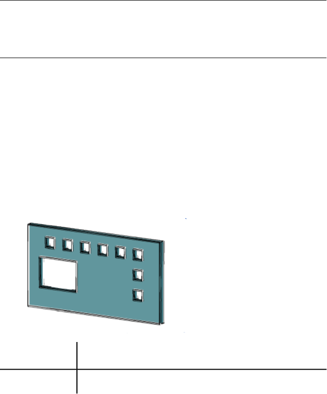
Value 0 designates ByBlock, value 256 designates ByLayer, and value 257
designates ByEntity. Values 1-255 designate an AutoCAD Color Index (ACI)
color. True Colors and Color Book colors are also available.
Valid values for True Colors are a string of integers each from 0 to 255 separated
by commas and preceded by RGB. The True Color setting is entered as follows:
RGB:000,000,000
If you have a color book installed, you can specify any colors that are defined
in the book.
NOTE
Existing visual styles are not changed when you enter a new value for this
system variable. Any new value entered for this system variable temporarily
creates an unsaved new visual style.
See also:
Control the Display of Edges
VSEDGEJITTER
Makes edges on 3D objects appear wavy, as though they were sketched with
a pencil.
IntegerType:
DrawingSaved in:
-2Initial value:
Low1
Medium2
1498 | Chapter 4 System Variables

High3
NOTE
Negative numbers store the value but turn off the effect. Plot styles are not
available for objects with the Jitter edge modifier applied.
NOTE
Existing visual styles are not changed when you enter a new value for this
system variable. Any new value entered for this system variable temporarily
creates an unsaved new visual style.
See also:
Control the Display of Edges
VSEDGELEX
Makes edges on 3D objects extend beyond their intersection for a hand-drawn
effect.
IntegerType:
DrawingSaved in:
-6Initial value:
The range is 1 to 100 pixels. Turn off the line extensions effect by preceding
the setting with a minus sign (-).
NOTE
Existing visual styles are not changed when you enter a new value for this
system variable. Any new value entered for this system variable temporarily
creates an unsaved new visual style.
See also:
Control the Display of Edges
System Variables | 1499
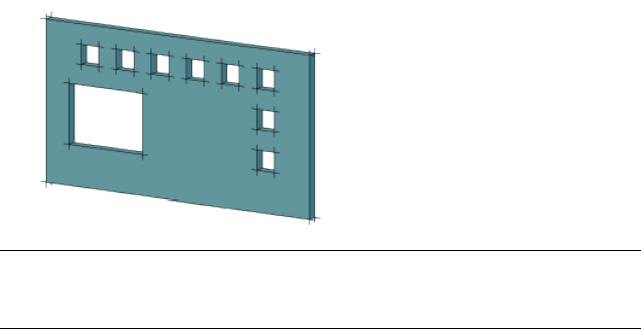
VSEDGEOVERHANG
Makes edges on 3D objects extend beyond their intersection for a hand-drawn
effect.
IntegerType:
DrawingSaved in:
-6Initial value:
The amount of overhang can be set between 1 and 100 pixels. Negative
numbers store the value but turn off the effect.
NOTE Existing visual styles are not changed when you enter a new value for this
system variable. Any new value entered for this system variable temporarily creates
an unsaved new visual style.
See also:
Control the Display of Edges
VSEDGES
Controls the types of edges that are displayed in the viewport.
IntegerType:
DrawingSaved in:
1Initial value:
1500 | Chapter 4 System Variables
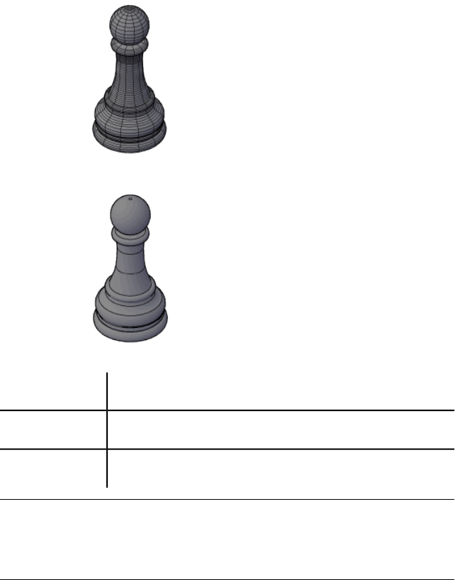
isolines displayed
facet edges displayed
No edges are displayed0
Isolines are displayed1
Facet edges are displayed2
NOTE
Existing visual styles are not changed when you enter a new value for this
system variable. Any new value entered for this system variable temporarily
creates an unsaved new visual style.
See also:
Control the Display of Edges
System Variables | 1501
VSEDGESMOOTH
Specifies the angle at which crease edges are displayed.
IntegerType:
DrawingSaved in:
1Initial value:
The range is 0 to 180.
NOTE
Existing visual styles are not changed when you enter a new value for this
system variable. Any new value entered for this system variable temporarily
creates an unsaved new visual style.
See also:
Control the Display of Edges
VSFACECOLORMODE
Controls how the color of faces is calculated.
IntegerType:
DrawingSaved in:
0Initial value:
Normal: Does not apply a face color modifier0
Monochrome: Displays all faces in the color that is specified in the
VSMONOCOLOR (page 1511) system variable
1
Tint: Uses the color that is specified in the VSMONOCOLOR (page
1511) system variable to shade all faces by changing the hue and sat-
uration values of the color
2
Desaturate: Softens the color by reducing its saturation component
by 30 percent
3
1502 | Chapter 4 System Variables

NOTE
Existing visual styles are not changed when you enter a new value for this
system variable. Any new value entered for this system variable temporarily
creates an unsaved new visual style.
See also:
Shade and Color Faces
VSFACEHIGHLIGHT
Controls the display of specular highlights on faces without materials in the
current viewport.
IntegerType:
DrawingSaved in:
-30Initial value:
The range is -100 to 100. The higher the number, the larger the highlight.
Objects with materials attached ignore the setting of VSFACEHIGHLIGHT
when VSMATERIALMODE (page 1509) is on.
NOTE
Existing visual styles are not changed when you enter a new value for this
system variable. Any new value entered for this system variable temporarily
creates an unsaved new visual style.
See also:
Shade and Color Faces
VSFACEOPACITY
Turns on and off a preset level of transparency for 3D objects.
IntegerType:
DrawingSaved in:
-60Initial value:
The level of transparency for 3D solids and surfaces can be set between 100
percent opaque and 0 percent opaque. Negative numbers store the value but
turn off the effect.
System Variables | 1503

NOTE Existing visual styles are not changed when you enter a new value for this
system variable. Any new value entered for this system variable temporarily creates
an unsaved new visual style.
See also:
Shade and Color Faces
VSFACESTYLE
Controls how faces are displayed in the current viewport.
IntegerType:
DrawingSaved in:
0Initial value:
No style applied0
Real: as close as possible to how the face would appear in the real
world
1
Gooch: uses cool and warm colors instead of dark and light to en-
hance the display of faces that might be shadowed and difficult to
see in a realistic display
2
NOTE
Existing visual styles are not changed when you enter a new value for this
system variable. Any new value entered for this system variable temporarily
creates an unsaved new visual style.
1504 | Chapter 4 System Variables
See also:
Shade and Color Faces
VSHALOGAP
Sets the halo gap in the visual style applied to the current viewport.
IntegerType:
DrawingSaved in:
0Initial value:
The range is 0 to 100.
NOTE
Existing visual styles are not changed when you enter a new value for this
system variable. Any new value entered for this system variable temporarily
creates an unsaved new visual style.
See also:
Use a Visual Style to Display Your Model
VSHIDEPRECISION
Controls the accuracy of hides and shades in the visual style applied to the
current viewport.
IntegerType:
Not-savedSaved in:
0Initial value:
Single precision; uses less memory0
Double precision; uses more memory1
NOTE
Existing visual styles are not changed when you enter a new value for this
system variable. Any new value entered for this system variable temporarily
creates an unsaved new visual style.
System Variables | 1505

See also:
Shade and Color Faces
VSINTERSECTIONCOLOR
Specifies the color of intersection polylines in the visual style applied to the
current viewport.
IntegerType:
DrawingSaved in:
7Initial value:
The initial value is 7, which is a special value that inverts the color (black or
white) based on the background color.
Value 0 designates ByBlock, value 256 designates ByLayer, and value 257
designates ByEntity. Values 1-255 designate an AutoCAD Color Index (ACI)
color. True Colors and Color Book colors are also available.
NOTE INTERSECTIONCOLOR (page 1341) controls the color of intersection polylines
when the visual style is set to 2D Wireframe.
NOTE Existing visual styles are not changed when you enter a new value for this
system variable. Any new value entered for this system variable temporarily creates
an unsaved new visual style.
See also:
Control the Display of Edges
VSINTERSECTIONEDGES
Controls the display of intersection edges in the visual style applied to the
current viewport.
SwitchType:
DrawingSaved in:
0Initial value:
1506 | Chapter 4 System Variables
NOTE INTERSECTIONDISPLAY (page 1342) controls the color of intersection polylines
when the visual style is set to 2D Wireframe.
Off0
On1
NOTE Existing visual styles are not changed when you enter a new value for this
system variable. Any new value entered for this system variable temporarily creates
an unsaved new visual style.
See also:
Control the Display of Edges
VSINTERSECTIONLTYPE
Sets the linetype for intersection lines in the visual style applied to the current
viewport.
IntegerType:
DrawingSaved in:
1Initial value:
The range is 1 to 11.
Solid1
Dashed2
Dotted3
Short Dash4
Medium Dash5
Long Dash6
Double Short Dash7
System Variables | 1507
Double Medium Dash8
Double Long Dash9
Medium Long Dash10
Sparse Dot11
NOTE Existing visual styles are not changed when you enter a new value for this
system variable. Any new value entered for this system variable temporarily creates
an unsaved new visual style.
See also:
Control the Display of Edges
VSISOONTOP
Displays isolines on top of shaded objects in the visual style applied to the
current viewport.
IntegerType:
DrawingSaved in:
0Initial value:
Off0
On1
NOTE Existing visual styles are not changed when you enter a new value for this
system variable. Any new value entered for this system variable temporarily creates
an unsaved new visual style.
See also:
Control the Display of Edges
1508 | Chapter 4 System Variables
VSLIGHTINGQUALITY
Sets the lighting quality in the current viewport.
IntegerType:
DrawingSaved in:
1Initial value:
Faceted. A single color is computed for each face of a surface or 3D
solid.
0
Smooth. The colors are computed as a gradient between the vertices
of the faces.
1
Smoothest. If the Per-Pixel Lighting setting is turned on in the
Manual Performance Tuning dialog box, then the colors are com-
puted for individual pixels. If not, the Smooth setting is used instead.
2
NOTE Existing visual styles are not changed when you enter a new value for this
system variable. Any new value entered for this system variable temporarily creates
an unsaved new visual style.
See also:
Use a Visual Style to Display Your Model
VSMATERIALMODE
Controls the display of materials in the current viewport.
IntegerType:
DrawingSaved in:
0Initial value:
Turn off the display of materials and textures to maximize performance during
unrelated operations.
Turn off the display of textures to modify materials, or to increase performance
during unrelated operations.
System Variables | 1509
After turning them off, you can restore the display of materials and textures.
No materials are displayed0
Materials are displayed, textures are not displayed1
Materials and textures are displayed2
NOTE Existing visual styles are not changed when you enter a new value for this
system variable. Any new value entered for this system variable temporarily creates
an unsaved new visual style.
See also:
Use a Visual Style to Display Your Model
VSMAX
Stores the upper-right corner of the current viewport's virtual screen.
(Read-only)
3D-pointType:
DrawingSaved in:
VariesInitial value:
Expressed as a UCS coordinate.
See also:
Save and Restore Model Layout Viewport Arrangements
VSMIN
Stores the lower-left corner of the current viewport's virtual screen.
(Read-only)
3D-pointType:
DrawingSaved in:
VariesInitial value:
Expressed as a UCS coordinate.
1510 | Chapter 4 System Variables

See also:
Save and Restore Model Layout Viewport Arrangements
VSMONOCOLOR
Sets the color for monochrome and tint display of faces in the visual style
applied to the current viewport.
StringType:
DrawingSaved in:
255,255,255Initial value:
The initial value is white.
NOTE
Existing visual styles are not changed when you enter a new value for this
system variable. Any new value entered for this system variable temporarily
creates an unsaved new visual style.
See also:
Shade and Color Faces
VSOBSCUREDCOLOR
Specifies the color of obscured (hidden) lines in the visual style applied to the
current viewport.
StringType:
DrawingSaved in:
BYENTITYInitial value:
Valid values include ByLayer (256), ByBlock (0), ByEntity (257), and any
AutoCAD Color Index (ACI) color (an integer from 1 to 255).
You can also specify a true color or a color book color. Valid values for true
colors are a string of integers each from 1 to 255 separated by commas and
preceded by RGB. The True Color setting is entered as follows:
RGB:000,000,000
System Variables | 1511

NOTE
Existing visual styles are not changed when you enter a new value for this
system variable. Any new value entered for this system variable temporarily
creates an unsaved new visual style.
See also:
Control the Display of Edges
VSOBSCUREDEDGES
Controls whether obscured (hidden) edges are displayed.
IntegerType:
DrawingSaved in:
1Initial value:
Off0
On1
NOTE Existing visual styles are not changed when you enter a new value for this
system variable. Any new value entered for this system variable temporarily creates
an unsaved new visual style.
See also:
Control the Display of Edges
VSOBSCUREDLTYPE
Specifies the linetype of obscured (hidden) lines in the visual style applied to
the current viewport.
IntegerType:
DrawingSaved in:
1Initial value:
1512 | Chapter 4 System Variables
The range is 1 to 11.
Solid1
Dashed2
Dotted3
Short Dash4
Medium Dash5
Long Dash6
Double Short Dash7
Double Medium Dash8
Double Long Dash9
Medium Long Dash10
Sparse Dot11
System Variables | 1513
The initial value of VSOBSCUREDLTYPE varies on the current visual style.
Initial ValueVisual Style (VSCURRENT)
12D Wireframe
1Conceptual
2Hidden
1Shaded
2Shaded with Edges
1Shades of Gray
1Sketchy
1Wireframe
1X-ray
1Realistic
NOTE
Existing visual styles are not changed when you enter a new value for this
system variable. Any new value entered for this system variable temporarily
creates an unsaved new visual style.
See also:
Control the Display of Edges
VSOCCLUDEDCOLOR
Specifies the color of occluded (hidden) lines in the visual style applied to the
current viewport.
1514 | Chapter 4 System Variables
StringType:
DrawingSaved in:
ByEntityInitial value:
Valid values include ByLayer (256), ByBlock (0), ByEntity (257), and any
AutoCAD Color Index (ACI) color (an integer from 1 to 255).
You can also specify a true color or a color book color. Valid values for true
colors are a string of integers each from 1 to 255 separated by commas and
preceded by RGB. The True Color setting is entered as follows:
RGB:000,000,000
NOTE
Existing visual styles are not changed when you enter a new value for this
system variable. Any new value entered for this system variable temporarily
creates an unsaved new visual style.
See also:
Control the Display of Edges
VSOCCLUDEDEDGES
Controls whether occluded (hidden) edges are displayed.
IntegerType:
DrawingSaved in:
1Initial value:
Off0
On1
NOTE Existing visual styles are not changed when you enter a new value for this
system variable. Any new value entered for this system variable temporarily creates
an unsaved new visual style.
See also:
Control the Display of Edges
System Variables | 1515
VSOCCLUDEDLTYPE
Specifies the linetype of occluded (hidden) lines in the visual style applied to
the current viewport.
IntegerType:
DrawingSaved in:
1Initial value:
The range is 1 to 11.
Solid1
Dashed2
Dotted3
Short Dash4
Medium Dash5
Long Dash6
Double Short Dash7
Double Medium Dash8
Double Long Dash9
1516 | Chapter 4 System Variables
Medium Long Dash10
Sparse Dot11
The initial value of VSOCCLUDEDLTYPE varies on the current visual style.
Initial ValueVisual Style (VSCURRENT)
12D Wireframe
1Conceptual
2Hidden
1Shaded
2Shaded with Edges
1Shades of Gray
1Sketchy
1Wireframe
1X-ray
1Realistic
NOTE Existing visual styles are not changed when you enter a new value for this
system variable. Any new value entered for this system variable temporarily creates
an unsaved new visual style.
See also:
Control the Display of Edges
System Variables | 1517
VSSHADOWS
Controls whether a visual style displays shadows.
IntegerType:
DrawingSaved in:
0Initial value:
Displaying shadows can slow performance. You can turn off shadows in the
current visual style while you work and turn them back on when you need
them.
Ground shadows are shadows that objects cast on the ground, not on other
objects.
No shadows are displayed0
Ground shadows only are displayed1
Full shadows are displayed2
NOTE
Existing visual styles are not changed when you enter a new value for this
system variable. Any new value entered for this system variable temporarily
creates an unsaved new visual style.
See also:
Display Backgrounds and Shadows
VSSILHEDGES
Controls display of silhouette edges of solid objects in the visual style applied
to the current viewport.
IntegerType:
DrawingSaved in:
0Initial value:
Off0
1518 | Chapter 4 System Variables
On1
The initial value of VSSILHEDGES depends on the current visual style.
Initial ValueVisual Style (VSCURRENT)
02D Wireframe
1Conceptual
1Hidden
0Shaded
1Shaded with Edges
1Shades of Gray
1Sketchy
System Variables | 1519
Initial ValueVisual Style (VSCURRENT)
0Wireframe
0X-ray
0Realistic
NOTE
Existing visual styles are not changed when you enter a new value for this
system variable. Any new value entered for this system variable temporarily
creates an unsaved new visual style.
See also:
Control the Display of Edges
VSSILHWIDTH
Specifies the width in pixels of silhouette edges in the current viewport.
IntegerType:
DrawingSaved in:
5Initial value:
The range is 1 to 25.
NOTE
Existing visual styles are not changed when you enter a new value for this
system variable. Any new value entered for this system variable temporarily
creates an unsaved new visual style.
See also:
Control the Display of Edges
VTDURATION
Sets the duration of a smooth view transition, in milliseconds.
1520 | Chapter 4 System Variables
IntegerType:
RegistrySaved in:
750Initial value:
The valid range is 0 to 5000.
See also:
Pan or Zoom a View
VTENABLE
Controls when smooth view transitions are used.
IntegerType:
RegistrySaved in:
3Initial value:
Smooth view transitions can be on or off for panning and zooming, for changes
of view angle, or for scripts. The valid range is 0 to 7.
For scriptsFor rotationFor pan/zoomSetting
OffOffOff0
OffOffOn1
OffOnOff2
OffOnOn3
OnOffOff4
OnOffOn5
OnOnOff6
OnOnOn7
System Variables | 1521

See also:
Pan or Zoom a View
VTFPS
Sets the minimum speed of a smooth view transition, in frames per second.
IntegerType:
RegistrySaved in:
7Initial value:
When a smooth view transition cannot maintain this speed, an instant
transition is used. The valid range is 1 to 30.
See also:
Pan or Zoom a View
W System Variables
WHIPARC
Controls whether the display of circles and arcs is smooth.
IntegerType:
RegistrySaved in:
0Initial value:
Circles and arcs are not smooth, but rather are displayed as a series
of vectors
0
Circles and arcs are smooth, displayed as true circles and arcs1
See also:
Draw Curved Objects
1522 | Chapter 4 System Variables
WINDOWAREACOLOR
Controls the color of the transparent selection area during window selection.
IntegerType:
RegistrySaved in:
150Initial value:
The valid range is 1 to 255. SELECTIONAREA (page 1425) must be on.
See also:
Customize Object Selection
WORLDUCS
Indicates whether the UCS is the same as the WCS.
(Read-only)
IntegerType:
Not-savedSaved in:
1Initial value:
UCS differs from the WCS0
UCS matches the WCS1
See also:
Overview of the User Coordinate System (UCS)
WORLDVIEW
Determines whether input to the DVIEW and VPOINT commands is relative
to the WCS (default) or the current UCS.
IntegerType:
DrawingSaved in:
1Initial value:
UCS remains unchanged0
System Variables | 1523
UCS changes to the WCS for the duration of the command; the
command input is relative to the current UCS
1
See also:
Define a 3D View with Coordinate Values or Angles
WRITESTAT
Indicates whether a drawing file is read-only or can be revised.
(Read-only)
IntegerType:
Not-savedSaved in:
1Initial value:
For developers who need to determine write status through AutoLISP.
Cannot write to the drawing0
Can write to the drawing1
See also:
Overview of AutoLISP and Visual LISP
X System Variables
XCLIPFRAME
Determines whether xref clipping boundaries are visible or plotted in the
current drawing.
IntegerType:
DrawingSaved in:
2Initial value:
1524 | Chapter 4 System Variables
The FRAME (page 1299) system variable overrides the XCLIPFRAME setting.Use
the XCLIPFRAME system variable after the FRAME system variable to reset
the clipped xref frame settings
The frame is not visible and it is not plotted.0
The frame temporarily reappears during selection preview or object
selection.
The clipped xref frame is displayed and plotted1
The clipped xref frame is displayed but not plotted2
See also:
Update Referenced Drawing Attachments
XDWGFADECTL
Controls the dimming for all DWG xref objects.
IntegerType:
RegistrySaved in:
70Initial value:
The valid XDWGFADECTL system variable value is between -90 and 90. When
XDWGFADECTL is set to a negative value, the Xref Fading feature is not turned
on, but the setting is stored.
DWG xref objects are not faded.0
When the value is positive, controls the percent of fading up to 90
percent.
>0
When the value is negative, xref objects are not faded, but the value
is saved for switching to that value by changing the sign.
<0
See also:
Attach Drawing References (Xrefs)
System Variables | 1525
XEDIT
Controls whether the current drawing can be edited in-place when being
referenced by another drawing.
IntegerType:
DrawingSaved in:
1Initial value:
Cannot use in-place reference editing0
Can use in-place reference editing1
See also:
Update Referenced Drawing Attachments
XFADECTL
Controls the amount of fading within a reference being edited in place. This
setting affects only the objects that are not being edited in the reference.
IntegerType:
RegistrySaved in:
50Initial value:
Valid values are from 0 to 90.
Also controls the fading intensity percentage of alternate object representations
that display in a dimmed state, such as alternate scale representations of
annotative objects.
SELECTIONANNODISPLAY (page 1424) controls whether or not alternate scale
representations of annotative objects are displayed.
See also:
Attach Drawing References (Xrefs)
1526 | Chapter 4 System Variables

XLOADCTL
Turns xref demand-loading on and off, and controls whether it opens the
referenced drawing or a copy.
IntegerType:
RegistrySaved in:
2Initial value:
Turns off demand-loading; the entire drawing is loaded.0
Turns on demand-loading. Referenced drawings are kept open and
locked.
1
Turns on demand-loading. Copies of referenced drawings are opened
and locked; referenced drawings are not locked
2
When XLOADCTL is set to 2, a copy of each referenced drawing file is stored
in the folder specified by the XLOADPATH system variable or the temporary
files folder (set in the Application Preferences dialog box).
Additionally, xrefs load faster when you work across a network: the
performance enhancement is most pronounced when you open drawings
with many xrefs.
See also:
Work with Demand Loading in Large Drawings
XLOADPATH
Creates a path for storing temporary copies of demand-loaded xref files.
StringType:
RegistrySaved in:
VariesInitial value:
For more information, see XLOADCTL (page 1527).
See also:
Set Paths for Temporary Xref File Copies
System Variables | 1527

XREFCTL
Controls whether external reference log (XLG) files are created.
IntegerType:
RegistrySaved in:
0Initial value:
Does not write log files0
Writes log files1
See also:
Track External Reference Operations (Log File)
XREFNOTIFY
Controls the notification for updated or missing xrefs.
IntegerType:
RegistrySaved in:
2Initial value:
Disables xref notification0 or 1
Enables xref notification and balloon messages.2
See also:
Update Referenced Drawing Attachments
XREFSTATE
Indicates whether the Reference Manager palette is open or closed, and can
be used to toggle the display state of the Reference Manager palette.
IntegerType:
RegistrySaved in:
1528 | Chapter 4 System Variables

VariesInitial value:
Closed0
Open1
See also:
Attach Drawing References (Xrefs)
XREFTYPE
Controls the default reference type when attaching or overlaying an external
reference.
IntegerType:
RegistrySaved in:
0Initial value:
Attachment is the default0
Overlay is the default1
See also:
Nest and Overlay Referenced Drawings
Z System Variables
ZOOMFACTOR
Controls how much the magnification changes when the mouse wheel moves
forward or backward.
IntegerType:
RegistrySaved in:
60Initial value:
System Variables | 1529
Accepts an integer between 3 and 100 as a valid value. The higher the number,
the more the change.
See also:
Pan or Zoom a View
ZOOMWHEEL
Toggles the direction of transparent zoom operations when you scroll the
middle mouse wheel.
IntegerType:
RegistrySaved in:
0Initial value:
Moves wheel forward zooms in; moving wheel backwards zooms
out.
0
Move wheel forward zooms out; moving wheel backwards zooms
in.
1
See also:
Pan or Zoom a View
1530 | Chapter 4 System Variables
Index
3D command 7
3D Edit Bar shortcut menu 30
3D Free Orbit cursor icons 34
3D Move Gizmo shortcut menu 39
3D Object Snap tab (Drafting Settings
dialog box) 374
3D Rotate Gizmo shortcut menu 50
3D Scale Gizmo shortcut menu 53
3DALIGN command 19
3DARRAY command 21
3DCONFIG command 22
3DDISTANCE command 25
3DEDITBAR command 25
3DFACE command 31
3DFORBIT command 33
3DMESH command 35
3DMOVE command 36
3DORBIT command 40
3DORBIT shortcut menu 41
3DORBITCTR command 44
3DOSMODE system variable 1166
3DOSNAP command 44
3DPAN command 46
3DPOLY command 46
3DROTATE command 48
3DSCALE command 50
3DSELECTIONMODE system
variable 1167
3DSWIVEL command 54
3DZOOM command 54
A
ABOUT command 55
ACADLSPASDOC system variable 1167
ACADPREFIX system variable 1167
ACADVER system variable 1168
ACISIN command 56
ACISOUT command 56
ACISOUTVER system variable 1168
Add Scales to Object dialog box 714
Additional Format dialog box 1035
ADDSELECTED command 57
AFLAGS system variable 1169
ALIGN command 59
Alternate Font dialog box 741
Alternate Units tab (New Dimension Style
dialog box) 339
AMECONVERT command 61
Analysis Options dialog box 64
ANALYSISCURVATURE command 62
ANALYSISDRAFT command 63
ANALYSISOPTIONS command 64
ANALYSISZEBRA command 67
ANGBASE system variable 1169
ANGDIR system variable 1170
ANNOALLVISIBLE system variable 1170
ANNOAUTOSCALE system variable 1171
ANNORESET command 69
Annotation tab (Leader Settings dialog
box) 856
Annotative Object Scale dialog box 712
ANNOTATIVEDWG system
variable 1172
ANNOUPDATE command 69
APBOX system variable 1172
APERTURE command 70
APERTURE system variable 1173
APPAUTOLOAD system variable 1173
Application tab (Application Preferences
dialog box) 735
APPLOAD command
about 70
Load/Unload Applications dialog
box 71
Startup Suite dialog box 74
ARC command 75
AREA command 83
AREA system variable 1174
ARRAY command 86
ARRAYCLOSE command 90
ARRAYEDIT command 90
ARRAYEDITSTATE system variable 1174
1531 | Index
ARRAYPATH command 96
Path Array visor 94
ARRAYPOLAR command 100
Polar Array visor 95
ARRAYRECT command 103
Rectangular Array visor 96
ARRAYTYPE system variable 1175
ARX command 105
ATTACH command 106
Attach External Reference dialog
box 1138
Attach Image dialog box 514
Attachment tab (Leader Settings dialog
box) 858
ATTDEF command 107
ATTDIA system variable 1175
ATTDISP command 115
ATTEDIT command 116
ATTEXT command 121
ATTIPE system variable 1175
ATTIPEDIT command 122
ATTMODE system variable 1176
ATTMULTI system variable 1176
ATTREDEF command 123
ATTREQ system variable 1177
Attribute Definition dialog box 108
Attribute Order dialog box 136
Attribute tab (Attribute Editor dialog
box) 131
Attribute tab (Enhanced Attribute
Editor) 394
ATTSYNC command 124
AUDIT command 125
AUDITCTL system variable 1177
AUNITS system variable 1178
AUPREC system variable 1178
AUTOCOMPLETE command 125
AUTOCOMPLETEDELAY system
variable 1179
AUTOCOMPLETEMODE system
variable 1179
AUTOCONSTRAIN command 126
Autoconstrain tab (Constraint Settings
dialog box) 214
AUTOSNAP system variable 1180
AutoStack Properties dialog box 691
B
Background Mask dialog box 686
BACKZ system variable 1181
BASE command 127
Batch Publish dialog box 846
BATTMAN command
about 128
Block Attribute Manager 129
Edit Attribute dialog box 131
BATTORDER command 135
BCLOSE command 137
BEDIT command
about 137
Block Editor 139
Edit Block Definition dialog box 138
BHATCH command 141
BINDTYPE system variable 1181
BLEND command 141
BLIPMODE command 143
BLIPMODE system variable 1182
Block Attribute Manager
about 129
Block Authoring Palettes window 139
BLOCK command 143
Block Definition dialog box 144
Block Editor
about 139
Block Editor visor 140
BLOCKEDITLOCK system variable 1182
BLOCKEDITOR system variable 1183
BMP Image Options dialog box 886
BMPOUT command 149
BOUNDARY command 149
Boundary Creation dialog box 151
BOX command 153
BREAK command 155
BREP command 157
BROWSER command 158
BSAVE command 159
BSAVEAS command 159
BTMARKDISPLAY system variable 1183
C
CAL command 161
1532 | Index
CAMERADISPLAY system variable 1184
CANNOSCALE system variable 1184
CANNOSCALEVALUE system
variable 1184
CCONSTRAINTFORM system
variable 1185
CDATE system variable 1185
CECOLOR system variable 1186
Cell Border Properties dialog box 836
CELTSCALE system variable 1186
CELTYPE system variable 1187
CELWEIGHT system variable 1187
CENTERMT system variable 1188
CETRANSPARENCY system
variable 1189
CHAMFER command 182
CHAMFERA system variable 1189
CHAMFERB system variable 1189
CHAMFERC system variable 1189
CHAMFERD system variable 1190
CHAMFEREDGE command 186
CHAMMODE system variable 1190
CHANGE command 187
Change to Layer dialog box 560
Check Spelling dialog box 982
Check Spelling Settings dialog box 985
CHPROP command 190
CIRCLE command 192
CIRCLERAD system variable 1190
CLASSICKEYS system variable 1191
CLAYER system variable 1191
CLEANSCREENOFF command 197
CLEANSCREENON command 196
CLEANSCREENSTATE system
variable 1192
CLISTATE system variable 1192
CLOSE command 197
CLOSEALL command 197
CMATERIAL system variable 1192
CMDACTIVE system variable 1193
CMDDIA system variable 1194
CMDECHO system variable 1194
CMDINPUTHISTORYMAX system
variable 1194
CMDNAMES system variable 1195
CMLEADERSTYLE system variable 1195
CMLJUST system variable 1196
CMLSCALE system variable 1196
CMLSTYLE system variable 1196
Color Books tab (Select Color dialog
box) 204
COLOR command 198
COLORSCHEME system variable 1197
Column Label shortcut menu 542
Column Settings dialog box 685
Columns menu 684
command line
entering data on 4
selecting options 4
COMMANDLINE command 206
COMMANDLINEHIDE command 207
commands
executing 2
recently-used list 5
repeating 5
starting 2
transparent 3
Commands tab (Customize dialog
box) 234
Compare Dimension Styles dialog
box 347
COMPASS system variable 1197
COMPILE command 207
CONE command 208
Constraint Settings dialog box 213
CONSTRAINTBAR command 211
CONSTRAINTBARDISPLAY system
variable 1198
CONSTRAINTBARMODE system
variable 1199
CONSTRAINTINFER system
variable 1199
CONSTRAINTNAMEFORMAT system
variable 1200
CONSTRAINTRELAX system
variable 1200
CONSTRAINTSETTINGS command 212
CONSTRAINTSOLVEMODE system
variable 1201
Content palette 217
Content tab (Modify Multileader Style
dialog box) 664
Index | 1533
CONTENTCLOSE command 220
CONTENTSTATE system variable 1201
CONVERT command 220
CONVTOMESH command 221
CONVTONURBS command 222
CONVTOSOLID command 223
CONVTOSURFACE command 226
Coordinate Filters command
modifier 1159
COPY command 229
COPYBASE command 231
COPYCLIP command 231
COPYHIST command 232
COPYMODE system variable 1202
CPLOTSTYLE system variable 1202
CPROFILE system variable 1203
Create New Dimension Style dialog
box 317
Create New Multileader Style dialog
box 666
CROSSINGAREACOLOR system
variable 1203
CSHADOW system variable 1204
CTAB system variable 1204
CTABLESTYLE system variable 1204
CUI command
about 232
Customize dialog box 233
Specify Tool Set Image dialog
box 240
CULLINGOBJ system variable 1205
CULLINGOBJSELECTION system
variable 1206
Cursor & Selection tab (Application
Preferences dialog box) 727
CURSORSIZE system variable 1206
Curvature tab (Analysis Options dialog
box) 65
Customize dialog box
CUI command 233
CUTCLIP command 241
CVADD command 241
CVHIDE command 242
CVPORT system variable 1206
CVREBUILD command
about 243
Rebuild Curve dialog box 245
Rebuild Surface dialog box 244
CVREMOVE command 246
CVSHOW command 248
CYLINDER command 249
D
DATE system variable 1207
DBLCLKEDIT system variable 1208
DBLIST command 251
DBMOD system variable 1208
DCALIGNED command 251
DCANGULAR command 254
DCCONVERT command 256
DCDIAMETER command 257
DCDISPLAY command 258
DCFORM command 258
DCHORIZONTAL command 259
DCLINEAR command 261
DCRADIUS command 262
DCVERTICAL command 263
DDEDIT command
about 265
Edit Attribure Definition dialog
box 266
DDPTYPE command 266
Default Scale List dialog box 741
DEFAULTGIZMO system variable 1211
DEFAULTLIGHTING system
variable 1211
DEFAULTLIGHTINGTYPE system
variable 1212
DEFLPLSTYLE system variable 1212
DEFPLSTYLE system variable 1213
DELAY command 268
DELCONSTRAINT command 269
Delete Duplicate Objects dialog box 745
DELOBJ system variable 1214
DEMANDLOAD system variable 1215
dialog boxes
suppressing display 3
DIASTAT system variable 1215
DIM and DIM1 commands 269
DIMADEC system variable 1216
DIMALIGNED command 272
1534 | Index
DIMALT system variable 1216
DIMALTD system variable 1217
DIMALTF system variable 1217
DIMALTRND system variable 1217
DIMALTTD system variable 1218
DIMALTTZ system variable 1218
DIMALTU system variable 1219
DIMALTZ system variable 1220
DIMANGULAR command 275
DIMANNO system variable 1220
DIMAPOST system variable 1221
DIMARC command 278
DIMARCSYM system variable 1221
DIMASSOC system variable 1222
DIMASZ system variable 1222
DIMATFIT system variable 1223
DIMAUNIT system variable 1224
DIMAZIN system variable 1224
DIMBASELINE command 280
DIMBLK system variable 1226
DIMBLK1 system variable 1226
DIMBLK2 system variable 1227
DIMBREAK command 282
DIMCEN system variable 1227
DIMCENTER command 284
DIMCLRD system variable 1228
DIMCLRE system variable 1228
DIMCLRT system variable 1228
DIMCONSTRAINT command 285
DIMCONSTRAINTICON system
variable 1229
DIMCONTINUE command 287
DIMDEC system variable 1229
DIMDIAMETER command 289
DIMDISASSOCIATE command 290
DIMDLE system variable 1230
DIMDLI system variable 1230
DIMDSEP system variable 1230
DIMEDIT command 291
Dimension Input Settings dialog
box 383
Dimension Style Manager
about 315
Dimensional tab (Constraint Settings
dialog box) 214
DIMEXE system variable 1231
DIMEXO system variable 1231
DIMFRAC system variable 1232
DIMFXL system variable 1232
DIMFXLON system variable 1232
DIMGAP system variable 1233
DIMINSPECT command 293
DIMJOGANG system variable 1233
DIMJOGGED command 296
DIMJOGLINE command 298
DIMJUST system variable 1234
DIMLDRBLK system variable 1234
DIMLFAC system variable 1235
DIMLIM system variable 1235
DIMLINEAR command 300
DIMLTEX1 system variable 1236
DIMLTEX2 system variable 1236
DIMLTYPE system variable 1236
DIMLUNIT system variable 1237
DIMLWD system variable 1237
DIMLWE system variable 1238
DIMORDINATE command 304
DIMOVERRIDE command 306
DIMPOST system variable 1238
DIMRADIUS command 307
DIMREASSOCIATE command 309
DIMREGEN command 310
DIMRND system variable 1239
DIMROTATED command 311
DIMSAH system variable 1239
DIMSCALE system variable 1240
DIMSD1 system variable 1240
DIMSD2 system variable 1241
DIMSE1 system variable 1241
DIMSE2 system variable 1242
DIMSOXD system variable 1242
DIMSPACE command 313
DIMSTYLE command
about 314
Compare Dimension Styles dialog
box 347
Create New Dimension Style dialog
box 317
Dimension Style Manager 315
Modify Dimension Style dialog
box 318
Index | 1535
New Dimension Style dialog
box 318
Override Dimension Style dialog
box 318
DIMSTYLE system variable 1243
DIMTAD system variable 1243
DIMTDEC system variable 1244
DIMTEDIT command 350
DIMTFAC system variable 1244
DIMTFILL system variable 1245
DIMTFILLCLR system variable 1245
DIMTIH system variable 1246
DIMTIX system variable 1246
DIMTM system variable 1247
DIMTMOVE system variable 1247
DIMTOFL system variable 1248
DIMTOH system variable 1248
DIMTOL system variable 1248
DIMTOLJ system variable 1249
DIMTP system variable 1249
DIMTSZ system variable 1250
DIMTVP system variable 1250
DIMTXSTY system variable 1250
DIMTXT system variable 1251
DIMTXTDIRECTION system
variable 1251
DIMTZIN system variable 1252
DIMUPT system variable 1252
DIMZIN system variable 1253
Direct Distance command modifier 1160
displaying
dialog boxes 3
DISPLAYVIEWCUBEIN2D system
variable 1254
DISPLAYVIEWCUBEIN3D system
variable 1254
DISPSILH system variable 1255
DIST command 353
DISTANCE system variable 1255
DISTANTLIGHT command 354
DIVIDE command 357
DIVMESHBOXHEIGHT system
variable 1256
DIVMESHBOXLENGTH system
variable 1257
DIVMESHBOXWIDTH system
variable 1257
DIVMESHCONEAXIS system
variable 1258
DIVMESHCONEBASE system
variable 1259
DIVMESHCONEHEIGHT system
variable 1260
DIVMESHCYLAXIS system variable 1261
DIVMESHCYLBASE system variable 1262
DIVMESHCYLHEIGHT system
variable 1262
DIVMESHPYRBASE system variable 1263
DIVMESHPYRHEIGHT system
variable 1264
DIVMESHPYRLENGTH system
variable 1264
DIVMESHSPHEREAXIS system
variable 1265
DIVMESHSPHEREHEIGHT system
variable 1266
DIVMESHTORUSPATH system
variable 1266
DIVMESHTORUSSECTION system
variable 1267
DIVMESHWEDGEBASE system
variable 1268
DIVMESHWEDGEHEIGHT system
variable 1268
DIVMESHWEDGELENGTH system
variable 1269
DIVMESHWEDGESLOPE system
variable 1270
DIVMESHWEDGEWIDTH system
variable 1270
Document Settings tab (Application
Preferences dialog box) 739
DONUT command 358
DONUTID system variable 1271
DONUTOD system variable 1271
Draft Angle Handle 590
Draft Angle tab (Analysis Options dialog
box) 66
DRAGMODE command 360
DRAGMODE system variable 1272
DRAGP1 system variable 1272
1536 | Index
DRAGP2 system variable 1272
DRAGVS system variable 1273
Drawing Units dialog box 1096
DRAWINGRECOVERY command
about 361
Files Recovered dialog box 361
DRAWORDER command 363
DRAWORDERCTL system variable 1274
DRSTATE system variable 1274
DSETTINGS command
about 364
Dimension Input Settings dialog
box 383
Pointer Input Settings dialog
box 382
Tooltip Appearance dialog box 384
DVIEW command 385
DWGCHECK system variable 1275
DWGCODEPAGE system variable 1276
DWGNAME system variable 1276
DWGPREFIX system variable 1276
DWGTITLED system variable 1277
DXBIN command 393
Dynamic Input tab (Drafting Settings
dialog box) 379
DYNCONSTRAINMODE system
variable 1277
DYNDIGRIP system variable 1278
DYNDIVIS system variable 1279
DYNINFOTIPS system variable 1279
DYNMODE system variable 1280
DYNPICOORDS system variable 1281
DYNPIFORMAT system variable 1281
DYNPIVIS system variable 1282
DYNPROMPT system variable 1282
DYNTOOLTIPS system variable 1283
E
EATTEDIT command 393
EDGE command 398
EDGEMODE system variable 1283
EDGESURF command 400
Edit Attribute Definition dialog box 266
Edit Attribute dialog box 131
Edit Attributes dialog box 117
Edit Block Definition dialog box 138
Edit Drawing Scales dialog box 919
EDIT PGP command 401
Edit Plot Style Table dialog box 809
ELEV command 401
ELEVATION system variable 1284
ELLIPSE command 403
Enhanced Attribute Editor
about 394
ERASE command 406
ERHIGHLIGHT system variable 1284
ERRNO system variable 1285
ERSTATE system variable 1285
EXPERT system variable 1286
EXPLMODE system variable 1286
EXPLODE command 407
EXPORT command 410
EXTEND command 411
External Reference visor 1140
EXTERNALREFERENCES command 414
EXTERNALREFERENCESCLOSE
command 423
EXTMAX system variable 1287
EXTMIN system variable 1287
EXTNAMES system variable 1288
EXTRUDE command 423
F
FACETERDEVNORMAL system
variable 1289
FACETERDEVSURFACE system
variable 1289
FACETERGRIDRATIO system
variable 1290
FACETERMAXEDGELENGTH system
variable 1290
FACETERMAXGRID system
variable 1291
FACETERMESHTYPE system
variable 1291
FACETERMINUGRID system
variable 1292
FACETERMINVGRID system
variable 1293
Index | 1537
FACETERPRIMITIVEMODE system
variable 1293
FACETERSMOOTHLEV system
variable 1294
FACETRATIO system variable 1295
FACETRES system variable 1295
FIELD command 429
Field dialog box 429
FIELDDISPLAY system variable 1296
FIELDEVAL system variable 1296
FILEDIA system variable 1297
Files Recovered dialog box 361
FILL command 431
FILLET command 432
FILLETEDGE command 436
FILLETRAD system variable 1297
FILLETRAD3D system variable 1298
FILLMODE system variable 1298
Find and Replace dialog box (mtext) 687
Find and Replace dialog box (text) 438
FIND command 437
Fit tab (New Dimension Style dialog
box) 331
FLATSHOT command 441
Flatshot dialog box 442
FONTALT system variable 1298
FONTMAP system variable 1299
FRAME system variable 1300
FRAMESELECTION system variable 1300
FREESPOT command 444
FREEWEB command 447
FROM command modifier 1160
FRONTZ system variable 1301
FULLPLOTPATH system variable 1301
G
GCCOINCIDENT command 450
GCCOLLINEAR command 452
GCCONCENTRIC command 453
GCEQUAL command 454
GCFIX command 455
GCHORIZONTAL command 456
GCPARALLEL command 458
GCPERPENDICULAR command 458
GCSMOOTH command 459
GCSYMMETRIC command 461
GCTANGENT command 462
GCVERTICAL command 464
General tab (Application Preferences dialog
box) 725
Generate Section / Elevation dialog
box 935
GEOMARKERVISIBILITY system
variable 1302
GEOMCONSTRAINT command 465
Geometric tab (Constraint Settings dialog
box) 213
Geometric Tolerance dialog box 1058
GFANG system variable 1302
GFCLR1 system variable 1302
GFCLR2 system variable 1303
GFCLRLUM system variable 1303
GFCLRSTATE system variable 1304
GFNAME system variable 1304
GFSHIFT system variable 1305
GRADIENT command
Gradient visor 486
Gradient tab (Hatch and Gradient dialog
box) 480
Gradient visor 486
GRID command 467
GRIDDISPLAY system variable 1306
GRIDMAJOR system variable 1306
GRIDMODE system variable 1306
GRIDSTYLE system variable 1307
GRIDUNIT system variable 1307
GRIPBLOCK system variable 1308
GRIPCOLOR system variable 1308
GRIPCONTOUR system variable 1308
GRIPDYNCOLOR system variable 1309
GRIPHOT system variable 1309
GRIPHOVER system variable 1309
GRIPMULTIFUNCTIONAL system
variable 1310
GRIPOBJLIMIT system variable 1310
GRIPS system variable 1311
GRIPSIZE system variable 1311
GRIPSUBOBJMODE system
variable 1312
GRIPTIPS system variable 1312
GROUP command 194, 469
1538 | Index
GROUPDISPLAYMODE system
variable 1313
GROUPEDIT command
about 471
GROUPLAYERDELETABLE system
variable 1314
GROUPSONTOP system variable 1314
GTAUTO system variable 1315
GTDEFAULT system variable 1315
GTLOCATION system variable 1316
H
HALOGAP system variable 1317
HANDLES system variable 1317
Hatch and Gradient dialog box 473
HATCH command
about 472
Hatch and Gradient dialog box 473
Hatch Library dialog box 489
Hatch Library palette 489
Hatch visor 484
Hatch Edit dialog box 497
Hatch Library dialog box 489
Hatch Library palette 489
Hatch tab (Hatch and Gradient dialog
box) 477
Hatch visor 484
HATCHEDIT command 497
HATCHGENERATEBOUNDARY
command 500
HATCHSETBOUNDARY command 501
HATCHSETORIGIN command 502
HATCHTOBACK command 502
HELIX command 503
HELPPREFIX system variable 1317
HIDE command 506
HIDEOBJECTS command 508
HIDEPALETTES command 508
HIDEPRECISION system variable 1318
HIDETEXT system variable 1318
hiding
dialog boxes 3
HIGHLIGHT system variable 1319
HPANG system variable 1319
HPANNOTATIVE system variable 1319
HPASSOC system variable 1320
HPBACKGROUNDCOLOR system
variable 1320
HPBOUND system variable 1321
HPBOUNDRETAIN system variable 1321
HPCOLOR system variable 1322
HPDLGMODE system variable 1322
HPDOUBLE system variable 1323
HPDRAWORDER system variable 1323
HPGAPTOL system variable 1324
HPINHERIT system variable 1324
HPISLANDDETECTION system
variable 1325
HPISLANDDETECTIONMODE system
variable 1325
HPLAYER system variable 1326
HPMAXAREAS system variable 1326
HPMAXLINES system variable 1326
HPNAME system variable 1327
HPOBJWARNING system variable 1327
HPORIGIN system variable 1327
HPORIGINMODE system variable 1328
HPQUICKPREVIEW system
variable 1329
HPQUICKPREVTIMEOUT system
variable 1329
HPSCALE system variable 1329
HPSEPARATE system variable 1330
HPSPACE system variable 1330
HPTRANSPARENCY system
variable 1330
I
ICONSIZE system variable 1331
ID command 509
IMAGE command 509
IMAGEADJUST command 512
IMAGEATTACH command
about 513
Attach Image dialog box 514
IMAGECLIP command 516
IMAGEFRAME system variable 1331
IMAGEHLT system variable 1332
IMAGEQUALITY command 517
IMPLIEDFACE system variable 1332
Index | 1539
IMPORT command 518
Import Page Setups dialog box 760
IMPRINT command 519
In-Place Text Editor
about 675
Index Color tab (Select Color dialog
box) 199
INDEXCTL system variable 1333
INETLOCATION system variable 1333
INPUTHISTORYMODE system
variable 1334
INSBASE system variable 1334
Insert Block in Table Cell dialog
box 1056
INSERT command 520
Insert dialog box 521
INSNAME system variable 1335
Inspection Dimension dialog box 294
INSUNITS system variable 1336
INSUNITSDEFSOURCE system
variable 1338
INSUNITSDEFTARGET system
variable 1339
INTELLIGENTUPDATE system
variable 1340
INTERFERE command
about 526
Interference Checking dialog
box 529
Interference Settings dialog box 528
INTERFERECOLOR system variable 1340
Interference Checking dialog box 529
Interference Settings dialog box 528
INTERFEREOBJVS system variable 1341
INTERFEREVPVS system variable 1341
INTERSECT command 531
INTERSECTIONCOLOR system
variable 1341
INTERSECTIONDISPLAY system
variable 1342
ISAVEBAK system variable 1342
ISAVEPERCENT system variable 1343
ISOLATEOBJECTS command 532
ISOLINES system variable 1343
ISOPLANE command 533
J
JOGSECTION command
(SECTIONPLANEJOG) 926
JOIN command 534
JPEG Image Options dialog box 889
JPGOUT command 537
L
LARGEOBJECTSUPPORT system
variable 1344
LASTANGLE system variable 1344
LASTPOINT system variable 1344
LASTPROMPT system variable 1345
LATITUDE system variable 1345
LAYER command
about 537
Layers palette 539
New Dynamic Group dialog
box 546
Select Linetype dialog box 551
LAYERCLOSE command 555
LAYEREVAL system variable 1346
LAYEREVALCTL system variable 1347
LAYERMANAGERSTATE system
variable 1347
LAYERNOTIFY system variable 1348
LAYERP command 555
LAYERPMODE command 556
Layers palette
about 539
LAYFRZ command 556, 557
LAYISO command 558
LAYLCK command 559
LAYLOCKFADECTL system
variable 1349
LAYMCUR command 561
LAYMRG command
about 561
LAYOFF command 562
LAYOUT command 564
Layout visor 565
Layout visor 565
LAYOUTCREATEVIEWPORT system
variable 1350
1540 | Index
LAYOUTREGENCTL system
variable 1351
LAYULK command 566
LAYUNISO command 567
LEADER command 567
Leader Format tab (Modify Multileader
Style dialog box) 662
Leader Line & Arrow tab (Leader Settings
dialog box) 858
Leader Settings dialog box 855
Leader Structure tab (Modify Multileader
Style dialog box) 663
LEGACYCTRLPICK system variable 1351
LENGTHEN command 570
LENSLENGTH system variable 1352
LIGHT command 572
LIGHTGLYPHDISPLAY system
variable 1352
Lighting Properties dialog box 837
LIGHTINGUNITS system variable 1353
LIGHTSINBLOCKS system variable 1353
LIMCHECK system variable 1354
LIMITS command 573
LIMMAX system variable 1354
LIMMIN system variable 1354
LINE command 574
LINEARBRIGHTNESS system
variable 1355
LINEARCONTRAST system variable 1355
Lines and Arrows tab (New Dimension
Style dialog box) 319
LINETYPE command
about 576
Linetype Manager 577
Load or Reload Linetypes dialog
box 579
Linetype Manager
about 577
Lineweight Settings dialog box 595
LIST command 581
List View shortcut menu 542
LIVESECTION command 582
LOAD command 583
Load or Reload Linetypes dialog box 579
Load/Unload Applications dialog box 71
LOCALE system variable 1356
LOCALROOTPREFIX system
variable 1356
LOFT command 583
Loft Handle 590
Loft Settings dialog box 588
LOFTANG1 system variable 1356
LOFTANG2 system variable 1357
LOFTMAG1 system variable 1357
LOFTMAG2 system variable 1358
LOFTNORMALS system variable 1358
LOFTPARAM system variable 1359
LOGEXPBRIGHTNESS system
variable 1359
LOGEXPCONTRAST system
variable 1360
LOGEXPDAYLIGHT system
variable 1360
LOGEXPMIDTONES system
variable 1361
LOGEXPPHYSICALSCALE system
variable 1361
LOGFILEMODE system variable 1362
LOGFILENAME system variable 1362
LOGFILEOFF command 592
LOGFILEON command 593
LOGFILEPATH system variable 1362
Login to AutoCAD WS dialog box 1102
LOGINNAME system variable 1363
LONGITUDE system variable 1363
Look & Feel tab (Application Preferences
dialog box) 732
LTSCALE command 593
LTSCALE system variable 1363
LUNITS system variable 1364
LUPREC system variable 1364
LWDEFAULT system variable 1365
LWDISPLAY system variable 1365
LWEIGHT command 594
LWUNITS system variable 1366
M
Magnitude Handle 590
Manage Cell Content dialog box 1032
manage content 219
Index | 1541
Manage Content Libraries dialog
box 219
MASSPROP command 597
MATBROWSERCLOSE command 601
MATBROWSEROPEN command 602
MATBROWSERSTATE system
variable 1366
MATCHCELL command 605
MATCHPROP command 606
Material Condition dialog box 1063
MATERIALASSIGN command 609
Materials Browser
about 603
MATERIALS command
about 610
MATERIALSCLOSE command 610
MAXACTVP system variable 1367
MAXSORT system variable 1367
MBUTTONPAN system variable 1367
MEASURE command 611
MEASUREGEOM command 613
MEASUREINIT system variable 1368
MEASUREMENT system variable 1368
MENUECHO system variable 1369
MENUNAME system variable 1369
Menus tab (Customize dialog box) 236
MESH command 617
MESHCAP command 630
MESHCOLLAPSE command 631
MESHCREASE command 631
MESHEXTRUDE command 633
MESHMERGE command 635
MESHREFINE command 636
MESHSMOOTH command 637
MESHSMOOTHLESS command 638
MESHSMOOTHMORE command 639
MESHSPIN command 640
MESHSPLIT command 641
MESHTYPE system variable 1370
MESHUNCREASE command 643
MINSERT command 644
MIRRHATCH system variable 1370
MIRROR command 648
MIRROR3D command 649
MIRRTEXT system variable 1371
MLEADER command 652
MLEADERALIGN command 654
MLEADERCOLLECT command 656
MLEADEREDIT command 657
MLEADERSCALE system variable 1371
MLEADERSTYLE command
about 658
Create New Multileader Style dialog
box 666
Modify Multileader Style dialog
box 661
Multileader Style Manager 659
MLINE command 668
MODEL command 671
Modify Dimension Style dialog box 318
Modify Multileader Style dialog box 661
More Options tab (Hatch and Gradient
dialog box) 481
MOVE command 671
MREDO command 672
MSLTSCALE system variable 1372
MSPACE command 673
MTEDIT command 674
MTEXT command
about 674
AutoStack Properties dialog box 691
Background Mask dialog box 686
Column Settings dialog box 685
Columns menu 684
Find and Replace dialog box 687
In-Place Text Editor 675
Paragraph dialog box 682
Stack Properties dialog box 689
Text Editor visor 679
MTEXTCOLUMN system variable 1372
MTEXTFIXED system variable 1373
MTJIGSTRING system variable 1374
MTP command modifier 1161
Multileader Style Manager 659
MULTIPLE command 699
MVIEW command 700
MVSETUP command 703
MYDOCUMENTSPREFIX system
variable 1374
1542 | Index
N
Named UCSs tab (UCS dialog box) 1082
Named Viewports tab (Viewports dialog
box) 1118
NAVVCUBE command 708
NAVVCUBEDISPLAY system
variable 1375
NAVVCUBELOCATION system
variable 1375
NAVVCUBEOPACITY system
variable 1376
NAVVCUBEORIENT system
variable 1376
NAVVCUBESIZE system variable 1377
NEW command
about 711
New Dimension Style dialog box 318
New Dynamic Group dialog box 546
New Layer Name dialog box 933
New Page Setup dialog box 753
New Viewports tab (Viewports dialog
box) 1116
NOMUTT system variable 1377
NORTHDIRECTION system
variable 1378
O
Object Snap tab (Drafting Settings dialog
box) 370
Object Snaps command modifier 1162
OBJECTISOLATIONMODE system
variable 1378
OBJECTSCALE command
about 712
Add Scales to Object dialog box 714
Annotative Object Scale dialog
box 712
OBSCUREDCOLOR system variable 1379
OBSCUREDLTYPE system variable 1380
OFFSET command 716
OFFSETDIST system variable 1380
OFFSETEDGE command 718
OFFSETGAPTYPE system variable 1381
OOPS command 719
OPEN command
about 720
Standard File Selection dialog
boxes 721
OPMSTATE system variable 1381
OPTIONS command
about 724
Alternate Font dialog box 741
Default Scale List dialog box 741
ORTHO command 743
Orthographic UCS Depth dialog
box 1087
Orthographic UCSs tab (UCS dialog
box) 1083
ORTHOMODE system variable 1382
OSMODE system variable 1383
OSNAP command 743
OSNAPCOORD system variable 1384
OSNAPNODELEGACY system
variable 1384
OSNAPZ system variable 1385
OSOPTIONS system variable 1385
Output Size dialog box
(RENDEROUTPUTSIZE) 895
OVERKILL command 745
Override Dimension Style dialog
box 318
P
Page Setup dialog box 754
Page Setup Manager
about 750
Page Setup dialog box 754
PAGESETUP command
about 749
Import Page Setups dialog box 760
New Page Setup dialog box 753
Page Setup dialog box 754
Page Setup Manager 750
PAGESETUPEDIT command 761
PALETTEICONOFF command 762
PALETTEICONON command 762
PALETTEICONSTATE system
variable 1386
PAN command 763
Index | 1543
Pan shortcut menu 765
PAPERSPACEVISOR system variable 1386
PAPERUPDATE system variable 1387
Paragraph dialog box 682
PARAMETERCOPYMODE system
variable 1388
PARAMETERS command 766
PASTECLIP command 767
Path Array visor 94
PCX Image Options dialog box 887
PDMODE system variable 1389
PDSIZE system variable 1389
PEDIT command 767
PEDITACCEPT system variable 1390
PELLIPSE system variable 1390
PERIMETER system variable 1390
PERSPECTIVE system variable 1391
PERSPECTIVECLIP system variable 1391
PFACE command 781
PFACEVMAX system variable 1392
PICKADD system variable 1392
PICKAUTO system variable 1393
PICKBOX system variable 1393
PICKDRAG system variable 1394
PICKFIRST system variable 1394
PICKSTYLE system variable 1395
PLAN command 783
PLANESURF command 784
PLATFORM system variable 1395
PLINE command 786
PLINECONVERTMODE system
variable 1396
PLINEGEN system variable 1396
PLINETYPE system variable 1397
PLINEWID system variable 1397
Plot and Publish Details dialog box 1107
PLOT command
about 792
Print dialog box 793
Plot Stamp dialog box 801
Plot Style Table Editor 810
PLOTOFFSET system variable 1398
PLOTROTMODE system variable 1398
PLOTSTAMP command
about 800
Plot Stamp dialog box 801
User Defined Fields dialog box 805
PLOTSTYLE command
about 808
Edit Plot Style Table dialog box 809
Plot Style Table Editor 810
PLOTTRANSPARENCYOVERRIDE system
variable 1399
PLQUIET system variable 1399
PNG Image Options dialog box 890
PNGOUT command 814
POINT command 815
Point Style dialog box 267
Pointer Input Settings dialog box 382
POINTLIGHT command 817
Polar Array visor 95
Polar Tracking tab (Drafting Settings dialog
box) 368
POLARADDANG system variable 1400
POLARANG system variable 1400
POLARDIST system variable 1400
POLARMODE system variable 1401
POLYGON command 821
POLYSIDES system variable 1402
POLYSOLID command 823
POPUPS system variable 1402
PRESSPULL command 827
PREVIEW command 828
PREVIEWCREATIONTRANSPARENCY
system variable 1403
PREVIEWEFFECT system variable 1403
PREVIEWFACEEFFECT system
variable 1403
PREVIEWFILTER system variable 1404
PREVIEWTYPE system variable 1405
Primary Units tab (New Dimension Style
dialog box) 336
Print dialog box 793
PRODUCT system variable 1405
PROGRAM system variable 1405
PROJECTGEOMETRY command 829
PROJECTNAME system variable 1406
PROJMODE system variable 1406
prompts
responding to 3
PROPERTIES command
about 831
1544 | Index
Cell Border Properties dialog
box 836
Lighting Properties dialog box 837
Properties palette 832
Properties Inspector palette
about 833
general properties 834
Properties palette
about 832
Properties tab (Attribute Editor dialog
box) 134
Properties tab (Enhanced Attribute
Editor) 397
PROPERTIESCLOSE command 844
Property Settings dialog box 607
PROXYGRAPHICS system variable 1407
PROXYNOTICE system variable 1407
PROXYSHOW system variable 1408
PROXYWEBSEARCH system
variable 1408
PSETUPIN command 844
PSLTSCALE system variable 1409
PSOLHEIGHTsystem variable 1409
PSOLWIDTH system variable 1410
PSPACE command 845
PSTYLEMODE system variable 1410
PSTYLEPOLICY system variable 1411
PSVPSCALE system variable 1411
PUBLISH command
Batch Publish dialog box 846
PUCSBASE system variable 1411
PYRAMID command 851
Q
QDIM command 853
QLEADER command
about 854
Leader Settings dialog box 855
QNEW command 860
QSAVE command 860
QTEXT command 861
QTEXTMODE system variable 1412
QUICKVIEW command 862
QuickView dialog box 863
QUIT command 864
R
RASTERDPI system variable 1412
RASTERPERCENT system variable 1413
RASTERPREVIEW system variable 1413
RASTERTHRESHOLD system
variable 1413
RAY command 865
RE-INIT system variable] 1419
Rebuild Curve dialog box 245
Rebuild Surface dialog box 244
REBUILD2DCV system variable 1414
REBUILD2DDEGREE system
variable 1414
REBUILD2DOPTION system
variable 1415
REBUILDDEGREEU system variable 1415
REBUILDDEGREEV system variable 1415
REBUILDOPTIONS system variable 1416
REBUILDU system variable 1417
REBUILDV system variable 1417
RECOVER command 866
RECOVERAUTO system variable 1418
RECTANG command 866
Rectangular Array visor 96
REDEFINE command 868
REDO command 868
REDRAW command 869
REDRAWALL command 869
REFCLOSE command 870
REFEDIT command
about 871
Reference Edit dialog box 872
Reference Editor visor 872
REFEDITNAME system variable 1418
Reference Edit dialog box 872
Reference Editor visor 872
Reference Manager palette
about 415
REFSET command 876
REGEN command 877
REGENALL command 878
REGENAUTO command 878
REGENMODE system variable 1418
REGION command 879
Reload Linetypes dialog box 579
Index | 1545
REMEMBERFOLDERS system
variable 1420
RENAME command 880
Rename dialog box 881
RENDER command
about 883
BMP Image Options dialog box 886
JPEG Image Options dialog box 889
PCX Image Options dialog box 887
PNG Image Options dialog box 890
Render Output File dialog box 885
Targa Image Options dialog box 887
TIFF Image Options dialog box 888
Render Environment dialog box 894
Render Output File dialog box 885
RENDERENVIRONMENT command 893
RENDEROUTPUTSIZE command 894
RENDERUSERLIGHTS system
variable 1420
RENDERWIN command 897
repeating commands 5
REPORTERROR system variable 1421
RESETBLOCK command 897
RESETPALETTES command 897
RESUME command 898
REVCLOUD command 899
REVERSE command 900
REVOLVE command 901
REVSURF command 905
ROAMABLEROOTPREFIX system
variable 1421
ROTATE command 908
ROTATE3D command 909
RSCRIPT command 911
RTDISPLAY system variable 1421
RULESURF command 912
S
Save Block As dialog box 160
SAVE command 914
SAVEAS command
about 915
Template Options display 915
SAVEFIDELITY system variable 1422
SAVEFILE system variable 1422
SAVEFILEPATH system variable 1423
SAVEIMG command 916
SAVENAME system variable 1423
SAVETIME system variable 1424
SCALE command 917
SCALELISTEDIT command
about 918
Edit Drawing Scales dialog box 919
SCREENSIZE system variable 1424
SCRIPT command 921
SECTION command 921
Section Settings dialog box 928
SECTIONPLANE command 924
SECTIONPLANEJOG command 926
SECTIONPLANESETTINGS command
about 927
New Layer Name dialog box 933
Section Settings dialog box 928
SECTIONPLANETOBLOCK command
about 934
Generate Section / Elevation dialog
box 935
Select Color dialog box
about 198
Color Books tab 204
Index Color tab 199
True Color tab 201
SELECT command 937
Select Linetype dialog box 551
Select Similar Settings dialog box 942
Selection Modes command
modifier 1163
SELECTIONANNODISPLAY system
variable 1424
SELECTIONAREA system variable 1425
SELECTIONAREAOPACITY system
variable 1425
SELECTIONCYCLING system
variable 1426
SELECTIONPREVIEW system
variable 1426
SELECTSIMILAR command 941
SELECTSIMILARMODE system
variable 1427
Settings tab (UCS dialog box) 1085
SETVAR command 943
1546 | Index
SHADEDGE system variable 1428
SHADEDIF system variable 1428
SHADEMODE command 943
SHADOWPLANELOCATION system
variable 1428
SHAPE command 944
SHORTCUTMENU system variable 1429
SHORTCUTMENUDURATION system
variable 1430
SHOWALLUSEDLAYERSGROUP system
variable 1430
SHOWEMPTYGROUPS system
variable 1431
SHOWGROUPS system variable 1431
SHOWHIST system variable 1432
SHOWPAGESETUPFORNEWLAYOUTS
system variable 1432
SHOWPALETTES command 945
SHOWPALETTESTATE system
variable 1433
SHOWUNRECONCILEDLAYERSGROUP
system variable 1433
SHOWVPOVERRIDESGROUP system
variable 1434
SHOWXREFGROUPS system
variable 1434
SHOWXREFLAYERS system
variable 1434
SHPNAME system variable 1435
SIGWARN system variable 1435
SKETCH command 945
SKETCHINC system variable 1435
SKPOLY system variable 1436
SKTOLERANCE system variable 1436
SKYSTATUS system variable 1437
SLICE command 947
SMOOTHMESHCONVERT system
variable 1437
SMOOTHMESHGRID system
variable 1438
SMOOTHMESHMAXFACE system
variable 1439
SMOOTHMESHMAXLEV system
variable 1439
Snap and Grid tab (Drafting Settings dialog
box) 364
SNAP command 952
SNAPANG system variable 1439
SNAPBASE system variable 1440
SNAPISOPAIR system variable 1440
SNAPMODE system variable 1441
SNAPSTYL system variable 1441
SNAPTYPE system variable 1441
SNAPUNIT system variable 1442
SOLDRAW command 954
SOLID command 955
SOLIDCHECK system variable 1442
SOLIDEDIT command 957
SOLIDHIST system variable 1443
SOLPROF command 973
SOLVIEW command 975
SORTENTS system variable 1444
SPACEPAN system variable 1444
SPACEPANTIMEOUT system
variable 1444
Specify Tool Set Image dialog box 240
SPELL command
about 981
Check Spelling dialog box 982
SPHERE command 986
SPLDEGREE system variable 1445
SPLFRAME system variable 1446
SPLINE command 988
SPLINEDIT command 993
SPLINESEGS system variable 1446
SPLINETYPE system variable 1446
SPLKNOTS system variable 1447
SPLMETHOD system variable 1448
SPLPERIODIC system variable 1448
SPOTLIGHT command 998
Stack Properties dialog box 689
Standard File Selection dialog boxes 721
Startup Suite dialog box 74
STATUS command 1001
STATUSBAR system variable 1448
STLOUT command 1003
STRETCH command 1004
STYLE command 1006
STYLESMANAGER command
about 1011
SUBOBJECTSELECTIONMODE system
variable 1451
Index | 1547
SUBTRACT command 1012
Sun & Sky Properties display 842
SUNSTATUS system variable 1452
SURFACEASSOCIATIVITY system
variable 1452
SURFACEASSOCIATIVITYDRAG system
variable 1453
SURFACEAUTOTRIM system
variable 1453
SURFACEMODELINGMODE system
variable 1454
SURFBLEND command 1014
SURFEXTEND command 1015
SURFFILLET command 1017
SURFNETWORK command 1018
SURFOFFSET command 1019
SURFPATCH command 1022
SURFSCULPT command 1023
SURFTAB1 system variable 1454
SURFTAB2 system variable 1454
SURFTRIM command 1024
SURFTYPE system variable 1455
SURFU system variable 1455
SURFUNTRIM command 1026
SURFV system variable 1456
SWEEP command 1028
Symbol dialog box 1061
Symbols and Arrows tab (New Dimension
Style dialog box) 323
SYSCODEPAGE system variable 1456
T
Table Cell Format dialog box 1033
TABLE command
about 1031
Manage Cell Content dialog
box 1032
TABLEDIT command 1038
TABLEEXPORT command 1038
TABLEINDICATOR system variable 1457
TABLESTYLE command
Table Cell Format dialog box 1033
TABSURF command 1039
Targa Image Options dialog box 887
TARGET system variable 1457
TARGETPOINT command 1041
TBSHOWSHORTCUTS system
variable 1457
TDCREATE system variable 1458
TDINDWG system variable 1458
TDUCREATE system variable 1458
TDUPDATE system variable 1459
TDUSRTIMER system variable 1459
TDUUPDATE system variable 1459
Template Options display 915
TEMPOVERRIDES system variable 1460
TEMPPREFIX system variable 1460
TEXT command 1044
Text Editor shortcut menu 675
Text Editor visor 679
Text Options tab (Attribute Editor dialog
box) 132
Text Options tab (Enhanced Attribute
Editor) 395
Text shortcut menu 1048
Text Style dialog box 1007
Text tab (New Dimension Style dialog
box) 327
TEXTED system variable 1461
TEXTEDIT command 1051
TEXTEVAL system variable 1461
TEXTFILL system variable 1462
TEXTOUTPUTFILEFORMAT system
variable 1462
TEXTQLTY system variable 1463
TEXTSIZE system variable 1463
TEXTSTYLE system variable 1463
TEXTTOFRONT command 1052
THICKEN command 1053
THICKNESS system variable 1464
TIFF Image Options dialog box 888
TIFOUT command 1053
TILEMODE system variable 1464
TIME command 1054
TIMEZONE system variable 1469
TINSERT command 1055
TOLERANCE command
about 1057
Geometric Tolerance dialog
box 1058
Material Condition dialog box 1063
1548 | Index
Symbol dialog box 1061
Tolerances tab (New Dimension Style
dialog box) 342
Tool Sets tab (Customize dialog box) 238
TOOLSETS command 1063
TOOLSETSCLOSE command 1063
TOOLSETSSTATE system variable 1469
Tooltip Appearance dialog box 384
TOOLTIPMERGE system variable 1470
TOOLTIPSIZE system variable 1470
TOOLTIPTRANSPARENCY system
variable 1470
TORUS command 1064
Tracking command modifier 1161
TRACKPATH system variable 1471
TRANSPARENCY command 1066
TRANSPARENCYDISPLAY system
variable 1471
transparent commands 3
TREEDEPTH system variable 1472
TREEMAX system variable 1473
TREESTAT command 1066
TRIM command 1067
TRIMMODE system variable 1473
True Color tab (Select Color dialog
box) 201
TSPACEFAC system variable 1474
TSPACETYPE system variable 1474
TSTACKALIGN system variable 1475
TSTACKSIZE system variable 1475
U
U command 1071
UCS command 1072
UCS Details dialog box 1087
UCS dialog box 1082
UCS Icon dialog box 1080
UCS2DDISPLAYSETTING system
variable 1476
UCS3DPARADISPLAYSETTING system
variable 1476
UCS3DPERPDISPLAYSETTING system
variable 1477
UCSAXISANG system variable 1477
UCSBASE system variable 1477
UCSDETECT system variable 1478
UCSFOLLOW system variable 1479
UCSICON command 1078
UCSICON system variable 1479
UCSMAN command
about 1082
Orthographic UCS Depth dialog
box 1087
UCS Details dialog box 1087
UCS dialog box 1082
UCSNAME system variable 1480
UCSORG system variable 1480
UCSORTHO system variable 1480
UCSSELECTMODE system variable 1481
UCSVIEW system variable 1481
UCSVP system variable 1482
UCSXDIR system variable 1482
UCSYDIR system variable 1482
UNDEFINE command 1088
UNDO command 1089
UNDOCTL system variable 1483
UNDOMARKS system variable 1484
UNGROUP command 1092
UNION command 1092
UNISOLATEOBJECTS command 1094
UNITMODE system variable 1484
Units & Guides tab (Application
Preferences dialog box) 730
UNITS command
about 1095
Drawing Units dialog box 1096
UPDATEFIELD command 1100
UPDATETHUMBNAIL system
variable 1485
UPDATETHUMBSNOW command 1100
Upload Complete dialog box 1103
UPLOADTOWS command 1101
User Defined Fields dialog box 805
USERI1-5 system variable 1485
USERR1-5 system variable 1485
USERS1-5 system variable 1486
V
VIEW command
about 1104
Index | 1549
VIEWCTR system variable 1486
ViewCube Settings dialog box 709
VIEWDIR system variable 1487
VIEWMODE system variable 1487
VIEWPLOTDETAILS command
about 1106
Plot and Publish Details dialog
box 1107
Viewports dialog box 1116
VIEWRES command 1108
VIEWSIZE system variable 1488
VIEWTWIST system variable 1488
VISRETAIN system variable 1489
VISUALSTYLES command 1109
VPCLIP command 1110
VPCONTROL system variable 1489
VPCOORDDISPLAY system
variable 1490
VPLAYER command 1110
VPLAYEROVERRIDES system
variable 1490
VPLAYEROVERRIDESMODE system
variable 1491
VPMAX command 1113
VPMAXIMIZEDSTATE system
variable 1491
VPMIN command 1113
VPOINT command 1114
VPORTS command 1116
VPROTATEASSOC system variable 1492
VSACURVATUREHIGH system
variable 1492
VSACURVATURELOW system
variable 1492
VSACURVATURETYPE system
variable 1493
VSADRAFTANGLEHIGH system
variable 1494
VSADRAFTANGLELOW system
variable 1494
VSAZEBRACOLOR1 system
variable 1495
VSAZEBRACOLOR2 system
variable 1495
VSAZEBRADIRECTION system
variable 1496
VSAZEBRASIZE system variable 1496
VSAZEBRATYPE system variable 1497
VSBACKGROUNDS system variable 1497
VSCURRENT command 1124
VSEDGECOLOR system variable 1498
VSEDGEJITTER system variable 1499
VSEDGELEX system variable 1499
VSEDGEOVERHANG system
variable 1500
VSEDGES system variable 1501
VSEDGESMOOTH system variable 1502
VSFACECOLORMODE system
variable 1503
VSFACEHIGHLIGHT system
variable 1503
VSFACEOPACITY system variable 1504
VSFACESTYLE system variable 1505
VSHALOGAP system variable 1505
VSHIDEPRECISION system variable 1506
VSINTERSECTIONCOLOR system
variable 1506
VSINTERSECTIONEDGES system
variable 1507
VSINTERSECTIONLTYPE system
variable 1508
VSISOONTOP system variable 1508
VSLIGHTINGQUALITY system
variable 1509
VSMATERIALMODE system
variable 1510
VSMAX system variable 1510
VSMIN system variable 1511
VSMONOCOLOR system variable 1511
VSOBSCUREDCOLOR system
variable 1512
VSOBSCUREDEDGES system
variable 1512
VSOBSCUREDLTYPE system
variable 1514
VSOCCLUDEDCOLOR system
variable 1515
VSOCCLUDEDEDGES system
variable 1515
VSOCCLUDEDLTYPE system
variable 1517
VSSAVE command 1125
1550 | Index
VSSHADOWS system variable 1518
VSSILHEDGES system variable 1520
VSSILHWIDTH system variable 1520
VTDURATION system variable 1521
VTENABLE system variable 1522
VTFPS system variable 1522
W
WBLOCK command 1126
WEBLIGHT command 1130
WEDGE command 1133
WHIPARC system variable 1522
WHOHAS command 1135
wildcard characters
command line prompts 5
WINDOWAREACOLOR system
variable 1523
WIPEOUT command 1136
WORLDUCS system variable 1523
WORLDVIEW system variable 1524
Write Block dialog box 1127
WRITESTAT system variable 1524
X
XATTACH command
about 1138
Attach External Reference dialog
box 1138
External Reference visor 1140
XBIND command 1141
Xbind dialog box 1142
XCLIP command 1144
XCLIPFRAME system variable 1525
XDWGFADECTL system variable 1525
XEDGES command 1146
XEDIT system variable 1526
XFADECTL system variable 1526
XLINE command 1147
XLOADCTL system variable 1527
XLOADPATH system variable 1527
XOPEN command 1149
XPLODE command 1149
XREF command 1151
XREFCTL system variable 1528
XREFNOTIFY system variable 1528
XREFSTATE system variable 1529
XREFTYPE system variable 1529
Z
Zebra Analysis tab (Analysis Options dialog
box) 65
ZOOM command 1153
Zoom shortcut menu 1158
ZOOMFACTOR system variable 1530
ZOOMWHEEL system variable 1530
Index | 1551
1552
