Benefon E TDM 20 N Owner’s Manual Forte Sm En
User Manual: benefon TDM 20 N - Owner’s Manual Free User Guide for Benefon Mobile Phone, Manual
Open the PDF directly: View PDF ![]() .
.
Page Count: 134 [warning: Documents this large are best viewed by clicking the View PDF Link!]
- 1.0 GENERAL 1 - 1
- 2.0 INSTALLATION INSTRUCTIONS 2 - 1
- 3.0 OWNER’S MANUAL 3 - 1
- 4.0 LOCAL SERVICE COMMANDS 4 - 1
- 5.0 TUNING INSTRUCTIONS 5 - 1
- 6.0 TRANSMITTER MODULE OT0001 SPECIFICATIONS: 6 - 1
- 7.0 RECEIVER MODULE OR0002 SPECIFICATIONS 7 - 1
- 8.0 SYNTHESIZER MODULE OS0021 SPECIFICATIONS 8 - 1
- 9.0 POWER SUPPLY MODULE OW0002 SPECIFICATIONS 9 - 1
- 10.0 AUDIO 10 - 1
- 11.0 PRINCIPLES OF HANDSET OPERATION 11 - 1
- 12.0 DATA-INTERFACE FUNCTION OUTLINE 12 - 1
- 13.0 INSTALLATION OF ANSWERING MACHINE 13 - 1
- 1.0 GENERAL
- 2.0 INSTALLATION INSTRUCTIONS
- 2.0.1 Techninal Data of Benefon Forte
- 2.0.2 Car Installation kit
- 2.0.3 Transceiver Unit Installation
- 2.0.4 Handset Installation
- 2.0.5 Speaker Installation
- 2.0.6 Microphone Installation
- 2.0.7 Voice-Controlled HF Installation
- 2.0.8 Mounting the Cables
- 2.0.9 Antenna Installation
- 2.0.10 Connections
- 2.0.11 Identity Programming
- 2.0.12 Combination Lock Programming
- 2.0.13 Test Local Commands
- 3.0 OWNER’S MANUAL
- 4.0 LOCAL SERVICE COMMANDS
- 5.0 TUNING INSTRUCTIONS
- 5.0.1 Connect To Phone
- 5.0.2 Synthesizer
- 5.0.3 RX-VCO
- 5.0.4 TX-VCO
- 5.0.5 Channel Frequency Adjustment
- 5.0.6 Transmitter
- 5.0.7 TX-Audio
- 5.0.8 Max DEV
- 5.0.9 FFSKT
- 5.0.10 RX-Audio
- 5.0.11 RX-Response
- 5.0.12 RX-Distortion
- 5.0.13 TX-Distortion
- 5.0.14 FII DEV
- 5.0.15 Tuning The RSSI-Levels
- 5.0.16 Tuning FSK-split level
- 5.0.17 Program Base-Band (if neccessery)
- 5.0.18 Programming The Subscriber Number
- 6.0 TRANSMITTER MODULE OT0001 SPECIFICATIONS:
- 7.0 RECEIVER MODULE OR0002 SPECIFICATIONS
- 8.0 SYNTHESIZER MODULE OS0021 SPECIFICATIONS
- 9.0 POWER SUPPLY MODULE OW0002 SPECIFICATIONS
- 10.0 AUDIO
- 10.0.1 Principles Of Audio Operation
- 10.0.2 TX-Audio
- 10.0.3 RX-Audio
- 10.0.4 Regulator
- 10.0.5 Audio
- 10.0.6 Audio Input Signals
- 10.0.7 Audio Output Signals
- 10.0.8 Audio Settings
- 10.0.9 Operating Voltages
- 10.0.10 RX Audio
- 10.0.11 TX-Audio
- 10.0.12 Maximum Deviation
- 10.0.13 FFSKT Deviation
- 10.0.14 FII Deviation, Method 1
- 10.0.15 FII Deviation, Method 2
- 10.0.16 Limiter Adjustment
- 10.0.17 Deviation Limiter
- 10.0.18 Voice Operated HF
- 10.1 Processor Functions
- 11.0 PRINCIPLES OF HANDSET OPERATION
- 12.0 DATA-INTERFACE FUNCTION OUTLINE
- 13.0 INSTALLATION OF ANSWERING MACHINE

28.1.1999
Tdm20enTOC.fm 1
Product: TDM-20-N (Forte i) /
TDM-20-N
1.0 GENERAL . . . . . . . . . . . . . . . . . . . . . . . . . . . . . . . . . . 1 - 1
1.0.1 Benefon Forte and Data Interface . . . . . . . . . . . . . . . . . . . . . . . 1 - 1
1.0.2 Benefon Forte and Fax . . . . . . . . . . . . . . . . . . . . . . . . . . . . . . . 1 - 2
1.0.3 Benefon Forte and PC . . . . . . . . . . . . . . . . . . . . . . . . . . . . . . . . 1 - 3
2.0 INSTALLATION INSTRUCTIONS . . . . . . . . . . . . . . . 2 - 1
2.0.1 Techninal Data of Benefon Forte . . . . . . . . . . . . . . . . . . . . . . . . 2 - 3
2.0.2 Car Installation kit . . . . . . . . . . . . . . . . . . . . . . . . . . . . . . . . . . . . 2 - 3
2.0.3 Transceiver Unit Installation . . . . . . . . . . . . . . . . . . . . . . . . . . . . 2 - 3
2.0.4 Handset Installation . . . . . . . . . . . . . . . . . . . . . . . . . . . . . . . . . . 2 - 5
2.0.5 Speaker Installation . . . . . . . . . . . . . . . . . . . . . . . . . . . . . . . . . . 2 - 6
2.0.6 Microphone Installation . . . . . . . . . . . . . . . . . . . . . . . . . . . . . . . 2 - 6
2.0.7 Voice-Controlled HF Installation . . . . . . . . . . . . . . . . . . . . . . . . . 2 - 7
2.0.8 Mounting the Cables . . . . . . . . . . . . . . . . . . . . . . . . . . . . . . . . . 2 - 7
2.0.9 Antenna Installation . . . . . . . . . . . . . . . . . . . . . . . . . . . . . . . . . . 2 - 9
2.0.10 Connections . . . . . . . . . . . . . . . . . . . . . . . . . . . . . . . . . . . . . . 2 - 10
2.0.11 Identity Programming . . . . . . . . . . . . . . . . . . . . . . . . . . . . . . . 2 - 11
2.0.12 Combination Lock Programming . . . . . . . . . . . . . . . . . . . . . . 2 - 11
2.0.13 Test Local Commands . . . . . . . . . . . . . . . . . . . . . . . . . . . . . . 2 - 12
3.0 OWNER’S MANUAL . . . . . . . . . . . . . . . . . . . . . . . . . . 3 - 1
4.0 LOCAL SERVICE COMMANDS . . . . . . . . . . . . . . . . . 4 - 1
4.0.1 General . . . . . . . . . . . . . . . . . . . . . . . . . . . . . . . . . . . . . . . . . . . 4 - 1
4.0.2 Special Push Buttons In Local . . . . . . . . . . . . . . . . . . . . . . . . . . 4 - 1
4.0.3 General Form Of Commands . . . . . . . . . . . . . . . . . . . . . . . . . . . 4 - 1
4.0.4 Local Commands . . . . . . . . . . . . . . . . . . . . . . . . . . . . . . . . . . . . 4 - 2
4.0.5 Guide Texts And Error Situations . . . . . . . . . . . . . . . . . . . . . . . 4 - 11
4.0.6 Local-Box . . . . . . . . . . . . . . . . . . . . . . . . . . . . . . . . . . . . . . . . . 4 - 12
5.0 TUNING INSTRUCTIONS . . . . . . . . . . . . . . . . . . . . . . 5 - 1
5.0.1 Connect To Phone . . . . . . . . . . . . . . . . . . . . . . . . . . . . . . . . . . . 5 - 1
5.0.2 Synthesizer . . . . . . . . . . . . . . . . . . . . . . . . . . . . . . . . . . . . . . . . 5 - 1
5.0.3 RX-VCO . . . . . . . . . . . . . . . . . . . . . . . . . . . . . . . . . . . . . . . . . . . 5 - 1

28.1.1999
Tdm20enTOC.fm 2
Product: TDM-20-N (Forte i) /
5.0.4 TX-VCO . . . . . . . . . . . . . . . . . . . . . . . . . . . . . . . . . . . . . . . . . . . 5 - 1
5.0.5 Channel Frequency Adjustment . . . . . . . . . . . . . . . . . . . . . . . . . 5 - 2
5.0.6 Transmitter . . . . . . . . . . . . . . . . . . . . . . . . . . . . . . . . . . . . . . . . . 5 - 2
5.0.7 TX-Audio . . . . . . . . . . . . . . . . . . . . . . . . . . . . . . . . . . . . . . . . . . 5 - 2
5.0.8 Max DEV . . . . . . . . . . . . . . . . . . . . . . . . . . . . . . . . . . . . . . . . . . 5 - 3
5.0.9 FFSKT . . . . . . . . . . . . . . . . . . . . . . . . . . . . . . . . . . . . . . . . . . . . 5 - 3
5.0.10 RX-Audio . . . . . . . . . . . . . . . . . . . . . . . . . . . . . . . . . . . . . . . . . 5 - 3
5.0.11 RX-Response . . . . . . . . . . . . . . . . . . . . . . . . . . . . . . . . . . . . . . 5 - 3
5.0.12 RX-Distortion . . . . . . . . . . . . . . . . . . . . . . . . . . . . . . . . . . . . . . 5 - 3
5.0.13 TX-Distortion . . . . . . . . . . . . . . . . . . . . . . . . . . . . . . . . . . . . . . 5 - 4
5.0.14 FII DEV . . . . . . . . . . . . . . . . . . . . . . . . . . . . . . . . . . . . . . . . . . . 5 - 4
5.0.15 Tuning The RSSI-Levels . . . . . . . . . . . . . . . . . . . . . . . . . . . . . 5 - 4
5.0.16 Tuning FSK-split level . . . . . . . . . . . . . . . . . . . . . . . . . . . . . . . 5 - 5
5.0.17 Program Base-Band (if neccessery) . . . . . . . . . . . . . . . . . . . . 5 - 5
5.0.18 Programming The Subscriber Number . . . . . . . . . . . . . . . . . . 5 - 5
6.0 TRANSMITTER MODULE OT0001 SPECIFICATIONS: 6 - 1
6.0.1 Connector Description: . . . . . . . . . . . . . . . . . . . . . . . . . . . . . . . . 6 - 1
6.0.2 Tuning Instructions: . . . . . . . . . . . . . . . . . . . . . . . . . . . . . . . . . . 6 - 1
6.0.3 Test Point Voltages . . . . . . . . . . . . . . . . . . . . . . . . . . . . . . . . . . 6 - 2
6.0.4 Parts list . . . . . . . . . . . . . . . . . . . . . . . . . . . . . . . . . . . . . . . . . . . 6 - 4
7.0 RECEIVER MODULE OR0002 SPECIFICATIONS . . 7 - 1
7.0.1 Principles Of Receiver Operation . . . . . . . . . . . . . . . . . . . . . . . . 7 - 1
7.1 Receiver OR0002 settings . . . . . . . . . . . . . . . . . . . . . . 7 - 2
7.1.1 Supply Voltages . . . . . . . . . . . . . . . . . . . . . . . . . . . . . . . . . . . . . 7 - 2
7.1.2 Setting Order: . . . . . . . . . . . . . . . . . . . . . . . . . . . . . . . . . . . . . . . 7 - 2
7.1.3 Check Sensitivities . . . . . . . . . . . . . . . . . . . . . . . . . . . . . . . . . . . 7 - 3
7.1.4 Parts list . . . . . . . . . . . . . . . . . . . . . . . . . . . . . . . . . . . . . . . . . . . 7 - 4
8.0 SYNTHESIZER MODULE OS0021 SPECIFICATIONS 8 - 1
8.0.1 Functions . . . . . . . . . . . . . . . . . . . . . . . . . . . . . . . . . . . . . . . . . . 8 - 1
8.0.2 Circuit Description . . . . . . . . . . . . . . . . . . . . . . . . . . . . . . . . . . . 8 - 1
8.0.3 RX-Synthesizer . . . . . . . . . . . . . . . . . . . . . . . . . . . . . . . . . . . . . 8 - 1
8.0.4 TX-Synthesizer . . . . . . . . . . . . . . . . . . . . . . . . . . . . . . . . . . . . . . 8 - 2
8.1 Synthesizer OS0021 Settings . . . . . . . . . . . . . . . . . . . 8 - 3

28.1.1999
Tdm20enTOC.fm 3
Product: TDM-20-N (Forte i) /
8.1.1 Checking Operating Voltages . . . . . . . . . . . . . . . . . . . . . . . . . . 8 - 3
8.1.2 RX-VCO Adjustment . . . . . . . . . . . . . . . . . . . . . . . . . . . . . . . . . 8 - 3
8.1.3 TX-VCO Adjustment . . . . . . . . . . . . . . . . . . . . . . . . . . . . . . . . . . 8 - 3
8.1.4 Setting Channel Frequency: . . . . . . . . . . . . . . . . . . . . . . . . . . . . 8 - 4
8.1.5 Adjusting The Modulation: . . . . . . . . . . . . . . . . . . . . . . . . . . . . . 8 - 4
8.1.6 Correcting The Low-frequency Response: . . . . . . . . . . . . . . . . . 8 - 4
8.1.7 Parts list . . . . . . . . . . . . . . . . . . . . . . . . . . . . . . . . . . . . . . . . . . . 8 - 5
9.0 POWER SUPPLY MODULE OW0002 SPECIFICATIONS 9 - 1
9.0.1 Connector X800 . . . . . . . . . . . . . . . . . . . . . . . . . . . . . . . . . . . . . 9 - 1
9.0.2 Connector X820 . . . . . . . . . . . . . . . . . . . . . . . . . . . . . . . . . . . . . 9 - 1
9.0.3 Connector X830 . . . . . . . . . . . . . . . . . . . . . . . . . . . . . . . . . . . . . 9 - 1
9.0.4 Operation Principles: . . . . . . . . . . . . . . . . . . . . . . . . . . . . . . . . . 9 - 1
9.0.5 Parts list . . . . . . . . . . . . . . . . . . . . . . . . . . . . . . . . . . . . . . . . . . . 9 - 2
10.0 AUDIO . . . . . . . . . . . . . . . . . . . . . . . . . . . . . . . . . . . 10 - 1
10.0.1 Principles Of Audio Operation . . . . . . . . . . . . . . . . . . . . . . . . 10 - 1
10.0.2 TX-Audio . . . . . . . . . . . . . . . . . . . . . . . . . . . . . . . . . . . . . . . . 10 - 1
10.0.3 RX-Audio . . . . . . . . . . . . . . . . . . . . . . . . . . . . . . . . . . . . . . . . 10 - 1
10.0.4 Regulator . . . . . . . . . . . . . . . . . . . . . . . . . . . . . . . . . . . . . . . . 10 - 2
10.0.5 Audio . . . . . . . . . . . . . . . . . . . . . . . . . . . . . . . . . . . . . . . . . . . 10 - 2
10.0.6 Audio Input Signals . . . . . . . . . . . . . . . . . . . . . . . . . . . . . . . . 10 - 3
10.0.7 Audio Output Signals . . . . . . . . . . . . . . . . . . . . . . . . . . . . . . . 10 - 3
10.0.8 Audio Settings . . . . . . . . . . . . . . . . . . . . . . . . . . . . . . . . . . . . 10 - 4
10.0.9 Operating Voltages . . . . . . . . . . . . . . . . . . . . . . . . . . . . . . . . 10 - 4
10.0.10 RX Audio . . . . . . . . . . . . . . . . . . . . . . . . . . . . . . . . . . . . . . . 10 - 4
10.0.11 TX-Audio . . . . . . . . . . . . . . . . . . . . . . . . . . . . . . . . . . . . . . . 10 - 5
10.0.12 Maximum Deviation . . . . . . . . . . . . . . . . . . . . . . . . . . . . . . . 10 - 5
10.0.13 FFSKT Deviation . . . . . . . . . . . . . . . . . . . . . . . . . . . . . . . . . 10 - 6
10.0.14 FII Deviation, Method 1 . . . . . . . . . . . . . . . . . . . . . . . . . . . . 10 - 6
10.0.15 FII Deviation, Method 2 . . . . . . . . . . . . . . . . . . . . . . . . . . . . 10 - 6
10.0.16 Limiter Adjustment . . . . . . . . . . . . . . . . . . . . . . . . . . . . . . . . 10 - 7
10.0.17 Deviation Limiter . . . . . . . . . . . . . . . . . . . . . . . . . . . . . . . . . 10 - 7
10.0.18 Voice Operated HF . . . . . . . . . . . . . . . . . . . . . . . . . . . . . . . 10 - 7
10.1 Processor Functions . . . . . . . . . . . . . . . . . . . . . . . . 10 - 8
10.1.1 The Processor Includes . . . . . . . . . . . . . . . . . . . . . . . . . . . . . 10 - 8

28.1.1999
Tdm20enTOC.fm 4
Product: TDM-20-N (Forte i) /
10.1.2 Connectors: . . . . . . . . . . . . . . . . . . . . . . . . . . . . . . . . . . . . . . 10 - 9
10.1.3 Circuit Diagram . . . . . . . . . . . . . . . . . . . . . . . . . . . . . . . . . . 10 - 11
10.1.4 Parts list . . . . . . . . . . . . . . . . . . . . . . . . . . . . . . . . . . . . . . . . 10 - 16
11.0 PRINCIPLES OF HANDSET OPERATION . . . . . . 11 - 1
11.0.1 Connector Signals: . . . . . . . . . . . . . . . . . . . . . . . . . . . . . . . . . 11 - 1
11.0.2 Audio . . . . . . . . . . . . . . . . . . . . . . . . . . . . . . . . . . . . . . . . . . . 11 - 1
11.0.3 Automatic Control For Keyboard And Lcd Backlight . . . . . . . 11 - 1
11.0.4 Leds . . . . . . . . . . . . . . . . . . . . . . . . . . . . . . . . . . . . . . . . . . . . 11 - 1
11.0.5 Keyboard . . . . . . . . . . . . . . . . . . . . . . . . . . . . . . . . . . . . . . . . 11 - 2
12.0 DATA-INTERFACE FUNCTION OUTLINE . . . . . . . 12 - 1
12.0.1 The Processor . . . . . . . . . . . . . . . . . . . . . . . . . . . . . . . . . . . . 12 - 1
12.0.2 Memory Addresses . . . . . . . . . . . . . . . . . . . . . . . . . . . . . . . . 12 - 1
12.0.3 Interrupts . . . . . . . . . . . . . . . . . . . . . . . . . . . . . . . . . . . . . . . . 12 - 1
12.0.4 Processor I/O Functions . . . . . . . . . . . . . . . . . . . . . . . . . . . . . 12 - 2
12.0.5 Audio . . . . . . . . . . . . . . . . . . . . . . . . . . . . . . . . . . . . . . . . . . . 12 - 3
12.0.6 Ring- And Line-voltage Power Supply . . . . . . . . . . . . . . . . . . 12 - 3
12.0.7 Parts list . . . . . . . . . . . . . . . . . . . . . . . . . . . . . . . . . . . . . . . . . 12 - 5
13.0 INSTALLATION OF ANSWERING MACHINE . . . . 13 - 1
13.1 Answering Machine . . . . . . . . . . . . . . . . . . . . . . . . . 13 - 2
13.1.1 Processor . . . . . . . . . . . . . . . . . . . . . . . . . . . . . . . . . . . . . . . . 13 - 2
13.1.2 Memory Control . . . . . . . . . . . . . . . . . . . . . . . . . . . . . . . . . . . 13 - 2
13.1.3 Watchdog . . . . . . . . . . . . . . . . . . . . . . . . . . . . . . . . . . . . . . . . 13 - 2
13.1.4 Audio Paths . . . . . . . . . . . . . . . . . . . . . . . . . . . . . . . . . . . . . . 13 - 2
13.1.5 ICC-Operation . . . . . . . . . . . . . . . . . . . . . . . . . . . . . . . . . . . . 13 - 3
13.1.6 Operating Voltages . . . . . . . . . . . . . . . . . . . . . . . . . . . . . . . . 13 - 3
13.1.7 Parts list . . . . . . . . . . . . . . . . . . . . . . . . . . . . . . . . . . . . . . . . . 13 - 4
28.1.1999
TDM-10E2_fm5.fm 1
Product: TDM-20-N (Forte i) /
1.0 GENERAL
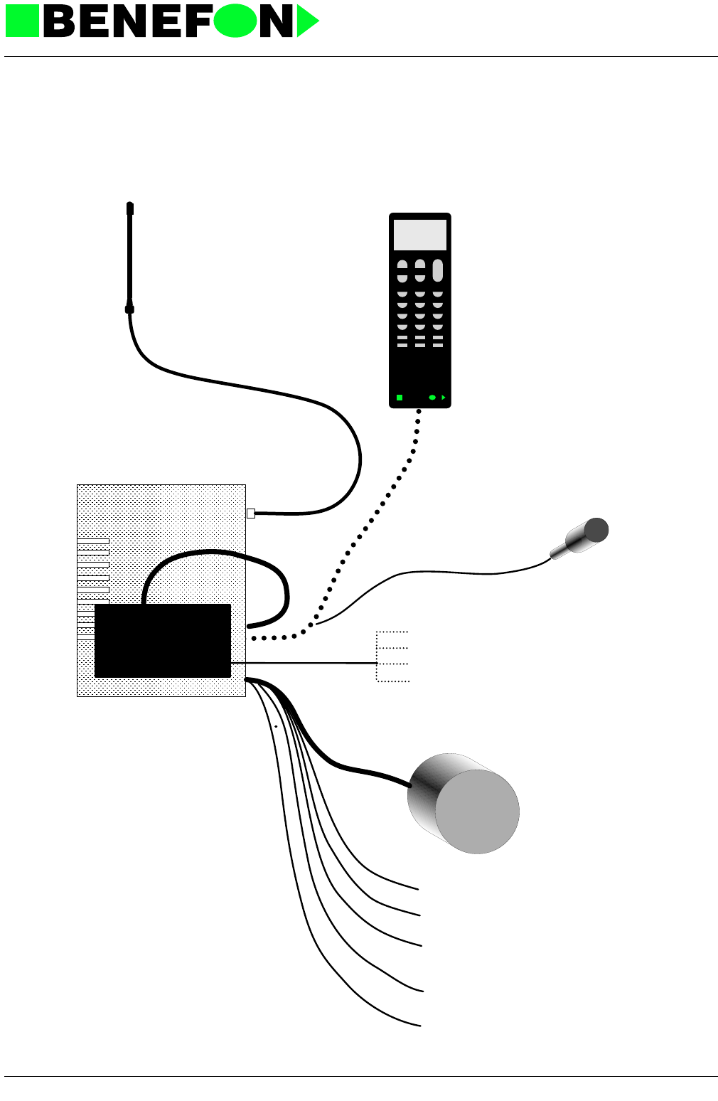
1.0.1 Benefon Forte and Data Interface
Microphone
Data interface
Telefax
Home telephone
Modem ja PC
PABX
Forte
with optional answering machine
BENEF N
Microphone is plugged to
the jack, which is in the
handset's connector
Car radio mute
External alarm
+ Car battery
(+12 VDC)
GND
IGS
Loudspeaker
Outdoor antenna
28.1.1999
TDM-10E2_fm5.fm 2
Product: TDM-20-N (Forte i) /
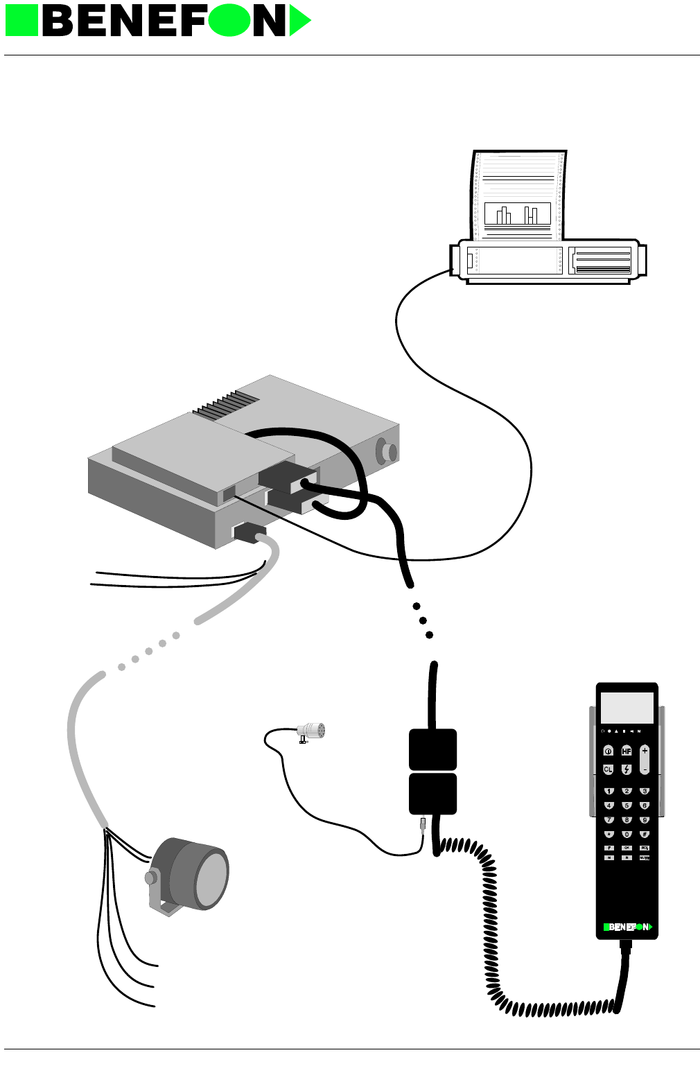
1.0.2 Benefon Forte and Fax
IGS
AL
MUTE
+12 V
GND
28.1.1999
TDM-10E2_fm5.fm 3
Product: TDM-20-N (Forte i) /
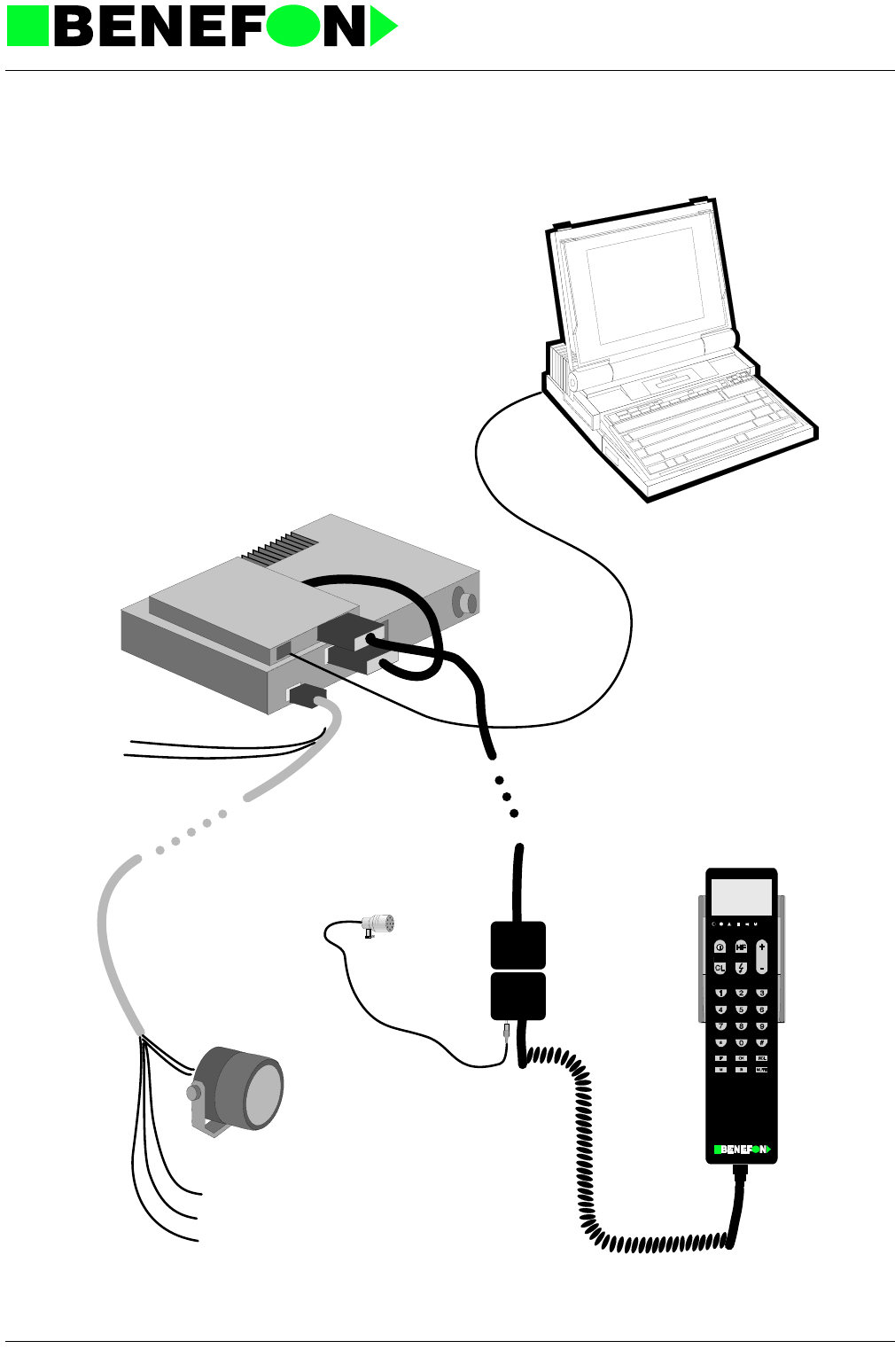
1.0.3 Benefon Forte and PC
IGS
AL
MUTE
+12 V
GND

28.1.1999
TDM-10E6_fm5.fm 1
Product: TDM-20-N / Installation Instructions
2.0 INSTALLATION INSTRUCTIONS
Installation Instructions
PROLOGUE
These installation instructions have been prepared to assist fitters in installing the
equipment, and are as such only to serve as a guide. Nothing beats common sense
and good experience.
Installation is always based on the need of the customer to use the phone in the
environment in which it will be installed. Negotiate with the customer where the dif-
ferent parts will be installed. It is important that the customer tells of his own prefer-
ences and choices, and that the fitter/salesman tells where it is possible/advisable to
locate different items.
It is the salesman’s responsibility to see that the installation order is properly filled
out.
RECOMMEND
- antenna location on the roof
- handset location does not interfere with road safety
- speaker located in the driver’s side leg-room
- microphone as close as possible to the driver’s mouth
- car radio muting
ASK IF THE USER WANTS
- automatic start-up
- additional alarm
- car radio muting
Benefon Oy

28.1.1999
TDM-10E6_fm5.fm 2
Product: TDM-20-N / Installation Instructions
CONTENTS
1.0.1 Techninal Data of Benefon Forte . . . . . . . . . . . . . . . . . . . . . . . . . . .3
1.0.2 Car Installation kit . . . . . . . . . . . . . . . . . . . . . . . . . . . . . . . . . . . . . . .3
1.0.3 Transceiver Unit Installation . . . . . . . . . . . . . . . . . . . . . . . . . . . . . . .3
1.0.3.1 Positioning the Mounting Bracket . . . . . . . . . . . . . . . . . . . . . . .4
1.0.3.2 Locking the Connector . . . . . . . . . . . . . . . . . . . . . . . . . . . . . . .4
1.0.4 Handset Installation . . . . . . . . . . . . . . . . . . . . . . . . . . . . . . . . . . . . .5
1.0.4.1 Holder Installation . . . . . . . . . . . . . . . . . . . . . . . . . . . . . . . . . . .5
1.0.4.2 Mounting the Handset Holder-Base . . . . . . . . . . . . . . . . . . . . .5
1.0.4.3 Removal of the holder . . . . . . . . . . . . . . . . . . . . . . . . . . . . . . . .6
1.0.5 Speaker Installation . . . . . . . . . . . . . . . . . . . . . . . . . . . . . . . . . . . . .6
1.0.6 Microphone Installation . . . . . . . . . . . . . . . . . . . . . . . . . . . . . . . . . .6
1.0.7 Voice-Controlled HF Installation . . . . . . . . . . . . . . . . . . . . . . . . . . . .7
1.0.7.1 HF Tuning . . . . . . . . . . . . . . . . . . . . . . . . . . . . . . . . . . . . . . . . .7
1.0.8 Mounting the Cables . . . . . . . . . . . . . . . . . . . . . . . . . . . . . . . . . . . .7
1.0.8.1 Power Connector . . . . . . . . . . . . . . . . . . . . . . . . . . . . . . . . . . .8
1.0.8.2 System Connector (Same Pinning in the System Cable) . . . . .8
1.0.9 Antenna Installation . . . . . . . . . . . . . . . . . . . . . . . . . . . . . . . . . . . . .9
1.0.9.1 On Car Roof . . . . . . . . . . . . . . . . . . . . . . . . . . . . . . . . . . . . . . .9
1.0.9.2 On Car Wing . . . . . . . . . . . . . . . . . . . . . . . . . . . . . . . . . . . . . . .9
1.0.9.3 On Boot Lid . . . . . . . . . . . . . . . . . . . . . . . . . . . . . . . . . . . . . . . .9
1.0.9.4 On Vehicle Window . . . . . . . . . . . . . . . . . . . . . . . . . . . . . . . . . .9
1.0.10 Connections . . . . . . . . . . . . . . . . . . . . . . . . . . . . . . . . . . . . . . . . .10
1.0.10.1 Power timer . . . . . . . . . . . . . . . . . . . . . . . . . . . . . . . . . . . . . .10
1.0.10.2 Car Radio Muting . . . . . . . . . . . . . . . . . . . . . . . . . . . . . . . . .10
1.0.10.3 Additional Alarm . . . . . . . . . . . . . . . . . . . . . . . . . . . . . . . . . .11
1.0.11 Identity Programming . . . . . . . . . . . . . . . . . . . . . . . . . . . . . . . . . .11
1.0.11.1 Subscriber Number Programming . . . . . . . . . . . . . . . . . . . .11
1.0.12 Combination Lock Programming . . . . . . . . . . . . . . . . . . . . . . . . .11
1.0.12.1 Sales Date Programming . . . . . . . . . . . . . . . . . . . . . . . . . . .12
1.0.13 Test Local Commands . . . . . . . . . . . . . . . . . . . . . . . . . . . . . . . . .12

28.1.1999
TDM-10E6_fm5.fm 3
Product: TDM-20-N / Installation Instructions
2.0.1 Techninal Data of Benefon Forte
Alarm signals settings for frequenct, level (either increasing or fixed), cycle and
tone (menu).
2.0.2 Car Installation kit
2.0.3 Transceiver Unit Installation
The mounting bracket can be installed in e.g. trunk.
Operating Voltage 13.8 VDC
Current consumption 0.25 A stby 4.5A TXon
Interfaces Current-timer IGS
- Car radio muting MUTE
Additional alarm AL
HF-microphone
DTMF-transmitter built-in
DTMF-receiver built-in
Voice-controlled HF built-in (requires separate micro-
phone)
Memories (tel.number) 99 + 2 memory places
( 0 RCL last-repeat dialling )
00 RCL memory search during
phonecall
( 01-99 RCL shortcode memories )
Number Description
1MUTE
2IGS
3GND
4AL
5 SPKR
28.1.1999
TDM-10E6_fm5.fm 4
Product: TDM-20-N / Installation Instructions
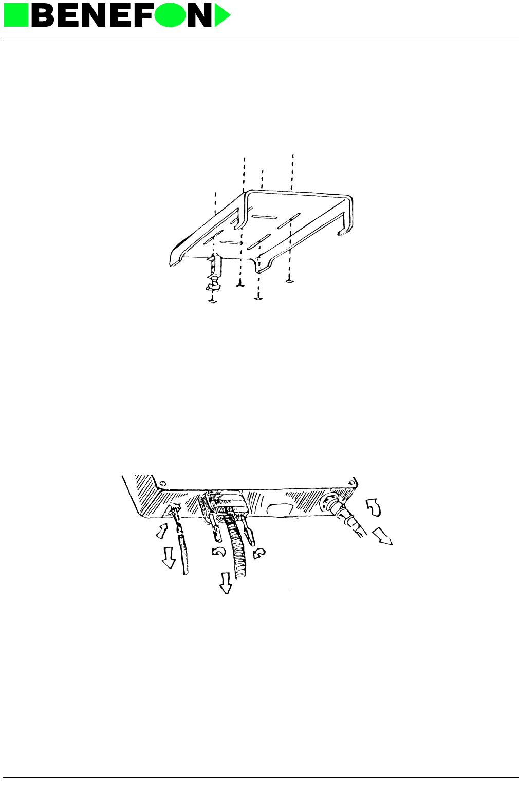
2.0.3.1 Positioning the Mounting Bracket
Should the telephone be requied also for indoor use, or in another vehicle, it is rec-
ommended to install the transceiver unit in an easily accessible place.
2.0.3.2 Locking the Connector
The antenna, system cable, and combined power/accessiry connector are fixed.
28.1.1999
TDM-10E6_fm5.fm 5
Product: TDM-20-N / Installation Instructions
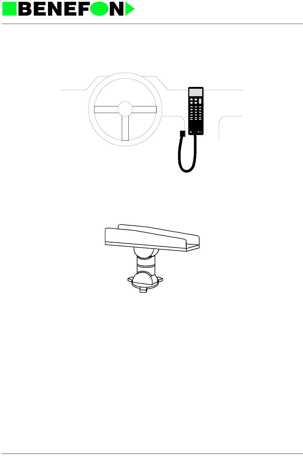
2.0.4 Handset Installation
The handset should be mounted to allow easy use and ensure safe operation
2.0.4.1 Holder Installation
2.0.4.2 Mounting the Handset Holder-Base
Screw the handset holder-base in place, and snap the holder into position by
twisting it carefully clockwise.
BENEF N
28.1.1999
TDM-10E6_fm5.fm 6
Product: TDM-20-N / Installation Instructions
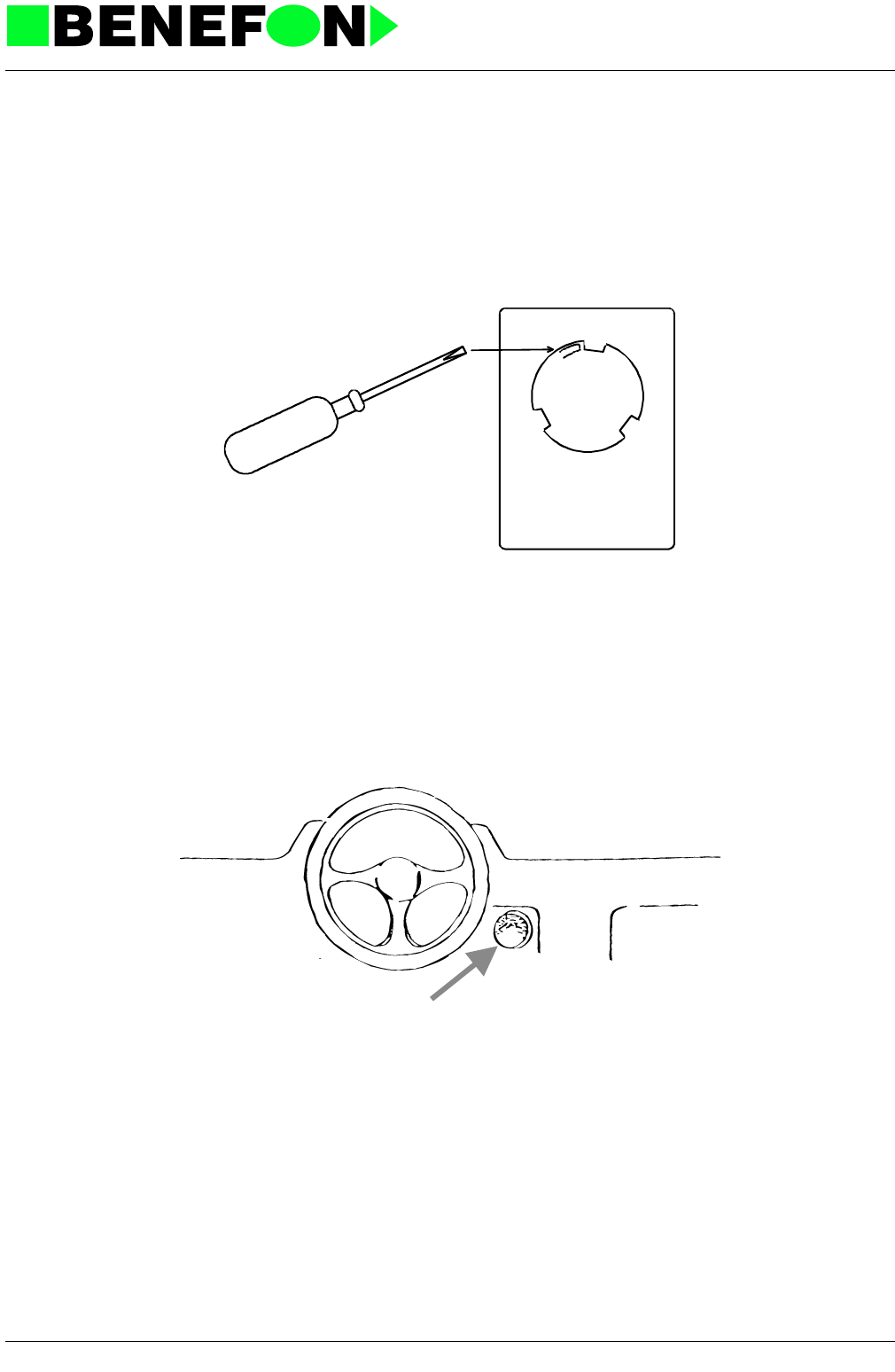
2.0.4.3 Removal of the holder
The holder can be removed by carefully pressing the locking-tab (back, left)
and carefully turning the holder counter-clockwise.
2.0.5 Speaker Installation
For Hands Free operation, the best place to mount the speaker is on the dirver’s
side of the dashboard, pointing directly towards the driver. The speaker is connected
with the connecting cable.
2.0.6 Microphone Installation
The following points should be noted when installing the microphone:
- the microphone must not be directed at the speaker
- it is not recommended to mount the microphone on a sun-blind, because the
microphone direction will change with movement of the sun-blind
- the microphone must not be in the driver’s line of vision, where it could be
distracting

28.1.1999
TDM-10E6_fm5.fm 7
Product: TDM-20-N / Installation Instructions
- maximum range from driver’s mouth - about 20 cm
- the microphone is connected to the handset with a jack-plug
- it is not recommended to mount the speaker on a door-pillar or similar location
due to the high background noise at the side of vehicle
2.0.7 Voice-Controlled HF Installation
To ensure trouble-free HF operation, be sure to mount the speaker and microphone
carefully, as descriped on the previous page.
2.0.7.1 HF Tuning
With installation complete, connect loccal-box to both the handset spiral cable
and the handset system cable, and set telephone to local mode; press 1# and
start the vehicle; check the reading on the display for different revs, and press
OK twice when it is at its greatest.
Best results are obtained when HF tuning can be accomplished with the
vehicle moving at normal speeds.
Default value on display is 34, and the final value is 34 + compensation value.
In practice 40...55, depending on the vehicle.
2.0.8 Mounting the Cables
There are two cables coming from the radio module: power and system cable.
The red supply cable connected to the battery.
With a 24 V supply, a voltage regulator must be used.
The black ground cable should be connected to a sufficiently firm place near the
radio module.

28.1.1999
TDM-10E6_fm5.fm 8
Product: TDM-20-N / Installation Instructions
2.0.8.1 Power Connector
Includes SPKR, GND, IGS, AL and MUTE connections.
2.0.8.2 System Connector (Same Pinning in the System Cable)
Number Description
1MUTE
2IGS
3GND
4AL
5 SPKR
6+12v
Number Description
1GND
2MIC
3AGND
4AUTOCALL
5-
6TXDX
712CINT
8SDAX
9+9
10 ERP
11 -
12 PTT
13 -
14 RXDX
15 SCLK

28.1.1999
TDM-10E6_fm5.fm 9
Product: TDM-20-N / Installation Instructions
2.0.9 Antenna Installation
2.0.9.1 On Car Roof
The most recommended antenna location is on the car roof.
+ highest location
+ circular radiation trace
+ no shadows
+ good grounding
2.0.9.2 On Car Wing
+ easy to mount
- irregular grounding
- car body creates shadows
2.0.9.3 On Boot Lid
Not recommended under any circumstances
- causes constant duplex-interference
2.0.9.4 On Vehicle Window
+ no holes in the bodywork
- does not work as well as body mounting
- expensive

28.1.1999
TDM-10E6_fm5.fm 10
Product: TDM-20-N / Installation Instructions
2.0.10 Connections
2.0.10.1 Power timer
IGS power timer is connected to the vehicle electrical system so that power on
is VB and power off is OV, figure 1.
NOTE!
IGS connection must not be made to the ignition system.
2.0.10.2 Car Radio Muting
MUTE car radio muting is connected with a connecting cable to the relay pins.
1MUTE
2IGS
3 GND Caution!
4AL
The same numbering is used
with the power cable
5 SPKR
6+VB
86
85
30
87A
RELAY
VBATT
30
85 86
87A
RELAY
car radio
Voltage from car battey
+ACC
MUTE
(EXTVB connector pin 1
in carbox)
Car radio supply voltage

28.1.1999
TDM-10E6_fm5.fm 11
Product: TDM-20-N / Installation Instructions
2.0.10.3 Additional Alarm
AL alarm system is connected with a 4-ply connector to either a relay or an
extension. Alarm on/off is set by the handset menu.
2.0.11 Identity Programming
Connect a local-box with programming rights between the handset and the radio
module; turn power on, and press 0#, and LOCAL will be shown on the display.
2.0.11.1 Subscriber Number Programming
Press 2#, and Z X1 X2 X3 X4 X5 X6 Y1 Y2 Y3, and finally OK
Check:
Press 2*, in case of error, and start subscriber-number programming again.
2.0.12 Combination Lock Programming
Press 3#, and X1 X2 X3 X4, and finally OK
X1...X4 = customer-defined combination
Check:
Press 3*, in case of error, and start combination lock programming again.
Z = country code X1...X6 = 6-digit subscriber number
Y1... Y3 = 3.digit password
VBATT
AL
30
85
86
87
HORN
RELAY
86
85
30
87A
RELAY
(EXTVB connector pin 4
in carbox)

28.1.1999
TDM-10E6_fm5.fm 12
Product: TDM-20-N / Installation Instructions
2.0.12.1 Sales Date Programming
Press 4#, and XX XX XX, and finally OK
XX XX XX = d mm yy, for example 08 0
Check:
Press 4*, in case of error, and start sales date programming again.
2.0.13 Test Local Commands
Command Function
0# Transfer to LOCAL mode
1# HF tuning OK adjustment OK end
2# Subscriber number programming, and OK
2* Check subscriber number
3# Combination lock programming (4 digits) and OK
3* Check combination lock
4# Sales date programming (6 digits) and OK
4* Check sales date
5# Change call country. Call country on the display -
enter new call coun with +/- buttons, store with OK
6# Additional Alarm on
6* Additional alarm OFF
7# Car radio mute ON
7* Car radio mute OFF
8# Reads IGN, HOOK, PTT, and AUTOCALL lines
9# Transfer shortcodes to LOCAL-BOX
999* Transfer shortcodes back to radio module

1user_gb.fm 1
3.0 OWNER’S MANUAL

28.1.1999
TDM-10E3_fm5.fm 1
Product: TDM-20-N /
4.0 LOCAL SERVICE COMMANDS
4.0.1 General
There is a special program module called LOCAL which makes it possible to set,
read and program various features of the phone.
In order to activate the LOCAL program it is necessary to connect a local box
between the radio unit and the handset. When the power is switched on, and the
local box is connected, the LOCAL program becomes activated.
There are two kinds of local boxes. One merely has "service rights", i.e. you cannot
program subscriber number. The other has "full rights", i.e. there are no restrictions
in LOCAL.
4.0.2 Special Push Buttons In Local
4.0.3 General Form Of Commands
Note:
In LOCAL mode * = b and # = C
Button Action
R Changes between LOCAL and NMT program
HF Changes between earphone and speaker
-HF-led indicates speaker mode-
SND/END Ends local command influence
MFT Used for scrolling letters A, b, C, D, E, F (accepts
either with OK or digit button)
+/- Volume settings
X(XX)# DO
X(XX)* UNDO corresponding X(XX)# command
XXXX# Channel command
XXXX* BURN-IN channel (default = 45)

28.1.1999
TDM-10E3_fm5.fm 2
Product: TDM-20-N /
4.0.4 Local Commands
4.0.4.1 INSTALL AND PURCHASE X
0# Reset LOCAL
1# Tune HF microphone threshold
- Background noise level appears on display. Push OK to add reg-
istered level to default (set level can be corrected with digit but-
tons).
- store with OK
2# Program subscriber number ( needs local box with "full rights")
- push Z X1 X2 X3 X4 X5 X6 Y1 Y2 Y3 (ten digits)
Z = Country code
X1...X6 = subscriber number
Y1...Y3 = password
- store with OK
2* Read subscriber number
3# Program lock code
- push four digits
- store with OK
3* Read lock code
4# Program purchase date
- push six digits (ddmmyy)
- store with OK
4* Read purchase date
5# Change countrycode
- give new country (5...8) or select with +/- button
- store with OK
6# External alert ON
6* External alert OFF

28.1.1999
TDM-10E3_fm5.fm 3
Product: TDM-20-N /
4.0.4.2 Read And Write Port 0X
7# Car radio mute ON
7* Car radio mute OFF
8# Read IGN / HOOK / PTT / AUTOCALL in realtime
9# Move shortcode memory from the phone to the local box
999* Move shortcode memory from the local box to the phone
00# Write to port
- push (portnumber) (bitnumber) (bitstate)
portnumber: 0 1. latch in processor-module
1 2. latch in processor-module
2 3. latch in processor-module
3 4. latch in processor-module
4 handset "button port"
5 handset "led port"
A6 processor PA
D processor PD
bitnumber: 0...7
bitstate: 0 or 1
01# Read port in realtime
- push (portnumber)
portnumber: 0 processor-module input-latch
1 IICINT / PTT / HOOK
02# Read A/D-channel in realtime
- push (channelnumber)
channelnumber: 0 RSSI
1 TXSENSE
2MICDET
3 ERPDET
4HOOK
5PTT
6 POTIND
7 not in use

28.1.1999
TDM-10E3_fm5.fm 4
Product: TDM-20-N /
4.0.4.3 Processor Tests 1X
10# Test memory
- EPROM fail XX1, no fail XX0
- EEPROM fail X2X, no fail X0X
- RAM fail 3XX, no fail 0XX
11# Test COP (= watchdog)
- Resets phone if COP is in order, otherwise stops
12# Send "0"-frequency
- Doesn‘t set transmitter
12* End send
13# Send of "1"-frequency
- Doesn‘t set transmitter
13* End send
14# Send frame
- frame is given by push button set (16 digits and #)
N1 N2 N3 P(X) Y1 Y2 Z X1 X2 X3 X4 X5 X6 J1 J2 J3 #
- default frame is 15
- letters A...F are given with MFT-button
14* End send
15# Receive frame
16# Detect FSK in realtime
17# Receive DTMF
18# DTMF loop test

28.1.1999
TDM-10E3_fm5.fm 5
Product: TDM-20-N /
4.0.4.4 Audio Tests 2X
20# AUDIOPWR = 1
20* AUDIOPWR = 0
200# Compander ON
200* Compander OFF
21# TX-audio ON
-AUDIOPWR = TXAON = 1
- MICVOL = 111
- microphone = MIC if ERPON, EXTMIC if SPKON
21* TX-audio OFF
- TXAON = 0
- microphone OFF
22# RX-audio ON
- AUDIOPWR = RXAON = ERPON = 1
- AUDIOLOOP = SPKON = 0
- ERPVOL = 011
22* RX-audio OFF
- RXAON = 0
23# Fiiloop ON
- AUDIOPWR = FIILOOP = 1
23* Fiiloop OFF
- FIILOOP = 0
24# FFSKT ON
- AUDIOPWR = FFSKT = 1
24* FFSKT OFF
- FFSKT = 0
25# Audio-tone generator ON
- AUDIOPWR = DTMFON = 1
- DTMF generator output = 980 Hz
25* Audio-tone generator OFF
- DTMFON = 0

28.1.1999
TDM-10E3_fm5.fm 6
Product: TDM-20-N /
- DTMF generator output = OFF
26# Auxiliary pass ON
- AUDIOPWR = AUXOFF = 1
26* Auxiliary pass OFF
- AUXOFF = 0
27# Audioloop ON
- AUDIOPWR = AUDIOLOOP = 1
27* Audioloop OFF
- AUDIOLOOP = 0
28# Microphone volume settings +/-
28* Earphone/speaker volume settings +/-
29# Handset microphone ON
29* Microphone OFF

28.1.1999
TDM-10E3_fm5.fm 7
Product: TDM-20-N /
4.0.4.5 Transmitter And Receiver Tests 3X, 4X
30# Transmitter ON in previous txpower
30* Transmitter OFF
31# Transmitter ON in low txpower
31* Transmitter OFF
32# Transmitter ON in medium txpower
32* Transmitter OFF
33# Transmitter ON in high txpower
33* Transmitter OFF
34# TXVCO ON
34* TXVCO OFF
35# First channel
36# Middle channel
37# Last channel
38# Tune and program RSSI levels
- Display shows level to tune (in dBm‘s)
PG-53, PG-63, PG-93, PG-103, PG-115
- Push OK to tune next level
- Push OK to store after tuning -115 dBm
- (If you want store values before tuning -115 dBm push RCL)
- Store is done if tuned values are -53 dBm > = -63 dBm > = -115
dBm
38* Read programmed RSSI-levels
39# Tune and program deviation limit levels
- Display shows level to tune DEV LO, DEV HI
- Push OK to tune next level
- Push OK to store after tuning DEV HI
- (If you want store DEV LO before tuning DEV HI push RCL)
- Store is done if tuned values are DEV HI > = DEV LO

28.1.1999
TDM-10E3_fm5.fm 8
Product: TDM-20-N /
4.0.4.6 Handset And Accessory Tests 5X
4.0.4.7 Read Information 6X
39* Read programmed audiolimiter levels
40# RX path measurement in middle channel
- AUDIOPWR = RXAON = ERPON = AUXOFF = 1
- TXON = TXVCO = AUDIOLOOP = FIILOOP = SPKON = 0
- ERPVOL = 111
41# TX path measurement in middle channel high txpower
- AUDIOPWR = TXVCO = TXAON = 1
- FFSKT = DTMFON = AUDIOLOOP = FIILOOP = 0
- ERPVOL = 111
42# RX path measurement in middle channel high txpower
- AUDIOPWR = TXVCO = FIILOOP = RXAON = ERPON = AUX-
OFF= TXAON = 1
- AUDIOLOOP = SPKON = FFSKT = DTMFON = 0
- MICVOL = 111, ERPVOL = 011
43# Channel scan
- starts from current channel
44# Step channels with +/- button
50# Display, leds and illumination ON
50* Display, leds and illumination OFF
51# Answering-machine loop test
60# Read power off counters
0RAM fail
1 EPROM fail
2 EEPROM fail
3 COP fail (not used)
4 No RSSI in conversation
5 Transmitter ON during scan

28.1.1999
TDM-10E3_fm5.fm 9
Product: TDM-20-N /
6 No Handset
7 FSK detected in conversation
60* Reset all power off counters
61# Read sellercode
62# Read program version (ddmmyy)
70# Tune FSK split level
- store with OK key
70* Read FSK split level
71# Base-band programming
71* Read Base-band

28.1.1999
TDM-10E3_fm5.fm 10
Product: TDM-20-N /
4.0.4.8 Clearing Of Memory 8X
4.0.4.9 Burn-in 9X
80# Clear RAM
81# Clear EEPROM
- not the tuned values
810# Clear whole EEPROM
82# Clear RAM and EEPROM
-not the tuned values
98# Start BURN-IN if enabled
98* Stop BURN-IN if IGN not connected
99# Enable BURN-IN
99* Disable BURN-IN
100# SIM using normal SAK number
- defaul value always when phone is ON
100* SIM using test SAK number

28.1.1999
TDM-10E3_fm5.fm 11
Product: TDM-20-N /
4.0.5 Guide Texts And Error Situations
After switching power the display shows LOCAL. Along with a local command, a
guide text always appears, explaining the given command.
The following list shows the most common error situations.
ERROR on the display:
1. Error in local command
2. Failed EEPROM programming
3. Wrong input data to EEPROM
- Length of data
- Erroneus digits
- RSSI-levels or deviation limit levels are
not in propersuccession
4. Loop test has failed
5. BURN-IN test cannot be activated when
not enabled
UNKNOW on the display:
Unknown local command
LOCAL on the display though
there is no local box:
BURN-IN test is enabled or subscriber
number is not programmed.

28.1.1999
TDM-10E3_fm5.fm 12
Product: TDM-20-N /
4.0.6 Local-Box
4.0.6.1 General
LOCAL = operating mode where it‘s possible to give commands to set, read and
program the MS features.
To get the MS to LOCAL a local-boxes, one merely has "service rights" i.e. you can-
not program subscriber number. The other has "full rights", i.e. there are no restic-
tions in LOCAL.
Each box has it‘s own serial number. Serial number and programming rights are
installed by manufacturer. Serial number is used for identifying the subscriber num-
ber programmer and it is stored automatically to MS during programming.
There is text LOCAL on the display when the local box is connected and power is
switched on.
4.0.6.2 Features Of Local-box
Switching ON/OFF the power supply:
- Set NORMAL/SERVICE switch NORMAL position
To be measured from audio of the radio unit:
- Set NORMAL/SERVICE switch SERVICE position and RADIO/HANDSET
switch RADIO position.
To measure handset audios:
- Set NORMAL/SERVICE switch NORMAL position and RADIO/HANDSET
switch HANDSET positon
4.0.6.3 Internal Ram
Local-box‘s internal RAM is intended for not losing the contents of shortcode mem-
ory during service operations.
GEN: -norm dev = 1 Vrms
- max dev = 3.33 Vrms
METER: - norm dev = 300 mVrms
SERVICE/HANDSET - max dev = 600 mVrms
(VOL = 0dB)
BNC-connectors:
GEN: -norm dev = 300 mVrms
- max dev = 600 mVrms
METER:
Commands 9# store shortcode memory to local-box
999* store shortcode memory to MS.

28.1.1999
TDM-20E5_fm5.fm 1
Product: TDM-20-N /
5.0 TUNING INSTRUCTIONS
5.0.1 Connect To Phone
- operating voltage (13.2V, X800 connector, loudspeaker needed)
- local-box (between handset and radio unit)
- RF-generator/power-meter
5.0.2 Synthesizer
Check-up of operating voltages
5.0.3 RX-VCO
Switch synthesizer to first channel (local 35#)
Measure voltage synthesizer unit TP6, adjust voltage C435( RX-VCO) to 3 V
Change to last channel (local 37#)
Check that the adjusting voltage is approx 6 V
5.0.4 TX-VCO
Start TX-VCO (local 34#)
Switch synthesizer to first channel (local 35#)
Measure TP4 voltage, adjust voltage by C498 (TX-VCO) to 5 V
Change to last channel (local 37#)
Check that the adjusting voltage is now approx 7.5...8.5 V
Input-connector V401 pin1 13.2 V
TP1 8.6...9.4 V
TP2 4.5...5.3 V
TP7 13...15 V
+ TX on (local 34#) 8.5...9.3 V TP3
+ TX off (local 34*) approx 5 V TP3

28.1.1999
TDM-20E5_fm5.fm 2
Product: TDM-20-N /
5.0.5 Channel Frequency Adjustment
Start transmitter (local 33#)
Change to first channel (local 35#)
Adjust channel frequency MHz (+/-100 Hz) with TCXO trimmer
5.0.6 Transmitter
Set operating voltage to 15.6 V
Switch on transmitter (local 33#)
Adjust audio/pros unit R162 (TX-POW) transmitter power to 41.8 dBm
Set operating voltage to 10.8 V, check the transmitter power.
Difference max +/-1.5 dB
Check 32# 31.8 dBm
Check 31# 21.8 dBm
5.0.7 TX-Audio
Feed 1 kHz, 1 V RMS signal to local box GEN-connector.
Switch on TX-audio, mic off (local 21#, 29*).
Measure the processor unit x-synte connector pin 2 , and adjust (maximum) level of
R241 to 550 mV RMS.
Switch transmitter to medium power, center channel (local 32#, 36#).
Adjust R459 (syntyhesizer-module) deviation to 3 kHz.
Check the deviation in channels (1, 180); difference must not exceed 150 Hz.
Change TX-VCO adjusting voltage if necessary (range in use approx 3...10 V).
Adjust R459 (MOD) again.
Drop the af.gen level until deviation is 1 kHz, measure V401 pin 2 in synthesizer,
write down the level.
Change af.gen frequency to 300 Hz.
Raise the af.gen level until V401 pin 2 level is equal to the reference level mentioned
before.
Adjust R457 deviation (with COMP.OS-module) to 1 kHz.

28.1.1999
TDM-20E5_fm5.fm 3
Product: TDM-20-N /
5.0.8 Max DEV
Feed pt.gen frquency 1 kHz, 3.33 Vrms.
Check deviation in channels (1, 90, 180).
Deviation must be within the limits 4.0...4.5 kHz; if it exceeds 4.5 kHz, adjust R244
(with MAX OA-module). Reset (local 0#)
5.0.9 FFSKT
Switch on medium power (local 32#).
Switch on FFSKT (local 12#).
Adjust R265 deviation (FFSKT) to 4.2 kHz.
Reset (local 0#).
5.0.10 RX-Audio
Set RF-generator frequency 465.225 MHz, level -57 dBm, mod freq 1 kHz, deviation
3 KHz.
Set channel 90 (local 36#, 22#).
Expander ON (local 200#).
Adjus LF output level R302 (RX) 300 mV RMS, measure at METER-connector
(local-box)
Reset (local 0#).
5.0.11 RX-Response
Set RF-generator values as above, except for level -113 dBm.
Switch on high-power, RXA on (local 33#, 22#)
Measure SINAD CCITT min. 20 dB.
Also check channels (1, 180).
RF-generator frequency 463.000 MHz (35#)
467.475 MHz (37#)
5.0.12 RX-Distortion
Set center channel, high-power (local 36#, 33#).
RF-generator frequency 465.225 MHz, level -57 dBm.
Measure distortion, max 5 %.
Reset by 0#.

28.1.1999
TDM-20E5_fm5.fm 4
Product: TDM-20-N /
5.0.13 TX-Distortion
Set center channel high-power, TXA on, mic off (local 36#, 33#, 21#, 29*).
Feed 1 kHz, 1 V RMS signal to local-box GEN-connector.
Measure distortion, max 5 %
Reset (local 0#).
5.0.14 FII DEV
Set RF-generator frequency 465.225 MHz, level -57 dBm, modulation frequency 4
kHz, dev 300 Hz.
Switch on fiiloop (local 23#), power (32#).
Adjust R255 deviation to 300 Hz.
Reset (local 0#).
5.0.15 Tuning The RSSI-Levels
Set RF-generator frequency 465.225 MHz, level -53 dBm.
Switch on RSSI tuning (local 38#).
Display shows "PG-53".
Wait until reading on the display settles down. Press OK.
Change RF-level to -63 dBm.
Phone display shows "PG-63"
Press OK.
Change RF-level to -93 dBm.
Phone display shows "PG-93
Press OK.
Change RF-level to -103 dBm.
Phone display shows "PG-103
Press OK.

28.1.1999
TDM-20E5_fm5.fm 5
Product: TDM-20-N /
Change RF-level to -115 dBm.
Phone display shows "PG-115
Press OK.
Check tuning (local 38*).
5.0.16 Tuning FSK-split level
RF-generator settings
Freq. 465.225 MHz, level -53 dBm ,mod freq 1 kHz, dev 350 Hz
Give local-command 70#. Handset display show value 20...30.
Store value by pressing OK button.
5.0.17 Program Base-Band (if neccessery)
Give local command 71#. Press 1 and OK
Press 180 and OK.
5.0.18 Programming The Subscriber Number
Requires local-box with programming rights.
Give local-command 2#.
Feed 10 digits, and press OK (country code + subcriber number + password)
Check 2*.

28.1.1999
XT0001E4_fm5.fm 1
Product: TDM-20-N / OT0001 Transmitter
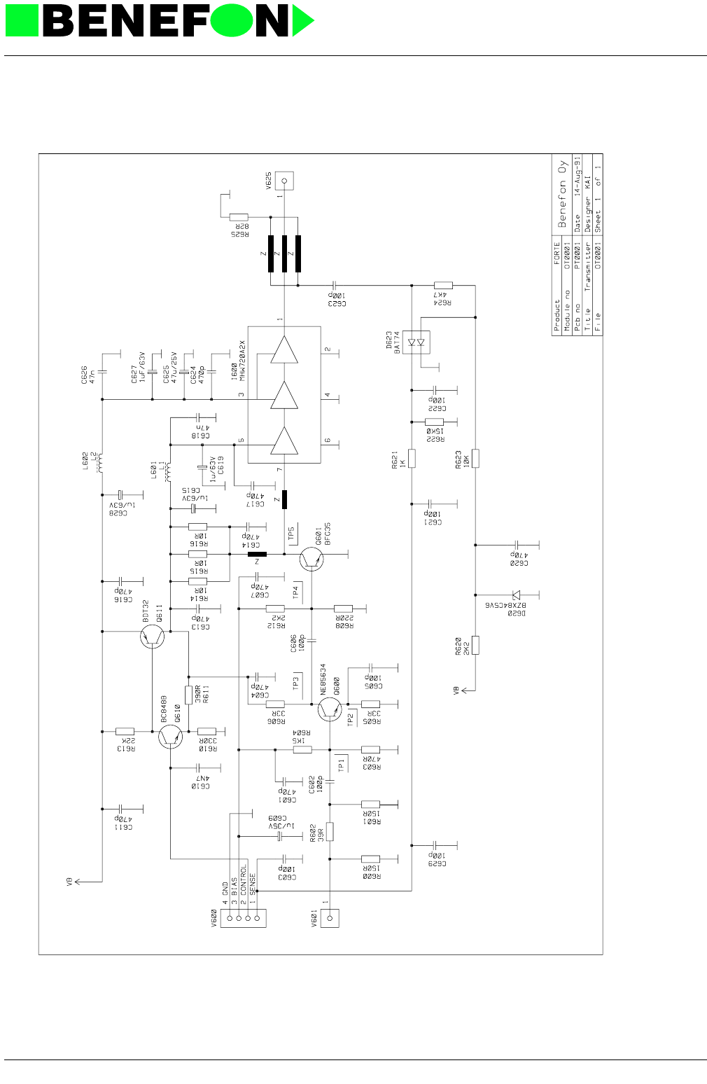
6.0 TRANSMITTER MODULE OT0001
SPECIFICATIONS:
OT0001 Transmitter
Operating voltage 10.8...15.6 VDC
Current consumption max 4.5 A
Input power level 10 dBm (+2/-2 dB)
Output power level max 44 dBm (25 W) without a duplex filter
Frequency range 453.000...457.475 MHz
6.0.1 Connector Description:
4-pole connector:
pin 1, voltage from directional coupler max 10 V
pin 2, control voltage for RF-power max 8 V
pin 3, bias for the preamplifiers 8 V
pin 4, GND
6.0.1.1 Transmitter operation:
The transmitter is a 5-stage amplifier chain. The two preamplifiers (Q600/601) oper-
ate in class AB as linear amplifiers. The final amplifier (I600) is a class C power mod-
ule. The output power is controlled with a loop: A signal coming from the directional
coupler is rectified and filtered. Then it is fed through processor controlled voltage
attenuator to the integrator, which has a preset reference voltage (a corresponding
value for 15 W output power). The control voltage from the integrator is amplified in
DC-amplifier (Q610/611) and fed to the preamplifiers/the first stage of the power
module. RF-power input has a 6 dB attenuator to improve impedance matching
between synthesizer and transmitter in different power level conditions.
6.0.2 Tuning Instructions:
Tuning can be done in local mode or using CMT-tester.
Set a power supply to 15.6 V.
Input signal 10 dBm (10 mW) on channel 090 from the synthesizer or signal genera-
tor.
Connect a 50 ohm dummy load and a power meter to the antenna connector.
Transmitter on (33#).
Tune output power with trimmer R162 on OA0014 (audio/processor) -module to
41.8 dBm (15 W).

28.1.1999
XT0001E4_fm5.fm 2
Product: TDM-20-N / OT0001 Transmitter
Set a power supply to 10.8 V and check output power. It should be about the same
value as set before (+/-1.5 dB).
Set a power supply to 13.2 V.
Check power levels:
High 41.8 dBm (15 W) +/-1.5 dB (33#)
Medium 31.8 dBm (1.5 W) +/-3 dB (32#)
Low 21.8 dBm (0.15 W) +/-3 dB (31#)
Power off (31*)
Tuning is completed.
Some useful local mode commands for the transmitter operation checking:
6.0.3 Test Point Voltages
Set the power supply to 13.2 V
Typical DC-values measured with a universal meter Ri = 10 Mohm (Philips PM
2505).
Channel 001 35#
090 36#
180 37#
high power on/off 33#/33*
medium power on/
off 32#/32*
low power on/off 31#/31*
Power level H M L
TP1 2.0 2.0 2.0
2 1.4 1.3 1.1
3 4.6 3.4 2.1
4 0.7 0.7 0.7
5 5.5 3.3 3.0

28.1.1999
XT0001E4_fm5.fm 3
Product: TDM-20-N / OT0001 Transmitter
Typical RF-voltages measured with R&S millivoltmeter URV-3.
Values can vary +-10 %. All values indicated as volts.
Power level H M L
TP1 0.4 0.4 0.4
2 0.15 0.06 0.04
3 0.85 0.65 0.55
4 0.28 0.3 0.32
53.62.72.4

28.1.1999
XT0001E4_fm5.fm 4
Product: TDM-20-N / OT0001 Transmitter
6.0.4 Parts list
CODE PART DESCRIPT. VALUE MANUF. TYPE
CC0471 C601 SMD capasitor 470 pF 5% 50 V NP0 Philips
CC0101 C602 SMD capasitor 100 pF 5% 50V NP0 Philips
CC0101 C603 SMD capasitor 100 pF 5% 50V NP0 Philips
CC0471 C604 SMD capasitor 470 pF 5% 50 V NP0 Philips
CC0101 C605 SMD capasitor 100 pF 5% 50V NP0 Philips
CC0101 C606 SMD capasitor 100 pF 5% 50V NP0 Philips
CC0471 C607 SMD capasitor 470 pF 5% 50 V NP0 Philips
CU0105 C609 SMD tantal 1uF/16V 20% 3.2x1.6mm Matsushita ECST1CY 105R
CC0472 C610 SMD capasitor 4.7 nF 10% 50 V X7R Philips
CC0471 C611 SMD capasitor 470 pF 5% 50 V NP0 Philips
CC0471 C613 SMD capasitor 470 pF 5% 50 V NP0 Philips
CC0471 C614 SMD capasitor 470 pF 5% 50 V NP0 Philips
CE0105 C615 Al elko 1uF/63V 4x7mm Philips 2222 097 58108
CC0471 C616 SMD capasitor 470 pF 5% 50 V NP0 Philips
CC0471 C617 SMD capasitor 470 pF 5% 50 V NP0 Philips
CC0473 C618 SMD capasitor 47 nF 10% 50 V X7R Philips
CE0105 C619 Al elko 1uF/63V 4x7mm Philips 2222 097 58108
CC0471 C620 SMD capasitor 470 pF 5% 50 V NP0 Philips
CC0101 C621 SMD capasitor 100 pF 5% 50V NP0 Philips
CC0101 C622 SMD capasitor 100 pF 5% 50V NP0 Philips
CC0101 C623 SMD capasitor 100 pF 5% 50V NP0 Philips
CC0471 C624 SMD capasitor 470 pF 5% 50 V NP0 Philips
CE0476 C625 Al elko 47 uF/25 V 7x7mm Philips 2222 097 56479
CC0473 C626 SMD capasitor 47 nF 10% 50 V X7R Philips
CE0105 C627 Al elko 1uF/63V 4x7mm Philips 2222 097 58108
CE0105 C628 Al elko 1uF/63V 4x7mm Philips 2222 097 58108
CC0101 C629 SMD capasitor 100 pF 5% 50V NP0 Philips
DZ0569 D620 SMD zener 5V6 5% 300mW Philips BZX84C5V6
DY0074 D623 Shottky diode Philips BAT 74
IW0720 I600 RF-power amplifier 450-460MHz Motorola MHW720A2X
LF0396 L601 Inductor 39 uH Philips
LF0396 L602 Inductor 39 uH Philips
PT0001 PCB PCB for OT0001 155 x 36 x 1.6
QA5634 Q600 SMD RF-transistor NPN 1 W 5 GHz NEC NE85634
QA0035 Q601 SMD RF-transistor NPN Wideband 1GHz Philips BFG-35
QSB848 Q610 SMD transistor NPN 0.1A/30V F=2dB Philips BC 848 B
QP0032 Q611 Power transistor PNP 3A/60V Philips BDT 32 AF
RC0151 R600 SMD resistor 150 R 5% 0.125 W Kamaya
RC0151 R601 SMD resistor 150 R 5% 0.125 W Kamaya
RC0390 R602 SMD resistor 39 R 5% 0.125 W Kamaya
RC0471 R603 SMD resistor 470 R 5% 0.125 W Kamaya
RC0152 R604 SMD resistor 1.5 k 5% 0.125 W Kamaya
RC0330 R605 SMD resistor 33 R 5% 0.125 W Kamaya
RC0330 R606 SMD resistor 33 R 5% 0.125 W Kamaya
RC0221 R608 SMD resistor 220 R 5% 0.125 W Kamaya
RC0331 R610 SMD resistor 330 R 5% 0.125 W Kamaya
RC0391 R611 SMD resistor 390 R 5% 0.125 W Kamaya
RC0222 R612 SMD resistor 2.2 k 5% 0.125 W Kamaya
RC0223 R613 SMD resistor 22 k 5% 0.125 W Kamaya
RC0100 R614 SMD resistor 10 R 5% 0.125 W Kamaya
RC0100 R615 SMD resistor 10 R 5% 0.125 W Kamaya
RC0100 R616 SMD resistor 10 R 5% 0.125 W Kamaya
RC0222 R620 SMD resistor 2.2 k 5% 0.125 W Kamaya
RC0102 R621 SMD resistor 1 k 5% 0.125 W Kamaya
RM1502 R622 Mini-Melf resistor 15k0 1% 0.25W Beyschlag MMA 0204-50
RC0103 R623 SMD resistor 10 k 5% 0.125 W Kamaya
RC0472 R624 SMD resistor 4.7 k 5% 0.125 W Kamaya

28.1.1999
XT0001E4_fm5.fm 5
Product: TDM-20-N / OT0001 Transmitter
RC0820 R625 SMD resistor 82 R 5% 0.125 W Kamaya
VN0104 V600 4-pin connector Wisher WKP-N4B1G-L
VR0235 V601 Coax cable + connector 50 ohm l=n.70mm Taikodenki TMP-P01X-A1
VR0122 V625 SMB + coax l=22 cm Radiall
Last
update
14.08.91
CODE PART DESCRIPT. VALUE MANUF. TYPE
28.1.1999
XT0001E4_fm5.fm 6
Product: TDM-20-N / OT0001 Transmitter
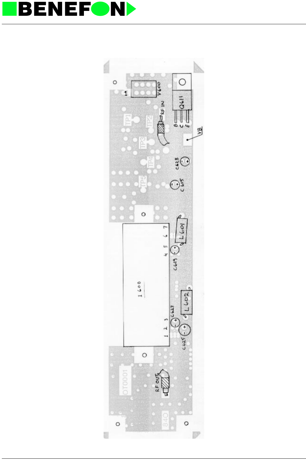
Component Side Layout PT0001A0 (Schematic OT0001A0)
28.1.1999
XT0001E4_fm5.fm 7
Product: TDM-20-N / OT0001 Transmitter
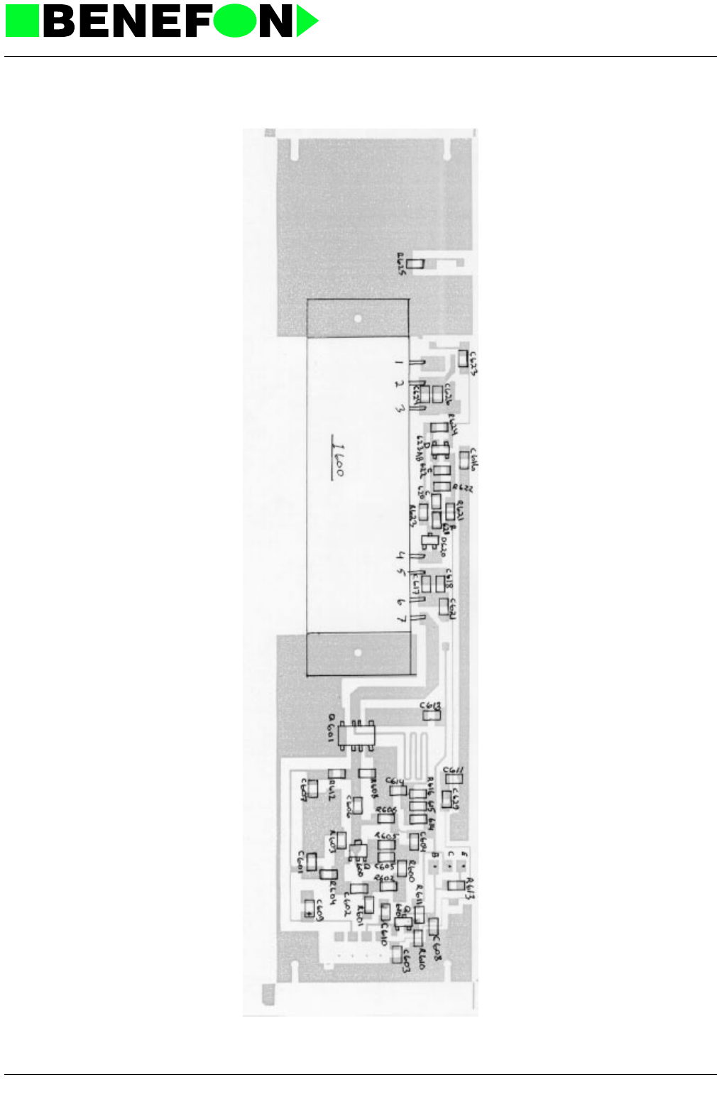
Solder Side Layout PT0001A0 (Schematic OT0001A0)
28.1.1999
XT0001E4_fm5.fm 8
Product: TDM-20-N / OT0001 Transmitter

28.1.1999
XR0002E4_fm5.fm 1
Product: TDM-20-N / OR0002 Receiver
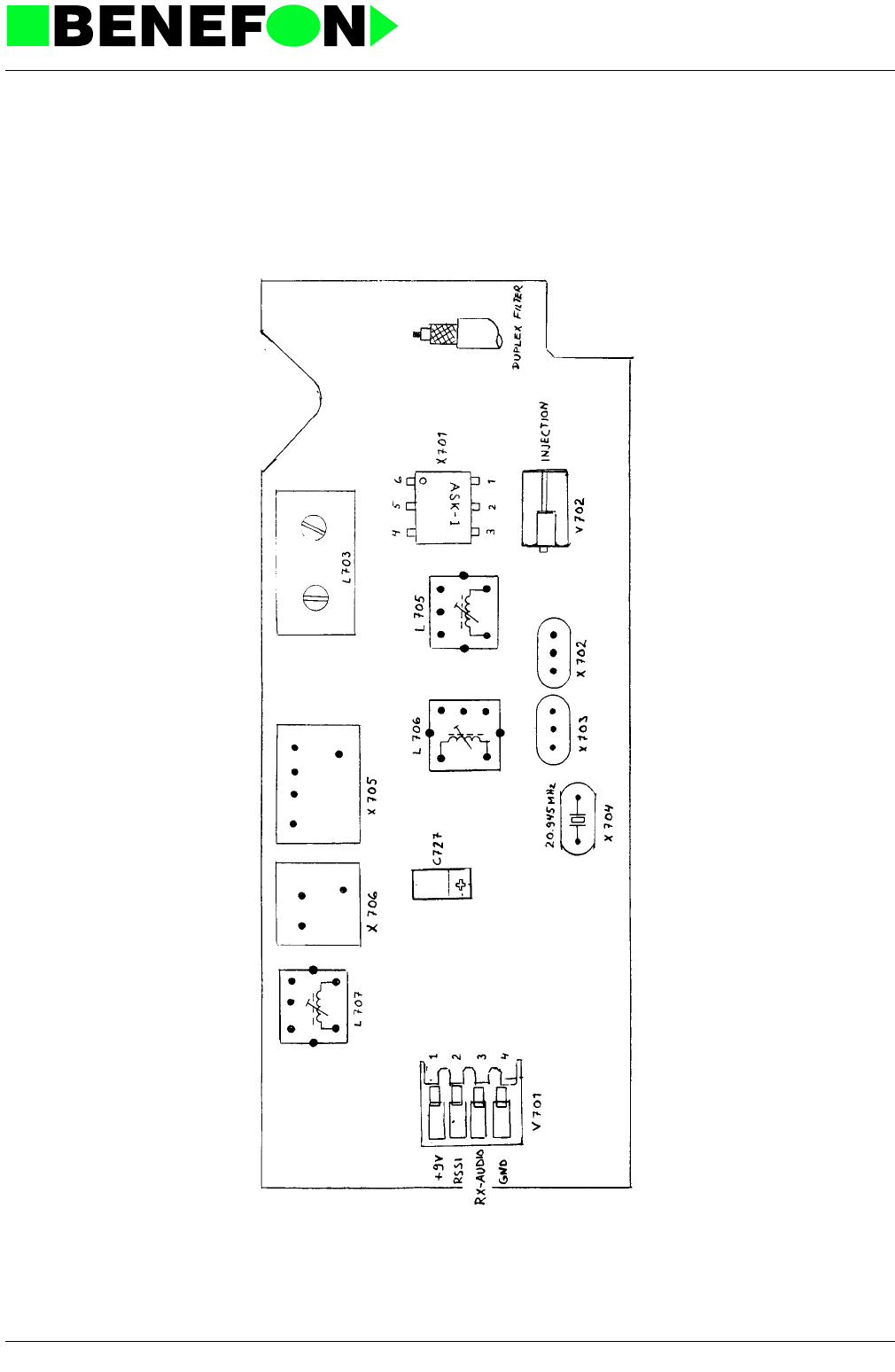
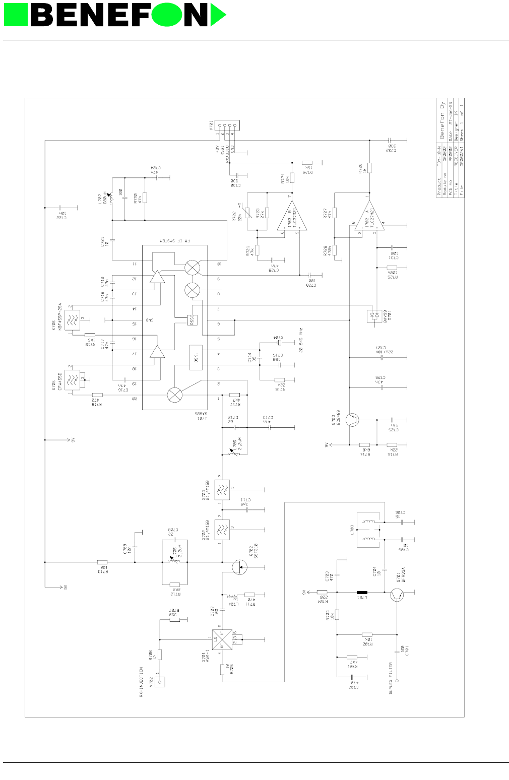
7.0 RECEIVER MODULE OR0002 SPECIFICATIONS
OR0002 Receiver
7.0.1 Principles Of Receiver Operation
The module includes all operational segments of FM receiver.
The receiver is connected to the V701 audio/processor unit with a connector.
ADAPTERS
The receiver RF-signal is brought through the duplex filter NBF40001 to the amplifier
stage Q701. The amplifier signal is led the dual balanced mixer X701 through the
band filter L703.
The upper injection frequency is brought from the synthesizer unit to the LO input of
the mixer through a small resistance attenuator. The IF (intermediate frequency)
21.4 MHz gained in this way is amplified and led through crystal filters X702 and
X703 to the FM IF-system IC-circuit (SA605D). The circuit includes another local
oscillator, and another mixer.
The second IF is 455 kHz: there is first a 6-pole ceramic filter, and another 4-pole fil-
ter in the limiter amplifier chain.
The temperature compensation for the AF-signal indicated has been included in the
buffer amplifier stage I702/B.
RF-amplifier BFR93A
1. mixer ASK-1
1. IF-amplifier SST310
FM IF-system SA605D including following functions:
2. local oscillator
2. mixer
IF limiter amplifiers
quadrature demodulator
RSSI (received signal strength indicator)
V701 1 +9 V receiver operating voltage
2RSSI DC-voltage comparable to field strength
(0.5...5 V)
3 RX-AUDIO AF-signal for audio unit, approx. 150 mVrms
(f.mod 1 kHz dev. 3 kHz)
4 GND ground (chassis)
V702:RX-injection 484.400...488.875 MHz +10 dBm/50 ohm.

28.1.1999
XR0002E4_fm5.fm 2
Product: TDM-20-N / OR0002 Receiver
The temperature compensation for the RSSI signal has been made with the diode
pai D701, which is followed by the buffer amplifier I702/A.
The receiver unit gets +9 V regulated operating voltage from the current input unit
OW0001 through the audio/processor unit.
The operating voltage is dropped with the transistor Q703 to the lower required by
the IF circuit.
7.1 Receiver OR0002 settings
7.1.1 Supply Voltages
A regulated +9 V power supply is fed to the module via connector V701 pin 1.
The intermediate frequency module uses a ca. +6 V supply which can be checked at
the solder joint of condenser C727 located on top of the board.
7.1.2 Setting Order:
1. Detector coil V707
2. Crystal filter matching coils L705, L706
3. Helical bandpass filter
1. Adjustment of detector coil L707 is not dependant on the channel used.
Feed a -13 dBm RF-signal to the aerial connector.
Enable RX audio (local 22#).
Connect the local box meter connector to an oscilloscope or AC voltmeter (1 V
range).
Adjust coil L707 to maximum value.
NOTE:
(Changing the receiver may cause difference at audio levels. When changing the
module, the audio unit RX adjustment should also be checked. If the RX adjustment
has been changed, then the FII-deviation must also be checked.)
2. Adjustment of the crystal filter matching coils L705 and L706 is not dependant on
the channel used.
Feed a -13 dBm modulated RF-signal to the aerial connector.
Enable RX audio (local 22#).
Connect the local box meter connector to a SINAD meter.
Trim coils L705 and L706 for maximum value on the SINAD meter and repeat
the adjustment (35...50 dB SINAD psoph.).

28.1.1999
XR0002E4_fm5.fm 3
Product: TDM-20-N / OR0002 Receiver
The effect of these coils can be seen even more clearly if the SINAD meter is con-
nected direct to the RX audio output connector V701 pin 3. This simplifies their
adjustment.
3. Helical bandpass filter
This adjustment influnces spurious response rejection and tuning must be done
carefully using suitable plastic screwdriver, which does not disturb tuning.
Switch on the first channel (local 35#)
Feed to the antenna connector RF-signal at level -93 dBm (463.000 MHz)
Connect DC-voltmeter (analog display) 3 V max connector V701 pin 2 RSSI
Adjust voltmeter to maximum with helix core nearest to the duplexfilter
Change receiver on the highest channel (local 37#) (467.475 MHz)
Adjust voltmeter to maximum value with the other core of the helix
Change back to the first channel
Adjust voltmeter again carefully to maximum value
7.1.3 Check Sensitivities
Channel RF-input SINAD psoph.
001 -113 dBm 26...27 dB
180 -113 dBm 26...29 dB (typical values)

28.1.1999
XR0002E4_fm5.fm 4
Product: TDM-20-N / OR0002 Receiver
7.1.4 Parts list
CODE PART DESCRIPT. VALUE MANUF. TYPE
CC0101 C701 SMD capasitor 100 pF 5% 50V NP0 Philips
CC0471 C702 SMD capasitor 470 pF 5% 50 V NP0 Philips
CC0471 C703 SMD capasitor 470 pF 5% 50 V NP0 Philips
CD0100 C704 SMD capasitor 10 pF/0.25pF 50 V NP0 Philips
CC0100 C705 SMD capasitor 10 pF 5% 50V NP0 Philips
CC0150 C706 SMD capasitor 15 pF 5% 50V NP0 Philips
CC0101 C707 SMD capasitor 100 pF 5% 50V NP0 Philips
CC0220 C708 SMD capasitor 22 pF 5% 50V NP0 Philips
CC0103 C709 SMD capasitor 10 nF 10% 50V X7R Philips
CD0399 C711 SMD capasitor 3.9pF 0.25 50V NP0 Philips
CC0220 C712 SMD capasitor 22 pF 5% 50V NP0 Philips
CC0473 C713 SMD capasitor 47 nF 10% 50 V X7R Philips
CC0390 C714 SMD capasitor 39pF 5% 50V NP0 Philips
CC0151 C715 SMD capasitor 150 pF 5% 50V NP0 Philips
CC0473 C716 SMD capasitor 47 nF 10% 50 V X7R Philips
CC0473 C717 SMD capasitor 47 nF 10% 50 V X7R Philips
CC0473 C718 SMD capasitor 47 nF 10% 50 V X7R Philips
CC0473 C719 SMD capasitor 47 nF 10% 50 V X7R Philips
CD0100 C721 SMD capasitor 10 pF/0.25pF 50 V NP0 Philips
CC0103 C722 SMD capasitor 10 nF 10% 50V X7R Philips
CC0473 C724 SMD capasitor 47 nF 10% 50 V X7R Philips
CC0473 C725 SMD capasitor 47 nF 10% 50 V X7R Philips
CC0473 C726 SMD capasitor 47 nF 10% 50 V X7R Philips
CU0225 C727 SMD tantal 2.2uF/16V 20% 4.7x2.6mm Matsushita ECST1CB 225R
CC0101 C728 SMD capasitor 100 pF 5% 50V NP0 Philips
CC0473 C729 SMD capasitor 47 nF 10% 50 V X7R Philips
CC0331 C730 SMD capasitor 330 pF 5% 50 V NP0 Philips
CC0101 C731 SMD capasitor 100 pF 5% 50V NP0 Philips
CC0331 C732 SMD capasitor 330 pF 5% 50 V NP0 Philips
DS0099 D701 SMD diode 70 V 200 mA Philips BAV 99
IV6050 I701 FM IF-system Philips SA605D
IA0272 I702\ 2 x op.amp. LinCMOS Low noise,power Texas TLC27M2ID
LH0465 L703\ Helix filter 450 MHz Neosid 7.2E 00519630
LC0105 L704 SMD inductor 1.0 uH Siemens B82412-A1102-M
LI0225 L705 IF-coil 2.2uH Toko 5SPN-0225AG 5S
LI0225 L706 IF-coil 2.2uH Toko 5SPN-0225AG 5S
LI0687 L707 Quad coil 680uH Toko 7MC-A2549HM 7P
PR0002 PCB PCB for OR0002 90.5 x 37 x 1.6 Perstorp
QAA093 Q701 SMD transistor NPN 0.25 W 5 GHz Philipsa BFR 93 A
QF0310 Q702 Transistor N-fet Siliconix SST 310
QSB848 Q703 SMD transistor NPN 0.1A/30V F=2dB Philips BC 848 B
RC0472 R701 SMD resistor 4.7 k 5% 0.125 W Kamaya
RC0103 R702 SMD resistor 10 k 5% 0.125 W Kamaya
RC0103 R703 SMD resistor 10 k 5% 0.125 W Kamaya
RC0221 R704 SMD resistor 220 R 5% 0.125 W Kamaya
RC0100 R705 SMD resistor 10 R 5% 0.125 W Kamaya
RC0120 R706 SMD resistor 12 R 5% 0.125 W Kamaya
RC0391 R707 SMD resistor 390 R 5% 0.125 W Kamaya
RC0471 R711 SMD resistor 470 R 5% 0.125 W Kamaya
RC0222 R712 SMD resistor 2.2 k 5% 0.125 W Kamaya
RC0101 R713 SMD resistor 100 R 5% 0.125 W Kamaya
RC0682 R714 SMD resistor 6.8 k 5% 0.125 W Kamaya
RC0223 R715 SMD resistor 22 k 5% 0.125 W Kamaya
RC0223 R716 SMD resistor 22 k 5% 0.125 W Kamaya
RC0472 R717 SMD resistor 4.7 k 5% 0.125 W Kamaya
RC0471 R718 SMD resistor 470 R 5% 0.125 W Kamaya
RC0152 R719 SMD resistor 1.5 k 5% 0.125 W Kamaya

28.1.1999
XR0002E4_fm5.fm 5
Product: TDM-20-N / OR0002 Receiver
RC0473 R720 SMD resistor 47 k 5% 0.125 W Kamaya
RC0473 R721 SMD resistor 47 k 5% 0.125 W Kamaya
RTN223 R722 SMD-NTC resistor 22k 10% Hokuriku
RC0273 R723 SMD resistor 27 k 5% 0.125 W Kamaya
RC0103 R724 SMD resistor 10 k 5% 0.125 W Kamaya
RC0104 R725 SMD resistor 100 k 5% 0.125 W Kamaya
RC0474 R726 SMD resistor 470 k 5% 0.125 W Kamaya
RC0473 R727 SMD resistor 47 k 5% 0.125 W Kamaya
RC0102 R728 SMD resistor 1 k 5% 0.125 W Kamaya
RC0153 R729 SMD resistor 15 k 5% 0.125 W Kamaya
VN0104 V701 4-pin connector Wisher WKP-N4B1G-L
VR0135 V702 Coax connector 50 ohm Taikodenki TMP-J02X-A1
XM0001 X701 Dual bal. mixer 1-600 MHz Mini Circ. ASK-1-X65
XF4214 X702 Crystal filter 4-pole monol 21.4MHz SUNNY-EMI
XF4214 X703 Crystal filter 4-pole monol 21.4MHz SUNNY-EMI
X20945 X704 Crystal 20.945MHz Telequarz HC-45/U-2L
XC6455 X705 Ceramic filter 6-pole 455 kHz Kyocera KBF-455R-20A
XC0455 X706 Ceramic Filter 4-pole 455 kHz Kyocera KBF-455P-20A
Last
update
14.08.91
CODE PART DESCRIPT. VALUE MANUF. TYPE
28.1.1999
XR0002E4_fm5.fm 6
Product: TDM-20-N / OR0002 Receiver
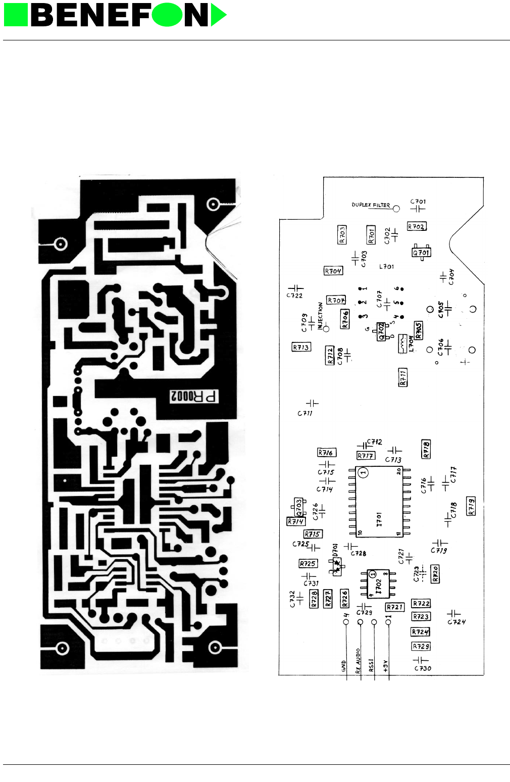
Component Side Layout PR0002A0 (Schematic OR0002A1)
28.1.1999
XR0002E4_fm5.fm 7
Product: TDM-20-N / OR0002 Receiver
Solder Side Layout PR0002A0 (Schematic OR0002A1)
28.1.1999
XR0002E4_fm5.fm 8
Product: TDM-20-N / OR0002 Receiver

28.1.1999
XS0001E4_fm5.fm 1
Product: TDM-20-N / OS0021 Synthesizer
8.0 SYNTHESIZER MODULE OS0021
SPECIFICATIONS
OS0021 Synthesizer
8.0.1 Functions
This unit generates the high frequency signals for respective channel frequencies:
this gives a modulated channel-frequency signal for the transmitter unit and upper
band injection frequency for the receiver unit.
The synthesizer is connected via connector V401 to the processor/audio unit.
Description of connector V401:
8.0.2 Circuit Description
The module can be divided into three main units: TX-synthesizer, RX-synthesizer,
and common power supply unit for both synthesizers.
The power supply unit provides stabilized voltages +9 V (TP1) for the high-frequency
parts and +5 V (TP2) for the synthesizer and pre-scaler circuits and TCXO. The
active components Q401...Q405 are included in the power supply unit.
8.0.3 RX-Synthesizer
Receiver injection frequency is generated by a phase-locked loop (PLL). The coil of
the voltage-controlled oscillator is a strip line on the PCB. VCO center frequency is
adjusted with trimmer C436. Q411 is the oscillator transistor. Next, there are two
amplifier stages Q412 and Q413. The circuit is provided with a 3 dB atttenuator for
the outcoming signal, with a part of this signal being fed to the pre-scaler I4022. This
is called the dual modulus divider having scaling factors 128/129. The divided fre-
quency is fed to the synthesizer circuit I401.
1VB operating voltage to synthesizer 13.2 V
2 TXAUDIO tx audio modulation nominal 550 mV RMS
3 GND ground(-)
4 SRE enable pulse for rx synthesizer IC 5 V
5 STE enable pulse for tx synthesizer IC 5 V
6 SCLK clock for rx and tx data 0/5 V
7 SDAT Arx and tx data for synthesizer IC 0/5 V
8 TXVCO voltage for tx vco. start-up 5 V
V403 TX-INJECTION MHz +10 dBm/50
ohm
V402 RX-INJECTION MHz +10 dBm/50
ohm

28.1.1999
XS0001E4_fm5.fm 2
Product: TDM-20-N / OS0021 Synthesizer
The synthesizer circuit I401 gets its control signals from the processor unit via con-
nector V401 in serial form. Signal CLK is the clock-frequency for synchronising the
transmission of channel-frequency data to the synthesizer. The scaler information is
stored by a latch-pulse on SRE bus sent to the synthesizeer circuit.
The divided frequency is compared to the reference frequency with a phase compar-
ator. The exact reference frequency comes from the thermal-compensated crystal
CXO). This 12.8 MHz frequency is divided by a factor of 512 in the synthesizer cir-
cuit, giving the reference frequency of 25 kHz (= channel space).
The synthesizer is phase-locked when these two frequncies fed to the phase com-
parator are equal. The phase comparator emits positive pulses in response to low
VCO frequency, and ground pulses for high VCO frequency. The phase comparator
output chargers and dischargers the capacitor C417 through the resistor R422, while
R423 and paralled-connected capacitors C418/419 stabilizing the loop function.
The voltage fed to the above described capacitor is amplified with transistors Q408/
409. Two RC-loops R427/C422 and R428/C433 prevent the pulse transfer from the
phase comparator to the VCO. The filtered DC voltage alers, when needed, the
reversed voltage of the capacitance-diode D403 located in the oscillator circuit, i.e.
controls the VCO frequency (TP6).
8.0.4 TX-Synthesizer
TX-frequency is generated with a similar phase-locked loop to the above described
Rs-injection frequency.
There are after the VCO three buffer amplifiers Q416, Q417, and Q418. The divider
and synthesizer circuits function like the RX-synthesizer. There are common DATA
and CLK signals. The scaler information is stored by a latch-pulse on STE bus sent
to the synthesizer circuit I403.
TX-synthesizer uses the phase comparator outputs φ/R and φ/V . This is followed by
avtive low-pass filter for control filtering. The VCO control voltage range is widened
by raising the filter IC power supply with a voltage converter Q414 (TP7). This fil-
tered control voltage is fed to the capacitance-diode-cathode in the oscillator circuit.
An excessive VCO frequency prompts φ /V output-pulses from the phase compara-
tor, but the φ /R output will stay in "1"-state. Too low VCO frequency prompts in turn
negative O/R output-pulses from the phase comparator, while the O/V output stays
in "1"-state.
Modulation is taken from the connector V401 pin 2 (TP5) via level control R459 to
the capacitancediode anode of the VCO circuit. With this arrangement the loop filter
does not affect the modulation by attenuating the high frequencies.
With low modulation frequencies (300...500 Hz), linear AF-response is maintained
by feeding the loop with a "compensation modulation" through the integrator I405.
Compensation is adjusted with trimmer R457 so that the AF-response is linear at
300 Hz frequency.

28.1.1999
XS0001E4_fm5.fm 3
Product: TDM-20-N / OS0021 Synthesizer
8.1 Synthesizer OS0021 Settings
When measuring, a multimeter with Ri = 10 M ohm has been used.
AC-range 20 Hz...20 kHz.
8.1.1 Checking Operating Voltages
Input operating voltage, connector V401 pin 1 (13.2 V)
Operating voltages require no adjustment.
+ 9 V accuracy is affected by the Zerner diode V401 (5V6).
Accuracy of this diode is 5% in 0-series. It will be changed to 2% diode. The resis-
tors R408, R409 used for voltage settings have 1% tolerance.
The + 5 V voltage reference is also taken from this 5V6 diode.
8.1.2 RX-VCO Adjustment
Change to lowest channel (local 35#)
Measure voltage TP6, adjust voltage RX-VCO to 3 V with trimmer C436.
Change to highest channel (local 37#)
Check that adjustment voltage is now approx 6 V.
(Synthesizer functions are optimized with above VCO settings-accuracy, channel
delay, overlap, channel selectivity).
(VCO-accuracy = voltage difference between end channels)
8.1.3 TX-VCO Adjustment
Switch on TX VCO (local 34#) or transmitter (local 32#)
Change lowest channel (local 35#)
Measure TP4 voltag, and adjust TX-VCO voltage to 5 V with trimmer C498.
Change to highest channel (local 37#)
Check that operating voltage is now approx 7.5...8 V.
+9 V, regulated TP1 8.6...9.4 V
+5V, regulated TP2 4.5...5.3 V
+14V TP7 13...15 V
+TX on TP3(local 34#) 8.5...9.3 V
+TXoff TP3(local 34*) approx 5...7 V

28.1.1999
XS0001E4_fm5.fm 4
Product: TDM-20-N / OS0021 Synthesizer
The operating voltage range has been raised to 13V. It may be necessary to deviate
from the above settings in some production runs in order to ensure linear modulation
for end channels.In practice the operating voltage can be between 3V...10V.
8.1.4 Setting Channel Frequency:
8.1.4.1 Measuring Devices:
Frequency counter (resolution 10 Hz)
Switch TX on (local 32#)
Switch to lowest channel (local 35#)
Set correct channel frequency MHz with TCXO trimmer (+/-100 Hz)
8.1.5 Adjusting The Modulation:
Adjust the modulation along wIth the audio unit; see setting instructions for the audio
unit, TX-AUDIO.
Set to middle channel (local 36#)
Switch TX on (local 32#) e.g. medium power.
Feed "normal" modulation to microphone input (f mod. 1 kHz 1 Vrms)
Switch microphone off (local 29*)
Switch TX-audio on (local 21#)
Check that TP5 voltage is now 550 mV rms.
Adjust deviation to +/-3 kHz peak with MOD-trimmer R459.
Check deviation of end channels, difference max +/-150 Hz or +/-0.5 dB
8.1.6 Correcting The Low-frequency Response:
Drop mic input level until deviation is +/-1 kHz.
Measure TP5 voltage (reference level).
Change modulation frequency to 300 Hz.
Raise mic input level until TP5 voltage increases to the same level as the reference
level.
Adjust deviation to +/-1 kHz with COMP-trimmer R457.

28.1.1999
XS0001E4_fm5.fm 5
Product: TDM-20-N / OS0021 Synthesizer
8.1.7 Parts list
CODE PART DESCRIPT. VALUE MANUF. TYPE
CC0473 C401 SMD capasitor 47 nF 10% 50 V X7R Philips
CE0476 C402 Al elko 47 uF/25 V 7x7mm Philips 2222 097 56479
CC0102 C403 SMD capasitor 1 nF 5% 50V NP0 Philips
CU0105 C404 SMD tantal 1uF/16V 20% 3.2x1.6mm Matsushita ECST1CY 105R
CE0476 C405 Al elko 47 uF/25 V 7x7mm Philips 2222 097 56479
CU0105 C407 SMD tantal 1uF/16V 20% 3.2x1.6mm Matsushita ECST1CY 105R
CC0102 C408 SMD capasitor 1 nF 5% 50V NP0 Philips
CC0473 C409 SMD capasitor 47 nF 10% 50 V X7R Philips
CD0101 C410 SMD capasitor 100 pF 5% 50 V NP0 Philips
CC0101 C411 SMD capasitor 100 pF 5% 50V NP0 Philips
CU0105 C412 SMD tantal 1uF/16V 20% 3.2x1.6mm Matsushita ECST1CY 105R
CC0101 C413 SMD capasitor 100 pF 5% 50V NP0 Philips
CC0102 C414 SMD capasitor 1 nF 5% 50V NP0 Philips
CC0102 C415 SMD capasitor 1 nF 5% 50V NP0 Philips
CC0473 C416 SMD capasitor 47 nF 10% 50 V X7R Philips
CC0103 C417 SMD capasitor 10 nF 10% 50V X7R Philips
CC0473 C418 SMD capasitor 47 nF 10% 50 V X7R Philips
CC0473 C419 SMD capasitor 47 nF 10% 50 V X7R Philips
CC0103 C421 SMD capasitor 10 nF 10% 50V X7R Philips
CC0223 C422 SMD capasitor 22 nF 10% 50 V X7R Philips
CU0105 C423 SMD tantal 1uF/16V 20% 3.2x1.6mm Matsushita ECST1CY 105R
CC0471 C424 SMD capasitor 470 pF 5% 50 V NP0 Philips
CD0569 C425 SMD capasitor 5.6 pF/0.25pF 50 V NP0 Philips
CD0100 C426 SMD capasitor 10 pF/0.25pF 50 V NP0 Philips
CD0479 C427 SMD capasitor 4.7 pF/0.25pF 50 V NP0 Philips
CC0473 C428 SMD capasitor 47 nF 10% 50 V X7R Philips
CD0279 C431 SMD capasitor 2.7 pF/0.25pF 50 V NP0 Philips
CD0109 C432 SMD capasitor 1 pF/0.25pF 50 V NP0 Philips
CC0103 C433 SMD capasitor 10 nF 10% 50V X7R Philips
CD0689 C434 SMD capasitor 6.8 pF/0.25pF 50 V NP0 Philips
CA0200 C435 Trim.kond. 5/20 pF Matsushita ECRLA020E52V
CC0101 C436 SMD capasitor 100 pF 5% 50V NP0 Philips
CC0471 C437 SMD capasitor 470 pF 5% 50 V NP0 Philips
CC0471 C438 SMD capasitor 470 pF 5% 50 V NP0 Philips
CC0471 C439 SMD capasitor 470 pF 5% 50 V NP0 Philips
CD0100 C441 SMD capasitor 10 pF/0.25pF 50 V NP0 Philips
CD0569 C442 SMD capasitor 5.6 pF/0.25pF 50 V NP0 Philips
CC0471 C443 SMD capasitor 470 pF 5% 50 V NP0 Philips
CD0829 C444 SMD capasitor 8p2/0.25pF 50V NP0 Philips
CD0569 C445 SMD capasitor 5.6 pF/0.25pF 50 V NP0 Philips
CC0101 C460 SMD capasitor 100 pF 5% 50V NP0 Philips
CC0101 C461 SMD capasitor 100 pF 5% 50V NP0 Philips
CC0101 C462 SMD capasitor 100 pF 5% 50V NP0 Philips
CC0103 C463 SMD capasitor 10 nF 10% 50V X7R Philips
CE0105 C464 Al elko 1uF/63V 4x7mm Philips 2222 097 58108
CC0473 C465 SMD capasitor 47 nF 10% 50 V X7R Philips
CC0473 C466 SMD capasitor 47 nF 10% 50 V X7R Philips
CC0473 C467 SMD capasitor 47 nF 10% 50 V X7R Philips
CU0105 C468 SMD tantal 1uF/16V 20% 3.2x1.6mm Matsushita ECST1CY 105R
CU0105 C469 SMD tantal 1uF/16V 20% 3.2x1.6mm Matsushita ECST1CY 105R
CC0101 C471 SMD capasitor 100 pF 5% 50V NP0 Philips
CC0101 C472 SMD capasitor 100 pF 5% 50V NP0 Philips
CC0473 C473 SMD capasitor 47 nF 10% 50 V X7R Philips
CC0223 C474 SMD capasitor 22 nF 10% 50 V X7R Philips
CC0223 C475 SMD capasitor 22 nF 10% 50 V X7R Philips
CC0101 C476 SMD capasitor 100 pF 5% 50V NP0 Philips
CC0102 C477 SMD capasitor 1 nF 5% 50V NP0 Philips

28.1.1999
XS0001E4_fm5.fm 6
Product: TDM-20-N / OS0021 Synthesizer
CC0102 C478 SMD capasitor 1 nF 5% 50V NP0 Philips
CC0473 C479 SMD capasitor 47 nF 10% 50 V X7R Philips
CC0472 C481 SMD capasitor 4.7 nF 10% 50 V X7R Philips
CC0473 C482 SMD capasitor 47 nF 10% 50 V X7R Philips
CC0473 C483 SMD capasitor 47 nF 10% 50 V X7R Philips
CC0472 C484 SMD capasitor 4.7 nF 10% 50 V X7R Philips
CC0473 C485 SMD capasitor 47 nF 10% 50 V X7R Philips
CC0223 C486 SMD capasitor 22 nF 10% 50 V X7R Philips
CC0471 C487 SMD capasitor 470 pF 5% 50 V NP0 Philips
CC0473 C488 SMD capasitor 47 nF 10% 50 V X7R Philips
CU0105 C489 SMD tantal 1uF/16V 20% 3.2x1.6mm Matsushita ECST1CY 105R
CD0100 C491 SMD capasitor 10 pF/0.25pF 50 V NP0 Philips
CC0150 C492 SMD capasitor 15 pF 5% 50V NP0 Philips
CD0100 C493 SMD capasitor 10 pF/0.25pF 50 V NP0 Philips
CC0101 C494 SMD capasitor 100 pF 5% 50V NP0 Philips
CD0479 C496 SMD capasitor 4.7 pF/0.25pF 50 V NP0 Philips
CD0829 C497 SMD capasitor 8p2/0.25pF 50V NP0 Philips
CA0200 C498 Trim.kond. 5/20 pF Matsushita ECRLA020E52V
CU0105 C501 SMD tantal 1uF/16V 20% 3.2x1.6mm Matsushita ECST1CY 105R
CD0109 C502 SMD capasitor 1 pF/0.25pF 50 V NP0 Philips
CC0223 C504 SMD capasitor 22 nF 10% 50 V X7R Philips
CC0471 C505 SMD capasitor 470 pF 5% 50 V NP0 Philips
CC0471 C506 SMD capasitor 470 pF 5% 50 V NP0 Philips
CD0479 C507 SMD capasitor 4.7 pF/0.25pF 50 V NP0 Philips
CC0471 C508 SMD capasitor 470 pF 5% 50 V NP0 Philips
CC0471 C509 SMD capasitor 470 pF 5% 50 V NP0 Philips
CC0223 C510 SMD capasitor 22 nF 10% 50 V X7R Philips
CC0150 C511 SMD capasitor 15 pF 5% 50V NP0 Philips
CD0120 C512 SMD capasitor 12 pF 5% 50 V NP0 Philips
CC0471 C513 SMD capasitor 470 pF 5% 50 V NP0 Philips
CC0120 C515 SMD capasitor 12 pF 5% 50V NP0 Philips
CC0150 C516 SMD capasitor 15 pF 5% 50V NP0 Philips
DZ0569 D401 SMD zener 5V6 5% 300mW Philips BZX84C5V6
DS0099 D402 SMD diode 70 V 200 mA Philips BAV 99
DC0031 D403 Cap.diode UHF Philips BBY 31
DS0099 D404 SMD diode 70 V 200 mA Philips BAV 99
DC0031 D405 Cap.diode UHF Philips BBY 31
DC0031 D406 Cap.diode UHF Philips BBY 31
IS5158 I401 PLL freq.synthes. CMOS Motorola MC145158-1P
IS0501 I402 Two mod. prescaler (2nd MC12022D Motorola) Fujitsu MB501LPF
IS5158 I403 PLL freq.synthes. CMOS Motorola MC145158-1P
IS0501 I404 Two mod. prescaler (2nd MC12022D Motorola) Fujitsu MB501LPF
IA0272 I405\ 2 x op.amp. LinCMOS Low noise,power Texas TLC27M2ID
LC0334 L401 SMD inductor 330 nH Siemens B82412A3331M
LC0334 L402 SMD inductor 330 nH Siemens B82412A3331M
LC0334 L403 SMD inductor 330 nH Siemens B82412A3331M
LC0334 L408 SMD inductor 330 nH Siemens B82412A3331M
LC0334 L409 SMD inductor 330 nH Siemens B82412A3331M
LC0334 L412 SMD inductor 330 nH Siemens B82412A3331M
PS0001 PCB Piirilevy OS0001 66 x 130 x 1.6 Perstorp
QS0031 Q401 SMD transistor PNP 1A/60V Philips BSR 31
QSB858 Q402 SMD transistor PNP 0.1A/30V F<10dB Philips BC 858 B
QSB848 Q403 SMD transistor NPN 0.1A/30V F=2dB Philips BC 848 B
QSB848 Q404 SMD transistor NPN 0.1A/30V F=2dB Philips BC 848 B
QSB848 Q405 SMD transistor NPN 0.1A/30V F=2dB Philips BC 848 B
QS0031 Q406 SMD transistor PNP 1A/60V Philips BSR 31
QSB848 Q407 SMD transistor NPN 0.1A/30V F=2dB Philips BC 848 B
QSC849 Q408 SMD transistor NPN 0.2A/30V F=1.2dB Philips BC 849 C
QSC859 Q409 SMD transistor PNP 0.2A/30V F=1.2dB Philips BC 859 C
QAA093 Q411 SMD transistor NPN 0.25 W 5 GHz Philipsa BFR 93 A
CODE PART DESCRIPT. VALUE MANUF. TYPE

28.1.1999
XS0001E4_fm5.fm 7
Product: TDM-20-N / OS0021 Synthesizer
QAA093 Q412 SMD transistor NPN 0.25 W 5 GHz Philipsa BFR 93 A
QAA093 Q413 SMD transistor NPN 0.25 W 5 GHz Philipsa BFR 93 A
QSB848 Q414 SMD transistor NPN 0.1A/30V F=2dB Philips BC 848 B
QAA093 Q415 SMD transistor NPN 0.25 W 5 GHz Philipsa BFR 93 A
QAA093 Q416 SMD transistor NPN 0.25 W 5 GHz Philipsa BFR 93 A
QAA093 Q417 SMD transistor NPN 0.25 W 5 GHz Philipsa BFR 93 A
QAA093 Q418 SMD transistor NPN 0.25 W 5 GHz Philipsa BFR 93 A
RC0473 R401 SMD resistor 47 k 5% 0.125 W Kamaya
RC0102 R402 SMD resistor 1 k 5% 0.125 W Kamaya
RC0103 R403 SMD resistor 10 k 5% 0.125 W Kamaya
RC0222 R404 SMD resistor 2.2 k 5% 0.125 W Kamaya
RC0472 R405 SMD resistor 4.7 k 5% 0.125 W Kamaya
RC0102 R406 SMD resistor 1 k 5% 0.125 W Kamaya
RC0102 R407 SMD resistor 1 k 5% 0.125 W Kamaya
RM1002 R408 Mini-Melf resistor 10k0 1% 0.25W Beyschlag MMA 0204-50
RM5621 R409 Mini-Melf resistor 5k62 1% 0.25W Beyschlag MMA 0204-50
RC0101 R411 SMD resistor 100 R 5% 0.125 W Kamaya
RC0101 R412 SMD resistor 100 R 5% 0.125 W Kamaya
RC0104 R413 SMD resistor 100 k 5% 0.125 W Kamaya
RC0331 R414 SMD resistor 330 R 5% 0.125 W Kamaya
RC0472 R415 SMD resistor 4.7 k 5% 0.125 W Kamaya
RC0104 R416 SMD resistor 100 k 5% 0.125 W Kamaya
RC0104 R417 SMD resistor 100 k 5% 0.125 W Kamaya
RC0100 R418 SMD resistor 10 R 5% 0.125 W Kamaya
RC0102 R419 SMD resistor 1 k 5% 0.125 W Kamaya
RC0222 R420 SMD resistor 2.2 k 5% 0.125 W Kamaya
RC0100 R421 SMD resistor 10 R 5% 0.125 W Kamaya
RC0822 R422 SMD resistor 8.2 k 5% 0.125 W Kamaya
RC0223 R423 SMD resistor 22 k 5% 0.125 W Kamaya
RC0473 R424 SMD resistor 47 k 5% 0.125 W Kamaya
RC0472 R425 SMD resistor 4.7 k 5% 0.125 W Kamaya
RC0332 R426 SMD resistor 3.3 k 5% 0.125 W Kamaya
RC0472 R427 SMD resistor 4.7 k 5% 0.125 W Kamaya
RC0103 R428 SMD resistor 10 k 5% 0.125 W Kamaya
RC0101 R431 SMD resistor 100 R 5% 0.125 W Kamaya
RC0101 R432 SMD resistor 100 R 5% 0.125 W Kamaya
RC0153 R433 SMD resistor 15 k 5% 0.125 W Kamaya
RC0472 R434 SMD resistor 4.7 k 5% 0.125 W Kamaya
RC0101 R435 SMD resistor 100 R 5% 0.125 W Kamaya
RC0332 R436 SMD resistor 3.3 k 5% 0.125 W Kamaya
RC0221 R437 SMD resistor 220 R 5% 0.125 W Kamaya
RC0223 R438 SMD resistor 22 k 5% 0.125 W Kamaya
RC0102 R439 SMD resistor 1 k 5% 0.125 W Kamaya
RC0562 R441 SMD resistor 5.6 k 5% 0.125 W Kamaya
RC0221 R442 SMD resistor 220 R 5% 0.125 W Kamaya
RC0223 R443 SMD resistor 22 k 5% 0.125 W Kamaya
RC0471 R444 SMD resistor 470 R 5% 0.125 W Kamaya
RC0560 R445 SMD resistor 56 R 5% 0.125 W Kamaya
RC0221 R446 SMD resistor 220 R 5% 0.125 W Kamaya
RC0180 R447 SMD resistor 18 R 5% 0.125 W Kamaya
RC0271 R448 SMD resistor 270 R 5% 0.125 W Kamaya
RC0473 R451 SMD resistor 47 k 5% 0.125 W Kamaya
RC0102 R452 SMD resistor 1 k 5% 0.125 W Kamaya
RC0105 R453 SMD resistor 1 M 5% 0.125 W Kamaya
RC0473 R454 SMD resistor 47 k 5% 0.125 W Kamaya
RC0473 R455 SMD resistor 47 k 5% 0.125 W Kamaya
RC0224 R456 SMD resistor 220 k 5% 0.125 W Kamaya
RQ0103 R457 Trimmer resistor 10k 20% 0.5W Bourns 3329H-1-103
RC0222 R458 SMD resistor 2.2 k 5% 0.125 W Kamaya
RQ0103 R459 Trimmer resistor 10k 20% 0.5W Bourns 3329H-1-103
CODE PART DESCRIPT. VALUE MANUF. TYPE

28.1.1999
XS0001E4_fm5.fm 8
Product: TDM-20-N / OS0021 Synthesizer
RC0222 R460 SMD resistor 2.2 k 5% 0.125 W Kamaya
RC0103 R461 SMD resistor 10 k 5% 0.125 W Kamaya
RC0222 R471 SMD resistor 2.2 k 5% 0.125 W Kamaya
RC0100 R472 SMD resistor 10 R 5% 0.125 W Kamaya
RC0102 R473 SMD resistor 1 k 5% 0.125 W Kamaya
RC0473 R474 SMD resistor 47 k 5% 0.125 W Kamaya
RC0472 R475 SMD resistor 4.7 k 5% 0.125 W Kamaya
RC0472 R476 SMD resistor 4.7 k 5% 0.125 W Kamaya
RC0223 R477 SMD resistor 22 k 5% 0.125 W Kamaya
RC0223 R478 SMD resistor 22 k 5% 0.125 W Kamaya
RC0104 R479 SMD resistor 100 k 5% 0.125 W Kamaya
RC0473 R481 SMD resistor 47 k 5% 0.125 W Kamaya
RC0222 R482 SMD resistor 2.2 k 5% 0.125 W Kamaya
RC0222 R483 SMD resistor 2.2 k 5% 0.125 W Kamaya
RC0222 R484 SMD resistor 2.2 k 5% 0.125 W Kamaya
RC0101 R491 SMD resistor 100 R 5% 0.125 W Kamaya
RC0101 R492 SMD resistor 100 R 5% 0.125 W Kamaya
RC0472 R493 SMD resistor 4.7 k 5% 0.125 W Kamaya
RC0560 R494 SMD resistor 56 R 5% 0.125 W Kamaya
RC0103 R495 SMD resistor 10 k 5% 0.125 W Kamaya
RC0153 R497 SMD resistor 15 k 5% 0.125 W Kamaya
RC0472 R498 SMD resistor 4.7 k 5% 0.125 W Kamaya
RC0102 R501 SMD resistor 1 k 5% 0.125 W Kamaya
RC0332 R502 SMD resistor 3.3 k 5% 0.125 W Kamaya
RC0223 R503 SMD resistor 22 k 5% 0.125 W Kamaya
RC0102 R504 SMD resistor 1 k 5% 0.125 W Kamaya
RC0221 R505 SMD resistor 220 R 5% 0.125 W Kamaya
RC0562 R506 SMD resistor 5.6 k 5% 0.125 W Kamaya
RC0223 R507 SMD resistor 22 k 5% 0.125 W Kamaya
RC0471 R508 SMD resistor 470 R 5% 0.125 W Kamaya
RC0221 R511 SMD resistor 220 R 5% 0.125 W Kamaya
RC0562 R512 SMD resistor 5.6 k 5% 0.125 W Kamaya
RC0223 R513 SMD resistor 22 k 5% 0.125 W Kamaya
RC0331 R514 SMD resistor 330 R 5% 0.125 W Kamaya
RC0680 R515 SMD resistor 68 R 5% 0.125 W Kamaya
RC0121 R516 SMD resistor 120 R 5% 0.125 W Kamaya
RC0270 R517 SMD resistor 27 R 5% 0.125 W Kamaya
RC0181 R518 SMD resistor 180 R 5% 0.125 W Kamaya
VN0108 V401 8-pin connector Wisher WKP-N8B1G-L
VR0235 V402 Coax cable + connector 50 ohm l=n.70mm Taikodenki TMP-P01X-A1
VR0135 V403 Coax connector 50 ohm Taikodenki TMP-J02X-A1
XO0128 X401 TCXO 12.8 MHz 2 ppm Toyocom TCO-903B1
Last
update
13.03.90
CODE PART DESCRIPT. VALUE MANUF. TYPE
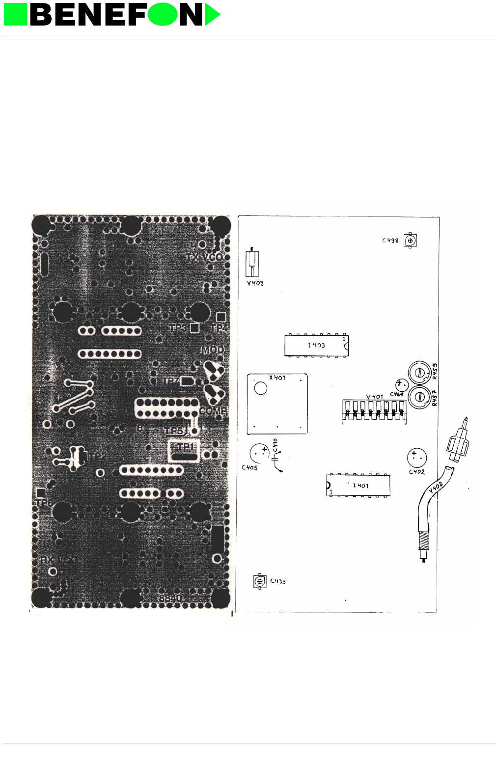
28.1.1999
XS0001E4_fm5.fm 9
Product: TDM-20-N / OS0021 Synthesizer
Component Side Layout PS0001A0 (Schematic OS0001A0)
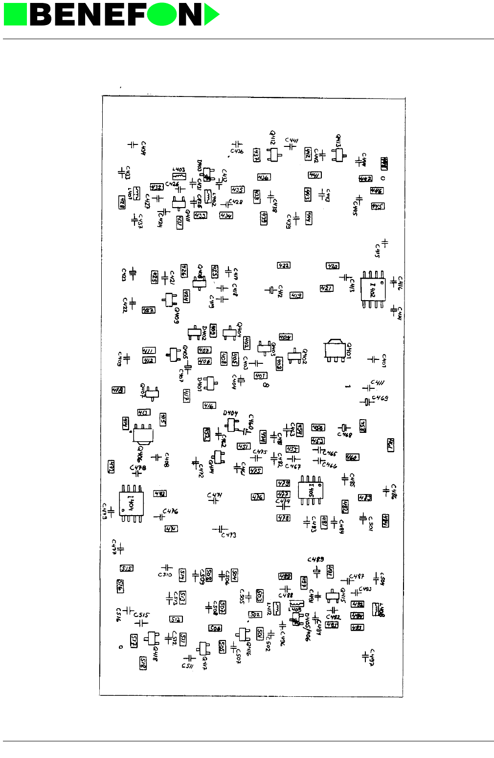
28.1.1999
XS0001E4_fm5.fm 10
Product: TDM-20-N / OS0021 Synthesizer
Solder Side Layout PS0001A0 (Schematic OS0001A0)
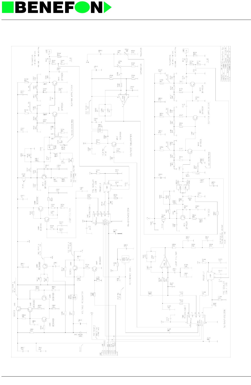
28.1.1999
XS0001E4_fm5.fm 11
Product: TDM-20-N / OS0021 Synthesizer

28.1.1999
XW0002E4_fm5.f 1
Product: TDM-20-N / OW0002 Power supply
9.0 POWER SUPPLY MODULE OW0002
SPECIFICATIONS
OW0002 Power supply
P.S.U. includes noise filter, 9 V-regulator, speaker amplifier, and relay drivers.
9.0.1 Connector X800
9.0.2 Connector X820
9.0.3 Connector X830
9.0.4 Operation Principles:
Noise from vehicle electrical-system is filtered with low-pass filter C810, C811, L810,
C813, C812, L811, and zenerdiode D812. Main relay A800 in driven from connector
X820/4(5 V). The speaker must be connected to X800/5, or otherwise transistor
Q813 conducts and cannot swich the power ON. D811, D814, and transistor Q810
prevent switching power ON when supply voltage is too high.
The output voltage of the regulator is set by R806, R807, and zenerdiode D800, and
current limit by R803.
Speaker amplifier is in stand-by position (low current-consumption) when there is no
blas voltage in connector X820/5.
1MUTE
CAR RADIO MUTE relay-driver
0.5A
2 IGS IGNITION SENSE
3 GND GROUND
4AL
EXTERNAL ALARM relay-
driver 0.5A
5 SPKR SPEAKER 4...8 ohm
6 VB SUPPLY VOLTAGE 10.8...15.6 V 5 A
1 12 V 12V for processor module
2 9 V 9 V regulator 8.5...9 V 1 A
3 BCUP BACK-UP power supply for RAM-memory
4 PWR ON/OFF control
5 AFIN audio input for speaker amplifier
6 IGN IGNITION control
7 EXAL EXTERNAL ALARM control
8 EXMUTE CAR RADIO MUTE control
1 +TX SUPPLY VOLTAGE FOR TRANSMITTER

28.1.1999
XW0002E4_fm5.f 2
Product: TDM-20-N / OW0002 Power supply
9.0.5 Parts list
CODE PART DESCRIPT. VALUE MANUF. TYPE
AR0002 A800\ Relay 12V/10A Guardian 1655S-IC-12D
CC0473 C800 SMD capasitor 47 nF 10% 50 V X7R Philips
CE0106 C801 Al elko 10 uF/35 V 5x7mm Philips 2222 097 50109
CC0222 C802 SMD capasitor 2.2 nF 5% 50 V NP0 Philips
CC0473 C803 SMD capasitor 47 nF 10% 50 V X7R Philips
CP0104 C810 Polyester cap 100n 63V 20% Wima
CP0104 C811 Polyester cap 100n 63V 20% Wima
CE0228 C812 Al elko 2200 uF/25 V 16x25 Elna RE2-25V222M
CE0477 C813 Al elko 470 uF/25 V 10x25mm ROE EB00GD347E00R
CE0107 C814 Al elko 100uF 16V 7x7mm Philips 2222 097 55101
CE0476 C815 Al elko 47 uF/25 V 7x7mm Philips 2222 097 56479
CC0473 C816 SMD capasitor 47 nF 10% 50 V X7R Philips
CE0107 C817 Al elko 100uF 16V 7x7mm Philips 2222 097 55101
CC0222 C818 SMD capasitor 2.2 nF 5% 50 V NP0 Philips
CE0477 C819 Al elko 470 uF/25 V 10x25mm ROE EB00GD347E00R
CC0222 C820 SMD capasitor 2.2 nF 5% 50 V NP0 Philips
CC0222 C821 SMD capasitor 2.2 nF 5% 50 V NP0 Philips
CC0222 C822 SMD capasitor 2.2 nF 5% 50 V NP0 Philips
CC0222 C823 SMD capasitor 2.2 nF 5% 50 V NP0 Philips
CE0476 C824 Al elko 47 uF/25 V 7x7mm Philips 2222 097 56479
CC0473 C825 SMD capasitor 47 nF 10% 50 V X7R Philips
CE0107 C826 Al elko 100uF 16V 7x7mm Philips 2222 097 55101
CP0104 C827 Polyester cap 100n 63V 20% Wima
CC0222 C828 SMD capasitor 2.2 nF 5% 50 V NP0 Philips
CP0104 C829 Polyester cap 100n 63V 20% Wima
CC0473 C830 SMD capasitor 47 nF 10% 50 V X7R Philips
CP0104 C831 Polyester cap 100n 63V 20% Wima
CC0222 C832 SMD capasitor 2.2 nF 5% 50 V NP0 Philips
CC0223 C833 SMD capasitor 22 nF 10% 50 V X7R Philips
CC0473 C834 SMD capasitor 47 nF 10% 50 V X7R Philips
DZ1569 D800 SMD zener 5V6 2% 300mW Philips BZX84B5V6
DS0070 D801 SMD diode pair 70V/100mA common cathode Philips BAV 70
DS0017 D810 SMD diode 1.5A/400V Philips BYD 17 G
DS0017 D811 SMD diode 1.5A/400V Philips BYD 17 G
DT0018 D812 Transient filter 18V/50A 1500W Motorola ICTE-18
DS0017 D813 SMD diode 1.5A/400V Philips BYD 17 G
DZ0180 D814 SMD zener 18V 5% 300mW Philips BZX84C18
DS0070 D815 SMD diode pair 70V/100mA common cathode Philips BAV 70
DS0017 D816 SMD diode 1.5A/400V Philips BYD 17 G
DS0017 D817 SMD diode 1.5A/400V Philips BYD 17 G
IA1020 I800 Audio power amplifier 7W/14.4V/4ohm Philips TDA1020/N4
LA5107 L810 Inductor 100uH 5A Fuji SL05B101
VI0040 MEK1 Component base 1 base = 40 holes Perlos
VI0040 MEK2 Component base 1 base = 40 holes Perlos
VI0040 MEK3 Component base 1 base = 40 holes Perlos
VI0040 MEK4 Component base 1 base = 40 holes Perlos
VI0040 MEK5 Component base 1 base = 40 holes Perlos
VI0040 MEK6 Component base 1 base = 40 holes Perlos
PW0002 PCB PCB for OW0002 149 x 56 x 1.6mm FR4
QP0032 Q800 Power transistor PNP 3A/60V Philips BDT 32 AF
QS0051 Q801 SMD transistor PNP 1.5A/45V Philips BCX 51
QSB848 Q802 SMD transistor NPN 0.1A/30V F=2dB Philips BC 848 B
QSB848 Q803 SMD transistor NPN 0.1A/30V F=2dB Philips BC 848 B
QSB848 Q810 SMD transistor NPN 0.1A/30V F=2dB Philips BC 848 B
QSB848 Q811 SMD transistor NPN 0.1A/30V F=2dB Philips BC 848 B
QS0054 Q812 SMD transistor NPN 1.5A/45V Philips BCX 54
QSB848 Q813 SMD transistor NPN 0.1A/30V F=2dB Philips BC 848 B

28.1.1999
XW0002E4_fm5.f 3
Product: TDM-20-N / OW0002 Power supply
QS0054 Q814 SMD transistor NPN 1.5A/45V Philips BCX 54
QSB848 Q815 SMD transistor NPN 0.1A/30V F=2dB Philips BC 848 B
QS0054 Q816 SMD transistor NPN 1.5A/45V Philips BCX 54
QSB848 Q817 SMD transistor NPN 0.1A/30V F=2dB Philips BC 848 B
QSB848 Q818 SMD transistor NPN 0.1A/30V F=2dB Philips BC 848 B
QSB858 Q819 SMD transistor PNP 0.1A/30V F<10dB Philips BC 858 B
RC0473 R800 SMD resistor 47 k 5% 0.125 W Kamaya
RC0102 R801 SMD resistor 1 k 5% 0.125 W Kamaya
RC0103 R802 SMD resistor 10 k 5% 0.125 W Kamaya
RA0681 R803 Metal film resistor 680R 5% 0.25 W Philips
RC0472 R804 SMD resistor 4.7 k 5% 0.125 W Kamaya
RC0102 R805 SMD resistor 1 k 5% 0.125 W Kamaya
RM6041 R806 Mini-Melf resistor 6k04 1% 0.25W Beyschlag MMA 0204-50
RM1002 R807 Mini-Melf resistor 10k0 1% 0.25W Beyschlag MMA 0204-50
RC0330 R810 SMD resistor 33 R 5% 0.125 W Kamaya
RC0103 R812 SMD resistor 10 k 5% 0.125 W Kamaya
RC0103 R813 SMD resistor 10 k 5% 0.125 W Kamaya
RC0103 R814 SMD resistor 10 k 5% 0.125 W Kamaya
RC0103 R815 SMD resistor 10 k 5% 0.125 W Kamaya
RC0104 R816 SMD resistor 100 k 5% 0.125 W Kamaya
RC0473 R817 SMD resistor 47 k 5% 0.125 W Kamaya
RC0473 R818 SMD resistor 47 k 5% 0.125 W Kamaya
RC0104 R819 SMD resistor 100 k 5% 0.125 W Kamaya
RC0473 R820 SMD resistor 47 k 5% 0.125 W Kamaya
RC0104 R821 SMD resistor 100 k 5% 0.125 W Kamaya
RC0104 R824 SMD resistor 100 k 5% 0.125 W Kamaya
RC0334 R825 SMD resistor 330 k 5% 0.125 W Kamaya
RC0104 R826 SMD resistor 100 k 5% 0.125 W Kamaya
RC0104 R827 SMD resistor 100 k 5% 0.125 W Kamaya
RA0479 R828 Metal film resistor 4R7 5% 0.25 W Philips
RC0103 R829 SMD resistor 10 k 5% 0.125 W Kamaya
RC0104 R830 SMD resistor 100 k 5% 0.125 W Kamaya
RC0393 R831 SMD resistor 39 k 5% 0.125 W Kamaya
RC0102 R832 SMD resistor 1 k 5% 0.125 W Kamaya
VW0106 X800 Connector male 6-pin Molex 5569-06-A1
VN0208 X820 8-pin connector Wisher WKP-N8SG-L
Last
update
21.04.94
CODE PART DESCRIPT. VALUE MANUF. TYPE
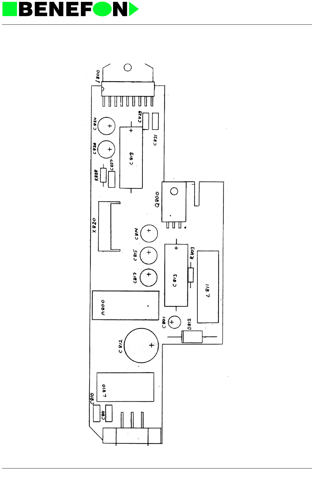
28.1.1999
XW0002E4_fm5.f 4
Product: TDM-20-N / OW0002 Power supply
Component Side Layout PW0002A0 (Schematic OW0002A0)
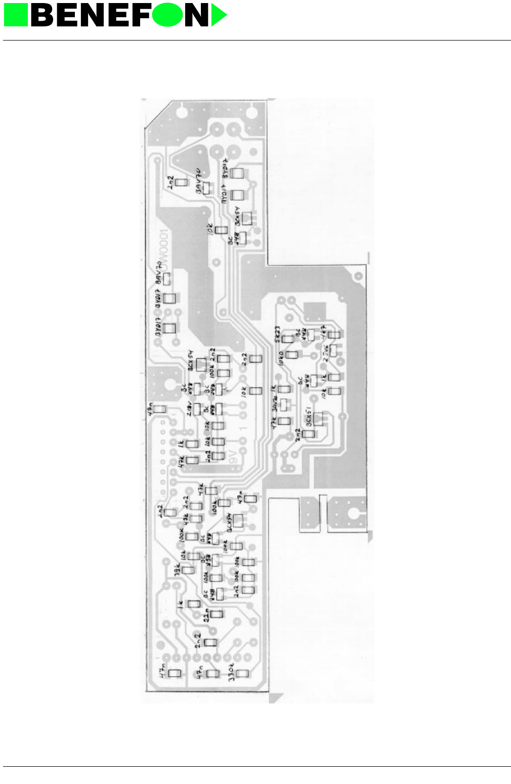
28.1.1999
XW0002E4_fm5.f 5
Product: TDM-20-N / OW0002 Power supply
Solder Side Layout PW0002A0 (Schematic OW0002A0)
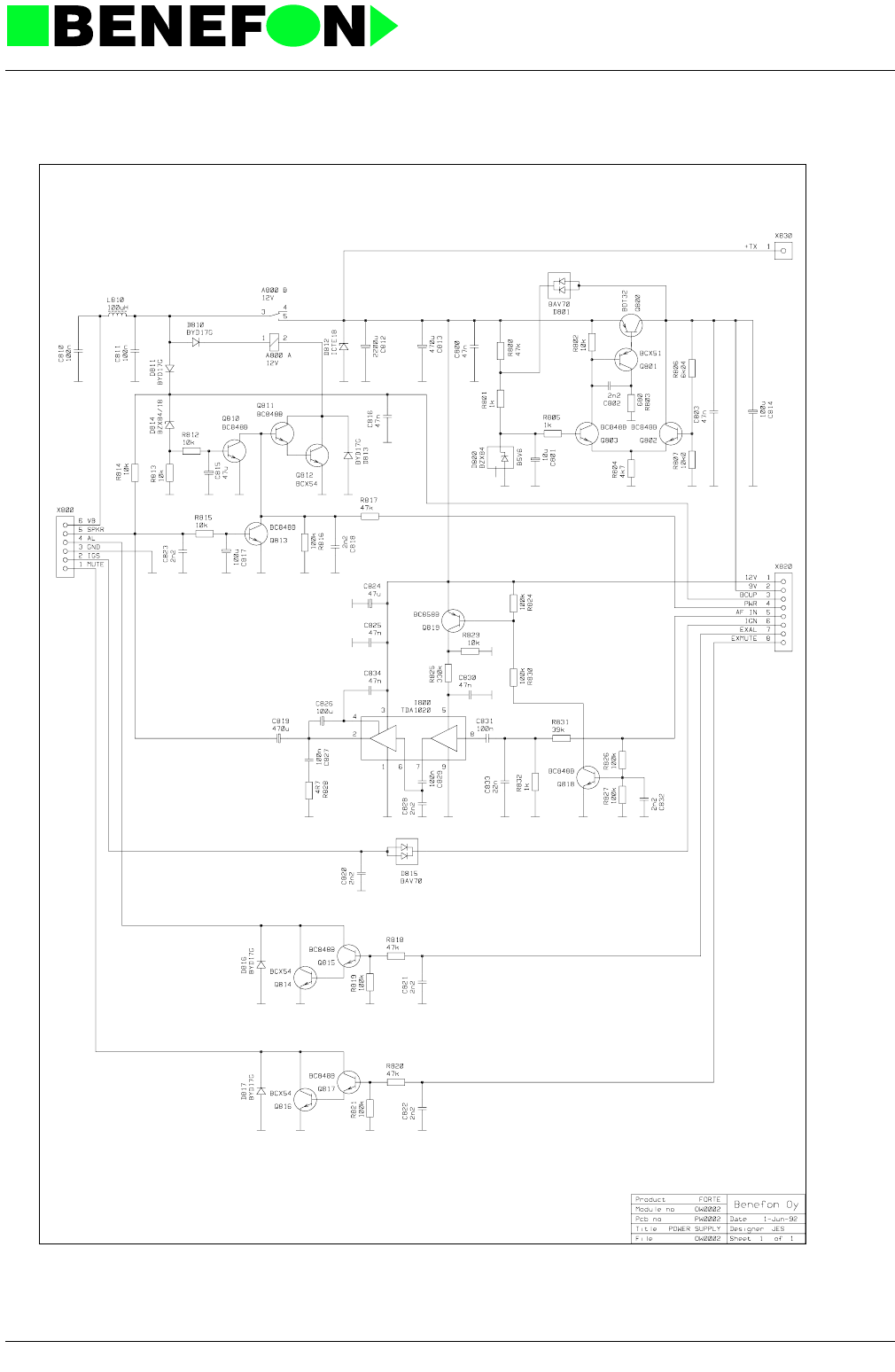
28.1.1999
XW0002E4_fm5.f 6
Product: TDM-20-N / OW0002 Power supply

28.1.1999
XZ0014E4_fm5.fm 1
Product: TDM-20-N (Forte i) / Audio
10.0 AUDIO
Audio
10.0.1 Principles Of Audio Operation
Audio is split into three sections, according to part-numbers:
10.0.2 TX-Audio
I382 works as input buffer and attenuator and band-pass-filter (300 Hz...3.4 kHz).
I220 and I384D control the microphone line VOL in VOX mode (range c.20 dB), and
function as two-step limiters (c. 1 dB, 3 dB) in normal use. Yhe circuits combine the
TXAUXOUT and DTMFTX signals too.
I210A act as MICDET AC/DC conventer.
I384C act as dynamic compressor which is passed-by I390B.
C234 and R234 set a 6 dB pre-emph, and I235A act as amplifier.
I235B form a first maximum deviation limiter.
I382D form a second limiter and a low-pass-filter with the cut-off frequency of 3.4
kHz.
I382E act as the band-pass-filter of FII signal.
I210B combines FII and FFSKT signals, which are fed through the TXAUDIO line to
the synthesizer.
VR is modulated to VFF-voltage for I205C modem connection.
10.0.3 RX-Audio
I382 serves as an amplifier for reciever signals, or an attenuator in AUDLOOPON
mode. From I382F the FII signal branches to TXAUDIO. In the other branch, I382F
filters audio signal (300 Hz...3,4 kHz) and forms a 6 dB de-emph.
I384E works as an attenuator to expandor which is passed-by I390C.
I321A act as ERPDET AC/DC converter.
I361 and I321 together give VOL-control on SPK-line (control range +15...-10 dB),
and also combine DTMF signals. The control is also used in VOX mode. VPS is
modulated to VDref-half-voltage for I321B.
TX-AUDIO parts 200 ... 289
Regulator parts 290 ... 299
RX-AUDIO parts 300 ... 399

28.1.1999
XZ0014E4_fm5.fm 2
Product: TDM-20-N (Forte i) / Audio
Half-voltage goes also to DTMF switch I305A.
I331 and I342A together give VOL-control on ERP-line (control rante +15 dB...-10
dB).
I342 is an amplifier for the system-cable.
10.0.4 Regulator
I380 regulate 9 V to 5 V (VR). Q295 switch on VPS-voltage to the audio parts.
The processor provides 4 MHz clock frequency for the CMOS switched capasitor fil-
ter of which parts B, D, E and F are filters and A generates half-voltage Vbias.
I384A generates half-voltages Vref and VTref. B part is an expandor, C part is an
compressor and D and E parts are amplifiers.
10.0.5 Audio
10.0.5.1 Logic Control
MICVOL: 2 microphone VOL-control (0,1,2)
TXAUDCONT: 3 TX logic control
- AUXOFF accessory bypass
- TXAON TX audio ON
- FFSKT modem ON
- DTMFON DTMF ON
ERPVOL: 2 erp/spk VOL control (0,1,2)
RXAUDCONT: 7 RX logic control
- FIILOOP ON (FII signal loop ON)
- AUDILOOP audioloop from TX to RX
(test)
- RXAON RX-AUDIO ON
- ERPON handset ON
- SPKON speaker ON
- HIDTMFON hi DTMF level ON
- COMPOFF compandor OFF
- AUDIOPWR audio power amplifier ON
-DTMFRXON DTMF to speaker ON

28.1.1999
XZ0014E4_fm5.fm 3
Product: TDM-20-N (Forte i) / Audio
10.0.6 Audio Input Signals
(ac-values 3 kHz deviation, 1 kHz signal)
10.0.7 Audio Output Signals
(ac-values 3 kHz deviation, 1 kHz signal)
MIC microphone signal
(+PWRSW-signal) 1 VRMS
SO modem signal 775 mVRMS
TXAOUT accessory to transmitter 400 mVRMS
RXAOUT accessory to erp/speaker 400 mVRMS
DTMFTX DTMF generator to TX and
speaker 150 mVRMS
RXAUDIO receiver to audio c.120 VRMS
4 MHz 4 MHz clock to audio-filter cir-
cuit
MICDET microphone DC-signal level to processor
AD converter 0...8 VDC
PWRSW PWR-switch signal 5/0 VDC
TXAUXIN microphone to aux 400 mVRMS
RXAUXIN receiver to aux 300 mVRMS
TXAUDIO audio to synthesizer 550 mVRMS
ERPDET receiver DC-signal level to processor
AD converter 0...8 VDC
DTMFRX DTMF-signals from receiver to DTMF
receiver 400 mVRMS
SPK audio output to speaker (+15...-10 dB) 120 mVRMS
(VOL 0 dB)
ERP audio output to handset (+15...-10 dB) 300 mVRMS
(+ HOOK-signal) (VOL 0 dB)
FFSKR modem signal 400 mVRMS
HOOK HOOK-signal from handset 5/0 mVRMS

28.1.1999
XZ0014E4_fm5.fm 4
Product: TDM-20-N (Forte i) / Audio
10.0.7.1 Operating Voltages In Audio
10.0.8 Audio Settings
Measurements must be made with a multimeter of 10 Mohm resistance. AC range of
meter should be 20 Hz... 20 kHz. LOCAL-BOX must be used when making adjust-
ments.
10.0.9 Operating Voltages
10.0.10 RX Audio
RF-generator settings:
- frequency 465.225 MHz
- rf-level 60 dBuV
- modulation frequency 1 kHz
- deviation 3 kHz
9V supply voltage from OW-module 9V
VR constant voltage in audio (regulated) 5V
VPS interrupt voltage in audio (regulated) 5V
VTREF TX half-voltage 2.5V
VFF DC bias to modem 1.5V
VREF RX half-voltage (interrupted) 2.5V
VDREF RX half-voltage (interrupted) 2.5V
Vbias RX/TX half-voltage (continuous) 2.5V
9V X-PWR pin 2 9V
VR I380 pin 1 4.8 ... 5.1 V
Vbias I382 pin 7 2.4 ... 2.55 V
Vref I384 pin 8 2.35 ... 2.5 V
VPS I384 pin 20 4.7 ... 5.0 V
VTref I384 pin 8 2.35 ... 2.5 V
VFF I205 pin 9 1.4 ... 1.6 V
VDref I321 pin 5 2.35...2.5 V

28.1.1999
XZ0014E4_fm5.fm 5
Product: TDM-20-N (Forte i) / Audio
Local-box switches set to SERVICE and RADIO
Set mid-channel (local 36#)
By-pass compandor (local 200*, COMPOFF).
Turn on RX-audio (local 22# RXA ON , local 200# EXP ON). DO NO TOUCH VOL-
control during setting operation.
RX-audio level is set with 300 mVRMS trimmer R302 (RX) and is measured at the
local-box METER-connector.
Reset (local 0#).
10.0.11 TX-Audio
10.0.11.1 Normal Deviation:
- Local-box switches set to SERVICE and RADIO.
- Turn to TX-audio (local 21#, TXA ON).
- By-pass compandor (local 200*, COMPOFF)
- Feed a 1 kHz, 1 VRMS signal from a AF-generator to the local-box GEN
connector.
- Connect multimeter to X-SYNTE, pin 2, and adjust trimmer R241 (TX) to
show 550 mVRMS.
- Switch on transmitter to medium power (LOCAL 32#, M TXON) on mid-
channel (local 36#, MIDLEC).
- Adjust deviation with trimmer R459 (MOD; OS-module) to +/-3 kHz peak.
- Drop AF-generator level until deviation is +/-1 kHz and measure comparative
level at X-SYNTE, pin 2.
- Change AF-generator frequency to 300 Hz.
- Raise pt-generator level until meter level showe the previous comparative
level.
- Adjust the deviation with trimmer R457 (COMP., OS-module) to +/-1 kHz.
10.0.12 Maximum Deviation
- Change AF-generator frequency to 1 kHz.
- Raise AF-generator level to 3.33 Vrms
- Compare channels 0,90 and 180 in turn, and check that max. deviation is +/-
4.5 kHz. If deviation exceeds 4.5 kHz then adjust with trimmer R244 to max.
4.45 kHz.

28.1.1999
XZ0014E4_fm5.fm 6
Product: TDM-20-N (Forte i) / Audio
10.0.13 FFSKT Deviation
- Switch to medium power (local 32#, M TXON).
- Turn FFSKT on (local 12#, SEND 0).
- Adjust deviation with trimmer R265 (FFSKT) to +/-4.2 kHz.
- Reset (local 0#).
10.0.14 FII Deviation, Method 1
RF-generator settings:
- frequency 465.225 MHz (mid-channel)
- RF-level 60 dBuV
- modulation frequency 4 kHz
- deviation 600 Hz
Open FII-LOOP (local 23#, FII ON).
Medium-power ON (local 32#, MTXON)
Adjust devialtion with trimmer R255 (FII) to +/-670 Hz
FII-limits 610...730 Hz
Reset (local 0#).
10.0.15 FII Deviation, Method 2
(not recommendable)
- Set phone to NMT-mode
- Set CMT to mid-channel
- Make a call with CMT
- Set handset to MUTED-mode
- Find "PASS SUP. TONE" from CMT
- Set CMT-deviation frequency to 0 Hz
- Adjust deviation with trimmer R255 (FII) to +/-650 Hz
- FII-limits 590...710 Hz
- End call

28.1.1999
XZ0014E4_fm5.fm 7
Product: TDM-20-N (Forte i) / Audio
10.0.16 Limiter Adjustment
- Local-box switches set to SERVICE and RADIO
- Turn on TX-audio (local 21#, TXA ON)
- Switch to medium power (local 32#, MTXON)
- Feed a 1 kHz, 1 VRMS signal from a AF-generator to the local-box GEN
connector
- Indicated deviation should be +/-3 kHz
- Set to adjust-mode (local 39#, DEV LO)
- Raise AF-generator level until deviation reading is +/-3.4 kHz; handset
reading should be c. 80...90 (AD-converter value)
- Press OK (first limiter-level set to EEPROM memory); "DEV HI" on display
- Raise pt-generator level until deviation is +/-4.15 kHz
- Press OK (second limiter level stored to EEPROM)
- Should the maximum deviation remain below +/-4.15 kHz, set the second
limiter level to AD-converter value 145 (display shows DEV HI)
- Limiter settings can be checked with local 39*, DEVLIM.
10.0.17 Deviation Limiter
There is an SW controlled deviation limiter in the phone. The purpose of the devia-
tion limiter is to compress microphone levels which causes maximum deviation and
distortion to transmitted voice.
Deviation limiter is tuned during manufacturing.
There are two thresholds in the limiter. When microphone signal is above tuned
threshold the limiter attenuates it. Attenuation is 0.8 dB when microphone signal is
above the first threshold and 2.7 dB when above the second.
10.0.18 Voice Operated HF
10.0.18.1 General:
Voice operated HF software uses microphone and speaker level detectors to mea-
sure, and TX and RX attenuators to set the microphone and speaker signals.
Voice operated HF is designed in such a way that a detected microphone signal
above tuned HF threshold always attenuates the speaker signal.
Microphone threshold is tuned in LOCAL by installer to work properly in the vehicle
where the phone is used.

28.1.1999
XZ0014E4_fm5.fm 8
Product: TDM-20-N (Forte i) / Audio
10.0.18.2 Seesaw Model Of The Voice Operated HF
1. When microphone signal rises above tuned threshold the TX attenuation is
decreased and RX attenuation is increased.
Note: The deviation limiter may work which causes some TX attenuation.
2. When microphone signal drops below tuned threshold TX attenuation is increased
and RX attenuation is decreased.
Note: The actual RX attenuation minimum depends on user preset speaker volume
level.
3. When there are simultaneous speaker and microphone signals HF is set in duplex
state where TX and RX attenuators are in middle positions.
Note: The actual RX attenuation depends on user preset speaker volume level.
10.1 Processor Functions
All audio and processor functions of the radio are located on the same PCB; other
modules are interconnected through it. Only the RF-signals have a different route.
The processor controls the audio and radio units and the handset.
10.1.1 The Processor Includes
CPU 68HC11 8-bit, 8 A/D, 512*8 EEPROM, I/O
PROM 27C512 64K*8 EPROM, program memory
RAM 44658K*8 CMOS
RAM program space and short-code mem-
ory
MODEM FX439 1200bd FFSK modem, radio path sig-
nalling
I/O 33 pcs outputs and 18 pcs inputs
DTMFTX PCD3312 DTMF generator and tone signals
DTMFRX MV8870 DTMF receiver
TXLOG TX power adjustment and control

28.1.1999
XZ0014E4_fm5.fm 9
Product: TDM-20-N (Forte i) / Audio
10.1.2 Connectors:
10.1.2.1 Handset:
XBUS
10.1.2.2 Regulator:
X-PWR
1 GND ground
2 MICF audio signal from microphone 1 VRMS
3 AGND audio ground
4AUTO-
CALLF activates the autocall function 12 V
5 EXTALF
6
7 I2cINTF i2c interrupt from handset, 0-active
8 SDAXF i2c dataline, duplex
9 +9VF +9 V voltage to handset .5 A
10 ERPF audio earphone (VOL 0dB) .4 VRMS
11 RXFIXF
12 PTTF push to talk, exterior switch to ground
13
14
15 SCLXF i2c clock to handset 0/5 V
1 VB 12 V operating voltage via relay 5 A max
2 +9V 9 V operating voltage 1 A max
3 VBAT continuous power supply
for maintaining RAM standby
4 RELAY current relay control, PWR on 5 V
5 SPK audio signal to speaker amplifier 120 mV
6 IGN activates IGN function 12 V
7 EXTAL external alarm control, 5 V activates
8 EXTMUTE car radio muting 5 V activates

28.1.1999
XZ0014E4_fm5.fm 10
Product: TDM-20-N (Forte i) / Audio
10.1.2.3 Synthesizer:
X-SYNTE
10.1.2.4 Receiver:
X-RX
10.1.2.5 Transmitter:
X-TX
1 VB synthesizer 12 V operating voltage
2 TXAUDIO tx audio modulation 550 mV
3 GND ground
4 SRE enable pulse for rx scaler 5 V
5 STE enable pulse for tx scaler 5 V
6 SCLK clock for rx and tx data 0/5 V
7 SDATA rx and tx data for scalers 0/5 V
8 TXVCO tx for vco ON 5 V
1 +9V operating voltage to receiver 9 V
2 RSSI rx signal strength indicator, analog 0...5 V
3 RXAUDIO rx audio signal 100...150 mV
4 GND ground
1 TXSENSE tx power sensing, analog 0...10 V
2TXP-
WRCTR tx power control, analog 0...9 V
3 TXBIAS tx bias 9 V 50 mA, Ov= tx off
4

28.1.1999
XZ0014E4_fm5.fm 11
Product: TDM-20-N (Forte i) / Audio
10.1.2.6 Accessory:
X-E1
- Power switch connected to mic line, grounds the mic line.
- Hook switch connected to erp line, dropping the dc level of the handset erp
line while the handset is on the holder.
10.1.3 Circuit Diagram
The circuit diagram of the processor is divided into six parts. The first figure shows
the connector interfaces and the division between audio and processor. The orther
five figures illustrate the subfunctions. Audio is shown in three drawings. In the dia-
grams, the signals have been given names so that identical names are connected
between drawings.
The circuit includes:
10.1.3.1 Component Numbering
The components on each module are numbered unambiguously. Each component
number is only shown in one place. The processor has the numbers between 001
and 199, and the audio between 200 and 399.
1TXAIN
2TXAOUT
3GND
4RXAIN
5RXAOUT
6 VB operating voltage 12 V
7 I2cINT i2c interrupt, 0 active
8EXTi2cE
Nenable to accessory’s i2c bus 5 V
9 SDA i2c data 0/5 V
10 SCL i2c clock 0/5 V
OACONN figure of PCB connectors (sheet 1 of 9)
CPU cpu, memory coding and modem (sheet 5 of 9)
MEM memory (RAM, EPROM), supply input and start-up(sheet 7 of
9)
IO input and output gates, DTMF rx and tx (sheet 6 of 9)
TXLOG TX control logic (sheet 8 of 9)
AUDIO audio power supply and block diagrams (sheet 2 of 9)
RXAUDIO receiver audio parts (sheet 3 of 9)
TXAUDIO transmitter audio parts (sheet 4 of 9)
SIS sis function (sheet 9 of 9)

28.1.1999
XZ0014E4_fm5.fm 12
Product: TDM-20-N (Forte i) / Audio
10.1.3.2 Functions
The I050 is the processor circuit. It includes the CPU, the 512*8bit EEPROM, timers
A/D converters and serial and parallel I/O lines. The X052 is an 8 MHz clock oscilla-
tor; diving this by a factor of 4 gives timing signal E.
While the processor is working, RESET is 5 V, VCC is 5 V, E is 2MHz; AS, R/W, and
AO...A15 pulses must change between 0 and 5 V.
The address codes for memory circuits and external I/O-circuits are made with
I103...I107. The chipselects CSR, CSP and CSIO are 0-active.
The FFSK modem I065 has its own clock X065 4.032 MHz. The modem is con-
nected to CPU by serial lines, reception is connected to the syncron gate, and trans-
mission is controlled by IRQ-interrupt. The modem gives 1200 Hz clock pulses
RXCLK and TXCLK to the processor.
The data detector is located in the modem, and its speed is determined by C070 and
C073.
The 4 MHz clock required by the audio circuit is obtained by dividing the CPU clock-
signal with I062.
C040 and R040 sense the length of voltage break, the voltage drops during the
break, after which the voltage is measured with an A/D converter. The time constant
is approx. 10 seconds.
The program memory is in 64k*8 EPROM and it uses the addresses
4000H...FFFFH.
The RAM memory is in 8k*8 CMOS RAM using addresses 0000H...1FFFH. The
power supply to RAM has three different paths: in normal use through D133, when
the radio is OFF, the D135 regulates the voltage, and when the battery power is dis-
connected, the RAM gets its supply from A135 (3 V lithium battery).
Voltage control circuit Q128, Q130, and D126 stops the processor, and resets the
control functions when the supply voltage drops below 7 V. When the voltage
exceeds 8 V, the processor is restarted. The power supply switch logic I118 is also
connected to RAM supply in order to maintain proper RAM functions when the radio
is off.
The power switch (PWRSW) is ground-connected, and activates the current relay
while pressed. The program starts and checks the PWRSWS line to ensure that the
button is pressed and sets the current relay to hold mode on the PWRCTRL line. If
the power switch is pressed a long time, the program trips to the PWROFF line. The
C1231 and R123 maintains stored control during a short voltage break, i.e the relay
becomes active again when the voltage comes back within 10 seconds. It also works
as a control circuit in case of prolonged voltage-drop or processor malfunction and
after 10 seconds the radio will switch off.

28.1.1999
XZ0014E4_fm5.fm 13
Product: TDM-20-N (Forte i) / Audio
While the IGN line is connected, the radio is switched on when IGN rises to 12 V.
The radio is switched off by the mains switch or by the handset-programmable timer
(0...99 h) when IGN goes to 0.
The buffers of the i2c path (to the handset) are Q138, Q139 and I094C,D.
The external (outside CPU) I/O gates I090...I094are 8-bit addressable latches. DATA
is sent ot the output determined by three address lines. When the RESET line goes
down, it closes all outputs down too.
The input circuit I096 works correspondingly, except that there are inputs instead of
outputs.
The DTMF receiver I097 gives an StD pulse at the beginning of the tone and the
data is then in lines Q0...Q3. The StD closes down when the tone signal finishes.
The DTMF generator I099 is I2c bus controlled. It forms DTMF tones and all radio
tone signals. The crystal X099works as a common clock for both DTMF circuits and
it is controlled by the program.
The transmitter control logic sets the TX power to the right level and turns the power
off. The TXVCO signal sets the transmitter to standby mode (bias on), the TX0 and
TX1 set the power levels and the TXON turns the power on and off.
TXVCO TX0 TX1 TXON
0xxx tx off
1 x x 0 tx standby, no power
1 0 0 1 low tx power
1 0 1 1 medium tx power
1 1 0 1 high tx power
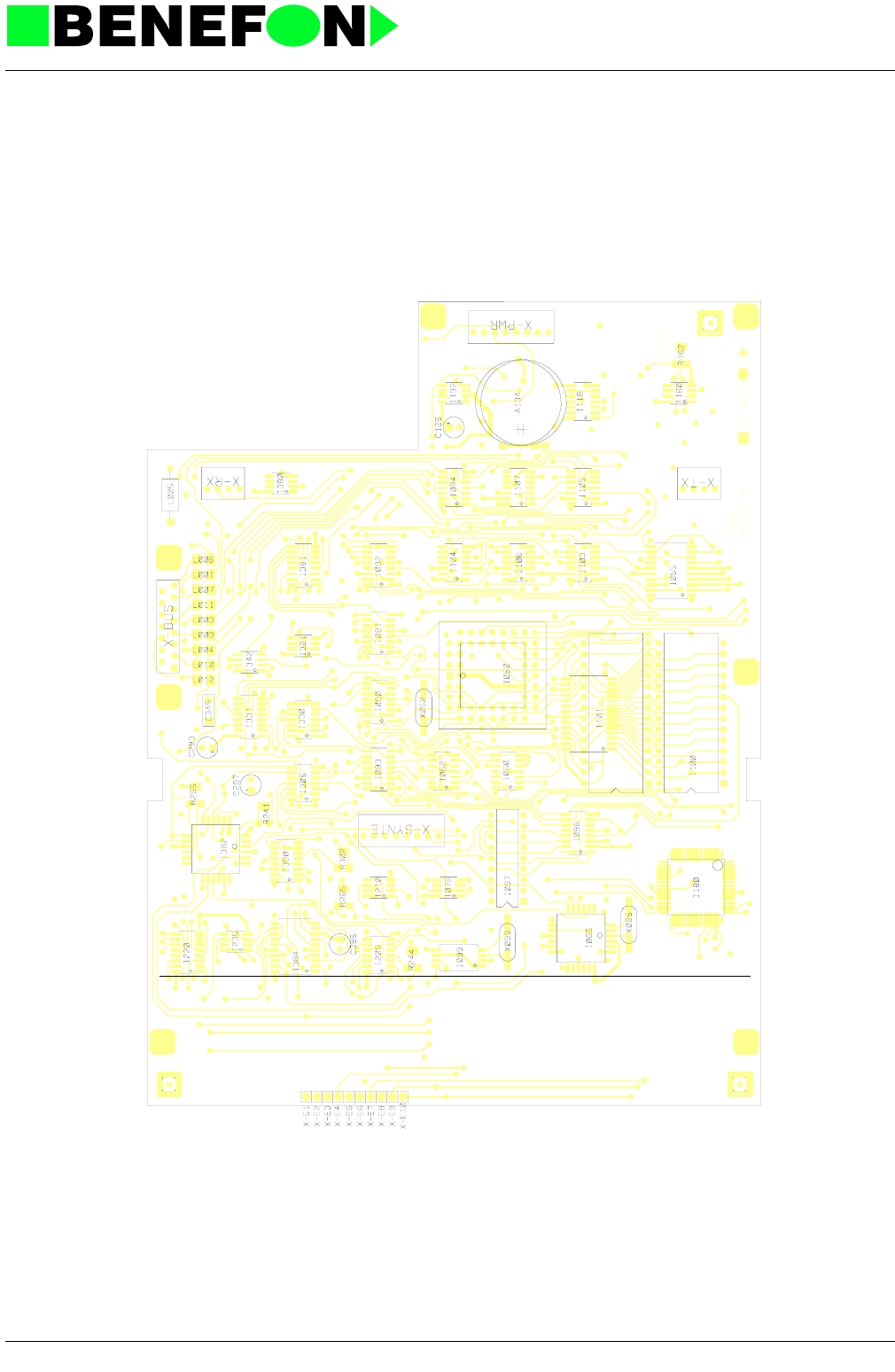
28.1.1999
XZ0014E4_fm5.fm 14
Product: TDM-20-N (Forte i) / Audio
Component Side Layout PA0014A0 (Schematic OA0014A-I2)
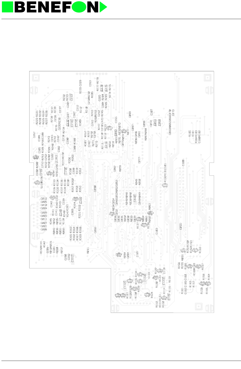
28.1.1999
XZ0014E4_fm5.fm 15
Product: TDM-20-N (Forte i) / Audio
Solder Side Layout PA0014A0 (Schematic OA0014A-I2)

28.1.1999
XA0014E4_FM5.f 16
Product: TDM-20-N (Forte i) /
10.1.4 Parts list
CODE PART DESCRIPT. VALUE MANUF. TYPE
AB0003 A134 Lithium battery 3V 180mAh d=20mm Matsushita BR2032-1HG
CD0471 C001 SMD capasitor 470 pF 5% 50 V NP0 Philips
CD0471 C003 SMD capasitor 470 pF 5% 50 V NP0 Philips
CD0471 C004 SMD capasitor 470 pF 5% 50 V NP0 Philips
CD0471 C005 SMD capasitor 470 pF 5% 50 V NP0 Philips
CD0471 C006 SMD capasitor 470 pF 5% 50 V NP0 Philips
CD0471 C007 SMD capasitor 470 pF 5% 50 V NP0 Philips
CD0471 C009 SMD capasitor 470 pF 5% 50 V NP0 Philips
CD0471 C010 SMD capasitor 470 pF 5% 50 V NP0 Philips
CD0471 C011 SMD capasitor 470 pF 5% 50 V NP0 Philips
CD0471 C012 SMD capasitor 470 pF 5% 50 V NP0 Philips
CD0102 C030 SMD capasitor 1 nF 5 % NP0 Philips
CD0223 C032 SMD capasitor 22 nF 10% 50 V X7R Philips
CD0223 C034 SMD capasitor 22 nF 10% 50 V X7R Philips
CD0223 C035 SMD capasitor 22 nF 10% 50 V X7R Philips
CD0223 C036 SMD capasitor 22 nF 10% 50 V X7R Philips
CD0223 C038 SMD capasitor 22 nF 10% 50 V X7R Philips
CD0223 C039 SMD capasitor 22 nF 10% 50 V X7R Philips
CU0106 C040 SMD tantal 10uF/16V 20% 6x3.2mm Matsushita ECST1CC 106R
CD0223 C046 SMD capasitor 22 nF 10% 50 V X7R Philips
CD0223 C049 SMD capasitor 22 nF 10% 50 V X7R Philips
CD0220 C052 SMD capasitor 22 pF 5% 50 V NP0 Philips
CD0220 C053 SMD capasitor 22 pF 5% 50 V NP0 Philips
CD0223 C055 SMD capasitor 22 nF 10% 50 V X7R Philips
CD0223 C062 SMD capasitor 22 nF 10% 50 V X7R Philips
CD0330 C065 SMD capasitor 33 pF 5% 50 V NP0 Philips
CD0330 C066 SMD capasitor 33 pF 5% 50 V NP0 Philips
CU0105 C068 SMD tantal 1uF/16V 20% 3.2x1.6mm Matsushita ECST1CY 105R
CC0473 C070 SMD capasitor 47 nF 10% 50 V X7R Philips
CU0105 C071 SMD tantal 1uF/16V 20% 3.2x1.6mm Matsushita ECST1CY 105R
CD0223 C072 SMD capasitor 22 nF 10% 50 V X7R Philips
CC0473 C073 SMD capasitor 47 nF 10% 50 V X7R Philips
CD0223 C075 SMD capasitor 22 nF 10% 50 V X7R Philips
CD0223 C077 SMD capasitor 22 nF 10% 50 V X7R Philips
CD0223 C090 SMD capasitor 22 nF 10% 50 V X7R Philips
CC0473 C091 SMD capasitor 47 nF 10% 50 V X7R Philips
CD0223 C092 SMD capasitor 22 nF 10% 50 V X7R Philips
CU0105 C093 SMD tantal 1uF/16V 20% 3.2x1.6mm Matsushita ECST1CY 105R
CD0100 C094 SMD capasitor 10 pF/0.25pF 50 V NP0 Philips
CC0473 C096 SMD capasitor 47 nF 10% 50 V X7R Philips
CD0223 C097 SMD capasitor 22 nF 10% 50 V X7R Philips
CD0223 C098 SMD capasitor 22 nF 10% 50 V X7R Philips
CD0223 C099 SMD capasitor 22 nF 10% 50 V X7R Philips
CD0223 C100 SMD capasitor 22 nF 10% 50 V X7R Philips
CD0223 C101 SMD capasitor 22 nF 10% 50 V X7R Philips
CD0223 C103 SMD capasitor 22 nF 10% 50 V X7R Philips
CD0223 C107 SMD capasitor 22 nF 10% 50 V X7R Philips
CU0105 C115 SMD tantal 1uF/16V 20% 3.2x1.6mm Matsushita ECST1CY 105R
CD0223 C118 SMD capasitor 22 nF 10% 50 V X7R Philips
CU0106 C123 SMD tantal 10uF/16V 20% 6x3.2mm Matsushita ECST1CC 106R
CE0107 C125 Al elko 100uF 16V 7x7mm Philips 2222 097 55101
CU0106 C132 SMD tantal 10uF/16V 20% 6x3.2mm Matsushita ECST1CC 106R
CD0223 C133 SMD capasitor 22 nF 10% 50 V X7R Philips
CU0106 C134 SMD tantal 10uF/16V 20% 6x3.2mm Matsushita ECST1CC 106R
CD0223 C153 SMD capasitor 22 nF 10% 50 V X7R Philips
CD0223 C160 SMD capasitor 22 nF 10% 50 V X7R Philips
CD0331 C162 SMD capasitor 330 pF 5% 50 V NP0 Philips

28.1.1999
XA0014E4_FM5.f 17
Product: TDM-20-N (Forte i) /
CC0222 C165 SMD capasitor 2.2 nF 5% 50 V NP0 Philips
CD0223 C180 SMD capasitor 22 nF 10% 50 V X7R Philips
CC0473 C200 SMD capasitor 47 nF 10% 50 V X7R Philips
CD0102 C202 SMD capasitor 1 nF 5 % NP0 Philips
CD0330 C203 SMD capasitor 33 pF 5% 50 V NP0 Philips
CD0103 C204 SMD capasitor 10 nF 10% 50 V X7R Philips
CD0103 C210 SMD capasitor 10 nF 10% 50 V X7R Philips
CU0105 C216 SMD tantal 1uF/16V 20% 3.2x1.6mm Matsushita ECST1CY 105R
CD0330 C227 SMD capasitor 33 pF 5% 50 V NP0 Philips
CD0102 C229 SMD capasitor 1 nF 5 % NP0 Philips
CD0103 C230 SMD capasitor 10 nF 10% 50 V X7R Philips
CU0105 C232 SMD tantal 1uF/16V 20% 3.2x1.6mm Matsushita ECST1CY 105R
CU0105 C233 SMD tantal 1uF/16V 20% 3.2x1.6mm Matsushita ECST1CY 105R
CC0222 C234 SMD capasitor 2.2 nF 5% 50 V NP0 Philips
CD0330 C235 SMD capasitor 33 pF 5% 50 V NP0 Philips
CU0225 C236 SMD tantal 2.2uF/16V 20% 4.7x2.6mm Matsushita ECST1CB 225R
CC0473 C237 SMD capasitor 47 nF 10% 50 V X7R Philips
CD0100 C238 SMD capasitor 10 pF/0.25pF 50 V NP0 Philips
CD0223 C242 SMD capasitor 22 nF 10% 50 V X7R Philips
CD0101 C243 SMD capasitor 100 pF 5% 50 V NP0 Philips
CC0473 C247 SMD capasitor 47 nF 10% 50 V X7R Philips
CC0102 C252 SMD capasitor 1 nF 5% 50V NP0 Philips
CC0102 C253 SMD capasitor 1 nF 5% 50V NP0 Philips
CD0471 C257 SMD capasitor 470 pF 5% 50 V NP0 Philips
CC0102 C262 SMD capasitor 1 nF 5% 50V NP0 Philips
CC0102 C263 SMD capasitor 1 nF 5% 50V NP0 Philips
CC0222 C267 SMD capasitor 2.2 nF 5% 50 V NP0 Philips
CD0221 C270 SMD capasitor 220 pF 5% 50 V NP0 Philips
CU0105 C275 SMD tantal 1uF/16V 20% 3.2x1.6mm Matsushita ECST1CY 105R
CU0105 C278 SMD tantal 1uF/16V 20% 3.2x1.6mm Matsushita ECST1CY 105R
CD0223 C290 SMD capasitor 22 nF 10% 50 V X7R Philips
CU0106 C291 SMD tantal 10uF/16V 20% 6x3.2mm Matsushita ECST1CC 106R
CD0223 C292 SMD capasitor 22 nF 10% 50 V X7R Philips
CE0107 C293 Al elko 100uF 16V 7x7mm Philips 2222 097 55101
CU0105 C295 SMD tantal 1uF/16V 20% 3.2x1.6mm Matsushita ECST1CY 105R
CD0223 C296 SMD capasitor 22 nF 10% 50 V X7R Philips
CE0107 C297 Al elko 100uF 16V 7x7mm Philips 2222 097 55101
CD0472 C300 SMD capasitor 4.7 nF 10% 50 V X7R Philips
CC0473 C301 SMD capasitor 47 nF 10% 50 V X7R Philips
CD0330 C305 SMD capasitor 33 pF 5% 50 V NP0 Philips
CC0473 C306 SMD capasitor 47 nF 10% 50 V X7R Philips
CD0223 C307 SMD capasitor 22 nF 10% 50 V X7R Philips
CC0473 C308 SMD capasitor 47 nF 10% 50 V X7R Philips
CD0221 C312 SMD capasitor 220 pF 5% 50 V NP0 Philips
CU0225 C314 SMD tantal 2.2uF/16V 20% 4.7x2.6mm Matsushita ECST1CB 225R
CD0103 C320 SMD capasitor 10 nF 10% 50 V X7R Philips
CD0223 C321 SMD capasitor 22 nF 10% 50 V X7R Philips
CU0105 C326 SMD tantal 1uF/16V 20% 3.2x1.6mm Matsushita ECST1CY 105R
CD0223 C332 SMD capasitor 22 nF 10% 50 V X7R Philips
CD0101 C339 SMD capasitor 100 pF 5% 50 V NP0 Philips
CC0473 C341 SMD capasitor 47 nF 10% 50 V X7R Philips
CD0101 C342 SMD capasitor 100 pF 5% 50 V NP0 Philips
CP0474 C345 Polyester cap 470nF 63V 10% Evox
CU0105 C348 SMD tantal 1uF/16V 20% 3.2x1.6mm Matsushita ECST1CY 105R
CD0223 C353 SMD capasitor 22 nF 10% 50 V X7R Philips
CD0472 C355 SMD capasitor 4.7 nF 10% 50 V X7R Philips
CD0101 C369 SMD capasitor 100 pF 5% 50 V NP0 Philips
CU0225 C370 SMD tantal 2.2uF/16V 20% 4.7x2.6mm Matsushita ECST1CB 225R
CD0223 C382 SMD capasitor 22 nF 10% 50 V X7R Philips
CU0106 C383 SMD tantal 10uF/16V 20% 6x3.2mm Matsushita ECST1CC 106R
CODE PART DESCRIPT. VALUE MANUF. TYPE

28.1.1999
XA0014E4_FM5.f 18
Product: TDM-20-N (Forte i) /
CD0223 C384 SMD capasitor 22 nF 10% 50 V X7R Philips
CE0107 C385 Al elko 100uF 16V 7x7mm Philips 2222 097 55101
CD0223 C387 SMD capasitor 22 nF 10% 50 V X7R Philips
CD0223 C390 SMD capasitor 22 nF 10% 50 V X7R Philips
DS0070 D032 SMD diode pair 70V/100mA common cathode Philips BAV 70
DS0070 D076 SMD diode pair 70V/100mA common cathode Philips BAV 70
DS0070 D094 SMD diode pair 70V/100mA common cathode Philips BAV 70
DS0070 D120 SMD diode pair 70V/100mA common cathode Philips BAV 70
DS0070 D125 SMD diode pair 70V/100mA common cathode Philips BAV 70
DZ0759 D126 SMD zener 7V5 5% 300mW Philips BZX84C7V5
DS0070 D133 SMD diode pair 70V/100mA common cathode Philips BAV 70
DS0070 D134 SMD diode pair 70V/100mA common cathode Philips BAV 70
DZ0569 D135 SMD zener 5V6 5% 300mW Philips BZX84C5V6
DS0099 D200 SMD diode 70 V 200 mA Philips BAV 99
DS0099 D214 SMD diode 70 V 200 mA Philips BAV 99
DS0099 D324 SMD diode 70 V 200 mA Philips BAV 99
DS0099 D345 SMD diode 70 V 200 mA Philips BAV 99
IP6811 I050 8-BIT MIKROPROS 512 EEPROM, 8A/D, no ROM Motorola MC68HC11A1FN
IH0373 I055 3-st.octal latch HCMOS RCA 74HC373
IH0004 I060\ Hex inverter HCMOS RCA 74HC04
IH0074 I062\ 2xD-flip-flop HCMOS RCA 74HC74
IX0439 I065 FFSK modem 1200 baud CMOS CML FX439LG
IA0272 I075\ 2 x op.amp. LinCMOS Low noise,power Texas TLC27M2ID
IH0259 I090 8-bit addr latch HCMOS RCA 74HC259
IH0259 I091 8-bit addr latch HCMOS RCA 74HC259
IH0259 I092 8-bit addr latch HCMOS RCA 74HC259
IH0259 I093 8-bit addr latch HCMOS RCA 74HC259
IH0032 I094\ 4x2-inp OR HCMOS RCA 74HC32
IH0251 I096 8-inp multipl. 3-state HCMOS RCA 74HC251
IA8870 I097 DTMF decoder Plessey MV8870
II3312 I099 DTMF generator I2C Philips PCD3312T
IM7512 I100 One time prom CMOS 65.536 x 8b 200ns Fujitsu MBM27C512P-20P
IM3664 I101 8K*8 CMOS RAM F28GA-P 11.8mm width Toshiba TC5565AFL-15L
IH4002 I103\ 2x4-inp NOR HCMOS 74HC4002
IH4078 I104 1x8-inp OR/NOR HCMOS 74HC4078
IH0004 I105\ Hex inverter HCMOS RCA 74HC04
IH0000 I106\ 4x2-inp NAND HCMOS 74HC00
IH0010 I107\ 3x3-inp. NAND HCMOS RCA 74HC10
IH0132 I118\ 4x2 inp NAND schm. HCMOS RCA 74HC132
IR2952 I132 Regulator 100mA 5V adj. 0.5% Micrel MIC2951-02BM
IA0272 I160\ 2 x op.amp. LinCMOS Low noise,power Texas TLC27M2ID
IP6831 I180 Processor (SIS) 8k maskPROM,512EEPROM Motorola MC68HC11A8 FU
IH4066 I205\ 4xbilateral switch HCMOS RCA 74HC4066B
IA0272 I210\ 2 x op.amp. LinCMOS Low noise,power Texas TLC27M2ID
IH4051 I220 8-ch anal.multipl. HCMOS RCA 74HC4051B
IA0272 I235\ 2 x op.amp. LinCMOS Low noise,power Texas TLC27M2ID
IH4066 I305\ 4xbilateral switch HCMOS RCA 74HC4066B
IA0272 I321\ 2 x op.amp. LinCMOS Low noise,power Texas TLC27M2ID
IH4066 I330\ 4xbilateral switch HCMOS RCA 74HC4066B
IH4051 I331 8-ch anal.multipl. HCMOS RCA 74HC4051B
IA3182 I342\ 2xop.amp. Low power,jfet input Motorola MC 33182D
IH4051 I361 8-ch anal.multipl. HCMOS RCA 74HC4051B
IR2952 I380 Regulator 100mA 5V adj. 0.5% Micrel MIC2951-02BM
IX0346 I382\ Audio filter array Rx/Tx CMOS CML FX346GL
IX0575 I384\ Compander Philips SA575
IH4053 I390\ 3x2-ch analog mpxer HCMOS RCA 74HC4053
LC0105 L001 SMD inductor 1.0 uH Siemens B82412-A1102-M
LC0105 L003 SMD inductor 1.0 uH Siemens B82412-A1102-M
LC0105 L004 SMD inductor 1.0 uH Siemens B82412-A1102-M
LF0396 L005 Inductor 39 uH Philips
CODE PART DESCRIPT. VALUE MANUF. TYPE

28.1.1999
XA0014E4_FM5.f 19
Product: TDM-20-N (Forte i) /
LC0105 L006 SMD inductor 1.0 uH Siemens B82412-A1102-M
LC0105 L007 SMD inductor 1.0 uH Siemens B82412-A1102-M
LC0105 L009 SMD inductor 1.0 uH Siemens B82412-A1102-M
LC0105 L010 SMD inductor 1.0 uH Siemens B82412-A1102-M
LC0105 L011 SMD inductor 1.0 uH Siemens B82412-A1102-M
LC0105 L012 SMD inductor 1.0 uH Siemens B82412-A1102-M
PA0014 PCB PCB for OA0014 Forte 450 I Aspocomp
QSB848 Q063 SMD transistor NPN 0.1A/30V F=2dB Philips BC 848 B
QSB848 Q114 SMD transistor NPN 0.1A/30V F=2dB Philips BC 848 B
QSB848 Q122 SMD transistor NPN 0.1A/30V F=2dB Philips BC 848 B
QSB848 Q128 SMD transistor NPN 0.1A/30V F=2dB Philips BC 848 B
QSB848 Q130 SMD transistor NPN 0.1A/30V F=2dB Philips BC 848 B
QSB848 Q131 SMD transistor NPN 0.1A/30V F=2dB Philips BC 848 B
QSB848 Q138 SMD transistor NPN 0.1A/30V F=2dB Philips BC 848 B
QSB858 Q139 SMD transistor PNP 0.1A/30V F<10dB Philips BC 858 B
QSB848 Q151 SMD transistor NPN 0.1A/30V F=2dB Philips BC 848 B
QSB858 Q153 SMD transistor PNP 0.1A/30V F<10dB Philips BC 858 B
QSB848 Q159 SMD transistor NPN 0.1A/30V F=2dB Philips BC 848 B
QSB848 Q165 SMD transistor NPN 0.1A/30V F=2dB Philips BC 848 B
QSB848 Q168 SMD transistor NPN 0.1A/30V F=2dB Philips BC 848 B
QSB848 Q169 SMD transistor NPN 0.1A/30V F=2dB Philips BC 848 B
QSB858 Q295 SMD transistor PNP 0.1A/30V F<10dB Philips BC 858 B
QSB848 Q375 SMD transistor NPN 0.1A/30V F=2dB Philips BC 848 B
RD0103 R011 SMD resistor 10 k 5% 0.125 W Kamaya
RD0104 R015 SMD resistor 100 k 5% 0.125 W Kamaya
RD0103 R020 SMD resistor 10 k 5% 0.125 W Kamaya
RC0000 R022 SMD resistor 0 R Kamaya
RD0104 R030 SMD resistor 100 k 5% 0.125 W Kamaya
RD0104 R031 SMD resistor 100 k 5% 0.125 W Kamaya
RD0104 R032 SMD resistor 100 k 5% 0.125 W Kamaya
RD0104 R034 SMD resistor 100 k 5% 0.125 W Kamaya
RD0104 R035 SMD resistor 100 k 5% 0.125 W Kamaya
RD0104 R036 SMD resistor 100 k 5% 0.125 W Kamaya
RD0105 R038 SMD resistor 1 M 5% 0.125 W Kamaya
RD0104 R039 SMD resistor 100 k 5% 0.125 W Kamaya
RD0105 R040 SMD resistor 1 M 5% 0.125 W Kamaya
RD0104 R042 SMD resistor 100 k 5% 0.125 W Kamaya
RD0103 R043 SMD resistor 10 k 5% 0.125 W Kamaya
RD0103 R045 SMD resistor 10 k 5% 0.125 W Kamaya
RD0104 R046 SMD resistor 100 k 5% 0.125 W Kamaya
RD0103 R048 SMD resistor 10 k 5% 0.125 W Kamaya
RD0104 R049 SMD resistor 100 k 5% 0.125 W Kamaya
RD0103 R050 SMD resistor 10 k 5% 0.125 W Kamaya
RD0105 R052 SMD resistor 1 M 5% 0.125 W Kamaya
RD0104 R060 SMD resistor 100 k 5% 0.125 W Kamaya
RD0104 R061 SMD resistor 100 k 5% 0.125 W Kamaya
RD0103 R063 SMD resistor 10 k 5% 0.125 W Kamaya
RD0103 R064 SMD resistor 10 k 5% 0.125 W Kamaya
RD0105 R065 SMD resistor 1 M 5% 0.125 W Kamaya
RD0334 R073 SMD resistor 330 k 5% 0.125 W Kamaya
RD0222 R074 SMD resistor 2.2 k 5% 0.125 W Kamaya
RD0333 R075 SMD resistor 33 k 5% 0.125 W Kamaya
RD0684 R076 SMD resistor 680 k 5% 0.125 W Kamaya
RD0104 R077 SMD resistor 100 k 5% 0.125 W Kamaya
RD0101 R078 SMD resistor 100 R 5% 0.125 W Kamaya
RD0104 R091 SMD resistor 100 k 5% 0.125 W Kamaya
RD0104 R092 SMD resistor 100 k 5% 0.125 W Kamaya
RD0474 R093 SMD resistor 470 k 5% 0.125 W Kamaya
RD0103 R094 SMD resistor 10 k 5% 0.125 W Kamaya
RD0474 R096 SMD resistor 470 k 5% 0.125 W Kamaya
CODE PART DESCRIPT. VALUE MANUF. TYPE

28.1.1999
XA0014E4_FM5.f 20
Product: TDM-20-N (Forte i) /
RD0104 R097 SMD resistor 100 k 5% 0.125 W Kamaya
RD0104 R098 SMD resistor 100 k 5% 0.125 W Kamaya
RD0104 R110 SMD resistor 100 k 5% 0.125 W Kamaya
RD0104 R111 SMD resistor 100 k 5% 0.125 W Kamaya
RD0104 R112 SMD resistor 100 k 5% 0.125 W Kamaya
RD0103 R113 SMD resistor 10 k 5% 0.125 W Kamaya
RD0104 R114 SMD resistor 100 k 5% 0.125 W Kamaya
RD0105 R115 SMD resistor 1 M 5% 0.125 W Kamaya
RD0104 R117 SMD resistor 100 k 5% 0.125 W Kamaya
RD0104 R118 SMD resistor 100 k 5% 0.125 W Kamaya
RD0104 R119 SMD resistor 100 k 5% 0.125 W Kamaya
RD0105 R120 SMD resistor 1 M 5% 0.125 W Kamaya
RD0104 R122 SMD resistor 100 k 5% 0.125 W Kamaya
RD0223 R123 SMD resistor 22 k 5% 0.125 W Kamaya
RD0223 R124 SMD resistor 22 k 5% 0.125 W Kamaya
RD0223 R126 SMD resistor 22 k 5% 0.125 W Kamaya
RD0223 R127 SMD resistor 22 k 5% 0.125 W Kamaya
RD0223 R128 SMD resistor 22 k 5% 0.125 W Kamaya
RD0474 R129 SMD resistor 470 k 5% 0.125 W Kamaya
RD0223 R130 SMD resistor 22 k 5% 0.125 W Kamaya
RD0223 R131 SMD resistor 22 k 5% 0.125 W Kamaya
RD0223 R132 SMD resistor 22 k 5% 0.125 W Kamaya
RD0101 R134 SMD resistor 100 R 5% 0.125 W Kamaya
RD0103 R135 SMD resistor 10 k 5% 0.125 W Kamaya
RD0104 R137 SMD resistor 100 k 5% 0.125 W Kamaya
RD0103 R138 SMD resistor 10 k 5% 0.125 W Kamaya
RD0103 R140 SMD resistor 10 k 5% 0.125 W Kamaya
RD0101 R141 SMD resistor 100 R 5% 0.125 W Kamaya
RD0101 R142 SMD resistor 100 R 5% 0.125 W Kamaya
RD0104 R150 SMD resistor 100 k 5% 0.125 W Kamaya
RD0223 R151 SMD resistor 22 k 5% 0.125 W Kamaya
RD0103 R152 SMD resistor 10 k 5% 0.125 W Kamaya
RD0101 R153 SMD resistor 100 R 5% 0.125 W Kamaya
RM1003 R155 Mini-Melf resistor 100k 1% 0.25W Beyschlag MMA 0204-50
RM1003 R156 Mini-Melf resistor 100k 1% 0.25W Beyschlag MMA 0204-50
RM4643 R157 Mini-Melf resistor 464k 1% 0.25W Beyschlag MMA 0204-50
RD0223 R158 SMD resistor 22 k 5% 0.125 W Kamaya
RM3922 R159 Mini-Melf resistor 39k2 1% 0.25W Beyschlag MMA 0204-50
RD0224 R161 SMD resistor 220 k 5% 0.125 W Kamaya
RI0103 R162 SMD trimmer resistor 10k 20% 0.25 W Copal ST-4A
RM4752 R163 Mini-Melf resistor 47k5 1% 0.25W Beyschlag MMA 0204-50
RD0223 R164 SMD resistor 22 k 5% 0.125 W Kamaya
RM1783 R165 Mini-Melf resistor 178k 1% 0.25W Beyschlag MMA 0204-50
RD0103 R166 SMD resistor 10 k 5% 0.125 W Kamaya
RD0223 R167 SMD resistor 22 k 5% 0.125 W Kamaya
RD0223 R168 SMD resistor 22 k 5% 0.125 W Kamaya
RD0223 R169 SMD resistor 22 k 5% 0.125 W Kamaya
RD0104 R181 SMD resistor 100 k 5% 0.125 W Kamaya
RD0103 R182 SMD resistor 10 k 5% 0.125 W Kamaya
RD0103 R183 SMD resistor 10 k 5% 0.125 W Kamaya
RD0103 R184 SMD resistor 10 k 5% 0.125 W Kamaya
RD0103 R185 SMD resistor 10 k 5% 0.125 W Kamaya
RM3922 R200 Mini-Melf resistor 39k2 1% 0.25W Beyschlag MMA 0204-50
RM1002 R202 Mini-Melf resistor 10k0 1% 0.25W Beyschlag MMA 0204-50
RM2003 R203 Mini-Melf resistor 200k 1% 0.25W Beyschlag MMA 0204-50 BL
RM3013 R205 Mini-Melf resistor 301k 1% 0.25W Beyschlag MMA 0204-50
RM1623 R206 Mini-Melf resistor 162k 1% 0.25W Beyschlag MMA 0204-50
RM3012 R210 Mini-Melf resistor 30k1 1% 0.25W Beyschlag MMA 0204-50
RM2213 R211 Mini-Melf resistor 221k 1% 0.25W Beychlag MMA 0204-50
RM6813 R212 Mini-Melf resistor 681k 1% 0.25W Beyschlag MMA 0204-50
CODE PART DESCRIPT. VALUE MANUF. TYPE

28.1.1999
XA0014E4_FM5.f 21
Product: TDM-20-N (Forte i) /
RD0222 R213 SMD resistor 2.2 k 5% 0.125 W Kamaya
RM3012 R220 Mini-Melf resistor 30k1 1% 0.25W Beyschlag MMA 0204-50
RM4752 R221 Mini-Melf resistor 47k5 1% 0.25W Beyschlag MMA 0204-50
RM7502 R222 Mini-Melf resistor 75k0 1% 0.25W Beyschlag MMA 0204-50
RM1003 R223 Mini-Melf resistor 100k 1% 0.25W Beyschlag MMA 0204-50
RM1623 R224 Mini-Melf resistor 162k 1% 0.25W Beyschlag MMA 0204-50
RM2213 R225 Mini-Melf resistor 221k 1% 0.25W Beychlag MMA 0204-50
RM2373 R226 Mini-Melf resistor 237k 1% 0.25W Beyschlag MMA 0204-50 BL
RM3013 R227 Mini-Melf resistor 301k 1% 0.25W Beyschlag MMA 0204-50
RM1004 R229 Mini-Melf resistor 1.0M 1% 0.25W Beyschlag MMA 0204-50
RM1004 R230 Mini-Melf resistor 1.0M 1% 0.25W Beyschlag MMA 0204-50
RM3012 R232 Mini-Melf resistor 30k1 1% 0.25W Beyschlag MMA 0204-50
RM3012 R233 Mini-Melf resistor 30k1 1% 0.25W Beyschlag MMA 0204-50
RM1002 R234 Mini-Melf resistor 10k0 1% 0.25W Beyschlag MMA 0204-50
RM1623 R235 Mini-Melf resistor 162k 1% 0.25W Beyschlag MMA 0204-50
RM5112 R237 Mini-Melf resistor 51k1 1% 0.25W Beyschlag MMA 0204-50
RM3323 R238 Mini-Melf resistor 332k 1% 0.25W Beyschlag MMA 0204-50
RM6491 R239 Mini-Melf resistor 6k49 1% 0.25W Beyschlag MMA 0204-50
RD0104 R240 SMD resistor 100 k 5% 0.125 W Kamaya
RI0503 R241 SMD trimmer resistor 50k 20% 0.25 W Copal ST-4A
RM1783 R242 Mini-Melf resistor 178k 1% 0.25W Beyschlag MMA 0204-50
RI0503 R244 SMD trimmer resistor 50k 20% 0.25 W Copal ST-4A
RM2002 R245 Mini-Melf resistor 20k0 1% 0.25W Beyschlag MMA 0204-50
RM4752 R247 Mini-Melf resistor 47k5 1% 0.25W Beyschlag MMA 0204-50
RM2002 R250 Mini-Melf resistor 20k0 1% 0.25W Beyschlag MMA 0204-50
RM2002 R252 Mini-Melf resistor 20k0 1% 0.25W Beyschlag MMA 0204-50
RM1623 R253 Mini-Melf resistor 162k 1% 0.25W Beyschlag MMA 0204-50
RI0503 R255 SMD trimmer resistor 50k 20% 0.25 W Copal ST-4A
RM3012 R256 Mini-Melf resistor 30k1 1% 0.25W Beyschlag MMA 0204-50
RM2743 R257 Mini-Melf resistor 274k 1% 0.25W Beyschlag MMA 0204-50
RD0104 R260 SMD resistor 100 k 5% 0.125 W Kamaya
RM1002 R262 Mini-Melf resistor 10k0 1% 0.25W Beyschlag MMA 0204-50
RM1002 R263 Mini-Melf resistor 10k0 1% 0.25W Beyschlag MMA 0204-50
RI0503 R265 SMD trimmer resistor 50k 20% 0.25 W Copal ST-4A
RM1002 R267 Mini-Melf resistor 10k0 1% 0.25W Beyschlag MMA 0204-50
RD0683 R270 SMD resistor 68 k 5% 0.125 W Kamaya
RD0103 R271 SMD resistor 10 k 5% 0.125 W Kamaya
RD0104 R274 SMD resistor 100 k 5% 0.125 W Kamaya
RD0104 R275 SMD resistor 100 k 5% 0.125 W Kamaya
RM1003 R277 Mini-Melf resistor 100k 1% 0.25W Beyschlag MMA 0204-50
RM4752 R278 Mini-Melf resistor 47k5 1% 0.25W Beyschlag MMA 0204-50
RD0473 R294 SMD resistor 47 k 5% 0.125 W Kamaya
RD0103 R295 SMD resistor 10 k 5% 0.125 W Kamaya
RM3013 R300 Mini-Melf resistor 301k 1% 0.25W Beyschlag MMA 0204-50
RD0224 R301 SMD resistor 220 k 5% 0.125 W Kamaya
RI0503 R302 SMD trimmer resistor 50k 20% 0.25 W Copal ST-4A
RM4752 R304 Mini-Melf resistor 47k5 1% 0.25W Beyschlag MMA 0204-50
RM2743 R305 Mini-Melf resistor 274k 1% 0.25W Beyschlag MMA 0204-50
RM3922 R309 Mini-Melf resistor 39k2 1% 0.25W Beyschlag MMA 0204-50
RM1783 R310 Mini-Melf resistor 178k 1% 0.25W Beyschlag MMA 0204-50
RM3922 R312 Mini-Melf resistor 39k2 1% 0.25W Beyschlag MMA 0204-50
RD0224 R318 SMD resistor 220 k 5% 0.125 W Kamaya
RM1183 R320 Mini-Melf resistor 118k 1% 0.25W Beyschlag MMA 0204-50
RM1003 R321 Mini-Melf resistor 100k 1% 0.25W Beyschlag MMA 0204-50
RM1004 R322 Mini-Melf resistor 1.0M 1% 0.25W Beyschlag MMA 0204-50
RD0222 R324 SMD resistor 2.2 k 5% 0.125 W Kamaya
RM1623 R330 Mini-Melf resistor 162k 1% 0.25W Beyschlag MMA 0204-50
RM1502 R332 Mini-Melf resistor 15k0 1% 0.25W Beyschlag MMA 0204-50
RM2002 R333 Mini-Melf resistor 20k0 1% 0.25W Beyschlag MMA 0204-50
RM3012 R334 Mini-Melf resistor 30k1 1% 0.25W Beyschlag MMA 0204-50
CODE PART DESCRIPT. VALUE MANUF. TYPE

28.1.1999
XA0014E4_FM5.f 22
Product: TDM-20-N (Forte i) /
RM3922 R335 Mini-Melf resistor 39k2 1% 0.25W Beyschlag MMA 0204-50
RM4752 R336 Mini-Melf resistor 47k5 1% 0.25W Beyschlag MMA 0204-50
RM5622 R337 Mini-Melf resistor 56k2 1% 0.25W Beyschlag MMA 0204-50
RM6492 R338 Mini-Melf resistor 64k9 1% 0.25W Beyschlag MMA 0204-50 BL
RM7502 R339 Mini-Melf resistor 75k0 1% 0.25W Beyschlag MMA 0204-50
RM4752 R341 Mini-Melf resistor 47k5 1% 0.25W Beyschlag MMA 0204-50
RM1623 R342 Mini-Melf resistor 162k 1% 0.25W Beyschlag MMA 0204-50
RM1002 R343 Mini-Melf resistor 10k0 1% 0.25W Beyschlag MMA 0204-50
RD0101 R345 SMD resistor 100 R 5% 0.125 W Kamaya
RM1003 R347 Mini-Melf resistor 100k 1% 0.25W Beyschlag MMA 0204-50
RM1003 R348 Mini-Melf resistor 100k 1% 0.25W Beyschlag MMA 0204-50
RD0104 R350 SMD resistor 100 k 5% 0.125 W Kamaya
RD0224 R351 SMD resistor 220 k 5% 0.125 W Kamaya
RM1623 R353 Mini-Melf resistor 162k 1% 0.25W Beyschlag MMA 0204-50
RD0473 R355 SMD resistor 47 k 5% 0.125 W Kamaya
RD0473 R356 SMD resistor 47 k 5% 0.125 W Kamaya
RM1623 R357 Mini-Melf resistor 162k 1% 0.25W Beyschlag MMA 0204-50
RM4752 R358 Mini-Melf resistor 47k5 1% 0.25W Beyschlag MMA 0204-50
RM1502 R362 Mini-Melf resistor 15k0 1% 0.25W Beyschlag MMA 0204-50
RM2002 R363 Mini-Melf resistor 20k0 1% 0.25W Beyschlag MMA 0204-50
RM3012 R364 Mini-Melf resistor 30k1 1% 0.25W Beyschlag MMA 0204-50
RM4752 R365 Mini-Melf resistor 47k5 1% 0.25W Beyschlag MMA 0204-50
RM7502 R366 Mini-Melf resistor 75k0 1% 0.25W Beyschlag MMA 0204-50
RM1183 R367 Mini-Melf resistor 118k 1% 0.25W Beyschlag MMA 0204-50
RM1783 R368 Mini-Melf resistor 178k 1% 0.25W Beyschlag MMA 0204-50
RM2743 R369 Mini-Melf resistor 274k 1% 0.25W Beyschlag MMA 0204-50
RD0473 R370 SMD resistor 47 k 5% 0.125 W Kamaya
RD0473 R371 SMD resistor 47 k 5% 0.125 W Kamaya
RD0101 R375 SMD resistor 100 R 5% 0.125 W Kamaya
RD0103 R376 SMD resistor 10 k 5% 0.125 W Kamaya
VI0052 V100 IC - socket PLCC-52 1R piikit Methode
VI0028 V140 IC -socket DIL-28
VI0028 V141 IC -socket DIL-28
VD0016 X-BUS D-connector D-15S 90 ast.kulma Cannon DA121073-5044
VI0102 X-E1 Lead socket d=1.35mm,1.8mm h=4.2mm Assmann AP 102 B/g
VI0102 X-E10 Lead socket d=1.35mm,1.8mm h=4.2mm Assmann AP 102 B/g
VI0102 X-E2 Lead socket d=1.35mm,1.8mm h=4.2mm Assmann AP 102 B/g
VI0102 X-E3 Lead socket d=1.35mm,1.8mm h=4.2mm Assmann AP 102 B/g
VI0102 X-E4 Lead socket d=1.35mm,1.8mm h=4.2mm Assmann AP 102 B/g
VI0102 X-E5 Lead socket d=1.35mm,1.8mm h=4.2mm Assmann AP 102 B/g
VI0102 X-E6 Lead socket d=1.35mm,1.8mm h=4.2mm Assmann AP 102 B/g
VI0102 X-E7 Lead socket d=1.35mm,1.8mm h=4.2mm Assmann AP 102 B/g
VI0102 X-E8 Lead socket d=1.35mm,1.8mm h=4.2mm Assmann AP 102 B/g
VI0102 X-E9 Lead socket d=1.35mm,1.8mm h=4.2mm Assmann AP 102 B/g
VN0108 X-PWR 8-pin connector Wisher WKP-N8B1G-L
VN0104 X-RX 4-pin connector Wisher WKP-N4B1G-L
VN0108 X-SYN 8-pin connector Wisher WKP-N8B1G-L
VN0104 X-TX 4-pin connector Wisher WKP-N4B1G-L
X80006 X052 Crystal 8.0000 MHz Telequartz 8.00MHZ/B
X40326 X065 Crystal 4.032 MHz -+30ppm Meiden MQX-3H2-04032-20
X35796 X099 DTMF-quartz crystal 3.579545 MHZ +-30PPM Meiden
Last
update
18.04.95
CODE PART DESCRIPT. VALUE MANUF. TYPE
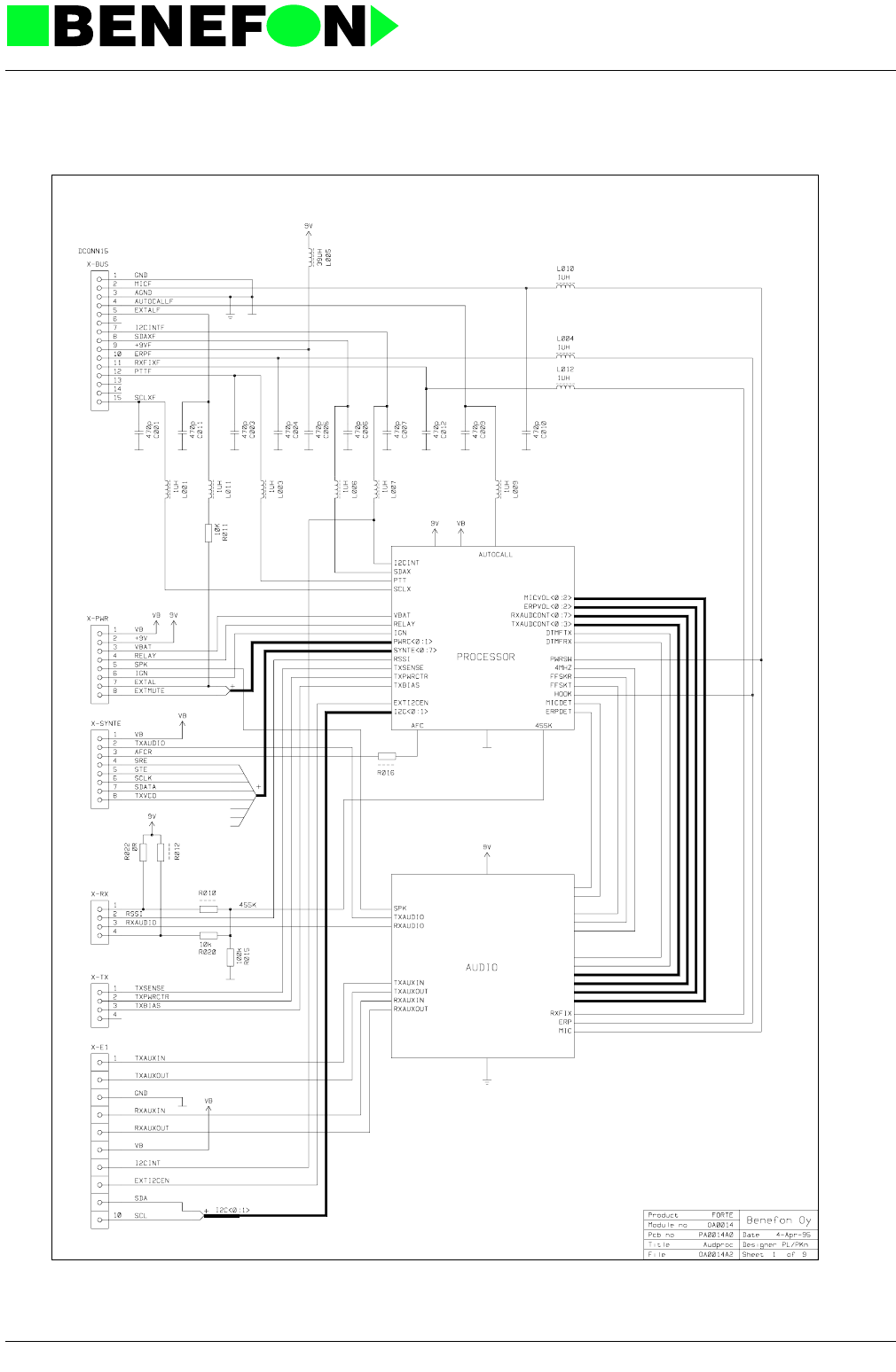
28.1.1999
XA0014E4_FM5.f 23
Product: TDM-20-N (Forte i) /
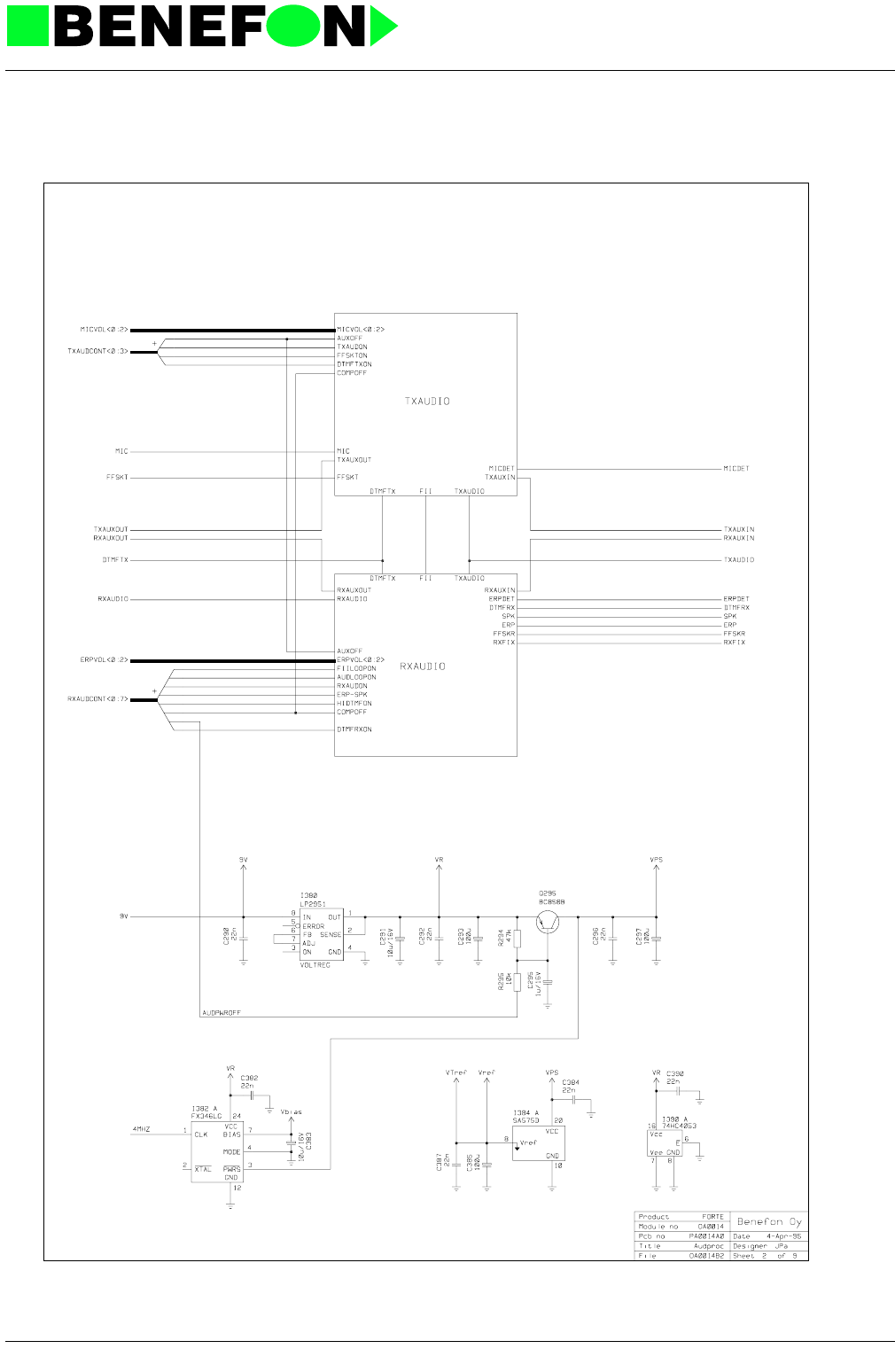
28.1.1999
XA0014E4_FM5.f 24
Product: TDM-20-N (Forte i) /
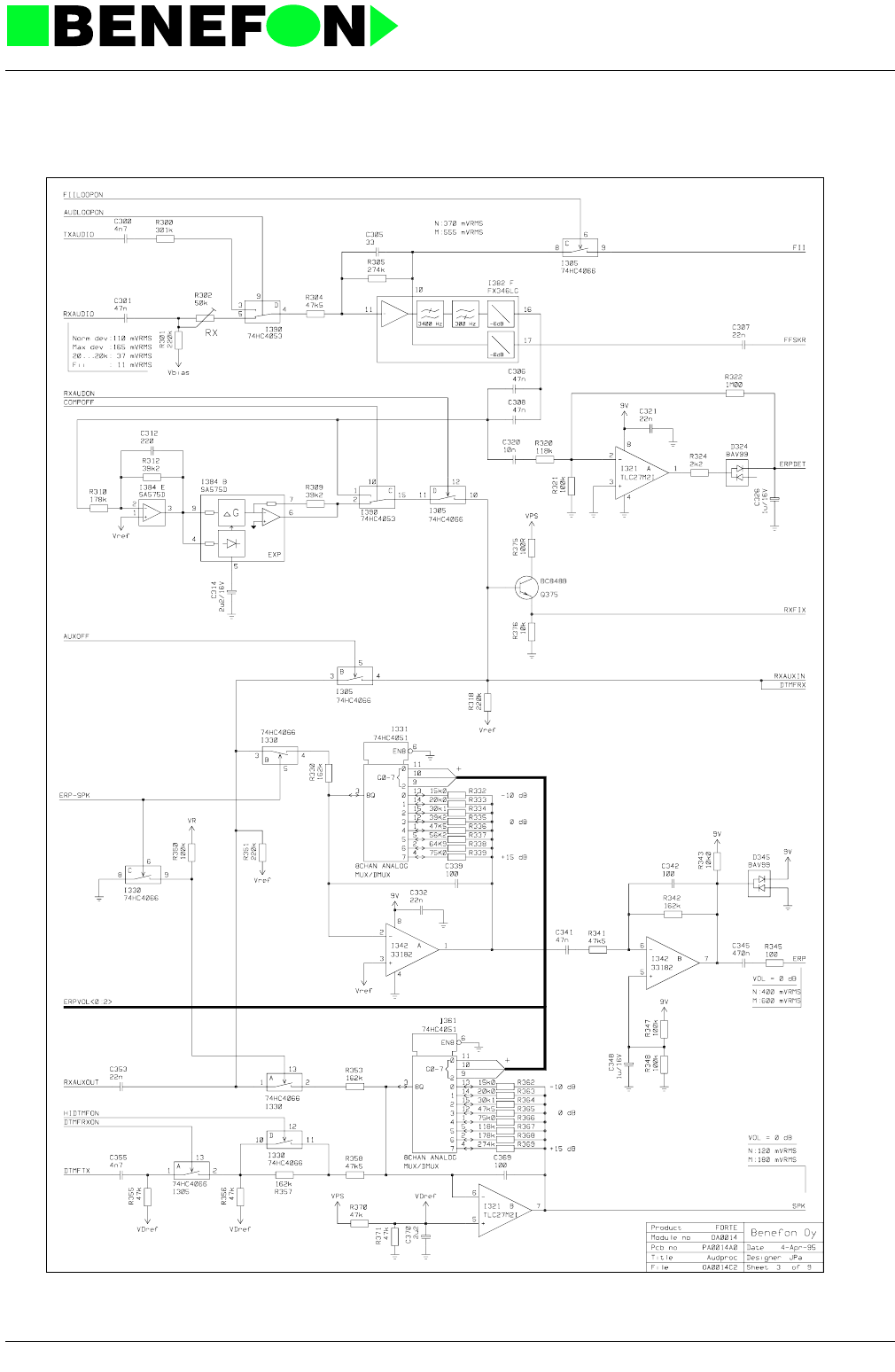
28.1.1999
XA0014E4_FM5.f 25
Product: TDM-20-N (Forte i) /
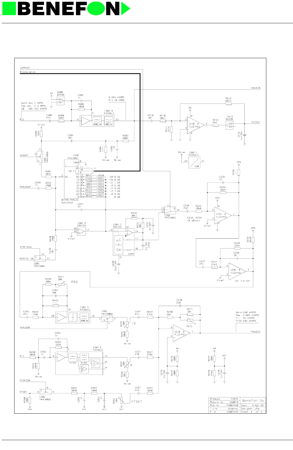
28.1.1999
XA0014E4_FM5.f 26
Product: TDM-20-N (Forte i) /
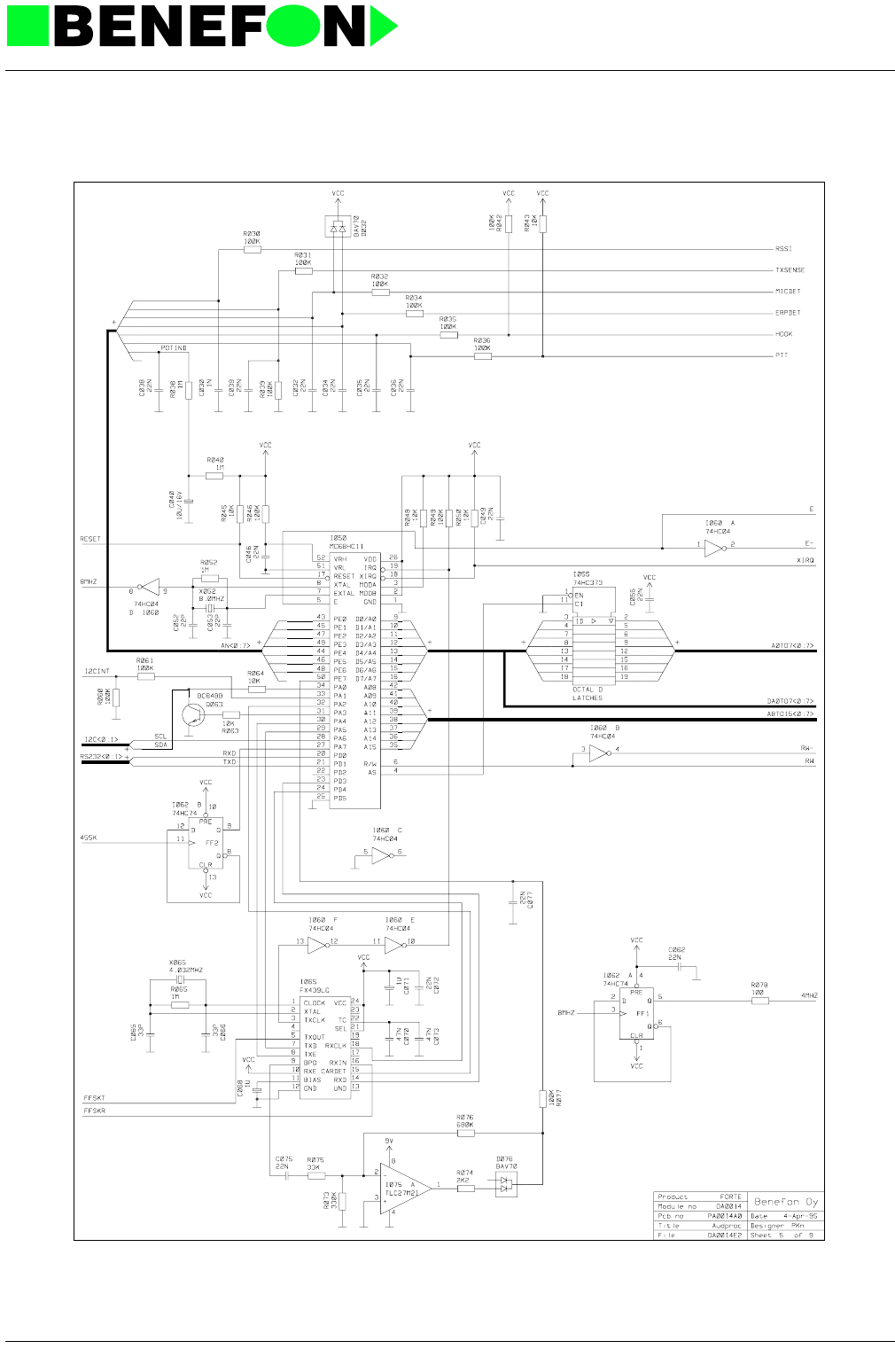
28.1.1999
XA0014E4_FM5.f 27
Product: TDM-20-N (Forte i) /
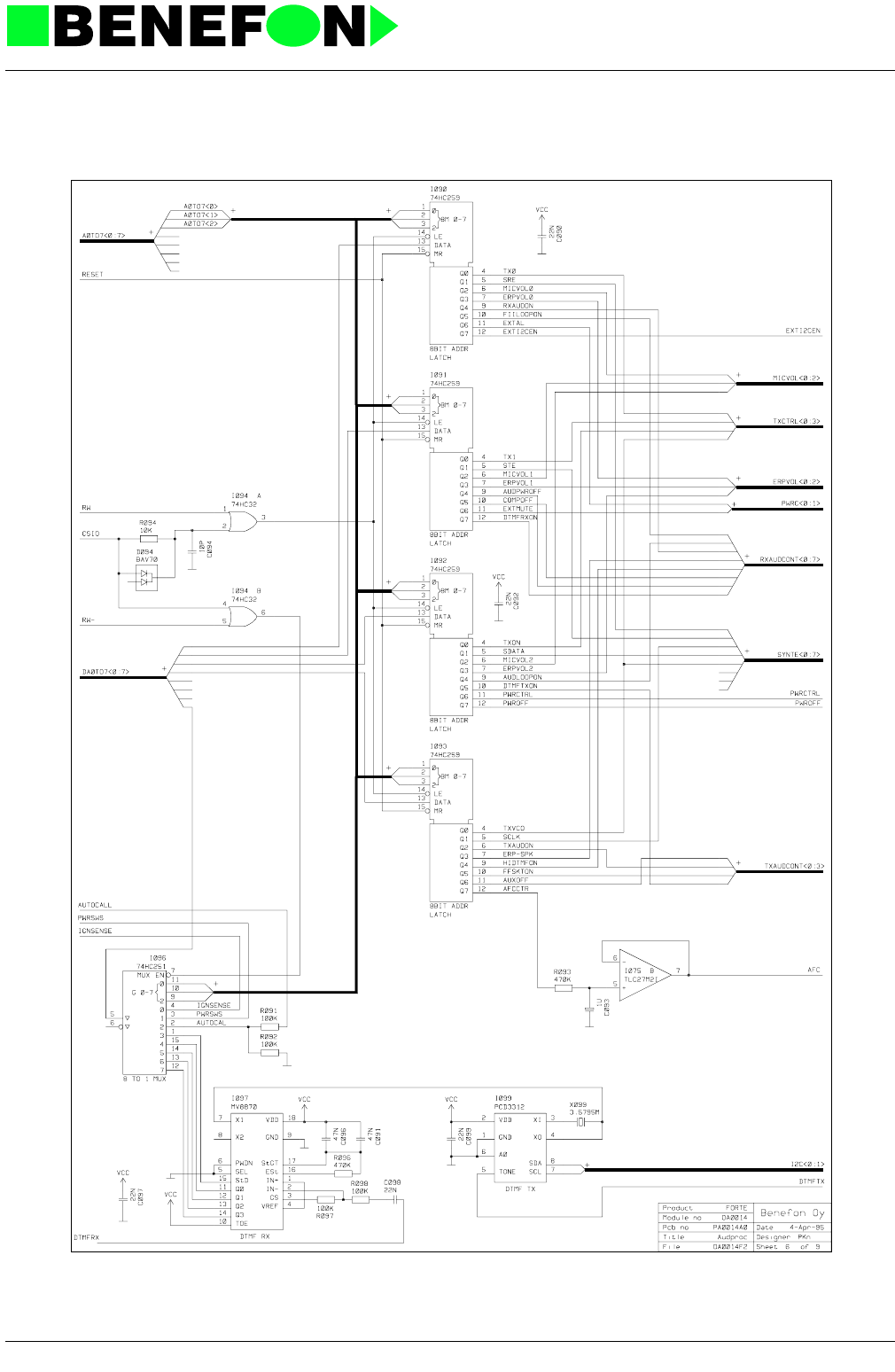
28.1.1999
XA0014E4_FM5.f 28
Product: TDM-20-N (Forte i) /
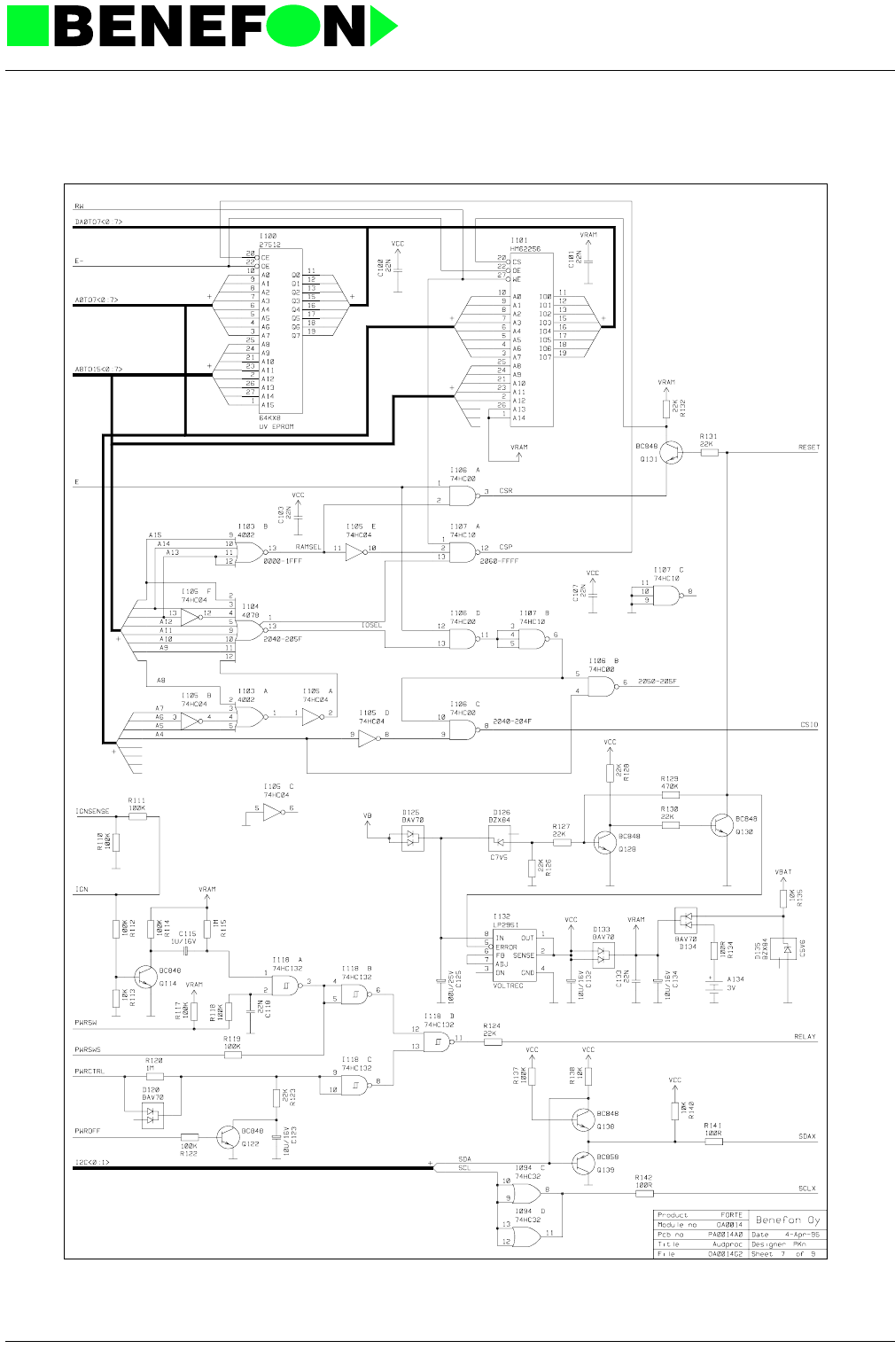
28.1.1999
XA0014E4_FM5.f 29
Product: TDM-20-N (Forte i) /
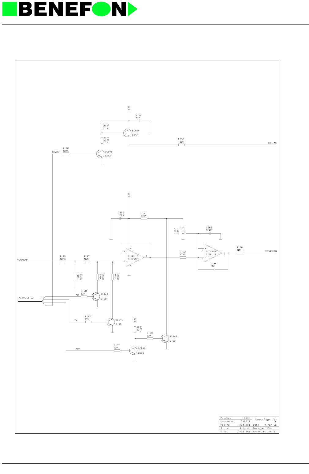
28.1.1999
XA0014E4_FM5.f 30
Product: TDM-20-N (Forte i) /
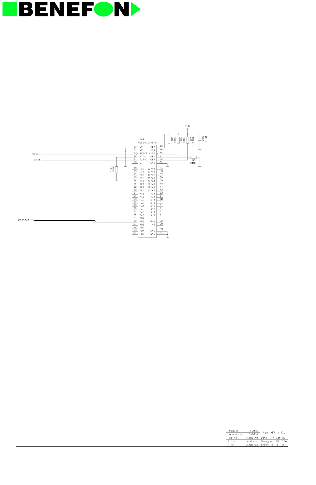
28.1.1999
XA0014E4_FM5.f 31
Product: TDM-20-N (Forte i) /

28.1.1999
XH0002E4_fm5.fm 1
Product: HS-10 / OH0002 Handset
11.0 PRINCIPLES OF HANDSET OPERATION
OH0002 Handset
11.0.1 Connector Signals:
11.0.2 Audio
I202 A and B are parallel audio-switches, and operate the earphone audio functions.
Operational amplifiers I206 A and B are inter-connected and provide a push-pull
input for the earphone capsule. Components 270-272 constitute a HOOK connec-
tion.
Audio switches I230 A and B activate either the normal- (A223) or HF-microphone.
I228B works as preamplifier for both microphones, and I228A is an active low-pass
filter, having a cut-off frequency of approx 3400 Hz. I230 C and D are parallel
switches for microphone audio.
11.0.3 Automatic Control For Keyboard And Lcd Backlight
Light dependable resistor (R130) controls I135A, which feeds transistor Q132. Q132
adjusts supply voltage (about 6...8V) to the backlight leds. IC circuit I135B switches
off the lights totally when ambient lighting increases enough.
11.0.4 Leds
LEDs D141-D146 illuminate LCD, and D151-D164 illuminate the keyboard. The
radio may turn both of them separately on and off. In bright light, the illumination is
also turned off by the dimmer-control.
pin signal
1 9V 9 V operating voltage
2 ERP earphone input, HOOK
(VOL = 0 dB, norm dev. 300 mVrms)
(HOOK, 5 V / 0 V)
3 GND logic ground, erphone audio-ground
4 SDA data for I2C path
5 SCL clock for I2C path
6 I2CINT interrupt for I2C path
7 AGND microphone audio-ground
8EXT-
MIC microphone HF input
9-
10 mic microphone output, PWR
(normal deviation 1 Vrms)
(PWR, 5 V / 0 V)

28.1.1999
XH0002E4_fm5.fm 2
Product: HS-10 / OH0002 Handset
Symbol- LEDs D171, D173, D175, D177, D179, and D180 can all be individually
switched on and off. They have no brightness control. The LED series resistors
adjus LEDs of different colors to the same brightness. All LED controls come from
I130, which is an I/O circuit controlled by I2C path. Pins A0, A1 and A2 are used for
coding all circuits to different path addresses so that the radio can control them indi-
vidually.
11.0.5 Keyboard
The keyboard is controlled primarily by I110, and partly by I120. The keyboard base
is rubber matting, and the contacts are PCB foils. The I/O-lines of I120 have been
determined as outputs, and the I110 I/O-lines are all inputs. In stand-by, the inputs
are at 5 V, and the outputs are at 0 V. When a key is pressed, I110 activates interrupt
(I2CINT-line goes to zero), and the radio scans the keyboard matrix until it locates
the pressed key. Each of the outputs P0...P2 (I220) alternates between 5 V and 0 V,
and the states are read via I110.
11.0.5.1 Display
I100 is an I2C path-controlled display control-circuit. It controls the LCD- display
directly with 44 outputs. The display is 4/1-multiplexed. There are 4x40 (=160) indi-
vidually controlled LCD segments.
R103 determines the multiplexing frequency, and R100-R102 provide LCD tempera-
ture compensation.
11.0.5.2 Power Supply
I261 is a 5 V regulator, which drops the 9 V voltage coming from the radio to a 5 V
voltage for logic circuits. There is separate regulator for LCD: D264, which provides
a voltage of 5.6 V (the temperature compensation requires more than 5 V).

28.1.1999
XH0002E4_fm5.fm 3
Product: HS-10 / OH0002 Handset
11.0.5.3 Parts list
CODE PART DESCRIPT. VALUE MANUF. TYPE
AD4629 A100 Benefon LCD I 46x29mm 6xalpha,10x7seg+6 Phi/Varitr LP-1707-B (=Ph)
AEE004 A207
AMY063 A223 Microphone Omnidirectio -42-+3dB Matsushita WM-060AY
CC0223 C102 SMD capasitor 22 nF 10% 50 V X7R Philips
CC0223 C110 SMD capasitor 22 nF 10% 50 V X7R Philips
CC0223 C120 SMD capasitor 22 nF 10% 50 V X7R Philips
CC0223 C130 SMD capasitor 22 nF 10% 50 V X7R Philips
CC0101 C134 SMD capasitor 100 pF 5% 50V NP0 Philips
CC0101 C139 SMD capasitor 100 pF 5% 50V NP0 Philips
CC0473 C206 SMD capasitor 47 nF 10% 50 V X7R Philips
CB0224 C210 SMD capasitor 220 nF 20% 50 V X7R Philips
CU0105 C216 SMD tantal 1uF/16V 20% 3.2x1.6mm Matsushita ECST1CY 105R
CU0106 C221 SMD tantal 10uF/16V 20% 6x3.2mm Matsushita ECST1CC 106R
CC0680 C222 SMD capasitor 68 pF 5% 50 V NP0 Philips
CD0101 C223 SMD capasitor 100 pF 5% 50 V NP0 Philips
CC0473 C224 SMD capasitor 47 nF 10% 50 V X7R Philips
CC0392 C226 SMD capasitor 3.9 nF 10% 50 V X7R Philips
CC0680 C227 SMD capasitor 68 pF 5% 50 V NP0 Philips
CC0473 C228 SMD capasitor 47 nF 10% 50 V X7R Philips
CC0473 C232 SMD capasitor 47 nF 10% 50 V X7R Philips
CC0331 C242 SMD capasitor 330 pF 5% 50 V NP0 Philips
CB0224 C248 SMD capasitor 220 nF 20% 50 V X7R Philips
CU0105 C251 SMD tantal 1uF/16V 20% 3.2x1.6mm Matsushita ECST1CY 105R
CU0106 C260 SMD tantal 10uF/16V 20% 6x3.2mm Matsushita ECST1CC 106R
CC0473 C261 SMD capasitor 47 nF 10% 50 V X7R Philips
CU0106 C262 SMD tantal 10uF/16V 20% 6x3.2mm Matsushita ECST1CC 106R
CC0473 C264 SMD capasitor 47 nF 10% 50 V X7R Philips
DLG050 D141 SMD led Green Citizen CL-50G-CD
DLG050 D142 SMD led Green Citizen CL-50G-CD
DLG050 D143 SMD led Green Citizen CL-50G-CD
DLG050 D144 SMD led Green Citizen CL-50G-CD
DLG050 D145 SMD led Green Citizen CL-50G-CD
DLG050 D146 SMD led Green Citizen CL-50G-CD
DLG050 D151 SMD led Green Citizen CL-50G-CD
DLG050 D152 SMD led Green Citizen CL-50G-CD
DLG050 D153 SMD led Green Citizen CL-50G-CD
DLG050 D154 SMD led Green Citizen CL-50G-CD
DLG050 D155 SMD led Green Citizen CL-50G-CD
DLG050 D156 SMD led Green Citizen CL-50G-CD
DLG050 D157 SMD led Green Citizen CL-50G-CD
DLG050 D158 SMD led Green Citizen CL-50G-CD
DLG050 D159 SMD led Green Citizen CL-50G-CD
DLG050 D160 SMD led Green Citizen CL-50G-CD
DLG050 D161 SMD led Green Citizen CL-50G-CD
DLG050 D162 SMD led Green Citizen CL-50G-CD
DLG050 D163 SMD led Green Citizen CL-50G-CD
DLG050 D164 SMD led Green Citizen CL-50G-CD
DLY050 D171 SMD led Yellow Citizen CL-50Y-CD
DLG050 D173 SMD led Green Citizen CL-50G-CD
DLR050 D175 SMD led Red Citizen CL-50UR-CD
DLY050 D177 SMD led Yellow Citizen CL-50Y-CD
DLY050 D179 SMD led Yellow Citizen CL-50Y-CD
DLY050 D181 SMD led Yellow Citizen CL-50Y-CD
DZ0569 D221 SMD zener 5V6 5% 300mW Philips BZX84C5V6
DZ0569 D264 SMD zener 5V6 5% 300mW Philips BZX84C5V6
II8576 I100 LCD driver 160-segment I2C Philips PCF8576T
II8574 I110 8 bit I/O I2C Philips PCF8574T

28.1.1999
XH0002E4_fm5.fm 4
Product: HS-10 / OH0002 Handset
II8574 I120 8 bit I/O I2C Philips PCF8574T
II8574 I130 8 bit I/O I2C Philips PCF8574T
IA0272 I135\ 2 x op.amp. LinCMOS Low noise,power Texas TLC27M2ID
IH4066 I202\ 4xbilateral switch HCMOS RCA 74HC4066B
IA3182 I206\ 2xop.amp. Low power,jfet input Motorola MC 33182D
IA3182 I228\ 2xop.amp. Low power,jfet input Motorola MC 33182D
IH4066 I230\ 4xbilateral switch HCMOS RCA 74HC4066B
IR2951 I261 Regulator 100mA 5V adj. 5% National LP2951CM
PH0002 PCB PCB handset 46.0 x 153 x 1.6 FR4 (x4pcs)
QS0051 Q132 SMD transistor PNP 1.5A/45V Philips BCX 51
QSC849 Q148 SMD transistor NPN 0.2A/30V F=1.2dB Philips BC 849 C
QSC849 Q150 SMD transistor NPN 0.2A/30V F=1.2dB Philips BC 849 C
QS0054 Q151 SMD transistor NPN 1.5A/45V Philips BCX 54
QSC849 Q170 SMD transistor NPN 0.2A/30V F=1.2dB Philips BC 849 C
QSC849 Q172 SMD transistor NPN 0.2A/30V F=1.2dB Philips BC 849 C
QSC849 Q174 SMD transistor NPN 0.2A/30V F=1.2dB Philips BC 849 C
QSC849 Q176 SMD transistor NPN 0.2A/30V F=1.2dB Philips BC 849 C
QSC849 Q178 SMD transistor NPN 0.2A/30V F=1.2dB Philips BC 849 C
QSC849 Q180 SMD transistor NPN 0.2A/30V F=1.2dB Philips BC 849 C
QSC849 Q201 SMD transistor NPN 0.2A/30V F=1.2dB Philips BC 849 C
QSC849 Q236 SMD transistor NPN 0.2A/30V F=1.2dB Philips BC 849 C
QSC849 Q246 SMD transistor NPN 0.2A/30V F=1.2dB Philips BC 849 C
QSC849 Q271 SMD transistor NPN 0.2A/30V F=1.2dB Philips BC 849 C
RTN153 R100 SMD-NTC resistor 15k 5% 3.7%/C Hokuriku
RC0562 R101 SMD resistor 5.6 k 5% 0.125 W Kamaya
RC0332 R102 SMD resistor 3.3 k 5% 0.125 W Kamaya
RC0184 R103 SMD resistor 180 k 5% 0.125 W Kamaya
RC0102 R104 SMD resistor 1 k 5% 0.125 W Kamaya
RC0102 R105 SMD resistor 1 k 5% 0.125 W Kamaya
RTL678 R130 LDR-SMD resistor 50-200k...5M Moririca MKY-54L678
RC0103 R131 SMD resistor 10 k 5% 0.125 W Kamaya
RC0104 R132 SMD resistor 100 k 5% 0.125 W Kamaya
RC0104 R133 SMD resistor 100 k 5% 0.125 W Kamaya
RC0104 R134 SMD resistor 100 k 5% 0.125 W Kamaya
RC0102 R135 SMD resistor 1 k 5% 0.125 W Kamaya
RC0153 R136 SMD resistor 15 k 5% 0.125 W Kamaya
RC0104 R137 SMD resistor 100 k 5% 0.125 W Kamaya
RC0473 R138 SMD resistor 47 k 5% 0.125 W Kamaya
RC0105 R139 SMD resistor 1 M 5% 0.125 W Kamaya
RC0221 R141 SMD resistor 220 R 5% 0.125 W Kamaya
RC0221 R143 SMD resistor 220 R 5% 0.125 W Kamaya
RC0221 R145 SMD resistor 220 R 5% 0.125 W Kamaya
RC0103 R147 SMD resistor 10 k 5% 0.125 W Kamaya
RC0102 R148 SMD resistor 1 k 5% 0.125 W Kamaya
RC0103 R149 SMD resistor 10 k 5% 0.125 W Kamaya
RC0102 R150 SMD resistor 1 k 5% 0.125 W Kamaya
RC0271 R151 SMD resistor 270 R 5% 0.125 W Kamaya
RC0271 R153 SMD resistor 270 R 5% 0.125 W Kamaya
RC0331 R155 SMD resistor 330 R 5% 0.125 W Kamaya
RC0331 R157 SMD resistor 330 R 5% 0.125 W Kamaya
RC0331 R159 SMD resistor 330 R 5% 0.125 W Kamaya
RC0221 R161 SMD resistor 220 R 5% 0.125 W Kamaya
RC0271 R163 SMD resistor 270 R 5% 0.125 W Kamaya
RC0222 R165 SMD resistor 2.2 k 5% 0.125 W Kamaya
RC0103 R170 SMD resistor 10 k 5% 0.125 W Kamaya
RC0391 R171 SMD resistor 390 R 5% 0.125 W Kamaya
RC0103 R172 SMD resistor 10 k 5% 0.125 W Kamaya
RC0391 R173 SMD resistor 390 R 5% 0.125 W Kamaya
RC0103 R174 SMD resistor 10 k 5% 0.125 W Kamaya
RC0391 R175 SMD resistor 390 R 5% 0.125 W Kamaya
CODE PART DESCRIPT. VALUE MANUF. TYPE

28.1.1999
XH0002E4_fm5.fm 5
Product: HS-10 / OH0002 Handset
RC0103 R176 SMD resistor 10 k 5% 0.125 W Kamaya
RC0391 R177 SMD resistor 390 R 5% 0.125 W Kamaya
RC0103 R178 SMD resistor 10 k 5% 0.125 W Kamaya
RC0391 R179 SMD resistor 390 R 5% 0.125 W Kamaya
RC0103 R180 SMD resistor 10 k 5% 0.125 W Kamaya
RC0391 R181 SMD resistor 390 R 5% 0.125 W Kamaya
RC0104 R200 SMD resistor 100 k 5% 0.125 W Kamaya
RC0393 R201 SMD resistor 39 k 5% 0.125 W Kamaya
RC0103 R205 SMD resistor 10 k 5% 0.125 W Kamaya
RC0103 R206 SMD resistor 10 k 5% 0.125 W Kamaya
RC0102 R207 SMD resistor 1 k 5% 0.125 W Kamaya
RC0153 R209 SMD resistor 15 k 5% 0.125 W Kamaya
RC0104 R210 SMD resistor 100 k 5% 0.125 W Kamaya
RC0153 R211 SMD resistor 15 k 5% 0.125 W Kamaya
RC0104 R215 SMD resistor 100 k 5% 0.125 W Kamaya
RC0104 R216 SMD resistor 100 k 5% 0.125 W Kamaya
RC0102 R220 SMD resistor 1 k 5% 0.125 W Kamaya
RC0272 R221 SMD resistor 2.7 k 5% 0.125 W Kamaya
RC0184 R224 SMD resistor 180 k 5% 0.125 W Kamaya
RC0183 R225 SMD resistor 18 k 5% 0.125 W Kamaya
RC0224 R226 SMD resistor 220 k 5% 0.125 W Kamaya
RC0153 R227 SMD resistor 15 k 5% 0.125 W Kamaya
RC0222 R231 SMD resistor 2.2 k 5% 0.125 W Kamaya
RC0184 R232 SMD resistor 180 k 5% 0.125 W Kamaya
RC0104 R235 SMD resistor 100 k 5% 0.125 W Kamaya
RC0393 R236 SMD resistor 39 k 5% 0.125 W Kamaya
RC0393 R238 SMD resistor 39 k 5% 0.125 W Kamaya
RC0103 R239 SMD resistor 10 k 5% 0.125 W Kamaya
RI0203 R240 SMD trimmer resistor 20k 20% 0.25W Copal ST-4A
RC0333 R241 SMD resistor 33 k 5% 0.125 W Kamaya
RC0184 R242 SMD resistor 180 k 5% 0.125 W Kamaya
RC0104 R245 SMD resistor 100 k 5% 0.125 W Kamaya
RC0393 R246 SMD resistor 39 k 5% 0.125 W Kamaya
RC0104 R248 SMD resistor 100 k 5% 0.125 W Kamaya
RC0104 R250 SMD resistor 100 k 5% 0.125 W Kamaya
RC0104 R251 SMD resistor 100 k 5% 0.125 W Kamaya
RC0103 R255 SMD resistor 10 k 5% 0.125 W Kamaya
RC0101 R256 SMD resistor 100 R 5% 0.125 W Kamaya
RC0101 R257 SMD resistor 100 R 5% 0.125 W Kamaya
RC0101 R258 SMD resistor 100 R 5% 0.125 W Kamaya
RC0222 R264 SMD resistor 2.2 k 5% 0.125 W Kamaya
RC0104 R270 SMD resistor 100 k 5% 0.125 W Kamaya
RC0104 R271 SMD resistor 100 k 5% 0.125 W Kamaya
RC0103 R272 SMD resistor 10 k 5% 0.125 W Kamaya
000000 S110
000000 S111
000000 S112
000000 S113
000000 S114
000000 S115
000000 S116
000000 S117
000000 S120
000000 S121
000000 S122
000000 S123
000000 S124
000000 S125
000000 S126
000000 S127
CODE PART DESCRIPT. VALUE MANUF. TYPE

28.1.1999
XH0002E4_fm5.fm 6
Product: HS-10 / OH0002 Handset
000000 S130
000000 S131
000000 S132
000000 S133
000000 S134
000000 S135
000000 S136
000000 S210
AR0014 S270 Reed switch 15-20AT l=14.2 mm Philips RI-27AA
000000 V207
000000 V222
VM0110 V260 Contact strip angle 1 x 10 NB-electr. PH3-10-10G
Last
update
18.04.95
CODE PART DESCRIPT. VALUE MANUF. TYPE
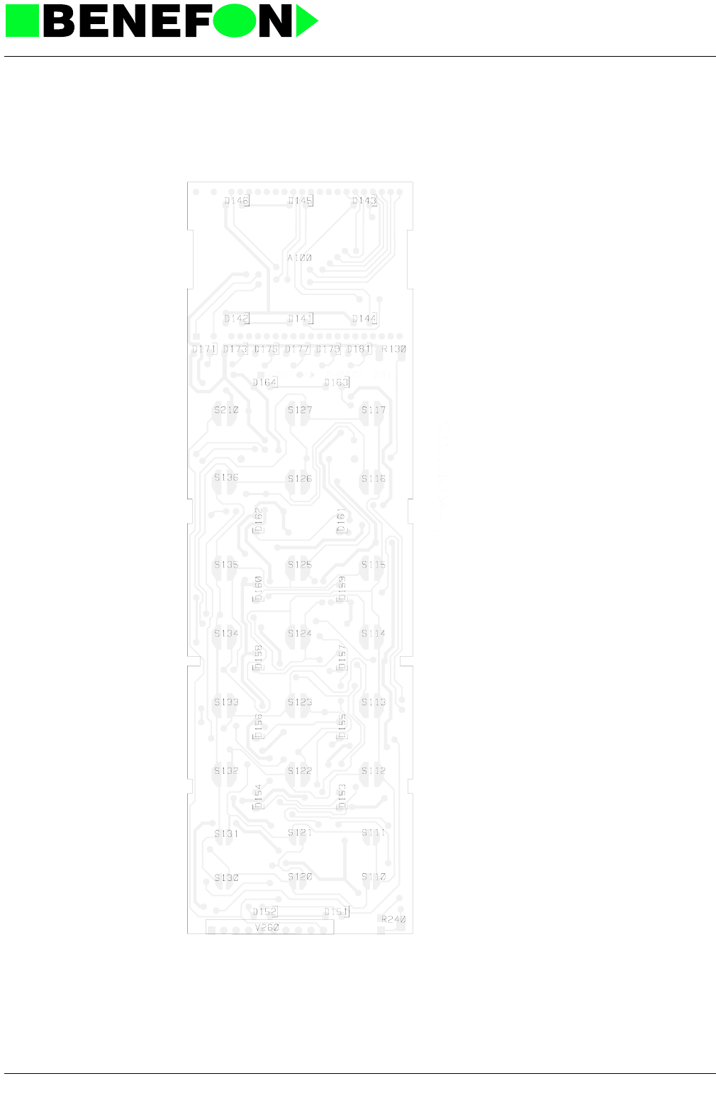
28.1.1999
XH0002E4_fm5.fm 7
Product: HS-10 / OH0002 Handset
Component Side Layout PH0002A0 (Schematic OH0002A-C0)
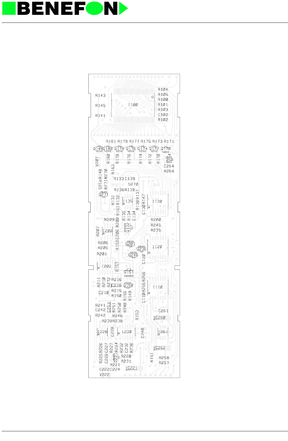
28.1.1999
XH0002E4_fm5.fm 8
Product: HS-10 / OH0002 Handset
Solder Side Layout PH0002A0 (Schematic OH0002A-C0)
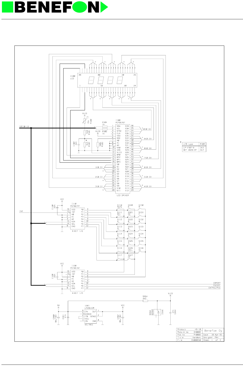
28.1.1999
XH0002E4_fm5.fm 9
Product: HS-10 / OH0002 Handset
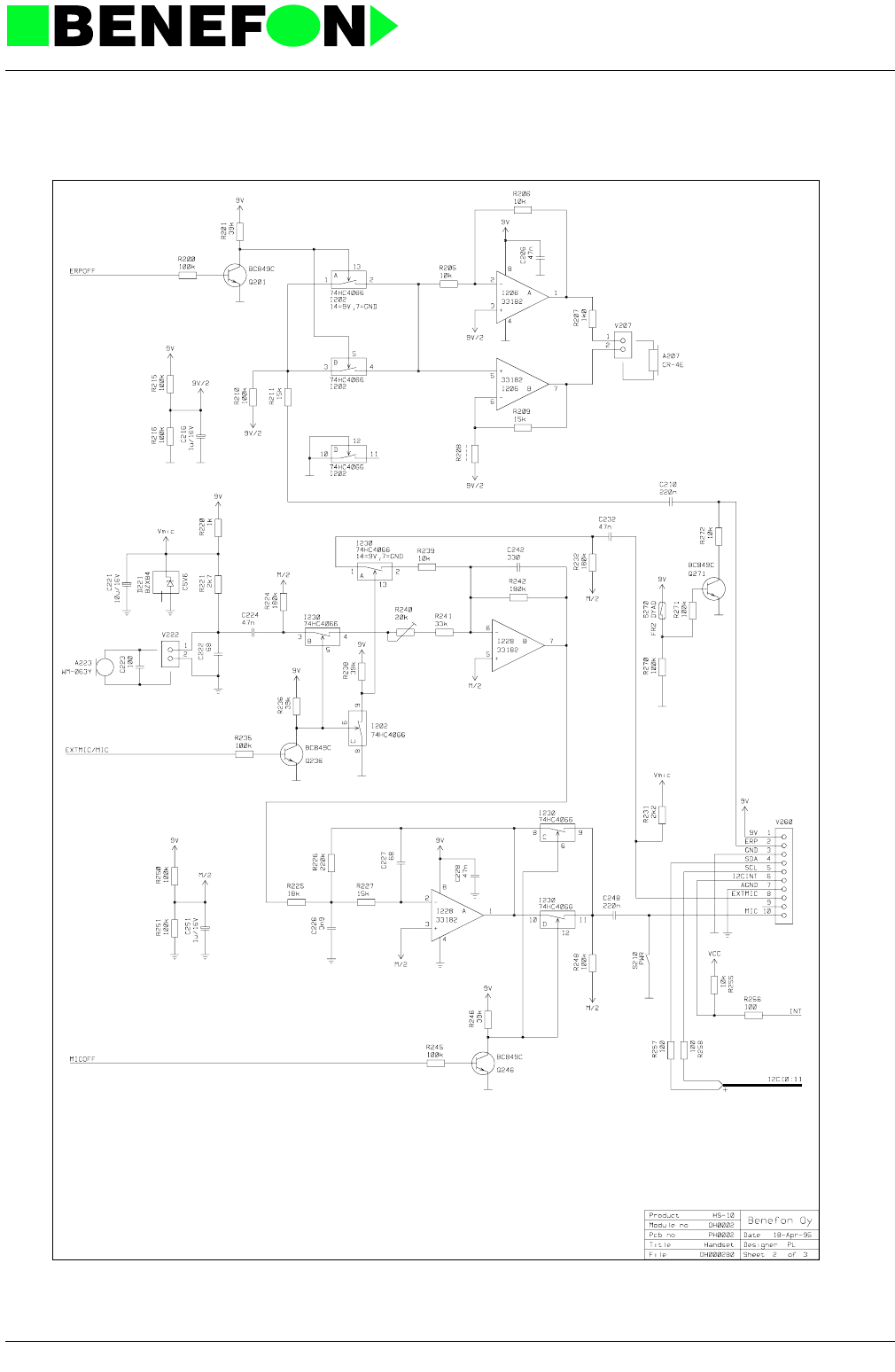
28.1.1999
XH0002E4_fm5.fm 10
Product: HS-10 / OH0002 Handset
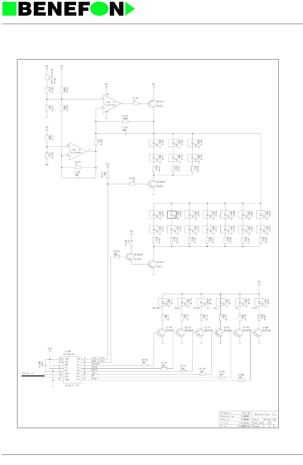
28.1.1999
XH0002E4_fm5.fm 11
Product: HS-10 / OH0002 Handset

28.1.1999
Xo0402e4_fm5.fm 1
Product: DA-10 / OO0402
12.0 DATA-INTERFACE FUNCTION OUTLINE
OO0402
The data-interface can be divided into three functional parts: the processor, audio,
and ring and line voltage circuits. Circuit diagrams are also separated into these
three sections.
12.0.1 The Processor
The processor function is provided by I010 MC68HC11 chip, which uses a 3.57 MHz
crystal X010. Program memory is provided by 64k*8 EPROM I030. Program mem-
ory and external I/O circuit address coding is performed by I050 and I060.
Communication between the processor and the radio unit uses an IIC-bus con-
nected to I070, I080, I090 and I100. Each chip is connected to the processor data-
bus with latch circuit.
The battery supported IIC-RAM I120 is connected to the processor IIC bus. The cir-
cuit is set to "power-saving" mode by inverting the regulator I001 ERROR output
with Q121.
The DTMF receiver I040 interprets codes sent from the tele-VDU and feeds them to
the processor through the I/O port. The oscillator I040 input is connected to the pro-
cessor’s oscillator output.
The logical +5V power supply is regulated by I001, the ERROR output of which is
used to reset the processor.
12.0.2 Memory Addresses
12.0.3 Interrupts
The DTMF-receiver I040 StD output is activated by the circuit detecting a DTMF sig-
nal. This generates an "input capture" timer-interrupt to processor I010 (PAO/IC3).
Keyed in numeric codes (inc. * and #) are saved in the number buffer, with room for
23 digits. As the number buffer becomes full, further input is ignored.
The first DTMF code received suppresses the dialling tone by grounding the audio
frequency generator processor pins PA5/OC4, PA5/OC3 and PA6/OC2. A DTMF
interrupt activates a 7 second timer which will also display "number ready" mode.
I030 EPROM 8000H - FFFFH program memory
I071 LATCH 4000H keyboard (input)
1081 LATCH 5000H indicator values
I091 LATCH 6000H tariff rate reception
I110 LATCH 7000H keyboard (output)
CPU inc. RAM OOH - FFH

28.1.1999
Xo0402e4_fm5.fm 2
Product: DA-10 / OO0402
The system clock’s interrupt interval is 9.15424 ms. The clock updates the SW
counters, which are used for timing functions, dialling-tone formation (call, dial,
busy), and directing the adapter transfer modes.
The timer PA5/OC3 is used to generate a 25 Hz call tone. The relevent frequency
half-cycle is loaded into register TOC3; pin OC3 connected as the output pin (TCTL1
register); the OC3 interrupt flag is nullified in register RFLG1 and an interrupt is
allowed by activating the relevant interrupt-bit in register TMSK1.
When the ouput-compare register corresponds to the reference clock value, the
interrupt is completed and a new half-cycle reading is loaded into register TOC3.
The output square-wave is of 25 Hz frequency. Call-tone duration is governed by the
above mentioned system-clock interrupts from the synchronised SW counters.
Dialling- and busy-tones are formed using PA4/PC4 output. The frequency in both
cases is 425 Hz. Busy-tone cycle is 300/300 ms. Tone generation is similar to the
process described above. (Dialling-tone is not broken by the SW counters). The
PA6/OC2 output is reserved for generation of a tariff-pulse (16 kHz). This is not in
use with the data-interface.
12.0.4 Processor I/O Functions
During an input-capture interrupt, DTMF data is read from gate E pins PE0 ... PE3.
EXAL (incoming call) is registered at E gate pin PE4.
TERMHOOK (accessory hook) is registered at gate A pin PA2.
IN USE (PD3) control activates the data-interface and prevents simultaneous opera-
tion of tele-VDU and accessories.
RING GATE (PD5) - 120V regulator required for data-interface call functions.
IIC RAM circuit I120 data and clock (PA7, PF4). Included is a pulse counter for use
with the coin-operated version. The data-interface uses this circuit to store call data
(ACALL and BCALL data).
In case of a power failure with the adapter in call-mode, the RAM memory will be
checked after reset, and operation will continue as before. If the call was terminated
before reset, then the adapter will function normally, switching to dial-mode when the
handset is lifted.
IIC LATCH ENABLE (PD0). Control for latch circuit I110. The circuit is used to trans-
fer a key-code to the radio unit. IIC-interrupt to the radio is simulated as follows: key-
in the required code to the latch circuit I110, de-activate the PD0 control and wait
until the latch circuit I071 can be read by the radio prompted keyboard scan. For
each scan, the relevant code is written via PD0-control to I110. Finally, the corre-
sponding key release interrupt is simulated.
Call-mode is recognised by reading the CALL-led state from circuit I081. Continuous
illumination of the led for one second during calibration indicates call-mode.

28.1.1999
Xo0402e4_fm5.fm 3
Product: DA-10 / OO0402
12.0.5 Audio
The telephone connection branch is formed by the operational amplifier I215. The
branch is matched to 820R/38 nF line impedance with resistors R218, R219 and
condensator C218. The telephone line, with +- 3.0 kHz deviation (1 kHz) and 3/7
loudness (400 mVrms), has a 600 Ohm resistive load with a -28 dBm signal level.
Similarly, a -3dBm input level will provide 1.0 Vrms in the TXAUDIO line, with +- 3.0
kHz deviation in the transmitter.
Audio tones (425 Hz) are filtered with the operational amplifier I205A, and then fed
through the branch to the telephone line.
Tariff pulses (12/16 kHz) are filtered with the operational amplifiers I235A, and are
fed to the standard current modulated telephone line.
The telephone line includes a return-feed constant current integrator I235, Q250,
and Q251, to provide the telephone line loop current. The constant current load
maintains the loop current supply without any loss of audio signal.
Loop current switching is detected from the transistor Q265 constant current load
emitter surplus potential.
12.0.6 Ring- And Line-voltage Power Supply
The telephone connection line-potential (60 V) is derived from a current form flyback
power supply.
During operation, the control-circuit I341 measures the current flowing through the
transformer primary windings at resistor R338. When the current exceeds the value
specified by the control circuit, FET Q335 is de-activated. This results in the energy
stored in the transformer being discharged from the secondary windings through
diode D328 to output condensators C329 and C328. When the output drops to the
value determined by resistors F342 and R343, the control circuit lowers the level at
which FET Q335 switches.
With RING-GATE control, offset-current is directed to the control circuit adjuster
through resistor R347, resulting in an output voltage of 120V during the ring.
The secondary current is limited with operational amplifier I205B, which measures
the transformer secondary current flowing through resistor R371, and when second-
ary current limit is exceeded 1205B adjusts the control-circuit 1341 via diode D367.
RING-control is normally in 0-state, and Q325 functions as a constant-current gener-
ator, providing a continuous voltage for FET Q323. This causes Q323 to conduct,
and the line-voltage is fed to the telephone line. During a call, RING-line alternates
between 1 and 0 at 25Hz, causing Q323 and Q326 to conduct in turn. As the power-
supply voltage is raised to 120V in call-mode, the telephone line is provided with
both 60V DC and 60V AC voltages.

28.1.1999
Xo0402e4_fm5.fm 4
Product: DA-10 / OO0402
The audio signals are changed with relay A315 to the branch circuit with IN-USE
control. The diode D303 allows radio unit to be switched off if for some reason the
call cannot be terminated from the VDU. FET Q317 breaks the SDA-line, so that the
keyboard is inoperative while the tele-VDU is in use. The display functions as normal
as the diode D303 will permit writing to the screen.

28.1.1999
Xo0402e4_fm5.fm 5
Product: DA-10 / OO0402
12.0.7 Parts list
OO0402
CODE PART DESCRIPT. VALUE MANUF. TYPE
AB0003 A120 Lithium battery 3V 180mAh d=20mm Matsushita BR2032-1HG
AR0004 A315\ Relay 9V/1.25A Takamisawa RA-9W-K
CC0473 C001 SMD capasitor 47 nF 10% 50 V X7R Philips
CC0473 C002 SMD capasitor 47 nF 10% 50 V X7R Philips
CU0106 C003 SMD tantal 10uF/16V 20% 6x3.2mm Matsushita ECST1CC 106R
CC0473 C010 SMD capasitor 47 nF 10% 50 V X7R Philips
CC0220 C011 SMD capasitor 22 pF 5% 50V NP0 Philips
CC0220 C012 SMD capasitor 22 pF 5% 50V NP0 Philips
CC0473 C020 SMD capasitor 47 nF 10% 50 V X7R Philips
CC0473 C030 SMD capasitor 47 nF 10% 50 V X7R Philips
CC0473 C040 SMD capasitor 47 nF 10% 50 V X7R Philips
CC0473 C041 SMD capasitor 47 nF 10% 50 V X7R Philips
CC0102 C044 SMD capasitor 1 nF 5% 50V NP0 Philips
CC0473 C045 SMD capasitor 47 nF 10% 50 V X7R Philips
CC0473 C050 SMD capasitor 47 nF 10% 50 V X7R Philips
CC0473 C060 SMD capasitor 47 nF 10% 50 V X7R Philips
CC0473 C070 SMD capasitor 47 nF 10% 50 V X7R Philips
CC0473 C071 SMD capasitor 47 nF 10% 50 V X7R Philips
CC0473 C080 SMD capasitor 47 nF 10% 50 V X7R Philips
CC0473 C081 SMD capasitor 47 nF 10% 50 V X7R Philips
CC0473 C090 SMD capasitor 47 nF 10% 50 V X7R Philips
CC0473 C091 SMD capasitor 47 nF 10% 50 V X7R Philips
CC0473 C100 SMD capasitor 47 nF 10% 50 V X7R Philips
CC0473 C110 SMD capasitor 47 nF 10% 50 V X7R Philips
CC0393 C203 SMD capasitor 39 nF 10% 50V X7R Philips
CC0393 C205 SMD capasitor 39 nF 10% 50V X7R Philips
CB0224 C212 SMD capasitor 220 nF 20% 50 V X7R Philips
CC0332 C215 SMD capasitor 3.3 nF 5% 50 V NP0 Philips
CC0393 C218 SMD capasitor 39 nF 10% 50V X7R Philips
CE0106 C219 Al elko 10 uF/35 V 5x7mm Philips 2222 097 50109
CB0224 C226 SMD capasitor 220 nF 20% 50 V X7R Philips
CC0102 C233 SMD capasitor 1 nF 5% 50V NP0 Philips
CC0102 C235 SMD capasitor 1 nF 5% 50V NP0 Philips
CC0152 C241 SMD capasitor 1.5 nF 5% 50V NPO Philips
CC0102 C245 SMD capasitor 1 nF 5% 50V NP0 Philips
CU0105 C254 SMD tantal 1uF/16V 20% 3.2x1.6mm Matsushita ECST1CY 105R
CC0683 C263 SMD capasitor 68nF/50V/10%/X7R
CC0103 C267 SMD capasitor 10 nF 10% 50V X7R Philips
CU0105 C282 SMD tantal 1uF/16V 20% 3.2x1.6mm Matsushita ECST1CY 105R
CP0683 C321 Polypropylen 68nF/250/160V Evox PMR10
CE0226 C328 Al elko 22 uF/160V 25x10mm Philips 222204131229
CE0226 C329 Al elko 22 uF/160V 25x10mm Philips 222204131229
CC0103 C333 SMD capasitor 10 nF 10% 50V X7R Philips
CC0471 C339 SMD capasitor 470 pF 5% 50 V NP0 Philips
CC0101 C345 SMD capasitor 100 pF 5% 50V NP0 Philips
CC0152 C352 SMD capasitor 1.5 nF 5% 50V NPO Philips
CC0473 C353 SMD capasitor 47 nF 10% 50 V X7R Philips
CE0337 C355 Al elko 330uF/16V 20% 15x7.3mm Philips 222213555331
CE0337 C356 Al elko 330uF/16V 20% 15x7.3mm Philips 222213555331
CE0337 C357 Al elko 330uF/16V 20% 15x7.3mm Philips 222213555331
CC0473 C373 SMD capasitor 47 nF 10% 50 V X7R Philips
CC0473 C375 SMD capasitor 47 nF 10% 50 V X7R Philips
CC0473 C376 SMD capasitor 47 nF 10% 50 V X7R Philips
CC0473 C378 SMD capasitor 47 nF 10% 50 V X7R Philips

28.1.1999
Xo0402e4_fm5.fm 6
Product: DA-10 /
DS0070 D120 SMD diode pair 70V/100mA common cathode Philips BAV 70
DS0099 D219 SMD diode 70 V 200 mA Philips BAV 99
DY0074 D303 Shottky diode Philips BAT 74
DS0070 D315 SMD diode pair 70V/100mA common cathode Philips BAV 70
DF0026 D328 Diode (very fast) 1A/400V 30ns Philips BYV 26B
DS0070 D361 SMD diode pair 70V/100mA common cathode Philips BAV 70
DS0070 D367 SMD diode pair 70V/100mA common cathode Philips BAV 70
DS0099 D373 SMD diode 70 V 200 mA Philips BAV 99
IR2951 I001 Regulator 100mA 5V adj. 5% National LP2951CM
IP6811 I010 8-BIT MIKROPROS 512 EEPROM, 8A/D, no ROM Motorola MC68HC11A1FN
IH0573 I020 Octal D-latches HCMOS 74HC573
IM7512 I030 One time prom CMOS 65.536 x 8b 200ns Fujitsu MBM27C512P-20P
IA8870 I040 DTMF decoder Plessey MV8870
IH0138 I050 3 to 8-line decod. inv. HCMOS RCA 74HC138
IH0002 I060\ 4x2-inp.NOR HCMOS 74HC02
II8574 I070 8 bit I/O I2C Philips PCF8574T
IH0573 I071 Octal D-latches HCMOS 74HC573
II8574 I080 8 bit I/O I2C Philips PCF8574T
IH0573 I081 Octal D-latches HCMOS 74HC573
II8574 I090 8 bit I/O I2C Philips PCF8574T
IH0573 I091 Octal D-latches HCMOS 74HC573
II8574 I100 8 bit I/O I2C Philips PCF8574T
IH0573 I110 Octal D-latches HCMOS 74HC573
II8570 I120 SRAM I2C 256x8bit Philips PCF8570T
IA3182 I205\ 2xop.amp. Low power,jfet input Motorola MC 33182D
IA0204 I215\ Dual operational amp. High performance SGS LS204M
IA0272 I235\ 2 x op.amp. LinCMOS Low noise,power Texas TLC27M2ID
IX2843 I341 Current mode controller Motorola UC2843AN
LA0106 L321 Inductor 9.5x4mm 10uH+-10% 0.34A Q=55(8MHz) Dale
LT0001 L331 Transformer DRW NO 2/90 Salcomp RM5 SCP7801
LA0105 L357 Incuctor 9.5x4mm 1uH-+10% 0.9A Q=50(25MHz) Dale
VI0028 MEC1 IC -socket DIL-28
VI0052 MEC2 IC - socket PLCC-52 1R piikit Methode
NI3065 MEC3 Snap rivet (pikaniitti) Nylon 6, RMS-28 Richco SR 3065B
PO0003 PCB PCB data-adapter 190 x 161,5mm FR4 (2x) Benefon
QSC849 Q121 SMD transistor NPN 0.2A/30V F=1.2dB Philips BC 849 C
QSC849 Q250 SMD transistor NPN 0.2A/30V F=1.2dB Philips BC 849 C
QP0158 Q251 Medium power transistor NPN 0.5A/300V 20W Motorola BD 158
QSC849 Q265 SMD transistor NPN 0.2A/30V F=1.2dB Philips BC 849 C
QSC849 Q306 SMD transistor NPN 0.2A/30V F=1.2dB Philips BC 849 C
QSC849 Q311 SMD transistor NPN 0.2A/30V F=1.2dB Philips BC 849 C
QF0003 Q317 SMD n-channel FET 60V/0.75A Rds 3.2 I&R IRFS 1Z3
QF9210 Q323 SMD p-channel FET 200V/2A Rds=3 I&R IRFR 9210
QS0040 Q325 SMD transistor NPN 1A/250V Philips BST40
QS0040 Q326 SMD transistor NPN 1A/250V Philips BST40
QF0024 Q335 SMD n-channel 60V/15A/Rds=0.1 I&R IRFR024
QSC849 Q370 SMD transistor NPN 0.2A/30V F=1.2dB Philips BC 849 C
QSC859 Q371 SMD transistor PNP 0.2A/30V F=1.2dB Philips BC 859 C
RC0223 R002 SMD resistor 22 k 5% 0.125 W Kamaya
RC0105 R010 SMD resistor 1 M 5% 0.125 W Kamaya
RC0104 R011 SMD resistor 100 k 5% 0.125 W Kamaya
RC0103 R012 SMD resistor 10 k 5% 0.125 W Kamaya
RC0103 R013 SMD resistor 10 k 5% 0.125 W Kamaya
RC0684 R041 SMD resistor 680 k 5% 0.125 W Kamaya
RC0223 R044 SMD resistor 22 k 5% 0.125 W Kamaya
RC0104 R045 SMD resistor 100 k 5% 0.125 W Kamaya
RC0104 R070 SMD resistor 100 k 5% 0.125 W Kamaya
RC0104 R120 SMD resistor 100 k 5% 0.125 W Kamaya
RC0334 R121 SMD resistor 330 k 5% 0.125 W Kamaya
RC0472 R123 SMD resistor 4.7 k 5% 0.125 W Kamaya
CODE PART DESCRIPT. VALUE MANUF. TYPE

28.1.1999
Xo0402e4_fm5.fm 7
Product: DA-10 /
RC0472 R124 SMD resistor 4.7 k 5% 0.125 W Kamaya
RC0334 R201 SMD resistor 330 k 5% 0.125 W Kamaya
RC0121 R202 SMD resistor 120 R 5% 0.125 W Kamaya
RC0470 R203 SMD resistor 47 R 5% 0.125 W Kamaya
RC0564 R205 SMD resistor 560 k 5% 0.125 W Kamaya
RC0472 R211 SMD resistor 4.7 k 5% 0.125 W Kamaya
RC0333 R212 SMD resistor 33 k 5% 0.125 W Kamaya
RC0183 R215 SMD resistor 18 k 5% 0.125 W Kamaya
RC0102 R218 SMD resistor 1 k 5% 0.125 W Kamaya
RC0682 R219 SMD resistor 6.8 k 5% 0.125 W Kamaya
RC0223 R221 SMD resistor 22 k 5% 0.125 W Kamaya
RC0223 R222 SMD resistor 22 k 5% 0.125 W Kamaya
RC0183 R225 SMD resistor 18 k 5% 0.125 W Kamaya
RC0221 R226 SMD resistor 220 R 5% 0.125 W Kamaya
RC0223 R231 SMD resistor 22 k 5% 0.125 W Kamaya
RC0682 R232 SMD resistor 6.8 k 5% 0.125 W Kamaya
RC0102 R233 SMD resistor 1 k 5% 0.125 W Kamaya
RC0223 R235 SMD resistor 22 k 5% 0.125 W Kamaya
RC0103 R241 SMD resistor 10 k 5% 0.125 W Kamaya
RC0103 R245 SMD resistor 10 k 5% 0.125 W Kamaya
RC0472 R250 SMD resistor 4.7 k 5% 0.125 W Kamaya
RB6809 R251 Metal film resistor 68R 5% 0.4W Beyschlag MBA0207-50
RC0104 R253 SMD resistor 100 k 5% 0.125 W Kamaya
RC0124 R254 SMD resistor 120 k 5% 0.125 W Kamaya
RC0103 R262 SMD resistor 10 k 5% 0.125 W Kamaya
RC0472 R263 SMD resistor 4.7 k 5% 0.125 W Kamaya
RC0104 R265 SMD resistor 100 k 5% 0.125 W Kamaya
RC0104 R281 SMD resistor 100 k 5% 0.125 W Kamaya
RC0104 R282 SMD resistor 100 k 5% 0.125 W Kamaya
RC0472 R303 SMD resistor 4.7 k 5% 0.125 W Kamaya
RC0103 R305 SMD resistor 10 k 5% 0.125 W Kamaya
RC0103 R306 SMD resistor 10 k 5% 0.125 W Kamaya
RC0472 R311 SMD resistor 4.7 k 5% 0.125 W Kamaya
RC0000 R315 SMD resistor 0 R Kamaya
RC0103 R317 SMD resistor 10 k 5% 0.125 W Kamaya
RC0103 R323 SMD resistor 10 k 5% 0.125 W Kamaya
RC0472 R325 SMD resistor 4.7 k 5% 0.125 W Kamaya
RC0103 R326 SMD resistor 10 k 5% 0.125 W Kamaya
RC0150 R333 SMD resistor 15 R 5% 0.125 W Kamaya
RC0103 R335 SMD resistor 10 k 5% 0.125 W Kamaya
RC0560 R336 SMD resistor 56 R 5% 0.125 W Kamaya
RB0228 R338 Metal film resistor 0.22R 5% 0.4W Beyschlag MBA0207-50
RC0102 R339 SMD resistor 1 k 5% 0.125 W Kamaya
RC0334 R342 SMD resistor 330 k 5% 0.125 W Kamaya
RC0103 R343 SMD resistor 10 k 5% 0.125 W Kamaya
RC0104 R345 SMD resistor 100 k 5% 0.125 W Kamaya
RC0333 R347 SMD resistor 33 k 5% 0.125 W Kamaya
RC0682 R352 SMD resistor 6.8 k 5% 0.125 W Kamaya
RC0104 R362 SMD resistor 100 k 5% 0.125 W Kamaya
RC0224 R365 SMD resistor 220 k 5% 0.125 W Kamaya
RC0472 R368 SMD resistor 4.7 k 5% 0.125 W Kamaya
RB1000 R371 Metal film resistor 100R 5% 0.4W Beyschlag MBA0207-50
VD0016 VH01 D-connector D-15S 90 ast.kulma Cannon DA121073-5044
VM0116 VR01 Contact strip angle 2x8 NB-electr. H4-6-16G
VP0077 VT01 Modular jack Right angle 6/4cont. Molex 90077-1076
X35796 X010 DTMF-quartz crystal 3.579545 MHZ +-30PPM Meiden
Last
update
01.09.92
CODE PART DESCRIPT. VALUE MANUF. TYPE
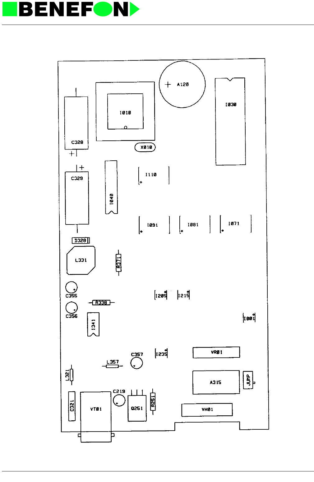
28.1.1999
Xo0402e4_fm5.fm 8
Product: DA-10 /
Component Side Layout PO0003A0 (Schematic OO0402A-C0)

28.1.1999
Xo0402e4_fm5.fm 9
Product: DA-10 /
Solder Side Layout PO0003A0 (Schematic OO0402A-C0)
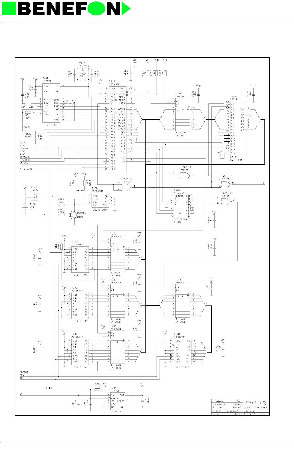
28.1.1999
Xo0402e4_fm5.fm 10
Product: DA-10 /
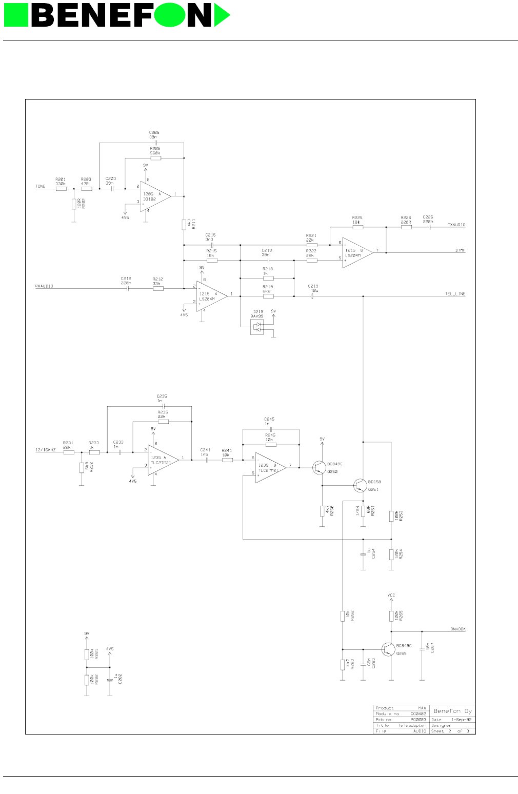
28.1.1999
Xo0402e4_fm5.fm 11
Product: DA-10 /
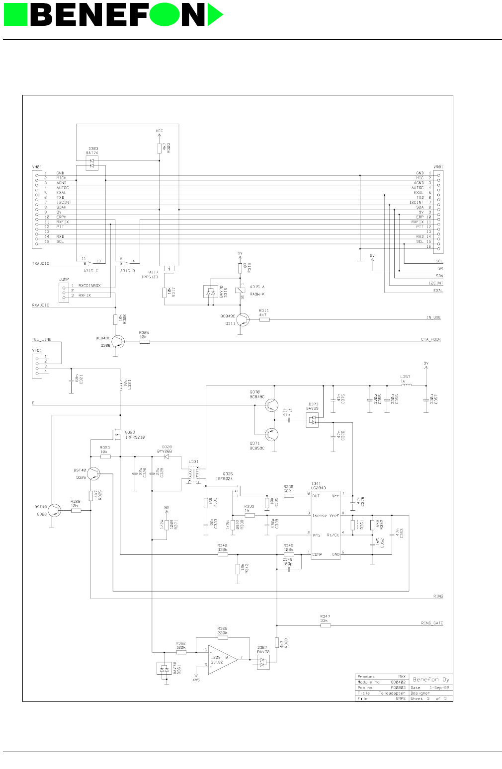
28.1.1999
Xo0402e4_fm5.fm 12
Product: DA-10 /
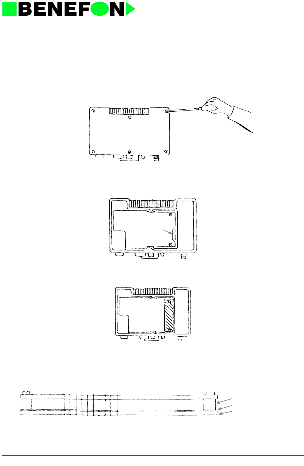
28.1.1999
Xo0004e4_fm5.fm 1
Product: Answering Machine /
13.0 INSTALLATION OF ANSWERING MACHINE
The answering machine is installed inside the transceiver unit.
Place the transceiver unit on the table, the cooling plate away from yourself, so that
the antenna connector is on its right side and the power connector on its left side, fig-
ure 1.
Unscrew the head bolts, and remove the cover. Now you can see thr Audio/Proces-
sor voard and on its right side the connector-strip A, to which the answering machine
is connected, figure 2.
Release screws 1 and 2, and place the Audio/Processor plastic foil peaks into the
corresponding holes in connector-strip A. Fasten the unit with screws 3 and 4.
Check that all connector peaks are in their holes, and when you are sure that every-
thing is in order, close the cover and test the machine.
connector-strip Aanswering machine board
1
2
A
3
4
connector strip A answering machine board
bush ring
plastic foil
Audio/Prosesso
r

28.1.1999
Xo0004e4_fm5.fm 2
Product: Answering Machine /
13.1 Answering Machine
13.1.1 Processor
The central processing unit for the answering machine is Intel 80C31. The processor
- reads the PROM program memory
- stores the speech, digitized with the delta-modulator, in DRAM memory, and
tran stored speech from RAM to the delta-modulator,
- refreshes DRAM circuits
- communicates via the I2c bus with other devices connected to the system,
- controls the audio signal path control switches,
- controls the ringing tone signal,
- generates the "watchdog" reset pulse.
13.1.2 Memory Control
The processor may uses the program memory D190 and the dynamic RAM D200-
D220.
The memory addressing timing functions are assisted by control logic. The proces-
sor refreshes the dynamic RAM circuits at 8 ms intervals.
13.1.3 Watchdog
D110C resonates at a frequency of approx 3 kHz, independent of the processor.
This logic-level pulse is led to the counter D260. The watchdog reset pulse of the
processor zeroes this counter at 8 ms intervals. There is no reset pulse when the
program malfuctions. In that case the counter is free to proceed so that the counter
D260A MSB will reset the processor.
13.1.4 Audio Paths
The answering machine recognizes the audio signals coming from TXAIN- and
RXAIN-lines. It transmits an audio signal to TXAOUT- and RXAOUT- lines.
N230A ampflies the incoming audio signals. N240B is a compressor which drops the
incoming audio signal dynamics to an appropriate level for the delta modulator.
N170 is a delta modulator which converts the incoming audio signal to serial data.
When repeating the stored speech, N170 converts the serial data coming from the
memoriesn to an analog signal, which is led to the buffer amplifier N230d. The signal
goes forward to the expander N240C, which then expands the comperssed speech
dynamics to the original level. The compressor is followed by an active low-pass fil-
ter on which the processor-generated ringing-tone signal is combined. The last unit
is the buffer amplifier N230C. The signal coming from N230C is led to either

28.1.1999
Xo0004e4_fm5.fm 3
Product: Answering Machine /
RXAOUT- or TXAOUT-line with CMOS- switches N250C and N250D.
13.1.5 ICC-Operation
Communication between the radio unit and the answering machine is accomplished
with an IIC-bus (lines SDA, IICINT, and IICENA). When necessary, the radio unit can
disconnect the SCL-line with N140D. There is an open-collector output (V291) on
the IICINT-line; the up-draught resistor is at the radio unit.
13.1.6 Operating Voltages
The answering machine gets its operating voltage from the radio unit (X290).
The operating voltage range of the answering machine is 10.6 - 16 V dc. In stand-by,
the current consumption is approx 20 mA; when recording and repeating speech, it
is approx
90 mA.

28.1.1999
Xo0004e4_fm5.fm 4
Product: Answering Machine /
13.1.7 Parts list
CODE PART DESCRIPT. VALUE MANUF. TYPE
CD0220 C101 SMD capasitor 22 pF 5% 50 V NP0 Philips
CD0220 C102 SMD capasitor 22 pF 5% 50 V NP0 Philips
CC0473 C111 SMD capasitor 47 nF 10% 50 V X7R Philips
CD0102 C112 SMD capasitor 1 nF 5 % NP0 Philips
CC0473 C140 SMD capasitor 47 nF 10% 50 V X7R Philips
CC0473 C171 SMD capasitor 47 nF 10% 50 V X7R Philips
CD0223 C200 SMD capasitor 22 nF 10% 50 V X7R Philips
CD0223 C210 SMD capasitor 22 nF 10% 50 V X7R Philips
CC0104 C220 SMD capasitor 100 nF 10% 50V X7R Philips
CC0473 C230 SMD capasitor 47 nF 10% 50 V X7R Philips
CD0562 C231 SMD capasitor 5.6 nF 10% 50V Philips
CD0562 C232 SMD capasitor 5.6 nF 10% 50V Philips
CD0222 C233 SMD capasitor 2.2 nF 5% 50 V NP0 Philips
CC0473 C234 SMD capasitor 47 nF 10% 50 V X7R Philips
CD0222 C235 SMD capasitor 2.2 nF 5% 50 V NP0 Philips
CD0222 C236 SMD capasitor 2.2 nF 5% 50 V NP0 Philips
CD0562 C237 SMD capasitor 5.6 nF 10% 50V Philips
CC0473 C238 SMD capasitor 47 nF 10% 50 V X7R Philips
CD0102 C239 SMD capasitor 1 nF 5 % NP0 Philips
CC0473 C240 SMD capasitor 47 nF 10% 50 V X7R Philips
CU0105 C241 SMD tantal 1uF/16V 20% 3.2x1.6mm Matsushita ECST1CY 105R
CU0105 C242 SMD tantal 1uF/16V 20% 3.2x1.6mm Matsushita ECST1CY 105R
CU0105 C243 SMD tantal 1uF/16V 20% 3.2x1.6mm Matsushita ECST1CY 105R
CC0104 C244 SMD capasitor 100 nF 10% 50V X7R Philips
CC0473 C245 SMD capasitor 47 nF 10% 50 V X7R Philips
CU0105 C246 SMD tantal 1uF/16V 20% 3.2x1.6mm Matsushita ECST1CY 105R
CU0105 C247 SMD tantal 1uF/16V 20% 3.2x1.6mm Matsushita ECST1CY 105R
CU0105 C248 SMD tantal 1uF/16V 20% 3.2x1.6mm Matsushita ECST1CY 105R
CC0473 C250 SMD capasitor 47 nF 10% 50 V X7R Philips
CU0106 C280 SMD tantal 10uF/16V 20% 6x3.2mm Matsushita ECST1CC 106R
CU0105 C281 SMD tantal 1uF/16V 20% 3.2x1.6mm Matsushita ECST1CY 105R
CC0473 C282 SMD capasitor 47 nF 10% 50 V X7R Philips
CU0105 C283 SMD tantal 1uF/16V 20% 3.2x1.6mm Matsushita ECST1CY 105R
DS0099 D100 SMD diode 70 V 200 mA Philips BAV 99
DZ0919 D281 SMD zener 9V1 5% 300mW Philips BZX84-C9V1
DS0099 D290 SMD diode 70 V 200 mA Philips BAV 99
IP8052 I100 Prosessor (answ.mach.) CMOS (maskprom) MatraHarri S80C52-xxx
IH0132 I110\ 4x2 inp NAND schm. HCMOS RCA 74HC132
IH0032 I120\ 4x2-inp OR HCMOS RCA 74HC32
IH0074 I130\ 2xD-flip-flop HCMOS RCA 74HC74
IH4053 I140\ 3x2-ch analog mpxer HCMOS RCA 74HC4053
IH0138 I150 3 to 8-line decod. inv. HCMOS RCA 74HC138
IX5564 I170 Deltamodulator Harris HC55564
IM1024 I200 DRAM 1MB x 1 TMS4C1024D
IM1024 I210 DRAM 1MB x 1 TMS4C1024D
IM1024 I220 DRAM 1MB x 1 TMS4C1024D
IA0324 I230\ 4 x opamp LM324
IA0571 I240\ Compandor Philips SA 571
IH4053 I250\ 3x2-ch analog mpxer HCMOS RCA 74HC4053
IH0393 I260\ Dual 4bit bin counter HCMOS 74HC393
IR2951 I280 Regulator 100mA 5V adj. 5% National LP2951CM
QS1054 Q280 SMD transistor NPN 1.5A/45V Philips BCP 54
QSB848 Q291 SMD transistor NPN 0.1A/30V F=2dB Philips BC 848 B
RD0103 R110 SMD resistor 10 k 5% 0.125 W Kamaya
RD0104 R111 SMD resistor 100 k 5% 0.125 W Kamaya
RD0103 R200 SMD resistor 10 k 5% 0.125 W Kamaya
RD0223 R230 SMD resistor 22 k 5% 0.125 W Kamaya

28.1.1999
Xo0004e4_fm5.fm 5
Product: Answering Machine /
RD0223 R231 SMD resistor 22 k 5% 0.125 W Kamaya
RD0103 R232 SMD resistor 10 k 5% 0.125 W Kamaya
RD0103 R233 SMD resistor 10 k 5% 0.125 W Kamaya
RD0224 R234 SMD resistor 220 k 5% 0.125 W Kamaya
RD0104 R235 SMD resistor 100 k 5% 0.125 W Kamaya
RD0103 R236 SMD resistor 10 k 5% 0.125 W Kamaya
RD0104 R237 SMD resistor 100 k 5% 0.125 W Kamaya
RD0183 R240 SMD resistor 18 k 5% 0.125 W Kamaya
RD0183 R241 SMD resistor 18 k 5% 0.125 W Kamaya
RD0222 R242 SMD resistor 2.2 k 5% 0.125 W Kamaya
RD0332 R243 SMD resistor 3.3 k 5% 0.125 W Kamaya
RD0104 R280 SMD resistor 100 k 5% 0.125 W Kamaya
RD0104 R283 SMD resistor 100 k 5% 0.125 W Kamaya
RD0104 R284 SMD resistor 100 k 5% 0.125 W Kamaya
RD0182 R286 SMD resistor 1.8 k 5% 0.125 W Kamaya
RD0473 R290 SMD resistor 47 k 5% 0.125 W Kamaya
X10247 X100 Crystal 10.245 MHz 30 ppm Meiden
VM0210 X290 Contact strip adapter 1 x10-pin McKenzie SST 1x10-880S
Last
update
10.04.92
CODE PART DESCRIPT. VALUE MANUF. TYPE
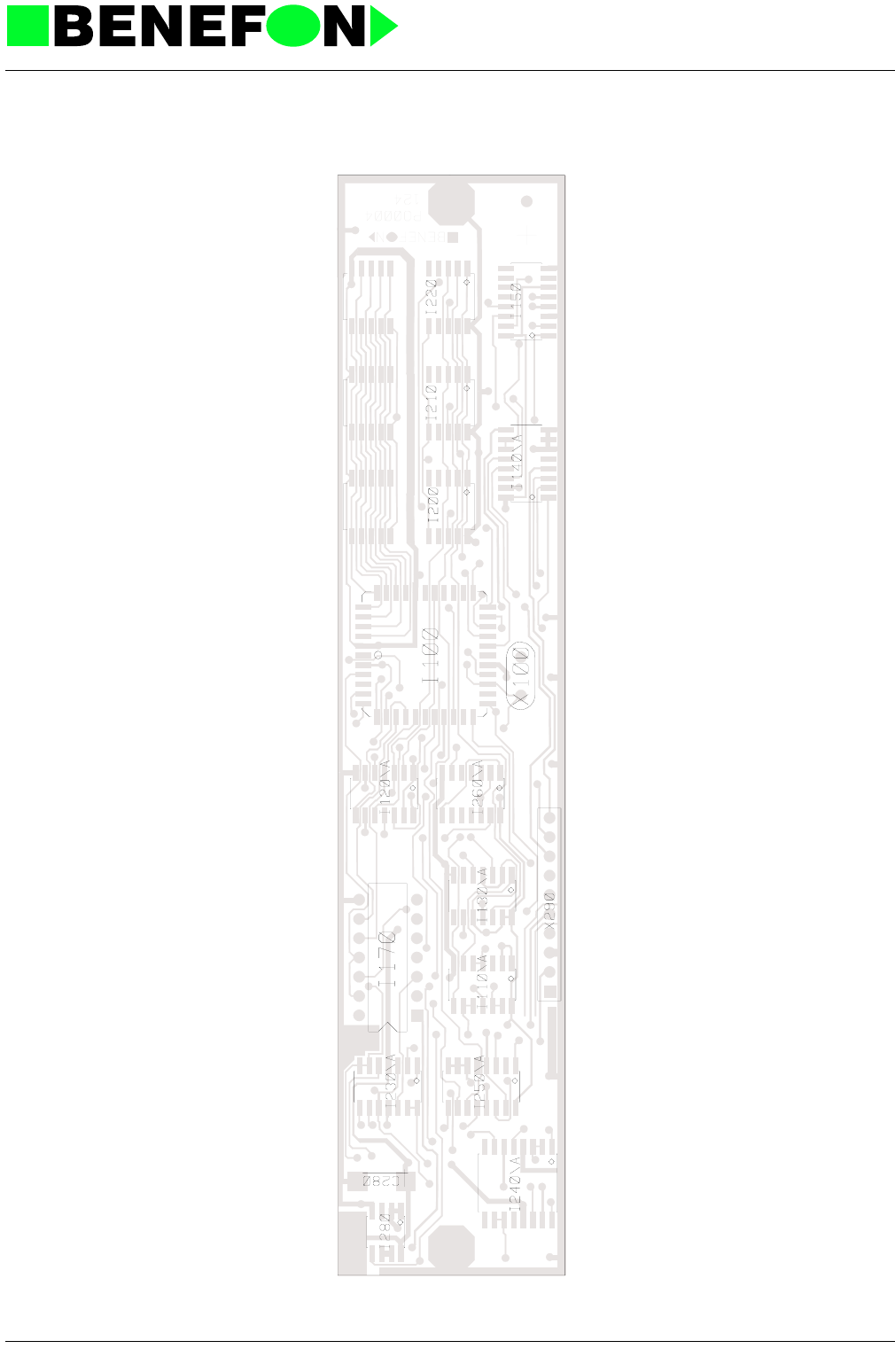
28.1.1999
Xo0004e4_fm5.fm 6
Product: Answering Machine /
Component Side Layout
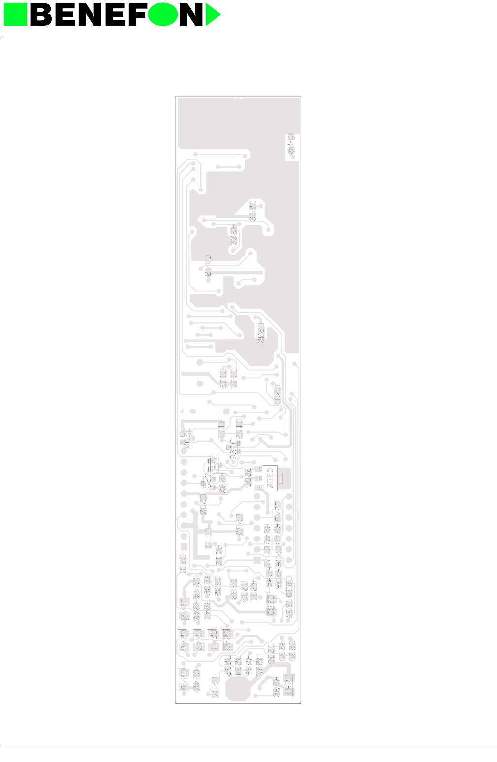
28.1.1999
Xo0004e4_fm5.fm 7
Product: Answering Machine /
Solder Side Layout
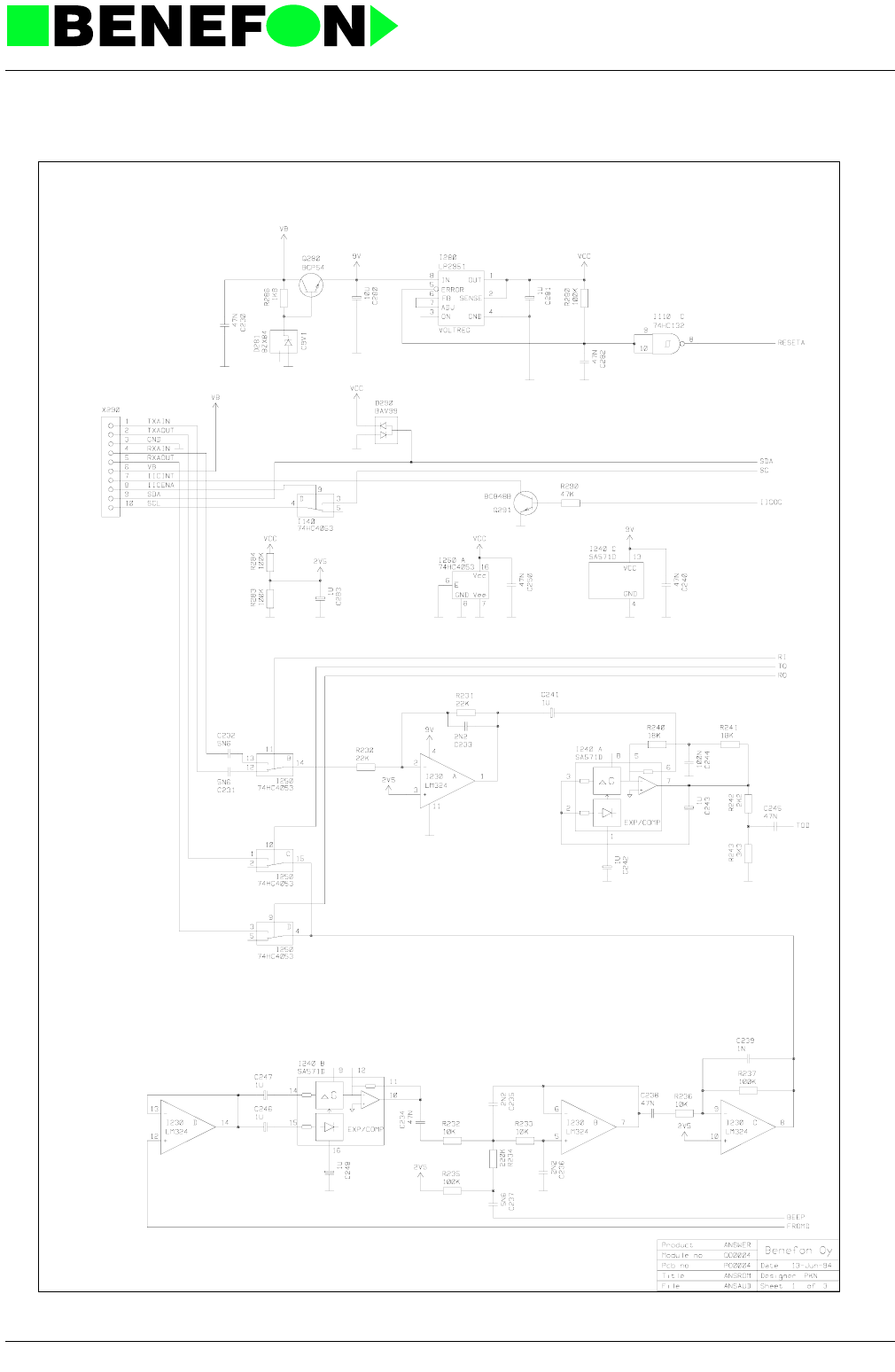
28.1.1999
Xo0004e4_fm5.fm 8
Product: Answering Machine /
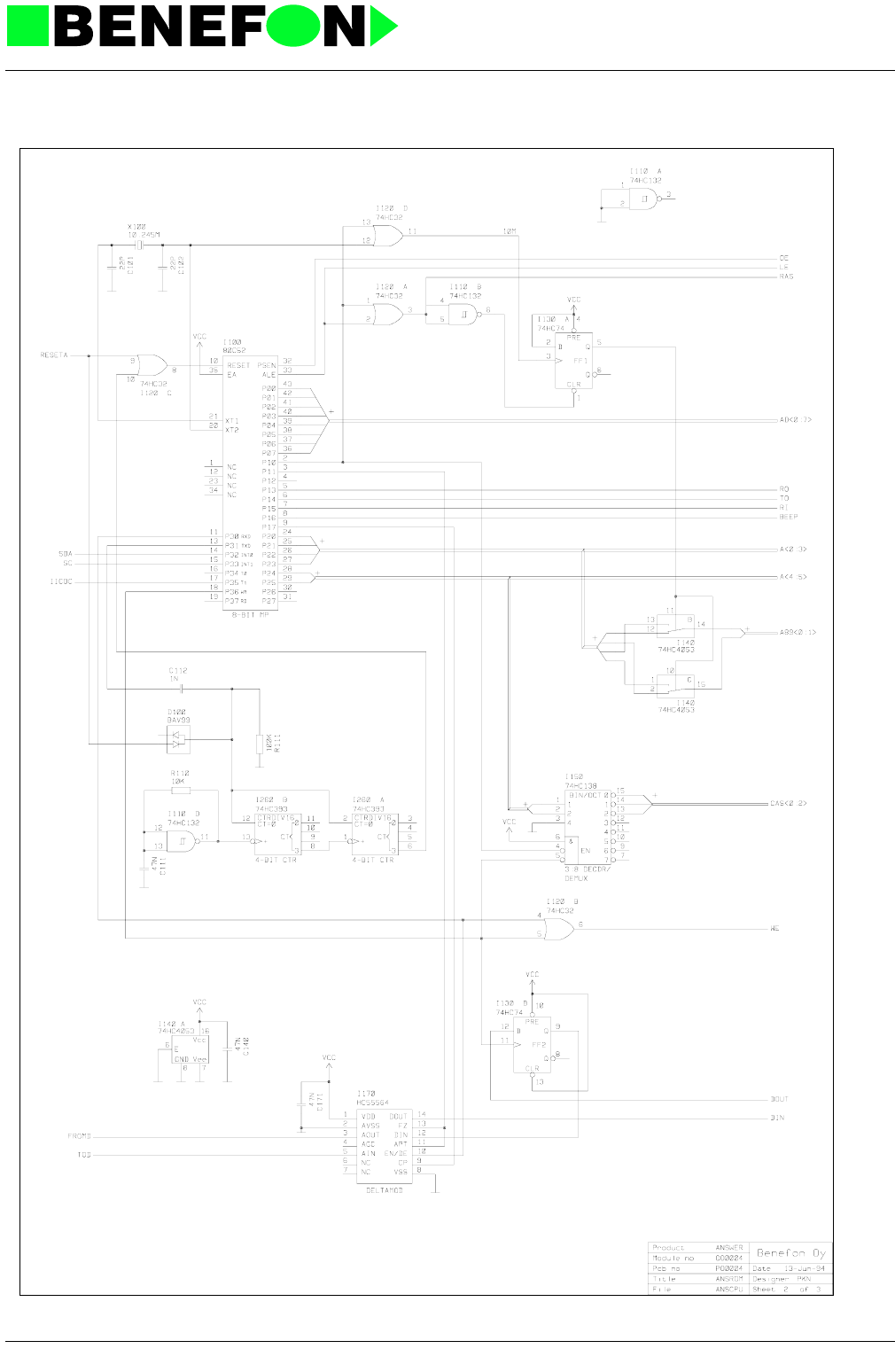
28.1.1999
Xo0004e4_fm5.fm 9
Product: Answering Machine /
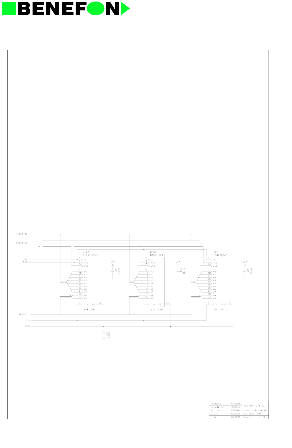
28.1.1999
Xo0004e4_fm5.fm 10
Product: Answering Machine /
