dormakaba Canada 515123 ZigBee GEN2 User Manual Q8S 515123UserMan1x
dormakaba Canada Inc. ZigBee GEN2 Q8S 515123UserMan1x
User Manual
ZigBee Gen 2 Module Installation
Guide
Document No.
Revision:
7
Prepared by: Michael Mosca Date: 05/09/2018
Q8S-515123UserMan1.docx 1
of 7
ZigBee Gen 2 Module Installation Guide
ZigBee Gen 2 Module Installation
Guide
Document No.
Revision:
7
Prepared by: Michael Mosca Date: 05/09/2018
2 of 7
REVISION HISTORY
Rev.
Date Description Made by Checked
Approved
1 11/14/2017 Release of document MM GC
2 11/20/17 Photo on page 3 changed to
correct PCB MM
GC
3 12/21/17 Update FCC-IC Statements MM
4 04/16/2018 Update FCC-IC label LH
5 5/01/2018 Update Installation of FCC-
IC label on inside trim LH
6 5/09/2018 Correction of FCC / IC label
for Zigbee internal installation LH
7 5/14/2018
Clarification of instructions
for host user to provide
accurate documentation
required
LH
TABLE OF CONTENTS
1.
INSTALL DOUBLE DECKER END CAP .................................................................................................................................... 3
2.
LABEL UPGRADES AND ADDITIONS ...................................................................................................................................... 6
ZigBee Gen 2 Module Installation
Guide
Document No.
Revision:
7
Prepared by: Michael Mosca Date: 05/09/2018
3 of 7
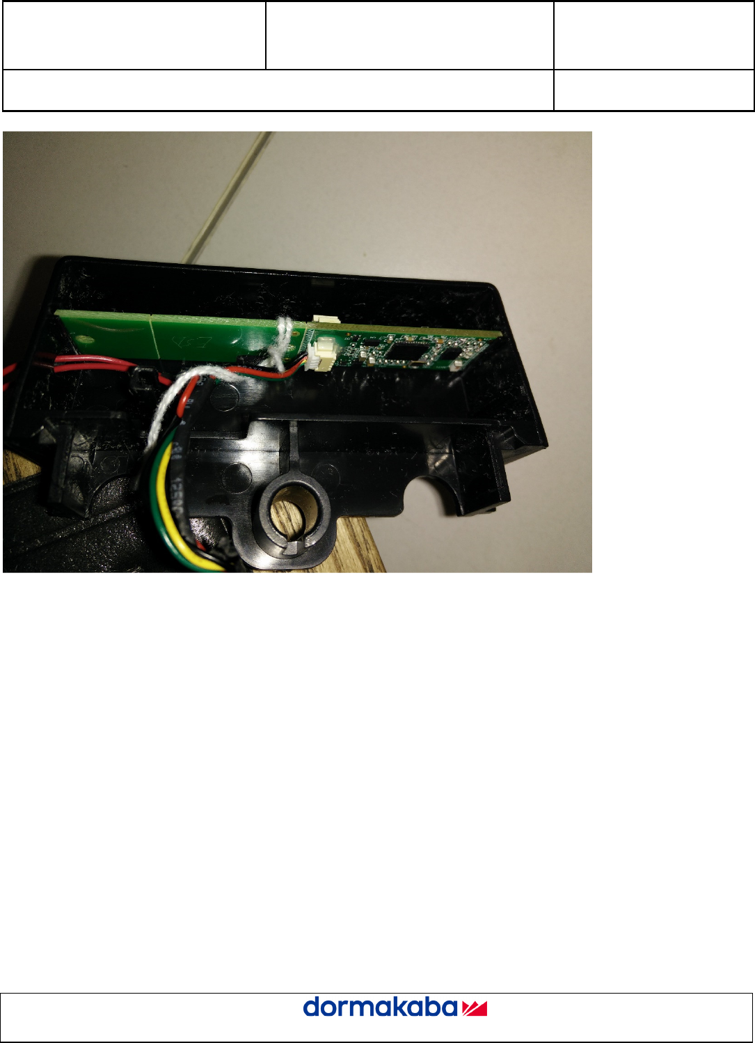
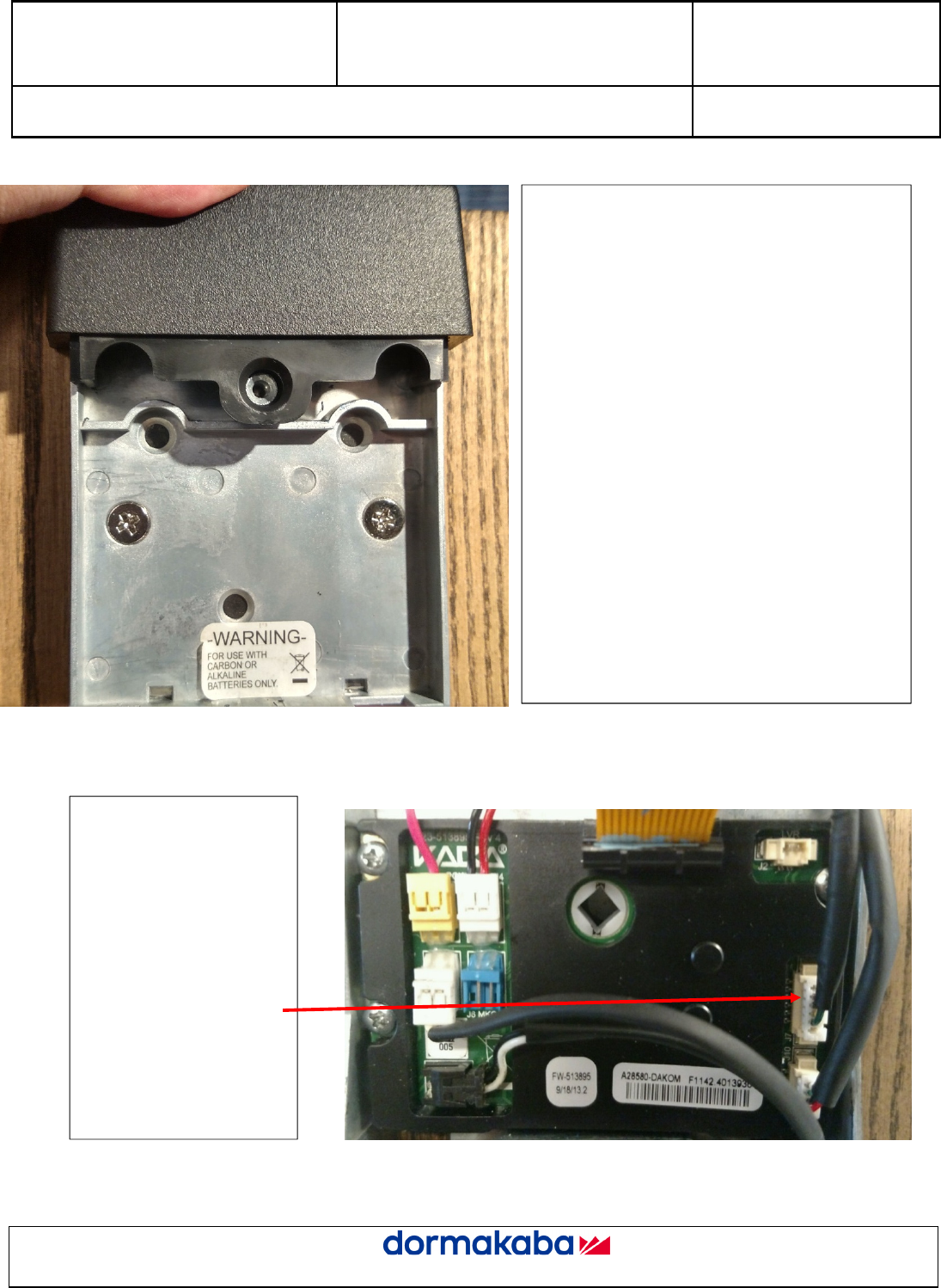
1. Install Double Decker End Cap
Install the communication boards as shown.
RF board is in the upper position.
Ensure the wires run through the notch in
the cap so they do not become pinched
when the cap is installed on the chassis.
ZigBee Gen 2 Module Installation
Guide
Document No.
Revision:
7
Prepared by: Michael Mosca Date: 05/09/2018
4 of 7
ZigBee Gen 2 Module Installation
Guide
Document No.
Revision:
7
Prepared by: Michael Mosca Date: 05/09/2018
5 of 7
Install the end cap onto the chassis by pressing it
over the screw post as shown.
Connect the ZigBee module
wire harness to the MT4
PCB as shown.
Ensure all wires are
connected and routed
properly and will not be
pinched when the cover is
reinstalled.
ZigBee Connection
ZigBee Gen 2 Module Installation
Guide
Document No.
Revision:
7
Prepared by: Michael Mosca Date: 05/09/2018
6 of 7
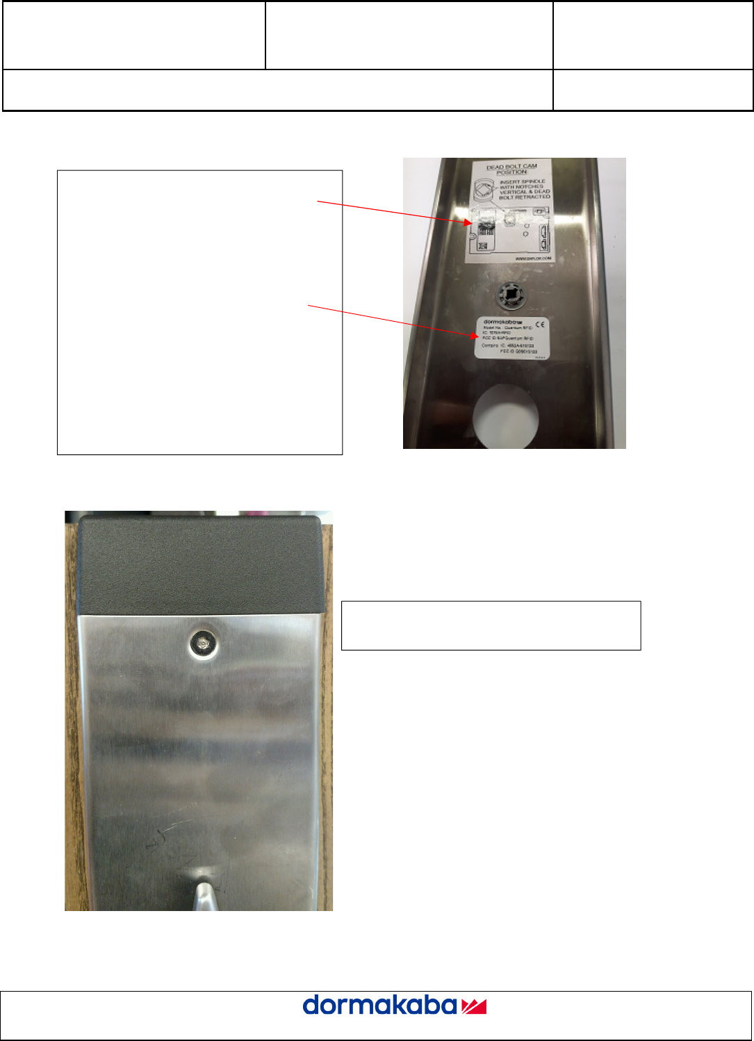
2. Label Upgrades and Additions
Reinstall the escutcheon and tighten the screws
with a tamper resistant T20 bit.
Ensure the “DEAD BOLT CAM POSITION”
label is replaced with the latest MT4 version.
Part Number: A37780
Ensure the Certification label is applied on the
inside cover of the lock.
Part Number: 038-516218
Note: Part displayed is the inside cover
ZigBee Gen 2 Module Installation
Guide
Document No.
Revision:
7
Prepared by: Michael Mosca Date: 05/09/2018
7 of 7
Hosts integrating this module must show the IDs information, i.e. Contains FCC ID Q8S515123, Contains IC: 4652A-
515123 and provide the following warnings in their documentation;
1) FCC Interference Statement (Part 15.105 (b))
This equipment has been tested and found to comply with the limits for a Class B digital device, pursuant to Part
15 of the FCC Rules. These limits are designed to provide reasonable protection against harmful interference in
a residential installation. This equipment generates uses and can radiate radio frequency energy and, if not
installed and used in accordance with the instructions, may cause harmful interference to radio communications.
However, there is no guarantee that interference will not occur in a particular installation. If this equipment does
cause harmful interference to radio or television reception, which can be determined by turning the equipment off
and on, the user is encouraged to try to correct the interference by one of the following measures:
Reorient or relocate the receiving antenna.
Increase the separation between the equipment and receiver.
Connect the equipment into an outlet on a circuit different from that to which the receiver is connected.
Consult the dealer or an experienced radio/TV technician for help.
2) ISED RSS-Gen Notice:
“Le présent appareil est conforme aux CNR d’Industrie Canada applicables aux appareils radio exempts de
licence. L’exploitation est autorisée aux deux conditions suivantes :
1) l’appareil ne doit pas produire de brouillage;
2) l’appareil doit accepter tout brouillage radioélectrique subi, même si le brouillage est susceptible d’en
compromettre le fonctionnement.”
This device complies with Part 15 of FCC Rules. Operation is subject to the following two conditions;
1) This device may not cause harmful interference.
2) This device must accept any interference received including interference that may cause undesired operation.
3) FCC/ISEDC RF Exposure Guidance Statement:
“Afin de se conformer aux exigences d'exposition RF FCC / ISED, cet appareil doit être installé pour fournir au
moins 20 cm de séparation du corps humain en tout temps.“
In order to comply with the requirements of the RF FCC / ISED, this device must be installed to provide at least
20 cm of separation from the human body at all times.