dormakaba Canada CSC79X Door Lock User Manual Manual
Kaba Ilco Inc. Door Lock Manual
Manual
INSTALLATION GUIDE
79 Series Multi-housing Lock
ASM, ESM, ASM Auto Deadbolt Mortises &
Cylindrical Models 23
/
8" and 23
/
4" Backset
PK3561
79 Series Multi-housing Lock

PK3561_10_09 • 79 SERIES INSTALLATION GUIDE
1
1. Introduction and Disclaimers ...................................................2
2. Checklist and Exploded Views
2.1. Parts and Tools List ..........................................................3
2.2. ASM/ESM 79M Standard Mode ................................................4
2.3. ASM/ESM 79T Toggle Mode ...................................................5
2.4. Autodeadbolt; ASM Inside Trim Assembly 79T . . . . . . . . . . . . . . . . . . . . . . . . . . . . . . . . . . . . . 6
2.6. Inside Trim Assembly for 79T Toggle Mode Cylindrical . . . . . . . . . . . . . . . . . . . . . . . . . . . . . . . 6
3. Installation of Standard ASM or ESM Models
3.1. Check the Mortise Handing ....................................................7
3.2. Install the Strike .............................................................8
3.3. Install the Mortise ...........................................................9
3.4. Install the Outside Housing & Inside Trim Assembly without key override . . . . . . . . . . . . . . . 10
3.5. Reversing the Outside Lever ..................................................11
4 Lock Testing ................................................................12
5. Lock Programming ...........................................................13
6. Installing the Mechanical Override ..............................................15
Appendices
A. Mortise Models
A.1. Reversing the Mortise Handing ................................................23
A.1.1. Reversible ASM .......................................................24
A.1.2. Reversible ESM .......................................................26
A.2. Additional Steps for Autodeadbolt ASM for 79M Standard Mode only . . . . . . . . . . . . . . . . . 28
A.3. Additional Steps for ASM Office for 79M Standard Mode only . . . . . . . . . . . . . . . . . . . . . . . . 29
A.4. Additional Steps for ASM/ESM Storeroom for 79M Standard Mode only . . . . . . . . . . . . . . . 29
B. Cylindrical Models
B.1. Installing Cylindrical Models ..................................................30
B.1. Install the Strike. . . . . . . . . . . . . . . . . . . . . . . . . . . . . . . . . . . . . . . . . . . . . . . . . . . . . . . . . 30
B.2. Install the Latch .........................................................30
B.3. Install the Cylindrical Unit .................................................31
B.4. Inside Trim Assembly ....................................................32
B.5. Install Outside Housing & Trim Assembly . . . . . . . . . . . . . . . . . . . . . . . . . . . . . . . . . . . . . 33
Note: This installation Guide is for the 79 Series Multi-housing lock. Images of the lock may be different than your
model. See photo on front cover.
©2009 Kaba Lodging Systems. All trademarks and registered trademarks are the property of their respective owners.
Table of Contents
1 • Introduction and Disclaimers
PK3561_10_09 • 79 SERIES INSTALLATION GUIDE
2
Target Audience
These instructions are designed for use by maintenance professionals or lock installers who are familiar with common safety practices
and competent to perform the steps described. Kaba Lodging Systems is not responsible for damage or malfunction due to incorrect
installation however arising.
Definition of Terms
In these instructions, the term ASM refers to American Standard Mortise, ESM refers to European Slim Mortise, and ADB refers to
Autodeadbolt Mortise.
Technical Assistance
For technical assistance, call: 1 800 906-4526 / +1 514 340 9025
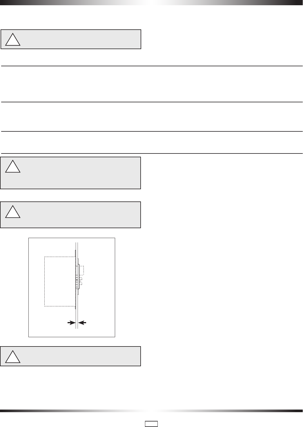
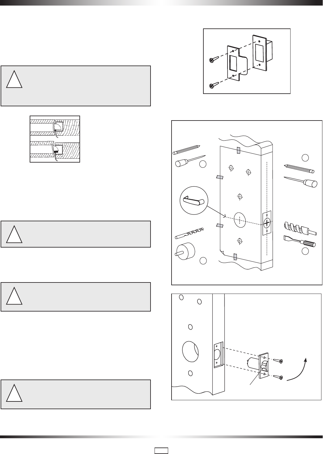
Warnings and Cautions
Door Door Frame
Mortise
Max. 3/16"
Please read and follow all directions carefully.
Important: Carefully inspect windows, doorframe, door,
etc. to ensure that the recommended procedures will not
cause damage. Kaba Lodging Systems standard warranty
does not cover damages caused by installation.
Important: The gap between the mortise front plate and
the strike must not exceed 3/16"
Caution: Wear safety glasses when making the holes.
!
!
!
!

PK3561_10_09 • 79 SERIES INSTALLATION GUIDE
3
2 • Checklist and Exploded Views
2.1 Parts and Tools List
Each lockset includes:
(A) Ouside lever handle
(or)
Parts for Mechanical override model only:
(A1) Outside lever handle
(B1) Outside housing 79M Standard mode or B3 for 79T Toggle mode
(C1) Cylinder plug
(D1) Cylinder (79M Series with cylinders keyed different only)
(E1) Cylinder cap
(E2) Instruction sheet “How to attach lever on lock"
(B) Outside housing 79M Standard mode
(B2) Outside housing 79T Toggle mode
(C) Battery holder with 3 AA batteries
(D) Mortise (ASM only shipped assembled with faceplate and 2 x 8-32 x 1
/4" screws)
(or)
Parts for cylindrical models (see illustrations in appendix B):
- cylindrical latch (see B3 page 31)
- cylindrical unit assembled with one pair of screws & 3 spacers
- four (4) other pairs of screws & 3 spacers in hardware bag
- additional extension spring
(E) Inside trim assembly, details depend on lock model (see 2.2, 2.3, 2.4, 2.5, 2.6, A2, A3, A4)
(E2) Inside Trim assembly for 79T Toggle mode (see 2.4 & 2.6 at page 6)
(N) Outdoor gasket to be ordered. ESSENTIAL FOR OUTDOOR INSTALLATIONS
(N1) Tension Spring
Parts inside hardware bag:
(F) Thumbturn (hex) spindle
(G) Square spindle
(H) Torx-head screw
(I) 3 x mounting screws (10-24, 1/8 Hex Head) or (12-24, 1/8" Hex Head for recent models only)
(J) 2 Machined screws (12-24X 1/2" Philips) & 2 wood screws (#12 X 1" Philips)
(K) Strike kit (screws, strike and ASM or Cylindrical dustbox)
(L) 1 extension spring
(M) Parts required to control thumbturn motion
(Q1) 4 pairs of Flat Head Screws 10-24 (for cylindrical only)
(R1) 3 Spacers (for cylindrical only)
(R2) 1 Cylinder with 2 keys for locks with override and cylinders keyed different only
(S) 3 spacers (see page 28) for recent Models only
Tools Required:
Safety glasses
1/2" (13mm) chisel
1/8" (3mm) drill bit
1/4" (6.5mm) drill bit (ESM only)
1/2" (13mm) drill bit
7/8" (22mm) drill bit or hole saw
Drill
Awl or center punch
3/4 (19mm) drill bit
2 1/8" (54mm) hole saw
(Cylindrical Only)
Hammer Rubber mallet
Small flat screwdriver
Torx screwdriver (T-15)
Phillips screwdriver (#2)
Fine steel file
Mortising machine
Router
Mortise faceplate router template
Adjustable square
Tape measure
Pencil
Tape
Cleaning supplies (drop cloth,
vacuum)
Spanner screwdriver #6
For doors more than 2 1/2" thick up to 3 3/4", order the
appropriate hardware bag to receive the correct length of
spindles and mounting screws. Part# 062-510189-XXX;
(XXX = choice of finish).
iFor outdoor installations, order gasket 033-512017-1.
i
PK3561_10_09 • 79 SERIES INSTALLATION GUIDE
4
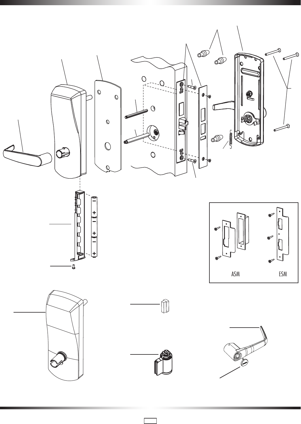
Notes: D: American Standard Mortise illustrated.
A
C
H
B
N
F
D
S
G
J
J
L
I
E
K
B1
D1
C1
A1
E1
2.2 ASM, ESM, 79M Standard Mode (For Cylindrical, see Appendix B)
PK3561_10_09 • 79 SERIES INSTALLATION GUIDE
5
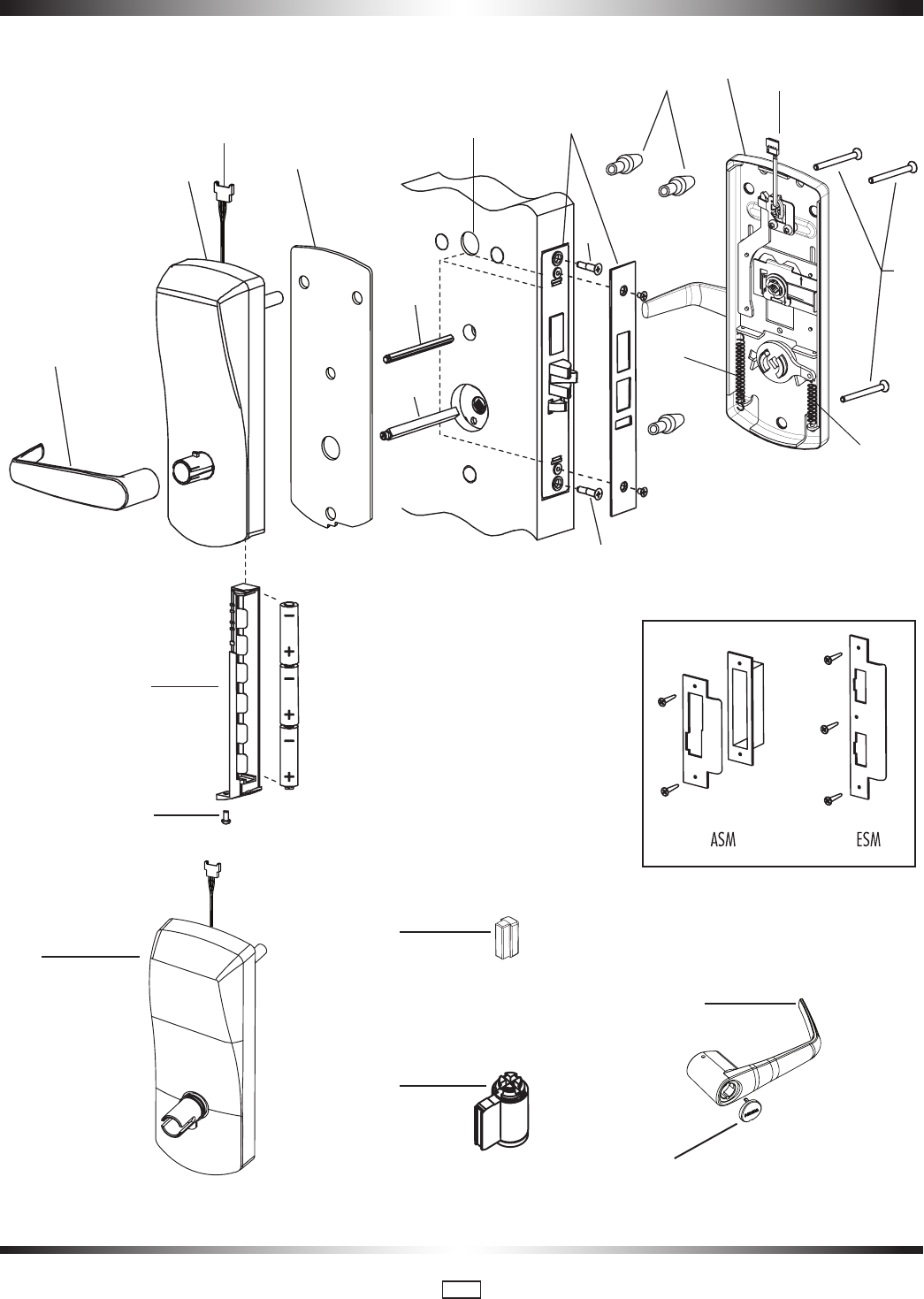
Notes: D: American Standard Mortise illustrated.
A
C
H
B2
W1
W2
N1
H1
N
F
D
S
G
J
J
L
I
E2
K
B3
D1
C1
A1
E1
2.3 ASM, ESM, 79T Toggle Mode (For Cylindrical, see Appendix B)
PK3561_10_09 • 79 SERIES INSTALLATION GUIDE
6
For Right Hand Lock
Autodeadbolt
Right Hand
Autodeadbolt
Left Hand
ASM Right &
Left Hand
For Left Hand Lock
E2
M2
M2
N1 N1L L
LEVER
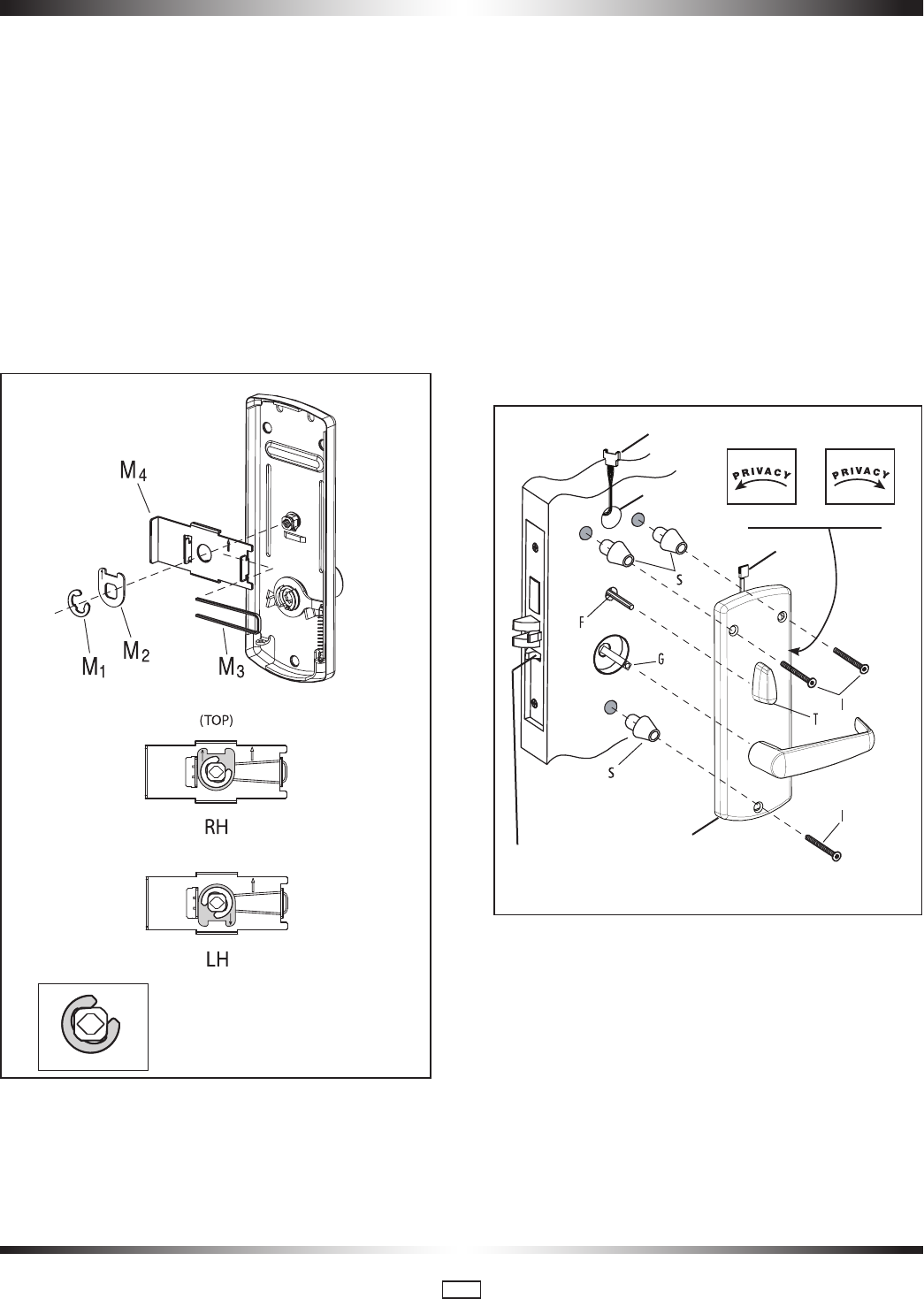
2.4 Autodeadbolt; ASM Inside Trim Assembly for 79T (Toggle Mode)
(for 79M standard mode with Autodeadbolt; ASM Office and ASM/ESM Storeroom models, use parts (M) as shown in Appendix
A2)
NOTE:
The inside trim assembly (E) for ASM and ADB on 79T models includes the parts (M) as shown below. Position of stopper
M2 is very important
2.5 Cylindrical Unit and Inside Trim Assembly for 79M Standard Mode see Appendix B
2.6 Inside Trim Assembly 79T Toggle Mode Cylindrical
PK3561_10_09 • 79 SERIES INSTALLATION GUIDE
7
3 • Installation of Standard ASM OR ESM Models
3.1 Check the Mortise Handing
Compare the mortise with the diagram below. If the
mortise is the correct handing for the door, continue
with step 3.2.
Refer to Appendix A.1 to change the handing of a
field-reversible mortise.
i
For LH (left hand) and
RHR (right hand reverse)
For RH (right hand) and
LHR (left hand reverse)
ASM
For LH (left hand) and
RHR (right hand reverse)
For RH (right hand) and
LHR (left hand reverse)
ESM
Door Handing (Top View)
Right Hand (RH)
Left Hand (LH)
Right Hand Reverse (RHR)
Left Hand Reverse (LHR)
PK3561_10_09 • 79 SERIES INSTALLATION GUIDE
8
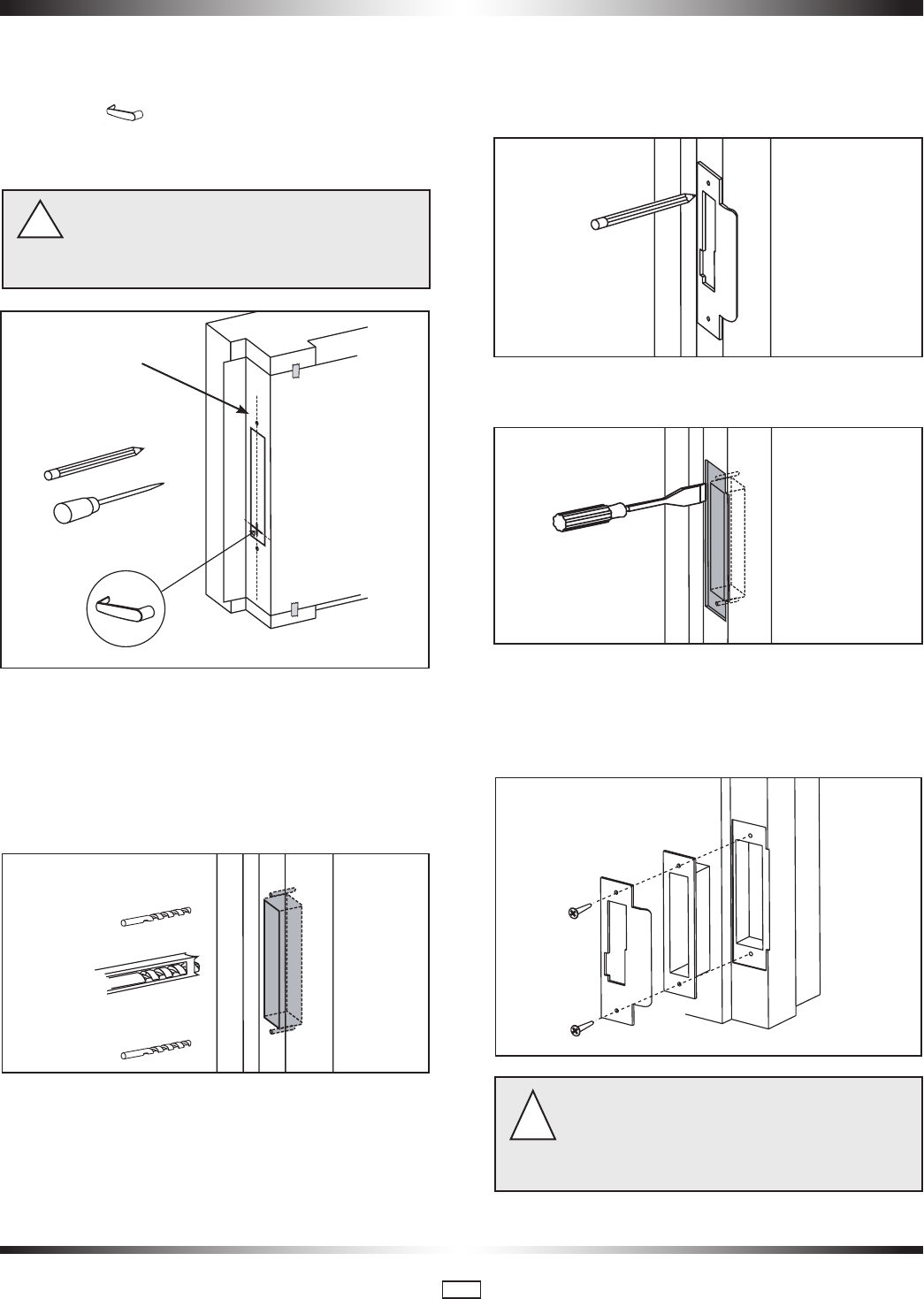
3.2 Install the Strike
1. Align the paper template on the door frame at the desired
handle height ( ), and along the vertical center line of the
mortise (CL), which is also the center line of the door edge,
allowing for any bumpers on the door frame.
Respect applicable building codes regarding handle
height.
Note that the centerline of an ESM mortise does
NOT pass through the screw holes on the strike.
!
2. Mark the locations of the dust box cutout and mounting
screws for the strike.
3. Mortise the door frame to receive the dust box, and drill the
pilot holes for the mounting screws (dimensions and depths
marked on template).
4. Position the strike against the doorframe and align it with the
mounting screw holes. Trace the outline of the strike.
5. Remove material from within the strike outline so that the
strike will be flush with the doorframe.
6. For ASM, install the dust box (optional for wood door frames,
required for metal door frames), and check the strike handing
on the template. Install the strike using the screws provided.
Use wood screws for wood frame and machine screws for
steel frames.
When strike is installed on wood frames under one
inch thick, wood screws supplied are not adequate. use
screws of efficient length to engage the structural stud
behind the frame. Use only the strike and dust box sup-
plied. Use of non-approved parts may void the warranty.
!
(CL)
PK3561_10_09 • 79 SERIES INSTALLATION GUIDE
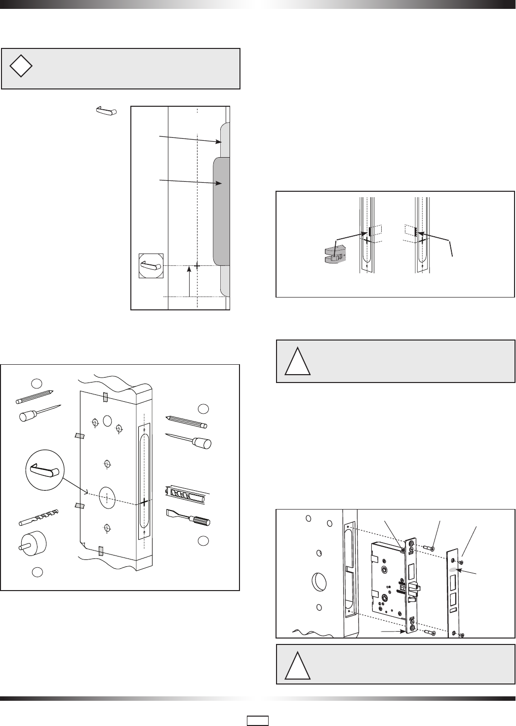
9
If using the installation jig to prepare the door, refer to the
instructions provided with the jig, then proceed with step
6 below.
i
1. Mark the handle ( )
height on the edge of the door,
as determined directly from the
strike.
For ASM, the axis of rotation
of the handle is level with the
bottom lip of the strike.
For ESM, the axis of rotation of
the handle is 1-1/4" above the
bottom lip of the strike.
For cylindrical models, see B2
in Appendix B
2. Align the template along the
vertical center line of the mor-
tise (CL) at the desired handle
height, and tape it to the door.
Mark all holes and cutouts for the mortise in the edge of the
door and remove the template.
3. Locate the two sets of vertical fold lines on the template
allowing you to adjust the positioning of the template depend-
ing on the bevel of the door.
If the door has no bevel, fold the template along the solid lines.
Align the fold with the edge of the door and mark the holes for
the lock. Repeat on the other side of the door.
If the door has a 3º bevel, fold and align the dashed line
marked “H" on the template with the higher-beveled edge
of the door and mark the lock holes on that side of the door.
Repeat on the side with the lower-beveled edge using the
dashed line marked “L". Remove the template.
4. Prepare the cut-outs for the mortise in the edge of the door
using a mortising machine, router and chisel (for dimensions,
refer to template).
Ensure clearance is provided for moving latch parts as indi-
cated on the template.
5. Drill the holes in the sides of the door (for dimensions, refer
to template).
Drill from both sides of the door to prevent unsightly
damage
!
6. For ASM only, check the bevel of the mortise. If adjust-
ment is required, loosen bevel screws (R) and adjust mortise
front plate angle to match the bevel of the door. Re-tighten
screws.
Install the mortise with 2 screws (Q). Use wood screws for
wood doors and machined screws for steel doors.
Install mortise faceplate (P) with the two 8-32 x 1/4" screws
provided.
The ESM faceplate must be installed so you can read the
logo (see arrow in figure above right-side-up for proper
operation.)
!
3.3 Install the Mortise
ESM
Strike
(ESM)
ASM
Strike
11
/4"
Door
(CL)
2
5
4
3
RH/LHR (ASM shown) LH/RHR
Logo
P
Q
R
R
PK3561_10_09 • 79 SERIES INSTALLATION GUIDE
10
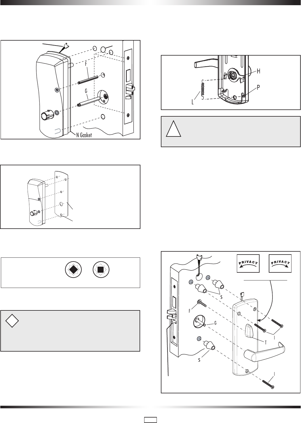
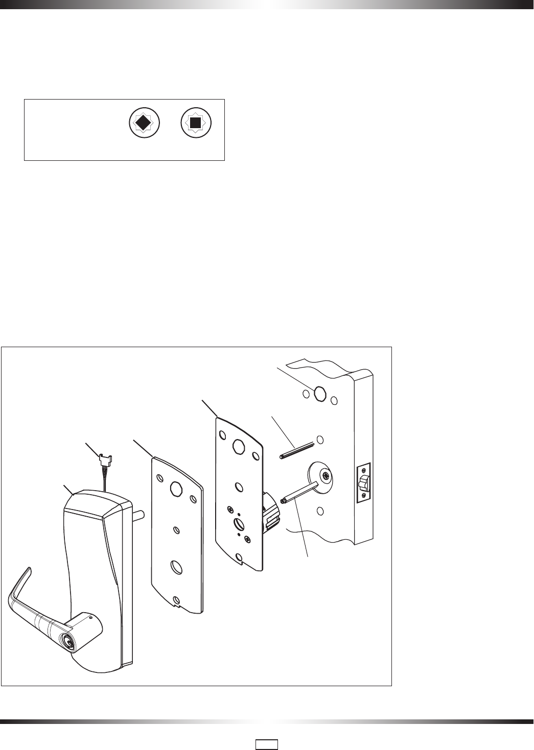
3.4 Install the Outside Housing and Inside Trim Assembly for 79 Series
(for 79 with Mechanical Override, see page 15)
A- For Mortise
1.Install the gasket (N) (if required) on the outside housing prior
to assembly, aligning the notch in the gasket with the battery
compartment. See page 3 for gasket information.
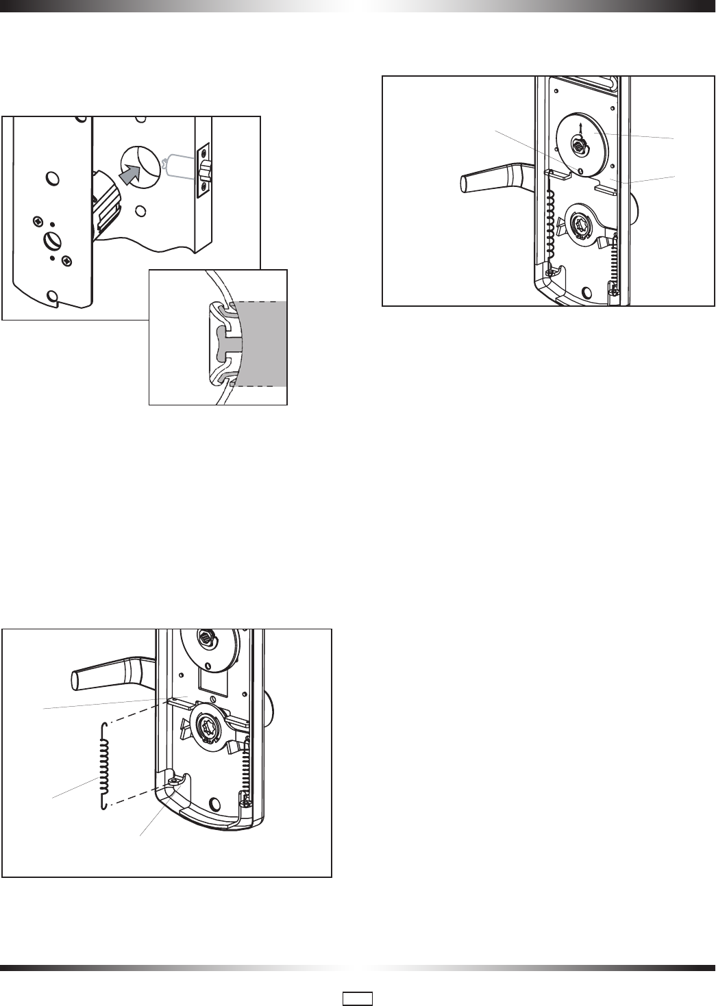
2. Insert the slotted end of the square spindle (G) into the out-
side lever hub until it locks, at an angle of 45º. (The spindle can
be removed by pulling on it, if oriented incorrectly.)
3. Insert the thumbturn spindle (F) in the upper hub of the
outside housing. (It will clip in place.)
If installing the lock with mortise outdoors, order the
proper Gasket (See page 3).
For doors more than 2 1/2" thick, order the appropriate
hardware bag to receive the correct length of spindles
and mounting screws. (See page 3)
i
4. Place the outside housing on the door so that the spindles
engage the hubs on the mortise.
For 79T Toggle Mode, insert cable W1 in hole H1 on the door
(See fig. above)
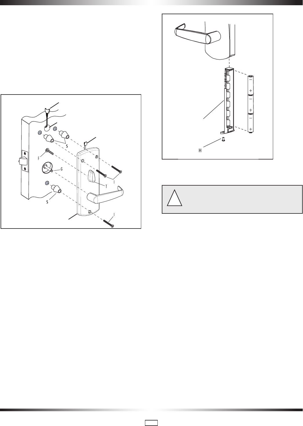
5. On the inside trim assembly turn the lever to the correct
horizontal rest position for the handing of the door. Install the
tension spring (L) between the handle (H) and the post (P).
For 79M with ASM Office and ASM/ESM Store-
room models, refer to Appendix A.2, A.3, A.4 at this point.
For 79M Cylindrical, refer to Appendix B.
For 79T Toggle Mode, see 2.6 on page 6
!
5. Put the thumbturn (T) in a vertical position. Place 3 spacers
(S) on the door (for recent models only) and place the inside
trim assembly on the door so that the upper and lower spindles
(F) and (G) engage the thumbturn and the inside lever. Fasten
to the outside housing using the three 1/8" hex drive mount-
ing screws (I ). Install the screws without tightening. Verify the
inside lever and thumbturn operates smootly. If not move the
inside and outside housings slightly. Then tighten the screws.
For Autodeadbolt only, apply the privacy thumbturn sticker
as shown. If in doubt as to the direction of the arrow press the
auxiliary latch (X) to extend the deadbolt, and verify in which
direction to rotate the thumbturn to reach the horizontal (pri-
vacy) position.
Outdoor Gasket
Notch
Square Spindle Position
correct incorrect
H1W1
(Toggle mode only)
RH/LHR LH/RHR
X
PK3561_10_09 • 79 SERIES INSTALLATION GUIDE
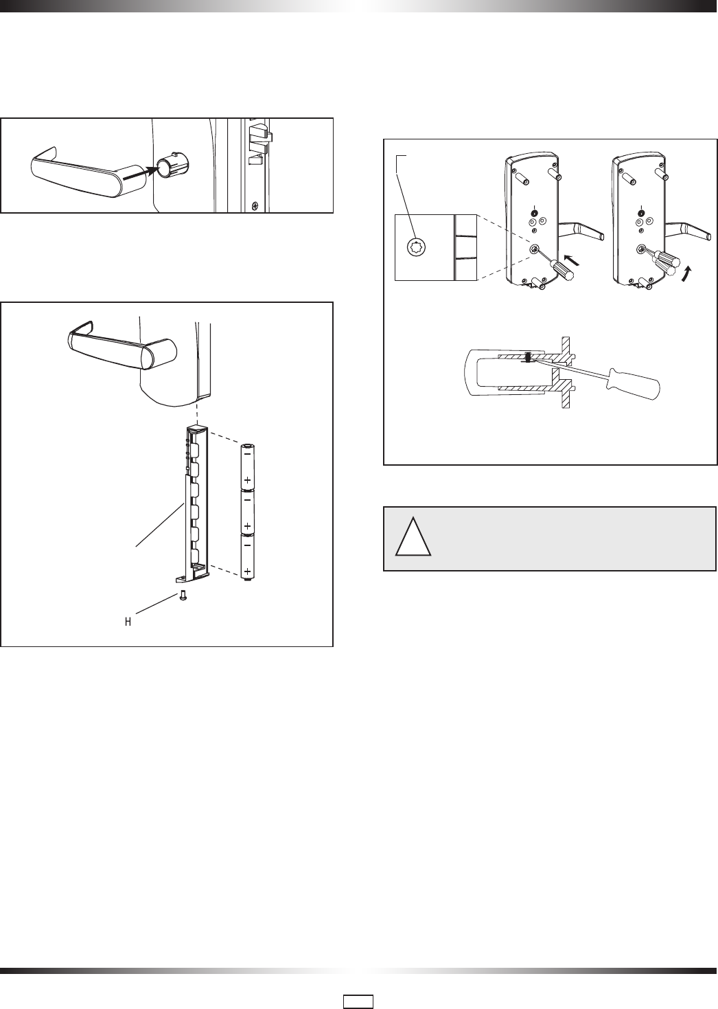
11
6. Assemble the lever on the outside housing, in the horizontal rest
position appropriate to the handing of the door. Simply push the lever
onto the tube until it clicks in place. If more force is required, use a
rubber mallet. Test the attachment of the handle by pulling
smartly on it. (For locks with mechanical override, see p.15)
7. Three AA batteries should already be installed in the battery
holder (C). Insert the battery holder into the outside housing
and secure it using the 6-32 x 5/16" (7.9mm) Torx drive screw
(H).
3.5 Reversing the Outside Lever
(for Series without Mechanical Override)
The lever is field reversible. If the handing is incorrect, insert a
small pick or flat screwdriver in the hole in the hub as shown.
Gently pry back the spring clip inside the hub, and remove the
handle.
3.6 For Cylindrical, see p.29
If the lock makes a continuous buzzing noise or the red
LED lights continuously, reset the electronics by removing
the battery holder for ten seconds then reinsert it.
!
C
Access Hole
cut-away view
PK3561_10_09 • 79 SERIES INSTALLATION GUIDE
12
Caution! Perform the following procedures in order, with
the door OPEN unless otherwise indicated.
!
Inside Lever:
Turn the inside lever downward. The latch bolt retracts fully.
If the lever or the thumbturn feels tight (hard to turn or does
not return easily to its horizontal position), check the alignment
of the lock assemblies. Loosen the mounting screws and shift
the inside trim assembly slightly until the friction is eliminated.
If the problem persists check the position of the holes on the
door (compared to the mortise).
Standard Deadbolt:
Turn the thumbturn back and forth. The deadbolt extends and
retracts fully and without undue friction.
Turn the thumbturn to extend the deadbolt again then turn the
inside lever. The deadbolt and the latch bolt retract simultane-
ously and fully without undue friction.
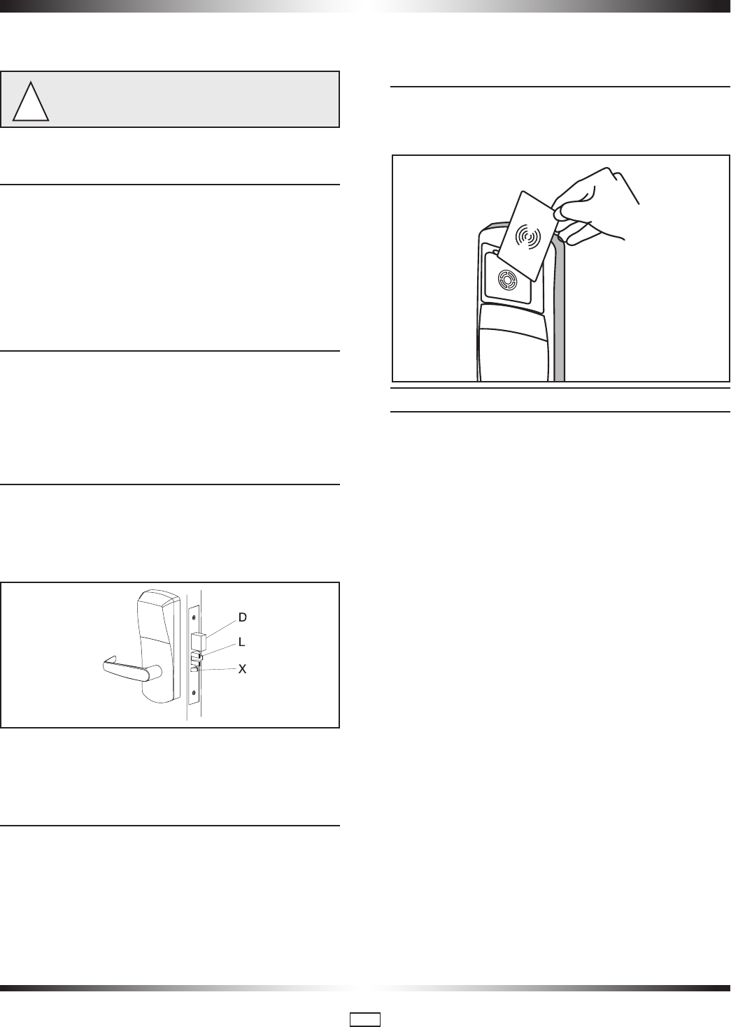
Optional Autodeadbolt:
Press and hold the auxiliary bolt (X). The deadbolt (D) will
extend. Keep the auxiliary bolt depressed, and turn the inside
lever all the way down and hold it there. The latch (L) and
deadbolt retract together.
Release the auxiliary bolt (X), then let the inside lever return to
a horizontal position. The deadbolt will remain retracted while
the latch will extend.
Outside Lever:
Turn the outside lever downward. The latch bolt does not
retract.
If the latch bolt retracts, verify that the batteries are properly
installed.
If the lever feels tight (hard to turn, or does not return easily
to its horizontal position), ensure the square spindle is not too
long.
Electronics and Card Reader:
Test the lock’s response to keycards: a Test keycard, a Grand
Master keycard, and an Emergency keycard. Present card to
reader.
A. Test the Lock Before Programming
Normal Entry: Verify that the deadbolt is retracted. Present test
keycard to reader. The red and green LEDs each flash once
and then the green LED flashes for four seconds.
Turn the outside lever downward while the green LED is flash-
ing. The latch retracts fully. Release the lever then turn it again
after the LED stops flashing. The latch must not retract after
the LED stops flashing without first presenting the keycard.
Privacy Switch: Turn the thumbturn to the horizontal position.
(On autodeadbolt models, first extend the deadbolt by pressing
the auxiliary latch (X). On storeroom locks, skip this test.) Use
the Test keycard in the reader but do not turn the lever. Instead
of the normal sequence of indicator lights you should see the
following: the red and green LEDs each flash once and then
the green LED flashes once, followed by the red LED flashing
continuously for four seconds. If you see the flashing green
LED there is a problem with the privacy switch.
.
4 • Lock Testing For mechanical override testing , see Step 8 Page 19

PK3561_10_09 • 79 SERIES INSTALLATION GUIDE
13
B. Privacy Function: Lockout of Keycards
Turn the thumbturn to the horizontal position for privacy. (On
autodeadbolt models press and hold the auxiliary latch (X) to
extend the deadbolt, then turn the thumbturn for privacy. On
storeroom locks, skip this test.)
Present the Grand Master Keycard to the reader. The red LED
flashes once. Then turn the outside lever downward. The latch
does not retract.
C. Emergency Keycard Access:
Deadbolt Override
Present the Emergency keycard to the reader. The red LED
flashes for 4 seconds. Turn the outside lever downward while
the red LED is flashing. The deadbolt and latch bolt retract
simultaneously and fully.
While standing outside the room close the door and ensure that
it is properly latched. Open the door using the Grand Master
keycard using the same procedure.
D. Inside and Outside Lever Detection for
79T Toggle Mode only.
Before fastening the inside trim assembly to the outside
housing assembly, check that the lever switch (W2) is well
connected to the wire harness (W1) (see p.5). Check that the
thumbturn (T) is in the vertical position as shown in step 5
page 10.
Present the emergency card to the reader. (The LED will flash
for 4 seconds). Rotate the lever as soon as the LED starts
flashing - The LED will stop flashing. If it does not, there is a
problem with the lever detection
Deadbolt Deactivation:
A. Deadbolt Deactivation by Thumbturn
While standing inside the room, close the door, and then turn
the thumbturn to extend the deadbolt. (If the lock has an auto-
deadbolt mortise go to step B below).
Turn the thumbturn to retract the deadbolt. Repeat.
B. Deadbolt Deactivation by Lever
While standing inside the room, close the door and turn the
thumbturn to the horizontal position to extend the deadbolt
(or to select privacy on autodeadbolt models). Open the door
by turning the lever. The deadbolt and the latch bolt retract
simultaneously and fully. Take note of any excess friction
which might necessitate filing the strike (deadbolt area only).
Repeat.
Once a lock is correctly installed on the door and the battery
pack inserted, it will go into locked mode (always locked). In
this unprogrammed state (virgin mode), a lock can be unlocked
using one of the Test Keycards provided in a pack with the
installation equipment. While in virgin mode, the lock has no
address or date/time and will relock automatically after 4 sec-
onds once unlocked using a Test Keycard.
Locks need to be programmed to give them their door ID, to
synchronize them with the system date and time and program
them with all of the property setup settings (employees, sub-
master levels, etc.)
Once ATLAS-Multi-housing is installed on the dedicated laptop
or PC and the property’s System Setup has been configured by
the customer, locks are programmed using a Maintenance Unit
(M-Unit) and an Infrared Programming Module (IPM).
STEP 1 - Create Lock Configuration File
Log in to ATLAS-Multi-Housing and select Transfer Files
M-Unit > PC from the main Admin menu
Select Expiry for the length of time you want the files to remain
in the M-Unit. 24 hours is the default
If you select “Yes” to Electrical Override, another field “Number
of Overrides” appears, enabling you to limit the maximum
5 • Lock Programming

PK3561_10_09 • 79 SERIES INSTALLATION GUIDE
14
number of times lock electronic overrides can be performed
with the M-Unit before resynchronization
Select unit(s) from list that appears when you click on the tree
at right
Click on Save
The folder to hold your files to transfer to the locks, is called
ATLAS M-Unit and is located in the Main folder for your ATLAS
application
Leave the default name that shows the date the file was cre-
ated. The extension is .lcf for “lock configuration file”
Click Save
STEP 2 – Create Initialization and Programming key-
cards
An Initialization keycard initializes the lock during a first-time
installation, or after an interruption of battery power (e.g. dur-
ing a battery replacement, or whenever the battery power is
temporarily disconnected).
Log in to ATLAS-Multi-Housing and select Make keycards
from the main Staff menu
Select Initialization from the drop down menu
Enter the number of cards required
Placed the keycards on the encoder
Clear label the Initialization keycards
A Programming keycard prepares the lock for communica-
tion with the M-Unit. If the lock has never been initialized, the
Initialization keycard must be presented to the lock prior to the
Programming keycard. If communication with the lock does
not begin within 30 seconds, the lock will return to the normal
state with no changes to its programming.
Log in to ATLAS-Multi-Housing and select Make keycards
from the main Staff menu
Select Programming from the drop down menu
Enter the number of cards required
Placed the keycards on the encoder
Clear label the Programming keycards
STEP 3 - Synchronize ATLAS-Multi-Housing with the
M-Unit
Turn on M-Unit
Ensure that your M-Unit is connected directly to the USB port
Click on the HotSync icon and you will receive a message that
the HotSync is in progress
Return to the main screen by clicking on the Applications icon
STEP 4 - Program Infrared Programming Module
(IPM)
Go to the main page of the ATLAS application on the M-Unit
Login with the same name and password you use for the main
application
Click on ATLAS at top left, and it changes to Tools, with a
dropdown menu
Select IPM from the pulldown menu under Tools
Click on IPM Configuration. A list of available IPMs appears
Select the IPM you want to use
Click on Program and hold the M-Unit up to the IPM you are
programming. The M-Unit must be at least 2” away from the
IPM and the panel on top of the M-Unit must be parallel to the
IrDA window (small red glass panel) in the IPM, with the M-Unit
screen facing upwards.
STEP 5 - Program Lock
Click on ATLAS on the M-Unit screen
Tap on Doors. The list appears with all the lock numbers that
need to be programmed
PK3561_10_09 • 79 SERIES INSTALLATION GUIDE
15
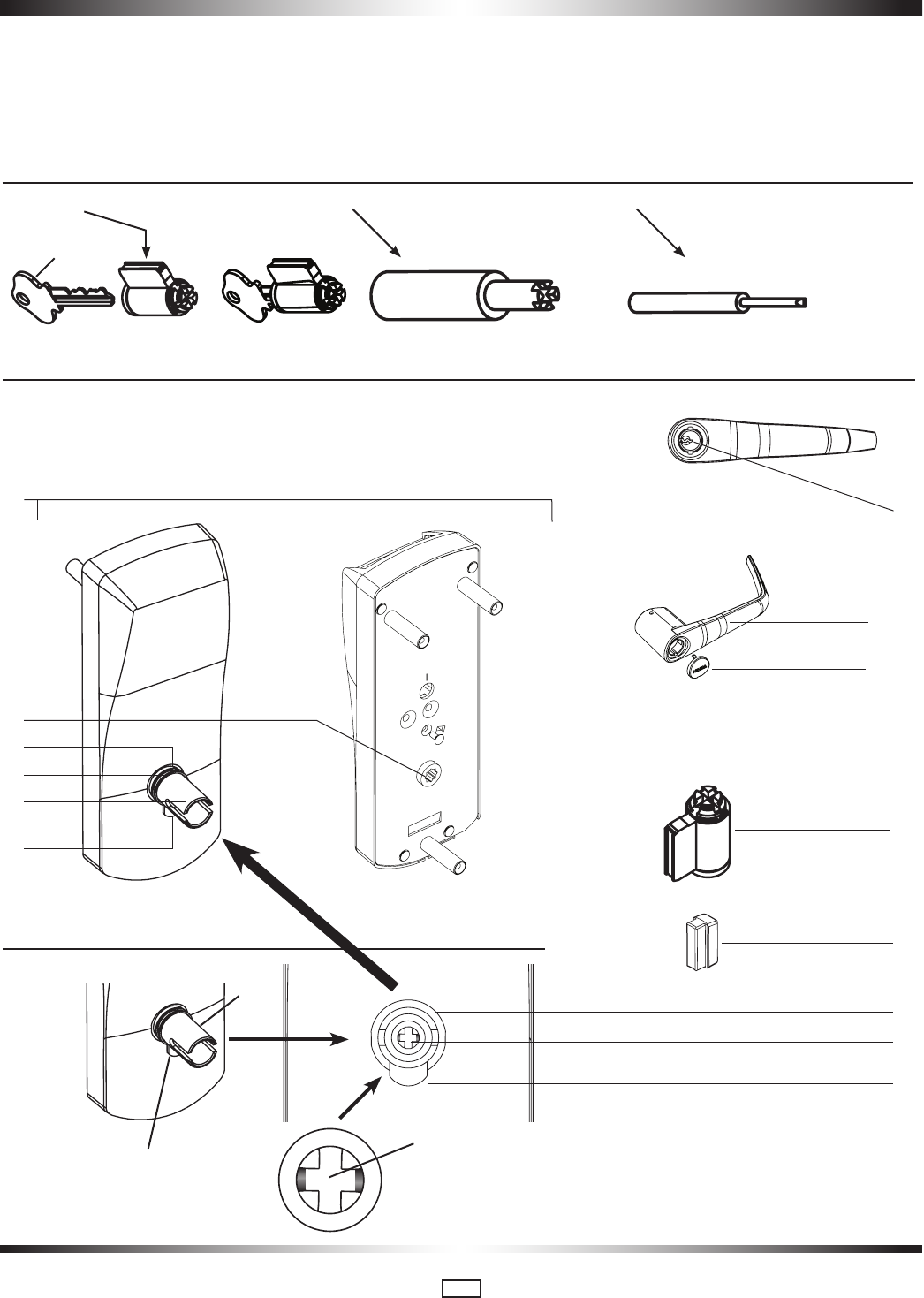
6 • Installation of Mechanical Override Model
(E)
(L)
Override
Shaft
Parts and Tools List
Tools Required:
Cylinder (J, provided with lock) or equivalent ( T ) Small flat scewdriver (less that 1/8")
(A) Lock housing
(B) Inside drive hub
(C) Nylon washer
(D) Spring washer
(E) Drive tube
(F) Lever catch
(G) Countersink
(H) Lever handle
(I) Cap
(J) Cylinder
(K) Cylinder plug
(L) Override shaft
Diagram of lock:
Facing view of drive tube: (E)
BackFront
(A)
(H)
(E)
(B)
(D)
(F)
(I)
(J)
(K)
(E)
(L)
(F)
(G)
(C)
(F)
(N)
PK3561_10_09 • 79 SERIES INSTALLATION GUIDE
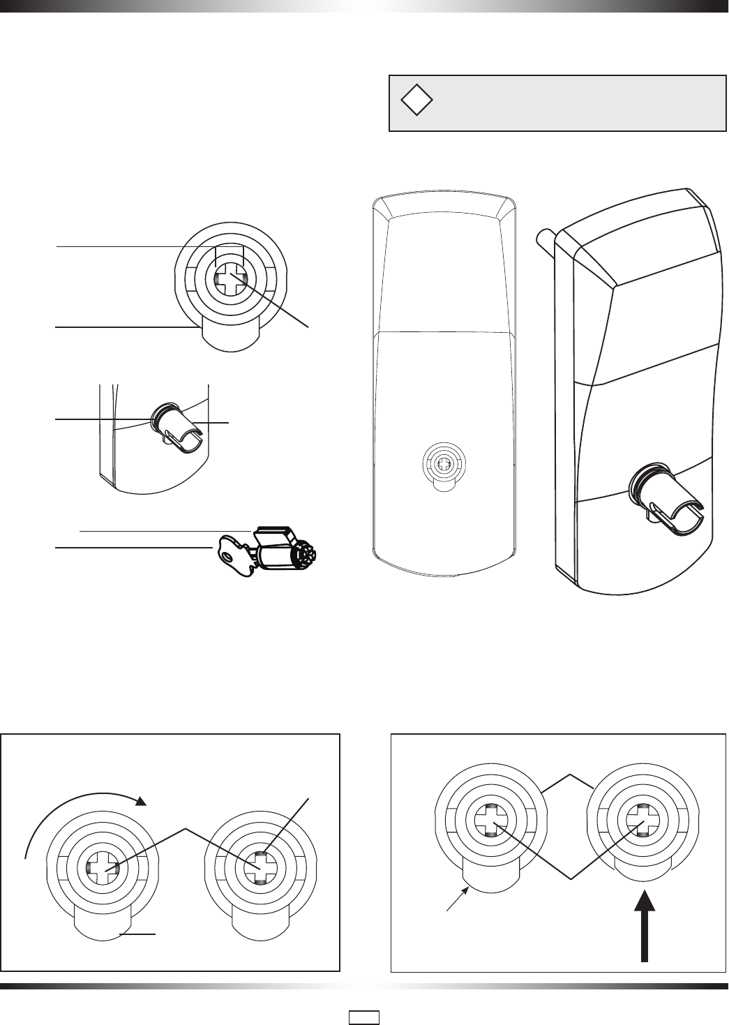
16
2. Push in the lever catch (F) firmly. (see Fig. 2) to be flush
with drive tube diameter
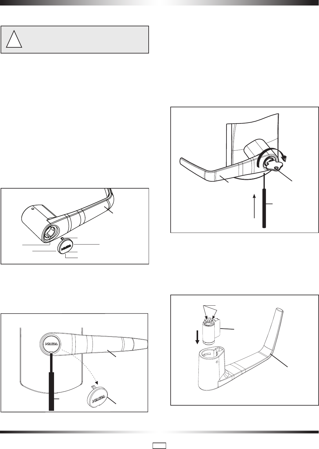
2. Preparing the outside housing for the installation of the lever handle
1. Insert the cylinder (J) to be used as a tool or equivalent tool
to rotate the override shaft (L) and turn it clockwise until it stops
so that the two small indents (M) on the cross are now
vertically in line. (Fig.1)
(F) (L)
(E)
(M)
(C)
(N)
(J)
Fig. 1 Fig. 2
lever catch (F)
Push lever
catch (F) in
1.
Upon unpacking, lock housing with mechanical override should look like the diagram below with:
(M) The small indents on the cross of the override
shaft in line Horizontally
(C) The nylon washer and the spring washer on
the drive tube
(F) The lever catch in the out position
(J) Cylinder and 2 keys for 79M keyed different only
included in the hardware bag
(F)
Override
Shaft (L)
Indents (M)
In vertical
position
(L)
(E)
Important: Assemble the lever, cylinder and lock
components before affixing the entire unit to the door.
i
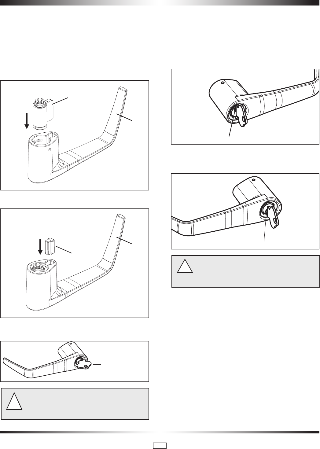
PK3561_10_09 • 79 SERIES INSTALLATION GUIDE
17
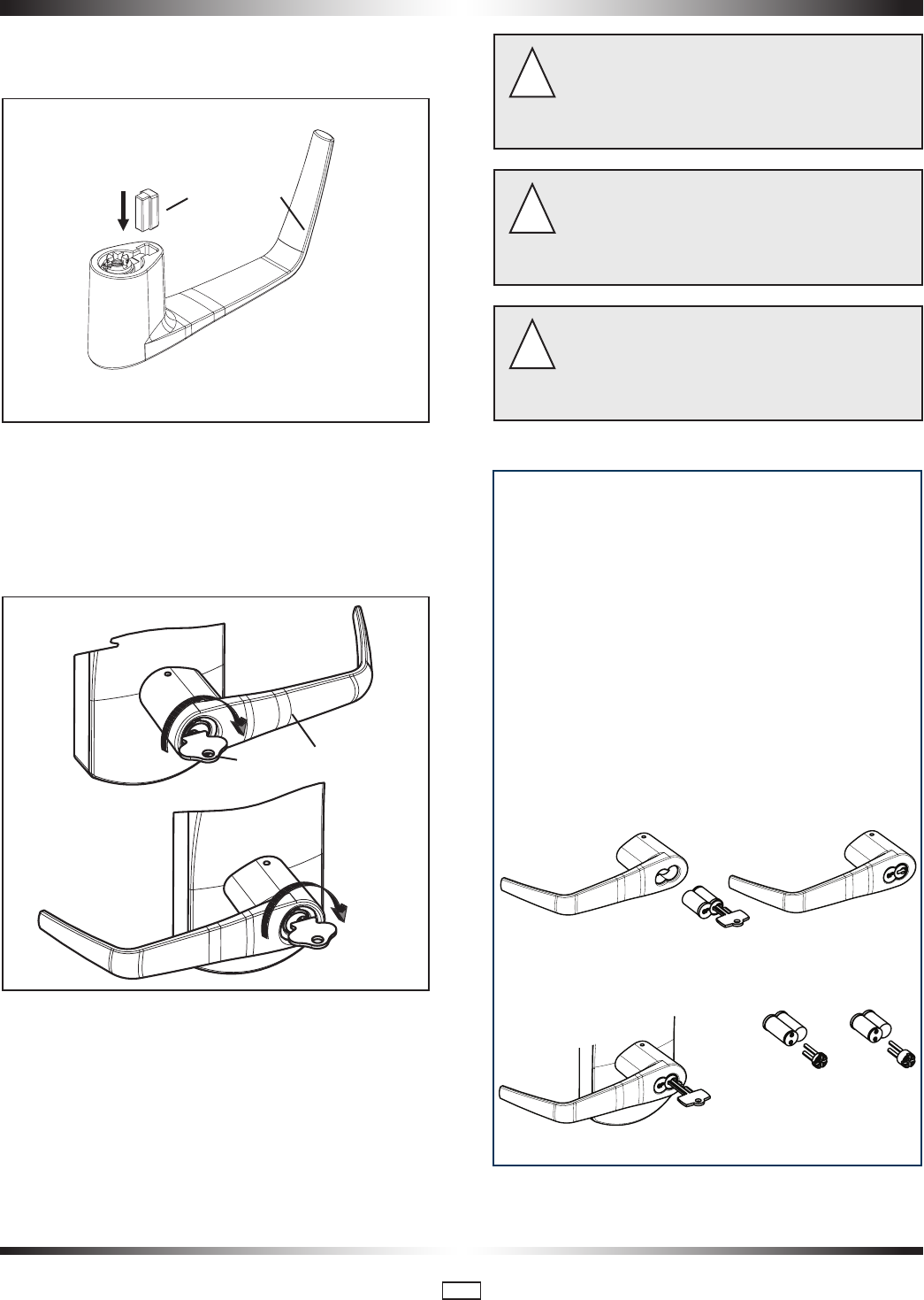
NOTE: For locks with Best Removable core, skip steps a,b &
c below. Assemble Best core and adaptors as per instructions
F5, F6 & F7 on page 21. Then follow step 4 of this page. Step
to attach the lever handle to the lock housing.
a. Insert the cylinder (J) without key (N) into the lever handle
(H) (see Fig.3)
b. Put the cylinder plug (K) into the lever (H) (see Fig.4)
c. Insert key (N) into cylinder (J). Hold plug (K) in position. (See
Fig. 5).
Caution: If the Lever is Not Assembled with the key in the
position shown in Fig. 6 & Fig. 7, the inside mechanism
of the lock could be damaged if the lever is rotated and
forced.
!
3. Preparing the lever handle and cylinder for
installation
Right-handed Lever handle: Turn the key (N) aprroximately
to 100º clockwise so that it is in the vertical position and the
recess entry for key is in the top position. (See Fig. 6)
Left-handed lever handle: Turn the key (N) approximately to
100º clockwise so that it is in the vertical position and the
recess entry for key is in the bottom position. (See Fig. 7)
The key (N) and the recess entry for key must be in the
positions shown in Figs 6 & 7 before placing the lever
handle on the housing or the lever and the override
mechanism will not work.
!
Troubleshooting:
If you have assembled the lever and housing with
the key (N) in the wrong position, the key (N) will
get stuck. To remove the key (N), turn it so that
it is in the vertical position and insert a small flat
screwdriver (T) (see page 15) into the hole under the
lever handle to push Lever Catch (F) in (see page16
Fig.2). Remove lever, remove key. If it is still stuck,
turn the key 90º clockwise to the horizontal position
and push the Lever Catch (F) in again with the small
screwdriver (T). Remove key (N).
Fig. 6
Recess entry for key in the top position
Fig. 7
Recess entry for key in the bottom position
4. Steps to attach the lever handle to the lock
housing
*NOTE: the position of the key is very important
Fig. 3
(J)
(H)
Fig. 4
(H)
(K)
Fig. 5
(N)
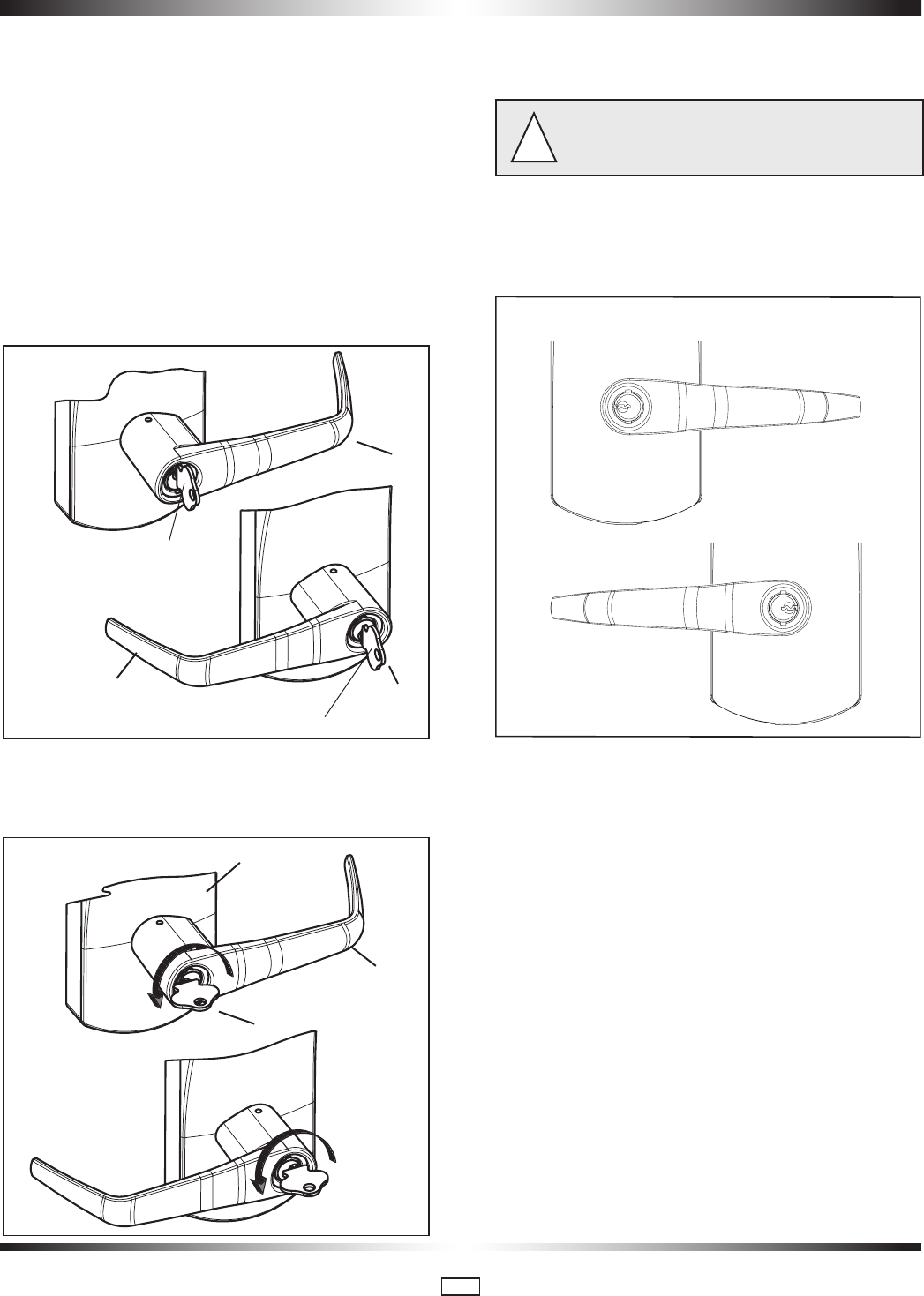
PK3561_10_09 • 79 SERIES INSTALLATION GUIDE
18
7. Fit the lever handle (H) onto the drive tube (E) see page 15.
It should rest approximately 1/16" from the body of the hous-
ing. If not, wiggle and jiggle key (N) to align cylinder (J) with
override shaft (L)(See Fig. 8)
If it can’t be pushed that close to the housing, the lever catch (F) is
probably not pushed in. Push it in. (see fig 2 page 16)
If the lever catch (F) is stuck, the override shaft (L) is in the
wrong position. (see fig 2 page 16) The two small indents (M)
on the cross of the override shaft (L) must be vertically aligned
as in fig 2 page 16
right-handed lock
Recess entry for key in TOP Position
Recess entry for key in BOTTOM Position
left-handed lock
Fig. 8
(H)
(N)
(H)
8. Press the lever (H) firmly against the housing while turning the
key (N) counterclockwise (this applies to both right-handed and
left-handed locks) until it is in the horizontal position. (Fig. 9)
Fig. 9
right-handed lock
left-handed lock
(Housing)
(N)
(H)
If it is not possible to turn the key (N) counter-clockwise
to complete this step, the spring washer (D, see page 15)
may be too tense:
!
Hit the lever carefully with a rubber mallet to loosen the spring
washer (D). (you may want to cover the lever handle (H) with a
cloth or other material to protect the finish of the metal)
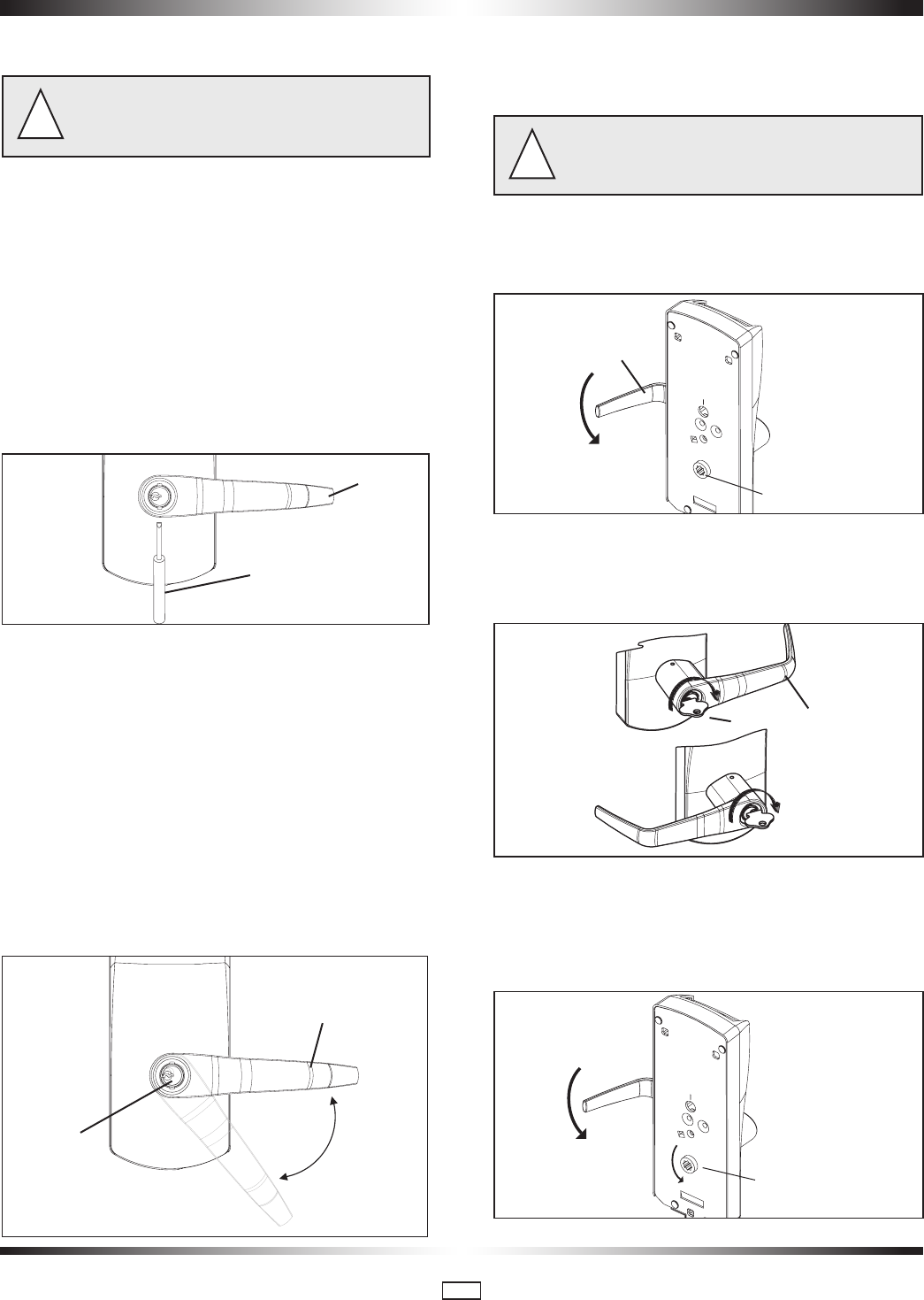
9. Remove the key (N). The lock will look as shown in Fig.10.
right-handed lock
left-handed lock
Fig. 10
Gently check the rotation of the lever handle (H). It should
easily rotate approximately 45º.
Troubleshooting:
Right-handed Lock: Turn the lever handle (H) clockwise without
forcing it. If it stops at approximately 15º, it was not assembled
correctly as shown in step 4 (Fig. 6 & 7). Do not try to force it to
turn. Release the lever handle (H). Insert the small screwdriver
(T, page 15) into the small hole on the underside of the lever
handle (H) and push in the lever catch (F) see page 16 fig.2.
Re-do steps 2, 3, 4 & 5.
Left-handed Lock: Turn the lever handle (H) counter-clockwise
without forcing. The drive hub (B) (Fig.12 page 19) should not
rotate when the lever handle (H) is turned. If it does, it was not
assembled correctly as shown in step 4 (Fig. 6 & 7). Release
the lever handle (H). Insert the small screwdriver (T, page
15) into the small hole on the underside of the lever handle
(H) and push in the lever catch (F). Re-do steps 2, 3, 4 & 5.
5. Attaching the Lever Handle to the Lock (with the key as shown in Fig. 6 & Fig. 7)
PK3561_10_09 • 79 SERIES INSTALLATION GUIDE
19
6. Verify the attachment of the lever handle
Very Important: To verify that the lever handle has been
correctly attached to the housing:
!
10. Remove key (N)
11. Insert a small flat screwdriver (tool T, page 15) into the
hole on the underside of the lever handle (H) and push in
the lever catch (F) see fig 10A.
12. Pull on the lever handle (H).
You should not be able to remove the lever handle (H). If it comes
off of the housing, you did not assemble the lock correctly.
Return to steps 2, 3, 4 & 5 and make sure that the lever (H)
looks like Fig. 10 page 18 and repeat this verification process.
(Step 6)
Fig. 10A
(T) Small screwdriver or
equivalent tool
(H)
7. Test the movement of the lever handle
(remove the key (N) in cylinder (J))
13. Turn the handle (H) clockwise (for a right-handed lock) or
counter-clockwise (for a left-handed lock)
14. Release the handle (H) slowly. It should return freely to its
horizontal position. (Fig.11)
15. If the handle (H) doesn’t easily return to its original posi-
tion, the spring washer (D) (page 15) is probably too tight.
Use a rubber mallet to hit the lever (H) carefully against the
housing to reduce the tension of the spring washer (D), until
the handle (H) moves freely back to its horizontal position when
turned slowly.
Fig. 11
(H)
Cylinder
(J)
8. Test the mechanical override function (Complete
all tests in Section 4, pages 12 & 13 after lock is
assembled on the door)
* This test can only be performed when the lock
is not affixed to the door.
!
16. Without using the key (N), turn the lever handle (H) clock-
wise (for Right-handed locks) or counter-clockwise (for Left-
handed locks). The inside drive hub (B) should not rotate when
the handle (H) turns. (Fig. 12)
Fig. 12
(B) inside drive hub does
not move
(H)
17. With the lever handle (H) in the horizontal position, insert
the key (N) into the cylinder (J) and turn it clockwise until it
stops. (This applies to both Right and Left-handed locks, see
Fig.13)
Fig. 13
(H)
(N)
18. Let go of the key (N), and again turn the lever handle (H)
clockwise (for Right-handed locks) or counter-clockwise (for
Left-handed locks). Now the inside drive hub (B) should rotate
in the same direction as the lever handle (H) when it is turned.
(Fig. 14)
Fig. 14
(B) inside drive hub
rotates
PK3561_10_09 • 79 SERIES INSTALLATION GUIDE
20
Test the Mechanical Override Function (continued)
Verify the functionality of the override after the
lock is installed on the door: (Door must be opened)
!
19. With the door open, insert key (N) in cylinder (J) and turn
it clockwise until it stops.
20. Let go of the key (N) and turn the lever handle (H) (clock-
wise for right-handed and counter-clockwise for left-handed
locks). The latch must retract.
21. Extend deadbolt and repeat the above operation (turn key
(N) clockwise until it stops), latch and deadbolt must retract
completely.
9. cover the keyhole & cylinder with the cap
22. The cap (I) has a small groove on one edge (to allow ease
of removal) this should be facing down. Insert bottom snap of
cap (I), (see Fig. 15) in handle hole below the cylinder (J). With
a small screwdriver, push top snap of cap down while pushing
the cap (I) into place to cover the keyhole (Fig. 15)
Groove facing down
Fig. 15
(I)
Hole below
cylinder
Bottom snap
(First)
Top snap (Second)
Push (Third)
(H)
23. To remove the cap (I), insert a small flat screwdriver into
the groove and gently pry the cap off, being careful not to
damage it. (You may want to cover the bottom of the lever to
protect the finish from being scratched through the process of
removing the cap). (Fig.16)
Fig. 16
(H)
(I)
(T)
10. How to change lock cylinders
24. Remove the cap (I) from the lever handle (H) (see step 23,
Fig. 16).
25. Insert key (N).
26. Turn the key (N) clockwise until it stops.
27. Release key (N).
28. Use a small flat screwdriver to push in the lever catch (F)
through the small hole underneath the lever handle (H) (Fig.
17).
Fig. 17
(H)
(T)
Small screwdriver
or equivalent tool
(N)
29. Pull the lever handle (H) off of the lock housing (be careful
not to lose the cylinder plug (K) see page 15).
30. Replace the old cylinder with the new one in the lever
handle (H). Only same kind of cylinder with 2 grooves in cross,
in the end of the cylinder plug could be used on the locks.
(Fig. 18)
Fig. 18 2 Grooves in cross
(H)
(J)
Groove
PK3561_10_09 • 79 SERIES INSTALLATION GUIDE
21
How to change lock cylinders (continued)
31. Re-insert the cylinder plug (K) (Fig. 19)
Fig. 19
(H)
(K)
32. While holding the cylinder (J) and plug (K) in place, insert
the key (N)
33. Turn the key (N) approximately 100º clockwise
34. Repeat the steps 1 to 9 to attach the lever handle (H) to
the lock housing. (see Fig. 20)
Fig. 20
Right-handed
lock
Left-handed
lock
(H)
(N)
Important: The Key Override itself does not retract the
latch or deadbolt. Do not use too much force when turn-
ing the key as this may damage the unit. To retract the
latch, turn the key clockwise until it stops, release the
key and turn the lever handle (H). See page 19
!
Note: The lever handle must stay in the horizontal posi-
tion when turning the key (do not try to turn the key while
turning the handle) or the override mechanism will not
work.
!
Important: Always keep the door open while installing and
verifying the functionality of the 79 Series lock with the
keycard or key override. Do not close the door until you
are certain that you have installed the unit correctly.
!
Preparing the lever handle for Best Removable
Core
F-5 Insert 6-pin Best adapter (thicker) into 6-pin
interchangeable core or insert 7-pin Best adapter
(thinner) into 7-pin interchangeable core. Insert the
adapter until it makes contact with the removable
core.
F-6 Using the control key, assemble the removable
core with its adapter into the lever. Remove control
key.
F-7 Insert the change key into the removable core.
Follow the rest of instructions from step 3.C of page 17
7 Pins
Thinner
Adapter
6 Pins
Thicker
Adapter
PK3561_10_09 • 79 SERIES INSTALLATION GUIDE
22
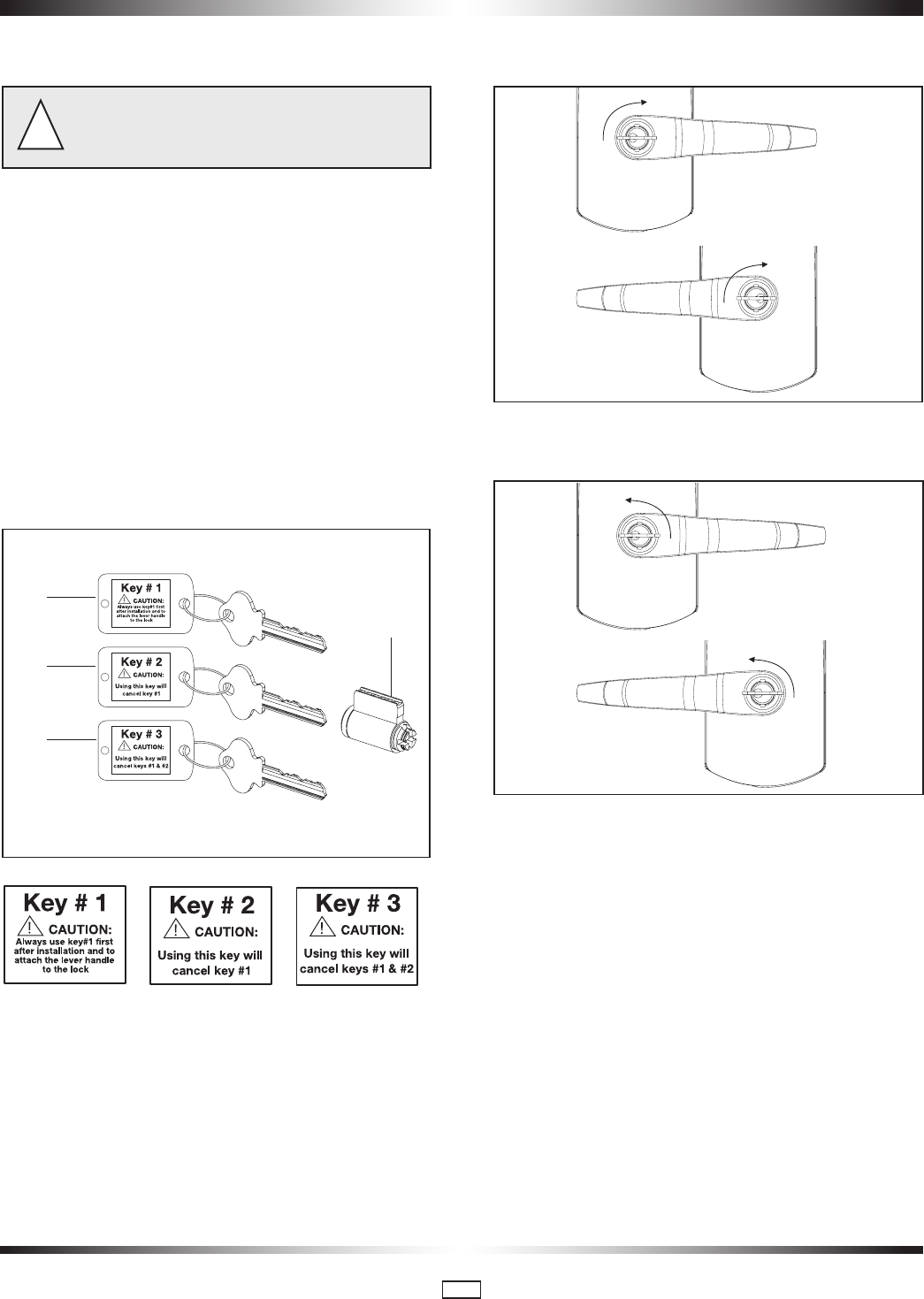
Important: Read the following instructions before using
any of the 3 keys supplied
!
The 79M with a recodable cylinder can be operated with three
different keys. The keys are numbered 1, 2 & 3, and each
key is labeled and supplied in a separate plastic bag. It is very
important to use them in order.
* Always read the label instructions on the label before
using a key.
Caution: The use of key #2 automatically cancels the
function of key #1, and the use of key #3 automatically
cancels both keys #1 and #2.
If key #3 is used first, it will immediately make keys #1 and
#2 unusable.
Once a key is cancelled, it can’t be reactivated unless
the cylinder itself is re-pinned.
Fig. 21
Key #1
Key #2
(cancels key #1)
Key #3
(cancels keys
#1and #2)
cylinder
How to change lock combination from key #1 to key #2:
35. Insert key #2 into cylinder.
36. Turn the key clockwise until it stops (see Fig. 22) for both
left-handed and right-handed locks.
Right-handed lock
Left-handed lock
Fig. 22
37. Turn the key back counter-clockwise until it is in the hori-
zontal position.
Fig. 23 Right-handed lock
Left-handed lock
38. Remove the key.
Now the lock should work with key #2, and key #1 has been
cancelled.
*Test: Try to use key #1 in the lock. It should no longer work.
How to change lock combination from key #2 to key #3
39. Insert key #3 into cylinder.
40. Turn the key clockwise until it stops.
41. Turn the key back counter-clockwise until it is in the
horizontal position.
42. Remove the key.
Now the lock should work with key #3, and key #2 has been
cancelled.
*Test: Try to use key #2 in the lock. It should no longer
work.
11. The Recodable Cylinder with 3 different keys
PK3561_10_09 • 79 SERIES INSTALLATION GUIDE
23
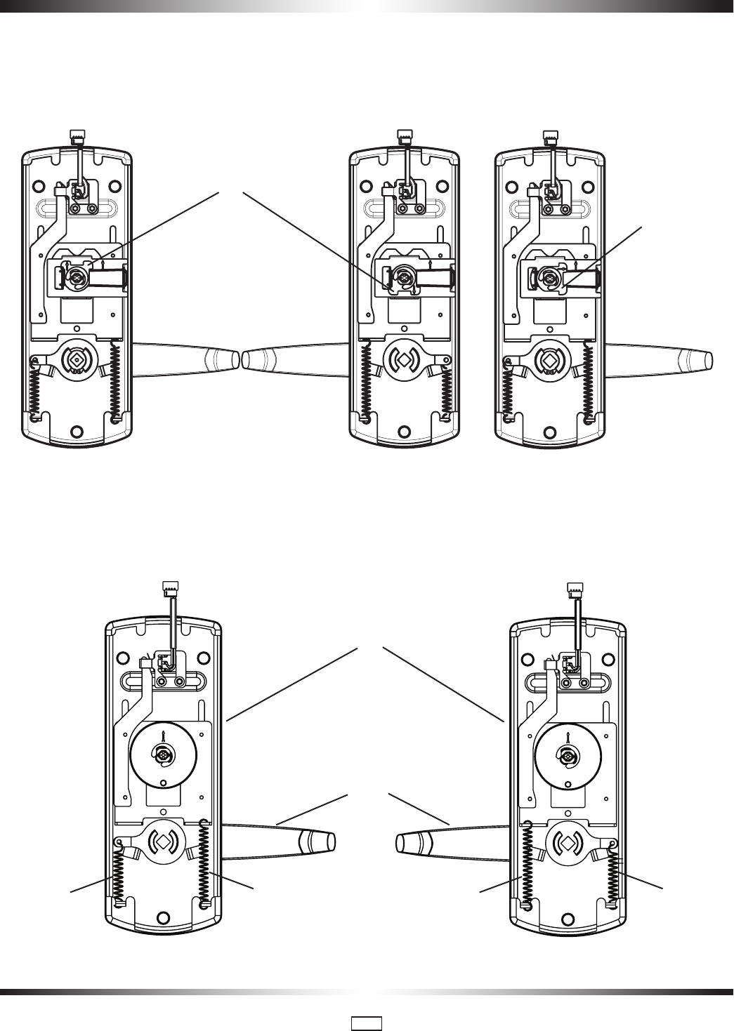
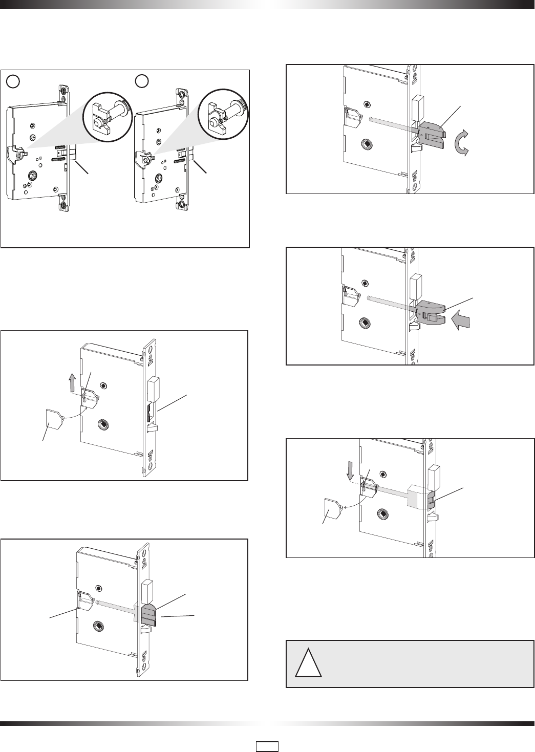
APPENDIX A.1 • Reversing the Mortise Handing
A.1.1 Reversible ASM
1. Remove the mortise faceplate. Remove screw (V) and lock
washer (W) if applicable and place the mortise on a flat
surface for the following steps.
W
V
2. Partially extend the deadbolt:
For normal ASM, rotate hub (H) using a screwdriver, until the
deadbolt (D) extends approximately 1/4".
D
1/4"
H
Proceed to step 3.
For Autodeadbolt ASM, rotate hub (H) until the deadbolt (D)
is fully retracted. The deadbolt will extend approx. 1/16" from
the mortise case.
D
1
/16"
H
Hold deadbolt (D) gently. Press and release the auxiliary latch
(X). You should feel the deadbolt trigger and begin to extend
under the force of the spring.
D (hold gently)
X (press and release)
Release the deadbolt (D) gently. It should extend to 5/16"
approx. and stop. If the deadbolt extends past this point, gently
press it in until it locks at 5/16" throw, or start step 2 again.
D
5
/16"
Only apply to mortise no deadbolt,
auto-deadbolt and armed automatic deadbolt (if applicable)
PK3561_10_09 • 79 SERIES INSTALLATION GUIDE
24
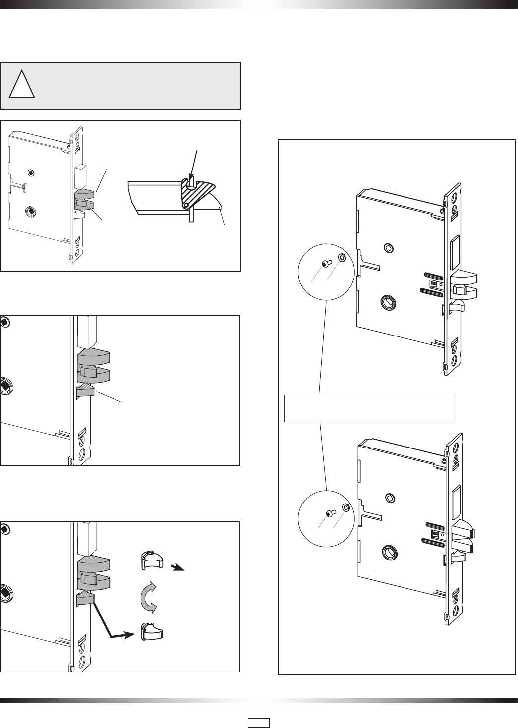
A.1.1 Reversible ASM (continued)
3. Push in the latch bolt (L) to the middle of its stroke, and hold
it there. ( Continue Step 1 and 2)
Hold the latch (L) inside the mortise, and insert the tailpiece
retaining tool (S, part #027-510382 available separately) so
that the tailpiece (T) will not drop inside the mortise case. Hold
the tool and the latch with one hand, and slide up the tailpiece
using a small screwdriver.
L
T
S
(part #027-510382)
Continue to hold tool (S). Release the latch bolt (L) and keep
the anti-friction latch (F) toward the flat side of the latch bolt so
that the bolt extends fully.
L
F
S
4. Pull out the latch bolt (L), until it just clears the front plate.
(Note: If you remove the bolt completely, you must turn it 90°
to re-insert it.)
L
180°
Rotate the latch bolt (L) 180°. Re-insert it to the end of its
stroke.
L
Holding tool (S) in place, re-engage tailpiece (T) with latch bolt
(L) (slide tailpiece down). There may be some play required to
align the parts. Remove the tool (S).
L
T
S
Release the latch to the middle of the stroke and hold it there.
Use a small screwdriver to push the lock mechanism back on
lock position (see step 1 and 2) .
Important: The lock mechanism has to be horizontal on
lock position
!
12
Use a small screwdriver
to lift unlock mechanism.
Unlock PositionLock Position
Push in the latchbolt to the
end of the stroke, and hold
it there.
LL
PK3561_10_09 • 79 SERIES INSTALLATION GUIDE
25
5. Release the latch bolt (L). Position the latch bolt so that the
bottom tooth of the anti-friction latch (F) remains inside the
mortise case as shown.
If the tooth of (F) is outside the mortise, you will not be
able to re-assemble the faceplate on the mortise.
!
L
F
L
F (tooth)
mortise
bottom view
6. If the auxiliary latch (X) is shaped like a triangle, there
is no need to change its handing.
X (triangular = OK)
If the auxiliary latch (X) is a crescent shape, remove it,
turn it 180°, and replace it. The auxiliary latch slides easily in
and out of the mortise.
X (crescent = must be reversed)
180°
(re-insert)
7. Assemble back screw (V) and lock washer (W) if applicable.
The screw (V) must be tightened.
IMPORTANT: Screw (V) must not touch the back wall of
mortise cut-out on the door
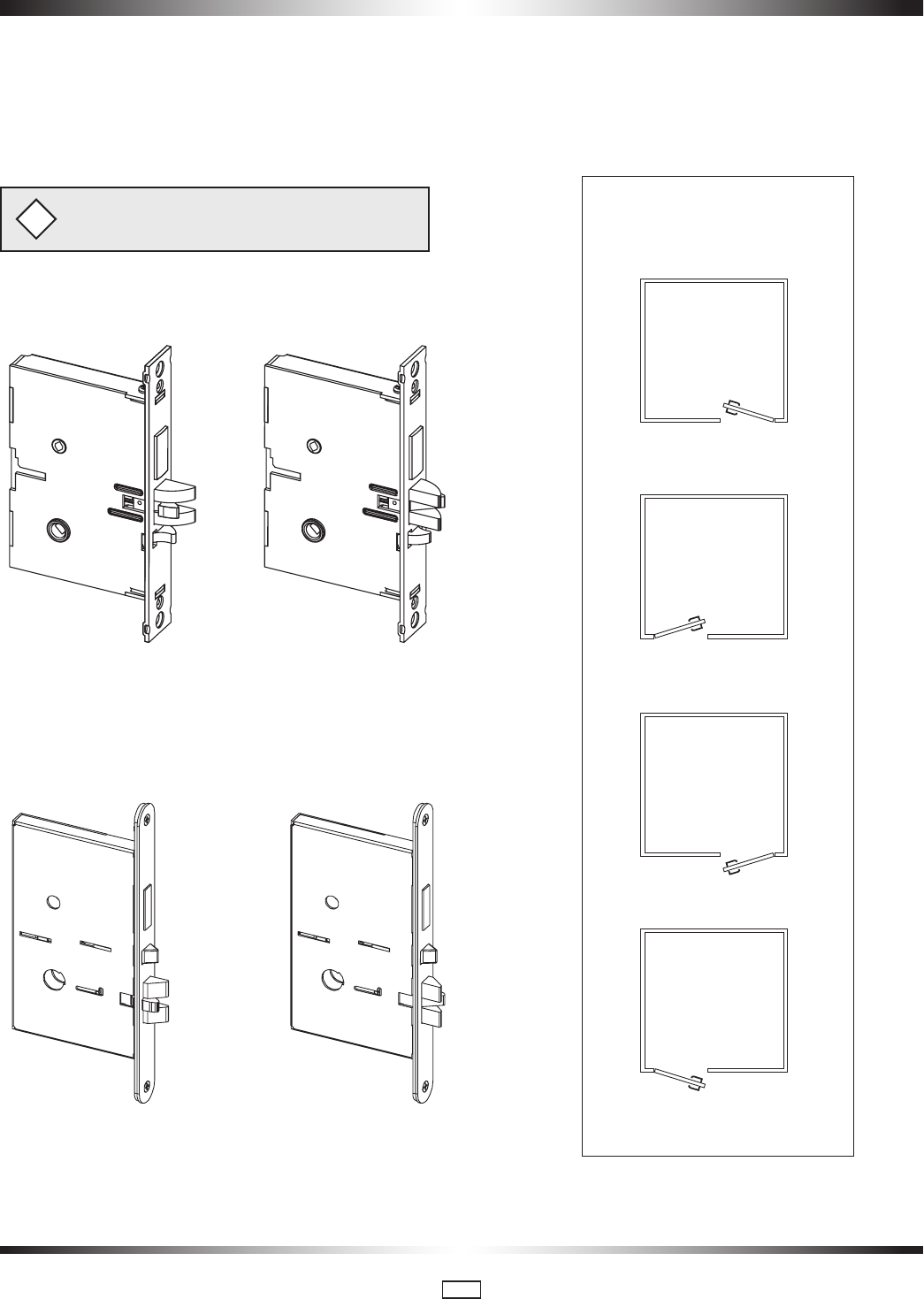
8. The mortise should look like the diagram below. (Check the
orientation of the latch bolt and auxiliary latch.) Check the bevel
of the mortise and change it if required as described in section
3.3, paragraph 6 page 9.
For LH (left hand) and RHR
(right hand reverse)
For RH (right hand) and
LHR (left hand reverse)
ASM
W
V
W
V
Only apply to mortise no deadbolt,
auto-deadbolt and armed automatic deadbolt
PK3561_10_09 • 79 SERIES INSTALLATION GUIDE
26
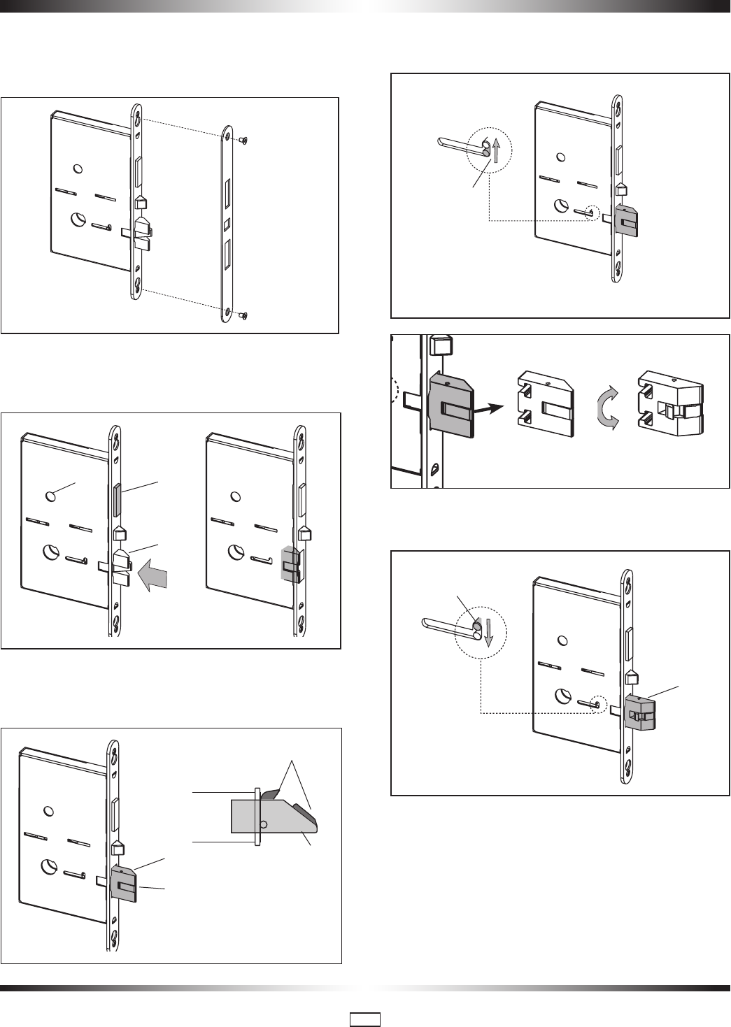
A.1.2 Reversible ESM
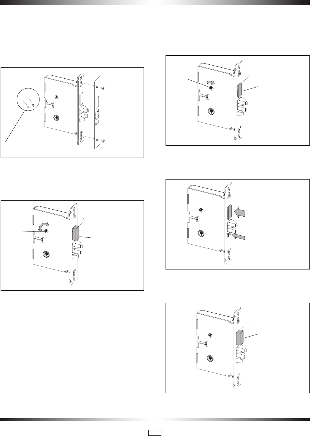
1. Remove the mortise faceplate, and place the mortise on a
flat surface for the following steps.
2. Retract deadbolt (D) as shown by turning the hub (H) with
a small screwdriver, then push in the latch bolt (L) to the end
of its stroke.
D
H
L
Release the latch bolt, and guide anti-friction latch (F) against
the flat side of the latch bolt so that it will slide out of the mor-
tise beyond its normal throw.
F
mortise
bottom view
L
F
L
3. Using a small screwdriver, slide up the locking pin (P). Pull
out the latch bolt (L) and rotate it 180°.
P
180°
4. Re-insert the rotated latch bolt (L) until it stops. Push down
pin (P) to lock the latch bolt in the mortise.
L
P
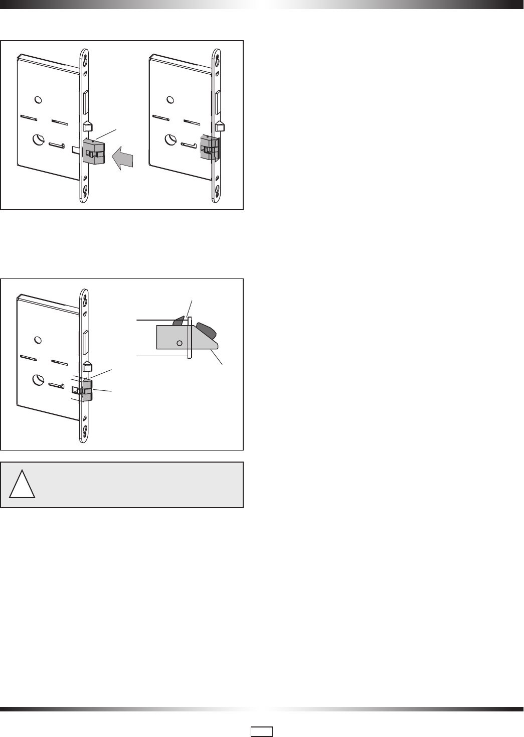
PK3561_10_09 • 79 SERIES INSTALLATION GUIDE
27
5. Push in the latch bolt (L) to the end of its stroke.
L
Release the latch bolt (L) while positioning anti-friction latch
(F) so that it will remain inside the mortise. Ensure the bottom
tooth of the anti-friction latch (F) remains inside the mortise
case as shown.
L
F (tooth)
mortise
bottom view
L
F
If the bottom tooth of (F) is outside the mortise, you will
NOT be able to re-assemble the faceplate on the mortise.
!
PK3561_10_09 • 79 SERIES INSTALLATION GUIDE
28
APPENDIX A.2 • Additional steps for Autodeadbolt ASM for 79M
Standard mode only
Do the following INSTEAD OF page 10, step 5:
A. 2.1 79M Standard mode inside trim assembly for ASM. See
E on page 4
A. 2.2 79T Toggle mode inside trim assembly, for cylindrical;
autodeadbolt and ASM. See page 6
A. 2.3 79M Standard mode autodeadbolt inside trim assembly.
If not already installed at the factory, put the thumbturn in the
vertical position and install all four parts (M) as shown on the
inside trim assembly.
Install clip M1
diagonally on hub
The thumbturn has to be in the vertical position as shown in
Fig. A.2.3. For Right Hand installation, the arrow of M2 points
UP. For a Left Hand installation the arrow of stopper M2 points
down.
Place 3 spacers (S) on the door (for recent models only). For
79T Toggle mode, connect switch cable (W2) to outside hous-
ing cable(W1). Place the inside trim assembly with thumbturn
"T" in position shown below, on the door so that the upper
and lower spindles (F) and (G) engage the thumbturn and the
inside lever. For 79T Toggle mode, push the 2 connectors &
the maximum of their cable in hole (H1).Fasten to the outside
housing using the three 1/8" hex head mounting screws (I).
Apply the privacy thumbturn sticker as shown. If in doubt as
to the direction of the arrow, press the auxiliary latch (X) to
extend the deadbolt, and verify in which direction to rotate the
thumbturn to reach the horizontal (privacy) position.
RH/LHR LH/RHR
X
W1
W2
E or E2
H1
Fig. A.2.3
PK3561_10_09 • 79 SERIES INSTALLATION GUIDE
29
APPENDIX A.3 • Additional steps for ASM Office for 79M Standard
mode Only
Do the following BEFORE placing the inside trim assembly on the door (page 9, step 5):
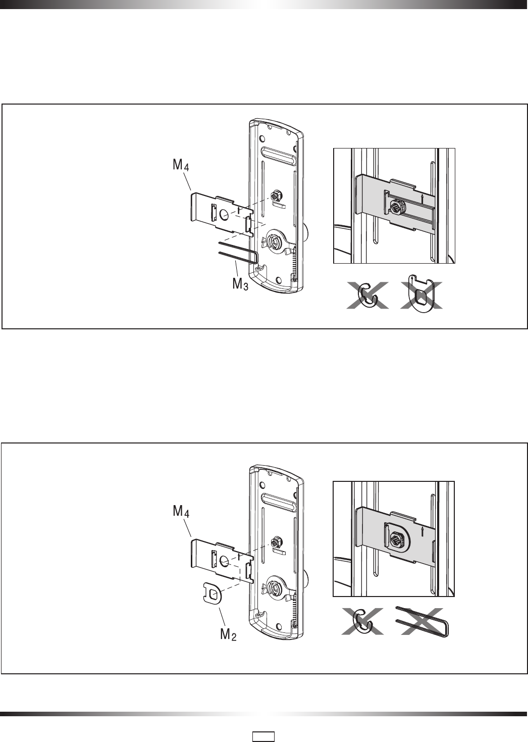
Install only parts (M3 and M4) as shown, on the inside trim assembly.
APPENDIX A.4 • Additional steps for ASM/ESM STOREROOM for 79M
Standard mode Only
Do the following BEFORE placing the inside trim assembly on the door (page 8, step 5):
Put the thumbturn in the vertical position and install only parts (M2 and M4) as shown, on the inside trim assembly. The notch
on the stopper cam (M2) must engage the tab on the plate (M4), so that the thumbturn is locked in the vertical position.
Install M3 onto M4, then slide both
parts onto the thumbturn.
Install M2 onto M4, then slide both
parts onto the thumbturn.
The thumbturn should be locked
in the vertical position
PK3561_10_09 • 79 SERIES INSTALLATION GUIDE
30
APPENDIX B • Installing Cylindrical Models 23/8" & 23/4" Backset
B.1 Install the Strike
Follow the same steps as for a mortise model strike (see page
8, all steps in section 3.2). Note that the handle height is
aligned with the center of the strike.
For cylindrical latch models, ensure the dead-locking pin
will stop against the strike when the door is closed (see
figure). An incorrect installation that permits the pin to
slip inside the strike may result in a total lockout and will
void the warranty of the complete lock mechanism.
!
Correct
Incorrect
4
6
B.2 Install the Latch
Follow the instructions on page 9, steps 1 to 3.
Note that for cylindrical models, the axis of rotation of the
handle is level with the center of the strike. Mark this height
on the edge of the door in step 1 on page 9.
Respect applicable building codes regarding handle
height.
!
4. Drill the holes for the cylindrical unit, thumbturn spindle,
and lock mounting screws. Refer to template for dimensions
and depths.
Drill from both sides of the door to prevent unsightly
damage.
!
5. Drill the hole for the latch, and chisel out clearance for the latch
plate.
6. Install the latch using 1" Phillips mounting screws. Position
the deadlocking pin (D) opposite to the closing direction as
shown.
7. Install Strike and strike box.
Use only the strike and strike box supplied. The use of
non-approved parts will result in a functionality problem
and may void the warranty.
!
Strike Kit
D
2
5
3
4
Closing
Direction
PK3561_10_09 • 79 SERIES INSTALLATION GUIDE
31
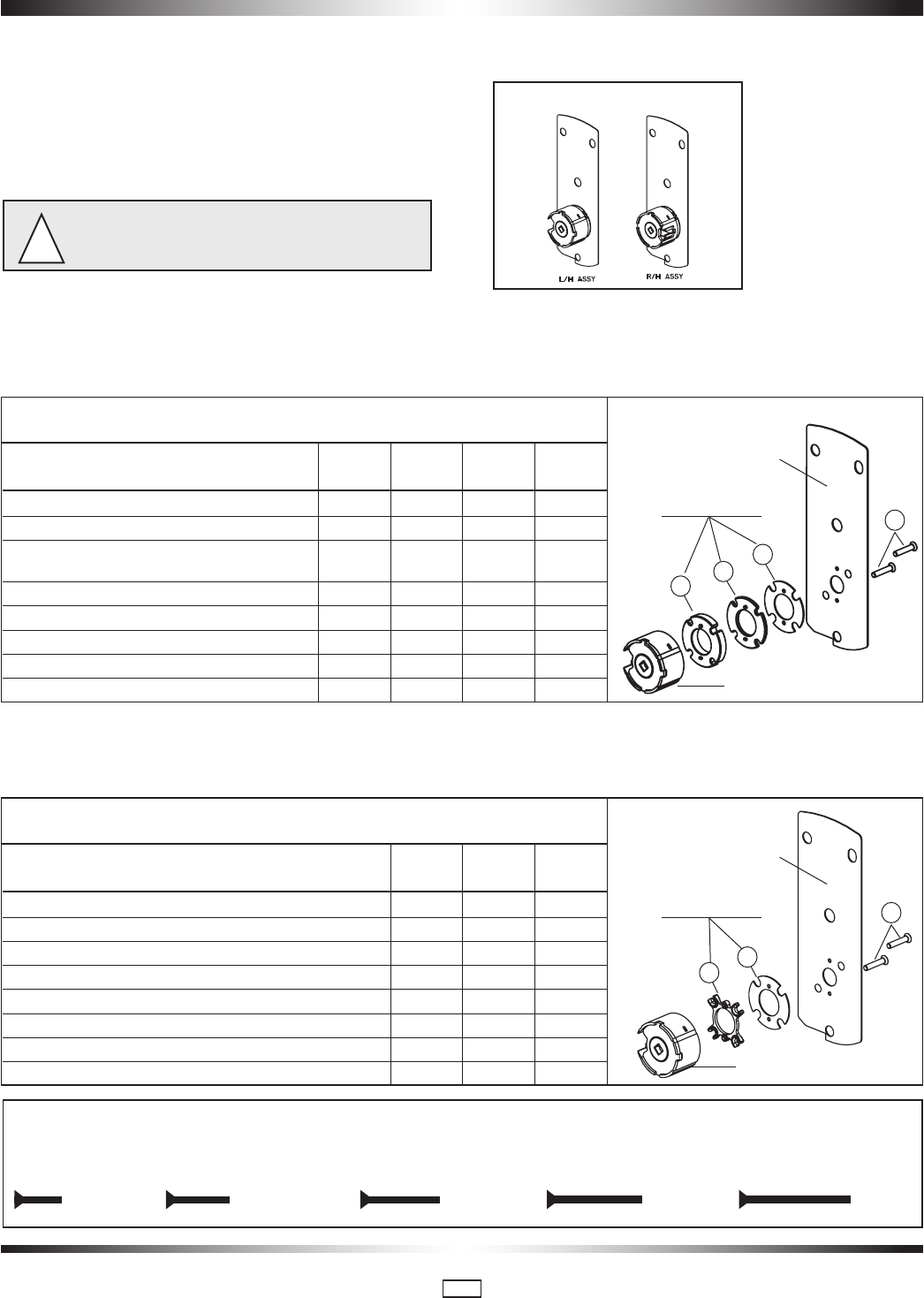
B.3 Install the Cylindrical Unit
Depending on the kind of Spacers shipped with the lock
assembled in the factory for 1 3/4" door thickness, choose
door thickness Table 1 or door thickness Table 2 to prepare
the attachement plate and cylindrical drive unit for the door
thickness other than 1 3/4"
It is very important to assemble the spacers in position
shown.
!
HANDING
1. Lock with 3 DIFFERENT SPACERS (see fig.2)
The cylindrical Unit and Attachement Plate assembly is shipped assembled in the factory for 1 3/4" door thickness (44mm) with 2
spacers "04", 1 spacer "02" and 2 flat head screws "06" 5/8" LG (see fig.2).
2. Lock with 2 DIFFERENT SPACERS (see fig.3)
The cylindrical Unit and Attachement Plate assembly is shipped assembled in the factory for 1 3/4" door thickness (44mm) with 2
spacers "07", 1 spacer "08" and 2 flat head screws "06" 5/8" LG (see fig.3).
Fig. 4
Screw Length (Full Scale)
Length 3/8" Length 1/2" Length 5/8" Length 3/4" Length 7/8"
Door Thickness Spacer Spacer Spacer Screw
02 04 05 06
1-3/8" (35mm) up to 1-9/16" (40mm) - 1 - 3/8 (10mm)
Over 1-9/16" (40mm) to less than 1-11/16" (43mm) - 2 - 1/2 (13mm)
1-3/4" (44mm)
1-11/16" (43mm) to less than 1-7/8" (48mm) 1 2 - 5/8 (16mm)
1-7/8" (48mm) to 1-15/16" (49mm) 1 - 1 5/8 (16mm)
Over 1-15/16" (49mm) to less than 2-1/8" (54mm) 2 - 1 3/4 (19mm)
2-1/8" (54mm) to 2-3/16" (56mm) - 1 1 3/4 (19mm)
Over 2-3/16" (56mm) to 2-3/8" (60mm) 2 1 1 7/8 (22mm)
Over 2-3/8" (60mm) to 2-1/2" (64mm) - - 2 7/8 (22mm)
Door Thickness Spacer Spacer Screw
07 08 06
1-3/8" (35mm) to 1-9/16" (40mm) 2 - 3/8 (10mm)
1-5/8" (41mm) to 1-11/16" (43mm) 1 1 1/2 (13mm)
1-3/4" (44mm) to 1-13/16" (46mm) 2 1 5/8 (16mm)
1-7/8" (48mm) to 1-15/16" (49mm) - 2 5/8 (16mm)
2" (51mm) to 2-1/16" (52.5mm) 1 2 3/4 (19mm)
2-1/8" (54mm) to 2-3/16" (56mm) 2 2 3/4 (19mm)
2-1/4" (57mm) to 2-5/16" (59mm) - 3 7/8 (22mm)
2-3/8" (60mm) to 2-1/2" (64mm) 1 3 7/8 (22mm)
Door Thickness Table 1
Door Thickness Table 2
See 1
See 2
Screws
Screws
Attachement Plate
Attachement Plate
Cylindrical Unit Assembly
Cylindrical Unit Assembly
Fig.2
Fig.3
Fig.1
02
07
04
08
05
06
06
PK3561_10_09 • 79 SERIES INSTALLATION GUIDE
32
B.3 Install the Cylindrical Unit (con’t)
2. Insert the cylindrical unit from the outside of the door toward
the inside, so that it engages the latch as shown. This opera-
tion is to be done at B.5 step 3.
(outside)
cylindrical
unit
latch
B.4 Inside Trim Assembly for Cylindrical 79M
Standard Series
The inside trim assembly for cylindrical includes parts
assembled at the factory to control the motion of the
thumbturn, and an additional spring.
Do the following BEFORE placing the inside trim assem-
bly on the door (page 34, step6):
Install the additional tension spring (N) between the plate (P)
and the post (Q), on the side opposite the lever handle spring
installed in the last step.
N
Q
P
Put the thumbturn in the vertical position as shown on
page 34 so that the arrow (A) on the disc points UP.
VW
D
A
P
For Inside Trim assembly for cylindrical 79T Toggle
mode use the inside trim assembly shown on page
6.
PK3561_10_09 • 79 SERIES INSTALLATION GUIDE
33
B.5 Install Outside Housing and Trim Assembly for
Cylindrical
1. Insert the slotted end of the square spindle (G) into the
outside lever hub until it locks, at an angle of 45º. (The spindle
can be removed by pulling on it, if oriented incorrectly.)
Square Spindle Position
correct incorrect
2. Insert the thumbturn spindle (F) in the upper hub of the
outside housing. (It will clip in place.)
3. Assemble gasket onto the outside housing. Assemble cylin-
drical plate assembly onto the outside housing.
4. For 79T Toggle mode, pass cable (W1) through hole (H1)
on the door.
5. Place the outside housing on the door so that spindle (F)
engages thumbturn hole and spindle(G) engage hub of cylin-
drical unit. The cylindrical unit will engage the latch as shown
in step 2 of B.3 (page 32).
Lock Housing
Gasket
W1
Cylindrical Plate
Assembly
F
H1
G
PK3561_10_09 • 79 SERIES INSTALLATION GUIDE
34
6. Put the thumbturn (T) in a vertical position as shown below.
Assemble 3 spacers (S) on the door (for recent models only).
For 79T Toggle mode connect (W2) to (W1) and push both
connectors and all excess of wire in hole (H1). Place the
inside trim assembly on the door so that the upper and lower
spindles (F) and (G) engage the thumbturn and the inside lever.
Fasten to the outside housing using the three 1/8" hex drive
mounting screws (I). Install the screws without tightening.
Verify the inside lever and thumbturn operates smootly. If not
move the inside and outside housings slightly. Then tighten
the screws.
7. Three AA batteries should already be installed in the battery
holder (C). Insert the battery holder into the outside housing
and secure it using the 6-32 x 5/16" (7.9mm) Torx drive
screw (H).
C
8. Testing the cylindrical lock: Follow all steps of page 12 or 13
but extension and retraction will be for latch only.
If the lock makes a continuous buzzing noise or the red
LED lights continuously, reset the electronics by removing
the battery holder for ten seconds, then reinsert it.
!
W1
W2
E or E2
H1

PK3561_10_09 • 79 SERIES INSTALLATION GUIDE
35
Note for customers:
Statement according to FCC part 15.105
This equipment has been tested and found to comply with the
limits for a Class B digital device, pursuant to Part 15 of the
FCC Rules. These limits are designed to provide reasonable
protection against harmful interference in a residential instal-
lation. This equipment generates, uses, and can radiate radio
frequency energy and, if not installed and used in accordance
with the instructions, may cause harmful interference to radio
communications. However, there is no guarantee that interfer-
ence will not occur in a particular installation. If this equipment
does cause harmful interference to radio or television recep-
tion, which can be determined by turning the equipment off
and on, the user is encouraged to try to correct the interfer-
ence by one or more of the following measures:
• Reorient or relocate the receiving antenna.
• Increase the separation between the equipment and
receiver.
• Consult the dealer or an experienced radio/TV technician
for help.
Statement according to FCC part 15.21
Modifications not expressly approved by Kaba Ilco could void
the user's authority to operate the equipment.
Statement according to FCC part 15.19
This device complies with Part 15 of the FCC Rules. Operation
is subject to the following two conditions:
(1) this device may not cause harmful interference, and
(2) this device must accept any interference received, includ-
ing interference that may cause undesired operation.

PK3561_10_09 • 79 SERIES INSTALLATION GUIDE
36

Kaba Ilco Inc.
7301 Boul. Décarie Montréal (QC) H4P 2G7
Technical Support:
1.800.906.4526
Customer Service:
T: 1.877.468.3555
F: 514.735.6589
General Information:
www.ilcolodging.com
Online Consumable Orders:
www.keycard.com
To access all of our easy steps, please visit our Support Website:
http://connect.kabalodging.com
Printed in Canada PK3561_10_09