dormakaba EAD B-WEB9600 RFID Time Attendance/ Access Control/ Data Collection Terminal User Manual Device Operation Manual
Kaba GmbH RFID Time Attendance/ Access Control/ Data Collection Terminal Device Operation Manual
UserManual.wiki
>
dormakaba EAD
>
B WEB9600 User Manual
Manual
Navigation menu
Upload a User Manual
Namespaces
Wiki Guide
HTML
PDF
Info
Views
User Manual
Discussion / Help
Navigation
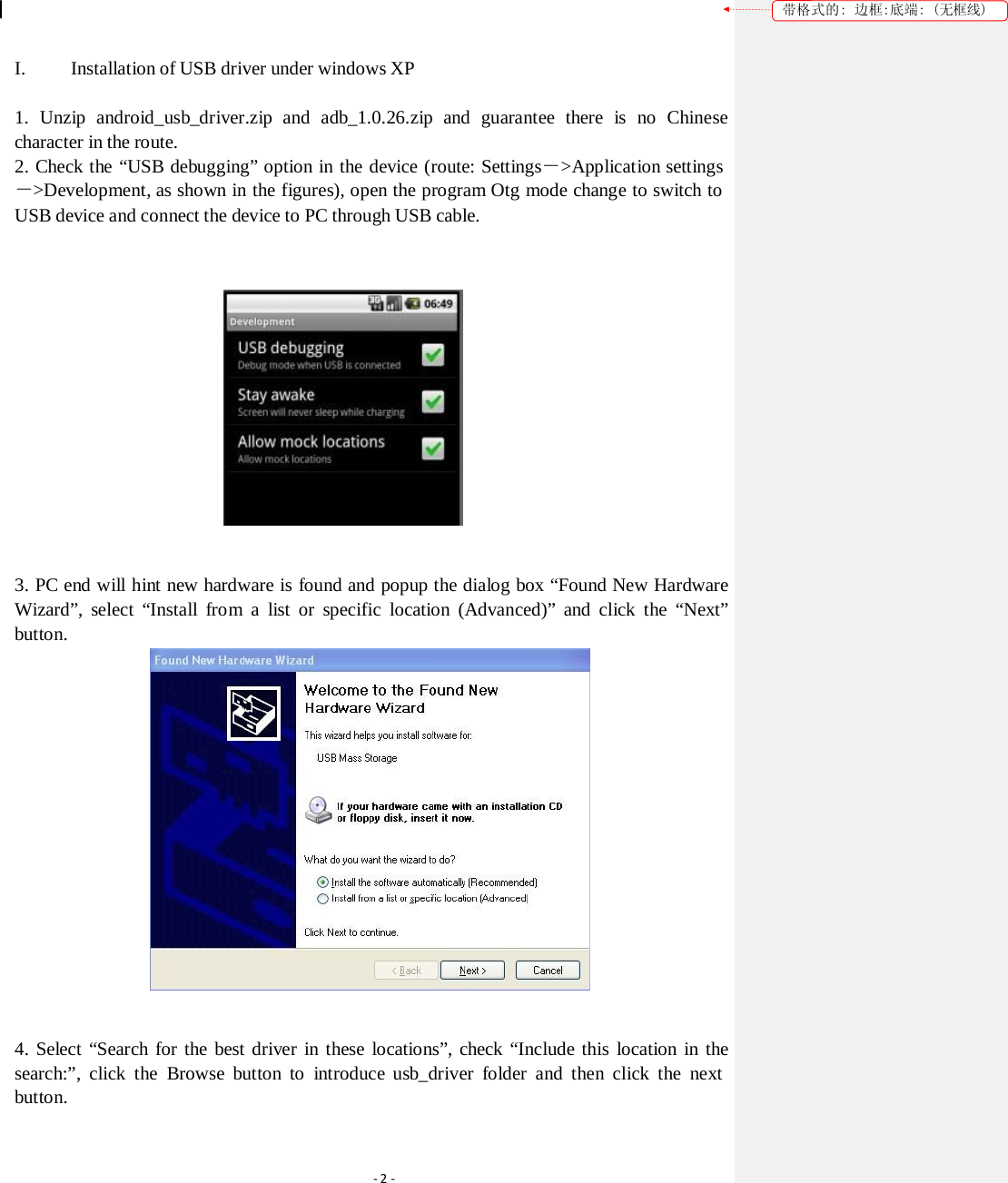
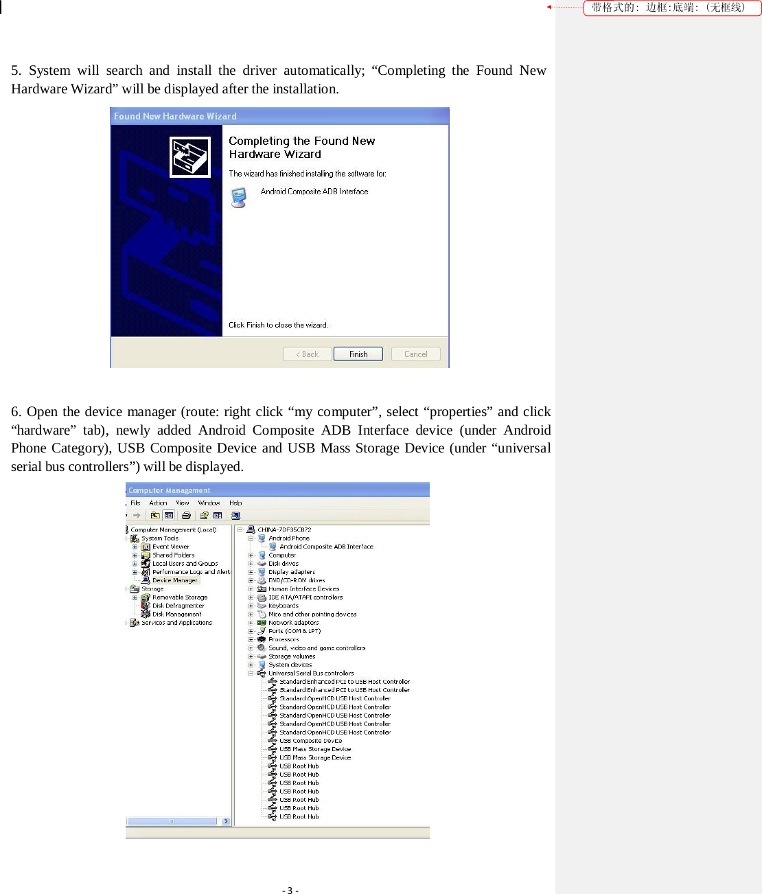
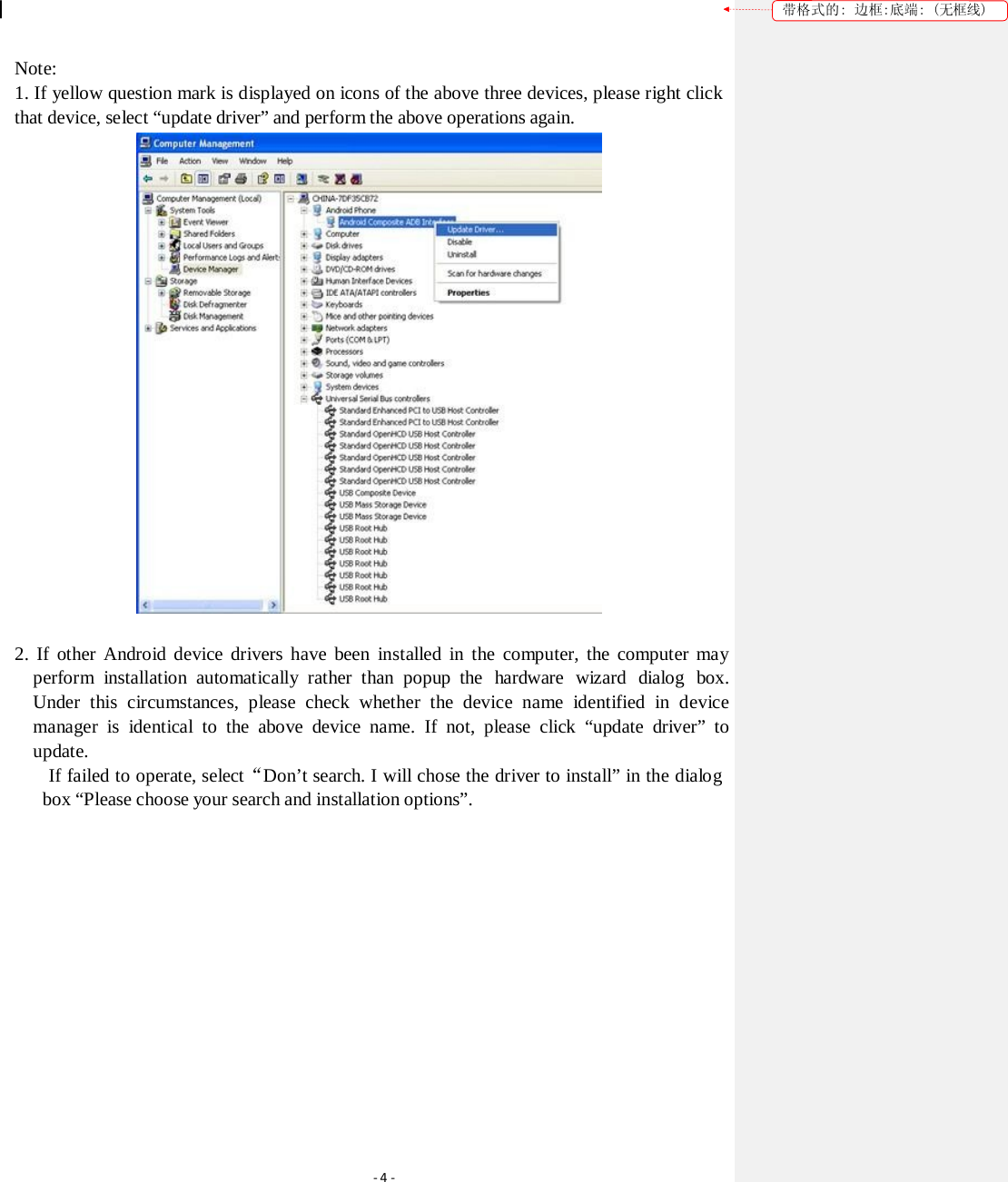
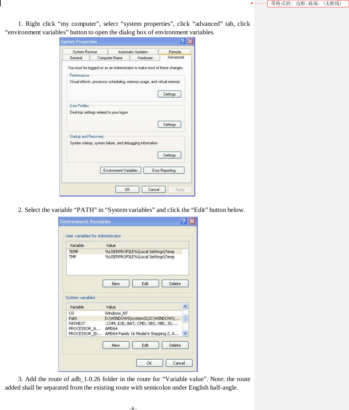
![带格式的: 边框:底端: (无框线) Device Operation Manual Version: [1.0] Issued on: June 20, 2012 ‐1‐](https://usermanual.wiki/dormakaba-EAD/B-WEB9600/User-Guide-1914191-Page-1.png)
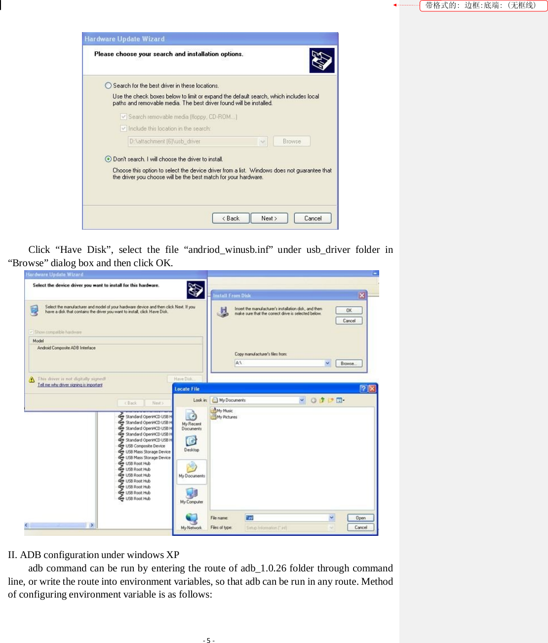
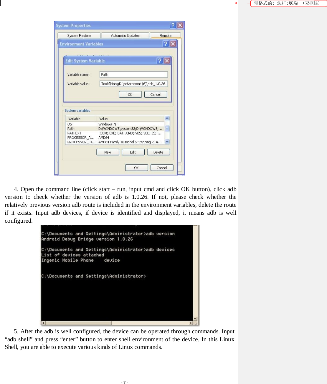
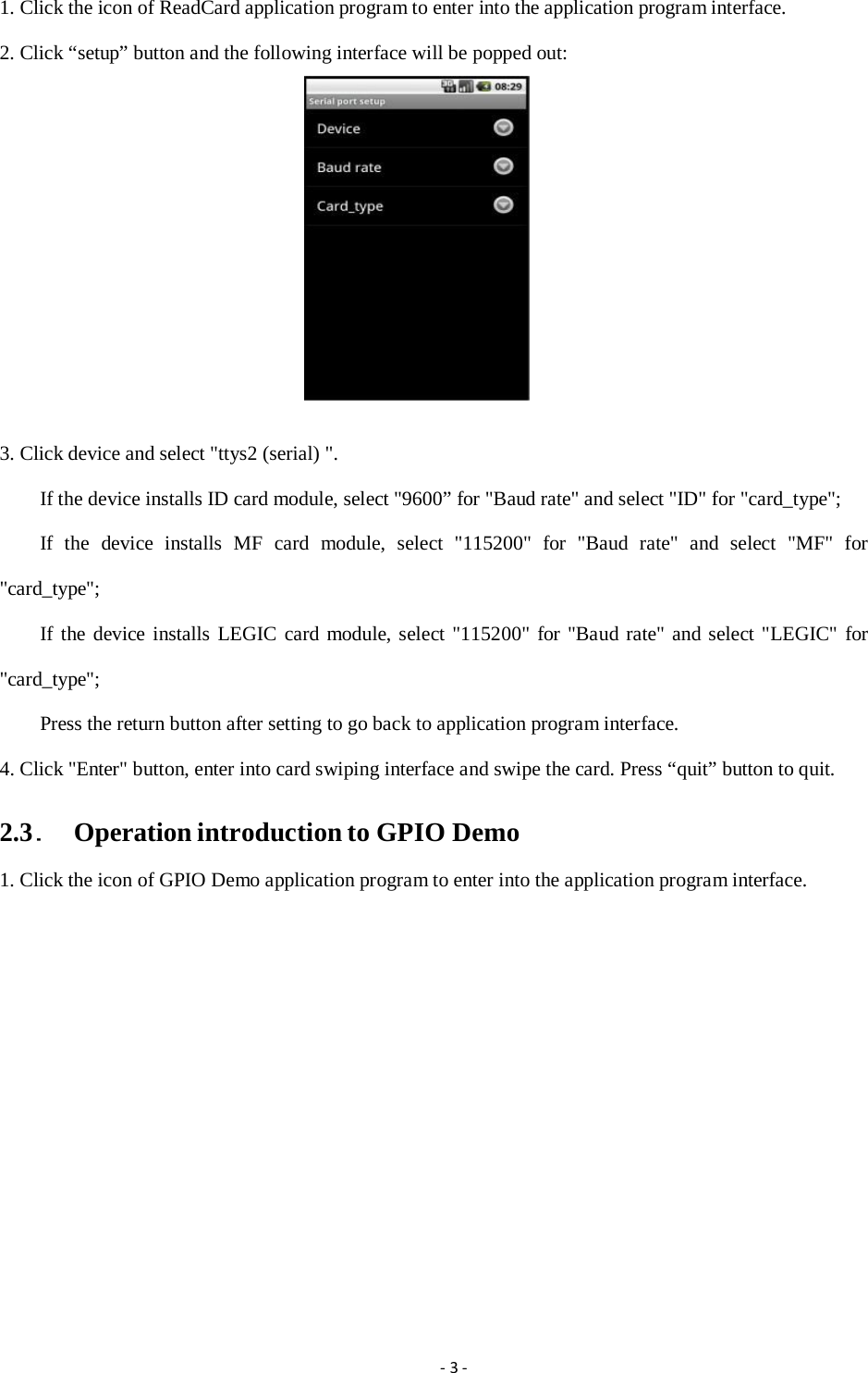
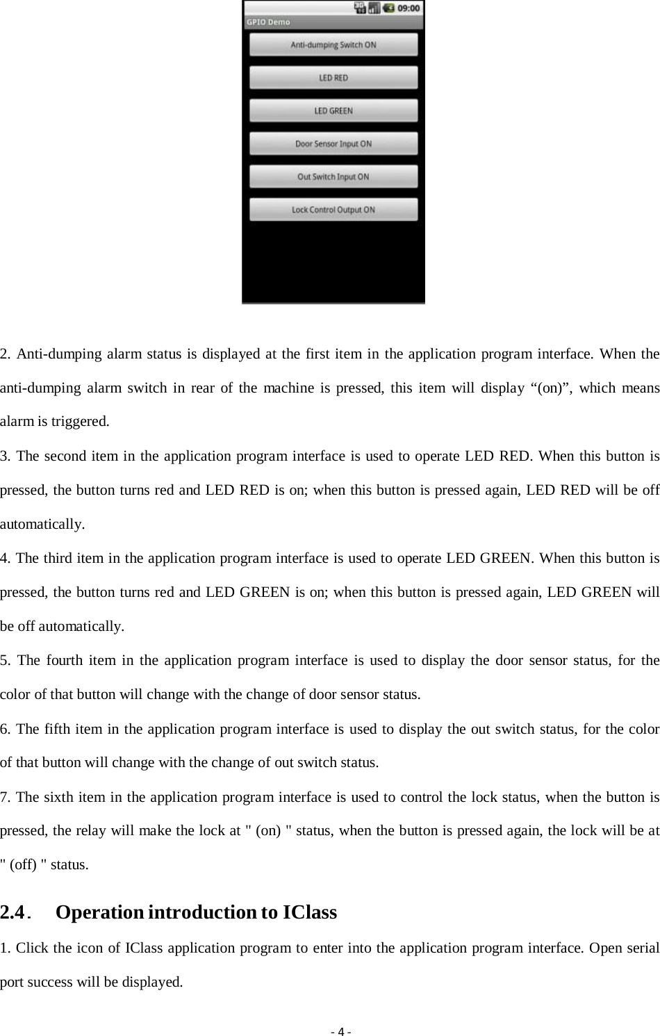
![Operation Introduction to Demo Application Version: [1.0] Issued on: June 20, 2012](https://usermanual.wiki/dormakaba-EAD/B-WEB9600/User-Guide-1914191-Page-8.png)