dormakaba EAD B-WEB9600 RFID Time Attendance/ Access Control/ Data Collection Terminal User Manual Device Operation Manual
Kaba GmbH RFID Time Attendance/ Access Control/ Data Collection Terminal Device Operation Manual
Manual

带格式的: 边框:底端:
(无框线)
Device Operation
Manual
Version: [1.0]
Issued on: June 20, 2012
‐1‐
带格式的: 边框:底端:
(无框线)
I. Installation of USB driver under windows XP
1. Unzip android_usb_driver.zip and adb_1.0.26.zip and guarantee there is no Chinese
character in the route.
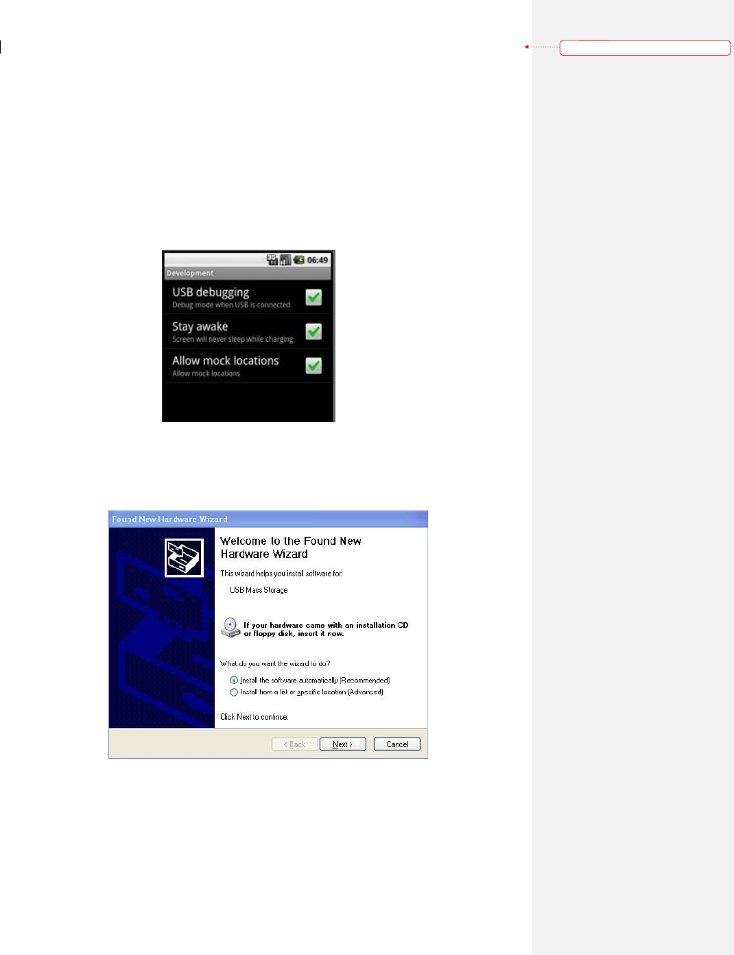
2. Check the “USB debugging” option in the device (route: Settings->Application settings
->Development, as shown in the figures), open the program Otg mode change to switch to
USB device and connect the device to PC through USB cable.
3. PC end will hint new hardware is found and popup the dialog box “Found New Hardware
Wizard”, select “Install from a list or specific location (Advanced)” and click the “Next”
button.
4. Select “Search for the best driver in these locations”, check “Include this location in the
search:”, click the Browse button to introduce usb_driver folder and then click the next
button.
‐2‐
带格式的: 边框:底端:
(无框线)
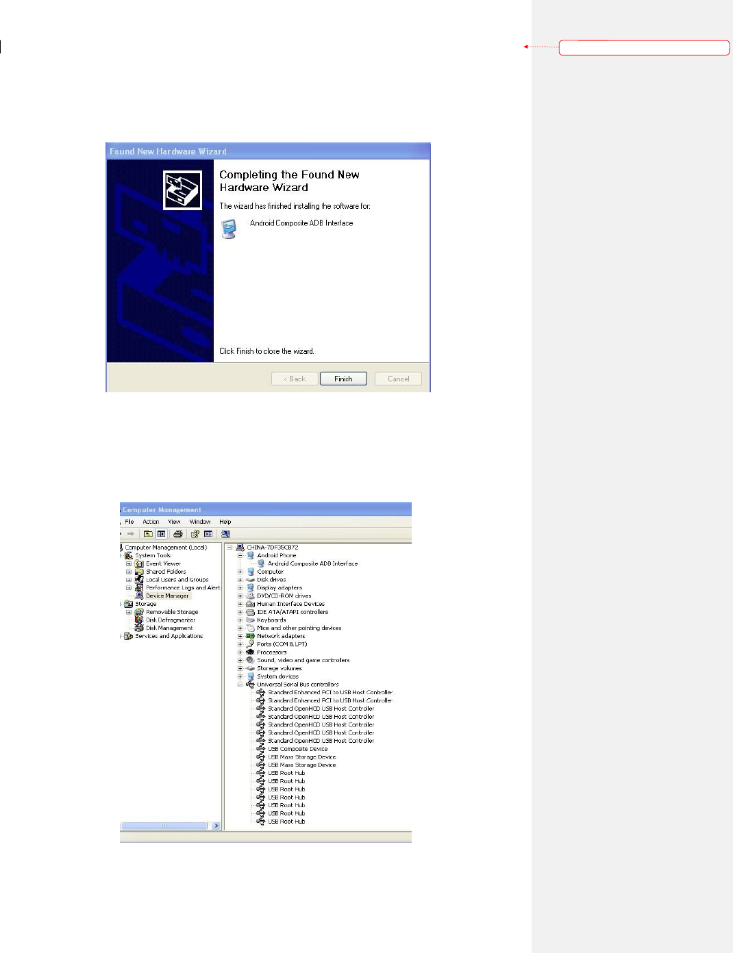
5. System will search and install the driver automatically; “Completing the Found New
Hardware Wizard” will be displayed after the installation.
6. Open the device manager (route: right click “my computer”, select “properties” and click
“hardware” tab), newly added Android Composite ADB Interface device (under Android
Phone Category), USB Composite Device and USB Mass Storage Device (under “universal
serial bus controllers”) will be displayed.
‐3‐
带格式的: 边框:底端:
(无框线)
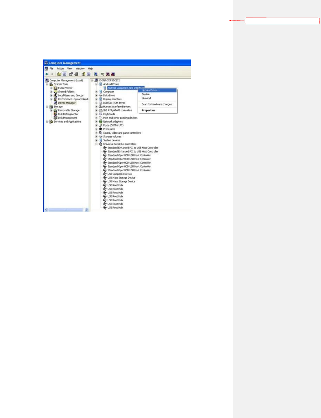
Note:
1. If yellow question mark is displayed on icons of the above three devices, please right click
that device, select “update driver” and perform the above operations again.
2. If other Android device drivers have been installed in the computer, the computer may
perform installation automatically rather than popup the hardware wizard dialog box.
Under this circumstances, please check whether the device name identified in device
manager is identical to the above device name. If not, please click “update driver” to
update.
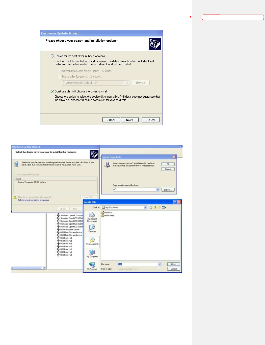
If failed to operate, select“Don’t search. I will chose the driver to install” in the dialog
box “Please choose your search and installation options”.
‐4‐
带格式的: 边框:底端:
(无框线)
Click “Have Disk”, select the file “andriod_winusb.inf” under usb_driver folder in
“Browse” dialog box and then click OK.
II. ADB configuration under windows XP
adb command can be run by entering the route of adb_1.0.26 folder through command
line, or write the route into environment variables, so that adb can be run in any route. Method
of configuring environment variable is as follows:
‐5‐
带格式的: 边框:底端:
(无框线)
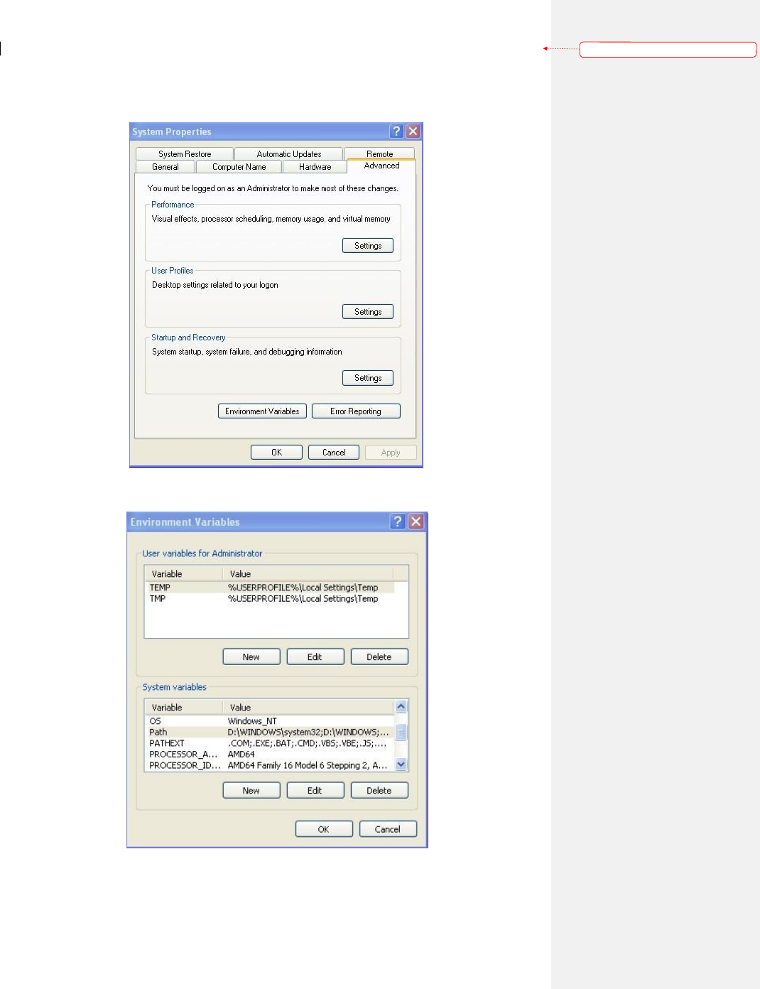
1. Right click “my computer”, select “system properties”, click “advanced” tab, click
“environment variables” button to open the dialog box of environment variables.
2. Select the variable “PATH” in “System variables” and click the “Edit” button below.
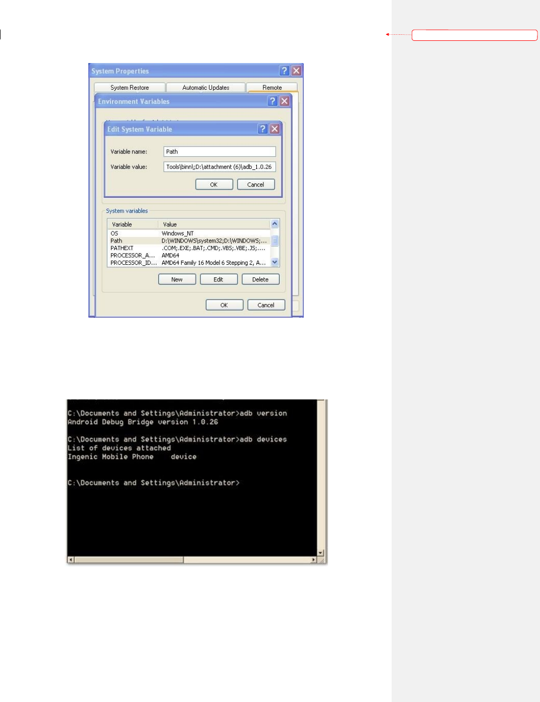
3. Add the route of adb_1.0.26 folder in the route for “Variable value”. Note: the route
added shall be separated from the existing route with semicolon under English half-angle.
‐6‐
带格式的: 边框:底端:
(无框线)
4. Open the command line (click start – run, input cmd and click OK button), click adb
version to check whether the version of adb is 1.0.26. If not, please check whether the
relatively previous version adb route is included in the environment variables, delete the route
if it exists. Input adb devices, if device is identified and displayed, it means adb is well
configured.
5. After the adb is well configured, the device can be operated through commands. Input
“adb shell” and press “enter” button to enter shell environment of the device. In this Linux
Shell, you are able to execute various kinds of Linux commands.
‐7‐
Operation Introduction to Demo Application
Version: [1.0]
Issued on: June 20, 2012
Contents
I. Import of projects into eclipse.................................................................................................................. 1
II. Introduction to Demo.............................................................................................................................. 2
2.1. Operation introduction to MotionDemo ...................................................................................... 2
2.2. Operation introduction to ReadCard ........................................................................................... 2
2.3. Operation introduction to GPIO Demo ....................................................................................... 3
2.4. Operation introduction to IClass ................................................................................................. 4
2.5. Operation introduction to NewHIDDemo ................................................................................... 5
2.6. Operation introduction to NewWiegenDemo .............................................................................. 5
2.7. Operation introduction to Otg mode change ............................................................................... 5
I
.
Import of projects into eclipse
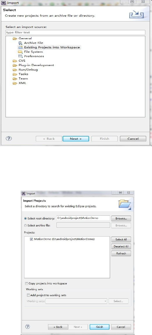
1. Open eclipse, click the files menu, select “import”, in the displayed dialog box, select “Existing
Projects into Workspace” under “General” and click “next”.
2. Select “Select root directory”, click “Browse” to introduce the route of application program and
then click “Finish” to complete the import of projects.
‐1
‐
II
.
Introduction to Demo
2.1
.
Operation introduction to MotionDemo
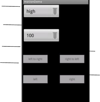
Sense
level
Time threshold value judges sense
motion
Motion sensed: Left to
right
Motion sensed:
Left
Motion sensed: right to
left
Motion sensed:
right
1. Open the app list (click the app list button), find Motion Demo application, click the icon to enter into
application program interface.
2. If it remains initial settings, card swiping motion can be tested when opening the surface. It is
recommended to set the sense level as high and set the time threshold value which judges sense motion as
100ms.
3. Click the drop-down list box of sense level display, different levels are displayed and then click the
wanted level to set the sense level. After the level is set, card swiping motion can be tested.
4. Click the drop-down list box of time threshold value which judges sense motion and different times are
displayed and then click the wanted time to set the time threshold value which judges sense motion. After
the time is set, card swiping motion can be tested.
2.2
.
Operation introduction to ReadCard
‐2
‐
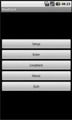
1. Click the icon of ReadCard application program to enter into the application program interface.
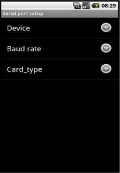
2. Click “setup” button and the following interface will be popped out:
3. Click device and select "ttys2 (serial) ".
If the device installs ID card module, select "9600” for "Baud rate" and select "ID" for "card_type";
If the device installs MF card module, select "115200" for "Baud rate" and select "MF" for
"card_type";
If the device installs LEGIC card module, select "115200" for "Baud rate" and select "LEGIC" for
"card_type";
Press the return button after setting to go back to application program interface.
4. Click "Enter" button, enter into card swiping interface and swipe the card. Press “quit” button to quit.
2.3
.
Operation introduction to GPIO Demo
1. Click the icon of GPIO Demo application program to enter into the application program interface.
‐3
‐
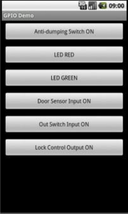
2. Anti-dumping alarm status is displayed at the first item in the application program interface. When the
anti-dumping alarm switch in rear of the machine is pressed, this item will display “(on)”, which means
alarm is triggered.
3. The second item in the application program interface is used to operate LED RED. When this button is
pressed, the button turns red and LED RED is on; when this button is pressed again, LED RED will be off
automatically.
4. The third item in the application program interface is used to operate LED GREEN. When this button is
pressed, the button turns red and LED GREEN is on; when this button is pressed again, LED GREEN will
be off automatically.
5. The fourth item in the application program interface is used to display the door sensor status, for the
color of that button will change with the change of door sensor status.
6. The fifth item in the application program interface is used to display the out switch status, for the color
of that button will change with the change of out switch status.
7. The sixth item in the application program interface is used to control the lock status, when the button is
pressed, the relay will make the lock at " (on) " status, when the button is pressed again, the lock will be at
" (off) " status.
2.4
.
Operation introduction to IClass
1. Click the icon of IClass application program to enter into the application program interface. Open serial
port success will be displayed.
‐4
‐
‐5
‐
2. When swiping card in card wiping area, card number will be displayed and when the whole screen is
occupied, screen will be cleared automatically.
2.5
.
Operation introduction to NewHIDDemo
1. Click the icon of NewHIDDemo application program to enter into the application program interface.
2. When swiping card in card wiping area, card number will be displayed.
2.6
.
Operation introduction to NewWiegenDemo
1. Click the icon of NewWiegenDemo application program to enter into the application program interface.
2. Default as Weigen26, connect Weigen26 read head to bottom left in rear of the machine; when swiping
card in card wiping area, card number will be displayed.
3. Connect Weigen34 read head to bottom left in rear of the machine, click Weigen26 bit to convert into
Weigen34; when swiping card in card wiping area, card number will be displayed.
2.7
.
Operation introduction to Otg mode change
1. Click the icon of Otg mode change application program to enter into the application program interface.
2. Click the button to switch the status of usb interface (status includes usb device and usb host).
When usb interface is in usb device status, usb interface can be used for program debugging;
When usb interface is in usb host status, usb interface can be connected with usb disk.
2.8.
FCC Statement
This device complies with Part 15 of the FCC Rules. Operation
is subject to the following two conditions:
(1) This device may not cause harmful interference, and
(2) This device must accept any interference received, including interference that may cause
undesired operation.
NOTE:
The manufacturer is not responsible for ANY interference, for example RADIO or TV interference,
caused by unauthorized modifications to this equipment. Such modifications could void the user’s
authority to operate the equipment.
NOTE:
This equipment has been tested and found to comply with the limits for a Class B digital device,
pursuant to Part 15 of the FCC Rules. These limits are designed to provide reasonable protection against
harmful interference in a residential installation.
This equipment generates, uses and can radiate radio frequency energy and, if not installed and used in
accordance with the instructions, may cause harmful interference to radio communications. However,
there is no guarantee that interference will not occur in a particular installation.If this equipment does
‐6
‐
cause harmful interference to radio or television reception, which can be determined by turning the
equipment off and on, the user is encouraged to try to correct the interference by one or more of the
following measures:
-- Reorient or relocate the receiving antenna.
-- Increase the separation between the equipment and receiver.
-- Connect the equipment into an outlet on a circuit different from that to which the receiver is
connected.
-- Consult the dealer or an experienced radio/TV technician for help.
RF Exposure Important Note:
To comply with the FCC RF exposure compliance requirements, the antenna(s) used for this
transmitter must be installed to provide a separation distance of at least 20 cm from all persons and
must not be co-located or operating in conjunction with any other antenna or transmitter. No
change to the antenna or the device is permitted. Any change to the antenna or the device could
result in the device exceeding the RF exposure requirements and void user’s authority to operate
the device.