dormakaba EAD BNET9104 Inductive Tag Reader User Manual docuglobe f r Handb cher
Kaba GmbH Inductive Tag Reader docuglobe f r Handb cher
UserManual.wiki
>
dormakaba EAD
>
BNET9104 User Manual
Users Manual
Navigation menu
Upload a User Manual
Namespaces
Wiki Guide
HTML
PDF
Info
Views
User Manual
Discussion / Help
Navigation
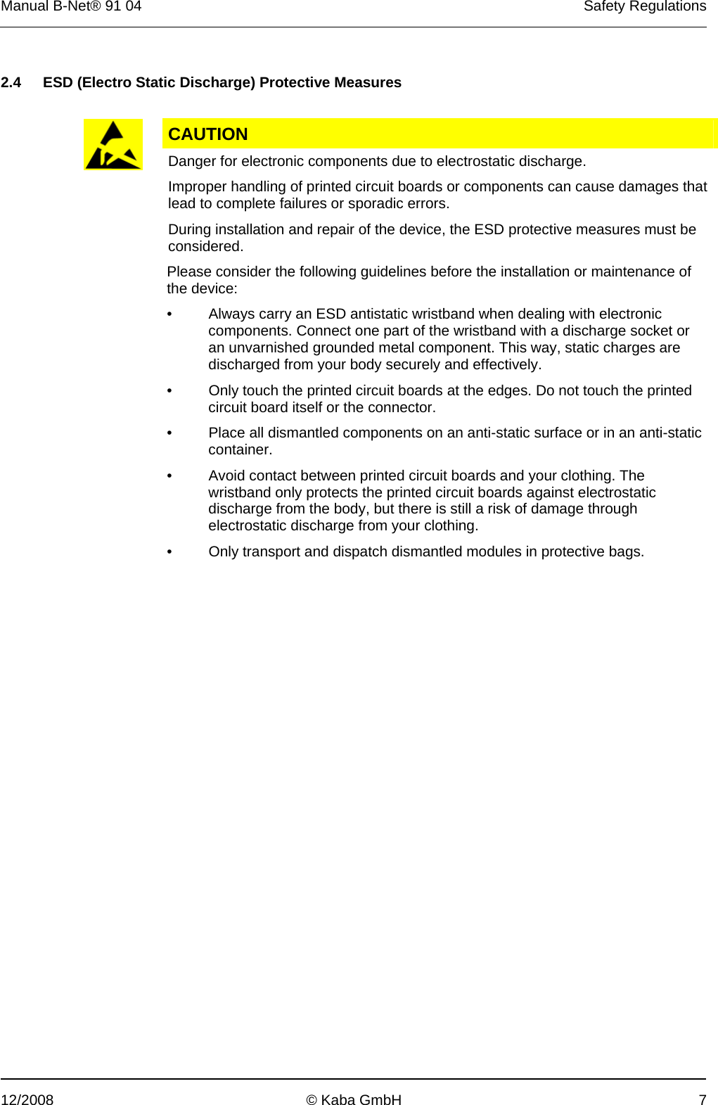

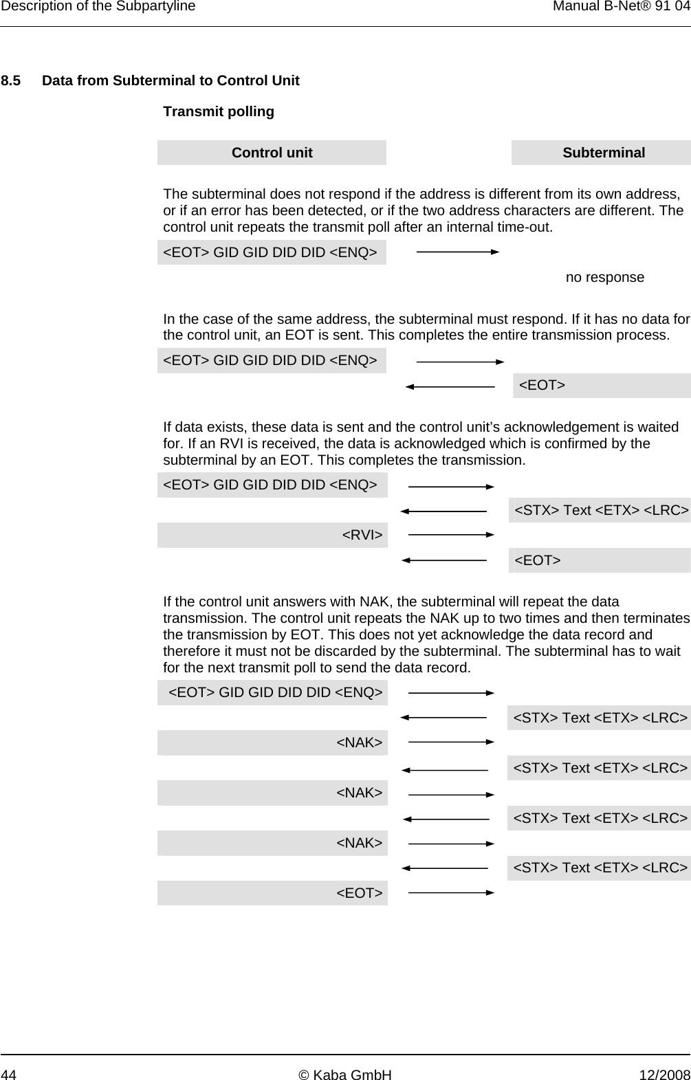
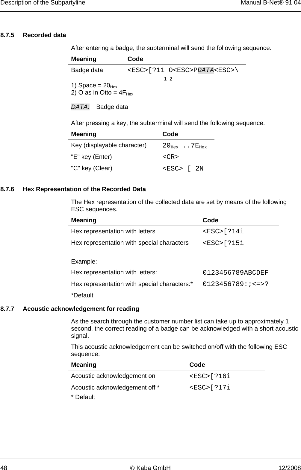
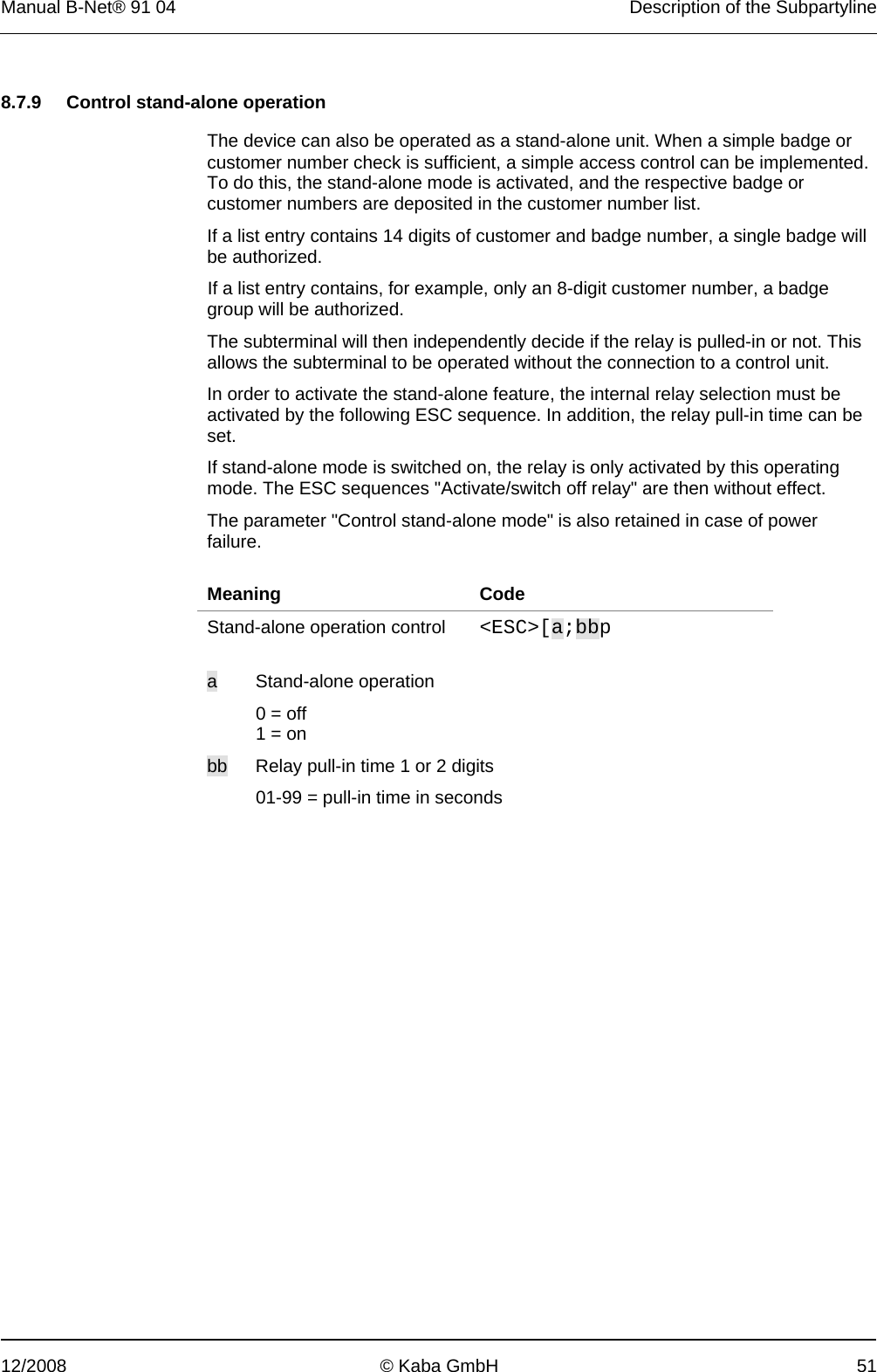
![Description of the Subpartyline Manual B-Net® 91 04 52 © Kaba GmbH 12/2008 8.8 ASCII Table CONTROL NUMBERS SYMBOLS UPPER CASE LOWER CASE 0 1 2 3 4 5 6 7 0 NUL DLE SP 0 @ P ` p 1 SOH DC1 ! 1 A Q a q 2 STX DC2 " 2 B R b r 3 ETX DC3 # 3 C S c s 4 EOT DC4 $ 4 D T d t 5 ENQ NAK % 5 E U e u 6 ACK SYN & 6 F V f v 7 BEL ETB ´ 7 G W g w 8 BS CAN ( 8 H X h x 9 HT EM ) 9 I Y I y A LF SUB * : J Z j z B VT ESC + ; K [ k { C FF FS , < L \ l | D CR GS - = M ] m } E SO RS . > N ^ n ~ F SI US / ? O _ o DEL](https://usermanual.wiki/dormakaba-EAD/BNET9104/User-Guide-1170202-Page-52.png)