dormakaba EAD BNET9104 Inductive Tag Reader User Manual docuglobe f r Handb cher
Kaba GmbH Inductive Tag Reader docuglobe f r Handb cher
Users Manual
B-Net® 91 04
Manual
12/2008
© Copyright by
Kaba GmbH
Albertistraße 3
D-78056 Villingen-Schwenningen
Phone +49 7720/603-0
Fax +49 7720/603-102
info@kbs.kaba.com
www.kaba.com/workforce-management
All rights reserved. The document and its parts are copyrighted. Only Kaba GmbH has the right to
commercialize, market and distribute this document. This document, or any part of it, may not be copied
or reproduced, adapted, arranged, reworked or modified without the prior consent of Kaba GmbH.
All company, trademark or product names are trademarks or registered trademarks of their respective
owners and are protected.
Subject to technical changes without notice!
Order no. 04038521
1 About this Manual...................................................................................................................5
2 Safety Regulations..................................................................................................................6
2.1 Use as directed...............................................................................................................6
2.2 General Remarks............................................................................................................6
2.3 Installation Instructions ...................................................................................................6
2.4 ESD (Electro Static Discharge) Protective Measures ....................................................7
3 Product Description................................................................................................................8
3.1 Technical data ................................................................................................................9
3.2 Conformity ....................................................................................................................10
3.3 Labeling ........................................................................................................................10
4 Design and Function ............................................................................................................11
4.1 Models / Delivery volume..............................................................................................11
4.2 Input possibilities ..........................................................................................................12
4.3 Hardware equipment ....................................................................................................12
4.3.1 LED...................................................................................................................12
4.3.2 Acoustic signal generator.................................................................................12
4.3.3 Digital outputs...................................................................................................12
4.4 Operating Modes ..........................................................................................................13
4.4.1 Online mode.....................................................................................................13
4.4.2 Stand-alone operation......................................................................................13
5 Mounting and Installation ....................................................................................................14
5.1 Installation Conditions...................................................................................................14
5.2 Installation Diagram......................................................................................................16
5.3 Installation Lines...........................................................................................................18
5.4 Mounting .......................................................................................................................19
5.5 Installation of devices with connecting cable................................................................20
5.6 Installation of devices with connecting panel................................................................20
5.7 Pin assignment .............................................................................................................21
5.8 Description of connections............................................................................................22
5.8.1 Power Supply ...................................................................................................22
5.8.2 Relay output .....................................................................................................22
5.8.3 Data interface to access control unit (subpartyline).........................................22
5.9 DIP-Switch ....................................................................................................................23
5.9.1 Required DIP switch settings in different operating modes .............................24
5.10 Final assembly..............................................................................................................25
6 Start-Up..................................................................................................................................26
6.1 Online mode .................................................................................................................27
6.1 Stand-alone operation ..................................................................................................28
6.2 Cold start.......................................................................................................................29
6.3 Status LED....................................................................................................................29
6.4 Adjusting the reader......................................................................................................30
7 System mode.........................................................................................................................31
7.1 Commands ...................................................................................................................32
7.1.1 SETHWC..........................................................................................................33
7.1.2 GETHWC .........................................................................................................36
7.1.3 GETPRG ..........................................................................................................37
7.1.4 LOWPAR..........................................................................................................38
7.1.5 RUN..................................................................................................................40
7.1.6 ORIGIN.............................................................................................................40
7.1.7 GETDGN ..........................................................................................................41
7.1.8 RSTDGN ..........................................................................................................41
8 Description of the Subpartyline...........................................................................................42
8.1 BPA Subset ..................................................................................................................42
8.2 Addressing....................................................................................................................42
8.3 Control Characters and Control Sequences.................................................................43
8.4 Data Records................................................................................................................43
8.5 Data from Subterminal to Control Unit..........................................................................44
8.6 Data from the Control Unit to the Subterminal..............................................................45
8.7 Escape sequences .......................................................................................................46
8.7.1 Controlling LED, relay and beeper...................................................................46
8.7.2 Reset ................................................................................................................46
8.7.3 Device configuration.........................................................................................47
8.7.4 Program number ..............................................................................................47
8.7.5 Recorded data..................................................................................................48
8.7.6 Hex Representation of the Recorded Data ......................................................48
8.7.7 Acoustic acknowledgement for reading ...........................................................48
8.7.8 Customer number list .......................................................................................49
8.7.9 Control stand-alone operation..........................................................................51
8.8 ASCII Table ..................................................................................................................52
9 Packaging / Returns .............................................................................................................53
9.1 Complete Devices.........................................................................................................53
9.2 Electronic Assemblies...................................................................................................53
9.3 Labeling ........................................................................................................................54
10 Disposal .................................................................................................................................55
11 Index.......................................................................................................................................56

Manual B-Net® 91 04 About this Manual
12/2008 © Kaba GmbH 5
1 About this Manual
Validity This manual describes the Kaba B-Net 91 04 subterminal as of
Serial number: 072114- 000100
Creation date: November 2008
Addressees The manual addresses specialists for mounting, installation, set-up, service, and
maintenance of the device.
The descriptions in this manual are intended for trained personnel. The information
in this manual cannot substitute a product training.
Contents and
purpose The contents are limited to the assembly, installation, set-up, and basic operation of
the hardware.
Orientation in
the manual This manual contains the following orientation guide to find specific topics more
easily:
• The table of contents at the beginning of the manual gives an overview of all
topics.
• The header always contains the respective main chapter.
• An index in alphabetical order is at the end of the manual.
Remarks with
symbols Please pay special attention to the remarks that are marked with symbols. The
symbols used in this manual have the following meaning:
NOTICE!
Important information for a proper handling of the product. Ignoring this information
can cause device malfunction.
Remark
Tips and useful information. This information will help you to best use the product
and its functionality.

Safety Regulations Manual B-Net® 91 04
6 © Kaba GmbH 12/2008
2 Safety Regulations
2.1 Use as directed
The device or system is only intended for usage as described in chapter ”Product
Description”.
Any use beyond the designated use is not according to rules. The manufacturer is
not responsible for damages resulting from improper use. The user/operator is
responsible for any risks associated with non-duly use.
2.2 General Remarks
Removal of malfunctions and maintenance may only be performed by skilled
technical specialists.
Only specialists authorized by the manufacturer may carry out reconstruction and
modification.
All reconstructions and modifications carried out by unauthorized personnel shall
render void any liability.
2.3 Installation Instructions
Only trained personnel may carry out mounting and installation.
Kaba GmbH is not liable for damages resulting from improper handling or incorrect
installation.
NOTICE!
The relay is designed for 30 V AC / DC and 1 A maximum.
For device safety reasons 120 / 230 V may not be switched with this relay.
Installation may only be carried out in places that fulfill climatic and technical
conditions stated by the manufacturer.
Any changes or modifications not expressly approved by the party responsible for
compliance could void the user's authority to operate the equipment.
This equipment has been tested and found to comply with the limits for a Class A
digital device, pursuant to part 15 of the FCC Rules. These limits are designed to
provide reasonable protection against harmful interference when the equipment is
operated in a commercial environment. This equipment generates, uses, and can
radiate radio frequency energy and, if not installed and used in accordance with
the instruction manual, may cause harmful interference to radio communications.
Operation of this equipment in a residential area is likely to cause harmful
interference in which case the user will be required to correct the interference at
his own expense.

Manual B-Net® 91 04 Safety Regulations
12/2008 © Kaba GmbH 7
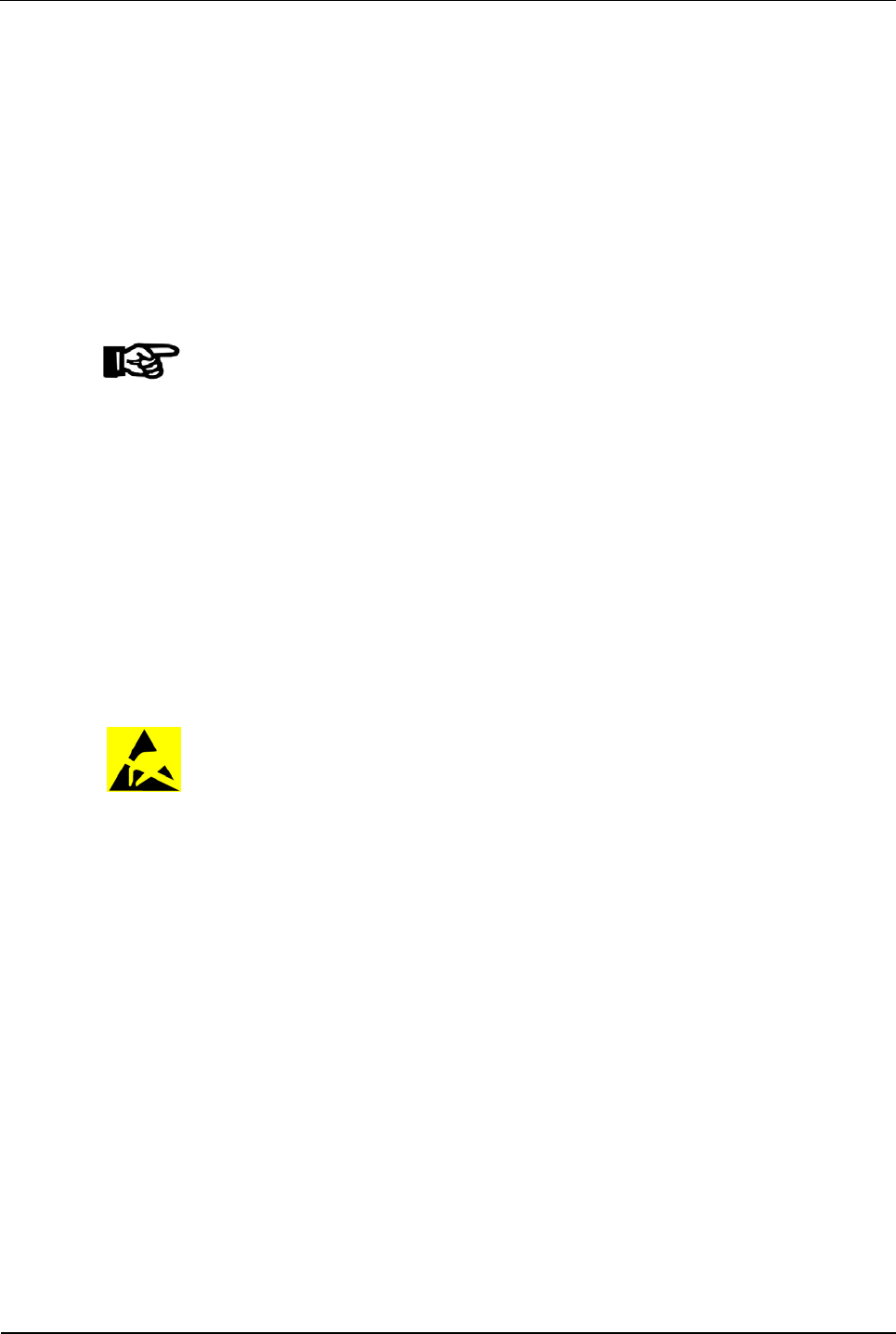
2.4 ESD (Electro Static Discharge) Protective Measures
CAUTION
Danger for electronic components due to electrostatic discharge.
Improper handling of printed circuit boards or components can cause damages that
lead to complete failures or sporadic errors.
During installation and repair of the device, the ESD protective measures must be
considered.
Please consider the following guidelines before the installation or maintenance of
the device:
• Always carry an ESD antistatic wristband when dealing with electronic
components. Connect one part of the wristband with a discharge socket or
an unvarnished grounded metal component. This way, static charges are
discharged from your body securely and effectively.
• Only touch the printed circuit boards at the edges. Do not touch the printed
circuit board itself or the connector.
• Place all dismantled components on an anti-static surface or in an anti-static
container.
• Avoid contact between printed circuit boards and your clothing. The
wristband only protects the printed circuit boards against electrostatic
discharge from the body, but there is still a risk of damage through
electrostatic discharge from your clothing.
• Only transport and dispatch dismantled modules in protective bags.
Product Description Manual B-Net® 91 04
8 © Kaba GmbH 12/2008
3 Product Description
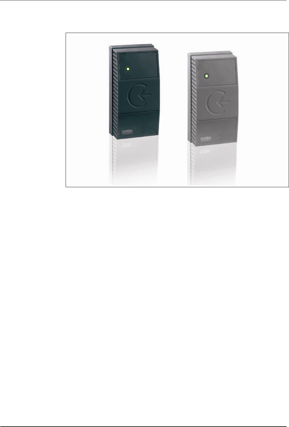
Fig. 1: Subterminal B-Net 91 04, colors anthracite and grey aluminum
B-Net 91 04 is a subterminal to be used for access control. It is compatible with the
terminal series Bedas / Bedanet 90 00.
The reader is in a sealed plastic housing and also designed for use under rough
environmental conditions. Its compact design allows for installation on door frames
or similar surfaces.
The following operating modes are possible:
• Online mode
The B-Net 91 04 is connected to a higher-level control system, for example
an access manager or a terminal of the B-Net series, by means of the RS-
485 sub-party line.
• Stand-alone operation without control
The B-Net 91 04 subterminal includes the LEGIC® contact-free identification
medium. The reader is equipped with LEGIC® advant-RFID technology. LEGIC®
data carriers can be read. Writing data on the LEGIC® medium also is possible.
B-Net 91 04 has a relay which can be used for door opening in secured areas.
The subterminal has a multi-color LED and a beeper for optical and acoustic user
guidance.
Manual B-Net® 91 04 Product Description
12/2008 © Kaba GmbH 9
3.1 Technical data
• Operating voltage: 12 – 32 V DC / 16 – 27 V AC
Power supply
• Current
consumption: max. 150 mA at 24 V
Interface • RS-485 2-wire subpartyline
Protocol: BPA9; transmission parameters: 9600/19200 baud, 7 data bits, parity
even, 1 stop bit
Other settings via system mode are possible.
Output • 1 relay output, contact load 30 V AC/DC, max. 1 A
Readers • LEGIC® reader
Reading and writing of LEGIC® media.
Data retention in
case of power failure • Modified parameters, list of badges, etc. are stored in non-volatile memory
(EEPROM) and are retained when a power failure occurs.
• Protection class according
to IEC 60529: IP66 with connecting cable
IP54 with terminal board
Environmental
conditions
• Environmental temperature: - 25° C - + 55° C
Environmental class: 4
• National Electrical Manufacturers Association (NEMA) 4
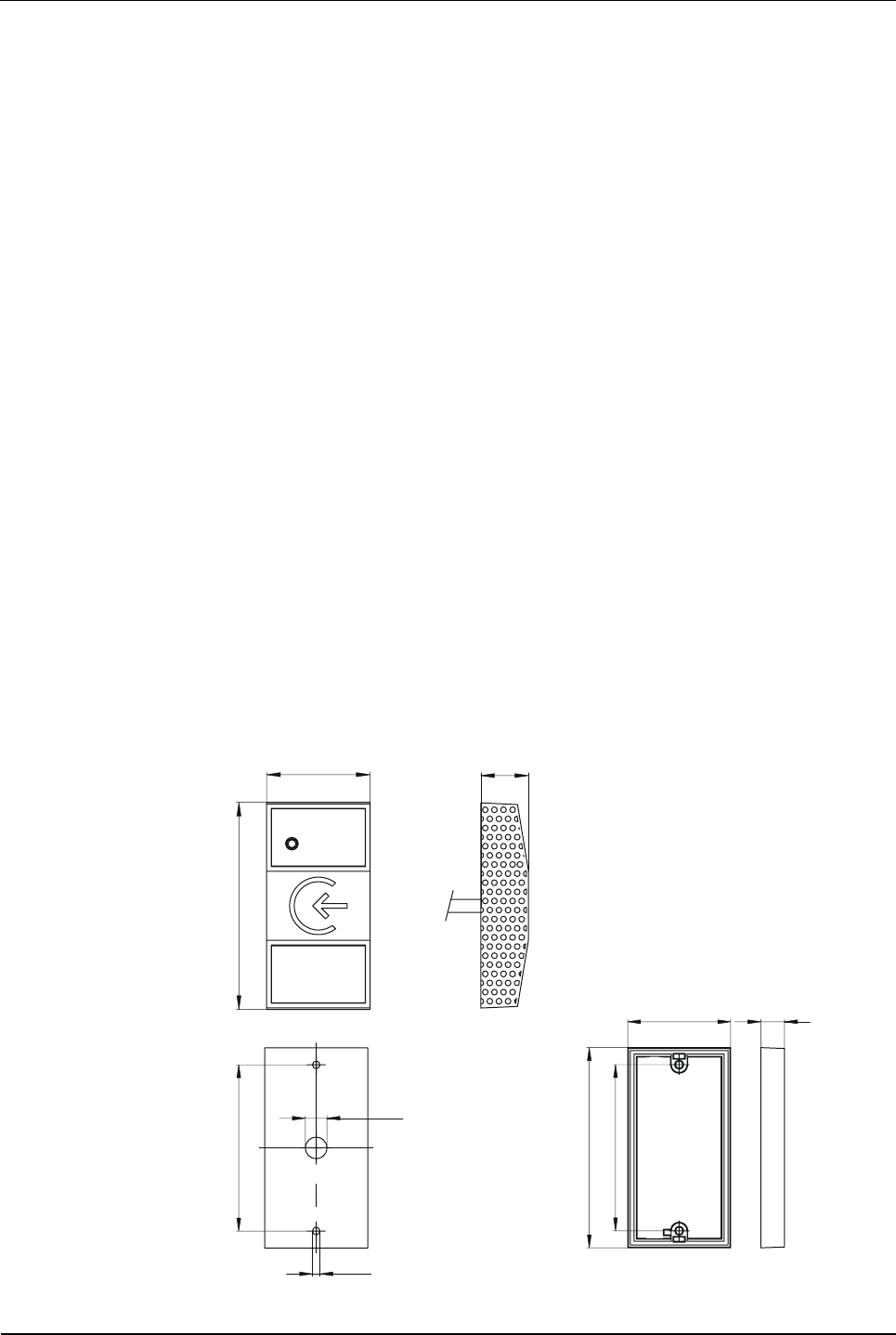
Dimensions
Dimensions in mm
45
90
21
Ø10
Ø3,5
77
93
77
48 11

Product Description Manual B-Net® 91 04
10 © Kaba GmbH 12/2008
3.2 Conformity
This device complies with the standards
EN 60950-1 2003
EN 301 489-3 V1.4.1
EN 300 330-2 V1.1.1
according to the regulations of the EU Directives
1999/5/EC
R&TTE Directive
To the best of our knowledge, this device does not contain any substances in
concentration or application, whose introduction in products is permitted according
to the requirements of the 2002/95/EC directive released by the European Union
("RoHS" = Restriction of Hazardous Substances).
3.3 Labeling
The identification plate is located on the rear of the device.
Specified on the identification plate:
• Device name
• Product number
• Serial number
• Power data
• CE identification
• WEEE specification according to DIN EN 50419, please refer to chapter 10
Manual B-Net® 91 04 Design and Function
12/2008 © Kaba GmbH 11
4 Design and Function
4.1 Models / Delivery volume
The device can be delivered in two versions:
• With 3.5 mm connecting cable (standard)
• With terminal board without connecting cable (optional)
The connecting frame provides additional room for cable storage, if needed, and
possesses a predefined location of rupture for cable outlet for surface mounting.
The connecting frame is always part of the delivery.
In addition, the delivery comprises a bag with installation accessories, consisting of
a 6 cm insulating tube and 9 butt connectors for extending the connecting cable.
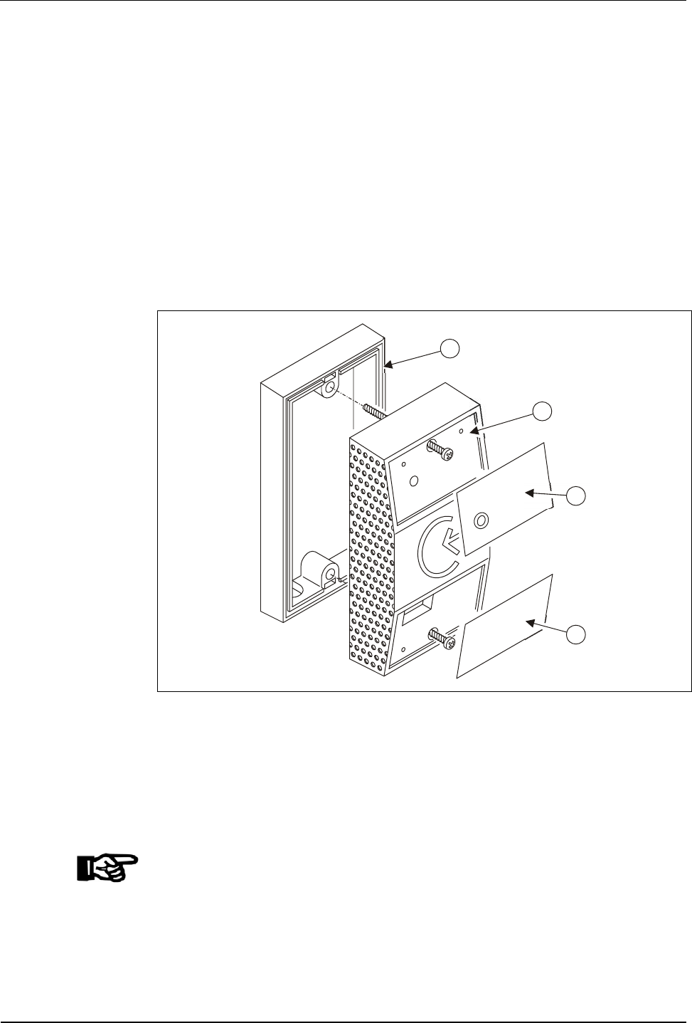
Upper and lower front panel (cover) are attached unpacked.
1
2
3
4
Fig. 2: Parts view
1 Terminal frame
2 B-Net 91 04
3 Upper front panel
4 Lower front panel
NOTICE!
Please stick on front plates after setting into operation and test of function.
Design and Function Manual B-Net® 91 04
12 © Kaba GmbH 12/2008
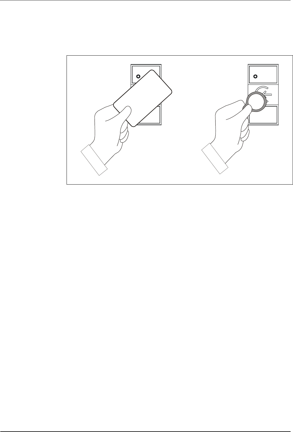
4.2 Input possibilities
LEGIC® media, such as badges, key tags, smartkeys, etc., can be read. The
LEGIC® medium is positioned in front of the subterminal.
Fig. 3: Entry of LEGIC® media
The reading distance depends on the environmental conditions and the type of
LEGIC®.
• The range of a LEGIC® badge is 5 cm.
• The range of a LEGIC® key tag is approx. 2.5 cm.
4.3 Hardware equipment
4.3.1 LED
For optical user guidance, the subterminal is equipped with a two-color LED (red
and green).
The LED is directly activated by B-Net 91 04 depending on the operating mode or
by corresponding commands from the control unit.
4.3.2 Acoustic signal generator
The subterminal has a beeper for acoustically signalizing certain states. The
beeper is directly activated by B-Net 91 04 depending on the operating mode or by
corresponding commands from the control unit.
4.3.3 Digital outputs
The B-Net 91 04 has one relay. The name of the relay is R1.
In stand-alone mode, this relay is used for the door opener.
In online operation, the relay may be activated by the corresponding commands
from the access control unit, e.g. door opening in secured areas.

Manual B-Net® 91 04 Design and Function
12/2008 © Kaba GmbH 13
4.4 Operating Modes
4.4.1 Online mode
In online operation, the device works as subterminal of an access control.
The device can be connected to access control units of the device families Bedas,
Bedanet and B-Net, such as B-Net 92 50, Bedanet 92 90, or a time recording
terminal of the B-Net series.
One or several subterminals are connected to the control unit by means of the
RS-485 subpartyline. The subterminal is operated in the polling mode. The control
unit polls the connected subterminals one after the other in order to send or receive
data.
If a badge is presented, the badge data is sent to the control unit. The control unit
decides whether a badge is authorized or not and sends the respective commands
for LED, beeper and relay back to the subterminal. The internal relay should only be
used in secure areas for opening a door. Therefore, the control unit generally
controls and opens the door.
Remark
On delivery, online operation is preset in the subterminal.
4.4.2 Stand-alone operation
NOTICE!
Stand-alone operation may only be used together with LEGIC® prime media (media
with existing data structure).
In stand-alone operation, the device works independently without connected
control unit. A customer number list stored in the device allows for the verification
check of every booking. LED, beeper and relay are activated accordingly.
A service PC and a parameter setting tool are required for set-up. The customer
number list is transmitted via the RS-485 subpartyline. After activating the stand-
alone operation, the service PC is removed again.
A customer number list can contain up to 5 entries. One individual entry may be a
customer number or a complete badge number. If, for examples, the authorization
is given to all employees of a company, the customer number must be stored. If
the authorization is given to individual employees, the complete badge number
(customer number + ID) must be stored.
The green LED is lighted during operation. When a badge is presented, the badge
data is read and checked. If the verification is positive, the relay is activated for 3
seconds (default). A successful booking is confirmed by means of a 1-second
acoustic signal. After an invalid booking, the red LED and the beeper are activated
alternately for 3 seconds.
Mounting and Installation Manual B-Net® 91 04
14 © Kaba GmbH 12/2008
5 Mounting and Installation
5.1 Installation Conditions
General An accurate installation of all components is a basic requirement for proper
functioning. The following installation instructions must be adhered to.
Installation site The device can be mounted either directly on the wall or on a door frame.
For cable outlet, a drilling of approx. 10 mm diameter is required. An edge which
might be produced must be trimmed.
A screw guide is positioned in the middle of the housing’s top and bottom. Use only
the screws included in the delivery for fastening the device.
Connectors The following connectors must be prearranged at the installation site of the device.
• Power supply
• Data line for access control unit (online operation only)
• Cables to the door opener (if required)
Grounding The terminal must be grounded!
To guarantee the highest possible noise immunity according to EMC, the ground
wire must be led to the terminal and connected.
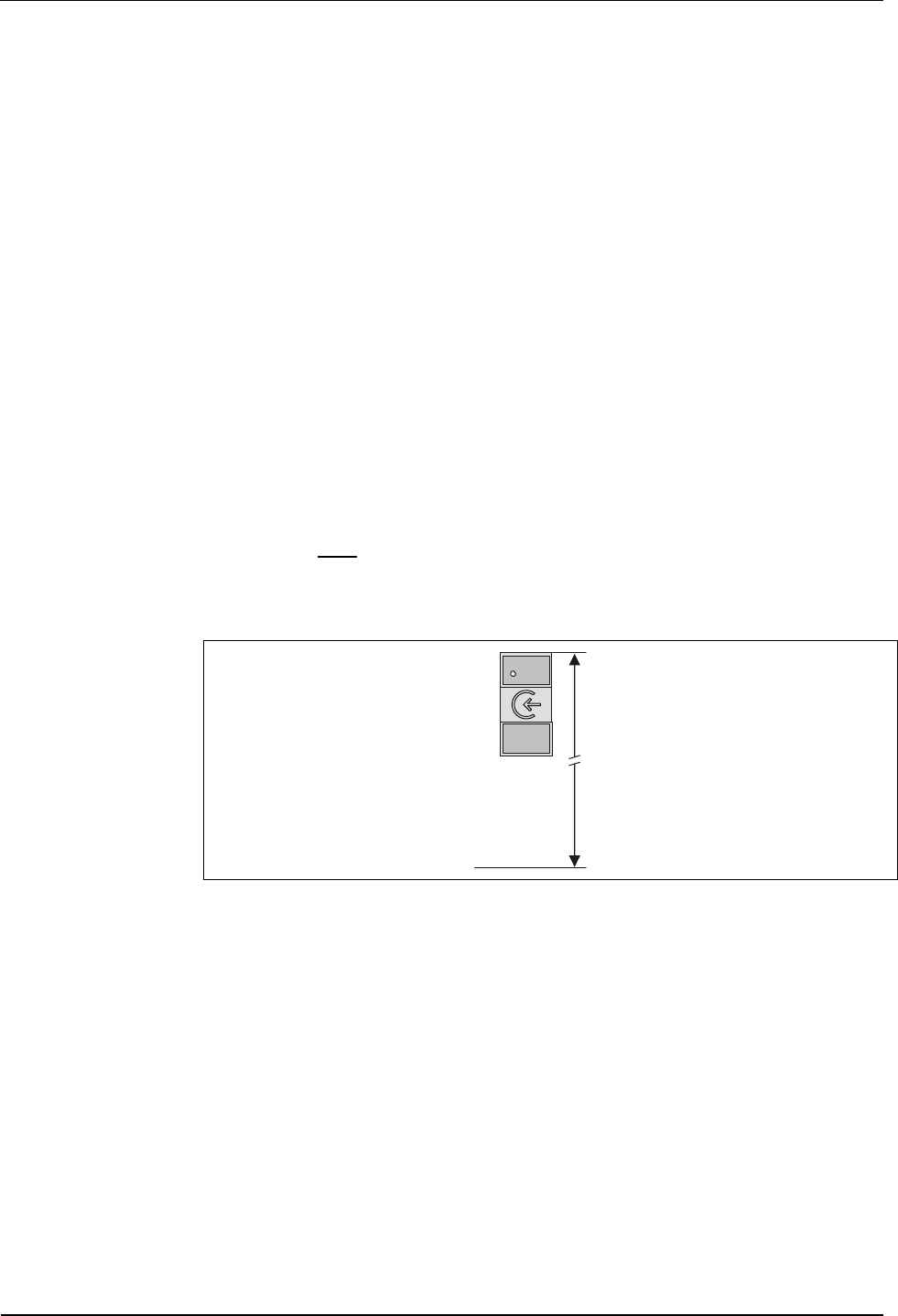
Mounting height
140 c
m
Fig. 4: Recommended mounting height 140 cm to top edge of terminal.
Electromagnetic
fields The terminal must not be installed in the area of strong electromagnetic fields,
caused by e.g. switching power supply, power lines, phase controllers, etc.!
Electromagnetic fields can affect the reading power or cause failures, in particular
with contact-free readers (LEGIC, Mifare).
Manual B-Net® 91 04 Mounting and Installation
12/2008 © Kaba GmbH 15
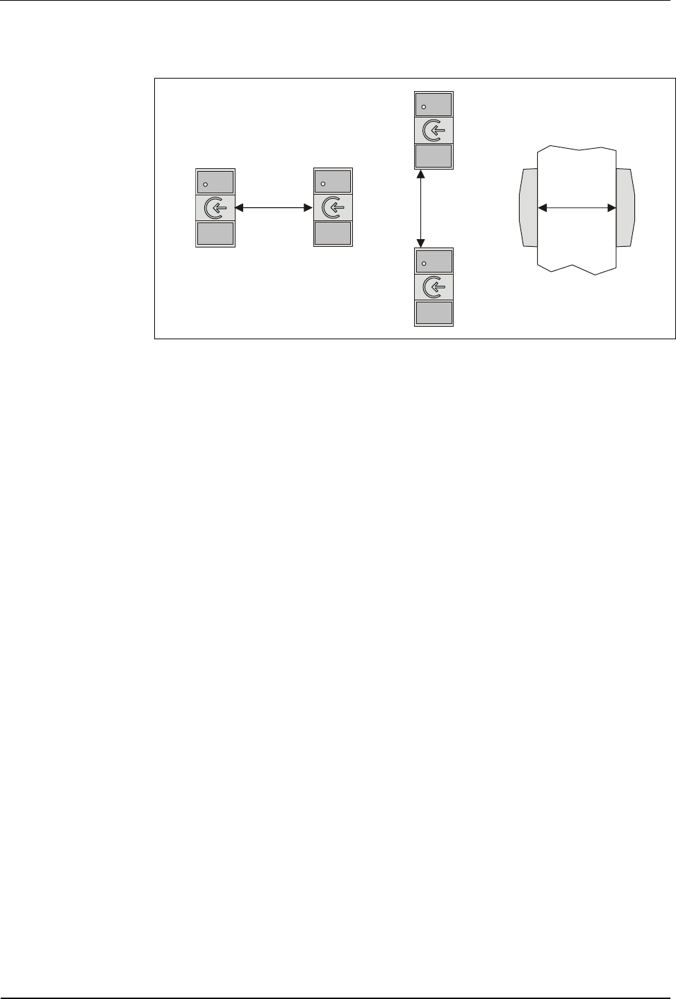
Clearances Between two B-Net 91 04 devices, a distance of 20 cm must be observed on all
sides.
min. 20 cm
min. 20 cm
min. 20 cm
Fig. 5: Minimum distance between devices with LEGIC® readers.
To steel parts, a distance of 10 cm must be observed on all sides. If this distance is
not observed, the reading quality is impaired. Then, the maximum reading distance
is not achieved. Problems may appear with different LEGIC® media.
The terminals frame included in the delivery must be used for mounting the device
on metal surfaces.
The terminal frame increases the distance between reader and metal surface thus
reducing damping by the metal.
Mounting and Installation Manual B-Net® 91 04
16 © Kaba GmbH 12/2008
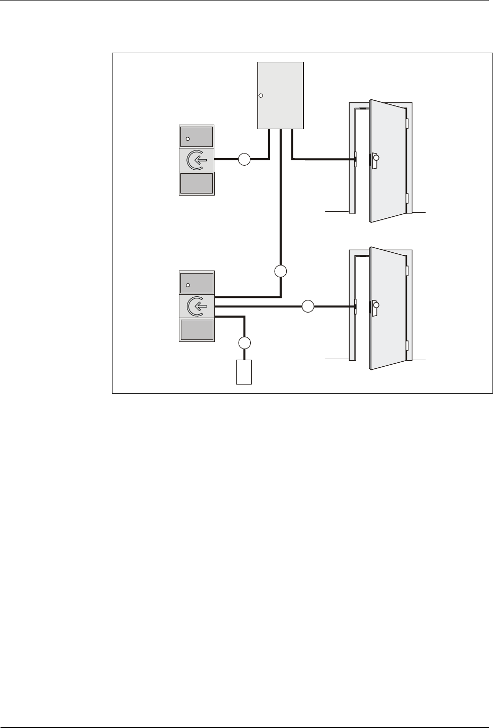
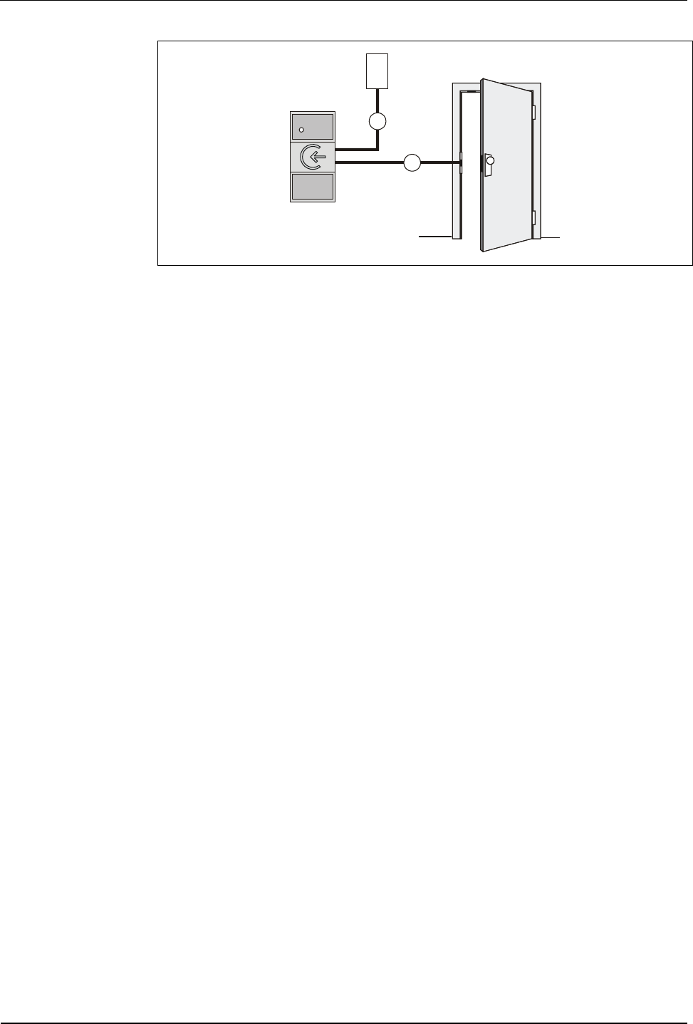
5.2 Installation Diagram
A
A
B
C
1
2
4
3
5
5
Fig. 6: B-Net 91 04 installation in online operation
1 Access Control Unit
2 B-Net 91 04
Power is supplied via the access control unit. The power supply is also led
through the data line (A). This is permitted for cable lengths up to 20 m.
The door opener is led to the access control unit.
3 Subterminal B-Net 91 04 with separate power supply (4).
The door opener is connected to the subterminal. This is only recommended,
however, in secure areas.
4 Power supply SV 100, SV 900 or SV 905 with supply for door opener
5 Door opener
Installation Lines
A Data line (subpartyline)
B Line to door opener
C Power supply and grounding
Manual B-Net® 91 04 Mounting and Installation
12/2008 © Kaba GmbH 17
B
C
1
2
3
Fig. 7: B-Net 91 04 installation in stand-alone operation
1 Subterminal B-Net 91 04
2 Power supply SV 100, SV 900 or SV 905 with supply for door opener
3 Door opener
Installation Lines
B Line to door opener
C Power supply and grounding

Mounting and Installation Manual B-Net® 91 04
18 © Kaba GmbH 12/2008
5.3 Installation Lines
(A) Data line to subterminal
The subterminals are connected to the control unit via a 2-wire subpartyline. It can
be designed in star-shape or as partyline.
NOTICE!
The shielding of the data line is generally connected on both sides.
The complete bus connection (master lines and branch lines) may be up to 2,000
meters long. One branch line may not exceed 100 m.
For short distances (up to 20 meters max.), it is permitted to have the operating
voltage for the subterminal and the data line in one single cable. In this case, the
subterminal is grounded via the shield of the data line.
For line lengths over 20 m, a separate power supply cable (C) must be provided for
the subterminal.
Line requirements:
Shielded line with twisted wire pairs,
cable diameter 0.4 mm to 0.6 mm
for instance standard telephone cable J-Y (St) Y 2 x 2 x 0.6 mm.
Recommended cable:
CAT.5 S-UTP 4 x 2 AWG 24 or AWG 22 (according to EIA/TIA568).
(B) Line to the door opener
Line requirements:
Cables with a cable diameter from 0.5 mm to 0.8 mm can be used.
Recommended cable:
CAT.5 S-UTP 4 x 2 AWG 24 or AWG 22 (according to EIA/TIA568) or higher.
(C) Power supply and grounding
In online operation, power is supplied by the superior control unit and can be tapped
easily from there.
If the device is used without control unit or if power cannot be supplied by the
control unit, a separate supply unit, e.g. SV 100, SV 900, SV 905, must be used.
In case of long lines, the voltage drop - caused by the line resistance - must be
considered.
The ground wire must be led from the power supply to the terminal.
Cables with a cable diameter from 0.5 mm to 0.8 mm can be used.
Three wires are required for power supply + ground (SV 100 / SV 900).
If door-opener voltage is required, two further wires are needed (SV905).
Manual B-Net® 91 04 Mounting and Installation
12/2008 © Kaba GmbH 19
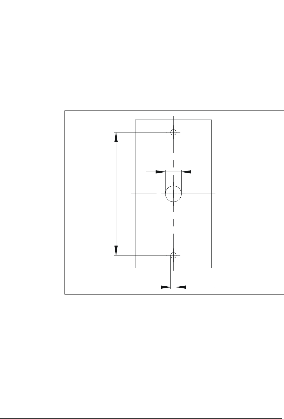
5.4 Mounting
The device can be mounted either directly on the wall or on a door frame. The
terminal frame included in the delivery must be used for mounting the device on
metal surfaces.
For cable outlet, a drilling of approx. 10 mm diameter is required. A possible edge
must be trimmed.
A screw guide is positioned in the middle of the housing’s top and bottom.
In order to avoid danger of concealed or hidden cracks and tightness problems at
the screw head, this device may only be mounted with the original screws included
in delivery.
Ø
3,5
Ø 10
77
Fig. 8: Hole pattern for B-Net 91 04; dimensions in mm
Mounting and Installation Manual B-Net® 91 04
20 © Kaba GmbH 12/2008
5.5 Installation of devices with connecting cable
For the prolongation of the cable tail or for the link to an already mounted data
cable, appropriate butt connectors are attached.
Possible wire and/or stranded wire dimensions are AWG 26-22 (D:0,4-0,65,
A:0,13-0,36) The butt connectors must be fastened offset on the cable to allow
introducing the connecting position into an empty tube or through a bore hole into
the door frame. In case the butt connectors cannot be used, the attached
connecting frame can be used as place for cable joint and/or cable storage room.
The different stranded wires in the cable tail have different colors.
The butt connectors can be joined with the stranded wires with a standard crimping
plier.
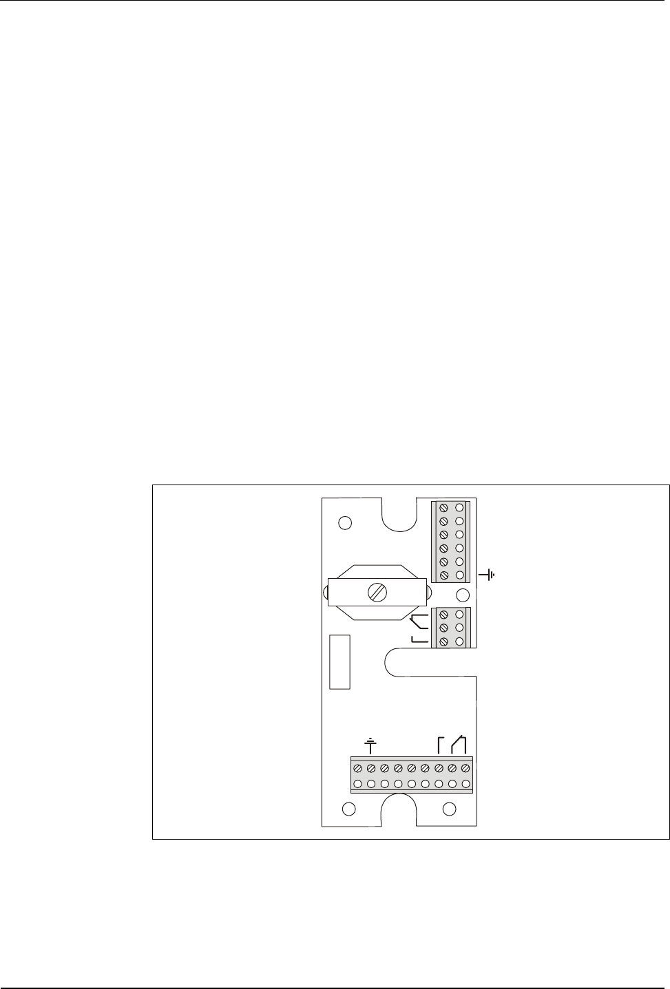
5.6 Installation of devices with connecting panel
As an option, the B-Net 91 04 terminal can be delivered with a connecting panel.
The terminal board is located on the back side of the device.
The connecting clamps can be drawn from the connecting panel in order to render
the connecting procedure easier.
The connecting panel is available as spare part. Owing to its double plug
configuration, it can even be used if the subterminal was delivered with cable tail,
for instance, if the cross section of the installed cable does not match with the butt
connectors.
The connecting panel is labeled with the corresponding seizure of the clamps.
During discharge of tensile load, the shield can be directly laid up.
A
C
B
AC
B
~
+
~ -
~+
~ -
Fig. 9: Terminal board

Manual B-Net® 91 04 Mounting and Installation
12/2008 © Kaba GmbH 21
5.7 Pin assignment
The following table shows designations and assignments of clamps with regard to
wire colors.
Color Description Data
Power Supply
red AC/DC + or +
Gray Ground
blue AC/DC + or +
12-32 V DC or 16-27 V AC
Power consumption max. 150 mA at 24 V
Relay
yellow Opener (NC)
green Center contact (COM)
orange Closer (NO)
Contact loading capacity:
30 V AC/DC; 1 A max.
Subpartyline
brown A
violet B
black C
NOTICE!
On principle, all connections have to be performed in off-circuit state.

Mounting and Installation Manual B-Net® 91 04
22 © Kaba GmbH 12/2008
5.8 Description of connections
5.8.1 Power Supply
The B-Net 91 04 subterminal can either be operated at 12 V DC or 24 V AC/DC.
The current consumption with 24 V is 150 mA at maximum.
5.8.2 Relay output
The function of the R1 relay is defined by the access control unit in online mode. In
stand-alone mode, the relay is used for the control of the door opener.
For door openers, which are supplied with direct current, a freewheeling diode
must be connected in parallel to suppress interference (in reverse-bias direction). A
varistor must be connected in parallel to AC door openers.
5.8.3 Data interface to access control unit (subpartyline)
The access control unit is connected via a 2-wire subpartyline. The subpartyline is
an RS485 bus operated in 2-wire technology.
The shielding of the data line is generally connected on both sides.
NOTICE!
Please pay attention to the correct pin assignment of the different control units.
A A
B B
B-Net 91 04
C C
B-Net 92 50
B-Net 93 xx
Bedanet 92 90 Rack BEX105
A B
B A
B-Net 91 04
C C
Bedanet 92 20
Bedanet 92 90
Bedanet 93 60
Bedas 92 90
Bedas 93 60
Manual B-Net® 91 04 Mounting and Installation
12/2008 © Kaba GmbH 23
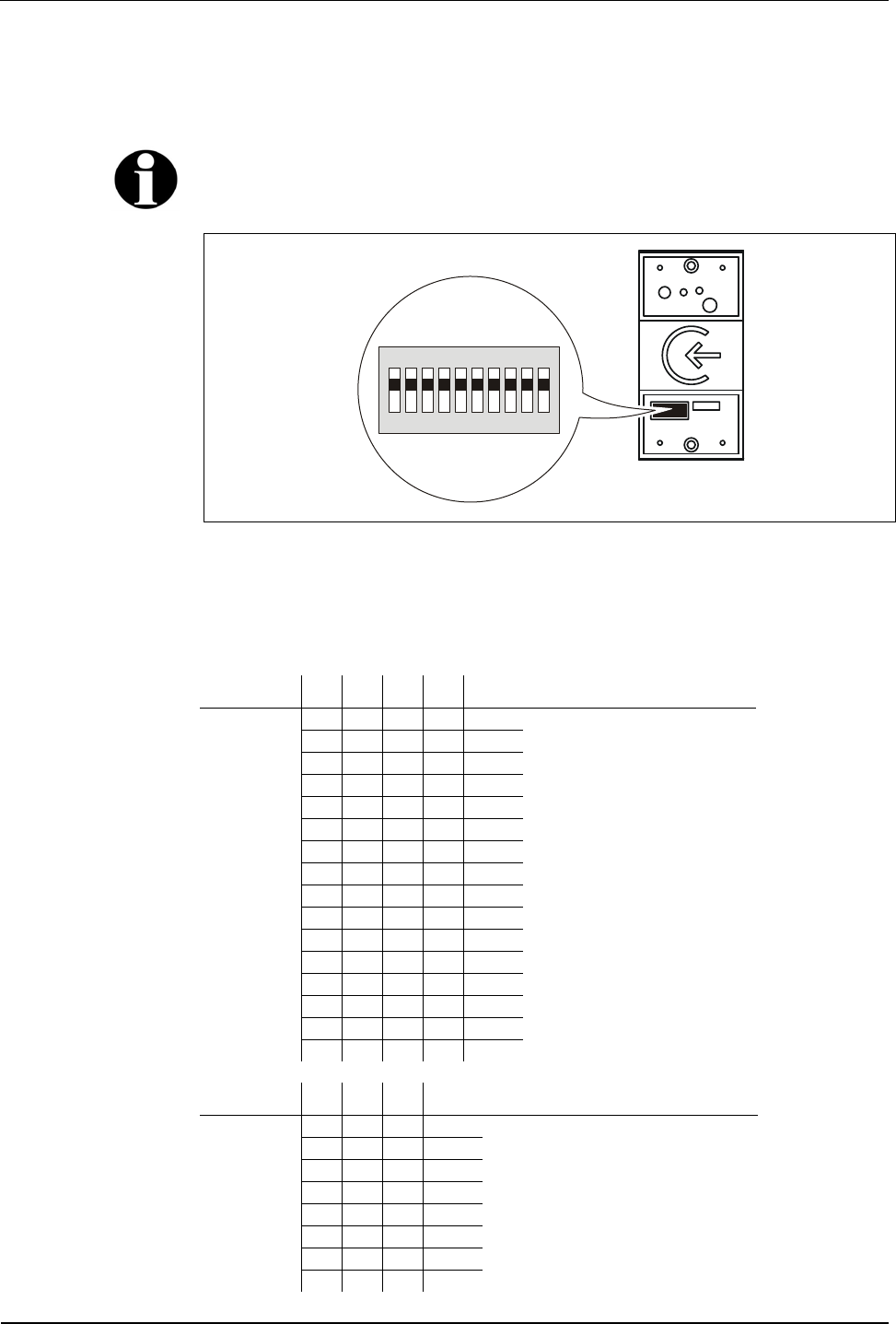
5.9 DIP-Switch
The DIP switch row is located under the lower front panel. Therefore, the switches
must be adjusted before fixing the front panel.
Remark
All switches are set to ON when delivered.
1
OFF
2345678910
Fig. 10: DIP switch position
GID/DID The group and device identifications (GID/DID) serve for addressing a subterminal
via the RS-485 interface. This setting is required if the device is used as a
subterminal in an access control unit.
Switch 1 2 3 4 Logical device address (DID)
on on on on 00
off on on on 01
on off on on 01
off off on on 03
on on off on 04
off on off on 05
on off off on 06
off off off on 07
on on on off 08
off on on off 09
on off on off 10
off off on off 11
on on off off 12
off on off off 13
on off off off 14
off off off off 15
Switch 5 6 7 Logical group address (GID)
on on on 00
off on on 01
on off on 01
off off on 03
on on off 04
off on off 05
on off off 06
off off off 07

Mounting and Installation Manual B-Net® 91 04
24 © Kaba GmbH 12/2008
Baud Rate The baud rate of the RS-485 subpartyline can be set by means of switch 8.
The remaining transmission parameters are fix.
7 data bits, even parity, 1 stop bit, response control 3 seconds, operation
monitoring 3.5 seconds
Switch 8 Baud Rate
on 19200 (standard)
off 9600
BPA/9 protocol The BPA/9 protocol can be switched off by means of switch 9.
Switch 9 BPA/9 protocol
on BPA/9 protocol (standard)
off no protocol
DIP switch All DIP switches can be deactivated by means of switch 10. The parameters are set
in the system mode (see chapter 7) by means of the "LOWPAR" command.
Switch 10 DIP switch
on ON (standard)
off Off
5.9.1 Required DIP switch settings in different operating modes
Online mode:
Switch 1 2 3 4 5 6 7 8 9 10
Device address Group address on on on
Stand-alone operation
Switch 1 2 3 4 5 6 7 8 9 10
Device address Group address on on on
Manual B-Net® 91 04 Mounting and Installation
12/2008 © Kaba GmbH 25
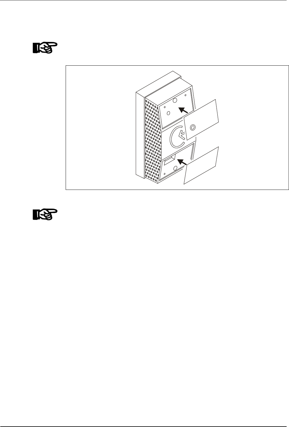
5.10 Final assembly
Fasten the front foils for finishing installation.
NOTICE!
Before fixing the front foils, the device must be put into service, see chapter 6.
Fig. 11: Fixing the front foils
NOTICE!
Observe the following to avoid leaks:
• Use only new front foils with undamaged peel-off foil.
• The housing surfaces on which the foil is to be fixed must be dry, fat-free and
clean. For cleaning purposes use solvents free of any oily or greasy
substances such as n-Heptan or isopropyl alcohol.
• Press the foil down to fix it.
• The ambient temperature must be minimum +4°C.
The ambient temperature must be at least + 4°C. If the minimum processing
temperature is not of + 4°C, or if you expect the temperature to drop below
this value within the next 3 hours after bonding, do not mount the
subterminal.

Start-Up Manual B-Net® 91 04
26 © Kaba GmbH 12/2008
6 Start-Up
NOTICE!
The descriptions in chapter Set-up refer to devices with standard configuration
preset in the factory.
By default, the driver "LEGIC® prime read-only" is active. This driver is compatible
to the Bedas/Bedanet series, i.e. media with previous data structure can be read.
The stand-alone mode is only possible with standard configuration.
Other drivers can be configured in system mode, see chapter 7. These include
"LEGIC® prime read and write" or "LEGIC® advant read and write".
In this case, make sure that the access control unit supports these drivers in the
online mode.
Remark
As a standard, only those badges are accepted which have a segment containing
SSC 02 and a fixed structure of the badge data according to Kaba group header.
Non-segmented badges may have an arbitrary SSC, but must also be coded
according to Kaba group header.
It is also possible to allow badges having a different SSC and a different data field
structure if defined so in the "Customer Number List".
The customer number list can be set by the control (see chapter 8.7.8) or a service
PC with parameter setting tool (see chapter 6.1).

Manual B-Net® 91 04 Start-Up
12/2008 © Kaba GmbH 27
6.1 Online mode
Requirements
• A connection to the access control unit must exist.
• The DIP switches must have been set in accordance with the description in
chapter 5.9.
Set-up procedure
1. Provide the subterminal with power.
2. Start up the subterminal at the control unit (see the Control Unit Manual).
3. Perform a functional test.
Start-Up Manual B-Net® 91 04
28 © Kaba GmbH 12/2008
6.1 Stand-alone operation
Requirements
• The connections to power supply and door opener must exist.
• The DIP switches must have been set in accordance with the description in
chapter 5.9.
• A service PC and the parameter setting tool, order number 04036126, must
be available. In the service PC, the program "List Editor" (listedit.exe) must
have been installed. This program is part of the parameter setting tool.
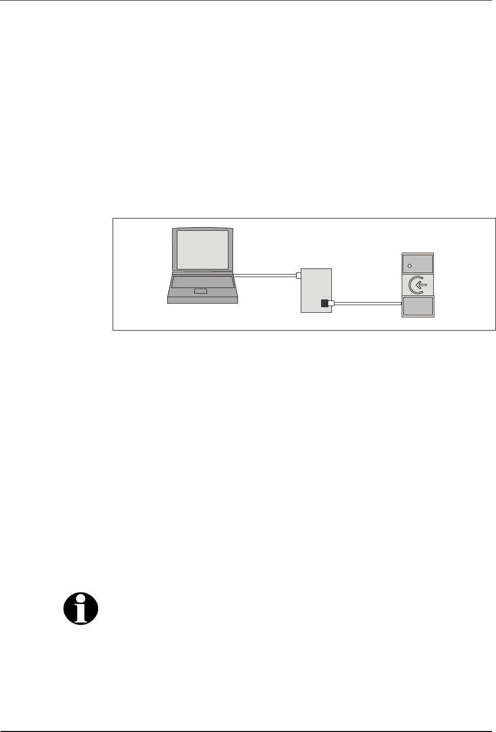
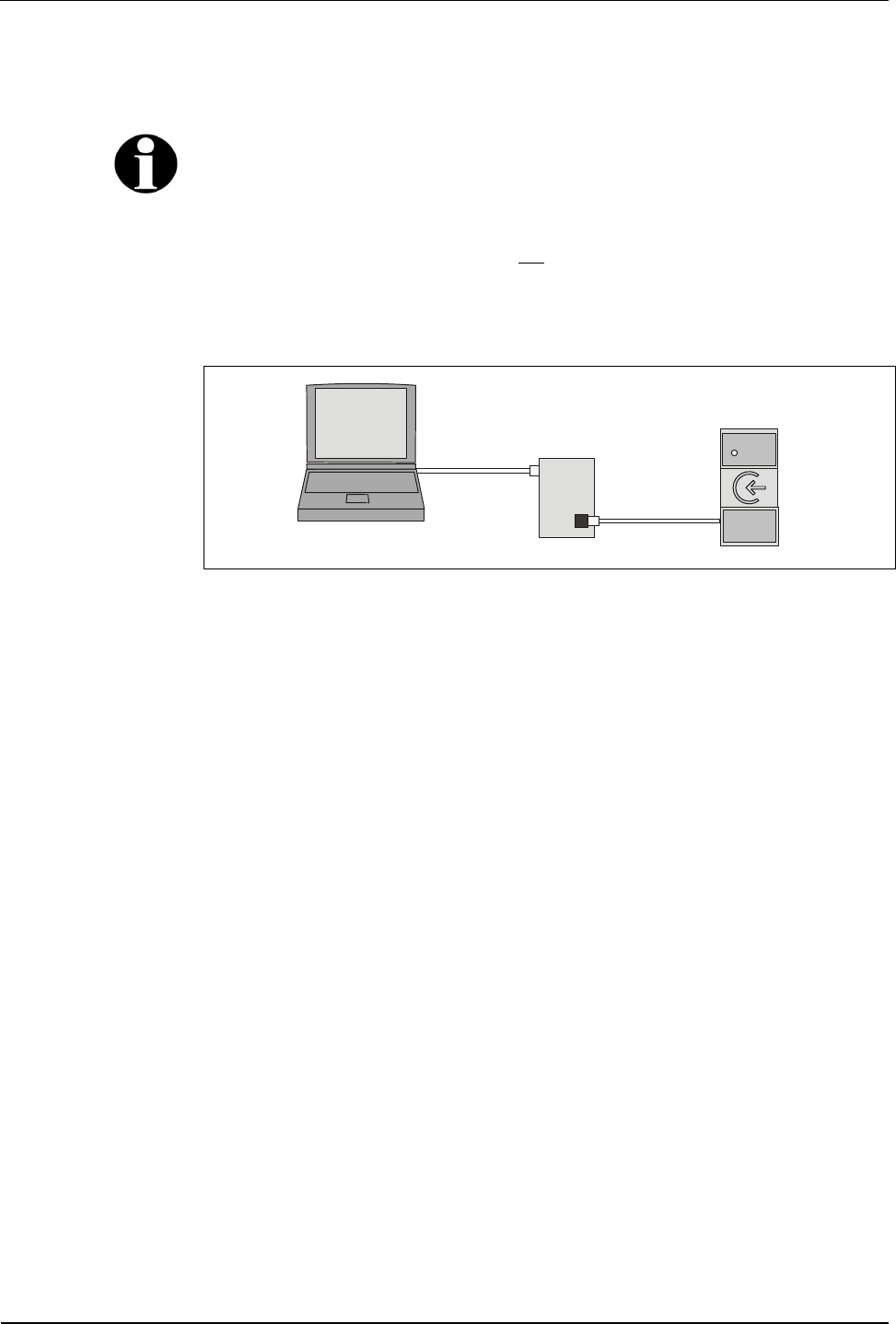
Set-up procedure
1. Connect the service PC via the parameter setting tool to the B-Net 91 04.
Use the yellow connecting cable for connecting B-Net 91 04 to the
parameter setting tool.
RS-232C
RS-485
B-Net 91 04
Para-Tool
Service-PC
Fig. 12: Connecting the service PC to B-Net 91 04
2. Provide the parameter setting tool with power (B-Net 91 04 is also supplied
with power).
3. Start the "List Editor" on the service PC.
In the Options menu, the COM port must have been selected and the device
address used of the B-Net 91 04 must have been set.
4. Prepare the desired customer number list and load it to the subterminal.
If a list entry contains 14 digits of customer and badge number in
accordance with the Kaba group header, a single badge will be authorized.
If a list entry contains, for example, only an 8-digit customer number in
accordance with the Kaba group header, a badge group will be authorized.
5. Activate the stand-alone operation and enter the relay pull-in time (default 3
seconds).
6. Perform a functional test.
7. Service PC and parameter setting tool are no longer required and can be
removed.
Remark
The operation of the List Editor is described in the manual of the parameter setting
tool.
The description of the customer number list can be found in chapter 8.7.8.
Manual B-Net® 91 04 Start-Up
12/2008 © Kaba GmbH 29
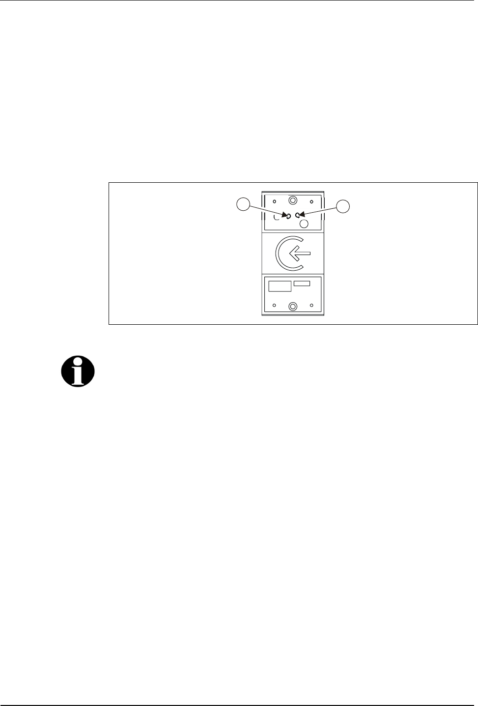
6.2 Cold start
The device can be reset to default settings by means of a cold start.
How to perform a cold start:
• Turn off the device
• Push the cold start button and keep it pressed
• Turn the device on
• Release the cold start button after approx. 3 seconds
After a successful cold start, an acoustic signal can be heard, and the status LED
flashes three times.
2
1
Fig. 13: Cold start button (1) and status LED (2).
Remark
The following applies to parameters being changed in the system mode:
Parameters adapted via LOWPAR are reset to default settings by means of the cold
start.
Configuration parameters set by the SETHWC command and diagnostics data are
maintained.
6.3 Status LED
The device has a red status LED (2) to signalize states or errors.
After switching on, the LED is lighted shortly and switched off immediately if
operation is trouble-free.
The following states are possible:
LED is still lighted after reset Program does not run
LED flashes 6 times after reset First start (basic initialization)
LED flashes 3 times after reset Cold start
LED flashes once System mode becomes active
LED is switched off immediately after reset Program runs error-free
LED flashes continuously Program has detected an error
The error can be stored in the EEPROM memory and displayed directly or via a
command, see system mode).
Start-Up Manual B-Net® 91 04
30 © Kaba GmbH 12/2008
6.4 Adjusting the reader
The reader has been adjusted in the factory to an optimum range. Normally, it
needs not to be readjusted.
The reader range is influenced by the damping of conducting material around the
reading unit (e.g. housing, built-in units, conductive paint, reinforced concrete,
etc.).
If used in critical environment (small distance to metal parts, etc.), the reading
characteristics might be improved by an adjustment. The reader can thus be
adapted to the installation environment to limited extent.
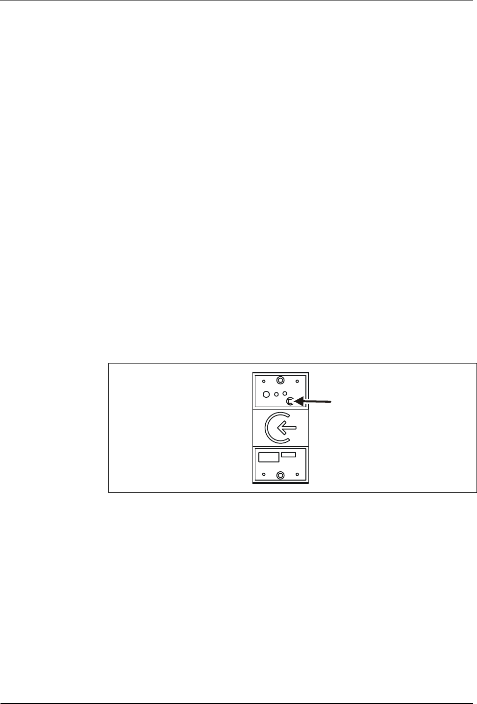
There is a small trimmer on the front of the device. This trimmer can be accessed
after removing the housing frame.
The adjustment should be made using an alignment pin.
An oscilloscope or LEGIC® Powermeter, order number 04032432, can be used for
adjustment.
Adjusting using an oscilloscope
The logic probe is converted into a measuring loop (connect logic probe ground to
test tip) or extend the test tip by a short piece of wire (antenna effect). The logic
probe must be fastened in front of the reader. The pulses are then set to max.
amplitude.
Adjusting using LEGIC® Powermeter
Fasten the powermeter in front of the reader. Adjust the knob on the powermeter
so that the LED field is lighted in yellow/green.
Then select maximum amplitude on the trimmer.
Fig. 14: Trimmer position for reader adjustment
Manual B-Net® 91 04 System mode
12/2008 © Kaba GmbH 31
7 System mode
The system mode allows parameter setting for the device.
Remark
Default parameters can be modified in system mode. However, this is only required
for special applications.
The "online" and "stand-alone" modes described in this manual require factory
settings. Therefore, parameters have not to be changed in system mode for these
operating modes.
The system mode is an imitation of the operating system. It can be accessed via
the data interface of the device. A service PC is connected by means of the
parameter setting tool, order number 04036126.
RS-232C
RS-485
Bedanet 91 04
P
a
r
a
-T
oo
l
Service-PC
Fig. 15: Connecting the service PC to B-Net 91 04
Connection is established via a standard terminal software, e.g. HyperTerminal. A
protocol is not used. The following communication parameters are valid:
Baud rate: 9600 Baud
Parity: even
Data bits: 7
Stop bits: 1
The system mode is started by:
• continuously pressing the cold start button (see chapter 6.2) for 2 seconds:
or
• executing the command <ESC>[=99x
This method requires connection to a control unit that supports this
command.
Activation of the system mode is confirmed by a flashing status LED and an
acoustic signal.
After starting system mode, the device replies with the prompt
(<CR>, <LF>, '>').
System mode can only be exited via the commands RUN, ORIGIN, a warm start or
a cold start. It is not cancelled via timeout.

System mode Manual B-Net® 91 04
32 © Kaba GmbH 12/2008
7.1 Commands
Commands only contain capital letters and terminate with <CR>.
When entering commands, the characters following the command are ignored, as
parameters might follow if the device is provided with an operating system. A
wrong command is shown as follows:
Command not found
>_
Once a command has been called successfully, it will be processed.
Upon termination of a command, the device terminal displays a prompt.
If the output of a command is too large for the screen, the stopped output can be
continued with <CR> (Enter key).
If an error is detected upon termination of the command, an error message is
displayed before outputting the prompt:
Write Error
>_
After entering <BS> (backspace key) or <DEL> (delete key), the last entered
character is deleted and the cursor is put back one character.
All entered characters are sent back as echo.
It is checked whether the parameters are correct, and only correct parameters are
applied. The parameters are only accepted if the format (length) is strictly adhered
to.
Before entry, a parameter description is displayed. The currently valid parameter
values, surrounded by simple quotation marks ('parameter'), are then transmitted in
the required input format.
Preset parameters can be applied by means of <CR> (Enter key).
The character '_' represents the cursor in the following examples.

Manual B-Net® 91 04 System mode
12/2008 © Kaba GmbH 33
7.1.1 SETHWC
The SETHWC command (Set Hardware Configuration) is used to enter the
parameters defining the hardware of device.
After having changed the hardware parameters, a cold start must be performed so
that the device applies the defined state. The hardware parameters are not
changed by the cold start.
Example:
>SETHWC
Protocol
Type : '01' : 01
AUX 1
Type : '16' : 16
CIR : '00' : 00
Serial Interface
Baudrate : '009600' :
Number of Data Bits: '8' :
Parity : '0' :
Number of Stop Bits: '1' :
Flow Control : '0' :
LEDs
Number : '02' : 02
Outputs
Number : '01' : 01

System mode Manual B-Net® 91 04
34 © Kaba GmbH 12/2008
7.1.1.1 Description of the Parameters
Protocol Type:
2-digit protocol to control unit (data interface)
00 no protocol
01 BPA/9 protocol
02 BPA/9 protocol with activatable header
Keyboard type:
2 digits: Keyboard type
00 No keyboard
Driver type for AUX channels:
2-digit type for AUX 1
00 no component
16 Serial driver for LEGIC prime - read-only
(data such as LEGIC MAG reader without protocol)
- serial interface
- CIR: Information from LEGIC SM100-S
- Interface parameter: 9600 baud, 8 data bits, no parity, 1 stop bit
18 Serial driver for LEGIC advant - read-only
(data such as LEGIC MAG reader without protocol)
- serial interface
- CIR: Information from LEGIC advant SM
- Interface parameter: 9600 baud, 8 data bits, no parity, 1 stop bit
32 Serial driver for LEGIC prime - read and write
(protocol corresponding to ISO 7816-4)
- serial interface
- CIR: Information from SM100-S
- Interface parameter: 9600 baud, 8 data bits, no parity, 1 stop bit
34 Serial driver for LEGIC advent - read and write
(protocol corresponding to ISO 7816-4)
- serial interface
- CIR: Information from LEGIC advant SM
- Interface parameter: 9600 baud, 8 data bits, no parity, 1 stop bit
If the serial interface is used for a driver, specify the interface parameters also. For
some drivers, the above-mentioned parameters must be firmly defined, for
transparent drivers, the following parameters are possible:
Baud rate: 1200, 2400, 4800, 9600, 19200, 38400, 57600, 115200 baud
Data bits: 7, 8
Parity: 0 (no), 1 (odd), 2 (even)
Stop bits: 1, 2

Manual B-Net® 91 04 System mode
12/2008 © Kaba GmbH 35
CIR type:
2-digit type for CIR 1+2
00 No CIR
01 CIR exists
Status and generation depend on component for AUX channel
LEDs
2-digit number of LEDs
00 No LEDs
01 1 LED
02 2 LEDs
Outputs
2-digit number of outputs
00 no output
01 1 output
7.1.1.2 Default configuration
Protocol type 01 BPA/9 protocol
AUX 1 16 LEGIC prime – read-only
00 No CIR
Serial interface 9600 Baud, 8 data bits, no parity, 1 stop bit
Number of LEDs 02
No. of outputs 01

System mode Manual B-Net® 91 04
36 © Kaba GmbH 12/2008
7.1.2 GETHWC
The GETHWC command (Get Hardware Configuration) displays the parameters
described under SETHWC.
Example with default values:
>GETHWC
Protocol
Type : '01'
AUX 1
Type : '16'
CIR : '00'
Serial Interface
Baudrate : '009600'
Number of Data Bits: '8'
Parity : '0'
Number of Stop Bits: '1'
Flow Control : '0'
LEDs
Number : '02'
Outputs
Number : '01'
>_

Manual B-Net® 91 04 System mode
12/2008 © Kaba GmbH 37
7.1.3 GETPRG
The GETPRG command (Get Program Number) requests the program number of
the device.
Example:
>GETPRG
Program Number : '844-00-X-K00'
>_

System mode Manual B-Net® 91 04
38 © Kaba GmbH 12/2008
7.1.4 LOWPAR
The LOWPAR command (Low Level Parametrierung) is used to adjust the
parameters of the data interface.
The parameters for a protocol are only requested if a protocol with SETHWC
command has been registered.
These parameters are reset to default values after a cold start.
Low level parameters without protocol (protocol type 00):
>LOWPAR
Serial Interface
Baudrate : '019200' : 009600
Number of Data Bits : '7' : 7
Parity : '2' : 2
Number of Stop Bits : '1' : 1
Flow Control : '0' : 0
>_
Low level parameters with protokol BPA/9 (protokol type 01):
>LOWPAR
Serial Interface
Baudrate : '019200' : 009600
Number of Data Bits : '7' : 7
Parity : '2' : 2
Number of Stop Bits : '1' : 1
Flow Control : '0' : 0
Protocol BPA/9
Group (GID) : '00' : 01
Device (DID) : '00' : 01
Poll / Cont. Mode : '0' : 0
Fast Select : '0' : 0
Add. <CR> : '0' : 0
Response-TO : '003' : 003
Activity-TO : '004' : 004
Output Delay : '000' : 000

Manual B-Net® 91 04 System mode
12/2008 © Kaba GmbH 39
Additional parameters with protocol type 02:
Header Length
Up : '00' : 00
Down : '00' : 00
>_
7.1.4.1 Description of the Parameters
Serial interface:
5 digits: Baud rate (01200 to 76800)
1 digit: Number of data bits (7, 8)
1 digit: Parity (0 or N = no; 1 or O = odd; 2 or E = even)
1 digit: Number of stop bits (1, 2)
BPA/9:
2 digits: Group number (00 to 29)
2 digits: Device number (00 to 59)
1 digit: Polling (0) or contention mode (1)
1 digit: Quick call (0 or 1)
1 digit: Additional end character (0 or 1)
3 digits: Response timeout (001 to 999 = 0.1 – 99.9 sec.)
3 digits: Operating timeout (001 to 999 = 0.1 – 99.9 sec.)
3 digits: Transmit delay (000 to 999 = 0.0 – 99.9 sec.)
Header Up/Down:
2 digits: Header when sending (00 to 05)
2 digits: Header when receiving (00 to 05)
Remark
The parameters for "serial interface" as well as GID and DID can only be changed
using the LOWPAR command if the DIP switch 10 is set to OFF, see chapter 5.9.

System mode Manual B-Net® 91 04
40 © Kaba GmbH 12/2008
7.1.5 RUN
The command RUN (restart of the program) is used to quit the system mode and
perform a warm start.
Example:
>RUN_
or
>RUN,,S_
The warm start is indicated by the following message:
>Restarting …
7.1.6 ORIGIN
The ORIGIN command resets the device to factory settings. This applies to all cold
start parameters, to hardware parameters that can be set using the SETHWC
command and to the diagnostics data.
Example:
>ORIGIN_
The following messages appear:
Resetting device to delivery state
Are you sure?
After acknowledgement with '1' or 'Y', the factory settings are restored, and the
following message is displayed:
>Restarting …
In all other cases, there is no action, and the system mode remains active.

Manual B-Net® 91 04 System mode
12/2008 © Kaba GmbH 41
7.1.7 GETDGN
The GETDGN command is used to query diagnostics data (possible errors).
Query without error messages:
>GETDGN_
No Errors found
>_
Query with error messages:
>GETDGN
Errors found : 01
Code: 010 Meaning: Error while allocating memory
>_
The following error codes are possible:
1 Unspecific Error
2 Unknown Error
10 Error while initializing Task Manager
11 Error while creating Task
12 Error from Task Manager
20 Error while initializing EEPROM
21 Error while writing to EEPROM
22 Error while reading from EEPROM
30 Error while allocating memory
31 Error while initializing Buffer
40 Error while writing to Display
7.1.8 RSTDGN
The RSTDGN command is used to delete all diagnostics data.
Example:
>RSTDGN
>_

Description of the Subpartyline Manual B-Net® 91 04
42 © Kaba GmbH 12/2008
8 Description of the Subpartyline
In online mode, data transfer takes place via the subpartyline. The subpartyline is
an RS485 bus operated in 2-wire technology.
Normally, transmission takes place at 19,200 baud, parity even and one stop bit.
Alternatively 9,600 baud are also possible. 7 bit ASCII characters are transmitted.
8.1 BPA Subset
The BPA (Benzing Protocol Asynchronous) is a master slave protocol with the
subterminal being the slave. The master is always the superior control unit. The
BPA’s overall control is performed by the control unit.
The BPA subset is a protocol with reduced functionality adapted to data exchange
with subterminals.
8.2 Addressing
Because several subterminals can be connected to a control unit, these must be
distinguished by addresses. For this, two addresses exist. The group ID (GID) is a
group address, the device ID (DID) the actual device address. These addresses
are set at the subterminal. The range of values goes from 0 to 7 for the GID and
from 0 to 15 for the DID.
In transmission these addresses are always represented in ASCII characters. For
transmit polling the upper case letters are used. For receive polling for the GID
lower case letters are used:
GID(hex)
Address DID(hex) Address Transmit polling Receive polling
0 @(40) 0 @(40) ´
(60)
1 A(41) 1 A(41) a
(61)
2 B(42) 2 B(42) b
(62)
3 C(43) 3 C(43) c
(63)
4 D(44) 4 D(44) d
(64)
5 E(45) 5 E(45) e
(65)
6 F(46) 6 F(46) f
(66)
7 G(47) 7 G(47) g
(67)
8 H(48)
9 I(49)
10 J(4A)
11 K(4B)
12 L(4C)
13 M(4D)
14 N(4E)
15 O(4F)

Manual B-Net® 91 04 Description of the Subpartyline
12/2008 © Kaba GmbH 43
8.3 Control Characters and Control Sequences
Remark
Control characters are displayed in angle brackets, e.g. ESC (1Bhex) as <ESC>. An
underline character “_” is used as blank (2Øhex).
In the following examples “0” is used as group address (GID) and “1” as device
address (DID).
The following characters and sequences are used as control characters:
Control characters/
sequence Meaning
<STX> STX Start of Text Beginning of the text
<ETX> ETX End of Text End of the text
<EOT> EOT End of transmission End of the transmission
<NAK> NAK Negative
Acknowledgement Negative feedback
<ENQ> ENQ Enquiry Enquiry
<DLE> 0 ACK0 Acknowledgement 0
<DLE> 1 ACK1 Acknowledgement 1
Alternating positive feedback
<DLE> < RVI Reverse Interrupt Reverse Interrupt
ACK0, ACK1 and RVI consist of two characters. The second character (0, 1, <)
added to the control character DLE defines which of the three control characters is
meant.
The handshake in the BPA is effected via control characters and control
sequences.
The control sequences are:
<EOT> @ @ A A <ENQ> Transmit polling
<EOT> ´ ´ A A <ENQ> Receive polling
These control sequences are used to notify the subterminal whether it has to send
existing data records, or if it has to receive a data record. For receive and transmit
polling, the two addresses are sent twice in order to have a verification possibility.
<EOT> GID GID DID DID <ENQ>
8.4 Data Records
Data records are marked up by the control characters STX (beginning) and ETX
(end). The ETX is followed by an LRC - a check character which is calculated by
exclusive OR of the data and the ETX control character. The STX is not considered
in this calculation.
<STX> Data <ETX> <LRC>

Description of the Subpartyline Manual B-Net® 91 04
44 © Kaba GmbH 12/2008
8.5 Data from Subterminal to Control Unit
Transmit polling
Control unit Subterminal
The subterminal does not respond if the address is different from its own address,
or if an error has been detected, or if the two address characters are different. The
control unit repeats the transmit poll after an internal time-out.
<EOT> GID GID DID DID <ENQ>
no response
In the case of the same address, the subterminal must respond. If it has no data for
the control unit, an EOT is sent. This completes the entire transmission process.
<EOT> GID GID DID DID <ENQ>
<EOT>
If data exists, these data is sent and the control unit’s acknowledgement is waited
for. If an RVI is received, the data is acknowledged which is confirmed by the
subterminal by an EOT. This completes the transmission.
<EOT> GID GID DID DID <ENQ>
<STX> Text <ETX> <LRC>
<RVI>
<EOT>
If the control unit answers with NAK, the subterminal will repeat the data
transmission. The control unit repeats the NAK up to two times and then terminates
the transmission by EOT. This does not yet acknowledge the data record and
therefore it must not be discarded by the subterminal. The subterminal has to wait
for the next transmit poll to send the data record.
<EOT> GID GID DID DID <ENQ>
<STX> Text <ETX> <LRC>
<NAK>
<STX> Text <ETX> <LRC>
<NAK>
<STX> Text <ETX> <LRC>
<NAK>
<STX> Text <ETX> <LRC>
<EOT>

Manual B-Net® 91 04 Description of the Subpartyline
12/2008 © Kaba GmbH 45
8.6 Data from the Control Unit to the Subterminal
Receive polling
Control unit Subterminal
The subterminal does not respond if the address is different from its own address,
or if an error has been detected, or if the two address characters are different. The
control unit repeats the receive poll after an internal time-out.
<EOT> GID GID DID DID <ENQ>
no response
If the address has been detected correctly, the receive poll is acknowledged by the
subterminal by ACK0. After that the control unit sends the data record, which is
acknowledged by ACK1 if correctly received. If the control unit receives a correct
acknowledgement, the control unit terminates the transmission by sending an EOT.
<EOT> GID GID DID DID <ENQ>
<ACK0>
<STX> Text <ETX> <LRC>
<ACK1>
<EOT>
If the control unit’s data record has not been received correctly, the subterminal will
acknowledge by sending an NAK until the record has been understood.
<EOT> GID GID DID DID <ENQ>
<ACK0>
<STX> Text <ETX> <LRC>
<NAK>
<STX> Text <ETX> <LRC>
<ACK1>
<EOT>
If the control receives no correct acknowledgement, it will send an ENQ to request
a retry of the acknowledgement.
<EOT> GID GID DID DID <ENQ>
<ACK0>
<STX> Text <ETX> <LRC>
no response
<ENQ>
<ACK1>
<EOT>

Description of the Subpartyline Manual B-Net® 91 04
46 © Kaba GmbH 12/2008
8.7 Escape sequences
The subterminal functions are controlled by the following escape sequences.
Which ESC sequences are used or supported depends on the particular control
unit.
8.7.1 Controlling LED, relay and beeper
With the following sequences, the relay and the acoustic signal transmitter
(beeper) in the subterminal are controlled.
Meaning Code
Switching on LED n <ESC>[Pnq
Switching on flashing LED n <ESC>[?Pnq
Switching off LED n <ESC>[=Pnq
Pn: Number of the local LED: 1 to 2
Meaning Code
Switch off relays and beeper <ESC>[ q
Turn on beeper <ESC>[99q
Switch on beeper alternatingly <ESC>[?99q
Turn off beeper <ESC>[=99q
Switch on relay <ESC>[3q
Switch off relay <ESC>[=3q
The acoustic signal transmitter in the subterminal is activated by means of the
control character <BEL> for 0.3 seconds. The acoustic signal transmitter does not
have to be switched off afterwards.
Meaning Code
Activate the beeper dynamically <BEL>
8.7.2 Reset
The following ESC sequence will reset the subterminal. The same settings as after
a warm start apply for all parameters.
Meaning Code
Perform reset <ESC>c
After a reset, the subterminal will send the ESC sequence “LOG IN”.
Meaning Code
LOG IN <ESC>[98~

Manual B-Net® 91 04 Description of the Subpartyline
12/2008 © Kaba GmbH 47
8.7.3 Device configuration
The device configuration of the subterminal is requested by means of the following
ESC sequence. The subterminal sends the ESC sequence “Device configuration”
in response.
Meaning Code
Requesting equipment
configuration <ESC>[c
Response from the subterminal <ESC>[:2;Ps;Ps;..c
The number of configuration entries may vary depending on the device
configuration. The individual configuration entries are separated from each other by
“;” (semicolon).
Example:
<ESC>[:2;3;?10;?1000;?1116c
Ps: State:
0 = Keypad present
3 = No keyboard available
?10 = Channel AUX 1 present
?13 = Channel AUX 1 not available
Type:
?1000 No keyboard available
?1100 Channel AUX 1 not available
?11xx Component type xx at AUX 1 channel
8.7.4 Program number
The program number (version of the terminal software) is requested by means of
the following ESC sequence. The subterminal will send the ESC sequence “Report
program number” in response.
Meaning Code
Request program number <ESC> [ ? c
Response from the
subterminal <ESC>[?18 O<ESC>P844-00-X-K00<ESC>\
1 2
1) Space = 20Hex
2) O as in Otto = 4FHex

Description of the Subpartyline Manual B-Net® 91 04
48 © Kaba GmbH 12/2008
8.7.5 Recorded data
After entering a badge, the subterminal will send the following sequence.
Meaning Code
Badge data <ESC>[?11 O<ESC>PDATA<ESC>\
1 2
1) Space = 20Hex
2) O as in Otto = 4FHex
DATA: Badge data
After pressing a key, the subterminal will send the following sequence.
Meaning Code
Key (displayable character) 20Hex ..7EHex
"E" key (Enter) <CR>
"C" key (Clear) <ESC> [ 2N
8.7.6 Hex Representation of the Recorded Data
The Hex representation of the collected data are set by means of the following
ESC sequences.
Meaning Code
Hex representation with letters <ESC>[?14i
Hex representation with special characters <ESC>[?15i
Example:
Hex representation with letters: 0123456789ABCDEF
Hex representation with special characters:* 0123456789:;<=>?
*Default
8.7.7 Acoustic acknowledgement for reading
As the search through the customer number list can take up to approximately 1
second, the correct reading of a badge can be acknowledged with a short acoustic
signal.
This acoustic acknowledgement can be switched on/off with the following ESC
sequence:
Meaning Code
Acoustic acknowledgement on <ESC>[?16i
Acoustic acknowledgement off * <ESC>[?17i
* Default

Manual B-Net® 91 04 Description of the Subpartyline
12/2008 © Kaba GmbH 49
8.7.8 Customer number list
If no entries are stored in the customer number list (factory setting), only those
badges are accepted which have a segment containing SSC 02 and a fixed
structure of badge data according to Kaba group header. Non-segmented badges
may have an arbitrary SSC, but must also be coded according to Kaba group
header.
The customer number list allows to accept also badges with a different SSC and
another data field structure. Moreover, it can be determined if only the SSC
decides on the identification of the badge or if the whole customer number must
match so that the badge is passed on to the control unit. In the list, up to 5
badge/customer numbers can be stored. This list is retained also in case of power
failure.
As soon as an entry in the customer number list is stored, the SSC 02 default
check is no longer valid. If the customer number list is deleted, the SSC 02 default
check is performed again.
The following ESC sequence allows a customer number to be deposited in the
customer number list of the terminal.
<ESC>[?19_O <ESC>Paabbbbbbbbccccccddeeffgghh<ESC>\
1 2
1) Space = 20Hex
2) O as in Otto = 4FHex
aa Number of relevant bytes which are used for customer number
verification.
00 = Delete list
01 = Byte 1
...
07 = Byte 1-7
b…b Customer number (hex) consisting of SSC/SC/SC/SC (4 bytes); 8 digits
c…c Badge number (hex) 3 bytes 6 digits
dd Start address of data bytes (BCD); 2 digits
ee Number of data bytes (BCD); 2 digits
ff Address of CRC (BCD); 2 digits
gg CRC check; 2 digits
00 = none
01 = CRC8
02 = CRC16
hh Start segment, segment number from search is started (BCD) 2 digits
The parameters a to h have a fixed length of 26 digits.
Remark
If a list entry contains 14 digits of customer and badge number, a single badge will
be authorized.
If a list entry contains, for example, only an 8-digit customer number, a badge group
will be authorized.

Description of the Subpartyline Manual B-Net® 91 04
50 © Kaba GmbH 12/2008
The following example corresponds to the setting according to Kaba group header.
<ESC>[?19_O<ESC>P04020000000000001411250101<ESC>\
The following ESC sequences allow the entries of the customer number list to be
requested.
Meaning Code
1. Request entry <ESC>[?1c
Request another entry <ESC>[?2c
As response, the subterminal sends the ESC sequence "Customer number list",
description see above.
<ESC>[?19_O <ESC>Paabbbbbbbbccccccddeeffgghh<ESC>\

Manual B-Net® 91 04 Description of the Subpartyline
12/2008 © Kaba GmbH 51
8.7.9 Control stand-alone operation
The device can also be operated as a stand-alone unit. When a simple badge or
customer number check is sufficient, a simple access control can be implemented.
To do this, the stand-alone mode is activated, and the respective badge or
customer numbers are deposited in the customer number list.
If a list entry contains 14 digits of customer and badge number, a single badge will
be authorized.
If a list entry contains, for example, only an 8-digit customer number, a badge
group will be authorized.
The subterminal will then independently decide if the relay is pulled-in or not. This
allows the subterminal to be operated without the connection to a control unit.
In order to activate the stand-alone feature, the internal relay selection must be
activated by the following ESC sequence. In addition, the relay pull-in time can be
set.
If stand-alone mode is switched on, the relay is only activated by this operating
mode. The ESC sequences "Activate/switch off relay" are then without effect.
The parameter "Control stand-alone mode" is also retained in case of power
failure.
Meaning Code
Stand-alone operation control <ESC>[a;bbp
a Stand-alone operation
0 = off
1 = on
bb Relay pull-in time 1 or 2 digits
01-99 = pull-in time in seconds

Description of the Subpartyline Manual B-Net® 91 04
52 © Kaba GmbH 12/2008
8.8 ASCII Table
CONTROL NUMBERS
SYMBOLS UPPER
CASE LOWER
CASE
0 1 2 3 4 5 6 7
0 NUL DLE SP 0 @ P ` p
1 SOH DC1 ! 1 A Q a q
2 STX DC2 " 2 B R b r
3 ETX DC3 # 3 C S c s
4 EOT DC4 $ 4 D T d t
5 ENQ NAK % 5 E U e u
6 ACK SYN & 6 F V f v
7 BEL ETB ´ 7 G W g w
8 BS CAN ( 8 H X h x
9 HT EM ) 9 I Y I y
A LF SUB * : J Z j z
B VT ESC + ; K [ k {
C FF FS , < L \ l |
D CR GS - = M ] m }
E SO RS . > N ^ n ~
F SI US / ? O _ o DEL
Manual B-Net® 91 04 Packaging / Returns
12/2008 © Kaba GmbH 53
9 Packaging / Returns
Not properly packaged components and devices can cause costs due to damages
during shipping.
Please note the following when dispatching Kaba products.
Kaba GmbH is not liable for products that have been damaged due to negligent
packaging.
9.1 Complete Devices
The original packaging has been specifically designed to fit the device. It offers
maximum protection against damage in transit.
NOTICE!
When returning an item, please ensure that you always use the original
packaging.
If this is not possible, packaging must be provided which ensures that the device is
not damaged during shipping and handling.
• Use a robust and thick-walled transport box or cardboard box. Approximately
8 to 10 cm of room needs to be allowed on either side of the device.
• Wrap the device with a suitable foil or put it into a bag.
• Place a sufficient quantity of padding, for example foam pads or air
cushions, all around the device. Movements of the device inside the
packaging must be excluded.
• Use only dustless and environmentally friendly padding material.
9.2 Electronic Assemblies
ESD sensitive electronic assemblies such as printed circuit boards, readers, etc.
must be stored, transported, and shipped in appropriate ESD protective bags.
Packing of electronic assemblies may only
• take place at ESD secure workstations
• be done by persons familiar with general ESD safety standards and who
apply them on a regular basis.
Returning electronic assemblies in packaging with sufficient ESD protection is a
prerequisite for
• the submission of warranty claims after functional failures of any type.
• replacement of printed circuit boards and electronic components in
exchange.
Electronic components delivered in packaging without sufficient ESD protection are
--in order to maintain a high quality standard-- neither analyzed nor repaired but
directly disposed of.

Packaging / Returns Manual B-Net® 91 04
54 © Kaba GmbH 12/2008
9.3 Labeling
Complete return documents and a correct labeling allow for fast processing.
Please make sure that each package includes a delivery note. The delivery note
should contain the following information:
• Number of devices or components per package
• Product numbers, serial numbers, specifications
• Name and address of your company / contact person
• Reason for return, e.g. repair exchange
• Meaningful and detailed error description
Returns from countries outside the European Union require a customs invoice
stating the real customs value.
Some countries (e.g. Switzerland) require a preference.
Manual B-Net® 91 04 Disposal
12/2008 © Kaba GmbH 55
10 Disposal
This product complies with the WEEE directive and is, according to DIN EN 50419,
marked with the “Crossed out garbage can” symbol. See chapter 3.3 Labeling.
The symbol refers to separated disposal of electric and electronic devices in EU
countries.
Please do not dispose of the device in your regular garbage.
Used devices contain valuable materials that should be recycled. Used devices
should therefore be disposed of via your country’s take back system.
At the end of use of the goods supplied, Kaba GmbH will take them back for a
proper disposal in accordance with the legal regulations (German law on the
disposal of electrical equipment). Charges incurred for transport to the manufacturer
will be at the expense of the owner of the waste electrical equipment.
Please dispose of in an environmentally responsible way
The packaging materials are recyclable. Please do not throw packaging material
into your regular garbage can. Always take it to a recycling center or have it picked
up by your local waste recycler.

Index Manual B-Net® 91 04
56 © Kaba GmbH 12/2008
11 Index
A
Access Control Unit ............................................13
Acoustic acknowledgment..................................48
Acoustic signal generator ...................................12
B
Baud Rate...........................................................24
Beeper ................................................................12
BPA subset.........................................................42
BPA9/Subset ........................................................9
C
CE.......................................................................10
Clearances..........................................................15
Cold start ............................................................29
Conformity ..........................................................10
Connectors .........................................................14
Control stand-alone operation ............................51
Controlling relay and beeper ..............................46
Current consumption ............................................9
Customer number list..........................................13
D
Data retention in case of power failure.................9
Description of connections .................................22
Device address...................................................23
Device configuration ...........................................47
DID......................................................................23
Digital outputs.....................................................12
Dimensions...........................................................9
DIP switch...........................................................23
Disposal ..............................................................55
Door opener..................................................16, 17
E
Entry....................................................................12
Escape sequences .............................................46
ESD (Electro Static Discharge) Protective
Measures ......................................................... 7
G
GID..................................................................... 23
Grounding .......................................................... 14
Group address ................................................... 23
H
Hex representation of the recorded data ........... 48
Hole pattern ....................................................... 19
I
Identification plate.............................................. 10
Installation.......................................................... 14
Installation diagram............................................ 16
Installation Lines ................................................ 18
Installation site ................................................... 14
Interface............................................................... 9
L
LED .................................................................... 12
LEGIC® Media................................................... 12
Line requirements .............................................. 18
M
Mounting ...................................................... 14, 19
Mounting height ................................................. 14
O
Online mode................................................. 13, 27
Operating voltage................................................. 9
Output .................................................................. 9
Outputs .............................................................. 12
P
Parameter setting tool........................................ 13
Power Supply............................................... 16, 17
Product description .............................................. 8
Program number................................................ 47

Manual B-Net® 91 04 Index
12/2008 © Kaba GmbH 57
Protection class ....................................................9
Protocol.................................................................9
R
Rated reader range.............................................12
Reader..................................................................9
Reader range......................................................12
Reading distance................................................12
Recorded data ....................................................48
Relay...................................................................12
Relay output..........................................................9
Relay pull-in time ................................................51
Reset...................................................................46
RoHS ..................................................................10
RS-485..................................................................9
S
Service PC......................................................... 13
Stand-alone operation ................................. 13, 28
Standards........................................................... 10
Start-Up.............................................................. 26
Status LED......................................................... 29
Subpartyline description .................................... 42
Subterminal........................................................ 13
Switch base........................................................ 23
T
Technical data...................................................... 9
Terminal frame................................................... 15
U
Use as Directed ................................................... 6