dormakaba EAD KAM9232-K5 RFID Reader User Manual TM AM9232 201609 en
Kaba GmbH RFID Reader TM AM9232 201609 en
UserManual.wiki
>
dormakaba EAD
>
KAM9232 K5 User Manual
user manual
Navigation menu
Upload a User Manual
Namespaces
Wiki Guide
HTML
PDF
Info
Views
User Manual
Discussion / Help
Navigation

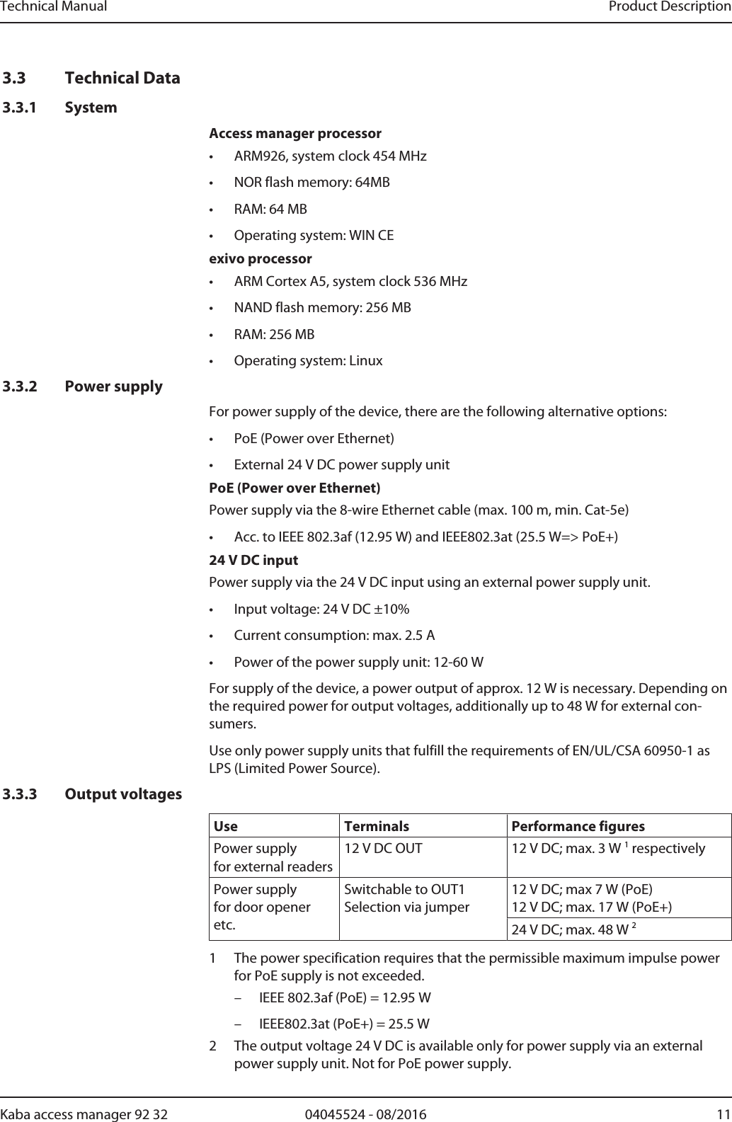
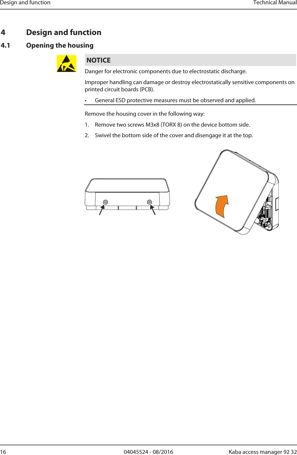
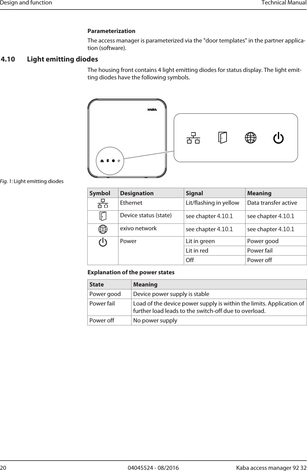
![About this Document Technical Manual6 04045524 - 08/2016 Kaba access manager 92 321.5 Orientation in the documentThis document contains the following orientation aids to facilitate finding of specifictopics:• The table of contents at the beginning of the manual gives an overview of alltopics.• The header always contains the respective main chapter.• Cross references always indicate the number of the chapter in which the supple-mentary information can be found. Example [ 5.7].• An index in the alphabetical order is given at the end of the manual.1.6 Complementary documentsThe planning guideline "exivo" contains details on the optimum use of the device.Supplementary documentation is available on the Kaba website. The technical man-uals are located in a secured area of the website.• Access is only possible after logging in.• An account will need to be created before logging in for the first time.Access and login:1. In the browser, access the Kaba page http://www.kaba.com.2. Select the language in the top right.3. Under "Products", select the "Access Management" or "Workforce Management"product division.4. In the top right section of the screen, click on the following symbol:.5. Enter your e-mail address and password and login or create an account (see be-low).ðThe technical manuals can be found under "Downloads".Create account:1. Click "Create account".2. Complete the data fields and confirm.ðA confirmation link will be sent to your e-mail address.3. To activate your account, click on the confirmation link in your e-mail.](https://usermanual.wiki/dormakaba-EAD/KAM9232-K5/User-Guide-3343810-Page-6.png)
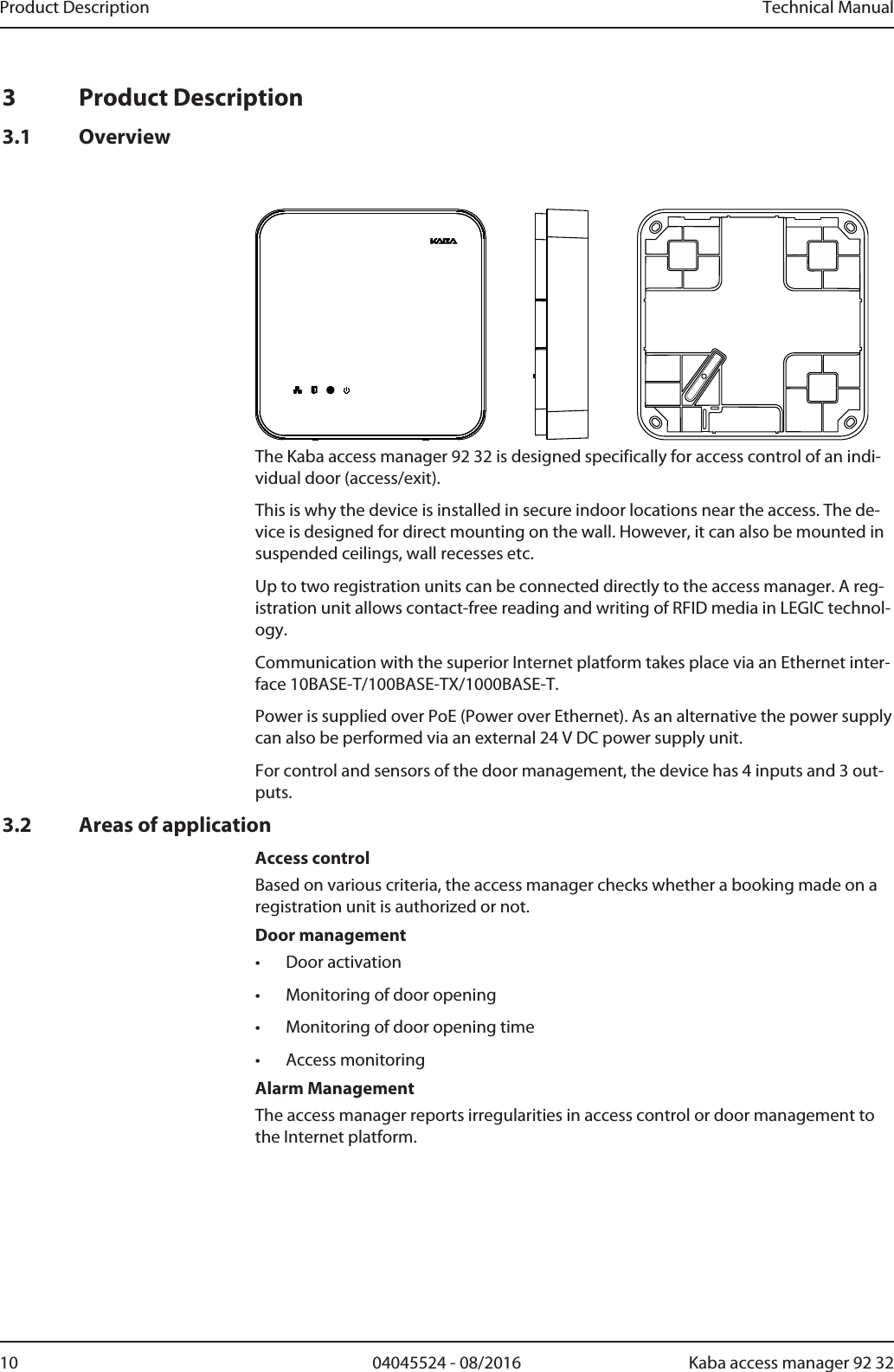
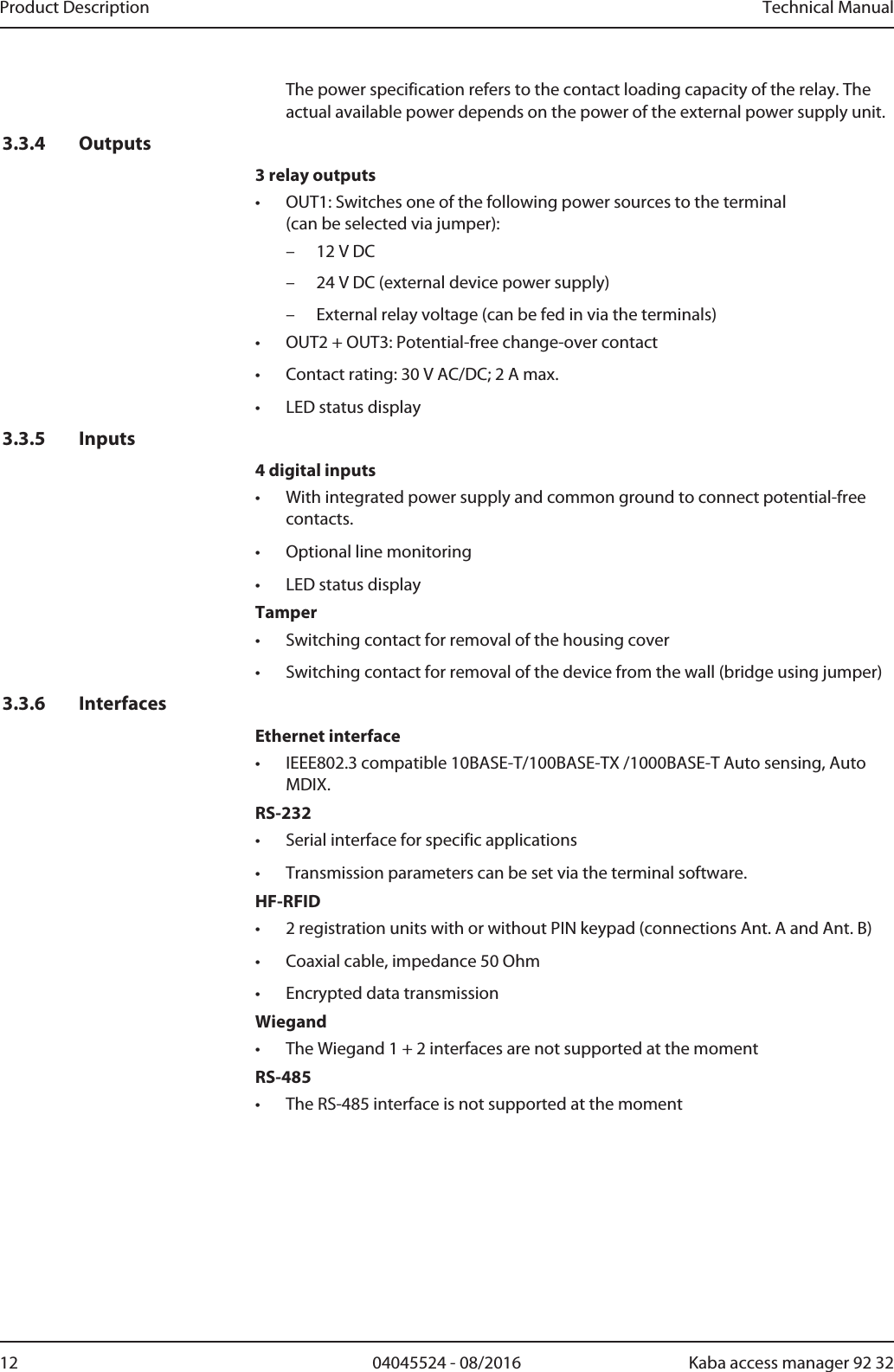
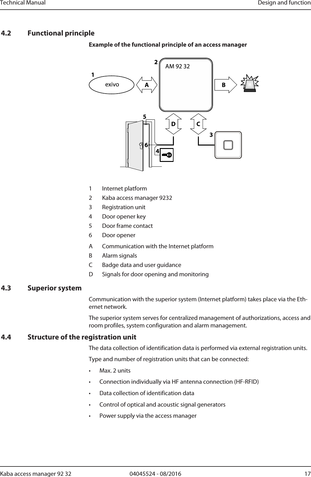
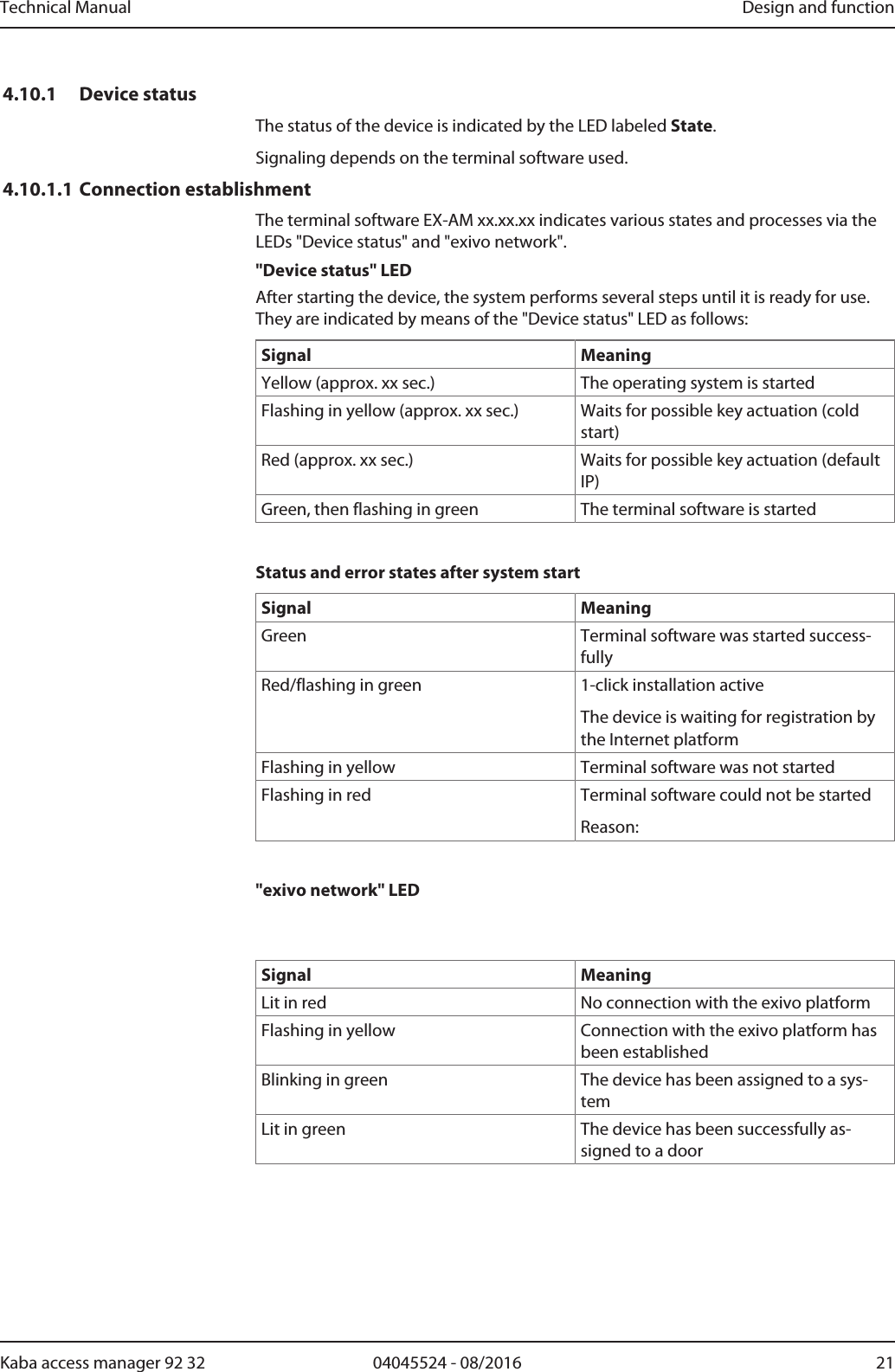
![Product Description Technical Manual14 04045524 - 08/2016 Kaba access manager 92 323.4 ConformityThis product conforms to the following standards: EN 60950-1:2006 + A11:2009 + A1:2010 + A12:2011EN 300 330-1 V1.7.1EN 300 330-2 V1.5.1EN 301 489-1 V1.9.2EN 301 489-3 V1.6.1EN 55022:2010, Class BEN 55024:2010according to the regulations of the EC Directive1999/5/EC R&TTE DirectiveFCC FCC Code of Federal Regulations, CFR 47, Part 15, Sections 15.205, 15.207,15.215 and 15.225FCC ID NVI-KAM9232-K5FCC § 15.19This device complies with Part 15 of the FCC rules. Operation is subject to the follow-ing two conditions: (1) This device may not cause harmful interference, and (2) thisdevice must accept any interference received, including interference that may causeundesired operation.FCC § 15.21 (Warning Statement)[Any] changes or modifications not expressly approved by the party responsible forcompliance could void the user’s authority to operate the equipment.FCC § 15.105Note: This equipment has been tested and found to comply with the limits for a ClassA digital device, pursuant to part 15 of the FCC Rules.These limits are designed to provide reasonable protection against harmful interfer-ence when the equipment is operated in a commercial environment. This equipmentgenerates, uses, and can radiate radio frequency energy and, if not installed and usedin accordance with the instruction manual, may cause harmful interference to radiocommunications. Operation of this equipment in a residential area is likely to causeharmful interference in which case the user will be required to correct the interfer-ence at his own expense.IC Industry Canada Radio Standards Specifications RSS-GEN Issue 4, Sections 8.8,8.9 and 8.10 and RSS-210 Issue 8, Section A2.6 (Category I Equipment)IC:11038A-KAM9232K5ICES-003This Class A digital apparatus complies with Canadian ICES-003.Cet appareil numérique de la classe A est conforme à la norme NMB-003 du Canada.Canada RSS-GEN 8.4This device complies with Industry Canada’s licence-exempt RSSs. Operation is sub-ject to the following two conditions: (1) This device may not cause interference; and (2) This device must accept any interference, including interference that may causeundesired operation of the device.](https://usermanual.wiki/dormakaba-EAD/KAM9232-K5/User-Guide-3343810-Page-14.png)
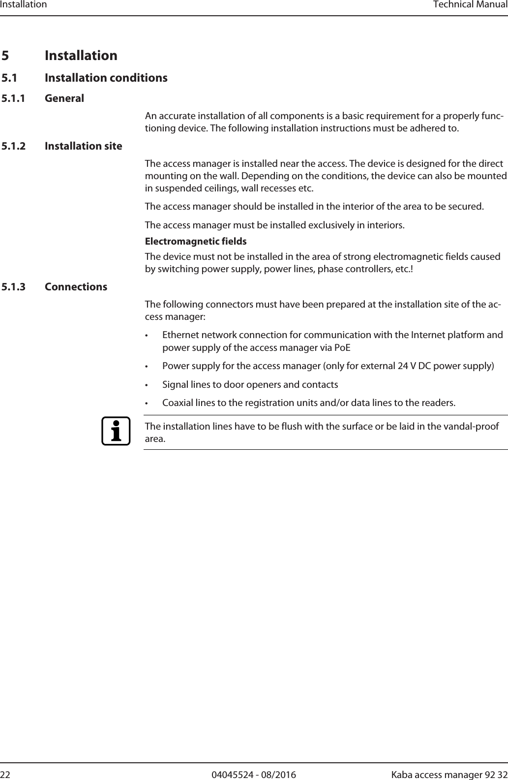
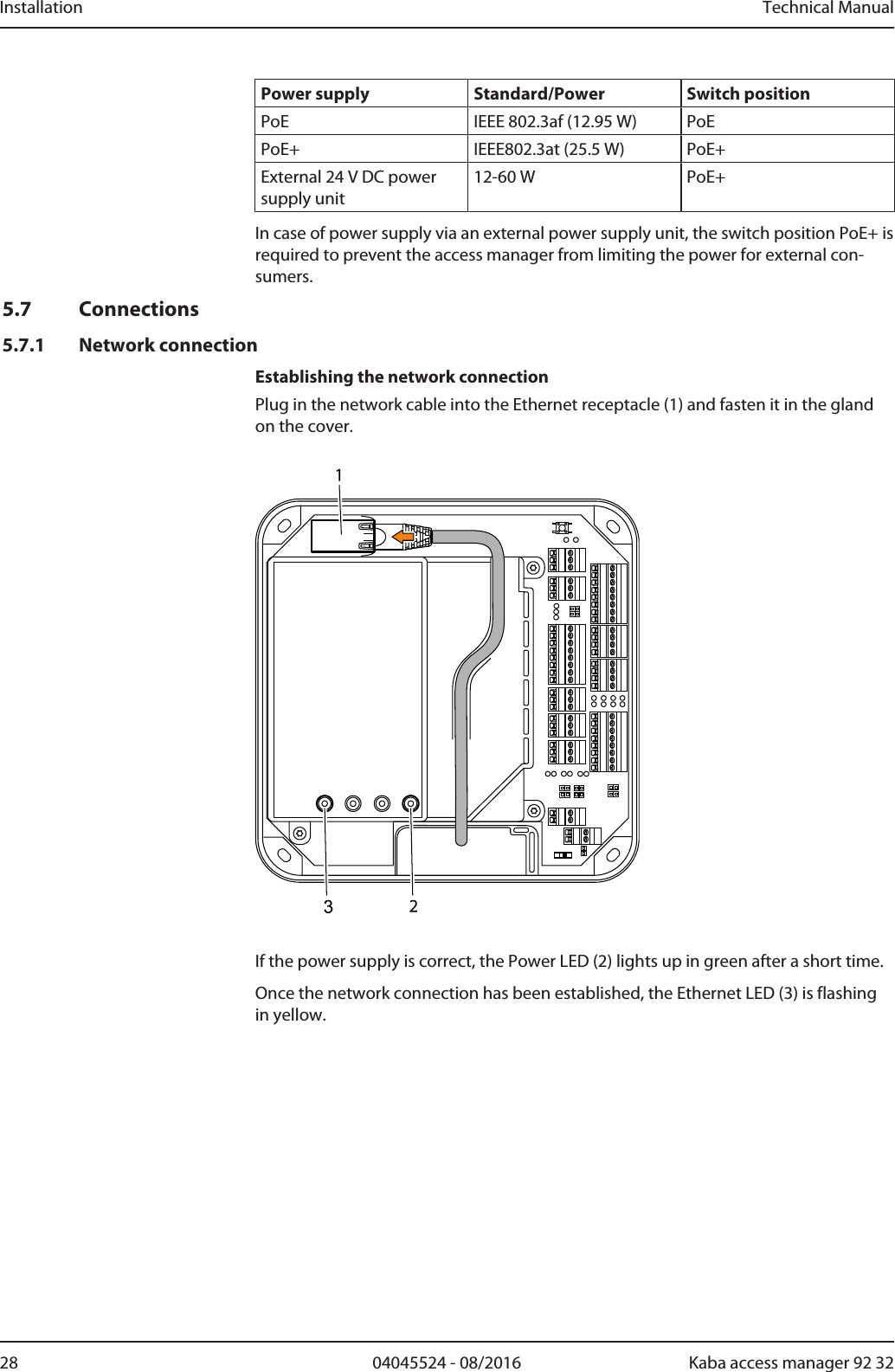
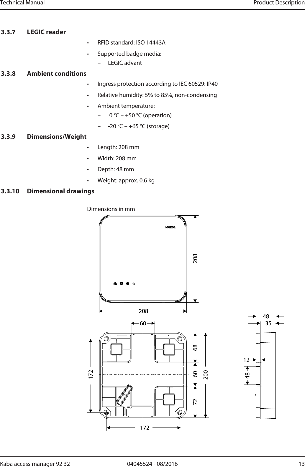
![Installation Technical Manual30 04045524 - 08/2016 Kaba access manager 92 325.7.3 External 24 V DC power supplyAs an alternative to the PoE power supply, the access manager can also be suppliedvia an external 24 V DC power source.NOTICEPossible damage in case of simultaneous power supply via PoE and 24 V DCThe device can be damaged in case of simultaneous power supply via PoE and exter-nal supply.• Before connecting the external supply, make sure that the device is not suppliedwith power via PoE.Use only power supply units that fulfill the requirements of EN/UL/CSA 60950-1 aslimited power source (LPS).Also see about this25.7.1Network connection [}28]](https://usermanual.wiki/dormakaba-EAD/KAM9232-K5/User-Guide-3343810-Page-30.png)
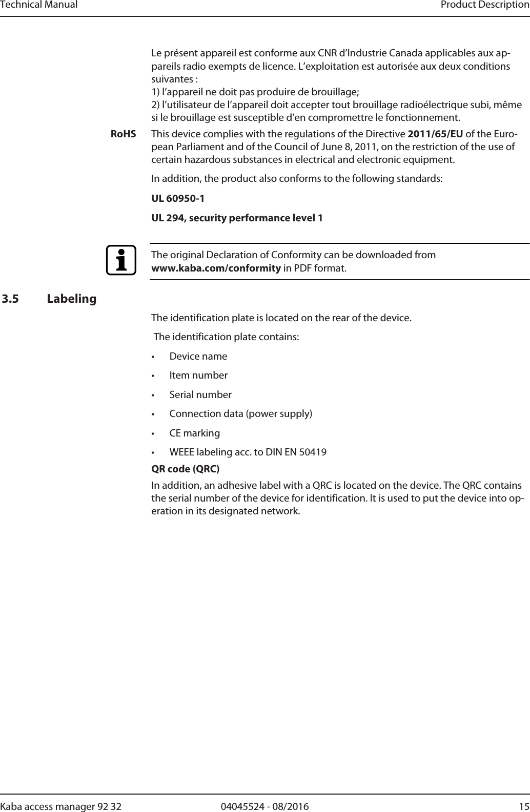
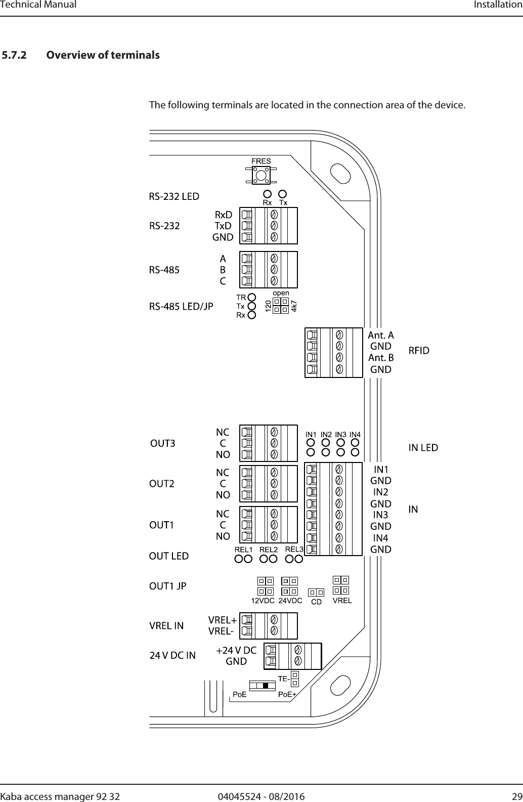
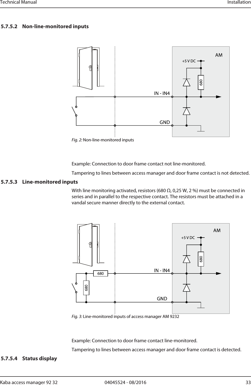
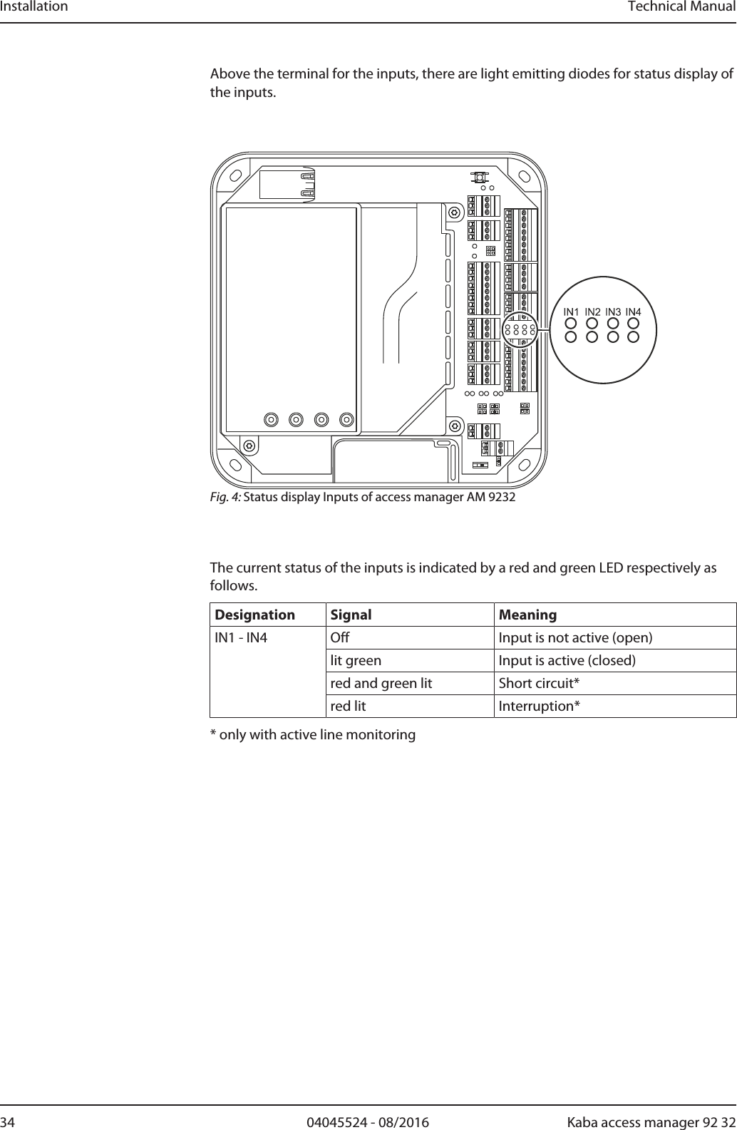
![Installation Technical Manual32 04045524 - 08/2016 Kaba access manager 92 325.7.5 InputsThe access manager has 4 inputs IN1 to IN4.Function of the inputsThe inputs are used for the inquiry of sensors such as door-opener key, door handlecontact, door frame contact, bolt contact, vandal contact, passage control (e.g., turn-stile, light barrier), etc.The function of the individual inputs depends on the selected door template.PrincipleThe inputs (IN1-IN4) are activated by means of a potential-free contact (switch or re-lay contact). An open input is recognized as “high” due to the internal pull-up resis-tor.5.7.5.1 Line monitoringThe inputs can be designed as follows:• Without line monitoring• With line monitoring (if supported and activated by the terminal software)Line monitoring allows the terminal software to detect the states short circuit and in-terruption, in addition to the states active (input closed) and not active (input open)and report them to the higher-level system.The current states of the inputs are indicated by light emitting diodes (see chapterLight emitting diodes [}4.10]).](https://usermanual.wiki/dormakaba-EAD/KAM9232-K5/User-Guide-3343810-Page-32.png)

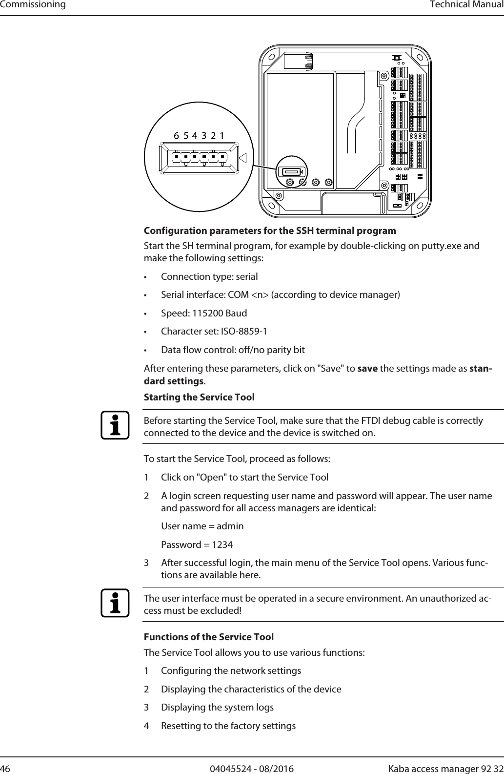
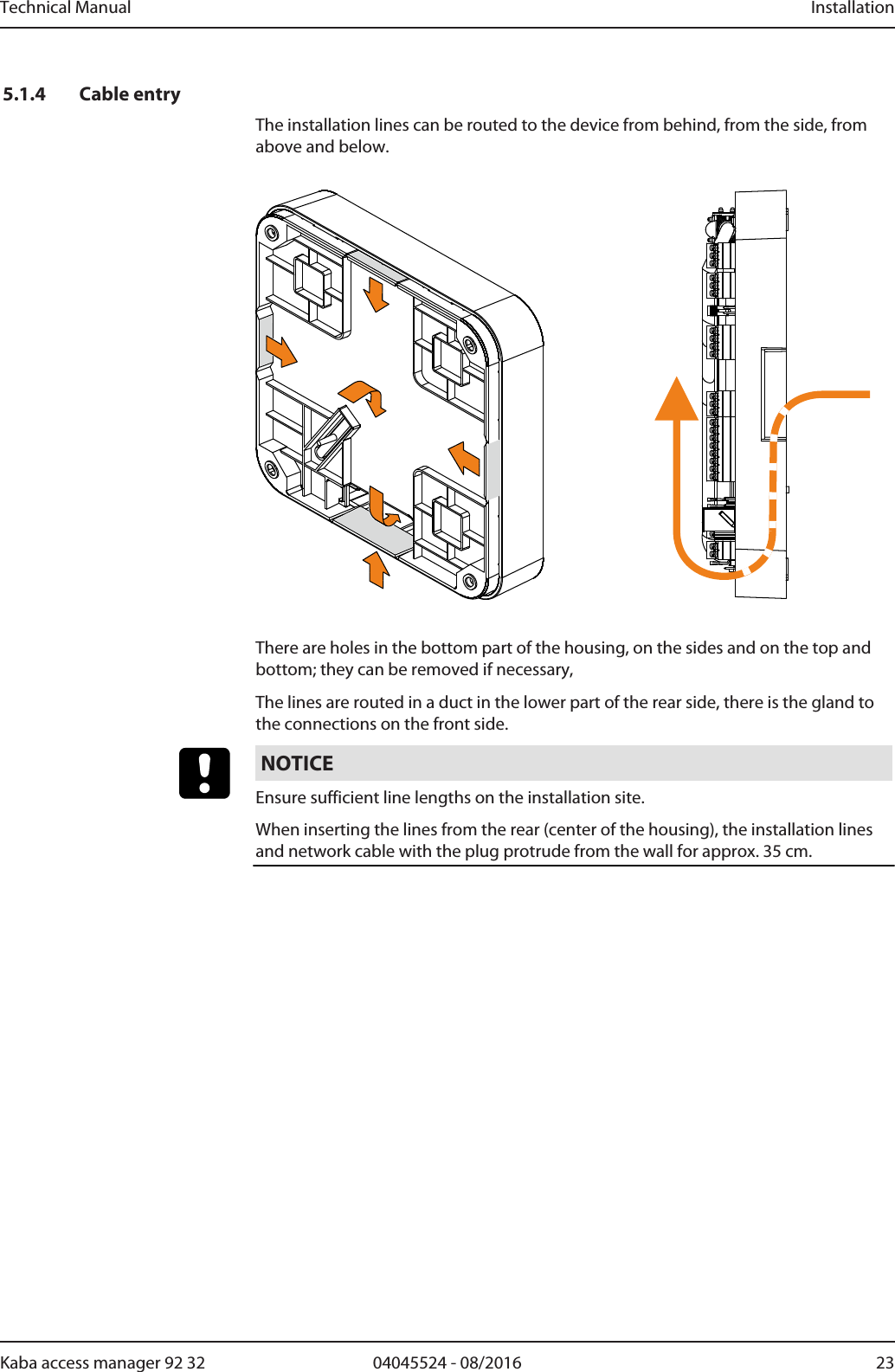
![Technical Manual Commissioning4504045524 - 08/2016Kaba access manager 92 326.3.3 Connecting the device to the power supplyOnce the registration unit(s) is/are connected, the access manager must be con-nected to the power supply. If the device is supplied with current via the Ethernet(PoE), it is sufficient to connect the Ethernet cable. Otherwise, an external 24 V DCsupply must be connected (see External 24 V DC power supply [}5.7.3]).6.3.4 Configuring the Ethernet interface using Service ToolIf no functioning DHCP server is available or a manual parameterizing of the Ethernetinterface is desired, the Ethernet interface must be put into operation using ServiceTool. For this, a computer with an USB connection and a SSH terminal program, forexample PuTTY which can be downloaded from the Internet is required.RequirementsThe following work steps must be carried out to meet the requirements for the use ofthe Service Tool.1 Install a SSH terminal program (e.g. PuTTY) on the computer.2 Download FTDI driver (can be obtained from Kaba)and install on the computer.3 Connect the FTDI debug cable (can also be obtained from Kaba) to the computervia USB. The FTDI debug cable is detected by the system and shown in the devicemanager as virtual COM port (e. g. COM3).4 After that, connect the connector on the other end of the FTDI debug cable tothe device as described below.5 Start the SSH terminal program end enter the configuration parameters de-scribed below.Connecting the FTDI debug cable to the deviceEnsure correct polarity! The black cable at the connector must be connected to pin 1.Pin 1 is marked on the cover by an arrow.](https://usermanual.wiki/dormakaba-EAD/KAM9232-K5/User-Guide-3343810-Page-45.png)