dormakaba EAD KAM9232-K5 RFID Reader User Manual TM AM9232 201609 en
Kaba GmbH RFID Reader TM AM9232 201609 en
user manual
Kaba access manager 92 32
Technical Manual
EN
04045524 - 08/2016

Kaba AG
Access & Workforce Management
Hofwisenstrasse 24
8153 Rümlang
Switzerland
Phone +41 44 818 93 11
www.kaba.com
Kaba AG
Access & Workforce Management
Mühlebühlstrasse 23
8620 Wetzikon
Switzerland
Phone +41 44 931 61 11
www.kaba.com
Kaba GmbH
Access & Workforce Management
Albertistraße 3
78056 Villingen-Schwenningen
Germany
Phone +49 7720 603 0
www.kaba.com
This document must not be reproduced in any way or otherwise further used without the written consent of Kaba AG.
All product names are trademarks of the respective companies.
Copyright 2016 Kaba AG. All rights reserved.
04045524 - 08/2016

Technical Manual Table of contents
Kaba access manager 92 32 304045524 - 08/2016
Table of contents
1 About this Document ............................................................................................................................. 5
1.1 Validity............................................................................................................................................................................... 5
1.2 Target group ................................................................................................................................................................... 5
1.3 Contents and purpose................................................................................................................................................. 5
1.4 Availability of Documents.......................................................................................................................................... 5
1.5 Orientation in the document.................................................................................................................................... 6
1.6 Complementary documents ..................................................................................................................................... 6
1.7 Warnings........................................................................................................................................................................... 7
1.7.1 Hazard Categories.......................................................................................................................................... 7
1.7.2 Symbols.............................................................................................................................................................. 7
1.8 Notes.................................................................................................................................................................................. 7
2 Grouped safety messages...................................................................................................................... 8
2.1 Use as directed ............................................................................................................................................................... 8
2.2 Mounting and installation.......................................................................................................................................... 8
2.3 Service and Maintenance ........................................................................................................................................... 8
2.4 Accessories and spare parts ...................................................................................................................................... 8
2.5 ESD (electrostatic discharge) protective measures........................................................................................... 9
2.6 Environmental protection ......................................................................................................................................... 9
3 Product Description ............................................................................................................................. 10
3.1 Overview.........................................................................................................................................................................10
3.2 Areas of application....................................................................................................................................................10
3.3 Technical Data ..............................................................................................................................................................11
3.3.1 System ..............................................................................................................................................................11
3.3.2 Power supply .................................................................................................................................................11
3.3.3 Output voltages............................................................................................................................................11
3.3.4 Outputs ............................................................................................................................................................12
3.3.5 Inputs................................................................................................................................................................12
3.3.6 Interfaces .........................................................................................................................................................12
3.3.7 LEGIC reader...................................................................................................................................................13
3.3.8 Ambient conditions.....................................................................................................................................13
3.3.9 Dimensions/Weight.....................................................................................................................................13
3.3.10 Dimensional drawings................................................................................................................................13
3.4 Conformity.....................................................................................................................................................................14
3.5 Labeling ..........................................................................................................................................................................15
4 Design and function ............................................................................................................................. 16
4.1 Opening the housing.................................................................................................................................................16
4.2 Functional principle....................................................................................................................................................17
4.3 Superior system ...........................................................................................................................................................17
4.4 Structure of the registration unit...........................................................................................................................17
4.5 Function of the inputs ...............................................................................................................................................18
4.6 Function of the outputs ............................................................................................................................................18
4.7 Terminal software .......................................................................................................................................................18
4.8 Registration units ........................................................................................................................................................19

Table of contents Technical Manual
4 Kaba access manager 92 3204045524 - 08/2016
4.9 Door templates ............................................................................................................................................................19
4.10 Light emitting diodes ................................................................................................................................................20
4.10.1 Device status..................................................................................................................................................21
5 Installation ............................................................................................................................................ 22
5.1 Installation conditions...............................................................................................................................................22
5.1.1 General.............................................................................................................................................................22
5.1.2 Installation site ..............................................................................................................................................22
5.1.3 Connections ...................................................................................................................................................22
5.1.4 Cable entry......................................................................................................................................................23
5.2 Installation diagram ...................................................................................................................................................24
5.2.1 Access control with registration unit ....................................................................................................24
5.3 Installation lines...........................................................................................................................................................25
5.3.1 Ethernet ...........................................................................................................................................................25
5.3.2 Line to the door opener, the door opener key, and the door contacts....................................25
5.3.3 Coaxial cables to registration units........................................................................................................25
5.4 Wall mounting..............................................................................................................................................................26
5.5 Cable routing ................................................................................................................................................................27
5.6 Setting the PoE switches ..........................................................................................................................................27
5.7 Connections ..................................................................................................................................................................28
5.7.1 Network connection....................................................................................................................................28
5.7.2 Overview of terminals.................................................................................................................................29
5.7.3 External 24 V DC power supply ...............................................................................................................30
5.7.4 Registration units .........................................................................................................................................31
5.7.5 Inputs................................................................................................................................................................32
5.7.6 Outputs ............................................................................................................................................................35
5.8 Vandal contact..............................................................................................................................................................40
5.9 Fastening the cover....................................................................................................................................................41
6 Commissioning ..................................................................................................................................... 42
6.1 Start options..................................................................................................................................................................42
6.1.1 Reset key and status LED ...........................................................................................................................42
6.2 Performing a cold start..............................................................................................................................................43
6.3 Commissioning procedure ......................................................................................................................................44
6.3.1 Planning the system in partner application .......................................................................................44
6.3.2 Registering the setup medium in partner application ...................................................................44
6.3.3 Connecting the device to the power supply......................................................................................45
6.3.4 Configuring the Ethernet interface using Service Tool ..................................................................45
6.3.5 Installing the registration unit .................................................................................................................48
6.3.6 Commissioning the device with setup medium...............................................................................48
7 Packaging/Return................................................................................................................................. 49
7.1 Complete Devices .......................................................................................................................................................49
7.2 Electronic Assemblies ................................................................................................................................................49
7.3 Marking ...........................................................................................................................................................................50
8 Disposal................................................................................................................................................. 51
Index...................................................................................................................................................... 52

Technical Manual About this Document
504045524 - 08/2016Kaba access manager 92 32
1 About this Document
1.1 Validity
This document describes the product:
Product name: Kaba access manager 92 32
Item number 04079232
Terminal software: EX-AM xx.xx.xx
Manufacturing date: As of November 2015
This document describes all device versions and optional equipment and functions.
Options need to be paid for and are therefore only available if they have been pur-
chased. Additional equipment and functions may not yet be available at the time of
issuing the document and, possibly, can only be purchased at a later stage.
1.2 Target group
This document is exclusively intended for specialist personnel.
The descriptions require specialist personnel trained by the manufacturer. The de-
scriptions do not replace product training.
For reasons of device safety, the installation and maintenance operations described
in this document must be carried out only by service persons according to EN
60950-1 (Information technology equipment - Safety).
Service persons are persons having adequate technical training and sufficient experi-
ence to be aware of and to minimize the possible risks for themselves or other per-
sons, which may occur when carrying out these operations. The service persons are
responsible for adhering to the instructions given by the manufacturer and to the ap-
plicable standards and regulations during execution of their work.
This document is also used as information for persons with the following tasks:
•Project planning and implementation
• Commissioning the product within the network
• Connecting the product to the user software by programming customer applica-
tions
• Customer-specific adjustment by setting the parameters of the product
1.3 Contents and purpose
The content is limited to the assembly, installation, start-up, and basic operation of
the hardware.
1.4 Availability of Documents
All documents can be obtained from our sales partners.

About this Document Technical Manual
6 04045524 - 08/2016 Kaba access manager 92 32
1.5 Orientation in the document
This document contains the following orientation aids to facilitate finding of specific
topics:
• The table of contents at the beginning of the manual gives an overview of all
topics.
• The header always contains the respective main chapter.
• Cross references always indicate the number of the chapter in which the supple-
mentary information can be found. Example [ 5.7].
• An index in the alphabetical order is given at the end of the manual.
1.6 Complementary documents
The planning guideline "exivo" contains details on the optimum use of the device.
Supplementary documentation is available on the Kaba website. The technical man-
uals are located in a secured area of the website.
• Access is only possible after logging in.
• An account will need to be created before logging in for the first time.
Access and login:
1. In the browser, access the Kaba page http://www.kaba.com.
2. Select the language in the top right.
3. Under "Products", select the "Access Management" or "Workforce Management"
product division.
4. In the top right section of the screen, click on the following symbol:
.
5. Enter your e-mail address and password and login or create an account (see be-
low).
ðThe technical manuals can be found under "Downloads".
Create account:
1. Click "Create account".
2. Complete the data fields and confirm.
ðA confirmation link will be sent to your e-mail address.
3. To activate your account, click on the confirmation link in your e-mail.
Technical Manual About this Document
704045524 - 08/2016Kaba access manager 92 32
1.7 Warnings
Warnings containing information/instructions and prohibitions to prevent injury to
persons and damage to property are specially labeled.
Please pay attention to warnings. They are intended to help prevent accidents and
avoid damage.
1.7.1 Hazard Categories
Warnings are split into the following categories:
CAUTION
Slight Risk
Describes a potentially hazardous situation that could result in minor physical in-
juries.
NOTICE
Information on how to handle the product correctly.
Failure to comply with these warnings may result in malfunctions. The product or
something in its vicinity could be damaged.
1.7.2 Symbols
Depending on the source of the hazard, symbols are used for the warnings, and
these have the following meanings:
General danger Danger for electronic compo-
nents from electrostatic dis-
charge
1.8 Notes
Particular attention must be paid to notes identified with the symbol!
Tips and useful information. These help you to make best use of the product and its
functions.

Grouped safety messages Technical Manual
8 04045524 - 08/2016 Kaba access manager 92 32
2 Grouped safety messages
This product has been built in accordance with state-of-the-art standards and the
recognized safety rules. Nevertheless, its use may constitute a risk to persons and
cause damage to material property.
Read and observe the following safety instructions before using the product.
2.1 Use as directed
The product is only intended for use as described in chapter “Product description”.
Any use beyond that is considered contrary to its designated use. The manufacturer
cannot be held liable for damage resulting from such use. Such use is at the sole risk
of the user/operator.
2.2 Mounting and installation
Mounting and installation may only be carried out by service persons (see chapter 1
“Target group”).
Mains voltage installations may only be carried out by a certified specialized com-
pany or authorized electricians.
Installation may only be carried out in places that fulfill the climatic and technical
conditions stated by the manufacturer.
The manufacturer is not liable for damages resulting from improper handling or in-
correct installation.
2.3 Service and Maintenance
Maintenance work / troubleshooting
Only the service person (see chapter 1 “Target group”) is entitled to remove faults
and carry out maintenance work.
Reconstruction and modification
Any alteration or modification to the device may only be performed by the service
person (see chapter 1 “Target group”). Any alteration or modification performed by
unauthorized persons shall render void any liability.
2.4 Accessories and spare parts
Accessories and spare parts must comply with the technical requirements specified
by the manufacturer. This is guaranteed when using original accessories and spare
parts from Kaba.

Technical Manual Grouped safety messages
904045524 - 08/2016Kaba access manager 92 32
2.5 ESD (electrostatic discharge) protective measures
NOTICE
Danger for electronic components due to electrostatic discharge.
Improper handling of printed circuit boards or components can cause damages that
lead to complete failures or sporadic errors.
• During installation and repair of the product, the ESD protective measures must
be considered.
• Wear an ESD wristband when handling electronic components. Connect the end
of the wristband to a discharge socket or an unvarnished grounded metal com-
ponent. This way, static charges are discharged from your body securely and ef-
fectively.
• Touch only the edges of circuit boards. Do not touch the circuit board nor the
connector.
• Place all dismantled components on an antistatic surface or in an antistatic con-
tainer.
• Avoid contact between circuit boards and clothing. The wristband only protects
the printed circuit boards against electrostatic discharge from your body, but
there is still a risk of damage through electrostatic discharge from your clothing.
• Transport and dispatch dismantled modules only in electrostatically shielded
protective bags.
2.6 Environmental protection
It is prohibited to dispose of the device in your domestic waste.
Used devices contain valuable materials that should be recycled. Properly dispose of
used devices.
Product Description Technical Manual
10 04045524 - 08/2016 Kaba access manager 92 32
3 Product Description
3.1 Overview
The Kaba access manager 92 32 is designed specifically for access control of an indi-
vidual door (access/exit).
This is why the device is installed in secure indoor locations near the access. The de-
vice is designed for direct mounting on the wall. However, it can also be mounted in
suspended ceilings, wall recesses etc.
Up to two registration units can be connected directly to the access manager. A reg-
istration unit allows contact-free reading and writing of RFID media in LEGIC technol-
ogy.
Communication with the superior Internet platform takes place via an Ethernet inter-
face 10BASE-T/100BASE-TX/1000BASE-T.
Power is supplied over PoE (Power over Ethernet). As an alternative the power supply
can also be performed via an external 24 V DC power supply unit.
For control and sensors of the door management, the device has 4 inputs and 3 out-
puts.
3.2 Areas of application
Access control
Based on various criteria, the access manager checks whether a booking made on a
registration unit is authorized or not.
Door management
• Door activation
• Monitoring of door opening
• Monitoring of door opening time
• Access monitoring
Alarm Management
The access manager reports irregularities in access control or door management to
the Internet platform.

Technical Manual Product Description
1104045524 - 08/2016Kaba access manager 92 32
3.3 Technical Data
3.3.1 System
Access manager processor
• ARM926, system clock 454 MHz
• NOR flash memory: 64MB
• RAM: 64 MB
• Operating system: WIN CE
exivo processor
• ARM Cortex A5, system clock 536 MHz
• NAND flash memory: 256 MB
• RAM: 256 MB
• Operating system: Linux
3.3.2 Power supply
For power supply of the device, there are the following alternative options:
• PoE (Power over Ethernet)
• External 24 V DC power supply unit
PoE (Power over Ethernet)
Power supply via the 8-wire Ethernet cable (max. 100 m, min. Cat-5e)
• Acc. to IEEE 802.3af (12.95 W) and IEEE802.3at (25.5 W=> PoE+)
24 V DC input
Power supply via the 24 V DC input using an external power supply unit.
• Input voltage: 24 V DC ±10%
• Current consumption: max. 2.5 A
• Power of the power supply unit: 12-60 W
For supply of the device, a power output of approx. 12 W is necessary. Depending on
the required power for output voltages, additionally up to 48 W for external con-
sumers.
Use only power supply units that fulfill the requirements of EN/UL/CSA 60950-1 as
LPS (Limited Power Source).
3.3.3 Output voltages
Use Terminals Performance figures
Power supply
for external readers
12 V DC OUT 12 V DC; max. 3 W 1 respectively
Power supply
for door opener
etc.
Switchable to OUT1
Selection via jumper
12 V DC; max 7 W (PoE)
12 V DC; max. 17 W (PoE+)
24 V DC; max. 48 W 2
1 The power specification requires that the permissible maximum impulse power
for PoE supply is not exceeded.
– IEEE 802.3af (PoE) = 12.95 W
– IEEE802.3at (PoE+) = 25.5 W
2 The output voltage 24 V DC is available only for power supply via an external
power supply unit. Not for PoE power supply.

Product Description Technical Manual
12 04045524 - 08/2016 Kaba access manager 92 32
The power specification refers to the contact loading capacity of the relay. The
actual available power depends on the power of the external power supply unit.
3.3.4 Outputs
3 relay outputs
• OUT1: Switches one of the following power sources to the terminal
(can be selected via jumper):
– 12 V DC
– 24 V DC (external device power supply)
– External relay voltage (can be fed in via the terminals)
• OUT2 + OUT3: Potential-free change-over contact
• Contact rating: 30 V AC/DC; 2 A max.
• LED status display
3.3.5 Inputs
4 digital inputs
• With integrated power supply and common ground to connect potential-free
contacts.
• Optional line monitoring
• LED status display
Tamper
• Switching contact for removal of the housing cover
• Switching contact for removal of the device from the wall (bridge using jumper)
3.3.6 Interfaces
Ethernet interface
• IEEE802.3 compatible 10BASE-T/100BASE-TX /1000BASE-T Auto sensing, Auto
MDIX.
RS-232
• Serial interface for specific applications
• Transmission parameters can be set via the terminal software.
HF-RFID
• 2 registration units with or without PIN keypad (connections Ant. A and Ant. B)
• Coaxial cable, impedance 50 Ohm
• Encrypted data transmission
Wiegand
• The Wiegand 1 + 2 interfaces are not supported at the moment
RS-485
• The RS-485 interface is not supported at the moment
Technical Manual Product Description
1304045524 - 08/2016Kaba access manager 92 32
3.3.7 LEGIC reader
• RFID standard: ISO 14443A
• Supported badge media:
– LEGIC advant
3.3.8 Ambient conditions
• Ingress protection according to IEC 60529: IP40
• Relative humidity: 5% to 85%, non-condensing
• Ambient temperature:
– 0 °C – +50 °C (operation)
– -20 °C – +65 °C (storage)
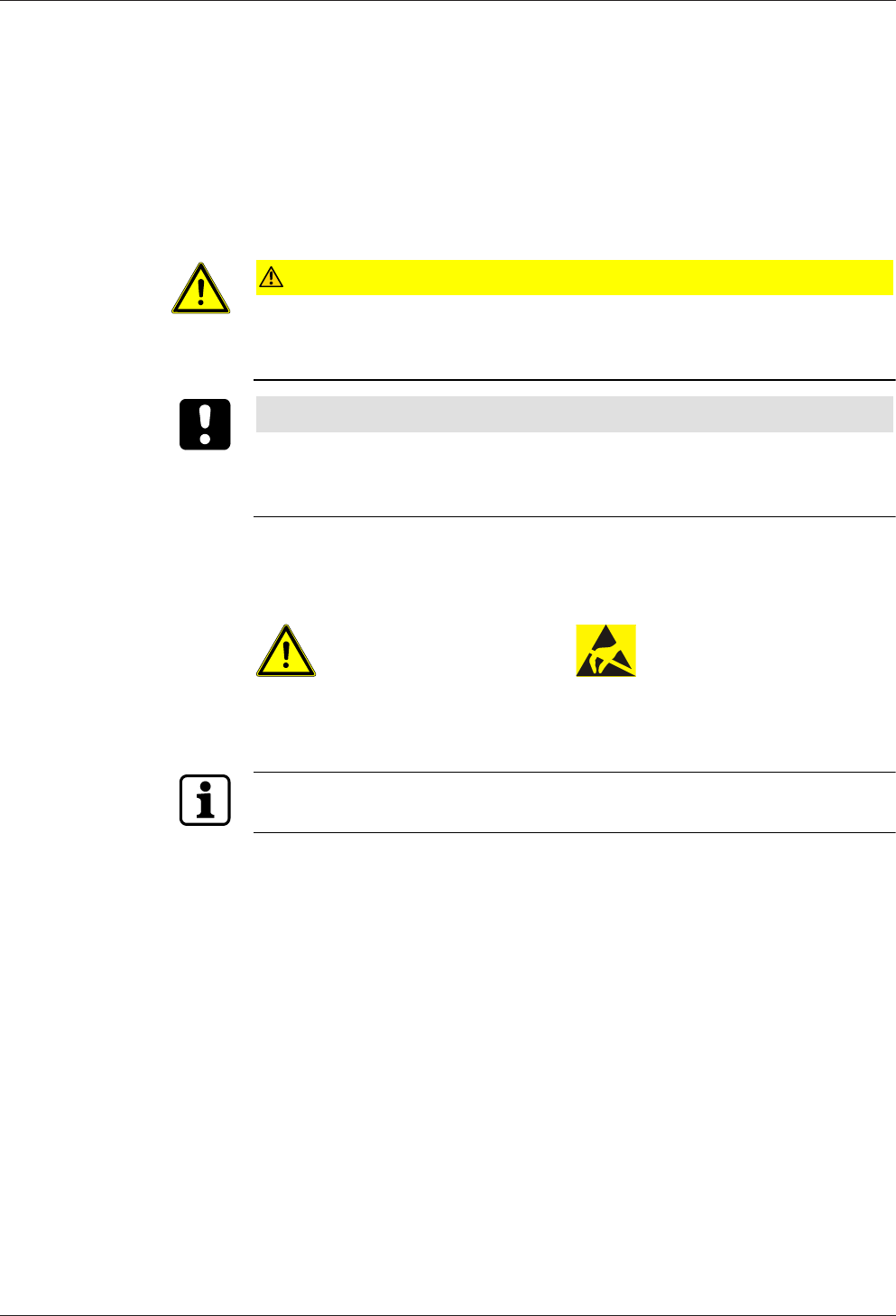
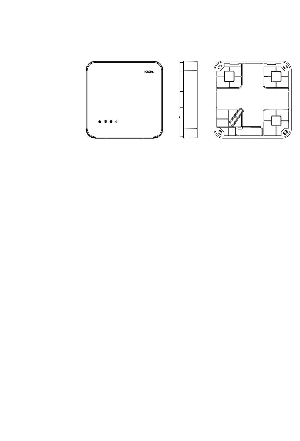
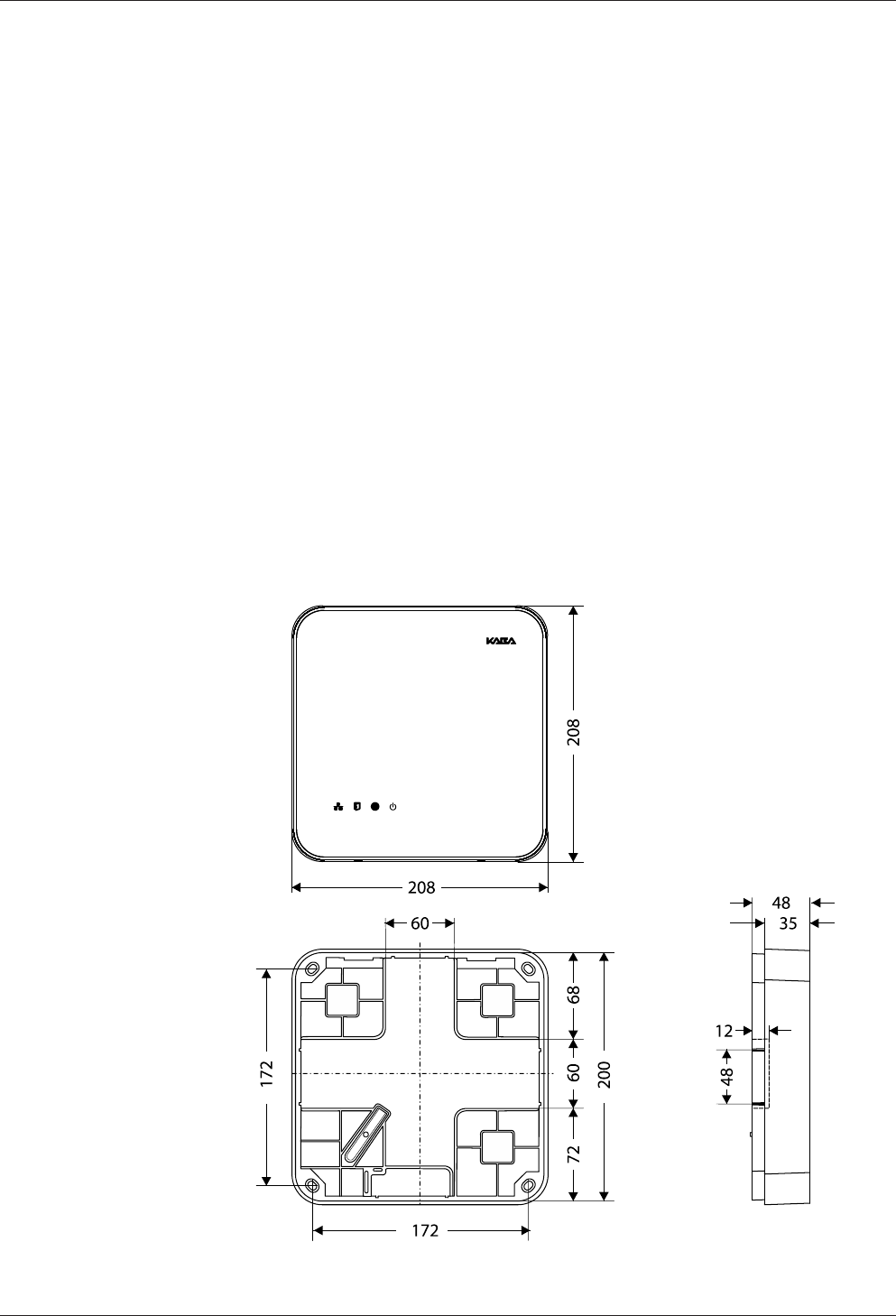
3.3.9 Dimensions/Weight
• Length: 208 mm
• Width: 208 mm
• Depth: 48 mm
• Weight: approx. 0.6 kg
3.3.10 Dimensional drawings
Dimensions in mm

Product Description Technical Manual
14 04045524 - 08/2016 Kaba access manager 92 32
3.4 Conformity
This product conforms to the following standards:
EN 60950-1:2006 + A11:2009 + A1:2010 + A12:2011
EN 300 330-1 V1.7.1
EN 300 330-2 V1.5.1
EN 301 489-1 V1.9.2
EN 301 489-3 V1.6.1
EN 55022:2010, Class B
EN 55024:2010
according to the regulations of the EC Directive
1999/5/EC R&TTE Directive
FCC FCC Code of Federal Regulations, CFR 47, Part 15, Sections 15.205, 15.207,
15.215 and 15.225
FCC ID NVI-KAM9232-K5
FCC § 15.19
This device complies with Part 15 of the FCC rules. Operation is subject to the follow-
ing two conditions: (1) This device may not cause harmful interference, and (2) this
device must accept any interference received, including interference that may cause
undesired operation.
FCC § 15.21 (Warning Statement)
[Any] changes or modifications not expressly approved by the party responsible for
compliance could void the user’s authority to operate the equipment.
FCC § 15.105
Note: This equipment has been tested and found to comply with the limits for a Class
A digital device, pursuant to part 15 of the FCC Rules.
These limits are designed to provide reasonable protection against harmful interfer-
ence when the equipment is operated in a commercial environment. This equipment
generates, uses, and can radiate radio frequency energy and, if not installed and used
in accordance with the instruction manual, may cause harmful interference to radio
communications. Operation of this equipment in a residential area is likely to cause
harmful interference in which case the user will be required to correct the interfer-
ence at his own expense.
IC Industry Canada Radio Standards Specifications RSS-GEN Issue 4, Sections 8.8,
8.9 and 8.10 and RSS-210 Issue 8, Section A2.6 (Category I Equipment)
IC:11038A-KAM9232K5
ICES-003
This Class A digital apparatus complies with Canadian ICES-003.
Cet appareil numérique de la classe A est conforme à la norme NMB-003 du Canada.
Canada RSS-GEN 8.4
This device complies with Industry Canada’s licence-exempt RSSs. Operation is sub-
ject to the following two conditions:
(1) This device may not cause interference; and
(2) This device must accept any interference, including interference that may cause
undesired operation of the device.

Technical Manual Product Description
1504045524 - 08/2016Kaba access manager 92 32
Le présent appareil est conforme aux CNR d’Industrie Canada applicables aux ap-
pareils radio exempts de licence. L’exploitation est autorisée aux deux conditions
suivantes :
1) l’appareil ne doit pas produire de brouillage;
2) l’utilisateur de l’appareil doit accepter tout brouillage radioélectrique subi, même
si le brouillage est susceptible d’en compromettre le fonctionnement.
RoHS This device complies with the regulations of the Directive 2011/65/EU of the Euro-
pean Parliament and of the Council of June 8, 2011, on the restriction of the use of
certain hazardous substances in electrical and electronic equipment.
In addition, the product also conforms to the following standards:
UL 60950-1
UL 294, security performance level 1
The original Declaration of Conformity can be downloaded from
www.kaba.com/conformity in PDF format.
3.5 Labeling
The identification plate is located on the rear of the device.
The identification plate contains:
• Device name
• Item number
• Serial number
• Connection data (power supply)
• CE marking
• WEEE labeling acc. to DIN EN 50419
QR code (QRC)
In addition, an adhesive label with a QRC is located on the device. The QRC contains
the serial number of the device for identification. It is used to put the device into op-
eration in its designated network.
Design and function Technical Manual
16 04045524 - 08/2016 Kaba access manager 92 32
4 Design and function
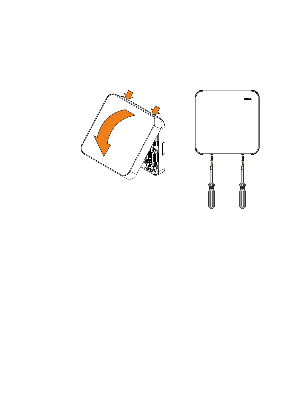
4.1 Opening the housing
NOTICE
Danger for electronic components due to electrostatic discharge.
Improper handling can damage or destroy electrostatically sensitive components on
printed circuit boards (PCB).
• General ESD protective measures must be observed and applied.
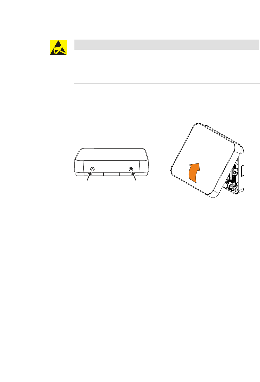
Remove the housing cover in the following way:
1. Remove two screws M3x8 (TORX 8) on the device bottom side.
2. Swivel the bottom side of the cover and disengage it at the top.
Technical Manual Design and function
1704045524 - 08/2016Kaba access manager 92 32
4.2 Functional principle
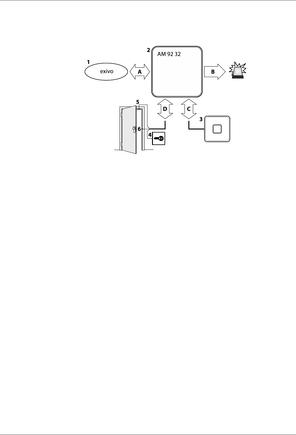
Example of the functional principle of an access manager
1 Internet platform
2 Kaba access manager 9232
3 Registration unit
4 Door opener key
5 Door frame contact
6 Door opener
A Communication with the Internet platform
B Alarm signals
C Badge data and user guidance
D Signals for door opening and monitoring
4.3 Superior system
Communication with the superior system (Internet platform) takes place via the Eth-
ernet network.
The superior system serves for centralized management of authorizations, access and
room profiles, system configuration and alarm management.
4.4 Structure of the registration unit
The data collection of identification data is performed via external registration units.
Type and number of registration units that can be connected:
• Max. 2 units
• Connection individually via HF antenna connection (HF-RFID)
• Data collection of identification data
• Control of optical and acoustic signal generators
• Power supply via the access manager
Design and function Technical Manual
18 04045524 - 08/2016 Kaba access manager 92 32
4.5 Function of the inputs
The function of the inputs depends on the configuration. Some examples of possible
functions are listed below:
Door frame contact
The door frame contact is used to transmit the door status (open/closed) to the ac-
cess manager. If the maximum allowed door-opening time defined for the door has
elapsed and the door is still open, the access manager sends an alarm record to the
Internet platform.
Door opener key
A door-opener key can be connected if no registration unit is connected in the inte-
rior and if the door is not equipped with a door handle. If the door-opener key is
pressed the respective door-opener relay is activated.
Bolt contact
With the bolt contact, the access manager can identify the current bolt position of
the door lock. If the bolt is not in the expected position after the end of the allowed
time, the access control manager sends an alarm message to the Internet platform.
Door handle contact
With the door handle contact, the access manager can identify the door handle’s cur-
rent position. If the door frame contact responds without previous activation of the
door opener or pressing of the door handle, the access manager sends an alarm
record to the Internet platform.
The functions of the door frame contact and door opener key can be optionally con-
figured in the door templates of the partner application.
4.6 Function of the outputs
The function of the individual outputs depends on the configuration. Important func-
tions are:
Door-opener relay
A door opener can be connected to the door opener relay. The door-opener relay is
activated if the access manager releases access, e.g., after an authorized booking.
Alarm relay
Depending on the configuration, the alarm relay can be activated in case of an au-
thorized booking or alarm (e.g. door breakup).
4.7 Terminal software
This documentation describes the complete hardware equipment of the access man-
ager and its performance features.
The functions of the terminal software used EX-AM xx.xx.xx are not described in this
document and can be found in the specific software documentation, in the online
help and the descriptions saved in the software itself.
The terminal software is designed for the access control via an Internet platform. It
supports the connection of the following components to the access manager:
• Kaba registration units
• Various closing mechanisms

Technical Manual Design and function
1904045524 - 08/2016Kaba access manager 92 32
4.8 Registration units
Two registration units can be connected to the access manager via coaxial cables
(connections Ant. A and Ant. B). Make sure that the connection A is always connected
first and the connection B is connected after that.
Supported registration units
• Kaba registration unit 90 00
• Kaba registration unit 90 01
• Kaba registration unit 90 02 (with PIN keypad)
• Kaba registration unit 90 03
• Kaba registration unit 90 04
The registration units to be used are assigned to the device when planning the sys-
tem in the Kaba exivo software via a door template.
Functional features
• A registration unit allows contact-free reading of RFID media in LEGIC technol-
ogy.
• The registration units are supplied with power via the coaxial cable.
Parameterization
The parameterization of the registration units is defined via the "door templates" in
the partner application (software).
Parameterizing information
For the two registration units, it is not possible to determine different configurations.
The configuration can be established via address A or address B and is valid for both
registration units.
External inputs, relays and vandal contact are not available.
4.9 Door templates
The access manager can be parameterized using different door templates.
Supported door templates
The number of available door templates is constantly expanded. The current door
templates are listed in the Kaba exivo partner application.
The following components can be connected to the access manager via the corre-
sponding door template:
• Door opener
• Magnetic lock
• Automatic door
• Electric lock
• Motor lock
Functional features
• In the Kaba exivo software, various door templates with the above-mentioned
components are predefined. The door template to be used is selected via the
Kaba exivo software and assigned to the corresponding access manager.
• The components are supplied with power by the access manager.
Design and function Technical Manual
20 04045524 - 08/2016 Kaba access manager 92 32
Parameterization
The access manager is parameterized via the "door templates" in the partner applica-
tion (software).
4.10 Light emitting diodes
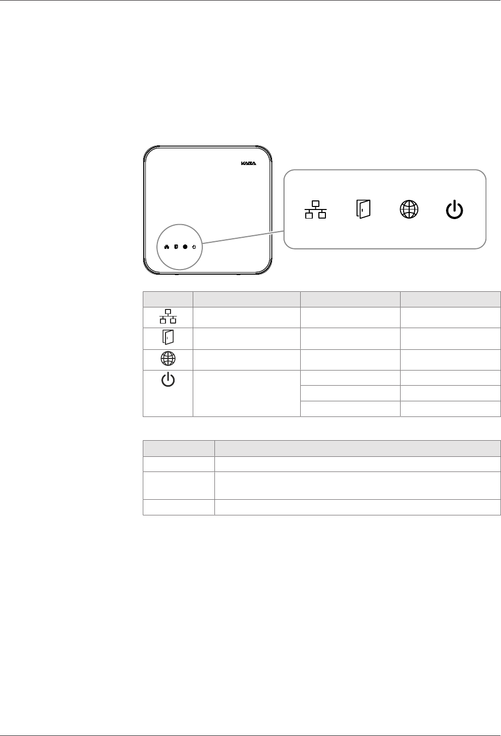
The housing front contains 4 light emitting diodes for status display. The light emit-
ting diodes have the following symbols.
Fig.1: Light emitting diodes
Symbol Designation Signal Meaning
Ethernet Lit/flashing in yellow Data transfer active
Device status (state) see chapter 4.10.1 see chapter 4.10.1
exivo network see chapter 4.10.1 see chapter 4.10.1
Power Lit in green Power good
Lit in red Power fail
Off Power off
Explanation of the power states
State Meaning
Power good Device power supply is stable
Power fail Load of the device power supply is within the limits. Application of
further load leads to the switch-off due to overload.
Power off No power supply

Technical Manual Design and function
2104045524 - 08/2016Kaba access manager 92 32
4.10.1 Device status
The status of the device is indicated by the LED labeled State.
Signaling depends on the terminal software used.
4.10.1.1 Connection establishment
The terminal software EX-AM xx.xx.xx indicates various states and processes via the
LEDs "Device status" and "exivo network".
"Device status" LED
After starting the device, the system performs several steps until it is ready for use.
They are indicated by means of the "Device status" LED as follows:
Signal Meaning
Yellow (approx. xx sec.) The operating system is started
Flashing in yellow (approx. xx sec.) Waits for possible key actuation (cold
start)
Red (approx. xx sec.) Waits for possible key actuation (default
IP)
Green, then flashing in green The terminal software is started
Status and error states after system start
Signal Meaning
Green Terminal software was started success-
fully
Red/flashing in green 1-click installation active
The device is waiting for registration by
the Internet platform
Flashing in yellow Terminal software was not started
Flashing in red Terminal software could not be started
Reason:
"exivo network" LED
Signal Meaning
Lit in red No connection with the exivo platform
Flashing in yellow Connection with the exivo platform has
been established
Blinking in green The device has been assigned to a sys-
tem
Lit in green The device has been successfully as-
signed to a door
Installation Technical Manual
22 04045524 - 08/2016 Kaba access manager 92 32
5 Installation
5.1 Installation conditions
5.1.1 General
An accurate installation of all components is a basic requirement for a properly func-
tioning device. The following installation instructions must be adhered to.
5.1.2 Installation site
The access manager is installed near the access. The device is designed for the direct
mounting on the wall. Depending on the conditions, the device can also be mounted
in suspended ceilings, wall recesses etc.
The access manager should be installed in the interior of the area to be secured.
The access manager must be installed exclusively in interiors.
Electromagnetic fields
The device must not be installed in the area of strong electromagnetic fields caused
by switching power supply, power lines, phase controllers, etc.!
5.1.3 Connections
The following connectors must have been prepared at the installation site of the ac-
cess manager:
• Ethernet network connection for communication with the Internet platform and
power supply of the access manager via PoE
• Power supply for the access manager (only for external 24 V DC power supply)
• Signal lines to door openers and contacts
• Coaxial lines to the registration units and/or data lines to the readers.
The installation lines have to be flush with the surface or be laid in the vandal-proof
area.
Technical Manual Installation
2304045524 - 08/2016Kaba access manager 92 32
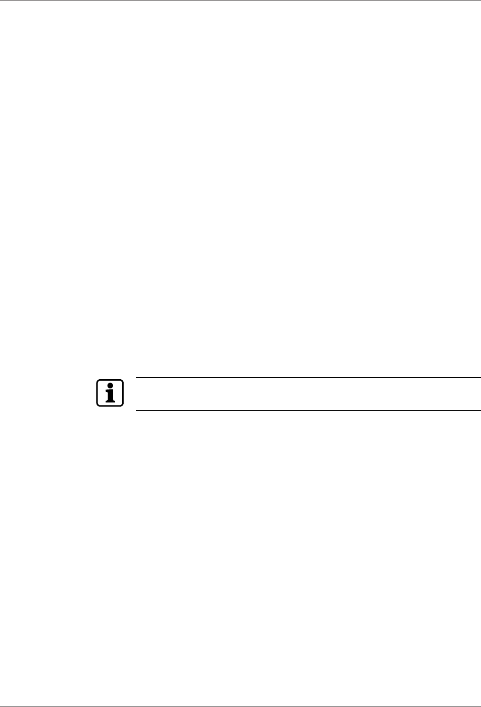
5.1.4 Cable entry
The installation lines can be routed to the device from behind, from the side, from
above and below.
There are holes in the bottom part of the housing, on the sides and on the top and
bottom; they can be removed if necessary,
The lines are routed in a duct in the lower part of the rear side, there is the gland to
the connections on the front side.
NOTICE
Ensure sufficient line lengths on the installation site.
When inserting the lines from the rear (center of the housing), the installation lines
and network cable with the plug protrude from the wall for approx. 35 cm.
Installation Technical Manual
24 04045524 - 08/2016 Kaba access manager 92 32
5.2 Installation diagram
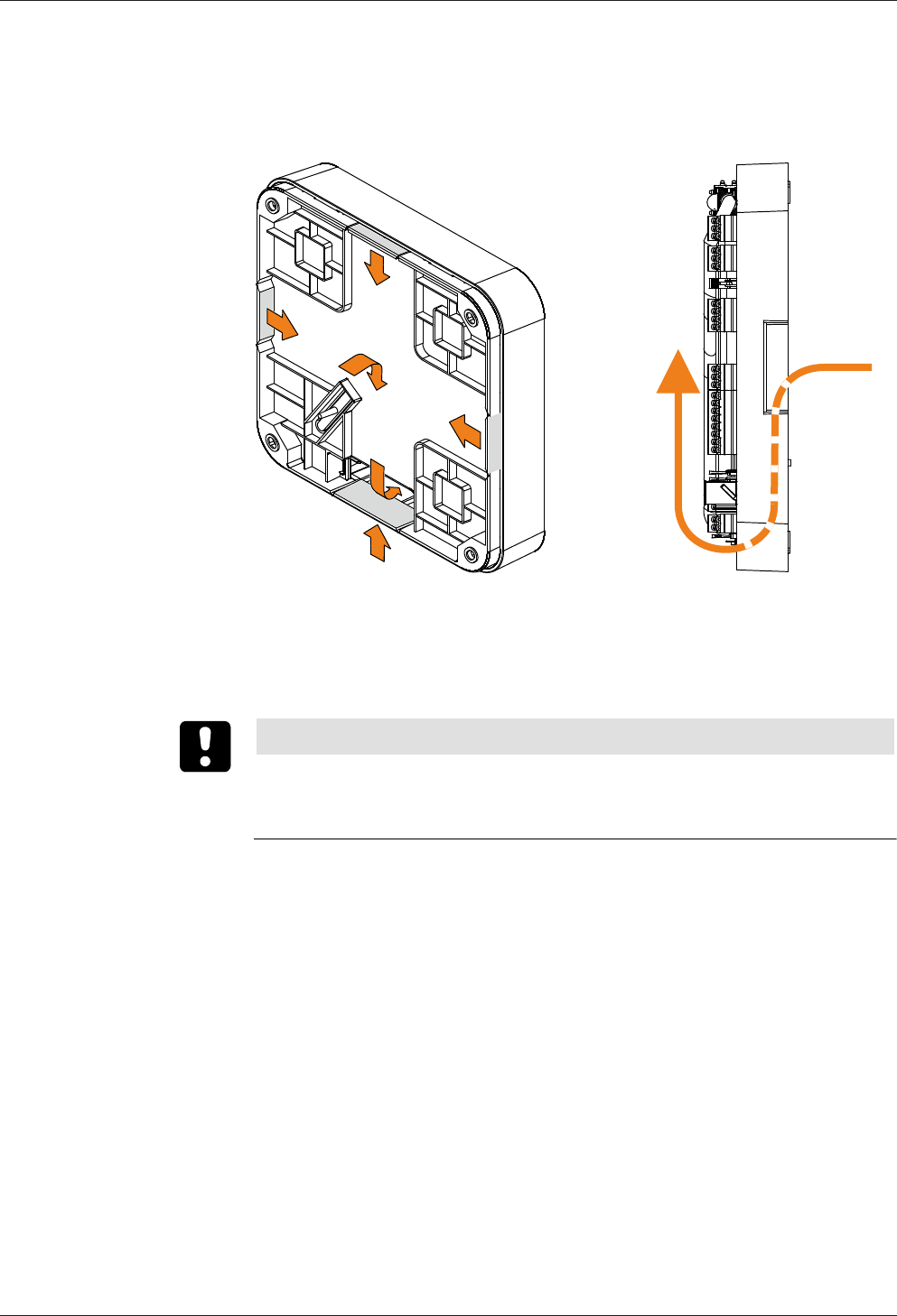
5.2.1 Access control with registration unit
Example:
• Access control with RFID registration units
• PoE power supply of the access manager
Method for feeding in the power supply via the PSE (Power Sourcing Equip-
ment):
– End span (direct supply, e.g. via PoE switch)
– Midspan (supply via intermediate sources, e.g. PoE injector)
1 Kaba access manager 92 32
2 Registration unit
3 Door opener key
4 Door opener
5 Door frame contact
Installation lines
A Coaxial cable to the registration unit
B Line to the door contact, the door opener key, and the door opener
C Ethernet network cable

Technical Manual Installation
2504045524 - 08/2016Kaba access manager 92 32
5.3 Installation lines
5.3.1 Ethernet
Network cable with RJ45 plug, line requirement: CAT.5 S-UTP 4 x 2 AWG 24 oder AWG
22 (according to EIA/TIA568) or higher quality.
5.3.2 Line to the door opener, the door opener key, and the door contacts
Line requirements: Cable diameters from 0.5 mm to 0.8 mm.
Recommended cable: CAT.5 S-UTP 4 x 2 AWG 24 or AWG 22 (according to EIA/
TIA568) or higher.
5.3.3 Coaxial cables to registration units
Registration units are connected to the access manager via coaxial cables The coaxial
cable transfers the HF signals from the RFID antenna, keyboard data and trigger data
for the optical and acoustic signal generators.
Line requirements: Coaxial cable 50 ohms, type RG174/U.
Maximum cable length: 30 m
Recommended cable length: < 10 m
Installation Technical Manual
26 04045524 - 08/2016 Kaba access manager 92 32
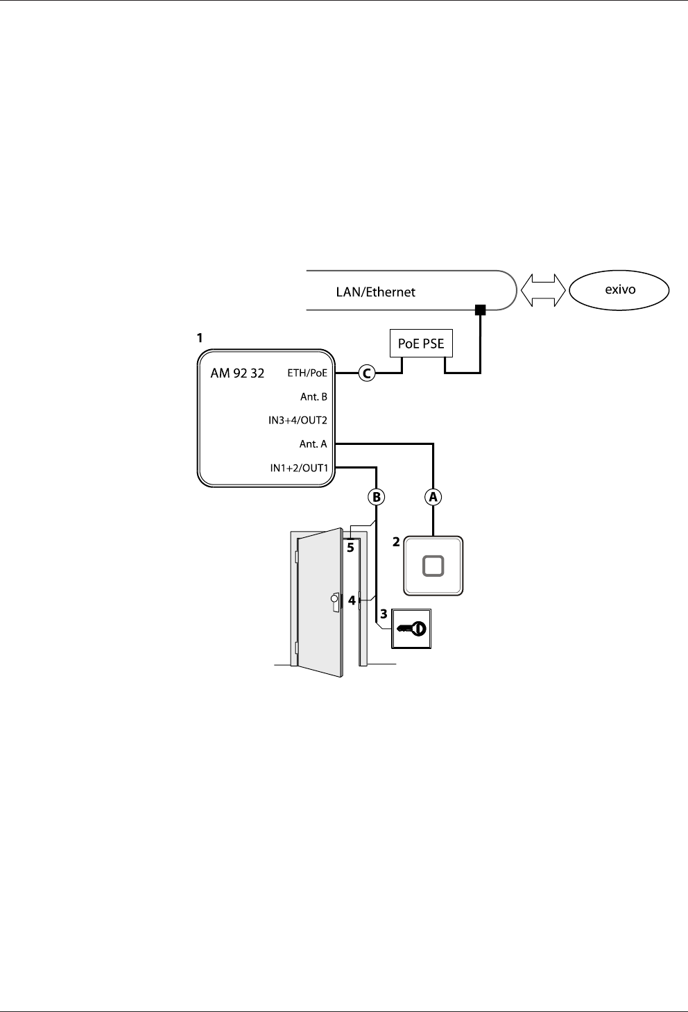
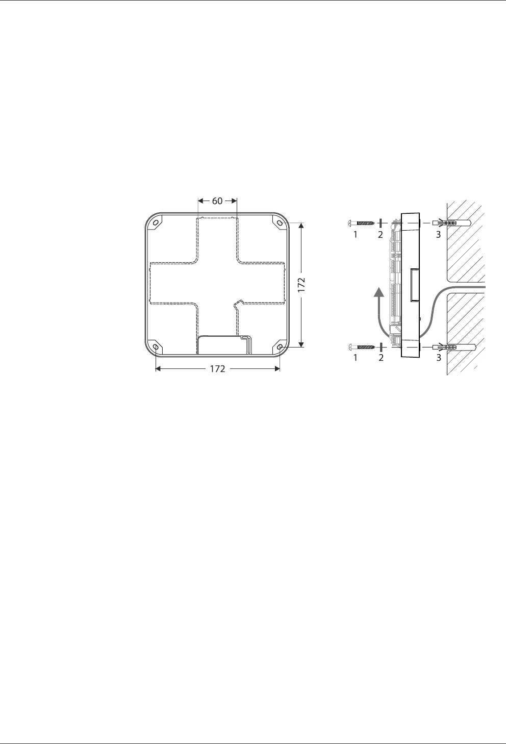
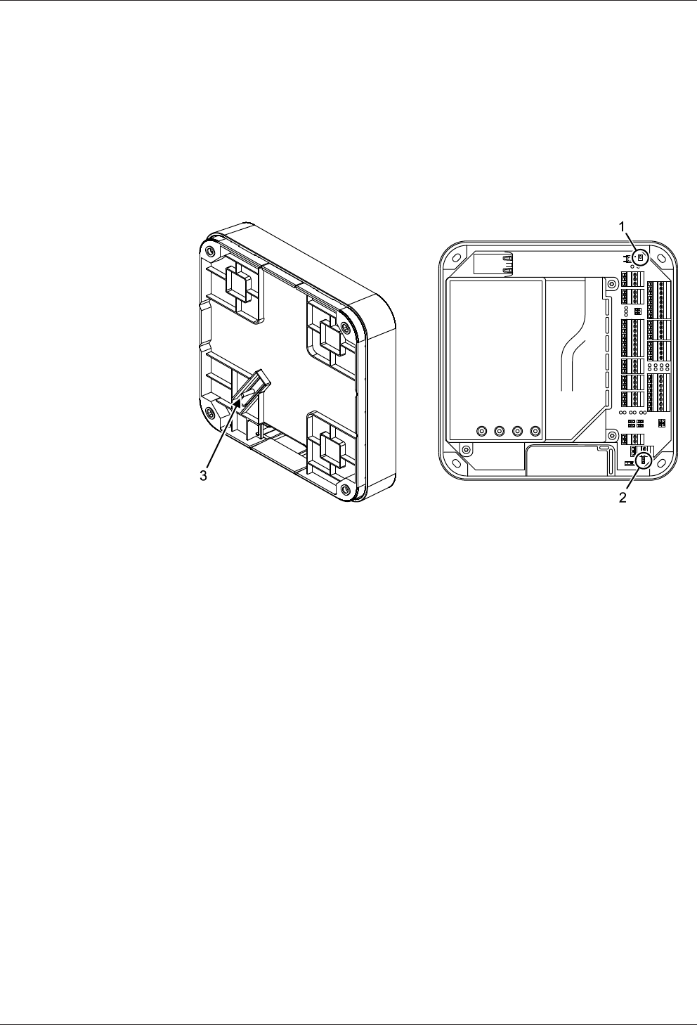
5.4 Wall mounting
When feeding the cable from the side, top or below, first, provide holes for the entry
of the installation lines. Not necessary for cable entry from the rear.
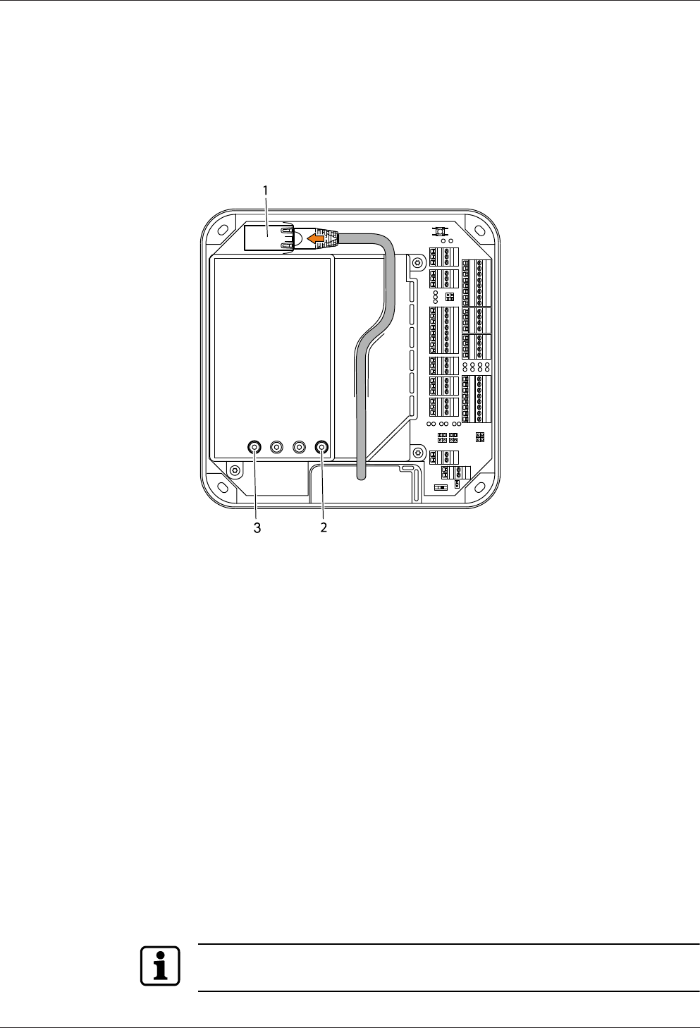
The housing is mounted directly to the wall using screws/dowels. There are three
oval fastening holes for fastening in the housing.
Fastening material (included in the delivery):
• 4 round-head wood screws DIN 96, diam. 4.5 x 35 (1)
• 4 washers (2)
• 4 dowels S6 (3)
The washers absorb mechanical tensions in case of slightly uneven surfaces and
cover the fastening hole completely once the screw has been tightened. The deliv-
ered washers must also be used if you use other fastening screws (depending on the
mounting surface).
In case of soft mounting surfaces, make sure that the housing is not pressed into the
surface when mounting it. The unevenness of the mounting surface may not exceed
0.5 mm. The unevenness of the mounting surface may have to be compensated for
or adjusted by means of suitable measures (e.g. washers).
The installation lines are led down in the duct on the rear side of the device and then
to the front side of the device with connections. Make sure that the lines are not
squeezed or buckled during mounting.
Technical Manual Installation
2704045524 - 08/2016Kaba access manager 92 32
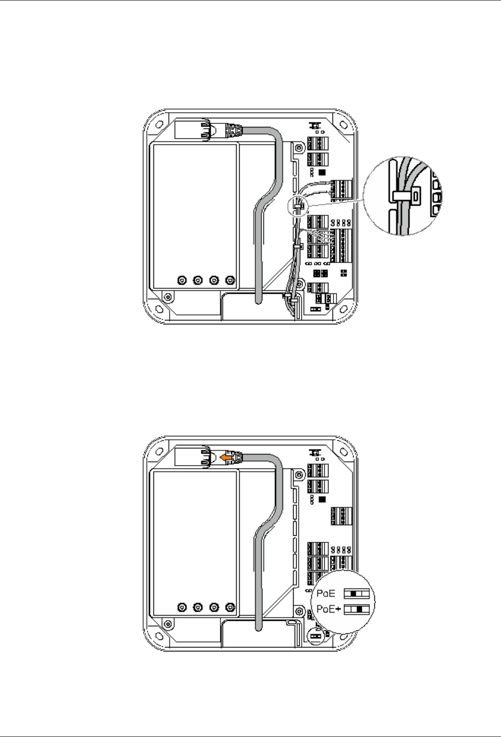
5.5 Cable routing
The installation lines are guided through an opening on the bottom side of the de-
vice from the rear side to the front side of the device.
The cable passage and the internal cover have eyelets for fastening of installation
lines by means of cable ties (not included in the scope of delivery).
For the network cable, there is a routing duct on the inner cover.
5.6 Setting the PoE switches
Depending on the power supply type, the PoE switch must be set as described be-
low.
Installation Technical Manual
28 04045524 - 08/2016 Kaba access manager 92 32
Power supply Standard/Power Switch position
PoE IEEE 802.3af (12.95 W) PoE
PoE+ IEEE802.3at (25.5 W) PoE+
External 24 V DC power
supply unit
12-60 W PoE+
In case of power supply via an external power supply unit, the switch position PoE+ is
required to prevent the access manager from limiting the power for external con-
sumers.
5.7 Connections
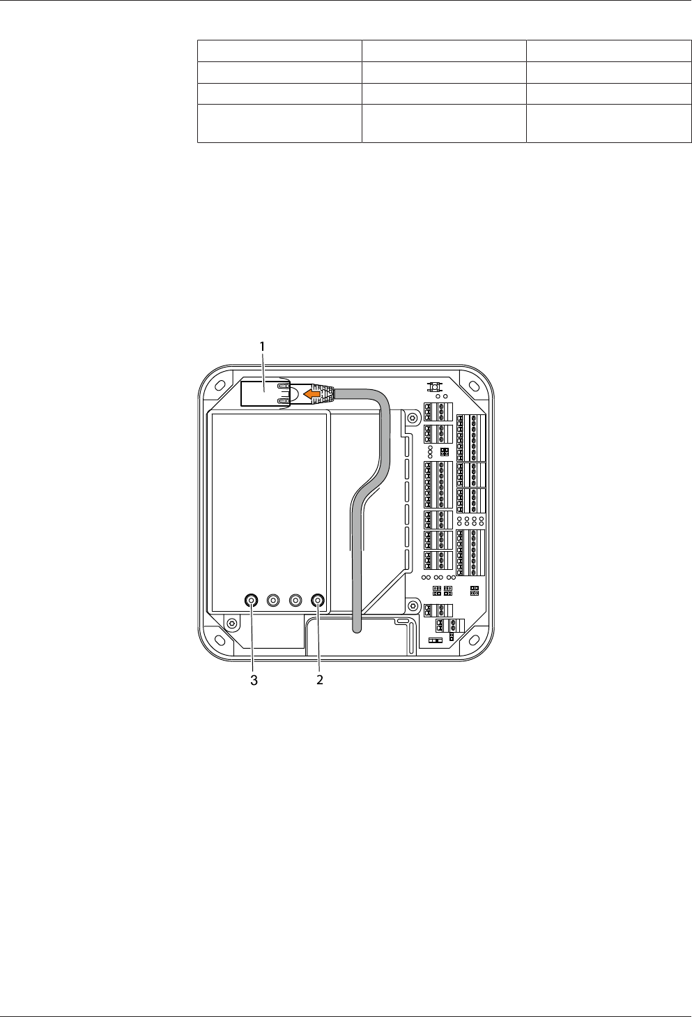
5.7.1 Network connection
Establishing the network connection
Plug in the network cable into the Ethernet receptacle (1) and fasten it in the gland
on the cover.
If the power supply is correct, the Power LED (2) lights up in green after a short time.
Once the network connection has been established, the Ethernet LED (3) is flashing
in yellow.
Technical Manual Installation
2904045524 - 08/2016Kaba access manager 92 32
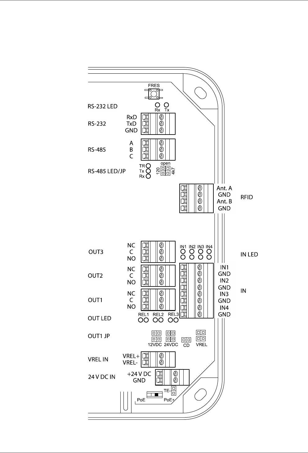
5.7.2 Overview of terminals
The following terminals are located in the connection area of the device.
Installation Technical Manual
30 04045524 - 08/2016 Kaba access manager 92 32
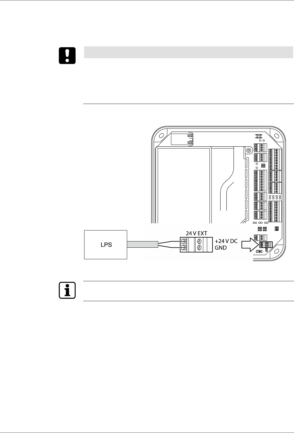
5.7.3 External 24 V DC power supply
As an alternative to the PoE power supply, the access manager can also be supplied
via an external 24 V DC power source.
NOTICE
Possible damage in case of simultaneous power supply via PoE and 24 V DC
The device can be damaged in case of simultaneous power supply via PoE and exter-
nal supply.
• Before connecting the external supply, make sure that the device is not supplied
with power via PoE.
Use only power supply units that fulfill the requirements of EN/UL/CSA 60950-1 as
limited power source (LPS).
Also see about this
25.7.1Network connection [}28]
Technical Manual Installation
3104045524 - 08/2016Kaba access manager 92 32
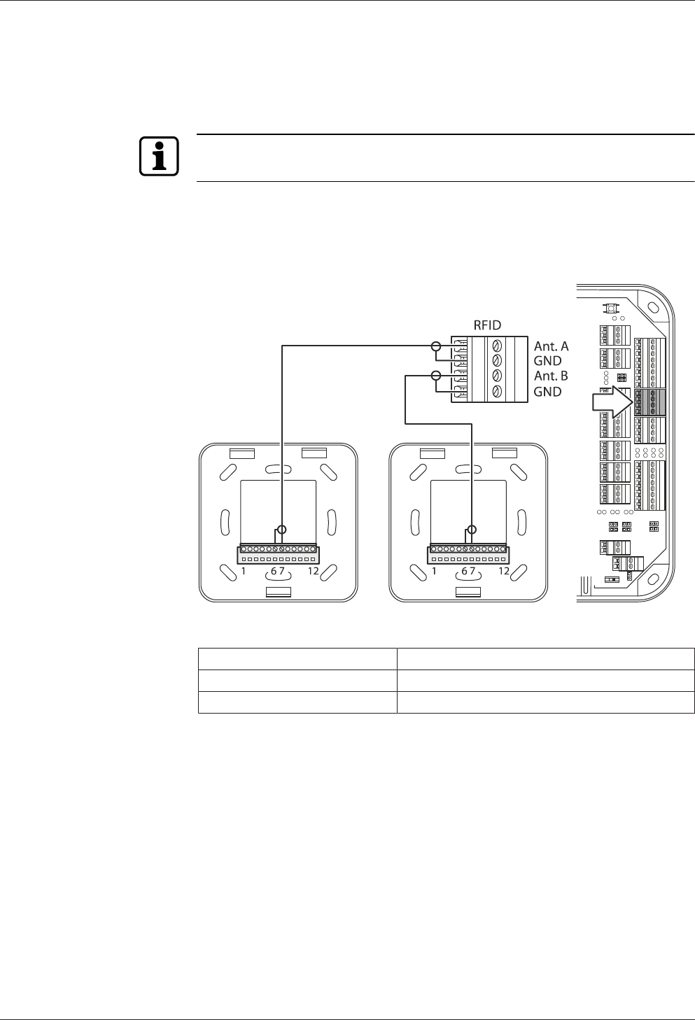
5.7.4 Registration units
Up to 2 registration units can be connected. The registration units A + B are con-
nected by means of the coaxial cable to the RFID input terminal.
Make sure that antenna A (Ant.A) is connected first and antenna B (Ant. B) is con-
nected after that.
Example: Connection of Kaba registration unit 90 01.
Connection designation Assignment
Ant. A/B Central conductor of coaxial cable
GND Shield of coaxial cable
Installation Technical Manual
32 04045524 - 08/2016 Kaba access manager 92 32
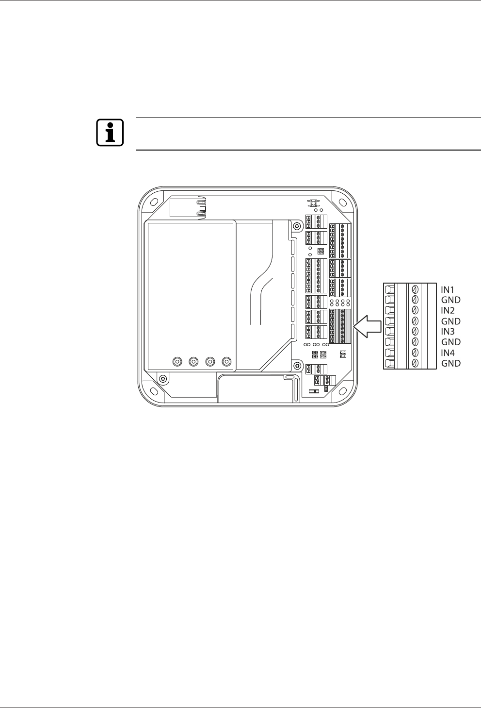
5.7.5 Inputs
The access manager has 4 inputs IN1 to IN4.
Function of the inputs
The inputs are used for the inquiry of sensors such as door-opener key, door handle
contact, door frame contact, bolt contact, vandal contact, passage control (e.g., turn-
stile, light barrier), etc.
The function of the individual inputs depends on the selected door template.
Principle
The inputs (IN1-IN4) are activated by means of a potential-free contact (switch or re-
lay contact). An open input is recognized as “high” due to the internal pull-up resis-
tor.
5.7.5.1 Line monitoring
The inputs can be designed as follows:
• Without line monitoring
• With line monitoring (if supported and activated by the terminal software)
Line monitoring allows the terminal software to detect the states short circuit and in-
terruption, in addition to the states active (input closed) and not active (input open)
and report them to the higher-level system.
The current states of the inputs are indicated by light emitting diodes (see chapter
Light emitting diodes [}4.10]).
Technical Manual Installation
3304045524 - 08/2016Kaba access manager 92 32
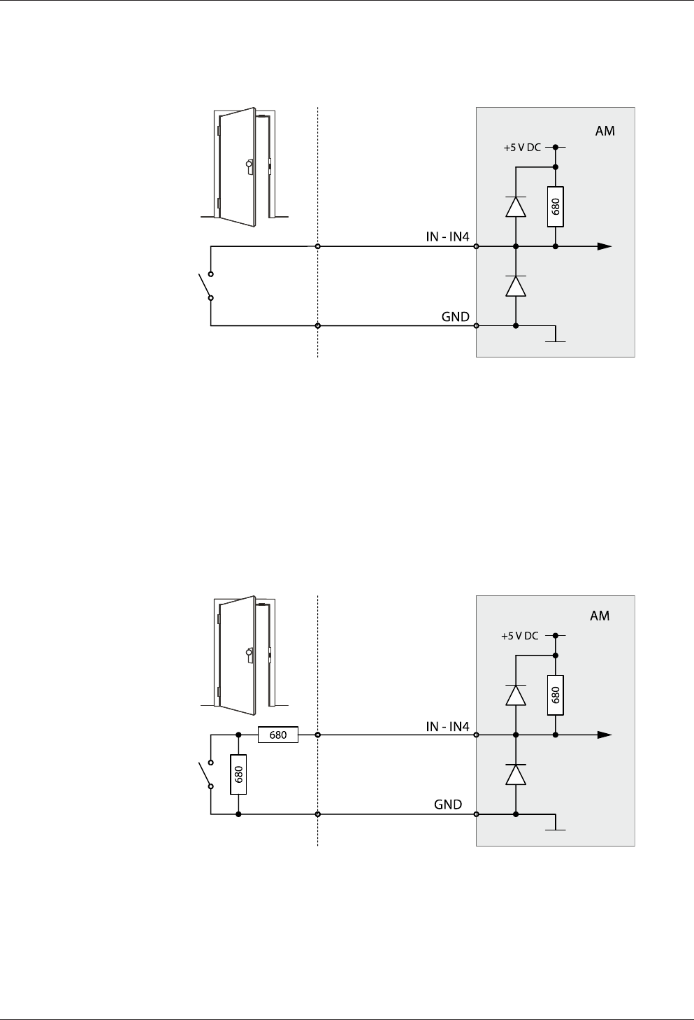
5.7.5.2 Non-line-monitored inputs
Fig.2: Non-line-monitored inputs
Example: Connection to door frame contact not line-monitored.
Tampering to lines between access manager and door frame contact is not detected.
5.7.5.3 Line-monitored inputs
With line monitoring activated, resistors (680 Ω, 0,25 W, 2 %) must be connected in
series and in parallel to the respective contact. The resistors must be attached in a
vandal secure manner directly to the external contact.
Fig.3: Line-monitored inputs of access manager AM 9232
Example: Connection to door frame contact line-monitored.
Tampering to lines between access manager and door frame contact is detected.
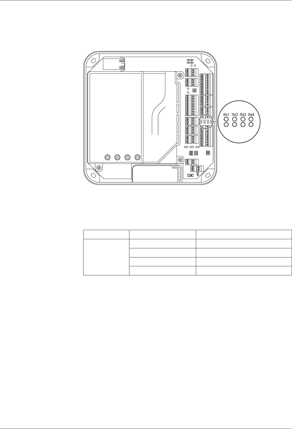
5.7.5.4 Status display
Installation Technical Manual
34 04045524 - 08/2016 Kaba access manager 92 32
Above the terminal for the inputs, there are light emitting diodes for status display of
the inputs.
Fig.4: Status display Inputs of access manager AM 9232
The current status of the inputs is indicated by a red and green LED respectively as
follows.
Designation Signal Meaning
IN1 - IN4 Off Input is not active (open)
lit green Input is active (closed)
red and green lit Short circuit*
red lit Interruption*
* only with active line monitoring
Technical Manual Installation
3504045524 - 08/2016Kaba access manager 92 32
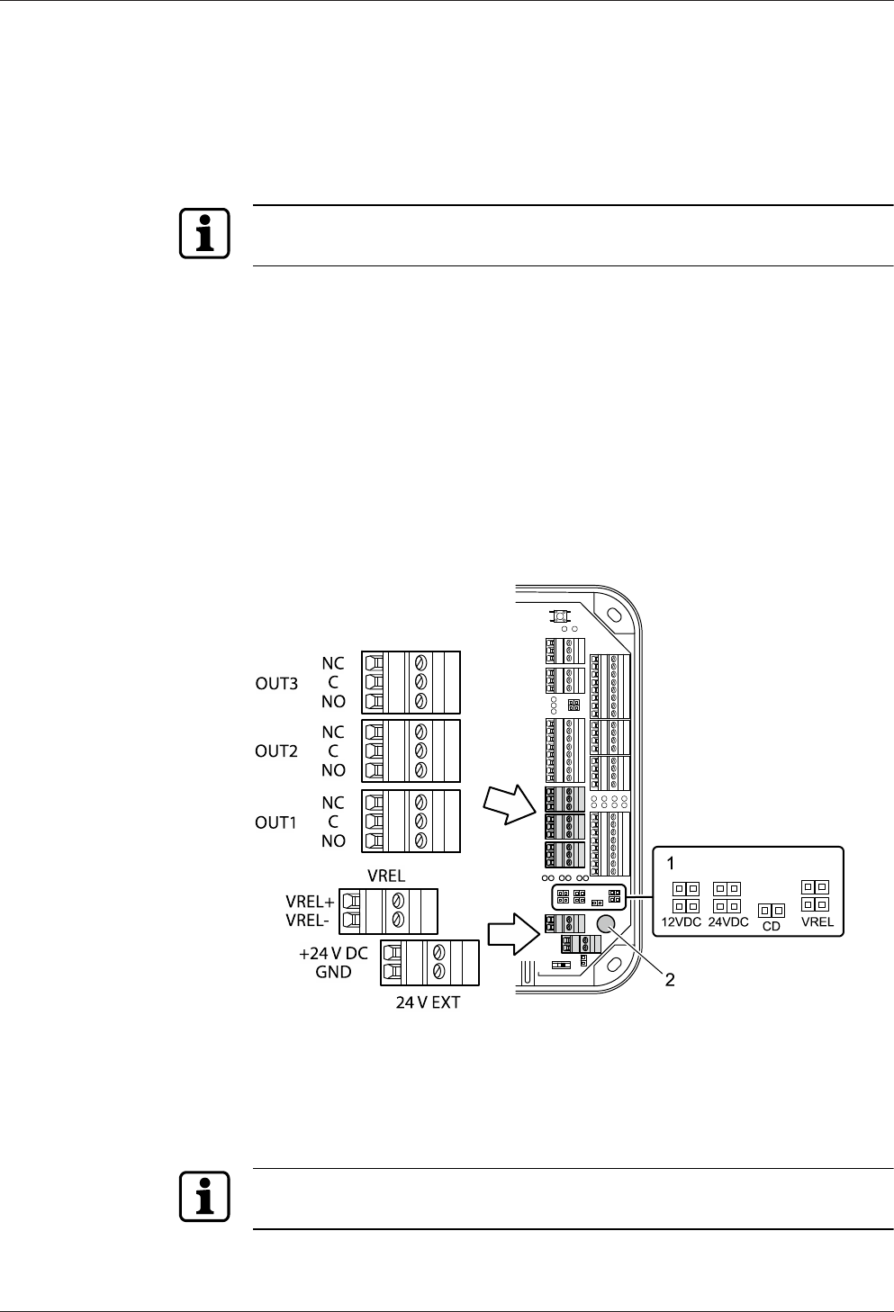
5.7.6 Outputs
The access manager has 3 relay outputs OUT1 to OUT3.
Contact rating: 30 V AC/DC; 2 A max.
The outputs can be used for the activation of motor locks, door openers, turnstile
drives, technical alarm day/night, security alarm day/night etc.
The function of the individual outputs depends on the selected door template.
The wiring of the output OUT1 can be adjusted via jumper (1). The following variants
are possible as an alternative:
• OUT1 is used as a potential-free contact
• The internal 12 V DC power supply is switched to the output OUT1.
• A power supply (max. 24 VAC) applied to the VREL terminal is switched to the
output OUT1
• The external 24 V DC power supply (24 V EXT terminal) is switched to the output
OUT1.
The outputs OUT2 and OUT3 are designed permanently as potential-free relay out-
puts with one switching contact each.
1 Jumper for the wiring of output OUT1
2 Fuse F1 for protection of the power supply via OUT1
Fuse value: T2.5 A
The fuse is plugged in and can be replaced without problems.
The fuse F1 may only be replaced with fuses of the same type.
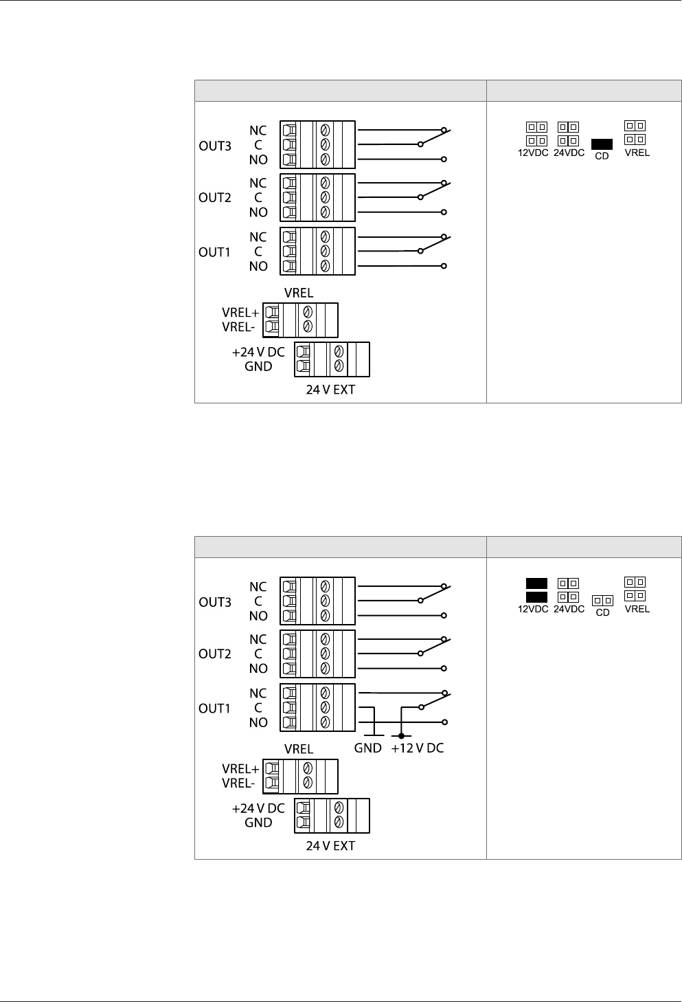
5.7.6.1 OUT1 as potential-free switching contact
Installation Technical Manual
36 04045524 - 08/2016 Kaba access manager 92 32
By setting the jumper with the designation CD, the OUT1 output can be used simi-
larly to the outputs OUT2 and OUT3 as potential-free switching contact.
Principle of output wiring Jumper position
IMPORTANT: Only the CD
jumper may be set. All other
jumpers may not be set.
5.7.6.2 Switching 12 V DC to OUT1
By setting the jumper with designation 12 V DC, the internal 12 V DC power supply is
switched to the OUT1 output. Consumers, for example door openers which are oper-
ated with 12 V DC can be directly connected to OUT1 in this way.
This variant can be used both with device power supply via PoE and device power
supply via an external 24 V DC power supply unit.
Principle of output wiring Jumper position
IMPORTANT: Only the jumper
pair 12 V DC may be set. All
other jumpers may not be set.
Technical Manual Installation
3704045524 - 08/2016Kaba access manager 92 32
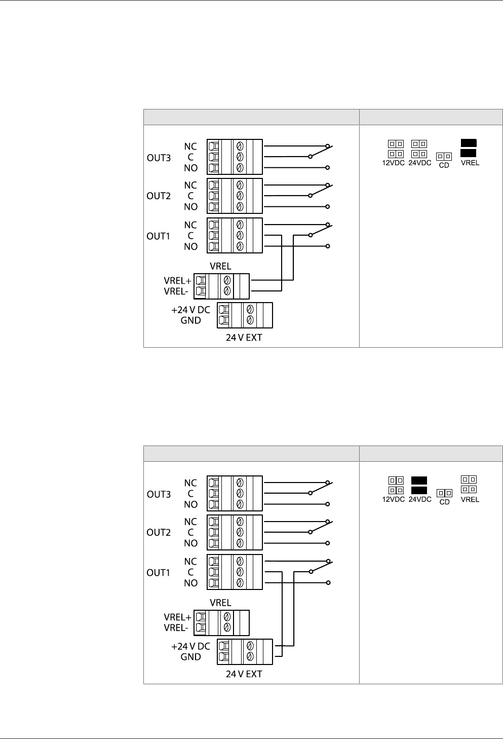
5.7.6.3 Switching the external DC power supply to OUT1
By setting the jumper pair with designation VREL, a DC power supply connected via
the VREL terminal (max. 30 V DC, 2 A) is switched to the OUT1 output.
This variant can be used both with device power supply via PoE and device power
supply via an external 24 V DC power supply unit.
Principle of output wiring Jumper position
IMPORTANT: Only the jumper
pair VREL may be set. All other
jumpers may not be set.
5.7.6.4 Switching 24 V DC to OUT1
By setting the jumper pair with designation 24 V DC, the 24 V DC power supply (ter-
minal 24 V EXT) is switched to the OUT1 output. Consumers, for example door open-
ers which are operated with 24 V DC, can be directly connected to OUT1 in this way.
This variant can be used only with device power supply via an external 24 V DC
power supply unit. Not for power supply via PoE.
Principle of output wiring Jumper position
IMPORTANT: Only the jumper
pair 24 V DC may be set. All
other jumpers may not be set.
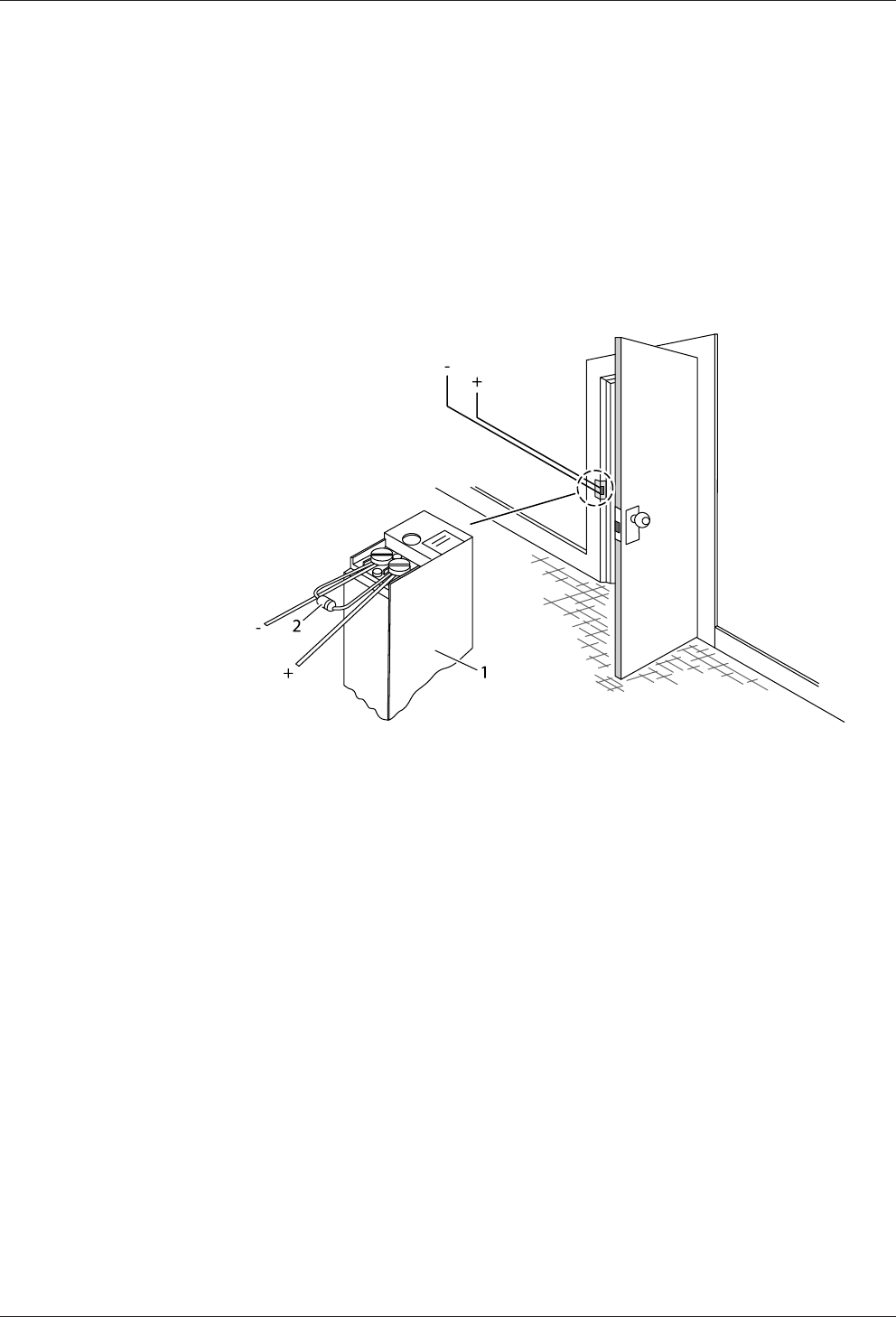
5.7.6.5 Connecting door openers
Closed-circuit door-openers and open-circuit door-openers can be used.
Installation Technical Manual
38 04045524 - 08/2016 Kaba access manager 92 32
For door openers that are supplied with DC voltage, a diode (a freewheeling diode)
must be connected in parallel to the door opener to suppress interference. In doing
so, make sure that the diode is connected in reverse-bias direction and check the po-
larity of the connected voltage.
When using an alternating voltage power supply, a varistor or a bipolar suppressor
diode must be connected in parallel. As regards the dimensioning and type, observe
the specifications of the door opener manufacturer.
The diode or varistor must be connected directly to the door opener and may not be
fitted to the access manager.
This step is not required if a door opener with internal varistor or diode is used.
1 Door-opener
2 Freewheeling diode or varistor
Technical Manual Installation
3904045524 - 08/2016Kaba access manager 92 32
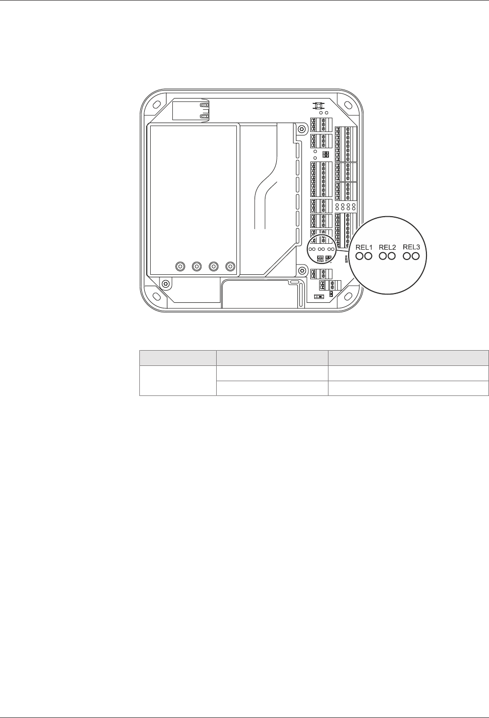
5.7.6.6 Status display
Below the terminals for the outputs, there are light emitting diodes for status display
of the outputs.
The current status of the outputs is indicated as follows.
Designation Signal Meaning
REL1-3 Off Relay is not pulled-in
lit green Relay is pulled-in
Installation Technical Manual
40 04045524 - 08/2016 Kaba access manager 92 32
5.8 Vandal contact
The device has two vandal contacts (tamper).
A switching contact (1) is opened if the housing cover is removed.
Another switching contact (3) is opened if the device is removed from the wall.
Switching contact (3) is deactivated by the jumper with designation TE- (2) in the de-
livery state. To activate the switching contact (3), the jumper TE- (2) must be re-
moved.
Opening of one or both switching contacts leads to the status indication of the inter-
nal input 5.
Technical Manual Installation
4104045524 - 08/2016Kaba access manager 92 32
5.9 Fastening the cover
Fasten the housing cover in the following way:
1. Hang the mounting lugs of the housing cover at the top of the bottom part of
the housing.
2. Pivot the housing cover down and close the housing.
3. Fasten the housing cover by means of two screws M3x8 (TORX 8) on the bottom
part of the housing.
Commissioning Technical Manual
42 04045524 - 08/2016 Kaba access manager 92 32
6 Commissioning
The device can be put into operation largely automatically only if the following re-
quirements are met:
• A functioning DHCP server is available
• When connecting to the Ethernet, the device automatically receives an IP ad-
dress from the DHCP server and thus an access to the Internet via ports 80 and
443.
If the device does not obtain access to the Internet or no functioning DHCP server is
available, the Ethernet interface must be manually configured using Service Tool be-
fore putting the device into operation.
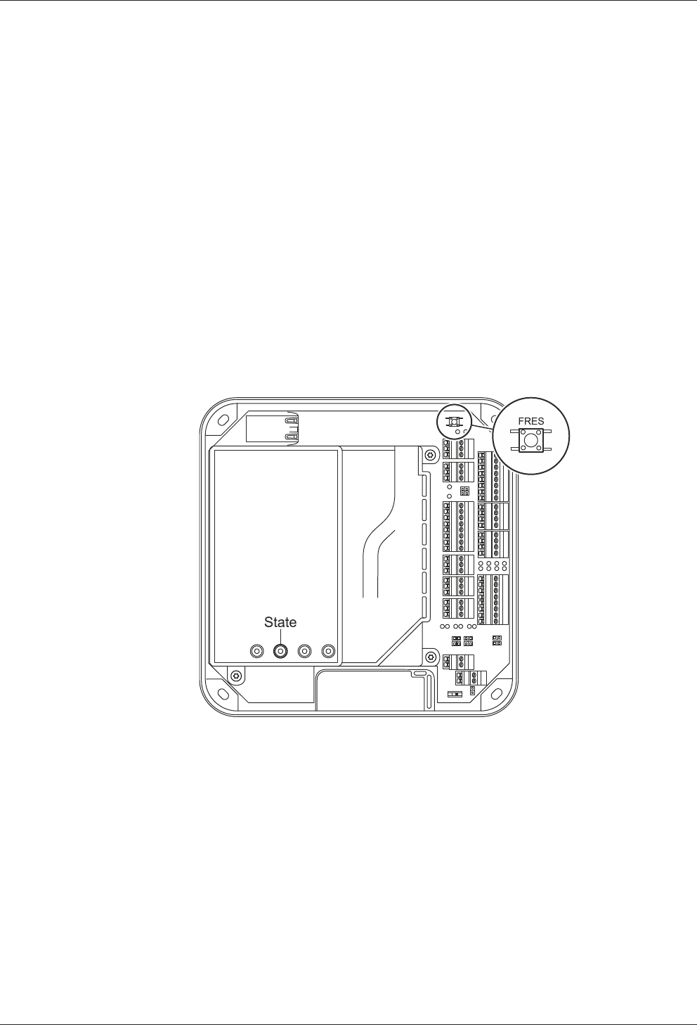
6.1 Start options
6.1.1 Reset key and status LED
The device includes a reset key, designated FRES and a status LED (State).
The reset key allows a system start with execution of the start options described be-
low. The status LED signals the current phase of the execution.

Technical Manual Commissioning
4304045524 - 08/2016Kaba access manager 92 32
6.2 Performing a cold start
NOTICE
When performing a cold start, parameters are reset to their default values. Master
records and booking records are deleted.
Network settings as well as group and terminal addresses remain unchanged.
1. Turn off the device.
2. Turn on the device.
ðThe yellow status LED is lit.
ðAfter approx. 40 seconds, the yellow status LED starts flashing.
3. Within 10 seconds, press the reset key and keep it depressed.
ðThe status LED flashes faster for 5 seconds.
ðThe status LED lights up in green for 2 seconds.
ðA cold start was performed.
4. Release the reset key again.
ðThe status LED lights up in red for 5 seconds.
ðThe status LED is lit in green.
ðThe system is ready for use, a cold start was performed.
Commissioning Technical Manual
44 04045524 - 08/2016 Kaba access manager 92 32
6.3 Commissioning procedure
Commissioning
The device is put into operation in 5 work steps:
1 Planning the system in partner application
2 Adding setup medium in partner application
3 Connecting the device to the power supply
4 Configuring the Ethernet interface using Service Tool, if required
5 Connecting at least one registration unit to the device
6 Putting the device into operation by means of the setup medium via a registra-
tion unit
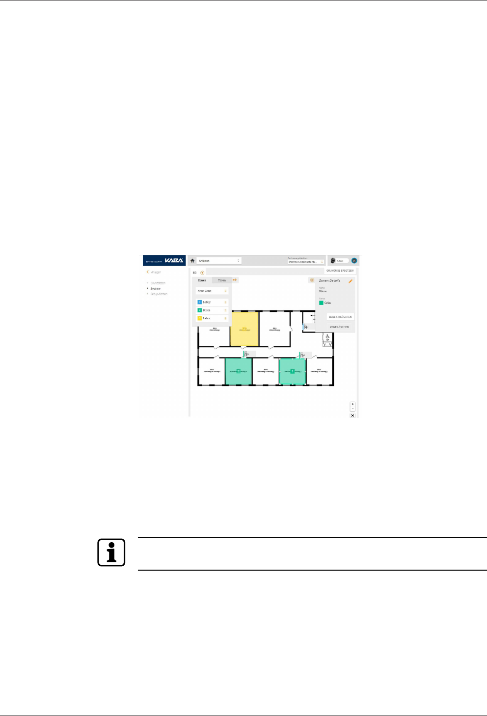
6.3.1 Planning the system in partner application
Before putting the device into operation, at least the door to be connected must be
planned in the partner application. The device is configured by assigning its installa-
tion site and the additional hardware components in this software.
For information on the planning of the system, see online help of the parter applica-
tion.
6.3.2 Registering the setup medium in partner application
After the system has been planned in the partner application, a setup medium for
this system - also in the partner application - must be registered. This setup medium
is then used for commissioning the individual components used for the system , i.e.
for connecting them to the Internet platform.
A setup medium is a card with a code which must be activated in the partner appli-
cation for the corresponding system (add setup medium).
For information on the registration of a setup medium in the partner application, re-
fer to the online help of the partner application.
Technical Manual Commissioning
4504045524 - 08/2016Kaba access manager 92 32
6.3.3 Connecting the device to the power supply
Once the registration unit(s) is/are connected, the access manager must be con-
nected to the power supply. If the device is supplied with current via the Ethernet
(PoE), it is sufficient to connect the Ethernet cable. Otherwise, an external 24 V DC
supply must be connected (see External 24 V DC power supply [}5.7.3]).
6.3.4 Configuring the Ethernet interface using Service Tool
If no functioning DHCP server is available or a manual parameterizing of the Ethernet
interface is desired, the Ethernet interface must be put into operation using Service
Tool. For this, a computer with an USB connection and a SSH terminal program, for
example PuTTY which can be downloaded from the Internet is required.
Requirements
The following work steps must be carried out to meet the requirements for the use of
the Service Tool.
1 Install a SSH terminal program (e.g. PuTTY) on the computer.
2 Download FTDI driver (can be obtained from Kaba)
and install on the computer.
3 Connect the FTDI debug cable (can also be obtained from Kaba) to the computer
via USB. The FTDI debug cable is detected by the system and shown in the device
manager as virtual COM port (e. g. COM3).
4 After that, connect the connector on the other end of the FTDI debug cable to
the device as described below.
5 Start the SSH terminal program end enter the configuration parameters de-
scribed below.
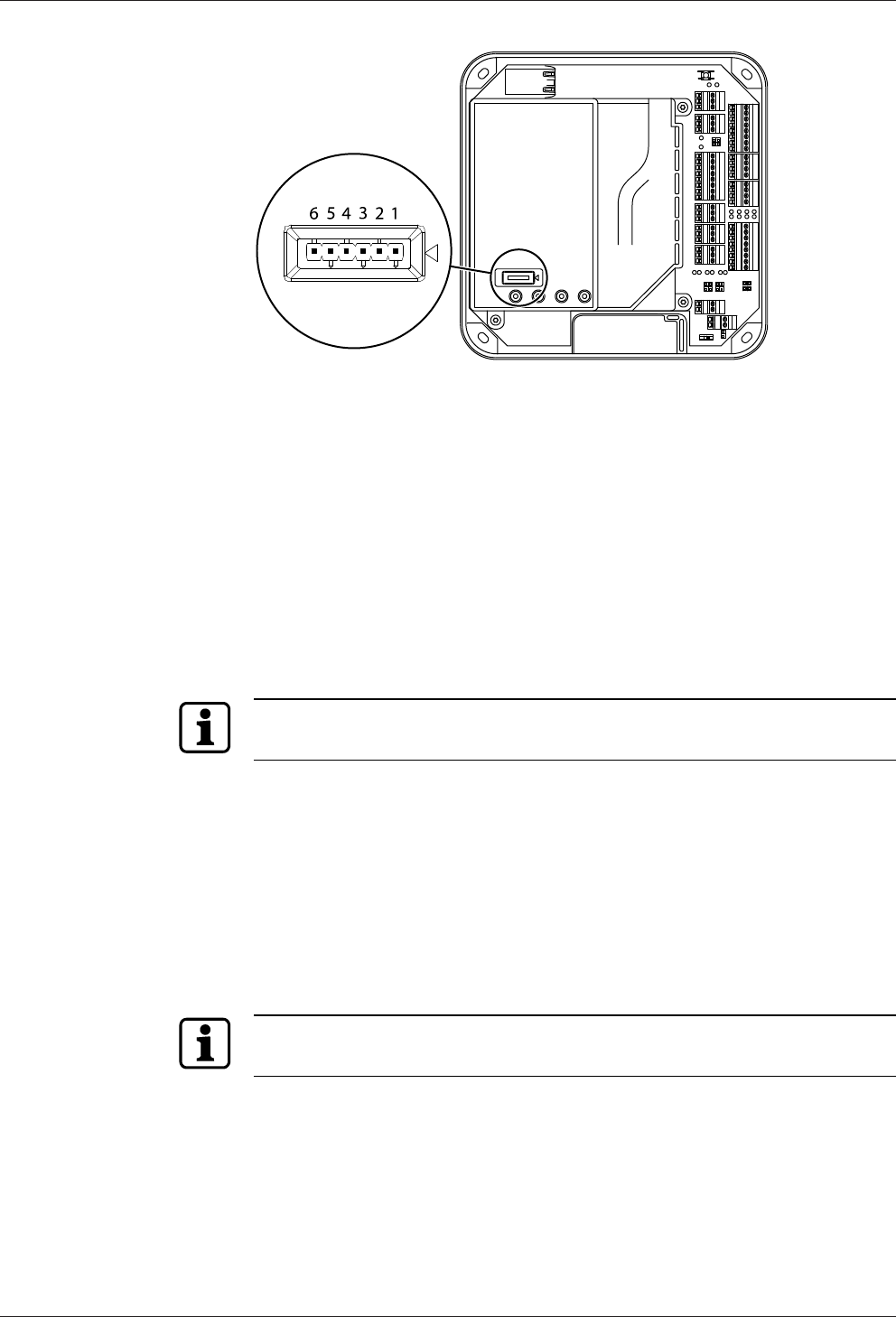
Connecting the FTDI debug cable to the device
Ensure correct polarity! The black cable at the connector must be connected to pin 1.
Pin 1 is marked on the cover by an arrow.
Commissioning Technical Manual
46 04045524 - 08/2016 Kaba access manager 92 32
Configuration parameters for the SSH terminal program
Start the SH terminal program, for example by double-clicking on putty.exe and
make the following settings:
• Connection type: serial
• Serial interface: COM <n> (according to device manager)
• Speed: 115200 Baud
• Character set: ISO-8859-1
• Data flow control: off/no parity bit
After entering these parameters, click on "Save" to save the settings made as stan-
dard settings.
Starting the Service Tool
Before starting the Service Tool, make sure that the FTDI debug cable is correctly
connected to the device and the device is switched on.
To start the Service Tool, proceed as follows:
1 Click on "Open" to start the Service Tool
2 A login screen requesting user name and password will appear. The user name
and password for all access managers are identical:
User name = admin
Password = 1234
3 After successful login, the main menu of the Service Tool opens. Various func-
tions are available here.
The user interface must be operated in a secure environment. An unauthorized ac-
cess must be excluded!
Functions of the Service Tool
The Service Tool allows you to use various functions:
1 Configuring the network settings
2 Displaying the characteristics of the device
3 Displaying the system logs
4 Resetting to the factory settings

Technical Manual Commissioning
4704045524 - 08/2016Kaba access manager 92 32
5 Starting the firmware update
Configuring the network settings
The following network parameters can be configured here:
• Static IP address (instead of DHCP)
• Network mask
• Device address
• IP address of the domain name server 1 and possibly also 2
• Proxy server
Displaying the characteristics of the device
The following characteristics can be displayed:
• Firmware version (OS, AML, OSGI Bundles)
• Device ID
• Serial number, date of manufacture
• IP address
• MAC address
• Certificate information
• Routing table
• ARP table
• Uptime
• Load average
• Network interface statistics
• Firewall rules
• Device statistics
• Statistics of the connected (wireless) devices
Displaying the system logs
The following logs can be displayed:
• Logs created by the application
• Logs created by the OS
• Logs created by the device

Commissioning Technical Manual
48 04045524 - 08/2016 Kaba access manager 92 32
6.3.5 Installing the registration unit
The actual commissioning of the device is carried out via a registration unit assigned
to it in the partner application. Therefore, at least one registration unit must be in-
stalled and connected to the device before the commissioning of the device.
6.3.6 Commissioning the device with setup medium
After the system has been planned and the setup medium has been detected in the
partner application, the registration units have been connected to the access man-
ager on site, the access manager has been connected to the network (Ethernet) on
site and power supply has been provided, it can be put into operation after a waiting
period of approx. 4 minutes by means of the setup medium as follows:
• Hold the setup medium at a registration unit
For commissioning of the device by means of the setup medium, only a reader with-
out PIN can be used!
• The access manager will produce 2 consecutive acoustic signals. This means that
it has detected the setup medium and begins now to communicate with the
Kaba exivo Internet platform. After registration in the Internet platform, the
green status LED is lit
• The access manager is displayed in the partner application
• The ID of the access manager appears in the partner application in a drop-down
list with all access managers available in the system with the same template type
• Now, the access manager to be used must be assigned to the corresponding
door in the partner application
• The configuration determined in the partner application is loaded now to the ac-
cess manager
• After that, the access manager is ready for use
Technical Manual Packaging/Return
4904045524 - 08/2016Kaba access manager 92 32
7 Packaging/Return
Incorrectly packaged assemblies and devices may cause expenses due to damage
during transport.
Please observe the following information when sending Kaba products.
Kaba shall not be liable for damage to products which can be attributed to insuffi-
cient packaging.
7.1 Complete Devices
The original packaging is specially adapted for the device. It offers the greatest possi-
ble protection against transport damage.
Always use the original packaging for returns.
If this is not possible, then ensure the packaging prevents damage to the device.
• Use a stable, thick-walled transport crate or a box. The transport crate should be
large enough that there is 8–10cm space between the device and the container
wall.
• Wrap the device in suitable film or put in a bag.
• Pad generously around the device e.g. using foam padding or bubble wrap. It
must be ensured that the device does not move within the packaging.
• Only use dust-free environmentally-friendly filling material.
7.2 Electronic Assemblies
Electronic assemblies sensitive to ESD, such as circuit boards, readers, etc., must be
stored, transported and sent in suitable ESD protective packaging. The packaging of
electronic assemblies may only be carried out in ESD-protected workplaces by per-
sons who are familiar with and follow the general ESD protective regulations.
The return of electronic assemblies in packaging with sufficient ESD protection is a
condition for
• making guarantee claims in the event of malfunctions of any kind.
• replacement delivery of electronic circuit boards and components when an ex-
change is provided.
In order to guarantee a high quality standard, electronic components supplied in
packaging without sufficient ESD protection will be neither analyzed nor repaired,
but instead disposed of directly.

Packaging/Return Technical Manual
50 04045524 - 08/2016 Kaba access manager 92 32
7.3 Marking
Complete return papers and correct labeling allow us to process matters quickly.
Please ensure that a delivery note is included with the package. The delivery note
should include the following information:
• Number of devices or components per package.
• Item numbers, serial numbers, designations.
• Address of your company/contact.
• Reason for the return, e.g. repair exchange.
• Informative description of the fault.
In the event of returns from outside of the EU, a customs invoice with the real cus-
toms value and customs tariff no. will also be required.

Technical Manual Disposal
5104045524 - 08/2016Kaba access manager 92 32
8 Disposal
This product meets the requirements of the WEEE Directive and, in accordance with
DIN standard EN 50419, is labeled with the WEEE crossed-out garbage can symbol.
The symbol indicates the separate disposal of electric and electronic equipment in
EU countries.
Do not dispose of the device with household waste under any circumstances.
Used devices contain valuable recyclable materials that should be recycled. Used de-
vices should therefore be disposed of via the collection system used in your country.
Disposal in Germany:
After use, Kaba GmbH undertakes to carry out the proper disposal of the supplied
goods in line with legal requirements (such as the ElektroG law in Germany). All costs
incurred for the transport of goods to the manufacturer's plant will be borne by the
owner of the used electronic equipment.
Disposal in Switzerland:
Send the device to an electronic equipment collection facility as per the VREG regula-
tion.
In the EU, electrical devices should be disposed of in accordance with national waste
disposal and environmental directives.
The erasure of personal data before disposal must be carried out self-dependent.
Dispose of packaging in an environmentally-friendly manner.
The packaging materials are recyclable. Please do not put the packaging in with
household waste, instead dispose of with waste for recycling.

Disposal Technical Manual
52 04045524 - 08/2016 Kaba access manager 92 32
Index
Numerical
24 V DC input.............................................................................. 11
A
Alarm relay................................................................................... 18
Ambient conditions.................................................................. 13
Ambient temperature.............................................................. 13
B
Bolt contact ................................................................................. 18
C
Cable entry .................................................................................. 23
CE conformity ............................................................................. 14
Coaxial cable............................................................................... 25
Cold start ...................................................................................... 43
Conformity................................................................................... 14
D
Designated use .............................................................................8
Device status............................................................................... 21
Digital inputs .............................................................................. 12
Dimensions.................................................................................. 13
Disposal ........................................................................................ 51
Door frame contact .................................................................. 18
Door handle contact ................................................................ 18
Door opener key........................................................................ 18
Door-opener ............................................................................... 38
Door-opener relay..................................................................... 18
E
Electromagnetic fields............................................................. 22
ESD protective measures...........................................................9
Ethernet interface ..................................................................... 12
Ethernet LED ............................................................................... 20
Ethernet receptacle .................................................................. 28
External power supply unit.................................................... 11
F
Fastening dimension ............................................................... 26
Fastening the cover.................................................................. 41
Function of the inputs............................................................. 18
Function of the outputs.......................................................... 18
G
Grouped safety messages.........................................................8
H
HF-RFID ......................................................................................... 12
Hole pattern ................................................................................ 26
I
Identification plate ................................................................... 15
Ingress protection..................................................................... 13
Inputs.......................................................................................12, 32
Inputs - Function ....................................................................... 18
Installation lines......................................................................... 25
Installation scheme................................................................... 24
Interfaces...................................................................................... 12
L
Labeling ........................................................................................ 15
LEDs Inputs.................................................................................. 34
LEDs Outputs .............................................................................. 39
Light emitting diodes .............................................................. 20
Limited power source.............................................................. 11
Line monitoring ......................................................................... 32
N
Network cable ............................................................................ 25
Network connection ................................................................ 28
O
Output voltages......................................................................... 11
Outputs...................................................................................12, 35
P
Packaging..................................................................................... 49
PoE (Power over Ethernet)..................................................... 11
PoE switch.................................................................................... 27
Power LED.................................................................................... 20
Power supply .............................................................................. 11
Power supply unit ..................................................................... 11
Q
QR code......................................................................................... 15
R
Registration unit ........................................................................ 31
Registration units ...................................................................... 17
Relative humidity ...................................................................... 13
Relay outputs........................................................................12, 35
Reset key....................................................................................... 42
Return............................................................................................ 49
RoHS............................................................................................... 15
RS-232............................................................................................ 12
S
Safety ................................................................................................ 8
Safety messages ...........................................................................8
Status display Inputs................................................................ 34
Status display Outputs ............................................................ 39
Status LED .......................................................................20, 21, 42
Supplementary Documentation.............................................6
Switch PoE ................................................................................... 27
T
Tamper.......................................................................................... 40
V
Vandal contact ........................................................................... 40
W
Wall mounting............................................................................ 26
