dormakaba EAD KCR9104-L1 RFID Reader User Manual
Kaba GmbH RFID Reader
UserManual.wiki
>
dormakaba EAD
>
KCR9104 L1 User Manual
User Manual
Navigation menu
Upload a User Manual
Namespaces
Wiki Guide
HTML
PDF
Info
Views
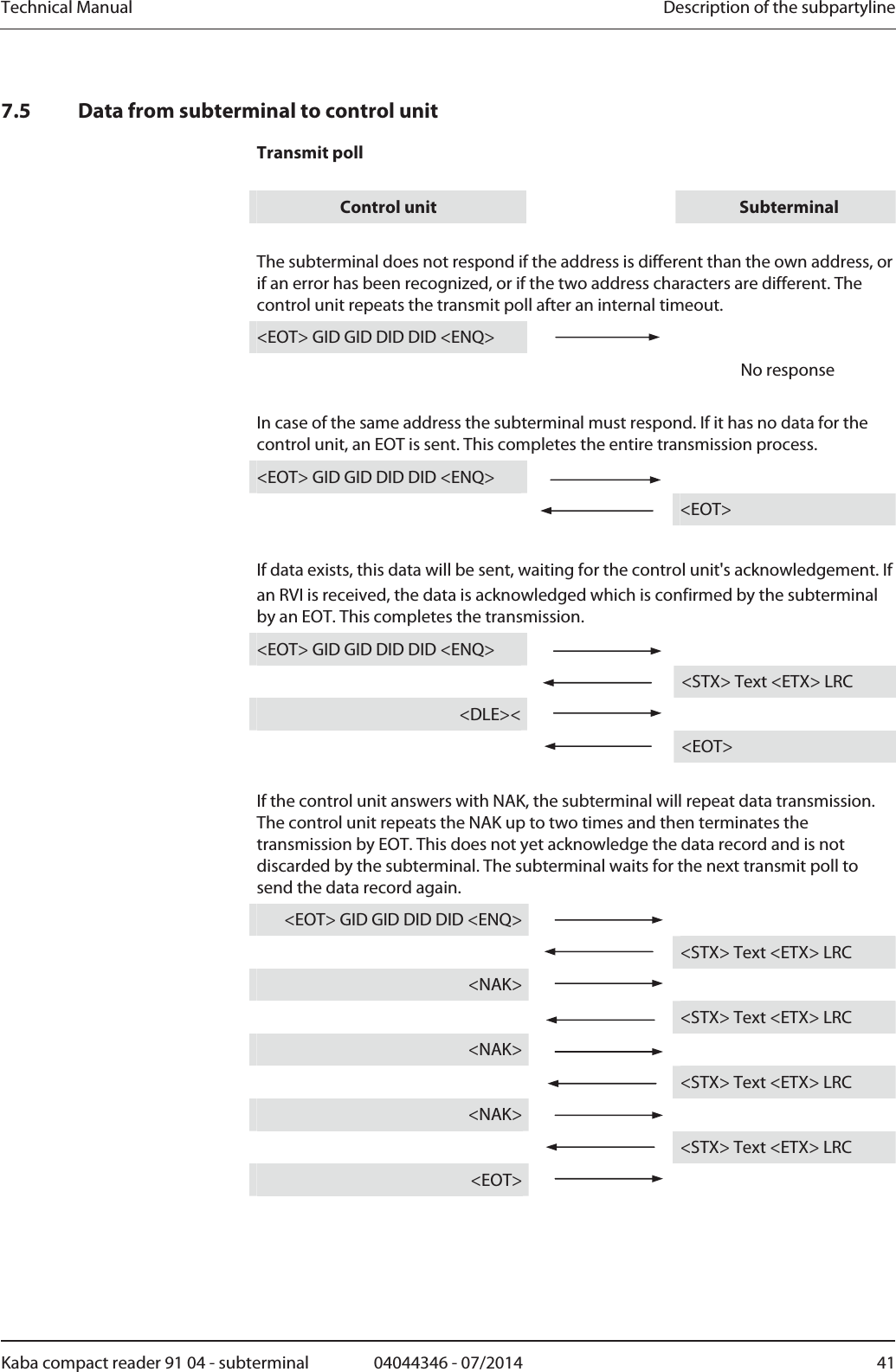
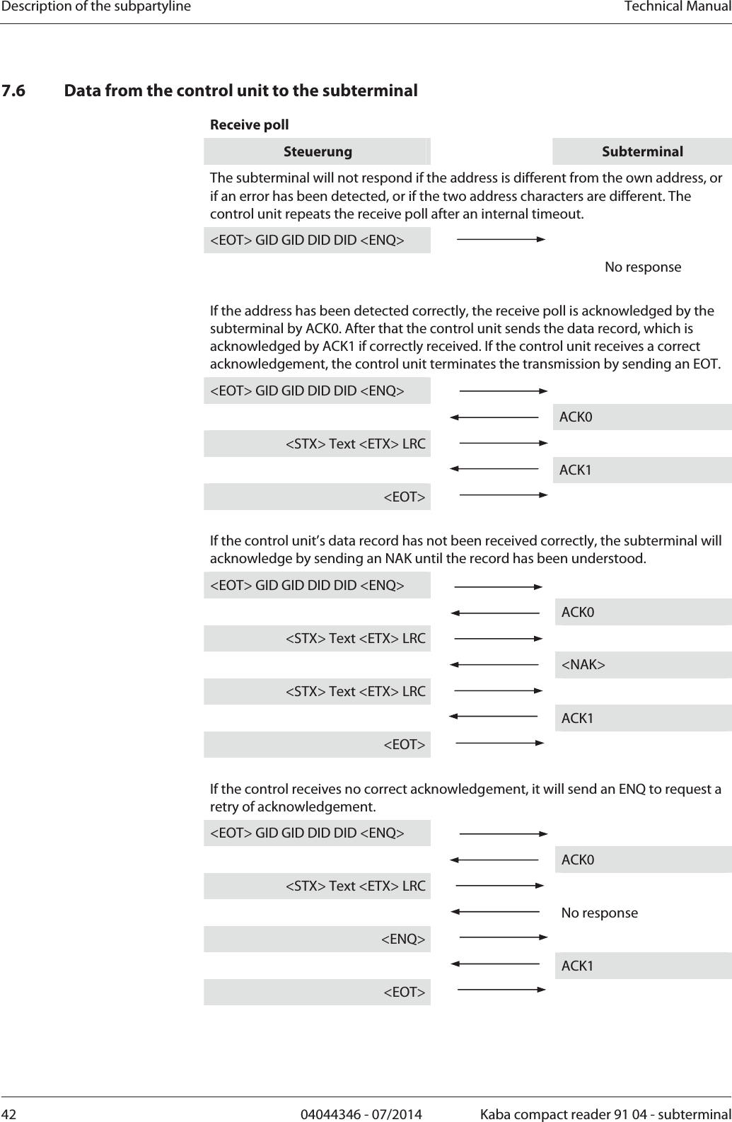
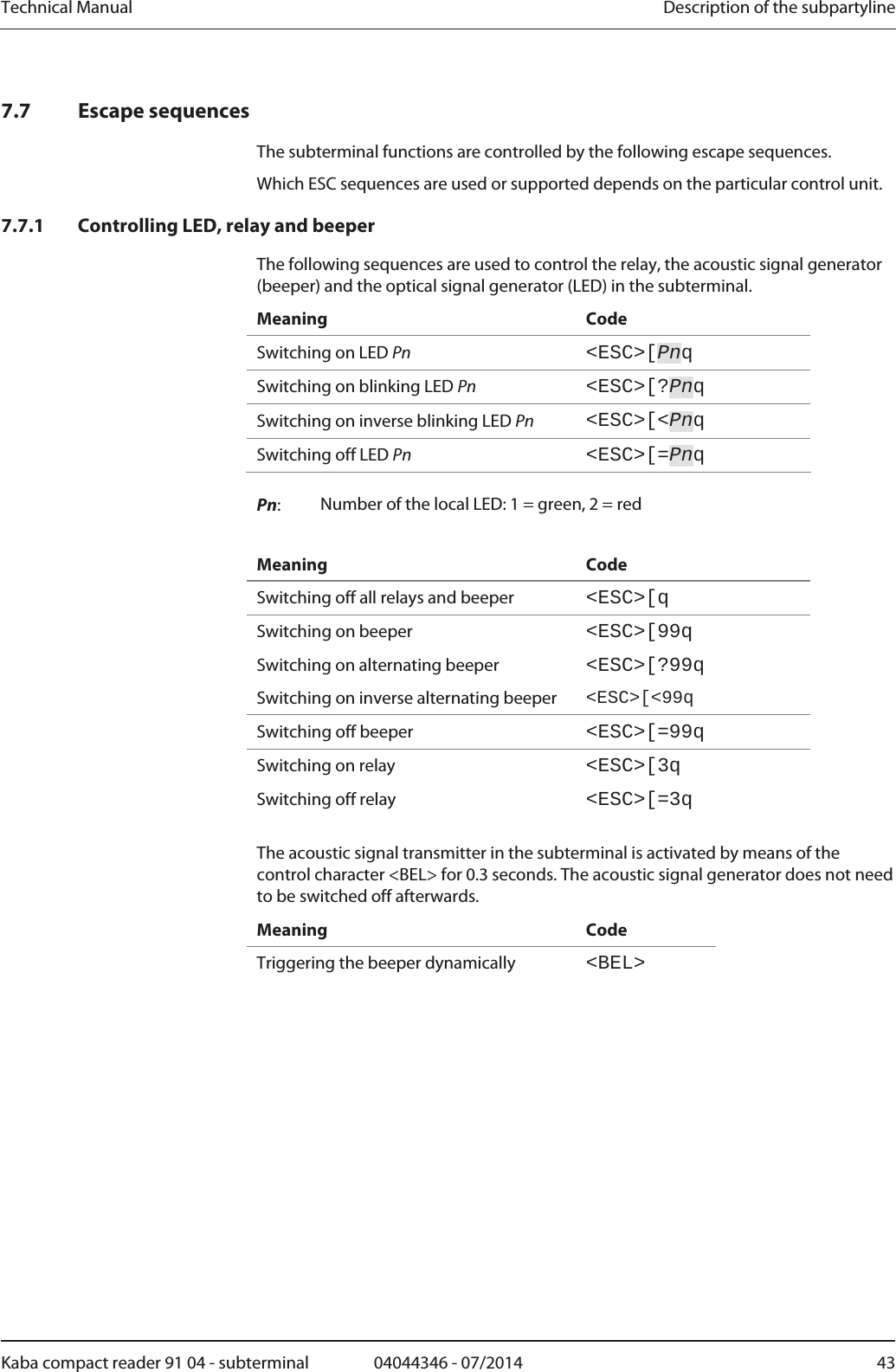
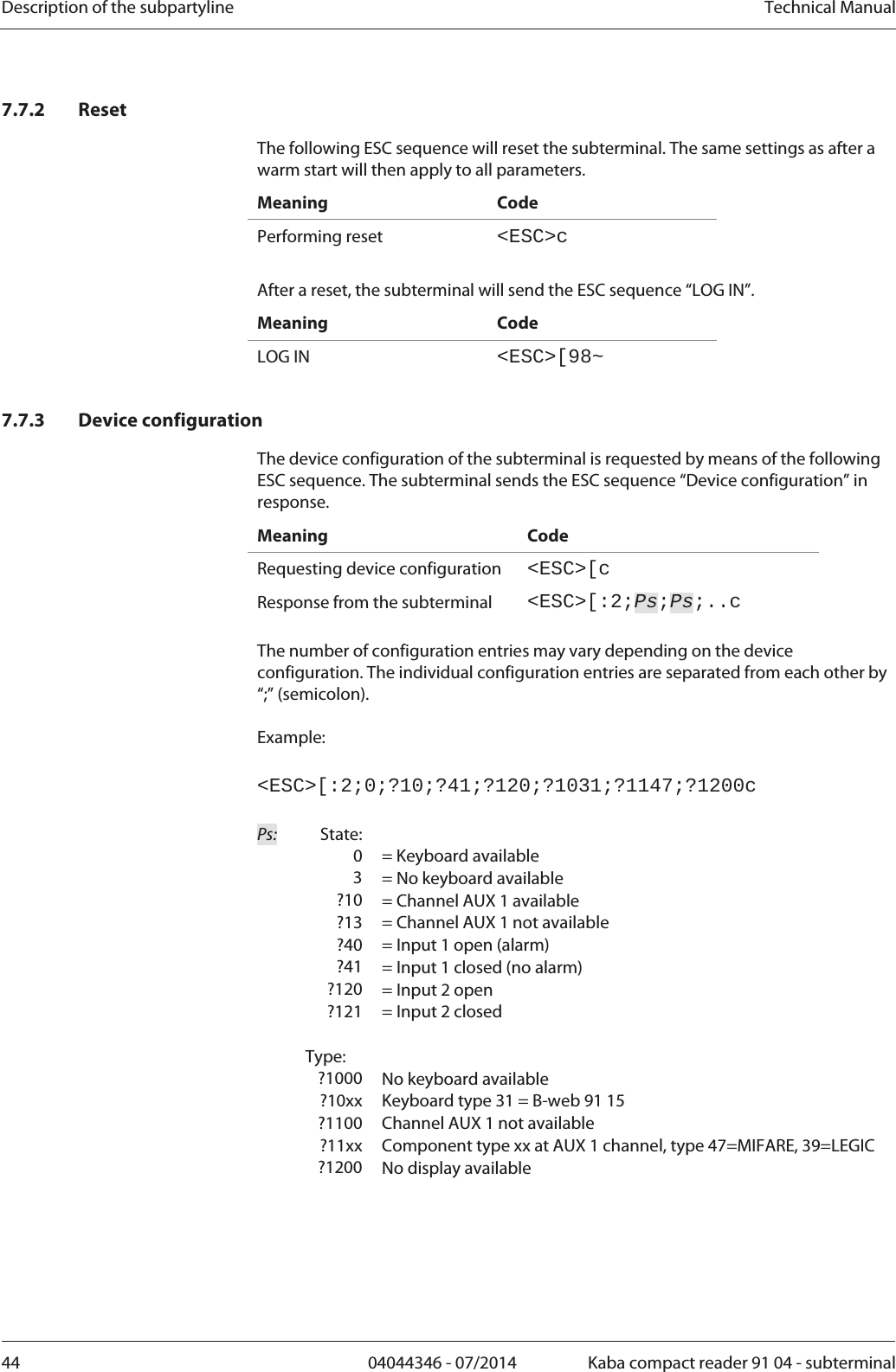
User Manual
Discussion / Help
Navigation