dormakaba EAD KCR9104-L1 RFID Reader User Manual
Kaba GmbH RFID Reader
User Manual

Kaba compact reader 91 04 - subterminal
Technical Manual
04044346 - 07/2014 EN
© Copyright by
Kaba GmbH
Albertistraße 3
D-78056 Villingen-Schwenningen
Phone +49 7720/603-0
Fax +49 7720/603-102
www.kaba.com/workforce-management
All rights reserved. The document and its parts are copyrighted. Only Kaba GmbH has the right to commercialize,
market and distribute this document. This document, or any part of it, may not be copied or reproduced, adapted,
arranged, reworked or modified without the prior consent of Kaba GmbH.
All company, trademark or product names are trademarks or registered trademarks of their respective owners and are
protected.
Subject to technical changes without notice!
Order no. 04044346 - 07/2014
1 About this manual ............................................................................................................................ 5
2 Grouped safety messages................................................................................................................ 7
2.1 Use as directed .....................................................................................................................................................7
2.2 Mounting and Installation................................................................................................................................7
2.3 Service and Maintenance .................................................................................................................................7
2.4 ESD (electrostatic discharge) protective measures..................................................................................8
3 Product description.......................................................................................................................... 9
3.1 Technical data.................................................................................................................................................... 10
3.1.1 Interfaces............................................................................................................................................. 10
3.1.2 Power supply..................................................................................................................................... 10
3.1.3 Reader.................................................................................................................................................. 10
3.1.4 Inputs / Outputs ............................................................................................................................... 10
3.1.5 Umgebungsbedingungen ............................................................................................................ 11
3.1.6 Dimensions ........................................................................................................................................ 11
3.2 Conformity.......................................................................................................................................................... 12
3.3 Labeling............................................................................................................................................................... 13
3.4 Device variants .................................................................................................................................................. 14
3.4.1 RFID reader......................................................................................................................................... 14
3.4.2 Design.................................................................................................................................................. 14
3.5 Terminal software............................................................................................................................................. 14
3.6 Device structure................................................................................................................................................ 15
3.7 System connection .......................................................................................................................................... 16
3.8 System requirements...................................................................................................................................... 17
3.9 Supported features.......................................................................................................................................... 17
3.10 Operating sequence........................................................................................................................................ 18
3.10.1 Badge input........................................................................................................................................ 18
3.10.2 Valid booking .................................................................................................................................... 18
3.10.3 Invalid booking................................................................................................................................. 18
4 Installation ......................................................................................................................................19
4.1 Installation conditions .................................................................................................................................... 19
4.1.1 General ................................................................................................................................................ 19
4.1.2 Installation site.................................................................................................................................. 19
4.1.3 Connections....................................................................................................................................... 19
4.2 Installation diagram......................................................................................................................................... 20
4.3 Installation lines ................................................................................................................................................ 21
4.3.1 Power supply cable ......................................................................................................................... 21
4.3.2 Data line .............................................................................................................................................. 21
4.3.3 Line to the door opener and door contacts............................................................................ 21
4.4 Fastening the base frame .............................................................................................................................. 22
4.5 Connections ....................................................................................................................................................... 23
4.5.1 Compact reader 91 04 with plug-in terminal clamp ............................................................ 23
4.5.2 Compact reader 91 04 with permanently connected connecting cable ...................... 24
4.5.3 Note on the use of door openers................................................................................................ 24
4.6 Setting the switches ........................................................................................................................................ 25
4.6.1 DIP switch ........................................................................................................................................... 25
4.6.2 Rotary switch ..................................................................................................................................... 27
4.7 Final assembly ................................................................................................................................................... 28
4.8 Dismounting ...................................................................................................................................................... 29
5 Start-up ........................................................................................................................................... 30
5.1 Set-up procedure ............................................................................................................................................. 30
5.2 Cold start............................................................................................................................................................. 30
6 System mode .................................................................................................................................. 31
6.1 Function of the system mode...................................................................................................................... 31
6.2 Access to the system mode .......................................................................................................................... 31
6.3 Starting the system mode............................................................................................................................. 31
6.4 Terminating the system mode .................................................................................................................... 32
6.5 Commands ......................................................................................................................................................... 32
6.5.1 SETHWC............................................................................................................................................... 33
6.5.2 GETHWC.............................................................................................................................................. 35
6.5.3 GETPRG................................................................................................................................................ 35
6.5.4 GETKVS ................................................................................................................................................ 35
6.5.5 RUN....................................................................................................................................................... 35
6.5.6 COLD .................................................................................................................................................... 36
6.5.7 ORIGIN ................................................................................................................................................. 36
6.5.8 LOWPAR.............................................................................................................................................. 37
6.5.9 GETDGN .............................................................................................................................................. 38
6.5.10 RSTDGN............................................................................................................................................... 38
7 Description of the subpartyline.................................................................................................... 39
7.1 BPA/9 Subset ..................................................................................................................................................... 39
7.2 Addressing.......................................................................................................................................................... 39
7.3 Control characters and control sequences.............................................................................................. 40
7.4 Data records....................................................................................................................................................... 40
7.5 Data from subterminal to control unit...................................................................................................... 41
7.6 Data from the control unit to the subterminal....................................................................................... 42
7.7 Escape sequences ............................................................................................................................................ 43
7.7.1 Controlling LED, relay and beeper............................................................................................. 43
7.7.2 Reset..................................................................................................................................................... 44
7.7.3 Device configuration ...................................................................................................................... 44
7.7.4 Program number.............................................................................................................................. 45
7.7.5 Recorded data................................................................................................................................... 45
7.7.6 Hex representation of the recorded data................................................................................ 45
7.7.7 Acoustic acknowledgement for reading ................................................................................. 46
7.7.8 Digital inputs ..................................................................................................................................... 46
8 Maintenance ................................................................................................................................... 47
8.1 Updating terminal software ......................................................................................................................... 47
8.1.1 Programming interface.................................................................................................................. 47
8.1.2 Equipment.......................................................................................................................................... 47
8.1.3 Procedure ........................................................................................................................................... 48
9 Packaging / returns ........................................................................................................................ 49
9.1 Complete devices............................................................................................................................................. 49
9.2 Electronic assemblies...................................................................................................................................... 49
9.3 Labeling............................................................................................................................................................... 50
10 Disposal........................................................................................................................................... 51
11 Index................................................................................................................................................ 52

Technical Manual About this manual
Kaba compact reader 91 04 - subterminal 04044346 - 07/2014 5
1 About this manual
Validity This manual describes the Kaba compact reader 91 04 as of
Manufacturing date: April 2014
Terminal software: ARCC01_05RA (LEGIC)
MRCC01_08RA (MIFARE)
Functional type: Subterminal
Addressees This manual is written exclusively for specialists.
The descriptions in this manual are intended for personnel trained by the
manufacturer. The information in this manual cannot substitute the product
training.
The contents of this manual is intended for use by the following groups of people:
• Project manager
Project manager who is responsible for the system and entrusted with
project planning and realization.
• Fitter
Person specialized in mounting and installation.
Person who has an adequate technical training and sufficient experience and
who has been authorized by the manufacturer after completing the training
on the product.
• Service technician
Specialist for initial set-up and maintenance of the installation.
Person who has an adequate technical training and sufficient experience and
who has been authorized by the manufacturer after completing the training
on the product.
• Network administrator
Realizes the set-up of the device within the network and makes sure that the
devices are accessible within the network.
• Software partner
Specialists for connecting the system to the user software by defining
operating and booking sequences, programming the customer applications
and setting the parameters of the devices.
Important!
For reasons of device safety, some of the activities might only be carried out by the
SERVICE PERSON.
Only persons of the groups "Fitter" and "Service technician" have the status of a
SERVICE PERSON according to DIN EN 60950-1:2006.
About this manual Technical Manual
6 04044346 - 07/2014 Kaba compact reader 91 04 - subterminal
Contents and purpose The contents is limited to the assembly, installation, start-up, and basic operation of
the hardware.
Orientation in the manual This manual contains the following orientation aids to facilitate finding of specific
topics:
• The table of contents at the beginning of the manual gives an overview of all
topics.
• The header always contains the respective main chapter.
• An index in the alphabetical order is given at the end of the manual.
Danger categories Remarks with specifications or rules and restrictions to prevent injuries and property
damage are particularly marked.
Please read the danger warnings and user tips carefully. This information will help
prevent accidents and damage to your equipment.
Danger warnings are divided into the following categories.
CAUTION
Describes a possibly dangerous situation that can lead to minor injuries.
NOTICE!
Important information for proper handling of the product.
Ignoring this information can cause device malfunction and the device or something
near it can get damaged.
Symbols Depending on the source of danger, warnings are marked with symbols of the
following meaning.
General danger
Danger for electronic
components due to
electrostatic discharge
Remarks Please pay special attention to the remarks that are marked with symbols.
Tips and useful information.
This information will help you to best use the product and its functionality.

Technical Manual Grouped safety messages
Kaba compact reader 91 04 - subterminal 04044346 - 07/2014 7
2 Grouped safety messages
The device has been built in accordance with state-of-the-art standards and the
recognized safety rules. Nevertheless, its use may constitute a risk to persons and
cause damage to material property.
Read and observe the following safety instructions, before using the product.
2.1 Use as directed
The device or system is only intended for usage as described in chapter ”Product
description.”
Any use beyond the designated use is not according to rules. The manufacturer is not
responsible for damages resulting from improper use. The user/operator is
responsible for any risks associated with non-duly use.
2.2 Mounting and Installation
Mounting and installation may only be carried out by the SERVICE PERSON (see
chapter 1 / Addressees).
Installation may only be carried out in places that fulfill climatic and technical
conditions stated by the manufacturer.
Kaba GmbH is not liable for damages resulting from improper handling or incorrect
installation.
2.3 Service and Maintenance
Maintenance work / troubleshooting
Only the SERVICE PERSON (see chapter 1 / Addressees) is entitled to remove faults
and carry out the maintenance work.
Reconstruction and modification
Any reconstruction and modification of the device may only be realized by the
SERVICE PERSON (see chapter 1 / Addressees). All reconstructions and modifications
carried out by unauthorized personnel shall render void any liability.

Grouped safety messages Technical Manual
8 04044346 - 07/2014 Kaba compact reader 91 04 - subterminal
2.4 ESD (electrostatic discharge) protective measures
NOTICE!
Danger for electronic components due to electrostatic discharge.
Improper handling of printed circuit boards or components can cause damages that
lead to complete failures or sporadic errors.
• During installation and repair of the device, the ESD protective measures must
be considered.
The following rules must be considered:
• Wear an ESD wristband when handling electronic components.
Connect the end of the wristband to a discharge socket or an unvarnished
grounded metal component. This way, static charges are discharged from
your body securely and effectively.
• Touch only the edges of circuit boards. Do not touch the circuit board nor the
connector.
• Place all dismantled components on an antistatic surface or in an antistatic
container.
• Avoid contact between circuit boards and clothing. The wristband only
protects the printed circuit boards against electrostatic discharge from your
body, but there is still a risk of damage through electrostatic discharge from
your clothing.
• Transport and dispatch dismantled modules only in electrostatically shielded
protective bags.
Technical Manual Product description
Kaba compact reader 91 04 - subterminal 04044346 - 07/2014 9
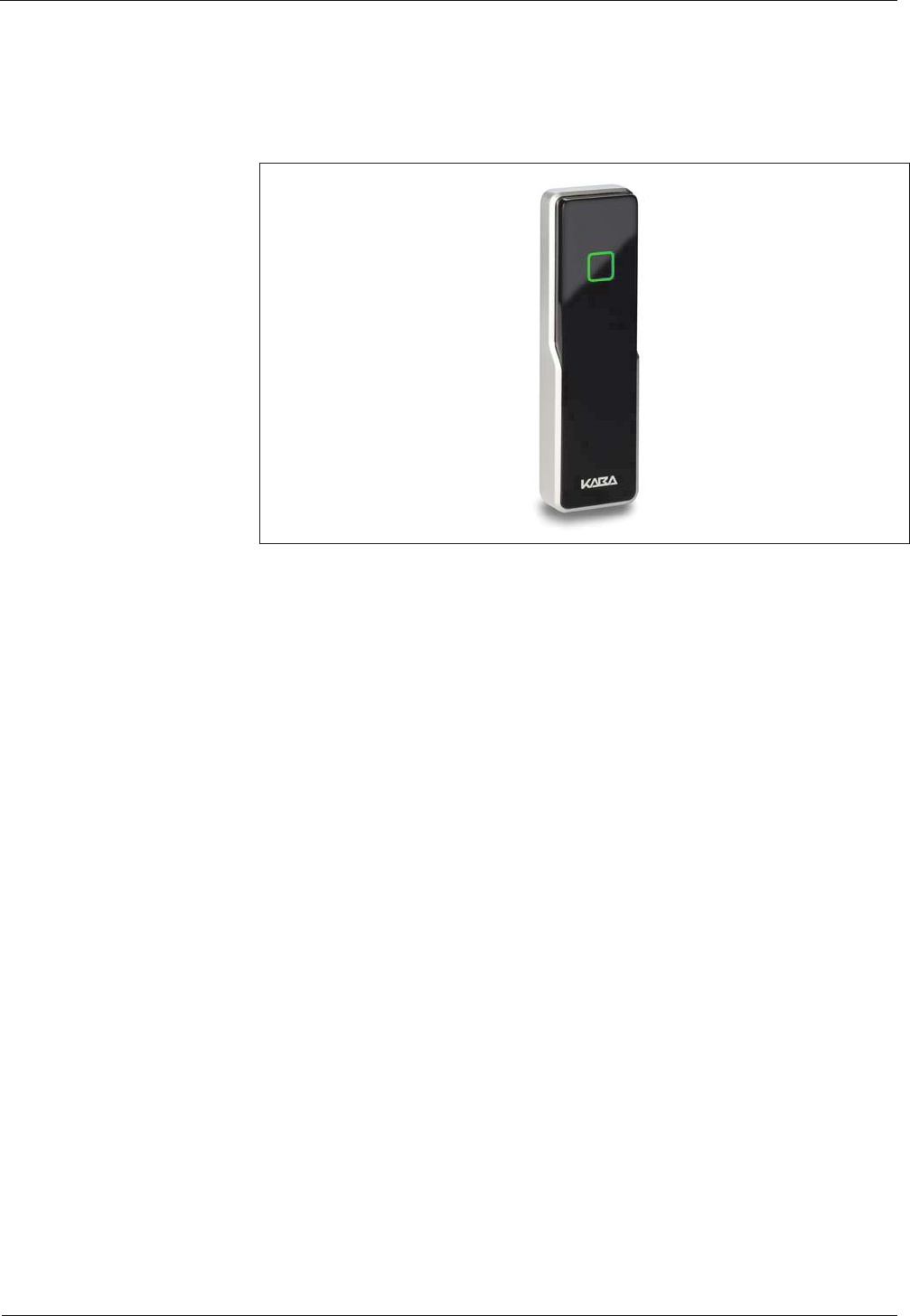
3 Product description
The Kaba compact reader 91 04 has been designed as subterminal for use at a time
and attendance terminal or an access control manager.
The Kaba compact reader 91 04 is installed in an ergonomically suitable position in
secured areas, e.g., in the access area (door).
The integrated RFID reader allows contact-free reading and writing of RFID media in
MIFARE or LEGIC technology (depending on the version).
Communication with the superior access control system or the time and attendance
terminal is performed in the "Online" operating mode via the RS-485 subpartyline.
Depending on settings of the superior control system Access, IN or OUT booking
operations are possible.
The device has 2 digital inputs that can be used in combination with an access
control, e.g., for door frame contact or door-opener. The built-in relay can be used for
door opening in secure areas.
The compact reader is equipped with a light icon (red/green) and a buzzer for optical
and acoustic signaling.

Product description Technical Manual
10 04044346 - 07/2014 Kaba compact reader 91 04 - subterminal
3.1 Technical data
3.1.1 Interfaces
RS-485
RS-485 2-wire subpartyline for communication with the superior access control
system unit or a time and attendance terminal.
• Protocol: BPA/9 Subset.
• Automatic baud rate detection; 9600 / 19200 Baud.
• 7 data bits, even parity, 1 stop bit.
Programming interface
For terminal software update.
3.1.2 Power supply
• Voltage range: 12 – 27 V AC; 10 – 34 V DC
• Power consumption: Typically 1.2 W; max. 2.2 W
3.1.3 Reader
MIFARE version
• RFID standard: ISO 14443A
• Badge media supported:
MIFARE DESfire
MIFARE Classic
LEGIC version
• RFID standard: ISO 14443A, ISO 15693, LEGIC RF
• Badge media supported:
LEGIC advant
LEGIC prime
3.1.4 Inputs / Outputs
1 relay output
• One potential-free changeover contact.
• Contact loading capacity: 30 V AC / DC; max. 2 A.
2 digital inputs
• With integrated power supply and common ground to connect potential-free
contacts.
• Input voltage: max. 5 V DC.
Technical Manual Product description
Kaba compact reader 91 04 - subterminal 04044346 - 07/2014 11
3.1.5 Umgebungsbedingungen
• Ingress protection according to IEC 60529:
IP54 (device variant with plug-in terminal clamp)
IP66 (device variant with permanently connected connecting cable)
• Relative humidity:
5% to 95%, non-condensing
• Ambient temperature:
-25 °C – +70 °C (operation)
-40 °C – +85 °C (storage)
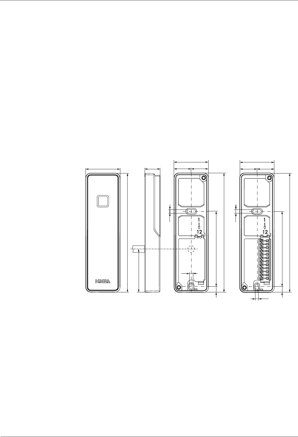
3.1.6 Dimensions
Dimensional drawing compact reader 91 04, dimensions in mm
3.6
3.6
17.5(17.5)
77
6
3.6
17.5(17.5)
3.6
77
6
122
35
35 35
122
122
16
44.5
Outer dimensions Back housing IP66 Back housing IP54
Product description Technical Manual
12 04044346 - 07/2014 Kaba compact reader 91 04 - subterminal
Konf
3.2 Conformity
This device complies with the following standards:
EN 60950-1:2006 + A11:2009
EN 301 489-1 V1.8.1
EN 301 489-3 V1.4.1
EN 300 330-1 V1.7.1
EN 300 330-2 V1.5.1
according to the regulations of the EU Directives
2006/95/EG
Low voltage directive
1999/5/EG
R&TTE Directive
2004/108/EG
EMC Directive
RoHS This device is in conformity with Directive 2011/65/EU of the European Parliament
and of the Council of 8 June 2011 on the restriction of the use of certain hazardous
substances in electrical and electronic equipment.
In addition, the product also conforms to the following standards:
UL 60950-1
UL 294
The components shall be supplied by a limited power source according to chapter
2.5 of IEC 60950-1. When installing/inserting the components in end-use
equipment/system all requirements of the mentioned test standards must be
fulfilled.
The external power supply unit shall be in accordance to UL 294. The secondary
output shall fulfill the requirements for class 2 or class 3 outputs.
UL 294 Security Level 1
FCC ID NVI-KCR9110-L1
This device complies with part 15 of the FCC Rules. Operation is subject to the
following two conditions:
• This device may not cause harmful interference
• This device must accept any interference received, including interference that
may cause undesired operation.
A
ny changes or modifications not expressly approved by the party responsible fo
r
compliance could void the user's authority to operate the equipment.
FCC ID NVI-KCR9104-L1
FC
C
ID
N
VI
-K
CR
91
10
-L
1
FCC ID NVI-KCR9104-L1
FCC
I
D
NVI
-
KCR
9
1
0
4
-L
1

Technical Manual Product description
Kaba compact reader 91 04 - subterminal 04044346 - 07/2014 13
3.3 Labeling
The identification plate is located on the rear of the device.
Specified on the identification plate:
• Device name
• Product number
• Serial number
• Power data
• CE identification
• WEEE labeling acc. to DIN EN 50419
Product description Technical Manual
14 04044346 - 07/2014 Kaba compact reader 91 04 - subterminal
3.4 Device variants
3.4.1 RFID reader
The compact reader 91 04 is available with the following RFID reader types:
• MIFARE
• LEGIC
3.4.2 Design
The device is available in two designs:
• With permanently connected connecting cable (IP66 version).
• With plug-in terminal clamp (IP54 version).
3.5 Terminal software
The hardware of the Kaba compact reader 91 04 is used in various Kaba system
solutions. Type of use and functions of the device are determined by the software
used:
This description of the Kaba compact reader 91 04 only refers to the terminal
software for online operation as a subterminal.
Designation of the terminal software
The software designation has the following meaning:
Reader type M
A
MIFARE
LEGIC
Device type RC Compact reader
Operating mode A
B
C
Standalone
Access manager
Subterminal
Version number 01.00 Version
Addition 1 R Released
Addition 2 A Subversion
Addition 3 _ Reserve
Examples:
MRCC01.08RA_ Terminal software for MIFARE compact reader.
ARCC01.05RA_ Terminal software for LEGIC compact reader.
Labeling of the device
"Type: Subterminal" is written on the identification plate of devices using the
terminal software for online operation as a subterminal.
Technical Manual Product description
Kaba compact reader 91 04 - subterminal 04044346 - 07/2014 15
3.6 Device structure
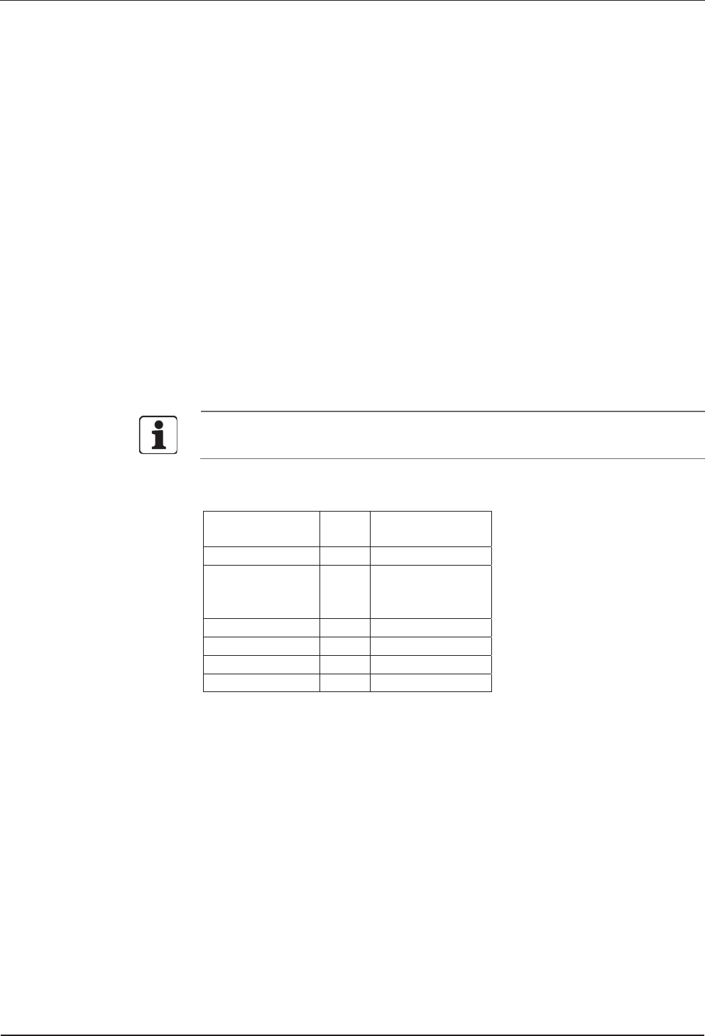
Compact reader 91 04 with permanently connected connecting cable
(IP66 version)
4
3
2
1
1 Front cover
2 Sealing plug for the DIP switch
3 Core device with electronics and permanently connected connecting cable
length 3.5 m
4 Base frame
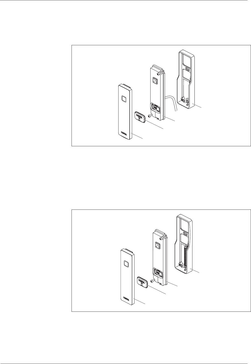
Compact reader 91 04 with plug-in terminal clamp (IP54 version)
4
3
2
1
1 Front cover
2 Sealing plug for the DIP switch
3 Core device with electronics
4 Base frame with plug-in terminal clamp
Product description Technical Manual
16 04044346 - 07/2014 Kaba compact reader 91 04 - subterminal
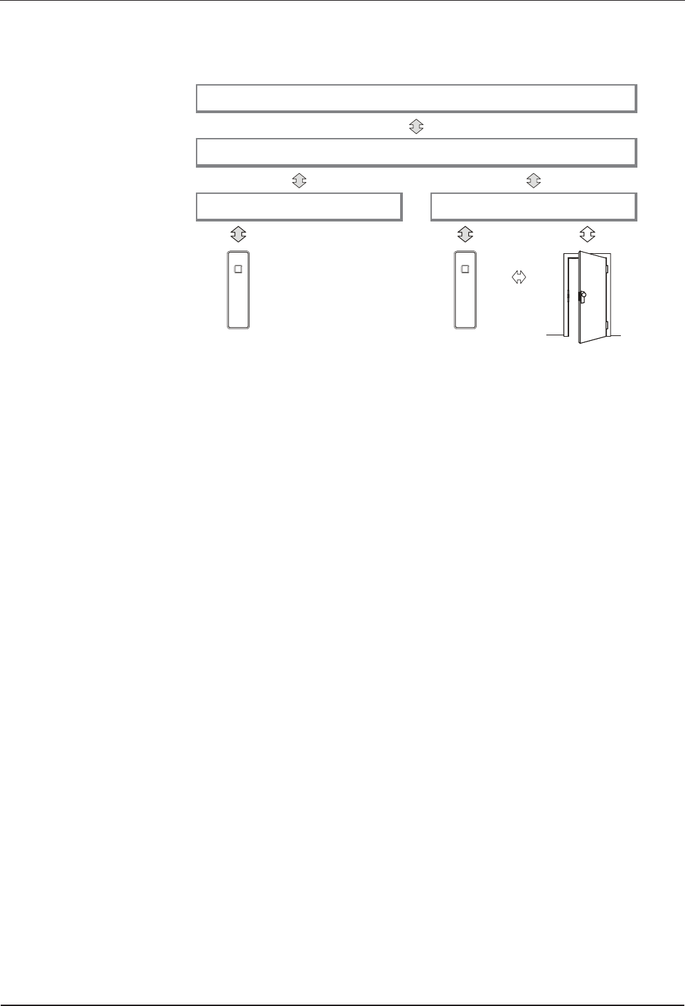
3.7 System connection
Customer application
B-COMM communications software
Time and attendance terminal Access control manager
Compact reader
The compact reader operates as a subterminal of a superior time and attendance
terminal or an access control system, which control system in the following text.
Data exchange takes place via the RS-485 interface (subpartyline). Communication
takes place via the transmission protocol BPA/9 subset.
Once the subterminal has been switched on, it will be initialized. This process
includes setting the parameters of the reader driver, thus defining the method for
transferring badge data to the entry data record.
The subterminal can be used for Access, IN, or OUT booking operations.
The compact reader itself has no decision-making authority and is to be considered
as a separate operating unit. Once a valid RFID medium (badge) is detected, a
corresponding badge data record will be sent to the control system. The control
system will decide whether a badge is authorized or not and return the respective
commands for signaling (acoustic signal generator and luminous ring) and relay
control to the subterminal.
The built-in relay can be used to trigger the door opener. The inputs may be used for
door monitoring in combination with an access control system.

Technical Manual Product description
Kaba compact reader 91 04 - subterminal 04044346 - 07/2014 17
3.8 System requirements
Communication software
• B-COMM version 2.10 and higher
Control
• Terminal of the B-web 93 00 series with B-Client HR10 terminal software
version 754-00-X-K02 and higher.
• B-Net 92 50 access control manager with B-Client AC2 terminal software
version 664-03-X-K03 and higher.
• B-Net 92 90 access control manager with B-Client AC3 terminal software
version 666-03-X-K03 and higher.
• B-Net 92 90-2 access control manager with B-Client AC3 terminal software
version 668-00-X-K04 and higher.
3.9 Supported features
Depending on the system connection, the following functional elements are
supported:
HR = B-web 93 00 time and attendance terminal with B-Client HR10 terminal
software.
AC = Access control unit with B-Client AC2/3 terminal software.
HR AC
Inputs - X
Outputs X X
CardLink update - -
CardLink validation and invalidation - X
Distribution of site keys via download
(ARIOS security concept)
X -
Product description Technical Manual
18 04044346 - 07/2014 Kaba compact reader 91 04 - subterminal
3.10 Operating sequence
The exact operating sequence at the subterminal is defined by the parameters set for
the superior control unit. The operating sequences described below correspond to
the default settings.
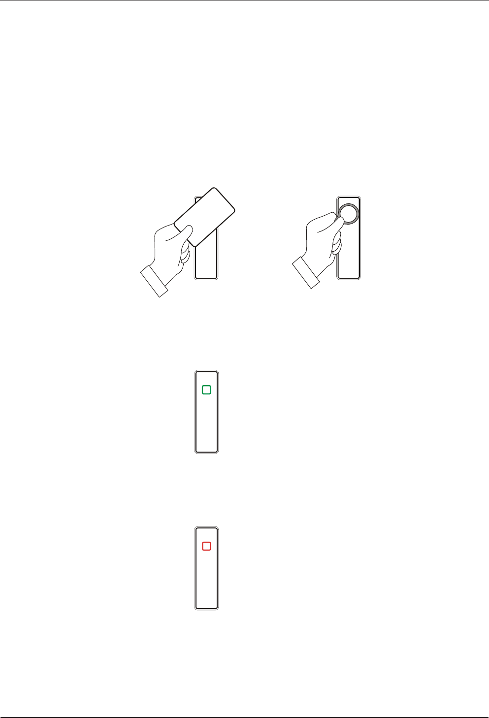
3.10.1 Badge input
The luminous ring is green while the reader is in idle state. A booking operation is
started by a badge input.
The contactless media are simply held in front of the terminal.
3.10.2 Valid booking
If the booking is valid, a short acoustic signal is emitted, and the luminous ring blinks
once in green.
• short acoustic signal
• luminous ring blinks once
3.10.3 Invalid booking
If the booking is invalid, an alternating acoustic signal is emitted for about 5 seconds
while the luminous ring is blinking in red.
• alternating acoustic signal
• luminous ring blinks in red
Duration approx. 5 seconds

Technical Manual Installation
Kaba compact reader 91 04 - subterminal 04044346 - 07/2014 19
Installation
4 Installation
4.1 Installation conditions
4.1.1 General
An accurate installation of all components is a basic requirement for a properly
functioning device. The following installation instructions must be adhered to.
4.1.2 Installation site
The compact reader is installed in an ergonomically suitable position, e.g., in the
access area (door).
The compact reader is mounted directly on the wall or on the door frame.
In the device variant with permanently connected connecting cable, the cable must
be led to the back into the wall.
In the device variant with plug-in terminal clamp, the cable feed can take place from
behind (flush-mounted cable routing) or from below (surface-mounted cable
routing).
Clearances
Between two compact readers, a distance of 20 cm must be observed on all sides.
Mounting height
Recommended mounting height 110 cm to top edge of the compact reader.
Electromagnetic fields
The device must not be installed in the area of strong electromagnetic fields caused
by switching power supply, power lines, phase controllers, etc.!
Electromagnetic fields can affect the reading power or cause failures, in particular
with contactless RFID readers.
4.1.3 Connections
The following connectors must be prearranged at the installation site.
• Power supply for the compact reader.
• Data line to the control unit.
• Signal lines to door openers and door contacts (if required).
Installation Technical Manual
20 04044346 - 07/2014 Kaba compact reader 91 04 - subterminal
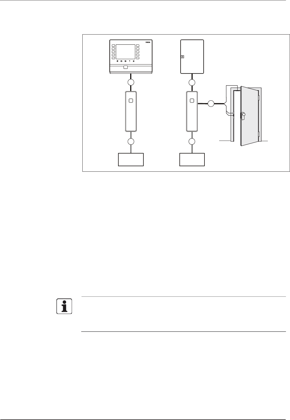
4.2 Installation diagram
123
456
789
C0 E
6
A
B
1
3
4
5
3
4
2
B
A
C
1 B-web 93 00 time and attendance terminal
2 access control manager
3 Compact reader 91 04
4 Power supply
5 Door frame contact
6 Door contact, door opener
Installation lines
A Data line
B Power supply cable
C Cable to the door opener and to the door contacts (if required)
In the example top right, the relay in the subterminal is used for door opening. This
is only recommended in secure areas.
Alternatively, the door opening can take place via an internal relay of the terminal
or of the access control manager.

Technical Manual Installation
Kaba compact reader 91 04 - subterminal 04044346 - 07/2014 21
4.3 Installation lines
4.3.1 Power supply cable
Power is normally supplied to the subterminal by the superior access control manger
and can be tapped easily from there.
A separate power supply needs to be provided if the subterminal is connected to a
B-web time and attendance terminal.
For distances up to 20 meters max., it is permitted to have the power supply for the
subterminal and the data line in one single cable. A separate power supply cable
needs to be provided for longer distances.
Recommended cable: 1 x 2 x 0.6 mm or 1 x 2 x AWG 24.
In case of long lines, the voltage drop - caused by the line resistance - must be
considered.
4.3.2 Data line
The communication with the superior control unit is performed via the RS-485 2-wire
subpartyline.
The complete bus network (master lines and stubs) may be up to 1,200 meters
long. One stub must not exceed 100 m.
Line requirements: Shielded line with twisted wire pairs,
for instance standard telephone cable J-Y (St) Y 2 x 2 x 0.6 mm.
Recommended cable: CAT.5 S/UTP 4 x 2 AWG 24 or AWG 22 (according to
EIA/TIA568).
4.3.3 Line to the door opener and door contacts
Line requirements: Cable diameters from 0.5 mm to 0.8 mm.
Recommended cable: CAT.5 S-UTP 4 x 2 AWG 24 or AWG 22 (according to
EIA/TIA568) or higher.
Installation Technical Manual
22 04044346 - 07/2014 Kaba compact reader 91 04 - subterminal
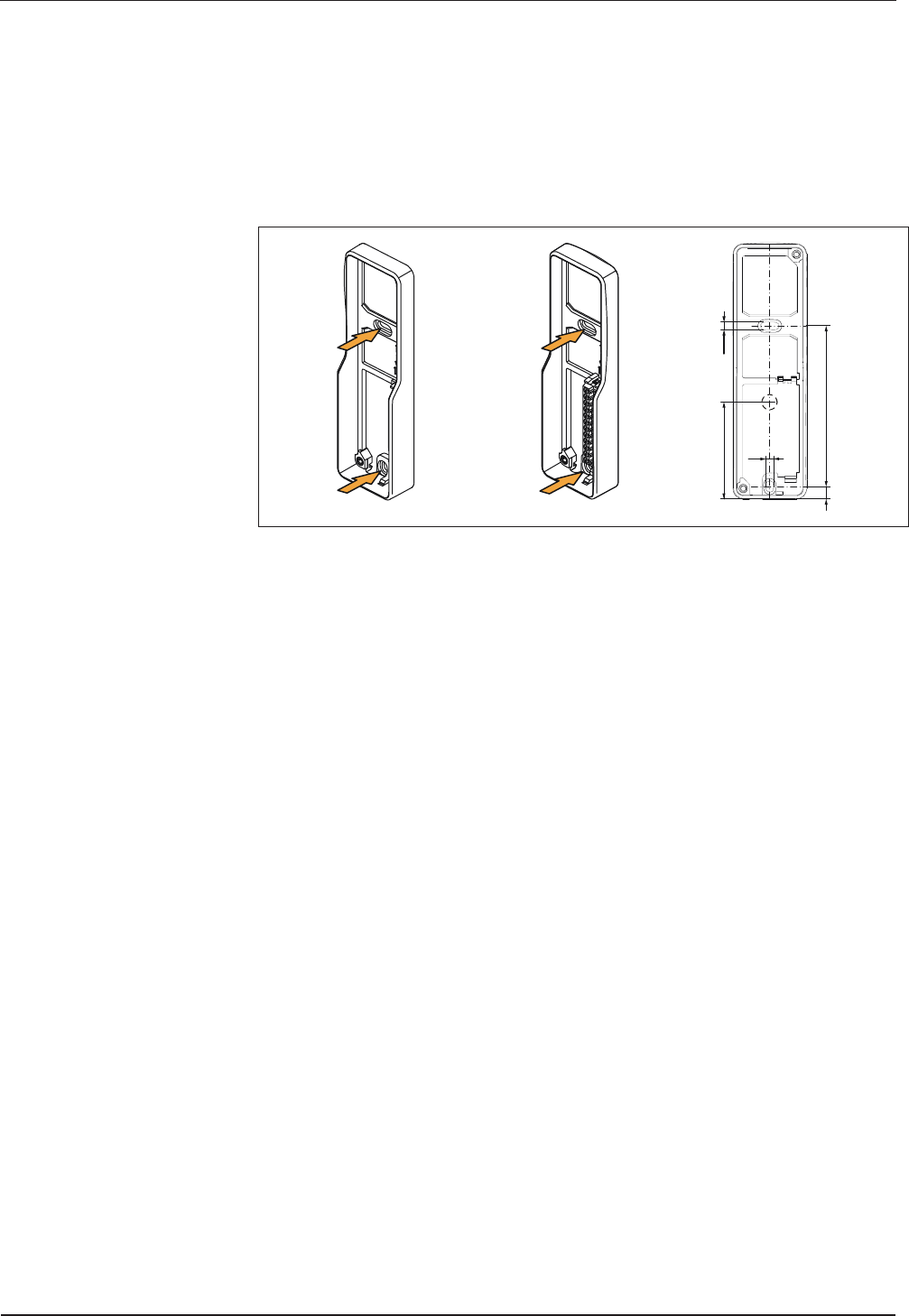
4.4 Fastening the base frame
The base frame is mounted directly on the wall or on the door frame.
For fastening, two long holes (arrow) are provided in the base frame. Depending on
the surface, screws/dowels or self-tapping screws are used for fastening.
For cable feed from behind, ensure correct position via hole or empty tube.
3,6
3,6
77
6
44,5
The base frame may not be mounted twisted. The screws may only be tightened
slightly. The base frame may not be deformed or bent.
In the case of soft mounting surfaces, make sure that when installed, the base frame
is not pressed into the mounting surface.
The unevenness of the mounting surface must be compensated for or adjusted by
means of suitable measures (e.g. washers).
Technical Manual Installation
Kaba compact reader 91 04 - subterminal 04044346 - 07/2014 23
4.5 Connections
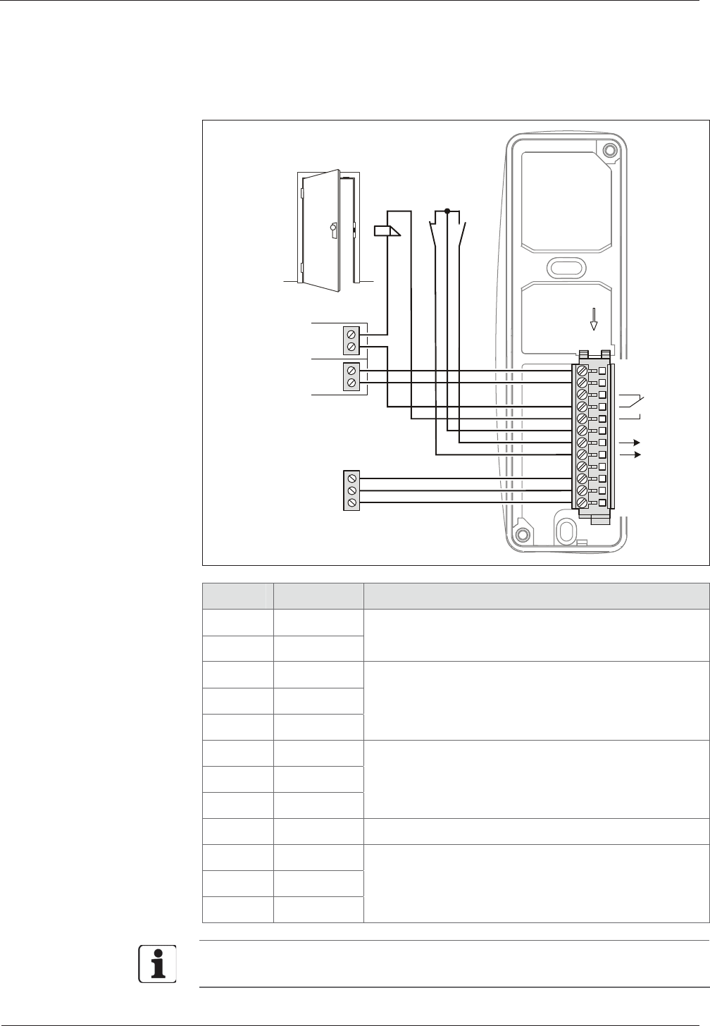
4.5.1 Compact reader 91 04 with plug-in terminal clamp
24 V
12 V
A
B
C
B-Net 92 90
B-Net 92 50
B-web 92 90
B-web 93 00
A
OUT
IN2
DC- /AC
B
C
IN1
GND
DC+/AC
RS-48
5
1
12
Terminal Assignment Description
1 DC- / AC
2 DC+ / AC
Power supply input 12 – 27 V AC; 10 – 34 V DC
3 NC
4 COM
5 NO
Relay output, contact load 30 V AC/DC, max. 2 A.
6 GND
7 IN1
8 IN2
Digital inputs
The inputs are connected to common ground using a
simple switch or relay contact.
9 -
10 A
11 B
12 C
RS-485 subpartyline,
data interface to the superior control unit.
The function of inputs and outputs depends on the control unit used and its
parameter setting.

Installation Technical Manual
24 04044346 - 07/2014 Kaba compact reader 91 04 - subterminal
4.5.2 Compact reader 91 04 with permanently connected connecting cable
The wires of the connecting cable have different colors.
The following table shows the assignment on the basis of the wire color.
Color Assignment Description
blue DC- / AC
red DC+ / AC
Power supply input
12 – 27 V AC; 10 – 34 V DC.
yellow NC
green COM
orange NO
Relay output, contact load 30 V AC/DC, max. 2 A.
white GND
white/black IN1
gray IN2
Digital inputs
The inputs are connected to common ground using
a simple switch or relay contact.
white/red -
brown A
violet B
black C
RS -485 subpartyline,
data interface to the superior control unit.
rose Shield
4.5.3 Note on the use of door openers
The relay can be used for activating the door opener. For door openers supplied with
direct voltage, a freewheeling diode must be connected in parallel to suppress
interference (in reverse direction). A varistor must be connected in parallel to AC
door openers.
Technical Manual Installation
Kaba compact reader 91 04 - subterminal 04044346 - 07/2014 25
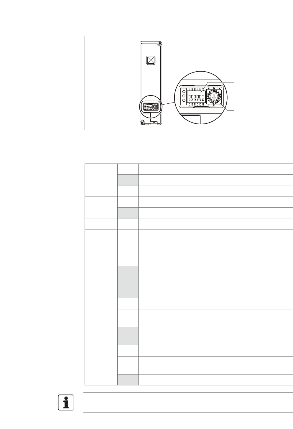
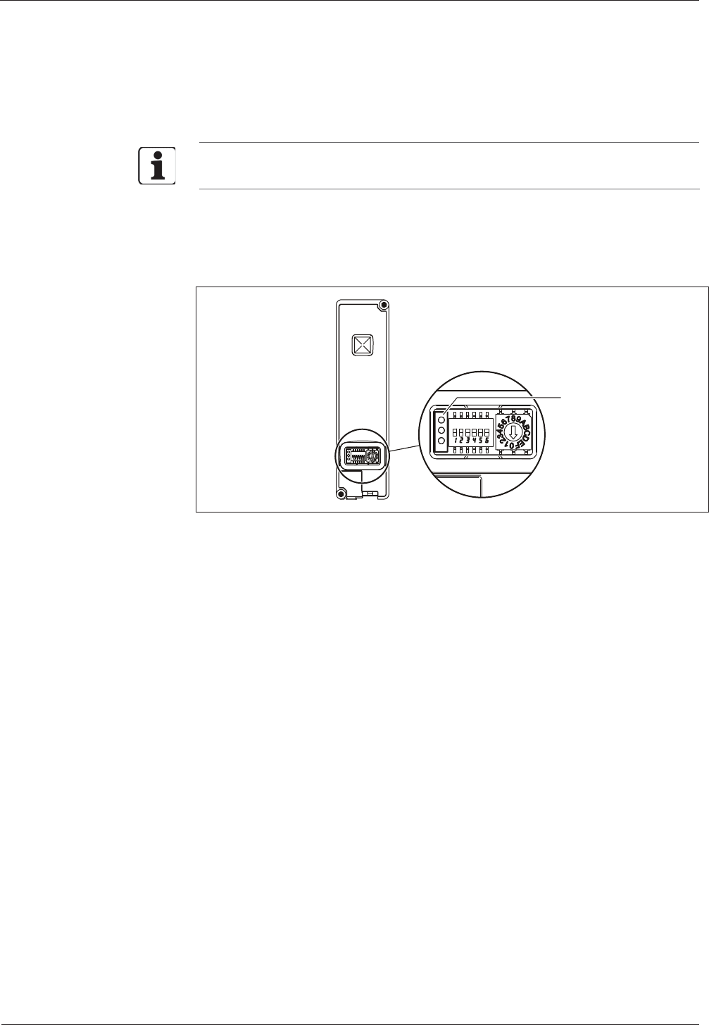
4.6 Setting the switches
1
2
A DIP switch (1) and a rotary switch (2) are located on the front of the compact
reader.
4.6.1 DIP switch
RS-485 bus termination
ON Terminating resistor 4.7 kOhm (star topology)
Switch 1
OFF Open
ON Bus terminating resistor 120 Ohm Switch 2
OFF Open
Switch 3 Not used
Rotary switch settings
ON The interface parameters and the GID/DID, set in system
mode by means of the LOWPAR command, are active
(special applications).
Switch 4
OFF The device address DID set by means of the rotary switch is
active, the GID group address is always 00. The baud rate of
the subpartyline 9600 or 19200 is detected automatically by
the remote reader.
System mode
ON The device is started in system mode after switch-on
(Service/Setup).
Switch 5
OFF The terminal software is started after switch-on (normal
start).
Cold start
ON A cold start is performed after switch-on and the update
mode is started.
Switch 6
OFF Normal start.
The switch positions needed for normal operation as a subterminal are shown in
bold with a gray background.
Installation Technical Manual
26 04044346 - 07/2014 Kaba compact reader 91 04 - subterminal
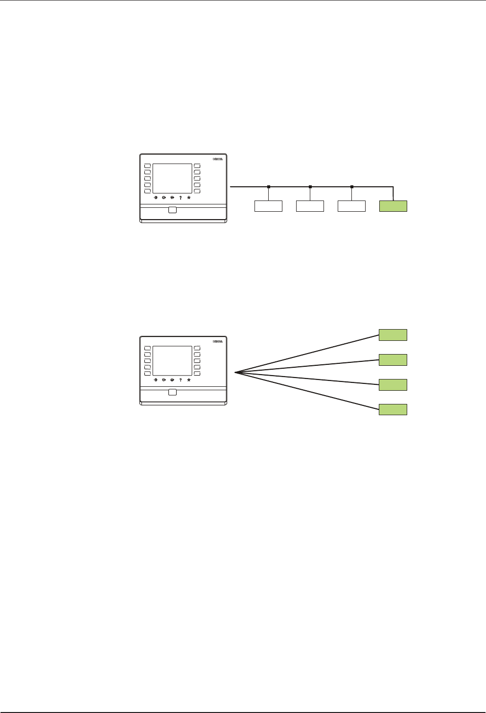
4.6.1.1 RS-485 bus termination
The RS-485 terminating resistor is set via DIP switches 1 and 2.
The selection of the terminating resistors depends on the connection architecture.
Bus wiring
In the example, the subterminals (2) are connected to the superior control (1) via a
bus.
120
open open open
1
2
123
456
789
C0 E
The last terminal at the bus requires a 120-ohm terminating resistor.
Star wiring
In the example, the subterminals (2) are connected to the superior control (1) via a
star topology.
4k7
4k7
4k7
4k7
1
2
123
456
789
C0 E
All subterminals require a 4.7-kohm terminating resistor.

Technical Manual Installation
Kaba compact reader 91 04 - subterminal 04044346 - 07/2014 27
4.6.2 Rotary switch
A device is addressed via the RS-485 subpartyline by means of the group address and
device address.
The rotary switch is used to set the logical device address (DID) of the subterminal.
The GID logical group address is fixed to 00 and cannot be changed.
Position DID
0 16
1 01
2 02
3 03
4 04
5 05
6 06
7 07
8 08
9 09
A 10
B 11
C 12
D 13
E 14
F 15
Installation Technical Manual
28 04044346 - 07/2014 Kaba compact reader 91 04 - subterminal
4.7 Final assembly
After the connections have been made and the switches have been set, the final
assembly of the compact reader is carried out.
In case of cable feed from below:
• Break off the tab at the inside cover.
Carrying out the final assembly:
1.Place core on the base frame and screw it down.
2.Insert sealing plug
3.Hang in front cover at the top and then press it at the bottom into the base
frame until it locks into place.
1. 2. 3.
This completes the installation process.
Technical Manual Installation
Kaba compact reader 91 04 - subterminal 04044346 - 07/2014 29
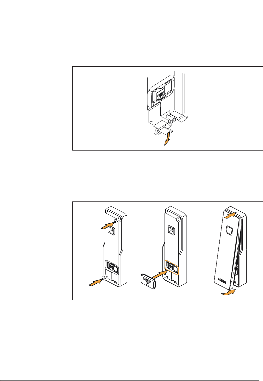
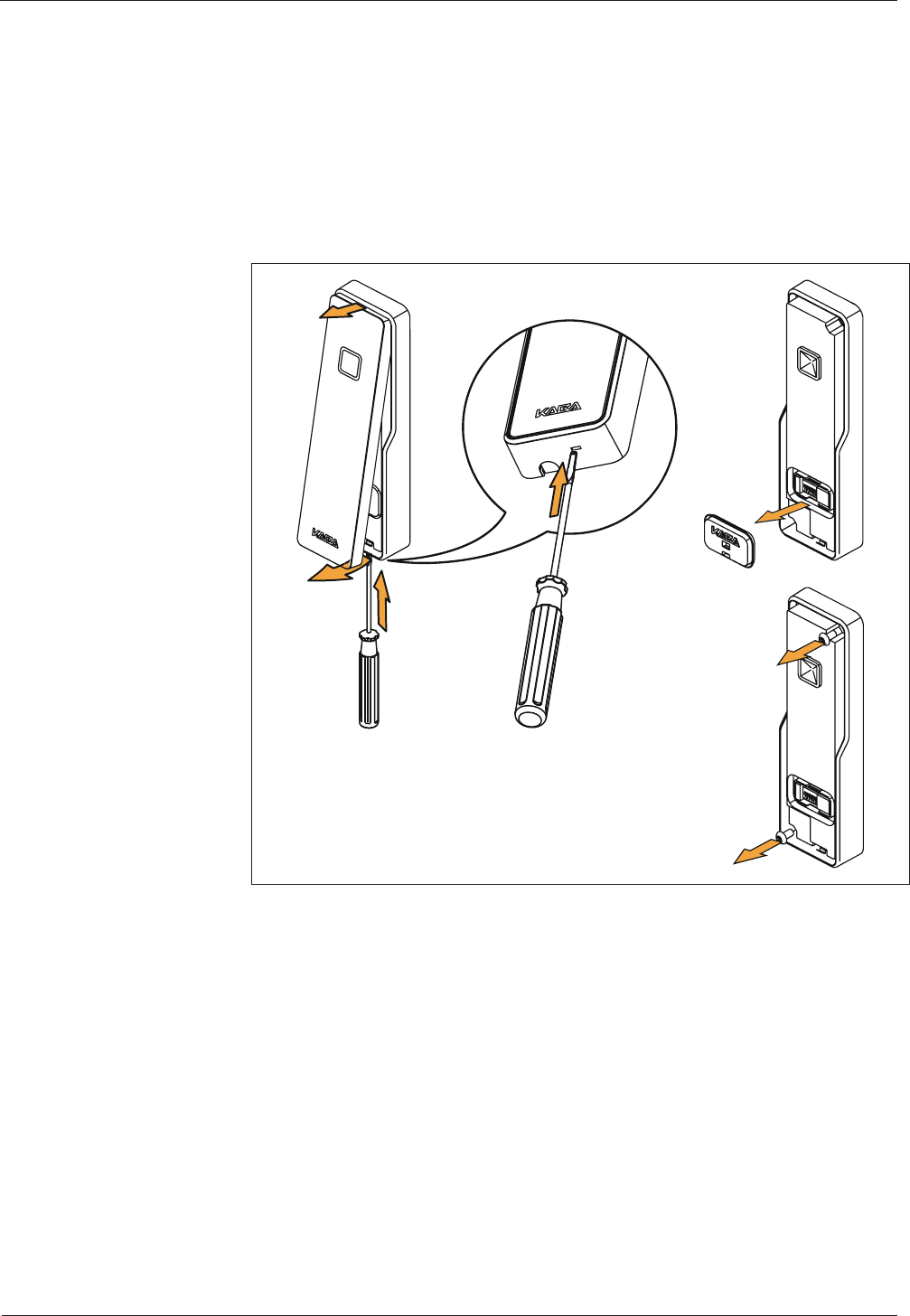
4.8 Dismounting
Dismounting the compact reader:
1.Unlock the locking tab of the front cover using a small screwdriver. Lift off the
front cover at the bottom and then disengage it at the top and remove it.
2.Remove the sealing plug (if required)
3.Unscrew the fastening screws and remove the core from the base frame.
1. 2.
3.

Start-up Technical Manual
30 04044346 - 07/2014 Kaba compact reader 91 04 - subterminal
5 Start-up
5.1 Set-up procedure
1.Switch on the power supply
2.Log the subterminal on to the control unit in B-COMM and put it into
operation.
3.Carry out a functional test.
5.2 Cold start
The device is reset to default (factory) settings by means of a cold start.
How to perform a cold start:
• Turn off the device.
• Set DIP switch 6 to ON.
• Turn on the device.
An acoustic signal can be heard; after approx. 3 seconds, the luminous ring
blinks alternately in red and green.
• Turn off the device.
• Set DIP switch 6 to OFF.
• Turn on the device.
The device is now again in normal operation mode.
Technical Manual System mode
Kaba compact reader 91 04 - subterminal 04044346 - 07/2014 31
6 System mode
6.1 Function of the system mode
The system mode allows setting additional parameters for the device.
Default (factory) parameters can be modified in system mode. However, the
parameters need only to be modified via the system mode for special applications.
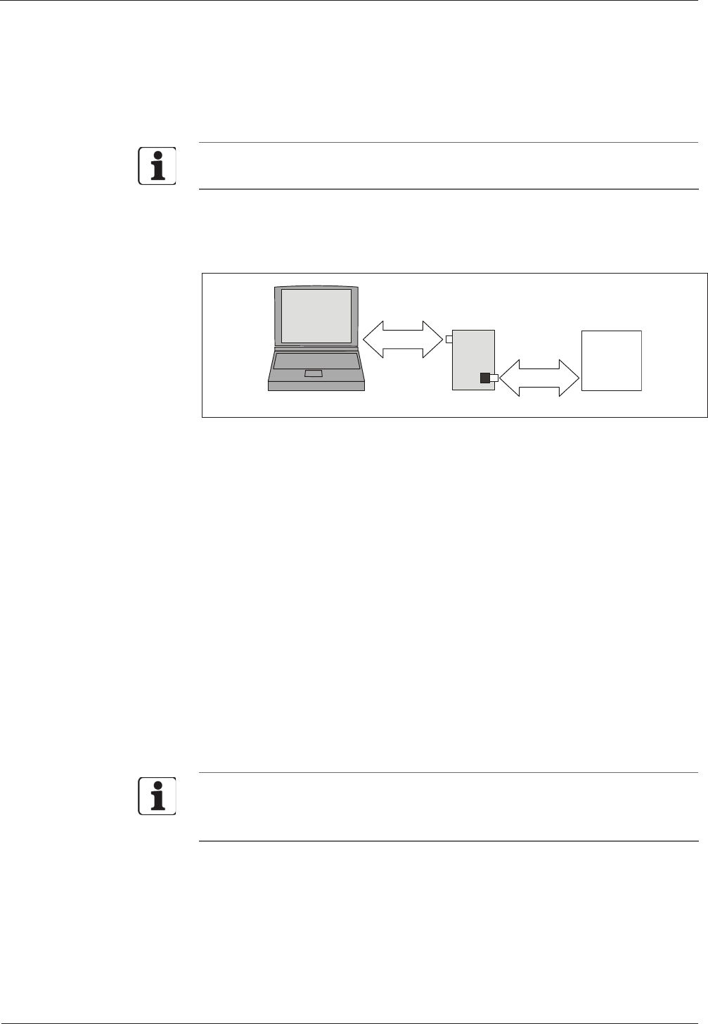
6.2 Access to the system mode
It can be accessed via the data interface of the device. A service PC is connected by
means of the parameter setting tool, order number 04036126.
Subterminal
Para-Tool
Service-PC
RS-232C
RS-485
For communication with the system mode, a standard terminal software, e.g.
HyperTerminal, is used on the service PC.
The connection is established with the following communication parameters:
Baud rate: 9600 Baud
Parity: even
Data bits: 7
Stop bits: 1
6.3 Starting the system mode
Start the device in system mode.
1. Turn off the device.
2.Set DIP switch 5 to ON (see chapter 4.6.1).
3.Turn on the device.
The device starts in system mode.
After starting system mode, the device replies with the prompt (<CR>, <LF>, '>') in
the terminal software window.
The luminous ring blinks red while the device is in system mode.

System mode Technical Manual
32 04044346 - 07/2014 Kaba compact reader 91 04 - subterminal
6.4 Terminating the system mode
Terminate the system mode and start the device with terminal software (normal
start).
1.Turn off the device.
2.Set DIP switch 5 to OFF (see chapter 4.6.1).
3.Turn on the device.
The device starts with the terminal software.
The system mode is not terminated automatically with a timeout.
6.5 Commands
Commands only contain capital letters and terminate with <CR>.
When entering commands, the characters following the command are ignored, as
parameters might follow if the device is provided with an operating system. A wrong
command is shown as follows:
Command not found
>_
Once a command has been called successfully, it will be processed.
Upon termination of a command, the device terminal displays a prompt.
If the output of a command is too large for the screen, the stopped output can be
continued with <CR> (Enter key).
If an error is detected upon termination of the command, an error message will be
displayed before outputting the prompt:
Write Error
>_
After entering <BS> (backspace key) or <DEL> (delete key), the last entered character
is deleted and the cursor is put back one character.
All entered characters are sent back as echo.
It is checked whether the parameters are correct, and only correct parameters are
applied. The parameters are only accepted if the format (length) is strictly adhered to.
Before entry, a parameter description is displayed. The currently valid parameter
values, surrounded by simple quotation marks ('parameter'), are then transmitted.
Preset parameters can be applied by means of <CR> (Enter key).
The character '_' represents the cursor in the following examples.

Technical Manual System mode
Kaba compact reader 91 04 - subterminal 04044346 - 07/2014 33
6.5.1 SETHWC
The SETHWC command (Set Hardware Configuration) is used to enter the parameters
defining the device hardware.
After having changed hardware parameters, a cold start must be performed to
enable the parameters.
Example:
>SETHWC
Protocol
Type : '01' : 01
Keyboard
Type : '31' : 31
AUX 1
Type : '47' : 47
CIR : '00' : 00
LEDs
Number : '02' : 02
Outputs
Number : '01' : 01
Inputs
Number : '02' : 02
Buzzers
Number : '01' : 01

System mode Technical Manual
34 04044346 - 07/2014 Kaba compact reader 91 04 - subterminal
6.5.1.1 Description of the parameters
Protocol type:
2-digit protocol to control unit (data interface) Default
00 No protocol
01 BPA/9 Subset protocol X
Keyboard type:
2 digits keyboard type Default
00 No keyboard X
Driver type for AUX channels:
Devices with RFID reader Default
14 LEGIC
47 MIFARE
00 No component
CIR:
2 digits for CIR 1+2 each Default
00 No CIR X
01 CIR provided, depending on component for AUX channel
LED number:
2 digits number of LEDs Default
02 2 LEDs X
Output number:
2 digits number of outputs Default
01 1 output X
Input number:
2 digits number of inputs Default
02 2 inputs X
Buzzer number:
2 digits number of acoustic signal generators Default
01 1 acoustic signal generator X

Technical Manual System mode
Kaba compact reader 91 04 - subterminal 04044346 - 07/2014 35
6.5.2 GETHWC
The command GETHWC (Get Hardware Configuration) is used to display the
parameters set with the SETHWC command.
6.5.3 GETPRG
The command GETPRG (Get Program Number) is used to query the program number
of the device.
Example:
>GETPRG
Program Number : '854-00-X-K00'
>_
6.5.4 GETKVS
The command GETKVS (Get Kaba Version String) is used to query the program
number of the device in the format of the Kaba Programmer 1460.
Example:
>GETKVS
Version String : 'ARCC01.04RA'
>_
6.5.5 RUN
The RUN command (restart of the program) is used to perform a warm start.
Example:
>RUN_
The warm start is indicated by the following message:
>Restarting …
Depending on the position of DIP switch 5, the device will start in system mode or
with the terminal software (normal start).

System mode Technical Manual
36 04044346 - 07/2014 Kaba compact reader 91 04 - subterminal
6.5.6 COLD
The COLD command starts execution of a cold start (see chapter 5.2).
Example:
>COLD_
The following messages appear:
Resetting device with Cold Start
Are you sure?
After acknowledgement with '1' or 'Y', the cold start is executed and indicated by the
following message:
>Restarting …
In all other cases, there is no action, and the system mode remains active.
6.5.7 ORIGIN
The ORIGIN command resets the device to its delivery state. This applies to all cold
start parameters, to hardware parameters that can be set using the SETHWC
command and to the diagnostics data.
Example:
>ORIGIN_
The following messages appear:
Resetting device to delivery state
Are you sure?
After acknowledgement with '1' or 'Y', the delivery state is restored and indicated by
the following message:
>Restarting …
In all other cases, there is no action, and the system mode remains active.

Technical Manual System mode
Kaba compact reader 91 04 - subterminal 04044346 - 07/2014 37
6.5.8 LOWPAR
The LOWPAR command (Low Level Parameterization) is used to set the parameters of
the data interface.
The parameters for a protocol will only be queried if a protocol has been logged on
with the SETHWC command.
These parameters are reset to the default values by a cold start. The default value is
always the first value after the parameter name.
Low level parameterization with BPA/9 subset protocol (protocol type 01):
>LOWPAR
Serial Interface
Baudrate : 'AUTO : 009600
Number of Data Bits : '7' : 7
Parity : '2' : 2
Number of Stop Bits : '1' : 1
Flow Control : '0' : 0
Protocol BPA/9
Group (GID) : '00' : 01
Device (DID) : '00' : 01
Response-TO : '005' : 005
Activity-TO : '010' : 010
Output Delay : '000' : 000
6.5.8.1 Description of the parameters
Serial interface:
6 digits: Baud rate (001200 to 057600 and 009600/019200 (AUTO ))
1 digit: Number of data bits (7, 8)
1 digit: Parity (0 or N = no; 1 or O = odd; 2 or E = even)
1 digit: Number of stop bits (1, 2)
BPA/9:
2 digits: Group number (00 to 29)
2 digits: Device number (00 to 59)
3 digits: Response timeout (001 to 999 = 0.1 – 99.9 sec.)
3 digits: Operating timeout (001 to 999 = 0.1 – 99.9 sec.)
3 digits: Transmit delay (000 to 999 = 0.0 – 99.9 sec.)
The parameters for "serial interface" as well as GID and DID can only be changed
using the LOWPAR command if the DIP switch 4 is set to OFF.

System mode Technical Manual
38 04044346 - 07/2014 Kaba compact reader 91 04 - subterminal
6.5.9 GETDGN
The GETDGN command is used to query diagnostics data (possible errors).
Query without error messages:
>GETDGN_
No Errors found
>_
Query with error messages:
>GETDGN
Errors found : 01
Code: 030 Meaning: Error while allocating memory
>_
The following error codes are possible:
1 Unspecific Error
2 Unknown Error
10 Error while initializing Task Manager
11 Error while creating Task
12 Error from Task Manager
20 Error while initializing EEPROM
21 Error while writing to EEPROM
22 Error while reading from EEPROM
30 Error while allocating memory
31 Error while initializing Buffer
40 Error while writing to Display
6.5.10 RSTDGN
The RSTDGN command is used to delete all diagnostics data.
Example:
>RSTDGN
>_

Technical Manual Description of the subpartyline
Kaba compact reader 91 04 - subterminal 04044346 - 07/2014 39
7 Description of the subpartyline
In the online mode, communication between the subterminal and the superior
control unit takes place via the subpartyline with BPA/9 subset protocol. The
subpartyline is an RS485 bus operated in 2-wire technology. Normally, transmission
takes place at 19,200 baud, with even parity and one stop bit. Alternatively 9,600
baud are also possible. 7 bit ASCII characters are transmitted.
7.1 BPA/9 Subset
The BPA (Benzing Protocol Asynchronous) is a master slave protocol with the
subterminal being the slave. The master is always the superior control unit. The BPA’s
overall control is performed by the control unit.
The BPA/9 subset is a protocol of a reduced range of functions adapted to data
exchange with subterminals.
7.2 Addressing
Since several subterminals can be connected to a control unit, these must be
distinguished by addresses. For this, two addresses exist. The group ID (GID) is a
group address, the device ID (DID) is the actual device address. These addresses are
set at the subterminal.
In transmission these addresses are always ASCII characters. Capitals are used for GID
and DID in a transmit poll. Lower case letters are used for GID in a receive poll:
GID(hex)
Address DID(hex) Address Transmit poll Receive poll
1 A(41) 0 @(40) ´
(60)
2 B(42) 1 A(41) a
(61)
3 C(43) 2 B(42) b
(62)
4 D(44) 3 C(43) c
(63)
5 E(45) 4 D(44) d
(64)
6 F(46) 5 E(45) e
(65)
7 G(47) 6 F(46) f
(66)
8 H(48) 7 G(47) g
(67)
9 I(49)
10 J(4A)
11 K(4B)
12 L(4C)
13 M(4D)
14 N(4E)
15 O(4F)
16 P(50)

Description of the subpartyline Technical Manual
40 04044346 - 07/2014 Kaba compact reader 91 04 - subterminal
7.3 Control characters and control sequences
Control characters are displayed in angle brackets, e.g. ESC (1Bhex) as <ESC>. An
underline character “_” is used as blank (2Øhex).
In the following examples “0” is used as group address (GID) and “1” as device
address (DID).
The following characters and sequences are used as control characters:
Control
characters/
sequence
Meaning
<STX> STX Start of Text Beginning of the text
<ETX> ETX End of Text End of the text
<EOT> EOT End of Transmission End of the transmission
<NAK> NAK Negative Acknowledgement Negative feedback
<ENQ> ENQ Enquiry Enquiry
<DLE> 0 ACK0 Acknowledgement 0
<DLE> 1 ACK1 Acknowledgement 1
Alternating positive feedback
<DLE> < RVI Reverse Interrupt Reverse interrupt
ACK0, ACK1 and RVI consist of two characters. The second character (0, 1, <) added
to the control character DLE defines which of the three control characters is meant.
The handshake in the BPA is effected via control characters and control sequences.
The control sequences are:
<EOT> @ @ A A <ENQ>
Transmit poll
<EOT> ´ ´ A A <ENQ>
Receive poll
These control sequences instruct the subterminal to send existing data records or to
receive a data record. For receive and transmit polling, the two addresses are sent
twice in order to have a verification possibility.
<EOT> GID GID DID DID <ENQ>
7.4 Data records
Data records are marked up by the control characters STX (beginning) and ETX
(end). The ETX is followed by an LRC - a check character which is calculated by
exclusive OR of the data and the ETX control character. The STX is not considered in
this calculation.
<STX> Data <ETX> LRC

Technical Manual Description of the subpartyline
Kaba compact reader 91 04 - subterminal 04044346 - 07/2014 41
7.5 Data from subterminal to control unit
Transmit poll
Control unit Subterminal
The subterminal does not respond if the address is different than the own address, or
if an error has been recognized, or if the two address characters are different. The
control unit repeats the transmit poll after an internal timeout.
<EOT> GID GID DID DID <ENQ>
No response
In case of the same address the subterminal must respond. If it has no data for the
control unit, an EOT is sent. This completes the entire transmission process.
<EOT> GID GID DID DID <ENQ>
<EOT>
If data exists, this data will be sent, waiting for the control units acknowledgement. If
an RVI is received, the data is acknowledged which is confirmed by the subterminal
by an EOT. This completes the transmission.
<EOT> GID GID DID DID <ENQ>
<STX> Text <ETX> LRC
<DLE><
<EOT>
If the control unit answers with NAK, the subterminal will repeat data transmission.
The control unit repeats the NAK up to two times and then terminates the
transmission by EOT. This does not yet acknowledge the data record and is not
discarded by the subterminal. The subterminal waits for the next transmit poll to
send the data record again.
<EOT> GID GID DID DID <ENQ>
<STX> Text <ETX> LRC
<NAK>
<STX> Text <ETX> LRC
<NAK>
<STX> Text <ETX> LRC
<NAK>
<STX> Text <ETX> LRC
<EOT>

Description of the subpartyline Technical Manual
42 04044346 - 07/2014 Kaba compact reader 91 04 - subterminal
7.6 Data from the control unit to the subterminal
Receive poll
Steuerung Subterminal
The subterminal will not respond if the address is different from the own address, or
if an error has been detected, or if the two address characters are different. The
control unit repeats the receive poll after an internal timeout.
<EOT> GID GID DID DID <ENQ>
No response
If the address has been detected correctly, the receive poll is acknowledged by the
subterminal by ACK0. After that the control unit sends the data record, which is
acknowledged by ACK1 if correctly received. If the control unit receives a correct
acknowledgement, the control unit terminates the transmission by sending an EOT.
<EOT> GID GID DID DID <ENQ>
ACK0
<STX> Text <ETX> LRC
ACK1
<EOT>
If the control unit’s data record has not been received correctly, the subterminal will
acknowledge by sending an NAK until the record has been understood.
<EOT> GID GID DID DID <ENQ>
ACK0
<STX> Text <ETX> LRC
<NAK>
<STX> Text <ETX> LRC
ACK1
<EOT>
If the control receives no correct acknowledgement, it will send an ENQ to request a
retry of acknowledgement.
<EOT> GID GID DID DID <ENQ>
ACK0
<STX> Text <ETX> LRC
No response
<ENQ>
ACK1
<EOT>

Technical Manual Description of the subpartyline
Kaba compact reader 91 04 - subterminal 04044346 - 07/2014 43
7.7 Escape sequences
The subterminal functions are controlled by the following escape sequences.
Which ESC sequences are used or supported depends on the particular control unit.
7.7.1 Controlling LED, relay and beeper
The following sequences are used to control the relay, the acoustic signal generator
(beeper) and the optical signal generator (LED) in the subterminal.
Meaning Code
Switching on LED Pn <ESC>[Pnq
Switching on blinking LED Pn <ESC>[?Pnq
Switching on inverse blinking LED Pn <ESC>[<Pnq
Switching off LED Pn <ESC>[=Pnq
Pn: Number of the local LED: 1 = green, 2 = red
Meaning Code
Switching off all relays and beeper <ESC>[q
Switching on beeper <ESC>[99q
Switching on alternating beeper <ESC>[?99q
Switching on inverse alternating beeper <ESC>[<99q
Switching off beeper <ESC>[=99q
Switching on relay <ESC>[3q
Switching off relay <ESC>[=3q
The acoustic signal transmitter in the subterminal is activated by means of the
control character <BEL> for 0.3 seconds. The acoustic signal generator does not need
to be switched off afterwards.
Meaning Code
Triggering the beeper dynamically <BEL>

Description of the subpartyline Technical Manual
44 04044346 - 07/2014 Kaba compact reader 91 04 - subterminal
7.7.2 Reset
The following ESC sequence will reset the subterminal. The same settings as after a
warm start will then apply to all parameters.
Meaning Code
Performing reset <ESC>c
After a reset, the subterminal will send the ESC sequence “LOG IN”.
Meaning Code
LOG IN <ESC>[98~
7.7.3 Device configuration
The device configuration of the subterminal is requested by means of the following
ESC sequence. The subterminal sends the ESC sequence “Device configuration” in
response.
Meaning Code
Requesting device configuration <ESC>[c
Response from the subterminal <ESC>[:2;Ps;Ps;..c
The number of configuration entries may vary depending on the device
configuration. The individual configuration entries are separated from each other by
“;” (semicolon).
Example:
<ESC>[:2;0;?10;?41;?120;?1031;?1147;?1200c
Ps: State:
0 = Keyboard available
3 = No keyboard available
?10 = Channel AUX 1 available
?13 = Channel AUX 1 not available
?40 = Input 1 open (alarm)
?41 = Input 1 closed (no alarm)
?120 = Input 2 open
?121 = Input 2 closed
Type:
?1000 No keyboard available
?10xx Keyboard type 31 = B-web 91 15
?1100 Channel AUX 1 not available
?11xx Component type xx at AUX 1 channel, type 47=MIFARE, 39=LEGIC
?1200 No display available

Technical Manual Description of the subpartyline
Kaba compact reader 91 04 - subterminal 04044346 - 07/2014 45
7.7.4 Program number
The program number (version of the terminal software) is requested by means of the
following ESC sequence. The subterminal will send the ESC sequence “Report
program number” in response.
Meaning Code
Requesting program
number <ESC>[?c
Response from the
subterminal <ESC>[?18 O<ESC>P852-00-X-K00<ESC>\
1 2
1) Space = 20Hex
2) O as in Otto = 4FHex
7.7.5 Recorded data
After entering a badge, the subterminal will send the following sequence.
Meaning Code
Badge data <ESC>[?11 O<ESC>PDATA<ESC>\
1 2
1) Space = 20Hex
2) O as in Otto = 4FHex
DATA: Badge data
7.7.6 Hex representation of the recorded data
The Hex representation of the collected data is set by means of the following ESC
sequences.
Meaning Code
Hex representation with letters <ESC>[?14i
Hex representation with special characters <ESC>[?15i
Example:
Hex representation with letters: 0123456789ABCDEF
Hex representation with special characters*: 0123456789:;<=>?
* Default (after a warm start or cold start)

Description of the subpartyline Technical Manual
46 04044346 - 07/2014 Kaba compact reader 91 04 - subterminal
7.7.7 Acoustic acknowledgement for reading
Correct reading of a badge can be acknowledged by a short acoustic signal.
This acoustic acknowledgement can be switched on/off with the following ESC
sequence:
Meaning Code for AUX 1
Acoustic acknowledgement ON <ESC>[?16i
Acoustic acknowledgement OFF* <ESC>[?17i
* Default (after a warm start or cold start)
7.7.8 Digital inputs
The subterminal sends the following sequences if the state of the inputs has
changed.
Meaning Code
Input 1 open <ESC>[70~
Input 1 closed <ESC>[71~
Input 2 open <ESC>[72~
Input 2 closed <ESC>[73~
After resetting, the states of all logged-on digital inputs are reported.
The states of all logged-on digital inputs can be requested by means of the following
command:
Meaning Code
Requesting input states <ESC>[?99c
Technical Manual Maintenance
Kaba compact reader 91 04 - subterminal 04044346 - 07/2014 47
8 Maintenance
8.1 Updating terminal software
The terminal software can be updated if needed.
Update of terminal software requires special equipment which usually is only
available to authorized specialist partners and Kaba Service staff.
8.1.1 Programming interface
The compact reader contains a 3-pin socket (1) on the front for connecting the Kaba
Programmer 1460. This programming interface is used for updating the terminal
software.
1
8.1.2 Equipment
The following equipment is needed for terminal software update:
• Current terminal software:
• Service PC with Kaba EAC Service Tool.
• Kaba Programmer 1460.

Maintenance Technical Manual
48 04044346 - 07/2014 Kaba compact reader 91 04 - subterminal
8.1.3 Procedure
Preparation:
1.Transfer the current terminal software to Kaba Programmer 1460 using the
EAC Service Tool.
Details on how to proceed can be found in the description of the EAC Service Tool
and the Kaba Programmer 1460 operating instructions.
Updating the subterminal firmware:
2.Turn off the device.
3.Set DIP switch 6 to ON (see chapter 4.6.1).
4.Turn on the device.
The luminous ring blinks red/green after 2 short acoustic signals.
5.Connect Programmer 1460 to the programming socket of the device.
LED briefly blinks twice. Blinking extinguishes after a short acoustic signal.
6.Select the terminal software on Programmer 1460 and start the update.
Short acoustic signal, LED briefly blinks twice in green.
Technical Manual Packaging / returns
Kaba compact reader 91 04 - subterminal 04044346 - 07/2014 49
9 Packaging / returns
Not properly packaged components and devices can cause costs due to damages
during shipping.
Please observe the following information when sending products to Kaba.
Kaba GmbH is not liable for products that have been damaged due to negligent
packaging.
9.1 Complete devices
The original packaging has been specifically designed to fit the device. It offers
maximum protection against damage in transit.
Always use the original packaging for returning the products!
If this is not possible, packaging which ensures that the device is not damaged
during shipping and handling must be provided.
• Use a robust and thick-walled transport box or cardboard box. Approximately
8 to 10 cm of space needs to be allowed on either side of the device.
• Wrap the device with a suitable foil or put it into a bag.
• Generously stuff foam pads or air cushions, for example, all around device.
Movements of the device inside the packaging must be excluded.
• Use only dustless and environmentally friendly padding material.
9.2 Electronic assemblies
ESD sensitive electronic assemblies such as printed circuit boards, readers, etc. must
be stored, transported, and shipped in appropriate ESD protective bags.
Electronic assemblies may only be packed at ESD secure workplaces and by persons
familiar with general ESD safety standards and who apply them on a regular basis.
Returning electronic assemblies in packaging with sufficient ESD protection is a
prerequisite for
• the submission of warranty claims after functional failures of any type.
• replacement of printed circuit boards and electronic components in
exchange.
Electronic components delivered in packaging without sufficient ESD protection are -
-in order to maintain a high quality standard-- neither analyzed nor repaired but
directly disposed of.

Packaging / returns Technical Manual
50 04044346 - 07/2014 Kaba compact reader 91 04 - subterminal
9.3 Labeling
Complete return documents and a correct labeling allow for fast processing.
Please make sure that each package includes a delivery note. The delivery note
should contain the following information:
• Number of devices or components per package.
• Product numbers, serial numbers, specifications.
• Name and address of your company / contact person.
• Reason for return, e.g. repair exchange.
• Meaningful and detailed error description.
Returns from countries outside the European Union require a customs invoice stating
the real customs value.
Some countries (e.g. Switzerland) require a preference.

Technical Manual Disposal
Kaba compact reader 91 04 - subterminal 04044346 - 07/2014 51
10 Disposal
This product complies with the WEEE directive and is, according to DIN EN
standard 50419, marked with the “Crossed out garbage can” symbol. See chapter
3.3 Labeling.
The symbol refers to separated disposal of electric and electronic devices in EU
countries.
Please do not dispose of device in your regular garbage.
Used devices contain valuable materials that should be recycled. Used devices
should therefore be disposed of via your country’s take back system.
At the end of use of the goods supplied, Kaba GmbH will take them back for a
proper disposal in accordance with the legal regulations (German law on the
disposal of electrical equipment (ElektroG)). Charges incurred for transport to the
manufacturer will be at the expense of the owner of the waste electrical
equipment.
In the EU and Switzerland, electronic devices have to be disposed of according to
national disposal and environmental legislation.
Please dispose of in an environmentally responsible way.
The packaging materials are recyclable. Please do not throw packaging material
into your regular garbage can. Always take it to a recycling center or have it picked
up by your local waste recycler.

Index Technical Manual
52 04044346 - 07/2014 Kaba compact reader 91 04 - subterminal
11 Index
A
Access control manager.......................................... 16, 17, 20
Acoustic acknowledgment .................................................. 46
Addressing.......................................................................... 27, 39
Ambient temperature............................................................ 11
ARIOS........................................................................................... 17
B
Badge input............................................................................... 18
B-Client AC2/3 .......................................................................... 17
B-Client HR10............................................................................ 17
B-COMM............................................................................... 16, 17
B-Net 92 50 ................................................................................ 17
B-Net 92 90 ................................................................................ 17
Booking....................................................................................... 18
BPA/9 Subset............................................................................. 39
B-web 93 00........................................................................ 17, 20
C
CardLink...................................................................................... 17
CE conformity ........................................................................... 12
Clearances.................................................................................. 19
COLD............................................................................................ 36
Cold start ...................................................................... 25, 30, 36
Communication software..................................................... 17
Conformity................................................................................. 12
Connections ....................................................................... 19, 23
Controlling relay and beeper .............................................. 43
D
Data line...................................................................................... 21
Delivery state ............................................................................ 36
Design ......................................................................................... 14
Device address (DID) .............................................................. 27
Device configuration.............................................................. 44
Device structure....................................................................... 15
Device variants......................................................................... 14
Diagnostics data ...................................................................... 38
DID................................................................................................ 27
Digital inputs............................................................................. 46
Dimensions................................................................................ 11
DIP switch................................................................................... 25
Dismounting ............................................................................. 29
Disposal ......................................................................................51
Door contact ............................................................................. 20
Door frame contact................................................................. 20
Door opener....................................................................... 20, 24
E
Electromagnetic fields ........................................................... 19
EMC Directive............................................................................ 12
Escape sequences ................................................................... 43
ESD (electrostatic discharge) protective measures........ 8
F
Fastening the base frame......................................................22
Final assembly...........................................................................28
Functions....................................................................................17
G
GETDGN ......................................................................................38
GETHWC......................................................................................35
GETKVS ........................................................................................35
GID ................................................................................................27
Group address (GID)................................................................27
H
Hex representation of the recorded data........................45
I
Identification plate..................................................................13
Ingress protection ...................................................................11
Inputs....................................................................................10, 17
Installation..................................................................................19
Installation conditions............................................................19
Installation diagram................................................................20
Installation lines ................................................................20, 21
Interfaces ....................................................................................10
L
Labeling ......................................................................................13
Low voltage directive.............................................................12
LOWPAR......................................................................................37
Luminous ring...........................................................................18
M
Maintenance..............................................................................47
Mounting height......................................................................19
O
Operation ...................................................................................18
ORIGIN .........................................................................................36
Outputs .......................................................................................17
P
Power supply cable.................................................................21
Product description .................................................................. 9
Program number .....................................................................45
R
R&TTE...........................................................................................12
Reader..........................................................................................10
Recorded data...........................................................................45
Registration unit.......................................................................17
Relative humidity.....................................................................11

Technical Manual Index
Kaba compact reader 91 04 -
subterminal
04044346 - 07/2014 53
Relay outputs ............................................................................10
Reset.............................................................................................44
RFID reader types.....................................................................14
RoHS.............................................................................................12
Rotary switch.............................................................................27
RS-485..........................................................................................10
RSTDGN.......................................................................................38
RUN...............................................................................................35
S
SETHWC.......................................................................................33
Site keys ......................................................................................17
Start-up .......................................................................................30
Subpartyline ..............................................................................39
Supported features.................................................................17
Switches ......................................................................................25
System connection..................................................................16
System mode......................................................................25, 31
System requirements..............................................................17
T
Technical data ...........................................................................10
Terminal software ....................................................................14
Time and attendance terminal..............................16, 17, 20
U
Umgebungsbedingungen....................................................11
Use as directed............................................................................ 7