dormakaba EAD WRU200 Inductive Tag Reader Module User Manual
Kaba GmbH Inductive Tag Reader Module
UserManual.wiki
>
dormakaba EAD
>
WRU200 User Manual
>
User Manual
Contents
1.
USer Manual
2.
User Manual
User Manual
Navigation menu
Upload a User Manual
Namespaces
Wiki Guide
HTML
PDF
Info
Views
User Manual
Discussion / Help
Navigation
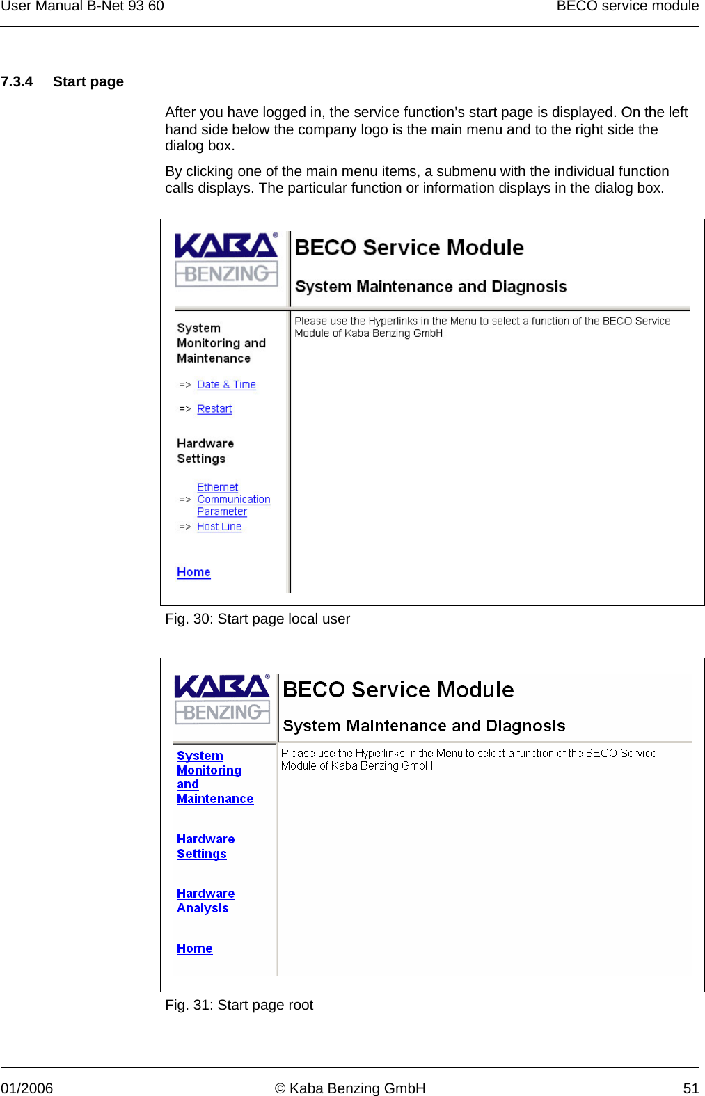
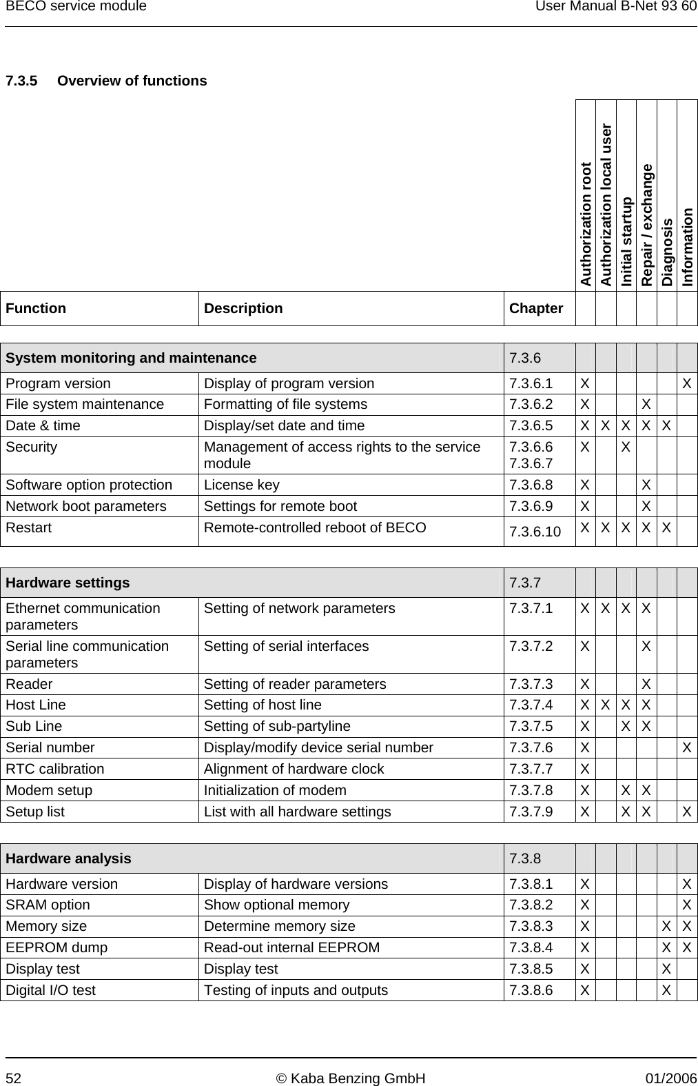
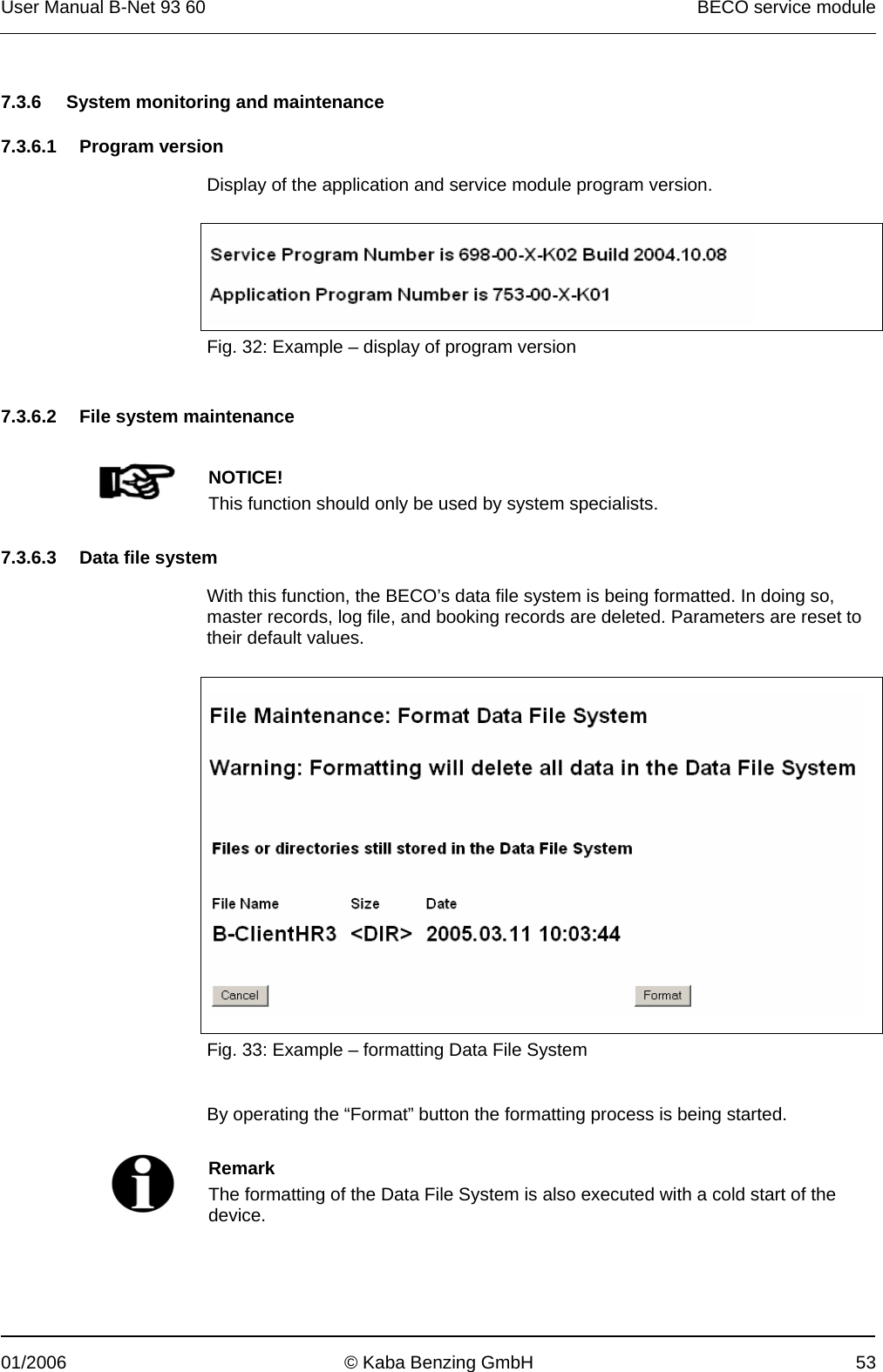
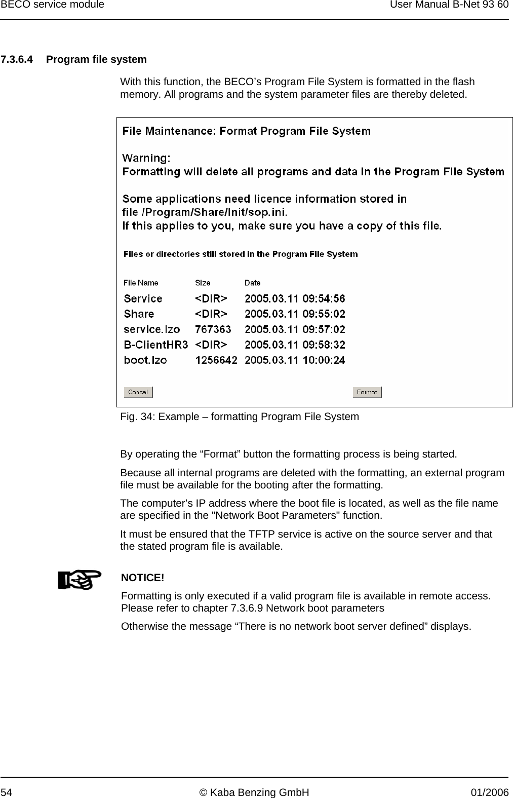
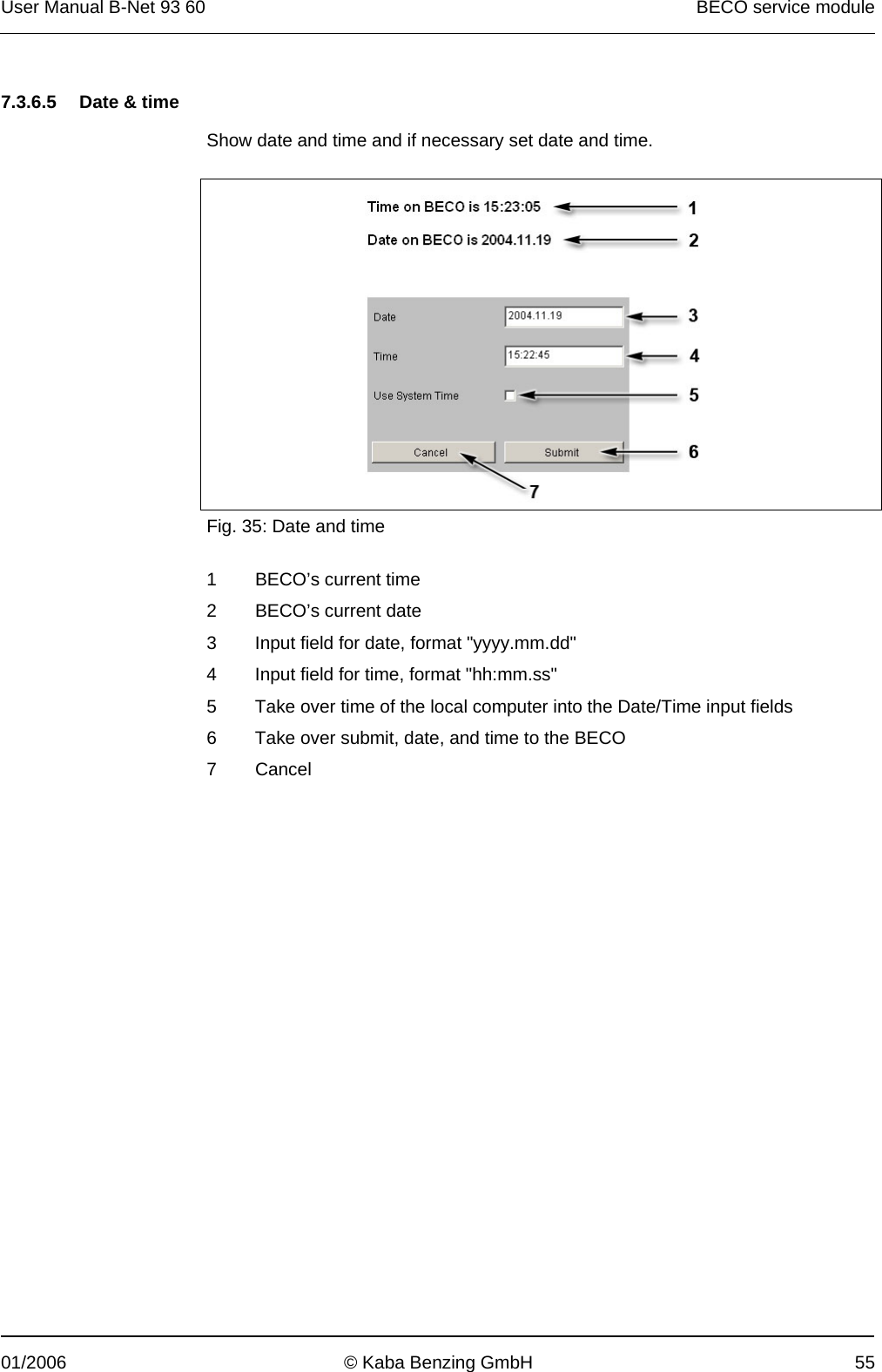
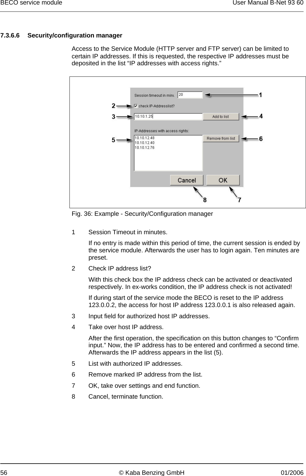
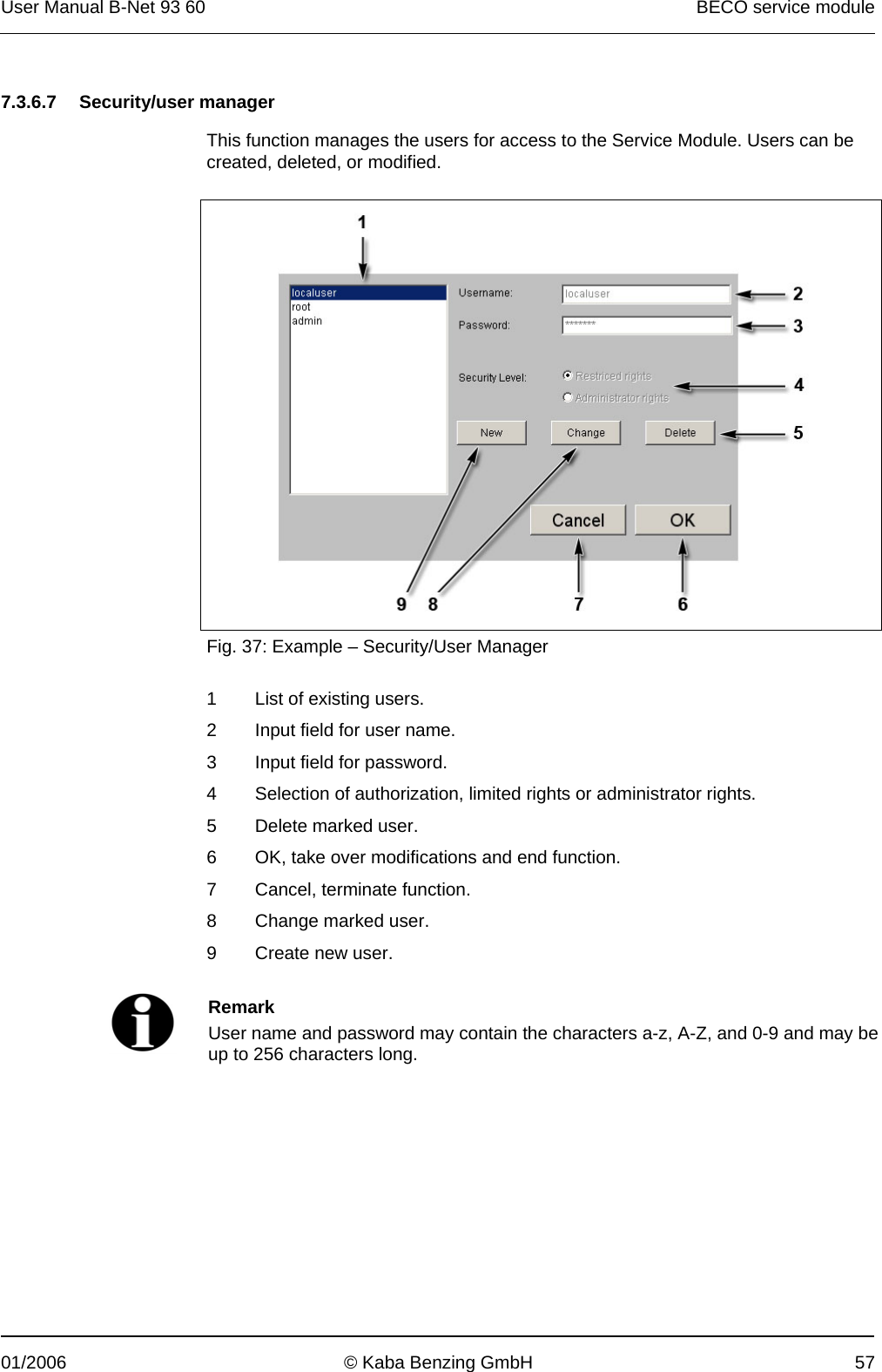
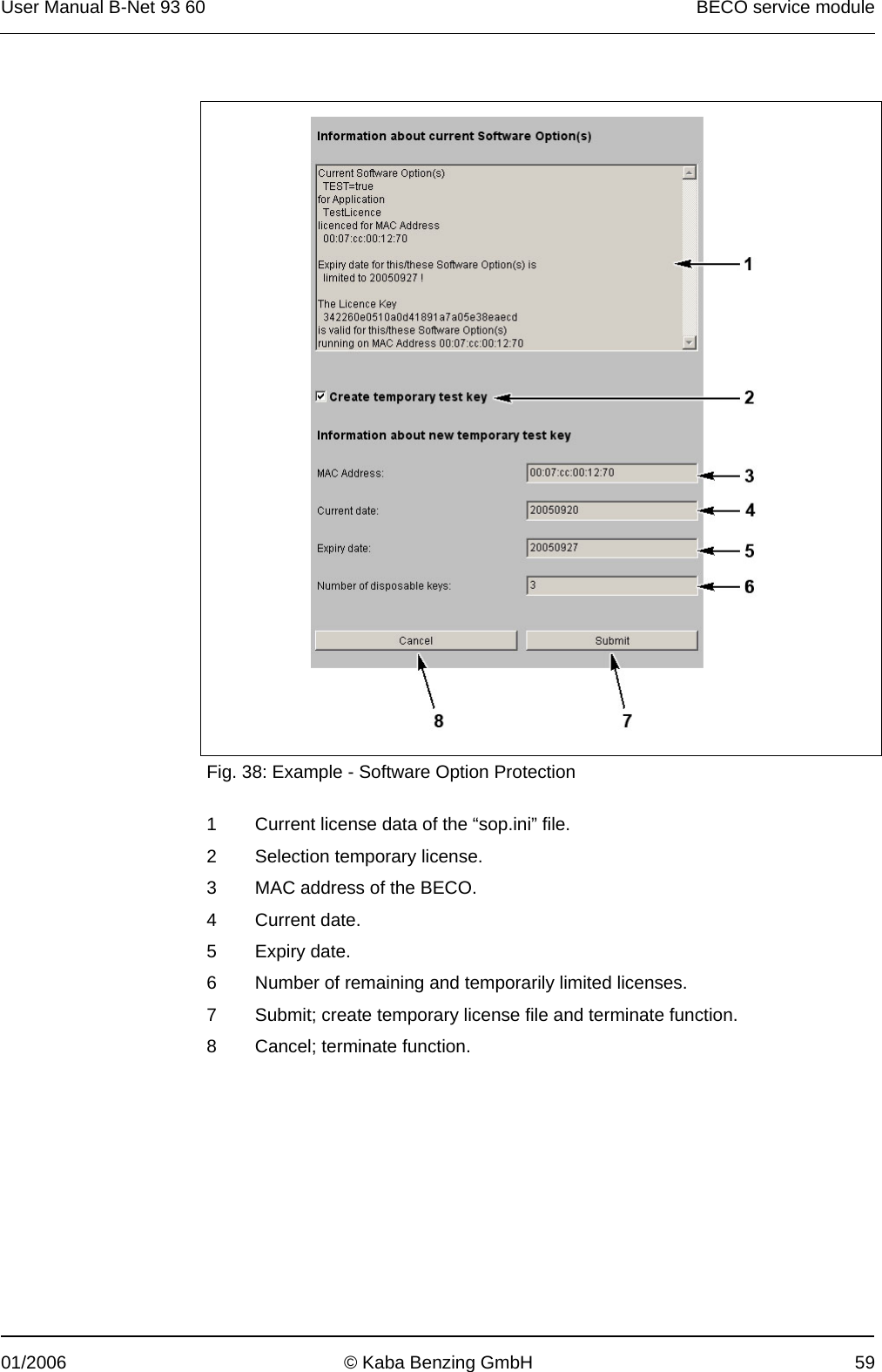
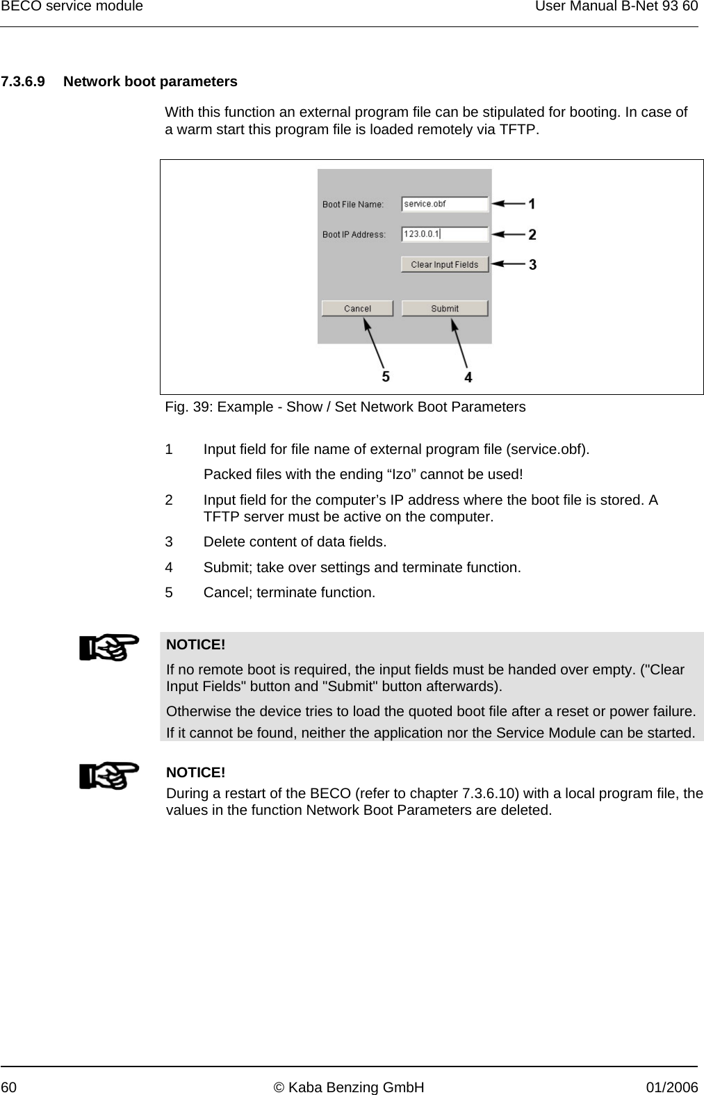
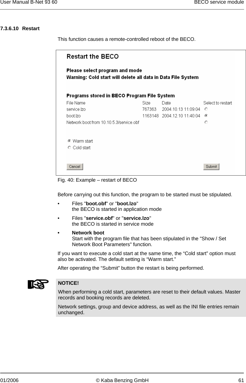
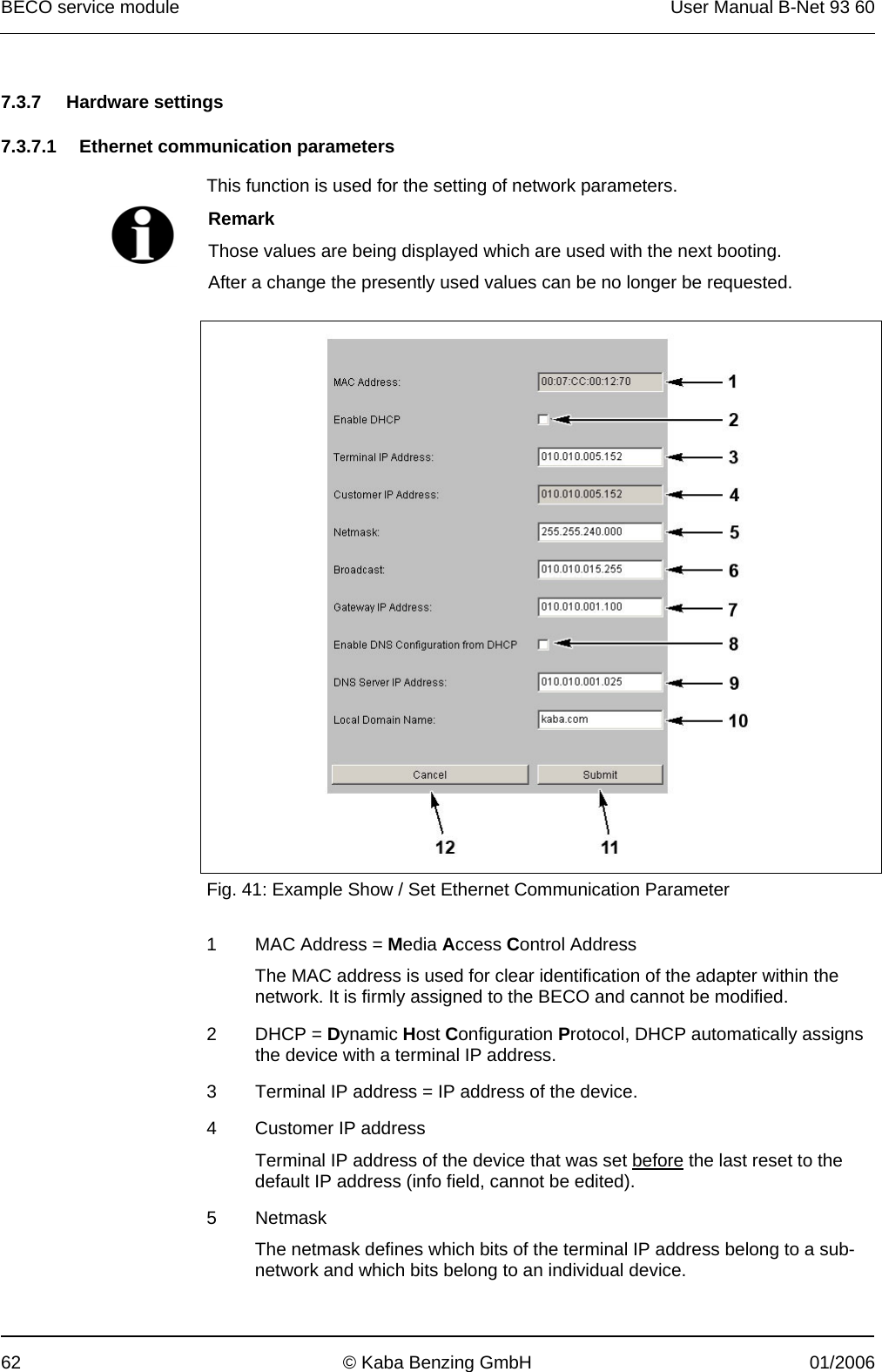
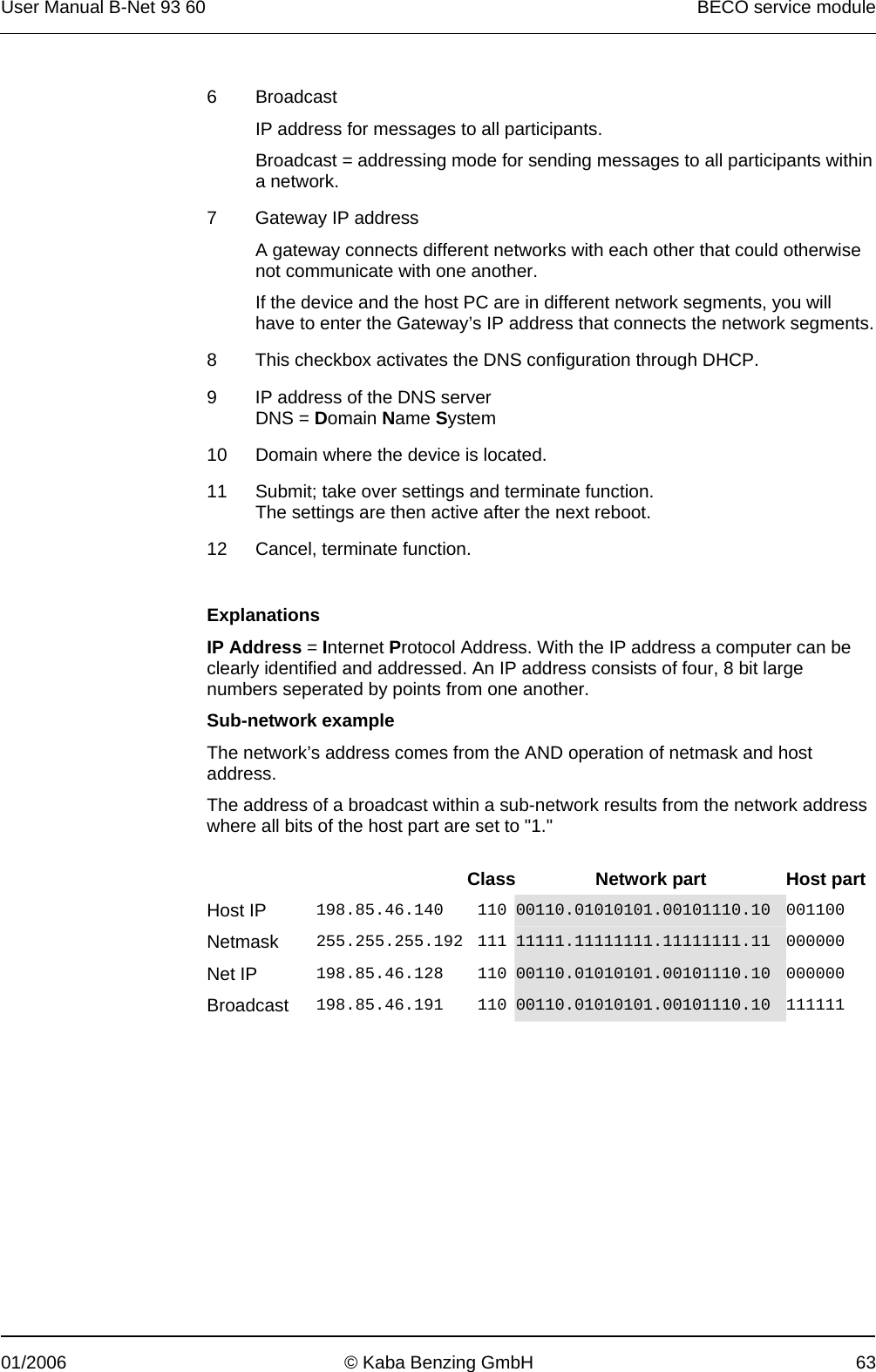
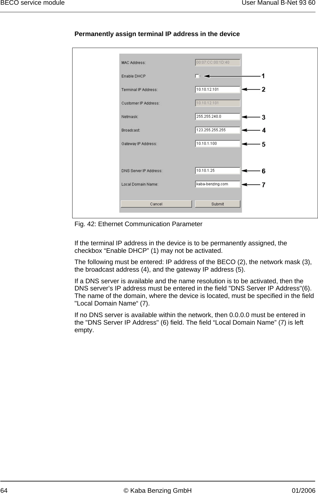
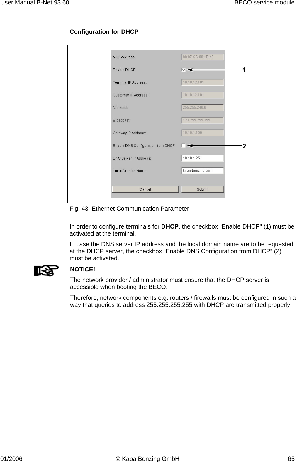
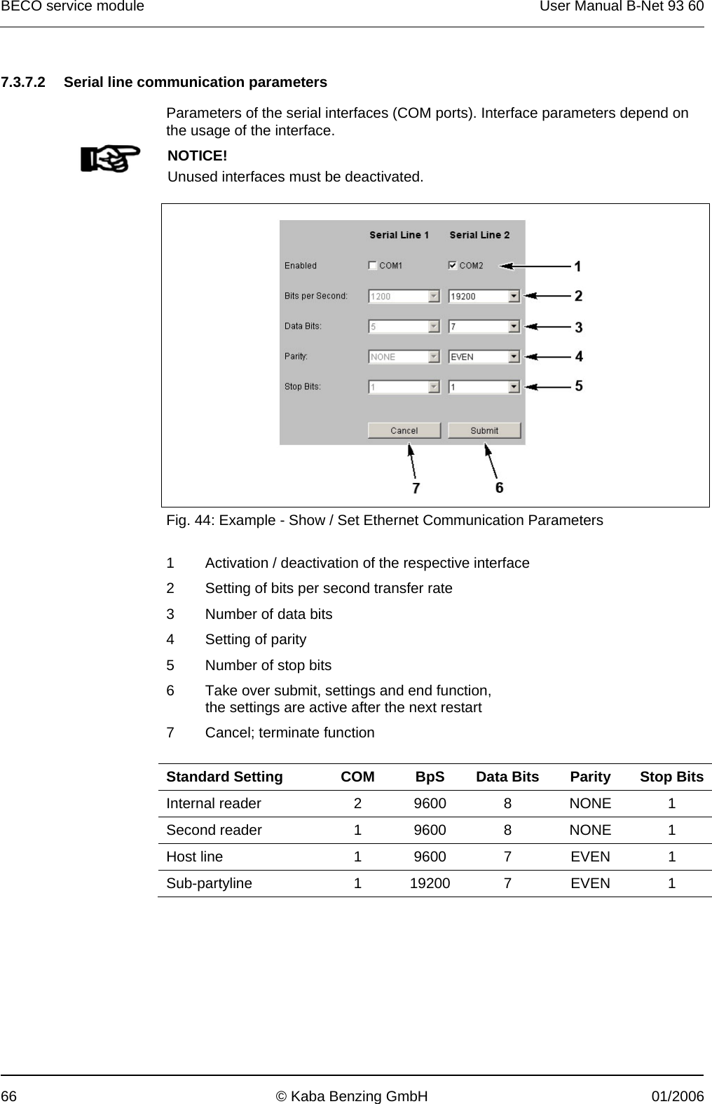
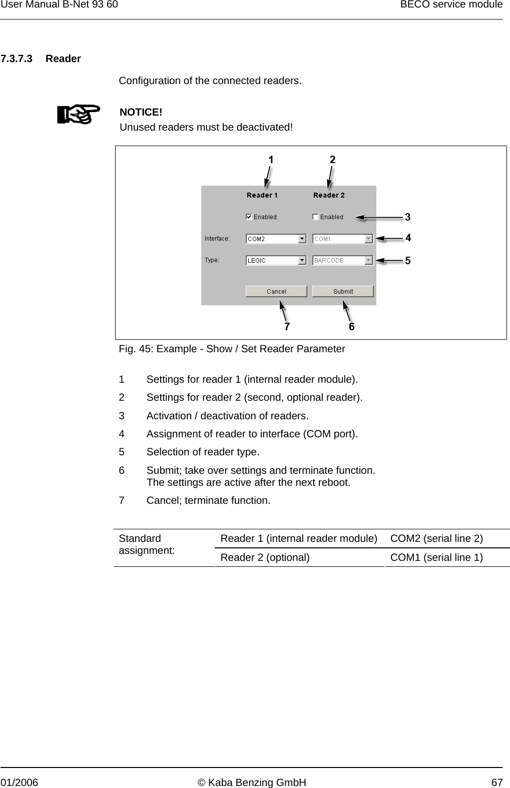
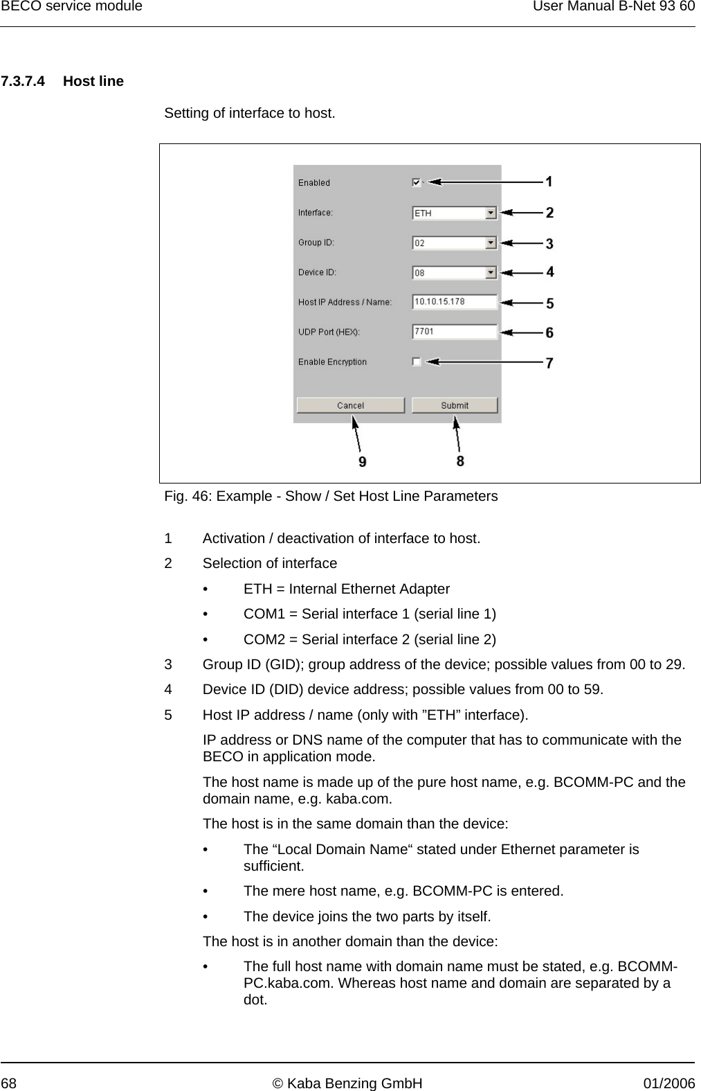
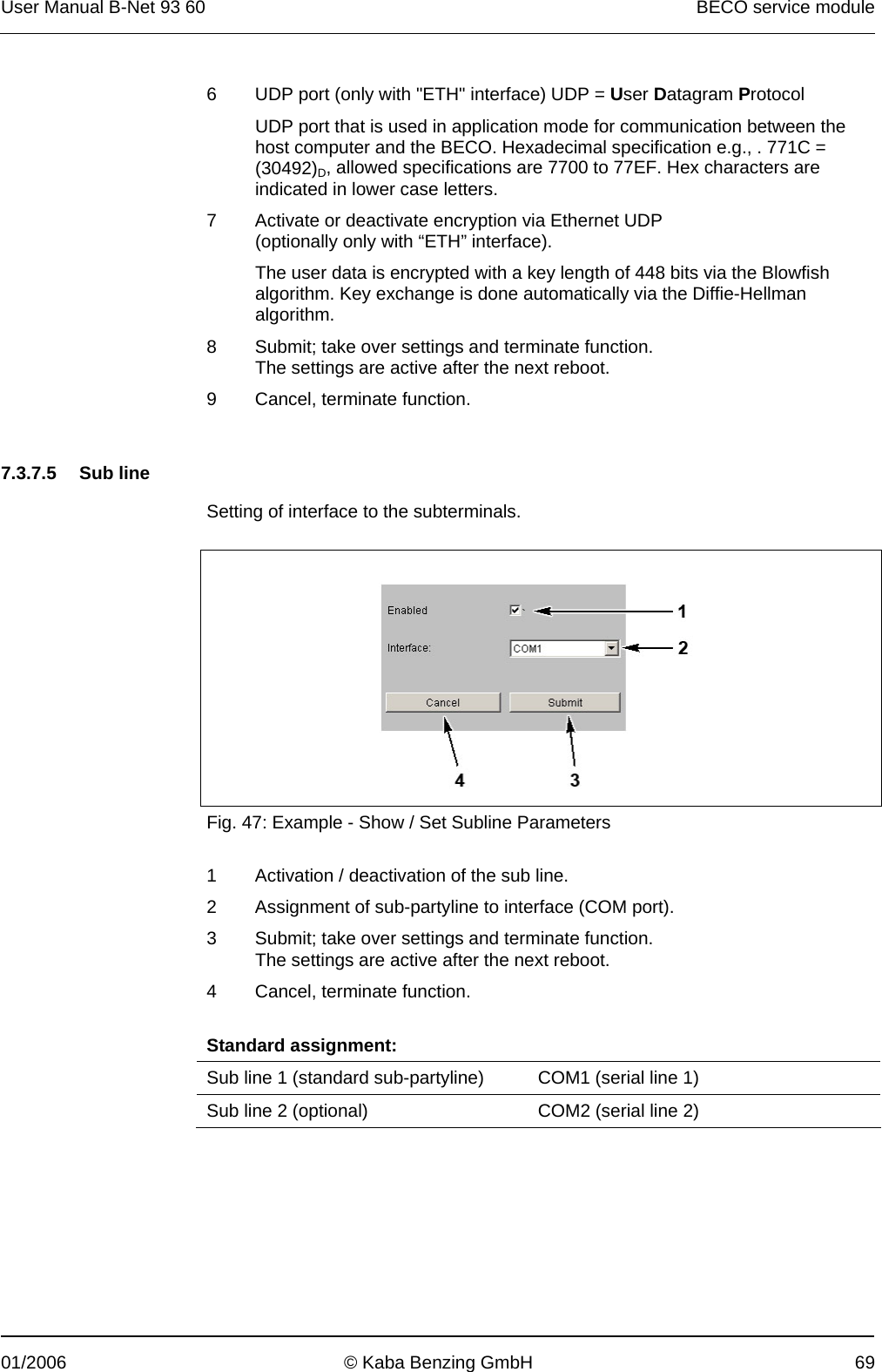
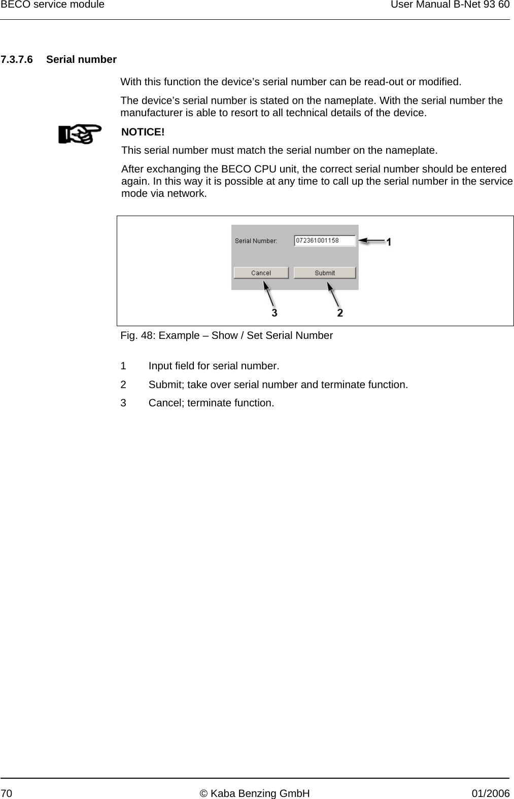
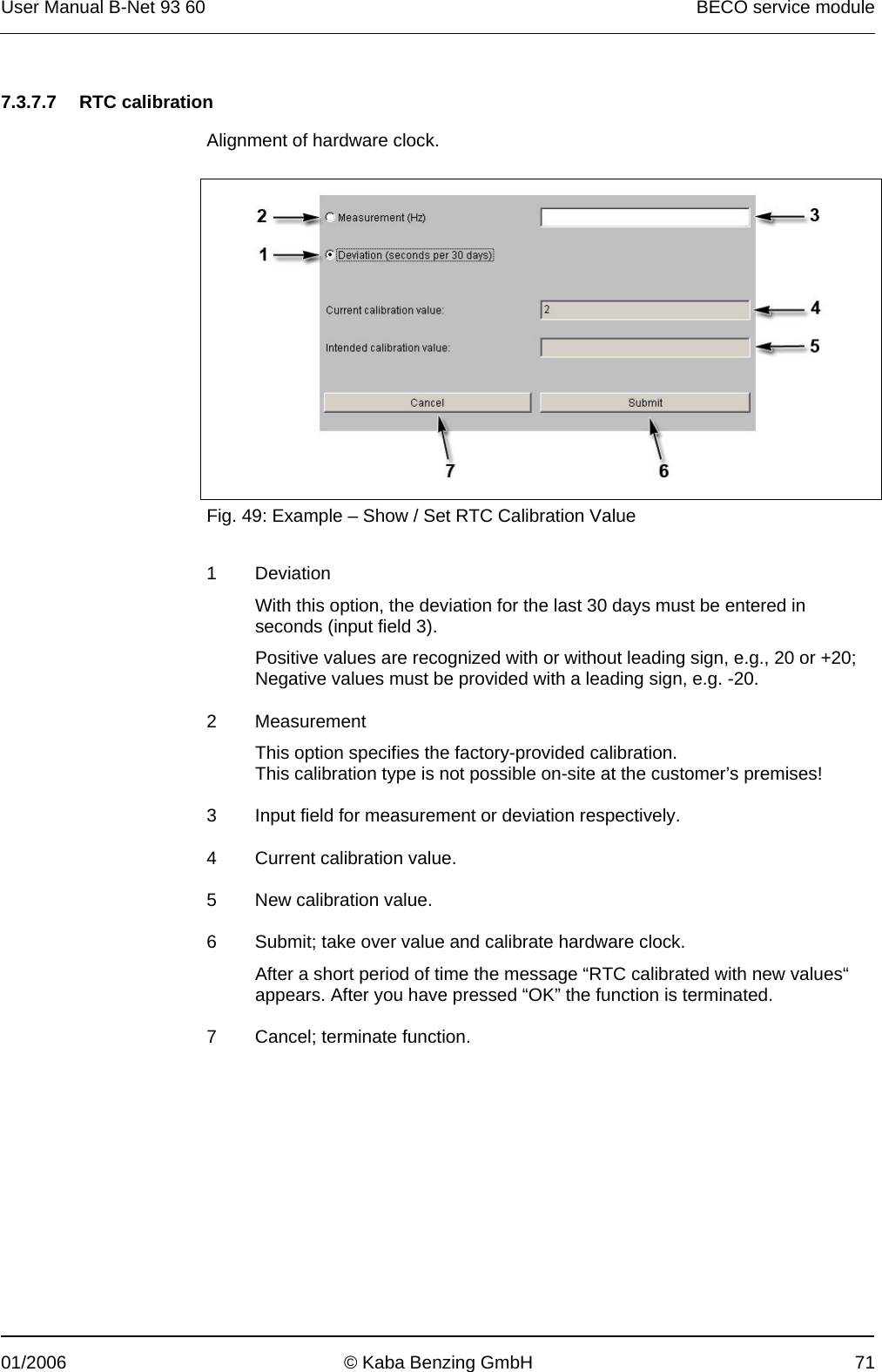
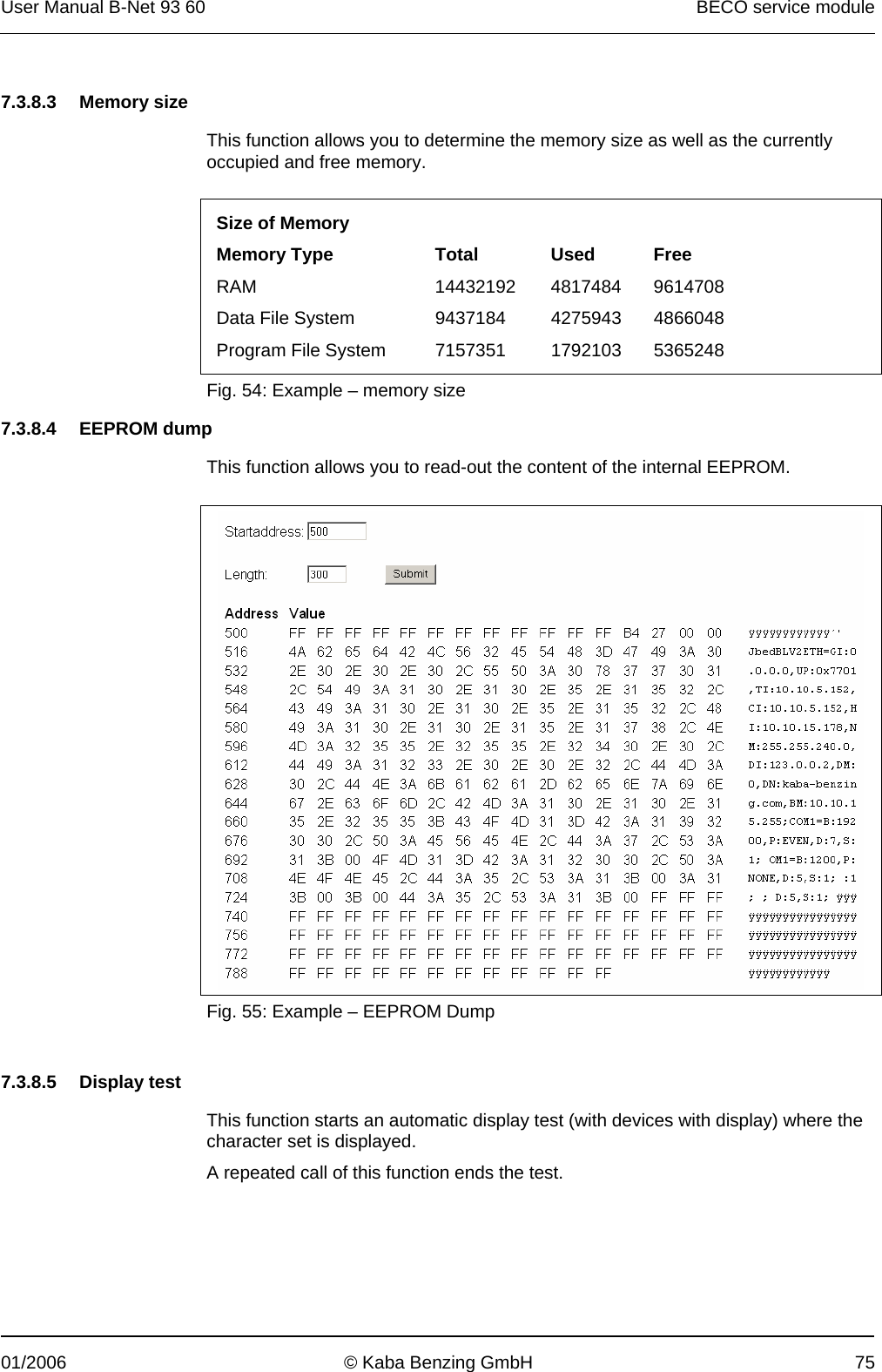
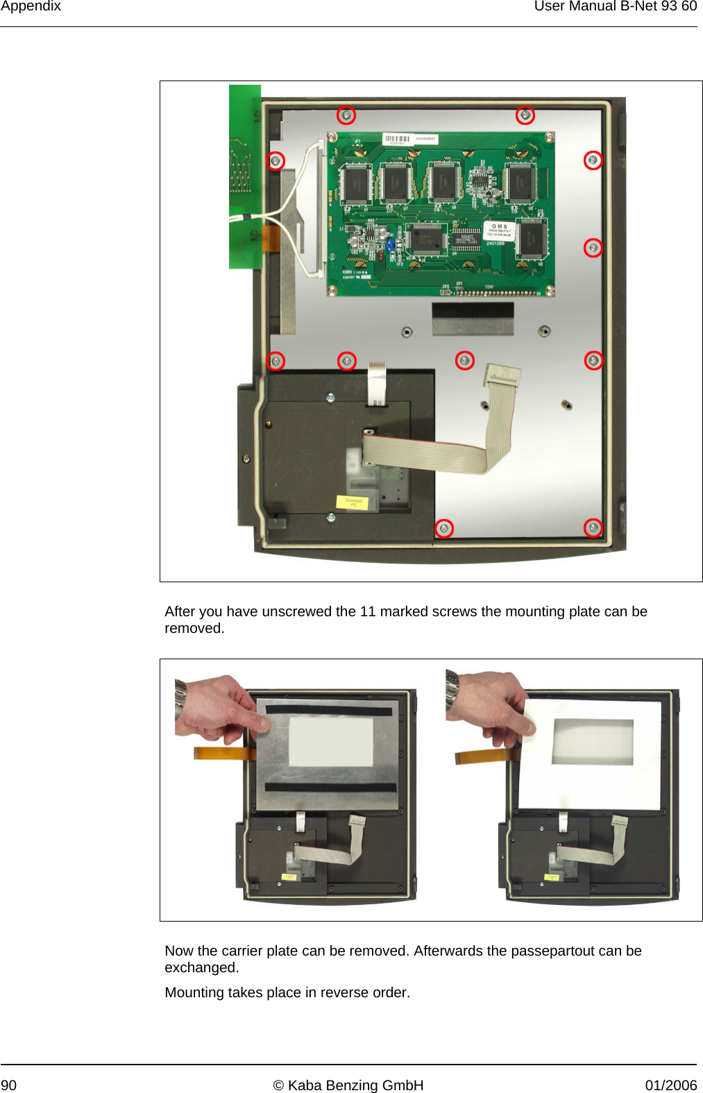
![User Manual B-Net 93 60 BECO service module 01/2006 © Kaba Benzing GmbH 77 7.4 FTP access An FTP server is installed on the device. The FTP server can be addressed in application mode as well as in service mode. When the system starts in service mode, the FTP is started principally. In application mode (B-Client HR2 / HR3 / AC2 / AC3 / PDC3), the FTP server can be activated or deactivated with an entry in the /Program/Share/Init/bedanet.ini file. Example: [Programs] Application0 = FTPServer FTP server is started in application mode [Programs] Application0 = FTP server is not started in application mode Remark In case that no access via FTP is possible in application mode, this parameter must be checked in the bedanet.ini file. Access is performed via a standard FTP client. Users The following users are already created by default: User name: Password: Path: localuser Bedanet Ram/Transfer root Bedanet /](https://usermanual.wiki/dormakaba-EAD/WRU200.User-Manual/User-Guide-629130-Page-27.png)