dormakaba EAD WRU200 Inductive Tag Reader Module User Manual
Kaba GmbH Inductive Tag Reader Module
Contents
- 1. USer Manual
- 2. User Manual
User Manual
User Manual B-Net 93 60 BECO service module
01/2006 © Kaba Benzing GmbH 51
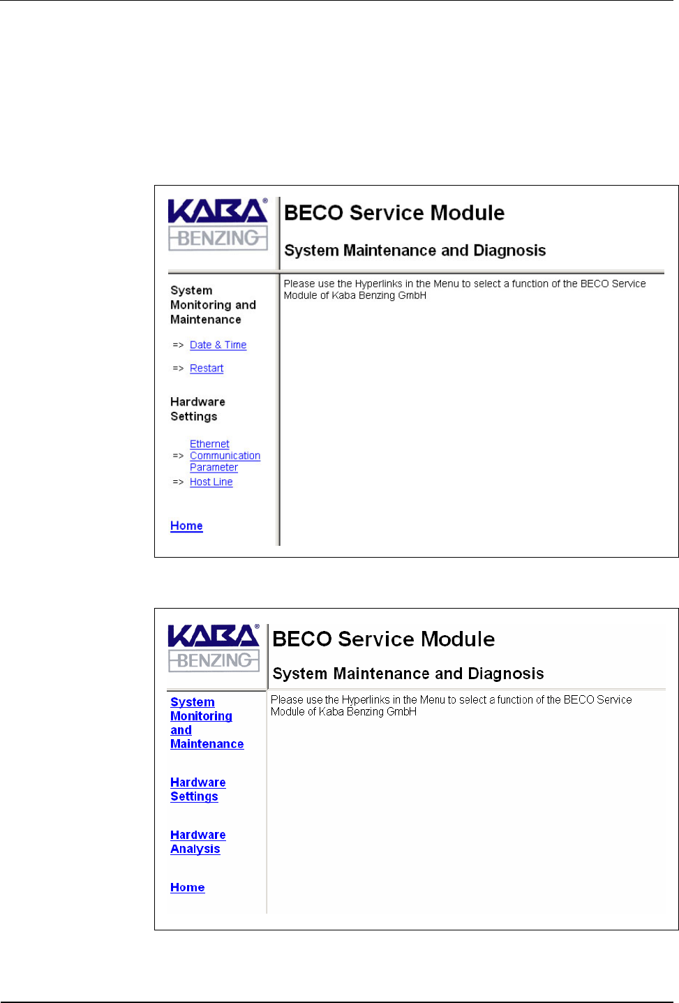
7.3.4 Start page
After you have logged in, the service function’s start page is displayed. On the left
hand side below the company logo is the main menu and to the right side the
dialog box.
By clicking one of the main menu items, a submenu with the individual function
calls displays. The particular function or information displays in the dialog box.
Fig. 30: Start page local user
Fig. 31: Start page root

BECO service module User Manual B-Net 93 60
52 © Kaba Benzing GmbH 01/2006
7.3.5 Overview of functions
Authorization root
Authorization local user
Initial startup
Repair / exchange
Diagnosis
Information
Function Description Chapter
System monitoring and maintenance 7.3.6
Program version Display of program version 7.3.6.1 X X
File system maintenance Formatting of file systems 7.3.6.2 X X
Date & time Display/set date and time 7.3.6.5 X X X X X
Security Management of access rights to the service
module 7.3.6.6
7.3.6.7 X X
Software option protection License key 7.3.6.8 X X
Network boot parameters Settings for remote boot 7.3.6.9 X X
Restart Remote-controlled reboot of BECO 7.3.6.10 X X X X X
Hardware settings 7.3.7
Ethernet communication
parameters Setting of network parameters 7.3.7.1 X X X X
Serial line communication
parameters Setting of serial interfaces 7.3.7.2 X X
Reader Setting of reader parameters 7.3.7.3 X X
Host Line Setting of host line 7.3.7.4 X X X X
Sub Line Setting of sub-partyline 7.3.7.5 X X X
Serial number Display/modify device serial number 7.3.7.6 X X
RTC calibration Alignment of hardware clock 7.3.7.7 X
Modem setup Initialization of modem 7.3.7.8 X X X
Setup list List with all hardware settings 7.3.7.9 X X X X
Hardware analysis 7.3.8
Hardware version Display of hardware versions 7.3.8.1 X X
SRAM option Show optional memory 7.3.8.2 X X
Memory size Determine memory size 7.3.8.3 X X X
EEPROM dump Read-out internal EEPROM 7.3.8.4 X X X
Display test Display test 7.3.8.5 X X
Digital I/O test Testing of inputs and outputs 7.3.8.6 X X
User Manual B-Net 93 60 BECO service module
01/2006 © Kaba Benzing GmbH 53
7.3.6 System monitoring and maintenance
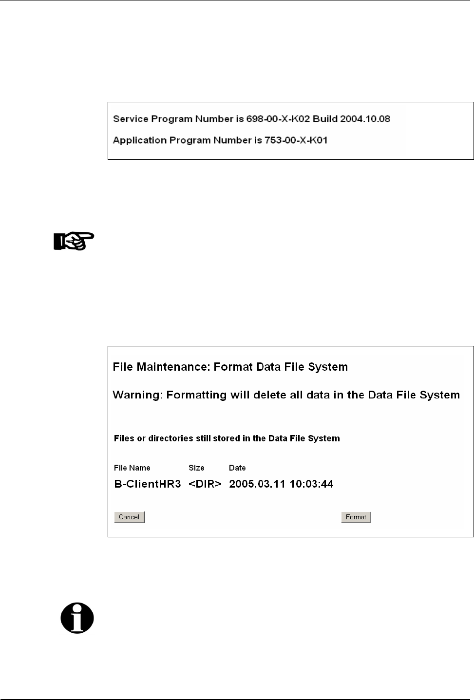
7.3.6.1 Program version
Display of the application and service module program version.
Fig. 32: Example – display of program version
7.3.6.2 File system maintenance
NOTICE!
This function should only be used by system specialists.
7.3.6.3 Data file system
With this function, the BECO’s data file system is being formatted. In doing so,
master records, log file, and booking records are deleted. Parameters are reset to
their default values.
Fig. 33: Example – formatting Data File System
By operating the “Format” button the formatting process is being started.
Remark
The formatting of the Data File System is also executed with a cold start of the
device.
BECO service module User Manual B-Net 93 60
54 © Kaba Benzing GmbH 01/2006
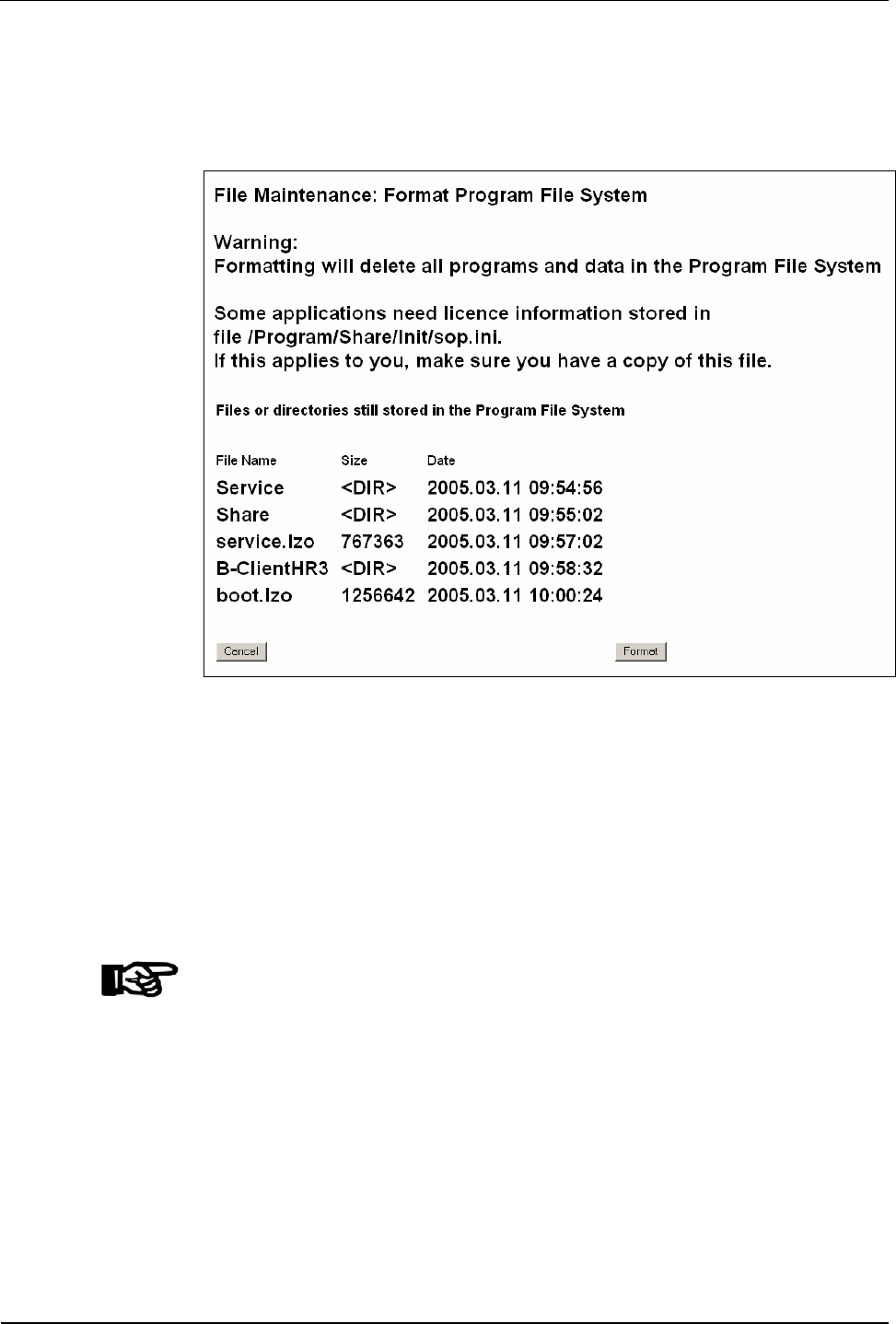
7.3.6.4 Program file system
With this function, the BECO’s Program File System is formatted in the flash
memory. All programs and the system parameter files are thereby deleted.
Fig. 34: Example – formatting Program File System
By operating the “Format” button the formatting process is being started.
Because all internal programs are deleted with the formatting, an external program
file must be available for the booting after the formatting.
The computer’s IP address where the boot file is located, as well as the file name
are specified in the "Network Boot Parameters" function.
It must be ensured that the TFTP service is active on the source server and that
the stated program file is available.
NOTICE!
Formatting is only executed if a valid program file is available in remote access.
Please refer to chapter 7.3.6.9 Network boot parameters
Otherwise the message “There is no network boot server defined” displays.
User Manual B-Net 93 60 BECO service module
01/2006 © Kaba Benzing GmbH 55
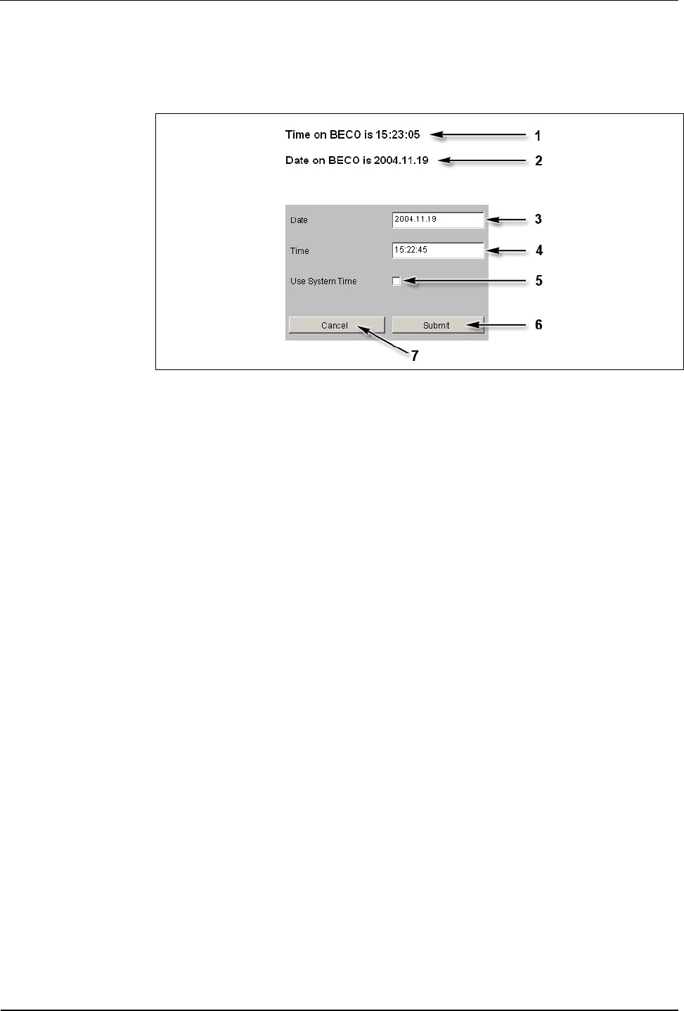
7.3.6.5 Date & time
Show date and time and if necessary set date and time.
Fig. 35: Date and time
1 BECO’s current time
2 BECO’s current date
3 Input field for date, format "yyyy.mm.dd"
4 Input field for time, format "hh:mm.ss"
5 Take over time of the local computer into the Date/Time input fields
6 Take over submit, date, and time to the BECO
7 Cancel
BECO service module User Manual B-Net 93 60
56 © Kaba Benzing GmbH 01/2006
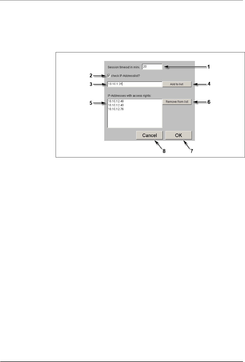
7.3.6.6 Security/configuration manager
Access to the Service Module (HTTP server and FTP server) can be limited to
certain IP addresses. If this is requested, the respective IP addresses must be
deposited in the list “IP addresses with access rights.”
Fig. 36: Example - Security/Configuration manager
1 Session Timeout in minutes.
If no entry is made within this period of time, the current session is ended by
the service module. Afterwards the user has to login again. Ten minutes are
preset.
2 Check IP address list?
With this check box the IP address check can be activated or deactivated
respectively. In ex-works condition, the IP address check is not activated!
If during start of the service mode the BECO is reset to the IP address
123.0.0.2, the access for host IP address 123.0.0.1 is also released again.
3 Input field for authorized host IP addresses.
4 Take over host IP address.
After the first operation, the specification on this button changes to “Confirm
input.” Now, the IP address has to be entered and confirmed a second time.
Afterwards the IP address appears in the list (5).
5 List with authorized IP addresses.
6 Remove marked IP address from the list.
7 OK, take over settings and end function.
8 Cancel, terminate function.
User Manual B-Net 93 60 BECO service module
01/2006 © Kaba Benzing GmbH 57
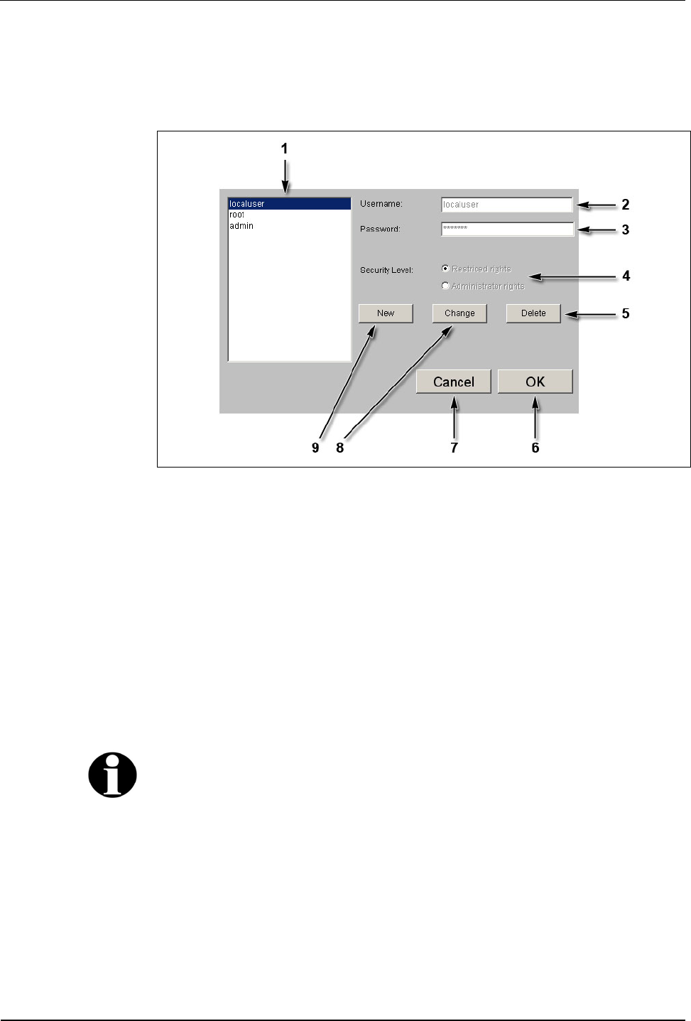
7.3.6.7 Security/user manager
This function manages the users for access to the Service Module. Users can be
created, deleted, or modified.
Fig. 37: Example – Security/User Manager
1 List of existing users.
2 Input field for user name.
3 Input field for password.
4 Selection of authorization, limited rights or administrator rights.
5 Delete marked user.
6 OK, take over modifications and end function.
7 Cancel, terminate function.
8 Change marked user.
9 Create new user.
Remark
User name and password may contain the characters a-z, A-Z, and 0-9 and may be
up to 256 characters long.

BECO service module User Manual B-Net 93 60
58 © Kaba Benzing GmbH 01/2006
7.3.6.8 Software option protection
In order to use the application a corresponding license key is required.
This license key is bound to the device’s MAC address.
The function ”Software Option Protection” allows to create a temporary test license.
Unlimited license key
NOTICE!
An unlimited license file can only be obtained from Kaba Benzing.
Normally, the license key is supplied with the ”sop.ini” file.
The license key is being activated by copying this file via FTP to the
/Program/Share/Init/ directory.
The license key is only accepted, if the application and their options indicated in
the fields, corresponds with the license.
Test license
The “Software Option Protection“ function offers the option to create a temporary
license key. This test license allows you to utilize all options.
NOTICE!
The license key is valid for a duration of 7 days. After the license key has expired
the device automatically switches to service mode.
A temporary license key can be created seven times altogether. By deploying an
unlimited license file this counter is reset again.
Create test license
• Select “Create temporary test key.”
• Confirm with “Submit."
Remark
A possibly already existing unlimited license file is saved as "sop.bak."
User Manual B-Net 93 60 BECO service module
01/2006 © Kaba Benzing GmbH 59
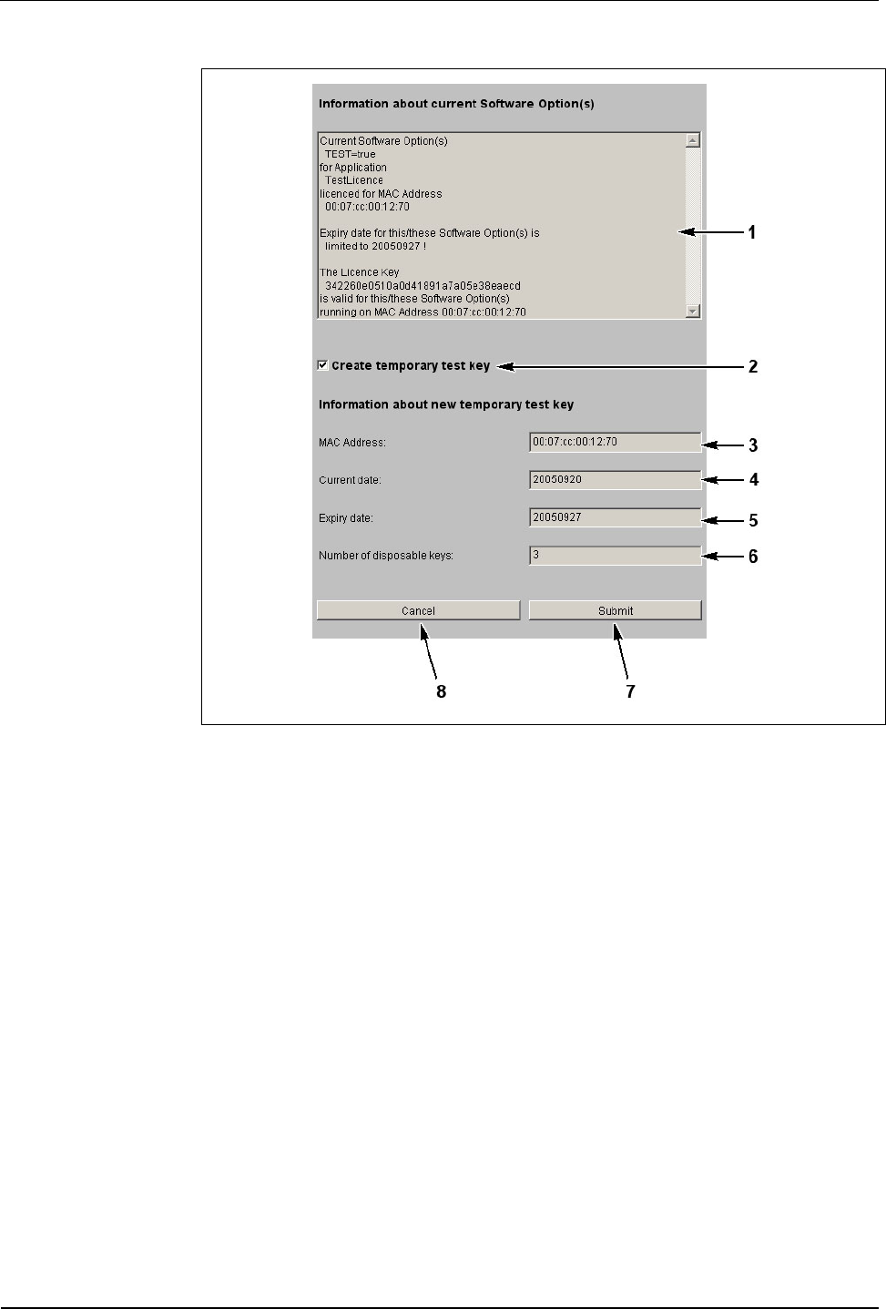
Fig. 38: Example - Software Option Protection
1 Current license data of the “sop.ini” file.
2 Selection temporary license.
3 MAC address of the BECO.
4 Current date.
5 Expiry date.
6 Number of remaining and temporarily limited licenses.
7 Submit; create temporary license file and terminate function.
8 Cancel; terminate function.

BECO service module User Manual B-Net 93 60
60 © Kaba Benzing GmbH 01/2006
7.3.6.9 Network boot parameters
With this function an external program file can be stipulated for booting. In case of
a warm start this program file is loaded remotely via TFTP.
Fig. 39: Example - Show / Set Network Boot Parameters
1 Input field for file name of external program file (service.obf).
Packed files with the ending “Izo” cannot be used!
2 Input field for the computer’s IP address where the boot file is stored. A
TFTP server must be active on the computer.
3 Delete content of data fields.
4 Submit; take over settings and terminate function.
5 Cancel; terminate function.
NOTICE!
If no remote boot is required, the input fields must be handed over empty. ("Clear
Input Fields" button and "Submit" button afterwards).
Otherwise the device tries to load the quoted boot file after a reset or power failure.
If it cannot be found, neither the application nor the Service Module can be started.
NOTICE!
During a restart of the BECO (refer to chapter 7.3.6.10) with a local program file, the
values in the function Network Boot Parameters are deleted.
User Manual B-Net 93 60 BECO service module
01/2006 © Kaba Benzing GmbH 61
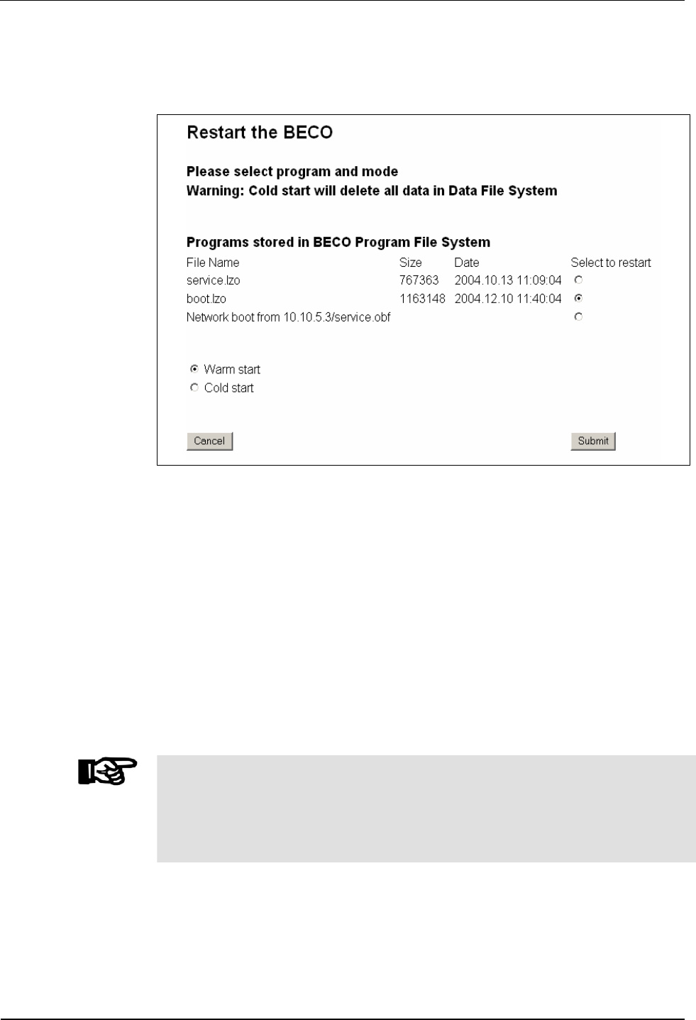
7.3.6.10 Restart
This function causes a remote-controlled reboot of the BECO.
Fig. 40: Example – restart of BECO
Before carrying out this function, the program to be started must be stipulated.
• Files "boot.obf" or "boot.lzo"
the BECO is started in application mode
• Files "service.obf" or "service.lzo"
the BECO is started in service mode
• Network boot
Start with the program file that has been stipulated in the "Show / Set
Network Boot Parameters" function.
If you want to execute a cold start at the same time, the “Cold start” option must
also be activated. The default setting is “Warm start.”
After operating the “Submit” button the restart is being performed.
NOTICE!
When performing a cold start, parameters are reset to their default values. Master
records and booking records are deleted.
Network settings, group and device address, as well as the INI file entries remain
unchanged.
BECO service module User Manual B-Net 93 60
62 © Kaba Benzing GmbH 01/2006
7.3.7 Hardware settings
7.3.7.1 Ethernet communication parameters
This function is used for the setting of network parameters.
Remark
Those values are being displayed which are used with the next booting.
After a change the presently used values can be no longer be requested.
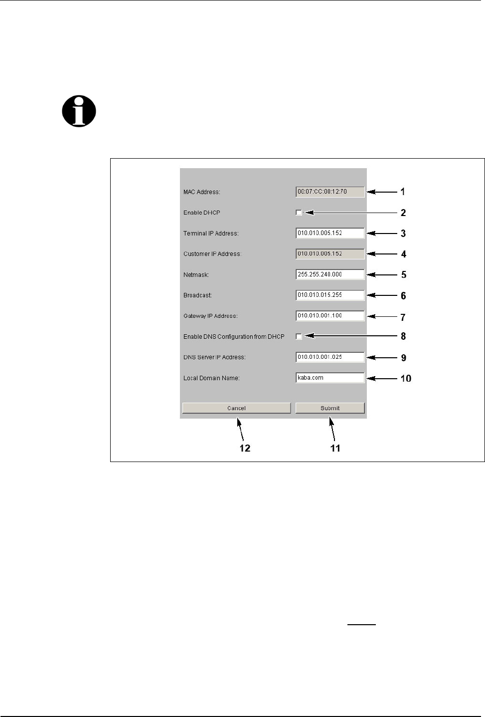
Fig. 41: Example Show / Set Ethernet Communication Parameter
1 MAC Address = Media Access Control Address
The MAC address is used for clear identification of the adapter within the
network. It is firmly assigned to the BECO and cannot be modified.
2 DHCP = Dynamic Host Configuration Protocol, DHCP automatically assigns
the device with a terminal IP address.
3 Terminal IP address = IP address of the device.
4 Customer IP address
Terminal IP address of the device that was set before the last reset to the
default IP address (info field, cannot be edited).
5 Netmask
The netmask defines which bits of the terminal IP address belong to a sub-
network and which bits belong to an individual device.

User Manual B-Net 93 60 BECO service module
01/2006 © Kaba Benzing GmbH 63
6 Broadcast
IP address for messages to all participants.
Broadcast = addressing mode for sending messages to all participants within
a network.
7 Gateway IP address
A gateway connects different networks with each other that could otherwise
not communicate with one another.
If the device and the host PC are in different network segments, you will
have to enter the Gateway’s IP address that connects the network segments.
8 This checkbox activates the DNS configuration through DHCP.
9 IP address of the DNS server
DNS = Domain Name System
10 Domain where the device is located.
11 Submit; take over settings and terminate function.
The settings are then active after the next reboot.
12 Cancel, terminate function.
Explanations
IP Address = Internet Protocol Address. With the IP address a computer can be
clearly identified and addressed. An IP address consists of four, 8 bit large
numbers seperated by points from one another.
Sub-network example
The network’s address comes from the AND operation of netmask and host
address.
The address of a broadcast within a sub-network results from the network address
where all bits of the host part are set to "1."
Class Network part Host part
Host IP 198.85.46.140 110 00110.01010101.00101110.10 001100
Netmask 255.255.255.192 111 11111.11111111.11111111.11 000000
Net IP 198.85.46.128 110 00110.01010101.00101110.10 000000
Broadcast 198.85.46.191 110 00110.01010101.00101110.10 111111
BECO service module User Manual B-Net 93 60
64 © Kaba Benzing GmbH 01/2006
Permanently assign terminal IP address in the device
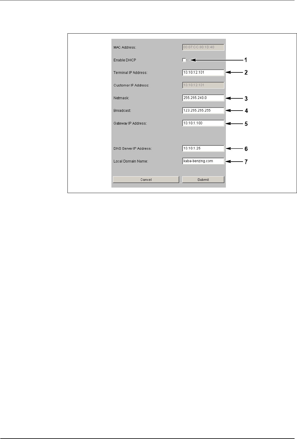
Fig. 42: Ethernet Communication Parameter
If the terminal IP address in the device is to be permanently assigned, the
checkbox “Enable DHCP” (1) may not be activated.
The following must be entered: IP address of the BECO (2), the network mask (3),
the broadcast address (4), and the gateway IP address (5).
If a DNS server is available and the name resolution is to be activated, then the
DNS server’s IP address must be entered in the field "DNS Server IP Address"(6).
The name of the domain, where the device is located, must be specified in the field
"Local Domain Name“ (7).
If no DNS server is available within the network, then 0.0.0.0 must be entered in
the "DNS Server IP Address" (6) field. The field “Local Domain Name” (7) is left
empty.
User Manual B-Net 93 60 BECO service module
01/2006 © Kaba Benzing GmbH 65
Configuration for DHCP
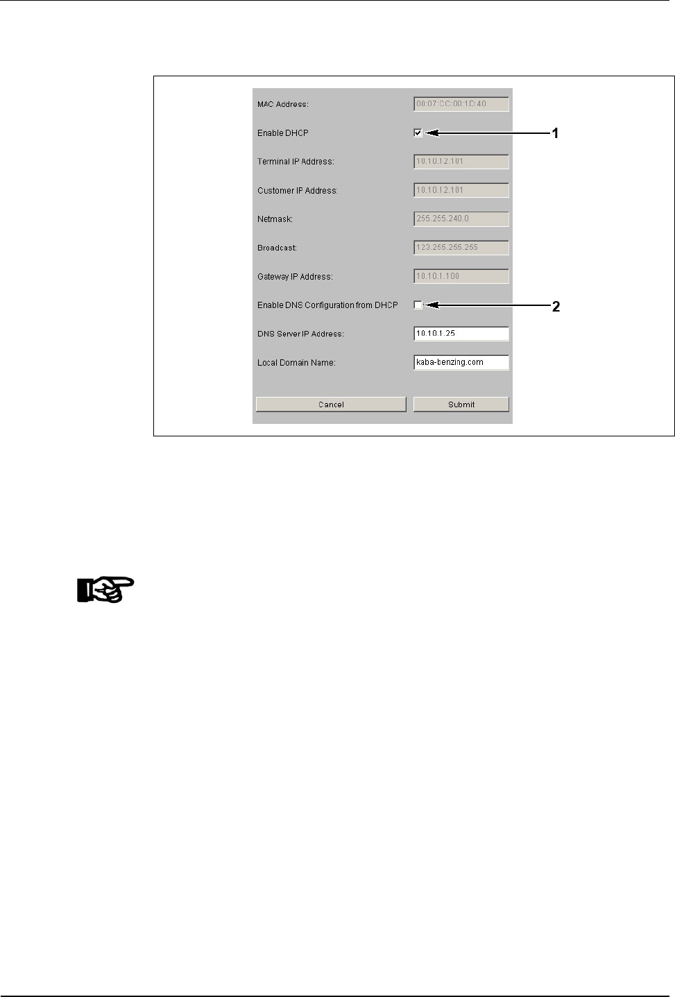
Fig. 43: Ethernet Communication Parameter
In order to configure terminals for DHCP, the checkbox “Enable DHCP" (1) must be
activated at the terminal.
In case the DNS server IP address and the local domain name are to be requested
at the DHCP server, the checkbox “Enable DNS Configuration from DHCP” (2)
must be activated.
NOTICE!
The network provider / administrator must ensure that the DHCP server is
accessible when booting the BECO.
Therefore, network components e.g. routers / firewalls must be configured in such a
way that queries to address 255.255.255.255 with DHCP are transmitted properly.
BECO service module User Manual B-Net 93 60
66 © Kaba Benzing GmbH 01/2006
7.3.7.2 Serial line communication parameters
Parameters of the serial interfaces (COM ports). Interface parameters depend on
the usage of the interface.
NOTICE!
Unused interfaces must be deactivated.
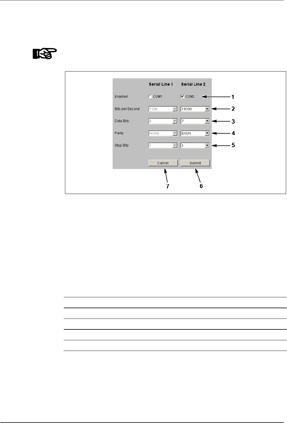
Fig. 44: Example - Show / Set Ethernet Communication Parameters
1 Activation / deactivation of the respective interface
2 Setting of bits per second transfer rate
3 Number of data bits
4 Setting of parity
5 Number of stop bits
6 Take over submit, settings and end function,
the settings are active after the next restart
7 Cancel; terminate function
Standard Setting COM BpS Data Bits Parity Stop Bits
Internal reader 2 9600 8 NONE 1
Second reader 1 9600 8 NONE 1
Host line 1 9600 7 EVEN 1
Sub-partyline 1 19200 7 EVEN 1
User Manual B-Net 93 60 BECO service module
01/2006 © Kaba Benzing GmbH 67
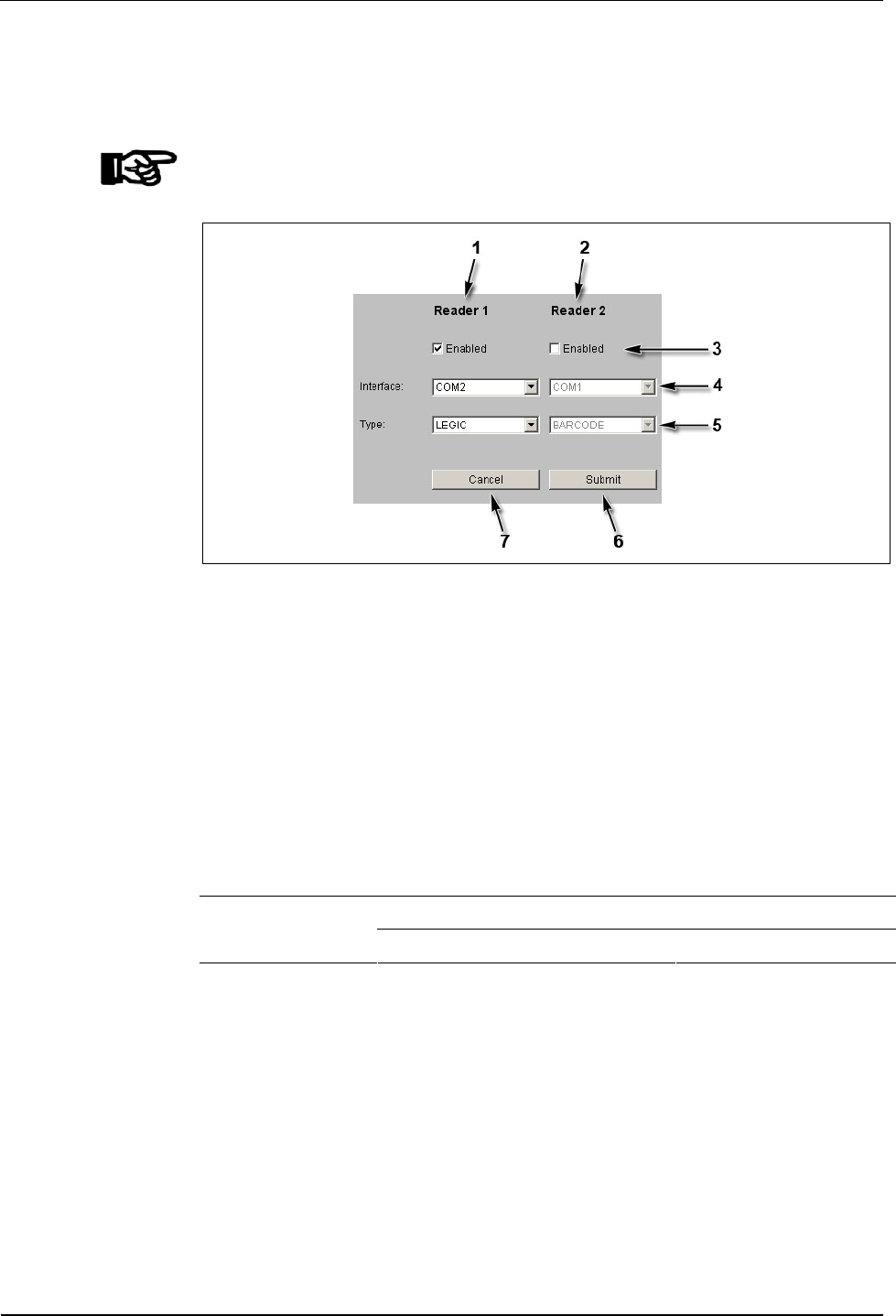
7.3.7.3 Reader
Configuration of the connected readers.
NOTICE!
Unused readers must be deactivated!
Fig. 45: Example - Show / Set Reader Parameter
1 Settings for reader 1 (internal reader module).
2 Settings for reader 2 (second, optional reader).
3 Activation / deactivation of readers.
4 Assignment of reader to interface (COM port).
5 Selection of reader type.
6 Submit; take over settings and terminate function.
The settings are active after the next reboot.
7 Cancel; terminate function.
Reader 1 (internal reader module) COM2 (serial line 2) Standard
assignment: Reader 2 (optional) COM1 (serial line 1)
BECO service module User Manual B-Net 93 60
68 © Kaba Benzing GmbH 01/2006
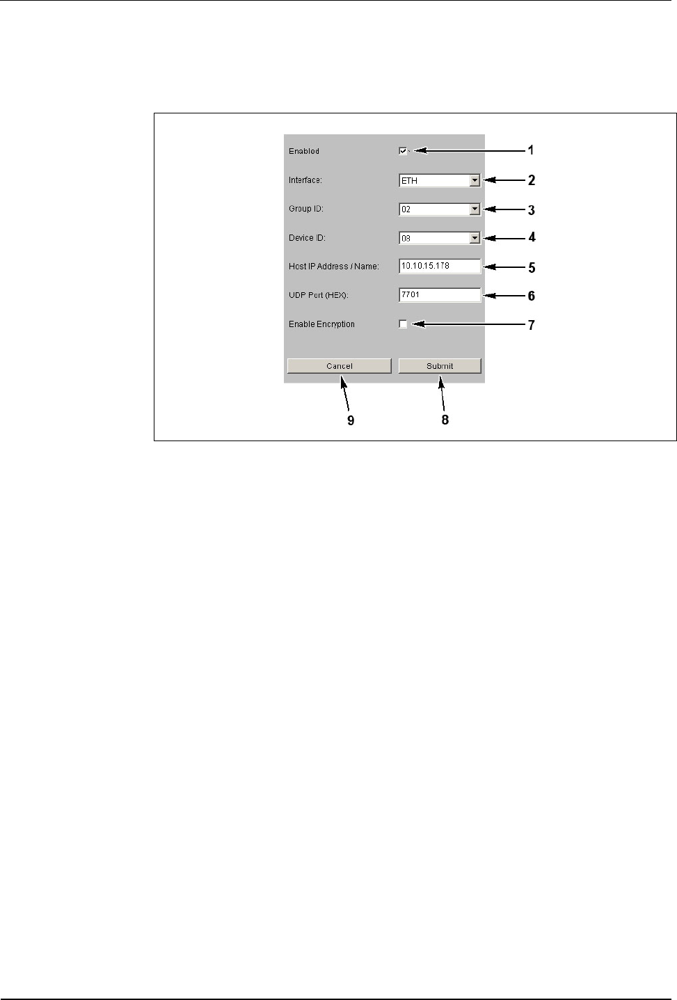
7.3.7.4 Host line
Setting of interface to host.
Fig. 46: Example - Show / Set Host Line Parameters
1 Activation / deactivation of interface to host.
2 Selection of interface
• ETH = Internal Ethernet Adapter
• COM1 = Serial interface 1 (serial line 1)
• COM2 = Serial interface 2 (serial line 2)
3 Group ID (GID); group address of the device; possible values from 00 to 29.
4 Device ID (DID) device address; possible values from 00 to 59.
5 Host IP address / name (only with ”ETH” interface).
IP address or DNS name of the computer that has to communicate with the
BECO in application mode.
The host name is made up of the pure host name, e.g. BCOMM-PC and the
domain name, e.g. kaba.com.
The host is in the same domain than the device:
• The “Local Domain Name“ stated under Ethernet parameter is
sufficient.
• The mere host name, e.g. BCOMM-PC is entered.
• The device joins the two parts by itself.
The host is in another domain than the device:
• The full host name with domain name must be stated, e.g. BCOMM-
PC.kaba.com. Whereas host name and domain are separated by a
dot.
User Manual B-Net 93 60 BECO service module
01/2006 © Kaba Benzing GmbH 69
6 UDP port (only with "ETH" interface) UDP = User Datagram Protocol
UDP port that is used in application mode for communication between the
host computer and the BECO. Hexadecimal specification e.g., . 771C =
(30492)D, allowed specifications are 7700 to 77EF. Hex characters are
indicated in lower case letters.
7 Activate or deactivate encryption via Ethernet UDP
(optionally only with “ETH” interface).
The user data is encrypted with a key length of 448 bits via the Blowfish
algorithm. Key exchange is done automatically via the Diffie-Hellman
algorithm.
8 Submit; take over settings and terminate function.
The settings are active after the next reboot.
9 Cancel, terminate function.
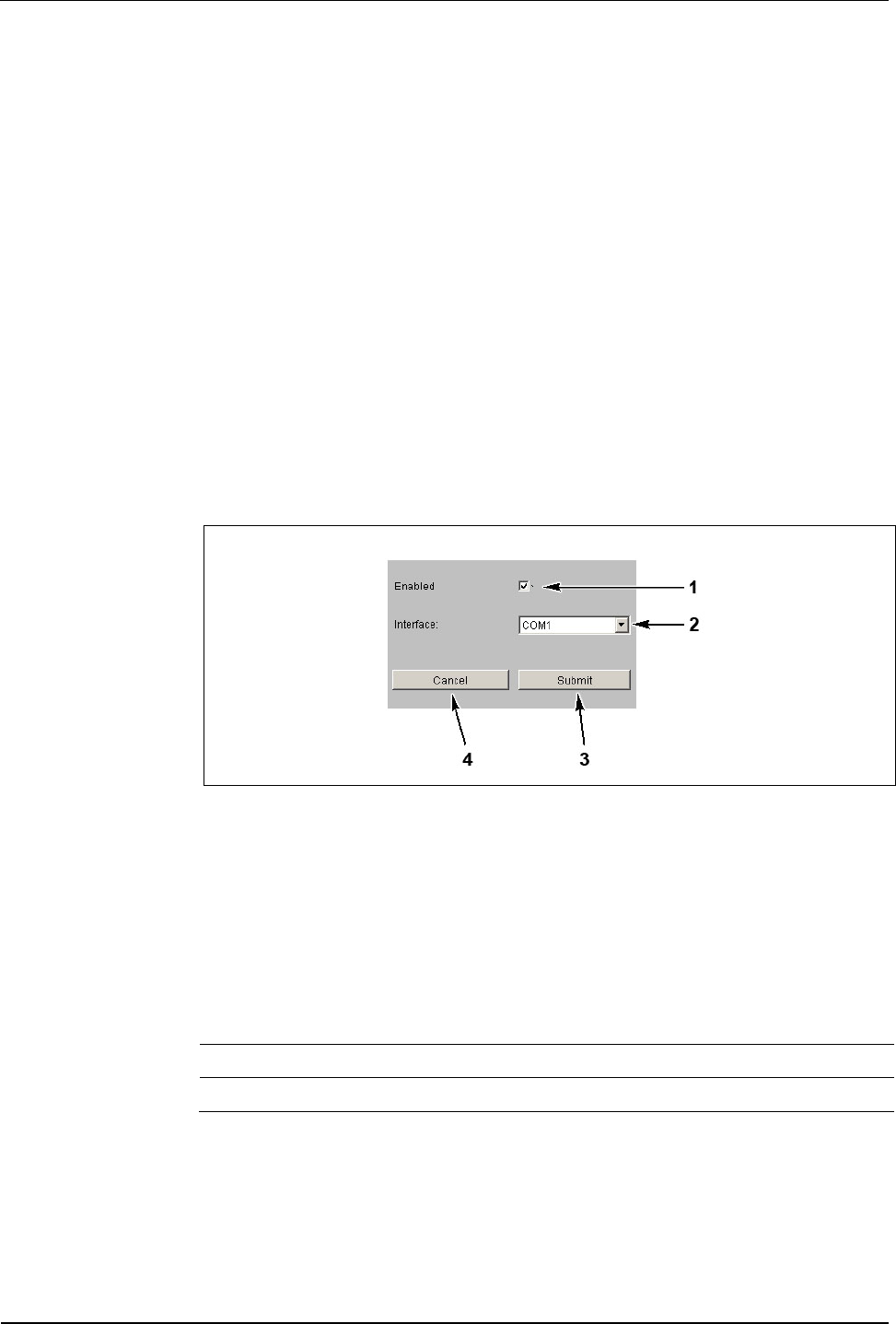
7.3.7.5 Sub line
Setting of interface to the subterminals.
Fig. 47: Example - Show / Set Subline Parameters
1 Activation / deactivation of the sub line.
2 Assignment of sub-partyline to interface (COM port).
3 Submit; take over settings and terminate function.
The settings are active after the next reboot.
4 Cancel, terminate function.
Standard assignment:
Sub line 1 (standard sub-partyline) COM1 (serial line 1)
Sub line 2 (optional) COM2 (serial line 2)
BECO service module User Manual B-Net 93 60
70 © Kaba Benzing GmbH 01/2006
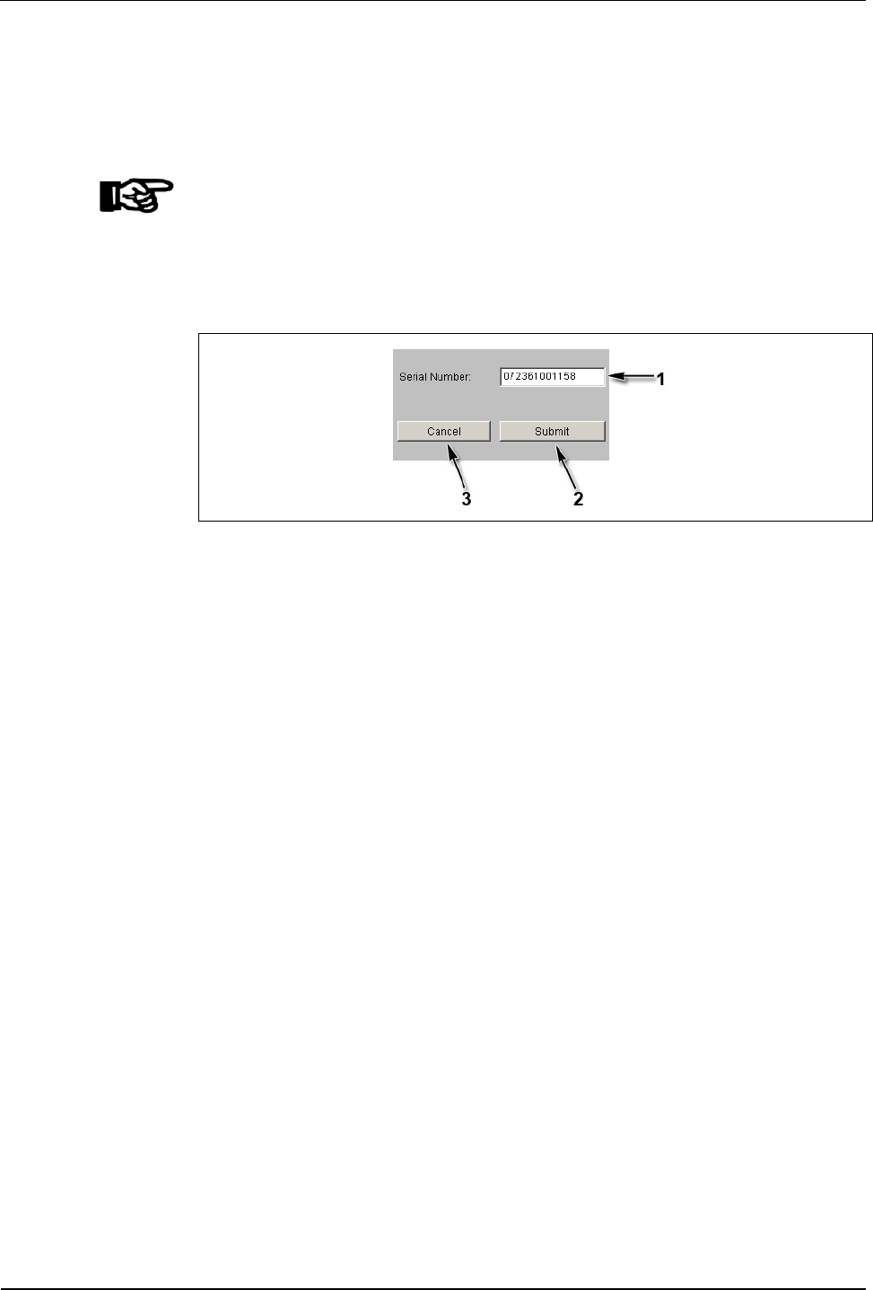
7.3.7.6 Serial number
With this function the device’s serial number can be read-out or modified.
The device’s serial number is stated on the nameplate. With the serial number the
manufacturer is able to resort to all technical details of the device.
NOTICE!
This serial number must match the serial number on the nameplate.
After exchanging the BECO CPU unit, the correct serial number should be entered
again. In this way it is possible at any time to call up the serial number in the service
mode via network.
Fig. 48: Example – Show / Set Serial Number
1 Input field for serial number.
2 Submit; take over serial number and terminate function.
3 Cancel; terminate function.
User Manual B-Net 93 60 BECO service module
01/2006 © Kaba Benzing GmbH 71
7.3.7.7 RTC calibration
Alignment of hardware clock.
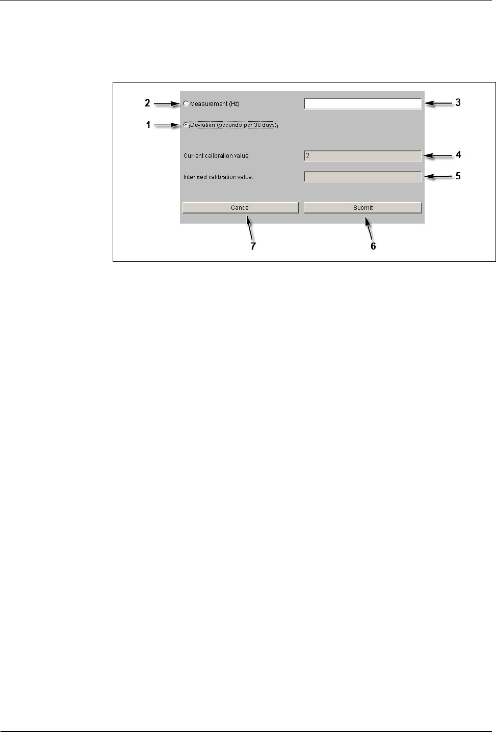
Fig. 49: Example – Show / Set RTC Calibration Value
1 Deviation
With this option, the deviation for the last 30 days must be entered in
seconds (input field 3).
Positive values are recognized with or without leading sign, e.g., 20 or +20;
Negative values must be provided with a leading sign, e.g. -20.
2 Measurement
This option specifies the factory-provided calibration.
This calibration type is not possible on-site at the customer’s premises!
3 Input field for measurement or deviation respectively.
4 Current calibration value.
5 New calibration value.
6 Submit; take over value and calibrate hardware clock.
After a short period of time the message “RTC calibrated with new values“
appears. After you have pressed “OK” the function is terminated.
7 Cancel; terminate function.
BECO service module User Manual B-Net 93 60
72 © Kaba Benzing GmbH 01/2006
7.3.7.8 Modem setup
This function allows for initializing a modem at COM1.
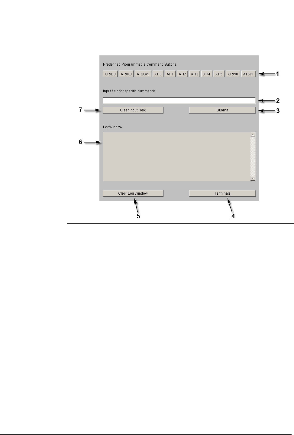
Fig. 50: Example—Gateway to serial host line port
1 Buttons preallocated with AT commands.
When pressing one of these buttons, an AT command is sent to the modem.
2 Input field for commands.
By pressing the “Submit“ (3) button this command is sent to the modem.
If one of the preallocated buttons (1) is pressed, the content of the input field
is assigned to this button. The command can be sent over and over again by
repeatedly pressing the button. The allocation remains as long as the
function is terminated with “Terminate” (4) or is newly applied.
3 Submit; send command in input field (2) to modem.
4 Terminate function.
5 Clear LogWindow, reset log window (6).
6 LogWindow.
7 Clear Input Field; delete content of input field (2).

User Manual B-Net 93 60 BECO service module
01/2006 © Kaba Benzing GmbH 73
Initialization of optional modem
The initialization of ISDN modem and analog modem, deviating from the standard,
is identical.
The following commands must be sent to the modem one after the other:
Command Meaning
AT&D0 Ignore DTR.
AT&K0 No data flow control between DTE (Data Terminal Equipment) and
DCE (Data Communication Equipment).
ATS0=1 Instructs the modem to answer on the first ring.
AT&W Save settings.
With the AT&F command, the modem parameters can be reset to default values.
7.3.7.9 Setup list
The function ‘setup list’ shows an overview of the current settings:
• Ethernet parameters
• Serial line parameters
• Reader parameters
• Host line
• Sub line
Parameters can be adjusted by clicking the headlines.

BECO service module User Manual B-Net 93 60
74 © Kaba Benzing GmbH 01/2006
7.3.8 Hardware analysis
7.3.8.1 Hardware version
The hardware version can be retrieved with this function.
Bootloader Version is 2.4.1
BEX Feature Code is 1
BECO Index is 15
NetArm Revision is 27
Fig. 51: Example – Display of hardware version
7.3.8.2 SRAM option
This function determines, if an SRAM option is installed and which one.
Installed SRAM Option
There is an 8 MB SRAM Option installed
Fig. 52: Example - SRAM option recognized
Installed SRAM Option
There is no SRAM Option installed
Warning:
The SRAM Option installed is not formatted and not available for the
Application File System. BECO Applications use SRAM as Data File System.
To make the installed memory available for the application, you must save
the Application files and format the SRAM File System or perform a cold
start.
Fig. 53: Example – no SRAM option recognized
User Manual B-Net 93 60 BECO service module
01/2006 © Kaba Benzing GmbH 75
7.3.8.3 Memory size
This function allows you to determine the memory size as well as the currently
occupied and free memory.
Size of Memory
Memory Type Total Used Free
RAM 14432192 4817484 9614708
Data File System 9437184 4275943 4866048
Program File System 7157351 1792103 5365248
Fig. 54: Example – memory size
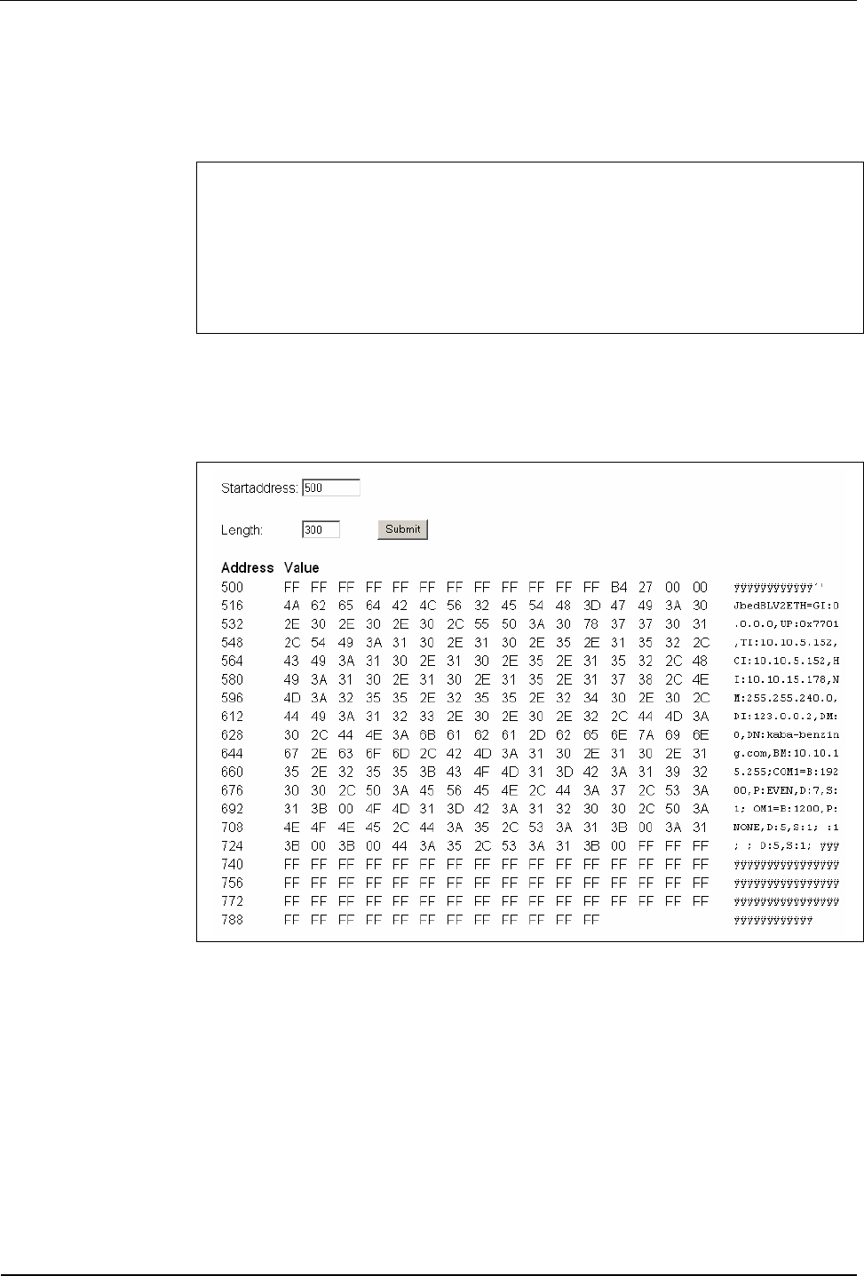
7.3.8.4 EEPROM dump
This function allows you to read-out the content of the internal EEPROM.
Fig. 55: Example – EEPROM Dump
7.3.8.5 Display test
This function starts an automatic display test (with devices with display) where the
character set is displayed.
A repeated call of this function ends the test.
BECO service module User Manual B-Net 93 60
76 © Kaba Benzing GmbH 01/2006
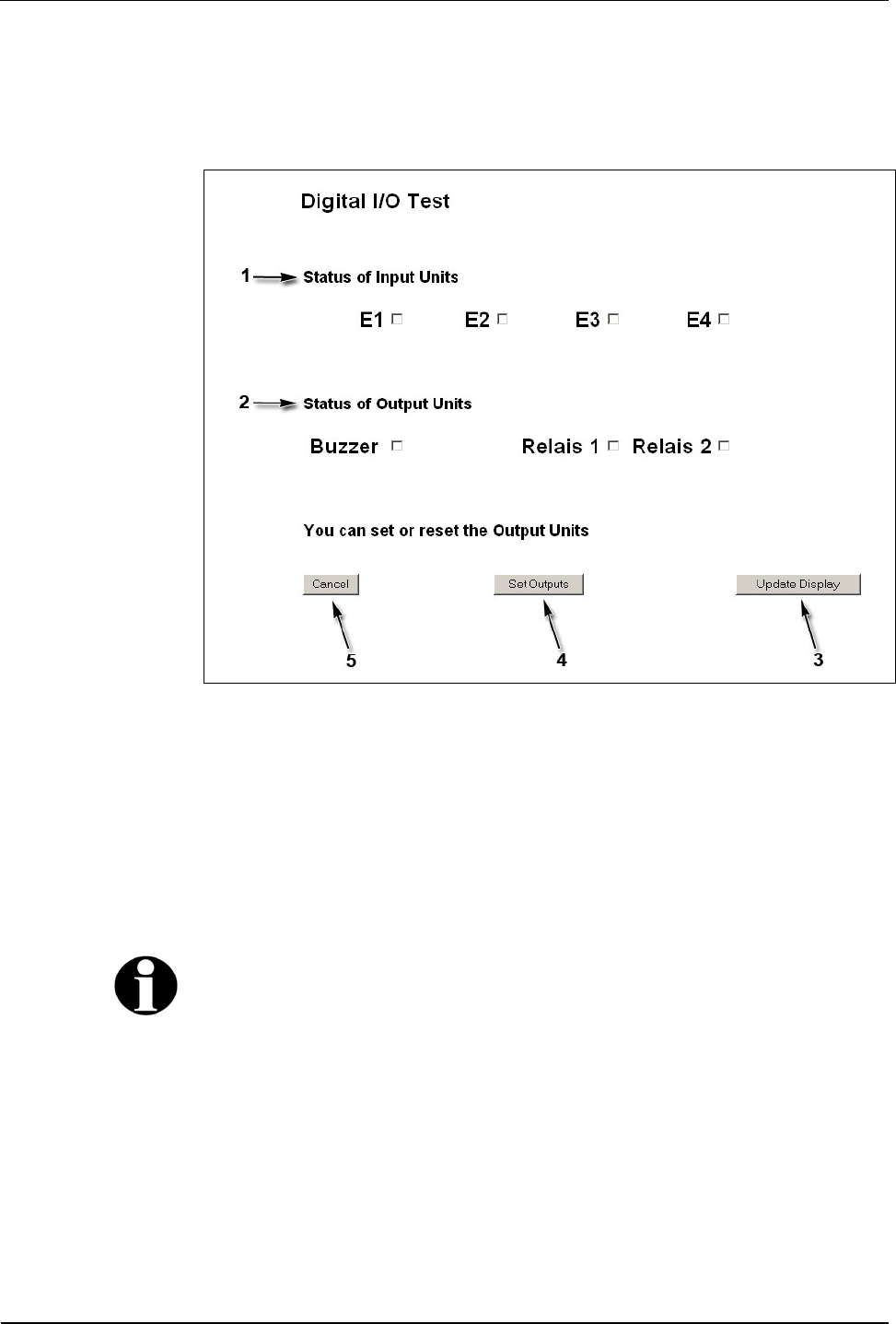
7.3.8.6 Digital I/O test
This function allows you to retrieve the states of the digital inputs and to set the
outputs.
Fig. 56: Example – Digital I/O test
1 The current input status is shown under “Status of Input Units.“
2 By activating the check boxes under “Status of Output Units“ the output
status is preset.
3 With the “Update Display“ button the current status can be retrieved.
4 By pressing the “Set Outputs” button the outputs are set.
5 Cancel; terminate function.
Remark
The number as well as the specification of the available inputs and outputs depends
on the device hardware and on the used application.

User Manual B-Net 93 60 BECO service module
01/2006 © Kaba Benzing GmbH 77
7.4 FTP access
An FTP server is installed on the device. The FTP server can be addressed in
application mode as well as in service mode.
When the system starts in service mode, the FTP is started principally.
In application mode (B-Client HR2 / HR3 / AC2 / AC3 / PDC3), the FTP server can
be activated or deactivated with an entry in the /Program/Share/Init/bedanet.ini file.
Example:
[Programs]
Application0 = FTPServer FTP server is started in application mode
[Programs]
Application0 = FTP server is not started in application mode
Remark
In case that no access via FTP is possible in application mode, this parameter must
be checked in the bedanet.ini file.
Access is performed via a standard FTP client.
Users
The following users are already created by default:
User name: Password: Path:
localuser Bedanet Ram/Transfer
root Bedanet /
Operating elements User Manual B-Net 93 60
78 © Kaba Benzing GmbH 01/2006
8 Operating elements
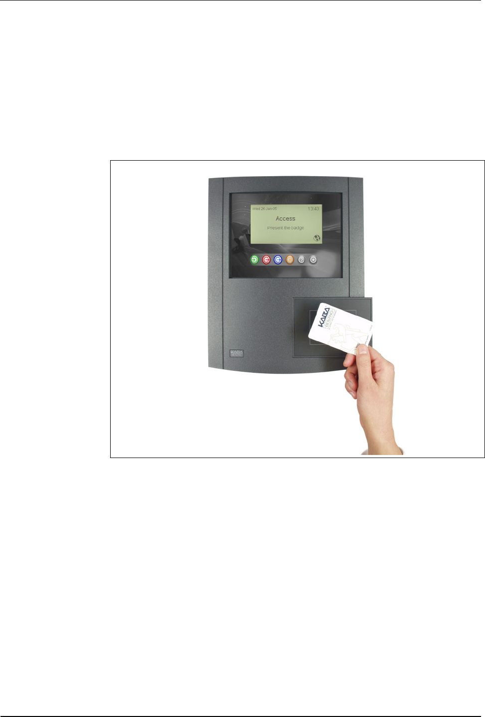
8.1 Badge input
8.1.1 Contactless media
Contactless media such as LEGIC® or Mifare is simply held in front of the
terminal’s reader module.
The reading distance with a badge is approximately 5 – 10 cm and 3 cm with a key
tag.
Fig. 57: Present LEGIC® media
User Manual B-Net 93 60 Operating elements
01/2006 © Kaba Benzing GmbH 79
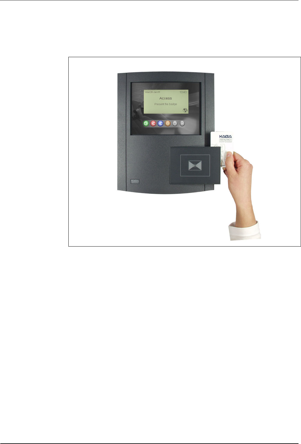
8.1.2 Mag-stripe badges and barcode badges
Swiftly slide the badges through the reading bar in any direction, either from top to
bottom or from the bottom up. The magnetic stripe / barcode must show towards
the scanning unit.
Fig. 58: Swipe mag-stripe badges and barcode badges
Operating elements User Manual B-Net 93 60
80 © Kaba Benzing GmbH 01/2006
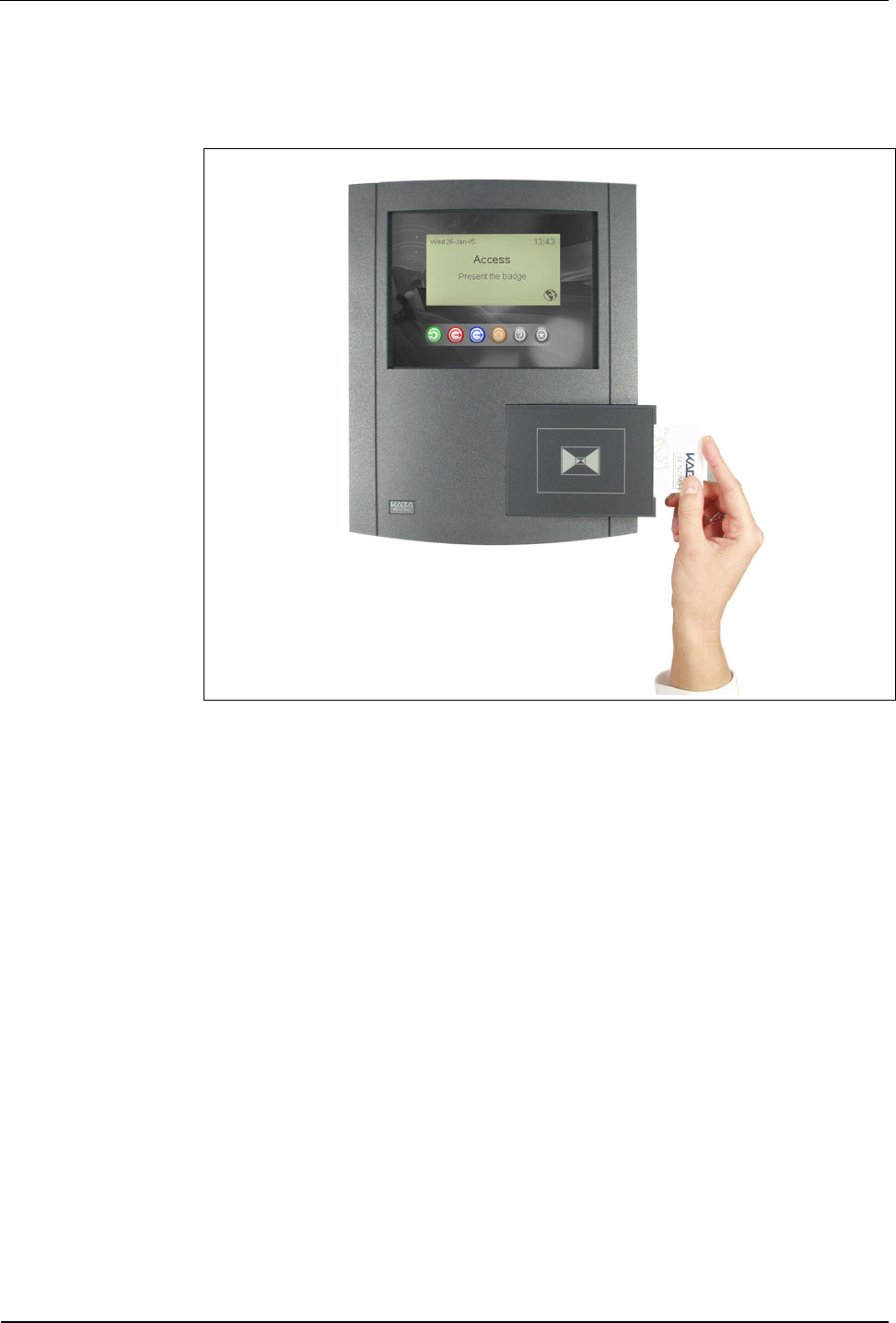
8.1.3 Inductive badges
The badge is simply inserted into the slot on the side as far as it will go. After the
reading process the badge is released from the reader and can be taken out.
Fig. 59: Insert inductive badges
User Manual B-Net 93 60 Operating elements
01/2006 © Kaba Benzing GmbH 81
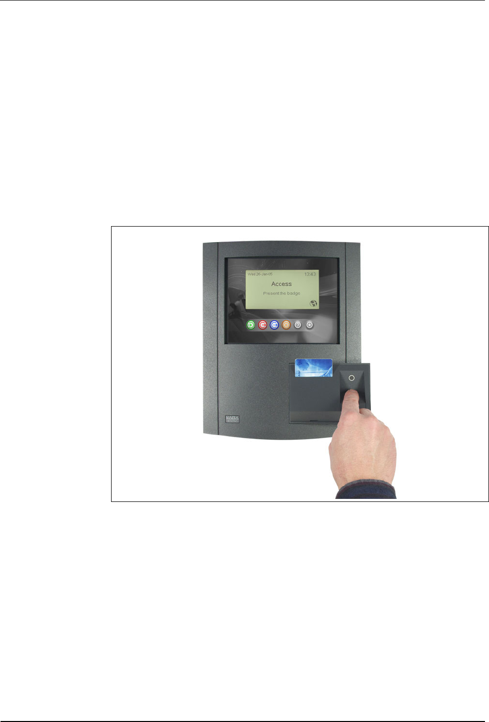
8.1.4 Verification LEGIC® & Fingerprint
The "Verification LEGIC® & Fingerprint" reader module has an insertion reader for
segmented LEGIC® MIM 1024 badges and a sensor for thermal recording of a
fingerprint. For user prompting, a tri color LED is located above the sensor.
First the LEGIC® badge is inserted. If no valid biometric segment is identified on
the badge, the LED blinks after a short period of time. If a valid biometric segment
is identified the LED blinks yellow. Now the finger must be evenly swiped over the
sensor surface within the next 4 seconds.
During verification, the scanned biometric data of the individual is compared with
the reference data record stored on the LEGIC® medium IM 1024.
If the two data records match within certain tolerances, a green LED lights up. If
the result turns out to be negative, the LED lights up red. In this case the scan
process is repeated twice.
Fig. 60: Verification LEGIC® & Fingerprint
Operating elements User Manual B-Net 93 60
82 © Kaba Benzing GmbH 01/2006
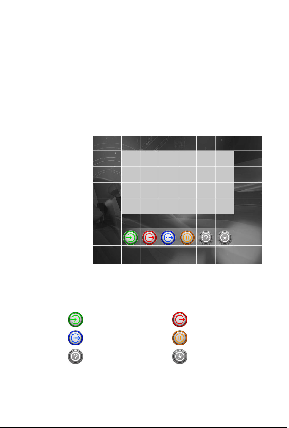
8.2 Matrix touch
A matrix touch with 8 x 8 fields forms the B-Net 93 60’s operator panel. Basically,
the matrix touch is operated just like a keypad. After a valid operation a short
acoustic signal sounds.
The matrix touch spreads across the visible display area as well as across the
subjacent passepartout.
All functional elements can be designed and placed individually.
For this purpose a customized passepartout or label template must be created.
Function and position of the individual buttons is tailored to the customer’s specific
needs via the terminal software’s parameter setting feature.
Virtual buttons on the display can also be individually adapted with the parameter
setting feature.
Fig. 61: Matrix touch of the B-Net 93 60 with standard passepartout. The 8 x 8
touch fields are accentuated with white lines.
The standard version has 6 buttons with the following meaning:
In Out
Official absence Break
Inquiry Special function
Via virtually created buttons on the display, navigation takes place, numeric values
can be entered, and languages can be selected.
The device is also available with an optional alphanumeric reader keypad.

User Manual B-Net 93 60 Operating elements
01/2006 © Kaba Benzing GmbH 83
8.3 Display illumination
The display illumination is switched off after a certain preset period of time
(standard time 10 minutes after the last operation).
The display illumination is again activated after any operation.
Maintenance User Manual B-Net 93 60
84 © Kaba Benzing GmbH 01/2006
9 Maintenance
9.1 Battery change
A Lithium Mangandioxid battery, type CR2032, is located on the BECO CPU unit to
buffer the SRAM memory. Refer to chapter Fehler! Verweisquelle konnte nicht
gefunden werden.
The buffer battery must be replaced by a new one every 2 years when the
devices are in operation.
The buffer battery must be replaced by a new one every 6 months if the
device is stored and not in operation.
Safety advice Only skilled specialists authorized by the manufacturer may exchange the buffer
battery.
To prevent data loss the terminal may not be switched off during battery change.
WARNING
Hazardous voltage at the SV9001 power supply.
Carelessness can lead to an electric shock.
• Take off all metallic jewelry such as rings, necklaces, bracelets, etc.
• Avoid working around or near the power supply.
CAUTION
Lithium batteries can rupture or burst like an explosive.
Improper handling of Lithium batteries can lead to fire and explosions.
• The buffer battery may only be replaced by the same type of battery.
• Do not open, bore through, or crush Lithium batteries.
• Do not burn Lithium batteries or expose to high temperatures.
• Do not short-circuit Lithium batteries.
CAUTION
Danger of electrostatic discharge (ESD).
Touching printed circuit boards can cause damages that lead to complete failures or
sporadic errors.
• Wear an ESD wrist strap when changing batteries.
Proceeding • Do not switch off the device.
• Open the housing.
• Carefully remove the old buffer battery from the battery holder by hand. Do
not use any tools such as screwdrivers etc.
• Gently push the new battery in the holder until it snaps into place.
User Manual B-Net 93 60 Packaging / returns
01/2006 © Kaba Benzing GmbH 85
10 Packaging / returns
Not properly packaged components and devices can cause costs due to damages
during shipping.
Please note the following when dispatching Kaba Benzing products.
Kaba Benzing GmbH is not liable for products that have been damaged due to
negligent packaging.
10.1 Devices
The original packaging has been specifically designed to fit the device. It offers
maximum protection against damages in transit.
NOTICE!
When returning an item, please ensure that you always use the original
packaging.
If this is not possible, packaging must be provided which ensures that the device is
not damaged during shipping and handling.
• Use a robust and thick-walled transport box or cardboard box. Approximately
8 to 10 cm of room needs to be allowed on either side of the device.
• Wrap the device with a suitable foil or put it into a bag.
• Generously stuff for instance foam pads or air cushions all around device.
Movements of the device inside the packaging must be avoided.
• Use only dustfree and environmentally friendly padding material.
10.2 Electronic assemblies
ESD sensitive electronic assemblies such as printed circuit boards, readers, etc.
must be stored, transported, and shipped in appropriate ESD protective bags.
Packing of electronic assemblies may only
• take place at ESD secure workstations
• be done by persons familiar with general ESD safety standards and who
apply them on a regular basis.
Returning electronic assemblies in packaging with sufficient ESD protection is a
prerequisite for
• the submission of warranty claims after functional failures of any type.
• replacement of printed circuit boards and electronic components in
exchange.
Electronic components delivered in packaging without sufficient ESD protection are
--in order to maintain a high quality standard-- neither analyzed nor repaired but
directly disposed of.

Packaging / returns User Manual B-Net 93 60
86 © Kaba Benzing GmbH 01/2006
10.3 Labeling
Complete return documents and a correct labeling allow for fast processing.
Please make sure that each package includes a delivery note. The delivery note
should contain the following information:
• Number of devices or components per package
• Product numbers, serial numbers, specifications
• Name and address of your company / contact person
• Reason for return, e.g. repair order
• Informative and detailed error description
Returns from countries outside the European Union require a customs invoice with
the real customs value.
Some countries (e.g. Switzerland) require a preference.
User Manual B-Net 93 60 Disposal
01/2006 © Kaba Benzing GmbH 87
11 Disposal
This product complies with the WEEE directive and is, according to the DIN norm
EN 50419, marked with the “Crossed out garbage can” symbol. Please refer to
chapter 3.4 Labeling.
The symbol refers to separated disposal of electric and electronic devices in EU
countries.
Please do not dispose of device in your regular garbage.
Used devices contain valuable materials that should be recycled. Used devices
should therefore be disposed of via your country’s take back system.
Kaba Benzing is committed to take back and dispose this device after the end of its
life cycle.
Please dispose of in an environmentally responsible way
The packaging materials are recyclable. Please do not throw packaging material
into your regular garbage can. Always take it to a recycling center or have it picked
up by your local waste recycler.
Lithium batteries
CAUTION
Lithium batteries can rupture or burst like an explosive.
Improper handling of Lithium batteries can lead to fire and explosions.
Please carefully deposit the batteries that must be disposed, in order to avoid short-
circuits, crushing, or damage of the battery housing.
Please refer to chapter 2.4 Handling of Lithium batteries
Used Lithium batteries must be disposed of according to state and local regulations.
Appendix User Manual B-Net 93 60
88 © Kaba Benzing GmbH 01/2006
12 Appendix
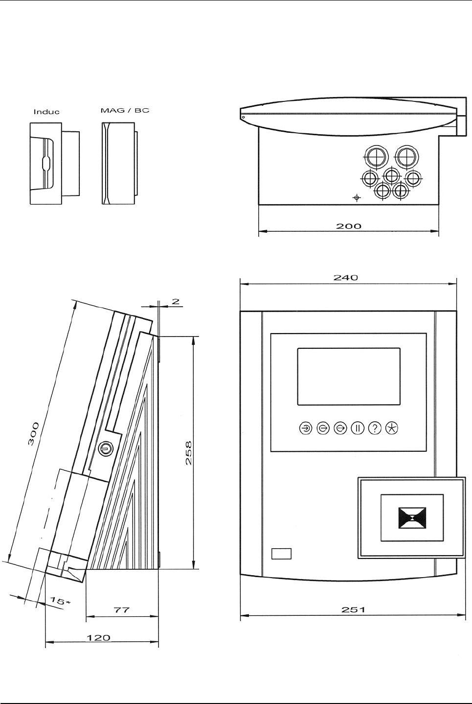
12.1 Dimensional drawings
Fig. 62: Dimensional drawings B-Net 93 60; dimensions in mm
User Manual B-Net 93 60 Appendix
01/2006 © Kaba Benzing GmbH 89
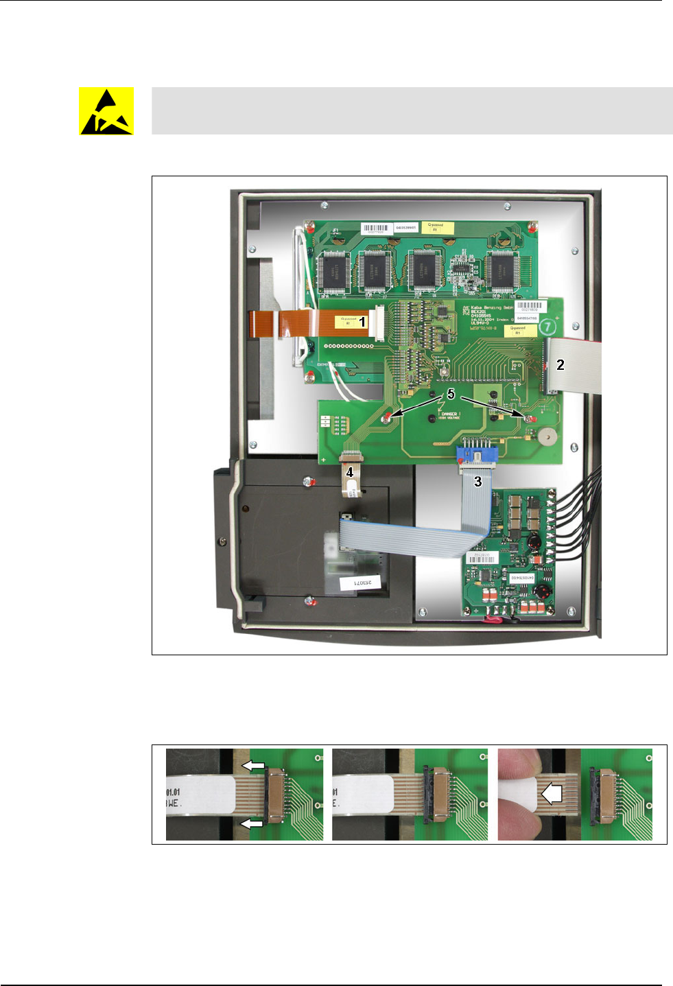
12.2 Exchange of passepartout
During execution of the tasks described below, the ESD protective measures
must be considered.
To exchange the passepartout (label template), please proceed as follows:
First remove the cable to the matrix touch on the user interface (1), the cable to the
mother board (2), the cable to the reader module (3) and the cable to the reader
keypad (4) if available.
Please consider that the connectors of cables 1 and 4 must be unlocked first (see
illustration). After connecting, the cable must be locked again.
The user interface is plugged on the display board. After the two screws (5) have
been removed the user interface can be carefully lifted upwards and removed.
Appendix User Manual B-Net 93 60
90 © Kaba Benzing GmbH 01/2006
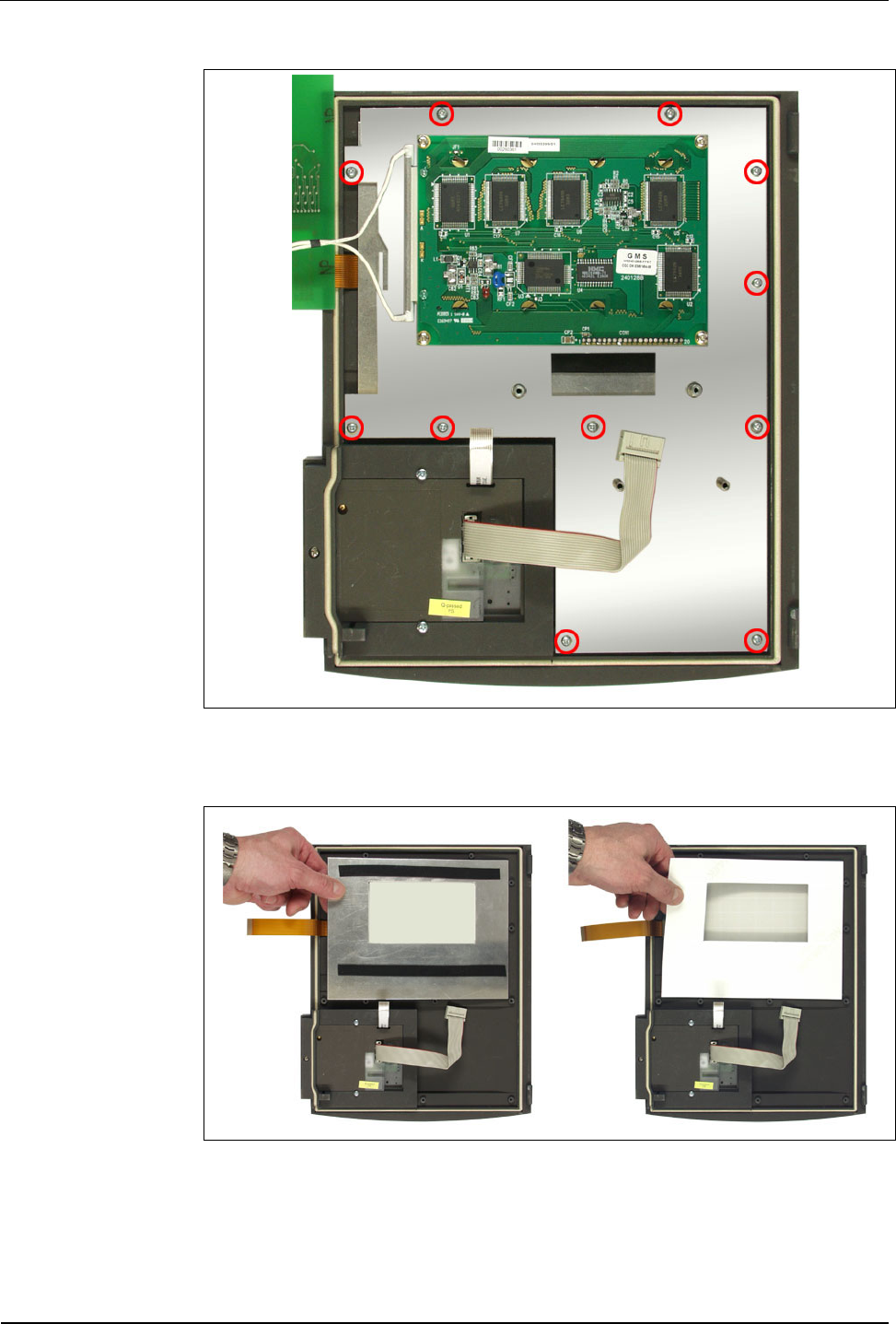
After you have unscrewed the 11 marked screws the mounting plate can be
removed.
Now the carrier plate can be removed. Afterwards the passepartout can be
exchanged.
Mounting takes place in reverse order.

User Manual B-Net 93 60 Index
01/2006 © Kaba Benzing GmbH 91
13 Index
A
Analog modem....................................................29
AT commands...............................................72, 73
Available memory ...............................................75
B
Badge input.........................................................78
Battery ......................................................8, 17, 87
Battery change....................................................84
BECO service module ........................................48
BEX301...............................................................34
BEX400 memory expansion unit ........................39
BEX500 UPS ......................................................40
Block IP addresses.............................................56
Broadcast............................................................63
Buffer battery ..........................................16, 17, 39
Buffer time ..........................................................12
C
Cable clamp........................................................26
Cable inlet.....................................................18, 26
Capacity of data memory....................................12
CE.......................................................................13
Cold start button ...........................................16, 46
Cold start of application ......................................47
COM port settings...............................................66
Communication...................................................11
Conformity ..........................................................13
Connection for second reader ............................34
Connection of subterminals ................................32
Connections on BECO500 CPU unit..................27
Connections on BEX101 mother board..............27
Connectors .........................................................18
Contrast control ..................................................15
D
Data retention in case of power failure...............12
Default IP ........................................................... 47
Default IP address ............................................. 49
Device address .................................................. 68
DHCP................................................................. 62
DID..................................................................... 68
Digital inputs ...................................................... 35
Dimensions ........................................................ 11
Display ............................................................... 11
Display contrast ................................................. 15
Display illumination ............................................ 83
Display test ........................................................ 75
Display/set date and time .................................. 55
Disposal ............................................................. 87
DNS server ........................................................ 63
Door control line................................................. 22
Door opener....................................................... 36
Door-opener voltage .......................................... 38
E
Earthing.............................................................. 18
EMC standard.................................................... 13
Emergency power operation.............................. 41
Encryption.......................................................... 68
Environmental conditions................................... 11
ESD (Electro Static Discharge) protective
measures ......................................................... 9
Ethernet connector............................................. 28
Ethernet interface............................................... 11
Exchange of passepartout................................. 89
F
File system formatting........................................ 53
FTP access........................................................ 77
Fuse ................................................................... 16
G
GID..................................................................... 68
Group address ................................................... 68

Index User Manual B-Net 93 60
92 © Kaba Benzing GmbH 01/2006
H
Hole pattern ........................................................23
Host connection..................................................22
Host line settings ................................................68
I
Identification plate...............................................13
Input 24 V ...........................................................37
Inputs ..................................................................35
Installation...........................................................18
Installation lines ..................................................21
Installation scheme.............................................20
Interface parameters...........................................66
Interface to host settings ....................................68
IP address...........................................................62
IP address default...............................................49
ISDN modem ......................................................30
J
Jumper assignment BEX302 ..............................31
Jumper SV9001..................................................38
K
Keypad................................................................11
L
License key.........................................................58
Light emitting diodes on BEX101 .......................46
Light-emitting diodes Ethernet............................28
Line requirements...............................................21
Lithium battery ..........................................8, 17, 87
Low voltage directive ..........................................13
M
MAC address................................................58, 62
Mains switch .................................................16, 17
Maintenance .......................................................84
Matrix touch ........................................................82
Memory...............................................................11
Memory size .......................................................75
Modem................................................................29
Modem initialization ............................................73
Modem setup ..................................................... 72
Mounting ............................................................ 18
Mounting height ................................................. 19
Mounting plate ................................................... 24
N
Netmask............................................................. 62
Network parameters........................................... 62
O
Outdoor installation............................................ 19
Outputs .............................................................. 36
P
Partyline............................................................. 22
Partyline to host ................................................. 31
Passepartout...................................................... 82
Password ........................................................... 57
Power input........................................................ 38
Power supply ..................................................... 11
Power supply line............................................... 21
Processor........................................................... 11
Program version................................................. 53
Protection class.................................................. 11
Protection roof.................................................... 19
R
Reader ............................................................... 11
Reader keypad................................................... 82
Reader second................................................... 34
Reader settings.................................................. 67
Relay outputs..................................................... 36
Remoteboot ....................................................... 60
Restart ............................................................... 61
RS232 interface ................................................. 34
S
Second reader ............................................. 34, 43
Serial interface settings ..................................... 66
Serial number............................................... 13, 70
Service button.............................................. 16, 46
Service functions................................................ 49

User Manual B-Net 93 60 Index
01/2006 © Kaba Benzing GmbH 93
Service mode......................................................47
Service module access rights.......................56, 57
Service module password ..................................50
Service module user administration ...................57
Service module user name.................................50
Set-up .................................................................42
Setup list.............................................................73
Software option protection..................................58
Start of application..............................................47
Start of service module.......................................48
Subpartyline........................................................32
Subterminal...................................................21, 45
Subterminal settings ...........................................69
Supply voltage ....................................................37
Surface mounting............................................... 23
SV9001 power supply........................................ 38
T
Technical data.................................................... 11
Technical data BEX500 UPS............................. 40
Test license........................................................ 58
Transfer rate ...................................................... 66
U
UDP port ............................................................ 68
Uninterruptible power supply BEX500............... 40
Use as directed.................................................... 7
V
Verification ......................................................... 81